Contents Eurocode 2 2004 WALL 002
User Manual: Eurocode 2-2004 WALL-002
Open the PDF directly: View PDF ![]() .
.
Page Count: 5
Software Verification
PROGRAM NAME:
ETABS
REVISION NO.:
4
EXAMPLE Eurocode 2-2004 Wall-002
P-M INTERACTION CHECK FOR A WALL
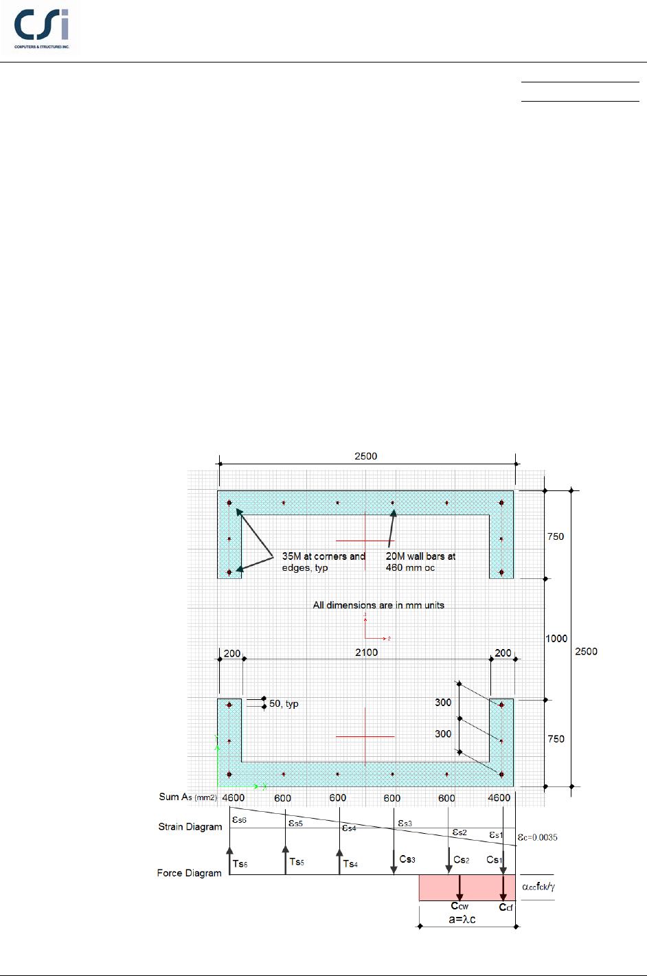
EXAMPLE DESCRIPTION
The Demand/Capacity ratio for a given axial load and moment are tested in this
example. A reinforced concrete wall is subjected to factored axial load Pu =
11605 kN and moments Muy = 15342 kN-m. This wall is reinforced as noted
below. The design capacity ratio is checked by hand calculations and the results
are compared with ETABS program results.
GEOMETRY, PROPERTIES AND LOADING
EXAMPLE Eurocode 2-2004 Wall-002 - 1
Software Verification
PROGRAM NAME:
ETABS
REVISION NO.:
4
TECHNICAL FEATURES OF ETABS TESTED
Concrete wall flexural demand/capacity ratio
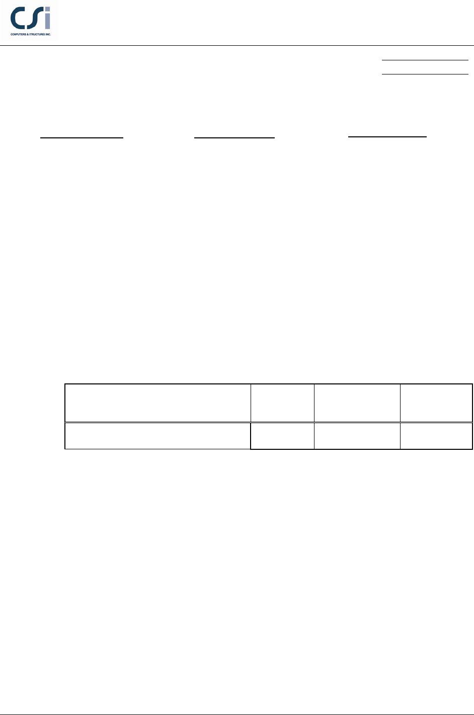
RESULTS COMPARISON
Independent results are hand calculated and compared with ETABS design
check.
Output Parameter ETABS Independent Percent
Difference
Wall Demand/Capacity Ratio 1.011 1.00 1.10%
COMPUTER FILE: EUROCODE 2-2004 WALL-002
CONCLUSION
The ETABS results show an acceptable comparison with the independent results.
Material Properties
E = 25000 MPa
ν = 0.2
Section Properties
Design Properties
f ′
c
= 30 MPa
fy = 460 MPa
tb = 200 mm
H = 2500 mm
d = 2400 mm
s = 460 mm
As1= As5 = 4-35M+2-20M (4600 mm^2)
As2, As3, As4, As5 = 2-20M (600 mm^2)
EXAMPLE Eurocode 2-2004 Wall-002 - 2
Software Verification
PROGRAM NAME:
ETABS
REVISION NO.:
4
HAND CALCULATION
Wall Strength Determined as follows:
1) A value of e = 1322 mm was determined using
/
uu
eM P=
where
u
M
and
u
P
were
taken from the ETABS test model PMM interaction diagram for pier P1. Values for
u
M
and
u
P
were taken near the balanced condition and large enough to produce a
flexural D/C ratio very close to or equal to one. The depth to the neutral axis, c, was
determined by iteration using an excel spreadsheet so that equations 1 and 2 below
were equal.
2) From the equation of equilibrium:
=+−
n cs
PCCT
Where
c
C= +
cw cf
CC
, where
cw
C
and
cf
C
are the area of the concrete web and flange in
compression
( ) ( )
α
= −= −= −
γ
0.85•30
•200• 200 •200• 200 3400( 200)
1.5
cc ck
cw
m
f
C a aa
()
( )
( )
( )
α
= −= −=
γ
0.85(30)
200• 2500 1000 200• 2500 1000 5,100,000
1.5
cc ck
cf
m
f
C
ααα
′′ ′
=−+−+−
γγγ
11 2 2 33
cc ck cc ck cc ck
ss s s
mmm
fff
C Af Af Af
=++
γγγ
444
456
sss
sss
sss
fff
TA A A
αα
= −+ + − + −
γ γγ γ
α
+ − −−−
γ γγ γγ
12
1 12
3 456
3 456
3400( 200) 5,100,000 s cc ck s cc ck
n ss
s ms m
s cc ck s s s
s sss
s ms s s
A fA f
Pa f f
A fA A A
f fff
(Eqn. 1)
EXAMPLE Eurocode 2-2004 Wall-002 - 3
Software Verification
PROGRAM NAME:
ETABS
REVISION NO.:
4
3) Taking moments about As6:
( ) ( )
( ) ( ) ( ) ( )
ff
a
12
=
T 2s T s
cf cw s1
n2
s2 s3 s4 s5
t
C d-d' C d- t C d-d'
PeC 4s C 3s
−
+ −+ +
′
+−−
(Eqn. 2)
where
1
11
s cc ck
ss
sm
Af
Cf
α
= −
γγ
;
2
22
s cc ck
ss
sm
Af
Cf
α
= −
γγ
;
3
33
s cc ck
ss
sm
Af
Cf
α
= −
γγ
;
( )
4
44
s
ss
s
A
Tf
=γ
and the bar strains and stresses are determined below.
The plastic centroid is at the center of the section and
d′′
= 700 mm
′ ′′
=+= + =
1322 700 2472e ed
mm.
4) Using c = 1299 mm (from iteration),
=β= =
1
0.895•1299 1163ac
mm
5) Assuming the extreme fiber strain equals 0.0035 and c = 1299 mm, the steel stresses
and strains can be calculated. When the bar strain exceeds the yield strain, then
sy
ff=
:
1
0.0035
s
cd
c
′
−
ε=
= 0.00323;
ss y
f EF=ε≤
;
1s
f
= 460 MPa
20.0035
s
csd
c
′
−−
ε=
= 0.00199
2s
f
= 398.2 MPa
3
20.0035
s
c sd
c
′
−−
ε=
= 0.00075
3s
f
= 150.3 MPa
46
2
ss
dc s
dc
−−
ε= ε
−
= 0.00049
4s
f
= 97.5 MPa
56
ss
dcs
dc
−−
ε= ε
−
= 0.00173
5s
f
= 345.4 MPa
60.0035
s
dc
c
−
ε=
= 0.00297
6s
f
= 460.00 MPa
EXAMPLE Eurocode 2-2004 Wall-002 - 4

Software Verification
PROGRAM NAME:
ETABS
REVISION NO.:
4
Substituting in Eqn. 1 and 2 and iterating the value of the neutral axis depth until the
two equations are equal give
=
n1
P
11605 kN
=
n2
P
11605 kN
nn
M Pe= =
11605(1322) /1000
= 15342 kN-m
EXAMPLE Eurocode 2-2004 Wall-002 - 5
