VLT AutomationDrive FC 300 FC300Manual
User Manual: FC300Manual
Open the PDF directly: View PDF ![]() .
.
Page Count: 110 [warning: Documents this large are best viewed by clicking the View PDF Link!]

Contents
1 How to Read these Operating Instructions
3
Approvals 4
Symbols 4
Abbreviations 5
2 Safety Instructions and General Warning
7
High Voltage 7
Safe Stop of FC 300 9
IT Mains 14
3 How to Install
15
Mechanical Installation 18
Electrical Installation 20
Power and Control Wiring for Unscreened Cables 21
Connection to Mains and Earthing 22
Motor Connection 26
Fuses 29
Electrical Installation, Control Terminals 33
Connection Examples 34
Electrical Installation, Control Cables 36
Switches S201, S202, and S801 38
Final Set-Up and Test 39
Additional Connections 41
Mechanical Brake Control 41
Motor Thermal Protection 42
How to Connect a PC to the Frequency Converter 42
The FC 300 PC Software 42
4 How to Programme
43
The Graphical and Numerical LCP 43
How to Programme on the Graphical LCP 43
How to Programme on the Numerical Local Control Panel 43
Quick Setup 45
Basic Setup Parameters 49
Parameter Lists 70
5 General Specifications
93
6 Troubleshooting
99
Warnings/Alarm Messages 99
Index
108
VLT
®
AutomationDrive FC 300 Operating
Instructions Contents
MG.33.AG.02 - VLT® is a registered Danfoss trademark
1

1 How to Read these Operating Instructions
VLT
®
AutomationDrive FC 300 Operating
Instructions
2
MG.33.AG.02 - VLT® is a registered Danfoss trademark
1

1 How to Read these Operating Instructions
VLT AutomationDrive
Operating Instructions
Software version: 6.0x
These Operating Instructions can be used for all VLT AutomationDrive frequency converters with software version 6.0x.
The software version number can be seen from par. 15-43
Software Version
.
1.1.1 How to Read these Operating Instructions
VLT AutomationDrive is designed to provide high shaft performance on electrical motors. Please read this manual carefully for proper use. Incorrect
handling of the frequency converter may cause improper operation of the frequency converter or related equipment, shorten lifetime or cause other
troubles.
These Operating Instructions will help you get started, install, program, and troubleshoot your VLT AutomationDrive.
The VLT AutomationDrive comes in twoshaft performance levels. FC 301 ranges from scalar (U/f) to VVC+ and handles asynchronous motors only. FC
302 is a high performance frequency converter for asynchronous as well as permanent motors and handles various kinds of motor control principles such
as scalar (U/f), VVC+ and Flux vector motor control.
These Operating Instructions cover both FC 301 and FC 302. Where information covers both series, we refer to VLT AutomationDrive. Otherwise, we
refer specifically to either FC 301 or FC 302.
Chapter 1, How to Read these Operating Instructions, introduces the manual and informs you about the approvals, symbols, and abbreviations
used in this literature.
Chapter 2, Safety Instructions and General Warnings, entails instructions on how to handle the FC 300 correctly.
Chapter 3, How to Install, guides you through mechanical and technical installation.
Chapter 4, How to Programme, shows you how to operate and programme the FC 300 via the LCP.
Chapter 5, General Specifications, contains technical data about FC 300.
Chapter 6, Troubleshooting, assists you in solving problems that may occur when using FC 300.
Available Literature for FC 300
-The VLT AutomationDrive Operating Instructions provide the necessary information for getting the drive up and running.
-The VLT AutomationDrive Design Guide entails all technical information about the drive design and applications including encoder, resolver and
relay options.
-The VLT AutomationDrive Programming Guide provides information on how to programme and contain all parameters of the frequency converter.
-The VLT AutomationDrive Profibus Operating Instructions provide the information required for controlling, monitoring and programming the
drive via a Profibus fieldbus.
-The VLT AutomationDrive DeviceNet Operating Instructions provide the information required for controlling, monitoring and programming the
drive via a DeviceNet fieldbus.
-The VLT AutomationDrive MCT 10 Operating Instructions provide information for installation and use of the software on a PC.
-The VLT AutomationDrive IP21 / Type 1 Instruction provides information for installing the IP21 / Type 1 option.
-The VLT AutomationDrive 24 V DC Backup Instruction provides information for installing the 24 V DC Backup option.
Danfoss technical literature is also available online at www.danfoss.com/drives.
VLT
®
AutomationDrive FC 300 Operating
Instructions 1 How to Read these Operating Instructions
MG.33.AG.02 - VLT® is a registered Danfoss trademark
3
1
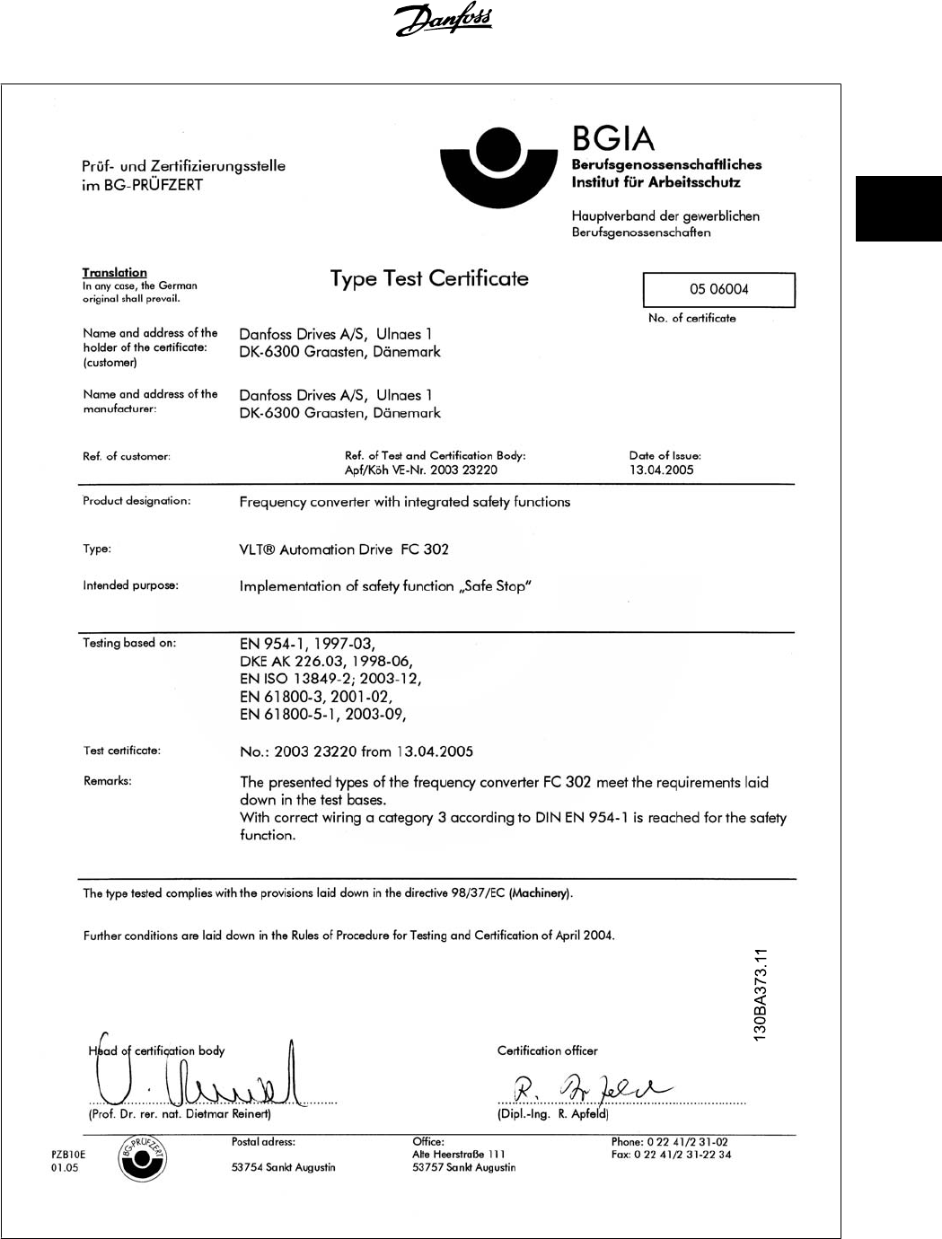
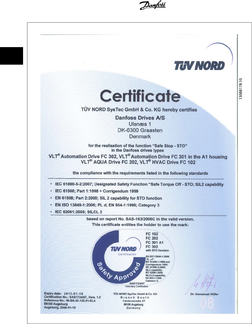
1.1.2 Approvals
1.1.3 Symbols
Symbols used in this Operating Instructions.
NB!
Indicates something to be noted by the reader.
Indicates a general warning.
Indicates a high-voltage warning.
∗Indicates default setting
1 How to Read these Operating Instructions
VLT
®
AutomationDrive FC 300 Operating
Instructions
4
MG.33.AG.02 - VLT® is a registered Danfoss trademark
1

1.1.4 Abbreviations
Alternating current AC
American wire gauge AWG
Ampere/AMP A
Automatic Motor Adaptation AMA
Current limit ILIM
Degrees Celsius °C
Direct current DC
Drive Dependent D-TYPE
Electro Magnetic Compatibility EMC
Electronic Thermal Relay ETR
Frequency Converter FC
Gram g
Hertz Hz
Kilohertz kHz
Local Control Panel LCP
Meter m
Millihenry Inductance mH
Milliampere mA
Millisecond ms
Minute min
Motion Control Tool MCT
Nanofarad nF
Newton Meters Nm
Nominal motor current IM,N
Nominal motor frequency fM,N
Nominal motor power PM,N
Nominal motor voltage UM,N
Parameter par.
Protective Extra Low Voltage PELV
Printed Circuit Board PCB
Rated Inverter Output Current IINV
Revolutions Per Minute RPM
Regenerative terminals Regen
Second s
Synchronous Motor Speed ns
Torque limit TLIM
Volts V
The maximum output current IVLT,MAX
The rated output current supplied by the frequency converter IVLT,N
1.1.5 Disposal Instruction
Equipment containing electrical components may not be disposed of together with domestic
waste.
It must be separately collected with electrical and electronic waste according to local and currently
valid legislation.
VLT
®
AutomationDrive FC 300 Operating
Instructions 1 How to Read these Operating Instructions
MG.33.AG.02 - VLT® is a registered Danfoss trademark
5
1

2 Safety Instructions and General Warning
VLT
®
AutomationDrive FC 300 Operating
Instructions
6
MG.33.AG.02 - VLT® is a registered Danfoss trademark
2
2Safety Instructions and General Warning
The DC link capacitors remain charged after power has been disconnected. To avoid electrical shock hazard, disconnect the frequency
converter from mains before carrying out maintenance. When using a PM-motor, make sure it is disconnected. Before doing service
on the frequency converter wait at least the amount of time indicated below:
Voltage Power Waiting Time
200 - 240 V 0.25 - 3.7 kW 4 minutes
5.5 - 37 kW 15 minutes
380 - 480/500 V 0.37 - 7.5 kW 4 minutes
11 - 75 kW 15 minutes
525 - 600 V 0.75 - 7.5 kW 4 minutes
11 - 75 kW 15 minutes
525 - 690 V 11 - 75 kW 15 minutes
2.1.1 High Voltage
The voltage of the frequency converter is dangerous whenever the frequency converter is connected to mains. Incorrect installation
or operation of the motor or frequency converter may cause damage to the equipment, serious personal injury or death. The instructions
in this manual must consequently be observed, as well as applicable local and national rules and safety regulations.
Installation in high altitudes
380 - 500 V: At altitudes above 3 km, please contact Danfoss regarding PELV.
525 - 690 V: At altitudes above 2 km, please contact Danfoss regarding PELV.
2.1.2 Safety Precautions
The voltage of the frequency converter is dangerous whenever connected to mains. Incorrect installation of the motor, frequency
converter or fieldbus may cause death, serious personal injury or damage to the equipment. Consequently, the instructions in this
manual, as well as national and local rules and safety regulations, must be complied with.
Safety Regulations
1. The mains supply to the frequency converter must be disconnected whenever repair work is to be carried out. Check that the mains supply has
been disconnected and that the necessary time has elapsed before removing motor and mains supply plugs.
2. The [OFF] button on the control panel of the frequency converterr does not disconnect the mains supply and consequently it must not be used
as a safety switch.
3. The equipment must be properly earthed, the user must be protected against supply voltage and the motor must be protected against overload
in accordance with applicable national and local regulations.
4. The earth leakage current exceeds 3.5 mA.
5. Protection against motor overload is not included in the factory setting. If this function is desired, set par. 1-90
Motor Thermal Protection
to
data value ETR trip 1 [4] or data value ETR warning 1 [3].
6. Do not remove the plugs for the motor and mains supply while the frequency converter is connected to mains. Check that the mains supply has
been disconnected and that the necessary time has elapsed before removing motor and mains plugs.
VLT
®
AutomationDrive FC 300 Operating
Instructions 2 Safety Instructions and General Warning
MG.33.AG.02 - VLT® is a registered Danfoss trademark
7
2
7. Please note that the frequency converter has more voltage sources than L1, L2 and L3, when load sharing (linking of DC intermediate circuit)
or external 24 V DC are installed. Check that all voltage sources have been disconnected and that the necessary time has elapsed before
commencing repair work.
Warning against unintended start
1. The motor can be brought to a stop by means of digital commands, bus commands, references or a local stop, while the frequency converter
is connected to mains. If personal safety considerations (e.g. risk of personal injury caused by contact with moving machine parts following an
unintentional start) make it necessary to ensure that no unintended start occurs, these stop functions are not sufficient. In such cases the mains
supply must be disconnected or the
Safe Stop
function must be activated.
2. The motor may start while setting the parameters. If this means that personal safety may be compromised (e.g. personal injury caused by
contact with moving machine parts), motor starting must be prevented, for instance by use of the
Safe Stop
function or secure disconnection
of the motor connection.
3. A motor that has been stopped with the mains supply connected, may start if faults occur in the electronics of the frequency converter, through
temporary overload or if a fault in the power supply grid or motor connection is remedied. If unintended start must be prevented for personal
safety reasons (e.g. risk of injury caused by contact with moving machine parts), the normal stop functions of the frequency converter are not
sufficient. In such cases the mains supply must be disconnected or the
Safe Stop
function must be activated.
NB!
When using the
Safe Stop
function, always follow the instructions in the
Safe Stop
section of the VLT AutomationDrive Design Guide.
4. Control signals from, or internally within, the frequency converter may in rare cases be activated in error, be delayed or fail to occur entirely.
When used in situations where safety is critical, e.g. when controlling the electromagnetic brake function of a hoist application, these control
signals must not be relied on exclusively.
Touching the electrical parts may be fatal - even after the equipment has been disconnected from mains.
Also make sure that other voltage inputs have been disconnected, such as external 24 V DC, load sharing (linkage of DC intermediate
circuit), as well as the motor connection for kinetic back up.
Systems where frequency converters are installed must, if necessary, be equipped with additional monitoring and protective devices
according to the valid safety regulations, e.g law on mechanical tools, regulations for the prevention of accidents etc. Modifications on
the frequency converters by means of the operating software are allowed.
NB!
Hazardous situations shall be identified by the machine builder/ integrator who is responsible for taking necessary preventive means
into consideration. Additional monitoring and protective devices may be included, always according to valid national safety regulations,
e.g. law on mechanical tools, regulations for the prevention of accidents.
NB!
Crane, Lifts and Hoists:
The controlling of external brakes must always have a redundant system. The frequency converter can in no circumstances be the
primary safety circuit. Comply with relevant standards, e.g.
Hoists and cranes: IEC 60204-32
Lifts: EN 81
Protection Mode
Once a hardware limit on motor current or dc-link voltage is exceeded the frequency converter will enter “Protection mode”. “Protection mode” means a
change of the PWM modulation strategy and a low switching frequency to minimize losses. This continues 10 sec after the last fault and increases the
reliability and the robustness of the frequency converter while re-establishing full control of the motor.
In hoist applications “Protection mode” is not usable because the frequency converter will usually not be able to leave this mode again and therefore it
will extend the time before activating the brake – which is not recommendable.
The “Protection mode” can be disabled by setting par. 14-26
Trip Delay at Inverter Fault
to zero which means that the frequency converter will trip
immediately if one of the hardware limits is exceeded.
2 Safety Instructions and General Warning
VLT
®
AutomationDrive FC 300 Operating
Instructions
8
MG.33.AG.02 - VLT® is a registered Danfoss trademark
2

NB!
It is recommended to disable protection mode in hoisting applications (par. 14-26
Trip Delay at Inverter Fault
= 0)
2.1.3 General Warning
Warning:
Touching the electrical parts may be fatal - even after the equipment has been disconnected from mains.
Also make sure that other voltage inputs have been disconnected, such as load-sharing (linkage of DC intermediate circuit), as well as
the motor connection for kinetic back-up.
Using VLT AutomationDrive: wait at least 15 minutes.
Shorter time is allowed only if indicated on the nameplate for the specific unit.
Leakage Current
The earth leakage current from the frequency converter exceeds 3.5 mA. To ensure that the earth cable has a good mechanical
connection to the earth connection (terminal 95), the cable cross section must be at least 10 mm2 or 2 times rated earth wires termi-
nated separately.
Residual Current Device
This product can cause a D.C. current in the protective conductor. Where a residual current device (RCD) is used for extra protection,
only an RCD of Type B (time delayed) shall be used on the supply side of this product. See also RCD Application Note MN.90.GX.02.
Protective earthing of the VLT AutomationDrive and the use of RCD's must always follow national and local regulations.
NB!
For vertical lifting or hoisting applications it is strongly recommended to ensure that the load can be stopped in case of an emergency
or a malfunction of a single part such as a contactor, etc.
If the frequency converter is in alarm mode or in an over voltage situation, the mechanical brake cuts in.
2.1.4 Before Commencing Repair Work
1. Disconnect the frequency converter from mains
2. Disconnect DC bus terminals 88 and 89 from load share applications
3. Wait for discharge of the DC-link. See period of time on the warning label
4. Remove motor cable
2.1.5 Safe Stop of FC 300
The FC 302, and also the FC 301 in A1 enclosure, can perform the safety function
Safe Torque Off
(As defined by IEC 61800-5-2) or
Stop Category 0
(as
defined in EN 60204-1).
FC 301 A1 enclosure: When Safe Stop is included in the drive, position 18 of Type Code must be either T or U. If position 18 is B or X, Safe Stop Terminal
37 is not included!
Example:
Type Code for FC 301 A1 with Safe Stop: FC-301PK75T4Z20H4TGCXXXSXXXXA0BXCXXXXD0
VLT
®
AutomationDrive FC 300 Operating
Instructions 2 Safety Instructions and General Warning
MG.33.AG.02 - VLT® is a registered Danfoss trademark
9
2
It is designed and approved suitable for the requirements of :
-Safety Cat. 3 (EN 954-1) / PL “d” (ISO 13849-1)
-Performance Level "d" in ISO EN 13849-1
-SIL 2 Capability in IEC 61508 and EN 61800-5-2
-SILCL 2 in EN 61062
This functionality is called Safe Stop. Prior to integration and use of Safe Stop in an installation, a thorough risk analysis on the installation must be carried
out in order to determine whether the Safe Stop functionality and safety levels are appropriate and sufficient.
After installation of Safe Stop, a commissioning test as specified in section
Safe Stop Commissioning Test
of the Design Guide must
be performed. A passed commissioning test is mandatory for fulfilment of Safety Cat. 3 (EN 954-1) / PL “d” (ISO 13849-1)
The following values are associated to the different types of safety levels:
Performance Level "d":
-MTTFD (Mean Time To Dangerous Failure): 24816 years
-DC (Diagnstic Coverage): 99,99%
-Category 3
SIL 2 Capability, SILCL 2:
-PFH (Probability of Dangerous failure per Hour) = 7e-10FIT = 7e-19/h
-SFF (Safe Failure Fraction) > 99%
-HFT (Hardware Fault Tolerance) = 0 (1oo1D architecture)
In order to install and use the Safe Stop function in accordance with the requirements of Safety Cat. 3 (EN 954-1) / PL “d” (ISO 13849-1), the related
information and instructions of the VLT AutomationDrive Design Guide MG.33.BX.YY must be followed! The information and instructions of the Operating
Instructions are not sufficient for a correct and safe use of the Safe Stop functionality!
Abbreviations related to Functional Safety
Abbreviation Reference Description
Cat. EN 954-1 Safety category, levels 1-4
FIT Failure In Time: 1E-9 hours
HFT IEC 61508 Hardware Fault Tolerance: HFT = n means, that n+1 faults could cause a loss of the safety function
MTTFd EN ISO 13849-1 Mean Time To dangerous Failure: (The total number of life units) / (the number of dangerous,
undetected failures), during particular measurement interval under stated conditions
PFHd IEC 61508 Probability of Dangerous Failures per Hour. This value shall be considered if the safety device is
operated in high demand (more often than once per year) or continuous mode of operation, where
the frequency of demands for operation made on a safety-related system is greater than one per
year or greater than twice the proof-test frequency.
PL EN ISO 13849-1 Performance Level: Corresponds SIL, Levels a-e
SFF IEC 61508 Safe Failure Fraction [%] ; Percentage part of safe failures and dangerous detected failures of a
safety function or a subsystem related to all failures.
SIL IEC 61508 Safety Integrity Level
STO EN 61800-5-2 Safe Torque Off
2 Safety Instructions and General Warning
VLT
®
AutomationDrive FC 300 Operating
Instructions
10
MG.33.AG.02 - VLT® is a registered Danfoss trademark
2
VLT
®
AutomationDrive FC 300 Operating
Instructions 2 Safety Instructions and General Warning
MG.33.AG.02 - VLT® is a registered Danfoss trademark
11
2
2 Safety Instructions and General Warning
VLT
®
AutomationDrive FC 300 Operating
Instructions
12
MG.33.AG.02 - VLT® is a registered Danfoss trademark
2
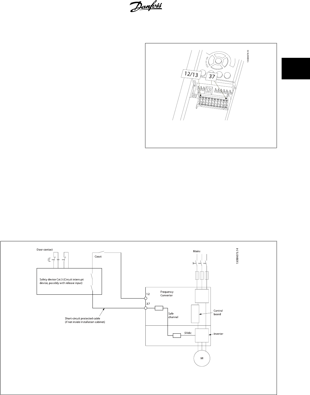
2.1.6 Safe Stop Installation - FC 302 only (and FC 301 in Frame Size A1)
To carry out an installation of a Category 0 Stop (EN60204) in
conformance with Safety Cat. 3 (EN 954-1) / PL “d” (ISO
13849-1), follow these instructions:
1. The bridge (jumper) between Terminal 37 and 24 V DC must be
removed. Cutting or breaking the jumper is not sufficient. Re-
move it entirely to avoid short-circuiting. See jumper on illus-
tration.
2. Connect terminal 37 to 24 V DC by a short-circuit protected ca-
ble. The 24 V DC voltage supply must be interruptible by a Cat.
3 (EN 954-1) / PL “d” (ISO 13849-1) circuit interrupt device. If
the interrupt device and the frequency converter are placed in
the same installation panel, you can use a regular cable instead
of a protected one.
3. The Safe Stop function only fulfills Cat. 3 (EN 954-1) / PL “d”
(ISO 13849-1) if particular protection against, or avoidance of,
conductive contamination is provided. Such a protection is ach-
ieved by using FC 302 with protection class IP54 or higher. If
FC 302 with lower protection (or FC 301 A1, which is only de-
livered with an IP21 enclosure) are used, then an operating en-
vironment corresponding to the inside of an IP54 encapsulation
must be ensured. An obvious solution, if there is a risk of con-
ductive contamination in the operating environment, would be
to mount the devices in a cabinet that provides IP54 protection.
Illustration 2.1: Bridge jumper between terminal 37 and 24
VDC
The illustration below shows a Stopping Category 0 (EN 60204-1) with Safety Cat. 3 (EN 954-1) / PL “d” (ISO 13849-1). The circuit interrupt is caused
by an opening door contact. The illustration also shows how to connect a non-safety related hardware coast.
Illustration 2.2: Illustration of the essential aspects of an installation to achieve a Stopping Category 0 (EN 60204-1) with Safety Cat. 3 (EN
954-1) / PL “d” (ISO 13849-1).
VLT
®
AutomationDrive FC 300 Operating
Instructions 2 Safety Instructions and General Warning
MG.33.AG.02 - VLT® is a registered Danfoss trademark
13
2

2.1.7 IT Mains
Par. 14-50
RFI Filter
can be used to disconnect the internal RFI capacitors from the RFI filter to ground in the 380 - 500 V frequency converters. If this
is done it will reduce the RFI performance to A2 level. For the 525 - 690 V frequency converters, par. 14-50
RFI Filter
has no function. The RFI switch
cannot be opened.
2 Safety Instructions and General Warning
VLT
®
AutomationDrive FC 300 Operating
Instructions
14
MG.33.AG.02 - VLT® is a registered Danfoss trademark
2
3How to Install
3.1.1 About How to Install
This chapter covers mechanical and electrical installations to and from power terminals and control card terminals.
Electrical installation of
options
is described in the relevant Operating Instructions and Design Guide.
Read the safety instructions before installing the unit.
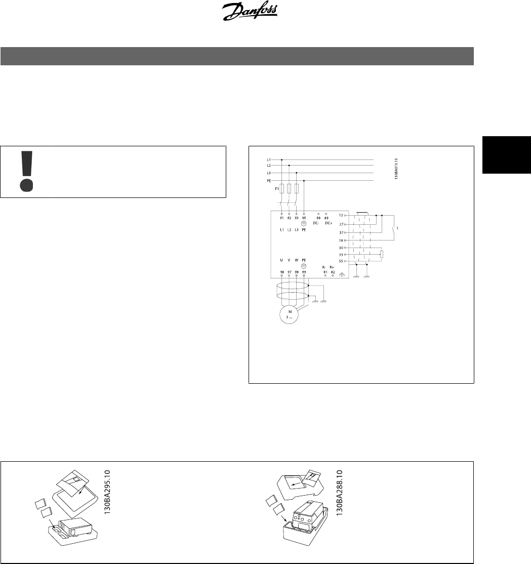
Illustration 3.1: Diagram showing basic installation including
mains, motor, start/stop key, and potentiometer for speed
adjustment.
3.1.2 Checklist
When unpacking the frequency converter, ensure that the unit is undamaged and complete.
For power ratings, please see
Mechanical Dimensions
table on the next page
A selection of screwdrivers (phillips or cross-thread screwdriver and torx), a side-cutter, drill and knife is also recommended to have handy for unpacking
and mounting the frequency converter. The packaging for these enclosures contains, as shown: Accessories bag(s), documentation and the unit. De-
pending on options fitted there may be one or two bags and one or more booklets.
VLT
®
AutomationDrive FC 300 Operating
Instructions 3 How to Install
MG.33.AG.02 - VLT® is a registered Danfoss trademark
15
3
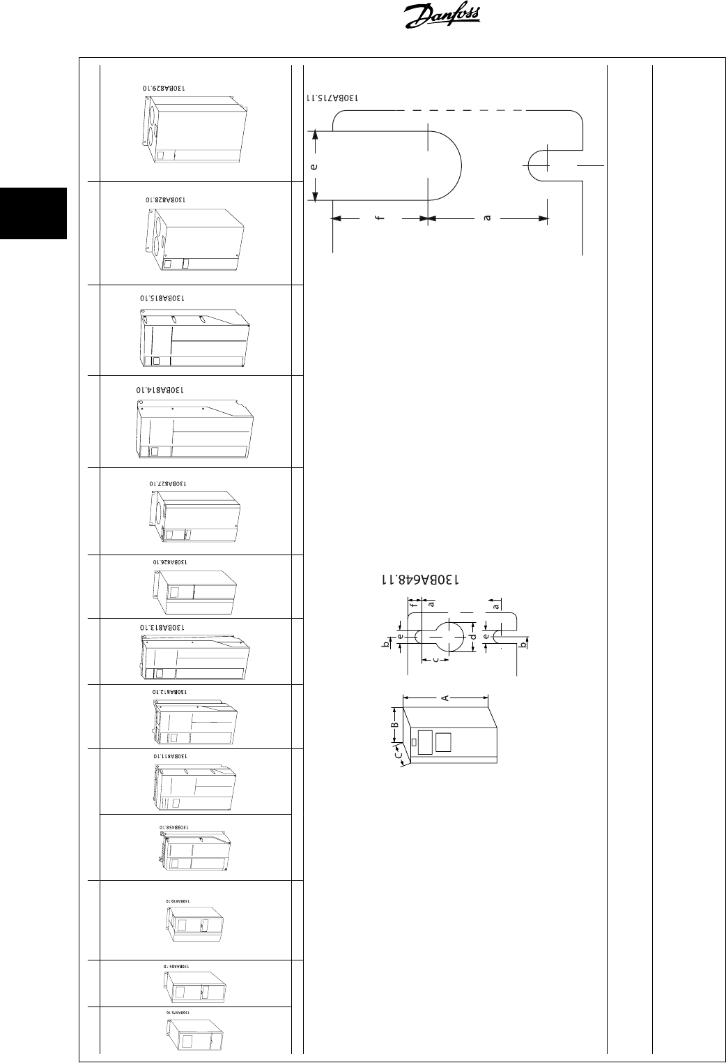
A1 A2 A3 A4 A5 B1 B2 B3 B4 C1 C2 C3 C4
IP20 IP20/21 IP20/21 IP55/66 IP55/66 IP21/55/66 IP21/55/66 IP20 IP20 IP21/55/66 IP21/55/66 IP20 IP20
Accessory bags containing necessary brackets, screws and connectors are included with the drives upon delivery. Top and bottom mounting holes (B4, C3 and C4
only)
All measurements in mm.
* A5 in IP55/66 only
3 How to Install
VLT
®
AutomationDrive FC 300 Operating
Instructions
16
MG.33.AG.02 - VLT® is a registered Danfoss trademark
3

Frame Size A1 A2 A3 A4 A5 B1 B2 B3 B4 C1 C2 C3 C4
Rated Pow-
er
[kW]
200-240 V 0.25–1.5 0.25-2.2 3-3.7 0.25-2.2 0.25-3.7 5.5-7.5 11 5.5-7.5 11-15 15-22 30-37 18.5-22 30-37
380-480/500
V0.37-1.5 0.37-4.0 5.5-7.5 0.37-4 0.37-7.5 11-15 18.5-22 11-15 18.5-30 30-45 55-75 37-45 55-75
525-600 V 0.75-7.5 0.75-7.5 11-15 18.5-22 11-15 18.5-30 30-45 55-90 37-45 55-90
525-690 V 11-22 30-75
IP
NEMA
20
Chassis
20
Chassis
21
Type 1
20
Chassis
21
Type 1
55/66
Type 12
55/66
Type 12
21/ 55/66
Type 1/Type
12
21/55/66
Type 1/
Type 12
20
Chassis
20
Chassis
21/55/66
Type 1/
Type 12
21/55/66
Type 1/
Type 12
20
Chassis
20
Chassis
Height
Height of back plate A200 mm 268 mm 375 mm 268 mm 375 mm 390 mm 420 mm 480 mm 650 mm 399 mm 520 mm 680 mm 770 mm 550 mm 660 mm
Height with de-coupling plate
for Fieldbus cables A 316 mm 374 mm 374 mm - - - - - 420 mm 595 mm 630 mm 800 mm
Distance between mounting
holes a190 mm 257 mm 350 mm 257 mm 350 mm 401 mm 402 mm 454 mm 624 mm 380 mm 495 mm 648 mm 739 mm 521 mm 631 mm
Width
Width of back plate B75 mm 90 mm 90 mm 130 mm 130 mm 200 mm 242 mm 242 mm 242 mm 165 mm 230 mm 308 mm 370 mm 308 mm 370 mm
Width of back plate with one
C option B 130 mm 130 mm 170 mm 170 mm 242 mm 242 mm 242 mm 205 mm 230 mm 308 mm 370 mm 308 mm 370 mm
Width of back plate with two
C options B150 mm 150 mm 190 mm 190 mm 242 mm 242 mm 242 mm 225 mm 230 mm 308 mm 370 mm 308 mm 370 mm
Distance between mounting
holes b 60 mm 70 mm 70 mm 110 mm 110 mm 171 mm 215 mm 210 mm 210 mm 140 mm 200 mm 272 mm 334 mm 270 mm 330 mm
Depth
Depth without option A/B C 207 mm 205 mm 207 mm 205 mm 207 mm 175 mm 195 mm 260 mm 260 mm 249 mm 242 mm 310 mm 335 mm 333 mm 333 mm
With option A/B C222 mm 220 mm 222 mm 220 mm 222 mm 175 mm 195 mm 260 mm 260 mm 262 mm 242 mm 310 mm 335 mm 333 mm 333 mm
Screw holes
c6.0 mm 8.0 mm 8.0 mm 8.0 mm 8.0 mm 8.25 mm 8.25 mm 12 mm 12 mm 8 mm 12.5 mm 12.5 mm
d ø8 mm ø11 mm ø11 mm ø11 mm ø11 mm ø12 mm ø12 mm ø19 mm ø19 mm 12 mm ø19 mm ø19 mm
eø5 mm ø5.5 mm ø5.5 mm ø5.5
mm ø5.5 mm ø6.5 mm ø6.5 mm ø9 mm ø9 mm 6.8 mm 8.5 mm ø9 mm ø9 mm 8.5 mm 8.5 mm
f 5 mm 9 mm 9 mm 9 mm 9 mm 6 mm 9 mm 9 mm 9 mm 7.9 mm 15 mm 9.8 mm 9.8 mm 17 mm 17 mm
Max weight 2.7 kg 4.9 kg 5.3 kg 6.6 kg 7.0 kg 9.7 kg 13.5/14.2 kg 23 kg 27 kg 12 kg 23.5 kg 45 kg 65 kg 35 kg 50 kg
VLT
®
AutomationDrive FC 300 Operating
Instructions 3 How to Install
MG.33.AG.02 - VLT® is a registered Danfoss trademark
17
3
3.1 Mechanical Installation
3.2.1 Mechanical Mounting
All Frame Sizes allow side-by-side installation except when a
IP21/IP4X/ TYPE 1 Enclosure Kit
is used (see the
Options and Accessories
section of the
Design Guide).
If the IP 21 Enclosure kit is used on frame size A1, A2 or A3, there must be a clearance between the drives of min. 50 mm.
For optimal cooling conditions allow a free air passage above and below the frequency converter. See table below.
Air passage for different frame sizes
Frame
size: A1* A2 A3 A4 A5 B1 B2 B3 B4 C1 C2 C3 C4
a
(mm): 100 100 100 100 100 100 200 100 200 200 225 200 225
b
(mm): 100 100 100 100 100 100 200 100 200 200 225 200 225
* FC 301 only
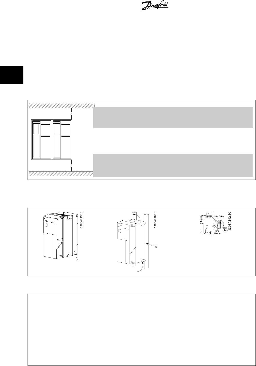
1. Drill holes in accordance with the measurements given.
2. You must provide screws suitable for the surface on which you want to mount the frequency converter. Retighten all four screws.
Table 3.1: Mounting frame sizes A4, A5, B1, B2, C1 andC2 on a non-solid back wall, the drive must be provided with a back plate A due to insufficient
cooling air over the heat sink.
Frame
Tightening torque for covers (Nm)
IP20 IP21 IP55 IP66
A1 * - - -
A2 * * - -
A3 * * - -
A4/A5 - - 2 2
B1 - * 2,2 2,2
B2 - * 2,2 2,2
B3 * - - -
B4 2 - - -
C1 - * 2,2 2,2
C2 - * 2,2 2,2
C3 2 - - -
C4 2 - - -
* = No screws to tighten
- = Does not exist
3 How to Install
VLT
®
AutomationDrive FC 300 Operating
Instructions
18
MG.33.AG.02 - VLT® is a registered Danfoss trademark
3

3.2.2 Panel Through Mounting
A Panel Through Mount Kit is available for frequency converter series VLT HVAC FC 102, VLT Aqua Drive and VLT AutomationDrive.
In order to increase heatsink cooling and reduce panel depth, the frequency converter may be mounted in a through panel. Furthermore the in-built fan
can then be removed.
The kit is available for enclosures A5 through C2.
NB!
This kit cannot be used with cast front covers. IP21 plastic cover must be used instead.
Information on ordering numbers is found in the
Design Guide
, section
Ordering Numbers.
More detailed information is available in the
Panel Through Mount Kit instruction, MI.33.HX.YY,
where yy=language code.
VLT
®
AutomationDrive FC 300 Operating
Instructions 3 How to Install
MG.33.AG.02 - VLT® is a registered Danfoss trademark
19
3
3.2 Electrical Installation
NB!
Cables General
All cabling must comply with national and local regulations on cable cross-sections and ambient temperature. Copper (75°C) conductors
are recommended.
Aluminium Conductors
Terminals can accept aluminium conductors but the conductor surface has to be clean and the oxidation must be removed and sealed by neutral acid-
free Vaseline grease before the conductor is connected.
Furthermore the terminal screw must be retightened after two days due to softness of the aluminium. It is crucial to keep the connection a gas tight
joint, otherwise the aluminium surface will oxidize again.
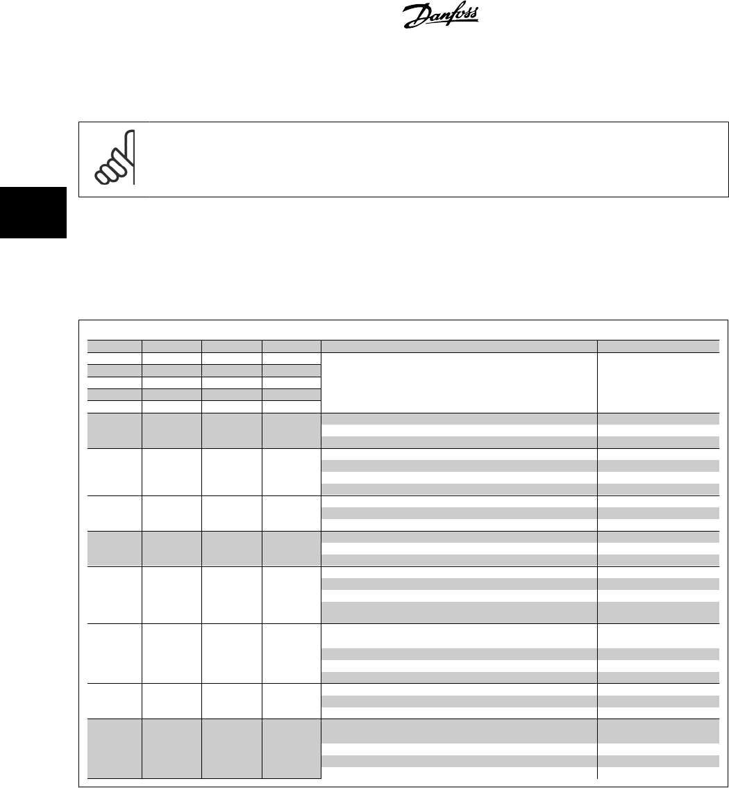
Tightening-up Torque
Frame size 200 - 240 V 380 - 500 V 525 - 690 V Cable for: Tightening up torque
A1 0.25-1.5 kW 0.37-1.5 kW -
Mains, Brake resistor, load sharing, Motor cables
0.5-0.6 Nm
A2 0.25-2.2 kW 0.37-4 kW -
A3 3-3.7 kW 5.5-7.5 kW -
A4 0.25-2-2 kW 0.37-4 kW
A5 3-3.7 kW 5.5-7.5 kW -
B1 5.5-7.5 kW 11-15 kW -Mains, Brake resistor, load sharing, Motor cables 1.8 Nm
Relay 0.5-0.6 Nm
Earth 2-3 Nm
B2 11 kW 18.5-22 kW 11-22 kW Mains, Brake resistor, load sharing cables 4.5 Nm
Motor cables 4.5 Nm
Relay 0.5-0.6 Nm
Earth 2-3 Nm
B3 5.5-7.5 kW 11-15 kW - Mains, Brake resistor, load sharing, Motor cables 1.8 Nm
Relay 0.5-0.6 Nm
Earth 2-3 Nm
B4 11-15 kW 18.5-30 kW -Mains, Brake resistor, load sharing, Motor cables 4.5 Nm
Relay 0.5-0.6 Nm
Earth 2-3 Nm
C1 15-22 kW 30-45 kW - Mains, Brake resistor, load sharing cables 10 Nm
Motor cables 10 Nm
Relay 0.5-0.6 Nm
Earth 2-3 Nm
C2 30-37 kW 55-75 kW 30-75 kW Mains, motor cables 14 Nm (up to 95 mm2)
24 Nm (over 95 mm2)
Load Sharing, brake cables 14 Nm
Relay 0.5-0.6 Nm
Earth 2-3 Nm
C3 18.5-22 kW 30-37 kW - Mains, Brake resistor, load sharing, Motor cables 10 Nm
Relay 0.5-0.6 Nm
Earth 2-3 Nm
C4 37-45 kW 55-75 kW -Mains, motor cables 14 Nm (up to 95 mm2)
24 Nm (over 95 mm2)
Load Sharing, brake cables 14 Nm
Relay 0.5-0.6 Nm
Earth 2-3 Nm
3 How to Install
VLT
®
AutomationDrive FC 300 Operating
Instructions
20
MG.33.AG.02 - VLT® is a registered Danfoss trademark
3
3.3.1 Power and Control Wiring for Unscreened Cables
Induced Voltage!
Run motor cables from multiple drives separately. Induced voltage from output motor cables run together can charge equipment
capacitors even with the equipment turned off and locked out. Failure to run output cables separately could result in death or serious
injury.
Run drive input power, motor wiring, and control wiring in three separate metallic conduits or trays for high frequency noise isolation.
Failure to isolate power, motor, and control wiring could result in less than optimum controller and associated equipment performance.
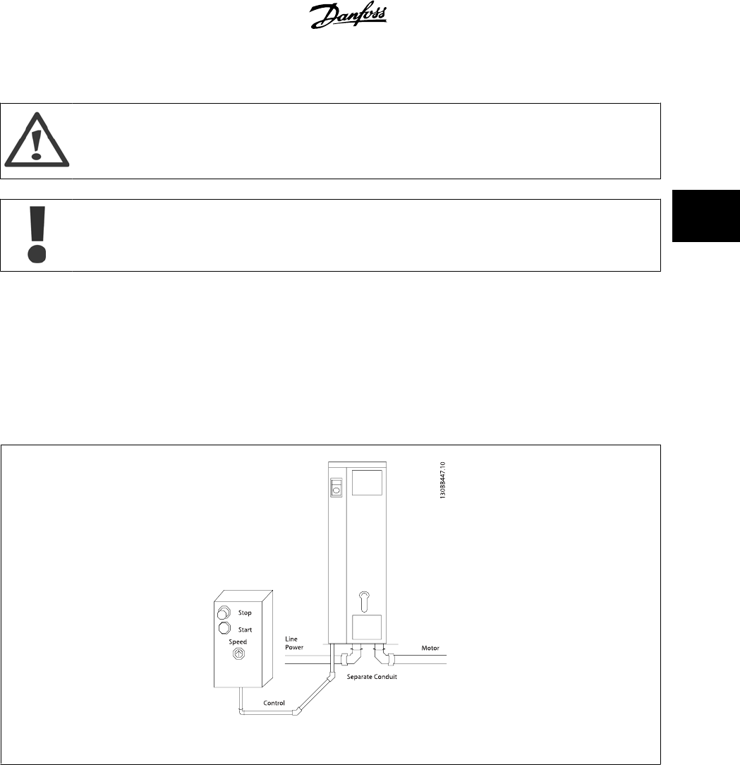
Because the power wiring carries high frequency electrical pulses, it is important that input power and motor power are run in separate conduit. If the
incoming power wiring is run in the same conduit as the motor wiring, these pulses can couple electrical noise back onto the building power grid. Control
wiring should always be isolated from the high voltage power wiring.
When screened/armoured cable is not used, at least three separate conduits must be connected to the panel option (see figure below).
• Power wiring into the enclosure
• Power wiring from the enclosure to the motor
•Control wiring
Illustration 3.2: Power and control wiring connection
VLT
®
AutomationDrive FC 300 Operating
Instructions 3 How to Install
MG.33.AG.02 - VLT® is a registered Danfoss trademark
21
3
3.3.2 Removal of Knockouts for Extra Cables
1. Remove cable entry from the frequency converter (Avoiding foreign parts falling into the frequency converter when removing knockouts)
2. Cable entry has to be supported around the knockout you intend to remove.
3. The knockout can now be removed with a strong mandrel and a hammer.
4. Remove burrs from the hole.
5. Mount Cable entry on frequency converter.
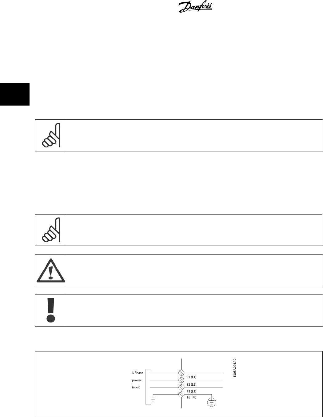
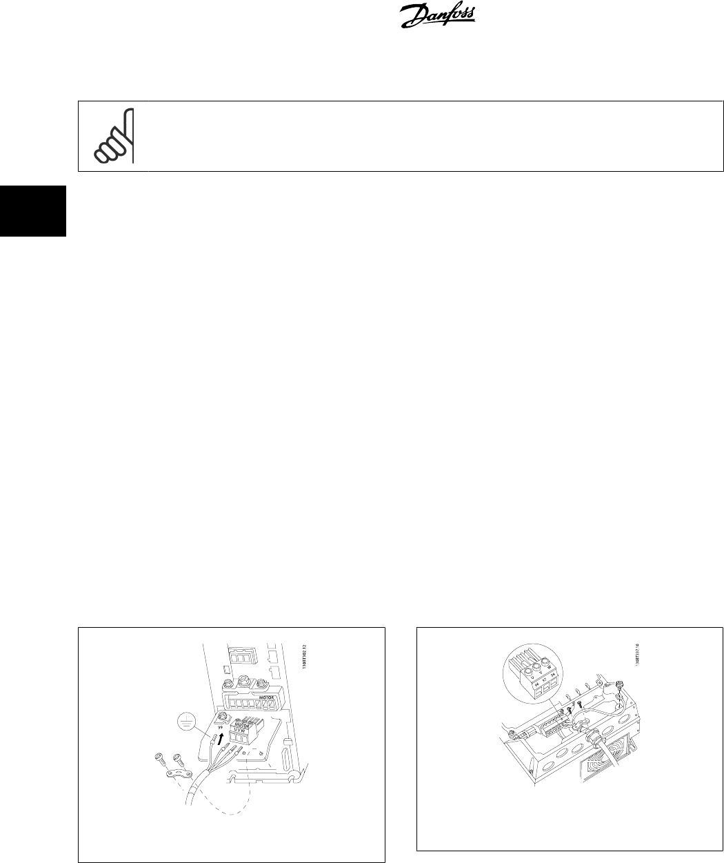
3.3.3 Connection to Mains and Earthing
NB!
The plug connector for power is plugable on frequency converters up to 7.5 kW.
1. Fit the two screws in the de-coupling plate, slide it into place and tighten the screws.
2. Make sure the frequency converter is properly earthed. Connect to earth connection (terminal 95). Use screw from the accessory bag.
3. Place plug connector 91(L1), 92(L2), 93(L3) from the accessory bag onto the terminals labelled MAINS at the bottom of the frequency converter.
4. Attach mains wires to the mains plug connector.
5. Support the cable with the supporting enclosed brackets.
NB!
Check that mains voltage corresponds to the mains voltage of the name plate.
IT Mains
Do not connect 400 V frequency converters with RFI-filters to mains supplies with a voltage between phase and earth of more than
440 V.
The earth connection cable cross section must be at least 10 mm2 or 2 x rated mains wires terminated separately according to EN
50178.
The mains connection is fitted to the mains switch if this is included.
3 How to Install
VLT
®
AutomationDrive FC 300 Operating
Instructions
22
MG.33.AG.02 - VLT® is a registered Danfoss trademark
3
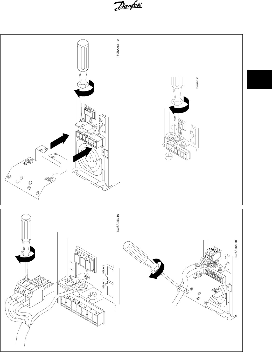
Mains connection for frame sizes A1, A2 and A3:
VLT
®
AutomationDrive FC 300 Operating
Instructions 3 How to Install
MG.33.AG.02 - VLT® is a registered Danfoss trademark
23
3
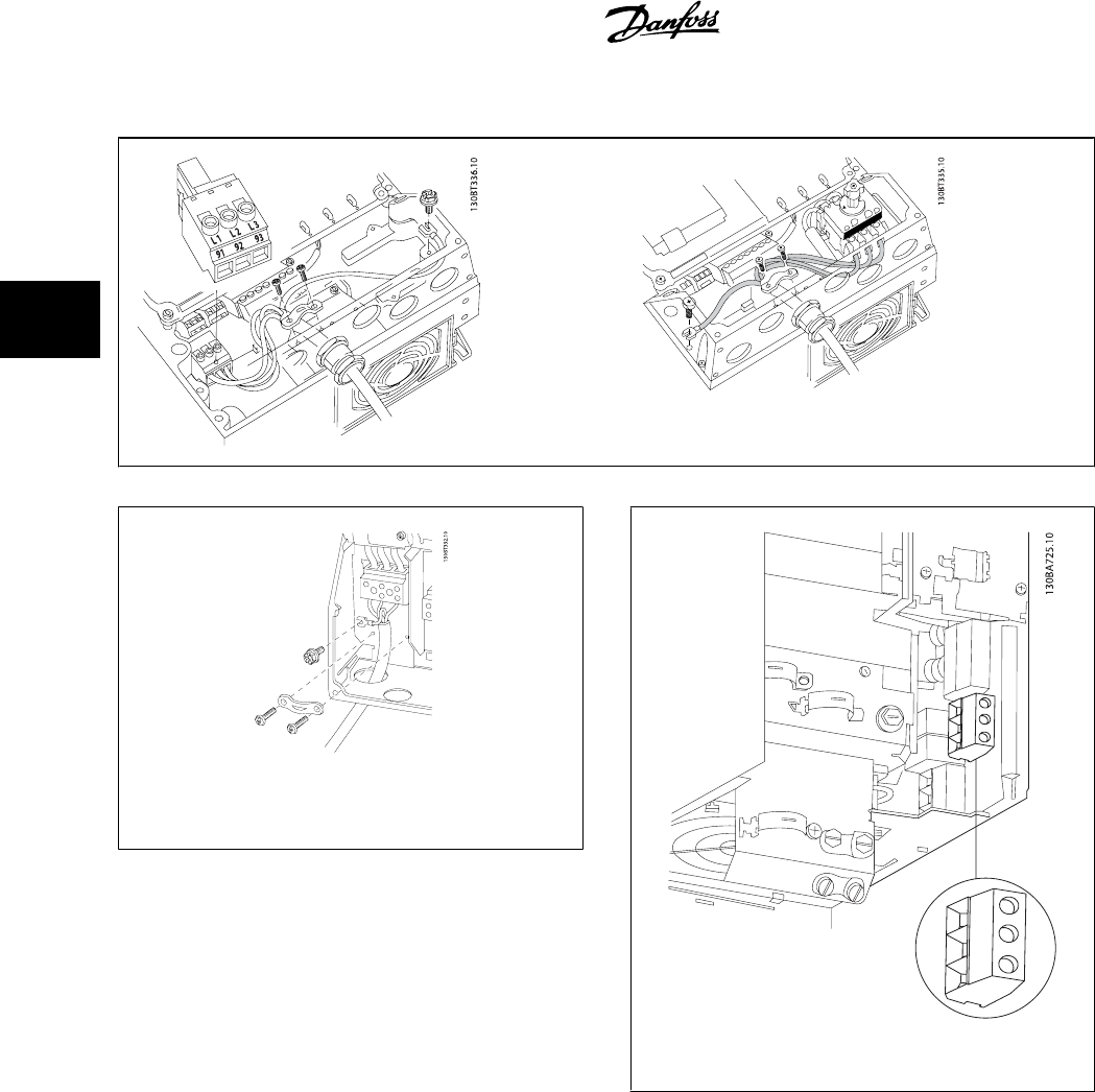
Mains connector frame size A4/A5 (IP 55/66)
When disconnector is used (frame size A4/A5) the PE must be mounted on the left side of the drive.
Illustration 3.3: Mains connection frame sizes B1 and B2 (IP
21/NEMA Type 1 and IP 55/66/ NEMA Type 12).
Illustration 3.4: Mains connection size B3 (IP20).
3 How to Install
VLT
®
AutomationDrive FC 300 Operating
Instructions
24
MG.33.AG.02 - VLT® is a registered Danfoss trademark
3
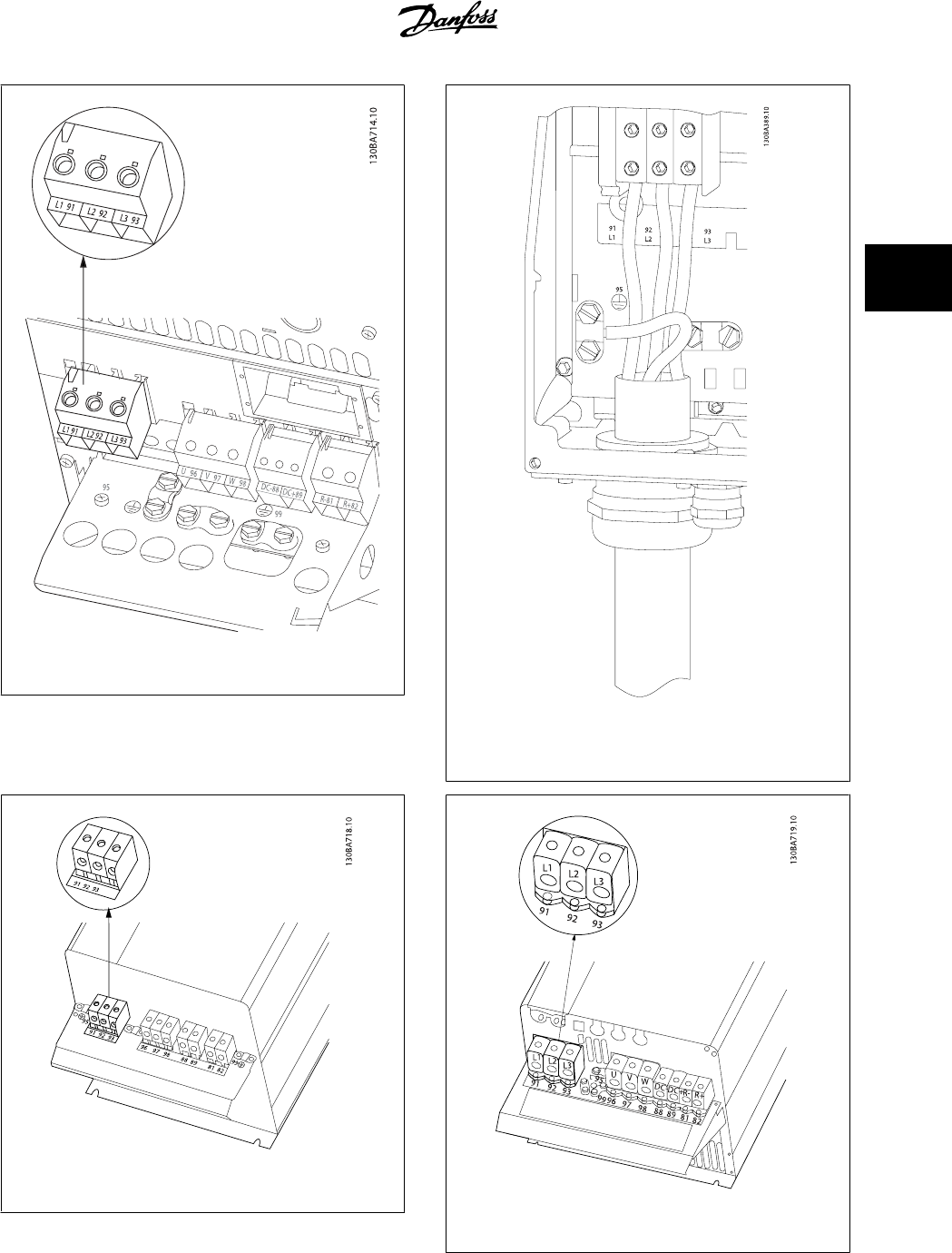
Illustration 3.5: Mains connection size B4 (IP20).
Illustration 3.6: Mains connection size C1 and C2 (IP 21/
NEMA Type 1 and IP 55/66/ NEMA Type 12).
Illustration 3.7: Mains connection size C3 (IP20).
Illustration 3.8: Mains connection size C4 (IP20).
Usually the power cables for mains are unscreened cables.
VLT
®
AutomationDrive FC 300 Operating
Instructions 3 How to Install
MG.33.AG.02 - VLT® is a registered Danfoss trademark
25
3
3.3.4 Motor Connection
NB!
To comply with EMC emission specifications, screened/armoured cables are recommended. If an unscreened/unarmoured cable is
used, see section
Power and Control Wiring for Unscreened Cables
.. For more information, see
EMC Test Results
in the Design Guide.
See section General Specifications for correct dimensioning of motor cable cross-section and length.
Screening of cables: Avoid installation with twisted screen ends (pigtails). They spoil the screening effect at higher frequencies. If it is necessary to
break the screen to install a motor isolator or motor contactor, the screen must be continued at the lowest possible HF impedance.
Connect the motor cable screen to both the decoupling plate of the frequency converter and to the metal housing of the motor.
Make the screen connections with the largest possible surface area (cable clamp). This is done by using the supplied installation devices in the frequency
converter.
If it is necessary to split the screen to install a motor isolator or motor relay, the screen must be continued with the lowest possible HF impedance.
Cable-length and cross-section: The frequency converter has been tested with a given length of cable and a given cross-section of that cable. If the
cross-section is increased, the cable capacitance - and thus the leakage current - may increase, and the cable length must be reduced correspondingly.
Keep the motor cable as short as possible to reduce the noise level and leakage currents.
Switching frequency: When frequency converters are used together with Sine-wave filters to reduce the acoustic noise from a motor, the switching
frequency must be set according to the Sine-wave filter instruction in par. 14-01
Switching Frequency
.
1. Fasten decoupling plate to the bottom of the frequency converter with screws and washers from the accessory bag.
2. Attach motor cable to terminals 96 (U), 97 (V), 98 (W).
3. Connect to earth connection (terminal 99) on decoupling plate with screws from the accessory bag.
4. Insert plug connectors 96 (U), 97 (V), 98 (W) (up to 7.5 kW) and motor cable to terminals labelled MOTOR.
5. Fasten screened cable to decoupling plate with screws and washers from the accessory bag.
All types of three-phase asynchronous standard motors can be connected to the frequency converter. Normally, small motors are star-connected (230/400
V, Y). Large motors are normally delta-connected (400/690 V, Δ). Refer to the motor name plate for correct connection mode and voltage.
Illustration 3.9: Motor connection for A1, A2 and A3
Illustration 3.10: Motor connection for size A4/A5 (IP 55/66/
NEMA Type 12)
3 How to Install
VLT
®
AutomationDrive FC 300 Operating
Instructions
26
MG.33.AG.02 - VLT® is a registered Danfoss trademark
3
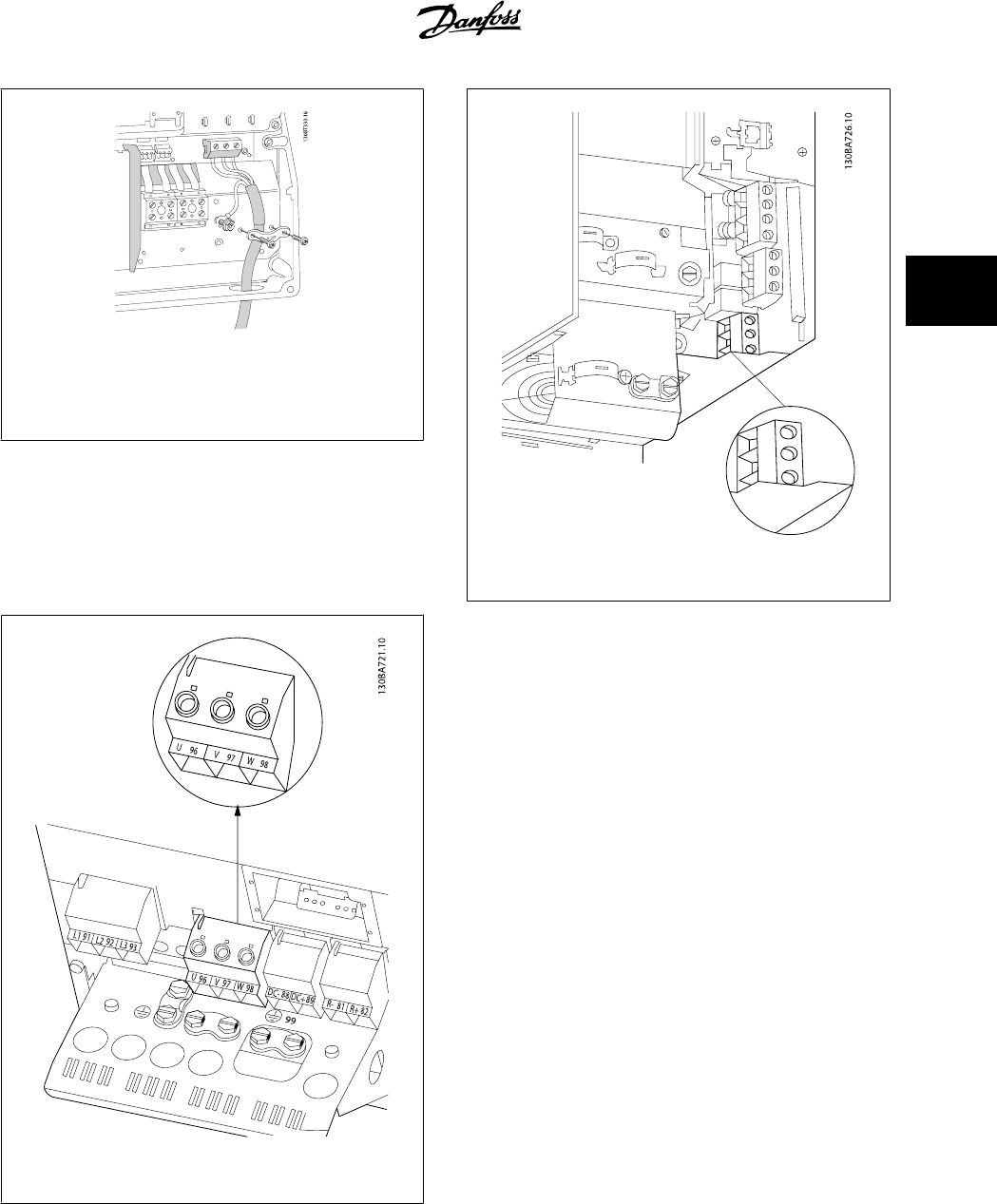
Illustration 3.11: Motor connection for size B1 and B2 (IP
21/ NEMA Type 1, IP 55/ NEMA Type 12 and IP66/ NEMA
Type 4X)
Illustration 3.12: Motor connection for size B3.
Illustration 3.13: Motor connection for frame size B4 .
VLT
®
AutomationDrive FC 300 Operating
Instructions 3 How to Install
MG.33.AG.02 - VLT® is a registered Danfoss trademark
27
3
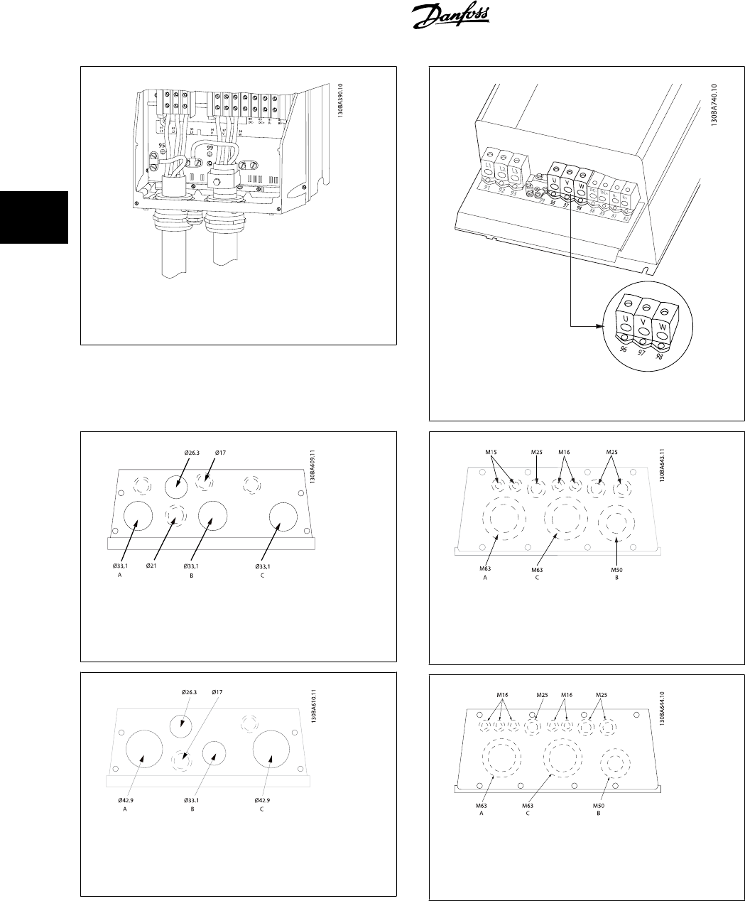
Illustration 3.14: Motor connection frame size C1 and C2 (IP
21/ NEMA Type 1 and IP 55/66/ NEMA Type 12)
Illustration 3.15: Motor connection for frame size C3 and C4.
Illustration 3.16: Cable entry holes for frame size B1. The
suggested use of the holes are purely recommendations and
other solutions are possible.
Illustration 3.17: Cable entry holes for frame size B2. The
suggested use of the holes are purely recommendations and
other solutions are possible.
Illustration 3.18: Cable entry holes for frame size C1. The
suggested use of the holes are purely recommendations and
other solutions are possible.
Illustration 3.19: Cable entry holes for frame size C2. The
suggested use of the holes are purely recommendations and
other solutions are possible.
Unused cable entry holes can be sealed with rubber grommets (for IP 21). More information and ordering numbers can be found in the Design Guide.
3 How to Install
VLT
®
AutomationDrive FC 300 Operating
Instructions
28
MG.33.AG.02 - VLT® is a registered Danfoss trademark
3
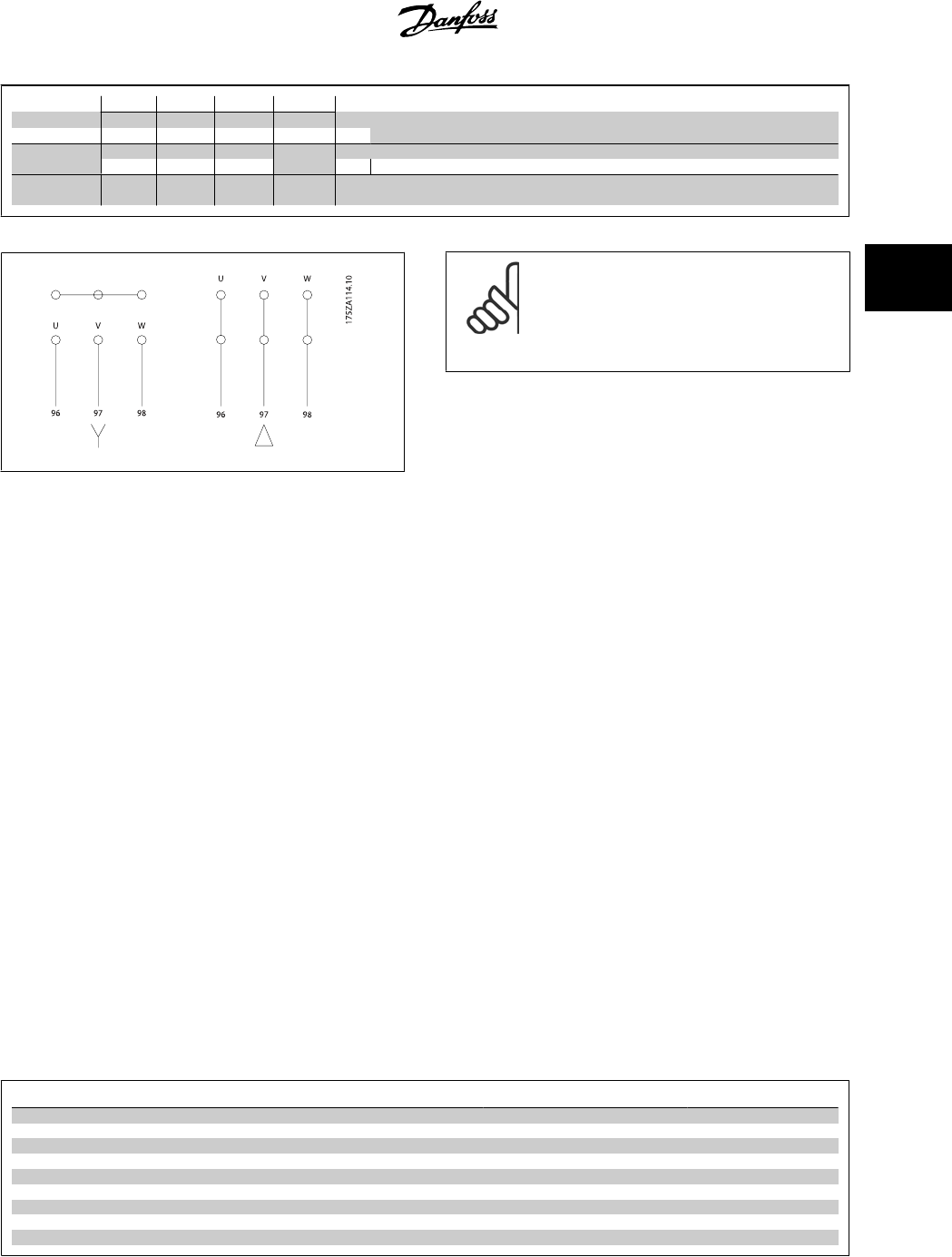
Term. no. 96 97 98 99
U V W PE1) Motor voltage 0-100% of mains voltage.
3 wires out of motor
U1 V1 W1 PE1) Delta-connected
W2 U2 V2 6 wires out of motor
U1 V1 W1 PE1) Star-connected U2, V2, W2
U2, V2 and W2 to be interconnected separately.
1)Protected Earth Connection
NB!
In motors without phase insulation paper or other in-
sulation reinforcement suitable for operation with volt-
age supply (such as a frequency converter), fit a Sine-
wave filter on the output of the frequency converter.
3.3.5 Fuses
Branch circuit protection:
In order to protect the installation against electrical and fire hazard, all branch circuits in an installation, switch gear, machines etc., must be short-circuited
and overcurrent protected according to national/international regulations.
Short-circuit protection:
The frequency converter must be protected against short-circuit to avoid electrical or fire hazard. Danfoss recommends using the fuses mentioned below
to protect service personnel and equipment in case of an internal failure in the drive. The frequency converter provides full short-circuit protection in case
of a short-circuit on the motor output.
Overcurrent protection:
Provide overload protection to avoid fire hazard due to overheating of the cables in the installation. The frequency converter is equipped with an internal
overcurrent protection that can be used for upstream overload protection (UL-applications excluded). See par. 4-18
Current Limit
. Moreover, fuses or
circuit breakers can be used to provide the overcurrent protection in the installation. Overcurrent protection must always be carried out according to
national regulations.
Fuses must be designed for protection in a circuit capable of supplying a maximum of 100,000 Arms (symmetrical), 500 V maximum.
Non UL compliance
If UL/cUL is not to be complied with, we recommend using the following fuses, which will ensure compliance with EN50178:
In case of malfunction, not following the recommendation may result in unnecessary damage to the frequency converter.
FC Type Max. fuse size1) Min. rated Voltage Type
K25-K75 10A 200-240 V type gG
1K1-2K2 20A 200-240 V type gG
3K0-3K7 32A 200-240 V type gG
5K5-7K5 63A 200-240 V type gG
11K 80A 200-240 V type gG
15K-18K5 125A 200-240 V type gG
22K 160A 200-240 V type aR
30K 200A 200-240 V type aR
37K 250A 200-240 V type aR
1) Max. fuses - refer to national/international regulations to select an appropriate fuse size.
VLT
®
AutomationDrive FC 300 Operating
Instructions 3 How to Install
MG.33.AG.02 - VLT® is a registered Danfoss trademark
29
3

FC Type Max. fuse size1) Min. rated Voltage Type
K37-1K5 10A 380-500 V type gG
2K2-4K0 20A 380-500 V type gG
5K5-7K5 32A 380-500 V type gG
11K-18K 63A 380-500 V type gG
22K 80A 380-500 V type gG
30K 100A 380-500 V type gG
37K 125A 380-500 V type gG
45K 160A 380-500 V type aR
55K-75K 250A 380-500 V type aR
UL Compliance
200-240 V
FC Type Bussmann Bussmann Bussmann Bussmann Bussmann Bussmann
kW Type RK1 Type J Type T Type CC Type CC Type CC
K25-K37 KTN-R05 JKS-05 JJN-06 FNQ-R-5 KTK-R-5 LP-CC-5
K55-1K1 KTN-R10 JKS-10 JJN-10 FNQ-R-10 KTK-R-10 LP-CC-10
1K5 KTN-R15 JKS-15 JJN-15 FNQ-R-15 KTK-R-15 LP-CC-15
2K2 KTN-R20 JKS-20 JJN-20 FNQ-R-20 KTK-R-20 LP-CC-20
3K0 KTN-R25 JKS-25 JJN-25 FNQ-R-25 KTK-R-25 LP-CC-25
3K7 KTN-R30 JKS-30 JJN-30 FNQ-R-30 KTK-R-30 LP-CC-30
5K5 KTN-R50 KS-50 JJN-50 - - -
7K5 KTN-R60 JKS-60 JJN-60 ---
11K KTN-R80 JKS-80 JJN-80 - - -
15K-18K5 KTN-R125 JKS-150 JJN-125 ---
FC Type SIBA Littel fuse Ferraz-
Shawmut
Ferraz-
Shawmut
kW Type RK1 Type RK1 Type CC Type RK1
K25-K37 5017906-005 KLN-R05 ATM-R05 A2K-05R
K55-1K1 5017906-010 KLN-R10 ATM-R10 A2K-10R
1K5 5017906-016 KLN-R15 ATM-R15 A2K-15R
2K2 5017906-020 KLN-R20 ATM-R20 A2K-20R
3K0 5017906-025 KLN-R25 ATM-R25 A2K-25R
3K7 5012406-032 KLN-R30 ATM-R30 A2K-30R
5K5 5014006-050 KLN-R50 - A2K-50R
7K5 5014006-063 KLN-R60 -A2K-60R
11K 5014006-080 KLN-R80 - A2K-80R
15K-18K5 2028220-125 KLN-R125 -A2K-125R
FC Type Bussmann SIBA Littel fuse Ferraz-
Shawmut
kW Type JFHR2 Type RK1 JFHR2 JFHR2
22K FWX-150 2028220-150 L25S-150 A25X-150
30K FWX-200 2028220-200 L25S-200 A25X-200
37K FWX-250 2028220-250 L25S-250 A25X-250
KTS-fuses from Bussmann may substitute KTN for 240 V frequency converters.
FWH-fuses from Bussmann may substitute FWX for 240 V frequency converters.
KLSR fuses from LITTEL FUSE may substitute KLNR fuses for 240 V frequency converters.
L50S fuses from LITTEL FUSE may substitute L50S fuses for 240 V frequency converters.
A6KR fuses from FERRAZ SHAWMUT may substitute A2KR for 240 V frequency converters.
A50X fuses from FERRAZ SHAWMUT may substitute A25X for 240 V frequency converters.
380-500 V
FC Type Bussmann Bussmann Bussmann Bussmann Bussmann Bussmann
kW Type RK1 Type J Type T Type CC Type CC Type CC
K37-1K1 KTS-R6 JKS-6 JJS-6 FNQ-R-6 KTK-R-6 LP-CC-6
1K5-2K2 KTS-R10 JKS-10 JJS-10 FNQ-R-10 KTK-R-10 LP-CC-10
3K0 KTS-R15 JKS-15 JJS-15 FNQ-R-15 KTK-R-15 LP-CC-15
4K0 KTS-R20 JKS-20 JJS-20 FNQ-R-20 KTK-R-20 LP-CC-20
5K5 KTS-R25 JKS-25 JJS-25 FNQ-R-25 KTK-R-25 LP-CC-25
7K5 KTS-R30 JKS-30 JJS-30 FNQ-R-30 KTK-R-30 LP-CC-30
11K KTS-R40 JKS-40 JJS-40 - - -
15K KTS-R50 JKS-50 JJS-50 - - -
18K KTS-R60 JKS-60 JJS-60 - - -
22K KTS-R80 JKS-80 JJS-80 - - -
30K KTS-R100 JKS-100 JJS-100 - - -
37K KTS-R125 JKS-150 JJS-150 - - -
45K KTS-R150 JKS-150 JJS-150 - - -
3 How to Install
VLT
®
AutomationDrive FC 300 Operating
Instructions
30
MG.33.AG.02 - VLT® is a registered Danfoss trademark
3

FC Type SIBA Littel fuse Ferraz-
Shawmut
Ferraz-
Shawmut
kW Type RK1 Type RK1 Type CC Type RK1
K37-1K1 5017906-006 KLS-R6 ATM-R6 A6K-6R
1K5-2K2 5017906-010 KLS-R10 ATM-R10 A6K-10R
3K0 5017906-016 KLS-R15 ATM-R15 A6K-15R
4K0 5017906-020 KLS-R20 ATM-R20 A6K-20R
5K5 5017906-025 KLS-R25 ATM-R25 A6K-25R
7K5 5012406-032 KLS-R30 ATM-R30 A6K-30R
11K 5014006-040 KLS-R40 - A6K-40R
15K 5014006-050 KLS-R50 -A6K-50R
18K 5014006-063 KLS-R60 - A6K-60R
22K 2028220-100 KLS-R80 -A6K-80R
30K 2028220-125 KLS-R100 - A6K-100R
37K 2028220-125 KLS-R125 -A6K-125R
45K 2028220-160 KLS-R150 - A6K-150R
FC Type Bussmann Bussmann Bussmann Bussmann
kW JFHR2 Type H Type T JFHR2
55K FWH-200 - - -
75K FWH-250 - - -
FC Type SIBA Littel fuse Ferraz-
Shawmut
Ferraz-
Shawmut
kW Type RK1 JFHR2 JFHR2 JFHR2
55K 2028220-200 L50S-225 - A50-P225
75K 2028220-250 L50S-250 A50-P250
Ferraz-Shawmut A50QS fuses may be substituted for A50P fuses.
170M fuses shown from Bussmann use the -/80 visual indicator. –TN/80 Type T, -/110 or TN/110 Type T indicator fuses of the same size and
amperage may be substituted.
550 - 600V
FC Type Bussmann Bussmann Bussmann Bussmann Bussmann Bussmann
kW Type RK1 Type J Type T Type CC Type CC Type CC
K75-1K5 KTS-R-5 JKS-5 JJS-6 FNQ-R-5 KTK-R-5 LP-CC-5
2K2-4K0 KTS-R10 JKS-10 JJS-10 FNQ-R-10 KTK-R-10 LP-CC-10
5K5-7K5 KTS-R20 JKS-20 JJS-20 FNQ-R-20 KTK-R-20 LP-CC-20
FC Type SIBA Littel fuse Ferraz-
Shawmut
kW Type RK1 Type RK1 Type RK1
K75-1K5 5017906-005 KLSR005 A6K-5R
2K2-4K0 5017906-010 KLSR010 A6K-10R
5K5-7K5 5017906-020 KLSR020 A6K-20R
FC Type Bussmann SIBA Ferraz-
Shawmut
kW JFHR2 Type RK1 Type RK1
P37K 170M3013 2061032.125 6.6URD30D08A0125
P45K 170M3014 2061032.160 6.6URD30D08A0160
P55K 170M3015 2061032.200 6.6URD30D08A0200
P75K 170M3015 2061032.200 6.6URD30D08A0200
170M fuses shown from Bussmann use the -/80 visual indicator. –TN/80 Type T, -/110 or TN/110 Type T indicator fuses of the same size and
amperage may be substituted.
170M fuses from Bussmann when provided in the 525-600/690 V FC 302 P37K-P75K, FC 102 P75K, or P45K-P90K drives are 170M3015.
170M fuses from Bussmann when provided in the 525-600/690V FC 302 P90K-P132, FC 102 P90K-P132, or P110-P160 drives are 170M3018.
170M fuses from Bussmann when provided in the 525-600/690V FC 302 P160-P315, FC 102 P160-P315, or P200-P400 drives are 170M5011.
VLT
®
AutomationDrive FC 300 Operating
Instructions 3 How to Install
MG.33.AG.02 - VLT® is a registered Danfoss trademark
31
3
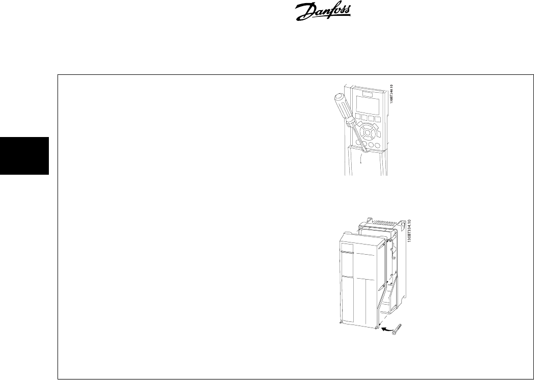
3.3.6 Access to Control Terminals
All terminals to the control cables are located underneath the terminal cover
on the front of the frequency converter. Remove the terminal cover with a
screwdriver.
Illustration 3.20: Access to control terminals for A2, A3, B3, B4, C3
and C4 enclosures
Remove front-cover to access control terminals. When replacing the front-
cover, please ensure proper fastening by applying a torque of 2 Nm.
Illustration 3.21: Access to control terminals for A4, A5, B1, B2, C1
and C2 enclosures
3 How to Install
VLT
®
AutomationDrive FC 300 Operating
Instructions
32
MG.33.AG.02 - VLT® is a registered Danfoss trademark
3
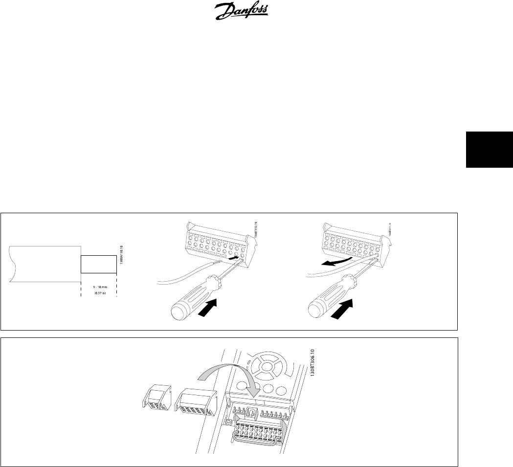
3.3.7 Electrical Installation, Control Terminals
To mount the cable to the terminal:
1. Strip insulation of 9-10 mm
2. Insert a screwdriver1) in the square hole.
3. Insert the cable in the adjacent circular hole.
4. Remove the screw driver. The cable is now mounted to the terminal.
To remove the cable from the terminal:
1. Insert a screwdriver1) in the square hole.
2. Pull out the cable.
1) Max. 0.4 x 2.5 mm
1.
2. 3.
VLT
®
AutomationDrive FC 300 Operating
Instructions 3 How to Install
MG.33.AG.02 - VLT® is a registered Danfoss trademark
33
3
3.3 Connection Examples
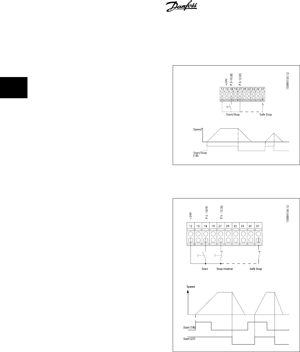
3.4.1 Start/Stop
Terminal 18 = par. 5-10
Terminal 18 Digital Input
[8]
Start
Terminal 27 = par. 5-12
Terminal 27 Digital Input
[0]
No operation
(De-
fault
coast inverse
)
Terminal 37 = Safe stop (where available!)
3.4.2 Pulse Start/Stop
Terminal 18 = par. 5-10
Terminal 18 Digital Input
Latched start, [9]
Terminal 27= par. 5-12
Terminal 27 Digital Input
Stop inverse, [6]
Terminal 37 = Safe stop (where available!)
3 How to Install
VLT
®
AutomationDrive FC 300 Operating
Instructions
34
MG.33.AG.02 - VLT® is a registered Danfoss trademark
3
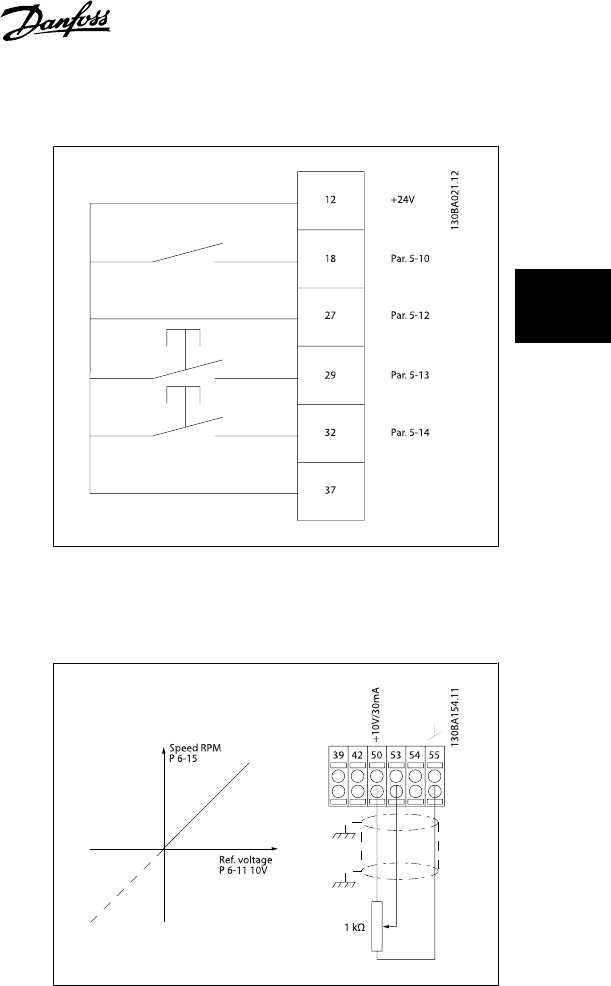
3.4.3 Speed Up/Down
Terminals 29/32 = Speed up/down:
Terminal 18 = par. 5-10
Terminal 18 Digital Input
Start [9] (de-
fault)
Terminal 27 = par. 5-12
Terminal 27 Digital Input
Freeze refer-
ence [19]
Terminal 29 = par. 5-13
Terminal 29 Digital Input
Speed up [21]
Terminal 32 = par. 5-14
Terminal 32 Digital Input
Speed down
[22]
NOTE: Terminal 29 only in FC x02 (x=series type).
3.4.4 Potentiometer Reference
Voltage reference via a potentiometer:
Reference Source 1 = [1]
Analog input 53
(default)
Terminal 53, Low Voltage = 0 Volt
Terminal 53, High Voltage = 10 Volt
Terminal 53, Low Ref./Feedback = 0 RPM
Terminal 53, High Ref./Feedback = 1500 RPM
Switch S201 = OFF (U)
VLT
®
AutomationDrive FC 300 Operating
Instructions 3 How to Install
MG.33.AG.02 - VLT® is a registered Danfoss trademark
35
3
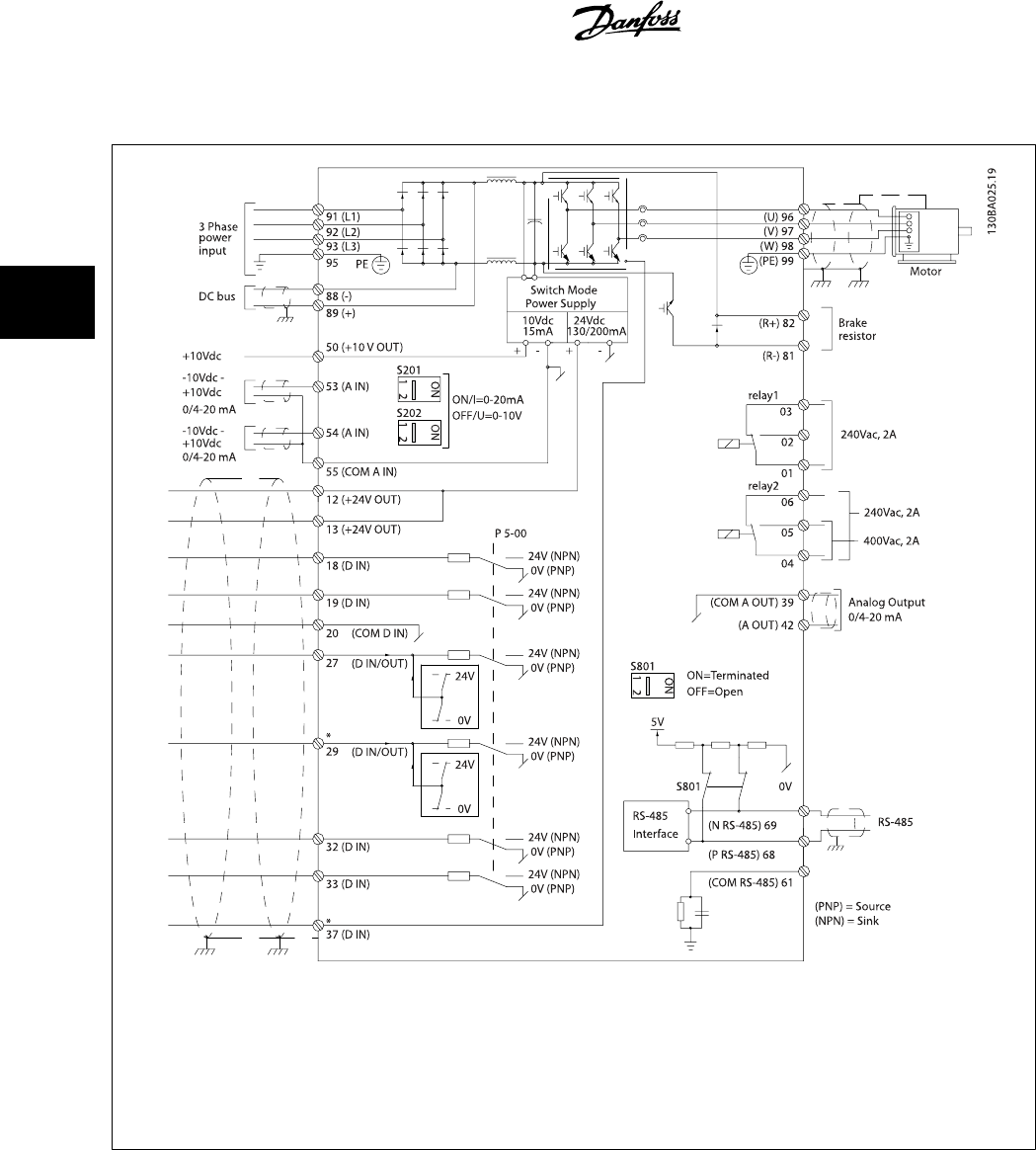
3.5.1 Electrical Installation, Control Cables
Illustration 3.22: Diagram showing all electrical terminals without options.
A = analog, D = digital
Terminal 37 is used for Safe Stop. For instructions on Safe Stop installation please refer to the section
Safe Stop Installation
of the Design
Guide.
* Terminal 37 is not included in FC 301 (Except FC 301 A1, which includes Safe Stop).
Relay 2 and Terminal 29, have no function in FC 301.
Very long control cables and analogue signals may in rare cases and depending on installation result in 50/60 Hz earth loops due to noise from mains
supply cables.
If this occurs, it may be necessary to break the screen or insert a 100 nF capacitor between screen and chassis.
The digital and analogue inputs and outputs must be connected separately to the common inputs (terminal 20, 55, 39) of the frequency converter to
avoid ground currents from both groups to affect other groups. For example, switching on the digital input may disturb the analog input signal.
3 How to Install
VLT
®
AutomationDrive FC 300 Operating
Instructions
36
MG.33.AG.02 - VLT® is a registered Danfoss trademark
3
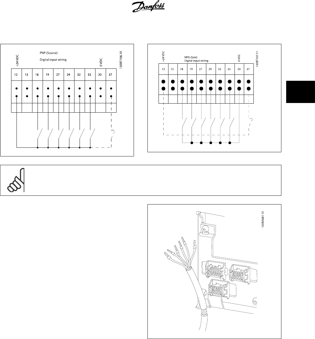
Input polarity of control terminals
NB!
To comply with EMC emission specifications, screened/armoured cables are recommended. If an unscreened/unarmoured cable is
used, see section
Power and Control Wiring for Unscreened Cables
.. For more information, see
EMC Test Results
in the Design Guide.
VLT
®
AutomationDrive FC 300 Operating
Instructions 3 How to Install
MG.33.AG.02 - VLT® is a registered Danfoss trademark
37
3
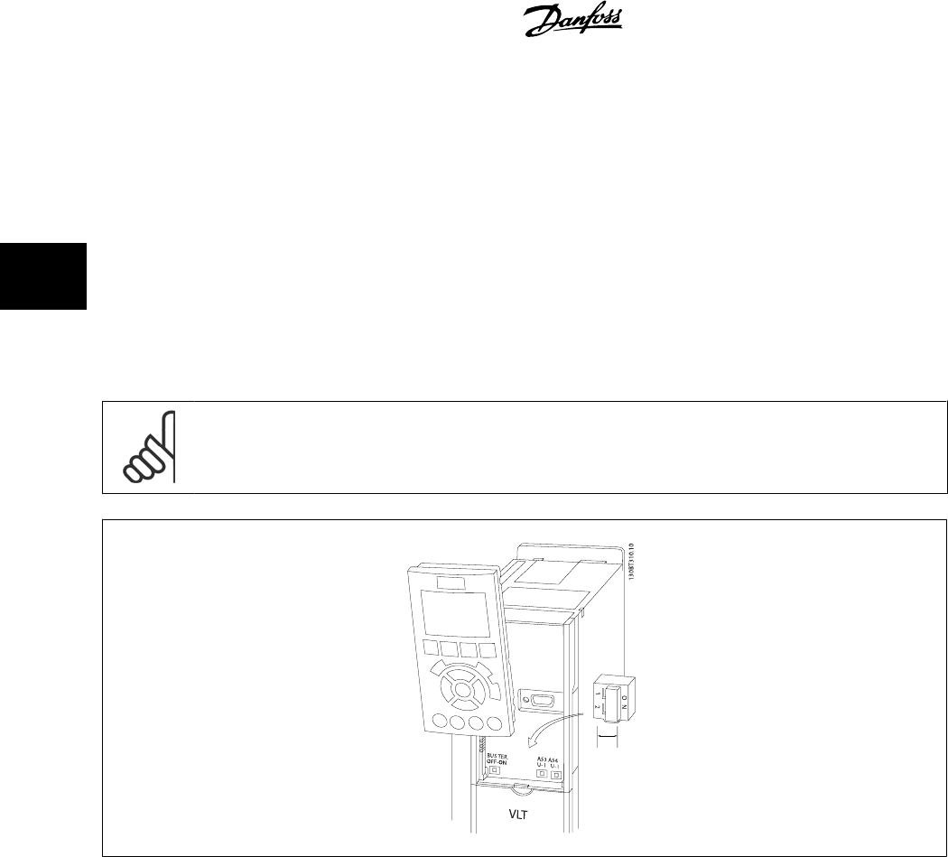
3.5.2 Switches S201, S202, and S801
Switches S201 (A53) and S202 (A54) are used to select a current (0-20 mA) or a voltage (-10 to 10 V) configuration of the analog input terminals 53 and
54 respectively.
Switch S801 (BUS TER.) can be used to enable termination on the RS-485 port (terminals 68 and 69).
See drawing
Diagram showing all electrical terminals
in section
Electrical Installation.
Default setting:
S201 (A53) = OFF (voltage input)
S202 (A54) = OFF (voltage input)
S801 (Bus termination) = OFF
NB!
When changing the function of S201, S202 or S801 be careful not to use force for the switch over. It is recommended to remove the
LCP fixture (cradle) when operating the switches. The switches must not be operated with power on the frequency converter.
3 How to Install
VLT
®
AutomationDrive FC 300 Operating
Instructions
38
MG.33.AG.02 - VLT® is a registered Danfoss trademark
3
3.4 Final Set-Up and Test
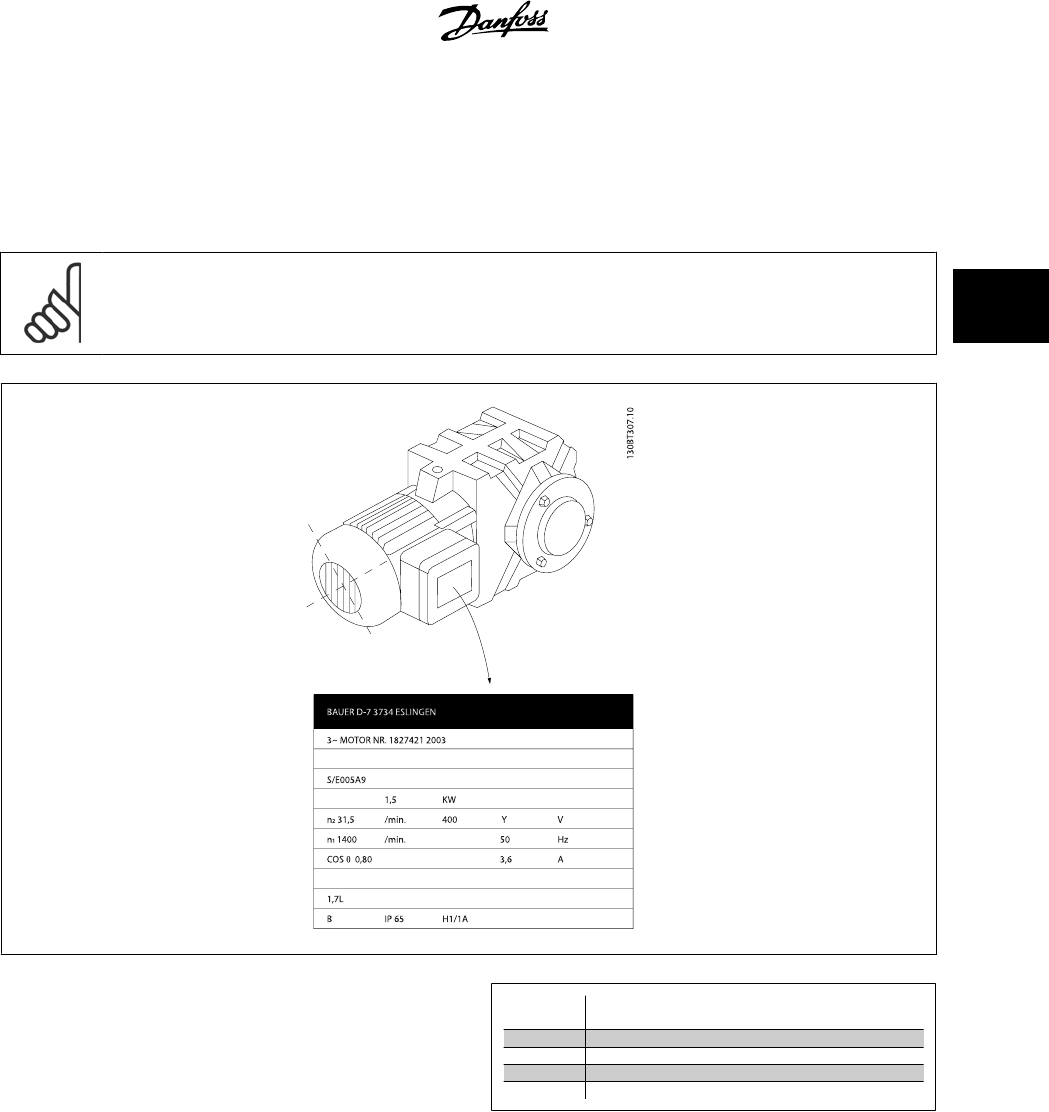
To test the set-up and ensure that the frequency converter is running, follow these steps.
Step 1. Locate the motor name plate
NB!
The motor is either star- (Y) or delta- connected (). This information is located on the motor name plate data.
Step 2. Enter the motor name plate data in this parameter list.
To access this list first press the [QUICK MENU] key then select “Q2 Quick
Setup”.
1. Par. 1-20
Motor Power [kW]
Par. 1-21
Motor Power [HP]
2. Par. 1-22
Motor Voltage
3. Par. 1-23
Motor Frequency
4. Par. 1-24
Motor Current
5. Par. 1-25
Motor Nominal Speed
Step 3. Activate the Automatic Motor Adaptation (AMA)
Performing an AMA will ensure optimum performance. The AMA measures the values from the motor model equivalent diagram.
1. Connect terminal 37 to terminal 12 (if terminal 37 is available).
2. Connect terminal 27 to terminal 12 or set par. 5-12
Terminal 27 Digital Input
to 'No function'.
3. Activate the AMA par. 1-29
Automatic Motor Adaptation (AMA)
.
4. Choose between complete or reduced AMA. If a Sine-wave filter is mounted, run only the reduced AMA, or remove the Sine-wave filter during
the AMA procedure.
5. Press the [OK] key. The display shows “Press [Hand on] to start”.
6. Press the [Hand on] key. A progress bar indicates if the AMA is in progress.
Stop the AMA during operation
1. Press the [OFF] key - the frequency converter enters into alarm mode and the display shows that the AMA was terminated by the user.
VLT
®
AutomationDrive FC 300 Operating
Instructions 3 How to Install
MG.33.AG.02 - VLT® is a registered Danfoss trademark
39
3
Successful AMA
1. The display shows “Press [OK] to finish AMA”.
2. Press the [OK] key to exit the AMA state.
Unsuccessful AMA
1. The frequency converter enters into alarm mode. A description of the alarm can be found in the
Warnings and Alarms
chapter.
2. "Report Value” in the [Alarm Log] shows the last measuring sequence carried out by the AMA, before the frequency converter entered alarm
mode. This number along with the description of the alarm will assist you in troubleshooting. If you contact Danfoss for service, make sure to
mention number and alarm description.
NB!
Unsuccessful AMA is often caused by incorrectly registered motor name plate data or a too big difference between the motor power
size and the frequency converter power size.
Step 4. Set speed limit and ramp times
Par. 3-02
Minimum Reference
Par. 3-03
Maximum Reference
Table 3.2: Set up the desired limits for speed and ramp time.
Par. 4-11
Motor Speed Low Limit [RPM]
or par. 4-12
Motor Speed
Low Limit [Hz]
Par. 4-13
Motor Speed High Limit [RPM]
or par. 4-14
Motor Speed
High Limit [Hz]
Par. 3-41
Ramp 1 Ramp up Time
Par. 3-42
Ramp 1 Ramp Down Time
3 How to Install
VLT
®
AutomationDrive FC 300 Operating
Instructions
40
MG.33.AG.02 - VLT® is a registered Danfoss trademark
3
3.5 Additional Connections
3.7.1 Mechanical Brake Control
In hoisting/lowering applications, it is necessary to be able to control an electro-mechanical brake:
• Control the brake using any relay output or digital output (terminal 27 or 29).
• Keep the output closed (voltage-free) as long as the frequency converter is unable to ‘support’ the motor, for example due to the load being
too heavy.
•Select
Mechanical brake control
[32] in par. 5-4* for applications with an electro-mechanical brake.
• The brake is released when the motor current exceeds the preset value in par. 2-20
Release Brake Current
.
• The brake is engaged when the output frequency is less than the frequency set in par. 2-21
Activate Brake Speed [RPM]
or par. 2-22
Activate
Brake Speed [Hz]
, and only if the frequency converter carries out a stop command.
If the frequency converter is in alarm mode or in an over-voltage situation, the mechanical brake immediately cuts in.
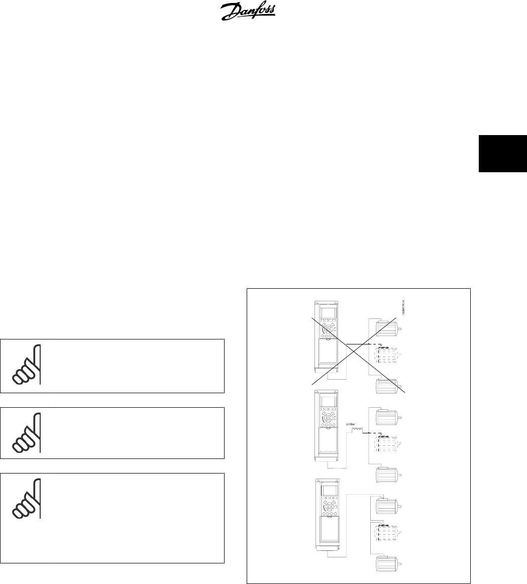
3.7.2 Parallel Connection of Motors
The frequency converter can control several parallel-connected motors.
The total current consumption of the motors must not exceed the rated
output current IM,N for the frequency converter.
NB!
Installations with cables connected in a common joint
as in the illustration below, is only recommended for
short cable lengths.
NB!
When motors are connected in parallel, par. 1-29
Au-
tomatic Motor Adaptation (AMA)
cannot be used.
NB!
The electronic thermal relay (ETR) of the frequency
converter cannot be used as motor protection for the
individual motor in systems with parallel-connected
motors. Provide further motor protection by e.g. ther-
mistors in each motor or individual thermal relays (cir-
cuit breakers are not suitable as protection).
Problems may arise at start and at low RPM values if motor sizes are widely different because small motors' relatively high ohmic resistance in the stator
calls for a higher voltage at start and at low RPM values.
VLT
®
AutomationDrive FC 300 Operating
Instructions 3 How to Install
MG.33.AG.02 - VLT® is a registered Danfoss trademark
41
3
3.7.3 Motor Thermal Protection
The electronic thermal relay in the frequency converter has received UL-approval for single motor protection, when par. 1-90
Motor Thermal Protection
is
set for
ETR Trip
and par. 1-24
Motor Current
is set to the rated motor current (see motor name plate).
For thermal motor protection it is also possible to use the MCB 112 PTC Thermistor Card option. This card provides ATEX certificate to protect motors in
explosion hazardous areas, Zone 1/21 and Zone 2/22. Please refer to the
Design Guide
for further information.
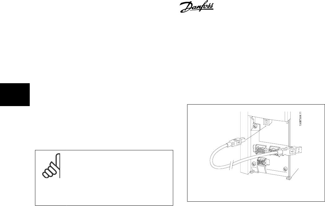
3.7.4 How to Connect a PC to the Frequency Converter
To control the frequency converter from a PC, install the MCT 10 Set-up
Software.
The PC is connected via a standard (host/device) USB cable, or via the
RS485 interface as shown in the section
Bus Connection
in the Program-
ming Guide.
NB!
The USB connection is galvanically isolated from the
supply voltage (PELV) and other high-voltage termi-
nals. The USB connection is connected to protection
earth on the frequency converter. Use only isolated
laptop as PC connection to the USB connector on the
frequency converter.
Illustration 3.23: USB connection.
3.7.5 The FC 300 PC Software
Data storage in PC via MCT 10 Set-Up Software:
1. Connect a PC to the unit via USB com port
2. Open MCT 10 Set-up Software
3. Select in the “network” section the USB port
4. Choose “Copy”
5. Select the “project” section
6. Choose “Paste”
7. Choose “Save as”
All parameters are now stored.
Data transfer from PC to drive via MCT 10 Set-Up Software:
1. Connect a PC to the unit via USB com port
2. Open MCT 10 Set-up software
3. Choose “Open”– stored files will be shown
4. Open the appropriate file
5. Choose “Write to drive”
All parameters are now transferred to the drive.
A separate manual for MCT 10 Set-up Software is available.
3 How to Install
VLT
®
AutomationDrive FC 300 Operating
Instructions
42
MG.33.AG.02 - VLT® is a registered Danfoss trademark
3
4 How to Programme
4.1 The Graphical and Numerical LCP
The easiest programming of the frequency converter is performed by the Graphical LCP (LCP 102). It is necessary to consult the frequency converter
Design Guide, when using the Numeric Local Control Panel (LCP 101).
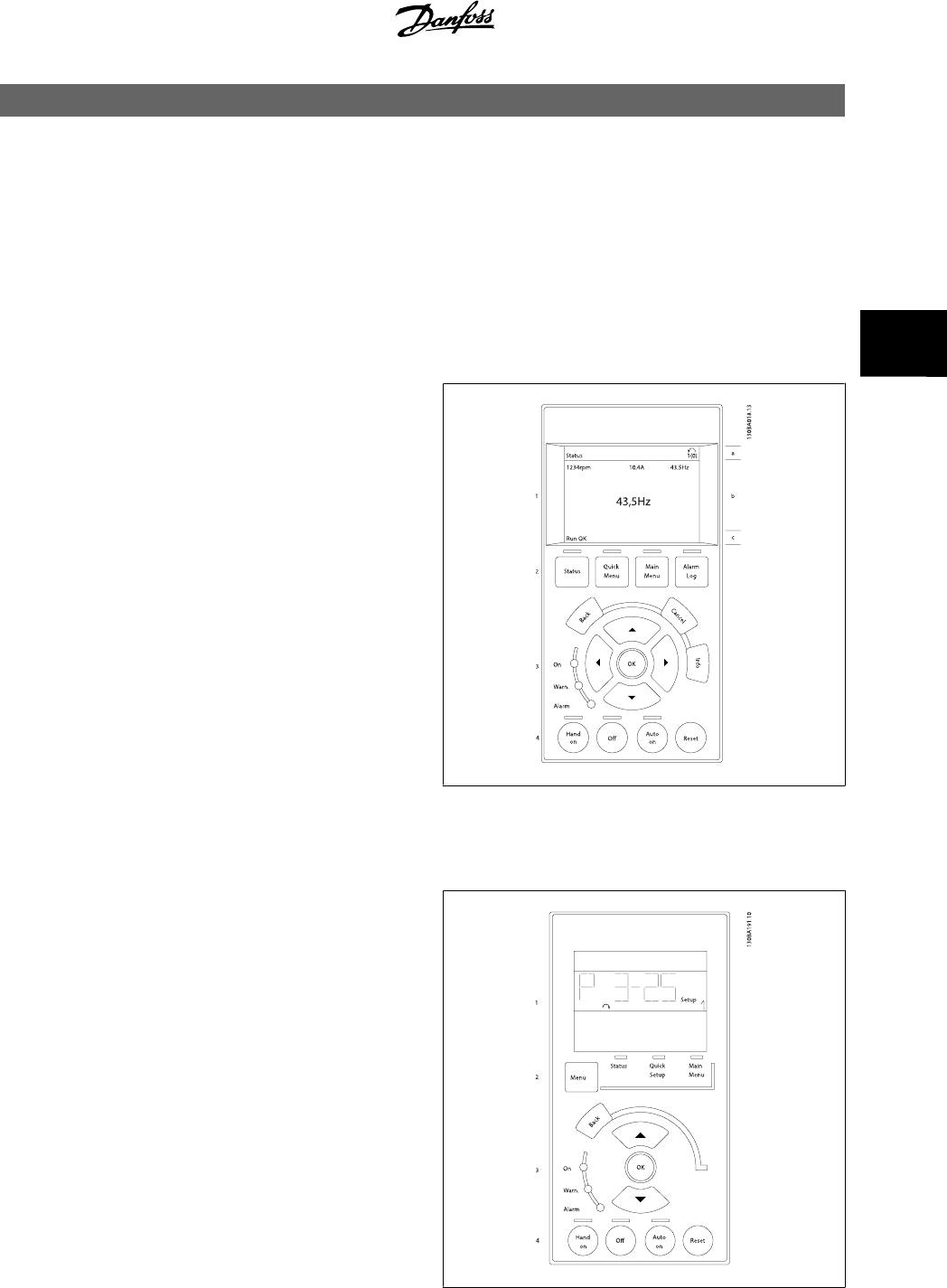
4.1.1 How to Programme on the Graphical LCP
The following instructions are valid for the graphical LCP (LCP 102):
The control panel is divided into four functional groups:
1. Graphical display with Status lines.
2. Menu keys and indicator lights - changing parameters and
switching between display functions.
3. Navigation keys and indicator lights (LEDs).
4. Operation keys and indicator lights (LEDs).
All data is displayed in a graphical LCP display, which can show up to five
items of operating data while displaying [Status].
Display lines:
a. Status line: Status messages displaying icons and graphic.
b. Line 1-2: Operator data lines displaying data defined or chosen
by the user. By pressing the [Status] key, up to one extra line
can be added.
c. Status line: Status messages displaying text.
4.1.2 How to Programme on the Numerical Local Control Panel
The following instructions are valid for the numerical LCP (LCP 101):
The control panel is divided into four functional groups:
1. Numerical display.
2. Menu keys and indicator lights - changing parameters and
switching between display functions.
3. Navigation keys and indicator lights (LEDs).
4. Operation keys and indicator lights (LEDs).
VLT
®
AutomationDrive FC 300 Operating
Instructions 4 How to Programme
MG.33.AG.02 - VLT® is a registered Danfoss trademark
43
4
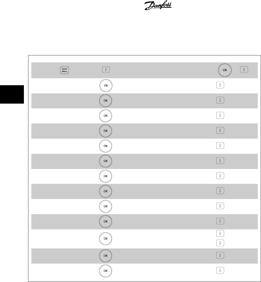
4.1.3 Initial Commissioning
The easiest way of carrying out the initial commissioning is by using the Quick Menu button and follow the quick set-up procedure using LCP 102 (read
table from left to right). The example applies to open loop applications:
Press
Q2 Quick Menu
Par. 0-01
Language
Set language
Par. 1-20
Motor Power [kW]
Set Motor nameplate power
Par. 1-22
Motor Voltage
Set Nameplate voltage
Par. 1-23
Motor Frequency
Set Nameplate frequency
Par. 1-24
Motor Current
Set Nameplate current
Par. 1-25
Motor Nominal Speed
Set Nameplate speed in RPM
Par. 5-12
Terminal 27 Digital Input
If terminal default is
Coast inverse
it is possible to change this
setting to
No function
. No connection to terminal 27 is then
needed for running AMA
Par. 1-29
Automatic Motor Adaptation
(AMA)
Set desired AMA function. Enable complete AMA is recommen-
ded
Par. 3-02
Minimum Reference
Set the minimum speed of the motor shaft
Par. 3-03
Maximum Reference
Set the maximum speed of the motor shaft
Par. 3-41
Ramp 1 Ramp up Time
Set the ramping up time with reference to synchronous motor
speed, ns
Par. 3-42
Ramp 1 Ramp Down Time
Set the ramping downdecel time with reference to synchronous
motor speed, ns
Par. 3-13
Reference Site
Set the site from where the reference must work
4 How to Programme
VLT
®
AutomationDrive FC 300 Operating
Instructions
44
MG.33.AG.02 - VLT® is a registered Danfoss trademark
4

4.2 Quick Setup
0-01 Language
Option: Function:
Defines the language to be used in the display. The frequency converter can be delivered with 4
different language packages. English and German are included in all packages. English cannot be
erased or manipulated.
[0] * English Part of Language packages 1 - 4
[1] Deutsch Part of Language packages 1 - 4
[2] Francais Part of Language package 1
[3] Dansk Part of Language package 1
[4] Spanish Part of Language package 1
[5] Italiano Part of Language package 1
Svenska Part of Language package 1
[7] Nederlands Part of Language package 1
[10] Chinese Part of Language package 2
Suomi Part of Language package 1
[22] English US Part of Language package 4
Greek Part of Language package 4
Bras.port Part of Language package 4
Slovenian Part of Language package 3
Korean Part of Language package 2
Japanese Part of Language package 2
Turkish Part of Language package 4
Trad.Chinese Part of Language package 2
Bulgarian Part of Language package 3
Srpski Part of Language package 3
Romanian Part of Language package 3
Magyar Part of Language package 3
Czech Part of Language package 3
Polski Part of Language package 4
Russian Part of Language package 3
Thai Part of Language package 2
Bahasa Indonesia Part of Language package 2
[99] Unknown
VLT
®
AutomationDrive FC 300 Operating
Instructions 4 How to Programme
MG.33.AG.02 - VLT® is a registered Danfoss trademark
45
4
1-20 Motor Power [kW]
Range: Function:
Application
dependent*
[Application dependant] Enter the nominal motor power in kW according to the motor nameplate data. The default value
corresponds to the nominal rated output of the unit.
This parameter cannot be adjusted while the motor is running. This parameter is visible in LCP if
par. 0-03
Regional Settings
is
International
[0].
NB!
Four sizes down, one size up from nominal unit rating.
1-22 Motor Voltage
Range: Function:
Application
dependent*
[Application dependant] Enter the nominal motor voltage according to the motor nameplate data. The default value corre-
sponds to the nominal rated output of the unit.
This parameter cannot be adjusted while the motor is running.
1-23 Motor Frequency
Range: Function:
Application
dependent*
[20 - 1000 Hz] Min - Max motor frequency: 20 - 1000 Hz.
Select the motor frequency value from the motor nameplate data. If a value different from 50 Hz
or 60 Hz is selected, it is necessary to adapt the load independent settings in par. 1-50
Motor
Magnetisation at Zero Speed
to par. 1-53
Model Shift Frequency
. For 87 Hz operation with 230/400
V motors, set the nameplate data for 230 V/50 Hz. Adapt par. 4-13
Motor Speed High Limit
[RPM]
and par. 3-03
Maximum Reference
to the 87 Hz application.
1-24 Motor Current
Range: Function:
Application
dependent*
[Application dependant] Enter the nominal motor current value from the motor nameplate data. This data is used for cal-
culating motor torque, motor thermal protection etc.
NB!
This parameter cannot be adjusted while the motor is running.
1-25 Motor Nominal Speed
Range: Function:
Application
dependent*
[100 - 60000 RPM] Enter the nominal motor speed value from the motor nameplate data. This data is used for calcu-
lating automatic motor compensations.
NB!
This parameter cannot be adjusted while the motor is running.
4 How to Programme
VLT
®
AutomationDrive FC 300 Operating
Instructions
46
MG.33.AG.02 - VLT® is a registered Danfoss trademark
4

5-12 Terminal 27 Digital Input
Option: Function:
Select the function from the available digital input range.
No operation [0]
Reset [1]
Coast inverse [2]
Coast and reset inverse [3]
Quick stop inverse [4]
DC-brake inverse [5]
Stop inverse [6]
Start [8]
Latched start [9]
Reversing [10]
Start reversing [11]
Enable start forward [12]
Enable start reverse [13]
Jog [14]
Preset ref bit 0 [16]
Preset ref bit 1 [17]
Preset ref bit 2 [18]
Freeze reference [19]
Freeze output [20]
Speed up [21]
Speed down [22]
Set-up select bit 0 [23]
Set-up select bit 1 [24]
Catch up [28]
Slow down [29]
Pulse input [32]
Ramp bit 0 [34]
Ramp bit 1 [35]
Mains failure inverse [36]
DigiPot Increase [55]
DigiPot Decrease [56]
DigiPot Clear [57]
Reset Counter A [62]
Reset Counter B [65]
1-29 Automatic Motor Adaptation (AMA)
Option: Function:
The AMA function optimizes dynamic motor performance by automatically optimizing the advanced
motor parameters (par. 1-30 to par. 1-35) at motor standstill.
Activate the AMA function by pressing [Hand on] after selecting [1] or [2]. See also the section
Automatic Motor Adaptation
. After a normal sequence, the display will read: "Press [OK] to finish
AMA". After pressing the [OK] key the frequency converter is ready for operation.
This parameter cannot be adjusted while the motor is running.
[0] * OFF
[1] Enable complete AMA Performs AMA of the stator resistance RS, the rotor resistance Rr, the stator leakage reactance X1,
the rotor leakage reactance X2 and the main reactance Xh.
FC 301: The complete AMA does not include Xh measurement for FC 301. Instead, the Xh value is
determined from the motor database. Par. 1-35 may be adjusted to obtain optimal start perform-
ance.
[2] Enable reduced AMA Performs a reduced AMA of the stator resistance Rs in the system only. Select this option if an LC
filter is used between the drive and the motor.
Note:
• For the best adaptation of the frequency converter, run AMA on a cold motor.
• AMA cannot be performed while the motor is running.
• AMA cannot be performed on permanent magnet motors.
VLT
®
AutomationDrive FC 300 Operating
Instructions 4 How to Programme
MG.33.AG.02 - VLT® is a registered Danfoss trademark
47
4
NB!
It is important to set motor par. 1-2* correctly, since these form part of the AMA algorithm. An AMA must be performed to achieve
optimum dynamic motor performance. It may take up to 10 min, depending on the power rating of the motor.
NB!
Avoid generating external torque during AMA.
NB!
If one of the settings in par. 1-2* is changed, par. 1-30 to par. 1-39, the advanced motor parameters, will return to default setting.
3-02 Minimum Reference
Range: Function:
Application
dependent*
[Application dependant] Enter the Minimum Reference. The Minimum Reference is the lowest value obtainable by summing
all references.
Minimum Reference is active only when par. 3-00
Reference Range
is set to
Min.- Max.
[0].
The Minimum Reference unit matches:
• The choice of configuration in par. 1-00
Configuration Mode
Configuration Mode
: for
Speed
closed loop
[1], RPM; for
Torque
[2], Nm.
• The unit selected in par. 3-01
Reference/Feedback Unit
.
3-03 Maximum Reference
Range: Function:
Application
dependent*
[Application dependant] Enter the Maximum Reference. The Maximum Reference is the highest value obtainable by summing
all references.
The Maximum Reference unit matches:
• The choice of configuration in par. 1-00
Configuration Mode
: for
Speed closed loop
[1],
RPM; for
Torque
[2], Nm.
• The unit selected in par. 3-00
Reference Range
.
3-41 Ramp 1 Ramp up Time
Range: Function:
Application
dependent*
[Application dependant] Enter the ramp-up time, i.e. the acceleration time from 0 RPM to the synchronous motor speed nS.
Choose a ramp-up time such that the output current does not exceed the current limit in
par. 4-18
Current Limit
during ramping. The value 0.00 corresponds to 0.01 sec. in speed mode.
See ramp-down time in par. 3-42
Ramp 1 Ramp Down Time
.
Par
. 3 −41 =
tacc
s
x
ns
RPM
ref
RPM
3-42 Ramp 1 Ramp Down Time
Range: Function:
Application
dependent*
[Application dependant] Enter the ramp-down time, i.e. the deceleration time from the synchronous motor speed ns to 0
RPM. Choose a ramp-down time such that no over-voltage arises in the inverter due to regenerative
operation of the motor, and such that the generated current does not exceed the current limit set
in par. 4-18
Current Limit
. The value 0.00 corresponds to 0.01 s in speed mode. See ramp-up time
in par. 3-41
Ramp 1 Ramp up Time
.
Par
. 3 −42 =
tdec
s
x
ns
RPM
ref
RPM
4 How to Programme
VLT
®
AutomationDrive FC 300 Operating
Instructions
48
MG.33.AG.02 - VLT® is a registered Danfoss trademark
4

4.3 Basic Setup Parameters
0-02 Motor Speed Unit
Option: Function:
This parameter cannot be adjusted while the motor is running.
The display showing depends on settings in par. 0-02
Motor Speed Unit
and par. 0-03
Regional
Settings
. The default setting of par. 0-02
Motor Speed Unit
and par. 0-03
Regional Settings
depends
on which region of the world the frequency converter is supplied to, but can be re-programmed as
required.
NB!
Changing the
Motor Speed Unit
will reset certain parameters to their initial value.
It is recommended to select the motor speed unit first, before modifying other
parameters.
[0] RPM Selects display of motor speed variables and parameters (i.e. references, feedbacks and limits) in
terms of motor speed (RPM).
[1] * Hz Selects display of motor speed variables and parameters (i.e. references, feedbacks and limits) in
terms of output frequency to the motor (Hz).
0-50 LCP Copy
Option: Function:
[0] * No copy
[1] All to LCP Copies all parameters in all set-ups from the frequency converter memory to the LCP memory.
[2] All from LCP Copies all parameters in all set-ups from the LCP memory to the frequency converter memory.
[3] Size indep. from LCP Copy only the parameters that are independent of the motor size. The latter selection can be used
to programme several frequency converters with the same function without disturbing motor data.
[4] File from MCO to LCP
[5] File from LCP to MCO
[6] Data from DYN to LCP
[7] Data from LCP to DYN
[8] LCP Compare
This parameter cannot be adjusted while the motor is running.
1-03 Torque Characteristics
Option: Function:
Select the torque characteristic required.
VT and AEO are both energy saving operations.
[0] * Constant torque Motor shaft output provides constant torque under variable speed control.
[1] Variable torque Motor shaft output provides variable torque under variable speed control. Set the variable torque
level in par. 14-40
VT Level
.
[2] Auto Energy Optim. Automatically optimises energy consumption by minimising magnetisation and frequency via
par. 14-41
AEO Minimum Magnetisation
and par. 14-42
Minimum AEO Frequency
.
[5] Constant Power The function provide a constant power in field weakening area. Follows the formula:
Pconstant
=
Torque
x
RPM
9550
This selection maybe unavailable depending on drive configuration.
This parameter cannot be adjusted while the motor is running.
VLT
®
AutomationDrive FC 300 Operating
Instructions 4 How to Programme
MG.33.AG.02 - VLT® is a registered Danfoss trademark
49
4

1-04 Overload Mode
Option: Function:
[0] * High torque Allows up to 160% over torque.
[1] Normal torque For oversized motor - allows up to 110% over torque.
This parameter cannot be adjusted while the motor is running.
1-90 Motor Thermal Protection
Option: Function:
The frequency converter determines the motor temperature for motor protection in three different
ways:
• Via a thermistor sensor connected to one of the analog or digital inputs (par. 1-93
Ther-
mistor Source
). See section
PTC Thermistor Connection
.
• Via a KTY sensor connected to an analog input (par. 1-96
KTY Thermistor Resource
). See
section
KTY Sensor Connection
.
• Via calculation (ETR = Electronic Terminal Relay) of the thermal load, based on the actual
load and time. The calculated thermal load is compared with the rated motor current
IM,N and the rated motor frequency fM,N. The calculations estimate the need for a lower
load at lower speed due to less cooling from the fan incorporated in the motor.
[0] * No protection Continuously overloaded motor, when no warning or trip of the frequency converter is required.
[1] Thermistor warning Activates a warning when the connected thermistor or KTY-sensor in the motor reacts in the event
of motor over-temperature.
[2] Thermistor trip Stops (trips) frequency converter when connected thermistor or KTY sensor in the motor reacts in
the event of motor over-temperature.
The thermistor cut-out value must be > 3 k.
Integrate a thermistor (PTC sensor) in the motor for winding protection.
[3] ETR warning 1 Please see detailed description below
[4] ETR trip 1
[5] ETR warning 2
[6] ETR trip 2
[7] ETR warning 3
[8] ETR trip 3
[9] ETR warning 4
[10] ETR trip 4
Select
ETR Warning 1-4
, to activate a warning on the display when the motor is overloaded.
Select
ETR Trip 1-4
to trip the frequency converter when the motor is overloaded.
Programme a warning signal via one of the digital outputs. The signal appears in the event of a warning and if the frequency converter trips (thermal
warning).
ETR (Electronic Terminal Relay) functions 1-4 will calculate the load when the set-up where they were selected is active. For example ETR starts calculating
when set-up 3 is selected. For the North American market: The ETR functions provide class 20 motor overload protection in accordance with NEC.
4 How to Programme
VLT
®
AutomationDrive FC 300 Operating
Instructions
50
MG.33.AG.02 - VLT® is a registered Danfoss trademark
4
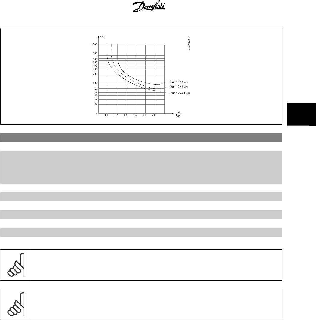
1-93 Thermistor Source
Option: Function:
Select the input to which the thermistor (PTC sensor) should be connected. An analog input option
[1] or [2] cannot be selected if the analog input is already in use as a reference source (selected in
par. 3-15
Reference 1 Source
, par. 3-16
Reference 2 Source
or par. 3-17
Reference 3 Source
).
When using MCB 112, choice [0]
None
must always be selected.
[0] * None
[1] Analog input 53
[2] Analog input 54
[3] Digital input 18
[4] Digital input 19
[5] Digital input 32
[6] Digital input 33
NB!
This parameter cannot be adjusted while the motor is running.
NB!
Digital input should be set to [0]
PNP - Active at 24V
in par. 5-00.
VLT
®
AutomationDrive FC 300 Operating
Instructions 4 How to Programme
MG.33.AG.02 - VLT® is a registered Danfoss trademark
51
4

2-10 Brake Function
Option: Function:
[0] * Off No brake resistor is installed.
[1] Resistor brake A brake resistor is incorporated in the system, for dissipation of surplus brake energy as heat. Con-
necting a brake resistor allows a higher DC link voltage during braking (generating operation). The
Resistor brake function is only active in frequency converters with an integral dynamic brake.
[2] AC brake Is selected to improve braking without using a brake resistor. This parameter controls an overmag-
netization of the motor when running with a generatoric load. This function can improve the OVC-
function. Increasing the electrical losses in the motor allows the OVC function to increase the braking
torque without exceeding the over voltage limit. Please note that AC brake is not as effective as
dynamic breaking with resistor.
AC brake is for VVC+ and flux mode in both open and closed loop.
2-11 Brake Resistor (ohm)
Range: Function:
Application
dependent*
[Application dependant] Set the brake resistor value in Ohms. This value is used for monitoring the power to the brake
resistor in par. 2-13
Brake Power Monitoring
. This parameter is only active in frequency converters
with an integral dynamic brake.
Use this parameter for values without decimals. For a selection with two decimals, use
par. 30-81
Brake Resistor (ohm)
.
2-12 Brake Power Limit (kW)
Range: Function:
Application
dependent*
[Application dependant] Set the monitoring limit of the brake power transmitted to the resistor.
The monitoring limit is a product of the maximum duty cycle (120 sec.) and the maximum power
of the brake resistor at that duty cycle. See the formula below.
For 200 - 240 V units:
Presistor
= 3902 ×
dutytime
R
× 120
[W]
For 380 - 480 V units
Presistor
= 7782 ×
dutytime
R
× 120
[W]
For 380 - 500 V units
Presistor
= 8102 ×
dutytime
R
× 120
[W]
For 575 - 600 V units
Presistor
= 9432 ×
dutytime
R
× 120
[W]
This parameter is only active in frequency converters with an integral dynamic brake.
2-13 Brake Power Monitoring
Option: Function:
This parameter is only active in frequency converters with an integral dynamic brake.
This parameter enables monitoring of the power to the brake resistor. The power is calculated on
the basis of the resistance (par. 2-11
Brake Resistor (ohm)
), the DC link voltage, and the resistor
duty time.
[0] * Off No brake power monitoring required.
[1] Warning Activates a warning on the display when the power transmitted over 120 s exceeds 100% of the
monitoring limit (par. 2-12
Brake Power Limit (kW)
).
The warning disappears when the transmitted power falls below 80% of the monitoring limit.
[2] Trip Trips frequency converter and displays an alarm when the calculated power exceeds 100% of the
monitoring limit.
[3] Warning and trip Activates both of the above, including warning, trip and alarm.
If power monitoring is set to
Off
[0] or
Warning
[1], the brake function remains active, even if the monitoring limit is exceeded. This may lead to thermal
overload of the resistor. It is also possible to generate a warning via a relay/digital outputs. The measuring accuracy of the power monitoring depends
on the accuracy of the resistance of the resistor (better than ± 20%).
4 How to Programme
VLT
®
AutomationDrive FC 300 Operating
Instructions
52
MG.33.AG.02 - VLT® is a registered Danfoss trademark
4
2-15 Brake Check
Option: Function:
Select type of test and monitoring function to check the connection to the brake resistor, or whether
a brake resistor is present, and then display a warning or an alarm in the event of a fault.
NB!
The brake resistor disconnection function is tested during power-up. However the
brake IGBT test is performed when there is no braking. A warning or trip discon-
nects the brake function.
The testing sequence is as follows:
1. The DC link ripple amplitude is measured for 300 ms without braking.
2. The DC link ripple amplitude is measured for 300 ms with the brake turned on.
3. If the DC link ripple amplitude while braking is lower than the DC link ripple amplitude
before braking + 1 %:
Brake check has failed by returning a warning or alarm.
4. If the DC link ripple amplitude while braking is higher than the DC link ripple amplitude
before braking + 1 %:
Brake check is OK.
[0] * Off Monitors brake resistor and brake IGBT for a short-circuit during operation. If a short-circuit occurs,
warning 25 appears.
[1] Warning Monitors brake resistor and brake IGBT for a short-circuit, and runs a test for brake resistor dis-
connection during power-up.
[2] Trip Monitors for a short-circuit or disconnection of the brake resistor, or a short-circuit of the brake
IGBT. If a fault occurs, the frequency converter cuts out while displaying an alarm (trip locked).
[3] Stop and trip Monitors for a short-circuit or disconnection of the brake resistor, or a short-circuit of the brake
IGBT. If a fault occurs, the frequency converter ramps down to coast and then trips. A trip lock
alarm is displayed (e.g. warning 25, 27 or 28).
[4] AC brake Monitors for a short-circuit or disconnection of the brake resistor, or a short-circuit of the brake
IGBT. If a fault occurs, the frequency converter performs a controlled ramp-down. This option is
available for FC 302 only.
[5] Trip Lock
NB!
Remove a warning arising in connection with
Off
[0] or
Warning
[1] by cycling the mains supply. The fault must be corrected first. For
Off
[0] or
Warning
[1], the frequency converter keeps running even if a fault is located.
This parameter is only active in frequency converters with an integral dynamic brake.
4.3.1 2-2* Mechanical Brake
Parameters for controlling operation of an electro-magnetic (mechanical) brake, typically required in hoisting applications.
To control a mechanical brake, a relay output (relay 01 or relay 02) or a programmed digital output (terminal 27 or 29) is required. Normally this output
must be closed during periods when the frequency converter is unable to ‘hold’ the motor, e.g. due to an excessive load. Select
Mechanical Brake
Control
[32] for applications with an electro-magnetic brake in par. 5-40
Function Relay
, par. 5-30
Terminal 27 Digital Output
, or par. 5-31
Terminal 29
Digital Output
. When selecting
Mechanical brake control
[32], the mechanical brake is closed from start up until the output current is above the level
selected in par. 2-20
Release Brake Current
. During stop, the mechanical brake activates when the speed falls below the level specified in par. 2-21
Activate
Brake Speed [RPM]
. If the frequency converter enters an alarm condition or an over-current or over-voltage situation, the mechanical brake immediately
cuts in. This is also the case during safe stop.
VLT
®
AutomationDrive FC 300 Operating
Instructions 4 How to Programme
MG.33.AG.02 - VLT® is a registered Danfoss trademark
53
4
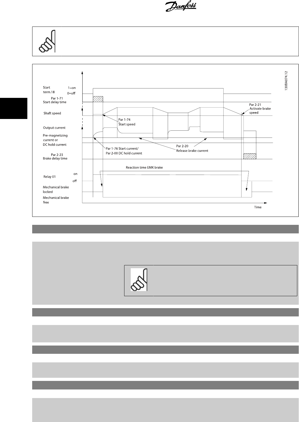
NB!
Protection mode and trip delay features (par. 14-25
Trip Delay at Torque Limit
and par. 14-26
Trip Delay at Inverter Fault
) may delay
the activation of the mechanical brake in an alarm condition. These features must be disabled in hoisting applications.
2-20 Release Brake Current
Range: Function:
Application
dependent*
[Application dependant] Set the motor current for release of the mechanical brake, when a start condition is present. The
default value is the maximum current the inverter can provide for the particular power size. The
upper limit is specified in par. 16-37
Inv. Max. Current
.
NB!
When Mechanical brake control output is selected but no mechanical brake is
connected, the function will not work by default setting due to too low motor
current.
2-21 Activate Brake Speed [RPM]
Range: Function:
Application
dependent*
[0 - 30000 RPM] Set the motor speed for activation of the mechanical brake, when a stop condition is present. The
upper speed limit is specified in par. 4-53
Warning Speed High
.
2-22 Activate Brake Speed [Hz]
Range: Function:
Application
dependent*
[Application dependant] Set the motor frequency for activation of the mechanical brake, when a stop condition is present.
2-23 Activate Brake Delay
Range: Function:
0.0 s* [0.0 - 5.0 s] Enter the brake delay time of the coast after ramp-down time. The shaft is held at zero speed with
full holding torque. Ensure that the mechanical brake has locked the load before the motor enters
coast mode. See
Mechanical Brake Control
section in the Design Guide.
4 How to Programme
VLT
®
AutomationDrive FC 300 Operating
Instructions
54
MG.33.AG.02 - VLT® is a registered Danfoss trademark
4
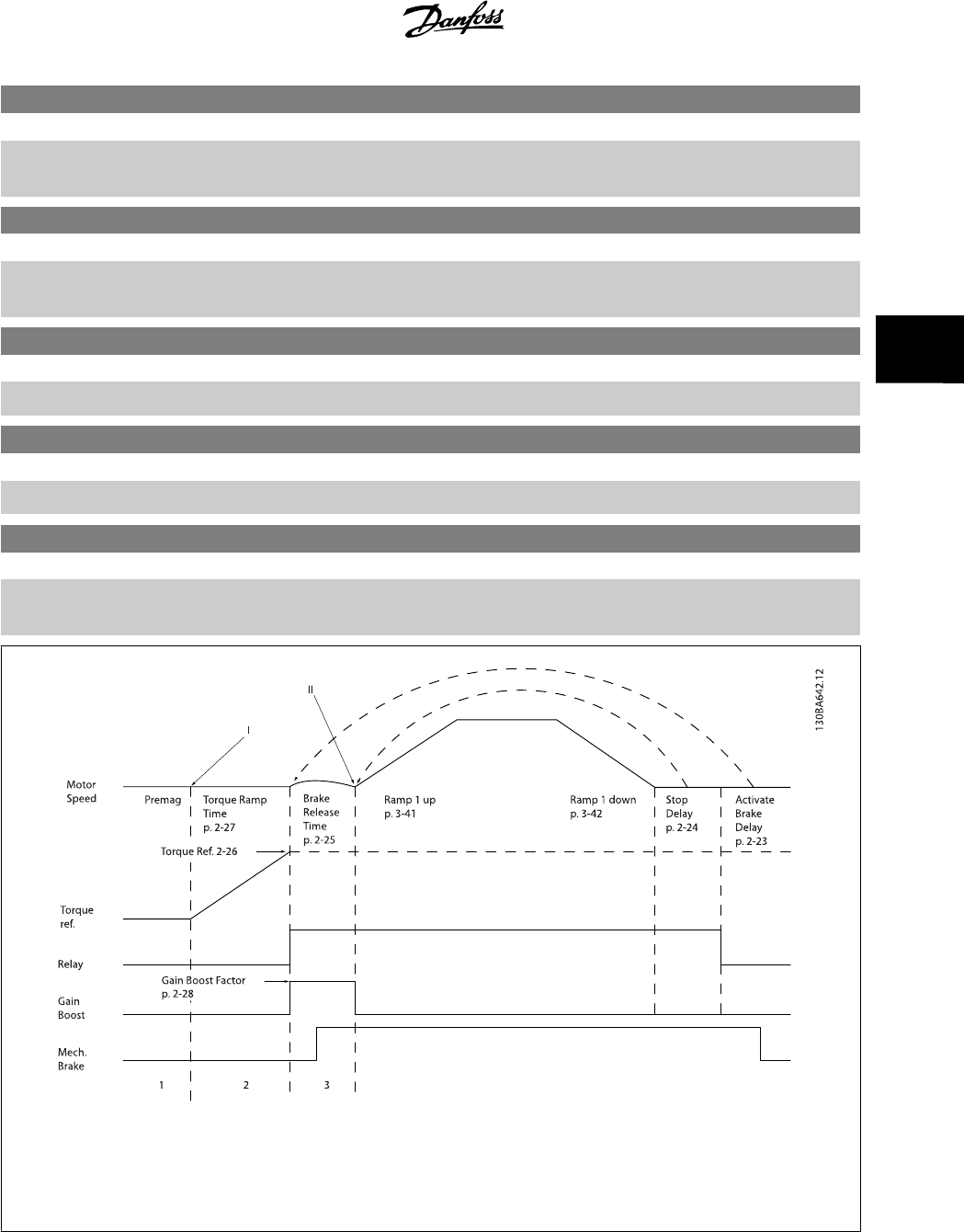
2-24 Stop Delay
Range: Function:
0.0 s* [0.0 - 5.0 s] Set the time interval from the moment when the motor is stopped until the brake closes. This pa-
rameter is a part of the stopping function.
2-25 Brake Release Time
Range: Function:
0.20 s* [0.00 - 5.00 s] This value defines the time it takes for the mechanical brake to open. This parameter must act as
a time-out when brake feedback is activated.
2-26 Torque Ref
Range: Function:
0.00 %* [Application dependant] The value defines the torque applied against the closed mechanical brake, before release
2-27 Torque Ramp Time
Range: Function:
0.2 s* [0.0 - 5.0 s] The value defines the duration of the torque ramp in clockwise direction.
2-28 Gain Boost Factor
Range: Function:
1.00* [1.00 - 4.00 ] Only active in flux closed loop. The function ensures a smooth transition from torque control mode
to speed control mode when the motor takes over the load from the brake.
Illustration 4.1: Brake release sequence for hoist mechanical brake control
I)
Activate brake delay
: The frequency converter starts again from the
mechanical brake engaged
position.
II)
Stop delay
: When the time between successive starts is shorter than the setting in par. 2-24
Stop Delay
, the frequency converter starts
without applying the mechanical brake (e.g. reversing).
VLT
®
AutomationDrive FC 300 Operating
Instructions 4 How to Programme
MG.33.AG.02 - VLT® is a registered Danfoss trademark
55
4
3-10 Preset Reference
Array [8]
Range: 0-7
Range: Function:
0.00 %* [-100.00 - 100.00 %] Enter up to eight different preset references (0-7) in this parameter, using array programming. The
preset reference is stated as a percentage of the value RefMAX (par. 3-03
Maximum Reference
) If a
RefMIN different from 0 (par. 3-02
Minimum Reference
) is programmed, the preset reference is
calculated as a percentage of the full reference range, i.e. on the basis of the difference between
RefMAX and RefMIN. Afterwards, the value is added to RefMIN. When using preset references, select
Preset ref. bit 0 / 1 / 2 [16], [17] or [18] for the corresponding digital inputs in parameter group
5-1*.
Preset ref. bit 2 1 0
Preset ref. 0 0 0 0
Preset ref. 1 0 0 1
Preset ref. 2 0 1 0
Preset ref. 3 0 1 1
Preset ref. 4 1 0 0
Preset ref. 5 1 0 1
Preset ref. 6 1 1 0
Preset ref. 7 1 1 1
3-11 Jog Speed [Hz]
Range: Function:
Application
dependent*
[Application dependant] The jog speed is a fixed output speed at which the frequency converter is running when the jog
function is activated.
See also par. 3-80
Jog Ramp Time
.
3-15 Reference Resource 1
Option: Function:
Select the reference input to be used for the first reference signal. par. 3-15
Reference Resource
1
, par. 3-16
Reference Resource 2
and par. 3-17
Reference Resource 3
define up to three different
reference signals. The sum of these reference signals defines the actual reference.
[0] No function
[1] * Analog input 53
[2] Analog input 54
[7] Frequency input 29
[8] Frequency input 33
[11] Local bus reference
[20] Digital pot.meter
4 How to Programme
VLT
®
AutomationDrive FC 300 Operating
Instructions
56
MG.33.AG.02 - VLT® is a registered Danfoss trademark
4

[21] Analog input X30-11 (General Purpose I/O Option Module)
[22] Analog input X30-12 (General Purpose I/O Option Module)
[29] Analog Input X48/2
3-16 Reference Resource 2
Option: Function:
Select the reference input to be used for the second reference signal. par. 3-15
Reference Resource
1
, par. 3-16
Reference Resource 2
and par. 3-17
Reference Resource 3
define up to three different
reference signals. The sum of these reference signals defines the actual reference.
[0] No function
[1] Analog input 53
[2] Analog input 54
[7] Frequency input 29
[8] Frequency input 33
[11] Local bus reference
[20] * Digital pot.meter
[21] Analog input X30-11
[22] Analog input X30-12
[29] Analog Input X48/2
3-17 Reference Resource 3
Option: Function:
Select the reference input to be used for the third reference signal. par. 3-15
Reference Resource
1
, par. 3-16
Reference Resource 2
and par. 3-17
Reference Resource 3
define up to three different
reference signals. The sum of these reference signals defines the actual reference.
[0] No function
[1] Analog input 53
[2] Analog input 54
[7] Frequency input 29
[8] Frequency input 33
[11] * Local bus reference
[20] Digital pot.meter
[21] Analog input X30-11
[22] Analog input X30-12
[29] Analog Input X48/2
VLT
®
AutomationDrive FC 300 Operating
Instructions 4 How to Programme
MG.33.AG.02 - VLT® is a registered Danfoss trademark
57
4

5-00 Digital I/O Mode
Option: Function:
Digital inputs and programmed digital outputs are pre-programmable for operation either in PNP or
NPN systems.
[0] * PNP Action on positive directional pulses (↕). PNP systems are pulled down to GND.
[1] NPN Action on negative directional pulses (↕). NPN systems are pulled up to + 24 V, internally in the
frequency converter.
NB!
Once this parameter has been changed, it must be activated by performing a power cycle.
This parameter cannot be adjusted while the motor is running.
5-01 Terminal 27 Mode
Option: Function:
[0] * Input Defines terminal 27 as a digital input.
[1] Output Defines terminal 27 as a digital output.
Please note that this parameter cannot be adjusted while the motor is running.
5-02 Terminal 29 Mode
Option: Function:
[0] * Input Defines terminal 29 as a digital input.
[1] Output Defines terminal 29 as a digital output.
This parameter is available for FC 302 only.
This parameter cannot be adjusted while the motor is running.
4 How to Programme
VLT
®
AutomationDrive FC 300 Operating
Instructions
58
MG.33.AG.02 - VLT® is a registered Danfoss trademark
4

4.3.2 5-1* Digital Inputs
Parameters for configuring the input functions for the input terminals.
The digital inputs are used for selecting various functions in the frequency converter. All digital inputs can be set to the following functions:
Digital input function Select Terminal
No operation [0] All *term 32, 33
Reset [1] All
Coast inverse [2] All *term 27
Coast and reset inverse [3] All
Quick stop inverse [4] All
DC-brake inverse [5] All
Stop inverse [6] All
Start [8] All *term 18
Latched start [9] All
Reversing [10] All *term 19
Start reversing [11] All
Enable start forward [12] All
Enable start reverse [13] All
Jog [14] All *term 29
Preset reference on [15] All
Preset ref bit 0 [16] All
Preset ref bit 1 [17] All
Preset ref bit 2 [18] All
Freeze reference [19] All
Freeze output [20] All
Speed up [21] All
Speed down [22] All
Set-up select bit 0 [23] All
Set-up select bit 1 [24] All
Precise stop inverse [26] 18, 19
Precises start, stop [27] 18, 19
Catch up [28] All
Slow down [29] All
Counter input [30] 29, 33
Pulse input Edge Trigged [31] 29, 33
Pulse input Time Based [32] 29, 33
Ramp bit 0 [34] All
Ramp bit 1 [35] All
Mains failure inverse [36] All
Latched precise start [40] 18, 19
Latched precise stop inverse [41] 18, 19
DigiPot Increase [55] All
DigiPot Decrease [56] All
DigiPot Clear [57] All
Digipot Hoist [58] All
Counter A (up) [60] 29, 33
Counter A (down) [61] 29, 33
Reset Counter A [62] All
Counter B (up) [63] 29, 33
Counter B (down) [64] 29, 33
Reset Counter B [65] All
Mech. Brake Feedb. [70] All
Mech. Brake Feedb. Inv. [71] All
PID Error Inv. [72] All
PID Reset I-part [73] All
PID enable [74] All
PTC Card 1 [80] All
FC 300 standard terminals are 18, 19, 27, 29, 32 and 33. MCB 101 terminals are X30/2, X30/3 and X30/4.
Terminal 29 functions as an output only in FC 302.
Functions dedicated to only one digital input are stated in the associated parameter.
All digital inputs can be programmed to these functions:
[0] No operation No reaction to signals transmitted to the terminal.
[1] Reset Resets frequency converter after a TRIP/ALARM. Not all alarms can be reset.
[2] Coast inverse (Default Digital input 27): Coasting stop, inverted input (NC). The frequency converter leaves the
motor in free mode. Logic ‘0’ => coasting stop.
[3] Coast and reset inverse Reset and coasting stop Inverted input (NC). Leaves motor in free mode and resets frequency con-
verter. Logic ‘0’ => coasting stop and reset.
VLT
®
AutomationDrive FC 300 Operating
Instructions 4 How to Programme
MG.33.AG.02 - VLT® is a registered Danfoss trademark
59
4
[4] Quick stop inverse Inverted input (NC). Generates a stop in accordance with quick-stop ramp time set in par. 3-81
Quick
Stop Ramp Time
. When motor stops, the shaft is in free mode. Logic ‘0’ => Quick-stop.
[5] DC-brake inverse Inverted input for DC braking (NC). Stops motor by energizing it with a DC current for a certain time
period. See par. 2-01
DC Brake Current
to par. 2-03
DC Brake Cut In Speed [RPM]
. The function is
only active when the value in par. 2-02
DC Braking Time
is different from 0. Logic ’0’ => DC braking.
[6] Stop inverse Stop Inverted function. Generates a stop function when the selected terminal goes from logical level
‘1’ to ‘0’. The stop is performed according to the selected ramp time (par. 3-42
Ramp 1 Ramp Down
Time
, par. 3-52
Ramp 2 Ramp down Time
, par. 3-62
Ramp 3 Ramp down Time
, par. 3-72
Ramp 4
Ramp Down Time
).
NB!
When the frequency converter is at the torque limit and has received a stop
command, it may not stop by itself. To ensure that the frequency converter stops,
configure a digital output to
Torque limit & stop
[27] and connect this digital
output to a digital input that is configured as coast.
[8] Start (Default Digital input 18): Select start for a start/stop command. Logic ‘1’ = start, logic ‘0’ = stop.
[9] Latched start The motor starts, if a pulse is applied for min. 2 ms. The motor stops when Stop inverse is activated.
[10] Reversing (Default Digital input 19). Change the direction of motor shaft rotation. Select Logic ‘1’ to reverse.
The reversing signal only changes the direction of rotation. It does not activate the start function.
Select both directions in par. 4-10
Motor Speed Direction
. The function is not active in process closed
loop.
[11] Start reversing Used for start/stop and for reversing on the same wire. Signals on start are not allowed at the same
time.
[12] Enable start forward Disengages the counterclockwise movement and allows for the clockwise direction.
[13] Enable start reverse Disengages the clockwise movement and allows for the counterclockwise direction.
[14] Jog (Default Digital input 29): Use to activate jog speed. See par. 3-11
Jog Speed [Hz]
.
[15] Preset reference on Shifts between external reference and preset reference. It is assumed that
External/preset
[1] has
been selected in par. 3-04
Reference Function
. Logic '0' = external reference active; logic '1' = one
of the eight preset references is active.
[16] Preset ref bit 0 Preset ref. bit 0,1, and 2 enables a choice between one of the eight preset references according to
the table below.
[17] Preset ref bit 1 Same as Preset ref bit 0 [16].
[18] Preset ref bit 2 Same as Preset ref bit 0 [16].
Preset ref. bit 2 1 0
Preset ref. 0 0 0 0
Preset ref. 1 0 0 1
Preset ref. 2 0 1 0
Preset ref. 3 0 1 1
Preset ref. 4 1 0 0
Preset ref. 5 1 0 1
Preset ref. 6 1 1 0
Preset ref. 7 1 1 1
[19] Freeze ref Freezes the actual reference, which is now the point of enable/condition for Speed up and Speed
down to be used. If Speed up/down is used, the speed change always follows ramp 2
(par. 3-51
Ramp 2 Ramp up Time
and par. 3-52
Ramp 2 Ramp down Time
) in the range 0 -
par. 3-03
Maximum Reference
.
[20] Freeze output Freezes the actual motor frequency (Hz), which is now the point of enable/condition for Speed up
and Speed down to be used. If Speed up/down is used, the speed change always follows ramp 2
(par. 3-51
Ramp 2 Ramp up Time
and par. 3-52
Ramp 2 Ramp down Time
) in the range 0 -
par. 1-23
Motor Frequency
.
4 How to Programme
VLT
®
AutomationDrive FC 300 Operating
Instructions
60
MG.33.AG.02 - VLT® is a registered Danfoss trademark
4
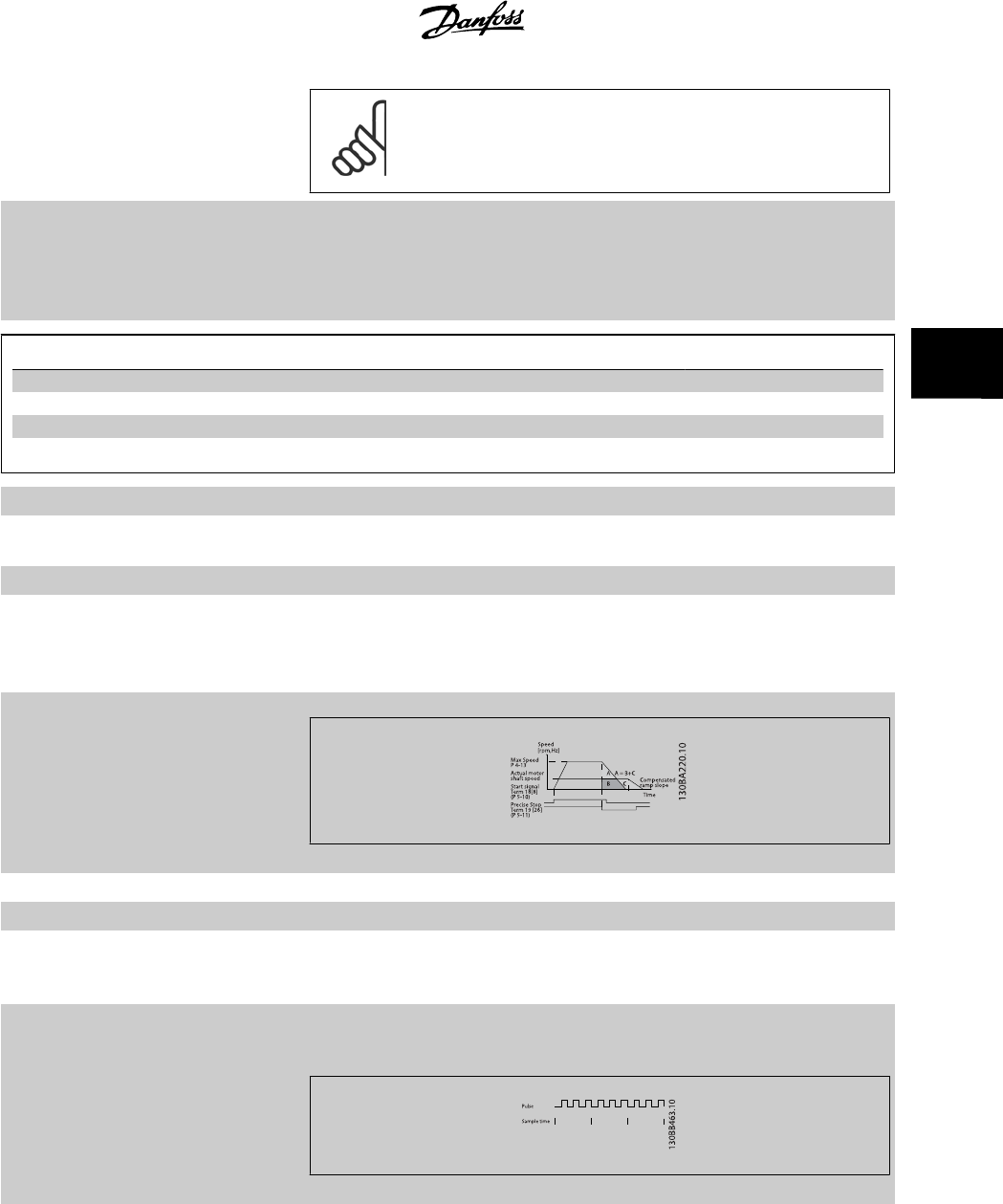
NB!
When Freeze output is active, the frequency converter cannot be stopped via a
low ‘start [8]’ signal. Stop the frequency converter via a terminal programmed
for Coasting inverse [2] or Coast and reset, inverse.
[21] Speed up Select Speed up and Speed down if digital control of the up/down speed is desired (motor poten-
tiometer). Activate this function by selecting either Freeze reference or Freeze output. When Speed
up/ down is activated for less than 400 msec. the resulting reference will be increased/ decreased
by 0.1 %. If Speed up/ down is activated for more than 400 msec. the resulting reference will follow
the setting in ramping up/ down parameter 3-x1/ 3-x2.
Shut down Catch up
Unchanged speed 0 0
Reduced by %-value 10
Increased by %-value 0 1
Reduced by %-value 11
[22] Speed down Same as Speed up [21].
[23] Set-up select bit 0 Select Set-up select bit 0 or Select Set-up select bit 1 to select one of the four set-ups. Set
par. 0-10
Active Set-up
to Multi Set-up.
[24] Set-up select bit 1 (Default Digital input 32): Same as Set-up select bit 0 [23].
[26] Precise stop inv. Prolongs stop signal to give a precise stop independent of speed.
Sends an inverted stop signal when the precise stop function is activated in par. 1-83
Precise Stop
Function
.
Precise stop inverse function is available for terminals 18 or 19.
[27] Precise start, stop Use when Precise ramp stop [0] is selected in par 1-83.
[28] Catch up Increases reference value by percentage (relative) set in par. 3-12
Catch up/slow Down Value
.
[29] Slow down Reduces reference value by percentage (relative) set in par. 3-12
Catch up/slow Down Value
.
[30] Counter input Precise stop function in par. 1-83
Precise Stop Function
acts as Counter stop or speed compensated
counter stop with or without reset. The counter value must be set in par. 1-84
Precise Stop Counter
Value
.
[31] Pulse edge triggered Edge triggered pulse input counts number of pulse flanks per sample time. This gives a higher
resolution at high frequencies, but is not as precise at lower frequencies. Use this pulse principle
for encoders with very low resolution (e.g. 30 ppr).
[32] Pulse time based Time based pulse input measures the duration between flanks. This gives a higher resolution at
lower frequencies, but is not as precise at higher frequencies. This principle has a cut-off frequency
which makes it unsuited for encoders with very low resolutions (e.g. 30 ppr) at low speeds.
VLT
®
AutomationDrive FC 300 Operating
Instructions 4 How to Programme
MG.33.AG.02 - VLT® is a registered Danfoss trademark
61
4
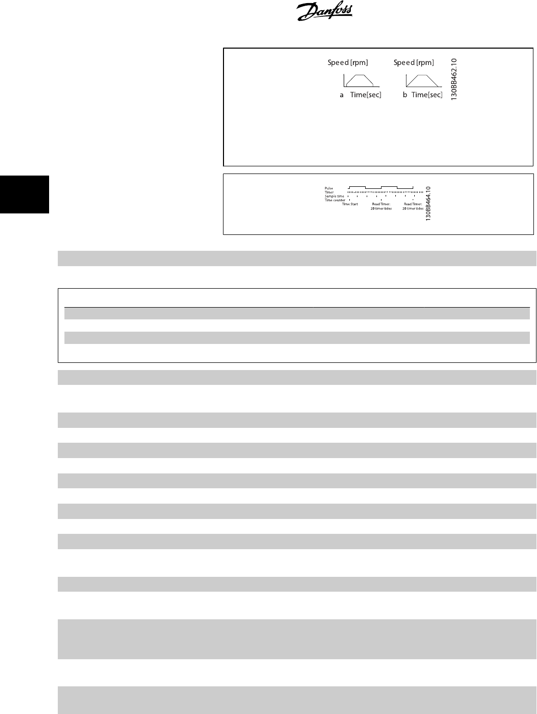
a: very low encoder resolution b: standard encoder resolution
[34] Ramp bit 0 Enables a choice between one of the 4 ramps available, according to the table below.
[35] Ramp bit 1 Same as Ramp bit 0.
Preset ramp bit 10
Ramp 1 0 0
Ramp 2 01
Ramp 3 1 0
Ramp 4 11
[36] Mains failure inverse Activates par. 14-10
Mains Failure
. Mains failure inverse is active in the Logic .0. situation.
[41] Latched Precise Stop inverse Sends a latched stop signal when the precise stop function is activated in par. 1-83
Precise Stop
Function
. The Latched Precise stop inverse function is available for terminals 18 or 19.
[55] DigiPot Increase INCREASE signal to the Digital Potentiometer function described in par. group 3-9*
[56] DigiPot Decrease DECREASE signal to the Digital Potentiometer function described in par. group 3-9*
[57] DigiPot Clear Clears the Digital Potentiometer reference described in par. group 3-9*
[60] Counter A (Terminal 29 or 33 only) Input for increment counting in the SLC counter.
[61] Counter A (Terminal 29 or 33 only) Input for decrement counting in the SLC counter.
[62] Reset Counter A Input for reset of counter A.
[63] Counter B (Terminal 29 or 33 only) Input for increment counting in the SLC counter.
[64] Counter B (Terminal 29 or 33 only) Input for decrement counting in the SLC counter.
[65] Reset Counter B Input for reset of counter B.
[70] Mech. Brake Feedback Brake feedback for hoisting applications: Set par 1-01 to [3]
flux w/ motor feedback
; set par 1-72
to [6]
Hoist mech brake Ref.
[71] Mech. Brake Feedback inv. Inverted brake feedback for hoisting applications
[72] PID error inverse When enabled, it inverts the resulting error from the process PID controller. Available only if "Con-
figuration Mode" is set to "Surface Winder", "Extended PID Speed OL" or "Extended PID Speed CL".
[73] PID reset I-part When enabled, resets the I-part of the Process PID controller. Equivalent to par. 7-40. Available
only if "Configuration Mode" is set to "Surface Winder", "Extended PID Speed OL" or "Extended PID
Speed CL".
[74] PID enable When enabled, enables the extended process PID controller. Equivalent to par. 7-50. Available only
if "Configuration Mode" is set "Extended PID Speed OL" or "Extended PID Speed CL".
[80] PTC Card 1 All Digital Inputs can be set to PTC Card 1 [80]. However, only one Digital Input must be set to this
choice.
4 How to Programme
VLT
®
AutomationDrive FC 300 Operating
Instructions
62
MG.33.AG.02 - VLT® is a registered Danfoss trademark
4

4.3.3 5-3* Digital Outputs
Parameters for configuring the output functions for the output terminals. The 2 solid-state digital outputs are common for terminals 27 and 29. Set the
I/O function for terminal 27 in par. 5-01
Terminal 27 Mode
, and set the I/O function for terminal 29 in par. 5-02
Terminal 29 Mode
. These parameters
cannot be adjusted while the motor is running.
[0] No operation
Default for all digital outputs and relay outputs
[1] Control ready The control card is ready. E.g.: Feedback from a drive where the control is supplied by an external
24 V (MCB107) and the main power to drive is not detected.
[2] Drive ready The frequency converter is ready for operation and applies a supply signal on the control board.
[3] Drive ready / remote control The frequency converter is ready for operation and is in Auto On mode.
[4] Enable / no warning Ready for operation. No start or stop command is been given (start/disable). No warnings are active.
[5] VLT running Motor is running and shaft torque present.
[6] Running / no warning Output speed is higher than the speed set in par. 1-81
Min Speed for Function at Stop [RPM]
. The
motor is running and there are no warnings.
[7] Run in range / no warning Motor is running within the programmed current and speed ranges set in par. 4-50
Warning Current
Low
to par. 4-53
Warning Speed High
. There are no warnings.
[8] Run on reference / no warning Motor runs at reference speed. No warnings.
[9] Alarm An alarm activates the output. There are no warnings.
[10] Alarm or warning An alarm or a warning activates the output.
[11] At torque limit The torque limit set in par. 4-16
Torque Limit Motor Mode
or par. 4-17 has been exceeded.
[12] Out of current range The motor current is outside the range set in par. 4-18
Current Limit
.
[13] Below current, low Motor current is lower than set in par. 4-50
Warning Current Low
.
[14] Above current, high Motor current is higher than set in par. 4-51
Warning Current High
.
[15] Out of range Output frequency is outside the frequency range set in par. 4-52
Warning Speed Low
and
par. 4-53
Warning Speed High
.
[16] Below speed, low Output speed is lower than the setting in par. 4-52
Warning Speed Low
.
[17] Above speed, high Output speed is higher than the setting in par. 4-53
Warning Speed High
.
[18] Out of feedback range Feedback is outside the range set in par. 4-56
Warning Feedback Low
and par. 4-57
Warning Feed-
back High
.
[19] Below feedback low Feedback is below the limit set in par. 4-56
Warning Feedback Low
.
[20] Above feedback high Feedback is above the limit set in par. 4-57
Warning Feedback High
.
[21] Thermal warning The thermal warning turns on when the temperature exceeds the limit in the motor, the frequency
converter, the brake resistor, or the thermistor.
[22] Ready, no thermal warning Frequency converter is ready for operation and there is no over-temperature warning.
[23] Remote, ready, no thermal warning Frequency converter is ready for operation and is in Auto On mode. There is no over-temperature
warning.
[24] Ready, no over-/ under voltage Frequency converter is ready for operation and the mains voltage is within the specified voltage
range (see
General Specifications
section in the Designn Guide).
[25] Reverse
Reversing. Logic ‘1’
when CW rotation of the motor. Logic ‘0’ when CCW rotation of the motor. If
the motor is not rotating the output will follow the reference.
[26] Bus OK Active communication (no time-out) via the serial communication port.
[27] Torque limit and stop Use in performing a coasting stop and in torque limit condition. If the frequency converter has
received a stop signal and is at the torque limit, the signal is Logic ‘0’.
[28] Brake, no brake warning Brake is active and there are no warnings.
[29] Brake ready, no fault Brake is ready for operation and there are no faults.
[30] Brake fault (IGBT) Output is Logic ‘1’ when the brake IGBT is short-circuited. Use this function to protect the frequency
converter if there is a fault on the brake modules. Use the output/relay to cut out the main voltage
from the frequency converter.
[31] Relay 123 Relay is activated when Control Word [0] is selected in parameter group 8-**.
VLT
®
AutomationDrive FC 300 Operating
Instructions 4 How to Programme
MG.33.AG.02 - VLT® is a registered Danfoss trademark
63
4

[32] Mechanical brake control Enables control of an external mechanical brake, see description in the section
Control of Mechanical
Brake
, and par. group 2-2*
[33] Safe stop activated (FC 302 only) Indicates that the safe stop on terminal 37 has been activated.
[40] Out of ref range Active when the actual speed is outside settings in par 4-52 to 4-55.
[41] Below reference low Active when actual speed is below speed reference setting.
[42] Above reference high Active when actual speed is above speed reference setting
[43] Extended PID Limit
[45] Bus Ctrl Controls output via bus. The state of the output is set in par. 5-90
Digital & Relay Bus Control
. The
output state is retained in the event of bus time-out.
[46] Bus Ctrl On at timeout Controls output via bus. The state of the output is set in par. 5-90
Digital & Relay Bus Control
. In
the event of bus time-out the output state is set high (On).
[47] Bus Ctrl Off at timeout Controls output via bus. The state of the output is set in par. 5-90
Digital & Relay Bus Control
. In
the event of bus time-out the output state is set low (Off).
[51] MCO controlled Active when a MCO 302 or MCO 305 is connected. The output is controlled from option.
[55] Pulse output
[60] Comparator 0 See par. group 13-1*. If Comparator 0 is evaluated as TRUE, the output will go high. Otherwise, it
will be low.
[61] Comparator 1 See par. group 13-1*. If Comparator 1 is evaluated as TRUE, the output will go high. Otherwise, it
will be low.
[62] Comparator 2 See par. group 13-1*. If Comparator 2 is evaluated as TRUE, the output will go high. Otherwise, it
will be low.
[63] Comparator 3 See par. group 13-1*. If Comparator 3 is evaluated as TRUE, the output will go high. Otherwise, it
will be low.
[64] Comparator 4 See par. group 13-1*. If Comparator 4 is evaluated as TRUE, the output will go high. Otherwise, it
will be low.
[65] Comparator 5 See par. group 13-1*. If Comparator 5 is evaluated as TRUE, the output will go high. Otherwise, it
will be low.
[70] Logic Rule 0 See par. group 13-4*. If Logic Rule 0 is evaluated as TRUE, the output will go high. Otherwise, it
will be low.
[71] Logic Rule 1 See par. group 13-4*. If Logic Rule 1 is evaluated as TRUE, the output will go high. Otherwise, it
will be low.
[72] Logic Rule 2 See par. group 13-4*. If Logic Rule 2 is evaluated as TRUE, the output will go high. Otherwise, it
will be low.
[73] Logic Rule 3 See par. group 13-4*. If Logic Rule 3 is evaluated as TRUE, the output will go high. Otherwise, it
will be low.
[74] Logic Rule 4 See par. group 13-4*. If Logic Rule 4 is evaluated as TRUE, the output will go high. Otherwise, it
will be low.
[75] Logic Rule 5 See par. group 13-4*. If Logic Rule 5 is evaluated as TRUE, the output will go high. Otherwise, it
will be low.
[80] SL Digital Output A See par. 13-52
SL Controller Action
. The output will go high whenever the Smart Logic Action [38]
Set dig. out. A high
is executed. The output will go low whenever the Smart Logic Action [32] Set
dig. out. A low is executed.
[81] SL Digital Output B See par. 13-52
SL Controller Action
. The input will go high whenever the Smart Logic Action [39]
Set dig. out. A high
is executed. The input will go low whenever the Smart Logic Action [33]
Set
dig. out. A low
is executed.
[82] SL Digital Output C See par. 13-52
SL Controller Action
. The input will go high whenever the Smart Logic Action [40]
Set dig. out. A high
is executed. The input will go low whenever the Smart Logic Action [34]
Set
dig. out. A low
is executed.
[83] SL Digital Output D See par. 13-52
SL Controller Action
. The input will go high whenever the Smart Logic Action [41]
Set dig. out. A
high is executed. The input will go low whenever the Smart Logic Action [35]
Set
dig. out. A low
is executed.
4 How to Programme
VLT
®
AutomationDrive FC 300 Operating
Instructions
64
MG.33.AG.02 - VLT® is a registered Danfoss trademark
4
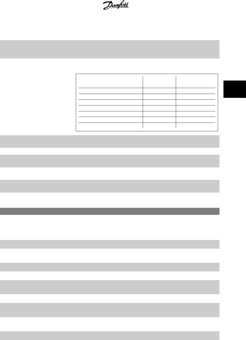
[84] SL Digital Output E See par. 13-52
SL Controller Action
. The input will go high whenever the Smart Logic Action [42]
Set dig. out. A high
is executed. The input will go low whenever the Smart Logic Action [36]
Set
dig. out. A low
is executed.
[85] SL Digital Output F See par. 13-52
SL Controller Action
. The input will go high whenever the Smart Logic Action [43]
Set dig. out. A high
is executed. The input will go low whenever the Smart Logic Action [37]
Set
dig. out. A low
is executed.
[120] Local reference active Output is high when par. 3-13
Reference Site
= [2] Local or when par. 3-13
Reference Site
= [0]
Linked to hand auto
at the same time as the LCP is in Hand on mode.
Reference site set in par. 3-13 Local reference
active [120]
Remote reference
active [121]
Reference site: Local par. 3-13 [2] 1 0
Reference site: Remote par. 3-13 [1] 0 1
Reference site: Linked to Hand/ Auto
Hand 1 0
Hand -> off 1 0
Auto -> off 0 0
Auto 0 1
[121] Remote reference active Output is high when par. 3-13
Reference Site
= Remote
[1] or
Linked to hand/auto
[0] while the
LCP is in [Auto on] mode. See above.
[122] No alarm Output is high when no alarm is present.
[123] Start command active Output is high when there is an active Start command (i.e. via digital input bus connection or [Hand
on] or [Auto on]), and no Stop or Start command is active.
[124] Running reverse Output is high when the frequency converter is running counter clockwise (the logical product of
the status bits ‘running’ AND ‘reverse’).
[125] Drive in hand mode Output is high when the frequency converter is in Hand on mode (as indicated by the LED light
above [Hand on]).
[126] Drive in auto mode Output is high when the frequency converter is in Hand on mode (as indicated by the LED light
above [Auto on]).
5-40 Function Relay
Array [9]
(Relay 1 [0], Relay 2 [1], Relay 3 [2] (MCB 113), Relay 4 [3] (MCB 113), Relay 5 [4] (MCB 113), Relay 6 [5] (MCB 113), Relay 7 [6] (MCB 105), Relay
8 [7] (MCB 105), Relay 9 [8] (MCB 105))
Option: Function:
[0] * No operation All digital and relay outputs are default set to “No Operation”.
[1] Control ready The control card is ready. E.g.: Feedback from a drive where the control is supplied by an external
24 V (MCB107) and the main power to drive is not detected.
[2] Drive ready Drive is ready to operate. Mains and control supplies are OK.
[3] Drive rdy/rem ctrl The frequency converter is ready for operation and is in Auto On mode
[4] Enable / no warning Ready for operation. No start or stop commands have been applied (start/disable). No warnings are
active.
[5] Running Motor is running, and shaft torque present.
[6] Running / no warning Output speed is higher than the speed set in par. 1-81 Min Speed for Function at Stop [RPM]. The
motor is running and no warnings.
[7] Run in range/no warn Motor is running within the programmed current and speed ranges set in par. 4-50
Warning Current
Low
and par. 4-53
Warning Speed High
. No warnings.
[8] Run on ref/no warn Motor runs at reference speed. No warnings.
[9] Alarm An alarm activates the output. No warnings
VLT
®
AutomationDrive FC 300 Operating
Instructions 4 How to Programme
MG.33.AG.02 - VLT® is a registered Danfoss trademark
65
4

[10] Alarm or warning An alarm or a warning activates the output.
[11] At torque limit The torque limit set in par. 4-16
Torque Limit Motor Mode
or par. 4-17
Torque Limit Generator
Mode
has been exceeded.
[12] Out of current range The motor current is outside the range set in par. 4-18
Current Limit
.
[13] Below current, low Motor current is lower than set in par. 4-50
Warning Current Low
.
[14] Above current, high Motor current is higher than set in par. 4-51
Warning Current High
.
[15] Out of speed range Output speed/frequency is outside the frequency range set in par. 4-52
Warning Speed Low
and
par. 4-53
Warning Speed High
.
[16] Below speed, low Output speed is lower than the setting in par. 4-52
Warning Speed Low
[17] Above speed, high Output speed is higher than the setting in par. 4-53
Warning Speed High
.
[18] Out of feedb. range Feedback is outside the range set in par. 4-56
Warning Feedback Low
and par. 4-57
Warning Feed-
back High
.
[19] Below feedback, low Feedback is below the limit set in par. 4-56
Warning Feedback Low
.
[20] Above feedback, high Feedback is above the limit set in par. 4-57
Warning Feedback High
.
[21] Thermal warning Thermal warning turns on when the temperature exceeds the limit either in motor, frequency con-
verter, brake resistor, or connected thermistor.
[22] Ready,no thermal W Frequency converter is ready for operation and there is no over-temperature warning.
[23] Remote,ready,no TW Frequency converter is ready for operation and is in Auto On mode. There is no over-temperature
warning.
[24] Ready, Voltage OK Frequency converter is ready for operation and the mains voltage is within the specified voltage
range (see General Specifications section in Design Guide).
[25] Reverse Logic ‘1’ when CW rotation of the motor. Logic ‘0’ when CCW rotation of the motor. If the motor is
not rotating the output will follow the reference.
[26] Bus OK Active communication (no time-out) via the serial communication port.
[27] Torque limit & stop Use in performing a coasted stop and frequency converter in torque limit condition. If the frequency
converter has received a stop signal and is in torque limit, the signal is Logic ‘0’.
[28] Brake, no brake war Brake is active and there are no warnings.
[29] Brake ready, no fault Brake is ready for operation and there are no faults.
[30] Brake fault (IGBT) Output is Logic ‘1’ when the brake IGBT is short-circuited. Use this function to protect the frequency
converter if there is a fault on the brake module. Use the digital output/relay to cut out the main
voltage from the frequency converter.
[31] Relay 123 Digital output/relay is activated when Control Word [0] is selected in parameter group 8-**.
[32] Mech brake ctrl Selection of mechanical brake control. When selected parameters in parameter group 2.2x are ac-
tive. The output must be reinforced to carry the current for the coil in the brake. Usually solved by
connecting an external relay to the selected digital output.
[33] Safe stop active (FC 302 only) Indicates that the safe stop on terminal 37 has been activated.
[36] Control word bit 11 Activate relay 1 by control word from fieldbus. No other functional impact in the frequency converter.
Typical application: controlling auxiliary device from fieldbus. The function is valid when FC profile
[0] in par 8-10 is selected.
[37] Control word bit 12 Activate relay 2 FC 302 only) by control word from fieldbus. No other functional impact in the fre-
quency converter. Typical application: controlling auxiliary device from fieldbus. The function is valid
when FC profile [0] in par 8-10 is selected.
[38] Motor feedback error Failure in the speed feedback loop from motor running in closed loop. The output can eventually be
used to prepare switching the drive in open loop in emergency case.
4 How to Programme
VLT
®
AutomationDrive FC 300 Operating
Instructions
66
MG.33.AG.02 - VLT® is a registered Danfoss trademark
4

[39] Tracking error When the difference between calculated speed and actual speed in par 4-35 is larger than selected
the digital output/relay is active.
[40] Out of ref range Active when the actual speed is outside settings in par 4-52 to 4-55.
[41] Below reference, low Active when actual speed is below speed reference setting.
[42] Above ref, high Active when actual speed is above speed reference setting.
[43] Extended PID Limit
[45] Bus ctrl. Controls digital output/relay via bus. The state of the output is set in par. 5-90 ‘Digital & Relay Bus
Control’. The output state is retained in the event of bus time-out.
[46] Bus ctrl, 1 if timeout Controls output via bus. The state of the output is set in par. 5-90
Digital & Relay Bus Control
. In
the event of bus time-out the output state is set high (On).
[47] Bus ctrl, 0 if timeout Controls output via bus. The state of the output is set in par. 5-90
Digital & Relay Bus Control
. In
the event of bus time-out the output state is set low (Off).
[51] MCO controlled Active when a MCO 302 or MCO 305 is connected. The output is controlled from option.
[60] Comparator 0 See par. group 13-1* (Smart Logic Control). If Comparator 0 in SLC is TRUE, the output will go high.
Otherwise, it will be low.
[61] Comparator 1 See par. group 13-1* (Smart Logic Control). If Comparator 1 in SLC is TRUE, the output will go high.
Otherwise, it will be low.
[62] Comparator 2 See par. group 13-1* (Smart Logic Control). If Comparator 2 in SLC is TRUE, the output will go high.
Otherwise, it will be low.
[63] Comparator 3 See par. group 13-1* (Smart Logic Control). If Comparator 3 in SLC is TRUE, the output will go high.
Otherwise, it will be low.
[64] Comparator 4 See par. group 13-1* (Smart Logic Control). If Comparator 4 in SLC is TRUE, the output will go high.
Otherwise, it will be low.
[65] Comparator 5 See par. group 13-1* (Smart Logic Control). If Comparator 5 in SLC is TRUE, the output will go high.
Otherwise, it will be low.
[70] Logic rule 0 See par. group 13-4*(Smart Logic Control). If Logic Rule 0 in SLC is TRUE, the output will go high.
Otherwise, it will be low.
[71] Logic rule 1 See par. group 13-4*(Smart Logic Control). If Logic Rule 1 in SLC is TRUE, the output will go high.
Otherwise, it will be low.
[72] Logic rule 2 See par. group 13-4*(Smart Logic Control). If Logic Rule 2 in SLC is TRUE, the output will go high.
Otherwise, it will be low.
[73] Logic rule 3 See par. group 13-4*(Smart Logic Control). If Logic Rule 3 in SLC is TRUE, the output will go high.
Otherwise, it will be low.
[74] Logic rule 4 See par. group 13-4*(Smart Logic Control). If Logic Rule 4 in SLC is TRUE, the output will go high.
Otherwise, it will be low.
[75] Logic rule 5 See par. group 13-4*(Smart Logic Control). If Logic Rule 5 in SLC is TRUE, the output will go high.
Otherwise, it will be low.
[80] SL digital output A See par. 13-52 ‘Smart Logic Control Action’. Output A is low on Smart Logic Action [32]. Output A
is high on Smart Logic Action [38].
[81] SL digital output B See par. 13-52 ‘Smart Logic Control Action’. Output B is low on Smart Logic Action [33]. Output B
is high on Smart Logic Action [39].
[82] SL digital output C See par. 13-52 ‘Smart Logic Control Action’. Output C is low on Smart Logic Action [34]. Output C
is high on Smart Logic Action [40].
[83] SL digital output D See par. 13-52 ‘Smart Logic Control Action’. Output D is low on Smart Logic Action [35]. Output D
is high on Smart Logic Action [41]
VLT
®
AutomationDrive FC 300 Operating
Instructions 4 How to Programme
MG.33.AG.02 - VLT® is a registered Danfoss trademark
67
4

[84] SL digital output E See par. 13-52 ‘Smart Logic Control Action’. Output E is low on Smart Logic Action [36]. Output E
is high on Smart Logic Action [42].
[85] SL digital output F See par. 13-52 ‘Smart Logic Control Action’. Output F is low on Smart Logic Action [37]. Output F
is high on Smart Logic Action [43].
[120] Local ref active Output is high when par. 3-13 Reference Site = [2] Local or when par. 3-13 Reference Site = [0]
Linked to hand auto at the same time as the LCP is in Hand on mode.
Reference site set in par. 3-13 Local reference
active [120]
Remote reference
active [121]
Reference site: Local par. 3-13 [2] 1 0
Reference site: Remote par. 3-13 [1] 0 1
Reference site: Linked to Hand/ Auto
Hand 1 0
Hand -> off 1 0
Auto -> off 0 0
Auto 0 1
[121] Remote ref active Output is high when par. 3-13
Reference Site
= Remote [1] or Linked to hand/auto [0] while the
LCP is in [Auto on] mode. See above.
[122] No alarm Output is high when no alarm is present.
[123] Start command activ Output is high when the Start command high (i.e. via digital input, bus connection or [Hand on] or
[Auto on]), and a Stop has been last command.
[124] Running reverse Output is high when the frequency converter is running counter clockwise (the logical product of
the status bits ‘running’ AND ‘reverse’).
[125] Drive in hand mode Output is high when the frequency converter is in Hand on mode (as indicated by the LED light
above [Hand on]).
[126] Drive in auto mode Output is high when the frequency converter is in ‘Auto’ mode (as indicated by LED on above [Auto
On]).
14-22 Operation Mode
Option: Function:
Use this parameter to specify normal operation; to perform tests; or to initialise all parameters
except par. 15-03
Power Up's
, par. 15-04
Over Temp's
and par. 15-05
Over Volt's
. This function is
active only when the power is cycled to the frequency converter.
Select
Normal operation
[0] for normal operation of the frequency converter with the motor in the
selected application.
Select
Control card test
[1] to test the analog and digital inputs and outputs and the +10 V control
voltage. The test requires a test connector with internal connections. Use the following procedure
for the control card test:
1. Select
Control card test
[1].
2. Disconnect the mains supply and wait for the light in the display to go out.
3. Set switches S201 (A53) and S202 (A54) = ‘ON’ / I.
4. Insert the test plug (see below).
5. Connect to mains supply.
6. Carry out various tests.
7. The results are displayed on the LCP and the frequency converter moves into an infinite
loop.
8. Par. 14-22
Operation Mode
is automatically set to Normal operation. Carry out a power
cycle to start up in Normal operation after a control card test.
If the test is OK:
4 How to Programme
VLT
®
AutomationDrive FC 300 Operating
Instructions
68
MG.33.AG.02 - VLT® is a registered Danfoss trademark
4
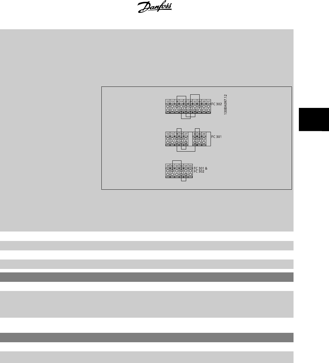
LCP read-out: Control Card OK.
Disconnect the mains supply and remove the test plug. The green LED on the Control Card will light
up.
If the test fails:
LCP read-out: Control Card I/O failure.
Replace the frequency converter or Control card. The red LED on the Control Card is turned on. Test
plugs (connect the following terminals to each other): 18 - 27 - 32; 19 - 29 - 33; 42 - 53 - 54
Select
Initialization
[2] to reset all parameter values to default settings, except for par. 15-03
Power
Up's
, par. 15-04
Over Temp's
, and par. 15-05
Over Volt's
. The frequency converter will reset during
the next power-up.
Par. 14-22
Operation Mode
will also revert to the default setting
Normal operation
[0].
[0] * Normal operation
[1] Control card test
[2] Initialisation
[3] Boot mode
14-50 RFI Filter
Option: Function:
[0] Off Select
Off
[0] only if the frequency converter is fed by an isolated mains source (IT mains).
In this mode, the internal RFI filter capacitors between chassis and the mains RFI filter circuit are
cut-out to reduce the ground capacity currents.
[1] * On Select
On
[1] to ensure that the frequency converter complies with EMC standards.
15-43 Software Version
Range: Function:
0 N/A* [0 - 0 N/A] View the combined SW version (or ‘package version’) consisting of power SW and control SW.
VLT
®
AutomationDrive FC 300 Operating
Instructions 4 How to Programme
MG.33.AG.02 - VLT® is a registered Danfoss trademark
69
4
4.4 Parameter Lists
Changes during operation
”TRUE” means that the parameter can be changed while the frequency converter is in operation and “FALSE” means that the it must be stopped before
a change can be made.
4-Set-up
'All set-up': the parameters can be set individually in each of the four set-ups, i.e. one single parameter can have four different data values.
’1 set-up’: data value will be the same in all set-ups.
Conversion index
This number refers to a conversion figure used when writing or reading to and from the frequency converter.
Conv. index 100 67 6 5 4 3 2 1 0 -1 -2 -3 -4 -5 -6
Conv. factor 1 1/60 1000000 100000 10000 1000 100 10 1 0.1 0.01 0.001 0.0001 0.00001 0.000001
Data type Description Type
2Integer 8 Int8
3Integer 16 Int16
4Integer 32 Int32
5Unsigned 8 Uint8
6 Unsigned 16 Uint16
7Unsigned 32 Uint32
9 Visible String VisStr
33 Normalized value 2 bytes N2
35 Bit sequence of 16 boolean variables V2
54 Time difference w/o date TimD
See the frequency converter
Design Guide
for further information about data types 33, 35 and 54.
4 How to Programme
VLT
®
AutomationDrive FC 300 Operating
Instructions
70
MG.33.AG.02 - VLT® is a registered Danfoss trademark
4

Parameters for the frequency converter are grouped into various parameter groups for easy selection of the correct parameters for optimized operation
of the frequency converter.
0-** Operation and Display parameters for basic frequency converter settings
1-** Load and Motor parameters, includes all load and motor related parameters
2-** Brake parameters
3-** References and ramping parameters, includes DigiPot function
4-** Limits Warnings, setting of limits and warning parameters
5-** Digital inputs and outputs, includes relay controls
6-** Analog inputs and outputs
7-** Controls, setting parameters for speed and process controls
8-** Communication and option parameters, setting of FC RS485 and FC USB port parameters.
9-** Profibus parameters
10-** DeviceNet and CAN Fieldbus parameters
13-** Smart Logic Control parameters
14-** Special function parameters
15-** Drive information parameters
16-** Read out parameters
17-** Encoder Option parameters
32-** MCO 305 Basic parameters
33-** MCO 305 Advanced parameters
34-** MCO Data Readout parameters
VLT
®
AutomationDrive FC 300 Operating
Instructions 4 How to Programme
MG.33.AG.02 - VLT® is a registered Danfoss trademark
71
4

4.4.1 0-** Operation/Display
Par.
No. #
Parameter description Default value 4-set-up FC 302
only
Change during
operation
Conver-
sion index
Type
0-0* Basic Settings
0-01 Language [0] English 1 set-up TRUE - Uint8
0-02 Motor Speed Unit [0] RPM 2 set-ups FALSE -Uint8
0-03 Regional Settings [0] International 2 set-ups FALSE - Uint8
0-04
Operating State at Power-up
(Hand) [1] Forced stop, ref=old All set-ups TRUE -Uint8
0-09 Performance Monitor 0.0 % All set-ups TRUE -1 Uint16
0-1* Set-up Operations
0-10 Active Set-up [1] Set-up 1 1 set-up TRUE - Uint8
0-11 Edit Set-up [1] Set-up 1 All set-ups TRUE -Uint8
0-12 This Set-up Linked to [0] Not linked All set-ups FALSE - Uint8
0-13 Readout: Linked Set-ups 0 N/A All set-ups FALSE 0Uint16
0-14 Readout: Edit Set-ups / Channel 0 N/A All set-ups TRUE 0 Int32
0-2* LCP Display
0-20 Display Line 1.1 Small 1617 All set-ups TRUE - Uint16
0-21 Display Line 1.2 Small 1614 All set-ups TRUE -Uint16
0-22 Display Line 1.3 Small 1610 All set-ups TRUE - Uint16
0-23 Display Line 2 Large 1613 All set-ups TRUE -Uint16
0-24 Display Line 3 Large 1602 All set-ups TRUE - Uint16
0-25 My Personal Menu SR 1 set-up TRUE 0Uint16
0-3* LCP Custom Readout
0-30 Unit for User-defined Readout [0] None All set-ups TRUE -Uint8
0-31 Min Value of User-defined Readout 0.00 CustomReadoutUnit All set-ups TRUE -2 Int32
0-32 Max Value of User-defined Readout
100.00 CustomReadoutU-
nit All set-ups TRUE -2 Int32
0-37 Display Text 1 0 N/A 1 set-up TRUE 0 VisStr[25]
0-38 Display Text 2 0 N/A 1 set-up TRUE 0VisStr[25]
0-39 Display Text 3 0 N/A 1 set-up TRUE 0 VisStr[25]
0-4* LCP Keypad
0-40 [Hand on] Key on LCP null All set-ups TRUE - Uint8
0-41 [Off] Key on LCP null All set-ups TRUE -Uint8
0-42 [Auto on] Key on LCP null All set-ups TRUE - Uint8
0-43 [Reset] Key on LCP null All set-ups TRUE -Uint8
0-44 [Off/Reset] Key on LCP null All set-ups TRUE - Uint8
0-45 [Drive Bypass] Key on LCP null All set-ups TRUE -Uint8
0-5* Copy/Save
0-50 LCP Copy [0] No copy All set-ups FALSE -Uint8
0-51 Set-up Copy [0] No copy All set-ups FALSE - Uint8
0-6* Password
0-60 Main Menu Password 100 N/A 1 set-up TRUE 0 Int16
0-61 Access to Main Menu w/o Password [0] Full access 1 set-up TRUE -Uint8
0-65 Quick Menu Password 200 N/A 1 set-up TRUE 0 Int16
0-66
Access to Quick Menu w/o Pass-
word [0] Full access 1 set-up TRUE -Uint8
0-67 Bus Password Access 0 N/A All set-ups TRUE 0 Uint16
4 How to Programme
VLT
®
AutomationDrive FC 300 Operating
Instructions
72
MG.33.AG.02 - VLT® is a registered Danfoss trademark
4

4.4.2 1-** Load/Motor
Par.
No. #
Parameter description Default value 4-set-up FC 302
only
Change dur-
ing opera-
tion
Conver-
sion index
Type
1-0* General Settings
1-00 Configuration Mode null All set-ups TRUE - Uint8
1-01 Motor Control Principle null All set-ups FALSE -Uint8
1-02 Flux Motor Feedback Source [1] 24V encoder All set-ups x FALSE - Uint8
1-03 Torque Characteristics [0] Constant torque All set-ups TRUE -Uint8
1-04 Overload Mode [0] High torque All set-ups FALSE - Uint8
1-05 Local Mode Configuration [2] As mode par 1-00 All set-ups TRUE -Uint8
1-06 Clockwise Direction [0] Normal All set-ups FALSE - Uint8
1-1* Motor Selection
1-10 Motor Construction [0] Asynchron All set-ups FALSE - Uint8
1-2* Motor Data
1-20 Motor Power [kW] SR All set-ups FALSE -2 Uint32
1-21 Motor Power [HP] SR All set-ups FALSE -2 Uint32
1-22 Motor Voltage SR All set-ups FALSE 0 Uint16
1-23 Motor Frequency SR All set-ups FALSE 0Uint16
1-24 Motor Current SR All set-ups FALSE -2 Uint32
1-25 Motor Nominal Speed SR All set-ups FALSE 67 Uint16
1-26 Motor Cont. Rated Torque SR All set-ups FALSE -1 Uint32
1-29 Automatic Motor Adaptation (AMA) [0] Off All set-ups FALSE -Uint8
1-3* Adv. Motor Data
1-30 Stator Resistance (Rs) SR All set-ups FALSE -4 Uint32
1-31 Rotor Resistance (Rr) SR All set-ups FALSE -4 Uint32
1-33 Stator Leakage Reactance (X1) SR All set-ups FALSE -4 Uint32
1-34 Rotor Leakage Reactance (X2) SR All set-ups FALSE -4 Uint32
1-35 Main Reactance (Xh) SR All set-ups FALSE -4 Uint32
1-36 Iron Loss Resistance (Rfe)SRAll set-upsFALSE-3Uint32
1-37 d-axis Inductance (Ld) SR All set-ups xFALSE -4 Int32
1-39 Motor Poles SR All set-ups FALSE 0 Uint8
1-40 Back EMF at 1000 RPM SR All set-ups xFALSE 0Uint16
1-41 Motor Angle Offset 0 N/A All set-ups FALSE 0 Int16
1-5* Load Indep. Setting
1-50 Motor Magnetisation at Zero Speed 100 % All set-ups TRUE 0 Uint16
1-51 Min Speed Normal Magnetising [RPM] SR All set-ups TRUE 67 Uint16
1-52 Min Speed Normal Magnetising [Hz] SR All set-ups TRUE -1 Uint16
1-53 Model Shift Frequency SR All set-ups xFALSE -1 Uint16
1-54 Voltage reduction in fieldweakening 0 V All set-ups FALSE 0 Uint8
1-55 U/f Characteristic - U SR All set-ups TRUE -1 Uint16
1-56 U/f Characteristic - F SR All set-ups TRUE -1 Uint16
1-58 Flystart Test Pulses Current 30 % All set-ups FALSE 0Uint16
1-59 Flystart Test Pulses Frequency 200 % All set-ups FALSE 0 Uint16
1-6* Load Depen. Setting
1-60 Low Speed Load Compensation 100 % All set-ups TRUE 0 Int16
1-61 High Speed Load Compensation 100 % All set-ups TRUE 0Int16
1-62 Slip Compensation SR All set-ups TRUE 0 Int16
1-63 Slip Compensation Time Constant SR All set-ups TRUE -2 Uint16
1-64 Resonance Dampening 100 % All set-ups TRUE 0 Uint16
1-65 Resonance Dampening Time Constant 5 ms All set-ups TRUE -3 Uint8
1-66 Min. Current at Low Speed 100 % All set-ups x TRUE 0 Uint8
1-67 Load Type [0] Passive load All set-ups xTRUE -Uint8
1-68 Minimum Inertia SR All set-ups x FALSE -4 Uint32
1-69 Maximum Inertia SR All set-ups xFALSE -4 Uint32
1-7* Start Adjustments
1-71 Start Delay 0.0 s All set-ups TRUE -1 Uint8
1-72 Start Function [2] Coast/delay time All set-ups TRUE - Uint8
1-73 Flying Start [0] Disabled All set-ups FALSE -Uint8
1-74 Start Speed [RPM] SR All set-ups TRUE 67 Uint16
1-75 Start Speed [Hz] SR All set-ups TRUE -1 Uint16
1-76 Start Current 0.00 A All set-ups TRUE -2 Uint32
1-8* Stop Adjustments
1-80 Function at Stop [0] Coast All set-ups TRUE - Uint8
1-81 Min Speed for Function at Stop [RPM] SR All set-ups TRUE 67 Uint16
1-82 Min Speed for Function at Stop [Hz] SR All set-ups TRUE -1 Uint16
1-83 Precise Stop Function [0] Precise ramp stop All set-ups FALSE -Uint8
1-84 Precise Stop Counter Value 100000 N/A All set-ups TRUE 0 Uint32
1-85 Precise Stop Speed Compensation Delay 10 ms All set-ups TRUE -3 Uint8
1-9* Motor Temperature
1-90 Motor Thermal Protection [0] No protection All set-ups TRUE -Uint8
1-91 Motor External Fan [0] No All set-ups TRUE - Uint16
1-93 Thermistor Resource [0] None All set-ups TRUE -Uint8
1-95 KTY Sensor Type [0] KTY Sensor 1 All set-ups x TRUE - Uint8
1-96 KTY Thermistor Resource [0] None All set-ups xTRUE -Uint8
1-97 KTY Threshold level 80 °C 1 set-up x TRUE 100 Int16
VLT
®
AutomationDrive FC 300 Operating
Instructions 4 How to Programme
MG.33.AG.02 - VLT® is a registered Danfoss trademark
73
4

4.4.3 2-** Brakes
Par.
No. #
Parameter description Default value 4-set-up FC 302
only
Change dur-
ing opera-
tion
Conver-
sion index
Type
2-0* DC-Brake
2-00 DC Hold Current 50 % All set-ups TRUE 0 Uint8
2-01 DC Brake Current 50 % All set-ups TRUE 0Uint16
2-02 DC Braking Time 10.0 s All set-ups TRUE -1 Uint16
2-03 DC Brake Cut In Speed [RPM] SR All set-ups TRUE 67 Uint16
2-04 DC Brake Cut In Speed [Hz] SR All set-ups TRUE -1 Uint16
2-05 Maximum Reference MaxReference (P303) All set-ups TRUE -3 Int32
2-1* Brake Energy Funct.
2-10 Brake Function null All set-ups TRUE -Uint8
2-11 Brake Resistor (ohm) SR All set-ups TRUE 0 Uint16
2-12 Brake Power Limit (kW) SR All set-ups TRUE 0Uint32
2-13 Brake Power Monitoring [0] Off All set-ups TRUE - Uint8
2-15 Brake Check [0] Off All set-ups TRUE -Uint8
2-16 AC brake Max. Current 100.0 % All set-ups TRUE -1 Uint32
2-17 Over-voltage Control [0] Disabled All set-ups TRUE -Uint8
2-18 Brake Check Condition [0] At Power Up All set-ups TRUE - Uint8
2-19 Over-voltage Gain 100 % All set-ups TRUE 0Uint16
2-2* Mechanical Brake
2-20 Release Brake Current ImaxVLT (P1637) All set-ups TRUE -2 Uint32
2-21 Activate Brake Speed [RPM] SR All set-ups TRUE 67 Uint16
2-22 Activate Brake Speed [Hz] SR All set-ups TRUE -1 Uint16
2-23 Activate Brake Delay 0.0 s All set-ups TRUE -1 Uint8
2-24 Stop Delay 0.0 s All set-ups TRUE -1 Uint8
2-25 Brake Release Time 0.20 s All set-ups TRUE -2 Uint16
2-26 Torque Ref 0.00 % All set-ups TRUE -2 Int16
2-27 Torque Ramp Time 0.2 s All set-ups TRUE -1 Uint8
2-28 Gain Boost Factor 1.00 N/A All set-ups TRUE -2 Uint16
4 How to Programme
VLT
®
AutomationDrive FC 300 Operating
Instructions
74
MG.33.AG.02 - VLT® is a registered Danfoss trademark
4

4.4.4 3-** Reference/Ramps
Par.
No. #
Parameter description Default value 4-set-up FC 302
only
Change dur-
ing opera-
tion
Conver-
sion index
Type
3-0* Reference Limits
3-00 Reference Range null All set-ups TRUE - Uint8
3-01 Reference/Feedback Unit null All set-ups TRUE -Uint8
3-02 Minimum Reference SR All set-ups TRUE -3 Int32
3-03 Maximum Reference SR All set-ups TRUE -3 Int32
3-04 Reference Function [0] Sum All set-ups TRUE - Uint8
3-1* References
3-10 Preset Reference 0.00 % All set-ups TRUE -2 Int16
3-11 Jog Speed [Hz] SR All set-ups TRUE -1 Uint16
3-12 Catch up/slow Down Value 0.00 % All set-ups TRUE -2 Int16
3-13 Reference Site [0] Linked to Hand / Auto All set-ups TRUE -Uint8
3-14 Preset Relative Reference 0.00 % All set-ups TRUE -2 Int32
3-15 Reference Resource 1 null All set-ups TRUE -Uint8
3-16 Reference Resource 2 null All set-ups TRUE - Uint8
3-17 Reference Resource 3 null All set-ups TRUE -Uint8
3-18 Relative Scaling Reference Resource [0] No function All set-ups TRUE - Uint8
3-19 Jog Speed [RPM] SR All set-ups TRUE 67 Uint16
3-4* Ramp 1
3-40 Ramp 1 Type [0] Linear All set-ups TRUE -Uint8
3-41 Ramp 1 Ramp up Time SR All set-ups TRUE -2 Uint32
3-42 Ramp 1 Ramp Down Time SR All set-ups TRUE -2 Uint32
3-45 Ramp 1 S-ramp Ratio at Accel. Start 50 % All set-ups TRUE 0 Uint8
3-46 Ramp 1 S-ramp Ratio at Accel. End 50 % All set-ups TRUE 0Uint8
3-47 Ramp 1 S-ramp Ratio at Decel. Start 50 % All set-ups TRUE 0 Uint8
3-48 Ramp 1 S-ramp Ratio at Decel. End 50 % All set-ups TRUE 0Uint8
3-5* Ramp 2
3-50 Ramp 2 Type [0] Linear All set-ups TRUE -Uint8
3-51 Ramp 2 Ramp up Time SR All set-ups TRUE -2 Uint32
3-52 Ramp 2 Ramp down Time SR All set-ups TRUE -2 Uint32
3-55 Ramp 2 S-ramp Ratio at Accel. Start 50 % All set-ups TRUE 0 Uint8
3-56 Ramp 2 S-ramp Ratio at Accel. End 50 % All set-ups TRUE 0Uint8
3-57 Ramp 2 S-ramp Ratio at Decel. Start 50 % All set-ups TRUE 0 Uint8
3-58 Ramp 2 S-ramp Ratio at Decel. End 50 % All set-ups TRUE 0Uint8
3-6* Ramp 3
3-60 Ramp 3 Type [0] Linear All set-ups TRUE -Uint8
3-61 Ramp 3 Ramp up Time SR All set-ups TRUE -2 Uint32
3-62 Ramp 3 Ramp down Time SR All set-ups TRUE -2 Uint32
3-65 Ramp 3 S-ramp Ratio at Accel. Start 50 % All set-ups TRUE 0 Uint8
3-66 Ramp 3 S-ramp Ratio at Accel. End 50 % All set-ups TRUE 0Uint8
3-67 Ramp 3 S-ramp Ratio at Decel. Start 50 % All set-ups TRUE 0 Uint8
3-68 Ramp 3 S-ramp Ratio at Decel. End 50 % All set-ups TRUE 0Uint8
3-7* Ramp 4
3-70 Ramp 4 Type [0] Linear All set-ups TRUE -Uint8
3-71 Ramp 4 Ramp up Time SR All set-ups TRUE -2 Uint32
3-72 Ramp 4 Ramp Down Time SR All set-ups TRUE -2 Uint32
3-75 Ramp 4 S-ramp Ratio at Accel. Start 50 % All set-ups TRUE 0 Uint8
3-76 Ramp 4 S-ramp Ratio at Accel. End 50 % All set-ups TRUE 0Uint8
3-77 Ramp 4 S-ramp Ratio at Decel. Start 50 % All set-ups TRUE 0 Uint8
3-78 Ramp 4 S-ramp Ratio at Decel. End 50 % All set-ups TRUE 0Uint8
3-8* Other Ramps
3-80 Jog Ramp Time SR All set-ups TRUE -2 Uint32
3-81 Quick Stop Ramp Time SR 2 set-ups TRUE -2 Uint32
3-82 Quick Stop Ramp Type [0] Linear All set-ups TRUE -Uint8
3-83 Quick Stop S-ramp Ratio at Decel. Start 50 % All set-ups TRUE 0 Uint8
3-84 Quick Stop S-ramp Ratio at Decel. End 50 % All set-ups TRUE 0Uint8
3-9* Digital Pot.Meter
3-90 Step Size 0.10 % All set-ups TRUE -2 Uint16
3-91 Ramp Time 1.00 s All set-ups TRUE -2 Uint32
3-92 Power Restore [0] Off All set-ups TRUE -Uint8
3-93 Maximum Limit 100 % All set-ups TRUE 0 Int16
3-94 Minimum Limit -100 % All set-ups TRUE 0Int16
3-95 Ramp Delay SR All set-ups TRUE -3 TimD
VLT
®
AutomationDrive FC 300 Operating
Instructions 4 How to Programme
MG.33.AG.02 - VLT® is a registered Danfoss trademark
75
4
4.4.5 4-** Limits / Warnings
Par.
No. #
Parameter description Default value 4-set-up FC 302
only
Change dur-
ing opera-
tion
Conver-
sion index
Type
4-1* Motor Limits
4-10 Motor Speed Direction null All set-ups FALSE - Uint8
4-11 Motor Speed Low Limit [RPM] SR All set-ups TRUE 67 Uint16
4-12 Motor Speed Low Limit [Hz] SR All set-ups TRUE -1 Uint16
4-13 Motor Speed High Limit [RPM] SR All set-ups TRUE 67 Uint16
4-14 Motor Speed High Limit [Hz] SR All set-ups TRUE -1 Uint16
4-16 Torque Limit Motor Mode SR All set-ups TRUE -1 Uint16
4-17 Torque Limit Generator Mode 100.0 % All set-ups TRUE -1 Uint16
4-18 Current Limit SR All set-ups TRUE -1 Uint32
4-19 Max Output Frequency 132.0 Hz All set-ups FALSE -1 Uint16
4-2* Limit Factors
4-20 Torque Limit Factor Source [0] No function All set-ups TRUE - Uint8
4-21 Speed Limit Factor Source [0] No function All set-ups TRUE -Uint8
4-3* Motor Speed Mon.
4-30 Motor Feedback Loss Function [2] Trip All set-ups TRUE -Uint8
4-31 Motor Feedback Speed Error 300 RPM All set-ups TRUE 67 Uint16
4-32 Motor Feedback Loss Timeout 0.05 s All set-ups TRUE -2 Uint16
4-34 Tracking Error Function null All set-ups TRUE - Uint8
4-35 Tracking Error 10 RPM All set-ups TRUE 67 Uint16
4-36 Tracking Error Timeout 1.00 s All set-ups TRUE -2 Uint16
4-37 Tracking Error Ramping 100 RPM All set-ups TRUE 67 Uint16
4-38 Tracking Error Ramping Timeout 1.00 s All set-ups TRUE -2 Uint16
4-39 Tracking Error After Ramping Timeout 5.00 s All set-ups TRUE -2 Uint16
4-5* Adj. Warnings
4-50 Warning Current Low 0.00 A All set-ups TRUE -2 Uint32
4-51 Warning Current High ImaxVLT (P1637) All set-ups TRUE -2 Uint32
4-52 Warning Speed Low 0 RPM All set-ups TRUE 67 Uint16
4-53 Warning Speed High
outputSpeedHighLimit
(P413) All set-ups TRUE 67 Uint16
4-54 Warning Reference Low -999999.999 N/A All set-ups TRUE -3 Int32
4-55 Warning Reference High 999999.999 N/A All set-ups TRUE -3 Int32
4-56 Warning Feedback Low
-999999.999 Reference-
FeedbackUnit All set-ups TRUE -3 Int32
4-57 Warning Feedback High
999999.999 ReferenceFeed-
backUnit All set-ups TRUE -3 Int32
4-58 Missing Motor Phase Function null All set-ups TRUE -Uint8
4-6* Speed Bypass
4-60 Bypass Speed From [RPM] SR All set-ups TRUE 67 Uint16
4-61 Bypass Speed From [Hz] SR All set-ups TRUE -1 Uint16
4-62 Bypass Speed To [RPM] SR All set-ups TRUE 67 Uint16
4-63 Bypass Speed To [Hz] SR All set-ups TRUE -1 Uint16
4 How to Programme
VLT
®
AutomationDrive FC 300 Operating
Instructions
76
MG.33.AG.02 - VLT® is a registered Danfoss trademark
4

4.4.6 5-** Digital In/Out
Par.
No. #
Parameter description Default value 4-set-up FC 302
only
Change dur-
ing opera-
tion
Conver-
sion index
Type
5-0* Digital I/O mode
5-00 Digital I/O Mode [0] PNP All set-ups FALSE - Uint8
5-01 Terminal 27 Mode [0] Input All set-ups TRUE -Uint8
5-02 Terminal 29 Mode [0] Input All set-ups x TRUE - Uint8
5-1* Digital Inputs
5-10 Terminal 18 Digital Input null All set-ups TRUE - Uint8
5-11 Terminal 19 Digital Input null All set-ups TRUE -Uint8
5-12 Terminal 27 Digital Input null All set-ups TRUE - Uint8
5-13 Terminal 29 Digital Input null All set-ups xTRUE -Uint8
5-14 Terminal 32 Digital Input null All set-ups TRUE - Uint8
5-15 Terminal 33 Digital Input null All set-ups TRUE -Uint8
5-16 Terminal X30/2 Digital Input null All set-ups TRUE - Uint8
5-17 Terminal X30/3 Digital Input null All set-ups TRUE -Uint8
5-18 Terminal X30/4 Digital Input null All set-ups TRUE - Uint8
5-19 Terminal 37 Safe Stop [1] Safe Stop Alarm 1 set-up TRUE -Uint8
5-20 Terminal X46/1 Digital Input [0] No operation All set-ups TRUE - Uint8
5-21 Terminal X46/3 Digital Input [0] No operation All set-ups TRUE -Uint8
5-22 Terminal X46/5 Digital Input [0] No operation All set-ups TRUE - Uint8
5-23 Terminal X46/7 Digital Input [0] No operation All set-ups TRUE -Uint8
5-24 Terminal X46/9 Digital Input [0] No operation All set-ups TRUE - Uint8
5-25 Terminal X46/11 Digital Input [0] No operation All set-ups TRUE -Uint8
5-26 Terminal X46/13 Digital Input [0] No operation All set-ups TRUE - Uint8
5-3* Digital Outputs
5-30 Terminal 27 Digital Output null All set-ups TRUE - Uint8
5-31 Terminal 29 Digital Output null All set-ups xTRUE -Uint8
5-32 Term X30/6 Digi Out (MCB 101) null All set-ups TRUE - Uint8
5-33 Term X30/7 Digi Out (MCB 101) null All set-ups TRUE -Uint8
5-4* Relays
5-40 Function Relay null All set-ups TRUE -Uint8
5-41 On Delay, Relay 0.01 s All set-ups TRUE -2 Uint16
5-42 Off Delay, Relay 0.01 s All set-ups TRUE -2 Uint16
5-5* Pulse Input
5-50 Term. 29 Low Frequency 100 Hz All set-ups xTRUE 0Uint32
5-51 Term. 29 High Frequency 100 Hz All set-ups x TRUE 0 Uint32
5-52 Term. 29 Low Ref./Feedb. Value
0.000 ReferenceFeedbackU-
nit All set-ups xTRUE -3 Int32
5-53 Term. 29 High Ref./Feedb. Value SR All set-ups x TRUE -3 Int32
5-54 Pulse Filter Time Constant #29 100 ms All set-ups xFALSE -3 Uint16
5-55 Term. 33 Low Frequency 100 Hz All set-ups TRUE 0 Uint32
5-56 Term. 33 High Frequency 100 Hz All set-ups TRUE 0Uint32
5-57 Term. 33 Low Ref./Feedb. Value
0.000 ReferenceFeedbackU-
nit All set-ups TRUE -3 Int32
5-58 Term. 33 High Ref./Feedb. Value SR All set-ups TRUE -3 Int32
5-59 Pulse Filter Time Constant #33 100 ms All set-ups FALSE -3 Uint16
5-6* Pulse Output
5-60 Terminal 27 Pulse Output Variable null All set-ups TRUE - Uint8
5-62 Pulse Output Max Freq #27 SR All set-ups TRUE 0Uint32
5-63 Terminal 29 Pulse Output Variable null All set-ups x TRUE - Uint8
5-65 Pulse Output Max Freq #29 SR All set-ups xTRUE 0Uint32
5-66 Terminal X30/6 Pulse Output Variable null All set-ups TRUE - Uint8
5-68 Pulse Output Max Freq #X30/6 SR All set-ups TRUE 0Uint32
5-7* 24V Encoder Input
5-70 Term 32/33 Pulses per Revolution 1024 N/A All set-ups FALSE 0Uint16
5-71 Term 32/33 Encoder Direction [0] Clockwise All set-ups FALSE - Uint8
5-9* Bus Controlled
5-90 Digital & Relay Bus Control0 N/AAll set-upsTRUE0Uint32
5-93 Pulse Out #27 Bus Control 0.00 % All set-ups TRUE -2 N2
5-94 Pulse Out #27 Timeout Preset 0.00 % 1 set-up TRUE -2 Uint16
5-95 Pulse Out #29 Bus Control 0.00 % All set-ups xTRUE -2 N2
5-96 Pulse Out #29 Timeout Preset 0.00 % 1 set-up x TRUE -2 Uint16
5-97 Pulse Out #X30/6 Bus Control 0.00 % All set-ups TRUE -2 N2
5-98 Pulse Out #X30/6 Timeout Preset 0.00 % 1 set-up TRUE -2 Uint16
VLT
®
AutomationDrive FC 300 Operating
Instructions 4 How to Programme
MG.33.AG.02 - VLT® is a registered Danfoss trademark
77
4

4.4.7 6-** Analog In/Out
Par.
No. #
Parameter description Default value 4-set-up FC 302
only
Change dur-
ing opera-
tion
Conver-
sion index
Type
6-0* Analog I/O Mode
6-00 Live Zero Timeout Time 10 s All set-ups TRUE 0 Uint8
6-01 Live Zero Timeout Function [0] Off All set-ups TRUE -Uint8
6-1* Analog Input 1
6-10 Terminal 53 Low Voltage 0.07 V All set-ups TRUE -2 Int16
6-11 Terminal 53 High Voltage 10.00 V All set-ups TRUE -2 Int16
6-12 Terminal 53 Low Current 0.14 mA All set-ups TRUE -5 Int16
6-13 Terminal 53 High Current 20.00 mA All set-ups TRUE -5 Int16
6-14 Terminal 53 Low Ref./Feedb. Value 0 ReferenceFeedbackUnit All set-ups TRUE -3 Int32
6-15 Terminal 53 High Ref./Feedb. Value SR All set-ups TRUE -3 Int32
6-16 Terminal 53 Filter Time Constant 0.001 s All set-ups TRUE -3 Uint16
6-2* Analog Input 2
6-20 Terminal 54 Low Voltage 0.07 V All set-ups TRUE -2 Int16
6-21 Terminal 54 High Voltage 10.00 V All set-ups TRUE -2 Int16
6-22 Terminal 54 Low Current 0.14 mA All set-ups TRUE -5 Int16
6-23 Terminal 54 High Current 20.00 mA All set-ups TRUE -5 Int16
6-24 Terminal 54 Low Ref./Feedb. Value 0 ReferenceFeedbackUnit All set-ups TRUE -3 Int32
6-25 Terminal 54 High Ref./Feedb. Value SR All set-ups TRUE -3 Int32
6-26 Terminal 54 Filter Time Constant 0.001 s All set-ups TRUE -3 Uint16
6-3* Analog Input 3
6-30 Terminal X30/11 Low Voltage 0.07 V All set-ups TRUE -2 Int16
6-31 Terminal X30/11 High Voltage 10.00 V All set-ups TRUE -2 Int16
6-34 Term. X30/11 Low Ref./Feedb. Value 0 ReferenceFeedbackUnit All set-ups TRUE -3 Int32
6-35 Term. X30/11 High Ref./Feedb. Value SR All set-ups TRUE -3 Int32
6-36 Term. X30/11 Filter Time Constant 0.001 s All set-ups TRUE -3 Uint16
6-4* Analog Input 4
6-40 Terminal X30/12 Low Voltage 0.07 V All set-ups TRUE -2 Int16
6-41 Terminal X30/12 High Voltage 10.00 V All set-ups TRUE -2 Int16
6-44 Term. X30/12 Low Ref./Feedb. Value 0 ReferenceFeedbackUnit All set-ups TRUE -3 Int32
6-45 Term. X30/12 High Ref./Feedb. Value SR All set-ups TRUE -3 Int32
6-46 Term. X30/12 Filter Time Constant 0.001 s All set-ups TRUE -3 Uint16
6-5* Analog Output 1
6-50 Terminal 42 Output null All set-ups TRUE -Uint8
6-51 Terminal 42 Output Min Scale 0.00 % All set-ups TRUE -2 Int16
6-52 Terminal 42 Output Max Scale 100.00 % All set-ups TRUE -2 Int16
6-53 Terminal 42 Output Bus Control 0.00 % All set-ups TRUE -2 N2
6-54 Terminal 42 Output Timeout Preset 0.00 % 1 set-up TRUE -2 Uint16
6-55 Analog Output Filter [0] Off 1 set-up TRUE - Uint8
6-6* Analog Output 2
6-60 Terminal X30/8 Output null All set-ups TRUE - Uint8
6-61 Terminal X30/8 Min. Scale 0.00 % All set-ups TRUE -2 Int16
6-62 Terminal X30/8 Max. Scale 100.00 % All set-ups TRUE -2 Int16
6-63 Terminal X30/8 Bus Control 0.00 % All set-ups TRUE -2 N2
6-64 Terminal X30/8 Output Timeout Preset 0.00 % 1 set-up TRUE -2 Uint16
6-7* Analog Output 3
6-70 Terminal X45/1 Output null All set-ups TRUE - Uint8
6-71 Terminal X45/1 Min. Scale 0.00 % All set-ups TRUE -2 Int16
6-72 Terminal X45/1 Max. Scale 100.00 % All set-ups TRUE -2 Int16
6-73 Terminal X45/1 Bus Control 0.00 % All set-ups TRUE -2 N2
6-74 Terminal X45/1 Output Timeout Preset 0.00 % 1 set-up TRUE -2 Uint16
6-8* Analog Output 4
6-80 Terminal X45/3 Output null All set-ups TRUE - Uint8
6-81 Terminal X45/3 Min. Scale 0.00 % All set-ups TRUE -2 Int16
6-82 Terminal X45/3 Max. Scale 100.00 % All set-ups TRUE -2 Int16
6-83 Terminal X45/3 Bus Control 0.00 % All set-ups TRUE -2 N2
6-84 Terminal X45/3 Output Timeout Preset 0.00 % 1 set-up TRUE -2 Uint16
4 How to Programme
VLT
®
AutomationDrive FC 300 Operating
Instructions
78
MG.33.AG.02 - VLT® is a registered Danfoss trademark
4

4.4.8 7-** Controllers
Par.
No. #
Parameter description Default value 4-set-up FC 302
only
Change dur-
ing opera-
tion
Conver-
sion index
Type
7-0* Speed PID Ctrl.
7-00 Speed PID Feedback Source null All set-ups FALSE - Uint8
7-02 Speed PID Proportional Gain SR All set-ups TRUE -3 Uint16
7-03 Speed PID Integral Time SR All set-ups TRUE -4 Uint32
7-04 Speed PID Differentiation Time SR All set-ups TRUE -4 Uint16
7-05 Speed PID Diff. Gain Limit 5.0 N/A All set-ups TRUE -1 Uint16
7-06 Speed PID Lowpass Filter Time SR All set-ups TRUE -4 Uint16
7-07 Speed PID Feedback Gear Ratio 1.0000 N/A All set-ups FALSE -4 Uint32
7-08 Speed PID Feed Forward Factor 0 % All set-ups FALSE 0Uint16
7-1* Torque PI Ctrl.
7-12 Torque PI Proportional Gain 100 % All set-ups TRUE 0Uint16
7-13 Torque PI Integration Time 0.020 s All set-ups TRUE -3 Uint16
7-2* Process Ctrl. Feedb
7-20 Process CL Feedback 1 Resource [0] No function All set-ups TRUE - Uint8
7-22 Process CL Feedback 2 Resource [0] No function All set-ups TRUE -Uint8
7-3* Process PID Ctrl.
7-30 Process PID Normal/ Inverse Control [0] Normal All set-ups TRUE -Uint8
7-31 Process PID Anti Windup [1] On All set-ups TRUE - Uint8
7-32 Process PID Start Speed 0 RPM All set-ups TRUE 67 Uint16
7-33 Process PID Proportional Gain 0.01 N/A All set-ups TRUE -2 Uint16
7-34 Process PID Integral Time 10000.00 s All set-ups TRUE -2 Uint32
7-35 Process PID Differentiation Time 0.00 s All set-ups TRUE -2 Uint16
7-36 Process PID Diff. Gain Limit 5.0 N/A All set-ups TRUE -1 Uint16
7-38 Process PID Feed Forward Factor 0 % All set-ups TRUE 0 Uint16
7-39 On Reference Bandwidth 5 % All set-ups TRUE 0Uint8
7-4* Adv. Process PID I
7-40 Process PID I-part Reset [0] No All set-ups TRUE -Uint8
7-41 Process PID Output Neg. Clamp -100 % All set-ups TRUE 0 Int16
7-42 Process PID Output Pos. Clamp 100 % All set-ups TRUE 0Int16
7-43 Process PID Gain Scale at Min. Ref. 100 % All set-ups TRUE 0 Int16
7-44 Process PID Gain Scale at Max. Ref. 100 % All set-ups TRUE 0Int16
7-45 Process PID Feed Fwd Resource [0] No function All set-ups TRUE - Uint8
7-46 Process PID Feed Fwd Normal/ Inv. Ctrl. [0] Normal All set-ups TRUE -Uint8
7-49 Process PID Output Normal/ Inv. Ctrl. [0] Normal All set-ups TRUE - Uint8
7-5* Adv. Process PID II
7-50 Process PID Extended PID [1] Enabled All set-ups TRUE - Uint8
7-51 Process PID Feed Fwd Gain 1.00 N/A All set-ups TRUE -2 Uint16
7-52 Process PID Feed Fwd Ramp up 0.01 s All set-ups TRUE -2 Uint32
7-53 Process PID Feed Fwd Ramp down 0.01 s All set-ups TRUE -2 Uint32
7-56 Process PID Ref. Filter Time 0.001 s All set-ups TRUE -3 Uint16
7-57 Process PID Fb. Filter Time 0.001 s All set-ups TRUE -3 Uint16
VLT
®
AutomationDrive FC 300 Operating
Instructions 4 How to Programme
MG.33.AG.02 - VLT® is a registered Danfoss trademark
79
4

4.4.9 8-** Comm. and Options
Par.
No. #
Parameter description Default value 4-set-up FC 302
only
Change dur-
ing opera-
tion
Conver-
sion index
Type
8-0* General Settings
8-01 Control Site [0] Digital and ctrl.word All set-ups TRUE - Uint8
8-02 Control Word Source null All set-ups TRUE -Uint8
8-03 Control Word Timeout Time 1.0 s 1 set-up TRUE -1 Uint32
8-04 Control Word Timeout Function null 1 set-up TRUE -Uint8
8-05 End-of-Timeout Function [1] Resume set-up 1 set-up TRUE - Uint8
8-06 Reset Control Word Timeout [0] Do not reset All set-ups TRUE -Uint8
8-07 Diagnosis Trigger [0] Disable 2 set-ups TRUE - Uint8
8-08 Readout Filtering null All set-ups TRUE -Uint8
8-1* Ctrl. Word Settings
8-10 Control Word Profile [0] FC profile All set-ups TRUE -Uint8
8-13 Configurable Status Word STW null All set-ups TRUE - Uint8
8-14 Configurable Control Word CTW [1] Profile default All set-ups TRUE -Uint8
8-3* FC Port Settings
8-30 Protocol [0] FC 1 set-up TRUE -Uint8
8-31 Address 1 N/A 1 set-up TRUE 0 Uint8
8-32 FC Port Baud Rate null 1 set-up TRUE -Uint8
8-33 Parity / Stop Bits [0] Even Parity, 1 Stop Bit 1 set-up TRUE - Uint8
8-34 Estimated cycle time 0 ms 2 set-ups TRUE -3 Uint32
8-35 Minimum Response Delay 10 ms All set-ups TRUE -3 Uint16
8-36 Max Response Delay SR 1 set-up TRUE -3 Uint16
8-37 Max Inter-Char Delay SR 1 set-up TRUE -5 Uint16
8-4* FC MC protocol set
8-40 Telegram selection [1] Standard telegram 1 2 set-ups TRUE - Uint8
8-41 Parameters for signals 0All set-ups FALSE -Uint16
8-42 PCD write configuration SR All set-ups TRUE - Uint16
8-43 PCD read configuration SR All set-ups TRUE -Uint16
8-5* Digital/Bus
8-50 Coasting Select [3] Logic OR All set-ups TRUE -Uint8
8-51 Quick Stop Select [3] Logic OR All set-ups TRUE - Uint8
8-52 DC Brake Select [3] Logic OR All set-ups TRUE -Uint8
8-53 Start Select [3] Logic OR All set-ups TRUE - Uint8
8-54 Reversing Select [3] Logic OR All set-ups TRUE -Uint8
8-55 Set-up Select [3] Logic OR All set-ups TRUE - Uint8
8-56 Preset Reference Select [3] Logic OR All set-ups TRUE -Uint8
8-57 Profidrive OFF2 Select [3] Logic OR All set-ups TRUE - Uint8
8-58 Profidrive OFF3 Select [3] Logic OR All set-ups TRUE -Uint8
8-8* FC Port Diagnostics
8-80 Bus Message Count 0 N/A All set-ups TRUE 0Uint32
8-81 Bus Error Count 0 N/A All set-ups TRUE 0 Uint32
8-82 Slave Messages Rcvd 0 N/A All set-ups TRUE 0Uint32
8-83 Slave Error Count 0 N/A All set-ups TRUE 0 Uint32
8-9* Bus Jog
8-90 Bus Jog 1 Speed 100 RPM All set-ups TRUE 67 Uint16
8-91 Bus Jog 2 Speed 200 RPM All set-ups TRUE 67 Uint16
4 How to Programme
VLT
®
AutomationDrive FC 300 Operating
Instructions
80
MG.33.AG.02 - VLT® is a registered Danfoss trademark
4

4.4.10 9-** Profibus
Par.
No. #
Parameter description Default value 4-set-up FC 302
only
Change dur-
ing opera-
tion
Conver-
sion index
Type
9-00 Setpoint 0 N/A All set-ups TRUE 0Uint16
9-07 Actual Value 0 N/A All set-ups FALSE 0 Uint16
9-15 PCD Write Configuration SR 2 set-ups TRUE -Uint16
9-16 PCD Read Configuration SR 2 set-ups TRUE - Uint16
9-18 Node Address 126 N/A 1 set-up TRUE 0Uint8
9-22 Telegram Selection [100] None 1 set-up TRUE - Uint8
9-23 Parameters for Signals 0All set-ups TRUE -Uint16
9-27 Parameter Edit [1] Enabled 2 set-ups FALSE - Uint16
9-28 Process Control [1] Enable cyclic master 2 set-ups FALSE -Uint8
9-44 Fault Message Counter 0 N/A All set-ups TRUE 0 Uint16
9-45 Fault Code 0 N/A All set-ups TRUE 0Uint16
9-47 Fault Number 0 N/A All set-ups TRUE 0 Uint16
9-52 Fault Situation Counter 0 N/A All set-ups TRUE 0Uint16
9-53 Profibus Warning Word 0 N/A All set-ups TRUE 0 V2
9-63 Actual Baud Rate [255] No baudrate found All set-ups TRUE -Uint8
9-64 Device Identification 0 N/A All set-ups TRUE 0 Uint16
9-65 Profile Number 0 N/A All set-ups TRUE 0
OctStr[
2]
9-67 Control Word 1 0 N/A All set-ups TRUE 0 V2
9-68 Status Word 1 0 N/A All set-ups TRUE 0V2
9-71 Profibus Save Data Values [0] Off All set-ups TRUE - Uint8
9-72 ProfibusDriveReset [0] No action 1 set-up FALSE -Uint8
9-75 DO Identification 0 N/A All set-ups TRUE 0 Uint16
9-80 Defined Parameters (1) 0 N/A All set-ups FALSE 0Uint16
9-81 Defined Parameters (2) 0 N/A All set-ups FALSE 0 Uint16
9-82 Defined Parameters (3) 0 N/A All set-ups FALSE 0Uint16
9-83 Defined Parameters (4) 0 N/A All set-ups FALSE 0 Uint16
9-84 Defined Parameters (5) 0 N/A All set-ups FALSE 0Uint16
9-90 Changed Parameters (1) 0 N/A All set-ups FALSE 0 Uint16
9-91 Changed Parameters (2) 0 N/A All set-ups FALSE 0Uint16
9-92 Changed Parameters (3) 0 N/A All set-ups FALSE 0 Uint16
9-93 Changed parameters (4) 0 N/A All set-ups FALSE 0Uint16
9-94 Changed parameters (5) 0 N/A All set-ups FALSE 0 Uint16
9-99 Profibus Revision Counter 0 N/A All set-ups TRUE 0Uint16
4.4.11 10-** CAN Fieldbus
Par.
No. #
Parameter description Default value 4-set-up FC 302
only
Change dur-
ing opera-
tion
Conver-
sion index
Type
10-0* Common Settings
10-00 CAN Protocol null 2 set-ups FALSE - Uint8
10-01 Baud Rate Select null 2 set-ups TRUE -Uint8
10-02 MAC ID SR 2 set-ups TRUE 0 Uint8
10-05 Readout Transmit Error Counter 0 N/A All set-ups TRUE 0Uint8
10-06 Readout Receive Error Counter 0 N/A All set-ups TRUE 0 Uint8
10-07 Readout Bus Off Counter 0 N/A All set-ups TRUE 0Uint8
10-1* DeviceNet
10-10 Process Data Type Selection null All set-ups TRUE -Uint8
10-11 Process Data Config Write SR All set-ups TRUE - Uint16
10-12 Process Data Config Read SR All set-ups TRUE -Uint16
10-13 Warning Parameter 0 N/A All set-ups TRUE 0 Uint16
10-14 Net Reference [0] Off 2 set-ups TRUE -Uint8
10-15 Net Control [0] Off 2 set-ups TRUE - Uint8
10-2* COS Filters
10-20 COS Filter 1 0 N/A All set-ups FALSE 0 Uint16
10-21 COS Filter 2 0 N/A All set-ups FALSE 0Uint16
10-22 COS Filter 3 0 N/A All set-ups FALSE 0 Uint16
10-23 COS Filter 4 0 N/A All set-ups FALSE 0Uint16
10-3* Parameter Access
10-30 Array Index 0 N/A 2 set-ups TRUE 0Uint8
10-31 Store Data Values [0] Off All set-ups TRUE - Uint8
10-32 Devicenet Revision SR All set-ups TRUE 0Uint16
10-33 Store Always [0] Off 1 set-up TRUE - Uint8
10-34 DeviceNet Product Code SR 1 set-up TRUE 0Uint16
10-39 Devicenet F Parameters 0 N/A All set-ups TRUE 0 Uint32
10-5* CANopen
10-50 Process Data Config Write. SR 2 set-ups TRUE - Uint16
10-51 Process Data Config Read. SR 2 set-ups TRUE -Uint16
VLT
®
AutomationDrive FC 300 Operating
Instructions 4 How to Programme
MG.33.AG.02 - VLT® is a registered Danfoss trademark
81
4

4.4.12 12-** Ethernet
Par.
No. #
Parameter description Default value 4-set-up FC 302
only
Change during
operation
Conver-
sion index
Type
12-0* IP Settings
12-00 IP Address Assignment null 2 set-ups TRUE - Uint8
12-01 IP Address 0 N/A 1 set-up TRUE 0OctStr[4]
12-02 Subnet Mask 0 N/A 1 set-up TRUE 0 OctStr[4]
12-03 Default Gateway 0 N/A 1 set-up TRUE 0OctStr[4]
12-04 DHCP Server 0 N/A 2 set-ups TRUE 0 OctStr[4]
12-05 Lease Expires SR All set-ups TRUE 0TimD
12-06 Name Servers 0 N/A 1 set-up TRUE 0 OctStr[4]
12-07 Domain Name 0 N/A 1 set-up TRUE 0VisStr[48]
12-08 Host Name 0 N/A 1 set-up TRUE 0 VisStr[48]
12-09 Physical Address 0 N/A 1 set-up TRUE 0VisStr[17]
12-1* Ethernet Link Parameters
12-10 Link Status [0] No Link 1 set-up TRUE -Uint8
12-11 Link Duration SR All set-ups TRUE 0 TimD
12-12 Auto Negotiation [1] On 2 set-ups TRUE -Uint8
12-13 Link Speed [0] None 2 set-ups TRUE - Uint8
12-14 Link Duplex [1] Full Duplex 2 set-ups TRUE -Uint8
12-2* Process Data
12-20 Control Instance SR 1 set-up TRUE 0Uint8
12-21 Process Data Config Write SR All set-ups TRUE - Uint16
12-22 Process Data Config Read SR All set-ups TRUE -Uint16
12-28 Store Data Values [0] Off All set-ups TRUE - Uint8
12-29 Store Always [0] Off 1 set-up TRUE -Uint8
12-3* EtherNet/IP
12-30 Warning Parameter 0 N/A All set-ups TRUE 0Uint16
12-31 Net Reference [0] Off 2 set-ups TRUE - Uint8
12-32 Net Control [0] Off 2 set-ups TRUE -Uint8
12-33 CIP Revision SR All set-ups TRUE 0 Uint16
12-34 CIP Product Code SR 1 set-up TRUE 0Uint16
12-35 EDS Parameter 0 N/A All set-ups TRUE 0 Uint32
12-37 COS Inhibit Timer 0 N/A All set-ups TRUE 0Uint16
12-38 COS Filter 0 N/A All set-ups TRUE 0 Uint16
12-4* Modbus TCP
12-40 Status Parameter 0 N/A All set-ups TRUE 0 Uint16
12-41 Slave Message Count 0 N/A All set-ups TRUE 0Uint32
12-42
Slave Exception Message
Count 0 N/A All set-ups TRUE 0 Uint32
12-8* Other Ethernet Services
12-80 FTP Server [0] Disabled 2 set-ups TRUE - Uint8
12-81 HTTP Server [0] Disabled 2 set-ups TRUE -Uint8
12-82 SMTP Service [0] Disabled 2 set-ups TRUE - Uint8
12-89
Transparent Socket Channel
Port SR 2 set-ups TRUE 0Uint16
12-9* Advanced Ethernet Services
12-90 Cable Diagnostic [0] Disabled 2 set-ups TRUE -Uint8
12-91 MDI-X [1] Enabled 2 set-ups TRUE - Uint8
12-92 IGMP Snooping [1] Enabled 2 set-ups TRUE -Uint8
12-93 Cable Error Length 0 N/A 1 set-up TRUE 0 Uint16
12-94 Broadcast Storm Protection -1 % 2 set-ups TRUE 0Int8
12-95 Broadcast Storm Filter [0] Broadcast only 2 set-ups TRUE - Uint8
12-96 Port Mirroring [0] Disable 2 set-ups TRUE -Uint8
12-98 Interface Counters 4000 N/A All set-ups TRUE 0 Uint16
12-99 Media Counters 0 N/A All set-ups TRUE 0Uint16
4 How to Programme
VLT
®
AutomationDrive FC 300 Operating
Instructions
82
MG.33.AG.02 - VLT® is a registered Danfoss trademark
4
4.4.13 13-** Smart Logic
Par.
No. #
Parameter description Default value 4-set-up FC 302
only
Change dur-
ing opera-
tion
Conver-
sion index
Type
13-0* SLC Settings
13-00 SL Controller Mode null 2 set-ups TRUE - Uint8
13-01 Start Event null 2 set-ups TRUE -Uint8
13-02 Stop Event null 2 set-ups TRUE - Uint8
13-03 Reset SLC [0] Do not reset SLC All set-ups TRUE -Uint8
13-1* Comparators
13-10 Comparator Operand null 2 set-ups TRUE -Uint8
13-11 Comparator Operator null 2 set-ups TRUE - Uint8
13-12 Comparator Value SR 2 set-ups TRUE -3 Int32
13-2* Timers
13-20 SL Controller Timer SR 1 set-up TRUE -3 TimD
13-4* Logic Rules
13-40 Logic Rule Boolean 1 null 2 set-ups TRUE -Uint8
13-41 Logic Rule Operator 1 null 2 set-ups TRUE - Uint8
13-42 Logic Rule Boolean 2 null 2 set-ups TRUE -Uint8
13-43 Logic Rule Operator 2 null 2 set-ups TRUE - Uint8
13-44 Logic Rule Boolean 3 null 2 set-ups TRUE -Uint8
13-5* States
13-51 SL Controller Event null 2 set-ups TRUE -Uint8
13-52 SL Controller Action null 2 set-ups TRUE - Uint8
VLT
®
AutomationDrive FC 300 Operating
Instructions 4 How to Programme
MG.33.AG.02 - VLT® is a registered Danfoss trademark
83
4
4.4.14 14-** Special Functions
Par.
No. #
Parameter description Default value 4-set-up FC 302
only
Change dur-
ing opera-
tion
Conver-
sion index
Type
14-0* Inverter Switching
14-00 Switching Pattern null All set-ups TRUE - Uint8
14-01 Switching Frequency null All set-ups TRUE -Uint8
14-03 Overmodulation [1] On All set-ups FALSE - Uint8
14-04 PWM Random [0] Off All set-ups TRUE -Uint8
14-06 Dead Time Compensation [1] On All set-ups TRUE - Uint8
14-1* Mains On/Off
14-10 Mains Failure [0] No function All set-ups FALSE - Uint8
14-11 Mains Voltage at Mains Fault SR All set-ups TRUE 0Uint16
14-12 Function at Mains Imbalance [0] Trip All set-ups TRUE - Uint8
14-13 Mains Failure Step Factor 1.0 N/A All set-ups TRUE -1 Uint8
14-14 Kin. Backup Time Out 60 s All set-ups TRUE 0 Uint8
14-2* Trip Reset
14-20 Reset Mode [0] Manual reset All set-ups TRUE - Uint8
14-21 Automatic Restart Time 10 s All set-ups TRUE 0Uint16
14-22 Operation Mode [0] Normal operation All set-ups TRUE - Uint8
14-23 Typecode Setting null 2 set-ups FALSE -Uint8
14-24 Trip Delay at Current Limit 60 s All set-ups TRUE 0 Uint8
14-25 Trip Delay at Torque Limit 60 s All set-ups TRUE 0Uint8
14-26 Trip Delay at Inverter Fault SR All set-ups TRUE 0 Uint8
14-28 Production Settings [0] No action All set-ups TRUE -Uint8
14-29 Service Code 0 N/A All set-ups TRUE 0 Int32
14-3* Current Limit Ctrl.
14-30 Current Lim Ctrl, Proportional Gain 100 % All set-ups FALSE 0 Uint16
14-31 Current Lim Ctrl, Integration Time 0.020 s All set-ups FALSE -3 Uint16
14-32 Current Lim Ctrl, Filter Time 1.0 ms All set-ups TRUE -4 Uint16
14-35 Stall Protection [1] Enabled All set-ups FALSE -Uint8
14-4* Energy Optimising
14-40 VT Level 66 % All set-ups FALSE 0Uint8
14-41 AEO Minimum Magnetisation SR All set-ups TRUE 0 Uint8
14-42 Minimum AEO Frequency 10 Hz All set-ups TRUE 0Uint8
14-43 Motor Cosphi SR All set-ups TRUE -2 Uint16
14-5* Environment
14-50 RFI Filter [1] On 1 set-up x FALSE - Uint8
14-51 DC Link Compensation [1] On 1 set-up TRUE -Uint8
14-52 Fan Control [0] Auto All set-ups TRUE - Uint8
14-53 Fan Monitor [1] Warning All set-ups TRUE -Uint8
14-55 Output Filter [0] No Filter All set-ups FALSE - Uint8
14-56 Capacitance Output Filter 2.0 uF All set-ups FALSE -7 Uint16
14-57 Inductance Output Filter 7.000 mH All set-ups FALSE -6 Uint16
14-59 Actual Number of Inverter Units SR 1 set-up xFALSE 0Uint8
14-7* Compatibility
14-72 Legacy Alarm Word 0 N/A All set-ups FALSE 0Uint32
14-73 Legacy Warning Word 0 N/A All set-ups FALSE 0 Uint32
14-74 Leg. Ext. Status Word 0 N/A All set-ups FALSE 0Uint32
14-8* Options
14-80 Option Supplied by External 24VDC [1] Yes 2 set-ups FALSE -Uint8
14-9* Fault Settings
14-90 Fault Level null 1 set-up TRUE -Uint8
4 How to Programme
VLT
®
AutomationDrive FC 300 Operating
Instructions
84
MG.33.AG.02 - VLT® is a registered Danfoss trademark
4

4.4.15 15-** Drive Information
Par.
No. #
Parameter description Default value 4-set-up FC 302
only
Change dur-
ing operation
Conver-
sion index
Type
15-0* Operating Data
15-00 Operating Hours 0 h All set-ups FALSE 74 Uint32
15-01 Running Hours 0 h All set-ups FALSE 74 Uint32
15-02 kWh Counter 0 kWh All set-ups FALSE 75 Uint32
15-03 Power Up's 0 N/A All set-ups FALSE 0Uint32
15-04 Over Temp's 0 N/A All set-ups FALSE 0 Uint16
15-05 Over Volt's 0 N/A All set-ups FALSE 0Uint16
15-06 Reset kWh Counter [0] Do not reset All set-ups TRUE - Uint8
15-07 Reset Running Hours Counter [0] Do not reset All set-ups TRUE -Uint8
15-1* Data Log Settings
15-10 Logging Source 02 set-ups TRUE -Uint16
15-11 Logging Interval SR 2 set-ups TRUE -3 TimD
15-12 Trigger Event [0] False 1 set-up TRUE -Uint8
15-13 Logging Mode [0] Log always 2 set-ups TRUE - Uint8
15-14 Samples Before Trigger 50 N/A 2 set-ups TRUE 0Uint8
15-2* Historic Log
15-20 Historic Log: Event 0 N/A All set-ups FALSE 0Uint8
15-21 Historic Log: Value 0 N/A All set-ups FALSE 0 Uint32
15-22 Historic Log: Time 0 ms All set-ups FALSE -3 Uint32
15-3* Fault Log
15-30 Fault Log: Error Code 0 N/A All set-ups FALSE 0Uint8
15-31 Fault Log: Value 0 N/A All set-ups FALSE 0 Int16
15-32 Fault Log: Time 0 s All set-ups FALSE 0Uint32
15-4* Drive Identification
15-40 FC Type 0 N/A All set-ups FALSE 0VisStr[6]
15-41 Power Section 0 N/A All set-ups FALSE 0 VisStr[20]
15-42 Voltage 0 N/A All set-ups FALSE 0VisStr[20]
15-43 Software Version 0 N/A All set-ups FALSE 0 VisStr[5]
15-44 Ordered Typecode String 0 N/A All set-ups FALSE 0VisStr[40]
15-45 Actual Typecode String 0 N/A All set-ups FALSE 0 VisStr[40]
15-46 Frequency Converter Ordering No 0 N/A All set-ups FALSE 0VisStr[8]
15-47 Power Card Ordering No 0 N/A All set-ups FALSE 0 VisStr[8]
15-48 LCP Id No 0 N/A All set-ups FALSE 0VisStr[20]
15-49 SW ID Control Card 0 N/A All set-ups FALSE 0 VisStr[20]
15-50 SW ID Power Card 0 N/A All set-ups FALSE 0VisStr[20]
15-51 Frequency Converter Serial Number 0 N/A All set-ups FALSE 0 VisStr[10]
15-53 Power Card Serial Number 0 N/A All set-ups FALSE 0VisStr[19]
15-59 CSIV Filename SR 1 set-up FALSE 0 VisStr[16]
15-6* Option Ident
15-60 Option Mounted 0 N/A All set-ups FALSE 0 VisStr[30]
15-61 Option SW Version 0 N/A All set-ups FALSE 0VisStr[20]
15-62 Option Ordering No 0 N/A All set-ups FALSE 0 VisStr[8]
15-63 Option Serial No 0 N/A All set-ups FALSE 0VisStr[18]
15-70 Option in Slot A 0 N/A All set-ups FALSE 0 VisStr[30]
15-71 Slot A Option SW Version 0 N/A All set-ups FALSE 0VisStr[20]
15-72 Option in Slot B 0 N/A All set-ups FALSE 0 VisStr[30]
15-73 Slot B Option SW Version 0 N/A All set-ups FALSE 0VisStr[20]
15-74 Option in Slot C0 0 N/A All set-ups FALSE 0 VisStr[30]
15-75 Slot C0 Option SW Version 0 N/A All set-ups FALSE 0VisStr[20]
15-76 Option in Slot C1 0 N/A All set-ups FALSE 0 VisStr[30]
15-77 Slot C1 Option SW Version 0 N/A All set-ups FALSE 0VisStr[20]
15-9* Parameter Info
15-92 Defined Parameters 0 N/A All set-ups FALSE 0Uint16
15-93 Modified Parameters 0 N/A All set-ups FALSE 0 Uint16
15-98 Drive Identification 0 N/A All set-ups FALSE 0VisStr[40]
15-99 Parameter Metadata 0 N/A All set-ups FALSE 0 Uint16
VLT
®
AutomationDrive FC 300 Operating
Instructions 4 How to Programme
MG.33.AG.02 - VLT® is a registered Danfoss trademark
85
4

4.4.16 16-** Data Readouts
Par.
No. #
Parameter description Default value 4-set-up FC 302
only
Change dur-
ing opera-
tion
Conver-
sion index
Type
16-0* General Status
16-00 Control Word 0 N/A All set-ups FALSE 0 V2
16-01 Reference [Unit]
0.000 ReferenceFeedbackU-
nit All set-ups FALSE -3 Int32
16-02 Reference % 0.0 % All set-ups FALSE -1 Int16
16-03 Status Word 0 N/A All set-ups FALSE 0V2
16-05 Main Actual Value [%] 0.00 % All set-ups FALSE -2 N2
16-09 Custom Readout 0.00 CustomReadoutUnit All set-ups FALSE -2 Int32
16-1* Motor Status
16-10 Power [kW] 0.00 kW All set-ups FALSE -2 Int32
16-11 Power [hp] 0.00 hp All set-ups FALSE -2 Int32
16-12 Motor Voltage 0.0 V All set-ups FALSE -1 Uint16
16-13 Frequency 0.0 Hz All set-ups FALSE -1 Uint16
16-14 Motor Current 0.00 A All set-ups FALSE -2 Int32
16-15 Frequency [%] 0.00 % All set-ups FALSE -2 N2
16-16 Torque [Nm] 0.0 Nm All set-ups FALSE -1 Int16
16-17 Speed [RPM] 0 RPM All set-ups FALSE 67 Int32
16-18 Motor Thermal 0 % All set-ups FALSE 0Uint8
16-19 KTY sensor temperature 0 °C All set-ups FALSE 100 Int16
16-20 Motor Angle 0 N/A All set-ups TRUE 0Uint16
16-21 Torque [%] High Res. 0.0 % All set-ups FALSE -1 Int16
16-22 Torque [%] 0 % All set-ups FALSE 0Int16
16-25 Torque [Nm] High 0.0 Nm All set-ups FALSE -1 Int32
16-3* Drive Status
16-30 DC Link Voltage 0 V All set-ups FALSE 0 Uint16
16-32 Brake Energy /s 0.000 kW All set-ups FALSE 0Uint32
16-33 Brake Energy /2 min 0.000 kW All set-ups FALSE 0 Uint32
16-34 Heatsink Temp. 0 °C All set-ups FALSE 100 Uint8
16-35 Inverter Thermal 0 % All set-ups FALSE 0 Uint8
16-36 Inv. Nom. Current SR All set-ups FALSE -2 Uint32
16-37 Inv. Max. Current SR All set-ups FALSE -2 Uint32
16-38 SL Controller State 0 N/A All set-ups FALSE 0Uint8
16-39 Control Card Temp. 0 °C All set-ups FALSE 100 Uint8
16-40 Logging Buffer Full [0] No All set-ups TRUE -Uint8
16-41 LCP Bottom Statusline 0 N/A All set-ups TRUE 0
VisStr[
50]
16-49 Current Fault Source 0 N/A All set-ups xTRUE 0Uint8
16-5* Ref. & Feedb.
16-50 External Reference 0.0 N/A All set-ups FALSE -1 Int16
16-51 Pulse Reference 0.0 N/A All set-ups FALSE -1 Int16
16-52 Feedback [Unit]
0.000 ReferenceFeedbackU-
nit All set-ups FALSE -3 Int32
16-53 Digi Pot Reference 0.00 N/A All set-ups FALSE -2 Int16
16-6* Inputs & Outputs
16-60 Digital Input 0 N/A All set-ups FALSE 0 Uint16
16-61 Terminal 53 Switch Setting [0] Current All set-ups FALSE -Uint8
16-62 Analog Input 53 0.000 N/A All set-ups FALSE -3 Int32
16-63 Terminal 54 Switch Setting [0] Current All set-ups FALSE -Uint8
16-64 Analog Input 54 0.000 N/A All set-ups FALSE -3 Int32
16-65 Analog Output 42 [mA] 0.000 N/A All set-ups FALSE -3 Int16
16-66 Digital Output [bin] 0 N/A All set-ups FALSE 0 Int16
16-67 Freq. Input #29 [Hz] 0 N/A All set-ups xFALSE 0Int32
16-68 Freq. Input #33 [Hz] 0 N/A All set-ups FALSE 0 Int32
16-69 Pulse Output #27 [Hz] 0 N/A All set-ups FALSE 0Int32
16-70 Pulse Output #29 [Hz] 0 N/A All set-ups x FALSE 0 Int32
16-71 Relay Output [bin] 0 N/A All set-ups FALSE 0Int16
16-72 Counter A 0 N/A All set-ups TRUE 0 Int32
16-73 Counter B 0 N/A All set-ups TRUE 0Int32
16-74 Prec. Stop Counter 0 N/A All set-ups TRUE 0 Uint32
16-75 Analog In X30/11 0.000 N/A All set-ups FALSE -3 Int32
16-76 Analog In X30/12 0.000 N/A All set-ups FALSE -3 Int32
16-77 Analog Out X30/8 [mA] 0.000 N/A All set-ups FALSE -3 Int16
16-78 Analog Out X45/1 [mA] 0.000 N/A All set-ups FALSE -3 Int16
16-79 Analog Out X45/3 [mA] 0.000 N/A All set-ups FALSE -3 Int16
16-8* Fieldbus & FC Port
16-80 Fieldbus CTW 1 0 N/A All set-ups FALSE 0V2
16-82 Fieldbus REF 1 0 N/A All set-ups FALSE 0 N2
16-84 Comm. Option STW 0 N/A All set-ups FALSE 0V2
16-85 FC Port CTW 1 0 N/A All set-ups FALSE 0 V2
16-86 FC Port REF 1 0 N/A All set-ups FALSE 0N2
16-9* Diagnosis Readouts
16-90 Alarm Word 0 N/A All set-ups FALSE 0Uint32
16-91 Alarm Word 2 0 N/A All set-ups FALSE 0 Uint32
16-92 Warning Word 0 N/A All set-ups FALSE 0Uint32
16-93 Warning Word 2 0 N/A All set-ups FALSE 0 Uint32
16-94 Ext. Status Word 0 N/A All set-ups FALSE 0Uint32
4 How to Programme
VLT
®
AutomationDrive FC 300 Operating
Instructions
86
MG.33.AG.02 - VLT® is a registered Danfoss trademark
4
4.4.17 17-** Motor Feedb.Option
Par.
No. #
Parameter description Default value 4-set-up FC 302
only
Change dur-
ing opera-
tion
Conver-
sion index
Type
17-1* Inc. Enc. Interface
17-10 Signal Type [1] RS422 (5V TTL) All set-ups FALSE - Uint8
17-11 Resolution (PPR) 1024 N/A All set-ups FALSE 0Uint16
17-2* Abs. Enc. Interface
17-20 Protocol Selection [0] None All set-ups FALSE -Uint8
17-21 Resolution (Positions/Rev) SR All set-ups FALSE 0 Uint32
17-24 SSI Data Length 13 N/A All set-ups FALSE 0Uint8
17-25 Clock Rate SR All set-ups FALSE 3 Uint16
17-26 SSI Data Format [0] Gray code All set-ups FALSE -Uint8
17-34 HIPERFACE Baudrate [4] 9600 All set-ups FALSE - Uint8
17-5* Resolver Interface
17-50 Poles 2 N/A 1 set-up FALSE 0 Uint8
17-51 Input Voltage 7.0 V 1 set-up FALSE -1 Uint8
17-52 Input Frequency 10.0 kHz 1 set-up FALSE 2 Uint8
17-53 Transformation Ratio 0.5 N/A 1 set-up FALSE -1 Uint8
17-56 Encoder Sim. Resolution [0] Disabled 1 set-up FALSE - Uint8
17-59 Resolver Interface [0] Disabled All set-ups FALSE -Uint8
17-6* Monitoring and App.
17-60 Feedback Direction [0] Clockwise All set-ups FALSE -Uint8
17-61 Feedback Signal Monitoring [1] Warning All set-ups TRUE - Uint8
4.4.18 18-** Data Readouts 2
Par.
No. #
Parameter description Default value 4-set-up FC 302
only
Change dur-
ing opera-
tion
Conver-
sion index
Type
18-3* Analog Readouts
18-36 Analog Input X48/2 [mA] 0.000 N/A All set-ups TRUE -3 Int32
18-37 Temp. Input X48/4 0 N/A All set-ups TRUE 0Int16
18-38 Temp. Input X48/7 0 N/A All set-ups TRUE 0 Int16
18-39 Temp. Input X48/10 0 N/A All set-ups TRUE 0Int16
18-6* Inputs & Outputs 2
18-60 Digital Input 2 0 N/A All set-ups FALSE 0Uint16
18-90 PID Readouts
18-90 Process PID Error 0.0 % All set-ups FALSE -1 Int16
18-91 Process PID Output 0.0 % All set-ups FALSE -1 Int16
18-92 Process PID Clamped Output 0.0 % All set-ups FALSE -1 Int16
18-93 Process PID Gain Scaled Output 0.0 % All set-ups FALSE -1 Int16
VLT
®
AutomationDrive FC 300 Operating
Instructions 4 How to Programme
MG.33.AG.02 - VLT® is a registered Danfoss trademark
87
4

4.4.19 30-** Special Features
Par.
No. #
Parameter description Default value 4-set-up FC 302
only
Change dur-
ing opera-
tion
Conver-
sion index
Type
30-0* Wobbler
30-00 Wobble Mode [0] Abs. Freq., Abs. Time All set-ups FALSE - Uint8
30-01 Wobble Delta Frequency [Hz] 5.0 Hz All set-ups TRUE -1 Uint8
30-02 Wobble Delta Frequency [%] 25 % All set-ups TRUE 0 Uint8
30-03 Wobble Delta Freq. Scaling Resource [0] No function All set-ups TRUE -Uint8
30-04 Wobble Jump Frequency [Hz] 0.0 Hz All set-ups TRUE -1 Uint8
30-05 Wobble Jump Frequency [%] 0 % All set-ups TRUE 0Uint8
30-06 Wobble Jump Time SR All set-ups TRUE -3 Uint16
30-07 Wobble Sequence Time 10.0 s All set-ups TRUE -1 Uint16
30-08 Wobble Up/ Down Time 5.0 s All set-ups TRUE -1 Uint16
30-09 Wobble Random Function [0] Off All set-ups TRUE -Uint8
30-10 Wobble Ratio 1.0 N/A All set-ups TRUE -1 Uint8
30-11 Wobble Random Ratio Max. 10.0 N/A All set-ups TRUE -1 Uint8
30-12 Wobble Random Ratio Min. 0.1 N/A All set-ups TRUE -1 Uint8
30-19 Wobble Delta Freq. Scaled 0.0 Hz All set-ups FALSE -1 Uint16
30-2* Adv. Start Adjust
30-20 High Starting Torque Time [s] 0.00 s All set-ups xTRUE -2 Uint8
30-21 High Starting Torque Current [%] 100.0 % All set-ups x TRUE -1 Uint32
30-22 Locked Rotor Protection [0] Off All set-ups xTRUE -Uint8
30-23 Locked Rotor Detection Time [s] 0.10 s All set-ups x TRUE -2 Uint8
30-8* Compatibility (I)
30-80 d-axis Inductance (Ld) SR All set-ups x FALSE -6 Int32
30-81 Brake Resistor (ohm) SR 1 set-up TRUE -2 Uint32
30-83 Speed PID Proportional Gain SR All set-ups TRUE -4 Uint32
30-84 Process PID Proportional Gain 0.100 N/A All set-ups TRUE -3 Uint16
4 How to Programme
VLT
®
AutomationDrive FC 300 Operating
Instructions
88
MG.33.AG.02 - VLT® is a registered Danfoss trademark
4
4.4.20 32-** MCO Basic Settings
Par.
No. #
Parameter description Default value 4-set-up FC 302
only
Change dur-
ing opera-
tion
Conver-
sion index
Type
32-0* Encoder 2
32-00 Incremental Signal Type [1] RS422 (5V TTL) 2 set-ups TRUE - Uint8
32-01 Incremental Resolution 1024 N/A 2 set-ups TRUE 0Uint32
32-02 Absolute Protocol [0] None 2 set-ups TRUE - Uint8
32-03 Absolute Resolution 8192 N/A 2 set-ups TRUE 0Uint32
32-05 Absolute Encoder Data Length 25 N/A 2 set-ups TRUE 0 Uint8
32-06 Absolute Encoder Clock Frequency 262.000 kHz 2 set-ups TRUE 0Uint32
32-07 Absolute Encoder Clock Generation [1] On 2 set-ups TRUE - Uint8
32-08 Absolute Encoder Cable Length 0 m 2 set-ups TRUE 0Uint16
32-09 Encoder Monitoring [0] Off 2 set-ups TRUE - Uint8
32-10 Rotational Direction [1] No action 2 set-ups TRUE -Uint8
32-11 User Unit Denominator 1 N/A 2 set-ups TRUE 0 Uint32
32-12 User Unit Numerator 1 N/A 2 set-ups TRUE 0Uint32
32-3* Encoder 1
32-30 Incremental Signal Type [1] RS422 (5V TTL) 2 set-ups TRUE -Uint8
32-31 Incremental Resolution 1024 N/A 2 set-ups TRUE 0 Uint32
32-32 Absolute Protocol [0] None 2 set-ups TRUE -Uint8
32-33 Absolute Resolution 8192 N/A 2 set-ups TRUE 0 Uint32
32-35 Absolute Encoder Data Length 25 N/A 2 set-ups TRUE 0Uint8
32-36 Absolute Encoder Clock Frequency 262.000 kHz 2 set-ups TRUE 0 Uint32
32-37 Absolute Encoder Clock Generation [1] On 2 set-ups TRUE -Uint8
32-38 Absolute Encoder Cable Length 0 m 2 set-ups TRUE 0 Uint16
32-39 Encoder Monitoring [0] Off 2 set-ups TRUE -Uint8
32-40 Encoder Termination [1] On 2 set-ups TRUE - Uint8
32-5* Feedback Source
32-50 Source Slave [2] Encoder 2 2 set-ups TRUE - Uint8
32-51 MCO 302 Last Will [1] Trip 2 set-ups TRUE -Uint8
32-6* PID Controller
32-60 Proportional factor 30 N/A 2 set-ups TRUE 0Uint32
32-61 Derivative factor 0 N/A 2 set-ups TRUE 0 Uint32
32-62 Integral factor 0 N/A 2 set-ups TRUE 0Uint32
32-63 Limit Value for Integral Sum 1000 N/A 2 set-ups TRUE 0 Uint16
32-64 PID Bandwidth 1000 N/A 2 set-ups TRUE 0Uint16
32-65 Velocity Feed-Forward 0 N/A 2 set-ups TRUE 0 Uint32
32-66 Acceleration Feed-Forward 0 N/A 2 set-ups TRUE 0Uint32
32-67 Max. Tolerated Position Error 20000 N/A 2 set-ups TRUE 0 Uint32
32-68 Reverse Behavior for Slave [0] Reversing allowed 2 set-ups TRUE -Uint8
32-69 Sampling Time for PID Control 1 ms 2 set-ups TRUE -3 Uint16
32-70 Scan Time for Profile Generator 1 ms 2 set-ups TRUE -3 Uint8
32-71 Size of the Control Window (Activation) 0 N/A 2 set-ups TRUE 0 Uint32
32-72 Size of the Control Window (Deactiv.) 0 N/A 2 set-ups TRUE 0Uint32
32-8* Velocity & Accel.
32-80 Maximum Velocity (Encoder) 1500 RPM 2 set-ups TRUE 67 Uint32
32-81 Shortest Ramp 1.000 s 2 set-ups TRUE -3 Uint32
32-82 Ramp Type [0] Linear 2 set-ups TRUE -Uint8
32-83 Velocity Resolution 100 N/A 2 set-ups TRUE 0 Uint32
32-84 Default Velocity 50 N/A 2 set-ups TRUE 0Uint32
32-85 Default Acceleration 50 N/A 2 set-ups TRUE 0 Uint32
32-9* Development
32-90 Debug Source [0] Controlcard 2 set-ups TRUE - Uint8
VLT
®
AutomationDrive FC 300 Operating
Instructions 4 How to Programme
MG.33.AG.02 - VLT® is a registered Danfoss trademark
89
4

4.4.21 33-** MCO Adv. Settings
Par.
No. #
Parameter description Default value 4-set-up FC 302
only
Change dur-
ing opera-
tion
Conver-
sion index
Type
33-0* Home Motion
33-00 Force HOME [0] Home not forced 2 set-ups TRUE - Uint8
33-01 Zero Point Offset from Home Pos. 0 N/A 2 set-ups TRUE 0Int32
33-02 Ramp for Home Motion 10 N/A 2 set-ups TRUE 0 Uint32
33-03 Velocity of Home Motion 10 N/A 2 set-ups TRUE 0Int32
33-04 Behaviour during HomeMotion [0] Revers and index 2 set-ups TRUE - Uint8
33-1* Synchronization
33-10 Synchronization Factor Master (M:S) 1 N/A 2 set-ups TRUE 0 Int32
33-11 Synchronization Factor Slave (M:S) 1 N/A 2 set-ups TRUE 0Int32
33-12 Position Offset for Synchronization 0 N/A 2 set-ups TRUE 0 Int32
33-13 Accuracy Window for Position Sync. 1000 N/A 2 set-ups TRUE 0Int32
33-14 Relative Slave Velocity Limit 0 % 2 set-ups TRUE 0 Uint8
33-15 Marker Number for Master 1 N/A 2 set-ups TRUE 0Uint16
33-16 Marker Number for Slave 1 N/A 2 set-ups TRUE 0 Uint16
33-17 Master Marker Distance 4096 N/A 2 set-ups TRUE 0Uint32
33-18 Slave Marker Distance 4096 N/A 2 set-ups TRUE 0 Uint32
33-19 Master Marker Type [0] Encoder Z positive 2 set-ups TRUE -Uint8
33-20 Slave Marker Type [0] Encoder Z positive 2 set-ups TRUE - Uint8
33-21 Master Marker Tolerance Window 0 N/A 2 set-ups TRUE 0Uint32
33-22 Slave Marker Tolerance Window 0 N/A 2 set-ups TRUE 0 Uint32
33-23 Start Behaviour for Marker Sync [0] Start Function 1 2 set-ups TRUE -Uint16
33-24 Marker Number for Fault 10 N/A 2 set-ups TRUE 0 Uint16
33-25 Marker Number for Ready 1 N/A 2 set-ups TRUE 0Uint16
33-26 Velocity Filter 0 us 2 set-ups TRUE -6 Int32
33-27 Offset Filter Time 0 ms 2 set-ups TRUE -3 Uint32
33-28 Marker Filter Configuration [0] Marker filter 1 2 set-ups TRUE - Uint8
33-29 Filter Time for Marker Filter 0 ms 2 set-ups TRUE -3 Int32
33-30 Maximum Marker Correction 0 N/A 2 set-ups TRUE 0 Uint32
33-31 Synchronisation Type [0] Standard 2 set-ups TRUE -Uint8
33-4* Limit Handling
33-40 Behaviour atEnd Limit Switch [0] Call error handler 2 set-ups TRUE -Uint8
33-41 Negative Software End Limit -500000 N/A 2 set-ups TRUE 0 Int32
33-42 Positive Software End Limit 500000 N/A 2 set-ups TRUE 0Int32
33-43 Negative Software End Limit Active [0] Inactive 2 set-ups TRUE - Uint8
33-44 Positive Software End Limit Active [0] Inactive 2 set-ups TRUE -Uint8
33-45 Time in Target Window 0 ms 2 set-ups TRUE -3 Uint8
33-46 Target Window LimitValue 1 N/A 2 set-ups TRUE 0Uint16
33-47 Size of Target Window 0 N/A 2 set-ups TRUE 0 Uint16
33-5* I/O Configuration
33-50 Terminal X57/1 Digital Input [0] No function 2 set-ups TRUE - Uint8
33-51 Terminal X57/2 Digital Input [0] No function 2 set-ups TRUE -Uint8
33-52 Terminal X57/3 Digital Input [0] No function 2 set-ups TRUE - Uint8
33-53 Terminal X57/4 Digital Input [0] No function 2 set-ups TRUE -Uint8
33-54 Terminal X57/5 Digital Input [0] No function 2 set-ups TRUE - Uint8
33-55 Terminal X57/6 Digital Input [0] No function 2 set-ups TRUE -Uint8
33-56 Terminal X57/7 Digital Input [0] No function 2 set-ups TRUE - Uint8
33-57 Terminal X57/8 Digital Input [0] No function 2 set-ups TRUE -Uint8
33-58 Terminal X57/9 Digital Input [0] No function 2 set-ups TRUE - Uint8
33-59 Terminal X57/10 Digital Input [0] No function 2 set-ups TRUE -Uint8
33-60 Terminal X59/1 and X59/2 Mode [1] Output 2 set-ups FALSE - Uint8
33-61 Terminal X59/1 Digital Input [0] No function 2 set-ups TRUE -Uint8
33-62 Terminal X59/2 Digital Input [0] No function 2 set-ups TRUE - Uint8
33-63 Terminal X59/1 Digital Output [0] No function 2 set-ups TRUE -Uint8
33-64 Terminal X59/2 Digital Output [0] No function 2 set-ups TRUE - Uint8
33-65 Terminal X59/3 Digital Output [0] No function 2 set-ups TRUE -Uint8
33-66 Terminal X59/4 Digital Output [0] No function 2 set-ups TRUE - Uint8
33-67 Terminal X59/5 Digital Output [0] No function 2 set-ups TRUE -Uint8
33-68 Terminal X59/6 Digital Output [0] No function 2 set-ups TRUE - Uint8
33-69 Terminal X59/7 Digital Output [0] No function 2 set-ups TRUE -Uint8
33-70 Terminal X59/8 Digital Output [0] No function 2 set-ups TRUE - Uint8
33-8* Global Parameters
33-80 Activated Program Number -1 N/A 2 set-ups TRUE 0 Int8
33-81 Power-up State [1] Motor on 2 set-ups TRUE -Uint8
33-82 Drive Status Monitoring [1] On 2 set-ups TRUE - Uint8
33-83 Behaviour afterError [0] Coast 2 set-ups TRUE -Uint8
33-84 Behaviour afterEsc. [0] Controlled stop 2 set-ups TRUE - Uint8
33-85 MCO Supplied by External 24VDC [0] No 2 set-ups TRUE -Uint8
33-86 Terminal at alarm [0] Relay 1 2 set-ups TRUE - Uint8
33-87 Terminal state at alarm [0] Do nothing 2 set-ups TRUE -Uint8
33-88 Status word at alarm 0 N/A 2 set-ups TRUE 0 Uint16
4 How to Programme
VLT
®
AutomationDrive FC 300 Operating
Instructions
90
MG.33.AG.02 - VLT® is a registered Danfoss trademark
4

4.4.22 34-** MCO Data Readouts
Par.
No. #
Parameter description Default value 4-set-up FC 302
only
Change dur-
ing opera-
tion
Conver-
sion index
Type
34-0* PCD Write Par.
34-01 PCD 1 Write to MCO 0 N/A All set-ups TRUE 0 Uint16
34-02 PCD 2 Write to MCO 0 N/A All set-ups TRUE 0Uint16
34-03 PCD 3 Write to MCO 0 N/A All set-ups TRUE 0 Uint16
34-04 PCD 4 Write to MCO 0 N/A All set-ups TRUE 0Uint16
34-05 PCD 5 Write to MCO 0 N/A All set-ups TRUE 0 Uint16
34-06 PCD 6 Write to MCO 0 N/A All set-ups TRUE 0Uint16
34-07 PCD 7 Write to MCO 0 N/A All set-ups TRUE 0 Uint16
34-08 PCD 8 Write to MCO 0 N/A All set-ups TRUE 0Uint16
34-09 PCD 9 Write to MCO 0 N/A All set-ups TRUE 0 Uint16
34-10 PCD 10 Write to MCO 0 N/A All set-ups TRUE 0Uint16
34-2* PCD Read Par.
34-21 PCD 1 Read from MCO 0 N/A All set-ups TRUE 0Uint16
34-22 PCD 2 Read from MCO 0 N/A All set-ups TRUE 0 Uint16
34-23 PCD 3 Read from MCO 0 N/A All set-ups TRUE 0Uint16
34-24 PCD 4 Read from MCO 0 N/A All set-ups TRUE 0 Uint16
34-25 PCD 5 Read from MCO 0 N/A All set-ups TRUE 0Uint16
34-26 PCD 6 Read from MCO 0 N/A All set-ups TRUE 0 Uint16
34-27 PCD 7 Read from MCO 0 N/A All set-ups TRUE 0Uint16
34-28 PCD 8 Read from MCO 0 N/A All set-ups TRUE 0 Uint16
34-29 PCD 9 Read from MCO 0 N/A All set-ups TRUE 0Uint16
34-30 PCD 10 Read from MCO 0 N/A All set-ups TRUE 0 Uint16
34-4* Inputs & Outputs
34-40 Digital Inputs 0 N/A All set-ups TRUE 0 Uint16
34-41 Digital Outputs 0 N/A All set-ups TRUE 0Uint16
34-5* Process Data
34-50 Actual Position 0 N/A All set-ups TRUE 0Int32
34-51 Commanded Position 0 N/A All set-ups TRUE 0 Int32
34-52 Actual Master Position 0 N/A All set-ups TRUE 0Int32
34-53 Slave Index Position 0 N/A All set-ups TRUE 0 Int32
34-54 Master Index Position 0 N/A All set-ups TRUE 0Int32
34-55 Curve Position 0 N/A All set-ups TRUE 0 Int32
34-56 Track Error 0 N/A All set-ups TRUE 0Int32
34-57 Synchronizing Error 0 N/A All set-ups TRUE 0 Int32
34-58 Actual Velocity 0 N/A All set-ups TRUE 0Int32
34-59 Actual Master Velocity 0 N/A All set-ups TRUE 0 Int32
34-60 Synchronizing Status 0 N/A All set-ups TRUE 0Int32
34-61 Axis Status 0 N/A All set-ups TRUE 0 Int32
34-62 Program Status 0 N/A All set-ups TRUE 0Int32
34-64 MCO 302 Status 0 N/A All set-ups TRUE 0 Uint16
34-65 MCO 302 Control 0 N/A All set-ups TRUE 0Uint16
34-7* Diagnosis readouts
34-70 MCO Alarm Word 1 0 N/A All set-ups FALSE 0Uint32
34-71 MCO Alarm Word 2 0 N/A All set-ups FALSE 0 Uint32
VLT
®
AutomationDrive FC 300 Operating
Instructions 4 How to Programme
MG.33.AG.02 - VLT® is a registered Danfoss trademark
91
4

4.4.23 35-** Sensor Input Option
Par.
No. #
Parameter description Default value 4-set-up FC 302
only
Change dur-
ing opera-
tion
Conver-
sion index
Type
35-0* Temp. Input Mode
35-00 Term. X48/4 Temp. Unit [60] °C All set-ups TRUE - Uint8
35-01 Term. X48/4 Input Type [0] Not Connected All set-ups TRUE -Uint8
35-02 Term. X48/7 Temp. Unit [60] °C All set-ups TRUE - Uint8
35-03 Term. X48/7 Input Type [0] Not Connected All set-ups TRUE -Uint8
35-04 Term. X48/10 Temp. Unit [60] °C All set-ups TRUE - Uint8
35-05 Term. X48/10 Input Type [0] Not Connected All set-ups TRUE -Uint8
35-06 Temperature Sensor Alarm Function [5] Stop and trip All set-ups TRUE - Uint8
35-1* Temp. Input X48/4
35-14 Term. X48/4 Filter Time Constant 0.001 s All set-ups TRUE -3 Uint16
35-15 Term. X48/4 Temp. Monitor [0] Disabled All set-ups TRUE -Uint8
35-16 Term. X48/4 Low Temp. Limit ExpressionLimit All set-ups TRUE 0 Int16
35-17 Term. X48/4 High Temp. Limit ExpressionLimit All set-ups TRUE 0Int16
35-2* Temp. Input X48/7
35-24 Term. X48/7 Filter Time Constant 0.001 s All set-ups TRUE -3 Uint16
35-25 Term. X48/7 Temp. Monitor [0] Disabled All set-ups TRUE - Uint8
35-26 Term. X48/7 Low Temp. Limit ExpressionLimit All set-ups TRUE 0Int16
35-27 Term. X48/7 High Temp. Limit ExpressionLimit All set-ups TRUE 0 Int16
35-3* Temp. Input X48/10
35-34 Term. X48/10 Filter Time Constant 0.001 s All set-ups TRUE -3 Uint16
35-35 Term. X48/10 Temp. Monitor [0] Disabled All set-ups TRUE -Uint8
35-36 Term. X48/10 Low Temp. Limit ExpressionLimit All set-ups TRUE 0 Int16
35-37 Term. X48/10 High Temp. Limit ExpressionLimit All set-ups TRUE 0Int16
35-4* Analog Input X48/2
35-42 Term. X48/2 Low Current 4.00 mA All set-ups TRUE -5 Int16
35-43 Term. X48/2 High Current 20.00 mA All set-ups TRUE -5 Int16
35-44 Term. X48/2 Low Ref./Feedb. Value 0.000 N/A All set-ups TRUE -3 Int32
35-45 Term. X48/2 High Ref./Feedb. Value 100.000 N/A All set-ups TRUE -3 Int32
35-46 Term. X48/2 Filter Time Constant 0.001 s All set-ups TRUE -3 Uint16
4 How to Programme
VLT
®
AutomationDrive FC 300 Operating
Instructions
92
MG.33.AG.02 - VLT® is a registered Danfoss trademark
4

5 General Specifications
Mains supply (L1, L2, L3):
Supply voltage 200-240 V ±10%
Supply voltage FC 301: 380-480 V / FC 302: 380-500 V ±10%
FC 302: 525-600 V ±10%
Supply voltage FC 302: 525-690 V ±10%
Mains voltage low / mains drop-out:
During low mains voltage or a mains drop-out, the FC continues until the intermediate circuit voltage drops below the minimum stop level, which
corresponds typically to 15% below the frequency converter's lowest rated supply voltage. Power-up and full torque cannot be expected at mains voltage
lower than 10% below the frequency converter's lowest rated supply voltage.
Supply frequency 50/60 Hz ±5%
Max. imbalance temporary between mains phases 3.0 % of rated supply voltage
True Power Factor (λ)≥ 0.9 nominal at rated load
Displacement Power Factor (cos ϕ)near unity (> 0.98)
Switching on input supply L1, L2, L3 (power-ups) ≤ 7.5 kW maximum 2 times/min.
Switching on input supply L1, L2, L3 (power-ups) 11-75 kW maximum 1 time/min.
Switching on input supply L1, L2, L3 (power-ups) ≥ 90 kW maximum 1 time/2 min.
Environment according to EN60664-1 overvoltage category III/pollution degree 2
The unit is suitable for use on a circuit capable of delivering not more than 100,000 RMS symmetrical Amperes, 240/500/600/ 690 V maximum.
Motor output (U, V, W):
Output voltage 0 - 100% of supply voltage
Output frequency (0.25-75 kW) FC 301: 0.2 - 1000 Hz / FC 302: 0 - 1000 Hz
Output frequency (90-1000 kW) 0 - 800* Hz
Output frequency in Flux Mode (FC 302 only) 0 - 300 Hz
Switching on output Unlimited
Ramp times 0.01 - 3600 sec.
* Voltage and power dependent
Torque characteristics:
Starting torque (Constant torque) maximum 160% for 60 sec.*
Starting torque maximum 180% up to 0.5 sec.*
Overload torque (Constant torque) maximum 160% for 60 sec.*
Starting torque (Variable torque) maximum 110% for 60 sec.*
Overload torque (Variable torque) maximum 110% for 60 sec.
*Percentage relates to the nominal torque.
Digital inputs:
Programmable digital inputs FC 301: 4 (5)1) / FC 302: 4 (6)1)
Terminal number 18, 19, 271), 291), 32, 33,
Logic PNP or NPN
Voltage level 0 - 24 V DC
Voltage level, logic'0' PNP < 5 V DC
Voltage level, logic'1' PNP > 10 V DC
Voltage level, logic '0' NPN2) > 19 V DC
Voltage level, logic '1' NPN2) < 14 V DC
Maximum voltage on input 28 V DC
Pulse frequency range 0 - 110 kHz
(Duty cycle) Min. pulse width 4.5 ms
Input resistance, Riapprox. 4 k
Safe stop Terminal 373, 5) (Terminal 37 is fixed PNP logic):
Voltage level 0 - 24 V DC
Voltage level, logic'0' PNP < 4 V DC
Voltage level, logic'1' PNP >20 V DC
Nominal input current at 24 V 50 mA rms
VLT
®
AutomationDrive FC 300 Operating
Instructions 5 General Specifications
MG.33.AG.02 - VLT® is a registered Danfoss trademark
93
5
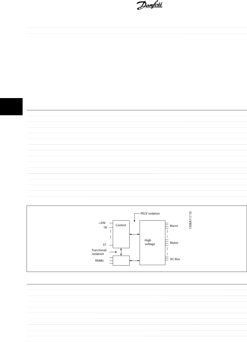
Nominal input current at 20 V 60 mA rms
Input capacitance 400 nF
All digital inputs are galvanically isolated from the supply voltage (PELV) and other high-voltage terminals.
1) Terminals 27 and 29 can also be programmed as output.
2) Except safe stop input Terminal 37.
3) Terminal 37 is only available in FC 302 and FC 301 A1 with Safe Stop. It can only be used as safe stop input. Terminal 37 is suitable for category 3
installations according to EN 954-1 (safe stop according to category 0 EN 60204-1) as required by the EU Machinery Directive 98/37/EC. Terminal 37
and the Safe Stop function are designed in conformance with EN 60204-1, EN 50178, EN 61800-2, EN 61800-3, and EN 954-1. For correct and safe use
of the Safe Stop function follow the related information and instructions in the Design Guide.
4) FC 302 only.
5) When using a contactor with a DC coil inside in combination with Safe Stop, it is important to make a return way for the current from the coil when
turning it off. This can be done by using a freewheel diode (or, alternatively, a 30 or 50 V MOV for quicker response time) across the coil. Typical
contactors can be bought with this diode.
Analog inputs:
Number of analog inputs 2
Terminal number 53, 54
Modes Voltage or current
Mode select Switch S201 and switch S202
Voltage mode Switch S201/switch S202 = OFF (U)
Voltage level FC 301: 0 to + 10/ FC 302: -10 to +10 V (scaleable)
Input resistance, Riapprox. 10 k
Max. voltage ± 20 V
Current mode Switch S201/switch S202 = ON (I)
Current level 0/4 to 20 mA (scaleable)
Input resistance, Riapprox. 200
Max. current 30 mA
Resolution for analog inputs 10 bit (+ sign)
Accuracy of analog inputs Max. error 0.5% of full scale
Bandwidth FC 301: 20 Hz/ FC 302: 100 Hz
The analog inputs are galvanically isolated from the supply voltage (PELV) and other high-voltage terminals.
Pulse/encoder inputs:
Programmable pulse/encoder inputs 2/1
Terminal number pulse/encoder 291), 332) / 323), 333)
Max. frequency at terminal 29, 32, 33 110 kHz (Push-pull driven)
Max. frequency at terminal 29, 32, 33 5 kHz (open collector)
Min. frequency at terminal 29, 32, 33 4 Hz
Voltage level see section on Digital input
Maximum voltage on input 28 V DC
Input resistance, Riapprox. 4 k
Pulse input accuracy (0.1 - 1 kHz) Max. error: 0.1% of full scale
Encoder input accuracy (1 - 110 kHz) Max. error: 0.05 % of full scale
The pulse and encoder inputs (terminals 29, 32, 33) are galvanically isolated from the supply voltage (PELV) and other high-voltage terminals.
5 General Specifications
VLT
®
AutomationDrive FC 300 Operating
Instructions
94
MG.33.AG.02 - VLT® is a registered Danfoss trademark
5

1) FC 302 only
2) Pulse inputs are 29 and 33
3) Encoder inputs: 32 = A, and 33 = B
Digital output:
Programmable digital/pulse outputs 2
Terminal number 27, 29 1)
Voltage level at digital/frequency output 0 - 24 V
Max. output current (sink or source) 40 mA
Max. load at frequency output 1 k
Max. capacitive load at frequency output 10 nF
Minimum output frequency at frequency output 0 Hz
Maximum output frequency at frequency output 32 kHz
Accuracy of frequency output Max. error: 0.1 % of full scale
Resolution of frequency outputs 12 bit
1) Terminal 27 and 29 can also be programmed as input.
The digital output is galvanically isolated from the supply voltage (PELV) and other high-voltage terminals.
Analog output:
Number of programmable analog outputs 1
Terminal number 42
Current range at analog output 0/4 - 20 mA
Max. load GND - analog output 500
Accuracy on analog output Max. error: 0.5 % of full scale
Resolution on analog output 12 bit
The analogue output is galvanically isolated from the supply voltage (PELV) and other high-voltage terminals.
Control card, 24 V DC output:
Terminal number 12, 13
Output voltage 24 V +1, -3 V
Max. load FC 301: 130 mA/ FC 302: 200 mA
The 24 V DC supply is galvanically isolated from the supply voltage (PELV), but has the same potential as the analog and digital inputs and outputs.
Control card, 10 V DC output:
Terminal number 50
Output voltage 10.5 V ±0.5 V
Max. load 15 mA
The 10 V DC supply is galvanically isolated from the supply voltage (PELV) and other high-voltage terminals.
Control card, RS 485 serial communication:
Terminal number 68 (P,TX+, RX+), 69 (N,TX-, RX-)
Terminal number 61 Common for terminals 68 and 69
The RS 485 serial communication circuit is functionally separated from other central circuits and galvanically isolated from the supply voltage (PELV).
Control card, USB serial communication:
USB standard 1.1 (Full speed)
USB plug USB type B “device” plug
Connection to PC is carried out via a standard host/device USB cable.
The USB connection is galvanically isolated from the supply voltage (PELV) and other high-voltage terminals.
The USB ground connection is not galvanically isolated from protection earth. Use only an isolated laptop as PC connection to the USB connector on
the frequency converter.
Relay outputs:
Programmable relay outputs FC 301all kW: 1 / FC 302 all kW: 2
Relay 01 Terminal number 1-3 (break), 1-2 (make)
Max. terminal load (AC-1)1) on 1-3 (NC), 1-2 (NO) (Resistive load) 240 V AC, 2 A
Max. terminal load (AC-15)1) (Inductive load @ cos 0.4) 240 V AC, 0.2 A
Max. terminal load (DC-1)1) on 1-2 (NO), 1-3 (NC) (Resistive load) 60 V DC, 1A
Max. terminal load (DC-13)1) (Inductive load) 24 V DC, 0.1A
Relay 02 (FC 302 only) Terminal number 4-6 (break), 4-5 (make)
VLT
®
AutomationDrive FC 300 Operating
Instructions 5 General Specifications
MG.33.AG.02 - VLT® is a registered Danfoss trademark
95
5

Max. terminal load (AC-1)1) on 4-5 (NO) (Resistive load)2)3) Overvoltage cat. II 400 V AC, 2 A
Max. terminal load (AC-15)1) on 4-5 (NO) (Inductive load @ cos 0.4) 240 V AC, 0.2 A
Max. terminal load (DC-1)1) on 4-5 (NO) (Resistive load) 80 V DC, 2 A
Max. terminal load (DC-13)1) on 4-5 (NO) (Inductive load) 24 V DC, 0.1A
Max. terminal load (AC-1)1) on 4-6 (NC) (Resistive load) 240 V AC, 2 A
Max. terminal load (AC-15)1) on 4-6 (NC) (Inductive load @ cos 0.4) 240 V AC, 0.2A
Max. terminal load (DC-1)1) on 4-6 (NC) (Resistive load) 50 V DC, 2 A
Max. terminal load (DC-13)1) on 4-6 (NC) (Inductive load) 24 V DC, 0.1 A
Min. terminal load on 1-3 (NC), 1-2 (NO), 4-6 (NC), 4-5 (NO) 24 V DC 10 mA, 24 V AC 20 mA
Environment according to EN 60664-1 overvoltage category III/pollution degree 2
1) IEC 60947 part 4 and 5
The relay contacts are galvanically isolated from the rest of the circuit by reinforced isolation (PELV).
2) Overvoltage Category II
3) UL applications 300 V AC 2A
Cable lengths and cross sections for control cables*:
Max. motor cable length, screened FC 301: 50 m / FC 301 (A1): 25 m/ FC 302: 150 m
Max. motor cable length, unscreened FC 301: 75 m / FC 301 (A1): 50 m/ FC 302: 300 m
Maximum cross section to control terminals, flexible/ rigid wire without cable end sleeves 1.5 mm2/16 AWG
Maximum cross section to control terminals, flexible wire with cable end sleeves 1 mm2/18 AWG
Maximum cross section to control terminals, flexible wire with cable end sleeves with collar 0.5 mm2/20 AWG
Minimum cross section to control terminals 0.25 mm2/ 24 AWG
* Power cables, see tables in section “Electrical Data” of the Design Guide
For more information, see section
Electrical Data
in the VLT AutomationDrive Design Guide, MG.33.BX.YY.
Control card performance:
Scan interval FC 301: 5 ms / FC 302: 1 ms
Control characteristics:
Resolution of output frequency at 0 - 1000 Hz +/- 0.003 Hz
Repeat accuracy of
Precise start/stop
(terminals 18, 19) ≤± 0.1 msec
System response time (terminals 18, 19, 27, 29, 32, 33) ≤ 2 ms
Speed control range (open loop) 1:100 of synchronous speed
Speed control range (closed loop) 1:1000 of synchronous speed
Speed accuracy (open loop) 30 - 4000 rpm: error ±8 rpm
Speed accuracy (closed loop), depending on resolution of feedback device 0 - 6000 rpm: error ±0.15 rpm
All control characteristics are based on a 4-pole asynchronous motor
Surroundings:
Enclosure IP 201)/ Type 1, IP 212)/ Type 1, IP 55/ Type 12, IP 66
Vibration test 1.0 g
Max. relative humidity 5% - 93%(IEC 721-3-3; Class 3K3 (non-condensing) during operation
Aggressive environment (IEC 60068-2-43) H2S test class Kd
Ambient temperature3) Max. 50 °C (24-hour average maximum 45 °C)
1) Only for ≤ 3.7 kW (200 - 240 V), ≤ 7.5 kW (400 - 480/ 500 V)
2) As enclosure kit for ≤ 3.7 kW (200 - 240 V), ≤ 7.5 kW (400 - 480/ 500 V)
3) Derating for high ambient temperature, see special conditions in the Design Guide
Minimum ambient temperature during full-scale operation 0 °C
Minimum ambient temperature at reduced performance - 10 °C
Temperature during storage/transport -25 - +65/70 °C
Maximum altitude above sea level without derating 1000 m
Derating for high altitude, see special conditions in the Design Guide
EMC standards, Emission EN 61800-3, EN 61000-6-3/4, EN 55011
EMC standards, Immunity
EN 61800-3, EN 61000-6-1/2,
EN 61000-4-2, EN 61000-4-3, EN 61000-4-4, EN 61000-4-5, EN 61000-4-6
See section on special conditions in the Design Guide.
5 General Specifications
VLT
®
AutomationDrive FC 300 Operating
Instructions
96
MG.33.AG.02 - VLT® is a registered Danfoss trademark
5

Protection and Features:
• Electronic thermal motor protection against overload.
• Temperature monitoring of the heatsink ensures that the frequency converter trips if the temperature reaches a predefined level. An overload
temperature cannot be reset until the temperature of the heatsink is below the values stated in the tables on the following pages (Guideline -
these temperatures may vary for different power sizes, frame sizes, enclosure ratings etc.).
• The frequency converter is protected against short-circuits on motor terminals U, V, W.
• If a mains phase is missing, the frequency converter trips or issues a warning (depending on the load).
• Monitoring of the intermediate circuit voltage ensures that the frequency converter trips if the intermediate circuit voltage is too low or too high.
• The frequency converter constantly checks for critical levels of internal temperature, load current, high voltage on the intermediate circuit and
low motor speeds. As a response to a critical level, the frequency converter can adjust the switching frequency and/ or change the switching
pattern in order to ensure the performance of the drive.
VLT
®
AutomationDrive FC 300 Operating
Instructions 5 General Specifications
MG.33.AG.02 - VLT® is a registered Danfoss trademark
97
5

6 Troubleshooting
VLT
®
AutomationDrive FC 300 Operating
Instructions
98
MG.33.AG.02 - VLT® is a registered Danfoss trademark
6

6 Troubleshooting
6.1.1 Warnings/Alarm Messages
A warning or an alarm is signalled by the relevant LED on the front of the frequency converter and indicated by a code on the display.
A warning remains active until its cause is no longer present. Under certain circumstances operation of the motor may still be continued. Warning messages
may be critical, but are not necessarily so.
In the event of an alarm, the frequency converter will have tripped. Alarms must be reset to restart operation once their cause has been rectified.
This may be done in three ways:
1. By using the [RESET] control button on the LCP.
2. Via a digital input with the “Reset” function.
3. Via serial communication/optional fieldbus.
NB!
After a manual reset using the [RESET] button on the LCP, the [AUTO ON] button must be pressed to restart the motor.
If an alarm cannot be reset, the reason may be that its cause has not been rectified, or the alarm is trip-locked (see also table on following page).
Alarms that are trip-locked offer additional protection, meaning that the mains supply must be switched off before the alarm can be reset. After being
switched back on, the frequency converter is no longer blocked and may be reset as described above once the cause has been rectified.
Alarms that are not trip-locked can also be reset using the automatic reset function in par. 14-20
Reset Mode
(Warning: automatic wake-up is possible!)
If a warning and alarm is marked against a code in the table on the following page, this means that either a warning occurs before an alarm, or else that
you can specify whether it is a warning or an alarm that is to be displayed for a given fault.
This is possible, for instance, in par. 1-90
Motor Thermal Protection
. After an alarm or trip, the motor carries on coasting, and the alarm and warning
flash. Once the problem has been rectified, only the alarm continues flashing until the frequency converter is reset.
VLT
®
AutomationDrive FC 300 Operating
Instructions 6 Troubleshooting
MG.33.AG.02 - VLT® is a registered Danfoss trademark
99
6

No. Description Warning Alarm/Trip Alarm/Trip Lock Parameter
Reference
110 Volts low X
2 Live zero error (X) (X) Par. 6-01
Live Zero Time-
out Function
3No motor (X) Par. 1-80
Function at
Stop
4 Mains phase loss (X) (X) (X) Par. 14-12
Function at
Mains Imbalance
5DC link voltage high X
6 DC link voltage low X
7DC over-voltage X X
8 DC under voltage X X
9Inverter overloaded X X
10 Motor ETR over temperature (X) (X) Par. 1-90
Motor Thermal
Protection
11 Motor thermistor over temperature (X) (X) Par. 1-90
Motor Thermal
Protection
12 Torque limit X X
13 Over Current X X X
14 Earth Fault X X X
15 Hardware mismatch X X
16 Short Circuit X X
17 Control word time-out (X) (X) Par. 8-04
Control Word
Timeout Function
22 Hoist Mech. Brake (X) (X) Parameter group 2-2*
23 Internal Fan Fault X
24 External Fan Fault X Par. 14-53
Fan Monitor
25 Brake resistor short-circuited X
26 Brake resistor power limit (X) (X) Par. 2-13
Brake Power
Monitoring
27 Brake chopper short-circuited X X
28 Brake check (X) (X) Par. 2-15
Brake Check
29 Heatsink temp X X X
30 Motor phase U missing (X) (X) (X) Par. 4-58
Missing Motor
Phase Function
31 Motor phase V missing (X) (X) (X) Par. 4-58
Missing Motor
Phase Function
32 Motor phase W missing (X) (X) (X) Par. 4-58
Missing Motor
Phase Function
33 Inrush Fault X X
34 Fieldbus communication fault X X
36 Mains failure X X
37 Phase imbalance X
38 Internal Fault X X
39 Heatsink sensor X X
40 Overload of Digital Output Terminal 27 (X) Par. 5-00
Digital I/O
Mode
, par. 5-01
Terminal
27 Mode
41 Overload of Digital Output Terminal 29 (X) Par. 5-00
Digital I/O
Mode
, par. 5-02
Terminal
29 Mode
42 Overload of Digital Output On X30/6 (X) Par. 5-32
Term X30/6
Digi Out (MCB 101)
42 Overload of Digital Output On X30/7 (X) Par. 5-33
Term X30/7
Digi Out (MCB 101)
45 Earth Fault 2 X X X
46 Pwr. card supply X X
47 24 V supply low X X X
48 1.8 V supply low X X
49 Speed limit X
50 AMA calibration failed X
51 AMA check Unom and Inom X
52 AMA low Inom X
53 AMA motor too big X
Table 6.1: Alarm/Warning code list
6 Troubleshooting
VLT
®
AutomationDrive FC 300 Operating
Instructions
100
MG.33.AG.02 - VLT® is a registered Danfoss trademark
6
No. Description Warning Alarm/Trip Alarm/Trip Lock Parameter
Reference
54 AMA motor too small X
55 AMA parameter out of range X
56 AMA interrupted by user X
57 AMA time-out X
58 AMA internal fault X X
59 Current limit X
60 External Interlock X X
61 Feedback Error (X) (X) Par. 4-30
Motor Feed-
back Loss Function
62 Output Frequency at Maximum Limit X
63 Mechanical Brake Low (X) Par. 2-20
Release Brake
Current
64 Voltage Limit X
65 Control Board Over-temperature X X X
66 Heat sink Temperature Low X
67 Option Configuration has Changed X
68 Safe Stop (X) (X)1) Par. 5-19
Terminal 37
Safe Stop
69 Pwr. Card Temp X X
70 Illegal FC configuration X
71 PTC 1 Safe Stop X X1) Par. 5-19
Terminal 37
Safe Stop
72 Dangerous Failure X1) Par. 5-19
Terminal 37
Safe Stop
73 Safe Stop Auto Restart (X) (X) Par. 5-19
Terminal 37
Safe Stop
76 Power Unit Setup X
77 Reduced power mode X Par. 14-59
Actual Num-
ber of Inverter Units
78 Tracking Error (X) (X) Par. 4-34
Tracking Error
Function
79 Illegal PS config X X
80 Drive Initialized to Default Value X
81 CSIV corrupt X
82 CSIV parameter error X
85 Profibus/Profisafe Error X
90 Feedback Monitor (X) (X) Par. 17-61
Feedback
Signal Monitoring
91 Analogue input 54 wrong settings X S202
100-199 See Operating Instructions for MCO 305
243 Brake IGBT X X
244 Heatsink temp X X X
245 Heatsink sensor X X
246 Pwr.card supply X X
247 Pwr.card temp X X
248 Illegal PS config X X
250 New spare part X Par. 14-23
Typecode
Setting
251 New Type Code X X
Table 6.2: Alarm/Warning code list
(X) Dependent on parameter
1) Can not be Auto reset via par. 14-20
Reset Mode
A trip is the action when an alarm has appeared. The trip will coast the motor and can be reset by pressing the reset button or make a reset by a digital
input (par. group 5-1* [1]). The origin event that caused an alarm cannot damage the frequency converter or cause dangerous conditions. A trip lock is
an action when an alarm occurs, which may cause damage to frequency converter or connected parts. A Trip Lock situation can only be reset by a power
cycling.
LED indication
Warning yellow
Alarm flashing red
Trip locked yellow and red
VLT
®
AutomationDrive FC 300 Operating
Instructions 6 Troubleshooting
MG.33.AG.02 - VLT® is a registered Danfoss trademark
101
6

Alarm Word Extended Status Word
Bit Hex Dec Alarm Word Alarm Word 2 Warning Word Warning
Word 2
Extended
Status Word
0 00000001 1 Brake Check (A28) ServiceTrip, Read/
Write
Brake Check (W28) reserved Ramping
100000002 2Heatsink temp.
(A29)
ServiceTrip, (re-
served)
Heatsink temp. (W29) reserved AMA Running
2 00000004 4 Earth Fault (A14) ServiceTrip, Type-
code/Sparepart
Earth Fault (W14) reserved Start CW/CCW
300000008 8Ctrl.Card Temp
(A65)
ServiceTrip, (re-
served)
Ctrl.Card Temp (W65) reserved Slow Down
4 00000010 16 Ctrl. Word TO (A17) ServiceTrip, (re-
served)
Ctrl. Word TO (W17) Catch Up
500000020 32 Over Current (A13) reserved Over Current (W13) reserved Feedback High
6 00000040 64 Torque Limit (A12) reserved Torque Limit (W12) reserved Feedback Low
700000080 128 Motor Th Over
(A11)
reserved Motor Th Over (W11) reserved Output Current High
8 00000100 256 Motor ETR Over
(A10)
reserved Motor ETR Over (W10) reserved Output Current Low
900000200 512 Inverter Overld.
(A9)
reserved Inverter Overld (W9) reserved Output Freq High
10 00000400 1024 DC under Volt (A8) reserved DC under Volt (W8) Output Freq Low
11 00000800 2048 DC over Volt (A7) reserved DC over Volt (W7) Brake Check OK
12 00001000 4096 Short Circuit (A16) reserved DC Voltage Low (W6) reserved Braking Max
13 00002000 8192 Inrush Fault (A33) reserved DC Voltage High (W5) Braking
14 00004000 16384 Mains ph. Loss (A4) reserved Mains ph. Loss (W4) Out of Speed Range
15 00008000 32768 AMA Not OK reserved No Motor (W3) OVC Active
16 00010000 65536 Live Zero Error (A2) reserved Live Zero Error (W2) AC Brake
17 00020000 131072 Internal Fault (A38) KTY error 10V Low (W1) KTY Warn Password Timelock
18 00040000 262144 Brake Overload
(A26)
Fans error Brake Overload (W26) Fans Warn Password Protection
19 00080000 524288 U phase Loss (A30) ECB error Brake Resistor (W25) ECB Warn
20 00100000 1048576 V phase Loss (A31) reserved Brake IGBT (W27) reserved
21 00200000 2097152 W phase Loss (A32) reserved Speed Limit (W49) reserved
22 00400000 4194304 Fieldbus Fault
(A34)
reserved Fieldbus Fault (W34) reserved Unused
23 00800000 8388608 24 V Supply Low
(A47)
reserved 24V Supply Low (W47) reserved Unused
24 01000000 16777216 Mains Failure (A36) reserved Mains Failure (W36) reserved Unused
25 02000000 33554432 1.8V Supply Low
(A48)
reserved Current Limit (W59) reserved Unused
26 04000000 67108864 Brake Resistor
(A25)
reserved Low Temp (W66) reserved Unused
27 08000000 134217728 Brake IGBT (A27) reserved Voltage Limit (W64) reserved Unused
28 10000000 268435456 Option Change
(A67)
reserved Encoder loss (W90) reserved Unused
29 20000000 536870912 Drive Initial-
ized(A80)
Feedback Fault
(A61, A90)
Feedback Fault (W61,
W90)
Unused
30 40000000 1073741824 Safe Stop (A68) PTC 1 Safe Stop
(A71)
Safe Stop (W68) PTC 1 Safe
Stop (W71)
Unused
31 80000000 2147483648 Mech. brake low
(A63)
Dangerous Failure
(A72)
Extended Status Word Unused
Table 6.3: Description of Alarm Word, Warning Word and Extended Status Word
The alarm words, warning words and extended status words can be read out via serial bus or optional fieldbus for diagnose. See also par. 16-94
Ext.
Status Word
.
WARNING 1, 10 Volts low:
The 10 V voltage from terminal 50 on the control card is below 10 V.
Remove some of the load from terminal 50, as the 10 V supply is over-
loaded. Max. 15 mA or minimum 590 Ω.
WARNING/ALARM 2, Live zero error:
The signal on terminal 53 or 54 is less than 50% of the value set in
par. 6-10
Terminal 53 Low Voltage
, par. 6-12
Terminal 53 Low Current
,
par. 6-20
Terminal 54 Low Voltage
, or par. 6-22
Terminal 54 Low Cur-
rent
respectively.
WARNING/ALARM 3, No motor:
No motor has been connected to the output of the frequency converter.
WARNING/ALARM 4, Mains phase loss:
A phase is missing on the supply side, or the mains voltage imbalance is
too high.
This message also appears in case of a fault in the input rectifier on the
frequency converter.
Check the supply voltage and supply currents to the frequency converter.
WARNING 5, DC link voltage high:
The intermediate circuit voltage (DC) is higher than the overvoltage limit
of the control system. The frequency converter is still active.
WARNING 6, DC link voltage low
The intermediate circuit voltage (DC) is below the undervoltage limit of
the control system. The frequency converter is still active.
WARNING/ALARM 7, DC over voltage:
If the intermediate circuit voltage exceeds the limit, the frequency con-
verter trips after a time.
Possible corrections:
Connect a brake resistor
Extend the ramp time
Activate functions in par. 2-10
Brake Function
6 Troubleshooting
VLT
®
AutomationDrive FC 300 Operating
Instructions
102
MG.33.AG.02 - VLT® is a registered Danfoss trademark
6

Increase par. 14-26
Trip Delay at Inverter Fault
Alarm/warning limits:
3 x 200 - 240
V
3 x 380 - 500 V 3 x 525 - 600 V
[VDC] [VDC] [VDC]
Undervoltage 185 373 532
Voltage warning
low
205 410 585
Voltage warning
high (w/o brake
- w/brake)
390/405 810/840 943/965
Overvoltage 410 855 975
The voltages stated are the intermediate circuit voltage of the fre-
quency converter with a tolerance of ± 5 %. The corresponding
mains voltage is the intermediate circuit voltage (DC-link) divided
by 1.35
WARNING/ALARM 8, DC under voltage:
If the intermediate circuit voltage (DC) drops below the “voltage warning
low” limit (see table above), the frequency converter checks if 24 V back-
up supply is connected.
If no 24 V backup supply is connected, the frequency converter trips after
a given time depending on the unit.
To check whether the supply voltage matches the frequency converter,
see
General Specifications
.
WARNING/ALARM 9, Inverter overloaded:
The frequency converter is about to cut out because of an overload (too
high current for too long). The counter for electronic, thermal inverter
protection gives a warning at 98% and trips at 100%, while giving an
alarm. You cannot reset the frequency converter until the counter is be-
low 90%.
The fault is that the frequency converter is overloaded by more than
100% for too long.
WARNING/ALARM 10, Motor ETR over temperature:
According to the electronic thermal protection (ETR), the motor is too hot.
You can choose if you want the frequency converter to give a warning or
an alarm when the counter reaches 100% in par. 1-90
Motor Thermal
Protection
. The fault is that the motor is overloaded by more than 100%
for too long. Check that the motor par. 1-24
Motor Current
is set correctly.
WARNING/ALARM 11, Motor thermistor over temp:
The thermistor or the thermistor connection is disconnected. You can
choose if you want the frequency converter to give a warning or an alarm
when the counter reaches 100% in par. 1-90
Motor Thermal Protection
.
Check that the thermistor is connected correctly between terminal 53 or
54 (analog voltage input) and terminal 50 (+ 10 V supply), or between
terminal 18 or 19 (digital input PNP only) and terminal 50. If aKTY sen-
soris used, check for correct connection between terminal 54 and 55.
WARNING/ALARM 12, Torque limit:
The torque is higher than the value in par. 4-16
Torque Limit Motor
Mode
(in motor operation) or the torque is higher than the value in
par. 4-17
Torque Limit Generator Mode
(in regenerative operation).
WARNING/ALARM 13, Over Current:
The inverter peak current limit (approx. 200% of the rated current) is
exceeded. The warning will last approx. 8-12 sec., then the frequency
converter trips and issues an alarm. Turn off the frequency converter and
check if the motor shaft can be turned and if the motor size matches the
frequency converter.
If extended mechanical brake control is selected, trip can be reset exter-
nally.
ALARM 14, Earth fault:
There is a discharge from the output phases to earth, either in the cable
between the frequency converter and the motor or in the motor itself.
Turn off the frequency converter and remove the earth fault.
ALARM 15, Incomplete hardware:
A fitted option is not handled by the present control board (hardware or
software).
ALARM 16, Short-circuit
There is short-circuiting in the motor or on the motor terminals.
Turn off the frequency converter and remove the short-circuit.
WARNING/ALARM 17, Control word timeout:
There is no communication to the frequency converter.
The warning will only be active when par. 8-04
Control Word Timeout
Function
is NOT set to
OFF
.
If par. 8-04
Control Word Timeout Function
is set to
Stop
and
Trip
, a
warning appears and the frequency converter ramps down until it trips,
while giving an alarm.
Par. 8-03
Control Word Timeout Time
could possibly be increased.
WARNING/ALARM 22, Hoist Mechanical Brake:
Report value will show what kind it is. 0 = The torque ref. was not reached
before timeout. 1 = There was no brake feedback before timeout.
WARNING 23, Internal fan fault:
The fan warning function is an extra protection function that checks if the
fan is running / mounted. The fan warning can be disabled in
par. 14-53
Fan Monitor
(set to [0] Disabled).
WARNING 24, External fan fault:
The fan warning function is an extra protection function that checks if the
fan is running / mounted. The fan warning can be disabled in
par. 14-53
Fan Monitor
(set to [0] Disabled).
WARNING 25, Brake resistor short-circuited:
The brake resistor is monitored during operation. If it short-circuits, the
brake function is disconnected and the warning appears. The frequency
converter still works, but without the brake function. Turn off the fre-
quency converter and replace the brake resistor (see par. 2-15
Brake
Check
).
WARNING/ALARM 26, Brake resistor power limit:
The power transmitted to the brake resistor is calculated as a percentage,
as a mean value over the last 120 s, on the basis of the resistance value
of the brake resistor (par. 2-11
Brake Resistor (ohm)
) and the intermedi-
ate circuit voltage. The warning is active when the dissipated braking
power is hi gher than 90 %. If
Trip
[2] has been s el ec te d in pa r. 2- 13
Brake
Power Monitoring
, the frequency converter cuts out and issues this alarm,
when the dissipated braking power is higher than 100%.
WARNING/ALARM 27, Brake chopper fault:
The brake transistor is monitored during operation and if it short-circuits,
the brake function disconnects and the warning comes up. The frequency
converter is still able to run, but since the brake transistor has short-
circuited, substantial power is transmitted to the brake resistor, even if it
is inactive.
Turn off the frequency converter and remove the brake resistor.
This alarm/ warning could also occur should the brake resistor overheat.
Terminal 104 to 106 are available as brake resistor. Klixon inputs, see
section Brake Resistor Temperature Switch.
VLT
®
AutomationDrive FC 300 Operating
Instructions 6 Troubleshooting
MG.33.AG.02 - VLT® is a registered Danfoss trademark
103
6

Warning: There is a risk of substantial power being
transmitted to the brake resistor if the brake transistor
is short-circuited.
WARNING/ALARM 28, Brake check failed:
Brake resistor fault: the brake resistor is not connected/working.
ALARM 29, Drive over temperature:
If the enclosure is IP 20 or IP 21/Type 1, the cut-out temperature of the
heat-sink is 95 ºC +5 ºC. The temperature fault cannot be reset, until the
temperature of the heatsink is below 70 ºC +5 ºC.
The fault could be:
-Ambient temperature too high
-Too long motor cable
ALARM 30, Motor phase U missing:
Motor phase U between the frequency converter and the the motor is
missing.
Turn off the frequency converter and check motor phase U.
ALARM 31, Motor phase V missing:
Motor phase V between the frequency converter and the motor is missing.
Turn off the frequency converter and check motor phase V.
ALARM 32, Motor phase W missing:
Motor phase W between the frequency converter and the motor is miss-
ing.
Turn off the frequency converter and check motor phase W.
ALARM 33, Inrush fault:
Too many power ups have occured within a short time period. See the
chapter
General Specifications
for the allowed number of power ups with-
in one minute.
WARNING/ALARM 34, Fieldbus communication fault:
The fieldbus on the communication option card is not working correctly.
Please check parameters associated with the module and make sure
module is properly inserted in Slot A of the drive. Check the wiring for
fieldbus.
WARNING/ALARM 36, Mains failure:
This warning/alarm is only active if the supply voltage to the frequency
converter is lost and par. 14-10
Mains Failure
is NOT set to OFF. Possible
correction: check the fuses to the frequency converter
ALARM 37, Phase imbalance:
There is a current imbalance between the power units
ALARM 38, Internal fault:
By this alarm it may be necessary to contact your Danfoss supplier. Some
typical alarm messages:
0 The serial port cannot be initialized. Serious hardware
failure
256 The power EEPROM data is defect or too old
512 The control board EEPROM data is defect or too old
513 Communication time out Reading EEPROM data
514 Communication time out Reading EEPROM data
515 The Application Orientated Control cannot recognize the
EEPROM data
516 Cannot write write to the EEPROM because a write com-
mand is on progress
517 The write command is under time out
518 Failure in the EEPROM
519 Missing or invalid BarCode data in EEPROM 1024 – 1279
CAN telegram cannot be sent. (1027 indicate a possible
hardware failure)
1281 Digital Signal Processor flash time-out
1282 Power micro software version mismatch
1283 Power EEPROM data version mismatch
1284 Cannot read Digital Signal Processor software version
1299 Option SW in slot A is too old
1300 Option SW in slot B is too old
1311 Option SW in slot C0 is too old
1312 Option SW in slot C1 is too old
1315 Option SW in slot A is not supported (not allowed)
1316 Option SW in slot B is not supported (not allowed)
1317 Option SW in slot C0 is not supported (not allowed)
1318 Option SW in slot C1 is not supported (not allowed)
1536 An exception in the Application Orientated Control is
registered. Debug information written in LCP
1792 DSP watchdog is active. Debugging of power part data
Motor Orientated Control data not transferred correctly
2049 Power data restarted
2315 Missing SW version from power unit
2816 Stack overflow Control board module
2817 Scheduler slow tasks
2818 Fast tasks
2819 Parameter thread
2820 LCP stack overflow
2821 Serial port overflow
2822 USB port overflow
3072-
5122
Parameter value is outside its limits. Perform a initiali-
zation. Parameter number causing the alarm: Subtract
the code from 3072. Ex Error code 3238: 3238-3072 =
166 is outside the limit
5123 Option in slot A: Hardware incompatible with Control
board hardware
5124 Option in slot B: Hardware incompatible with Control
board hardware
5125 Option in slot C0: Hardware incompatible with Control
board hardware
5126 Option in slot C1: Hardware incompatible with Control
board hardware
5376-
6231
Out of memory
ALARM 39, Heatsink sensor
No feedback from the heatsink temperature sensor.
The signal from the IGBT thermal sensor is not available on the power
card. The problem could be on the power card, on the gate drive card,
or the ribbon cable between the power card and gate drive card.
WARNING 40, Overload of Digital Output Terminal 27
Check the load connected to terminal 27 or remove short-circuit connec-
tion. Check par. 5-00
Digital I/O Mode
and par. 5-01
Terminal 27 Mode
.
WARNING 41, Overload of Digital Output Terminal 29:
Check the load connected to terminal 29 or remove short-circuit connec-
tion. Check par. 5-00
Digital I/O Mode
and par. 5-02
Terminal 29 Mode
.
WARNING 42, Overload of Digital Output On X30/6 :
Check the load connected to X30/6 or remove short-circuit connection.
Check par. 5-32
Term X30/6 Digi Out (MCB 101)
.
6 Troubleshooting
VLT
®
AutomationDrive FC 300 Operating
Instructions
104
MG.33.AG.02 - VLT® is a registered Danfoss trademark
6

WARNING 42, Overload of Digital Output On X30/7 :
Check the load connected to X30/7 or remove short-circuit connection.
Check par. 5-33
Term X30/7 Digi Out (MCB 101)
.
ALARM 45, Earth fault 2:
There is a discharge from the output phases to earth, either in the cable
between the frequency converter and the motor or in the motor it-
self.Turn off the frequency converter and remove the earth fault. This
alarm is detected under the start-up test sequence.
ALARM 46, Power card supply
The supply on the power card is out of range.
There are three power supplies generated by the switch mode power
supply (SMPS) on the power card: 24 V, 5V, +/- 18V. When powered with
24 VDC with the MCB 107 option, only the 24 V and 5 V supplies are
monitored. When powered with three phase mains voltage, all three sup-
plied are monitored.
WARNING 47, 24 V supply low:
The external 24 V DC backup power supply may be overloaded, otherwise
Contact your Danfoss supplier.
WARNING 48, 1.8 V supply low:
Contact your Danfoss supplier.
WARNING 49, Speed limit:
The speed is not within the specified range in par. 4-11
Motor Speed Low
Limit [RPM]
and par. 4-13
Motor Speed High Limit [RPM]
.
ALARM 50, AMA calibration failed:
The motor is not suitable for the particular size of drive. Start the AMA
procedure once again by par. 1-29
Automatic Motor Adaptation (AMA)
,
eventually with a reduced AMA function. If still failing; check the motor
data.
ALARM 51, AMA check Unom and Inom:
The setting of motor voltage, motor current, and motor power is pre-
sumably wrong. Check the settings.
ALARM 52, AMA low Inom:
The motor current is too low. Check the settings.
ALARM 53, AMA motor too big:
The motor is too big for the AMA to be carried out.
ALARM 54, AMA motor too small:
The motor is too small for the AMA to be carried out.
ALARM 55, AMA par. out of range:
The motor parameter values found from the motor are outside acceptable
range.
ALARM 56, AMA interrupted by user:
The AMA has been interrupted by the user.
ALARM 57, AMA timeout:
Try to start the AMA again a number of times, until the AMA is carried
out. Please note that repeated runs may heat the motor to a level where
the resistance Rs and Rr are increased. In most cases, however, this is
not critical.
ALARM 58, AMA internal fault:
Contact your Danfoss supplier.
WARNING 59, Current limit:
The current is higher than the value in par. 4-18
Current Limit
.
WARNING 60, External interlock
External interlock has been activated. To resume normal operation, apply
24 V DC to the terminal programmed for external interlock and reset the
frequency converter (via serial communication, digital I/O, or by pressing
reset button on keypad).
WARNING/ALARM 61, Feedback Error:
An error between calculated speed and speed measurement from feed-
back device. The function Warning/Alarm/Disabling setting is in
par. 4-30
Motor Feedback Loss Function
. Accepted error setting in
par. 4-31
Motor Feedback Speed Error
and the allowed time the error
occur setting in par. 4-32
Motor Feedback Loss Timeout
. During a com-
missioning procedure the function may be effective.
WARNING 62, Output Frequency at Maximum Limit:
The output frequency is higher than the value set in par. 4-19
Max Output
Frequency
. This is a warning in VVCplus mode and an alarm (trip) in Flux
mode.
ALARM 63, Mechanical Brake Low:
The actual motor current has not exceeded the “release brake” current
within the “Start delay” time window.
WARNING 64, Voltage Limit:
The load and speed combination demands a motor voltage higher than
the actual DC link voltage.
WARNING/ALARM/TRIP 65, Control Card Over Temperature:
Control card over temperature: The cut-out temperature of the control
card is 80° C.
WARNING 66, Heatsink Temperature Low:
The heat sink temperature is measured as 0° C. This could indicate that
the temperature sensor is defect and thus the fan speed is increased to
the maximum in case the power part or control card is very hot.
ALARM 67, Option Configuration has Changed:
One or more options has either been added or removed since the last
power down.
ALARM 68, Safe Stop:
Safe Stop has been activated. To resume normal operation, apply 24 V
DC to T-37. Press reset button on LCP.
WARNING 68, Safe Stop:
Safe Stop has been activated. Normal operation is resumed when Safe
Stop is disabled. Warning: Automatic Restart!
ALARM 69, Power card temperature
The temperature sensor on the power card is either too hot or too cold.
Troubleshooting:
Check the operation of the door fans.
Check that the filters for the door fans are not blocked.
Check that the gland plate is properly installed on IP 21 and IP
54 (NEMA 1 and NEMA 12) drives.
ALARM 70, Illegal FC Configuration:
Actual combination of control board and power board is illegal.
ALARM 71, PTC 1 Safe Stop:
Safe Stop has been activated from the MCB 112 PTC Thermistor Card
(motor too warm). Normal operation can be resumed when the MCB 112
applies 24 V DC to T-37 again (when the motor temperature reaches an
acceptable level) and when the Digital Input from the MCB 112 is deac-
tivated. When that happens, a reset signal must be is be sent (via Bus,
Digital I/O, or by pressing [RESET]).
VLT
®
AutomationDrive FC 300 Operating
Instructions 6 Troubleshooting
MG.33.AG.02 - VLT® is a registered Danfoss trademark
105
6

WARNING 71, PTC 1 Safe Stop:
Safe Stop has been activated from the MCB 112 PTC Thermistor Card
(motor too warm). Normal operation can be resumed when the MCB 112
applies 24 V DC to T-37 again (when the motor temperature reaches an
acceptable level) and when the Digital Input from the MCB 112 is deac-
tivated. Warning: Automatic Restart.
ALARM 72, Dangerous Failure:
Safe Stop with Trip Lock. The Dangerous Failure Alarm is issued if the
combination of safe stop commands is unexpected. This is the case if the
MCB 112 VLT PTC Thermistor Card enables X44/ 10 but safe stop is
somehow not enabled. Furthermore, if the MCB 112 is the only device
using safe stop (specified through selection [4] or [5] in par. 5-19), an
unexpected combination is activation of safe stop without the X44/ 10
being activated. The following table summarizes the unexpected combi-
nations that lead to Alarm 72. Note that if X44/ 10 is activated in selection
2 or 3, this signal is ignored! However, the MCB 112 will still be able to
activate Safe Stop.
Function No. X44/ 10 (DI) Safe Stop
T37
PTC 1 Warning [4] + -
-+
PTC 1 Alarm [5] + -
-+
PTC 1 & Relay A [6] + -
PTC 1 & Relay W [7] + -
PTC 1 & RelayA/ W [8] + -
PTC 1 & Relay W/A [9] + -
+ = activated
- = Not activated
WARNING 73, Safe stop auto restart
Safe stopped. Note that with automatic restart enabled, the motor may
start when the fault is cleared.
WARNING 76, Power Unit Setup
The required number of power units does not match the detected number
of active power units.
Troubleshooting:
When replacing an F-frame module, this will occur if the power specific
data in the module power card does not match the rest of the drive.
Please confirm the spare part and its power card are the correct part
number.
WARNING 77, Reduced power mode:
This warning indicates that the drive is operating in reduced power mode
(i.e. less than the allowed number of inverter sections). This warning will
be generated on power cycle when the drive is set to run with fewer
inverters and will remain on.
ALARM 78, Tracking Error:
The difference between set point value and actual value has exceeded
the value in par. 4-35
Tracking Error
. Disable the function by
par. 4-34
Tracking Error Function
or select an alarm/warning also in
par. 4-34
Tracking Error Function
. Investigate the mechanics around the
load and motor, Check feedback connections from motor – encoder – to
drive. Select motor feedback function in par. 4-30
Motor Feedback Loss
Function
. Adjust tracking error band in par. 4-35
Tracking Error
and
par. 4-37
Tracking Error Ramping
.
ALARM 79, Illegal power section configuration
The scaling card is the incorrect part number or not installed. Also MK102
connector on the power card could not be installed.
ALARM 80, Drive Initialised to Default Value:
Parameter settings are initialised to default setting after a manual (three-
finger) reset.
ALARM 81, CSIV corrupt:
CSIV file has syntax errors.
ALARM 82, CSIV parameter error:
CSIV failed to init a parameter.
ALARM 85, Dang fail PB:
Profibus/Profisafe Error.
ALARM 86, Dang fail DI:
Sensor Error.
ALARM 90, Feedback Monitor:
Check the connection to encoder/ resolver option and eventually replace
the MCB 102or MCB 103.
ALARM 91, Analogue Input 54 Wrong Settings:
Switch S202 has to be set in position OFF (voltage input) when a KTY
sensor is connected to analogue input terminal 54.
ALARM 243, Brake IGBT
This alarm is only for F Frame drives. It is equivalent to Alarm 27. The
report value in the alarm log indicates which power module generated
the alarm:
1 = left most inverter module.
2 = middle inverter module in F2 or F4 drive.
2 = right inverter module in F1 or F3 drive.
3 = right inverter module in F2 or F4 drive.
5 = rectifier module.
ALARM 244, Heatsink temperature
This alarm is only for F Frame drives. It is equivalent to Alarm 29. The
report value in the alarm log indicates which power module generated
the alarm:
1 = left most inverter module.
2 = middle inverter module in F2 or F4 drive.
2 = right inverter module in F1 or F3 drive.
3 = right inverter module in F2 or F4 drive.
5 = rectifier module.
6 Troubleshooting
VLT
®
AutomationDrive FC 300 Operating
Instructions
106
MG.33.AG.02 - VLT® is a registered Danfoss trademark
6

ALARM 245, Heatsink sensor
This alarm is only for F Frame drives. It is equivalent to Alarm 39. The
report value in the alarm log indicates which power module generated
the alarm:
1 = left most inverter module.
2 = middle inverter module in F2 or F4 drive.
2 = right inverter module in F1 or F3 drive.
3 = right inverter module in F2 or F4 drive.
5 = rectifier module.
ALARM 246, Power card supply
This alarm is only for F Frame drives. It is equivalent to Alarm 46. The
report value in the alarm log indicates which power module generated
the alarm:
1 = left most inverter module.
2 = middle inverter module in F2 or F4 drive.
2 = right inverter module in F1 or F3 drive.
3 = right inverter module in F2 or F4 drive.
5 = rectifier module.
ALARM 247, Power card temperature
This alarm is only for F Frame drives. It is equivalent to Alarm 69. The
report value in the alarm log indicates which power module generated
the alarm:
1 = left most inverter module.
2 = middle inverter module in F2 or F4 drive.
2 = right inverter module in F1 or F3 drive.
3 = right inverter module in F2 or F4 drive.
5 = rectifier module.
ALARM 248, Illegal power section configuration
This alarm is only for F Frame drives. It is equivalent to Alarm 79. The
report value in the alarm log indicates which power module generated
the alarm:
1 = left most inverter module.
2 = middle inverter module in F2 or F4 drive.
2 = right inverter module in F1 or F3 drive.
3 = right inverter module in F2 or F4 drive.
5 = rectifier module.
ALARM 250, New Spare Part:
The power or Switch Mode Power Supply has been exchanged. The fre-
quency converter type code must be restored in the EEPROM. Select the
correct type code in par. 14-23
Typecode Setting
according to the label
on unit. Remember to select ‘Save to EEPROM’ to complete.
ALARM 251, New Type Code:
The Frequency Converter has got a new type code.
VLT
®
AutomationDrive FC 300 Operating
Instructions 6 Troubleshooting
MG.33.AG.02 - VLT® is a registered Danfoss trademark
107
6

Index
A
Abbreviations 5
Access To Control Terminals 32
Activate Brake Delay 2-23 54
[Activate Brake Speed Hz] 2-22 54
[Activate Brake Speed Rpm] 2-21 54
Alarm Messages 99
Ama 39
Analog Inputs 94
Analog Output 95
Approvals 4
Automatic Motor Adaptation (ama) 39, 47
B
Brake Check 2-15 53
Brake Control 103
Brake Function 2-10 52
Brake Power Limit (kw) 2-12 52
Brake Power Monitoring 2-13 52
Brake Release Time 2-25 55
Brake Resistor (ohm) 2-11 52
C
Cable Lengths And Cross Sections 96
Cable Lengths And Cross Sections-continued 96
Catch Up 61
Checklist 15
Communication Option 104
Connection To Mains 22
Control Cables 36
Control Card Performance 96
Control Card, +10 V Dc Output 95
Control Card, 24 V Dc Output 95
Control Card, Rs 485 Serial Communication 95
Control Card, Usb Serial Communication 95
Control Characteristics 96
Control Terminals 33
Cooling 50
Cooling Conditions 18
D
Dc Backup 3
Dc Link 102
Decoupling Plate 26
Default Settings 70
Devicenet 3
Digital I/o Mode 5-00 58
Digital Inputs: 93
Digital Output 95
Disposal Instruction 5
E
Electrical Installation 33, 36
Electrical Terminals 36
Electronic Terminal Relay 50
Etr 103
F
Function Relay 5-40 65
Fuses 29
Index
VLT
®
AutomationDrive FC 300 Operating
Instructions
108
MG.33.AG.02 - VLT® is a registered Danfoss trademark

G
Gain Boost Factor 2-28 55
General Warning 9
Graphical Display 43
I
Intermediate Circuit 102
Ip21 / Type 1 3
J
[Jog Speed Hz] 3-11 56
K
Kty Sensor 103
L
Language 0-01 45
Language Package 1 45
Language Package 2 45
Language Package 3 45
Language Package 4 45
Lcp Copy 0-50 49
Leakage Current 9
Leds 43
Local Control Panel 43
M
Main Reactance 47
Mains Supply (l1, L2, L3) 93
Maximum Reference 3-03 48
Mcb 113 65
Mct 10 3
Mechanical Brake Control 41
Mechanical Dimensions 16
Mechanical Mounting 18
Minimum Reference 3-02 48
Motor Connection 26
Motor Current 1-24 46
Motor Frequency 1-23 46
Motor Name Plate 39
Motor Nominal Speed 1-25 46
Motor Output 93
[Motor Power Kw] 1-20 46
Motor Protection 50, 97
Motor Speed Unit 0-02 49
Motor Thermal Protection 42, 50
Motor Voltage 1-22 46
N
Name Plate Data 39
Non Ul Compliance 29
Numerical Display 43
O
Operation Mode 14-22 68
Output Performance (u, V, W) 93
Overload Mode 1-04 50
P
Panel Through Mounting 19
VLT
®
AutomationDrive FC 300 Operating
Instructions Index
MG.33.AG.02 - VLT® is a registered Danfoss trademark
109

Parallel Connection Of Motors 41
Potentiometer Reference 35
Preset Reference 3-10 56
Profibus 3
Protection 29
Protection And Features 97
Protection Mode 8
Pulse Start/stop 34
Pulse/encoder Inputs 94
R
Ramp 1 Ramp Down Time 3-42 48
Ramp 1 Ramp Up Time 3-41 48
Reference Resource 1 3-15 56
Reference Resource 2 3-16 57
Reference Resource 3 3-17 57
Relay Outputs 63
Relay Outputs 95
Release Brake Current 2-20 54
Removal Of Knockouts For Extra Cables 22
Repair Work 9
Residual Current Device 9
Rfi Filter 14-50 69
S
Safe Stop 9
Safety Precautions 7
Screened/armoured 21, 26, 37
Serial Communication 95
Shaft Performance Levels. 3
Side-by-side Installation 18
Sine-wave Filter 29
Software Version 15-43 69
Speed Up/down 35
Start/stop 34
Stator Leakage Reactance 47
Status Messages 43
Stop Delay 2-24 55
Surroundings 96
Switches S201, S202, And S801 38
Symbols 4
T
Terminal 27 Mode 5-01 58
Terminal 29 Mode 5-02 58
Thermistor 50
Thermistor Source 1-93 51
Torque Characteristics 1-03 49, 93
Torque Ramp Time 2-27 55
Torque Ref 2-26 55
V
Voltage Level 93
Voltage Reference Via A Potentiometer 35
W
Warnings 99
Index
VLT
®
AutomationDrive FC 300 Operating
Instructions
110
MG.33.AG.02 - VLT® is a registered Danfoss trademark
