Fitting Instructions Optimo
Fitting-Instructions-KIT-SYSTEM-II Fitting-Instructions-KIT-SYSTEM-II
User Manual: Fitting-Instructions-optimo
Open the PDF directly: View PDF ![]() .
.
Page Count: 9
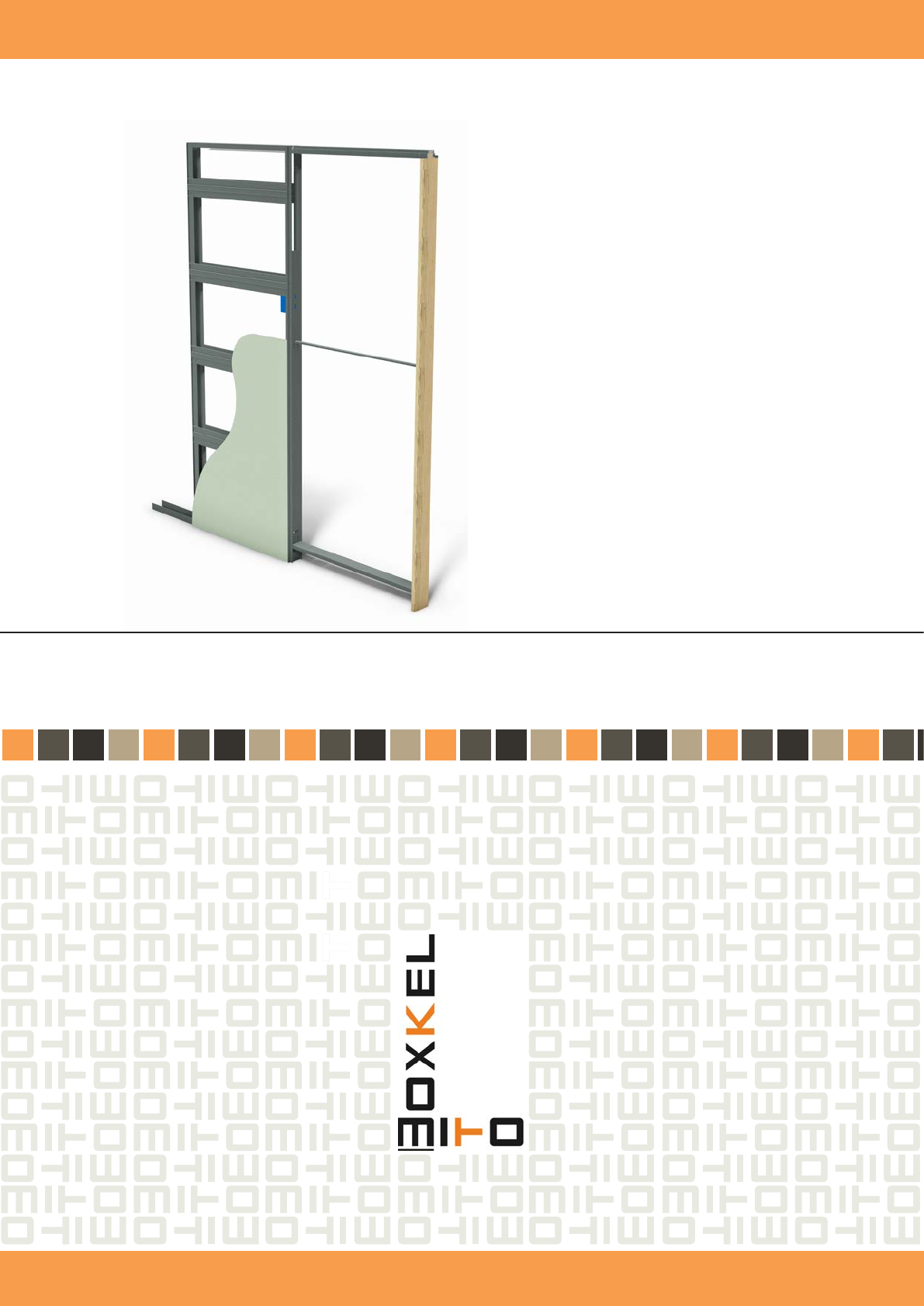
OPTIMO
FITTING INSTRUCTIONS

FITTING INSTRUCTIONS
POCKET DOOR FRAME “OPTIMO” FOR PLASTERBOARD WALLS 100MM THICKNESS
Available in kit format for self assembly
1. Insert horizontal front proles (9) and x them to the provided holes in the rear upright (3) and to the front proles (1) and (2).
2. Repeat this procedure to the opposite side of the pocket door frame.
3. Insert the top cover (4) and x it to the predrilled holes with the screws provided.
4. Insert the sliding top track (10) into the top cover (4) pushing it unl it is fully inserted and stops.
5. Insert the lower installaon alignment bar.
6. Fix the mber frame stop jamb (7) to the sliding top track with the nails provided.
7. Insert the middle installaon alignment bar (12)
8. Place a plasterboard guide onto the oor aligned with the wall to be constructed and insert the pocket door frame.
9. Connue with the pocket door frame installaon aaching the plasterboard sheets to the pocket door frame to form the
nished wall.
NOTE – all numbers are in brackets () not speech marks “”
FITTING INSTRUCTIONS
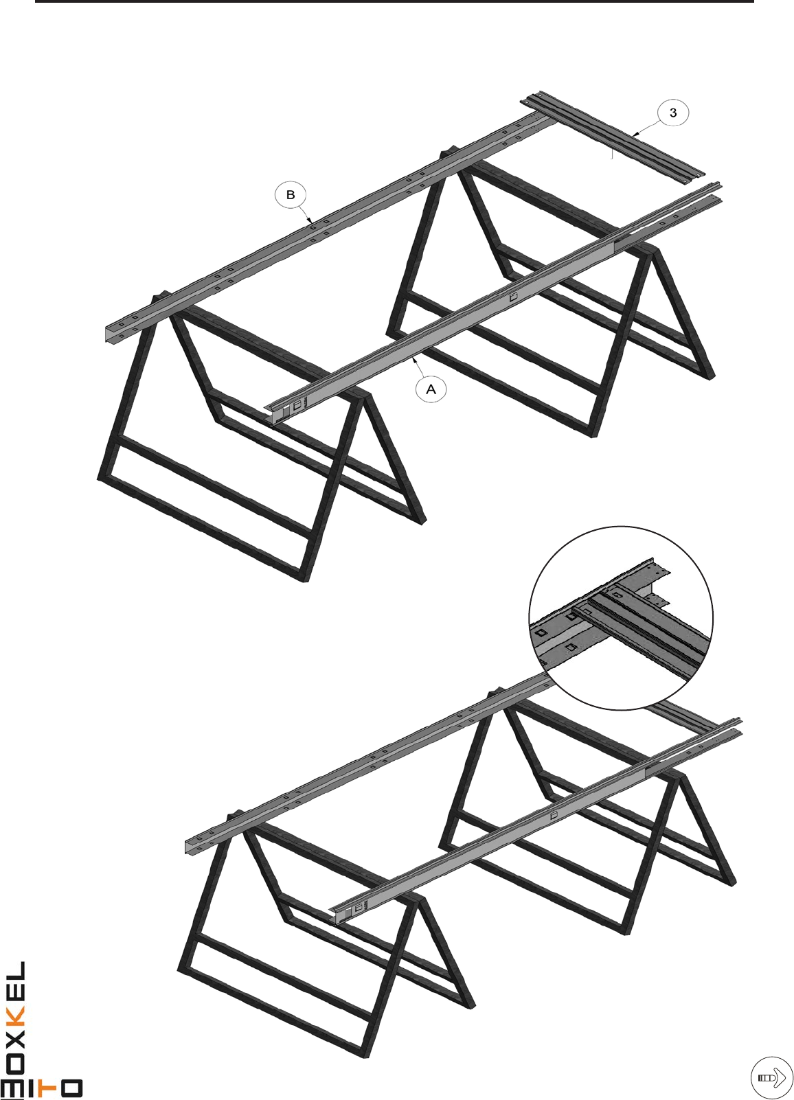
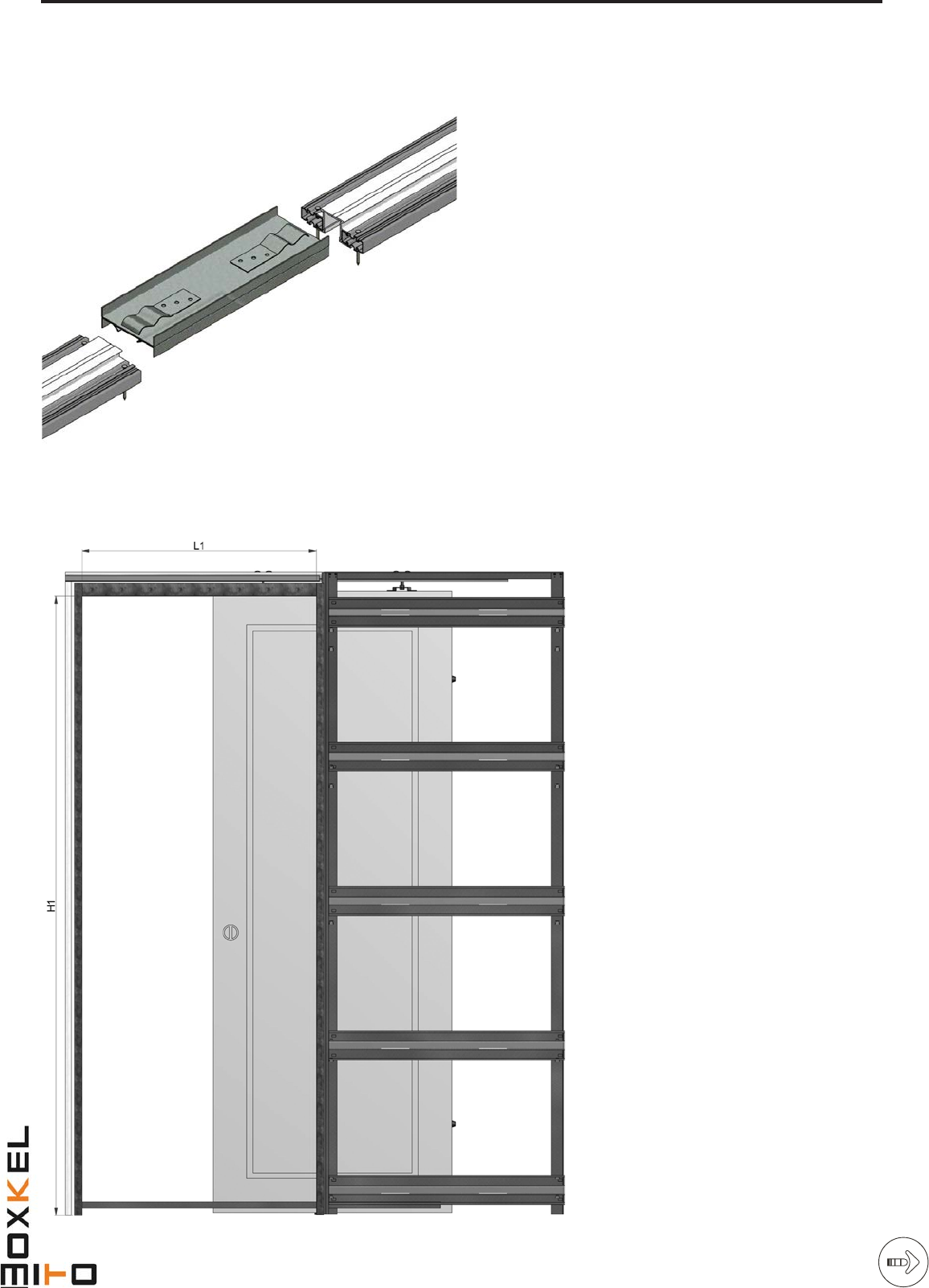
Place the vercal front (A) and rear (B) pocket door frame proles onto two trestles as shown.
Insert between the uprights the horizontal cross members (3) to the xing points indicated where they click and lock into place.
Repeat this procedure on the opposite side once the pocket door frame has been turned over.
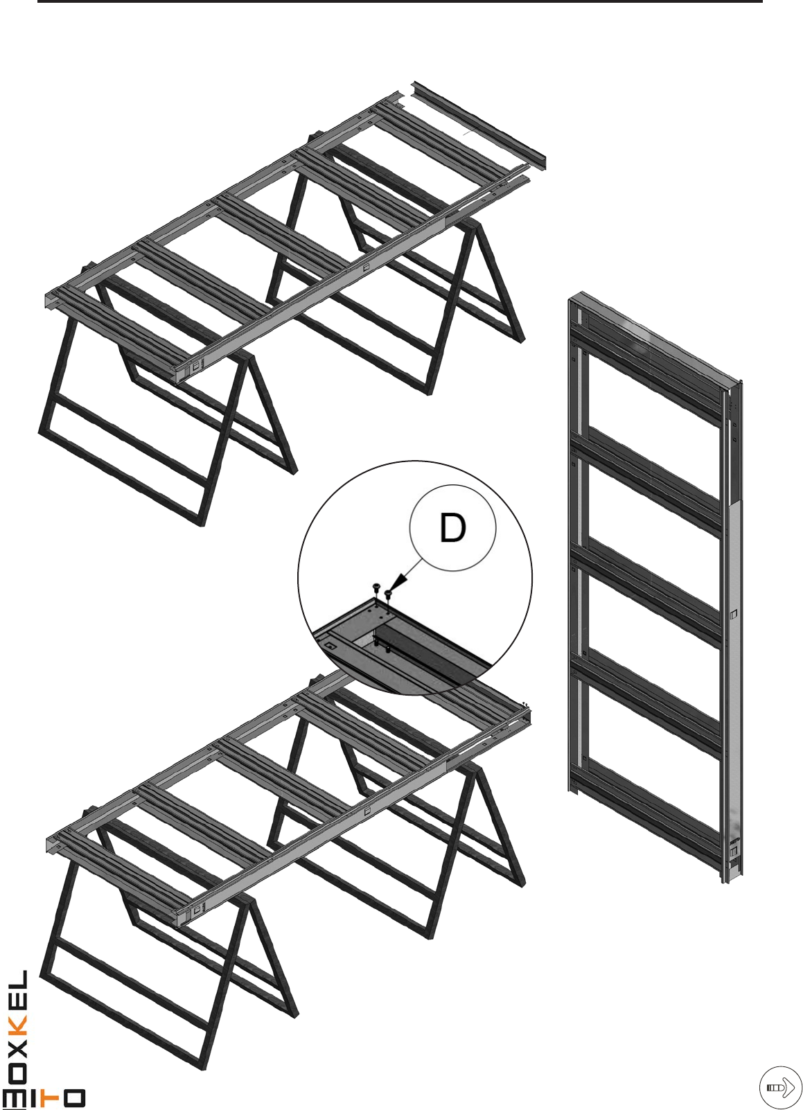
FITTING INSTRUCTIONS
1st Diagram – top cover needs to be labelled with “C” in a circle like third diagram has a “D”
Now the pocket door frame is ready to be completed with the sliding accessory set being ed to the door and then nal installaon
with the plasterboard panels to complete the nished wall.
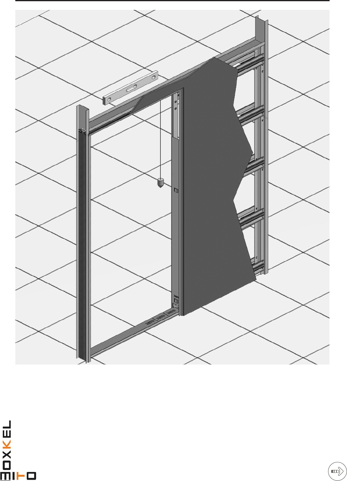
POCKET DOOR FRAME “OPTIMO” INSTALLATION.
Posion the pocket door frame into the plasterboard guide previously placed onto the oor and aligned with the wall to be
constructed. Check the alignment of the top of the pocket door frame with the oor using a plumb line as shown; should there
be a discrepancy, assume the oor is correct and adjust the alignment of the top of the pocket door frame accordingly. Place the
wooden frame stop jamb next to the boom installaon alignment bar and x the jamb to the bar. On the pocket side x again
x the boom installaon alignment bar to the vercal upright which forms the mouth of the pocket. Fix the middle installaon
alignment bar to the wooden frame stop jamb and the vercal upright in the same way. Now x the plasterboard sheets (not
supplied) to the pocket door frame using self-tapping screws, ensuring the screws penetrate through the metal parts of the
frame. For this purpose self-tapping screws to a maximum length of 20mm should be used assuming a plasterboard thickness of
12.5mm.
GUIDEDOUBLE WING DOOR AND JOINING KIT
DOUBLE WING
Aer inserng and xing the transom in the box-frame, insert
the joining bracket into one rail for half of ints length and
x it with supplied screws. then insert the second transom
and the second rail unl they touch. Fix the second rail with
supplied screws, insert distance transom into the provided
space of the bow-frame frontal part, then go on with the
box-frame placement.
JUNCTION KIT
If you want to make a double wing box-frame from two sin-
gle wing box-frames, is necessary to cut the front part of the
rail, taking as reference the predisposed hole in the plate.
We advise to x the rail and the support plate with
further screws to get a more solid structure. Join the two
rails inside the plate, the rails should touch in the middle
of the juncon kit, marked with the appropriate hole with
triangle form.
OVERALL SIZE
L1 = Nominal W + 40 mm.
L2 = Nominal W x 2 + 70 mm.
H1 = Nominal H + 50 mm.
H2 = Nominal H + 85 mm.
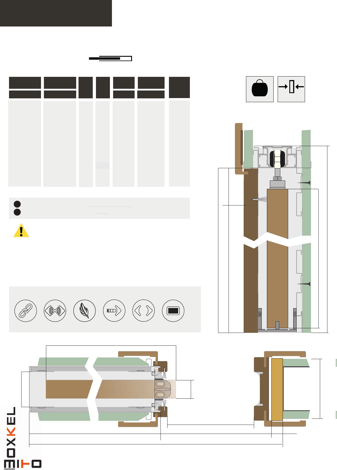
INTERNAL BOX FRAME SPACE:
Finished wall mm. 100, internal box frame
space mm. 58.
JUNCTION KIT
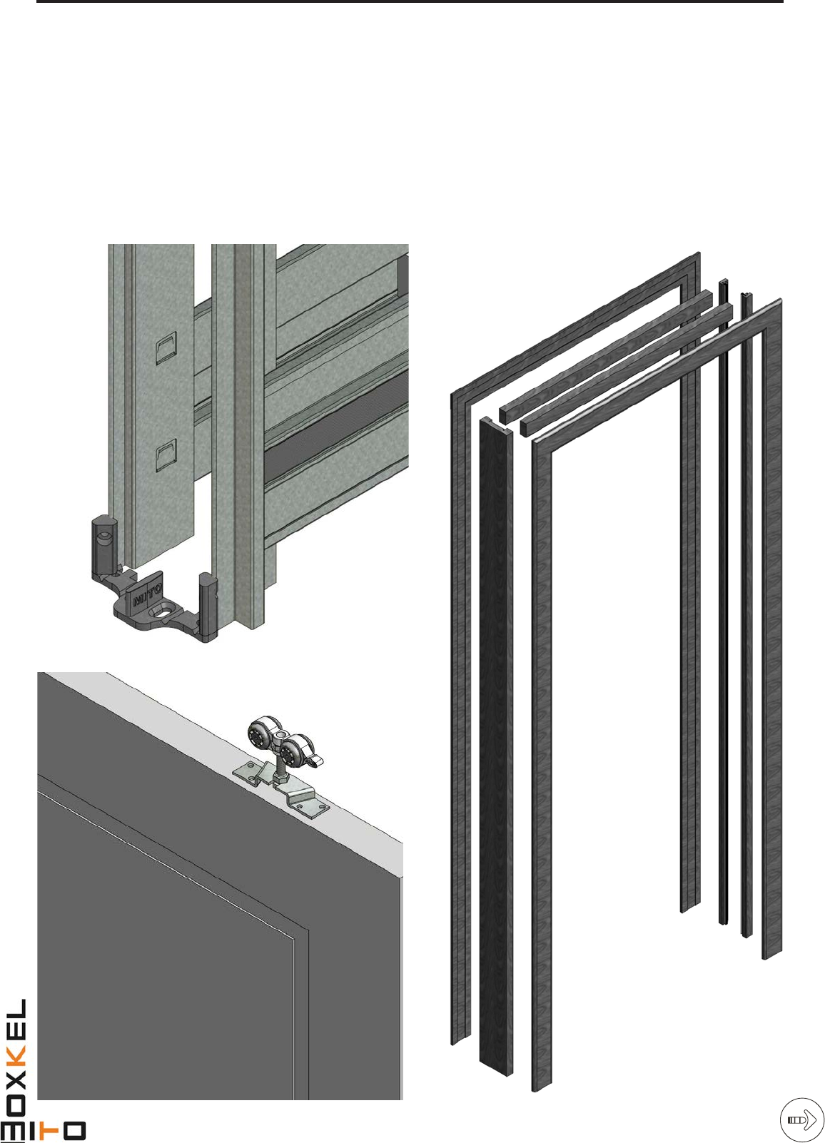
DOOR PANEL ASSEMBLY
Remove the box frame frontal cover, place the lower rail at the box frame base and x it to the metallic box with
supplied dowels or to the oor with sher. Insert door proles brush holders into the box-frame opening in the provided
seat. Fix suspension brackets to the upper part of the door panel and make sure that provided holes for the carriage
introducon are turn to the same side. Fix impact rubber to the back box-frame side and add shims if you prefer the
door panel is not completely disappeared into the box-frame when the door is open. Insert carriages into the sliding rail
in the provided hole placed in the side of the impact upright. Hook the door panel to the sliding carriages, regulate the
height and check the alignment of plumb respect to the ground level. Insert upper transoms and then the impact jamb
checking their perpendicularity respect the closed door panel. At the end x frame covers on both wall sides.
B
Lp
A
La
20mm
Si=57mm
Sa
Sp=100
L Mi
Plasterboard version
> If flush pull handles are to be fitted to the door face, it is recommended that the
door track stopper is positioned such that in the fully open position a small part
of the door width remainds outside the pocket frame. This is to prevent the risk of
personal injury via trapped fingers.
> In the event that the door track stopper is positioned to allow the full width of the
door to slide inside the pocket frame when in the fully open position, we can not
accept liability for any personal injuries that occur.
> Doors, plasterboard panels, and outside architrave sections not supplied.
PW x PH W x H Standard
DW DH
Sp
MAX PASSAGE
SIZE OVER DIMENSION PANEL
DIMENSION
FINISHED
WALL
A
B
Jointing set Automatic door
operator set
Self closing set
Soft closing set Synchronised
operation set Switching points
set
H Mi
Ha
Hp
Hg
50mm
Optimo
POCKET DOOR FRAMES FOR SINGLE DOORS
available accessory sets
99690133
99690135
99690137
99690139
99690141
99690143
99690145
99690147
99690149
99690151
CODE
* Dimensions are given in mm.
160 KG
Max. 25-44mm
626x2040
726x2040
826x2040
926x2040
1026x2040
610x1981
686x1981
762x1981
838x1981
914x1981
100
100
100
100
100
100
100
100
100
100
615
715
815
915
1015
615
715
815
915
915
640
740
840
940
1040
625
701
777
853
940
1288 x2115
1488x2115
1688x2115
1888x2115
2088x2115
1273x2056
1449x2056
1625x2056
1701x2056
1888x2056
600x2030
700x2030
800x2030
900x2030
1000x2030
585x1971
661x1971
737x1971
813x1971
900x1971
Jamb finishing kit
Architrave finishing kit
2
1> Code 996090060 (included with pocket door set)
> Code 996090061 (optional)
C/ Bellmunt, 104 - P.I. La Foradada
08580 Sant Quirze de Besora (Barcelona) - SPAIN
Telf. + 34 93 852 96 15 // Fax +34 93 855 13 42
boxkel@boxkel.com
Country Sales Manager UK - Mr. Rod Flanagan
M 07557640348
rod.flanagan@saheco.co.uk
sales@saheco.co.uk

www.boxkel.com
BOXKEL
Poligono Industrial la Foradada
08580 San Quirze de Besora - Barcelona (SPAIN)
Tel. +34 93 852 96 15
Fax +34 93 855 13 42
boxkel@boxkel.com
