1.2 SPECIFICATIONS Fluke PG7202 High Pressure Gas Piston Gauge User Manual
Fluke-PG7601-Piston-Gauge-Manual-Brochure Fluke-PG7601-Piston-Gauge-Manual-Brochure
Fluke-PG7202-High-Pressure-Gas-Piston-Gauge-Manual-Brochure Fluke-PG7202-High-Pressure-Gas-Piston-Gauge-Manual-Brochure
User Manual: Fluke-PG7202-High-Pressure-Gas-Piston-Gauge-User-Manual
Open the PDF directly: View PDF ![]() .
.
Page Count: 214 [warning: Documents this large are best viewed by clicking the View PDF Link!]
- Table of Contents
- Tables
- Figures
- About This Manual
- 1. Introduction
- 2. Installation
- 2.1 Unpacking And Inspection
- 2.2 Site Requirements
- 2.3 Setup
- 2.4 Power Up and Verification
- 2.4.1 Power UP
- 2.4.2 Check that On-Board Piston-Cylinder Module and Mass Set Information are Correct
- 2.4.3 Set Local Gravity Value
- 2.4.4 Setup Pressure Equation Variable Input Sources
- 2.4.5 Check Proper Operation of Ambient Condition Measurements
- 2.4.6 apply pressure to THE piston-cylinder module
- 2.4.7 Check Proper Behavior of Motorized Piston Rotation
- 2.4.8 Check Proper Operation of Piston Behavior Measurements
- 2.4.9 Check Automated Pressure Generation (If Present)
- 2.4.10 Check/Set Security Level
- 2.4.11 Additional Precautions to Take Before Making Pressure Measurements
- 2.5 Short Term Storage
- 3. General Operation
- 3.1 Fundamental Operating Principles
- 3.2 Keypad Layout And Protocol
- 3.3 Sounds
- 3.4 Pressure Ready/Not Ready Indication
- 3.5 Piston Position
- 3.6 Mass Loading Protocol
- 3.7 Main Run Screen
- 3.8 General Function/Menu Flow Chart
- 3.9 Direct Function Keys
- 3.10 [SETUP] Menu
- 3.11 [SPECIAL] Menu
- 3.11.1 <1PC/MS>
- 3.11.1.1 Create Piston-Cylinder Module
- 3.11.1.2 Edit Piston-Cylinder Module
- 3.11.1.3 View Piston-Cylinder Module
- 3.11.1.4 Delete Piston-Cylinder Module
- 3.11.1.5 Select the active piston-cylinder module
- 3.11.1.6 Add Mass Set
- 3.11.1.7 Edit mass set
- 3.11.1.8 View Mass Set
- 3.11.1.9 Delete Mass Set
- 3.11.1.10 Select Mass Set
- 3.11.1.11 Add Mass Loading Bell
- 3.11.1.12 Edit Mass Loading Bell
- 3.11.1.13 View mass loading bell
- 3.11.1.14 delete mass loading bell
- 3.11.1.15 Select Mass Loading Bell
- 3.11.2 <2presu>
- 3.11.3 <3HEAD>
- 3.11.4 <4Prefs>
- 3.11.5 <5remote>
- 3.11.6 <6GL>
- 3.11.7 <7cal>
- 3.11.8 <8AMH>
- 3.11.9 <9reset>
- 3.11.1 <1PC/MS>
- 4. Remote Operation
- 5. Maintenance, Adjustments and Calibration
- 5.1 Introduction
- 5.2 Platform
- 5.3 Piston-Cylinder Modules
- 5.3.1 Disassembly, Cleaning and Maintenance
- 5.3.2 Disassembly and Reassembly
- 5.3.2.1 Disassembly and Reassembly of gas operated, gas lubricated pistoncylinder modules (PC7100/7600)
- 5.3.2.2 Disassembly And Reassembly of Gas Operated, Liquid Lubricated PistonCylinder Modules (PC-7200)
- 5.3.2.3 Disassembly and Reassembly of Oil Operated, Oil Lubricated PistonCylinder Modules (PC-7300)
- 5.3.3 Filling or Emptying Gas Operated, Liquid Lubricated Piston-Cylinder Module Reservoir with Liquid
- 5.3.4 Cleaning Piston-Cylinders
- 5.3.5 Lubricating Piston-Cylinder Modules
- 5.3.6 Recalibration
- 5.4 Mass Sets
- 5.5 Reloading Embedded Software into PG7000 Flash Memory
- 5.6 Disassembly and Reassembly of PG7000
- 6. Troubleshooting
- 7. Appendix

© 2011 Fluke Calibration
PG7000™ Piston Gauges
PG7102™, PG7202™,
PG7302™, PG7601™
(Ver. 3.0 and Higher)
Operation and Maintenance Manual

© 2011 Fluke Calibration Page II
Warning
High pressure liquids and gases are potentially hazardous. Energy stored in these
liquids and gases can be released unexpectedly and with extreme force. High
pressure systems should be assembled and operated only by personnel who have
been instructed in proper safety practices.
© 2011 Fluke Calibration All rights reserved.
Information in this document is subject to change without notice. No part of this document may be reproduced or transmitted in any
form or by any means, electronic or mechanical, for any purpose, without the express written permission of Fluke Calibration, 4765
East Beautiful Lane, Phoenix, Arizona 85044-5318 USA.
Fluke Calibration makes sincere efforts to ensure the accuracy and quality of its published materials; however, no warranty,
expressed or implied, is provided. Fluke Calibration disclaims any responsibility or liability for any direct or indirect damages
resulting from the use of the information in this manual or products described in it. Mention of any product or brand does not
constitute an endorsement by Fluke Calibration of that product or brand. This manual was originally composed in English and was
subsequently translated into other languages. The fidelity of the translation cannot be guaranteed. In case of conflict between the
English version and other language versions, the English version predominates.
Products described in this manual are manufactured under international patents and one or more of the following U.S. patents:
6,701,791, 5,142,483, 5,257,640, 5,331,838, 5,445,035. Other U.S. and international patents pending.
Fluke Calibration, FCAL, DH, DHI, PG7000, PG7102, PG7202, PG7302, PG7601, COMPASS, CalTool are trademarks, registered
and otherwise, of Fluke Corporation.
LabVIEW is registered trademark of National Instruments Corporation.
Swagelok is a registered trademark of the Swagelok Company.
Document No. 3152117
110325
Printed in the USA

Page III © 2011 Fluke Calibration
Table of Contents
Table of Contents ................................................................. III
Tables ................................................................................ VII
Figures .............................................................................. VIII
About This Manual ................................................................ IX
1. Introduction ..................................................................... 1
1.1 Product Overview ................................................................................................................................... 1
1.2 Specifications ......................................................................................................................................... 2
1.2.1 General Specifications ............................................................................................................................. 2
1.2.1.1 Embedded Features ............................................................................................................................... 3
1.2.1.2 Ambient and Instrument Condition Measurements ................................................................................. 4
1.2.2 Piston-Cylinder Modules ......................................................................................................................... 5
1.2.2.1 PC-7100/7600 ........................................................................................................................................ 5
1.2.2.2 PC-7200 ................................................................................................................................................. 6
1.2.2.3 PC-7300 ................................................................................................................................................. 7
1.2.3 Mass Sets ................................................................................................................................................. 7
1.2.4 Pressure Measurements .......................................................................................................................... 8
1.2.4.1 PC-7100/7600 ........................................................................................................................................ 8
1.2.4.2 PC-7200 ................................................................................................................................................. 9
1.2.4.3 PC-7300 ................................................................................................................................................. 9
1.3 Terminal and Platform Front and Rear Panels ................................................................................... 10
1.3.1 Terminal Front and Rear Panels ............................................................................................................ 10
1.3.1.1 PG Terminal Front Panel ...................................................................................................................... 10
1.3.1.2 PG terminal Rear Panel ....................................................................................................................... 11
1.3.2 Platform Rear Panels ............................................................................................................................. 11
2. Installation ..................................................................... 13
2.1 Unpacking And Inspection .................................................................................................................. 13
2.1.1 Removing from Packaging .................................................................................................................... 13
2.1.1.1 Platform ............................................................................................................................................... 13
2.1.1.2 Mass Set .............................................................................................................................................. 13
2.1.1.3 Piston-Cylinder Module(s) .................................................................................................................... 14
2.1.1.4 Automated Mass Handler ..................................................................................................................... 14
2.1.2 Inspecting Contents ............................................................................................................................... 14
2.1.2.1 Platform ............................................................................................................................................... 14
2.1.2.2 Mass Set .............................................................................................................................................. 19
2.1.2.3 Piston-Cylinder Module(s) .................................................................................................................... 21
2.2 Site Requirements ................................................................................................................................ 22
2.3 Setup ..................................................................................................................................................... 23
2.3.1 Preparing for Operation ......................................................................................................................... 23
2.3.1.1 Setting Up the Platform ........................................................................................................................ 23
2.3.1.2 System Pressure Interconnections ....................................................................................................... 24
2.3.1.3 Setting Up a Mass Set .......................................................................................................................... 24
2.3.2 installing a Piston-Cylinder Module into the Platform ......................................................................... 25
2.3.3 Switching a PG7202 Between Gas Operation and Oil Operation ........................................................ 26

PG7000™ OPERATION AND MAINTENANCE MANUAL
© 2011 Fluke Calibration Page IV
2.4 Power Up and Verification ................................................................................................................... 28
2.4.1 Power UP ................................................................................................................................................ 28
2.4.2 Check that On-Board Piston-Cylinder Module and Mass Set Information are Correct ...................... 28
2.4.3 Set Local Gravity Value ......................................................................................................................... 28
2.4.4 Setup Pressure Equation Variable Input Sources ................................................................................ 28
2.4.5 Check Proper Operation of Ambient Condition Measurements .......................................................... 29
2.4.6 apply pressure to THE piston-cylinder module .................................................................................... 29
2.4.7 Check Proper Behavior of Motorized Piston Rotation ......................................................................... 30
2.4.8 Check Proper Operation of Piston Behavior Measurements ............................................................... 30
2.4.8.1 Verify Vacuum Reference (PG7601 Only) ............................................................................................ 30
2.4.9 Check Automated Pressure Generation (If Present) ............................................................................ 31
2.4.10 Check/Set Security Level ....................................................................................................................... 31
2.4.11 Additional Precautions to Take Before Making Pressure Measurements .......................................... 31
2.5 Short Term Storage .............................................................................................................................. 32
3. General Operation ........................................................... 33
3.1 Fundamental Operating Principles ..................................................................................................... 33
3.1.1 Gas Operated, Liquid Lubricated Piston-Cylinder Operating Principle (PG7202) .............................. 34
3.2 Keypad Layout And Protocol .............................................................................................................. 35
3.3 Sounds .................................................................................................................................................. 36
3.4 Pressure Ready/Not Ready Indication ................................................................................................ 36
3.4.1 Piston Position Ready/Not Ready ......................................................................................................... 36
3.4.2 Piston Rotation Ready/Not Ready ......................................................................................................... 37
3.4.3 Vacuum Reference Ready/Not Ready (PG7601 Only) .......................................................................... 38
3.5 Piston Position ..................................................................................................................................... 38
3.6 Mass Loading Protocol ........................................................................................................................ 39
3.7 Main Run Screen .................................................................................................................................. 42
3.8 General Function/Menu Flow Chart .................................................................................................... 43
3.9 Direct Function Keys............................................................................................................................ 44
3.9.1 Direct Function Keys Summary ............................................................................................................ 44
3.9.2 [P-C] ........................................................................................................................................................ 45
3.9.3 [UNIT] ...................................................................................................................................................... 46
3.9.3.1 Customizing Pressure Units Available Under the UNIT Function .......................................................... 47
3.9.4 [MODE] .................................................................................................................................................... 48
3.9.4.1 Differential Measurement Mode (PG7601 Only) ................................................................................... 49
3.9.4.2 HIGH LINE Differential measurement mode (PG7102, PG7302 and PG7202 ONLY) ........................... 56
3.9.5 [SYSTEM] ................................................................................................................................................ 68
3.9.5.1 First System Run Screen...................................................................................................................... 68
3.9.5.2 Second System Run Screen ................................................................................................................ 69
3.9.6 [AMBIENT] .............................................................................................................................................. 70
3.9.7 [HEAD] .................................................................................................................................................... 71
3.9.8 [ROTATE] ................................................................................................................................................ 73
3.9.8.1 <2PRE-DECEL> .................................................................................................................................. 74
3.9.9 [GEN] (OPTIONAL) ................................................................................................................................. 75
3.9.9.1 <2target>.............................................................................................................................................. 76
3.9.9.2 <3raise> ............................................................................................................................................... 77
3.9.9.3 <4UL> .................................................................................................................................................. 77
3.9.9.4 <5tol> ................................................................................................................................................... 77
3.9.9.5 <6refloat> ............................................................................................................................................. 78
3.9.9.6 <7Vol> ................................................................................................................................................. 78
3.9.10 [RES] ....................................................................................................................................................... 79
3.9.11 [ENTER/SET P] from Run Screen .......................................................................................................... 80
3.9.11.1 [ENTER/SET P] in Pressure to Mass Mode .......................................................................................... 81
3.9.11.2 [ENTER/SET P] in Mass to Pressure Mode .......................................................................................... 83
3.9.11.3 Commands for Zero Pressure, Ending a Test ....................................................................................... 83
3.9.12 [P OR M] .................................................................................................................................................. 84
3.9.13 [
] and [ ], [←] ................................................................................................................................. 84
3.10 [SETUP] Menu ....................................................................................................................................... 86
3.10.1 <1select> ................................................................................................................................................ 87
3.10.2 <2view> ................................................................................................................................................... 88
3.10.3 <3edit> .................................................................................................................................................... 89

TABLE OF CONTENTS
Page V © 2011 Fluke Calibration
3.11 [SPECIAL] Menu ................................................................................................................................... 91
3.11.1 <1PC/MS> ............................................................................................................................................... 92
3.11.1.1 Create Piston-Cylinder Module ............................................................................................................. 93
3.11.1.2 Edit Piston-Cylinder Module ................................................................................................................. 95
3.11.1.3 View Piston-Cylinder Module ................................................................................................................ 95
3.11.1.4 Delete Piston-Cylinder Module ............................................................................................................. 96
3.11.1.5 Select the active piston-cylinder module ............................................................................................... 96
3.11.1.6 Add Mass Set ....................................................................................................................................... 97
3.11.1.7 Edit mass set ......................................................................................................................................101
3.11.1.8 View Mass Set ....................................................................................................................................101
3.11.1.9 Delete Mass Set ..................................................................................................................................101
3.11.1.10 Select Mass Set ..................................................................................................................................102
3.11.1.11 Add Mass Loading Bell ........................................................................................................................102
3.11.1.12 Edit Mass Loading Bell ........................................................................................................................104
3.11.1.13 View mass loading bell ........................................................................................................................104
3.11.1.14 delete mass loading bell ......................................................................................................................104
3.11.1.15 Select Mass Loading Bell ....................................................................................................................105
3.11.2 <2presu> ................................................................................................................................................105
3.11.3 <3HEAD> ...............................................................................................................................................105
3.11.3.1 <3head>, <1fluid> ...............................................................................................................................106
3.11.3.2 <3head>, <2unit> ................................................................................................................................106
3.11.3.3 <3head>, <3atm> ................................................................................................................................107
3.11.3.4 <3head>, <4piston> ............................................................................................................................107
3.11.4 <4Prefs> .................................................................................................................................................108
3.11.4.1 <4PREFS>, <1ScrSVR> .....................................................................................................................108
3.11.4.2 <4PREFS>, <2Sound> ........................................................................................................................108
3.11.4.3 <4PREFS>, <3Time> ..........................................................................................................................109
3.11.4.4 <4PREFS>, <4ID> ..............................................................................................................................109
3.11.4.5 <4prefs>, <5level> ..............................................................................................................................110
3.11.5 <5remote> ..............................................................................................................................................113
3.11.5.1 COM1, COM2 AND COM3 (RS232) ....................................................................................................113
3.11.5.2 IEEE-488.............................................................................................................................................113
3.11.5.3 RS232 Self Test ..................................................................................................................................114
3.11.5.4 External Barometer (RPM) Communications (COM2) ..........................................................................114
3.11.5.5 External Vacuum Gauge Communications (COM2) (PG7601 Only) ....................................................116
3.11.6 <6GL>.....................................................................................................................................................118
3.11.7 <7cal>.....................................................................................................................................................119
3.11.8 <8AMH> .................................................................................................................................................119
3.11.8.1 <2control>, <1up/down> ......................................................................................................................120
3.11.8.2 <2control>, <2discreet> .......................................................................................................................120
3.11.8.3 <2control>, <3loadall> .........................................................................................................................120
3.11.8.4 <2control>, <4unloadall> .....................................................................................................................121
3.11.9 <9reset> .................................................................................................................................................121
3.11.9.1 <9reset>, <1sets> ...............................................................................................................................121
3.11.9.2 <9reset>, <2units> ..............................................................................................................................122
3.11.9.3 <9reset>, <3com> ...............................................................................................................................122
3.11.9.4 <9reset>, <4cal> .................................................................................................................................122
3.11.9.5 <9RESET>, <5SETUPS> ....................................................................................................................123
3.11.9.6 <9reset>, <6all> ..................................................................................................................................123
4. Remote Operation ......................................................... 125
4.1 Overview ............................................................................................................................................. 125
4.2 Interfacing ........................................................................................................................................... 125
4.2.1 RS232 Interface .....................................................................................................................................125
4.2.1.1 COM1 .................................................................................................................................................125
4.2.1.2 COM2 AND COM3 ..............................................................................................................................126
4.2.2 IEEE-488 (GPIB) .....................................................................................................................................126
4.3 Commands .......................................................................................................................................... 127
4.3.1 Command Syntax ..................................................................................................................................127
4.3.2 COMMAND summary ............................................................................................................................127
4.3.3 Error Messages .....................................................................................................................................129
4.3.3.1 AMH errors ..........................................................................................................................................130
4.3.4 Command Descriptions ........................................................................................................................130
4.3.4.1 IEEE Std. 488.2 Common and Status Commands ...............................................................................130
4.3.4.2 PG7000 commands.............................................................................................................................133
4.4 Status System ..................................................................................................................................... 160
4.4.1 Status Reporting System ......................................................................................................................160
4.4.1.1 Status Byte Register............................................................................................................................160
4.4.1.2 Standard Event Register .....................................................................................................................161

PG7000™ OPERATION AND MAINTENANCE MANUAL
© 2011 Fluke Calibration Page VI
4.5 High Line Differential Mode Programming Examples ..................................................................... 162
4.5.1 Recommended sequence for a host program to remotely set a new high line
pressure and enable high line differential mode .................................................................................162
4.5.2 Recommended Sequence for a Host Program to Remotely Enable
High Line Differential Mode using the Last Line Pressure Setting ....................................................164
5. Maintenance, Adjustments and Calibration ...................... 165
5.1 Introduction ........................................................................................................................................ 165
5.2 Platform ............................................................................................................................................... 166
5.2.1 Calibration/Adjustment of On-Board Measurement Functions ..........................................................166
5.2.1.1 Principles ............................................................................................................................................166
5.2.1.2 Barometric Pressure Sensor ...............................................................................................................166
5.2.1.3 AMBIENT TEMPERATURE sensor .....................................................................................................167
5.2.1.4 Relative Humidity sensor .....................................................................................................................168
5.2.1.5 piston-cylinder module temperature sensor .........................................................................................168
5.2.1.6 Reference Vacuum Gauge (PG7601 Only) ..........................................................................................170
5.2.2 Piston Position Detection Adjustment .................................................................................................170
5.2.3 Emptying Oil Run-Off Tray (PG7202 and PG7302 Only) .....................................................................171
5.2.4 Purge Mounting Post Liquid Run Off (PG7202 Only) ..........................................................................172
5.2.5 Drive Belt Replacement ........................................................................................................................172
5.3 Piston-Cylinder Modules ................................................................................................................... 173
5.3.1 Disassembly, Cleaning and Maintenance ............................................................................................173
5.3.2 Disassembly and Reassembly .............................................................................................................174
5.3.2.1 Disassembly and Reassembly of gas operated, gas lubricated piston-cylinder modules
(PC-7100/7600) ...............................................................................................................................174
5.3.2.2 Disassembly And Reassembly of Gas Operated, Liquid Lubricated
Piston-Cylinder Modules (PC-7200) ....................................................................................................178
5.3.2.3 Disassembly and Reassembly of Oil Operated, Oil Lubricated
Piston-Cylinder Modules (PC-7300) ....................................................................................................180
5.3.3 Filling or Emptying Gas Operated, Liquid Lubricated Piston-Cylinder Module
Reservoir with Liquid ............................................................................................................................182
5.3.4 Cleaning Piston-Cylinders ....................................................................................................................183
5.3.5 Lubricating Piston-Cylinder Modules ..................................................................................................185
5.3.6 Recalibration .........................................................................................................................................188
5.3.6.1 updating piston-cylinder module files ...................................................................................................188
5.4 Mass Sets ............................................................................................................................................ 189
5.4.1 Cleaning .................................................................................................................................................189
5.4.2 Recalibration .........................................................................................................................................189
5.4.2.1 Updating Mass Set Files .....................................................................................................................189
5.5 Reloading Embedded Software into PG7000 Flash Memory .......................................................... 189
5.6 Disassembly and Reassembly of PG7000 ........................................................................................ 190
5.6.1 Platform .................................................................................................................................................190
5.6.2 Terminal .................................................................................................................................................190
5.6.3 AMH Automated Mass Handler Removal .............................................................................................190
6. Troubleshooting............................................................ 191
6.1 Overview ............................................................................................................................................. 191
7. Appendix ...................................................................... 195
7.1 Conversion of Numerical Values ...................................................................................................... 195
7.1.1 Pressure ................................................................................................................................................195
7.2 Defined Pressure Calculations .......................................................................................................... 195
7.2.1 PG7102, PG7202 and PG7302 ...............................................................................................................197
7.2.2 PG7601 ...................................................................................................................................................198
7.2.3 Fluid Heads ............................................................................................................................................199
7.2.3.1 Fluid Head Components ......................................................................................................................199
7.2.3.2 Overall Fluid Head Correction .............................................................................................................200
7.3 Glossary .............................................................................................................................................. 201
7.4 Limited Warranty and Limitation of Liability .................................................................................... 203

Page VII © 2011 Fluke Calibration
Tables
Table 1. PG7102 Parts List ........................................................................................................................ 15
Table 2. PG7202 Parts List ........................................................................................................................ 16
Table 3. PG7302 Parts List ........................................................................................................................ 17
Table 4. PG7601 Parts List ........................................................................................................................ 18
Table 5. Manual Mass Set Parts List (excluding 80 and 100 kg) ............................................................... 19
Table 6. Manual Mass Set Parts List (80 and 100 kg) ............................................................................... 19
Table 7. AMH-38 Mass Set Parts List ........................................................................................................ 19
Table 8. AMH-100 Mass Set Parts List ...................................................................................................... 19
Table 9. Mass Set Compositions ............................................................................................................... 20
Table 10. Mass Set Compatibility .............................................................................................................. 20
Table 11. PC-7100/7600 Piston-Cylinder Modules Parts List .................................................................... 21
Table 12. PC-7200 Piston-Cylinder Modules Parts List ............................................................................. 21
Table 13. PC-7300 Piston-Cylinder Modules Parts List ............................................................................ 22
Table 14. Summary of PG7000 Direct Function Key Operations .............................................................. 44
Table 15. Pressure Units of Measure Available ......................................................................................... 47
Table 16. Valve Settings for Setting Differential Mode Static Pressure ..................................................... 52
Table 17. Valve Settings to Apply PG7000 Pressure to the RPM for Differential Mode Offsetting ........... 53
Table 18. Valve Settings for Operating in Differential Mode ...................................................................... 55
Table 19. SETUP File Choices, Factory Preferred Choice and Normal Value .......................................... 87
Table 20. Security Levels - Functions NOT Executed Per Function/Level .............................................. 111
Table 21. COM1, COM2 and COM3 Available Settings .......................................................................... 113
Table 22. COM1 DB-9F Pin Designation ................................................................................................. 126
Table 23. COM2 and COM3 DB-9M Pin Designation .............................................................................. 126
Table 24. Command Summary ................................................................................................................ 127
Table 25. Error Messages ........................................................................................................................ 129
Table 26. Status Byte Register ................................................................................................................ 160
Table 27. Standard Event Register .......................................................................................................... 161
Table 28. Mounting Post Wire Colors, Description and Location ............................................................ 170
Table 29. PG7000 Troubleshooting Checklist ......................................................................................... 191
Table 30. Pressure Unit of Measure Conversions ................................................................................... 195
Table 31. PG7000 Defined Pressure Calculation Variables .................................................................... 196
Table 32. DHI Authorized Service Providers ........................................................................................... 204

TABLES AND FIGURES
© 2011 Fluke Calibration Page VIII
Figures
Figure 1. PG Terminal Front Panel ............................................................................................................ 10
Figure 2. PG Terminal Rear Panel ............................................................................................................. 11
Figure 3. PG Platform Rear Panel ............................................................................................................. 11
Figure 4. Piston-Cylinder Module Installation ............................................................................................ 26
Figure 5. Piston Gauge Operating Principle .............................................................................................. 33
Figure 6. Gas Operated, Liquid Lubricated Piston-Cylinder (PC-7200) Operating Principle .................... 35
Figure 7. PG7000 Keypad Layout .............................................................................................................. 35
Figure 8. Piston Stroke and Zones ............................................................................................................ 39
Figure 9. Run Screen Flow Chart .............................................................................................................. 43
Figure 10. Differential Mode Controller Schematic .................................................................................... 51
Figure 11. High Line Differential Mode Schematic .................................................................................... 59
Figure 12. Status Byte Register ............................................................................................................... 160
Figure 13. PG7202 Mounting Post Drain ................................................................................................. 172
Figure 14. 10 and 20 kPa/kg Gas Piston-Cylinder Module (Expanded View) ......................................... 175
Figure 15. 10 kPa/kg Piston Insertion Tool .............................................................................................. 176
Figure 16. Gas Piston-Cylinder Module Sleeve Nut Tool ........................................................................ 176
Figure 17. 50, 100 and 200 kPa/kg Gas Piston-Cylinder Modules (Expanded View) ............................. 177
Figure 18. Gas Operated, Liquid Lubricated Piston-Cylinder Module (Expanded View) ........................ 179
Figure 19. Oil Piston-Cylinder Module (Expanded View) ......................................................................... 181
Figure 20. Filling Gas Operated, Liquid Lubricated Piston-Cylinder Module Reservoir (PC-7200) ........ 183
Figure 21. Gas Operated, Gas Lubricated Piston-Cylinder Module Lubrication Chart ............................. 186
Figure 22. Gas Operated, Liquid Lubricated Piston-Cylinder Module Lubrication Chart ......................... 187
Figure 23. Oil Operated Piston-Cylinder Module Lubrication Chart ......................................................... 188

Page IX © 2011 Fluke Calibration
About This Manual
This manual provides the user with the information necessary to operate various PG7000 Piston Gauges.
It also includes a great deal of additional information provided to help you optimize PG7000 use and take
full advantage of its many features and functions.
This manual covers four PG7000 models: PG7102, PG7202, PG7302 and PG7601. The four models
have many features and characteristics in common as well as individual differences. When discussing
features that are common to all four models, they are referred to collectively as PG7000. When providing
information pertaining to a specific model, that model is referred to by its specific model number.
Before using the manual, take a moment to familiarize yourself with the Table of Contents structure.
All first time PG7000 users should read Sections 1 and 2. Section 3 provides a comprehensive
description of general PG7000 operating principles. Section 4 covers remote communication with an
external computer. Section 5 provides maintenance and calibration information. Section 6 is a quick
troubleshooting guide. Use the information in Section 6 to troubleshoot unexpected PG7000 behavior
based on the symptoms of that behavior.
Certain words and expressions have specific meaning as they pertain to PG7000s. The Glossary
(see Section 7) is useful as a quick reference for the definition of specific words and expressions as they
are used in this manual.
Note
For those of you who “don’t read manuals”, go directly to section Error! Reference
source not found., initial setup, to set up your PG7000. Then go to section 2.4,
power up and verification. This will get you running quickly with minimal risk of
causing damage to yourself or your PG7000. THEN… when you have questions or
start to wonder about all the great features you might be missing, get into the
manual!
Manual Conventions
Caution
“Caution” is used in throughout the manual to identify conditions or actions that
could cause harm to the PG7000 or to the devices that are connected to it.
Warning
“Warning” is used in throughout the manual to identify actions that could pose a
hazard to the user of the PG7000.
Note
“Note” is used throughout the manual to identify operating and applications advice
and additional explanations.
[ ] Indicates direct function keys (e.g., [RANGE]).
< > Indicates molbox1+ screen displays (e.g., <1yes>).

ABOUT THIS MANUAL
© 2011 Fluke Calibration Page X
Notes

Page 1 © 2011 Fluke Calibration
1. Introduction
1.1 Product Overview
PG7000 Piston Gauges are reference level pressure standards that operate on the piston
gauge principle. Pressure is defined by balancing it against the force exerted by a known mass
accelerated by gravity on the effective area of a piston-cylinder.
A PG7000 piston gauge consists of the PG7000 Platform, one or several piston-cylinder modules, a mass
set. An automated mass handling system is available. A PG7000 system normally also includes the
means to generate and adjust pressures and to interconnect the system components and a device being
calibrated or tested. The pressure generation component can be manual or automated. COMPASS® for
Pressure software may also be included to assist in executing test sequences, acquiring test data and
producing test reports.
There are four PG7000 Platforms: PG7102, PG7202, PG7302 and PG7601. These have a common
PG7000 presentation and features. They are distinguished by their normal operating medium (oil and/or
gas) and the capability to define pressures relative to a vacuum reference.
• PG7102 - Gas operated with gas lubricated piston-cylinder modules (PC-7100/7600 modules)
- Maximum pressure is 11 MPa (1 600 psi)
- Does not support definition of pressure against a vacuum reference
• PG7202 - Gas operated, liquid lubricated piston-cylinder modules (PC-7200 modules)
- Oil operated piston-cylinder modules (PC-7300 modules)
- Maximum pressure is 110 MPa (16 000 psi) when operated with a PC-7200 module
- Maximum pressure is 200 MPa (30 000 psi) when operated with a PC-7300 module
- Does not support definition of pressure against a vacuum reference
• PG7302 - Oil operated (PC-7300 modules)
- Maximum pressure is 500 MPa (72 500 psi)
• PG7601 - Gas operated, gas lubricated piston-cylinder modules (PC-7100/7600 modules)
- Maximum pressure is 7 MPa (1 000 psi)
- Supports definition of pressure against a vacuum reference
PG7000 platforms, piston-cylinder modules, mass sets and mass handling systems are designed to
maximize metrological performance and ease of operation. They include many features that enhance the
fundamental precision and stability of pressure measurements as well as simplifying use and reducing
operator influence on the measurements. Extensive monitoring and controlling capability and advanced
local and remote user interfaces are integrated into PG7000 Platforms.
Operator interaction with PG7000 and its extensive capabilities and peripherals is accomplished through
a single display and keypad on the PG Terminal or from a computer via a single standard RS232 or
IEEE-488 interface.

PG7000™ OPERATION AND MAINTENANCE MANUAL
© 2011 Fluke Calibration Page 2
1.2 Specifications
1.2.1 General Specifications
Power Requirements 85 to 264 VAC, 50/60 Hz, 22 VA max. consumption.
Operating Temperature Range 15 to 35 °C
Operating Humidity Range 5 to 95% R.H., non-condensing
Weight
Instrument platform with no mass loaded.
PG7102
PG7202
PG7302
PG7601
PG Terminal
13 kg (29 lb)
13 kg (29 lb)
13 kg (29 lb)
17 kg (37 lb)
1.4 kg (3 lb)
Dimensions
Instrument Platform
PG Terminal
36 cm H x 40 cm W x 35 cm D (14.5 in. x 15.8 in. x 13.8 in.)
(Height: Top of mounting post with piston-cylinder module installed
for PG7102/PG7202/PG7302; top of bell jar for PG7601.)
12 cm H x 15 cm W x 20 cm D (4.7 in. H x 5.9 in. W x 7.9 in. D)
Microprocessors
Instrument Platform
PG Terminal
Motorola 68302
Hitachi 64180
Communication Ports
RS232
IEEE-488
COM1: Host computer
COM2: External barometer or vacuum gauge (PG7601) and pass
through communications
COM3: Automated pressure generator/controller
Host computer
Overall Pressure Ranges
Actual range depends on piston-cylinder
and mass set selection
PG7102 Gauge: 5 kPa to 11 MPa (0.7 to 1 600 psi)
Absolute: 105 kPa to 11 MPa (15 to 1 600 psi)
Differential: DP + static pressure < 11 MPa (1 600 psi)
PG7202 Gauge (gas): 100 kPa to 110 MPa (15 to 16 000 psi)
Absolute (gas): 200 kPa to 110 MPa (30 to 16 000 psi)
Gauge (oil): (PG7302 module): 1 to 200 MPa (150 to 30 000 psi)
Absolute (oil): (PG7302 module) 1.1 to 200 MPa (165 to 30 000 psi)
Differential: DP + static pressure < 110 MPa (16 000 psi)
Note
PC-7200 can be operated in oil up to 200 MPa (30 000
psi) when used with PC-7300 oil operated piston-
cylinders.
PG7302 Gauge: 20 kPa to 500 MPa (3 to 75 000 psi)
Absolute: 120 kPa to 500 MPa (20 to 75 000 psi)
PG7601 Gauge: 4 kPa to 7 MPa (0.6 to 1 000 psi)
Absolute: 7 kPa to 7 MPa (0.7 to 1 000 psi)
Differential: - 90 to 350 kPa (-13 to 50 psi) at
15 to 200 kPaa (2 to 30 psia) static pressure
Operating Media
PG7102
PG7202
PG7302
PG7601
Gas: air, helium, nitrogen
Gas: any non-corrosive
Oil: Di2-EthylHexyl Sebacate (synthetic oil)
Oil: Di2-EthylHexyl Sebacate (synthetic oil)
Gas: air, helium, nitrogen

1. INTRODUCTION
Page 3 © 2011 Fluke Calibration
Maximum Mass Load
PG7102
PG7202
PG7302
PG7601
100 kg, while not exceeding 11 MPa (1 600 psi)
100 kg, while not exceeding 110 MPa (16 000 psi) when operated
with PC-7200 piston-cylinder modules or 200 MPa (30 000 psi) when
operated with PC-7300 piston-cylinder modules
100 kg
38 kg
Pressure Connections
PG7102
PG7202
PG7302
PG7601
Test port: DH200
Test port: DH500
Drain port: DH500
Test port: DH500
Test port: DH200
Bell Jar Vent Port: DH200
Vacuum Reference
Pump Down Port: KF25 (KF40 available on optional AMH
automated mass handler)
External Vacuum Port: Optional KF25 on bell jar (KF40 available
on optional AMH automated mass handler)
Note
DH200 and DH500 are gland and collar type fittings for
1/4 in. (6.35 mm) coned and left hand threaded tubes.
DH200 is equivalent to AE SF250C, HIP LF4, etc.
DH500 is equivalent to AE F250C, HIP HF4, etc.
CE Conformance Available, must be specified.
1.2.1.1 Embedded Features
• Local control with 2 x 20 vacuum fluorescent display and 4 x 4 function
driven keypad.
• Real time (1 second update rate) display and measurement of ambient
(pressure, temperature, humidity) and instrument (piston-cylinder
temperature, piston position, piston drop rate, piston rotation rate, piston
rotation decay rate, reference vacuum) conditions.
• Real time (1 second update rate) mass-to-pressure and pressure-to-
mass calculations taking into consideration all environmental and
operational variables.
• Full gas and liquid fluid head corrections including DUT head correction
and piston position head correction.
• Adjustable mass loading resolution (0.01 g to 0.1 kg).
• Audible prompts of instrument status (piston movement, Ready/Not Ready
indication) with override capability.
• Integrated automated mass handling option (AMH-38 or AMH-100).
• Interfacing and automatic exploitation of external barometer via RS232.
• Interfacing and automatic exploitation of any external vacuum gauge via
RS232 (PG7601 only).
• Automated differential mode to define low differential pressures at
various static pressures between vacuum and two atmospheres.
• Automated high line differential mode to define differential pressure at
high line pressure.
• Storage and one step activation of metrological data on up to 18 piston-
cylinder modules, (3) mass sets and (3) mass loading bells.

PG7000™ OPERATION AND MAINTENANCE MANUAL
© 2011 Fluke Calibration Page 4
• Continuous pressure Ready/Not Ready indication based on measured
conditions.
• Motorized, intelligent piston drive system based measured rotation rate
with operator alert and manual override.
• Integrated automated pressure control with standard Fluke Calibration
pressure controllers.
• Full RS232 and IEEE-488 communications with multi-level commands to
set and read all instrument functions.
1.2.1.2 Ambient and Instrument Condition Measurements
Temperature
Range
Resolution
Measurement Uncertainty
Ambient
0 to 40 o C 0 to 40 oC
Piston Cylinder Module
0.1 0.01
± 1 ± 0.1
Barometric Pressure
with Internal Sensor
Range
Resolution
Measurement Uncertainty
70 to 110 kPa
10 Pa
± 140 Pa
Barometric pressure can also be read automatically with any
RS232 device such as a FCAL RPM.
Relative Humidity
Range
Resolution
Measurement Uncertainty
5 to 95 % RH
1 % RH
± 10 % RH
Piston Position
Range
Resolution
Measurement Uncertainty
± 4.5 mm
0.1 mm
± 0.2 mm
Piston Rotation
(Rate and deceleration)
Range
Resolution
2 to 99 rpm
1 rpm
Vacuum
(PG7601 only)
Range
Resolution
Measurement Uncertainty
0 to 20 Pa
0.01 Pa
± 0.1 Pa or 10 % of reading, whichever is greater

1. INTRODUCTION
Page 5 © 2011 Fluke Calibration
1.2.2 Piston-Cylinder Modules
All piston-cylinders are integrated modules including mounting hardware delivered in individual
shipping and storage bullet cases.
1.2.2.1 PC-7100/7600
Gas operated, gas lubricated piston-cylinder characteristics. Used in PG7102
and PG7601 platforms.
PC-7100/7600-10, TC
PC-7100/7600-10-L
Operation
Piston Material
Cylinder Material
Nominal Diameter
Nominal Area
Mounting System
Gas operated, gas lubricated
Tungsten carbide
Tungsten carbide
35 mm
1 000 mm2
Simple free deformation
PC-7100/7600-20
Operation
Piston Material
Cylinder Material
Nominal Diameter
Nominal Area
Mounting System
Gas operated, gas lubricated
Tungsten carbide
Tungsten carbide
25 mm
500 mm2
Simple free deformation
PC-7100/7600-50
Operation
Piston Material
Cylinder Material
Nominal Diameter
Nominal Area
Mounting system
Gas operated, gas lubricated
Tungsten carbide
Tungsten carbide
16 mm
200 mm2
Negative free deformation
PC-7100/7600-100
Operation
Piston Material
Cylinder Material
Nominal Diameter
Nominal Area
Mounting System
Gas operated, gas lubricated
Tungsten carbide
Tungsten carbide
11 mm
98 mm2
Negative free deformation
PC-7100/7600-200
Operation
Piston Material
Cylinder Material
Nominal Diameter
Nominal Area
Mounting System
Gas operated, gas lubricated
Tungsten carbide
Tungsten carbide
8 mm
50 mm2
Negative free deformation

PG7000™ OPERATION AND MAINTENANCE MANUAL
© 2011 Fluke Calibration Page 6
1.2.2.2 PC-7200
Gas operated, liquid lubricated piston-cylinder module characteristics. Used in
PG7202 platform.
Note
Though not recommended for day-to-day operation, PC-7200
modules can also be filled completely with oil and operated with
oil as the test medium (see Section 2.3.3).
PC-7200-100
Operation
Lubricating Liquid
Piston and Cylinder Material
Nominal Diameter
Nominal Area
Mounting System
Gas operated, liquid lubricated
Synturion 6 (Krytox® optional)
Tungsten carbide
11.2 mm
98.1 mm2
Negative free deformation
PC-7200-200
Operation
Lubricating Liquid
Piston and Cylinder Material
Nominal Diameter
Nominal Area
Mounting System
Gas operated, liquid lubricated
Synturion 6 (Krytox® optional)
Tungsten carbide
7.9 mm
49.0 mm2
Negative free deformation
PC-7200-500
Operation
Lubricating Liquid
Piston and Cylinder Material
Nominal Diameter
Nominal Area
Mounting System
Gas operated, liquid lubricated
Di-2-ethylhexyl Sebacate (Krytox® optional)
Tungsten carbide
5.0 mm
19.6 mm2
Negative free deformation
PC-7200-1
Operation
Lubricating Liquid
Piston and Cylinder Material
Nominal Diameter
Nominal Area
Mounting System
Gas operated, liquid lubricated
Di-2-ethylhexyl Sebacate (Krytox® optional)
Tungsten carbide
3.5 mm
9.8 mm2
Negative free deformation
PC-7200-2
Operation
Lubricating Liquid
Piston and Cylinder Material
Nominal Diameter
Nominal Area
Mounting System
Gas operated, liquid lubricated
Di-2-ethylhexyl Sebacate (Krytox® optional)
Tungsten carbide
2.5 mm
4.9 mm2
Negative free deformation

1. INTRODUCTION
Page 7 © 2011 Fluke Calibration
1.2.2.3 PC-7300
Oil operated, oil lubricated piston-cylinder module characteristics. Used in
PG7302 and PG7202 platforms (1 MPa/kg and higher only in PG7202).
Note
PC-7300 modules PC-7300-1, -2 and -5 may also be used in a
PG7202 platform.
PC-7300-100
Operation
Piston and Cylinder Material
Nominal Diameter
Nominal Area
Mounting System
Oil operated, oil lubricated
Tungsten carbide
11.2 mm
98.1 mm2
Simple free deformation
PC-7300-200
Operation
Piston and Cylinder Material
Nominal Diameter
Nominal Area
Mounting System
Oil operated, oil lubricated
Tungsten carbide
7.9 mm
49.0 mm2
Simple free deformation
PC-7300-500
Operation
Piston and Cylinder Material
Nominal Diameter
Nominal Area
Mounting System
Oil operated, oil lubricated
Tungsten carbide
5.0 mm
19.6 mm2
Simple free deformation
PC-7300-1
Operation
Piston and Cylinder Material
Nominal Diameter
Nominal Area
Mounting System
Oil operated, oil lubricated
Tungsten carbide
3.5 mm
9.8 mm2
Simple free deformation
PC-7300-2
Operation
Piston and Cylinder Material
Nominal Diameter
Nominal Area
Mounting System
Oil operated, oil lubricated
Tungsten carbide
2.5 mm
4.9 mm2
Simple free deformation
PC-7300-5
Operation
Piston and Cylinder Material
Nominal Diameter
Nominal Area
Mounting System
Oil operated, oil lubricated
Tungsten carbide
1.6 mm
2.0 mm2
Simple free deformation
1.2.3 Mass Sets
All masses are delivered in molded, reusable, transit cases with custom inserts.
Masses > 50g
Material
Finish
Adjustment Tolerance
Uncertainty of Measured Values
304L non-magnetic stainless steel
Electropolished
± 20 ppm of nominal value (manual mass sets, AMH
automated mass handler mass sets do not have fixed
adjustment tolerances)
± 5 ppm or 1 mg, whichever is greater
Masses < 50g ± 1 mg

PG7000™ OPERATION AND MAINTENANCE MANUAL
© 2011 Fluke Calibration Page 8
Note
Masses designated “tare” are delivered without reported measured values
and are intended only for use on the “tare” PG7000 in high line differential
pressure measurement mode.
1.2.4 Pressure Measurements
1.2.4.1 PC-7100/7600
Note
For uncertainty in piston-cylinder effective area and typical
measurement uncertainty in pressure defined by the piston
gauge, see the piston-cylinder calibration report and current
revision of Technical Note 7920TN01.
PC-7100/7600-10
PC-7100/7600-10-L
Sensitivity1
Reproducibility2
Typical Drop Rate (35 kg)
0.02 Pa + 0.5 ppm
± 2 ppm
0.2 mm/min
PC-7100/7600-20
Sensitivity1
Reproducibility2
Typical Drop Rate (35 kg)
0.04 Pa + 0.5 ppm
± 2 ppm
0.3 mm/min
PC-7100/7600-50
Sensitivity1
Reproducibility2
Typical Drop Rate (35 kg)
0.1 Pa + 0.5 ppm
± 2 ppm
0.5 mm/min
PC-7100/7600-100
Sensitivity1
Reproducibility2
Typical Drop Rate (35 kg)
0.2 Pa + 0.5 ppm
± 3 ppm
0.7 mm/min
PC-7100/7600-200
Sensitivity1
Reproducibility2
Typical Drop Rate (35 kg)
0.4 Pa + 0.5 ppm
± 3 ppm
1.0 mm/min
1 Sensitivity: The smallest variation in input detectable in output.
Note
Piston-cylinder modules designated “tare” are delivered without
reported values and are intended only for use on the “tare”
PG7000 in high line differential pressure measurement mode.

1. INTRODUCTION
Page 9 © 2011 Fluke Calibration
1.2.4.2 PC-7200
Note
For uncertainty in piston-cylinder effective area and typical
measurement uncertainty in pressure defined by the piston
gauge, see the piston-cylinder calibration report and current
revision of Technical Note 7920TN01.
PC-7200-100
Sensitivity1
Reproducibility2
Typical Drop Rate (50 kg)
2 Pa + 1 ppm
± 5 ppm
0.10 mm/min
PC-7200-200
Sensitivity1
Reproducibility2
Typical Drop Rate (50 kg)
4 Pa + 1 ppm
± 5 ppm
0.15 mm/min
PC-7200-500
Sensitivity1
Reproducibility2
Typical Drop Rate (50 kg)
10 Pa + 1 ppm
± 5 ppm
0.20 mm/min
PC-7200-1
Sensitivity1
Reproducibility2
Typical Drop Rate (50 kg)
20 Pa + 1 ppm
± 5 ppm
0.25 mm/min
PC-7200-2
Sensitivity1
Reproducibility2
Typical Drop Rate (50 kg)
40 Pa + 1 ppm
± 5 ppm
0.50 mm/min
1 Sensitivity: The smallest variation in input detectable in output.
2 Reproducibility: Combined long term stability of piston-cylinder effective area and masses.
1.2.4.3 PC-7300
Note
For uncertainty in piston-cylinder effective area and typical
measurement uncertainty in pressure defined by the piston
gauge, see the piston-cylinder calibration report and current
revision of Technical Note 7920TN01.
PC-7300-100
Sensitivity1
Reproducibility2
Typical Drop Rate (50 kg)
2 Pa + 1 ppm
± 5 ppm
0.02 mm/min
PC-7300-200
Sensitivity1
Reproducibility2
Typical Drop Rate (50 kg)
4 Pa + 1 ppm
± 5 ppm
0.04 mm/min
PC-7300-500
Sensitivity1
Reproducibility2
Typical Drop Rate (50 kg)
10 Pa + 1 ppm
± 5 ppm
0.10 mm/min
PG7000™ OPERATION AND MAINTENANCE MANUAL
© 2011 Fluke Calibration Page 10
PC-7300-1
Sensitivity1
Reproducibility2
Typical Drop Rate (50 kg)
20 Pa + 1 ppm
± 5 ppm
0.20 mm/min
PC-7300-2
Sensitivity1
Reproducibility2
Typical Drop Rate (50 kg)
40 Pa + 1 ppm
± 5 ppm
0.40 mm/min
PC-7300-5
Sensitivity1
Reproducibility2
Typical Drop Rate (50 kg)
100 Pa + 1 ppm
± 5 ppm
1.00 mm/min
1 Sensitivity: The smallest variation in input detectable in output.
2 Reproducibility: Combined long term stability of piston-cylinder effective area and masses.
1.3 Terminal and Platform Front and Rear Panels
1.3.1 Terminal Front and Rear Panels
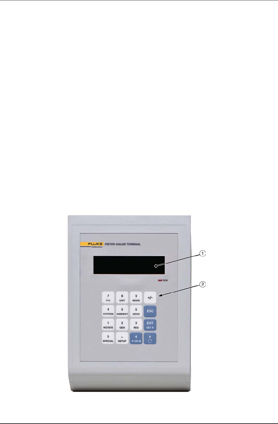
1.3.1.1 PG Terminal Front Panel
The front panel assembly provides a 2 x 20 vacuum fluorescent display and a
4 x 4 membrane keypad for local user interface. The terminal front panel assembly
is the same for all PG7000 models.
Fluorescent display
Keypad
Figure 1. PG Terminal Front Panel
1. INTRODUCTION
Page 11 © 2011 Fluke Calibration
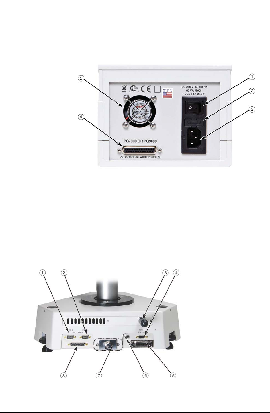
1.3.1.2 PG terminal Rear Panel
The rear panel assembly provides the communications connection to the
PG7000 Platform and the power connection module. The terminal rear panel
assembly is the same for all PG7000 models.
1. Power switch
2. Fuse
3. Power receptacle
4. Connector for cable to PG7000 (25-pin)
5. Cooling fan
Figure 2. PG Terminal Rear Panel
1.3.2 Platform Rear Panels
The PG7000 Platform rear panels provide the connection to the PG Terminal, remote
communication connections and pressure connection ports. The rear panels of all PG7000
models are identical except for the pressure connections (see Figure 3, # 7).
COM2 (RS232) - External
Barometer, External Vacuum
Gauge (PG7601 only) and Pass
Through Communications
COM3 (RS232) - Automated
Pressure Generation/Control
Component
Temperature - Humidity Probe
COM1 (RS232) - Remote Host
Communications
IEEE-488 - Remote Host
Communications
AMH Connection
Pressure Ports:
PG7102 - TEST port: DH200
PG7202 - TEST and DRAIN
ports: DH500
PG7302 - TEST port: DH500
PG7601 - TEST and VACUUM vent
ports: DH200
Vacuum pull down port on front
left side: KF25
PG7000 Terminal Port
Figure 3. PG Platform Rear Panel

PG7000™ OPERATION AND MAINTENANCE MANUAL
© 2011 Fluke Calibration Page 12
Notes

Page 13 © 2011 Fluke Calibration
2. Installation
2.1 Unpacking And Inspection
2.1.1 Removing from Packaging
A typical PG7000 system includes the PG7000 Platform (see Section 2.1.1.1), a mass set, (see
Section 2.1.1.2), one or more piston-cylinder modules (see Section 2.1.1.3) and other accessories
such as an AMH automated mass handler and/or pressure generation and control components
(see the accessory Operation and Maintenance Manual or Instruction Sheet).
2.1.1.1 Platform
Caution
The mass loading bell is a metrological element that is part of
the mass set. Like all of the masses, it is preferable not to
handle it with bare hands. Protective gloves are provided in the
accessory kit of each PG7000 Platform.
The PG7000 Platform is shipped in a reusable, molded shipping and storage case.
Open the PG7000 shipping and storage case (it is the large, 66 cm x 53 cm
x 47 cm case).
Remove the PG Terminal and accessories from upper packing insert.
Inspect and inventory the accessories (see Section 2.1.2).
Remove the upper packing insert.
Carefully lift the PG7000 Platform from its position in the lower packing
insert. Note the orientation so that the same orientation will be used when
PG7000 is repacked.
Reinstall the upper packing insert into the shipping and storage case and
store in a safe place.
2.1.1.2 Mass Set
Caution
The stability over time of PG7000 pressure measurements is a
function of the stability of the masses loaded on the piston.
Precautions should be taken in handling the masses to minimize
influences that may change their mass. This includes always
wearing protective gloves when handling the masses to avoid
contaminating them with body oils and perspiration. Protective
gloves are provided in the accessory kits of PG7000 Platforms.
The mass set accessories are shipped in a separate corrugated container.
Open the corrugated container and inspect and inventory the accessories.
The PG7000 masses are shipped in reusable, molded shipping and
storage cases. The PG7000 masses should be removed from their shipping
cases and inventoried when actually setting up the PG7000 system.

PG7000™ OPERATION AND MAINTENANCE MANUAL
© 2011 Fluke Calibration Page 14
2.1.1.3 Piston-Cylinder Module(s)
The piston-cylinder modules are shipped in Acetal bullet cases that are packed in
corrugated containers with custom foam inserts.
Open the corrugated containers and remove the piston-cylinder modules
and accessories.
The bullet cases screw open by turning the lid counterclockwise.
Caution
When reinstalling an oil (PC-7300) or liquid lubricated (PC-7200)
piston-cylinder module in its bullet case, be sure to empty out
any liquid that may have collected in the hole in the bottom of
the case. Excess liquid will not compress, making it difficult to
fully close the case and could result in damaging it.
2.1.1.4 Automated Mass Handler
See the AMH-38/AMH-100 Operation and Maintenance Manual.
2.1.2 Inspecting Contents
Check that all items are present and have NO visible signs of damage. A parts list of items
supplied is provided in Section 2.1.2.1 for PG7000, Section 2.1.2.2 for mass sets, and
Section 2.1.2.3 for piston-cylinder modules.
2.1.2.1 Platform
Each PG7000 Platform is delivered complete with accessories as listed by part
number in Tables 1 through 4.

2. INSTALLATION
Page 15 © 2011 Fluke Calibration
Table 1. PG7102 Parts List
DESCRIPTION
PG7102
P/N 3069572
NON-CE
PG7102
P/N 3072317
CE
Platform 3117734 3117752
Manual Mass Bell 3071537
Terminal 3069735
PG Terminal to Platform Cable
Non-CE (DB25M - DB25F,
≈ 1.8 meters) 3068724
CE (DB25M - DB25F,
≈ 1.5 meters) 3072235
Power Cable 3133781 (Black) 3153005 (Gray)
TH Probe Assembly 2106009
Accessory Kit 3117741
NIP, SS, DH200, 2.75 in. 3068377
ADPT, SS, DH200 F x 1/8 in. NPT F 3068547
O-ring, Buna 2-242 (2 ea.) 3135041
Storage Cover, 7600 Type 3135594
Allen Wrench, 2.5 mm 3136044
Allen Wrench, 3 mm 3135703
Allen Wrench, 5 mm 3136098
Spanner Wrench (Metrological) 3068940
Krytox GPL205/6 0.5 oz. 2493420
Gift Kit with Gloves 3123777
ADPT, DH200 M x 1/8 in. swage 3069062
Documentation
Calibration Report (PG Platform)
Calibration Report (Mass Bell)
Technical Data
PG7000 Operation &
Maintenance Manual
Documentation CD
3152121
3152121
3152139
3152117
3139043

PG7000™ OPERATION AND MAINTENANCE MANUAL
© 2011 Fluke Calibration Page 16
Table 2. PG7202 Parts List
DESCRIPTION
PG7202
#3070404
NON-CE
PG7202
#3072395
CE
Platform 3119996 3120027
Manual Mass Bell 3071537
Terminal 3069735
PG Terminal to Platform Cable
Non-CE (DB25M - DB25F,
≈ 1.8 meters) 3068724
CE (DB25M - DB25F,
≈ 1.5 meters) 3072235
Power Cable 3133781 (Black) 3153005 (Gray)
TH Probe Assembly 2106009
Accessory Kit 3120011
DH500 M x 1/8 in. NPT F 3142684
O-ring, Buna 2-242 (2 ea.) 3135041
Storage Cover, 7600 Type 3135594
Allen Wrench, 2.5 mm 3136044
Allen Wrench, 3 mm 3135703
Allen Wrench, 5 mm 3136098
Wrench, 5/8 in. 3139417
Collar, SS, DH500 3068607
Krytox GPL205/6 0.5 oz. 2493420
Gift Kit with Gloves 3123777
Documentation
Calibration Report (PG)
Calibration Report (Mass Bell)
Technical Data
PG7000 Operation &
Maintenance Manual
Documentation CD
3152121
3152121
3152139
3152117
3139043

2. INSTALLATION
Page 17 © 2011 Fluke Calibration
Table 3. PG7302 Parts List
DESCRIPTION
PG7302
P/N 3069747
NON-CE
PG7302
P/N 3072339
CE
Platform 3118073 3118086
Manual Mass Bell 3071537
Terminal 3069735
PG Terminal to Platform Cable
Non-CE (DB25M - DB25F,
≈ 1.8 meters) 3068724
CE (DB25M - DB25F,
≈ 1.5 meters) 3072235
Power Cable 3133781 (Black) 3153005 (Gray)
TH Probe Assembly 2106009
Accessory Kit 3120011
DH500 M x 1/8 in. NPT F 3142684
O-ring, Buna 2-242 (2 ea.) 3135041
Storage Cover, 7600 Type 3135594
Allen Wrench, 2.5 mm 3136044
Allen Wrench, 3 mm 3135703
Allen Wrench, 5 mm 3136098
Wrench, 5/8 in. 3139417
Collar, SS, DH500 3068607
Krytox GPL205/6 0.5 oz. 2493420
Gift Kit with Gloves 3123777
Documentation
Calibration Report (PG)
Calibration Report (Mass Bell)
Technical Data
PG7000 Operation &
Maintenance Manual
Documentation CD
3152121
3152121
3152139
3152117
3139043

PG7000™ OPERATION AND MAINTENANCE MANUAL
© 2011 Fluke Calibration Page 18
Table 4. PG7601 Parts List
DESCRIPTION
PG7601
P/N 3069028
NON-CE
PG7601
P/N 3072258
CE
Platform 3117525 3117540
Manual Mass Bell 3071603
Bell Jar and Seal 3068933 and 3068634
Terminal 3069735
PG Terminal to Platform Cable
Non-CE (DB25M - DB25F,
≈ 1.8 meters) 3068724
CE (DB25M - DB25F,
≈ 1.5 meters) 3072235
Power Cable 3133781 (Black) 3153005 (Gray)
TH Probe Assembly 2106009
Accessory Kit 3117533
NIP, SS, DH200, 2.75 in. 3068377
ADPT, SS, DH200 F x 1/8 in. NPT F 3068547
O-ring, Buna 2-242 (2 ea.) 3135041
Storage Cover, 7600 Type 3135594
Allen Wrench, 2.5 mm 3136044
Allen Wrench, 3 mm 3135703
Allen Wrench, 5 mm 3136098
Spanner Wrench (Metrological) 3068940
Krytox GPL205/6 .5 oz. 2493420
Gift Kit with Gloves 3123777
ADPT, DH200 M x 1/8 in. swage 3069062
Valve, Vacuum Relief 3124573
Documentation
Calibration Report (PG)
Calibration Report (Mass Bell)
Technical Data
PG7000 Operation &
Maintenance Manual
Documentation CD
3152121
3152121
3152139
3152117
3139043

2. INSTALLATION
Page 19 © 2011 Fluke Calibration
2.1.2.2 Mass Set
PG7000 mass sets are composed of different combinations of individual masses
and accessories depending on the specific mass set ordered (see Tables 5 - 9).
Table 5. Manual Mass Set Parts List (excluding 80 and 100 kg)
DESCRIPTION PART NO.
Mass Set Refer to Table 9
Reusable Molded Transit Case with Foam Inserts
35 kg set
40 kg set
45 kg set
55 kg set
3068969
1 ea.
1 ea.
1 ea.
1 ea.
3068991
1 ea.
1 ea.
1 ea.
2 ea.
Mass Set Tray and Spindle 3147461 and 3148764
Dust Covers 3138017 and 3138130
Calibration Report 3152121
Table 6. Manual Mass Set Parts List (80 and 100 kg)
DESCRIPTION PART NO.
Mass Set Refer to Table 9
Reusable Molded Transit Case with Foam Inserts
80 kg set
100 kg set
3068969
1 ea.
1 ea.
3068984
2 ea.
3 ea.
Mass Set Tray and Spindle 3147461 and 3148764
Dust Covers 3138017 and 3138127
Calibration Report 3152121
Table 7. AMH-38 Mass Set Parts List
DESCRIPTION PART NO.
Mass Set Refer to Table 9
Reusable Molded Transit Case with Foam Inserts
13 kg set (MS-AMH-13)
25 kg set (MS-AMH-25)
39 kg set (MS-AMH-38)
3123990
1 ea.
1 ea.
1 ea.
3069004
1 ea.
1 ea.
1 ea.
Calibration Report 3152121
Table 8. AMH-100 Mass Set Parts List
DESCRIPTION PART NO.
Mass Set Refer to Table 9
Reusable Molded Transit Case with Foam Inserts
40 kg set (MS-AMH-40)
60 kg set (MS-AMH-60)
80 kg set (MS-AMH-80)
100 kg set (MS-AMH-100)
3123990
1 ea.
1 ea.
1 ea.
1 ea.
3068984
1 ea.
2 ea.
2 ea.
3 ea.
Calibration Report 3152121
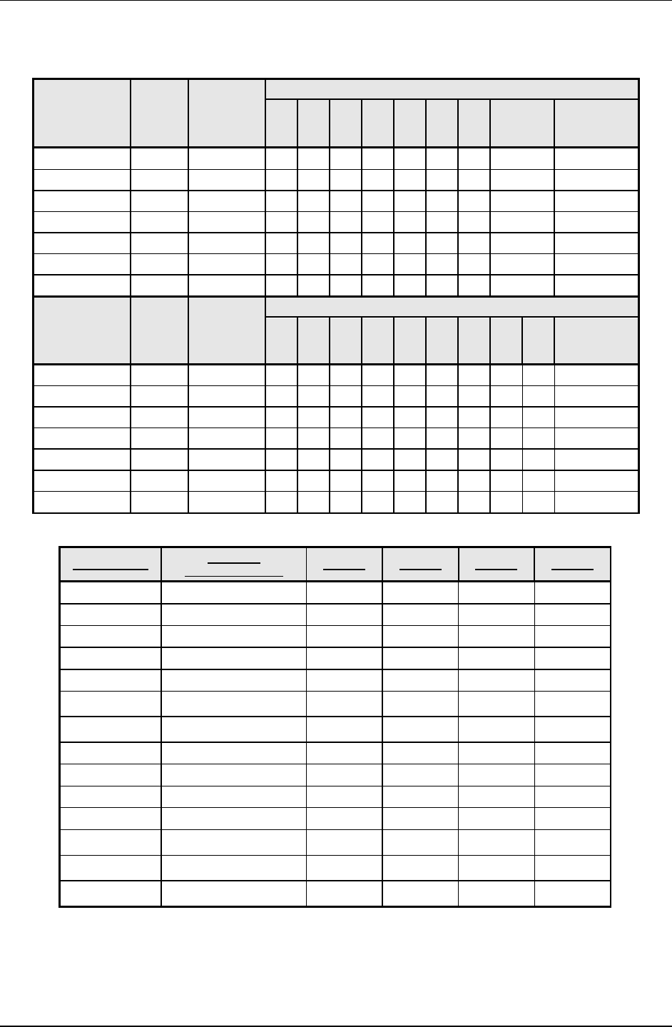
PG7000™ OPERATION AND MAINTENANCE MANUAL
© 2011 Fluke Calibration Page 20
Table 9. Mass Set Compositions
DESIGNATION PART # NOMINAL
TOTAL
MASS (kg)
MASS SET COMPOSITION
10
kg 5
kg 2
kg 1
kg 0.5
kg 0.2
kg 0.1
kg
MAKE-UP
MASS
(kg)
MS-7001-35 3069850 35 - 5 2 1 1 2 1 1 (4.5) -
MS-7002-35 3069861 35 - 5 2 1 1 2 1 1 (4) -
MS-7002-40 3070021 40 - 6 2 1 1 2 1 1 (4) -
MS-7002-45 3069980 45 - 7 2 1 1 2 1 1 (4) -
MS-7002-55 3069877 55 - 9 2 1 1 2 1 1 (4) -
MS-7002-80 3070000 80 6 1 2 1 1 2 1 1 (9) -
MS-7002-100 3070017 100 8 1 2 1 1 2 1 1 (9) -
DESIGNATION PART # NOMINAL
TOTAL
MASS (kg)
MASS SET COMPOSITION
10
kg 6.4
kg 6.2
kg 3.2
kg 1.6
kg 0.8
kg 0.4
kg 0.2
kg 0.1
kg
BELL, SHAFT,
BINARY MASS
CARRIER
(3 PARTS)
MS-AMH-13 3071491 13 - - 1 1 1 1 1 1 1 1
MS-AMH-25 3071484 25 - - 3 1 1 1 1 1 1 1
MS-AMH-38 3071433 38 - - 5 1 1 1 1 1 1 1
MS-AMH-40 3071528 40 3 1 - 1 1 1 1 1 1 1
MS-AMH-60 3071519 60 5 1 - 1 1 1 1 1 1 1
MS-AMH-80 3071504 80 7 1 - 1 1 1 1 1 1 1
MS-AMH-100 3071440 100 9 1 - 1 1 1 1 1 1 1
Table 10. Mass Set Compatibility
1 These mass sets, on certain piston-cylinder sizes, can cause the maximum working pressure of the PG Platform to be
exceeded. Do not exceed the following maximum working pressures:
1. PG7201: 11 MPa (1 600 psi)
2. PG7202: When using PC-7200 piston-cylinder modules: 110 MPa (16 000 psi)
When using PC-7300 piston-cylinder modules: 200 MPa (30 000 psi)
3. PG7302:500 MPa (72 500 psi)
DESIGNATOR NOMINAL
TOTAL MASS (kg) PG7102 PG7202 PG7302
MS-7001-35
PG7601
35 •
MS-7002-35 35 • • •
MS-7002-40 40 • • •
MS-7002-45 45 • • •
MS-7002-55 55 • • •
MS-7002-80 80 •1 •1 •
MS-7002-100 100 •1 •1 •
MS-AMH-13 13 •
MS-AMH-25 25 •
MS-AMH-38 38 •
MS-AMH-40 40 • • •
MS-AMH-60 60 •1 •1 •
MS-AMH-80 80 •1 •1 •
MS-AMH-100 100 •1 •1 •

2. INSTALLATION
Page 21 © 2011 Fluke Calibration
Note
The mass loading bell and piston make up part of the total mass
load. The mass loading bell for loading manual mass sets is
delivered with the PG7000 platform. The mass loading bell for
AMH mass sets is delivered with the mass set. Piston-cylinder
modules are purchased and delivered separately.
2.1.2.3 Piston-Cylinder Module(s)
Table 11. PC-7100/7600 Piston-Cylinder Modules Parts List
10 kPa
PC-7100/
7600-10-L
10 kPa
PC-7100/ 7600-
10 TC
20 kPa
PC-7100/
7600-20
50 kPa
PC-7100/
7600-50
100 kPa
PC-7100/
7600-100
200 kPa
PC-7100/
7600-200
Piston-Cylinder Kit 3171975 3070095 3071581 3070109 3071615 3070111
Piston-Cylinder
Module 3125106 3122937 3122116 3124088 3122234 3124194
Hermetic Acetal
Bullet Case 3070203 3070203 3070203 3070203 3070203 3070203
Accessory Kit 3125242 3122928 3122229 3124345 3124345 3124345
O-rings 3134867
3136458
3134867
3136458
3134867
3136458
3134880
3136458
3134880
3136458
3134880
3136458
Insertion Tool 3071793 3071841 N/A N/A N/A N/A
Calibration Report 3152121 3152121 3152121 3152121 3152121 3152121
Table 12. PC-7200 Piston-Cylinder Modules Parts List
100 kPa
PC-7200-100
200 kPa
PC-7200-200
500 kPa
PC-7200-500
1 MPa
PC-7200-1
2 MPa
PC-7200-2
Piston-Cylinder Kit 3070419 3070428 3070437 3070443 3070455
Piston-Cylinder Module 3120245 3120250 3120292 3120303 3120326
Hermetic Acetal
Bullet Case 3071852 3071852 3071852 3071852 3071852
Accessory Kit 3120277 3120277 3120315 3120315 3120315
O-rings
(2) 3134158
2721018
2644003
(2) 3134158
2721018
2644003
(2) 3134158
2721018
2644003
(2) 3134158
2721018
2644003
(2) 3134158
2721018
2644003
Anti-Extrusion Ring N/A N/A 3148417 3148417 3148417
Syringe 3139439 3139439 3139439 3139439 3139439
Syringe tips (3) 3139421 (3) 3139421 (3) 3139421 (3) 3139421 (3) 3139421
Synturion 6 fluid 3120289 3120289 - - -
Sebacate fluid - - 3120590 3120590 3120590
Calibration Report 3152121 3152121 3152121 3152121 3152121

PG7000™ OPERATION AND MAINTENANCE MANUAL
© 2011 Fluke Calibration Page 22
Table 13. PC-7300 Piston-Cylinder Modules Parts List
100 kPa
PC-7300-100
200 kPa
PC-7300-200
500 kPa
PC-7300-500
1 MPa
PC-7300-1
2 MPa
PC-7300-2
5 MPa
PC-7300-5
Piston-Cylinder Kit 3070039 3070042 3070056 3070063 3070074 3070088
Piston-Cylinder
Module 3118918 3118976 3119032 3119116 3119178 3119229
Hermetic Acetal
Bullet Case 3071865 3071865 3071865 3071865 3071865 3071865
Accessory Kit 3119102 3119102 3119102 3119366 3119366 3119366
O-rings 2527053
3134022
2527053
3134022
2527053
3134022
1785497
(5) 927863
1785497
(5) 927863
1785497
(5) 927863
Calibration
Reports 3152121 3152121 3152121 3152121 3152121 3152121
2.2 Site Requirements
The exact PG7000 system installation is affected by the elements other than the PG7000 Platform that
make up the PG7000 system.
When selecting and preparing a site to set up the PG7000 system, the following should be considered:
• Ambient conditions: To achieve optimum metrological performance, ambient conditions should be
controlled and maintained within the following:
♦ Temperature: 19 to 23 °C, minimize rate of change of temperature.
♦ Relative Humidity: 10 to 60 %RH (non-condensing).
♦ Ambient Pressure: Minimize external influences that will cause barometric instability.
♦ Air Currents: Do not install the PG7000 Platform under a source of vertical air currents such as an
overhead air conditioning duct. These can blow on the mass load and add unquantified forces.
♦ Vibration: Minimize local vibration. Excessive vibration will reduce the stability of the pressures
defined by PG7000 (vibration affects the floating piston). Excessive high frequency vibration, for
example from a vacuum pump on the same table as the PG7000, may affect piston sensitivity.
• Bench stability: Up to 100 kg may be loaded and unloaded onto the PG7000 Platform. The bench
on which the PG7000 sits should not deflect significantly under the mass load changes. This can be
verified by setting the PG7000 Platform on the bench, leveling it, loading and unloading the complete
mass set while observing whether the level setting changes.
• Location of other components: Plan the space required and a convenient layout for the complete
PG7000 system including the PG Terminal, mass set, pressure generation/control component(s), test
instrument connection and computer (if present). If using a PPC, MPC, GPC or OPG to
generate/control pressure, see its Operation and Maintenance Manual for information on installing it.
If a Fluke Calibration interconnections kit is being used to interconnect the components, see its
instruction sheet.
• Electrical and pressure supplies: Plan the supply of electrical power to the PG Terminal and to the
pressure generation/control component(s), if needed. If using a PPC, MPC, GPC or OPG to
generate/control pressure, see its Operation and Maintenance Manual for information on the
pressures source(s) it needs and how to connect them. Gas supplied to a PC-7100/7600
piston-cylinder module must be clean and dry (instrument grade minimum, high purity preferred) to
avoid contaminating the piston-cylinder gap.
• Reference vacuum supply (PG7601 only): Plan for the vacuum connection to the platform or the
optional AMH automated mass handler and the location of the reference vacuum pump.
• Bell jar placement (PG7601 only): Plan a location for the bell jar when it is removed from the
platform to load and unload masses. A small shelf is often used for this purpose.
• AMH automated mass handler (optional) placement: If an AMH is being used, plan electrical and
pneumatic connections to it as well as a location to place it when it is removed from the platform (see
the AMH-38/AMH-100 Operation and Maintenance Manual).

2. INSTALLATION
Page 23 © 2011 Fluke Calibration
2.3 Setup
2.3.1 Preparing for Operation
Note
Before setting up the PG7000 system, see Section 2.2 for information on
site requirements.
To prepare PG7000 for check out and operation:
Set up the PG7000 Platform (see Section 2.3.1.1).
If an optional AMH-100 mass set is being used, set it up with its mass set (see the AMH-
38/AMH-100 Operation and Maintenance Manual).
Make the system pressure interconnections (see Section 2.3.1.2).
If a manual mass set is being used, set up the manual mass set (see Section 2.3.1.3).
2.3.1.1 Setting Up the Platform
To set up the PG7000 Platform proceed as follows:
Place the PG7000 Platform on the site table in the desired orientation.
Though the rear panel is usually in the back, any orientation can be used.
Place the PG7000 Terminal at the desired location.
Connect the PG7000 Terminal to the PG7000 Platform using the 25-pin
cable supplied.
Connect the PG7000 Temperature - Humidity Probe per Figure 3.
Connect electrical power (85 to 264 VAC, 50/60 Hz) to the PG7000 Terminal
using the power cable supplied. Any grounded power cable with a standard
IEC320-313 connection may be used.
(PG7601 Only) - Install the vacuum vent valve kit on the vacuum vent port
on the rear of the PG7000 Platform. Refer to the instruction sheet provided
with the vent valve assembly.
Connect the reference vacuum source and shutoff valve to the reference
vacuum port. Take measures to assure that vacuum oil cannot return to the
PG7601. If an optional AMH-38 automated mass handler is being used, the
reference vacuum may be connected to the larger KF40 vacuum connection
on the AMH-38 vacuum chamber.
If an external barometer and/or vacuum gauge is/are being used, establish
communications between the barometer/vacuum gauge and the PG7000
Platform by connecting the external device RS232 port to the PG7000
Platform Com2 port and setting up PG7000 to read and use an external
barometer and/or vacuum gauge (see Section 3.11.5.4, 3.11.5.5). Set the
external barometer head height (see Section 3.11.3.3).
If an automated pressure generation/control component is being used,
establish communications between the automated pressure
generation/control component and the PG7000 Platform by connecting the
generation/control component RS232 port to the PG7000 Platform COM3 port
and setting up PG7000 to use an automated pressure generation/control
component (see Section 3.9.9).
If an AMH automated mass handling system is being used, set up the AMH
mass set and the AMH mass handler following the instructions in the AMH-
38/AMH-100 Operation and Maintenance Manual.
Level the platform using the PG7000 Platform’s two leveling feet and the
level mounted on the front of the platform. (Or on the optional AMH mass
handling system.)

PG7000™ OPERATION AND MAINTENANCE MANUAL
© 2011 Fluke Calibration Page 24
2.3.1.2 System Pressure Interconnections
Interconnect the PG7000 Platform, pressure generation/control components and
a test connection.
The pressure connection on the PG7000 TEST port is:
• PG7102/PG7601: DH200 (DH200 is equivalent to AE SF250C,HIP LF4,
etc.). Adapters to convert the DH200 connection to 1/8 in. NPT female and
1/8 in. swage are provided with PG7102 and PG7601 Platform accessories.
• PG7202: DH500 (DH500 is equivalent to AE F250C, HIP HF4, etc.).
Connect the gas test medium pressure control/generation component to
the TEST port. If the PG7202 is to be operated in oil, connect the oil
pressure control/generation component to the DRAIN port (the gas or oil
component is disconnected when not in use, see Section 2.3.3).
• PG7302: DH500 (DH500 is equivalent to AE F250C, HIP HF4, etc.).
Note
If using a standard interconnections kit such as PK-7600-
PPC/MPC P/N 3069508, PK-7600-PPC/MPC-DIF P/N 3070127 or
PK-7100-MPCD-DIF P/N 3070226, see the instruction sheet
provided with the kit for installation instructions. If an OPG1 or
GPC1 generator/controller is being used, pressure
interconnecting hardware is included with it. See its Operation
and Maintenance Manual for connection instructions.
2.3.1.3 Setting Up a Mass Set
Note
If installing an MS-AMH-xxx mass set for use with an AMH
automated mass handling system, see the AMH-38/AMH-100
Operation and Maintenance Manual.
To install a PG7000 manual mass set, place the mass loading tray (provided with
the mass set accessories) at the desired location then install the individual
masses on the mass loading tray. See the AMH-38/AMH-100 Operation and
Maintenance Manual for instructions on installation of an AMH mass set for
automated mass handling.
Caution
It is VERY IMPORTANT that the individual masses be installed
on the mass loading tray in proper sequence. This will ensure
that PG7000 mass loading instructions are executed properly
(carefully follow the instructions provided in Section 2.3.1.3,
Installing Masses on the Mass Loading Tray).
PG7000 masses are shipped in reusable, molded shipping and storage cases.
One of the cases contains a 4.0, 4.5 or 5 kg mass and the masses of 2 kg and
under, the other case(s) contain(s) the main masses of 10 or 5 kg each. Each mass
is packed in a sealed plastic bag and then placed in a protective shipping insert.
Installing Masses on the Mass Loading Tray (Manual Mass Set)
Caution
The stability over time of PG7000 pressure measurements is a
function of the stability of the masses loaded on the piston.
Precautions should be taken in handling the masses to minimize
influences that may change their mass. This includes always
wearing protective gloves when handling the masses to avoid
contaminating them with body oils and perspiration. Protective
gloves are provided in the accessory kits of PG7000 Platforms.

2. INSTALLATION
Page 25 © 2011 Fluke Calibration
To install the masses on the mass loading tray, proceed as follows:
Open the shipping cases.
Install the main masses: The main masses (a series of 10 kg masses if the
mass set is > 55 kg, a series of 5 kg masses if the mass set is < 60 kg)
are installed horizontally aligned on the mass loading spindle.
The main masses are sequentially numbered starting with he number 1.
The main mass with the highest sequential number is installed first at the
bottom of the stack (i.e., the first mass loaded on the tray). The rest of the
main masses should be stacked upwards in descending order ending with
main mass sequential number 1. Be careful NOT to confuse the makeup
mass (refer to next item) with main mass 1.
Install the make up mass: The make up mass is a single mass sequentially
numbered 1. It has the same diameter as the main masses. It is a 9 kg
mass if the main masses are 10 kg. It is 4 or 4.5 kg if the main masses are 5 kg.
The make up mass is placed on top of the main mass stack. It is always the
top of the stack.
Install the fractionary masses: The fractionary masses are all the masses
of lower value than the main masses and makeup mass. These are masses
of 5 kg and under for mass sets with 10 kg main masses. They are masses
of 2 kg and under for mass sets with 5 kg main masses. Fractionary masses
of 1 to 5 kg are discs with a central hole. Fractionary masses of 100 to 500 g
are solid, small diameter pucks. Fractionary masses of 50 g and under are
grams masses packed and stored in their own separate storage case.
Fractionary mass discs and pucks are installed vertically in the corresponding slots
in the mass loading tray. Use a consistent setup for the sequence number
when there are two masses (e.g., always load sequential number 1 in the front).
2.3.2 installing a Piston-Cylinder Module into the Platform
To operate the PG7000 Platform, a piston-cylinder module must be installed in its mounting
post. To install a piston-cylinder module in the PG7000 Platform, proceed as follows:
Remove the PG7000 Platform mounting post plug. Unscrew the ORANGE plastic
mounting post plug that is installed in the PG7000 Platform mounting post.
Rotate counterclockwise to remove.
Remove the piston-cylinder module from its bullet case. Select a piston-cylinder
module. Open the piston-cylinder module bullet case by rotating its lid counterclockwise.
Remove the piston-cylinder module from the bullet case base by unthreading it from the case.
Hold the piston-cylinder module body by the knurled area and rotate it counterclockwise.
Note
PC-7200 gas operated, liquid lubricated piston-cylinder modules are
delivered with their lubricating liquid reservoir drained. The reservoir must
be filled prior to using the piston-cylinder module. If installing a PC-7200
gas operated, liquid lubricated piston-cylinder module, see Section 5.3.3
for instructions on how to fill the module’s liquid lubrication reservoir prior
to installation, then continue the procedure from this point.
Caution
When reinstalling an oil or liquid lubricated gas piston-cylinder module in
its bullet case, be sure to empty out any liquid that may have collected in
the hole in the bottom of the case. The liquid will not compress, making it
difficult to fully close the case and could result in damaging it.
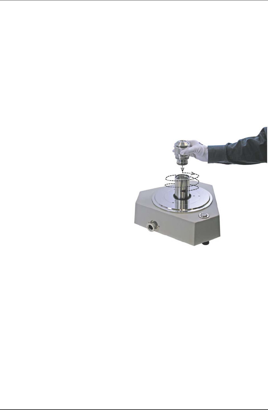
PG7000™ OPERATION AND MAINTENANCE MANUAL
© 2011 Fluke Calibration Page 26
Place the piston-cylinder module in the PG7000 Platform mounting post. Place
the piston-cylinder module (thread down) into the PG7000 Platform mounting post
(see Figure 4 below).
Note
If installing the piston-cylinder module into a PG7302 or a PG7202 to be
operated with oil, first use the oil generation control component to fill the
counter bore in the mounting post with oil until it just starts to overflow.
Purge the air from under the piston-cylinder module (PC-7300 modules only in
PG7302 or PG7202). Rotate the piston-cylinder module clockwise until all threads are
engaged and there is no gap between the piston-cylinder module and the mounting post.
Back the piston-cylinder module off slightly by rotating it counterclockwise 3/4 turn.
Slowly supply additional oil to the mounting post from the pressure generation/control
component. Watch the oil run off tube on the bottom right of the platform. As soon as oil
appears or can be seen flowing, stop the oil supply.
Screw the piston-cylinder
module into the PG7000
Platform mounting post.
Rotate the piston-cylinder
module clockwise until all
threads are engaged and there
is NO gap between the piston-
cylinder module and the PG7000
mounting post. Slight resistance
will be encountered in the
second half of travel as the
piston-cylinder module O-rings
seat in the mounting post.
Figure 4. Piston-Cylinder Module Installation
Caution
• Low torque manual rotation is all that should be required to fully seat the
piston-cylinder module into the PG7000 mounting post. Never force the
piston-cylinder module into the mounting post.
• Always maintain PG7202 and PG7302 piston- cylinder modules vertical
with the piston cap up. Do not invert the assembly, as this might allow
liquid to run up into the piston head and into the adjustment mass and
cap. Liquid contamination of the piston head and cap changes the
mass of the piston assembly and could lead to out of tolerance
pressure definitions at low mass loads. If liquid contaminates the
adjustment mass and cap, disassemble the module and clean it (see
Sections 5.3.1, 5.3.4, 5.3.2.2).
2.3.3 Switching a PG7202 Between Gas Operation and Oil
Operation
PG7202 can be operated with gas as the pressurized medium using PC-7200 gas operated,
liquid lubricated modules or with oil as the pressurized medium using oil operated PC-7300
modules.

2. INSTALLATION
Page 27 © 2011 Fluke Calibration
Note
PC-7200 gas operated, liquid lubricated piston-cylinder modules can be
operated in gas oil filled with oil and operated in oil. Oil operation of PC-
7202 modules is not recommended for routine operation. It can be useful
in very specific crossfloating circumstances, particularly when
establishing a calibration link between independent gas operated and oil
operated piston gauges. When switching PC-7200 module between oil and
gas and oil operation, see Section 5.3.3 for information on emptying
excess oil from the module.
Note
Switching a PG7202 from gas to oil operation
Only the high pressure PC-7300 oil modules may be used in the PG7202
platform (PC-7300-1, -2, -5)
Disconnect the gas generation/control system from the TEST port. Disconnect the
tube at the DH500 TEST port connection on the back of the PG7202. Loosely install a
DH500 plug in the TEST port.
Connect the oil generation/control system to the DRAIN port. Connect a tube from
the oil generation/control system to the PG7202 DRAIN port and tighten it (torque DH500
glands to 15 Nm (12 ft.lb)).
Fill the PG7202 mounting post with oil. Hand tighten the DH500 plug in the TEST
port. Use the oil generation/control component to fill the PG7202 mounting post with oil.
Fill to the edge of the second step in the mounting post. Place a paper towel under the
TEST port plug and loosen the DH500 plug allowing oil to run out until it is at the level of
the first step in the mounting post and there is no air in the run off oil. If there is still air in
the run off, repeat the operation. After filling the mounting post, tighten the DH500 plug
(torque DH500 glands to 15 Nm (12 ft.lb)).
Install a PC-7300 oil operated piston-cylinder module in the PG7202 platform.
Install the module and purge the air from underneath it (see Section2.3.2).
Operate with oil as the test medium. The PG7202 can now be operated with oil as the
test medium.
Caution
The maximum working pressure of the PG7202 platform when used in
oil with a PC-7300 module is 200 MPa (30 000 psi). The maximum
pressure when using a PC-7200 module is 110 MPa (16 000 psi). Do not
exceed this limit.
Remove the piston-cylinder module. Disinstall the PC-7300 oil operated piston-cylinder
module for the PG7202 platform.
Switching a PG7202 from oil to gas operation
Disconnect the oil generation/control system from the DRAIN port. Place a paper
towel under the DRAIN port and disconnect the tube to the oil generation/control system.
Let all the oil run out of the PG7202 platform.
Remove the DH500 plug from the TEST port. Place a paper towel under the TEST
port and remove the DH500 plug. Let all the oil run out of the PG7202 platform..
Install a PC-7200 gas operated, liquid lubricated piston-cylinder module in the
PG7202 platform. Install the piston-cylinder module (see Section 2.3.2).
Connect the gas generation/control system to the TEST port. Connect a tube from
the oil generation/control system to the PG7202 TEST port and tighten it (torque DH500
glands to 15 Nm (12 ft.lb)).
Prepurge the oil from the PG7202 mounting post. Hold a paper towel lightly over the
DRAIN port opening. Leaving the drain port open, use the gas generation/control
component to flow enough gas through the mounting post to just lift the piston.

PG7000™ OPERATION AND MAINTENANCE MANUAL
© 2011 Fluke Calibration Page 28
Purge the PG7202 mounting post. Purge the PG7202 mouting post using the standard
purging procedure (see Section 5.2.4) and finish by tightening the plug in the DRAIN port.
Operate with gas as the test medium. The PG7202 can now be operated with gas as
the test medium.
Caution
The maximum working pressure of the PG7202 platform when used with a
PC-7200 module is 110 MPa (16 000 psi). Do not exceed this limit.
2.4 Power Up and Verification
2.4.1 Power UP
Turn the PG7000 power ON by pressing the power ON/OFF switch on the rear panel of the
PG Terminal. Observe the PG terminal display as the terminal connects with the PG7000
Platform, tests, initializes and goes to the main run screen (see Section 3.7).
If <….Searching…..> displays for more than 5 seconds, the communications between the
PG7000 and the PG Terminal are failing. Check that the PG7000 to PG Terminal cable is
properly installed.
If PG7000 fails to reach the main run screen, service may be required. Record the sequence
of operations and displays observed and contact a Fluke Calibration Authorized Service
Provider
(see Table 32).
2.4.2 Check that On-Board Piston-Cylinder Module and
Mass Set Information are Correct
PG7000 uses stored piston-cylinder and mass set metrological information to calculate the
reference pressures it defines (see Section 3.1). For the pressure values to be correct, the
stored metrological information on the piston-cylinder, mass set and mass loading bell must
be correct. Before using PG7000 for accurate pressure definition, the validity of the stored
information should be verified. This consists of comparing the piston-cylinder, mass set and
mass loading bell information stored in PG7000 to the information in the current piston-cylinder
and mass set calibration reports.
To verify the PG7000 piston-cylinder, mass set and mass loading bell information, use the
piston-cylinder and mass set viewing capabilities accessed by pressing [SPECIAL],
<1PC/MS> (see Section 3.11.1). Compare all the information contained in the PG7000
piston-cylinder, mass set and mass loading bell files to the information on the current
piston-cylinder, mass set and mass loading bell calibration reports.
2.4.3 Set Local Gravity Value
PG7000 uses the value of local acceleration due to gravity (gl) in its calculation of the
reference pressure it defines (see Section 3.1). The correct value of local acceleration due to
gravity at the site of PG7000 use must be entered. This is accomplished by pressing
[SPECIAL], <6gl> (see Section 3.11.6) and editing the value of local gravity.
2.4.4 Setup Pressure Equation Variable Input Sources
PG7000 uses many variables in calculating defined pressures. The sources of the variables
are determined by the current SETUP file. SETUP files are viewed, created, edited and
selected using the SETUP function accessed by pressing [SETUP] (see Section 3.10).
A factory SETUP file is available and already selected on a new PG7000, but the operator
may desire to customize it. The factory setup file assumes that PG7000’s internal
measurement values will be used whenever possible.

2. INSTALLATION
Page 29 © 2011 Fluke Calibration
2.4.5 Check Proper Operation of Ambient Condition
Measurements
PG7000 automatically measures ambient conditions and uses these conditions in its
pressure calculations.
To verify that the ambient condition measurements are operating properly proceed as follows:
• Display current ambient condition readings: Press [AMBIENT]. The ambient conditions
run screen is displayed (see Section 3.9.6).
• Verify proper ambient condition readings: Compare the ambient condition values
displayed to the actual values of ambient conditions. Refer to the ambient condition
measurement specifications when evaluating the ambient readings (see Section 1.2.1.2).
Note
• The unit of measure in which ambient pressure is displayed is the same as
the unit selected by pressing [UNIT] (see Section 3.9.3). Units of measure
in which other ambient condition values are expressed cannot be
changed.
• PG7000 allows the source of ambient condition values used in reference
pressure calculations to be specified. The source may be PG7000’s on-
board measurements, default values or operator entered values. See
Section 3.10 for information on specifying the source of ambient
condition values used by PG7000 in reference pressure calculations.
2.4.6 apply pressure to THE piston-cylinder module
Note
This section assumes that the PG7000 system has already been set up,
including pressure interconnection (see Section 2.3).
Caution
Before applying pressure to the PG7000 system, be sure that all pressure
vessels and connections are rated for the pressure levels that will be
applied and that all connections have been properly tightened.
Continuing with the PG7000 set up and check out requires applying pressure to the piston-
cylinder module and floating the piston.
Proceed as follows:
Turn OFF automated piston rotation (if present) and automated pressure
generation (if present). This will prevent the automated rotation and pressure
generation features (if present) from interfering during verification of these features (see
Sections 3.9.8 and 3.9.9 for information on automated piston rotation and
pressure generation).
Load mass on the piston. Install the mass loading bell on the piston. Then load the
make up mass (9, 4.5 or 4 kg depending on the mass set) (see Section 2.3.1.3). If the
PG7000 platform is equipped with AMH automated mass handling, press [ENTER] and
enter a low value of pressure or mass to cause mass to be loaded onto the piston.
Float the piston. Use the pressure generation/control component of the PG7000 system
to apply pressure under the piston through the PG7000 Platform TEST port. The piston
will float at a pressure approximately equal to the piston mass to pressure conversion
factor multiplied by the mass load in kg. The piston-cylinder conversion factor is marked
on the top of the piston cap and is in either kPa or MPa per kilogram [kPa/kg or MPa/kg].

PG7000™ OPERATION AND MAINTENANCE MANUAL
© 2011 Fluke Calibration Page 30
Note
If the piston cannot be floated because it immediately sinks down from a
float position, there is a leak in the pressure system. Identify and eliminate
leaks until the piston, once floated, falls at a rate less than the nominal fall
rate given in the specifications of the piston-cylinder module being used
(see Section 1.2.2).
2.4.7 Check Proper Behavior of Motorized Piston Rotation
The motorized rotation feature can be set to engage and disengage automatically as needed to
maintain the floating piston rotating within a set rotation rate range when floating, and to stop rotation
before mass manipulation to set a different pressure occurs (see Section 3.9.8). Motorized piston
rotation can also be activated manually by pressing [
]. Stopping piston rotation can be activated
by pressing and holding [] and then pressing [←] (see Section 3.9.13).
Turn automated rotation OFF by pressing [ROTATE] and selecting <1off>. Load at least the
mass bell on the piston, float the piston and press []. When the piston is floating, the
motorized rotation system should engage and cause the mass bell and piston to begin
rotating. Within 5 to 30 seconds, depending on the mass load, the rotation rate should reach
80 rpm for PG7601 or about 50 rpm for PG7102 or PG7302. Current rotation rate can be
observed by pressing [SYSTEM] (see Section 3.9.5).
2.4.8 Check Proper Operation of Piston Behavior
Measurements
Float the piston and rotate it (see Sections 2.4.6 and 2.4.7).
Press [SYSTEM] once to reach the first SYSTEM run screen. Verify that the piston position,
piston fall/rise rate, piston rotation rate and piston rotation decay rate are indicating correctly
(see Section 3.9.5). The piston position reading system may be calibrated using an on-board
procedure if necessary (see Section 5.2.2). Calibration of piston position is recommended
when installing a new PG7000 and regularly after installation.
Press [SYSTEM] again to reach the second SYSTEM run screen. Verify that the piston-cylinder
temperature and temperature rate of change are indicating correctly (see Section 3.9.5).
If checking a PG7601 Platform, verify that the vacuum reference measurement is operating
correctly (see Section 2.4.8.1).
2.4.8.1 Verify Vacuum Reference (PG7601 Only)
PG7601 includes provisions for establishing and measuring a vacuum reference.
To verify the vacuum reference capability:
Install a piston-cylinder module (see Section 2.3.2).
Install the bell jar on the PG7601 Platform (the bell jar aligns on the PG7601
vacuum plate and seals itself). If using AMH-38 automated mass handling,
install the AMH-38 mass handler (see the AMH-38/AMH-100 Operation and
Maintenance Manual).
Apply a vacuum through the reference vacuum port (KF25 port on front left
side of platform or KF40 if using the optional AMH-38 automated mass
handler).
Press [SYSTEM] twice to observe the value of vacuum read by the
PG7601’s built-in vacuum gauge.
If a vacuum pump of adequate capacity has been correctly connected to the
reference vacuum port, the vacuum read by the PG7601 built-in vacuum gauge
should go to 4 Pascal [Pa] or lower in less than five minutes on the first pump
down and two to three minutes on immediately subsequent pump downs.

2. INSTALLATION
Page 31 © 2011 Fluke Calibration
If this performance is NOT achieved:
• The vacuum pump may be inadequate.
• The connection of the vacuum pump to the PG7601 platform of AMH-38
may have leaks or excessive restrictions.
• The PG7601 built-in vacuum gauge or external vacuum gauge may be
incorrect.
• There may be a leak in the PG7601.
2.4.9 Check Automated Pressure Generation (If Present)
Caution
Before applying pressure to the PG7000 system, be sure that all pressure
vessels and connections are rated for the pressure levels that will be
applied and that all connections have been properly tightened.
To check automated pressure generation/control:
Verify that the automated pressure generation/control component is properly connected
to the system (see Section 2.3.1.2).
When operation has returned to the main run screen, turn ON automated pressure generation
control, if available, by pressing [GEN] and selecting <1on> (see Section 3.9.9).
Press [P OR M], <1pressure> to select pressure entry mode (see Section 3.9.12). Press
[ENTER] and enter a pressure value to be generated and follow the mass loading
instruction (see Section 3.6).
Verify the pressure generation/control component properly generates pressure and floats
the PG7000 piston.
2.4.10 Check/Set Security Level
PG7000 has a security system based on User Levels. By default, the security system is set
to low and NO password is required to change the security level. See Section 3.11.4.5 for
information on the security system. As part of the PG7000 startup, set your desired security
level and a password.
Caution
PG7000 is delivered with the security level set to low to avoid inadvertent
altering of critical internal settings but with access to changing security
levels unrestricted. It is recommended that the low security level be
maintained at all times and password protection be implemented if control
over setting of security levels is desired.
2.4.11 Additional Precautions to Take Before Making
Pressure Measurements
Before using PG7000 to make accurate pressure measurements, consider the following:
• Select/activate the correct piston-cylinder module, mass set and mass loading bell
(see Sections 3.9.2, 3.11.1.10, 3.11.1.15).
• If using an automated pressure generation/control component with automated pressure
generation, set the pressure controller’s upper limit (UL) (see Section 3.9.9.3).
• Enter the correct value of local gravity at the site of use (see Section 3.11.6).
• Consider head corrections (see Sections 3.9.7 and 3.11.3).
• Level the PG7000 Platform properly (see Section 2.3.1.1).

PG7000™ OPERATION AND MAINTENANCE MANUAL
© 2011 Fluke Calibration Page 32
• Select the correct pressure unit of measure and measurement mode (see Sections 3.9.3
and 3.9.5).
• Verify that the settings for the sources of variables to be used by PG7000 in its
calculations of reference pressures are those desired (see Section 3.10).
• Verify that the piston-cylinder module is correctly cleaned and operating properly
(see Section 5.3).
• PG7202 only: Ensure that the piston-cylinder module liquid reservoir is filled (see
Section 5.3.3).
• Verify that there are NO leaks in the pressure system.
2.5 Short Term Storage
The following is recommended for short term storage of PG7000.
Remove all masses from the PG7000 Platform (manual mass set only).
Vent all circuits to atmosphere.
Turn OFF power using the power switch on the rear of the PG7000 Terminal.
Cover the PG7000 Platform and mass set with the dust covers included in the platform and mass set
accessories (not used with AMH mass handling system).
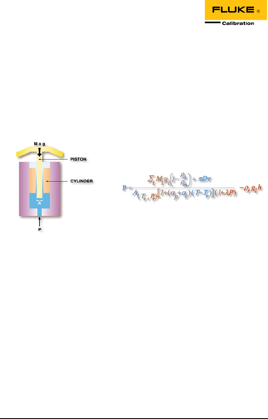
Page 33 © 2011 Fluke Calibration
3. General Operation
3.1 Fundamental Operating Principles
PG7000s operate on the principle of the piston gauge in which pressure is defined by balancing it against
a known force on a known area (see Figure 5). The known area is defined by a vertically mounted piston
rotating in a cylinder and the known force is applied to the piston by loading it with known mass subjected
to acceleration due to gravity. When the force applied by the pressure and the force applied by the mass
accelerated by gravity are in equilibrium, the piston floats and the pressure under the piston remains constant.
The pressure can be calculated following the equation in Figure 5 (see also, Section 7.2). Generally, the
pressurized fluid under the piston also lubricates the gap between the piston and the cylinder. PG7202
uses a unique gas operated, liquid lubricated piston-cylinder (see Section 3.1.1).
Figure 5. Piston Gauge Operating Principle
The PG7000 Platform is designed to mount a variety of piston-cylinder sizes, allow pressure to be applied
under the piston and allow masses to be loaded on top of the piston. There are different PG7000 models
depending upon whether the pressure medium is oil or gas and whether a vacuum reference is needed.
The measurement uncertainty in the pressure defined by the piston gauge depends on the uncertainty in
the effective area of the piston-cylinder and the force applied by the mass accelerated by gravity.
PG7000 stores the calibrated values of the piston-cylinders and masses it uses in on-board files (see
Section 3.11.1). To determine the effective area of the piston-cylinder and the force applied by the
masses under actual operating conditions, a number of influences on these values must be quantified
and taken into consideration. For this reason, PG7000 includes extensive features to monitor the
behavior and conditions of the piston-cylinder as well as ambient conditions that affect pressure definition
(see Sections 3.9.5 and 3.9.6). PG7000 uses the piston-cylinder, mass and ambient condition information
to calculate the pressure defined by a given mass load or the mass load needed to define a given
pressure (see Section 7.2). The source of each value used by PG7000 in its calculations can be selected
by the user between PG7000’s internal measurements, default values or user entered values. These
sources are defined in SETUP files (see Section 3.10).

PG7000™ OPERATION AND MAINTENANCE MANUAL
© 2011 Fluke Calibration Page 34
Once PG7000 has been set up, it is used in day-to-day operation either to define pressures applied to a device
or system under test or to measure a stable pressure. To interface with the PG Terminal, the operator:
Selects the appropriate piston-cylinder to cover the pressure range (see Section 3.11.1.5).
Selects the desired pressure unit of measure (see Section 3.9.3).
Selects the desired pressure measurement mode (gauge, absolute, differential) (see Section 3.9.4).
Sets the head difference between the PG7000 and the device under test (see Section 3.9.7).
Selects mass to pressure or pressure to mass operating mode (see Section 3.9.12).
Enters a pressure to define or a current mass load to calculate (see Section 3.9.11.1 and 3.9.11.2).
Loads masses by hand or with optional AMH automated mass handler, floats piston and defines
pressure.
3.1.1 Gas Operated, Liquid Lubricated Piston-Cylinder
Operating Principle (PG7202)
PG7202 provides very high pressure gas pressure operation using a unique gas operated,
liquid lubricated piston-cylinder system.
The principle of operation of the gas operated, liquid lubricated piston-cylinder is simple but
very effective (see Figure 6). The measured gas pressure, Pg, is applied to the bottom of the
piston and to the top of a liquid reservoir located around the cylinder. The reservoir is
connected to the gap between the piston and the cylinder through lateral holes near the
bottom of the cylinder, allowing liquid from the reservoir to enter the gap. The pressure of the
liquid in the gap, Pl, is equal to the gas pressure Pg, plus the liquid head, h. Therefore, the
liquid pressure in the gap is always higher than the gas pressure by the amount of the liquid
head regardless of the gas pressure value. Since h is small and the space between the
piston and cylinder is typically < 1 micron, the bleed of liquid from the bottom of the cylinder
towards the gas pressure is extremely small. The mounting post of the 7202 piston gauge is
configured so this minute amount of liquid drops directly into a sump that is deadened (see
Section 5.2.4, 3.1.1) and not in the flow path of test gas into and out of the system. Though
molecules of the liquid may migrate through the gas, no significant contamination of the test
system occurs. Because the liquid reservoir is contained in the piston-cylinder module,
piston-cylinders can be removed and installed in the PG7202 piston gauge platform with no
loss of liquid from the reservoir. All PC-7200 piston-cylinder modules can be delivered using
Krytox, a fluorinated synthetic fluid, to lubricate the piston-cylinder in applications where the
system must remain perfectly free of hydrocarbons (e.g. when calibrating instrumentation for
oxygen service).
Note
PC-7200 gas operated, liquid lubricated piston-cylinder modules are
delivered with their lubricating liquid reservoir drained. The reservoir must
be filled prior to using the piston-cylinder module and then regularly when
used (see Section 5.3.3)
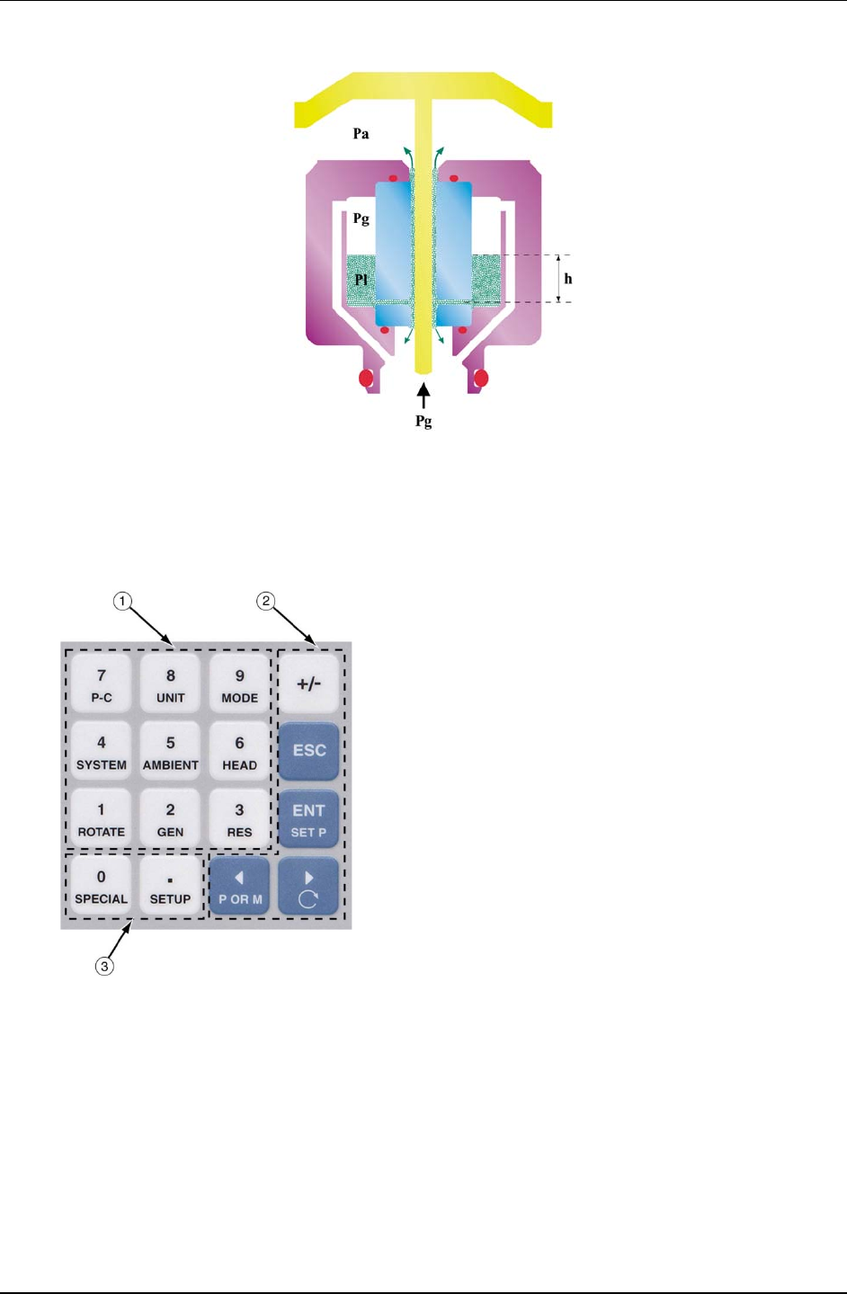
3. GENERAL OPERATION
Page 35 © 2011 Fluke Calibration
Figure 6. Gas Operated, Liquid Lubricated
Piston-Cylinder (PC-7200) Operating Principle
3.2 Keypad Layout And Protocol
PG7000 has a 4 x 4 keypad for local operator access to direct functions, function menus and for data entry.
The Function/Data keys
allow very commonly used
functions to be accessed directly from the main run screen by
a single keystroke. The name of the function is on the bottom
half of the key (see Section 3.9.1). These keys enter
numerical values when editing.
The Editing and Execution keys
are for execution,
suspending execution, backing up in menus and editing
entries.
The Menu/Data keys provide access to function menus from
the main run screen. The menu name is on the bottom half of
the key. The SETUP menu is for more frequently used
functions. The SPECIAL menu is for functions that are NOT
generally used as a part of day to day operation. These keys
enter numerical values when editing.
Figure 7. PG7000 Keypad Layout
Key press confirmation is provided by both tactile and audible feedback. A single beep confirms a valid entry.
A descending two note tone signals an invalid entry. The audible valid entry feedback can be suppressed or
modified by pressing [SPECIAL] and selecting <5prefs>, <2sound> (see Section 3.11.4.2).
Pressing the [ENTER/SET P] key generally causes execution or forward movement in the menu tree.
[ENTER/SET P] is also used to enter a command to set a pressure.
Pressing the [ESCAPE] key generally allows movement back in the menu tree and/or causes execution
to cease or suspend without changes being implemented. Pressing [ESCAPE] repeatedly eventually
returns to the main run screen. From the main run screen, pressing [ESCAPE] allows momentary
viewing of the PG7000 identification screen.
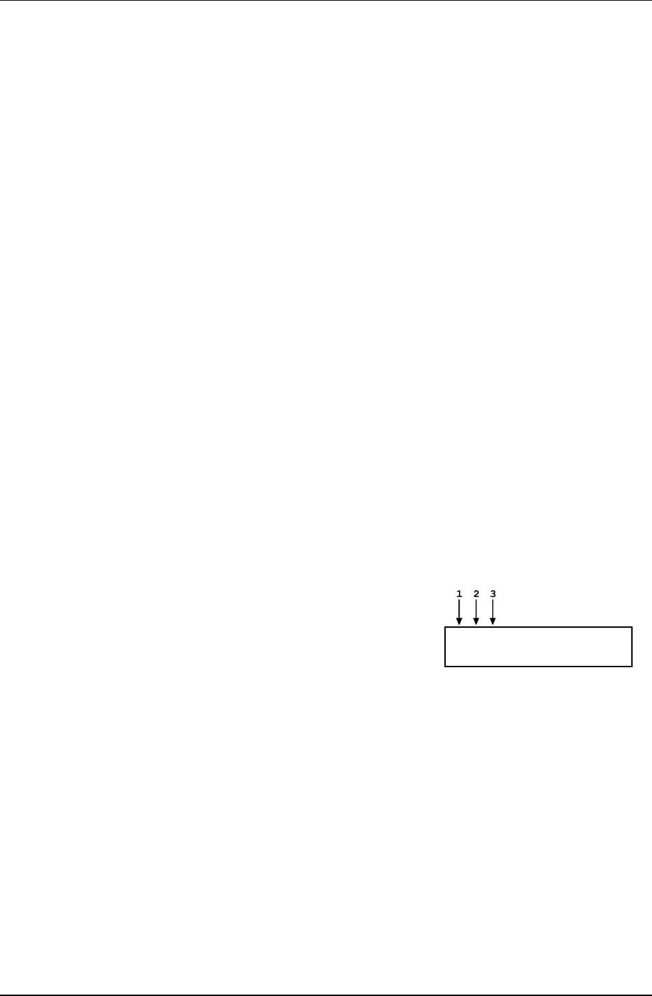
PG7000™ OPERATION AND MAINTENANCE MANUAL
© 2011 Fluke Calibration Page 36
Pressing the [+/-] key changes a numerical sign when editing. It also toggles through multiple screens
when available.
Pressing the [←] and [→] keys when editing allows reverse and forward cursor movement when editing
data entry. These keys are also used to scroll through choices.
Menu selections can be made by pressing the number of the selection directly or by pressing [←] and
[→] to place the cursor on the number of the desired selection and pressing [ENTER].
Note
Some screens go beyond the two lines provided by the display. This is indicated
by a flashing arrow in the second line of the display. Press [←] and [→] to move
the cursor to access the lines that are NOT visible or directly enter the number of
the hidden menu choice if you know it.
3.3 Sounds
The PG Terminal is equipped with a variable frequency tone device to provide audible feedback
and alarms. Some sounds can be modified and all sounds can be suppressed (see Section 3.11.4.2).
Sounds are used for the following indications:
Valid key press Brief high frequency beep.
Invalid key press Three rapid, low frequency beeps.
Piston left end of stroke high
or low Three rapid valid key press beeps. Piston was at low stop or high stop and
just entered spring zone (see Section 3.5).
3.4 Pressure Ready/Not Ready Indication
The three characters on the top line, far left, of the main run screen provide a pressure Ready/Not Ready
indication. This indication is intended to give the user a clear and objective indication of when PG7000
conditions are such that the value of pressure it is defining is valid and in tolerance. There are three
Ready/Not Ready indication characters to indicate the status of the three main Ready/Not Ready criteria.
The Ready/Not Ready indication characters are shown on the first line, top left hand side, of the main run screen.
1. Piston position and vertical movement.
2. Piston rotation.
3. Reference vacuum (PG7601 in absolute by
vacuum measurement mode only).
*** 100.4755 kPa g h
+ 0.1 mm 10.00564 kg
For each Ready/Not Ready indication character, <*> indicates a Ready condition. Therefore, <***> or <** >
indicates that all conditions necessary for an in tolerance pressure definition are present. Any indication
other than <*> indicates Not Ready.
See Sections 3.4.1, 3.4.2 and 3.4.3 for details on each of the three Ready/Not Ready indicating characters.
Note
The criteria used to distinguish between Ready and Not Ready conditions can be
customized by the user (see Sections 3.4.1, 3.4.2, 3.4.3).
3.4.1 Piston Position Ready/Not Ready
The piston position Ready/Not Ready character indicates Ready or Not Ready based on the
position of the piston in its vertical stroke (see Section 3.5) and an automated measure
generation status (see Section 3.9.9). This ensures that pressure definitions will be made with
the piston not more than a certain distance from mid-float position and that measurements will
not be made while the action of an automated pressure controller may influence the pressure.
The piston position Ready/Not Ready character is the first character from the left on the top
line of the main run screen.

3. GENERAL OPERATION
Page 37 © 2011 Fluke Calibration
The piston position Ready/Not Ready criterion is determined by the current SETUP file and
can be customized by the user (see Section 3.10).
Piston position Ready/Not Ready character indications include:
<*> Piston position Ready (within the position limits specified in the current SETUP file)
(see Section 3.5).
<↓> Piston position Not Ready, low (below the position limits specified in the current
SETUP file, see Section 3.10). The <↓> flashes if the piston is not at the bottom stop
position to alert the user that this indicator is Not Ready.
<↑> Piston position Not Ready, high (above the position limits specified in the current
SETUP file) (see Section 3.10). The <↑> flashes if the piston is not at the top stop
position to alert the user that this indicator is Not Ready.
<?> Piston position not known (current specified mass load is less than the load of the piston
+ bell). The bell must be installed for PG7000 piston position measurement to operate
correctly so piston position values shown are not valid when the bell is not installed.
<T> Tare PG7000 is Not Ready (PG7102 and PG7202 only). Indicates that piston
position or rotation rate is Not Ready on the tare PG7000 in high line differential
mode (see Section 3.9.4.2).
Note
• Piston position always indicates Not Ready if automated pressure
generation is adjusting pressure, regardless of actual piston
position.
• In PG7102 and PG7202 high line differential pressure mode (see
Section 3.9.4.2), the piston position Ready/Not Ready indicator
applies to the pistons of both the tare and the reference PG7000.
For Ready to be indicated, both pistons must be within the ready
limits for piston position.
3.4.2 Piston Rotation Ready/Not Ready
The piston rotation Ready/Not Ready character indicates Ready or Not Ready based on the
rotation rate of the piston.
The piston rotation Ready/Not Ready character is the second character from the left on the
top line of the main run screen.
The piston rotation rate Ready/Not Ready criterion is specific to the currently active
piston-cylinder module and can be edited by the user (see Sections 3.11.1.1).
Piston rotation rate Ready/Not Ready character indications include:
<*> Rotation rate Ready: Rotation rate is within the rotation rate limits specified in the
current piston-cylinder module file) (see Section 3.11.1.1).
<<> Rotation rate Not Ready, low: Rotation rate is less than the lower rotation rate limit
specified in the current piston-cylinder module file (see Section 3.11.1.1)
or motorized rotation system is currently engaged. Note that the low rotation limit is
automatically reduced when the mass loaded on the piston is less than 3 kg. The
<<> flashes if the piston is floating to alert the user that this indicator is Not Ready.
<?> Rotation rate not known: Current specified mass load is less than the load of the
(piston + bell). The bell must be installed for PG7000 piston rotation rate measurement
to operate correctly so piston rotation rate cannot be measured when the bell is not
installed.

PG7000™ OPERATION AND MAINTENANCE MANUAL
© 2011 Fluke Calibration Page 38
Note
At mass loads less then 3 kg the low rotation limit is automatically reduced
to an operational minimum to maximize free rotation time.
In PG7102 and PG7202 high line differential pressure mode (see
Section 3.9.4.2), the piston rotation rate Ready/Not Ready indicator
applies to the pistons of both the tare and the reference PG7000. For
Ready to be indicated, both pistons must be within the ready limits for
piston rotation rate.
3.4.3 Vacuum Reference Ready/Not Ready (PG7601 Only)
The vacuum reference Ready/Not Ready character is only used with PG7601, as it is the only
PG7000 model with vacuum reference capability. It is only active when operating in absolute
by vacuum mode (see Section 3.9.4).
The vacuum reference Ready/Not Ready character indicates Ready or Not Ready based on
the value of reference vacuum when making measurements in absolute by vacuum mode.
This ensures that definitions of absolute pressure with a vacuum reference will be made with
the vacuum under the PG7601 bell jar lower than a specified value. When the vacuum is not
low enough, vacuum measurement errors may be excessive.
The vacuum reference Ready/Not Ready character is the third character from the left on the
top line of the main run screen.
The vacuum reference Ready/Not Ready criterion is determined by the current SETUP file
and can be customized by the user (see Section 3.10). The vacuum reference criterion is
a fixed value that can be customized by the user when the vacuum reference selection in the
SETUP file is internal. If the selection in the SETUP file is NOT internal, the vacuum reference
Ready/Not Ready character always indicates Ready and the value cannot be customized.
Vacuum reference Ready/Not Ready character indications include:
< > (Blank) Vacuum reference Ready/Not Ready is not in use. This is not a PG7601;
or if PG7601, current measurement mode is not absolute by vacuum.
<*> Vacuum reference Ready. Vacuum value is below limit specified in the current
SETUP file if source is internal OR source is default or user and the vacuum value is
not a measured value (see Section 3.10).
< > > Vacuum reference Not Ready. Current SETUP file source for vacuum is internal
and vacuum value is above the limit specified (see Section 3.10). The <>> flashes if
the piston is floating to alert the user that this indicator is Not Ready.
3.5 Piston Position
When operating a PG7000 piston gauge, reference pressure values are defined by loading known mass
values on the piston and adjusting the pressure to float the piston. Piston position is measured and
displayed real time on the MAIN run screen (see Section 3.7) and in the first SYSTEM run screen (see
Section 3.9.5). Piston position is used as a criterion for the Ready/Not Ready indication as valid
measurements can only be made when the piston is in the correct position (see Section 3.4.1).
The full piston stroke is ± 4.5 mm from the midstroke position. The stroke is divided into different
positions and zones as illustrated in Figure 8. These zones are:
• High and low stops: The piston is at the minimum or maximum end of stroke. The pressure applied
to the piston is higher (at high stop) or lower (at low stop) than that corresponding to the mass loaded
on the piston. The high and low stop positions are fixed.
• High and low spring zones: The combination of pressure and the force of the high or low stop
springs have caused the piston to leave the stop. The pressure applied to the piston is within the
equivalent of 2 kg of the pressure corresponding to the mass loaded on the piston. The high and low
spring zones indicate the piston is about to float. The spring zone positions are fixed.

3. GENERAL OPERATION
Page 39 © 2011 Fluke Calibration
• High and low measurement zones: The piston is within the zone in which a Ready measurement
can be made (see Section 3.4.1). The pressure applied to the piston is the pressure corresponding
to the mass loaded on the piston. The default value of the high and low measurement zones is
± 2.5 mm around midstroke position. This value can be adjusted in the SETUP file (see Section 3.10).
• Midstroke: The piston is at the middle of its stroke. The bottom of the piston (or its equivalent
for hollow pistons) is at the reference level marked on the mounting post (see Section 3.9.7).
There is equal stroke available to the high and low stops.
Note
The piston position monitoring system is driven by the internal ring in the base of
the mass loading bell. When the bell is not installed, piston position cannot be
measured. If the current mass load is less than the mass of the piston + bell,
PG7000 will display < ---- > where piston position is normally displayed. If the
current mass load is greater than the mass of the piston + bell but the bell is not
actually installed, the piston position indication is not valid.
Figure 8. Piston Stroke and Zones
3.6 Mass Loading Protocol
PURPOSE
To provide the operator with mass loading instructions and allow mass entry in convenient nominal values
which PG7000 can accurately convert to measured mass values to determine the actual mass load.
PRINCIPLE
All PG7000 manual mass set masses of 0.1 kg and above, including those in the mass set, the mass
loading bell and the piston assembly, are adjusted so that their true mass is within ± 20 ppm of their
nominal value. The nominal value is marked on each mass. Each mass’s actual individual value is
measured more accurately than ± 20 ppm and reported in the mass set, mass loading bell or piston-
cylinder module calibration report. These measured actual values are used by PG7000 in all of its
defined pressure calculations. The nominal mass values, and the sequential numbers of the nominal
masses when there are several of the same value, are used by PG7000 to describe the mass to load or
the mass that is loaded. Following a few simple mass loading rules allows PG7000 to accurately
transform actual mass values into nominal mass values and vice-versa so that mass loading
instructions to the operator and the operator mass entries can be made in simple nominal mass
instructions while representing actual individual mass values.
Since the nominal mass values written on the masses and the actual values of the individual masses
are different, in pressure to mass mode (see Section 3.9.12) the actual mass value loaded on the piston
will be different from the mass loading instruction. In the same manner, in mass to pressure mode
the nominal value of the mass load that the operator enters is different from the actual mass loaded
on the piston. The mass value shown in the MAIN run screen (see Section 3.7) is always the
actual mass value. The mass loading instruction given in pressure to mass mode and the mass value

PG7000™ OPERATION AND MAINTENANCE MANUAL
© 2011 Fluke Calibration Page 40
entered by the operator in mass to pressure mode is always the nominal mass value. If PG7000 mass
loading protocol is followed, the conversion from nominal mass to actual mass occurs correctly allowing
very simple nominal mass loading and accounting for the operator while using very accurate measured
mass values for metrological calculations.
OPERATION
Note
To avoid wear to masses and to the piston-cylinder module end of stroke stops,
the piston should not be rotating when masses are loaded or unloaded. Before
loading masses, stop piston rotation by hand or using the motorized rotation
system (see Section 3.9.13).
PG7000 instructions to the operator of mass to load, and operator entries of the mass that is loaded, are
always expressed in terms of nominal mass within 0.1 kg and in terms of grams for values under 0.1 kg.
This protocol is also followed when using the AMH automated mass handler.
In pressure to mass mode, the instruction of the mass to load to
achieve the requested pressure is formatted:
Load nominal mass:
kkk.k
kg and gg.gg g
In mass to pressure mode, the entry of the mass currently loaded
on the piston is formatted:
Nominal mass load:
kkk.k
kg and gg.gg g
kkk.k and gg.gg must be expressed and loaded following the mass loading rules below:
See Sections 2.3.1.3,
Mass Loading Rules
Installing Masses On The Mass Loading Tray
PG7000 mass loading entries and instructions are always formatted:
and 3.6. for PG7000 mass set principles
and protocol information. Refer to display examples immediately above to identify kkk.k and gg.gg.
See EXAMPLES: Mass Loading below for mass loading examples.
kkk.k kg and nn.nn g
• The mass set being used must be selected as the active mass set (see Section 3.11.1.10) and must
be properly set up prior to use (see Section 3.11.1.6).
• kkk.k is made up of the piston, the mass loading bell and mass set masses of 0.1 kg and greater.
When using an AMH mass set, the binary mass carrier and mass lifting shaft are also included.
• kkk.k always includes the mass loading bell and then the makeup mass, if possible.
• kkk.k is made up of the largest masses possible rather than a combination of smaller masses.
USE the piston (0.2 kg) + the mass loading bell (0.3 kg) + the 4.5 kg makeup mass.
EXAMPLE: To load 5 kg on a PG7601:
DO NOT USE the piston + the mass loading bell + 2 kg #1 + 2 kg #2 + 0.5 kg #1.
When several masses of the same nominal value are included in kkk.k, they are loaded in numerical
sequence, low to high.
USE 5 kg mass #1, #2 and #3.
EXAMPLE: When loading three 5 kg masses:
DO NOT USE 5 kg mass #4, #3, #1.
This rule will be followed automatically if masses are installed and used as described in Section 3.6.
• gg.gg is made up of mass from the gram trim mass set (masses of 50 g to 0.01 g). These masses
can be loaded in any order.

3. GENERAL OPERATION
Page 41 © 2011 Fluke Calibration
Caution
When PG7000 provides mass loading instructions and calculates the true mass of
the mass currently loaded, it assumes that the mass set in use has been set up
correctly (see Section 2.3.1.3). For PG7000 mass loading protocol to operate
properly, the mass set in use must be EXACTLY the mass set that has been
defined by the add and/or edit mass function (see Section 3.11.1.6).
Note
In PG7102 and PG7202 High Line Differential mode (see Section 3.9.4.2), there are
two types of mass loading instructions: line pressure setting and differential
pressure setting. Both follow conventional PG7000 mass loading protocol. The line
pressure mass instructions are always given with 0.1 kg resolution. This is to
preserve the smaller masses for setting the differential pressure. The differential
pressure mass loading instructions follow conventional mass loading protocol
using the masses that remain after the line pressure has been set. It may be
necessary to adjust the line pressure value to assure that adequate masses remain
to set the desired differential pressure. For example, if the line pressure requires
loading 10.6 kg, the 0.5 and 0.1 kg masses will be used to set the line pressure and
will not be available if they are needed to set the differential pressure. If this
situation occurs, consider adjusting the line pressure so that it is set using a
whole number of kilograms, in this example 10.0 or 11.0 kg.
• Mass loading instruction using a PG7601 and a
35 kg mass set:
EXAMPLES: Manual Mass Loading
12.3 kg and 32.33 g
Load:
piston (0.2 kg)
bell (0.3 kg)
4.5 kg #1 (makeup mass)
5 kg #1
2 kg #1
0.2 kg #1
0.1 kg #1
32.33 g from trim mass set
• Mass loading instruction using PG7302 and an
80 kg mass set:
77.6 kg and 10.45 g
Load:
piston (0.2 kg)
bell (0.8 kg)
9 kg #1 (makeup mass)
10 kg #1 through #6
5 kg #1
2 kg #1
0.5 kg #1
0.1 kg #1
10.45 g from trim mass set
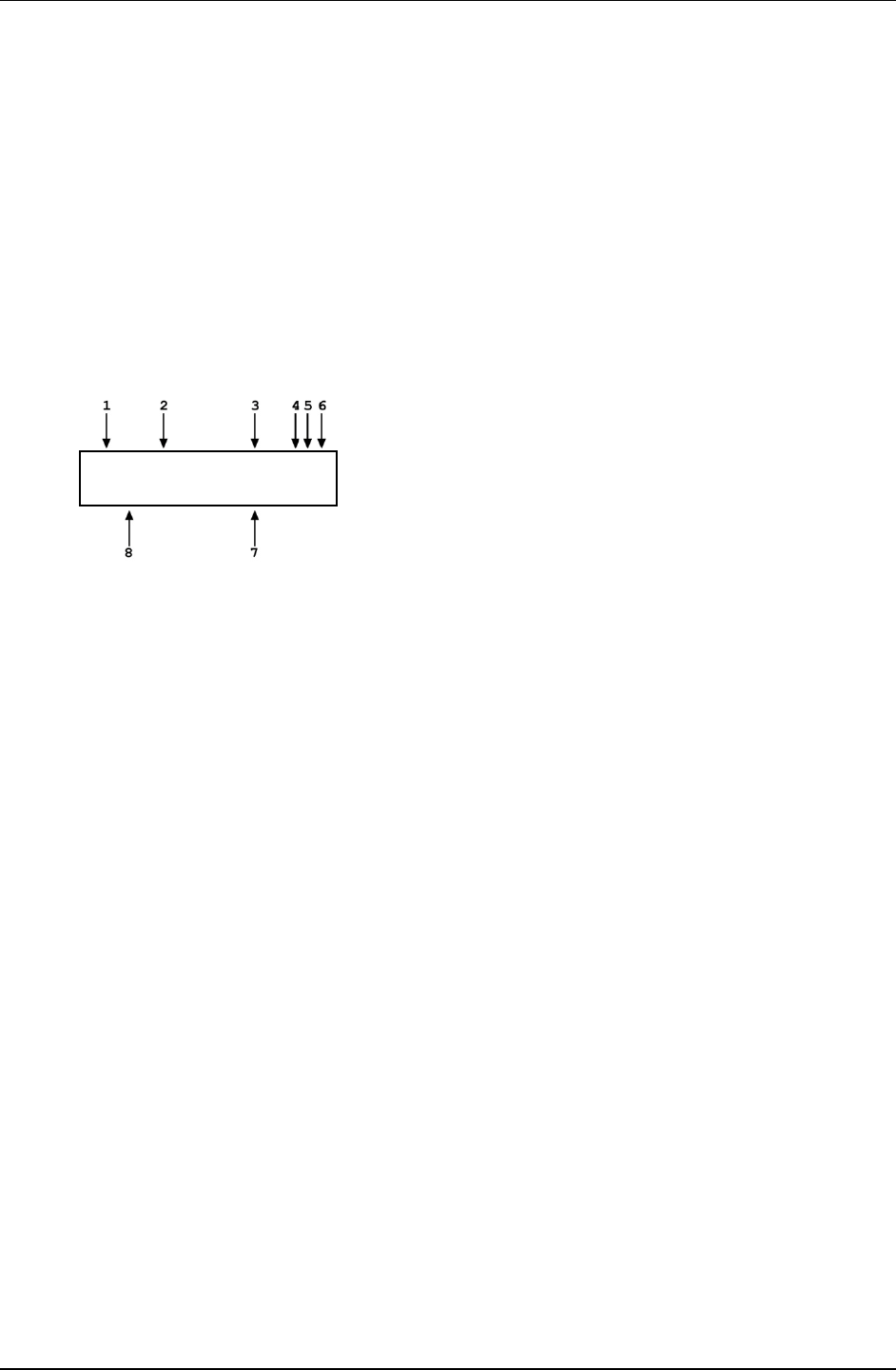
PG7000™ OPERATION AND MAINTENANCE MANUAL
© 2011 Fluke Calibration Page 42
3.7 Main Run Screen
The PG7000 main run screen is its home display that is reached upon powering up and from which other
functions and menus are accessed. It is the top level of all menu structures.
The main run screen is where PG7000 is left in normal operation. It displays the pressure defined by
PG7000, Ready/Not Ready condition and a variety of other information.
Note
The screen described below is called the MAIN run screen. The SYSTEM and
AMBIENT screens (see Sections 3.9.5 and 3.9.6) are also run screens in the sense
that all the other functions may be accessed directly from them and pressure or
mass entries may be made from them. See Section 3.8 for a description of
PG7000’s main menu/function structure.
prvPRESSURE1 unit aGh
+N.N mm NN.NNNNN kg
1. <prv>: Three Ready/Not Ready indication characters
(from left to right: piston position, piston rotation,
vacuum reference) (see Section 3.4). Each character
indicates as follows:
<p>: Piston Position Ready/Not Ready. <*> when
Ready, <↑> when Not Ready due to piston above
measuring zone, <↓> when Not Ready due to piston
below measuring zone, <?> if piston position not
available or out of range. Flashes if condition is Not
Ready and piston is floating (see Section 3.4.1).
Indicates Not Ready when automated pressure
generation is adjusting pressure.
<r>: Piston Rotation Ready/Not Ready. <*> when
Ready, <<> when Not Ready due to piston rotation rate
too low or motorized rotation engaged, <?> if piston
position not available or out of range. Flashes if condition
is Not Ready and piston is floating. (see Section 3.4.2).
<v>: Vacuum Reference Ready/Not Ready
(PG7601 only). <*> when Ready, <v> if Not Ready due
to vacuum not below ready limit. Flashes if condition is
Not Ready and piston is floating (see Section 3.4.3).
2. <PRESSURE1>: Numerical value and sign of the
pressure defined by PG7000 with current mass loaded
on current piston when all Ready/Not Ready indication
characters indicate Ready.
3. <unit>: Current pressure unit of measure (see Section
3.9.3).
4. Current measurement mode. <a> for absolute, <g>
for gauge, <d> for differential or high line differential
(see Section 3.9.4).
5. Automated pressure generation status. <G> if automated
pressure generation is ON. The <G> flashes if
automated pressure generation is ON and active, blank
if automated pressure generation is not ON (see
Section 3.9.9).
6. DUT head correction status. <h> if a head correction is
currently being applied, blank if head height is zero (see
Section 3.9.7).
7. <NN.NNNNN kg>: Current mass load in actual mass
(assuming mass loading instructions have been
followed and/or mass loading entries are correct (see
Section 3.6).
8. <± N.N mm>: Current piston position in millimeters
from midstroke position. Positive values are above
midstroke, negative values below. Indicates < ---- >
if piston position not available or out of range (see
Section 3.5).
Note
• When a number is too large to display in
the allocated screen space, PG7000
displays <********> or <OVERFLOW>.
• PG7000 has a screen saver function that
causes the display to dim if NO key is
pressed for 10 minutes. Pressing a key
restores full power to the display. The
screen saver activation time can be
changed or screen saving can be
completely disabled (see Section 3.4.5.1).
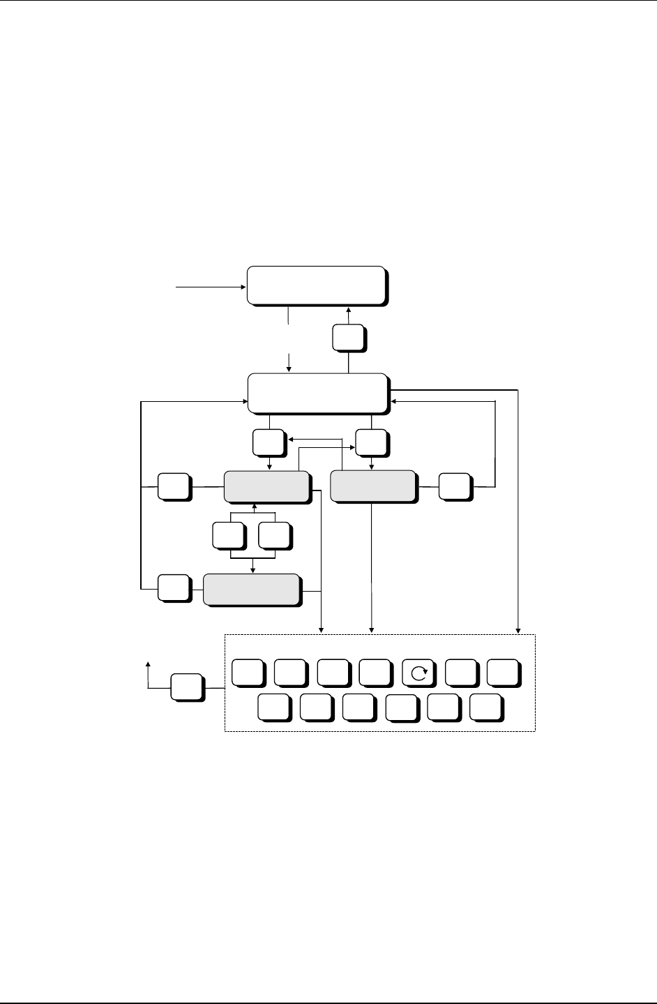
PG7000™ OPERATION AND MAINTENANCE MANUAL
Page 43 © 2010 Fluke Calibration
3.8 General Function/Menu Flow Chart
Local operator interface with PG7000 is provided by PG Terminal keypad and display. Normal PG7000
operation is organized around run screens from which functions and menus are accessed. The run
screens include:
• MAIN run screen: Displays Ready/Not Ready, defined pressure, piston position and mass load.
• (2) SYSTEM run screens: Display piston position, rotation, temperature and reference vacuum
(PG7601 only).
• AMBIENT run screen: Displays ambient pressure temperature, relative humidity and local gravity.
The flow chart below outlines the operating protocol of the run screens and associated key presses.
INTRO SCREEN
MAIN RUN SCREEN
SYSTEM 1
RUN SCREEN
SYSTEM 2
RUN SCREEN
AMBIENT
RUN SCREEN
POWER
UP
or
RESET
AMBIENT
ESC
SYSTEM
+/-
or
SYSTEM
ESCESC
ESC
P-C UNIT MODE SYSTEM
ENT SPECIAL SETUP
OTHER FUNCTION KEYS
RES
≈ 5 SEC
DELAY
HEAD ROTATE
AMBIENT
GEN
ESC
TO PREVIOUS
RUN SCREEN
Figure 9. Run Screen Flow Chart
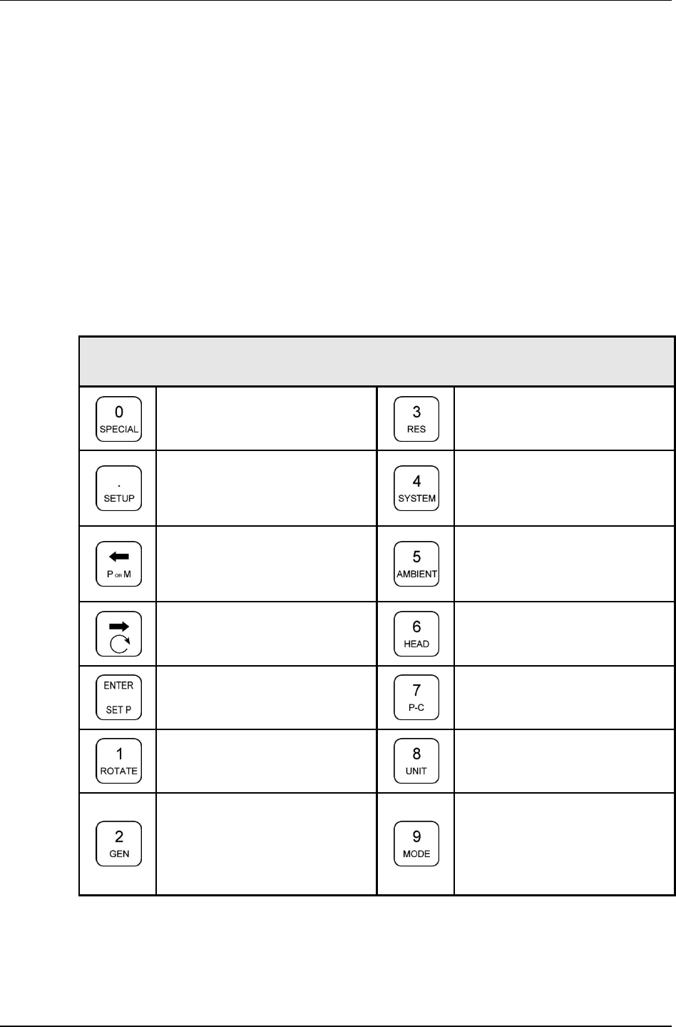
PG7000™ OPERATION AND MAINTENANCE MANUAL
© 2011 Fluke Calibration Page 44
3.9 Direct Function Keys
3.9.1 Direct Function Keys Summary
Local operator interface with PG7000 is provided by PG Terminal keypad and display.
To minimize the use of multi-layered menu structures, the keypad’s numerical keys also
provide direct access to the most commonly used functions. The function accessed is
labeled on the bottom half of the each key. Direct function keys are active whenever PG7000
is in a run screen (MAIN, SYSTEM or AMBIENT). Table 14 summarizes the operation of the
direct function keys. Section 3.8 provides a flow chart of PG Terminal general operation.
See corresponding manual Sections to 3.9.1 to 3.11.9.
Note
It may be useful to keep a copy of Table 14 near the PG7000, especially
when first becoming acquainted with its operation.
Table 14. Summary of PG7000 Direct Function Key Operations
DIRECT FUNCTION KEYS ARE ACTIVE FROM ANY RUN SCREEN
(main, ambient, system).
See corresponding manual sections for full detail.
Menu of less frequently used internal
functions and settings including resets,
user preferences, internal calibration
and remote interface setup.
Set the resolution of PG7000 mass
loading commands (0.01 g to 0.1 kg).
Edit and select files that determine the
sources of the values for the variables
PG7000 uses in calculations of reference
pressures.
Access SYSTEM run screens (2) which
display current measurements of piston
behavior, piston-cylinder temperature
and reference vacuum if present.
Toggles between the two screens.
Select pressure to mass or mass to
pressure operation.
Access AMBIENT run screen which
displays current values of barometric
pressure, ambient temperature, ambient
humidity and local gravity as specified in
the active SETUP file.
Activate motorized control manually.
Activates when pressed, deactivates
when released.
Adjust height of DUT fluid head
correction. Set to zero to defeat head
correction.
From a run screen: Access mass or
pressure setting commands.
From other screens: Select menu
choice, enter value, confirm selection.
Select active piston-cylinder module
(range).
Turn automatic activation of motorized
rotation ON/OFF.
Set unit of measure in which pressures
are defined. Choice of units available
from this key can be customized.
Turn automated pressure
generation/control ON/OFF, adjust
control parameters, set upper limit for
automated pressure control. Has no
effect if an automated pressure
generation/control component is not part
of the PG7000 system.
Set pressure measurement mode
(gauge, absolute, differential).
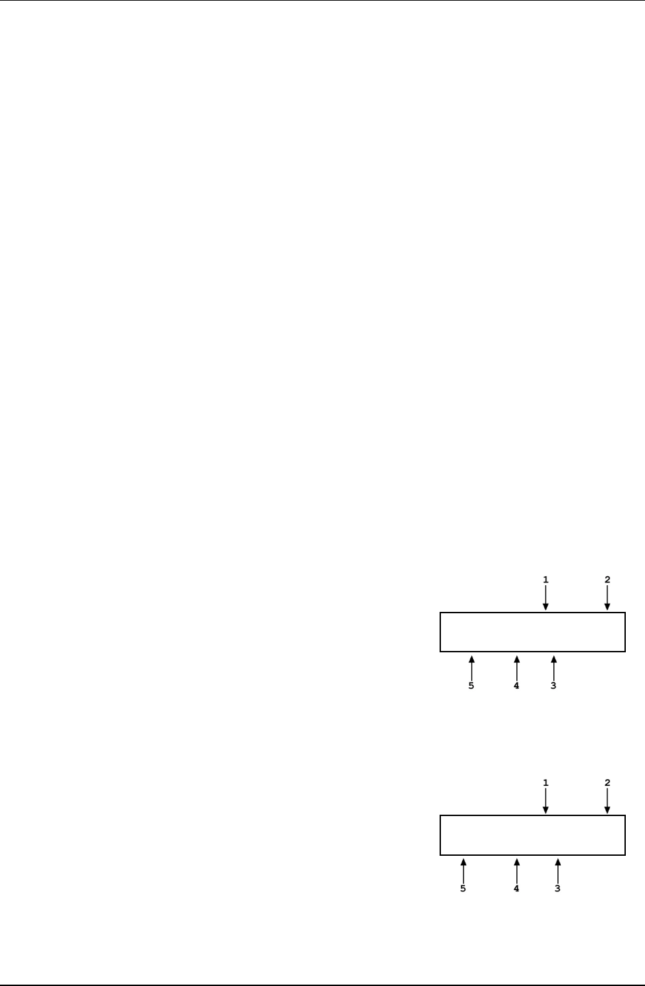
3. GENERAL OPERATION
Page 45 © 2011 Fluke Calibration
3.9.2 [P-C]
PURPOSE
To view and/or change the active piston-cylinder module. In most cases, changing the
piston-cylinder module is equivalent to changing the range.
Note
• [P-C] is for selecting the active piston-cylinder module only. Piston-
cylinder modules can be added and deleted and their characteristics can
be edited by pressing [SPECIAL] and selecting <1PC/MS> (see Section
3.11.1).
• The active mass set and mass loading bell are selected by pressing
[SPECIAL] and selecting <1PC/MS> (see Section 3.11.1).
PRINCIPLE
To make valid pressure and mass load calculations, PG7000 must know the exact
characteristics of the piston-cylinder module that is currently in use. See Section 7.2 for
detailed information on PG7000 pressure and mass calculations.
Most PG7000s are used with more than one piston-cylinder module. Detailed characteristics
on up to 18 piston-cylinder modules are stored in files. These files can be added, deleted,
viewed and edited by pressing [SPECIAL], 1pc/ms (see Section 3.11.1).
The P-C function provides rapid access, from any run screen, to viewing the piston-cylinder
modules available and selecting one to be active.
OPERATION
Pressing [P-C] activates the piston-cylinder module viewing and selecting function. Pressing
the [P-C] key again or [+/-] while in the P-C function steps through displays of available
piston-cylinder modules.
When [P-C] is first pressed, a summary of the characteristics of the active piston-cylinder
module is displayed, for example:
1. Nominal pressure to mass conversion coefficient of the piston-
cylinder module that is currently selected (active). This value is
calculated from the effective area of the piston-cylinder and is
in kPa (if < 1 MPa) or MPa. Upgraded Type 5000 piston-
cylinders may be displayed in psi.
2. Serial number of the active piston-cylinder module.
3. Current pressure unit of measure.
4. Nominal pressure in current pressure units resulting from
loading all the mass of the active mass set.
5. Nominal pressure in current pressure units resulting from
loading the piston and mass bell only.
Active 10 kPa/kg 247
0.7 to 50 psi
Pressing [P-C] again or [+/-] causes the screen to step through the other available piston-cylinder
modules in the sequence that they were added.
1. Nominal pressure to mass conversion coefficient of the piston-
cylinder module. This value is calculated from the effective area
of the piston-cylinder and is always in kPa (if < MPa) or MPa.
2. Serial number of the piston-cylinder module.
3. Current pressure unit of measure.
4. Nominal maximum pressure using the piston-cylinder
module. Pressure, in current pressure units, resulting from
loading all the mass of the active mass set.
5. Nominal minimum pressure using the piston-cylinder module.
Pressure, in current pressure units, resulting from loading the
piston and mass bell only.
Select 200kPa/kg 382
14 to 1000 psi
Pressing [ENTER] while in the P-C function causes PG7000 to select the currently displayed
piston-cylinder module as the active piston-cylinder module.

PG7000™ OPERATION AND MAINTENANCE MANUAL
© 2011 Fluke Calibration Page 46
Pressing [ESCAPE] while in the P-C function returns to the main run screen without
changing piston-cylinder modules.
Note
• The pressure unit of measure in which the range offered by the piston-
cylinder module using the active mass set is displayed can be changed by
pressing [UNIT] (see Section 3.9.3).
• When the current pressure unit of measure is an altitude unit, piston-
cylinder module range is expressed in kPa if the altitude unit is meters (m)
or psi if the altitude unit is feet (ft).
3.9.3 [UNIT]
PURPOSE
To specify the unit of measure in which defined pressures are expressed.
PRINCIPLE
PG7000 supports a wide variety of pressure units of measure. Internally, PG7000 always
operates in Pascal [Pa] (the SI unit of pressure). Values of pressure are represented in other
units by the application of conversion factors to convert from Pascal. See Section 7.1.1 for
Unit of Measure Conversions.
The pressure unit of measure selection (e.g., psi, kPa, etc.) is separate from the pressure
measurement mode selection (gauge, absolute or differential). See Section 3.9.4 for
information on changing the measurement mode.
OPERATION
To change the pressure unit of measure, press the
[UNIT]
function key from any run screen. The
display is (default units depend on model):
1kPa 2Mpa 3Pa
4bar 5psi 6kcm2
The cursor is on the number corresponding to the active unit. To change the pressure unit, select
the desired unit. The display returns to the previous run screen with the selected unit active.
If the pressure unit selected is inWa, the reference
temperature for water density must be specified. When
inWa is selected as the unit, the next display is:
Select inWa ref temp
4°C 20°C 20°F
Select the desired reference temperature for water density using the [←] or [→] key to move
the cursor. Pressing [ENTER] returns to the main run screen with inWa based on water
density at the selected reference temperature as the active pressure unit. The current inWa
reference temperature can be viewed by observing the position of the cursor in the reference
temperature screen.
Note
• See Section 7.1 for tables of the pressure unit of measure conversion
factors used by PG7000.
• The UNIT function provides rapid access to a choice of up to six units.
The choice of units can be customized from a wider selection by the user
(see Section 3.9.3.1). The default units of the UNIT function depend on the
PG7000 model. The default units are:
• PG7102 and PG7601: 1kPa 2MPa 3Pa 4bar 5psi 6kcm2
• PG7202 and PG7302: 1MPa 2kPa 3bar 4psi 5kcm2
• To restore the default UNIT function settings, use the Unit Reset (see
Section 3.11.9.2).
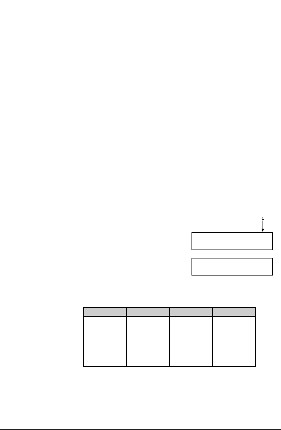
3. GENERAL OPERATION
Page 47 © 2011 Fluke Calibration
• Certain internal and/or metrological functions (e.g., vacuum reference
pressure) are always represented in Pascal [Pa], regardless of the active
pressure unit of measure.
• When the current pressure unit of measure is an altitude unit, atmospheric
pressure in the AMBIENT run screen is expressed in kPa if the altitude unit
is meters (m) or psi if the altitude unit is feet (ft).
3.9.3.1 Customizing Pressure Units Available Under the
UNIT Function
PURPOSE
To customize the selection of pressure units that are available for selection from
the [UNIT] function key.
PRINCIPLE
The UNIT function provides a choice of different pressure units of measure
depending on the PG7000 model. The units that are available by default are
those indicated in the Note in Section 3.9.3. However, PG7000 supports many
other pressure units of measure. Other units can be made available for selection
and units can be deleted by customizing the UNIT function. This allows PG7000
to offer a very wide selection of units while simplifying day to day operation.
The typical user will customize the [UNIT] function key to support the six most
commonly used units.
OPERATION
To customize the [UNIT] function key, from the main run screen press [SETUP]
and select <2PresU>. The display is:
1. The UNIT number in the [UNIT] menu that is
to be changed.
Set up user unit #6
Enter the number of the unit position that
you would like to change. The display
becomes:
Unit #6 1SI 2other
3altitude 4user
Select the desired pressure unit category. SI units include units based on SI
such as mmHg. Select the desired unit from the unit list (see Table 15).
Table 15. Pressure Units of Measure Available
<1SI> <2Other> <3altitude>* <4User>**
<1Pa>
<2Kpa>
<3MPa>
<4mbar>
<5bar>
<6mmHg>
<7mmWa>
<1psi>
<2psf>
<3inHg>
<4inWa>
<5kcm2>
<6Torr>
<7mTor>
<8none>
<1m>
<2ft>
<1user>
* <3altitude>: PG7601 in absolute by vacuum mode only. Not available in
PG7102, PG7202 and PG7302.
** <4user>: User defined unit. As there are no altitude units on PG7102,
PG7202 and PG7302, user is <3user>.

PG7000™ OPERATION AND MAINTENANCE MANUAL
© 2011 Fluke Calibration Page 48
The UNIT function display is not required to display six units. To delete the
current unit from the UNIT screen and show no unit, select <2other>, <6none>
for that unit number.
If <4user> was selected, the user unit must be defined. The display is:
1. Entry field.
Define user unit:
1.000000 Units/Pa
Enter the number of user units per Pascal [Pa] in the entry field. Pressing [ENTER]
defines the user unit and returns to the <Set up unit #> screen.
Note
• See Section 7.1.1 for the pressure unit of measure
conversion factors used by PG7000.
• The user defined unit can be assigned a user defined label
using the UDU remote command (see Section 4.3.4.2).
3.9.4 [MODE]
PURPOSE
To specify the measurement mode (gauge, absolute, differential) in which PG7000 defines
reference pressures.
Note
Pressure measurement mode and unit of measure are not the same thing.
See Section 3.9.3 for information on the pressure unit of measure.
PRINCIPLE
Pressure defined relative to absolute zero or vacuum is generally referred to as absolute
pressure.
Pressure defined relative to atmospheric pressure is generally referred to as gauge pressure,
with pressure below atmosphere called negative gauge pressure.
Pressure defined relative to another pressure that may be, but is not necessarily atmospheric
pressure, is generally referred to as differential pressure.
PG7000s (depending on the model) can define absolute, gauge, negative gauge and
differential pressures. These are referred to as measurement modes.
The specific PG7000 measurement modes are as follows:
• gauge: Defines gauge pressure by leaving the PG7000 mass load open to atmosphere.
This measurement mode is supported by all PG7000 models. It does not allow negative
gauge pressures. The minimum gauge pressure is the pressure resulting from loading
the combined mass of the piston and the bell on piston-cylinder effective area.
• absolute by adding atmospheric pressure (absolute by ATM): Defines absolute
pressure by defining a pressure in the same manner as in gauge mode and adding the
value of atmospheric pressure measured by a barometer. This measurement mode is
supported by all PG7000 models. The barometer can be PG7000’s on-board sensor or a
remote RS232 barometer. The uncertainty on the value of atmospheric pressure
measured by the barometer must be considered but this value can become relatively
small as pressure goes up. For example, if using a ± 0.01 % barometer, the added uncertainty
at 1 MPa (150 psi) is 10 ppm.

3. GENERAL OPERATION
Page 49 © 2011 Fluke Calibration
This mode is more convenient and less costly than absolute by vacuum since no vacuum
reference needs to be established. However, it does not allow absolute pressures under
atmosphere and the minimum absolute pressure is atmospheric pressure plus the pressure
resulting from loading the combined mass of the piston and the bell on the piston-cylinder
effective area.
• absolute by vacuum (absolute by vac) (PG7601 only): Defines absolute pressure by
measuring relative to an evacuated bell jar. This mode is time consuming as the vacuum
under the bell jar must be made and broken to adjust the mass load for each pressure to
be set. This mode is required for setting absolute pressures under atmospheric pressure
and for lowest uncertainty under about 1 MPa (150 psi).
• differential (dif) (PG7601 only): Defines differential pressures at an absolute static
pressure between vacuum and two atmospheres by defining an absolute pressure
relative to an evacuated bell jar and subtracting static pressure monitored by a digital
pressure indicator. An offsetting technique ensures that only the digital indicator’s
resolution and very short term repeatability influence the measurement results.
Allows positive and negative differential pressure (including gauge pressures) with one
common hardware setup. Covers pressures very near and at zero without limitations due
to piston-cylinder size and mass loads (see Section 3.9.4.1).
• high line differential (HLdif) (PG7102 and PG7202 only): Defines differential
pressures and at gauge static pressure between the lowest gauge pressure supported by
the piston-cylinder and the maximum gauge pressure supported by the piston-cylinder.
Requires the use of a PG7202 or PG7102 as the “reference” and a second gas operated
PG7000 as the “tare”. Differential pressures are defined by setting a common line
pressure on both PG7000s and then adding the differential pressure to the reference
PG7000 (see Section 3.9.4.2).
OPERATION
To change the pressure measurement mode, press [MODE] from any run screen. The resulting
display depends on the PG7000 Model:
The cursor is on the number corresponding to the current measurement mode.
Measurement mode:
1gauge 2abs 3HLdif
Measurement mode:
1g 2avac 3aatm 4dif
PG7102, PG7202, PG7302 [MODE] Screen PG7601 [MODE] Screen
For PG7102, PG7202 and PG7302, selecting <2abs> accesses absolute by ATM mode
(see PRINCIPLE above).
For PG7102, PG7202 and PG7302 selecting <3HLdif> accesses high line differential mode
(see PRINCIPLE above and Section 3.9.4.2).
For PG7601, selecting <2avac> accesses absolute by vacuum mode. Selecting <3aatm>
accesses absolute by ATM mode. Selecting <4dif> accesses differential mode
(see PRINCIPLE above and Section 3.9.4.1).
Making a measurement mode selection returns to the previous run screen with the selected
mode active.
Note
When using an AMH automated mass handler, be sure to apply drive
vacuum to the AMH when switching operation to absolute by vacuum
mode (see the AMH-38/AMH-100 Operation and Maintenance Manual).
3.9.4.1 Differential Measurement Mode (PG7601 Only)
PURPOSE
To define gauge pressures near and under atmospheric pressure that cannot be
covered in conventional gauge mode; to define pressures at a static pressure
near atmospheric pressure but other than atmospheric pressure.

PG7000™ OPERATION AND MAINTENANCE MANUAL
© 2011 Fluke Calibration Page 50
Note
Differential mode operation is only supported by PG7601.
Differential mode operation requires that the PG7601 SETUP
AtmP selection be for an external barometer connected to
COM2 (see Section 3.10, 3.11.5.4). Differential mode operation
also requires the PG7000 Differential Mode Interconnections Kit
P/N 3070127, which includes the Differential Mode Controller.
PRINCIPLE
Differential mode is designed to allow PG7601 to define pressures which piston
gauges have typically not covered or for which they have been difficult to use.
This includes positive and negative gauge pressures right around zero, for
example ± 2.5 kPa (10 in. H2O); as well as low differential pressures at low
absolute static pressures, for example 0 to 2.5 kPa (20 Torr) at 15 kPa absolute
(2.2 psia) static pressure.
The principal of differential mode is to define a differential pressure as the
difference between an absolute pressure relative to vacuum and a second
absolute pressure (the static pressure) measured by a precision Reference
Pressure Monitor (RPM). An offsetting procedure “tares” the RPM so that the
uncertainty contributed to the differential pressure by the RPM’s measurement is
a function of the RPM resolution and short term repeatability rather than its
absolute accuracy and long term stability.
For differential mode operation, the static pressure is set to the desired value as
measured by the RPM (atmospheric pressure for gauge pressure
measurements). Then RPM offset at the static pressure is determined by
applying the static pressure as defined by the PG7601 following:
RPMoffset = PGRPMstart - RPMindicate
Where:
PGRPMstart = Pressure applied by PG7601 to RPM
(nominally equal to RPM
start
)
RPMindicate = RPM reading when PGRPMstart is applied
to RPM test port
Once the RPM offset has been determined, differential pressures are defined by
subtracting the static pressure measured by the RPM from an absolute pressure
defined by the PG7601 following:
PGdif = PGabs - RPMcurrent - RPMoffset
Where:
Pg
dif
=
Differential pressure defined by PG7601
Pg
abs
=
Absolute pressure defined by PG7601
RPM
current
=
Current RPM indication of static pressure
RPMoffset = Disagreement between PG7601 and RPM at
the operating static pressure
For differential mode operation, the PG7000 Differential Mode Interconnections
Kit should be used to provide the DUT high and low test connections and support
the RPM offsetting procedure (see Figure 9 and Section 3.9.4.1). A precision
Reference Pressure Monitor, such as a Dhi RPM, must be selected for the AtmP
source in SETUP (see Section 3.10, 3.11.5.4).
PG7601 differential measurement mode manages the data acquisition and
handling to support differential mode operation without operator effort.
Differential mode operation requires setting the static pressure at which
differential measurements are to be made and regular determination of the RPM
offset. These functions are supported under [MODE], <4dif>.

3. GENERAL OPERATION
Page 51 © 2011 Fluke Calibration
1. PG/STATIC P
CONTROL Port
2. PG Port
3. TEST HIGH
Port (Quick
Connection)
4. TEST LOW
Port (Quick
Connection)
5. 1/8 in. NPT F or
4T Quick
Connector
6. STATIC P Port
7. STATIC P
SUPPLY Port
8. CONTROL
SELECTION
Valve
9. PG SHUTOFF
Valve
10. TEST BYPASS
Valve
11. Reference
Pressure
Monitor (RPM)
(Optional)
12. STATIC P
SELECTION
Valve
13. Static Pressure
Exhaust
(Internal)
Figure 10. Differential Mode Controller Schematic
Note
Technical Note 9940TN02 provides more detailed information on
differential mode principles and includes a complete
uncertainty analysis. Consult Fluke Calibration or visit
www.dhinstruments.com.
OPERATION
To select differential mode operation and access differential mode functions
press [MODE] and select <4dif>.
Differential mode operation includes:
• Selecting differential mode, setting static pressure and finding the RPM
offset (see Section 3.9.4.1, Selecting Differential Mode, Setting Static
Pressure, Finding RPM Offset (<1run>)
• Operating in differential mode (see Section 3.9.4.1,
.
Operating In
Differential Mode
• Viewing differential mode static pressure and RPM offset (see
Section 3.9.4.1,
).
Viewing Static Pressure and RPM Offset (<2view>)
• Selecting Differential Mode, Setting Static Pressure, Finding RPM
Offset (<1run>)
.
PG7000™ OPERATION AND MAINTENANCE MANUAL
© 2011 Fluke Calibration Page 52
Note
To operate in differential mode and/or execute the RPM offset
determination procedure, the AtmP selection under SETUP must
be external (COM2) (see Section 3.10). If this is not the case, an
error message will be displayed (<Dif mode requires COM2 AtmP
SETUP>) when attempting to activate differential mode.
To select differential mode operation and/or execute the RPM offset determination
procedure, press [MODE] and select <4dif>, <1run>. The display is:
1. Current value of RPM offset. Always in Pascal
[Pa].
Offset: 9.03 Pa
New offset? 1no 2yes
Select <1no> to use the existing RPM offset and return the previous run screen
in differential mode (see Section 3.9.4.1, Operating in Differential Mode
Note
).
The RPM offset should be redetermined any time the static
pressure value is changed, as well as at the beginning of each
calibration or test sequence. If the difference in the value of the
RPM offset in subsequent determinations is < 0.1 Pa, then less
frequent offset determinations may be considered.
Select <2yes> to proceed with a new determination of the RPM offset
(see Section 3.9.4.1, PRINCIPAL. The display is:
1. Current pressure reading of the RPM in the
current units of.
Set RPM P & [ENT]
96.57785 kPa a
Table 16. Valve Settings for Setting Differential Mode Static Pressure
VALVE VALVE SETTING
Control Selection Static P
PG Shutoff Closed
Test Bypass Open
Static P Selection Off
If static pressure is atmospheric
pressure VENT or OFF
With the Differential Mode Controller valves (see Figure 9) set as indicated
in Table 16 use the system’s pressure control component to set the desired static
pressure value as read by the RPM.
If the desired static pressure is atmospheric pressure (for example, for low gauge
and negative gauge differential pressures), set the STATIC P SELECTION valve
to VENT.
If a REFERENCE VOLUME is connected to the STATIC P port and the desired
static pressure is less than atmospheric pressure, consider setting the STATIC P
SELECTION VALVE to SUPPLY. This will connect the pressure setting vacuum
source directly to the reference volume and reduce pull down time.

3. GENERAL OPERATION
Page 53 © 2011 Fluke Calibration
Caution
Be sure the TEST BYPASS valve is in the OPEN position before
adjusting the static pressure. Failure to do so will cause
differential pressure to be generated across the HIGH and LOW
TEST ports which may overpressure the DUT.
When the static pressure, as indicated
by the RPM, has been set to the desired
value, press [ENTER]. PG7000 reads
the RPM and calculates the mass to load
on PG7000 to set the pressure value
indicated by the RPM. The display is:
Load mass & vac:
9.2 kg & 32.47 g
Note
When using an AMH automated mass handler, the mass value
to set the value indicated by the RPM is always loaded with
resolution of 0.1 kg. This is to avoid having to break the
reference vacuum to load trim masses. The differential
pressure values are loaded with the resolution specified in
[RES] (see Section 3.9.10).
This is the standard nominal mass loading in instruction display of pressure to mass
mode (see Section 3.9.11.1). The mass loading instruction is always given with 0.01
g resolution regardless of the current mass loading resolution setting (see Section
3.9.10). Load the mass value following PG7000 mass loading protocol (see Section
3.6). If an AMH-38 automated mass handler is being used, the mass is loaded
automatically and default mass loading reasolution of 0.1 kg is used.
Set the PG7000 Differential Mode Controller (see Figure 9) to apply the pressure
defined by the PG7000 to the RPM (see Table 17).
Table 17. Valve Settings to Apply PG7000 Pressure
to the RPM for Differential Mode Offsetting
VALVE VALVE SETTING
Control Selection PG
PG Shutoff Open
Test Bypass Open
Static P Selection Off
If static pressure is atmospheric
pressure VENT or OFF
Once the valves have been properly set and the mass has been loaded, install
the bell jar and establish vacuum under the bell jar. Then press [ENTER].
The display is:
1. Current pressure reading of the RPM in the
current units of measure.
2. Standard main run screen piston position
indication (see Section 3.7).
3. Current RPM offset (pressure applied by
PG7000 - RPM indication). Indicates
******* if the value is > 9999.99 Pa.
Pressure unit of measure is always
Pascal [Pa].
<<* 99.9785 kPa a h
-3.5 Off: -7.89 Pa

PG7000™ OPERATION AND MAINTENANCE MANUAL
© 2011 Fluke Calibration Page 54
Float and rotate the PG7000 piston. When the PG7000 is ready
(see Section 3.4), press [ENTER]. Wait about 6 seconds while the PG7000
takes and averages multiple readings. The display is:
1. RPM offset currently in use.
2. New RPM offset just measured.
Old offset: -7.72 Pa
New offset: -7.89 Pa
To record the new RPM offset and go to the previous run screen in differential
mode with the new RPM offset active, press [ENTER].
To return to the <New offset?> screen, press [ESCAPE].
See Section 3.9.4.1, Operating in Differential Mode
Note
, for information on differential
mode operation.
• The value of the RPM offset typically should be inside of ±
20 Pa. An RPM offset value outside of this range may
indicate a poorly calibrated RPM or a problem with the
offset determination procedure.
• The difference between the RPM offset at the beginning
and at the end of a test will be reflected as zero drift of the
differential pressures defined during the test. To quantify
this value, perform the RPM offset procedure at the
beginning and at the end of a test and evaluate the
difference between the starting and ending RPM offset
values.
Caution
Operating in Differential Mode
Differential mode is often used to calibrate DUTs with very low
differential pressure ranges. These can easily be over
pressured and damaged by inadvertently applying excessive
pressure to one port. OPEN the MPC1-D BYPASS valve to zero
the differential across the DUT when there is a risk of
overpressure.
From a practical standpoint, operating in differential mode is nearly identical to
operating in absolute by vacuum mode (see Section 3.9.11). Unless and AMH-38
automated mass handler is used, vacuum under the bell jar must be broken to make
mass load changes and reestablished to set a pressure.
Operation is in either pressure to mass or mass to pressure mode
(see Section 3.9.12).
To operate in differential mode, set the PG7000 Differential Mode Controller
(see Figure 9) to apply pressure defined by PG7000 to the high side of the DUT
(see Table 18).

3. GENERAL OPERATION
Page 55 © 2011 Fluke Calibration
Table 18. Valve Settings for Operating in Differential Mode
VALVE VALVE SETTING
Control Selection To adjust pressure under PG7000 piston: PG
To adjust static pressure: STATIC P
PG Shutoff Piston is floating or near floating: OPEN
Any other time: CLOSED
Test Bypass To make differential pressure measurements: CLOSED
To set or check DUT zero: OPEN
Static P Selection OFF
If static pressure is atmospheric pressure: VENT or OFF
Note
For the highest quality differential mode measurements, use
consistent conditions for static pressure and PG7000 vacuum
reference pressure at each point. Set the PG7000 Differential
Mode Interconnections Kit CONTROL valve to STATIC P to
readjust the static pressure to the same value at each point if
necessary. This value should be the same as the value at which
the RPM offset was determined.
See Figure 9 for a schematic of the Differential Mode Controller and its valves.
Typical Differential Mode Operational Sequence
Set RPM offset at desired static pressure (see Section 3.9.4.1, Selecting
Differential Mode, Setting Static Pressure, Finding RPM Offset (<1run>)).
Select pressure to mass or mass to pressure mode (see Section 3.9.12).
Put the Differential Mode Controller PG SHUTOFF valve in CLOSED position.
If desired, read DUT output at zero differential pressure with
TEST BYPASS valve open. Put TEST BYPASS valve in CLOSED position. If
desired, put CONTROL valve in STATIC P position and use system control
component to adjust static pressure to starting value.
Press [ENTER] and enter a pressure or mass value. Load mass as instructed
on PG7000.
Install bell jar on PG7000, shut the PG7000 vacuum vent valve, open vacuum
reference shutoff valve. Wait for vacuum under bell jar to reach Ready
condition. If using AMH-38 automated mass handler and mass loading
resolution of 0.1kg, mass can be changed without breaking vacuum.
Put CONTROL valve in PG position and use system control component to float
PG7000 piston. Slowly put PG SHUTOFF valve into OPEN position. Readjust
pressure to float the PG7000 piston if necessary.
If desired, put CONTROL valve in STATIC P position and use system control
component to adjust static pressure to starting value.
When PG7000 indicates Ready on all Ready/Not Ready indicators, take DUT
reading at differential pressure indicated on the top line of the PG7000 display.
Slowly put PG SHUTOFF valve in CLOSED position.
Shut vacuum reference shutoff valve, open vacuum vent valve. Wait for
pressure under bell jar to return to ambient. Remove bell jar. This step is not
necessary is using AMH-38 automated mass handler and mass loading
resolution of 0.1 kg.
Repeat Steps through for each desired differential pressure point.
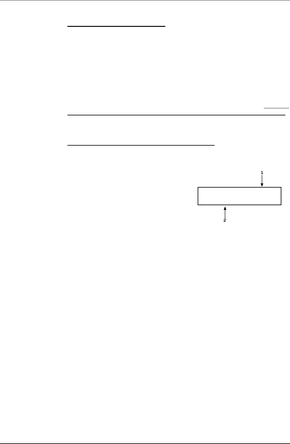
PG7000™ OPERATION AND MAINTENANCE MANUAL
© 2011 Fluke Calibration Page 56
See Figure 9 for a schematic of the Differential Mode Controller and its valves.
Setting Zero Differential Pressure
Zero differential pressure can be set by PG7000 or simply by setting the
Differential Mode Controller TEST BYPASS valve to the OPEN position which
connects the HIGH and LOW TEST ports together. The TEST BYPASS valve
OPEN position is a “true” zero. The zero differential pressure value set by
PG7000 has the same uncertainty as any other differential pressure point (see
Section 1.2.4.1). Comparing the DUT reading at zero set by TEST BYPASS in
the OPEN position and at zero set by PG7000 in differential mode like any other
differential pressure, can help quantify the quality of the current RPM
offset value. If the difference between the two zero readings is excessive, the
RPM offset value should be redetermined (see Section 3.9.4.1, Selecting
Differential Mode, Setting Static Pressure, Finding RPM Offset (<1run>)).
Also, consider correcting all the DUT readings by the difference in the zero
reading found in the two different conditions to correct for the defect in the
RPM offset.
To view the current RPM offset and the static pressure value at which the offset
was recorded, press [MODE] and select <4dif>, <2view>. This display is:
Viewing Static Pressure and RPM Offset (<2view>)
1. RPM offset value that is currently active.
2. PG7000 pressure at which RPM offset was
recorded.
Offset: -6.33 Pa
@99.8755 kPa a
Press [ESCAPE] to return to the <Differential mode:> menu.
Press [ENTER] to return to the previous run screen.
3.9.4.2 HIGH LINE Differential measurement mode (PG7102,
PG7302 and PG7202 ONLY)
PURPOSE
To define differential pressures at elevated line pressures up to 11 MPa (1 600 psi)
with PG7102 or 110 MPa (16 000 psi) with PG7202 in gas and up to 500 MPa
(72 500 psi) in oil.
Note
High line differential (HL dif) mode operation is only supported
by PG7102, PG7202 and PG7302. HL dif mode operation
requires the use of a two identical PG7102, PG7202 or PG7302s
in tandem. Both PG7000s must have nominally identical piston-
cylinders and one of the PG7000s must have a “tare” piston-
cylinder. The HL dif mode setup for pressure up to 110 MPa (1
600 psi) in gas normally also includes an MPC1-D-1000 or
MPC1-D-3000 manual pressure controller and the PK-7100-
MPCD-DIF Interconnections Kit P/N 3070226. The HL dif mode
setup for pressure greater than 110 MPa uses GPC1 (gas),
OPG1 or MPG1 (oil) and custom interconnecting hardware.

3. GENERAL OPERATION
Page 57 © 2011 Fluke Calibration
PRINCIPLE
Note
Technical Note 0080TN03 provides more detailed information on
high line differential mode principles including a complete
uncertainty analysis. Consult Fluke Calibration or visit our
website, www.dhinstruments.com to obtain a copy.
High line differential mode is designed to allow two PG7102, PG7202 or PG7302
piston gauges to be used together to define differential pressures relative to line
pressures significantly above atmospheric pressure. This capability is most often
used to test or calibrate differential pressure devices designed to operate at elevated
line pressures under their normal operating line pressure conditions.
The main challenge of defining differential pressures at elevated line pressures
comes from the very high ratio of line pressure to differential pressure. Relatively
small errors and instabilities in the line pressure are very large relative to the
differential pressure.
The principal of high line differential mode is to “crossfloat” two PG7000 piston
gauges so that they define a common line pressure. After the crossfloat is
completed, a BYPASS valve is closed isolating one PG7000 from the other. The
“tare” PG7000 maintains the line pressure. Mass is added to the “reference”
PG7000 to define differential pressures “on top of” the line pressure. The very high
precision of the PG7000 gas operated piston gauges allows them to set and
maintain a common line pressure with uncertainty much lower than the overall
measurement uncertainty on either piston gauge. The two PG7000s are
crossfloated at the line pressure prior to making differential measurement to
minimize the contribution of line pressure errors to differential pressure. The
crossfloating procedure consists of making mass adjustments on the tare
PG7000 so that both pistons, when connected together at the line pressure, fall
at their “natural” drop rate. PG7000’s embedded piston fall rate measurements
and calculations capabilities are used to assist the operator in performing the
crossfloat.
The PG7000 that is used only to maintain the line pressure on the low side of the
device under test (DUT) is designated the tare PG7000. The tare PG7000 is a
standard PG7000 but it is normally used with a tare piston-cylinder and a tare mass
set (a standard piston-cylinder and mass set may also be used). A tare piston-
cylinder effective area is entered as the nominal effective area and its
characteristics include k(P), which must be entered in the piston-cylinder
definition file (see Section 3.11.1.1). A tare mass set has the same configuration
as a standard mass set but the exact values of the masses are not measured
and the mass set is set up using nominal values for each mass measured value
(see Section 3.11.1.6). The tare piston mass is adjusted to be slightly under the
nominal piston mass. This assures that the tare side will always be the light side
when crossfloated with the reference side. If a tare piston-cylinder and mass set
is not used on the tare PG7000, the tare side may not be the light side in a
crossfloat. In this case, the tare mass load on the reference side should be
increased slightly (generally < 1 g) to ensure that it is heavier, taking care not to
confuse the added tare mass with the subsequent differential mass load.
The PG7000 that is used to apply the added pressure to create the differential
pressures on the high side of the DUT is designated the reference PG7000. The
reference PG7000 is a standard PG7102, PG7202 or PG7302 with a standard
piston-cylinder and mass set. The reference must be a PG7102, PG7202 or
PG7302. The tare may be a PG7102, PG7202, PG7302 or a PG7601.

PG7000™ OPERATION AND MAINTENANCE MANUAL
© 2011 Fluke Calibration Page 58
The tare and reference PG7000s must have nominally identical piston-cylinders.
The two PG7000s operate together with the reference acting as “master” and
the tare as “slave”. For communications between the two to occur, COM2 of the
reference must be connected to COM1 of the tare with a valid RS232 cable and
proper settings must be made on both interfaces (see Section 3.11.5.1).
For high line differential mode operation up to 11 MPa (1 600 psi) in gas, an
MPC1-D and the PK-7100-MPCD-DIF Interconnections Kit P/N 401645 should
be used to provide the DUT high and low test connections and support line
pressure and differential pressure setting procedures (see Figure 10). For
operation at pressure greater than 11 MPa, GPC1 for gas, OPG1 or MPG1 for
oil, and custom interconnecting hardware are used in a functionally similar setup.
PG7000 high line differential measurement mode manages the data acquisition
and handling necessary to support differential mode operation. Differential mode
operation requires setting the line pressure including crossfloating the two
PG7000 piston gauges and then setting differential pressures at the line
pressure. These two independent operations are supported under
[MODE], <3HLdif>, <1run>.
Caution
• High line differential mode relies upon the very high
sensitivity of PG7000 gas operated piston-cylinders to set
and stabilize low differential pressures relative to very high
line pressures. To meet the full performance potential of
PG7000 high line differential mode operation, external
influences on the piston gauges must be minimized. Air
currents and vibrations are the most significant
possible influences. Do not operate near an active air
conditioning or heating duct, avoid opening and closing
doors or any movement of personnel around the system.
Consider putting the PG7000s in an electrostatic free
enclosure if the environment cannot be adequately
controlled.
• See Section 7.2.1 for information on the exact calculations
used by PG7000 to obtain the differential pressures defined
in high line differential mode.

3. GENERAL OPERATION
Page 59 © 2011 Fluke Calibration
Tare PG7000 (PG7102, PG7202,
PG7302, or PG7601)
Differential Device Under Test (DUT
Reference PG7000 (PG7102, PG7202
or PG7302)
MPC1-D or other INLET Valve
MPC1-D or other Hi Variable Volume (Hi VV)
MPC1-D or other VENT Valve
MPC1-D or other HI/LO BYPASS Valve
MPC1-D or other Lo Variable Volume (Lo VV)
Figure 11. High Line Differential Mode Schematic
Note
Technical Note 0080TN03 provides more detailed information on
high line differential mode principles using PG7102 and PG7601
piston gauges and includes a complete uncertainty analysis.
Consult Fluke Calibration or visit our website,
www.dhinstruments.com to obtain a copy.
OPERATION
Note
High line differential mode does not support operation with
AMH automated mass handler(s).
To select high line differential mode operation and access differential mode
functions press [MODE], <3HLdif> on the reference PG7000.
Note
When operating in high line differential pressure mode, the
reference PG7000 is “master” and the tare PG7000is “slave”.
All operator interaction is with the PG Terminal of the reference
PG7000. The tare’s display is for information only. The tare
PG7000 keypad is inactive.

PG7000™ OPERATION AND MAINTENANCE MANUAL
© 2011 Fluke Calibration Page 60
High line differential mode operation includes:
• Entering differential mode (see Section 3.9.4.2, Entering High Line
Differential Mode
• Setting a line pressure (see Section 3.9.4.2,
([MODE], <3HLdif>, <1run>)).
Setting a Line Pressure
• Setting differential pressures at a high line pressure (see Section 3.9.4.2,
([MODE], <3HLdif>, <1run>, <2yes>)).
Setting Differential Pressures at a High Line Pressure
• Viewing current line pressure and natural fall rates for the line pressure
(see Section 3.9.4.2,
).
Viewing Line Pressure, Starting Piston-Cylinder
Temperatures and Natural Piston Fall Rates ([MODE], <3HLdif>,
<2view>).
To enter high line differential mode, press [MODE] ,<3HLdif>, <1run> on the
reference PG7000’s PG Terminal.
Entering High Line Differential Mode ([MODE], <3HLdif>, <1run>)
The reference PG7000 initializes high line differential mode. To successfully enter
high line differential mode the reference PG7000 must be able to communicate
with the tare PG7000, the piston-cylinders in both PG7000s must be nominally
identical and the piston-cylinder in the tare PG7000 must have a non-zero value
for k(P) in its piston-cylinder module file. When initializing high line differential
mode, the reference PG7000 tests for these conditions and provides error
messages as follows:
• <Cannot find PG7000 on COM2>: COM2 of the reference PG7000 must
be connected to COM1 of the tare PG7000 using a valid RS232 cable and
both interfaces must be properly set so that communications between
the two PG7000s can occur (see Sections 3.11.5.1, 3.11.5.4). If the
reference is unable to communicate with the tare, this error message is
displayed. If this error message is observed, correct the communications
problem and retry (see Section 3.11.5.1).
• <T & R PCs not a pair, cannot run HLdif>: The piston-cylinder
modules in the two PG7000s must be nominally identical (have the same
nominal mass to pressure conversion coefficient). If the reference
PG7000 finds the two piston-cylinder modules to be different, this error
message is displayed. If this error message is observed, correct the
situation by changing piston-cylinder selection or adjusting one piston-
cylinder’s definition (see Sections 3.9.2, 3.11.1.2).
• <No T PC in T PG7000, cannot run HLdif>: The piston-cylinder
module selected in the tare PG7000 must have a non-zero value for k(P)
in the active piston-cylinder module file. If the k(P) value is zero, this
error message is displayed. If this error message is observed, correct
the situation by providing a non-zero value for k(P) in the piston-cylinder
module file of the tare piston-cylinder (see Section 3.11.1.2).
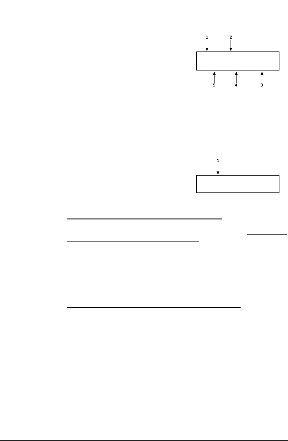
3. GENERAL OPERATION
Page 61 © 2011 Fluke Calibration
After high line differential mode is initialized, the display of the tare PG7000 is:
1. Standard Ready/Not Ready indicators for the
tare PG7000.
2. Last line pressure set in the pressure unit of
measure that was active when the line
pressure was set. The unit of measure
remains the same, even if the reference
PG7000’s unit of measure is changed, until a
new line pressure is set.
< 1000.70 psi LP
- 3.7 30.3 kg + trim
3. Label indicating that the mass load includes whatever trim masses were loaded on the tare
piston in the crossfloating process to reach equilibrium.
4. Tare mass load for the last line pressure set.
5. Current piston position of the tare PG7000.
While in high line differential pressure mode, the tare PG Terminal keypad
is inactive.
After high line differential mode is initialized, the display of the reference PG7000 is:
1. Current (last set) value of line pressure in
current pressure unit of measure.
Line P: 1000 psi
New line P? 1no 2yes
Select <1no> to use the existing line pressure settings and return to the previous
run screen in high line differential measurement mode (see Section 3.9.4.2,
Setting Differential Pressures at a High Line Pressure
Select <2yes> to set a new line pressure value or repeat the line pressure setting
procedure at the current line pressure value (see Section 3.9.4.2,
).
Setting a Line
Pressure ([MODE], <3HLdif>, <1run>, <2yes>)
Note
).
The line pressure setting procedure must be executed each
time the line pressure is changed and should be executed at the
beginning of each differential pressure calibration sequence
even if the line pressure is the same as the line pressure
previously used. Select <2yes> to go to the line setting
procedure.
Caution
Setting a Line Pressure ([MODE], <3HLdif>, <1run>, <2yes>)
To meet the full performance potential of PG7000 high line
differential mode operation, external influences on the piston
gauges must be reduced or eliminated. Air currents and
vibrations are the most significant possible influences. Do not
operate near an active air conditioning or heating duct, avoid
opening and closing doors or any movement of personnel
around the system.
Caution
Leaks at any point in the test system are highly detrimental to
measurement results in high line differential mode. Thoroughly
leak check the system before operation and correct any leaks
detected.

PG7000™ OPERATION AND MAINTENANCE MANUAL
© 2011 Fluke Calibration Page 62
Setting a line pressure has two steps:
Setting the line pressure and determining the natural fall rates of the tare and
reference pistons.
Performing a crossfloat of the pistons to reach equilibrium and minimize
differential pressure zero offset.
To set a line pressure press [MODE], <3HLdif>, <1run>, <2yes> on the
reference PG7000’s PG Terminal. The display is:
1. Edit field for entry of desired line pressure
value in current pressure unit of measure.
Defaults to last value used.
Target line P:
1000 psi
Note
Values of line pressure are always entered and displayed in
gauge mode (i.e., relative to atmospheric pressure). Line
pressure mass loading instructions are always given with 0.1 kg
resolution. The minimum line pressure is the pressure resulting
when the mass of the piston + mass bell is loaded.
Enter the desired line pressure value.
The next display indicates the mass to
load to set the line pressure.
Load nominal mass on
T & R: 33.3 kg
This display corresponds to the standard mass loading instruction display of
pressure to mass mode (see Section 3.9.11.1). The mass loading instruction is
always given with 0.1 kg resolution regardless of the current mass loading
resolution setting (see Section 3.9.10). Load the indicated mass on both the tare
and reference PG7000s following PG7000 mass loading protocol using main
and fractional masses only (do not use trim masses) (see Section 3.6). Press
[ENTER] when ready.
Note
Line pressure mass instructions are always given with 0.1 kg
resolution. This is to preserve the smaller masses for setting
the differential pressure. The differential pressure mass loading
instructions follow conventional PG7000 mass loading protocol
using the masses that remain after the line pressure has been
set. It may be necessary to select the line pressure value to
assure that adequate masses remain to set the desired
differential pressure. For example, if the line pressure requires
loading 33.3 kg, a 0.2 and 0.1 kg mass will be used to set the
line pressure and will not be available if needed to set the
desired differential pressure. If this situation occurs, consider
changing the line pressure so that it is set using a whole
number of kilograms, in this example 33 or 34 kg.
The display is:
Open bypass, float T
Close bypass,[ENTER]
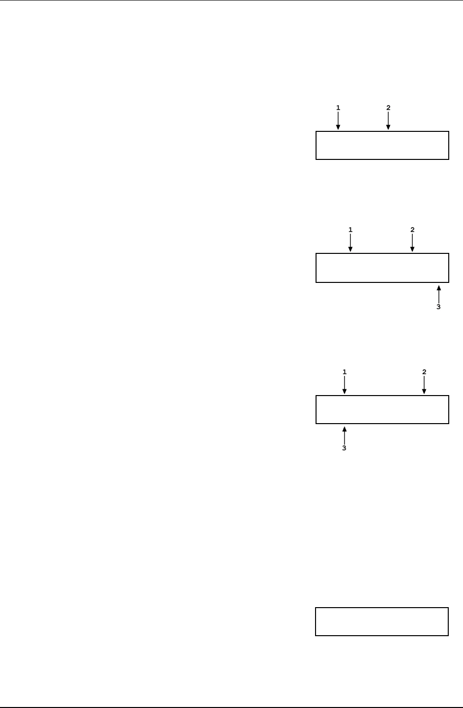
3. GENERAL OPERATION
Page 63 © 2011 Fluke Calibration
With the system’s BYPASS valve OPEN (see Figure 10), use the INLET and/or
VENT valve and the high side variable volume to adjust the pressure to float the
piston of the tare PG7000. This should cause the reference PG7000 piston to
be at its bottom stop. Once the tare piston is floating, close the system’s
BYPASS valve and press [ENTER]. The next display is:
1. Tare piston position.
2. Reference piston position.
+1.2 mm –3.6 Set
T & R to + 1.0&[ENT]
Use the high and/or low side variable volume to set both pistons to a position just
above + 1.0 mm. Ensure that both pistons are rotating. As both pistons fall
through the + 1.0 position, press [ENTER]. PG7000 pauses for 5 seconds and
then measures the natural fall rates of both pistons for 30 seconds.
1. Indication of tare piston position.
2. Indication of reference piston position.
3. 30 second count down.
T+1.0 mm R+1.0
Findingrates 29
Wait for the 30 second timer to count down while the measurements are made.
Be sure not to interfere with the free movement of the piston-cylinders during
the countdown. After the countdown completes, the results are displayed:
1. Average fall rate of the taring piston.
2. Average fall rate of the reference piston.
3. Difference between the reference and taring
piston fall rates (R - T). This is the “natural fall
rate difference”.
T-0.9 mm/min R-1.1
∆-0.2 Save 1yes 2no
Note
The “natural fall rate difference” is the difference between the
fall rates of the two pistons when they are floating naturally at
the line pressure. When performing the crossfloat between the
pistons in the next step of line pressure setting, the objective
will be to adjust the mass of the tare piston until the “crossfloat
fall rate difference” measured with the system’s BYPASS valve
open is equal to the “natural fall rate difference” measured with
the BYPASS closed.
Select <2no> to repeat the “natural fall
rate difference” measurement. Select
<2yes> to accept the “natural fall rate
difference” value and continue to the
second step of line pressure setting which
is crossfloating the two piston-cylinders.
The display is:
Open bypass and
[ENTER] to xfloat

PG7000™ OPERATION AND MAINTENANCE MANUAL
© 2011 Fluke Calibration Page 64
Open the BYPASS valve and press [ENTER] to proceed with the crossfloat. The
display is:
1. Tare piston position.
2. Reference piston position.
3. Difference between the “natural fall rate
difference” and the “crossfloat fall rate
difference” in mm/min. This is the “equilibrium
fall rate”.
T-1.2 mm R+0.5
∆+1.2 B/P open,[ENT]
Note
The “equilibrium fall rate” is the difference between the “natural
fall rate difference” and the “crossfloat fall rate difference”:
Equilibrium fall rate = (Rnat - Tnat) - (Rxfloat -Txfloat)
When the “equilibrium fall rate” is zero, the two piston-cylinders
are at equilibrium at the line pressure.
Crossfloat the two pistons to find equilibrium by making mass adjustments on the
tare piston. Finding equilibrium is an iterative process which is assisted by PG7000.
Pressing [ENTER] starts an automated fall rate measurement sequence that
measures the fall rates more precisely than the real time indication. Following a
30 second countdown or when one of the pistons has moved more than 1 mm,
PG7000 displays the measured “equilibrium fall rate” and suggests the mass
adjustment needed on the tare piston to achieve an “equilibrium fall rate” of zero.
This process can be repeated as many times as desired.
Note
If a standard piston-cylinder and mass set (rather than a tare
piston-cylinder and mass set) is being used in the tare PG7000,
the tare piston may be the heavy one at the start of the
crossfloat (see Section 3.9.4.2, PRINCIPLE). In this case, rather
than reduce mass on the tare PG7000, add a small amount of
mass to the reference PG7000 before starting the crossfloat so
that the tare piston will be the lighter one (generally < 1 g is
needed). This will simplify the crossfloating procedure and
subsequent differential mass loading. Be sure not to confuse
the additional tare mass on the reference piston with the
subsequent differential mass loads.
Using trim masses (50 g and below) from the trim mass set, adjust the mass load
on the tare PG7000 to establish equilibrium (“equilibrium fall rate” near zero).
When the mass adjustments are complete, close the BYPASS valve and put both
pistons at a position just above 0.0 mm. Ensure that both pistons are rotating.
As the pistons fall through the 0.0 mm point, OPEN the BYPASS valve, then
press [ENTER]. After a 5 second delay for stabilization, PG7000 begins the fall
rate measurement. The display is:
1. Indication of tare piston position.
2. Indication of reference piston position.
3. 30 second count down.
4. Average “equilibrium fall rate” since start of
the countdown.
T +0.1 mm R +0.0
∆-12.2 Xfloating 30

3. GENERAL OPERATION
Page 65 © 2011 Fluke Calibration
PG7000 is measuring the drop rate of the two pistons and calculating the
“equilibrium fall rate”. Be sure to not interfere with the free movement of the
piston-cylinders or to introduce any outside interference while the countdown
occurs. The fall rate measurement continues until either piston has moved 1 mm
or 30 seconds have elapsed. The measurement can also be concluded by
pressing [ENTER]. When the fall rate measurement has concluded, the results
are displayed:
1. Average “equilibrium fall rate” measured in
last crossfloat.
2. Suggested mass change (in grams) on the
tare (T) piston to achieve equilibrium based on
equilibrium fall rate just measured.
∆-10.3 +0.050 g on T
Repeat 1yes 2no
Evaluate the quality of the equilibrium. Check the value of the “equilibrium fall rate”.
Consider that the closer the rate is to zero, the better the equilibrium; consider that
the suggested mass change on the tare piston times the mass to pressure
conversion coefficient of the piston approximates the pressure value of the defect in
the equilibrium. Check the difference between the DUT output with the BYPASS
open and BYPASS closed to evaluate the zero error due to the equilibrium.
Select <1yes> to return to the crossfloat <B/P open, [ENTER]> screen.
If you are satisfied with the quality of the equilibrium, select <2no> to go to the
run screen in high line differential pressure mode and set differential pressures at
this line pressure (see Section 3.9.4.2, Setting Differential Pressures at a High
Line Pressure
Note
).
• The value of the average “equilibrium fall rate” measured by
the crossfloat should typically be inside of ± 5 mm/min
and/or the suggested mass adjustment should be inside of
50 mg.
• The device under test (DUT) can often be used to evaluate
the quality of the equilibrium between the two pistons and
to correct for the zero error caused by the defect in
equilibrium. Observe the change in the DUT output when
the system BYPASS valve is opened and closed with the
pistons floating. With the system BYPASS valve open, by
definition, the differential pressure applied to the DUT is
zero. The change in the DUT output observed when the
BYPASS valve is closed with the pistons floating is the zero
error due to the defect in the crossfloat equilibrium.
Consider correcting all of the DUT readings by the value of
this offset to correct for the crossfloat zero error. When
using the offset, keep in mind that, due to differential
evolution of the two PG7000 piston-cylinder temperatures,
the differential pressure at zero differential mass load may
not be zero.
Caution
Setting Differential Pressures at a High Line Pressure
• To meet the full performance potential of PG7000 high line
differential mode operation, external influences on the piston
gauges must be reduced or eliminated. Air currents and
vibrations are the most significant possible influences. Do
not operate near an active air conditioning or heating duct,
avoid opening and closing doors or any movement of
personnel around the system.

PG7000™ OPERATION AND MAINTENANCE MANUAL
© 2011 Fluke Calibration Page 66
• It is not possible to operate in differential mode with leaks at
any point in the test system. Thoroughly leak check the
system before operation and correct any leaks detected.
• High line differential mode is often used to calibrate DUTs
whose differential pressure range is very low relative to the
line pressure. These DUTs can easily be over pressured by
inadvertently applying excessive pressure to one port.
When operating in high line differential pressure mode,
OPEN the system BYPASS valve to zero the differential
across the DUT when there is any risk of overpressure.
Before operating in differential mode the line pressure must be set (see Section
3.9.4.2,
Once the line pressure is set, from a practical standpoint, operating in high line
differential mode is very similar to operating in gauge mode (see Section 3.9.11).
Setting a Line Pressure ([MODE], <3HLdif>, <1run>, <2yes>)).
All operator interaction is with the PG Terminal of the reference PG7000. The PG
Terminal of the tare PG7000 is for display only. The tare PG7000 PG Terminal
keypad is locked out during high line differential mode operation.
Operation is in either pressure to mass or mass to pressure mode
(see Section 3.9.12).
To operate in differential mode the system BYPASS valve must be closed (see
Figure 10).
All mass loading and unloading to define differential pressures is made on the
reference PG7000. Mass loading and unloading instructions follow conventional
PG7000 mass loading protocol (see Section 3.6) but the differential mass loading
instructions are “on top of” the line pressure mass load. The mass load
corresponding to the line pressure on the tare and reference PG7000s must
remain exactly the same throughout the differential measurements.
While in high line differential mode, the piston position and piston rotation
Ready/Not Ready indicators on the reference PG7000 reflect the status of both
the tare and the reference PG7000s. For the indicator to indicate Ready, both
the tare and the reference PG7000s must meet their current Ready/Not Ready
criteria (see Section 3.4). A <T> in a Ready/Not Ready status indicator indicates
that the tare PG7000 is Not Ready.
Note
• When operating in high line differential mode, the
measurement mode indicating character directly to the right
of the pressure unit of measure in the main run screen is
<d> (see Section 37).
• Zero differential pressure (BYPASS valve closed) can be set
by the system. In some cases, the differential mass to load
to set zero is not zero. This is normal and can occur due to
differential changes in the temperature of the tare and
reference piston-cylinders after the original line pressure
crossfloat. A differential piston-cylinder module
temperature change while running in high line differential
mode affects the line pressure causing an offset to the
differential pressure. The offset to the differential pressure
causes a non-zero differential mass load to be needed to set
zero differential pressure (see Section 7.2.1). Conversely,
and for the same reason, a differential mass load of zero
may not result in a differential pressure of zero.
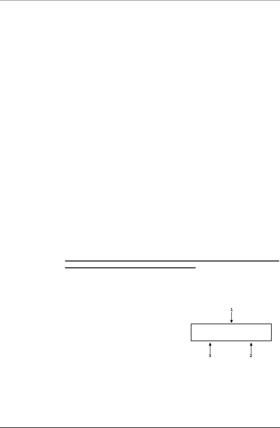
3. GENERAL OPERATION
Page 67 © 2011 Fluke Calibration
Typical Sequence to Set Differential Pressures at a High Line Pressure
Set the desired line pressure (see Section 3.9.4.2, Setting a Line
Pressure ([MODE], <3HLdif>, <1run>, <2yes>)).
Select pressure to mass or mass to pressure mode (see Section 3.9.12).
If desired, read DUT output at zero differential pressure with BYPASS valve
OPEN. Then, put the BYPASS valve in CLOSED position. Float both
PG7000 pistons before operating the BYPASS valve. Read DUT output at
zero as defined by the PG7000s if desired (this value can be used as an
offset correction on subsequent DUT differential pressure outputs).
Press [ENTER] and enter a pressure or mass value. All mass loading and
unloading to define differential pressures is performed on the
reference PG7000. Follow normal PG7000 mass loading protocol (see
Section 3.6). Note, however, that the mass loading instructions are “on top
of” the mass already loaded to define the line pressure.
The mass corresponding to the line pressure must remain exactly the same
on both the tare and reference PG7000s throughout the differential
pressure measurements.
Float the tare and reference pistons. For best results put both pistons
slightly above the 0.0 point, for example +0.3 mm.
When the reference PG7000 indicates Ready on both Ready/Not Ready
indicators (see Section 3.4), take the DUT reading at the differential
pressure indicated on the top line of the reference display. For best
results log DUT readings and average them over time while the PG7000
pistons fall through the 0.0 mm point. Averaging for 10 to 30 seconds allows
the random pressure noise from piston rotation to be integrated and
eliminated.
Repeat Steps through for each desired differential pressure point.
If the last differential pressure is zero, consider reading the DUT output with
the BYPASS valve CLOSED. Then OPEN the BYPASS valve to set “true”
zero differential pressure.
To view the last line pressure setting, the starting piston-cylinder module
temperatures, the natural piston fall rates and the “natural fall rate difference”
recorded at that line pressure, press [MODE] and select <3HLdif>, <2view>.
The display is:
Viewing Line Pressure, Starting Piston-Cylinder Temperatures and Natural
Piston Fall Rates ([MODE], <3HLdif>, <2view>)
1. Last line pressure value set (line pressure is
always in gauge mode).
2. Temperature of the reference piston-cylinder
logged when the line pressure crossfloat was
completed.
3. Temperature of the tare piston-cylinder
module logged when the line pressure
crossfloat was completed. The starting
temperatures are the temperatures logged at
the time the line pressure setting crossfloat
was completed. These temperatures are
Line P: 1000 psi
T 21.24 ºC R 21.47
used in calculating corrections to the differential pressure to take into account differential
temperature changes in the piston after completion of the crossfloat (see Section 7.2.1 for
differential pressure calculation information).

PG7000™ OPERATION AND MAINTENANCE MANUAL
© 2011 Fluke Calibration Page 68
Press [ENTER] to continue to the next view screen or [ESCAPE] to go to the
previous screen. The next view screen is:
1. Average fall rate of the tare piston recorded at the
last line pressure.
2. Average fall rate of the reference piston recorded at
the last line pressure.
3. Difference between the reference and tare piston
average fall rates (R - T). This is the “natural fall rate
difference”.
T-0.91 mm/min R-1.10
∆ -0.2 Save 1yes 2no
Note
The “natural fall rate difference” is the difference between the
fall rates of the two pistons when they are floating naturally at
the line pressure. The “natural fall rate” can change slightly as
operating conditions change so the “natural fall rate”
determination and piston crossfloat procedure should be
performed at the beginning of each sequence of differential
pressure definitions.
To return to the <HLDif mode:> menu, press [ESCAPE].
To return to the previous run screen, press [ENTER].
3.9.5 [SYSTEM]
PURPOSE
To access the two SYSTEM run screens which display current values of PG7000 piston
behavior, piston-cylinder temperature and vacuum reference (PG7601 only) measurements.
OPERATION
To access the SYSTEM run screens, press [SYSTEM] from any other run screen. There are
two SYSTEM run screens. Pressing [SYSTEM] or [±] when in a SYSTEM screen toggles
between the first and second SYSTEM screens.
See Sections 3.9.5.1 and 3.9.5.2 for detailed information on the contents of the first and
second SYSTEM run screens.
Note
The SYSTEM screens are run screens. This means that other functions
can be accessed from the SYSTEM screens and the active SYSTEM screen
will be returned to when leaving functions. The MAIN screen and
AMBIENT screen are also run screens (see Section 3.8).
3.9.5.1 First System Run Screen
OPERATION
The first SYSTEM run screen provides real time display of piston rotation rate,
decay in piston rotation rate, piston position and piston fall rate.
To access the first SYSTEM run screen, press [SYSTEM] from any other
run screen.

3. GENERAL OPERATION
Page 69 © 2011 Fluke Calibration
The first SYSTEM run screen displays:
1. <nnn rpm>:
Numerical value of current
piston rate of rotation. The unit of measure is
rotations per minute [rpm] and cannot be
changed. Flashes when Not Ready and
piston is floating (see Section 3.4.2).
Indicates < ---- >
when information is
unavailable or out of range.
2. <±nn/min>: Numerical value of current decay
in piston rotation rate (deceleration). The unit
of measure is rotations per minute [rpm/min]
and cannot be changed. < ---- > when
information is unavailable or out of range.
nnn rpm ±nn/min
±n.nn mm ±n.nn/min
3. <
±
n.nn/min>: Sign and numerical value of current piston vertical rate of displacement. A
negative value indicates piston falling. A positive value indicates piston rising. The unit of measure
is millimeters per minute [mm/min] and cannot be changed. Indicates < ---- > when
information is unavailable or out of range.
4. <
±
n.nn mm>: Sign and numerical value of current position of the piston within the piston
stroke (see Section 3.5). The unit of measure is millimeters [mm] away from mid-stroke
position and cannot be changed. Indicates <HSTOP> when the piston is at the high stop (all
the way up) and <LSTOP>
when the piston is at the low stop
(all the way down). Flashes when Not Ready and piston is floating (see Section 3.4.1). Indicates
< ---- > when information is unavailable or out of range.
Pressing [ESCAPE] in the first SYSTEM run screen returns operation to the MAIN
run screen. Pressing [SYSTEM] or [±] toggles between the first and second run
screen. All function keys are active from the first SYSTEM run screen and
operation returns to that screen when leaving functions the were accessed from it.
Note
• The measurement systems for piston behavior indications
rely on movement of the mass loading bell. Piston behavior
indications (piston position, piston rotation rate) are not
valid when the mass bell is not loaded on the piston.
• See Section 3.5 for information on the piston stroke and
measurement zone.
3.9.5.2 Second System Run Screen
OPERATION
The second SYSTEM run screen displays the values of piston-cylinder
temperature and temperature rate of change measured by PG7000.
PG7601 also displays reference vacuum and vacuum rate of change. If internal
or external measurement is specified for the vacuum values in SETUP (see
Section 3.10), the second SYSTEM run screen provides a real time display of the
values measured.
To access the second SYSTEM run screen, press [SYSTEM] or [±] from the first
SYSTEM run screen. To access the first SYSTEM run screen, press [SYSTEM]
from any run screen.

PG7000™ OPERATION AND MAINTENANCE MANUAL
© 2011 Fluke Calibration Page 70
The second SYSTEM run screen displays:
1. <n.nn°C>: Current piston-cylinder
temperature. Source of value can be internal
measurement, default or user depending on
current SETUP selection (see Section 3.10).
The unit of measure is degrees Centigrade
[
±
°C] and cannot be changed. Indicates < ----
> when information is unavailable or out of
range.
2. <+n.nn/min>: Sign and numerical value of
current rate of change of temperature. A
negative value indicates temperature
decreasing. A positive value indicates
temperature increasing. The unit of
n.nn°C ±n.nn/min
nnn.n Pa ±nnn.n/min
measure is degrees Centigrade per minute [°C/min] and cannot be changed. Indicates < ---- >
when information is unavailable or out of range. Indicates < ---- > when “user” or “default” is
the current SETUP selection for piston-cylinder temperature source (see Section 3.10).
3. <+nnn.n/min>: (Used for PG7601 only.) Sign and numerical value of current rate of change
of the vacuum reference pressure. A negative value indicates pressure decreasing. A positive
value indicates pressure increasing. The unit of measure is Pascal per minute [Pa/min] and
cannot be changed. Indicates < ---- >
when information is unavailable or out of range.
<Blank> if the PG7000 model is not PG7601 or if user or default is the current SETUP
selection for reference vacuum (see Section 3.10).
4. <nnn.n Pa>: (Used for PG7601 only.) Current vacuum reference value. Can be internal
measurement, external measurement, default or user depending on current SETUP selection.
Flashes when Not Ready and piston is floating (see Section 3.4.3). The unit of measure is
Pascal [Pa] and cannot be changed. Indicates < >20 Pa > if current SETUP selection is
internal or external and current measurement
is out of range or greater than 20 Pascal.
<Blank> if PG7000 model is not PG7601.
Pressing [ESCAPE] in the second SYSTEM run screen returns operation to the
MAIN run screen. Pressing [SYSTEM] or [±] toggles between the first and
second SYSTEM run screen. All function keys are active from the second
SYSTEM run screen and operation returns to that screen when leaving functions
that were accessed from it.
Note
The current selection in SETUP determines the source of the
values used by PG7000 for piston-cylinder temperature and
vacuum reference values. If the SETUP setting is user or
default, the SYSTEM screen displays the user or default value,
not PG7000’s on-board measurement(s).
3.9.6 [AMBIENT]
PURPOSE
Access the AMBIENT run screen which displays the current ambient condition values being
used by PG7000 for calculations of reference pressures.
PRINCIPLE
PG7000 uses ambient condition values to calculate the reference pressures that it defines
(see Section 7.2). The source of the ambient condition values is specified in the current
SETUP file (see Section 3.10). The AMBIENT run screen displays the current ambient
condition values. If the SETUP selection for the ambient condition is internal measurement,
then the AMBIENT run screen provides a real time display of the measurement of PG7000’s
on-board sensor for that variable.
OPERATION
To access the AMBIENT run screen, press [AMBIENT] from any other run screen
(MAIN or SYSTEM).

3. GENERAL OPERATION
Page 71 © 2011 Fluke Calibration
Note
The AMBIENT screen is a run screen. This means that other functions can
be accessed from the AMBIENT screen and the active AMBIENT screen
will be returned to when leaving functions. The MAIN screen and SYSTEM
screens are also run screens (see Sections 3.7 and 3.9.5).
The AMBIENT run screen displays:
1. <nnnnnnn uuuu>: Current numerical value and pressure
unit of atmospheric pressure. Source of value can be internal
measurement, remote barometer, default or user depending
on current SETUP selection (see Section 3.10). The unit of
measure is determined by the UNIT function setting (see
Section 3.9.3). ATM head is applied to internal or external
barometer reading to correct atmospheric pressure to the
PG7000 reference level (see Section 3.11.3.3). Indicates < --
-- >
when information is unavailable or out of range.
Indicates <TIMEOUT> if the current SETUP selection is a
remote barometer and PG7000 communication with the
barometer times out.
nnnnnnn uuuu nn.n°C
nn%RH n.nnnnnn/s2
2. <n.nn°C>: Current ambient temperature. Source of value can be internal measurement, default or user
depending on current SETUP selection (see Section 3.10). The unit of measure is degrees Centigrade [ºC]
and cannot be changed. Indicates < ---- > when information is unavailable or out of range.
3. <n.nnnnnnm/s2>: Value of local acceleration due to gravity. Can be default or user depending on current SETUP
selection (see Section 3.10). The unit of measure is meters per second squared (m/s2) and cannot be changed.
4. <nn%RH>: Current ambient relative humidity. Can be internal measurement, default or user depending on
current SETUP selection (see Section 3.10). The unit of measure is percent relative humidity (%RH) and
cannot be changed. Indicates < -- > if current SETUP selection is internal and current measurement is
unavailable or out of range.
Pressing [ESCAPE] in the AMBIENT run screen returns operation to the MAIN run screen.
All function keys are active from the AMBIENT run screen and operation returns to that
screen when leaving functions that were accessed from it.
Note
• The current selection in SETUP determines the source of the values used
by PG7000 for atmospheric pressure, ambient temperature and relative
humidity. If the SETUP setting for these values is user or default, the
AMBIENT screen displays the user or default value, not PG7000’s on-
board measurement(s).
• To change the ambient pressure units of measure, see Section 3.9.3.
When the current pressure unit of measure is an altitude unit, atmospheric
pressure in the AMBIENT run screen is expressed in kPa if the altitude unit
is meters (m) or psi if the altitude unit is feet (ft).
3.9.7 [HEAD]
PURPOSE
To cause a pressure value, representing the fluid head resulting from a difference in height,
to be added to the pressure defined by PG7000 at its reference level. To set the height of the
DUT head.
PRINCIPLE
The pressure defined by the PG7000’s floating piston is the pressure at the bottom of the piston.
This is referred to as the PG7000 reference level. The height of the bottom of the piston with
the piston in mid-stroke position is marked reference level on the PG7000 piston-cylinder
module mounting post. Frequently, when performing a calibration or test, the device or
system under test is at a different height than the PG7000 reference level. This difference in
height (referred to as DUT head) can cause a significant difference between the pressure
defined by the PG7000 at its reference level and the pressure actually applied to the device
under test located at a different height. In this case, it is useful to make a head correction to
the pressure defined by the PG7000 at its reference level in order to accurately predict the
pressure actually applied at a different height. The HEAD function allows this head correction
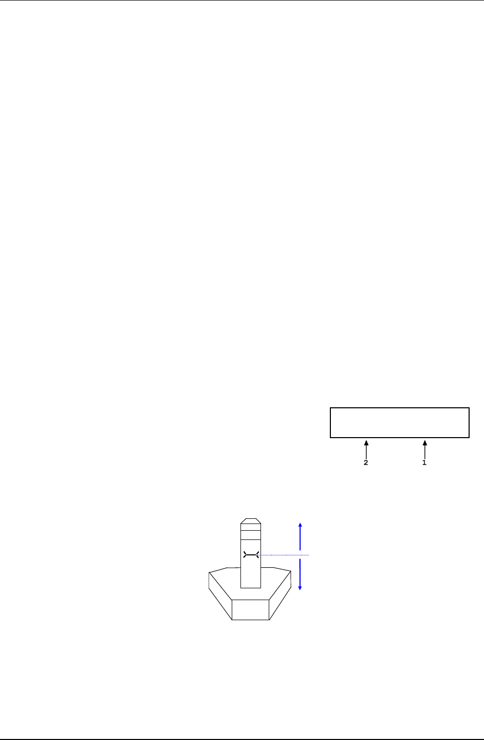
PG7000™ OPERATION AND MAINTENANCE MANUAL
© 2011 Fluke Calibration Page 72
to be applied automatically for a variety of fluids based on operator entry of the height difference.
The fluid used and the HEAD function units of measure are set by pressing [SPECIAL] and
selecting <3head> (see Section 3.11.3).
PG7000 can accurately determine head pressures for gases (nitrogen, helium and air) and liquids
(Di-2 ethylhexyl Sebacate oil, water and a user defined liquid) as the pressurized medium.
Note
• When gas is the test fluid, use of the HEAD function is most important at
low absolute pressures. In this case, specifying the head height within
± 0.2 in. (5 mm) is adequate to ensure that, even in the worst case, the
uncertainty on the head correction will be insignificant relative to the
tolerance on the PG7000 measurement. Use of the HEAD function to
ensure tolerance measurements is particularly critical when a liquid is the
test fluid, due to the high density of liquids. To determine when and how
precisely a head correction for liquids must be made, 0.03 psi/inch (90
Pa/cm) may be used as an estimation of the liquid head value.
• Regardless of the head function’s setting, corrections are automatically
applied to the calculated reference pressure to compensate for the
deviation between the current piston position and the mid-stroke position
(see Section 3.11.3.4).
• The pistons of certain gas operated piston-cylinder modules are hollow.
Due to their irregular shape, for these pistons, the natural reference level is
not at the bottom of the piston. So that, in practice, the actual reference
level is the same for all piston-cylinder modules, a reference level offset is
applied when a hollow piston is used. The reference level offset is
included in the piston-cylinder file (see Section 3.11.1.1) and corrects the
reference level back to the reference point marked on the mounting post.
OPERATION
To access the HEAD function, press [HEAD]. The display is:
1. Test fluid currently specified for the head correction.
2. Entry field for head height (1 to 999 cm or in.).
Edit DUT head height
95 cm N2
Entering a value of zero turns the HEAD function OFF. Entering a value other than zero
turns the HEAD function ON using the height entered. Pressing [ESCAPE] returns to the
main run screen with NO change to the current head setting.
REFERENCE
LEVEL
Reference
Line
(+)
(-)

3. GENERAL OPERATION
Page 73 © 2011 Fluke Calibration
Note
• The reference height of PG7000 pressure definition is the bottom of the
piston in mid-stroke float position. This position is marked on the piston-
cylinder module mounting post and on the optional AMH, mass automated
handler. The DUT head height should be entered as a positive value if the
device or system under test is higher than the PG7000 reference level and
negative if it is lower.
• To change units of DUT head height between inches and centimeters and
to change the test fluid, press [SPECIAL] and select <3Head> (see Section
3.11.3).
• When the HEAD function is ON (DUT head value different from 0), the
application of a head correction is indicated by <h> in the right side of the
top line of the MAIN run screen (see Section 3.7). When the HEAD function
is OFF, the <h> is NOT shown. PG7000’s also have a separate head
correction to compensate for the deviation between the current piston
position and mid-stroke (see Section 3.11.3.4). This PISTON head can be
turned ON and OFF (see Section 3.11.3.4).
3.9.8 [ROTATE]
PURPOSE
To turn automatic control of motorized piston rotation (acceleration and brake) ON and OFF.
Note
See Section 3.9.13 for information on manual control of motorized piston
rotation.
PRINCIPLE
The motorized piston rotation system is used to start or increase piston rotation rate when the
piston is floating. It is also used to stop piston rotation when necessary, for example before
manipulating mass to set a new pressure. The system operates by engaging a motor driven
belt around the bottom of the mass loading bell to accelerate or brake the rotation rate of the
mass bell and piston it is loaded on. The motorized rotation system can engage with the
piston at any position in its stroke and at any rotation speed with minimal impact on piston
position and the defined pressure. When the motorized rotation system disengages, the
piston is completely free.
With automatic motorized rotation ON, the motorized rotation system engages and
disengages automatically as needed when the piston is floating to maintain the piston rotation
rate above the minimum rate Ready limit (see Section 3.4.2). The rotation rate is measured
by PG7000 on board sensors and the rotation rate limits are set in the file of the active piston
cylinder (see Section 3.11.1.1). Whenever the piston is floating, the motorized rotation
system will attempt to maintain the piston rotation rate within the Ready limits (except under
the cutoff mass load of 3 kg, at which the low limit is reduced to minimum to maximize free
rotation time. The piston rotation Ready/Not Ready indication character indicates Not Ready
to alert the operator when the motorized rotation system is about to engage. The rotation
system will not engage when the current mass load is less than the mass of the piston +
mass loading bell.
The motorized rotation system is also used to brake and stop rotation when starting a new
pressure point. If the piston is floating and rotating when [ENTER/SET P] is pressed, the
motorized rotation system engages at a speed near the rotation rate of the piston and then
brakes it to a stop. Piston rotation is stopped to avoid loading and unloading masses on the
rotating piston and to avoid stopping rotation by friction between the piston and the piston
end of stroke stops.
With automatic motorized rotation OFF, the motorized rotation system engages only when
actuated by the operator. Pressing [] accelerates rotation or [] followed by [←] stops
rotation (see Section 3.9.13).

PG7000™ OPERATION AND MAINTENANCE MANUAL
© 2011 Fluke Calibration Page 74
Automatic motorized rotation is generally left ON for normal operation. It is turned OFF in
situations where rotation system actuation independent of operator initiative is undesired
(e.g. when performing a crossfloat intercomparison with another piston gauge).
OPERATION
To access the AutoRotate functions, press
[ROTATE]. The display is:
AutoRotate OFF
1on 2pre-decel
<AutoRotate ON> or <AutoRotate OFF> indicates the current state of AutoRotate. Use
<1on> or <1off> to change the state.
When automated rotation is OFF, the PG7000 motorized rotation system will only engage if
the operator presses [] or [] followed by [←] (see Section 3.9.13).
When automated rotation is ON, the automated rotation system engages automatically.
When the piston is floating, it engages as needed to maintain the piston rotation rate above
the Ready limit (see Section 3.4.2). When [ENTER/SET P] is pressed, it engages to stop
rotation before masses are loaded and/or the pressure is adjusted (this function can be
turned ON and OFF, see Section 3.9.8.1). Manual control using [] and [] followed by
[←] is also still active.
Note
• Automatic motorized piston rotation is dependent on PG7000’s
measurements of piston position and rotation rate. These measurements
are only available when the mass loading bell is installed on the piston.
Automatic piston rotation is suspended when the current PG7000 mass
load does not include the mass loading bell.
• Proper operation of the rotation system is dependent on PG7000’s
measurements of piston position. When using AutoGen, be sure that the
piston position indication system is properly adjusted (see Section 5.2.2).
• When PG7601 is operating in absolute by vacuum mode using the internal
vacuum sensor to measure reference vacuum, automatic motorized piston
rotation will not engage until the reference vacuum value is within the
Ready limit (see Section 3.4.3).
3.9.8.1 <2PRE-DECEL>
PURPOSE
To turn ON and OFF a function that causes the automated rotation system to
begin the piston rotation deceleration when [ENTER/SET P] is pressed rather
than at the time mass is to be loaded.
On a PG7000 Platform equipped with motorized rotation, when AutoRotate is on,
the piston rotation deceleration function is used to stop rotation before masses
are loaded or pressure is adjusted. As the deceleration function can take up to
one minute to execute, it can be initiated the moment that [ENTER/SET P] is
pressed to enter a new pressure or mass target. The deceleration function then
runs while the new target value is being entered. However, when the next target
does not require changing main masses, it may not be necessary to stop piston
rotation. In these cases, the running the deceleration function is probably not
desired and it is not beneficial for piston deceleration to initiate it when
[ENTER/SET P] is pressed. For this reason, the function to start piston
deceleration when [ENTER/SET P] is pressed can be turned ON and OFF.
If pre-deceleration is ON and AutoRotate is ON, piston rotation deceleration
always initiates immediately when [ENTER/SET P] is pressed.
If pre-deceleration is OFF and AutoRotate is ON, piston rotation deceleration
occurs after entry of the pressure or mass target value and only if the new target
requires changing main masses with a manual mass set or operation AMH if an
automated mass handling system is active.

3. GENERAL OPERATION
Page 75 © 2011 Fluke Calibration
OPERATION
To turn ON and OFF the function that causes stopping piston rotation to initiate
when [ENTER/SET P] is pressed, press [ROTATE], <2pre-decel>. The cursor
is on the choice corresponding to the current state. Select <2on> for piston
rotation deceleration to initiate when [ENTER/SET P] is pressed. Select <1off>
for deceleration to initiate only after entry of a new pressure or mass target and
only if main masses need to be moved or AMH automated mass handling needs
to be operated. The default is <2on>.
3.9.9 [GEN] (OPTIONAL)
PURPOSE
To turn ON and OFF automated pressure generation/control and view and edit automated
pressure control settings. Requires that an automated pressure generation/control
component be included in the PG7000 system and properly configured (see Section 2.4.9).
PRINCIPLE
PG7000s support automated pressure generation/control components. These components, when
properly configured and interfaced with the PG7000 platform, are controlled by the PG7000
platform to automatically set and adjust pressure to float the piston. Automated pressure
generation and control components are interfaced via the PG7000 platform’s COM3 RS232
port (see Section 3.11.5.1).
Once an automated pressure generation/control component has been properly configured
and interfaced with the PG7000 platform, the functions under [GEN] are used to turn
automated pressure generation/control ON and OFF and to set operating parameters
associated with automated pressure control.
With automated pressure generation/control ON, PG7000 uses the automated control
component to float and refloat its piston when a pressure or mass value is entered.
[ENTER/SET P] is pressed to initiate a new command. The automated control function is
suspended when any function key is pressed, when entering remote mode or if automated
pressure control is turned OFF.
After a target pressure or mass has been entered (locally or remotely) and the required mass
has been loaded, the GEN function controls the pressure control component as needed to
float the PG7000 piston at the piston float target (see Section 3.9.9.1) and refloat it if
necessary. If the piston moves beyond the high or low piston position Ready limit the GEN
function refloats it to the piston float target. The piston float target and piston position ready
limits are user adjustable (see Section 3.10 <6READY). See Section 3.5, Figure 8 for a
description piston position stroke zones and limits.
With automated pressure generation/control OFF, PG7000 leaves the automated
pressure generation/control component idle and does not attempt to use it.
If an automated pressure control component is included in the PG7000 system, automated
pressure generation/control is generally left ON for normal operation. It is turned OFF in
situations where pressure control independent of operator initiative is undesired (e.g. when
performing a crossfloat intercomparison with another piston gauge).
The [GEN] menu includes:
1. Turning the GEN function ON and OFF.
2. The adjustable piston float target that defines the position to which the piston is set when
floated (see Section 3.9.9.1).
3. A choice to have the piston raised to the top of the stroke before manipulating mass using
an AMH automated mass handler (see Section 3.9.9.2).
4. Viewing and setting the UPPER LIMIT of the automated pressure generation component to
avoid accidental overpressure (see Section 3.9.9.2).
5. Viewing and setting the assumed pressure controller tolerance used to determine pressure
setting limits when floating the PG7000 piston (see Section 3.9.9.4).
6. A choice to not readjust piston position if the piston is already floating within the Ready
position limit after a new target is executed (see Section 3.9.9.5).

PG7000™ OPERATION AND MAINTENANCE MANUAL
© 2011 Fluke Calibration Page 76
7. Viewing and setting the volume of the system to which the PG7000 system is connected
(PG7302 and PG7307 only) (see Section 3.9.9.6).
OPERATION
To access the GEN functions, press [GEN]. The
display is:
AutoGen OFF 1on
2target 3raise 4UL
5tol 6refloat
<AutoGen ON> or <AutoGen OFF> indicates the current state of AutoGen. Use <1on> or
<1off> to change the state.
If automated pressure control is OFF, PG7000 attempts to turn automated pressure control
ON when <1on> is pressed. To do so, communication must be established with a valid
automated pressure control component over its COM3 RS232 port (see Section 3.11.5.1). If
PG7000 is not able to establish communication with a valid pressure control component, <P
control timeout, autogen off> is displayed momentarily. Correct the communications error
with the pressure control component and try again. If PG7000 is able to establish
communications with a valid automated pressure control component, <Turning ON
automated generation> is displayed momentarily and automated control is turned ON.
The PG7000 automated control function will attempt to float the piston within the piston
position ready limits (see Section 3.4.1) after any mass to pressure or pressure to mass
command once mass loading has been confirmed. It will continue to attempt to float its
piston until [ENTER] is pressed to initiate a new command, a function key is pushed to
interrupt AugoGen, or automated pressure control is turned OFF using [GEN].
If automated pressure control is ON and <1off> is pressed, <Turning OFF automated
generation> is displayed momentarily and automated control is turned OFF. The PG7000
automated control function is inactive.
Note
• Automated pressure generation/control ON is indicated by a <G> in the
right of the top line of the PG Terminal main run screen. The <G> flashes
when automated generation is active (see Section 3.7).
• Proper operation of the automated pressure generation/control function is
dependent on PG7000’s measurements of piston position. When using
AutoGen, be sure that the piston position indication system is properly
adjusted (see Section 5.2.2).
• Proper operation of the automated pressure generation/control function is
dependent on PG7000’s measurements of piston position and rotation
rate. These measurements are only available when the mass loading bell
is installed on the piston. Automated pressure generation/control is
automatically turned off when the PG7000 entered pressure or mass load
does not include the mass loading bell.
• Automated pressure generation/control is not available when operating in
PG7000 high line differential pressure mode (see Section 3.9.4.2).
Caution
To help protect against accidental overpressure, when using automated
pressure generation/control, set the upper limit (UL) of the pressure
control system using [GEN], <4UL> (see Section 3.9.9.3).
3.9.9.1 <2target>
PURPOSE
To adjust the distance from midstroke to which the piston position must be set
before the automated generation system considers the piston floating process
complete (see Sections 3.9.9, 3.5).

3. GENERAL OPERATION
Page 77 © 2011 Fluke Calibration
Note
With PG7202, AutoGen pressure control using the PPCH-G
pressure control does not stop when the target piston position
is reached. The PPCH-G thermal pressure control unit (TPCU)
is used continuously to attempt to maintain the piston at the
target position. The default target piston position for a PG7202
is mid-float position (0.0 mm).
OPERATION
To adjust the AutoGen piston float target press [GEN], <2target>. Edit the value of
the target as desired. The default is + 1 mm (0 mm for PG7202). The entry should
not exceed + 2.5 mm.
3.9.9.2 <3raise>
PURPOSE
To turn ON and OFF a function that causes the automated generation component (see
Section 3.9.9.) to raise the PG7000 piston to the top of its stroke before automated
mass manipulation by an AMH automated mass handler. This can avoid a large
pressure change which may occur in certain circumstances when AMH lifts the mass
load off of the piston.
OPERATION
To turn ON and OFF the raise piston before mass loading fuction, press [GEN],
<3raise>. The cursor is on the choice corresponding to the current state. Select <1no>
for the piston not to be raised or <2yes> to raise the piston. The default is <1no>.
3.9.9.3 <4UL>
PURPOSE
To read and/or set the UPPER LIMIT (UL) of the automated pressure generation
component used by AutoGen. This function is used to protect against accidential
overpressure when using the PG7000 automated pressure generation function (see
Section 3.9.9 and the generation component’s Operation and Maintenance Manual, UL
section)
OPERATION
To view or set the UPPER LIMIT of the automated pressure control component
used by AutoGen, press [GEN], <4UL>.
If AutoGen is not currently ON, the control component UPPER LIMIT cannot be
accessed and an error message is displayed.
If AutoGen is ON, the current UPPER LIMIT of the automated control component
is displayed and can be edited.
The automated pressure control component will abort pressure generation and
beep repeatedly if its UPPER LIMIT is exceeded.
3.9.9.4 <5tol>
PURPOSE
To read and/or set the pressure measuring tolerance of the pressure controller used by
AutoGen to automate pressure control.
Note
This function is used only when the pressure controller is a
PPC3.

PG7000™ OPERATION AND MAINTENANCE MANUAL
© 2011 Fluke Calibration Page 78
PRINCIPLE
The control tolerance function can be used to reduce the time required to set pressure
and float the PG7000 piston when the pressure controller used is significantly more
accurate than the default tolerance value. The tolerance can also be described as the
degree of agreement between the pressure control’s pressure measurement and the
pressure value set by the PG7000 when its piston is floating. In general, making the
tolerance smaller reduces the time required to float the piston and making the tolerance
wider increases the time. However, if the tolerance is set too small so that it does not
correctly reflect the degree of agreement between the pressure controller pressure
measurement and the PG7000’s floating piston, overshoot of the piston float point or
inability to float the piston will result.
The pressure controller tolerance determines, when applicable:
a) the distance from the actual pressure target that pressure is set before the
AutoGen function begins to seek movement of the piston.
b) the amount of pressure overshoot that must occur before “forced rotation” is
used to overcome possible friction between the piston and the cylinder.
Note
This function is used only when the pressure controller is a
PPC3.
OPERATION
To view or set the pressure control tolerance, press [GEN], <5tol>.
The current value of the pressure control tolerance is displayed. The value is in
% of full scale of the pressure controller. If the pressure controller is
AutoRanged, the AutoRange maximum pressure is used as full scale (see the
pressure controller’s Operation and Maintenance Manual).
The default tolerance value is 0.05% of full scale.
Edit the tolerance value if desired. Do not make the pressure tolerance less than
the worse case agreement between the pressure controller pressure measurement
and the pressure indicated by the PG7000 when its piston is floating.
3.9.9.5 <6refloat>
PURPOSE
To turn ON and OFF a function that causes the automated generation component (see
Section 3.9.9.) to refloat the piston to the target piston position after a new pressure or
mass target is entered, even if the piston is already floating within the piston position
Ready limits. When Refloat is ON, the piston is always refloated to the target piston
position after a new pressure or mass target command. This gives the full stroke of the
piston to drop before refloat is necessary. When Refloat is OFF, the time required to
activate the pressure control component and refloat the piston is eliminated if it is not
needed. This can result in very rapid pressure setting when the piston is still floating
after a mass load change.
OPERATION
To turn ON and OFF the Refloat function, press [GEN], <6refloat>. The cursor is on
the choice corresponding to the current state. Select <1no> for the piston NOT to be
controlled to the target position after a pressure or mass command if the piston is
already in the Ready piston position limits. Select <2yes> for the piston to always to be
controlled to the raise the piston. The default is <2yes>.
3.9.9.6 <7Vol>
PURPOSE
To read and/or set the volume of the system to which the PG7000 system is
connected.

3. GENERAL OPERATION
Page 79 © 2011 Fluke Calibration
Note
This function is used available only with PG7302 and PG7307.
PRINCIPLE
The piston floating routines of PG7302 or PG7307 oil operated piston gauge using a
PPCH automated pressure controller are highly dependent upon the volume of the test
system into which pressure is being controlled. The VOL function is used to specify the
test volume so that the PG7302 or PG7307 may scale the PPCH rates properly for the
volume.
Operating with an improperly specified volume will cause the piston floating
routine to be either very slow (specified volume to small) or to overshoot
(specified volume too large).
Note
• If the test system volume is not known, the PPCH volume
determination function may be used to measure it. This
function is run directly from the PPCH front panel (see the
PPCH Operation and Maintenance Manual, {INTERNAL],
<1CONFIG>).,
• The test volume can be read or set remotely (see Section
4.3.4, ).
OPERATION
To view or set the test volume, press [GEN], <7vol>.
The current volume value is displayed. The value is in cubic centimeres (cc).
The default volume is 30 cc. The maximum volume is 300 cc.
Edit the volume value if desired.
3.9.10 [RES]
PURPOSE
To set the resolution with which PG7000 loads mass in response to pressure or mass
commands (see Section 3.9.12).
PRINCIPLE
PG7000 piston-cylinders are sized such that there is a whole number, nominal relationship
between mass loaded on the piston in kilograms [kg] and the pressure at which the piston will
float in kilo Pascal [kPa] or Mega Pascal [MPa]. This relationship is called the pressure to
mass conversion coefficient and is expressed as kPa/kg or MPa/kg. The pressure to mass
conversion coefficient is marked on the cap of each piston.
PG7000 mass sets are made up of masses in multiples and submultiples of the kilogram
making it simple to load mass values rounded to 0.01 g, 1 g, 10 g or 0.1 kg.
When using PG7000 to define pressure, the desired pressure value is entered (see Section
3.9.11) and PG7000 prompts the user with the mass value to be loaded. Due to the many
variables that influence the exact pressure to mass relationship for a piston-cylinder
(even though there is nominally a whole number mass to pressure relationship) the mass
value to load to reach exactly the pressure requested is always an odd value. Therefore,
defining the exact pressure value requested always requires loading mass with 0.01 g
resolution.
When it is acceptable for the pressure values defined to not be exactly the nominal pressure value
of the point, operation can be simplified and mass loading errors can be reduced by loading mass
with a lower level of resolution and using the pressure that the lower level resolution mass load
generates. For example, on a piston-cylinder with a nominal pressure to mass relationship of 10
kPa/kg, defining a pressure of exactly 100 kPa, nominally requires loading 10 kg of mass.
However, once all the influences on the measurement are taken into consideration, the actual
mass to load to define exactly 100 kPa will not be 10.00000 kg, it will be a value near 10 kg such
as 9.99731 kg. This value is difficult to load, as it requires relatively complex mass accounting

PG7000™ OPERATION AND MAINTENANCE MANUAL
© 2011 Fluke Calibration Page 80
and the manipulation of very small sub-gram masses. To avoid handling a difficult, odd mass
value, one might instead decide to load 10 kg and use whatever pressure results as the
reference pressure. In this example, loading 10 kg rather than 9.99731 kg would result in defining
100.0269 kPa rather than 100.0000 kPa. The pressure defined is only very slightly different from
the nominal value and there is no additional uncertainty if that value is used. The savings in time
and reduction of possible mass loading errors are significant.
The PG7000 RES function is used to cause PG7000 to automatically calculate mass loads to a
whole number value starting at 0.01 g and increasing in powers of 10 to 0.1 kg. This function is very
useful to make operation more convenient and less error prone when it is not imperative that the
pressure defined by PG7000 be exactly the nominal pressure of the test or calibration sequence.
Note
The mass loading resolution of AMH automated mass handling systems is
0.1 kg. The default mass loading resolution when AMH is initialized is 0.1
kg. If resolution finer than 0.1 kg is set when AMH is active, the AMH loads
the required mass value wit 0.1 kg resolution and the operator is prompted
with an instruction to load the trim mass under 0.1 kg. For fully automated
operation, the mass loading resolution should always be set to 0.1 kg.
OPERATION
To access the resolution function, press [RES]. The
display is:
Mass loading rsltn:
0.01 g < and >
Press the [←] and [→] keys to select the desired level of resolution. [←] decreases
resolution and [→] increases resolution. Press [ENTER] to set the selected resolution and
return to the main run screen. The resolution range is from 0.01 g to 0.1 kg in powers of 10.
Note
• The RES setting has no affect in mass to pressure mode. The RES setting
only affects the resolution of the mass commands that result from
pressure entries in pressure to mass mode (see Section 3.9.12).
• In PG7000 high line differential pressure mode (see Section 3.9.4.2), line
pressures setting is not affected by the RES setting; line pressures are
always set with 0.1 kg resolution. Differential pressure mass loading
resolution is determined by the RES setting.
3.9.11 [ENTER/SET P] from Run Screen
PURPOSE
To enter and execute pressure to mass or mass to pressure commands (see Section 3.9.12).
PRINCIPLE
PG7000 can calculate and display the mass to be loaded to achieve an entered pressure
value (pressure to mass mode), or the pressure resulting from an entered mass load (mass
to pressure mode). The P OR M function is used to set pressure to mass or mass to pressure
mode (see Section 3.9.12).
Pressing [ENTER/SET P] from any run screen (MAIN, SYSTEM or AMBIENT) accesses the
pressure or mass entry screen which allows the command value to be entered and proceeds
through the sequence to set or read the pressure defined by PG7000.
OPERATION
To access the pressure or mass entry screen, press [ENTER/SET P] from any run screen. The
sequence after [ENTER/SET P] has been pressed varies between mass to pressure and
pressure to mass mode. The mode is selected by pressing [P OR M] (see Section 3.9.12).
See Section 3.9.11.1 for details on [ENTER/SET P] in pressure to mass mode and Section
3.9.11.2 for mass to pressure mode. See immediately below for typical operational sequences in
gauge and absolute modes. See Section 3.9.4.1, Operating in Differential Mode, for typical
differential mode operational sequence.

3. GENERAL OPERATION
Page 81 © 2011 Fluke Calibration
Press [MODE] and select gauge or absolute by ATM mode as desired (see Section 3.9.4).
Typical Gauge and Absolute by ATM Mode Operational Sequence
Press [P OR M] and select pressure to mass or mass to pressure mode (see Section 3.9.12).
Press [ENTER/SET P] and enter a pressure or mass value. If the piston is floating and
AutoRoate is ON, the braking function engages to stop piston rotation (see Section 3.9.8).
Load mass as instructed (see Section 3.6). If an AMH automated mass handling system
is active, the mass is loaded automatically with resolution of 0.1 kg.
Use the system pressure control component to float the PG7000 piston. If the AutoGen
function is ON, the automated pressure control component floats the piston automatically
(see Section 3.9.9).
When PG7000 indicates Ready on all Ready/Not Ready indicators (see Section 3.4), take a
DUT reading at the pressure indicated on the top line of PG7000 display.
Repeat Steps through for each desired pressure value.
Press [MODE] and absolute by vacumm (avac) mode (see Section 3.9.4).
Typical Absolute by Vacuum Mode Operational Sequence (PG7601 Only)
Press [P OR M] and select pressure to mass or mass to pressure mode (see Section 3.9.12).
Press [ENTER/SET P] and enter a pressure or mass value. If AutoRoate is ON, the
braking function engages to stop piston rotation (see Section 3.9.8).
Load mass as instructed (see Section 3.6). If an AMH automated mass handling
system is active, the mass is loaded automatically to resolution of 0.1 kg.
Install bell jar on PG7000, shut PG7000 vacuum vent valve, open vacuum reference
shutoff valve. Wait for vacuum under bell jar to reach Ready condition (see Section 3.4.3).
Use system pressure control component to float the PG7000 piston. If the AutoGen
function is ON, the automated pressure control component floats the piston automatically
(see Section 3.9.9).
When PG7000 indicates Ready on all Ready/Not Ready indicators (see Section 3.4), take a
DUT reading at absolute pressure indicated on the top line of the PG7000 display.
Shut vacuum reference shutoff valve, open vacuum vent valve. Wait for pressure under
bell jar to return to ambient. Remove bell jar. If an AMH automated mass handling
system is active and mass loading resolution is 0.1 kg, the vacuum does not need to be
broken and reestablished at each increment since the masses are moved automatically.
Repeat Steps through for each desired differential pressure point.
3.9.11.1 [ENTER/SET P] in Pressure to Mass Mode
PURPOSE
To enter and execute a pressure to mass command in pressure to mass mode
(see Section 3.9.12).
OPERATION
Put the PG7000 in pressure to mass operation mode (see Section 3.9.12), then
press [ENTER/SET P] in any run screen. If automated rotation is on, the
<DECELERATING> screen shows until piston deceleration is complete.
Note
Pressing [ENTER] in the run screen causes automated pressure
generation to be suspended if ON (see Section 3.9.9) and
AutoRotate to stop piston rotation if ON (see Section 3.9.8).
When [ENTER] is pressed to confirm mass entry, automated
pressure generation and/or motorized rotation resume.

PG7000™ OPERATION AND MAINTENANCE MANUAL
© 2011 Fluke Calibration Page 82
The display is:
1. Current measurement mode (see Section
3.9.4).
2. Current pressure unit of measure (see Section
3.9.3).
3. Entry field for the target value of pressure to
be set.
Target pressure:
100.0000 kPa a
Use the numerical keys and editing keys to enter the target pressure value desired.
Press [ENTER/SET P] to process the target pressure value. If the pressure
value entered cannot be executed, an explanatory error message is displayed
momentarily and operation returns to the target pressure entry screen with the
previous target pressure value displayed. If the target pressure value entered is
valid, the value is processed and operation proceeds to the mass loading
instruction screen. The display is:
1. Mass to load using trim masses.
2. Nominal mass to load using main and
fractional masses.
Load nominal mass:
10.0 kg and 3.17 g
Note
If an AMH automated mass handling system is active and mass
loading resolution is set to 0.1 kg, the AMH loads the mass
automatically. As it does, the steps of its operation are
displayed. If resolution is set to higher than 0.1 kg, the operator
is prompted to load the trim mass value.
With PG7601 in absolute by vacuum measurement mode (see Section 3.9.4), the instruction
is <Load mass & vac:> indicating that the nominal mass value should be loaded and
then the bell jar should be installed and vacuum established under the bell jar.
Load the nominal mass value following the protocol described in Section 3.6 and
press [ENTER/SET P]. When [ENTER/SET P] is pressed confirming that the
nominal mass value has been loaded, operation returns to the previous run
screen with the new pressure target and mass value active.
Caution
To make “in tolerance” measurements, it is imperative that all
mass loading instructions be executed following the protocol
describe in Section 3.6. This ensures that the actual mass value
resulting from a nominal mass loading command will be
correct. Failure to load masses following the PG7000 mass
loading protocol is likely to result in out of tolerance mass load
determinations and pressure definitions.
Note
• The resolution with which the pressure to mass mode mass
loading instruction is given depends on the resolution set in
the RES function. The RES function makes it possible to
avoid loading high resolution mass values when it is not
imperative that the pressure defined be exactly the nominal
pressure requested (see Section 3.9.10).
• The pressure to mass loading instruction is given in
nominal mass while the main run screen displays the true
mass loaded. For this reason, the nominal mass loading
instruction and the true mass displayed in the main run screen
are slightly different values. This is normal operation (see
Section 3.6).
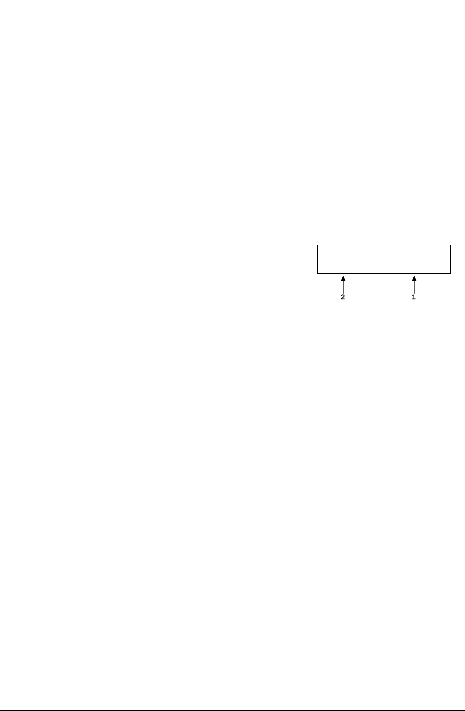
3. GENERAL OPERATION
Page 83 © 2011 Fluke Calibration
3.9.11.2 [ENTER/SET P] in Mass to Pressure Mode
PURPOSE
To enter and execute a mass to pressure command in mass to pressure mode
(see Section 3.9.12).
OPERATION
Put the PG7000 in mass to pressure operation mode (see Section 3.9.12), then
press [ENTER/SET P] in any run screen. If automated rotation is on, the
<DECELERATING> screen shows until piston deceleration is complete.
Note
Pressing [ENTER] in the run screen causes automated pressure
generation to be suspended if ON (see Section 3.9.9) and
AutoRotate to stop piston rotation if ON (see Section 3.9.8).
When [ENTER] is pressed to confirm mass entry, automated
pressure generation and/or motorized rotation resume.
The display is:
1. Edit field for total trim mass currently loaded.
2. Edit field for nominal mass of main and
fractional masses currently loaded.
Load nominal mass:
10.0 kg and 3.17 g
Use the numerical and editing keys to enter the nominal mass to be loaded on
the piston following the mass loading protocol described in Section 3.6.
Press [ENTER/SET P] to process the mass value. If the mass value entered
cannot be executed, an explanatory error message is displayed momentarily and
operation returns to the mass entry screen with the previous nominal mass value
displayed. If the mass value entered is valid, the value is processed and
operation proceeds to the previous run screen with the new mass value active.
Caution
To make “in tolerance” measurements, it is imperative that the
value of mass loaded on the piston be the NOMINAL mass
following the protocol describe in Section 3.6. This ensures
that PG7000 will correctly determine the true mass value
loaded. Failure to enter nominal mass values following the
PG7000 mass loading protocol is likely to result in out of
tolerance mass load determination and pressure definitions.
Note
• The setting of the RES function has no effect on the
resolution of mass load entries in mass to pressure mode
(see Section 3.9.10).
• The mass to pressure mass entry is expressed in nominal
mass while the MAIN run screen displays the true mass
loaded. For this reason, the nominal mass loading
instruction and the true mass displayed in the main run
screen are slightly different values. This is normal operation
(see Section 3.6).
3.9.11.3 Commands for Zero Pressure, Ending a Test
Entering a value of zero as the target presure is a convenient way to end a test
and vent the automated pressure control component when AutoGen is ON.
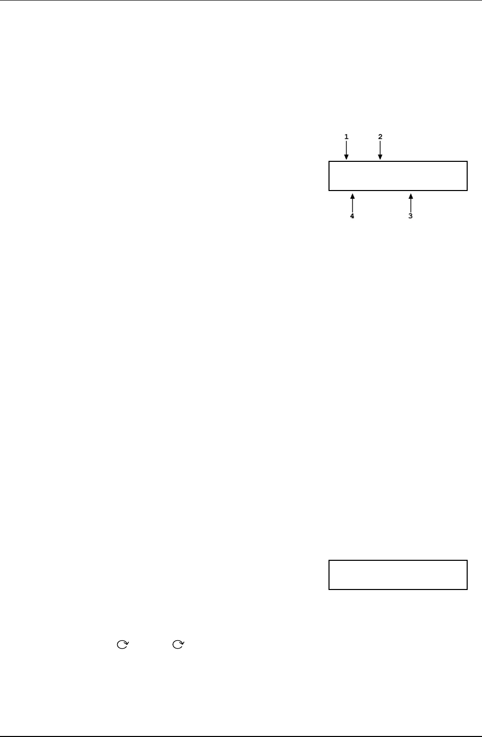
PG7000™ OPERATION AND MAINTENANCE MANUAL
© 2011 Fluke Calibration Page 84
Entering a value of zero in pressure to mass mode causes the following
sequence to occur:
Stop piston rotation if AutoRotate is ON.
Vent pressure control component if AutoGen is ON or prompt operator to vent.
A special run screen displays reflecting that the PG7000 is at rest and the
mass loading bell may not be installed. The display is:
1. <?> in ready/not ready indicator positions as
status of piston is unknown since mass loading
bell may not be installed.
2.
Unknown pressure except in absolute by
atmosphere measurement mode in which the
current value of atmospheric pressure is
displayed. This is the value of absolute by
atmospheric pressure when the system is
vented.
3. Unknown/meaningless mass load.
4. Unknown/meaningless piston position.
???----- psi a
--- mm --------kg
3.9.12 [P OR M]
PURPOSE
To select between PG7000 pressure to mass or mass to pressure operation mode.
PRINCIPLE
Piston gauges are generally used either to define desired pressure set points (e.g. when
applying reference pressures to a device to be calibrated) or to measure a static pressure
(e.g. when performing a crossfloat intercomparison with another piston gauge).
PG7000s support these two typical situations with two operating modes: pressure to mass
and mass to pressure.
In pressure to mass operating mode, the operator enters target pressure values and the
PG7000 provides instructions of the mass to load to achieve the desired target pressure.
In mass to pressure operating mode, the operator enters the mass currently loaded and the
PG7000 determines the pressure resulting from the current mass load. Mass to pressure
mode is also useful to determine the true mass resulting from a nominal mass load (see
Section 3.6).
The P OR M function is used to set the PG7000 operating mode to either pressure to mass or
mass to pressure.
OPERATION
Note
For details on pressure to mass and mass to pressure operation, see
Section 3.9.11.
To access the P OR M function, press [P OR M],
the display is:
Select entry mode:
1pressure 2mass
Selecting <1pressure> activates pressure to mass mode and returns to the previous run screen.
Selecting <2mass> activates mass to pressure mode and returns to the previous run screen.
3.9.13 [
] and [ ], [←]
PURPOSE
To activate motorized piston rotation manually.
PRINCIPLE
Motorized rotation engages and disengages to rotate or stop the rotation of the PG7000 piston.

3. GENERAL OPERATION
Page 85 © 2011 Fluke Calibration
Motorized rotation can be set to operate automatically to maintain the piston within Ready
condition rotation rate limits when the piston is floating and stop rotation before changing the
pressure or mass load (see Section 3.9.8). Motorized rotation can also be engaged manually
to accelerate or brake piston rotation at any time under direct operator control.
[] is used for momentary acceleration of piston rotation. [ ] followed by [←] is used to
start a function that stops piston rotation.
OPERATION
To momentarily engage the motorized piston rotation system and accelerate the piston, press
[] from any run screen. If PG7000 is equipped with motorized rotation, the motorized
rotation system engages and remains engaged until maximum rotation rate has been
achieved or the key is released.
The display is a modified version of the 1st system run screen to indicate the piston rotation is
being accelerated while showing rotation rate and position:
1. Current piston rotation rate.
2. Current rate of piston vertical displacement.
3. Current piston position.
12 rpm ACCELERATING
+ 2.05 mm 0.1/min
To start the piston braking function press and hold [], then press [←]. If PG7000 is
equipped with motorized rotation, the motorized rotation system engages and stays engaged
until the piston rotation is stopped. Once the braking function starts the keys may be released
and the function will complete unless [ESCAPE] is pressed.
The display is a modified version of the 1st system run screen to indicate the piston rotation is
being decelerated while showing rotation rate and position:
1. Current piston rotation rate.
2. Current rate of piston vertical displacement.
3. Current piston position.
48 rpm DECELERATING
+ 2.05 mm 0.1/min
To interrupt the piston rotation braking routine, press [ESCAPE].
Note
• Most PG7000 platforms produced before 2006 use a solenoid based
rotation actuation system. The system is protected against overloading. If
the duty cycle becomes excessive, motorized rotation cuts OFF and
remains off for a 25 second delay. During the cutoff time, [ ] has no
effect.
• The motorized rotation system can be set to operate automatically based
on current piston position and rotation rate. See Section 3.9.8 for
information.
• In PG7000 high line differential mode (see Section 3.9.4.2), pressing [ ]
on the reference PG7102 engages motorized rotation on both the reference
and tare PG7000s.

PG7000™ OPERATION AND MAINTENANCE MANUAL
© 2011 Fluke Calibration Page 86
3.10 [SETUP] Menu
PURPOSE
To select, view and edit the SETUP files that determine the source of the values that PG7000 uses in its
calculation of defined pressure and as criteria for Ready/Not Ready condition determination.
PRINCIPLE
PG7000 piston gauges perform continuous, real time calculations of the pressure defined by the floating
piston under current conditions (see Section 7.2 for the details on the calculations applied). The
calculations are used to determine the defined pressure displayed in the MAIN run screen, and to arrive
at the mass to load value when a target pressure is entered in pressure to mass mode.
The equations that PG7000 uses to calculate pressure include many instrument and ambient variables.
PG7000 allows the source of the value used for each variable to be defined. For example, the value
of barometric pressure used to calculate current air density and to add to gauge pressure to define
absolute pressure in absolute by atmosphere mode could come either from PG7000’s internal sensor,
an external barometer connected to PG7000’s COM2, a user entered value or be set to standard
atmospheric pressure. The PG7000 SETUP function allows the source (and in some cases the value) of
the variables used in the pressure equations to be specified. In order to allow various combinations of
sources and/or values to be setup and recalled, SETUP files can be created, stored, edited and recalled.
The SETUP files also include certain variables used to determine PG7000 Ready/Not Ready status.
Table 19 identifies the variables included in the SETUP file, the factory source setting for each variable
and the default value for each variable.
Variable source and value selections are recorded in SETUP files. These files can be stored and recalled
so that specific combinations of variable sources and/or values can be conveniently recalled. There are
20 SETUP files. File #1 is a factory SETUP file that cannot be edited. It includes the factory default
variable choices and values.
Note
SETUP files, USER values and PG7000’s calculation capabilities can be used to
calculate defined pressure in specific conditions independent of actual PG7000
operation.
The SETUP function supports the following:
• View SETUP files (see Section 3.10.2);
• Create/edit SETUP files (see Section 3.10.3);
• Select active SETUP file (see Section 3.10.1).

3. GENERAL OPERATION
Page 87 © 2011 Fluke Calibration
Table 19. SETUP File Choices, Factory Preferred Choice and Normal Value
VARIABLE SOURCE
CHOICES FACTORY
DEFAULT CHOICE
NORMAL VALUE
Atmospheric pressure 1. Internal
2. Normal
3. User
4. COM2
1. Internal 101.325 kPa
(14.6959 psi)
Ambient temperature 1. Internal
2. Normal
3. User
1. Internal 20 °C
Ambient relative humidity 1. Internal
2. Normal
3. User
1. Internal 45 %RH
Piston-cylinder
temperature 1. Internal
2. Normal
3. User
1. Internal 20 °C
Gravity 1. Local
2. Normal
3. User
1. Local 9.806650 m/s2
Vacuum
(PG7601 only)
1. Internal
2. Normal
3. User
4. COM2
1. Internal 0 Pa
Ready/Not Ready
Piston position
1. User 1. User ± 2.5 mm from
midfloat position
(default)
Ready/Not Ready
Maximum vacuum
reference pressure in
absolute by vacuum mode
(PG7601 only)
1. User 1. User 5 Pa (default)
Note
The factory default SETUP choice is the SETUP choice setting for all variables in a new
SETUP file. SETUP file #1 is fixed to factory SETUP choices and cannot be altered.
OPERATION
To access the SETUP menu, press [SETUP] from the main run
screen. The display is:
Current SETUP: #01
1select 2view 3edit
#nn in the upper right hand corner displays the number of the SETUP file that is currently active.
Select <1select> to select a different active SETUP file. Select <2view> to view the variable choices and
values of the active SETUP file. Select <3edit> to create or edit a SETUP file.
See Sections 3.10.1 to 3.10.3 for detailed information on each SETUP function operation.
3.10.1 <1select>
PURPOSE
To change the active SETUP file number.

PG7000™ OPERATION AND MAINTENANCE MANUAL
© 2011 Fluke Calibration Page 88
Caution
Changing the current SETUP file will change the source and in some cases
the values of the variables used by PG7000 in calculating defined
pressure. SETUP files should be selected and changed only by qualified
personnel. Incorrect SETUP file selection may cause out of tolerance
calculations and measurements. See Section 3.10, PRINCIPLE, for
information on SETUP files and their use.
OPERATION
To select a SETUP file number to make it the active SETUP file, press [SETUP] and select
<1select>. In the following screen enter the number of the desired SETUP file and press
[ENTER]. If a valid SETUP file number has been entered, operation returns to the previous
run screen with the selected SETUP file number displayed and active.
Note
• Entering an invalid SETUP file number causes an error message to be
displayed briefly and returns to the select SETUP file screen.
• If the SETUP file selected specifies COM2 as the source of barometric
pressure, PG7000 will attempt to read a barometer on COM2 when
initializing the new SETUP file. If PG7000 is unable to read a barometer on
COM2, a communications time out message is displayed briefly and
operation returns to the select SETUP file screen. See Section 3.11.5.4 for
information on configuring COM2 to read an external barometer.
3.10.2 <2view>
PURPOSE
To view the variable source choices and values of any SETUP file number.
OPERATION
Note
• Selecting <2view> SETUP allows the variable source choices and values of
the active SETUP file for viewing only. <2view> does not make the viewed
SETUP file active. To select the active SETUP file, press [SETUP] and
select <1select>.
• See Table 19 for a listing of the source choices for each variable.
To view an existing SETUP file, press [SETUP] and select <2view>. The display is:
1. Entry field for number of SETUP file to be viewed. Defaults
to SETUP file currently selected. Must be a number from 2 to
10.
View SETUP file:
#02
Enter the desired SETUP file number and press [ENTER].
If a valid SETUP file number is entered, the display is:
View #02 latmP 2ambT
3%RH 4PCT 5g 6READY
7vac
Select <1atmP> to view the atmospheric pressure variable source choice and current value.
The value is displayed in the current pressure units (see Section 3.9.3).
Select <2ambT> to view the ambient temperature variable source choice and the
current value. The value is displayed in degrees Centigrade [°C].
Select <3%RH> to view the ambient relative humidity variable source choice and the current
value. The value is displayed in %RH.
3. GENERAL OPERATION
Page 89 © 2011 Fluke Calibration
Select <4PCT> to view the piston-cylinder temperature variable source choice and the
current value. The value is displayed in degrees Centigrade [°C].
Select <5g> to view the gravity variable source choice and the current value. The value is
displayed in meters per second squared [m/s2].
Select <6READY> to view the values of Ready/Not Ready status criteria (see Section 3.4).
These include:
<1Pposition>: Piston position Ready/Not Ready limits (see Section 3.4.1). The value is
displayed as a band in millimeters about mid-float position [
±
mm] (see Section
3.5).
<2vac> (PG7601 only):
Maximum reference vacuum pressure limit when operating in absolute by
vacuum mode. The value is displayed in Pascal [Pa].
Select <7vac> (PG7601 only): to view the reference vacuum variable source choice and the
current value. The value is displayed in Pascal [Pa].
3.10.3 <3edit>
PURPOSE
To edit an existing SETUP file and/or to create a new SETUP file.
Note
See Section 3.10, PRINCIPLE for information on SETUP files and their
purpose.
OPERATION
Note
• SETUP file #1 is the factory preferred file and it cannot be edited.
• See Table 19 for a listing of the source choices for each variable.
To edit an existing SETUP file or create a new SETUP file, press [SETUP] and
select <3edit>. The display is:
1.
Entry field for number of SETUP file to be edited or created.
Defaults to SETUP file currently selected. Must be a number
from 2 to 10.
Edit SETUP file:
#02
Enter the desired SETUP file number and press [ENTER].
If a valid SETUP file number is entered, the display is:
Edit #02 latmP 2ambT
3%RH 4PCT 5g 6READY
7vac
Selecting an item leads to the variable source choices menu for that item. The cursor is on the
source choice that is currently selected in that SETUP file number. Select the desired
variable source. The selection causes the variable choice selection to be made and returns
to the edit menu. From the variable source choice menus, pressing [ENTER] or [ESCAPE]
returns to the edit selection menu. This allows easy, discreet movement between variable
source choices when editing a SETUP file.
Select <1atmP> to specify the atmospheric pressure variable source for the pressure values
that are used to calculate ambient air density and to add to gauge pressure measurements to
calculate absolute pressure in absolute by addition of atmosphere mode. Selecting <1atmP>
offers the atmospheric pressure variable source choices:
<1internal> Use real time readings from PG7000’s on-board barometer.
<2normal> Use a fixed value of 101.325 kPa (14.6959) psi.
<3user> Use a fixed user entered value. If <3user> is selected, the user value must be
entered, in the current pressure unit of measure (see Section 3.9.3).

PG7000™ OPERATION AND MAINTENANCE MANUAL
© 2011 Fluke Calibration Page 90
<4COM2> Use real time readings from the device connected by RS232 to PG7000’s COM2
port. The external barometer must be properly set up to communicate with PG7000
(see Section 3.11.5.4 for information on setting up to read an external barometer).
Note
For differential mode operation (see Section 3.9.4) the AtmP selection
must be <4COM2>.
Select <2ambT> to specify the ambient temperature variable source for the temperature
values that are used to calculate ambient air density. Selecting <2ambT> offers the
temperature variable source choices:
<1internal>: Use real time readings from PG7000’s on-board ambient temperature platinum
resistance thermometer (in the Temperature - Humidity (TH) Probe on the
platform rear panel).
<2normal>: Use a fixed value of 20 °C.
<3user>: Use a fixed user entered value. If <3user> is selected, the user value must be
entered, in degrees Centigrade [
°
C].
Select <3%RH> to specify the relative humidity variable source for the relative humidity
values that are used to calculate ambient air density. Selecting <3%RH> offers the relative
humidity variable source choices:
<1internal>: Use real time readings from PG7000’s on-board relative humidity sensor (in the
Temperature - Humidity (TH) Probe on the platform rear panel).
<2normal>: Use a fixed value of 45 %RH.
<3user>: Use a fixed user entered value. If <3user> is selected, the user value must be
entered, in percent relative humidity [%RH].
Select <4PCT> to specify the piston-cylinder temperature variable source for the temperature
values that are used to compensate piston-cylinder effective area for temperature. Selecting
<4PCT> offers the temperature variable source choices:
<1internal>: Use real time readings from PG7000’s on-board piston-cylinder temperature
platinum resistance thermometer (embedded in the piston-cylinder module
mounting post).
<2normal>: Use a fixed value of 20 °C.
<3user>: Use a fixed user entered value. If <3user> is selected, the user value must be
entered, in degrees Centigrade [
°
C].
Select <5g> to specify the value of acceleration due to gravity that is used in calculating the
force applied to the piston. Pressing <5g> offers the gravity variable source choices:
<1locall>: Use the fixed value of local gravity stored under [SPECIAL], <6gl> (see Section
3.11.6).
<2normal>: Use a fixed value of 9.806650 m/s2.
<3user>: Use a fixed user entered value different from the current local gravity value
stored in the [SPECIAL], <6gl> menu option. If <3user> is selected, the user
value must be entered, in meters per second squared [m/s2].
Select <6READY> to edit the values of Ready/Not Ready status criteria (see Section 3.4).
These include:
<1position>: Piston position limits. Edit the fixed value, in millimeters [mm], of the band
around mid-float position within which the piston position is Ready (see
Section 3.4.1). This also determines the limit at which the piston is refloated by
the GEN function when GEN is ON (see Section 3.9.9).
<2vacl>
(PG7601 only): Maximum reference vacuum pressure when operating in absolute by vacuum
mode. Edit the value, in Pascal [Pa], under which the reference vacuum must
be for a vacuum Ready condition to occur (see Section 3.4.3).

3. GENERAL OPERATION
Page 91 © 2011 Fluke Calibration
Select <7vac> to specify the reference vacuum variable source for the value used for the
pressure under the bell jar when calculating the absolute pressure defined in absolute by
vacuum mode. Pressing <7vac> offers the reference vacuum variable source choices:
<1internal>: Use real time readings from PG7000’s on-board vacuum gauge (mounted
directly in the vacuum plate, under the mass load).
<2normal>: Use a fixed value of 0 Pa.
<3user>: Use a fixed user entered value. If <3user> is selected, the user value must be
entered, in Pascal [Pa].
<4COM2>: Use real time readings from or through the device connected by RS232 to
PG7601’s COM2 port. The external vacuum gauge must be properly set up to
communicate with PG7601 (see Section 3.11.5.5 for information on setting up to
read an external vacuum gauge).
3.11 [SPECIAL] Menu
PURPOSE
The [SPECIAL] key accesses a menu of PG7000 functions and settings that are less
commonly or not normally used in regular operation.
OPERATION
To access the SPECIAL menu, press [SPECIAL] from
the main run screen. This display is:
1PC/MS 2presU 3head
4prefs 5remote 6gl
7cal 8AMH 9reset
Note
Some screens, such as the SPECIAL menu, go beyond the two lines
provided by the display. This is indicated by a flashing arrow in the
second line of the display. Press the [←] and [→] keys to move the cursor
to access the lines that are NOT visible or directly enter the number of the
hidden menu choice if you know it.
Special menu choices include:
<1PC/MS>: Edit and view stored piston-cylinder module and mass set metrological
information. Select mass set to be used (see Section 3.11.1).
<2presU>: Customize the pressure unit of measure choices available under [UNIT]
(see Section 3.11.2).
<3head>: Change the height unit of measure and the fluid used in DUT head corrections;
adjust the barometer head height; turn the automated piston position head
correction ON and OFF (PG7302 only) (see Section 3.11.3).
<4prefs>: To access a menu of internal PG7000 operational preferences and functions
including screen saver, sounds, time/date, instrument ID and user level
protection (see Section 3.11.4).
<5remote>: Set up/modify PG7000 RS232 (COM1, COM2, COM3) and IEEE-488 interfaces.
Test RS232 ports. Set up external barometer communications (see Section 3.11.5).
<6gl>: Set the value of local gravity used by PG7000 in reference pressure
calculations when gl is specified as the gravity value in the active SETTINGS
file (see Section 3.11.6).
<7cal>: View the output of and adjust PG7000 internal sensors and measurement
systems (see Section 3.11.7).
<8AMH>: View the status of and directly control an AMH automated mass handler (see
Section 3.11.8).
<9reset>: Access and execute various reset options (see Section 3.11.9).

PG7000™ OPERATION AND MAINTENANCE MANUAL
© 2011 Fluke Calibration Page 92
3.11.1 <1PC/MS>
PURPOSE
To perform the following piston-cylinder module and mass set metrological functions:
• View and edit piston-cylinder module metrological information.
• Create new piston-cylinder modules.
• View and edit mass set and mass loading bell information.
• Create new mass sets and mass loading bells.
• Select the active mass set and mass loading bell.
Note
See Section 3.9.2 for information on more direct access to selecting the
active piston-cylinder module.
Caution
The piston-cylinder module and mass set information contained in
<1PC/MS> is element specific metrological data. Uninformed or accidental
altering of this information may lead to out of tolerance measurements.
Piston-cylinder module and mass set information should only be edited by
qualified personnel as part of the PG7000 calibration or recalibration
process.
PRINCIPLE
To calculate the pressure defined by its floating piston, PG7000 must have available the
specific characteristics of the piston-cylinder module, mass set and mass loading bell that are
being used. This information is entered, viewed and edited under [SPECIAL], <1PC/MS>.
This is also where the active mass and mass loading bell are selected.
The piston-cylinder module and mass set information required by PG7000 is reported on the
Calibration Reports that are delivered with the metrological elements. When the PG7000
Platform and metrological elements are delivered together, the metrological elements
information is entered by Fluke Calibration at the factory. If the metrological elements are
delivered separately from the platform or after a recalibration when new data is available, the
information must be entered or edited by the user.
OPERATION
To access the piston-cylinder module, mass set and
mass loading bell information, press [SPECIAL] and
select <1PC/MS>. The display is:
1PC 2mass set
3mass bell
Select the type of metrological element that you would like to view, edit, create or select.
See Sections 3.11.1.1 to 3.11.1.7 for operation of specific piston-cylinder module, mass set
and mass bell functions as follows:
• Create a new piston-cylinder module (see Section 3.11.1.1).
• Edit piston-cylinder module information (see Section 3.11.1.2).
• View piston-cylinder module information (see Section 3.11.1.3).
• Delete a piston-cylinder module (see Section 3.11.1.4).
• Select the active piston-cylinder module (see Section 3.11.1.5).
• Create a new mass set (see Section 3.11.1.6).
• Edit mass set information (see Section 3.11.1.7).
• View mass set information (see Section 3.11.1.8).
• Delete a mass set (see Section 3.11.1.9).
• Select a mass set (see Section 3.11.1.10).
• Add a mass loading bell (see Section 3.11.11).

3. GENERAL OPERATION
Page 93 © 2011 Fluke Calibration
• Edit mass loading bell information (see Section 3.11.12).
• View the active mass loading bell (see Section 3.11.1.13).
• Delete a mass loading bell (see Section 3.11.1.14).
• Select a mass loading bell (see Section 3.11.1.15).
3.11.1.1 Create Piston-Cylinder Module
PURPOSE
To create a new piston-cylinder module that will be available for selection from
the [P-C] function key. Use this function when a new piston-cylinder module has
been acquired.
Note
If the piston-cylinder module and PG7000 Platform were delivered
together, the piston-cylinder module has already been entered at
the factory. Before creating a new piston-cylinder module, press
[P-C] to check if it already exists (see Section 3.9.2).
PRINCIPLE
The PG7000 add and edit piston-cylinder module functions allow piston-cylinder
metrological module variable values to be defined and stored. These values will
be used by PG7000 in calculating defined pressure, piston-cylinder range and
pressure to mass and mass to pressure values when the piston-cylinder module
is made active using [P-C]. The information needed can be found in the
calibration report for the piston-cylinder module.
Setting up or editing a piston-cylinder module requires specifying, in sequential
order, the following:
Serial number (S/N) [nnnn].
Effective area (Ae) at 0 pressure and 20 °C [mm2].
Piston temperature coefficient [linear thermal expansivity/°C].
Cylinder temperature coefficient [linear thermal expansivity/°C].
Effective area pressure coefficient [change in Ae/MPa].
Piston-cylinder surface tension effect [N/m].
Reference level offset [mm].
Piston assembly mass [kg].
Piston assembly apparent density [kg/m3].
Rotation rate ready limits [rpm].
k(P) [kg/mm/min].
Calibration report number [nnnnnnnnn].
Calibration report date [yyyymmdd].
OPERATION
Note
• Adding or editing a piston-cylinder module requires the user
to specify a large number of variables in a series of data
entry screens described below. For a summary of the
piston-cylinder module data requirements in the order they
are edited see PRINCIPLE in this section.
• PG7000 can store up to 18 piston-cylinder module (PC) files.
When <3add> is selected and all the files have already been
used, a warning is displayed. A file must be deleted before
a file can be added.

PG7000™ OPERATION AND MAINTENANCE MANUAL
© 2011 Fluke Calibration Page 94
To create a new piston-cylinder module press [SPECIAL] , <1PC/MS> and
select <1PC>, <3add>. A series of data entry menus will be presented. Edit
each menu to reflect the correct information on the piston-cylinder module being
added. Press [ENTER] after each entry to proceed to the next menu. Pressing
[ESCAPE] at any point offers an <Abandon edits?> query and then returns to
the <1PC> menu without saving any of the edited data or [ENTER] returns to the
add piston-cylinder module process.
The data entry screens to add or edit a piston-cylinder module are, in order:
• Serial number (S/N): Edit the serial number using four digits. This
value is marked on the piston cap. The default is 1.
• Effective area at 0 pressure and 20 °C: Edit the value of the piston-
cylinder effective area at 0 pressure and 20 °C. The value must be
entered in square millimeters [mm2]. This value is reported in the
calibration report for the piston-cylinder module. The default is 0.
• Piston temperature coefficient: Edit the value of the piston material linear
thermal expansivity. The value must be entered in terms of relative change per
degree centigrade [nn x 10-6/°C]. The E-6 exponent is fixed. This value is
reported in the calibration report for the piston-cylinder module. The default is
00.
• Cylinder temperature coefficient: Edit the value of the cylinder
material linear thermal expansivity. The value must be entered in terms
of relative change per degree centigrade [nn x 10-6/°C]. The 10-6
exponent is fixed. This value is reported in the calibration report for the
piston-cylinder module. The default is 00.
• Effective area pressure coefficient: Edit the value of the piston-
cylinder change in effective area in terms of relative change per
MegaPascal [n.nn x 10-6/MPa]. The exponent is 10-6 for PG7601 and
PG7102 and 10-6 for PG7302. This value is reported in the calibration
report for the
piston-cylinder module. The default is 0.00.
• Piston-cylinder surface tension effect: Edit the value of the surface
tension effect of the pressurized fluid on the piston. The value must be
entered in Newton per meter [N/m]. This value is reported in the
calibration report for the piston-cylinder module. The default is 0.00.
The correct value for all gas lubricated and liquid lubricated, gas
operated piston-cylinders (PG7102, PG7601 and PG7202) is 0 unless
they are operated with oil as the test medium.
• Reference level offset: Edit the value of the reference level offset
which corrects the piston-cylinder reference level for hollow pistons (5
kPa/kg,
10 kPa/kg, 20 kPa/kg and 50 kPa/kg gas lubricated piston-cylinder
modules only) to the reference level marked on the mounting post
(see Section 3.9.7). The value must be entered in millimeters [mm].
This value is reported in the calibration report for 5 kPa/kg, 10 kPa/kg,
20 kPa/kg and 50 kPa/kg gas lubricated piston-cylinders; it is 0 for all
other piston-cylinders. The default is 0.00.
• Piston assembly mass: Edit the value of the mass of the piston
assembly (piston + piston head + piston cap). The value must be entered in
kilogram [kg]. This value is reported in the calibration report for the
piston-cylinder module. The default is 0.200000.
• Piston assembly average density: Edit the value of the average
density of the piston assembly (piston + piston head + cap). The value
must be entered in kilogram per cubic meter [kg/m3]. This value is
reported in the calibration report for the piston-cylinder module. The
default is 0.

3. GENERAL OPERATION
Page 95 © 2011 Fluke Calibration
• Rotation rate ready limits [rpm]: The minimum Ready rotation rate
(see Section 3.4.2) and the target maximum rate. The values must be
entered in rotations per minute [rpm]. The values (min and max) must
be entered in rotations per minute [rpm]. The value automatically
defaults to the factory recommended value for the piston-cylinder size
and pressurized medium. In most circumstances, the factory default
values should be used.
• k(P) coefficient [kg/mm/min]: Edit the value of the mass to equilibrium
fall rate proportionality coefficient. This value is non-zero only for
PG7102 or PC-7600 piston-cylinder modules that are used as the taring
piston-cylinder in high line differential measurement mode (see Section
3.9.4.2). In all other cases, this value is zero. The value, when
applicable, is specified in the piston-cylinder module technical data.
• Calibration report number: Edit the calibration report number to reflect
the number of the piston-cylinder module calibration report that is
currently valid. The number can be up to nine digits. The default is 1.
• Calibration report date: Edit the date of the current calibration report.
The date must be expressed in yyyymmdd format. The default is
19800101.
After pressing [ENTER]
to accept the
edited calibration report date the option to
save the edited piston-
cylinder module
information is presented. The display is:
Save PC S/N nnnn
1no 2yes
Select <2yes> to save the piston-cylinder module information under serial
number nnnn and return to the <1PC/MS> menu.
Select <1no> to discard all edits and return to the <1PC/MS> menu.
3.11.1.2 Edit Piston-Cylinder Module
PURPOSE
To edit information contained in an existing piston-cylinder module file. Use this
function to change piston-cylinder module data after a recalibration.
PRINCIPLE/OPERATION
Caution
Piston-cylinder module information is element specific
metrological data. Uninformed or accidental altering of this
information may lead to out of tolerance measurements.
Piston-cylinder module information should only be edited by
qualified personnel as part of the PG7000 calibration or
recalibration process.
See Section 3.11.1.1 describing adding a new piston-cylinder module.
The principles and procedures to add or edit a piston-cylinder module are
identical except for the identification of the piston-cylinder module to be edited.
To edit information on an existing piston-cylinder module, press [SPECIAL] ,
<1PC/MS> and select <1PC>, <2edit>.
The display identifies the currently active piston-cylinder module. Press [ENTER]
to edit the currently active piston-cylinder module or press [P-C] to toggle
through the other piston-cylinder modules available. When the desired piston-
cylinder module is identified, press [ENTER] to proceed with editing piston-
cylinder module information. Operation of the editing function is identical to the
add new piston-cylinder module procedure (see Section 3.11.1.1, OPERATION).
3.11.1.3 View Piston-Cylinder Module

PG7000™ OPERATION AND MAINTENANCE MANUAL
© 2011 Fluke Calibration Page 96
PURPOSE
To view the information contained in an existing piston-cylinder module file.
PRINCIPLE/OPERATION
See Section 3.11.1.1, PRINCIPLE. The piston-cylinder module viewing function
allows the piston-cylinder module information to be viewed but not altered.
To view information on an existing piston-cylinder module, press [SPECIAL] ,
<1PC/MS> and select <1PC>, <3view>.
The display identifies the currently active piston-cylinder module. Press
[ENTER] to view the currently active piston-cylinder module or press [P-C] to
toggle through the other piston-cylinder modules available (see Section 3.9.2).
When the desired piston-cylinder module is identified, press [ENTER] to proceed
with viewing piston-cylinder module information. Successive pressing of
[ENTER] steps through the piston-cylinder information screens in the same order
as the add and edit functions (see Section 3.11.1, View Piston-Cylinder
Module, Principle
3.11.1.4 Delete Piston-Cylinder Module
).
PURPOSE
To delete a piston-cylinder module file so that it is no longer included in the
piston-cylinder modules available for selection by pressing [P-C].
OPERATION
Caution
Once a piston-cylinder module file has been deleted it cannot
be recovered. To recreate it, the add piston-cylinder module
function must be used (see Section 3.11.1.1) which requires
entering all the piston-cylinder module information. Before
deleting a piston-cylinder module, consider editing it (see
Section 3.11.1.2).
To delete a piston-cylinder module press [SPECIAL] , <1PC/MS> and select
<1PC>, <4delete>.
The display identifies the currently active piston-cylinder module. Press
[ENTER] to delete the currently active piston-cylinder module or press [P-C] to
toggle through the other piston-cylinder modules available (see Section 3.9.2).
When the desired piston-cylinder module is identified, press [ENTER] to proceed
with deleting the piston-cylinder module information. Confirmation to delete is
required. Select <2yes> to delete the piston-cylinder module. Select <1no> to
NOT delete.
Note
The active piston-cylinder module (piston-cylinder module that is
currently selected) cannot be deleted. Before attempting to delete
a piston-cylinder module, be sure it is not currently selected.
3.11.1.5 Select the active piston-cylinder module
PURPOSE
To select the piston-cylinder module that is active and used by PG7000 in its
mass loading and defined pressure calculations.
Note
This function serves the same purpose as pressing [P-C] (see
Section 3.9.2).

3. GENERAL OPERATION
Page 97 © 2011 Fluke Calibration
OPERATION
To select the active piston-cylinder module press [SPECIAL] , <1PC/MS> and
select <1PC>, <5select>.
3.11.1.6 Add Mass Set
PURPOSE
To create a new mass set that will be available for selection as the active mass
set to load on the PG7000 piston. Use this function when a new mass set has
been acquired or a mass set was deleted and must be reentered.
Note
If the mass set and PG7000 Platform were delivered together,
the mass set has already been entered at the factory. Before
creating a new mass set, check whether it already exists using
the view mass set function (see Section 3.11.1.8).
PRINCIPLE
The PG7000 add and edit mass set functions allow mass set composition and
metrological variable values to be defined and stored. These values will be used
by PG7000 when the mass set is made active to calculate nominal mass
instructions and true mass loads. Up to three mass sets can be created.
Setting up or editing a mass set requires defining the density of the masses, the
mass set composition and the true mass of each individual mass. This
information can be found in the calibration report for the mass set.
Mass sets are created and edited in terms of mass groups reflecting the normal
composition of a PG7000 mass set. Standard PG7000 mass sets are made up
of these groups (see Section 2.1.2.2 for listings of standard PG7000 mass
set compositions).
The mass groups of a MANUAL mass set include:
1. Make up mass (9, 4.5 or 4 kg): A single mass, sequentially numbered 1.
The value of this mass is 9 kg if the mass set main masses are 10 kg and
4 kg or 4.5 kg if the mass set main masses are 5 kg. The purpose of this mass
is to arrive at a whole number nominal mass load equal to the sets main
masses (10 kg or 5 kg) when added to the piston and mass loading bell.
2. 10 kg masses: The main masses in a standard 80 or 100 kg mass set.
Sequentially numbered from 1 up to the total number of 10 kg masses.
Mass sets of < 80 kg do not normally include 10 kg masses.
3. 5 kg masses: The main masses in any standard mass set of less than
80 kg. Sequentially numbered from 1 up to the total number of 5 kg masses.
Standard 80 and 100 kg mass sets have one 5 kg mass.
4. 2 kg masses: Every standard mass set has two 2 kg masses numbered 1
and 2.
5. 1 kg masses: Every standard mass set has one 1 kg mass numbered 1.
6. 0.5 kg masses: Every standard mass set has one 0.5 kg mass number 1.
7. 0.2 kg masses: Every standard mass set has two 0.2 kg masses numbered 1
and 2.
8. 0.1 kg masses: Every standard mass set has one 0.1 kg mass numbered 1.
9. Trim masses: Every standard mass set has a trim mass set made up of
masses from 50 to 0.01 g. These masses are NOT defined and entered as
part of the mass set.
The mass groups of an AMH automated mass handler mass set include:

PG7000™ OPERATION AND MAINTENANCE MANUAL
© 2011 Fluke Calibration Page 98
1. Main masses (10 kg with AMH-100, 6.2 kg with AMH-38): Sequentially
numbered from 1 to a maximum of 9 for AMH-100 or 1 to a maximum of 5 for
AMH-38.
2. 6.4 kg mass (AMH-100 only): Single tubular, binary mass.
3. 3.2 kg mass: Single tubular, binary mass.
4. 1.6 kg mass: Single tubular, binary mass.
5. 0.8 kg mass: Single tubular, binary mass.
6. 0.4 kg mass: Single tubular, binary mass.
7. 0.2 kg mass: Single tubular, binary mass.
8. 0.1 kg mass: Single tubular, binary mass.
9. Trim masses: Every standard mass set has a trim mass set made up of
masses from 50 to 0.01 g. These masses are NOT defined and entered as
part of the mass set.
Caution
When PG7000 provides mass loading instructions and calculates
the true mass of the mass currently loaded, it assumes that the
mass set in use has been set up correctly and that masses have
been loaded following PG7000 mass loading protocol (see Section
3.6). For PG7000 mass loading protocol to operate properly, the
mass set in use must be EXACTLY the mass set that has been
defined by the add and/or edit mass function. No extra mass can
be included, no mass used can be missing and the sequential
numbers of masses in each mass group must be followed with the
correct true mass value entered for each individual mass. Using a
mass set that is not accurately set up may result in out of
tolerance pressure definitions.
Note
Though the piston and the mass loading bell constitute part of
the mass load, they are not included in the definition of a mass
set. Also, one PG7000 system may be used with several piston-
cylinder modules, mass loading bells and mass sets.
Therefore, the piston mass and mass loading bell mass
information are not part of the mass set. Piston mass
information is defined and stored in the piston-cylinder module
file (see Section 3.11.1.1) and mass loading bell information is
defined and stored in a separate mass loading bell files (see
Section 3.11.1.11). In an AMH mass set, the binary mass carrier
and mass lifting shaft are considered part of the bell.
OPERATION
Caution
Mass set information is element specific metrological data.
Uninformed or accidental altering of this information may lead
to out of tolerance measurements. Mass set information should
only be edited by qualified personnel as part of the PG7000
calibration or recalibration process.

3. GENERAL OPERATION
Page 99 © 2011 Fluke Calibration
Note
• To use the create or edit mass set function with a manual
mass set, it is important to have an understanding of mass
set structure and mass groups. Consult Section 3.6,
PRINCIPLE, to familiarize yourself with this information
before attempting to create or edit a mass set. Before
creating or editing an AMH automated mass handler mass
set, see the AMH-38/AMH-100 Operation and Maintenance
Manual.
• PG7000 can store up to 3 MS (mass set) files. When <3add>
is selected and all the files have already been used, a
warning is displayed. A mass set must be deleted before a
mass set can be added.
To create a new PG7000 mass set there are three sequential steps:
Initialize mass set: Define serial number, density, mass set type (manual or
AMH), calibration report number and date.
Define individual masses: Edit, add and delete mass groups as necessary to
identify and define all masses in the mass set.
Save mass set file or abandon changes.
Press [SPECIAL] , <1PC/MS> and select <2mass set>, <3add>.
Step : Initialize Mass Set
Edit the serial number to the number of
the mass set being added and press
[ENTER]. The display is:
Add mass set:
S/N 1
Edit the density of the masses being
added (all PG7000 mass sets have
density of 8 000 kg/m3) and press
[ENTER]. The display is:
Mass density:
8000 kg/m3
Select <1manual> for a manual mass set
or <2AMH>
for an automated mass
handler mass set.
Mass set type:
1manual 2AMH
Edit the calibration report number (up to
nine digits)
to the the number of the
current calibration report of the mass set
that is being added and press [ENTER].
The display is:
Cal report number?
1
Edit the calibration report date to the date
of the current calibration report of the
mass set that is being added (format must
be YYYYMMDD) and press [ENTER].
[ENTER]
leads to the second step of
mass set adding or editing.
Cal report date?
19800101
Pressing [ESCAPE] at any point goes to an abandon edits warning screen.
To continue with defining the mass set proceed to Step .
This step can only be reached by going through Step .
Step : Define Individual Masses

PG7000™ OPERATION AND MAINTENANCE MANUAL
© 2011 Fluke Calibration Page 100
If the mass set is a MANUAL mass set,
the display is:
Select mass grp (kg)
MKUP 5.00 2.00 1.001
0.50 0.20 0.10 ADD
If the mass set is an AMH automated
mass handler mass set, the display is:
(6.4 is only present for AMH-100)
Select mass grp (kg)
MAIN 6.40 3.20 1.60
0.80 0.40 0.20 0.10
Note
Some screens, such as the SPECIAL menu, go beyond the two
lines provided by the display. This is indicated by a flashing arrow
in the second line of the display. Press the [←] and [→] keys to
move the cursor to access the lines that are NOT visible or directly
enter the number of the hidden menu choice if you know it.
Refer to Sections 3.11.1.6, PRINCIPLE and 3.6 for information on mass
group definitions. To create the mass set, each and every mass in the mass set,
no more and no less, (but not the piston and the bell) must be identified and its
true mass entered. To select a mass group press the [←] and [→] keys to
position the cursor on the mass group to be edited. If the mass is needed but not
shown, select <ADD> to create a new mass group. To delete a mass group,
enter <0> as the number of masses in the group.
Caution
All standard PG7000 MANUAL mass sets have a makeup mass
(MKUP). This mass may be 4, 4.5 or 9 kg depending on the
mass set (see Section 3.6, PRINCIPLE). It is imperative that the
make up mass be defined and entered in the MKUP group.
Operation within each mass group is identical, for example, select <5.00>. The
display is:
1. Edit field for number of masses in the mass
group.
# of masses in group
(0 deletes grp): 1
Edit the number of masses in group to reflect the number of masses of that
nominal value there are in the group and press [ENTER]. The display is:
1. Sequential ID number of this specific mass
within the mass group.
2. Edit field for the true value of this specific
mass.
5.0 kg mass #1
True mass: 5.00000
Edit the mass value to the true value of the specific mass identified and press
[ENTER].
Note
For high line differential mode, when setting up the tare mass
set of the tare PG7000, the true mass of each mass is entered as
equal to the nominal value. Enter the nominal mass values for
the true mass values.

3. GENERAL OPERATION
Page 101 © 2011 Fluke Calibration
If there are additional masses in this mass group, the next display is the same as
the display immediately above but with the next mass specific mass sequential
ID number in the mass group. The screens continue until the true value of all of
the masses within the group has been entered. After the last entry, the screen
returns to the <Select mass grp> screen.
Edit, add and delete mass groups as necessary until all of the masses in the
mass set (do not include pistons, bells and trim masses of 50 grams and less)
have been entered, no more, no less. When Step is completed, press [ESCAPE]
to go to Step .
Note
Setting up an 80 kg or 100 kg manual mass set requires using
<ADD> to add a 10 kg mass group as the 10 kg mass group is
not included by default.
Pressing [ESCAPE] in the mass set editing screen goes to the save screen.
Step : Save Mass Set File
The display is:
Save MS S/N 4573
1no 2yes
Select <2yes> to save the all changes made to the mass set and exit.
Select <1no> to abandon all changes made to the mass set and exit.
3.11.1.7 Edit mass set
PURPOSE
To edit information contained in an existing mass set file. Use this function to
change mass set data after a recalibration or if a mass set configuration
changes.
PRINCIPLE/OPERATION
Caution
Mass set information is element specific metrological data.
Uninformed or accidental altering of this information may lead
to out of tolerance measurements. Mass set information should
only be edited by qualified personnel as part of the PG7000
calibration or recalibration process.
See Section 3.11.1.6 describing adding a new mass set. The principles and
procedures to add or edit a mass set are identical except that the mass set to
edit is selected from the existing mass sets screen.
The mass set type (manual or AMH) cannot be changed when a mass set is edited.
3.11.1.8 View Mass Set
PURPOSE
To view information contained in an existing mass set file.
OPERATION
To view information contained in an existing mass set file press [SPECIAL] ,
<1PC/MS> and select <2mass set>, <1view>. The viewing function operates in
the same manner as the add function (see Section 3.11.1.6).
3.11.1.9 Delete Mass Set
PURPOSE
To delete an existing mass set file entirely.

PG7000™ OPERATION AND MAINTENANCE MANUAL
© 2011 Fluke Calibration Page 102
OPERATION
Caution
Once a mass set file has been deleted it cannot be recovered.
To recreate it, the add mass set function must be used (see
Section 3.11.1.6) which requires entering all the mass set
information. Before deleting a mass set, consider editing it (see
Section 3.11.1.7).
To delete a mass set press [SPECIAL] , <1PC/MS> and select <2mass set>,
<4delete>. Select the mass set to be deleted and press [ENTER]. Select
<2yes> to delete the mass set. Press <1no> to NOT delete.
Note
The active mass set (mass set that is currently selected) cannot
be deleted. Before attempting to delete a mass bell, be sure it is
not currently selected.
3.11.1.10 Select Mass Set
PURPOSE
To select a mass set to be active and used by PG7000 in its mass loading and
defined pressure calculations. To initialize the optional AMH automated mass
handler if present.
OPERATION
To select the active mass set press [SPECIAL] , <1PC/MS> and select <2mass
set>, <5select>.
Mass sets for an AHM automated mass handler are identified by a letter <A> after their
serial number.
Put the cursor on the desired mass set and press [ENTER].
If a MANUAL mass set is selected, operation returns to the MAIN run screen.
If an AMH automated mass handler mass set is selected, the PG7000 platform
attempts to establish communication with the AMH and initialize it. If the
communication cannot be established with the AMH, an error is displayed. If
communication with the AMH mass set is established, the AMH is initialized and all
masses are loaded. If the AMH is unable to complete initialization, an error message is
displayed. The most common reason for failure to complete initialization is inadequate
drive pressure supply to the AMH. For trouble shooting, see the AMH-38/AMH-100
Operation and Maintenance Manual. If the AMH initialization completes successfully,
operation returns to the main run screen with the AMH active. The AMH remains active
until a non-AMH mass set is selected. The PG7000 platform will attempt to initialize the
AMH on power up if an AMH mass set is the active mass set.
3.11.1.11 Add Mass Loading Bell
PURPOSE
To create a new mass loading bell that will be available for selection as the active mass
loading bell. Use this function when a new mass loading bell has been acquired.
Note
If the mass loading bell and PG7000 Platform were delivered
together, the mass loading bell has already been entered at the
factory. Before creating a new mass loading bell, check
whether it already exists (see Section 3.11.1.13).

3. GENERAL OPERATION
Page 103 © 2011 Fluke Calibration
PRINCIPLE
See Section 3.11.1.6, PRINCIPLE.
OPERATION
Caution
Mass loading bell information is element specific metrological
data. Uninformed or accidental altering of this information may
lead to out of tolerance measurements. Mass loading bell
information should only be edited by qualified personnel as part
of the PG7000 calibration or recalibration process.
Note
PG7000 can store up to 3 mass bell files. When <3add> is
selected and all the files have already been used, a warning is
displayed. A mass loading bell must be deleted before a mass
loading bell can be added.
To create a new PG7000 mass loading bell press [SPECIAL] and select
<1PC/MS>, <3mass bell>, <3add>.
Edit the serial number to the number of
the mass bell being added and
press [ENTER]. The display is:
Add mass bell:
S/N 1
Edit the average mass densi
ty of the
mass loading bell and press [ENTER].
The value defaults to the default density
for the typical mass loading bell for the
PG7000 model. The display is:
Mass density?
5058 kg/m3
Note
The AMH automated mass handler mass bell includes the bell,
the binary mass carrier and the mass lifting shaft.
Edit the calibration report number (up to
nine digits) to the the number of the
current calibration report of the mass
loading bell that is being added and press
[ENTER]. The display is:
Cal report number?
1775
Edit the calibration report date to the date
of the current calibration report of the
mass loading bell that is being added and
press [ENTER]. The display is:
Cal report date?
20040101

PG7000™ OPERATION AND MAINTENANCE MANUAL
© 2011 Fluke Calibration Page 104
Edit the the true mass value of the mass
loading bell that is being added and press
[ENTER]. The value defaults to the nominal
mass of the typical mass loading bell for the
PG7000 model. The display is:
Bell #2832
True mass: 0.449985
Note
For high line differential mode, when setting up the tare bell of
the tare PG7000, the true mass of is entered as equal to the
nominal mass. Enter the nominal mass of the bell as the true
mass.
Select <2yes> to save the all changes
made to the mass loading bell and exit.
Select <2no>
to abandon all changes
made to the mass loading bell and exit.
Save bell S/N 2832?
1no 2yes
3.11.1.12 Edit Mass Loading Bell
PURPOSE
To edit information contained in an existing mass loading bell file. Use this
function to change mass loading bell data after a recalibration.
PRINCIPLE/OPERATION
Caution
Mass loading bell information is element specific metrological
data. Uninformed or accidental altering of this information may
lead to out of tolerance measurements. Mass loading bell
information should only be edited by qualified personnel as part
of the PG7000 calibration or recalibration process.
See Section 3.11.1.11 describing adding a new mass loading bell. The principles
and procedures to add or edit a mass loading bell are identical except that the mass
loading bell to edit is selected from the existing mass loading bell screen.
3.11.1.13 View mass loading bell
PURPOSE
To view information contained in an existing mass loading bell file.
OPERATION
To view information contained in an existing mass loading bell file press
[SPECIAL] and select <1PC/MS>, <3mass bell>, <1view>. The viewing
function is identical to the add function (see Section 3.11.1.11).
3.11.1.14 delete mass loading bell
PURPOSE
To delete an existing mass loading bell file entirely.
OPERATION
Caution
Once a mass loading bell file has been deleted it cannot be
recovered. To recreate it, the add mass loading bell function
must be used (see Section 3.11.1.11) which requires entering all
the mass loading bell information. Before deleting a mass
loading bell, consider editing it (see Section 3.11.1.12).

3. GENERAL OPERATION
Page 105 © 2011 Fluke Calibration
To delete a mass loading bell press [SPECIAL], <1PC/MS> and select <3mass
bell>, <4delete>.
Confirmation to delete is requested. Select <2yes> to delete the mass loading bell.
Press <1no> to NOT delete.
Note
The active mass bell (mass bell that is currently selected)
cannot be deleted. Before attempting to delete a mass bell, be
sure it is not currently selected.
3.11.1.15 Select Mass Loading Bell
PURPOSE
To select the mass loading bell that is active and used by PG7000 in its mass
loading and defined pressure calculations.
OPERATION
To select the active mass loading bell set press [SPECIAL], <1PC/MS> and
select <3mass bell>, <5select>.
3.11.2 <2presu>
PURPOSE
To customize the selection of pressure units that are available for selection from the UNIT
function key (see Section 3.9.3).
PRINCIPLE/OPERATION
See Section 3.9.3.1.
3.11.3 <3HEAD>
PURPOSE
To change DUT head configuration; to change the ATM head height; turn to turn the PISTON
head ON and OFF (PG7302 only).
PRINCIPLE
PG7000 supports three different fluid head correction functions.
1. There is a correction to consider the difference in height between the PG7000 reference
level and a device under test (see Section 3.9.7, PRINCIPLE). This head correction is
referred to as DUT head. The head height can be adjusted by pressing [HEAD]. The
head unit of measure and fluid are adjusted by pressing [SPECIAL] and selecting
<3head>, <1fluid> and <2unit>.
2. The second head function is the head correction for the PG7000 reading of atmospheric
pressure that is used to calculate air density and/or to add to atmospheric pressure in absolute
by adding atmosphere mode. The barometer reading atmospheric pressure may not be at the
same height as the piston reference level and, if so, a head correction is needed to determine
atmospheric pressure at the piston reference level. This head correction is referred to as ATM
head. The ATM head height can be edited by pressing [SPECIAL] and selecting <3head>,
<3atm>. The ATM head is only applied to internal or external barometer readings. It is not
applied to normal or user values of atmospheric pressure.
3. The third head function is the automated correction for the piston position, referred to as
PISTON head. The PG7000 reference level marked on the piston-cylinder module
mounting post is the level at which pressures are defined when the piston is in midstroke
position. But it may not always be practical to make measurement with the PG7000
piston exactly in its midstroke position. In fact, the piston position is Ready within a limit
band above and below midstroke (see Section 3.4.1). As the piston moves away from
midstroke, the pressure definition reference level moves proportionally. PG7000’s
automated correction for piston position calculates the head pressure corresponding to
the deviation in piston position from midstroke and compensates the defined pressure
back to midstroke. In this way, the defined pressure calculated by PG7000 is always the

PG7000™ OPERATION AND MAINTENANCE MANUAL
© 2011 Fluke Calibration Page 106
pressure at the reference level marked on the mounting post, even if the piston is not at
midstroke position. The PISTON head function can be turned ON and OFF by pressing
[SPECIAL] and selecting <3head>, <4piston>.
Note
See Section 7.2.3 for information on calculation of the three fluid head
correction functions.
OPERATION
To access various fluid HEAD correction functions press
[SPECIAL], and select <3head>. The display is:
Edit head: 1fluid
2unit 3atm 4piston
• Select <1fluid> to change the DUT head fluid (see Section 3.11.3.1).
• Select <2unit> to specify the DUT head height unit of measure (see Section 3.11.3.2).
• Select <3atm> to adjust the ATM head height (see Section 3.11.3.3).
• Select <4piston> to turn the PISTON head correction ON and OFF (see Section
3.11.3.4).
3.11.3.1 <3head>, <1fluid>
OPERATION
• To specify the DUT head fluid (see
Section 3.11.3, PRINCIPLE), press
[SPECIAL] and select <3head>,
<1fluid>. The display is:
Head fluid:
1gas 2liquid
• If <1gas> is selected, the display
offers the choice of three gasses.
Making a gas selection returns to the
previous run screen with that gas
active for the DUT head function.
The display is:
Gas type:
1N2 2He 3Air
• If <2liquid> is selected, the display
offers the choice of oil, water or a
user defined liquid. If the user
defined liquid is selected, its density
must be specified. Making a liquid
selection returns to the previous run
screen with that liquid active for the
DUT head function. The display is:
Liquid type:
1oil 2H20 3user
Note
In systems using fluid interfaces, the head fluid selected should
be the medium used in the height separating the P7000
reference level from the device under test.
3.11.3.2 <3head>, <2unit>
OPERATION
To specify the DUT and ATM head
height unit (see Section 3.11.3,
PRINCIPLE), press [SPECIAL] and
select <3head>, <2unit>. The display is:
Head height unit:
1in 2cm
Selecting the desired unit returns to the previous run screen with that unit active
for the DUT and ATM head function heights.

3. GENERAL OPERATION
Page 107 © 2011 Fluke Calibration
3.11.3.3 <3head>, <3atm>
OPERATION
To specify the ATM head height (see
Section 3.11.3, PRINCIPLE), press
[SPECIAL] and select <3head>,
<3atm>. The display is:
Edit ATM head unit:
-10.00 cm
Entering the ATM head returns to the previous run screen with the new height active.
The correct head height when using the PG7000 internal barometer is the
source for atmospheric pressure measurements (see Section 3.10) is -10.00 cm
(-3.94 in.).
Note
The ATM head height is negative if the barometer is below the
PG7000 reference level and positive if the barometer is above the
reference level. The ATM head fluid is air and it cannot be
changed. The ATM head height unit is set by pressing
[SPECIAL] and selecting <3head>, <2unit>. The default ATM head
height is -10 cm, which is the difference in height between the
PG7000 reference level and its internal barometer mounted on the
PG7000 Platform rear panel.
3.11.3.4 <3head>, <4piston>
OPERATION
To turn the PISTON head correction function ON and OFF (see Section 3.11.3,
PRINCIPLE), press [SPECIAL] and select <3head>, <4piston>.
Select <1on> to turn the PISTON head correction function ON so that a head
correction for piston position IS automatically applied.
Select <2off> to turn the PISTON head correction function OFF so that a head
correction for piston position IS NOT applied.
Note
• The PISTON head is automatically turned OFF (has no
effect) in gauge or differential measurement mode when the
set pressure is zero (system vented or bypassed). When the
system is vented or bypassed, the piston position no longer
affects the head. If the pressurized medium is a liquid, the
head reference level is the top of the fluid in the tank to
which the PG7000 system is connected.
• In PG7202, the test medium to use for the head correction is
determined by the piston-cylinder module pressure
deformation coefficient and the surface tension correction
value. If the pressure deformation coefficient value is
positive, the piston-cylinder module in use is assumed to be
a PC-7300 module and the test medium is oil. If the
pressure deformation coefficient is negative and the surface
tension correction is zero, the piston-cylinder module in use
is assumed to be a PC-7200 and the test medium is gas.
PC-7300 modules have free deformation mounting systems
and thus positive pressure deformation coefficients while
PC-7200 modules have negative free deformation mounting
systems and thus negative deformation coefficients.

PG7000™ OPERATION AND MAINTENANCE MANUAL
© 2011 Fluke Calibration Page 108
3.11.4 <4Prefs>
PURPOSE
To access a menu of PG7000 internal operational preferences and functions including screen
saver, sounds, time and date, instrument ID and user protection levels.
OPERATION
To access the PREFS menu press [SPECIAL], and
select <4prefs>. The display is:
1ScrSvr 2sound 3time
4ID 5level
Prefs menu choices include:
<1ScrSvr>: View and change the screen saver function (see Section 3.11.4.1).
<2sounds>: View and change keypad press and piston position sound settings (see Section
3.11.4.2).
<3time>: View and edit the internal time and date settings (see Section 3.11.4.3).
<4ID>: View and edit the PG7000 user ID (see Section 3.11.4.4).
<5level>: View and edit user protection levels and password (see Section 3.11.4.5).
3.11.4.1 <4PREFS>, <1ScrSVR>
PURPOSE
To adjust the time of inactivity after which PG7000’s SCREEN SAVER function
activates or to turn off the screen saver function.
PRINCIPLE
PG7000 has a SCREEN SAVER function which causes the display to dim after a
front panel key is NOT pressed for a certain amount of time. The default time
activates the screen saver after 10 minutes. The time can be adjusted by the
user or screen saving can be disabled.
OPERATION
To access the SCREEN SAVER function, press [SPECIAL] and select
<4prefs>, <1ScrSav>. Edit the time, in minutes, after which the screen saver will
activate to dim the screen. Set zero to disable the SCREEN SAVER function.
Note
Setting the screen saver time to zero disables the screen saver
function so that the display remains permanently at full
brightness.
3.11.4.2 <4PREFS>, <2Sound>
PURPOSE
To adjust the key press sounds and turn piston position sounds ON and OFF.
PRINCIPLE
PG7000 provides audible feedback of valid and invalid key presses and of when
the piston leaves the high or low stop position (see Section 3.5). Key press
sounds can be adjusted in frequency or turned OFF completely. Piston position
sounds may be turned ON and OFF.
OPERATION
To access the audible feedback adjustment function, press [SPECIAL] and
select <4prefs>, <2sound>.
Select <1keypad> to adjust keypad sounds. Select <2piston> to turn the
position sounds ON or OFF.

3. GENERAL OPERATION
Page 109 © 2011 Fluke Calibration
3.11.4.3 <4PREFS>, <3Time>
PURPOSE
To view and edit the PG7000 internal time and date settings.
OPERATION
To access the time function press
[SPECIAL] and select <4prefs>,
<3time>. The display is:
Edit: 1time 2date
08:32:11 am 19980101
Select <1time> to edit the time. Edit hours, then minutes, then am/pm by
pressing [ENTER] at each entry. Seconds go to zero when minutes are entered.
Select <2date> to edit the date. The date must be specified in YYYYMMDD
format.
Note
The PG7000 date and time are set to United States Mountain
Standard Time in the final test and inspection process at the
factory. If desired, use the date function to set your local time
and date.
3.11.4.4 <4PREFS>, <4ID>
PURPOSE
To view or edit the PG7000 user ID and to view the PG7000 serial number.
PRINCIPLE
PG7000 has a factory programmed serial number that is included on the rear of
the platform and can be viewed in the introductory screen.
PG7000 also allows the user to store one unique, twelve character, alpha
numeric ID number. This feature is frequently used to assign an organizational
control ID such as an asset number, tool number, standard number, etc. The ID
function allows the ID number to be viewed and edited. It also displays the
PG7000 factory serial number.
OPERATION
To access the ID function press [SPECIAL] and select <4prefs>, <4ID>.
Select <1view> to view the current ID.
Select <2edit> to edit the ID.
The ID has twelve characters. When the edit screen is opened, the cursor is on the
first character. Numerical values can be entered directly from the keypad.
In addition, the [←] and [→] keys can be used to toggle through a list of available
alpha numeric characters. Holding the key steps through the characters. Character
order going up ([→]) is: blank space, symbols, lower case letters, upper case letters,
numbers. Press [ENTER] to select a character and move to the next character.
When a character is selected the cursor moves to the next character. To leave a
blank character, press [ENTER] with the field for that character blank.
Press [ESCAPE] when all ID characters have been entered to access the
<Save ID?> option. Select <1no> to abandon edits and exit or select <2yes> to save
the edited ID.
Note
The ID can be viewed and edited but it cannot be cleared or
reset by any reset functions (see Section 3.11.9).

PG7000™ OPERATION AND MAINTENANCE MANUAL
© 2011 Fluke Calibration Page 110
3.11.4.5 <4prefs>, <5level>
PURPOSE
To set user protection levels that restrict access to certain functions and to edit
the password required for changing User Levels.
PRINCIPLE
PG7000’s front panel user interface provides the means to access all PG7000 user
defined data, settings and functions including calibration data. Inadvertent,
uninformed or unauthorized altering or deleting of data, settings and functions could
require extensive reconfiguration by the user and might cause invalid readings. For
these reasons, depending upon the application in which PG7000 is being used, it
may be desirable to restrict access to certain functions. The USER LEVEL function
provides a means of restricting access to certain functions. Four different levels of
security are available: none, low, medium and high.
Access to changing security levels can be left open, or be protected by a
password so that security levels can be used as a convenient way to avoid
accidental changing of data or as a secured means of preventing tampering with
PG7000 settings.
The security levels are structured to support typical operating environments as
follows:
None This level is intended for use only by the system manager and/or calibration
facility. It allows access and editing in all areas including critical metrological
information and other settings that affect measurement integrity.
Low Low security is designed to protect the specific metrological information and
system diagnostic and maintenance functions of the system against accidental
alteration. It is intended for an advanced operator performing many different
tasks. Low security is the default User Level setting.
Medium Medium security is designed to protect specific metrological information in the system
and to ensure that PG7000 is operated using consistent operational parameters.
High High security protects all operating parameters. It is intended to minimize
operator choices (e.g., to perform repeated identical tests under consistent conditions).
Caution
• PG7000 is delivered with the security level set to low to
avoid inadvertent altering of critical internal settings but
with unrestricted access to changing security level setting.
It is recommended that the low security level be maintained
at all times and password protection be implemented if
control over setting of security levels is desired.
• If there is a risk of unauthorized changing of the security
level, changing authority should be password protected
(see OPERATION of this section).
• The High security level disables remote communications
and returns an error message (“ERROR”) to all remote
commands. All other security levels have NO effect on
remote communications.

3. GENERAL OPERATION
Page 111 © 2011 Fluke Calibration
The security levels are structured to support typical levels of operation.
Specifically, the security levels prevent execution of the functions marked by “•”:
Table 20. Security Levels - Functions NOT Executed Per Function/Level
FUNCTION LOW MEDIUM HIGH
[P-C] •
[UNIT] •
[MODE] •
[SYSTEM] •
[AMBIENT] •
[HEAD] • •
[ROTATE] •
[GEN] •
[RES] (change setting) • •
[P OR M] • •
[SETUP], <1select> • •
[SETUP], <2view> •
[SETUP], <3edit> • •
[SPECIAL], <1PC/MS>, <any selection>, <1view> •
[SPECIAL], <1PC/MS>, <any selection>, <2edit> • • •
[SPECIAL], <1PC/MS>, <any selection>, <3add> • • •
[SPECIAL], <1PC/MS>, <any selection>, <4delete> • • •
[SPECIAL], <1PC/MS>, <1PC>, <5select> •
[SPECIAL], <1PC/MS>, <2mass set>, <5select> • •
[SPECIAL], <1PC/MS>, <2mass bell>, <5select> • •
[SPECIAL], <2presU> • •
[SPECIAL], <3head> • •
[SPECIAL], <4prefs> • •
[SPECIAL], <4prefs>, <3time> (make changes) • • •
[SPECIAL], <4prefs>, <4ID>, <2edit> • • •
[SPECIAL], <6remote> (access) •
[SPECIAL], <6remote> (make changes) • •
[SPECIAL], <5prefs>, <3time> (make changes) • • •
[SPECIAL], <6gl> (access) • • •
[SPECIAL], <7cal>, (access) •
[SPECIAL], <7cal>, <any selection except 5Pposition>, <2cal> • • •
[SPEICAL], <8AMH>, <any selection> • •
[SPECIAL], <9reset> • •
[SPECIAL], <9reset>, <1sets> • • •
[SPECIAL], <9reset>, <3com> • • •
[SPECIAL], <9reset>, <4cal> • • •
[SPECIAL], <9reset>, <5setups> • • •
[SPECIAL], <9reset>, <6all> • • •
Remote communications disabled •

PG7000™ OPERATION AND MAINTENANCE MANUAL
© 2011 Fluke Calibration Page 112
OPERATION
Note
PG7000 is delivered with NO active password so access to the
User Level menu is open. The User Level is set to <1Low>.
User Levels can be changed freely until a password has been
created. Reset functions (see Section 3.11.9) do not affect the
password setting.
To access the User Level function, press [SPECIAL] and select <2level>.
If NO password yet ex
ists or if the
correct password has been entered, the
display is:
1change user level
2edit password
Selecting <1change user level> brings
up the restriction menu:
Restriction: 1none
2low 3medium 4high
You can then select the current restriction level, or press [ESCAPE] to return to
the main run screen.
Selecting <2edit password> displays the
user password and allows it to be edited.
Passwords can be up to six numbers in
length and cannot start with a zero.
Password:
pppppp
0 disables password
If 0 is entered as the password value, then the password is made inactive and a
password will NOT be required to access the User Level menu. This is the
factory default with a security level of <2low>.
Caution
Once a password has been entered, the User Level cannot be
changed without reentering the password.
If there is an active password
, the
PG7000 password entry screen appears.
PG7000 NS
nnn-xx
Password:
pppppp
The user must enter the user defined password or the factory secondary
password to proceed. When a password is entered correctly, operation proceeds
to the <1change user level 2edit password> screen.
The first field, <nnnn>, is the serial number of PG7000, followed by a second
field, <xx>. That counts the number of times that a secondary password has
been used. This second field increments each time a secondary password
is used. The third field, <pppppp>, is for normal password entry.
The factory secondary password is available in case the user’s password has
been misplaced or forgotten. It can be obtained by contacting a Fluke Calibration
Authorized Service Provider. The factory secondary password is different for all
PG7000’s and changes each time it is used.
3. GENERAL OPERATION
Page 113 © 2011 Fluke Calibration
3.11.5 <5remote>
PURPOSE
To configure the PG7000 COM1, COM2, COM3 and IEEE-488 communication ports. To test
COM1, COM2 and COM3 communications.
PRINCIPLE
PG7000 has three RS232 communications ports referred to as COM1, COM2 and COM3 and
a single IEEE-488 port. COM1 and the IEEE-488 port are for communicating with a host
computer (see Section 4). COM2 is for communicating with an external barometer and/or
vacuum gauge (see Section 3.11.5.4, 3.11.5.5) or for pass through commands to an RS232
device. COM3 is reserved for communications with an automated pressure
generation/control component. The communication ports can be set up from the PG7000
front panel.
PG7000 provides a self-test for its RS232 communication ports. The self-test allows
verification that the PG7000 RS232 ports (COM1, COM2, COM3) are operating properly and
that a valid interface cable is being used. (see Section 3.11.5.3)
OPERATION
To access the port communications settings, press [SPECIAL] and select <5remote>.
Select <1COM1>, <2COM2>, <3COM3> or <4IEEE-488> to view and edit that port’s
communications settings (see Section 4.2.1 for information on COM port settings). Selecting
<2COM2> includes the choice to set up external barometer communications as well as the
port’s communications settings. Select <1settings> to view and edit COM2 communications
settings. Select <2baro> to view and edit external barometer communications settings (see
Section 3.11.5.4).
To access the RS232 self-test press [SPECIAL], <5remote>, <5RS232test>.
3.11.5.1 COM1, COM2 AND COM3 (RS232)
The COMx ports can be set for the specific settings required by the user.
The settings are baud rate, parity, data bits and stop bits. The available options
are found in Table 21.
Table 21. COM1, COM2 and COM3 Available Settings
BAUD RATE 300, 600, 1 200, 2 400, 4 800, 9 600, 19 200
PARITY NONE, ODD or EVEN
DATA BITS 7 or 8
STOP BITS 1 or 2
TERMINATORS <CR><LF> or <LF><CR>
The default COMx settings are 2400, E, 7,1, <CR><LF> or <LF><CR> for all three
COM ports.
PG7000 appends a carriage return (<CR>) and a line feed (<LF>) or <LF><CR>
to all messages that are sent out of the COM1 port to the host. It looks for a
carriage return to terminate incoming messages and ignores line feeds. The
user MUST wait for a reply to each message sent to PG7000 before sending
another message to it (see Section 4.3).
3.11.5.2 IEEE-488
The IEEE-488 port address can be defined from 1 to 31. The default address is 10.
PG7000 sends a line feed (<LF>) and asserts the EOI line at the end of all
transmitted messages. It looks for a line feed and/or assertion of the EOI line to
terminate incoming messages.

PG7000™ OPERATION AND MAINTENANCE MANUAL
© 2011 Fluke Calibration Page 114
3.11.5.3 RS232 Self Test
The RS232 self-test is provided to check the PG7000 COM ports and the
interface cable independently of an external device or computer.
If you are having difficulty communicating with PG7000 from a host
computer using RS232, the RS232 self test can help establish that the PG7000
COM1 port you are trying to communicate with and the interface cable you are
using are good.
To run a self test of the RS232 ports (COM1 and COM2 or COM1 and COM3),
press [SPECIAL] and select <5remote>, <5RS232test>. Then select <1COM2>
to test COM1 and COM2 or <2COM3> to test COM1 and COM3.
The display prompts you to connect COM1 to COM2 or COM1 to COM3 using a
standard pin-to-pin DB-9F to DB-9M RS232 cable (see Section 4.2.1).
Once the cable has been installed, press [ENTER] to run the self-test. The test
is first executed in the COM1→COM2 (or COM3) direction and then in the COM2
(or COM3) →COM1 direction.
If the COM1→COM2 (or COM3) test passes: <PASSED> displays briefly and
the test proceeds to COM2 (or COM3) →COM1.
If COM2 (or COM3) →COM1 passes: <PASSED> is displayed briefly followed
by the conclusion, <PG7000 RS232 test has PASSED>.
If a test fails: Execution is suspended until [ENTER] is pressed.
Note
• The PG7000 RS232 test can fail for three reasons:
1. The RS232 cable being used is incorrect (see Section
4.2.1, for information on the correct cable).
2. COM1 and COM2 (or COM3) do NOT have the same
serial communications settings and therefore cannot
communicate together (see Section 3.11.5.1 to set the COM
ports).
3. One of the COM ports is defective.
• The reason for failed communications is almost always a
cable or incorrect RS232 interface settings. Be sure that
these are correct before concluding that a COM port
is defective.
3.11.5.4 External Barometer (RPM) Communications (COM2)
PURPOSE
To set up communications with an external barometer from which PG7000 will
read the value of atmospheric pressure used in its internal calculations. The external
device is also used for reading the static pressure when PG7601 is used in
differential mode (see Section 3.9.4).
Note
The source of the values of atmospheric pressure used by
PG7000 in its internal calculations is determined by the AtmP
setting in the current SETUP file (see Section 3.10). Setting up
communications with an external barometer does NOT set
PG7000 to utilize the external barometer.
PRINCIPLE
PG7000 uses atmospheric pressure values in its calculations of reference
pressure (see Section 7.2). The source of the value is determined by the AtmP
setting in the current SETUP file (see Section 3.10). One of the possible sources
is COM2, which allows an external barometer, connected to PG7000’s COM2

3. GENERAL OPERATION
Page 115 © 2011 Fluke Calibration
RS232 port to be read automatically to obtain the atmospheric pressure values
that are used. In order to communicate with an the external barometer PG7000’s
COM2 must be properly set up. This setup occurs by pressing [SPECIAL] and
selecting <5remote>, <2COM2>, <2baro>.
OPERATION
To set up PG7000’s COM2 port to communicate with an external barometer,
press [SPECIAL] and select <5remote>, <2COM2>, <2baro>. Select <1RPMx>
if the external barometer is a RPM. Select <2user> to set up communications
with a barometer other than a Fluke Calibration RPM.
Note
Setting Up for User Barometer Communications
For a remote barometer to be able to be used for automated
atmospheric pressure readings on PG7000 COM2, the following
requirements apply to the remote barometer’s communications:
• Replies to a request to send string within 2 seconds.
• Accepts <CR, LF> terminators.
• Supplies <CR> or <CR, LF> terminators.
• Request to send string must be printable alphanumeric (no
control modes or nulls).
After pressing [SPECIAL] and selecting
<5remote>, <2COM2>, <2baro>,
<2user>, the display is:
COM2 meas req string
The string value is entered on the second line. It may have up to 20 characters.
When the string screen is opened, the cursor is on the first character.
Numerical values can be entered directly from the keypad. In addition, the [←] and
[→] keys can be used to toggle through a list of available alpha numeric characters.
Holding the key steps through the characters. Character order going up ([→]) is:
blank space, symbols, lower case letters, upper case letters, numbers.
Press [ENTER] to select a character and move to the next character. When a
character is selected the cursor moves to the next character. To leave a character
blank, press [ENTER] with the field for that character blank. After the last character
has been entered, press [ESCAPE]. This causes a <Save edits?> screen
to appear. Select <2yes> to save the edited string and move to the next screen.
Select <1no> abandon the edits. Also, if [ENTER] is pressed on the 20th character,
the string is saved automatically and operation advances to the next screen.
Note
The external barometer parameters including the
communication string can also be set by remote command,
which is more convenient than front panel entry (see Section
4.3.4.2, “UDD” command).
After the string value has been entered
the display is:
Reply conv coef:
1.000000 Pa/unit
<conv coef> is the conversion coefficient that PG7000 will use to convert
readings from the external barometer to the pressure unit of measure
Pascal [Pa]. If the readings from the external barometer are NOT Pascal, edit
the conversion coefficient value as needed to convert the readings to Pascal.

PG7000™ OPERATION AND MAINTENANCE MANUAL
© 2011 Fluke Calibration Page 116
When the conversion coefficient is entered
the next setup screen is opened. The
display is:
Leading characters to
Strip: 0
This entry specifies the leading characters in the return string that precede the
numerical value of the pressure. PG7000 will strip the specified number of
characters from the front of the return string and assume that the next character
is the first number defining the current value of atmospheric pressure.
To verify whether external barometer communications have been set up properly,
select a SETUP file that specifies COM2 under AtmP (see Section 3.10) and verify
that communications with the external barometer are achieved. Then view current
barometer readings in the AMBIENT run screen (see Section 3.9.6) and verify that
the readings are correct. Note that a fluid head correction should be set if the
external barometer is not at the PG7000 reference level. This correction may
cause the reading of the external barometer and the value of ambient pressure
indicated by the PG7000 to not be identical (see Section 3.11.3.3).
Note
For communications with an external barometer on COM2 to be
established properly, the inquiry string to send to the barometer
must be defined following this section and the PG7000 COM2
port and barometer COM port must have the same
communications settings. Press [SPECIAL] and select
<5remote>, <2COM2>, <1settings> to set up PG7000 COM2
communications settings. When unable to establish
communications between COM2 and the external barometer,
consider using the PG7000 RS232 self test to verify COM2
operation (see Section 3.11.5.3). If both a barometer and a
vacuum gauge are connected, the barometer must always be
the first device connected to the PG7000 Platform COM2.
3.11.5.5 External Vacuum Gauge Communications (COM2)
(PG7601 Only)
PURPOSE
To set up communications with an external vacuum gauge from which PG7601
will read the value of reference vacuum under the bell jar used in the calculation of
absolute pressure in absolute by vacuum measurement mode (see Section 3.9.4).
Note
The source of the value of vacuum pressure used by PG7000 in
its internal calculations is determined by the Vac setting in the
current SETUP file (see Section 3.10). Setting up
communications with an external vacuum gauge does NOT set
PG7601 to utilize the external vacuum gauge.

3. GENERAL OPERATION
Page 117 © 2011 Fluke Calibration
PRINCIPLE
PG7601 uses a value of reference vacuum under the bell jar in its calculation of
the pressure defined by the PG in absolute by vacuum measurement mode (see
Section 7.2). The source of the value is determined by the Vac setting in the
current SETUP file (see Section 3.10). One of the possible sources is COM2,
which allows an external vacuum gauge, connected to PG7601’s COM2 RS232
port to be read automatically to obtain the reference vacuum values that are
used. In order to communicate with the external vacuum gauge, PG7601’s
COM2 must be properly set up. This setup occurs by pressing [SPECIAL] and
selecting <5remote>, <2COM2>, <3vac>.
Note
If a RPM is being used on COM2 for external measurement of
barometric pressure, the vacuum gauge may be connected to
COM2 of the RPM. In this case, COM2 of the RPM barometer
must be set to have the same communication settings as the
external vacuum gauge. If both a barometer and a vacuum
gauge are connected, the barometer must always be the first
device connected to the PG7000 Platform COM2.
OPERATION
To set up PG7601’s COM2 port to communicate with an external vacuum gauge,
press [SPECIAL] and select <5remote>, <2COM2>, <3vac>. Select <1RPMx>
if the external barometer is a RPM. Select <2user> to set up communications
with a vacuum gauge other than a Fluke Calibration RPM.
Note
Setting Up for User Vacuum Gauge Communications
For an external vacuum gauge to be able to be used for
automated reference vacuum readings on PG7601 COM2 or a
RPM’s COM2, the following requirements apply to the remote
vacuum gauge’s communications:
• Replies to a request to send string within 2 seconds.
• Accepts <CR, LF> terminators.
• Supplies <CR> or <CR, LF> terminators.
• Request to send string must be printable alphanumeric (no
control modes or nulls).
After pressing [SPECIAL] and selecting
<5remote>, <2COM2>, <3vac>, <2user>,
the display is:
COM2 meas req string
The string value is entered on the second line. It may have up to 20 characters.
When the string screen is opened, the cursor is on the first character.
Numerical values can be entered directly from the keypad. In addition, the [←] and
[→] keys can be used to toggle through a list of available alpha numeric characters.
Holding the key steps through the characters. Character order going up ([→]) is:
blank space, symbols, lower case letters, upper case letters, numbers.
Press [ENTER] to select a character and move to the next character. When a
character is selected the cursor moves to the next character. To leave a character
blank, press [ENTER] with the field for that character blank. After the last character
has been entered, press [ESCAPE]. This causes a <Save edits?> screen
to appear. Select <2yes> to save the edited string and move to the next screen.
Select <1no> abandon the edits. Also, if [ENTER] is pressed on the 20th character,
the string is saved automatically and operation advances to the next screen.

PG7000™ OPERATION AND MAINTENANCE MANUAL
© 2011 Fluke Calibration Page 118
Note
The external vacuum gauge parameters including the
communication string can also be set by remote command
which is more convenient than front panel entry (see Section
4.3.4.2, “UDV” command).
After the string value has been entered
the display is:
Reply conv coef:
1.000000 Pa/unit
<conv coef> is the conversion coefficient that PG7600 will use to convert
readings from the external vacuum gauge to the pressure unit of measure
Pascal [Pa]. If the readings from the external vacuum gauge are NOT Pascal,
edit the conversion coefficient value as needed to convert the readings to Pascal.
When the conversion coefficient is entered
the next setup screen is opened. The
display is:
Leading characters to
Strip: 0
This entry specifies the leading characters in the return string that precede the
numerical value of the pressure. PG7601 will strip the specified number of
characters from the front of the return string and assume that the next character is
the first number defining the current value of reference vacuum.
To verify whether external vacuum gauge communications have been set up
properly, select a SETUP file that specifies COM2 under Vac (see Section 3.10) and
verify that communications with the external vacuum gauge are achieved. Then view
current vacuum readings in the AMBIENT run screen (see Section 3.9.6) and verify
that the readings are correct.
Note
For communications with an external vacuum gauge on COM2
to be established properly, the inquiry string to send to the
vacuum gauge must be defined following this section and the
PG7000 COM2 port and vacuum gauge COM port must have the
same communications settings (or if the vacuum gauge is
connected to COM2 of a RPM, the RPM3 COM2 and vacuum
gauge COM port must have the same communication settings.
Press [SPECIAL] and select <5remote>, <2COM2>, <1settings>
to set up PG7000 COM2 communications settings. When unable
to establish communications between COM2 and the external
vacuum gauge, consider using the PG7000 RS232 self test to
verify COM2 operation (see Section 3.11.5.3).
3.11.6 <6GL>
PURPOSE
To view and set the value of local gravity used by PG7000 in reference pressure calculations
(see Section 7.2) when gl is specified as the gravity value in SETTINGS (see Section 3.10).
OPERATION
To access the PG7000 local gravity value (gl), press
[SPECIAL] and select <6gl>. The display is:
Local gravity:
9.806650 m/s2
The value displayed is the PG7000 local gravity value. This value can be edited unless it is
protected by the current security level. The default value is normal gravity of 9.806650 m/s2.

3. GENERAL OPERATION
Page 119 © 2011 Fluke Calibration
Note
The local gravity (gl) value may or may not be used by PG7000 in its
calculations of defined pressure. Whether gl or another value, such as
normal gravity, is used is determined by the current SETUP file (see
Section 3.10), not by what is entered by pressing [SPECIAL] and
selecting <6gl>.
3.11.7 <7cal>
PURPOSE
To view the output of and adjust or calibrate PG7000’s internal sensors and measurement
systems including:
Barometric pressure Ambient relative humidity
Ambient temperature Piston-cylinder module temperature
Vacuum (PG7601 only) Piston position
Piston rotation rate
Note
In normal operation, the measurements made by PG7000s internal sensors
can be viewed in the SYSTEM and AMBIENT run screens by pressing
[SYSTEM] or [AMBIENT] (see Sections 3.9.5 and 3.9.6).
PRINCIPLE/OPERATION
PG7000 internal sensor adjustment functions are considered part of PG7000 maintenance
and are covered in the maintenance section of this manual (see Section 5).
3.11.8 <8AMH>
PURPOSE
Control optional AMH automated mass handling system directly and view its status (see the
AMH-38/AMH-100 Operation and Maintenance Manual for information).
PRINCIPLE
An optional automated mass handling system is available for PG7000 Platforms. AMH-38 is
used with PG7601 and AMH-100 is used with other models.
Operation of the AMH is integrated into PG7000 Platform operation so that mass handling
occurs automatically when necessary. [SPECIAL], <8AMH> accesses functions to view the
current mass loading status, load all masses, unloaded all masses and load specific masses.
OPERATION
To access the AMH status and control functions, an AMH automated mass handler must
already be initialized by selecting an AMH type mass set (see Section 3.11.1.10). To access
the AMH status and control functions, press [SPECIAL], <8AMH>.
Select <1status> for a display of the current loaded/not loaded status of AMH masses (the
indication is the same as the discreet control function screen in Section 3.11.8.2).
Select <2control> to control AMH directly:
Select <1up/down> to move the AMH mass handler up or down (see Section
3.11.8.1).
Select <2discreet> to specify masses to be loaded and unloaded (see Section
3.11.8.2).
Select <3loadall> to load all the AMH masses onto the piston (see Section 3.11.8.3).
Select <4unloadall> to unload all the AMH masses from the piston (see Section
3.11.8.3).

PG7000™ OPERATION AND MAINTENANCE MANUAL
© 2011 Fluke Calibration Page 120
3.11.8.1 <2control>, <1up/down>
PURPOSE
To move the AMH mass load to the up or down position (see the AMH-38/
AMH-100 Operation and Maintenance Manual).
OPERATION
To move the AMH mass handler to the up and down positions, press [SPECIAL],
<8AMH>, <1up/down>.
The display indicates the current position. Press [ENTER] to change the
position.
Caution
Do not put your fingers or anything else under the AMH trim
mass tray. When the mass load is lowered, it will pinch or
crush anything under it.
3.11.8.2 <2control>, <2discreet>
PURPOSE
To load and unload specifc AMH masses.
OPERATION
To load and unload specific AMH masses, press [SPECIAL], <8AMH>,
<2control>, <2discreet>.
The display is (64 is present only with
AMH-100):
1* 2 4* 8 16 32
64 Main:1
The <1>, <2>, <4>, <8>, <16>, <32> and <64> indicate the 0.1, 0.2, 0.4, 0.8, 1.6,
3.2 and 6.4 kg masses. <*> indicates that the mass is loaded. Move the cursor
to a mass and press [+/-] or [.] to change its status.
<Main:> indicates the number of main masses that are loaded. Edit this number
to the desired value.
If any condition in the discreet display is changed the bottom right of the display
changes to <ENT loads>. Press [ENTER] to causes AMH to operate to load the
new mass configuration. Press [ESCAPE] to return to the AMH menu with no
change in mass load.
Caution
Do not put your fingers or anything else under the AMH trim
mass tray. When the mass load is lowered, it will pinch or
crush anything under it.
3.11.8.3 <2control>, <3loadall>
PURPOSE
To clear the AMH mass handler and cause all the masses in the AMH mass set to
be loaded onto the piston. The function is used to remove all the masses from the
AMH mass handler and prepare it to be removed or installed on the PG7000
platform.
OPERATION
To load all AMH masses, press [SPECIAL], <8AMH>, <3loadall>. Confirm the
loadall instruction and AMH proceeds to lower all the masses onto the piston.
Caution
Do not put your fingers or anything else under the AMH trim
mass tray. When the mass load is lowered, it will pinch or
crush anything under it.

3. GENERAL OPERATION
Page 121 © 2011 Fluke Calibration
3.11.8.4 <2control>, <4unloadall>
PURPOSE
To clear the AMH mass handler and cause all the masses in the AMH mass set
to be unloaded from the piston (retained in the AMH automated mass hander).
OPERATION
To unload all AMH masses, press [SPECIAL], <8AMH>, <4unloadall>. Confirm the
unloadall instruction and AMH proceeds to raise all the masses off the piston. When
the mass handler lowers, the bell and mass lifting shaft are still loaded on the piston.
Caution
Do not put your fingers or anything else under the AMH trim
mass tray. When the mass load is lowered, it will pinch or
crush anything under it.
3.11.9 <9reset>
PURPOSE
To reset various PG7000 settings to default or factory values.
PG7000 stores its user definable settings in non-volatile memory. The reset menu allows the
user to selectively or completely reset these settings to factory defaults. Resets clear
settings that the user may have made, and should be used only to restore the PG7000 to a
known state. PG7000 will go through its reboot routine after any type of reset is executed.
OPERATION
To access the reset choices press [SPECIAL] and
select <9reset>. The display is:
1sets 2units 3com
4cal 5setups 6all
Select the desired reset. After confirmation, the reset occurs. A reset always puts PG7000
through its start up routine as if power had been turned OFF and back ON.
See Sections 3.11.9.1 through 3.11.9.6 for detailed information on the specific reset choices.
Caution
Reset functions change user settings that affect pressure measurement. If
not used properly, resetting can cause out of tolerance measurements.
Reset functions should only be used by qualified personnel with reference
to this manual for information on the reset functions.
3.11.9.1 <9reset>, <1sets>
PURPOSE/OPERATION
To access Reset - Sets, press [SPECIAL] and select <1reset>, <1sets>.
Reset - Sets clears and sets to default the user settings. This includes:
• Pressure unit of measure to pressure unit #1 of [UNIT] (see Section
3.9.3).
• Measurement mode to gauge (see Section 3.9.4).
• DUT head height to zero and ATM head height to -10 cm (see Sections
3.9.7, 3.11.3.3).
• DUT head height units to centimeters (see Section 3.11.3.2).
• PISTON head correction ON (PG7302 only) (see Section 3.11.3.4).
• Set up file to #1 (see Section 3.10).
• Active piston-cylinder module, mass set and mass loading bell to #1 (first
in list) (see Sections 3.11.1.5, 3.11.1.10, 3.11.1.15).
• Mass loading resolution to 0.01 g (see Section 3.9.10).

PG7000™ OPERATION AND MAINTENANCE MANUAL
© 2011 Fluke Calibration Page 122
• Automatic rotation off (see Section 3.9.8).
• Automatic rotation pre-decel on (see Section 3.9.8.1).
• Automatic pressure generation off (see Section 3.9.9).
• Automatic pressure generation controller raise function to OFF (see
Section 3.9.9.2).
• Automatic pressure generation controller tolerance to 0.05% of full scale
(see Section 3.9.9.4).
• Automatic pressure generation controller refloat function to ON (see
Section 3.9.9.5).
• Mode to pressure to mass (see Section 3.9.12).
• Screen saver to 10 minutes (see Section 3.11.4.1).
• PC sounds to ON and keyboard sounds to medium frequency (see Section
3.11.4.2).
3.11.9.2 <9reset>, <2units>
PURPOSE/OPERATION
To access Reset - Units, press [SPECIAL] and select <1reset>, <2units>.
Reset - Units clears and sets to default all unit of measure functions. This includes:
• [UNIT] pressure unit of measure selections to defaults and active unit to
#1 (see Section 3.9.3).
• Sets the user pressure unit coefficient to 1.00/Pa (see Section 3.9.3.1).
3.11.9.3 <9reset>, <3com>
OPERATION/PURPOSE
To access Reset - Com, press [SPECIAL] and select <1reset>, <3com>.
Reset - Com clears and sets to default the PG7000 communications ports
(see Section 3.11.5). This includes:
COM1, COM2 and COM3
Baud Rate
Parity
Data Bits
Stop Bits
Terminating Characters
2 400
Even
7
1
<CR>, <LF>
IEEE-488 (GPIB)
Address
Terminating Characters
10
<CR>, <LF>
COM2 User Barometer Inquiry String and Characters Learned
(see Section 3.10.9.4)
3.11.9.4 <9reset>, <4cal>
OPERATION/PURPOSE
Caution
Use special caution with this reset as critical calibration data
may be altered.
To access Reset - Cal, press [SPECIAL] and select <1reset>, <4cal>.
Reset - Cal DOES NOT reset piston-cylinder module, mass set and mass bell files.
There is no user available reset for them.

3. GENERAL OPERATION
Page 123 © 2011 Fluke Calibration
Reset - Cal clears and sets to default the user calibration coefficients for PG7000
on-board sensors (see Section 5.2.1). This includes:
Barometric Sensor
Adder
Multiplier
Calibration Date
0
1
19980101
Humidity Sensor
Adder
Multiplier
Calibration Date
0
1
19980101
Ambient Temperature Sensor
Adder
Multiplier
Calibration Date
0
1
19980101
Piston-Cylinder Module Temperature Sensor
RZ
Slope
Calibration Date
100.000 Ω
0.3896
19980101
Vacuum Gauge (PG7601 Only)
Adder
Multiplier
Calibration Date
0
1
19980101
Note
Reset - Cal has NO effect on the reference resistance values
used to calibrate PG7000s internal ohmic measurement system
(see Section 5.3).
3.11.9.5 <9RESET>, <5SETUPS>
To access Reset - Setups, press [SPECIAL] and select <1reset>, <5setups>.
Reset - Setups deletes all SETUP files and selects SETUP file #1 as the active
SETUP file (see Section 3.10).
3.11.9.6 <9reset>, <6all>
OPERATION/PURPOSE
To return PG7000 to the original, as delivered, factory condition.
To access Reset - All, press [SPECIAL] and select <1reset>, <6all>.
• Performs the functions of the Sets, Units, Cal and Com resets
(see Sections 3.11.9.1 to 3.11.9.5).
• User security level to low, but does not affect the User Level password
(see Section 3.11.8).
• Local gravity to 9.80665 m/s2 (see Section 3.11.6)

PG7000™ OPERATION AND MAINTENANCE MANUAL
© 2011 Fluke Calibration Page 124
Notes

Page 125 © 2010 Fluke Calibration
4. Remote Operation
4.1 Overview
Most of the PG7000 Terminal’s front panel functions can also be executed by commands from
a remote computer. The host computer can communicate with PG7000 using the COM1 RS232 port
or the IEEE-488 port located on the PG7000 Platform rear panel. The command syntax is the same for
either port except when using the IEEE STD. 488.2 Common commands.
4.2 Interfacing
Sending a command to PG7000 places it in remote mode. The function keys on the front panel are
locked-out, except for the [SYSTEM] and [AMBIENT] keys which still respond to allow the user to change
the data displayed. Pressing the [ESC] key returns PG7000 to local mode unless the “REMOTE”
command was sent which locks out keypad operation until the “LOCAL” command is sent.
Most remote commands return a reply within 500 ms. The following commands may query external
devices connected to PG7000’s COM2 and/or COM3 ports and can take up to 5 seconds to reply:
“MASS=” (possible communications with an external AMH mass handler)
“PGEN=” (requires communications with an external pressure controller)
“SETUP=” (possible communications with external barometer or vacuum gage)
You must wait for this reply before issuing another command to PG7000. This ensures that PG7000 has
completed the command. An exception is the use of any of the IEEE STD. 488.2 Common Commands
(see Section 4.3.4.1) via the IEEE-488 interface (common commands all start with an asterisk, “*”). The
common commands only generate a reply if using the COM1 port or if the query form of the common
command is used (command followed by a “?”).
4.2.1 RS232 Interface
To establish RS232 communications a standard pin-to-pin DB-9F to DB-9M RS232 cable
must be used to connect the host COM port to PG7000 COM1. The interface settings of both
ports must be the same.
Note
PG7000 supports an independent RS232 self-test to verify that the
PG7000 RS232 ports are operating correctly and the interface cable
being used is valid. Use this self-test to troubleshoot if you are having
difficulty establishing communications with any PG7000 COM1 (see
Section 3.11.5.3).
4.2.1.1 COM1
The PG7000 COM1 RS232 interface is located on the PG7000 Platform rear
panel. It is a 9-pin female DB-9F connector configured as a DCE device. Data is
transmitted out of PG7000 using pin 2, and is received on pin 3. This allows a
standard pin-to-pin DB-9M to DB-9F RS232 cable to be used to connect to a
DTE host. Handshaking is NOT required or supported.
COM1 RS232 commands must be terminated with at least a single carriage
return character, while line feed characters are ignored. All RS232 responses
from PG7000 are terminated with a carriage return character and a line feed
character (either <CR><LF> or <LF><CR> see Section 3.11.5.1).
PG7000™ OPERATION AND MAINTENANCE MANUAL
© 2011 Fluke Calibration Page 126
Table 22. COM1 DB-9F Pin Designation
IBM PC/XT DB-9F CONNECTIONS IBM PC/XT DB-9M to PG7000 DB9F CONNECTIONS
DB-25M DB-9F DB-9M DB-9F
2 3 3 3
3 2 2 2
7 5 5 5
4.2.1.2 COM2 AND COM3
The PG7000 COM2 and COM3 RS232 interfaces are located on the PG7000
Platform rear panel. They are 9-pin male DB-9M connectors configured as a
DTE device. Data is transmitted out of PG7000 using pin 3 and is received on
pin 2. This allows a standard pin-to-pin DB-9F to DB-9M RS232 cable to be
used to connect to a DCE slave. Handshaking is NOT required or supported.
COM2 and COM3 are used by the PG7000 Platform to communicate with external
devices. An external barometer and/or vacuum gauge can be connected to COM2
(see Sections 3.11.5.4, 3.11.5.5). An automated pressure control component can be
connected to COM3.
Table 23. COM2 and COM3 DB-9M Pin Designation
PIN # FUNCTION DESCRIPTION
2 RxD This pin accepts serial data from another PG7000 or another
device.
3 TxD This pin transmits serial data from the PG7000 to another
PG7000 or another device.
4 DTR Data Terminal Ready. Held at 5 Volts.
5 Grn This pin is the common return for the TxD and RxD signals.
IBM PC/XT DB-25F to DB-9M
CONNECTIONS IBM PC/XT DB-9F to PG7000 DB9M CONNECTIONS
DB-25F DB-9M DB-9F DB-9M
2 3 3 3
3 2 2 2
7 5 5 5
4.2.2 IEEE-488 (GPIB)
The PG7000 IEEE-488 interface is located on the PG7000 Platform rear panel. The physical
and electrical interface conforms to IEEE Std 488.1-1987 Subset E2 and IEEE
Std. 488.2-1992. You should NOT attempt to communicate with the IEEE-488 interface while
using the COM1 interface. The IEEE-488 receive buffer is 250 bytes deep. PG7000 will hold
OFF release of the NRFD handshake line until it can service and empty the receive buffer.
This keeps the buffer from overflowing.
IEEE-488 commands must be terminated with a single line feed character along with the
assertion of the EOI line. All IEEE-488 responses from PG7000 are terminated with a line
feed character along with the assertion of the EOI line. Replies are held in a buffer until the
host computer gets them, so it is possible to have old replies in this buffer, while you are
expecting new replies from a just issued command.

4. REMOTE OPERATION
Page 127 © 2011 Fluke Calibration
Address
Terminating Characters
10
<CR> and <LF> with EOI asserted with <LF>
IEEE Local Functions
Supported SH1, AH1, T4, L2, RL2, DC2
Parallel poll mode is not supported
Physical Interface IEEE-488.2 with tri-state bus drivers
IEEE-488 To establish IEEE-488 communications the host computer must
have an IEEE-488 card and PG7000 must be correctly addressed.
PG7000’s IEEE-488 address can be set locally from the front panel
using [SPECIAL], <5Remote> (see Section 3.11.5.2). An IEEE-488
interface cable must be used.
4.3 Commands
4.3.1 Command Syntax
All PG7000 commands are ASCII strings. The user must wait for PG7000 to reply before
sending another command. An exception to this is the use of any of the IEEE Std. 488.2
Common Commands via the IEEE-488 interface (these Common Commands are shown first
in 4.3.4.1 and always start with an asterisk: “*”). The common commands only generate a
reply if using the COM1 port or if the query form of the common command is used (command
followed by a “?”).
4.3.2 COMMAND summary
Table 24. Command Summary
COMMAND DESCRIPTION
ABORT Interrupt PG7000 activity and put it in an idle state
AMPHx(=) Set or read the source for ambient humidity
AMBPx(=) Set or read the source for ambient pressure
AMBTx(=) Set or read the source for ambient temperature
AMB Read back the current ambient conditions
AMHERR Read error messages from AMH automated mass handler
AMHLOAD(=) Load or unload all AMH masses
AMHMS(=) Read or set the discreet AMH mass load
AROT(=) Set or read the current automated motorized rotation status
ATMHEIGHT(=) Set or read the ATM head height
BELL(=) Read or select the mass loading bell to use
BELLx(=) Read or set a mass loading bell’s information
CALx(=) Set or read the calibration coefficients for an internal sensor
*CLS Clear the status registers and all queues
COMx(=) Set or read the COMx port configuration
DATE(=) Set or read the current date
DIFLOAD Execute the mass load determined by the DIFSETUP command
DIFOFFSET(=) Read or set the differential mode RPM offset value
DIFSETUP Prepare PG7601 to determine the differential mode RPM offset
DUTHEIGHT(=) Set or read the DUT head height
*ESE(?) Read or set the Event Status Enable Register
ERR Read the last error message
*ESR? Read the Event Status Register
HLDFALL Read the results of the last natural fall rate measurement step completed in high
line differential mode

PG7000™ OPERATION AND MAINTENANCE MANUAL
© 2011 Fluke Calibration Page 128
COMMAND DESCRIPTION
HLDLINEP Set a new line pressure in high line differential mode
HLDVIEW Read the results of the last line pressure set in high line differential mode
HLDXFLT Read the results of the last crossfloat fall rate measurement step completed in high
line differential mode
*IDN? Identify the product and software version
LOCALG(=) Set or read the local gravity
LOCAL Local operation
MASSSETx(=) Set or read the mass set values
MASSx(=) Set or read the mass set data
MASS(=) Set or read the selected mass set
MEDIA(=) Set or read the DUT head medium
MEM Read the memory OK flag
MMODE(=) Set or read the measurement mode
MRES(=) Set or read the mass loading resolution
MROT(=) Set or read the manual motorized rotation status
MR Read the current mass load
MS= Specify a new mass target, loading masses if AMH enabled
OHMS Read the ambient PRT and piston-cylinder PRT resistance
*OPC(?) Read or set the Operation Complete register (not applicable to the PG7000)
*OPT? Read the PG7000 options installed
PCTx(=) Set or read the source for the piston-cylinder temp
PGEN(=) Set or read the automated pressure generation setting
PISTONRDYx(=) Set or read piston rotation rate limits.
PISTONVARx(=) Set or read additional piston variables
PISTONx(=) Set or read the piston header information
PISTON(=) Set or read the piston in use
PPC= Send a command to an external pressure generation/control component.
PPCPR Read the pressure measured by a PPC pressure controller connected to PG7000’s
COM3.
PPOS Read the current piston position
PRTPC Set or read the piston cylinder temperature PRT information
PR Read the current PG7000 defined pressure and “ready” status
PS= Specify a new PG7000 target pressure, loading masses if AMH enabled
READYx(=) Set or read the ready criteria for a specific “Setup”
READYCK(=) Set or read the ready check flag status
REMOTE Set the PG7000 into local lockout condition
RESET Set basic PG7000 operating conditions to default. Equivalent to front panel “Reset,
Sets”.
RESUME Resume the suspended process of setting a new pressure by remote command.
RESUME(=mode) Set the resume mode, which determines whether a pressure setting process
initiated by remote command will pause after target entry and require the RESUME
comand to continue .
RPM(x) Send a command to an external Fluke Calibration RPM connected to COM2
*RST Reset user settings to factory defaults
SETUP(=) Set or read the setup to use
SN Read the PG7000 serial number
SPEED Read the piston rotation speed
*SRE(?) Read or set the Service Request Register
*STB? Read the Status Byte

4. REMOTE OPERATION
Page 129 © 2011 Fluke Calibration
COMMAND DESCRIPTION
TIME(=) Set or read the current time
*TST? Read the system self test results
UCOEF Read the current pressure units conversion coefficient
UDD(=) Set or read the user defined external barometer settings
UDU(=) Set or read the user defined pressure unit
UDV(=) Set or read the user defined external vacuum gage settings
UL(=) Set or read the upper limit of an external pressure generation/control component.
UNIT(=) Set or read the current pressure unit
VACPx(=) Set or read the source for the vacuum measurement
VAC(=) Set or read the vacuum reference flag
VENT(=)
To vent the test pressure to atmosphere if an automated pressure
generation/control component is being used for automatic pressure generation.
VER Read version number of the internal software
VOL(=) Read or set the currently active test volume for AutoGen using PG7203 or PG7307
with a PPCH pressure controller
# Send a command through PG7000 to an external RPM on COM2
4.3.3 Error Messages
The PG7000 always replies to a command. If the command is incorrect or contains invalid
data, an error number is returned in the form “ERR# n” where n is an integer number that
represents a specific error. This allows for easy error trapping by the host computer.
Table 25 is a list of the possible error numbers and the error description for each.
Table 25. Error Messages
REPLY DESCRIPTION
ERR #0 OK
ERR #1 First argument missing or out of range
ERR #2 Second argument missing or out of range
ERR #3 Third argument missing or out of range
ERR #4 Fourth argument missing or out of range
ERR #5 Fifth argument missing or out of range
ERR #6 Sixth argument missing or out of range
ERR #7 Seventh argument missing or out of range
ERR #8 Eighth argument missing or out of range
ERR #9 Unknown command
ERR #10 Motorized rotation recovering from overload
ERR #11 Command missing argument
ERR #12 System overpressured
ERR #13 External RPM or PG7000 not detected
ERR #14 User unit not defined
ERR #15 Range jumper setting invalid
ERR #16 Element not defined
ERR #17 UDD not defined
ERR #18 Command not yet available
ERR #19 Not available with gauge units
ERR #20 Not available with vacuum reference
ERR #21 Internal pointer error
ERR #22 Pressure must be below 20 psia

PG7000™ OPERATION AND MAINTENANCE MANUAL
© 2011 Fluke Calibration Page 130
REPLY DESCRIPTION
ERR #23 Option not available or installed
ERR #24 Not available with isolation on
ERR #25 Must be READY set
ERR #26 COM port failed to initialize
ERR #27 Internal device time out error
ERR #28 External device time out error
ERR #29 File not opened
ERR #30 File end
ERR #35 PG7601 must first be setup for differential mode
ERR #36 Mass load invalid
ERR #37 External device invalid
ERR #38 External device configured incorrectly
ERR #39 External device reply invalid
ERR #40 Not ready
ERR #41 Measurement outside limits
4.3.3.1 AMH errors
If the optional AMH mass handler is being used, it can generate it’s own error
message during operation. This usually occurs if the AMH is not properly setup, or
has a mechanical failure. The 3rd character of the “PR” query reply will be an ‘E’ to
indicate if the AMH has failed to operate as expected. If this occurs, you can use the
“AMHERR” command to get the specific AMH error message, and refer to the
AMH-38/AMH-100 Operation and Maintenance Manual for more details.
4.3.4 Command Descriptions
Each command description gives the full syntax showing usage. Ranges of parameters or
parameter types are indicated. There are two types of commands. The Common and Status
Commands support IEEE STD 488.2, while the PG7000 commands access all other functions.
4.3.4.1 IEEE Std. 488.2 Common and Status Commands
PG7000 supports a set of commands that are common to all instruments
conforming to IEEE Std. 488.2 protocol. Though defined by the IEEE-488.2
standard, they also apply to PG7000 RS232 (COM1) communications. These
commands make it easy to perform basic functions for any device that
supports them. These command also cover the status reporting commands.
Refer to Section 4.4 for details on the status registers mentioned in these
commands. Query forms of these commands must be followed by a question
mark and IEEE-488.2 Common Commands always start with an asterisk (“*”).
Unlike the other PG7000 commands, they must have a space instead of an
equals sign (“=”) between the command and any arguments. Also unlike the
other PG7000 commands, if you are using the IEEE-488 port, the query form
(command is immediately followed by a “?”) must be used to get a reply. If using
the COM1 port and the command is not a query, “OK” will be replied.
4. REMOTE OPERATION
Page 131 © 2011 Fluke Calibration
∗CLS
Purpose
Clear all of the status and event structures.
Syntax
“∗CLS”
Remarks This program message clears the following evens and status registers:
Standard Byte Register (STB)
Standard Event Status Register (ESR)
Error Queue
AMH error message
Pending OPC operations
Example
Command:
Reply:
“*CLS”
“OK” (using COM1. No reply if IEEE-488 port)
∗ESE(?)
Purpose Read or set the Standard Event Status Enable Register.
Syntax
“
∗
ESE n”
“
∗
ESE?”
Parameters
n:
’0 to 255’ This is the decimal representation of the bit(s) to
enable. To enable the PON and QYE bits, the argument would
be 128 + 4 = 132.
Query Reply
n (0 to 255)
Remarks
The Standard Event Status Enable register determines which bits in the standard Event
Status Register are enabled and included in the Status Byte Register (ESB bit), and can
assert the SRQ line. The reply is in decimal numeric form.
Example Command:
Reply: “*ESE 132”
“OK” (using COM1. No reply if IEEE-488 port)
Command:
Reply:
“*ESE?”
“132”
∗ESR?
Purpose
Read the Standard Event Register.
Syntax
“
∗
ESR?”
Query Reply
n (0 to 255)
Remarks The Standard Event Register contents are cleared after reading. The reply is in decimal
numeric form.
Example
Command:
Reply:
“*ESR?”
“4”
∗IDN?
Purpose
Identify the PG7000 model, and serial number.
Syntax
“
∗
IDN?”
Remarks The identification reply is made up of the manufacturer, the model, the serial number
and the software version. Each is separated by a comma.
Query Reply The version string.
Example Command:
Reply:
“*IDN?”
“DH INSTRUMENTS INC, PG7102, 1001, Ver2.00 –fhf”
∗OPC(?)
Purpose
Sets the operation complete bit when all operations have completed.
Syntax
“∗OPC”
“
∗
OPC?”
Remarks
This Command enables PG7000 to set the OPC bit in the Standard Event Status Register
when it has completed all pending functions. The Query replies with a “1” when all functions
are complete.
Since PG7000 does not support overlapping commands, this command has no practical use.
Query Reply “0” or “1”
Example Command:
Reply:
“*OPC”
“OK” (using COM1. No reply if IEEE-488 port)
Command:
Reply:
“*OPC?”
“1”

PG7000™ OPERATION AND MAINTENANCE MANUAL
© 2011 Fluke Calibration Page 132
∗OPT?
Purpose
Reads the list of installed molbloc RFM options.
Syntax
“∗OPT?”
Remarks This Query returns any registered option(s) installed in the PG. Each option is
separated by a comma.
Query Reply
A comma delimited text field of the installed options.
Example Command:
Reply:
Reply:
“*OPT?”
“NONE” (no options installed)
“auto rotation” (auto rotation option)
∗RST
Purpose
Resets the PG7000 settings to factory settings.
Syntax
“
∗
RST”
Remarks This Command sets the PG7000 settings to factory settings which is equivalent to a
front panel executed [SPECIAL], <5Reset>, 1sets
. This does not affect the
communications settings.
Example
Command:
Reply:
“*RST”
“OK” (using COM1. No reply if IEEE-488 port)
See Also:
3.11.9.1
∗SRE(?)
Purpose
Read or set the Service Request Enable Register.
Syntax
“∗SRE n”
“∗SRE?”
Parameters
n:
’0 to 255’
This is the decimal representation of the bit(s) to enable. To allow the MAV and ESB
bits to assert the SRQ line, the argument would be 32 + 16 = 48. Bit 6 (64) is reserved
and cannot be set.
Remarks
The Service Request Enable Register determines which bits of the Status Byte can set
the MSS bit of the Status Byte and request service by asserting the SRQ line of the
IEEE-488 interface.
Query Reply
n (0 to 255)
Example
Command:
Reply:
“*SRE 48”
“OK” using COM1. No reply if IEEE-488 port)
Command:
Reply: “*SRE?”
“48”
∗STB?
Purpose
Read the Status Byte Register.
Syntax
“
∗
STB?”
Remarks
The Status Byte Register reflects the general status of the PG. The ‘MSS’ bit state is
represented by bit 6.
Query Reply
n (0 to 255)
Example
Command:
Reply:
“*STB?”
“4”
∗TST?
Purpose Read the power on self test status.
Syntax
“
∗
TST?””
Remarks
The PG7000 system memory stores the user settings (units, mode, resolution) and
retains them when the unit is shut off. On power up, this memory is checked. If this
memory is corrupted, all user settings are reset to default (as if the “∗RST” program
message was executed), and the ∗TST query returns a ‘1’. If PG7000 passed the test
on power up OR if the ∗TST query was used at least once since the unit was powered
up the reply is ‘0’.
Query Reply
“0” or “1”
Example
Command:
Reply:
“*TST?”
“1”
See Also
3.11.9.1

4. REMOTE OPERATION
Page 133 © 2011 Fluke Calibration
4.3.4.2 PG7000 commands
#
Purpose To send a command through PG7000 to an external device on COM2.
Syntax
“#ddddd”
Default
N/A
Argument
N/A
Remarks
If PG7000 receives a command from the serial port (COM1) with a “#” as the leading
character, the character is stripped off and the command is sent out the secondary serial
port (COM2).
Any data received from the secondary serial port (COM2) is sent back out the main
serial port (COM1) automatically.
Example
Typical command:
Typical reply:
“#*0100P3”
“*000114.503”
Error
3.11.5
ABORT
Purpose Aborts any active process executing in the PG7000.
Syntax
“ABORT”
Default
N/A
Argument N/A
Remarks
The ABORT command places the PG7000 in an Idle state, halting the execution of any
active processes. This includes automated AMH mass loads, auto float operations or
any differential or high line differential mode preparation sequence.
Example
Typical command:
Typical reply:
“ABORT”
“ABORT”
Error
None
See Also
“PS=”, “MS=”, AROT, DIFOFFSET, DIFSETUP, HLDLINEP
AMBHx(=)
Purpose Set or read the source for the ambient humidity measurement. Also optionally sets the
USER defined measurement.
Syntax “AMBHx=source, meas”
“AMBHx=source”
“AMBHx”
Default INTERNAL
Argument
x:
The setup number from 1 to 19. See the SETUP command.
Setup 21 is reserved for remote communication use only.
Source:
The measurement source. This can be INTERNAL, DEFAULT
(normal) or USER.
Meas:
The current measurement used. This can only be set if the
source argument is USER. If specified, the limit for this
argument is 0 to 100 %.
Remarks
PG7000 has an on-board humidity sensor that can be used as the source of ambient
humidity values in calculations. You may also request that another source be used for
this measurement.
The measurement source can be the internal sensor, a user defined fixed value, or a
normal value. The SETUP function allows 19 separate source configurations for the
various SETUP variables to be saved in 19 files. The SETUP command selects which
of the files to make active. Setup number 1 is restricted as INTERNAL only to serve as
a manufacturer’s fixed Setup, and cannot be changed.
Example
Typical command:
Typical reply:
“AMBH2=USER,50”
“USER, 50 %”
Typical command:
Typical reply:
“AMBH9=INTERNAL”
“INTERNAL, 25 %”
Error See 9.3.2 Error Messages
ERR #1
ERR #2
ERR #3
The setup number x is invalid
The source argument is invalid
The meas argument is invalid
See Also
1.2.1.2, 3.1, 3.9.6, 3.10, SETUP

PG7000™ OPERATION AND MAINTENANCE MANUAL
© 2011 Fluke Calibration Page 134
AMBPx(=)
Purpose
Set or read the source for the ambient pressure measurement. Also optionally sets the
USER defined measurement.
Syntax
“AMBPx=source, meas”
“AMBPx=source”
“AMBPx”
Default
INTERNAL
Argument x:
The setup number from 1 to 21. See the SETUP command.
Setup 21 is reserved for remote communication use only.
Source:
The measurement source. This can be INTERNAL, DEFAULT
(normal), USER, RPM or the user defined barometer “label”.
Meas:
The current measurement used is kPaa. This can only be set if
the source argument is USER. If specified, the limit for this
argument is 70 to 110 kPaa.
Remarks
PG7000 has an internal atmospheric pressure sensor that can be used as the source of
ambient pressure values in calculations. You may also request that another source be
used for this measurement.
The measurement source can be the internal sensor, a user defined fixed value, the
manufacturer’s fixed default value, an external RPM, or a user defined external barometer.
If an external RPM or a user defined external barometer is chosen, you must setup the
COM2 port to the proper settings. It is also advised to set this up prior to selecting the
setup to make the device active. If you specify “RPM” or the user defined barometer “label”
, then all other barometer source setups set to “RPM” or the user defined barometer will
change to this source, as it is a global selection.
The SETUP function allows 19 separate source configurations for the various SETUP
variables to be saved in 19 files. The SETUP command selects which of the files to make
active. Setup number 1 is the manufacturer’s preferred Setup, and cannot be changed.
The meas argument is used to allow the user to define a fixed value if the source is set to
USER. The reply will always include the source and the meas fields.
Example
Typical command:
Typical reply:
“AMBP2=USER,101.g0”
“USER, 101.90 kPaa”
Typical command:
Typical reply:
“AMBP9=INTERNAL”
“INTERNAL, 98.234kPaa”
Error
See the “UDU” command
See the “COM2” command
See 9.3.2 Error Messages
ERR #1
ERR #2
ERR #3
The setup number x is invalid
The source argument is invalid
The meas argument is invalid
See Also
1.2.1.2, 3.1, 3.9.6, 3.10, SETUP, UDU, COM2
AMBTx(=)
Purpose Set or read the source for the ambient temperature measurement. Also optionally sets
the USER defined measurement.
Syntax
“AMBTx=source, meas”
“AMBTx=source”
“AMBTx”
Default INTERNAL
Argument
x:
The setup number from 1 to 21. See the SETUP command.
Setup 21 is reserved for remote communication use only.
Source:
The measurement source. This can be INTERNAL, DEFAULT
(normal), or USER.
Meas:
The current measurement used is degrees Celsius. This can
only be set if the source
argument is USER. If specified, the
limit for this argument is 0 to 50 ° C.
Remarks
PG7000 has an internal ambient temperature sensor that can be used as the source of
ambient temperature values in calculations. You may also request that another source be
used for this measurement.
The measurement source can be the internal sensor, a user defined fixed value or the
manufacturer’s fixed default value. The SETUP function allows 19 separate source
configurations for the various SETUP variables to be saved in 19 files. The SETUP
command selects which of the files to make active. The SETUP command selects which
of the 19 to use. Setup number 1 is restricted as INTERNAL only to serve as a
manufacturer’s fixed Setup, and cannot be changed.
The meas argument is used to allow the user to define a fixed value if the source is set to
USER. The reply will always include the source and the meas fields.
Example
Typical command:
Typical reply:
“AMBT2=USER,22.00”
“USER, 22.0 dC”
Typical command:
Typical reply:
“AMBT9=INTERNAL”
“INTERNAL, 23.2 dC”

4. REMOTE OPERATION
Page 135 © 2011 Fluke Calibration
Error See 9.3.2 Error Messages
ERR #1
ERR #2
ERR #3
The setup number x is invalid
The source argument is invalid
The meas argument is invalid
See Also
1.2.1.2, 3.1, 3.9.6, 3.10, SETUP
AMB
Purpose To read all of the ambient conditions from the sources defined by the current setup.
Syntax
“AMB”
Default
N/A
Argument none
Remarks
PG7000 calculations use five ambient conditions to calculate the current pressure. The
source of these ambient conditions is defined by the current setup (see the SETUP
command).
These ambient values can be read at once using this command. They are returned
along with the measurement units, and are separated by commas. The units and
resolution of the measurement fields are fixed. The format returned is:
“xxx.xxxx kPaa, xxx.x Paa, xxx %, xx.xx dC, xx.xx dC”
The first field is the atmospheric pressure.
The second field is the vacuum under the bell jar (PG76XX only).
The third field is the relative humidity.
The fourth field is the ambient temperature.
The fifth field is the piston-cylinder temperature.
Example
Typical command:
Typical reply:
“AMB”
“98,4594 kPaa, 18.3 Paa, 24%, 23.45 dC, 22.53 dC
Error
None
See Also
1.2.1.2, 3.1, 3.9.6, 3.10, SETUP
AMHERR
Purpose
To read the last known error message from an active external AMH automated mass
handler.
Syntax
“AMHERR”
Remarks
If an optional AMH automated mass handler is being used, it can generate it’s own error
message during operation. This usually occurs if the AMH is not properly setup, for
example the drive air pressure is inadequate, or it has a mechanical failure. If the AMH
fails to operate at expected., the 3rd character of the “PR” command reply is an “E”. If
this occurs, you can use the “AMHERR” command to get the specific AMH error
message, and refer to the AMH-38/AMH-100 Operation and Maintenance Manual for
more details. You should not routinely poll the PG with the AMHERR command, as it
may contain a previously saved error that was recoverable by the PG. Instead, use the
“PR” command to detect an AMH error first.
The AMH error message is cleared by the next successful AMH operation or by sending
the “*CLS” command. If there is no error, “OK” is returned.
Example Typical command:
Typical reply:
Typical reply:
“AMHERR”
“ERR#122” (consult AMH-38/AMH-100 Operation and
Maintenance Manual)
“OK” (no AMH errors or AHM not active)
See Also
AMH-38/AMH-100 Operation and Maintenance Manual, “”PR”
AMHLOAD=
Purpose
Load or unload all the AMH’s masses (used with optional AMH automated mass
handling system).
Syntax “AMHLOAD=action”
Default
N/A
Argument
action::
‘0’ Unloads masses
Loads all masses
Remarks
The optional AMH automated mass handling system can load and unload masses on
the PG7000 piston-cylinder automatically. The masses can all be loaded onto the piston
or unloaded and held in the mass handling by a single command. Setting ‘1’ causes the
AMH to operate to load all the masses. Setting ‘0’ causes the AMH to operate to unload
all the masses. This command can only be executed when the an AMH mass set is
selected and the AMH is idle. The operation can take several seconds to complete
before the PG replies to this command. The PG uses the resulting mass load for its
current pressure target. The AMHERR command should be used to check for AMH
errors after the load
Example
Typical command:
Typical reply:
“AMHLOAD=1”
“AMHLOAD=1”
Error
ERR #1 Invalid or missing argument
ERR# 13 AMH is not enabled
ERR# 37 AMH load / unload operation error
ERR# 40 AMH is not idle
See Also
3.11.8, 3.11.8.3, 3.11.8.4, AMH Operation and Maintenance Manual

PG7000™ OPERATION AND MAINTENANCE MANUAL
© 2011 Fluke Calibration Page 136
See Also
3.11.8.2, “MASS=”, “”MASSn”
Error
ERR #1 Invalid mass load or AMH not active.
AROT(=)
Purpose To set or read the automated motorized rotation status (optional on PG7102 and
PG7302).
Syntax
“AROT=x”
“AROT”
Default
AROT=0
Argument
x:
The status to set.
Remarks
PG7000 (optional on PG7102, PG7203 and PG7302) can rotate and brake the piston
automatically when appropriate. This function can be enabled by setting the status to
‘1’. Setting the status to ‘0’ disables the auto rotate function.
Example
Typical command:
Typical reply:
“AROT=0”
“AROT=0”
Error
See 9.3.2 Error Messages
ERR #1
The argument was not a ‘0’ or a ‘1’
See Also 3.9.8, 3.9.13
ATMHEIGHT(=)
Purpose
To set or read the height of an external barometer relative to the reference level on the
PG7000 mounting post (ATM head).
Syntax
“ATMHEIGHT=height”
“ATMHEIGHT”
Default
“ATMHEIGHT= 0.00 cm
Argument
height:
The position of the barometer relative to the PG7000 mounting
post reference level. This value will be negative if the sensor is
below the reference level, and positive if the sensor is above
the mark.
Remarks
PG7000 uses this height difference to apply a head correction to the atmospheric
measurement (ATM head). For the internal sensor, this value is -10 cm. This value can
be set from –1 000 to 1 000 cm.
Example
Typical command:
Typical reply:
“ATMHEIGHT=-20”
“-20.00 cm”
Error
See 9.3.2 Error Messages
ERR #1
The argument was <-1000 or >1000
See Also
3.9.7 PRINCIPLE, 3.11.3.3
BELL(=)
Purpose
Read or select the mass loading bell to use.
Syntax “BELL=x”
“BELL”
Default
1
Argument
x:
The mass bell number 1, 2, or 3.
Remarks
You may define up to three different loading mass bells to use with PG7000 using the
BELLx command. You can then use the “BELL=x” command to select one of the three
to use.
Example
Typical command:
Typical reply:
“BELL=2”
“2”
Error
See 9.3.2 Error Messages
ERR #1
Invalid or specifies a mass bell that is not defined
See Also 3.11.1 PRINCIPLE, 3.11.1.15
AMHMS(=)
Purpose
Read or set the discrete AMH mass load.
Syntax “AMHMS=main, binary”
“AMHMS”
Argument main:
bin: The number of main masses to load
The binary mass load. This is a sum of the binary masses to load:
1: 0.1 kg mass
2: 0.2 kg mass
4: 0.4 kg mass
8: 0.8 kg mass
16: 1.6 kg mass
32: 3.2 kg mass
64: 6.4 kg mass
Remarks
An AMH mass set must be active and an AMH automated mass handler must already
be initialized to use this command. The PG7000 will reflect the requested mass load in
the displayed pressure measurements. The RESUME command is not required to
initiate the auto float sequence when automatic pressure generation is enabled.
Example
Typical command:
Typical reply:
“AMH=3,19” (3 main masses plus 1.9 kg binary mass load)
“3, 19”

4. REMOTE OPERATION
Page 137 © 2011 Fluke Calibration
BELLx(=)
Purpose
Read or set a mass loading bell’s information.
Syntax “BELLx=Sn, Dens, Mass, Report#, CalDate, EditDate”
“BELLx”
Default
N/A
Argument
x:
The mass bell number 1, 2, or 3
Sn:
The mass bell serial number (4 digits max)
Dens: The mass bell density
Mass:
The bell mass (kg)
Cert#: The Calibration report number (4 digits max)
CalDate:
The date that the mass set was last calibrated (YYYYMMDD)
EditDate:
The date that the mass information was last
edited.(YYYYMMDD)
Remarks
You may define up to three different mass bells to use with the PG7000 using the BELLx
command. You can then use the “BELL=x” command to select one of the three to use.
Example
Typical command:
Typical reply:
“BELL1”
“BELL1=101,5058.0 kg/m3,0.500010 kg, 1001, 19980415,
9980415”
Error
See 9.3.2 Error Messages
ERR #1..7
Invalid or specifies a mass set that is not defined
See Also
3.11.1 PRINCIPLE, 3.11.1.13
CALx(=)
Purpose To set or read the calibration adder and multiplier for PG7000 Platform internal measurement
sensors.
Syntax
“CALx=adder, mult”
“CALx”
Default
CALx=0, 1
Argument
x:
“1” for the piston temperature sensor (degrees Celsius).
“2” for the ambient temperature sensor (degrees Celsius).
“3” for the ambient pressure sensor (Paa).
“4” for the vacuum sensor (Paa).
“5” for the relative humidity sensor (%RH).
adder:
The calibration adder.
mult:
The calibration multiplier.
Remarks
The internal sensors can be calibrated by the user if needed. This is possible by specifying
an adder or a multiplier, or both if needed.
The ambient sensor measurement is adjusted using the user calibration adder and multiplier:
Adjusted Ambient measurement = (measurement x multiplier) + adder
This calibration information should be changed with care, as it affects the ambient value. It
does not affect the default value or a user defined value.
Example Typical command:
Typical reply: “CAL2=100.0, 1”
“100.0 Paa, 1.000000”
Error
See 9.3.2 Error Messages
See Also
5.2.1

PG7000™ OPERATION AND MAINTENANCE MANUAL
© 2011 Fluke Calibration Page 138
COMx(=)
Purpose
To set or retrieve the configuration of the COM ports.
Syntax “COMx=baud,parity,data,stop”
“COMx”
Default
“COM1=2400,E,7,1”
“COM2=2400,E,7,1”
“COM3=2400,E,7,1”
Argument x: “1” for COM1 port
“2” for COM2 port
“3” for COM3 port
The arguments must be separated by commas.
Remarks
The available parameters are listed below. Once the port is configured, the configuration is
stored in permanent memory and becomes active on power up.
When the configuration of the primary port (COM1) is changed, the returned reply is sent at the
original COM1 settings but all subsequent replies will be sent at the new configuration settings.
COM2 is used for an external barometer and/or external vacuum gage.
COM3 is used for control of an external PPC pressure controller.
Serial Parameters:
Baud rates:
150 300 600 1 200 2 400 4 800 9 600
Parity: O – Odd
E - Even
N - None
Data bits:
7 8
Stop bits:
1 2
Example
Typical command:
Typical reply:
“COM1=9600,E,7,1”
“9600,E,7,1”
Error
See 9.3.2 Error Messages
ERR #1
Missing or wrong COM setting
See Also
3.11.5
DATE(=)
Purpose
To read or set the internal calendar.
Syntax
“DATE=YYYYMMDD”
“DATE”
Default
N/A
Argument
The date in the YYYYMMDD format.
YYYY:
The year from 1980 to 2079.
MM:
The month 1 to 12.
DD:
The day of the month 1 to (up to) 31 depending on the month
and year.
Remarks
The internal calendar is used to date stamp changes made to the internal sensor
calibrations and the piston-cylinder module, mass set and mass loading bell files.
Example
Typical command:
Typical reply:
“DATE“19991231
”=19991231”
Error See 9.3.2 Error Messages
ERR #1
If invalid date argument
See Also
3.11.4.3
DIFLOAD
Purpose
Executes the mass load determined by the DIFSETUP command.
Syntax
“DIFLOAD”
Remarks This command must be preceded by the DIFSETUP command. The DIFSETUP
command sets up the PG7601 and determines the proper mass load for offset
determination.
The DIFLOAD command executes the mass load determined by the DIFSETUP
command and places the PG7601 into the offset determination mode. When in this
mode, use the DIFOFFSET command to query the PG for the calculated differential
offset. The DIFOFFSET command is also used to save the offset as the new differential
mode RPM offset value, and to exit the offset determination mode. The ABORT
command can also be used to exit the offset determination mode.
The reply is the same nominal mass values returned by the DIFSETUP command that is
expected to be loaded.
Example
Typical command:
Typical reply:
“”DIFLOAD”
“9.7 kg, 28.05 g”
Error
See the “DIFSETUP” and “DIFOFFSET” commands.
ERR #1
ERR #23
ERR #35
Argument is invalid.
Vacuum reference not supported by this PG7000.
The “DIFSETUP” was not used prior to this command.
See Also
3.9.4.1, DIFLOAD, DIFSETUP

4. REMOTE OPERATION
Page 139 © 2011 Fluke Calibration
DIFOFFSET (=)
Purpose
Set or read the differential offset value.
Syntax “DIFOFFSET=offset, pressure”
“DIFOFFSET”
Default
Offset:
Pressure:
0 Pa
101325.0 Paa
Argument
Offset:
“NEW”
Saves the current calculation of RPM offset if PG7601 is
currently in the offset determination mode, else set the
differential offset value in Pa.
Pressure:
The PG7601 defined pressure when the previously determined
differential offset was saved or if Offset is “NEW”, this argument
is ignored and should not be used.
Remarks
The DIFOFFSET commands have two types of operation.
If PG7601 is in the offset determination mode, the calculated offset of the external
measurement device from the PG7601 defined pressure is returned along with the
current PG7601 pressure. If the “NEW” arguments is given with this command, the
calculated offset and PG7601 pressure are saved as the new RPM offset and pressure,
and PG7601 exits the offset determination mode returning to normal operation, with
differential measurement mode enabled.
If the PG7601 is not in the offset determination mode, this command just reads back the
RPM offset and pressure as determined previously, or can be used set them to another
value.
Example Typical command:
Typical reply: “DIFOFFSET=7.1,97.100”
“7.10 Pa, 97.10 000 Paa”
If PG7601 is in the offset determination mode:
Typical command:
Typical reply:
“DIFOFFSET=NEW”
“4.13 Pa, 96.14321 Paa”
Error
See the “DIFSETUP” and “DIFLOAD” commands.
ERR #1
ERR #2
ERR #35
The Offset field is invalid or missing.
The Pressure field is invalid or missing.
Offset was “NEW” but the PG is not in the offset determination
mode.
See Also 3.9.4.1, DIFLOAD, DIFSETUP
DIFSETUP
Purpose
Prepare PG7601 to determine the differential RPM mode offset.
Syntax
“DIFSETUP”
Remarks The differential mode of operation requires that an RPM offset be determined. This
command sets up PG7601 to determine the RPM offset. The PG measurement mode is
changed to absolute by vacuum, the mass load resolution is set to 0.01g, and the head
correction isdisabled. You MUST have PG7601 setup to use an external pressure
measurement device (RPM) connected to COM2 to execute this command. The reply
to this command is the external device measurement; the true and the nominal mass
load needed to generate the pressure indicated by the external device. After using this
command to setup PG7601 for offset determination, you then should use the
“DIFLOAD” command to execute the mass load determined by this command.
The external device (RPM) measurement, the actual true mass value, the main mass
nominal value, and trim mass values that need to be loaded are returned by this
command. It is provided in the following comma delimited format:
bb.bbbbb Paa, aa.aaaaaa Kg, mm.m Kg, t.ttt g
bb.bbbbb Paa:
The barometer measurement.
aa.aaaaaa kg:
The actual total true mass value.
mm.m kg: The total of the main mass's nominal values.
t.tttg:
The trim mass loaded.
Example
Typical command:
Typical reply:
“”DIFSETUP”
“97.23238 Paa, 9.728002 kg, 9.7 ,g, 28.05 g”
Error
See the “DIFLOAD” and “DIFOFFSET” commands
ERR #1 The barometer measurement resulted in an invalid mass load
ERR #23
ERR #28
Vacuum reference not supported by this PG7000
An external measurement device has not been SETUP
See Also
3.9.4.1, DIFLOAD, DIFOSSET(=)

PG7000™ OPERATION AND MAINTENANCE MANUAL
© 2011 Fluke Calibration Page 140
DUTHEIGHT(=)
Purpose
To set or read the height of an external Device Under Test (DUT) relative to the
reference level on the PG7000 mounting post (DUT head).
Syntax
“DUTHEIGHT=height”
“DUTHEIGHT”
Default “ATMHEIGHT=0.00cm”
Argument
height:
The position of the device under test relative to the PG7000
mounting post reference mark. This value will be negative if the
DUT is below the reference level, and positive if the DUT is
above the reference level.
Remarks
PG7000 uses this height difference to apply a head correction to the pressure
calculation. This value can be set from –1 000 to 1 000 cm.
Example Typical command:
Typical reply:
“DUTHEIGHT=20”
“20.00cm”
Error
See 9.3.2 Error Messages
ERR #1 The argument was <-1000 or >1000
See Also
3.9.7, 3.11.3
ERR
Purpose
To read the error messages of the last command.
Syntax
“ERR”
Default
ERR#=OK
Argument
N/A
Remarks
If the last response returned from PG7000 was an error (ERR#xx), then the error
message that corresponds to that error can be read. If an error is received and a valid
command is sent to PG7000 before the “ERR” command has been sent, the error
pointer is reset and an “ERR# 0 = OK” will be returne
d with the next “ERR” command.
The *CLS command clears any pending error messages.
See Error Message Summary List Section 4.3.3.
Example Typical command:
Typical reply: “ERR”
“ERR# 0 = OK”
Error
None
See Also
4.3.3, AMHERR
HLDFALL
Purpose
Get the results of the last natural fall rate measurement step while executing the line
pressure sequence in high line differential mode.
Syntax “HLDFALL”
Remarks
This command should only be used after the natural fall rate measurement function of
setting a line pressure has completed (see Section 4.5). The reply contains:
Reference piston average fall rate (mm/min)
Tare piston average fall rate (mm/min)
Natural fall rate difference (Ref-Tare) or “ERR”
If the reference or tare piston position was outside of ± 2.9 mm during this step, an ERR
message will be contained in the third data field of the reply.
Example
Typical command:
Typical reply:
“HLDFALL”
“-1.1, -1.3, 0.2” (step completed without error)
Error
ERR #40
Did not just complete crossfloat step of LineP sequence
ERR #41
Piston position exceeded ± 2.9 mm
See Also
3.9.4.2, 3.11.5, 4.5, MODE, ABORT, HLDVIEW, HLDPPOS, HLDFALL, HLDXFLT

4. REMOTE OPERATION
Page 141 © 2011 Fluke Calibration
HLDLINEP
Purpose
Execute the functions needed to set a new line pressure in high line differential mode.
Syntax “HLDLINEP”
“HLDLINEP=LineP”
“HLDLINEP=NEXT”
“HLDLINEP=REPEAT”
Remarks
This command controls the new line pressure set sequence. It starts the sequence,
increments through the sequence steps and completes the sequence (see Section 4.5).
Use the “ABORT” command to abort the sequence at any time.
Argument
LineP:
The new line pressure to set. This is the initial step to setting a
new line pressure for high line differential mode. PG7102 will
check the request to ensure that the mass set and piston
combination can cover the pressure requested. PG7102 will
also configure itself and the tare PG7000 to set a new line
pressure. A tare PG7000 must be connected to the reference
PG7102’s COM2 port and communications setting of the tare
PG7000’s COM1 port must match the reference PG7102’s
COM2 port. After this command is successfully executed, you
can use the “MR” command to get the mass value needed to
set the line pressure.
NEXT:
Executes the next step when setting the line pressure. Refer to
Section 4.5 for examples of the use of this argument. This
argument is only valid if a new line pressure has previously
been requested by using the “LineP” argument, but the line
pressure sequence has not been completed yet.
REPEAT:
Repeats the previous step when setting a new line pressure.
This argument is only valid at specific points in the line pressure
set sequence. Refer to Section 4.5 for examples of the use of
this argument.
Example
Typical command:
“”HLDLINEP=2000” (Start new line pressure set sequence)
Typical reply:
“2000.00 kPa”
Typical command:
“”HLDLINEP=NEXT” (Start the next step)
Typical reply:
BUSY1” or “BUSY2” (The next step has started)
Typical command:
“”HLDLINEP=REPEAT” (Repeat the last step)
Typical reply:
“OK”
Typical command: “”HLDLINEP”
Typical reply:
“BUSY1” (Natural fall rate function is running)
Typical reply:
“BUSY2” (Crossfloat function is running)
Typical reply:
“OK” (Function is complete)
Error
ERR #1
ERR #1
ERR #13
ERR #28
ERR #37
ERR #38
ERR #39
ERR #40
Line pressure is invalid for active piston and mass set
Text argument not as expected
Tare PG7000 has not been detected
Tare PG7000 communications timeout
Tare PG7000 incorrect type or software version
Tare and reference pistons do not match
Tare PG7000’s reply not as expected
“NEXT” argument given but current step not complete or failed
See Also
3.9.4.2, 4.5, MODE, ABORT, MR, HLDVIEW, HLDPPOS, HLDFALL, HLDXFLT
HLDPPOS
Purpose Get the piston positions of the reference and tare PG7000s in high line differential mode.
Also returns the real time or average crossfloat fall rate difference when available.
Syntax “HLDPPOS”
Remarks
This command can be used while generating the line pressure or during normal high line
pressure operation. The third field (crossfloat fall rate difference) is only available during
the crossfloating step of line pressure setting. It is an average value during the
crossfloat fall rate measurement function and a real time value in all other conditions.
Example Typical command:
Typical reply:
“HLDPPOS”
“0.7, 0.6, 9 8”
Notes
See the “HLDLINEP” command
See Also
3.9.4.2, 3.11.5, 4.5, MODE, ABORT, HLDVIEW, HLDPPOS, HLDFALL, HLDXFLT

PG7000™ OPERATION AND MAINTENANCE MANUAL
© 2011 Fluke Calibration Page 142
HLDVIEW
Purpose Get the results from the previous line pressure set in high line differential mode.
Syntax
“HLDVIEW”
Remarks
Returns the results of the previous line pressure set sequence (local or remote). This
data is replied in the following comma delimited format:
pppp.pp uuuu, rr.r, tt.t, RR.R, TT.T, delta
Pppp.pp
uuuu
rr.r
The nominal line pressure
The line pressure units
The reference piston-cylinder temperature recorded at the time
of crossfloat in º C
tt.t
The tare piston-cylinder temperature recorded at the time of
crossfloat º C
RR.R
TT.T
Delta
The reference piston natural fall rate (mm/s)
The tare piston natural fall rate (mm/s)
The natural fall rate difference
Example
Typical command:
Typical reply:
“”HLDVIEW”
“2000.0 kPa, 23.4, 23.2, -0.3, -0.4, 0.21”
See Also
3.9.4.2, 3.11.5, 4.5, MODE, ABORT, HLDVIEW, HLDPPOS, HLDFALL, HLDXFLT
HLDXFLT
Purpose Get the results of the last crossfloat fall rate measurement step while executing the line
pressure sequence in high line differential mode.
Syntax
“HLDXFLT”
Remarks
This command should only be used after the crossfloat fall rate measurement function of
setting a line pressure has completed (see Section 4.5). The reply contains:
Final average crossfloat fall rate difference (∆mm/min) or “ERR”
Suggested trim mass (g) adjustment on the tare PG7000 or “ERR”
If the reference or tare piston position was outside of ± 2.9 mm during this step, an ERR
message is contained in both data fields.
Example
Typical command:
Typical reply:
Typical reply:
“HLDXFLT”
“0.1, 0.001g” (step completed without error)
“ERR, ERR” (piston position exceeded
±
2.9 mm)
Error ERR #40
ERR #41 Did not just complete crossfloat step of LineP sequence
Piston position exceeded ± 2.9 mm
See Also 3.9.4.2, 3.11.5, 4.5, MODE, ABORT, HLDVIEW, HLDPPOS, HLDFALL, HLDXFLT
LOCALG(=)
Purpose
Set or read the PG7000 local gravity.
Syntax
“LOCALG=x”
“LOCALG”
Default “LOCALG=9.80665”
Argument
X:
The current local gravity.
Remarks
The local gravity is used in the mass to pressure calculation. The Setup determines if
the local gravity, the default gravity or a user defined gravity will be used for this
calculation.
Example
Typical command:
Typical reply:
“LOCALG=9.805”
“9.80500”
Error
See 9.3.2 Error Messages
ERR #1
If x is <8 or >11
See Also
3.11.6, 2.4.3, 3.10
LOCAL
Purpose Place the device in the LOCAL mode.
Syntax
“LOCAL”
Default
N/A
Argument
N/A
Remarks
In LOCAL mode all front panel operations are available. The LOCAL command
deactivates REMOTE mode.
Example
Typical command:
Typical reply:
“”LOCAL”
“LOCAL”
Error
None

4. REMOTE OPERATION
Page 143 © 2011 Fluke Calibration
MASS(=)
Purpose
Read or set the current mass set.
Syntax “MASS=n”
“MASS”
Default
N/A
Argument
N:
The mass set number 1, 2, or 3.
Remarks
You may define up to three different mass sets to use with PG7000 using the MASSx
and MASSSETx commands. The MASS(=) command is then used to select the current
active mass set. A mass set must be defined before selecting it. If an AMH mass set is
specified, the AMH automated mass handler is initialized.
Example
Typical command:
Typical reply:
“”MASS”
“MASS=1”
Error
See 9.3.2 Error Messages
ERR #1
ERR #13
n invalid or specifies a mass set that is not defined
AMH mass set was specified but an AMH automated mass
handler was not detected.
See Also
3.11.1.10, 3.11.1 PRINCIPLE
MASSx(=)
Purpose
Read or set a mass set’s general information.
Syntax
“Massx=Sn,Dens,extra1,extra2,extra3,Cert#,CalDate,EditDate, AMH”
“Massx”
Default N/A
Argument
x:
The mass set number 1, 2, or 3.
Sn:
The mass set serial number (4 digits max).
Dens:
The main mass density.
extra1/2/3:
These are placeholders for data fields that are obsolete and are
always ‘0’.
Cert#:
The calibration report number (4 digits max).
CalDate: The date that the mass set was last calibrated (YYYYMMDD).
EditDate:
AMH:
The date that the mass information was last edited
(YYYYMMDD).
‘0’ for a manual mass set ‘1’ for an AMH mass set.
Remarks
You may define up to three different mass sets to use with PG7000 using the MASSx
and MASSSETx command. The MASSSETx command must be used first. The MASSx
command is then used to edit the mass set general information. If the “AMH” flag is set,
the mass set defined must correspond exactly to the AMH’s mass set.
Example
Typical command:
Typical reply:
“MASS1”
“MASS1=101,8000.0 kg/m3,0,0,0,1002,19980415,19980415, 0”
Error
See 9.3.2 Error Messages
ERR #1..9
Invalid arguments
See Also
3.11.1.6, 3.11.1 PRINCIPLE, 3.6, MASSSETx

PG7000™ OPERATION AND MAINTENANCE MANUAL
© 2011 Fluke Calibration Page 144
MASSSETx(=)
Purpose
Read and define the masses included in mass sets.
Syntax “MASSSETX”
“MASSSET=nominal,true (, AMHtype)”
“MASSSET”
Default N/A
Argument
x:
The mass set number 1, 2, or 3.
0 To “close” a mass set.
nominal:
The nominal mass value.
true:
AMHtype:
The true mass value.
Optional AMH mass type specifier.
‘1’ indicates that this mass is an AMH ‘main’ mass
‘0’ indicates that this mass is an AMH ‘binary’ mass
Return
nominal mass, true mass, mass ID, AMH Type
nominal:
true:
ID:
AMHtype:
The nominal mass value (kg)
The true mass value (kg)
The mass sequential ID (1..10)
The AMH mass type. Only valid if the mass set is defined as an
AMH mass set (see the “MASSx command).
Remarks The PG7000 supports setu up of up to three mass sets. A valid mass includes a
nominal and a true mass value. The MASSSETx command accesses masses
sequentially starting from the first defined mass. As a result, it is not possible to view or
edit a specific mass in the mass set with a single command. All masses in the mass set
must be edited or viewed in order to view or modify a single mass in the mass set.
To read the mass set contents, send the “MASSSETx” command substituting 1,2 or 3
for “x” to specify a specific mass set. This “opens” the mass set for reading and returns
the data for the first mass in the set. For a non AMH mass set, the first mass returned is
always the makeup mass. Then send the “MASSSET” command without a mass set
number repeatedly to retrieve the additional masses in the set one at a time. Masses
are returned in their mass sequence order. When the end of the mass set is reached,
“ERR #30” is returned. Always send “MASSSET0” to close a mass set that was opened
using the MASSSETx command.
Use the MASSx command to create a new mass set prior to using the MASSSETx
command to add masses to the set. To define the mass set contents, send the
“MASSSETx=nominal, true,[AMHType]” command to specify the mass set (1, 2, or 3)
and to set the nominal and true mass values for the first mass in the set. This erases
the current mass set and “opens” the mass set for writing. Then send
“MASSSET=nominal,true,” one at a time for each mass in the mass set. The
commands must be sent in the mass loading order. With a manual mass set, the first
mass in the set is always the special case “make up” mass that is always loaded first,
when the requested mass exceeds it’s mass value. For an AMH mass set, always
define the main mass set group first. In this case the first mass sent with the
MASSSETx command will be the first main mass of the AMH mass set. Make sure to
use “1” as the third argument for AMH mass set main masses.ie.
“MASSSET1=6.2,6.2004746,1”
The mass ID returned by the MASSSETx command is auto determined by the PG7000
based on the order of mass entry. The ID orders masses that have the same nominal
mass. If there are five (5) 10 kg masses, then they are identified as #1 through #5, and
are loaded in this order when defining a pressure.
Example
(non AMH set)
Typical command:
Typical reply:
“”MASSSET1”
“4.50, 4.5000012, 1, 0”
Typical command:
Typical reply:
“”MASSSET”
“5.00, 5.0000008, 1, 0”
Typical command:
Typical reply:
“”MASSSET”
“5.00, 5.0000014, 2, 0”
Typical command:
Typical reply:
“”MASSSET”
“5.00, 5.0000011, 3, 0”
Typical command:
Typical reply: “”MASSSET”
“5.00, 5.0000004, 4, 0”
Typical command:
Typical reply:
“”MASSSET0”
“MASSSET0”
Example (AMH
Mass Set)
Typical command:
Typical reply:
“”MASSSET1=6.2,6.201446,1”
“6.2,6.201446,1,1”
Typical command:
Typical reply:
“”MASSSET=6.2,6.200029,1”
“6.2, 6.200029,2,1”
Typical command:
Typical reply:
”MASSSET=0.1,0.100086,0”
“0.1, 0.100086,1,0”
Typical command:
Typical reply: ”MASSSET=0.2,0.200062,0”
“0.2, 0.200062,1,0”
Typical command:
Typical reply:
“”MASSSET0”
“MASSSET0”

4. REMOTE OPERATION
Page 145 © 2011 Fluke Calibration
Error
See 9.3.2 Error Messages
ERR #1
ERR #2
ERR #3
ERR #29
ERR #30
x mass set # is invalid
The nominal mass value given is invalid
The true mass value not within 10% of the nominal mass
The mass set has not been “opened” yet
You are at the end of the mass set
See Also
3.11.1.6, 3.6, 2.3.1.3, MASS, MASSx
Error ERR #1 Invalid mass load or AMH not active.
MEDIA(=)
Purpose
Read or set the PG7000 pressurized medium type for DUT head corrections.
Syntax
“MEDIA=mediaType”
“MEDIA”
Default
“MEDIA=N2
Argument mediaType: “N2”, “He”, “Air”, “Oil”, “H2O” or user set density value.
Remarks
You must select one of five (5) available media for use with the PG, of specified a user
defined density. This allows PG7000 to utilize the correct internal calculations for head
corrections.
Example
Typical command:
Typical reply:
“MEDIA=Air”
“Air”
Error
See 9.3.2 Error Messages
ERR #1
Media type is invalid
See Also
3.9.7 PRINCIPLE, 3.11.3.1
MEM
Purpose
Read the status of the internal data RAM since the last power up.
Syntax
“MEM”
Default
N/A
Argument
N/A
Remarks On power up a memory test is run to check the integrity of the internal data RAM. If the
memory has been corrupted then “FATAL MEMORY LOSS” will be displayed to alert the
user. The status memory can be read from a remote computer.
Typical causes of memory fault:
Upgrade of PG7000 software
Connection of a cable to PG7000 when PG7000 is on
Failure of internal memory
Return string:
“MEM=1”
System is OK
“MEM=0”
System memory has been corrupted and the default operating
parameters were loaded into memory
Example
Typical command:
Typical reply:
“”MEM”
“MEM=1”
Error
None
MMODE
Purpose
Get or set the PG measurement mode and reference.
Syntax
“MMODE”
“MMODE=mode”
Argument
Mode:
"AATM" Absolute mode with atmospheric reference
"AVAC Absolute mode with vacuum reference
"G" Gauge mode with atmospheric reference
"D" Differential mode (PG7601) or high line differential mode
(PG7102)
Remarks
This command sets both the unit mode and the measurement reference. This can also
be accomplished using the UNIT and the VAC commands. Differential mode is a
special case depending on the PG7000 model, and requires special conditions to run.
Example
Typical command:
Typical reply:
“MMODE”
“AATM”
Error
ERR #1
ERR #32
Invalid mode specified
Altitude or airspeed unit not allowed with atmospheric reference.
See Also
3.9.4, 3.9.3, UNIT, VAC

PG7000™ OPERATION AND MAINTENANCE MANUAL
© 2011 Fluke Calibration Page 146
MRES(=)
Purpose
Read or set the PG7000 mass loading resolution.
Syntax “MRES=massResolution”
“MRES”
Default
“MRES=0.01g
Argument
MassResolution:
The mass loading resolution in grams.
Remarks
You must set the resolution that PG7000 uses to convert user provided pressure
requests into mass loads. PG7000 will calculate the required mass load to the precision
defined by the mass loading resolution. The maximum resolution is 0.001 gram, and the
minimum is 100 g. The mass resolution is automatically set to 100 g whenever an AMH
mass set is made active or AMH is initialized.
Example
Typical command:
Typical reply:
“”MRES=.01”
“MRES=0.010g”
Error
See 9.3.2 Error Messages
ERR #1
The resolution given is greater that 100g of less than 0.001 g
See Also
3.9.10
MROT(=)
Purpose
Read or set the manual motorized piston rotation status.
Syntax “MROT=rotationStatus”
“MROT”
Default
“MROT=0”
Argument
Rotation Status:
“ 1” Accelerates the piston rotation.
“-1” Decelerates (brakes) the piston rotation.
“ 0” Aborts current acceleration or deceleration
Remarks
You may manually control the rotation of the PG7000 piston (with bell installed) instead
of using the auto rotate function (see the “AROT” command). The PG7000 will only
rotate the piston if the bell is installed and the piston position is not close or against the
top or bottom of the piston travel. You should not typically use this command when the
auto-rotate feature is enabled.
Example
Typical command:
Typical reply:
“MROT=1”
“MROT=1”
Error See 9.3.2 Error Messages
ERR #1
The argument given is not “-1”, “0” or a “1”
See Also 3.9.13, 3.9.8, AROT
MR
Purpose
Read the current mass load variables.
Syntax
“MR”
Default N/A
Argument
N/A
Remarks
The actual true mass value, main mass nominal value, and trim mass values of the
mass currently loaded are retrieved with this command. The data is provided in the
following comma delimited format:
aa.aaaaaa kg, mm.m kg, t.ttt g
aa.aaaaaa kg:
The actual total true mass value.
mm.m kg:
The total of the main masses nominal values (mass > 0.1 kg).
t.tttg:
The trim mass loaded.
These values are the result of a user provided pressure request or mass request. Since
the actual total true mass value is a result of the true mass values, it’s resolution is not
controlled by the “MRES” command.
Example Typical command:
Typical reply: “”MR”
“20.687002 kg, 20.6 Kg, 77.000 g”
Error
None
See Also
3.6

4. REMOTE OPERATION
Page 147 © 2011 Fluke Calibration
MS=
Purpose
To set the nominal main (mass > 0.1 kg) and trim mass to be loaded on PG7000. The
actual mass value used is determined by the true mass values of the selected mass set.
Syntax
“MS=mm.m Kg, t.ttt g”
Default
N/A
Argument
mm.m kg:
The total of the main masses nominal values to be loaded.
t.ttt g:
The trim mass to be loaded.
Remarks
The user may specify a target for PG7000 in mass or pressure. When a mass target is
given, the selected mass set is used to determine the masses
available for loading.
PG7000 starts at the largest value smallest numbered main mass until enough mass
has been found to satisfy the main mass request. The trim mass is then added to the
total of the required true mass values. Then a series of actions may occur:
1. If auto rotate feature is enabled, the masses are decelerated to a stop.
2. If the auto generation piston raise feature is enabled, the piston is be lifted.
3. If an AMH mass handler is active, the appropriate mass is loaded.
4. If the auto generation is enabled, the external PPC attempts to float the piston.
5. If the automatic rotation is enabled, the masses are rotated when floating.
6. The PG7000 achieves a Ready condition at the requested mass load.
This command replies before execution of the steps actually starts. The “PR” command
can be used to monitor the status of these events and determine when the PG7000
measurement is Ready. The “ABORT” command or changing to local front panel
operation using the [ESC] key, the LOCAL command or a GPIB go to local function
stops the operation.
Example
Typical command:
Typical reply:
“”MS=5, 50”
“5.0 kg, 50.000 g”
Error See 9.3.2 Error Messages
ERR #1
ERR #2
If the first argument is invalid
If the second argument is invalid
See Also
3.9.12, 3.6, 3.9.11, 3.9.11.1, PR , PS=, ABORT, AROT, PGEN
OHMS
Purpose
Read the mounting post and the ambient PRT resistances.
Syntax
“OHMS”
Default
N/A
Argument N/A
Remarks
The mounting post and ambient temperature are measured and used for internal
calculations. This command always returns the last measured value using the internal
PRTs. If the current Setup does not specify “INTERNAL” as the measurement source,
this measurement is not made, and the value returned is a measurement made when
the unit was powered up.
Example Typical command:
Typical reply:
“OHMS”
“109.519 ohms, 110.995 ohms”
The two measurements are comma delimited. The first field is the mounting post PRT
resistance. The second field is the ambient PRT resistance.
Error
None
See Also
5.2.1.5

PG7000™ OPERATION AND MAINTENANCE MANUAL
© 2011 Fluke Calibration Page 148
PCTx(=)
Purpose
Set or read the source for the mounting post temperature measurement. Also optionally
sets the USER defined measurement.
Syntax
“PCTx=source, meas”
“PCTx=source”
“PCTx”
Default
20
°
C if the source is DEFAULT
Argument
x:
The setup number from 1 to 21. See the SETUP command.
Setup is reserved for remote command use only.
Source: The measurement source. This can be INTERNAL, DEFAULT,
or USER.
Meas:
The current measurement used. This can only be set if the
source argument is USER. If specified, the limit for this
argument is 0 to 40
°
C
Remarks PG7000 has an internal mounting post PRT sensor whose measurements can be used
as the value of piston-cylinder temperature in calculations. You may also request that
another source be used for this measurement.
The measurement source can be the internal sensor, a user defined fixed value, or the
manufacturer’s fixed default value. The Setup number
allows 19 separate
configurations for each sensor. The SETUP command selects which of the 20 to use.
Setup number 1 is restricted as INTERNAL only to serve as manufacturer’s fixed Setup,
and cannot be changed.
The meas argument is used to allow the user to define a fixed value if the source is set
to USER. The reply will always include the source and the meas fields.
Example
Typical command:
Typical reply:
“PRT2=USER,25”
“USER,25dC”
Typical command:
Typical reply:
“PRT9=INTERNAL”
“INTERNAL, 21.34 dC”
Error See 9.3.2 Error Messages
ERR #1
ERR #2
ERR #3
The setup number x is invalid
The source argument is invalid
The meas argument is invalid
See Also
3.10, 1.2.1.2, SETUP
PGEN(=)
Purpose
Set or read the piston float target for automatic piston floating (using an external
pressure generation/control component). Also can turn the automated pressure
generation function OFF and ON.
Syntax “PGEN=m.m”
“PGEN”
Default
PGEN=0.0 (off)
Argument
N/A
Remarks
An external pressure generation/control component can be used to automatically float
the PG7000 piston. This command specifies the piston position to which the automated
pressure generation function sets the piston when floating or refloating it. The auto
generation stops pressure control once the piston passes the piston float target and then
does not control again until the piston falls outside of the piston position "Ready" limits
(see PISTONRDY cmd). Setting PGEN to 0 turns OFF automated pressure generation
in the same manner as turning it OFF locally from the PG Terminal.
The pressure generation/control component should be “configured” (see pressure
generation/control component Operation and Maintenance Manual) and the “PGEN”
command should be issued whenever the Device Under Test is changed or the piston is
changed.
Example Typical command:
Typical reply: “PGEN=1.5”
“PGEN=1.5mm”
Error
See 9.3.2 Error Messages
ERR #1 The argument is invalid
See Also
3.9.9, PPC, READYx

4. REMOTE OPERATION
Page 149 © 2011 Fluke Calibration
PISTONRDYx(=)
Purpose
Read or set a piston-cylinder module’s rotation rate limits.
Syntax “PISTONRDYx=MinRPM, MaxRPM
“PISTONRDYx”
Default
N/A
Argument
MinRPM:
The minimum allowed rotation speed at which the measurement
becomes Ready [rpm]. If autorotate is enabled, this is also the
point at which the rotation system will engage. This does not
apply if the bell is not loaded.
MaxRPM:
The target maximum rotation rate when automated rotation
engages to rotate the piston. This does not apply if the bell is
not loaded.
Remarks
There are a number of conditions to allow the PG7000 measurement to become Ready.
These two piston-cylinder module dependent limits determine when the rotation rate is
in the correct limits.
Example
Typical command:
Typical reply:
“PISTONRDY1”
“10, 50”
Error
See 9.3.2 Error Messages
ERR #1..2
x invalid first or second argument
See Also
3.4, 3.4.2, 3.11.1.1, READYx
PISTONVARx(=)
Purpose Read or set a piston-cylinder module’s characteristics.
Syntax
“PISTONVARx=Sn,PCalpha,CylAlpha,DefCoef,Tension,Offset, k (P)”
“PISTONVARx”
Default
N/A
Argument
x:
The piston-cylinder number 1, 2, or 3
Sn:
The piston-cylinder serial number (4 digits max)
Pcalpha:
The piston temperature coefficient
CylAlpha: The cylinder temperature coefficient
DefCoef:
The piston-cylinder Ae pressure coefficient
Tension:
The surface tension
Offset:
The reference level offset from the mounting post reference
mark
k(P): The mass to fall rate coefficient for tare piston-cylinders used in
high line differential mode.
Remarks
You may define up to seventeen different piston-cylinder sets to use with PG7000 using
the PISTONx, and the PISTONVARx command is then used to edit the piston-cylinder
set physical information.
Example Typical command:
Typical reply: “PISTONVAR1”
225, 5.5000 10-6/dC, 4.5000 10-6/dC, 5.3800 10-6/MPa,
0.0000000N/m, 32.4600mm
Error See 9.3.2 Error Messages
ERR #1..7
x invalid first through seventh argument
See Also
3.11.1.1
PISTONx(=)
Purpose
Read or set a piston-cylinder module’s general information.
Syntax
“PISTONx=Sn,Area,Mass,Density,CalCert#,CertDate; EditDate”
“PISTONx”
Default
n/a
Argument
x:
The piston-cylinder module number 1 through 17
Sn: The piston-cylinder module serial number
Area:
The piston-cylinder module effective area (mm2)
Mass:
The piston assembly mass (kg)
Density:
The piston assembly apparent density (kg/m3)
CalCert#:
The calibration report number (dd/mm/yy)
CertDate: The calibration report date (dd/mm/yy)
EditDate:
The date that this data was last edited
Remarks You may define up to seventeen different piston-cylinder sets to use with the PG7000
using the PISTONx, and PISTONVARx commands. The PISTONx command is used to
edit the piston-cylinder set general information.
Example Typical command:
Typical reply: “PISTON1”
“225, 196.110000 mm2, 0.200000kg, 4233.0Kg/m3, 100,
19990115, 19990120
Error
See 9.3.2 Error Messages
ERR #1..7
x invalid first through seventh argument
See Also 3.11.1, 3.11.1.1, PISTONVARX (=)

PG7000™ OPERATION AND MAINTENANCE MANUAL
© 2011 Fluke Calibration Page 150
PISTON(=)
Purpose
Read or set the current piston-cylinder module.
Syntax “PISTON=n”
“PISTON”
Default
N/A
Argument
n:
The piston-cylinder module number 1 through 17.
Remarks
You may define up to seventeen different piston-cylinder modules to use with PG7000
using the PISTONx and PISTONVARx commands. The PISTON(=) commands are
then used to select the currently active piston-cylinder module. A piston-cylinder module
must be defined before selecting it.
Example
Typical command:
Typical reply:
“PISTON”
“PISTON=1”
Error
See 9.3.2 Error Messages
ERR #1
n invalid or specifies a piston-cylinder set that is not defined
See Also
3.9.2, 3.11.1.5
PPC(=)
Purpose Send a command to an external pressure generation/control component connected to
COM3 of the PG7000.
Syntax “PPC=xxx”
Default
N/A
Argument
N/A
Remarks This command allows communications to an external pressure generation/control
component through COM3 of PG7000. COM3 must be previously set up to the correct
settings to match the pressure generation/control component R2323 interface. The
PG7000 auto pressure generation should be disabled before using the PPC(=)
command (see the “PGEN” command) to prevent interference with the PPC’s auto
generation functions. Any reply from the component will be returned until another
command is sent to the PG7000.
Example Typical command:
Typical reply: “PPC=PR”
“R 561.0 psi a”
See Also
3.9.9, PGEN
PPOS
Purpose
Read the current piston position rate of vertical movement.
Syntax “PPOS”
Default
N/A
Argument
N/A
Remarks
The PG7000 piston position has a total travel of 9 mm. This piston position is
represented from -4.5 mm (all the way down, LSTOP) to 4.5 mm (all the way up,
HSTOP). This measurement is updated every 2 seconds, along with the piston drop
rate which is updated when the system is stable. These two fields are comma delimited.
Example
Typical command:
Typical reply:
“PPOS”
“-3.44 mm, 0.5 mm/min”
Error
None
See Also 3.5, 3.9.5, 3.9.5.1
PPCPR
Purpose
Read the most recent pressure measurement from an external PPC pressure controller.
Syntax
“PPCPR”
Remarks
The PG7000’s automated pressure generation and control function does not have to be
active to use the PPCPR command. The external PPC’s COM1 port must be connected
into the PG7000’s COM3 port, and the PPC’s COM1 settings and the PG7000’s COM3
settings must match.
If the PG7000 has a previous PPC measurement that is less than 5 seconds old, it will
be replied. Otherwise, a current measurement will be obtained from the PPC for the
reply. The reply is in the active pressure unit of measure.
Example
Typical command:
Typical reply:
“PPCPR
“10.030210”
Error
ERR #13 PPC did not respond.
See Also
3.9.9, COM3, PPC=

4. REMOTE OPERATION
Page 151 © 2011 Fluke Calibration
PRTPC
Purpose
Set or read the mounting post PRT temperature sensor calibration data.
Syntax “PRTPC=Sn, slope, zero, report number, cal date”
“PRTPC”
Default
1, 0.3896, 100.00, 1, 19880101
Argument
Sn:
The serial number from 0 to 9999
slope:
The PRT slope (Ohms/0
°
C)
zero:
The PRT resistance at 0 °C
cert number:
The calibration report number
cal date
The calibration date (yyyymmdd)
Remarks
The mounting post PRT data can be read or set using this command. Care must be
taken to ensure that you do not accidentally overwrite this date.
Example
Typical command:
Typical reply:
“PRTPC”
“103, 0.3896 ohms/dC, 99.999500 ohms, 1001, 19990115
Error
See 9.3.2 Error Messages
ERR #1..5
ERR #7
If the arguments are missing or invalid
The date is invalid
See Also
5.2.1, 5.2.1.5
PR
Purpose
Read the current calculated pressure value and Ready/Not Ready status.
Syntax
“PR”
Default
N/A
Argument N/A
Remarks
The current pressure resulting from the mass loaded is calculated every 2 seconds. It is
displayed in the current pressure units. The data string also contains ready information.
The string is in the format “ssx dddddddd uuuum”.
“ss”: The first two characters indicate the ready status. This is determined by the
piston position, rotation speed, AMH automated mass handler status, and the
pressure generation status:
“R ” for Ready,
“NR” for Not Ready.
“x”: This 3rd character indicates any ongoing activity by the PG7000 to reach a
Ready condition. Any character except a “ ” (whitespace) will keep the PG
ready status Not Ready (“NR”):
“ ” no activity.
“A” the auto rotate feature is accelerating mass rotation.
“D” the auto rotate feature is decelerating mass rotation before a mass load
occurs.
“R” the piston is being raised by a pressure controller before a mass load
occurs.
“L” AMH automated mass handler is busy loading the required mass load.
“W” AMH has completed a mass load and is waiting for a “RESUME”
command to continue operations.
“E” an AMH error has occurred. You can use the “AMHERR” command to
get further AMH error information.
“V” the PG is in absolute by vacuum mode and waiting to reach the
required vacuum limit before continuing. Current residual pressure
exceeds the vacuum limit.
“dddddddd”: This 8 digit numeric field indicates the current calculated pressure in the
current pressure units. It has 3 leading spaces before it.
“uuuu”: This 4 character field indicates the current pressure unit.(see “UNIT” )
“m”: This character indicates the measurement mode. (see “MMODE” ).
Example Typical command:
Typical reply:
“PR”
“NR 7.003647 kPa g” (not ready)
“R 7.003647 kPa g” (ready)
“NRL 7.003647 kPa g” (not ready, busy loading mass)
Error
None
See Also
3.4, 3.9.8, 3.9.9, 3.9.11, MS=, PS=, RESUME, AMHERR

PG7000™ OPERATION AND MAINTENANCE MANUAL
© 2011 Fluke Calibration Page 152
PS=
Purpose
To set a new PG7000 target pressure.
Syntax “PS=targ”
Default
N/A
Argument
N/A
Remarks The pressure command is interpreted in the current pressure unit of measure. If a
pressure is requested that is not in the range of operation, the pressure request isl not
implemented and an error message is returned. The mass load needed to set the
pressure is calculated using the current mass loading resolution and the measured
pressure resulting from this mass is calculated.
. Then a series of actions can occur:
1. If the auto rotate feature is enabled, the masses are decelerated to a stop.
2. If the auto generation piston raise feature is enabled, the piston is lifted.
3. If an AMH automated mass handler is active, the appropriate mass is
loaded.
4. If an AMH is active and the mass resolution is set to less than 100g, the
PG7000 waits for the “RESUME” command to be sent before proceeding.
This gives the host program the opportunity to instruct the operator to load
trim mass before pressure generation and piston rotation proceed.
5. If auto generation is enabled, the external PPC attempts to float the piston.
6. If the automatic rotation is enabled, the masses are rotated when floating.
This command replies before these actions actually start. The “PR” command can be
used to monitor the status of these events and determine when the PG7000
measurement is actually Ready. The “ABORT” command or changing to local front
panel operation using the [ESCAPE] key, the LOCAL command or a GPIB go to local
function will stop the operation.
Example
Typical command:
Typical reply:
“PS=100”
“100.0000 kPa g”
Error
See 9.3.2 Error Messages
ERR #1
If target results in an invalid mass load
See Also
3.9.12, 3.9.10, 3.9.11, 3.9.3, MS=, PR, UNIT=, RESUME
READYx(=)
Purpose
Set or read the ready criteria for a specific “Setup”
Syntax “READYx=USER, RdyBand, RdyVac”
“READYx=DEFAULT” (specifies to use fixed defaults)
“READYx”
Default “READYx=USER, 2.5mm, 5Paa”
Argument
x:
RdyBand:
The setup number whose ready criteria are to be accessed
(1 to 20)
Piston position “ready band” (
±
mm)
VacLim:
The vacuum ready limit (Paa)
Remarks
The PG7000 uses the piston position and the vacuum measurement (PG7601 in
absolute by vacuum mode only) to determine if the Ready/Not Ready condition. Other
factors can also keep the PG7000 measurement from being Ready (such as an active
external pressure controller, active rotation system, active AMH automated mass
handler). The piston position must be within the ready band (“RdyBand”) to allow a
ready condition. In absolute by vacuum measurement mode, the vacuum measurement
must also be below the Vacuum Limit (“VacLim”). Each “Setup” defined for the PG7000
can have a different set of Ready/Not Ready criteria. If the “DEFAULT” conditions are
specified, then these values are fixed and cannot be changed.
The piston position ready limits define the piston position beyond which the GEN
function refloats the piston when GEN is ON.
Piston rotation rate limits are in the individual piston-cylinder file.
Example
Typical command:
Typical reply:
“READY2=USER, 3, 10”
“USER, 3.0mm, 10Paa”
Error
See 9.3.2 Error Messages
ERR #1,2,3,4
Invalid arguments
See Also
3.4, 3.11.1.1, SETUP, VACP, PISTONRDYx(=), READYCK(=)

4. REMOTE OPERATION
Page 153 © 2011 Fluke Calibration
READYCK(=)
Purpose
To set or check the ready check flag, or, used to determine if a Not Ready OT READY
condition has occurred.
Syntax
“READYCK=1”
“READYCK”
Default READYCK=0
Argument
N/A
Remarks
The internal ready check flag is cleared whenever PG7000 reaches a Not Ready (NR)
condition. The “READYCK” command will return the status of this flag. This flag can be
set only by sending the “READYCK=1” command while PG7000 is in a Ready condition.
If you send the “READYCK=1” command when PG7000 is in a Not Ready (NR)
condition, the reply will be “READYCK=0”.
If you set READYCK=1 when PG7000 achieves a Ready (R) condition, you can use
READYCK later to determine if a Not Ready (NR) condition has occurred. If NR has
occurred READYCK returns “0”. If NR has not occurred READYCK returns “1”.
Example
Typical command:
Typical reply:
Typical reply:
“READYCK=1”
“READYCK=1” (If PG7000 condition is Ready)
“READYCK=0” (if PG7000 condition is Not Ready)
Error
See 9.3.2 Error Messages
ERR #1 If n is not a 1
See Also
3.4
REMOTE
Purpose
To place PG7000 into a remote lock-out mode.
Syntax “REMOTE”
Default
N/A
Argument
N/A
Remarks A REMOTE command deactivates the front panel. All front panel controls will be disabled.
The REMOTE command can only be canceled by a LOCAL command or by turning off
PG7000 power then reapplying it.
Example
Typical command:
Typical reply:
“REMOTE”
“REMOTE”
Error None
See Also
LOCAL
RESET
Purpose
To reset all operating parameters to factory default settings.
Syntax “RESET”
Default
N/A
Argument
N/A
Remarks
The reset command can be given to return the PG7000 to a known state.
This command is the same as locally executing a “Reset Sets”.
Example
Typical command:
Typical reply:
“RESET”
“RESET”
Error None
See Also
3.11.9.1
RESUME
Purpose
Resume the suspended process of setting a new pressure.
Syntax “RESUME”
Default
N/A
Argument
N/A
Remarks
After setting a new target pressure using the “PS=” command the process of setting the
pressure may be suspended after the PG7000 calculate
s the new target mass load.
This is to allow the host program to instruct the operator to load mass if necessary and
wait for confirmation from the operator that the mass loading operation is complete. The
operator can load the mass without interference from AutoRotate or AutoGen if they are
enabled. The “RESUME” command continues the pressure setting process, starting
AutoRotate and AutoGen again if they are enabled. The activity status field of the “PR”
query can be used to determine when the PG7000 has suspended operation and is
waiting for the “RESUME” command.
Example
Typical command:
Typical reply:
“RESUME”
“RESUME”
Error
None
See Also 3.9.11, 3.4, PS=, PR, MR, RESUME(=mode)

PG7000™ OPERATION AND MAINTENANCE MANUAL
© 2011 Fluke Calibration Page 154
RPMx
Purpose
To send a command through PG7000 to a remote Fluke Calibration RPM connected to
the PG7000 COM2 port.
Syntax
“RPMx,dddd”
“RPMSx,dddd”
Default N/A
Argument
x:
1-99
Remarks
x is the address of the RPM1. If x is omitted then the default address is 1. Address 99 is a
global address to send a command to all RPM1s that are connected to the COM2 port. You
must have an RPM connected and communicating properly for this command to work
properly.
The RPMS command is used to perform a write to the EPROM of the RPM1. This command
should be used with caution because a given RPM1 register is only guaranteed for 10 000
rewrites. See the RPM1 manual for further information on writing to the EPROM.
A “RPM,DP” command has the same syntax as sending *0100DP to the RPM from a remote computer.
A “RPM,DP=6” has the same syntax as sending *0100EW*0100DP=6 to the RPM from a
remote computer.
The commands available are given in the RPM1 or RPM1 manual depending on the model.
They allow you to change the RPM1 resolution, integration time, etc. The reply will be
whatever the RPM1 returns.
Example
Typical command:
Typical reply:
“RPM,DP” or “RPM1, DP”
“*0001DP=6”
Error
None
See Also
3.10, UDD=
RESUME(=mode)
Purpose
Sets the resume “mode”.
Syntax
“RESUME=mode”
Default
“RESUME=1”
Argument Mode: ‘0’ “RESUME” command is not needed to complete a remote pressure set
operation .
‘1’ “RESUME” command is needed to complete any remote pressure set
operation
Remarks
“RESUME=1” is needed only if it is necessary for PG7000 operation to pause after a
pressure target has been given to allow the operator to load mass. This is the case
when using a manual mass set or when using AMH automated mass handling but
manually loading additional masses to load with resolution higher than the AMH mass
set resolution.
Example
Typical command:
Typical reply:
“RESUME=1”
“RESUME=1”
Error
None
See Also
3.9.11, 3.4, PS=, RESUME
RESUME
Purpose Resume the suspended process of setting a pressure.
Syntax
“RESUME”
Default
N/A
Argument
N/A
Remarks
When “RESUME=1” using RESUME
(=mode),
after setting a new target pressure using
the “PS=” command, the process of setting the pressure is suspended after the PG7000
calculates the new target mass load (and loads the if an AMH automatic mass handler is
active). The pause is too allow a host program to instruct the operator to load trim mass
if desired. The RESUME command ends the pause, allowing the auto-rotate and auto-
generate functions to execute is enabled. The activity status field of the “PR” field can
be used to determine when the PG7000 has suspended operation and is waiting for the
“RESUME” command.
Example
Typical command:
Typical reply:
“RESUME”
“RESUME”
Error
None
See Also
3.9.11, 3.4, PS=, PR=, RESUME(=mode)

4. REMOTE OPERATION
Page 155 © 2011 Fluke Calibration
SETUP(=)
Purpose
To change or read the current SETUP to be used.
Syntax “SETUP=n”
“SETUP”
Default
“SETUP=1”
Argument
N/A
Remarks
Up to 19 SETUP files can be created by the user to allow quick change from one
configuration of pressure calculation sources to another. Each configuration can specify
the source of the ambient measurements, the gravity, and the Ready/Not Ready criteria.
The “AMBHx”, “AMBPx”, “AMBTx”, “READYx”, “VACP” and “PCTX” commands
reference the SETUP command. The first setup (“SETUP=1”) is reserved for the factory
default setup, and cannot be changed. Setup #21 is reserved for remote access only.
Selecting a setup that references an external device (barometer or vacuum gauge) can
take up to 5 seconds to reply.
Example
Typical command:
Typical reply:
“SETUP=2”
“2”
Error
See 9.3.2 Error Messages
ERR #1
If setup is <1 or >21
See Also
3.10, AMBHx”, “AMBPx”, “AMBTx”, “READYx”, “VACP”, “PCT
SN
Purpose
To read the PG7000 serial number.
Syntax
“SN”
Default
N/A
Argument
N/A
Remarks
Each PG7000 is assigned a serial number. This command reads this number back.
Example
Typical command:
Typical reply:
“SN”
“201”
Error
None
SPEED
Purpose
To read the current piston rotation speed and rotation decay (deceleration).
Syntax
“SPEED”
Default
N/A
Argument N/A
Remarks
The current piston rotation speed and decay rate are returned separated by a comma.
The decay rate is returned as ‘0’ if there is not enough valid data to calculate the rate.
The speed will also be returned as ‘0’ if the bell is not installed.
Example
Typical command:
Typical reply:
“SPEED”
“44.2 rpm, 2.3 rpm/min
Error
None
See Also
3.9.5
TIME(=)
Purpose To read or set the internal real time clock.
Syntax
“TIME=HH:MMxp”
“TIME”
Default
N/A
Argument
The time is in the HH:MMxp format.
HH:
MM:
xp:
The hour 1 to 12
The minute 00 to 59
“am” or “pm”
Remarks
The internal time clock is part of the internal calendar. The seconds are always set to
“00” when setting the time.
Example
Typical command:
Typical reply:
“TIME=8:31PM”
“8:31pm”
Error
See 9.3.2 Error Messages
ERR #1
If invalid time argument
See Also
3.11.4.3

PG7000™ OPERATION AND MAINTENANCE MANUAL
© 2011 Fluke Calibration Page 156
UCOEF
Purpose
To read the conversion coefficient used to convert Pascal to the current pressure unit of
measure.
Syntax
“UCOEF”
Default
N/A
Argument
N/A
Remarks
Use this command to read the pressure conversion coefficient used to convert pressure
in Pascal to the displayed pressure units. Pressure in Pascal multiplied by this
coefficient yields the pressure in the PG7000 units.
Example
Typical command:
Typical reply:
“UCOEF” (current units are “kPa”)
“1.000000e-003”
Error
None
See Also 7.1.1, 3.9.3, UNIT
UDD(=)
Purpose
To set or retrieve the settings for the user defined external barometer.
Syntax
“UDD=label,reqstr,skip,coef”
“UDD”
Default
N/A
Argument label: A user defined barometer label to identify this setup (1 to 3
ASCII char).
Reqstr:
The text string to be sent to the external barometer every
2 seconds to query it for a pressure measurement. It must
consist of up to 20 printable ASCII characters only.
skip: The number of leading characters to ignore from the external
barometer’s reply.
coef:
The pressure conversion coefficient that PG7000 will multiply
the external barometer reply by to result in a measurement in
Pascal.
Remarks
An external barometer must be defined first by the user before being selected to be
used as source for atmospheric pressure values instead of the PG7000 internal
barometer. The external barometer must accept the carriage return/line feed terminated
request string every 2 seconds, and reply with a carriage return or carriage return/line
feed terminated reply within the 2 second cycle. The COM2 port must also be setup
properly according to the barometer’s communications settings. After setting up the
COM2 port and defining the device, you must then use the “AMBPx” and “SETUP”
commands to direct PG7000 to use the external barometer if you want this device to be
used as the source of atmospheric pressure values.
Example
Typical command:
Typical reply:
“UDD=DEV, PR, 4, 1000” (ext barometer is in kPa)
“DEV, PR, 4, 1000.000”
Error
See 9.3.2 Error Messages
ERR #1
ERR #2
ERR #3
ERR #4
label must not exceed 3 characters
request string must not exceed 20 characters
# of char to ignore must be 1 to 80
user defined coefficient cannot be 0
See Also
3.11.5.4, 3.10, AMBPx, SETUP
UDU(=)
Purpose
To set or retrieve the USER DEFINED UNIT (use defined pressure unit of measure).
Syntax
“UDU=uuuuu,cccccc”
“UDU”
Default
UDU not defined
Argument uuuuu=
ccccc=
User unit label (five characters maximum)
User coefficient (cannot be <=0)
Remarks The USER COEFFICIENT (UCOEF) is a value that is used to convert the current
pressure units to Pascal. You may assign up to 4 characters for the unit label. When
selecting the unit to choose using the “UNIT” command, add a trailing ‘a’ to specify an
absolute unit, else the unit will be a gauge unit.
Example
Typical command:
Typical reply:
“UDU=MyUn,.0015”
“MyUn,.0015”
Pressure in Pa = pressure in units/UCOEF
Error
See 9.3.2 Error Messages
ERR #1
ERR #2
uuuuu must not exceed 4 characters
user defined coefficient cannot be 0
See Also
3.9.3.1, 7.1.1, UNIT, UCOEF

4. REMOTE OPERATION
Page 157 © 2011 Fluke Calibration
UDV(=)
Purpose
To set or retrieve the settings for the user defined external vacuum gauge.
Syntax “UDV=label,reqstr,skip,coef”
“UDV”
Default
N/A
Argument
label:
A user defined vacuum gauge label to identify this setup (1 to 3
ASCII char).
Reqstr: The text string to be sent to the external vacuum gauge every
2 seconds to query it for a pressure measurement. It must
consist of up to 20 printable ASCII characters only.
skip:
The number of leading characters to ignore from the external
vacuum gauge’s reply.
coef: The pressure conversion coefficient that PG7000 will multiply
the external vacumm sensor’s reply by to result in a
measurement in Pascal.
Remarks
An external vacuum gauge must be defined first by the user before being selected to be
used as a source of vacuum pressure under the PG7601 bell jar instead of the internal
vacuum sensor. The external vacuum gauge must accept the carriage return/line feed
terminated request string every 2 seconds, and reply with a carriage return or carriage
return/line feed terminated reply within the 2 second cycle. The COM2 port must also
be setup properly according to the vacuum gauge’s communications settings. After
setting up the COM2 port and defining the device, you must then use the “VACPx” and
“SETUP” commands to if you want the PG7000 to use the the external vacuum gauge
as the source of values of vacuum in the PG7601 bell jar.
It is also possible to use both an external barometer and an external vacuum sensor
using the PG COM2 port. The barometer must be an RPM3 or RPM4 plugged into the
PG COM2 port, and selected as an active external barometer. The vacuum sensor is
then plugged into the RPM3/RPM4’s COM2 port. The RPM3/RPM4’s COM2 port must
be set to the same settings as the vacuum sensor.
Example
Typical command:
Typical reply:
“UDV=DEV, PR, 4, 100” (ext vacuum sensor is in mbar)
“DEV, PR, 4, 100.0000”
Error
See 9.3.2 Error Messages
ERR #1
ERR #2
ERR #3
ERR #4
label must not exceed 3 characters
request string must not exceed 20 characters
# of char to ignore must be 1 to 80
user defined coefficient cannot be 0
See Also
3.11.5.5, 3.10, VACPx, SETUP, COM2
UL(=)
Purpose
Set or read the upper limit of an external pressure generation/control component.
Syntax
“UL=xxxx”
“UL”
Default Default N/A.
Argument
xxxx=
Controller’s upper limit in the controller’s pressure units
Remarks
An external pressure controller can have an upper limit set to prevent accidential
overpressure conditions. The controller must be properly initialized prior to using this
command. The reply will be in the controller’s.format Please consult the controller’s
Operation and Maintenance Manual, UL Section, for details about it’s upper limit and
“UL” reply. Note that PCM pressure controllers are always set to the unit kPag
Example Typical command:
Typical reply: “UL=1000”
“1000.00 kPa g”
Error
See the controller’s manual for details about it’s “UL” command.
ERR #13 External controller not detected
See Also
3.9.9.3, PGEN

PG7000™ OPERATION AND MAINTENANCE MANUAL
© 2011 Fluke Calibration Page 158
UNIT(=)
Purpose
Set or change the current pressure unit of measure and pressure measurement mode.
Syntax “UNIT=xxxxx”
“UNIT”
Default
“UNIT=MPa g”
“UNIT=kPa g”
Argument
N/A
Remarks
The units in which PG7000 interprets and executes commands can be changed. The
available units are:
psi g
psf g
bar g
mbarg
Pa g
kPa g
MPa g
MmHgg
InHgg
InWag
MmWag
kcm2g
psi a
psf a
bar a
mbara
Pa a
kPa a
MPa a
mmHga
inHga
inWaa
mmWaa
kcm2a
psi d
psf d
bar d
mbard
Pa d
kPa d
MPa d
mmHgd
inHgd
inWad
mmWad
kcm2d
Mm
(altitude available only with a vac reference)
Ft
(altitude available only with a vac reference)
Xxxxg
xxxxa
Xxxxd
The gauge/absolute/differential trailing designator ‘g’, ‘a’ or ‘d’, always appears in the 5th
character position. The gauge unit trailing designator ‘g’ does not have to be given to
specify a gauge unit.
Example Typical command:
Typical reply:
“UNIT=mbar”
“mbarg”
Error
See 9.3.2 Error Messages
ERR #1
ERR #20
Invalid unit specified
Vacuum must be enabled with absolute unit
See Also 3.9.3, 3.9.4, UDU, UCOEF, MMODE
VACPx(=)
Purpose
Set or read the source for the vacuum pressure measurement. Also optionally sets the
USER defined measurement. This command is only valid for PG7601.
Syntax
“VACPx=source, meas”
“VACPx=source”
“VACPx
Default
INTERNAL
Argument
x:
The Setup number from 1 to 21. See the SETUP command.
Setup 21 is reserved for remote command use only.
source:
The measurement source. This can be INTERNAL, DEFAULT
(normal), USER, RPM or the user defined vacuum “label”
meas: The current measurement used in Paa. This can only be set if
the source argument is USER. If specified, the limit for this
argument is 0 to 99 Paa.
Remarks
PG7601 has an internal vacuum pressure gauge that can be used as the source of values of
reference vacuum under the bell jar used in pressure calculations. You may also request that
another source be used for this measurement. The range of the internal gauge is 0 to 20 Paa.
The measurement source can be the internal gauge, a user defined fixed value, the
manufacturer’s fixed default value, an external RPM or a user defined external vacuum
gauge. If an external RPM or a user defined external vacuum is chosen, you must setup
the COM2 port to the proper settings. It is also advised to set this up prior to selecting the
setup to make the device active. If you specify “RPM” or the user defined barometer “label”
, then all other barometer source setups set to “RPM” or the user defined barometer will
change to this source, as it is a global selection.
The SETUP function allows 19 separate source configurations for the various SETUP
variables to be saved in 19 files. The SETUP command selects which of the files to
make active. The SETUP command selects which of the 19 to use. Setup number 1 is
restricted as INTERNAL only to serve as a manufacturer’s fixed Setup, and cannot be changed.
Example
Typical command:
Typical reply:
“VACP2=USER,10”
USER, 10.0 Paa”
Typical command:
Typical reply:
“VACP9=INTERNAL”
“INTERNAL, 13.2 Paa”
Error
See 9.3.2 Error Messages
ERR #1
ERR #2
ERR #3
The setup number x is invalid
The source argument is invalid
The meas argument is invalid
See Also
3.10, 3.11.5.5, SETUP, COM2, UDV

4. REMOTE OPERATION
Page 159 © 2011 Fluke Calibration
VAC(=)
Purpose
To set or read PG7000 reference mode. This command is only valid
for PG7601.
Syntax
“VAC=n”
“VAC”
Default VAC=0
Argument
n = 1:
n = 0:
PG7000 is being operated with a bell jar and vacuum
PG7000 is being operated at atmospheric pressure
Remarks
You must let PG7000 know when you are operating under vacuum. The reported
PG7000 measured pressure will then reference the vacuum.
Example
Typical command:
Typical reply:
“VAC=1”
“VAC=1”
Error
See 9.3.2 Error Messages
ERR #1
If n not set to 1 or 0
See Also
3.9.4, MODE
VENT(=)
Purpose To vent the test pressure to atmosphere if an automated pressure generation/control
component is being used for automatic pressure generation.
Syntax “VENT=n”
Default
VENT=0
Argument
n = 1:
n = 0:
Activates the vent procedure on an automated pressure
generation/control component
Closes exhaust valve on an automated pressure
generation/control component
Remarks
When n = 1 the external automated pressure generation/control component test
pressure will quickly decrease to atmospheric.
Example
Typical command:
Typical reply:
“VENT=1”
“VENT=1”
Error
See 9.3.2 Error Messages
ERR #1
If n not set to 1 or 0
See Also
3.9.9, PPC, PGEN
VER
Purpose Read the version number of the internal software.
Syntax
“VER”
Default
N/A
Argument N/A
Remarks
The software version of the EPROM can be read.
Example
Typical command:
Typical reply:
“VER”
“DH INSTRUMENTS, INC PG7302 Ver2.00”
Error
None
VOL
Purpose Read or set the currently active test volume for AutoGen when using a PG7302 or
PG7307 with a PPCH pressure controller
Syntax
“VOL=
cc
”
“VOL”
Default
“VOL=30”
Argument
cc: The test volume in cubic centimeters (0 to 300)
Remarks
This setting only affects operation of a PG7302 or PG7302 (oil operated piston gauge)
when using automated pressure control (AutoGen) with a PPCH pressure controller.
Accurately specifying the test volume improves pressure control for AutoGeneration of
initial piston float and for refloating. It is indispensable if the test volume is greater than
100 cc.
Example
Typical command:
Typical reply:
“VOL=50”
“50”
Error
ERR #1 Invalid argument
See Also
3.9.9, 3.9.9.6
PG7000™ OPERATION AND MAINTENANCE MANUAL
© 2011 Fluke Calibration Page 160
4.4 Status System
The status system includes the status reporting system which reports general PG7000 events. The user
can select which PG7000 events will cause a status change event. These events are then reported to the
status system (bit7 and bit3 of the status byte register), which also must be configured for the STATus
subsystem to generate the service requests described in Section 4.4.1, Status Reporting System.
There are two 16 bit event registers that make up the top layer of the status subsystem. The OPERation
status register handles conditions that are normal for PG7000. The QUEStionable status register handles
events that could cause measurements to be made under questionable conditions.
4.4.1 Status Reporting System
The PG7000 status reporting system is used to track and report system status and errors.
The status subsystem is layered under and reports to the status reporting system. It follows
the model of the IEEE Std 488.2 and works for the COM1 and the IEEE-488 port with
slight differences. PG7000 can be programmed to respond to various status conditions by
asserting the SRQ of the IEEE-488 interface. The COM1 port cannot be supported in this
manner, so polling must be used.
4.4.1.1 Status Byte Register
PG7000 contains an 8 bit status byte register that reflects the general status of PG7000.
Table 26. Status Byte Register
OPER
(128)
RQS/MSS
(64)
ESB
(32)
MAV
(16)
N/A
(8)
ERROR
(4)
N/A
(2)
RSR
(1)
This register is affected by the PG7000 reply output queue, the error queue, the
Standard Event Status register, the Ready Event Status register, and the
STATus subsystem.
(“∗STB?” or “∗SRE n”)
OPERation
Bit7 (128)
OPERation summary bit
RQS/MSS
Bit6 (64)
Standard Event Status Register
(“∗ESR?” or “∗ESE n”)
ESB
Bit5 (32)
PON
Bit7
URQ
Bit6
CMD
Bit5
EXE
Bit4
DDE
Bit3
QYE
Bit2
RQC
Bit1
OPC
Bit0
MAV
Bit4 (16)
OUTPUT
QUEUE
N/A
Bit3 (8)
ERROR
Bit2 (4)
ERROR
QUEUE
N/A
Bit1 (2)
N/A
Bit0 (1)
Figure 12. Status Byte Register
The status byte register can be read using the “*STB?” query, or by performing a
serial poll on the IEEE-488 bus. If you read this using a serial poll then bit 6 is
the RQS. If the “∗STB?” query is used, then bit 6 is the MSS bit. All of the other
bits are common to both types of query.
Each of these status bits can cause an SRQ to occur. The Service Request
Enable Register (“∗SRE” program message) determines which of these flags are
able to assert the SRQ line. This enabled register has a matching set of bits that

4. REMOTE OPERATION
Page 161 © 2011 Fluke Calibration
each will enable the designated bit to cause an SRQ, except for the RQS/MSS
bit(s) which cannot cause an SRQ. If you set this register to 20 ($14 hex), an
SRQ will occur if the MAV or the ERROR bit are set. The description of these
bits are given as:
• OPER: OPERational event register summary bit (Bit 7)
This bit is not supported by PG7000.
• RQS: Requested Service (Bit 6)
Indicates that the SRQ line of the IEEE-488 interface has been
asserted by PG7000. This bit is cleared when a serial poll is performed
on PG7000, and is a part of the status byte register when read using
a serial poll. This bit does not apply if the COM1 port is being used.
• MSS: Master Summary Status (Bit 6)
Indicates that an event or events occurred that caused PG7000 to
request service from the Host, much like the RQS bit. Unlike the
RQS bit, it is READ ONLY and can be only cleared when the
event(s) that caused the service request are cleared.
• ESB: Event Summary Bit (Bit 5)
Indicates if an enabled bit in the Standard Event Status Register
became set. (See the section below.)
• MAV: Message Available Bit (Bit 4)
Indicates that at least one reply message is waiting in the PG7000
IEEE-488 output queue.
• ERR: Error Queue not empty (Bit 2)
Indicates that at least one command error message is waiting in the
PG7000 IEEE-488 error message queue. Use the “SYSTem:ERRor?”
query to get this message.
4.4.1.2 Standard Event Register
PG7000 contains an 8 bit Standard Event Register that reflects specific PG7000
events that are not RPT dependent. Enabled events in this register will set or
clear the ESB bit of the status byte register.
Table 27. Standard Event Register
PON
(128)
URQ
(64)
CMD
(32)
EXE
(16)
DDE
(8)
QYE
(4)
RQC
(2)
OPC
(1)
This register can be read using the “*ESR?” query. Each of these status bits can
set the ESB bit of the status byte register, causing a SRQ to occur IF the ESB bit
is enabled to do so. The Standard Event Status Enable Register (“∗ESE”
program message) determines which of these flags are able to assert the
ESB bit. The description of these bits are given as:
• PON: Power On (Bit 7)
Indicates that the PG7000 power has been cycled since the last time
this bit was read or cleared.
• URQ: User Request (Bit 6)
Indicates that PG7000 was set to local operation manually from the
front panel by the user (pressing the ESC key).
• CMD: Command Error (Bit 5)
Indicates that a remote command error has occurred. A command error
is typically a syntax error in the use of a correct program message.
• EXE: Execution Error (Bit 4)
Indicates if a remote program message cannot be processed due to
device related condition.

PG7000™ OPERATION AND MAINTENANCE MANUAL
© 2011 Fluke Calibration Page 162
• DDE: Device Dependent Error (Bit 3)
Indicates that an internal error has occurred in PG7000 such as a
transducer time-out.
• QYE: Query Error (Bit 2)
Indicates that an error has occurred in the protocol for program
message communications. This is typically caused by a program
message being sent to PG7000 without reading a waiting reply.
• RQC: Request Control (Bit 1)
This bit is not supported as PG7000 cannot become the active
controller in charge.
• OPC: Operation Complete (Bit 0)
Indicates that PG7000 has completed all requested functions.
4.5 High Line Differential Mode Programming Examples
High line differential measurement mode is only available with a PG7102 or PG7202 piston gauge
(see Section 3.9.4.2).
4.5.1 Recommended sequence for a host program to
remotely set a new high line pressure and enable
high line differential mode
Select the desired piston-cylinder and mass set in the reference and tare PG7000s.
Select the desired pressure unit of measure in which to set the line pressure. Ensure that the
reference PG7000 COM2 port and the tare PG7000 COM1 port have identical configurations
and that a valid RS232 connection is made between them. The line pressure setting process
is sequential, following the same steps as local line pressure setting (see Section 3.9.3.2).
The line setting process can be aborted at any time by sending the “ABORT” command.
Request a new line pressure in the current PG000 pressure unit of measure:
Send: “HLDLINEP=2000” (Request a line pressure of 2 000)
Reply: “2000.0” (The actual nominal line pressure that will be set)
Query for the mass load needed to set the line pressure:
Send: “MR” (Request the mass load for the line pressure)
Reply: “10.600023 Kg, 10.6 Kg, 0.000 g” (Get the mass load)
Display the mass value to load, and instruct the user to load the mass, open the bypass
valve and float the pistons. After this has occurred, the user will select to continue.
A message should then prompt the user to close the bypass valve and set the two
pistons to + 1.0 mm. Also, the piston positions of the reference and tare PG7000s should
be displayed until the user elects to continue:
Send: “HLDPPOS” (Request the reference and tare PG7000 piston positions. Repeat
until user elects to continue)
Reply: “0.4, 0.5” (Reference and tare positions)
When the user indicates ready, the 30 second (or less) natural fall rate measurement
function should be started.
Send: “HLDLINEP=NEXT” (Request the fall rate function to start)
Reply: “BUSY1” (Indicates that the fall rate function is running)

4. REMOTE OPERATION
Page 163 © 2011 Fluke Calibration
The status of the fall rate step can be monitored by sending the HLDLINEP command
until the reply is no longer “BUSY1”. During this time, the reference and tare piston
positions should also be monitored. So, while using HDLPPOS to monitor piston,
occasionally send HLDLINEP looking for the response OK.
Send: “HLDPPOS” (Request the reference and tare PG piston positions)
Reply: “0.4, 0.5, 0.1” (Reference and tare piston positions)
Send: “HLDLINEP” (Check if the step is completed)
Reply: “BUSY1” (Step is still busy, continue in this loop)
Reply: “OK” (Step is complete; go to next step)
The results of the natural fall rate measurement can now be obtained:
Send: “HLDFALL” (Request the natural fall rate results)
Reply: “-0.1, -0.2“ (Average reference and tare natural fall rates in mm/min)
Reply: “ERR #41” (One of the piston positions had exceeded ± 2.9 mm)
The natural fall rate measurement function can be repeated if the user is not satisfied with the
step, or if one of the piston positions has exceeded ± 2.9 mm, returning to Step (3):
Send: “HLDLINEP=REPEAT” (Request the natural fall rate function to start again)
Reply: “OK”
And then:
Send: “HLDLINEP=NEXT” (Request the natural fall rate function to start again)
Reply: “BUSY1”
To keep the resulting natural fall rate:
Send: “HLDLINEP=NEXT” (Request to save the natural fall rate)
Reply: “OK” (This step just saves the fall rate, so a busy reply is not used)
Reply: “ERR #35” (Current step not complete or failed)
The program should then instruct the user to open the bypass valve, crossfloat the
pistons to within about 150 mg, close the bypass valve, set both pistons to about
+1.0 mm, open the bypass and press ENTER. The piston positions along with the real
time crossfloat fall rate difference (the difference between the current fall rate difference
and the natural fall rate difference) should be displayed and updated until the user elects
to start the crossfloat by pressing ENTER:
Send: “HLDPPOS” (Request the reference and tare PG piston positions)
Reply: “-0.4, -0.5, 10.2” (Reference and tare piston positions, real time crossfloat fall
rate difference)
When ENTER is pressed, start the crossfloat measurement function. Send:
Send: “HLDLINEP=NEXT” (Request the crossfloat function to start)
Reply: “BUSY2” (Indicates that the crossfloat function is running)
The status of the crossfloat step can be monitored by sending the HLDLINEP command
until the reply is no longer “BUSY2”. The reference, tare piston positions and the
crossfloat fall rate should also be monitored:
Send: “HLDPPOS” (Request the reference and tare piston positions)
Reply: “0.4, 0.5, 6.9” (Reference and tare positions, average crossfloat fall rate
difference since the start of this function)
Send: “HLDLINEP” (Check if the step is completed)
Reply: “BUSY2” (Step is still busy, continue in this loop)
Reply: “OK” (Step is still complete; go to next step)

PG7000™ OPERATION AND MAINTENANCE MANUAL
© 2011 Fluke Calibration Page 164
The results of the crossfloat fall rate measurement step can now be obtained:
Send: “HLDXFLT” (Request the crossfloat results)
Reply: “6.9.1, 0.046 g” (Crossfloat fall rate difference and recommended trim mass
adjustment)
Reply: “ERR #41” (One of the piston positions has exceeded ± 2.9 mm)
The crossfloat fall rate measurement function can be repeated if the user is not satisfied
with the step, or if one of the piston positions has exceeded ± 2.9 mm, by returning to
Step (9).
Send: “HLDLINEP=REPEAT” (Request the crossfloat function to start again)
Reply: “OK”
And then:
Send: “HLDLINEP=NEXT” (Request the crossfloat function to start again)
Reply: “BUSY2”
The crossfloat fall rate measurement results can be saved:
Send: “HLDLINEP=NEXT” (Request to save the crossfloat data)
Reply: “OK”
Reply: “ERR #40” (Current step not complete or failed)
You are now in high line differential mode. High line differential target pressures can be
accomplished using the normal PG7000 remote commands “PS” and “MS”, or locally.
The natural fall rate difference and crossfloat piston-cylinder temperatures for the last line
pressure setting sequence (same is the <2view> screens of HL dif mode) can be
reviewed anytime using the “HLDVIEW” command.
4.5.2 Recommended Sequence for a Host Program to
Remotely Enable High Line Differential Mode using
the Last Line Pressure Setting
The line pressure must already be established using the steps in the previous example
(recommended sequence for a host program to remotely set a new line pressure and
enable high line differential mode
Change the measured mode to high line differential:
). Use the “HLDVIEW” command to verify whether the
current line pressure is as expected. Ensure that the reference PG7000 COM2 port is
configured identically to the tare PG7000 COM1 port and that the two COM ports are
connected properly.
Send: “UNIT=UUUUD” (Request for unit UUUU and high line differential mode)
Reply: “UUUUD” (Unit and measurement mode set complete)
Or
Send: “MMODE=D” (Request for high line differential mode)
Reply: “D” (Measurement mode set complete)
High line differential target pressures can now be accomplished using the normal
PG remote commands “PS” and “MS”, or using local operation. The current line pressure
results can be reviewed using the “HLDVIEW” command.

Page 165 © 2010 Fluke Calibration
5. Maintenance, Adjustments and
Calibration
5.1 Introduction
PG7000 was designed for very low maintenance operation. No maintenance is required other than:
• Adjustment of piston position measurement system (see Section 5.2.2)
• Cleaning piston-cylinders (see Section 5.3.4)
• Lubricating piston-cylinder modules (see Section 5.3.5)
• Emptying oil run off tray (PG7302, PG7202 only) (see Section 5.2.3)
• Cleaning masses (see Section 5.4.1)
• Filling piston-cylinder module lubricating liquid reservoir (PG7202 only) (see 5.3.3).
• Purging mounting post drain (PG7202 only) (see Section 5.2.4)
• Adjustment/calibration of on-board ambient conditions sensors (see Section 5.2.1)
• Calibration of piston-cylinder temperature platinum resistance thermometer (PRT) (see Section 5.2.1.5)
• Calibration of reference vacuum sensor (PG7601 only) (see Section 5.2.1.6)
• Calibration of piston-cylinder modules and mass set (see Sections 5.3.2, 5.4.2)
• Drive belt replacement (see Section 5.2.54)
This section provides information on maintenance, adjustment and calibration procedures and certain
repair procedures.
Note
Calibration, maintenance and repair services for PG7000 are offered by authorized
Fluke Calibration Authorized Service Providers (see Table 32).
Caution
• PG7000 is a sophisticated measuring instrument with advanced on-board
features and functions. Before assuming that unexpected behavior is caused
by a system defect or breakdown, use this manual and other training facilities
to become thoroughly familiar with PG7000 operation. For rapid assistance in
specific situations, see Section 6, Troubleshooting.
• PG7000 is covered by a limited 1 year warranty (see Section 7.4). Unauthorized
service or repair during the warranty period is undertaken at the owner's risk
and may cause damage that is NOT covered under product warranty and/or
may void the product warranty.

PG7000™ OPERATION AND MAINTENANCE MANUAL
© 2011 Fluke Calibration Page 166
5.2 Platform
5.2.1 Calibration/Adjustment of On-Board Measurement
Functions
5.2.1.1 Principles
The PG7000 Platform includes sensors and systems to measure ambient and
instrument conditions. These sensors and systems may need calibration or
adjustment. The calibration and/or adjustments are performed using functions
accessed by pressing [SPECIAL] and selecting <7cal>.
The on-board measurement functions that can be adjusted or calibrated include:
• Barometric pressure sensor
• Relative humidity sensor
• Ambient temperature sensor
• Piston-cylinder module temperature sensor
• Piston position measurement system
• Reference vacuum gauge (PG7601 only)
The ambient conditions sensors and the vacuum gauge are generally verified
and adjusted relative to a reference without being removed from the platform.
The measurement uncertainty specification of the on-board sensor should be
taken into consideration when selecting a reference relative to which to adjust
them (see Section 1.2.1.2). The ambient pressure, temperature and relative
humidity sensors, in particular, do not require a high level reference.
The PG7000 CAL function supports a user defined adder and multiplier that are
used to offset and, if necessary, adjust the slope of the sensors output. The adder
and multiplier adjust the sensor output as follows:
Corrected Output = (Measured Output X Multiplier) + Adder
Where:
• Corrected output, measured output and adder are in the current unit of
measure of the sensor
• Multiplier is dimensionless
[SPECIAL], <7cal> provides capabilities to view internal sensor outputs and edit
their Adders and Multipliers. The CAL view function provides an additional digit
of resolution relative to other displays of internal sensor outputs. To calibrate
or adjust the on-board sensors, compare their outputs to a reference and
adjust the corresponding Adder and/or Multiplier as needed to arrive at
acceptable agreement.
5.2.1.2 Barometric Pressure Sensor
PURPOSE
To view and adjust the output of the on-board barometric sensor.

5. MAINTENANCE, ADJUSTMENTS AND CALIBRATION
Page 167 © 2011 Fluke Calibration
OPERATION
To view the output of the barometric pressure sensor, press [SPECIAL] and
select <1atmp>, <1view>. The display is:
1. Current reading of the barometric sensor in
current pressure unit of measure.
2. Indication that this is a barometric pressure
sensor display.
3.
Current value of the Pressure Multiplier
applied to the barometric pressure sensor
reading.
4. Current value of the Pressure Adder (always
in Pascal [Pa]) applied to the barometric
pressure sensor reading.
100.0031 kPa atmP
PA 101 Pa PM0.99999
To adjust the values of PA and/or PM press [SPECIAL] and select <1atmP>,
<2cal> to access a screen in which the values of PA and PM can be edited.
From here, press [ESCAPE] and select <1atmP>, <1view> to view the
barometric sensor reading with the edited calibration coefficients applied.
Note
See Section 5.2.1.1 for an explanation of Adders and Multipliers
and their use in adjusting internal sensors.
5.2.1.3 AMBIENT TEMPERATURE sensor
PURPOSE
To view and adjust the output of the on-board ambient temperature sensor.
Note
• The ambient temperature sensor and piston-cylinder
module temperature sensor are of the same technology and
read in the same manner. However, their recommended
calibration procedures differ reflecting the different
measurement uncertainty specifications of the two
measurements. See Section 5.2.1.5 for recommended
calibration procedure on the piston-cylinder module
temperature sensor, which is used to measure temperature
with much lower uncertainty.
• The ambient temperature sensor is housed in the
temperature - humidity (TH) Probe along with the humidity
sensor. Each sensor maintains it’s own calibration. See
Section 5.2.1.4.
OPERATION
To view the output of the ambient temperature sensor, press [SPECIAL] and
select <2ambT>, <1view>. The display is:
1. Current reading of the ambient temperature sensor.
2. Indication that this is an ambi
ent temperature
display.
3. Current value of the Temperature Multiplier applied
to the ambient temperature sensor reading.
4. Current value of the Temperature Adder (always in
°C) applied to the ambient temperature sensor
reading.
20.51 °C ambT
TA 0.1 °C PM 0.99997
To adjust the values of TA and/or TM press [SPECIAL] and select <2ambT>,
<2cal> to access a screen in which the values of TA and TM can be edited.
From here, press [ESCAPE] and select <2ambT>, <1view> to view the ambient
temperature sensor reading with the edited calibration coefficients applied.
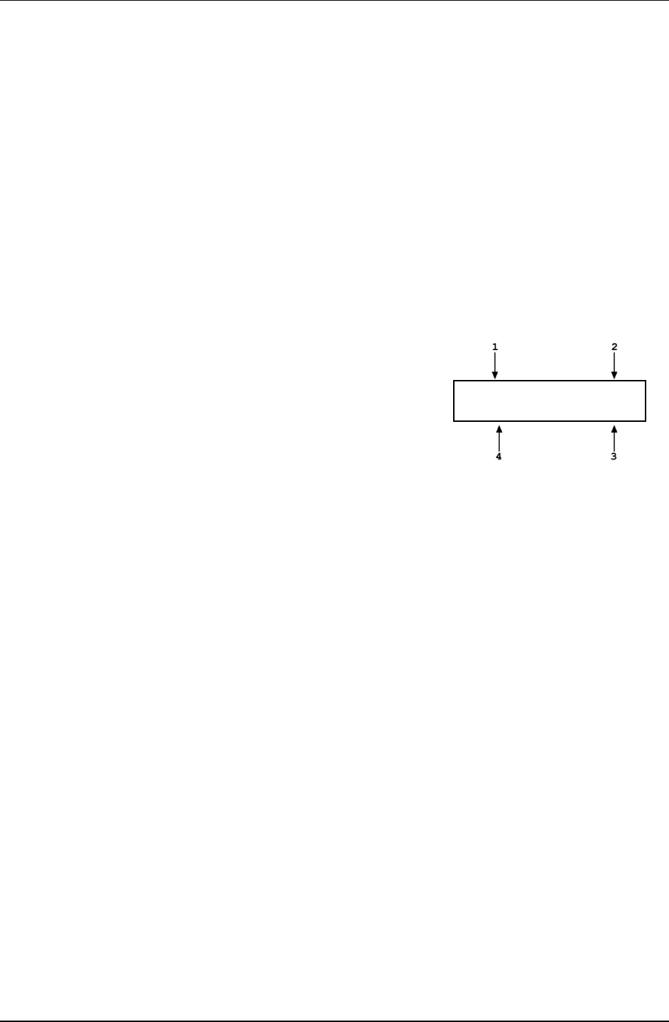
PG7000™ OPERATION AND MAINTENANCE MANUAL
© 2011 Fluke Calibration Page 168
Note
See Section 5.2.1.1 for an explanation of Adders and Multipliers
and their use in adjusting internal sensors.
5.2.1.4 Relative Humidity sensor
PURPOSE
To view and adjust the output of the on-board relative humidity sensor.
Note
The relative humidity sensor is housed in the temperature -
humidity (TH) Probe along with the ambient temperature sensor.
Each sensor maintains it’s own calibration. See Section 5.2.1.3.
OPERATION
To view the output of the relative humidity sensor, press [SPECIAL] and select
<3%RH>, <1view>. The display is:
1. Current reading of the relative humidity
sensor.
2. Indication that this is a relative humidity
display.
3. Current value of the Humidity Multiplier applied
to the relative humidity sensor reading.
43.2 %RH amb%RH
HA 5 %RH HM 0.99984
4. Current value of the Humidity Adder (always in %RH) applied to the relative humidity sensor
reading.
To adjust the values of HA and/or HM press [SPECIAL] and select <3%RH>,
<2cal> to access a screen in which the values of HA and HM can be edited.
From here, press [ESCAPE] and select <3%RH>, <1view> to view the relative
humidity sensor reading with the edited calibration coefficients applied.
Note
See Section 5.2.1.1 for an explanation of Adders and Multipliers
and their use in adjusting internal sensors.
5.2.1.5 piston-cylinder module temperature sensor
PURPOSE
To view and adjust the output of the on-board piston-cylinder module
temperature sensor.
PRINCIPLE
Piston-cylinder module temperature is measured by a platinum resistance
thermometer (PRT) built into the PG7000 mounting post. The resistance of the
PRT is read by PG7000's internal ohmic measurement system and temperature
is calculated as follows:
Temperature = (Measured resistance - resistance at 0 C)/slope
The PRT is a 10052 4-pole type following DIN Norm 43760. The current
supplied to the PRT is 1 mA and the slope of resistance relative to temperature
over the valid temperature range of 0 to 40 C is 0.3896 /C. The uncertainty
specification is ± 0.1 C ( 0.04 ) with a resolution of 0.01 C.
The ohmic measurement system in PG7000 is self-calibrated using on-board
100 and 110 reference resistors.
The normal calibration procedure of the PRT is to remove it from the PG7000
mounting post and determine its offset (actual resistance at 0 C) by calibration.
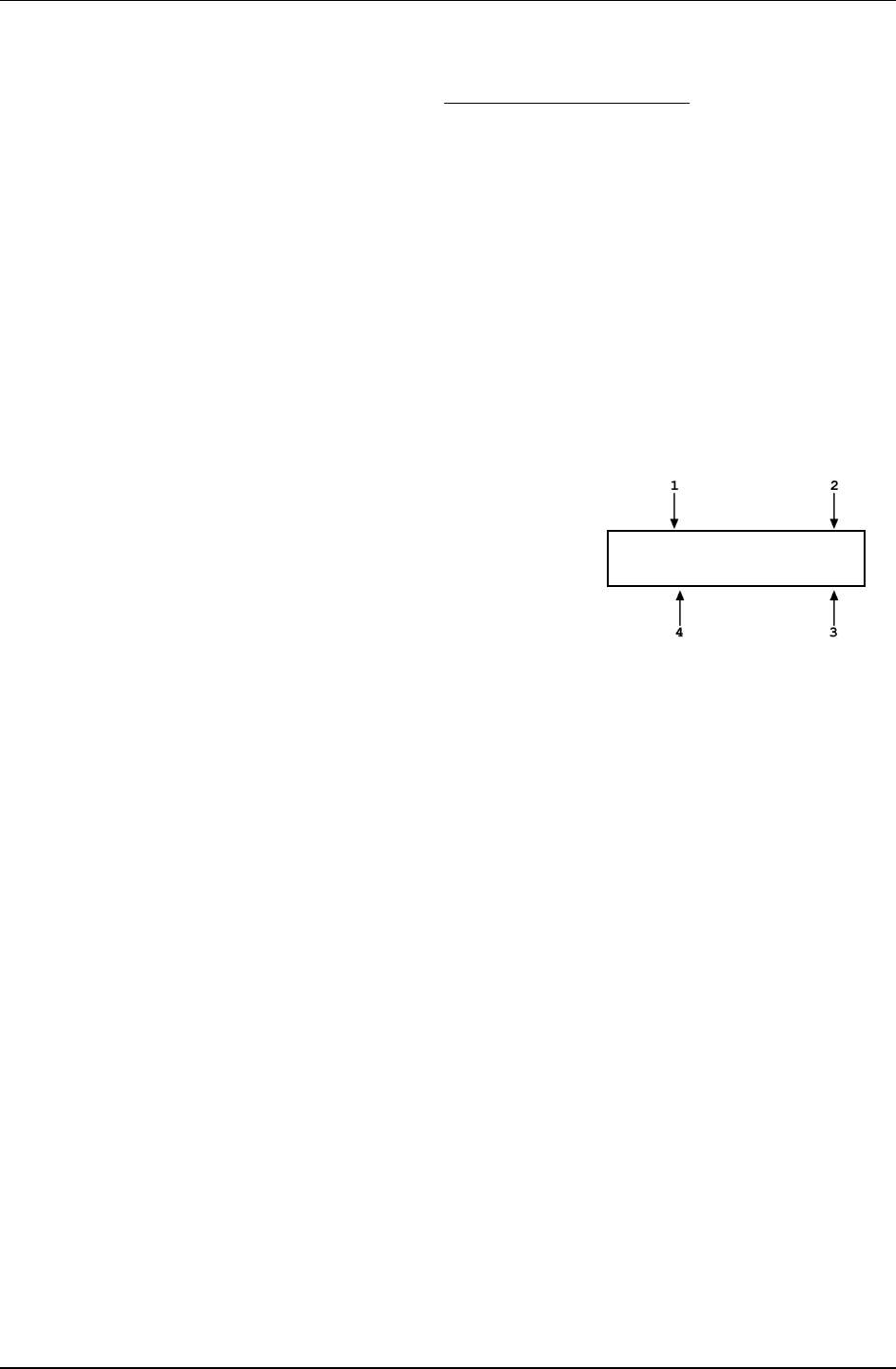
5. MAINTENANCE, ADJUSTMENTS AND CALIBRATION
Page 169 © 2011 Fluke Calibration
To remove the PRT from the PG7000 mounting post, follow the instructions
provided in Section 5.2.1.5, Mounting Post PRT Removal
The value of resistance at 0 °C and the slope, if desired, can be edited to reflect
the new calibration by pressing [SPECIAL] and select <4PCT>.
.
Note
Though the ambient temperature sensor and piston-cylinder
module temperature sensor are of the same technology and
read in the same manner, the recommended calibration
procedures differ reflecting the difference in measurement
uncertainty needed. The ambient temperature sensor (whose
measurement uncertainty is ± 1 °C) is calibrated by simple
offset relative to an external reference measurement (see
Section 5.2.1.3).
OPERATION
To view the output of the piston-cylinder module temperature sensor, press
[SPECIAL] and select <4PCT>, <1view>. The display is:
1. Current reading of the piston-cylinder module
temperature sensor converted to degrees
Centigrade.
2. Indication that this is a piston-cylinder
module temperature display.
3. Current value of the resistance slope relative
to temperature.
4. Current value of the offset at 0 °C in ohm.
19.951 °C PCT
RZ100.003 Ω S0.3896
To adjust the values of RZ and/or S, press [SPECIAL] and select <4PCT>, <2cal>
to access a screen in which the values of RZ and S can be edited.
From here, press [ESCAPE] and select <4PCT>, <1view> to view the piston-
cylinder module temperature reading with the edited calibration coefficients applied.
Mounting Post PRT Removal
To remove the mounting post PRT:
Remove the piston-cylinder module from the mounting post and replace with
the ORANGE storage plug.
Disconnect the PG7000 Platform from the PG7000 Terminal.
Invert the PG7000 Platform so that the bottom of the platform is up.
Support the platform so that it does not tip over. A simple solution is to place
the platform upside down on a sturdy box which is smaller than the outside
platform dimensions and is also tall enough to allow the mounting post to
be suspended.
Remove the six socket head screws (3 mm) around the perimeter of the
platform.
Lift the platform up and carefully disconnect the sensor leads at their board
connections, noting their locations.
For PG7607 and PG7601, loosen - but do not remove - the four socket head
screws (3 mm) located on the PRT/cable pass through plate. The plate is
located on the inside of the base.
For all other PG7000 models, loosen knurled nut securing PRT by hand. It is
not necessary to remove the knurled nut.
The PRT is able to be removed by gently grasping the shaft (not the wires)
and sliding out in a straight motion.
Slide the PRT out of the mounting post.
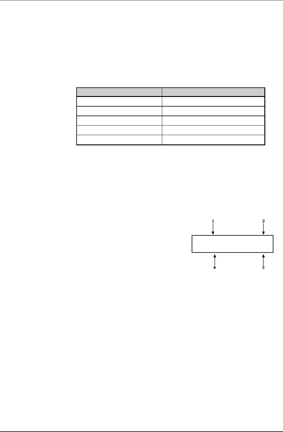
PG7000™ OPERATION AND MAINTENANCE MANUAL
© 2011 Fluke Calibration Page 170
After reinstalling the PRT and tightening the four socket head screws,
reassemble in the reverse order. Thermal grease may be applied lightly to
the PRT, if available. If the sensor lead locations were not noted correctly,
follow Table 28.
Reconnect the PG7000 terminal to the PG7000 Platform using the
cable supplied.
Power up PG7000 and verify proper operation of all on-board sensors.
Table 28. Mounting Post Wire Colors, Description and Location
WIRE COLORS DESCRIPTION AND LOCATION
Black/Yellow/White RPM (P4)
Black/Black/Black/Black Vacuum Sensor (center raised micro board)
White/White/Yellow/Yellow Mounting Post PRT (P2)
Purple/Blue/Red Motor Solenoid (J2)
Gray/Orange/Green/Brown LVDT (P1)
5.2.1.6 Reference Vacuum Gauge (PG7601 Only)
PURPOSE
To view and adjust the output of the on-board reference vacuum gauge
(PG7601 only).
OPERATION
To view the output of the reference vacuum gauge, press [SPECIAL] and select
<6vac>, <1view>. The display is:
1. Current reading of the vacuum gauge in
Pascal. Reads < > 20 > whenever the
current reading is greater than 20 Pa.
2. Indication that this is a vacuum display.
3.
Current value of the Vacuum Multiplier
applied to the vacuum gauge reading.
4. Current value of the Vacuum Adder (always
in Pa) applied to the vacuum gauge reading.
6.52 Pa vac
VA 0.5 VM 0.99984
To adjust the values of VA and/or VM press [SPECIAL] and select <6vac>,
<2cal> to access a screen in which the values of VA and VM can be edited.
From here, press [ESCAPE] and select <6vac>, <1view> to view the vacuum
gauge reading with the edited calibration coefficients applied.
Note
See Section 5.2.1.1 for an explanation of Adders and Multipliers
and their use in adjusting internal sensors.
5.2.2 Piston Position Detection Adjustment
PURPOSE
To adjust the piston position measurement system.
PRINCIPLE
The PG7000 piston position measurement operates on the LVDT principle. There are coils
mounted on either side of the piston-cylinder module mounting post and a ring on the inside
of the mass loading bell acts as the sensor element. As the bell moves, the LVDT signal
changes proportionally to bell position, and therefore piston position. The signal is translated
into relative position in the ± 4.5 mm stroke of the piston (see Section 3.5). The piston
position and fall rate can be viewed in the [SYSTEM] run screen (see Section 3.9.5).

5. MAINTENANCE, ADJUSTMENTS AND CALIBRATION
Page 171 © 2011 Fluke Calibration
The piston position indication system can be realigned by an automated on-board routine.
This routine sets and records the LVDT output at the piston hi and lo stop positions.
Note
When an AMH mass set is used, it is important to follow a specific
procedure to adjust the piston position detection system. See Special
Considerations When Using an AMH Mass Set
OPERATION
in the OPERATION
Section below.
Note
• Refer to piston stroke schematic Figure 8.
• If the PG7000 Platform is equipped with an AMH mass set, be sure to see
To automatically adjust the PG7000 piston position indication system, load the mass bell only
on the piston. Then press [SPECIAL], <7cal>, <5Pposition>, <2cal>.
Special Considerations When Using an AMH Mass Set.
The prompt <Hold piston at max down stop> appears. Place the piston in the fully down
position (be sure to compress the springs so that the piston is truly at the low stop position by
pressing down firmly on the piston or loading at least 5 more kg of mass). Press [ENTER].
The prompt <Hold piston at max up stop> appears. Place the piston in the fully up position
(be sure to compress the springs so that the piston is truly at the high stop position by
applying pressure underneath the piston that is the equivalent to at least 5 kg greater than
the pressure required to float the piston with the current load). Press [ENTER].
Pressing [SPECIAL] and select <7cal>, <5Pposition>, <1view> allows current piston
position and fall rate (see Section 3.9.5.1) to be viewed on the bottom line of the display.
Position is on the left and fall rate is on the right.
The tubular binary masses of an AMH mass set have some influence on the piston position
detection system so it is important to adjust the piston position detection system with all the
binary masses loaded.
Special Considerations When Using an AMH Mass Set
To adjust the PG7000 piston position system when an AMH mass set is being used, proceed
as follows:
Vent pressure.
Select [SPECIAL], <8AMH>, .<2control>, <2discreet> and load all of the binary masses
and none of the main masses (see Section 3.11.8.2).
Press [SPECIAL], <7cal>, <5Pposition>, <2cal>.
The prompt <Hold piston at max down stop> appears. Check that the pressure under
the piston is really vented and press [ENTER].
The prompt <Hold piston at max up stop> appears. Without changing the mass load,
generate a pressure under the piston great enough to insure that the piston will go
completely to the top stop. This requires a pressure equivalent to a mass load of 18 kg
with an AMH-100 or 12 kg with an AMH-38. For example, if the mass handler is an AMH-
100 and the piston is a 2 MPa/kg, generate 36 MPa or if the mass handler is an AMH-38
and the piston is a 10 kPa/kg, generate 120 kPa. Press [ENTER].
Process is complete. Use [SPECIAL], select <7cal>, <5Pposition>, <1view> to verify
that piston position is <+4.5 mm> when fully up and <-4.5 mm> when fully down.
5.2.3 Emptying Oil Run-Off Tray (PG7202 and PG7302 Only)
In PG7302, small quantities of oil escape from beneath the piston-cylinder during the air
purge process when installing a piston-cylinder module (see Section 2.3.2). In both PG7202
and PG7302, very small quantities of oil leak out of the top of the gap between the piston and
cylinder when pressure is applied.
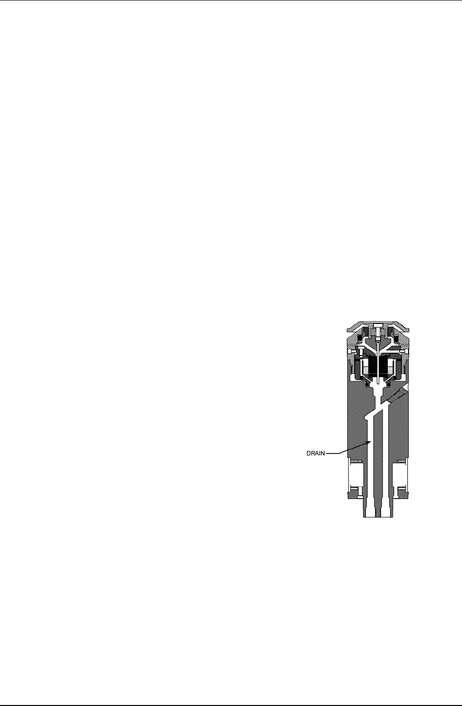
PG7000™ OPERATION AND MAINTENANCE MANUAL
© 2011 Fluke Calibration Page 172
Excess oil is collected and runs down the mounting post, and out through a transparent tube
on the right side of the PG7202/PG7302 Platform to an oil run-off tray under the platform.
To empty the oil run-off tray, proceed as follows:
Using a paper towel or cloth to catch oil drops, gently pull the transparent tube out of the
oil run-off tray.
Grasp the run-off tray by its protruding handle and slide it completely out and away from
the PG7202/PG7302 Platform.
Empty the oil run-off tray by shaking it out or removing the screws on the top plate.
Clean the oil run-off tray. Discard any accumulated oil.
Slide the oil run-off tray back into the PG7202/PG7302 Platform. Push it in beyond the
holding stops until it seats firmly.
Reinsert the transparent oil run-off tube into the hole in the run-off tray handle.
5.2.4 Purge Mounting Post Liquid Run Off (PG7202 Only)
In PG7202, minute quantities of the liquid that lubricates the gap between the piston and the
cylinder flow out of the bottom of the gap. A passage in the mounting post (see Figure 13),
channels this liquid directly to a low point drain. A DRAIN port on the rear of the PG7202
Platform (see Figure 3) allows the drain to be purged. The drain should be purged
approximately once a day when PG7202 is being used extensively or before using PG7202
any time it has been idle with a piston-cylinder module installed for an extended period.
To purge the mounting post liquid drain, proceed as follows:
Apply approximately 700 kPa (100 psi) to the
mounting post using the normal gas pressure
generation/control component.
Cover the weep hole on the top of the DRAIN
port fitting with a paper towel. Then loosen the
DRAIN port DH500 gland slowly. A wrench for
the DRAIN port gland is supplied in the PG7202
accessories.
Wait for all of the pressure to escape.
Repeat through until no oil is visible on the
paper towel.
Retighten the DH500 gland (torque to 15 Nm
(12 ft.lb).
Figure 13. PG7202 Mounting Post Drain
5.2.5 Drive Belt Replacement
Periodic replacement of the drive system belts may be necessary to retain maximum
performance of the rotational engagement system. Due to specific material properties of the
drive belts, it is important that only genuine Fluke Calibration replacement parts be used.
Note
A set of spare drive belts is included in the accessories delivered with the
PG7000 Platform.

5. MAINTENANCE, ADJUSTMENTS AND CALIBRATION
Page 173 © 2011 Fluke Calibration
To remove the drive belts:
Using a 2.5 mm Allen tool, remove the three screws on the outer diameter of the
pulley plate. Do not remove the screws on the inner diameter. The pulley plate is
located directly around the mounting post.
Remove the two drive belts and replace them with the new ones.
Realign the notched pulley with the pins on the drive motor.
Replace the pulley plate and three screws.
Engage the drive system to ensure proper operation.
5.3 Piston-Cylinder Modules
5.3.1 Disassembly, Cleaning and Maintenance
PURPOSE
To disassemble and reassemble piston-cylinder modules and clean the piston-cylinder
elements when necessary.
PRINCIPLE
PG7000 piston-cylinders are high precision metrological assemblies. The annular gap
between the piston and the cylinder is adjusted to be less than 1 micron, and in some cases,
less than 0.5 micron. In normal operation, this space is lubricated by the pressurized medium
(except PC-7200 in which the piston-cylinder modules are gas operated but the space is
lubricated with a liquid). If the space becomes contaminated, usually due to foreign matter
carried by the pressurized medium, PG7000 performance can be affected. Symptoms of
contamination of the space (a dirty piston-cylinder) include:
• Difficulty rotating piston: The motorized rotation system is unable to start
piston rotation.
• Decay in rotation rate is more rapid than normal: Piston rotation slows down too
quickly, especially at low mass loads.
• Poor sensitivity: Very small mass changes do not have usual effect.
• Noisy pressure: The pressure defined when the piston is floating is not a stable as it
usually is.
If any of these symptoms are present, they may be caused by a dirty piston-cylinder.
The piston-cylinder module should be disassembled and the piston-cylinder cleaned. See Section
5.3.2.1 for instructions and disassembly and cleaning of gas operated, gas lubricated piston-
cylinders (PC-7100 and PC-7600), Section 5.3.2.2 for gas operated, liquid lubricated piston-
cylinders (PC-7200) and Section 5.3.2.3 for oil operated piston-cylinders (PC-7300).
Note
• Gas lubricated piston-cylinders (PC-7100 and PC-7600) are highly sensitive
to contamination, much more so than liquid lubricated piston-cylinders
(PC-7200 and PC-7300). When using gas lubricated piston-cylinders, if
symptoms of contamination develop rapidly with operation after cleaning,
there is almost certainly a source of contamination within the PG7000
system. This source must be identified and eliminated to reduce piston-
cylinder cleaning frequency. Very often, the source of contamination is
the test gas supply itself (which contains humidity or lubricating oil) or it is
the return from unclean gas operated DUTs that are connected to the
PG7000 system.
• Gas operated, liquid lubricated piston-cylinders (PC-7200) can exhibit
behavior similar to that of a dirty piston-cylinder when they are operated
without lubricating liquid in the piston-cylinder module reservoir. Before
disassembling a PC-7200 piston-cylinder module for cleaning due to poor
performance, try filling the lubricating liquid reservoir (see Section 5.3.3).

PG7000™ OPERATION AND MAINTENANCE MANUAL
© 2011 Fluke Calibration Page 174
Caution
The PG7000 piston-cylinder module design affords maximum protection to
the piston-cylinder element assuring that it is protected during routine
piston-cylinder handling. Cleaning the piston-cylinder requires
disassembly of the module and exposure of the piston-cylinder to possible
damage. These risks include damage to the critical working surfaces for
all piston-cylinder sizes and chipping or breaking, especially for small
diameter piston-cylinders. Only qualified personnel should undertake
piston-cylinder disassembly and reassembly and the instructions and
recommendations contained in this manual should be followed carefully
throughout the operation.
5.3.2 Disassembly and Reassembly
5.3.2.1 Disassembly and Reassembly of gas operated,
gas lubricated piston-cylinder modules
(PC-7100/7600)
Caution
• The PG7000 piston-cylinder module design affords
maximum protection to the piston-cylinder element assuring
that it is protected during routine piston-cylinder handling.
Cleaning the piston-cylinder requires disassembly of the
module and exposure of the piston-cylinder to possible
damage. These risks include damage to the critical working
surfaces for all piston-cylinder sizes and chipping or
breaking, especially for small diameter piston-cylinders.
Only qualified personnel should undertake piston-cylinder
disassembly and reassembly and the instructions and
recommendations contained in this manual should be
followed carefully throughout the operation.
• NEVER touch the lapped surfaces (polished appearance) of
the piston or cylinder with your bare hands. Body oils and
acids can permanently etch the surfaces.
• The piston assembly (piston + piston head + adjusting mass
+ piston cap + piston cap retaining screw) is part of the
PG7000 mass load. Its mass has been measured and is
reported in the calibration report. Use caution when
handling these parts, to avoid changing their mass by
swapping parts, contaminating them or leaving parts out
in reassembly. Out of tolerance pressure definitions could
result.
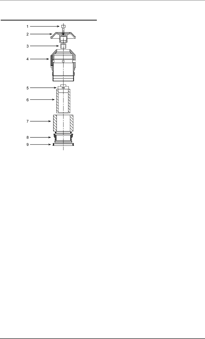
5. MAINTENANCE, ADJUSTMENTS AND CALIBRATION
Page 175 © 2011 Fluke Calibration
10 and 20 kPa/kg Gas Piston-Cylinder Module
Figure 14. 10 and 20 kPa/kg Gas
Piston-Cylinder Module (Expanded View)
Place the piston-cylinder module upside down
on a clean stable surface (piston cap (2) down).
Using the sleeve nut tool (see Figure 16), remove
the sleeve nut (9). The sleeve nut tool is a
spanner that fits into the two holes on the
sleeve nut.
Note
The sleeve nut for 10 and 20 kPa/kg modules
has a left hand thread so it is loosened by
turning clockwise.
Remove the O-ring assembly (8). Then, being
sure to support the cylinder (7) so it doesn’t fall
out, turn over the remaining assembly so that
the piston cap (2) is up.
While firmly holding down the cap (2), use a 5 mm
Allen tool, to loosen the socket head cap
retaining screw (1). The cap retaining screw
will not fully disengage from the piston cap due
to the adjustment mass (3). Gently remove the
cap and screw from the assembly.
Note
When installing the piston cap during
reassembly, remember to reinstall the
adjustment mass (3).
Remove the main module housing (4) by
sliding it upward leaving the piston-cylinder
assembly behind.
Step 6 applies only to 20 kPa/kg:
Reinstall the piston cap (2) directly onto the
piston head (6). Using the cap as a handle,
slide the piston out of the cylinder. Take care
not to cock the piston in the cylinder at the
point at which it leaves the cylinder.
Steps 7, 8, and 9 apply only to 10 kPa/kg:
Reinstall the piston cap (2) directly onto the
piston head (5).
Place the 10 kPa/kg piston insertion tool (see
Figure 15) on the work surface with the large
diameter down. DO NOT TOUCH the white
plastic centering ring of the insertion tool.
Holding the cylinder (7) to prevent it from falling
out, place the piston-cylinder assembly onto the
tool sliding the hollowed end of the piston (6)
onto the tool shaft. Carefully allow the cylinder
to drop down over the white plastic centering
ring. Holding the cylinder, gently remove the
piston (6) from the tool. Finally, remove the tool
from the cylinder.
Note
In reassembly, the end of the cylinder
marked with the serial number must enter
the main module housing first.
Caution
The orientation of the piston on the cylinder
is important. The end of the cylinder that is
marked with the serial number should go
into the sleeve and/or main module housing
first. The piston enters the end of the
cylinder that is marked with the serial
number. Installing the cylinder with the
wrong orientation may lead to out of
tolerance measurements.
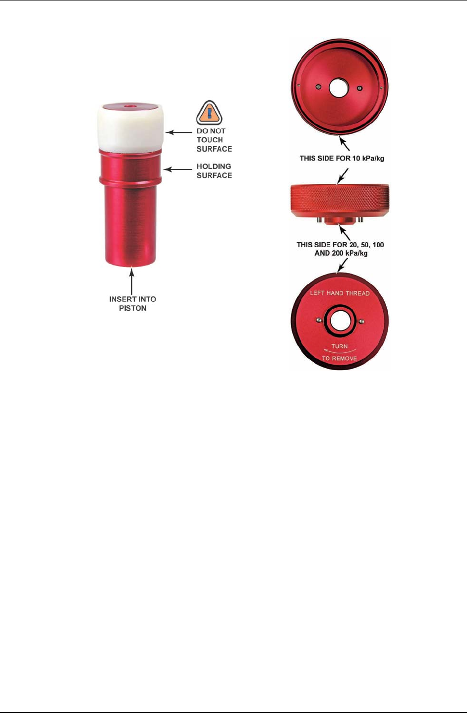
PG7000™ OPERATION AND MAINTENANCE MANUAL
© 2011 Fluke Calibration Page 176
Figure 15. 10 kPa/kg
Piston Insertion Tool Figure 16. Gas Piston-Cylinder Module
Sleeve Nut Tool
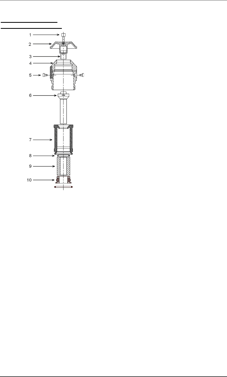
5. MAINTENANCE, ADJUSTMENTS AND CALIBRATION
Page 177 © 2011 Fluke Calibration
50, 100 and 200 kPa/kg
Piston-Cylinder Modules
Figure 17. 50, 100 and 200 kPa/kg Gas
Piston-Cylinder Modules (Expanded View)
Place the piston-cylinder module on a clean
stable surface with the piston cap (2) up.
Using a 3 mm Allen tool, loosen the two sleeve
retaining socket head screws (5) from the
opposing sides of the main module housing (4).
Note
In reassembly, after the two sleeve retaining
screws (5) are installed, the sleeve (7) must still
have a small amount of freedom to move and
rotate within the main module housing (4).
While firmly holding down the cap (2), use a
5 mm Allen tool to loosen the socket head cap
retaining screw (1). The cap retaining screw
will not fully disengage from the piston cap
due to the adjustment mass (3). Gently remove
the cap and screw from the assembly.
Note
When installing the piston cap during
reassembly, remember to reinstall the
adjustment mass (3).
Remove the main module housing (4) by
sliding it upward leaving the piston-cylinder and
sleeve assembly behind.
Reinstall the piston cap (2) directly onto the
piston head (6). Using the cap as a handle,
slide the piston out of the cylinder. Take care
not to cock the piston in the cylinder at the
point at which it leaves the cylinder.
Turn over the cylinder sleeve (7) so that the
sleeve nut (10) is facing up.
∠ Using the sleeve nut tool (see Figure 16),
remove the sleeve nut (5). The sleeve nut tool
is a spanner that fits into the two holes on the
sleeve nut.
Note
The 50, 100 and 200 kPa/kg sleeve nuts have
a right hand thread so they are loosened by
turning counter-clockwise.
Holding the cylinder (9) in the open end of the
cylinder sleeve (7), turn the cylinder sleeve
over and then allow the cylinder to gently
slide out.
Note
In reassembly, verify that the cylinder
O-ring (8) is still located in the top of the
cylinder sleeve (7). It is recommended that a
thin film of vacuum grease (Krytox®) be
applied to the top outside edge of the
cylinder sleeve (7) where it mates with the
main module housing (4). This must be
applied before the sleeve is inserted into the
housing. The end of the cylinder marked
with the serial number must enter the main
module housing first.
Caution
• The two sleeve retaining screws (5)
MUST be reinstalled before pressure is
applied to the piston-cylinder module.
Damage to equipment and injury to
personnel may result from pressurizing
the piston-cylinder module without the
sleeve retaining screws installed.
• The orientation of the piston on the
cylinder is important. The end of the
cylinder that is marked with the serial
number should go into the sleeve and/or
main module housing first. The piston
enters the end of the cylinder that is
marked with the serial number. Installing
the cylinder with the wrong orientation
may lead to out of tolerance
measurements.

PG7000™ OPERATION AND MAINTENANCE MANUAL
© 2011 Fluke Calibration Page 178
5.3.2.2 Disassembly And Reassembly of Gas Operated,
Liquid Lubricated Piston-Cylinder Modules (PC-7200)
Caution
• The PG7000 piston-cylinder module design affords
maximum protection to the piston-cylinder element assuring
that it is protected during routine piston-cylinder handling.
Cleaning the piston-cylinder requires disassembly of the
module and exposure of the piston-cylinder to possible
damage. These risks include damage to the critical working
surfaces for all piston-cylinder sizes and chipping or
breaking, especially for small diameter piston-cylinders.
Only qualified personnel should undertake piston-cylinder
disassembly, cleaning and reassembly. The instructions
and recommendations contained in this manual should be
followed carefully throughout the operation.
• NEVER touch the lapped surfaces (polished appearance) of
the piston or cylinder with your bare hands. Body oils and
acids can permanently etch the surfaces.
• In normal use, always maintain PC-7200 gas operated, liquid
lubricated piston-cylinder modules vertical with the O-ring
assembly down. Tilting or inverting the assembly can cause
the liquid in the modules reservoir to run out. Inverting the
assembly can allow liquid to run up into the piston head into
the adjustment mass and cap. Liquid contamination of the
piston head and cap changes the mass of the piston
assembly and could lead to out of tolerance pressure
definitions at low mass loads. If liquid contaminates the
adjustment mass and cap, disassemble the module and
clean it (see Section 5.3).
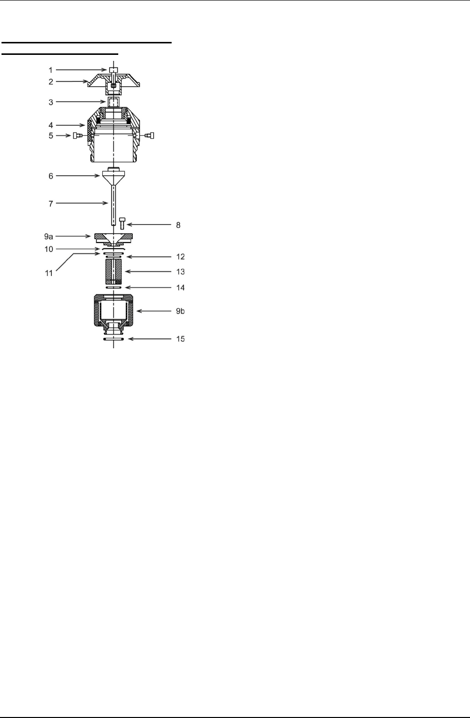
5. MAINTENANCE, ADJUSTMENTS AND CALIBRATION
Page 179 © 2010 Fluke Calibration
All Gas Operated, Liquid Lubricated
Piston-Cylinder Modules
Figure 18. Gas Operated, Liquid Lubricated
Piston-Cylinder Module (Expanded View)
Note
• Before disassembling a gas operated, liquid
lubricated piston-cylinder module, empty the
lubricating liquid reservoir (see Section 5.3.3).
After reassembling, fill the reservoir before
using the piston-cylinder module again.
• Gas operated, liquid lubricated piston-
cylinders can usually be cleaned by simply
removing the piston, cleaning it and running it
in and out of the cylinder several times. Do
not completely disassemble the piston-
cylinder module beyond removing the piston
(step ) unless it is absolutely necessary.
Screw the piston-cylinder module into the base of
its bullet case (Acetal shipping and storage case)
and place the base and module on a clean stable
surface with the piston cap (2) up.
Using a 3 mm Allen tool, loosen the two socket
head sleeve retaining screws (5) from the opposing
sides of the main module housing (4).
Note
In reassembly, after the two sleeve retaining
screws (5) are installed, the sleeve (9) must still
have a small amount of freedom to move and
rotate within the main module housing (4).
While firmly holding down the cap (2), use a 5 mm
Allen tool, to loosen the socket head cap retaining
screw (1). Turning the screw (1) pushes the piston
head (6) straight out of the piston cap (2) ensuring
that no sideways torque is applied to the piston (7).
The cap retaining screw will not fully disengage
from the piston cap due to the adjustment mass (3).
Gently remove the cap and screw from the
assembly. Take care to be sure the piston head is
out of the cap so as NOT to apply torque to the
piston (7) when removing the cap.
Note
In reassembly, when installing the piston cap, be
sure the adjustment mass (3) is still in place on
the screw. Take great care to slip piston cap (2)
straight onto the piston head (6) and not to apply
torque to the piston (7).
Unscrew the main module housing (4) from the
bullet case leaving the piston-cylinder and sleeve
assembly behind in the bullet case base. Holding
piston head (6) and taking care not to apply
sideways torque on the piston (7), slide the piston
straight out of the cylinder (13).
Note
• Stop here if you are doing a simple cleaning
of the piston-cylinder (see Section 5.3.4). Do
not proceed with this step of disassembly if
you do NOT have a new set of O-rings (11, 12,
14) to use in reassembly. It is imperative that
new O-rings be used in reassembly.
• Using a 3 mm Allen tool, unscrew and remove
the four reservoir cover retaining screws (8).
Lift off the reservoir cover (9a). The small
O-ring (12) stays with the reservoir cover.
Remove the large O-ring (11) and its anti-
extrusion ring (10) taking care not to deform
the extrusion ring (PC-7200-100 and PC-7200-
200 do not have an anti-extrusion ring). Note:
Anti-extrusion ring needs to be installed with
beveled edge facing down.
Remove the reservoir assembly with the cylinder in
it from the bullet case base. Turn over the
assembly and place it on the sturdy surface with the
bottom O-ring (15) up.
Push the cylinder (13) out of the reservoir through
the hole in the bottom of the reservoir and remove
it. Remove the small O-ring (14) from the bottom of
the reservoir.
Caution
• The sleeve retaining screws (5) MUST be
reinstalled before pressure is applied to the
piston-cylinder module. Damage to
equipment and injury to personnel may result
from pressurizing the piston-cylinder module
without the sleeve retaining screws installed.
• The orientation of the piston on the cylinder is
important. The end of the cylinder that is
marked with the serial number should go into
the sleeve and/or main module housing first.
The piston enters the end of the cylinder that
is marked with the serial number. Installing
the cylinder with the wrong orientation may
lead to out of tolerance measurements.

PG7000™ OPERATION AND MAINTENANCE MANUAL
© 2010 Fluke Calibration Page 180
5.3.2.3 Disassembly and Reassembly of Oil Operated, Oil
Lubricated Piston-Cylinder Modules (PC-7300)
Caution
• The PG7000 piston-cylinder module design affords
maximum protection to the piston-cylinder element
ensuring that it is protected during routine piston-
cylinder handling. Cleaning the piston-cylinder requires
disassembly of the module and exposure of the
piston-cylinder to possible damage. These risks include
damage to the critical working surfaces and chipping or
breaking, especially for small diameter pistons, in particular
the PC-7300 5 MPa/kg. Only qualified personnel should
undertake piston-cylinder disassembly, cleaning and
reassembly. The instructions and recommendations
contained in this manual should be followed carefully
throughout the operation.
• NEVER touch the lapped surfaces (polished appearance) of
the piston or cylinder with your bare hands. Body oils and
acids can permanently etch the surfaces.
• In normal use, always maintain PG7302 oil piston-cylinders
vertical with the O-ring assembly down. Do not invert the
assembly and allow oil to run up into the piston head into
the adjustment mass and cap. Oil contamination of the
piston head and cap changes the mass of the piston
assembly and could lead to out of tolerance pressure
definitions at low mass loads. If oil contaminates the
adjustment mass and cap, disassemble the module and
clean it (see Section 5.3).
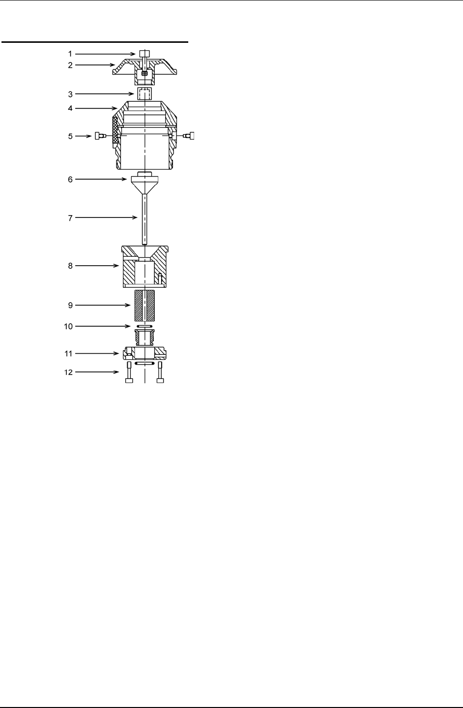
5. MAINTENANCE, ADJUSTMENTS AND CALIBRATION
Page 181 © 2010 Fluke Calibration
All Oil Operated Piston-Cylinder Module
Figure 19. Oil
Piston-Cylinder Module (Expanded View)
Screw the piston-cylinder module into the base of
its bullet case (Acetal shipping and storage case)
and place the base and module on a clean stable
surface with the piston cap up.
Using a 3 mm Allen tool, loosen the two socket
head sleeve retaining screws (5) from the opposing
sides of the main module housing (4).
Note
In reassembly, after the two sleeve retaining
screws (5) are installed, the sleeve (8) must still
have a small amount of freedom to move and
rotate within the main module housing (4).
While firmly holding down the cap (2), use a 5 mm
Allen tool, to loosen the socket head cap retaining
screw (1). Turning the screw pushes the piston
head (6) straight out of the piston cap (2) ensuring
that no sideways force is applied to the piston (7).
NOTE: Small diameter pistons can be snapped
by excessive sideways force. The cap retaining
screw will not fully disengage from the piston cap
due to the adjustment mass (3).
Gently remove the cap and screw from the
assembly. Use caution to be sure the piston head
is out of the cap so as NOT to apply sideways force
to the piston (7) when removing the cap.
Note
When installing the piston cap during
reassembly, remember to reinstall the adjustment
mass (3). Take great care to slip the piston cap
(2) straight onto the piston head (6) and not to
apply torque to the piston (7).
Unscrew the main module housing (4) from the
bullet case leaving the piston-cylinder and sleeve
assembly behind in the bullet case base. Carefully
reinstall the piston cap (2) onto the piston head (6)
taking care not to apply sideways torque on the
piston (7). Using the cap as a handle, slide the
piston straight out of the cylinder. NOTE: Do not
twist the piston or apply sideways force to it. It
can easily be snapped.
Remove the cylinder and sleeve assembly from the
bullet case base. Turn over the assembly and
place it on the sturdy surface with the O-ring
assembly (10) up.
Using a 3 mm Allen tool, loosen the two O-ring
assembly retainer screws (12). The screws are
captive so they will not disengage completely.
Remove the O-ring retainer (11) with the retainer
screws. Remove the O-ring assembly (10).
Note
There are low pressure and high pressure oil
piston-cylinder modules, which are identical
except for the size of the O-ring assembly. The
low pressure assembly has a large, single
diameter and is shorter (see below). In
reassembly, take care to ensure that a low
pressure O-ring assembly is never installed on a
high pressure module as excessive force and
damage under pressure could result.
Holding the cylinder (9) in the open end of the
cylinder sleeve (8), turn the cylinder sleeve over.
Allow the cylinder to gently slide out. The end of
the cylinder marked with the serial number must
enter the module housing first.
Caution
• Before reinstalling the piston in the cylinder,
make sure that the piston is lubricated with a
light film of oil .
• The sleeve retaining screws (5) MUST be
reinstalled before pressure is applied to the
piston-cylinder module. Damage to
equipment and injury to personnel may result
from pressurizing the piston-cylinder module
without the sleeve retaining screws installed.
Continued on next page --->

PG7000™ OPERATION AND MAINTENANCE MANUAL
© 2011 Fluke Calibration Page 182
Caution
NEVER install a low pressure O-ring assembly (11 in
Figure 14) on a high pressure oil piston-cylinder
module. High pressure piston-cylinder modules
are PC-7300-1, -2 and -5. The low pressure O-ring
assembly has a single diameter and is shorter
than a high pressure O-ring assembly. Operating a
high pressure oil piston-cylinder module with a
low pressure O-ring assembly installed could
cause excessive force and damage the module.
Low Pressure High Pressure
O-ring Assembly O-ring Assembly
Caution
The orientation of the piston on the cylinder is
important. The end of the cylinder that is marked
with the serial number should go into the sleeve
and/or main module housing first. The piston
enters the end of the cylinder that is marked with
the serial number. Installing the cylinder with the
wrong orientation may lead to out of tolerance
measurements.
5.3.3 Filling or Emptying Gas Operated, Liquid Lubricated
Piston-Cylinder Module Reservoir with Liquid
PURPOSE
To fill or empty the reservoir that holds the liquid used to lubricate the piston-cylinder gap in
PC-7200 piston-cylinder modules.
PRINCIPLE
PC-7200 gas operated, liquid lubricated piston-cylinder modules include a reservoir, which
holds the liquid used to lubricate the gap between the piston and the cylinder
(see Figure 3.1.1). If this reservoir is allowed to go empty, the piston-cylinder module will not
operate properly. Symptoms of lack of lubricating liquid are poor piston sensitivity, excessive
piston drop rate and/or excessive rotation decay rate.
To avoid running out of lubricating liquid, it is recommended that the piston-cylinder module
liquid reservoir be refilled approximately once a week when the module is being used
extensively or if the module has not been used for an extended period of time.
The reservoir may also be emptied for shipping or disassembly.
OPERATION
To fill the reservoir of a PC-7200 gas operated, liquid lubricated piston-cylinder module,
proceed as follows (see Figure 5.3.3). To empty the reservoir, uses steps and only.
Place the piston-cylinder module horizontally with one of the liquid fill holes facing up.
Some liquid may come out of the hole. This indicates that the reservoir is not empty.
Use a syringe supplied with the piston-cylinder module. Empty the syringe and insert it
snugly into the fill hole. Draw back the syringe plunger and withdraw the remaining liquid
from the reservoir until air begins to enter the syringe.
Dispose of the contents of the syringe and wipe off any liquid residue in the bottom of the
module and around the fill hole.
Fill the syringe with 8 cc of fresh liquid. With the piston-cylinder module still in the
horizontal position, inject the full 8 cc of liquid into the fill hole. Be sure to use the correct
fluid for the piston-cylinder module (PC-7200-100, -200 and use Synturion 6; PC-7200-500,
-1 and -2 use Sebacate, see Section 1.2.2.2).
Simultaneously, remove the syringe and hold the module in the vertical position. Let any
liquids run off and wipe off the inside bottom of the module, if necessary, with a lint free wipe.
The module is ready to be reinstalled in the PG7202 Platform (see Section 2.3.2).

5. MAINTENANCE, ADJUSTMENTS AND CALIBRATION
Page 183 © 2011 Fluke Calibration
Figure 20. Filling Gas Operated, Liquid Lubricated
Piston-Cylinder Module Reservoir (PC-7200)
Note
• When refilling piston-cylinder modules, if the quantity of liquid withdrawn
in step above is less than 2 cc, you should fill the module more
frequently.
• In day to day use, always keep gas operated, liquid lubricated modules in
the vertical position when handling them to avoid having liquid escape
from the fill holes.
5.3.4 Cleaning Piston-Cylinders
Water/Detergent Method
Note
Of the two cleaning methods, the water/detergent method is more time
consuming but it is also more thorough.
Caution
DO NOT undertake piston-cylinder module disassembly without
familiarizing yourself with Section 5.3.1 of this manual. Incorrect
disassembly may damage or destroy the piston-cylinder element.
Disassemble the piston-cylinder module following the instructions given in Section 5.3.2.1
for PC-7100/7600 modules, Section or Section 5.3.2.2 for PC-7200 modules or Section
5.3.2.3 for PC-7300 modules.
Reinsert the piston (with cap installed) into the cylinder.
Create a bath of water and mild liquid dishwashing detergent. Distilled water is
acceptable. De-ionized water is best. Detergent must be free of additives (i.e., lotions
or softening agents which may leave a residue after cleaning). To avoid undesired
thermal effects, bring the bath to room temperature.
Holding the piston-cylinder assembly by the outside of the cylinder and the piston cap,
submerge the assembly in the bath. Using a rotating motion, thoroughly work the
detergent into the piston-cylinder assembly.
With the piston-cylinder still assembled, thoroughly rinse the assembly in a bath of
water only. Use the same rotating motion as in the previous step.

PG7000™ OPERATION AND MAINTENANCE MANUAL
© 2011 Fluke Calibration Page 184
Remove the piston from the cylinder and thoroughly dry all areas of the assembly using
a lint free towel. DO NOT touch the critical lapped surfaces of the piston or the cylinder
with anything other than the drying towel. Only use one side of the towel during this
process as the other side will become contaminated by contact with the operator’s
hands. Dry thoroughly.
Reassemble the metrological assembly in reverse order.
If the assembly temperature was elevated during cleaning, it may be necessary to wait
to allow the temperature of the assembly to return to ambient temperature before the
assembly will operate normally.
Note
To avoid static build up on the 35 mm ceramic piston surface, do not
excessively rub or buff the surface after it has been dried. After cleaning
ceramic elements, it is recommended that they be discharged to remove
any possibility of static charge. This can be accomplished by running a
clean, grounded wire (typically from an ESD pad) across the inner and
outer surfaces of the piston and cylinder.
Quick Method
Note
Of the two cleaning methods, the quick method is less demanding but it is
less thorough.
Caution
DO NOT undertake piston-cylinder module disassembly without
familiarizing yourself with Section 5.3.1 of this manual. Incorrect
disassembly may damage or destroy the piston-cylinder element.
Disassemble the piston-cylinder module following the instructions given in Section 5.3.2.1
for PC-7100/7600 modules, Section or Section 5.3.2.2 for PC-7200 modules or Section
5.3.2.3 for PC-7300 modules. Note, it is frequently adequate to clean only the piston of PC-
7200 and PC-7300 modules which avoids complete disassembly of the module.
If you have not already done so, reinstall the cap on the piston.
Apply a small amount of Dow Corning® OS-20 or glass cleaner to a lint free wipe. If
glass cleaner is used, slightly dilute the cleaner using distilled or de-ionized water to help
ensure that no residue will be left behind. Wipe the lapped surfaces (polished
appearance) of both the piston and cylinder.
Using a separate, clean, lint free wipe, wipe the surfaces again to remove any remaining
moisture. If canned air is available, blow the surfaces off with a slow flow of air.
Reassemble the piston-cylinder assembly in reverse order.
Note
To avoid static build up on the 35 mm ceramic piston surface, do not
excessively rub or buff the surface after it has been dried. After cleaning
ceramic piston, it is recommended that it be discharged to remove any
possibility of static charge. This can be accomplished by running a clean,
grounded wire (typically from an ESD pad) across the inner and outer
surfaces of the piston and cylinder.

5. MAINTENANCE, ADJUSTMENTS AND CALIBRATION
Page 185 © 2011 Fluke Calibration
5.3.5 Lubricating Piston-Cylinder Modules
The purpose of piston-cylinder module lubrication is to minimize wear to components of the
piston-cylinder module. The proper long term functioning of the module requires that specific
areas of certain components be properly lubricated, especially after they have been cleaned.
Lubricant
Vacuum Grease: DuPont Krytox GPL-205/6 is the recommended lubricant. Krytox is
selected because it is a non-reactive, nonflammable, oxygen service safe grease. Very small
amounts are used. Krytox is made of perfluoropolyether (PFPE) thickened with
polytetrafluoroethylene (PTFE). Users should avoid contact with eyes and skin.
A tube of Krytox GPL-205/6 is included in the PG7000 Platform accessory kit.
Where to Lubricate
The lubrication charts in Figures 21, 22 and 23 depict the areas that require application of
vacuum grease. A thin film (i.e. just enough lubricant to fully cover the area indicated)
applied to these areas is all that is necessary. Lubrication with more than a thin film will
increase the cost of lubrication and may result in contamination of the piston and/or cylinder.
Areas not indicated for lubrication should be kept free from vacuum grease.
Lubricating O-Rings
O-rings identified for lubrication should be lubricated prior to installation. During service O-
rings may be left in place and a thin film of vacuum grease applied to the outside diameter.
Vacuum grease may be applied by placing a drop (3-4mm diameter - approximately 15-
30mg) of grease between the thumb and forefinger and then rolling the O-ring between the
thumb and forefinger to apply a thin film over the entire o-ring (use of gloves is
recommended). An alternate method is to place a drop (3-4mm diameter - approximately 15-
30mg) of vacuum grease in a small zip closure plastic bag (just large enough to fit the largest
O-ring). Place the O-ring in the bag, close the bag, and then gently work the vacuum grease
over the entire O-ring.
Spring Carrier Lubrication
The spring carrier is lubricated at Fluke Calibration. Under normal conditions it is not
necessary for the user to remove the spring carrier for lubrication. In the event that
lubrication is necessary, use caution during disassembly. Remove the clip, spacer, spring
carrier and springs (qty 6). Lubricate the spring carrier as shown in the lubrication chart.
Reassemble, using care to install the springs, spacer and clip in the reverse order of
disassembly.
Pistons and Cylinders
Pistons and cylinders should be kept free from vacuum grease and any other contaminant
(see Section 5.3.4). Vacuum grease or other contaminants on the piston or cylinder will
adversely affect the piston-cylinder module’s performance.
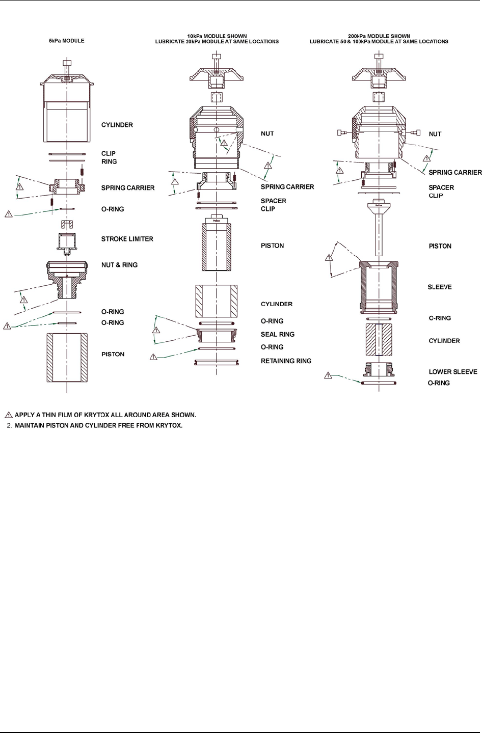
PG7000™ OPERATION AND MAINTENANCE MANUAL
© 2011 Fluke Calibration Page 186
Figure 21. Gas Operated, Gas Lubricated Piston-Cylinder Module Lubrication Chart
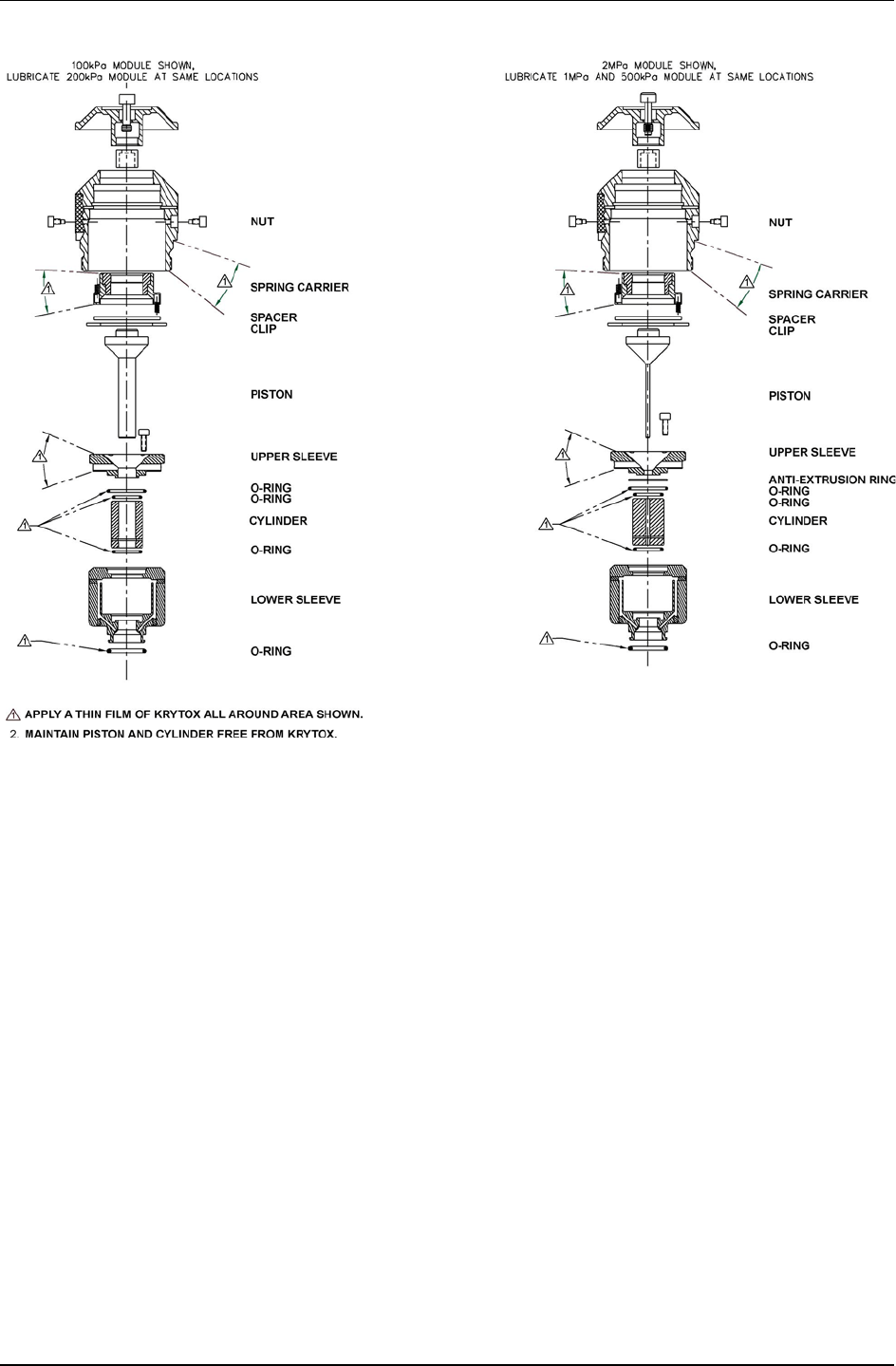

PG7000™ OPERATION AND MAINTENANCE MANUAL
© 2011 Fluke Calibration Page 188
Figure 23. Oil Operated Piston-Cylinder Module Lubrication Chart
5.3.6 Recalibration
PRINCIPLE
Piston-cylinders and mass sets are recalibrated by redetermining the effective area of the
piston-cylinder and the true mass values of the masses. It is recommended that
piston-cylinders and mass sets be recalibrated at the end of their first and second years
of operation. Then, based on their observed stability, a longer calibration interval can usually
be assigned. Though other organizations may be able to perform these calibrations, it is
recommended that a Fluke Calibration Service be used, if possible.
The recalibration process may find values for piston-cylinder effective area, pressure
coefficient and mass values that are different from the previous values. The PG7000
piston-cylinder and/or mass set files must be changed to reflect the new values (see
Sections 5.3.2.1 and 5.4.2.1).
5.3.6.1 updating piston-cylinder module files
See Section 3.11.1.2 for information on editing a piston-cylinder module file to
reflect new calibration data.

5. MAINTENANCE, ADJUSTMENTS AND CALIBRATION
Page 189 © 2011 Fluke Calibration
5.4 Mass Sets
5.4.1 Cleaning
Care should always be taken with all PG7000 masses, including the piston assembly and the
mass loading bell, to avoid contaminating them with liquids or particles. They should never
be handled with bare hands.
Over time, or by an accidental incident, masses may become soiled. In these cases, they
can be cleaned.
Masses should be cleaned with a non-abrasive general purpose cleaner (such as glass
cleaner) and wiped dry with lint free paper towels.
5.4.2 Recalibration
PRINCIPLE
Piston-cylinders and mass sets are recalibrated by redetermining the effective area of the
piston-cylinder and the true mass values of the masses. It is recommended that
piston-cylinders and mass sets be recalibrated at the end of their first and second years of
operation. Then, based on their observed stability, a longer calibration interval may be
assigned. Though other organizations may be able to perform these calibrations, it is
recommended that a Fluke Calibration Service be used, if possible.
The recalibration process may find values for piston-cylinder effective area, pressure
coefficient and mass values that are different from the previous values. The PG7000
piston-cylinder and/or mass set files must be changed to reflect the new values (see Sections
5.3.2.1 and 5.4.2.1).
5.4.2.1 Updating Mass Set Files
See Sections 3.11.1.7 and 3.11.1.12 for information on editing mass set and
mass loading bell files to reflect new calibration data. The mass of the piston
assembly is included in the piston-cylinder module file (see Section 3.11.1.2).
5.5 Reloading Embedded Software into PG7000 Flash
Memory
PG7000 uses FLASH memory. This allows the embedded software that controls PG7000 operations and
functions to be loaded into PG7000 over its COM1 port from a computer with a simple FLASH loading
utility program.
Note
Previous versions of PG7000 embedded software required the use of a NULL
MODEM cable to flash via the COM2 port. Version 3.0 and newer use a different
scheme requiring only a traditional cross-over RS232 cable and flashes on the
COM1 port.
To replace corrupted software or upgrade your software, access the Fluke Calibration worldwide web site
at www.dhinstruments.com and go to embedded located under software. A Flash loading utility and
the latest PG7000 software are available for download at no charge. If you do not have access to the web
or have difficulty downloading or loading software, contact your Fluke Calibration representative or a
Fluke Calibration Authorized Service Provider for assistance.
If you believe you have discovered an error or “bug” in PG7000 software, please report it with complete
details by email to dhiservice@fluke.com or submit an on-line Quality Feedback Report at
www.dhinstruments.com.

PG7000™ OPERATION AND MAINTENANCE MANUAL
© 2011 Fluke Calibration Page 190
Note
The Fluke Calibration flash software loading utility and PG7000 embedded
software are available for download from the SOFTWARE section of DHI’s
worldwide web site at www.dhinstruments.com.
5.6 Disassembly and Reassembly of PG7000
5.6.1 Platform
See Section 5.2.1.5, Mounting Post PRT Removal.
5.6.2 Terminal
To open the PG7000 Terminal proceed as follows:
Disconnect power.
Remove the pop-off screw covers on the bottom of the case.
Remove the four case screws.
Lift OFF the cover. Be careful not to over stress the ribbon cables connecting the display
and keypad in the cover to the printed circuit board in the base.
Disconnect the cover to base ribbon cables at the connectors on the base printed
circuit board. Be aware that the connectors are locking connectors.
To reassemble, proceed in reverse order.
5.6.3 AMH Automated Mass Handler Removal
See the AMH-38/AMH-100 Operation and Maintenance Manual.

Page 191 © 2010 Fluke Calibration
6. Troubleshooting
6.1 Overview
PG7000 is a sophisticated pressure measuring instrument with advanced on-board features
and functions. Before assuming that unexpected behavior is caused by a system defect or breakdown,
the operator should use this manual and other training facilities to become thoroughly familiar with
PG7000 operation. This troubleshooting guide is intended as an aid in identifying the cause of
unexpected PG7000 behavior and determining whether the behavior is due to normal operation or an
internal or external problem.
Identify the symptom or unexpected behavior you are observing from the SYMPTOM list below.
A PROBABLE CAUSE is provided and a SOLUTION is proposed including references to manual
sections that provide information that may be of assistance.
See the AMH-38/AMH-100 Operation and Maintenance Manual for troubleshooting the operation of an
AMH automated mass handler.
Table 29. PG7000 Troubleshooting Checklist
SYMPTOM PROBABLE CAUSE SOLUTION
Will NOT power up. Blown fuse. Replace fuse in PG7000 Terminal.
Front panel keys seem to be disabled. “REMOTE” command has been sent from
a host computer. Send “LOCAL” command from host
computer or cycle PG7000 power. 4.3.4.2
Front panel display is dim. Screen saver option has been activated. Press any key to resume full screen power,
adjust activation time if desired. 3.11.4.1
Keypad presses make undesired
sounds or no sounds. Keypad sound settings are incorrect. Use sounds function to set keypad sounds
as desired. 3.11.42
Cannot access certain functions.
Display shows:
<ACCESS RESTRICTED>.
User Level setting restricts access to
those functions. Change User Level or consult system
manager. 3.11.8
Cannot establish communication over
interface. Computer and/or PG7000 interface not
correctly configured; incorrect or bad
interface cable.
Check and correct interface configurations
and cables if necessary. Run COM port test.
3.11.5, 3.11.5.3, 4.2
Displays <FATAL ERROR> or
<FATAL FAULT>. Encountered unresolved internal software
conflict. Cycle power to clear. Please record
conditions leading up to the event, including
the numbers displayed when enter is
pressed and report the information to a Fluke
Calibration Authorized Service Provider.
Display <TOUT> or <TIME-OUT>. PG7000 is having a communications
problem with an external barometer or
pressure generation/control component.
Check setup and communications with
external barometer or pressure
generation/control component. 3.11.5.4
Displays <******> or <OVERFLOW>
where a numerical value should be. Number to be displayed is too large for
allocated space. Usually due to an
erroneous setting or measurement
causing an out of limit high value to be
calculated.
Check settings that may be causing an out of
limit high measurement and adjust if
necessary. 3.9.3
The PG Terminal constantly displays
<Searching …. >. The PG Terminal is unable to establish
communications with the PG7000
Platform.
Check that the PG Terminal to Platform
cable is installed correctly. If still unable to
get beyond <Searching …. >, contact a
Fluke Calibration Authorized Service
Provider. 2.3.1.1
The run screen is not the normal MAIN
run screen. You are in the SYSTEM or AMBIENT run
screen. Operation is normal. Press [ESCAPE]
3.8

PG7000™ OPERATION AND MAINTENANCE MANUAL
© 2011 Fluke Calibration Page 192
SYMPTOM PROBABLE CAUSE SOLUTION
Displays of ambient conditions values
are not accurate. The reference to which the ambient
condition values are being compared is
not accurate or the specifications of the
ambient conditions sensors are not being
evaluated correctly.
Check the specifications and operation of the
reference being used for ambient conditions.
Consider the specifications of the ambient
conditions measurements. 1.2.1.2
On power up, PG Terminal displays
<RH Sensor ERR#xx> or PRT or RH
field displays flashing <ERR>
TH Probe is not connected Turn power off. Check TH Probe
connection. Turn power on. 2.3.1.1
Piston drop rate is excessive. There is a leak in the pressurized system
or the device under test itself. Correct leak.
Piston drop rate is excessive
(PG7202). Liquid lubrication reservoir is empty and gas
is escaping through piston-cylinder gap. Refill piston-cylinder liquid lubrication reservoir.
5.3.3
Piston rotation rate decay is excessive
(PG7202). Liquid lubrication reservoir is empty so
piston-cylinder gap is not properly
lubricated.
Refill piston-cylinder liquid lubrication reservoir.
5.3.3
Piston rotation rate decay rate is
excessive. Piston position detection is out of
adjustment is piston is in spring zone, not
floating freely.
Adjust piston position detection. 5.2.2
Motorized rotation will not engage. Motorized rotation system recovering from
overload or measurement made is
absolute by vacuum and reference
vacuum is not under ready limit.
Wait 25 seconds for system to recover.
3.9.13, 3.9.8
Automated motorized rotation is not
operating. Automated motorized rotation is OFF. Press [ROTATE]. 3.9.8
Manually activated motorized rotation
cutoff while the [
] was still pressed.
Motorized rotation has overloaded or
maximum rotation rate was reached. Operation is normal. Wait 25 seconds for
system to recover from overload or wait until
rotation rate is below maximum. .9.8
Automated motorized rotation is not
engaging even though rotation rate is
less than minimum Ready rotation
rate.
Current mass load is under cutoff
load of 3 kg. Operation is normal. 3.4.2
Motorized rotation unable to start
piston rotation. Piston-cylinder dirty. Clean piston-cylinder. 5.3.1
The piston deceleration function starts
immediately when [ENTER/SET P] is
pressed.
Operation is normal but can be modified
so that deceleration does not occur if it is
not needed.
Turn off the PRE-DECEL function. 3.9.8.1
Piston rotation rate slows down too
quickly; motorized rotation engages
too frequently.
Piston-cylinder dirty, PG7000 Platform not
level, PG7000 subjected to excessive
vibration.
Clean piston-cylinder, level PG7000
Platform, adjust piston position indication,
remove sources of vibration. 2.3.1.1, 5.2.2,
5.3.1
Piston position indication is not properly
calibrated and piston is not floating when
rotation engages.
Calibrate piston position indication system.
5.2.2
The mass value loading instruction
resulting from a pressure entry and the
mass value displayed in the MAIN run
screen are not the same.
Mass entries are in nominal mass and
MAIN run screen displays actual mass. Operation is normal. Familiarize yourself
with PG7000 mass protocol. 3.6
The resolution of mass loading
instructions doesn’t seem correct. The mass loading resolution setting is set
incorrectly. Use [RES] to set mass loading resolution as
desired. 3.9.10
Piston position readings seem
incorrect. Piston position reading system needs to
be adjusted; mass bell is not loaded so
piston position indication is not operating.
Execute piston position reading adjustment
procedure, load mass bell. 5.2.2
Pressure defined by PG7000 is grossly
incorrect. Active piston-cylinder module and/or mass
set are not those that are in use, the
correct mass value is not loaded.
Select correct piston-cylinder module and
mass set; check mass load accounting. 3.6,
3.9.2, 3.11.1.10

6. TROUBLESHOOTING
Page 193 © 2011 Fluke Calibration
SYMPTOM PROBABLE CAUSE SOLUTION
Pressure defined by PG7000 is
incorrect by roughly 100 kPa (14.5 psi). PG7000 is in absolute measurement mode
when it should be in gauge measurement
mode or vice-versa.
Use [MODE] to select correct measurement
mode. 3.9.4
Pressure defined by PG7000 is
incorrect by relatively small amounts. A pressure head is applied incorrectly or
inadvertently, the value of gravity used by
the SETUP file is incorrect, the PG7000
Platform is not level, information in the
piston-cylinder module and/or mass set file
is incorrect.
Check and correct if necessary. 3.9.7, 3.10,
2.4.11, 3.11.1
Pressure defined by PG7000 is
incorrect. Piston is in spring zone although piston
position indicates it is floating freely. Adjust piston position measurement system.
5.2.2
Cannot set a hydraulic pressure >110
MPa (16 000 psi) with PG7202. PG7202 believes a gas piston-cylinder
(PC-7200-x) is in operation and gas
piston-cylinder modules cannot be used
above 110 MPa (16 000 psi).
Install and select an oil (PC-7300-x) piston-
cylinder.
When using automated pressure
control pressure generation stopped
and the controller is beeping.
Pressure reached controller’s UPPER
LIMIT. Check [GEN] UPPER LIMIT and adjust if
desired. 3.9.9.3
When using AMH automated mass
handler, PG7000 still prompts for
manual mass loads.
Mass loading resolution is set to finer than
0.1 kg and prompts are to load trim mass,
AMH mass handler did not initialize.
Adjust mass loading resolution to 0.1 kg,
initialize AMH mass set by selecting it.
3.9.10, 3.11.1.10
Automated pressure control (GEN) is
overshooting the pressure at which the
piston floats.
The pressure controller TOLERANCE
function setting is too small or the volume
setting (PG7302/PG7307 only) is
incorrect.
Adjust the tolerance setting, adjust the
volume setting (PG7302/PG7307 only).
3.9.9.4, 3.9.9.6
Piston position detection system is not
properly calibrated and piston is not
floating as expected.
Calibrate piston position indication system.
5.2.2
With a PG7302 at low pressure there may
be excessive air in the test system. Purge the test system of air prior to
operating the PG7302. Use the PPCH prime
and purge function. PPCH Operation and
Maintenance Manual
Automated pressure control (GEN) is
extremely slow or never floats the
pistons.
The test volume is too large or the volume
setting is incorrect (PG7302/PG7307
only).
Reduce the test volume and/or, if possible,
make the tolerance setting smaller, adjust
the volume setting (PG7302/PG7307 only).
3.9.9.4, 3.9.9.6
Automated pressure control (GEN) is
not increasing or decreasing pressure
as expected.
Pressure or vacuum supply on the
pressure controller is not adequate. Provide correct pressure and vacuum
supplies to pressure controller. See the
pressure controllers Operation and
Maintenance Manual.
Automated pressure control (GEN) is
not starting after setting a target and
loading mass AND measurement
mode is absolute by vacuum.
In absolute by vacuum measurement
mode, fefore automated pressure
generation begins, the reference vacuum
must be below 20 Pa.
Wait for vacuum to reach less than 20 Pa,
check and correct vacuum supply if
inadequate.

PG7000™ OPERATION AND MAINTENANCE MANUAL
© 2011 Fluke Calibration Page 194
Notes
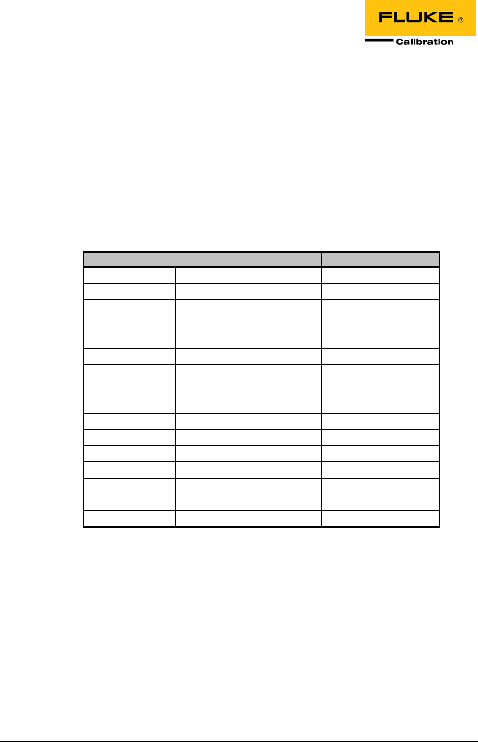
Page 195 © 2010 Fluke Calibration
7. Appendix
7.1 Conversion of Numerical Values
PG7000 performs all internal calculations in SI units. Numerical values input or output in other units are
converted to SI immediately after entry and back to other units just before output as needed.
The tables below provide the conversion coefficients used by PG7000 to convert numerical values
expressed in SI units to corresponding values expressed in other units.
7.1.1 Pressure
Table 30. Pressure Unit of Measure Conversions
TO CONVERT FROM PA TO MULTIPLY BY
Pa Pascal 1.0
mbar millibar 1.0 E-02
kPa kilo Pascal 1.0 E-03
bar Bar 1.0 E-05
mmWa @ 4°C millimeter of water 1.019716 E-01
mmHg @ 0°C millimeter of mercury 7.50063 E-03
psi pound per square inch 1.450377 E-04
psf pound per square foot 1.007206 E-06
inWa @ 4°C inch of water 4.014649 E-03
inWa @ 20°C inch of water 4.021732 E-03
inWa @ 60°F inch of water 4.018429 E-03
inHg @ 0°C inch of mercury 2.953 E-04
kcm2 kilogram force per centimeter square 1.019716 E-05
Torr Torr (mmHg @ 0°C) 7.50063 E-03
mTor milli Torr (micron Hg @ 0°C) 7.50063
user User User defined coefficient
7.2 Defined Pressure Calculations
Sections 7.2.1 and 7.2.2 document the calculations used by PG7000 piston gauges to obtain the defined
pressure.
Table 31 defines the pressure calculation variables used in Sections 7.2.1 and 7.2.2.

PG7000™ OPERATION AND MAINTENANCE MANUAL
© 2011 Fluke Calibration Page 196
Table 31. PG7000 Defined Pressure Calculation Variables
VARIABLE DEFINITION UNITS SOURCE OF VALUE
/πΑ
Pθ,
Piston radius at temperature θ and
pressure P
m Calculated.
A20,0 Piston effective area at 20°C, Patm mm
2
Piston-cylinder module file (3.11.1.3).
Aθ,P Piston effective area at temperature θ,
pressure P m
2
Calculated from A20,0 in piston-cylinder
module file (3.11.1.3).
G Local gravity m/s
2
Local, standard or user as specified in
current SETUP file (3.10).
KN
Nominal mass to pressure conversion
coefficient for a given piston-cylinder size Pa/kg Calculated from A20,0 and standard
conditions.
M Mass load kg Current mass loading instruction (3.6, 3.9.11).
PA Absolute pressure Paa Calculated.
Patm Atmospheric (ambient) pressure Paa Internal measurement, user entered value
or standard as specified by SETUP file (3.10).
PG Gauge pressure Pa Calculated.
PHA Fluid head correction in absolute mode Pa Calculated using device heights and
medium (7.2.3.2, 3.9.7, 3.11.3).
PHG Fluid head correction in gauge mode Pa Calculated using device heights and
medium (7.2.3.2, 3.9.7, 3.11.3).
PHD
Fluid head correction in high line
differential mode Pa Calculated using device heights and
medium (7.2.3.2, 3.9.7, 3.11.3).
PL Line Pressure Pa High line differential mode only (3.9.4.2).
Pnom Nominal pressure Pa In pressure to mass mode Pnom=Preq
In mass to pressure mode Pnom=M·KN
Poffset Difference between PG7601 and RPM at
the static pressure of differential mode Pa Determined experimentally in PG7601
differential mode operation (see Section
3.9.4.1, Selecting Differential Mode, Setting
Static Pressure, Finding RPM Offset).
PRPM
Current static pressure reading from
reference pressure monitor Paa Read automatically from external atm P
source specified by SETUP file. Used in
PG7601 differential mode only (3.10, 3.9.4.1).
∆PD Differential pressure Pa Calculated. PG7601 differential mode only
(3.9.4.1).
∆PHLD High line differential pressure Pa Calculated. High line differential mode only
(3.9.4.2).
∆Pnom Nominal differential pressure in high line
differential mode Pa In pressure to mass mode
∆
Pnom=
∆
Preq
In mass to pressure mode
∆Pnom=(MR - MRX)·KN.
Γ
Surface tension coefficient N/m Piston-cylinder module file (3.11.1.3).
αC Cylinder linear thermal expansion coefficient °C
-1
Piston-cylinder module file (3.11.1.3).
αP Piston linear thermal expansion coefficient °C
-1
Piston-cylinder module file (3.11.1.3).
λ
Piston-cylinder pressure coefficient Pa-1 Piston-cylinder module file (3.11.1.3).
θ
Temperature of piston-cylinder °C Internal measurement, user entered value
or standard as specified by SETUP file (3.10).
ρa Air density kg/m
3
Calculated from standard air density
corrected for actual atmospheric pressure,
ambient temperature and relative humidity
(atm p, humidity and temp source are
specified by SETUP file) (3.10).
ρm Mass density kg/m
3
Mass set file (3.11.1.8).
Subscripts specific to high line differential mode (see Section 3.9.4.2).
( )P+∆P
Line pressure + differential pressure
(reference piston-cylinder) -
( )R Reference -
( )RX Reference, at time of cross float -
( )T Tare -
( )TX Tare, at time of cross float -

7. APPENDIX
Page 197 © 2011 Fluke Calibration
7.2.1 PG7102, PG7202 and PG7302
PG7102, PG7202 and PG7302 perform mass to pressure and pressure to mass calculations
as follows:
• Gauge pressure:
ΗG
P,
,P
m
a
G
P
A
π
Α
πΓ
ρ
ρ
Mg
P+
+
−
=
θ
θ
21
( )( )
[ ]
( )
nomCP,P PAA
λααθ
θ
++−+⋅⋅= −120110 6
0,20
• Absolute pressure by addition of atmosphere reference:
atmHA
,P
,P
m
a
APP
A
π
A
πΓ
ρ
ρ
Mg
P++
+
−
=
θ
θ
21
( )( )
[ ]
( )
nomCP,Pθ
PλααθAA ++−+⋅⋅=
−
120110
6
0,20
• High line differential pressure:
( )
( )
( )
( )
( )
[ ]
ΗDTTXCPRRXCPL
PP
m
a
RXR
HLD
PααP
A
ρ
ρ
gMM
ΔP
TTRR
+−+−−++
−−
=
∆+
θθθθαα
θ
,
1
( )
( )
[ ]
( )
[ ]
nomLCPRP,Pθ
ΔPPλααθAA
RR
+++−+⋅⋅=
−
+
120110
6
0,20Δ
RX
ΗG
P,
,P
m
a
GL
P
A
π
Α
πΓ
ρ
ρ
Mg
PP
RX
+
+
−
==
θ
θ
21

PG7000™ OPERATION AND MAINTENANCE MANUAL
© 2011 Fluke Calibration Page 198
7.2.2 PG7601
PG7601 performs pressure to mass and mass to pressure calculations as follows:
• Gauge mode:
ΗG
P,
,P
m
a
G
P
A
π
Α
πΓ
ρ
ρ
Mg
P+
+
−
=
θ
θ
21
( )( )
[ ]
( )
nomCP,Pθ
PλααθAA ++−+⋅⋅=
−
120110
6
0,20
• Absolute pressure by adding atmospheric pressure:
atmHA
,P
,P
m
a
A
PP
A
π
A
πΓ
ρ
ρ
Mg
P++
+
−
=
θ
θ
21
( )( )
[ ]
( )
nomCP,Pθ
PλααθAA ++−+⋅⋅=
−
120110
6
0,20
• Absolute pressure with vacuum reference:
vacHA
,P
,P
APP
A
π
A
πΓMg
P++
+
=
θ
θ
2
( )( )
[ ]
( )
nomCP,Pθ
PλααθAA ++−+⋅⋅=
−
120110
6
0,20
• Differential pressure (differential mode):
offsetRPMvacHA
,P
,P
DPPPP
A
π
A
πΓMg
P−−++
+
=
θ
θ
∆
2
( )( )
[ ]
( )
nomCP,Pθ
PλααθAA ++−+⋅⋅=
−
120110
6
0,20

7. APPENDIX
Page 199 © 2011 Fluke Calibration
7.2.3 Fluid Heads
7.2.3.1 Fluid Head Components
PG7000 supports three different fluid head components (see
Sections 3.11.3, 3.9.7): DUT head, ATM head and Piston head. The three
components are combined to create the overall head correction for each PG7000
measurement mode (see Section 7.2.3.2).
DUT head: Calculates and applies a fluid head correction to predict the defined
pressure at a level other than the PG7000’s reference level (see Section 3.9.7).
The DUT head is calculated following:
( )
DafH
ghP
DUT
ρρ
−=
Where:
DUT
H
P
, DUT head [Pa] = fluid head correction applied to the defined pressure
calculated at the PG7000 reference level.
ρ
f, fluid density [kg/m3] = density of the pressurized medium (oil density = 916 kg/m3,
water density = 998.2321 kg/m3, gas densities are calculated
for N2, He or air dependent on current pressure and
temperature).
ρ
a, air density [kg/m3] = density of ambient air calculated using current ambient
pressure, temperature and relative humidity (values as
specified in the active SETUP file, see Section 3.10).
Assumed to be zero when operating in absolute with a
vacuum reference mode. Calculated using static pressure
density measured by RPM in PG7601 differential mode.
g, gravity [m/s2] = acceleration due to gravity (value as specified in the active
SETUP file, see Section 3.10).
hD, DUT height [m] = Height of DUT above PG7000 reference level. Value is
negative if below reference level.
ATM head: Calculates and applies a fluid head correction to internal or external
barometer readings to correct the atmospheric pressure value to the PG7000’s
reference level if the barometer is reading at a different level (see Section 3.11.3.3).
The ATM head is calculated following:
BasH ghρPatm =
Where:
atm
H
P
, ATM head [Pa] = fluid head correction applied to the internal or external
barometer reading.
ρ
as, air density [kg/m3] = standard air density of 1.2 kg/m3.
g, gravity [m/s2] = acceleration due to gravity (value as specified in the active
SETUP file, see Section 3.10).
hB, barometer height [m] = Height of the internal or external barometer above the
PG7000 reference level. Value is negative if below
reference level.

PG7000™ OPERATION AND MAINTENANCE MANUAL
© 2011 Fluke Calibration Page 200
PISTON head: Calculates and applies a fluid head correction to compensate for
the difference between the current piston position and the PG7000’s reference
level (see Section 3.11.3.4).
The DUT head is calculated following:
( )
PafH
ghρρP
P
−=
Where:
P
H
P
, Piston head [Pa] = fluid head correction applied to calculate defined pressure.
ρ
f, fluid density [kg/m3] = Density of test fluid at current pressure.
ρ
a, air density [kg/m3] = density of ambient air calculated using current ambient
pressure, temperature and relative humidity (values as
specified in the active SETUP file, see Section 3.10).
Assumed to be zero when operating in absolute with a
vacuum reference mode. Calculated using static pressure
density measured by RPM in PG7601 differential mode.
g, gravity [m/s2] = acceleration due to gravity (value as specified in the active
SETUP file, see Section 3.10).
hP, piston height [m] = Height of the current piston position above PG7000
reference level.
7.2.3.2 Overall Fluid Head Correction
The overall fluid head correction for each PG7000 mode results from combining
the three head components. In general, overall head correction is given by:
PatmDUT
HHHH
PPPP +−−=
Gauge mode:
( ) ( )
PafDafHG
ghghP
ρρρρ
−+−−=
Absolute mode by adding atmospheric pressure: Air density is zero for all
components except for the ATM head which is used to compensate for
barometer height.
PfBasDfHA ghghghP
ρρρ
+−−=
Absolute mode with vacuum reference: Air density is zero for all terms and no
barometer is used.
PfDfHA ghghP
ρρ
+−=
High line differential mode: Subtraction of tare head correction from reference
gives total differential head correction, assuming both tare and reference
PG7000 levels are at the same height. Note that (P+
∆
P) represents fluid
properties evaluated at line pressure plus differential pressure. Also note that the
barometer head corrections cancel out.
( ) ( )
ghhhgPPP TPRPPPPPTR
PfPfDffHGHGHD
ρρρρ
−+−−=−= ∆+∆+
Differential mode: Head correction is the same as for absolute mode with
vacuum reference. Head correction for the height of the RPM is unnecessary
through the use of the RPM offset.
PfDfHA ghghP
ρρ
+−=

7. APPENDIX
Page 201 © 2011 Fluke Calibration
7.3 Glossary
Absolute As in absolute pressure. Pressure expressed relative to vacuum.
Absolute by vacuum,
avac Absolute pressure determined by defining pressure relative to vacuum in an evacuated bell jar
(PG7601 only).
Absolute by
atmosphere, aatm Absolute pressure determined by adding atmospheric pressure to gauge pressure.
Adder A value added to internal sensor readings to offset the readings (pressure adder, temperature
adder, humidity adder, vacuum adder) for calibration adjustment.
Ae Piston-cylinder effective area.
AMH Optional automated mass handling system.
ATM Head Pressure head correction to the barometer measurement to take into consideration the
difference between the actual barometer level and the PG7000 reference level.
Crossfloat Process of comparison of two piston cylinders in which they are connected together under
pressure and the mass of one is adjusted so that both pistons float together at a common
pressure. Used to set the line pressure in high line differential measurement mode.
Differential As in differential pressure. Pressure expressed relative to atmospheric or another static
pressure determined by subtracting the static pressure from absolute by vacuum (differential
measurement mode).
DUT (Device Under
Test) The device being tested or calibrated.
DUT Head Fluid head correction to the pressure defined by PG7000 to predict the pressure at the level of
the DUT, which may be different from the PG7000 reference level.
FS (Full Scale) The full scale value is the maximum value or the span of a measurement range. Limits and
specifications are often expressed as % FS.
g, gl Acceleration due to gravity (g). Acceleration due to gravity at location of use (gl).
Gauge As in gauge pressure. Pressure expressed relative to atmospheric pressure.
He Helium gas.
Head Fluid head, a pressure difference due to a difference in height. See also ATM head, DUT head
and PISTON head.
High Line Differential As in high line differential pressure measurement mode. Pressure expressed relative to a line
pressure greater than atmospheric pressure. Defined by using two piston gauges.
HSTOP, LSTOP High stop and low stop, piston maximum end of stroke positions.
InHg Pressure unit of measure, inches of mercury.
InWa Pressure unit of measure, inches of water.
kcm2 Pressure unit of measure, kilogram per centimeter square.
Line Pressure Pressure on the low side in high line differential pressure measurement mode. Pressure relative to
which the differential pressure is defined.
Measurement Mode Mode in which PG7000 is defining pressures. These include gauge (pressure relative to
atmospheric pressure), absolute by atmosphere (pressure relative to vacuum determined by
adding atmospheric pressure to gauge pressure), absolute by vacuum (PG7601 only) (pressure
relative to absolute vacuum determined by establishing a vacuum around the mass load),
differential (PG7601 only) (pressure relative to atmospheric or another static pressure
determined by subtracting the static pressure from absolute by vacuum).
MS (Mass Set) A group of masses composed for use with a PG7000 piston gauge.
Mass Bell The sleeve loaded onto the piston to carry other masses.
Mass Entry Mode
(mass to pressure) Operating mode in which the user enters the mass loaded on the piston and the PG7000
calculates the defined pressure. See also Pressure Entry Mode.
Medium, pressurized The pressurized fluid.
Multiplier A value by which internal sensor readings are multiplied to change their slope (pressure multiplier,
temperature multiplier, humidity multiplier, vacuum multiplier) for calibration adjustment.

PG7000™ OPERATION AND MAINTENANCE MANUAL
© 2011 Fluke Calibration Page 202
N2 Nitrogen gas.
Nominal Mass The mass loaded on the piston in terms of the nominal values written on the individual masses.
See also True Mass.
Normal A conventional or standard value.
PC Piston-cylinder, piston-cylinder module.
Pressure Entry Mode
(pressure to mass) Operating mode in which the user enters the pressure to be defined and PG7000 calculates the
mass to load. See also Mass entry mode.
PISTON head Fluid head correction based on the difference between the piston’s current position and the
reference level.
PRT Platinum Resistance Thermometer. The element used in the piston-cylinder mounting post to
measure temperature.
Ready/Not Ready Indication of when conditions are present to make in tolerance pressure definitions based on
specific criteria for each condition.
Reference Level Height at which pressures are defined. PG7000 defines pressures at its reference level. Fluid head
corrections correct the pressure relative to the reference level.
Reference PG7000 The PG7000 used on the reference side (high side) in high line differential pressure mode (see also
Tare PG7000).
SETUP file File specifying the source of values for the variables used by PG7000 to calculate defined pressure.
Static Pressure Pressure on the low side in PG7601 differential mode.
Tare PG7000 The PG7000 on used on the tare side (low side) in high line differential pressure mode (see also
Reference PG7000).
True Mass The actual mass loaded on the piston using the measured value of each mass. See also
Nominal Mass.
User Level Level of security that can be set to limit access to certain PG7000 functions

7. APPENDIX
Page 203 © 2011 Fluke Calibration
7.4 Limited Warranty and Limitation of Liability
Each Fluke product is warranted to be free from defects in material and workmanship under normal use and service.
The warranty period is one year and begins on the date of shipment. Parts, product repairs and services are
warranted for 90 days. This warranty extends only to the original buyer or end-user customer of a Fluke authorized
reseller, and does not apply to fuses, disposable batteries or to any product which, in Fluke's opinion, has been
misused, altered, neglected, contaminated, or damaged by accident or abnormal conditions of operation or handling.
Fluke warrants that software will operate substantially in accordance with its functional specifications for 90 days and
that it has been properly recorded on non-defective media. Fluke does not warrant that software will be error free or
operate without interruption.
Fluke authorized resellers shall extend this warranty on new and unused products to end-user customers only but
have no authority to extend a greater or different warranty on behalf of Fluke. Warranty support is available only if
product is purchased through a Fluke authorized sales outlet or Buyer has paid the applicable international price.
Fluke reserves the right to invoice Buyer for importation costs of repair/replacement parts when product purchased in
one country is submitted for repair in another country.
Fluke's warranty obligation is limited, at Fluke's option, to refund of the purchase price, free of charge repair, or
replacement of a defective product which is returned to a Fluke authorized service center within the warranty period.
To obtain warranty service, contact your nearest Fluke authorized service center to obtain return authorization
information, then send the product to that service center, with a description of the difficulty, postage and insurance
prepaid (FOB Destination). Fluke assumes no risk for damage in transit. Following warranty repair, the product will
be returned to Buyer, transportation prepaid (FOB Destination). If Fluke determines that failure was caused by
neglect, misuse, contamination, alteration, accident or abnormal condition of operation or handling, including
overvoltage failures caused by use outside the product’s specified rating, or normal wear and tear of mechanical
components, Fluke will provide an estimate of repair costs and obtain authorization before commencing the work.
Following repair, the product will be returned to the Buyer transportation prepaid and the Buyer will be billed for the
repair and return transportation charges (FOB Shipping Point).
THIS WARRANTY IS BUYER'S SOLE AND EXCLUSIVE REMEDY AND IS IN LIEU OF ALL OTHER WARRANTIES,
EXPRESS OR IMPLIED, INCLUDING BUT NOT LIMITED TO ANY IMPLIED WARRANTY OF MERCHANTABILITY
OR FITNESS FOR A PARTICULAR PURPOSE. FLUKE SHALL NOT BE LIABLE FOR ANY SPECIAL, INDIRECT,
INCIDENTAL OR CONSEQUENTIAL DAMAGES OR LOSSES, INCLUDING LOSS OF DATA, ARISING FROM ANY
CAUSE OR THEORY.
Since some countries or states do not allow limitation of the term of an implied warranty, or exclusion or limitation of
incidental or consequential damages, the limitations and exclusions of this warranty may not apply to every buyer. If
any provision of this Warranty is held invalid or unenforceable by a court or other decision-maker of competent
jurisdiction, such holding will not affect the validity or enforceability of any other provision.
Fluke Corporation Fluke Europe B.V.
P.O. Box 9090 P.O. Box 1186
Everett, WA 98206-9090 5602 BD Eindhoven
U.S.A. The Netherlands
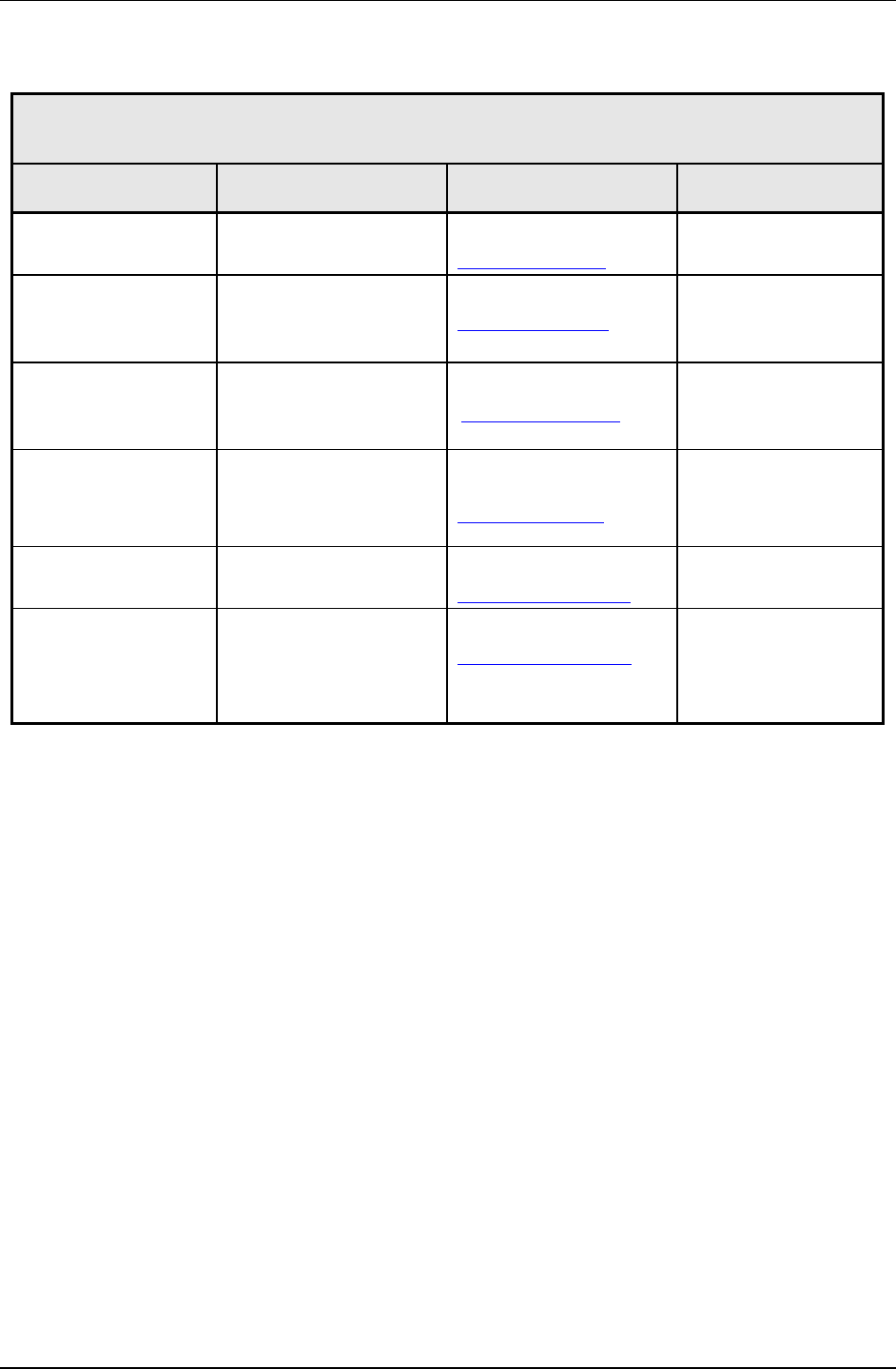
PG7000™ OPERATION AND MAINTENANCE MANUAL
© 2011 Fluke Calibration Page 204
Table 32. Fluke Calibration Authorized Service Providers
FLUKE CALIBRATION
AUTHORIZED SERVICE PROVIDERS – PRESSURE AND FLOW CALIBRATION PRODUCTS
COMPANY
ADDRESS TELEPHONE,
FAX & EMAIL NORMAL SUPPORT
REGION
Fluke Calibration
4765 East Beautiful Lane
Phoenix AZ 85044-5318
USA
Tel: 602.431.9100
Fax: 602.431.9559
dhiservice@fluke.com
Worldwide
Minerva Meettechniek B.V. Chrysantstraat 1
3812 WX Amersfoort
The Netherlands
Tel: 31 33 46 22 000
Fax: 31 33 46 22 218
info@minervaipm.com
European Union
europascal GmbH An der Wiesenhecke 10
D-63456 Hanau
Germany
Tel: +49 61 81 42 309 0
Fax: +49 61 81 42 309 22
service@europascal.de
European Union
Ohte Giken Inc
Technology Center 258-1, Nakadai
Kasumigaura-machi,
Niihari-Gun,
Ibaraki 300-0133
Japan
Tel: 81/29.840.9111
Fax: 81/29.840.9100
tech@ohtegiken.co.jp
Japan/Asia
Fluke Beijing Service
Center Rm. 401, SCITEC Tower,
N0. 22, Jianguomenwai Dajie,
Beijing 100004, PRC
Hot Line: 400.810.3435-3
Fax:(8610) 65286307
serviceinfo@fluke.com.cn
Peoples Republic of China
Fluke South East Asia
PTE LTD. Fluke ASEAN Regional Office
Service Center
60 Alexandra Terrace #03-16
The Comtech (Lobby D)
118502
Singapore
Tel: (65) 6799-5588
Fax: (65) 6799-5589
service.asean@fluke.com
South East Asia
