Front End Signal Conditioners Owner's Guide Owners
User Manual: Front-end Signal Conditioners Owner's Guide Manuals | ADInstruments
Open the PDF directly: View PDF ![]() .
.
Page Count: 223 [warning: Documents this large are best viewed by clicking the View PDF Link!]
- Safety Notes
- Overview
- Animal Bio Amp
- Bio Amp
- BP Amp
- Bridge Amp
- Dual Bio Amp/Stimulator
- GSR Amp
- Neuro Amp EX
- pH Amp
- Spirometer
- Stimulator HC
- Stimulus Isolator
- Warranty

Owner’s Guide
FRONT-END
SIGNAL CONDITIONERS

This document was, as far as possible, accurate at the time of release. However, changes may have been
made to the soware and hardware it describes since then. ADInstruments Pty Ltd reserves the right to
alter specifications as required. Late-breaking information may be supplied separately.
Trademarks of ADInstruments
PowerLab®, LabChart®, LabTutor®, LabAuthor® and MacLab® are registered trademarks of ADInstruments
Pty Ltd. The names of specific recording units, such as PowerLab 8/35, are trademarks of ADInstruments
Pty Ltd. LabTutor Server, Chart and Scope (application programs) and LabTutor Online are trademarks of
ADInstruments Pty Ltd.
Other Trademarks
Apple, Mac and Macintosh are registered trademarks of Apple Computer, Inc.
Windows, Windows 7, Windows 8, Windows 10 and Windows Vista are either registered trademarks or
trademarks of Microso Corporation.
All other trademarks are the property of their respective owners.
Document Number: U-FE/OG-35E. Date of issue: 01/17
Copyright © ADInstruments Pty Ltd, 2000 - 2014. All rights reserved. PowerLab, MacLab, LabChart,
LabTutor and LabAuthor are registered trademarks of ADInstruments Pty Ltd. Chart and Scope (application
programs), LabTutor Server and LabTutor Online are trademarks of ADInstruments Pty Ltd. The names of
specific recording units, such as PowerLab 16/35, are trademarks of ADInstruments Pty Ltd. Windows 8,
Windows 7, Windows 10, Windows Vista and .NET Framework are trademarks of Microso Corporation.
Apple, the Apple logo, MacOS, and Macintosh are trademarks of Apple Computer Inc. registered in the
U.S. and other countries. Acrobat and Adobe are registered trademarks of Adobe Systems Incorporated.
Igor is a trademark of Wavemetrics Inc. MATLAB is a registered trademark of The MathWorks Inc. Grass is a
trademark of Astro-Med Inc. All other trademarks are the property of their respective owners.
Web: www.adinstruments.com
Manufactured in Australia by: ADInstruments (Sydney) Pty. Ltd., 13/22 Lexington Drive
Bella Vista 2153 New South Wales
Technical Support: support.au@adinstruments.com
Documentation: documentation@adinstruments.com
ADInstruments Pty Ltd. ISO 9001:2008 Certified Quality Management System
Reg. No. 1053
FRONT-END SIGNAL CONDITIONERS - Owner’s Guide
ii

FRONT-END SIGNAL CONDITIONERS - Owner’s Guide
iii
1 Safety Notes 1
Statement of Intended Use . . . . . . . . . . . . . . . . . . . . . . . . . . . . . . . . . . . . . . . . . . . . . . . . .1
Safety and Quality Standards . . . . . . . . . . . . . . . . . . . . . . . . . . . . . . . . . . . . . . . . . . . . . . .1
General Safety Instructions . . . . . . . . . . . . . . . . . . . . . . . . . . . . . . . . . . . . . . . . . . . . . . . . .3
Bio Amp Safety Instructions . . . . . . . . . . . . . . . . . . . . . . . . . . . . . . . . . . . . . . . . . . . . . .4
Stimulus Isolator Safety Instructions . . . . . . . . . . . . . . . . . . . . . . . . . . . . . . . . . . . . . .5
Earthing and Ground Loop Noise . . . . . . . . . . . . . . . . . . . . . . . . . . . . . . . . . . . . . . . . .6
Cleaning and Sterilization . . . . . . . . . . . . . . . . . . . . . . . . . . . . . . . . . . . . . . . . . . . . . . . . . . .6
Inspection and Maintenance . . . . . . . . . . . . . . . . . . . . . . . . . . . . . . . . . . . . . . . . . . . . . . . .6
Environment . . . . . . . . . . . . . . . . . . . . . . . . . . . . . . . . . . . . . . . . . . . . . . . . . . . . . . . . . . . . . .7
Storage Conditions . . . . . . . . . . . . . . . . . . . . . . . . . . . . . . . . . . . . . . . . . . . . . . . . . . . . . .7
Operating Conditions . . . . . . . . . . . . . . . . . . . . . . . . . . . . . . . . . . . . . . . . . . . . . . . . . . . .7
Disposal . . . . . . . . . . . . . . . . . . . . . . . . . . . . . . . . . . . . . . . . . . . . . . . . . . . . . . . . . . . . . . . .7
2 Overview 8
Introduction . . . . . . . . . . . . . . . . . . . . . . . . . . . . . . . . . . . . . . . . . . . . . . . . . . . . . . . . . . . . . . .9
Checking the Front-end . . . . . . . . . . . . . . . . . . . . . . . . . . . . . . . . . . . . . . . . . . . . . . . . . . . . .9
Connecting to the PowerLab . . . . . . . . . . . . . . . . . . . . . . . . . . . . . . . . . . . . . . . . . . . . . . .10
Single Front-ends . . . . . . . . . . . . . . . . . . . . . . . . . . . . . . . . . . . . . . . . . . . . . . . . . . . . . .10
Multiple Front-ends . . . . . . . . . . . . . . . . . . . . . . . . . . . . . . . . . . . . . . . . . . . . . . . . . . . . 11
Special Cases . . . . . . . . . . . . . . . . . . . . . . . . . . . . . . . . . . . . . . . . . . . . . . . . . . . . . . . . . 11
Connecting Stimulator Front-Ends . . . . . . . . . . . . . . . . . . . . . . . . . . . . . . . . . . . . 11
Maximum Number of Front-Ends . . . . . . . . . . . . . . . . . . . . . . . . . . . . . . . . . . . . . 12
Using ADInstruments Programs . . . . . . . . . . . . . . . . . . . . . . . . . . . . . . . . . . . . . . . . . . . 12
Front-end Drivers . . . . . . . . . . . . . . . . . . . . . . . . . . . . . . . . . . . . . . . . . . . . . . . . . . . . . 12
The Front-end Self-test . . . . . . . . . . . . . . . . . . . . . . . . . . . . . . . . . . . . . . . . . . . . . . . . 13
Soware Behavior . . . . . . . . . . . . . . . . . . . . . . . . . . . . . . . . . . . . . . . . . . . . . . . . . . . . . 13
Preventing Problems . . . . . . . . . . . . . . . . . . . . . . . . . . . . . . . . . . . . . . . . . . . . . . . . . . . . . .14
Aliasing . . . . . . . . . . . . . . . . . . . . . . . . . . . . . . . . . . . . . . . . . . . . . . . . . . . . . . . . . . . . . . .14
Frequency Distortion . . . . . . . . . . . . . . . . . . . . . . . . . . . . . . . . . . . . . . . . . . . . . . . . . . .14
Saturation . . . . . . . . . . . . . . . . . . . . . . . . . . . . . . . . . . . . . . . . . . . . . . . . . . . . . . . . . . . . 15
Ground Loops . . . . . . . . . . . . . . . . . . . . . . . . . . . . . . . . . . . . . . . . . . . . . . . . . . . . . . . . . 15
Mains filter . . . . . . . . . . . . . . . . . . . . . . . . . . . . . . . . . . . . . . . . . . . . . . . . . . . . . . . . . .16
Notch Filter . . . . . . . . . . . . . . . . . . . . . . . . . . . . . . . . . . . . . . . . . . . . . . . . . . . . . . . . .16
Contents

FRONT-END SIGNAL CONDITIONERS - Owner’s Guide
iv
Electrode Contact . . . . . . . . . . . . . . . . . . . . . . . . . . . . . . . . . . . . . . . . . . . . . . . . . . . . . .16
Motion Artifacts . . . . . . . . . . . . . . . . . . . . . . . . . . . . . . . . . . . . . . . . . . . . . . . . . . . . . . . .17
3 Animal Bio Amp 18
The Animal Bio Amp . . . . . . . . . . . . . . . . . . . . . . . . . . . . . . . . . . . . . . . . . . . . . . . . . . . . . . 19
The Front Panel . . . . . . . . . . . . . . . . . . . . . . . . . . . . . . . . . . . . . . . . . . . . . . . . . . . . . . . 19
The Back Panel . . . . . . . . . . . . . . . . . . . . . . . . . . . . . . . . . . . . . . . . . . . . . . . . . . . . . . . 19
Connecting to the PowerLab . . . . . . . . . . . . . . . . . . . . . . . . . . . . . . . . . . . . . . . . . . . . . . 20
Using LabChart and Scope . . . . . . . . . . . . . . . . . . . . . . . . . . . . . . . . . . . . . . . . . . . . . . . . 21
The Bio Amp dialog . . . . . . . . . . . . . . . . . . . . . . . . . . . . . . . . . . . . . . . . . . . . . . . . . . . . 22
Using the Animal Bio Amp . . . . . . . . . . . . . . . . . . . . . . . . . . . . . . . . . . . . . . . . . . . . . . . . 25
Some Suitable Uses . . . . . . . . . . . . . . . . . . . . . . . . . . . . . . . . . . . . . . . . . . . . . . . . . . . 25
Some Unsuitable Uses . . . . . . . . . . . . . . . . . . . . . . . . . . . . . . . . . . . . . . . . . . . . . . . . . 25
The Animal Bio Amp Input . . . . . . . . . . . . . . . . . . . . . . . . . . . . . . . . . . . . . . . . . . . . . . 26
Technical Aspects . . . . . . . . . . . . . . . . . . . . . . . . . . . . . . . . . . . . . . . . . . . . . . . . . . . . . . . . .27
Troubleshooting . . . . . . . . . . . . . . . . . . . . . . . . . . . . . . . . . . . . . . . . . . . . . . . . . . . . . . . . . 29
Specifications . . . . . . . . . . . . . . . . . . . . . . . . . . . . . . . . . . . . . . . . . . . . . . . . . . . . . . . . . . . 32
4 Bio Amp 34
Bio Amp Safety Instructions . . . . . . . . . . . . . . . . . . . . . . . . . . . . . . . . . . . . . . . . . . . . . . . 34
The Bio Amp front-ends . . . . . . . . . . . . . . . . . . . . . . . . . . . . . . . . . . . . . . . . . . . . . . . . . . 35
The Back Panel . . . . . . . . . . . . . . . . . . . . . . . . . . . . . . . . . . . . . . . . . . . . . . . . . . . . . . . 36
Connecting to the PowerLab . . . . . . . . . . . . . . . . . . . . . . . . . . . . . . . . . . . . . . . . . . . . . . 38
Using More Than One Bio Amp . . . . . . . . . . . . . . . . . . . . . . . . . . . . . . . . . . . . . . . . . . 38
The Bio Amp Cable . . . . . . . . . . . . . . . . . . . . . . . . . . . . . . . . . . . . . . . . . . . . . . . . . . . . 39
Using LabChart . . . . . . . . . . . . . . . . . . . . . . . . . . . . . . . . . . . . . . . . . . . . . . . . . . . . . . . . . . .41
The Bio Amp dialog . . . . . . . . . . . . . . . . . . . . . . . . . . . . . . . . . . . . . . . . . . . . . . . . . . . . .41
Using the Bio Amp . . . . . . . . . . . . . . . . . . . . . . . . . . . . . . . . . . . . . . . . . . . . . . . . . . . . . . . 44
Some Suitable Uses . . . . . . . . . . . . . . . . . . . . . . . . . . . . . . . . . . . . . . . . . . . . . . . . . . . 44
Some Unsuitable Uses . . . . . . . . . . . . . . . . . . . . . . . . . . . . . . . . . . . . . . . . . . . . . . . . . 45
Recording Technique . . . . . . . . . . . . . . . . . . . . . . . . . . . . . . . . . . . . . . . . . . . . . . . . . . 45
Right-leg Drive . . . . . . . . . . . . . . . . . . . . . . . . . . . . . . . . . . . . . . . . . . . . . . . . . . . . . 46
Troubleshooting . . . . . . . . . . . . . . . . . . . . . . . . . . . . . . . . . . . . . . . . . . . . . . . . . . . . . . . . . .47
Specifications . . . . . . . . . . . . . . . . . . . . . . . . . . . . . . . . . . . . . . . . . . . . . . . . . . . . . . . . . . . 50
Single Bio Amp . . . . . . . . . . . . . . . . . . . . . . . . . . . . . . . . . . . . . . . . . . . . . . . . . . . . . . . . 50
Dual Bio Amp . . . . . . . . . . . . . . . . . . . . . . . . . . . . . . . . . . . . . . . . . . . . . . . . . . . . . . . . . 52
Quad/Octal Bio Amp . . . . . . . . . . . . . . . . . . . . . . . . . . . . . . . . . . . . . . . . . . . . . . . . . . . 54
Electromagnetic Compatibility . . . . . . . . . . . . . . . . . . . . . . . . . . . . . . . . . . . . . . . 57
5 BP Amp 58
The BP Amp . . . . . . . . . . . . . . . . . . . . . . . . . . . . . . . . . . . . . . . . . . . . . . . . . . . . . . . . . . . . . 59
The Front Panel . . . . . . . . . . . . . . . . . . . . . . . . . . . . . . . . . . . . . . . . . . . . . . . . . . . . . . . 59
The Back Panel . . . . . . . . . . . . . . . . . . . . . . . . . . . . . . . . . . . . . . . . . . . . . . . . . . . . . . . 60
Connecting to the PowerLab . . . . . . . . . . . . . . . . . . . . . . . . . . . . . . . . . . . . . . . . . . . . . . 60
Equipment and Technique . . . . . . . . . . . . . . . . . . . . . . . . . . . . . . . . . . . . . . . . . . . . . . . . 62
The Disposable BP Transducer . . . . . . . . . . . . . . . . . . . . . . . . . . . . . . . . . . . . . . . . . . 62

FRONT-END SIGNAL CONDITIONERS - Owner’s Guide
v
Using LabChart and Scope . . . . . . . . . . . . . . . . . . . . . . . . . . . . . . . . . . . . . . . . . . . . . . . . 64
The BP Amp dialog . . . . . . . . . . . . . . . . . . . . . . . . . . . . . . . . . . . . . . . . . . . . . . . . . . . . 64
Technical Aspects . . . . . . . . . . . . . . . . . . . . . . . . . . . . . . . . . . . . . . . . . . . . . . . . . . . . . . . . 67
Troubleshooting . . . . . . . . . . . . . . . . . . . . . . . . . . . . . . . . . . . . . . . . . . . . . . . . . . . . . . . . . 68
Specifications . . . . . . . . . . . . . . . . . . . . . . . . . . . . . . . . . . . . . . . . . . . . . . . . . . . . . . . . . . . .70
6 Bridge Amp 72
The Bridge Amp . . . . . . . . . . . . . . . . . . . . . . . . . . . . . . . . . . . . . . . . . . . . . . . . . . . . . . . . . 73
The Front Panel . . . . . . . . . . . . . . . . . . . . . . . . . . . . . . . . . . . . . . . . . . . . . . . . . . . . . . . 73
The Back Panel . . . . . . . . . . . . . . . . . . . . . . . . . . . . . . . . . . . . . . . . . . . . . . . . . . . . . . . .74
Setting Up . . . . . . . . . . . . . . . . . . . . . . . . . . . . . . . . . . . . . . . . . . . . . . . . . . . . . . . . . . . . . . .76
Connecting to the PowerLab . . . . . . . . . . . . . . . . . . . . . . . . . . . . . . . . . . . . . . . . . . . . . . .76
Using LabChart and Scope . . . . . . . . . . . . . . . . . . . . . . . . . . . . . . . . . . . . . . . . . . . . . . . . 77
The Bridge Amp dialog . . . . . . . . . . . . . . . . . . . . . . . . . . . . . . . . . . . . . . . . . . . . . . . . . 78
Using Transducers . . . . . . . . . . . . . . . . . . . . . . . . . . . . . . . . . . . . . . . . . . . . . . . . . . . . . . . 82
Compatibility . . . . . . . . . . . . . . . . . . . . . . . . . . . . . . . . . . . . . . . . . . . . . . . . . . . . . . . . . 82
Suitable Transducers . . . . . . . . . . . . . . . . . . . . . . . . . . . . . . . . . . . . . . . . . . . . . . . . . . 83
Unsuitable Transducers . . . . . . . . . . . . . . . . . . . . . . . . . . . . . . . . . . . . . . . . . . . . . . . . 83
How Transducers Work . . . . . . . . . . . . . . . . . . . . . . . . . . . . . . . . . . . . . . . . . . . . . . . . 83
Checking the Transducer . . . . . . . . . . . . . . . . . . . . . . . . . . . . . . . . . . . . . . . . . . . . . . . 84
Using Grass Transducers with Bridge Amps . . . . . . . . . . . . . . . . . . . . . . . . . . . . 85
Adapting Transducers . . . . . . . . . . . . . . . . . . . . . . . . . . . . . . . . . . . . . . . . . . . . . . . . . . . . 85
Introduction . . . . . . . . . . . . . . . . . . . . . . . . . . . . . . . . . . . . . . . . . . . . . . . . . . . . . . . . . . 85
Setting the Excitation Voltage . . . . . . . . . . . . . . . . . . . . . . . . . . . . . . . . . . . . . . . . . . 86
Wiring Up the Transducer . . . . . . . . . . . . . . . . . . . . . . . . . . . . . . . . . . . . . . . . . . . . . . 87
Technical Aspects . . . . . . . . . . . . . . . . . . . . . . . . . . . . . . . . . . . . . . . . . . . . . . . . . . . . . . . . 89
Troubleshooting . . . . . . . . . . . . . . . . . . . . . . . . . . . . . . . . . . . . . . . . . . . . . . . . . . . . . . . . . 90
Specifications . . . . . . . . . . . . . . . . . . . . . . . . . . . . . . . . . . . . . . . . . . . . . . . . . . . . . . . . . . . 93
7 Dual Bio Amp/Stimulator 95
The Dual Bio Amp/Stimulator . . . . . . . . . . . . . . . . . . . . . . . . . . . . . . . . . . . . . . . . . . . . . 96
The Front Panel . . . . . . . . . . . . . . . . . . . . . . . . . . . . . . . . . . . . . . . . . . . . . . . . . . . . . . . 96
The Back Panel . . . . . . . . . . . . . . . . . . . . . . . . . . . . . . . . . . . . . . . . . . . . . . . . . . . . . . . 98
Connecting to the PowerLab . . . . . . . . . . . . . . . . . . . . . . . . . . . . . . . . . . . . . . . . . . . . . . 99
Using LabChart and Scope . . . . . . . . . . . . . . . . . . . . . . . . . . . . . . . . . . . . . . . . . . . . . . . 101
The Bio Amp dialog . . . . . . . . . . . . . . . . . . . . . . . . . . . . . . . . . . . . . . . . . . . . . . . . . . . 102
The Stimulator . . . . . . . . . . . . . . . . . . . . . . . . . . . . . . . . . . . . . . . . . . . . . . . . . . . . . . . . . 105
Using the Dual Bio Amp/Stimulator . . . . . . . . . . . . . . . . . . . . . . . . . . . . . . . . . . . . . . . 109
Some Suitable Uses . . . . . . . . . . . . . . . . . . . . . . . . . . . . . . . . . . . . . . . . . . . . . . . . . . 109
Some Unsuitable Uses . . . . . . . . . . . . . . . . . . . . . . . . . . . . . . . . . . . . . . . . . . . . . . . . 110
Recording Technique . . . . . . . . . . . . . . . . . . . . . . . . . . . . . . . . . . . . . . . . . . . . . . . . . 110
Technical Aspects . . . . . . . . . . . . . . . . . . . . . . . . . . . . . . . . . . . . . . . . . . . . . . . . . . . . . . . 111
Troubleshooting . . . . . . . . . . . . . . . . . . . . . . . . . . . . . . . . . . . . . . . . . . . . . . . . . . . . . . . . 114
Specifications . . . . . . . . . . . . . . . . . . . . . . . . . . . . . . . . . . . . . . . . . . . . . . . . . . . . . . . . . . .117

FRONT-END SIGNAL CONDITIONERS - Owner’s Guide
vi
8 GSR Amp 120
The GSR Amp . . . . . . . . . . . . . . . . . . . . . . . . . . . . . . . . . . . . . . . . . . . . . . . . . . . . . . . . . . . 121
The Front Panel . . . . . . . . . . . . . . . . . . . . . . . . . . . . . . . . . . . . . . . . . . . . . . . . . . . . . . 121
The Back Panel . . . . . . . . . . . . . . . . . . . . . . . . . . . . . . . . . . . . . . . . . . . . . . . . . . . . . . 122
Connecting to the PowerLab . . . . . . . . . . . . . . . . . . . . . . . . . . . . . . . . . . . . . . . . . . . . . 122
Using LabChart and Scope . . . . . . . . . . . . . . . . . . . . . . . . . . . . . . . . . . . . . . . . . . . . . . . 123
The GSR Amp dialog . . . . . . . . . . . . . . . . . . . . . . . . . . . . . . . . . . . . . . . . . . . . . . . . . . 124
Equipment and Technique . . . . . . . . . . . . . . . . . . . . . . . . . . . . . . . . . . . . . . . . . . . . . . . 126
Technical Aspects . . . . . . . . . . . . . . . . . . . . . . . . . . . . . . . . . . . . . . . . . . . . . . . . . . . . . . . 128
Troubleshooting . . . . . . . . . . . . . . . . . . . . . . . . . . . . . . . . . . . . . . . . . . . . . . . . . . . . . . . . 129
Specifications . . . . . . . . . . . . . . . . . . . . . . . . . . . . . . . . . . . . . . . . . . . . . . . . . . . . . . . . . . 131
9 Neuro Amp EX 133
The Neuro Amp . . . . . . . . . . . . . . . . . . . . . . . . . . . . . . . . . . . . . . . . . . . . . . . . . . . . . . . . . 134
The Front Panel . . . . . . . . . . . . . . . . . . . . . . . . . . . . . . . . . . . . . . . . . . . . . . . . . . . . . . 134
The Back Panel . . . . . . . . . . . . . . . . . . . . . . . . . . . . . . . . . . . . . . . . . . . . . . . . . . . . . . 135
Connecting to the PowerLab . . . . . . . . . . . . . . . . . . . . . . . . . . . . . . . . . . . . . . . . . . . . . 136
Single Front-end . . . . . . . . . . . . . . . . . . . . . . . . . . . . . . . . . . . . . . . . . . . . . . . . . . . . . 136
Multiple Front-ends . . . . . . . . . . . . . . . . . . . . . . . . . . . . . . . . . . . . . . . . . . . . . . . . . . . 136
Using More Than One Neuro Amp EX . . . . . . . . . . . . . . . . . . . . . . . . . . . . . . . . . 137
Soware Requirements . . . . . . . . . . . . . . . . . . . . . . . . . . . . . . . . . . . . . . . . . . . . 137
Using LabChart and Scope . . . . . . . . . . . . . . . . . . . . . . . . . . . . . . . . . . . . . . . . . . . . . . . 138
Neuro Amp EX dialog . . . . . . . . . . . . . . . . . . . . . . . . . . . . . . . . . . . . . . . . . . . . . . . . . 138
Types of Measurement . . . . . . . . . . . . . . . . . . . . . . . . . . . . . . . . . . . . . . . . . . . . . . . . . . .141
The Neuro Amp EX Headstage . . . . . . . . . . . . . . . . . . . . . . . . . . . . . . . . . . . . . . . . . .141
Recording Technique . . . . . . . . . . . . . . . . . . . . . . . . . . . . . . . . . . . . . . . . . . . . . . . . . 142
Setting up to Record From a Subject . . . . . . . . . . . . . . . . . . . . . . . . . . . . . . . . . . . 142
Motion Eects . . . . . . . . . . . . . . . . . . . . . . . . . . . . . . . . . . . . . . . . . . . . . . . . . . . 144
Electrode Contact . . . . . . . . . . . . . . . . . . . . . . . . . . . . . . . . . . . . . . . . . . . . . . . . . 144
Technical Aspects . . . . . . . . . . . . . . . . . . . . . . . . . . . . . . . . . . . . . . . . . . . . . . . . . . . . . . . 145
The Neuro Amp EX Input . . . . . . . . . . . . . . . . . . . . . . . . . . . . . . . . . . . . . . . . . . . . . . 147
Troubleshooting . . . . . . . . . . . . . . . . . . . . . . . . . . . . . . . . . . . . . . . . . . . . . . . . . . . . . . . . 148
Specifications . . . . . . . . . . . . . . . . . . . . . . . . . . . . . . . . . . . . . . . . . . . . . . . . . . . . . . . . . . 150
Neuro Amp EX Front-end [FE185] . . . . . . . . . . . . . . . . . . . . . . . . . . . . . . . . . . . . . . . 150
Neuro Amp EX Headstage [MLT185] . . . . . . . . . . . . . . . . . . . . . . . . . . . . . . . . . . . . 151
Electromagnetic Compatibility . . . . . . . . . . . . . . . . . . . . . . . . . . . . . . . . . . . . . . . . 152
10 pH Amp 153
The pH Amp . . . . . . . . . . . . . . . . . . . . . . . . . . . . . . . . . . . . . . . . . . . . . . . . . . . . . . . . . . . . 154
The Front Panel . . . . . . . . . . . . . . . . . . . . . . . . . . . . . . . . . . . . . . . . . . . . . . . . . . . . . . 154
The Back Panel . . . . . . . . . . . . . . . . . . . . . . . . . . . . . . . . . . . . . . . . . . . . . . . . . . . . . . 155
Connecting to the PowerLab . . . . . . . . . . . . . . . . . . . . . . . . . . . . . . . . . . . . . . . . . . . . . 155
Single Front-end . . . . . . . . . . . . . . . . . . . . . . . . . . . . . . . . . . . . . . . . . . . . . . . . . . . . . 156
Multiple Front-ends . . . . . . . . . . . . . . . . . . . . . . . . . . . . . . . . . . . . . . . . . . . . . . . . . . . 156
Using LabChart and Scope . . . . . . . . . . . . . . . . . . . . . . . . . . . . . . . . . . . . . . . . . . . . . . . 157
The pH Amp dialog . . . . . . . . . . . . . . . . . . . . . . . . . . . . . . . . . . . . . . . . . . . . . . . . . . . 157

FRONT-END SIGNAL CONDITIONERS - Owner’s Guide
vii
Calibrating the pH Amp Electrode . . . . . . . . . . . . . . . . . . . . . . . . . . . . . . . . . . . . . . 160
Setting Up the Temperature Signal . . . . . . . . . . . . . . . . . . . . . . . . . . . . . . . . . . . . . 160
The Temperature Probe . . . . . . . . . . . . . . . . . . . . . . . . . . . . . . . . . . . . . . . . . . . . 162
Technical Aspects . . . . . . . . . . . . . . . . . . . . . . . . . . . . . . . . . . . . . . . . . . . . . . . . . . . . . . . 163
Troubleshooting . . . . . . . . . . . . . . . . . . . . . . . . . . . . . . . . . . . . . . . . . . . . . . . . . . . . . . . . 164
Specifications . . . . . . . . . . . . . . . . . . . . . . . . . . . . . . . . . . . . . . . . . . . . . . . . . . . . . . . . . . 165
11 Spirometer 167
The Spirometer . . . . . . . . . . . . . . . . . . . . . . . . . . . . . . . . . . . . . . . . . . . . . . . . . . . . . . . . . 168
The Front Panel . . . . . . . . . . . . . . . . . . . . . . . . . . . . . . . . . . . . . . . . . . . . . . . . . . . . . . 168
The Back Panel . . . . . . . . . . . . . . . . . . . . . . . . . . . . . . . . . . . . . . . . . . . . . . . . . . . . . . 169
Connecting to the PowerLab . . . . . . . . . . . . . . . . . . . . . . . . . . . . . . . . . . . . . . . . . . . . . 169
Using LabChart and Scope . . . . . . . . . . . . . . . . . . . . . . . . . . . . . . . . . . . . . . . . . . . . . . . .171
The Spirometer dialog . . . . . . . . . . . . . . . . . . . . . . . . . . . . . . . . . . . . . . . . . . . . . . . . .171
Using the Spirometer . . . . . . . . . . . . . . . . . . . . . . . . . . . . . . . . . . . . . . . . . . . . . . . . . . . . 173
Fitting the Flow Head . . . . . . . . . . . . . . . . . . . . . . . . . . . . . . . . . . . . . . . . . . . . . . . . . .174
Calibrating the Flow Head . . . . . . . . . . . . . . . . . . . . . . . . . . . . . . . . . . . . . . . . . . . . . .175
Using an approximate conversion factor . . . . . . . . . . . . . . . . . . . . . . . . . . . . . .175
Injecting a known volume and integrating . . . . . . . . . . . . . . . . . . . . . . . . . . . . .175
Using the Spirometry Extension . . . . . . . . . . . . . . . . . . . . . . . . . . . . . . . . . . . . . .176
Reducing Dri . . . . . . . . . . . . . . . . . . . . . . . . . . . . . . . . . . . . . . . . . . . . . . . . . . . . 177
Technical Aspects . . . . . . . . . . . . . . . . . . . . . . . . . . . . . . . . . . . . . . . . . . . . . . . . . . . . . . . .178
Troubleshooting . . . . . . . . . . . . . . . . . . . . . . . . . . . . . . . . . . . . . . . . . . . . . . . . . . . . . . . . .179
Specifications . . . . . . . . . . . . . . . . . . . . . . . . . . . . . . . . . . . . . . . . . . . . . . . . . . . . . . . . . . 181
12 Stimulator HC 183
The Stimulator HC . . . . . . . . . . . . . . . . . . . . . . . . . . . . . . . . . . . . . . . . . . . . . . . . . . . . . . 184
The Front Panel . . . . . . . . . . . . . . . . . . . . . . . . . . . . . . . . . . . . . . . . . . . . . . . . . . . . . . 184
The Safety Switch . . . . . . . . . . . . . . . . . . . . . . . . . . . . . . . . . . . . . . . . . . . . . . . . . 185
The Back Panel . . . . . . . . . . . . . . . . . . . . . . . . . . . . . . . . . . . . . . . . . . . . . . . . . . . . . . 185
Connecting to the PowerLab . . . . . . . . . . . . . . . . . . . . . . . . . . . . . . . . . . . . . . . . . . . . . 186
The Stimulator HC dialog . . . . . . . . . . . . . . . . . . . . . . . . . . . . . . . . . . . . . . . . . . . . . . . . 188
Choosing How Stimulation Should Start . . . . . . . . . . . . . . . . . . . . . . . . . . . . . . . . 190
Creating a Custom Stimulus Waveform . . . . . . . . . . . . . . . . . . . . . . . . . . . . . . . . . 190
The Stimulator Panel . . . . . . . . . . . . . . . . . . . . . . . . . . . . . . . . . . . . . . . . . . . . . . . . 191
PowerLabs with Independent versus Dierential Analog Outputs . . . . . . . . . 192
Technical Aspects . . . . . . . . . . . . . . . . . . . . . . . . . . . . . . . . . . . . . . . . . . . . . . . . . . . . . . . 193
Troubleshooting . . . . . . . . . . . . . . . . . . . . . . . . . . . . . . . . . . . . . . . . . . . . . . . . . . . . . . . . 194
Specifications . . . . . . . . . . . . . . . . . . . . . . . . . . . . . . . . . . . . . . . . . . . . . . . . . . . . . . . . . . 196
13 Stimulus Isolator 198
The Stimulus Isolator . . . . . . . . . . . . . . . . . . . . . . . . . . . . . . . . . . . . . . . . . . . . . . . . . . . . 199
The Front Panel . . . . . . . . . . . . . . . . . . . . . . . . . . . . . . . . . . . . . . . . . . . . . . . . . . . . . . 199
The Safety Switch . . . . . . . . . . . . . . . . . . . . . . . . . . . . . . . . . . . . . . . . . . . . . . . . . 200
The Back Panel . . . . . . . . . . . . . . . . . . . . . . . . . . . . . . . . . . . . . . . . . . . . . . . . . . . . . . 200
Connecting to the PowerLab . . . . . . . . . . . . . . . . . . . . . . . . . . . . . . . . . . . . . . . . . . . . . 201

FRONT-END SIGNAL CONDITIONERS - Owner’s Guide
viii
The Stimulus Isolator dialog . . . . . . . . . . . . . . . . . . . . . . . . . . . . . . . . . . . . . . . . . . . . . 203
Choosing How Stimulation Should Start . . . . . . . . . . . . . . . . . . . . . . . . . . . . . . . . 205
Choosing a Stimulus Type . . . . . . . . . . . . . . . . . . . . . . . . . . . . . . . . . . . . . . . . . . . . . 205
Setting Stimulus Parameters . . . . . . . . . . . . . . . . . . . . . . . . . . . . . . . . . . . . . . . . . . 205
The Stimulator Panel . . . . . . . . . . . . . . . . . . . . . . . . . . . . . . . . . . . . . . . . . . . . . . . . 206
Technical Aspects . . . . . . . . . . . . . . . . . . . . . . . . . . . . . . . . . . . . . . . . . . . . . . . . . . . . . . . 207
Troubleshooting . . . . . . . . . . . . . . . . . . . . . . . . . . . . . . . . . . . . . . . . . . . . . . . . . . . . . . . . 208
Specifications . . . . . . . . . . . . . . . . . . . . . . . . . . . . . . . . . . . . . . . . . . . . . . . . . . . . . . . . . . 210
14 Warranty 212

FRONT-END SIGNAL CONDITIONERS - Owner’s Guide
1
Statement of Intended Use
All products manufactured by ADInstruments are intended for use in teaching and
research applications and environments only. ADInstruments products are NOT
intended to be used as medical devices or in medical environments. That is, no product
supplied by ADInstruments is intended to be used to diagnose, treat or monitor a
subject. Furthermore no product is intended for the prevention, curing or alleviation of
disease, injury or handicap. ADInstruments products are intended to be installed, used
and operated under the supervision of an appropriately qualified life-science researcher.
The typical usage environment is a research or teaching lab or hospital. ADInstruments
equipment is not intended for use in domestic environments.
Where a product meets IEC 60601-1 it is under the principle that:
•this is a more rigorous standard than other standards that could be chosen.
•it provides a high safety level for subjects and operators.
The choice to meet IEC 60601-1 is in no way to be interpreted to mean that a product:
•is a medical device,
•may be interpreted as a medical device, or
•is safe to be used as a medical device.
Safety and Quality Standards
When used with ADInstruments isolated front-ends, PowerLab systems are safe for
connection to subjects. The FE132 Bio Amp, FE135 Dual Bio Amp, FE136 Animal Bio Amp,
FE185 Neuro Amp EX, ML408 Dual Bio Amp/Stimulator, FE116 GSR Amp, FE117 BP Amp,
FE234/FE238 Quad/Octal Bio Amps and FE180 Stimulus Isolator front-ends conform to
international safety requirements. Specifically these are IEC60601-1 and its addenda
(Safety Standards, page 3) and various harmonized standards worldwide (CSA601.1
in Canada and AS/NZS 3200.1 in Australia and New Zealand).
In accordance with European standards they also comply with the electromagnetic
compatibility requirements under EN61326-1, which encompasses the EMC directive.
Safety Notes
Chapter 1
FRONT-END SIGNAL CONDITIONERS - Owner’s Guide
2
Quality Management System ISO 9001:2008
ADInstruments manufactures products under a quality system certified as complying
with ISO 9001:2008 by an accredited certification body.
Regulatory Symbols
Devices manufactured by ADInstruments that are designed for direct connection to
humans and animals are tested to IEC60601-1:1998 and IEC60601-1:2005 (including
amendments 1 and 2) and EN61326-1:2006, and carry one or more of the safety symbols
below. These symbols appear next to those inputs and output connectors that can be
directly connected to human subjects.
!
BF (body protected) symbol. This means that the input connectors
are suitable for connection to humans and animals provided there is no
direct electrical connection to the heart.
Warning symbol. The exclamation mark inside a triangle means that the
supplied documentation must be consulted for operating, cautionary or
safety information before using the device.
CE Mark. All front-end amplifiers and PowerLab systems carry the CE
mark and meet the appropriate EU directives.
UL Mark. ADInstruments isolated preamplifiers and 35 series PowerLab
data acquisition units meet standards set by Underwriters Laboratories.
ISOLATED SIGNAL AMPLIFIERS (FE116, 117, 132, 135, 136, 185) AND
ISOLATED STIMULATOR (FE180) WITH RESPECT TO ELECTRICAL SHOCK,
FIRE AND MECHANICAL HAZARDS ONLY, IN ACCORDANCE WITH UL
60601-1 AND CAN/CSA-C22.2 NO. 601.1.
Further information is available on request.
Refer to booklet symbol. This symbol specifies that the user needs
to refer to the Instruction manual or the booklet associated with the
device.
Date of Manufacture/ Manufacturer’s name symbol. This symbol
indicates the date of manufacture of the device and the name of the
manufacturer
WEEE directive symbol. Unwanted equipment bearing the Waste
Electrical and Electronic Equipment (WEEE) Directive symbol requires
separate waste collection. (See disposal section at the end of this
chapter)

FRONT-END SIGNAL CONDITIONERS - Owner’s Guide
3
Safety Standards
IEC Standard - International Standard - Medical Electrical Equipment
IEC 60601-1:1998 General requirements for safety
IEC 60601-1-1:1992 Safety requirements for medical electrical systems
IEC 60601-1:2005 + A1 General requirements for safety
EN61326-1:2006 Electrical equipment for measurement, control and laboratory use – EMC requirements
IEC 61010-1ed2.0 Safety requirements for electrical equipment for measurement, control and laboratory use.
UL Standard - Medical Electrical Equipment
UL 60601-1 Medical Electrical Equipment, Part 1: General Requirements for Safety - Edition 1.
CSA C22.2 NO. 601.1 Medical Electrical Equipment, Part 1: General Requirements for Safety - Edition 1.
General Safety Instructions
To achieve the optimal degree of subject and operator safety, consideration should
be given to the following guidelines when setting up a PowerLab system either as
stand-alone equipment or when using PowerLab equipment in conjunction with other
equipment. Failure to do so may compromise the inherent safety measures designed
into PowerLab equipment. ADInstruments front-ends are only suitable for operation
with ADInstruments PowerLabs. Front-ends are suitable for use with any S/, SP/, /20,
/25, /30 and /35 series and 15T PowerLabs (FE234 and FE238 only suitable for use with
35 series PowerLabs). Note that compliance with IEC60601-1 can only be achieved when
front-ends are used with a /35 series Powerlab.
The following guidelines are based on principles outlined in the international safety
standard IEC 60601-1: General requirements for safety – Collateral standard: Safety
requirements for medical systems. Reference to this standard is required when setting
up a system for human connection. The user is responsible for ensuring any particular
configuration of equipment complies with IEC60601-1-1.
PowerLab systems (and many other devices) require the connection of a personal
computer for operation. This personal computer should be certified as complying with
IEC 60950 and should be located outside a 1.8 m radius from the subject (so that the
subject cannot touch it while connected to the system). Within this 1.8 m radius, only
equipment complying with IEC 60601-1 should be present. Connecting a system in this
way obviates the provision of additional safety measures and the measurement of
leakage currents.
Accompanying documents for each piece of equipment in the system should be
thoroughly examined prior to connection of the system.
While it is not possible to cover all arrangements of equipment in a system, some
general guidelines for safe use of the equipment are presented below:
•Any electrical equipment which is located within the SUBJECT AREA should be
approved to IEC 60601-1.

FRONT-END SIGNAL CONDITIONERS - Owner’s Guide
4
•Only connect those parts of equipment that are marked as an APPLIED PART to
the subject. APPLIED PARTS may be recognized by the BF symbol which appears
in the Safety Symbols section of these Safety Notes.
•Never connect parts which are marked as an APPLIED PART to those which are
not marked as APPLIED PARTS.
•Do not touch the subject to which the PowerLab (or its peripherals) is connected
at the same time as making contact with parts of the PowerLab (or its peripherals)
that are not intended for contact to the subject.
•Cleaning and sterilization of equipment should be performed in accordance
with manufacturer’s instructions. The isolation barrier may be compromised if
manufacturer’s cleaning instructions are not followed.
•The ambient environment (such as the temperature and relative humidity) of the
system should be kept within the manufacturer’s specified range or the isolation
barrier may be compromised.
•The entry of liquids into equipment may also compromise the isolation barrier. If
spillage occurs, the manufacturer of the aected equipment should be contacted
before using the equipment.
•Many electrical systems (particularly those in metal enclosures) depend upon
the presence of a protective earth for electrical safety. This is generally provided
from the power outlet through a power cord, but may also be supplied as a
dedicated safety earth conductor. Power cords should never be modified so as
to remove the earth connection. The integrity of the protective earth connection
between each piece of equipment and the protective earth should be verified
regularly by qualified personnel.
•Avoid using multiple portable socket-outlets (such as power boards) where
possible as they provide an inherently less safe environment with respect to
electrical hazards. Individual connection of each piece of equipment to fixed
mains socket-outlets is the preferred means of connection.
If multiple portable socket outlets are used, they are subject to the following constraints:
•They shall not be placed on the floor.
•Additional multiple portable socket outlets or extension cords shall not be
connected to the system.
•They shall only be used for supplying power to equipment which is intended to
form part of the system.
Bio Amp Safety Instructions
The Bio Amp inputs displaying any of the safety symbols are electrically isolated from
the mains supply in order to prevent current flow that may otherwise result in injury to
the subject. Several points must be observed for safe operation of the Bio Amp:
•All Bio Amp front-ends (except for the FE234 Quad and FE238 Octal Bio Amps)
and all PowerLab units with a built-in Bio Amp are supplied with a 3-lead or
5-lead Bio Amp subject cable and lead wire system. The FE234 Quad and FE238
Octal Bio Amps are supplied with unshielded lead wires (1.8 m). Bio Amps are
only safe for human connection if used with the supplied subject cable and lead
wires.

FRONT-END SIGNAL CONDITIONERS - Owner’s Guide
5
•All Bio Amp front-ends and PowerLab units with a built-in Bio Amp are not
defibrillator-protected. Using the Bio Amp to record signals during defibrillator
discharges may damage the input stages of the amplifiers. This may result in a
safety hazard.
•Never use damaged Bio Amp cables or leads. Damaged cables and leads must
always be replaced before any connection to humans is made.
Stimulus Isolator Safety Instructions
The Stimulator outputs from the Stimulus Isolator front-end (or any PowerLab with a
built-in isolated stimulator) are electrically isolated and safe for human connection.
However, they can produce pulses of up to 100 V at up to 20 mA. Injury can still occur
from careless use of these devices. Several points must be observed for safe operation
of the Stimulus Isolator front-end:
•The FE180 Stimulus Isolator front-end must only be used with the supplied power
pack (product code: SP0108), which complies with medical safety standards.
•The Stimulus Isolator must only be used with the supplied bar stimulus electrode.
•The Isolated Stimulator output must not be used with individual (physically
separate) stimulating electrodes.
•Stimulation must not be applied across the chest or head.
•Do not hold one electrode in each hand.
•Always use a suitable electrode cream or gel and proper skin preparation to
ensure a low-impedance electrode contact. Using electrodes without electrode
cream can result in burns to the skin or discomfort for the subject.
•Subjects with implantable or external cardiac pacemakers, a cardiac condition,
or a history of epileptic episodes must not be subject to electrical stimulation.
•Always commence stimulation at the lowest current setting and slowly increase
the current.
•Stop stimulation if the subject experiences pain or discomfort.
•Do not use faulty cables, or those that have exhibited intermittent faults.
Do not attempt to measure or record the Isolated Stimulator output while connected to
a subject using a PowerLab input or any other piece of equipment that does not carry
the appropriate safety symbol (see Safety Symbols above).
Always check the status indicator on the front panel. It will always flash green each time
the stimulator delivers a current pulse. A yellow flash indicates an ‘out-of-compliance’
(OOC) condition that may be due to poor electrode contact or electrode cream drying
up. Always ensure that there is good electrode contact at all times. Electrodes that
are le on a subject for some time need to be checked for dry contacts. An electrode
impedance meter can be used for this task.
•Always be alert for any adverse physiological eects in the subject. At the first
sign of a problem, stimulation must be stopped, either from the soware or
by flicking down the safety switch on the front panel of any built-in Isolated
Stimulator or the FE180 Stimulus Isolator.
•The FE180 Stimulus Isolator is supplied with a special transformer power
pack, which complies with medical safety requirements. Therefore, under
no circumstances should any other transformer be used with the Stimulus

FRONT-END SIGNAL CONDITIONERS - Owner’s Guide
6
Isolator. For a replacement transformer power pack please contact your nearest
ADInstruments representative.
•The FE155 Stimulator HC is not safe for human connection and should never be
used for human stimulation.
Earthing and Ground Loop Noise
The prime function of earthing is safety, that is, protection against fatal electrocution.
Safety concerns should always override concerns about signal quality. Secondary
functions of earthing are to provide a reference potential for the electrical equipment
and to mitigate against interference.
The earthing (grounding) stud provided on the back panel of the PowerLab is a
potential equalization post and is compatible with the DIN 42801 standard. It is directly
connected to the earth pin of the power socket and the PowerLab chassis. The earthing
stud can be used where other electronic equipment is connected to the PowerLab, and
where conductive shields are used to reduce radiative electrical pick-up. Connection to
the stud provides a common earth for all linked devices and shields, to reduce ground-
loops.
The earthing stud can also be used where a suitable ground connection is not provided
with the mains supply by connecting the stud to an earthed metal infrastructure,
such as a metal stake driven into the ground, or metal water piping. This may also be
required in laboratories where safety standards require additional grounding protection
when equipment is connected to human subjects. Always observe the relevant safety
standards and instructions.
Note that electromagnetically-induced interference in the recorded signal can be
reduced by minimizing the loop area of signal cables, for example by twisting them
together, or by moving power supplies away from sensitive equipment to reduce the
inductive pick-up of mains frequency fields. Please consult a good text for further
discussion of noise reduction.
Cleaning and Sterilization
ADInstruments products may be wiped down with a lint free cloth moistened with
industrial methylated spirit. Refer to the manufacturer’s guidelines or the Data
Card supplied with transducers and accessories for specific cleaning and sterilizing
instructions.
Inspection and Maintenance
PowerLab systems and ADInstruments front-ends are all maintenance-free and do
not require periodic calibration or adjustment to ensure safe operation. Internal
diagnostic soware performs system checks during power up and will report errors if a
significant problem is found. There is no need to open the instrument for inspection or
maintenance, and doing so within the warranty period will void the warranty.

FRONT-END SIGNAL CONDITIONERS - Owner’s Guide
7
Your PowerLab system can be periodically checked for basic safety by using an
appropriate safety testing device. Tests such as earth leakage, earth bond, insulation
resistance, subject leakage and auxiliary currents and power cable integrity can all be
performed on the PowerLab system without having to remove the covers. Follow the
instructions for the testing device if performing such tests. If the PowerLab system is
found not to comply with such testing you should contact your PowerLab representative
to arrange for the equipment to be checked and serviced.
Environment
Electronic components are susceptible to corrosive substances and atmospheres, and
must be kept away from laboratory chemicals.
Storage Conditions
•Temperature in the range 0–40 °C
•Non-condensing humidity in the range 0–95%.
Operating Conditions
•Temperature in the range 5–35 °C
•Non-condensing humidity in the range 0–90%.
Disposal
•Forward to recycling center or return to manufacturer.
•Unwanted equipment bearing the Waste Electrical and Electronic Equipment
(WEEE) Directive symbol requires separate waste collection. For a product
labeled with this symbol, either forward to a recycling center or contact your
nearest ADInstruments representative for methods of disposal at the end of its
working life.
WEEE Directive
symbol
FRONT-END SIGNAL CONDITIONERS - Owner’s Guide
8
The PowerLab system consists of a recording unit and application programs that run
on the computer to which the unit is connected. It provides an integrated system of
hardware and soware designed to record, display, and analyze experimental data.
Front-ends are ancillary devices that connect to the PowerLab recording unit to extend
the system’s capabilities. They provide additional signal conditioning, and other
features, and extend the types of experiments that you can conduct and the data you
can record.
The front-ends are compatible with PowerLab and MacLab hardware and require the
following ADInstruments soware versions unless otherwise specified: Chart v4 or
Chart v5, LabChart v6 or later, or Scope v3.6 or later.
All ADInstruments front-ends are designed to be operated under full soware control.
No knobs, dials, or switches are needed, although some may be provided for reasons of
convenience or safety.
Overview
Chapter 2

FRONT-END SIGNAL CONDITIONERS - Owner’s Guide
9
Introduction
The PowerLab controls front-ends through an expansion connector called the I2C (eye-
squared-sea) bus. This makes it very easy to add front-ends to the system or to transfer
them between PowerLabs. Many front-ends can be added to the system by connecting
the I2C sockets in a simple daisy-chain structure. The PowerLab provides control and
low-voltage power to front-ends through the I2C bus so, in general, no separate power
supply is required.
In addition, each front-end requires a separate connection to one or more analog input
channel(s) of the PowerLab. External signals are acquired through the PowerLab analog
inputs and amplified before being digitized by the PowerLab. The digitized signal is
transmitted to the computer using a fast USB connection. ADInstruments soware
applications LabChart, LabTutor and Scope, receive, display, and record the data and
your analysis to the computer’s hard disk.
Front-ends are automatically recognized by the PowerLab system. Once connected, the
features of the front-end are combined with the appropriate features of the PowerLab
(for example, range and filtering options) and are presented as a single set of soware
controls.
Note: The Stimulator front-ends dier from other front-ends in two respects:
1. Since they need to produce a reasonably high voltage and current, the Stimulator
front-ends require a power supply in addition to the power provided by the I2C
bus.
2. As they produce voltage output for stimulation, they are connected to a positive
analog output socket of the PowerLab as a source for timing and producing
pulses.
A variety of accessory products are available with ADInstruments Front-ends, such as
transducers, signal cables and recording electrodes. Some of these are listed in the
Getting Started with Front-end Signal Conditioners booklet, supplied with your Front-
end. For more details see: http://www.adinstruments.com/ or contact your local
ADInstruments representative.
Checking the Front-end
Before connecting the front-end to anything, check it carefully for signs of physical
damage.
1. Check that there are no obvious signs of damage to the outside of the front-end
casing.
2. Check that there is no obvious sign of internal damage, such as rattling. Pick up
the front-end, tilt it gently from side to side, and listen for anything that appears
to be loose.
If you have found a problem, contact your authorized ADInstruments representative
immediately and describe the problem. Arrangements can be made to replace or repair
the front-end.
FRONT-END SIGNAL CONDITIONERS - Owner’s Guide
10
Connecting to the PowerLab
To connect a front-end to the PowerLab, first ensure that the PowerLab is turned o.
Failure to do this may damage the PowerLab, the front-end, or both.
The BNC cable from the front-end signal output must connect to an analog input on
the PowerLab. If you have an older PowerLab that has dierential (rather than single-
ended) inputs, the front-end must connect to a positive input.
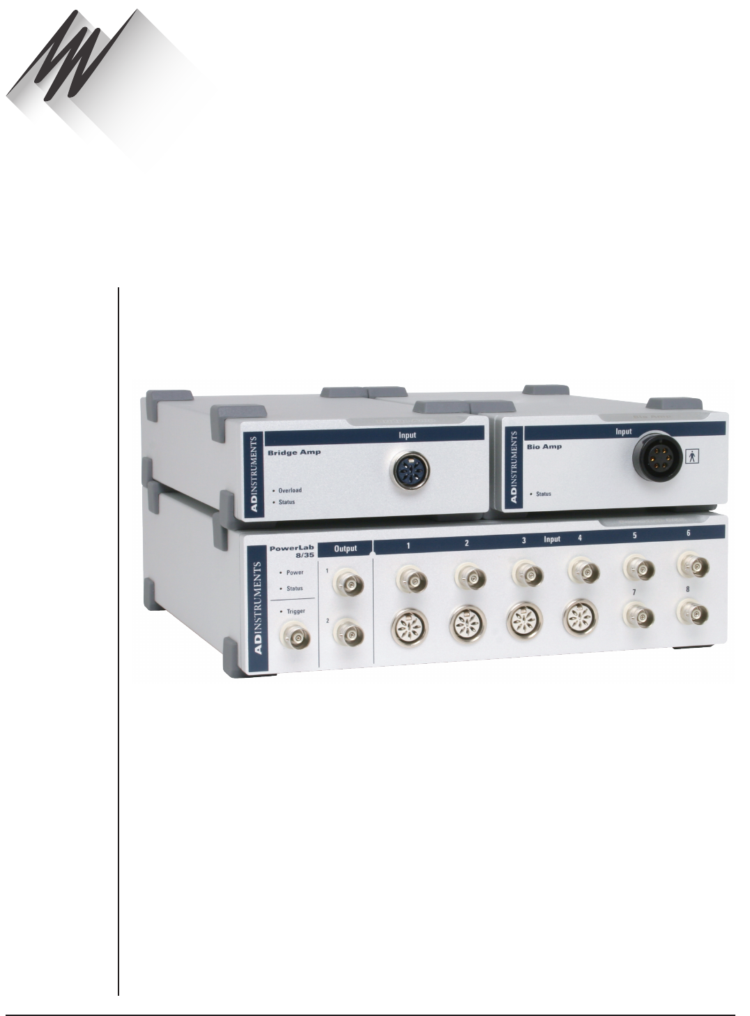
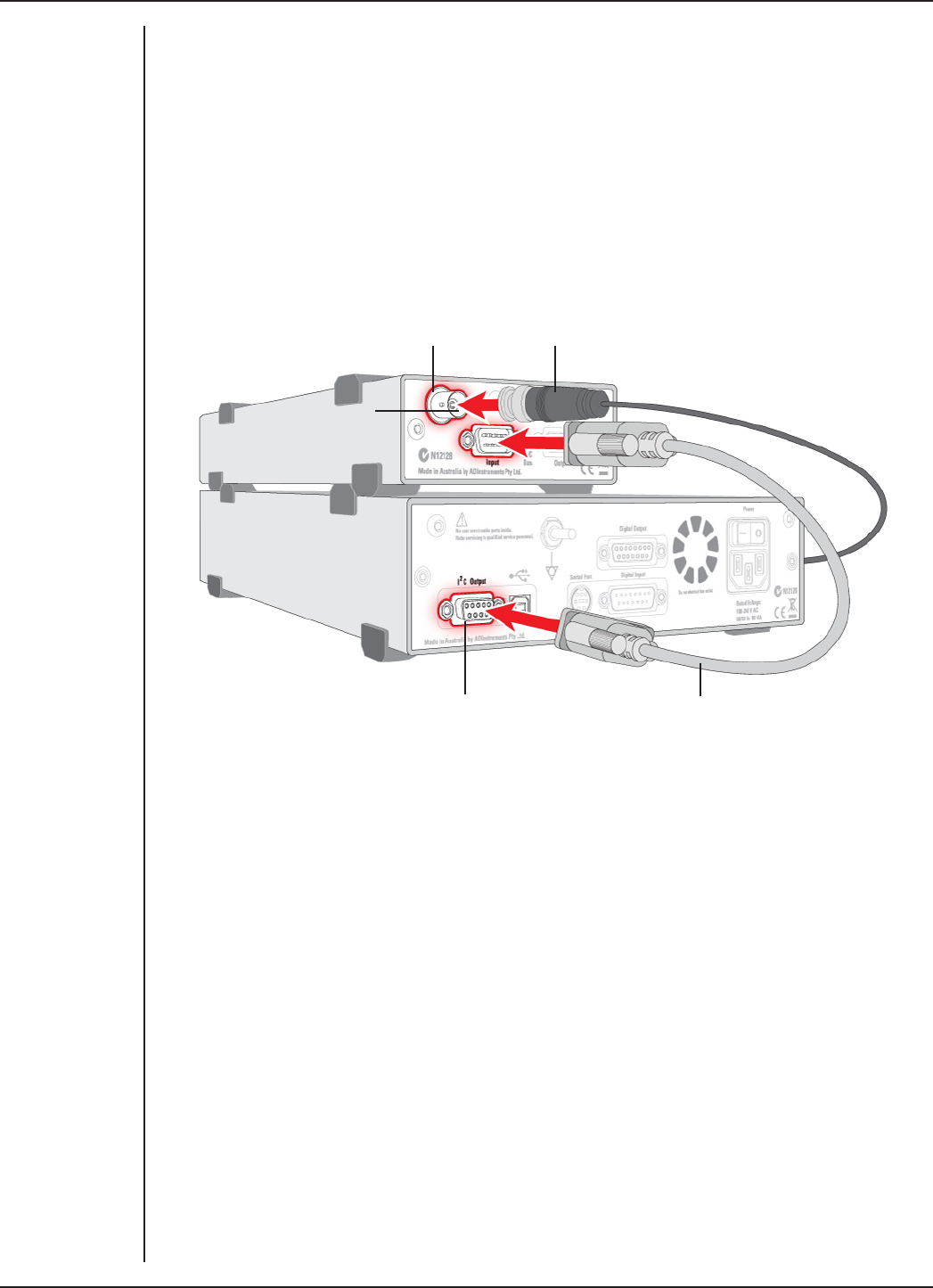
Single Front-ends
Connect the I2C output of the PowerLab to the I2C input of the front-end using the I2C
cable provided. Figure 2–1 shows how to connect up a single front-end to your recording
unit.
I2C connector cable
PowerLab I2C output
Front-end Signal output
Front-end I2C input
Check that the connectors for the I2C bus are screwed in firmly. Check the BNC cable
for firm connections as well. Loose connectors can cause erratic front-end behavior, or
may cause the front-end to fail to work at all.
The Signal Output Socket
The BNC socket labelled Signal Output on the back panel of the front-end provides
the signal output to connect to an analog input socket on the front of the PowerLab. A
BNC-to-BNC cable is supplied for this connection. If necessary, use a BNC to DIN smart
adapter [MLAC22] to connect the BNC cable to your PowerLab’s input.
Note: If you have an older PowerLab with dierential (rather than single-ended) inputs,
the BNC cable must connect to a positive analog input on the PowerLab.
Figure 2–1
Connecting a
front-end to the
PowerLab: a
PowerLab has
only one I2C
output, and each
front-end has one
I2C output and
one I2C input
FRONT-END SIGNAL CONDITIONERS - Owner’s Guide
11
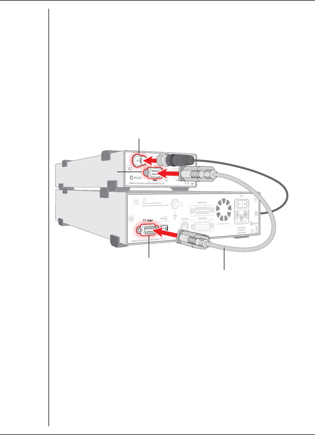
Multiple Front-ends
Multiple separate front-ends can be connected up to a PowerLab. The initial front-
end should be connected with the I2C cable as in Figure 2–1. The remainder are daisy-
chained via I2C cables, connecting the I2C output of the last connected front-end to the
I2C input of the front-end to be added (Figure 2–2).
Second I2C cable connected to
Front-end I2C output
First I2C cable connected
to PowerLab I2C output
The number of normal front-ends that can be connected to a PowerLab depends on the
number of analog input channels on the PowerLab. Each BNC cable from a front-end
should be connected to one analog input channel on the PowerLab, for example, Input
1 on a /30 or /35 series PowerLab.
Note: Only one Stimulator front-end such as a Stimulus Isolator can be connected to
the positive output of the PowerLab.
Special Cases
Some front-ends have their own specific connection requirements. Please refer to the
individual chapter for each front-end in this guide.
Connecting Stimulator Front-Ends
The PowerLab analog outputs provide a variable, computer-controlled voltage output
that can be used with LabChart, LabTutor or Scope to connect a Stimulator front-end,
or to stimulate directly, or to control a peripheral device. A voltage output is generated
by the PowerLab and delivered via the BNC output sockets, giving positive, negative,
dierential, or independent stimuli, depending on the PowerLab used and the soware
settings.
The /20, /25, and /26 series PowerLabs have analog outputs labeled + and –. In contrast,
the SP, ST, /30 and /35 series PowerLabs have the outputs labeled Output 1 and Output
2.
Figure 2–2
Connecting
multiple front-
ends to the
PowerLab (two
single front-
ends shown for
simplicity) Second
Front-end
I2C input

FRONT-END SIGNAL CONDITIONERS - Owner’s Guide
12
For the /20, /25 and /26 series PowerLabs:
The negative (–) output is the complement of the positive (+) output, so the stimuli from
the two outputs are mirror images. If one output gives a positive voltage, the other
gives a negative one, and the two together give a dierential voltage. One Stimulator
front-end such as a Stimulus Isolator or Stimulator HC can be connected to the positive
output of these PowerLabs.
Note: If you connect the Stimulator HC to a PowerLab that has an in-built Isolated
Stimulator, such as a PowerLab 26T, only the external, connected stimulator is used.
For /SP, /ST, /30 and /35 series PowerLabs:
Output 1 and Output 2 can function independently. However, only one Stimulator
front-end such as a Stimulus Isolator or Stimulator HC can be connected to the positive
output (Output 1) of these PowerLabs. With a Stimulator front-end connected, the
second output (Output 2) can function independently, and a second tab appears in the
Stimulator dialog in LabChart 7 for Windows. Therefore Output 2 remains available for
other uses, such as creating analog waveforms and triggering other systems.
Maximum Number of Front-Ends
The I2C bus can control a maximum of sixteen front-ends. Therefore, if you are using
a PowerLab 16/30, which has sixteen input channels, you can record from sixteen
single channel front-ends. However, please note that the Dual Bio Amp/Stimulator
is an exception because it counts as four front-ends, not three as one would expect.
Therefore, you cannot use all the analog inputs for normal front-ends while using the
Dual Bio Amp/Stimulator.
For example, if you are using the Dual Bio Amp/Stimulator with a PowerLab 16/30, you
can only use an additional twelve single channel front-ends or, for example, one Octal
Bridge Amp plus one Quad Bridge Amp.
Using ADInstruments Programs
Front-ends are designed for use with PowerLabs and ADInstruments programs such
as LabChart, LabTutor and Scope. The functions of the front-end are combined with
those of the PowerLab, and are presented as a single set of soware controls in the
ADInstruments program. Depending on the front-end(s) connected, front-end-specific
dialogs replace the Input Amplifier dialogs or the Stimulator dialog.
The LabChart Help and Scope User’s Guide detail the Input Amplifier and Stimulator
dialogs, and explain relevant terms and concepts, but they do not cover front-end-
specific features. These features are described in detail in the following chapters for
each front-end.
Front-end Drivers
A device driver is a piece of soware that allows the computer’s operating system and
other soware to interact with a hardware device. ADInstruments applications like
LabChart communicate with a front-end via an appropriate front-end driver. These
FRONT-END SIGNAL CONDITIONERS - Owner’s Guide
13
drivers are automatically set up on the computer when ADInstruments applications are
installed, and their operation is usually invisible to the user.
However, under certain circumstances you may receive an error message during the
startup of LabChart or Scope indicating that there is a problem with the front-end
driver. Subsequently, the front-end will not function. This is invariably caused by the
absence or incompatibility of a driver required for communication with the front-end
due to an old version of the soware being run. The problem can be remedied simply by
reinstalling and rerunning a current version of the soware, which will include the latest
front-end drivers.
The Front-end Self-test
Once the front-end is properly connected to the PowerLab, and the proper soware is
installed on the computer, a quick check can be performed on the front-end. To perform
the self-test:
•Turn on the PowerLab and check that it is working properly, as described in the
owner’s guide that was supplied with it.
•Once the PowerLab is ready, start LabChart, LabTutor or Scope.
•While the program is starting, watch the Status indicator on the front-end’s front
panel. During initialization, you should see the indicator flash briefly and then
remain lit.
If the indicator lights correctly, the front-end has been found by the PowerLab and is
working properly. If the indicator doesn’t light, check your cable connections and repeat
the start-up procedure.
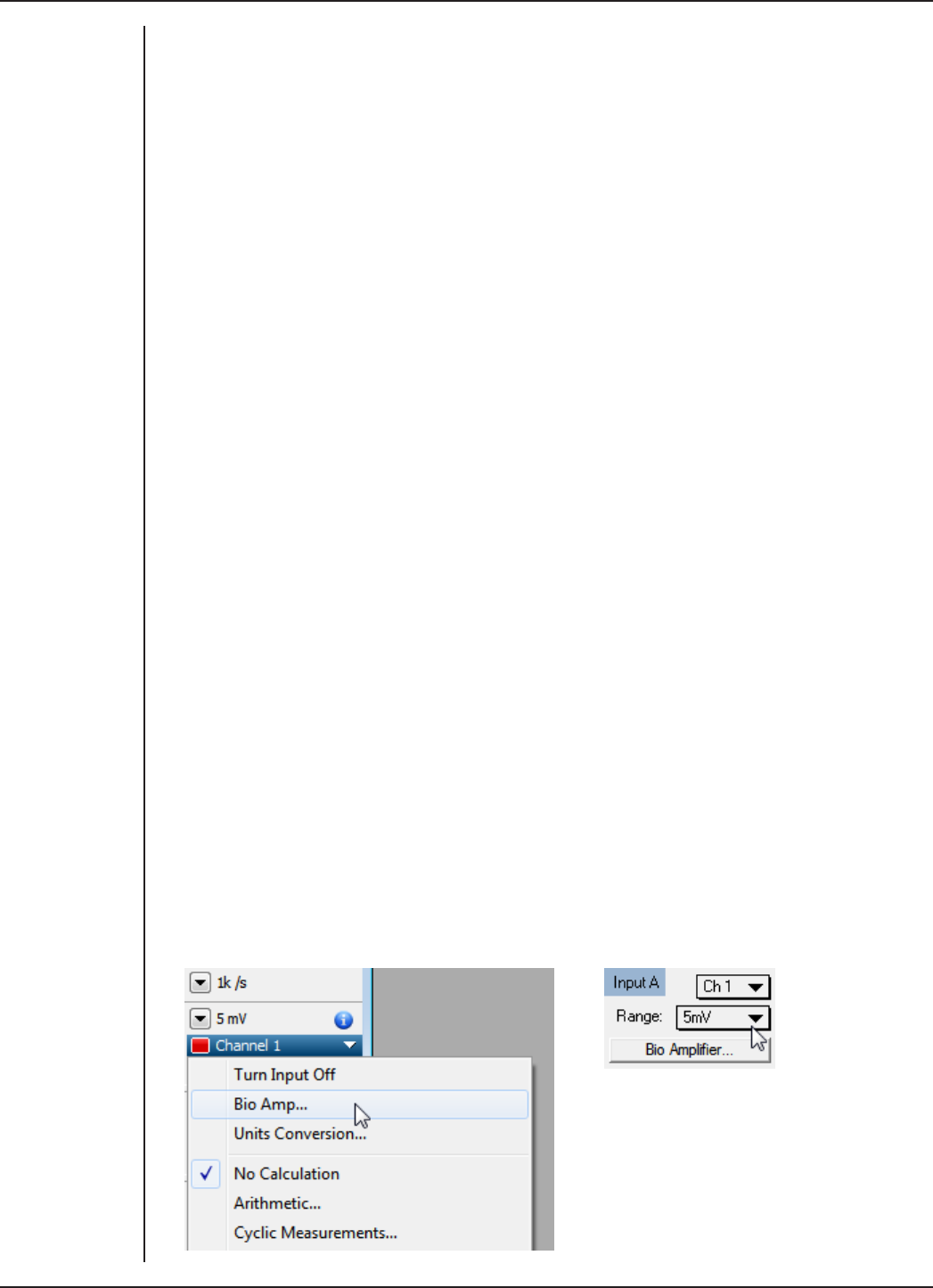
Soware Behavior
When a front-end is connected to a PowerLab and the ADInstruments soware is
successfully installed, the Input Amplifier… menu command from the Channel
Function pop-up menu in LabChart should be replaced by the <Front-end>... menu
command.
For example, with a Bio Amp front-end connected, Bio Amp… should appear in the
Channel function pop-up menu. In Scope the Input Amplifier… button in the Input A
panel (or Input B panel) is replaced by the Bio Amplifier… button.
Figure 2–3
Channel Function
pop-up menu in
LabChart, and
the Input panel in
Scope, with the
Bio Amp front-end
connected

FRONT-END SIGNAL CONDITIONERS - Owner’s Guide
14
If the application fails to find a front-end attached to a channel, the normal Input
Amplifier… command or button remains. If you were expecting a connected front-end,
you should close the program, turn everything o, check the connections, restart the
PowerLab and then relaunch LabChart, LabTutor or Scope.
Preventing Problems
Several problems can arise when using the PowerLab system for recording biological
signals. It is important to understand the types of problems that can occur, how they
manifest themselves, and what can be done to remove them or to minimize their eect.
These are usually problems of technique, and should be addressed before you set up
your equipment.
Aliasing
Recordings of periodic waveforms that have been undersampled may have misleading
shapes and may also have artifacts introduced by aliasing. Aliasing occurs when a
regular signal is digitized at too low a sampling rate, causing the false appearance of
lower frequency signals. An analogy to aliasing can be seen in old films: spoked wagon
wheels may appear to stop, rotate too slowly or even go backwards when their rate of
rotation matches the film frame speed – this is obviously not an accurate record.
The Nyquist–Shannon sampling theorem states that the minimum sampling rate (fs)
to accurately describe an analog signal must be at least twice the highest frequency in
the original signal. Therefore, the signal must not contain components greater or equal
to fs/2. The term fs/2 is known as the Nyquist frequency (fn) or the ‘folding frequency’
because frequencies greater than or equal to fn fold down to lower frequencies about
the axis of fn.
When aliasing of noise or signals is seen, or even suspected, the first action you should
take is to increase the sampling rate. The highest available sampling rates are 100k /s or
200k /s, depending on your PowerLab. To view the frequencies present in your recorded
signal open the Spectrum window in LabChart. For more information about Spectrum,
see the LabChart Help Center.
If unwanted high-frequency components are present in the sampled signal, you will
achieve better results by using a low-pass filter to remove them. The best kind of filter
for this purpose is the Anti-alias filter option available in the front-end-specific Input
Amplifier... dialog. This is a special low-pass filter that is configured to automatically
remove all signals that could alias; i.e., those whose frequency is greater or equal to half
the sampling rate.
For certain PowerLabs, the Anti-alias filter option is not available. Therefore you
should select an appropriate low-pass filter to remove any unwanted signals (or noise)
occurring at frequencies greater or equal to half the sampling rate.
Frequency Distortion
Frequency distortion will occur if the bandwidth of your recording is made smaller
than the bandwidth of the incoming signal. For example, if an ECG was measured with
a sampling rate of 100 samples per second (100 Hz) and the Bio Amp had a low-pass

FRONT-END SIGNAL CONDITIONERS - Owner’s Guide
15
filter applied at 50 Hz, the fast-changing sections of the waveform (the QRS complex)
may appear smaller and ‘blunted’, while the slower T-wave sections remain relatively
unchanged. This overall eect is called frequency distortion.
It can be eliminated by increasing the frequency cut-o of the low-pass filter in the front-
end-specific Input Amplifier... dialog to obtain an undistorted waveform.
Similarly, if the high-pass filter was set too high, the amplitude of the T-wave sections
may be reduced. The Input Amplifier... dialog allows you to examine ECGs and similar
slowly changing waveforms to fine-tune filter settings before recording.
Saturation
Saturation occurs when the range is set too low for the signal being measured (the
amplification, or gain, is too high). As the signal amplitude exceeds the allocated range,
the recorded waveform appears as if part of the waveform had been cut o, an eect
referred to as clipping.
Clipping can also be caused by excessive baseline oset: the oset eectively moves
the whole waveform positively or negatively to an extent that causes all or part of it to
be clipped. This problem is overcome by selecting a higher range from the Range menu
in the front-end-specific Input Amplifier... dialog. In the case of excessive baseline
oset, you may wish to apply a high-pass filter with a higher frequency cut-o.
Ground Loops
Ground loops occur when multiple connected pieces of recording equipment are
connected to mains power grounds. For safety reasons, all electrical equipment
should have a proper connection to the mains power grounds, or to a primary earth
connection in situations where a mains ground connection is not available. Connecting
linked electrical equipment to a common earth connection (equipotential connection
point) – such as the earthing (grounding) stud provided on the rear of all PowerLabs –
can prevent ground loops.
The electric fields generated by power lines can introduce interference at the line
frequency into the recorded signal. Electromagnetic fields from other sources can also
cause interference: fluorescent tubes, apparatus with large transformers, computers,
laptop batteries, network cables, x-ray machines, microwave ovens, electron
microscopes, even cyclic air conditioning.
Reasonable care in the arrangement of equipment to minimize the ground loop area,
together with proper shielding, can reduce electrical frequency interference. For
example, use shielded cables, keep recording leads as short as possible, and try twisting
recording leads together. For sensitive measurements, it may be necessary to place the
subject (the biological source) in a Faraday cage.
Interference should first be minimized, and then you can turn on the Mains or notch
filter in the front-end-specific Input Amplifier... dialog.

FRONT-END SIGNAL CONDITIONERS - Owner’s Guide
16
Mains filter
The Mains filter (/20, /25, /30, /35 and 26T PowerLabs) allows you to filter out interference
at the mains frequency (typically 50 or 60 Hz). The mains filter is an adaptive filter which
tracks the input signal over approximately 1 second. A template of mains-frequency
signal present in the input is computed from the signal. The width of the template is
the mains power period (typically 16.6 or 20 ms) as determined from zero-crossings of
the mains power. The filtered signal is obtained by subtracting the template from the
incoming signal.
In comparison with a conventional notch filter, this method produces little waveform
distortion. It attenuates harmonics of the mains frequency as well as the 50 or 60 Hz
fundamental and therefore eectively removes non-sinusoidal interference, such as
that commonly caused by fluorescent lights.
The filter should not be used when:
•the interference changes rapidly. The filter takes about 1 second to adapt to
the present level. If interference is present and then is suddenly removed,
interference in the filtered signal will temporarily worsen.
•your signal contains exact factors or harmonics of frequencies close to the mains
frequencies, for example, a 30 Hz signal with 60 Hz mains frequency.
•your signal is already free from interference. If the signal-to-noise ratio is greater
than about 64 the mains filter introduces more noise than it removes.
•you are recording at close to maximum sampling rates. The mains filter uses
some of the PowerLab’s processing power and therefore reduces the maximum
rate at which you can sample.
Notch Filter
The notch filter is automatically set to either 50 or 60 Hz, depending on the power
line voltage frequency being used by the PowerLab (the mains frequency). It provides
approximately 32 dB of attenuation, thus reducing the eect of the 50 or 60 Hz signals
that can easily be picked up by long leads. The notch filter is only available with older
model PowerLabs, such as the /20 series.
Electrode Contact
Occasionally one of the lead wires connecting the subject to the front-end may become
disconnected, or an electrode contact may become poor. If this should happen,
relatively high voltages (potentials) can be induced in the open wire by electric fields
generated by power lines or other sources close to the front-end or the subject. Such
induced potentials will result in a constant amplitude disturbance in the recorded
waveform at the power line frequency (50 or 60 Hz), and loss of the desired signal. If
the problem is a recurring one, one of the leads may be faulty. Check connections and
replace faulty leads, if necessary.

FRONT-END SIGNAL CONDITIONERS - Owner’s Guide
17
Motion Artifacts
A common source of artifacts when recording biological signals is due to motion of
the subject or equipment. Oen applying a high-pass filter can help to remove slowly
changing components in a recorded signal.
•Muscular activity generates its own electrical signals, which may be recorded
along with an ECG, say, depending on the location of the electrodes.
•If an electrode is not firmly attached, impedance (and hence the recorded signal)
may vary as the contact area changes shape owing to movement.
•Movement of patient cables, particularly bending or rubbing together
(triboelectric eects) may generate artifacts in a signal.
•Subject respiration can also generate a signal; breathing can result in a slowly
changing baseline corresponding to inspiration and expiration.
If the subject is liable to move during recording, then special care needs to be taken
when attaching the electrodes and securing the patient leads. Make sure the skin is
cleaned and lightly abraded before attaching the electrodes.
FRONT-END SIGNAL CONDITIONERS - Owner’s Guide
18
The FE136 Animal Bio Amp is a modular device, in a family called front-ends, designed
to extend the capabilities of the PowerLab system. The Animal Bio Amp is designed to
allow the PowerLab system to record bioelectrical signals, such as ECG, EOG, ERG, EMG,
and EEG, from animals or isolated tissues, or action potentials from isolated nerves.
Warning! The Animal Bio Amp is not intended for human use and should never be
connected to a human subject.
The Animal Bio Amp provides:
•a low-noise, high-gain dierential amplifier specifically designed for biological
signal measurements;
•soware-controlled low-pass, high-pass, and notch filters to remove unwanted
signal frequencies for particular uses;
•audio output, for use with EMG or EEG signals, and so on.
Animal Bio Amp
Chapter 3
FRONT-END SIGNAL CONDITIONERS - Owner’s Guide
19
The Animal Bio Amp
The Animal Bio Amp has been designed to integrate fully into the PowerLab system.
The Animal Bio Amp is essentially an extension of the PowerLab’s input amplifiers, so
the amplification (and hence the ranges) you see oered in the LabChart, LabTutor and
Scope soware will be the combination of both pieces of hardware.
This chapter contains general information about the features, connections, and uses of
the Animal Bio Amp. More detailed information can be found in the Technical Aspects
and Specifications sections.
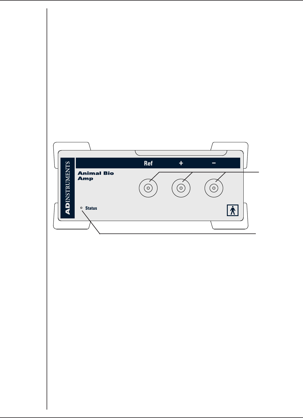
The Front Panel
The front panel of the Animal Bio Amp has three input connectors and one indicator
light.
Input Sockets
Status indicator
The Input Sockets
Connections are made to the Animal Bio Amp are made using the three shrouded 1.5
mm male pin sockets on the front panel. A separate socket is provided for each of the
positive (+), negative (–) and Ground/Reference (Ref) cables. Three cables are provided
and each is terminated with a miniature alligator clip suitable for use with a wide variety
of electrodes (not supplied).
The Status Indicator
Located at the bottom right of the front panel of the Animal Bio Amp is the status
indicator light. When lit, it indicates that the PowerLab soware (such as LabChart or
Scope) has found the Animal Bio Amp and that it is ready to use. If the light does not
go on, then the Animal Bio Amp is not connected properly, or there is a soware or
hardware problem.
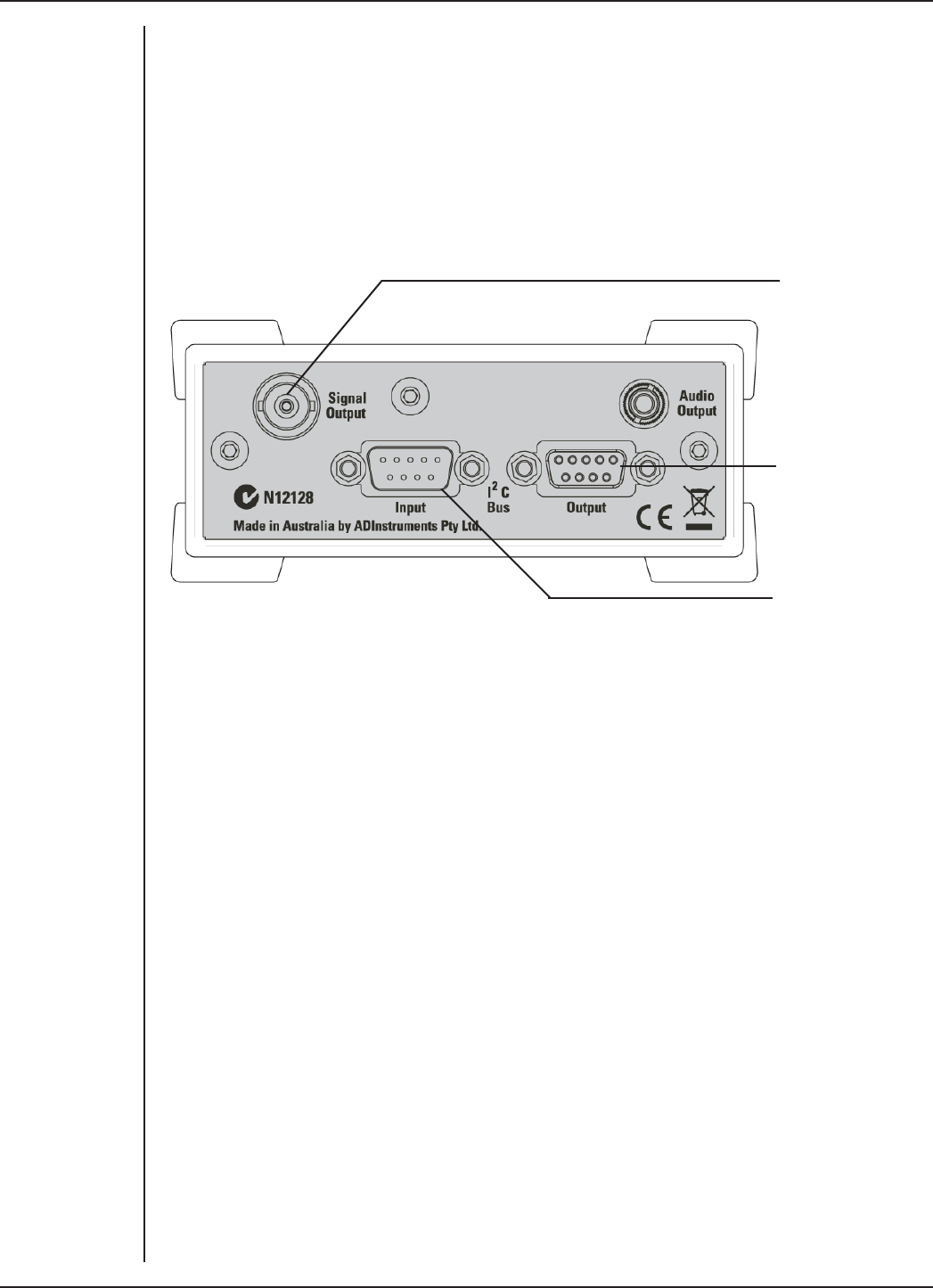
The Back Panel
The back panel of the Animal Bio Amp provides all the sockets for connection of the
Animal Bio Amp to the PowerLab and to other front-ends.
Figure 3–1
The front panel
of the Animal Bio
Amp
FRONT-END SIGNAL CONDITIONERS - Owner’s Guide
20
I2C Input and Output Sockets
Two nine-pin sockets are used to communicate with the PowerLab (they are marked ‘I2C
Bus’: a ‘bus’ is simply an information transmission connection such as connectors and
cabling). These sockets in conjunction with the proper cables allow multiple front-ends
to be used independently with one PowerLab: power and control signals to connected
front-ends come from the PowerLab. Multiple front-ends can be connected to each
other in series, ‘output to input’. This is discussed in detail in Chapter 2.
Signal output to the
PowerLab
I2C connection to a
further front-end
I2C connection from
the PowerLab or
previous front-end
Signal Output Socket
The BNC socket labeled Signal Output is used to connect the Animal Bio Amp to one of
the analog input channel sockets on the front of the PowerLab. The supplied BNC-to-
BNC cable is used for this purpose.
Audio Output Socket
The Animal Bio Amp has an audio monitor output that can be used with a wide range
of headphones or externally powered speakers. The 3.5 mm stereo socket is wired to
provide mono sound (the same signal to a set of stereo speakers or headphones. This
audio output is of particular use when monitoring bursts or nerve activity.
Connecting to the PowerLab
To connect a front-end, such as your Animal Bio Amp, to the PowerLab, first make sure
that the PowerLab is turned o. Failure to do this may damage the PowerLab, the Animal
Bio Amp, or both.
Figure 3–2
The back panel
of the Animal Bio
Amp
FRONT-END SIGNAL CONDITIONERS - Owner’s Guide
21
Single Front-end
Connect the I2C output of the PowerLab to the I2C input of the front-end using the
I2C cable provided. Figure 3–3 shows how to connect up a single front-end to your
PowerLab.
Check that the plugs for the I2C bus are screwed in firmly. Check the BNC cable for firm
connections as well. Loose connectors can cause erratic front-end behavior, or may
cause the front-end to fail to work at all. The BNC cable can be tucked under the front-
end to keep it out of the way if desired. Once the Animal Bio Amp is connected, turn the
PowerLab on and launch LabChart.
Multiple Front-ends
Multiple front-ends can be connected up to a PowerLab; up to sixteen, depending on the
number of input channels on the PowerLab. The initial front-end should be connected
as shown in Figure 3–3. The remainder are daisy-chained via I2C cables, connecting the
I2C output of the last connected front-end to the I2C input of the front-end to be added
(see Figure 2–2). The BNC cable for each front-end is connected to one of the analog
inputs of the PowerLab. Note that signal degradation can be expected if multiple Bio
Amps are connected to a single subject.
Using LabChart and Scope
When the Animal Bio Amp is connected to a channel and successfully installed, the Input
Amplifier… menu command from the Channel Function pop-up menu in LabChart is
replaced by the Bio Amp… menu command. In Scope, the Input Amplifier… button in
the Input A (or Input B) panel is replaced by the Bio Amplifier… button.
If the application fails to find a front-end attached to a channel, the normal Input
Amplifier… command or button remains. If you were expecting a connected front-end,
Figure 3–3
Connecting the
Animal Bio Amp
front-end to the
PowerLab
Animal Bio Amp Signal Output
Animal Bio Amp
I2C input
PowerLab I2C output I2C connector cable
BNC connector cable
FRONT-END SIGNAL CONDITIONERS - Owner’s Guide
22
you should close the program, turn everything o, check the connections, then start
things up again.
Note: Leaving the PowerLab on while changing connections can damage the PowerLab,
the Animal Bio Amp, or both.
Choosing the Bio Amp… menu command will bring up the Bio Amp dialog, which
replaces the Input Amplifier dialog for the channel. The LabChart Help Center and Scope
User’s Guide have further details on the Input Amplifier dialog, and explain some of the
soware terms used here.
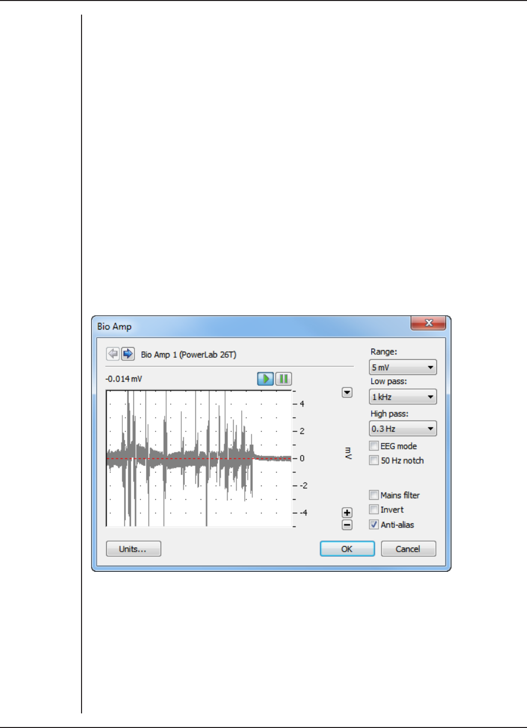
The Bio Amp dialog
The Bio Amp dialog is similar for LabChart and Scope. It allows soware control of the
various amplifiers and filters in the Animal Bio Amp (and PowerLab) for a channel. The
signal present at that channel’s input is displayed so that you can immediately see the
eects of any changes. Once you have changed the settings in the dialog, click OK to
apply the changes to the Chart or Scope window. The channel that the dialog applies to
is shown next to the arrows, and the channel title or axis label (if any) is shown along the
vertical Amplitude axis.
Signal Display
The input signal is displayed so that you can see the eect of changing the settings —
no data is actually recorded when setting up the Animal Bio Amp. The average signal
value is displayed at the top le of the display area. Slowly changing waveforms will be
represented quite accurately, whereas quickly changing signals will be displayed as a
solid dark area showing only the envelope (shape) of the signal formed by the minimum
and maximum recorded values.
Figure 3–4
The Bio Amp
dialog for
LabChart for
Windows (the
Macintosh version
and the Scope
version are
similar).

FRONT-END SIGNAL CONDITIONERS - Owner’s Guide
23
Range
The Range pop-up menu lets you select the input range or sensitivity of the channel —
the combined range of the Animal Bio Amp and the PowerLab. Changing the range in
the Bio Amp dialog is equivalent to changing it in the Chart or Scope window (all dialog
changes are made in the main window aer clicking OK). For the Animal Bio Amp, the
default setting is 100 mV, and the ranges go down to 5 µV in 14 steps.
EEG Mode
The EEG Mode changes the available filters of the Animal Bio Amp to suit EEG
applications. When this checkbox is on, the High Pass pop-up menu gives filter settings
of 0.03, 0.1, 0.3 and 1 seconds, and the Low Pass pop-up menu gives filter settings of 3,
10, 30, 60, and 120 Hz. It is a convention in EEG to deal with high-pass filter settings in
terms of seconds (giving the time constant of the first-order filter).
Filtering
The Animal Bio Amp provides signal filtering options that can be adjusted to suit your
requirements. The default settings are appropriate to the signals usually measured,
which tend to be of lower frequency.
The notch filter and the mains filter are used to remove excessive mains frequency
interference. The high-pass filter limits the bandwidth of low-frequency signals and the
low-pass filter limits the bandwidth of high-frequency signals.
Not all possible combinations of high-pass and low-pass filters are available, for
instance, if the 5 kHz low-pass filter is selected, then high-pass filtering cannot be below
1 Hz.
Notch Filter. Click the Notch checkbox to turn the notch filter on and o (it is on when
checked). The notch filter is set to either 50 or 60 Hz depending on the power line voltage
(mains) frequency. It provides 32 dB of attenuation to remove electrical interference,
thus reducing the eect of 50/60 Hz signals that can be picked up by long patient leads.
Mains Filter. Select or deselect the Mains filter checkbox to turn the mains filter on and
o. The mains filter allows you to remove interference related to the mains frequency
(both fundamental and harmonic frequencies). This is an adaptive filter. It adjusts to
filter the interference by tracking the input signal for a second, creating a template of
the interfering frequencies and then subtracting this template from the input signal.
Because of this, in general, using the mains filter is better than using the notch filter.
However, the mains filter does have some limitations, such as not being useful for very
short recordings of less than one second. More details on the mains filter can be found
in the LabChart Help Center.
High-Pass Filtering. There are normally five options in the High Pass pop-up menu: 0.1,
0.3, 1, 3 and 10 Hz. When the EEG Mode checkbox is on, four options are provided in the
High Pass pop-up menu: 0.03, 0.1, 0.3 and 1 seconds. (Units of seconds give the time
constant of the first-order filter.) When any of the options is chosen, a high-pass filter
removes any DC components and attenuates those frequency components below the
AC filter frequency from the signal. This is useful to remove slowly changing baselines,
such as motion or respiration artifacts, commonly found in ECG (EKG) recordings.

FRONT-END SIGNAL CONDITIONERS - Owner’s Guide
24
Low-Pass Filtering. The Low Pass pop-up menu normally gives a choice of six low-pass
filters to remove high-frequency components from an input signal: 50, 100, 200 and
500 Hz, and 1 and 5 kHz. When the EEG Mode checkbox is on, five options are provided
in the Low Pass pop-up menu: 3, 10, 30, 60 and 120 Hz. These settings are useful to
eliminate high-frequency components, such as noise, and to prevent aliasing in the
recorded signal.
Anti-alias. Click the Anti-alias checkbox to turn the anti-aliasing filter on and o.
This applies a low-pass filter that attenuates frequencies in the incoming signal that
are greater than or equal to half the sampling frequency. This filter helps to eliminate
aliasing, in which such frequencies ‘fold down’ to lower frequencies, and the recorded
waveform appears quite dierent from the actual signal.
Inverting the Signal
The Invert checkbox allows you to invert the signal on the screen. It provides a simple
way to change the polarity of the recorded signal without having to rewire a circuit or
reconnect to the signal. Select the Invert checkbox to change the signal polarity.
Units
Click Units… to display the Units Conversion dialog, with which you specify the units
for the channel and, using waveform measurements, calibrate the channel. Units
conversion is not normally required for measurements taken using the Animal Bio Amp,
but is provided just in case.
When the button is clicked, the waveform currently in the data display area of the
dialog is transferred to the data display area of the Units Conversion dialog. (Use the
Pause button to capture any specific signal that you want to use.) The units conversion
only applies to subsequently recorded signals, so it is more limited than choosing
Units Conversion… from a Channel Function pop-up menu, as it does not allow the
conversion of individual blocks or pages of data. For more information about units
conversion, see the LabChart Help Center and Scope User’s Guide.

FRONT-END SIGNAL CONDITIONERS - Owner’s Guide
25
Using the Animal Bio Amp
This section looks at the use of the Animal Bio Amp for measurements, describes the
input connection in detail, and looks at how to avoid some common problems when
setting up. It is recommended that you read the material in this section before you
attempt to record biological signals with the Animal Bio Amp, especially if you intend to
use your own cables or are unsure about how to connect to the Animal Bio Amp.
The Animal Bio Amp amplifies the signal from a biological signal source so it can be used
by the PowerLab, and provides appropriate filtering. The tasks listed below, and the
basics of setting up measurement, are covered in detail in standard electrophysiology
texts. Note that signal degradation can be expected if multiple Bio Amps are connected
to a single subject.
Some Suitable Uses
This version of the Animal Bio Amp [FE136] has been designed to measure a wide variety
of biological signal sources. Some of the tasks for which it is suitable include:
ECG. Electrocardiogram (also referred to as EKG); a recording of the electrical currents
that constitute the cardiac action potential.
EOG. Electro-oculogram; a recording of the electrical activity of the muscles which
control movement of the eyeball. For bilateral measurement, a Dual Bio Amp [FE135] is
recommended, although two Animal Bio Amps can be used. The lowest possible high-
pass filter setting is recommended for EOG measurements.
ERG. Electroretinogram; a recording of the electrical currents produced in the retina by
a light stimulus. Two Animal Bio Amps are required for bilateral measurement.
EMG. Electromyography (surface electrode electromyography); a recording of the
electrical activity of a muscle, using surface or needle electrodes: voluntary, M-wave
(nerve stimulation), and so on.
EEG. Electroencephalogram; a recording of the electrical activity of the brain. The
Animal Bio Amp is suitable for both ‘biofeedback’ and clinical types of EEG recording, if
the environment is electrically quiet.
Cortical Evoked Potentials. Averaged recordings of the electrical activity of the brain
when subject to stimulation: visual evoked response, auditory evoked response, and
somatosensory response. This should be done with signal averaging, using Scope.
SNAP. Sensory nerve action potentials; a recording of evoked response in stimulated
nerves. This is usually done with signal averaging, using Scope.
Slow Waves. For some smooth muscle studies; recording the long-term electrical
activity involved in involuntary muscle contractions.
Some Unsuitable Uses
The Animal Bio Amp is not recommended for work requiring high-impedance electrodes
or using a high bandwidth. Some of the tasks for which it is not really suitable include:
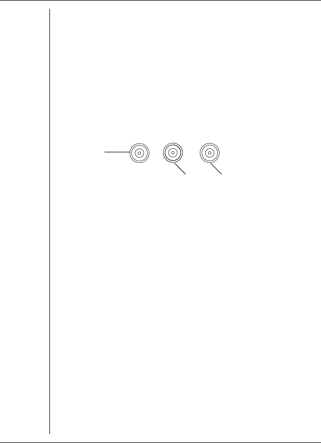
FRONT-END SIGNAL CONDITIONERS - Owner’s Guide
26
•Intracellular micropipette recordings. Recordings from a very fine, electrolyte-
filled tube inserted into a nerve or muscle cell. These require an electrometer
amplifier.
•Any biopotential recordings requiring low input capacitance and a driven guard
circuit.
The Animal Bio Amp Input
Connections are made to the Animal Bio Amp using the three shrouded 1.5 mm male pin
sockets on the front panel. The sockets are of a sort commonly used with life science
connection leads, and their arrangement is shown below.
Three cables are provided and each is terminated with a miniature alligator clip suitable
for use with a wide variety of electrodes (not supplied).
Ref +-
Ground/Reference
(green)
Positive input
(red)
Negative input
(black)
The sockets provide two pins for a dierential input signal (+ or red, – or black), and an
input for an isolated Ground/reference (Ref or green). The Ground/reference electrode
should always be attached to the subject under investigation (or to the recording
preparation), providing a zero reference for the dierential amplifier. Then the active
(+) and reference (-) electrodes should be securely attached to the subject or recording
preparation, for example, ECG recording leads on opposite sides of the chest, or needle
electrodes at dierent sites over a nerve.
Note: The Animal Bio Amp should never be used on humans. For human connection,
the Bio Amp [FE132] or Dual Bio Amp [FE135] should be used with their associated
approved subject cables.
Figure 3–5
The connectors
for each input of
the
Animal Bio Amp

FRONT-END SIGNAL CONDITIONERS - Owner’s Guide
27
Technical Aspects
This section describes some of the important technical features of the Animal Bio Amp.
It describes the capabilities of the Animal Bio Amp, and its suitability for particular
purposes. Be advised that user modification of the equipment voids the warranty
agreement.
Technical Description
As with other ADInstruments front-ends, all internal functions of the Animal Bio Amp
are controlled from the PowerLab through a special communications connector called
the I2C bus. This connection also supplies power to the Animal Bio Amp. Front-ends are
also connected to the analog input channels of the PowerLab via a BNC-to-BNC cable,
through which the amplified and filtered signal is sent to the PowerLab. The overall
operation of the Animal Bio Amp can be better understood by referring to Figure 3–6.
The input amplifier of the Animal Bio Amp starts with an electrically isolated dierential
amplifier. The output of this amplifier is fed into a low-noise demodulator and then to a
programmable gain stage, before being fed across an isolation transformer to the non-
isolated circuitry. Control of the isolated gain is provided via a high-isolation-voltage
optocoupler. An auto-restore circuit monitors the level of the input signal and restores
the input before the signal produces amplifier ‘blocking’. Isolated power comes from
a second isolation transformer driven by a power oscillator circuit running at about 38
kHz.
The signal from the isolated input amplifier is synchronously demodulated and then fed
to a programmable, switched-capacitor, high-pass filter. Any switching clock noise is
filtered by the low-pass filter following this stage.
The signal then passes to the first non-isolated gain stage, where it is amplified 1, 10
or 100 times. A switched-capacitor notch filter follows (this is automatically set to 50
or 60 Hz depending on the mains frequency of your power supply). Aer this, the signal
passes to the final programmable gain stage, where it is amplified 1, 2 or 5 times. The
last part of the signal-conditioning circuitry is the low-pass filter.
The output of the Animal Bio Amp is buered with an amplifier with a fixed gain
(nominally X 1.66), to compensate for gain dierences through the previous stages of
the device. An audio signal output, capable of driving headphones or powered speakers,
is provided by tapping o the output stage and buering it.
The control for the various filters and gain stages in the Animal Bio Amp is provided
by on-board microprocessors, which also communicate with the PowerLab over the I2C
bus.
Note that the Animal Bio Amp is an extremely sensitive instrument, and it is
important that under no circumstances should you try to repair or adjust it yourself.
If you experience problems with the Animal Bio Amp, it should be returned to your
ADInstruments representative for repair under the terms of your Warranty & Licensing
Agreement.
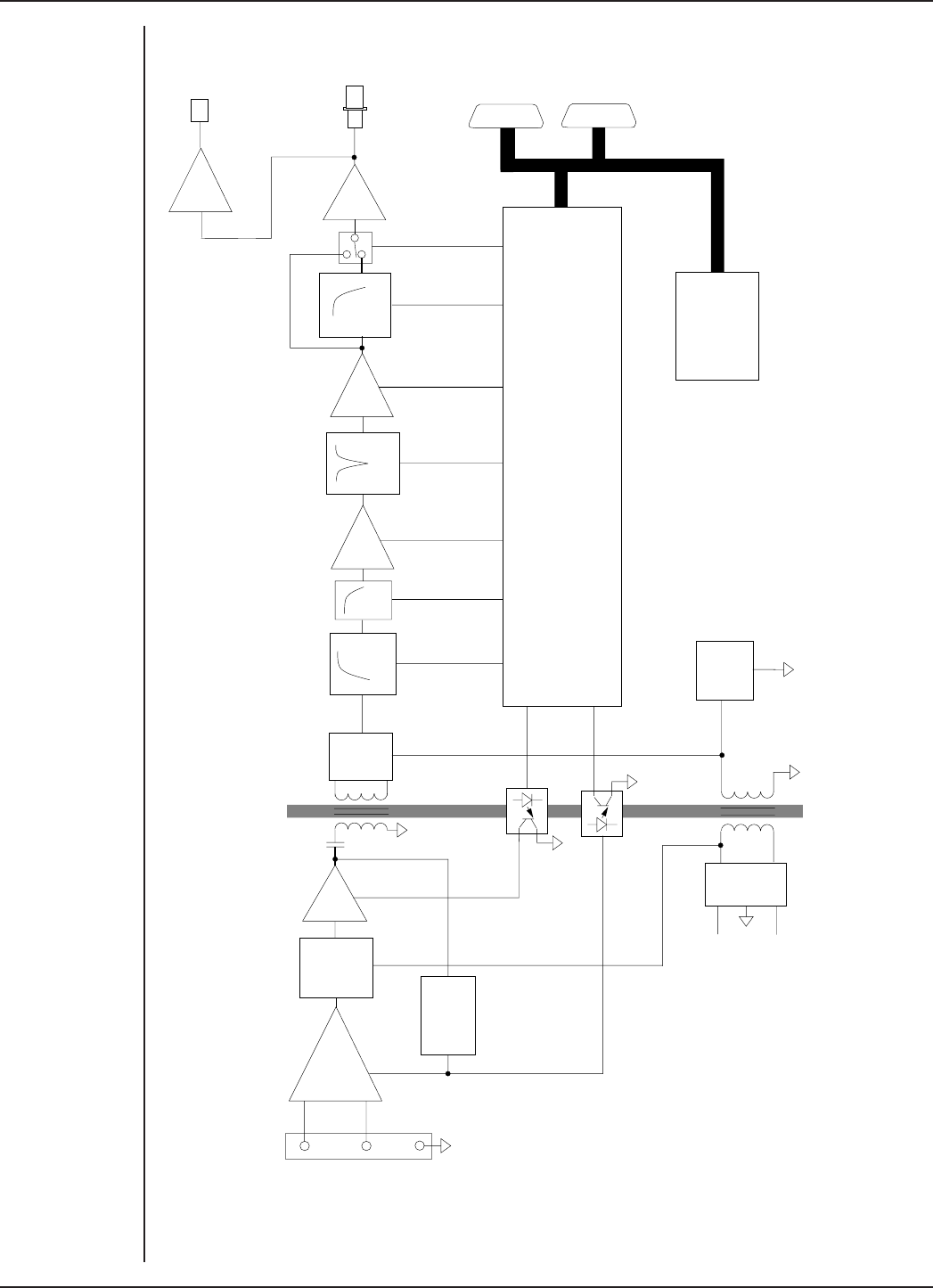
FRONT-END SIGNAL CONDITIONERS - Owner’s Guide
28
+
-
x1,x10
x1.66
Microprocessor Controller
Power Supply
Power
Oscillator
Rectify
and
Filter
+10 V
-10 V
Restore Sense
Auto
Restore
Circuitry
Low
Noise
Modulator
Signal
Input
Synch
Demod HPF LPF
x1,x10,
x100 Notch
x1,x2,
x5 LPF
x1
Audio
Output
Signal
Output
I C
Interface
2
Figure 3–6
Block diagram of
the Animal Bio
Amp

FRONT-END SIGNAL CONDITIONERS - Owner’s Guide
29
Troubleshooting
This section describes some problems that may arise when using the Animal Bio Amp
with the PowerLab. If you have any trouble getting the Animal Bio Amp to work with the
PowerLab, use this section to try and isolate and cure the problem. If the solutions here
do not work, refer to earlier chapters, the LabChart Help Center, and the Owner’s Guide
for your PowerLab for possible solutions. If none of the solutions here or elsewhere are
of help, then consult your ADInstruments representative.
Although the PowerLab and the Animal Bio Amp are designed to be very reliable, there
may be occasions when they do not appear to function correctly. In the majority of
cases, the problem can be fixed by checking connections and starting up the application
again. Very rarely will there be an actual problem with the Animal Bio Amp or the
PowerLab itself. This following section should help you determine what kind of fault you
have and find an appropriate solution.
Problems and Solutions
The online indicator fails to light when the application is opened
The PowerLab is o or the power is switched o at the wall, the power cable is not
connected firmly, or a fuse has blown.
•Check switches, power connections, and fuses.
The BNC-to-BNC cable from the Animal Bio Amp to the analog input channel of the
PowerLab is not connected, has been connected incorrectly, or is loose.
•Check that the cable is firmly connected at the back of the front-end and to the
PowerLab input.
The I2C cable from the Animal Bio Amp to the PowerLab is not connected, has been
connected incorrectly, or is loose.
•Check to see that the I2C cables are firmly seated and screwed in. Start up again
to see if this has fixed the problem.
You are using an early version of LabChart or Scope.
•Upgrade to the current version of the soware — contact your ADInstruments
representative.
The BNC or I2C cable is faulty.
•Replace the cable and try again. Immediately label all cables proved faulty so
that you don’t use them again by accident.
The Animal Bio Amp is faulty.
•This is the least likely event. If you have tried the above suggestions and still
cannot get the Animal Bio Amp to work properly, then try using it on another
PowerLab if you have access to one. If the online indicator fails to light on the
second PowerLab, the unit may be faulty and should be returned for repair.

FRONT-END SIGNAL CONDITIONERS - Owner’s Guide
30
The Bio Amp... command does not appear in LabChart or Scope
The BNC-to-BNC cable from the Animal Bio Amp to the analog input of the PowerLab
might not be connected, has been connected incorrectly (to the wrong input, for
instance), or is loose.
•Check that the cable is firmly connected at the back of the front-end and to a
PowerLab input.
The I2C cable from the Animal Bio Amp to the PowerLab is not connected, has been
connected incorrectly, or is loose.
•Check to see that the I2C cables are firmly seated and screwed in. Start up again
to see if this has fixed the problem.
You are using an early version of LabChart or Scope.
•Upgrade to the current version of the soware — contact your ADInstruments
representative.
The BNC or I2C cable is faulty.
•Replace the cable and try again. Immediately label all cables proved faulty so
that you don’t use them again by accident.
The Animal Bio Amp is faulty.
•This is the least likely event. If you have tried the above suggestions and still
cannot get the Animal Bio Amp to work properly, then try using it on another
PowerLab if you have access to one. If the online indicator fails to light on the
second PowerLab, the unit may be faulty and should be returned for repair.
The trace will not zero properly when adjusting high-pass filtering
The Animal Bio Amp is receiving signals at a level that has saturated the input amplifier,
resulting in a large oset. This is normally due to poor contact between the electrodes
and the subject.
•Check the connections for proper contact and try again.
The signal appears to display a constant amplitude oscillation
Frequency interference from power lines can become superimposed on the biological
signal you are measuring.
•You can use the internal notch filter in the Animal Bio Amp to remove excessive
line voltage frequency interference (use the checkbox in the Bio Amp dialog).
If you are using cables and leads that were not supplied with your Animal Bio Amp, they
may be of low quality.
•Check to make sure that you are using only high-quality cables, and that all
soldered joints are in good condition.
Sometimes the alligator clips do not make good electrical contact with the electrodes.
•Check to make sure that the electrodes are clean and dry where they contact
the alligator clips. Refresh the electrode surface by polishing with a fine abrasive
cloth to remove any oxide layer, if necessary. Make sure there is no grease, oil or
wax covering the electrodes.

FRONT-END SIGNAL CONDITIONERS - Owner’s Guide
31
The signal is noisy at lower ranges
This is probably the amplified noise from the electrodes and not a fault, as such. In
addition, there is noise that cannot be avoided by any amplifier (called ‘thermal’ or
‘Johnson-Nyquist’ noise).
•Set the low-pass filter to remove the noise. (But be careful, since important
components of the signal could also be attenuated.)
This could be due an electrically noisy environment, particularly if there is some
equipment that produces a radio frequency that interacts with the Animal Bio Amp
modulator, giving a heterodyne eect.
•Turn o pieces of unnecessary equipment to try and isolate the cause, then
either leave the equipment o, or, if possible, move the subject or equipment
outside the area of any interfering field.
•At the lowest amplification ranges cables may have to be shortened, as long
cables will tend to act as radio receivers.
Problems with the Front-end Driver
On starting up, LabChart or Scope presents a dialog indicating that it could not find the
driver
The Bio Amp driver is not installed on the computer you are using.
•Reinstall the LabChart and Scope soware from your PowerLab Installer CD.
On starting up, LabChart or Scope presents a dialog indicating that the driver is
incompatible
You are probably trying to use the Animal Bio Amp with an old version of soware.
•Reinstall the LabChart and Scope soware from your PowerLab Installer CD. If
you do not have a copy of the current version of soware, please contact your
ADInstruments representative.

FRONT-END SIGNAL CONDITIONERS - Owner’s Guide
32
Specifications
Input
Connection type: Three shrouded 1.5 mm male pin sockets
Input impedance: 200 MΩ dierential
Safety: Approved to IEC 60601-1 Standard (BF rating)
EMC: Approved to EN61326-1:2006 Standard
Input leakage current: < 3 µArms @ 240 V, 50 Hz
< 2 µArms @ 120 V, 60 Hz
DC blocking: ±1 V
Baseline restore: Automatic
Amplification
Configuration: Isolated dierential channel with isolated ground
reference
Input range: ±5 µV to ±100 mV full scale in 14 steps
(combined PowerLab and Bio Amp)
Full Scale Resolution
± 100 mV 50 µV
± 50 mV 25 µV
± 20 mV 10 µV
± 10 mV 5 µV
± 5 mV 2.5 µV
± 2 mV 1 µV
± 1 mV 500 nV
± 500 µV 250 nV
± 200 µV 100 nV
± 100 µV 50 nV
± 50 µV 25 nV
± 20 µV 10 nV
± 10 µV 5 nV
± 5 µV 2.5 nV
Mid-band gain accuracy: ±1.5% (all ranges, within Bio Amp)
Non-linearity: < 0.2% within range
Noise at various bandwidths: 1 Hz to 5 kHz: < 1.3 µVrms (< 8 µV peak-to-peak)

FRONT-END SIGNAL CONDITIONERS - Owner’s Guide
33
0.3 Hz to 1 kHz: < 0.6 µVrms
0.1 Hz to 100 Hz: < 0.35 µVrms (@ 200 samples/second)
CMRR: > 85 dB (typically, 1–60 Hz)
IMRR: > 130 dB (to true earth, 50–60 Hz)
Filtering
Low-pass filter: Fourth-order Bessel filter, ±3% accuracy
Low-pass options: Soware selectable.
Standard: 50, 100, 200 and 50 Hz, and 1 and 5 kHz (all at
–3 dB);
EEG mode: 3, 10, 30, 60 and 120 Hz
High-pass filter: First-order filter, ±0.25% accuracy
High-pass options: Soware selectable.
Standard: 0.1, 0.3, 1, 3 and 10 Hz (all at –3 dB);
EEG mode: 0.03, 0.1, 0.3 and 1 seconds
Notch filter: Second-order filter, –32 dB attenuation;
50 or 60 Hz frequency (automatic sensing)
Output
Signal: ±2.0 V standard; (within ±4.0 V over range)
Audio: 3.5 mm stereo jack; ±200 mV
Suitable for headphones or powered speakers
Control Port
I2C port: Provides control and power. Interface
communications rate of ~50 kbits/s.
Physical Configuration
Dimensions (h × w × d): 55 mm × 120 mm × 260 mm (2.2" × 4.7" × 10.2")
Weight: 1.2 kg (2 lb 11 oz)
Power requirements: < 2 W
Operating conditions: 5–35 °C
0–90% humidity (non-condensing)
ADInstruments reserves the right to alter these specifications at any time.
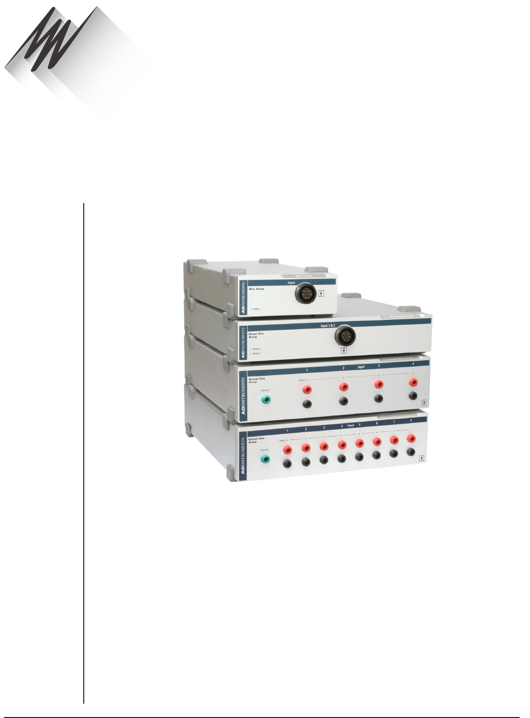
FRONT-END SIGNAL CONDITIONERS - Owner’s Guide
34
This chapter provides an overview of the Bio Amp [FE132], Dual Bio Amp [FE135], Quad
Bio Amp [FE234] and Octal Bio Amp [FE238]. The Bio Amp allows the PowerLab system
to record biological signals, such as ECGs, EMGs, and EEGs from humans or animals.
Bio Amp Safety Instructions
The Bio Amp inputs displaying safety symbols are electrically isolated from the mains
supply in order to prevent current flow that may otherwise result in injury to the subject.
Several points must be observed for safe operation of the Bio Amp:
•The Bio Amp [FE132], Dual Bio Amp [FE135] and PowerLab units with a built-in
Bio Amp are supplied with a 3-lead or 5-lead Bio Amp subject cable and lead wire
system. The Octal Bio Amp [FE238] and Quad Bio Amp [FE234] are supplied with
unshielded lead wires (1.8m). Bio Amps are only safe for human connection if
used with the supplied subject cable and lead wires.
•All Bio Amp front-ends and PowerLab units with a built-in Bio Amp are not
defibrillator-protected. Using the Bio Amp to record signals during defibrillator
discharges may damage the input stages of the amplifiers. This may result in a
safety hazard.
Bio Amp
Chapter 4
WARNING:
Refer to Intended
Use statement
on page 1 of this
Owner’s Guide
before use.
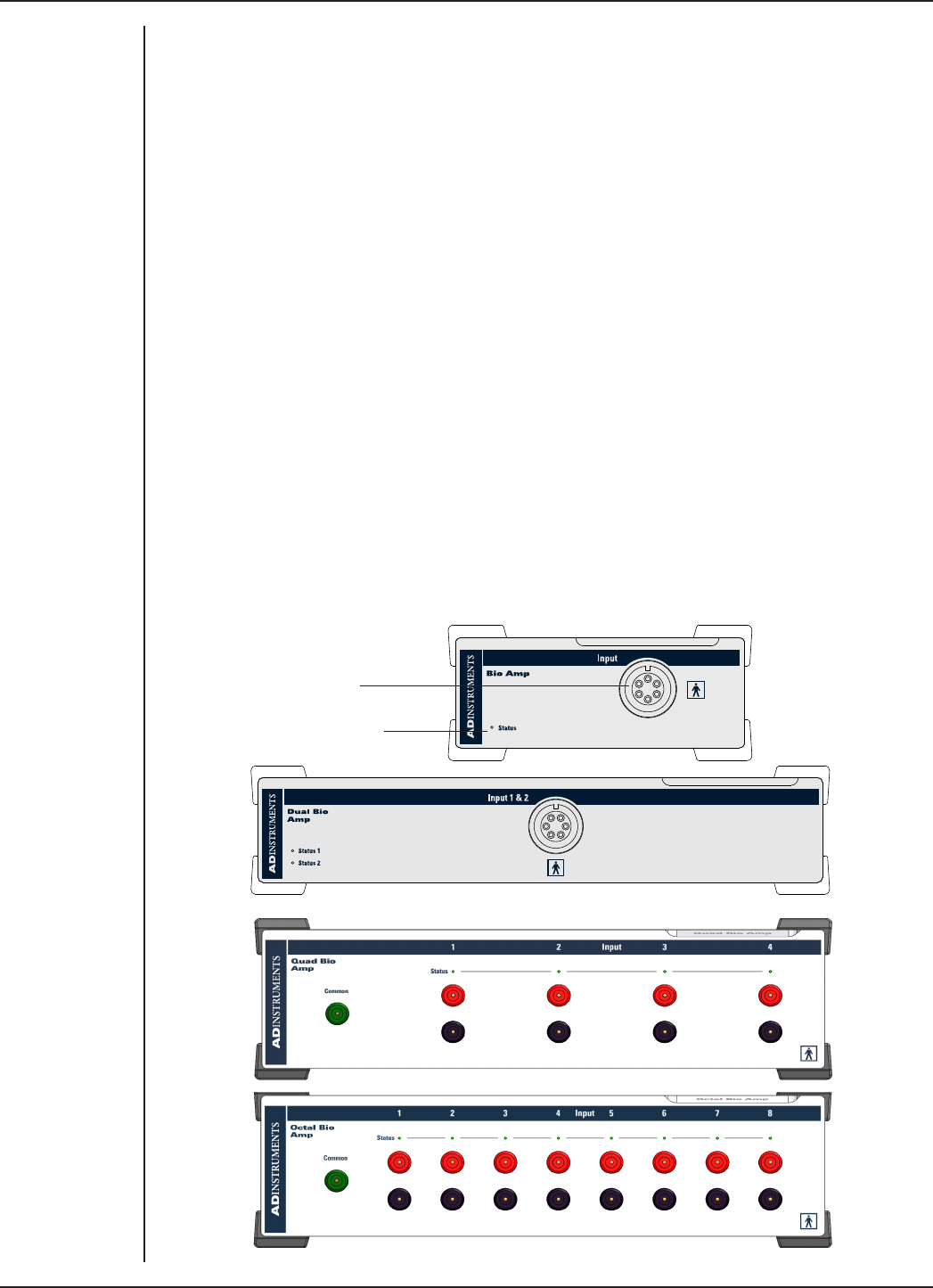
FRONT-END SIGNAL CONDITIONERS - Owner’s Guide
35
•Never use damaged Bio Amp cables or leads. Damaged cables and leads must
always be replaced before any connection to humans is made.
The Bio Amp front-ends
All Bio Amps consist of electrically isolated, dierential input AC amplifiers with common
isolated ground connections (FE234/238 support both AC and DC coupled mode). The
number of amplifiers corresponds to the number of Bio Amp channels. For example,
the Dual Bio Amp has two amplifiers with a shared ground connector and input socket,
and the Octal Bio Amp has eight dierential amplifiers with a shared ground connector
and separate inputs. For multiple biological recordings (more than two) from a single
subject, it is recommended that you use a multi-channel Bio Amp rather than “daisy-
chaining” multiple Bio Amps.
The Front Panel
The front panel of a Bio Amp has a single input and an indicator light.
The front panel of a Dual Bio Amp has a single input, two indicator lights and an audio
output connector.
The front panel of the Quad Bio Amp has nine single-ended 1.5mm sockets consisting of
four red connectors, four black connectors and a single green connector.
The front panel of the Octal Bio Amp has seventeen single-ended 1.5 mm sockets
consisting of eight red connectors, eight black connectors and a single green connector.
Input socket
Status indicator
Figure 4–1
The front views of
the Bio Amp, Dual
Bio Amp, Quad
Bio Amp and
Octal Bio Amp

FRONT-END SIGNAL CONDITIONERS - Owner’s Guide
36
The Input Socket
Connections are made to the Bio Amp and Dual Bio Amp using the six-pin socket on
the front panel. The socket is physically and electrically isolated from the low-voltage
mains-supply circuitry of the PowerLab, and the input connections are isolated
internally, by isolation circuitry. The socket is of a sort commonly used with ECG-type
cables and leads, such as the Bio Amp cable and leads with which your Bio Amp is
supplied (Tronomed D-1340 or Tronomed D-1540). The single Bio Amp and Dual Bio
Amp have dierent pin arrangements, so their Bio Amp cables are not interchangeable.
The socket and connections to it are discussed in more detail later on.
Connections are made to the Quad/Octal Bio Amp using individual lead wires (supplied
with every unit) and a common ground, rather than using a single multi-pin socket. Each
of the Bio Amp inputs has one red and one black connector and an indicator light. The
green connector is a shared ground connection across all eight inputs in Octal and four
in Quad.
The Status Indicator
The status indicator light of a single Bio Amp is located at the bottom le of the front
panel. The status indicator lights of an Octal and Quad Bio Amp are located above the
pair of red and black connectors of each input on the front panel.
When an ADInstruments application such as LabChart starts, the status indicators
should flash briefly and then remain green, indicating that the program has found the
front-end, checked and selected it, and is ready to use it. If a status indicator does not
turn on and stay on when the application starts, it is most likely that the front-end is not
connected properly.
The Back Panel
The back panel of the Bio Amp provides all the sockets required to connect the front-
end to the PowerLab and to other front-ends.
Audio Out Socket
Bio Amps have audio monitor outputs on the rear panel that can be used with standard
headphones or externally powered speakers. The 3.5mm headphone socket provides
sound output from a soware-selected data channel. The audio output may be of use
when monitoring nerve firings to control the placement of electrodes, for instance.
I2C Input and Output
The Bio-Amp communicates with the PowerLab via the 9 Pin I2C Input connector.
This connector can either be connected directly to a PowerLab or to the ‘I2C Output’
connector of another Front-End. Up to 16 Front Ends can be ‘daisy chained’ in this
fashion. More details can be found in the ‘Connecting to the PowerLab’ section in
Chapter 2. The I2C socket allows multiple front-ends to be used independently with one
PowerLab. Power and control signals to connected front-ends come from the PowerLab.
WARNING:
When used
in ambient
temperatures
of 38 degrees C
and above, do
not touch the Bio
Amp enclosure
for more than
a minute
continuously.
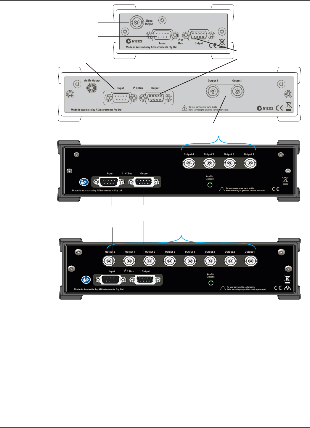
FRONT-END SIGNAL CONDITIONERS - Owner’s Guide
37
Analog Output Sockets
The BNC sockets on the back panel of the Bio Amps provide the signal outputs to
connected analog input sockets of the PowerLab. The sockets are labeled Signal Output
on a single Bio Amp and Output 1 to Output n on a multi-channel Bio Amp. A BNC-to-BNC
cable is supplied for each connection. It is recommended that, to avoid confusion, you
match the Bio Amp output number with the corresponding PowerLab input connector.
Audio Out Socket
The single Bio Amp has an audio monitor output on the back panel that can be used
with a wide range of headphones or externally powered speakers. The 3.5 mm stereo
socket provides mono sound. The audio output may be of use when monitoring nerve
firings to control the placement of electrodes, for instance.
I2C connection
from the
PowerLab or
previous front-end
I2C connection to a
further front-end
Signal output to
the PowerLab
I2C connection from
the PowerLab or
previous front-end Signal outputs to
the PowerLab
I2C connection to a
further front-end
Figure 4–2
The rear views of
the Bio Amp, Dual
Bio Amp, Quad
Bio Amp and
Octal Bio Amp
Signal outputs to
the PowerLab
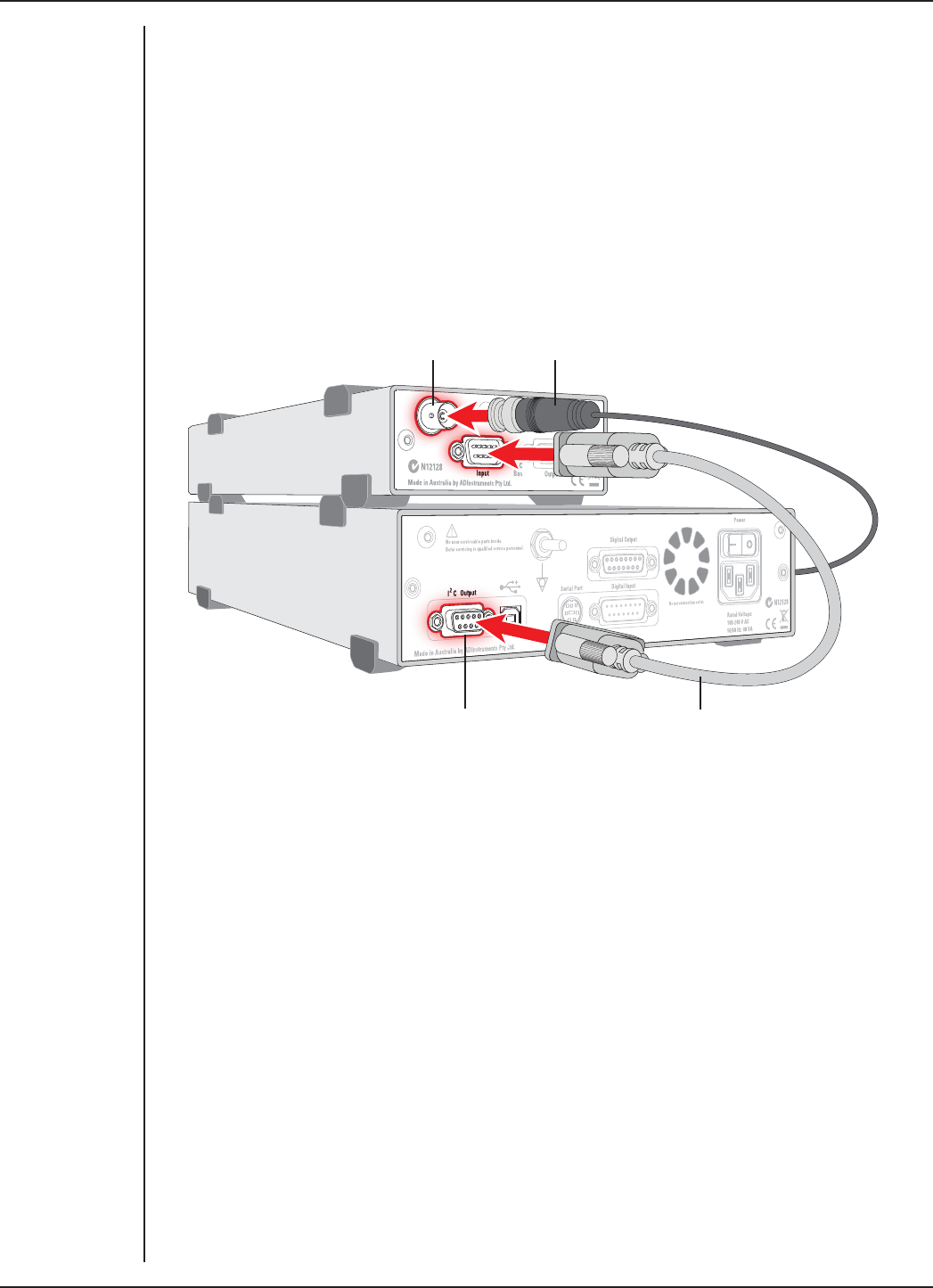
FRONT-END SIGNAL CONDITIONERS - Owner’s Guide
38
Connecting to the PowerLab
To connect a Bio Amp to the PowerLab, first ensure that the PowerLab is turned o.
Failure to do this may damage the PowerLab, the Bio Amp, or both.
Connect each signal output on the rear panel of the Bio Amp, Dual Bio Amp or Octal Bio
Amp to an analog input on the front panel of the PowerLab using a BNC cable. Connect
the I2C output of the PowerLab to the I2C input of the front-end using the I2C cable
provided. Figure 4–3 shows how to connect up a single front-end to your recording unit.
Check that the plugs for the I2C bus are screwed in firmly. Check the BNC cable for firm
connections as well. Loose connectors can cause erratic front-end behavior, or may
cause the front-end to fail to work at all. The BNC cable can be tucked under the front-
end to keep it out of the way if desired.
Multiple separate front-ends can be connected to a PowerLab. The number of front-
ends that can be connected depends on the number of input channels on the PowerLab,
since each signal output from a front-end connects to one of the analog inputs of the
PowerLab. The initial front-end should be connected with the I2C cable as shown in
Figure 4–3. The remainder are daisy-chained via I2C cables, connecting the I2C output of
the last connected front-end to the I2C input of the front-end to be added, as shown in
Figure 2–2.
Using More Than One Bio Amp
If you intend to record with more than one channel using a common Ground/reference,
such as when recording from a single subject, it is recommended that you use a Dual Bio
Amp rather than two Bio Amps, or that you use an Quad/Octal Bio Amp rather than two
or more Dual Bio Amps. Some interaction can take place between individual Bio Amp
WARNING:
The FE132,
FE135, FE136 and
FE185 amplifiers
have only been
assessed as
compliant with
IEC60601-1 safety
standard when
used with a 35
series PowerLab
Figure 4–3
Connecting a
Bio Amp to the
PowerLab
Bio Amp Signal Output
Bio Amp I2C input
PowerLab I2C output I2C connector cable
BNC connector cable
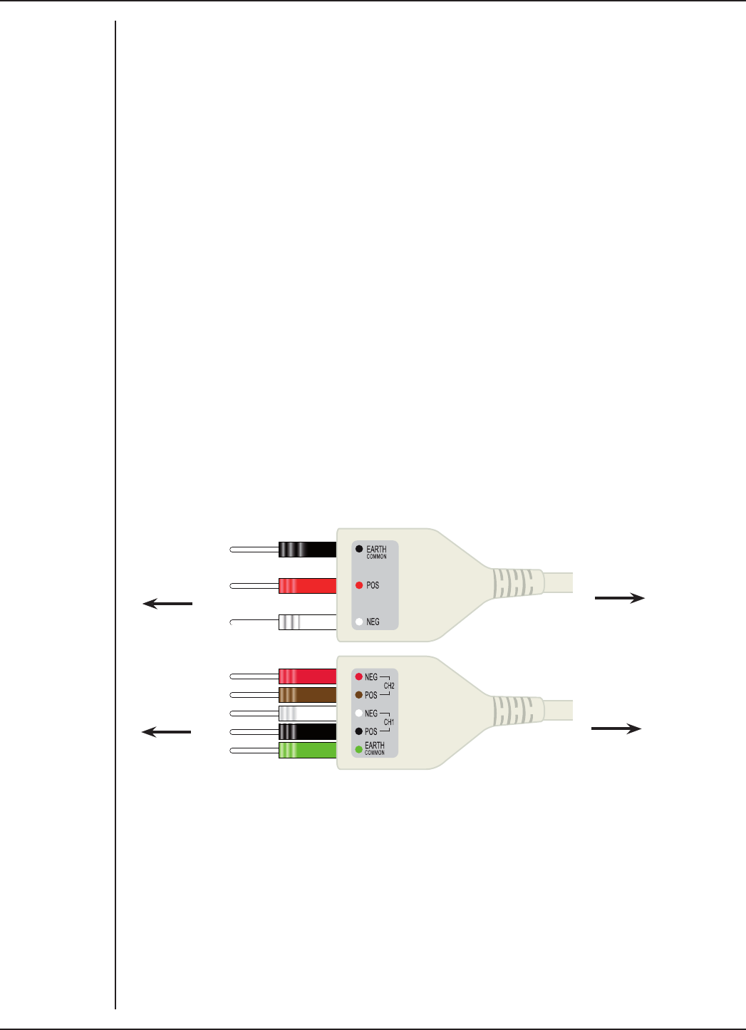
FRONT-END SIGNAL CONDITIONERS - Owner’s Guide
39
front-ends, causing up to 10 µV of induced low-frequency signal due to slight dierences
in frequency between the isolated power supplies.
For multiple channel recordings, using the Dual Bio Amp or the Octal Bio Amp avoids
this problem because the Dual Bio Amp has two amplifiers with a shared Ground/
reference connector and single input socket, and the Octal Bio Amp has eight dierential
amplifiers with a shared Ground/reference connector and separate inputs.
Supplied Accessories
Octal/Quad Bio Amp:
•MLA0310 Lead wires, unshielded
•MLAC27 Quad BNC-BNC cables
•MLAC02 DB9M- DB9M cable
The Bio Amp Cable
Connections should be made to the Bio Amp and Dual Bio Amp inputs using the
supplied Bio Amp cable and leads. The cable plugs into the six-pin input socket on the
front panel: a notch in the plug ensures that polarity is correct. Only the supplied Bio
Amp cable and leads should be used. Other cables may not meet safety requirements.
Note: The single Bio Amp and Dual Bio Amp have dierent pin arrangements, so their
Bio Amp cables are not interchangeable.
To Bio Amp
To Dual Bio Amp
To electrodes
To electrodes
The single Bio Amp is supplied with a 3-lead Bio Amp cable and lead wires. The Dual
Bio Amp is supplied with a 5-lead Bio Amp cable and lead wires; it uses a shared ground
signal for its Bio Amp inputs. The supplied cables are of the type used for ECG or EMG
studies: Tronomed D-1340 or Tronomed D-1540 cables respectively. The cable has a
yoke with three or five sockets for the lead wires. Note that the active pins of a shielded
cable are those closest to the label.
The lead wires supplied are of the type used for ECG studies. They click into place in
the cable yoke, and have snap connectors at the other end to connect to typical ECG
electrodes. The leads are color-coded for identification. The labels on the Bio Amp cable
also have color spots to help sort out which cables connect where and what they are
Figure 4–4
Bio Amp cable
yokes, with leads
attached: 3 leads
for the Bio Amp,
and 5 leads for
the Dual Bio Amp
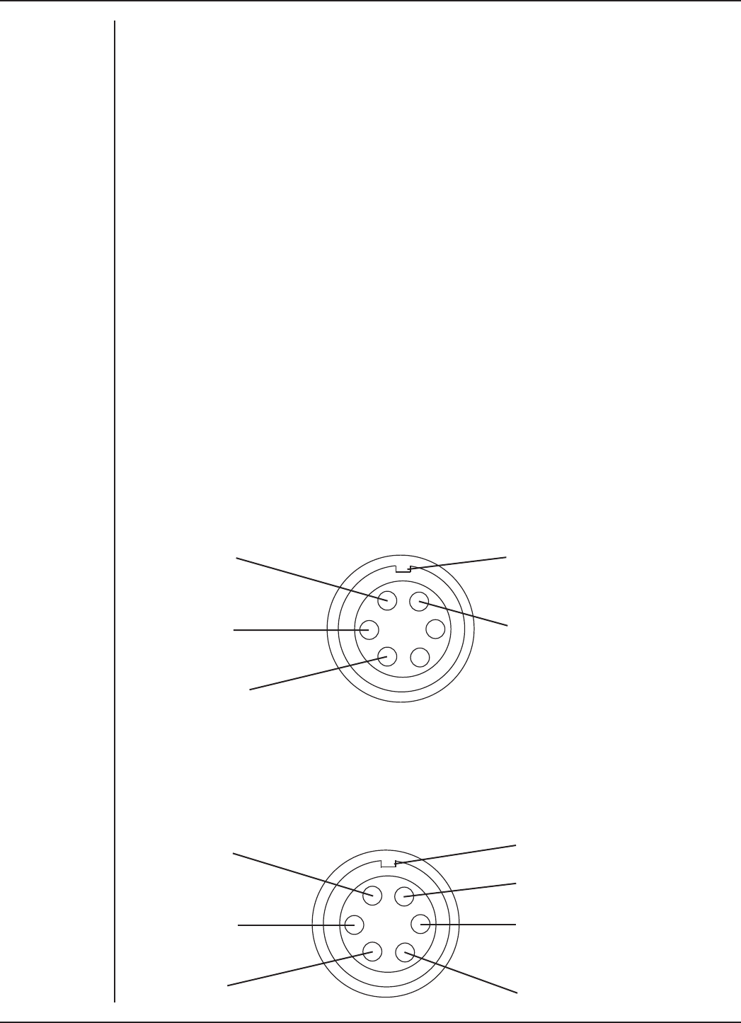
FRONT-END SIGNAL CONDITIONERS - Owner’s Guide
40
measuring. (The colors are arbitrary, since the PowerLab system is for general-purpose
recording.)
Connections to the Octal and Quad Bio Amp inputs can be made with the supplied lead
wires. The input sockets are for unshielded, single-ended lead wires with a 2 mm inside
diameter with 1.5 mm pins.
ADInstruments supplies other types of lead wires that connect to the Bio Amp cable
yoke. Also available are disposable and reusable electrodes, electrode cream (for
reusable electrodes), and abrasive gel, for lightly abrading the skin before the electrodes
are attached.
The Bio Amp Cable Input
The Bio Amp cable, for the Bio Amp and Dual Bio Amp, plugs into the six-pin input socket
on the front panel of the Bio Amp. A notch in the plug ensures that polarity is correct.
Only the supplied Bio Amp cable and lead wires should be used as other cables may not
meet safety requirements.
Note: The pin arrangement of the Bio Amp and the Dual Bio Amp is dierent; the Bio
Amp cables are not interchangeable. (The Bio Amp is supplied with a 3-lead Bio Amp
cable, whereas the Dual Bio Amp is supplied with a 5-lead Bio Amp cable.)
The Bio Amp has one connector: providing two pins for a dierential input signal, a
separate pin for the Ground/reference signal, and another connected to the cable’s
shield. The entire connector is physically and electrically isolated to ensure subject
safety.
Polarising key (to fit notch in plug)
Shield
Ground/Reference
Positive input (+)
Negative input (–)
The Dual Bio Amp has one common connector for two Bio Amp channels, nominally
channels 1 and 2. The biological amplifiers both have dierential inputs, a shared
Ground/reference, and connection to the cable’s shield. The entire connector is
physically and electrically isolated to ensure subject safety.
Ground/Reference
CH2 Negative (–)
CH2 Positive (+)
Polarising key (to fit notch in plug)
Shield
CH1 Positive (+)
CH1 Negative (–)
Figure 4–5
The pin
assignments
for the single
Bio Amp input
connector
Figure 4–6
The pin
assignments for
the Dual Bio Amp
input connector

FRONT-END SIGNAL CONDITIONERS - Owner’s Guide
41
The Octal Bio Amp has a pair of connectors for each of the eight Bio Amp inputs, and a
single connector for the shared Ground/reference. The Quad has a pair of connectors for
each the four Bio Amp inputs, and a single connector for the shared Ground/reference.
The connectors are physically and electrically isolated to ensure subject safety. The
Octal and Quad Bio Amps should be used with the supplied 1.8m unshielded lead wires.
Positive input
(red)
Negative input
(black)
Ground/
Reference (green)
Common
The Common lead must always be connected to the subject to ensure that the common-
mode signal seen by the inputs is not unduly large. An unduly large common mode
signal may lead to poor signal quality.
Shutdown Procedure: Aer use, the Bio Amp should be shut down by quitting LabChart
and powering o the PowerLab
Using LabChart
Once the Bio Amp is connected, turn the PowerLab on and launch LabChart. When a Bio
Amp is properly connected to the PowerLab, the Input Amplifier… menu command is
replaced by Bio Amp… for the input channel to which it is connected.
If LabChart fails to find a front-end connected, the normal text remains. If you were
expecting a connected front-end and see the normal text instead, you should quit
the application, turn the PowerLab o and check the connections. Then restart the
PowerLab and re-launch LabChart.
The documentation for LabChart and Scope does not cover front-end-specific features.
These features are described in detail here for LabChart.
The Bio Amp dialog
The Bio Amp dialog (Figure 4–8 and Figure 4–9) allows soware control of the combined
input amplifiers and filters in the PowerLab and Bio Amp. The signal present at a
channel’s input is displayed in the preview area so that you can see the eects of
changes in settings. Change settings in the dialog, then click the OK button to apply
them.
The Bio Amp dialog appears when you choose Bio Amp… from a Channel Drop
Down menu. To set up many channels quickly, open the Setup > Channel Settings...
dialog. Here you can view all the channels that are turned on, and you can turn o
Figure 4–7
The connectors
for each input of
the Octal/Quad
Bio Amp
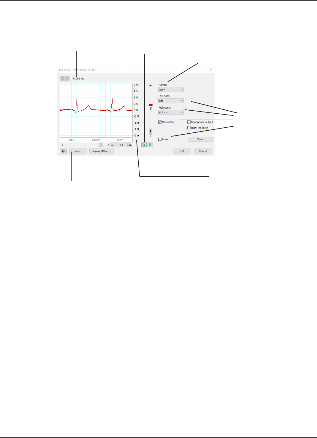
FRONT-END SIGNAL CONDITIONERS - Owner’s Guide
42
any unnecessary channels. Clicking on Bio Amp… in the Input Settings column of the
Channel Settings dialog will also open the Bio Amp dialog.
Signal amplitude Pause and Scroll buttons
Range pop-up menu
Filtering options
Amplitude axis
Click this button to open the Units Conversion dialog
Signal Display
The input signal is displayed so you can see the eect of changing the settings — no data
are recorded while setting things up. The instantaneous signal value is shown above the
display area.
Figure 4–8
The Bio Amp
dialog in LabChart
for Windows for
the Dual
and Octal/Quad
Bio Amps

FRONT-END SIGNAL CONDITIONERS - Owner’s Guide
43
Setting the Range
The Range pop-up menu lets you select the input range of the channel (combined range
of the PowerLab and Bio Amp). Note that range is inversely related to gain (e.g, 100 mV
range is the lowest gain and sensitivity setting). Changing the range in the Bio Amp
dialog is equivalent to changing it using the arrow in the top right hand corner of the
channel in the Chart View Window. Changing the hardware range setting should not be
confusing with adjusting the y axis scaling using the + and - buttons on the le of each
channel. The default setting (if you have not loaded a settings file) is 100 mV and the
ranges go down to 5 µV in 14 steps (100 µV in 10 steps for Quad/Octal Bio Amps).
Filtering
The Bio Amp has low-pass, high-pass, and mains filter circuitry that can be adjusted
to suit the application. The mains and notch filters remove excessive mains-frequency
interference. The high-pass and low-pass filters provide bandwidth limiting of low-
frequency and high-frequency signals respectively. Note that the settings for one filter
type may restrict the possible settings for the other.
High-Pass Filtering. The High Pass pop-up menu gives a choice of high-pass filters.
The high-pass filter removes frequencies below the chosen frequency and allows high
frequencies in the signal. These filters are useful for removing slowly moving baselines,
such as motion or respiration artifacts, particularly in ECG (EKG) recordings.
Low-Pass Filtering. The Low Pass pop-up menu gives a choice of low-pass filters.
The low-pass filter removes frequencies above the chosen frequency and allows low
frequencies in the signal. These filters are useful for removing high-frequency signals,
such as noise, and to prevent aliasing in the recorded signal.
Notch Filter. Notch filtering is a hardware filter which is only supported on certain Bio
Amps (FE/ML 132, 135, 136, 138). Select or deselect the Notch checkbox to turn the notch
filter on and o. The notch filter is automatically set to either 50 or 60 Hz, depending on
the power line voltage frequency being used by the PowerLab (the mains frequency). It
provides approximately 32 dB of attenuation, thus reducing the eect of the 50 or 60 Hz
signals that can easily be picked up by long leads.
Mains Filter. Select or deselect the Mains filter checkbox to turn the mains filter
on and o. The mains filter allows you to remove interference related to the mains
frequency (both fundamental and harmonic frequencies). This is an adaptive filter. It
adjusts to filter the interference by tracking the input signal for a second. Because of
this, in general, using the mains filter is better than using the notch filter but the mains
filter does have some limitations. More details on the mains filter can be found in the
LabChart Help Center.
Anti-alias. Anti-aliasing is a feature only supported when the Single and Dual Bio Amp
(Octal and Quad not supported) is connected to 2/26, 4/26, 15T and 26T PowerLabs.
Click the Anti-alias checkbox to turn anti-aliasing on and o. Aliasing occurs when a
regular signal is digitized at too low a sampling rate, causing the false appearance of
lower frequency signals. To prevent aliasing, the sampling rate must be at least twice
the highest frequency in the incoming waveform. When aliasing of noise or signals is
seen, or even suspected, the first action you should take is to increase the sampling
rate. If this reveals unwanted high-frequency components in the sampled signal, you
will achieve better results by using a low-pass filter to remove them. The best kind of

FRONT-END SIGNAL CONDITIONERS - Owner’s Guide
44
filter for this purpose is the Anti-alias filter option in the Bio Amp... dialog. This is a
special low-pass filter that is configured to automatically remove all signals that could
alias; i.e., those whose frequency is greater or equal to half the sampling rate. A high
sampling rate, however, will use more computer memory and may limit recording time
so, once you have established the frequencies of interest in your incoming signal, with
Anti-alias selected the sampling rate can be scaled down accordingly.
Inverting the Signal
The Invert checkbox provides a simple way to change the polarity of the recorded signal
without having to swap the connections to the recording electrodes.
DC Restore
The DC Restore or Zero button is available in the Bio Amp dialog for the Dual, Quad and
Octal Bio Amps. It provides a quick way to bring the recording trace back to zero. It is
for use with very low high-pass filter settings, since the trace can take a long time to
zero automatically at those settings. In later versions of LabChart the DC Restore All
command from the Setup menu performs this operation on all Bio Amp channels.
Using the Bio Amp
Standard electrophysiology texts describe how to record various types of biological
signal. ADInstruments also produces materials describing specific uses of Bio Amps,
such as Animal Physiology and Human Physiology LabChart experiments, that can be
downloaded from the ADInstruments website or obtained from your ADInstruments
representative.
Some Suitable Uses
The Bio Amp can measure a wide variety of biological signal sources. Some of these
measurements include:
ECG. Electrocardiogram (also referred to as EKG); a recording of surface potentials due
to electrical currents associated with the heartbeat.
EEG. Electroencephalogram; a recording of the electrical activity of the brain. Scalp
electrodes record potential waves (10–100 µV) representing the summed activity of
cortical neurons.
EMG. Electromyography; a recording of the electrical activity of a muscle, using surface
electrodes. The recorded activity may be a voluntary contraction, or evoked by motor
nerve stimulation.
EOG. Electro-oculogram; a recording of the potential dierence between the front and
back of the eyeball, as projected on to the face. Only supported on Octal and Quad Bio
Amps (not supported on Single and Dual Bio Amps)
ERG. Electroretinogram; a recording of the electrical signals produced in the retina by a
light stimulus. Bilateral measurements require a Dual Bio Amp, or two Bio Amps.

FRONT-END SIGNAL CONDITIONERS - Owner’s Guide
45
Cortical Evoked Potentials. Averaged recordings of the electrical activity of the brain
when subject to stimulation: visual evoked response, auditory evoked response, and
somatosensory response. These should be done with signal averaging, using Scope
view.
SNAP. Sensory nerve action potential; a recording of evoked responses in stimulated
nerves. This is usually done with signal averaging, using Scope view.
Some Unsuitable Uses
The Bio Amp, Dual Bio Amp and Quad/Octal Bio Amp are not recommended for work
requiring high-impedance electrodes or using a high bandwidth. Some of the tasks for
which it is not really suitable include:
•Intracellular micropipette recordings. Recordings from a very fine, electrolyte-
filled tube inserted into a nerve or muscle cell. These require an electrometer
amplifier.
•Needle electromyography; the intramuscular recording of the electrical activity
of a muscle, which requires low input capacitance and a driven guard.
For these a headstage is required. The bandwidth is limited to approximately 5 kHz.
Recording Technique
Several problems can arise when using the Bio Amp to record signals. These are basic
problems of technique, and should be addressed before setting up. It is important to
understand the types of problems that can occur, how they manifest, and what can
be done to remove them or to minimize their eect. Potential problem areas include
aliasing, frequency distortion, saturation, ground loops, electrode contact, motion
artifacts, electromagnetic fields, and data display.
There is a good introduction to data acquisition provided in the documentation for
LabChart. It is highly recommended reading for anyone recording biological signals
using the front-end. Apart from the general areas covered in that material, two things
particularly aect the kind of measurements made with the Bio Amp, and can cause
‘artifacts’ (spurious readings) in the recorded waveform: electrode contact and motion
eects.
Electrode Contact. Occasionally during measurement of a biological signal, one of
the lead wires connecting the source to the front-end may become disconnected, or
an electrode contact may become poor. If this should happen, relatively high voltages
(potentials) can be induced in the open wire, due to electric fields caused by the power
line or other sources close to the front-end or to the subject. This induced potential
results in a constant amplitude disturbance of the recorded waveform at the power line
frequency, and loss of the desired signal. If the problem is a recurring one, one of the
leads may be faulty. Check connections and replace faulty leads, if necessary.
Make sure that skin is cleaned and lightly abraded before attaching electrodes to it.
Ensure that there is suicient electrode cream to maintain a good contact: if it dries out,
the contact will be poor, and the recorded signal may be degraded or lost.
Motion Eects. A common source of artifacts when recording biological signals is
motion of the subject or equipment. For example, muscular activity generates its own

FRONT-END SIGNAL CONDITIONERS - Owner’s Guide
46
electrical signals, which may be recorded along with an ECG, depending on the
location of the electrodes. If an electrode is not firmly attached, impedance (and
hence the recorded signal) may vary as the contact area changes shape owing
to movement. Movement of Bio Amp cables and leads, particularly bending or
rubbing together (triboelectric eects) may also generate artifacts in a signal.
Subject respiration can also generate a signal: breathing can result in a slowly
changing baseline corresponding to inspiration and expiration. Oen applying a
high-pass filter can help to remove slowly changing components from a recorded
signal.
Bio Amp Operation
The Bio Amp and other ADInstruments front-ends have been designed to integrate
fully into the PowerLab system. The Bio Amp is essentially an extension of the
PowerLab’s input amplifiers. The amplification and ranges oered in LabChart
result from the combination of both pieces of hardware. The Dual Bio Amp is an
enhanced double version of the single Bio Amp, with a common power supply and
isolated ground. There are some modifications, but it is similar to the Bio Amp
overall.
The Bio Amp provides:
•full electrical isolation from power-line (mains) circuitry to guarantee
subject safety
•a low-noise, high-gain dierential amplifier specifically designed for
biological signal measurements
•soware-controlled low-pass, high-pass, and notch filters to remove
unwanted signal frequencies for particular uses
•audio output for use with EMG or EEG signals.
Right-leg Drive
The Quad and Octal Bio Amps include a feature known as Right-leg drive or a Driven
Right Leg circuit. This circuit helps to reduce electrical interference from the mains
picked up by the human body or via patient leads. In order to use this feature, the
patient connections of channel 1 must be connected to the subject and the Right-
Leg drive checkbox must be ticked. If the Right-leg drive checkbox is unticked, the
green common terminal is connected to isolated ground inside the Bio Amp. The
Right-leg drive circuit uses the green Common terminal and a patient lead must be
connected to this terminal in order to use this feature.
The Bio Amp Cable Input
The Bio Amp cable, supplied with the Bio Amp and Dual Bio Amp, plugs into the six-
pin input socket on the front panel of the Bio Amp. A notch in the plug ensures that
polarity is correct. Only the supplied Bio Amp cable and lead wires should be used
as other cables may not meet safety requirements.
Note: The pin arrangements for the Bio Amp and the Dual Bio Amp are dierent;
the Bio Amp cables are not interchangeable. (The Bio Amp is supplied with a 3-lead
Bio Amp cable, whereas the Dual Bio Amp is supplied with a 5-lead Bio Amp cable.)

FRONT-END SIGNAL CONDITIONERS - Owner’s Guide
47
Troubleshooting
This section describes the common problems that can occur when using the Bio Amp
with your PowerLab recording unit. It covers how these problems are caused, and what
you can do to alleviate them. If the solutions here do not work, refer to earlier chapters,
the LabChart Help Center, and your PowerLab Owner’s guide for possible remedies. If
none of the solutions here or elsewhere are of help, then consult your ADInstruments
representative.
Most of the problems that users encounter are connection problems, and can usually be
fixed by checking connections and starting up the hardware and soware again. Very
rarely will there be an actual problem with the front-end or the PowerLab.
Problems and Solutions
The status indicator fails to light when the soware is started, or the Bio Amp... dialog(s) do
not appear where they should
The I2C cable or one or more BNC-to-BNC cables from the Bio Amp to the PowerLab are
not connected, have been connected incorrectly (to the wrong input, for instance), or
are loose.
•Turn everything o. Check to see that all cables are firmly seated and screwed
in. BNC cables from the Bio Amp must be connected to a positive input on the
PowerLab. Make sure the input is the same channel from which you expect to use
the front-end in the soware. Start up again to see if this has fixed the problem.
You are using an early version of LabChart.
•Upgrade to the latest version of the soware. Contact your ADInstruments
representative for information.
The BNC or I2C cable is faulty.
•Replace the cable and try again. Immediately label all cables proved faulty so
that you don’t use them again by accident.
The Bio Amp is faulty
•This is the least likely event. If the front-end will not work properly aer the
previous measures, then try using it on another PowerLab. If the same problems
recur with a second PowerLab, the front-end may be faulty. Contact your
ADInstruments representative to arrange for repairs.
On starting up the soware, an alert indicates that there is a problem with the front-end or
driver
The correct Bio Amp driver is not installed on your computer.
•Reinstall the soware.
You are using an early version of LabChart or Scope.
•Upgrade to the latest version of the soware. Contact your ADInstruments
representative for information.

FRONT-END SIGNAL CONDITIONERS - Owner’s Guide
48
The BNC or I2C cable is faulty.
•Replace the cable and try again. Immediately label all cables proved faulty so
that you don’t use them again by accident.
The Bio Amp is faulty.
•This is the least likely event. If the front-end will not work properly aer the
previous measures, then try using it on another PowerLab. If the same problems
recur with a second PowerLab, the front-end may be faulty. Contact your
ADInstruments representative to arrange for repairs.
The trace will not zero properly when adjusting high-pass filtering
The Bio Amp is receiving signals at a level that has saturated the input amplifier,
resulting in a large oset. This is normally due to poor contact between the electrodes
and the subject.
•Check the connections for proper contact and try again.
If you are using the Dual, Quad or Octal Bio Amps, with the 0.02 Hz high-pass filter, the
trace can take a long time to zero by itself.
•Click the DC Restore button in the Bio Amp dialog to bring the trace back to zero
quickly.
The signal appears to display a constant amplitude oscillation
Frequency interference from power lines can become superimposed on the biological
signal being measured.
•You can use the internal notch filter in the Bio Amp to remove excessive line
voltage frequency interference (use the checkbox in the Bio Amp dialog).
If you are using cables and leads that were not supplied with your Bio Amp, they may be
unshielded or of low quality.
•Check to make sure that you are using high-quality shielded cables and high-
quality leads. Only the supplied Bio Amp cable and leads should really be used.
The signal is noisy at lower ranges
This is probably the amplified noise from the electrodes, not a fault as such. There is, in
addition, noise that cannot be avoided by any amplifier (called ‘thermal’ or ‘Johnson’
noise).
•Set the low-pass filter to remove the noise. (But be careful, since important
components of the signal could also be attenuated.)
This could be due an electrically noisy environment, particularly if there is some
equipment that produces a radio frequency that interacts with the Bio Amp modulator,
giving a heterodyne eect.
•Turn o pieces of unnecessary equipment to try and isolate the cause, then
either leave the equipment o, or, if possible, move the subject or equipment
outside the area of any interfering field.
•At the lowest ranges you may have to shield, shorten, or even replace the Bio
Amp leads, since they will tend to act as radio receptors.
The signal appears to be unusual, very weak, clipped, or distorted in some way

FRONT-END SIGNAL CONDITIONERS - Owner’s Guide
49
This may be a problem of technique: the sampling rate, range, or filter settings may be
inappropriate for the signal you are recording.
•Make sure the settings are appropriate for the expected signal.
You may be using the wrong Bio Amp cable for the type of input. The single Bio Amp
and Dual Bio Amp have dierent pin arrangements, so their Bio Amp cables are not
interchangeable.
•Use the correct, supplied Bio Amp cable: a 3-lead cable for the single Bio Amp
and a 5-lead cable for the Dual Bio Amp.

FRONT-END SIGNAL CONDITIONERS - Owner’s Guide
50
Specifications
Single Bio Amp
Input
Connection type: Six-pin DIN/MS socket to fit 3-lead Bio Amp cable
(Tronomed D-1340)
Input configuration: 1 isolated dierential channel with isolated ground
reference
Input impedance: 200 MΩ dierential, 30 pF (no cable) or 500 pF (supplied
Bio Amp cable and leads) to isolated ground
Isolation: 4000 Vrms (50 Hz for 1 minute)
Amplification ranges: ± 5 µV to ± 100 mV full scale in 14 steps (combined
PowerLab and Bio Amp)
± 100 mV
± 50 mV
± 20 mV
± 10 mV
± 5 mV
± 2 mV
± 1 mV
± 500 µV
± 200 µV
± 100 µV
± 50 µV
± 20 µV
± 10 µV
± 5 µV
Gain accuracy: ± 1.5% all ranges
Non-linearity: < 0.2% within range
Noise at various bandwidths: 1 Hz to 5 kHz: < 1.3 µVrms (< 8 µV p-p)
0.3 Hz to 1 kHz: < 0.6 µVrms
0.1 Hz to 100 Hz: < 0.35 µVrms (@ 200 samples/second)
IMRR (isolation mode): > 130 dB (to true earth, 50–60 Hz)
CMRR (common mode): > 85 dB typical (1–60 Hz)

FRONT-END SIGNAL CONDITIONERS - Owner’s Guide
51
Input leakage current: < 3 µArms @ 240V, 50 Hz
< 2 µArms @ 120V, 60 Hz
DC blocking: ± 1 V
Baseline restoration: Automatic
Filtering
Low-pass filtering: Fourth-order Bessel filter, ± 3% accuracy. Frequencies
soware-selectable. Standard: 50, 100, 200, 500, 1000, &
5000 Hz (@ –3 dB);
EEG mode: 3, 10, 30, 60, & 120 Hz
High-pass filtering: First-order filter, ± 0.25% accuracy. Frequencies
soware-selectable.
Standard: 0.1, 0.3, 1, 3, & 10 Hz (@ –3 dB);
EEG mode: 0.03, 0.1, 0.3 & 1 seconds
Notch filter: Second-order filter, –32 dB attenuation;
50 or 60 Hz frequency (automatic sensing)
Output
Signal: ± 2.0 V standard
Audio: Stereo jack with mono output; ± 200 mV full scale,
current limited to ± 5 mA. Suitable for headphones or
unpowered speakers.
Control Port
I2C port: Provides control and power. Interface communications
rate of ~50 kbits/s.
Physical Configuration
Dimensions (h × w × d): 55 mm × 120 mm × 260 mm (2.2" × 4.7" × 10.2")
Weight: 1.3 kg (2 lb 12 oz)
Power requirements: ~2 W
Operating conditions: 5–35 °C, 0–90% humidity (non-condensing)
Safety
Safety: Approved to IEC 60601-1 Standard (BF rating)
EMC: Approved to EN61326-1:2006 Standard
Other approvals: CSA/US
Equipment: Class I
Operation: Continuous
WARNING:
In order to
comply with
IEC60601-1,
MLA1250 stereo
headphones
must be used.

FRONT-END SIGNAL CONDITIONERS - Owner’s Guide
52
Unsuitable uses: Do not use in the presence of flammable anaesthetic - air
mixtures. Avoid operating near high voltage, RF or strong
magnetic fields that may cause interference.
Method of disposal: Forward to recycling centre or return to manufacturer.
Dual Bio Amp
Input
Connection type: Six-pin DIN/MS socket to fit 5-lead Bio Amp cable
(Tronomed D-1540)
Configuration: 2 isolated dierential channels with common isolated
ground reference
Input impedance: 200 MΩ dierential, 30 pF (no cable) or 500 pF (supplied
Bio Amp cable and leads) to isolated ground
Isolation: 4000 Vrms (50 Hz for 1 minute)
Input ranges: ± 5 µV to ± 100 mV full scale in 14 steps (combined
PowerLab and Bio Amp)
± 100 mV
± 50 mV
± 20 mV
± 10 mV
± 5 mV
± 2 mV
± 1 mV
± 500 µV
± 200 µV
± 100 µV
± 50 µV
± 20 µV
± 10 µV
± 5 µV
Accuracy: ± 1.5% all ranges
Non-linearity: < 0.2% within range
Noise at various bandwidths: 1 Hz to 5 kHz: < 1.3 µVrms (< 8 µV p-p)
0.3 Hz to 1 kHz: < 0.6 µVrms
0.1 Hz to 100 Hz: < 0.35 µVrms (@ 200 samples/second)

FRONT-END SIGNAL CONDITIONERS - Owner’s Guide
53
IMRR (isolation mode): > 135 dB (to true earth, 50–60 Hz)
CMRR (common mode): > 85 dB typical (1–60 Hz)
Input leakage current: < 3 µArms @ 240 V, 50 Hz
< 2 µArms @ 120 V, 60 Hz
DC blocking: ± 1 V
Baseline restoration: Automatic or manual
Filtering
Low-pass filtering: Fourth-order Bessel filter, ± 3% accuracy. Frequencies
soware-selectable. Standard: 50, 100, 200, 500, 1000,
2000, & 5000 Hz (@ –3 dB);
EEG mode: 3, 10, 30, 60, & 120 Hz
High-pass filtering: First-order filter, ± 0.25% accuracy. Frequencies
soware-selectable.
Standard: 0.02, 0.1, 0.3, 1, 3, & 10 Hz (@ –3 dB);
EEG mode: 0.03, 0.1, 0.3 & 1 seconds
Notch filter: Second-order filter, –32 dB attenuation;
50 or 60 Hz frequency (automatic sensing)
Output
Signal: ± 2.0 V standard
Audio output: Stereo output supplying signals from both data channels;
±200 mV full scale, current limited to ± 5 mA. Suitable for
headphones or unpowered speakers.
Control Port
I2C port: Provides control and power. Interface communications
rate of ~50 kbits/s.
Physical Configuration
Dimensions (h × w × d): 55 mm × 240 mm × 260 mm
(2.2" × 9.4" × 10.2")
Weight: 2.0 kg (4 lb 6.4oz)
Power requirements: ~3 W
Operating conditions: 5–35 °C, 0–90% humidity (non-condensing)
Transport/storage conditions: 0–40 °C, 0–95% relative humidity
WARNING:
In order to
comply with
IEC60601-1,
MLA1250 stereo
headphones
must be used.

FRONT-END SIGNAL CONDITIONERS - Owner’s Guide
54
Safety
Safety: Approved to IEC 60601-1 Standard (BF rating)
EMC: Approved to EN61326-1:2006 Standard
Other Approvals: CSA/US
Operation: Continuous
Unsuitable uses: Do not use in the presence of flammable anaesthetic - air
mixtures. Avoid operating near high voltage, RF or strong
magnetic fields that may cause interference. Equipment
is not suitable for use in the presence of a flammable
anaesthetic mixture with air or oxygen or nitrous oxide.
Method of Disposal: Forward to recycling centre or return to manufacturer.
Quad/Octal Bio Amp
Input
Connection type: 9 × 1.5 mm (Quad) or 17 × 1.5 mm (Octal) pin shrouded
male socket to suit single pin 1.5 mm
Configuration: 4 (Quad) or 8 (Octal) isolated dierential channels with
common isolated ground reference or right leg drive
Input impedance: >1 GΩ dierential, <100 pF (no cable) to isolated ground
Isolation: 4000 Vrms (50 Hz for 1 minute)
Input ranges: ± 100 µV to ± 100 mV full scale in 10 steps (combined
PowerLab and Bio Amp)
± 100 mV
± 50 mV
± 20 mV
± 10 mV
± 5 mV
± 2 mV
± 1 mV
± 500 µV
± 200 µV
± 100 µV
Gain accuracy: ± 1.5% all ranges
Non-linearity: < 0.2% within range
Noise at various bandwidths: 1 Hz to 10 kHz: < 1.3 µVrms (< 8 µV p-p)

FRONT-END SIGNAL CONDITIONERS - Owner’s Guide
55
0.3 Hz to 1 kHz: < 0.7 µVrms
0.1 Hz to 100 Hz: < 0.35 µVrms
IMRR (isolation mode): > 160 dB (to non-isolated earth, 50 Hz)
CMRR (common mode): >75 dB typical (150K electrode impedance, 5K imbalance
@50Hz and 60Hz)
>100dB typical (Balanced electrode impedance @50Hz
and 60Hz)
Input leakage current: < 4 µArms @ 240 V, 50 Hz
DC tolerance: ± 370 mV
Baseline restoration: Automatic or manual
Filtering
Low-pass filtering: Frequencies soware-selectable.
50, 100, 200, 500, 1000, 2000, 5000, 10000 Hz, O
High-pass filtering: Frequencies soware-selectable.
D.C, 0.0003, 0.001, 0.003, 0.01, 0.03, 0.1, 0.3, 1, 3, 10, 30,
100, 200, 300 Hz
Adaptive main filter: 50 or 60 Hz frequency (Refer to Powerlab owner’s guide
for further information )
Output
Signal: ± 5.0 V maximum
Audio output: 3.5mm stereo output socket suitable for direct
headphone or powered speaker connection. Output
selectable from soware.
Control Port
I2C port: Provides control and power. Interface communications
rate of ~50 kbits/s.
Physical Configuration
Dimensions (h × w × d): 70mm x 240mm x 260mm
(2.7” x 9.45” x 10.2”)
Weight: 2.5 kg (5.5 lb)
Power requirements: ~10 W
Operating conditions: 5–35 °C, 0–90% humidity (non-condensing)
Storage conditions: 0–40 °C, 0–95% humidity (non-condensing)
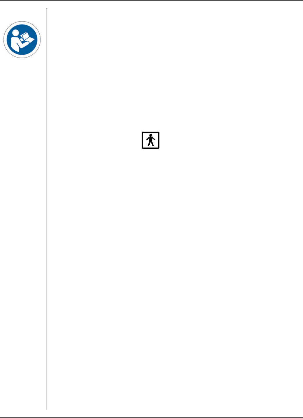
FRONT-END SIGNAL CONDITIONERS - Owner’s Guide
56
Regulatory Information
Safety: Complies with IEC 60601-1:2012 (tested by TUV
Singapore)
EMC: Complies with IEC 60601-1-2:2014 (tested by EMC
Technologies, Sydney, Australia)
Equipment: Use only with an ADInstruments 35 series PowerLab.
The PowerLab must be connected to safety earth via the
power supply cable to ensure electrical safety.
Operation: Continuous
Body protection rating
(Applied parts only): (BF)
Unsuitable uses: Do not use in the presence of flammable anaesthetic - air
mixtures. Avoid operating near high voltage, RF or strong
magnetic fields that may cause interference.
Method of Disposal: Forward to recycling centre or return to manufacturer.
This equipment is not intended to be modified or serviced by the user. No user serviceable
parts inside. Refer servicing to authorised ADInstruments service centre. ADInstruments
reserves the right to alter these specifications at any time.
NOTE:
PowerLabs
provide power
to the Bio Amp
and no other
power source is
required.
NOTE:
Applied parts of
the Quad/Octal
Bio Amps are the
1.5 mm input
sockets and the
patient leads
(e.g MLA0310,
MLA0311)

FRONT-END SIGNAL CONDITIONERS - Owner’s Guide
57
Electromagnetic Compatibility
The Bio Amps (the devices) have been tested to comply with the requirements of EN
61326-1:2006 and IEC 60601-1-2. (The relevant basic EMC standards are IEC 61000-4-2,
IEC 61000-4-3, IEC 61000-4-6, IEC 61000-4-8, IEC 61000-4-11 and CISPR 11).
Emissions
•The devices use RF energy for its internal function only. RF emissions are very
low and are not likely to cause any interference in nearby electronic equipment.
•The devices are suitable for use in all establishments, including domestic
establishments and those directly connected to the public low-voltage power
supply network that supplies buildings used for domestic purposes.
Immunity
•Mains power quality should be that of a typical commercial or hospital
environment. If the user of the device requires continued operation during
power mains interruptions, it is recommended that the device be powered from
an uninterruptible power supply or a battery.
•Power frequency magnetic fields should be at levels characteristic of a typical
location in a typical commercial or hospital environment.
•Floors should be wood, concrete or ceramic tile. If floors are covered with
synthetic material, the relative humidity should be at least 30%.
Separation Distances
•The devices are intended for use in an electromagnetic environment in which
radiated RF disturbances are controlled.
•Portable and mobile RF communications equipment should be used no closer
to any part of the device, including cables, than the recommended separation
distance in the table below.
•Field strengths from fixed RF transmitters, as determined by an electromagnetic
site survey, should be less than the compliance level in each frequency range.
Rated maximum output
power of transmitter, P
Separation distance
150 kHz to 800 MHz
d = 1.17√P
800 MHz to 2.7 GHz
d = 2.33√P
0.01 W 0.1 m 0.2 m
0.1 W 0.4 m 0.7 m
1 W 1.2 m 2.3 m
10 W 3.7 m 7.4 m
100 W 11.7 m 23.4 m
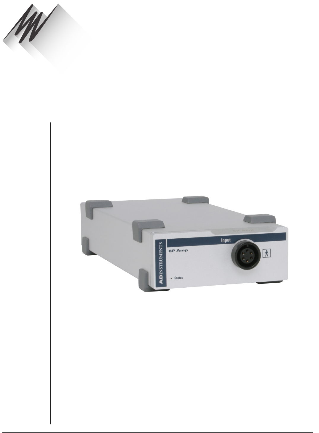
FRONT-END SIGNAL CONDITIONERS - Owner’s Guide
58
The BP Amp [FE117] is a modular device, in a family called front-ends, designed to extend
the capabilities of the PowerLab system. The BP Amp is a blood pressure measurement
amplifier for use with economical disposable blood pressure transducers. It provides
full electrical isolation.
The BP Amp measures blood pressure directly in mmHg (millimeters of mercury): units
conversion is done for you. It is precalibrated for use with the MLT0670 disposable blood
pressure transducer, or can be used with other pressure transducers if required.
BP Amp
Chapter 5
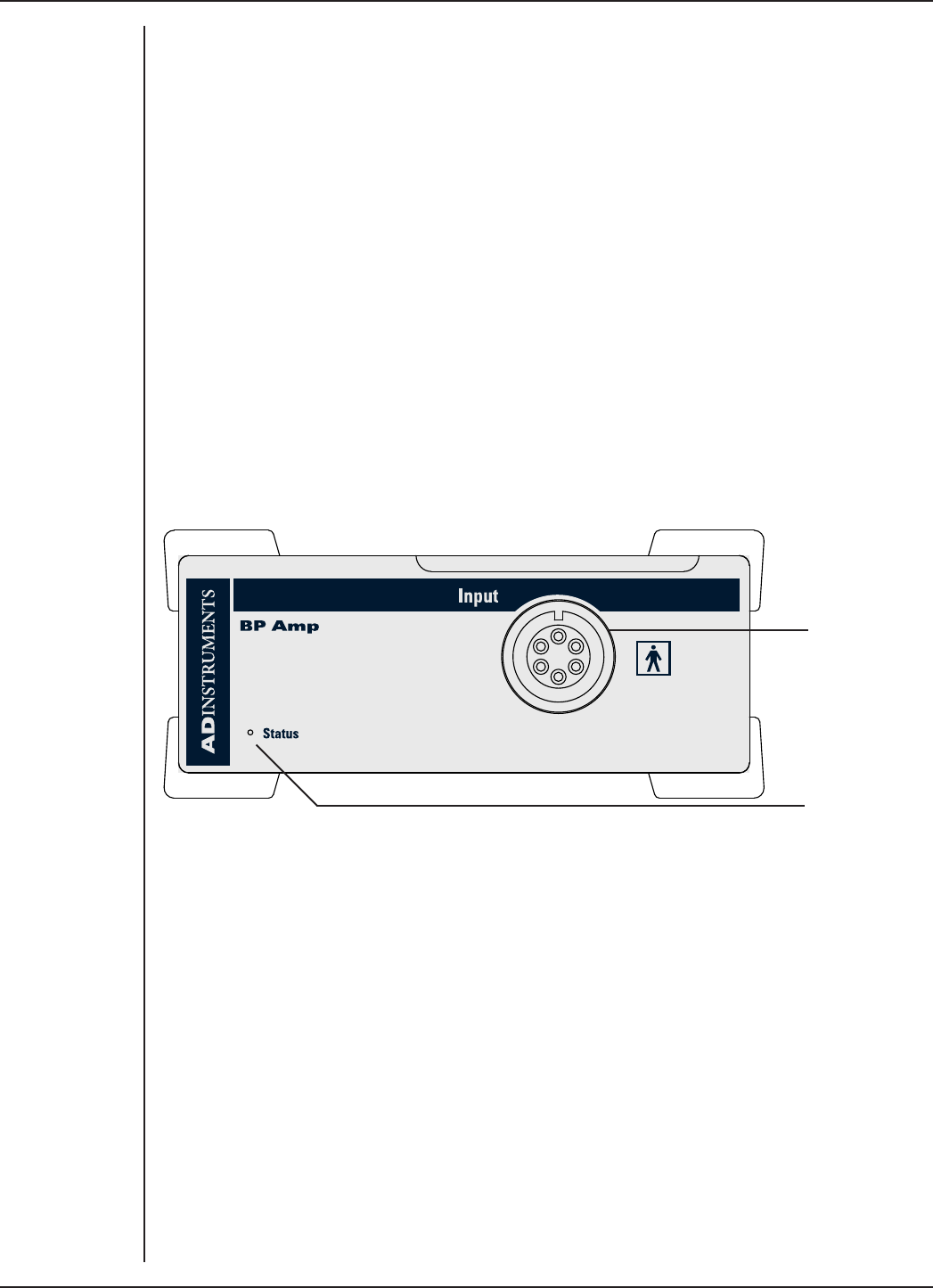
FRONT-END SIGNAL CONDITIONERS - Owner’s Guide
59
The BP Amp
The BP Amp is designed to provide a fully subject-isolated blood pressure measurement
amplifier for use with economical disposable blood pressure transducers. The BP Amp
measures blood pressure directly in mmHg (millimeters of mercury). Units conversion
is performed for you. It is precalibrated for use with the MLT0670 disposable blood
pressure transducer. The pre-calibration can be overridden if you want to use another
kind of transducer.
The rest of this chapter contains general information about the features, connections,
and indicators of the BP Amp. It also looks at the disposable blood pressure transducer.
More detailed information can be found in the technical section at the end of the
chapter.
The Front Panel
The front panel of the BP Amp (Figure 5–1) is simple, with one input connector and an
indicator light.
Input socket
Status indicator
The Status Indicator
The status indicator light is located at the bottom le of the front panel. When an
ADInstruments program such as LabChart starts up, the status indicator should flash
briefly and then remain green, indicating that the program has found the front-end,
checked and selected it, and that it is ready for use. If a status indicator does not turn
on and stay on when the program is run, this indicates either that the front-end is not
connected properly or that there is a soware or hardware problem.
The Input Socket
Connections are made to the BP Amp using the six-pin socket on the front panel. The
Utah Medical transducer cable, supplied with the BP Amp, has a 4-pin transducer
connection at the other end, suitable for the MLT0670 blood pressure transducer. The
input connection has internal isolation circuitry. The socket and connections to it are
discussed in more detail later (“The Disposable BP Transducer” on page 62).
Figure 5–1
The front panel of
the BP Amp
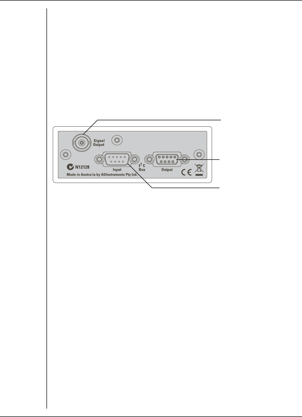
FRONT-END SIGNAL CONDITIONERS - Owner’s Guide
60
The Back Panel
The back panel of the BP Amp (Figure 5–2) provides all of the sockets that are required
to connect the front-end to the PowerLab and to other front-ends.
I2C Input and Output Sockets
Two nine-pin sockets are used to communicate with the PowerLab (they are marked ‘I2C
Bus’: a ‘bus’ is simply information-transmission circuitry such as cables and connectors).
These sockets, in conjunction with the proper cables, allow multiple front-ends to be
used independently with one PowerLab. Power and control signals to connected front-
ends come from the PowerLab. ADInstruments front-ends are connected to each other
in series, output to input (this is discussed in more detail in Chapter 2).
Signal output to the PowerLab
I2C connection to a further front-
end
I2C connection from the
PowerLab or previous front-end
The Signal Output Socket
The BNC socket labeled Signal Output on the back panel of the BP Amp provides the
signal output to connect to an analog input socket on the front of the PowerLab. A BNC-
to-BNC cable is supplied for this connection. If you are using a PowerLab with dierential
inputs, remember to connect the cable only to a positive analog input. ADInstruments
applications will not find the front-end on starting up if a negative input is used.
Connecting to the PowerLab
To connect your BP Amp to the PowerLab, first ensure that the PowerLab is turned o.
Failure to do this may damage the PowerLab, the front-end, or both.
The BNC cable from the BP Amp signal output must connect to one of the PowerLab’s
analog inputs (e.g. Input 1). If necessary, use a BNC to DIN smart adapter [MLAC22] to
connect the BNC cable to your PowerLab’s input.
Connect the I2C output of the PowerLab to the I2C input of the front-end using the I2C
cable provided.
Check that the connectors for the I2C bus are screwed in firmly. Check the BNC cable
for firm connections as well. Loose connectors can cause erratic front-end behavior, or
may cause the front-end to fail to work at all.
Figure 5–2
The back panel of
the BP Amp
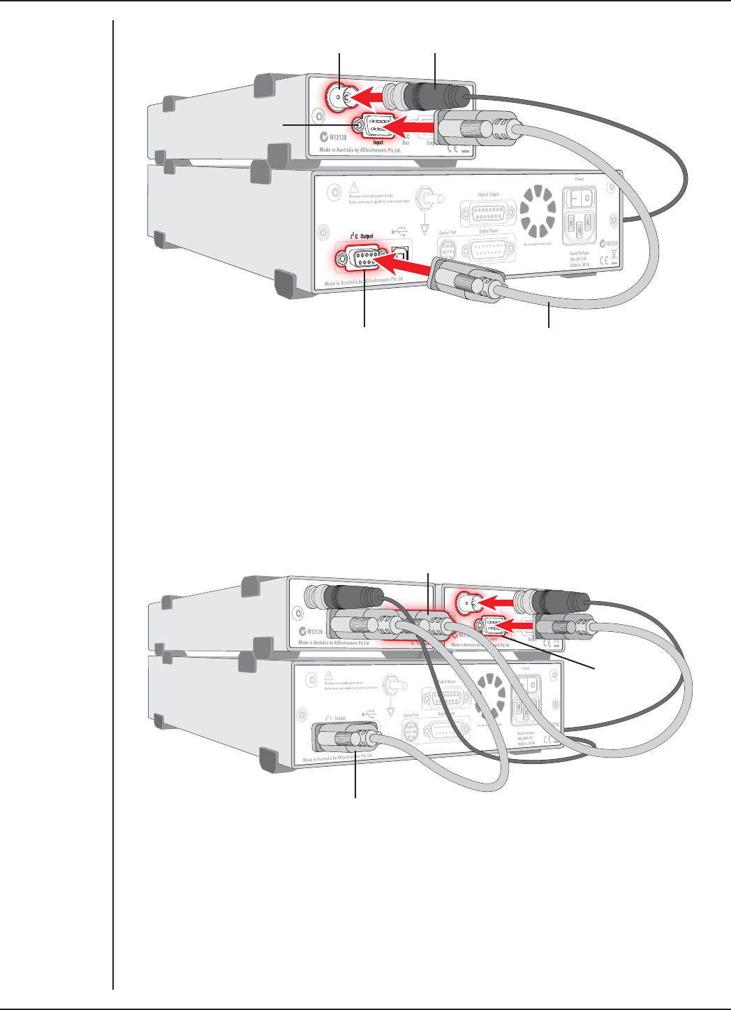
FRONT-END SIGNAL CONDITIONERS - Owner’s Guide
61
Multiple Front-ends
Multiple separate front-ends can be connected up to a PowerLab. The number of normal
front-ends that can be connected depends on the number of analog inputs on the
PowerLab. The initial front-end should be connected with the I2C cable as in Figure 5–3.
The remainder are daisy-chained via I2C cables, connecting the I2C output of the last
connected front-end to the I2C input of the front-end to be added (Figure 5–4).
Figure 5–3
Connecting a
single BP Amp
front-end to the
PowerLab
BP Amp Signal Output
BP Amp I2C input
PowerLab I2C output I2C connector cable
BNC connector cable
Figure 5–4
Connecting two
front-ends to
the PowerLab:
a connection is
made from the I2C
output on the first
front-end to the
I2C input on the
second front-end
Second I2C cable connected to
Front-end I2C output
Second
Front-end
I2C input
First I2C cable connected
to PowerLab I2C output
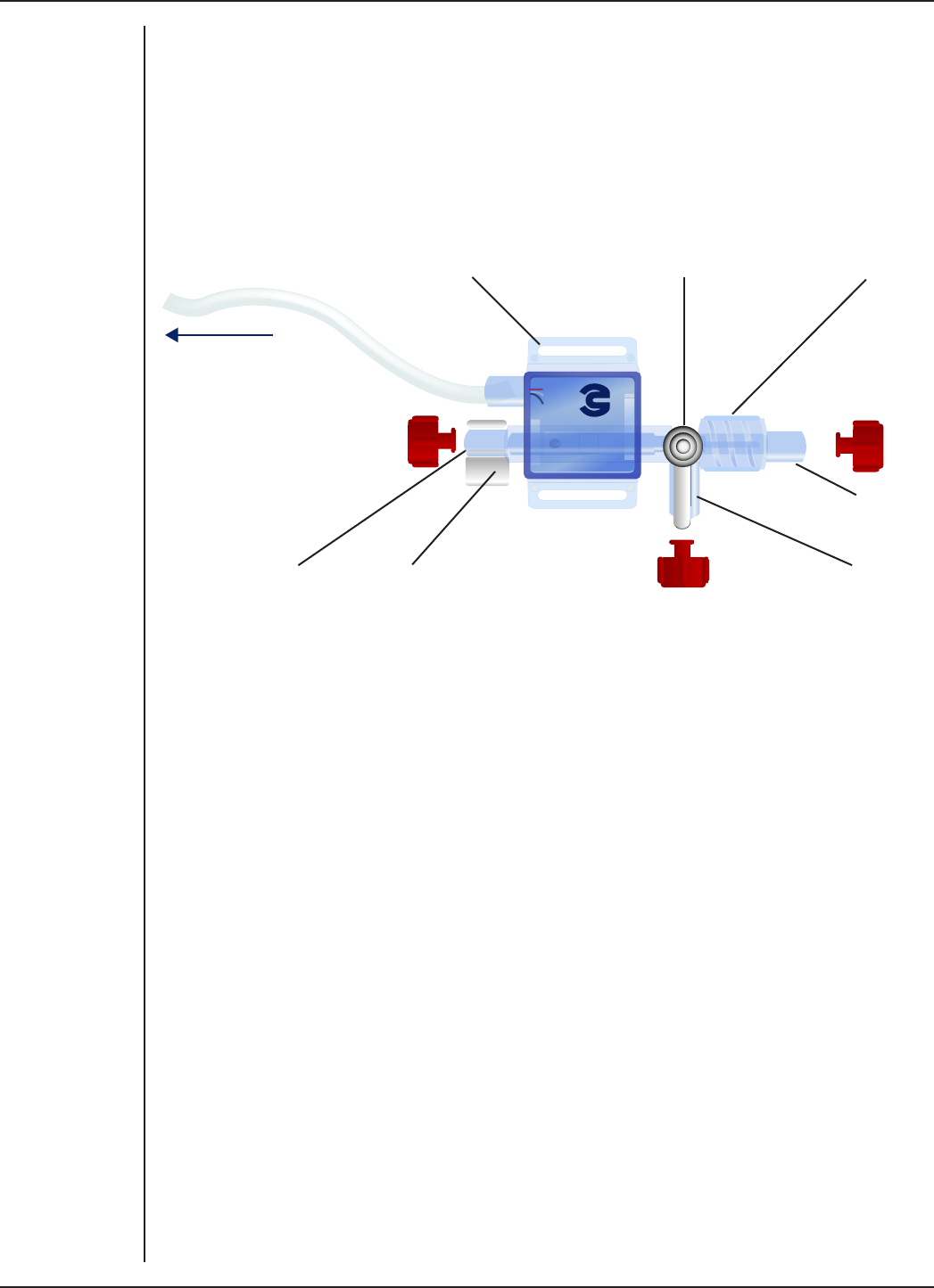
FRONT-END SIGNAL CONDITIONERS - Owner’s Guide
62
Equipment and Technique
The Disposable BP Transducer
The Disposable BP Transducer [MLT0670] is reliable and economical. Its components
and functions are described below.
To BP Amp Strap slots 3-way tap Thumbscrew
Cannula port
Injection portFilling and
flushing port
Squeeze to open for
filling and flushing
The transducer has three ports, up to two of which can be open at one time. The cannula
port is the one that connects a pressure line (cannula or catheter) to the subject. The
thumbscrew by the cannula port turns anticlockwise to tighten the connection to the
port, and clockwise to loosen it and unscrew the pressure line. Either or both of the
other ports can be used.
The flushing port helps to get rid of air bubbles, if the transducer is arranged with this
port at the top. The squeeze valve is squeezed to open it for filling and flushing; it is
closed in the rest position. The injection port is used to fill the device and pressure line
with saline solution and to draw blood from the subject if necessary.
The three-way valve controls which ports remain open (although the filling and flushing
port requires the squeeze valve to be squeezed in addition). Point the valve handle at
the port to be turned o.
The 4-pin connection from the transducer slots into the end of the Utah Medical 650-208
cable that is supplied with the BP Amp. The transducer may be attached to a subject or
support frame using a strap through the strap slots.
Figure 5–5
The MLT0670
Disposable BP
Transducer
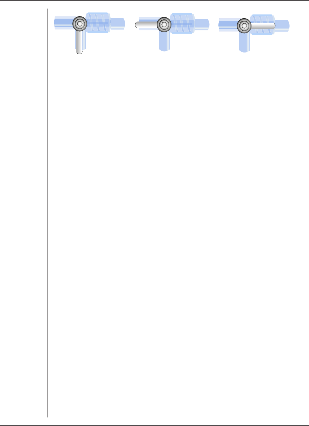
FRONT-END SIGNAL CONDITIONERS - Owner’s Guide
63
Measurement position Injection and blood-sampling
position
Flushing and zeroing position
Sterilization of the Disposable BP Transducer
If using the MLT0670 Disposable BP Transducer (stopcock) for measuring blood pressure
in human subjects, the transducer must be sterilized prior to use. Although the MLT0670
is supplied in sterile packaging, ADInstruments cannot guarantee its sterility. Therefore
it is recommended that the user gas sterilize the transducer prior to use.
Zeroing
When zeroing the BP Amp, close the cannula port (Figure 5–6, right), leaving the central
area of the transducer and its pressure sensor open to the atmosphere.
Connecting a Subject
Note. Only appropriately qualified and experienced personnel should attempt to
connect the device to a human subject.
Before connecting up a subject, the transducer, pressure line, and so on should be filled
with sterile ‘heparinized’ saline (saline solution containing heparin to prevent blood
clots). Aer this is done, make sure the setup is free of air bubbles, insert the cannula or
catheter into the vein or artery, and secure the insertion point.
For animal monitoring, the catheter or pressure line to the cannula is kept as short
as possible. When monitoring humans, there are usually extra safety devices, and the
transducer will likely be part of an infusion set. A pressure line, if used, should be short
and rigid, to avoid losing measurements of fast changes in pressure. The catheter or
cannula should lie flat where it enters the blood vessel, to prevent obstruction of the
tip.
If the pressure line back-fills with blood, the blood may clot, since it is not circulating.
To prevent this, sterile ‘heparinized’ saline is injected or infused as required to keep the
pressure line clear of clottable blood. In a transparent pressure line, diusing blood can
be seen, and the onset of clotting is also indicated by waveform amplitude attenuation
in the blood pressure signal. It is important to keep blood out of the transducer itself.
Figure 5–6
Three-way valve
positions on the
blood pressure
transducer
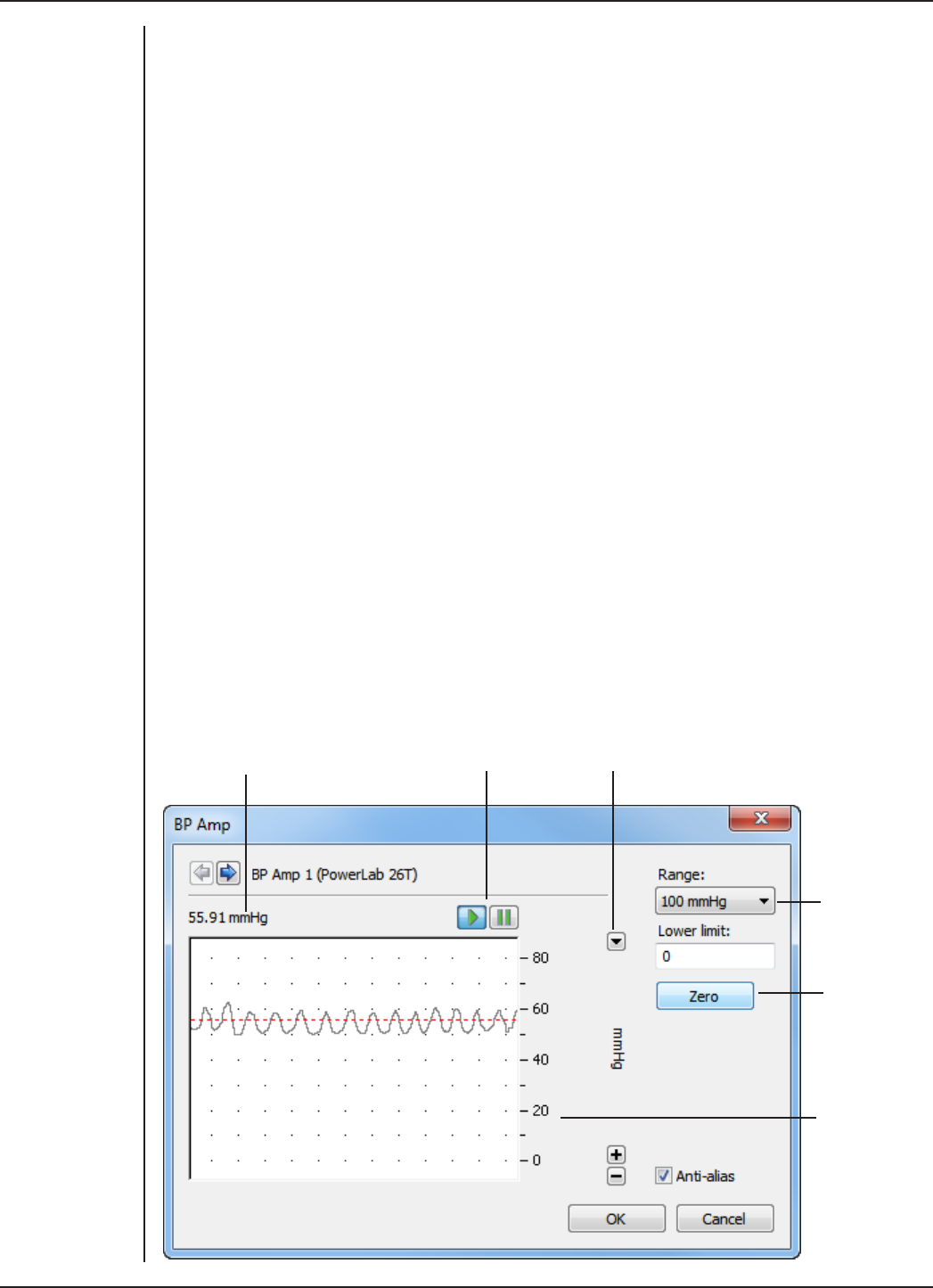
FRONT-END SIGNAL CONDITIONERS - Owner’s Guide
64
Using LabChart and Scope
Once the BP Amp is connected, turn the PowerLab on and launch LabChart. When a BP
Amp is properly connected to the PowerLab, the Input Amplifier… menu command is
replaced by BP Amp… for the input channel to which it is connected.
If LabChart (or Scope) fails to find a front-end connected, the normal text remains. If
you were expecting a connected front-end and see the normal text instead, you should
quit the application, turn the PowerLab o and check the connections. Then restart the
PowerLab and re-launch LabChart.
The LabChart Help Center and Scope User’s Guide detail the Input Amplifier dialog, and
explain relevant terms and concepts.
The documentation for LabChart and Scope does not cover front-end-specific features.
These features are described in detail here for LabChart.
The BP Amp dialog
The BP Amp... dialog appears when you choose BP Amp... from the Channel Function
pop-up menu of the input channel it is attached to, or click BP Amp... in the Input
Settings column of the Channel Settings dialog. The BP Amp... dialog allows soware
control of the combined filters and other circuitry in the PowerLab and BP Amp. The
signal present at an input is displayed so that you can see the eects of changes straight
away.
The BP Amp is pre-calibrated and measures blood pressure directly in mmHg
(millimeters of mercury). The dialog also allows you to zero the BP Amp. Aer changing
settings in the dialog, click OK to apply them.
Signal amplitude Pause and Scroll buttons Scale pop-up
Range pop-up
Zero BP Amp
button
Amplitude
axis
Figure 5–7
The BP Amp
dialog for
Windows
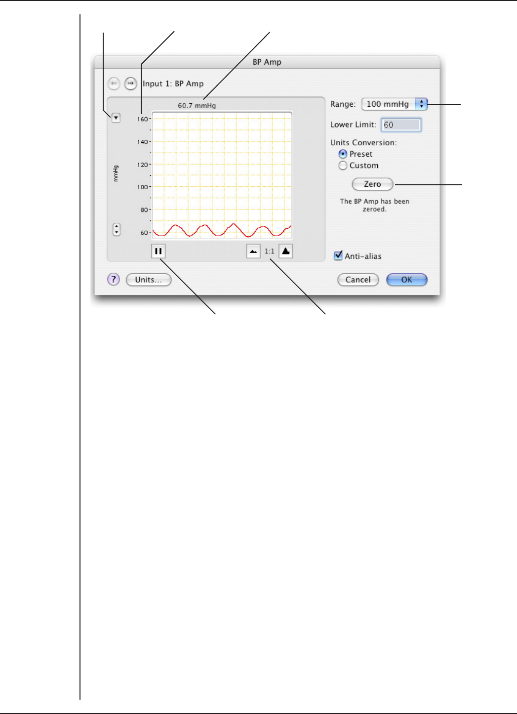
FRONT-END SIGNAL CONDITIONERS - Owner’s Guide
65
Scale pop-up Amplitude axis
Range pop-
up menu
Zero BP
Amp button
Signal amplitude
Pause/Scroll button Compression buttons
Signal Display
The input signal is displayed to show you the eect of changing the settings — no data
are recorded when setting things up. The average signal value is shown above the
display area.
You can stop the signal scrolling by clicking the Pause button at the bottom le
(Macintosh) or top right (Windows) of the data display area. On the Macintosh this
changes to the Scroll button. Click the Scroll button to start scrolling again.
Shi and stretch the vertical Amplitude axis, by clicking and dragging it in various
ways, to make the best use of the available display area. It functions the same as the
Amplitude axis of the Chart window, controls are identical and any change is applied to
the Chart Window.
Setting the Range
The Range pop-up menu lets you select the input range or sensitivity of the channel
(combined range of the PowerLab and BP Amp). Changing the range in the BP Amp
dialog is equivalent to changing it in the Chart Window. There are three ranges: 50, 100
and 250 mmHg.
Figure 5–8
The BP Amp
dialog for
Macintosh

FRONT-END SIGNAL CONDITIONERS - Owner’s Guide
66
Lower Limit
The Lower Limit text entry box lets you set the lowest value for the displayed range, in
mmHg. You can enter negative values. If you enter 70 with the range set to 50 mmHg,
then the display will show values from 70 to 120 mmHg. The display adjusts aer a
second or so. The display can still be stretched and shied aerwards.
Zeroing
Before measurements can be made with the BP Amp, it must be zeroed. A note below
the Zero button indicates its status. To zero the BP Amp, connect up the blood pressure
transducer and leave it open to the atmosphere (arranging the transducer valve is
described in Figure 5–6 on page 63), then click Zero in the BP Amp dialog. If you start
sampling before the BP Amp has been zeroed, you will receive an alert and the BP Amp
dialog will appear, at which stage the amp must zeroed.
On a Macintosh, Zero will be highlighted if the BP Amp is not zeroed. Aer clicking Zero,
the note below the Zero button changes to indicate that the BP Amp has been zeroed,
and the OK button is highlighted.
Anti-alias
Click the Anti-alias checkbox to turn anti-aliasing on and o. Aliasing occurs when a
regular signal is digitized at too low a sampling rate, causing the false appearance of
lower frequency signals. To prevent aliasing, the sampling rate must be at least twice
the highest frequency in the incoming waveform.
When aliasing of noise or signals is seen, or even suspected, the first action you should
take is to increase the sampling rate. The highest available sampling rates are 100k
/s or 200k /s, depending on your PowerLab. If this reveals unwanted high-frequency
components in the sampled signal, you will achieve better results by using a low-pass
filter to remove them.
The best kind of filter for this purpose is the Anti-alias filter option in the BP Amp...
dialog. This is a special low-pass filter that is configured to automatically remove
all signals that could alias; i.e., those whose frequency is greater or equal to half the
sampling rate. A high sampling rate, however, will use more computer memory and may
limit recording time, so once you have established the frequencies of interest to you in
an incoming signal, the sampling rate can be scaled down accordingly with the Anti-
alias filter applied.
Units
The BP Amp measures pressure directly in mmHg (millimeters of mercury), once the BP
Amp is zeroed. The BP Amp is pre-calibrated for use with the MLT0670 Disposable BP
Transducer, but most blood pressure transducers connecting to the 4-pin connection of
the supplied cable should also work. To open the Units Conversion dialog, choose Units
Conversion... from the Channel Function pop-up menu (Windows).
In the Units Conversion dialog you can check the preset unit conversion or – if you prefer
or are using another transducer – do your own calibration, using a pressure standard.
On a Macintosh, you can click Units… in the BP Amp dialog to open the Units Conversion
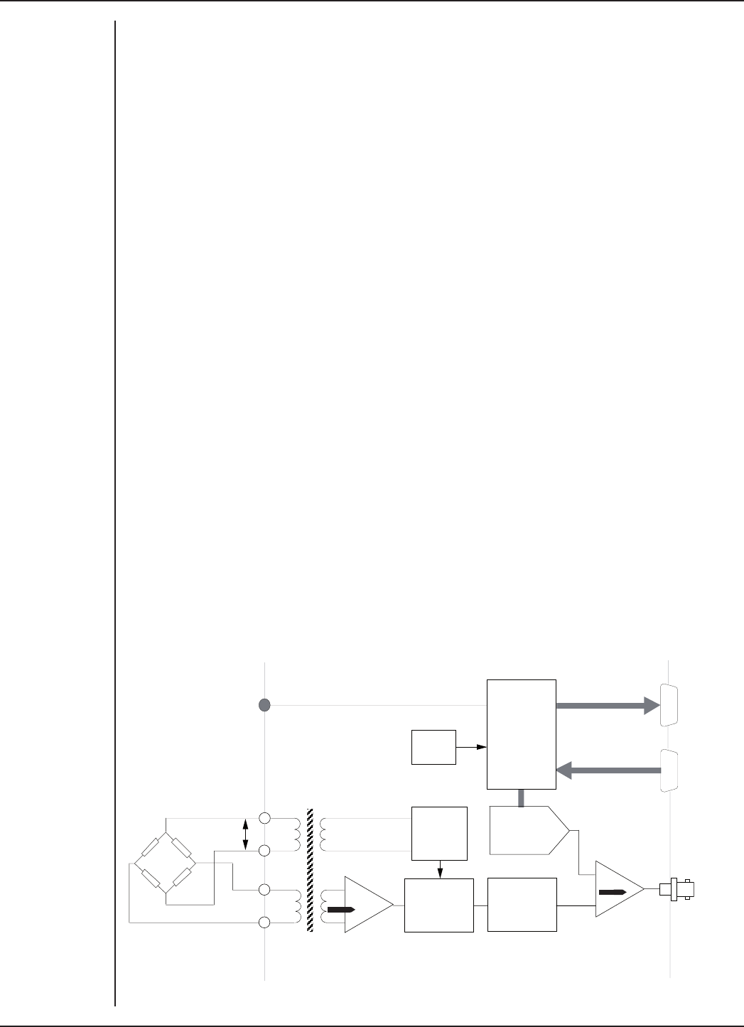
FRONT-END SIGNAL CONDITIONERS - Owner’s Guide
67
dialog, and select Preset or Custom to change between the preset calibration and the
one you set yourself in the Units Conversion dialog.
Technical Aspects
This section describes some of the important technical aspects of the BP Amp, to give
some insight into how it works. You should not use this section as a service manual:
user modification of the equipment voids your rights under warranty.
The BP Amp and other ADInstruments front-ends have been designed to integrate fully
into the PowerLab system. Each requires connection to the PowerLab via a special
communications connector called the I2C bus, and a BNC connector.
BP Amp Operation
The BP Amp is essentially an extension of the PowerLab’s analog input. The BP Amp
provides:
•full electrical isolation from power-line (mains) circuitry to guarantee subject
safety
•measurement of blood pressure directly in mmHg: units conversion is done for
you
•precalibration with the MLT0670 blood pressure transducer, for convenient set-
up
•the ability to override calibration when using other transducers.
The internal functions of the BP Amp are controlled from the PowerLab through the I2C
bus, which also supplies power to the BP Amp. The front-end is also connected to an
analog input channel of the PowerLab via a BNC-to-BNC cable, through which the signal
is sent. The overall operation of the BP Amp can be better understood by referring to
Figure 5–9.
Micro
Processor
Controller
12-bit
Offsetting
DAC
55 Hz 2nd
Order Low-
pass filter
Synchron-
ous
Rectifier
400 Hz
Power
Oscillator
8 MHz
Crystal
Isolation
Barrier
500
Status
Indicator
5 Vrms
Isolation
Transformers
I2C Output
I2C Input
Signal
Output
+
_
Transducer
1
Figure 5–9
Block diagram of
the BP Amp

FRONT-END SIGNAL CONDITIONERS - Owner’s Guide
68
A power oscillator circuit running at 400 Hz is used to excite the transducer bridge. The
BP Amp uses AC excitation for isolation, and for freedom from thermoelectric DC errors.
The input signal from the connected transducer is fed across an isolation transformer
into a stable, accurate, fixed-gain amplifier. The output of this amplifier is fed into a
synchronous (phase-sensitive) rectifier to recover the DC content of the signal. For the
bridge used, each mmHg of the signal gives about 25 µV of signal for 5 Vrms excitation.
The synchronous demodulation scheme is very eective at cancelling systematic and
thermal (amplifier) noise.
The rectified signal then passes through a 55 Hz, second-order, low-pass filter, which
provides output filtering of the data, and anti-alias filtering for the PowerLab input. A
precision X1 instrumentation amplifier finally compares the signal with the output of
the 12-bit DAC. The DAC provides an exact oset voltage for zeroing and osetting of
the synchronously demodulated and filtered signal. This ensures maximum signal-to-
noise ratio, good zeroing resolution, and maximum resolution in the displayed signal.
The control for osetting and zeroing functions in the BP Amp is provided by an on-
board microcontroller, which also communicates with the PowerLab over the I2C bus.
The good reproducibility of the blood-pressure transducers ensures good overall
accuracy without the need for the user to apply units conversion. The only operations
required are selection of pressure-range and an optional baseline pressure (zero is the
default), then clicking on the Zero button with the pressure transducer open to the
atmosphere (before connection to the subject).
Troubleshooting
This section describes most of the common problems that can occur when using the BP
Amp with your PowerLab recording unit. Most of the problems that users encounter are
connection problems, and can usually be fixed by checking connections and starting up
the hardware and soware again. Very rarely will there be an actual problem with the
front-end or the PowerLab itself.
Problems and Solutions
The status indicator fails to light when the soware is started, or the front-end commands
do not appear where they should
The I2C cable or the BNC-to-BNC cable from the front-end to the PowerLab is not
connected, has been connected incorrectly (to the wrong input or output, for instance),
or is loose.
•Turn everything o. Check to see that all cables are firmly seated and screwed
in. BNC cables from the BP Amp must be connected to a positive input on the
PowerLab. Make sure the input is the same channel from which you expect to use
the front-end in the soware. Start up again to see if this has fixed the problem.
You are using an early version of LabChart or Scope.
•Upgrade to the latest version of the soware. Contact your ADInstruments
representative for information.
The BNC or I2C cable is faulty.

FRONT-END SIGNAL CONDITIONERS - Owner’s Guide
69
•Replace the cable and try again. Immediately label all cables proved faulty so
that you don’t use them again by accident.
The front-end is faulty.
•This is the least likely event. If the front-end will not work properly aer the
previous measures, then try using it on another PowerLab. If the same problems
recur with a second PowerLab, the front-end may be faulty. Contact your
ADInstruments representative to arrange for repairs.
On starting up the soware, an alert indicates that there is a problem with the front-end or
driver
The correct drivers are not installed on your computer.
•Reinstall the soware.
You are using an early version of LabChart or Scope.
•Upgrade to the latest version of the soware. Contact your ADInstruments
representative for information.
The BNC or I2C cable is faulty.
•Replace the cable and try again. Immediately label all cables proved faulty so
that you don’t use them again by accident.
The front-end is faulty.
•This is the least likely event. If the front-end will not work properly aer the
previous measures, then try using it on another PowerLab. If the same problems
recur with a second PowerLab, the front-end may be faulty. Contact your
ADInstruments representative to arrange for repairs.
Some soware settings don’t resemble those in this guide
You are using an early version of the front-end driver, or of LabChart or Scope. Some
changes may have been made since then.
•Upgrade to the latest version of the soware. Contact your ADInstruments
representative for information.

FRONT-END SIGNAL CONDITIONERS - Owner’s Guide
70
Specifications
Input
Connection type: 6-pin socket to fit Utah Medical 650-208 transducer cable
with a 4-pin transducer connection cable
Safety: Approved to IEC 60601-1 Standard (BF rating)
EMC: Approved to EN61326-1:2006 Standard
Input impedance: > 10 kΩ at 400 Hz AC
Configuration: Isolated AC bridge
Isolation rating: 4000 V ACrms for 1 minute
Input ranges: 50–250 mmHg full scale in 3 steps
(combined PowerLab and BP Amp)
0–250 mmHg
0–100 mmHg
0–50 mmHg
User oset: Arbitrary scale oset
(for example, –50 with 100 mmHg range gives –50 to 50
mmHg range)
Frequency response: –3 dB at 50 Hz
Sensitivity: Correct for 5 µV/V/mmHg transducer standard (~350 Ω
bridge)
Accuracy: ±2% (±0.2 mmHg) all points, aer zero correction
Input leakage current: < 3 µArms at 240 V, 50 Hz
< 2 µArms at 120 V, 60 Hz
Zeroing and oset: Automatic soware-controlled fast zeroing, controlled
by internal 12-bit DAC; resolution = ± 0.2 mmHg (with
supplied transducer)
Transducers
Transducer type: Precalibrated for use with MLT0670 Disposable BP
Transducer: no further calibration needed for normal
applications
Excitation: ~5 Vrms AC at 400 Hz ±5%
Alternative types: Transducers up to 1 kΩ with ~ 5 µV/V/mmHg sensitivity,
with a 4-pin transducer connection cable: they will need
calibration.

FRONT-END SIGNAL CONDITIONERS - Owner’s Guide
71
Filters
Low-pass filtering: Fixed 50 Hz (–3 dB) two-pole Bessel filter (limited by
PowerLab setting)
Output
Signal: ±2.0 V full scale: suitable for PowerLab
Control Port
I2C port: Provides control and power. Interface communications
rate of ~50 kbits/s.
Physical Configuration
Dimensions (h × w × d): 55 mm × 120 mm × 260 mm (2.2" × 4.7" × 10.2")
Weight: 1.2 kg (2 lb 11 oz)
Power requirements: 2.5 W max
Operating temperature range: 5–35 °C
Operating humidity range: 0–90% (non-condensing)
ADInstruments reserves the right to alter these specifications at any time.
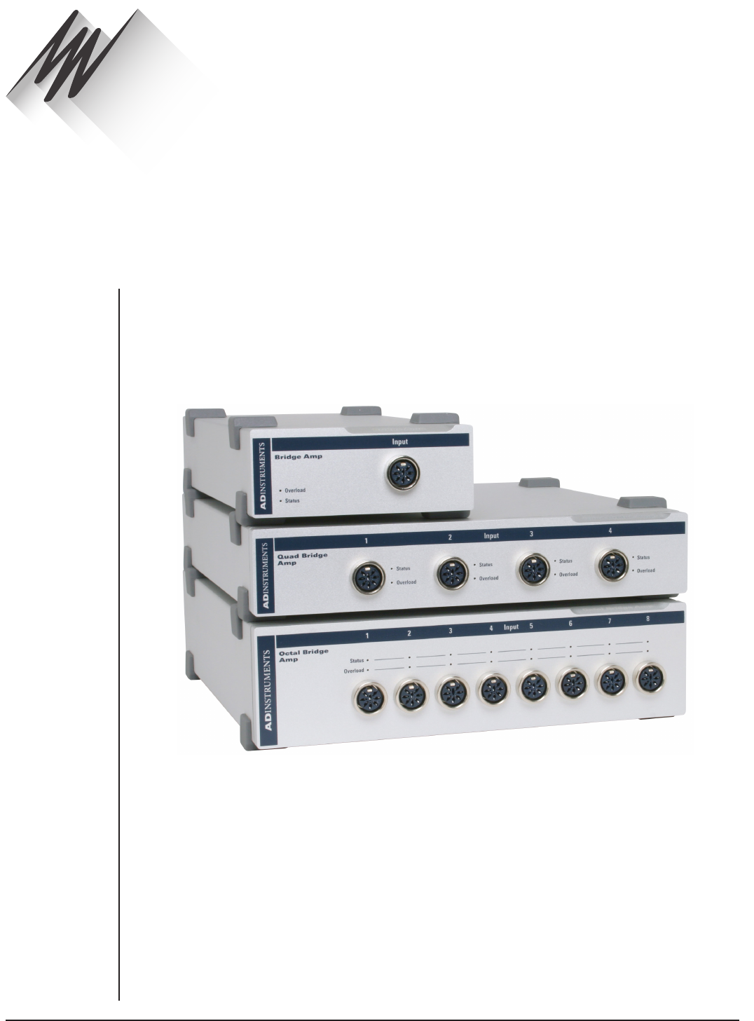
FRONT-END SIGNAL CONDITIONERS - Owner’s Guide
72
The Bridge Amp is a modular device, in a family called front-ends, designed to extend
the capabilities of the PowerLab system. This chapter provides an overview of the
various Bridge Amps, namely the Bridge Amp [FE221], Quad Bridge Amp [FE224] and
Octal Bridge Amp [FE228].
The Bridge Amp is designed to allow the PowerLab to connect to most DC bridge
transducers, including commonly available force transducers, temperature probes,
light meters, displacement transducers, pressure transducers, and similar devices.
Grass transducers can connect to any ADInstruments Bridge Amp using a Grass adapter
cable [MLAC11] available from ADInstruments.
Bridge Amp
Chapter 6
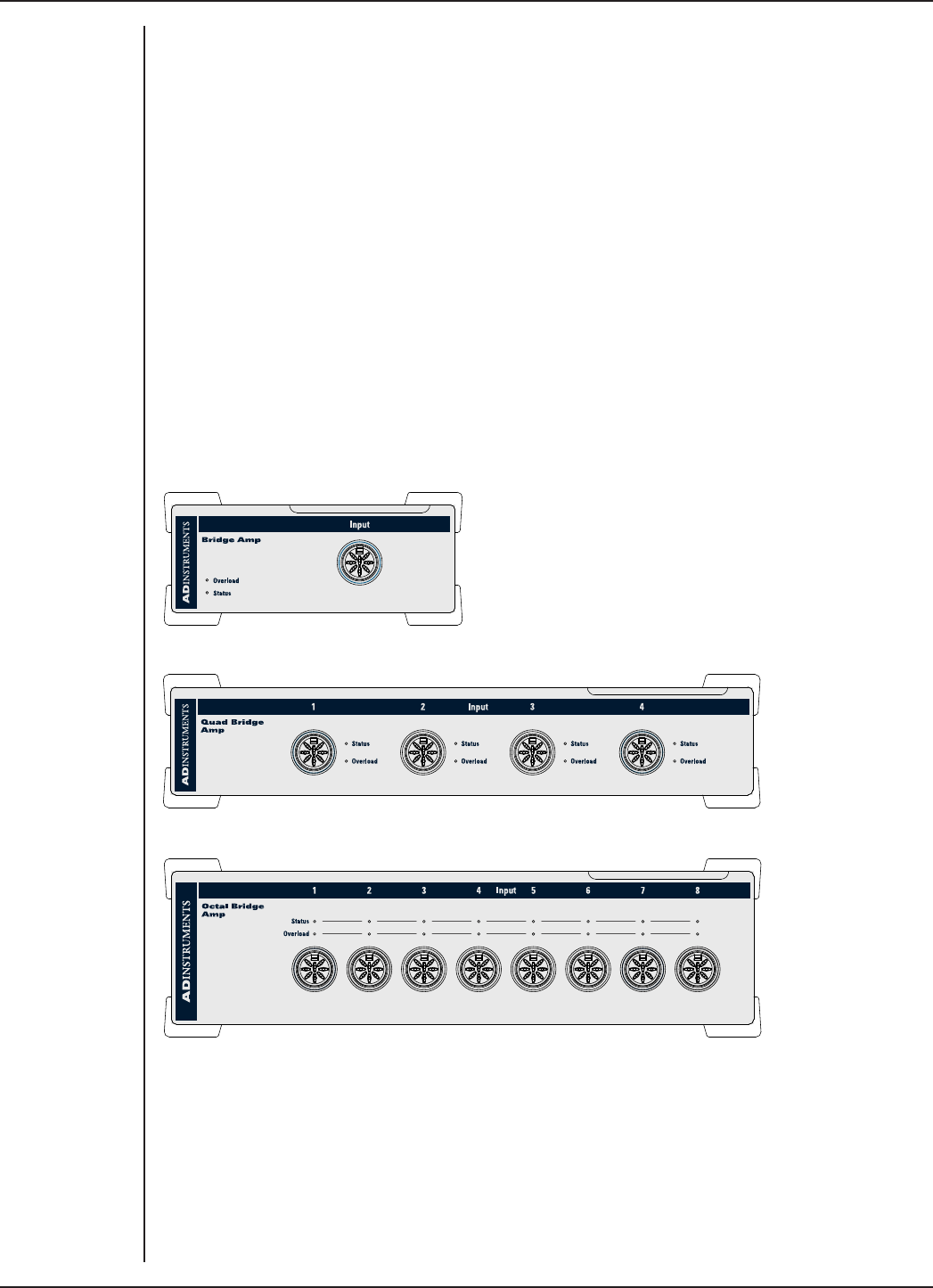
FRONT-END SIGNAL CONDITIONERS - Owner’s Guide
73
The Bridge Amp
The Bridge Amp is designed to allow the PowerLab to connect to most DC bridge
transducers, including force transducers, temperature probes, light meters,
displacement transducers, pressure transducers, and similar devices. There are several
models of Bridge Amp. The Bridge Amp provides just one connection for a bridge
transducer, the Quad Bridge Amp provides four connections for bridge transducers and
the Octal Bridge Amp provides eight connections for bridge transducers.
The Front Panel
The front panel of a Bridge Amp has a single socket for a transducer connection, a status
indicator light and an overload indicator light. The front panel of a Quad or Octal Bridge
Amp has four or eight transducer connections, respectively, each of which has a status
indicator light and an overload indicator light.
FE221 Bridge Amp
FE224 Quad Bridge Amp
FE228 Octal Bridge Amp
The Status Indicator
The Status indicator of the Bridge Amp is located at the bottom le of the front panel,
and the Status indicators of the Quad Bridge Amp and Octal Bridge Amp are located
adjacent to each connector on the front panel. When an ADInstruments program such
as LabChart starts up, the Status indicator light should glow green, indicating that the
program has found the front-end, checked and selected it, and is ready to use it. If the
Figure 6–1
The front panels
of the Bridge
Amps

FRONT-END SIGNAL CONDITIONERS - Owner’s Guide
74
light does not glow when the program is running, this indicates either that the front-end
is not connected properly or that there is a soware or hardware problem.
The Input Socket
Transducers are connected to a Bridge Amp using the eight-pin DIN sockets on the
front panel. The sockets provide terminals for supplying a transducer with power and
for receiving the transducer output. Front-ends are supplied with DIN plug kits (one
per connection) to be fitted to those transducers that lack them. The connection is
discussed in more detail in the Technical section at the end of this chapter.
The Overload Indicator
The Overload indicator is located on the le side of the front panel of the Bridge Amp
and to the right of the Status indicator on the Quad and Octal Bridge Amps.
The Overload indicator is normally o. If the indicator lights when a transducer is
attached, it indicates an out-of-compliance condition (meaning that the excitation
voltage drops because too much current is being drawn by the load). When the Bridge
Amp detects a problem with the transducer (for instance a wiring fault with a transducer
causing a short-circuit), the overload indicator will glow yellow or amber and will remain
on until the fault is rectified.
If the overload indicator remains on with a transducer attached, the transducer should
be removed immediately to minimize the risk of damage to the transducer. Check the
transducer wiring carefully before re-attaching the transducer. If the fault persists, refer
to the Troubleshooting section in this chapter.
For the overload indicator to function, power must be supplied to the Bridge Amp from
a PowerLab. LabChart soware does not need to be loaded.
When a soware application is running and a channel is being zeroed, the Status
indicators for the other channels should temporarily be o.
The Back Panel
The back panel of the Bridge Amp provides all the sockets required to connect the
Bridge Amp to the PowerLab and to other front-ends.
I2C Input and Output Sockets
Two nine-pin sockets are used to communicate with the PowerLab (they are marked ‘I2C
Bus’: a ‘bus’ is simply information-transmission circuitry such as cables and connectors).
These sockets allow multiple front-ends to be used independently with one PowerLab.
Power and control signals to the front-ends come from the PowerLab. Many front-ends
can be connected to the system, in series, output to input, providing there is the same
number of channel inputs available on the PowerLab (this is discussed in more detail in
Chapter 2).
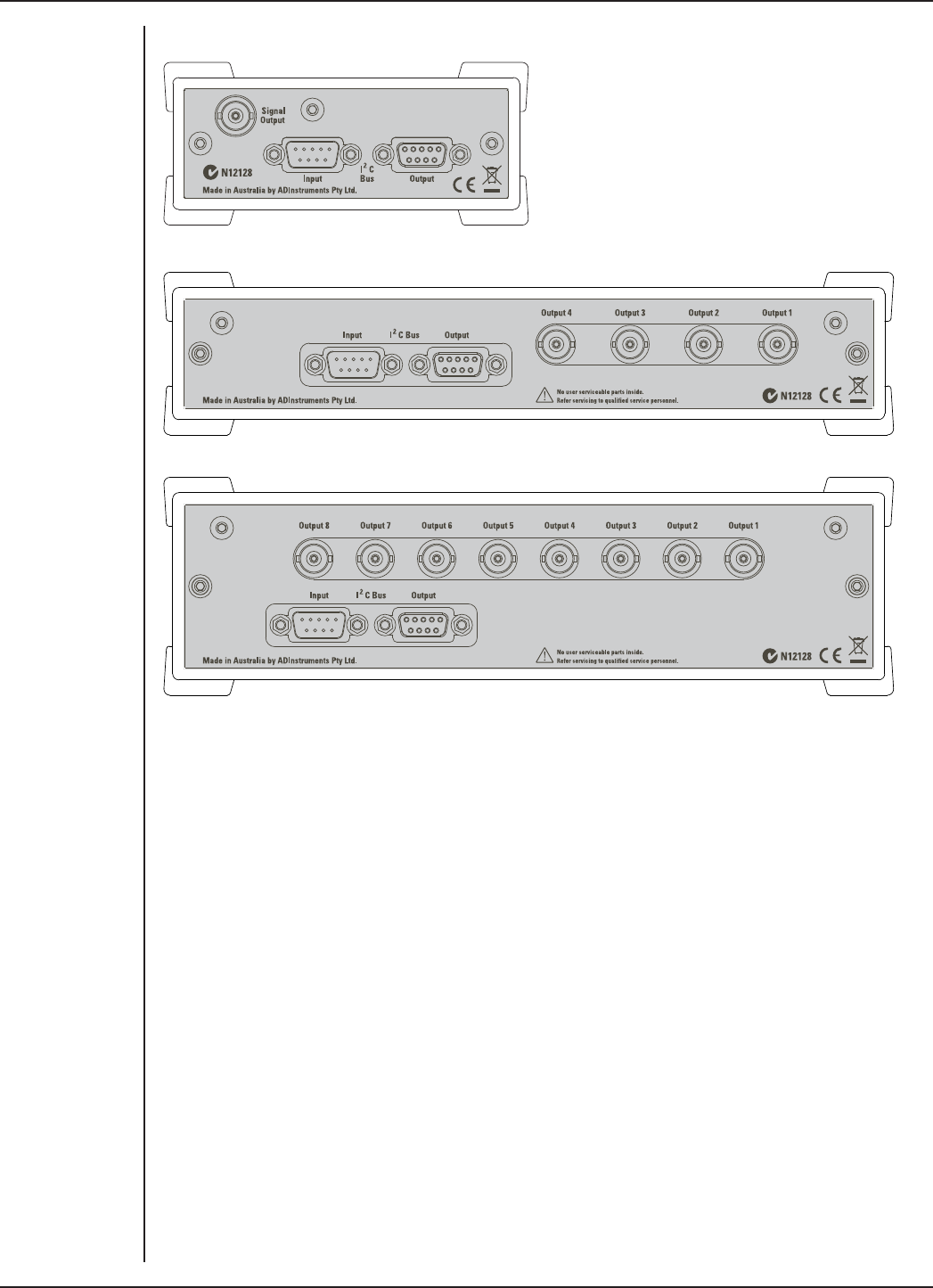
FRONT-END SIGNAL CONDITIONERS - Owner’s Guide
75
FE221 Bridge Amp
FE224 Quad Bridge Amp
FE228 Octal Bridge Amp
Analog Output Sockets
BNC sockets on the back panel of the Bridge Amp provide the signal outputs to connect
to the analog input sockets on the front of the PowerLab. The sockets are labelled Signal
Output on a Bridge Amp and Output 1 to 4 or Output 1 to 8 on Quad and Octal Bridge
Amps, respectively. You don’t have to match the channel numbers when connecting
outputs to inputs, but it helps to prevent confusion if you do. A BNC-to-BNC cable is
supplied for each connection.
Figure 6–2
The back panels
of the Bridge
Amps

FRONT-END SIGNAL CONDITIONERS - Owner’s Guide
76
Setting Up
This section describes connecting a Bridge Amp to your PowerLab.
PowerLab Requirements
The FE221, FE224 and FE228 Bridge Amps will only operate with newer models of
PowerLabs, such as the /SP, /20, /25, /26, /30 and /35 series.
Soware Requirements
The FE221, FE224 and FE228 Bridge Amps require the following versions of
ADInstruments soware applications:
•LabChart version 6, or later, for Windows or Macintosh
•Chart version 5.4.2, or later, for Windows or Macintosh
•Scope for Windows version 3.7.8, or later
•Scope for Macintosh version 4.0.3, or later
•LabTutor version 3, or later.
Note: the Bridge Amps will not operate with earlier versions of these applications. Free
updates are available from the ADInstruments website for users with earlier versions of
Chart 5 and Scope. If you have queries regarding hardware and soware requirements
of the Bridge Amps, please contact your local ADInstruments representative.
Connecting to the PowerLab
Connect your Bridge Amp, to the PowerLab, as follows:
•Ensure that the PowerLab is turned o. Failure to do this may damage the
PowerLab, the Bridge Amp, or both.
•Connect the I2C output of the PowerLab to the I2C input of the front-end using the
I2C cable provided.
•Connect a BNC cable from each signal output, on the rear of the Bridge Amp, to
an input on the front panel of the PowerLab.
Note that the Quad Bridge Amp acts just as if it were four individual Bridge Amps; the
Octal Bridge Amp, eight. The I2C connections are internal, though, so there is only one
I2C cable needed to connect the Quad or Octal Bridge Amps to the recording unit.
Check that the plugs for the I2C bus are screwed in firmly and the BNC cables have firm
connections. Loose connectors can cause erratic front-end behavior, or may cause the
front-end to fail to work at all. BNC cables can lie under the front-end to keep them out
of the way.
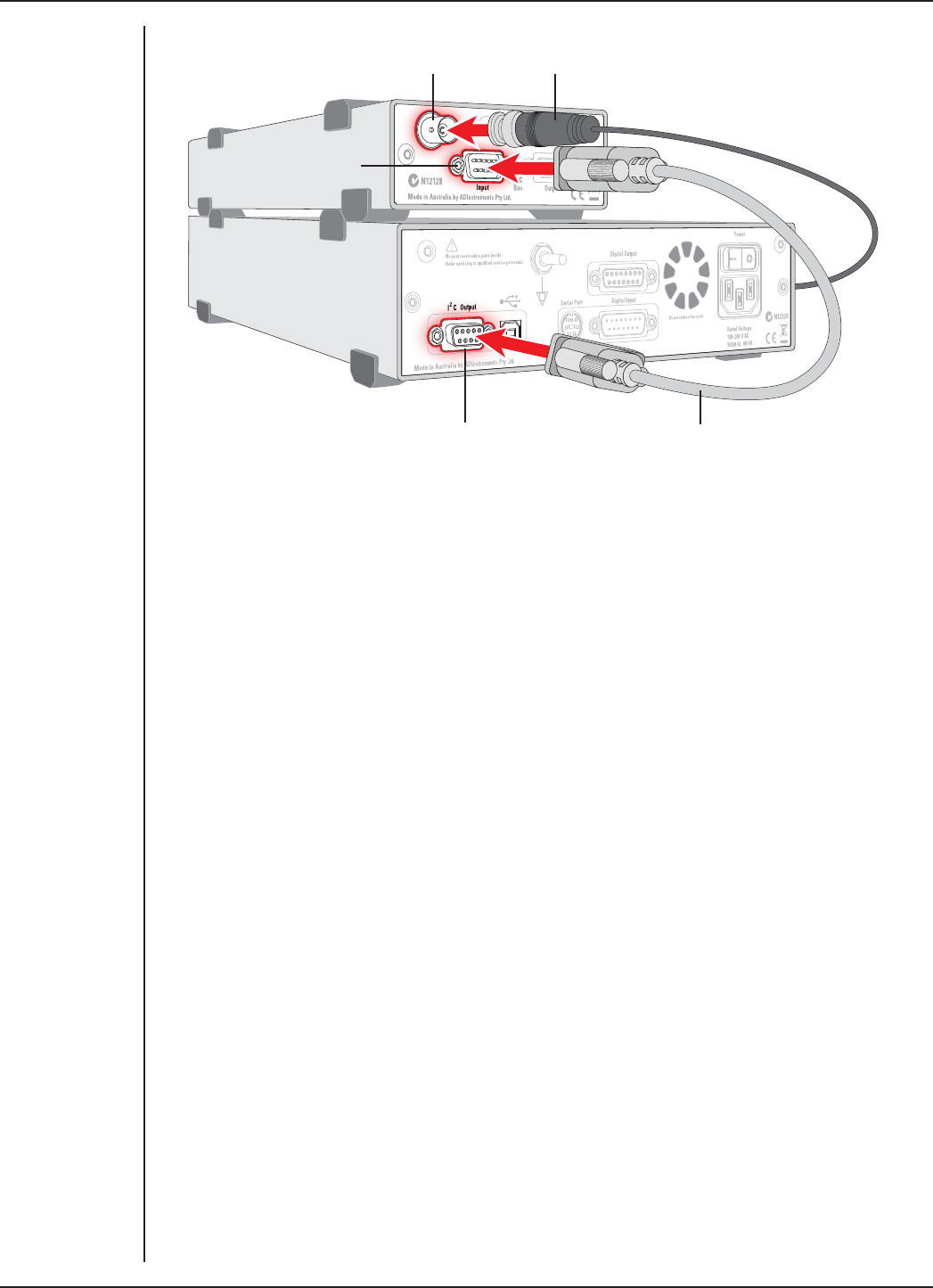
FRONT-END SIGNAL CONDITIONERS - Owner’s Guide
77
Multiple Front-ends
Multiple front-ends can be connected up to a PowerLab. The number that can be
connected depends on the number of analog inputs on the PowerLab. The initial front-
end should be connected as shown in Figure 6–3. The remainder are daisy-chained via
I2C cables, connecting the I2C output of the last connected front-end to the I2C input of
the next front-end to be added, as shown in Figure 2–2. The BNC cable for each front-end
is connected to one of the inputs of the PowerLab (except where otherwise specified).
Using LabChart and Scope
Once the Bridge Amp is connected, turn the PowerLab on and launch LabChart (or
Scope).While the soware starts up, keep a close eye on the Status and Overload
indicators on the Bridge Amp. During initialization, the Status indicators glow green,
flash briefly, and then remain lit.
If the indicator glows green, the Bridge Amp is working properly. If a light does not go
on when the program is started, this indicates either that the front-end is not connected
properly or that there is a soware or hardware problem. If the overload light glows
yellow (or amber) on any Bridge Amp, this indicates some fault such as a short circuit,
a badly wired bridge transducer, or an excitation overload. In the first instance, check
your cable connections and transducers, and repeat the self-test. If this does not solve
the problem, contact your ADInstruments representative.
When a Bridge Amp is properly connected to the PowerLab, the Input Amplifier…
menu commands are replaced by Bridge Amp… for the input channel(s) to which
it is connected. If the application fails to find a front-end connected, the normal text
remains. If this occurs you should quit the application, turn the PowerLab o and check
the connections. Then restart the PowerLab and relaunch the application.
Figure 6–3
Connecting a
single Bridge Amp
front-end to the
PowerLab
Bridge Amp Signal Output
Bridge Amp I2C input
PowerLab I2C output I2C connector cable
BNC connector cable
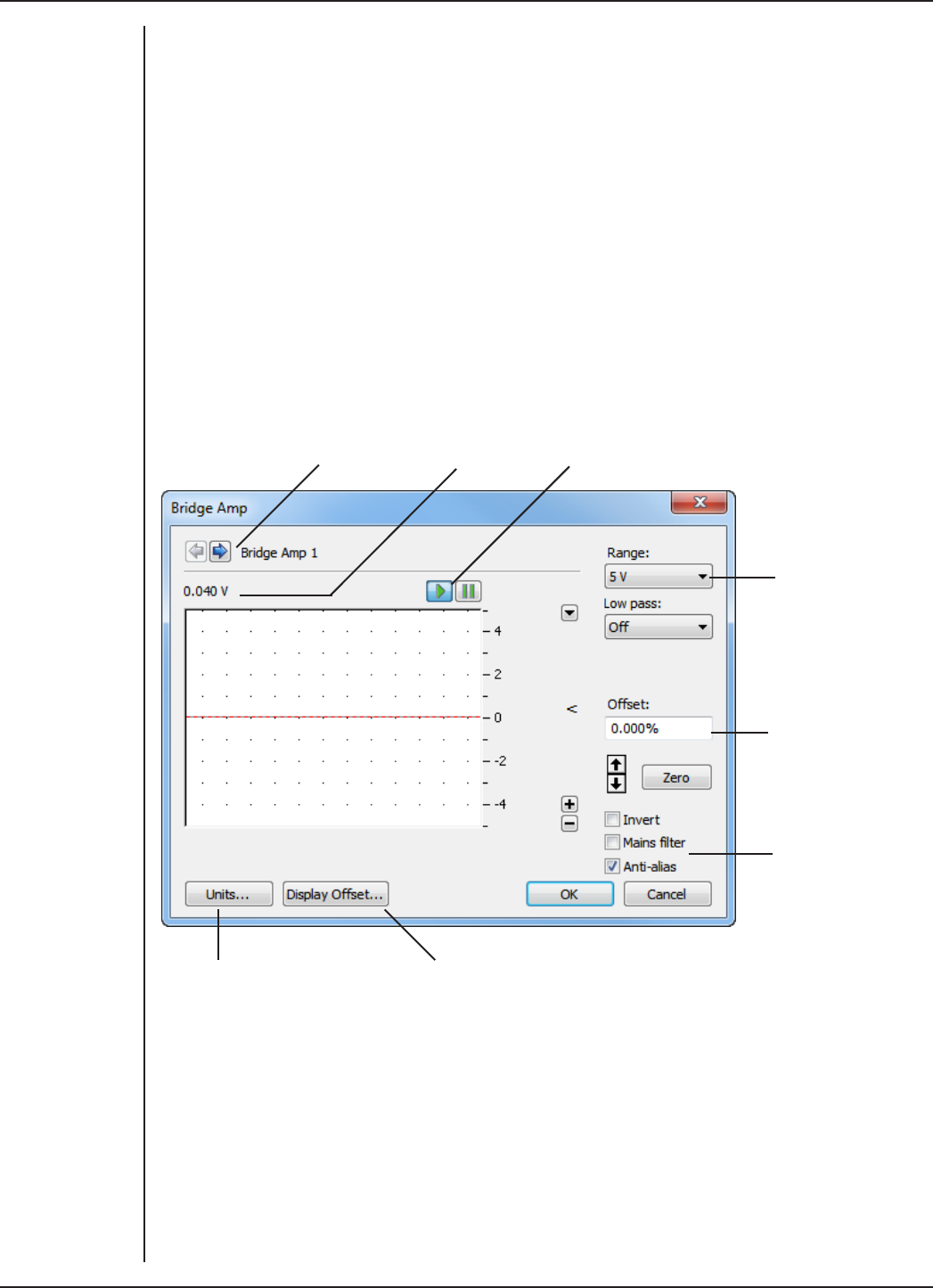
FRONT-END SIGNAL CONDITIONERS - Owner’s Guide
78
The documentation for LabChart and Scope does not cover front-end-specific features.
These features are described in detail here for LabChart. For the most part, dialogs for
LabChart and Scope should be much the same.
The Bridge Amp dialog
The Bridge Amp dialog allows soware control of the various amplifiers and filters in
the Bridge Amp and PowerLab for an input. The signal present at a PowerLab input is
displayed so that you can see the eects of changes straight away. Once the settings in
the dialog are changed, click OK to apply them.
To set up many channels quickly, open the Setup > Channel Settings... dialog. Here
you can view all the channels that are turned on, and you can turn o any unnecessary
channels. Clicking on Bridge Amp… in the Input Settings column of the Channel
Settings dialog will also open the Bridge Amp dialog.
Input selection Average signal value Pause/Scroll buttons
Range pop-up
Set the offset for
the Bridge Amp
Filter options
Displays the Units Conversion
dialog
Displays a voltmeter on screen for use
when setting the offset externally
Signal Display
The input signal is displayed so you can see the eect of changing the settings — no
data are in fact recorded when setting things up. The average signal value is shown at
the top le of the display area.
You can stop the signal scrolling by clicking the Pause button at the bottom le
(Macintosh) or top right (Windows) of the data display area. On the Macintosh this
changes to the Scroll button. Click the Scroll button to start scrolling again.
Figure 6–4
The Bridge
Amp dialog for
Windows (before
zeroing)

FRONT-END SIGNAL CONDITIONERS - Owner’s Guide
79
You can shi and stretch the vertical Amplitude axis by clicking and dragging it to make
the best use of the available display area. It functions the same as the Amplitude axis
of the Chart window; the controls are identical and any change is applied to the Chart
Window.
On a Macintosh, Show Range Axis in the Scale pop-up menu displays the range axis at
the right of the display area, and the Compression buttons adjust the horizontal axis of
the data display area.
Setting the Range
The Range pop-up menu lets you select the input range or sensitivity of the channel
(combined range of the PowerLab and Bridge Amp). Changing the range in the Bridge
Amp dialog is equivalent to changing it in the Chart window. The default setting is 5 V
and the ranges go down to 200 µV in 14 steps.
Filtering
The filtering options provided are appropriate to the type of transducers used with the
Bridge Amp, and the signals usually measured, which tend to be of lower frequency.
Low-pass filters allow you to remove high-frequency components, such as noise,
from an input signal. The Mains filter allows you to remove interference at the mains
frequency (typically 50 or 60 Hz).
Low-Pass Filtering. The Low Pass pop-up menu provides a choice of filters to remove
high-frequency components from the signal. They are: 1, 2, 10, 20, 100, and 200 Hz, and
1 kHz. (The highest frequency you can actually record is limited by the transducer you
use: such information should be in the documentation supplied with it.)
Mains Filter (/20, /25, /30 and /35 series PowerLabs). The Mains filter checkbox allows
you to filter out interference at the mains frequency (typically 50 or 60 Hz). Note that in
general it is better to prevent interference at its source than to filter it. The mains filter is
an adaptive filter which tracks the input signal over approximately 1 second. It analyzes
the signal and creates a template of any interference due to the mains frequency (see
“Specifications” on page 93). Subtraction of the template from the incoming signal
cancels most of the interference.
In comparison with a notch filter, this method produces little waveform distortion and
attenuates harmonics of the mains frequency as well as the fundamental; it eectively
removes non-sinusoidal interference, such as that commonly caused by fluorescent
lights.
The filter should not be used when:
•the interference changes rapidly. The filter takes about 1 second to adapt to
the present level. If interference is present, and then is suddenly removed,
interference in the filtered signal will temporarily be increased.
•your signal contains repetitive components at frequencies close to the mains
frequencies.
•your signal is already free from interference. If the signal-to-noise ratio is greater
than about 64 the mains filter introduces more noise than it removes.

FRONT-END SIGNAL CONDITIONERS - Owner’s Guide
80
•you are recording at close to maximum sampling rates. The mains filter uses
some of the PowerLab’s processing power and therefore reduces the maximum
rate at which you can sample.
The template is not fully generated until about 1 second aer sampling starts and so the
mains filter is not fully eective in the first second of each data block.
Anti-alias
Click the Anti-alias checkbox to turn anti-aliasing on and o. Aliasing occurs when a
regular signal is digitized at too low a sampling rate, causing the false appearance of
lower frequency signals. To prevent aliasing, the sampling rate must be at least twice
the highest frequency in the incoming waveform.
When aliasing of noise or signals is seen, or even suspected, the first action you should
take is to increase the sampling rate. The highest available sampling rates are 100k
/s or 200k /s, depending on your PowerLab. If this reveals unwanted high-frequency
components in the sampled signal, you will achieve better results by using a low-pass
filter to remove them.
The best kind of filter for this purpose is the Anti-alias filter option in the Bridge Amp...
dialog. This is a special low-pass filter that is configured to automatically remove
all signals that could alias; i.e., those whose frequency is greater or equal to half the
sampling rate. A high sampling rate, however, will use more computer memory and
may limit recording time, so, once you have established the frequencies of interest to
you in an incoming signal, if Anti-alias is selected the sampling rate can be scaled down
accordingly.
Inverting the Signal
The Invert checkbox allows you to invert the signal on the screen. It provides a
simple way to change the polarity of the recorded signal without having to swap the
connections to the recording electrodes.
For example, you might be recording from a force transducer where an increase in force
downwards gives a negative signal, but you want to have a downwards force shown as
a positive signal on the screen. Checking the Invert checkbox will change the display to
do this.
Oset Adjustment
Transducers almost always produce some amount of signal, usually small, when in the
equilibrium or rest state. Oset from a zero reading need to be removed, in a process
called zeroing. Commonly, the user also wants to remove a constant term, for example
baseline blood pressure or initial tension in a muscle, from a measurement of interest.
This enables more accurate measurement of the changes in the signal under stimuli.
The oset controls in the Bridge Amp dialog can be used to zero the reading manually or
automatically.
Manual Zeroing. The up and down arrows near the Zero button allow manual
adjustment of the signal oset. Click the up arrow to shi the signal positively and the
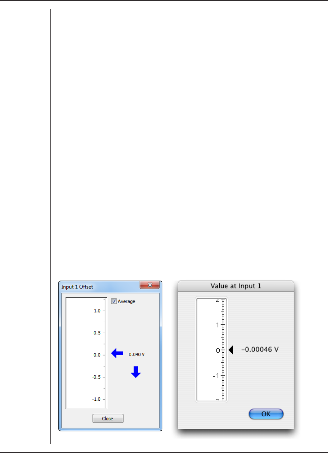
FRONT-END SIGNAL CONDITIONERS - Owner’s Guide
81
down arrow to shi it negatively. The shi by clicking the arrow buttons depends on the
range setting. At high ranges the increments are larger to adjust the oset eiciently.
Automatic Zeroing. To perform automatic zeroing, click Zero: the program works out
a corrective DC voltage that cancels, as closely as possible, the output voltage from
the transducer. Auto-zeroing may take about 20 seconds to work out the best zeroing
value at all ranges. A dialog with a progress bar appears: click the Cancel button or type
Command-period to stop the zeroing process. If there is still oset aer auto-zeroing,
then Option-click the up and down arrow buttons to adjust the zeroing slightly, by the
smallest increment at any range.
Note: Variations in the transducer signal during the auto-zeroing operation will cause
the soware to fail to zero the oset properly, if it zeroes at all. Make sure that the
transducer is kept still and that no varying signal is applied during the operation.
The oset display, a small numeric indicator above the Zero button, shows the
corrective voltage used to adjust for transducer oset. The oset is given in the units
of the channel. When the Bridge Amp is first powered up, the soware sets the oset
circuit to its default position (no oset adjustment of the transducer) and the oset
display value is zero. When either Zero or the manual oset controls are clicked, this
value will change to indicate the positive or negative corrective adjustment.
On a Macintosh, click the small 0 button to restore the oset circuit to its initial, non-
zeroed position (and the oset display value to zero). This can be used to determine the
oset generated by a transducer.
Display Oset
Click Display Oset… to display the Input Value dialog, which is a voltmeter displaying
the voltage currently being measured for an input (the input channel is indicated at
the top of the dialog). If a transducer or some other external equipment has oset
adjustment capabilities, you can use this to zero it.
Figure 6–5
The Input Value
dialog, Windows
(le) and
Macintosh (right)

FRONT-END SIGNAL CONDITIONERS - Owner’s Guide
82
Because the dialog allows for such fine adjustment, a vertical arrow appears indicating
the zero point if the oset is substantial. This dialog is not a control, simply an indicator
that acts like a voltmeter.
Units
Click Units… to display the Units Conversion dialog, in which you specify the units for
the channel and calibrate the channel. The waveform in the display area of the Bridge
Amp dialog is transferred to the data display area of the Units Conversion dialog. (Use
the Pause button to capture a specific signal.) The units conversion only applies to
subsequently recorded signals, so it is more limited than choosing Units Conversion…
from a Channel Function pop-up menu, which allows units conversion of previously
recorded data.
Using Transducers
Bridge Amps are designed to allow the PowerLab to connect to most DC bridge
transducers, including commonly-available force, pressure, and displacement
transducers, temperature probes, light meters, and similar devices. They are capable
of supporting various powered transducers, and certain low-impedance unpowered
(or self-powered) transducers. However, because transducers vary in sensitivity and
suitability, you should read the following sections before connecting a transducer to a
Bridge Amp.
The ‘Adapting Transducers’ section describes the modifications that may be required
to connect third-party transducers to the Bridge Amp. Transducers supplied by
ADInstruments should connect directly without modification, so if using these you need
not read this section. If you are using powered third-party transducers with your Bridge
Amp you may need to adapt them using the information provided in this later section.
NOTE: Please ensure that any modifications made to transducers are carried out
by experienced technical sta. Some soldering of components is required to adapt
third-party transducers for use with your Bridge Amp. Incorrect wiring may damage
the transducer or Bridge Amp. If you have little experience with electronics and no
technician to assist you, please contact your nearest ADInstruments representative for
further assistance.
Compatibility
Transducers supplied by ADInstruments will operate with the FE22x Bridge Amps. All
transducers which operated with the older model ML110, ML112, ML118, ML119 Bridge
Amps will operate with the FE22x Bridge Amps. The ML110 and ML112 amplifiers had
provision for increasing osetting resolution via an optional resistor installed in the
transducer connector. Transducers which have this osetting resistor fitted will operate
with the FE22x Bridge Amps without modification.

FRONT-END SIGNAL CONDITIONERS - Owner’s Guide
83
Suitable Transducers
The Bridge Amps are designed to connect to transducers that require DC excitation
voltages, such as DC strain-gauge or semiconductor transducers.
If you are uncertain about the suitability of your transducer, please provide
ADInstruments with an accurate circuit of the transducer and a sample, and we will see
about testing the device for compatibility. Half-bridge transducers will need to be wired
up with compensating resistors before they can be used with any of the Bridge Amps
(see Technical Aspects section).
DC Strain-gauge. These are full-bridge or half-bridge transducers requiring a DC
excitation voltage, and output voltages of less than 200 mV full scale. They include
strain-gauge force transducers, temperature transducers and pressure transducers.
Semiconductor. These are powered transducers typically used for light, displacement,
and temperature measurements, giving output voltages less than 200 mV full scale.
Generally, a Bridge Amp can be used with transducers that:
•require DC excitation voltages, not AC
•have transducer output voltages less than 5 V full scale
•have transducer impedances less than 10 kΩ.
Unsuitable Transducers
Some transducers are not supported and should not be used with the Bridge Amp.
These include LVDT, capacitive bridge, piezoelectric and high-voltage transducers.
LVDT (linear variable dierential transformer). This type of transducer requires AC
excitation voltages. The Bridge Amp is for use with transducers requiring DC excitation.
Connecting an LVDT transducer to the Bridge Amp may damage the transducer.
Capacitive Bridge. These transducers require AC excitation. The Bridge Amp is for use
with transducers requiring DC excitation.
Piezoelectric. These transducers are not recommended owing to the relatively
low input impedance of the single Bridge Amp (piezoelectric transducers typically
need amplifiers with input impedances of tens of megaohms), and their half-bridge
configuration.
High-voltage. Transducers generating more than ±5 V full scale will exceed the input
range of the Bridge Amp. A high-voltage powered transducer may require some signal
attenuation.
How Transducers Work
The Bridge Amp can connect to most bridge-type transducers, hence its name. The term
‘bridge’ refers to the circuit configuration that is normally called a Wheatstone bridge.
These transducers come in two forms: full-bridge and half-bridge. Some explanation
is given here of bridge-type transducers, although there are of course other types that
work dierently, such as the semiconductor transducer.
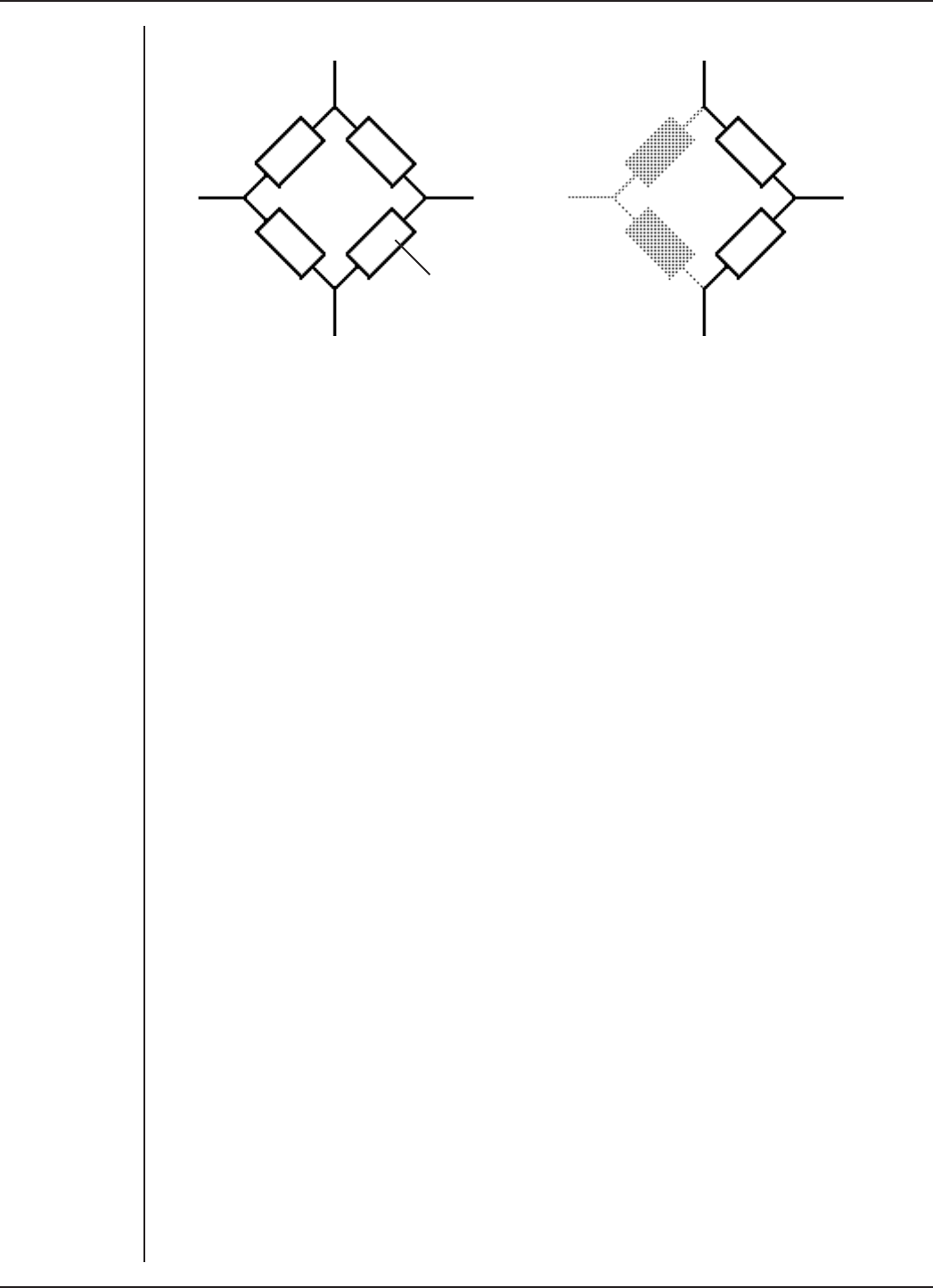
FRONT-END SIGNAL CONDITIONERS - Owner’s Guide
84
positive excitation positive excitation
negative excitation negative excitation
Bridge elements —
resistors, thermistors,
capacitors, or a mixture
++
−
The full-bridge circuit is fairly versatile, in that the circuit elements, shown as the
rectangular boxes in Figure 6–6, can be resistive, capacitive, or thermal circuit elements,
allowing the bridge to measure force, pressure, temperature, and so forth. This circuit
produces an electrical output in proportion to an appropriate stimulus applied to one
or more of the four elements. Because of the balancing eect of the four elements, high
precision is possible. Full-bridge transducers should work without problems.
A half-bridge transducer only uses half of the full-bridge circuit. It consists of two
elements of equal value with an excitation voltage applied across them. The output of
the transducer is taken at the junction of the two elements.
The circuit forms a simple voltage divider. If one of the elements changes value owing to
an external stimulus, the output voltage will also change. In practice, this configuration
is not oen used. Half-bridge transducers will require adapting with compensating
resistors before use with a Bridge Amp.
Checking the Transducer
Before attempting to connect any transducer to a Bridge Amp, you will need to
determine the three things listed below. (This information is normally supplied with the
transducer; if not, you should consult the manufacturer or supplier of the transducer.)
1. If the transducer requires an excitation voltage, and if so, what the maximum
excitation voltage, or recommended range, is for the transducer.
2. The configuration of the transducer wiring connections.
3. If the transducer is a bridge-type transducer, and whether it has a full-bridge or
half-bridge configuration.
Transducers supplied by ADInstruments are supplied pre-adjusted, and need no
adjustment.
Do not attempt to connect the signal leads from the transducer to the Bridge Amp if
the wiring configuration is not known. Connecting an incorrectly wired transducer to an
excitation source is likely to damage both the transducer and Bridge Amp.
Unpowered transducers, or those with their own power supply, do not have to be
supplied with any excitation voltage from the Bridge Amp: they supply their own signal
Figure 6–6
Le, a full-bridge
transducer; right,
a half-bridge
transducer

FRONT-END SIGNAL CONDITIONERS - Owner’s Guide
85
to it directly. The wiring connections should still be carefully checked before connection,
along with transducer impedance and output voltage. Such transducers do not need
the excitation range to be adjusted from the default setting. If they have low output
voltages, though, then it is possible that their oset ranges require adjusting.
Using Grass Transducers with Bridge Amps
Most Grass transducers should have an impedance of about 350 Ω or so. A few Grass
and Grass-compatible transducers have a much lower impedance of about 250 Ω. Grass
transducers can connect to any ADInstruments Bridge Amp using a Grass adapter cable
available from ADInstruments. Use the MLAC11 Grass Adapter Cable to connect a Grass
transducer to the FE221, FE224 or FE228 Bridge Amp.
Adapting Transducers
This section describes the modifications that may be required to connect third-party
transducers to the Bridge Amp. Transducers supplied by ADInstruments should connect
directly without modification, so if using these you need not read this section.
If you are using powered third-party transducers with your Bridge Amp you may need to
adapt them using the information provided here.
NOTE: Please ensure that any modifications made to transducers are carried out by
experienced technical sta, as incorrect wiring may damage the transducer or Bridge
Amp. If you are unsure, please contact your nearest ADInstruments representative for
further assistance.
Introduction
Conventional amplifiers usually have controls on the front to adjust for the connected
transducer: this means making adjustments each time you change transducers or
amplifiers.
In contrast, ADInstruments Front-ends are designed to be easily transferred between
recording units, and to be quick to disconnect and reconnect, so it makes more sense
to adapt the transducer. The change needs only be done once for any third-party
transducer, which can then be used with any Bridge Amp with the same connector.
Once set up, multiple transducers will work with the same Bridge Amp without needing
further adjustment, and one can simply change connected transducers as required.
Some soldering of components is required to adapt third-party transducers for use
with your Bridge Amp. If you have little experience with electronics and no technician to
assist you, your ADInstruments representative should be able to help.

FRONT-END SIGNAL CONDITIONERS - Owner’s Guide
86
Transducer Adaptations
This section covers adapting transducers for use with the ADInstruments Bridge Amps.
To connect transducers that require some form of power supply from the Bridge
Amp, first read this section carefully. The requirements of the transducer should be
determined before attempting to connect it.
To adapt a transducer for use with the Bridge Amp, you need to:
•set the excitation voltage for the transducer
•wire the transducer to use the eight-pin DIN plug.
You will need the following equipment:
•a soldering iron and resin-cored solder (ONLY resin-cored solder)
•an eight-pin DIN-style male plug with 45-degree pin spacing (supplied with your
Bridge Amp)
•common E12 resistors: 0.25 or 0.125 Watt, 2% or 1% metal film.
Setting the Excitation Voltage
The first step in preparing a powered transducer for use with the Bridge Amps is to
set the required excitation voltage. Two of the pins in the Bridge Amp’s DIN socket can
provide up to 20 volts DC as excitation voltage to power the transducer.
The voltage is varied by a resistor fitted between the two corresponding pins of the
transducer’s DIN plug. When no resistor is present, the Bridge Amp’s internal circuitry
cuts o all voltage to prevent mishaps. Once a resistor is fitted, the correct excitation
voltage is provided automatically when the transducer is plugged into the Bridge Amp.
Excitation voltage
(DC volts)
Excitation
resistance
(Ω)
Excitation voltage
(DC volts)
Excitation
resistance
(Ω)
20 Short circuit 5470 k
18 12 k 4 560 k
15 47 k 3.5 680 k
12 100 k 3820 k
10 150 k 2.5 1 M
8220 k 21.2 M
6 330 k
To program the excitation voltage for a particular transducer, choose a value of
resistance from Table 6–1 to match the required excitation voltage for your transducer.
In most cases, you should be able to get close to the required excitation voltage by
selecting one of those values. We recommend that the excitation resistor be 0.25 or
0.125 Watt, 2% or 1% metal film. Larger resistors may not fit in the confined space of the
transducer’s DIN plug.
Table 6–1
Transducer
excitation voltage
and resistance
FRONT-END SIGNAL CONDITIONERS - Owner’s Guide
87
In general, the output voltage from the transducer is directly proportional to the
excitation voltage placed across it. The greater the excitation voltage, the more sensitive
the transducer becomes.
However, transducers have a limit to the level of excitation voltage that can be applied
before they are damaged. Some resistive elements may start to heat at high excitation
voltages, causing their resistance to change. This degrades the accuracy of the
transducer. High voltages may also damage capacitive bridge transducer elements. To
avoid problems, the excitation voltage should be set according to the manufacturer’s
recommendation for that transducer.
To set the excitation voltage for a transducer, you will need to solder the chosen resistor
between pins 5 and 8 of the eight-pin DIN plug, as shown in Figure 6–7. Mount the
resistor as shown for maximum clearance within the plug.
Excitation voltage
programming
resistor
Pin 8
Pin 5
Wiring Up the Transducer
The second step in preparing a powered transducer for use with the Bridge Amp is to
wire the transducer to the DIN plug.
There are several things to note when wiring up transducers:
1. Make sure that the transducer wiring passes through the casing before soldering
the wires to the plug.
2. The transducer wires should be cut, stripped and tinned prior to soldering, to
ensure a good connection.
3. The pin numbers shown in the diagrams are the numbers marked on most
standard DIN plugs. If the plug has no numbers or dierent ones, go by the
layout shown here.
Wiring Up a Full-Bridge Transducer
This procedure should be used to wire full-bridge transducers only, not half-bridge
transducers. The transducer lead wires should be soldered to the pins of the DIN plug as
shown in Figure 6–8.
Any unused wires from the transducer should be cut and insulated to prevent shorting
of signals or damage to the equipment.
Figure 6–7
Installing the
programming
resistor (the pins
are labeled on the
plug)
FRONT-END SIGNAL CONDITIONERS - Owner’s Guide
88
1
2
3
4
5
67
8
Ground or centre tap (shield)
Signal positive (+)
Signal negative (–)
Excitation negative (–)
Excitation positive (+)
Excitation voltage
programming resistor
The main insulation sheath of the transducer wiring should be clamped with the strain-
relief device within the plug, so that it just clears the excitation voltage resistor. The
transducer will normally have some sort of cable shield, which should be connected to
pin 7 of the DIN plug. If the casing of the DIN plug is metal, it is recommended and good
practice to ensure that the casing will also be connected to the shield.
Wire from
transducer
Transducer ground
(earth) wire
The Finished Transducer
Aer connecting the excitation voltage programming resistor and wiring up the
transducer to the DIN plug, the transducer should now be fully configured for your
application. The excitation voltage will be set automatically when you plug the
transducer into the Bridge Amp.
Figure 6–8
The wiring
connections
for a full-bridge
transducer,
looking at the
DIN plug from the
cable side
Figure 6–9
The correct
length of wiring to
the DIN plug
FRONT-END SIGNAL CONDITIONERS - Owner’s Guide
89
Technical Aspects
This section describes some of the important technical aspects of the Bridge Amp to
give some insight into how it works. You do not need to know the material here to use
the Bridge Amp. It is likely to be of special interest to the technically minded, indicating
what the Bridge Amp can and cannot do, and its suitability for particular applications.
Note: You should not use this section as a service manual: user modification of the
equipment voids your rights under warranty.
Bridge Amp Operation
The Bridge Amp and other ADInstruments front-ends have been designed to integrate
fully with the PowerLab system. The Bridge Amp is essentially an extension of the
PowerLab’s input amplifiers, so the amplification (and hence the ranges) oered in
LabChart and Scope are the combination of both pieces of hardware. The Bridge Amp
provides:
•the additional amplification necessary to deal with the low signal outputs of
most transducers
•additional programmable filtering, to remove unwanted signal frequencies
a stable DC excitation voltage supply for powering the transducer
•digitally-controlled transducer zeroing circuitry.
16-bit
DAC
+
–
Input
Gain
control
Prog.
Amp
Bridge
excitation
driver
Preamp
Vref
Signal
Output
Transducer
plug
I2C
I2C
Output
Transducer
signal inputs
Excitation
voltage
Online indicator
Excitation voltage
setting resistor
Overload
indicator
I2C
control
interface
+
power
supply
5th-order
8 kHz
low-pass
lter
Butterworth
Figure 6–10
Block diagram of
the FE221
Bridge Amp.
The FE224
and FE228 Bridge
Amps are
similar but
with four or
eight inputs,
respectively

FRONT-END SIGNAL CONDITIONERS - Owner’s Guide
90
Technical Description
The PowerLab provides control and low-voltage power to front-ends through a
special expansion connector called the I2C (eye-squared-sea) bus. Front-ends are also
connected to the analog inputs of the recording unit via a BNC-to-BNC cable. The overall
operation of the Bridge Amps can be better understood by referring to Figure 6–10.
The digital control interface used to control filter settings, gain, coupling, and zeroing
circuits uses an I2C interface system, which provides a 4-wire serial communication
bus to the recording unit and other front-ends. All control of the Bridge Amp is through
this bus. Also present on the I2C connector is a set of power supply rails derived from
the recording unit. The Bridge Amp has its own on-board regulators to ensure a stable
power supply.
The input stage consists of a low-dri instrumentation amplifier with programmable
gain (fully soware-controlled). The gain of this stage is combined with the gain of the
recording unit to give a total gain of up to 50 000 (at this amplification, 200 µV is full
scale). From the input amplifier, the signal is passed to a fixed fih-order, low-pass, filter.
The filter allows a range of cuto frequencies to be selected under soware control.
The excitation voltage output circuit is a complementary output stage, derived from
a stable internal voltage reference, capable of giving up to ± 10 volts (20 volts DC)
excitation. The excitation voltage for each channel is completely independent from
other channels. The transducer excitation voltage can be adjusted by connecting a
resistor between two pins on the plug that plugs into the Bridge Amp’s input socket.
This resistor is usually placed inside the transducer’s DIN plug so that the transducer
will always get the correct excitation voltage when it is connected.
To remove any osets caused by an attached transducer or signal baseline, a DC oset
circuit with a 16-bit DAC (digital-to-analog converter). This is internally connected to the
input stage. Transducer osets are zeroed by applying a corrective DC voltage to the
input stage via the DAC, under soware control.
The DAC is only capable of producing corrective voltages in discrete steps.
Troubleshooting
This section describes most of the common problems that can occur when using the
Bridge Amp with your PowerLab recording unit. Most of the problems that users
encounter are connection problems, and can usually be fixed by checking connections
and starting up the hardware and soware again. Very rarely will there be an actual
problem with the Bridge Amp or the PowerLab itself.
If the solutions here do not work, earlier chapters, the LabChart Help Center, and the
guide to your PowerLab may contain possible solutions. If none of the solutions here or
elsewhere are of help, then consult your ADInstruments representative.
Problems and Solutions
The Status indicator fails to light when the soware is started, or the Bridge Amp…
command does not appear where it should

FRONT-END SIGNAL CONDITIONERS - Owner’s Guide
91
The I2C cable or one or more BNC-to-BNC cables from the Bridge Amp to the PowerLab
are not connected, have been connected incorrectly (to the wrong input, for instance),
or are loose.
•Turn everything o. Check to see that all cables are firmly inserted and screwed
in. Make sure the input is the same channel from which you expect to use the
Bridge Amp in the soware. Ensure no other equipment is attached to the
particular channel of the PowerLab from which you expect to see the Bridge
Amp. Start up again to see if this has fixed the problem.
You are using an early version of LabChart or Scope.
•Upgrade to the latest version of the soware. Contact your ADInstruments
representative for information.
The BNC or I2C cable is faulty.
•Replace the cable and try again. Immediately label all cables proved faulty so
that you don’t use them again by accident.
The Bridge Amp is faulty.
•This is the least likely event. If the Bridge Amp will not work properly aer the
previous measures, then try using it on another PowerLab. If the Bridge Amp’s
Status indicator fails to light with a second PowerLab, the Bridge Amp may be
faulty. Contact your ADInstruments representative to arrange for repairs.
One or more overload indicators glow amber
If a light glows amber (yellow), it indicates some fault such as a short circuit, a badly
wired bridge transducer, or an excitation overload.
•Check to see that all transducer connections are firm.
• Check for short circuits and badly wired bridge transducers, by changing them
around, connecting new ones, and so on.
•Check transducer impedances. In particular, a low-impedance Grass transducer
(250 Ω or so) may suer overload if the excitation is too high.
On starting up the soware, an alert indicates that there is a problem with the front-end or
driver
The correct Bridge driver is not installed on your computer.
• Reinstall the soware.
You are using an early version of LabChart or Scope.
•Upgrade to the latest version of the soware. Contact your ADInstruments
representative for information.
The BNC or I2C cable is faulty.
•Replace the cable and try again. Immediately label all cables proved faulty so
that you don’t use them again by accident.
The Bridge Amp is faulty.
•This is the least likely event. If the Bridge Amp will not work properly aer the
previous measures, then try using it on another PowerLab. If the Bridge Amp’s

FRONT-END SIGNAL CONDITIONERS - Owner’s Guide
92
Status indicator fails to light with a second PowerLab, the Bridge Amp may be
faulty. Contact your ADInstruments representative to arrange for repairs.
The trace will not zero properly when using the automatic or manual zeroing controls
Variations in the transducer signal during auto-zeroing may cause the soware to fail to
zero the oset properly, if it zeroes at all.
•Make sure that the transducer is kept still and that no varying signal is applied
during auto-zeroing.
The transducer is defective or subject to excessive load, causing the oset range of the
Bridge Amp’s zeroing circuitry to be exceeded.
•Check the transducer with another Bridge Amp if possible and try again. Contact
the supplier or manufacturer of the transducer if there still seems to be a
problem.
You are using an unmodified half-bridge transducer.
•Half-bridge transducers may require rewiring with compensating resistors before
they can be used with Bridge Amps.
The signal from the transducer is noisy at lower ranges
This is usually the amplified noise from the transducer and its associated circuitry, not a
fault as such.
•Set the low-pass filter to remove the noise.
The signal from the transducer is weak even at lower ranges
The connection to the transducer may be connected incorrectly, or may be loose or
disconnected. Adaptations within the plug may be faulty or badly wired up.
•Check the connection and try again. If the transducer has been adapted for use
with the Bridge Amp, check the wiring and soldering within the plug.
•Ensure that the particular channel in LabChart has been correctly recognized as
a Bridge Amp (and not as Input Amplifier).
The transducer itself is faulty.
•Check the transducer with another Bridge Amp if possible and try again. Contact
the supplier or manufacturer of the transducer if there still seems to be a
problem.
The signal from the transducer dris excessively.
•Both the Bridge Amp and transducer require time to reach thermal equilibrium.
Allow 5 minutes of warm-up time with the transducer connected and then try to
re-zero the transducer.
•The transducer itself may be of low quality.
•The excitation voltage may be too high and causing the transducer to self-heat
and dri. Try reducing the excitation voltage.

FRONT-END SIGNAL CONDITIONERS - Owner’s Guide
93
Specifications
Single, Quad and Octal Bridge Amps (FE221, FE224 & FE228)
Input
Number of inputs: 1 (single), 4 (Quad) or 8 (Octal); 8-pin DIN
Connection type: 8-pin DIN socket
EMC: Approved to EN61326-1:2006 Standard
Configuration: Dierential
Input range: ± 200 µV to ± 5 V full scale in 14 steps
(combined PowerLab and Bridge Amp)
± 5 V
± 2 V
± 1 V
± 500 mV
± 200 mV
± 100 mV
± 50 mV
± 20 mV
± 10 mV
± 5 mV
± 2 mV
± 1 mV
± 500 µV
± 200 µV
Accuracy: ± 0.5% (combined PowerLab and Bridge Amp)
Maximum input voltage: ± 10 volts
Input impedance: 2 × 1 MΩ (single-ended) 2 MΩ (dierential)
Low-pass filtering: 1 Hz to 1 kHz in seven steps (soware-selectable)
Frequency response (–3 dB): 2 kHz maximum at all gains with the low-pass filter o
CMRR (dierential): 100 dB @ 50 Hz (typical)
Noise: <1 µVrms referred to input at highest gain

FRONT-END SIGNAL CONDITIONERS - Owner’s Guide
94
Excitation and Zeroing
Excitation voltage range: 0–20 V DC (± 10 V referred to ground), adjusted by
external resistor
Transducer drive current: ± 45 mA maximum
Zeroing circuitry: Soware-controlled, either manual or automatic
Internal osetting range: ± 10 V (1–5 V range)
± 1 V (100–500 mV range)
± 100 mV (0.2–50 mV)
Internal oset resolution: 16-bit (internal DAC) ± 32 000 steps about 0 V.
1, 2, 5 V - 310 µV/step
100 mV, 200 mV, 500 mV - 31 µV/step
200 µV to 50 mV - 3 µV/step
Control Port
I2C port: Power and control bus for front-end units. Supports
a number of front-ends dependent on the PowerLab.
Interface communications rate of ~50 kbits/s.
Physical Configuration
Dimensions (h × w × d) and Weight:
Single (FE221): 55 mm × 120 mm × 260 mm
(2.2" × 4.7" × 10.2"); 1.2 kg
Quad (FE224): 55 mm × 240 mm × 260 mm
(2.2" × 9.4" × 10.2"); 2.1 kg
Octal (FE228): 70 mm × 240 mm × 260 mm
(2.8" × 9.4" × 10.2"); 2.6 kg
Power requirements: 0.8 W (FE221); 2.5 W (FE224); 5.0 W (FE228)
(without transducer attached)
Operating conditions: 5–35 °C, 0–90% humidity (non-condensing)
ADInstruments reserves the right to alter these specifications at any time.
FRONT-END SIGNAL CONDITIONERS - Owner’s Guide
95
The ML408 Dual Bio Amp/Stimulator is a modular device known as a front-end, which
is designed to extend the capabilities of the PowerLab system. The Dual Bio Amp/
Stimulator allows the PowerLab system to record biological signals, such as ECGs, EEGs
and EMGs, from humans and other sources, with full electrical isolation, and can also be
used for any general-purpose stimulation work.
The Dual Bio Amp/Stimulator acts just as if it were two individual Bio Amps and a
Stimulus Isolator:
•The two Bio Amps are independently-controllable, electrically isolated, biological
amplifiers, which are suitable for a range of basic physiological measurements.
•The built-in Stimulator provides a soware-controlled, isolated, constant-current
pulse stimulator. The output is capable of supplying 100 V pulses and currents up
to 20 mA, so it should be treated with caution.
Note: The Dual Bio Amp/Stimulator can be used safely with human subjects.
Dual Bio Amp/Stimulator
Chapter 7
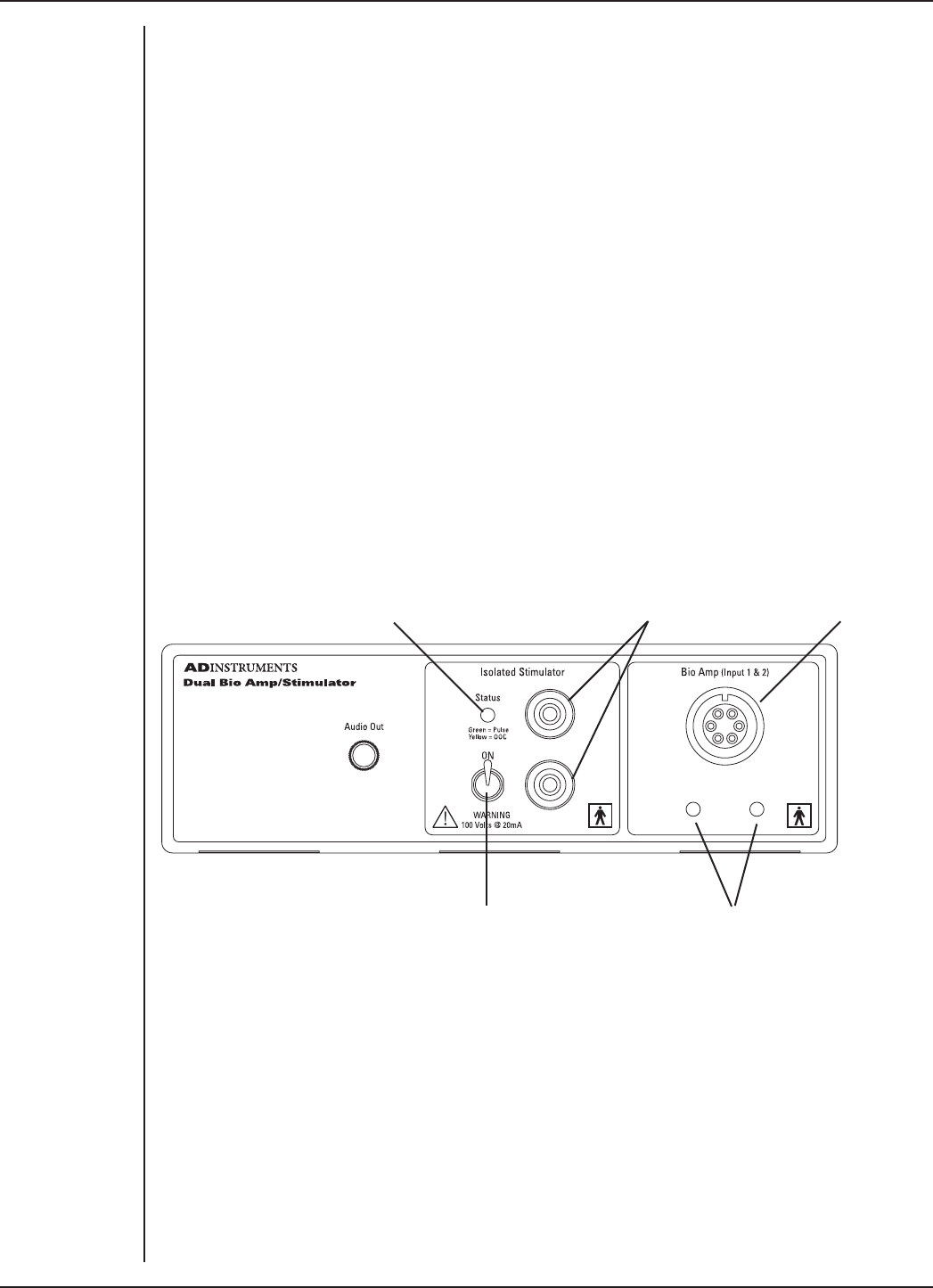
FRONT-END SIGNAL CONDITIONERS - Owner’s Guide
96
The Dual Bio Amp/Stimulator
The Dual Bio Amp/Stimulator provides three front-ends in one useful package: the two
Bio Amps (with a shared isolated ground connection and input socket) for electrically
isolated measurements of biological signals, and the Isolated Stimulator for any
general-purpose stimulation work. This front-end is designed to let the PowerLab
system conveniently perform both stimulation (of humans or other subjects) and
measurement of biological signals from them, such as ECGs, EMGs, and EEGs. Note that
signal degradation can occur if multiple Bio Amps are connected to a single subject.
The rest of this chapter contains general information about the features, connections,
and indicators of the Dual Bio Amp/ Stimulator, the Bio Amp cable, and how to use
them. More detailed information can be found in the technical appendices.
The Front Panel
The front panel of a Dual Bio Amp/Stimulator has two separate sections. The Dual Bio
Amp section has a common input connector and two Status indicators, one for each
Bio Amp input. The Isolated Stimulator section has two output connectors, a Status
indicator, and a safety switch. The front panel also has an audio output.
Isolated Stimulator
Status indicator
Isolated Stimulator
output
Bio Amp
inputs
Bio Amp
indicator lights
Safety switch
Dual Bio Amp
The Dual Bio Amp/Stimulator also has one common connector for two Bio Amp inputs
(marked Bio Amp Input 1 & 2). These biological amplifiers are needed to perform
electrically isolated measurements of biological signals, such as electrocardiograms
and electromyograms. The Bio Amps have a common six-pin connector with a shared
ground signal. The socket is of a sort commonly used with ECG-type cables and leads,
such as the Bio Amp cable and leads with which your front-end is supplied (Tronomed
D-1540). These inputs should only be used with the supplied Bio Amp cable and leads.
Figure 7–1
The front panel of
the Dual Bio Amp/
Stimulator

FRONT-END SIGNAL CONDITIONERS - Owner’s Guide
97
Other cables may not meet safety requirements. The socket and connections to it are
discussed in more detail later on.
The indicator lights of the Dual Bio Amp are located beneath the input connector on the
front panel. When an ADInstruments program such as LabChart starts up, the indicator
lights should flash briefly and then remain green, indicating that the program has found
the front-end, checked and selected it, and is ready to use it. If an indicator does not
turn on and stay on when the program is run, this indicates either that the front-end is
not connected properly or that there is a soware or hardware problem.
Audio Out
The Dual Bio Amp/Stimulator has an Audio Out socket on the front panel, with which
you can monitor the Bio Amp inputs. It can be used with a wide range of headphones or
externally powered speakers.
The 3.5 mm stereo socket provides two channels of sound, one for each data channel.
The audio output may be of use when monitoring nerve firings to control the placement
of electrodes, for instance.
Isolated Stimulator
The Dual Bio Amp/Stimulator has a built-in, isolated, constant-current pulse stimulator
that can be used for any general-purpose stimulation. The Isolated Stimulator section
of the front panel has two output sockets, a Status indicator light and a safety switch.
The stimulus output is supplied via two 4 mm shrouded banana sockets; the top (red)
socket is positive, the bottom (black) socket is negative. These are similar to the sockets
found on many digital multimeters, and designed for use with shrouded male 4 mm
plugs (the shrouding is to prevent accidental stimulation while fitting or removing the
plugs). The bar stimulus electrode supplied with the front-end uses such plugs. The
output is capable of supplying 100 V pulses and currents up to 20 mA, so it should be
treated with caution.
The Isolated Stimulator Status indicator is a multi-colored light that is used to indicate
the current status or operating condition of the Stimulator. The indicator light will
flash green for every stimulus pulse, and may seem to glow green constantly at higher
stimulus frequencies. A yellow color indicates that the output is overloaded or out-of-
compliance (compliance is the ability to supply voltage to meet the required current).
This means that the impedance of the tissue being stimulated is too high, or there is
a poor electrical connection (possibly due to electrode drying), and that the Isolated
Stimulator can no longer supply constant current stimulation. If this should happen,
reduce the output current amplitude and check connections.
To provide an additional level of safety, a safety switch has been placed on the front
panel to allow the output to be switched on and o as needed. The switch should be in
the up position when the output is turned on, and should be flicked down to turn it o:
that disconnects the output sockets from the internal circuitry, allowing connections to
be made in safety while the front-end is on.
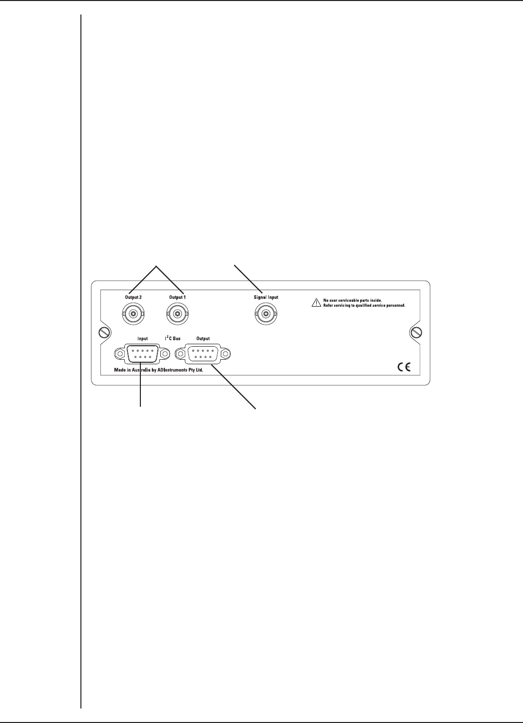
FRONT-END SIGNAL CONDITIONERS - Owner’s Guide
98
The Back Panel
The back panel of the Dual Bio Amp/Stimulator provides all the sockets required to
connect the front-end to the PowerLab and to other front-ends.
I2C Input and Output Sockets
Two nine-pin sockets are used to communicate with the PowerLab (they are marked I2C
Bus: a ‘bus’ is simply information-transmission circuitry such as cables and connectors).
These sockets allow multiple front-ends to be used independently with one PowerLab.
Power and control signals to the front-ends come from the PowerLab. Many front-ends
can be connected to the system, in series, output to input, providing there are suicient
channel inputs available on the PowerLab (see “Maximum Number of Front-Ends” on
page 12).
Signal outputs to the
PowerLab
Connection to the positive output
of the PowerLab
I2C connection to a further
front-end
I2C connection from the
PowerLab or previous front-end
The Dual Bio Amp/Stimulator acts as if it were two Bio Amps and a Stimulus Isolator
in series, with internal I2C connections between the separate front-ends. However, the
Dual Bio Amp/Stimulator counts as four front-ends, not three as one would expect.
Analog Out Sockets
BNC sockets on the back panel of the Dual Bio Amp/Stimulator provide the signal
outputs to connect to the analog input sockets on the front of the PowerLab. The sockets
are labelled Output 1 and Output 2. You don’t have to match the channel numbers when
connecting everything up, but it may help to prevent confusion if you do. A BNC-to-BNC
cable is supplied for each connection.
If you are using an older PowerLab with dierential inputs, remember to connect the
cable only to a positive analog input. ADInstruments applications will not find a front-
end on starting up if a negative input is used.
Figure 7–2
The back panel of
the Dual Bio Amp/
Stimulator
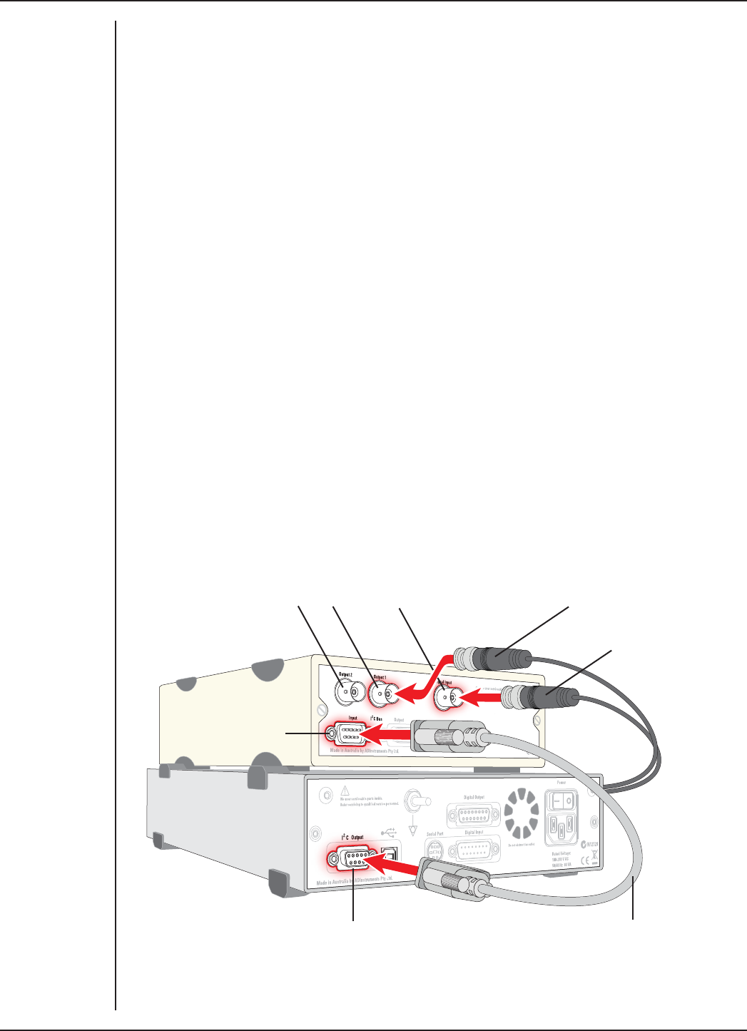
FRONT-END SIGNAL CONDITIONERS - Owner’s Guide
99
Signal Input Socket
A BNC connector labelled Signal Input on the back panel of the Dual Bio Amp/Stimulator
is used to connect the Isolated Stimulator in the front-end to the positive analog output
on the PowerLab. The positive output is labelled + on most PowerLabs and Output 1
on /30 and /35 series PowerLabs. A BNC-to-BNC cable is supplied for this connection.
The PowerLab output is used to provide the trigger pulses for the Stimulator and to
establish timing, as well as to check that the Stimulator is connected.
Connecting to the PowerLab
To connect a front-end, such as your Dual Bio Amp/Stimulator, to the PowerLab, first
ensure that the PowerLab is turned o. Failure to do this may damage the PowerLab,
the front-end, or both.
The BNC cables from the Dual Bio Amp analog outputs must connect to analog inputs
on the PowerLab. The BNC cable from the Stimulator analog input must connect to
the positive analog output of the PowerLab. The positive output is labelled + on most
PowerLabs and Output 1 on /30 and /35 series PowerLabs. ADInstruments applications
will not find the Stimulator on starting up if the negative output is used.
Single Front-ends
Connect the I2C output of the PowerLab to the I2C input of the front-end using the I2C
cable provided. Figure 7–3 shows how to connect up a Dual Bio Amp/Stimulator to your
recording unit.
Figure 7–3
Connecting the
Dual Bio Amp/
Stimulator to the
PowerLab
Dual Bio Amp
analog outputs
Stimulator
analog input
I2C connector cable
BNC connector cable
(to PowerLab input)
PowerLab I2C output
Dual Bio Amp/
Stimulator I2C input
BNC connector cable
(from PowerLab output)

FRONT-END SIGNAL CONDITIONERS - Owner’s Guide
100
The Dual Bio Amp/Stimulator acts just as if it were two individual Bio Amps and a
Stimulus Isolator. Its I2C connections are internal, though, so there is only one I2C cable
needed to connect the front-end to the PowerLab. However, three BNC cables are
required.
Check that the plugs for the I2C bus are screwed in firmly. Check the BNC cables for firm
connections as well. Loose connectors can cause erratic front-end behavior, or may
cause the front-end to fail to work at all. The BNC cables can be tucked under the front-
end to keep them out of the way if desired. You do not have to connect all the front-ends
if you do not want to.
Multiple Front-ends
Multiple separate front-ends can be connected up to a PowerLab. The number of normal
front-ends that can be connected depends on the number of input channels on the
PowerLab, since the BNC cable for each front-end is normally connected to one of the
analog input channels of the PowerLab. The initial front-end should be connected with
the I2C cable as shown in “Figure 7–3” on page 99. The remainder are daisy-chained
via I2C cables, as shown in Figure 2–2 on page 11.
The I2C bus can control a maximum of sixteen front-ends. However the Dual Bio Amp/
Stimulator counts as four front-ends. Therefore, if you are using a PowerLab 16/30,
which has sixteen input channels, you can only use an additional twelve single-channel
front-ends, for example one Octal Bridge Amp plus one Quad Bridge Amp, while the
Dual Bio Amp/Stimulator is in use.
Signal degradation can occur if multiple Bio Amps are connected to a single subject,
although this is avoided with the Dual Bio Amp because the two Bio Amps have a shared
isolated ground connection and input socket.
Note: Only one Stimulator front-end can be connected to the positive output of the
PowerLab. The Stimulator of the Dual Bio Amp/Stimulator connects to and uses the
positive analog output of the PowerLab as a source for producing pulses, so only one
such front-end can be used per PowerLab.
The Bio Amp Cable
Connections are made to the Bio Amp inputs using the supplied Bio Amp cable and
leads. The cable plugs into the six-pin input socket on the front panel: a notch in the
plug ensures that polarity is correct. Only the supplied Bio Amp cable and leads should
be used. Other cables may not meet safety requirements.
The Dual Bio Amp/Stimulator is supplied with a 5-lead Bio Amp cable and lead wires;
it uses a shared ground signal for its Bio Amp channels. The Bio Amp cable, otherwise
known as a Tronomed D-1540 cable, has a cable yoke with five holes for the leads.
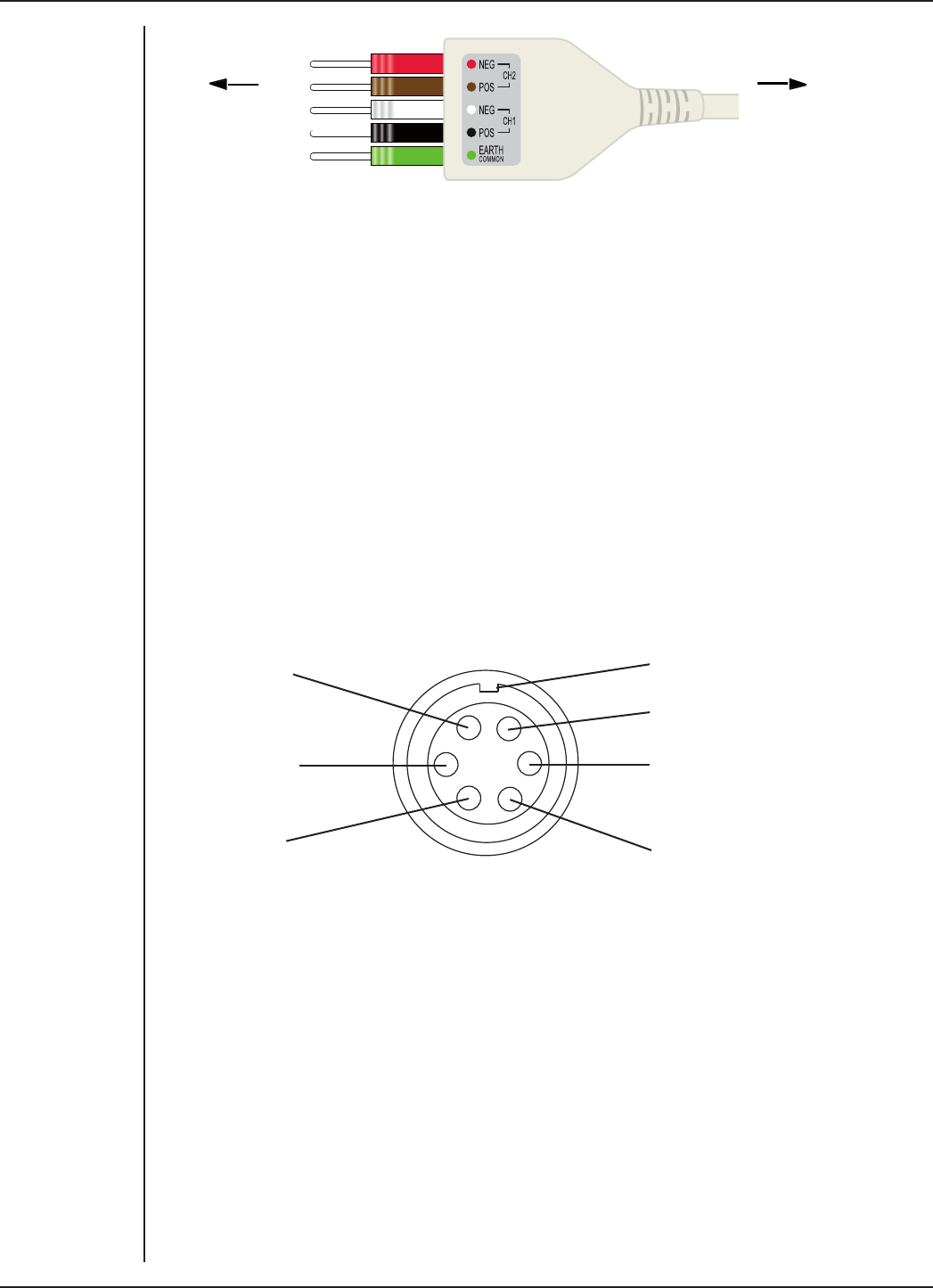
FRONT-END SIGNAL CONDITIONERS - Owner’s Guide
101
To electrodes To Dual Bio Amp inputs
The leads supplied are of the sort oen used for ECG work. They click into place in
the cable yoke, and have snap connectors at the other end to connect to typical ECG
electrodes. The leads are color-coded and the labels on the Bio Amp cable also have
color spots for ease of identification. (The colors are arbitrary, since the PowerLab
system is for general-purpose recording.) ADInstruments supplies other types of lead
that connect to the Bio Amp cable yoke, such as EEG/EMG leads and dry earth straps.
The Bio Amp Input
The 5-lead Bio Amp cable plugs into the six-pin input socket on the front panel of the
Bio Amp. A notch in the plug ensures that polarity is correct. Only the supplied Bio Amp
cable and leads should be used. Other cables may not meet safety requirements.
The Dual Bio Amp has one common connector for two Bio Amp inputs, nominally inputs
1 and 2. The biological amplifiers both have dierential inputs, and have a common
six-pin connector with a shared ground signal. The entire connector is physically and
electrically isolated to ensure subject safety.
Reference/Common
CH2 Negative (–)
CH2 Positive (+)
Polarising key (to fit notch in plug)
Shield
CH1 Positive (+)
CH1 Negative (-)
Using LabChart and Scope
Front-ends are designed for use with PowerLabs and ADInstruments programs such
as LabChart, LabTutor and Scope. The amplification and filtering of the Bio Amp is
combined with that of the PowerLab and the program and presented as a single set of
soware controls, replacing the Input Amplifier dialog with the Bio Amp dialog.
The functions of the Stimulator are combined with those of the PowerLab and are
presented as a single set of soware controls, replacing the Stimulator dialog with the
Stimulator Isolator dialog (Macintosh). In Windows, the Stimulator dialog displays the
Stimulus Isolator checkbox, which is selected and disabled.
The LabChart Help Center and Scope User’s Guide detail the Input Amplifier and
Stimulator dialogs, and explain relevant terms and concepts.
Figure 7–4
The Dual Bio Amp
cable yoke, with 5
leads attached
Figure 7–5
The pin
assignments for
the Dual Bio Amp
input connector

FRONT-END SIGNAL CONDITIONERS - Owner’s Guide
102
The Dual Bio Amp / Stimulator Self-test
Once the Dual Bio Amp/Stimulator is properly connected to the PowerLab, and the
proper soware is installed on the computer, a quick check can be performed on the
Bio Amp parts of the front-end. To perform the self-test:
1. Turn on the PowerLab.
2. Once the PowerLab is ready, open either LabChart, LabTutor or Scope.
3. While the program is opening, keep a close eye on the Status indicator(s) for the
Dual Bio Amp. During initialization, you should see the indicator or indicators
flash briefly and then remain lit.
If the indicator or indicators don’t light, check your cable connections and repeat the
procedure. The Stimulator Status indicator does not light during this procedure. It
is only used to indicate pulses, and whether they are valid stimuli or show an out-of-
compliance (OOC) condition.
Soware Behavior
When a Bio Amp is properly connected to a channel, the Input Amplifier… menu
commands are replaced by Bio Amp… where they appear. When the Stimulator is
properly connected to the PowerLab’s output:
•on Windows, the Stimulator dialog displays the Stimulus Isolator checkbox,
which is selected and disabled.
•on Macintosh, the Settings > Stimulator... menu command is replaced by
Stimulus Isolator... and the Stimulator dialog is replaced by the Stimulus
Isolator dialog.
If the application fails to find a front-end connected, the normal text remains. If you
were expecting a connected front-end and see the normal text, you should quit the
program, check the connections, then open it again to see if the front-end commands
appear. You do not have to connect all the front-ends if you do not want to.
As the documentation for LabChart and Scope does not cover front-end-specific
features, these features are described in detail here for LabChart. Dierences between
LabChart and Scope should be fairly obvious from perusing the Scope User’s Guide.
The Bio Amp dialog
The Bio Amp dialog allows soware control of the combined input amplifiers and filters
in the PowerLab and Bio Amp. The signal present at a channel’s input is displayed so
that you can see the eects of changes straight away. Once the settings in the dialog are
changed, click OK to apply them.
The Bio Amp dialog appears when you choose Bio Amp… from a Channel Function
pop-up menu. To set up many channels quickly, open the Setup > Channel Settings...
dialog. Here you can view all the channels that are turned on, and you can turn o
any unnecessary channels. Clicking on Bio Amp… in the Input Settings column of the
Channel Settings dialog will also open the Bio Amp dialog.
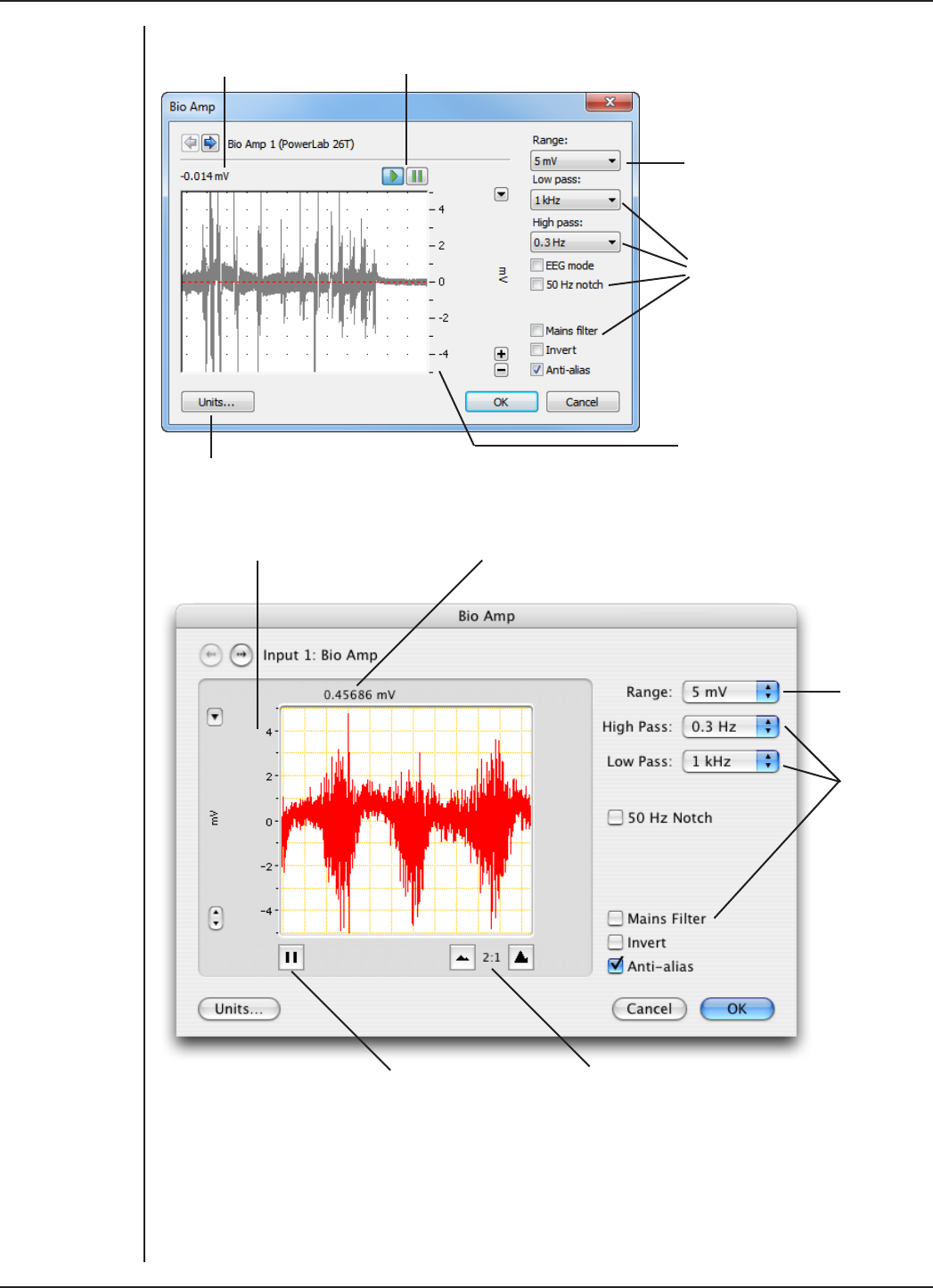
FRONT-END SIGNAL CONDITIONERS - Owner’s Guide
103
Signal amplitude Pause and Scroll buttons
Range pop-up menu
Filtering options
Amplitude axis
Click this buttons to open the Units Conversion dialog
Amplitude axis Signal amplitude
Range
pop-up
menu
Filtering
options
Pause/Scroll button Compression buttons
Signal Display
The input signal is displayed so you can see the eect of changing the settings — no
data are in fact recorded when setting things up. The average signal value is shown at
the top le of the display area.
Figure 7–6
The Bio Amp
dialog, Windows,
for the
Dual Bio Amp/
Stimulator
Figure 7–7
The Bio
Amp dialog,
Macintosh, for
the
Dual Bio Amp/
Stimulator

FRONT-END SIGNAL CONDITIONERS - Owner’s Guide
104
You can stop the signal scrolling by clicking the Pause button at the bottom le
(Macintosh) or top right (Windows) of the data display area. This changes to the Scroll
button on the Macintosh. Click the Scroll button to start scrolling again.
Shi and stretch the vertical Amplitude axis, by clicking and dragging it in various
ways, to make the best use of the available display area. It functions the same as the
Amplitude axis of the Chart Window, controls are identical and any change is applied to
the Chart Window.
Setting the Range
The Range pop-up menu lets you select the input range or sensitivity of the channel
(combined range of the PowerLab and Bio Amp). Changing the range in the Bio Amp
dialog is equivalent to changing it in the Chart Window. The default setting (if you have
not loaded settings files) is 50 mV and the ranges go down to 20 µV in 11 steps.
Filtering
Each of the Bio Amps in the Dual Bio Amp/Stimulator has low-pass, high-pass and notch-
filter circuitry that can be adjusted to suit the application. The notch filter removes
excessive mains-frequency interference. The high-pass and low-pass filters provide
bandwidth limiting of low-frequency and high-frequency signals, respectively. Note that
the settings for one filter type may restrict the possible settings for the other.
Notch Filter. Select or deselect the Notch checkbox to turn the notch filter on and
o. The notch filter is automatically set to either 50 or 60 Hz, depending on the power
line voltage frequency being used by the PowerLab (the mains frequency). It provides
approximately 32 dB of attenuation, thus reducing the eect of the 50 or 60 Hz signals
that can easily be picked up by long leads.
High-Pass Filtering. The High pass pop-up menu gives the choice of four high-pass
filters: 0.1, 0.3, 1, and 10 Hz. The high-pass filter allows high frequencies in the signal to
pass, and removes frequency components below the filter frequency (including any DC
signal). These filters are useful for removing slowly moving baselines, such as motion or
respiration artifacts, particularly in ECG recordings.
Low-Pass Filtering. The Low pass pop-up menu gives the choice of eight low-pass
filters: 20, 50, 100, 200, and 500 Hz, and 1, 2, and 5 kHz. The low-pass filter allows low
frequencies in the signal to pass, and removes frequency components above the filter
frequency. These filters are useful for removing high-frequency signals, such as noise,
and to prevent aliasing in the recorded signal.
Mains Filter. Select or deselect the Mains filter checkbox to turn the mains filter
on and o. The mains filter allows you to remove interference related to the mains
frequency (both fundamental and harmonic frequencies). This is an adaptive filter. It
adjusts to filter the interference by tracking the input signal for a second. Because of
this, in general, using the mains filter is better than using the notch filter but the mains
filter does have some limitations. More details on the mains filter can be found in the
LabChart Help Center.
Anti-alias. Click the Anti-alias checkbox to turn anti-aliasing on and o. Aliasing
occurs when a regular signal is digitized at too low a sampling rate, causing the false

FRONT-END SIGNAL CONDITIONERS - Owner’s Guide
105
appearance of lower frequency signals. To prevent aliasing, the sampling rate must be
at least twice the highest frequency in the incoming waveform. When aliasing of noise
or signals is seen, or even suspected, the first action you should take is to increase the
sampling rate. The highest available sampling rates are 100k /s or 200k /s, depending
on your PowerLab. If this reveals unwanted high-frequency components in the sampled
signal, you will achieve better results by using a low-pass filter to remove them. The
best kind of filter for this purpose is the Anti-alias filter option in the Bio Amp... dialog.
This is a special low-pass filter that is configured to automatically remove all signals that
could alias; i.e., those whose frequency is greater than half the sampling rate. A high
sampling rate, however, will use more computer memory and may limit recording time
so, once you have established the frequencies of interest to you in an incoming signal,
with Anti-alias selected the sampling rate can be scaled down accordingly.
Inverting the Signal
The Invert checkbox allows you to invert the signal on the screen. It provides a
simple way to change the polarity of the recorded signal without having to swap the
connections to the recording electrodes.
Units
Click Units… to display the Units Conversion dialog, with which you can set the units
for the channel and, using waveform measurements, calibrate the channel. A waveform
in the data display area of the Bio Amp dialog is transferred to the data display area
of the Units Conversion dialog. (Use the Pause button to capture a specific signal.) The
units conversion only applies to subsequently recorded signals, so it is more limited
than choosing Units Conversion… from a Channel Function pop-up menu as it does
not allow conversion of individual blocks of data.
The Stimulator
The Stimulator that is built into the Dual Bio Amp/Stimulator provides soware-
controlled, isolated, constant-current pulse stimuli that can be used with human
subjects. The stimulus is produced at the outputs on the front panel of the Dual Bio
Amp/Stimulator. The stimulus is independent of the PowerLab sampling rate and can
be generated whether the PowerLab is sampling or not. The stimulus is set up using the
Stimulator dialog.
Choose Setup > Stimulator... to display the Stimulator dialog (Figure 7–8, Figure 7–9).
This dialog is named Stimulus Isolator on the Macintosh. When setting up the Stimulator,
you:
•Choose how stimulation should start.
•Choose a preconfigured stimulus type or mode.
•Optionally, on Windows, create a custom stimulus waveform.
•Set stimulus parameters, such as start delay and current amplitude.
Scope has a dierent Stimulator dialog to that of LabChart: in the Stimulator dialog you
can choose Pulse and Multiple in the Mode pop-up menu (to produce single or multiple
pulses, respectively).
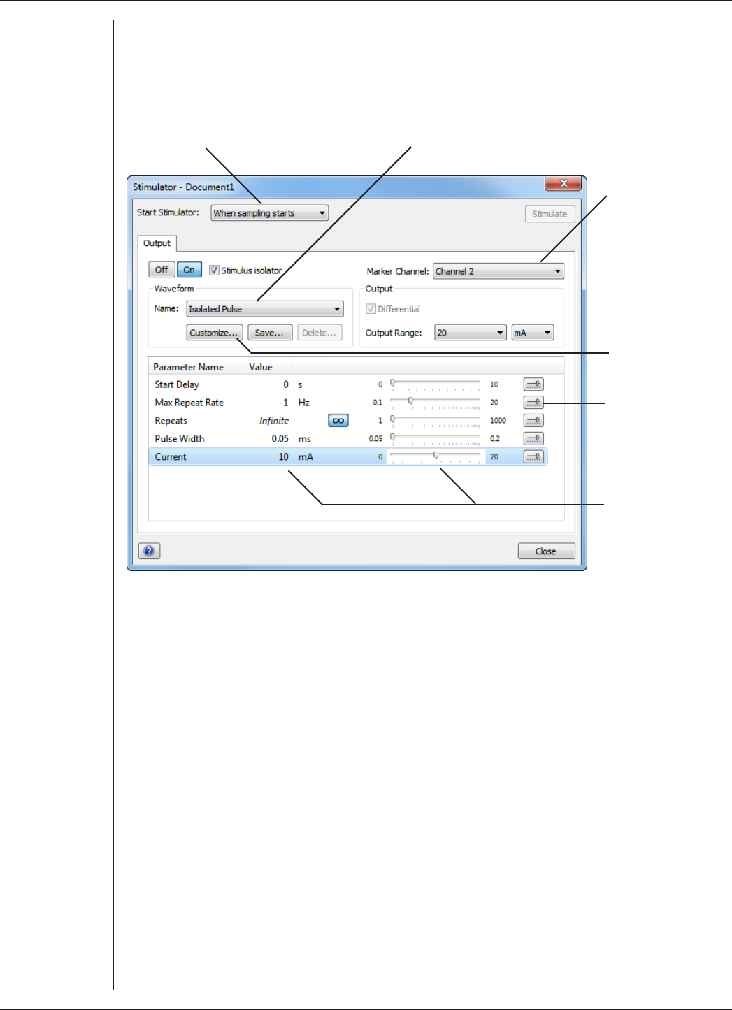
FRONT-END SIGNAL CONDITIONERS - Owner’s Guide
106
Note: If you connect the Dual Bio Amp/Stimulator to a PowerLab that has an in-built
Isolated Stimulator, such as a PowerLab 26T, only the external, connected stimulator is
used.
Choose how stimulation
should start
Choose a stimulus type preset
Specify a custom
stimulus waveform
Configure the range
of valid parameter
values in the
Parameter Settings
dialog
Set stimulus
parameters
Specify a Marker
channel
Choosing How Stimulation Should Start
Stimulation can be set to start in dierent ways:
•When sampling starts: stimulation begins automatically when the LabChart
Start button is clicked, and continues until sampling stops. Use the On and O
buttons to control pulse delivery, if necessary.
•Manually: stimulation begins when Stimulate in the dialog is clicked, and
continues until sampling stops. Use the On and O buttons to control pulse
delivery, if necessary.
•Independently of sampling: stimulation begins when On in the dialog is clicked,
whether or not LabChart is sampling. Available in LabChart for Windows only.
In all three modes, you can immediately restart a stimulus waveform by clicking
Stimulate.
Figure 7–8
The Stimulator
dialog, in
LabChart 7 for
Windows
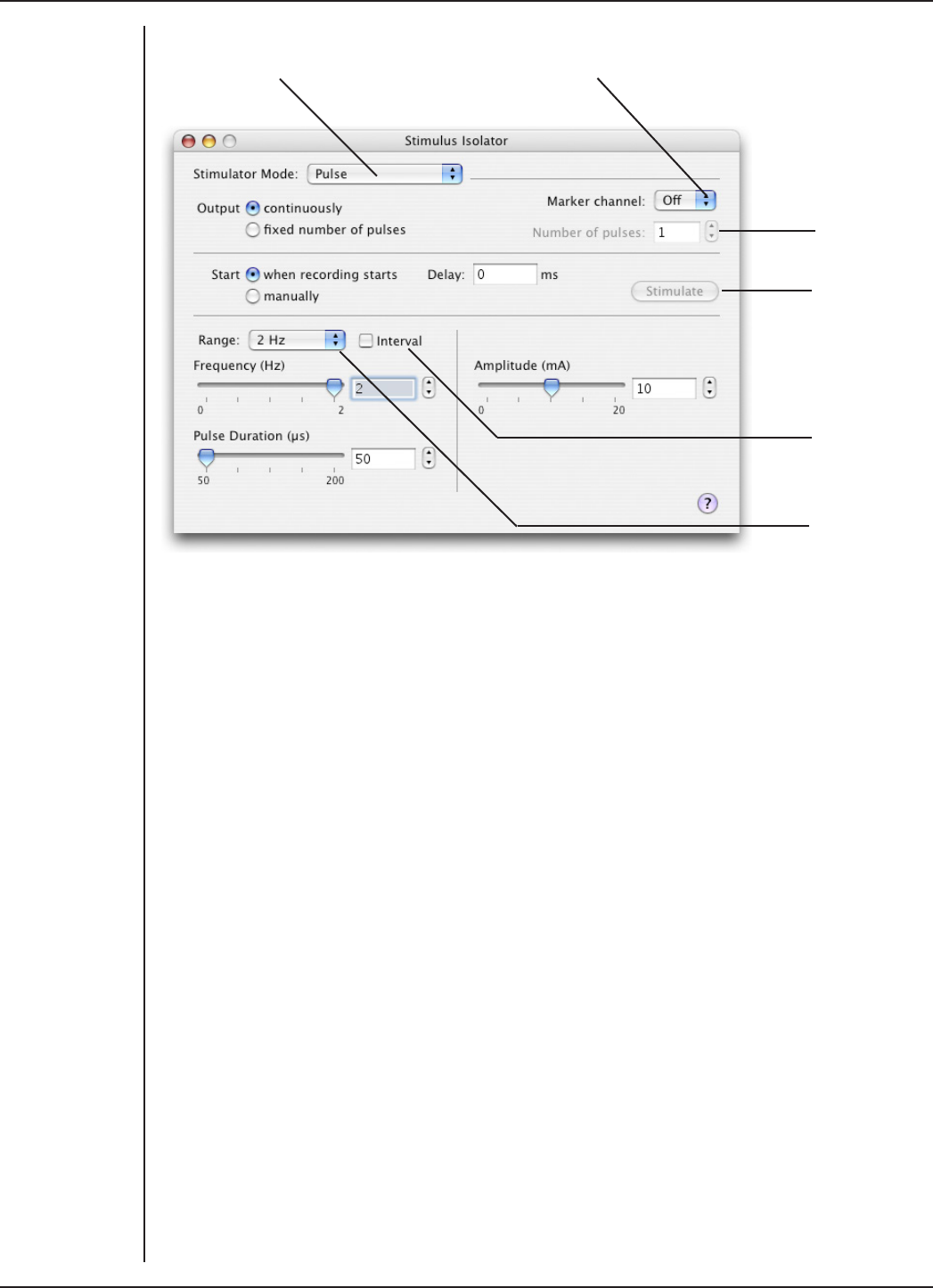
FRONT-END SIGNAL CONDITIONERS - Owner’s Guide
107
Turn stimulation on
(Pulse) or off
Mark the stimulus
event in a channel
Set the
number of
pulses to be
delivered
Click to start
a train of
pulses (when
sampling and
manual start is
selected)
Check to set
the interval
between pulse
starts
Change the
stimulus
frequency
range
Choosing a Stimulus Type
With the Dual Bio Amp/Stimulator connected, the Stimulator oers the Isolated Pulse
stimulation mode only (called Pulse on Macintosh). This generates a rectangular pulse
stimulus that starts at zero current, is raised to the set current amplitude for the set
pulse width (duration), and then falls to zero current again. By default, the stimulator is
o and the current amplitude is set to zero.
Creating a Custom Stimulus Waveform
In LabChart for Windows, you can:
•Specify whether parameter controls are displayed in the Stimulator and
Stimulator Panel dialogs.
•Define a sequence of segments to create a custom stimulus waveform.
Click Custom... to display the Waveform Customization dialog. Further details about
using this dialog are available in the LabChart Help.
Setting Stimulus Parameters
You use the text boxes and sliders to set values for the stimulus parameters. In LabChart
for Windows, you can use the Settings dialog for each parameter to configure the range
of values available to the parameter text box and slider controls.
Figure 7–9
The Isolated
Stimulator
dialog, LabChart
7 for Macintosh

FRONT-END SIGNAL CONDITIONERS - Owner’s Guide
108
In LabChart 7 for Windows, the following stimulus parameters can be set:
Start Delay: the wait time before stimulation is delivered, once the stimulus waveform
has been started.
Repeats: the number of times the stimulus waveform is repeated, once started.
Max Repeat Rate: the maximum frequency with which the stimulus waveform is
repeated.
Pulse Width: the duration of each pulse.
Current: the amplitude of the stimulus current.
End Delay: the wait time at the end of a stimulus segment, aer which the next segment
is delivered. This is not the same as a Delay segment.
In LabChart 7 for Macintosh, the following stimulus parameters can be set:
Range: lets you select the range for the Frequency control; either 0.1–2 Hz, 0.1–20 Hz,
or 2–200 PPM (~0.033 Hz to ~3.3 Hz). PPM (pulses per minute) can sometimes be a more
convenient expression of the pulse frequency.
Frequency: the rate at which pulses are delivered; available values are within those set
with Range.
Interval: allows pulses to be set up according to the time between the start of each
pulse.
Pulse Duration: the time for which the pulse lasts, from 50 µs to 200 µs (0.05 ms to 0.2
ms). The pulse duration is limited to 200 µs for safety reasons.
Amplitude: the exact amplitude of the stimulus current, from 0 to 20 mA.
Marker Channel
If you choose a channel from the Marker Channel pop-up menu, then the start time of
a stimulus pulse is marked by a small data spike (this adds to any data in that channel).
The Stimulator Panel
Once you have set up stimulation using the Stimulator dialog, you can easily start or
stop stimulation or change settings while sampling, by using the Stimulator Panel.
Choose Stimulator Panel from the Setup menu to open it (Stimulus Isolator Panel on
Macintosh).
In LabChart for Windows, you can specify which parameter controls are displayed in
the panel using checkboxes in the Panel column of the Waveform Customization dialog.
See the LabChart Help for details.
The Stimulator Panel ‘floats’ in front of the active window, can be moved around with
its title bar, and can only be dismissed by clicking its close box.
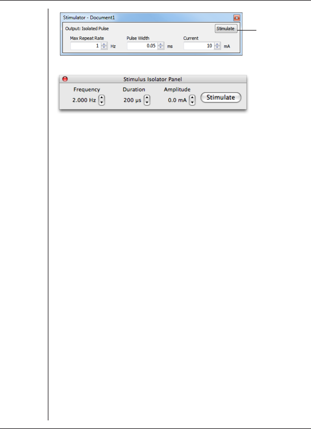
FRONT-END SIGNAL CONDITIONERS - Owner’s Guide
109
The Stimulate button
appears when
manual stimulation is
selected
Using the Dual Bio Amp/Stimulator
Some Suitable Uses
Standard electrophysiology texts describe various standard signals and how to measure
them. ADInstruments also produces materials describing specific uses of Bio Amps,
such as Application Notes that can be downloaded from the ADInstruments website or
obtained from your ADInstruments representative. A number of step-by-step student
experiments in electrophysiology that can be performed using one or two Bio Amps
and a Isolated Stimulator are included in the Human and Animal Physiology Experiment
collections, which can be downloaded from the ADInstruments website.
Just as the built-in Isolated Stimulator can be used for many general stimulation tasks,
the Bio Amp inputs can measure a wide variety of biological signal sources. Some of
these measurements include:
ECG. Electrocardiogram (also referred to as EKG); a recording of surface potentials due
to electrical currents associated with the heartbeat.
EEG. Electroencephalogram; a recording of the electrical activity of the brain. Scalp
electrodes record potential waves (10–100 µV) representing the summed activity of
cortical neurons.
EMG. Electromyography; a recording of the electrical activity of a muscle, using surface
electrodes. The recorded activity may be a voluntary contraction, or evoked by motor
nerve stimulation.
EOG. Electro-oculogram; a recording of the potential dierence between the front and
back of the eyeball, as projected on to the face.
ERG. Electroretinogram; a recording of the electrical signals produced in the retina by a
light stimulus.
Cortical Evoked Potentials. Averaged recordings of the electrical activity of the brain
when subject to stimulation: visual evoked response, auditory evoked response, and
somatosensory response. These should be done with signal averaging, using Scope.
Figure 7–10
The Stimulator
Panel: Windows
(upper) and
Macintosh (lower)

FRONT-END SIGNAL CONDITIONERS - Owner’s Guide
110
SNAP. Sensory nerve action potential; a recording of evoked responses in stimulated
nerves. This is usually done with signal averaging, using Scope.
Some Unsuitable Uses
The Bio Amp inputs are unsuitable for work requiring high-impedance electrodes or
using a high bandwidth. Such tasks include intracellular micropipette recordings, which
are made from a very fine, electrolyte-filled tube inserted into a nerve or muscle cell,
and require an electrometer amplifier; and needle electromyography, the intramuscular
recording of the electrical activity of a muscle, which requires low input capacitance
and a driven guard.
Recording Technique
Several problems can arise when using the Bio Amp inputs to record signals. These
are generally problems of technique, and should be addressed before setting up. It is
important to understand the types of problems that can occur, how they manifest, and
what can be done to remove them or to minimize their eect. Potential problem areas
include aliasing, frequency distortion, saturation, ground loops, electrode contact,
motion artifacts, electromagnetic fields and data display (see “Preventing Problems”
on page 14).
There is a good introduction to data acquisition provided in the documentation for
LabChart and Scope. Apart from the general areas covered in that material, two things
particularly aect the kind of measurements made with Bio Amp inputs, and can cause
‘artifacts’ (spurious readings) in the recorded waveform: electrode contact and motion
eects.
Electrode Contact. Occasionally during measurement of a biological signal, one of
the lead wires connecting the source to the front-end may become disconnected, or
an electrode contact may become poor. If this should happen, relatively high voltages
(potentials) can be induced in the open wire, due to electromagnetic fields caused by
the power line or other sources close to the front-end or to the subject. These induced
potentials result in a constant amplitude disturbance of the recorded waveform at the
power line frequency, and loss of the desired signal. If the problem is a recurring one,
one of the leads may be faulty. Check connections and replace faulty leads, if necessary.
Make sure that skin is cleaned and lightly abraded before attaching electrodes to it.
Ensure that there is suicient electrode cream to maintain a good contact: if it dries out,
the contact will be poor, and the recorded signal may be degraded or lost.
Motion Eects. A common source of artifacts when recording biological signals is
motion of the subject or equipment. For example, muscular activity generates its own
electrical signals, which may be recorded along with an ECG, say, depending on the
location of the electrodes. Movement of Bio Amp cables and leads, particularly bending
or rubbing together (triboelectric eects) may generate artifacts in a signal. If the
subject is liable to move during recording, then special care needs to be taken when
attaching the electrodes and securing the leads. Subject respiration can also generate
a signal: breathing can result in a slowly changing baseline corresponding to inspiration
and expiration. Applying a suitable high-pass filter should minimize these eects.

FRONT-END SIGNAL CONDITIONERS - Owner’s Guide
111
Technical Aspects
The PowerLab provides control and low-voltage power to front-ends through a special
expansion connector called the I2C (eye-squared-sea) bus. The Bio Amps in the Dual
Bio Amp/Stimulator are also connected to the analog inputs of the PowerLab via a
BNC-to-BNC cable, through which they send the amplified and filtered signals. The
Isolated Stimulator in the Dual Bio Amp/Stimulator produces current output for direct
stimulation, and is connected to the positive analog output socket of the PowerLab. The
overall operation of the Dual Bio Amp/Stimulator can be better understood by referring
to Figure 7–11.
Note: You should not use this section as a service manual as user modification of the
equipment voids your rights under warranty.
Dual Bio Amp Operation
The Bio Amp is essentially an extension of the PowerLab’s input amplifiers. The
amplification and ranges you see oered in LabChart and Scope result from the
combination of both pieces of hardware. The Dual Bio Amp in the front-end has a
common power supply and isolated ground. It provides:
•full electrical isolation from power-line (mains) circuitry to guarantee subject
safety
•a low-noise, high-gain dierential amplifier specifically designed for biological
signal measurements
•soware-controlled low-pass, high-pass, and notch filters to remove unwanted
signal frequencies for particular uses
•audio output for use with EMG signals and so on.
Isolated Stimulator Operation
The Isolated Stimulator in the front-end is essentially an extension of the PowerLab’s
analog output. It provides:
•a constant-current, 100-volt compliance, pulsed output
•high-voltage subject isolation (4000 Vrms)
•low leakage capacitance and low noise
•soware-adjustable current amplitudes
•soware-adjustable pulse duration.
Dual Bio Amp
The Dual Bio Amp/Stimulator has one common connector for the two Bio Amps (marked
Bio Amp Input 1 & 2). These two independently controllable, electrically isolated,
biological amplifiers are suitable for a range of basic physiological measurements. The
Bio Amps have a common six-pin connector with a shared ground signal. The front-end
is supplied with a 5-lead Bio Amp cable and lead wires for connection. (These inputs
should only be used with the supplied Bio Amp cable and leads. Other cables may not
meet safety requirements.)

FRONT-END SIGNAL CONDITIONERS - Owner’s Guide
112
Each amplifier consists of an electrically isolated, AC coupled, dierential amplifier with
programmable gain able to be set independently (the gain is set through the soware
range control: the less the range, the more the gain). The gain is controlled by optically
isolated digital control signals from the non-isolated section. The signal is then applied
to an isolation amplifier which provides electrical isolation of the input stage from the
supply.
The non-isolated stage consists of a series of filters and amplifiers. The first part of the
stage is a high-pass filter designed to remove any DC components from the signal and
the isolated stage. This is followed by amplification and an active notch filter. The notch
can be turned on or o under soware control as needed. The frequency of the notch
filter is automatically set to either 50 or 60 Hz to match the frequency of the connected
power supply.
The low-pass filter is an eighth-order, switched-capacitance, Bessel-type filter, with
a soware-selectable range of frequencies. (The output of the biological amplifier
is then passed to the PowerLab input, where it goes through the standard PowerLab
amplifier circuit.) An amplifier connected to the output of the biological amplifier is
used to provide an audio output facility that can be used with headphones or powered
speakers.
The control for the various filters and gain stages in the Bio Amp is provided by on-
board microprocessors, which also communicate with the PowerLab over the I2C bus.
The high-pass filters in the Dual Bio Amp are phase-matched to within 1° phase shi at
the –3 dB frequency to allow for accurate waveform arithmetic.
Isolated Stimulator
The output stage consists of a high-voltage constant-current source that can produce
pulses of variable duration and amplitude under soware control. The current source
can deliver pulses up to 20 mA at 100-volt compliance levels; its amplitude is set by a
digital attenuator network, which is in turn controlled by the I2C logic. The output to the
subject is through high-isolation optical couplers.
Trigger pulses are delivered to the current source through optical isolation as well.
During operation the Isolated Stimulator Status indicator light on the front panel lights
green with every pulse (it will glow yellow if the Isolated Stimulator is out of compliance).
The digital interface that controls pulse width and current amplitude uses an I2C
interface system, and provides a 4-wire serial communication bus to the PowerLab and
other front-ends. Also present on the connector is a set of power supply rails derived
from the PowerLab, used to provide power for the control circuitry of the Isolated
Stimulator and for the stimulator current source.
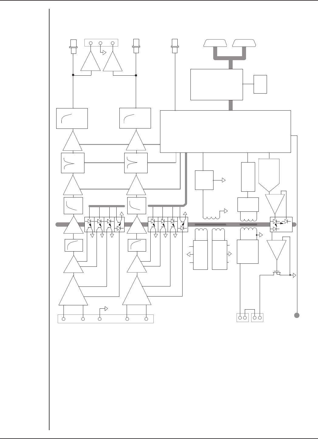
FRONT-END SIGNAL CONDITIONERS - Owner’s Guide
113
Audio
Output
x1
LPF
LPF
x1
Notch
50/60Hz
Notch
50/60Hz
Gain
Gain
+10V–10V
+10 V
–10 V
Rectification
& Filtering Power
Oscillator
8 MHz
Crystal
LPF HPF
+
–
x1,x10
G1
G2
G0
LPF HPF
Bio Amp
inputs
+
–
x1,x10 Output 2
G1
G2
G0
Pulse
Rectification
& Filtering
Pulse
Driver
8-bit Current
Setting DAC
Servo
Amp
Constant
Current
Source
System
Control Gate
Array
Gain
Gain
Control
Microprocessor
Rectification
& Filtering
Bio Amp Isolated
Power Supply
Stimulator Isolated
Power Supply
Stimulus
output
Stimulator
safety
switch
+100 V
Output 1
DAC+ (Stim Trigger)
Signal
Input
I2C Interface
Stimulator
Status
indicator
Pulse Timing &
Safety Control
Auto Restore
Auto Restore
Figure 7–11
Block diagram of
the Dual Bio Amp/
Stimulator

FRONT-END SIGNAL CONDITIONERS - Owner’s Guide
114
Troubleshooting
This section describes most of the common problems that can occur when using
the Dual Bio Amp/Stimulator with your PowerLab. It covers how these problems are
caused, and what you can do to alleviate them. If the solutions here do not work, earlier
chapters, the LabChart Help Center, and the guide to your PowerLab may contain
possible remedies. If none of the solutions here or elsewhere are of help, then consult
your ADInstruments representative.
Most of the problems that users encounter are connection problems, and can usually be
fixed by checking connections and starting up the hardware and soware again. Very
rarely will there be an actual problem with the front-end or the PowerLab itself.
Problems and Solutions
The Status indicators fail to light when the soware is started, or the front-end commands
do not appear where they should
The I2C cable or one or more BNC-to-BNC cables from the front-end to the PowerLab
are not connected, have been connected incorrectly (to the wrong input or output, for
instance), or are loose.
•Turn everything o. Check that all cables are firmly attached and screwed in.
BNC cables from the Bio Amp must be connected to an analog input on the
PowerLab, i.e. the input channel that you expect to use in the soware. The BNC
cable from the Isolated Stimulator must be connected to the positive output on
the PowerLab (it is labelled + on a most PowerLabs, and Output 1 on a /30 series
PowerLab). Switch the PowerLab on and start the soware again.
You are using an early version of LabChart or Scope.
•Upgrade to the latest version of the soware. Contact your ADInstruments
representative for information.
The BNC or I2C cable is faulty.
•Replace the cable and try again. Immediately label all cables proved faulty so
that you don’t use them again by accident.
The front-end, or a portion of it, is faulty.
•This is the least likely event. If the front-end will not work properly aer the
previous measures, then try using it on another PowerLab. If the same problems
recur with a second PowerLab, the front-end may be faulty. Contact your
ADInstruments representative to arrange for repairs.
The Stimulator Status indicator shows yellow
This means that the Stimulator is out of compliance (OOC). The impedance of the tissue
could be too high for the Stimulator to supply constant current at the level requested, or
there may be an inadequate electrical connection to the subject.
•Reduce the output current amplitude.
•Check the connections for proper contact and try again. Ensure the connection is
not dry (apply electrode cream) and that the leads are properly connected.

FRONT-END SIGNAL CONDITIONERS - Owner’s Guide
115
You could be attempting stimulation while the output safety switch is turned o (in the
down position).
•Turn the safety switch on (move to the up position).
On starting up the soware, an alert indicates that there is a problem with the front-end or
driver
The correct drivers are not installed on your computer.
•Reinstall the soware.
You are using an early version of LabChart or Scope.
•Upgrade to the latest version of the soware. Contact your ADInstruments
representative for information.
The BNC or I2C cable is faulty.
•Replace the cable and try again. Immediately label all cables proved faulty so
that you don’t use them again by accident.
The front-end, or a portion of it, is faulty.
•This is the least likely event. If the front-end will not work properly aer the
previous measures, then try using it on another PowerLab. If the same problems
recur with a second PowerLab, the front-end may be faulty. Contact your
ADInstruments representative to arrange for repairs.
The Bio Amp signal appears to display a constant amplitude oscillation
Frequency interference from power lines can become superimposed on the biological
signal being measured.
•You can use the internal notch filter in the Bio Amp to remove excessive line
voltage frequency interference (use the checkbox in the Bio Amp dialog).
If you are using cables and leads that were not supplied with your Bio Amp, they may be
unshielded or of low quality.
•Check to make sure that you are using high-quality shielded cables and high-
quality leads. Only the supplied Bio Amp cable and leads should really be used.
The Bio Amp signal is noisy at lower ranges
This is probably the amplified noise from the electrodes, not a fault as such. There is, in
addition, noise that cannot be avoided by any amplifier (called ‘thermal’ or ‘Johnson’
noise).
•Set the low-pass filter to remove the noise. (But be careful, since important
components of the signal could also be attenuated.)
This could be due an electrically noisy environment, particularly if there is some
equipment that produces a radio frequency that interacts with the Bio Amp modulator,
giving a heterodyne eect.
•Turn o pieces of unnecessary equipment to try and isolate the cause, then
either leave the equipment o, or, if possible, move the subject or equipment
outside the area of any interfering field.

FRONT-END SIGNAL CONDITIONERS - Owner’s Guide
116
•At the lowest ranges you may have to shield, shorten, or even replace the Bio
Amp leads, since they will tend to act as radio receptors.
The Bio Amp trace will not zero properly when adjusting high-pass filtering
The Bio Amp is receiving signals at a level that has saturated the input amplifier,
resulting in a large oset. This is normally due to poor contact between the electrodes
and the subject.
•Check the connections for proper contact and try again.
The Bio Amp signal appears to be unusual, very weak, clipped, or distorted in some way
This may be a problem of technique: the sampling rate, range, or filter settings may be
inappropriate for the signal you are recording.
•Make sure the settings are appropriate for the expected signal.
You may be using the wrong Bio Amp cable. The 3-lead Bio Amp cable used with the
single Bio Amp has a dierent pin arrangement and cannot be used with the Dual Bio
Amp/Stimulator front-end. Ensure that the correct, supplied, 5-lead Bio Amp cable is
used.

FRONT-END SIGNAL CONDITIONERS - Owner’s Guide
117
Specifications
Dual Bio Amp Input
Configuration: 2 dierential channels with common isolated ground
reference
Input impedance: 100 MΩ to ground (~200 pF per lead) using supplied Bio
Amp cable and leads
Safety: Approved to IEC 60601-1 (BF rating – body protection)
Standard
Isolation rating: 4000 V ACrms for 1 minute
Input ranges: ±20 µV to ±50 mV full scale in 11 steps (combined Bio
Amp and PowerLab)
± 50 mV
± 20 mV
± 10 mV
± 5 mV
± 2 mV
± 1 mV
± 500 µV
± 200 µV
± 100 µV
± 50 µV
± 20 µV
Accuracy: ± 1.5% all ranges
Non-linearity: < 1% of full scale
(better for ranges under 1 mV)
Noise levels: 0.1 Hz to 5 kHz < 1.95 µV
0.1 Hz to 1 kHz < 1.25 µV
0.1 Hz to 50 Hz < 0.5 µV
0.1 Hz to 20 Hz < 0.2 µV
IMRR (isolation mode): > 130 dB (@ 50–60 Hz)
CMRR (common mode): > 75 dB (DC–100 Hz)
> 60 dB (@ 1 kHz)
Input leakage current: < 6 µA rms @ 240 V, 50 Hz
< 4 µA rms @ 120 V, 60 Hz

FRONT-END SIGNAL CONDITIONERS - Owner’s Guide
118
DC blocking: ± 0.5 V
Baseline restoration: Automatic
Filtering
Notch filter: 50 or 60 Hz notch filter, automatically selected to match
supply frequency
High-pass filtering: Single-pole 0.1, 0.3, 1, and 10 Hz (–3 dB) with accuracy of
±10%. The high-pass filters are phase-matched to within
1° phase shi at the –3 dB frequency to allow for accurate
waveform arithmetic.
Low-pass filtering: 8th-order Bessel-type filters (linear time delay).
Frequencies soware-selectable at 20, 50, 100, 200, and
500 Hz, and 1, 2, and 5 kHz. Frequency accuracy is ±2%.
Output
Signal: ± 2.0 V standard
Audio output: Stereo output supplying signals from both Bio Amp
channels. Suitable for earphones, headphones, or most
externally powered speakers. Output is a 100 mV signal
for any full-scale signal. Current limited to ±5 mA.
Isolated Stimulator Output
Safety: Approved to IEC 60601-1 Standard (BF rating)
Configuration: Constant-current stimulator with hardware-limited
repetition rate
Isolation rating: 4000 Vrms to ground as per IEC 60601-1 Standard
2000 Vrms (60 seconds) to Bio Amp inputs
Pulse duration: 50–200 µs (soware-selectable)
Compliance voltage: 100–110 V typical
Output current: 0–20 mA in 0.1 mA steps (soware-selectable)
Pulse rate: Soware-selectable, but hardware-limited to a
maximum of 20 Hz for safety
Safety indicators: A single multi-color indicator displays the isolated
stimulator status. A green flash indicates delivery of
a valid stimulus. A yellow flash indicates an out-of-
compliance condition.
Safety switch: Isolating On-o switch flicks down to disconnect quickly

FRONT-END SIGNAL CONDITIONERS - Owner’s Guide
119
Control Port
I2C port: Provides control and power. Interface communications
rate of ~50 kbits/s.
Physical Configuration
Dimensions (h × w × d): 65 mm × 200 mm × 250 mm
(2.56" × 7.9" × 9.8")
Weight: 1.52 kg (3 lb 5oz)
Power requirements: ~6 W
Operating conditions: 5–35 °C, 0–90% humidity (non-condensing)
ADInstruments reserves the right to alter these specifications at any time.
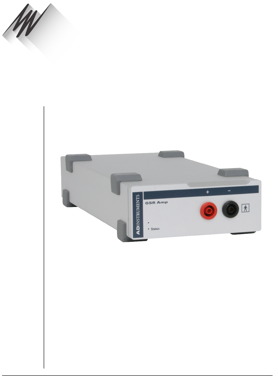
FRONT-END SIGNAL CONDITIONERS - Owner’s Guide
120
The FE116 GSR Amp is one of a family of modular devices called front-ends, designed to
extend the capabilities of the PowerLab system. Each provides full electrical isolation.
This chapter describes the basic features of the GSR Amp and discusses some aspects
of its use.
The GSR Amp is designed to provide a fully subject-isolated amplifier for measurement
of skin conductivity, in particular the Féré eect, which is the change in skin conductivity
when a subject is stimulated. This is also known as the galvanic skin response (GSR),
and gives a general measure of autonomic nervous system activity.
Measurement is displayed in SI conductance units (siemens), and absolute conductivity
of up to 100 µS (microsiemens) can be measured. Low, constant-voltage AC excitation
allows enhanced safety and the use of dry electrodes, with no special electrolytes
needed.
GSR Amp
Chapter 8
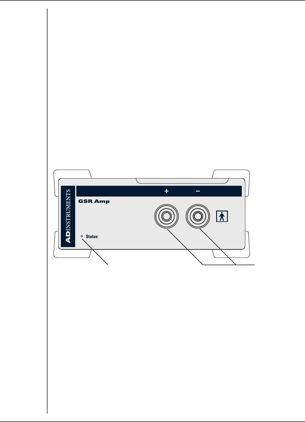
FRONT-END SIGNAL CONDITIONERS - Owner’s Guide
121
The GSR Amp
The GSR Amp provides a fully subject-isolated amplifier for measurement of skin
conductivity, in particular the change in skin conductivity in response to stress or
anxiety known as the galvanic skin response (GSR). This gives a general measure of
autonomic nervous system activity.
Measurement is displayed in SI conductance units (siemens), and absolute conductivity
of up to 100 µS (microsiemens) can be measured. Low, constant-voltage AC excitation
allows enhanced safety and the use of dry electrodes, with no special electrolytes
needed.
The rest of this chapter contains general information about the features, connections
and indications of the GSR Amp. It also looks at signal measurement for GSR. There is
more detailed information in the technical section.
The Front Panel
The front panel of the GSR Amp is simple, with a pair of input connectors for bipolar
electrodes and a small indicator light.
Status Indicator Input sockets
The Status Indicator
The status indicator light is at the bottom le of the front panel. When an ADInstruments
program opens, the status indicator flashes briefly and then remains green, indicating
that the program has found the front-end, checked and selected it, and it is ready for
use. If it does not light up when the program is open, this indicates a problem with the
connection, the soware or the hardware.
The GSR Amp Input Sockets
Connections are made to the GSR Amp using two 4 mm shrouded banana sockets,
similar to sockets found on many digital multimeters, and are designed to be used with
shrouded male 4 mm plugs. A cable with these plugs is supplied with the GSRAmp.
These provide very low-voltage and low-current AC excitation to measure conductance.
As the GSR Amp uses AC excitation, polarity of the connections is not important. The
input connections are isolated internally by circuitry.
Figure 8–1
The front panel of
the GSR Amp
FRONT-END SIGNAL CONDITIONERS - Owner’s Guide
122
The Back Panel
The back panel of the GSR Amp provides all the sockets required to connect the front-
end to the PowerLab and to other front-ends.
Signal output to the PowerLab
I2C connection to
a further front-end
I2C connection from the
PowerLab or previous front-end
I2C Input and Output Sockets
Two nine-pin sockets are used to communicate with the PowerLab (they are marked ‘I2C
Bus’: a ‘bus’ is simply information-transmission circuitry such as cables and connectors).
Power and control signals to the front-ends come from the PowerLab. These I2C sockets
allow multiple front-ends to be used independently with one PowerLab. Many front-
ends can be connected to the system, in series, output to input (as discussed in Chapter
2).
The Signal Output Socket
The BNC socket labelled Signal Output on the back panel provides the signal output to
connect to an analog input socket on the front of the PowerLab. A BNC-to-BNC cable is
supplied for this connection.
Connecting to the PowerLab
To connect a front-end, such as your GSR Amp, to the PowerLab, first ensure that the
PowerLab is turned o. Failure to do this may damage the PowerLab, the front-end, or
both.
The BNC cable from the GSR Amp signal output must connect to an analog input on the
PowerLab, for example, Input 1 on a /30 series PowerLab. If you have an older model
PowerLab with dierential (rather than single-ended) inputs, the BNC cable must
connect to a positive analog input on the PowerLab.
Single Front-ends
Connect the I2C output of the PowerLab to the I2C input of the GSR Amp front-end using
the I2C cable provided. Figure 8–3 shows how to connect the GSR Amp to your PowerLab.
Figure 8–2
The back panel of
the GSR Amp
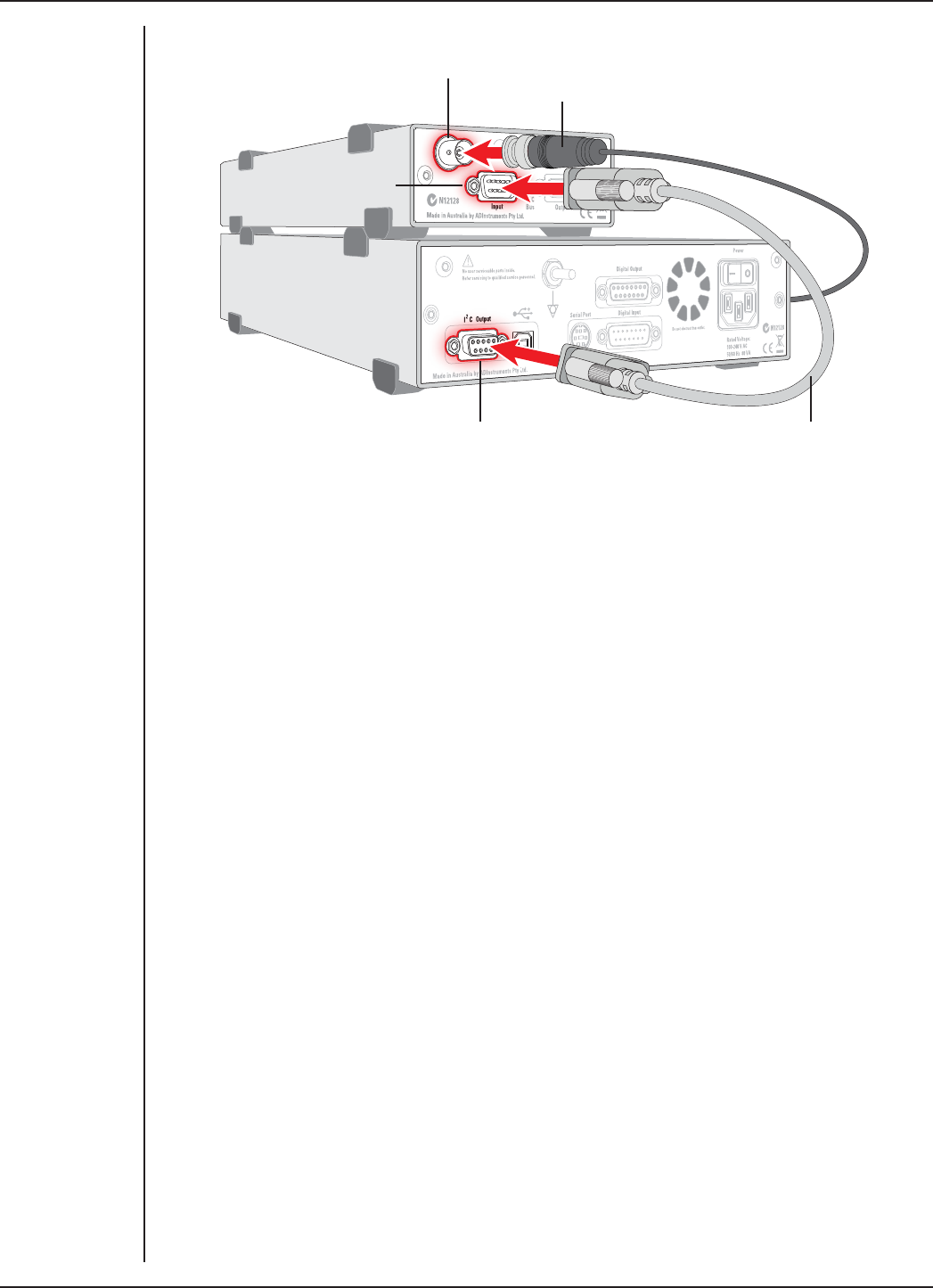
FRONT-END SIGNAL CONDITIONERS - Owner’s Guide
123
Check that the connectors for the I2C bus are screwed in firmly. Check the BNC cable
for firm connections as well. Loose connectors can cause erratic front-end behavior, or
may cause the front-end to fail to work at all.
Multiple Front-ends
Multiple separate front-ends can be connected up to a PowerLab. The number of normal
front-ends that can be connected depends on the number of (positive) input channels
on the PowerLab, since each BNC cable from a front-end is connected to one of the
analog inputs on the PowerLab. Only one front-end such as a Stimulus Isolator can be
connected to the (positive) output of the PowerLab.
The initial front-end should be connected with the I2C cable as in Figure 8–3. The
remainder are daisy-chained via I2C cables, connecting the I2C output of the last
connected front-end to the I2C input of the front-end to be added (see Figure 2–2 on
page 11).
Using LabChart and Scope
Once the GSR Amp is connected, turn the PowerLab on and launch LabChart (or Scope).
When a GSR Amp is properly connected to the PowerLab, the Input Amplifier… menu
command is replaced by GSR Amp… for the input channel to which it is connected.
If LabChart (or Scope) fails to find a front-end connected, the normal text remains. If
you were expecting a connected front-end and see the normal text instead, you should
quit the application, turn the PowerLab o and check the connections. Then restart the
PowerLab and re-launch LabChart.
The documentation for LabChart and Scope does not cover front-end-specific features.
These features are described in detail here for LabChart. In general, Scope dialogs are
Figure 8–3
Connecting a
GSR Amp to the
PowerLab
BNC connector cable
(to PowerLab input)
GSR Amp Signal Output
GSR Amp I2C input
I2C connector cable
PowerLab I2C output
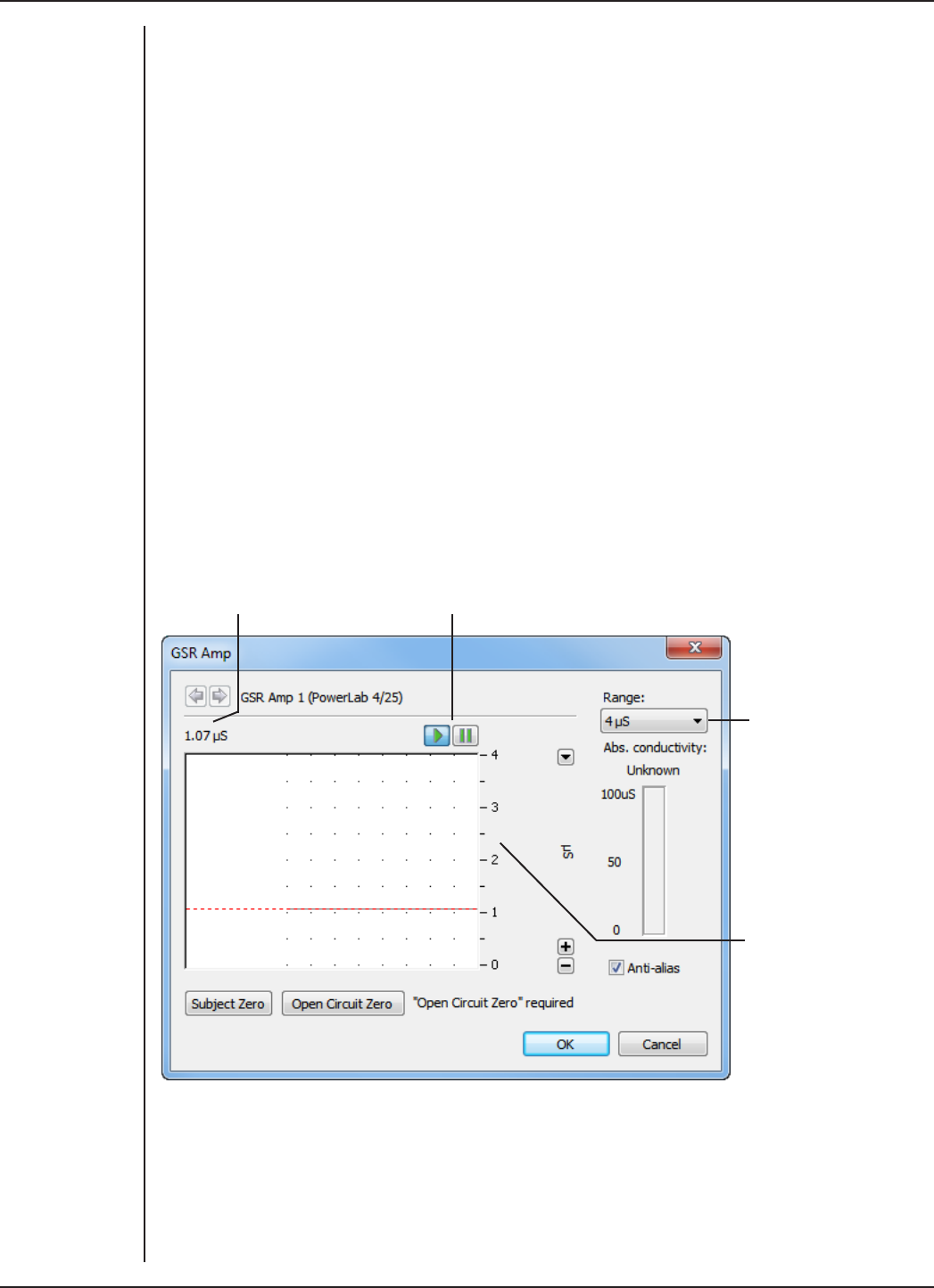
FRONT-END SIGNAL CONDITIONERS - Owner’s Guide
124
similar to those of LabChart. The GSR Amp dialogs for LabChart for Macintosh and
LabChart for Windows are very similar and are described here together.
Note: You cannot start sampling in LabChart and Scope if a connected GSR Amp is not
zeroed. Therefore, the first step is to zero the device.
The GSR Amp dialog
The GSR Amp dialog appears when you choose GSR Amp… from a Channel Function
pop-up menu (or click GSR Amp… in the Input Settings column in the Setup > Channel
Settings... dialog).
The GSR Amp dialog allows soware control of the combined options from the circuitry
of the PowerLab and GSR Amp. The signal present at a channel’s input is displayed so
you can see the eects of changing the settings. The GSR Amp is pre-calibrated and
measures skin conductivity directly in µS (microsiemens). Once the GSR Amp is zeroed
and settings have been changed, click OK to apply them.
Signal Display
The input signal is displayed so you can see the eect of changing the settings — no data
are recorded while you adjust the settings. The average signal value is shown above the
display area.
Signal amplitude Pause and Scroll buttons
Range
pop-up
menu
Amplitude
axis
You can stop the signal scrolling by clicking the Pause button at the bottom le
(Macintosh) or top right (Windows) of the data display area. This changes to the Scroll
button on the Macintosh. Click the Scroll button to start scrolling again. You can shi
and stretch the vertical Amplitude axis to make the best use of the available display
area. It functions the same as the Amplitude axis of the Chart window, and any change
is applied to the Chart window.
Figure 8–4
The GSR Amp
dialog for
Windows (before
an Open Circuit
Zero)

FRONT-END SIGNAL CONDITIONERS - Owner’s Guide
125
Amplitude axis Signal amplitude Range pop-up menu
Pause/Scroll button Compression buttons
Setting the Range
The Range pop-up menu lets you select the input range or sensitivity of the channel.
Changing the range in the GSR Amp dialog is equivalent to changing it in the Chart
Window. There are six ranges: 1, 2, 4, 10, 20 and 40 µS. The default range is 4 µS.
On a Macintosh, Show Range Axis in the Scale pop-up menu displays the range axis on
the right of the display area. The Compression buttons adjust the horizontal axis of the
data display area.
Zeroing
Before measurements can be made with the GSR Amp, it must be zeroed: this is a two-
stage process. A note next to the zeroing buttons indicates its status. If you try to start
sampling before the GSR Amp has been zeroed, you will receive an alert and the GSR
Amp dialog will appear, at which stage the system must be zeroed.
To zero the GSR Amp, first perform an open circuit zero by connecting up the cables
and electrodes to the front-end, without connecting them to the subject. Ensure that
the metal surfaces of the two electrodes do not touch each other, and then click Open
Circuit Zero. The status note changes to indicate that subject zeroing needs to be done
(the second stage). Connect up the subject (as described below), then click the Subject
Zero button.
The subject zero gives an absolute measure of the skin conductivity of the subject, i.e.
the baseline conductivity from which relative changes are measured. The absolute
conductivity value is shown when everything is zeroed. Normal baseline conductivity
values should be in the range of 10 to 50 µS, depending on the individual and the air
Figure 8–5
The GSR Amp
dialog for
Macintosh (also
before zeroing)

FRONT-END SIGNAL CONDITIONERS - Owner’s Guide
126
humidity level (which aects skin conductivity). A scale measuring the change in
conductivity (also in µS) is used for the final record. This scale corresponds to the GSR
readout in a traditional polygraph.
Units
The GSR Amp measures conductivity directly in microsiemens (µS): units conversion is
done once the GSR Amp is zeroed.
Equipment and Technique
Measurement of GSR
Electrical resistance decreases (and conductance increases) between two points on the
skin when a subject experiences a stressful stimulus. This is known as the Féré eect,
aer its discoverer. Terms such as psychogalvanic reflex and skin conductance response
have also been used to describe this eect. The modern term is galvanic skin response,
or GSR.
The change in conductivity on stimulation is due to an increase in the activity of sweat
glands, which provides a good general indicator of autonomic nervous system activity.
The increased conductivity arises through increased skin moisture, pre-secretory
activity of the sweat gland cell membranes, or both. The soles of the feet and palms
of the hands, including the palmar surfaces of the fingers and the plantar surfaces of
the toes, have the highest concentrations of these sweat glands (at least 2000 per cm2,
about ten times higher than elsewhere), and so provide the best places to measure GSR.
The latest recommendations for the preparation of skin are described in Boucsein et al.,
2012. Skin preparation should consist of washing the hands without soap (it can cause
swelling of the epidermis), followed by rinsing and thorough drying. Alcohol should not
be used to clean the fingers as it penetrates and dries out the skin too much to allow
reliable measurement. Skin abrasion is neither necessary nor desirable (it reduces
sensitivity).
The electrodes supplied for use with the GSR Amp should be used with an electrode gel
or paste that contains a chloride salt such as NaCl or KCl. NaCl-containing electrode gel
is most commonly used, with concentrations in the range of 0.05–0.075 molar (0.3–0.4%
by weight) — this approximates the concentration of NaCl in the sweat that reaches the
epidermal surface.
The bipolar electrodes should be attached to the palmar surfaces of the fingers of one
hand with the attachment straps, firmly but not tightly (see Figure 8–6). Normally, the
middle segments (phalanges) of the first and second fingers are used, although you may
want to use the first and third fingers to remove any chance of contact between the
electrodes; consistent sites should be used in any event.
The subject should keep the hand still to avoid movement artifacts, and have a few
minutes to relax, to establish good baseline conduction — you will need to perform a
second subject zero before commencing measurement. The galvanic skin response to a
stimulus or series of stimuli can then be measured, relative to the baseline conductivity.
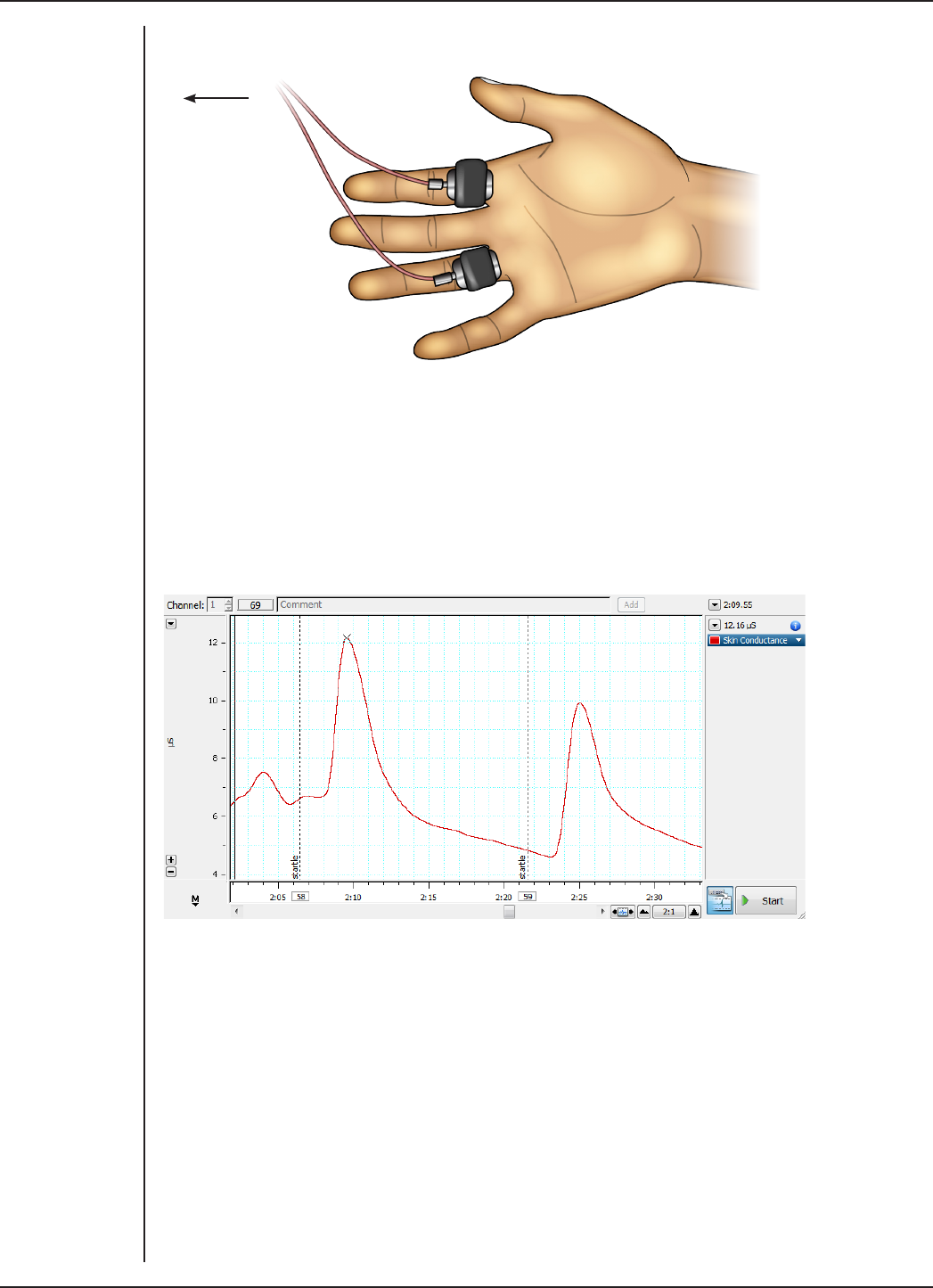
FRONT-END SIGNAL CONDITIONERS - Owner’s Guide
127
To GSR Amp
Increased arousal due to physical or emotional stimuli increases conductivity. Typically,
there is a short time lag, followed by a sharp increase and an exponential decay to
baseline level. The whole response may take up to 40 seconds, although the decay
phase is highly dependent on the subject.
The response is not fast, so a recording speed of 4 samples per second is adequate for
most purposes. Good stimuli for evoking the response include a sudden loud noise (as
shown in Figure 8–7), or a full inhalation, two second breath hold, then full exhalation.
Figure 8–6
Connecting the
electrodes to
the subject: the
GSR Amp uses
AC excitation, so
the polarity of the
connections is
unimportant
Figure 8–7
A typical GSR
response to a
startle stimulus,
recorded from the
palmar surface of
the fingers
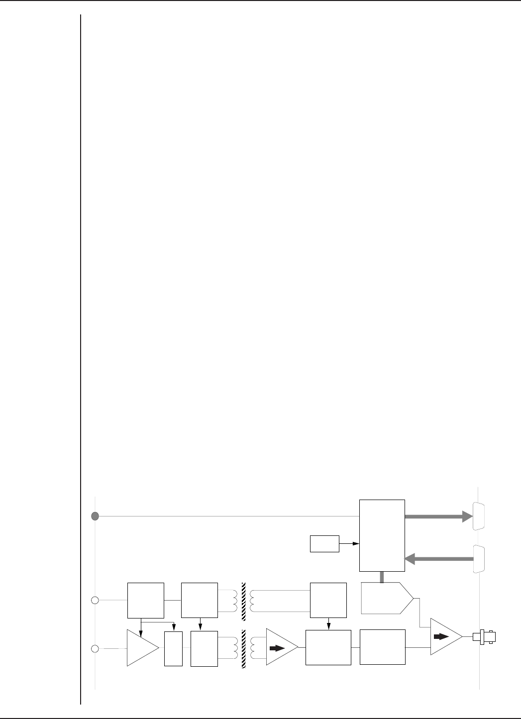
FRONT-END SIGNAL CONDITIONERS - Owner’s Guide
128
Technical Aspects
The following section describes some of the important technical aspects of the GSR Amp
to give some insight into how it works. You do not need to know the material here to use
a front-end. It is likely to be of special interest to the technically minded, indicating what
a front-end can and cannot do, and its suitability for particular purposes.
Note: You should not use this section as a service manual: user modification of the
equipment voids your rights under warranty.
GSR Amp Operation
The GSR Amp and other ADInstruments front-ends have been designed to integrate
fully into the PowerLab system. Each requires connection to the PowerLab via a special
communications connector called the I2C (eye-squared-sea) bus, and a BNC connector.
The GSR Amp is essentially an extension of the PowerLab’s analog input. The GSR Amp
provides:
•full electrical isolation from power-line (mains) circuitry to guarantee subject
safety
•measurement of the Féré eect, a general measure of autonomic nervous system
activity, directly in SI conductance units (siemens)
•low, constant-voltage AC excitation (22 mVrms @ 75 Hz) allows enhanced safety
and the use of dry electrodes, with no special electrolytes needed
•measurement of absolute conductivity up to 100 µS (microsiemens).
The internal functions of the GSR Amp are controlled from the PowerLab through the I2C
bus, which also supplies power to the GSR Amp. The front-end is also connected to an
analog input channel of the PowerLab via a BNC-to-BNC cable, through which the signal
is sent. The overall operation of the GSR Amp can be better understood by referring to
Figure 8–8.
I2C
Output
I2C
Input
Signal
Output
Micro
Processor
Controller
12-bit
Offsetting
DAC
1 Hz 2nd
Order Low-
pass filter
8 MHz
Crystal
400 Hz
Power
Oscillator
Synchronous
Rectifier
Isolation
Transformers
Isolation Barrier
Synchronous
Rectifier
Signal
Modulator
Isolated
Power
Supply
75 Hz
Oscillator
Status
Indicator
Subject
Connections
Transimpedance
Amplifier
_
+
Figure 8–8
Block diagram of
the GSR Amp

FRONT-END SIGNAL CONDITIONERS - Owner’s Guide
129
The 75 Hz oscillator supplies a near-square wave, low-impedance, low-voltage signal (22
mVrms) to an electrode on a finger of the subject. If the skin has measurable conductance
(rather than behaving as an insulator), then current flows, from an electrode on another
finger of the subject, into the very low impedance input of the transimpedance amplifier.
The transimpedance amplifier converts current to voltage. The current will change
as the autonomic reflexes change the skin’s conductivity. The resulting signal is
passed through a synchronous rectifier to obtain a DC voltage proportional to skin
conductance, then via a modulator to produce a 400 Hz AC signal suitable for passing
across the isolation barrier (providing electrical protection for the subject).
On the other side of the isolation barrier, the AC signal is multiplied then synchronously
rectified, restoring a DC voltage proportional to skin conductance. To reduce noise in the
rectified signal, it is passed through a 1 Hz, second-order, low-pass filter, which leaves
the general signal trends unchanged, but removes higher-frequency fluctuations. The
signal at this point consists of the overall (baseline) skin conductivity plus a component
representing the Féré eect changes, or galvanic skin response (GSR).
A precision ×1 instrumentation amplifier compares the signal with the output of the
12-bit digital-to-analog converter (DAC). The DAC provides an exact oset voltage for
zeroing and osetting of the synchronously demodulated and filtered signal. This
ensures maximum signal-to-noise ratio, good zeroing resolution, and maximum
resolution in the displayed signal. The DAC removes the constant baseline, allowing just
the fluctuations to be observed.
The control for osetting and zeroing functions in the GSR Amp is provided by an on-
board microcontroller, which also communicates with the PowerLab over the I2C bus.
Troubleshooting
This section describes most of the common problems that can occur when using the
GSR Amp with your PowerLab recording unit. If the solutions here do not work, earlier
chapters, the LabChart Help Center, and the guide to your PowerLab may contain
possible remedies. If none of the solutions here or elsewhere are of help, then consult
your ADInstruments representative.
Most of the problems that users encounter are connection problems, and can usually be
fixed by checking connections and starting up the hardware and soware again. Very
rarely will there be an actual problem with the front-end or the PowerLab itself.
Problems and Solutions
The status indicators fail to light when the soware is started, or the front-end commands
and so on do not appear where they should
The I2C cable or the BNC-to-BNC cable from the front-end to the PowerLab is not
connected, has been connected incorrectly (to the wrong input or output, for instance),
or is loose.

FRONT-END SIGNAL CONDITIONERS - Owner’s Guide
130
•Turn everything o. Check to see that all cables are firmly seated and screwed
in. BNC cables from the GSR Amp must be connected to a positive input on the
PowerLab. Make sure the input is the same channel from which you expect to use
the front-end in the soware. Aer checking connections, restart the PowerLab
and application to see if this has fixed the problem.
You are using an early version of LabChart or Scope.
•Upgrade to the latest version of the soware. Contact your ADInstruments
representative for information.
The BNC or I2C cable is faulty.
•Replace the cable and try again. Immediately label all cables proved faulty so
that you don’t use them again by accident.
The front-end is faulty.
•This is the least likely event. If the front-end will not work properly aer the
previous measures, then try using it on another PowerLab. If the same problems
recur with a second PowerLab, the front-end may be faulty. Contact your
ADInstruments representative to arrange for repairs.
On starting up the soware, an alert indicates that there is a problem with the front-end or
driver
The correct BP/GSR drivers are not installed on your computer.
•Reinstall the soware.
You are using an early version of LabChart or Scope.
•Upgrade to the latest version of the soware. Contact your ADInstruments
representative for information.
The BNC or I2C cable is faulty.
•Replace the cable and try again. Immediately label all cables proved faulty so
that you don’t use them again by accident.
The front-end is faulty.
•This is the least likely event. If the front-end will not work properly aer the
previous measures, then try using it on another PowerLab. If the same problems
recur with a second PowerLab, the front-end may be faulty. Contact your
ADInstruments representative to arrange for repairs.
Some soware settings don’t resemble those in this guide
You are using an early version of the front-end driver, or of LabChart or Scope. Some
changes may have been made since then.
•Upgrade to the latest version of the soware. Contact your ADInstruments
representative for information.

FRONT-END SIGNAL CONDITIONERS - Owner’s Guide
131
Specifications
Input
Connection type: 2 × 4 mm shrouded sockets. Custom cable with two
shrouded banana plugs and terminated with two
dry, bright-plated, bipolar electrodes with Velcro™
attachment strap suitable for adult fingers.
Excitation: Constant-voltage AC excitation
(22 mVrms @ 75 Hz)
Current density: 0.5 µA .cm–2
Safety: Approved to IEC 60601-1 Standard (BF rating)
EMC: Approved to EN61326-1:2006 Standard
Configuration: Transformer isolation (AC bridge operation)
Isolation rating: 4000 V ACrms for 1 minute
Input ranges: 1–40 µS full scale in 6 steps
(combined PowerLab and GSR Amp)
0–40 µS
0–20 µS
0–10 µS
0–4 µS
0–2 µS
0–1 µS
Frequency response: –3 dB at 1 Hz
Accuracy: ±5%
Input leakage current: < 3 µArms at 240 V, 50 Hz
< 2 µArms at 120 V, 60 Hz
Zeroing and oset: Automatic soware-controlled fast zeroing, controlled
by internal 12-bit DAC; resolution = ±0.2 µS
Output
Signal: ±2.0 V full scale: suitable for PowerLab
Control Port
I2C port: Provides control and power. Interface communications
rate of ~50 kbits/s.

FRONT-END SIGNAL CONDITIONERS - Owner’s Guide
132
Physical Configuration
Dimensions (h × w × d): 55 mm × 120 mm × 260 mm (2.2" × 4.7" × 10.2")
Weight: 1.2 kg (2 lb 10 oz)
Power requirements: 2.5 W max
Operating conditions: 5–35 °C
0–90% humidity (non-condensing)
ADInstruments reserves the right to alter these specifications at any time.
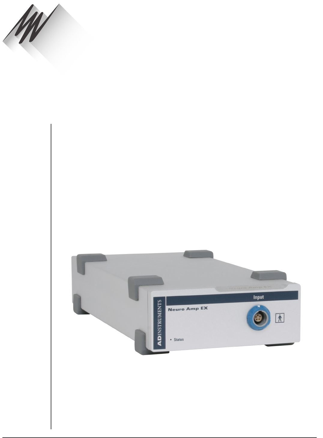
FRONT-END SIGNAL CONDITIONERS - Owner’s Guide
133
The FE185 Neuro Amp EX is one of a family of devices called front-ends, designed to
extend the capabilities of the PowerLab system. It diers from other front-ends by
including an additional piece of hardware, the headstage. The Neuro Amp EX allows the
PowerLab system to record extracellular action potentials from single cells or groups of
cells.
The Neuro Amp EX provides:
•full electrical isolation from power-line (mains) circuitry to guarantee subject
safety.
•a low-noise, high-gain dierential amplifier specifically designed for
neurophysiological extracellular signal measurements.
•soware-controlled low-pass, high-pass, notch and mains filters to remove
unwanted signal frequencies for particular uses.
•audio output to listen to neurological signals.
The Neuro Amp EX is fully isolated for human use, in addition to being suitable for
making extracellular recordings from experimental animals.
Neuro Amp EX
Chapter 9
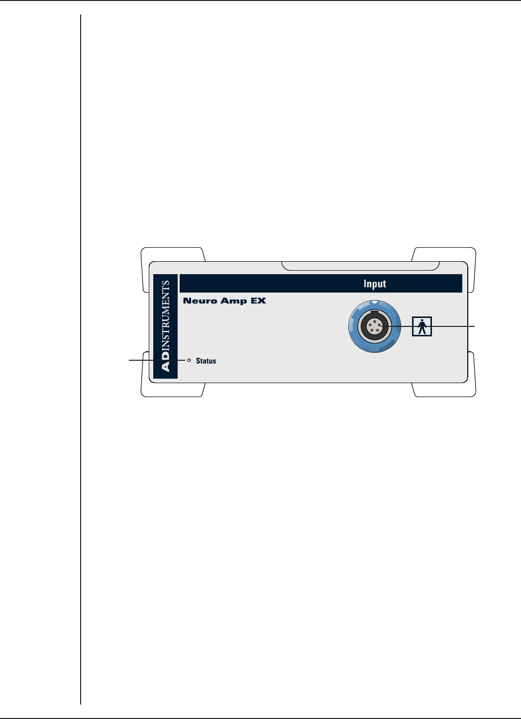
FRONT-END SIGNAL CONDITIONERS - Owner’s Guide
134
The Neuro Amp
The Neuro Amp EX [FE185] is designed to allow the PowerLab system to perform
isolated measurements of single-unit or multi-unit extracellular action potentials from
single neurons or axons, from human or animal subjects. It consists of an electrically
isolated dierential input AC amplifier with an isolated ground connection.
It is possible to ‘daisy-chain’ multiple Neuro Amp EXs to record from separate subjects,
using separate grounds. However, it is not recommended to use more than one Neuro
Amp EX to record from a single subject or to use a Neuro Amp EX with an ADInstruments’
Bio Amp to record from a single subject (this is discussed in more detail in the next
section).
The Front Panel
The front panel of a Neuro Amp EX has an input socket and a status indicator light.
Input Socket
Status
Indicator
The Input Socket
The headstage output cable is coupled to the Neuro Amp EX front-end using a five-pin
input socket on the front panel. The pin arrangement ensures that the polarity is correct.
The input socket is physically and electrically isolated from the low-voltage mains-
supply circuitry of the PowerLab and the input connections are isolated internally by
isolation circuitry. The socket provides 7.5 V supply lines to the headstage, a protected
earth and dierential input lines.
The Status Indicator
The status indicator light of a Neuro Amp EX is located at the bottom le of the front
panel.
When an ADInstruments application such as LabChart starts, the status indicator
should flash briefly and then remain green, indicating that the program has found the
front-end, checked and selected it, and is ready to use it. If the status indicator does not
turn on and stay on when the application starts, it is most likely that the front-end is not
connected properly.
Figure 9–1
The front panel
of the
Neuro Amp EX
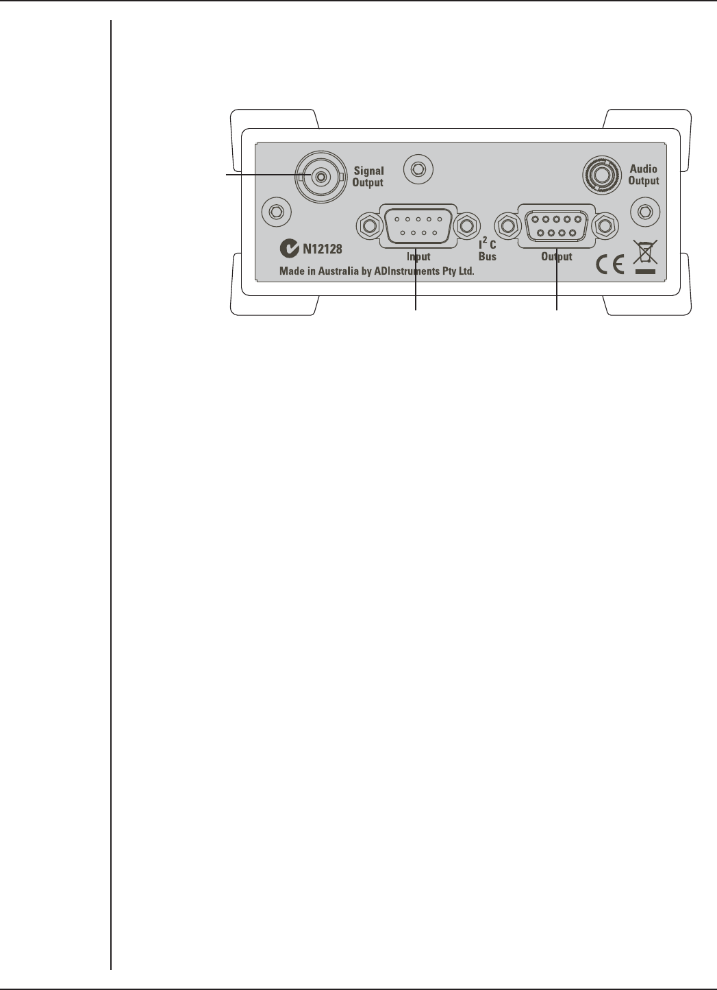
FRONT-END SIGNAL CONDITIONERS - Owner’s Guide
135
The Back Panel
The back panel of the Neuro Amp EX provides all the sockets required to connect the
front-end to the PowerLab and to other front-ends.
I2C connection from
the PowerLab or
previous front-end
I2C connection to a
further front-end
Signal Output to
the PowerLab
I2C Input and Output Sockets
Two nine-pin sockets are used to communicate with the PowerLab (they are marked ‘I2C
Bus’: a ‘bus’ is simply information-transmission circuitry such as cables and connectors).
These sockets allow multiple front-ends to be used independently with one PowerLab.
Power and control signals to the front-ends come from the PowerLab. Many front-ends
can be connected to the system, in series, output to input, providing there is the same
number of channel inputs available on the PowerLab (this is discussed in more detail in
the next chapter).
Analog Out Socket
The BNC socket labeled Analog Out on the back panel provides the signal output and a
connection is made to an analog input socket on the front of the PowerLab with a BNC-
to-BNC cable (supplied).
If you are connecting to an earlier model PowerLab with dierential inputs, only
connect the analog output to the positive analog input of the PowerLab. ADInstruments
applications do not find a front-end on start up if the negative input is used.
Audio Out Socket
The Neuro Amp EX has an audio monitor output on the back panel that can be used
with a wide range of headphones or externally powered speakers. The 3.5 mm socket
provides mono sound that may be of use when monitoring nerve firings, to control the
placement of electrodes for instance.
Figure 9–2
The back panel
of the
Neuro Amp EX
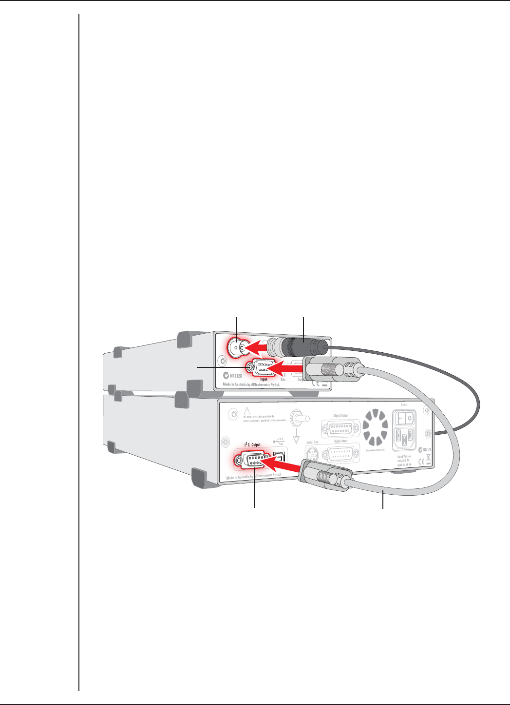
FRONT-END SIGNAL CONDITIONERS - Owner’s Guide
136
Connecting to the PowerLab
To connect a front-end to the PowerLab, first ensure that the PowerLab is turned o.
Failure to do this may damage the PowerLab, the front-end, or both.
Connect the signal output on the rear panel of the Neuro Amp EX to an analog input
on the front panel of the PowerLab using a BNC cable. If the PowerLab has dierential
(rather than single-ended) inputs, the BNC cable must connect to a positive analog
input of the PowerLab. ADInstruments applications will not find the front-end on start-
up if a negative input is used.
Single Front-end
Connect the I2C output of the PowerLab to the I2C input of the front-end using the I2C
cable provided. Figure 9–3 shows how to connect up a single front-end to your recording
unit.
Check that the plugs for the I2C bus are screwed in firmly. Check the BNC cable for firm
connections as well. Loose connectors can cause erratic front-end behavior, or may
cause the front-end to fail to work at all. The BNC cable can be tucked under the front-
end to keep it out of the way if desired.
Multiple Front-ends
Multiple separate front-ends can be connected to a PowerLab. The number of normal
front-ends that can be connected depends on the number of input channels on the
PowerLab, since each signal output from a front-end is connected to one of the analog
input channels on the PowerLab.
The initial front-end should be connected with the I2C cable, as shown in Figure 9–3.
The remainder are daisy-chained via I2C cables, connecting the I2C output of the last
connected front-end to the I2C input of the front-end to be added, as shown in Figure
9–4. Note that signal degradation may occur if multiple front-ends share a common
Ground/reference, such as when they are connected to a single subject.
Figure 9–3
Connecting the
Neuro Amp EX to
the PowerLab
Neuro Amp EX Signal Output
Neuro Amp EX
I2C input
PowerLab I2C output I2C connector cable
BNC connector cable
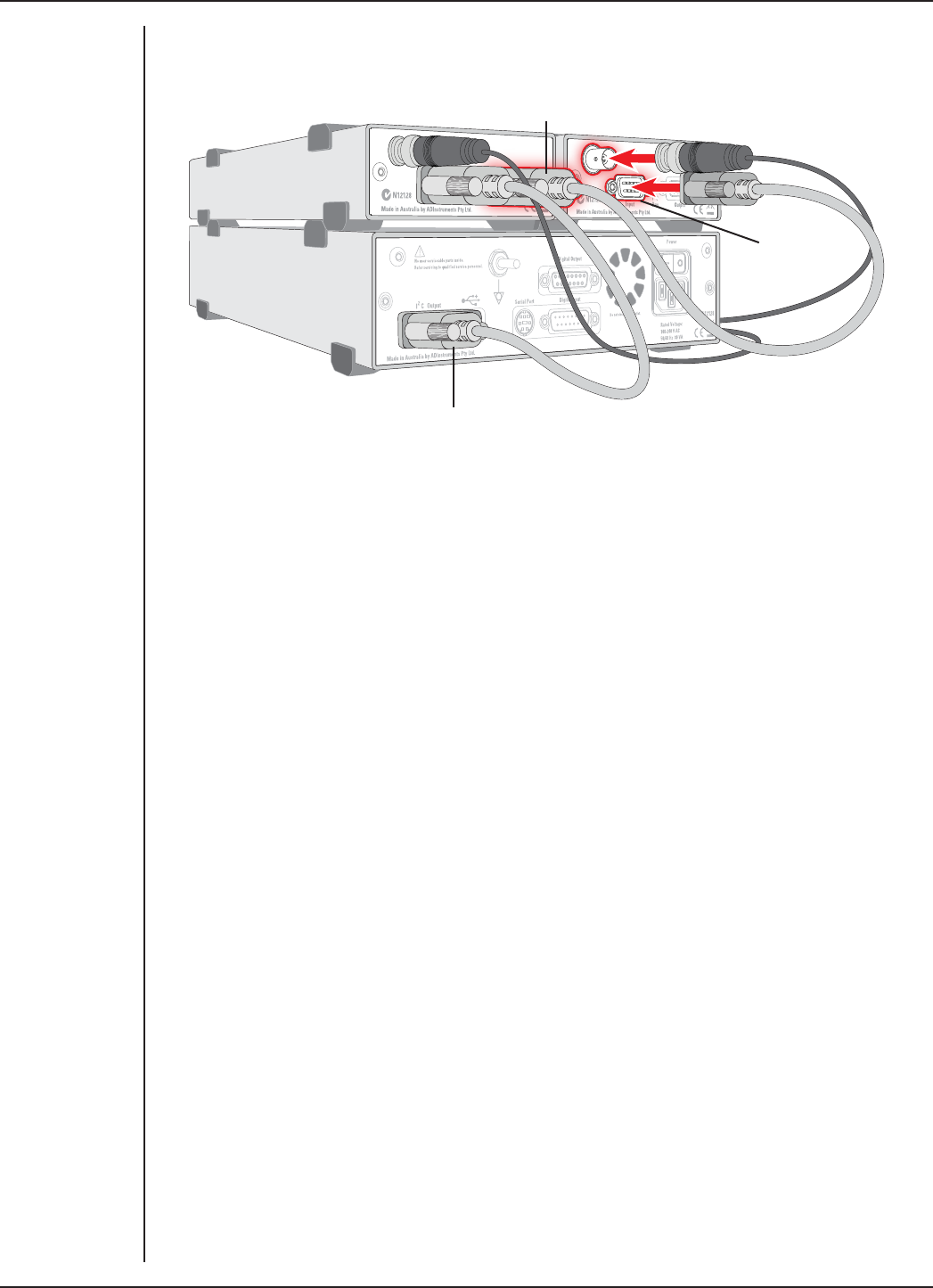
FRONT-END SIGNAL CONDITIONERS - Owner’s Guide
137
Using More Than One Neuro Amp EX
Although you can record with more than one Neuro Amp EX front-end using a common
Ground/reference, such as when recording from a single subject, it is not recommended.
If using two or more Neuro Amp EX front-ends, some interaction can take place between
them, causing up to 10 µV of induced low-frequency signal, due to slight dierences in
frequency between the isolated power supplies. This should not aect most biopotential
measurements, especially if using signal averaging. Narrowing the signal bandpass may
also reduce the eect.
Soware Requirements
The Neuro Amp EX requires the following versions of ADInstruments soware
applications:
•LabChart version 6, or later, for Windows or Macintosh
•Scope for Windows version 3.8.5, or later
•Scope for Macintosh version 4.1.1, or later
Note: the Neuro Amp EX may not operate correctly with earlier versions of these
applications. Free updates are available from the ADInstruments website for users
with earlier versions of Chart and Scope. If you have queries regarding hardware and
soware requirements of the Bridge Amps, please contact your local ADInstruments
representative.
Figure 9–4
Connecting two
front-ends to
the PowerLab:
a connection is
made from the I2C
output on the first
front-end to the
I2C input on the
second front-end
Second I2C cable connected to
Front-end I2C output
Second
Front-end
I2C input
First I2C cable connected
to PowerLab I2C output
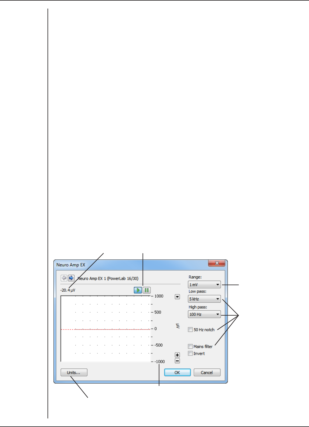
FRONT-END SIGNAL CONDITIONERS - Owner’s Guide
138
Using LabChart and Scope
When a Neuro Amp EX is properly connected to the PowerLab, the Input Amplifier…
menu command is replaced with Neuro Amp EX… for the input to which the Neuro Amp
EX is connected. If the application fails to find a front-end connected, the normal text
remains. If the expected text is not displayed, quit the application, turn the PowerLab
o and check the BNC and I2C connections. Then restart the PowerLab and relaunch the
application.
The documentation for LabChart and Scope does not cover front-end-specific features.
These features are described in detail here for LabChart. Generally, dialogs for these
applications are similar. The Neuro Amp EX dialog for LabChart for Macintosh and
LabChart for Windows are very similar and are described here together.
Neuro Amp EX dialog
The Neuro Amp EX dialog (Figure 9–5 and Figure 9–6) allows soware control of the
combined input amplifiers and filters in the PowerLab and Neuro Amp EX. The signal
present at a channel’s input is displayed in the preview area so that you can see the
eects of changes in settings. Aer changing settings in the dialog, click the OK button
to apply them.
The Neuro Amp EX dialog appears when you choose Neuro Amp EX… from a Channel
Function pop-up menu. To set up many channels quickly, open the Setup > Channel
Settings... dialog. Here you can view all the channels that are turned on, and you can
turn o any unnecessary channels. Clicking on Neuro Amp EX… in the Input Settings
column of the Channel Settings dialog will also open the Neuro Amp EX dialog.
Signal amplitude
Amplitude axis
Pause and Scroll buttons
Click this button to open the Units Conversion dialog
Filtering
options
Range pop-up
menu
Figure 9–5
The Neuro Amp
EX dialog for
Windows
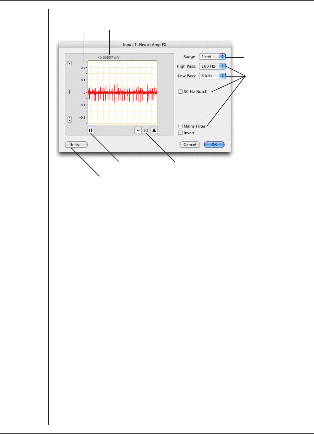
FRONT-END SIGNAL CONDITIONERS - Owner’s Guide
139
Signal amplitudeAmplitude axis
Pause/Scroll button
Click this button to open the Units Conversion dialog
Compression buttons
Filtering
options
Range pop-up
menu
Signal Display
The input signal is displayed so you can see the eect of changing the settings – no data
is recorded while setting things up. The average signal value is shown above the display
area.
You can stop the signal scrolling by clicking the Pause button at the bottom le
(Macintosh) or top right (Windows) of the data display area. This changes to the Scroll
button on the Macintosh. Click the Scroll button to start scrolling again.
On the Macintosh, Show Range Axis in the Scale pop-up menu displays the range axis at
the right of the display area, and the Compression buttons adjust the horizontal axis of
the data display area.
You can shi and stretch the vertical Amplitude axis by clicking and dragging it in
various ways to make the best use of the available display area. It functions the same
as the Amplitude axis of the Chart Window; the controls are identical and any change is
also applied to the Chart Window.
Setting the Range
The Range pop-up menu lets you select the input range or sensitivity of the channel –
the combined range of the PowerLab and the Neuro Amp EX. Changing the range in the
Neuro Amp EX dialog is equivalent to changing it in the LabChart or Scope window. The
default setting is 1 mV and the ranges go down to 20 µV in 6 steps.
Figure 9–6
The Neuro Amp
EX dialog for
Macintosh

FRONT-END SIGNAL CONDITIONERS - Owner’s Guide
140
Filtering
The Neuro Amp EX has low-pass, high-pass, notch and mains filter circuitry that can be
adjusted to suit the application. The notch filter removes 50 or 60 Hz interference and
the mains filter removes mains frequency related interference. In general, it is better to
prevent interference at the source than to filter it. The high-pass and low-pass filters
provide bandwidth limiting of low-frequency and high-frequency signals, respectively.
Note that the settings for one filter type may restrict the possible settings for the other.
High-Pass Filtering. The High Pass pop-up menu gives the choice of 100 Hz, 300 Hz and
500 Hz high-pass filters. The high-pass filter removes frequencies below the selected
cut-o frequency and allows high frequencies in the signal to pass. Note: this amplifier
is not suitable for DC recording.
Low-Pass Filtering. The Low Pass pop-up menu gives the choice of 1 kHz, 2 kHz and
5 kHz low-pass filters. The low-pass filter removes high-frequency components above
the selected cut-o frequency and allows lower frequencies in the signal to pass. These
filters are useful for removing high-frequency signals, such as noise, and to prevent
aliasing in the recorded signal (see page 24).
Notch Filter. Select or deselect the Notch checkbox to turn the notch filter on and
o. The notch filter is automatically set to either 50 or 60 Hz, depending on the power
line voltage frequency being used by the PowerLab (the mains frequency). It provides
approximately 32 dB of attenuation, thus reducing the eect of the 50 or 60 Hz signals
that can be easily picked up by long leads.
Mains Filter. Select or deselect the Mains filter checkbox to turn the mains filter on and
o. The mains filter allows you to remove interference related to the mains frequency
(both fundamental and harmonic frequencies). This is an adaptive filter. It adjusts to
filter the interference by tracking the input signal for a second, creating a template of
the interfering frequencies and then subtracting this template from the input signal.
Because of this, in general, using the mains filter is better than using the notch filter.
However, the mains filter does have some limitations, such as not being useful for very
short recordings of less than one second. More details on the mains filter can be found
in the LabChart Help Center.
Inverting the Signal
The Invert checkbox provides a simple way to change the polarity of the recorded signal
without having to swap the connections to the recording electrodes.
Units
Clicking the Units… button displays the Units Conversion dialog, which allows you to
set the units for a channel and, using waveform measurements, calibrate the channel.
The waveform in the data display area of the Neuro Amp EX dialog is transferred to the
data display area of the Units Conversion dialog. (Use the Pause button to capture a
specific signal.) The units conversion only applies to subsequently recorded signals;
hence it is more limited than choosing Units Conversion... from the Channel function
pop-up menu as it does not allow conversion of previously recorded blocks of data.
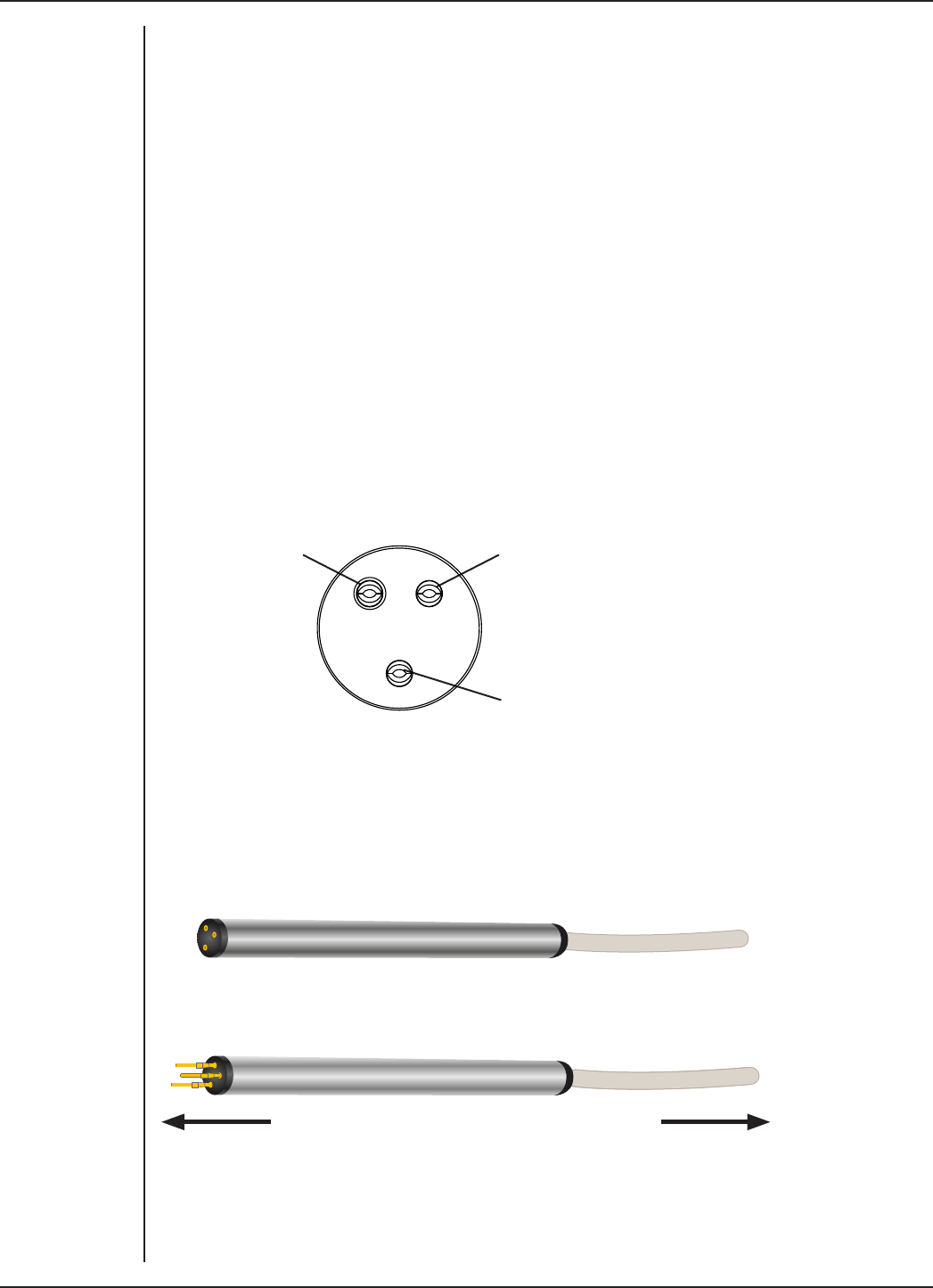
FRONT-END SIGNAL CONDITIONERS - Owner’s Guide
141
Types of Measurement
The low noise and high gain of the Neuro Amp EX makes it suitable for all recordings
that require a high bandpass (300 Hz – 5 kHz) and a high signal-to-noise ratio. Such
recordings may include extracellular recordings from single cells or groups of cells, or
from nerve fibres (split-nerve preparation or human microneurography). The headstage
provides a gain of 100x and the cable shielding is directly connected to the casing,
limiting the need for additional shielding at the input terminals.
Note: The Neuro Amp EX is not suitable for intracellular recording with glass
microelectrodes.
The Neuro Amp EX Headstage
The headstage can be mounted in a micromanipulator for animal use or taped directly
to the skin of a human subject. The casing of the headstage is connected to the shielding
of the cable, thereby providing shielding up to the input terminals. Three female gold
plated miniature sockets provide inputs on the headstage. The positive and negative
terminals are adjacent, while the ground terminal is further away. The positive terminal
is distinguished by a slightly recessed surround.
Signal Input (−)
Ground/Reference
Signal Input (+)
Connections are made to the Neuro Amp EX front-end using the supplied Neuro Amp
EX headstage and connectors (microelectrodes are not supplied). The headstage cable
plugs into the five-pin input socket on the front panel: the pin arrangement ensures that
polarity is correct. Only use the supplied Neuro Amp EX headstage as others may not
meet safety requirements.
To Electrodes To Neuro Amp EX
Figure 9–7
Input sockets for
the Neuro Amp EX
headstage
Figure 9–8
Headstage for
the Neuro Amp
EX, as supplied
(top), and with
male connectors
attached (below)

FRONT-END SIGNAL CONDITIONERS - Owner’s Guide
142
Six male gold plated miniature connectors or pins are supplied with the headstage.
These can be crimped or soldered to standard metal microelectrodes, such as
tungsten, stainless steel or platinum, to allow you to construct electrodes to suit your
requirements.
Recording Technique
When conducting research using the Neuro Amp EX, it is important to ensure that you
use correct preparation and recording techniques. It is important to understand the
types of problems that can occur, how they manifest, and what can be done to remove
them or to minimize their eect. Potential problems may arise due to aliasing, frequency
distortion, saturation, ground loops, electromagnetic fields, electrode contact and
motion artifacts. Many of these are discussed in “Preventing Problems” on page 14.
See the section below for discussion of preventing artifacts due to poor electrode
contact and subject movement.
Setting up to Record From a Subject
This section provides a step-by-step guide to making a recording from a subject. Aer
making the subject comfortable, a suitably qualified operator can use the following
steps to attach the headstage. The operator should follow their institute’s guidelines for
making neurological recordings and use precautions to minimize the risk of infection:
1. Attach the headstage to the Neuro Amp EX.
2. Securely attach the headstage to the subject by taping or bandaging it to the
limb or trunk.
3. Insert all the pins into the headstage. Attach the Ground/reference electrode
first, using Figure 9–7 as a guide.
4. Connect the active microelectrode (+) and the reference electrode (-) to the
positive and negative inputs of the headstage, respectively.
5. The Audio Output from the Neuro Amp EX can be connected to external
speakers, if required.
6. To help locate the nerve site, nerve stimulating techniques compatible with
your institute’s guidelines may be used. Stimulation may be made using the
ADInstruments Stimulus Isolator, or another Isolated Stimulator.
7. Changes in signal output in response to nerve stimulation can be observed using
the Neuro Amp EX dialog or by recording data using Scope or the Scope View in
LabChart.
8. If no longer required, move stimulation leads away from the headstage before
recording. Leaving them attached or close to the headstage will introduce noise.
For microneurography studies, the subject is normally passive during the procedure. The
headstage must be connected to the Neuro Amp EX before and during the procedure.
During the procedure, an operator:
•securely attaches the headstage to the subject using tape or a bandage (Figure
9–9);
•chooses a zero/reference point on the subject by attaching the Ground/Reference
electrode to the subject (Figure 9–10);
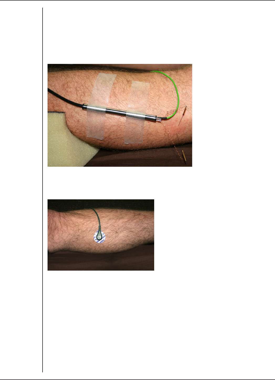
FRONT-END SIGNAL CONDITIONERS - Owner’s Guide
143
•and, finally, connects the active and reference microelectrodes to the subject
(Figure 9–11).
The headstage must be securely attached (Figure 9–9) to the limb of the subject under
investigation. This ensures that the headstage is in contact with the subject and helps to
minimize artifacts from movement.
The Ground/Reference lead can be attached to a surface electrode using a press stud or
snap fitting (Figure 9–10).
Microelectrode needles should be positioned using examination gloves to minimize the
risk of infection. The active microelectrode is inserted into the subject’s skin overlying
the nerve, while the reference electrode is inserted under adjacent skin. Under no
circumstances should the headstage be disconnected from the Neuro Amp EX while
the electrodes are still attached to the subject. Not having the headstage attached to
the Neuro Amp EX before and during the procedure may result in small static electric
shocks being delivered to the subject through the microelectrodes.
Figure 9–9
The headstage
should be
securely attached
to the subject.
Figure 9–10
The Ground/
Reference lead
wire attached
with a press stud
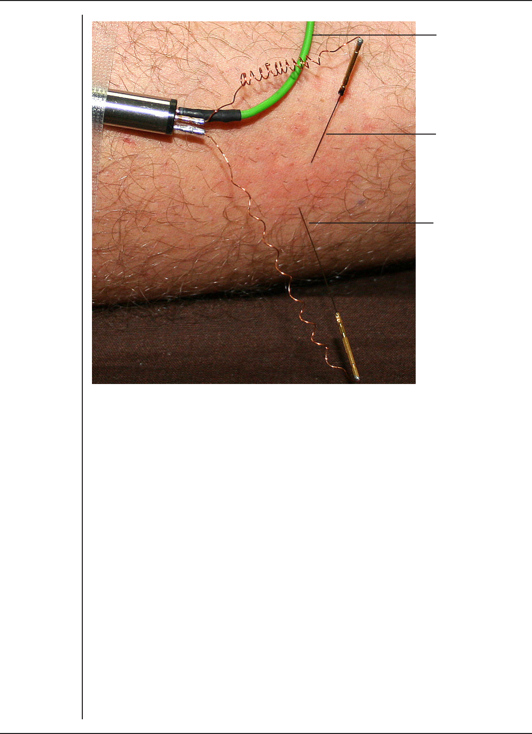
FRONT-END SIGNAL CONDITIONERS - Owner’s Guide
144
‘Active’
microelectrode
Reference
electrode
To Ground/
Reference
electrode
Motion Eects
A common source of artifacts when recording neurological signals is motion of the
subject or equipment. For example, muscular activity generates its own electrical
signals, which may interfere with the neuronal signal, depending on the location of the
electrodes.
If the subject is going to move during recording, then special care needs to be taken
when positioning electrodes and securing leads.
Electrode Contact
Occasionally during measurement of a neurological signal, one of the lead wires
connecting the source to the front-end may become disconnected, or electrode contact
may become poor. If this should happen, relatively high voltages (potentials) can be
induced in the open wire, due to electric fields caused by the power line or other sources
close to the front-end or to the subject. These induced potentials result in a constant
amplitude disturbance in the recorded signal at the mains frequency, causing masking
or loss of the desired signal. If the problem is a recurring one, one of the leads may be
faulty. Check connections and replace faulty leads, if necessary.
Figure 9–11
The active
microelectrode is
inserted over the
common peroneal
nerve at the
fibular head.
The reference
electrode is
inserted under
the skin.
The ground (Ag/
AgCl) electrode is
attached to the
surface of the skin
with the green
lead.
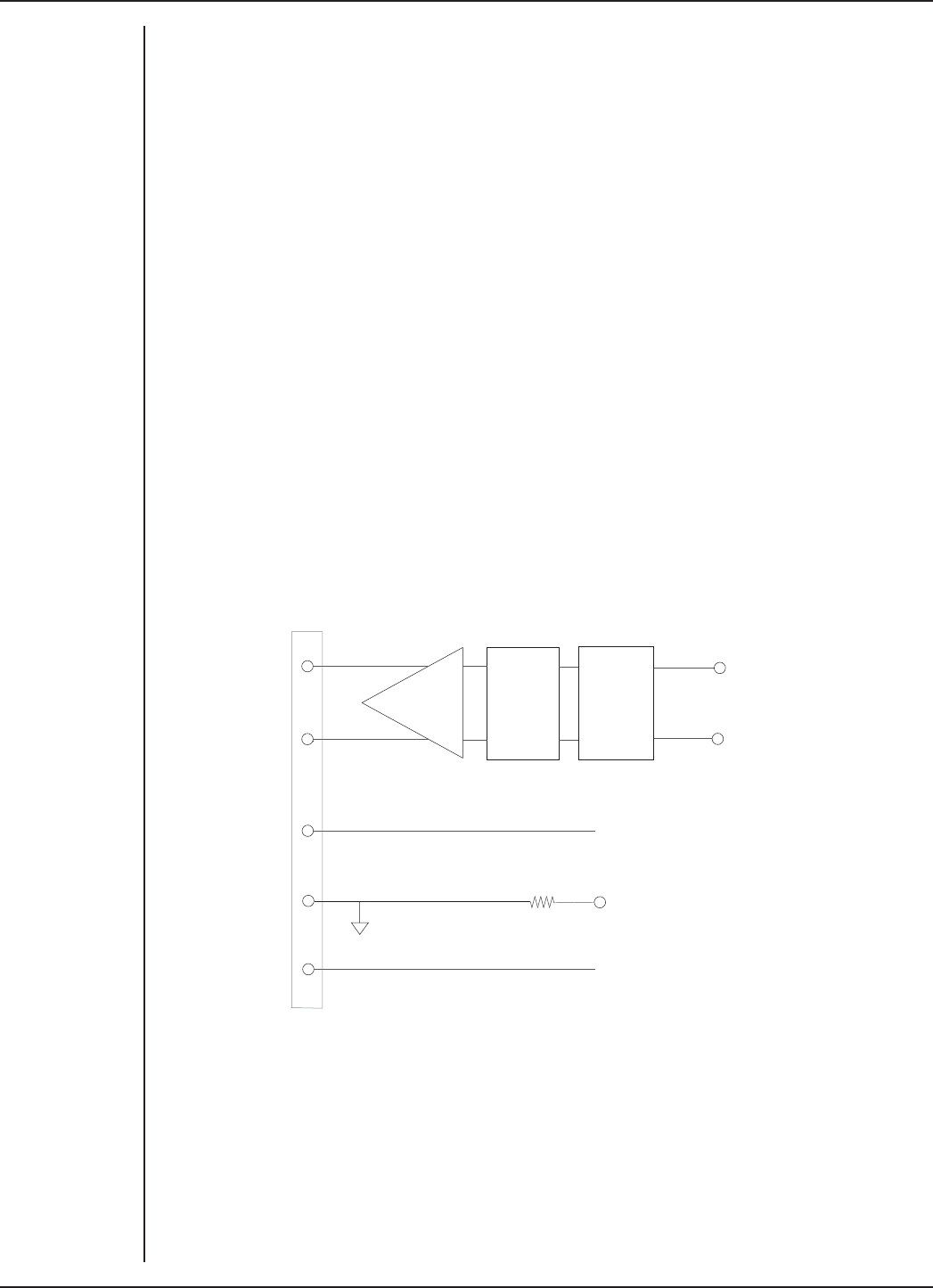
FRONT-END SIGNAL CONDITIONERS - Owner’s Guide
145
Technical Aspects
The Neuro Amp EX and other ADInstruments front-ends have been designed to
integrate fully into the PowerLab system. The Neuro Amp EX is essentially an extension
of the PowerLab’s input amplifiers. The amplification and ranges oered in LabChart,
LabTutor and Scope result from the combination of both pieces of hardware.
The PowerLab provides control and low-voltage power to front-ends through a special
expansion connector called the I2C bus. Front-ends are also connected to the analog
inputs of the PowerLab via a BNC cable, through which they send the amplified and
filtered signals. The overall operation of the Neuro Amp EX can be better understood by
referring to Figure 9–13 on page 146.
The headstage is a dierential in/dierential out amplifier with a fixed gain of ×100 and
a 10 Hz high-pass filter. The amplifier drives a dierential signal into the Neuro Amp EX.
Power is supplied through the connector. A reference pin is a current-limited isolated
ground return to protect against excessive auxiliary current. The overall operation of
the Neuro Amp EX headstage can be better understood by referring to Figure 9–12.
The input amplifier of the Neuro Amp EX starts with an electrically isolated dierential
amplifier. The output of this is fed into a low-noise demodulator and then to a
programmable gain stage, before being fed across an isolation transformer to the non-
isolated circuitry.
+7.5 V
+
-
-7.5 V
+ Signal
- Signal
10 Hz
HPF
Input
Protection
Ref
Control of the isolated gain is provided via a high-isolation-voltage optocoupler. Isolated
power comes from a second isolation transformer driven by a power oscillator circuit
running at about 38 kHz.
The signal from the isolated input amplifier is synchronously demodulated and then fed
to a programmable, switched-capacitor, high-pass filter. Any switching clock noise is
filtered by the low-pass filter following this stage.
Figure 9–12
Block diagram
of the headstage
amplifier
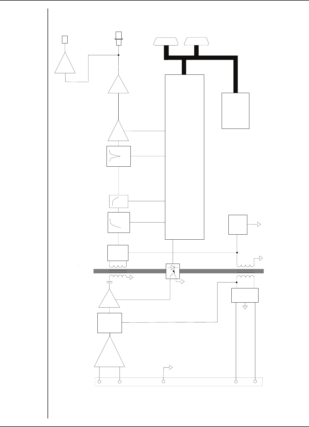
FRONT-END SIGNAL CONDITIONERS - Owner’s Guide
146
+7.5 V
+
-
-7.5 V
Signal
Input
Low
Noise
Modulator x1, x10 Synch
Demod
HPF LPF Notch
x1, x2,
x5 x1.66
x1
Microprocessor Control
Power
Supply
Power
Oscillator
Rect
&
Filter
Audio
Output
Signal
Output
I C
Interface
2
Figure 9–13
Block diagram of
the Neuro Amp EX

FRONT-END SIGNAL CONDITIONERS - Owner’s Guide
147
The signal then passes to the first non-isolated gain stage, where it is amplified 1 or 10
times. A switched-capacitor notch filter follows (this is automatically set to 50 or 60 Hz,
depending on the mains frequency of the power supply). Aer this, the signal passes to
the final programmable gain stage, where it is amplified 1, 2, or 5 times.
The output of the Neuro Amp EX is buered with an amplifier with a fixed gain (nominally
×1.66), to compensate for gain dierences through the previous stages of the device. An
audio signal output, capable of driving headphones or powered speakers, is provided
by tapping o and buering the output stage.
The control for the various filters and gain stages in the Neuro Amp EX is provided by on-
board microprocessors, which also communicate with the PowerLab over the I2C bus.
The Neuro Amp EX Input
The Neuro Amp EX headstage cable plugs into the five-pin input socket on the front
panel of the Neuro Amp EX (Figure 9–14). The pin arrangement ensures that polarity
is correct. Only the supplied Neuro Amp EX headstage should be used. Using other
headstages invalidates the warranty and may not be as safe. ADInstruments are not
responsible for damages incurred if using third party headstages.
Ground/Reference
Headstage power (−7.5 V)
Headstage power (+7.5 V)
Signal Input (−)
Signal Input (+)
The Neuro Amp EX has one connector: the socket provides two pins for a dierential
input signal, one pin for the ground/reference, and two pins for power supply to the
headstage. The entire connector is physically and electrically isolated to ensure subject
safety.
Figure 9–14
Pin assignments
for the Neuro
Amp EX input
connector

FRONT-END SIGNAL CONDITIONERS - Owner’s Guide
148
Troubleshooting
This appendix describes most of the common problems that can occur when using the
Neuro Amp EX with your PowerLab recording unit. It covers how these problems are
caused, and what you can do to alleviate them. If the solutions here do not work, earlier
chapters, the LabChart Help Center, and the guide to your PowerLab may contain
possible solutions. If none of the solutions here or elsewhere are of help, then consult
your ADInstruments representative.
Most of the problems you may encounter are connection problems, and can usually be
fixed by checking connections and starting up the hardware and soware again. Very
rarely will there be an actual problem with the front-end or the PowerLab.
Problems and Solutions
The status indicator fails to illuminate when the soware is started, or the front-end
commands do not appear where they should
The I2C cable or the BNC cable from the front-end to the PowerLab are not connected,
have been connected incorrectly (to the wrong input, for instance) or are loose.
•Turn everything o. Check to see that all cables are firmly seated and screwed in.
The BNC cable from the Neuro Amp EX must be connected to a positive input on
the PowerLab. Make sure the input is the same channel from which you expect
to use the front-end in the soware. Start up again to see if this has fixed the
problem.
You are using an early version of LabChart or Scope.
•Upgrade to the latest version of the soware. Contact your ADInstruments
representative for information.
The BNC or I2C cable is faulty.
•Replace the cable and try again. Immediately label all cables proved faulty so
that you don’t use them again by accident.
The Neuro Amp EX is faulty.
•This is the least likely event. If the front-end will not work properly aer the
previous measures, try using it on another PowerLab. If the same problems
recur with a second PowerLab, the front-end may be faulty. Contact your
ADInstruments representative to arrange for repairs.
On starting up the soware, an alert indicates that there is a problem with the front-end or
driver
The correct driver is not installed on your computer.
•Reinstall the soware.
You are using an early version of LabChart or Scope.
•Upgrade to the latest version of the soware. Contact your ADInstruments
representative for information.

FRONT-END SIGNAL CONDITIONERS - Owner’s Guide
149
The BNC or I2C cable is faulty.
•Replace the cable and try again. Immediately label all cables that proved faulty
so that you don’t use them again by accident.
The Neuro Amp EX is faulty.
•This is the least likely event. If the front-end will not work properly aer the
previous measures, try using it on another PowerLab. If the same problems
recur with a second PowerLab, the front-end may be faulty. Contact your
ADInstruments representative to arrange for repairs.
The trace will not zero properly when adjusting high-pass filtering
The Neuro Amp EX is receiving signals at a level that has saturated the input amplifier,
resulting in a large oset. This is normally due to poor contact between the electrodes
and the subject.
•Check the connections for proper contact and try again.
The signal appears to display a constant amplitude oscillation
Frequency interference from power lines can become superimposed on the biological
signal being measured.
•You can use the internal notch filter or the mains filter in the Neuro Amp EX to
remove excessive line voltage frequency interference (use the checkbox in the
Neuro Amp EX dialog).
The leads you are using may be unshielded or of low quality.
•Check to make sure that you are using high-quality leads. Only the supplied
Neuro Amp EX headstage cable should be used.
The signal is noisy at lower ranges
This is probably the amplified noise from the electrodes, not a fault as such. There is, in
addition, noise that cannot be avoided by any amplifier (called ‘thermal’ or ‘Johnson’
noise).
•Set the low-pass filter to remove the noise. (But be careful, since important
components of the signal could also be attenuated.)
This could be due an electrically noisy environment, particularly if there is some
equipment that produces a radio frequency that interacts with the Neuro Amp EX
modulator, giving a heterodyne eect.
•Turn o pieces of unnecessary equipment to try and isolate the cause, then
either leave the equipment o or, if possible, move the subject or equipment
outside the area of any interfering field.
•At the lowest ranges you may have to shield, shorten, or even replace the leads,
since they will tend to act as radio receptors.
The signal appears to be unusual, very weak, clipped or distorted in some way
This may be a problem of technique: the sampling rate, range or filter settings may be
inappropriate for the signal you are recording.
•Make sure the settings are appropriate for the expected signal.

FRONT-END SIGNAL CONDITIONERS - Owner’s Guide
150
Specifications
Neuro Amp EX Front-end [FE185]
Input
Connection type: Five-pin Redel connector
Configuration: One isolated dierential channel with isolated ground
reference
Input impedance: 100 MΩ
Safety: Approved to IEC 60601-1 Standard (BF rating)
Isolation: 4000 Vrms (50 Hz for 1 minute)
Input ranges: ± 20 μV to ± 1 mV full scale in 6 steps (combined
PowerLab, Neuro Amp EX front-end and headstage)
Gain: Range Resolution
1 mV 500 nV
500 μV 250 nV
200 μV 100 nV
100 μV 50 nV
50 μV 25 nV
20 μV 10 nV
Filtering
Low-pass filtering: Fourth-order Bessel filter, ± 3% accuracy. Frequencies
soware-selectable: 1 kHz, 2 kHz, 5 kHz.
High-pass filtering: First-order filter, ±0.25% accuracy.
Frequencies soware-selectable: 100 Hz, 300 Hz, 500 Hz.
Notch filter: Second-order filter, –32 dB attenuation;
50 or 60 Hz frequency (automatic sensing)
Output
Signal: ±2.0 V standard
Audio: Stereo jack with mono output; ±200 mV full scale, current
limited to ±5 mA. Suitable for headphones or powered
speakers.

FRONT-END SIGNAL CONDITIONERS - Owner’s Guide
151
Control Port
I2C port: Provides control and power. Interface communications
rate of ~50 kbits/s.
Physical Configuration
Dimensions (h × w × d): 55 mm × 240 mm × 260 mm (2.2" × 4.7" × 10.2")
Weight: 1.3 kg (2 lb 13 oz)
Power requirements: ~2 W
Operating conditions: 5–35 °C, 0–90% humidity (non-condensing)
Safety
Safety: Approved to IEC 60601-1 (BF rating – body protection)
EMC: Approved to EN61326-1:2006 Standard
Other approvals: CSA/US
Equipment: Class I
Operation: Continuous
Unsuitable uses: Do not use in the presence of flammable anaesthetic - air
mixtures. Avoid operating near high voltage, RF or strong
magnetic fields that may cause interference.
Neuro Amp EX Headstage [MLT185]
Connection type: Gold plated miniature sockets WPI 220-883-S02. To suit
Male 220-P02
Configuration: Dierential
Input impedance: 100 MΩ // ~100 pF
Gain: ×100
Input leakage current: ~1 pA
CMRR: 100 dB typical @ 50/60 Hz
Noise (rti): < 2 μVrms, < 14 μVpp (100 Hz – 5 kHz)
Power: From the Neuro Amp EX front-end
Electrode type: Suitable for metal microelectrodes (300 kΩ typical)
Dimensions: 8 mm OD, 100 mm long
Material: Stainless steel
Cable length: 2.8 m
ADInstruments reserves the right to alter these specifications at any time.

FRONT-END SIGNAL CONDITIONERS - Owner’s Guide
152
Electromagnetic Compatibility
The FE185 Neuro Amp EX (the device) has been tested to comply with the requirements
of IEC 60601-1-2, IEC 61000-3-2, IEC 61000-3-3, IEC 61000-4-2, IEC 61000-4-3, IEC 61000-
4-4, IEC 61000-4-5, IEC 61000-4-6, IEC 61000-4-8, IEC 61000-4-11 and CISPR 11. It is
approved to the EN61326-1:2006 Standard.
Emissions
•The device uses RF energy for its internal function only. RF emissions are very
low and are not likely to cause any interference in nearby electronic equipment.
•The device is suitable for use in all establishments, including domestic
establishments and those directly connected to the public low-voltage power
supply network that supplies buildings used for domestic purposes.
Immunity
•Mains power quality should be that of a typical commercial or hospital
environment. If the user of the device requires continued operation during
power mains interruptions, it is recommended that the device be powered from
an uninterruptible power supply or a battery.
•Power frequency magnetic fields should be at levels characteristic of a typical
location in a typical commercial or hospital environment.
•Floors should be wood, concrete or ceramic tile. If floors are covered with
synthetic material, the relative humidity should be at least 30%.
Separation Distances
•The device is intended for use in an electromagnetic environment in which
radiated RF disturbances are controlled.
•Portable and mobile RF communications equipment should be used no closer
to any part of the device, including cables, than the recommended separation
distance in the table below.
•Field strengths from fixed RF transmitters, as determined by an electromagnetic
site survey, should be less than the compliance level in each frequency range.
Rated maximum output
power of transmitter, P
Separation distance
150 kHz to 800 MHz
d = 1.17√P
800 MHz to 2.5 GHz
d = 2.33√P
0.01 W 0.1 m 0.2 m
0.1 W 0.4 m 0.7 m
1 W 1.2 m 2.3 m
10 W 3.7 m 7.4 m
100 W 11.7 m 23.4 m
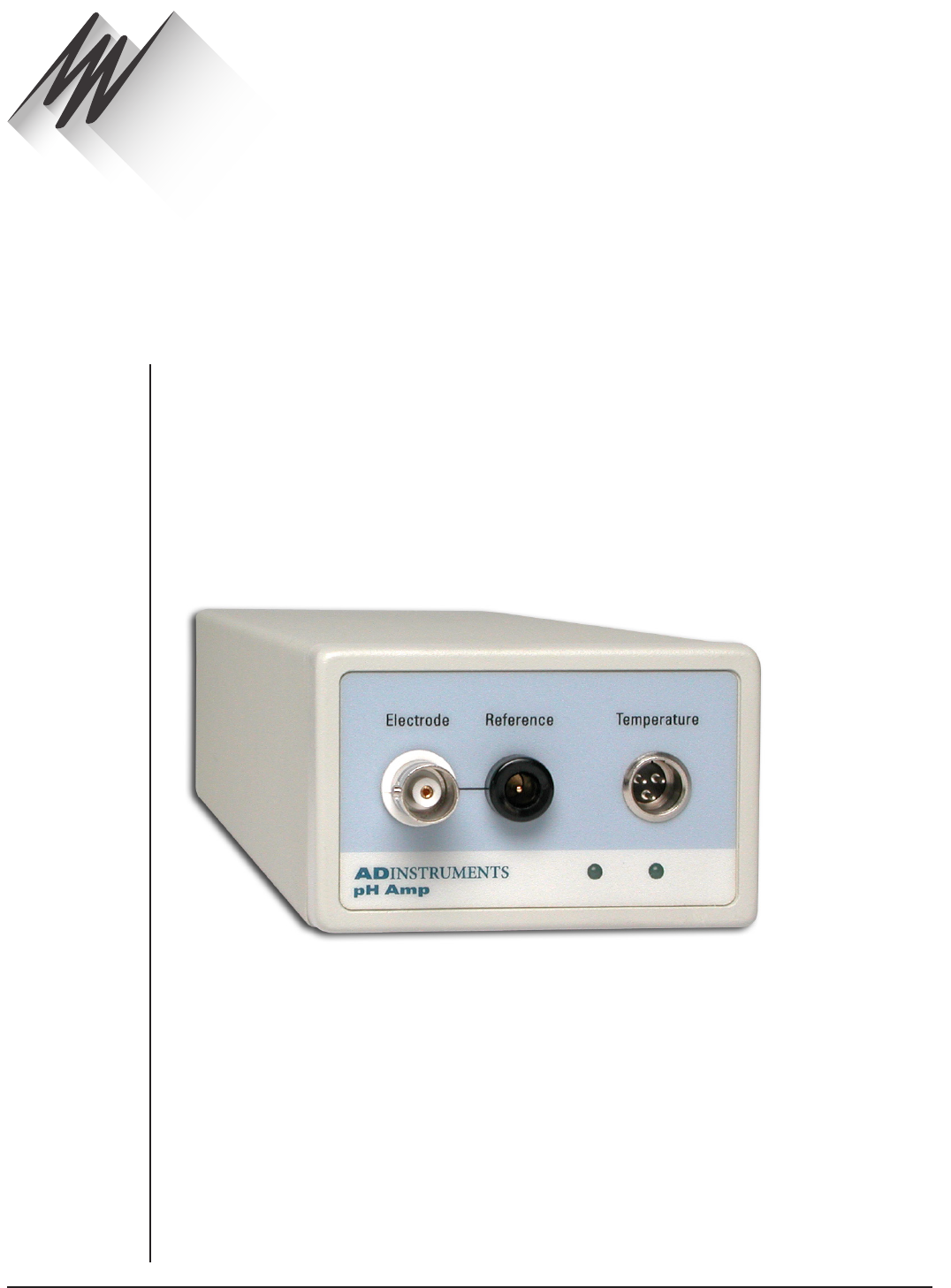
FRONT-END SIGNAL CONDITIONERS - Owner’s Guide
153
The ML165 pH Amp is one of a family of modular devices called front-ends, designed
to extend the capabilities of the PowerLab system. The pH Amp is designed to record
signals from:
•pH electrodes
•potentiometric ion selective electrodes (ISEs)
•redox (or ORP, oxidation-reduction potentiometric) electrodes
•other high impedance sources up to ±2 V requiring electrometer input.
The built-in temperature amplifier can be used to provide automatic temperature
compensation (ATC) for pH and ion selective electrodes.
pH Amp
Chapter 10
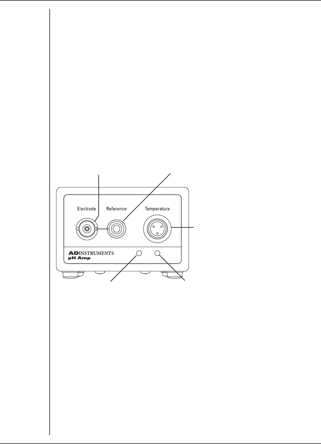
FRONT-END SIGNAL CONDITIONERS - Owner’s Guide
154
The pH Amp
The pH Amp is designed for recording signals from pH and other potentiometric
electrodes, and it operate under full soware control. It is automatically recognized
by ADInstruments soware, which controls the gain/ range, signal filtering, and other
settings.
It provides:
•a very high impedance amplifier suitable for direct connection to pH or other ion
selective electrodes;
•soware controlled filtering for the pH channel;
•reference electrode input;
•soware selectable electrode sensitivity;
•a temperature amplifier, factory configured for use with an RTD temperature
probe.
The Front Panel
Electrode input (BNC Socket)
Temperature status indicatorElectrode status indicator
Temperature probe input (3pin mini-audio socket)
Reference electrode (4 mm socket)
The Electrode and Reference Input
The BNC input connector of the pH Amp provides connection for a pH, ISE or redox
electrode. Combination electrodes, that is those with an internal reference, will only
need to be connected to this input.
Electrodes that do not have an internal reference (most ISEs and some pH electrodes)
will need to be used with a separate reference electrode. This electrode is connected via
the 4 mm Reference socket and shares the shield (ground) of the BNC electrode input
connector.
The Online Indicators
When lit, these indicate that the soware (such as LabChart or Scope) has located and
initialized the pH Amp. If the soware is on and an indicator has not lit up, check that
the pH Amp is properly connected. There are two indicators, one to show connection of
the electrode signal, and the other to show connection of the temperature signal.
Figure 10–1
The pH Amp
front panel
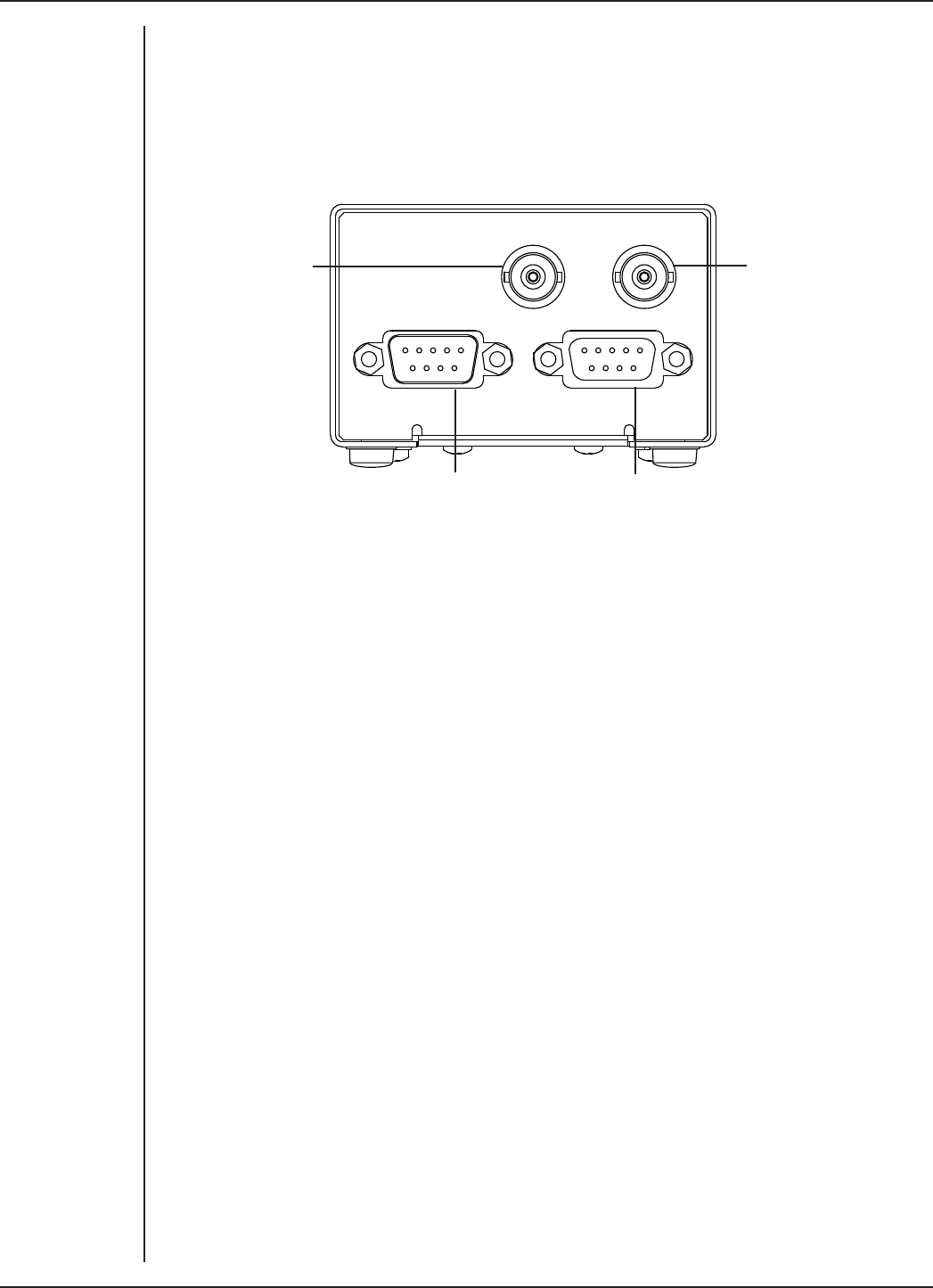
FRONT-END SIGNAL CONDITIONERS - Owner’s Guide
155
The Temperature Input
The temperature input can be used with the 100 Ω platinum resistance (RTD) probe that
is supplied with the unit.
The Back Panel
Temp Output
Output
pH Output
Input I C Bus
2
pH signal (BNC socket)Temperature signal
(BNC socket)
I2C connection to a
further front-end
I2C connection from
the PowerLab (or from
previous front-end)
The Signal Outputs
The pH Output BNC socket provides the signal of the potential at the electrode, while
the Temp Output BNC socket provides the signal of the temperature at the temperature
probe. The two signals are independent and do not have to be recorded simultaneously.
I2C Sockets
Two nine-pin sockets are used to communicate with the PowerLab (they are marked ‘I2C
Bus’: a ‘bus’ is simply information-transmission circuitry such as cable and connectors).
The Input socket connects to the PowerLab (or the output of a previous ADInstruments
front-end). This connection provides power and various control signals (such as gain
range and filter selection) to the pH Amp from the PowerLab. The Output socket
connects further front-ends to the system, in series, output to input (this is discussed in
more detail in the next section).
Connecting to the PowerLab
Always make sure that the PowerLab is turned o before you connect or disconnect the
pH Amp. Failure to do this may result in damage to the PowerLab, the pH Amp, or both.
Your pH Amp will have been supplied with an I2C cable and two BNC cables. Use the
BNC cables to connect the signal outputs on the back of the pH Amp to the signal inputs
on the front of the PowerLab. You can use the pH Output (electrode signal) and the
Temperature Output individually – you do not need to connect both signal outputs to
be able to record data.
Figure 10–2
The pH Amp
back panel
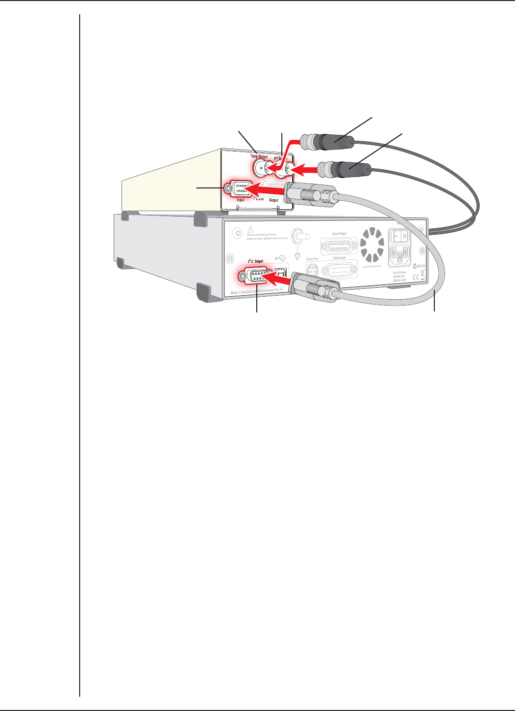
FRONT-END SIGNAL CONDITIONERS - Owner’s Guide
156
Single Front-end
Connect the I2C Output on the back of the PowerLab to the I2C Input on the back of the
pH Amp using the I2C cable provided. Figure 10–3 shows the connections between the
pH Amp and the PowerLab.
Check that all connections are firm. Loose connectors can cause erratic front-end
behavior, or may cause the front-end to fail to work at all. The BNC cable can be tucked
under the front-end to keep it out of the way, if desired.
Note: If you have an older PowerLab with dierential rather than single-ended
inputs, the BNC cables must connect to the positive analog inputs (+). ADInstruments
applications will not find the front-end on start-up if a negative input is used.
Multiple Front-ends
Multiple ADInstruments front-ends can be connected to a PowerLab. The number that
can be connected depends on the number of input channels on the PowerLab, since
each front-end signal output requires connection to an analog input channel of the
PowerLab. The initial ADInstruments front-end should be connected as shown in Figure
10–3.
The remainder are linked via I2C cables, connecting the I2C Output of the previous front-
end to the I2C Input of the next. The signal outputs of each ADInstruments front-end are
connected to a separate analog input on the PowerLab (see Figure 2–2 on page 11).
Figure 10–3
Connecting the
pH Amp front-end
to the PowerLab
Temperature
signal output
Electrode
signal output
PowerLab I2C output
pH Amp I2C input
I2C cable
BNC connectors
(to PowerLab inputs)
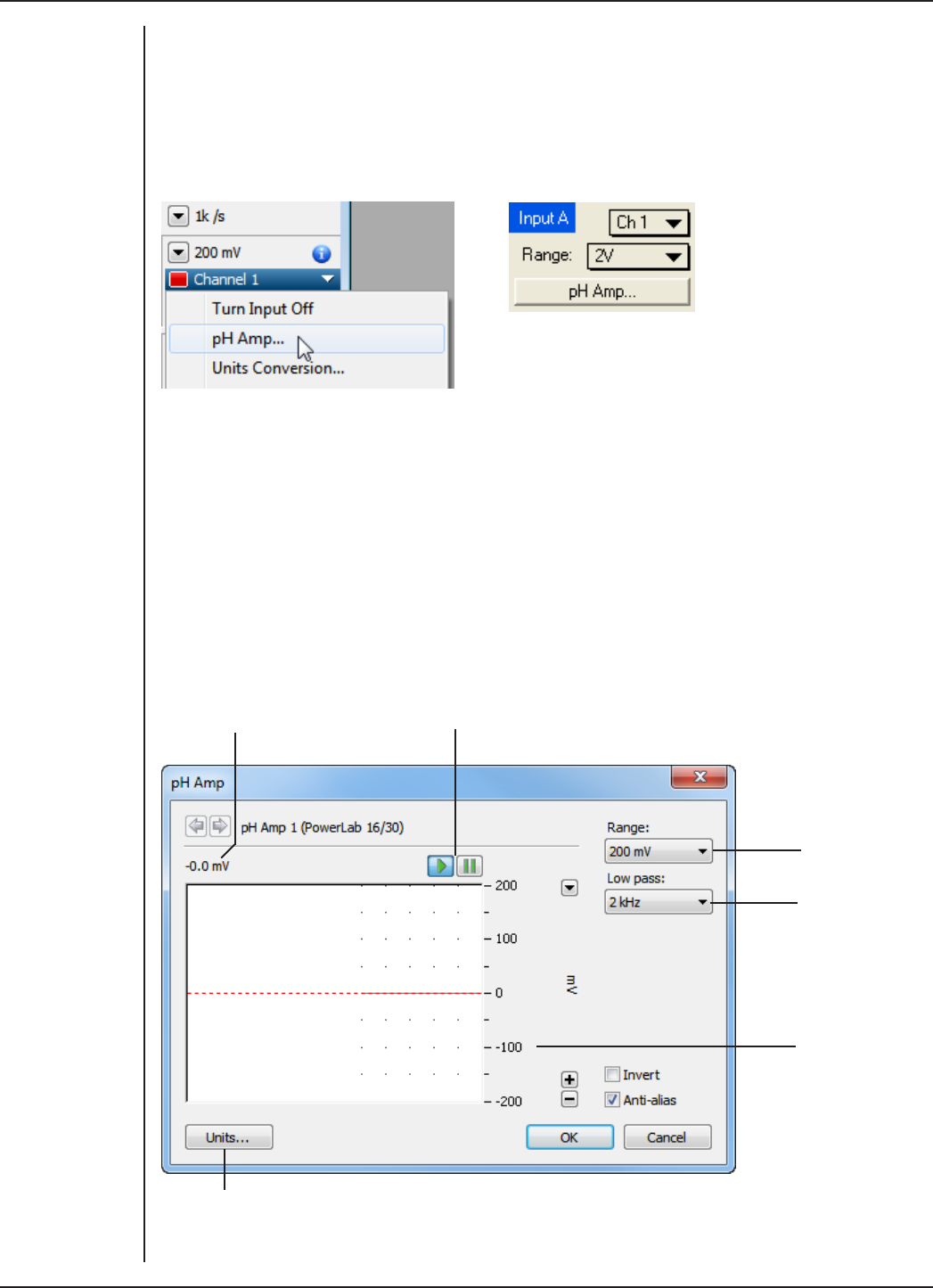
FRONT-END SIGNAL CONDITIONERS - Owner’s Guide
157
Using LabChart and Scope
When the pH Amp is properly connected to a channel, the Input Amplifier… menu
command is replaced by pH Amp… for the channel to which it is connected. In Scope,
the Input Amplifier… button in the Input A (or Input B) panel is replaced by the pH
Amp… button.
If you were expecting a connected front-end and see the Input Amplifier… text instead,
you should quit the application, turn the PowerLab o and check the connections. Then
restart the PowerLab and relaunch the application.
The pH Amp dialog
The pH Amp dialog appears when you choose the pH Amp… menu command in
LabChart (or click the pH Amp… button in Scope). This dialog allows soware control
of the various amplifiers and filters of the hardware. Change settings in the dialog, then
click OK to apply them.
Signal amplitude
Amplitude axis
Low-pass filter
pop-up menu
Range pop-up
menu
Click this button to open the Units Conversion dialog
Pause/Scroll buttons
Figure 10–4
Accessing the
pH Amp dialog:
LabChart (le),
Scope (right)
Figure 10–5
The pH Amp
dialog (LabChart
for Windows)
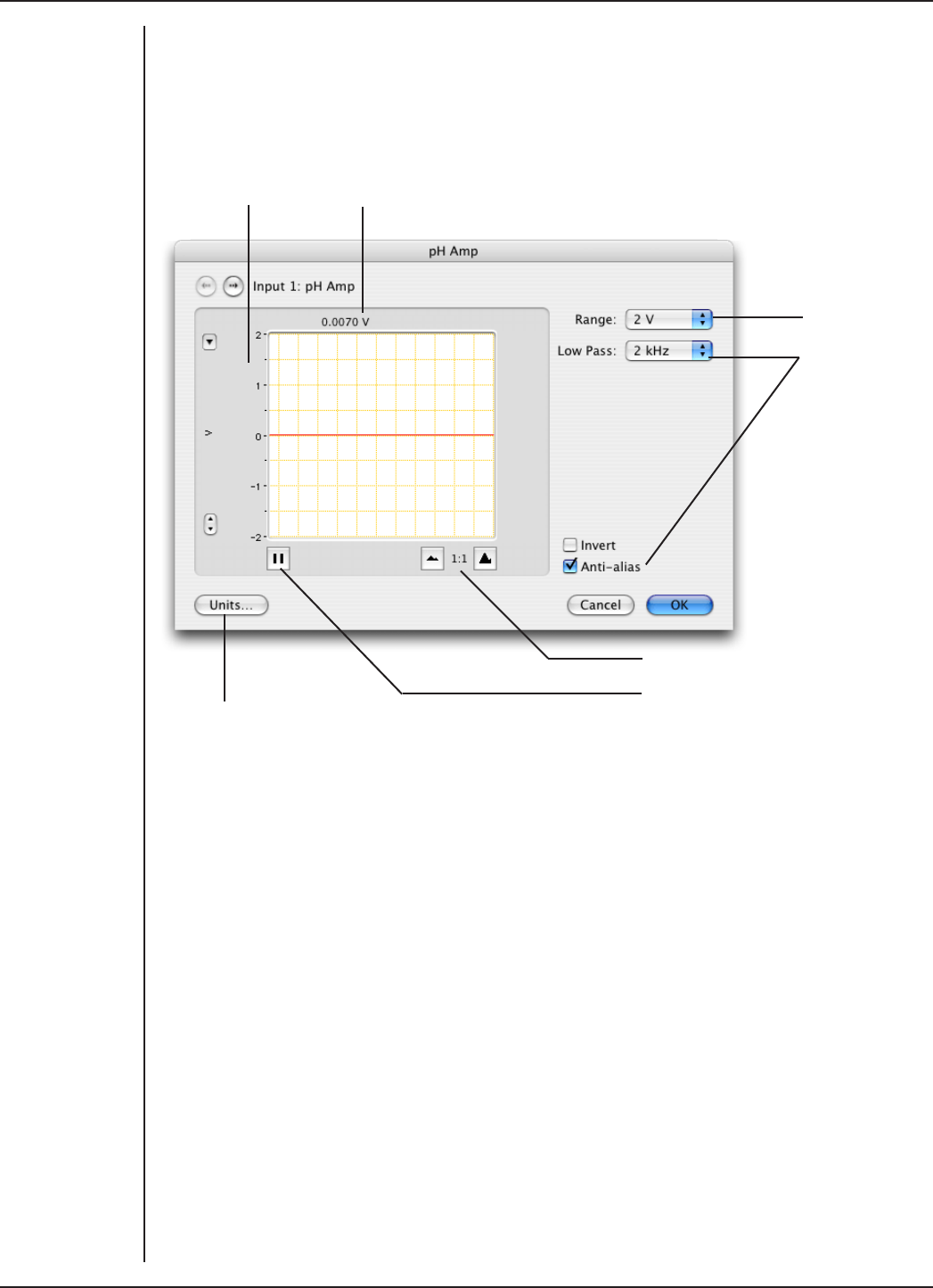
FRONT-END SIGNAL CONDITIONERS - Owner’s Guide
158
To set up many channels quickly, open the Setup > Channel Settings... dialog. Here
you can view all the channels that are turned on, and you can turn o any unnecessary
channels. Clicking on pH Amp... in the Input Settings column of the Channel Settings
dialog will also open the pH Amp dialog.
Signal amplitude
Amplitude
axis
Filter options
Range pop-up
menu
Click this button to open the Units Conversion dialog
Pause/Scroll button
Compression buttons
Signal Display
The signal at a channel’s input is displayed so that you can see the eect of changing
the settings – no data are recorded at this time. Slowly driing signals are shown quite
accurately, whereas quickly changing signals are displayed as a solid dark area showing
only the envelope (shape) of the signal from minimum and maximum values. The
average signal value is displayed at the top of the display area.
You can stop the signal scrolling by clicking the Pause button at the bottom le
(Macintosh) or top right (Windows) of the data display area. This changes to the Scroll
button on the Macintosh. Click the Scroll button to start scrolling again.
Shi and stretch the vertical Amplitude axis, by clicking and dragging it in various
ways, to make the best use of the available display area. It functions the same as the
Amplitude axis of the Chart Window, the controls are identical, and any change is also
applied to the Chart Window.
Figure 10–6
The pH Amp
dialog (LabChart
for Macintosh)

FRONT-END SIGNAL CONDITIONERS - Owner’s Guide
159
Setting the Range
The Range pop-up menu lets you select the input range or sensitivity of the channel –
the combined range of the pH Amp and PowerLab. Changing the range in the pH Amp
dialog is equivalent to changing it in the Chart or Scope window. Changes are applied
once you click OK.
At 25 °C a pH Amp range of 59 mV corresponds to a range of approximately one pH unit.
This relationship is the basis for Table 10–1, which shows the pH ranges corresponding
to pH Amp range settings.
For general pH measurements, a range of 500 mV is recommended, while the 200 mV
range is suitable for biological pH monitoring.
Range setting (mV) Resolution† (µV) Range (pH) Resolution (pH)
±500 15.6 –1.5 to 15.5* < 0.001
±200 6.25 3.6 to 10.4 < 0.001
±100 3.13 5.3 to 8.7 < 0.001
±50 1.56 6.2 to 7.8 < 0.001
±20 0.625 6.7 to 7.3 < 0.001
† Resolution is 16 bits, or 0.0015%, of range setting with LabChart and Scope
soware.
* This range will be limited by the pH electrode
Filtering
The Low pass pop-up menu gives the choice of 2 kHz, 50 Hz and 10 Hz low-pass filters.
This filter removes high frequency noise. pH and ion selective electrodes have a slow
response time, usually in the second time-scale, and the 10 Hz filter setting is suitable
for use with these electrodes.
Units
Click Units… to display the Units Conversion dialog. However, when using LabChart to
record data from pH and ion selective electrodes it is recommended that you do NOT
use Units Conversion.
For double point calibration or multiple point calibration (more than two points), you
should use the Multipoint Calibration extension. LabChart extensions are soware
additions to LabChart that provide extra functionality. All extensions are available as
free downloads from LabChart’s Feature Manager, or from the ADInstruments website.
To open Feature Manager, on Windows choose Help > Feature Manager... and on
Macintosh choose LabChart > Feature Manager.... For more information, see the
LabChart Help Center.
Table 10–1
pH Amp
range settings
corresponding to
pH ranges

FRONT-END SIGNAL CONDITIONERS - Owner’s Guide
160
Calibrating the pH Amp Electrode
Calibration of the pH electrode should be performed using the Multipoint Calibration
Extension.
The Multipoint Calibration Extension is a LabChart soware plug-in that performs
double or multiple point calibration of the pH or ion selective electrode. The resulting
calibration information is used to convert the raw voltage signal from the electrode into
appropriate units (e.g. pH, pF, pNa), which will then be displayed for that input channel.
Once installed, the extension is loaded automatically when you start LabChart. When
loaded, the Multipoint Calibration Extension adds the commands: Multipoint
Calibration (Windows) or MPCalibration… (Macintosh) to each Channel Function pop-
up menu.
The calibration is applied to the entire length of the channel. The raw signal can be
retrieved by choosing No Calculation from the Channel Function pop-up menu.
Full details on using this extension can be found in the LabChart Help Center (Windows)
or the Multipoint Calibration Guide (Macintosh), which is uploaded when the extension
soware is installed.
Setting Up the Temperature Signal
The built-in temperature amplifier can be used to provide automatic temperature
compensation (ATC) for pH and ion selective electrodes.
Choosing the Temperature… menu command in LabChart, or clicking the
Temperature… button in Scope, will open the Temperature dialog, which replaces
the Input Amplifier dialog for that channel. The Temperature dialog for LabChart for
Macintosh is shown in Figure 10–7 and the temperature Units Conversion dialog is
shown in Figure 10–8. The dialogs and controls for LabChart for Windows are similar.
Signal Display
In the Temperature dialog the input signal is displayed so that you can see the eect of
changing the settings – no data are actually recorded when setting up the Temperature
Amp. The average signal value is displayed at the top of the display area.
You can stop the signal scrolling by clicking the Pause button at the bottom le
(Macintosh) or top right (Windows) of the data display area. This changes to the Scroll
button on the Macintosh. Click the Scroll button to start scrolling again.
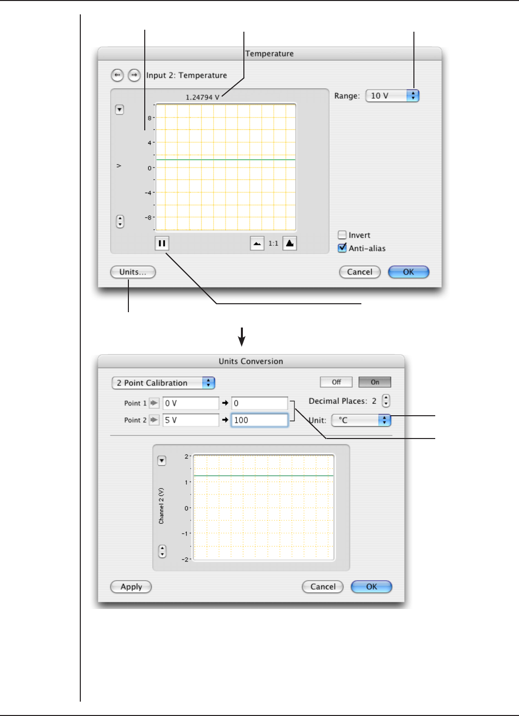
FRONT-END SIGNAL CONDITIONERS - Owner’s Guide
161
Unit pop-up
menu
The factory
settings
for the RTD
probe are:
0 V = 0 °C
5 V = 100 °C
Amplitude axis Signal amplitude Range pop-up menu
Click this to open the Units Conversion dialog
Pause/Scroll button
Setting the Range
The Range pop-up menu is used to select the input range, or sensitivity, of the
temperature measurement. The 2 V setting is suitable for temperatures up to 40 °C and
the 5 V setting is suitable for up to 100 °C.
Figure 10–7
The Temperature
dialog (LabChart
for Macintosh)
Figure 10–8
The Units
Conversion dialog
(LabChart for
Macintosh)

FRONT-END SIGNAL CONDITIONERS - Owner’s Guide
162
Inverting the Signal
The Invert checkbox changes the polarity, to invert displayed signals.
Anti-alias
Click the Anti-alias checkbox to turn anti-aliasing on and o. Aliasing occurs when a
regular signal is digitized at too low a sampling rate, causing the false appearance of
lower frequency signals. To prevent aliasing, the Anti-alias filter applies a low-pass filter
that attenuates all frequencies in the incoming signal that are greater than half the
sampling rate. For certain PowerLabs, the Anti-alias filter option is not available and an
appropriate low-pass filter can be applied to remove any unwanted signals (or noise)
occurring at frequencies greater than half the sampling rate.
Units
Click Units… to display the Units Conversion dialog, with which you can set the units
and calibrate the channel. The signal in the data display area of the Temperature dialog
is transferred to the data display area of the Units Conversion dialog – use the Pause
button if you want to capture a specific signal.
The raw temperature signal is in volts and must be converted to degrees Celsius,
Fahrenheit or Kelvin for relevant analysis. The temperature amplifier has been factory
set, for the RTD temperature probe provided with the unit, to produce 0 mV at 0 °C with
an output of 50 mV/°C. If temperature accuracy is of critical importance, you should use
two precision temperature sources to calibrate the temperature probe more accurately.
This units conversion only applies to subsequently recorded signals, so it is more limited
than choosing Units Conversion… from the Channel Function pop-up menu, as it does
not allow conversion of pre-recorded blocks of data. For more information about units
conversion, see the LabChart Help Center.
The Temperature Probe
The pH Amp is supplied with a RTD-type temperature probe with 100 Ω nominal
resistance. The factory settings of the temperature amplifier with the temperature
probe are to produce an output of 0 mV at 0 °C and 50 mV/°C (i.e. 5 V at 100 °C).
Note: Only use these values to calibrate the probe supplied with the pH Amp. You can
substitute other RTD probes for the one provided, but the factory calibration will no
longer apply, and you should use two precision temperature sources to calibrate the
probe.
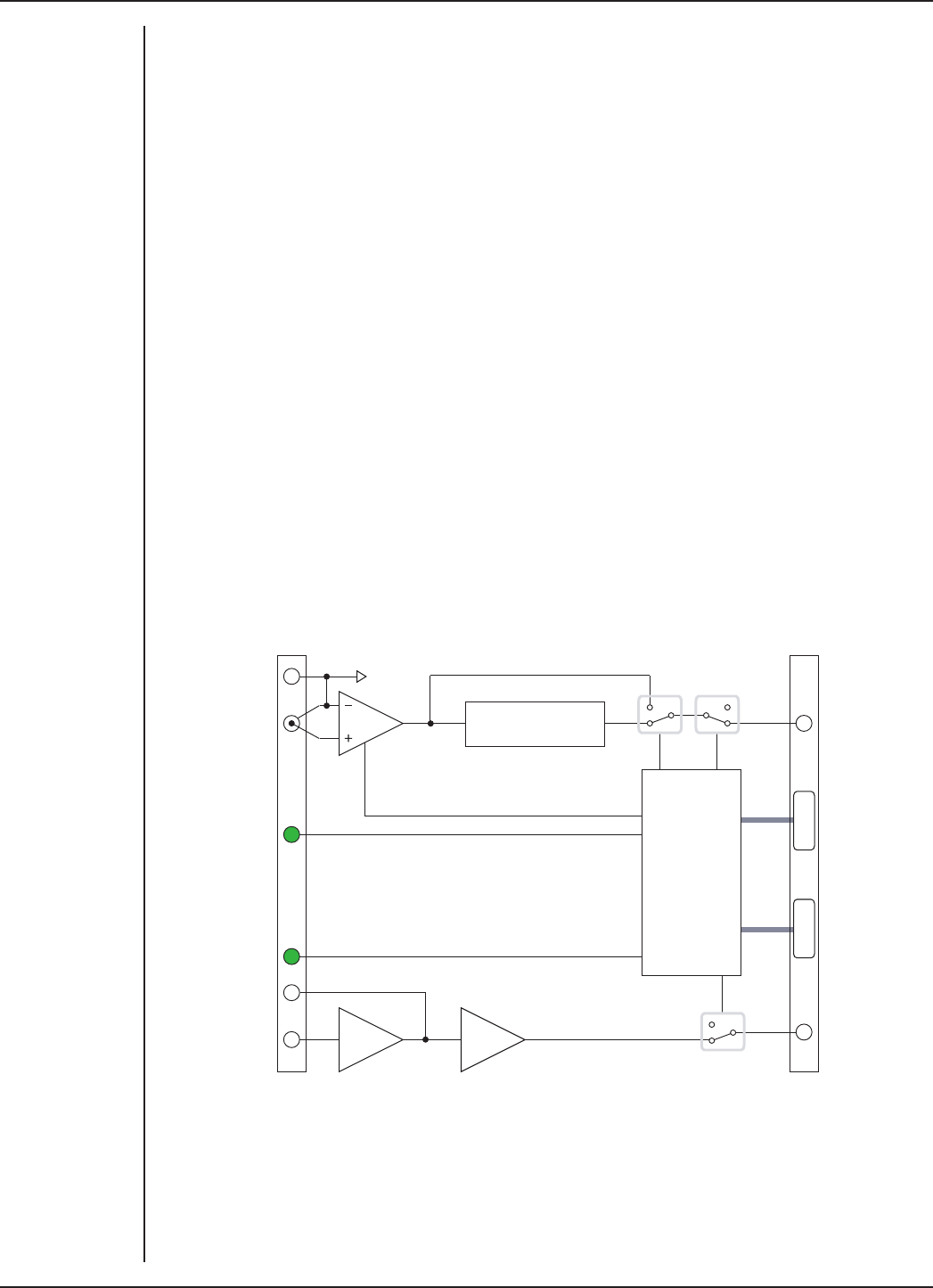
FRONT-END SIGNAL CONDITIONERS - Owner’s Guide
163
Technical Aspects
As with other PowerLab front-ends, all internal functions of the pH Amp are
controlled from the PowerLab by sending information on a special communications
connection called the I2C (eye-squared-sea) bus. This connection supplies power to
the ADInstruments front-end as well. ADInstruments front-ends are connected to the
analog inputs of the PowerLab via BNC-to-BNC cables, through which the amplified
and filtered signal is sent to the PowerLab. The overall operation of the pH Amp can be
better understood by referring to Figure 10–9.
The pH input amplifier of the pH Amp is an electrometer type amplifier with extremely
high input impedance. The input also has provision for connecting a reference electrode
to the analog ground of the amplifier. The input amplifier gain can be set by the soware
to 1 or 10, depending on the required sensitivity. The output of the electrometer
amplifier is fed to a 2 pole, 10 Hz low-pass filter which is soware selectable. The output
is then fed to the PowerLab for further amplification and filtering.
The temperature amplifier is eectively a separate ADInstruments front-end. It consists
of a bridge circuit that is factory configured for use with RTD temperature probes.
The pH Amp comes supplied with an RTD temperature probe. The output from the
temperature amplifier has been factory set with the supplied RTD probe to produce 0–5
V over 0–100°C.
I2C interface
Low-pass filter
Reference input
Electrode online
indicator
Temperature online
indicator
RTD input
Electrode Input
I2C Output
I2C Input
Temperature signal
output
Electrode signal
output
Figure 10–9
Block diagram of
the pH Amp

FRONT-END SIGNAL CONDITIONERS - Owner’s Guide
164
Troubleshooting
If you experience any diiculty with the pH Amp use this section to try to resolve the
problem. In the majority of cases, the problem can usually be fixed by ensuring that the
connecting cables are correctly connected and firmly attached and then re-starting the
LabChart or Scope soware.
If the solutions here do not work, earlier chapters, the LabChart Help Center, and the
guide to your PowerLab may contain possible solutions. If none of the solutions here or
elsewhere are of help, then consult your ADInstruments representative.
The online indicator fails to light when LabChart or Scope is opened
•If the PowerLab is o check switches and power connections.
•The BNC to BNC cable from the pH Amp or the temperature output to the analog
input channel of the PowerLab may not be properly connected. Check that the
cable is firmly connected to the BNC connector on the back panel of the pH Amp
and to a BNC input on the front panel of the PowerLab.
Either or both online indicators fail to light when the application is opened, and the pH
Amp is not accessible from LabChart or Scope
•The I2C cable from the pH Amp to the PowerLab may not be properly connected.
Check to see that the I2C cables are firmly seated and screwed in.
•Try new cables to check that the BNC and/or I2C cables are working correctly
•If you have tried the above suggestions and still cannot get the pH Amp to work
properly, then try using it on another PowerLab if you have access to one. If the
online indicators still fail to light on the second PowerLab, the unit may be faulty
and should be returned for repair.

FRONT-END SIGNAL CONDITIONERS - Owner’s Guide
165
Specifications
pH Amplifier
pH amplifier: High impedance, electrometer type.
Input ranges: ± 200 µV to ± 2 V full scale in 13 steps (combined
PowerLab and pH Amp)
Input resolution: 16 bits, 0.0015% of range
Input impedance: 1013 Ω typical
Amplifier noise: < 1 µVrms (< 4 µV p–p) with a bandwidth of DC–10 Hz
Maximum Input: ±10 V
Input connection type: Insulated BNC
Low pass filter: 10 Hz (-3 dB frequency)
Low pass filter accuracy: ±3.0%
Low pass filter type: Bessel (2 pole)
Temperature Amplifier
Temperature probe type: RTD – 100 Ω type (supplied with unit)
Temperature range: ±100°C
Temperature accuracy: ±0.2°C
Amplifier output: 0 V @ 0°C, 50 mV/°C (factory set)
Output ranges: Range Temperature °C Resolution °C
±10 V ±200 0.1
±5 V ±100 0.05
±2 V ±40 0.02
±1 V ±20 0.01
±500 mV ±10 0.01
Input connection: 3 pin mini–audio jack
Control Port
I2C input and output: Male and female DB–9 pin connectors. Provides control
and power.
Power requirements: ±17 V DC
+8 V DC
~3 W

FRONT-END SIGNAL CONDITIONERS - Owner’s Guide
166
Physical Configuration
Dimensions (h × w × d): 50 mm × 76 mm × 260 mm (1.97" × 3.0" × 10.2")
Weight: 0.8 kg (1.8 lb)
Operating conditions: 5–35 °C
0–90% humidity (non–condensing)
ADInstruments reserves the right to alter these specifications at any time.
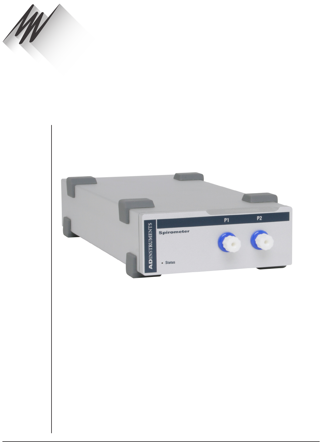
FRONT-END SIGNAL CONDITIONERS - Owner’s Guide
167
The FE141 Spirometer is a modular device, in a family called front-ends, designed
to extend the capabilities of the PowerLab system. The Spirometer is a precision
dierential pressure transducer for measurement of respiratory variables.
The Spirometer is essentially an extension of the PowerLab’s analog input. The
Spirometer provides:
•a precision dierential pressure input used to determine flow rates using an
attached flow head;
•the additional amplification necessary to deal with a variety of flow rates, from
fractions of a liter per minute (mice and rats) to a thousand liters per minute
(adult humans during exercise);
•additional programmable filtering to remove unwanted signal frequencies; and
•digitally controlled zeroing circuitry, for oset removal of unwanted constant
flow rates, for instance, to measure volume accurately when using computed
integration.
Spirometer
Chapter 11
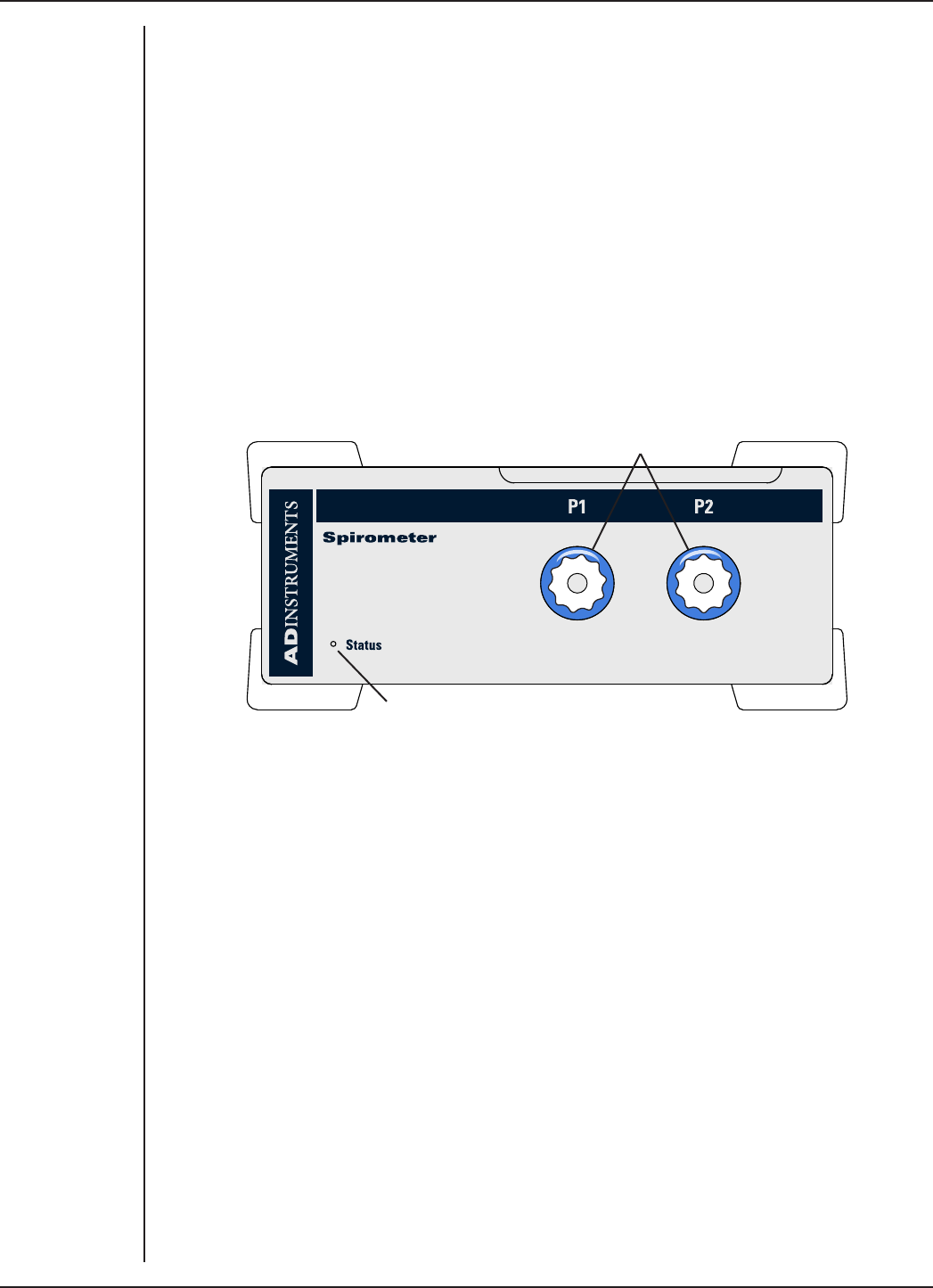
FRONT-END SIGNAL CONDITIONERS - Owner’s Guide
168
The Spirometer
The Spirometer [FE141] is a precision dierential pressure transducer for measuring
respiratory variables such as inspiration and expiration flows, hence allowing the
calculation of tidal volumes. It measures dierential pressure across fine gauze mounted
in a flow head. With a flow head of a suitable size, the Spirometer can be used with a
variety of creatures, from small animals such as mice and rats, to large animals and
humans. Accessories such as flow heads (various sizes), tubing, and calibration syringes
are available and can be purchased separately.
The rest of this chapter contains general information about the features, connections,
and indicators of the Spirometer. It also looks at the flow head and its calibration for
spirometry. More detailed information can be found in the technical section.
The Front Panel
Female Luer fittings
Status Indicator
The Status Indicator
When an ADInstruments program such as LabChart starts up, the Status indicator light
should flash briefly and then remain green, indicating that the program has found the
front-end, checked and selected it, and is ready to use it. If it does not turn on and stay
on when the program is run, this indicates either that the front-end is not connected
properly or that there is a soware or hardware problem.
The Spirometer Input Fittings
Connections are made to the Spirometer using two female Luer fittings on the front
panel. These are physical connections for airflow, not electrical ones. Two flexible
plastic tubes (3 mm internal diameter, 5 mm external diameter) connect the female
Luer fittings on the Spirometer to the connection pipes on the flow head. The female
Luer fittings carry a warning symbol (see margin).
Figure 11–1
The front panel of
the Spirometer
WARNING
The Spirometer
input is sensitive.
Do not blow
into or apply
high air flows to
the Spirometer
input, as this
may damage
the internal
transducer
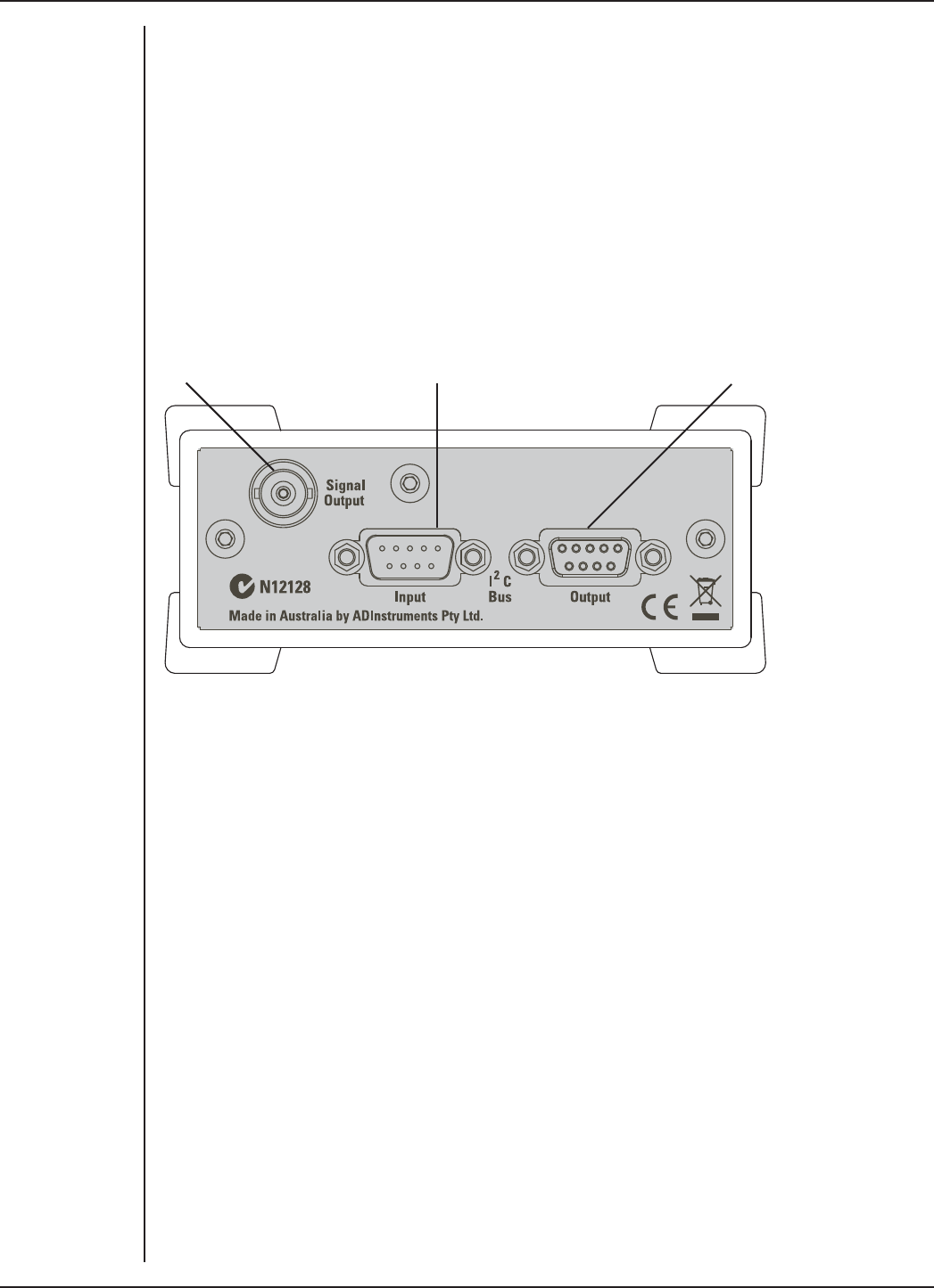
FRONT-END SIGNAL CONDITIONERS - Owner’s Guide
169
The Back Panel
I2C Input and Output Sockets
Two nine-pin sockets are used to communicate with the PowerLab (they are marked ‘I2C
Bus’: a ‘bus’ is simply information-transmission circuitry such as cables and connectors).
These sockets, in conjunction with the proper cables, allow multiple front-ends to be
used independently with one PowerLab. Power and control signals to connected front-
ends come from the PowerLab. ADInstruments front-ends are connected to each other
in series, output to input (discussed in more detail in the next chapter).
Signal Output
to PowerLab
I2C connection
to PowerLab
I2C connection to
other front-ends
The Analog Out Socket
The Signal Output provides the signal to an analog input socket on the front of
the PowerLab. A BNC-to-BNC cable is supplied for this connection. If you are using
a PowerLab with dierential inputs, only connect the cable to a positive input.
ADInstruments applications will not find the front-end on start up if a negative input is
used.
Connecting to the PowerLab
To connect a front-end to the PowerLab, first ensure that the PowerLab is turned o.
Failure to do this may damage the PowerLab, the front-end, or both.
Connect the Signal Output on the rear panel of the Spirometer to an analog input on the
front panel of the PowerLab using a BNC cable.
Single Front-ends
Connect the I2C output of the PowerLab to the I2C input of the front-end using the I2C
cable provided.
Figure 11–2
The back panel of
the Spirometer
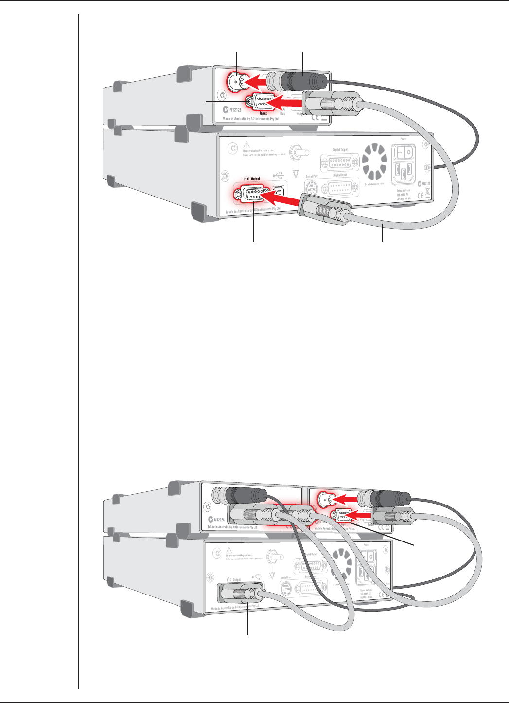
FRONT-END SIGNAL CONDITIONERS - Owner’s Guide
170
Check that the plugs for the I2C bus are screwed in firmly. Check the BNC cable for firm
connections as well. Loose connectors can cause erratic front-end behavior, or may
cause the front-end to fail to work at all. The BNC cable can be tucked under the front-
end to keep it out of the way if desired.
Multiple Front-ends
Multiple front-ends can be connected up to a PowerLab; up to sixteen, depending on
the number of positive inputs sockets on the PowerLab. The first front-end is connected
with the I2C cable as in Figure 11–3. The remainder are daisy-chained via I2C cables,
connecting the I2C Output of the previous connected front-end to the I2C Input of the
next front-end to be added (Figure 11–4). The BNC cable for each front-end is connected
to one of the analog inputs of the PowerLab.
Figure 11–3
Connecting
Spirometer
front-end to the
PowerLab
Spirometer Signal Output
Spirometer I2C input
PowerLab I2C output I2C connector cable
BNC connector cable
Figure 11–4
Connecting
multiple front-
ends to the
PowerLab
Second I2C cable connected to
Front-end I2C output
Second
Front-end
I2C input
First I2C cable connected
to PowerLab I2C output
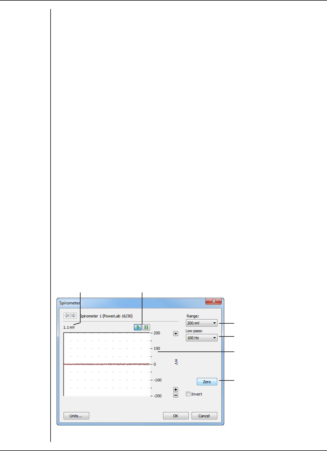
FRONT-END SIGNAL CONDITIONERS - Owner’s Guide
171
Using LabChart and Scope
Front-ends are used with PowerLabs and ADInstruments programs such as LabChart,
LabTutor and Scope. The combined amplification and filtering of the Spirometer, the
PowerLab and the program are presented as a single set of soware controls.
When the Spirometer is connected to a channel and successfully installed, the Input
Amplifier… menu command from the Channel Function pop-up menu in LabChart is
replaced by the Spirometer… menu command. In Scope, the Input Amplifier… button
in the Input A (or Input B) panel is replaced by the Spirometer… button. The LabChart
Help Center and Scope User’s Guide have details on the Input Amplifier dialog, and
explain some of the soware terms used here.
If the application fails to find a front-end attached, the normal text remains. If you were
expecting a connected front-end, close the program, turn the PowerLab o and check
the connections. Then turn on the PowerLab and restart the program.
Choosing the Spirometer… menu command (or clicking the button in Scope) will open
the Spirometer dialog. Only the Spirometer dialog for LabChart is described here, but
the Spirometer dialog for Scope is similar.
The Spirometer dialog
The Spirometer dialog allows soware control of the combined filters and other circuitry
in the PowerLab and Spirometer. Change settings in the dialog, then click OK to apply
them.
To set up many channels quickly, open the Setup > Channel Settings... dialog. Here
you can view all the channels that are turned on, and you can turn o any unnecessary
channels. Clicking on Spirometer... in the Input Settings column of the Channel Settings
dialog will also open the Spirometer dialog.
Range options
Signal amplitude Pause/Scroll buttons
Filter options
Amplitude axis
Click this to
remove the
offset for the
spirometer
Figure 11–5
The Spirometer
dialog

FRONT-END SIGNAL CONDITIONERS - Owner’s Guide
172
Signal Display
The signal at the channel input is displayed so you can see the eects of changing
settings – data is not recorded while setting things up. The average signal value is
displayed at the top of the display area: the oset is displayed when the Spirometer is
not zeroed, and may indicate a problem if it is large.
You can stop the signal scrolling by clicking the Pause button at the bottom le
(Macintosh) or top right (Windows) of the data display area. This changes to the Scroll
button on the Macintosh. Click the Scroll button to start scrolling again.
You can shi and stretch the vertical Amplitude axis by clicking and dragging it in
various ways, to make the best use of the available display area. It functions in the same
as the Amplitude axis of the Chart Window – the controls are identical and any change is
applied to the Chart Window.
Setting the Range
The Range pop-up menu lets you select the input range or sensitivity of the channel.
Changing the range in the Spirometer dialog is equivalent to changing it in the Chart or
Scope window. The available ranges are 500 mV, 200 mV, 100 mV, 50 mV and 20 mV. The
default range is 200 mV.
Filtering
The Low Pass pop-up menu gives a choice of 1, 10 and 100 Hz low-pass filters. These
filters are appropriate for the built-in pressure transducer in the Spirometer and help to
eliminate high-frequency components, such as noise, from the input signal.
Inverting the Signal
Click the Invert checkbox to invert the signal displayed on screen. It provides a simple
way to change the polarity of the recorded signal without having to swap the tubes on
the Spirometer or flow head. For example, you might be recording an experiment where
expiration gives a positive signal, but you want the expired air to give a negative signal
on the screen. The Invert checkbox would change the display.
Zeroing
The Spirometer is eectively a pressure transducer and amplifier, transducing flow
into voltage. Transducers almost always produce some amount of signal, usually small,
when at equilibrium or rest. Prior to making a recording, osets need to be removed,
in a process called zeroing. This enables more accurate measurement of the changes in
the signal under stimulus.
Before zeroing, the signal value above the display area shows this oset – if it is large, it
may indicate a problem. To perform automatic zeroing, click Zero. The program works
out a corrective DC voltage that cancels, as closely as possible, the transducer output
voltage. Auto-zeroing takes a few seconds to work out the best zeroing value at all
ranges.
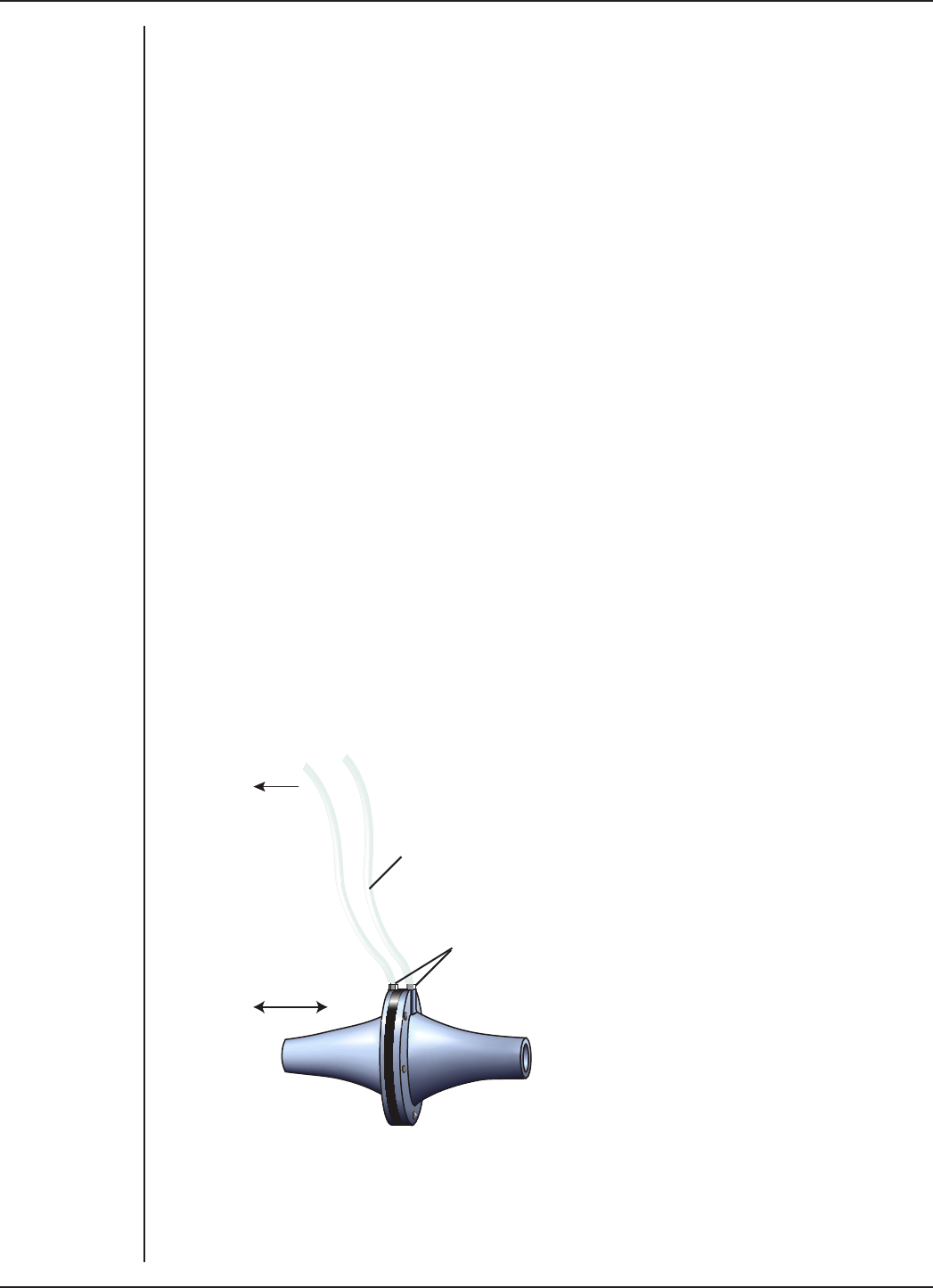
FRONT-END SIGNAL CONDITIONERS - Owner’s Guide
173
Note: Variations in the transducer signal during the auto-zeroing operation will cause
the soware to fail to zero the oset properly. Make sure the Spirometer and flow head
are kept still and that there is no airflow during the auto-zeroing.
Units
Click Units… to open the Units Conversion dialog, with which you can set the units for
a channel and, using waveform measurements, calibrate the channel. The waveform in
the data display area of the Spirometer dialog is transferred to the data display area of
the Units Conversion dialog. (Use the Pause button to capture a specific signal.) This
units conversion only applies to subsequently recorded signals, so it is more limited
than choosing Units Conversion… from the Channel Function pop-up menu, as it does
not allow the conversion of previously recorded data.
Using the Spirometer
The ADInstruments Spirometer and attached flow head together function as a
pneumotachometer, with an output signal proportional to the airflow during breathing.
Airflow is measured by means of a pressure dierential across a fine wire mesh inside
the flow head. This works on the principle that air flowing through an orifice of fixed
cross-section produces a pressure dierence across the mesh proportional to the air’s
velocity – within certain limits. The greater the velocity of the air (that is, the higher the
flow), the larger the pressure dierence.
The flow head itself contains no electronic parts, and is simply a tube with a wire mesh
placed across it. Two pipes, one on either side of the mesh, allow the pressure dierence
to be measured by a high-precision dierential pressure transducer in the Spirometer
itself, when connected with plastic tubing.
To Spirometer
Plastic tubing
Apply airflow
Flow head pipes
The Spirometer can support several sizes of flow head, each with diering maximum
flows, but all with the same connection to the Spirometer. Standard flow heads,
obtainable separately, are:
Figure 11–6
A flow head, with
the tubing in the
correct, upright
position
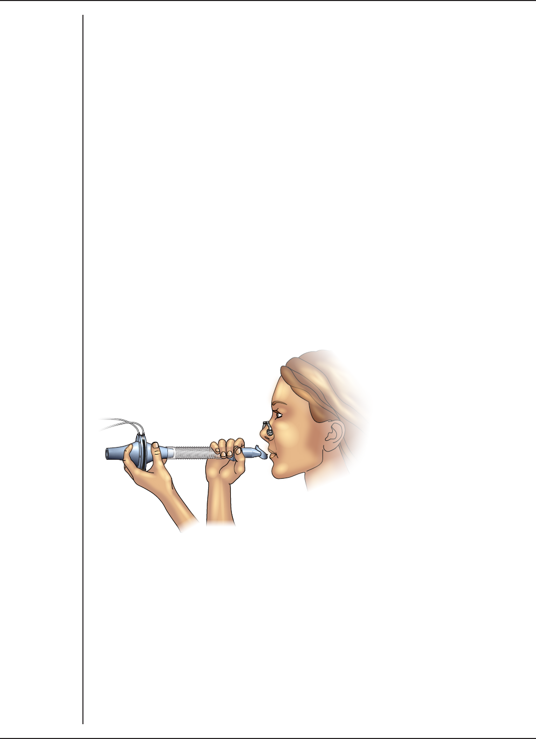
FRONT-END SIGNAL CONDITIONERS - Owner’s Guide
174
•MLT1L Respiratory Flow Head, 1 L/min, suitable for mice
•MLT10L Respiratory Flow Head, 10 L/min, suitable for rats
•MLT300L Respiratory Flow Head, 300 L/min, suitable for adult humans at rest
•MLT3813H Heated Pneumotach, 800 L/min, suitable for adult humans during
exercise
•MLT1000L Respiratory Flow Head, 1000 L/min, suitable for adult humans during
exercise.
Fitting the Flow Head
To connect the flow head to the Spirometer, simply push the ends of the two connection
tubes firmly over the flow head pipes and over the female Luer fittings on the front panel
of the Spirometer. In some cases you may find that the tubes are diicult to fit because
they are too tight. If so, dip the ends of the tubes into some boiling water to soen the
plastic to make it easier to push the tubes onto the pipes.
Any leakage from the connections will aect the precision of the flow readings, so
ensure that the tubes are pushed in firmly. The flow head is washable and can be cold-
sterilized, and should be dried gently before use. Care should be taken to ensure that
condensation does not block the tubing connecting the flow head to the Spirometer. To
avoid problems, the flow head should be turned so that the tubing connects at the top,
not at the bottom.
More elaborate setups are possible. For human respiration, disposable mouthpieces
and filters are widely used, to prevent contamination between subjects and to minimize
dri due to moisture (the filter helps remove droplets). For humans during exercise, the
flow head could be fixed in position, perhaps attached to a stand, and connected to
a mouthpiece and filter by a length of wide-bore flexible tubing, to allow the subject
to exercise freely. To obtain useful results with any method of spirometry, all the air
breathed by the subject must be measured. A nose clip prevents inadvertent nasal
breathing. With a little practice, the subject can prevent air leaks around the mouthpiece.
ADInstruments supplies suitable accessories separately:
•MLA140 Spirometer kit (containing each item below)
•MLA1026 Pack of 10 vinyl disposable mouthpieces
Figure 11–7
Flow head setup
for measuring
human respiration

FRONT-END SIGNAL CONDITIONERS - Owner’s Guide
175
•MLA1008 Pack of 50 foam-tipped disposable nose clips
•MLA304 Pack of 50 disposable droplet filters
•MLA1011A Clean bore tubing, 250 mm long by 35 mm i.d.
Calibrating the Flow Head
Before using the flow head, you will probably want to calibrate the Spirometer to read in
terms of flow (L/s rather than V). There are two ways of doing this: using an approximate
conversion factor, or injecting a known volume and integrating. The Spirometry
Extension for LabChart, which is available as a free download for both Windows and
Macintosh, can be used to assist with either of these methods.
Extensions are available from LabChart’s Feature Manager, or from the ADInstruments
website. To open Feature Manager, on Windows choose Help > Feature Manager... and
on Macintosh choose LabChart > Feature Manager.... For more information, see the
LabChart Help Center.
Using an approximate conversion factor
You can use an approximate conversion value for converting the voltage signal to L/s.
For the MLT1000L Flow Head, the linear conversion is given approximately by 0 V = 0 L/s;
1 V = 40.1 L/s. You apply this conversion in the Units Conversion dialog, opened from the
Channel Function pop-up menu.
Injecting a known volume and integrating
You can determine an accurate conversion value for your particular flow head by
injecting a known volume of air through the breathing circuit and integrating the flow
signal in LabChart. This section describes the procedure in detail.
ADInstruments has calibration syringes available for this purpose, such as the a 3-liter
MLA5530 calibration syringe. Try to depress the plunger at a steady rate, neither too
quickly or too slowly, and try not to bring the plunger to an abrupt stop at the end of the
syringe.
Connect the Spirometer to an input on the PowerLab. Set up that input channel using
the Channel Settings dialog:
1. Change the channel name to ‘Flow’.
2. Click Spirometer… in the Input Settings column to display the Spirometer
dialog.
3. Set the range to a suitable value, such as 500 mV or 200 mV.
4. Click Zero to zero the flow head signal. You should always do this before you
start a recording.
5. Set up a new channel called ‘Volume’ in the Channel Settings dialog. To display
the integral of the flow signal in this channel, choose Integral… from the
Channel Function pop-up menu. In the Integral dialog, select Flow as the source
channel, and use a standard integral with no reset.
Injections can now be recorded and integrated using the spirometer (Flow) and Volume
channels. Making a single injection should produce a trace similar to that shown in
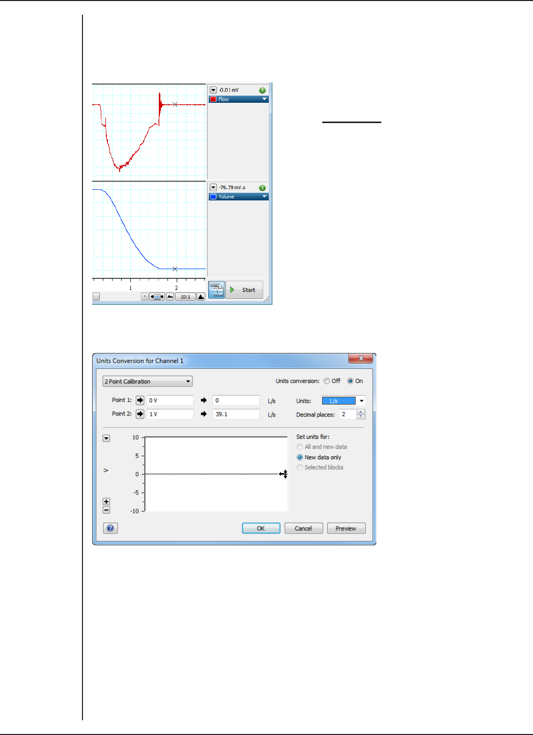
FRONT-END SIGNAL CONDITIONERS - Owner’s Guide
176
Figure 11–8, in which a 3 L calibration syringe was used to simulate a single expiration.
The absolute value of the integral at the cursor position is 76.79 mV.s. This corresponds
to a flow head correction factor of 39.1 L/s/V, obtained by dividing the syringe volume
by the integral value (converted to V.s).
3 L
0.07679 V.s = 39.1 L/s/V
The correction factor is applied in the Units Conversion dialog: (0 V = 0 L/s; 1 V = 39.1 L/s).
Click OK to apply the units conversion and close the dialog.
Using the Spirometry Extension
The Spirometry Extension for LabChart (for either the Windows or Macintosh platforms)
is available as a free download using Feature Manager in LabChart, or from the
ADInstruments website.
The Spirometry Extension can be used to perform the units conversion required for the
Spirometer channel, by using either an appropriate conversion value for your flow head,
or a value calculated by integrating the injection of a known volume. The extension adds
an item called Spirometry Flow... to the Channel Function pop-up menu.
Figure 11–8
The flow signal
integrated for a
single injection.
The value of the
integral at the
cursor position is
−76.79 mV.s
Figure 11–9
Setting units
to calibrate
the Spirometer
Channel

FRONT-END SIGNAL CONDITIONERS - Owner’s Guide
177
Full details on using the Spirometry Extension can be found in the Spirometry Extension
User’s Guide (Macintosh), or in the LabChart Help Center (Windows), both of which are
installed with the soware.
Reducing Dri
The Spirometer is subject to dri for various reasons. There are a number of ways to
reduce this. Zeroing the Spirometer immediately before use is an essential step in the
setup procedure. Zeroing ensures that the recorded flow signal is zero when there is no
airflow, and thereby prevents steady dri of the integrated volume trace.
•Internal dri in the Spirometer’s electronics is minimized if you leave the
PowerLab unit and Spirometer turned on for 15 minutes or so, before zeroing
and use. We recommend placing the Spirometer beside the PowerLab unit, or on
a shelf above, to avoid its being aected by heat from the power supply.
•Expired volume is greater than inspired volume in most atmospheric conditions.
The increase, due to warming and humidification, is typically 5–10%. For this
reason there may be ‘breath-dependent dri’ of an integrated (volume) trace
even when the Spirometer is correctly zeroed. Non-ideal distribution of air flow
across the flow head’s mesh screen may also contribute to breath-dependent
dri. This component of dri is minimized by use of disposable droplet filters.
•Finally, if you are using the Spirometry Extension, you can apply dri correction
aer recording, provided that your recording meets certain conditions.
For more details on dri correction, please refer to the Spirometry Extension User’s Guide
(Macintosh) and the LabChart Help Center (Windows).
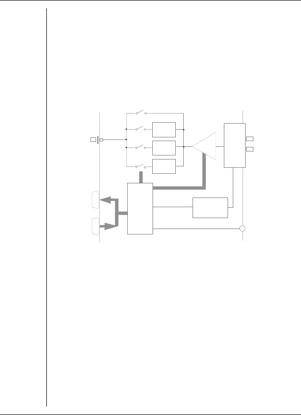
FRONT-END SIGNAL CONDITIONERS - Owner’s Guide
178
Technical Aspects
The Spirometer and other ADInstruments front-ends have been designed to integrate
fully into the PowerLab system. Each requires connection to the PowerLab via a special
communications connector called the I2C (eye-squared-sea) bus, and a BNC connector.
The internal functions of the Spirometer are controlled from the PowerLab through the
I2C bus, which also supplies power to the Spirometer. The front-end is also connected
to an analog input channel of the PowerLab via a BNC-to-BNC cable, through which the
pressure signal from the flow head is sent. The overall operation of the Spirometer can
be better understood by referring to Figure 11–10.
Pressure
Inputs
I2C
Control
Interface
+
Power
Supply
I2C
Input
I2C
Output
Pressure
Transducer
Voltage
Reference
1 Hz
10 Hz
100 Hz
Gain
Low-pass Filters
Status
Indicator
Signal
Output
The Spirometer and an attached flow head together function as a pneumotachometer,
with an output signal proportional to the airflow rate during breathing. Expired or
inspired air has to pass through a very fine wire mesh in the attached flow head. This
creates a pressure dierential between the two sides of the mesh proportional to the
flow rate or velocity of the air passing through the flow head. The input of the Spirometer
is a dierential pressure transducer that converts the dierential pressure in the flow
head into an analogous voltage. This output voltage is in turn fed into a programmable
gain amplifier, which provides additional signal amplification. The output of the
amplifier is passed through a set of soware-selectable, fourth-order, low-pass filters.
The signal is then sent to the PowerLab.
To remove any osets caused by its pressure transducer or a signal baseline, the
Spirometer uses a DC oset circuit consisting of a 12-bit DAC (digital-to-analog
converter) that is internally connected to the input stage when in the DC coupling mode.
Zeroing of osets is achieved by applying a corrective DC voltage to the input stage via
the DAC, under soware control. Since the DAC is only capable of producing corrective
voltages in ‘steps’, a facility to set the oset range is provided to decrease the size of
these steps and make the zeroing circuit more sensitive, especially at the higher range
settings.
Figure 11–10
Block diagram of
the Spirometer

FRONT-END SIGNAL CONDITIONERS - Owner’s Guide
179
Troubleshooting
If the solutions here do not work, earlier chapters, the LabChart Help Center, and the
guide to your PowerLab may contain possible solutions. If none of the solutions here or
elsewhere are of help, then consult your ADInstruments representative.
Most of the problems that users encounter are connection problems, and can usually be
fixed by checking connections and starting up the hardware and soware again. Very
rarely will there be an actual problem with the Spirometer front-end or the PowerLab
itself.
Problems and Solutions
The status indicators fail to light when the soware is started, or the front-end commands
and so on do not appear where they should
The I2C cable or the BNC-to-BNC cable from the front-end to the PowerLab is not
connected, has been connected incorrectly (to the wrong input or output, for instance),
or is loose.
•Turn everything o. Check to see that all cables are firmly seated and screwed in.
The BNC cable from the Signal Output of the Spirometer must be connected to
a positive input on the PowerLab. Make sure the input is the same channel from
which you expect to use the front-end in the soware. Start up again to see if this
has fixed the problem.
You are using an early version of LabChart or Scope.
•Upgrade to the latest version of the soware. Contact your ADInstruments
representative for information.
The BNC or I2C cable is faulty.
•Replace the cable and try again. Immediately label all cables proved faulty so
that you don’t use them again by accident.
The front-end is faulty.
•This is the least likely event. If the front-end will not work properly aer the
previous measures, then try using it on another PowerLab. If the same problems
recur with a second PowerLab, the front-end may be faulty. Contact your
ADInstruments representative to arrange for repairs.
On starting up the soware, an alert indicates that there is a problem with the front-end or
driver
The correct Bridge driver is not installed on your computer.
•Reinstall the soware.
You are using an early version of LabChart or Scope.
•Upgrade to the latest version of the soware. Contact your ADInstruments
representative for information.
The BNC or I2C cable is faulty.

FRONT-END SIGNAL CONDITIONERS - Owner’s Guide
180
•Replace the cable and try again. Immediately label all cables proved faulty so
that you don’t use them again by accident.
The front-end is faulty.
•This is the least likely event. If the front-end will not work properly aer the
previous measures, then try using it on another PowerLab. If the same problems
recur with a second PowerLab, the front-end may be faulty. Contact your
ADInstruments representative to arrange for repairs.
Some soware settings don’t resemble those in this guide
You are using an early version of the front-end driver, or of LabChart or Scope. Some
changes may have been made since then.
•Upgrade to the latest version of the soware. Contact your ADInstruments
representative for information.
The trace will not zero properly when using the automatic or manual zeroing controls
Variations in the signal during auto-zeroing may cause the soware to fail to zero the
oset properly, if it zeroes at all.
•Make sure that the apparatus is kept still and that no varying signal is applied
during auto-zeroing.
The signal from the flow head is beyond the range of the Spirometer’s zeroing circuitry.
•You may need to use another, more suitable, flow head.
The signal is noisy at lower ranges
This is usually the amplified noise from the transducer and its associated circuitry, not a
fault as such.
•Set the low-pass filter to remove the noise.
The signal recorded by the Spirometer is weak even at lower ranges
The tubing connection to the flow head may be leaking, or there is condensation in the
tubing or on the gauze of the flow head.
•Check the connection and try again.
•Ensure that both the tubing and gauze is clean and is free from condensation,
otherwise dry it. Make sure that the flow head is used with the tubes in an upward
direction.
The signal is inverted and inspiration is appearing as a downwards deflection.
The two tubing connections to the spirometer may have been swapped over, or the flow
head is being used in the reverse direction.
•Either swap the tubing connections over, or change the orientation of the flow
head.
•If this is inconvenient, select the Invert checkbox in the Spirometer dialog to
change the polarity of the signal.

FRONT-END SIGNAL CONDITIONERS - Owner’s Guide
181
Specifications
Input
Safety: Approved to IEC 60601-1 Standard (BF rating)
EMC: Approved to EN61326-1:2006 Standard
Connection type: Two female Luer fittings to enable connection to flow
head via male Luer fittings and suitable plastic tubing
Configuration: Dierential pressure input, ±1" (2.5 cm) H2O (1.9 mmHg,
249 Pa)
Input range: ±20 mV to ±500 mV full scale in 5 steps
(combined PowerLab and Spirometer)
Volts inches H2O Resolution
± 500 mV ±1 ±15.6 µV
± 200 mV ±0.4 ±6.25 µV
± 100 mV ±0.2 ±3.125 µV
± 50 mV ±0.1 ±1.56 µV
± 20 mV ±0.04 ±0.625 µV
Maximum input pressure: ± 28.1" H2O (7 kPa)
Pressure sensitivity: 0.5 V/inch (1.27 V/cm) H2O
Temperature dri: 0.05% of full scale per °C
Warm-up time: ~ 2 minutes
Max zero pressure oset: < 1% full scale, soware removable
Zero oset correction: Soware removed (up to ±10% full scale)
Response time: 1 ms (10–90% full scale) at maximum bandwidth
Linearity: ± 0.5% full scale
Repeatability: ± 0.25% full scale
Long term stability: ± 0.5% full scale
Amplifier noise: < 150 µVrms @ 100 Hz
< 50 µVrms @ 10 Hz
< 35 µVrms @ 1 Hz
Filters
Low-pass filtering: 1, 10 or 100 Hz (soware-selectable) using fourth-order
Bessel filter

FRONT-END SIGNAL CONDITIONERS - Owner’s Guide
182
Control Port
I2C port: Provides control and power. Interface communications
rate of ~50 kbits/s.
Physical Configuration
Dimensions (h × w × d): 55 mm × 120 mm × 260 mm (2.2" × 4.7" × 10.2")
Weight: 1.2 kg (2 lb 11 oz)
Power requirements: 1.5 W
Operating conditions: 5–35°C, 0–90% humidity (non-condensing)
ADInstruments reserves the right to alter these specifications at any time
FRONT-END SIGNAL CONDITIONERS - Owner’s Guide
183
The FE155 Stimulator HC is a modular device, in a family of front-ends, designed to
extend the capabilities of the PowerLab system. It is a general-purpose stimulator, able
to provide constant current stimulation with electrical isolation.
The Stimulator HC is essentially an extension of the PowerLab’s analog output. The
Stimulator HC provides:
•soware adjustable current amplitudes up to 100 mA
•a constant-current, 100-volt compliance, pulsed output
•low leakage capacitance and low noise
•soware-adjustable pulse duration
•high-voltage isolation (4000 Vrms).
Warning! The Stimulator HC is NOT for human connection. The output is capable of
supplying currents of up to 100 mA, so it should be treated with caution.
Stimulator HC
Chapter 12
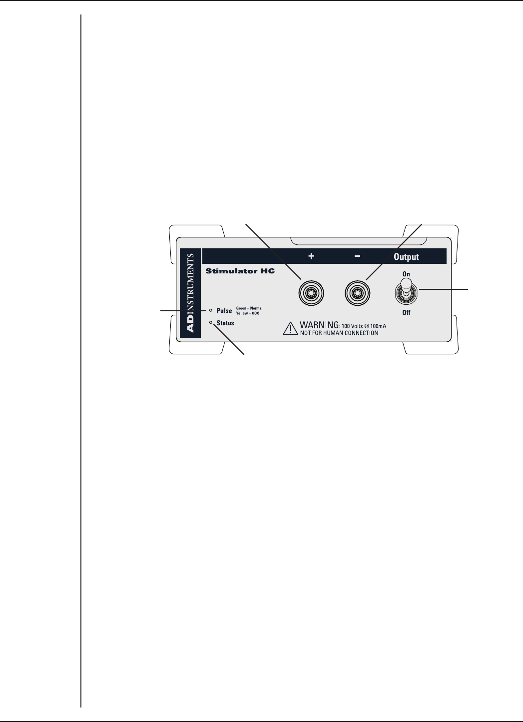
FRONT-END SIGNAL CONDITIONERS - Owner’s Guide
184
The Stimulator HC
The Stimulator HC is designed to provide electrically isolated, constant current
stimulation of nerve, muscle or tissue samples. The Stimulator HC uses the positive
analog output of the PowerLab. The I2C bus, as well as providing control, also provides
the low-voltage power supply required to operate most front-ends. However, as the
Stimulator HC needs to produce a reasonably high voltage and current, it has its own
power supply. It does not require batteries.
The Front Panel
The front panel of the Stimulator HC has two output sockets, two small indicator lights
and a ON/OFF switch.
Stimulator
Pulse Indicator
Status Indicator
Positive Output Negative Output
Stimulator
Switch
The Status Indicator
The Status indicator is located at the bottom le of the front panel. When an
ADInstruments application starts up, the Status indicator should flash briefly and then
remain green, indicating the application has found, checked and selected the front-end,
and it is ready for use.
If the Status indicator does not turn on and stay on when the soware application is
open, this indicates either that the front-end is not connected properly or that there
is a soware or hardware problem. Try restarting the application; this will sometimes
correct the problem. See Troubleshooting for more details.
The Stimulator Pulse Indicator
The current status or operating condition of the Stimulator HC is indicated by the
Stimulator Pulse indicator, a multi-colored light that is located on the le-hand side of
the front panel. The indicator light will flash green for every stimulus pulse, and may
seem to glow green constantly at higher stimulus frequencies.
A yellow color indicates that the output is overloaded or out-of-compliance (compliance
is the ability to supply voltage to meet the required current). This means that the
impedance of the tissue being stimulated is too high, or there is a poor electrical
connection (possibly due to electrode drying), and that the Stimulator HC can no longer
supply constant current stimulation. If this should happen, try reducing the output
current amplitude, and check all connections.
Figure 12–1
The Front Panel of
the Simulator HC.
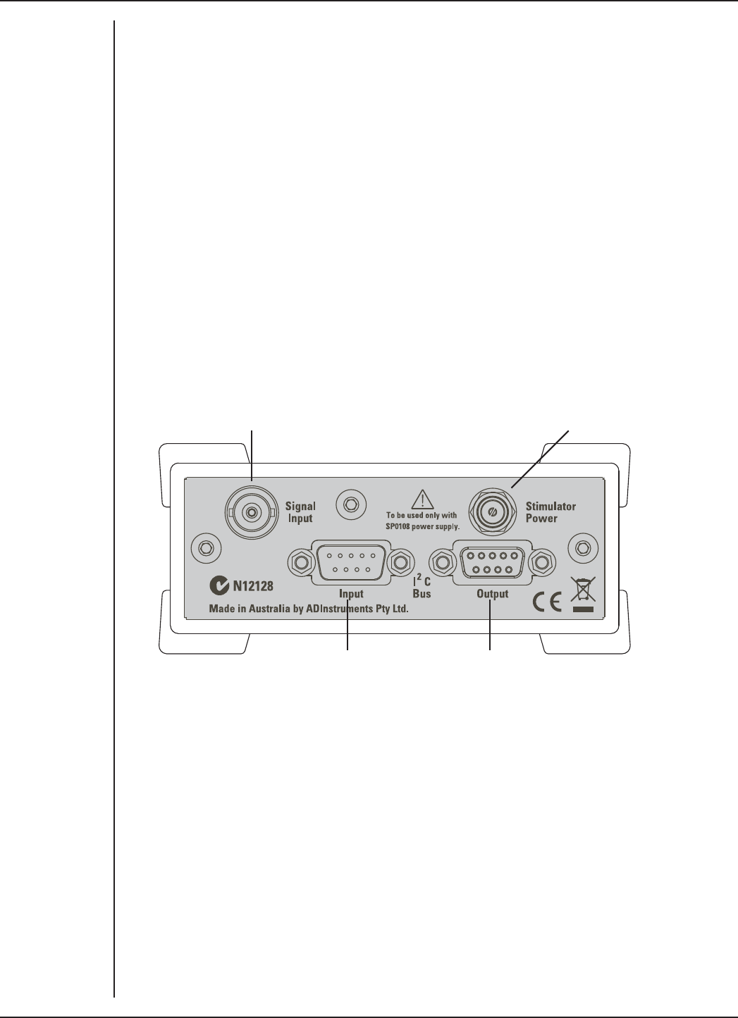
FRONT-END SIGNAL CONDITIONERS - Owner’s Guide
185
The Output Sockets
The stimulus output of the Stimulator HC is supplied through two 2 mm sockets; the
le (red) socket is positive, the right (black) socket is negative. The output is capable of
supplying 100 V pulses at currents up to 100 mA, so it should be treated with caution.
The output connections are isolated internally by isolation circuitry.
The Safety Switch
For additional safety, a switch on the front panel allows the output to be switched on
and o as needed. The switch should be in the up position when the output is turned
on, and the down position to turn it o: that disconnects the output sockets from the
internal circuitry, allowing connections to be made in safety while the front-end is on.
The Back Panel
The back panel of the Stimulator HC provides all the sockets required to connect the
front-end to the PowerLab and to other front-ends, and to connect it to its own power
supply.
Signal Input (from PowerLab output) Socket for power supply (SP0108)
I2C connection to a further front-endI2C connection from the
PowerLab or previous front-end
I2C Input and Output Sockets
Two nine-pin sockets are used to communicate with the PowerLab (they are labeled I2C
Bus). These sockets, in conjunction with the proper cables, allow multiple front-ends
to be used independently with one PowerLab. Power and control signals to connected
front-ends come from the PowerLab. ADInstruments front-ends are connected to the
system in series; previous device output to current front-end input.
The Stimulator HC has its own power supply, but uses power from the I2C bus for its
control circuitry, and uses signals from the bus to set pulse amplitude and duration (the
Stimulator HC allows for shorter pulses than the LabChart application usually handles,
for instance), and to control a beeper that provides an optional audible pulse signal.
Figure 12–2
The back panel of
the Stimulator HC

FRONT-END SIGNAL CONDITIONERS - Owner’s Guide
186
The Signal Input Socket
A BNC socket labeled Signal Input on the back panel of the Stimulator HC is used to
connect it to the positive analog output on the front of the PowerLab (see below). A BNC-
to-BNC cable is supplied for this connection. The PowerLab output is used to provide
the trigger pulses for the Stimulator HC and to establish timing, as well as to check that
the front-end is connected.
Power Socket
The Stimulator HC is supplied with a certified power pack, a (nominal) 12-volt AC
transformer, since it needs to produce a higher voltage and current than the PowerLab
can supply through the I2C bus. The transformer plugs into a normal wall socket, and its
cable jack plugs into the power socket at the back of the Stimulator HC. No batteries are
used. Only the supplied power pack should be used with the FE155 Stimulator HC.
Connecting to the PowerLab
To connect your Stimulator HC to the PowerLab, first ensure that the PowerLab is turned
o. Failure to do this may damage the PowerLab, the front-end, or both.
A BNC cable must connect the Signal Input socket on the rear panel of the Stimulator
HC to the positive analog output on the front panel of the PowerLab. The positive output
socket is labelled + on most PowerLabs and Output 1 on /30 and /35 series PowerLabs.
ADInstruments applications will not find the Stimulator HC when starting up if the
negative output socket is used.
Single Front-ends
Connect the I2C Output of the PowerLab to the I2C Input of the front-end using the
I2C cable provided. Figure 12–3 shows how to connect up a single front-end to your
recording unit.
Check that the connectors for the I2C bus are screwed in firmly. Check the BNC cable
for firm connections as well. Loose connectors can cause erratic front-end behavior, or
may cause the front-end to fail to work at all. The BNC cable can be tucked under the
front-end to keep it out of the way if desired.
Multiple Front-ends
The Stimulator HC connects to and uses the analog output of the PowerLab as a source
for producing pulses, so only one front-end of this nature can be used per PowerLab.
However, multiple front-ends can be connected to PowerLab system. The number of
standard front-ends that can be connected depends on the number of analog input
channels on the PowerLab, since each front-end is normally requires connection to one
of the analog input channels of the PowerLab to operate.
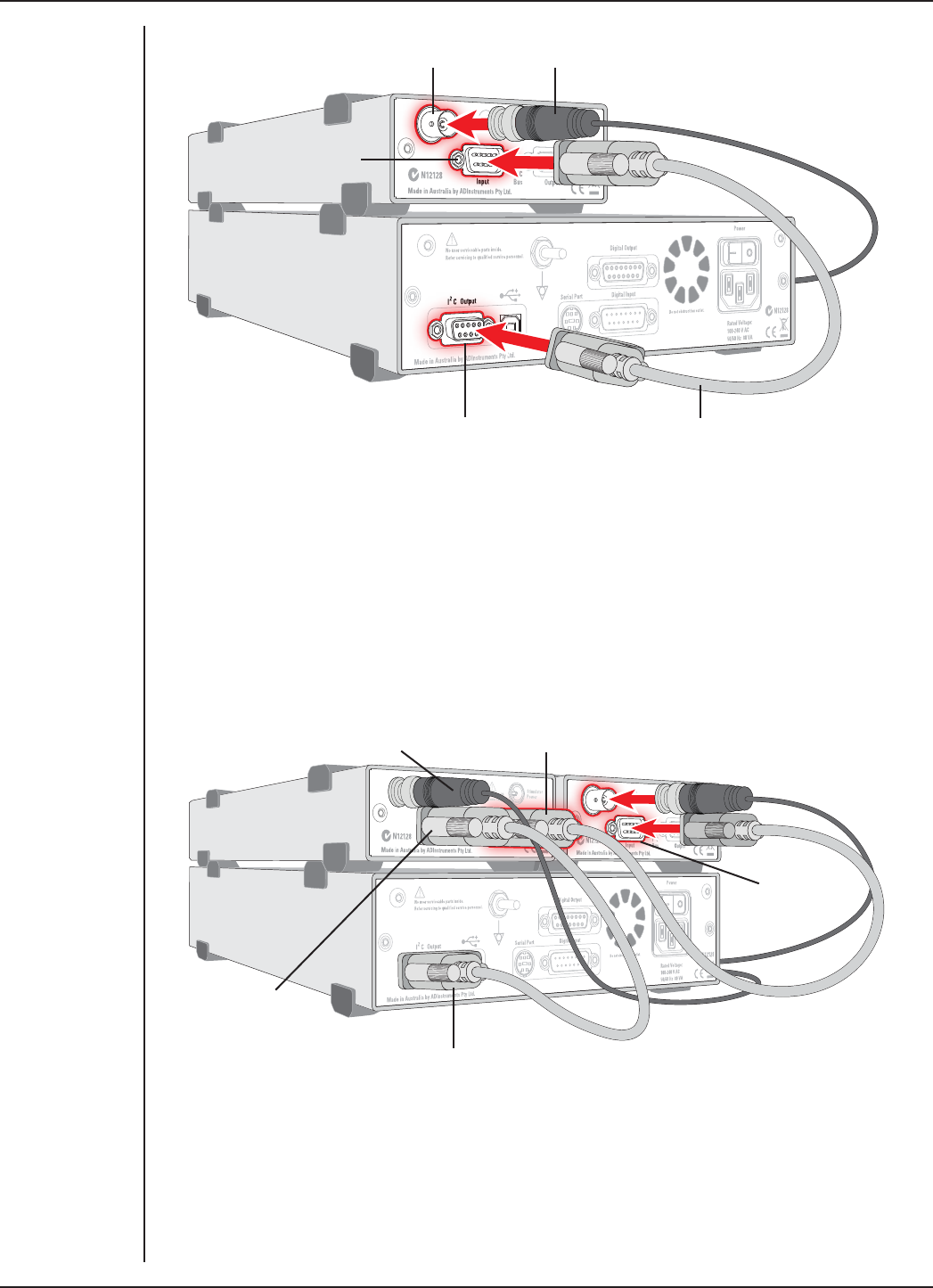
FRONT-END SIGNAL CONDITIONERS - Owner’s Guide
187
The initial front-end should be connected with an I2C cable as in Figure 12–3. The
remainder are daisy-chained via I2C cables, connecting the I2C Output of the previous
connected front-end to the I2C Input of the next front-end to be added.
The I2C Bus can control up to a maximum of sixteen front-ends (depending on the
PowerLab model). So if you are using a PowerLab 16/30, which has sixteen analog
inputs, you can connect up to fieen single-channel front-ends and the Stimulator HC
(representing sixteen front-ends).
Figure 12–3
Connecting the
Stimulator HC to
the PowerLab
(Power
connections
not shown)
Stimulator HC Signal Output
Stimulator HC
I2C input
PowerLab I2C output I2C connector cable
BNC connector cable
Figure 12–4
Connecting the
Stimulator HC
with other Front-
ends (Power
connections not
shown)
Second I2C cable connected to
Stimulator HC I2C output
Second
Front-end
I2C input
I2C cable connected to
PowerLab I2C output
BNC cable connected to
Stimulator HC Signal input
I2C cable
connected to
Stimulator HC
I2C input

FRONT-END SIGNAL CONDITIONERS - Owner’s Guide
188
Soware Requirements
The FE155 Stimulator HC requires the following versions of ADInstruments soware
applications:
•LabChart version 6, or later, for Windows or Macintosh
•Chart version 5.4.2, or later, for Windows or Macintosh
•Scope for Windows version 3.9.2, or later
•Scope for Macintosh version 4.0.3, or later
•LabTutor version 3, or later.
Note: the Stimulator HC will not operate with earlier versions of these applications. Free
updates are available from the ADInstruments website for users with earlier versions of
Chart 5 and Scope. If you have queries regarding hardware and soware requirements
of the Bridge Amps, please contact your local ADInstruments representative.
Software Behavior
When the Stimulator HC is properly connected to the output:
•on Windows, the Stimulator dialog displays the Stimulus Isolator checkbox,
which is selected and disabled.
•on Macintosh, the Stimulator dialog is replaced by the Stimulator HC dialog and
the Stimulator... menu commands are replaced by Stimulator HC... where they
appear.
If the application fails to find a front-end connected, the normal text remains. If you
were expecting a connected front-end and see the normal text, you should quit
the application, turn o the PowerLab and check the connections. Then restart the
PowerLab and application to see if the front-end commands appear.
The Stimulator HC dialog
The Stimulator HC lets you generate a pulse or series of pulses, for general-purpose
stimulation with currents up to 100 mA. The stimulus output is not suitable for human
connection. The stimulus is produced from the outputs on the front panel of the
Stimulator HC. The stimulus is independent of the PowerLab sampling rate and can be
generated whether the PowerLab is sampling or not. The stimulus is set up using the
Stimulator dialog.
In LabChart for Windows, choose Setup > Stimulator.... to display the Stimulator
dialog (Figure 12–5). On the Macintosh, choose Setup > Stimulator HC.... to display the
Stimulator HC dialog (Figure 12–6).
When setting up the Stimulator HC, you can:
•Choose how stimulation should start.
•Choose a preconfigured stimulus type or mode.
•Optionally, on Windows, create a custom stimulus waveform.
•Set stimulus parameters, such as start delay, pulse width and current amplitude.
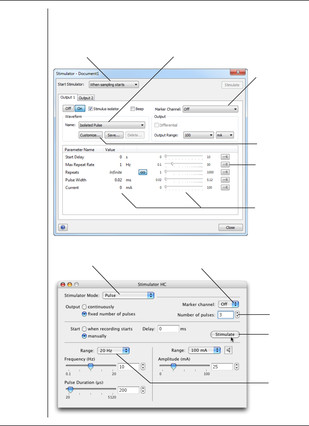
FRONT-END SIGNAL CONDITIONERS - Owner’s Guide
189
Scope has a dierent Stimulator dialog to that of LabChart: in the Stimulator dialog you
can choose Pulse and Multiple in the Mode pop-up menu (to produce single or multiple
pulses, respectively).
Choose how stimulation
should start
Choose a stimulus type preset
Specify a custom
stimulus waveform
Configure the range
of valid parameter
values in the
Parameter Settings
dialog
Set stimulus
parameters
Specify a Marker
channel
Turn stimulation on
(Pulse) or off
Mark the stimulus
event in a channel
Set the
number of
pulses to be
delivered
Click to start
a train of
pulses (when
sampling and
manual start is
selected)
Change the
stimulus
frequency
range
Figure 12–5
The Simulator
dialog
in LabChart for
Windows
Figure 12–6
The Stimulator
dialog
in LabChart for
Macintosh

FRONT-END SIGNAL CONDITIONERS - Owner’s Guide
190
Note that if you connect the Stimulator HC to a PowerLab that has an in-built Isolated
Stimulator, such as a PowerLab 26T, only the external, connected stimulator is used.
Choosing How Stimulation Should Start
Stimulation can be set to start in dierent ways:
•When sampling starts: stimulation begins automatically when the LabChart
Start button is clicked, and continues until sampling stops. Use the On and O
buttons to control pulse delivery, if necessary.
•Manually: stimulation begins when Stimulate in the dialog is clicked, and
continues until sampling stops. Use the On and O buttons to control pulse
delivery, if necessary.
•Independently of sampling: stimulation begins when On in the dialog is clicked,
whether or not LabChart is sampling. Available in LabChart for Windows only.
In all three modes, you can immediately restart a stimulus waveform by clicking
Stimulate.
Choosing a Stimulus Type
The Stimulator HC only oers the Isolated Pulse stimulation mode (Pulse on Macintosh).
This generates a rectangular pulse stimulus that starts at zero current, is raised to the
set current amplitude for the set pulse width (duration), and then falls to zero current
again. By default, the stimulator is o and the current amplitude is set to zero.
Creating a Custom Stimulus Waveform
In LabChart for Windows, you can:
•Specify whether parameter controls are displayed in the Stimulator and
Stimulator Panel dialogs.
•Define a sequence of segments to create a custom stimulus waveform.
Click Custom... to display the Waveform Customization dialog. For further details on
using this dialog consult the LabChart Help Center.
Setting Stimulus Parameters
You use the text boxes and sliders to set values for the stimulus parameters. In LabChart
for Windows, you can use the Settings dialog for each parameter to configure the range
of values available to the parameter text box and slider controls. Using suitable values
can improve the precision of control over the stimulus parameter when using the slider
and spinner controls.
Windows
In LabChart for Windows, the following stimulus parameters can be set:
Start Delay: the wait time before stimulation is delivered, once the stimulus waveform
has been started (0 to 10 s).

FRONT-END SIGNAL CONDITIONERS - Owner’s Guide
191
Repeats: the number of times the stimulus waveform is repeated, once started.
Max Repeat Rate: the maximum frequency with which the stimulus waveform is
repeated, within the ranges: 0.1 to 30 Hz, 6 to 1800 /min, and 33.33 ms to 10 s.
Pulse Width: the duration of each pulse (10 to 4000 µs).
Current: the amplitude of the stimulus current (0 to 100 mA).
End Delay: the wait time at the end of a stimulus segment, aer which the next segment
is delivered. This is not the same as a Delay segment.
Macintosh
In LabChart for Macintosh, the following stimulus parameters can be set:
Range: lets you select the range for the Frequency control; 0.1 Hz to the selected Hz
range (2, 20 or 30 Hz), or 2–200 PPM (~0.033 Hz to ~3.3 Hz). PPM (pulses per minute) can
sometimes be a more convenient expression of the pulse frequency.
Frequency: the rate at which pulses are delivered; available values are within those set
with Range.
Interval: allows pulses to be set up according to the time between the start of each
pulse.
Pulse duration: the time for which the pulse lasts, from 20 to 5120 µs (0.02 to 5.12 ms)
at all frequency ranges.
Amplitude: the exact amplitude of the stimulus current, from either 1 mA, 10 mA or 100
mA ranges.
Marker Channel
If you choose a channel from the Marker Channel pop-up menu, then the start time of
a stimulus pulse is marked by a small data spike (this adds to any data in that channel).
The Beeper
On Windows, check Beep to turn on the Stimulator HC’s internal beeper: when on, it
gives an audible beep with every pulse (although it is not very loud, and may not be that
clear in noisy environments). On a Macintosh system, click the speaker icon to turn o
or on the Stimulator HC’s internal beeper.
The Stimulator Panel
Once you have set up stimulation using the Stimulator dialog, you can easily start or
stop stimulation or change settings while sampling, by using the Stimulator Panel.
Choose Stimulator Panel from the Setup menu to open it, or Stimulator HC Panel on
Macintosh (Figure 12–7).
On Windows, you can specify which parameter controls are displayed in the panel using
checkboxes in the Panel column of the Stimulator Waveform Customization dialog. See
the LabChart Help Center for details.
The Stimulator Panel ‘floats’ in front of the active window, can be moved around with
its title bar, and can only be dismissed by clicking its close box.
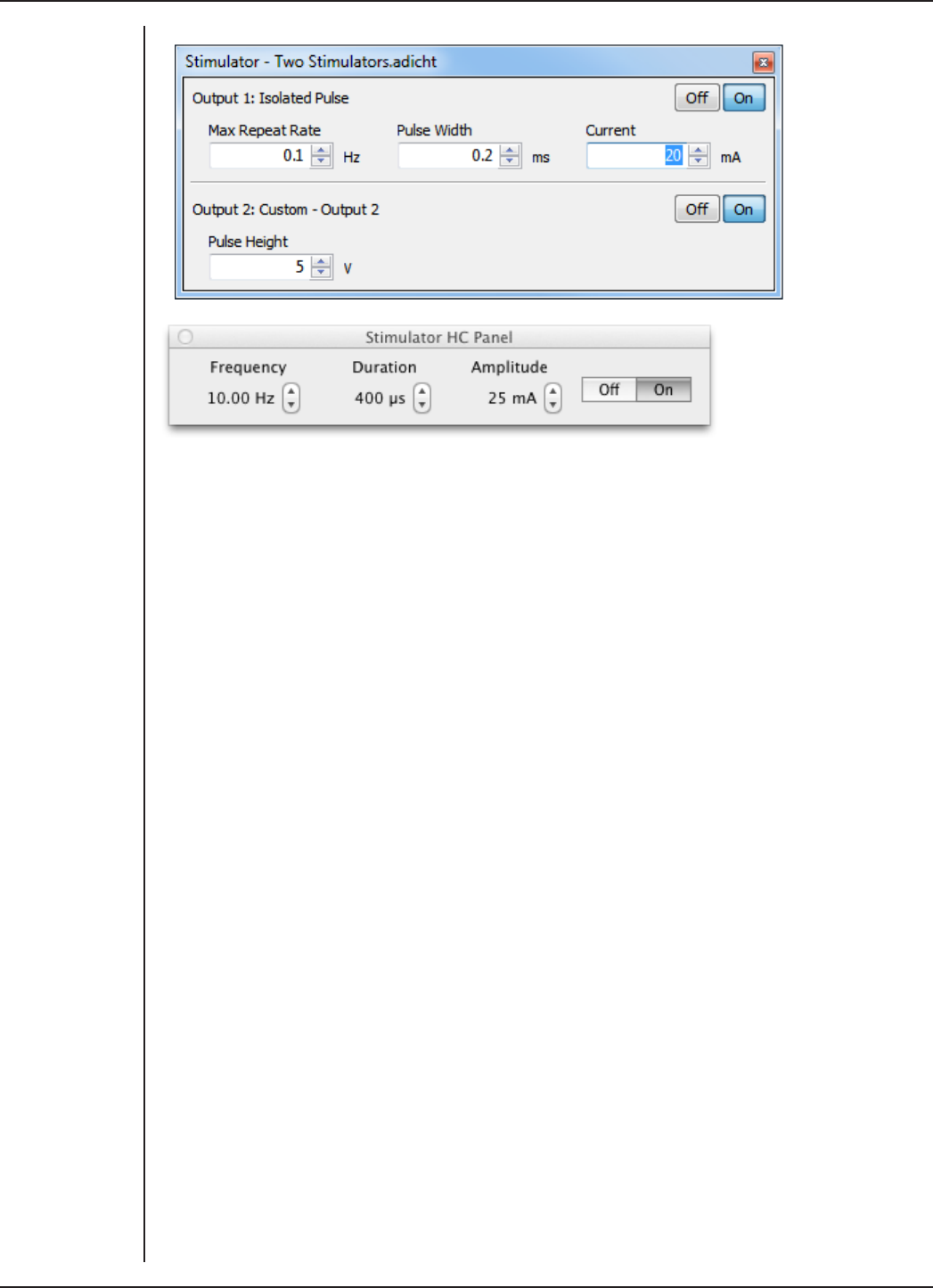
FRONT-END SIGNAL CONDITIONERS - Owner’s Guide
192
PowerLabs with Independent versus Dierential Analog
Outputs
The analog outputs on a PowerLab provide computer-controlled variable voltage
output that can be used with LabChart, either directly to connect to a Stimulator front-
end, or to control peripheral devices. All voltage output is generated by the PowerLab
and delivered via the BNC output sockets, giving positive, negative, dierential, or
independent stimuli, depending on the PowerLab, sockets used, and the soware
settings.
For the /20, /25, /26 and 15T series PowerLabs:
The negative (–) output is the complement of the positive (+) output, so the stimuli from
the two outputs are mirror images. If one output gives a positive voltage, the other gives
a negative one, and the two together give a dierential voltage. Only one Stimulator
front-end such as a Stimulus Isolator or Stimulator HC can be connected to the (positive)
output of these PowerLabs.
Note: If you connect the Stimulator HC to a PowerLab that has an in-built Isolated
Stimulator, such as a PowerLab 26T, only the external, connected stimulator is used.
For /SP, /ST, /30 and /35 series PowerLabs:
The analog outputs labelled Output 1 and Output 2 can function independently.
Although only one Stimulator front-end such as a Stimulus Isolator or Stimulator HC
can be connected to the positive output (Output 1) of these PowerLabs, the second
output (Output 2) remains available for other uses, such as creating analog waveforms
or controlling peripheral devices. In LabChart 7 for Windows, with a Stimulator front-
end connected, a second tab appears in the Stimulator dialog and the Stimulator Panel
(Figure 12–7). This allows for the independent control of Output 2. This feature is not yet
available in LabChart for Mac.
Figure 12–7
Stimulator Panels
for Windows
(upper) and Mac
(lower): these
allow manual
control of stimuli
while sampling
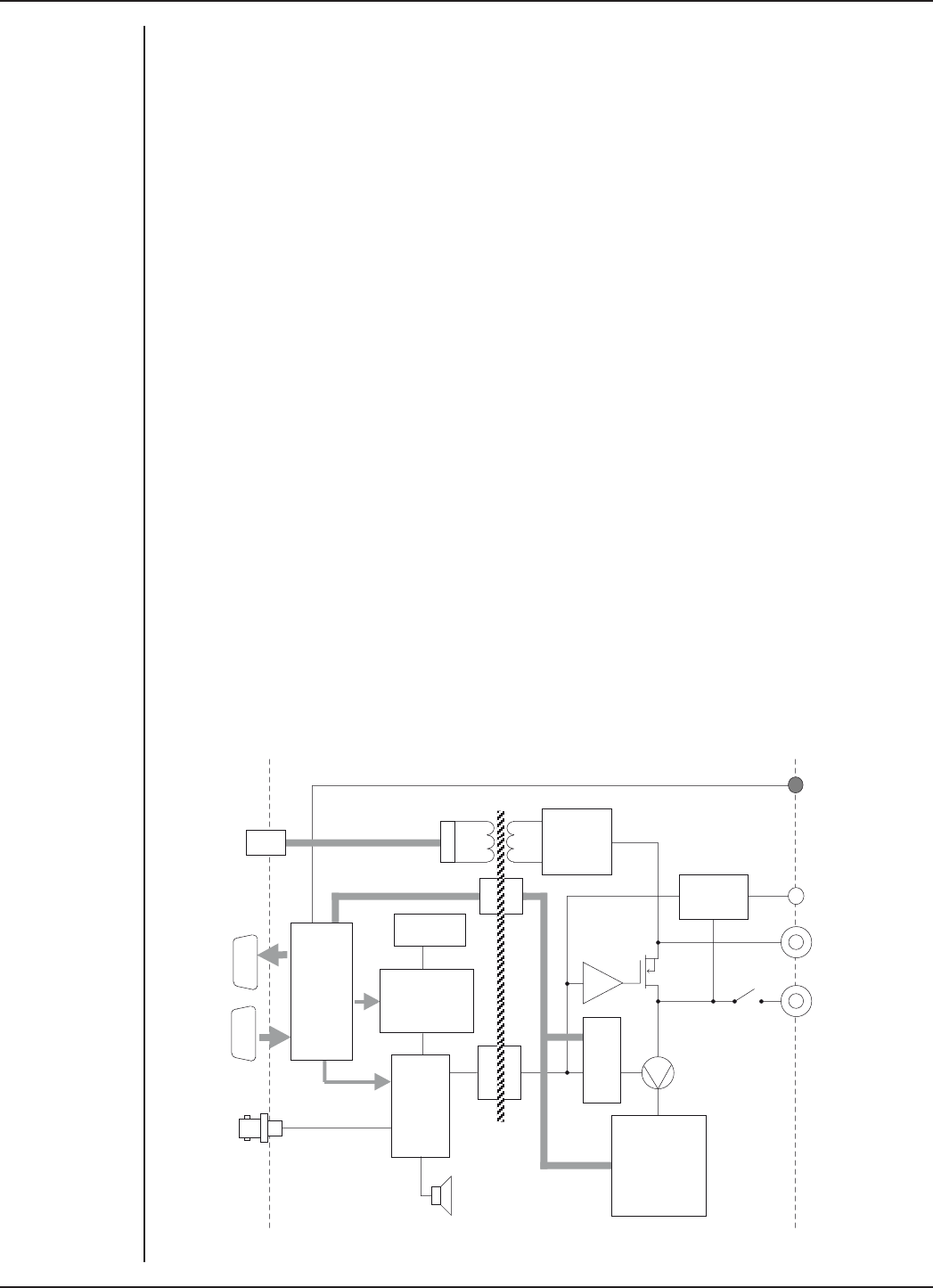
FRONT-END SIGNAL CONDITIONERS - Owner’s Guide
193
Technical Aspects
The Stimulator HC has been designed to integrate fully into the PowerLab system. It
requires connection to the PowerLab via a special communications connector called
the I2C bus, and a BNC connector.
Stimulator HC Operation
The PowerLab usually provides control and low-voltage power to front-ends through
the I2C bus. The Stimulator HC diers from other front-ends in some respects. Since it
needs to produce a reasonably high voltage and current, the Stimulator HC has its own
power supply in addition to the power for the control circuitry provided by the I2C bus.
Front-ends are also usually connected through the analog inputs of the PowerLab but
the Stimulator HC is not a signal conditioner; it produces stimulation voltage output
and so it is connected to a positive analog output socket of the PowerLab. The overall
operation of the Stimulator HC can be better understood by referring to Figure 12–8.
The output stage consists of a constant current source that can produce pulses of
variable duration and amplitude under soware control. The current source can deliver
pulses up to 100 mA at 100-volt compliance levels; its amplitude is set by a digital
attenuator network, which is in turn controlled by the I2C logic. The output to the nerve,
muscle or tissue sample is through high-isolation optical couplers.
Trigger pulses are delivered to the current source through optical isolation as well.
Power for the stimulator current source is derived from the external AC wall transformer
(plug pack) coupled through a custom isolation transformer, from which the isolated
low voltage and 100-volt supplies are derived. The supplied power pack complies with
medical safety requirements: under no circumstances should any other transformer be
used in its place.
Online
indicator
Signal
input
+100 V
+
–
Overload
detector
2 MHz osc
& divider
Programmable-
width
pulse generator
10 µs –4 ms
Pulse
control
logic
100 kHz STIMULUS
PULSE OUT
Beeper
Isolated
power
supply
Isolation
barrier
12 V AC
input from
power pack
I C
input
I C
output
2
2
I C
control
interface
+ power
supply
2
Status
indicator
Current range
setting
network
100mA, 10mA,
1mA
Voltage-
controlled
current
source
Digital
attenuator
Figure 12–8
Block Diagram of
the Stimulator HC

FRONT-END SIGNAL CONDITIONERS - Owner’s Guide
194
During operation an indicator light on the front panel lights green with every pulse (it
will glow yellow if the Stimulator HC is out of compliance). A small internal beeper can
also be enabled to give an audible beep with every pulse delivered.
The digital interface that controls pulse width and current amplitude uses an I2C
interface system, and provides a 4-wire serial communication bus to the PowerLab
and other front-ends. Signals from the bus also control the beeper. Also present on the
connector is a set of power supply rails derived from the PowerLab, used to power the
control circuitry of the Stimulator HC.
Troubleshooting
This section describes most of the common problems that can occur when using the
Stimulator HC with your PowerLab recording unit. It covers how these problems are
caused, and what you can do to alleviate them. If the solutions here do not work, earlier
chapters, the LabChart Help Center, and the guide to your PowerLab may contain
possible solutions. If none of the solutions here or elsewhere are of help, then consult
your ADInstruments representative.
Most of the problems that users encounter are connection problems, and can usually be
fixed by checking connections and starting up the hardware and soware again. Very
rarely will there be an actual problem with the front-end or the PowerLab itself.
Problems and Solutions
The status indicators fail to light when the soware is started, or the front-end commands
and so on do not appear where they should
The I2C cable or the BNC-to-BNC cable from the front-end to the PowerLab is not
connected, has been connected incorrectly (to the wrong input or output, for instance),
or is loose.
•Turn everything o. Check to see that all cables are firmly seated and screwed in.
The BNC cable from the Stimulator HC must be connected to the positive output
on the PowerLab (labelled + on most PowerLabs and Output 1 on /30 and /35
series PowerLabs). Restart the PowerLab and application to see if this has fixed
the problem.
You are using an early version of LabChart or Scope.
•Upgrade to the latest version of the soware. Contact your ADInstruments
representative for information.
The BNC or I2C cable is faulty.
•Replace the cable and try again. Immediately label all cables proved faulty so
that you don’t use them again by accident.
The front-end is faulty.
•This is the least likely event. If the front-end will not work properly aer the
previous measures, then try using it on another PowerLab. If the same problems
recur with a second PowerLab, the front-end may be faulty. Contact your
ADInstruments representative to arrange for repairs.

FRONT-END SIGNAL CONDITIONERS - Owner’s Guide
195
On starting up the soware, an alert indicates that there is a problem with the front-end or
driver
The correct Stimulator HC driver is not installed on your computer.
•Reinstall the soware.
You are using an early version of LabChart or Scope.
•Upgrade to the latest version of the soware. Contact your ADInstruments
representative for information.
The BNC or I2C cable is faulty.
•Replace the cable and try again. Immediately label all cables proved faulty so
that you don’t use them again by accident.
The front-end is faulty.
•This is the least likely event. If the front-end will not work properly aer the
previous measures, then try using it on another PowerLab. If the same problems
recur with a second PowerLab, the front-end may be faulty. Contact your
ADInstruments representative to arrange for repairs.
Some soware settings don’t resemble those in this guide
You are using an early version of the front-end driver, or of LabChart or Scope. Some
changes may have been made since then.
•Upgrade to the latest version of the soware. Contact your ADInstruments
representative for information.
The Stimulator Status indicator shows yellow
This means that the Stimulator HC is out of compliance (OOC). You could be attempting
stimulation while the output stimulator switch is turned o (in the down position).
•Turn the stimulator switch on (move to the up position).
•The impedance of the tissue could be too high for the Stimulator HC to supply
constant current at the level requested, or there is an inadequate electrical
connection to the tissue.
•Reduce the output current amplitude.
•Check the connections for proper contact and try again. Ensure the tissue is
mounted correctly.
The Stimulator Status indicator does not flash green, even when there is an audible beep
The supplied 12-volt AC power supply to the Stimulator HC is not connected or not
switched on at the wall or is faulty.
•Close the LabChart or Scope application, connect up and turn on the power
supply, and start up again.
•If the Status light still does not flash green (and does not light up at all), the
12-volt power supply may be faulty. Have a technician check the fuse and the
electrical connections.
•Once you have established that it is not faulty, you should ensure that the output
of the 12-volt power supply is indeed 12 volts – use a multimeter to measure this.

FRONT-END SIGNAL CONDITIONERS - Owner’s Guide
196
Specifications
Output
Safety: Not for Human Connection
EMC: Approved to EN61326-1:2006 Standard
Connection type: Two 2 mm touch-proof safety sockets
Configuration: Constant-current stimulator with hardware-limited
repetition rate.
Output waveform: Rectangular, monophasic pulses with soware-
selectable pulse amplitude and duration.
Isolation rating: 4000 V ACrms for 1 minute
Safety indicators: A single, multi-color indicator displays the Stimulator
HC status. A green flash indicates delivery of a valid
stimulus. A yellow flash indicates an out-of-compliance
condition (OOC).
Safety switch: Isolating On-O switch flicks down to disconnect quickly.
Compliance voltage: 100 V fixed
Current ranges: 1 mA, 10 mA, 100 mA full scale
Current rise time: <1 µs (100 Ω load @ 100 mA)
25 µs (10 kΩ load @ 0.5 mA)
Current fall time: <1 µs (100 Ω load @ 100 mA)
25 µs (10 kΩ load @ 0.5 mA)
Current rise and fall times are proportional to load
resistance and capacitance.
Operating duty cycle: up to 20%
Resolution: 1% of full scale (10 µA, 100 µA, or 1 mA)
AC line leakage current: <200 nA p–p
Dierential output noise: <1 µA p–p
Power source: Non-isolated circuitry supplied by PowerLab via I2C
connection.
Isolated and high-voltage circuitry derives power from
the external 12 V AC, 300 mArms, wall-plug transformer.
High-voltage isolation is provided by an internal isolation
transformer. No batteries required.

FRONT-END SIGNAL CONDITIONERS - Owner’s Guide
197
Pulse control (internal pulse duration control)
Pulse duration range: 0.02 to 5.12 ms in 0.02 ms steps
Duration accuracy: ±0.01% +5/–0 µs
Repetition rate: Up to 30 Hz
Repetition accuracy: ± 0.1% (determined by PowerLab)
Current rise delay: 22–45 µs (variable)
Control Port
I2C port: Provides control and power. Interface communications
rate of ~50 kbits/s.
Physical Configuration
Dimensions (h × w × d): 55 mm × 120 mm × 260 mm (2.2" × 4.7" × 10.2")
Weight: 1.3 kg (2 lb 15 oz)
Operating temperature range: 5–35°C
Operating humidity range: 0–90% (non-condensing)
ADInstruments reserves the right to alter these specifications at any time.
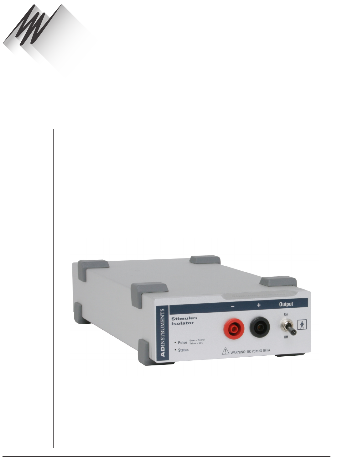
FRONT-END SIGNAL CONDITIONERS - Owner’s Guide
198
The FE180 Stimulus Isolator is a modular device, in a family of front-ends, designed to
extend the capabilities of the PowerLab system. It is a general-purpose stimulator, able
to provide high-voltage, constant-current stimulation, and it provides full electrical
isolation.
The Stimulus Isolator is essentially an extension of the PowerLab’s analog output. The
Stimulus Isolator provides:
•a constant-current, 100-volt compliance, pulsed output
•high-voltage subject isolation (4000 Vrms)
•low leakage capacitance and low noise
•soware-adjustable current amplitudes
•soware-adjustable pulse duration.
Warning! The output is capable of supplying 100 V pulses and generating currents of
up to 10 mA, so it should be treated with caution.
Stimulus Isolator
Chapter 13
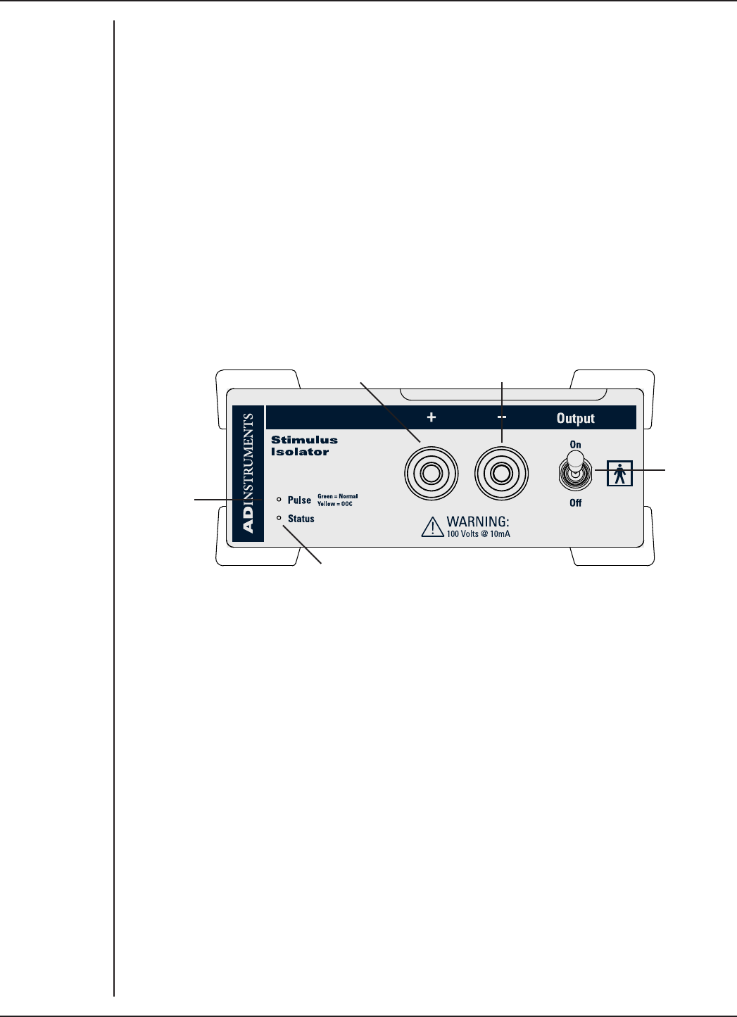
FRONT-END SIGNAL CONDITIONERS - Owner’s Guide
199
The Stimulus Isolator
The Stimulus Isolator is designed to provide electrically isolated, high-voltage, constant-
current stimulation of human or other subjects. It is also able to produce shorter pulses
than the LabChart application normally can. The I2C bus, as well as providing control,
also provides the low-voltage power supply required to operate most front-ends.
However, as the Stimulus Isolator needs to produce a reasonably high voltage and
current, it has its own power supply. It does not require batteries.
The rest of this chapter contains general information about the features, connectors
and indicators of the Stimulus Isolator. More detailed information can be found in the
technical appendices.
The Front Panel
The front panel of the Stimulus Isolator has two output sockets, two small indicator
lights and a safety switch.
Positive Output Negative Output
Stimulator
Switch
Status Indicator
Stimulator
Pulse Indicator
The Status Indicator
The Status indicator is located at the bottom right of the front panel. When an
ADInstruments application such as LabChart starts up, the Status indicator should flash
briefly and then remain green, indicating that the program has found the front-end,
checked and selected it, and it is ready for use.
If the Status indicator does not turn on and stay on when the soware application is
open, this indicates either that the front-end is not connected properly or that there
is a soware or hardware problem. Try restarting the application; this will sometimes
correct the problem. If the problem persists, see “Problems and Solutions” on page
208 for more details on possible solutions.
The Output Sockets
The stimulus output of the Stimulus Isolator is supplied via two 4 mm shrouded banana
sockets; the le (red) socket is positive, the right (black) socket is negative. These are
similar to the sockets found on many digital multimeters, and designed for use with
shrouded male 4 mm plugs (the shrouding is to prevent accidental stimulation while
fitting or removing the plugs). The stimulating bar electrode supplied with the front-end
Figure 13–1
The Front Panel
of the Stimulus
Isolator
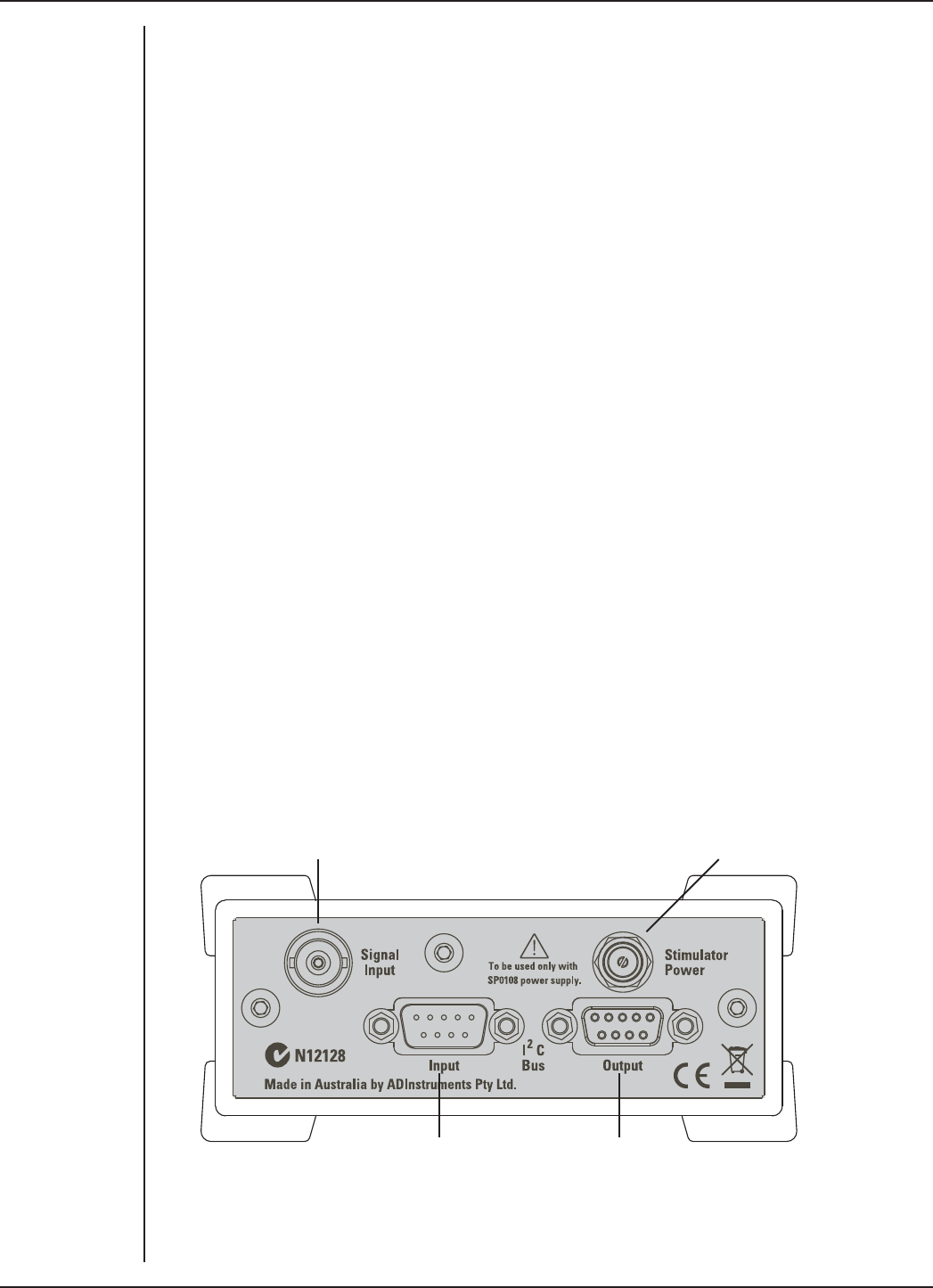
FRONT-END SIGNAL CONDITIONERS - Owner’s Guide
200
uses such plugs. The output is capable of supplying 100 V pulses at currents up to 10
mA, so it should be treated with caution. The output connections are isolated internally
by isolation circuitry.
The Stimulator Status Indicator
The current status or operating condition of the Stimulus Isolator is indicated by the
Stimulator Status indicator, a multi-colored light that is located on the le-hand side
of the front panel. The indicator light will flash green for every stimulus pulse, and may
seem to glow green constantly at higher stimulus frequencies.
A yellow color indicates that the output is overloaded or out-of-compliance (compliance
is the ability to supply voltage to meet the required current). This means that the
impedance of the tissue being stimulated is too high, or there is a poor electrical
connection (possibly due to electrode drying), and that the Stimulus Isolator can no
longer supply constant current stimulation. If this should happen, try reducing the
output current amplitude, and check all connections.
The Safety Switch
To provide an additional level of safety, a safety switch has been placed on the front
panel to allow the output to be switched on and o as needed. The switch should be in
the up position when the output is turned on, and should be flicked down to turn it o:
that disconnects the output sockets from the internal circuitry, allowing connections to
be made in safety while the front-end is on.
The Back Panel
The back panel of the Stimulus Isolator provides all the sockets required to connect the
front-end to the PowerLab and to other front-ends, and to connect it to its own power
supply.
Signal Input (from PowerLab output) Socket for power supply (SP0108)
I2C connection to a further front-endI2C connection from the
PowerLab or previous front-end
Figure 13–2
The back panel
of the Stimulus
Isolator
FRONT-END SIGNAL CONDITIONERS - Owner’s Guide
201
I2C Input and Output Sockets
Two nine-pin sockets are used to communicate with the PowerLab (they are labeled I2C
Bus). These sockets, in conjunction with the proper cables, allow multiple front-ends to
be used independently with one PowerLab. Power and control signals to connected
front-ends come from the PowerLab. ADInstruments front-ends are connected to each
other in series, output to input (this is discussed in more detail in the next chapter).
The Stimulus Isolator has its own power supply, but uses power from the I2C bus for
its control circuitry, and uses signals from the bus to set pulse amplitude and duration
(the Stimulus Isolator allows for shorter pulses than the LabChart application usually
handles, for instance), and to control the beeper that provides an optional audible
signal with each pulse.
The Signal Input Socket
A BNC socket labeled Signal Input on the back panel of the Stimulus Isolator is used to
connect the front-end to the positive analog output on the front of the PowerLab (see
below). A BNC-to-BNC cable is supplied for this connection. The PowerLab output is
used to provide the trigger pulses for the Stimulus Isolator and to establish timing, as
well as to check that the front-end is connected.
Power Socket
The Stimulus Isolator is supplied with a certified power pack (product code: SP0108), a
(nominal) 12-volt AC transformer, since it needs to produce a higher voltage and current
than the PowerLab can supply through the I2C bus. The transformer plugs into a normal
wall socket, and its cable jack plugs into the power socket at the back of the Stimulus
Isolator. No batteries are used. The supplied power pack complies with medical safety
requirements; under no circumstances should any other transformer be used with the
FE180 Stimulus Isolator.
Connecting to the PowerLab
To connect your Stimulus Isolator to the PowerLab, first ensure that the PowerLab is
turned o. Failure to do this may damage the PowerLab, the front-end, or both.
A BNC cable must connect the Signal Input socket on the rear panel of the Stimulus
Isolator to the positive analog output on the front panel of the PowerLab. The positive
output socket is labelled + on most PowerLabs and Output 1 on /30 and /35 series
PowerLabs. ADInstruments applications will not find the Stimulus Isolator when starting
up if the negative Output socket is used.
Single Front-ends
Connect the I2C Output of the PowerLab to the I2C Input of the front-end using the
I2C cable provided. Figure 13–3 shows how to connect up a single front-end to your
recording unit.
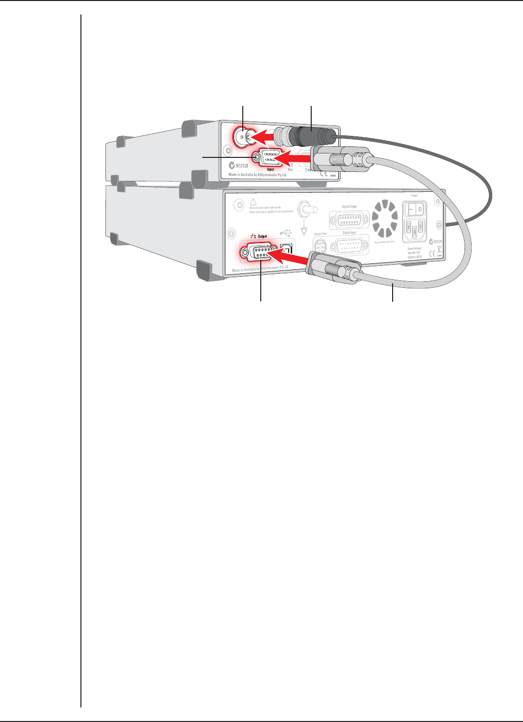
FRONT-END SIGNAL CONDITIONERS - Owner’s Guide
202
Check that the connectors for the I2C bus are screwed in firmly. Check the BNC cable for
firm connections as well. Loose connectors can cause erratic front-end behavior, or may
cause the front-end to fail to work at all. The BNC cable can be tucked under the front-
end to keep it out of the way if desired.
Multiple Front-ends
The Stimulus Isolator connects to and uses the positive analog output of the PowerLab
as a source for producing pulses, so only one front-end of this nature can be used per
PowerLab. However, multiple front-ends can be connected to PowerLab system. The
number of standard front-ends that can be connected depends on the number of analog
input channels on the PowerLab, since each front-end normally requires connection to
one of the positive analog input channels of the PowerLab to operate. The initial front-
end should be connected with an I2C cable as in Figure 13–3.
The remainder are daisy-chained via I2C cables, connecting the I2C Output of the
previous connected front-end to the I2C Input of the next front-end to be added (Figure
13–4).
The I2C Bus can control up to a maximum of sixteen front-ends (depending on the
PowerLab model). If you are using a PowerLab 16/30, which has sixteen analog inputs,
you can use up to fieen single-channel front-ends in addition to the Stimulus Isolator
(representing a total of sixteen front-ends).
Figure 13–3
Connecting a
Stimulus Isolator
to the PowerLab
Stimulus Isolator Signal Output
Stimulus Isolator
I2C input
PowerLab I2C output I2C connector cable
BNC connector cable
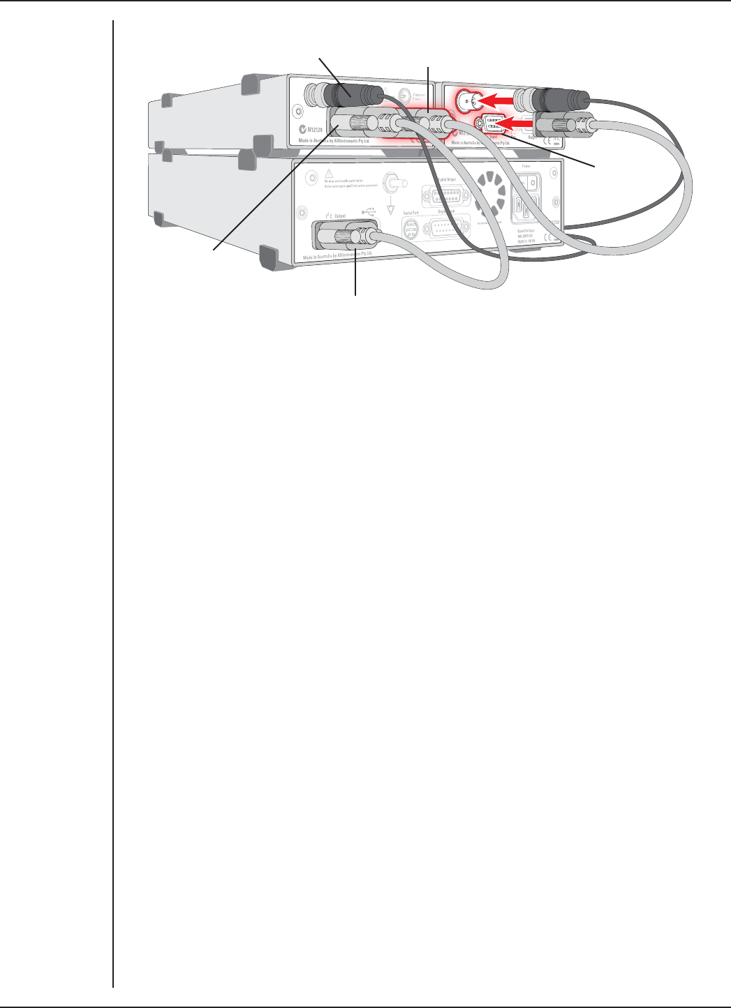
FRONT-END SIGNAL CONDITIONERS - Owner’s Guide
203
Soware Behavior
When the Stimulus Isolator is properly connected to the output:
•on Windows, the Stimulator dialog displays the Stimulus Isolator checkbox,
which is selected and disabled.
•on Macintosh, the Stimulator dialog is replaced by the Stimulus Isolator dialog
and the Stimulator... menu commands are replaced by Stimulus Isolator...
where they appear.
If the application fails to find a front-end connected, the normal text remains. If you
were expecting a connected front-end and see the normal text, you should quit
the application, turn o the PowerLab and check the connections. Then restart the
PowerLab and application to see if the front-end commands appear.
The Stimulus Isolator dialog
The Stimulus Isolator provides soware-controlled, isolated, constant-current pulse
stimuli that can be used with human subjects. The stimulus is produced at the outputs
on the front panel of the Stimulus Isolator. The stimulus is independent of the PowerLab
sampling rate and can be generated whether the PowerLab is sampling or not. The
stimulus is set up using the Stimulator dialog.
Choose Setup > Stimulator.... to display the Stimulator dialog (Figure 13–5). This dialog
is named Stimulus Isolator on the Macintosh (Figure 13–6). When setting up the Stimulus
Isolator, you can:
•Choose how stimulation should start.
•Choose a preconfigured stimulus type or mode.
•Set stimulus parameters, such as start delay, pulse width and current amplitude.
Figure 13–4
Connecting the
Stimulus Isolator
with other Front-
ends (Power
connections not
shown)
Second I2C cable connected to
Stimulus Isolator I2C output
Second
Front-end
I2C input
I2C cable connected to
PowerLab I2C output
BNC cable connected to
Stimulus Isolator Signal input
I2C cable
connected to
Stimulus Isolator
I2C input
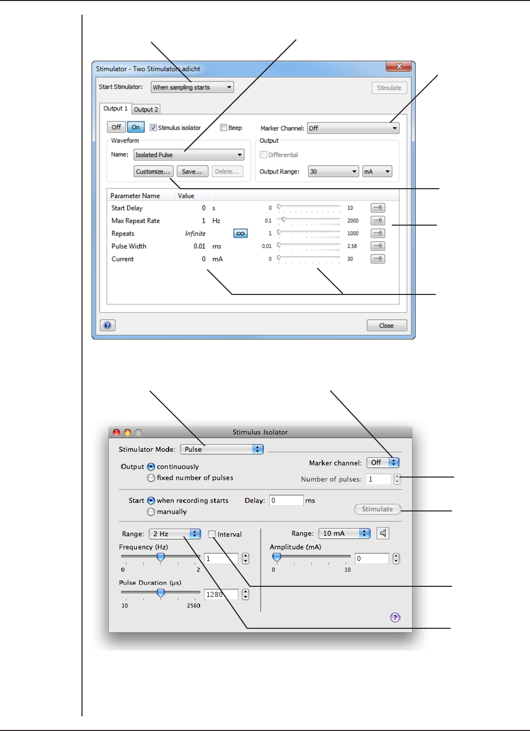
FRONT-END SIGNAL CONDITIONERS - Owner’s Guide
204
Choose how stimulation
should start
Choose a stimulus type preset
Specify a custom
stimulus waveform
Configure the range
of valid parameter
values in the
Parameter Settings
dialog
Set stimulus
parameters
Specify a Marker
channel
Check to set the
interval between
pulse starts
Turn stimulation on
(Pulse) or off
Mark the stimulus
event in a channel
Set the number
of pulses to be
delivered
Click to start a
train of pulses
(when sampling
and manual start
is selected)
Change the
stimulus
frequency range
Figure 13–5
The Stimulator
Dialog in LabChart
for Windows: with
the /30 or /35
series PowerLabs,
Output 1 is used
by the Stimulus
Isolator and
Output 2 is
available for
independent
stimulation
Figure 13–6
The Stimulus
Isolator dialog
in LabChart for
Macintosh

FRONT-END SIGNAL CONDITIONERS - Owner’s Guide
205
Scope has a dierent Stimulator dialog to that of LabChart. In the Scope Stimulator
dialog you can choose Pulse or Multiple in the Mode pop-up menu (to produce single
or multiple pulses, respectively).
Note: If you connect the Stimulus Isolator to a PowerLab that has an in-built Isolated
Stimulator such as a PowerLab 26T, only the external, connected stimulator is used.
Choosing How Stimulation Should Start
Stimulation can be set to start in dierent ways:
•When sampling starts: stimulation begins automatically when the LabChart Start
button is clicked, and continues until sampling stops. Use the On and O buttons
to control pulse delivery, if necessary.
•Manually: stimulation begins when Stimulate in the dialog is clicked, and
continues until sampling stops. Use the On and O buttons to control pulse
delivery, if necessary.
•Independently of sampling: stimulation begins when On in the dialog is clicked,
whether or not LabChart is sampling. Available in LabChart for Windows only.
In all three modes, you can immediately restart a stimulus waveform by clicking
Stimulate.
Choosing a Stimulus Type
The Stimulator only oers the Isolated Pulse stimulation mode (Pulse on Macintosh).
This generates a rectangular pulse stimulus that starts at zero current, is raised to the
set current amplitude for the set pulse width (duration), and then falls to zero current
again. By default, the stimulator is o and the current amplitude is set to zero.
Creating a Custom Stimulus Waveform
In LabChart for Windows, you can:
•Specify whether parameter controls are displayed in the Stimulator and
Stimulator Panel dialogs.
•Define a sequence of pulse segments to create a custom stimulus waveform.
Click Custom... to display the Waveform Customization dialog. Further details about
using this dialog are available in the LabChart Help.
Setting Stimulus Parameters
You use the text boxes and sliders to set values for the stimulus parameters. In LabChart
for Windows, you can use the Settings dialog for each parameter to configure the range
of values available to the parameter text box and slider controls. Choosing a suitable
range of values can improve the precision of control over the stimulus parameter when
using the slider and spinner controls.
Windows
In LabChart for Windows, the following stimulus parameters can be set:
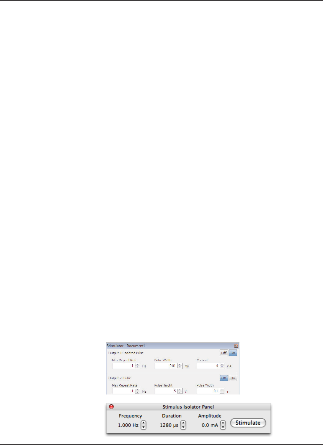
FRONT-END SIGNAL CONDITIONERS - Owner’s Guide
206
•Start Delay: the wait time before stimulation is delivered, once the stimulus
waveform has been started.
•Repeats: the number of times the stimulus waveform is repeated, once started.
•Max Repeat Rate: the maximum frequency with which the stimulus waveform is
repeated.
•Pulse Width: the duration of each pulse.
•Current: the amplitude of the stimulus current.
•Pulses: the number of pulses in the stimulus segment.
•End Delay: the wait time at the end of a stimulus segment, aer which the next
segment is delivered.
Macintosh
In LabChart for Macintosh, the following stimulus parameters can be set:
•Range: lets you select the range for the Frequency control; either in Hz or PPM
(pulses per minute).
•Frequency: the rate at which pulses are delivered; available values are within
those set with Range.
•Pulse duration: the time for which the pulse lasts.
•Amplitude: the exact amplitude of the stimulus current.
Marker Channel
If you choose a channel from the Marker Channel pop-up menu, then the start time of
a stimulus pulse is marked by a small data spike (this adds to any data in that channel).
The Stimulator Panel
Once you have set up stimulation using the Stimulator dialog, you can easily start or
stop stimulation (or change settings while sampling) by using the Stimulator Panel.
Choose Stimulator Panel from the Setup menu to open it (Stimulus Isolator Panel on
Macintosh).
The Stimulator Panel ‘floats’ in front of the active window, so can be moved around to
a convenient position, and can only be dismissed by clicking its close box. On Windows,
you can specify which parameter controls are displayed in the panel using checkboxes
in the Panel column of the Waveform Customization dialog.
Figure 13–7
The Stimulus
Isolator Panel
miniwindow.
Windows (upper):
o/on continuous
stimulation
Mac (lower):
manual control of
stimuli
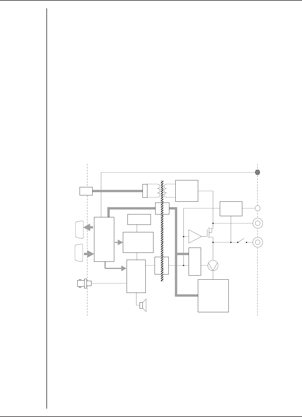
FRONT-END SIGNAL CONDITIONERS - Owner’s Guide
207
Technical Aspects
The Stimulus Isolator has been designed to integrate fully into the PowerLab system.
It requires connection to the PowerLab via a special communications connector called
the I2C (eye-squared-sea) bus, and a BNC connector.
Stimulus Isolator Operation
The PowerLab usually provides control and low-voltage power to front-ends through
the I2C bus. The Stimulus Isolator diers from other front-ends in some respects. Since
it needs to produce a reasonably high voltage and current, the Stimulus Isolator has its
own power supply in addition to the power for the control circuitry provided by the I2C
bus. Front-ends are also usually connected through the analog inputs of the PowerLab
but the Stimulus Isolator is not a signal conditioner; it produces stimulation voltage
output and so it is connected to a postive analog output socket of the PowerLab. The
overall operation of the Stimulus Isolator can be better understood by referring to
Figure 13–8.
Online
indicator
Signal
input
+100 V
+
–
Overload
detector
4 MHz osc
& divider
Programmable-
width
pulse generator
10 –2650 µs
Pulse
control
logic
200 kHz STIMULUS
PULSE OUT
Beeper
Isolated
power
supply
Isolation
barrier
12 V AC
input from
power pack
I C
input
I C
output
2
2
I C
control
interface
+ power
supply
2
Status
indicator
Current range
setting
network
10mA, 1mA,
100µA
Voltage-
controlled
current
source
Digital
attenuator
The output stage consists of a high-voltage constant-current source that can produce
pulses of variable duration and amplitude under soware control. The current source
can deliver pulses up to 10 mA at 100-volt compliance levels; its amplitude is set by a
digital attenuator network, which is in turn controlled by the I2C logic. The output to the
subject is through high-isolation optical couplers.
Trigger pulses are delivered to the current source through optical isolation as well.
Power for the stimulator current source is derived from the external AC wall transformer
(plug pack) coupled through a custom isolation transformer, from which the isolated
low voltage and 100-volt supplies are derived. The supplied power pack complies with
medical safety requirements: under no circumstances should any other transformer be
used in its place.
Figure 13–8
Block Diagram
of the Stimulus
Isolator

FRONT-END SIGNAL CONDITIONERS - Owner’s Guide
208
During operation an indicator light on the front panel lights green with every pulse (it
will glow yellow if the Stimulus Isolator is out of compliance). A small internal beeper
can also be enabled to give an audible beep with every pulse delivered.
The digital interface that controls pulse width and current amplitude uses an I2C
interface system, and provides a 4-wire serial communication bus to the PowerLab
and other front-ends. Signals from the bus also control the beeper. Also present on the
connector is a set of power supply rails derived from the PowerLab, used to power the
control circuitry of the Stimulus Isolator.
Troubleshooting
If the solutions here do not work, earlier chapters, the LabChart Help Center, and the
guide to your PowerLab may contain possible solutions. If none of the solutions here or
elsewhere are of help, then consult your ADInstruments representative.
Most of the problems that users encounter are connection problems, and can usually be
fixed by checking connections and starting up the hardware and soware again. Very
rarely will there be an actual problem with the front-end or the PowerLab itself.
Problems and Solutions
The status indicators fail to light when the soware is started, or the front-end commands
and so on do not appear where they should
The I2C cable or the BNC-to-BNC cable from the front-end to the PowerLab is not
connected, has been connected incorrectly (to the wrong input or output, for instance),
or is loose.
•Turn everything o. Check to see that all cables are firmly seated and screwed
in. The BNC cable from the Stimulus Isolator must be connected to the positive
output on the PowerLab (labelled + on most PowerLabs and Output 1 on /30 and
/35 series PowerLabs). Restart the Powerlab and application to see if this has
fixed the problem.
You are using an early version of LabChart or Scope.
•Upgrade to the latest version of the soware. Contact your ADInstruments
representative for information.
The BNC or I2C cable is faulty.
•Replace the cable and try again. Immediately label all cables proved faulty so
that you don’t use them again by accident.
The front-end is faulty.
•This is the least likely event. If the front-end will not work properly aer the
previous measures, then try using it on another PowerLab. If the same problems
recur with a second PowerLab, the front-end may be faulty. Contact your
ADInstruments representative to arrange for repairs.
On starting up the soware, an alert indicates that there is a problem with the front-end or
driver

FRONT-END SIGNAL CONDITIONERS - Owner’s Guide
209
The correct Stimulus Isolator driver is not installed on your computer.
•Reinstall the soware.
You are using an early version of LabChart or Scope.
•Upgrade to the latest version of the soware. Contact your ADInstruments
representative for information.
The BNC or I2C cable is faulty.
•Replace the cable and try again. Immediately label all cables proved faulty so
that you don’t use them again by accident.
The front-end is faulty.
•This is the least likely event. If the front-end will not work properly aer the
previous measures, then try using it on another PowerLab. If the same problems
recur with a second PowerLab, the front-end may be faulty. Contact your
ADInstruments representative to arrange for repairs.
Some soware settings don’t resemble those in this guide
You are using an early version of the front-end driver, or of LabChart or Scope. Some
changes may have been made since then.
•Upgrade to the latest version of the soware. Contact your ADInstruments
representative for information.
The Stimulator Status indicator shows yellow
This means that the Stimulus Isolator is out of compliance (OOC). You could be
attempting stimulation while the output safety switch is turned o (in the down
position).
•Turn the safety switch on (move to the up position).
The impedance of the tissue could be too high for the Stimulus Isolator to supply
constant current at the level requested, or there is an inadequate electrical connection
to the subject.
•Reduce the output current amplitude.
•Check the connections for proper contact and try again. Ensure the connection is
not dry (apply electrode cream) and that the leads are properly connected.
The Stimulator Status indicator does not flash green, or does not light up at all, even when
there is an audible beep
The supplied 12-volt AC power supply to the Stimulus Isolator is not connected or is not
switched on at the wall or is faulty.
•Close the LabChart or Scope application, connect up and turn on the power
supply, and start up again.
•If the Status light still does not flash green (and does not light up at all), the
12-volt power supply may be faulty. Have a technician check the fuse and the
electrical connections.
•Once you have established that it is not faulty, you should ensure that the output
of the 12-volt power supply is indeed 12 volts – use a multimeter to measure this.

FRONT-END SIGNAL CONDITIONERS - Owner’s Guide
210
Specifications
Output
Safety: Approved to IEC 60601-1 Standard (BF rating) when used
with the supplied power pack (product code: SP0108)
EMC: Approved to EN61326-1:2006 Standard
Connection type: Two shrouded 4 mm sockets
Configuration: Constant-current stimulator with hardware-limited
repetition rate
Waveform: Rectangular, monophasic pulses with soware-
selectable pulse amplitude and duration
Isolation rating: 4000 V ACrms for 1 minute
Safety indicators: A single, multi-color indicator displays the isolated
stimulator status. A green flash indicates delivery of
a valid stimulus. A yellow flash indicates an out-of-
compliance condition (OOC)
Safety switch: Isolating On-O switch flicks down to disconnect quickly
Compliance voltage: 100 V fixed
Current ranges: 100 µA, 1 mA, or 10 mA full scale
Current rise time: <1 µs (1 kΩ load @ 10 mA)
25 µs (100 kΩ load @ 0.5 mA)
Current fall time: <1 µs (1 kΩ load @ 10 mA)
25 µs (100 kΩ load @ 0.5 mA)
Note: Rise and fall times are proportional to load
resistance and capacitance. Unless otherwise specified, all
specifications relate to 1 kΩ load resistance in parallel with
220 pF load capacitance at a current of 10 mA.
Operating duty cycle: up to 20%
Resolution: 1% of full scale (1 µA, 10 µA, or 100 µA)
AC line leakage current: <200 nA p–p
Dierential output noise: <1 µArms
Output capacitance: ~70 pF (without cable)
Power source: Non-isolated circuitry supplied by PowerLab via I2C
connection.
Isolated and high-voltage circuitry derives power from
the external 12 V AC, 300 mArms, wall-plug transformer
(product code: SP0108). High-voltage isolation is

FRONT-END SIGNAL CONDITIONERS - Owner’s Guide
211
provided by an internal isolation transformer. No
batteries required.
Pulse control (internal pulse duration control)
Pulse duration range: 0.01 ms (10 µs) to 2.56 ms in 0.01 ms steps
Duration accuracy: ±0.01% +5/–0 µs
Repetition rate: Up to 2000 Hz
Repetition accuracy: ± 0.1% (determined by PowerLab)
Current rise delay: 12–22 µs (variable)
Control Port
I2C port: Provides control and power. Interface communications
rate of ~50 kbits/s.
Physical Configuration
Dimensions (h × w × d): 55 mm × 120 mm × 260 mm (2.2" × 4.7" × 10.2")
Weight: 1.3 kg (2 lb 15 oz)
Operating temperature range: 5–35°C
Operating humidity range: 0–90% (non-condensing)
ADInstruments reserves the right to alter these specifications at any time.

FRONT-END SIGNAL CONDITIONERS - Owner’s Guide
212
Warranty
Chapter 14
Product Purchase and License Agreement
This Agreement is between ADInstruments Pty Ltd [‘ADI’] and the purchaser [‘the Purchaser’]
of any ADI product or solution — software, hardware or both — and covers all obligations and
liabilities on the part of ADI, the Purchaser, and other users of the product. The Purchaser (or
any user) accepts the terms of this Agreement by using the product or solution. Any changes to
this Agreement must be recorded in writing and have ADI’s and the Purchaser’s consent.
Responsibilities
The Purchaser and any others using any ADI product or solution agree to use it in a sensible
manner for purposes for which it is suited, and agree to take responsibility for their actions and
the results of their actions. If problems arise with an ADI product, ADI will make all reasonable
efforts to rectify them. This service may incur a charge, depending on the nature of the problems,
and is subject to the other conditions in this Agreement. ADI does not separately warrant the
performance of products, equipment or software manufactured by third parties which may be
provided to Purchaser as part of an overall solution. However, as further noted below, ADI will
pass through to Purchaser all applicable third party warranties to the extent it has the right to
do so.
ADI Product Hardware Warranty
ADI warrants that PowerLab Data Acquisition Units (PL prefix)1 and Front-ends (FEprefix)2 shall
be free from defects in materials and workmanship for five (5) years from the date of purchase.
Other PowerLab Data Acquisition Units3, Front-ends4 and Pods5 shall be free of defects in
material and workmanship for three (3) years from their date of purchase. ADI also warrants
that ADI Specialized Data Recorders6 and Instruments7 shall be free of defects in material and
workmanship for one (1) year from their date of purchase. If there is such a defect, as Purchaser’s
sole remedy hereunder, ADI will repair or replace the equipment as appropriate, and the duration
of the warranty shall be extended by the length of time needed for repair or replacement.
To obtain service under this warranty, the Purchaser must notify the nearest ADI office, or
Authorized Representative, of the defect before the warranty expires. The ADI or Representative
office will advise the Purchaser of the nearest service center address to which the Purchaser
must ship the defective product at his or her own expense. The product should be packed safely,
preferably in its original packaging. ADI will pay return shipping costs.

FRONT-END SIGNAL CONDITIONERS - Owner’s Guide
213
Hardware Warranty Limitations
This warranty applies only to the ADI hardware specified in this document and used under
normal operating conditions and within specification. Consumables, electrodes and accessories
are not covered by this warranty. Third party equipment may be covered by the third party
manufacturer’s warranty. To the extent that ADI has the right to pass through any third party
manufacturer warranties to Purchaser it will do so to the extent it is able to do so. Copies of
applicable third party manufacturer warranties, to the extent they exist, are available upon
request. The warranty provided hereunder does not cover hardware modified in any way,
subjected to unusual physical, electrical or environmental stress, used with incorrectly wired or
substandard connectors or cables, or with the original identification marks altered. Tampering
with or breaking of the Warranty Seal will also void the warranty.
Product Types & Warranty Term
ADI manufactured products covered by a five (5) year warranty
1 Data Acquisition Units: PowerLab 35 series with PL prefix
2 Front-ends: ADI Front-end Signal Conditioners with FE prefix.
ADI manufactured products covered by three (3) year warranty
3 Data Acquisition Units: PowerLab 26 series with ML prefix
4 Front-ends: ADI Front-end Signal Conditioners with ML prefix.
5 Pods: The entire range of ADI Pod Signal Conditioners.
ADI manufactured products covered by one (1) year warranty
6 Specialized Data Recorders: Metabolic Systems (e.g., ML240 PowerLab/8M Metabolic
System)
7 Instruments: Blood FlowMeter, Gas Analyzers, NIBP System (excluding transducers), STH
Pump Controller.
Third Party Products (Including Transducers)
Products not manufactured by ADI are covered by the manufacturer’s warranty.
Accessories and Consumables
Accessories and Consumables are not covered by any type of warranty.
General Limitations
ADI products are produced to high standards, and should perform as described in the supplied
documentation. There is a limited hardware warranty, and technical support is provided for
all ADI products. Nevertheless, since ADI products could be affected by external factors (for
instance, the computer system on which they run and other hardware and/or software provided
by third parties), absolute performance and reliability of products and the overall solution
cannot be guaranteed. No warranty, either expressed or implied or statutory, other than that
expressly contained in this Agreement, is made in respect to ADI products or software, third
party products or software, the overall solution or otherwise. The Purchaser therefore assumes
all risks as to the performance and reliability of the products, the software, the solution and the
results gained using them. ADI neither assumes or authorizes any person to assume on its behalf
any liability in connection with the sale, installation, service or use of its products. ADI shall not
be held responsible for special, consequential or punitive damages of any kind arising out of

FRONT-END SIGNAL CONDITIONERS - Owner’s Guide
214
sale, installation service or use of its products.
EXCEPT FOR THE EXPRESS WARRANTY SET FORTH HEREIN, THE SOLUTION AS WELL AS ALL
EQUIPMENT AND SOFTWARE PROVIDED HEREUNDER ARE PROVIDED “AS IS” AND ADI MAKES
NO WARRANTY. AS TO ITS USE OR PERFORMANCE. EXCEPT FOR ANY WARRANTY, CONDITION,
REPRESENTATION OR TERM THE EXTENT TO WHICH CANNOT BE EXCLUDED OR LIMITED BY
APPLICABLE LAW, ADI AND ITS SUPPLIERS MAKE NO WARRANTY, CONDITION, REPRESENTATION,
OR TERM (EXPRESS OR IMPLIED, WHETHER BY STATUTE, COMMON LAW, CUSTOM, USAGE OR
OTHERWISE) AS TO ANY MATTER INCLUDING, WITHOUT LIMITATION, NON INFRINGEMENT
OF THIRD PARTY RIGHTS, MERCHANTABILITY, INTEGRATION, OR FITNESS FOR A PARTICULAR
PURPOSE. YOU ASSUME RESPONSIBILITY FOR SELECTING THE SOLUTION TO ACHIEVE YOUR
INTENDED RESULTS, AND FOR THE INSTALLATION OF, USE OF, AND RESULTS OBTAINED FROM
THE EQUIPMENT AND SOFTWARE. WITHOUT LIMITING THE FOREGOING PROVISIONS, ADI MAKES
NO WARRANTY THAT THE EQUIPMENT OR SOFTWARE WILL BE ERROR-FREE OR FREE FROM
INTERRUPTIONS OR OTHER FAILURES OR THAT THE SOFTWARE OR EQUIPMENT WILL MEET
YOUR REQUIREMENTS. UNDER NO CIRCUMSTANCES AND UNDER NO LEGAL THEORY, WHETHER
IN TORT, CONTRACT, OR OTHERWISE, SHALL ADI OR ITS SUPPLIERS BE LIABLE TO PURCHASER OR
TO ANY OTHER PERSON FOR LOSS OF PROFITS, LOSS OF GOODWILL, OR ANY INDIRECT, SPECIAL,
INCIDENTAL, OR CONSEQUENTIAL DAMAGES, OR DAMAGES FOR GROSS NEGLIGENCE OF ANY
CHARACTER INCLUDING, WITHOUT LIMITATION, DAMAGES FOR LOSS OF GOODWILL, WORK
STOPPAGE, COMPUTER FAILURE OR MALFUNCTION, OR FOR ANY OTHER DAMAGE OR LOSS. IN
NO EVENT SHALL ADI OR ITS SUPPLIERS BE LIABLE FOR ANY DAMAGES IN EXCESS OF THE PRICE
PAID FOR THE EQUIPMENT AND SOFTWARE, EVEN IF ADI, OR ITS AUTHORIZED PARTNERS OR
SUPPLIERS HAVE BEEN ADVISED OF THE POSSIBILITY OF SUCH DAMAGES.
ADI is acting on behalf of its suppliers for the purpose of disclaiming, excluding and/or limiting
obligations, warranties and liability as provided in this agreement, but in no other respects and
for no other purpose. The foregoing provisions shall be enforceable to the maximum extent
permitted by applicable law.
Controlling Law and Severability
This license shall be governed by the laws of the territory into which the software is sold, or if
sold into the United States of America, by the laws of the State of California.

FRONT-END SIGNAL CONDITIONERS - Owner’s Guide
215
Technical Support
The Purchaser is entitled to free technical support for any ADI product for one year from its
date of purchase. Our technical support staff can provide advice concerning installation and
operation of ADI products. Services outside of this may incur a charge. Technical support staff
will not provide experimental protocols or procedural instructions for conducting experiments.
However, information of this type may be provided in the supplied product documentation, or
on ADI web sites.
Inquiries
For additional information or service inquiries please contact the nearest ADInstruments office
or Authorized Distributor. For contact details see www.ADInstruments.com
Copyright © ADInstruments Pty Ltd, 2000 - 2014. All rights reserved. PowerLab, MacLab, LabChart, LabTutor and
LabAuthor are registered trademarks of ADInstruments Pty Ltd. Chart and Scope (application programs), LabTutor
Server and LabTutor Online are trademarks of ADInstruments Pty Ltd. The names of specific recording units, such
as PowerLab 16/35, are trademarks of ADInstruments Pty Ltd. Windows 8, Windows 7, Windows Vista and .NET
Framework are trademarks of Microsoft Corporation. Apple, the Apple logo, MacOS, and Macintosh are trademarks
of Apple Computer Inc. registered in the U.S. and other countries. Acrobat and Adobe are registered trademarks
of Adobe Systems Incorporated. Igor is a trademark of Wavemetrics Inc. MATLAB is a registered trademark of The
MathWorks Inc. Grass is a trademark of Astro-Med Inc. All other trademarks are the property of their respective
owners.
