GNX2000 Manual V5.1 REV B Digi Tech GNX3000 Multi Effects Owner’s Manuals GNX3000REVB
User Manual: DigiTech GNX3000 Multi Effects Owner’s Manuals Troubleshoot DigiTech GNX3000 Multi Effects s |
Open the PDF directly: View PDF ![]() .
.
Page Count: 142 [warning: Documents this large are best viewed by clicking the View PDF Link!]

GNX3000 Owner’s Manual
Warranty
We at DigiTech are very proud of our products and back-up each one we sell with the
following warranty:
1. The warranty registration card must be mailed within ten days after purchase
date to validate this warranty.
2. DigiTech warrants this product, when used solely within the U.S., to be free
from defects in materials and workmanship under normal use and service.
3. DigiTech liability under this warranty is limited to repairing or replacing
defective materials that show evidence of defect, provided the product is
returned to DigiTech WITH RETURN AUTHORIZATION, where all parts
and labor will be covered up to a period of one year. A Return Authorization
number may be obtained from DigiTech by telephone. The company shall not
be liable for any consequential damage as a result of the product’s use in any
circuit or assembly.
4. Proof-of-purchase is considered to be the burden of the consumer.
5. DigiTech reserves the right to make changes in design, or make additions to, or
improvements upon this product without incurring any obligation to install the
same on products previously manufactured.
6. The consumer forfeits the benefits of this warranty if the product’s main
assembly is opened and tampered with by anyone other than a certified
DigiTech technician or, if the product is used with AC voltages outside of the
range suggested by the manufacturer.
7. The foregoing is in lieu of all other warranties, expressed or implied, and
DigiTech neither assumes nor authorizes any person to assume any obligation
or liability in connection with the sale of this product. In no event shall
DigiTech or its dealers be liable for special or consequential damages or from
any delay in the performance of this warranty due to causes beyond their
control.
NOTE: The information contained in this manual is subject to change at any
time without notification. Some information contained in this manual may also be
inaccurate due to undocumented changes in the product or operating system since this
version of the manual was completed. The information contained in this version of the
owner’s manual supersedes all previous versions.

Introduction ...........................................................1
Quick Start ..................................................................... 3
Make Connections .................................................. 3
Apply Power ............................................................... 3
Setups ........................................................................... 3
Single Amp .............................................................. 3
Headphones ........................................................... 4
Mixer .......................................................................... 4
Selecting Presets and Amp Models ............... 5
Presets ....................................................................... 5
Amp and Cabinet Models ............................... 5
Recording - Computer .......................................... 6
Highlights of the GNX3000 ................................... 8
The Programming Matrix ..................................... 8
The Control Panel ................................................... 8
The Expression Pedal ............................................. 9
Down/Up Footswitches ...................................... 9
Footswitches 1-5 ...................................................... 10
GNX3000 Special Features ..................................... 11
Modes ........................................................................... 11
Amp Channels 1 and 2 ........................................... 11
Amp Channel - Warped ....................................... 11
HyperModels ............................................................. 11
Getting Familiar with the GNX3000 ................. 12
The Front Panel ........................................................ 12
The Rear Panel .......................................................... 17
Audio Routing Setups ..........................................20
Setups Introduction ................................................... 20
Output Setups .............................................................. 20
Speaker Compensation ............................................ 24
Mic and Line Setups .................................................. 25
Optimizing the Mic and Line Input Levels ..... 26
Hooking It Up .........................................................27
Live Performance Setups ......................................... 27
Small Club Setup (Mono Amp Rig) ................. 27
Medium Stage Setup (Stereo Amp Rig) ........ 28
Large Stage Setup
(Stereo Amp/Cabinet Rig) .................................. 29
TalkerTM Performance Setup ............................... 30
Computer Recording Setup ................................... 31
Applying Power ............................................................ 33
About the GNX3000 ............................................34
Presets ..... ......................................................................... 34
Learn-A-Lick ................................................................... 34
Using Learn-A-Lick .................................................. 34
Bypass ............................................................................... 35
Tuner .................................................................................. 35
Footswitch Modes ...................................................... 36
Preset Mode .............................................................. 36
Stompbox Mode ...................................................... 37
Record/Drum Mode ............................................. 37
Expression Pedal ......................................................... 37
GNX3000 Matrix Functions ...............................38
The GNX3000 Matrix ............................................ 38
Viewing/Editing GeNetXTM and
Amp Parameter Values .......................................... 39
Viewing/Editing Effect Parameter Values ... 39
GeNetX Row .............................................................. 40
CHAN ONE EQ and
CHAN TWO EQ Rows .......................................... 41
TONE Row .................................................................. 43
Amp/Cabinet Modeling ......................................44
Amp Models .............................................................. 44
Cabinet Types ........................................................... 46
Editing Amps and Cabinets ................................ 46
Selecting Amps and Cabinets ........................ 47
Adjusting Amp Parameters ............................. 47
Cabinet Tuning ...................................................... 48
Storing Amp Parameter Edits ......................... 48
Creating HyperModelsTM .................................... 48
Saving HyperModelsTM (Amp Save) ................ 48
Effects and Parameters .......................................50
Editing a Preset’s Effects ...................................... 50
Effect Definitions .................................................... 51
Wah-Pickup ............................................................ 51
Compressor ........................................................... 52
WhammyTM/IPS/Talk ...................................... 53
Whammy ............................................................. 54
Intelligent Pitch Shifting (IPS) ................... 55
Detune ................................................................. 56
Pitch Shift .......................................................... 56
TalkerTM ................................................................. 57
GNX3000 Owner’s Manual
GNX3000 Owner’s Manual

Stompbox Modeling .......................................... 58
Noise Gate .............................................................. 60
Chorus/Mod Effects ......................................... 61
Chorus ................................................................... 62
Flanger .................................................................. 63
Phaser .................................................................... 64
Triggered Flanger ............................................. 65
Triggered Phaser ............................................... 65
Unovibe ................................................................ 66
Tremolo ................................................................ 66
Panner ................................................................... 67
Vibrato .................................................................. 67
Rotary Speaker ................................................. 68
AutoYaTM .............................................................. 69
YaYaTM ................................................................... 70
SynthTalkTM ......................................................... 71
Envelope Filter .................................................. 71
Detune ................................................................. 72
Pitch Shift ............................................................ 72
Delay .......................................................................... 73
Reverb ...................................................................... 74
PreDelay ............................................................... 74
Expression Pedal Assignment ............................75
Expression Pedal ...................................................... 75
Expression Pedal Links 1-3 ................................... 75
Wah Pedal ................................................................... 75
Amp Channel Footswitch .................................. 76
LFOs ............................................................................... 76
LFO Links 1-2 .......................................................... 77
Expression Parameter Assignment List ......... 77
WhammyTM/IPS/TalkerTM
Parameters ............................................................... 78
Stompbox Parameters ....................................... 79
Noise Gate Parameters ..................................... 79
Modulation Parameters .................................... 79
Creating a Preset ...................................................81
Selecting a Preset .................................................... 81
Create a HyperModelTM ....................................... 81
Select Channel 1 Amp and Cabinet ............ 81
Select Channel 2 Amp and Cabinet ........... 82
Adjust Channel 1 Tone Controls .................. 82
Adjust Channel 2 Tone Controls .................. 83
Adjust EQ/Tune the Cabinets ...................... 84
Warping Amp Channels Together ............... 85
Save the HyperModelTM .................................. 85
Select Models for the Preset’s Channels ..... 86
Edit the Preset Effects ...................................... 87
Select the Pickup Type ..................................... 87
Turn the Compressor Off ................................ 88
Turn the WhammyTM/IPS/TalkerTM Off ... 88
Turn the Stompbox Modeling Off .............. 88
Adjust the Noise Gate ...................................... 88
Select and Adjust the Chorus ...................... 89
Turn the Delay Off .............................................. 89
Select and Adjust the Reverb ........................ 90
Store the Preset .................................................... 91
Storing/Copying a Preset ...................................92
Storing a Preset ........................................................ 92
Copying a Preset ...................................................... 93
Preset Levels .............................................................. 93
Footswitch Functions for Modes ......................94
Preset Mode - Green ............................................. 94
Stompbox Mode - Yellow ................................... 96
Record/Drum Mode - Red ................................. 98
Drum Machine .......................................................99
Control Panel - Drum Machine ........................ 99
STOP/PLAY ............................................................ 99
PATTERN ................................................................... 99
LEVEL ......................................................................... 99
TEMPO ...................................................................... 99
Footswitch Operation ....................................... 100
Computer Recording via USB ............................101
ASIO/Mac Mode vs. WDM Mode .................. 101
Changing USB Mode
(ASIO/Mac or WDM) ............................................ 101
Installing the GNX3000’s Software
Suite ............................................................................... 101
Connecting the GNX3000 to the
Computer .................................................................... 102
Audio Routing for USB Recording .................. 102
Inputs and Recording Routing
(4 In/2 Out USB Audio Interface) ............... 102
Table of Contents
GNX3000 Owner’s Manual

Input Sources ......................................................... 102
USB 1-2 Source ...................................................... 103
USB 3-4 Source ..................................................... 104
Guitar Signal Routing ......................................... 105
Mic Signal Routing .............................................. 106
Line Input Signal Routing ................................ 107
Using Pro Tracks PlusTM ........................................ 108
Hands-FreeTM Recording Capabilities ........ 108
Setting Up the GNX3000 MIDI Device .... 108
Setting up the GNX3000 for
Hands-Free Recording ....................................... 108
Configuring Pro Tracks Plus for
Recording in ASIO Mode ................................. 109
Setting up Pro Tracks Plus for
GNX3000 Audio .................................................. 109
Control Panel and Recording Setup ............... 110
Computer Recording with a Mac .................... 111
Using the GNX3000’s Footswitches
for Hands-Free Computer
Recording Functions .............................................112
Recording a Track or Tracks ............................... 112
Playing Back a Recorded Track ......................... 112
Recording Multiple Tracks .................................. 113
Using the UNDO Footswitch to Erase
a Track ........................................................................... 113
Using the GNXFC for Hands-Free
Computer Recording Functions ....................... 113
Re-Amping a Guitar Track ................................... 114
Recording the GNX3000 Drums as Audio .. 115
Recording the GNX3000 Drums and MIDI . 116
MIDI and Recording ............................................... 116
USB Playback Mix .................................................... 116
USB 1-2 Level/USB 3-4 Level ............................. 117
Utilities ....................................................................118
Volume Pedal Update ........................................... 118
Preset Bounceback .................................................. 118
Expression Pedal Calibration .............................. 119
Bank Names ................................................................ 119
MIDI Channel ............................................................. 120
Bulk Dump .................................................................. 120
Preset Dump .............................................................. 120
User HypermodelTM Amp Dump ...................... 121
MIDI Mapping ........................................................... 121
MIDI Merge ................................................................. 122
Factory Reset ............................................................. 122
Troubleshooting Guide .......................................124
Appendix .................................................................128
MIDI Implementation Chart .................................. 128
General MIDI Drum Sample List .......................... 128
MIDI CC List ................................................................... 129
Specifications ................................................................ 130
Bank and Preset Names ............................................ 133
GNX3000 Owner’s Manual
GNX3000 Owner’s Manual

Manufacturer’s Name: DigiTech
Manufacturer’s Address: 8760 S. Sandy Parkway
Sandy, Utah 84070, USA
declares that the product:
Product name: GNX3000
Product option: all (requires Class II power adapter that conforms
to the requirements of EN60065, EN60742, or equivalent.)
conforms to the following Product Specifications:
Safety: IEC 60065 (1998)
EMC: EN 55013 (2001+A1)
EN 55020 (2002+A1)
Supplementary Information:
The product herewith complies with the requirements of the Low Voltage
Directive 72/23/EEC and the EMC Directive 89/336/EEC as amended by
Directive 93/68/EEC.
Vice-President of Engineering-MI
8760 S. Sandy Parkway
Sandy, Utah 84070, USA
Date: June17, 2005
European Contact: Your local DigiTech Sales and Service Office or
Harman Music Group
8760 South Sandy Parkway
Sandy, Utah
84070 USA
Ph: (801) 566-8800
Fax: (801) 568-7583

Introduction
GNX3000 Owner’s ManualGNX3000 Owner’s Manual

GNX3000 Owner’s Manual
1GNX3000 Owner’s Manual
Introduction
Congratulations on your purchase of the GNX3000 Guitar Workstation®. The
GNX3000 delivers an award-winning GeNetX™ multi-modeling guitar processor,
General MIDI drum machine, and USB Audio/MIDI interface in a single integrated
package. Combined with the included suite of recording, editing, and production
software, the GNX3000 Guitar Workstation is a complete solution for your performing
and recording needs.
The new GNX3000 Guitar Workstation® also features our new advanced Component
Based Modeling™ for the most authentic tone you’ve ever heard.
Traditionally, amp modeling has been done either by electronic measurement or
A/B comparison between the physical amp and digital algorithms. These methods
can create a single amplifier “tone snapshot.” But as we all know, a classic amp is a
complex instrument.
Component Based Modeling analyzes the signal path, individual components and
acoustic behavior of an amp: preamp and tone stage topology, the type of power stage,
its feedback structure and tube saturation characteristics, how the speaker and output
transformer interact, cabinet size and composition, and much more.
When combined with traditional electronic measurements and hundreds of hours of
critical listening, the result is the first modeling that distorts, saturates, overdrives and
generally behaves the way the original amp’s designers intended. The only thing more
real is the amp itself!
The GNX3000’s intuitive user interface makes programming as simple as turning a
knob. However, your time would be well spent by reading through the Quick Start
section on page 3 (as well as the rest of this Owner’s Manual) with your GNX3000 in
front of you.
Be sure to visit the sound community at www.digitech.com and
www.guitarworkstation.com to exchange custom amps, presets and songs. Plus you can
get all the latest updates and lots of cool tips and tricks.

Included Items
Please check to make sure the following items have been included:
• DigiTech GNX3000 Guitar Workstation
• DigiTech GNX3000 Owner’s Manual
• DigiTech GNX3000 Software Install CD with:
• X-Edit™ Editor/Librarian, USB Drivers, and Pro Tracks Plus™
Software (Windows® XP only)
• Pro Tracks Plus™ User’s Guide (.pdf)
• Lexicon® Pantheon™ User’s Guide (.pdf)
• DigiTech PSS3 Power Supply
• DigiTech Warranty Card
• USB Cable
The utmost care was taken in the manufacturing and packaging of your GNX3000.
Everything should be included and in perfect working condition. However, if you find
anything missing, please contact the factory at once. Please take a moment to fill out
the warranty card or register online at www.digitech.com. It is your safeguard in the
unlikely event that the GNX3000 develops a problem.
2
Introduction
GNX3000 Owner’s Manual
Quick Start
Make Connections
1. Connect your instrument to the GUITAR/INSTRUMENT INPUT on the
GNX3000’s rear panel.
2. Connect either the 1/4” or XLR LEFT/RIGHT OUTPUTS to the input(s) of your
amplifier(s), power amp, or mixer.
Apply Power
1. Turn the OUTPUT LEVEL knobs (for both the 1/4” and XLR OUTPUTS), on the
rear panel of the GNX3000, all the way down (fully counter clockwise).
2. Connect the PSS3 power supply to the Power jack on the GNX3000.
3. Connect the other end of the PSS3 power supply to an AC outlet.
4. Turn the GNX3000 POWER SWITCH on.
5. Turn your amplifier(s) on, and adjust the volume(s) to a normal playing level.
Gradually turn up the GNX3000’s output level until you reach your desired
listening level.
Setups
Here are three of the most popular setups, and one of them is probably what you’re
looking for. For additional setups see page 27.
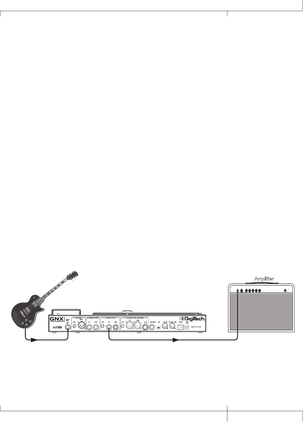
Single Amp
For a simple guitar-to-workstation-to-amp setup, just plug your guitar into the
GUITAR INPUT (on the back panel) and plug the LEFT 1/4” BALANCED OUTPUT
into your amp. Turn Speaker Compensation off for the 1/4” OUTPUTS (see page
24).
Guitar Input Left 1/4" Balanced Output
Amplifier
GNX3000 Owner’s Manual
3GNX3000 Owner’s Manual
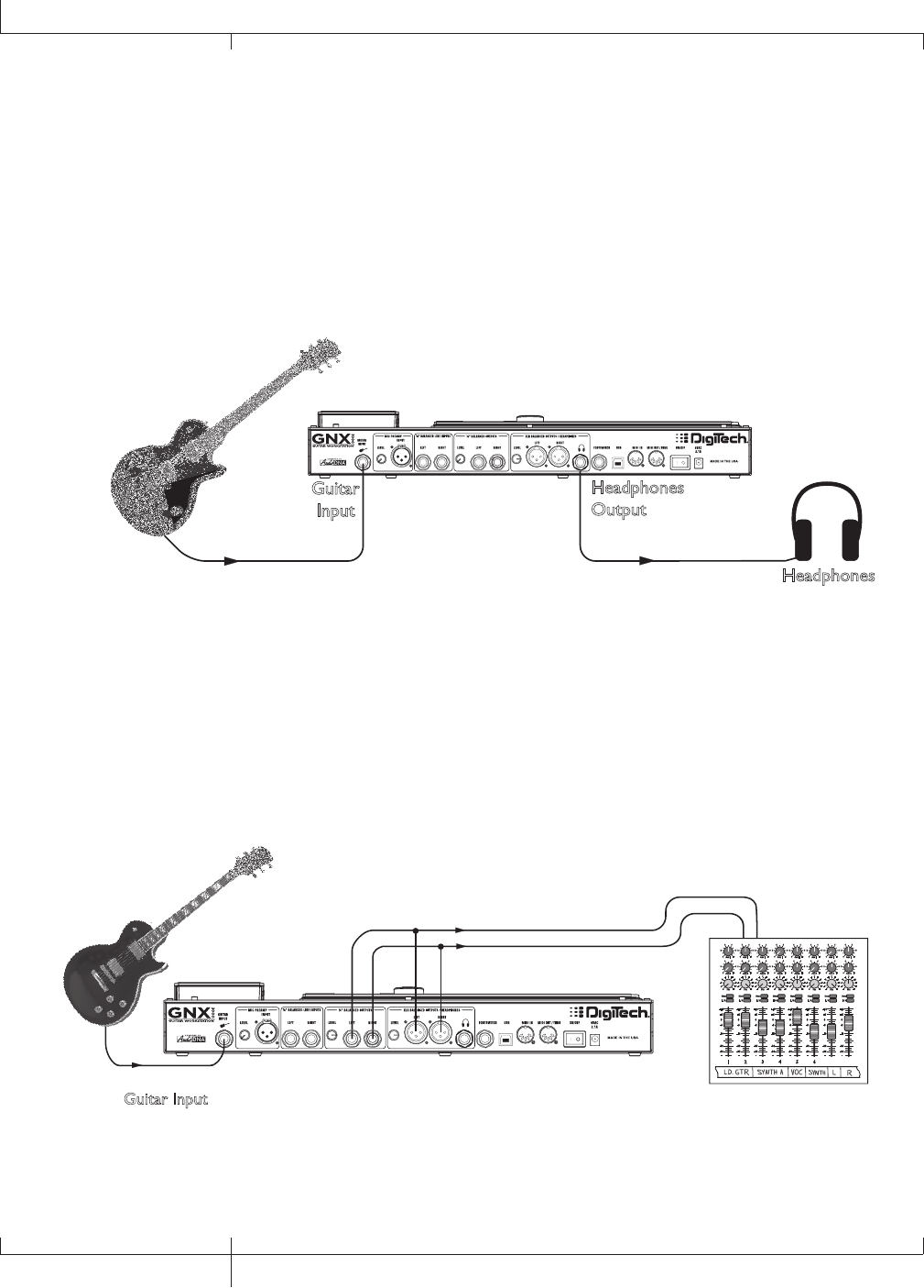
Headphones
This setup is ideal for practicing when neighbors, roommates or significant others
don’t want to listen. Plug your guitar into the GUITAR INPUT and plug your
headphones into the HEADPHONE OUTPUT. Note that the HEADPHONE OUTPUT
is a 1/4” jack, so if your headphones have an 1/8” jack, you’ll need an adapter
(available at your local electronics store). Turn Speaker Compensation on for the
XLR OUTPUTS (see page 24) which also enables it for the headphones.
Guitar
Input
Headphones
Output
Headphones
Mixer
To connect to a mixer, plug your guitar into the GUITAR INPUT, and connect the
GNX3000’s LEFT and RIGHT XLR or 1/4” BALANCED OUTPUTS to your mixer’s left
and right inputs. Turn Speaker Compensation on for the 1/4” and XLR OUTPUTS
(see page 24).
or
Guitar Input
Pan
Mute
-10
0
+5
+10
-20
-30
-
-5
L / R
Mute
L / R
Mute
L / R
Mute
L / R
-5
-4
-3
-2
-1 0+1
+2
+3
+4
+5 Pan
-5
-4
-3
-2
-1 0+1
+2
+3
+4
+5 Pan
-5
-4
-3
-2
-1 0+1
+2
+3
+4
+5 Pan
-5
-4
-3
-2
-1 0+1
+2
+3
+4
+5 Pan
-5
-4
-3
-2
-1 0+1
+2
+3
+4
+5 Pan
-5
-4
-3
-2
-1 0+1
+2
+3
+4
+5 Pan
-5
-4
-3
-2
-1 0+1
+2
+3
+4
+5 Pan
-5
-4
-3
-2
-1 0+1
+2
+3
+4
+5
1 2 3 4
-10
0
+5
+10
-20
-30
-
-5
-10
0
+5
+10
-20
-30
-
-5
-10
0
+5
+10
-20
-30
-
-5
Mute
L / R
5
-10
0
+5
+10
-20
-30
-
-5
Mute
L / R
6
-10
0
+5
+10
-20
-30
-
-5
Mute
L / R
-10
0
+5
+10
-20
-30
-
-5
Aux 1
0
2
4 6
8
10
Aux 2
0
2
4 6
8
10
Aux 1
0
2
4 6
8
10
Aux 2
0
2
4 6
8
10
Aux 1
0
2
4 6
8
10
Aux 2
0
2
4 6
8
10
Aux 1
0
2
4 6
8
10
Aux 2
0
2
4 6
8
10
Aux 1
0
2
4 6
8
10
Aux 2
0
2
4 6
8
10
Aux 1
0
2
4 6
8
10
Aux 2
0
2
4 6
8
10
Aux 1
0
2
4 6
8
10
Aux 2
0
2
4 6
8
10
Aux 1
0
2
4 6
8
10
Aux 2
0
2
4 6
8
10
Mute
L / R
-10
0
+5
+10
-20
-30
-
-5
Mixer
4
Quick Start
GNX3000 Owner’s Manual
Selecting Presets and Amp Models
Once you’re connected to the GNX3000, you can immediately transform the tone
of your guitar with the 130 Factory presets. (There are also 65 User presets you can
customize; learn how to create a custom preset on page 81.) Within each preset you
can also select different amp models that will further alter your guitar’s tone.
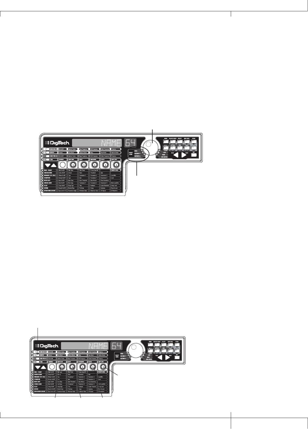
Presets
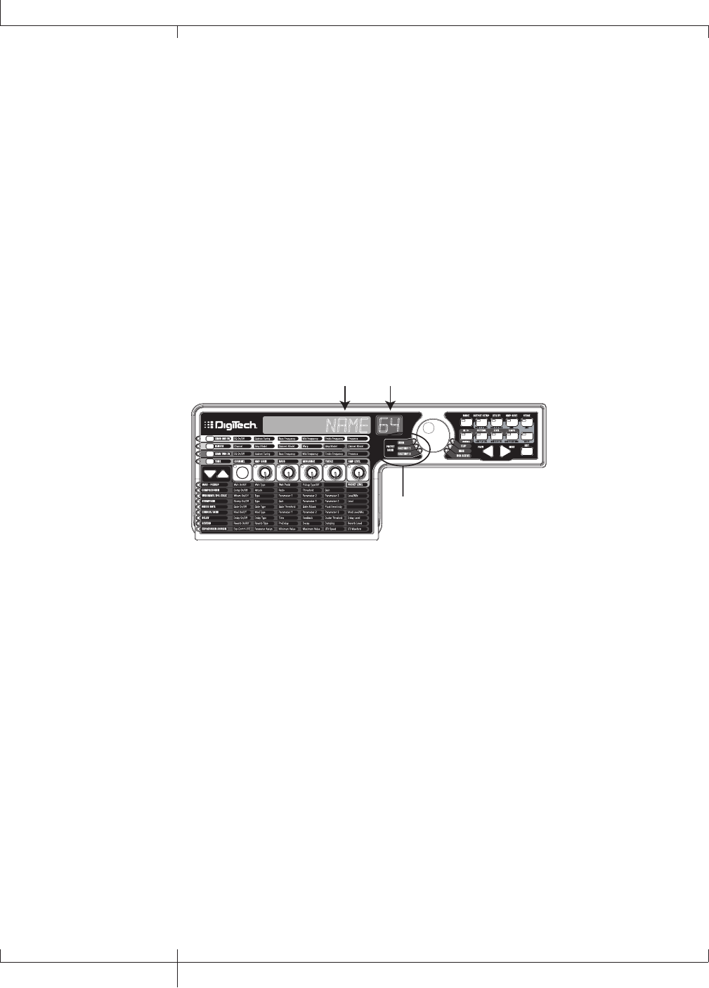
Turn the DATA WHEEL to scroll through the presets. The number and name in the
DISPLAYS change as you turn the DATA WHEEL. When you stop turning the DATA
WHEEL, the selected preset is automatically loaded. Play your guitar to hear it.
NAME 64
Preset Bank LEDs
Data Wheel
Look at the Preset Bank LEDs to the left of the DATA WHEEL, and notice that
either the User, Factory 1 or Factory 2 LED is lit. When you get to the end of one
bank, you start at the beginning of the next bank.
Amp and Cabinet Models
You can choose and customize a virtual amp/cabinet combo to run your guitar
signal through. (In this case, “amp” refers to the head, where all the knobs and
tubes or electronics reside, and “cabinet” refers to the enclosure where the
speakers are mounted.) For example, you can select the 62 bman amp model,
which by default uses two 12-inch speakers in a Blonde cabinet (Blnd2x12).
Then, if you want to, you can change the cabinet to a British model with four 12-
inch speakers (Brit4x12), which would result in the sound of a Bassman® head
powering British speakers.
NAME 64
GENETX Button
Knob 1 Knob 2 Knob 4
Knob 5
GNX3000 Owner’s Manual
5GNX3000 Owner’s Manual
To select an Amp and Cabinet model:
1. Push the GENETX BUTTON.
2. Turn KNOB 1 or KNOB 4 to select an amp model.
3. Turn KNOB 2 or KNOB 5 to select a cabinet model.
See page 44 for more information about Amp/Cabinet modeling.
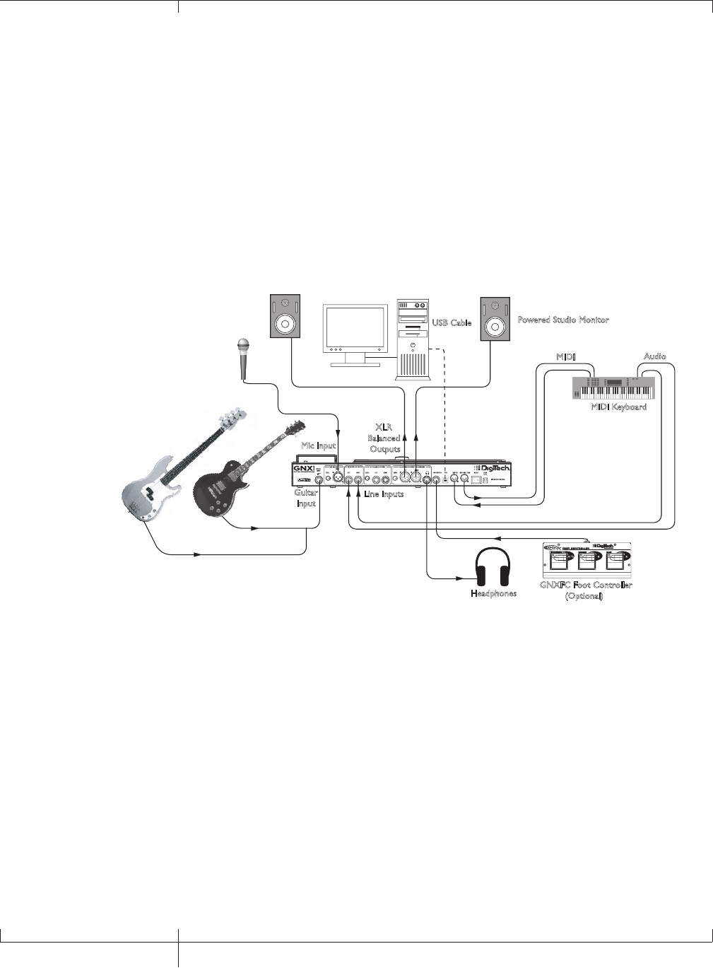
Recording - Computer
If you’re ready to start recording, here’s how to connect the GNX3000 to your
computer. You’ll also need to install the included software; see page 101 for more
information.
Guitar
Input
Line Inputs
XLR
Balanced
Outputs
MIDI Keyboard
MIDI Audio
Microphone
Headphones
Powered Studio Monitor
Powered Studio Monitor USB Cable
Computer
GNXFC Foot Controller
(Optional)
Mic Input
1. Connect your guitar (or bass guitar) to the GNX3000’s GUITAR INPUT.
2. Connect a microphone to the GNX3000’s MIC INPUT and use the MIC LEVEL
control knob located next to the MIC INPUT on the GNX3000’s rear panel to
adjust the microphone output level. To adjust your microphone input level for
optimal use see Mic Level Optimization on page 26.
3. Connect a keyboard, line level instrument, or stereo mixer (for feeding
submixes) to the GNX3000’s LEFT and RIGHT LINE INPUTS. To adjust your line
input levels for optimal use see Line Level Optimization on page 26.
4. Connect XLR cables from the GNX3000’s LEFT and RIGHT XLR OUTPUTS
to powered studio monitors, OR connect a pair of stereo headphones to the
HEADPHONE OUTPUT.
5. Connect a GNXFC Foot Controller (optional) to the GNX3000’s FOOTSWITCH
JACK.
6
Quick Start
GNX3000 Owner’s Manual

6. Connect the GNX3000 to your computer’s USB JACK using the included USB
cable.
ATTENTION: Refer to the “Installing the GNX3000’s Software Suite” section on page
101 before connecting the GNX3000 to the USB port on your PC and using Pro Tracks
Plus.
7. Connect a MIDI keyboard to the GNX3000’s MIDI IN and OUT/THRU JACKS
using 5 Pin MIDI cables.
8. Press the GNX3000’s OUTPUT SETUP button and select STEROALL as the
output mode using the DATA WHEEL.
9. Turn Speaker Compensation on for the XLR OUTPUTS (see page 24).
See page 24 for more information about Speaker Compensation.
GNX3000 Owner’s Manual
7GNX3000 Owner’s Manual
Highlights of the GNX3000
This section gives you a breakdown of the GNX3000’s main areas.
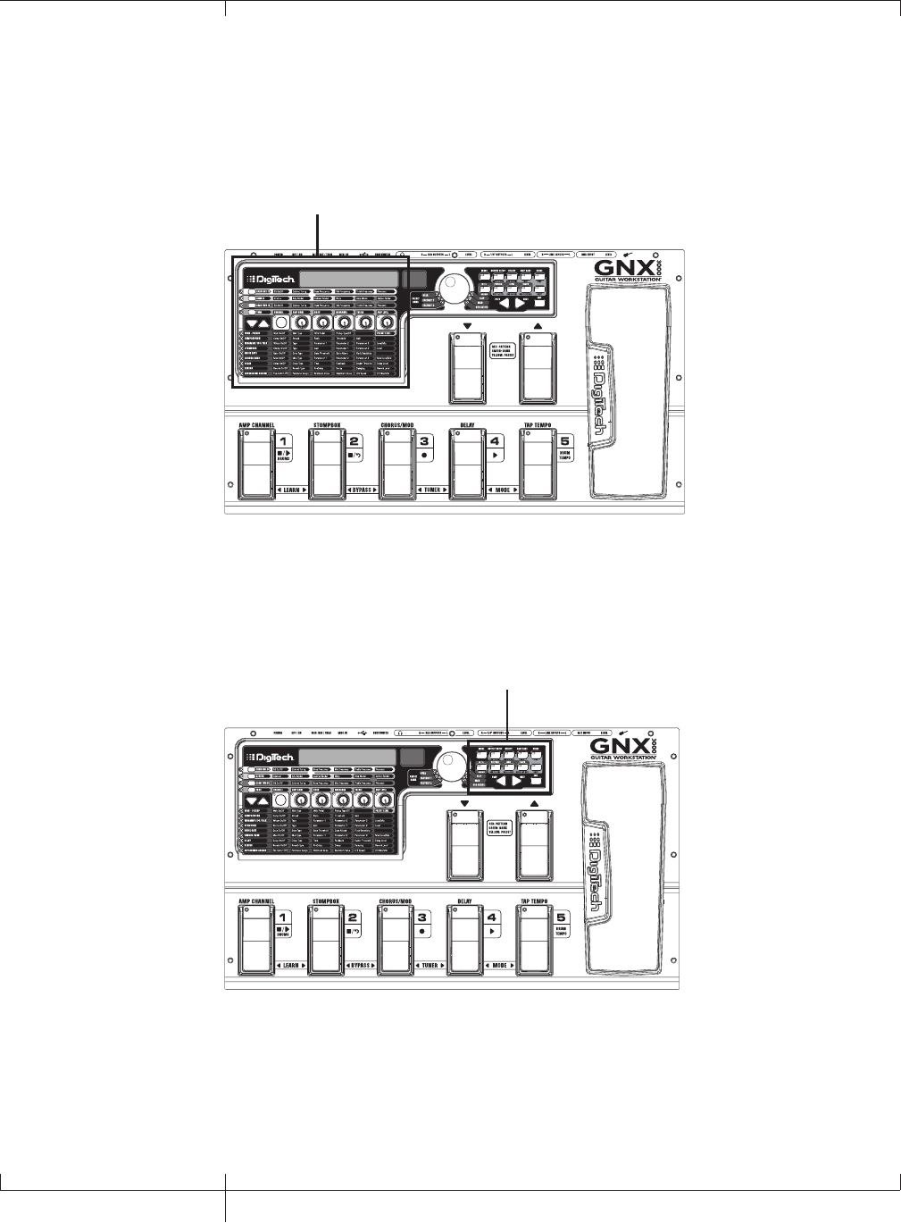
The Programming Matrix
Programming Matrix
This panel is divided into two main sections: the Amp/Cabinet section and the Effects
section. If the Amp/Cabinet section is active, you can select and adjust amp and
cabinet models and configurations. If the Effects section is active, you can select and
adjust effects. The knobs adjust settings for whichever section is active.
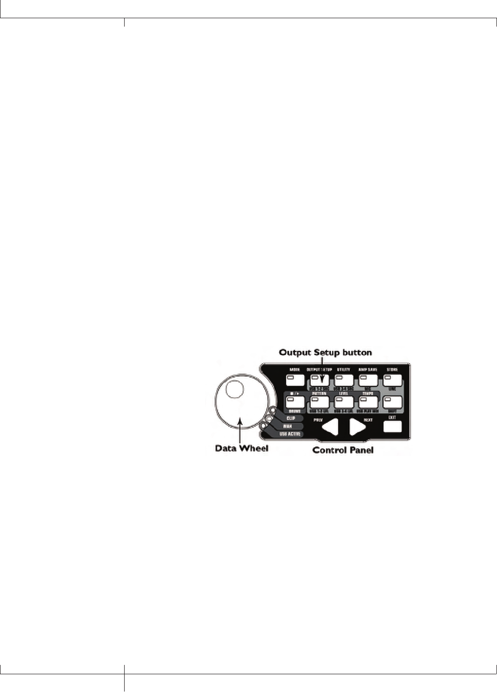
The Control Panel
Control Panel
These buttons control several “nuts and bolts” operations of the GNX3000. You can
use them to change the footswitch mode you’re in (page 36), choose output options
(page 20), audio setup for recording (page 31), control the drum machine (page 99),
save preset settings (page 92), and perform many other functions.
8
Highlights of the GNX3000
GNX3000 Owner’s Manual
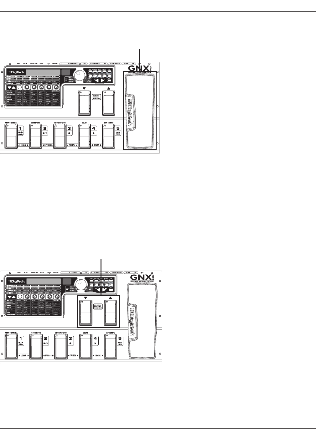
The Expression Pedal
Expression Pedal
The EXPRESSION PEDAL can control up to three parameters at a time for any preset.
For example, you could assign Chorus speed, Chorus depth, and volume to the
EXPRESSION PEDAL so that they all increase when you rock it forward, and decrease
when you rock it backward. See page 75 for more information about assigning
functions to the EXPRESSION PEDAL.
You can turn the Wah pedal on or off by rocking the EXPRESSION PEDAL all the way
forward (toe down), and pressing down firmly on the toe until WAH ON or WAH
OFF appears in the display.
Down/Up Footswitches
Down/Up Footswitches
Depending on the mode, these footswitches select drum patterns or navigate through
presets and preset banks. See page 36 for more on modes.
GNX3000 Owner’s Manual
9GNX3000 Owner’s Manual
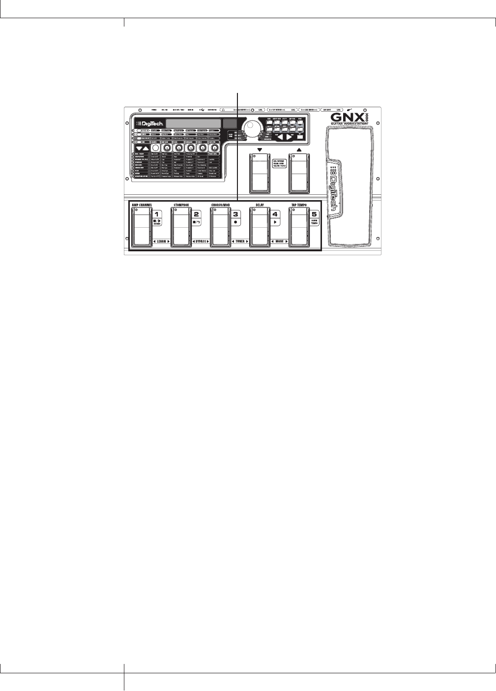
Footswitches 1-5
Footswitches 1-5
Depending on the mode, these five footswitches select presets, change amp channels,
turn individual effects on and off, control drum machine operations, and give you
Hands-FreeTM recording operation when recording on your computer. You can also
press pairs of footswitches to activate the Learn-A-LickTM feature, bypass individual
effects or the entire preset, access the tuner, or change the Footswitch modes.
10
Highlights of the GNX3000
GNX3000 Owner’s Manual

GNX3000 Owner’s Manual
11 GNX3000 Owner’s Manual
GNX3000 Special Features
This section describes some of the GNX3000’s unique characteristics in simple, easy-
to-understand language and directs you to the pages where you can learn more about
them.
Modes
The GNX3000 operates in one of three different modes. The active mode corresponds
directly to what functions the footswitches control. The modes are called Preset,
Stompbox, and Record/Drum. These modes are described in detail on page 36. The
short description goes like this: Preset Mode lets you easily change between groups of
presets; Stompbox Mode lets you change between individual presets and modify their
settings with the FOOTSWITCHES; Record/Drum Mode gives you Hands-FreeTM control
of the recording and drum machine functions.
To change modes, switch amp channels, and turn effects on and off, press the
MODE button (to the right of the DATA WHEEL) or step on FOOTSWITCHES 4 and 5
simultaneously. Each time the mode is changed, the name of the new mode will be
displayed briefly.
Amp Channels 1 and 2
Not only does the GNX3000 let you choose from a garage full of simulated amp head
and cabinet combinations (page 44), you can set up two different combinations within
the same preset and quickly switch back and forth between them.
For example, you can set up a Mesa/Boogie® Dual RectifierTM model amp on
Channel 1 and a ‘65 Fender® Deluxe Reverb® amp model on Channel 2. You can
play through either amp by switching channels with the AMP CHANNEL FOOTSWITCH
(FOOTSWITCH 1) when the GNX3000 is in Stompbox Mode.
Amp Channel - Warped
A third channel can exist in addition to Channel 1 and Channel 2; we call this the
Warped channel (yellow LED). Choose the Warped channel to hear a unique amp and
cabinet combination based on the amps and cabinets assigned to the Channel 1 and
Channel 2.
Refer to the Amp Channel Footswitch section on page 76 for more information.
HyperModels
A HyperModelTM is a custom user amp and cabinet model that is made by warping
two different amp/cabinet combinations together. You can select a HyperModel like
any other amp/cabinet model.
See page 81 for details about how to create a HyperModel; see page 44 for more on
amp and cabinet models.
GNX3000 Owner’s Manual
11 GNX3000 Owner’s Manual
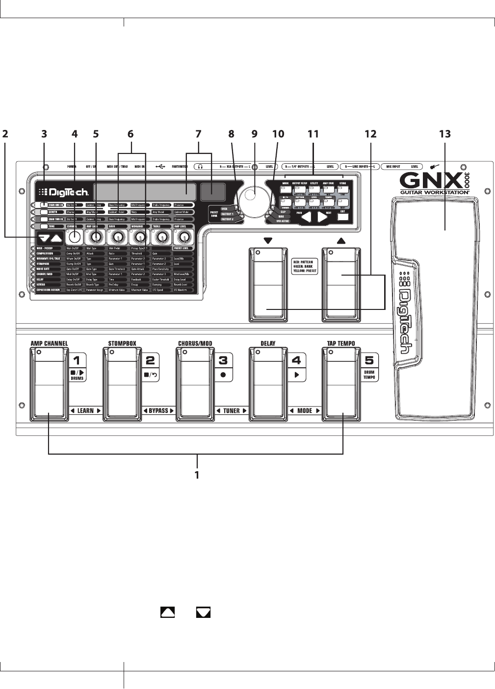
Getting Familiar with the GNX3000
The Front Panel
1. Footswitches 1-5
Depending on the selected mode, these five FOOTSWITCHES select presets, change
amp channels, turn individual effects on and off, and control drum machine and
recording operations. Learn-A-LickTM, Bypass, Tuner and Mode functions are
accessed by pressing the labeled pair of FOOTSWITCHES.
2. Effect Select Buttons
The and EFFECT SELECT buttons are used together with the Matrix LEDs
to choose the effects you want to edit.
12
Getting Familiar with the GNX3000
GNX3000 Owner’s Manual

3. Amp Control Buttons
The four AMP CONTROL buttons are used to select one of the amp/cabinet model
edit rows including: CHAN ONE EQ (Green), GENETX (Yellow), CHAN TWO EQ
(Red), and TONE (Silver).
4. Status button
The STATUS button has multiple functions that depend on the matrix row that is
selected. For example:
With the CHAN ONE EQ (Green) row selected, the STATUS button turns Channel
One’s EQ on and off.
With the GENETX (Yellow) amp/cabinet model row selected, the STATUS button
selects which amp you are listening to: Channel One, Channel Two, or the Warped
Amp (if a Warped state between both channels exists).
With the CHAN TWO EQ (Red) row selected, the STATUS button turns Channel
Two’s EQ on and off.
With the TONE (Silver) row selected, the STATUS button selects which amp you are
listening to: Channel One, Channel Two, or the Warped Amp (if a Warped state
between both channels exists). The Amp Gain, Bass, Midrange, Treble, and Amp
Levels alternate between editing Channel One’s (lit green) or Channel Two’s (lit
red) amp settings as the STATUS button is pressed.
When editing effects in the Effect Matrix, the STATUS button turns the selected
effect on and off, or selects a controller type for the expression assignment.
5. Knobs 1-5
After selecting one of the rows using the AMP CONTROL or EFFECT SELECT buttons,
these five knobs adjust the parameters listed in the column directly above or below
each knob.
6. Matrix
a. GeNetX™ Amp Controls Matrix
The GeNetX Amp Controls Matrix lists the Channel One and Channel Two
amp types, cabinet types, EQ/tone controls, and cabinet tuning parameters
available for editing in each preset.
b. Effects Matrix
The Effects Matrix lists the effects and effect parameters available for editing
in each preset.
GNX3000 Owner’s Manual
13 GNX3000 Owner’s Manual
14
GNX3000 Owner’s Manual
7. Displays
The Displays give feedback of the various functions that are being used in the
GNX3000, including preset name, editing functions, tuner, utility menus, and drum
machine settings.
8. Preset Bank LEDs
The Preset Bank LEDs indicate whether the selected preset resides in the User,
Factory 1, or Factory 2 banks.
9. Data Wheel
The DATA WHEEL is a multi-function control used for selecting presets and editing
preset parameters. It is also used for adjusting the settings of the Drum Machine,
Utilities, Output Setup, Mic/Line Routings, and Recording Setup menus.
10. Status Indicator LEDs (Clip, Wah, and USB Active)
There are three Status Indicator LEDs. The CLIP LED illuminates when one of the
four input signals clip (is at or above their maximum input level), The WAH PEDAL
LED lights when the Wah pedal is active. The USB LED lights when the USB
connection is active.
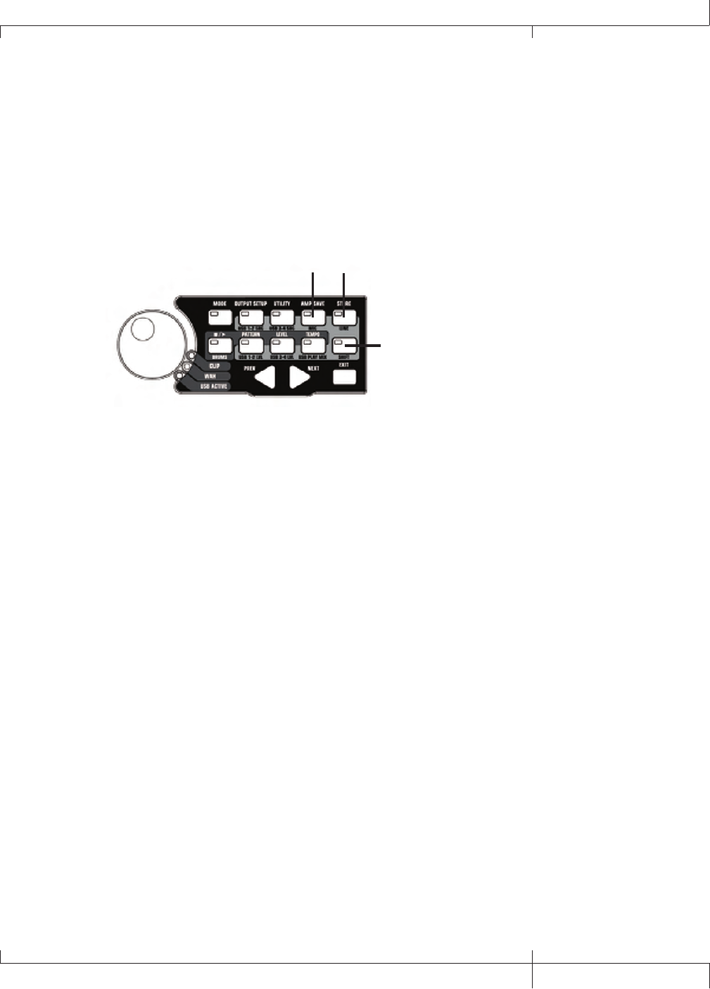
11. Control Panel Buttons
The Control Panel buttons are used to select the GNX3000’s Footswitch Modes,
Output Setups, and Utility functions, and to store Amp/Cabinet Model edits and
Preset changes. They also access the GNX3000’s Drum Machine functions as well
as mic/line routing and USB input source routing for recording. The buttons are
labeled as follows:
MODE - This button changes the functionality of the DOWN/UP FOOTSWITCHES
and FOOTSWITCHES 1-5 (see the Footswitch Functions for Modes section on page
94). Each time the mode is changed, the name of teh new mode is displayed
briefly.
OUTPUT SETUP - This button selects one of the GNX3000 Audio Output Setups:
Stereo All, Mono All, Mono 1/4”, Mono XLR, Split 1 and Split 2. Stereo and Mono
All have all the input sources (guitar, mic, line inputs, drums, and audio playback
from USB) routed to both output pairs in either stereo or mono respectively. Split 1
routes the guitar signal to just the 1/4” OUTPUTS while all other sources are routed
out the XLR OUTPUTS. Split 2 is the same as Split 1 but the guitar signal is also
routed out the XLR OUTPUTS. See page 24 for more information about Speaker
Compensation for XLR and 1/4” OUTPUTS.
UTILITY - This button accesses the GNX3000’s global functions including:
Volume Pedal Update, Expression Pedal Calibration, Preset Bounceback, Bank
Naming, MIDI Channel selection, Sysex Bulk Dump, MIDI Preset Dump, User
14
Getting Familiar with the GNX3000
GNX3000 Owner’s Manual
GNX3000 Owner’s Manual
15 GNX3000 Owner’s Manual
HyperModel™ Amp Dump, MIDI Mapping, MIDI Merge, USB Mode and Factory
Reset (see the Utilities section on page 118).
AMP SAVE - This button stores Amp and Cabinet changes (tone, gain, level, amp
type, cabinet type, warp, EQ or cabinet tuning) as HyperModelsTM.
STORE - This button is used to save Preset edits to the User Presets bank.
(STOP/PLAY) DRUMS - This button is used to turn the General MIDI
Drum Machine on and off. See page 99 for a list of drum patterns and page 128
for a list of samples.
PATTERN - Pressing this button and using the DATA WHEEL selects Drum
machine patterns.
LEVEL - Pressing this button and using the DATA WHEEL adjusts the Drum
Machine output level.
TEMPO - Pressing this button and using the DATA WHEEL adjusts the Drum
Machine.
SHIFT - When this button is lit, the secondary functions labeled below each
button are now active.
USB 1-2 SRC - Selects what input sources are to be recorded up the USB 1-2
channels.
USB 3-4 SRC - Selects what input sources are to be recorded up the USB 3-4
channels.
MIC - Selects the Mic Input Routing menu and how the mic signal is routed
through the GNX3000’s effects processing for both recording and live
performance.
LINE - Selects the Line Input Routing menu and how both LINE INPUTS are
routed through the GNX3000’s effects processing for both recording and live
performance.
USB 1-2 LVL - A gain/attenuation control to optimize the level of sources
being recorded up the USB 1-2 channels.
USB 3-4 LVL - A gain/attenuation control to optimize the level of sources
being recorded up the USB 3-4 channels.
GNX3000 Owner’s Manual
15 GNX3000 Owner’s Manual

16
GNX3000 Owner’s Manual
USB PLAY MIX - Controls the level balance between the GNX3000’s
processing and the USB stream played back from your computer. This button
is inactive when there is no active USB connection to a computer. The display
will read NO USB if the button is pushed for this case.
NOTE: When connected to the computer it is possible to lose your audio input
signal levels from the GUITAR, MIC, and/or LINE INPUTS if the USB Play/Mix
control is all the way down (GNX mix = 0).
PREV/NEXT - Use these buttons to scroll through the active selection’s menus or
values.
EXIT - Exits all functions back to the preset name display.
12. Down/Up Footswitches
These FOOTSWITCHES move up and down through the User preset banks (Preset
Mode), navigate through presets (Stompbox Mode), and select drum patterns
(Record/Drum Mode).
13. Expression Pedal
The EXPRESSION PEDAL controls up to three effect parameters in real time. Most
GNX3000 parameters can be assigned to the EXPRESSION PEDAL. Applying extra
pressure to the toe of the EXPRESSION PEDAL changes the EXPRESSION PEDAL’s
function to control the Wah.
16
GNX3000 Owner’s Manual
Getting Familiar with the GNX3000
GNX3000 Owner’s Manual
17 GNX3000 Owner’s Manual
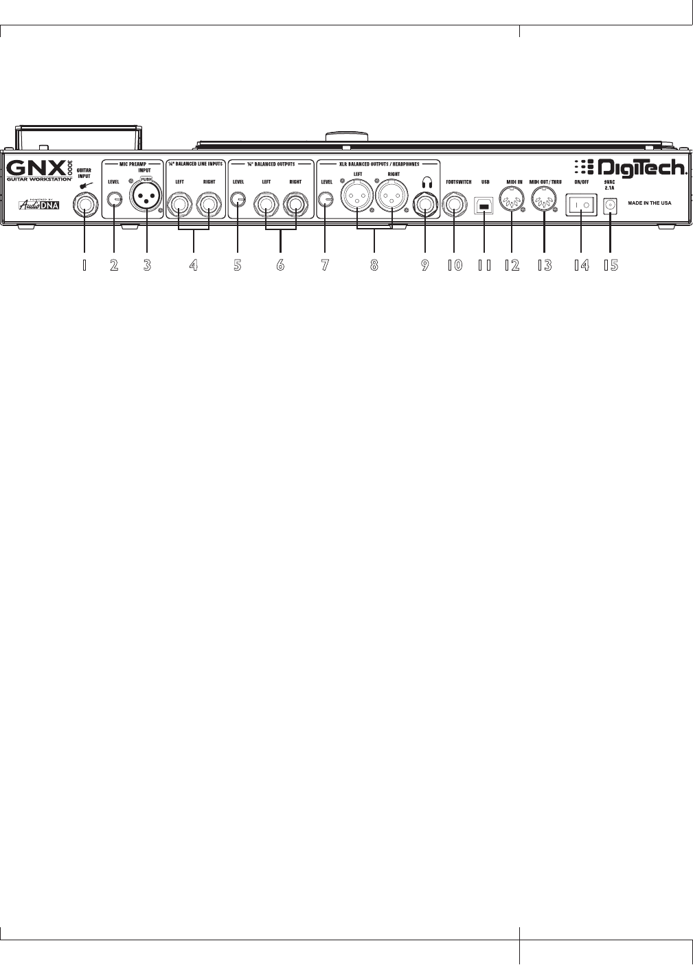
The Rear Panel
12 3 4 5 6 7 8 9 10 11 12 13 14 15
1. Guitar/Instrument Input
Connect your guitar/instrument to this jack.
2. Mic Level
Controls the gain of the MIC INPUT preamp.
3. Microphone Input
Connect a low impedance microphone to this jack for recording vocals or acoustic
instruments. It can also be used for the Talker™ Vocoder effect (see Talker on
page 57). The mic signal can remain dry or processed through the GNX3000’s
effects for live and recording applications (see page 25 for more information). The
Microphone Input is equipped with built-in phantom power (which is always on)
for use with condenser or ribbon mics that require phantom power.
4. Left/Right Balanced Line Inputs
Connect line level sources to these jacks for recording or live performance
mixing into the GNX3000. Line signals can remain dry or be processed through
the GNX3000’s effects for live and recording applications (see page 25 for more
information).
5. Output Level (1/4” Outputs Only)
Controls the overall volume level of the 1/4" OUTPUTS of the GNX3000.
6. Left/Right 1/4" Balanced Line Outputs
Connect these outputs to your guitar amplifier(s), power amplifier(s), or to a
mixing console that accepts 1/4" balanced connections.
7. Output Level (XLR and Headphone Outputs Only)
Controls the overall volume level of the balanced XLR and HEADPHONE OUTPUTS
of the GNX3000.
GNX3000 Owner’s Manual
17 GNX3000 Owner’s Manual

18
GNX3000 Owner’s Manual
8. Left/Right XLR Balanced Outputs
Connect these outputs to your power amplifier/speaker system or to a mixing
console that accepts XLR balanced connections. DigiTech® recommends that you
do not connect these GNX3000 XLR outputs to mixer or console channels that
have phantom power enabled.
9. Headphone Output
Connect a pair of stereo headphones to this jack. DO NOT connect a mono plug to
this jack, as it may damage the output driver.
10. Footswitch
(OPTIONAL ) Connect a GNXFC footswitch to this jack for remote control of the
GNX3000’s record functions.
11. USB Jack
Connect this jack to your computer’s USB port for hard disk recording and
computer preset editing via the X-Edit™ Editor/Librarian software. A standard
USB cable is included. The GNX3000 is compatible with USB 2.0 high speed ports,
however the USB 2.0 bus will switch to a USB v1.1 full speed (up to 12 Mbps) data
rate to work with the GNX3000.
ATTENTION: Refer to the “Installing the GNX3000’s Software Suite” section on page
101 before connecting the GNX3000 to the USB port on your PC and using Pro Tracks
Plus.
12. MIDI In
The MIDI In jack receives all incoming MIDI data including MIDI preset
changes. MIDI preset changes and CC control messages received from external
MIDI devices connected to the MIDI In jack can be used to control the GNX3000
and its preset parameters. When the GNX3000 is connected to the computer
via USB, the MIDI In can be used as a MIDI interface for recording any MIDI
data in Pro Tracks Plus™ or other MIDI recording software. (See page 129 for the
MIDI CC table.)
13. MIDI Out/Thru
The MIDI Out/Thru jack sends MIDI data from the GNX3000 MIDI preset
changes. When the GNX3000 is connected to the computer via USB, it can act as
a MIDI interface for sending MIDI data from Pro Tracks Plus™ or other MIDI
recording software to external keyboards or sound modules. When MIDI Merge
is enabled in the Utility menu, the MIDI Out acts as a MIDI Thru for any data
coming into the GNX3000 from the MIDI In jack. (See page 129 for the MIDI CC
table.)
18
GNX3000 Owner’s Manual
Getting Familiar with the GNX3000

GNX3000 Owner’s Manual
19 GNX3000 Owner’s Manual
14. Power Switch
Turns the power on and off.
15. Power Input
Connect only the provided DigiTech PSS3 power supply to this jack.
GNX3000 Owner’s Manual
19 GNX3000 Owner’s Manual
20
GNX3000 Owner’s Manual
Audio Routing Setups
Setups Introduction
The GNX3000 is equipped with four inputs and four outputs that can be configured
several different ways for both live and recording applications. These settings determine
which pair of outputs the guitar processing, MIC and LINE INPUTS are routed to and
how the MIC or LINE INPUTS are routed through the GNX3000’s effects processing.
For example, today you may be practicing with headphones, tomorrow you may be
recording on your computer, and next week you might be performing at a club, running
your guitar and vocals through monitors and a PA system. The GNX3000 has different
input/output options that are designed for each of those situations, and more.
Output Setups
The GNX3000 features both 1/4" and XLR OUTPUTS on the rear panel. These jacks let
you simultaneously connect the GNX3000 to an amplifier/speaker system on stage via
the 1/4" OUTPUTS and connect directly to your PA system via the XLR OUTPUTS.
Press the OUTPUT SETUP button and turn the DATA WHEEL to select one of the Output
Setup options. Press the EXIT button to save your selection.
20
GNX3000 Owner’s Manual
Audio Routing Setups
GNX3000 Owner’s Manual
21 GNX3000 Owner’s Manual
The six OUTPUT SETUPS are as follows:
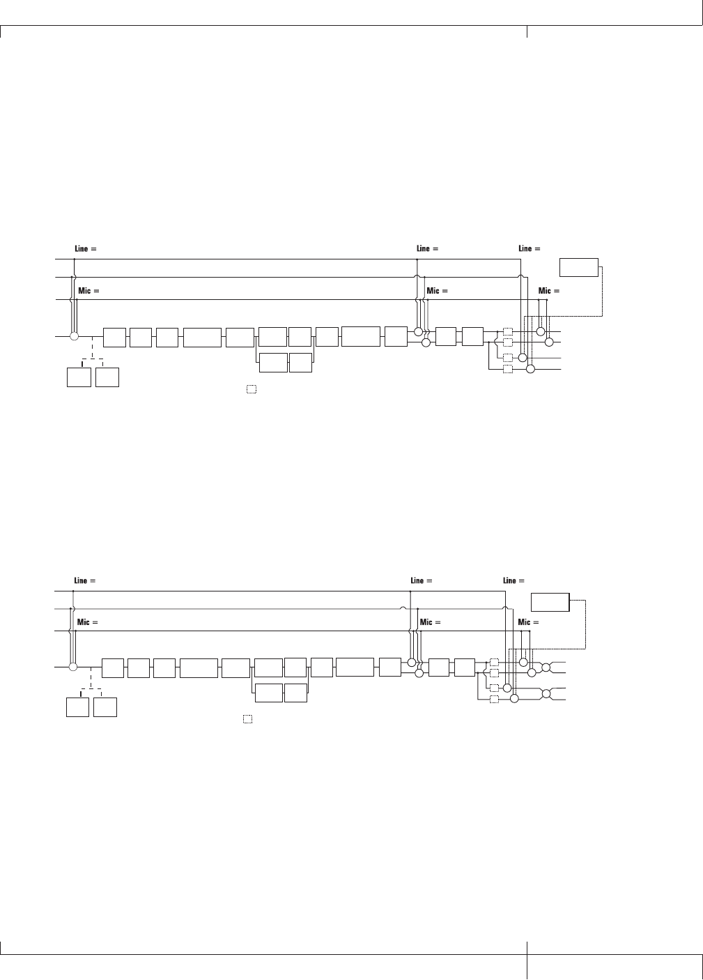
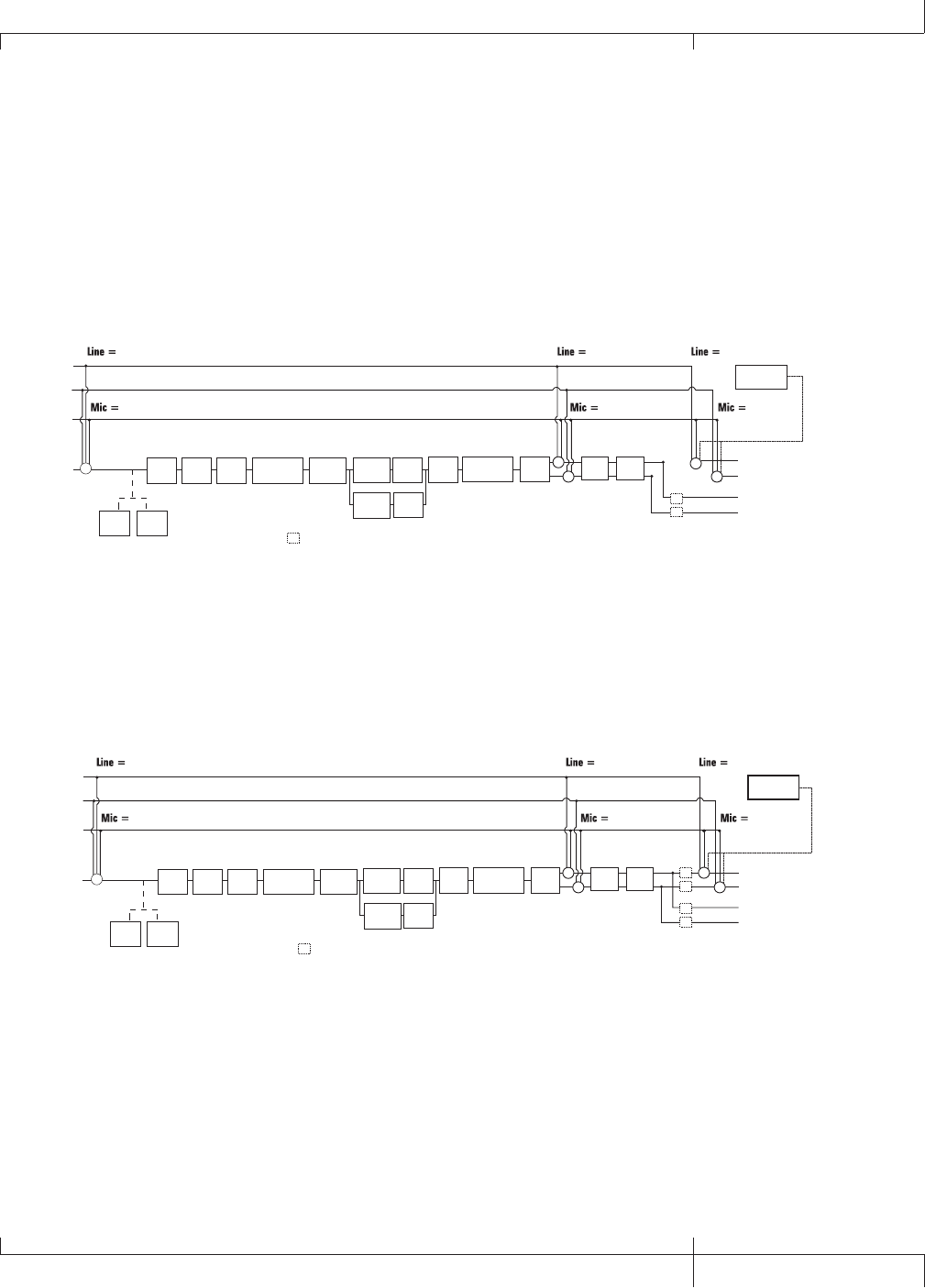
Stereo All ( steroall )
All input sources (guitar, mic, line inputs, drums, and USB playback) are routed
to both output pairs in stereo. Speaker Compensation can be turned on and off
independently for either the 1/4” or XLR OUTPUTS using the Speaker Compensation
menus (see page 24).
Mic Input
Guitar Input
Line Left
Line Right
mic rvb mic dry
line rvb line dry
DRUMS &
USB PLAYBACK
SC
mic fx
l
i
n
e
f
x
= Speaker Compensation Module
Delay Reverb
+
+
XLR Left Output
XLR Right Output
1/4" Left Output
1/4" Right Output
+
+
+SC
SC
SC
SC
Pickup
Sim Wah Comp Stompbox CH 1
Cabinet
Comp
Detector
Gate
Detector
Whammy/IPS
(except
Talker)
CH 1 Amp
Modeling/
Tone
CH 1
Cabinet
CH 1 Amp
Modeling/
Tone
CH 2
Cabinet
CH 2 Amp
Modeling/
Tone
Gate
Whammy/IPS
(Talker)
Chorus/
Mod
+
+
Mono All ( mono all)
All input sources (guitar, mic, line inputs, drums, and USB playback) are routed to both
output pairs in mono. Speaker Compensation can be turned on and off independently
for either the 1/4” or XLR OUTPUTS using the Speaker Compensation menus (see page
24).
Mic Input
Guitar Input
Line Left
Line Right
mic rvb mic dry
line rvb line dry
SC = Speaker Compensation Module
mic fx
l
i
n
e
f
x
Delay Reverb
+
+
XLR Left Output
XLR Right Output
1/4" Left Output
1/4" Right Output
+
+
+SC
SC
SC
SC
Pickup
Sim Wah Comp Stompbox CH 1
Cabinet
Comp
Detector
Gate
Detector
Whammy/IPS
(except
Talker)
CH 1 Amp
Modeling/
Tone
CH 1
Cabinet
CH 1 Amp
Modeling/
Tone
CH 2
Cabinet
CH 2 Amp
Modeling/
Tone
Gate
Whammy/IPS
(Talker)
Chorus/
Mod
+
+
+
+
DRUMS &
USB PLAYBACK
GNX3000 Owner’s Manual
21 GNX3000 Owner’s Manual
22
GNX3000 Owner’s Manual
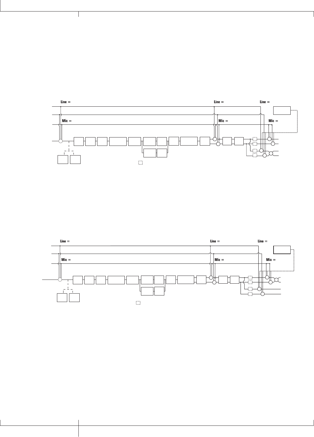
Mono 1/4 ( mono 1/4 )
All input sources (guitar, mic, line inputs, drums, and USB playback) are routed to the
1/4" OUTPUTS in mono. All input sources routed to the XLR OUTPUTS maintain stereo
separation. Speaker Compensation can be turned on and off independently for either
the 1/4” or XLR OUTPUTS using the Speaker Compensation menus (see page 24).
Mic Input
Guitar Input
Line Left
Line Right
mic rvb mic dry
line rvb line dry
SC
mic fx
line fx
= Speaker Compensation Module
Delay Reverb
+
+
XLR Left Output
XLR Right Output
1/4" Left Output
1/4" Right Output
+
+
+SC
SC
SC
SC
Pickup
Sim Wah Comp Stompbox CH 1
Cabinet
Comp
Detector
Gate
Detector
Whammy/IPS
(except
Talker)
CH 1 Amp
Modeling/
Tone
CH 1
Cabinet
CH 1 Amp
Modeling/
Tone
CH 2
Cabinet
CH 2 Amp
Modeling/
Tone
Gate Whammy/IPS
(Talker)
Chorus/
Mod
+
++
DRUMS &
USB PLAYBACK
Mono XLR ( mono xlr )
All input sources (guitar, mic, line inputs, drums, and USB playback) are routed to the
XLR OUTPUTS in mono. All input sources routed to the 1/4” OUTPUTS maintain stereo
separation. Speaker Compensation can be turned on and off independently for either
the 1/4” or XLR OUTPUTS using the Speaker Compensation menus (see page 24).
Mic Input
Guitar Input
Line Left
Line Right
mic rvb mic dry
line rvb line dry
SC
mic fx
line fx
= Speaker Compensation Module
Delay Reverb
+
+
XLR Left Output
XLR Right Output
1/4" Left Output
1/4" Right Output
+
+
+SC
SC
SC
SC
Pickup
Sim Wah Comp Stompbox CH 1
Cabinet
Comp
Detector
Gate
Detector
Whammy/IPS
(except
Talker)
CH 1 Amp
Modeling/
Tone
CH 1
Cabinet
CH 1 Amp
Modeling/
Tone
CH 2
Cabinet
CH 2 Amp
Modeling/
Tone
Gate Whammy/IPS
(Talker)
Chorus/
Mod +
+
+
DRUMS &
USB PLAYBACK
22
GNX3000 Owner’s Manual
Audio Routing Setups
GNX3000 Owner’s Manual
23 GNX3000 Owner’s Manual
Split 1 ( split1 )
Stereo guitar processing and any inputs routed through the GNX3000’s guitar
processing are routed to the 1/4" OUTPUTS. Audio playback from the computer, mic
dry, line dry and drums is routed to the XLR OUTPUTS. Speaker Compensation can
be turned on and off independently for either the 1/4” or XLR OUTPUTS using the
Speaker Compensation menus (see page 24).
Mic Input
Guitar Input
Line Left
Line Right
mic rvb mic dry
line rvb line dry
SC
mic fx
line fx
= Speaker Compensation Module
SC
SC
DRUMS &
USB PLAYBACK
Delay Reverb
+
+
+
+
XLR Left Output
XLR Right Output
1/4" Left Output
1/4" Right Output
Pickup
Sim Wah Comp Stompbox CH 1
Cabinet
Comp
Detector
Gate
Detector
Whammy/IPS
(except
Talker)
CH 1 Amp
Modeling/
Tone
CH 1
Cabinet
CH 1 Amp
Modeling/
Tone
CH 2
Cabinet
CH 2 Amp
Modeling/
Tone
Gate Whammy/IPS
(Talker)
Chorus/
Mod
+
Split 2 ( split2 )
SPLIT2 is the same as SPLIT1 but the guitar processing is also routed out the XLR
OUTPUTS.
Mic Input
Guitar Input
Line Left
Line Right
mic rvb mic dry
line rvb line dry
mic fx
line fx
DRUMS &
USB PLAYBACK
Delay Reverb
+
++
XLR Left Output
XLR Right Output
1/4" Left Output
1/4" Right Output
SC
SC
SC = Speaker Compensation Module
Pickup
Sim Wah Comp Stompbox CH 1
Cabinet
Comp
Detector
Gate
Detector
Whammy/IPS
(except
Talker)
CH 1 Amp
Modeling/
Tone
CH 1
Cabinet
CH 1 Amp
Modeling/
Tone
CH 2
Cabinet
CH 2 Amp
Modeling/
Tone
Gate Whammy/IPS
(Talker)
Chorus/
Mod
+
SC
SC
+
GNX3000 Owner’s Manual
23 GNX3000 Owner’s Manual

24
GNX3000 Owner’s Manual
Speaker Compensation
Both the 1/4” and XLR OUTPUTS can be used in a variety of ways. They can be plugged
directly into guitar combo amp inputs, XLR inputs on a power amp connected to
an external speaker cabinet, into mixer channels, and directly into full range studio
monitors. Depending on which application you are using them for, you can enable or
disable Speaker Compensation on either output pair independently.
Speaker Compensation is to be used when the outputs of the GNX3000 will be played
through a full range speaker system and emulates the rolled off response that a guitar
cabinet normally provides without having to use one. An example of where you would
want Speaker Compensation turned on is when the outputs are connected to a mixer
which is connected to your band’s PA system, or when plugging the outputs directly
into powered studio monitors while recording.
When running into the front end of an amp or into a power amp connected to a guitar
speaker cabinet, you will most likely want Speaker Compensation disabled on the
outputs that are being used. If you want to use one set of outputs for running into
a guitar amp and the other pair for running direct to the PA, just enable Speaker
Compensation on the outputs connected to the mixer.
To enable or disable Speaker Compensation, follow these steps:
1. Press the OUTPUT SETUP button.
2. Use the NEXT button to select SC XLR in the DISPLAY and use the DATA
WHEEL to turn Speaker Compensation on or off (the default factory setting is
on).
3. Press the NEXT button again to select SC 1/4 in the display and use the DATA
WHEEL to turn Speaker Compensation on or off (the default factory setting is
off).
4. Press the EXIT button.
24
GNX3000 Owner’s Manual
Audio Routing Setups
GNX3000 Owner’s Manual
25 GNX3000 Owner’s Manual
Mic and Line Setups
You can configure the MIC and LINE INPUTS routing for live performance and
recording applications. The GNX3000 acts as a mixing device for MIC and LINE
INPUTS, and can eliminate the need for a mixer when the outputs are to be plugged
directly into a full-range powered speaker system. When enabled, these inputs can be
routed around or through some or all of the effects processing and then mixed directly
into the GNX3000’s 1/4” and XLR OUTPUTS.
Use the SHIFT>MIC and SHIFT>LINE buttons along with the DATA WHEEL to select the
Mic/Line Setup options.
Mic
Button
Line
Button
Shift
Button
Both MIC and LINE INPUTS have four settings that can be independently selected.
They are as follows:
MIC OFF/LINE OFF - MIC and LINE INPUTS are disabled.
MIC DRY/LINe DRY - MIC and LINE INPUTS are routed directly to GNX3000’s outputs,
bypassing all effects processing.
MIC RVB/LINe RVB - MIC and LINE INPUTS are routed through delay and reverb effects
of the current preset.
MIC FX/LINE FX - MIC and LINE INPUTS are routed through all effects of the current
preset.
For more information about how these settings are routed, refer to the charts on pages
21 through 23.
GNX3000 Owner’s Manual
25 GNX3000 Owner’s Manual

26
GNX3000 Owner’s Manual
Optimizing the Mic and Line Input Levels
To properly use MIC and LINE INPUTS for recording, it is best to optimize their levels
for best signal to noise performance. This can be done one of two ways on the
GNX3000:
Mic Level Optimization
The MIC INPUT has an input level that can be used for optimizing the levels for singing
live, recording tracks to the computer, and matching levels with your guitar. While
singing or during an acoustic performance, adjust the MIC INPUT level on the back
panel of the GNX3000 until the CLIP LED next to the CONTROL PANEL lights only
occasionally during the loudest parts of the performance.
Line Level Optimization
When an external source such as an electronic keyboard or a submix from an external
mixer is brought into the GNX3000’s LINE INPUTS, it is ideal to have enough level
control to optimize these signals from the source. If the signal is weak and cannot
be made strong enough from the source, you can increase the USB 1-2 level or USB
3-4 level until the CLIP LED lights only occasionally during the loudest parts of the
performance.
See more in the Computer Recording via USB section of this manual and your
recording application’s User’s Guide for more information on proper level adjustment
for recording.
26
Optimizing the Mic and Line Input Levels
GNX3000 Owner’s Manual
GNX3000 Owner’s Manual
27 GNX3000 Owner’s Manual
Hooking It Up
Live Performance Setups
The GNX3000 was designed to be extremely flexible to meet any of your application
needs. For many GNX3000 users, its primary purpose will be for use in live
performances. The following diagrams show examples of how to utilize the GNX3000
in typical live performance applications.
NOTE: Before making connections to the GNX3000, make sure both the GNX3000
and your amplifier(s) are turned OFF.
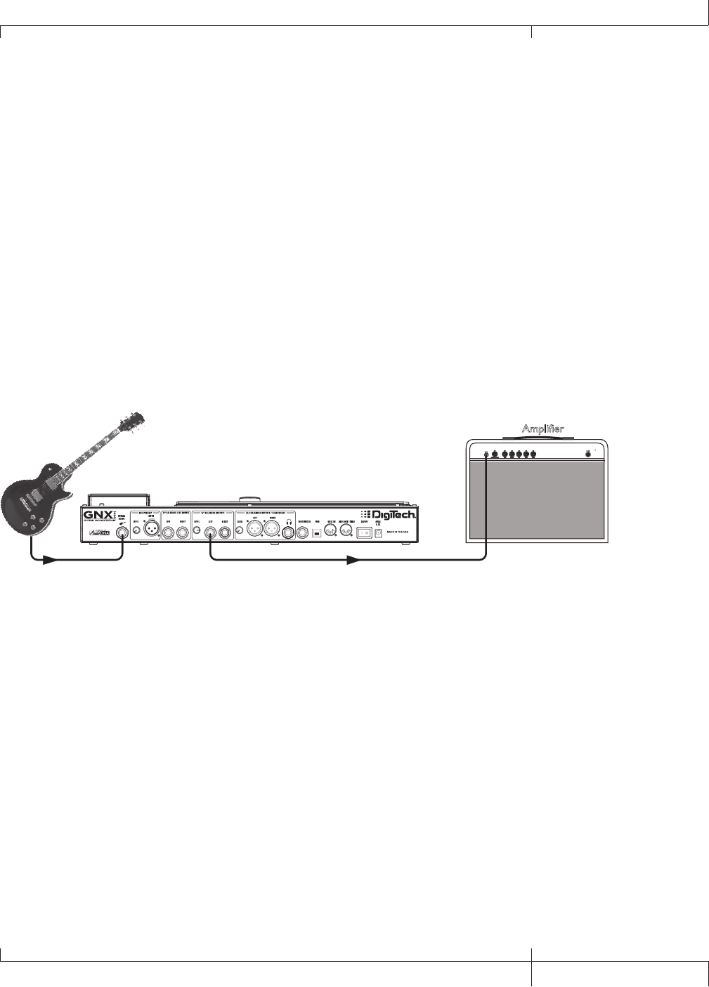
Small Club Setup (Mono Amp Rig)
This diagram demonstrates a minimum setup for using the GNX3000 in a typical, small
club performance setup. All you need is your guitar, two guitar cables, and an amp. This
connection scheme also applies for use with a power amp/speaker cabinet rig.
Guitar Input Left 1/4" Balanced Output
Amplifier
1. Connect your guitar to the GNX3000’s GUITAR INPUT.
2. Connect a single mono instrument cable from the LEFT 1/4" BALANCED OUTPUT
of the GNX3000 to the instrument input or the effect return on your amplifier.
3. Press the GNX3000’s OUTPUT SETUP button and select "MONO 1/4" mode using
the DATA WHEEL.
4. Turn OFF Speaker Compensation for the 1/4" BALANCED OUTPUTS in the 1/4”
Speaker Compensation menu (described on page 24).
NOTE: When connecting the GNX3000 to a guitar amp(s), it may be best to connect
the GNX3000’s Output to your amp’s effects return to avoid coloration of the tone
due to the amplifier’s tone controls.
GNX3000 Owner’s Manual
27 GNX3000 Owner’s Manual
28
GNX3000 Owner’s Manual
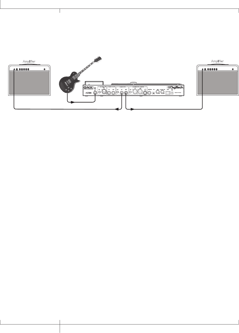
Medium Stage Setup (Stereo Amp Rig)
Whether your gig is at a large club or a small hall, nothing beats running your guitar
in stereo. This diagram demonstrates a typical setup using your GNX3000’s LINE
OUTPUTS, and two guitar combo amps.
Amplifier
Guitar Input
1/4" Balanced Outputs
Amplifier
1. Connect your guitar to the GUITAR INPUT.
2. Connect mono instrument cables from the LEFT and RIGHT 1/4” BALANCED
OUTPUTS of the GNX3000 to the instrument inputs or the effect returns on
your amplifiers.
3. Press the OUTPUT SETUP button and select “STEROAll” mode using the
DATA WHEEL.
4. Switch the Speaker Compensation for the 1/4” BALANCED OUTPUTS to OFF in
the Speaker Compensation menu described on page 24.
28
GNX3000 Owner’s Manual
Hooking It Up
GNX3000 Owner’s Manual
29 GNX3000 Owner’s Manual
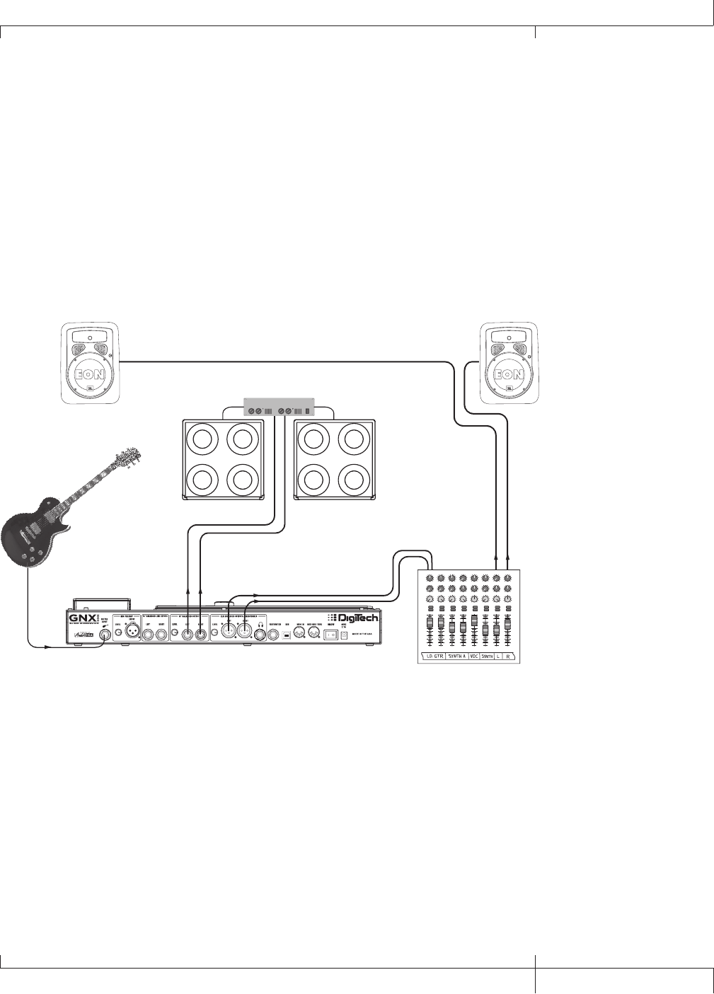
Large Stage Setup (Stereo Amp/Cabinet Rig)
A large stage rig lets you really pull out all the stops since space isn’t necessarily an
issue, but volume usually is. For this application, plug your guitar into the GNX3000
and connect mono instrument cables from the 1/4" OUTPUTS into a stereo power
amp feeding two cabinets. Using two cabinets gives you much more dramatic stereo
separation and helps widen the sweet spot for your sound when you move onstage.
Another great idea is to run the XLR OUTPUTS directly into the house P.A. and have
the sound engineer control your front of house volume in the overall mix. Then if
you need to turn up your stage volume, you won’t upset him by trying to rebalance
your guitar volume in the house mix. This diagram demonstrates a typical, large stage
performance setup.
Stereo Power Amp
2- Speaker Cabs
Guitar Input
PA Speaker (Left)
XLR Balanced Outputs
1/4" Balanced
Outputs
PA Speaker (Right)
Pan
Mute
-10
0
+5
+10
-20
-30
-
-5
L / R
Mute
L / R
Mute
L / R
Mute
L / R
-5
-4
-3
-2
-1 0+1
+2
+3
+4
+5 Pan
-5
-4
-3
-2
-1 0+1
+2
+3
+4
+5 Pan
-5
-4
-3
-2
-1 0+1
+2
+3
+4
+5 Pan
-5
-4
-3
-2
-1 0+1
+2
+3
+4
+5 Pan
-5
-4
-3
-2
-1 0+1
+2
+3
+4
+5 Pan
-5
-4
-3
-2
-1 0+1
+2
+3
+4
+5 Pan
-5
-4
-3
-2
-1 0+1
+2
+3
+4
+5 Pan
-5
-4
-3
-2
-1 0+1
+2
+3
+4
+5
1234
-10
0
+5
+10
-20
-30
-
-5
-10
0
+5
+10
-20
-30
-
-5
-10
0
+5
+10
-20
-30
-
-5
Mute
L / R
5
-10
0
+5
+10
-20
-30
-
-5
Mute
L / R
6
-10
0
+5
+10
-20
-30
-
-5
Mute
L / R
-10
0
+5
+10
-20
-30
-
-5
Aux 1
0
2
4 6
8
10
Aux 2
0
2
4 6
8
10
Aux 1
0
2
4 6
8
10
Aux 2
0
2
4 6
8
10
Aux 1
0
2
4 6
8
10
Aux 2
0
2
4 6
8
10
Aux 1
0
2
4 6
8
10
Aux 2
0
2
4 6
8
10
Aux 1
0
2
4 6
8
10
Aux 2
0
2
4 6
8
10
Aux 1
0
2
4 6
8
10
Aux 2
0
2
4 6
8
10
Aux 1
0
2
4 6
8
10
Aux 2
0
2
4 6
8
10
Aux 1
0
2
4 6
8
10
Aux 2
0
2
4 6
8
10
Mute
L / R
-10
0
+5
+10
-20
-30
-
-5
Mixer
1. Connect your guitar to the GUITAR INPUT.
2. Press the GNX3000’s OUTPUT SETUP button and select “STEROALL“ as the
output mode using the DATA WHEEL.
3. Connect mono instrument cables from the GNX3000’s LEFT and RIGHT 1/4"
LINE OUTPUTS to a stereo power amplifier and switch the 1/4” OUTPUTS
Speaker Compensation to OFF in the Speaker Compensation menu (described
on page 24).
4. Connect XLR cables from the GNX3000’s Left and Right XLR OUTPUTS to the
house P.A. mixer and switch the XLR OUTPUTS Speaker Compensation
to ON.
GNX3000 Owner’s Manual
29 GNX3000 Owner’s Manual
30
GNX3000 Owner’s Manual
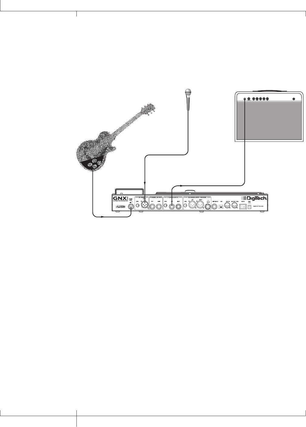
TalkerTM Performance Setup
The built-in Talker effect creates a talk box effect. To use this effect you must plug a
microphone into the GNX3000’s MIC INPUT and select one of the five Talker types in
the Whammy™/IPS/Talk module of a preset. Then as you play your guitar talk into the
microphone to emulate the talk box effect. The Talker can be used with any output
setup, but for this diagram it will be shown in conjunction with a mono amp rig.
Guitar Input
Microphone
Input
Left 1/4" Balanced Output
Microphone
Amplifier
1. Connect your guitar to the GNX3000’s GUITAR INPUT.
2. Press the GNX3000’s OUTPUT SETUP button and select "MONO 1/4" as the
output mode using the DATA WHEEL.
3. Connect a single mono instrument cable from the Left 1/4" LINE OUTPUT of
the GNX3000 to the instrument input or the effect return on your amplifier
and switch the 1/4" BALANCED OUTPUTS Speaker Compensation to OFF in the
Speaker Compensation menu described on page 24.
4. Connect a microphone to the GNX3000’s MIC INPUT using an XLR cable.
5. Select one of the five Talker types in the Whammy/IPS/Talk module of a preset.
6. Use the MIC LEVEL control knob located next to the MIC INPUT on the
GNX3000’s rear panel to adjust the microphone output level. To adjust your
microphone input level for optimal use see Mic Level Optimization on
page 26.
30
GNX3000 Owner’s Manual
Hooking It Up
GNX3000 Owner’s Manual
31 GNX3000 Owner’s Manual
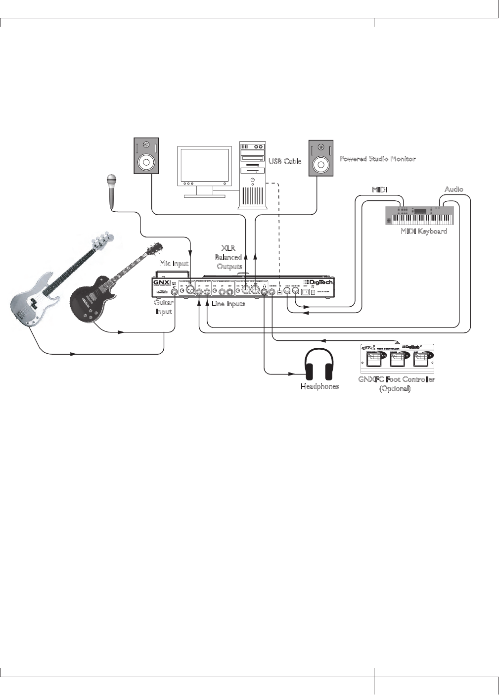
Computer Recording Setup
The GNX3000 offers tremendous flexibility for recording applications. Shown below is
a typical recording setup.
Guitar
Input
Line Inputs
XLR
Balanced
Outputs
MIDI Keyboard
MIDI Audio
Microphone
Headphones
Powered Studio Monitor
Powered Studio Monitor USB Cable
Computer
GNXFC Foot Controller
(Optional)
Mic Input
At the heart of your recording studio, the GNX3000 serves both as your guitar processor
and audio/MIDI interface. With MIC INPUT, LINE INPUTS, and MIDI I/O, you have a full
featured interface for recording almost any source you can think of. Connect your guitar
or bass to the GNX3000’s GUITAR INPUT and use the amp models for tracking your
guitar and bass parts. Next, plug in the mic and get your vocal or acoustic performance
nailed. You can even add line level instruments or feeds from submixes in and record
these and all of this completely hands-free. Even your MIDI keyboard performance can
be recorded so you can try the part with different synth voices later. Since the GNX3000
has professional BALANCED OUTPUTS, you can plug directly into your favorite powered
monitors and get the bonus of latency free recording to boot. For more information about
computer recording, see page 101.
1. Connect your guitar (or bass guitar) to the GNX3000’s GUITAR INPUT.
2. Connect a microphone to the GNX3000’s MIC INPUT and use the MIC LEVEL
control knob located next to the MIC INPUT on the GNX3000’s rear panel to
adjust the microphone output level. To adjust your microphone input level for
optimal use see Mic Level Optimization on page 26.
3. Connect a pair of stereo headphones to the HEADPHONE OUTPUT.
GNX3000 Owner’s Manual
31 GNX3000 Owner’s Manual

32
GNX3000 Owner’s Manual
4. Connect a keyboard, line level instrument, or stereo mixer (for feeding
submixes) to the GNX3000’s LEFT and RIGHT LINE INPUTS. To adjust your line
input levels for optimal use see Line Level Optimization on page 26.
5. Connect a GNXFC Foot Controller (optional) to the GNX3000’s Footswitch
jack.
6. Connect a MIDI keyboard to the GNX3000’s MIDI IN and OUT/THRU jacks
using 5 Pin MIDI cables.
7. Press the GNX3000’s OUTPUT SETUP button and select “STEROALL” as the
output mode using the DATA WHEEL.
8. Connect XLR cables from the GNX3000’s LEFT and RIGHT XLR OUTPUTS
to powered studio monitors and set XLR Speaker Compensation to ON
(described on page 24).
9. Connect the GNX3000 to your computer’s USB jack using the included USB
cable.
ATTENTION: Refer to the “Installing the GNX3000’s Software Suite” section on page
101 before connecting the GNX3000 to the USB port on your PC and using Pro Tracks
Plus.
32
Computer Recording Setup
GNX3000 Owner’s Manual
GNX3000 Owner’s Manual
33 GNX3000 Owner’s Manual
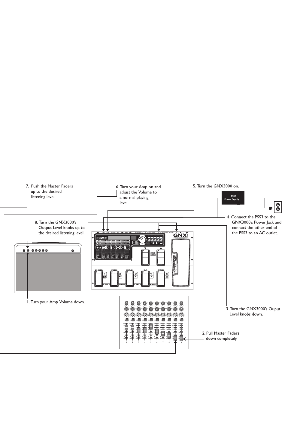
Applying Power
Before applying power to anything, set your amp(s) to a clean tone and set the
tone controls to a flat EQ response (on most amps, this would be 0 or 5 on the tone
controls). Then do the following:
1. Turn your amp’s volume all the way down.
2. Pull the mixer’s master faders all the way down.
3. Turn the GNX3000’s OUTPUT LEVEL KNOBS all the way down (fully counter-
clockwise).
4. Connect the plug of the PSS3 power supply to the GNX3000’s POWER JACK.
Connect the other end of the PSS3 power supply to an AC outlet.
5. Turn the GNX3000’s power on.
6. Turn your amplifier(s) on and adjust the volume(s) to a normal playing level.
7. Push the mixer’s master faders up to the desired listening level.
8. Gradually increase the GNX3000’s Output Levels to the desired listening level.
GNX3000 Owner’s Manual
33 GNX3000 Owner’s Manual
34
GNX3000 Owner’s Manual
About the GNX3000
Presets
A preset is a named and numbered location of a programmed sound that resides in
the GNX3000. Presets can be recalled with the FOOTSWITCHES or the DATA WHEEL.
The GNX3000 comes with 65 Factory 1, 65 Factory 2, and 65 User presets. The Factory
Presets do not let you store changes to them. The User presets let you store changes.
From the factory, the 65 User presets are exact duplicates from the 65 Factory 1 and
Factory 2 presets. This lets you create your own presets without worrying about losing
any of the original presets. When you select a preset, the name of the preset appears in
the green display and the number of the preset appears in the red numeric display. The
USER LED to the left of the DATA WHEEL lights indicating the User preset is active, or
the FACTORY 1 or FACTORY 2 LED lights indicating a Factory preset is active.
NAME 64
Preset Name Preset Number
LEDs indicate whether a User,
Factory 1, or Factory 2 preset
is active.
Learn-A-LickTM
The Learn-A-LickTM function lets you record a nine second passage of music and play
it back as slowly as 1/4 the original speed with no change in pitch. This is very useful
for picking out the notes of a fast guitar solo.
There are five Learn-A-Lick functions. They are:
• Stop (Controlled by FOOTSWITCH 1)
• Rewind (Controlled by FOOTSWITCH 2)
• Record (Controlled by FOOTSWITCH 3)
• Play (Controlled by FOOTSWITCH 4)
• Playback Speed (Controlled by the DOWN/UP FOOTSWITCHES)
Using Learn-A-Lick
1. Connect the player’s headphone output to the LINE INPUTS on the rear panel
of the GNX3000. Set the volume level of the player to match the level of your
guitar.
2. Find the passage you want to record and pause the Tape, CD, or MP3 player.
3. Press and hold FOOTSWITCHES 1 and 2 to enter Learn-A-Lick. The display
34
About the GNX3000
GNX3000 Owner’s Manual

GNX3000 Owner’s Manual
35 GNX3000 Owner’s Manual
reads: Lrn LICK
4. Release the pause button on your playback device and press FOOTSWITCH 3.
The display reads: RECORD. The red numeric display provides a time elapsed
reference while recording is in process. When recording is complete, the
recorded passage is set in an auto-loop playback, indicated by play appearing in
the display.
5. Press Stop or Pause on the playback device.
6. Use the DOWN FOOTSWITCH to slow the playback down, or use the UP
FOOTSWITCH to increase the playback speed at 1/8 speed intervals.Your
interval choices include: FULL, 7/8, 3/4, 5/8, 1/2, 3/8, and 1/4 speeds.
7. Press FOOTSWITCH 2 to step back through the loop at 1 second intervals.
8. The EXPRESSION PEDAL controls the output level of the recorded phrase.
9. To stop the playback, press FOOTSWITCH 1.
10. To resume playback, press FOOTSWITCH 4.
11. To record a new passage, press FOOTSWITCH 3.
12. To exit Learn-A-LickTM, press and hold FOOTSWITCHES 1 and 2, or press
EXIT in the control panel.
Bypass
The GNX3000 presets can be bypassed for a clean, unprocessed guitar signal. Bypass
turns off all effects and modeling. To bypass the GNX3000 in Preset Mode, press the
active preset’s Footswitch (the 1-5 footswitch that is lit). To bypass the GNX3000 while
in Stompbox or Record/Drum Mode, press FOOTSWITCHES 2 and 3 simultaneously.
When the GNX3000 is bypassed, the display reads BYPASS and all LEDs in the
Matrix turn off. Press any Footswitch to exit Bypass and return to the last preset. The
Matrix and Programming buttons do not function when Bypass is activated.
NOTE: If Preset Bounceback is enabled in the Utility menu, pressing the active
preset’s footswitch while in Preset Mode will not bypass the GNX3000’s effects. To
bypass the GNX3000’s presets while Preset Bounceback is enabled you must press
FOOTSWITCHES 2 and 3 simultaneously.
Tuner
The Tuner in the GNX3000 lets you quickly tune or check the tuning on your guitar.
Press FOOTSWITCHES 3 and 4 simultaneously to access the TUNER. The display briefly
flashes tuner. To begin tuning, play a note on your guitar (a harmonic at the 12th
fret also works). The red numeric display shows the note being played, and the green
alpha-numeric display indicates whether the note is sharp or flat. Arrows to the left
(<<<) indicate the note is sharp and should be tuned down. Arrows to the right (>>>)
indicate the note is flat and should be tuned up. When your note is in tune,
-><- is displayed.
GNX3000 Owner’s Manual
35 GNX3000 Owner’s Manual

While the tuner is selected, you can set your tuning reference with the DATA WHEEL.
The default factory setting is A=440 Hz. The tuning references range from 427 Hz to
453 Hz (± 50 cents (1/2 semitone) from either direction of 440 Hz). Below 427 Hz, are
alternate dropped tunings. The alternate tunings are REF A(A=Ab), REF G(A=G),
and REF G(A=Gb). The display window briefly flashes the selected tuning preference.
Footswitch Modes
When you first apply power to the GNX3000, it powers up in one of three Footswitch
Modes: Preset, Stompbox, or Record/Drum. The Footswitch Modes are selected in two
different ways:
Press the MODE button (located to the right of the DATA WHEEL)
OR
Press and hold FOOTSWITCHES 4 and 5 simultaneously.
Depending on which mode is selected, the DOWN/UP FOOTSWITCH LEDs will light a
different color. When Preset Mode is selected, these footswitches will be lit green. When
Stompbox Mode is selected, these footswitches will be lit yellow. And when Record/
Drum Mode is selected, these footswitches will be lit red. In any of the modes, the
display shows the selected preset’s name and number. The vertical LEDs on the Matrix
indicate which effects are active for the selected preset.
Preset Mode
The GNX3000’s Presets are grouped into thirteen banks of five presets. When
Preset Mode is active the DOWN/UP FOOTSWITCHES are used to select one of the
thirteen User, thirteen Factory 1, or thirteen Factory 2 Banks. Successive presses of
the DOWN/UP FOOTSWITCHES advance through all User/Factory Banks. Pressing
and holding the DOWN/UP FOOTSWITCHES scrolls through the User/Factory
Banks. Once a Bank is selected, FOOTSWITCHES 1-5 will flash indicating a preset
within that bank can be selected. If a preset is not selected within 5 seconds, the
GNX3000 returns to the currently selected bank and preset. A second press of an
active Preset’s footswitch bypasses the preset. Another press reloads the preset.
For a list of presets, refer to page 133.
Preset Bounceback
Preset Bounceback is a great live performance feature that lets you switch
beween two presets with the same footswitch. For example, let’s say you select
Preset 1 using FOOTSWITCH 1 as your rhythm tone. Then you select Preset 4
using FOOTSWITCH 4 as your solo tone. You can now press FOOTSWITCH 4
again and Preset 1 will be selected again. Pressing FOOTSWITCH 4 repeatedly
will bounceback between Preset 4 and Preset 1. To enable the Preset
Bounceback feature, do the following:
36
About the GNX3000
GNX3000 Owner’s Manual

1. Press the UTILITY control panel button and use the PREV/NEXT arrow
buttons to locate the Bounceback feature. The display will read BOUNCBAK.
2. Rotate the DATA WHEEL to turn the BounceBack feature on.
3. When finished press the EXIT button.
NOTE: The Preset Bounceback feature only works when the GNX3000 is in
Preset Mode. When Preset Bounceback is enabled, a preset cannot be bypassed
by pressing its footswitch repeatedly.
For more information regarding the footswitch functions for Preset Mode see page 94.
Stompbox Mode
Stompbox Mode is another mode of operation that can be used during a
performance. When Stompbox Mode is active, the DOWN/UP FOOTSWITCHES
are used to select presets. FOOTSWITCHES 1-4 turn the effects on and off.
FOOTSWITCH 5 is used as a Tap-Tempo switch for setting the delay time during a
live performance.
For more information regarding the footswitch functions for Stompbox Mode see
page 96.
Record/Drum Mode
When Record/Drum Mode is active, the DOWN/UP FOOTSWITCHES are used for
selecting drum patterns. FOOTSWITCHES 1-5 are used for Hands-FreeTM control of
the Pro Tracks PlusTM software.
For more information regarding the footswitch functions for Record/Drum Mode
see page 98.
Expression Pedal
The EXPRESSION PEDAL can control three different parameters simultaneously in
each preset. Rock the EXPRESSION PEDAL back and forth to change the values of
the assigned parameters. Each parameter the EXPRESSION PEDAL controls has an
adjustable minimum and maximum range. The EXPRESSION PEDAL also includes a
toe switch that turns on the Wah effect and switches from controlling the parameters
assigned to the EXPRESSION PEDAL and controls the Wah.
See page 75 for more information on Expression Pedal Assignment.
GNX3000 Owner’s Manual
37 GNX3000 Owner’s Manual
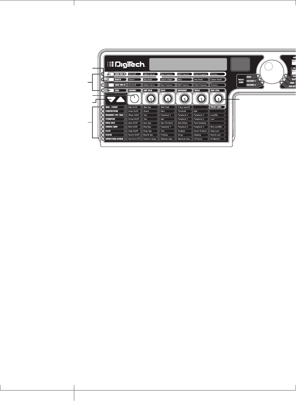
GNX3000 Matrix Functions
The GNX3000 Matrix
NAME 64
AMP/CABINET
SECTION
EFFECTS
SECTION
Effect Select
Buttons
Status Button
Knobs
Amp Control
Buttons
The main panel of the GNX3000 is the Matrix. The Matrix is comprised of two main
sections, AMP/CABINET and EFFECTS. It is used to navigate through the GNX3000’s
amp/cabinet modeling and effects parameters. Upon power up, the GNX3000 defaults
to the TONE row in the AMP/CABINET section and any effects that are enabled within
a preset will have their corresponding LEDs lit in the EFFECTS section of the Matrix.
You can select one of the other three Amp Control rows, CHAN 1 EQ, GENETX, or
CHAN 2 EQ using the AMP CONTROL buttons or you can select the different effects
and their parameters using the EFFECT SELECT buttons. The LED to the left of each
row indicates which row is active, while the STATUS button and five KNOBS control the
corresponding parameter above or below each knob.
38
GNX3000 Matrix Functions
GNX3000 Owner’s Manual
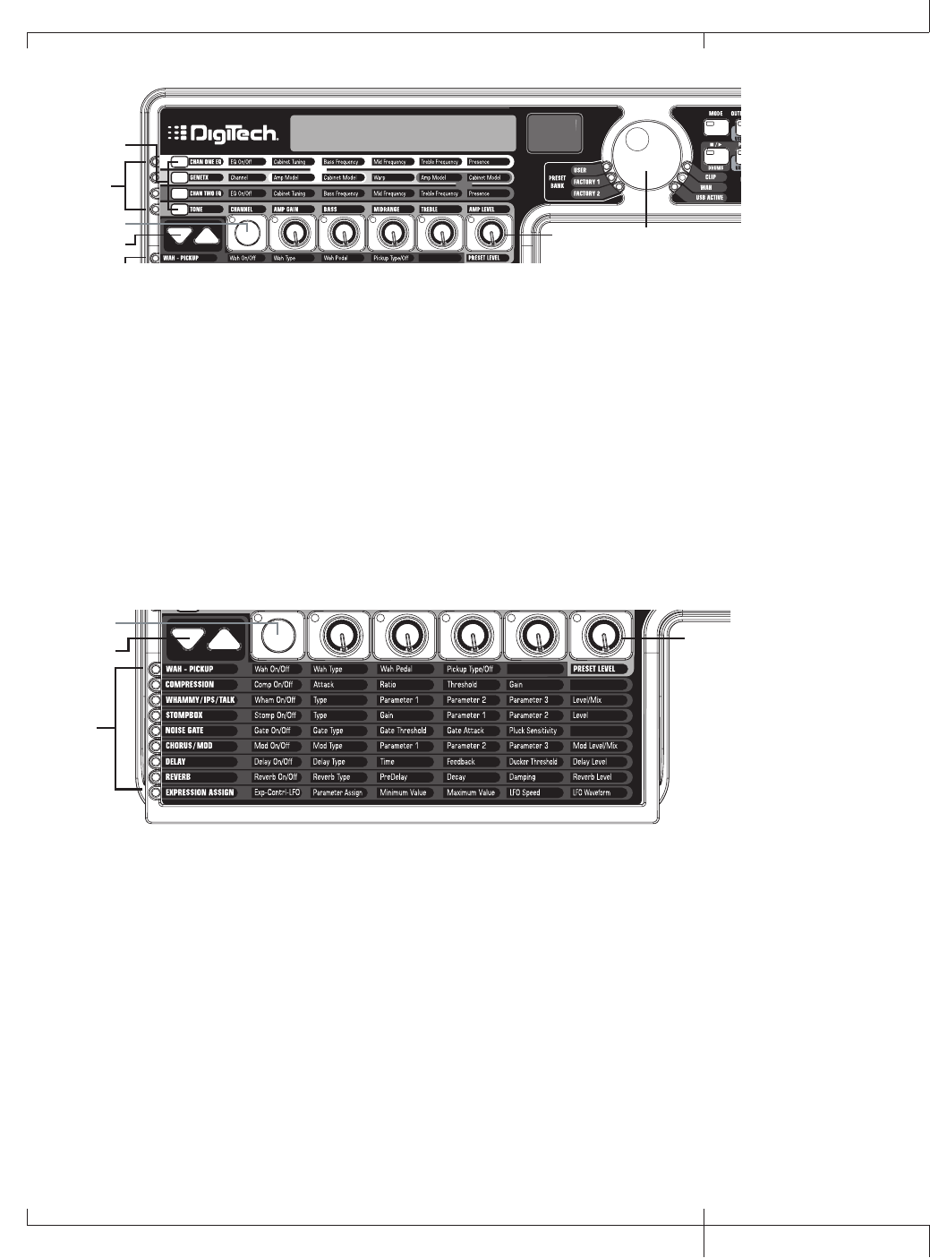
NAME 64
AMP/CABINET
SECTION
EFFECTS
SECTION
Effect Select
Buttons
Status Button
Knobs
Amp Control
Buttons
Data Wheel
Viewing/Editing GeNetXTM and Amp Parameter Values
To view or edit an amp parameter’s current value, you must first select the row in which
the parameter resides using the AMP CONTROL buttons located to the left of the amp
parameter rows. After selecting the desired row, use the STATUS button and KNOBS
to adjust the parameters. Turning a knob one click position will display the current
value of the selected parameter. If a KNOB is turned again within three seconds, the
parameter value will be changed and the new value will be displayed. If a KNOB is not
turned within three seconds, the main display returns back to the preset name.
NOTE: If a parameter name is shown in the display while editing both Amps and
Effects, the DATA WHEEL can change the value as well as the Knobs.
NAME 64
AMP/CABINET
SECTION
EFFECTS
SECTION
Effect Select
Buttons
Status Button
Knobs
Amp Control
Buttons
Data Wheel
Viewing/Editing Effect Parameter Values
To view or edit an effect parameter’s current value, you must first select the row in
which the desired parameter resides by using the EFFECT SELECT buttons. They are
located to the left of the STATUS button. After selecting the desired effect, use the
STATUS button and knobs to adjust the effect’s individual parameters. Parameter
adjustments will show in the displays as edits are made. To exit effect editing, press the
EXIT button in the Control Panel.
NOTE: If a parameter name is shown in the display while editing both Amps and
Effects, the DATA WHEEL can change the value as well as the Knobs.
GNX3000 Owner’s Manual
39 GNX3000 Owner’s Manual
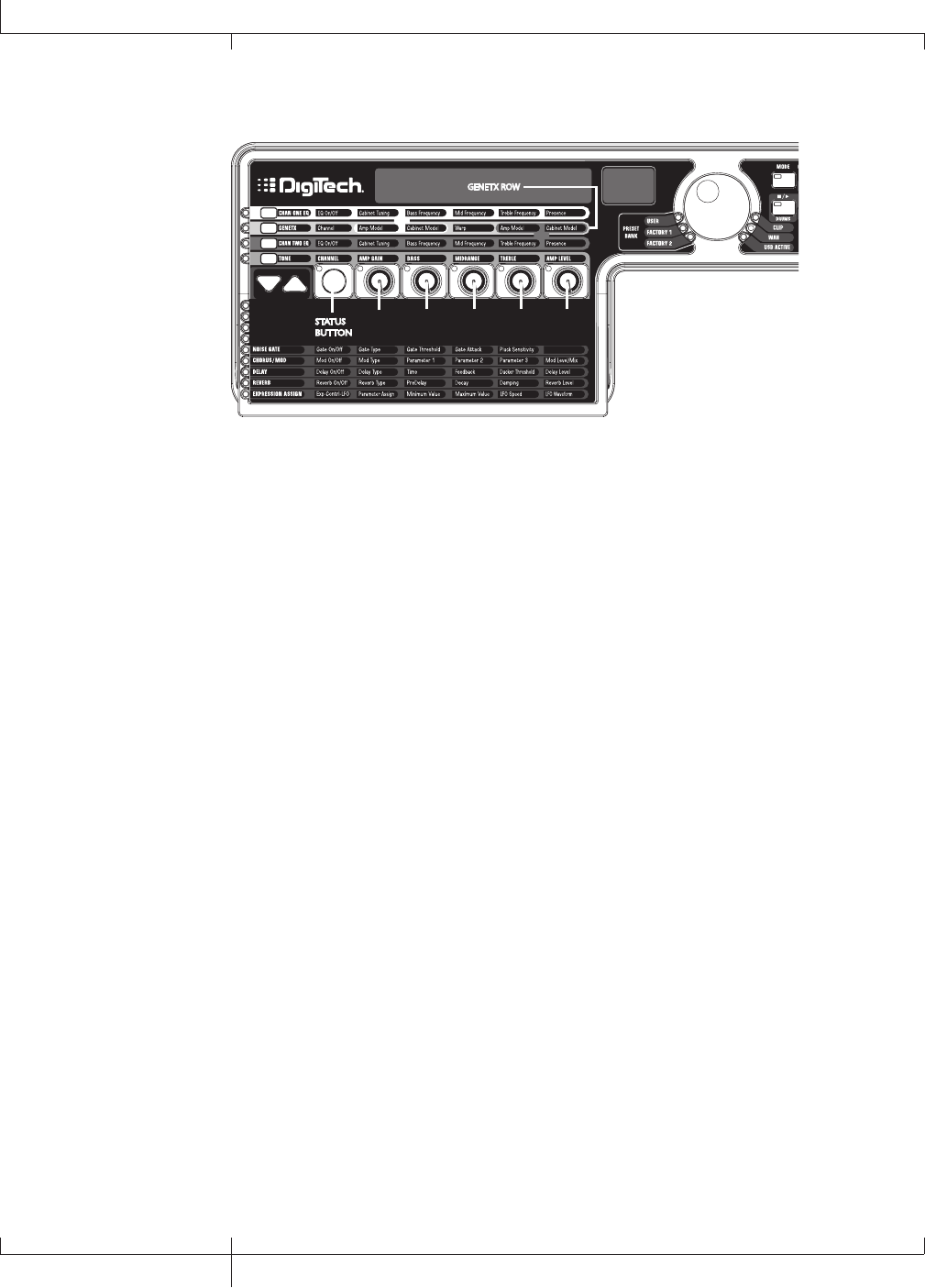
GENETXTM Row
STATUS
BUTTON
KNOB
1
KNOB
5
KNOB
4
KNOB
3
KNOB
2
GENETX ROW
The GENETX row is where amp and cabinet models are selected for the current preset.
It is also where the Warp function resides allowing GeNetXTM warping between the
two amp models. When the GENETX row is selected, the Knobs and STATUS button
perform the following functions:
Status button
Selects between Amp Channel 1 (Green) and Amp Channel 2 (Red) and lets
you hear each channel independently. If a Warped state (Yellow) between both
channels exists, this button also selects it and lets you hear the warped amp.
The STATUS button’s LED will light Green, Red, or Yellow depending on which
channel is selected.
Knob 1
Selects the Channel 1 (Green) amp model and its LED is lit green.
Knob 2
Selects the Channel 1 (Green) cabinet model and its LED is lit green.
Knob 3
Warps the Channel 1 and Channel 2 amp and cabinet models together. Setting
this parameter to its minimum position selects Channel 1’s amp and cabinet only
and its LED is lit green. Setting this parameter to its maximum position selects
Channel 2’s amp and cabinet only and its LED is lit red. Setting KNOB 3 to any
other position selects a warped state, a combination of Channel 1 and 2’s amp and
cabinet models and the LED will be lit yellow.
Knob 4
Selects the Channel 2 (Red) amp model and its LED is lit red.
Knob 5
Selects the Channel 2 (Red) cabinet model and its LED is lit red.
40
GNX3000 Owner’s Manual
GNX3000 Matrix Functions
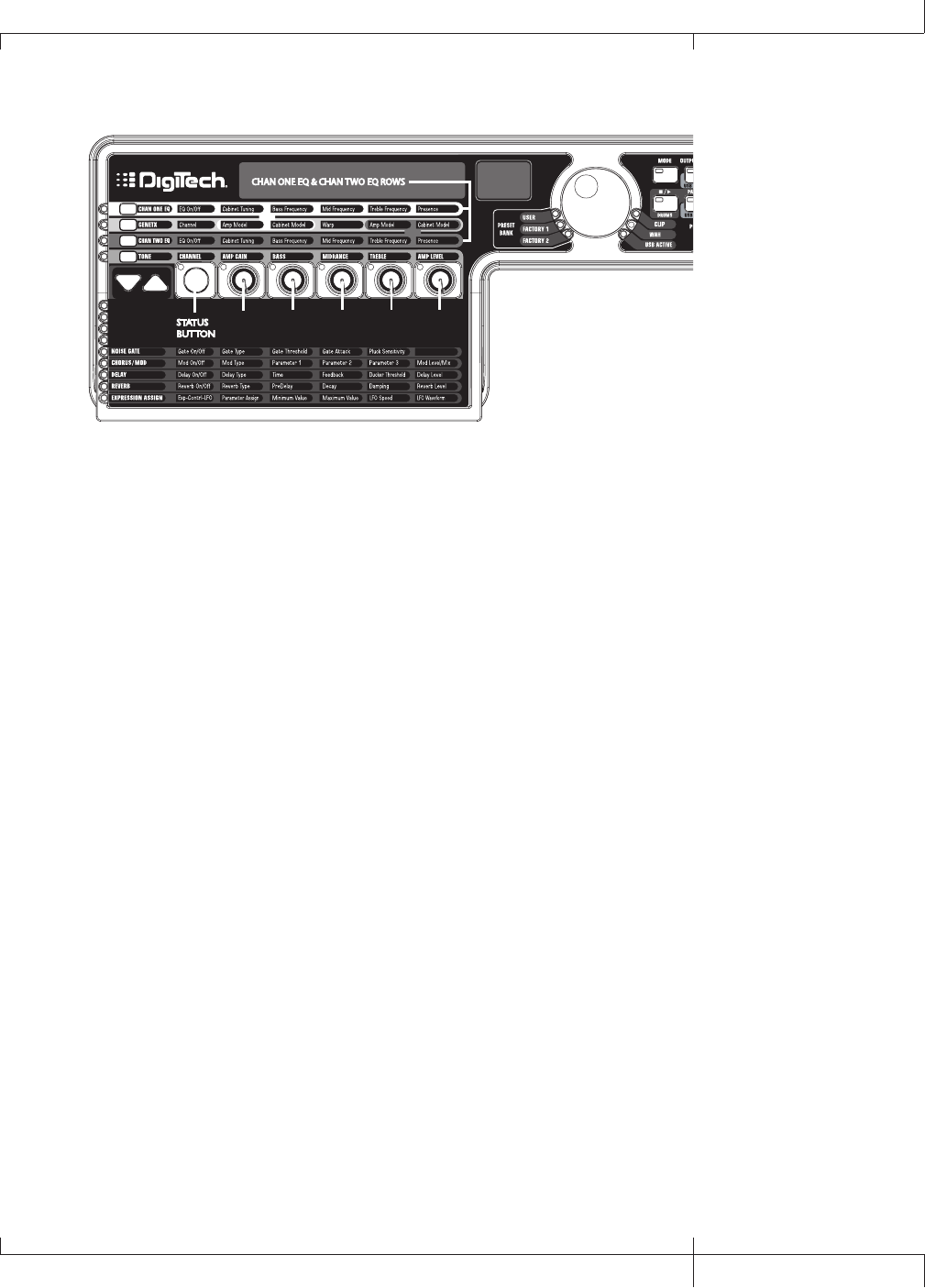
CHAN ONE EQ and CHAN TWO EQ Rows
STATUS
BUTTON
KNOB
1
KNOB
5
KNOB
4
KNOB
3
KNOB
2
CHAN ONE EQ & CHAN TWO EQ ROWS
The CHAN ONE EQ and CHAN TWO EQ rows are used for modifying the center
frequencies of the Bass, Midrange, and Treble controls of that reside within the TONE
Row. There is also a Cabinet Tuning control for changing the tuning of a selected
channel’s cabinet resonance, and a Presence control is available here for editing amp
tone as well. When either the CHAN ONE EQ or CHAN TWO EQ row is selected, the
knobs and STATUS button perform the following functions:
Status button
Turns the EQ on and off for the selected channel.
Knob 1
Adjusts the Cabinet Tuning resonance of the cabinet model for the selected
channel. The Cabinet Tuning ranges are from one octave below (-12.0) to one
octave above (12.0).
Knob 2
Selects the Bass Center Frequency for the selected channel. The Bass Center
Frequency range is from 50Hz (50 hz) to 300Hz (300 hz).
Knob 3
Selects the Midrange Center Frequency for the selected channel. The Midrange
Center Frequency range is from 300Hz (300 HZ) to 5000Hz (5000 HZ).
Knob 4
Selects the Treble Center Frequency for the selected channel. The Treble Center
Frequency range is from 500Hz (500 HZ) to 8000Hz (8000 HZ).
Knob 5
Boosts or cuts the Presence Level for the selected channel. The Presence Control
is a shelf EQ and has a fixed frequency of 7500Hz. The Presence Level range is
from -12dB (-12) to 12dB (12).
GNX3000 Owner’s Manual
41 GNX3000 Owner’s Manual

Here is an example of how the CHAN ONE EQ row would function when its button is
pressed:
Warped Amp Sound being heard:
If the sound being heard is a Warped sound of both amp models, pressing the CHAN
ONE EQ button selects the knobs to control the CHAN ONE EQ’s row of parameters.
The STATUS button LED will light yellow, indicating a Warped sound is being heard,
and the knobs will all light green. You can modify the CHAN ONE EQ row parameters
which will be heard as the knobs are turned. The STATUS button will turn the CHAN
ONE EQ on or off and indicate this status by turning the button LED on and off.
CHAN ONE amp sound being heard:
If the sound being heard is the CHAN ONE amp tone, pressing the CHAN ONE EQ
button selects the knobs to control CHAN ONE EQ’s row of parameters. The STATUS
button and the knobs will light green. You can modify the CHAN ONE EQ row
parameters, which can be heard as the knobs are turned. The STATUS button will turn
the CHAN ONE EQ on or off and indicate this status by turning the button LED on and
off.
CHAN TWO amp sound being heard:
If the sound being heard is the CHAN TWO amp tone, pressing the CHAN ONE EQ
button selects the knobs to control the CHAN ONE EQ’s row of parameters. The
STATUS button will be lit red indicating you are still listening to the CHAN TWO amp
tone. The knobs however will be lit green and once any of them are turned, the sound
will change from the CHAN TWO amp tone to the CHAN ONE amp tone. You can then
modify the CHAN ONE EQ parameters and these changes can be heard as the knobs
are turned. The STATUS button will also turn green at this time and can be used to
turn the CHAN ONE EQ on or off as will be indicated by the button’s LED turning on
and off.
42
GNX3000 Owner’s Manual
GNX3000 Matrix Functions
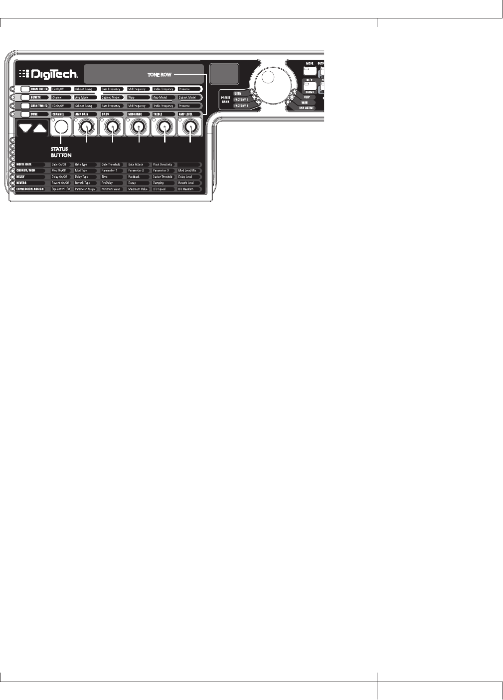
TONE Row
STATUS
BUTTON
KNOB
1
KNOB
5
KNOB
4
KNOB
3
KNOB
2
TONE ROW
The TONE row is where the amp tone controls are located for Channel 1 or Channel 2.
The sound that you hear while adjusting these parameters will depend on the channel
status (see chart below). TONE control row parameters are Channel, Amp Gain, Bass,
Midrange, Treble, and Amp Level.
Status button
Selects one of the four channel states in the following order:
Ch1 amp - The STATUS button LED lights green and the five control knobs
light green indicating that you are listening to Channel 1 and the
control knobs affect Channel 1’s tone settings.
Ch1 warp - The STATUS button LED lights yellow and the five control knobs
light green indicating that you are listening to a warped sound
and the control knobs affect Channel 1’s tone settings.
Ch2 amp - The STATUS button LED lights red and the five control knobs
light red indicating that you are listening to Channel 2 and the
control knobs affect Channel 2’s tone settings.
Ch2 warp - The STATUS button LED lights yellow and the five control knobs
light red indicating that you are listening to a warped sound and
the control knobs affect Channel 2’s tone settings.
Knob 1
Controls the amount of Amp Gain. The Amp Gain range is from 0 to 99.
Knob 2
Controls the Bass EQ Level (boost/cut). The Bass EQ Level range is from -12dB
(-12) to 12dB (12).
Knob 3
Controls the Midrange EQ Level (boost/cut). The Midrange EQ Level range is
from -12dB (-12) to 12dB (12).
Knob 4
Selects the Treble EQ Level (boost/cut). The Treble EQ Level range is from -
12dB (-12) to 12dB (12).
Knob 5
Controls the Amp Level. The Amp Level Range is from 0 to 99.
GNX3000 Owner’s Manual
43 GNX3000 Owner’s Manual
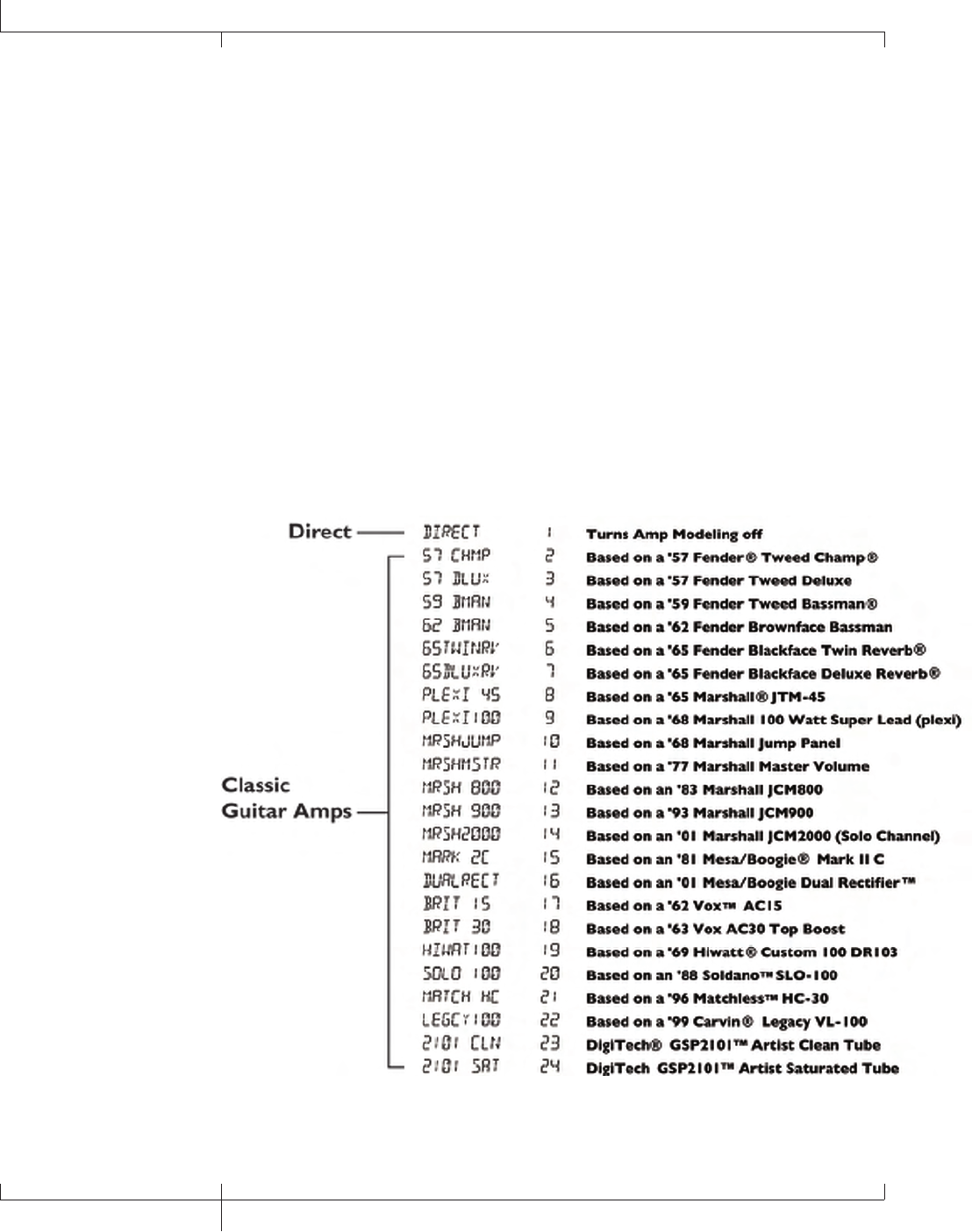
Amp/Cabinet Modeling
The GNX3000 was designed to make sound processing easy and intuitive. Because the
GNX3000 provides both Amp Modeling and Effects Processing, the editing functions
are divided into two sections: the AMP/CABINET MODELING section and the EFFECTS
section. The GeNetXTM technology contained in the GNX3000 lets you go much
further than mere Amp Modeling. GeNetX lets you create your own Amp/Cabinet
HyperModelTM and store this custom creation to a User Amp/Cabinet location. When
editing either the AMP/CABINET MODELING or the EFFECTS section, you must start
with one of the User or Factory presets. The preset you begin with does not need to
be in the location that you intend to save it.
After selecting a preset, you can select the Amp or Cabinet models for your preset.
Amp/Cabinet Modeling applies the tone of one of several vintage or modern Amp and
Cabinet models to your guitar signal. The GNX3000 includes 33 guitar Amp Models,
10 Bass Amp Models, 2 Acoustic Guitar Models, and 29 Speaker Cabinet Models. Your
choices include:
Amp Models
44
Amp/Cabinet Modeling
GNX3000 Owner’s Manual

Marshall, Vox, Fender, Matchless, HiWatt, Ashdown, Ampeg, Trace-Elliot, Sunn, Hartke
and Mesa Boogie, are trademarks of their respective companies and are in no way
associated with DigiTech®.
GNX3000 Owner’s Manual
45 GNX3000 Owner’s Manual
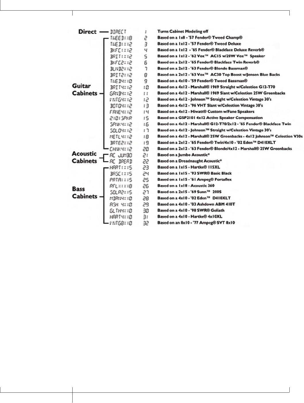
Cabinet Types
Fender, Ampeg, Ashdown, Sunn, Fane, Acoustic, Hartke, Eden, and SWR are trademarks
of their respective companies and are in no way associated with DigiTech®.
Editing Amps and Cabinets
Each GNX3000 preset has three channels, Channel 1 (green), Channel 2 (red), and
Warp (yellow). Amp channels 1 and 2 have selectable amps and cabinets. Each
channel has independent controls for gain, level, EQ, and cabinet tuning. The Warp
channel is effectively a mixture of the Channel 1 and 2 amps and cabinets using the
Warp knob in the AMP CONTROLS section of the matrix. When parameter values have
changed, the Store LED lights indicating the preset has been modified and needs to be
stored (see page 92 for more on the storing procedure).
Once you have selected your amps for Channel 1 and 2, you can switch between these,
as well as the Warp channel, using the Amp Channel footswitch (Stompbox Mode
only) or the STATUS button (GeNetX row is active) when the preset name is displayed.
The following sections guide you through the process of selecting amps and cabinets,
adjusting amp parameters, performing cabinet tuning, and creating then saving a
HypermodelTM Amp.
46
Amp/Cabinet Modeling
GNX3000 Owner’s Manual

Selecting Amps and Cabinets
The first step to editing an Amp/Cabinet model, or creating your own
HyperModelTM is to select the Amp and Cabinet model for Channel 1 and
Channel 2 in your preset. The procedure for selecting Amps or Cabinets is as
follows:
1. Press the GENETX AMP CONTROL button.
2. Use KNOB 1 to select the Amp for Channel 1. The Amp name appears in the
display. (See page 44 for a complete list of Amp Models.)
4. Use KNOB 2 to select the Cabinet for Channel 1. The Cabinet name appears in
the display. See page 46 for a complete list of Cabinet Types.)
5. Use KNOB 4 to select the Amp for Channel 2. The Amp name appears in the
display.
6. Use KNOB 5 to select the Cabinet for Channel 2. The Cabinet name appears in
the display.
Adjusting Amp Parameters
The Gain, EQ, and Level Parameters can be adjusted individually for Channel 1
and Channel 2. This is accomplished by pressing the TONE Amp Control button.
The sound that you hear while adjusting the knobs depends on the state of the
STATUS button and the KNOBS (see chart below). When the TONE row is selected,
the STATUS button steps through four states in the following order:
Ch1 amp - The STATUS button LED lights green and the five control knobs
light green indicating that you are listening to Channel 1 and the
control knobs affect Channel 1’s tone settings.
Ch1 warp - The STATUS button LED lights yellow and the five control knobs
light green indicating that you are listening to a warped sound
and the control knobs affect Channel 1’s tone settings.
Ch2 amp - The STATUS button LED lights red and the five control knobs
light red indicating that you are listening to Channel 2 and the
control knobs affect Channel 2’s tone settings.
Ch2 warp - The STATUS button LED lights yellow and the five control knobs
light red indicating that you are listening to a warped sound and
the control knobs affect Channel 2’s tone settings.
The Gain ranges from 0 (0) to 99 (99). The Bass, Midrange, and Treble EQ range
from -12 dB (-12) to +12dB (12). The Level ranges from 0 (0) to 99 (99). The
procedure for adjusting these parameters is as follows:
1. Press the TONE Amp Control button.
2. Press the STATUS button to select either Channel 1 Amp (Green) or Channel 2
Amp (Red).
3. Use Knobs 1 through 5 to adjust the Gain, Tone, and Level of the selected amp
channel.
GNX3000 Owner’s Manual
47 GNX3000 Owner’s Manual

Cabinet Tuning
Cabinet tuning actually changes the resonant frequency of the selected cabinet.
This is useful for changing the tonality of your sound without having to touch the
EQ parameters. Tuning down gives the sound more bottom end while tuning up
enhances higher frequencies. The procedure for tuning the cabinets is as follows:
1. Press the CHAN ONE EQ or the CHAN TWO EQ Amp Control button to access
the Cabinet Tuning parameters.
2. Use KNOB 1 to adjust the Cabinet Tuning resonance. The Cabinet Tuning ranges
are from -12.0 (one octave below) to 12.0 (one octave above) the cabinet’s
standard resonance.
Storing Amp Parameter Edits
Once you are satisfied with your amp edits, these changes need to be stored so
that they can be recalled later. See page 92 for more information on storing
changes to a preset.
Creating HyperModelsTM
Creating new, unique HyperModels is what Digitech’s GeNetXTM technology is all
about. Once both channels Amps and Cabinets are selected and the Amp Parameters
and Cabinet Tunings have been adjusted, GeNetX technology lets you do something
amazing. The characteristics of each Amp and Cabinet can be combined or “Warped”
to create a completely new custom HyperModel Amp. The procedure for Warping the
Channel 1 and Channel 2 Amps together is as follows:
1. Press the GENETX amp control button.
2. Rotate KNOB 3 to Warp the Channel 1 and Channel 2 Amps and Cabinets
together. Rotating it counter-clockwise emphasizes the Channel 1 characteristics
while rotating it clockwise emphasizes the Channel 2 characteristics. A warp
value of 1 produces the amp tone of only the Channel 1 (Green) Amp. A warp
value of 99 produces the amp tone of only the Channel 2 (Red) Amp.
Saving HyperModelsTM (Amp Save)
When you have found your ideal warp setting for Channel 1’s and Channel 2’s Amp
Models, you can save this sound as a HyperModel for future use. This HyperModel
can be saved in one of 9 User locations. After it has been saved, it can now be
selected by either Amp Channel as the starting point for a new HyperModel. The
Amp Save procedure is as follows:
1. Press the AMP SAVE button. The AMP SAVE button will begin flashing and the
display will read NEWAMP. The N of NEWAMP is flashing indicating that you can
name your HyperModel.
2. Use the DATA WHEEL to change the alpha-numeric character.
48
Amp/Cabinet Modeling
GNX3000 Owner’s Manual

3. Use the NEXT button to move to the next character (to the right), or the PREV
button to select the previous character (to the left).
4. Repeat steps 2 and 3 you have finished naming the new HyperModelTM.
5. Press the AMP SAVE button again to select one of the 9 User HyperModel
locations. If all HyperModel locations in the GNX3000 are available, the
display will read U1. The U1 flashes, indicating that this is the first available
location for storing a HyperModel. If one or more HyperModels have already
been stored, the number displayed will be the first empty HyperModel location.
If all 9 HyperModel locations are full, the GNX3000 defaults to the first
HyperModel location and displays U1 and the name of the HyperModel stored
in the first location.
6. Use the DATA WHEEL to select a User location to save the HyperModel. If all
locations have been used, the display shows the name of the HyperModel about
to be overwritten.
7. Press the AMP SAVE button again to complete the Amp Save procedure. Press
the EXIT button at any time during the Amp Save procedure to abort the
process.
NOTE: The Amp Save procedure only saves Amp/Cabinet combinations to the User
HyperModel locations. It does not store changes or the new HyperModel to the
selected preset. See page 92 for information on storing changes to a preset.
GNX3000 Owner’s Manual
49 GNX3000 Owner’s Manual
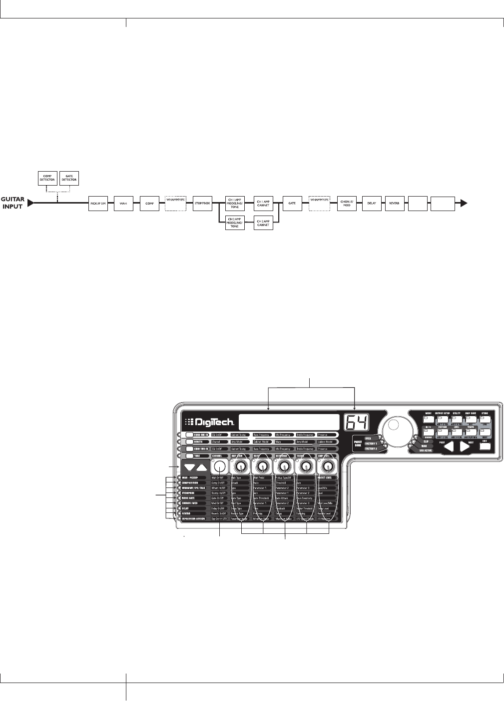
Effects and Parameters
The GNX3000 features a comprehensive set of effects for creating just the sound
you need for any musical application. These effects are connected in a standard
effects chain with pickup simulator, wah, compressor, WhammyTM/IPS, and distortion
stompbox effects placed before the amps. Effects placed post amp are those that
typically sound best when heard in stereo like modulation effects, delay and reverb.
The following diagram show the signal path through the effects of the GNX3000:
GNX3000
OUTPUTS
SPEAKER
COMPENSATION
PRESET
LEVEL
(WHAMMY,
TALKER)
(IPS, PITCH,
DETUNE)
Editing a Preset’s Effects
The EFFECTS section is accessed with the EFFECT SELECT UP/DOWN buttons. The
Matrix LEDs light one at a time to identify the selected row of effects. Each effect
has up to 5 Parameters that can be edited. Pressing the STATUS button turns the
effect row on and off. The 5 knobs control the Parameters listed directly beneath the
corresponding knob. Each effect’s parameter is labeled in the Matrix. When a knob is
turned, the corresponding parameter name and value appear in the displays.
Edit
Parameter name and value
are shown in display
Use Effect Select buttons
to select Effect row
LEDs indicate the
selected row
Status button
turns selected
effect on or off
Each knob adjusts the
column of parameters
directly below knob for
the selected Effect row
Rotating the knobs increases or decreases the value of the parameter (except for Type
which selects different effect types) and you hear the change in real time. Changing
presets, or turning the power off before storing any changes will erase your changes
and revert to the stored values. When the preset has been edited, the STORE BUTTON
LED turns on indicating that a change has been made.
50
Effects and Parameters
GNX3000 Owner’s Manual

Effect Definitions
Each Effect within the GNX3000 is fully programmable. Understanding how these
effects modify the sound, and how each parameter alters the effect will help you
achieve the sound you are looking for. The following overview outlines how each
effect and parameter in the GNX3000 works.
Wah-Pickup
A Wah is an effect controlled by the EXPRESSION PEDAL. A Wah applies a boost in
gain to a narrow band of frequencies. As the EXPRESSION PEDAL is rocked back and
forth, the center frequency receiving the boost is swept up and down making the
guitar sound as if it is saying “Wah”. The Wah is engaged and disengaged by applying
pressure to the toe of the EXPRESSION PEDAL.
The Pickup Simulator applies the warmth and thickness of a double coil humbucker
pickup to a single coil guitar, or the unique, crisp sound of a single coil pickup to a
guitar with a humbucker. This allows you to have the best of both worlds without ever
changing guitars.
Wah On/Off
The STATUS button (or the EXPRESSION PEDAL toe switch) turns the Wah (Wah) on
and off.
Wah Type
KNOB 1 selects the type of Wah. Values include: Cry Wah (CRY) is a traditional
sounding Wah, Boutique Wah (BOuTIQUe) is a wide sweeping Wah with a more
modern sound and Full Range Wah (fullrang) sweeps the entire spectrum of
audible frequencies.
Wah Pedal
KNOB 2 controls the pedal (wah pdl) parameter that adjusts the wah sweep
when the wah is active. The wah sweep range is from 0-99. The EXPRESSION
PEDAL is automatically linked to this parameter when the wah is activated. To
adjust the minimum and maximum range, see the Wah Pedal section on page 75.
Pickup Type/Off
KNOB 3 selects the type of Pickup to be simulated. Values include: Pickup
Simulator Off (pick off), Single Coil>Humbucker (SC>humb) gives a
single coil pick up the warm tone of a humbucker, and Humbucker>Single Coil
(humb>SC) gives a humbucker the unique sound of a single coil.
Knob 4
No function when the Wah-Pickup is selected.
Preset Level
KNOB 5 adjusts the overall preset level. Ranges from 0-99.
GNX3000 Owner’s Manual
51 GNX3000 Owner’s Manual

Compressor
A compressor is used to increase sustain, and even out the volume dynamics in guitar
signal. A compressor sets boundaries for a signal’s strength. When a signal exceeds
the set boundary, it is forced back into the set boundary. As the signal fades to a point
where it no longer exceeds the boundary, the compressor expands the signal strength
and increases sustain. The compression parameters are as follows:
Comp On/Off
The STATUS button turns the Compressor (Compress) on and off.
Attack
KNOB 1 adjusts the length of time it takes for the Compressor to respond to a
signal exceeding the Threshold. Values include: fast, meDIUM, and slOw.
Ratio
KNOB 2 adjusts the input to output ratio once the Threshold has been exceeded.
For instance, a Ratio of 4 to 1 means that a signal exceeding the Threshold by 4
dB will only be allowed 1 dB of increased output. Higher settings yield a tighter
sound and increase sustain. Lower settings allow better dynamics. Ratio settings
are: 1.2:1 (¡2-1), 1.5:1 (¡5-1), 1.8:1 (¡8-1), 2:1 (2-1), 2.5:1 (2.5-1), 3:1 (£0-
1), 4:1 (¢0-1), 5:1 (∞0-1), 8:1 (•0-1), 10:1 (10-1), 20:1 (20-1), and Infinity:1
(INFnty-1).
Threshold
KNOB 3 selects the Threshold (threshld). The Threshold is the level a signal
must reach before the compressor begins to work. Low Threshold settings
activate the compressor with weaker signals. Higher settings require a stronger
signal to activate compression. Ranges from 0 to 99.
Gain
KNOB 4 adjusts the Output Gain (CMP Gain) from the Compressor. This
parameter is used to balance the level of the Compressor to reach unity gain.
Other effects can clip if the Compressor Gain too high. Ranges from 0 to 20
(dB).
Knob 5
No function when the Compressor is selected.
52
Effects and Parameters
GNX3000 Owner’s Manual

WhammyTM/IPS/Talk
This module includes four types of pitch altering effects: Whammy, IPS, Detune, Pitch
Shift, and the TalkerTM effect. Only one of the effects in this row can be used at a
time. After selecting the type of effect in this module, the Knobs 2-5 can then be used
to adjust the individual parameters associated with the selected effect. The following
pages describe each effect and their parameters in more detail.
Whammy/IPS/Talk On/Off
When the Whammy/IPS/Talk effects module is selected the STATUS button turns
the Whammy/IPS/Talk effects on and off.
Whammy/IPS/Talk Select
KNOB 1 selects whether the module is a Whammy (WHAMMY), Intelligent Pitch
Shifting (IPS), Detuner (DETUNE), Pitch Shift (PITCH), or Talker (Talker
1-5).
GNX3000 Owner’s Manual
53 GNX3000 Owner’s Manual

Whammy
Whammy is an effect that uses the EXPRESSION PEDAL to bend the pitch of the
incoming signal, or add a bendable harmony with the original signal. As the
Pedal is moved, the note bends either up or down. When Whammy is selected, it is
automatically placed before the Amp Modeling as shown in the block diagram (see
page 50). The Whammy effect must be linked to the Expression Pedal in order to
function. See page 75 for more information on linking the EXPRESSION PEDAL.
Parameter 1
KNOB 2 selects the interval and direction of the pitch bend. Choices are as follows:
Whammy (no Dry Signal)
1 oct up (one octave up)
2 oct up (two octaves up)
2nddown (2nd down)
rev2nddn (2nd down
reversed pedal
action)
4th down (one 4th down)
1 oct dn (one octave down)
2 oct dn (two octaves down)
divebomb (Dive Bomb)
Harmony Bends (Dry Signal
Added)
m3->maj3 (a m3rd to a
Maj3rd)
2nd->maj3 (a 2nd above to a
Maj3rd up)
3rd->4th (a Maj3rd above to a
4th up)
4th->5th (a 4th above to a
5th up)
5th->oct (a 5th above to an
octave up)
h oct up (one octave up)
h oct dn (one octave down)
octup->Dn (one octave up to
one octave down)
Parameter 2
KNOB 3 provides a manual control of the Whammy Pedal (wham pdl) position.
Ranges from 0 to 99.
Knob 4
No function when the Whammy is selected.
Level
KNOB 5 adjusts the Whammy Mix (Wham mix) of all of the pitch-altering effects
in this module. Ranges from 0 to 99.
54
GNX3000 Owner’s Manual
Effects and Parameters

Intelligent Pitch Shifting (IPS)
Intelligent Pitch Shifting makes a copy of the incoming signal, and then changes the
pitch of the copied note to a diatonically correct interval specified by the Amount
parameter. An Intelligent Pitch Shifter sharpens or flattens the shifted pitch in
order to keep the specified interval within the selected key and scale creating a true
harmony.
Parameter 1
KNOB 2 selects the Amount or harmony interval for the Intelligent Pitch Shifter.
Interval choices include:
OCT DowN (octave down)
7TH DowN (a seventh below)
6tH DowN (a sixth below)
5tH DowN (a fifth below)
4tH DowN (a fourth below)
3RD DowN (a third below)
2ND DowN (a second below)
2ND UP (a second above)
3RD UP (a third above)
4TH UP (a fourth above)
5TH UP (a fifth above)
6TH UP (a sixth above)
7TH UP (a seventh above)
OCT UP (an octave above)
Parameter 2
KNOB 3 selects the Scale the IPS will use. Scale choices include: Major (MAJOR),
Minor (MINOR), Dorian (DORIAN), Mixolydian (MIXoLYDn), Lydian
(LYDIAN), Harmonic Minor (HARMINor).
Parameter 3
KNOB 4 selects the musical Key the IPS uses. Key choices range from the Key of
E (KEY E) through the Key of Eb (KEY E∫).
Level
KNOB 5 adjusts the IPS Level (IPS LEVL) of all the pitch-altering effects in this
module. Ranges from 0 to 99.
GNX3000 Owner’s Manual
55 GNX3000 Owner’s Manual

Detune
A Detuner makes a copy of your incoming signal, takes the copied signal slightly out
of tune from the original, and mixes the two signals together. The result is a doubling
type of effect as if two guitars were playing the same part together.
Parameter 1
KNOB 2 selects the Amount (AMouNT) of detuning applied to the copied pitch in
cents (100 cents equals 1 semitone). Ranges are from 24 cents below (-24) to 24
cents above (24).
Knob 3
No function when Detune is selected.
Knob 4
No function when Detune is selected.
Level
KNOB 5 adjusts the Detune Level (dtn LeVL) of all pitch-altering effects in this
module. Ranges from 0 to 99.
Pitch Shift
A Pitch Shifter copies the incoming signal, then shifts the pitch of the copied note to a
different note. The shifted note is then mixed back with the original signal sounding as
if two guitars were playing parallel notes.
Parameter 1
KNOB 2 selects the Shift (SHIFT) of the pitch in semitone intervals. Ranges from
two octaves below (-24) to two octaves above (24).
Knob 3
No function when Pitch Shift is selected.
Knob 4
No function when Pitch Shift is selected.
Level
KNOB 5 adjusts the Pitch Level (pch LeVL) of all pitch-altering effects in this
module. Ranges from 0 to 99.
56
GNX3000 Owner’s Manual
Effects and Parameters

TalkerTM
The Talker is an effect that lets your instrument’s signal be manipulated by your voice.
The Talker requires a microphone be connected to the MIC INPUT on the rear panel of
the GNX3000. As you speak into the microphone, your instrument mimics what you say.
There are five Talker types.
Type
KNOB 1 is used to select one of the 5 Talker types. Talker Types range from talker
1 (deep tonal characteristics), to talker 5 (bright tonal characteristics).
Parameter 1
KNOB 2 adjusts the Sensitivity of the microphone level (MIC LEVL). The input
level from your microphone must be loud enough for the Talker to work properly. If
the microphone input is too weak, the Talker will have trouble tracking. If the input
is too strong, the Talker will clip making the words unintelligible. Adjust the mic
level on the GNX3000’s rear panel so that the LEDs light, but stay below the clip
level. (See Mic Level Optimization on page 26 for more information regarding mic
level adjustment.) The mic level sensitivity ranges are from 0 (least sensitive) to 99
(most sensitive).
Knob 3
No function when Talker is selected.
Knob 4
No function when Talker is selected.
Knob 5
No function when Talker is selected.
GNX3000 Owner’s Manual
57 GNX3000 Owner’s Manual
Stompbox Modeling
The GNX3000 Modeling emulates the tones of the most popular distortion boxes ever
used including the DOD® OD250TM, Boss® DS-1TM, Arbiter® Fuzz FaceTM, Electro
Harmonix® Big MuffTM, ProCo® RATTM, DOD® GrungeTM, Boss® Metal ZoneTM,
Ibanez® TS-9TM, Voodoo Labs® Sparkle DriveTM, and the Guyatone® OD-2TM* and
the Roger® Mayer OctaviaTM*.
Stompbox On/Off
The STATUS button turns the Stompbox Modeling on and off.
Type
KNOB 1 selects the type of Stompbox to be used. Choices include:
Screamer Based on an Ibanez® TS-9TM
RODENT Based on a ProCo® Rat DistortionTM
DS Dist Based on a Boss® DS-1TM
DOD 250 Based on a DOD® Overdrive 250TM
BIG MP Based on the Electro® Harmonix Big Muff PiTM
Guy OD Based on a GuyaTone® OD-2TM
SpArkDrV Based on a Voodoo Labs® SparkleDriveTM
Grunge Based on a DigiTech® Grunge®
Fuzzy Based on an Arbiter® Fuzz FaceTM
Zone Based on a Boss® Metal ZoneTM
8tavia Based on a Roger Mayer® OctaviaTM
Type Gain Param1 Param2 Param3** Param4** Level
Screamer drive tone level
Rodent dist filter volume
DS Dist dist tone level
DOD 250 gain level
Big MP sustain tone volume
Guy OD drive level
Sparkdrv gain tone clean volume
Grunge grnggain butt face loud
Fuzzy fuzz volume
Zone dist mid freq mid lvl low high level
8tavia drive volume
58
GNX3000 Owner’s Manual
Effects and Parameters
* Arbiter, Boss, Electro-Harmonix, ProCo, Ibanez, Voodoo Labs, Guyatone, DS-1, Fuzz Face,
Big Muff, RAT, Metal Zone, TS-9, Sparkle Drive, Roger Mayer Octavia and OD-2 are
trademarks of their respective companies and are in no way associated with DigiTech.
** These Parameters are only available using the X-EditTM Editor/Librarian software.

Gain
KNOB 2 controls the amount of Gain or Distortion in the Stompbox model.
Range is from 0 to 99.
Parameter 1
KNOB 3 acts as a Tone control for each Stompbox (no function on DOD 250, Big
MP, Guy OD, Fuzzy and 8tavia models) and controls the Mid Frequency of
the Zone model. Range is from 0 to 99.
Parameter 2
KNOB 4 acts as a wet/dry control for the SparkleDriveTM and tone control for the
Grunge Stompbox models and controls the Mid Level of the Zone model. Range
is from 0 to 99.
*Parameter 3
Controls the Low Frequency of the Zone model. Range is from 0 to 99.
*Parameter 4
Controls the High Level of the Zone model. Range is from 0 to 99.
Level
KNOB 5 controls the output level of the Stompbox model. Range is from 0 to 99.
GNX3000 Owner’s Manual
59 GNX3000 Owner’s Manual
*These Parameters are only available using the X-EditTM Editor/Librarian software.

Noise Gate
A Noise Gate is designed to eliminate hiss and ambient noise while you are not
playing. A Noise Gate can also be used to create an automatic swell in volume.
The GNX3000 includes two different types of Noise Gates: Silencer and Pluck. The
Silencer operates as a standard Noise Gate. The Pluck feature is designed to close
after every note (depending on the Pluck Sensitivity). This allows automatic volume
swells to occur on a note by note basis.
Gate On/Off
The STATUS button turns the Noise Gate (gate) on and off.
Gate Type
KNOB 1 selects between the Silencer (Silencer) or Pluck (PLUCK) type of
Noise Gates.
Gate Threshold
KNOB 2 sets the signal strength required to open or close the Noise Gate. The
Gate Threshold (Threshld) parameter ranges from 0 (opens easily) to 99
(requires strong signals to open).
Gate Attack
KNOB 3 adjusts the length of time it takes the gate to open (ATTACK) and the
signal to become audible once the Threshold has been exceeded. Ranges from 0
(immediate signal), to 9 (This setting will gradually ramp up the volume).
Pluck Sensitivity
KNOB 4 selects the threshold (PLUCKSNS) where the Gate re-triggers when using
the Pluck type Noise Gate. This parameter is only available when Pluck is the
selected type of Noise Gate. Ranges from 0 (requires strong signals) to 99 (re-
triggers with weak signals).
Knob 5
No function when the Noise Gate is selected.
60
GNX3000 Owner’s Manual
Effects and Parameters

Chorus/Mod Effects
The Modulation Effects group is a multi-function module allowing you to select effects
such as: Chorus, Flanger, Phaser, Triggered Flanger, Triggered Phaser, UnivibeTM,
Tremolo, Panner, Vibrato, Rotary Speaker, AutoYaTM, YaYaTM, SynthTalkTM, Envelope
Filter (auto wah), Detune, and Pitch Shift. Only one of the effects in this row can be
used at a time. After selecting the type of effect in this module, the Knobs 2-5 can
then be used to adjust the individual parameters associated with the selected effect.
The following pages describe each effect and their parameters in more detail.
Chorus/Mod Effects On/Off
When the Chorus/Mod group is selected, the STATUS button turns the Chorus/
Mod Effects module on and off.
Chorus/Mod Effects Select
KNOB 1 selects whether the module is:
Chorus (Chorus)
Flanger (Flanger)
Phaser (Phaser)
Triggered Flanger (trigflng)
Triggered Phaser (trigphas)
UnivibeTM (unovibe)
Tremolo (TREMOLO)
Panner (PANNER)
Vibrato (VIBRATO)
Rotary (ROTARY)
AutoYa (AUTOYA)
YaYa (YAYA)
SynthTalk (SYNTHTLK)
Envelope Filter (ENVELOPE)
Detune (DETUNE)
Pitch Shift (PITCH)
GNX3000 Owner’s Manual
61 GNX3000 Owner’s Manual

Chorus
A Chorus adds a short delay to your signal. The delayed signal is modulated in and out
of tune and then mixed back with the original signal to create a thicker sound.
Parameter 1
KNOB 2 adjusts the rate (Speed) of the modulation. Ranges from 0 to 99.
Parameter 2
KNOB 3 adjusts the intensity (Depth) of the modulation. Ranges from 0 to 99.
Parameter 3
KNOB 4 adjusts the PreDelay (PREDeLaY) or length of time before the Chorus
effect is applied to the input signal. Ranges from 1 to 20.
*Parameter 4
Selects the waveform used by the Chorus. Waveforms include: Triangle,
Sine, and Square.
*Parameter 5
Adjusts the left to right balance of the wet signal, Ranges from mod left 99
to mod rght 99.
Mod Level
KNOB 5 controls the level (mod levl) of the Chorus. Ranges from 0 to 99.
*These Parameters are only available using the X-EditTM Editor/Librarian software.
62
GNX3000 Owner’s Manual
Effects and Parameters

Flanger
A Flanger uses the same principle as a Chorus but has a shorter delay time and adds
regeneration (or repeats) to the modulating delay. This results in an exaggerated up
and down sweeping motion to the effect.
Parameter 1
KNOB 2 adjusts the rate (Speed) of the modulation. Ranges from 0 to 99.
Parameter 2
KNOB 3 adjusts the intensity (Depth) of the Modulation. Ranges from 0 to 99.
Parameter 3
KNOB 4 adjusts the amount of feedback (Regen) added to the Flanger delay.
Ranges from 0 to 99.
*Parameter 4
Selects the waveform used by the Chorus. Waveforms include: Triangle,
Sine, and Square.
*Parameter 5
Adjusts the left to right balance of the wet signal, Ranges from mod left 99
to mod rght 99.
Mod Mix
KNOB 5 controls the mix (mod mix) of wet and dry signal. Ranges from 0 (all
dry) to 99 (all wet).
GNX3000 Owner’s Manual
63 GNX3000 Owner’s Manual
*These Parameters are only available using the X-EditTM Editor/Librarian software.

Phaser
A Phaser splits the incoming signal, takes the split signal in and out of phase and
mixes it back in with the original signal. As the phasing changes, different frequencies
are canceled resulting in a warm sort of twisting sound.
Parameter 1
KNOB 2 adjusts the rate (Speed) of the modulating phase. Ranges from 0 to 99.
Parameter 2
KNOB 3 adjusts the intensity (Depth) of the modulation. Ranges from 0 to 99.
Parameter 3
KNOB 4 adjusts the amount of effected signal returned to the input of the Phaser
(Regen). Ranges from 0 to 99.
*Parameter 4
Selects the waveform used by the Phaser. Waveforms include: Triangle,
Sine, and Square.
*Parameter 5
Adjusts the left to right balance of the wet signal, Ranges from mod left 99
to mod rght 99.
Mod Level
KNOB 5 controls the level (mod levl) of wet and dry signal. Ranges from 0 (all
dry) to 99 (all wet).
64
GNX3000 Owner’s Manual
Effects and Parameters
*These Parameters are only available using the X-EditTM Editor/Librarian software.

Triggered Flanger
A Triggered Flanger is the same sound as a regular Flanger but it lets you choose
the starting point of the Flanger sweep. With a regular Flanger, the low frequency
oscillator (LFO) is continually sweeping up and down. Therefore, when you begin to
play, the flanger may be at the top, bottom, or any random point of the sweep. With
a Triggered Flanger, every time the signal exceeds the Sensitivity level setting, the
Flanger begins at the LFO Start Parameter.
Parameter 1
KNOB 2 adjusts the rate (Speed) of the modulation. Ranges from 0 to 99.
Parameter 2
KNOB 3 adjusts the strength the signal must be (senstvty) in order to trigger the
Flanger. Ranges from 0 (strong signals) to 99 (weak signals).
Parameter 3
KNOB 4 selects the Flanger sweep starting point (LFO STrt). Ranges from 0
(bottom of the sweep point) to 99 (top of the sweep point).
Mod Mix
KNOB 5 controls the mix (mod mix) of wet and dry signal. Ranges from 0 (all dry)
to 99 (all wet).
Triggered Phaser
A Triggered Phaser is the same sound as a regular Phaser but it lets you choose the
starting point of the Phaser sweep. In a regular Phaser, the low frequency oscillator
(LFO) is continually changing the phase of the signal. Therefore, when you begin to
play, the phaser may be at any random point of the phase. With a Triggered Phaser,
every time the signal exceeds the Sensitivity level setting, the Phaser begins at the LFO
Start Parameter.
Parameter 1
KNOB 2 adjusts the rate (Speed) of the modulating phase. Ranges from 0 to 99.
Parameter 2
KNOB 3 adjusts the strength the signal must be (senstvty) in order to trigger the
Phaser. Ranges from 0 (strong signals) to 99 (weak signals).
Parameter 3
KNOB 4 selects the Phaser sweep starting point (LFO STrt). Ranges from 0
(bottom of the sweep point) to 99 (top of the sweep point).
Mod Mix
KNOB 5 controls the mix (mod mix) of wet and dry signal. Ranges from 0 (all dry)
to 99 (all wet).
GNX3000 Owner’s Manual
65 GNX3000 Owner’s Manual

Unovibe
Based on the Unicord® UnivibeTM pedal, Unovibe adds a lush chorus or rotary
speaker effect to your tone.
Parameter 1
KNOB 2 selects either the chorus or vibrato effect.
Parameter 2
KNOB 3 adjusts the intensity of the effect. Ranges from 0 to 99.
Parameter 3
KNOB 4 adjusts the pedalposition.
Knob 5
No function when the Unovibe is selected.
Tremolo
A Tremolo effect modulates the volume of the signal at an even rate.
Parameter 1
KNOB 2 adjusts the rate (Speed) at which the volume modulates. Ranges from 0
to 99.
Parameter 2
KNOB 3 adjusts the intensity (Depth) of the modulating volume. Ranges from 0
to 99.
Parameter 3
KNOB 4 selects the type of wave form the modulation uses. Choices include:
Triangle, Sine, and Square.
Knob 5
No function when the Tremolo is selected.
66
GNX3000 Owner’s Manual
Effects and Parameters

Panner
An Auto Panner modulates the sound from left to right at an even rate.
Parameter 1
KNOB 2 adjusts the rate (Speed) at which the signal pans from side to side.
Ranges from 0 to 99.
Parameter 2
KNOB 3 adjusts the intensity (Depth) of the changing pan. Ranges from 0 to 99.
Parameter 3
KNOB 4 selects the type of wave form the modulation uses. Choices include:
Triangle, Sine, and Square.
Knob 5
No function when the Panner is selected.
Vibrato
A Vibrato effect modulates the pitch of the incoming signal at an even rate.
Parameter 1
KNOB 2 adjusts the rate (Speed) at which the pitch modulates. Ranges from 0 to
99.
Parameter 2
KNOB 3 adjusts the intensity (Depth) of the modulating pitch. Ranges from 0 to
99.
Parameter 3
KNOB 4 selects the type of wave form the modulation uses. Choices include:
Triangle, Sine, and Square.
Knob 5
KNOB 5 does not function when the Vibrato is selected.
GNX3000 Owner’s Manual
67 GNX3000 Owner’s Manual

Rotary Speaker
Rotary Speaker is an emulation of a device that includes a spinning horn and rotor
(woofer). The rotation of these two speakers produces an interesting combination of
sound panning from side to side, as well as a slight pitch change due to the speed of
the sound coming towards, and then going away from the listener.
Parameter 1
KNOB 2 adjusts the rate (Speed) of the spinning speakers. Ranges from 0 to 99.
Parameter 2
KNOB 3 controls the intensity (Depth) of the Effect. Ranges from 0 to 99.
Parameter 3
KNOB 4 controls the Pitch Shift (doppler) effect that is the ratio between the
horn and the rotor positions. Ranges from 0 to 99.
*Parameter 4
Selects the crossover frequency between the horn and rotor. Ranges from 200Hz
to 1500Hz.
Mod Mix
KNOB 5 controls the mix (mod mix) of wet and dry signal. Ranges from 0 (all dry)
to 99 (all wet).
68
GNX3000 Owner’s Manual
Effects and Parameters
*This Parameter is only available using the X-EditTM Editor/Librarian software.

AutoYaTM
An AutoYa combines the characteristics of a Wah and a Flanger together creating
an almost human vowel sound as if the guitar were saying “Yah.” The AutoYa
automatically provides this animation by modulating the sound at an even rate.
Parameter 1
KNOB 2 adjusts the rate (Speed) of the AutoYa. Ranges from 0 to 99.
Parameter 2
KNOB 3 adjusts the intensity (Depth) of the AutoYa effect. Ranges from 0 to 99.
Parameter 3
KNOB 4 adjusts the throaty quality (Range) of the AutoYa effect. Ranges from 1
to 50.
*Parameter 4
Adjusts the left to right balance of the wet signal, Ranges from mod left 99
to mod rght 99.
Mod Mix
KNOB 5 controls the mix (mod mix) of wet and dry signal. Ranges from 0 (all
dry) to 99 (all wet).
*This Parameter is only available using the X-EditTM Editor/Librarian software.
GNX3000 Owner’s Manual
69 GNX3000 Owner’s Manual

YaYaTM
The YaYa is an effect exclusive to DigiTech® products. The YaYa is controlled by the
EXPRESSION PEDAL and combines the characteristics of a wah and a flanger together
providing a unique talk box type of effect. As the EXPRESSION PEDAL is rocked back
and forth, the guitar appears to say “Yah.” The YaYa effect must be linked to the
EXPRESSION PEDAL in order to function. See page 75 for more information on linking
the EXPRESSION PEDAL.
Parameter 1
KNOB 2 adjusts the Ya Pedal position (YA PeDaL). Ranges from 0 to 99.
Parameter 2
KNOB 3 adjusts the intensity (Depth) of the YaYa effect. Ranges from 0 to 99.
Parameter 3
KNOB 4 adjusts the throaty quality (Range) of the YaYa effect. Ranges from 1 to
50.
*Parameter 4
Adjusts the left to right balance of the wet signal, Ranges from mod left 99
to mod rght 99.
Mod Mix
KNOB 5 controls the mix (mod mix) of wet and dry signal. Ranges from 0 (all
dry) to 99 (all wet).
*This Parameter is only available using the X-EditTM Editor/Librarian software.
70
GNX3000 Owner’s Manual
Effects and Parameters

SynthTalkTM
SynthTalk is another effect exclusive to DigiTech®. It makes your guitar appear to
speak based upon the dynamics of your playing style.
Parameter 1
KNOB 2 adjusts the Attack (attack) of the synthesized voice. Ranges from 0 to
99.
Parameter 2
KNOB 3 adjusts the Release (release) of the synthesized voice. Ranges from 0
to 99, and oo (infinity).
Parameter 3
KNOB 4 changes the characteristics of the various synth voices (VOX). Ranges
from 0 to 99.
*Parameter 4
Adjusts the left to right balance of the wet signal, Ranges from mod left 99
to mod rght 99.
Sensitivity
KNOB 5 knob adjusts the sensitivity (senstvty) of the input signal required to
trigger the SynthTalk effect. Ranges from 0 to 99.
Envelope Filter
The Envelope Filter is an automatic Wah effect that alters your sound according to
how hard the strings are struck.
Parameter 1
KNOB 2 adjusts the sensitivity (Senstvty) of the input signal required to trigger the
Wah effect. Ranges from 0 to 99.
Parameter 2
KNOB 3 adjusts the frequency range (Range) of the Wah effect. Ranges from 0 to
99.
Parameter 3
KNOB 4 adjusts the left/right balance of the Wah signal. Ranges from left 99 (mod
left 99) to right 99 (mod rght 99).
Mod Mix
KNOB 5 controls the mix (mod mix) of wet and dry signal. Ranges from 0 (all
dry) to 99 (all wet).
*This Parameter is only available using the X-EditTM Editor/Librarian software.
GNX3000 Owner’s Manual
71 GNX3000 Owner’s Manual

Detune
A Detuner makes a copy of your incoming signal, takes the copied signal slightly out
of tune from the original, and mixes the two signals together. The result is a doubling
type of effect as if two guitars were playing the same part together.
Parameter 1
KNOB 2 selects the Amount (AMouNT) of detuning applied
to the copied pitch in cents (100 cents equals 1 semitone). Ranges are from 24
cents below (-24) to 24 cents above (24).
Parameter 2
KNOB 3 adjusts the left/right balance of the detuned signal. Ranges from left 99
(mod left 99) to right 99 (mod rght 99).
Knob 4
No function when Detune is selected.
Mod Level
KNOB 5 controls the level (mod levl) of the detuned note. Ranges from 0 to
99.
Pitch Shift
A Pitch Shifter copies the incoming signal, then shifts the pitch of the copied note to a
different note. The shifted note is then mixed back with the original signal sounding as
if two guitars were playing parallel notes.
Parameter 1
KNOB 2 adjusts the Amount of Pitch Shift (SHIFT) in intervals of one semi-tone.
Ranges from 12 semitones below (-12) to 24 semitones above (24).
Parameter 2
KNOB 3 adjusts the left/right balance of the shifted pitch. Ranges from left 99
(mod left 99) to right 99 (mod rght 99).
Knob 4
No function when Pitch Shift is selected.
Mod Level
KNOB 5 controls the level (mod levl) of the shifted pitch. Ranges from 0 to 99.
72
GNX3000 Owner’s Manual
Effects and Parameters

Delay
Delay records a portion of the incoming signal, and plays it back a short time later.
The recorded segment can repeat just once, several times, or infinitely (that turns off
the input to the Delay and lets you play over the top of a passage in the Delay loop).
The Delay in the GNX3000 also includes a Ducker Threshold that lets you set the
signal strength required before the Delay records. This feature lets you control the
Delay with your playing.
Delay On/Off
The STATUS button turns the Delay (delay) on and off.
Delay Type
KNOB 1 selects one of the five different types of Delay. The Delay choices include:
MONO (clear concise repeats), pingpong (bounces from side to side), ANALOG
(deteriorates with each repeat), anlgpong (side to side with deterioration),
Spread (clear concise repeats with stereo imaging)
Time
KNOB 2 adjusts the length of time between repeats. Ranges from 0 through 2000
milliseconds (2 seconds) (0 MS through 2000 MS) in 1 ms increments. Use
the DATA WHEEL while the Delay Time appears in the Display to adjust the Delay
Time in 100 ms increments.
Feedback
KNOB 3 adjusts the number of times the delayed signal will repeat (feedback).
Ranges from 0 to 99 and rpt hold (infinite repeat).
Ducker Threshold
KNOB 4 adjusts the level (threshld) the input signal must reach before the
Delay signal is attenuated. Ranges from 1 to 99 and off (oF).
*Ducker Attenuation
The Ducker Level selects the amount of attenuation applied to the Delay signal
when the Ducker Threshold has been exceeded. Ranges from 0 to 99.
*Delay Balance
The Delay Balance adjusts the left/right balance of the Delay signal. Ranges from
dly left 99 to dly rght 99.
Spread
This parameter increases or decreases the stereo imaging for the Spread Delay.
Range is 1 to 30.
Delay Level
KNOB 5 adjusts the volume (dly levl) of the Delay signal. Ranges from 0 to
99.
GNX3000 Owner’s Manual
73 GNX3000 Owner’s Manual
*These Parameters are only available using the X-EditTM Editor/Librarian software.

Reverb
Reverb gives the listener a sense that the music is being performed in various
acoustical environments. It can provide the tight acoustics of a small room, or the
ambience of a huge arena.
Reverb On/Off
The STATUS button turns the Reverb (reverb) on and off.
Reverb Type
KNOB 1 selects the type of Reverb or acoustic environment. The GNX3000
provides ten different environments to choose from including:
studio = Studio
room = Wood Room
club = Club
plate = Plate
hall = Hall
theater = Amphitheater
church = Church
garage = Parking Garage
arena = Arena
spring = Spring
PreDelay
KNOB 2 adjusts the amount of time (PREDeLaY) it takes for the initial sound to
reach the first reflective surface in the simulated environment. Ranges from 0 to
15.
Decay
KNOB 3 adjusts the length of time the Reverb is audible (DECAY). Ranges from 0
to 99.
Damping
KNOB 4 controls the amount of sound which is absorbed (damping) in the
simulated environment. Ranges from 0 to 99.
*Reverb Balance
The Reverb Balance adjusts the left/right balance of the Reverb signal. Ranges
from rvb left 99 to Rvb rght 99.
Reverb Level
KNOB 5 adjusts the level (rvb levl) of the Reverb. Ranges from 0 to 99.
74
GNX3000 Owner’s Manual
Effects and Parameters
*This Parameter is only available using the X-EditTM Editor/Librarian software.

Expression Pedal Assignment
The GNX3000 has several options for real-time control over effects parameters in
each of its presets. Parameters can be modified during performance both manually
and automatically by several methods. These are referred to as expression controllers
and include the built-in EXPRESSION PEDAL and the Internal LFOs (low frequency
oscillators) Each of these controllers can be programmed specifically for each preset,
giving you many options for manipulating parameters in different ways.
Expression Pedal
The EXPRESSION PEDAL on the GNX3000 can control up to 3 parameters in real time.
Each parameter assigned to the EXPRESSION PEDAL can have specific ranges of how
much the parameter is controlled by using the minimum and maximum controls.
Apply extra pressure to the toe of the EXPRESSION PEDAL to activate the toe switch,
and the EXPRESSION PEDAL switches between the assigned parameters and the Wah.
Expression Pedal Links 1-3
Each preset can have up to 3 parameters assignments to the EXPRESSION PEDAL. Each
assignment has the following assignment options:
1. Parameter Type (see parameter list on page 77)
2. Min Value
3. Max Value
The procedure for assigning a parameter to the EXPRESSION PEDAL is as follows:
1. Press either EFFECT SELECT button until the EXPRESSION ASSIGN row is selected.
2. Press the STATUS button until the display reads exp pdl1 (Expression Pedal
Link 1), exp pdl2 (Expression Pedal Link 2), or exp pdl3 (Expression
Pedal Link 3), depending upon which assignment you want to use or the
number of parameters you intend to assign.
3. Rotate KNOB 1 until the parameter appears in the display. See the Expression
Parameter Assignment List on page 77 for a complete list of assignable
parameters.
4. Rotate KNOB 2 to select the minimum value the parameter reaches with the
Expression Pedal in the toe up position.
5. Rotate KNOB 3 to select the maximum value the parameter reaches with the
Expression Pedal in the toe down position.
6. Store your Expression Pedal assignment to your preset. See page 92 for more
information on storing presets.
Wah Pedal
The wah effect can be programmed to have specific heel and toe ranges in each
preset. These settings are configured in the EXPRESSION ASSIGN row of the matrix. To
customize the heel/toe range for the wah effect, follow these steps:
GNX3000 Owner’s Manual
75 GNX3000 Owner’s Manual

1. Press either EFFECT SELECT button until the EXPRESSION ASSIGN row is selected.
2. Press the STATUS button multiple times until WAH PDL appears in the display.
3. Rotate KNOB 2 to set the heel position of the wah effect. Ranges from 0 to 99.
4. Rotate KNOB 3 to set the toe position of the wah effect. Ranges from 0 to 99.
5. Press EXIT when finished.
Amp Channel Footswitch
From the factory, the AMP CHANNEL FOOTSWITCH selects between the Channel 1
Amp, Channel 2 Amp, and the Warped Amp state when the GNX3000 is in Stompbox
Mode. However, you can configure the function of the AMP CHANNEL FOOTSWITCH
within a preset.
The procedure for assigning the function of the AMP CHANNEL FOOTSWITCH is as
follows:
1. Press either EFFECT SELECT button until the EXPRESSION ASSIGN row is selected.
2. Press the STATUS button until the display reads AMP FS (Amp Footswitch).
3. Rotate KNOB 1 to select the Amp Footswitch function. Your choices include:
CH1-CH2 - Switches between the Channel 1 (Green) and the Channel 2
(Red) Amp Channels.
CH1-Warp - Switches between the Channel 1 (Green) and the Warped Amp
(Yellow) Channels.
CH2-Warp - Switches between the Channel 2 (Red) and the Warped Amp
(Yellow) Channels.
C1-c2-wp - Switches between the Channel 1(Green), the Warped (Yellow)
Channel, and the Channel 2 (Red) Channels.
4. Store your Amp Footswitch assignment to your preset. See page 92 for more
information on storing presets.
LFOs
The GNX3000 includes two low frequency oscillators (LFO1 and LFO2) that can each
be assigned to a single parameter. A low frequency oscillator automatically varies the
value of the assigned parameter at a steady rate. A minimum and maximum value can
be assigned. For instance: if the Amp Gain was assigned to LFO1, and the minimum
value was set at 1 and the maximum value was set at 99, the GNX3000 would
automatically sweep the amount of distortion from clean to distorted and back to
clean. Individual LFO speeds can also be assigned. In the previous example, the LFO
speed would determine the length of time it took the LFO to sweep from the clean to
the distorted sound.
76
GNX3000 Owner’s Manual
Expression Pedal Assignment

LFO Links 1-2
Each preset has two LFOs that can each be assigned to a single parameter. Each LFO
has the following assignment options:
1. Parameter Type (see attached parameter list)
2. Min Value
3. Max Value
4. LFO Waveform
5. LFO Speed
The procedure for assigning a parameter to the LFO 1 or LFO 2 is as follows:
1. Press either EFFECT SELECT button until the EXPRESSION ASSIGN row is selected.
2. Press the STATUS button to assign LFO1 (LFO 1) or LFO2 (LFO 2).
3. Rotate KNOB 1 until the Parameter is displayed. See the Expression Parameter
Assignment List on page 77 for a complete list of assignable Parameters.
4. Rotate KNOB 2 to select the minimum value the assigned parameter reaches at
the bottom turn around point for the LFO.
5. Rotate KNOB 3 to select the maximum value the assigned parameter reaches at
the top turn around point for the LFO.
6. Rotate KNOB 4 to select the speed that the LFO oscillates from the minimum to
the maximum values. LFO speed ranges from (.O5 Hz) to 10 Hz (1o HZ).
7. Rotate KNOB 5 to select the waveform the LFO oscillates on. Your choices
include:
Triangle - a smooth rise and fall, but abrupt turn around in oscillation.
SINE - a smooth rise, fall, and turn around in oscillation.
SQUARE - an abrupt rise, fall, and turn around in oscillation.
8. Store your LFO assignment to your preset. See page 92 for more information
on the storing procedure.
Expression Parameter Assignment List
The following parameters can be assigned to the EXPRESSION PEDAL Links or LFO 1
and LFO 2.
NO LINK (No Link) No Parameter is assigned
AMP CHaN (Amp Channel) Switches Amp Channels
Amp WARP (Amp Warp) Warps the Channel 1 and Channel 2
Amp Models
Cab WARP (Cabinet Warp) Warps the Channel 1 and Channel 2
Cabinet types
WARP (Warp) Warps Channel 1 and Channel 2
Amp and Cabinet Models
simultaneously
ch1 GAIN (Channel 1 Gain) Controls the Gain for Channel 1
Amp Model
GNX3000 Owner’s Manual
77 GNX3000 Owner’s Manual

ch1 LeVL (Channel 1 Level) Controls the Volume of Channel 1
Amp Model
ch2 GAIN (Channel 2 Gain) Controls the Gain for Channel 2
Amp Model
ch2 LeVL (Channel 2 Level) Controls the Volume of Channel 2
Amp Model
wahonoff (Wah On/Off) Turns the Wah on and off
wah pdl (Wah Pedal) Adjusts the Wah sweep
pckonoff (Pickup Simulator On/Off) Turns the Pickup Simulator on and
off
pck type (Pickup Type) Selects the Pickup type
cmponoff (Compressor On/Off) Turns the Compressor effect on and
off
cmpattak (Compressor Attack) Controls the Compressor’s Attack
time
cmpratio (Compressor Ratio) Controls the Compressor’s Ratio
cmpthres (Compressor Threshold) Controls the Compressor’s
Threshold
CMP GAiN (Compressor Gain) Controls the Compressor’s Gain
ipsonoff (WhammyTM/IPS/TalkerTM On/Off) Turns the Whammy/IPS/Talker
module on and off
WhammyTM/IPS/TalkerTM Parameters
Active Effect
WHAMMY SHIFTAMT WHAM PDL WHAM MIX
IPS SHIFTAMT SCALE KEY IPS LEVL
DETUNE sHIFTAMT DTN LEVL
PITCH SHIFTAMT PCH LEVL
TALKER 1 MIC LEVL
TALKER 2 MIC LEVL
TALKER 3 MIC LEVL
TALKER 4 MIC LEVL
TALKER 5 MIC LEVL
78
GNX3000 Owner’s Manual
Expression Pedal Assignment

sboxonof (Stompbox On/Off) Turns the Stompbox module on and off
Modulation Parameters
Active Effect
Chorus Speed Depth predelay Mod levl MOD wave* mod bal*
Flanger Speed Depth Regen MOD mix MOD wave* mod bal*
Phaser Speed Depth Regen Mod levl mOD wave* mod bal*
Trigflng Speed Senstvty LFO Strt MOD MIX
Trigphas Speed SenstvtY LFO Strt MOD MIX
unovibe chorus/ Intensty Pedal
vibrato
Tremolo Speed Depth waveform
panner Speed Depth waveform
vibrato Speed Depth waveform
rotary Speed Depth Doppler mod mix xover* MOD bal*
autoya Speed Depth RANGE MOD mix MOD bal*
yaya yAya PDL Depth RANGE MOD mix MOD bal*
GNX3000 Owner’s Manual
79 GNX3000 Owner’s Manual
Stompbox Parameters
Active Stompbox
Screamer drive tone level
rodent dist filter volume
ds dist dist tone level
dod 250 gain level
Big mp sustain tone volume
guy od drive level
sparkdrv gain tone clean volume
grunge grnggain butt face loud
fuzzy fuzz volume
zone dist mid freq mid levl level
8tavia drive volume
Noise Gate Parameters
gatonoff (Noise Gate On/Off) Turns the Noise Gate on and off
gatthres (Noise Gate Threshold) Controls the Noise Gate’s Threshold
gatattak (Noise Gate Attack) Controls the Noise Gate’s Attack time
PLucksNS (Noise Gate Pluck) Controls the Noise Gate’s Pluck Sensitivity
fx onoff (Chorus/Mod On/Off) Turns the Chorus/Mod module on and off
*These Parameters are only available using the X-EditTM Editor/Librarian software.

synthtlk Attack Release Vox Senstvty mod bal*
Envelope Senstvty Range MOD Bal MOD MIX
DETUNe Amount MOD Bal Mod levl
pitch SHIFT MOD Bal Mod levl
dlyonoff (Delay On/Off) Turns the Delay module on and off
DLY fdbk (Delay Feedback) Controls the amount of Delay Feedback
threshld (Delay Threshold) Controls the Ducker Threshold for the Delay
duckattn (Ducker Attenuation) Controls the attenuation level applied to the Delay signal when
the Ducker Threshold is exceeded
Dly levl (Delay Level) Controls the Mix Level of the selected Delay Type
DLY BAL (Delay Balance) Controls the left/right balance of the selected Delay Type
**DLY sprd (Delay Spread) Controls the left/right balance of the selected Delay Type
rvbonoff (Reverb On/Off) Turns the Reverb effect on and off
RVB PRE (Reverb Predelay) Controls the Reverbs Predelay time
rvbdecay (Reverb Decay) Controls the Reverbs Decay time
RVB levl (Reverb Level) Controls the Reverbs Mix Level
RVB BAL (Reverb Balance) Controls the left/right balance of the selected Reverb Type
VOL PRE (Volume Pre) Controls the Volume after the Amp Modeling, but before the Effects
VOL PoST (Volume Post) Controls the Volume at the end of the Effects chain
LFo1 SPD (LFO 1 Speed) Controls the modulation speed of Expression LFO 1
LFo2 SPD (LFO 2 Speed) Controls the modulation speed of Expression LFO 2
80
GNX3000 Owner’s Manual
Expression Pedal Assignment
* This Parameter is only available using the X-EditTM Editor/Librarian software.
**Delay Balance is replaced by Delay Spread when Spread Delay is selected.
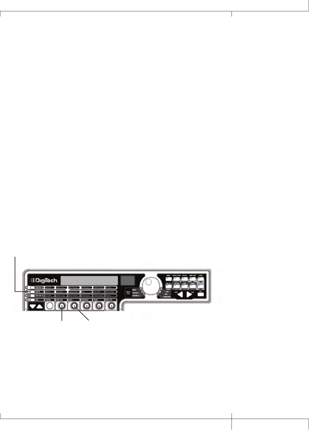
Creating a Preset
Suppose you wanted to create your own HyperModelTM that incorporates the sweet tones of a vintage
Tweed using an British 1x12 cabinet, and the ripping distortion of a Rectified Amp with a British 4x12
cabinet. Let’s also suppose that you want to be able to toggle between an acoustic guitar simulation
and this new HyperModel with a preset that gives your single coil pickup a humbucker sound, uses no
Compression, has a Noise Gate that opens quickly, a subtle Chorus effect, no Delay, and a little bit
of a Hall reverb. The following guide steps you through the process of creating just that preset in the
GNX3000. Start by selecting Stompbox Mode (yellow), using the MODE button.
Selecting a Preset
The first step to create a custom preset of your own is to select a starting point. You can start with
any existing preset, but for this example let’s start with Factory 1 Preset 40. Use the DATA WHEEL or
FOOTSWITCHES (when the GNX3000 is in either Preset or Stompbox Mode) to select Factory 1 Preset
40.
Create a HyperModelTM
For this example, we are going to use a vintage Tweed amp with an British 1x12 Cabinet, and warp it
with a Rectified Amp using a British 4x12 cabinet.
Select Channel 1 Amp and Cabinet
To assign the vintage Tweed amp to Channel 1 do the following:
1. Press the GENETX Amp Control button to access each channel’s amp and cabinet models.
2. Rotate KNOB 1 until the display reads 57 dlux (Tweed).
3. Rotate KNOB 2 until the display reads brit1X12 (VoxTM).
1. Press the GENETX
Amp Control button
2. Rotate Parameter 1 knob
until Display reads 57 dlux
3. Rotate parameter 2 knob
until Display reads brit1x12
GNX3000 Owner’s Manual
81 GNX3000 Owner’s Manual
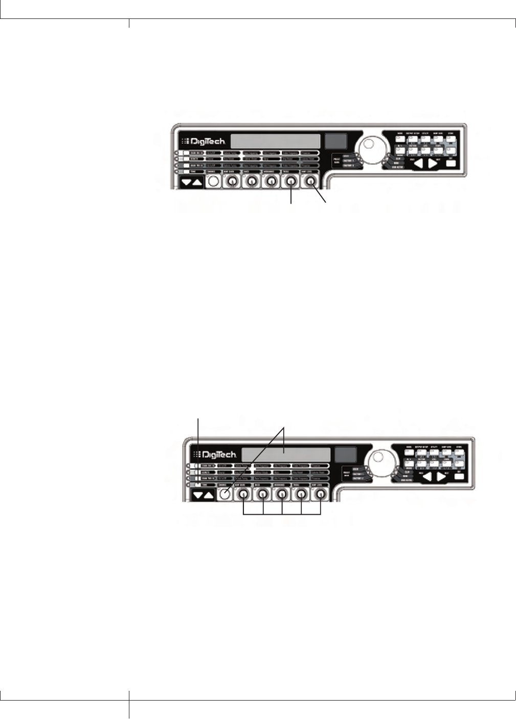
Select Channel 2 Amp and Cabinet
To assign the Rectified amp to the Channel 2 do the following:
1. Rotate KNOB 4 until the display reads DualRect (Rectified).
2. Rotate KNOB 5 until the display reads brit4x12 (British 4x12).
1. Rotate Parameter 4 knob
until Display reads dualrect
2. Rotate Parameter 5 knob
until Display reads brit4x12
Adjust Channel 1 Tone Controls
The Tweed amp that we selected for our Channel 1 assignment uses the factory
default settings for the Gain, EQ, and Level Parameters. Therefore, you may want
to change the settings. To access the tone controls for Channel 1, do the following:
1. Press the TONE Amp Control button.
2. Press the STATUS button until the display reads ch1 amp and all the
horizontal LEDs will light green indicating that all 5 knobs will adjust Channel
1’s tone controls.
3. Rotate KNOB 1 to adjust the Tweed Amp’s Gain. The range is from 0 to 99.
1. Press the Tone Amp
Control button
2. Press the Status button
until Display reads CH1 AMP
and all LEDs light green
3.-7. Rotate Parameter knobs to
adjust Channel 1’s Gain, EQ Level,
and Amp Level
4. Rotate KNOB 2 to adjust the Tweed Amp’s Bass EQ Level (boost/cut). The
range is from -12 dB (-12) to +12 dB (12).
5. Rotate KNOB 3 to adjust the Tweed Amp’s Midrange EQ Level(boost/cut). The
range is from -12 dB (-12) to +12 dB (12).
6. Rotate KNOB 4 to adjust the Tweed Amp’s Treble EQ Level(boost/cut). The
range is from -12 dB (-12) to +12 dB (12).
7. Rotate KNOB 5 to adjust the Tweed Amp’s Level. The range is from 0 to 99.
82
Creating a Preset
GNX3000 Owner’s Manual
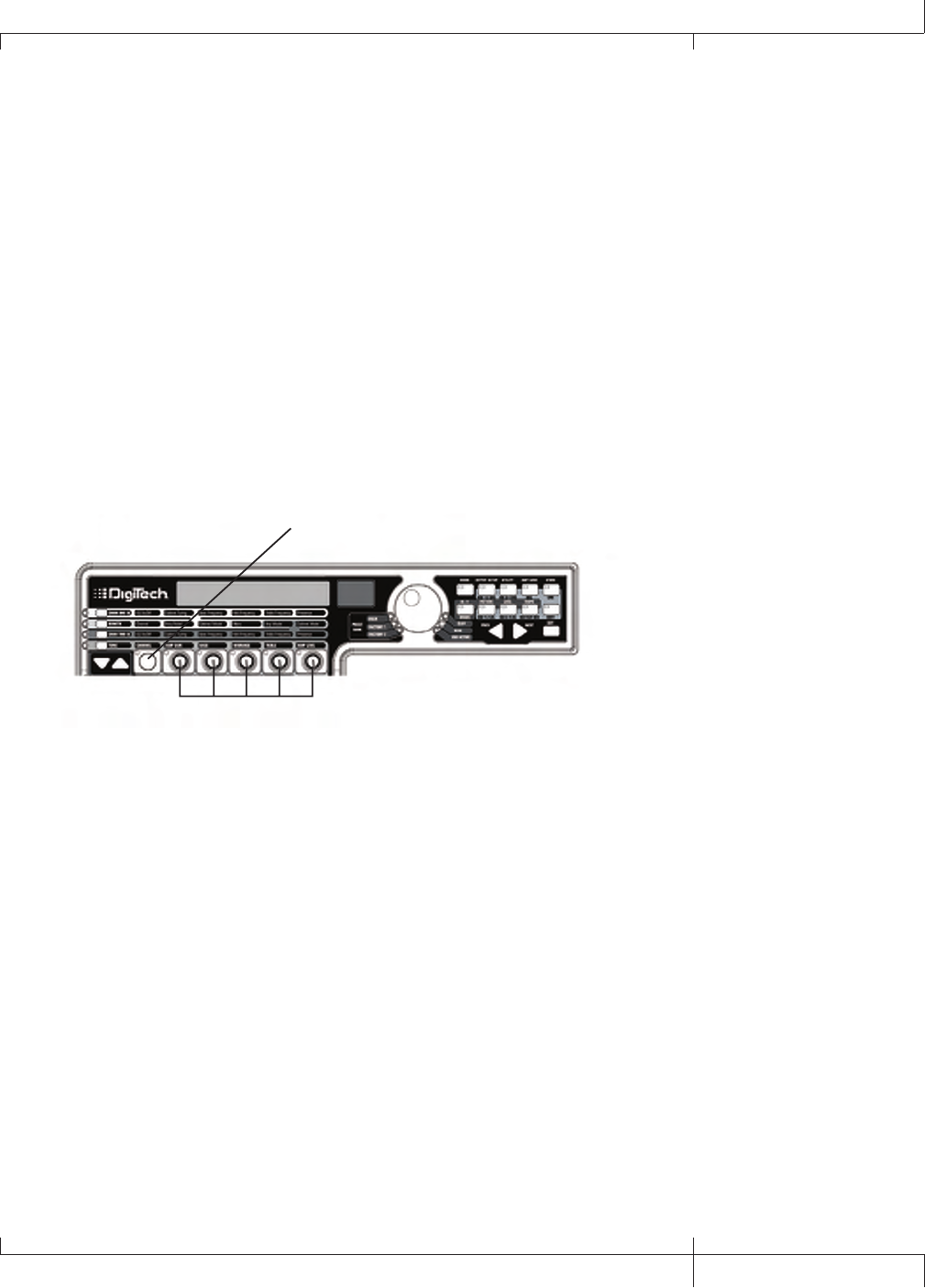
Adjust Channel 2 Tone Controls
Like the Tweed amp in Channel 1, the Rectified amp in Channel 2 may need to be
adjusted to suit your personal taste. To access the tone controls for Channel 2, do
the following:
1. Press the STATUS button until the display reads ch2 amp and all the
horizontal LEDs will light red indicating that all 5 knobs will adjust Channel 2’s
tone controls.
2. Rotate KNOB 1 to adjust the Rectified Amp’s Gain. The range is from 0 to 99.
3. Rotate KNOB 2 to adjust the Rectified Amp’s Bass EQ Level (boost/cut). The
range is from -12 dB (-12) to +12 dB (12).
4. Rotate KNOB 3 to adjust the Rectified Amp’s Midrange EQ Level (boost/cut).
The range is from -12 dB (-12) to +12 dB (12).
5. Rotate KNOB 4 to adjust the Rectified Amp’s Treble EQ Level (boost/cut). The
range is from -12 dB (-12) to +12 dB (12).
6. Rotate KNOB 5 to adjust the Rectified Amp’s Level. The range is from 0 to 99.
2.-6. Rotate Parameter knobs to
adjust Channel 2’s Gain, EQ levels,
and Amp levels.
1. Press the Status button to
turn the EQ on and off
GNX3000 Owner’s Manual
83 GNX3000 Owner’s Manual
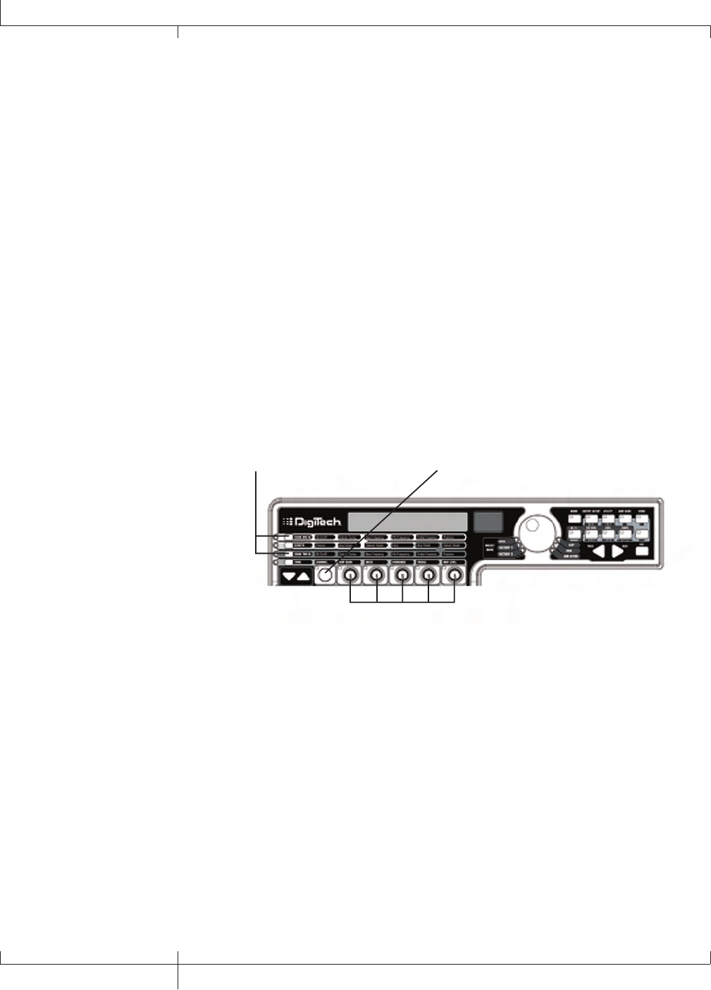
Adjust EQ/Tune the Cabinets
As an option, you may also want to modify each channel’s EQ center frequencies
(Bass, Midrange, and Treble found in the TONE row) and adjust the resonance for
the British 1x12 and the British 4x12 Cabinets. To access the EQ center frequency
settings and Cabinet tuning, do the following:
1. Select the amp channel that you would like to edit by pressing either the CHAN
ONE EQ AMP CONTROL button or the CHAN TWO EQ AMP CONTROL button.
2. Press the STATUS button to turn the EQ on and off.
3. Rotate KNOB 1 to adjust the Cabinet Tuning resonance. The Cabinet Tuning
ranges are from -12.0 (one octave below) to 12.0 (one octave above).
4. Rotate KNOB 2 to select the Bass center frequency. The range is from 50 Hz
(50 HZ) to 300 Hz (300 HZ).
5. Rotate KNOB 3 to select the Midrange center frequency. The range is from 300
Hz (300 HZ) to 5000 Hz (5000 HZ).
6. Rotate KNOB 4 to select the Treble center frequency. The range is from 500 Hz
(500 HZ) to 8000 Hz (8000 HZ).
7. Rotate KNOB 5 boosts or cuts the Presence Level. The range is from -12 dB
(-12) to +12 dB (12).
1. Press either the Chan One EQ or
Chan Two EQ Amp Control button
3.-7. Rotate Parameter knobs to
adjust cabinet Tuning, EQ Center
Frequencies, and Presence Level
2. Press the Status button to
turn the EQ on and off
84
GNX3000 Owner’s Manual
Creating a Preset
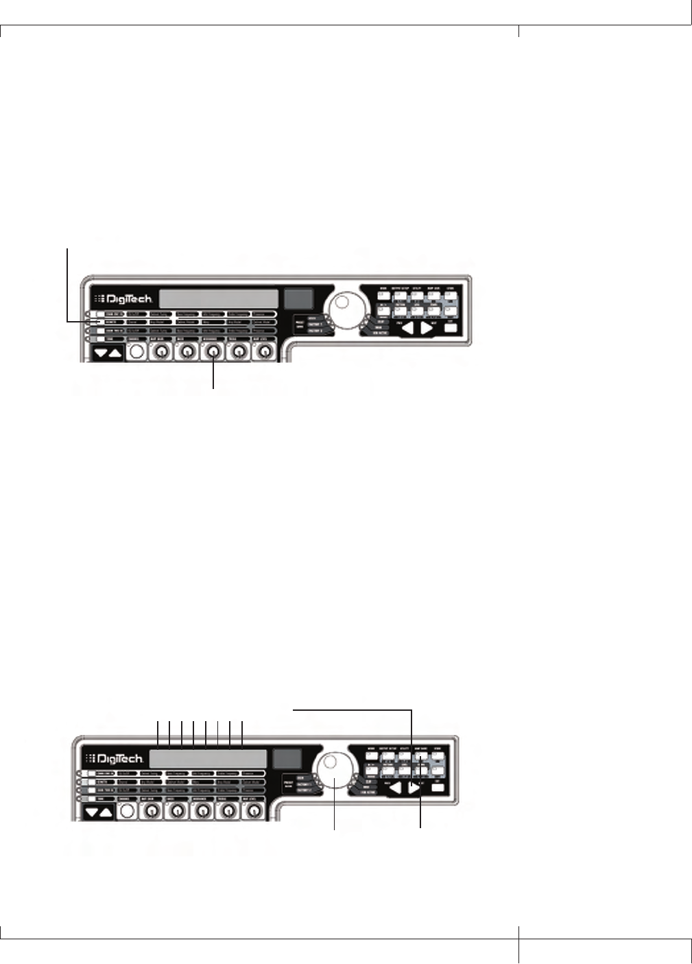
Warping Amp Channels Together
When the Amps and Cabinets in Channel 1 and Channel 2 are dialed in to
suit your taste, we can Warp their characteristics together to create a new
HyperModel. To warp the amps do the following:
1. Press the GENETX Amp Control button.
2. Rotate KNOB 3 (Warp) knob to blend the Amps and Cabinets together to
create a new unique amp.
1. Press the GENETX
Amp Control button
2. Rotate Parameter 3 knob to warp
amp and cabinet models together
Save the HyperModelTM
Now that we have designed our own Amp/Cabinet HyperModel, we need to save
it to one of the 9 User HyperModel locations. This allows us to use it in presets.
To save the HyperModel, do the following:
1. Press the AMP SAVE button until the display reads NEW AMP and the first
letter (N) is flashing. For this example, let’s name the HyperModel “Rectwed”
(Rectified Tweed).
2. Rotate the DATA WHEEL to select R as the first letter.
3. Press the NEXT ARROW button to select the next character in the display.
Continue using the DATA WHEEL and NEXT ARROW button until the display
reads RECTWED.
4. When the display reads RECTWeD, press the AMP SAVE button again.
3. Use the Next arrow button to
select character locations
2. Use the Data Wheel to
change characters
NEW AMP
1., 4. Press the Amp
Save button
GNX3000 Owner’s Manual
85 GNX3000 Owner’s Manual
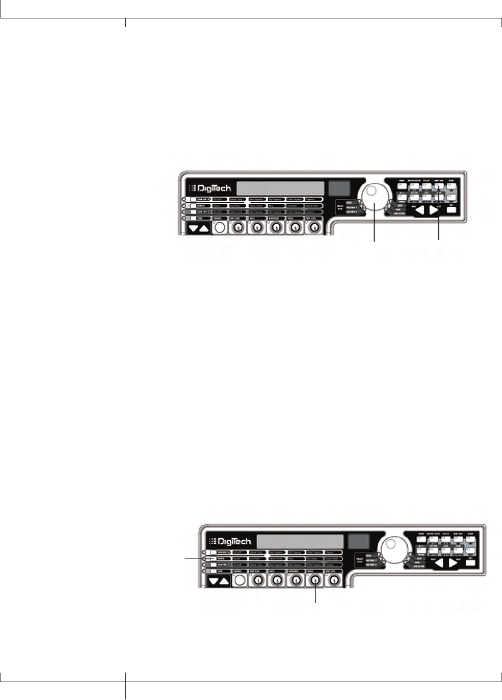
5. Now we need to choose one of the 9 User HyperModel locations. Use the
DATA WHEEL to select a an empty user location. The display should read
EMPTY (Empty) and the red numeric display should read U1 if this is the first
HyperModel stored to your GNX3000.
6. Press the AMP SAVE button again to save to this Amp location. The display
briefly reads AMP SaVeD (Amp Saved) and then returns to the name of the
selected preset.
5. Use the Data Wheel
to select an empty
User Amp location
empty
6. Press the Amp
Save button
u1
Select Models for the Preset’s Channels
In the previous steps, we selected a Tweed amp model for the Channel 1 amp and a
Rectified amp model for the Channel 2 amp. Then we warped the two together to
create our HyperModelTM. This HyperModel is saved as an amp type that we named
Rectwed, but it is not currently part of our preset. In this example preset, we need to
be able to toggle between an acoustic guitar simulation and our new HyperModel. To
do this we need to now select the Dreadnaught acoustic guitar model for Channel 1’s
amp and our custom Rectwed for Channel 2’s amp in our preset. This procedure is as
follows:
1. Press the GENETX Amp Control button.
2. Rotate KNOB 1 until the display reads AC dread. This is Channel 1’s Model
for the preset.
3. Rotate KNOB 4 until the display reads RECTWeD (our new HyperModel).
This is Channel 2’s Model for the preset. This lets us toggle between these two
sounds using the Amp Footswitch (when Preset Mode is active).
2. Rotate the Knob 1
until Display reads
ac dread
3. Rotate Knob 4
until Display reads
rectwed
1. Press the GENETX
Amp Control button
86
GNX3000 Owner’s Manual
Creating a Preset
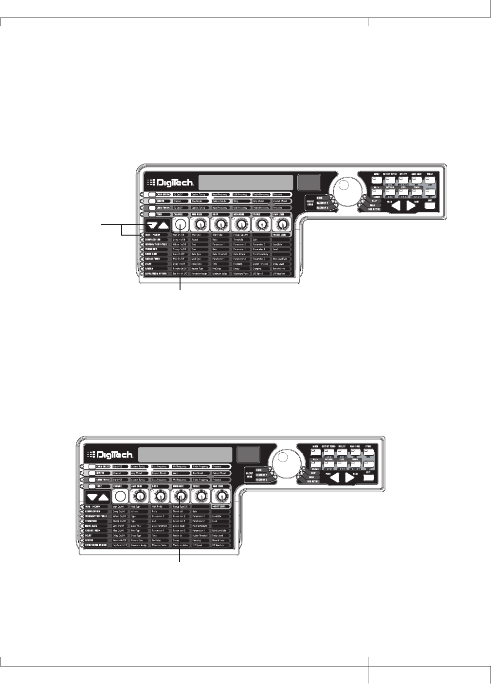
Edit the Preset Effects
The next step to creating our example preset involves editing the effects. To edit the
preset, do the following:
1. Press the EFFECT SELECT DOWN button. The display will briefly read EDIT and
the Matrix LED in the Wah-Pickup row will light.
2. If the display reads WAH On, press the STATUS button once to turn the Wah off
(since our example does not use a Wah).
wah OF
1. Press the Effect
Select Down button;
the LED lights on the
Wah-Pickup effect row
2. If necessary, press the
Status button to turn
the Wah effect off
Select the Pickup Type
In our example preset we use a single coil pickup, but want it to sound like a
double coil humbucker.
1. With the Wah-Pickup LED lit, rotate KNOB 3 until the display reads SC>Humb.
This makes a single coil pickup sound like a humbucker.
SC>HUMB OF
1. Rotate Knob 3 until
Display reads sc>humb
GNX3000 Owner’s Manual
87 GNX3000 Owner’s Manual

Turn the Compressor Off
We don’t use compression in our preset so, we need to turn the Compressor off.
To turn the Compressor off, do the following:
1. Press the EFFECT SELECT DOWN button. The Compression LED lights and the
display shows the current status of the Compressor.
2. If the Compressor is on, press the STATUS button until the red display reads off
(Of).
Turn the WhammyTM/IPS/TalkerTM Off
We don’t want Whammy, IPS, or Talker effects in this preset. To turn these effects
off, do the following:
1. Press the EFFECT SELECT DOWN button, and the Whammy/IPS/Talker LED is
lit.
2. If the display indicates that one of these effects is active, press the STATUS
button until the display reads off (Of).
Turn the Stompbox Modeling Off
To turn the Stompbox Modeling off for this preset, do the following
1. Press the EFFECT SELECT DOWN button until the Stompbox LED is lit.
2. If the display indicates that it is active, press the STATUS button until the
display reads off (Of).
Adjust the Noise Gate
For our example, we want our Noise Gate to open quickly with a relatively weak
signal. This type of gate uses the SilencerTM with a low threshold and short attack
time. To create this type of Noise Gate, do the following:
1. Press the AMP FOOTSWITCH to select the Channel 2 Amp (CH2 AMP), our
high gain model.
2. Press the EFFECT SELECT DOWN button and the Noise Gate’s LED lights.
3. If the display reads off (Of), press the STATUS button until the display reads on
(On).
4. Rotate KNOB 1 until the display reads SILeNCeR for the type of gate.
5. Rotate KNOB 2 to set the Threshold to 37 (this may need to be adjusted
depending upon your guitar).
6. Rotate KNOB 3 to set the Attack Time to 0 (fast attack).
88
GNX3000 Owner’s Manual
Creating a Preset
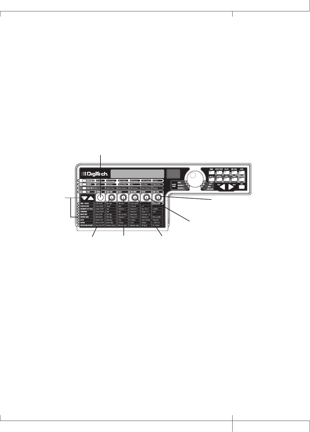
Select and Adjust the Chorus
Next we want to thicken up the sound, by adding a subtle Chorus effect, in the
following manner:
1. Press the EFFECT SELECT DOWN button again and the LED in the Chorus/Mod
row lights.
2. If the display reads off (Of), press the STATUS button until the display reads on
(On).
3. Rotate KNOB 1 until the display reads Chorus (Chorus) for the effect type.
4. Rotate KNOB 2 to set the Chorus Speed to 5.
5. Rotate KNOB 3 to set the Chorus Depth to 30.
6. Rotate KNOB 4 to set the PreDelay to 1.
7. Rotate KNOB 5 to set the Chorus Level to 50.
chorus
1. Press Effect Select
Down again until the
Chorus/Mod LED
lights
3. Rotate Knob 1
to select Chorus
2. Press the Status button to
turn on the Chorus/Mod effect
4. Rotate Knob 2
to set the Chorus
speed to 5
5. Rotate Knob 3
to set the Chorus
Depth to 30
6. Rotate Knob 4
to set the PreDelay
to 1
7. Rotate Knob 5
to set the Chorus
Level to 50
Turn the Delay Off
To bypass the Delay, do the following:
1. Press the EFFECT SELECT DOWN button until the LED in the Delay row lights.
2. If the display reads on (On), press the STATUS button until the display reads off
(Of).
GNX3000 Owner’s Manual
89 GNX3000 Owner’s Manual
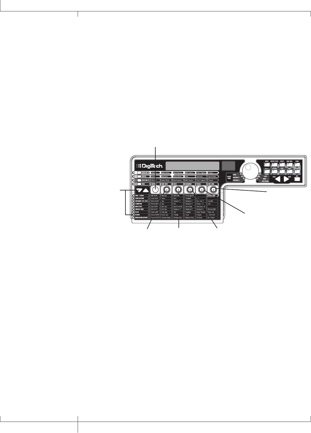
Select and Adjust the Reverb
In our example preset we wanted a little bit of Hall Reverb to provide some
ambience. To add the reverb, do the following:
1. Press the EFFECT SELECT DOWN button until the LED in the Reverb row lights.
2. If the display reads off (Of), press the STATUS button until the display reads on
(On).
3. Rotate KNOB 1 to select Hall (Hall) for the Reverb Type.
4. Rotate KNOB 2 to set the Reverb Predelay to 2.
5. Rotate KNOB 3 to set the Reverb Decay to 15.
6. Rotate KNOB 4 to set the Reverb Damping to 40.
7. Rotate KNOB 5 to set the Reverb Level to 30.
hall
1. Press Effect Select
Down again until the
Reverb LED lights
3. Rotate Knob 1
to select Hall as
the Reverb type
2. Press the Status button to
turn on the Reverb
4. Rotate Knob 2
to set the Reverb
PreDelay to 2
5. Rotate Knob 3
to set the Reverb
Decay to 15
6. Rotate Knob 4
to set the Reverb
Damping to 40
7. Rotate Knob 5
to set the Reverb
Level to 30
90
GNX3000 Owner’s Manual
Creating a Preset
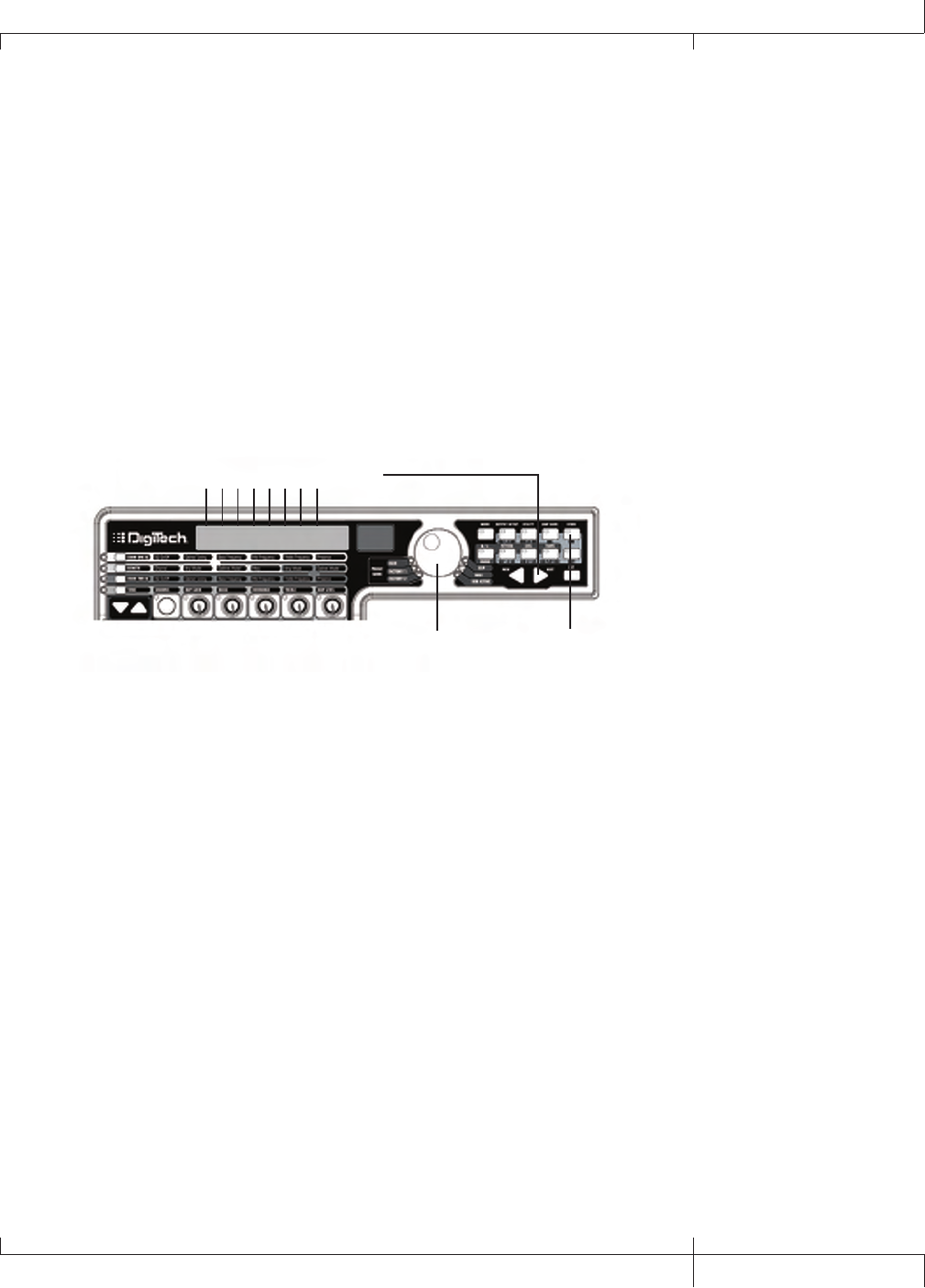
Store the Preset
The last step is to store our changes to a User Preset. If we changed presets
or turned the GNX3000 off without storing these settings, it would forget what
we had done and revert back to the original preset. To store the preset, do the
following:
1. Press the STORE button. The first letter in the display begins to flash. Since this
is an example preset, let’s name the preset examplE.
2. Rotate the DATA WHEEL until the flashing character in the display is an E.
3. Press the NEXT button once and the second character begins to flash.
4. Rotate the DATA WHEEL again until the flashing character is an X. Continue
using the NEXT button to select the character location and the DATA WHEEL to
change the characters.
3. Use the Next arrow button to
select character locations
2., 4., 6. Use the Data Wheel to
change characters
store
1., 5., 7. Press the Store
button
5. Once the Display reads exampLE, press the STORE button again. The numbers
in the red numeric display are flashing.
6. Rotate the DATA WHEEL to select User Preset 48 as the destination.
7. Press the STORE button once more to save the preset.
Congratulations! You have successfully created a Preset.
GNX3000 Owner’s Manual
91 GNX3000 Owner’s Manual
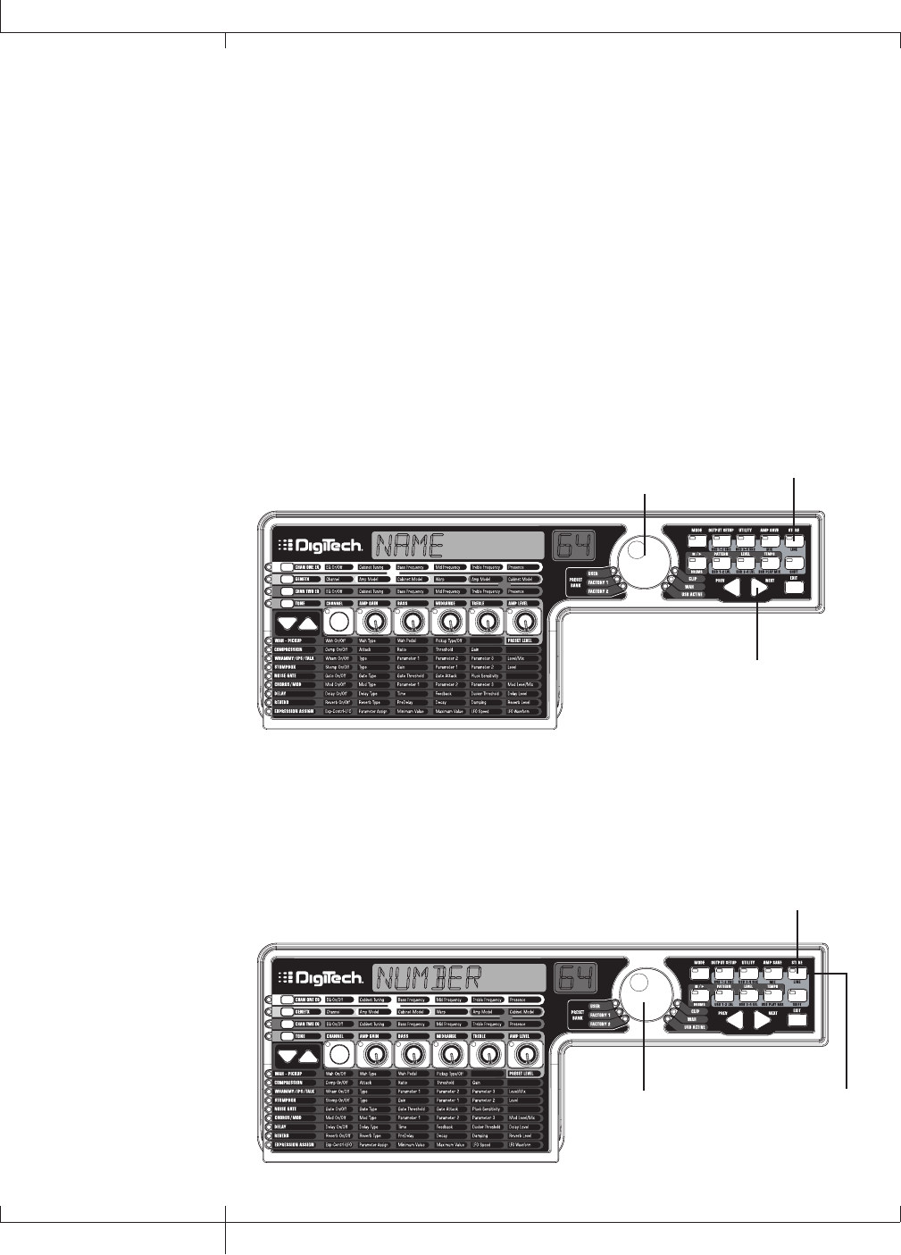
Storing/Copying a Preset
Storing a Preset
Once you have modified the Amp Models, Cabinet Types, and Effect Parameters, the
Store button LED flashes indicating you have changed a parameter and need to store
the changes to a User Preset location in order to recall them later. The following steps
outline the procedure for storing a preset:
1. Press the STORE button. The first letter of the preset name begins flashing.
2. Use the DATA WHEEL to select the alpha-numeric character.
3. Press the NEXT button to select the next character to the right, and the PREV
button to select the previous character to the left.
Name 64
2. Use the Data Wheel to select
an alpha-numeric character
1. Press Store
3. Use the Next button to
select the next character
4. Repeat steps 2 and 3 until you are finished naming the new preset.
5. Press the STORE button again. The current preset location will then flash in the
red display.
6. Select the User Preset location using the DATA WHEEL.
7. Press the STORE button again to finish.
number 64
5. Press Store again
6. Select a User
preset using the
Data Wheel
7. Press Store again
92
GNX3000 Owner’s Manual
Storing/Copying a Preset

Copying a Preset
To copy one preset to another preset location, begin by selecting the preset you want
to copy, then follow the steps listed above.
Press EXIT at any time during the procedure to abort the store process.
The FOOTSWITCHES perform different functions specific to the mode that has been
selected. Listed below are descriptions of each footswitch’s function within each of
the three Modes.
Preset Levels
The GNX3000 presets each have an independent level control for quick balancing of
the levels between presets. Preset Level is accessed by selecting the WAH – PICKUP
row of the Matrix using the EFFECT SELECT buttons and then adjusting KNOB 5. The
Preset Level adjusts the overall output level of the active Preset and the range is from
0 to 99. Preset Level changes need to be saved and stored to a user preset location
just as any other effect changes. See page 92 for more information on Storing a
Preset.
GNX3000 Owner’s Manual
93 GNX3000 Owner’s Manual
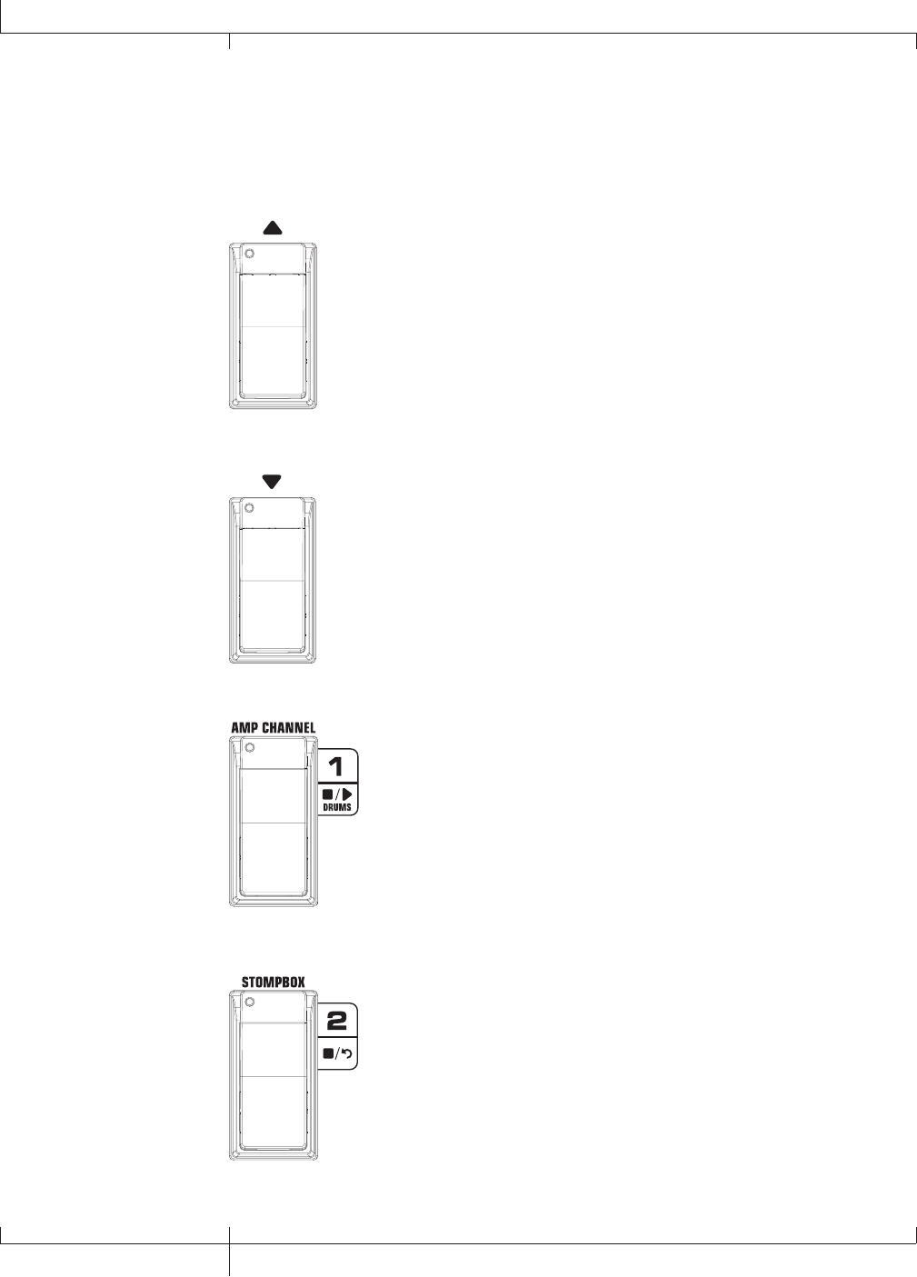
Footswitch Functions for Modes
Preset Mode - Green
Bank Up Footswitch - Selects the next bank of presets. Pressing
and holding this footswitch scrolls up through banks. When a new
bank is selected the FOOTSWITCH 1-5 LEDs will strobe left to right
prompting the user to select a preset. If a preset is not selected
within 5 seconds, the GNX3000 returns to the currently selected
bank and preset.
Bank Down Footswitch - Selects the previous bank of presets.
Pressing and holding this footswitch scrolls down through banks.
When a new bank is selected the FOOTSWITCH 1-5 LEDs will strobe
left to right prompting the user to select a preset. If a preset is not
selected within 5 seconds, the GNX3000 returns to the currently
selected bank and preset.
Footswitch 1 - Selects the first preset in the active bank. A second
press puts the GNX3000 into Bypass or selects the previous preset
if Preset Bounceback is enabled (see page 36 for more instructions
on the Preset Bounceback function). Pressing and holding
FOOTSWITCHES 1 and 2 together will activate the Learn-A-LickTM
feature (see page 34).
Footswitch 2 - Selects the second preset within the active bank. A
second press puts the GNX3000 into Bypass or selects the previous
preset if Preset Bounceback is enabled (see page 36 for more
instructions on the Preset Bounceback function). Pressing and
holding FOOTSWITCHES 1 and 2 together will enable the Learn-
A-LickTM feature. Pressing and holding FOOTSWITCHES 2 and 3
together will bypass the preset.
94
Footswitch Functions for Modes
GNX3000 Owner’s Manual
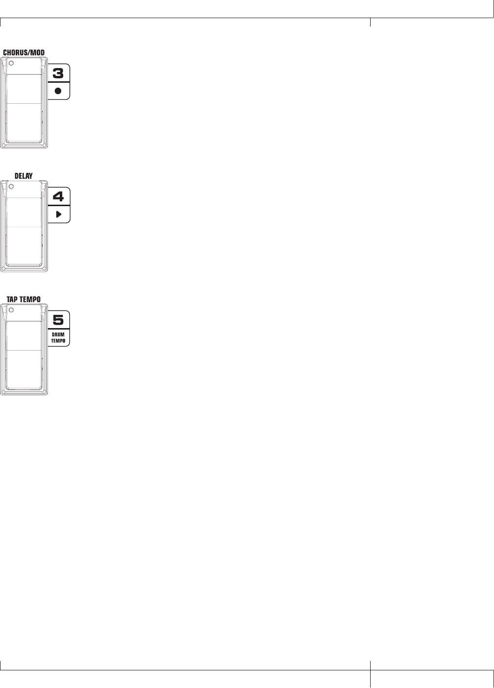
Footswitch 3 - Selects the third preset in the active bank. A second
press puts the GNX3000 into Bypass or selects the previous preset
if Preset Bounceback is enabled (see page 36 for more instructions
on the Preset Bounceback function). Pressing and holding
FOOTSWITCHES 2 and 3 together will bypass the preset. Pressing
and holding FOOTSWITCHES 3 and 4 together accesses the Tuner.
Footswitch 4 - Selects the fourth preset in the active Bank. A
second press puts the GNX3000 into Bypass or selects the previous
preset if Preset Bounceback is enabled (see page 36 for more
instructions on the Preset Bounceback function). Pressing and
holding FOOTSWITCHES 3 and 4 together accesses the Tuner.
Pressing and holding FOOTSWITCHES 4 and 5 together will change
the Footswitch Modes.
Footswitch 5 - Selects the fifth preset in the active Bank. A second
press puts the GNX3000 into Bypass or selects the previous preset
if Preset Bounceback is enabled (see page 36 for more instructions
on the Preset Bounceback function). Pressing and holding
FOOTSWITCHES 4 and 5 together will change the Footswitch
Modes.
GNX3000 Owner’s Manual
95 GNX3000 Owner’s Manual
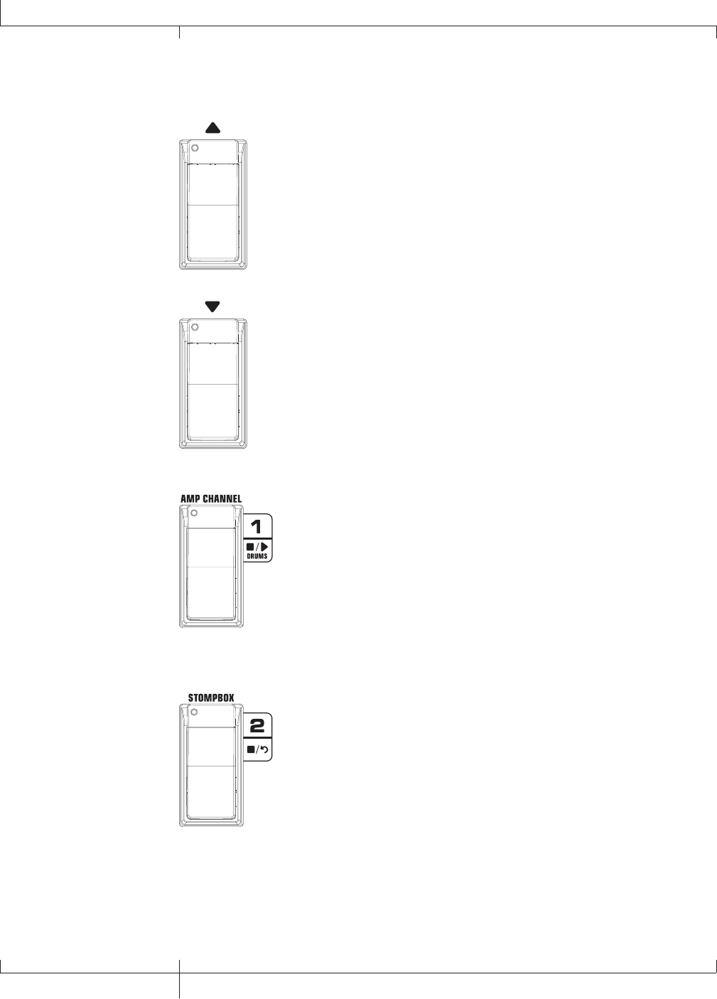
Stompbox Mode - Yellow
Preset Up Footswitch - Selects the next preset. Pressing and holding
this footswitch scrolls up through presets. After releasing, the preset
that is landed on is loaded and becomes active.
Preset Down Footswitch - Selects the previous preset. Pressing and
holding this footswitch scrolls down through presets. After releasing,
the preset that is landed on is loaded and becomes active.
Amp Channel Footswitch selects a preset’s amp channel (Ch1 amp,
Ch2 amp, or Warp amp). This footswitch’s function can be changed
in the Expression Assign menu. (See page 75 for more information
regarding Expression Pedal Assignment.) Pressing and holding
FOOTSWITCHES 1 and 2 together will enable the Learn-A-LickTM
feature (see page 34).
Stompbox Footswitch turns the Stompbox Modeling on and off.
Pressing and holding FOOTSWITCHES 1 and 2 together will activate
the Learn-A-Lick feature. Pressing and holding FOOTSWITCHES 2
and 3 together will bypass the preset.
96
GNX3000 Owner’s Manual
Footswitch Functions for Modes
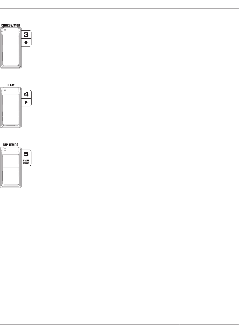
Chorus/Mod Footswitch turns the Chorus/Mod Effects on and off.
Pressing and holding FOOTSWITCHES 2 and 3 together will bypass
the preset. Pressing and holding FOOTSWITCHES 3 and 4 together
accesses the Tuner.
Delay Footswitch turns the Delay on and off. Pressing and holding
FOOTSWITCHES 3 and 4 together accesses the Tuner. Pressing and
holding FOOTSWITCHES 4 and 5 together will change the Footswitch
Modes.
Tap Tempo Footswitch is used for setting the repeat time of the
Delay effect. By tapping this switch repeatedly, you can set the
delay to repeat in time with your music. Pressing and holding
FOOTSWITCHES 4 and 5 together will change the Footswitch Modes.
GNX3000 Owner’s Manual
97 GNX3000 Owner’s Manual
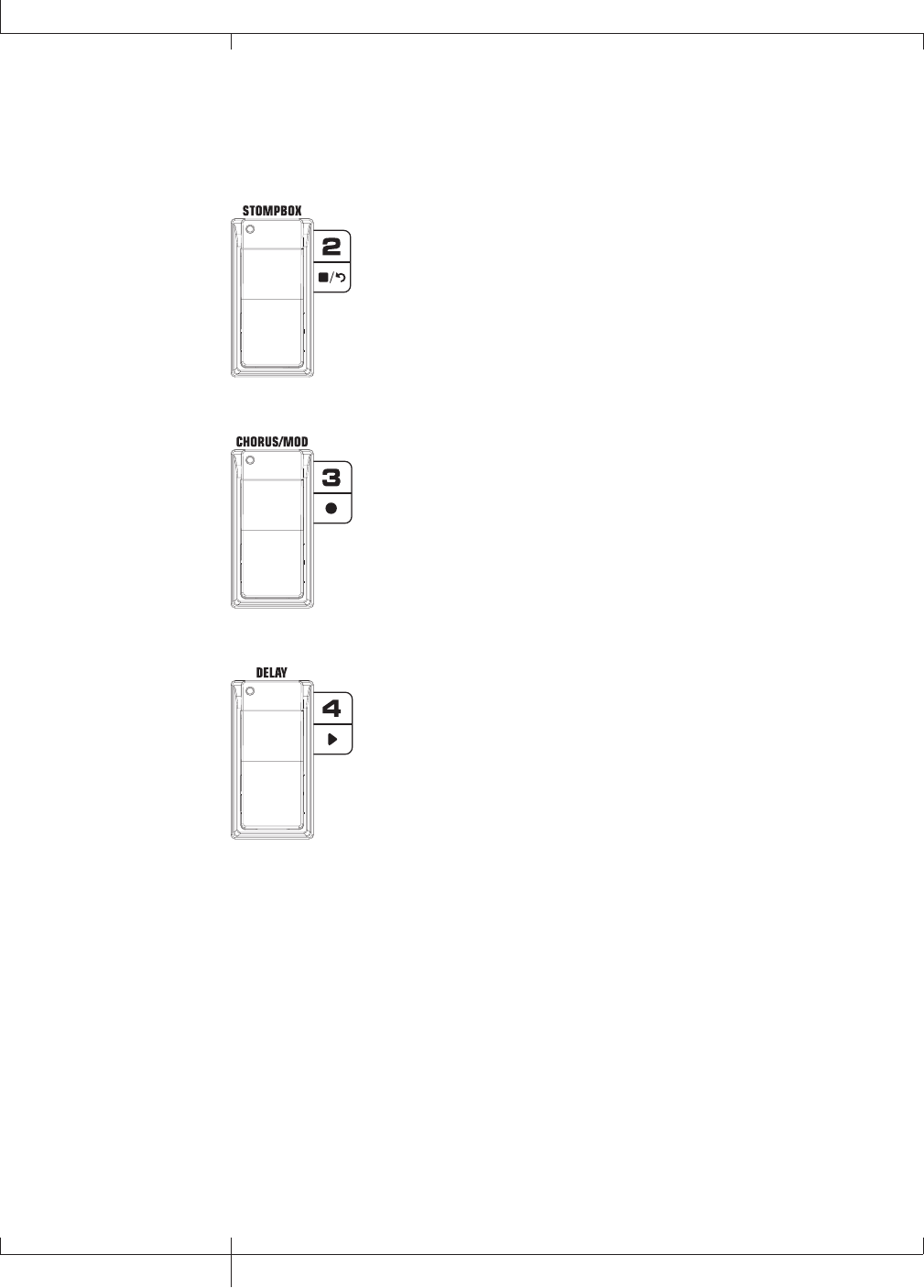
Record/Drum Mode - Red
The Record footswitch functions are listed here. See page 100 for the Drums
footswitch functions.
Stop/Undo Footswitch - Stops recording in the included ProTracksTM
Plus software. Pressing and holding this footswitch deletes the
last track recorded. Pressing and holding FOOTSWITCHES 1 and
2 together will enable the Learn-A-LickTM feature. Pressing and
holding FOOTSWITCHES 2 and 3 together will bypass the preset.
Record Footswitch - Inserts tracks for recording and starts recording
in the included ProTracksTM Plus software. Pressing and holding
FOOTSWITCHES 2 and 3 together will bypass the effects and amp
models. Pressing and holding FOOTSWITCHES 3 and 4 together
accesses the tuner.
Playback Footswitch - Starts playback of the included ProTracksTM
Plus software. Pressing and holding FOOTSWITCHES 3 and 4 together
accesses the Tuner. Pressing and holding FOOTSWITCHES 4 and 5
together will change the Footswitch Modes.
98
GNX3000 Owner’s Manual
Footswitch Functions for Modes
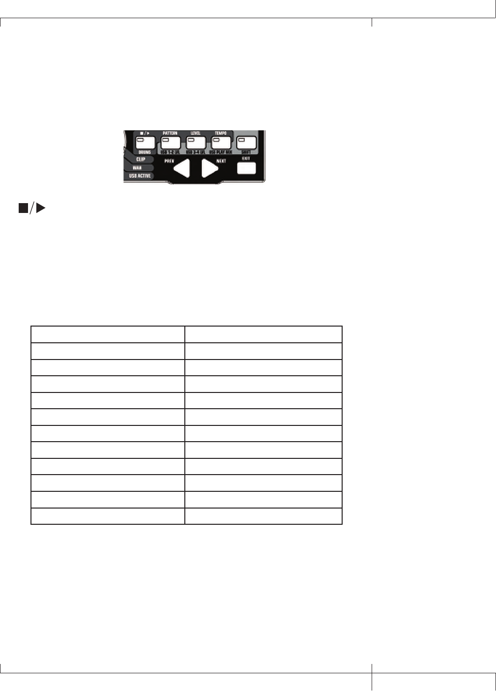
Drum Machine
The GNX3000 is equipped with a built-in General MIDI Drum Machine. You
can select from a variety of Factory-created drum patterns to play along with. The
GNX3000’s Drum Machine can be set up in different ways as shown below:
Control Panel - Drum Machine
STOP/PLAY
Press this button to start or stop the drum machine.
PATTERN
Press this button to select the Pattern library. Use the DATA WHEEL or PREV and
NEXT buttons to select one of the GNX3000’s internal drum patterns. There are 79
different drum patterns and 5 metronome settings available including:
Internal Drum Pattern List
8th Beat 1-8 Country 1-4
16thBeat 1-4 Jazz 1-4
Rock 1-8 HipHop 1-3
HardRock 1-8 dance 1-3
Metal 1-8 Latin 1-3
prog 1-2 Reggae 1-3
prog 6/8 3 Percusn 1-3
prog 7/8 4 METR 4/4 1
Blues 1-4 METR 3/4 2
R and B 1-4 METR 5/8 3
Funk 1-4 METR 7/8 4
groove 1-4 metronom 5
LEVEL
Press this button to select the drum machine playback level. Using the DATA
WHEEL or PREV and NEXT buttons to adjust the volume level of the drum machine
playback.
TEMPO
Press this button to select the Drum Machine tempo setting. Use the DATA WHEEL
or PREV and NEXT buttons to adjust the playback speed of the drum or pattern
being played back. Tempo range is 40-240 BPM (beats per minute).
GNX3000 Owner’s Manual
99 GNX3000 Owner’s Manual
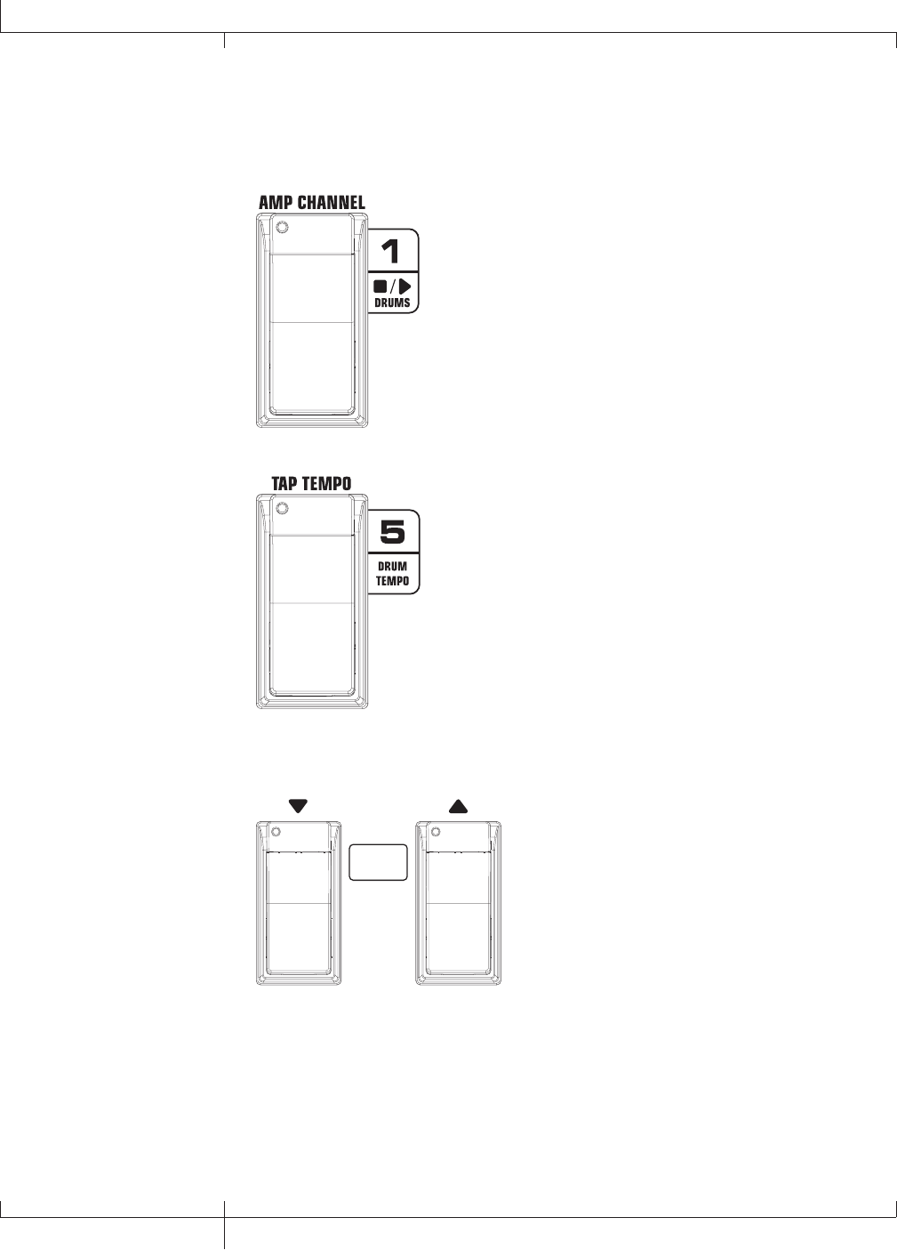
Footswitch Operation
When the GNX3000 is in Record/Drum Mode, four footswitches control drum
machine operations.
Drums Stop/Play Footswitch - Starts and stops playback of
drum patterns.
Drum Tempo Footswitch - Tapping this footswitch while
the drum machine is on or off sets the playback tempo.
It must be tapped at least 2 times within 3 seconds to set
a tempo. The Tempo can range from 40 to 240 beats per
minute.
RED: PATTERN
GREEN: BANK
YELLOW: PRESET
Pattern Footswitches - Press the DOWN/UP
FOOTSWITCHES to access all drum patterns.
You can audition these while the drums are
turned on.
100
GNX3000 Owner’s Manual
Footswitch Functions for Modes

Computer Recording via USB
The GNX3000’s USB connection provides 4 channels of audio streaming into
the computer and 2 channels of playback from the computer simultaneously.
Recording has never been easier thanks to the Hands-FreeTM tracking environment
that the GNX3000 and the Pro Tracks PlusTM software provide. The GNX3000’s
FOOTSWITCHES and Pro Tracks Plus software work seamlessly together to
automatically insert, arm, record, play, and delete tracks on the fly without ever having
to take your hands off the guitar. Multiple recording configurations can be selected to
best optimize your recording needs. For more information please refer to the Audio
Routing for USB Recording section starting on page 102.
ASIO/Mac Mode vs. WDM Mode
Recording applications run in a number of different modes; two of the most common
modes are WDM and ASIO/Mac. WDM and ASIO/Mac offer the least amount of
latency for the audio signal between the GNX3000 and the computer it’s connected to.
When the GNX3000 ships from the factory, it is configured to record in ASIO/Mac
mode. In ASIO/Mac mode, Windows® sees the GNX3000 as a 4-in, 2-out audio device.
In WDM mode, Windows sees the GNX3000 as a 2-in, 2-out device and an additional
2-in 0-out device.
Changing USB Mode (ASIO/Mac or WDM)
The GNX3000 supports two USB driver modes: ASIO/Mac and WDM. ASIO/Mac
is the default mode, and is for use with Macintosh computers and applications that
support ASIO drivers. WDM is for use with all other applications.
To change the USB mode:
1. Turn off the GNX3000.
2. Press and hold the MODE button.
3. While holding the MODE button, turn the GNX3000 on.
3. Use the DATA WHEEL to change the USB mode. Choose asio/mac if you’re
using a Mac or ASIO compatible application, or wdm if you’re using a WDM
compatible application.
4. Turn off the GNX3000.
5. Turn on the GNX3000. The selected USB mode is now active.
Installing the GNX3000’s Software Suite
The GNX3000 USB drivers must first be installed before using either the Pro Tracks
Plus recording software or the X-EditTM Editor/Librarian. These drivers are found on
the GNX3000 Software Install CD that came packaged with the GNX3000. To install
the software suite, insert the disc into your computer’s CD-ROM drive and follow
the on-screen prompts. Please review the Pro Tracks Plus documentation (located
GNX3000 Owner’s Manual
101 GNX3000 Owner’s Manual

on the Software Install CD) to ensure your computer system meets the necessary
requirements prior to installation. Once installed and configured, the GNX3000 can
then control Pro Tracks Plus and its recording functions.
Connecting the GNX3000 to the Computer
The GNX3000 comes equipped with a USB cable that is to be connected to your
computer whenever you will be recording or using the X-Edit Editor/Librarian. We
recommend that you only use the USB cable that is shipped with the GNX3000 since
it has been tested and approved for this specific use.
To connect the GNX3000 to the computer, follow these steps:
1. Install the GNX3000’s software suite (described above).
2. Begin with the GNX3000’s power turned off.
3. Plug the small end of the USB cable in to the USB jack on the back of the
GNX3000.
4. Plug the large flat end of the USB cable into an available USB port on your
computer.
5. Turn on the power to the GNX3000.
NOTE: DigiTech recommends that you do not use the GNX3000 as your default
sound playback device. This is configured in Windows in the Control Panel under
the Sounds and Audio Devices Properties. Windows Audio Samples are generally
recorded at full scale level and if played back through the GNX3000 may be very
loud in comparison with the configuration of audio level in the GNX3000.
Audio Routing for USB Recording
This section will cover the GNX3000’s inputs and how they are routed for recording
on your computer via USB.
Inputs and Recording Routing (4 In/2 Out USB Audio Interface)
The GNX3000 has four audio inputs, the GUITAR INPUT, MIC INPUT, and LEFT/
RIGHT LINE INPUTS. Each of these inputs can be used to record audio and each
has multiple routing configurations available. For instance, in a given recording
session you may want to record guitar with effects, a dry guitar only, vocal with
or without effects, or both the guitar processing and the LINE INPUTS. The
GNX3000’s flexible routing lets you record each of these inputs in different
combinations and even lets you utilize the GNX3000’s effects processing if
desired, giving you a wide variety of options for your particular recording
application. Having an understanding of how the GNX3000’s inputs and routing
options function is the best way to optimize your recording experience.
Input Sources
The GNX3000 has two recording input selections called Input Sources. Each of
these Input Sources offer several routing configurations for a variety of recording
options. The Input Sources are selected by first pressing the SHIFT button to
enable the Shift function and then using the USB 1-2 SRC and USB 3-4 SRC buttons
102
Computer Recording via USB
GNX3000 Owner’s Manual

in the Control Panel and the DATA WHEEL. Up to four channels of audio can be
recorded on the computer via USB. Each Input Source routes a pair of signals
(except MONO FX, MONO ALL, DRY GUITAR, DRY MIC, and DRUMS MN
which are mono signals) to the computer. The Input Sources signal combinations
are as follows:
USB 1-2 Source
stereofx
All input sources that are routed through the GNX3000’s effects are sent as a
stereo pair up USB 1 and 2 channels. Drums, Dry Mic, and Dry Line are not
recorded.
steroall
All input sources that are routed through the GNX3000’s effects, Drums, Dry
Mic, and Dry Line are sent as a stereo pair up USB 1 and 2 Channels.
mono fx
All input sources that are routed through the GNX3000’s effects are summed
to mono and sent up the USB 1 channel. Nothing is sent up USB 2 Channel.
Drums, Dry Mic, and Dry Line are not recorded.
mono all
All input sources that are routed through the GNX3000’s effects, Drums, Dry
Mic, and Dry Line are summed to mono and sent up the USB 1 Channel.
Nothing is sent up USB 2 channel.
sum+dGTR
All input sources that are routed through the GNX3000’s effects are summed
to mono and sent up the USB 1 channel. Dry guitar is sent up the USB 2
channel.
sum+mic
All input sources that are routed through the GNX3000’s effects are summed
to mono and sent up the USB 1 channel. Dry mic signal is sent up the USB 2
channel.
dgtr+mic
Dry guitar signal is sent up the USB 1 channel. Dry mic is sent up the USB 2
channel.
dry line
Dry Line Left Input signal is sent up the USB 1 channel. Dry Line Right
Input is sent up the USB 2 channel.
GNX3000 Owner’s Manual
103 GNX3000 Owner’s Manual

dryguitr
Dry Guitar signal is sent up the USB 1 channel. Nothing is sent up the USB 2
channel.
dry mic
Dry Mic signal is sent up the USB 1 channel. Nothing is sent up the USB 2
channel.
drums st
The GNX3000 drums playback is sent in stereo up the USB 1 and 2 channels.
drums mn
The GNX3000 drums playback (summed to mono) is sent up the USB 1
channel. Nothing is sent up the USB 2 channel.
reamp
Playback of a pre-recorded, dry guitar track can be routed back through
the GNX3000’s effects processing and recorded back up the USB 1 and 2
channels. See Re-Amping a Guitar Track on page 114 for more information
how this feature works.
USB 3-4 Source
USB OFF
USB 3 and 4 are disabled.
DGTR+Mic
Dry guitar signal is sent up the USB 3 channel. Dry mic signal is sent up the
USB 4 channel.
dry line
Dry Line Left Input signal is sent up the USB 3 channel and Dry Line Right
Input signal is sent up the USB 4 channel.
DRYGuiTR
Dry guitar signal is sent up the USB 3 channel. Nothing is sent up the USB 4
channel.
DRY MIC
Dry mic signal is sent up the USB 3 channel. Nothing is sent up the USB 4
channel.
DRUMS st
GNX3000 drum playback is sent in stereo up the USB 3 and 4 channels.
104
Computer Recording via USB
GNX3000 Owner’s Manual
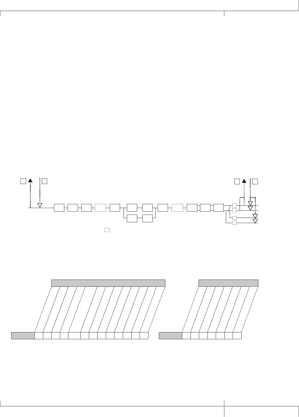
DRUMS mn
GNX3000 drum playback (summed to mono) up the USB 3 channel. Nothing
is sent up the USB 4 channel.
The following diagrams outline how the different input signals are routed through
the GNX3000 and out to computer (USB) for recording:
Guitar Signal Routing
The guitar signal is routed from the input through the GNX3000’s effects
processing and then to the pairs of analog outputs. There are two paths in which
the guitar signal can be routed up the USB port to the computer. Path A taps the
guitar signal off at the input and sends unprocessed signal up the USB port. Path
C taps the guitar signal at the output of the GNX3000 and includes any effects
processing that may be used. Signals recorded from USB Send Path A can be
played back later through the GNX3000 for re-amping. See Re-Amping a Guitar
Track on page 114 for more information on how this feature works.
Guitar Input
= Speaker Compensation Module
SC
SC
SC
XLR Left Output
XLR Right Output
1/4" Left Output
1/4" Right Output
USB Dry
Send Path
AUSB Re-Amp
Return Path
BUSB Send
Path
CUSB Playback
Return Path
D
SC
SC
(1/4" USB Playback
disabled in Split Modes)
CH 1 AMP
MODELING/
TONE
CH 1 AMP
CABINET
CH 2 AMP
MODELING/
TONE
CH 2 AMP
CABINET
PICKUP SIM WAH COMP WHAMMY/IPS
(except
TALKER) STOMPBOX GATE WHAMMY/IPS
(except
TALKER)
CHORUS/
MOD DELAY REVERB
Below is a matrix to show where the signal is tapped based on how the USB 1-2
Source and the USB 3-4 Source settings are configured.
stereofx
MONO all
SUM+DGtr
SUM+MIC
DGTR+Mic
dry line
DRYGuiTR
DRY MIC
DRUMS st
Drums mn
mic off
mic dry
mic RVB
MIC FX
Mic
• E • E E • • E • •
• E • E E • • E • •
CC, E C C, E E • • E • •
CC, E C C, E E • • E • •
Routing of Line Inputs to USB
Routing of Mic Inputs to USB
usb off
dgtr+mic
dry line
dryguitr
dry mic
drums st
mic off
mic dry
mic RVB
MIC FX
Mic
USB 3-4 Source
• E • • E •
• E • • E •
• E • • E •
• E • • E •
stereofx
steroall
SUM+DGtr
SUM+MIC
DGTR+Mic
dry line
DRYGuiTR
DRY MIC
DRUMS st
drums mn
Guitar Guitar
USB 1-2 Source
C C C, A C A • A • • •
Routing of Guitar Input to USB
usb off
dgtr+mic
dry line
dryguitr
dry mic
drums st
USB 3-4 Source
•A•A• •
mono fx
mono all
C
reamp
•
drums Mn
•
steroall
E
E
MONO fx
•
•
C
C
drums mn
•
•
•
•
usb off
dgtr+mic
dry line
dryguitr
dry mic
drums st
LINe off
LINe dry
LINe RVB
LINe FX
Line
USB 3-4 Source
• • F • • •
• • F • • •
• • F • • •
• • F • • •
drums mn
•
•
•
•
USB 1-2 Source
C
reamp
•
•
•
•
C, E
C, E
stereofx
MONO all
SUM+DGtr
SUM+MIC
DGTR+Mic
dry line
DRYGuiTR
DRY MIC
DRUMS st
Drums mn
line off
line dry
line FX
Line
• F • • • F • • • •
• F • • • F • • • •
CC, F
C, F
C • F • • • •
CC, F
C, F
• F • • • •
steroall
F
F
MONO fx
•
•
C
C
USB 1-2 Source
reamp 1-8/usb
•
•
•
•
C, F
C, F
Line RVB
C
Note: Speaker Compensation should be enabled on the XLR outputs when
recording guitar.
GNX3000 Owner’s Manual
105 GNX3000 Owner’s Manual
• = not recorded
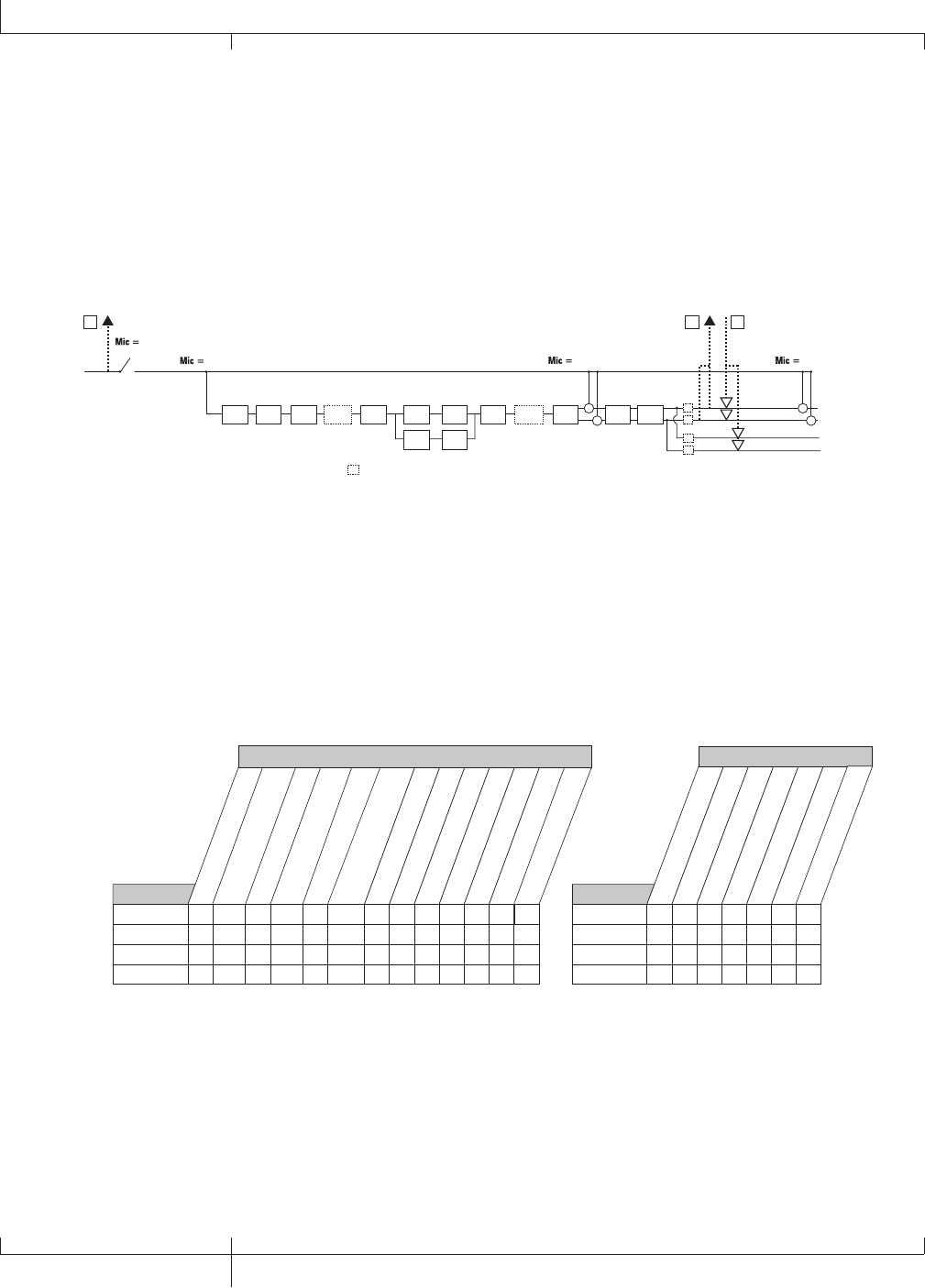
Mic Signal Routing
The mic signal can be routed in different ways through the GNX3000. mic
off disables the MIC INPUT from being heard out the analog outputs, but it
still may be recorded using steroall, Mono all, suM+MIC, DGTR+MIC,
or DRY MIC as the input source. mic dry routes the mic signal around the
GNX3000’s effects processing and mixes it in at the outputs. mic rvb routes
the mic signal only through the GNX3000’s Delay and Reverb modules. mic fx
routes the mic signal through all of the GNX3000’s effects.
mic off
mic rvb mic dry
Mic Input
SC
+
+
+
+
SC
XLR Left Output
XLR Right Output
1/4" Left Output
1/4" Right Output
SC
SC
(1/4" USB Playback
disabled in Split Modes)
USB Dry
Send Path
EUSB Send
Path
CUSB Playback
Return Path
D
= Speaker Compensation Module
SC
CH 1 AMP
MODELING/
TONE
CH 1 AMP
CABINET
CH 2 AMP
MODELING/
TONE
CH 2 AMP
CABINET
PICKUP SIM WAH COMP WHAMMY/IPS
(except TALKER) STOMPBOX GATEWHAMMY/IPS
(except TALKER)
CHORUS/
MOD DELA
Y REVERB
mic fx
The mic signal, as can be seen in the Mic Signal Routing diagram, has two paths in
which it is routed up the USB port to the computer. Path E taps the mic signal off
at the MIC INPUT and sends unprocessed signal up to the USB port. Path C taps
the signal at the output of the GNX3000 and can include any effects processing
that may be used. Below is a matrix to show where the signal is tapped based on
how the Mic, USB 1-2 Source, and USB 3-4 Source settings are configured.
stereofx
MONO all
SUM+DGtr
SUM+MIC
DGTR+Mic
dry line
DRYGuiTR
DRY MIC
DRUMS st
Drums mn
mic off
mic dry
mic RVB
MIC FX
Mic
• E • E E • • E • •
• E • E E • • E • •
CC, E C C, E E • • E • •
CC, E C C, E E • • E • •
Routing of Line Inputs to USB
Routing of Mic Inputs to USB
usb off
dgtr+mic
dry line
dryguitr
dry mic
drums st
mic off
mic dry
mic RVB
MIC FX
Mic
USB 3-4 Source
• E • • E •
• E • • E •
• E • • E •
• E • • E •
stereofx
steroall
SUM+DGtr
SUM+MIC
DGTR+Mic
dry line
DRYGuiTR
DRY MIC
DRUMS st
drums mn
Guitar Guitar
USB 1-2 Source
C C C, A C A • A • • •
Routing of Guitar Input to USB
usb off
dgtr+mic
dry line
dryguitr
dry mic
drums st
USB 3-4 Source
•A•A• •
mono fx
mono all
C
reamp
•
drums Mn
•
steroall
E
E
MONO fx
•
•
C
C
drums mn
•
•
•
•
usb off
dgtr+mic
dry line
dryguitr
dry mic
drums st
LINe off
LINe dry
LINe RVB
LINe FX
Line
USB 3-4 Source
• • F • • •
• • F • • •
• • F • • •
• • F • • •
drums mn
•
•
•
•
USB 1-2 Source
C
reamp
•
•
•
•
C, E
C, E
stereofx
MONO all
SUM+DGtr
SUM+MIC
DGTR+Mic
dry line
DRYGuiTR
DRY MIC
DRUMS st
Drums mn
line off
line dry
line FX
Line
• F • • • F • • • •
• F • • • F • • • •
CC, F
C, F
C • F • • • •
CC, F
C, F
• F • • • •
steroall
F
F
MONO fx
•
•
C
C
USB 1-2 Source
reamp 1-8/usb
•
•
•
•
C, F
C, F
Line RVB
C
106
GNX3000 Owner’s Manual
Computer Recording via USB
• = not recorded
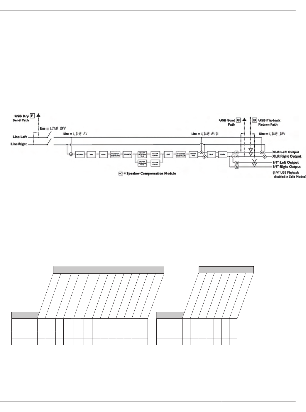
Line Input Signal Routing
The Line signals, like the mic signal, can be routed in different ways through
the GNX3000. Line OFF disables the LINE INPUTS from being heard out the
analog outputs, but they still may be recorded using steroall, Mono all,
and dry line as the input source. LINE DRY routes the left and right line
signals around the GNX3000’s effects processing and mixes them in at the left
and right outputs respectively. line rvb routes the line signal only through the
GNX3000’s Delay and Reverb modules. LINE FX sums the left and right input
signals together and then routes this signal through all the GNX3000’s effects.
The line input signals, as can be seen in the previous Line Signal Routing diagram,
have two paths in which they are routed up the USB port to the computer. Path
F taps the LINE INPUT signals off at the line input and sends unprocessed signal up
the USB port. Path C taps these signals at the output of the GNX3000 and can
include any effects processing that may be used. Below is a matrix to show where
the signal is tapped based on how the Line, USB 1-2 Source, and USB 3-4 Source
settings are configured.
stereofx
MONO all
SUM+DGtr
SUM+MIC
DGTR+Mic
dry line
DRYGuiTR
DRY MIC
DRUMS st
Drums mn
mic off
mic dry
mic RVB
MIC FX
Mic
• E • E E • • E • •
• E • E E • • E • •
CC, E C C, E E • • E • •
CC, E C C, E E • • E • •
Routing of Line Inputs to USB
Routing of Mic Inputs to USB
usb off
dgtr+mic
dry line
dryguitr
dry mic
drums st
mic off
mic dry
mic RVB
MIC FX
Mic
USB 3-4 Source
• E • • E •
• E • • E •
• E • • E •
• E • • E •
stereofx
steroall
SUM+DGtr
SUM+MIC
DGTR+Mic
dry line
DRYGuiTR
DRY MIC
DRUMS st
drums mn
Guitar Guitar
USB 1-2 Source
C C C, A C A • A • • •
Routing of Guitar Input to USB
usb off
dgtr+mic
dry line
dryguitr
dry mic
drums st
USB 3-4 Source
•A•A• •
mono fx
mono all
C
reamp
•
drums Mn
•
steroall
E
E
MONO fx
•
•
C
C
drums mn
•
•
•
•
usb off
dgtr+mic
dry line
dryguitr
dry mic
drums st
LINe off
LINe dry
LINe RVB
LINe FX
Line
USB 3-4 Source
• • F • • •
• • F • • •
• • F • • •
• • F • • •
drums mn
•
•
•
•
USB 1-2 Source
C
reamp
•
•
•
•
C, E
C, E
stereofx
MONO all
SUM+DGtr
SUM+MIC
DGTR+Mic
dry line
DRYGuiTR
DRY MIC
DRUMS st
Drums mn
line off
line dry
line FX
Line
• F • • • F • • • •
• F • • • F • • • •
CC, F
C, F
C • F • • • •
CC, F
C, F
• F • • • •
steroall
F
F
MONO fx
•
•
C
C
USB 1-2 Source
reamp 1-8/usb
•
•
•
•
C, F
C, F
Line RVB
C
• = not recorded
GNX3000 Owner’s Manual
107 GNX3000 Owner’s Manual

Using Pro Tracks PlusTM
When Pro Tracks Plus is first launched after installation, you will have to configure
the MIDI device and Audio settings to recognize the GNX3000 as the hardware you
want to use. These procedures must be followed to ensure you will be able to record
audio through all of the GNX3000’s inputs and to enable the Hands-FreeTM recording
capabilities the GNX3000 offers.
NOTE: Refer to the “Installing the GNX3000’s Software Suite” section on page 101
before connecting the GNX3000 to the USB port on your PC and using Pro Tracks
Plus.
Hands-FreeTM Recording Capabilities
Pro Tracks Plus software must be installed on your computer in order to use
the recording capabilities of the GNX3000. To install Pro Tracks Plus, insert the
Software Install CD into your computer’s CD-ROM drive and follow the on-
screen prompts.
Note: If Autorun is disabled on your computer, double-click on My Computer, then
double-click on your CD-ROM drive. When the installation program starts, follow
the on-screen prompts.
Setting Up the GNX3000 MIDI Device
The GNX3000 uses MIDI commands to communicate with Pro Tracks Plus. These
commands are used to determine which USB 1-2 Source and USB 3-4 Source
settings have been selected so that Pro Tracks Plus can function properly when
using the GNX3000’s Hands-FreeTM recording features. To configure Pro Tracks
Plus’ MIDI settings for use with the GNX3000 follow the steps outlined below:
1. Start the Pro Tracks Plus application on your computer.
2. If the Tip of the Day window appears, click the Close button.
3. If no previous MIDI outputs have been selected, the No MIDI Outputs Selected
window will appear. Click the Choose MIDI Outputs Now button. The MIDI
Devices window will open.
4. Under both Input and Output Selections, choose DigiTech USB MIDI. Do not
select DigiTech USB X-Edit or any other available selections. Click the Move
Selected Devices to Top button.
5. Click the OK button and the window will close.
6. If the Quick Start window appears, click the Close button.
Setting up the GNX3000 for Hands-Free Recording
1. From the Pro Tracks Plus menu bar, select Options>Control Surfaces. The
Control Surfaces window will appear.
108
GNX3000 Owner’s Manual
Computer Recording via USB

2. Click the + button to add a new control surface. The Control Surface Settings
window will open.
3. In the Control Surface pull-down menu, select DigiTech Hands-Free. Verify
that the Input and Output port settings still have DigiTech USB MIDI selected.
If they do not, do this now.
4. Click the OK button. DigiTech Hands-Free should now be displayed as the
Connected Surface in the Control Surfaces Window.
5. Click the Close button.
6. Pro Tracks Plus can now respond to the GNX3000 for automated recording
functions.
Configuring Pro Tracks PlusTM for Recording in ASIO Mode
1. From the Pro Tracks Plus menu bar, select Options>Audio.
2. Click the Advanced tab.
3. Under Playback and Record, select ASIO from the Driver Mode pull-down
menu.
4. Click the OK button.
5. If you are prompted to restart Pro Tracks Plus, click Yes.
6. From the Pro Tracks Plus menu bar, select Options>Audio.
7. Click the Drivers tab.
8. Under Input Drivers, select DigiTech USB 1-2 In/Out and DigiTech USB 3-4 In
Only. Deselect all other options.
9. Under Output Drivers, select DigiTech USB 1-2 In/Out. Deselect all other
options.
10. Click the OK button.
11. If you are prompted to restart Pro Tracks Plus, click Yes.
12. You can now select your inputs and begin recording.
Setting up Pro Tracks PlusTM for GNX3000 Audio
1. From the Pro Tracks Plus menu bar, select Options>Audio. The Audio Options
window will appear. Click the Drivers tab.
2. Under the Input Drivers settings, select DigiTech USB 1-2 In/Out and DigiTech
USB 3-4 In Only and deselect all other options.
3. Under the Output Drivers settings, select DigiTech USB 1-2 In/Out and
deselect all other options.
4. Click the OK button.
GNX3000 Owner’s Manual
109 GNX3000 Owner’s Manual
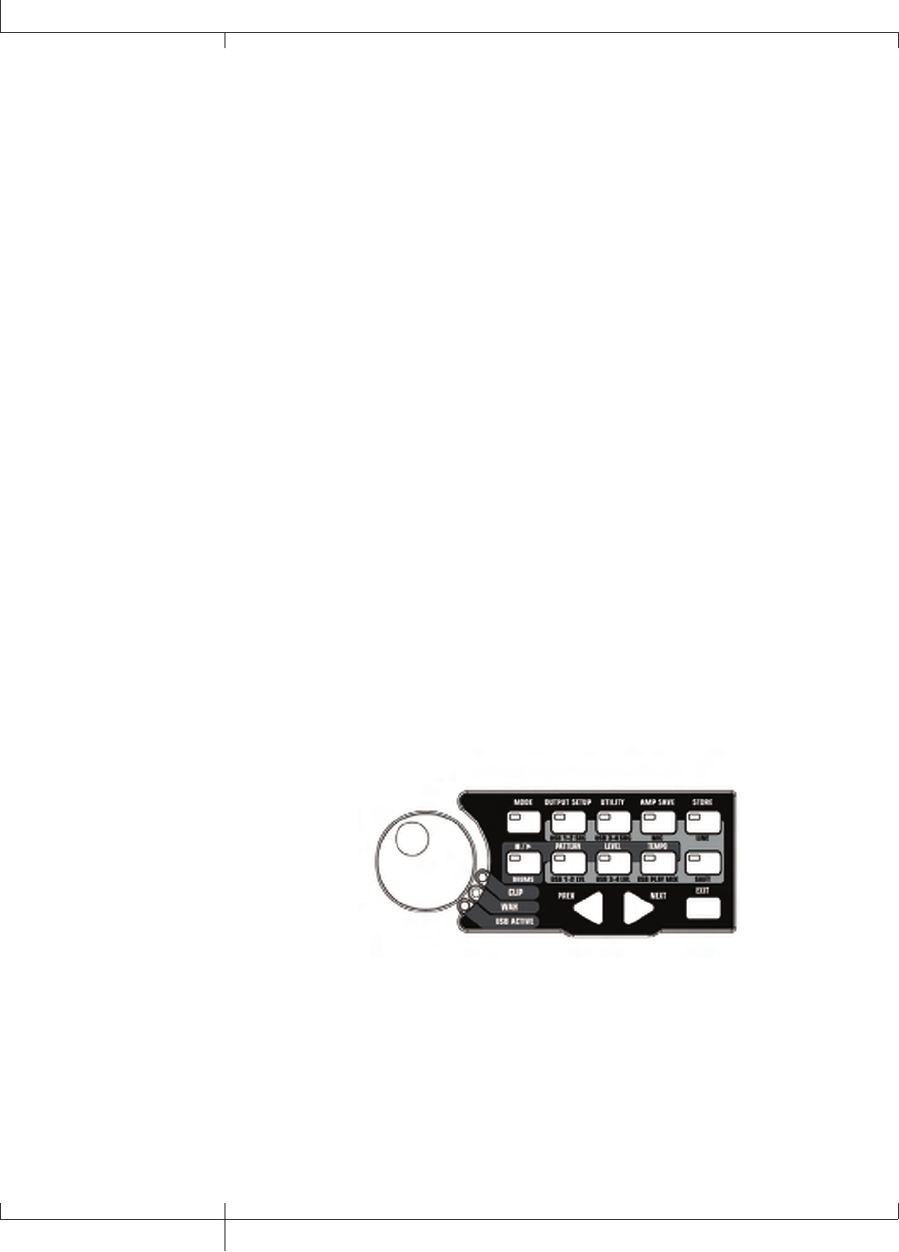
5. Click the OK button when the window stating changes will be saved upon re-
start appears.
6. Close the Pro Tracks Plus application. When you are prompted to save
changes, click No.
7. Re-start the Pro Tracks Plus application again.
8. Close the Tip of the Day and Quick Start windows if they appear.
9. From the Pro Tracks Plus menu bar, select Options>Audio.
10. Verify that the Playback and Record Timing Master settings have DigiTech
USB 1-2 In/Out selected. If not, select these now.
11. Click the Wave Profiler button at the bottom.
12. Click the Yes button to continue performing the tests.
13. When the profiling operation is successfully completed, click the OK button.
14. Click the OK button to close the Audio Options window if it is still open.
You are now ready to use the GNX3000 with Pro Tracks PlusTM recording
software.
CAUTION: Do not disconnect power or disconnect the USB cable from the
GNX3000 or the computer while the Pro Tracks Plus software is running. Doing so
can result in unpredictable behavior from your computer’s operating system.
Control Panel and Recording Setup
The CONTROL PANEL is where the routing of all audio signals, both internal and
those connected to the GNX3000’s audio inputs, are handled for both processing and
recording. Here is where you can route audio from the MIC and LINE INPUTS through
the GNX3000 effects as well as specify what signals are sent up USB to be recorded.
SHIFT
When this button is lit, the secondary functions labeled below specific buttons are now
active when these buttons are pressed.
USB 1-2 SOURCE
Selects what Input Sources are to be recorded up the USB 1-2 channels.
110
GNX3000 Owner’s Manual
Computer Recording via USB

USB 3-4 SOURCE
Selects what Input Sources are to be recorded up the USB 3-4 channels.
MIC
Selects how the mic input is routed through the GNX3000’s effects processing for
both recording an performance.
LINE
Selects how both LINE INPUTS are routed through the GNX3000’s effects
processing for both recording an performance.
USB 1-2 LVL
A gain/attenuation control to optimize the level of sources being recorded up the
USB 1-2 channels.
USB 3-4 LVL
A gain/attenuation control to optimize the level of sources being recorded up the
USB 3-4 channels.
USB PLAY MIX
Controls the level balance between the GNX3000’s processing and the USB
stream played back from your computer.
Computer Recording with a Mac
Out of the box, the GNX3000 is core audio and core MIDI compatible. No drivers
need to be installed. Just plug in the USB cable.
An installer is provided for X-Edit, the Editor/Librarian application. Just insert the
disc and follow the on-screen prompts.
If you’re using a Mac, use the GNX3000 in ASIO/MAC USB mode (this is the default
USB mode from the factory). To verify Audio MIDI connection, use Apple’s Audio
MIDI Setup application found in the Applications/Utilities folder.
If properly connected, “GNX3000” should appear in the Input/Output Audio Device
list and the MIDI Devices tab, an icon labeled “GNX3K” should be present. Refer to
Audio MIDI Setup help files for additional information on their use.
GNX3000 Owner’s Manual
111 GNX3000 Owner’s Manual
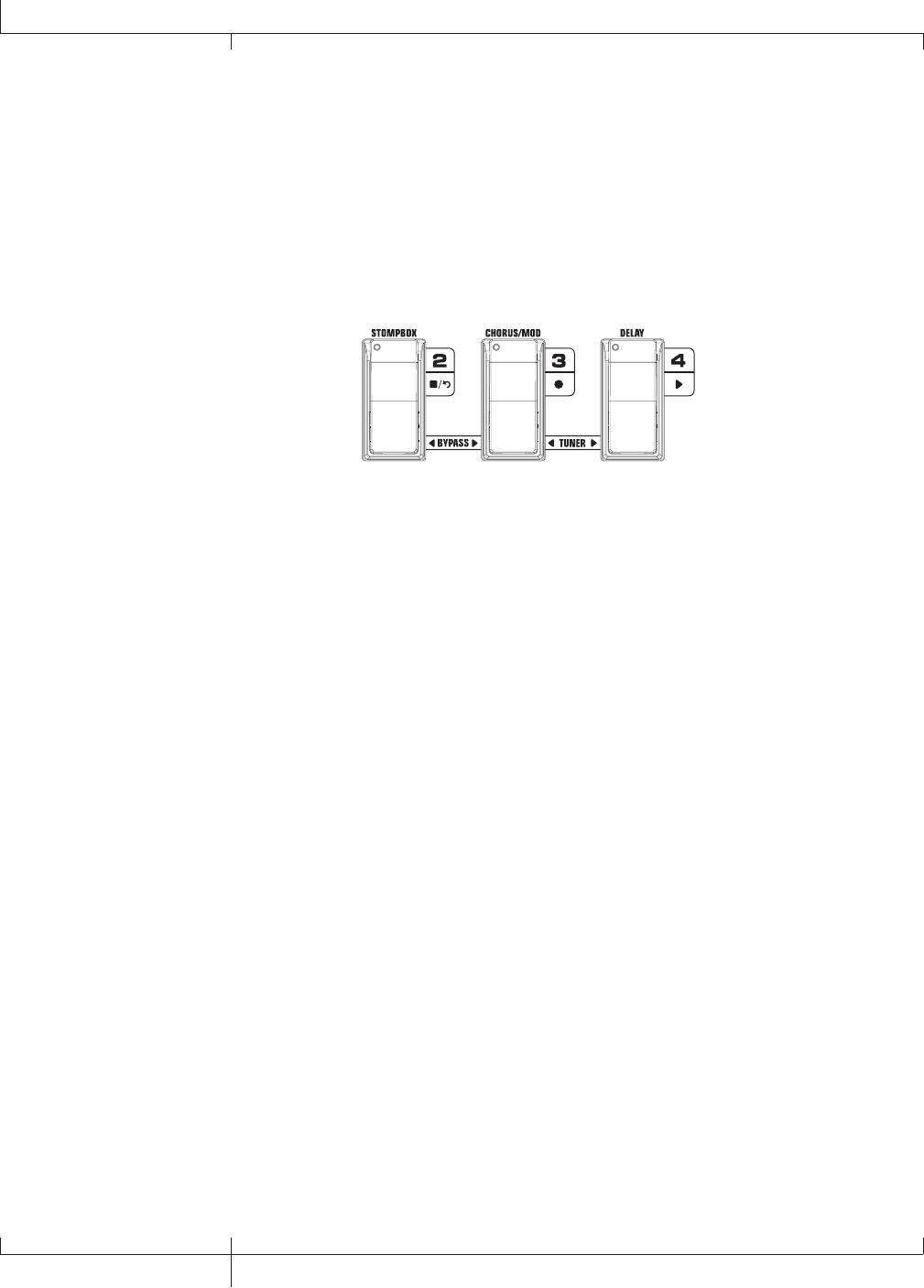
Using the GNX3000’s Footswitches for Hands-FreeTM
Computer Recording Functions
The GNX3000’s FOOTSWITCHES are capable of controlling the Pro Tracks PlusTM recording software,
creating a Hands-Free recording interface. To do this, the GNX3000 must be connected to the
computer via the included USB cable and the Pro Tracks PlusTM application must be installed and
open.
Stop/Undo Record Play
Hands-FreeTM Footswitch Controls
Recording a Track or Tracks
To begin recording a track using the FOOTSWITCHES, follow these steps:
1. Start the Pro Tracks Plus application.
2. From the Pro Tracks Plus menu bar, select File>New. The New Project File window will appear.
3. From the New Project File window, select Normal - Hands-Free Session.
4. Put the GNX3000 into Record/Drum Mode by pressing the MODE button located on the
Control Panel or by pressing FOOTSWITCHES 4 and 5 simultaneously until the display flashes
rec/drum.
5. Press the SHIFT and USB 1-2 SRC buttons, then use the DATA WHEEL to select the sources you’d
like to record. (Additional sources can be selected by pressing the USB 3-4 SRC button and
using the DATA WHEEL.)
6. Press the RECORD footswitch (FOOTSWITCH 3). The GNX3000’s display reads record. A track
or tracks are automatically inserted in the current session of the Pro Tracks Plus software and
recording on these tracks begins.
7. To stop recording, press the STOP/UNDO footswitch (FOOTSWITCH 2). The GNX3000’s display
reads stop and Pro Tracks Plus stops recording. The wave data for the track(s) can now be
viewed on your computer monitor.
Playing Back a Recorded Track
After a track or tracks have been recorded, playing them back is easy. If you want to start playback at
the beginning of a track or song but are someplace other than the end of the song, follow these steps:
1. Press the STOP/UNDO footswitch (FOOTSWITCH 2) once. The GNX3000 display will read
rewind. Pro Tracks Plus will rewind to the beginning of the current song.
2. Press the PLAY footswitch (FOOTSWITCH 4). The recorded track(s) will begin playing back.
112
Using the GNX3000’s Footswitches for Hands-FreeTM Computer Recording Functions
GNX3000 Owner’s Manual
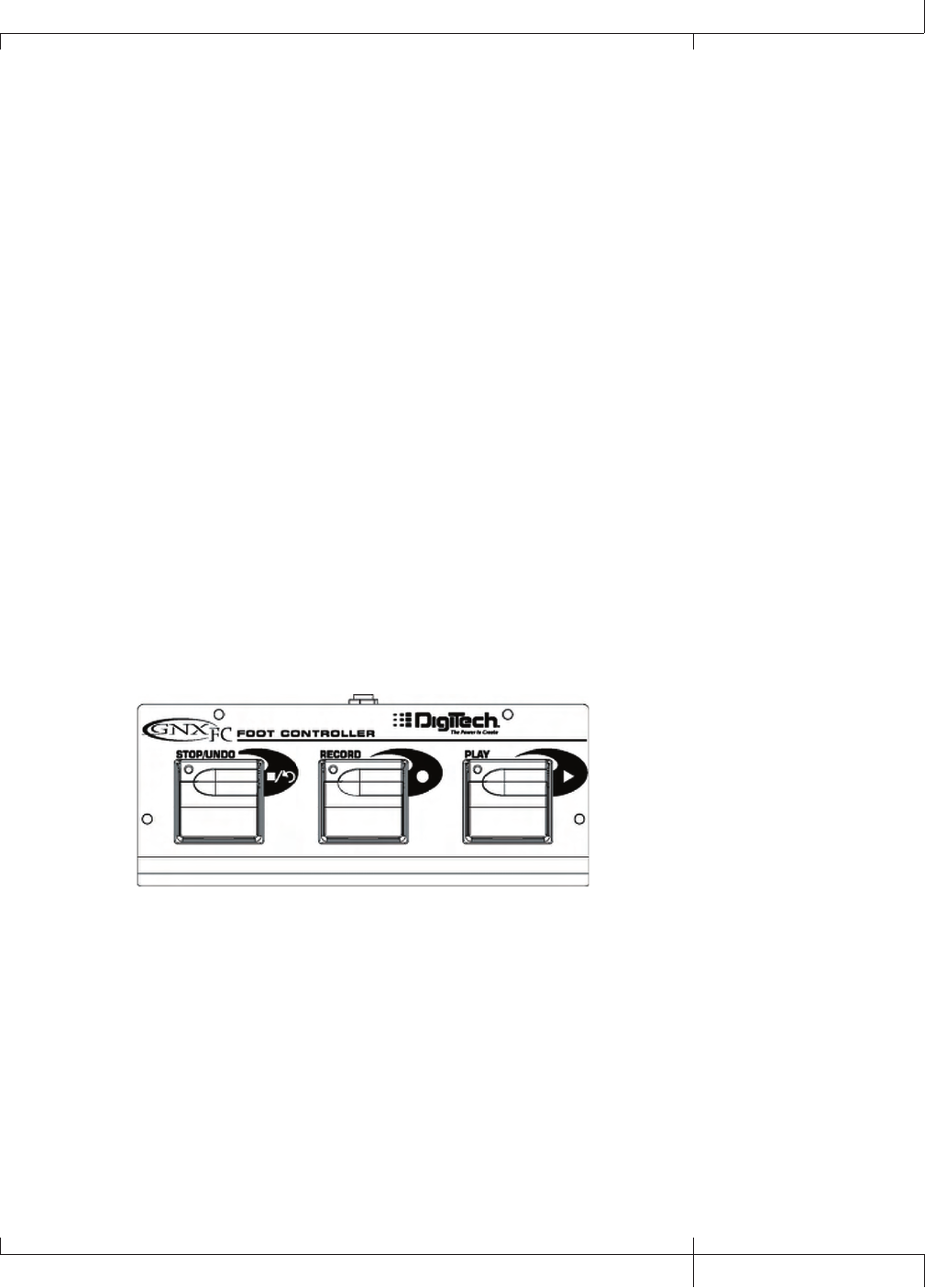
Recording Multiple Tracks
After tracks have been recorded, you may want to record other tracks that play along
with them. To record a new track or tracks with previously recorded tracks, follow
these steps:
1. (Optional) Press the SHIFT and USB 1-2 SRC buttons, then use the DATA WHEEL
to select the sources you’d like to record. (Additional sources can be selected
by pressing the USB 3-4 SRC button and using the DATA WHEEL.)
2. Press the STOP/UNDO footswitch (FOOTSWITCH 2) twice. This will rewind to
the beginning of the current song.
3. Press the RECORD footswitch (FOOTSWITCH 3). The GNX3000’s display reads
record. A track or tracks are automatically inserted in the current session of
the Pro Tracks Plus software and recording on these tracks begins.
4. To stop recording, press the STOP/UNDO footswitch (FOOTSWITCH 2).
Using the UNDO Footswitch to Erase a Track
You can undo the last take or previous tracks using the GNX3000’s FOOTSWITCHES.
To undo tracks, follow these steps:
1. Press and hold the STOP/UNDO footswitch (FOOTSWITCH 2). The GNX3000’s
display reads undo, indicating the last recorded track(s) are being deleted.
Using the GNXFC for Hands-Free Computer Recording Functions
The GNX3000 is equipped with a footswitch jack that lets you connect an optional
GNXFC for controlling the GNX3000’s record functions This 3-button footswitch
features functions for STOP/UNDO, RECORD, and PLAY. The GNXFC is an ideal
companion for recording as it lets you leave your GNX3000 FOOTSWITCHES setup for
changing presets and switching amp channels while the GNXFC is used specifically for
controlling the Pro Tracks Plus recording software. Use only a TRS stereo 1/4” cable
when connecting the GNXFC to the GNX3000.
The GNXFC functions are exactly the same as the GNX3000 FOOTSWITCHES when
it is in Record/Drum Mode. Refer to the previous section Using the GNX3000’s
Footswitches for Hands-Free Computer Recording for operating instructions.
GNX3000 Owner’s Manual
113 GNX3000 Owner’s Manual
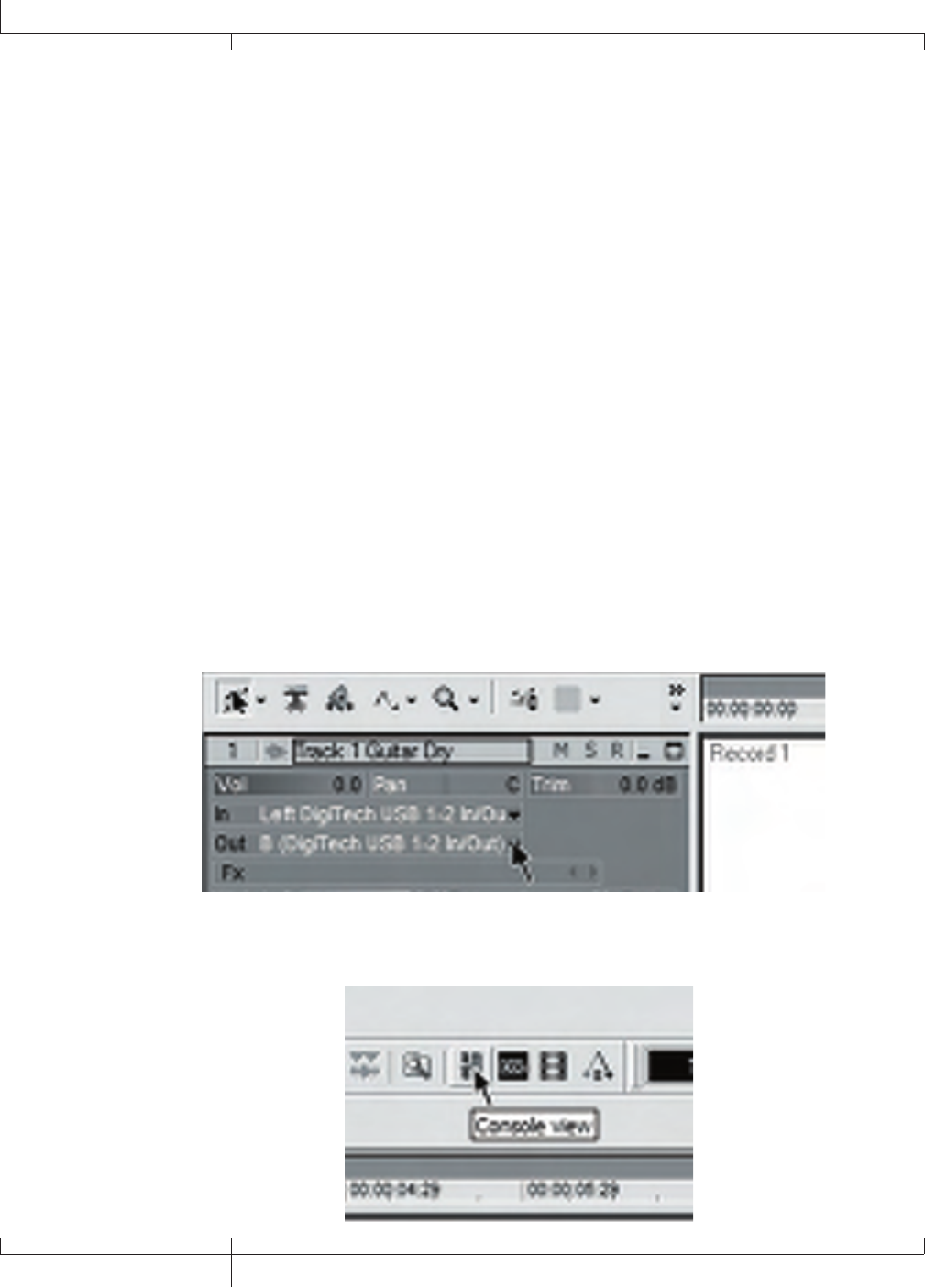
Re-Amping a Guitar Track
Using one of the Dry Guitar configurations for recording gives you the opportunity of playing a dry
take back into the GNX3000 for re-processing. The advantages of having this feature are you can
experiment playing the dry guitar take back through different amp models, effects, or entirely new
presets once you have your other tracks recorded. This helps when trying to fit a guitar sound into a
mix after the song is assembled rather than relying on tricky EQ settings that can tarnish the tone you
originally recorded.
To re-amp a track back through the GNX3000, follow these steps:
1. Put the GNX3000 into Record/Drum Mode by pressing the MODE button located on the
Control Panel or by pressing FOOTSWITCHES 4 and 5 simultaneously until the display flashes
rec/drum.
2. From the Pro Tracks Plus menu bar, select File>New. The New Project File window will open.
3. Select the Normal-Hands Free Session project template.
4. Press the SHIFT and USB 1-2 SRC buttons, then use the DATA WHEEL to select dryguitr. Then
press the USB 3-4 SRC button and use the DATA WHEEL to select usb off.
5. Press the RECORD footswitch (FOOTSWITCH 3). The GNX3000’s display reads record. A track
is automatically inserted in the current session of the Pro Tracks Plus software and recording on
this track begins.
6. To stop recording, press the STOP/UNDO footswitch (FOOTSWITCH 2). The GNX3000’s display
reads stop and recording will stop. Press Stop again to rewind to the beginning of the track.
7. In the Out box of the track you just recorded, select B(Digitech USB 1-2 In/Out).
8. In the tool bar press the Console View button to see the mixing console.
114
GNX3000 Owner’s Manual
Using the GNX3000’s Footswitches for Hands-FreeTM Computer Recording Functions
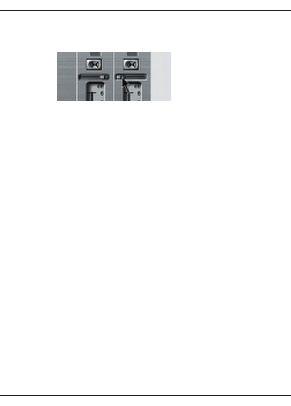
9. Pan the B - Mains Output hard left and the A - Mains Output hard right.
10. Press the SHIFT and USB 1-2 SRC buttons, then use the DATA WHEEL to select
reamP. This configures the recording software to playback audio through the
GNX3000’s effects processing.
11. Press the PLAY footswitch (FOOTSWITCH 4) then put the GNX3000 into to
Preset Mode by pressing the MODE button located on the Control Panel or
by pressing FOOTSWITCHES 4 and 5 simultaneously until the display flashes
Preset. You can now audition presets until you find one you like. Once you
have done so, return to Record/Drum Mode.
12. Press the STOP/UNDO footswitch (FOOTSWITCH 2) twice to rewind to the
beginning of the track.
13. Press the RECORD footswitch (FOOTSWITCH 3) and the recorder will now insert
and record a stereo track of processed guitar.
14. To stop recording, press the stop/undo footswitch.
Recording the GNX3000 Drums as Audio
The GNX3000’s drum machine can be recorded using Pro Tracks Plus. To record the
GNX3000 drums, follow these steps:
1. From the Pro Tracks Plus menu bar, select File>New. The New Project File
window will appear.
2. Select one of the templates and click the OK button. This will open up a new
recording session.
3. On the GNX3000, use the either the USB 1-2 SRC or USB 3-4 SRC buttons to
select drums stereo or drums Mono.
4. Press the record footswitch. The GNX3000’s display reads record. A new track
is automatically inserted in the current session of the Pro Tracks PlusTM software
and recording on these tracks begins.
5. To stop recording, press the STOP/UNDO footswitch.
GNX3000 Owner’s Manual
115 GNX3000 Owner’s Manual

Recording the GNX3000 Drums and MIDI
You can use MIDI drum files for playing the GNX3000 drum samples as long as
the events are mapped to the MIDI notes shown on page 128. The drum samples
of the GNX3000 only respond to MIDI messages transmitted on MIDI channel
10, which is the default channel for General MIDI drums.
For a complete list of the General MIDI Drum Samples see page 128.
MIDI and Recording
The GNX3000 features MIDI IN and OUT JACKS which serve several purposes:
1. MIDI IN can be used for remote control of the GNX3000 from external MIDI
devices such as MIDI sequencers and MIDI controller pedals (GNX3000
receives program changes, CC parameter control).
2. MIDI IN can be used as your MIDI interface to the computer allowing recording
of MIDI events to Pro Tracks Plus or other recording software applications via
USB.
3. MIDI OUT can be used as the MIDI out of your computer recording and
sequencer application for controlling external MIDI devices such as keyboards
or sound modules.
USB Playback Mix
The DATA WHEEL is an easy way to balance the GNX3000’s processing with playback
from the Pro Tracks PlusTM software using a single control. This function is only
available when the GNX3000 is connected to the computer via USB and Pro Tracks
Plus is up and running. To change the USB Playback mix, follow these steps:
1. Start playback of a session from Pro Tracks Plus.
2. Press the SHIFT button then press the USB PLAY MIX button (both are located in
the Control Panel).
3. Turn the DATA WHEEL to balance the level of GNX3000 guitar processing and
playback level. When the display reads USB MIX 0 it indicates that only
GNX3000 GUITAR, MIC, and LINE INPUT signals will be heard. Rotating this
knob clockwise, you will begin to hear the playback level increase. GNX mix
50 indicates the GNX3000/computer playback mix is a 50/50 mix of both
signals. Continuing to rotate the knob clockwise will decrease GNX3000 level.
GNX MIX 0 indicates that only playback from the computer will be heard.
When the GNX3000 is not connected to your computer via USB, the USB Playback
Mix parameter is hidden and returned to normal operating levels independent of USB.
If your GNX3000 is not connected to your computer and you press the SHIFT button
and then the USB PLAY MIX button, the GNX3000 will display NO USB.
116
GNX3000 Owner’s Manual
Using the GNX3000’s Footswitches for Hands-FreeTM Computer Recording Functions

USB 1-2 Level/USB 3-4 Level
The USB 1-2 LVL and USB 3-4 LVL knobs are used for boosting or cutting the amount
of signal sent out the USB port to the computer. These controls are to be used if
the signal level of the input source (mic, line input, guitar) isn’t optimized into your
recording software (consult the Pro Tracks Plus User’s Guide for information on
proper recording levels). If the signal is too hot to Pro Tracks Plus, use these controls
to decrease the level. The USB 1-2 LVL and USB 3-4 LVL parameters control the level for
each USB pair of outputs so for example, if sum+mic is the selected USB 1-2 Source,
increasing the level for the mic 6dB going up USB 2 will also increase the summed
signal by 6dB going up USB 1. To increase or decrease the level of audio going up to
the computer, follow these steps.
1. Play/sing through the GNX3000 and check the level of signal reaching the
recording software (consult the Pro Tracks PlusTM User’s Guide for information
on how to view recording signal levels).
2. Use whichever USB Level knob to boost or cut the signal level going to the
recording software. The boost/cut range is from -12dB (usb 1-2 -12) to
+24dB (usb 1-2 24). The DATA WHEEL may also be used to change the
selected USB level.
GNX3000 Owner’s Manual
117 GNX3000 Owner’s Manual

Utilities
The Utility section contains all of the menus for assigning global functions to the
GNX3000. Global functions affect the GNX3000 in its entirety rather than on a per
preset basis. The Utility menus include: Volume Pedal Update, Expression Pedal
Calibration, Bounce-Back, Bank Naming, MIDI Channel, MIDI Sysex Dumps, Amp
Dumps, MIDI Mapping, MIDI Merge, and Factory Reset. To enter the Utility section,
press the UTILITY button. Once in the Utility menu, the NEXT button selects the next
menu (scrolls to the right), and the PREV button selects the previous menu (scrolls
to the left). Each of these Utility menus is described in more detail in the following
pages.
Volume Pedal Update
The GNX3000 lets you select the EXPRESSION PEDAL’s position to be updated, after
changing presets, when it is linked to the Volume Parameter. This feature lets you
change presets and keep the volume level from the previous preset, if the EXPRESSION
PEDAL controls the volume for both presets. If this feature is disabled, new presets are
set to the volume level value stored with the preset. The procedure for enabling or
disabling the Volume Pedal Update is as follows:
1. Press the UTILITY button. The button will light indicating you are in the Utility
menu.
2. Use the PREV or NEXT buttons to select volumpdl (Volume Pedal Update) is
displayed.
3. Rotate the DATA WHEEL to select On (enabled), or OF (disabled).
4. When finished, press EXIT.
Preset Bounceback
If you would rather not bypass individual presets in Preset Mode by pressing their
FOOTSWITCHES repeatedly, you can enable the Preset Bounceback function in the
Utility menu. For example, let’s say you select Preset 1 using FOOTSWITCH 1 as your
rhythm tone. Then you select Preset 4 using FOOTSWITCH 4 as your solo tone. You
can now press FOOTSWITCH 4 again and Preset 1 will be selected again. Pressing
FOOTSWITCH 4 repeatedly will bounceback between Preset 4 and Preset 1. To enable
the Preset Bounceback feature, do the following:
1. Press the UTILITY control panel button and use the PREV/NEXT arrow buttons to
locate the Bounceback feature. The display will read BOUNCBAK.
2. Rotate the DATA WHEEL to turn the BounceBack feature on.
3. When finished, press EXIT.
NOTE: The Preset Bounceback feature only works when the GNX3000 is in Preset
Mode.
For more information regarding the footswitch functions for Preset Mode see page 94.
118
Utilities
GNX3000 Owner’s Manual

Expression Pedal Calibration
The EXPRESSION PEDAL on the GNX3000 needs to be recalibrated for use after
a factory reset has been performed. This calibration procedure is automatically
activated after a factory reset procedure. In the event the pedal’s calibration fails,
or if the pedal does not function properly, it can be re-calibrated using the Pedal
Calibration menu. The procedure for calibrating the EXPRESSION PEDAL is as follows:
1. Press the UTILITY button. The button will light indicating you are in the Utility
menu.
2. Use the PREV or NEXT buttons to select pedalcal (Expression Pedal
Calibration).
3. Press the flashing STORE button to enter the Pedal Calibration Menu. The
display will read TOE DowN (Toe Down).
4. Rock the EXPRESSION PEDAL all the way forward to the toe down position and
press the blinking FOOTSWITCH 3. The display changes to read TOE UP (toe
up).
5. Rock the EXPRESSION PEDAL all the way back to the toe up position and press
the blinking number FOOTSWITCH 4.
NOTE: If the Display shows cal eRR, a calibration error has occurred and steps
2 through 5 need to be repeated.
6. When finished, press EXIT.
Bank Names
The GNX3000 lets you customize the names of the 13 User Banks where the 65 User
Presets reside. Customized Bank names aids in quickly identifying the User Bank
containing the presets you may need for a particular song or set. The procedure for
naming the User Banks is as follows:
1. Press the UTILITY button. The button will light indicating you are in the Utility
menu.
2. Use the PREV or NEXT buttons to select bankname (Bank Names).
3. Use the DATA WHEEL to select the User Bank you want to rename. The Preset
Bank LEDs to the left of the DATA WHEEL indicate when a User Bank is
selected.
4. Press STORE to access the Naming menu. The far left character of the Bank
name begins to blink.
5. Use the DATA WHEEL to select the desired alpha-numeric character.
6. Press the NEXT button to select the next character to the right, and the PREV
button to select the previous character to the left.
7. Repeat steps 5 and 6 until the Bank name appears in the display.
8. Once the Bank name appears correctly in the display, press STORE again.
9. When finished, press EXIT.
See page 133 for a list of Banks and Presets.
GNX3000 Owner’s Manual
119 GNX3000 Owner’s Manual

MIDI Channel
The GNX3000 MIDI channel is only used for receiving incoming MIDI data (both
program change and CC data). The GNX3000 does send MIDI program change
commands but will not send CC data. The procedure for selecting the MIDI channel is
as follows:
1. Press the UTILITY button. The button will light indicating you are in the Utility
menu.
2. Use the PREV or NEXT buttons to select the midichnl (MIDI Channel). The
numeric display shows the selected MIDI channel.
3. Rotate the DATA WHEEL to select the MIDI channel. Your choices include 1
through 16, AL (all), and of (off).
4. When finished, press EXIT.
Bulk Dump
This operation performs a System Exclusive (SysEx) MIDI Bulk Dump that uploads
all the GNX3000 presets and utility data to a SysEx librarian. This is useful for making
a backup copy of all your customized settings. The procedure for performing a Bulk
Dump is as follows:
1. Connect a USB cable from the GNX3000 to your computer.
2. On the GNX3000 press the UTILITY button. The button will light indicating you
are in the Utility menu.
3. Use the PREV or NEXT buttons to select Bulkdump (Bulk Dump). The STORE
button will flash indicating it must be pressed to begin the bulk dump.
4. Open the application on your computer that you will be using to receive the
Bulk Dump and set it to record.
5. On the GNX3000 press the STORE button to begin the dump. The display reads
SEND BLK, then PRESET 1 and counts up to PRESET65, FSW BANK,
USER AMP, and USER CAB. When the dump is complete the display returns
to BULKDUMP.
6. When finished, press EXIT.
NOTE: Bulk Dump sends information on the MIDI channel defined in the MIDI
Channel Menu. Bulk Dump can only be sent and received via USB MIDI.
Preset Dump
This operation performs a System Exclusive (SysEx) MIDI Preset Dump that uploads
individual GNX3000 presets to a SysEx librarian or MIDI recording device. This is
useful for making a backup copy of customized presets. The procedure for performing
a SysEx Preset Dump is as follows:
120
Utilities
GNX3000 Owner’s Manual

1. Connect a MIDI cable from the GNX3000 MIDI Out to the MIDI In of a MIDI
recording device.
2. Press the UTILITY button. The Utility button’s LED will light.
3. Use the PREV or NEXT buttons to select PrSTDuMP (Preset Dump).
4. Use the DATA WHEEL to select the preset number you want to dump.
5. Press the STORE button. The Display will read SeND TO.
6. Press the STORE button again. The display will read send pst until the dump
is complete at which time the display returns to PrSTDuMP.
7. When finished, press EXIT.
NOTE: MIDI Preset Dump sends information on the MIDI channel defined in the
MIDI Channel Menu.
User HyperModelTM Amp Dump
This operation performs a System Exclusive (SysEx) User HypermodelTM Amp
Dump that uploads the GNX3000 Amp HyperModels to a SysEx librarian or MIDI
recording device. This is useful for making a backup copy of your customized Amp
HyperModels. The procedure for performing a User Amp Dump is as follows:
1. Connect a USB cable to your computer or a MIDI cable from the GNX3000
MIDI Out to the MIDI In of a MIDI recording device.
2. Press the UTILITY button. The Utility button’s LED will light.
3. Use the PREV or NEXT buttons to select AMP DuMP (Amp Dump).
4. Use the DATA WHEEL to select the Amp number you want to dump.
5. Press the STORE button. The display will read SND TO.
6. Set the MIDI recording device to record.
7. Press the STORE button again. The display will read send amp until the dump
is complete at which time the display returns to AMP DuMP.
8. When finished, press EXIT.
NOTE: Amp Dump sends information on the MIDI channel defined in the MIDI
Channel Menu.
MIDI Mapping
MIDI Mapping provides access to all factory and user presets from external MIDI
program change commands that may not correspond to the GNX3000 preset. This
is useful when multiple MIDI devices are chained together and controlled by one
central unit. For example, the main MIDI controller can send out a program change
command telling a particular MIDI unit to change to Program 10, but you may want
the GNX3000 to change to User Preset 27. You can remap the GNX3000 so when
it receives MIDI Program change 10, it calls up User Preset 27. The Procedure for
mapping MIDI program changes is as follows:
GNX3000 Owner’s Manual
121 GNX3000 Owner’s Manual

1. Press the Utility button. The UTILITY button’s LED lights.
2. Use the prev or next buttons to select M 1>U 1 (MIDI Mapping).
3. Use the DATA WHEEL to select the incoming MIDI program number you want
to remap. The flashing number to the right of the M increases and decreases as
you turn the DATA WHEEL.
4. Press the NEXT button. The number in the red numeric display begins flashing.
This number represents the GNX3000 preset number that is selected when the
GNX3000 receives the MIDI program number shown to the right of the M in
the alpha-numeric display.
5. Rotate the DATA WHEEL to select the preset number the GNX3000 will use
when it receives the selected MIDI program change.
6. When finished, press EXIT.
MIDI Merge
The MIDI Merge function echoes the incoming MIDI data to the MIDI Out port of
the GNX3000. This is useful when multiple MIDI devices are chained together, and
you want to pass incoming MIDI Data on to MIDI devices downstream from the
GNX3000. The procedure for enabling or disabling the MIDI Merge function is as
follows:
1. Press the UTILITY button located in the Control Panel. The Utility button’s
LED lights.
2. Use the PREV or NEXT buttons to select midimrge (MIDI Merge). The red
numeric display reflects the current MIDI Merge status On or OF.
3. Use the DATA WHEEL to select the status.
4. When finished, press EXIT.
NOTE: Sysex information cannot be merged through the GNX3000.
Factory Reset
This function resets the GNX3000 to its original factory settings. This procedure
erases ALL custom user presets, utility settings, and re-calibration of the EXPRESSION
PEDAL. The procedure for performing a Factory Reset is as follows:
NOTE: Performing this function will erase all user-programmed data. Be sure you
want to erase the memory and start fresh before continuing with this procedure.
1. Press the UTILITY button. The Utility button’s LED lights.
2. Use the next button to select RESET ? (Reset) and the STORE button will
begin to flash.
NOTE: This procedure resets ALL user settings. Press the EXIT button now to abort
the factory reset function.
3. Press the STORE button once and the display will show CONFIRM?.
122
Utilities
GNX3000 Owner’s Manual

4. Press the STORE button again and the display will display FACt rsT and then
TOE DowN. You must recalibrate the EXPRESSION PEDAL at this time.
5. While the display reads TOE DowN, rock the EXPRESSION PEDAL forward (toe
down) and then press the flashing FOOTSWITCH 3.
6. When the display reads TOE UP, rock the EXPRESSION PEDAL back (toe up)
and press the flashing FOOTSWITCH 4.
7. The GNX3000 will then restart.
GNX3000 Owner’s Manual
123 GNX3000 Owner’s Manual

Troubleshooting Guide
My computer does not recognize my GNX3000.
• If after turning on and initializing the GNX3000 the USB Active led does not
stay lit, the computer may not have correctly enumerated the GNX3000 USB
connection. The computer may give you a message stating that a USB Device is not
recognized. If this happens reboot your computer.
Audio playback from Pro Tracks PlusTM has pops and clicks.
1. From the Pro Tracks Plus menu bar, select Options->Audio.
2. Click the General tab.
3. Slide the ASIO Stream Reliability slider right (toward the Less CPU marker).
4. Click the Ok button.
Hands-Free recording on GNX3000 doesn’t work or has stopped working.
• If it was working at one point but has stopped working, try exiting Pro Tracks Plus
and then restarting it (make sure to save your project).
• Cycle power to the GNX3000 before entering Pro Tracks Plus or X-EditTM.
• If it has never worked at all, there is a problem with USB MIDI The most probable
causes are using incorrect or incorrectly installed drivers and/or .dll or a bad USB
cable.
• See the section on driver installation.
• Make sure DigiTech USB MIDI is highlighted for MIDI Input under
Options>MIDI devices.
• Make sure ‘Hands-Free’ is set as the default setting in the Utility menu.
• Check the Utility menu handfree is set to US for recording to Pro Tracks.
I can’t hear audio playback from Pro Tracks Plus.
• If the ‘Reamp’ mode in the GNX3000 is active try switching to a different mode like
’STEROALL’.
• Make sure the faders in Pro Tracks Plus are turned up.
• Check that the tracks you want to playback are un-muted.
• Go to Options->Audio->Drivers and under output drivers, select ‘DigiTech USB 1-2
In/Out’ and de-select everything else.
• See the section on driver installation.
• Make sure your speakers are connected properly and the volume is turned up.
My GNX3000 doesn’t record to Pro Tracks Plus.
• Go to Options->Audio->Drivers and under input drivers, select ‘DigiTech USB 1-2
In/Out’ and ‘DigiTech USB 3-4 In Only’ De-select everything else.
• Make sure the proper drivers are installed.
• See the section on driver installation.
• For an initial track, make sure ’Reamp’ mode in the GNX3000 is not selected in the
124
Troubleshooting Guide
GNX3000 Owner’s Manual

USB 1-2 Source menu.
• Make sure the track that you are recording on has the correct input assignment and
that it is armed.
I can’t get Re-Amping to work.
• See the Re-Amping a Guitar Track section of this Owner’s Manual.
Where did my wave files go?
• Wave files all get saved to the folder specified in Options->Global, Audio Data.
My waves are low/too high in level.
• The recording signal level can be boosted or reduced using the USB 1-2 and USB
3-4 Level controls.
Pro Tracks Plus intermittently locks up.
• Close any other open programs besides Pro Tracks Plus check “task manager” to
make sure there are no hidden programs running.
• Try reducing the number of plug-ins and soft-synths.
• Increase the amount of memory in your system.
• Get a faster hard drive.
• Put your audio data on a different hard drive from your OS and applications.
• Get a faster computer.
• Please refer to the system requirements section.
• Run chkdisk on your drive.
• Run msconfig (Windows XP), choose “selective start” and uncheck “load startup
items”.
• Reinstall Pro Tracks Plus.
Pro Tracks Plus playback is louder than my guitar.
• You can adjust the mix of playback versus guitar by adjusting the USB Playback
mix parameter.
I get audio dropout while I’m recording.
• Try increasing the latency slider in the Option>Audio Settings menu window.
• Try reducing the number of tracks in your project (mute won’t help, you either have
to “archive” the tracks, or delete them)
• Close any other open programs besides Pro Tracks Plus check Windows Task
Manager to make sure there are no hidden programs running.
• Try reducing the number of plug-ins and soft-synths.
• Increase the amount of memory in your system.
• Get a faster computer or faster hard drive.
• Put your audio data on a different hard drive from your OS and applications.
GNX3000 Owner’s Manual
125 GNX3000 Owner’s Manual

• The hardware has been profiled incorrectly. Run Wave Profiler and delete the
aud.ini file then reprofile the hardware.
• Verify the driver setup on the driver tab.
• Make sure the GNX3000 is set as the timing master for recording and playback.
• Make sure Service Pack 1A or later (Windows XP®) has been installed. Click on
the Advanced Tab and set the Buffer Size to 256.
• Choose Start>Run and type MSCONFIG, click “OK” then click on the Startup Tab
at the upper right of the window that opens. Uncheck all items listed, click “OK”.
Then restart your computer. You can go back and choose those items again at a
later time if necessary.
When I launch X-Edit, it can’t find the GNX3000.
• Make sure your drivers are loaded correctly and that the USB cable is inserted
securely.
• See the section on USB Driver installation.
I hear doubling of the playback.
• Input monitoring is probably active. Go to Options->Audio->Input Monitoring to
disable.
• Make sure the GNX3000 is the playback device, not your internal sound card.
My mic didn’t record.
• Make sure mic signal routing is set to mic dry, mic rvb, or mic fx and that
USB 1-2 or USB 3-4 sources are set to one of the following : steroall, mono
all, sum+dgtr, sum+mic, dgtr+mic, or dry mic.
My drums didn’t record.
• Make sure steroall, mono all, drums st or drums mn is selected as
source for USB 1-2 or USB 3-4.
My line inputs didn’t record.
• Make sure line signal routing is set to line dry, line rvb, or line fx
and that USB 1-2 or USB 3-4 sources are set to one of the following : steroall,
mono all, sum+dgtr, sum+mic or dry line.
Pro Tracks Plus won’t launch.
• This was probably caused by interrupting the USB connection while in a previous
Pro Tracks Plus session. You must reboot your system to fix this problem.
• There is a conflict with your computer’s video card. By disabling the theater audio
driver in the video card, the software should work.
126
Troubleshooting Guide
GNX3000 Owner’s Manual

I don’t hear playback from USB 3-4.
• Playback is only available on USB 1-2. USB 3-4 is used for additional track
recording – like dry guitar, mic, drums, etc.
I only get sound on one side of the recording.
• Locate the Mono/Stereo box at the bottom of each track and make sure the mono
tracks are set to mono and the stereo tracks are set to stereo.
When I export my song to a Wave file my CD burning program says the file type is not
recognized as a Wave file.
• Make sure when you export the audio that you choose 16 bit not 24.
Using a Mac to receive audio stream from the GNX3000, the Mac USB input and
output is visible, but so is the PC selection. Can these be removed?
• The PC audio will work on a Mac. However some Mac applications can’t select
more than one audio device and thus those applications must use the Mac device to
record all 4 channels.
GNX3000 Owner’s Manual
127 GNX3000 Owner’s Manual
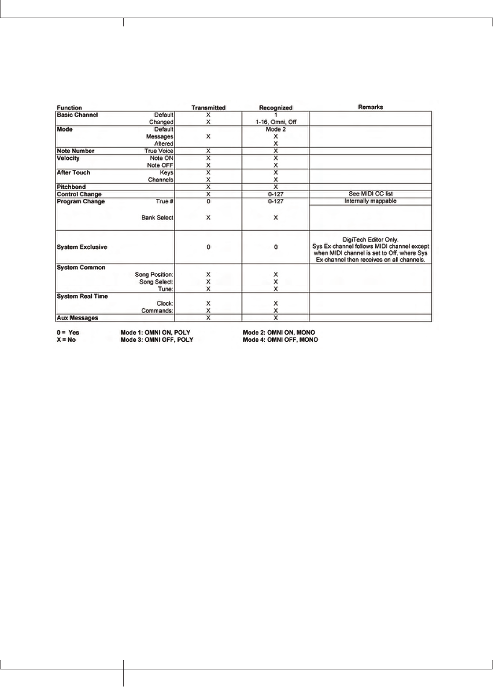
Appendix
MIDI Implementation Chart
General MIDI Drum Sample List
Sample Name #
Acoustic Bass Drum 35
Bass Drum 1 36
Side Stick 37
Acoustic Snare 38
Hand Clap 39
Electric Snare 40
Low Floor Tom 41
Closed Hi-Hat 42
High Floor Tom 43
Pedal Hi-Hat 44
Low Tom 45
Open Hi-Hat 46
Low-Mid Tom 47
Hi-Mid Tom 48
Crash Cymbal 1 49
High Tom 50
Ride Cymbal 1 51
Chinese Cymbal 52
Ride Bell 53
Tambourine 54
Splash Cymbal 55
Cowbell 56
Crash Cymbal 2 57
Vibraslap 58
Sample Name #
Ride Cymbal 2 59
Hi Bongo 60
Low Bongo 61
Mute Hi Conga 62
Open Hi Conga 63
Low Conga 64
High Timbale 65
Low Timbale 66
High Agogo 67
Low Agogo 68
Cabasa 69
Maracas 70
Short Whistle 71
Long Whistle 72
Short Guiro 73
Long Guiro 74
Claves 75
Hi Wood Block 76
Low Wood Block 77
Mute Cuica 78
Open Cuica 79
Mute Triangle 80
Open Triangle 81
128
Appendix
GNX3000 Owner’s Manual

MIDI CC List
Parameter CC#
Pickup Type/On/Off CC2
Pickup Type/Type CC3
Expression Pedal CC4
Volume Post CC6
Volume Pre CC7
Wah On/Off CC8
Wah Type CC9
Wah Pedal CC10
Compressor On/Off CC11
Compressor Attack CC12
Compressor Ratio CC13
Compressor Threshold CC14
Compressor Gain CC15
Whammy/IPS On/Off CC16
Whammy/IPS Type CC17
Whammy/IPS Level CC18
Whammy/IPS Parameter 1 CC19
Whammy/IPS Parameter 2 CC20
Whammy/IPS Parameter 3 CC21
Stompbox On/Off CC22
Stompbox Type CC23
Stompbox Gain CC24
Stompbox Level CC25
Stompbox Param1 CC26
Stompbox Param2 CC27
Stompbox Param3 CC28
Stompbox Param4 CC29
Amp Channel CC30
Ch 1 Amp Type CC31
Ch 1 Amp Gain CC33
Ch 1 Amp Level CC34
Ch 1 Cabinet CC35
Ch 1 Cabinet Tuning CC36
Ch 1 EQ On/Off CC37
Ch 1 Bass Frequency CC38
Ch 1 Bass CC39
Ch 1 Midrange Frequency CC40
Ch 1 Midrange CC41
Ch 1 Treble Frequency CC42
Ch 1 Treble CC43
Ch 1 Presence CC44
Ch 2 Amp Type CC45
Ch 2 Amp Gain CC46
Ch 2 Amp Level CC47
Ch 2 Cabinet CC48
Parameter CC#
Ch 2 Cabinet Tuning CC49
Ch 2 EQ On/Off CC50
Ch 2 Bass Frequency CC51
Ch 2 Bass CC52
Ch 2 Midrange Frequency CC53
Ch 2 Midrange CC54
Ch 2 Treble Frequency CC55
Ch 2 Treble CC56
Ch 2 Presence CC57
Noise Gate On/Off CC58
Noise Gate Type CC59
Noise Gate Threshold CC60
Noise Gate Attack CC61
Noise Gate Pluck Sensitivity CC62
Chorus/Mod On/Off CC65
Chorus/Mod Type CC66
Chorus/Mod Level CC67
Chorus/Mod Param1 CC68
Chorus/Mod Param2 CC69
Chorus/Mod Param3 CC70
Chorus/Mod Param4 CC71
Chorus/Mod Param5 CC72
Delay On/Off CC73
Delay Type CC74
Delay Level CC75
Delay Time CC76
Delay Feedback CC77
Delay Ducker Threshold CC78
Delay Ducker Attenuation CC79
Delay Balance CC80
GeNetX Warp Amp CC83
GeNetX Warp Cabinet CC84
GeNetX Amp/Cabinet Warp CC85
Reverb On/Off CC89
Reverb Type CC90
Reverb Level CC91
Reverb Decay CC92
Reverb Damping CC93
Reverb PreDelay CC94
Reverb Balance CC95
LFO1 Speed CC105
LFO1 Waveform CC106
LFO2 Speed CC110
LFO2 Waveform CC111
GNX3000 Owner’s Manual
129 GNX3000 Owner’s Manual

Specifications
General Specifications
A/D Converter: 24-bit high performance audio
D/A Converter: 24-bit high performance audio
Sampling Frequency: 44.1 kHz throughout
DSP Section: 4 Audio DNATM DSP Processors
Preset Memory: 65 User Presets
65 Factory 1 Presets
65 Factory 2 Presets
Analog Input Connections:
Guitar Input: 1/4” Unbalanced (Tip-Sleeve)
Input Impedance: 475 kOhms
Mic Preamp Input: XLR Balanced (Female XLR, pin 2 Hot)
Phantom Power: +15V
Input Impedance: 600 Ohms balanced
Maximum Input Level: -22 dBu with mic input level set to max, or -2 dBu
with mic input level set to max
Line Inputs: 1/4” Balanced (Tip-Ring-Sleeve) or Unbalanced
Input Impedance: 20 kOhms Balanced, 10kOhms Unbalanced
Maximum Input Level: +22 dBu
Analog Output Connections:
LINE OUTPUTS: 1/4 Impedance Balanced or Unbalanced
Output Impedance: 1 kOhm per side
Maximum Output Level: +22 dBu
BALANCED OUTPUTS: Male XLR
Output Impedance: 120 Ohms
Maximum Output Level: +22 dBu
Headphones: 1/4” Stereo (Tip = Left, Ring = Right, Sleeve =
Ground)
100 mW per channel at 50 Ohms
Digital Connections:
Footswitch: 1/4” jack (compatible with optional GNXFC)
MIDI In: 5-pin Din
MIDI Out/Thru: 5-pin Din
Universal Serial Bus (USB): Type B, supports USB1.1 Full Speed (12 Mbps
Bandwidth USB 2.0 compatible)
130
Specifications
GNX3000 Owner’s Manual
Analog Inputs to Analog Outputs:
Guitar Input to 1/4” Outputs
S/N ratio: > 108 dB A-weighted; ref = max signal @ 1kHz,
22kHz measurement bandwidth
Frequency Response: 20 Hz - 17 kHz (+0 / - 3 dB)
THD+N: < 0.0018% typical at -4 dBu, 1 kHz, 0 dB input gain
Guitar Input to XLR OUTPUTS
S/N ratio: > 108 dB A-weighted; ref = max signal @ 1kHz,
22kHz measurement bandwidth
Frequency Response: 20 Hz - 17 kHz (+0 / - 3 dB)
THD+N: < 0.0018% typical at -4 dBu, 1 kHz, 0 dB input gain
Mic Input to 1/4” Outputs (Mic Dry selected)
S/N ratio: > 108 dB A-weighted; ref = max signal @ 1kHz,
22kHz measurement bandwidth
Frequency Response: 20 Hz - 17 kHz (+0 / - 1 dB)
THD+N: < 0.0015% typical at -10 dBu, 1 kHz, 0 dB input gain
Mic Input to XLR OUTPUTS
S/N ratio: > 108 dB A-weighted; ref = max signal @ 1kHz,
22kHz measurement bandwidth
Frequency Response: 20 Hz - 20 kHz (+0 / - 1 dB)
THD+N: < 0.0018% typical at -18.4 dBu, 1 kHz, 0 dB input
gain
Line Inputs to 1/4” Outputs (Line Dry selected)
S/N ratio: > 104 dB A-weighted; ref = max signal @ 1kHz,
22kHz measurement bandwidth
Frequency Response: 20 Hz - 20 kHz (+0 / - 1 dB)
THD+N: < 0.0023% typical at +10 dBu, 1 kHz, 0 dB input gain
Line Inputs to XLR OUTPUTS
S/N ratio: > 104 dB A-weighted; ref = max signal @ 1kHz,
22kHz measurement bandwidth
Frequency Response: 20 Hz - 20 kHz (+0 / - 1 dB)
THD+N: < 0.0025% typical at +10 dBu, 1 kHz, 0 dB input gain
GNX3000 USB Recording Specifications:
Bit depth: supports 16-bit or 24-bit (depends on setup in
Recording Software)
Sample Rate: 44.1 kHz
GNX3000 Owner’s Manual
131 GNX3000 Owner’s Manual

Power Requirements:
US and Canada: 120 VAC, 60 Hz Adapter: PSS3-120
Japan: 100 VAC, 50/60 Hz Adapter: PSS3-100
Europe: 230 VAC, 50 Hz Adapter: PSS3-230
UK: 240 VAC, 50 Hz Adapter: PSS3-240
Power Consumption: 21.0 Watts
Dimensions: 18.5” Length x 10.5” Width x 3” Height
Unit Weight: 10 lbs.
Minimum PC Computer System Requirements:
Windows® XP
500 MHz processor speed (1.2 GHz recommended)
128 MB RAM (512MB recommended)
100 MB hard disk space for full install
EIDE/Ultra DMA 7200 RPM hard disk or better
Minimum Mac Computer System Requirements
OS 10.3 or higher
132
Specifications
GNX3000 Owner’s Manual
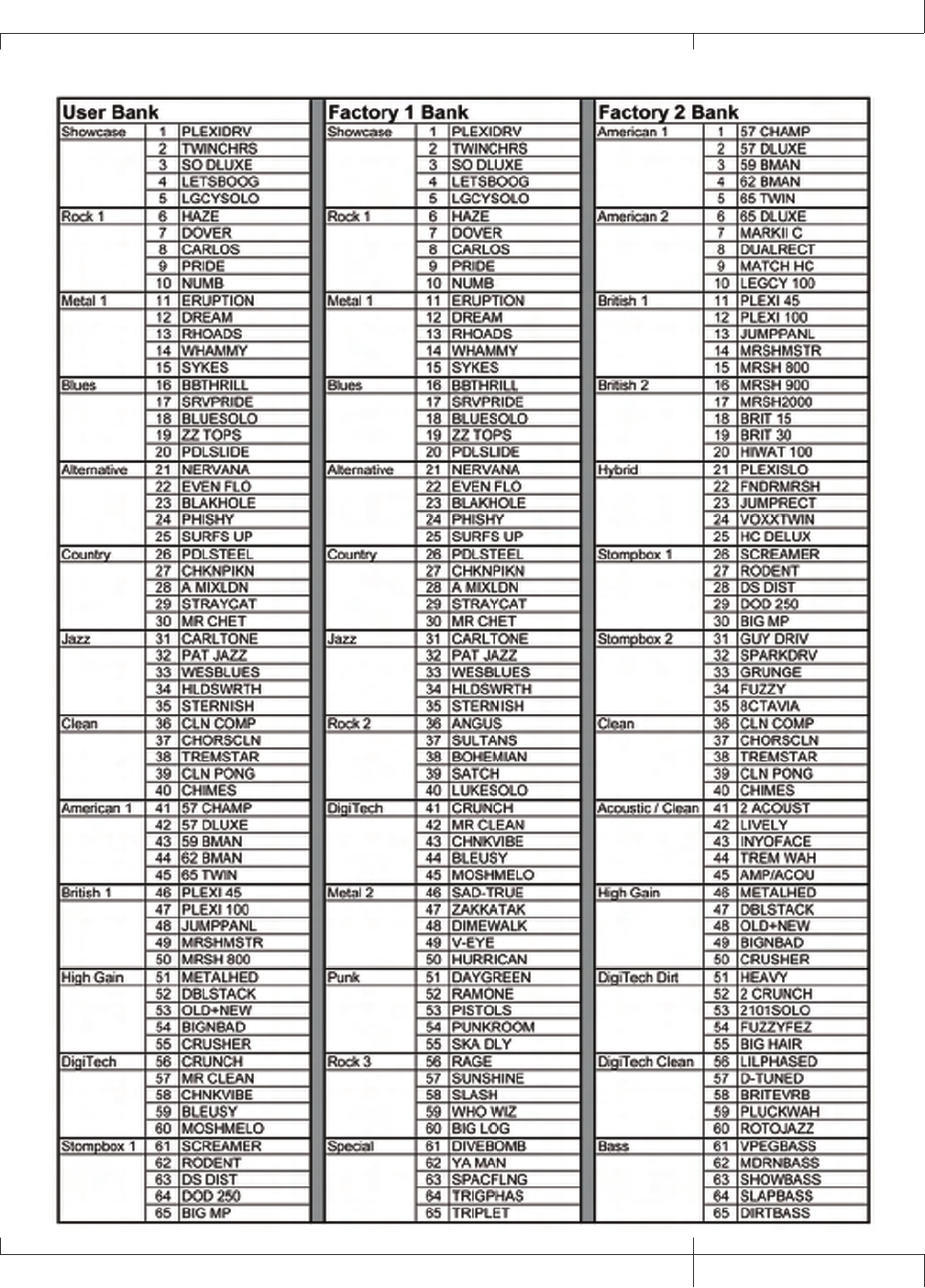
GNX3000 Owner’s Manual
133 GNX3000 Owner’s Manual
Bank and Preset Names

8760 S. Sandy Parkway
Sandy, Utah 84070
PH (801) 566-8800 FAX (801) 566-7005
International Distribution
8760 S. Sandy Parkway
Sandy, Utah 84070 USA
PH (801) 566-8800 FAX (801) 566-7005
DigiTech, GeNetX, Audio DNA, Guitar Workstation,
and GNX3000 are trademarks of
Harman Music Group Inc.
GNX3000 Owner’s Manual 18-6288-B
www.digitech.com
www.guitarworkstation.com
