Exlar Catalog 6/04 GSX GSXSeries
User Manual: GSX
Open the PDF directly: View PDF ![]() .
.
Page Count: 36
GSX Series – The Highest
Performance, Longest Life and
Most Compact Linear Actuators!
GSX Series linear actuators combine
the advantages of Exlar’s roller screw
technology and T-LAM™ technology
to create the next generation of linear
actuators. Exlar uses a specially
designed roller screw mechanism for
converting electric motor power into
linear motion within the actuator.
Planetary rollers assembled around
the actuator’s extending rod follow
threads which are precisely machined
on the inside surface of the actuator’s
hollow armature. Linear motion is
produced in precise synchronization
with the armature rotation. Because
this roller screw mechanism has an
inherently larger cumulative contact
surface, these actuators have a much
longer working life, and can handle
heavier loads at higher speeds than
is possible from a similarly sized unit
built around a ball screw system.
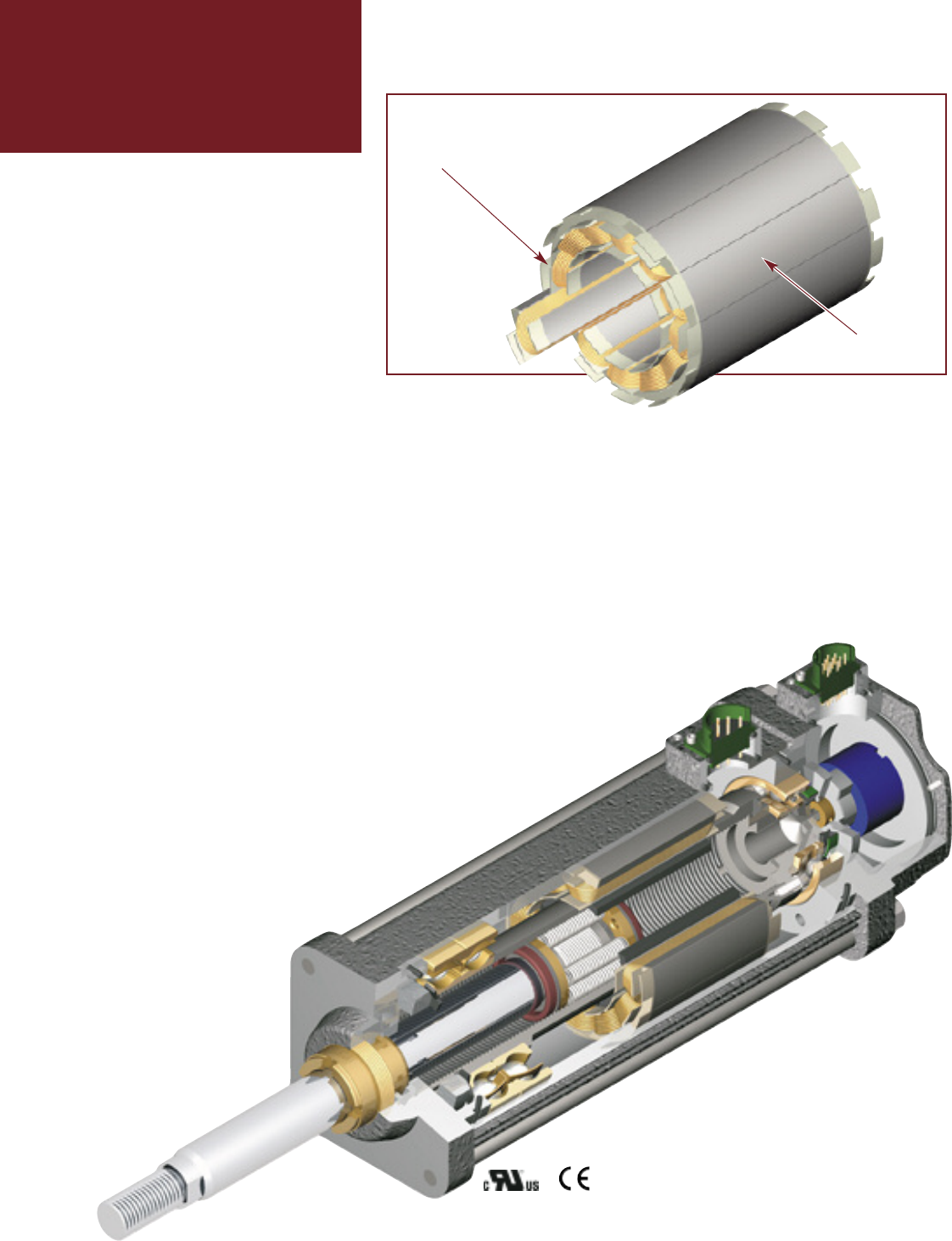
Exlar’s T-LAM segmented lamination
stator technology delivers higher
continuous motor torque than is
available in traditionally wound
motors. T-LAM technology consists
of stator segments, each containing
individual phase wiring for maximum
motor performance. The improved
efficiencies of the GSX Series
are a result of the limited
heat generation qualities
inherent in the segmented
stator design as seen
above. The elimination of
end turns in the stator, and
use of thermally conductive potting
removes the parts most susceptible
to failure in a traditional stator. Other
design advantages include:
• Neodymium-iron-boron magnets
provide high flux density and maxi-
mum motor torque.
• Thermally conductive potting of the
entire stator provides increased
heat dissipation and provides pro-
tection from contamination in oil-
cooled units.
• Each stator segment contains indi-
vidual phase wiring. External wind-
ing of individual segments provides
maximum slot fill for maximum
motor performance.
• Motors with T-LAM technology
have Class 180 H insulation sys-
tems compliant with UL require-
ments.
• UL recognized component.
• Motors with T-LAM technology are
CE compliant
The
Actuator & Motor,
All in one Compact Unit.
With other actuator technolo-
gies, customers are usually respon-
sible for engineering the completed
linear motion system. This usually
includes purchasing the motor, gear
reducer, timing belt, mounting hard-
ware, flexible couplings, etc. sepa-
rately. Then they all must be assem-
bled to perform properly in a given
application.
Lamination
Endcaps
Individual
Segments
3
EXLAR
GSX Series Linear Actuators
GSX Series actuators eliminate all
this systems engineering. These
units are single, fully integrated com-
ponent packages – much smaller
than traditional rotary-to-linear con-
version mechanisms.
Designed for Closed Loop Servo
Systems
Their brushless servo design means
GSX Series units can be used in
advanced closed-loop servo systems
when velocity and positioning is
required. Position feedback can be
delivered in a number of different
forms. These include
resolvers, encoders or
internally mounted linear
position feedback sen-
sors.
Sealed for Long Life
with Minimum
Maintenance
GSX Series actuators
have strong
advantages
whenever out-
side contami-
nants are an issue. In most rotary-to-
linear devices, critical mechanisms are
exposed to the environment. Thus,
they must be frequently inspected,
cleaned and lubricated.
In contrast, the converting components
in all Exlar GSX units are mounted
within the sealed motor housing. With
a simple bushing and seal arrangement
on the smooth extending rod, abrasive
particles or other contaminants are
prevented from reaching the actuator’s
critical mechanisms. This assures
trouble-free operation even in the most
harsh environments.
Lubrication requirements are minimal.
GSX actuators can be lubricated with
either grease or recirculated oil.
Grease lubricated units will run up to
10,000 hours without re-greasing.
Recirculated oil systems eliminate this
type of maintenance altogether. A GSX
Series actuator with a properly operat-
ing recirculating oil system will operate
indefinitely without any other lubrica-
tion requirements.
4
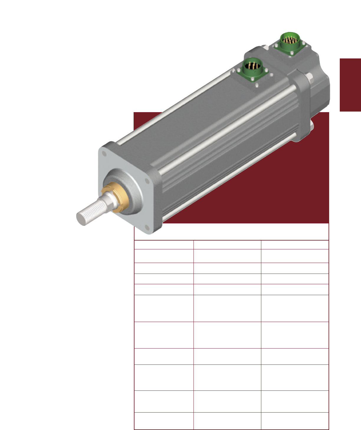
Available in Five Frame Sizes
2” GSX20 3” GSX30 4” GSX40
5” GSX50 7” GSX60
If you need a custom design, Exlar’s
Application Engineering department
will work with you to engineer
a solution specifically tai-
lored to your appli-
cation.
Feature Standard Optional
External anti-rotate No Yes
mechanism
Pre-loaded follower No Yes
Electric brake No Yes
Internal End switches No Yes
Two MS Style Connectors Electroless Nickel
Connectors (3 if brake and/or Connectors/Male NPT
Switches are Ordered) with Potted Leads/
Manufacturers Connectors
Extended Tie Rods, Side
Mounting Style Tapped Mounting Holes, Custom
Trunnion, Rear Clevis, or Mountings
Front Flange
Rod End Male or Female: Specials Available To
U.S. Standard or Metric Meet OEM Requirements
Greased, Oil Connection
Lubrication Ports are Built-in for Specials Available To
Customer Supplied Meet OEM Requirements
Recirculated Oil Lubrication
Standard Encoders or
Primary Feedback Resolvers to Meet Most Custom Feedback
Amplifier Requirements
Absolute Linear No VRVT, including
Feedback signal conditioner
GSX Series
5
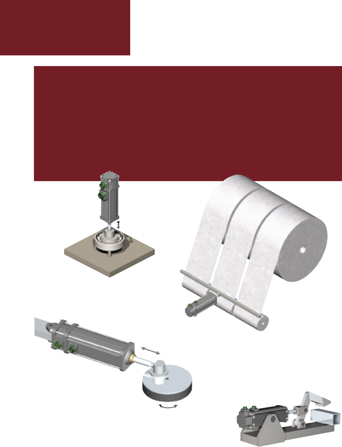
In clean room
applications like those
common to semiconductor
manufacturing, the compact
design of our GSX Series saves
critical space.
Because they
cycle quickly and
can be synchronized to line speeds,
Exlar actuators produce dramatic
improvements in web control applica-
tions.
Repeatable force, reliable posi-
tioning accuracy, and flexible con-
trol make GSX actuators a
perfect fit for assem-
bly presses or
test stands.
Hydraulic cylinder replacement
Ball screw replacement
Pneumatic cylinder replacement
Chip and wafer handling
Automated flexible fixturing
Dispensers
Machine tool
Automated assembly
Parts clamping
Automatic tool changers
Volumetric pumps
Medical equipment
Repeatable force control plus positioning
accuracy extends the life of costly tools
when Exlar linear actuators are used in
precision clamping applications.
EXLAR GSX SERIES ACTUATORS APPLICATIONS INCLUDE:
Conveyor diverters / gates
Plastics equipment
Cut-offs
Die cutters
Packaging machinery
Entertainment
Sawmill equipment
Open / close doors
Fillers
Formers
Precision grinders
Indexing stages
Lifts
Product sorting
Material cutting
Material handling
Riveting / fastening / joining
Molding
Volumetric pumps
Semiconductor
Pick and place systems
Robot manipulator arms
Simulators
Precision valve control
Ventilation control systems
Pressing
Process control
Tube bending
Welding
Stamping
Test stands
Tension control
Web guidance
Wire winding
EXLAR
GSX Series Linear Actuators
6
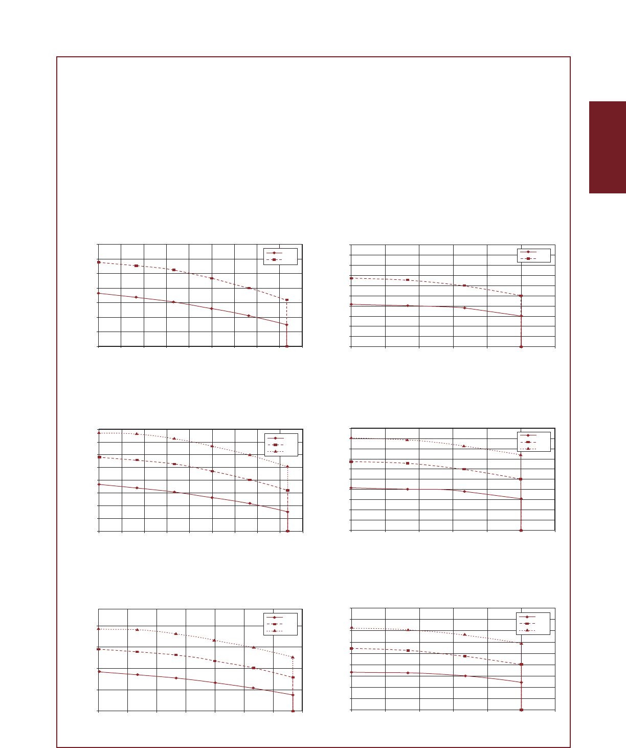
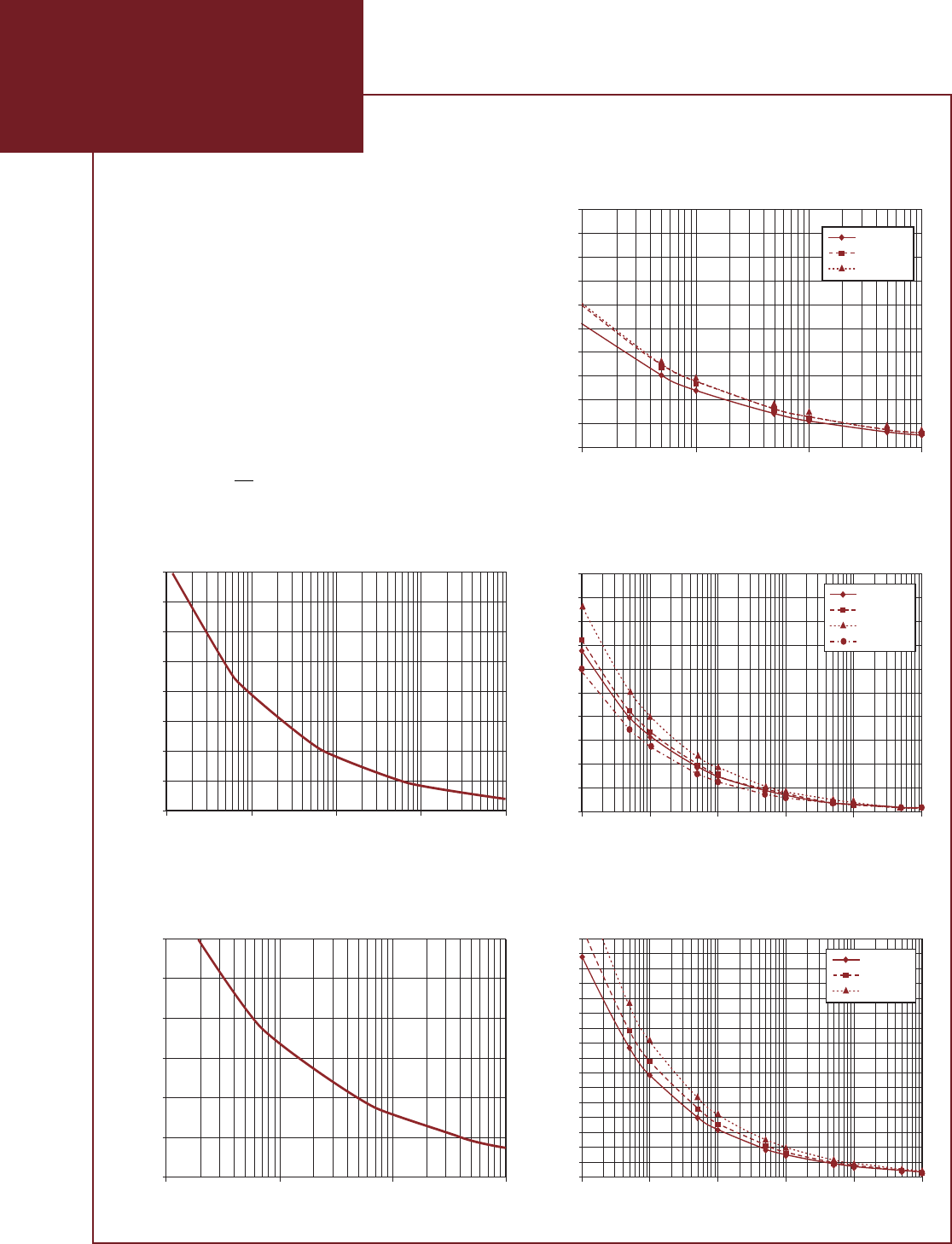
GSX Series Speed vs. Force Curves
These charts represent typical linear speed versus linear force curves for the GSX actuators using
common brushless motor amplifiers. The GSX Series are compatible with many different brushless
motor amplifiers, and differences in the performance ratings of these amplifiers can alter the actua-
tor’s performance. Thus, the curves below should be used for estimation only. (Further informa-
tion is available by contacting Exlar Application Engineering.)
138
238
2000
1800
1600
1400
1200
1000
800
600
400
200
0
012 345 6
Force (lbf)
Speed (inch / sec)
GSX30-.1 Inch Lead
138
238
700
600
500
400
300
200
100
00123456789
Force (lbf)
Speed (inch / sec)
GSX20-.1 Inch Lead
138
238
338
400
350
300
250
200
150
100
50
00 2 4 6 8 10 12 14 16 18
Force (lbf)
Speed (inch / sec)
GSX20-.2 Inch Lead
138
238
338
200
150
100
50
0
0510 15 20 25 30 35
Force (lbf)
Speed (inch / sec)
GSX20-.4 Inch Lead
138
238
338
1000
900
800
700
600
500
400
300
200
100
00 2 4 6 8 10 12
Force (lbf)
Speed (inch / sec)
GSX30-.2 Inch Lead
138
238
338
450
400
350
300
250
200
150
100
50
00 5 10 15 20 25 30
Force (lbf)
Speed (inch / sec)
GSX30-.5 Inch Lead
GSX Series

7
138
238
9000
8000
7000
6000
5000
4000
3000
2000
1000
0
012346
Force (lbf)
Speed (inch / sec)
GSX50-.1 Inch Lead
138
238
338
6000
5000
4000
3000
2000
1000
00 2 4 6 810
Force (lbf)
Speed (inch / sec)
GSX50-.2 Inch Lead
138
238
338
1400
1200
1000
800
600
400
200
0
0 5 10 15 20 25
Force (lbf)
Speed (inch / sec)
GSX50-.5 Inch Lead
138
238
338
1200
1000
800
600
400
200
0
0 10 20 30 40 50
Force (lbf)
Speed (inch / sec)
GSX50-1.0 Inch Lead
138
238
338
6000
5000
4000
3000
2000
1000
00123456
Force (lbf)
Speed (inch / sec)
GSX.40-.1 Inch Lead
138
238
338
800
700
600
500
400
300
200
100
0
0 5 10 15 20 25 30 35 40
Force (lbf)
Speed (inch / sec)
GSX40-.75 Inch Lead
138
238
338
3000
2500
2000
1500
1000
500
002 4 6 8 10 12
Force (lbf)
Speed (inch / sec)
GSX40-.2 Inch Lead
138
238
338
1200
1000
800
600
400
200
0
0 5 10 15 20 25 30
Force (lbf)
Speed (inch / sec)
GSX40-.5 Inch Lead
EXLAR
GSX Series Linear Actuators
8
Speed (inch / sec)
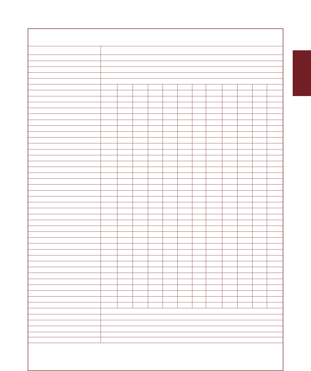
GSX Series Speed vs. Force Curves
These charts represent typical linear speed versus lin-
ear force curves for GSX actuators using common
brushless motor amplifiers. The GSX Series are
compatible with many different brushless motor
amplifiers, and differences in the performance ratings
of these amplifiers can alter the actuator’s perform-
ance. Thus, the curves below should be used for
estimation only. (Further information is available by
contacting Exlar Application Engineering.)
138
238
338
14000
12000
10000
8000
6000
4000
2000
00 2 4 6 8 10 12
Force (lbf)
Speed (inch / sec)
GSX60-.25 Inch Lead
138
238
338
7000
6000
5000
4000
3000
2000
1000
00 5 10 15 20 25
Force (lbf)
Speed (inch / sec)
GSX60-.5 Inch Lead
138
238
338
3500
3000
2500
2000
1500
1000
500
0
0 10 20 30 40 50
Force (lbf)
GSX60-1.0 Inch Lead
GSX Series
GSX60-xx03
GSX60-xx05
GSX60-xx10
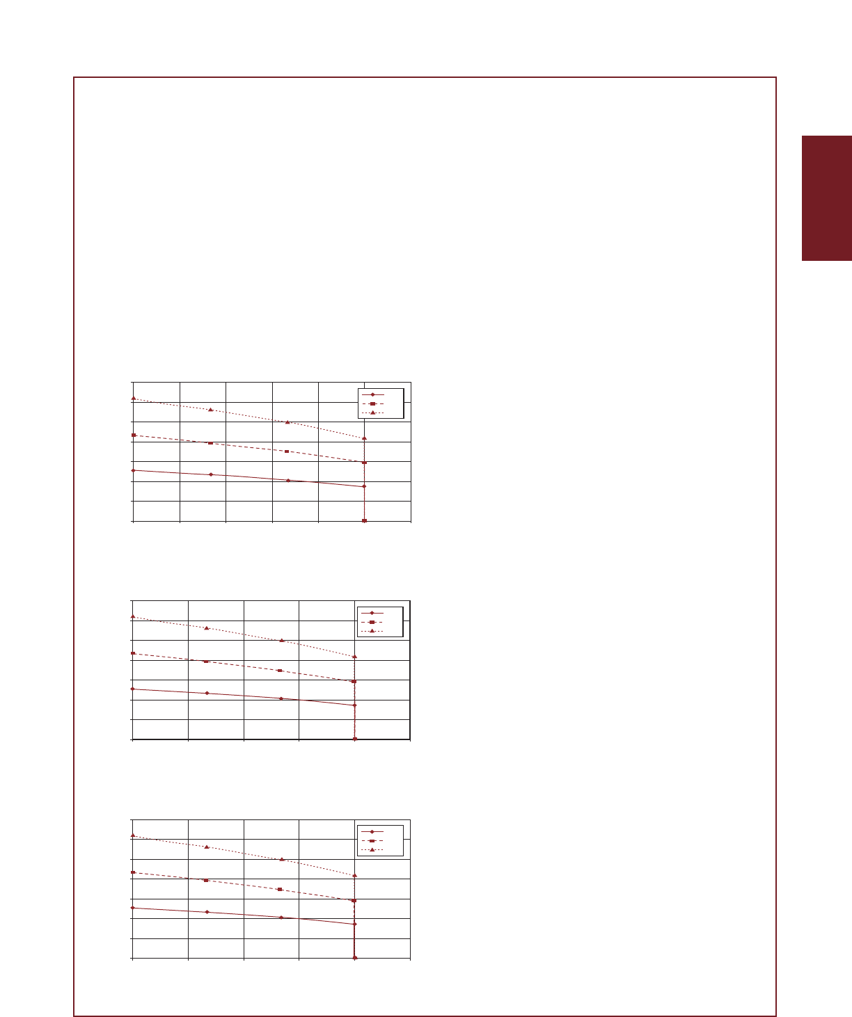
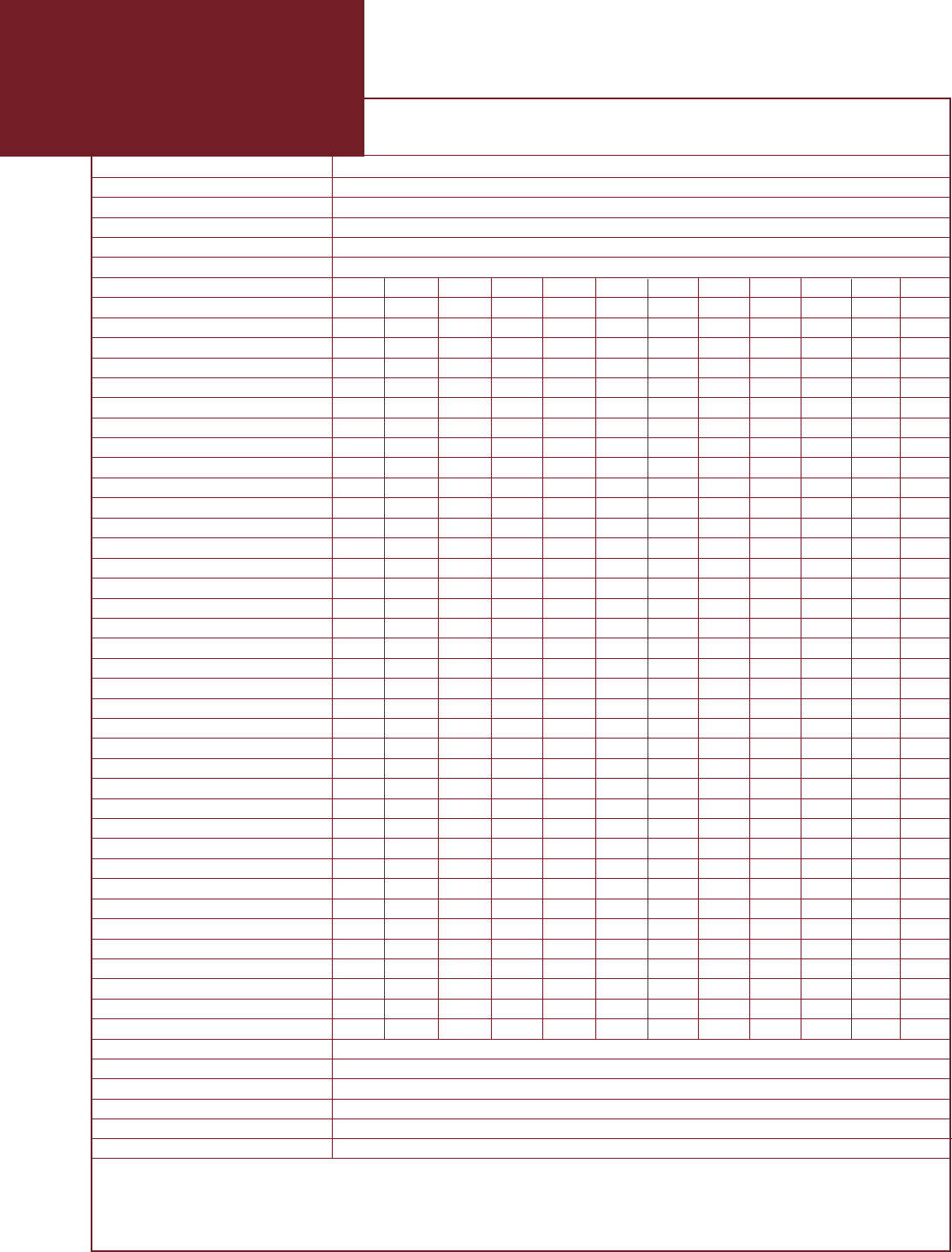
GSX Series Lifetime Curves
The L10 expected life of a roller screw linear actuator
is expressed as the linear travel distance that 90% of
properly maintained roller screws manufactured are
expected to meet or exceed. This is not a guarantee
and these charts should be used for estimation
purposes only.
The underlying formula that defines this value is:
Travel life in millions of inches, where:
C= Dynamic load rating (lbf)
F= Cubic mean applied load (lbf)
S= Roller screws lead (inches)
L10 =
(
C
)
3x S≡
F
All curves represent properly lubricated and maintained actuators.
GSX50-xx01
GSX50-xx02
GSX50-xx05
GSX50-xx10
GSX40-xx02
GSX40-xx05
GSX40-xx08
400
350
300
250
200
150
100
50
0
GSX20
Mean Load (pounds)
0 100 1,000 10,000 100,000
Travel Life (Millions of inches)
600
500
400
300
200
100
0
01,000 10,000 100,000
Mean Load (pounds)
Travel Life (Millions of inches)
GSX30
5000
4500
4000
3500
3000
2500
2000
1500
1000
500
0
10 100 1,000 10,000 100,000 1,000,000
Mean Load (pounds)
Travel Life (Millions of inches)
GSX50
8000
7000
6000
5000
4000
3000
2000
1000
0
10 100 1,000 10,000 100,000 1,000,000
Mean Load (pounds)
Travel Life (Millions of inches)
GSX60
2000
1600
1200
800
400
0
100 1,000 10,000 100,000
Mean Load (pounds)
Travel Life (Millions of inches)
GSX40
9
EXLAR
GSX Series Linear Actuators

GSX20 & GSX30 Performance Specifications
Model Frame Stroke Screw Force* Max Continuous Maximum Armature Dynamic Weight
Size
(nominal)*
Lead Rating Velocity Motor Static Inertia** Load (approx.)
in in in lb (N) in/sec Torque Load lb-in-s2Rating lb
(mm) (mm)* (mm) 1/2/3 stack (mm/sec) lb-in (N-m) lb (N) (Kg-m2) lb (N) (Kg)
GSX20-0301 2.25 3 0.1 367/578/NA 8.33 7.3/11.5/NA 1250 0.00101 2075 6.5
(57) (75) (2.54) (1632/2571/NA) (211.67) (0.82/1.30/NA) (5560) (0.000114) (9230) (2.9)
GSX20-0302 2.25 3 0.2 183/289/NA 16.77 7.3/11.5/NA 1250 0.00101 1540 6.5
(57) (75) (5.08) (814/1286/NA) (423.33) (0.82/1.30/NA) (5560) (0.000114) (6850) (2.9)
GSX20-0304 2.25 3 0.4 92/145/NA 33.33 7.3/11.5/NA 1250 0.00101 1230 6.5
(57) (75) (10.16) (409/645/NA) (846.67) (0.82/1.30/NA) (5560) (0.000114) (5471) (2.9)
GSX20-0601 2.25 6 0.1 367/578/NA 8.33 7.3/11.5/NA 1250 0.00114 2075 7.0
(57) (150) (2.54) (1632/2571/NA) (211.67) (0.82/1.30/NA) (5560) (0.000129) (9230) (3.2)
GSX20-0602 2.25 6 0.2 183/289/385 16.67 7.3/11.5/15.3 1250 0.00114 1540 7.0
(57) (150) (5.08) (814/1286/1713) (423.33) (0.82/1.30/1.73) (5560) (0.000129) (6850) (3.2)
GSX20-0604 2.25 6 0.4 92/145/192 33.33 7.3/11.5/15.3 1250 0.00114 1230 7.0
(57) (150) (10.16) (409/645/854) (846.67) (0.82/1.30/1.73) (5560) (0.000129) (5471) (3.2)
GSX20-1001 2.25 10 0.1 367/578/NA 8.33 7.3/11.5/NA 1250 0.00133 2075 7.5
(57) (250) (2.54) (1632/2571/NA) (211.67) (0.82/1.30/NA) (5560) (0.000150) (9230) (3.4)
GSX20-1002 2.25 10 0.2 183/289/385 16.67 7.3/11.5/15.3 1250 0.00133 1540 7.5
(57) (250) (5.08) (814/1286/1713) (423.33) (0.82/1.30/1.73) (5560) (0.000150) (6850) (3.4)
GSX20-1004 2.25 10 0.4 92/145/192 33.33 7.3/11.5/15.3 1250 0.00133 1230 7.5
(57) (250) (10.16) (409/645/854) (846.67) (0.82/1.30/1.73) (5560) (0.000150) (5471) (3.4)
GSX20-1201 2.25 12 0.1 367/578/NA 8.33 7.3/11.5/NA 1250 0.00143 2075 8.0
(57) (300) (2.54) (1632/2571/NA) (211.67) (0.82/1.30/NA) (5560) (0.000162) (9230) (3.6)
GSX20-1202 2.25 12 0.2 183/289/385 16.67 7.3/11.5/15.3 1250 0.00143 1540 8.0
(57) (300) (5.08) (814/1286/1713) (423.33) (0.82/1.30/1.73) (5560) (0.000162) (6850) (3.6)
GSX20-1204 2.25 12 0.4 92/145/192 33.33 7.3/11.5/15.3 1250 0.00143 1230 8.0
(57) (300) (10.16) (409/645/854) (846.67) (0.82/1.30/1.73) (5560) (0.000162) (5471) (3.6)
GSX30-0301 3.125 3 0.1 829/1347/NA 5 16.5/26.8/NA 2700 0.00319 5516 9.5
(79) (75) (2.54) (3688/5992/NA) (127) (1.86/3.03/NA) (12010) (0.000360) (24536) (4.3)
GSX30-0302 3.125 3 0.2 415/674/NA 10 16.5/26.8/NA 2700 0.00319 5800 9.5
(79) (75) (5.08) (1846/2998/NA) (254) (1.86/3.03/NA) (12010) (0.000360) (25798) (4.3)
GSX30-0305 3.125 3 0.5 166/269/NA 25 16.5/26.8/NA 2700 0.00319 4900 9.5
(79) (75) (12.7) (738/1197/NA) (635) (1.86/3.03/NA) (12010) (0.000360) (21795) (4.3)
GSX30-0601 3.125 5.9 0.1 829/1347/NA 5 16.5/26.8/NA 2700 0.00361 5516 11.5
(79) (150) (2.54) (3688/5992/NA) (127) (1.86/3.03/NA (12010) (0.000408) (24536) (5.2)
GSX30-0602 3.125 5.9 0.2 415/674/905 10 16.5/26.8/36 2700 0.00361 5800 11.5
(79) (150) (5.08) (1846/2998/4026) (254) (1.86/3.03/4.07) (12010) (0.000408) (25798) (5.2)
GSX30-0605 3.125 5.9 0.5 166/269/362 25 16.5/26.8/36 2700 0.00361 4900 11.5
(79) (150) (12.7) (738/1197/1610) (635) (1.86/3.03/4.07) (12010) (0.000408) (21795) (5.2)
GSX30-1001 3.125 10 0.1 829/1347/NA 5 16.5/26.8/NA 2700 0.00416 5516 19
(79) (250) (2.54) (3688/5992/NA) (127) (1.86/3.03/NA) (12010) (0.00047) (24536) (8.6)
GSX30-1002 3.125 10 0.2 415/674/905 10 16.5/26.8/36 2700 0.00416 5800 19
(79) (250) (5.08) (1846/2998/4026) (254) (1.86/3.03/4.07) (12010) (0.00047) (25798) (8.6)
GSX30-1005 3.125 10 0.5 166/269/362 25 16.5/26.8/36 2700 0.00416 4900 19
(79) (250) (12.7) (738/1197/1610) (635) (1.86/3.03/4.07) (12010) (0.00047) (21795) (8.6)
GSX30-1201 3.125 12 0.1 829/1347/NA 5 16.5/26.8/NA 2700 0.00443 5516 22
(79) (305) (2.54) (3688/5992/NA) (127) (1.86/3.03/NA) (12010) (0.000501) (24536) (10)
GSX30-1202 3.125 12 0.2 415/674/905 10 16.5/26.8/36 2700 0.00443 5800 22
(79) (305) (5.08) (1846/2998/4026) (254) (1.86/3.03/4.07) (12010) (0.000501) (25798) (10)
GSX30-1205 3.125 12 0.5 166/269/362 25 16.5/26.8/36 2700 0.00443 4900 22
(79) (305) (12.7) (738/1197/1610) (635) (1.86/3.03/4.07) (12010) (0.000501) (21795) (10)
GSX30-1402 3.125 14 0.2 415/674/905 10 16.5/26.8/36 2700 0.00473 5800 22
(79) (355) (5.08) (1846/2998/4026) (254) (1.86/3.03/4.07) (12010) (0.000534) (25798) (10)
GSX30-1405 3.125 14 0.5 166/269/362 25 16.5/26.8/36 2700 0.00473 4900 22
(79) (355) (12.7) (738/1197/1610) (635) (1.86/3.03/4.07) (12010) (0.000534) (21795) (10)
GSX30-1802 3.125 18 0.2 415/674/905 10 16.5/26.8/36 2700 0.00533 5800 25
(79) (455) (5.08) (1846/2998/4026) (254) (1.86/3.03/4.07) (12010) (0.000602) (25798) (11.3)
GSX30-1805 3.125 18 0.5 166/269/362 25 16.5/26.8/36 2700 0.00533 4900 25
(79) (455) (12.7) (738/1197/1610) (635) (1.86/3.03/4.07) (12010) (0.000602) (21795) (11.3)
Specifications subject to change without notice.*Please note that stroke mm are nominal dimensions. **Inertia +/–5%
10
GSX Series

11
GSX40 Performance Specifications
*Please note that stroke mm are nominal dimensions. **Inertia +/–5% Specifications subject to change without notice.
Model Frame Stroke Screw Force* Max Continuous Maximum Armature Dynamic Weight
Size
(nominal)*
Lead Rating Velocity Motor Static Inertia** Load (approx.)
in in in lb (N) in/sec Torque Load lb-in-s2Rating lb
(mm) (mm)* (mm) 1/2/3 stack (mm/sec) lb-in (N-m) lb (N) (Kg-m2) lb (N) (Kg)
GSX40-0601 3.9 6 0.1 2393/3966/NA 5 47.6/78.9/NA 5400 0.0152 7900 20
(99) (150) (2.54) (10645/17642/NA) (127) (5.38/8.91/NA) (24020) (0.001717) (35141) (9.1)
GSX40-0602 3.9 6 0.2 1196/1983/NA 10 47.6/78.9/NA 5400 0.0152 8300 20
(99) (150) (5.08) (5320/8821/NA) (254) (5.38/8.91/NA) (24020) ( 0.001717) (36920) (9.1)
GSX40-0605 3.9 6 0.5 479/793/NA 25 47.6/78.9/NA 5400 0.0152 7030 20
(99) (150) (12.7) (2131/3527/NA) (635) (5.38/8.91/NA) (24020) ( 0.001717) (31271) (9.1)
GSX40-0608 3.9 6 0.75 319/529/NA 37.5 47.6/78.9/107.1 5400 0.0152 6335 20
(99) (150) (19.05) (1419/2353/NA) (953) (5.38/8.91/12.1) (24020) ( 0.001717) (28179) (9.1)
GSX40-0801 3.9 8 0.1 2393/3966/NA 5 47.6/78.9/107.1 5400 0.0163 7900 24
(99) (200) (2.54) (10645/17642/NA) (127) (5.38/8.91/12.1) (24020) (0.001842) (35141) (10.9)
GSX40-0802 3.9 8 0.2 1196/1983/2692 10 47.6/78.9/107.1 5400 0.0163 8300 24
(99) (200) (5.08) (5320/8821/11975) (254) (5.38/8.91/12.1) (24020) ( 0.001842) (36920) (10.9)
GSX40-0805 3.9 8 0.5 479/793/1077 25 47.6/78.9/107.1 5400 0.0163 7030 24
(99) (200) (12.7) (2131/3527/4791) (635) (5.38/8.91/12.1) (24020) ( 0.001842) (31271) (10.9)
GSX40-0808 3.9 8 0.75 319/529/718 37.5 47.6/78.9/107.1 5400 0.0163 6335 24
(99) (200) (19.05) (1419/2353/3194) (953) (5.38/8.91/12.1) (24020) ( 0.001842) (28179) (10.9)
GSX40-1001 3.9 10 0.1 2393/3966/NA 5 47.6/78.9/107.1 5400 0.0175 7900 28
(99) (250) (2.54) (10645/17642/NA) (127) (5.38/8.91/12.1) (24020) (0.001977) (35141) (12.7)
GSX40-1002 3.9 10 0.2 1196/1983/2692 10 47.6/78.9/107.1 5400 0.0175 8300 28
(99) (250) (5.08) (5320/8821/11975) (254) (5.38/8.91/12.1) (24020) (0.001977) (36920) (12.7)
GSX40-1005 3.9 10 0.5 479/793/1077 25 47.6/78.9/107.1 5400 0.0175 7030 28
(99) (250) (12.7) (2131/3527/4791) (635) (5.38/8.91/12.1) (24020) (0.001977) (31271) (12.7)
GSX40-1008 3.9 10 0.75 319/529/718 37.5 47.6/78.9/107.1 5400 0.0175 6335 28
(99) (250) (19.05) (1419/2353/3194) (953) (5.38/8.91/12.1) (24020) (0.001977) (28179) (12.7)
GSX40-1201 3.9 12 0.1 2393/3966/NA 5 47.6/78.9/107.1 5400 0.0186 7900 32
(99) (305) (2.54) (10645/17642/NA) (127) (5.38/8.91/12.1) (24020) (0.002102) (35141) (14.5)
GSX40-1202 3.9 12 0.2 1196/1983/2692 10 47.6/8.9/107.1 5400 0.0186 8300 32
(99) (305) (5.08) (5320/8821/11975) (254) (5.38/8.91/12.1) (24020) ( 0.002102) (36920) (14.5)
GSX40-1205 3.9 12 0.5 479/793/1077 25 47.6/8.9/107.1 5400 0.0186 7030 32
(99) (305) (12.7) (2131/3527/4791) (635) (5.38/8.91/12.1) (24020) ( 0.002102) (31271) (14.5)
GSX40-1208 3.9 12 0.75 319/529/718 37.5 47.6/78.9/107.1 5400 0.0186 6335 32
(99) (305) (19.05) (1419/2353/3194) (953) (5.38/8.91/12.1) (24020) ( 0.002102) (28179) (14.5)
GSX40-1802 3.9 18 0.2 1196/1983/2692 10 47.6/78.9/107.1 5400 0.0220 8300 44
(99) (455) (5.08) (5320/8821/11975) (254) (5.38/8.91/12.1) (24020) (0.002486) (36920) (20)
GSX40-1805 3.9 18 0.5 479/793/1077 25 47.6/78.9/107.1 5400 0.0220 7030 44
(99) (455) (12.7) (2131/3527/4791) (635) (5.38/8.91/12.1) (24020) (0.002486) (31271) (20)
EXLAR
GSX Series Linear Actuators

12
GSX50 & GSX60 Performance Specifications
Specifications subject to change without notice.
Force Rating: The linear force produced by
the actuator at continuous motor torque.
Max Velocity: The linear velocity that the
actuator will achieve at rated motor rpm.
Continuous Motor Torque: Torque produced
by the motor at rated continuous current.
Maximum Static Load: The mechanical load limit
of the actuator if re-circulated oil or other cooling
method is used to allow higher than rated torque
from the motor.
Armature Inertia: The rotary inertia of the arma-
ture of the GSX Series actuators. For calculation
purposes, this value includes the screw inertia in a
GSX actuator.
Dynamic Load Rating: A design constant used
in calculating the estimated travel life of the
roller screw. The cubic mean load is the load
at which the device will perform one million
revolutions.
* GSX offers 1, 2, or 3 stack stators providing 3
torque force levels.
*Please note that stroke mm are nominal dimensions. **Inertia +/–5%
Model Frame Stroke Screw Continuous Max Continuous Maximum Armature Dynamic Weight
Size
(nominal)*
Lead Force* Rating Velocity Motor Static Inertia** Load (approx.)
in in in lb in/sec Torque Load lb-in-s2Rating lb
(mm) (mm)* (mm) 1/2/3 stack (mm/sec) lb-in (N-m) lb (N) (Kg-m2) lb (N) (Kg)
GSX50-0601 5.0 6 0.1 5127/8544/NA 4 102/170/NA 13200 0.03241 15693 54
(127) (150) (2.54) (22806/38006/NA) (101.6) (11.5/19.2/NA) (58717) (0.003662) (69806) (24)
GSX50-0602 5.0 6 0.2 2564/4272/NA 8 102/170/NA 13200 0.03241 13197 54
(127) (150) (5.08) (11405/19003/NA) (203) (11.5/19.2/NA) (58717) (0.003662) (58703) (24)
GSX50-0605 5.0 6 0.5 1026/1709/NA 20 102/170/NA 13200 0.03241 11656 54
(127) (150) (12.7) (4564/7602/NA) (508) (11.5/19.2/NA) (58717) (0.003662) (51848) (24)
GSX50-0610 5.0 6 1.0 513/855/NA 40 102/170/NA 13200 0.03241 6363 54
(127) (150) (25.4) (2282/3803/NA) (1016) (11.5/19.2/NA (58717) (0.003662) (28304) (24)
GSX50-1001 5.0 10 0.1 5127/8544/NA 4 102/170/NA 13200 0.03725 15693 62
(127) (250) (2.54) (22806/38006/NA) (101.6) (11.5/19.2/NA) (58717) (0.004209) (69806) (28)
GSX50-1002 5.0 10 0.2 2564/4272/NA 8 102/170/NA 13200 0.03725 13197 62
(127) (250) (5.08) (11405/19003/NA) (203) (11.5/19.2/NA) (58717) (0.004209) (58703) (28)
GSX50-1005 5.0 10 0.5 1026/1709/2261 20 102/170/226 13200 0.03725 11656 62
(127) (250) (12.7) (4564/7602/10057) (508) (11.5/19.2/25.5) (58717) (0.004209) (51848) (28)
GSX50-1010 5.0 10 1.0 513/855/1131 40 102/170/226 13200 0.03725 6363 62
(127) (250) (25.4) (2349/3803/5031) (1016) (11.5/19.2/25.5) (58717) (0.004209) (28304) (28)
GSX50-1402 5.0 14 0.2 2564/4272/5655 8 102/170/226 13200 0.04208 13197 70
(127) (355) (5.08) (11405/19003/25155) (203) (11.5/19.2/25.5) (58717) (0.004756) (58703) (32)
GSX50-1405 5.0 14 0.5 1026/1709/2261 20 102/170/226 13200 0.04208 11656 70
(127) (355) (12.7) (4564/7602/10057) (508) (11.5/19.2/25.5) (58717) (0.004756) (51848) (32)
GSX60-0603 7.0 6 0.25 5098/NA/NA 10 241/NA/NA 25000 0.1736 25300 69
(178) (150) (6.35) (22677/NA/NA) (254) (27/NA/NA) (111200) (0.019614) (112540) (31)
GSX60-0605 7.0 6 0.5 2549/NA/NA 20 241/NA/NA 25000 0.1736 22800 69
(178) (150) (12.7) (11339/NA/NA) (508) (27/NA/NA) (111200) (0.019614) (101420) (31)
GSX60-0610 7.0 6 1.0 1275/NA/NA 40 241/NA/NA 25000 0.1736 21200 69
(178) (150) (25.4) (5671/NA/NA) (1018) (27/NA/NA) (111200) (0.019614) (94302) (31)
GSX60-1003 7.0 10 0.25 5098/8656/12389 10 241/409/585 25000 0.1943 25300 101
(178) (250) (6.35) (22677/38504/55109) (254) (27/46/66) (111200) (0.021953) (112540) (46)
GSX60-1005 7.0 10 0.5 2549/4328/6195 20 241/409/585 25000 0.1943 22800 101
(178) (250) (12.7) (11339/19252/27557) (508) (27/46/66) (111200) (0.021953) (101420) (46)
GSX60-1010 7.0 10 1.0 1275/2164/3097 40 241/409/585 25000 0.1943 21200 101
(178) (250) (25.4) (5671/9626/13776) (1018) (27/46/66) (111200) (0.021953) (94302) (46)
GSX Series
13
GSX20 Mechanical and Electrical Specifications
Specifications subject to change without notice.
EXLAR
GSX Series Linear Actuators
GSX20
Nominal Backlash in (mm) 0.004 (.10)
Maximum Backlash (pre-loaded) in (mm) 0.0
Lead Accuracy in/ft (mm/300 mm) 0.001 (.025)
Maximum Radial Load lb (N) 20 (90)
Environmental Rating: Standard / Optional IP65/67
Motor Stator 118 138 158 168 218 238 258 268 318* 338* 358* 368*
RMS Sinusoidal Commutation
Continuous Motor Torque lbf-in 7.6 7.3 7.0 7.0 11.9 11.5 11.2 11.3 15.3 15.3 14.8 15.0
(Nm) (0.86) (0.83) (0.79) (0.79) (1.35) (1.30) (1.27) (1.28) (1.73) (1.73) (1.67) (1.69)
Torque Constant (Kt) lbf-in/A 2.5 5.2 8.3 9.5 2.5 5.2 8.9 10.2 2.3 5.3 8.8 10.2
(+/– 10% @ 25˚C) (Nm/A) (0.28) (0.59) (0.94) (1.07) (0.28) (0.59) (1.00) (1.15) (0.26) (0.60) (0.99) (1.15)
Continuous Current Rating: Greased (IG) A 3.4 1.6 0.9 0.8 5.4 2.5 1.4 1.2 7.3 3.2 1.9 1.6
Oiled (IL) A 6.9 3.1 1.9 1.6 10.8 4.9 2.8 2.5 14.6 6.5 3.8 3.3
Peak Current Rating Amps 6.9 3.1 1.9 1.6 10.8 4.9 2.8 2.5 14.6 6.5 3.8 3.3
Trapezoidal Commutation
Continuous Motor Torque lbf-in 7.3 7.0 6.7 6.7 11.4 11.0 10.7 10.8 14.7 14.6 14.1 14.3
(Nm) (0.82) (0.79) (0.76) (0.76) (1.29) (1.24) (1.21) (1.22) (1.66) (1.65) (1.60) (1.61)
Torque Constant (Kt) lbf-in/A 1.9 4.1 7.4 7.4 1.9 4.1 6.9 7.9 1.8 4.1 6.9 7.9
(+/– 10% @ 25˚C) (Nm/A) (0.22) (0.46) (0.73) (0.84) (0.22) (0.46) (0.78) (0.89) (0.21) (0.46) (0.77) (0.89)
Continuous Current Rating: Greased (IG) A 4.2 1.9 1.1 1.0 6.6 3.0 1.7 1.5 9.0 4.0 2.3 2.0
Oiled (IL) A 8.4 3.9 2.3 2.0 13.2 6.0 3.5 3.0 17.9 8.0 4.6 4.0
Peak Current Rating Amps 8.4 3.9 2.3 2.0 13.2 6.0 3.5 3.0 17.9 8.0 4.6 4.0
Motor Stator Data
Voltage Constant (Ke) Vrms/krpm 16.9 35.6 56.9 64.9 16.9 35.6 60.5 69.4 16.0 36.0 60.0 69.4
(+/– 10% @ 25˚C) Vpk/kprm 23.9 50.3 80.9 91.8 23.9 50.3 85.5 98.1 22.6 50.9 84.9 98.1
Pole Configuration 8 8 8 8 8 8 8 8 8 8 8 8
Resistance (L-L) (+/– 5% @ 25˚C) Ohms 2.6 12.5 35.2 45.8 1.1 5.3 16.0 20.7 0.62 3.1 9.4 12.2
Inductance (L-L)(+/– 15%) mH 5.1 22.8 58.3 75.8 2.5 11.0 31.7 41.7 1.5 7.4 20.5 27.4
Brake Inertia lbf-in-sec2.000025 .000025 .000025 .000025 .000025 .000025 .000025 .000025 .000025 .000025 .000025 .000025
(Kg-cm2)(0.028) (0.028) (0.028) (0.028) (0.028) (0.028) (0.028) (0.028) (0.028) (0.028) (0.028) (0.028)
Brake Current @ 24 Vdc A .21 .21 .21 .21 .21 .21 .21 .21 .21 .21 .21 .21
Brake Holding Torque - Dry lbf-in (Nm) 24 (2.71) 24 (2.71) 24 (2.71) 24 (2.71) 24 (2.71) 24 (2.71) 24 (2.71) 24 (2.71) 24 (2.71) 24 (2.71) 24 (2.71) 24 (2.71)
Brake Holding Torque - Oil Lubricated lbf-in (Nm) 8 (0.90) 8 (0.90) 8 (0.90) 8 (0.90) 8 (0.90) 8 (0.90) 8 (0.90) 8 (0.90) 8 (0.90) 8 (0.90) 8 (0.90) 8 (0.90)
Brake Engage/Disengage Time ms 250/50 250/50 250/50 250/50 250/50 250/50 250/50 250/50 250/50 250/50 250/50 250/50
Mechanical Time Constant (tm),ms min 6.0 6.5 7.1 7.1 2.5 2.7 2.9 2.8 1.6 1.6 1.7 1.7
max 8.5 9.2 10.1 10.1 3.6 3.9 4.0 4.0 2.2 2.2 2.4 2.4
Electrical Time Constant (te) ms 2.0 1.8 1.7 1.7 2.2 2.1 2.0 2.0 2.4 2.4 2.2 2.2
Damping Constant lbf-in/krpm 0.55 0.55 0.55 0.55 0.55 0.55 0.55 0.55 0.55 0.55 0.55 0.55
(Nm/krpm) (0.06) (0.06) (0.06) (0.06) (0.06) (0.06) (0.06) (0.06) (0.06) (0.06) (0.06) (0.06)
Friction Torque lbf-in 1.00 1.00 1.00 1.00 1.00 1.00 1.00 1.00 1.00 1.00 1.00 1.00
(Nm) (0.11) (0.11) (0.11) (0.11) (0.11) (0.11) (0.11) (0.11) (0.11) (0.11) (0.11) (0.11)
Bus Voltage Vrms 115 230 400 460 115 230 400 460 115 230 400 460
Speed @ Bus Voltage rpm 5000 5000 5000 5000 5000 5000 5000 5000 5000 5000 5000 5000
Motor Wire Insulation Class 180 H
Motor Stator Rating Class 180 H
Thermal Switch Case Temperature ˚C 100
Standard Connectors (O-option) Motor MS-3112-E16-8P
Feedback MS-3112-E14-18P
Brake/Limit Sw.MS-3112-E12-8P
All ratings at 25 degrees Celsius
For amplifiers with peak sinusoidal commutation Kt = Ktrms(0.707), Ic = Icrms/(0.707), Ipk = Ipkrms/(0.707)
*The 3 stack motor is not available with the .1 inch lead GSX20. The 3 stack lamination fits only the 6 inch
and longer GSX20. The GSX20-03 can only accommodate the 1 or 2 stack.
GSX30
Nominal Backlash in (mm) 0.004 (.10)
Maximum Backlash (pre-loaded) in (mm) 0.0
Lead Accuracy in/ft (mm/300 mm) 0.001 (.025)
Maximum Radial Load lb (N) 30 (134)
Environmental Rating: Standard / Optional IP65/67
Motor Stator 118 138 158 168 218 238 258 268 318* 338* 358** 368*
RMS Sinusoidal Commutation
Continuous Motor Torque lbf-in 16.6 16.5 15.7 15.7 26.8 26.8 26.7 26.7 38.7 38.3 36.3 36.3
(Nm) (1.88) (1.87) (1.77) (1.78) (3.03) (3.03) (3.02) (3.01) (4.38) (4.33) (4.10) (4.10)
Torque Constant (Kt) lbf-in/A 4.4 8.7 15.5 17.5 4.4 8.7 15.5 17.5 4.4 8.7 15.7 17.6
(+/– 10% @ 25˚C) (Nm/A) (0.49) (0.99) (1.75) (1.98) (0.49) (0.99) (1.75) (1.98) (0.50) (0.98) (1.77) (1.98)
Continuous Current Rating: Greased (IG) A 4.2 2.1 1.1 1.0 6.9 3.4 1.9 1. 7 9.7 4.9 2.6 2.3
Oiled (IL) A 8.5 4.2 2.3 2.0 13.7 6.8 3.8 3.4 19.5 9.9 5.2 4.6
Peak Current Rating Amps 8.5 4.2 2.3 2.0 13.7 6.8 3.8 3.4 19.5 9.9 5.2 4.6
Trapezoidal Commutation
Continuous Motor Torque lbf-in 15.9 15.8 14.9 15.0 25.6 25.6 25.5 25.5 37.0 36.6 34.8 34.7
(Nm) (1.79) (1.78) (1.69) (1.70) (2.89) (2.89) (2.88) (2.88) (4.18) (4.13) (3.91) (3.92)
Torque Constant (Kt) lbf-in/A 3.4 6.8 12.1 13.6 3.4 6.8 12.1 13.6 3.5 6.8 12.2 13.7
(+/– 10% @ 25˚C) (Nm/A) (0.39) (0.77) (1.37) (1.54) (0.39) (0.77) (1.37) (1.54) (0.39) (0.76) 1.38 (1.55)
Continuous Current Rating: Greased (IG) A 5.2 2.6 1.4 1.2 8.4 4.2 2.4 2.1 11.9 6.0 3.2 2.8
Oiled (IL) A 10.4 5.2 2.8 2.5 16.8 8.4 4.7 4.2 23.9 12.1 6.3 5.7
Peak Current Rating Amps 10.4 5.2 2.8 2.5 16.8 8.4 4.7 4.2 23.9 12.1 6.3 5.7
Motor Stator Data
Voltage Constant (Ke) Vrms/krpm 29.9 59.7 106.0 119.5 29.9 59.7 106.7 119.5 30.3 59.2 106.9 119.9
(+/– 10% @ 25˚C) Vpk/kprm 42.2 84.5 149.9 169.0 42.2 84.5 149.9 168.9 42.9 83.8 151.2 169.6
Pole Configuration 8 8 8 8888888 88
Resistance (L-L)(+/– 5% @ 25˚C) Ohms 2.8 11.2 39.5 49.6 1.1 4.5 14.1 18.0 0.65 2.6 9.3 11.6
Inductance (L-L)(+/– 15%) mH 7.7 30.7 96.8 123.0 3.7 14.7 46.2 58.7 2.5 9.5 30.9 38.8
Brake Inertia lbf-in-sec2.00012 .00012 .00012 .00012 .00012 .00012 .00012 .00012 .00012 .00012 .00012 .00012
(Kg-cm2) (0.136) ( 0.136) ( 0.136) ( 0.136) ( 0.136) ( 0.136) ( 0.136) ( 0.136) ( 0.136) ( 0.136) ( 0.136) ( 0.136)
Brake Current @ 24 Vdc A .72 .72 .72 .72 .72 .72 .72 .72 .72 .72 .72 .72
Brake Holding Torque - Dry lbf-in (Nm) 78 (8.81) 78 (8.81) 78 (8.81) 78 (8.81) 78 (8.81) 78 (8.81) 78 (8.81) 78 (8.81) 78 (8.81) 78 (8.81) 78 (8.81) 78 (8.81)
Brake Holding Torque - Oil Lubricated lbf-in (Nm) 26 (2.94) 26 (2.94) 26 (2.94) 26 (2.94) 26 (2.94) 26 (2.94) 26 (2.94) 26 (2.94) 26 (2.94) 26 (2.94) 26 (2.94) 26 (2.94)
Brake Engage/Disengage Time ms 250/50 250/50 250/50 250/50 250/50 250/50 250/50 250/50 250/50 250/50 250/50 250/50
Mechanical Time Constant (tm),ms min 6.5 6.5 7.3 7.2 2.6 2.6 2.6 2.6 1.5 1.5 1.7 1.7
max 10.8 10.9 12.2 12.0 4.3 4.3 4.4 4.4 2.5 2.5 2.8 2.8
Electrical Time Constant (te) ms 2.8 2.7 2.5 2.5 3.3 3.3 3.3 3.3 3.8 3.7 3.3 3.3
Damping Constant lbf-in/krpm 1.23 1.23 1.23 1.23 1.23 1.23 1.23 1.23 1.23 1.23 1.23 1.23
(Nm/krpm) (.14) (.14) (.14) (.14) (.14) (.14) (.14) (.14) (.14) (.14) (.14) (.14)
Friction Torque lbf-in 2.00 2.00 2.00 2.00 2.00 2.00 2.00 2.00 2.00 2.00 2.00 2.00
(Nm) (0.23) (0.23) (0.23) (0.23) (0.23) (0.23) (0.23) (0.23) (0.23) (0.23) (0.23) (0.23)
Bus Voltage Vrms 115 230 400 460 115 230 400 460 115 230 400 460
Speed @ Bus Voltage rpm 3000 3000 3000 3000 3000 3000 3000 3000 3000 3000 3000 3000
Motor Wire Insulation Class 180 H
Motor Stator Rating Class 180 H
Thermal Switch Case Temperature C 100
Standard Connectors (O-option) Motor MS-3112-E16-8P
Feedback MS-3112-E14-18P
Brake/Limit Sw.MS-3112-E12-8P
All ratings at 25 degrees Celsius
For amplifiers with peak sinusoidal commutation Kt = Ktrms(0.707), Ic = Icrms/(0.707), Ipk = Ipkrms/(0.707)
*The 3 stack lamination fits only the 6 inch and longer GSX30. The GSX30-03 can only accommodate the 1 or 2 stack.
**The 3X8 option is not available in the 3˝ stroke GSX30 actuator.
14
GSX30 Mechanical and Electrical Specifications
Specifications subject to change without notice.
GSX Series

GSX40
Nominal Backlash in (mm) 0.004 (.10)
Maximum Backlash (pre-loaded) in (mm) 0.0
Lead Accuracy in/ft (mm/300 mm) 0.001 (.025)
Maximum Radial Load lb (N) 40 (179)
Environmental Rating: Standard / Optional IP65/67
Motor Stator 118 138 158 168 238 258 268 338* 358* 368*
RMS Sinusoidal Commutation
Continuous Motor Torque lbf-in 47.6 47.6 44.7 45.5 78.9 78.8 79.7 107.1 105.5 107.1
(Nm) (5.38) (5.37) (5.05) (5.14) (8.91) (8.91) (9.00) (12.10) (11.92) (12.10)
Torque Constant (Kt) lbf-in/A 4.1 8.2 14.6 16.8 8.2 14.6 16.8 8.4 14.8 16.8
(+/– 10% @ 25˚C) (Nm/A) (0.46) (0.93) 1.65 (1.90) (0.93) (1.65) (1.90) (0.95) (1.65) (1.90)
Continuous Current Rating: Greased (IG) A 12.9 6.5 3.4 3.0 10.7 6.0 5.3 14.2 8.1 7.1
Oiled (IL) A 25.9 12.9 6.9 6.0 21.4 12.1 10.6 28.5 16.2 14.2
Peak Current Rating Amps 25.9 12.9 6.9 6.0 21.4 12.1 10.6 28.5 16.2 14.2
Trapezoidal Commutation
Continuous Motor Torque lbf-in 45.5 45.4 42.7 43.5 75.3 75.3 76.1 102.3 100.7 102.3
(Nm) (5.14) (5.13) (4.83) (4.91) (8.51) (8.50) (8.60) (11.56) (11.38) (11.56)
Torque Constant (Kt) lbf-in/A 3.2 6.4 11.4 13.1 6.4 11.4 13.1 6.6 11.4 13.1
(+/– 10% @ 25˚C) (Nm/A) (0.36) (0.72) (1.28) (1.48) (0.72) (1.28) (1.48) (0.74) (1.28) (1.48)
Continuous Current Rating: Greased (IG) A 15.9 7.9 4.2 3.7 13.1 7.4 6.5 17.4 9.9 8.7
Oiled (IL) A 31.7 15.8 8.4 7.4 26.3 14.8 13.0 34.9 19.8 17.4
Peak Current Rating Amps 31.7 15.8 8.4 7.4 26.3 14.8 13.0 34.9 19.8 17.4
Motor Stator Data
Voltage Constant (Ke) Vrms/krpm 28.1 56.1 96.5 114.8 56.1 99.5 114.8 57.4 99.5 114.8
(+/– 10% @ 25˚C) Vpk/kprm 39.7 79.4 140.7 162.4 79.4 140.7 162.4 81.2 140.7 162.4
Pole Configuration 8 8 8 8 8 8 8 8 8 8
Resistance (L-L) (+/– 5% @ 25˚C) Ohms 0.4 1.7 6.0 7.8 0.7 2.26 3.0 0.5 1.52 1.9
Inductance (L-L) (+/– 15%) mH 3.0 11.9 37.5 49.9 5.8 18.2 24.2 4.0 12.0 16.0
Brake Inertia lbf-in-sec2.00186 .00186 .00186 .00186 .00186 .00186 .00186 .00186 .00186 .00186
( Kg-cm2) (2.102) (2.102) (2.102) (2.102) (2.102) (2.102) (2.102) (2.102) (2.102) (2.102)
Brake Current @ 24 Vdc A.88 .88 .88 .88 .88 .88 .88 .88 .88 .88
Brake Holding Torque - Dry lbf-in (Nm) 120 (13.56) 120 (13.56) 120 (13.56) 120 (13.56) 120 (13.56) 120 (13.56) 120 (13.56) 120 (13.56) 120 (13.56) 120 (13.56)
Brake Holding Torque - Oil Lubricated lbf-in (Nm) 40 (4.52) 40 (4.52) 40 (4.52) 40 (4.52) 40 (4.52) 40 (4.52) 40 (4.52) 40 (4.52) 40 (4.52) 40 (4.52)
Brake Engage/Disengage Time ms 250/50 250/50 250/50 250/50 250/50 250/50 250/50 250/50 250/50 250/50
Mechanical Time Constant (tm),ms min 5.3 5.3 6.0 5.8 2.3 2.3 2.2 1.5 1.5 1.5
max 7.7 7.7 8.7 8.4 3.3 3.3 3.2 2.1 2.2 2.1
Electrical Time Constant (te) ms 7.0 7.0 8.2 6.4 8.0 8.0 8.2 8.2 7.9 8.2
Damping Constant lbf-in/krpm 3.25 3.25 3.25 3.25 3.25 3.25 3.25 3.25 3.25 3.25
(Nm/krpm) (0.37) (0.37) (0.37) (0.37) (0.37) (0.37) (0.37) (0.37) (0.37) (0.37)
Friction Torque lbf-in 4.50 4.50 4.50 4.50 4.50 4.50 4.50 4.50 4.50 4.50
(Nm) (0.51) (0.51) (0.51) (0.51) (0.51) (0.51) (0.51) (0.51) (0.51) (0.51)
Bus Voltage Vrms 115 230 400 460 230 400 460 230 400 460
Speed @ Bus Voltage rpm 3000 3000 3000 3000 3000 3000 3000 3000 3000 3000
Motor Wire Insulation Class 180 H
Motor Stator Rating Class 180 H
Thermal Switch Case Temperature ˚C 100
Standard Connectors (O-option) Motor MS-3102-E20-15P
Feedback MS-3112-E14-18P
Brake/Limit Sw.MS-3112-E12-8P
All ratings at 25 degrees Celsius
For amplifiers with peak sinusoidal commutation Kt = Ktrms(0.707), Ic = Icrms/(0.707), Ipk = Ipkrms/(0.707)
*The 3 stack lamination fits only the 8 inch and longer GSX40.
The shortest length of each actuator can only accommodate the 1 or 2 stack.
EXLAR
GSX Series Linear Actuators
15
GSX40 Mechanical and Electrical Specifications
Specifications subject to change without notice.
GSX50
Nominal Backlash in (mm) 0.004 (.10)
Maximum Backlash (preloaded) in mm 0.0
Lead Accuracy in/ft (m/300 mm) 0.001 (.025)
Maximum Radial Load lb (N) 100 (445)
Environmental Rating: Standard IP65
Motor Stator 138 158 168 238 258 268 358* 368*
RMS Sinusoidal Commutation
Continuous Motor Torque lbf-in 106.9 104.4 106.2 179.2 178.2 177.2 236.4 237.5
(Nm) (12.07) (11.80) (12.00) (20.25) (20.13) (20.02) (26.71) (26.83)
Torque Constant (Kt) lbf-in/A 11.8 20.1 23.5 11.8 20.1 23.5 20.1 23.9
(+/– 10% @ 25˚C) (Nm/A) (1.33) (2.28) (2.66) (1.33) (2.28) (2.66) (2.28) (2.70)
Continuous Current Rating: Greased (IG) A 10.2 5.8 5.0 17.0 9.9 8.4 13.1 11.1
Oiled (IL) A 20.3 11.6 10.1 34.1 19.8 16.8 26.2 22.2
Peak Current Rating Amps 20.3 11.6 10.1 34.1 19.8 16.8 26.2 22.2
Trapeziodal Commutation
Continuous Motor Torque lbf-in 102.0 99.7 101.5 171.1 170.1 169.2 225.8 226.8
(Nm) (11.53) (11.26) (11.46) (19.34) (19.22) (19.12) (25.51) (25.62)
Torque Constant (Kt) lbf-in/A 9.2 15.7 18.3 9.2 15.7 18.3 15.7 18.7
(+/– 10% @ 25˚C) (Nm/A) (1.04) (1.77) (2.07) (1.04) (1.77) (2.07) (1.77) (2.11)
Continuous Current Rating: Greased (IG) A 12.4 7.1 6.2 20.9 12.1 10.3 16.1 13.6
Oiled (IL) A 24.9 14.2 12.4 41.7 24.2 20.6 32.1 27.2
Peak Current Rating Amps 24.9 14.2 12.4 41.7 24.2 20.6 32.1 27.2
Motor Stator Data
Voltage Constant (Ke) Vrms/krpm 80.3 137.6 160.6 80.3 137.6 160.6 137.6 163.4
(+/– 10% @ 25˚C) Vpk/krpm 113.5 194.6 227.1 113.5 194.6 227.1 194.6 231.1
Pole Configuration 8 8 8 8 8 8 8 8
Resistance (L-L) (+/– 5% @ 25˚C) Ohm 1.00 3.09 4.06 0.37 1.11 1.52 0.66 0.92
Inductance (L-L) (+/– 15%) mH 23.7 69.6 94.8 10.7 31.6 43.0 20.3 28.7
Brake Inertia lbf-in-sec2.008408 .008408 .008408 .008408 .008408 .008408 .008408 .008408
(Kg-cm2)(9.5) (9.5) (9.5) (9.5) (9.5) (9.5) (9.5) (9.5)
Brake Current at 24 VDC A 1.0 1.0 1.0 1.0 1.0 1.0 1.0 1.0
Brake Holding Torque - Dry lbf-in 354 354 354 354 354 354 354 354
(Nm) (39.99) (39.99) (39.99) (39.99) (39.99) (39.99) (39.99) (39.99)
Brake Engage/Disengage Time ms 7.3 7.3 7.3 7.3 7.3 7.3 7.3 7.3
Mechanical Time Constant (tm) ms min 3.3 3.4 3.3 1.2 1.2 1.2 0.7 0.7
Max 4.7 5.0 4.8 1.8 1.8 1.8 1.1 1.0
Electrical Time Constant (te) ms 23.6 22.6 23.4 28.9 28.5 28.2 31.0 31.2
Damping Constant lbf-in/krpm 7.00 7.00 7.00 7.00 7.00 7.00 7.00 7.00
(Nm/krpm) (0.79) (0.79) (0.79) (0.79) (0.79) (0.79) (0.79) (0.79)
Friction Torque lbf-in 8.00 8.00 8.00 8.00 8.00 8.00 8.00 8.00
(Nm) (0.90) (0.90) (0.90) (0.90) (0.90) (0.90) (0.90) (0.90)
Bus Voltage Vrms 230 400 460 230 400 460 400 460
Speed @ Bus Voltage rpm 2400 2400 2400 2400 2400 2400 2400 2400
Motor Wire Insulation Class 180 H
Motor Stator Rating Class 180 H
Thermal Switch Case Temperature ˚C 100
Standard Connectors (O-option) Motor MS-3102-E20-8P
Feedback MS-3112_E14-18P
Brake/Limit Sw MS-3112-E12-8P
For amplifiers with peak sinusoidal commutation Kt = Ktrms(0.707), Ic = Icrms/(0.707), Ipk = Ipkrms/(0.707)
*The 3 stack lamination fits only the 10 inch or longer GSX50
16
GSX50 Mechanical and Electrical Specifications
Specifications subject to change without notice.
GSX Series

EXLAR
GSX Series Linear Actuators
17
GSX60 Mechanical and Electrical Specifications
Specifications subject to change without notice.
GSX60
Nominal Backlash in (mm) 0.004 (.10)
Maximum Backlash (pre-loaded) in (mm) 0.0
Lead Accuracy in/ft (mm/300 mm) 0.001 (.025)
Maximum Radial Load lb (N) 75 (337)
Environmental Rating: Standard / Optional IP65
Motor Stator 138 158 168 238 258 268 358 368
RMS Sinusoidal Commutation
Continuous Motor Torque lbf-in 252.6 249.9 252.6 424.8 423.0 427.5 604.2 615.0
(Nm) (28.53) (28.23) (28.53) (47.99) (47.79) (48.30) (68.26) (69.49)
Torque Constant (Kt) lbf-in/A 12.6 21.8 25.2 12.6 21.8 25.2 21.4 25.2
(+/– 10% @ 25˚C) (Nm/A) (1.42) (2.46) (2.84) (1.42) (2.46) (2.84) (2.42) (2.84)
Continuous Current Rating: Greased (IG) A 22.4 12.8 11.2 37.7 21.7 19.0 31.6 27.3
Oiled (IL) A 44.9 25.6 22.4 75.5 43.4 38.0 63.1 54.6
Peak Current Rating Amps 44.9 25.6 22.4 75.5 43.4 38.0 63.1 54.6
Trapezoidal Commutation
Continuous Motor Torque lbf-in 241.2 238.6 241.2 405.7 404.0 408.3 577.0 587.3
(Nm) (27.25) (26.96) (27.25) (45.83) (45.69) (46.13) (65.19) (66.35)
Torque Constant (Kt) lbf-in/A 9. 8 17 19.6 9.8 17.0 19.6 16.7 19.6
(+/– 10% @ 25˚C) (Nm/A) (1.11) (1.92) (2.22) (1.11) (1.92) (2.22) (1.88) (2.22)
Continuous Current Rating:Greased (IG) A 27.5 15.7 13.7 46.2 26.5 23.3 38.7 33.4
Oiled (IL) A 54.9 31.4 27.5 92.4 53.0 46.5 77.3 66.9
Peak Current Rating Amps 54.9 31.4 27.5 92.4 53.0 46.5 77.3 66.9
Motor Stator
Voltage Constant (Ke) Vrms/kprm 85.9 148.9 171.8 85.9 149.9 171.8 146.1 171.8
(+/– 10% @ 25˚C) Vpk/krpm 121.5 210.6 243.0 121.5 210.6 243.0 206.6 243.0
Pole Configuration 8 8 8 8 8 8 8 8
Resistance (L-L) (+/– 5% @ 25˚C) Ohms 0.33 1.0 1.3 0.13 0.41 0.53 0.23 0.30
Inductance (L-L) (+/– 15%) mH 8.3 24.8 33.0 3.9 11.8 15.8 7.5 10.3
Brake Inertia lbf-in-sec2.0167 .0167 .0167 .0167 .0167 .0167 .0167 .0167
(Kg-cm2)(18.86) (18.86) (18.86) (18.86) (18.86) (18.86) (18.86) (18.86)
Brake Current at 24 VDC Amps 1.13 1.13 1.13 1.13 1.13 1.13 1.13 1.13
Brake Holding Torque - Dry lbf-in (Nm) 600 (67.8) 600 (67.8) 600 (67.8) 600 (67.8) 600 (67.8) 600 (67.8) 600 (67.8) 600 (67.8)
Brake Holding Torque - Oil Lubricated lbf-in (Nm) 375 (42.38) 375 (42.38) 375 (42.38) 375 (42.38) 375 (42.38) 375 (42.38) 375 (42.38) 375 (42.38)
Brake Engage/Disengage Time ms 250/50 250/50 250/50 250/50 250/50 250/50 250/50 250/50
Mechanical Time Constant (tm), ms min 5.0 5.1 5.0 2.0 2.1 2.0 1.2 1.2
max 5.6 5.7 5.6 2.3 2.3 2.3 1.3 1.3
Electrical Time Constant (te), ms 25.4 24.6 25.1 29.4 29.1 29.8 33.0 34.2
Damping Constant lbf-in/krpm 28.0 28.0 28.0 28.0 28.0 28.0 28.0 28.0
(Nm/krpm) (3.16) (3.16) (3.16) (3.16) (3.16) (3.16) (3.16) (3.16)
Friction Torque lbf-in/krpm 40.0 40.0 40.0 40.0 40.0 40.0 40.0 40.0
(Nm/krpm) (4.52) (4.52) (4.52) (4.52) (4.52) (4.52) (4.52) (4.52)
Bus Voltage Vrms 230 400 460 230 400 460 400 460
Speed @ Bus Voltage rpm 2400 2400 2400 2400 2400 2400 2400 2400
Motor Wire Insulation Class 180 H
Motor Stator Rating Class 180 H
Thermal Switch Case Temperature ˚C 100
Standard Connectors (O-option) Motor MS-3102-E24-10P
Feedback MS-3112_E14-18P
Brake/Limit Sw MS-3112-E12-8P
For amplifiers with peak sinusoidal commutation Kt = Ktrms(0.707), Ic = Icrms/(0.707), Ipk = Ipkrms/(0.707)
18
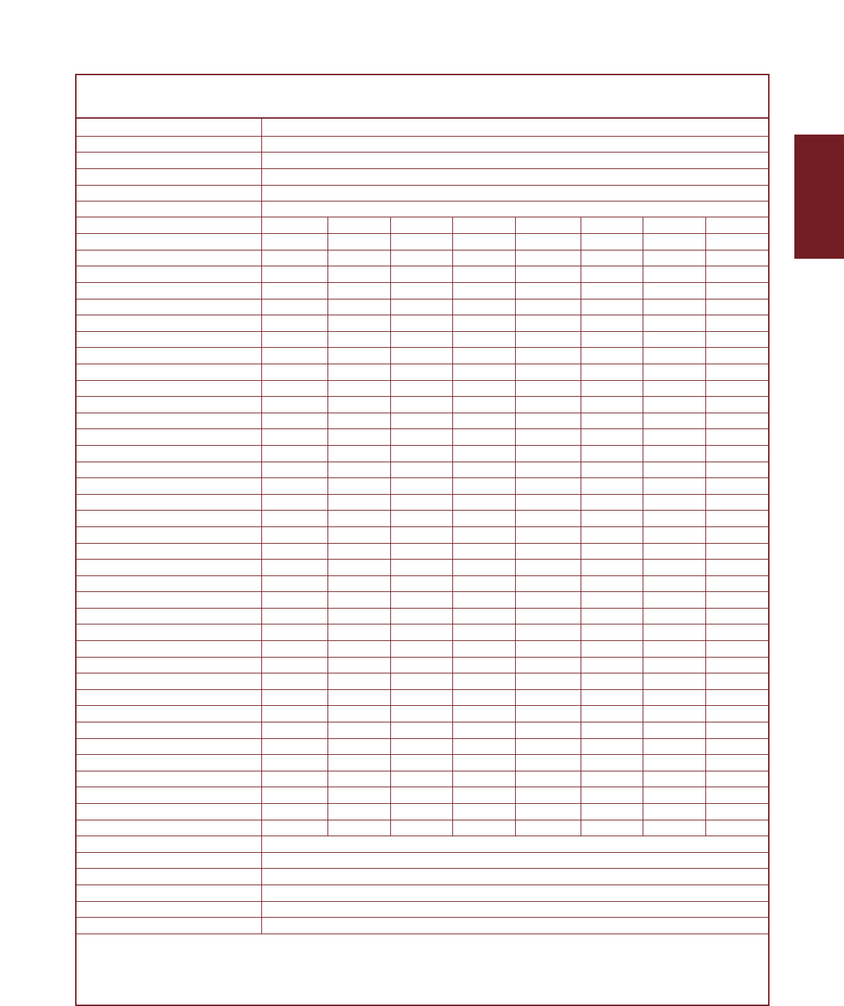
GSX Series actuators include an
integrated brushless servo
motor. Exlar’s unique design
gives users a variety of the feed-
back configuration options so
Brake and Limit Switch Cable
Motor Power Cable
Motor Feedback Cable
To line
power
Typical Servo
Amplifier
Motor and Power connections
Feedback Connections
I/O Connections
GSX units can be powered by
almost any brushless motor amplifi-
er on the market.
This flexibility means GSX actuators
can be incorporated into today’s
highest performance single and
multi-axis motion control systems.
In anything from food and beverage
packaging, to multi-axis turning cen-
ters, to aircraft assembly, GSX Series
units show incredible performance
and durability.
The schematic below shows the typi-
cal connections for a single axis sys-
tem with actuator and servo amplifier.
The Brake and Limit Switch Options for the GSX actuators are
mutually exclusive. Only one of the two options is available on a
GSX series actuator. They utilize the same cable, so connections
need be made only for the option being used.
GSX Series –
System Configuration
Drawings subject to change. Consult Exlar for certified drawings.
Note: rear brake option –
brake leads contained
in power cable
GSX Series

Cables For Actuators With Exlar Standard “O” Connections
Power Connector- Standard Exlar
Cables ization Description Power Cable
GSX20 O Standard Power, Molded, Shielded PC6-MC-xxx
GSX30 O Standard Power, Anodized PC1-AC-xxx
E Standard Power, Electroless Nickel, Environmentally Sealed, EMI/RFI Shielded PC1-EC-xxx
GSX40 OStandard Power, Molded, Shielded PC7-MC-xxx
GSX50 O Standard Power, Anodized PC7-AC-xxx
E Standard Power, Electroless Nickel, Environmentally Sealed, EMI/RFI Shielded PC7-EC-xxx
GSX60 OStandard Power, Anodized PC3-AC-xxx
E Standard Power, Electroless Nickel, Environmentally Sealed, EMI/RFI Shielded PC3-EC-xxx
Feedback Standard Exlar
Cables Feedback Cable
GSX20 O Standard Resolver Feedback, Anodized RC1-AC-xxx
GSX30 O Standard Encoder Feedback, Anodized EC1-AC-xxx
E Standard Resolver Feedback, Electroless Nickel, Environmentally Sealed, EMI/RFI Shielded RC1-EC-xxx
E Standard Encoder Feedback, Electroless Nickel, Environmentally Sealed, EMI/RFI Shielded EC1-EC-xxx
GSX40 O Standard Resolver Feedback, Anodized RC1-AC-xxx
GSX50 O Standard Encoder Feedback, Anodized EC1-AC-xxx
E Standard Resolver Feedback, Electroless Nickel, Environmentally Sealed, EMI/RFI Shielded RC1-EC-xxx
E Standard Encoder Feedback, Electroless Nickel, Environmentally Sealed, EMI/RFI Shielded EC1-EC-xxx
GSX60 OStandard Resolver Feedback, Anodized RC1-AC-xxx
OStandard Encoder Feedback, Anodized EC1-AC-xxx
E Standard Resolver Feedback, Electroless Nickel, Environmentally Sealed, EMI/RFI Shielded RC1-EC-xxx
EStandard Encoder Feedback, Electroless Nickel, Environmentally Sealed, EMI/RFI Shielded EC1-EC-xxx
Brake Standard Exlar
Cables Brake Cable
GSX20 OStandard Brake Cable, Anodized BC1-AC-xxx
GSX30 E Standard Brake Cable, Electroless Nickel, Environmentally Sealed, EMI/RFI Shielded BC1-EC-xxx
GSX40 O Standard Brake Cable, Anodized BC1-AC-xxx
GSX50 E Standard Brake Cable, Electroless Nickel, Environmentally Sealed, EMI/RFI Shielded BC1-EC-xxx
GSX60 OStandard Brake Cable, Anodized BC1-AC-xxx
E Standard Brake Cable, Electroless Nickel, Environmentally Sealed, EMI/RFI Shielded BC1-EC-xxx
EXLAR
GSX Series Linear Actuators
19
GSX Series Cable and
Connector Selection
This section provides you with cable
part numbers for operation of your
GSX Series actuators with both
Exlar’s and other manufacturers’
servo drives.
The "O" connector option on the
GSX Series of actuators provides
for an actuator with Exlar’s standard
MS style connectors, compatible
with Exlar’s standard cables.
The "M" connector option on the
GSX series of actuators provides
for an actuator configured with
connectors that allow the end user
to purchase the feedback cable or
power and feedback cables from
the manufacturer of their servo
amplifier, thus eliminating the
headaches and confusion that can
arise from power and feedback
wiring.
Depending on actuator size, volt-
age, and cable availability from the
amplifier manufacturer, some
cables must be obtained from Exlar.
For amplifier manufacturers who
use standard style military connec-
tors, with molded and shielded
cables, the feedback cable can be
purchased from the amplifier man-
ufacturer, and the power cable pur-
chased from Exlar. The Exlar power
cables with the PCx-MC-xxx model
numbers are molded and shielded
and provide a good match with the
cables provided by the amplifier
manufacturer.
For some amplifier manufacturers
who utilize a different style of con-
nector, when the "M" option is avail-
able from Exlar, both the connectors
will be configured to allow the feed-
back and power cables to be pur-
chased from the amplifier manufac-
turer. Consult Exlar for details on
all connector configurations.
Specifications subject to change without notice.

20
Amplifier Exlar Power Power Feedback Feedback
Exlar Manufacturer Feedback Cable Cable Cable Cable
Actuator and Type Callout Manufacturer Part Number Manufacturer Part Number
GSX20 Allen Bradley AB1 Exlar PC6-MC-xxx Allen Bradley 9101-1366-xxx
GSX30 Ultra 100/200
Allen Bradley AB7*Allen Bradley 2090-UXNPAMP-14Sxx Allen Bradley 2090-UXNFBMP-Sxx
Ultra 3000/5000
Allen Bradley AB4/AB5* Allen Bradley 2090-UXNPAMP-14Sxx Allen Bradley 2090-UXNFBMP-Sxx**
Ultra 3000/5000
Control Techniques En, EM2 Control Techniques CMDS-xxx Control CFCS-xxx
Epsilon and MDS Series Techniques
Kollmorgen Servo Star KM1 Kollmorgen CSSSRHA1H-xxx Kollmorgen CSSSRHA1H-xxx
& Servo Star CD (set includes feedback cable) (set includes power cable)
Kollmorgen KM5/KM2 Kollmorgen CSSSRHG1H-xxx Kollmorgen CSSSRHG1H-xxx
Servo Star 600 (set includes feedback cable) (set includes power cable)
Kollmorgen KM3/KM4 Kollmorgen CSSSS3HG2H-xxx Kollmorgen CSSSS3HG2H-xxx
Servo Star 600 set includes feedback cable) (set includes power cable)
Bosch/Rexroth Indramat IN1 Bosch/Rexroth IKG4077, IKG4017, IKG4009, IKG4008 Bosch/Rexroth IKS4001
DKC Series, ECO Drive Indramat depending on Indramat amplifier Indramat
Bosch/Rexroth Indramat IN2 Bosch/Rexroth IKG4077, IKG4017, IKG4009, IKG4008 Bosch/Rexroth IKS4001
DKC Series, ECO Drive Indramat depending on Indramat amplifier Indramat
Bosch/Rexroth Indramat IN4/IN3 Bosch/Rexroth IKG4009 Bosch/Rexroth IKS4374
DKC Series, ECO Drive Indramat Indramat
Bosch/Rexroth Indramat IN1 Bosch/Rexroth IKG4077 Bosch/Rexroth IKS4001
DIAX Series Indramat Indramat
Bosch/Rexroth Indramat IN2 Bosch/Rexroth IKG4077 Bosch/Rexroth IKS4001
DIAX Series Indramat Indramat
Bosch/Rexroth Indramat IN3 Bosch/Rexroth IKG4077 Bosch/Rexroth IKS4374
DIAX Series Indramat Indramat
Parker Compumotor PC3 Exlar PC6-MC-xxx Parker 71-018308-XX
Gemini Series Compumotor
Yaskawa Sigma II Series YS3 Yaskawa B1E-xxA Yaskawa JZSP-CMP02-XX(B)
(3 inch and smaller motors 100/200VAC)
Yaskawa Sigma II Series YS3 Yaskawa BAE-xxA Yaskawa JZSP-CMP02-XX(B)
(3 inch and smaller motors 400VAC)
Yaskawa Sigma II Series YS2 Yaskawa B1E-xxA Yaskawa JZSP-CMP02-XX(B)
(4 inch and larger motors 100/200VAC)
Yaskawa Sigma II Series YS2 Yaskawa BAE-xxA Yaskawa JZSP-CMP02-XX(B)
(4 inch and larger motors 400VAC)
GSX40 Allen Bradley AB1 Exlar 2090-UXNPAMP-14Sxx – GSX40 only Allen Bradley 9101-1366-xxx
GSX50 Ultra 100/200 2090-UXNPAMP-10Sxx – GSX50 only
Allen Bradley AB7*Allen Bradley 2090-UXNPAMP-14Sxx – GSX40 only Allen Bradley 2090-UXNFBMP-Sxx
Ultra 3000/5000 2090-UXNPAMP-10Sxx – GSX50 only
Allen Bradley AB4/AB5*Allen Bradley 2090-UXNPAMP-14Sxx Allen Bradley 2090-UXNFBMP-Sxx**
Ultra 3000/5000
Control Techniques En, EM2 Control Techniques CMMS-xxx Control CFCS-XXX
Epsilon and MDS Series Techniques
Kollmorgen Servo Star KM1 Kollmorgen CSSSRHA2H-xxx Kollmorgen CSSSRHA2H-xxx
& Servo Star CD (set includes feedback cable) (set includes power cable)
Kollmorgen KM5/KM2 Kollmorgen CSSSRHG2H-xxx Kollmorgen CSSSRHG2H-xxx
Servo Star 600 (set includes feedback cable) (set includes power cable)
Kollmorgen KM4/KM3 Kollmorgen CSSSS3HG2H-xxx Kollmorgen CSSSS3HG2H-xxx
Servo Star 600 (set includes feedback cable) (set includes power cable)
Bosch/Rexroth IN1 Bosch/Rexroth IKG4009 Bosch/Rexroth IKS4001
Indramat DKC Series, ECO Drive Indramat Indramat
Bosch/Rexroth IN2 Bosch/Rexroth IKG4009 Bosch/Rexroth IKS4001
Indramat DKC Series, ECO Drive Indramat Indramat
Bosch/Rexroth IN3/IN4 Bosch/Rexroth IKG4009 Bosch/Rexroth IKS4374
Indramat DKC Series, ECO Drive Indramat Indramat
Bosch/Rexroth IN1 Bosch/Rexroth IKG4077 Bosch/Rexroth IKS4001
Indramat DIAX Series Indramat Indramat
Bosch/Rexroth IN2 Bosch/Rexroth IKG4077 Bosch/Rexroth IKS4001
Indramat DIAX Series Indramat Indramat
Bosch/Rexroth IN3 Bosch/Rexroth IKG4077 Bosch/Rexroth IKS4374
Indramat DIAX Series Indramat Indramat
Parker Compumotor PC3 Exlar PC7-MC-xxx Parker 71-018308-XX
Gemini Series Compumotor
Yaskawa Sigma II Series YS3 Yaskawa B1E-xxA Yaskawa JZSP-CMP02-XX(B)
(3 inch and smaller motors 100/200VAC)
Yaskawa Sigma II Series YS3 Yaskawa BAE-xxA Yaskawa JZSP-CMP02-XX(B)
(3 inch and smaller motors 400VAC)
Yaskawa Sigma II Series YS2 Yaskawa B1E-xxA Yaskawa JZSP-CMP02-XX(B)
(4 inch and larger motors 100/200VAC)
Yaskawa Sigma II Series YS2 Yaskawa BAE-xxA Yaskawa JZSP-CMP02-XX(B)
(4 inch and larger motors 400VAC)
GSX60 As in tables As in tables Exlar PC3-AC-xxx As in tables As in tables
above for above for above for above for
GSX40/GSX50 GSX40/GSX50 GSX40/GSX50 GSX40/GSX50
Allen Bradley AB4/AB5/AB7*Allen Bradley 2090-UXNPAMP-10Sxx Allen Bradley 2090-UXNFBMP-Sxx
Ultra 3000/5000
*Brake Cable AB4/AB5 and AB7, 2090-UXNPAMP-18Sxx
** Exlar Corporation uses absolute encoders for AB4 and AB5 configurations that are powered by 5 VDC. A customer not using Allen-Bradley’s universal feedback cable referenced here, must make
provisions such that the wiring scheme provides connectivity according to Allen-Bradley’s wiring requirments for 5 VDC encoder power from the amplifier to the encoder.
Cables For Actuators With “M” Connectors (standard lengths of 15´, 25´ and 50´)
GSX Series
21
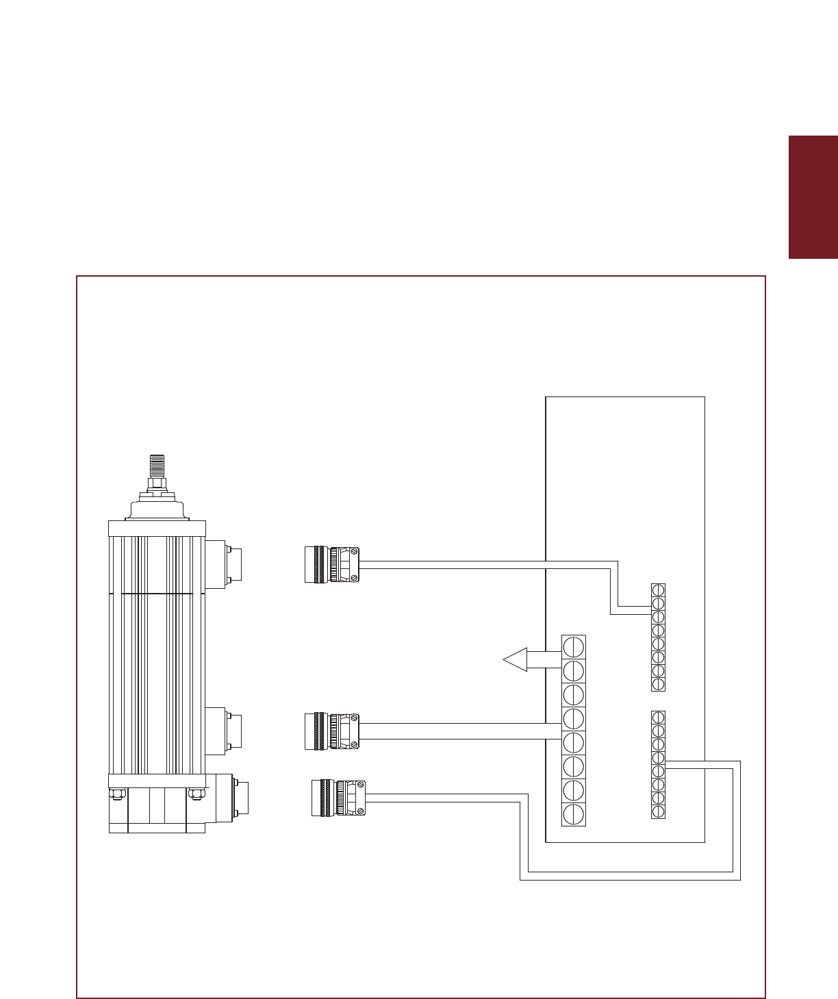
As shown in the schematic to the left, a check valve
or other method of pressure regulation should be
used to maintain an internal actuator oil pressure of
5 psi.
Filtering of 25 microns or better should be used.
Simple radiators or heat exchangers can be
used to maintain oil temperature.
Locate oil system
as close to
actuator as
possible. Use
as large as
possible oil line
to minimize any
possibility of
flow restriction.
High Power/Minimal
Maintenance Operation
Guidelines
Exlar GSX series actuators can be
lubricated with either grease or oil.
All are shipped from the factory
fully greased and are capable of
functioning for many thousands of
hours between re-greasings.
Typically, greased lubrication is
preferred for lower speed or inter-
mittent duty applications. In these
situations, you simply mount the
actuator, connect the servo amplifi-
er, and run.
However, many GSX Series actua-
tors are deployed into applications
Simple Oil System Schematic
involving high speed, high force, or
both. To provide the cooling
required when operating at these
high power levels and/or to elimi-
nate periodic re-greasing, all GSX
units have another built-in feature.
They are designed with an internal
circulation path and the portings
necessary for customers to convert
from grease by connecting a recir-
culation oil system. This feature
makes GSX units the only all-elec-
tric actuators on the market capable
of true continuous-duty perform-
ance in moderate and high power
applications when heat is an issue.
The conversion to externally sup-
plied oil is simple. Identify which
port will be lowest when the actua-
tor is mounted. That will become
the oil supply side. (For optimum
cooling it is important that GSX
actuators are mounted so the high-
side port is at least above the unit’s
centerline, preferably in the top
quarter region. This assures that
the stator windings receive the oil’s
cooling benefits.) Just connect
your oil lines and you’re done.
Residual grease will be flushed out
and filtered during initial operation.
A typical oil cooling system is
shown below. Whenever applica-
tion requirements are such that the
RMS current requirement exceeds
the continuous current rating of the
GSX motor, oil cooling should be
used to keep case temperatures
below their 85˚C maximum specifi-
cation. For very high speed appli-
cations, consult Exlar for oil routing
recommendations.
Radiator/ Heat Exchanger
Oil Filter 25 µ or better
Flow Direction
5 psi
Check Valve 1/2 psi
Check Valve
Oil Reservoir Oil Pump
Exlar recommends the use of petroleum based gear oils with EP additive. An ISO 100 grade is suitable for most
applications. Examples of this type of oil are: Mobil Mobilgear, Exxon Spartan EP, Shell Omala and Texaco Meropa.
Oils meeting the FDA’s food grade specifications are also available such as Mobil DTE FM 32.
EXLAR
GSX Series Linear Actuators

22
( )
Oil Cooling and Lubrication
Oil lubrication will extend the life of
the actuator and improve its effi-
ciency. More importantly, oil is
required in high power applications
Where
Use this relationship to determine oil flow requirements: W
Consider The Following Examples:
1. GSX Series actuators can be ordered with features that allow them to achieve case temperatures of 150˚C. Inquire with
Exlar’s application engineers or local representative for details.
for cooling. In applications where
the RMS current exceeds IG (see
electrical specs on pages 13-17),
oil lubrication is required in order
to maintain the case temperature
below its maximum of 85°C1.
When such oil lubrication is
required, you can determine oil
flow rates and case temperatures
from this information:
Actuator Load Constants: KL = ( )
KL GSX20 = 40
KL GSX30 = 70
KL GSX40 = 95
KL GSX50 = 125
KL GSX60 = 260
Application Load Factor: FL
FL =Irms
IG
2Where:
Irms = actual application current
IG = actuator current rating from
specifications (see pages 13-17)
W= K
L
FL
∆T∆T = TCASE – TOIL
CASE 1:
A GSX30-238 requires 4 amps of RMS current to perform the required application. The incoming oil tem-
perature is 45°C, and we desire to maintain the actuator at it’s maximum case temperature of 85°C.
FL = (4/3.4)2= 1.38 W = [(1.38 x 70)/(85 – 45)] = 2.415 GAL / HOUR
CASE 2:
A GS45 requires 12 amps of RMS current to perform the required application. The incoming oil tempera-
ture is 45°C, and we desire to maintain the actuator at it’s maximum case temperature of 85°C.
FL = ( 12/8 )2= 2.25 W = [( 2.25*125 ) / (85 – 45)] = 7.0 GAL / HOUR
˚C x Gal
Hour
GSX Series
4.750
(120.65)
2.00
(50.8)
2.50
(63.5)
3.84
(97.5)
R1.09
(R27.7)
2.13 (54.1)
0.75
(19.1)
2.38 (60.5)
ø1.00 (25.4)
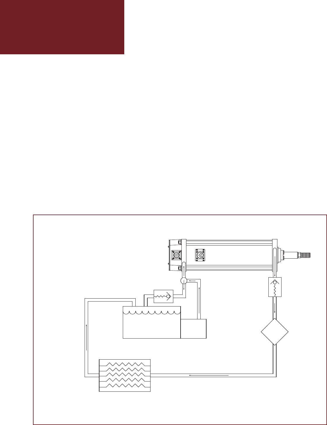
Anti-Rotate
GSX50 Linear Actuator
Contact exlar for a certified drawing.
and should be used for estimation purposes only.
This drawing is subject to change without notice
ALL DIMENSIONS IN INCHES
UNLESS OTHERWISE SPECIFIED:
GSX Series Linear
Actuator Anti-rotation
Option
The unique design of the
GSX Series of linear actua-
tors permits the extending
rod to rotate. This simplifies
actuator setup by allowing
the user to rotate the rod and
thread it in and out of the
actuator for mechanical
attachment or system testing.
However, this feature also
requires that once setup and
testing are completed, the
rod be kept from rotating so
proper linear motion will be
maintained. In most applica-
tions the actuator’s load is
coupled to linear bearings, or
some other support device.
In these cases the load can-
not rotate, and a separate
anti-rotation system is not
needed.
For applications in which the
load is free to rotate, Exlar
offers the anti-rotation sys-
tems shown below. Shorter
GSX units use an anti-rota-
tion arm on one side of the
actuator. Longer strokes
(defined above right) use
rods on both sides.
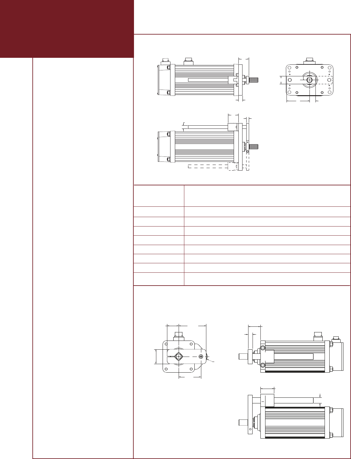
Dims in
inches (mm) GSX20 GSX30 GSX40 GSX60
A0.60 (15.2) 0.79 (20.1) 1.25 (31.8) 1.75 (44.5)
B1.81 (46.0) 2.54 (64.5) 3.78 (96.0) 5.79 (147)
C0.54 (13.7) 0.71 (18.0) 0.98 (24.9) 1.55 (39.4)
D1.00 (25.4) 1.30 (33.0) 1.64 (41.7) 1.94 (49.3)
E0.44 (11.2) 0.44 (11.2) 0.63 (16.0) 0.75 (19.1)
F0.28 (7.11) 0.32 (8.13) 0.38 (9.65) 0.50 (12.7)
G0.31 (7.87) 1.69 (42.9) 1.69 (42.9) 2.81 (71.4)
øH 0.37 (9.40) 0.50 (12.7) 0.50 (12.7) 1.00 (25.4)
CB
A
D
E
G
øH F
For longer strokes a second
Anti-Rotate arm is used.
Longer strokes are:
• GSX20, 12 inch
• GSX30, 10 inch and longer.
• GSX40, 12 inch and longer
• GSX60, 10 inch only and uses
a single sided Anti-Rotate.
Drawings subject to change. Consult Exlar for certified drawings.
Anti-rotation Option GSX20, GSX30, GSX40 and GSX60
EXLAR
GSX Series Linear Actuators
23
Anti-rotation Option GSX50
GSX Series Travel Options
PF = Preloaded Follower
This option offers a true zero backlash follower for the GSX Series actuator. The dynamic load rating of zero backlash,
preloaded screws is 63% of the dynamic load rating of the standard non-preloaded screws. The calculated travel life of a
preloaded screw will be 25% of the calculated travel life of the same size and lead of a non-preloaded screw for the same
application. Preloaded follower is not available with absolute internal feedback option.
EB = Electric Brake
This option provides an internal holding brake for the GSX20, 30, 40 & 60 actuators. The brake is spring activated and
electrically released.
RB = Rear Electric Brake
This option provides an internal holding brake for the GSX50 actuator. The brake is spring activated and electrically
released.
ES = Internal End of Travel Switches
This option allows for two internal end of travel switches to be included with the GSX Series actuator. These switches
provide end of travel indication to the controller and are not adjustable. See page 31 for details.
AR = External Anti-rotate Assembly
This option provides a rod and bushing to restrict the actuator rod from rotating when the load is not held by another
method. Shorter actuators have single sided anti-rotation attachments. Longer lengths require attachments on both
sides for proper operation.
XT = Special Travel Option Selections
The XT Option can be used to specify various special travel options on the GSX Series of Linear Actuators. Because this
option can be used to specify many things, it is important that an order including the -XT option spell out in detail, the
exact options being selected by the including of the -XT in the model number.
It is recommended that prior to ordering an actuator including the -XT specifier that a quote be obtained through Exlar’s
special products application engineers for the desired options, and that quote be referenced on, or included with any
order placed.
Descriptions:
Protective
Bellows
High Temp
Protective
Bellows
Splined
Main Rod
Manual
Drive
Handwheel
This option provides an accordion style protective bellows to protect the main actuator rod from damage
due to abrasives or other contaminants in the environment in which the actuator must survive. The stan-
dard material of this bellows is neoprene coated nylon. This standard bellows is rated for envi-
ronmental temperatures of -54 degrees to 121 degrees Celsius. Longer strokes may require
the main rod of the actuator to be extended beyond standard length. Consult Exlar appli-
cations engineers for details.
This option provides an accordion style protective bellows to protect the main
actuator rod from damage due to abrasives or other contaminants in the environ-
ment in which the actuator must survive. The high temperature material of this
bellows is silicone coated fiberglass. This standard bellows is rated for environmen-
tal temperatures of -73 degrees to 288 degrees Celsius. Longer strokes may require the main rod of the
actuator to be extended beyond standard length. Consult Exlar applications engineers for details.
This option provides a main rod manufactured of ball spline shafting, and the front seal and
bushing assembly replaced with a ball spline nut to provide the anti-rotate function with-
out using an external mechanism. Rod diameters are the closest metric equivalents
to standard Exlar rod sizes. This option is NOT sealed in any way. This option is
not suitable for any environment in which contaminants come in contact with the
actuator, and may enter the actuator.
This option provides for a manual drive handwheel on the side of the actuator. The hand-
wheel has a engagement/disengagement lever which allows for disengagement
of the handwheel during operation. This engagement/disengagement lever
is not tied to the operation of the motor and requires that the user guaran-
tee its disengagement before operating the motor. Not available on
GSX20.
L1, L2, L3 = Adjustable External Travel Switches
This option allows up to 3 external switches to be included with the GSX Series Actuator. These switches provide travel
indication to the controller and are adjustable (must purchase anti-rotate for this option). See page 32 for details.
XL =Non-Standard Lubrication
This option provides for indication in the model number that the customer has specified a lubrication other than the stan-
dard provided by Exlar.
24
GSX Series

Motor Speed Designators
All Exlar T-LAM™ motors and actuators carry a standard motor
speed designator as defined below. This is representative of the
standard base speed of the motor, for the selected bus voltage.
Designator Base Speed Actuator/Motor Series
-50 5000 rpm GSX20
-30 3000 rpm GSX30, GSX40
-24 2400 rpm GSX50, GSX60
01-99 Special Speed, Consult Exlar
If the model number is created and the location for the motor speed
designator is left blank, this is the base speed to which each motor
will be manufactured. The model number can also be created
including this standard speed designator.
Exlar also provides the flexibility to manufacture all of its T-LAM
products with special base speeds to match the customer’s exact
application requirements. This may be a higher than standard
speed motor, or lower base speed than standard which will allow
the customer to get the required torque, at a speed optimized to
their application, and use the minimum amount of current from
their amplifier.
The call out for a special speed is configured in the model number
by using a two digit code from 01-99. These numbers represent the
number, in hundreds, of RPM that will be the base speed for the
particular motor.
For example, an GSX-30-03-01-OSM-AD1-118-30 motor that nor-
mally has a 3000 rpm standard winding, can be changed to a 3300
rpm winding by changing the -30, to a -33. It can be changed to a
5000 rpm winding by changing the -30 to a -50.
Changing this speed designator will change the ratings of the
motor, and these must be obtained from Exlar applications engi-
neers. Also, it is not possible to produce every possible speed
from -01 to -99 for each motor at each voltage so please contact
Exlar applications engineers for confirmation of the speed that is
desired for the application.
Absolute Linear Feedback Options
LT = LVDT (VRVT) including conditioner
This option provides for an actuator containing an internally
mounted LVDT (VRVT) transducer spanning the full stroke of
the actuator. Inquire with Exlar engineering for details and con-
ditioner output preference.
Motor Options
GSX motor options are described with a 3
digit code. The first digit calls out the stack
length, the second the rated bus voltage,
and the third the number of poles of the
motor. Refer to the mechanical/electrical
specifications for motor torque and actuator
rated force.
118 = 1 stack, 115 Vrms, 8 Pole, Class 180 H
138 = 1 stack, 230 Vrms, 8 Pole, Class 180 H
158 = 1 stack, 400 Vrms, 8 Pole, Class 180 H
168 = 1 stack, 460 Vrms, 8 Pole, Class 180 H
218 = 2 stack, 115 Vrms, 8 Pole, Class 180 H
238 = 2 stack, 230 Vrms, 8 Pole, Class 180 H
258 = 2 stack, 400 Vrms, 8 Pole, Class 180 H
268 = 2 stack, 460 Vrms, 8 Pole, Class 180 H
318 = 3 stack, 115 Vrms, 8 Pole, Class 180 H
338 = 3 stack, 230 Vrms, 8 Pole, Class 180 H
358 = 3 stack, 400 Vrms, 8 Pole, Class 180 H
368 = 3 stack, 460 Vrms, 8 Pole, Class 180 H
Rod End Attachments
Rear Clevis Pin
Spherical Rod Eye
Rod Eye
Rod Clevis
See drawings on pages 33-36.
Attachments ordered separate from actuator.
Housing Options
FG = Food Grade Epoxy
This option provides for an actuator coat-
ed with FDA approved white epoxy.
EN = Electroless Nickel Plating
This option provides for an actuator with
electroless nickel plating.
SS = Stainless Steel Housing
This option provides an actuator with all
stainless steel construction. Housing
dimensions for this option are not equal
to the standard housing. Please inquire
with Exlar for dimensions.
XH = Special Housing Option
Any housing option that is not designated
by the above codes should be listed as XH
and described at time of order. All special
options must be discussed with Exlar
engineering.
EXLAR
GSX Series Linear Actuators
25
26
GSX Series
Note: Add 1.784 Inches to Dims "A,B,&D"
if ordering an Electric Brake or
Internal End of Travel Switches.
Rear Clevis Mount/Front Flange Mount
Single & Double Side Mounts/Extended Tie Rod Mount
Side Trunnion Mount
GS20
8.613
11.775
6.000
10.775
6 Inch Stroke
C
D
B
Dim
A
8.775
3.000
5.613
3 Inch Stroke
7.775
12 Inch Stroke
17.775
12.000
14.613
16.775
0.144
[3.66]
0.250
[6.35]
0.750
[19.1]
1/4-20 UNC-2B
x 0.375 Deep
(x4 SS, x8 DS)
1.00
[25.4]
ø2.546 [64.7]
B.C.
1.120
[28.45]
2.240
[56.9]
2.240
[56.9]
Single Side Mount
On This Side
ø1.500
+.000
-.003
[38.1 ]
+0.00
-0.08
#10-24
UNC-2A
Dim "B"
Dim "A"
ø0.2500
x 0.250 Deep
(Double Side
Mount Only)
+.0000
- .0005
[6.35 ]
+0.00
-0.01
1.000
[25.4]
2.740 [69.6]
3.115 [79.1]
5.115 [129.9]
1.000
[25.4]
1.00
[25.4]
Dim "A"
ø1.000
±.001
[25.4
±0.03
]
ø1.500
[38.1]
Dim "C"
2.240
[56.9]
Dim "D"
0.750 [19.1]
R0.625
[15.9]
3.125
[79.4]
3.750
[95.3]
ø0.125
[3.18]
1.750
[44.5]
1.000
[25.4]
1.00
[25.4]
2.24
[56.8]
ø0.250
[6.35]
0.750
[19.1]
1.500
[38.1]
0.438
[11.13]
[12.8 ]
+0.00
-0.03
ø0.502
+.000
- .001
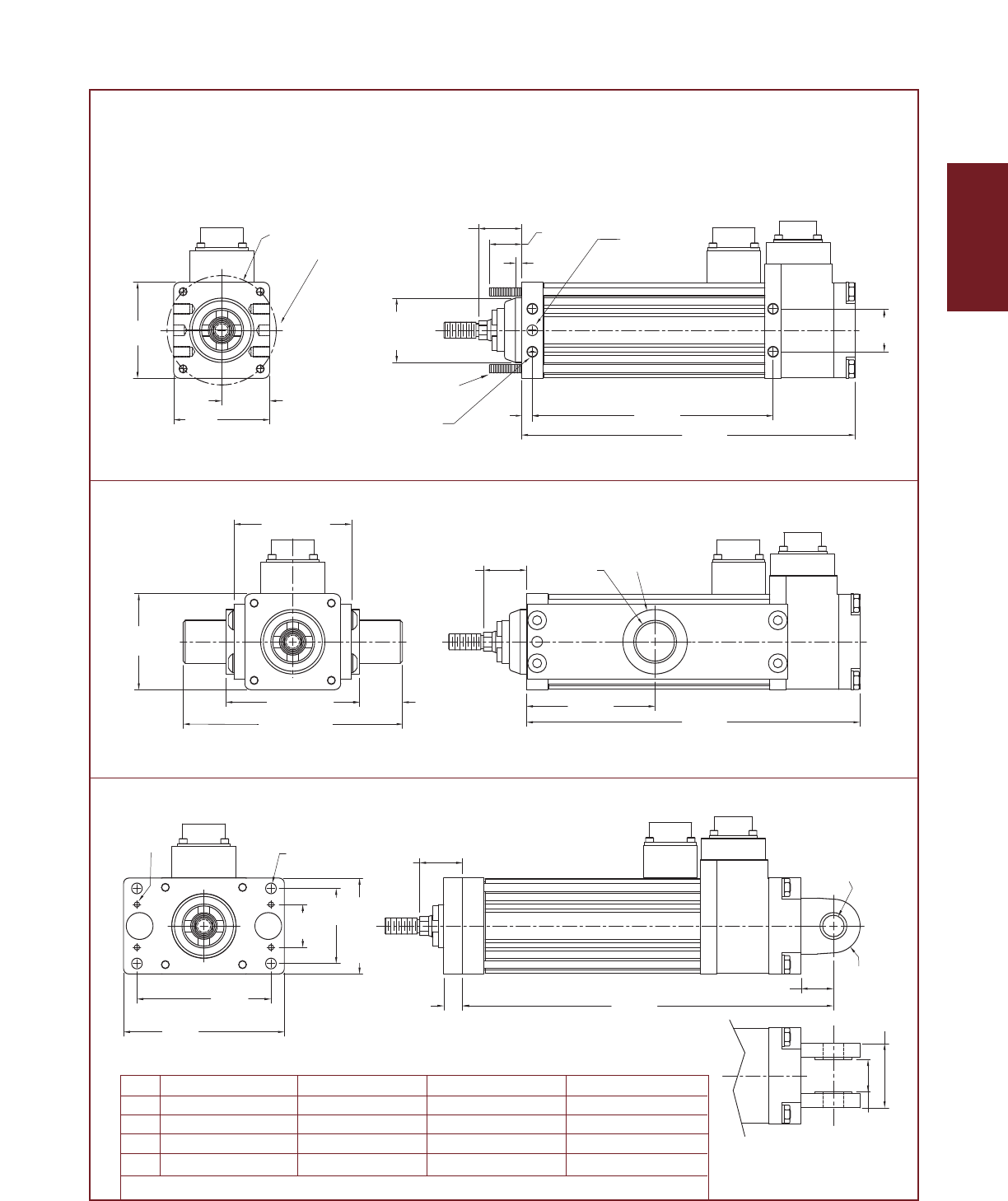
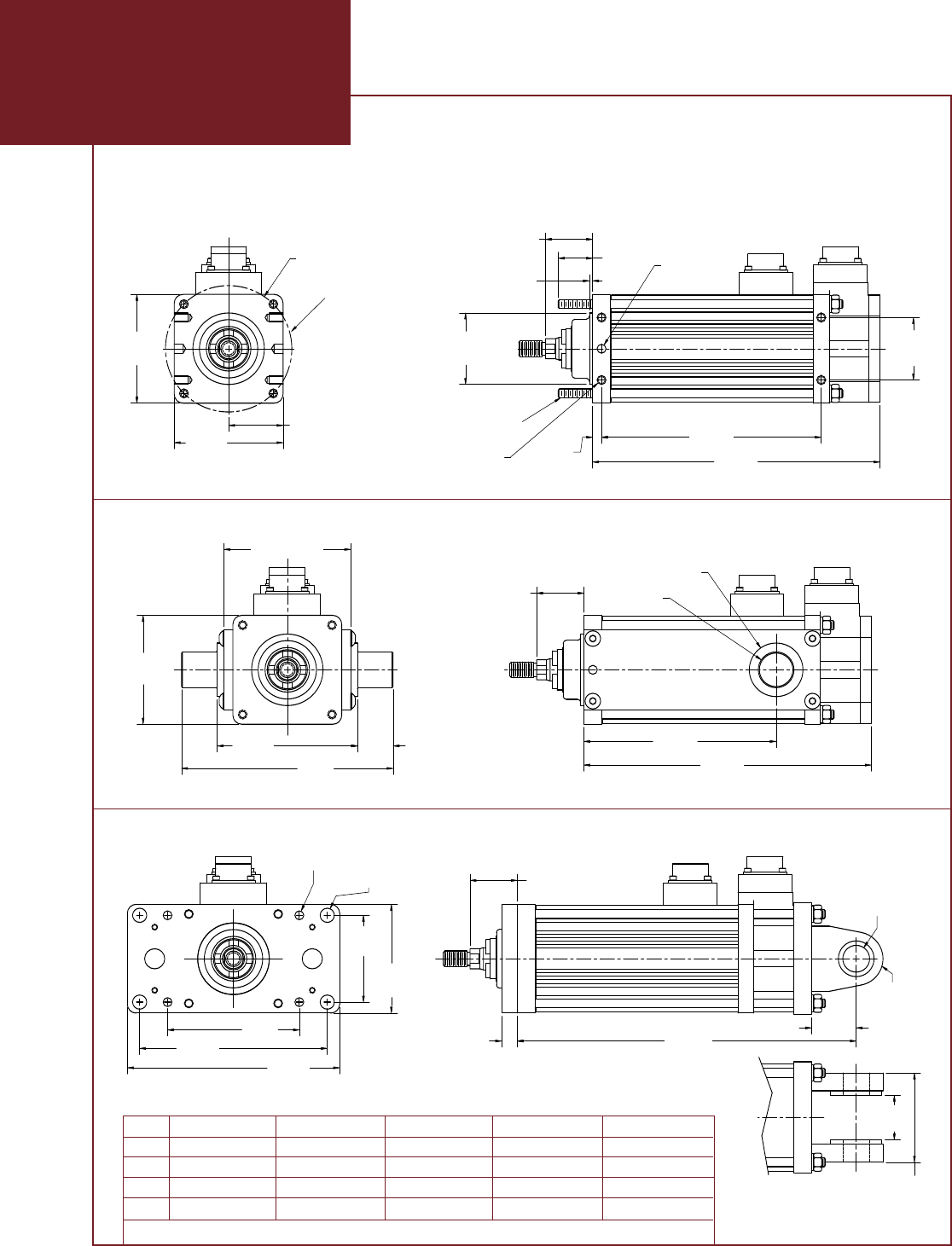
GSX20 Single, Double Side Mounts or Extended Tie Rod Mount
GSX20 Side Trunnion Mount
GSX20 Rear Clevis Mount or Front Flange Mount
Dim 3 inch (mm) stroke 6 inch (mm) stroke 10 inch (mm) stroke 12 inch (mm) stroke
A7.775 (197.5) 10.775 (273.7) 14.775 (375.3) 16.775 (426.1)
B5.613 (142.6) 8.613 (218.8) 12.613 (320.4) 14.613 (371.2)
C3.000 (76.2) 6.000 (152.4) 10.000 (254.4) 12.000 (304.8)
D8.775 (222.9) 11.775 (299.1) 15.775 (400.7) 17.775 (451.5)
Note: Add 1.784 Inches to Dims "A,B,& D" if ordering an Electric Brake or Internal End of Travel Switches.
1. Three mounting styles shown
2. Shown view is standard side for single side mount
1. Two mounting styles shown
2. With flange mount, dimension A is
equivalent to top two drawings
Drawings subject to change. Consult Exlar for certified drawings.
EXLAR
GSX Series Linear Actuators
1.32
[33.5]
1.750
[44.5]
3.046
[77.4]
3.046
[77.4] Dim "B"
Dim "A"
0.250
[6.35]
1/4-20 UNC-2B
x 0.38 Deep
(x4 SS, x8 DS)
1.523
[38.68]
Single Side Mount
On This Side
1/4-20
UNC-2A
0.962
[24.4]
ø2.000
+.000
-.003
[50.8
+0.00
-0.08
]
ø3.536 [89.8] B.C.
ø0.2500
x 0.250 Deep
(Double Side
Mount Only)
+.0000
-.0005
[6.35 ]
+0.00
-0.01
0.090
[2.29]
0.438
[11.1] Dim "D"
3.688
[93.7]
5.250
[133.4] 5.940
[150.9]
3.05
[77.4]
2.430
[61.72]
ø0.250 [6.35](x4)
ø0.397 [10.08](x4) 1.32
[33.5]
2.500
[50.8]
1.250
[31.8]
1.250
[31.8]
ø0.7505
+.000
- .001
[19.1 ]
+0.00
-0.03
R0.750
[19.1]
1.000
[25.4]
3.046
[77.4]
5.921
[150.4]
3.921
[99.6]
3.546 [90.1]
Dim "C"
Dim "A"
ø1.500
[3.81]
ø1.000
±.001
[25.4
±0.03
]
1.32
[33.5]
13.119
15.013
10 Inch Stroke
8.041 10.514A
B6.147 8.620
Dim 3 Inch Stroke 6 Inch Stroke
23.01319.013
21.11917.119
18 Inch Stroke14 Inch Stroke Note: Add 1.773 inches to Dim "A,B,&D"
if ordering an Electric Brake or Internal
GS30
Single & Double Side Mounts/Extended Tie Rod Mount
11.9599.486 16.458 20.458 24.458
Rear Clevis Mount/Front Flange Mount
D
18.000
C5.380 10.0008.006 14.000
Side Trunnion Mount
GSX30 Single, Double Side Mounts or Extended Tie Rod Mount
GSX30 Side Trunnion Mount
GSX30 Rear Clevis Mount or Front Flange Mount
1. Three mounting styles shown
2. Shown view is standard side for single side mount
1. Two mounting styles shown
2. With flange mount, dimension
A is equivalent to top two drawings
Drawings subject to change. Consult Exlar for certified drawings.
Dim 3 inch (mm) stroke 6 inch (mm) stroke 10 inch (mm) stroke 14 inch (mm) stroke 18 inch (mm) stroke
A8.041 (204.2) 10.514 (267.1) 15.013 (381.3) 19.013 (482.9) 23.013 (584.5)
B6.147 (156.1) 8.620 (218.9) 13.119 (333.3) 17.119 (434.8) 21.119 (536.4)
C5.380 (136.7) 8.006 (203.4) 10.000 (254.0) 14.000 (355.6) 18.000 (457.2)
D9.486 (240.9) 11.959 (303.8) 16.458 (418.0) 20.458 (519.6) 24.458 (621.2)
Note: Add 1.773 Inches to Dims "A,B,&D" if ordering an Electric Brake or Internal End of Travel Switches.
27
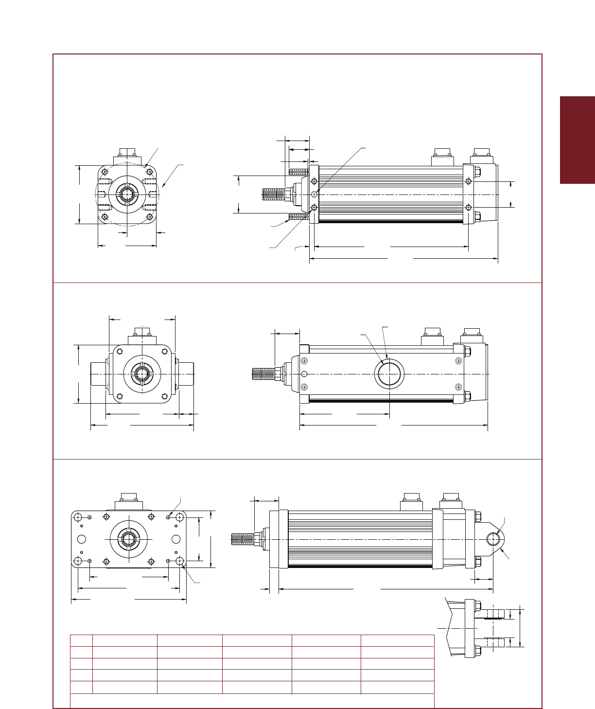
28
GSX Series
1.950
[49.9]
3.900
[99.1]
1.65
[41.8]
Dim "A"
1.750
[44.5]
Dim "B"
0.313
[7.95]
3.900
[99.1]
1.38
[34.9]
ø2.499
±.001
[63.47
±.025
]
3/8-16
UNC-2A
ø0.3750
x 0.438 Deep
(Double Side
Mount Only)
+.0000
- .0005
[9.53 ]
+0.00
-0.01
0.100
[2.54]
3/8-16 UNC-2B
x 0.75 Deep
(x4 SS, x8 DS)
ø4.243 [107.8] B.C.
Single Side Mount
On This Side
1.65
[41.8]
1.000
[25.4]
4.898
[124.4]
6.898
[175.2]
3.900
[99.1]
4.400 [111.8]
Dim "C"
Dim "A"
ø1.500
±.001
[38.10
±.003]
ø2.000
[50.80]
Dim "D"
0.625
[15.9]
6.800 [172.7]
7.680 [195.1]
ø0.250[6.35](x4)
5.250 [133.3]
3.800
[96.5]
ø0.516
[13.10]
(x4)
2.920
[74.2]
1.65
[41.8]
1.250 [31.8]
[19.1 ]
+0.00
-0.03
ø0.752
+.000
- .001
R0.750
[19.1]
Dim
A
6" Stroke
12.582
B 10.306 12.306
14.582
8" Stroke 12" Stroke
18.582
16.306 22.306
24.582
18" Stroke Note: Add 2.330 inches to Dim "A,B,&D"
if ordering an Electric Brake.
Single & Double Side Mounts/Extended Tie Rod Mount
Side Trunnion Mount
Rear Clevis Mount/Front Flange Mount
8.000
C 6.000 12.000 18.000
14.332
D16.332 20.332 26.332
GS40
2.500
[63.5]
1.250
[31.75]
GSX40 Single, Double Side Mounts or Extended Tie Rod Mount
GSX40 Side Trunnion Mount
GSX40 Rear Clevis Mount or Front Flange Mount
1. Three mounting styles shown
2. Shown view is standard side for single side mount
1. Two mounting styles shown
2. With flange mount, dimension A
is equivalent to top two drawings
Drawings subject to change. Consult Exlar for certified drawings.
Dim 6 inch (mm) stroke 8 inch (mm) stroke 10 inch (mm) stroke 12 inch (mm) stroke 18 inch (mm) stroke
A12.58 (319.6) 14.58 (370.4) 16.58 (421.1) 18.58 (472.0) 24.58 (624.4)
B10.31 (261.8) 12.31 (312.6) 14.31 (363.5) 16.31 (414.2) 22.31 (566.6)
C6.00 (152.4) 8.00 (203.2) 10.00 (254) 12.00 (304.8) 18.00 (457.2)
D14.33 (364.0) 16.33 (414.8) 18.33 (465.6) 20.33 (516.4) 26.33 (668.8)
Note: Add 2.330 Inches to Dims "A,B,&D" if ordering an Electric Brake or Internal End of Travel Switches.
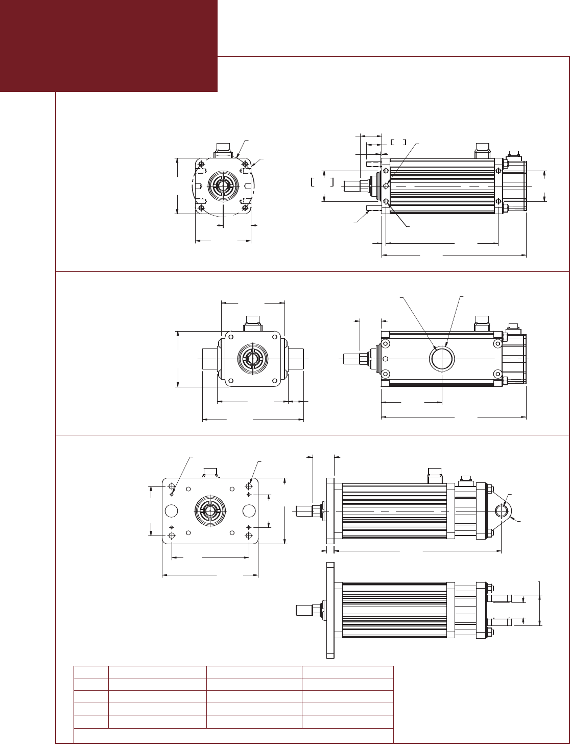
GSX50 Single, Double Side Mounts
or Extended Tie Rod Mount
GSX50 Side Trunnion Mount
GSX50
Rear Clevis
Mount or
Front
Flange
Mount
EXLAR
GSX Series Linear Actuators
29
1/2-13 UNC-2B
x .750 Deep
(x4 SS, x8 DS)
3.000
[76.2]
Dim "B"
0.406
[10.3]
Dim "A"
1.500
38.1
2.125
[54.0]
0.125
[3.2]
3.000 -0.003
+0.000
76.2 -0.1
0.0
x 0.500 Deep (2x)
(Double Side Mount Only)
[12.7 ]
0.0
-0.0
0.5000
+0.0000
-0.0005
1/2-13 UNC-2A
6.125 B.C.
[155.6]
2.750
[69.9]
5.500
[139.7]
5.500
[139.7]
Single Side Mount
On This Side
GSX50 Single, Double Side Mounts or Extended Tie Rod Mount
Dim "C"
Dim "A"
2.125
[54.0]
2.500
[63.5]
6.250
[158.8]
5.500
[139.7]
7.000
[177.8]
1.500
[38.1]
10.000
[254.0]
1. Three mounting styles shown
2. Shown view is standard side for single side mount
GSX50 Side Trunnion Mount
2.125
[54.0]
0.750
[19.1] Dim "D"
1.000
[25.4]
0.250
(4x)
[6.4] 0.563
(4x)
[14.3]
7.625
(4x)
[193.7]
9.500
[241.3]
4.875
(2x)
[123.8] 3.250
(2x)
[82.6]
6.500
(2x)
[165.1]
GSX50 Rear Clevis Mount or Front Flange Mount
1. Two mounting styles shown
2. With flange mount, dimension "A" is
equivalent to the top two drawings.
1.500
[38.1]
3.000
[76.2]
[50.8 ]
0.00
+
-
2.000
0.001
+
-
[25.4 ]
0.0
-0.0
1.001
+0.000
-0.001
1. Three mounting styles shown
2. Shown view is standard side for
single side mount
1. Two mounting styles shown
2. With flange mount, dimension A is
equilavent to top two drawings
Drawings subject to change. Consult Exlar for certified drawings
Dim 6 inch (mm) stroke 10 inch (mm) stroke 14 inch (mm) stroke
A14.31 (363.5) 18.31 (465.1) 22.31 (566.7)
B11.12 (282.4) 15.12 (384.0) 19.12 (485.6)
C6.00 (152.4) 10.00 (254.0) 14.00 (355.6)
D16.56 (420.6) 20.56 (522.2) 24.56 (623.8)
Note: Add 2.498 Inches to Dims "A,B,&D" if ordering an Electric Brake or Internal End of Travel Switches.
1/2-13 UNC-2B
x .750 Deep
(x4 SS, x8 DS)
3.000
[76.2]
Dim "B"
0.406
[10.3]
Dim "A"
1.500
38.1
2.125
[54.0]
0.125
[3.2]
3.000 -0.003
+0.000
76.2 -0.1
0.0
x 0.500 Deep (2x)
(Double Side Mount Only)
[12.7 ]
0.0
-0.0
0.5000
+0.0000
-0.0005
1/2-13 UNC-2A
6.125 B.C.
[155.6]
2.750
[69.9]
5.500
[139.7]
5.500
[139.7]
Single Side Mount
On This Side
GSX50 Single, Double Side Mounts or Extended Tie Rod Mount
Dim "C"
Dim "A"
2.125
[54.0]
2.500
[63.5]
6.250
[158.8]
5.500
[139.7]
7.000
[177.8]
1.500
[38.1]
10.000
[254.0]
1. Three mounting styles shown
2. Shown view is standard side for single side mount
GSX50 Side Trunnion Mount
2.125
[54.0]
0.750
[19.1] Dim "D"
1.000
[25.4]
0.250
(4x)
[6.4] 0.563
(4x)
[14.3]
7.625
(4x)
[193.7]
9.500
[241.3]
4.875
(2x)
[123.8] 3.250
(2x)
[82.6]
6.500
(2x)
[165.1]
GSX50 Rear Clevis Mount or Front Flange Mount
1. Two mounting styles shown
2. With flange mount, dimension "A" is
equivalent to the top two drawings.
1.500
[38.1]
3.000
[76.2]
[50.8 ]
0.00
+
-
2.000
0.001
+
-
[25.4 ]
0.0
-0.0
1.001
+0.000
-0.001
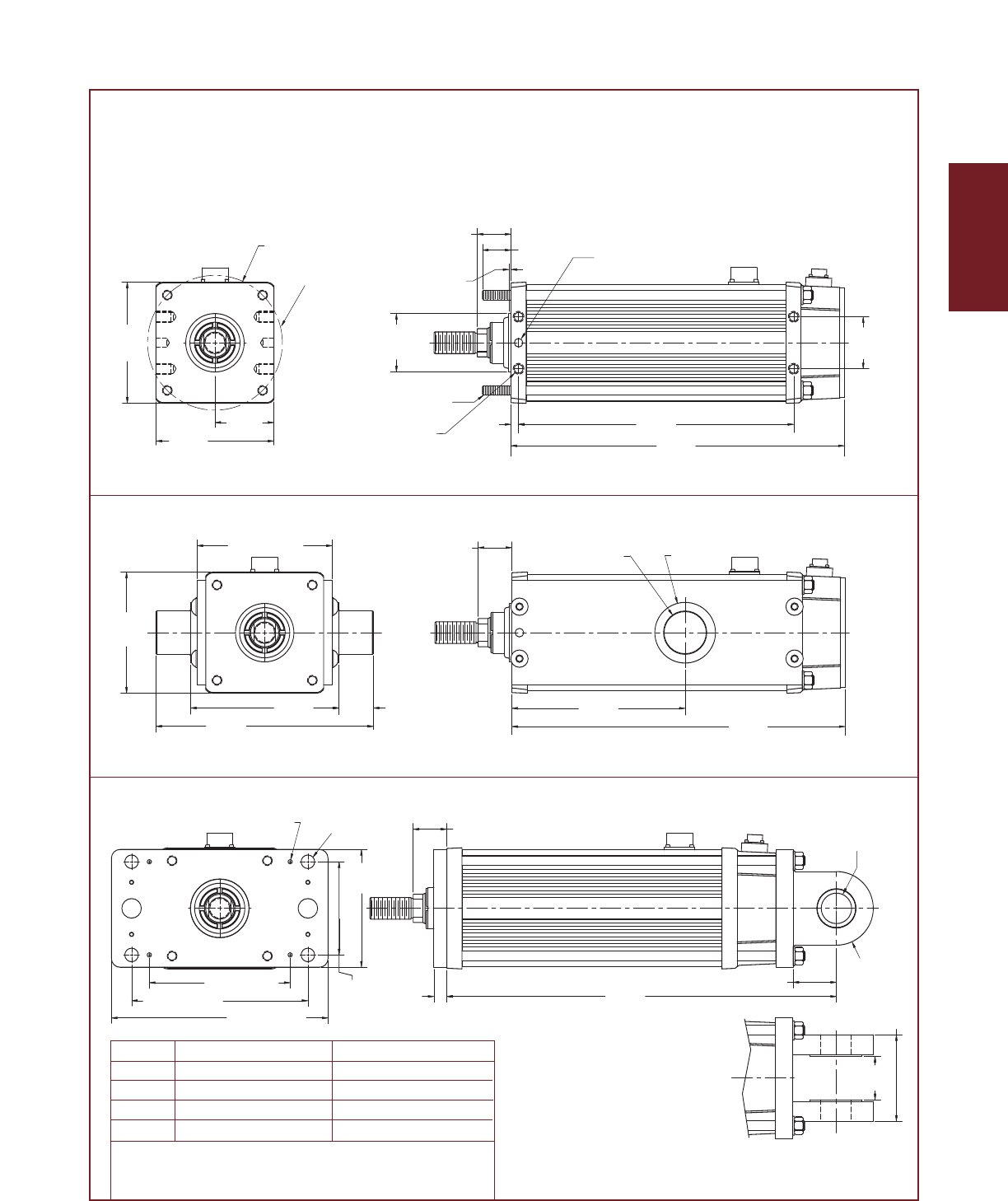
30
GSX Series
Single & Double Side Mounts/Extended Tie Rod Mount
GS60
15.876
19.229
10 Inch Stroke
B
A
Dim Note: Add 3.575 Inches to Dim "A,B,&D"
if ordering an Electric Brake or
C10.000
Side Trunnion Mount
D22.480
Rear Clevis Mount/Front Flange Mount
3.000
[76.2]
Dim "B"
0.438
[11.1] Dim "A"
6.800
[172.7]
3.400
[86.4]
1.94
[49.4]
6.989
[177.5]
0.125
[3.18]
ø0.5000
x 0.625 Deep (Double
Side Mount Only)
+.0000
- .0005
[12.7 ]
+0.00
- 0.01
5/8-11 UNC-2B
x 0.875 Deep
(x4 SS, x8 DS)
ø7.778 [197.6] B.C.
ø3.375
+.000
- .003
[85.73 ]
+0.0
-0.08
9/16-12
UNC-2A
1.65
[41.8]
Single Side
Mount On
This Side
7.800 [198.1]
12.550
[318.8]
8.550
[217.2]
6.989
[177.5]
2.000
[50.8]
ø2.500
+.000
-.002
[63.50 ]
+0.00
-0.05
Dim "A"
1.944
[49.4] ø3.500
[88.90]
Dim "C"
0.750
[19.1]
1.944 [49.4]
12.500 [317.5]
10.174 [258.4]
ø0.250 [6.35]
(x4)
ø0.781 [19.8]
(x4)
8.125 [206.4]
6.800
[172.7]
5.375
[136.5]
2.500
[63.50]
5.000
[127.0]
Dim "D"
[44.53 ]
+0.00
-0.04
ø1.753
+.0000
- .0015
R 2.125
[53.98]
2.500 [63.50]
GSX60 Single, Double Side Mounts or Extended Tie Rod Mount
GSX60 Side Trunnion Mount
GSX60 Rear Clevis Mount or Front Flange Mount
1. Three mounting styles shown
2. Shown view is standard side for single side mount
1. Two mounting styles shown
2. With flange mount, dimension A
is equivalent to top two drawings
Drawings subject to change. Consult Exlar for certified drawings.
Dim 6 inch (mm) stroke 10 inch (mm) stroke
A15.23 (386.8) 19.23 (488.4)
B11.88 (301.8) 15.88 (403.3)
C6.00 (152.4) 10.00 (254.0)
D18.48 (469.4) 22.48 (571.0)
Note: Add 3.575 Inches to Dimensions "A,B,&D" if ordering an Electric Brake or
Internal End of Travel Switches.
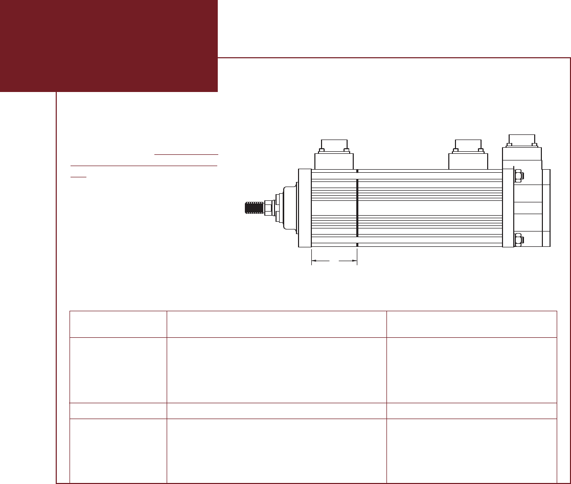
EXLAR
GSX Series Linear Actuators
31
GSX20, GSX30, GSX40 & GSX60 Brake and
Internal Limit Switch Extension Options
Actuator A - Limit Switch Extension Length Stroke Length Reduction
GSX20 1.784” (45.21 mm) 0.4” (10.1 mm)
GSX30 1.773” (44.96 mm) 0.4” (10.1 mm)
GSX40 No internal limit switch
GSX60 3.575” (90.81 mm) 0.4” (10.1) mm
Actuator A - Brake Extension Length Stroke Length Reduction
GSX20 1.784” (45.21 mm) NA
GSX30 1.773” (44.96 mm) NA
GSX40 2.330” (59.18 mm) NA
GSX60 3.575” (90.81 mm) NA
Note: The stroke limitation from the limit
switch option IS NOT MECHANICAL. It
represents the position at which the
switches will activate. The stroke limita-
tion for the brake is a mechanical limita-
tion. The brake and limit switch options
are mutually exclusive and thus are not
available in the same unit. Drawing and
specifications subject to change without
notice.
A
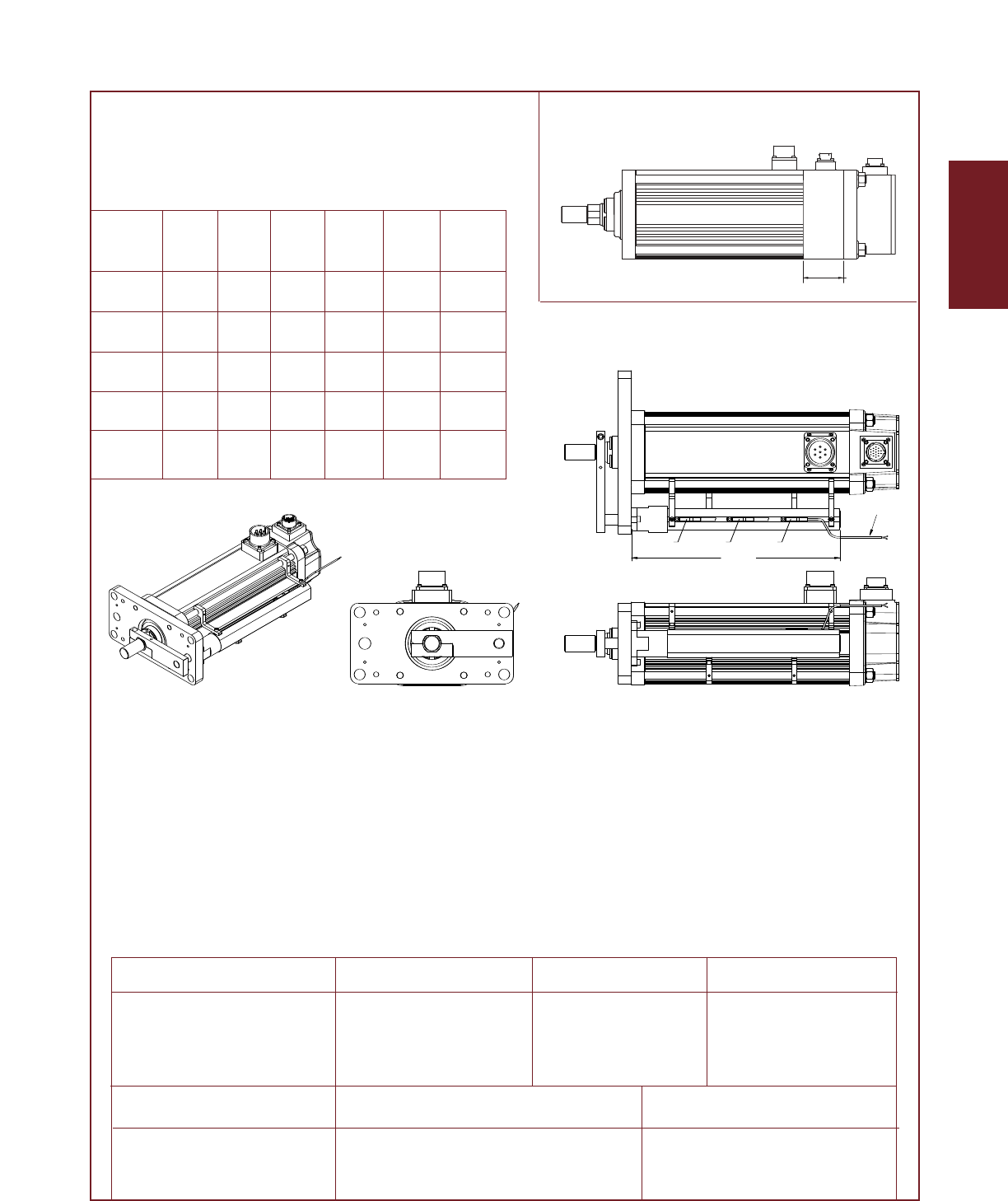
32
GSX Series
Dim A 3 inch 6 inch 10 inch 12 inch 14 inch 18 inch
(mm) (mm) (mm) (mm) (mm) (mm)
stroke stroke stroke stroke stroke stroke
GSX20 5.515 8.515 NA 14.515 NA NA
(140.1) (216.3) NA (368.7) NA NA
GSX30 6.932 9.832 13.832 15.832 17.832 21.832
(176.1) (249.7) (351.3) (402.1) (452.9) (554.5)
GSX40 NA 9.832 13.832 15.832 17.832 21.832
NA (249.7) (351.3) (402.1) (452.9) (554.5)
GSX50 NA 11.667 NA NA 19.667 23.667
NA (296.3) NA NA (499.5) (601.1)
GSX60 NA NA 14.461 NA NA NA
NA NA (367.3) NA NA NA
2.500
GSX50 Brake Extension Option
GSX20, GSX30, GSX40, GSX50 & GSX60
External Limit Switch Extension Options
DIM "A"
36" Flying Leads
L1 L2 L3
The external limit switch option for the GSX Series of linear actuators provides the user with 1, 2 or 3 exter-
nally mounted adjustable switches for use as the end of travel limit switches or home position sensors.
The number of switches desired is selected by ordering the L1, L2 or L3 option, in which 1, 2 or 3 switches
will be provided, respectively.
The switches are 9-30 VDC powered, PNP output, with either normally open or normally closed logic opera-
tion depending on the switch configuration ordered. Below is a diagram which logic operation will be pro-
vided for each switch, based on the option ordered.
Option SW1 SW2 SW3
L1 Not Supplied Normally Open Not Supplied
L2 Normally Closed Not Supplied Normally Closed
L3 Normally Closed Normally Open Normally Closed
Switch Type Exlar Part Number Turck Part Number
Normally Closed Switch 24631 BIM-INT-RP6X
Normally Open Switch 22303 BIM-INT-AP6X
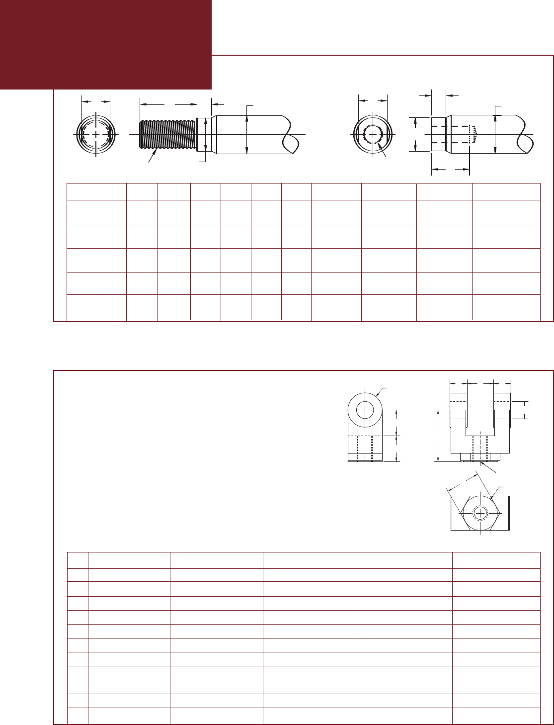
33
Drawings subject to change. Consult Exlar for certified drawings.
Part numbers for rod attachment options indicate the through hole size or pin diameter. Before selecting a spherical rod eye for use with a
GSX series actuator, please consult the information on the anti-rotation option for the GSX actuators. Spherical rod eyes will allow the rod
to rotate if the load is not held.
Actuator Rod End Options
D
A
H
F
G
øB
C
JK
E
AA
A
B
øA
C
D
F
E
DD
E
øF
C
B
A
øG
HøJ
K
CC
B
A
øE
øD
A
A
øC
øC
D
D
øE
øE
B
B
Male
Thread
Male
Thread
B
B
D
D
øE
øE
F
F
øC
øC
Female
Thread
Female
Thread
ABøCDøE F Male U.S. Male Metric Female U.S. Female Metric
GSX20 0.813 0.375 0.500 0.200 0.440 0.750 3⁄8 – 24 M8X1 5⁄16 – 24 M8X1
(20.7) (9.5) (12.7) (5.1) (11.2) (19.1) UNF – 2A UNF – 2B
GSX30 0.750 0.500 0.625 0.281 0.562 0.750 7⁄16 – 20 M12X1.75* 7⁄16 – 20 M10X1.5
(19.1) (12.7) (15.9) (7.1) (14.3) (19.1) UN F– 2A UNF – 2B
GSX40 1.500 0.750 1.000 0.381 0.875 1.000 3⁄4 – 16 M16X1.5 5⁄8 – 18 M16X1.5
(38.1) (19.1) (25.4) (9.7) (22.2) (25.4) UNF – 2A UNF – 2B
GSX50 1.500 0.750 1.000 0.381 0.875 1.000 1 – 14 M27X2 1 – 14 M24X2
(38.1) (19.05) (25.4) (9.7) (22.2) (25.4) UNS – 2A UNS – 2B
GSX60 2.500 1.250 1.750 0.550 1.625 1.750 11⁄4 – 12 M30X2 7⁄8 – 14 M25X1.5
(63.5) (31.8) (44.5) (14.0) (41.3) (44.5) UNF – 2A UNF – 2B
*A Dim = 40mm
Rod Clevis Dimensions
D
A
H
F
G
øB
C
JK
E
AA
A
B
øA
C
D
F
E
DD
E
øF
C
B
A
øG
HøJ
K
C C
B
A
øE
øD
A
A
øC
øC
D
D
øE
øE
B
B
Male
Thread
Male
Thread
B
B
D
D
øE
øE
F
F
øC
øC
Female
Thread
Female
Thread
GSX20 GSX30 GSX40 GSX50 GSX60
RC038 RC050 RC075 RC100 RC138
A0.787” (20 mm) 0.75” (19.1 mm) 1.125” (28.58 mm) 1.625” (41.2mm) 2.00” (50.8 mm)
B0.787” (20 mm) 0.75” (19.1 mm) 1.25” (31.75 mm) 1.500” (38.1 mm) 2.125” (53.98 mm)
C1.574” (40 mm) 1.50” (38.1 mm) 2.375” (60.3 mm) 3.125” (79.4 mm) 4.125” (104.78 mm)
D.575” (14.6 mm) 0.50” (12.7 mm) 0.625” (15.88 mm) .750” (19.1 mm) 1.00”(25.4 mm)
E0.375” (9.5 mm) 0.765” (19.43 mm) 1.265” (32.13 mm) 1.515” (38.5 mm) 2.032” (51.6 mm)
øF 0.375” (9.5 mm) 0.50” (12.7 mm) 0.75” (19.1 mm) 1.000” (25.4 mm) 1.375” (34.93 mm)
øG 0.75” (19.1 mm) 1.00” (25.4 mm) 1.50” (38.1 mm) 2.000” (50.8 mm) 2.75” (69.85 mm)
HNA 1.00” (25.4 mm) 1.25” (31.75 mm) 1.500” (38.1 mm) 2.00” (50.8 mm)
øJ NA 1.00” (25.4 mm) 1.25” (31.75 mm) 1.500” (38.1 mm) 2.00” (50.8 mm)
K3/8-24 7/16-20 3/4-16 1-14 1-1/4 - 12
EXLAR
GSX Series Linear Actuators
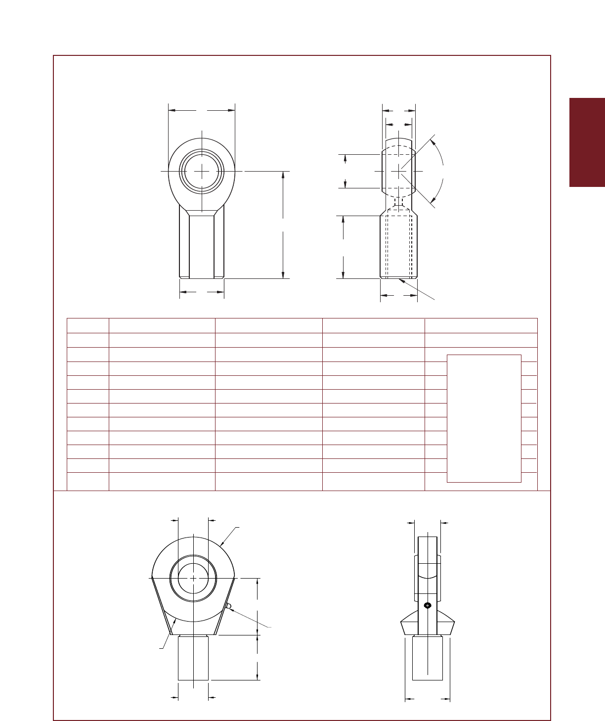
GSX20 GSX30 GSX40 GSX50
SRM038 SRM044 SRM075 SRF100
A1.625” (41.3mm) 1.81” (46.0 mm) 2.88” (73.2 mm)
øB .375” (9.525mm) 0.438” (11.13 mm) 0.75” (19.1 mm)
C.906” (23.0mm) 1.06” (26.9 mm) 1.72” (43.7 mm)
D1.0” (25.6mm) 1.13” (28.7 mm) 1.75” (44.5 mm)
E12 deg 14 deg 14 deg
F.406” (10.3mm) 0.44” (11.1 mm) 0.69” (17.5 mm)
G.500” (12.7mm) 0.56” (14.2 mm) 0.88” (22.3 mm)
H.688” (17.7mm) 0.75” (19.1 mm) 1.13” (28.7 mm)
J.562” (14.3mm) 0.63” (16.0 mm) 1.00” (25.4 mm)
K3/8-24 7/16-20 3/4-16
34
GSX Series
Drawings subject to change. Consult Exlar for certified drawings.
Spherical Rod Eye Dimensions
See GSX50
Sperical Rod Eye
drawing below.
Requires female
rod end.
D
A
H
F
G
øB
C
JK
E
AA
A
B
øA
C
D
F
E
DD
E
øF
C
B
A
øG
HøJ
K
CC
B
A
øE
øD
A
A
øC
øC
D
D
øE
øE
B
B
Male
Thread
Male
Thread
B
B
D
D
øE
øE
F
F
øC
øC
Female
Thread
Female
Thread
Spherical Rod Eye
DO NOT SCALE
FROM DRAWING
Spherical Rod Eye
SHEET 1 OF 1
REV:
Part Number:
A
SIZE
Description:
"Keywords"
Q.A.:
Mfg. Apprl:
Eng. Apprl:
Drawn/Date:
"Finsh/Heat treat"
"Material"
Finish/Heat Treat:
Material:
THE INFORMATION CONTAINED IN THIS DRAWING IS THE SOLE PROPERTY OF
EXLAR. ANY REPRODUCTION IN PART OR AS A WHOLE WITHOUT THE WRITTEN
PERMISSION OF EXLAR IS PROHIBITED.
MRP 11-15-04
"Eng/Date"
N/A
N/A
Plcs "in or mm" Plcs "in or mm"
1 plcs= ± 0.1 3 plcs= ± 0.005
2 plcs= ± 0.01 4 plcs= ± 0.0002
Inside Edge Break:
0.005" to 0.025"
Outside Edge Break:
0.005" to 0.015"
Angles= ± 1/2?
Finish= 63 µ inch or 1.5 µ M
Dimensions Shown In:
UNLESS SPECIFIED:
INCHES
Model:
REVISIONS
ECO# REV.DESCRIPTION DRAWN-DATEAPPROVED-DATE
Ø1" R1 3/8"
R 1 7/16"
1 1/2"
1 7/8"
1"-14
Thread
LUBE
FITTING
7/8"
1 1/2"
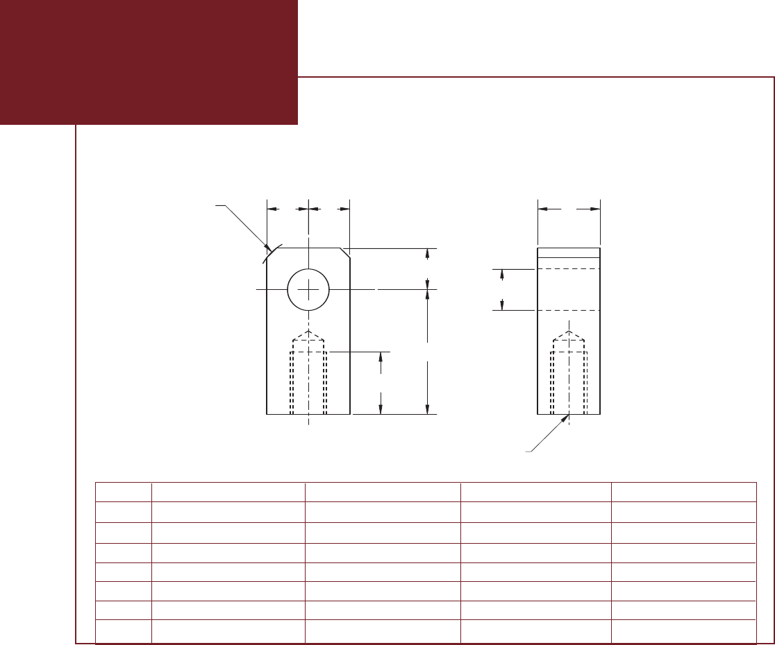
GSX30 GSX40 GSX50 GSX60
RE050 RE075 RE100 RE138
øA 0.50” (12.7 mm) 0.75” (19.1 mm) 1.00” (25.4 mm) 1.375” (34.93 mm)
B0.75” (19.1 mm) 1.25” (31.8 mm) 1.50” (38.1 mm) 2.0” (50.8 mm)
C1.50” (38.1 mm) 2.06” (52.3 mm) 2.81” (71.4 mm) 3.44” (87.3 mm)
D0.75” (19.1 mm) 1.13” (28.7 mm) 1.63” (41.4 mm) 2.0” (50.8 mm)
E0.63” (15.9 mm) 0.88” (22.3 mm) 1.19” (30.2 mm) 1.837” (46.67 mm)
F7/16-20 3/4-16 1 - 14 1-1/4 - 12
35
EXLAR
GSX Series Linear Actuators
Drawings subject to change. Consult Exlar for certified drawings.
D
A
H
F
G
øB
C
JK
E
AA
A
B
øA
C
D
F
E
DD
E
øF
C
B
A
øG
HøJ
K
CC
B
A
øE
øD
A
A
øC
øC
D
D
øE
øE
B
B
Male
Thread
Male
Thread
B
B
D
D
øE
øE
F
F
øC
øC
Female
Thread
Female
Thread
Rod Eye Dimensions
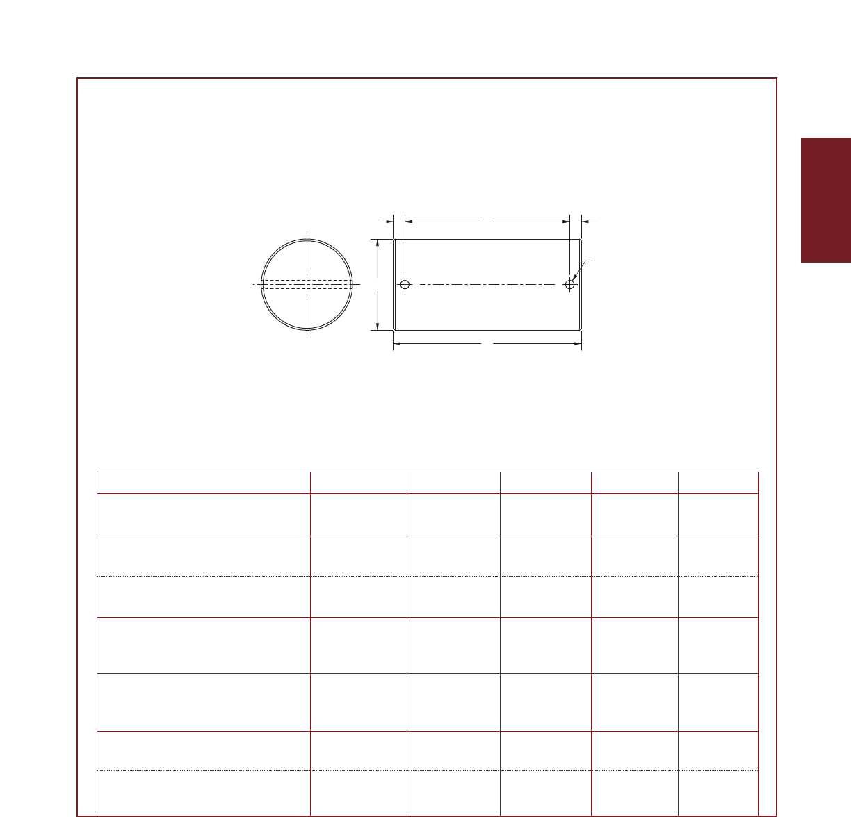
A B C øD øE
GSX20 2.28” 1.94” 0.17” 0.50” 0.095”
CP050-Rear Clevis (57.9 mm) (49.28 mm) (4.32 mm) (12.7 mm) (2.41 mm)
GSX30 2.28” 1.94” 0.17” 0.50” 0.095”
CP050-Rod eye, Rod Clevis (57.9 mm) (49.28 mm) (4.32 mm) (12.7 mm) (2.41 mm)
CP075-Rear Clevis 3.09” 2.72” 0.19” 0.75” 0.14”
(78.5 mm) (69.1 mm) (4.82 mm) (19.1 mm) (3.56 mm)
GSX40
CP075-Rod eye, Rod Clevis 3.09” 2.72” 0.19” 0.75” 0.14”
Spherical Eye, Rear Clevis (78.5 mm) (69.1 mm) (4.82 mm) (19.1 mm) (3.56 mm)
GSX50
CP100-Rod eye, Rod Clevis 3.59” 3.22” 0.19” 1.00” 0.14”
Spherical Eye, Rear Clevis (91.2 mm) (81.8 mm) (4.82 mm) (25.4 mm) (3.56 mm)
GSX60 4.66” 4.25” 0.20” 1.375” 0.173”
CP138-Rod eye, Rod Clevis (118.3 mm) (108 mm) (5.08 mm) (34.93 mm) (4.39 mm)
CP175-Rear Clevis 5.656” 5.25” 0.203” 1.750” 0.173”
(143.6 mm) (133.3 mm) (5.15 mm) (4.44 mm) (4.39 mm)
36
GSX Series
Clevis Pin Dimensions
D
A
H
F
G
øB
C
JK
E
A
A
A
B
øA
C
D
F
E
DD
E
øF
C
B
A
øG
HøJ
K
C C
B
A
øE
øD
A
A
øC
øC
D
D
øE
øE
B
B
Male
Thread
Male
Thread
B
B
D
D
øE
øE
F
F
øC
øC
Female
Thread
Female
Thread
Drawings subject to change. Consult Exlar for certified drawings.

37
AA = GSX Actuator Size
20 = 2 inch frame
30 = 3 inch frame
40 = 4 inch frame
50 = 5 inch frame
60 = 7 inch frame
BB = Stroke Length
03 = 3 inches (GSX20, GSX30)
06 = 5.9 inches (GSX30)
6 inches (GSX20, GSX40,
GSX50, GSX60)
08 = 8 inches (GSX40)
10 = 10 inches (all models)
12 = 12 inches (GSX20, GSX30,
GSX40)
14 = 14 inches (GSX30, GSX50)
18 = 18 inches (GSX30, GSX40)
CC = Lead
01 = 0.1 inch (GSX20, GSX30,
GSX40, GSX50)9
02 = 0.2 inch (GSX20, GSX30,
GSX40, GSX50)
03 = 0.25 inch (GSX60)
04 = 0.4 inch (GSX20 only)
05 = 0.5 inch (GSX30, GSX40,
GSX50, GSX60)
08 = 0.75 inch (GSX40)10
10 = 1.0 inch (GSX50, GSX60)11
D = Connections
O=MS style (anodized)
E = MS style (electroless nickel)
M = Manufacturer’s Connector7
I=Intercontec style (Exlar stan-
dard style connector)
X = Special (please specify)
E=Mounting
S = Side tapped mounting holes
D = Double side tapped mounting
E = Extended tie rods
F = Front flange
T = Trunnion
C=Rear clevis
X= Special (please specify)
F = Rod End
M = Male, US std. Thread
A = Male, Metric std. Thread
F = Female, US std. Thread
B = Female, Metric Thread
X = Special (please specify)
GGG = Brushless Amplifier (Please indicate the amplifier to be used to power the actuator)
XX1 = Custom Feedback - purchaser must supply drawing of feedback device and desired wiring
drawings
OO1 = Standard Feedback Mount - actuator is supplied ready for size 15 resolver or encoder, includes
.375 mm shaft
OO2 = Same as above with 8mm shaft
If the Rockwell Allen-Bradley system that you are using is the Kinetix platform or SERCOS based,
additional software and data files are required from Allen-Bradley. Please contact your Rockwell
Allen-Bradley representative for support.
AB1 = Allen-Bradley Ultra 100/2004(std encoder, 2048 line, with commutation, 5 VDC)
AB4 = Allen Bradley Ultra 3000 or 50004with single-turn (absolute encoder)
AB5 = Allen Bradley Ultra 3000 or 50004with multi-turn (absolute encoder)
AB6 = Allen Bradley 13948(resolver, type 2)(replaces AB2)
AB7 = Allen Bradley Ultra 3000 or 50004(std encoder, 2048 line, with commutation, 5 VDC)
AD1 = Advanced Digital "Simple Servo" (std encoder, 2048 line, with commutation, 5 VDC)
AP1 =API resolver based (resolver, type 2)
AP2 = API encoder based (std encoder, 2048 line, with commutation, 5 VDC)
AM1 = Advanced Motion Controls (std encoder, 2048 line, with commutation, 5 VDC)
AM2 = Advanced Motion Controls (std encoder, 1000 line, with commutation, 5 VDC)
AM3 = Advanced Motion Controls (resolver, type 1)
AM4 = Advanced Motion Controls BX Series default settings (std encoder, 2048 line, with
commutation, 5 VDC)
BD2 = Baldor Flex Series (resolver, type 1)(replaces BD1)
BD3 = Baldor Flex Series (std encoder, 2048 line, with commutation, 5 VDC)
BO1 = Bosch (resolver, type 2)
CC1 =Cleveland Machine Controls (resolver, type 1)
CM1 = Comau (resolver, type 1)
CO1 =Copley Controls (std encoder, 2048 line, with commutation, 5 VDC)
CS1 = Parker (Custom Servo Motors) MPA, MPSL (resolver, type 1)
CS2 = Parker (Custom Servo Motors) Servo Flex (std encoder, 2048 line, with commutation, 5 VDC)
EL1 = Elmo Motion Control (resolver, type 1)
EL2 = Elmo CLA, SBA, FLU Series, (std encoder, 2048 line, with commutation, 5 VDC)
EM2 = Emerson En, Epsilon, MDS Series and Uni-Drive4(std encoder, 2048 line, with commutation,
5 VDC)
EM3 = Emerson MX Series (resolver, type 2)
EM4 = Emerson UniDrive SP (resolver, type 1)
EU1 = Elau (absolute encoder, multi-turn, type 2)
EX4 = Exlar SV Series (resolver, type 1) (replaces EX3)
GL1 = Sheffield Automation (G&L) Smart Drive (standard encoder, 2048 line, with commutation, 5
VDC) If selecting the "M" connector option with GL1, the motor power and encoder connector
configuration will be equivalent to that used on the Sheffield Automation HSM Series motors.
GL2 = Sheffield Automation (G&L) Smart Drive (standard encoder, 2048 line, with commutation, 5
VDC) If selecting the "M" connector option with GL2, the motor power and encoder connector
configuration will be equivalent to that used on the Sheffield Automation LSM/MSM Series
motors.
IN1 = Bosch-Rexroth (Indramat) ECO Drive (absolute, multi-turn Heidenhain encoder, type 2)
IN2 = Bosch-Rexroth (Indramat) ECO Drive (absolute, single-turn Heidenhain encoder)
IN4 = Bosch-Rexroth (Indramat) ECO Drive, Standard resolver (resolver, type 1)(replaces IN3)
KM1 = Kollmorgen ServoStar Series4230V (resolver, type 2)
KM3 =Kollmorgen ServoStar600 Series4(Absolute encoder, single turn, type 1)
KM4 = Kollmorgen ServoStar600 Series4(Absolute encoder, multi-turn, type 2)
KM5 = Kollmorgen ServoStar600 Series4and ServoStar CD (resolver, type 2)(replaces KM2)
KM6 =Kollmorgen ServoStar300 Series4(std encoder, 2048 line, with commutation, 5 VDC)
LZ1 = Lenze 9300 Series (Multi-turn Absolute Encoder, type 2)
LZ2 = Lenze 9300 Series (resolver, type 2)
MD1 = Modicon (resolver, type 1)
MX1 = Metronix ARS Series, Resolver type 1
OR1 = Ormec (resolver, type 2)
PC1 = Parker Compumotor Apex & Z Series (resolver, type 1)
PC2 = Parker Compumotor TQ Series (std encoder, 2048 line, with commutation, 5 VDC)
PC3 =Parker Compumotor Gemini Series (std encoder, 2048 line, with commutation, 5 VDC)
PS2 =Pacific Scientific (std encoder, 2048 line, with commutation, 5 VDC)
PS3 = Pacific Scientific SC900, 700 Series (resolver, type 1)(replaces PS1)
SM2 =Siemens (resolver, type 1)
SP2 = In Motion, PAM Series (resolver, type 1)
WD1= Whedco (GE-Fanuc)(resolver, type 1)
YS2 = Yaskawa Sigma II Series for 4 inch and larger Exlar motors (multi-turn absolute encoder,
type 1)
YS3 = Yaskawa Sigma II Series for 3 inch and smaller Exlar actuators (multi-turn absolute encoder,
type 1)
GSX AA - BB CC - D E F - GGG - HHH - II - {XX..XX}
GSX Series
Ordering Information
EXLAR
GSX Series Linear Actuators

38
HHH = Motor Stator2– All 8 Pole
118 = 1 stack, 115 Vrms
218 = 2 stack, 115 Vrms
318 = 3 stack, 115 Vrms
138 = 1 stack, 230 Vrms
238 = 2 stack, 230 Vrms
338 = 3 stack, 230 Vrms
158 = 1 stack, 400 Vrms
258 = 2 stack, 400 Vrms
358 = 3 stack, 400 Vrms
168 = 1 stack, 460 Vrms
268 = 2 stack, 460 Vrms
368 = 3 stack, 460 Vrms
II = Motor Speed
24 = 2400 rpm, GSX50, GSX60
30 = 3000 rpm, GSX30, GSX40
50 = 5000 rpm, GSX20
01-99 = Customer specified base speed
XX .. XX = Options
Travel Options
PF =Preloaded follower1
ES = Internal end of travel switches5
AR = External Anti-rotate assembly
EB =Electric Brake5
RB = Rear Electric Brake5(GSX50)
XT = Special Travel Option (see pg. 24)
L1/L2/L3 = External Limit Switches
Motor Options
XM = Special motor option
XL = Special lubrication
Housing Options
FG = Food grade paint6
EN = Electroless nickel plating6
SS = Stainless steel housing6
XH = Special housing option
Absolute Linear Feedback
LT = VRVT, including signal conditioner3
1. The dynamic load rating of zero backlash, preloaded screws is 63% of the dynamic
load rating of the standard non-preloaded screws. The calculated travel life of a
preloaded screw will be 25% of the calculated travel life of the same size and lead
of a non-preloaded screw. Preloaded follower is not available with absolute internal
feedback option.
2. Stator voltage and pole options allow for catalog rated performance at varying
amplifier bus voltages and pole configuration requirements.
3. Linear feedback is not available in the GSX20.
4. Emerson EN and Epsilon Series, AB Ultra Series, Kollmorgen ServoStar and other
amps require motor data files for operation with GSX Series actuators. These files
can be downloaded from our website
at www.exlar.com. Contact Exlar for details.
5. The internal limit switch or brake options require a third cable. Internal limit
switches and brake together are not available.
6. These housing options would typically be accompanied by the choice of the electro-
less nickel connectors if a connectorized unit were selected. This choice may also
indicate the need for special material main rods or flanges.
7. Available with AB1, AB4/5, AB7, EM2, KM1, KM3, KM4, KM5, KM6, IN1, IN2, IN4,
LZ1, LZ2, PC3, PS3, YS2 and YS3 feedback. This option allows the customer to
use the standard cables supplied by their amplifier manufacturers.
8. Use of the A-B 1394 requires assistance from Allen-Bradley to configure the axis
for a custom motor.
9. .1 lead not available above 12˝ stroke in GSX40.
10. .75 lead not available above 12˝.
11. 1.0 lead not available above 10˝ stroke.
GSX Series
GSX Series Ordering Information
