Greenplum DCA Maintenance Guide 2.0.0.0 / 2.0.1.0 Data Computing Appliance 2.0.2.0 2.0.3.0
Greenplum-Data-Computing-Appliance-Maintenance-Guide-2.0.0.0---2.0.1.0---2.0.2.0---2.0.3.0
User Manual:
Open the PDF directly: View PDF ![]() .
.
Page Count: 214 [warning: Documents this large are best viewed by clicking the View PDF Link!]
- Important Information Before You Begin
- Replace a Master Server
- Replace a Segment, DIA, or Hadoop server
- Required tools
- Task summary
- Service tag locations
- Reseat cables before replacing a server
- Replace a server in an initialized GPDB module
- Replace a DIA server or a server in an uninitialized GPDB module
- Replace a server in a Greenplum Hadoop module (DCA version 2.0.0.0)
- Replace a server in a Pivotal Hadoop module (version 2.0.1.0 and later)
- Remove the failed PHD server and install the replacement PHD server
- Replace a Disk Drive
- Replace a Power Supply in a Server
- Replace a Fan Assembly or Power Supply in an Arista Switch
- Replace a Switch in the DCA
- Replace an Interconnect Switch Cable
- System Information and Configuration
- New firmware updates for DCA software version 2.0.3.0
- Identify the version of the installed DCA software
- DCA configuration rules
- Racking order
- Racking guidelines
- Mixed System rack components
- Hadoop-only System Rack components (minimum config.)
- HD-Compute System Rack components (minimum config.)
- Aggregation rack components
- Expansion rack components
- Power supply reference
- BMC Controller interface functionality
- BMC Controller LED indicators and meanings
- Network and cabling configurations
- Network hostname and IP configuration
- Multiple-rack cabling reference
- Configuration files
- Location of old core files
- Default passwords
- Connect a workstation to the DCA
- Power Off the DCA
- Linux and vi Command Reference
- Replace a Server in the Greenplum DCA Rack
- Install a Switch in a Rack
- Switch Configuration: Backup and Recovery
- DCA Part Numbers

EMC CONFIDENTIAL
EMC® Greenplum
Data Computing Appliance
Appliance Version 2.0.0.0/2.0.1.0/2.0.2.0 /2.0.3.0
Maintenance Guide
REV 11
2
EMC CONFIDENTIAL
Copyright © 2014 EMC Corporation. All rights reserved. Published in the USA.
Published April, 2014
EMC believes the information in this publication is accurate as of its publication date. The information is subject to change without
notice.
The information in this publication is provided as is. EMC Corporation makes no representations or warranties of any kind with respect
to the information in this publication, and specifically disclaims implied warranties of merchantability or fitness for a particular
purpose. Use, copying, and distribution of any EMC software described in this publication requires an applicable software license.
EMC2, EMC, and the EMC logo are registered trademarks or trademarks of EMC Corporation in the United States and other countries.
All other trademarks used herein are the property of their respective owners.
For the most up-to-date regulatory document for your product line, go to the technical documentation and advisories section on the
EMC online support website.

EMC Greenplum DCA Maintenance Guide
3
EMC CONFIDENTIAL
CONTENTS
Chapter 1 Important Information Before You Begin .............................................6
New firmware updates in support of DCA software version 2.0.3.0 ................ 6
Identify the version of the installed DCA software.......................................... 7
Avoid electrostatic discharge damage (ESD).................................................. 7
Handling field replaceable units (FRUs) ................................................... 8
Chapter 2 Replace a Master Server ...................................................................10
Required tools ............................................................................................ 10
Task summary............................................................................................. 11
Service tag location..................................................................................... 13
Replace the Primary Master server............................................................... 14
Replace the Standby Master server ............................................................. 23
Identifying a single-NIC master versus a dual-NIC master in a DCAv2 ........... 31
Replace a Master server in a DCA without a Greenplum database ................ 31
Chapter 3 Replace a Segment, DIA, or Hadoop server .......................................39
Required tools ............................................................................................ 39
Task summary............................................................................................. 40
Service tag locations................................................................................... 41
Reseat cables before replacing a server....................................................... 42
Replace a server in an initialized GPDB module........................................... 44
Replace a DIA server or a server in an uninitialized GPDB module................ 51
Replace a server in a Greenplum Hadoop module (DCA version 2.0.0.0)...... 58
Replace a server in a Pivotal Hadoop module (version 2.0.1.0 and later) ..... 64
Remove the failed PHD server and install the replacement PHD server......... 64
Replace hdm1 (namenode, DCA version 2.0.1.0)................................... 68
Replace hdm2 (zookeeper/secondary-namenode, DCA version 2.0.1.0) 72
Replace hdm3 (resourcemanager, DCA version 2.0.1.0) ........................ 76
Replace hdm4 (zookeeper/hive/hive-metastore, DCA version 2.0.1.0) .. 79
Replace hdw# (datanode, nodemanager, DCA version 2.0.1.0).............. 82
Chapter 4 Replace a Disk Drive .........................................................................86
Hot spare drives and the Copyback operation.............................................. 86
Replace a disk drive in a Master, DIA, or Hadoop Compute server ................ 87
Replace a drive in a Segment Server............................................................ 91
Replace a drive in an Hadoop server............................................................ 96
Replace a drive in a Hadoop Master server ............................................ 97
Replace a drive in a Hadoop Worker server.......................................... 101
Chapter 5 Replace a Power Supply in a Server ................................................110
Power supply LEDs.................................................................................... 110
Replace a power supply in a server............................................................ 110
EMC Greenplum DCA Maintenance Guide
4
Contents
EMC CONFIDENTIAL
Chapter 6 Replace a Fan Assembly or Power Supply in an Arista Switch ..........113
Replace a Fan Assembly in an Arista Switch............................................... 113
Fan Assembly Replacement Order Information .................................... 113
Tools................................................................................................... 113
Identify the Failed Fan Assembly ......................................................... 114
Remove the Failed Fan Assembly and Install the Replacement Part...... 115
Parts Return ........................................................................................ 115
Replace a Power Supply in an Arista Switch ............................................... 116
Power Supply Assembly Replacement Order Information ..................... 116
Tools................................................................................................... 116
Identify the Failed Power Supply.......................................................... 117
Remove the Failed Power Supply and Install the Replacement Part...... 118
Parts Return ........................................................................................ 118
Chapter 7 Replace a Switch in the DCA ...........................................................119
Requirements ........................................................................................... 120
Switch hostnames and IP addresses ......................................................... 120
Replace an Arista 7050S Interconnect or Aggregation Switch..................... 122
Replace an Arista 7048T Administration Switch......................................... 127
Chapter 8 Replace an Interconnect Switch Cable ............................................134
Appendix A System Information and Configuration............................................137
New firmware updates for DCA software version 2.0.3.0...................... 137
Identify the version of the installed DCA software................................ 138
DCA configuration rules....................................................................... 139
Racking order...................................................................................... 139
Racking guidelines.............................................................................. 140
Mixed System rack components ......................................................... 141
Hadoop-only System Rack components (minimum config.).................. 142
HD-Compute System Rack components (minimum config.).................. 143
Aggregation rack components............................................................. 144
Expansion rack components ............................................................... 145
Power supply reference ............................................................................. 146
BMC Controller interface functionality ....................................................... 151
BMC Controller LED indicators and meanings ............................................ 151
Network and cabling configurations .......................................................... 152
Interconnect cabling reference ............................................................ 152
Administration switch reference .......................................................... 159
Aggregation switch reference .............................................................. 163
Network hostname and IP configuration ................................................... 170
Multiple-rack cabling reference ................................................................. 173
Configuration files..................................................................................... 174
Location of old core files ........................................................................... 174
Default passwords .................................................................................... 175
Appendix B Connect a workstation to the DCA ...................................................176
Laptop prerequisites................................................................................. 176
Configure your laptop to connect to the DCA.............................................. 176
Configure a Windows 7 laptop............................................................. 176
Configure a Windows XP laptop........................................................... 178
Connect to the Master Server using an SSH client...................................... 178
EMC Greenplum DCA Maintenance Guide
5
Contents
EMC CONFIDENTIAL
Copy a file to the Master Server using an SCP client................................... 179
Connect to an Interconnect or Administration switch using PuTTY .............. 181
Appendix C Power Off the DCA...........................................................................183
Appendix D Linux and vi Command Reference....................................................189
Common Linux command reference........................................................... 189
vi Quick Reference .................................................................................... 191
Appendix E Replace a Server in the Greenplum DCA Rack ..................................192
Mounting kit parts..................................................................................... 192
Appendix F Install a Switch in a Rack.................................................................200
Switch mounting kit parts ......................................................................... 201
Replace the switch in the rack ................................................................... 201
Replace an optical SFP module.................................................................. 208
Appendix G Switch Configuration: Backup and Recovery....................................210
Create Two Files for Switch Recovery.......................................................... 210
Recover the Switch Configurations ............................................................ 210
Appendix H DCA Part Numbers ..........................................................................212

EMC Greenplum DCA Maintenance Guide Important Information Before You Begin
6
EMC CONFIDENTIAL
CHAPTER 1
Important Information Before You Begin
For detailed descriptions of DCA components and configurations, see Appendix A,
“System Information and Configuration,” on page 137.
This chapter includes the following major sections:
New firmware updates in support of DCA software version 2.0.3.0 ............................ 6
Identify the version of the installed DCA software...................................................... 7
Avoid electrostatic discharge damage (ESD) .............................................................. 7
New firmware updates in support of DCA software version 2.0.3.0
Customers can apply optional firmware updates prior to upgrading to DCA software
version 2.0.3.0 as follows:
Arista 7050S-52 and Arista 7048T switches
• New firmware version EOS-4.9.8.swi
• Field personnel can access the EOS-4.9.8.swi.zip firmware upgrade
package from:
ftp://ftp.aristanetworks.com/emc/certifiedeos/EOS-4.9.8.swi
Field personnel can obtain the following document available on
http://support.emc.com for step-by-step instructions:
EMC Greenplum DCA Firmware Upgrade Instructions for the Interconnect Switch
(Arista 7050S-52) and Administration Switch (Arista 7048T)
Intel Servers (Kylin with eight drives, Dragon 12 with twelve drives, and Dragon 24
with 24 drives)
• New BIOS upgrade revision level SE5C600.86B.02.01.0002
• Field personnel can access both the BIOS upgrade package, and the
EMC Greenplum DCA Intel BIOS Upgrade Instructions for Intel Servers
from
http://support.emc.com.
EMC Greenplum DCA Maintenance Guide Identify the version of the installed DCA software
7
Important Information Before You Begin
EMC CONFIDENTIAL
Identify the version of the installed DCA software
The replacement procedures in this guide pertain only to DCA clusters running software
version 2.0.x.x. DCA documentation is tied to a specific version of the DCA software.
Before beginning any replacement procedure on a DCA, make sure that the version of the
software running on the clusters matches the version of the guide that you are using.
1. Log in to the Primary Master server as the user root (see “Connect a workstation to
the DCA” on page 176).
2. View the contents of the /opt/dca/etc/dca-build-info.txt file.
Verify that the ISO_VERSION value is 2.0.x.x
# cat /opt/dca/etc/dca-build-info.txt
ISO_BUILD_DATE="Wed Oct 15 21:59:56 PST 2013"
ISO_VERSION="2.0.2.0"
ISO_BUILD_VERSION="4"
ISO_INSTALL_TYPE="iso"
If the version of the software is not 2.0.x.x, go to he EMC Online Support site
http://support.emc.com. From the Support by Product pages, search for Greenplum
Data Computing Appliance and obtain the documentation that matches the software
version running on the Primary Master server.
Avoid electrostatic discharge damage (ESD)
When you replace and install field replaceable units (FRUs), you can inadvertently damage
sensitive electronic circuits in the equipment simply by touching them. Electrostatic
charge that has accumulated on your body can discharge through the circuits. If the air in
the work area is dry, running a humidifier in the work area can help decrease the risk of
electrostatic discharge (ESD) damage.
Read and understand the following guidelines:
Provide enough room to work on the equipment. Clear the work site of any
unnecessary materials, especially materials that naturally build up electrostatic
charge such as foam packaging, foam cups, cellophane wrappers, and similar items.
Do not remove replacement or upgrade FRUs from their antistatic packaging until you
are ready to install them.
Set up your EMC-issued ESD kit and all other materials that you need before servicing
a Greenplum system. Once you begin service, avoid moving away from the work site;
otherwise, your body can build up an electrostatic charge.
Use the ESD kit when handling system components.
Wear an ESD wristband. Attach the clip of the ESD wristband to any bare (unpainted)
metal in the bay, and then place the wristband around your wrist with the metal
button against your skin.
EMC Greenplum DCA Maintenance Guide Avoid electrostatic discharge damage (ESD)
8
Important Information Before You Begin
EMC CONFIDENTIAL
Handling field replaceable units (FRUs)
This section describes the precautions that you must take and the general procedures
that you must follow when removing and storing any field replaceable unit (FRU). The only
FRUs in the server are the disk drive assemblies and power supply modules. Depending
on the product in which the server is used, the disk drive assemblies may be
hot-swappable; that is you can replace a disk drive assembly while the server is running.
To determine if disk drive assemblies are hot-swappable, refer to your product
documentation. Regardless of the product in which the server is used, the power supply
modules are hot-swappable; that is you can replace a power supply module while the
server is running.
You should not remove a faulty FRU until you have a replacement available.
When you replace FRUs, you can inadvertently damage the sensitive electronic circuits in
the equipment by simply touching them. Electrostatic charge (ESD) that has accumulated
on your body discharges through the circuits. If the air in the work area is very dry, running
a humidifier in the work area will help decrease the risk of ESD damage. Follow the
procedures below to prevent damage to the equipment.
Provide enough room to work on the equipment. Clear the work site of any
unnecessary materials or materials that naturally build up electrostatic charge, such
as foam packaging, foam cups, cellophane wrappers, and similar items.
Do not remove replacement or upgrade FRUs from their antistatic packaging until you
are ready to install them.
Before you service a server, gather together the ESD kit and all other materials you will
need. Once servicing begins, avoid moving away from the work site; otherwise, you
may build up an electrostatic charge.
Use the ESD kit when handling any FRU. Use an ESD wristband. To use the ESD
wristband (strap), attach the clip of the wristband to any bare (unpainted) metal on
the server; then put the wristband around your wrist with the metal button against
your skin. If an emergency arises and the ESD kit is not available, follow the
procedures in “Emergency procedures (without an ESD kit)” on page 8.
Emergency procedures (without an ESD kit)
In an emergency when an ESD kit is not available, use the procedures below to reduce the
possibility of an electrostatic discharge by ensuring that your body and the subassembly
are at the same electrostatic potential. These procedures are not a substitute for the use
of an ESD kit. Follow them only in the event of an emergency.
Before touching any FRU, touch a bare (unpainted) metal surface of the cabinet or
server.
Before removing any FRU from its antistatic bag, place one hand firmly on a bare metal
surface of the server, and at the same time, pick up the FRU while it is still sealed in
the antistatic bag. Once you have done this do not move around the room or touch
other furnishings, personnel, or surfaces until you have installed the FRU.
When you remove a FRU from the antistatic bag, avoid touching any electronic
components and circuits on it.
EMC Greenplum DCA Maintenance Guide Avoid electrostatic discharge damage (ESD)
9
Important Information Before You Begin
EMC CONFIDENTIAL
If you must move around the room or touch other surfaces before installing a FRU, first
place the FRU back in the antistatic bag. When you are ready again to install the FRU,
repeat these procedures.

EMC Greenplum DCA Maintenance Guide Replace a Master Server
10
EMC CONFIDENTIAL
CHAPTER 2
Replace a Master Server
This chapter describes how to replace a Primary or Standby Master server in
a GPDB-only DCA, a mixed DCA, or a Hadoop-only DCA.
(Applies only to version 2.0.1.0 and later)
Additional steps are required if you are servicing a Hadoop-only DCA. Look for the
following notice in the left margin:
**If you are servicing a Hadoop-only DCA**
Topics include:
Required tools ........................................................................................................ 10
Task summary......................................................................................................... 11
Service tag location................................................................................................. 13
Replace the Primary Master server........................................................................... 14
Replace the Standby Master server ......................................................................... 23
Replace a Master server in a DCA without a Greenplum database ............................ 31
Required tools
You need the following tools to remove and replace a server:
#2 Phillips screwdriver
Wrist grounding strap

EMC Greenplum DCA Maintenance Guide Task summary
11
Replace a Master Server
EMC CONFIDENTIAL
Task summary
Table 1 Summary of Master server replacement tasks
Tasks Primary Master Standby Master Primary or Standby Master in a DCA
with no initialized GP database
Check BIOS version when replacing a
Master server in the cluster
When installing a replacement server, identify the
BIOS version on the new server (as well as the
versions already running in the DCA). Then
upgrade so that all servers reflect the same
firmware levels.
Go to http://support.emc.com to obtain the
pertinent BIOS upgrade instructions. The upgrade
instructions provide information on how to access
and install the upgrade package.
xx x
Check with the customer if any custom
configurations have been applied.
xx x
Disable health monitoring. xx x
Check Master server sync state. xx
Check Greenplum database for errors. xx
If necessary, initiate an orchestrated failover from
the Primary server to the Standby server.
**If you are replacing a Primary Master in a
Hadoop-only DCA**
: include the argument
--deletevip
xx
Verify the success of the failover. x
Power off the failed server. xx x
Label then remove cables from the failed server. xx x
Install the replacement server. xx x
Transfer drives from the failed server to the
replacement server.
xx x
Connect cables to the replacement server (but do
not power it on yet).
xx x
Configure the BMC IP address. xx x
Power on the replacement server. xx x
Import foreign disk configurations. xx x
Check the health of the replacement server. xx x
Exchange SSH keys. xx
Initialize the replacement server as the
acting
Standby Master server (temporarily).
x

EMC Greenplum DCA Maintenance Guide Task summary
12
Replace a Master Server
EMC CONFIDENTIAL
Initiate a failover from the replacement server (the
acting
Standby Master server).
**If you are replacing a Primary Master in a
Hadoop-only DCA**
: include the argument
--deletevip
x
Revert the smdw server to its former standby role. x
**If you are replacing a Primary or Standby Master
in a Hadoop-only DCA**
Recover and rebalance the
GPDB segment instances on the Primary Master
server.
xx
Synchronize the system clock. xx
Ask the customer if there are any custom
configurations that must be reapplied to the DCA
(for example, NFS mounts or gateways).
xx
Re-enable health monitoring. xx x
Table 1 Summary of Master server replacement tasks
Tasks Primary Master Standby Master Primary or Standby Master in a DCA
with no initialized GP database

EMC Greenplum DCA Maintenance Guide Service tag location
13
Replace a Master Server
EMC CONFIDENTIAL
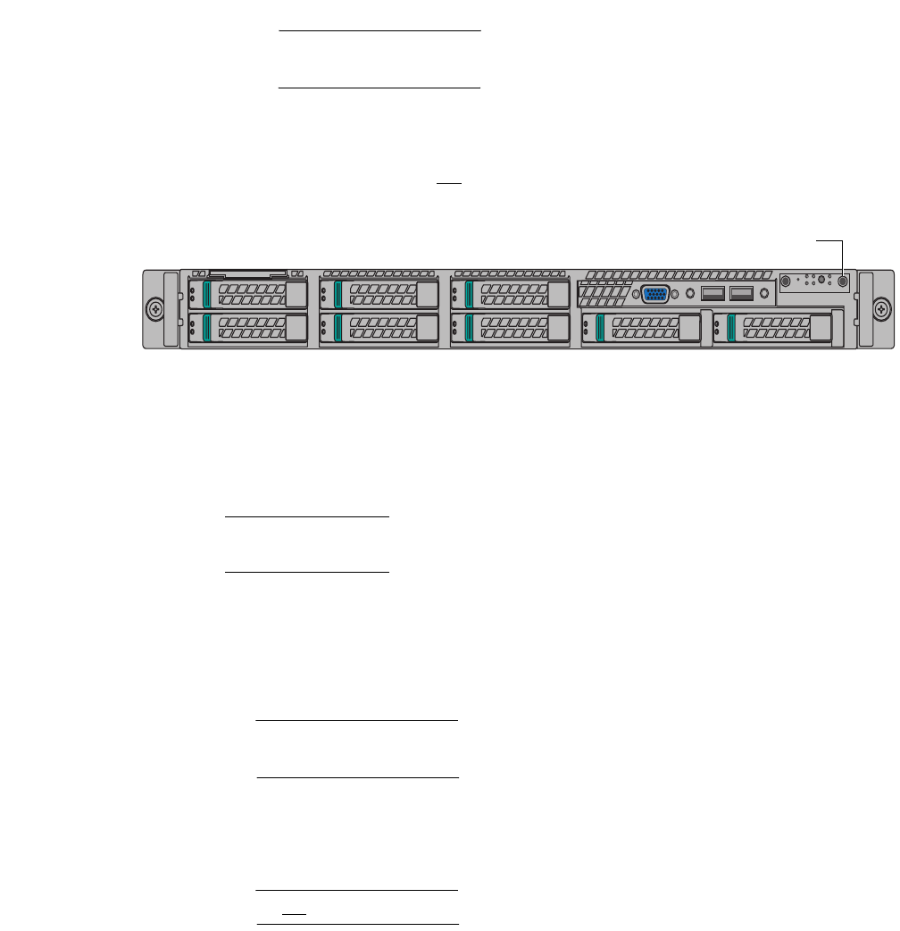
Service tag location
When replacing any hardware component, it is important that you properly debrief the
part. The serial number of a Master server is located on the blue service label affixed to
the front left corner of the server.
Figure 1 Service tag location on the Master server (Dragon24 shown)

EMC Greenplum DCA Maintenance Guide Replace the Primary Master server
14
Replace a Master Server
EMC CONFIDENTIAL
Replace the Primary Master server
Perform this procedure if the Primary Master server has failed or is failing.
IMPORTANT
This procedure directs you to transfer drives from the failed server to the replacement
server. Take great care when transferring drives. Transfer only one drive at a time. Insert
drives in the same slots that they occupied in the failed server.
1. You may want to consult “Task summary” on page 11 for a overview of the Master
server replacement procedures.
2. If it is not already connected, connect your service laptop to the red service cable
located on the laptop tray. The red service cable is connected to port 48 on the
Administration switch in the SYSRACK. For instructions on how to configure the IP
address on your laptop, see “Connect a workstation to the DCA” on page 176).
3. If the Primary Master server is still accessible through SSH, perform step a through
step e below. If the Primary Master server is not accessible through SSH, skip to
step 4.
a. Log in to the
Primary Master server
as the user root (see “Connect a workstation
to the DCA” on page 176).
b. Activate the server identification LED.
# dca_blinker -h mdw -a ON
c. Switch to the user gpadmin and determine whether the Primary and Standby
Master servers are synced:
# su - gpadmin
$ gpstate -f
If the output returns the status synchronized, the master servers are in sync. If
synchronized is not returned in the output or the database is not running, do
not replace the Primary Master server. Contact EMC Support.
d. Switch to the user root and make note of any custom NFS mounts the customer
may have created:
$ su -
# cat /etc/fstab
e. Make note of any custom network gateways the customer may have created:
# cat /etc/sysconfig/network
4. Before you replace the failed Primary Master server, perform the sub-steps below to
determine whether an automatic failover occurred when the Primary Master failed. If
an automatic failover did not occur, you must initiate an orchestrated (manual)
failover before you replace the failed server (see step 5 below). To determine whether
an automated failover occurred, do the following:
a. Start the DCA Setup utility as the user root:
# dca_setup

EMC Greenplum DCA Maintenance Guide Replace the Primary Master server
15
Replace a Master Server
EMC CONFIDENTIAL
b. Select option 2 to Modify DCA Settings.
c. Note the text of option 19:
– If the text is Disable Master Server Auto Failover (currently
enabled), an automatic failover occurred when the Primary Master failed.
Skip to step 6 to determine if the failover was successful.
–If the text is Enable Master Server Auto Failover (currently
disabled), you must initiate an orchestrated (manual) failover as described
in step 5.
d. Enter X to exit the DCA Setup utility.
5. If an automatic failover did occur, proceed to step 6. If an automatic failover did not
occur, initiate a orchestrated (manual) failover as follows:
a. From the
Standby Master server
, issue the dca_failover command:
# dca_failover --stopmasterdb --noninteractive --vip 10.10.10.10
--gateway 10.10.10.1 --netmask 255.255.255.0
**If you are servicing a
Hadoop-only DCA**
In a Hadoop-only DCA, make sure to include the option
--deletevip
:
# dca_failover --stopmasterdb --noninteractive --vip 10.10.10.10
--gateway 10.10.10.1 --netmask 255.255.255.0 --deletevip
b. Replace the values shown in bold above with the IP, Gateway, and Netmask of the
virtual IP address provided by the customer. If the customer has not specified a
virtual IP address, do not include the --vip, --gateway, and --netmask
parameters. Wait for the prompt to appear indicating that the failover has
completed before you continue.
c. When the failover has completed, proceed to step 6 to determine if the failover
operation was successful.
6. To determine whether the Master server failover operation was successful, switch to
the user gpadmin and issue the following command. Verify that the text in bold is
returned in the output:
# su - gpadmin
$ gpstate -f
[INFO]:-Starting gpstate with args: -f
[INFO]:-local Greenplum Version: 'postgres (Greenplum Database)
4.1.1.3 build 4'
[INFO]:-Obtaining Segment details from master...
[INFO]:-Standby master instance not configured
7. Check the Greenplum Database for errors. If any errors are returned in the output, you
must resolve them before you continue with this procedure:
$ gpstate -e
[INFO]:-----------------------------------------------------
[INFO]:-Segment Mirroring Status Report
[INFO]:-----------------------------------------------------
[INFO]:-All segments are running normally
8. To prevent false dial home messages from being sent to EMC Support during service,
log in to the
Standby Master server
as the user root and stop the healthmon
daemon to disable health monitoring:
$ su -
EMC Greenplum DCA Maintenance Guide Replace the Primary Master server
16
Replace a Master Server
EMC CONFIDENTIAL
# dca_healthmon_ctl -d
9. Shut down the Primary Master server:
• If the failed Primary Master server is accessible through SSH, log into to it as the
user root and issue the shutdown command.
IMPORTANT
Check the prompt to make sure that you are on the Primary Master (mdw) before
you issue the shutdown command!
$ ssh root@mdw
# shutdown -h now
• If the failed server is not accessible through SSH, power it off by pressing the
power button on the front of the server for 5 seconds (see Figure 2 below).
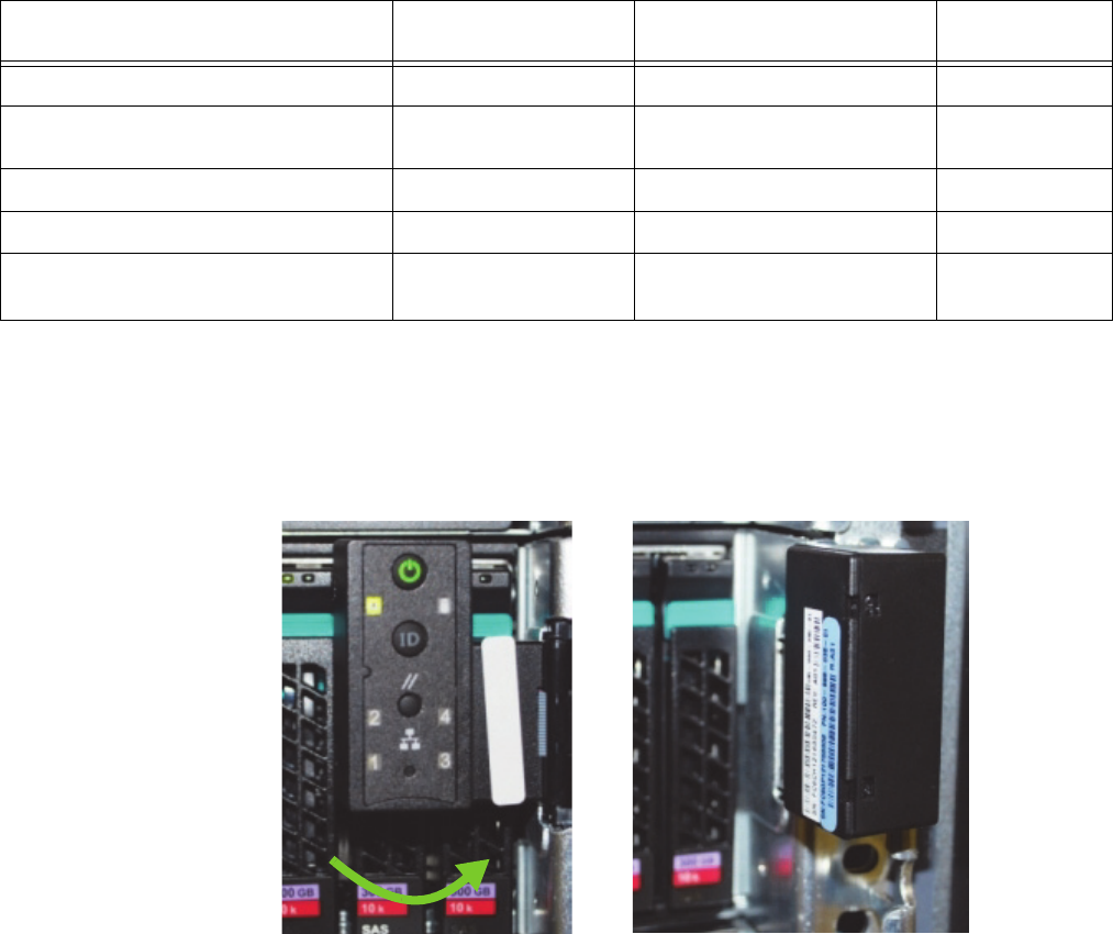
Figure 2 Power button location on Master server
10. Label all the cables connected to the failed server so that you’ll know where to
connect them on the replacement server.
11. Remove all power, Ethernet, and twin-axial cables from the back of the server.
Note: If the system has Dual NICs installed, note the connections for customer and
interconnect networks prior to disconnecting.
12. Remove the failed server and install the replacement server (see Appendix E, “Replace
a Server in the Greenplum DCA Rack,” on page 192).
13. Transfer disk drives one at a time from the failed server to the replacement server.
IMPORTANT
Use caution when transferring drives. Transfer only one drive at a time. Insert the
drives in the same slots that they occupied in the failed server.
14. Connect Ethernet and twin-ax cables to the replacement server. Refer to the labels on
the cables for proper connectivity.
IMPORTANT
Do not connect power to the replacement server yet.
15. From the
Standby Master server
start the dhcpd service as the user root:
# service dhcpd start
16. Connect the power cables to the replacement server.
Power button

EMC Greenplum DCA Maintenance Guide Replace the Primary Master server
17
Replace a Master Server
EMC CONFIDENTIAL
17. Next, use these steps to identify the IP address assigned to the server.
a. Issue the following command to obtain the lease information provided in the
dhcpd.leases file:
# tail /var/lib/dhcpd/dhcpd.leases
b. The dhcpd.leases file dispays (similar to the following):
Example
lease 172.28.6.170 {
starts 4 2012/10/18 20:09:08;
ends 5 2013/10/18 20:09:08;
cltt 4 2012/10/18 20:09:08;
binding state active;
next binding state free;
hardware ethernet 00:00:00:00:00:04;
uid "\001\000\036g,\242\014";
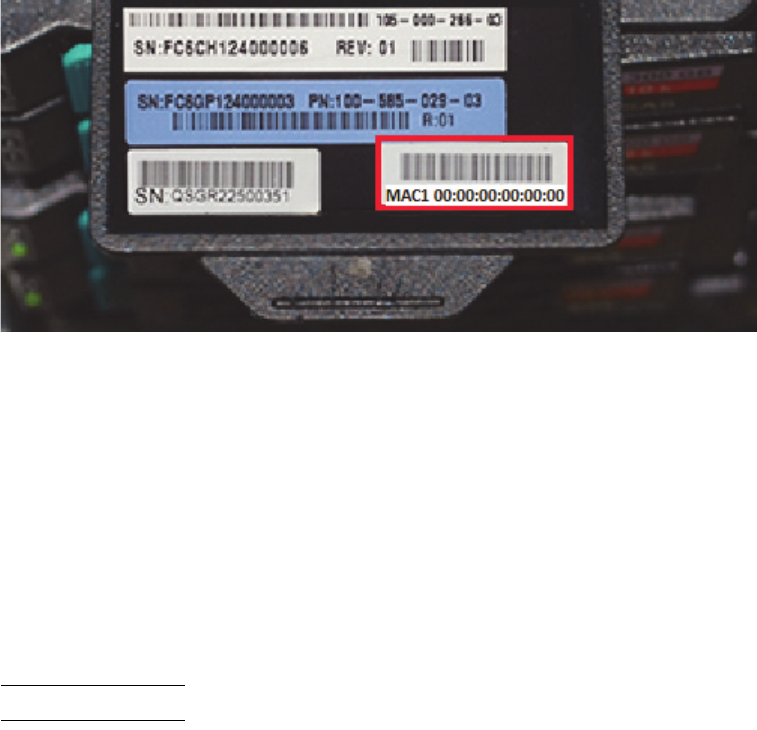
c. Locate the MAC address labelled hardware ethernet in the example
dhcpd.leases file above:
00:00:00:00:00:04
d. Locate the MAC address on the replacement server’s service tag (highlighted in the
photograph below):
MAC1 00:00:00:00:00:00
Figure 3 Locating the MAC address on the service tag (Primary Master server shown, Dragon24)
e. Compare the last two digits in the MAC addresses referenced in step c and step d
(for example, 00:00:00:00:00:04 and 00:00:00:00:00:00 ). Verify that the MAC
address in the dhcpd.leases file is four greater than the last two numbers in the
MAC address on the replacement server’s service tag.
If this is the case, it is certain that the IP address in the dhcpd.leases file is the
correct one to associate with the server. For example, the scenario described
above verifies that 172.28.6.170 is correct in this specific instance.
EMC Greenplum DCA Maintenance Guide Replace the Primary Master server
18
Replace a Master Server
EMC CONFIDENTIAL
f. Issue the following ipmiutil command. Insert the IP address (172.28.6.170)
identified in the previous steps using the example above as a guide:
Note: Disregard the long, detailed output after this command is executed.
# ipmiutil lan -e -l -I 172.28.0.250 -S 255.255.248.0 -N 172.28.6.170 -U root -P sephiroth
g. Ping the new address to verify that the change was applied:
# ping 172.28.0.#
Where # is the number of the server you are replacing.
18. Turn off the dhcpd service:
# service dhcpd stop
19. From the Primary Master server as user root, issue the following command to open a
BMC console session on the replacement Master server mdw:
# ipmiutil sol -a -e -N mdw-sp -U root -P sephiroth
You will need to press the F key within 15 seconds after seeing this WARNING message:
Foreign configuration(s) found on adapter
Press any key to continue or ‘C’ load the configuration
utility, or ‘F’ to import foreign configuration(s) and
continue.
20. Power on the replacement server by pressing the power button on the front panel, and
press the F key when prompted.
21. When the following message displays, disregard and press the space bar:
All of the disks from your previous configuration are gone. If this
is an unexpected message, then please power off your system and
check your cables to ensure all disks are present. Press any key to
continue, or 'C' to load the configuration utility.
EMC Greenplum DCA Maintenance Guide Replace the Primary Master server
19
Replace a Master Server
EMC CONFIDENTIAL
22. If the message below appears you will need to power off the server, verify that all LED
lights are off, and repeat steps 20 through 21.
CLIENT MAC ADDR: 00 1E 67 4D C5 1D GUID: 2A9B43A4 A50A 11E1 AAA0
001E674DC51D
DHCP....\
23. Monitor the boot process onscreen and verify that the system boots from hard disk.
If the system does boot from hard disk, proceed to step 24.
If the system does not boot from hard disk, perform the following sub-steps to force it
to boot from hard disk:
a. Exit the BMC console utility by pressing the a tilde key (~), and then the period (.)
key, as follows on the keyboard:
then
Note: When you exit the BMC console you are returned to your connection on the
smdw as the user root.
b. Issue the following command from smdw to force the appliance to boot from hard
drive:
# ipmiutil reset -h -N mdw-sp -U root -P sephiroth
c. Once the operating system is loaded, issue the following command to change the
boot order on mdw:
# ssh mdw
# syscfg /bbo “emcbios” HDD NW
d. Reboot mdw:
# reboot
e. Following the reboot, issue the following commands to connect to mdw and verify
the boot order:
# ssh mdw
# syscfg /bbosys
f. Exit mdw:
# exit
g. Proceed to step 24. (You can skip step 24 because you already exited the BMC
console in sub-step a above.)

EMC Greenplum DCA Maintenance Guide Replace the Primary Master server
20
Replace a Master Server
EMC CONFIDENTIAL
24. From the Standby Master server (smdw) check the health of the replacement server:
# dcacheck -h mdw
Verify that no errors display.
25. Exchange SSH keys on the replacement server using the DCA Setup utility:
a. Start the DCA Setup utility as the user root:
# dca_setup
b. Select option 2 to Modify DCA Settings.
c. Select option 6 to Generate SSH Keys.
d. Enter X to exit the DCA Setup utility.
e. Check the firmware level of the RAID controllers with the CmdTool2 utility:
# ssh mdw /opt/MegaRAID/CmdTool2/CmdTool2 -adpallinfo -aall | grep
"FW Package Build"
If the above command returns either: FW Package Build: 23.7.0-0033 or FW
Package Build: 23.9.0-0026, your firmware needs updating. Follow steps a
through n below to update the firmware.
f. Download ir3_2208SASHWR_FWPKG-v23.12.0-0013.zip file from Support Zone to
your laptop.
https://support.emc.com/downloads/9507_Greenplum-Data-Computing-Applian
ce
g. Extract the files to your laptop using unzip or similar unpacking tool. For example:
Unzip ir3_2208SASHWR_FWPKG-v23.12.0-0013.zip
h. As a root user copy the MR56p.rom file to the Master server (mdw) and place the
file in /root. You can use WinSCP or a similar utility.
Note: You may be required to provide a login to the destination server.
i. For each server in need of an update, log into the server as root.
j. SCP the MR56p.rom file from the master to the server you are updating.
k. Install the new firmware using the following command:
Note: This will take longer on 24-disk servers.
# /opt/MegaRAID/CmdTool2/CmdTool2 -adpfwflash -f /root/MR56p.rom
-aall
l. Reboot the server.
# reboot
m. When the server reboots, check the new firmware version:
# /opt/MegaRAID/CmdTool2/CmdTool2 -adpallinfo -aall | grep "FW
Package Build"

EMC Greenplum DCA Maintenance Guide Replace the Primary Master server
21
Replace a Master Server
EMC CONFIDENTIAL
The following should be returned, indicating your firmware has successfully been
updated on this server:
FW Package Build: 23.12.0-0013
n. Repeat these alphabetic steps to check/update the remaining servers in the
cluster.
26. Switch to the user gpadmin and issue the following commands to initialize the
replacement server as the
acting
Standby Master server:
# su - gpadmin
$ ssh mdw rm -r /data/master/*
$ gpinitstandby -s mdw
27. At the message Do you want to continue with standby master
initialization? enter Y to continue.
Wait for the message Successfully created standby master on mdw.
28. Log in to the replacement server (now the new
acting
Standby Master server) as the
user root:
$ ssh root@mdw
29. Issue the following command to initiate the orchestrated (manual) failover:
dca_failover --stopmasterdb --noninteractive --vip 10.10.10.10
--gateway 10.10.10.1 --netmask 255.255.255.0
**If you are servicing a
Hadoop-only DCA**
In a Hadoop-only DCA, make sure to include the option
--deletevip:
dca_failover --stopmasterdb --noninteractive --vip 10.10.10.10
--gateway 10.10.10.1 --netmask 255.255.255.0 --deletevip
30. At the message Do you want to continue? enter y.
IMPORTANT
Initiating a failover stops the Greenplum Database and renders it temporarily
unavailable.
When the failover operation finishes you are returned to the prompt [root@mdw]# .
31. Switch to the user gpadmin:
# su - gpadmin
32. Connect to the Standby Master server and empty the /data/master directory:
$ ssh smdw rm -r /data/master/*
33. Issue the following command to revert the smdw server to its standby role:
$ gpinitstandby -s smdw
34. At the message Do you want to continue with standby master
initialization? enter Y.

EMC Greenplum DCA Maintenance Guide Replace the Primary Master server
22
Replace a Master Server
EMC CONFIDENTIAL
**If you are servicing a
Hadoop-only DCA**
Perform the next two steps only if you are replacing a Master server in a Hadoop-only DCA
35. Issue the following command to recover the GPDB segment instances running on the
Primary and Standby Master servers:
$ gprecoverseg
Enter Y when prompted. For example:
Continue with segment recovery procedure Yy|Nn (default=N):
> Y
36. Issue the following command to rebalance the GPDB segment instances running on
the Primary and Standby Master servers:
$ gprecoverseg -r
Enter Y when prompted. For example:
Continue with segment rebalance procedure Yy|Nn (default=N):
> Y
The procedure continues here for all DCA types:
37. Exit the user gpadmin:
$ exit
38. Start the DCA Setup utility:
# dca_setup
39. Synchronize the system clock:
a. Select option 2 for Modify DCA Settings.
b. Select option 5 for Modify NTP/Clock Configuration Options.
c. Select option 3 for Synchronize clocks across the cluster to the
NTP server.
Enter X to exit the DCA Setup utility.
40.
IMPORTANT
- Note that the same DCA system Serial Number (located on a label affixed
to the top, rear of the rack) must be included in the following files for Dial Home to
work after replacing a Master application server (mdw and smdw in the case of GPDB
and hdm, and standby hdm in the case of Hadoop):
•/opt/connectemc/ConnectEMC.ini
•/opt/greenplum/serialnumber
First, check the DCA system Serial Number in the connectemc initialization file,
/opt/connectemc/ConnectEMC.ini file, as follows:
a. Open the connectemc initialization file:
/opt/connectemc/ConnectEMC.ini
b. Locate the DCA system Serial Number per the following keyword in the file:
SERIAL_NUMBER=

EMC Greenplum DCA Maintenance Guide Replace the Standby Master server
23
Replace a Master Server
EMC CONFIDENTIAL
c. Check that this matches the DCA system Serial Number on the label affixed to the
top, rear of the rack. Go to the next step (step d.) if the Serial Number is missing.
d. If missing, enter the Serial Number in the
/opt/connectemc/ConnectEMC.ini file, for example:
SERIAL_NUMBER=APMXXXXXXXXX
41. Next, check that the DCA system Serial Number in the
/opt/greenplum/serialnumber file matches the DCA system Serial Number in
the /opt/connectemc/ConnectEMC.ini file, per
step 40
above.
For example:
SERIAL_NUMBER=APM00140732731
Note: After verifying that the DCA system Serial Numbers are identical, remember to save
the /opt/greenplum/serialnumber file if you made any changes.
42. Re-enable health monitoring:
# dca_healthmon_ctl -e
43. You must stop and start the connectemc service (also referred to as Dial Home) to
complete restarting the healthmon daemon.
Enter the command:
service connectemc stop
You will see the message:
Shutting down ConnectEMC
44. When you see the # prompt again, enter:
service connectemc start
You will see the message:
Starting ConnectEMC
The # prompt returns, indicating that you have re-enabled health monitoring.
Replace the Standby Master server
Perform this procedure if the Standby Master server has failed or is failing and the Primary
Master server is in good health.
IMPORTANT
This procedure directs you to transfer drives from the failed server to the replacement
server. Take great care when transferring drives. Transfer only one drive at a time. Insert
drives in the same slots that they occupied in the failed server.
1. You may want to consult “Task summary” on page 11 for a overview of the Master
server replacement procedures.

EMC Greenplum DCA Maintenance Guide Replace the Standby Master server
24
Replace a Master Server
EMC CONFIDENTIAL
2. If it is not already connected, connect your service laptop to the red service cable
located on the laptop tray. For details on how to configure the IP address of your
laptop, see “Connect a workstation to the DCA” on page 176.
3. To prevent false dial home messages from being sent to EMC Support during service,
stop the healthmon daemon to disable health monitoring:
# dca_healthmon_ctl -d
4. If the Standby Master server is still accessible through SSH, perform step a through
step e below. If the failed Standby Master server is not accessible through SSH, skip to
step 5.
a. Log in to the
Primary Master server
as the user root (see “Connect a workstation
to the DCA” on page 176).
b. Activate the server identification LED.
# dca_blinker -h smdw -a ON
c. Switch to the user gpadmin and determine whether the Primary and Standby
Master servers are synchronized:
# su - gpadmin
$ gpstate -f
If the output returns the status synchronized, the Master servers are in sync. If
synchronized is not returned in the output, do not replace the Standby Master
server. Contact EMC Support.
d. Switch to the user root and make note of any custom NFS mounts the customer
may have created:
$ su -
# cat /etc/fstab
e. Make note of any custom network gateways the customer may have created:
# cat /etc/sysconfig/network
5. From the
Primary Master server
, switch to the user gpadmin and remove the Standby
Master server from the configuration:
# su - gpadmin
$ gpinitstandby -r
6. When prompted, enter Y to continue.
7. Shut down the Standby Master server:
• If the failed Standby Master server is accessible through SSH, log into to it as the
user root and issue the shutdown command.
IMPORTANT
Check the prompt to make sure that you are on the Standby Master (smdw) before
you issue the shutdown command!
$ ssh root@smdw
# shutdown -h now

EMC Greenplum DCA Maintenance Guide Replace the Standby Master server
25
Replace a Master Server
EMC CONFIDENTIAL
• If the failed server is not accessible through SSH, power it off by pressing the
power button on the front of the server.
8. Label all the cables connected to the failed server so that you’ll know where to
connect them on the replacement server.
9. Remove all power, Ethernet, and twin-axial cables from the back of the server.
Note: If the system has Dual NICs installed, note the connections for customer and
interconnect networks prior to disconnecting.
10. Remove the failed server and install the replacement server (see Appendix E, “Replace
a Server in the Greenplum DCA Rack,” on page 192).
11. Transfer disk drives one at a time from the failed server to the replacement server.
IMPORTANT
Use caution when transferring drives. Transfer only one drive at a time. Insert the
drives in the same slots that they occupied in the failed server.
12. Connect Ethernet and twin-ax cables to the replacement server. Refer to the labels on
the cables for proper connectivity.
IMPORTANT
Do not connect power to the replacement server yet.
13. From the Primary Master server start the dhcpd service as the user root:
# service dhcpd start
14. Connect the power cables to the replacement server.
15. Next, use these steps to identify the IP address assigned to the server.
a. Issue the following command to obtain the lease information provided in the
dhcpd.leases file:
# tail /var/lib/dhcpd/dhcpd.leases
b. The dhcpd.leases file dispays (similar to the following):
Example
lease 172.28.6.170 {
starts 4 2012/10/18 20:09:08;
ends 5 2013/10/18 20:09:08;
cltt 4 2012/10/18 20:09:08;
binding state active;
next binding state free;
hardware ethernet 00:00:00:00:00:04;
uid "\001\000\036g,\242\014";
EMC Greenplum DCA Maintenance Guide Replace the Standby Master server
26
Replace a Master Server
EMC CONFIDENTIAL
c. Locate the MAC address labelled hardware ethernet in the example
dhcpd.leases file above:
00:00:00:00:00:04
d. Locate the MAC address on the replacement server’s service tag (highlighted in the
photograph below):
MAC1 00:00:00:00:00:00
Figure 4 Locating the MAC address on the service tag (Standby Master server shown, Dragon24)
e. Compare the last two digits in the MAC addresses referenced in step c and step d
(for example, 00:00:00:00:00:04 and 00:00:00:00:00:00 ). Verify that the MAC
address in the dhcpd.leases file is four greater than the last two numbers in the
MAC address on the replacement server’s service tag.
If this is the case, it is certain that the IP address in the dhcpd.leases file is the
correct one to associate with the server. For example, the scenario described
above verifies that 172.28.6.170 is correct in this specific instance.
f. Issue the following ipmiutil command. Insert the IP address (172.28.6.170)
identified in the previous steps using the example above as a guide:
Note: Disregard the long, detailed output after this command is executed.
# ipmiutil lan -e -l -I 172.28.0.250 -S 255.255.248.0 -N 172.28.6.170 -U root -P sephiroth
g. Ping the new address to verify that the change was applied:
# ping 172.28.0.#
Where # is the number of the server you are replacing.
16. Turn off the dhcpd service:
# service dhcpd stop
17. Power on the replacement server by pressing the button on the front panel.

EMC Greenplum DCA Maintenance Guide Replace the Standby Master server
27
Replace a Master Server
EMC CONFIDENTIAL
18. Issue the following command to open a BMC console session on the replacement
Master server:
# ipmiutil sol -a -e -N smdw-sp -U root -P sephiroth
You will need to press the F key within 15 seconds after seeing this WARNING message:
Foreign configuration(s) found on adapter
Press any key to continue or ‘C’ load the configuration
utility, or ‘F’ to import foreign configuration(s) and
continue.
19. Power on the replacement server by pressing the power button on the front panel, and
press the F key when prompted.
20. When the following message displays, disregard and press the space bar:
All of the disks from your previous configuration are gone. If this
is an unexpected message, then please power off your system and
check your cables to ensure all disks are present. Press any key to
continue, or 'C' to load the configuration utility.
21. If the message below appears it indicates that the server did not accept the “F” key
request per the above WARNING. This means that you will need to power off the server,
verify that all LED lights are off, and go back to step 19 (press the F key when
prompted again):
CLIENT MAC ADDR: 00 1E 67 4D C5 1D GUID: 2A9B43A4 A50A 11E1 AAA0
001E674DC51D
DHCP....\

EMC Greenplum DCA Maintenance Guide Replace the Standby Master server
28
Replace a Master Server
EMC CONFIDENTIAL
22. Monitor the boot process onscreen and verify that the system boots from hard disk.
If it does not
, do the following to force it to boot from hard disk:
a. Exit the BMC console utility by pressing the a tilde key (~), and then the period (.)
key, as follows on the keyboard:
then
Note: When you exit the BMC console you are returned to your connection on the
mdw as the user root.
b. Issue the following command from mdw to force the replacement server to boot
from hard drive:
# ipmiutil reset -h -N smdw-sp -U root -P sephiroth
c. Once the operating system is loaded, issue the following command to change the
boot order on smdw:
# ssh smdw
# syscfg /bbo “emcbios” HDD NW
d. Reboot the system:
# reboot
e. Following the reboot, issue the following commands to connect to smdw and verify
the boot order:
# ssh smdw
# syscfg /bbosys
f. Exit smdw:
# exit
23. Check the health of the replacement server:
# dcacheck -h smdw
Verify that no errors display.
24. Exchange SSH keys on the replacement server using the DCA Setup utility:
a. Start the DCA Setup utility as the user root:
# dca_setup
b. Select option 2 to Modify DCA Settings.
c. Select option 6 to Generate SSH Keys.
d. Enter X to exit the DCA Setup utility.
e. Check the firmware level of the RAID controllers with the CmdTool2 utility:
# ssh smdw /opt/MegaRAID/CmdTool2/CmdTool2 -adpallinfo -aall | grep
"FW Package Build"

EMC Greenplum DCA Maintenance Guide Replace the Standby Master server
29
Replace a Master Server
EMC CONFIDENTIAL
If the above command returns either: FW Package Build: 23.7.0-0033 or FW
Package Build: 23.9.0-0026, your firmware needs updating. Follow steps a
through n below to update the firmware.
f. Download ir3_2208SASHWR_FWPKG-v23.12.0-0013.zip file from Support Zone to
your laptop.
https://support.emc.com/downloads/9507_Greenplum-Data-Computing-Applian
ce
g. Extract the files to your laptop using unzip or similar unpacking tool. For example:
Unzip ir3_2208SASHWR_FWPKG-v23.12.0-0013.zip
h. As a root user copy the MR56p.rom file to the Master server (mdw) and place the
file in /root. You can use WinSCP or a similar utility.
Note: You may be required to provide a login to the destination server.
i. For each server in need of an update, log into the server as root.
j. SCP the MR56p.rom file from the master to the server you are updating.
k. Install the new firmware using the following command:
Note: This will take longer on 24-disk servers.
# /opt/MegaRAID/CmdTool2/CmdTool2 -adpfwflash -f /root/MR56p.rom
-aall
l. Reboot the server.
# reboot
m. When the server reboots, check the new firmware version:
# /opt/MegaRAID/CmdTool2/CmdTool2 -adpallinfo -aall | grep "FW
Package Build"
The following should be returned, indicating your firmware has successfully been
updated on this server:
FW Package Build: 23.12.0-0013
n. Repeat these alphabetic steps to check/update the remaining servers in the
cluster.
25. Switch to the user gpadmin and issue the following command from the
Primary
Master server
(mdw) to initialize the replacement server as the Standby Master server:
# su - gpadmin
$ gpinitstandby -s smdw
**If you are servicing a
Hadoop-only DCA**
Perform the next two steps only if you are replacing a Master server in a Hadoop-only DCA
26. Issue the following command to recover the GPDB segment instances running on the
Primary and Standby Master servers:
$ gprecoverseg
Enter Y when prompted. For example:

EMC Greenplum DCA Maintenance Guide Replace the Standby Master server
30
Replace a Master Server
EMC CONFIDENTIAL
Continue with segment recovery procedure Yy|Nn (default=N):
> Y
27. Issue the following command to rebalance the GPDB segment instances running on
the Primary and Standby Master servers:
$ gprecoverseg -r
Enter Y when prompted. For example:
Continue with segment rebalance procedure Yy|Nn (default=N):
> Y
The procedure continues here for all DCA types:
28. Exit from the user gpadmin to the user root:
$ exit
29. Start the dca_setup utility:
# dca_setup
30. Synchronize the system clock:
a. Select option 2 for Modify DCA Settings.
b. Select option 5 for Modify NTP/Clock Configuration Options.
c. Select option 3 for Synchronize clocks across the cluster to the
NTP server.
d. Enter X to exit the DCA Setup utility.
31.
IMPORTANT
- Note that the same DCA system Serial Number (located on a label affixed
to the top, rear of the rack) must be included in the following files for Dial Home to
work after replacing a Master application server (mdw and smdw in the case of GPDB
and hdm, and standby hdm in the case of Hadoop):
•/opt/connectemc/ConnectEMC.ini
•/opt/greenplum/serialnumber
First, check the DCA system Serial Number in the connectemc initialization file,
/opt/connectemc/ConnectEMC.ini file, as follows:
a. Open the connectemc initialization file:
/opt/connectemc/ConnectEMC.ini
b. Locate the DCA system Serial Number per the following keyword in the file:
SERIAL_NUMBER=
c. Check that this matches the DCA system Serial Number on the label affixed to the
top, rear of the rack. Go to the next step (step d.) if the Serial Number is missing.
d. If missing, enter the Serial Number in the
/opt/connectemc/ConnectEMC.ini file, for example:
SERIAL_NUMBER=APMXXXXXXXXX

EMC Greenplum DCA Maintenance Guide Identifying a single-NIC master versus a dual-NIC master in a DCAv2
31
Replace a Master Server
EMC CONFIDENTIAL
32. Next, check that the DCA system Serial Number in the
/opt/greenplum/serialnumber file matches the DCA system Serial Number in
the /opt/connectemc/ConnectEMC.ini file, per
step 31
above.
For example:
SERIAL_NUMBER=APM00140732731
Note: After verifying that the DCA system Serial Numbers are identical, remember to save
the /opt/greenplum/serialnumber file if you made any changes.
33. Re-enable health monitoring:
# dca_healthmon_ctl -e
34. You must stop and start the connectemc service (also referred to as Dial Home) to
complete restarting the healthmon daemon.
Enter the command:
service connectemc stop
You will see the message:
Shutting down ConnectEMC
35. When you see the # prompt again, enter:
service connectemc start
You will see the message:
Starting ConnectEMC
The # prompt returns, indicating that you have re-enabled health monitoring.
Identifying a single-NIC master versus a dual-NIC master in a
DCAv2
The Master server is a dual-NIC master if both eth6 and eth7 are present on the mdw or
smdw. If the server is powered up, the only way to identify a dual-NIC master is to visually
inspect it, by counting the number of SFP ports.
Replace a Master server in a DCA without a Greenplum database
Perform this procedure to replace a failed Master server in a DCA in which the Greenplum
database is either not installed or is uninitialized.
IMPORTANT
This procedure directs you to transfer drives from the failed server to the replacement
server. Take great care when transferring drives. Transfer only one drive at a time. Insert
drives in the same slots that they occupied in the failed server.

EMC Greenplum DCA Maintenance Guide Replace a Master server in a DCA without a Greenplum database
32
Replace a Master Server
EMC CONFIDENTIAL
1. You may want to consult “Task summary” on page 11 for a overview of the Master
server replacement procedures.
2. If it is not already connected, connect your service laptop to the red service cable
located on the laptop tray. The red service cable is connected to port 48 on the first
Administration switch a-sw-1 (see “Connect a workstation to the DCA” on page 176).
3. To prevent false dial home messages from being sent to EMC Support during service,
stop the healthmon daemon to disable health monitoring:
# dca_healthmon_ctl -d
4. If the failed server is still accessible by SSH, perform the following steps. If the failed
Master server is not accessible through SSH, skip to step 5.
a. Log in to the
functioning
Master server as the user root (see “Connect a
workstation to the DCA” on page 176).
b. Activate the server identification LED:
Enter either mdw or smdw for the hostname, whichever applies.
# dca_blinker -h smdw -a ON
c. Make note of any custom NFS mounts the customer may have created:
# cat /etc/fstab
d. Make note of any custom network gateways the customer may have created:
# cat /etc/sysconfig/network
5. If possible, while connected to the failed Master server, issue the following command
to shut down the server.
IMPORTANT
Check the prompt to make sure that you are on the correct Master server (mdw or
smdw) before you issue the shutdown command!
# shutdown -h now
6. If the failed server is inaccessible through SSH, power it off by pressing the power
button on the front of the server.
7. Label all the cables connected to the failed server so that you’ll know where to
connect them on the replacement server.
8. Remove all power, Ethernet, and twin-axial cables from the back of the server.
Note: If the system has Dual NICs installed, note the connections for customer and
interconnect networks prior to disconnecting.
9. Remove the failed server and install the replacement server (see Appendix E, “Replace
a Server in the Greenplum DCA Rack,” on page 192).
10. Transfer disk drives one at a time from the failed server to the replacement server.

EMC Greenplum DCA Maintenance Guide Replace a Master server in a DCA without a Greenplum database
33
Replace a Master Server
EMC CONFIDENTIAL
IMPORTANT
Use caution when transferring drives. Transfer only one drive at a time. Insert the
drives in the same slots that they occupied in the failed server.
11. Connect Ethernet and twin-ax cables to the replacement server. Refer to the labels on
the cables for proper connectivity.
IMPORTANT
Do not connect power to the replacement server yet.
12. From the functional Master server start the dhcpd service:
# service dhcpd start
13. Connect the power cables to the replacement server.

EMC Greenplum DCA Maintenance Guide Replace a Master server in a DCA without a Greenplum database
34
Replace a Master Server
EMC CONFIDENTIAL
14. Next, use these steps to identify the IP address assigned to the server.
a. Issue the following command to obtain the lease information provided in the
dhcpd.leases file:
# tail /var/lib/dhcpd/dhcpd.leases
b. The dhcpd.leases file dispays (similar to the following):
Example
lease 172.28.6.170 {
starts 4 2012/10/18 20:09:08;
ends 5 2013/10/18 20:09:08;
cltt 4 2012/10/18 20:09:08;
binding state active;
next binding state free;
hardware ethernet 00:00:00:00:00:04;
uid "\001\000\036g,\242\014";
c. Locate the MAC address labelled hardware ethernet in the example
dhcpd.leases file above:
00:00:00:00:00:04
d. Locate the MAC address on the replacement server’s service tag (highlighted in the
photograph below):
MAC1 00:00:00:00:00:00
Figure 5 Locating the MAC address on the service tag (Master server shown, Dragon24)
e. Compare the last two digits in the MAC addresses referenced in step c and step d
(for example, 00:00:00:00:00:04 and 00:00:00:00:00:00 ). Verify that the MAC
address in the dhcpd.leases file is four greater than the last two numbers in the
MAC address on the replacement server’s service tag.
If this is the case, it is certain that the IP address in the dhcpd.leases file is the
correct one to associate with the server. For example, the scenario described
above verifies that 172.28.6.170 is correct in this specific instance.
EMC Greenplum DCA Maintenance Guide Replace a Master server in a DCA without a Greenplum database
35
Replace a Master Server
EMC CONFIDENTIAL
f. Issue the following ipmiutil command. Insert the IP address (172.28.6.170)
identified in the previous steps using the example above as a guide:
Note: Disregard the long, detailed output after this command is executed.
# ipmiutil lan -e -l -I 172.28.0.250 -S 255.255.248.0 -N 172.28.6.170 -U root -P sephiroth
g. Ping the new address to verify that the change was applied:
# ping 172.28.0.#
Where # is the number of the server you are replacing.
15. Turn off the dhcpd service:
# service dhcpd stop
16. Power on the replacement server by pressing the button on the front panel.
17. Issue the following command to open a console session on the replacement server.
Enter either mdw or smdw for the hostname, whichever applies. For example,
for smdw:
# ipmiutil sol -a -e -N smdw-sp -U root -P sephiroth
You will need to press the F key within 15 seconds after seeing this WARNING message:
Foreign configuration(s) found on adapter
Press any key to continue or ‘C’ load the configuration
utility, or ‘F’ to import foreign configuration(s) and
continue.
18. Power on the replacement server by pressing the power button on the front panel, and
press the F key when prompted.
19. When the following message displays, disregard and press the space bar:
All of the disks from your previous configuration are gone. If this
is an unexpected message, then please power off your system and
check your cables to ensure all disks are present. Press any key to
continue, or 'C' to load the configuration utility.

EMC Greenplum DCA Maintenance Guide Replace a Master server in a DCA without a Greenplum database
36
Replace a Master Server
EMC CONFIDENTIAL
20. If the message below appears it indicates that the server did not accept the “F” key
request per the above WARNING. This means that you will need to power off the server,
verify that all LED lights are off, and go back to step 18 (press the F key when
prompted again):
CLIENT MAC ADDR: 00 1E 67 4D C5 1D GUID: 2A9B43A4 A50A 11E1 AAA0
001E674DC51D
DHCP....\
21. Monitor the boot process onscreen and verify that the system boots from hard disk.
If it does not
, do the following to force it to boot from hard disk:
a. Exit the BMC console utility by pressing the a tilde key (~), and then the period (.)
key, as follows on the keyboard:
then
Note: When you exit the BMC console you are returned to your connection on the
functioning master server the user root.
b. Issue the following command from either the Primary or the Standby Master server,
which ever applies.
– If you replaced a
Primary
Master, issue the command from smdw.
– If you replaced a
Standby
Master, issue the command from mdw.
For example, for mdw:
# ipmiutil reset -h -N mdw-sp -U root -P sephiroth
c. Once the operating system is loaded, issue the following command to change the
boot order on the replacement server. For example, if you replaced mdw:
# ssh mdw
# syscfg /bbo “emcbios” HDD NW
d. Reboot the system:
# reboot
e. Following the reboot, issue the following commands to connect to the replacement
server and verify the boot order. For example, if you replaced mdw:
# ssh mdw
# syscfg /bbosys
f. Check the firmware level of the RAID controllers with the CmdTool2 utility:
# ssh mdw /opt/MegaRAID/CmdTool2/CmdTool2 -adpallinfo -aall | grep
"FW Package Build"
If the above command returns either: FW Package Build: 23.7.0-0033 or FW
Package Build: 23.9.0-0026, your firmware needs updating. Follow steps a
through n below to update the firmware.

EMC Greenplum DCA Maintenance Guide Replace a Master server in a DCA without a Greenplum database
37
Replace a Master Server
EMC CONFIDENTIAL
g. Download ir3_2208SASHWR_FWPKG-v23.12.0-0013.zip file from Support Zone to
your laptop.
https://support.emc.com/downloads/9507_Greenplum-Data-Computing-Applian
ce
h. Extract the files to your laptop using unzip or similar unpacking tool. For example:
Unzip ir3_2208SASHWR_FWPKG-v23.12.0-0013.zip
i. As a root user copy the MR56p.rom file to the Master server (mdw) and place the
file in /root. You can use WinSCP or a similar utility.
Note: You may be required to provide a login to the destination server.
j. For each server in need of an update, log into the server as root.
k. SCP the MR56p.rom file from the master to the server you are updating.
l. Install the new firmware using the following command:
Note: This will take longer on 24-disk servers.
# /opt/MegaRAID/CmdTool2/CmdTool2 -adpfwflash -f /root/MR56p.rom
-aall
m. Reboot the server.
# reboot
n. When the server reboots, check the new firmware version:
# /opt/MegaRAID/CmdTool2/CmdTool2 -adpallinfo -aall | grep "FW
Package Build"
The following should be returned, indicating your firmware has successfully been
updated on this server:
FW Package Build: 23.12.0-0013
o. Repeat these alphabetic steps to check/update the remaining servers in the
cluster.
22. Issue the following command to check the health of the replacement server. For
example, if you replaced mdw:
# dcacheck -h mdw
Verify that no errors display.
23. Re-enable health monitoring by restarting the healthmon daemon:
# dca_healthmon_ctl -e
24. You must stop and start the connectemc service to complete restarting the healthmon
daemon:
EMC Greenplum DCA Maintenance Guide Replace a Master server in a DCA without a Greenplum database
38
Replace a Master Server
EMC CONFIDENTIAL

EMC Greenplum DCA Maintenance Guide Replace a Segment, DIA, or Hadoop server
39
EMC CONFIDENTIAL
CHAPTER 3
Replace a Segment, DIA, or Hadoop server
This chapter describes how to replace a server used in GPDB, DIA, and GP HD modules. It
includes the following major sections:
Required tools ........................................................................................................ 39
Task summary......................................................................................................... 40
Service tag locations............................................................................................... 41
Reseat cables before replacing a server................................................................... 42
Replace a server in an initialized GPDB module....................................................... 44
Replace a DIA server or a server in an uninitialized GPDB module............................ 51
Replace a server in a Greenplum Hadoop module (DCA version 2.0.0.0).................. 58
Replace a server in a Pivotal Hadoop module (version 2.0.1.0 and later) ................. 64
Required tools
You need the following tools to remove and replace a server:
#2 Phillips screwdriver
Wrist grounding strap

EMC Greenplum DCA Maintenance Guide Task summary
40
Replace a Segment, DIA, or Hadoop server
EMC CONFIDENTIAL
Task summary
Table 2 Segment (GPDB), DIA, and Hadoop server replacement task summary
Tasks
Segment server in an
initialized GPDB module
DIA server; Segment server in an
uninitialized GPDB module
Hadoop Master or
Worker server
Check BIOS version when replacing a server
When installing a replacement server,
identify the BIOS version on the new server
(as well as the versions already running in
the DCA). Then upgrade so that all servers
reflect the same firmware levels.
Go to http://support.emc.com to obtain the
pertinent BIOS upgrade instructions. The
upgrade instructions provide information on
how to access and install the upgrade
package.
xxx
Check and reseat cables. xxx
Connect to the DCA. xxx
Disable health monitoring. xxx
Check number of segments that are showing
Change Tracking.
x
Activate light bar to locate the failed server. xxx
Ask the customer about 3rd party software. x
Note MAC address of the adapter eth1 x
Note NFS mounts and custom gateways. xx
Power off the failed server. xxx
Install the replacement server. xxx
Transfer drives from the failed server
to the replacement server.
xxx
Connect cables to the replacement server. xxx
Configure the BMC IP address. xxx
Power on the replacement server. xxx
Import foreign disk configurations. xxx
Monitor the boot process and verify that the
replacement server boots from hard disk.
xxx
Check the health of the replacement server. xxx
Exchange SSH keys. xxx
Launch gprecoverseg utility. x
Issue gpstate -m to verify data status of
all segments is Synchronized.
x
Issue gprecoverseg to restore the server
to its optimal configuration.
x
Issue gpstate -e to check for errors. x
EMC Greenplum DCA Maintenance Guide Service tag locations
41
Replace a Segment, DIA, or Hadoop server
EMC CONFIDENTIAL
Service tag locations
When replacing any hardware component, make sure to properly de-brief the part. Locate
the serial number on the blue label affixed to the rear of the rotating power console on the
front of each segment server.
Figure 6 Service tag location on 24-drive Segment server
Synchronize the system clock. xxx
Verify with the customer that NFS mounts or
gateways (if any) are functioning.
xx
Configure the external IP address (eth1). x
Re-enable health monitoring. xxx
Tell customer that they can reinstall 3rd party
software.
x
(DIA server only)
Table 2 Segment (GPDB), DIA, and Hadoop server replacement task summary
Tasks
Segment server in an
initialized GPDB module
DIA server; Segment server in an
uninitialized GPDB module
Hadoop Master or
Worker server

EMC Greenplum DCA Maintenance Guide Reseat cables before replacing a server
42
Replace a Segment, DIA, or Hadoop server
EMC CONFIDENTIAL
Reseat cables before replacing a server
Before you replace a failed server, determine whether the problem is caused by a faulty
cable connection. Remove and then reconnect cables as described below.
1. Connect your service laptop to the red service cable located on the laptop tray in
Rack 1. The red service cable is connected to port 48 on the first Administration switch
a-sw-1 (see “Connect a workstation to the DCA” on page 176).
2. Open a console connection to the Primary Master server as the user root using IP
Address 172.28.4.250 and password changeme.
3. To identify the failed server, activate its server identification light by issuing the
following command. Replace the hostname shown in bold below with the hostname of
the server want to identify:
# dca_blinker -h sdw1 -a ON
Note: If the server is completely non-operational, the light might not work.
4. Shut down the failed server:
•If you can
access the server through SSH: Enter the following command. Replace
the hostname shown in bold with the hostname of the segment server you are
working on:
IMPORTANT
Check the prompt to make sure that you are on the correct server before you issue
the shutdown command!
# ssh sdw1
# shutdown -h now
• If you cannot access the server through SSH: Make sure that the server is powered
off. Press the power button on the front of the server if necessary.
5. Once the server is powered off, unplug and then firmly reconnect the administration
network cable, two interconnect cables, and two power supply AC cables. Figure 7
shows the relevant cable connection sites.
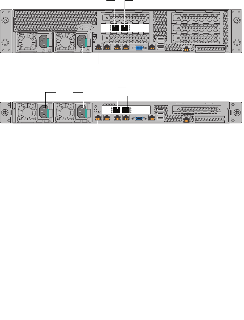
EMC Greenplum DCA Maintenance Guide Reseat cables before replacing a server
43
Replace a Segment, DIA, or Hadoop server
EMC CONFIDENTIAL
Figure 7 Re-seat cables on the back of the server
6. Power on the server by pressing the power button on the front of the server.
Wait for the server to boot (approximately 5 minutes).
7. From the Primary Master server, issue the ping command to each interface on the
server. Replace the text in bold with the hostname of the server you are evaluating.
# ping sdw1-cm
# ping sdw1
• If there is no response from the interfaces, replace the server by performing the
appropriate procedure listed below:
– “Replace a server in an initialized GPDB module” on page 44
– “Replace a DIA server or a server in an uninitialized GPDB module” on page 51
– “Replace a server in a Greenplum Hadoop module (DCA version 2.0.0.0)” on
page 58
•If all interfaces on the server respond, you do not need to replace the server. If the
server you are evaluating is a DIA server, you are done. If the server you are
evaluating is part of a GPDB or HD module, issue the following commands to
recover the segment instances:
# su - gpadmin
$ gprecoverseg
AF004061a
To Administration switch
(CM & BMC; 1Gb)
To upper Interconnect switch (10Gb)
Power
To lower Interconnect switch (10Gb)
AF004142a
To Administration switch
(CM & BMC; 1Gb)
To upper Interconnect switch (10Gb)
(CM = Cluster Management; BMC = Baseboard Management Controller service port)
Power To lower Interconnect switch (10Gb)

EMC Greenplum DCA Maintenance Guide Replace a server in an initialized GPDB module
44
Replace a Segment, DIA, or Hadoop server
EMC CONFIDENTIAL
Replace a server in an initialized GPDB module
Perform this procedure to replace a failed or failing Segment Server that is part of an
initialized GPDB module. This procedure describes how to replace the server hardware
and recover segment instances.
To replace a server that is part of a DIA module or part of an
uninitialized
GPDB module (or
a module in which GPBD is not installed), see page 51.
IMPORTANT
This procedure directs you to transfer drives from the failed server to the replacement
server. Take great care when transferring drives. Transfer only one drive at a time. Insert
drives in the same slots that they occupied in the failed server.
1. You may want to consult “Task summary” on page 40 for a overview of the segment
server replacement procedures.
2. Make sure that you have checked the cable connections (see “Reseat cables before
replacing a server” on page 42).
3. If it is not already connected, connect your service laptop to the red service cable
located on the laptop tray in Rack 1. The red service cable is connected to port 48 on
the first Administration switch a-sw-1 (see “Connect a workstation to the DCA” on
page 176).
4. To prevent false dial home messages from being sent to EMC Support during service,
disable health monitoring by stopping the healthmon daemon:
# dca_healthmon_ctl -d
5. Log in to the Primary Master Server as the user gpadmin.
6. Issue the gpstate -m command. Verify that no more than eight segment instances
display a status of Change Tracking. In this example, sdw1 has failed:
$ gpstate -m
Mirror Datadir Port Status Data Status
sdw2-2 /data2/mirror/gpseg0 50003 Acting as Primary Change Tracking
sdw3-2 /data2/mirror/gpseg1 50003 Acting as Primary Change Tracking
sdw4-2 /data2/mirror/gpseg2 50003 Acting as Primary Change Tracking
sdw2-1 /data1/mirror/gpseg3 50000 Acting as Primary Change Tracking
sdw3-1 /data1/mirror/gpseg4 50000 Acting as Primary Change Tracking
sdw4-1 /data1/mirror/gpseg5 50000 Acting as Primary Change Tracking
sdw3-1 /data1/mirror/gpseg6 50000 Acting as Primary Change Tracking
sdw4-1 /data1/mirror/gpseg7 50000 Acting as Primary Change Tracking
7. To locate the server, use the DCA Setup Utility to activate the green lightbar on the DCA
door and the blue server identification LED as the user root:
a. Launch the DCA Setup utility:
# dca_setup
b. Select option 2 to Modify DCA Settings.
c. Select option 18 for Light Bar Controls.
d. Select option 3 for Blink the light bar.

EMC Greenplum DCA Maintenance Guide Replace a server in an initialized GPDB module
45
Replace a Segment, DIA, or Hadoop server
EMC CONFIDENTIAL
e. Enter the hostname of the server and press ENTER.
f. Enter X to exit the DCA Setup utility.
The green lightbar on the DCA door and the blue server identification LED begin to
blink.
Note: If the DCA door does not have a lightbar, an error message displays. You can
safely ignore the error message. To identify the failed server, locate the blue server
identification LED.
8. If you can still access the server via SSH, perform sub-steps (a) through (d) below. If
you cannot access the server via SSH, proceed to step 9.
a. Log in to the failed segment server as the user root. Replace the hostname shown
in bold with the hostname of the failed server:
# ssh root@sdw1
b. Make note of any custom NFS mounts the customer may have created:
# cat /etc/fstab
c. Make note of any custom network gateways the customer may have created:
# cat /etc/sysconfig/network
d. Shut down the failed server:
# shutdown -h now
9. If the failed server is inaccessible through SSH, power it off by pressing the power
button on the front of the server.
10. Label all the cables connected to the failed server so that you’ll know where to
connect them on the replacement server.
11. Remove all power, Ethernet, and twin-axial cables from the back of the server.
Note: If the system has Dual NICs installed, note the connections for customer and
interconnect networks prior to disconnecting.
12. Remove the failed server and install the replacement server (see Appendix E, “Replace
a Server in the Greenplum DCA Rack,” on page 192).
13. Transfer disk drives one at a time from the failed server to the replacement server.
IMPORTANT
Use caution when transferring drives. Transfer only one drive at a time. Insert the
drives in the same slots that they occupied in the failed server.
14. Connect Ethernet and twin-ax cables to the replacement server. Refer to the labels on
the cables for proper connectivity.
IMPORTANT
Do not connect power to the replacement server yet.

EMC Greenplum DCA Maintenance Guide Replace a server in an initialized GPDB module
46
Replace a Segment, DIA, or Hadoop server
EMC CONFIDENTIAL
15. From the Primary Master server start the dhcpd service:
# service dhcpd start
16. Connect the power cables to the replacement server.
17. Next, use these steps to identify the IP address assigned to the server.
a. Issue the following command to obtain the lease information provided in the
dhcpd.leases file:
# tail /var/lib/dhcpd/dhcpd.leases
b. The dhcpd.leases file dispays (similar to the following):
Example
lease 172.28.6.170 {
starts 4 2012/10/18 20:09:08;
ends 5 2013/10/18 20:09:08;
cltt 4 2012/10/18 20:09:08;
binding state active;
next binding state free;
hardware ethernet 00:00:00:00:00:04;
uid "\001\000\036g,\242\014";
c. Locate the MAC address labelled hardware ethernet in the example
dhcpd.leases file above:
00:00:00:00:00:04
d. Locate the MAC address on the replacement server’s service tag (highlighted in the
photograph below):
MAC1 00:00:00:00:00:00
Figure 8 Locating the MAC address on the service tag (Dragon24)
e. Compare the last two digits in the MAC addresses referenced in step c and step d
(for example, 00:00:00:00:00:04 and 00:00:00:00:00:00 ). Verify that the MAC
address in the dhcpd.leases file is four greater than the last two numbers in the
MAC address on the replacement server’s service tag.
EMC Greenplum DCA Maintenance Guide Replace a server in an initialized GPDB module
47
Replace a Segment, DIA, or Hadoop server
EMC CONFIDENTIAL
If this is the case, it is certain that the IP address in the dhcpd.leases file is the
correct one to associate with the server. For example, the scenario described
above verifies that 172.28.6.170 is correct in this specific instance.
f. Issue the following ipmiutil command. Insert the IP address (172.28.6.170)
you’ve identified in the previous steps using the example above as a guide:
Note: Disregard the long, detailed output after this command is executed.
# ipmiutil lan -e -l -I 172.28.0.250 -S 255.255.248.0 -N 172.28.6.170 -U root -P sephiroth
g. Ping the new address to verify that the change was applied:
# ping 172.28.0.#
Where # is the number of the server you are replacing.
18. Turn off the dhcpd service:
# service dhcpd stop
19. From the Primary Master server as user root, issue the following command to open a
BMC console session on the replacement server. Replace the hostname shown in bold
below with the hostname of the replacement server:
# ipmiutil sol -a -e -N sdw1-sp -U root -P sephiroth
You will need to press the F key within 15 seconds after seeing this WARNING message:
Foreign configuration(s) found on adapter
Press any key to continue or ‘C’ load the configuration
utility, or ‘F’ to import foreign configuration(s) and
continue.
20. Power on the replacement server by pressing the power button on the front panel, and
press the F key when prompted.
Note that after pressing the space bar in the next step you will again be prompted to
press the F key within 15 seconds.
21. When the following message displays, disregard and press the space bar:
All of the disks from your previous configuration are gone. If this
is an unexpected message, then please power off your system and
check your cables to ensure all disks are present. Press any key to
continue, or 'C' to load the configuration utility.
22. Press the F key when prompted.
23. When the following message displays, disregard and press the space bar:
All of the disks from your previous configuration are gone. If this
is an unexpected message, then please power off your system and
check your cables to ensure all disks are present. Press any key to
continue, or 'C' to load the configuration utility.
EMC Greenplum DCA Maintenance Guide Replace a server in an initialized GPDB module
48
Replace a Segment, DIA, or Hadoop server
EMC CONFIDENTIAL
24. If the message below appears you will need to power off the server,essage below
appears you will need to power off the server, verify that all LED lights are off, and
repeat steps 21 through 23.
CLIENT MAC ADDR: 00 1E 67 4D C5 1D GUID: 2A9B43A4 A50A 11E1 AAA0
001E674DC51D
25. Monitor the boot process onscreen and verify that the replacement server boots from
hard disk. If it does not, do the following to force it to boot from hard disk:
a. Exit the BMC console utility by pressing the a tilde key (~), and then the period (.)
key, as follows on the keyboard:
then
Note: When you exit the BMC console you are returned to your connection on the
Primary Master server as the user root.
b. Issue the following command from the Primary Master server to force the
replacement server to boot from the hard drive. Change the hostname shown in
bold below to the hostname of the server you replaced:
# ipmiutil reset -h -N sdw1-sp -U root -P sephiroth
c. Once the operating system is loaded, issue the following command to change the
boot order on the replacement server. For example, on sdw1:
# ssh sdw1
# syscfg /bbo “emcbios” HDD NW
d. Reboot the replacement server:
# reboot
e. Following the reboot, issue the following commands to connect to the replacement
server and verify the boot order. Change the hostname shown in bold below to the
hostname of the server you replaced:
# ssh sdw1
# syscfg /bbosys
26. Check the health of the replacement server. Replace the text in bold with the
hostname of the replacement segment server:
# dcacheck -h sdw1
Verify that no errors display.
27. Exchange SSH keys on the replacement server using the DCA Setup utility:
a. Start the DCA Setup utility as the user root:
# dca_setup
b. Select option 2 to Modify DCA Settings.
c. Select option 6 to Generate SSH Keys.

EMC Greenplum DCA Maintenance Guide Replace a server in an initialized GPDB module
49
Replace a Segment, DIA, or Hadoop server
EMC CONFIDENTIAL
d. Enter X to exit the DCA Setup utility.
e. When the server reboots, check the new firmware version. Replace the text in bold
with the hostname of the replacement server:
# ssh sdw1 /opt/MegaRAID/CmdTool2/CmdTool2 -adpallinfo -aall |
grep "FW Package Build"
If the above command returns either: FW Package Build: 23.7.0-0033 or FW
Package Build: 23.9.0-0026, your firmware needs updating. Follow steps a
through n below to update the firmware.
f. Download ir3_2208SASHWR_FWPKG-v23.12.0-0013.zip file from Support Zone to
your laptop.
https://support.emc.com/downloads/9507_Greenplum-Data-Computing-Applian
ce
g. Extract the files to your laptop using unzip or similar unpacking tool. For example:
Unzip ir3_2208SASHWR_FWPKG-v23.12.0-0013.zip
h. As a root user copy the MR56p.rom file to the Master server (mdw) and place the
file in /root. You can use WinSCP or a similar utility.
Note: You may be required to provide a server login name and password.
i. For each server in need of an update, log into the server as root.
j. SCP the MR56p.rom file from the master to the server you are updating.
k. Install the new firmware using the following command:
Note: This will take longer on 24-disk servers.
# /opt/MegaRAID/CmdTool2/CmdTool2 -adpfwflash -f /root/MR56p.rom
-aall
l. Reboot the server.
# reboot
m. When the server reboots, check the new firmware version. Replace the text in bold
with the hostname of the replacement server:
# ssh sdw1 /opt/MegaRAID/CmdTool2/CmdTool2 -adpallinfo -aall |
grep "FW Package Build"
The following should be returned, indicating your firmware has successfully been
updated on this server:
FW package Build: 23.12.0-0013
n. Repeat these alphabetic steps to check/update the remaining servers in the
cluster.
28. Switch to the user gpadmin and launch the gprecoverseg utility to recover the
segment instances:
$ gprecoverseg -a

EMC Greenplum DCA Maintenance Guide Replace a server in an initialized GPDB module
50
Replace a Segment, DIA, or Hadoop server
EMC CONFIDENTIAL
29. When the gprecoverseg utility is finished, issue the gpstate -m command and
verify that the data status is reported as Resynchronizing in the output.
30. Wait a few minutes, and then issue the gpstate -m command again to verify that
the data status of all segments is reported as Synchronized in the output.
31. Return the Greenplum system to its optimal configuration:
$ gprecoverseg -ra
IMPORTANT
Issuing gprecoverseg -ra cancels running queries but does not interrupt
database connections.
32. Issue the $ gpstate -e command and verify that no errors are reported.
33. Synchronize the system clock:
a. Select option 2 for Modify DCA Settings.
b. Select option 5 for Modify NTP/Clock Configuration Options.
c. Select option 3 for Synchronize clocks across the cluster to the
NTP server.
Enter X to exit the DCA Setup utility.
34. Re-enable health monitoring by restarting the healthmon daemon:
# dca_healthmon_ctl -e

EMC Greenplum DCA Maintenance Guide Replace a DIA server or a server in an uninitialized GPDB module
51
Replace a Segment, DIA, or Hadoop server
EMC CONFIDENTIAL
Replace a DIA server or a server in an uninitialized GPDB module
Perform this procedure only to replace a failed server that is part of a DIA module or part of
an uninitialized GPDB module (or module in which GPBD is not installed).
IMPORTANT
This procedure directs you to transfer drives from the failed server to the replacement
server. Take great care when transferring drives. Transfer only one drive at a time. Insert
drives in the same slots that they occupied in the failed server.
1. Make sure that you have checked the cable connections as described in “Reseat
cables before replacing a server” on page 42.
2. If it is not already connected, connect your service laptop to the red service cable
located on the laptop tray in Rack 1. The red service cable is connected to port 48 on
the first Administration switch a-sw-1 (see “Connect a workstation to the DCA” on
page 176).
3. To prevent false dial home messages from being sent to EMC Support during service,
disable health monitoring by stopping the healthmon daemon:
# dca_healthmon_ctl -d
4. To locate the server, use the DCA Setup Utility to activate the green lightbar on the DCA
door and the blue server identification LED as the user root:
a. Launch the DCA Setup utility:
# dca_setup
b. Select option 2 to Modify DCA Settings.
c. Select option 18 for Light Bar Controls.
d. Select option 3 for Blink the light bar.
e. Enter the hostname of the server and press ENTER.
f. Enter X to exit the DCA Setup utility.
The green lightbar on the DCA door and the blue server identification LED begin to
blink.
Note: If the DCA door does not have a lightbar, an error message displays. You can
safely ignore the error message. To identify the failed server, locate the blue server
identification LED.
5. Log in to the Primary Master Server as the user gpadmin.
6. If you can still access the server via SSH, perform sub-steps (a) through (f) below. If
you cannot access the server via SSH, proceed to step 7.
a. Log in to the failed server as the user root. Replace the hostname shown in bold
with the hostname of the failed server:
$ ssh root@etl1

EMC Greenplum DCA Maintenance Guide Replace a DIA server or a server in an uninitialized GPDB module
52
Replace a Segment, DIA, or Hadoop server
EMC CONFIDENTIAL
b. If the server is part of a DIA module, ask the customer if any third-party software is
installed. Discuss with the customer whether any files need to be saved before you
power off the server.
c. Switch to the user root and make note of the MAC address of the adapter eth1
.
# ifconfig eth1
d. Make note of any custom NFS mounts the customer may have created:
# cat /etc/fstab
e. Make note of any custom network gateways the customer may have created:
# cat /etc/sysconfig/network
f. Shut down the failed server:
# shutdown -h now
7. Label all the cables connected to the failed server so that you’ll know where to
connect them on the replacement server.
8. Remove all power, Ethernet, and twin-axial cables from the back of the server.
Note: If the system has Dual NICs installed, note the connections for customer and
interconnect networks prior to disconnecting.
9. Remove the failed server and install the replacement server (see Appendix E, “Replace
a Server in the Greenplum DCA Rack,” on page 192).
10. Transfer disk drives one at a time from the failed server to the replacement server.
IMPORTANT
Use caution when transferring drives. Transfer only one drive at a time. Insert the
drives in the same slots that they occupied in the failed server.
11. Connect Ethernet and twin-ax cables to the replacement server. Refer to the labels on
the cables for proper connectivity.
IMPORTANT
Do not connect power to the replacement server yet.
12. From the Primary Master server start the dhcpd service:
# service dhcpd start
13. Connect the power cables to the replacement server.
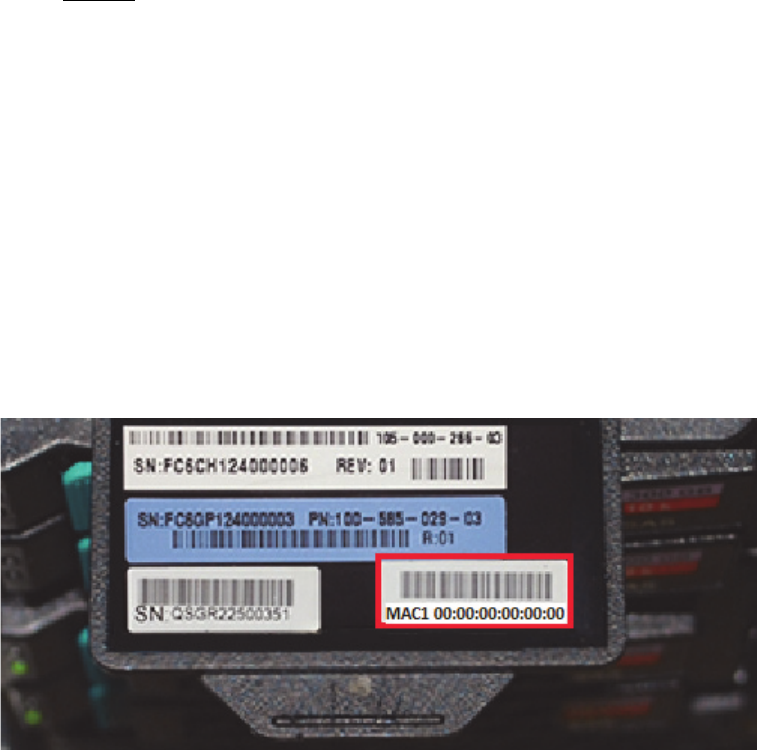
EMC Greenplum DCA Maintenance Guide Replace a DIA server or a server in an uninitialized GPDB module
53
Replace a Segment, DIA, or Hadoop server
EMC CONFIDENTIAL
14. Next, use these steps to identify the IP address assigned to the server.
a. Issue the following command to obtain the lease information provided in the
dhcpd.leases file:
# tail /var/lib/dhcpd/dhcpd.leases
b. The dhcpd.leases file dispays (similar to the following):
Example
lease 172.28.6.170 {
starts 4 2012/10/18 20:09:08;
ends 5 2013/10/18 20:09:08;
cltt 4 2012/10/18 20:09:08;
binding state active;
next binding state free;
hardware ethernet 00:00:00:00:00:04;
uid "\001\000\036g,\242\014";
c. Locate the MAC address labelled hardware ethernet in the example
dhcpd.leases file above:
00:00:00:00:00:04
d. Locate the MAC address on the replacement server’s service tag (highlighted in the
photograph below):
MAC1 00:00:00:00:00:00
Figure 9 Locating the MAC address on the service tag (Dragon24)
e. Compare the last two digits in the MAC addresses referenced in step c and step d
(for example, 00:00:00:00:00:04 and 00:00:00:00:00:00 ). Verify that the MAC
address in the dhcpd.leases file is four greater than the last two numbers in the
MAC address on the replacement server’s service tag.
If this is the case, it is certain that the IP address in the dhcpd.leases file is the
correct one to associate with the server. For example, the scenario described
above verifies that 172.28.6.170 is correct in this specific instance.
EMC Greenplum DCA Maintenance Guide Replace a DIA server or a server in an uninitialized GPDB module
54
Replace a Segment, DIA, or Hadoop server
EMC CONFIDENTIAL
f. Issue the following ipmiutil command. Insert the IP address (172.28.6.170)
identified in the previous steps using the example above as a guide:
Note: Disregard the long, detailed output after this command is executed.
# ipmiutil lan -e -l -I 172.28.0.250 -S 255.255.248.0 -N 172.28.6.170 -U root -P sephiroth
g. Ping the new address to verify that the change was applied:
# ping 172.28.0.#
Where # is the number of the server you are replacing.
15. Turn off the dhcpd service:
# service dhcpd stop
16. Power on the replacement server by pressing the button on the front panel.
17. From the Primary Master server issue the following command to open a BMC console
session on the replacement server. Replace the hostname shown in bold with the
hostname of the replacement server:
# ipmiutil sol -a -e -N etl1-sp -U root -P sephiroth
You will need to press the F key within 15 seconds after seeing this WARNING message:
Foreign configuration(s) found on adapter
Press any key to continue or ‘C’ load the configuration
utility, or ‘F’ to import foreign configuration(s) and
continue.
18. Power on the replacement server by pressing the power button on the front panel, and
press the F key when prompted.
Note that after pressing the space bar in the next step you may be prompted again to
press the F key within 15 seconds (if the DIA server is a Dragon24).
19. When the following message displays, disregard and press the space bar:
All of the disks from your previous configuration are gone. If this
is an unexpected message, then please power off your system and
check your cables to ensure all disks are present. Press any key to
continue, or 'C' to load the configuration utility.
20. Press the F key when prompted.
21. When the following message displays, disregard and press the space bar:
All of the disks from your previous configuration are gone. If this
is an unexpected message, then please power off your system and
check your cables to ensure all disks are present. Press any key to
continue, or 'C' to load the configuration utility.

EMC Greenplum DCA Maintenance Guide Replace a DIA server or a server in an uninitialized GPDB module
55
Replace a Segment, DIA, or Hadoop server
EMC CONFIDENTIAL
22. If the message below appears it indicates that the server did not accept the “F” key
request per the above WARNING. This means that you will need to power off the server,
verify that all LED lights are off, and go back to step 18 (press the F key when
prompted again):
CLIENT MAC ADDR: 00 1E 67 4D C5 1D GUID: 2A9B43A4 A50A 11E1 AAA0
001E674DC51D
DHCP....\
23. Monitor the boot process onscreen and verify that the replacement server boots from
hard disk. If it does not, do the following to force it to boot from hard disk:
a. Exit the BMC console utility by pressing the a tilde key (~), and then the period (.)
key, as follows on the keyboard:
then
Note: When you exit the BMC console you are returned to your connection on the
Primary Master server as the user root.
b. Issue the following command from the Primary Master server to force the Segment
server to boot from hard drive:
# ipmiutil reset -h -N etl1-sp -U root -P sephiroth
Change the hostname shown in bold above to the hostname of the server you
replaced.
c. Once the operating system is loaded, issue the following command to change the
boot order on the Segment server. For example, on etl1:
# ssh etl1
# syscfg /bbo “emcbios” HDD NW
d. Reboot the system:
# reboot
e. Following the reboot, issue the following commands to connect to the replacement
server and verify the boot order:
# ssh etl1
# syscfg /bbosys
Change the hostname shown in bold above to the hostname of the server you
replaced.
24. Issue the following command to check the health of the replacement server. Replace
the text in bold with the hostname of the replacement DIA or Segment server:
# dcacheck -h etl1
Verify that no errors display.
25. Exchange SSH keys on the replacement server using the DCA Setup utility:

EMC Greenplum DCA Maintenance Guide Replace a DIA server or a server in an uninitialized GPDB module
56
Replace a Segment, DIA, or Hadoop server
EMC CONFIDENTIAL
a. Start the DCA Setup utility as the user root:
# dca_setup
b. Select option 2 to Modify DCA Settings.
c. Select option 6 to Generate SSH Keys.
d. Enter X to exit the DCA Setup utility.
26. Using gpssh, check the firmware level of the RAID controllers with the CmdTool2
utility:
# /opt/MegaRAID/CmdTool2/CmdTool2 -adpallinfo -aall | grep "FW
Package Build"
If the above command returns either: FW Package Build: 23.7.0-0033 or FW
Package Build: 23.9.0-0026, your firmware needs updating. Follow steps a
through n below to update the firmware.
e. Download ir3_2208SASHWR_FWPKG-v23.12.0-0013.zip file from Support Zone to
your laptop.
https://support.emc.com/downloads/9507_Greenplum-Data-Computing-Applian
ce
f. Extract the files to your laptop using unzip or similar unpacking tool. For example:
Unzip ir3_2208SASHWR_FWPKG-v23.12.0-0013.zip
g. As a root user copy the MR56p.rom file to the Master server (mdw) and place the
file in /root. You can use WinSCP or a similar utility.
Note: You may be required to provide a server login name and password.
h. For each server in need of an update, log into the server as root.
i. SCP the MR56p.rom file from the master to the server you are updating.
j. Install the new firmware using the following command:
Note: This will take longer on 24-disk servers.
# /opt/MegaRAID/CmdTool2/CmdTool2 -adpfwflash -f /root/MR56p.rom
-aall
k. Reboot the server.
# reboot
l. When the server reboots, check the new firmware version. Replace the text in bold
with the hostname of the replacement server:
# ssh sdw1 /opt/MegaRAID/CmdTool2/CmdTool2 -adpallinfo -aall |
grep "FW Package Build"
The following should be returned, indicating your firmware has successfully been
updated on this server:
EMC Greenplum DCA Maintenance Guide Replace a DIA server or a server in an uninitialized GPDB module
57
Replace a Segment, DIA, or Hadoop server
EMC CONFIDENTIAL
FW package Build: 23.12.0-0013
m. Repeat these alphabetic steps to check/update the remaining servers in the
cluster.
27. Synchronize the system clock:
a. Select option 2 for Modify DCA Settings.
b. Select option 5 for Modify NTP/Clock Configuration Options.
c. Select option 3 for Synchronize clocks across the cluster to the
NTP server.
Enter X to exit the DCA Setup utility.
28. (
Applies only if you replaced a DIA server
): SSH into the replacement DIA server and
configure the external interface IP address:
Edit the file ...
# vi /etc/sysconfig/network-scripts/ifcfg-eth1
... and change the HWADDR setting using the MACADDRESS of eth1 that you
determined in step 6-c above. Change the values shown in bold below. Do not change
the other parameters:
DEVICE=eth1
BOOTPROTO=static
IPADDR=10.6.193.46
NETMASK=255.255.252.0
ONBOOT=YES
MTU=1500
HWADDR=MACADDRESS
29. Re-enable health monitoring by restarting the healthmon daemon:
# dca_healthmon_ctl -e
30. If any third-party software was installed, inform the customer that it is now safe to
reinstall and validate the software.

EMC Greenplum DCA Maintenance Guide Replace a server in a Greenplum Hadoop module (DCA version 2.0.0.0)
58
Replace a Segment, DIA, or Hadoop server
EMC CONFIDENTIAL
Replace a server in a Greenplum Hadoop module (DCA version
2.0.0.0)
Perform this procedure to replace a failed server that is part of a Hadoop module in DCA
version 2.0.0.0.
To replace a Hadoop server in DCA version 2.0.0.0, see the procedure “Replace a server in
a Pivotal Hadoop module (version 2.0.1.0 and later)” on page 64.
IMPORTANT
This procedure directs you to transfer drives from the failed server to the replacement
server. Take great care when transferring drives. Transfer only one drive at a time. Insert
drives in the same slots that they occupied in the failed server.
1. Make sure that you have checked the cable connections as described in “Reseat
cables before replacing a server” on page 42.
2. If it is not already connected, connect your service laptop to the red service cable
located on the laptop tray in Rack 1. The red service cable is connected to port 48 on
the first Administration switch a-sw-1 (see “Connect a workstation to the DCA” on
page 176).
3. To prevent false dial home messages from being sent to EMC Support during service,
disable health monitoring by stopping the healthmon daemon:
# dca_healthmon_ctl -d
4. To locate the server, use the DCA Setup Utility to activate the green lightbar on the DCA
door and the blue server identification LED as the user root:
a. Launch the DCA Setup utility:
# dca_setup
b. Select option 2 to Modify DCA Settings.
c. Select option 18 for Light Bar Controls.
d. Select option 3 for Blink the light bar.
e. Enter the hostname of the server and press ENTER.
f. Enter X to exit the DCA Setup utility.
The green lightbar on the DCA door and the blue server identification LED begin to
blink.
Note: If the DCA door does not have a lightbar, an error message displays. You can
safely ignore the error message. To identify the failed server, locate the blue server
identification LED.
5. If you can still access the server via SSH, perform sub-steps (a) through (c) below. If
you cannot access the server via SSH, proceed to step 6.

EMC Greenplum DCA Maintenance Guide Replace a server in a Greenplum Hadoop module (DCA version 2.0.0.0)
59
Replace a Segment, DIA, or Hadoop server
EMC CONFIDENTIAL
a. Log in to the failed server as the user root. Replace the hostname shown in bold
with the hostname of the failed server. For example, for the first Hadoop Master:
# ssh root@hdm1
b. Make note of any custom network gateways the customer may have created:
# cat /etc/sysconfig/network
c. Shut down the failed server:
# shutdown -h now
6. Label all the cables connected to the failed server so that you’ll know where to
connect them on the replacement server.
7. Remove all power, Ethernet, and twin-axial cables from the back of the server.
Note: If the system has Dual NICs installed, note the connections for customer and
interconnect networks prior to disconnecting.
8. Remove the failed server and install the replacement server (see Appendix E, “Replace
a Server in the Greenplum DCA Rack,” on page 192).
9. Transfer disk drives one at a time from the failed server to the replacement server.
IMPORTANT
Use caution when transferring drives. Transfer only one drive at a time. Insert the
drives in the same slots that they occupied in the failed server.
10. Connect Ethernet and twin-ax cables to the replacement server. Refer to the labels on
the cables for proper connectivity.
IMPORTANT
Do not connect power to the replacement server yet.
11. From the Primary Master server start the dhcpd service:
# service dhcpd start
12. Connect the power cables to the replacement server.
binding state active;
next binding state free;
hardware ethernet [server_mac_address];
uid "\001\000\036g,\242\014";
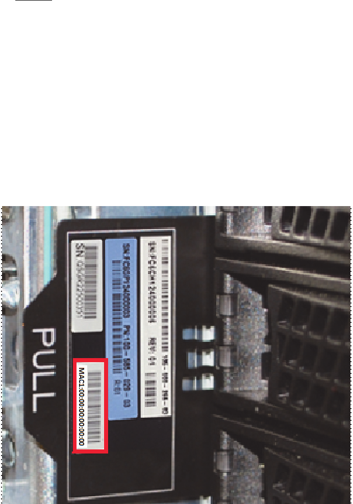
EMC Greenplum DCA Maintenance Guide Replace a server in a Greenplum Hadoop module (DCA version 2.0.0.0)
60
Replace a Segment, DIA, or Hadoop server
EMC CONFIDENTIAL
13. Next, use these steps to identify the IP address assigned to the server.
a. Issue the following command to obtain the lease information provided in the
dhcpd.leases file:
# tail /var/lib/dhcpd/dhcpd.leases
b. The dhcpd.leases file dispays (similar to the following):
Example
lease 172.28.6.170 {
starts 4 2012/10/18 20:09:08;
ends 5 2013/10/18 20:09:08;
cltt 4 2012/10/18 20:09:08;
binding state active;
next binding state free;
hardware ethernet 00:00:00:00:00:04;
uid "\001\000\036g,\242\014";
c. Locate the MAC address labelled hardware ethernet in the example
dhcpd.leases file above:
00:00:00:00:00:04
d. Locate the MAC address on the replacement server’s service tag (highlighted in the
photograph below):
MAC1 00:00:00:00:00:00
Figure 10 Locating the MAC address on the service tag (server shown, Dragon12)

EMC Greenplum DCA Maintenance Guide Replace a server in a Greenplum Hadoop module (DCA version 2.0.0.0)
61
Replace a Segment, DIA, or Hadoop server
EMC CONFIDENTIAL
e. Compare the last two digits in the MAC addresses referenced in step c and step d
(for example, 00:00:00:00:00:04 and 00:00:00:00:00:00 ). Verify that the MAC
address in the dhcpd.leases file is four greater than the last two numbers in the
MAC address on the replacement server’s service tag.
If this is the case, it is certain that the IP address in the dhcpd.leases file is the
correct one to associate with the server. For example, the scenario described
above verifies that 172.28.6.170 is correct in this specific instance.
f. Issue the following ipmiutil command. Insert the IP address (172.28.6.170)
identified in the previous steps using the example above as a guide:
Note: Disregard the long, detailed output after this command is executed.
# ipmiutil lan -e -l -I 172.28.0.250 -S 255.255.248.0 -N 172.28.6.170 -U root -P sephiroth
g. Ping the new address to verify that the change was applied:
# ping 172.28.0.#
Where # is the number of the server you are replacing.
14. Turn off the dhcpd service:
# service dhcpd stop
15. From the Primary Master server issue the following command to open a console
session on the replacement server. Replace the hostname shown in bold with the
hostname of the replacement server:
# ipmiutil sol -a -e -N hdm1-sp -U root -P sephiroth
You will need to press the F key within 15 seconds after seeing this WARNING message:
Foreign configuration(s) found on adapter
Press any key to continue or ‘C’ load the configuration
utility, or ‘F’ to import foreign configuration(s) and
continue.
16. Power on the replacement server by pressing the power button on the front panel, and
press the F key when prompted.
17. When the following message disp
18. lays, disregard and press the space bar:
All of the disks from your previous configuration are gone. If this
is an unexpected message, then please power off your system and
check your cables to ensure all disks are present. Press any key to
continue, or 'C' to load the configuration utility.
19. If the message below appears it indicates that the server did not accept the “F” key
request per the above WARNING. This means that you will need to power off the server,
verify that all LED lights are off, and go back to step 16 (press the F key when
prompted again):

EMC Greenplum DCA Maintenance Guide Replace a server in a Greenplum Hadoop module (DCA version 2.0.0.0)
62
Replace a Segment, DIA, or Hadoop server
EMC CONFIDENTIAL
CLIENT MAC ADDR: 00 1E 67 4D C5 1D GUID: 2A9B43A4 A50A 11E1 AAA0
001E674DC51D
DHCP....\
20. Monitor the boot process onscreen and verify that the replacement server boots from
hard disk. If it does not, do the following to force it to boot from hard disk:
a. Exit the BMC console utility by pressing the a tilde key (~), and then the period (.)
key, as follows on the keyboard:
then
Note: When you exit the BMC console you are returned to your connection on the
Primary Master server as the user root.
b. Issue the following command from the Primary Master server to force the Segment
server to boot from hard drive:
# ipmiutil reset -h -N hdm1-sp -U root -P sephiroth
Change the hostname shown in bold above to the hostname of the server you
replaced.
c. Once the operating system is loaded, issue the following command to change the
boot order on the server. For example, on hdm1:
# ssh hdm1
# syscfg /bbo “emcbios” HDD NW
d. Reboot the system:
# reboot
e. Following the reboot, issue the following commands to connect to the replaced
server, and verify the boot order:
# ssh hdm1
# syscfg /bbosys
Change the hostname shown in bold above to the hostname of the server you
replaced.
21. Issue the following command to check the health of the replacement server. Replace
the text in bold with the hostname of the replacement hadoop server:
# dcacheck -h hdm1
Verify that no errors display.
22. Exchange SSH keys on the replacement server using the DCA Setup utility:
a. Start the DCA Setup utility as the user root:
# dca_setup
b. Select option 2 to Modify DCA Settings.
c. Select option 6 to Generate SSH Keys.

EMC Greenplum DCA Maintenance Guide Replace a server in a Greenplum Hadoop module (DCA version 2.0.0.0)
63
Replace a Segment, DIA, or Hadoop server
EMC CONFIDENTIAL
d. Enter X to exit the DCA Setup utility.
23. Using gpssh, check the firmware level of the RAID controllers with the CmdTool2
utility:
# /opt/MegaRAID/CmdTool2/CmdTool2 -adpallinfo -aall | grep "FW
Package Build"
If the above command returns either: FW Package Build: 23.7.0-0033 or FW
Package Build: 23.9.0-0026, your firmware needs updating. Follow steps a
through n below to update the firmware.
e. Download ir3_2208SASHWR_FWPKG-v23.12.0-0013.zip file from Support Zone to
your laptop.
https://support.emc.com/downloads/9507_Greenplum-Data-Computing-Applian
ce
f. Extract the files to your laptop using unzip or similar unpacking tool. For example:
Unzip ir3_2208SASHWR_FWPKG-v23.12.0-0013.zip
g. As a root user copy the MR56p.rom file to the Master server (mdw) and place the
file in /root. You can use WinSCP or a similar utility.
Note: You may be required to provide a server login name and password.
h. For each server in need of an update, log into the server as root.
i. SCP the MR56p.rom file from the master to the server you are updating.
j. Install the new firmware using the following command:
Note: This will take longer on 24-disk servers.
# /opt/MegaRAID/CmdTool2/CmdTool2 -adpfwflash -f /root/MR56p.rom
-aall
k. Reboot the server.
# reboot
l. When the server reboots, check the new firmware version. Replace the text in bold
with the hostname of the replacement server:
# ssh sdw1 /opt/MegaRAID/CmdTool2/CmdTool2 -adpallinfo -aall |
grep "FW Package Build"
The following should be returned, indicating your firmware has successfully been
updated on this server:
FW package Build: 23.12.0-0013
m. Repeat these alphabetic steps to check/update the remaining servers in the
cluster.
24. Synchronize the system clock:
a. Select option 2 for Modify DCA Settings.

EMC Greenplum DCA Maintenance Guide Replace a server in a Pivotal Hadoop module (version 2.0.1.0 and later)
64
Replace a Segment, DIA, or Hadoop server
EMC CONFIDENTIAL
b. Select option 5 for Modify NTP/Clock Configuration Options.
c. Select option 3 for Synchronize clocks across the cluster to the
NTP server.
d. Enter X to exit the DCA Setup utility.
25. Re-enable health monitoring by restarting the healthmon daemon:
# dca_healthmon_ctl -e
Replace a server in a Pivotal Hadoop module (version 2.0.1.0 and
later)
Perform this procedure to replace a failed server that is part of a Pivotal Hadoop (PHD)
module.
To replace a Greenplum Hadoop server in DCA version 2.0.0.0, see the procedure “Replace
a server in a Greenplum Hadoop module (DCA version 2.0.0.0)” on page 58.
Choose the procedure for the type of PHD server you are replacing (see Table 3 below).
Remove the failed PHD server and install the replacement PHD
server
IMPORTANT
This procedure directs you to transfer drives from the failed server to the replacement
server. Take great care when transferring drives. Transfer only one drive at a time. Insert
drives in the same slots that they occupied in the failed server.
1. Make sure that you have checked the cable connections as described in “Reseat
cables before replacing a server” on page 42.
2. If it is not already connected, connect your service laptop to the red service cable
located on the laptop tray in Rack 1 (see “Connect a workstation to the DCA” on
page 176).
Table 3 Server replacement procedures by PHD module type
Hostname Server Module / Role Use this procedure
hdm1 Master Module - Namenode Replace hdm1 (namenode, DCA version 2.0.1.0)
hdm2 Master Module - Secondary
Namenode, Zookeeper
Replace hdm2 (zookeeper/secondary-namenode, DCA version 2.0.1.0)
hdm3 Master Module -
resourcemanager
Replace hdm3 (resourcemanager, DCA version 2.0.1.0)
hdm4 Master Module - Zookeeper,
Hive, Hive-Metastore
Replace hdm4 (zookeeper/hive/hive-metastore, DCA version 2.0.1.0)
hdw# Worker Module - Nodemanager,
Datanode
Replace hdw# (datanode, nodemanager, DCA version 2.0.1.0)

EMC Greenplum DCA Maintenance Guide Remove the failed PHD server and install the replacement PHD server
65
Replace a Segment, DIA, or Hadoop server
EMC CONFIDENTIAL
3. To prevent false dial home messages from being sent to EMC Support during service,
disable health monitoring by stopping the healthmon daemon:
# dca_healthmon_ctl -d
4. To locate the server, use the DCA Setup Utility to activate the green lightbar on the DCA
door and the blue server identification LED as the user root:
a. Launch the DCA Setup utility:
# dca_setup
b. Select option 2 to Modify DCA Settings.
c. Select option 18 for Light Bar Controls.
d. Select option 3 for Blink the light bar.
e. Enter the hostname of the server and press ENTER.
f. Enter X to exit the DCA Setup utility.
The green lightbar on the DCA door and the blue server identification LED begin to
blink.
Note: If the DCA door does not have a lightbar, an error message displays. You can
safely ignore the error message. To identify the failed server, locate the blue server
identification LED.
5. If you can still access the server via SSH, perform sub-steps (a) through (c) below. If
you cannot access the server via SSH, proceed to step 6.
a. Log in to the failed server as the user root. Replace the hostname shown in bold
with the hostname of the failed server:
# ssh root@hdm1
b. Make note of any custom network gateways the customer may have created:
# cat /etc/sysconfig/network
c. Shut down the failed server:
# shutdown -h now
6. Label all the cables connected to the failed server so that you’ll know where to
connect them on the replacement server.
7. Remove all power, Ethernet, and twin-axial cables from the back of the server.
Note: If the system has Dual NICs installed, note the connections for customer and
interconnect networks prior to disconnecting.
8. Remove the failed server and install the replacement server (see Appendix E, “Replace
a Server in the Greenplum DCA Rack,” on page 192).
9. Transfer disk drives one at a time from the failed server to the replacement server.

EMC Greenplum DCA Maintenance Guide Remove the failed PHD server and install the replacement PHD server
66
Replace a Segment, DIA, or Hadoop server
EMC CONFIDENTIAL
IMPORTANT
Use caution when transferring drives. Transfer only one drive at a time. Insert the
drives in the same slots that they occupied in the failed server.
10. Connect Ethernet and twin-ax cables to the replacement server. Refer to the labels on
the cables for proper connectivity.
IMPORTANT
Do not connect power to the replacement server yet.
11. From the Primary Master server start the dhcpd service:
# service dhcpd start
12. Connect the power cables to the replacement server.
13. Next, use these steps to identify the IP address assigned to the server.
a. Issue the following command to obtain the lease information provided in the
dhcpd.leases file:
# tail /var/lib/dhcpd/dhcpd.leases
b. The dhcpd.leases file dispays (similar to the following):
Example
lease 172.28.6.170 {
starts 4 2012/10/18 20:09:08;
ends 5 2013/10/18 20:09:08;
cltt 4 2012/10/18 20:09:08;
binding state active;
next binding state free;
hardware ethernet 00:00:00:00:00:04;
uid "\001\000\036g,\242\014";
c. Locate the MAC address labelled hardware ethernet in the example
dhcpd.leases file above:
00:00:00:00:00:04
d. Locate the MAC address on the replacement server’s service tag (highlighted in
Figure 11):
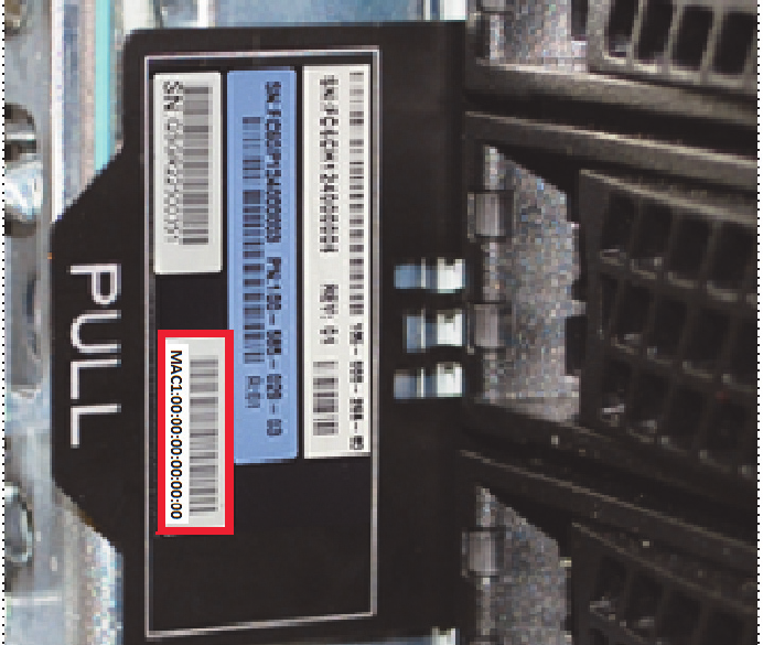
EMC Greenplum DCA Maintenance Guide Remove the failed PHD server and install the replacement PHD server
67
Replace a Segment, DIA, or Hadoop server
EMC CONFIDENTIAL
MAC1 00:00:00:00:00:00
Figure 11 Locating the MAC address on the service tag (server shown, Dragon12)
e. Compare the last two digits in the MAC addresses referenced in step c and step d
(for example, 00:00:00:00:00:04 and 00:00:00:00:00:00 ). Verify that the MAC
address in the dhcpd.leases file is four greater than the last two numbers in the
MAC address on the replacement server’s service tag.
If this is the case, it is certain that the IP address in the dhcpd.leases file is the
correct one to associate with the server. For example, the scenario described
above verifies that 172.28.6.170 is correct in this specific instance.
EMC Greenplum DCA Maintenance Guide Replace hdm1 (namenode, DCA version 2.0.1.0)
68
Replace a Segment, DIA, or Hadoop server
EMC CONFIDENTIAL
f. Issue the following ipmiutil command. Insert the IP address (172.28.6.170)
identified in the previous steps using the example above as a guide:
Note: Disregard the long, detailed output after this command is executed.
# ipmiutil lan -e -l -I 172.28.0.250 -S 255.255.248.0 -N 172.28.6.170 -U root -P sephiroth
g. Ping the new address to verify that the change was applied:
# ping 172.28.0.#
Where # is the number of the server you are replacing.
14. Turn off the dhcpd service:
# service dhcpd stop
15. Power on the replacement server by pressing the button on the front panel.
Replace hdm1 (namenode, DCA version 2.0.1.0)
1. From the Primary Master server issue the following command to open a console
session on the replacement server. Replace the hostname shown in bold with the
hostname of the replacement server:
# ipmiutil sol -a -e -N hdm1-sp -U root -P sephiroth
You will need to press the F key within 15 seconds after seeing this WARNING message:
Foreign configuration(s) found on adapter
Press any key to continue or ‘C’ load the configuration
utility, or ‘F’ to import foreign configuration(s) and
continue.
2. Power on the replacement server by pressing the power button on the front panel, and
press the F key when prompted.
3. When the following message displays, disregard and press the space bar:
All of the disks from your previous configuration are gone. If this
is an unexpected message, then please power off your system and
check your cables to ensure all disks are present. Press any key to
continue, or 'C' to load the configuration utility.
4. If the message below appears it indicates that the server did not accept the “F” key
request per the above WARNING. This means that you will need to power off the server,
verify that all LED lights are off, and go back to step 2 (press the F key when prompted
again):
CLIENT MAC ADDR: 00 1E 67 4D C5 1D GUID: 2A9B43A4 A50A 11E1 AAA0
001E674DC51D
DHCP....\

EMC Greenplum DCA Maintenance Guide Replace hdm1 (namenode, DCA version 2.0.1.0)
69
Replace a Segment, DIA, or Hadoop server
EMC CONFIDENTIAL
5. Monitor the boot process onscreen and verify that the replacement server boots from
hard disk. If it does not, do the following to force it to boot from hard disk:
a. Exit the BMC console utility by pressing the a tilde key (~), and then the period (.)
key, as follows on the keyboard:
then
Note: When you exit the BMC console you are returned to your connection on the
Primary Master server as the user root.
b. Issue the following command from the Primary Master server to force the Segment
server to boot from hard drive:
# ipmiutil reset -h -N hdm1-sp -U root -P sephiroth
c. Once the operating system is loaded, issue the following command to change the
boot order on the server. For example, on hdm1:
# ssh hdm1
# syscfg /bbo “emcbios” HDD NW
d. Reboot the system:
# reboot
e. Following the reboot, issue the following commands to connect to the replacement
server and verify the boot order:
# ssh hdm1
# syscfg /bbosys
Change the hostname shown in bold above to the hostname of the server you
replaced.
6. Issue the following command to check the health of the replacement server:
# dcacheck -h hdm1
Verify that no errors display.
7. Exchange SSH keys on the replacement server using the DCA Setup utility:
a. Start the DCA Setup utility as the user root:
# dca_setup
b. Select option 2 to Modify DCA Settings.
c. Select option 6 to Generate SSH Keys.
d. Enter X to exit the DCA Setup utility.
e. When the server reboots, check the new firmware version. Replace the text in bold
with the hostname of the replacement server:
# ssh sdw1 /opt/MegaRAID/CmdTool2/CmdTool2 -adpallinfo -aall |
grep "FW Package Build"

EMC Greenplum DCA Maintenance Guide Replace hdm1 (namenode, DCA version 2.0.1.0)
70
Replace a Segment, DIA, or Hadoop server
EMC CONFIDENTIAL
If the above command returns either: FW Package Build: 23.7.0-0033 or FW
Package Build: 23.9.0-0026, your firmware needs updating. Follow steps a
through n below to update the firmware.
f. Download ir3_2208SASHWR_FWPKG-v23.12.0-0013.zip file from Support Zone to
your laptop.
https://support.emc.com/downloads/9507_Greenplum-Data-Computing-Applian
ce
g. Extract the files to your laptop using unzip or similar unpacking tool. For example:
Unzip ir3_2208SASHWR_FWPKG-v23.12.0-0013.zip
h. As a root user copy the MR56p.rom file to the Master server (mdw) and place the
file in /root. You can use WinSCP or a similar utility.
Note: You may be required to provide a login to the destination server.
i. For each server in need of an update, log into the server as root.
j. SCP the MR56p.rom file from the master to the server you are updating.
k. Install the new firmware using the following command:
Note: This will take longer on 24-disk servers.
# /opt/MegaRAID/CmdTool2/CmdTool2 -adpfwflash -f /root/MR56p.rom
-aall
l. Reboot the server.
# reboot
m. When the server reboots, check the new firmware version:
# /opt/MegaRAID/CmdTool2/CmdTool2 -adpallinfo -aall | grep "FW
Package Build"
The following should be returned, indicating your firmware has successfully been
updated on this server:
FW package Build: 23.12.0-0013
n. Repeat these alphabetic steps to check/update the remaining servers in the
cluster.
8. Synchronize the system clock:
a. Select option 2 for Modify DCA Settings.
b. Select option 5 for Modify NTP/Clock Configuration Options.
c. Select option 3 for Synchronize clocks across the cluster to the
NTP server.
d. Enter X to exit the DCA Setup utility.
9. Re-enable health monitoring by restarting the healthmon daemon:
# dca_healthmon_ctl -e
EMC Greenplum DCA Maintenance Guide Replace hdm1 (namenode, DCA version 2.0.1.0)
71
Replace a Segment, DIA, or Hadoop server
EMC CONFIDENTIAL
10. Connect to hdm1:
# ssh hdm1
11. Issue the following command to view the status of the PHD cluster:
# dca_hadoop --status all
Verify that the status of hdm1 is stopped:
module namenode(service hadoop-namenode) is stopped on host hdm1
12. Start the namenode service:
# dca_hadoop --start namenode
When the namenode service starts the PHD cluster is in safemode.
13. Switch to the user hdfs and issue the following command:
# su - hdfs
$ hadoop fsck /
The following message indicates that the filesystem has an error:
The filesystem under path ‘/’ is CORRUPT
14. Exit safemode and return the filesystem to a normal state:
$ hadoop dfsadmin -safemode leave
15. Verify that the filesystem is healthy:
$ hadoop fsck /
The following message indicates that the filesystem is healthy:
The filesystem under path ‘/’ is HEALTHY
EMC Greenplum DCA Maintenance Guide Replace hdm2 (zookeeper/secondary-namenode, DCA version 2.0.1.0)
72
Replace a Segment, DIA, or Hadoop server
EMC CONFIDENTIAL
Replace hdm2 (zookeeper/secondary-namenode, DCA version 2.0.1.0)
1. From the Primary Master server issue the following command to open a console
session on the replacement server. Replace the hostname shown in bold with the
hostname of the replacement server:
# ipmiutil sol -a -e -N hdm2-sp -U root -P sephiroth
You will need to press the F key within 15 seconds after seeing this WARNING message:
Foreign configuration(s) found on adapter
Press any key to continue or ‘C’ load the configuration
utility, or ‘F’ to import foreign configuration(s) and
continue.
2. Power on the replacement server by pressing the power button on the front panel, and
press the F key when prompted.
3. When the following message displays, disregard and press the space bar:
All of the disks from your previous configuration are gone. If this
is an unexpected message, then please power off your system and
check your cables to ensure all disks are present. Press any key to
continue, or 'C' to load the configuration utility.
4. If the message below appears it indicates that the server did not accept the “F” key
request per the above WARNING. This means that you will need to power off the server,
verify that all LED lights are off, and go back to step 2 (press the F key when prompted
again):
CLIENT MAC ADDR: 00 1E 67 4D C5 1D GUID: 2A9B43A4 A50A 11E1 AAA0
001E674DC51D
DHCP....\
5. Monitor the boot process onscreen and verify that the replacement server boots from
hard disk. If it does not, do the following to force it to boot from hard disk:
a. Exit the BMC console utility by pressing the a tilde key (~), and then the period (.)
key, as follows on the keyboard:
then
Note: When you exit the BMC console you are returned to your connection on the
Primary Master server as the user root.
b. Issue the following command from the Primary Master server to force the Segment
server to boot from hard drive:
# ipmiutil reset -h -N hdm2-sp -U root -P sephiroth
Change the hostname shown in bold above to the hostname of the server you
replaced.
EMC Greenplum DCA Maintenance Guide Replace hdm2 (zookeeper/secondary-namenode, DCA version 2.0.1.0)
73
Replace a Segment, DIA, or Hadoop server
EMC CONFIDENTIAL
c. Once the operating system is loaded, issue the following command to change the
boot order on the server. For example, on hdm2:
# ssh hdm2
# syscfg /bbo “emcbios” HDD NW
d. Reboot the system:
# reboot
e. Following the reboot, issue the following commands to connect to the replacement
server and verify the boot order:
# ssh hdm2
# syscfg /bbosys
6. Issue the following command to check the health of the replacement server:
# dcacheck -h hdm2
Verify that no errors display.
7. Exchange SSH keys on the replacement server using the DCA Setup utility:
a. Start the DCA Setup utility as the user root:
# dca_setup
b. Select option 2 to Modify DCA Settings.
c. Select option 6 to Generate SSH Keys.

EMC Greenplum DCA Maintenance Guide Replace hdm2 (zookeeper/secondary-namenode, DCA version 2.0.1.0)
74
Replace a Segment, DIA, or Hadoop server
EMC CONFIDENTIAL
d. Enter X to exit the DCA Setup utility.
e. When the server reboots, check the new firmware version. Replace the text in bold
with the hostname of the replacement server:
# ssh hdm2 /opt/MegaRAID/CmdTool2/CmdTool2 -adpallinfo -aall |
grep "FW Package Build"
If the above command returns either: FW Package Build: 23.7.0-0033 or FW
Package Build: 23.9.0-0026, your firmware needs updating. Follow steps a
through n below to update the firmware.
f. Download ir3_2208SASHWR_FWPKG-v23.12.0-0013.zip file from Support Zone to
your laptop.
https://support.emc.com/downloads/9507_Greenplum-Data-Computing-Applian
ce
g. Extract the files to your laptop using unzip or similar unpacking tool. For example:
Unzip ir3_2208SASHWR_FWPKG-v23.12.0-0013.zip
h. As a root user copy the MR56p.rom file to the Master server (mdw) and place the
file in /root. You can use WinSCP or a similar utility.
Note: You may be required to provide a login to the destination server.
i. For each server in need of an update, log into the server as root.
j. SCP the MR56p.rom file from the master to the server you are updating.
k. Install the new firmware using the following command:
Note: This will take longer on 24-disk servers.
# /opt/MegaRAID/CmdTool2/CmdTool2 -adpfwflash -f /root/MR56p.rom
-aall
l. Reboot the server.
# reboot
m. When the server reboots, check the new firmware version:
# /opt/MegaRAID/CmdTool2/CmdTool2 -adpallinfo -aall | grep "FW
Package Build"
The following should be returned, indicating your firmware has successfully been
updated on this server:
FW package Build: 23.12.0-0013
n. Repeat these alphabetic steps to check/update the remaining servers in the
cluster.
8. Synchronize the system clock:
a. Select option 2 for Modify DCA Settings.
b. Select option 5 for Modify NTP/Clock Configuration Options.
EMC Greenplum DCA Maintenance Guide Replace hdm2 (zookeeper/secondary-namenode, DCA version 2.0.1.0)
75
Replace a Segment, DIA, or Hadoop server
EMC CONFIDENTIAL
c. Select option 3 for Synchronize clocks across the cluster to the
NTP server.
d. Enter X to exit the DCA Setup utility.
9. Re-enable health monitoring by restarting the healthmon daemon:
# dca_healthmon_ctl -e
10. Connect to hdm1:
# ssh hdm1
11. Issue the following command to view the status of the Hadoop cluster:
# dca_hadoop --status all
The status of the secondary-namenode and zookeeper modules on hdm2
should be:
module secondary-namenode(service hadoop-secondarynamenode) has error on host hdm2
module zookeeper(service zookeeper-server) has error on host hdm2
12. Start the secondary-namenode and zookeeper services:
# dca_hadoop --start secondary-namenode
# dca_hadoop --start zookeeper
13. Switch to the user hdfs and issue the following command:
# su - hdfs
$ hadoop fsck /
14. Verify that the filesystem is healthy:
$ hadoop fsck /
The following message indicates that the filesystem is healthy:
The filesystem under path ‘/’ is HEALTHY

EMC Greenplum DCA Maintenance Guide Replace hdm3 (resourcemanager, DCA version 2.0.1.0)
76
Replace a Segment, DIA, or Hadoop server
EMC CONFIDENTIAL
Replace hdm3 (resourcemanager, DCA version 2.0.1.0)
1. From the Primary Master server issue the following command to open a console
session on the replacement server. Replace the hostname shown in bold with the
hostname of the replacement server:
# ipmiutil sol -a -e -N hdm3-sp -U root -P sephiroth
You will need to press the F key within 15 seconds after seeing this WARNING message:
Foreign configuration(s) found on adapter
Press any key to continue or ‘C’ load the configuration
utility, or ‘F’ to import foreign configuration(s) and
continue.
2. Power on the replacement server by pressing the power button on the front panel, and
press the F key when prompted.
3. When the following message displays, disregard and press the space bar:
All of the disks from your previous configuration are gone. If this
is an unexpected message, then please power off your system and
check your cables to ensure all disks are present. Press any key to
continue, or 'C' to load the configuration utility.
4. If the message below appears it indicates that the server did not accept the “F” key
request per the above WARNING. This means that you will need to power off the server,
verify that all LED lights are off, and go back to step 2 (press the F key when prompted
again):
CLIENT MAC ADDR: 00 1E 67 4D C5 1D GUID: 2A9B43A4 A50A 11E1 AAA0
001E674DC51D
DHCP....\
5. Monitor the boot process onscreen and verify that the replacement server boots from
hard disk. If it does not, do the following to force it to boot from hard disk:
a. Exit the BMC console utility by pressing the a tilde key (~), and then the period (.)
key, as follows on the keyboard:
then
Note: When you exit the BMC console you are returned to your connection on the
Primary Master server as the user root.
b. Issue the following command from the Primary Master server to force the Segment
server to boot from hard drive:
# ipmiutil reset -h -N hdm3-sp -U root -P sephiroth
Change the hostname shown in bold above to the hostname of the server you
replaced.

EMC Greenplum DCA Maintenance Guide Replace hdm3 (resourcemanager, DCA version 2.0.1.0)
77
Replace a Segment, DIA, or Hadoop server
EMC CONFIDENTIAL
c. Once the operating system is loaded, issue the following command to change the
boot order on the server. For example, on hdm3:
# ssh hdm3
# syscfg /bbo “emcbios” HDD NW
d. Reboot the system:
# reboot
e. Following the reboot, issue the following commands to connect to the replacement
server and verify the boot order:
# ssh hdm3
# syscfg /bbosys
6. Issue the following command to check the health of the replacement server:
# dcacheck -h hdm3
Verify that no errors display.
7. Exchange SSH keys on the replacement server using the DCA Setup utility:
a. Start the DCA Setup utility as the user root:
# dca_setup
b. Select option 2 to Modify DCA Settings.
c. Select option 6 to Generate SSH Keys.
d. Enter X to exit the DCA Setup utility.
e. When the server reboots, check the new firmware version. Replace the text in bold
with the hostname of the replacement server:
# ssh hdm3 /opt/MegaRAID/CmdTool2/CmdTool2 -adpallinfo -aall |
grep "FW Package Build"
If the above command returns either: FW Package Build: 23.7.0-0033 or FW
Package Build: 23.9.0-0026, your firmware needs updating. Follow steps a
through n below to update the firmware.
f. Download ir3_2208SASHWR_FWPKG-v23.12.0-0013.zip file from Support Zone to
your laptop.
https://support.emc.com/downloads/9507_Greenplum-Data-Computing-Applian
ce
g. Extract the files to your laptop using unzip or similar unpacking tool. For example:
Unzip ir3_2208SASHWR_FWPKG-v23.12.0-0013.zip
h. As a root user copy the MR56p.rom file to the Master server (mdw) and place the
file in /root. You can use WinSCP or a similar utility.
Note: You may be required to provide a login to the destination server.
i. For each server in need of an update, log into the server as root.
j. SCP the MR56p.rom file from the master to the server you are updating.

EMC Greenplum DCA Maintenance Guide Replace hdm3 (resourcemanager, DCA version 2.0.1.0)
78
Replace a Segment, DIA, or Hadoop server
EMC CONFIDENTIAL
k. Install the new firmware using the following command:
Note: This will take longer on 24-disk servers.
# /opt/MegaRAID/CmdTool2/CmdTool2 -adpfwflash -f /root/MR56p.rom
-aall
l. Reboot the server.
# reboot
m. When the server reboots, check the new firmware version:
# /opt/MegaRAID/CmdTool2/CmdTool2 -adpallinfo -aall | grep "FW
Package Build"
The following should be returned, indicating your firmware has successfully been
updated on this server:
FW package Build: 23.12.0-0013
n. Repeat these alphabetic steps to check/update the remaining servers in the
cluster.
8. Synchronize the system clock:
a. Select option 2 for Modify DCA Settings.
b. Select option 5 for Modify NTP/Clock Configuration Options.
c. Select option 3 for Synchronize clocks across the cluster to the
NTP server.
d. Enter X to exit the DCA Setup utility.
9. Re-enable health monitoring by restarting the healthmon daemon:
# dca_healthmon_ctl -e
10. Connect to hdm1:
# ssh hdm1
11. Issue the following command to view the status of the Hadoop cluster:
# dca_hadoop --status all
The status of the resourcemanager and zookeeper modules on hdm3 should be:
module resourcemanager(service hadoop-resourcemanager) has error on host hdm3
module zookeeper(service zookeeper-server) has error on host hdm3
12. Start the resourcemanager and zookeeper services:
# dca_hadoop --start resourcemanager
# dca_hadoop --start zookeeper
13. Verify that all services are shown as started:
# dca_hadoop --status all
14. Switch to the user hdfs and issue the following command:
EMC Greenplum DCA Maintenance Guide Replace hdm4 (zookeeper/hive/hive-metastore, DCA version 2.0.1.0)
79
Replace a Segment, DIA, or Hadoop server
EMC CONFIDENTIAL
# su - hdfs
$ hadoop fsck /
15. Verify that the filesystem is healthy:
$ hadoop fsck /
The following message indicates that the filesystem is healthy:
The filesystem under path ‘/’ is HEALTHY
Replace hdm4 (zookeeper/hive/hive-metastore, DCA version 2.0.1.0)
1. From the Primary Master server issue the following command to open a console
session on the replacement server. Replace the hostname shown in bold with the
hostname of the replacement server:
# ipmiutil sol -a -e -N hdm4-sp -U root -P sephiroth
You will need to press the F key within 15 seconds after seeing this WARNING message:
Foreign configuration(s) found on adapter
Press any key to continue or ‘C’ load the configuration
utility, or ‘F’ to import foreign configuration(s) and
continue.
2. Power on the replacement server by pressing the power button on the front panel, and
press the F key when prompted.
3. When the following message displays, disregard and press the space bar:
All of the disks from your previous configuration are gone. If this
is an unexpected message, then please power off your system and
check your cables to ensure all disks are present. Press any key to
continue, or 'C' to load the configuration utility.
4. If the message below appears it indicates that the server did not accept the “F” key
request per the above WARNING. This means that you will need to power off the server,
verify that all LED lights are off, and go back to step 2 (press the F key when prompted
again):
CLIENT MAC ADDR: 00 1E 67 4D C5 1D GUID: 2A9B43A4 A50A 11E1 AAA0
001E674DC51D
DHCP....\
5. Monitor the boot process onscreen and verify that the replacement server boots from
hard disk. If it does not, do the following to force it to boot from hard disk:
a. Exit the BMC console utility by pressing the a tilde key (~), and then the period (.)
key, as follows on the keyboard:
then

EMC Greenplum DCA Maintenance Guide Replace hdm4 (zookeeper/hive/hive-metastore, DCA version 2.0.1.0)
80
Replace a Segment, DIA, or Hadoop server
EMC CONFIDENTIAL
Note: When you exit the BMC console you are returned to your connection on the
Primary Master server as the user root.
b. Issue the following command from the Primary Master server to force the Segment
server to boot from hard drive:
# ipmiutil reset -h -N hdm4-sp -U root -P sephiroth
Change the hostname shown in bold above to the hostname of the server you
replaced.
c. Once the operating system is loaded, issue the following command to change the
boot order on the server. For example, on hdm4:
# ssh hdm4
# syscfg /bbo “emcbios” HDD NW
d. Reboot the system:
# reboot
e. Following the reboot, issue the following commands to connect to the replacement
server and verify the boot order:
# ssh hdm4
# syscfg /bbosys
6. Issue the following command to check the health of the replacement server:
# dcacheck -h hdm4
Verify that no errors display.
7. Exchange SSH keys on the replacement server using the DCA Setup utility:
a. Start the DCA Setup utility as the user root:
# dca_setup
b. Select option 2 to Modify DCA Settings.
c. Select option 6 to Generate SSH Keys.
d. Enter X to exit the DCA Setup utility.
e. When the server reboots, check the new firmware version. Replace the text in bold
with the hostname of the replacement server:
# ssh hdm4 /opt/MegaRAID/CmdTool2/CmdTool2 -adpallinfo -aall |
grep "FW Package Build"
If the above command returns either: FW Package Build: 23.7.0-0033 or FW
Package Build: 23.9.0-0026, your firmware needs updating. Follow steps a
through n below to update the firmware.
f. Download ir3_2208SASHWR_FWPKG-v23.12.0-0013.zip file from Support Zone to
your laptop.
https://support.emc.com/downloads/9507_Greenplum-Data-Computing-Applian
ce

EMC Greenplum DCA Maintenance Guide Replace hdm4 (zookeeper/hive/hive-metastore, DCA version 2.0.1.0)
81
Replace a Segment, DIA, or Hadoop server
EMC CONFIDENTIAL
g. Extract the files to your laptop using unzip or similar unpacking tool. For example:
Unzip ir3_2208SASHWR_FWPKG-v23.12.0-0013.zip
h. As a root user copy the MR56p.rom file to the Master server (mdw) and place the
file in /root. You can use WinSCP or a similar utility.
Note: You may be required to provide a login to the destination server.
i. For each server in need of an update, log into the server as root.
j. SCP the MR56p.rom file from the master to the server you are updating.
k. Install the new firmware using the following command:
Note: This will take longer on 24-disk servers.
# /opt/MegaRAID/CmdTool2/CmdTool2 -adpfwflash -f /root/MR56p.rom
-aall
l. Reboot the server.
# reboot
m. When the server reboots, check the new firmware version:
# /opt/MegaRAID/CmdTool2/CmdTool2 -adpallinfo -aall | grep "FW
Package Build"
The following should be returned, indicating your firmware has successfully been
updated on this server:
FW package Build: 23.12.0-0013
n. Repeat these alphabetic steps to check/update the remaining servers in the
cluster.
8. Synchronize the system clock:
a. Select option 2 for Modify DCA Settings.
b. Select option 5 for Modify NTP/Clock Configuration Options.
c. Select option 3 for Synchronize clocks across the cluster to the
NTP server.
d. Enter X to exit the DCA Setup utility.
9. Re-enable health monitoring by restarting the healthmon daemon:
# dca_healthmon_ctl -e
10. Connect to hdm1:
# ssh hdm1
11. Issue the following command to view the status of the Hadoop cluster:
# dca_hadoop --status all

EMC Greenplum DCA Maintenance Guide Replace hdw# (datanode, nodemanager, DCA version 2.0.1.0)
82
Replace a Segment, DIA, or Hadoop server
EMC CONFIDENTIAL
The status of the zookeeper, hive, and hive-metastore modules on hdm4
should be:
module hive-server(service hive-server) is stopped on host hdm4
module hive-server(service hive-metastore) is stopped on host hdm4
module zookeeper(service zookeeper-server) is stopped on host hdm4
12. Start the stopped services:
# dca_hadoop --start zookeeper
# dca_hadoop --start hive-server
13. Verify that all services are shown as started:
# dca_hadoop --status all
14. Switch to the user hdfs and issue the following command:
# su - hdfs
$ hadoop fsck /
15. Verify that the filesystem is healthy:
$ hadoop fsck /
The following message indicates that the filesystem is healthy:
The filesystem under path ‘/’ is HEALTHY
Replace hdw# (datanode, nodemanager, DCA version 2.0.1.0)
1. From the Primary Master server issue the following command to open a console
session on the replacement server. Replace the hostname shown in bold with the
hostname of the replacement Hadoop Worker server.
# ipmiutil sol -a -e -N hdw1-sp -U root -P sephiroth
You will need to press the F key within 15 seconds after seeing this WARNING message:
Foreign configuration(s) found on adapter
Press any key to continue or ‘C’ load the configuration
utility, or ‘F’ to import foreign configuration(s) and
continue.
2. Power on the replacement server by pressing the power button on the front panel, and
press the F key when prompted.
3. When the following message displays, disregard and press the space bar:
All of the disks from your previous configuration are gone. If this
is an unexpected message, then please power off your system and
check your cables to ensure all disks are present. Press any key to
continue, or 'C' to load the configuration utility.

EMC Greenplum DCA Maintenance Guide Replace hdw# (datanode, nodemanager, DCA version 2.0.1.0)
83
Replace a Segment, DIA, or Hadoop server
EMC CONFIDENTIAL
4. If the message below appears it indicates that the server did not accept the “F” key
request per the above WARNING. This means that you will need to power off the server,
verify that all LED lights are off, and go back to step 2 (press the F key when prompted
again):
CLIENT MAC ADDR: 00 1E 67 4D C5 1D GUID: 2A9B43A4 A50A 11E1 AAA0
001E674DC51D
DHCP....\
5. Monitor the boot process onscreen and verify that the replacement server boots from
hard disk. If it does not, do the following to force it to boot from hard disk:
a. Exit the BMC console utility by pressing the a tilde key (~), and then the period (.)
key, as follows on the keyboard:
then
Note: When you exit the BMC console you are returned to your connection on the
Primary Master server as the user root.
b. Issue the following command from the Primary Master server to force the
replacement Hadoop Worker server to boot from hard drive. Change the hostname
shown in bold to the hostname of the server you replaced:
# ipmiutil reset -h -N hdw1-sp -U root -P sephiroth
c. Once the operating system is loaded, issue the following command to change the
boot order on the server. Change the hostname shown in bold to the hostname of
the server you replaced:
# ssh hdw1
# syscfg /bbo “emcbios” HDD NW
d. Reboot the system:
# reboot
e. Following the reboot, issue the following commands to connect to the replacement
server and verify the boot order. Change the hostname shown in bold to the
hostname of the server you replaced:
# ssh hdw1
# syscfg /bbosys
6. Issue the following command to check the health of the replacement server. Change
the hostname shown in bold to the hostname of the server you replaced:
oreign
Verify that no errors display.
7. Exchange SSH keys on the replacement server using the DCA Setup utility:
a. Start the DCA Setup utility as the user root:
# dca_setup

EMC Greenplum DCA Maintenance Guide Replace hdw# (datanode, nodemanager, DCA version 2.0.1.0)
84
Replace a Segment, DIA, or Hadoop server
EMC CONFIDENTIAL
b. Select option 2 to Modify DCA Settings.
c. Select option 6 to Generate SSH Keys.
d. Enter X to exit the DCA Setup utility.
e. When the server reboots, check the new firmware version. Replace the text in bold
with the hostname of the replacement server:
# ssh hdw1 /opt/MegaRAID/CmdTool2/CmdTool2 -adpallinfo -aall |
grep "FW Package Build"
If the above command returns either: FW Package Build: 23.7.0-0033 or FW
Package Build: 23.9.0-0026, your firmware needs updating. Follow steps a
through n below to update the firmware.
f. Download ir3_2208SASHWR_FWPKG-v23.12.0-0013.zip file from Support Zone to
your laptop.
https://support.emc.com/downloads/9507_Greenplum-Data-Computing-Applian
ce
g. Extract the files to your laptop using unzip or similar unpacking tool. For example:
Unzip ir3_2208SASHWR_FWPKG-v23.12.0-0013.zip
h. As a root user copy the MR56p.rom file to the Master server (mdw) and place the
file in /root. You can use WinSCP or a similar utility.
Note: You may be required to provide a login to the destination server.
i. For each server in need of an update, log into the server as root.
j. SCP the MR56p.rom file from the master to the server you are updating.
k. Install the new firmware using the following command:
Note: This will take longer on 24-disk servers.
# /opt/MegaRAID/CmdTool2/CmdTool2 -adpfwflash -f /root/MR56p.rom
-aall
l. Reboot the server.
# reboot
m. When the server reboots, check the new firmware version:
# /opt/MegaRAID/CmdTool2/CmdTool2 -adpallinfo -aall | grep "FW
Package Build"
The following should be returned, indicating your firmware has successfully been
updated on this server:
FW package Build: 23.12.0-0013
n. Repeat these alphabetic steps to check/update the remaining servers in the
cluster.
8. Synchronize the system clock:
EMC Greenplum DCA Maintenance Guide Replace hdw# (datanode, nodemanager, DCA version 2.0.1.0)
85
Replace a Segment, DIA, or Hadoop server
EMC CONFIDENTIAL
a. Select option 2 for Modify DCA Settings.
b. Select option 5 for Modify NTP/Clock Configuration Options.
c. Select option 3 for Synchronize clocks across the cluster to the
NTP server.
d. Enter X to exit the DCA Setup utility.
9. Re-enable health monitoring by restarting the healthmon daemon:
# dca_healthmon_ctl -e
10. Connect to hdm1:
# ssh hdm1
11. Issue the following command to view the status of the Hadoop cluster:
# dca_hadoop --status all
The status of the datanode and nodemanager modules on all hdw’s should be:
module hive-server(service hadoop-datanode) is stopped on host hdw#
module hive-server(service hadoop-nodemanager) is stopped on host
hdw#
12. Start the stopped datanode and nodemanager services:
# dca_hadoop --start datanode
# dca_hadoop --start nodemanager
13. Verify that all services are shown as started:
# dca_hadoop --status all
14. Switch to the user hdfs:
# su - hdfs
15. Verify that the filesystem is healthy:
$ hadoop fsck /
The following message indicates that the filesystem is healthy:
The fiesystem under path ‘/’ is HEALTHY

EMC Greenplum DCA Maintenance Guide Replace a Disk Drive
86
EMC CONFIDENTIAL
CHAPTER 4
Replace a Disk Drive
This chapter describes how to replace a failed drive in a Master, Segment, DIA, or Hadoop
server. It includes the following major sections:
Hot spare drives and the Copyback operation.......................................................... 86
Replace a disk drive in a Master, DIA, or Hadoop Compute server............................ 87
Replace a drive in a Segment Server........................................................................ 91
Replace a drive in an Hadoop server........................................................................ 96
Hot spare drives and the Copyback operation
(
Does not apply to drives in an Hadoop Worker server
) When a drive fails, the RAID
controller begins the rebuild process and writes data to the hot spare disk drive in the
server. A slowly blinking amber LED on the hot spare drive indicates that the drive has
been invoked as the rebuild drive. You must allow the rebuild process to complete on the
hot spare before you remove the failed drive and replace it with a replacement drive.
When the rebuild process is finished and you replace the failed drive with a replacement
drive, data is copied automatically from the hot spare drive to the replacement drive in a
process called the Copyback operation. When the Copyback operation is complete, the hot
spare drive ends its role as the rebuild drive and resumes its original role as the hot spare
drive. Returning the hot spare to its original role ensures that the hot spare drive always
occupies the same slot in the server. Hot spare locations are shown in Table 4 below.
The Copyback operation runs in the background. During the operation the virtual drive is
still available online to the host.
Table 4 Hot spare drive locations per server type
Server type Hot spare drive location(s)
Master, DIA, or Hadoop Compute server,
8 disk slots (slots 6 and 7 are empty)
Slot 5 (see Figure 12 on page 88)
GPDB server, 24 disk slots Slot 11 and Slot 23 (see Figure 15 on page 92)
Hadoop Master server, 12 disk slots Slot 11 (see Figure 18 on page 98)
Note: Hadoop Worker servers do not have a hot spare drive.

EMC Greenplum DCA Maintenance Guide Replace a disk drive in a Master, DIA, or Hadoop Compute server
87
Replace a Disk Drive
EMC CONFIDENTIAL
Replace a disk drive in a Master, DIA, or Hadoop Compute server
All drives are installed at the front of the server and connect to the system board through
the backplane. Hard drives are supplied in special hot-swappable hard-drive carriers that
fit in the hard-drive slots.
In addition to describing how to physically remove and insert the disk drive, this
procedure also describes how to do the following:
Determine if the RAID group is still rebuilding and how to monitor the rebuild process.
Verify that the Copyback operation is in progress and how to monitor it.
Manually initiate the Copyback operation if necessary.
1. Connect your service laptop to the DCA and log in to the Primary Master as the user
root (see “Connect a workstation to the DCA” on page 176).
2. To locate the server, use the DCA Setup Utility to activate the green lightbar on the DCA
door and the blue server identification LED as the user root:
a. Launch the DCA Setup utility:
# dca_setup
b. Select option 2 to Modify DCA Settings.
c. Select option 18 for Light Bar Controls.
d. Select option 3 for Blink the light bar.
e. Enter the hostname of the server and press ENTER.
f. Enter X to exit the DCA Setup utility.
The green lightbar on the DCA door and the blue server identification LED begin to
blink.
Note: If the DCA door does not have a lightbar, an error message displays. You can
safely ignore the error message. To identify the failed server, locate the blue server
identification LED.
3. Locate the failed drive.
Note: In this procedure, Disk 0 is the failed drive.
LED indicators on each drive carrier indicate the current status of the drive within
it. A failed drive is indicated by an amber LED or no LED. (A drive in the rebuild
process also displays an amber LED.)
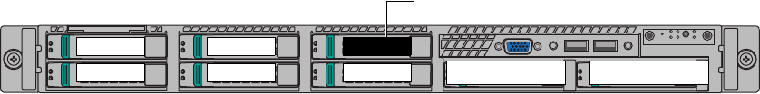
EMC Greenplum DCA Maintenance Guide Replace a disk drive in a Master, DIA, or Hadoop Compute server
88
Replace a Disk Drive
EMC CONFIDENTIAL
If the dial-home information includes a drive number, locate the drive with the
help of the following illustration:
Figure 12 Master and DIA server drive slot numbering
Verify the state of the
RAID group rebuild
process.
4. Before you remove the faulted drive, read the topic “Hot spare drives and the
Copyback operation” on page 86. Then issue the following command to determine
whether the RAID group is still being rebuilt:
# CmdTool2 -PDList -aALL|egrep “Adapter|Enclosure|Slot Number|Firmware state"
Example output is shown below. Focus on the items in bold.
Adapter #0
Enclosure Device ID: 252
Slot Number: 1
Enclosure position: 0
Firmware state: Online, Spun Up
Enclosure Device ID: 252
Slot Number: 2
Enclosure position: 0
Firmware state: Online, Spun Up
Enclosure Device ID: 252
Slot Number: 3
Enclosure position: 0
Firmware state: Online, Spun Up
Slot Number: 4
Enclosure position: 0
Firmware state: Online, Spun Up
Enclosure Device ID: 252
Slot Number: 5
Enclosure position: 0
Firmware state: Rebuild
In the example output above, note that the rebuild process is still in progress.
•If Rebuild appears anywhere in the output, the rebuild process is in progress. Do
remove the faulted drive yet. Monitor the rebuild process as described in step 5.
• If all drives in the output are shown as Online, Spun Up, the rebuild process is
complete. Proceed to removing the failed drive as described in step 6.
Monitor the rebuild
process.
5. To monitor the rebuild process if it is in progress, issue the following command.
Change the values in bold below to the actual values from your output. For example:
# CmdTool2 -pdrbld -progdsply -PhysDrv[252:5] -a0
The values in the above example refer to the following parameters:
•252 refers to the Enclosure Device ID.
•5 refers to the Slot Number of the hotspare drive invoked as the rebuild drive.
•0 refers to the Adapter Number.
Hot spare drive
Disk 1 Disk 3
Disk 0 Disk 2 Disk 4
Disk 5
Disk 6 (
empty
)Disk 7 (
empty
)
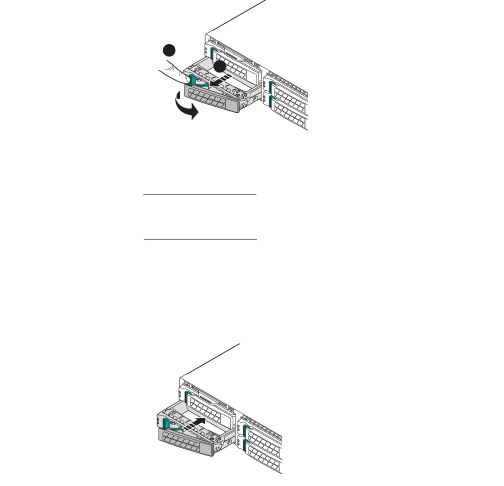
EMC Greenplum DCA Maintenance Guide Replace a disk drive in a Master, DIA, or Hadoop Compute server
89
Replace a Disk Drive
EMC CONFIDENTIAL
6. If the rebuild is complete, remove the failed drive from the server:
a. Press the button on the front of the drive carrier to release the drive handle.
b. Wait 10 seconds to allow the platter in the drive to stop spinning.
c. Pull the drive carrier out of the server.
Figure 13 Removing a drive from a Master Server
IMPORTANT
Make sure that adjacent drive carriers are fully installed and locked in place before
you remove or replace a drive carrier. Replacing a drive carrier and attempting to lock
its handle when the adjacent drive is only partially-installed can damage the drives.
7. To replace a drive in the server:
a. Press the button on the front of the drive carrier and open the handle.
b. Insert the drive carrier into the drive bay until the carrier contacts the backplane.
c. Close the handle to lock the drive carrier in place. The LED on the drive turns green
and blinks while it automatically starts the Copyback operation.
Figure 14 Replacing a drive in a Master Server
8. The Copyback operation should begin automatically when you insert the replacement
drive. (For details about Copyback, see “Hot spare drives and the Copyback operation”
on page 86.) Wait for the Copyback operation to complete. The hot spare always
occupies slot 5 on a Master server (see Figure 12 on page 88).
CL4966
A
B
CL4967
EMC Greenplum DCA Maintenance Guide Replace a disk drive in a Master, DIA, or Hadoop Compute server
90
Replace a Disk Drive
EMC CONFIDENTIAL
Verify that the Copyback
operation is in progress.
9. Issue the following command to verify that the Copyback operation is in progress:
# CmdTool2 -pdlist -aall | egrep "Adapter|Enclosure|Slot Number|Firmware state"
Example output is shown below. Focus on the items in bold.
Adapter #0
Enclosure Device ID: 252
Slot Number: 0
Enclosure position: 0
Firmware state: Copyback
Enclosure Device ID: 252
Slot Number: 1
Enclosure position: 0
Firmware state: Online, Spun Up
Enclosure Device ID: 252
Slot Number: 2
Enclosure position: 0
Firmware state: Online, Spun Up
Enclosure Device ID: 252
Slot Number: 3
Enclosure position: 0
Firmware state: Online, Spun Up
Enclosure Device ID: 252
Slot Number: 4
Enclosure position: 0
Firmware state: Online, Spun Up
Enclosure Device ID: 252
Slot Number: 5
Enclosure position: 0
Firmware state: Online, Spun Up
In the example output above, note that the firmware state of the drive in
Slot Number 0 is shown as Copyback. This indicates that the copyback operation is
in progress and that data is being restored to the new drive in Slot 0.
If no firmware states are shown as Copyback (for example, if the firmware states are
shown as Online, Spun Up or Hotspare Spun Up) the Copyback operation
is complete.
Monitor the Copyback
operation.
10. To monitor the progress of the Copyback operation, issue the following command.
Change the values shown in bold below to the actual values from your output.
# CmdTool2 -pdcpybk -progdsply -PhysDrv[252:0] -a0
The values in the above example refer to the following parameters:
•252 refers to the Enclosure Device ID.
•0 refers to the Slot Number of the hotspare drive invoked as the rebuild drive.
•0 refers to the Adapter Number.
The following is an example output of the Copyback progress.
Copyback Progress of Physical Drive...
Enclosure:Slot Percent Complete Time Elps
252 :00 ##############*********29 %*********** 00:10:38
Press <ESC> key to quit...

EMC Greenplum DCA Maintenance Guide Replace a drive in a Segment Server
91
Replace a Disk Drive
EMC CONFIDENTIAL
If the firmware state is reported as Unconfigured(Good) then the Copyback
operation did not occur automatically. In this unlikely event, you must initiate Copyback
manually by issuing the following command:
If necessary, manually
initiate the Copyback
operation.
# CmdTool2 -pdcpybk -start -PhysDrv[252:5,252:0] -a0
View the Copyback progress as described in step 10.
If no firmware states are shown as Copyback, the Copyback operation is complete.
11. Issue the following command:
CmdTool2 -pdlist -aall | egrep "Adapter|Enclosure|Slot Number|Firmware state"
12. In the output verify that the firmware state of the drives is reported as follows:
• Drives 0 - 4: Online, Spun Up
•Drive 5: hotspare, Spun Up
Replace a drive in a Segment Server
All drives are installed at the front of the server and connect to the system board through
the backplane. Hard drives are supplied in special hot-swappable hard-drive carriers that
fit in the hard-drive slots.
In addition to describing how to physically remove and insert the disk drive, this
procedure also describes how to do the following:
Determine if the RAID group is still rebuilding and how to monitor the rebuild process.
Verify that the Copyback operation is in progress and how to monitor it.
Manually initiate the Copyback operation if necessary.
1. Connect your service laptop to the DCA and log in to the Primary Master as the user
root (see “Connect a workstation to the DCA” on page 176).
2. To locate the server, use the DCA Setup Utility to activate the green lightbar on the DCA
door and the blue server identification LED as the user root:
a. Launch the DCA Setup utility:
# dca_setup
b. Select option 2 to Modify DCA Settings.
c. Select option 18 for Light Bar Controls.
d. Select option 3 for Blink the light bar.
e. Enter the hostname of the server and press ENTER.
f. Enter X to exit the DCA Setup utility.
The green lightbar on the DCA door and the blue server identification LED begin to
blink.
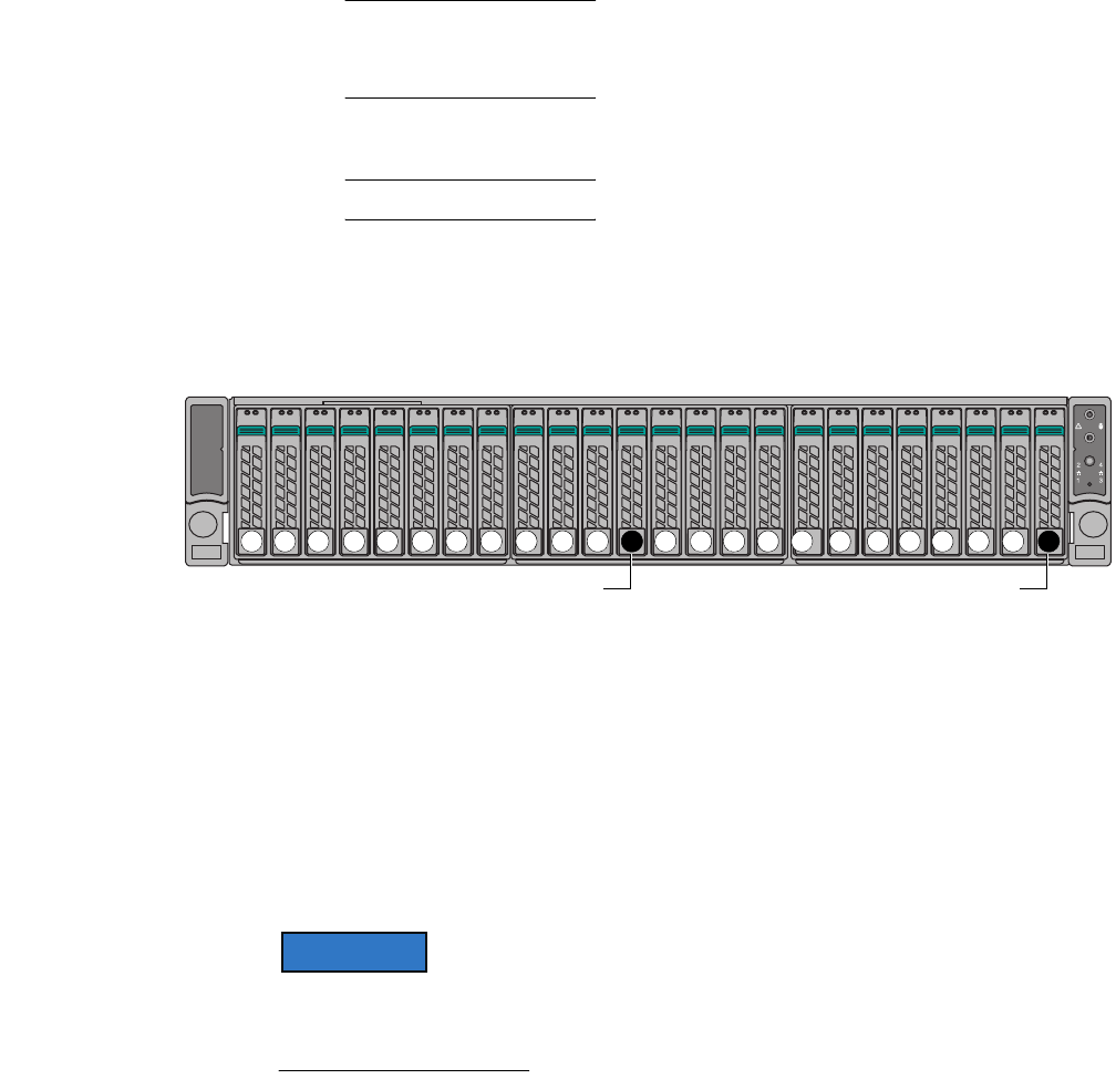
EMC Greenplum DCA Maintenance Guide Replace a drive in a Segment Server
92
Replace a Disk Drive
EMC CONFIDENTIAL
Note: If the DCA door does not have a lightbar, an error message displays. You can
safely ignore the error message. To identify the failed server, locate the blue server
identification LED.
g. Locate the failed drive.
Note: In this procedure, Disk 0 is the failed drive.
LED indicators on the each drive carrier indicate the current status of the drive
within it. A failed drive is indicated by a solid (unblinking) amber LED.
If the dial-home information includes a drive number, locate the drive with the
help of the following illustration:
Figure 15 Segment server drive slot numbering
Verify the state of the
RAID group rebuild
process.
3. Before you remove the faulted drive, read the topic “Hot spare drives and the
Copyback operation” on page 86.
4. Issue the following command to determine whether the RAID group is still being
rebuilt:
# CmdTool2 -pdlist -aall | egrep "Adapter|Enclosure|Slot Number|Firmware state"
Example output is shown below. Focus on the items in bold.
Note from the output that 24-disk GPDB servers have two Adapters (#0 and #1) that
control 12 slots each. Make sure that you investigate the correct area of the output for the
drive that you are replacing.
Adapter #0
Enclosure Device ID: 28
Slot Number: 1
Enclosure position: 0
Firmware state: Online, Spun Up
. . .
Enclosure Device ID: 28
Slot Number: 10
Enclosure position: 0
Firmware state: Online, Spun Up
Enclosure Device ID: 28
Slot Number: 11
Enclosure position: 0
Firmware state: Rebuild
AF004297
Hot spare drive Hot spare drive
1 2 3 4 5 6 7 8 9 10 12 13 14 15 16 17 18 19 20 21 22011 23

EMC Greenplum DCA Maintenance Guide Replace a drive in a Segment Server
93
Replace a Disk Drive
EMC CONFIDENTIAL
Adapter #1
Enclosure Device ID: 13
Slot Number: 0
Enclosure position: 0
Firmware state: Online, Spun Up
Enclosure Device ID: 13
. . .
Enclosure Device ID: 13
Slot Number: 11
Enclosure position: 0
Firmware state: Hotspare, Spun Up
In the example output above, note that the rebuild is still in progress.
•If Rebuild appears anywhere in the output, the rebuild is in progress. Do not
remove the faulted drive yet. Monitor the rebuild process as described in step 5.
• If all drives in the output are shown as Online, Spun Up the rebuild is
complete. Proceed to removing the failed drive as described in step 6.
Monitor the
rebuild process.
5. To monitor the rebuild process, issue the following command. Change the values
shown in bold below to the actual values from your output. For example:
# CmdTool2 -pdrbld -progdsply -PhysDrv[28:11] -a0
IMPORTANT
Remember that GPDB servers have two Adapters (#0 and #1) that control 12 slots
each. Make sure to specify the correct adapter number, slot number, and enclosure
device ID when issuing the above command.
The values in the above example refer to the following parameters:
•28 refers to the Enclosure Device ID.
•11 refers to the Slot Number of the hotspare drive invoked as the rebuild drive.
•0 refers to the Adapter Number.
6. If the rebuild is complete, remove the failed carrier from the server:
a. Press the button on the front of the drive carrier to release the drive handle.
b. Wait 10 seconds to allow the platter in the drive to stop spinning.
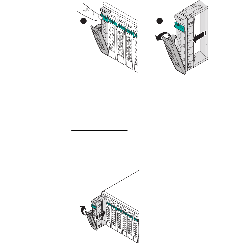
EMC Greenplum DCA Maintenance Guide Replace a drive in a Segment Server
94
Replace a Disk Drive
EMC CONFIDENTIAL
c. Pull the drive carrier out of the server.
Figure 16 Removing a drive from a Segment server
7. Make sure that the capacity of the replacement drive matches the capacity of the
failed drive. The drive capacity is printed on the label on each drive.
IMPORTANT
Do not mix drives of different capacities within a server.
8. To replace a drive carrier in the server:
a. Insert the drive carrier into the drive bay until the carrier contacts the backplane.
b. Close the handle to lock the drive carrier in place. The LED on the drive turns green
and blinks while it automatically starts the Copyback operation.
Figure 17 Replacing a drive in a Segment server
9. The Copyback operation should begin automatically when you insert the replacement
drive. (For details about Copyback, see “Hot spare drives and the Copyback operation”
on page 86.) Wait for the Copyback operation to complete. The hot spare drives always
occupy slot 11 and slot 23 in a 24-disk segment server (see Figure 15 on page 92).
Verify that the Copyback
operation is in progress.
10. Issue the following command to verify that the Copyback operation is in progress:
# CmdTool2 -pdlist -aall | egrep "Adapter|Enclosure|Slot Number|Firmware state"
CL5012
AB
CL5014
EMC Greenplum DCA Maintenance Guide Replace a drive in a Segment Server
95
Replace a Disk Drive
EMC CONFIDENTIAL
Example output is shown below. Focus on the items in bold.
Adapter #0
Enclosure Device ID: 28
Slot Number: 0
Enclosure position: 0
Firmware state: Copyback
. . .
Enclosure Device ID: 28
Slot Number: 11
Enclosure position: 0
Firmware state: Online, Spun Up
Adapter #1
Enclosure Device ID: 13
Slot Number: 0
Enclosure position: 0
Firmware state: Online, Spun Up
. . .
Enclosure Device ID: 13
Slot Number: 11
Enclosure position: 0
Firmware state: Hotspare, Spun Up
In the example output above, note that the firmware state of the drive in Adapter #0,
Slot Number 0 is shown as Copyback. This indicates that the copyback operation is
in progress and that data is being restored to the new drive in Slot 0.
If no firmware states are shown as Copyback, (for example, the firmware states are
Online, Spun Up or Hotspare Spun Up) the Copyback operation is complete.
Monitor the Copyback
operation.
11. To view the Copyback progress, issue the following command. Change the values
shown in bold below to the actual values from your output.
# CmdTool2 -pdcpybk -progdsply -PhysDrv[28:0] -a0
The values in the above example refer to the following parameters:
•28 refers to the Enclosure Device ID.
•0 refers to the Slot Number of the hotspare drive invoked as the rebuild drive.
•0 refers to the Adapter Number.
The following is an example output of the Copyback progress.
Copyback Progress of Physical Drive...
Enclosure:Slot Percent Complete Time Elps
28 :00 ##############*********29 %*********** 00:10:38
Press <ESC> key to quit...

EMC Greenplum DCA Maintenance Guide Replace a drive in an Hadoop server
96
Replace a Disk Drive
EMC CONFIDENTIAL
If the firmware state is reported as Unconfigured(Good) then the Copyback
operation did not occur automatically. In this unlikely event, you must initiate Copyback
manually by issuing the following command:
If necessary, manually
initiate the Copyback
operation.
# CmdTool2 -pdcpybk -start -PhysDrv[28:11,28:0] -a0
View the Copyback progress as described in step 11.
If no firmware states are shown as Copyback, the Copyback operation is complete.
12. Issue the following command:
CmdTool2 -pdlist -aall | egrep "Adapter|Enclosure|Slot Number|Firmware state"
13. In the output verify that the firmware state of the drives is reported as follows:
• Drives 0 - 10 and 12 - 22: Online, Spun Up
• Drives 11 and 23: hotspare, Spun Up
Replace a drive in an Hadoop server
The section describes how to replace a drive in a Hadoop server in DCA version 2.0.1.0 or
later. For details on replacing a drive in a Hadoop server in DCA version 2.0.0.0, see the
EMC Data Computing Appliance Maintenance Guide for 2.0.0.0, Rev A02
.
Hadoop-related procedures were not available at the time of this document’s publication.
The document will be updated in the short term and re-released. Until that time, please
contact platform-eng-support@gopivotal.com for Hadoop-related service questions.
The replacement procedure you use to replace a drive in a Hadoop server depends on the
type of Hadoop server it is, and—in the case of a Hadoop Worker—whether the faulted
drive is a System drive or a Data drive.
Hadoop Master servers—Drives are part of a RAID 5 configuration which can be rebuilt
automatically by the server’s RAID controller. For instructions, see “Replace a drive in
a Hadoop Master server” on page 97.
Hadoop Worker servers—The server has two different RAID configurations:
•System disks 0 – 1 are configured as RAID 1. If one of the System disks fails, the
RAID is rebuilt automatically by the server’s RAID controller after the replacement
drive is inserted. For instructions, see “Replace a System Disk (0 through 1)” on
page 101.
•Data disks 2 – 11 are each configured as single RAID-0. You must recover data
through the Hadoop filesystem after you replace the drive. For instructions, see
“Replace a failed Data Disk (2 through 11)” on page 104.

EMC Greenplum DCA Maintenance Guide Replace a drive in an Hadoop server
97
Replace a Disk Drive
EMC CONFIDENTIAL
Replace a drive in a Hadoop Master server
All drives are installed at the front of the server and connect to the system board through
the backplane. Hard drives are supplied in special hot-swappable hard-drive carriers that
fit in the hard-drive slots.
In addition to describing how to physically remove and insert the disk drive, this
procedure also describes how to do the following:
Determine if the RAID group is still being rebuilt and how to monitor the rebuild
process.
Verify that the Copyback operation is in progress and how to monitor the Copyback
operation.
Manually initiate the Copyback operation if necessary.
1. Connect your service laptop to the DCA and log in to the Primary Master as the user
root (see “Connect a workstation to the DCA” on page 176).
2. To locate the server, use the DCA Setup Utility to activate the green lightbar on the DCA
door and the blue server identification LED as the user root:
a. Launch the DCA Setup utility:
# dca_setup
b. Select option 2 to Modify DCA Settings.
c. Select option 18 for Light Bar Controls.
d. Select option 3 for Blink the light bar.
e. Enter the hostname of the server and press ENTER.
f. Enter X to exit the DCA Setup utility.
The green lightbar on the DCA door and the blue server identification LED begin to
blink.
Note: If the DCA door does not have a lightbar, an error message displays. You can
safely ignore the error message. To identify the failed server, locate the blue server
identification LED.
g. Locate the failed drive.
Note: In this procedure, Disk 0 is the failed drive.
LED indicators on the each drive carrier indicate the current status of the drive
within it. A faulted drive is indicated by a solid (unblinking) amber LED.
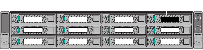
EMC Greenplum DCA Maintenance Guide Replace a drive in an Hadoop server
98
Replace a Disk Drive
EMC CONFIDENTIAL
If the dial-home information includes a drive number, locate the drive with the
help of the following illustration:
Figure 18 Hadoop Master server drive slot numbering
Verify the state of the
RAID group rebuild
process.
3. Before you remove the faulted drive, read the topic “Hot spare drives and the
Copyback operation” on page 86.
4. Issue the following command to determine whether the RAID group is still being
rebuilt:
# CmdTool2 -pdlist -aall | egrep "Adapter|Enclosure|Slot Number|Firmware state"
Example output is shown below. Focus on the items in bold.
Adapter #0
Enclosure Device ID: 28
Slot Number: 1
Enclosure position: 0
Firmware state: Online, Spun Up
. . .
Enclosure Device ID: 28
Slot Number: 11
Enclosure position: 0
Firmware state: Rebuild
In the example output above, note that the rebuild is still in progress.
•If Rebuild appears anywhere in the output, the rebuild is in progress. Do not
remove the faulted drive yet. Monitor the rebuild process as described in step 5.
• If all drives in the output are shown as Online, Spun Up the rebuild is
complete. Proceed to removing the failed drive as described in step 6.
Monitor the
rebuild process.
5. To monitor the rebuild process, issue the following command. Change the values
shown in bold below to the actual values from your output. For example:
# CmdTool2 -pdrbld -progdsply -PhysDrv[28:11] -a0
The values in the above example refer to the following parameters:
•28 refers to the Enclosure Device ID.
•11 refers to the Slot Number of the hotspare drive invoked as the rebuild drive.
•0 refers to the Adapter Number.
6. If the rebuild is complete, remove the failed drive from the server:
a. Press the button on the front of the drive carrier to release the drive handle.
Hot spare drive
(Hadoop Masters only)
Disk 0
Disk 1
Disk 2
Disk 0
Disk 4
Disk 5
Disk 3
Disk 7
Disk 8
Disk 6
Disk 10
Disk 11
Disk 9
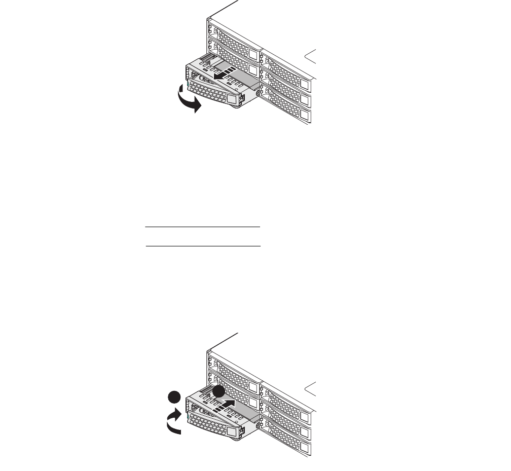
EMC Greenplum DCA Maintenance Guide Replace a drive in an Hadoop server
99
Replace a Disk Drive
EMC CONFIDENTIAL
b. Wait 10 seconds to allow the platter in the drive to stop spinning.
c. Pull the drive carrier out of the server.
Figure 19 Removing a drive from a Hadoop Master server
7. Make sure that the capacity of the replacement drive matches the capacity of the
failed drive. The drive capacity is printed on the label on each drive.
IMPORTANT
Do not mix drives of different capacities within a server.
8. To replace a drive carrier in the server:
a. Insert the drive carrier into the drive bay until the carrier contacts the backplane.
b. Close the handle to lock the drive carrier in place. The LED on the drive turns green
and blinks while it automatically starts the Copyback operation.
Figure 20 Replacing a drive in a Hadoop Master server
9. The Copyback operation should begin automatically when you insert the replacement
drive. (For details about Copyback, see “Hot spare drives and the Copyback operation”
on page 86.) Wait for the Copyback operation to complete. The hot spare always
occupies Slot 11 on a Hadoop Master server (see Figure 15 on page 92).
Verify that the Copyback
operation is in progress.
10. Issue the following command to verify that the Copyback operation is in progress:
# CmdTool2 -pdlist -aall | egrep "Adapter|Enclosure|Slot Number|Firmware state"
Example output is shown below. Focus on the items in bold.
CL4982
CL4983
A
B

EMC Greenplum DCA Maintenance Guide Replace a drive in an Hadoop server
100
Replace a Disk Drive
EMC CONFIDENTIAL
Adapter #0
Enclosure Device ID: 28
Slot Number: 0
Enclosure position: 0
Firmware state: Copyback
. . .
Enclosure Device ID: 28
Slot Number: 11
Enclosure position: 0
Firmware state: Online, Spun Up
In the example output above, note that the firmware state of the drive in
Slot Number 0 is shown as Copyback. This indicates that the copyback operation is
in progress and that data is being restored to the new drive in Slot 0.
If no firmware states are shown as Copyback, (for example, the firmware states are
Online, Spun Up or Hotspare Spun Up) the Copyback operation is complete.
Monitor the Copyback
operation.
11. To view the Copyback progress, issue the following command. Change the values
shown in bold below to the actual values from your output.
# CmdTool2 -pdcpybk -progdsply -PhysDrv[28:0] -a0
The values in the above example refer to the following parameters:
•28 refers to the Enclosure Device ID.
•0 refers to the Slot Number of the hotspare drive invoked as the rebuild drive.
•0 refers to the Adapter Number.
The following is an example output of the Copyback progress.
Copyback Progress of Physical Drive...
Enclosure:Slot Percent Complete Time Elps
28 :00 ##############*********29 %*********** 00:10:38
Press <ESC> key to quit...
If the firmware state is reported as Unconfigured(Good) then the Copyback operation
did not occur automatically. In this unlikely event, you must initiate Copyback manually by
issuing the following command:
If necessary, manually
initiate the Copyback
operation.
# CmdTool2 -pdcpybk -start -PhysDrv[28:11,28:0] -a0
View the Copyback progress as described in step 11.
If no firmware states are shown as Copyback, the Copyback operation is complete.
12. Issue the following command:
CmdTool2 -pdlist -aall | egrep "Adapter|Enclosure|Slot Number|Firmware state"
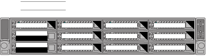
EMC Greenplum DCA Maintenance Guide Replace a drive in an Hadoop server
101
Replace a Disk Drive
EMC CONFIDENTIAL
13. In the output verify that the firmware state of the drives is reported as follows:
• Drives 0 - 10: Online, Spun Up
•Drive 11: Hotspare, Spun Up
Replace a drive in a Hadoop Worker server
There are two types of RAID configurations in an Hadoop Worker server:
•System disks 0 – 1 are configured as RAID 1. If one of the System disks fail, the
RAID is rebuilt automatically by the server’s RAID controller after the replacement
drive is inserted. For instructions, “Replace a System Disk (0 through 1)” on
page 101.
•Data disks 2 – 11 are each configured as individual RAID 0 disks. If a drive fails,
data must be recovered through the Hadoop filesystem after you replace the drive.
For instructions, see “Replace a failed Data Disk (2 through 11)” on page 104.
Note: Unlike other server types, Hadoop Workers do not have a hot spare drive.
Figure 21 Hadoop Worker server drive types and locations
Replace a System Disk (0 through 1)
All drives are installed at the front of the server and connect to the system board through
the backplane. Hard drives are supplied in special hot-swappable hard-drive carriers that
fit in the hard-drive slots.
In addition to describing how to physically remove and insert the disk drive, this
procedure also describes how to determine if the RAID group is still rebuilding and how to
monitor the rebuild process.
1. Connect your service laptop to the DCA and log in to the Primary Master as the user
root (see “Connect a workstation to the DCA” on page 176).
2. To locate the server, use the DCA Setup Utility to activate the green lightbar on the DCA
door and the blue server identification LED as the user root:
a. Launch the DCA Setup utility:
# dca_setup
b. Select option 2 to Modify DCA Settings.
c. Select option 18 for Light Bar Controls.
d. Select option 3 for Blink the light bar.
e. Enter the hostname of the server and press ENTER.
Physical disk 0:0:10
Physical disk 0:0:9
Physical disk 0:0:0
System Disk
Data
Data
Data
Data
Data
Data
Data
Data
Data
Physical disk 0:0:5
Physical disk 0:0:4
Physical disk 0:0:8
Physical disk 0:0:7
Physical disk 0:0:3 Physical disk 0:0:6
Physical disk 0:0:1
System Disk
Physical disk 0:0:2 Physical disk 0:0:11
Data
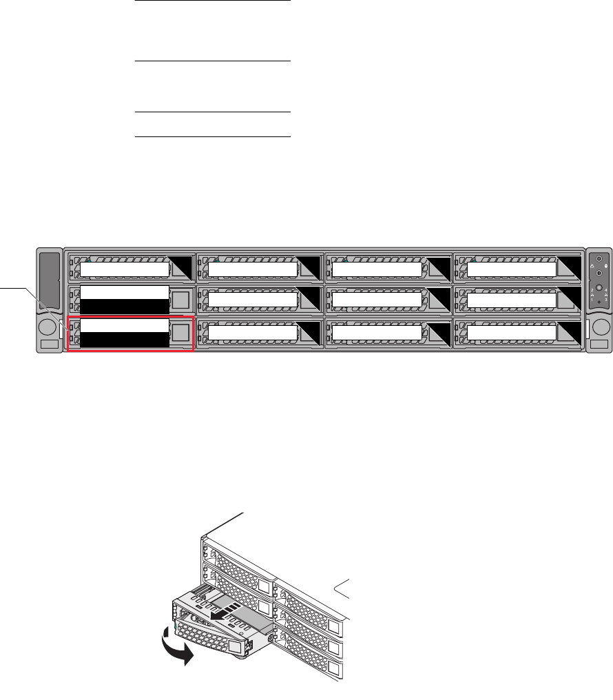
EMC Greenplum DCA Maintenance Guide Replace a drive in an Hadoop server
102
Replace a Disk Drive
EMC CONFIDENTIAL
f. Enter X to exit the DCA Setup utility.
The green lightbar on the DCA door and the blue server identification LED begin to
blink.
Note: If the DCA door does not have a lightbar, an error message displays. You can
safely ignore the error message. To identify the failed server, locate the blue server
identification LED.
g. Locate the failed drive.
Note: In this procedure, System Disk 0 is the failed drive.
LED indicators on the each drive carrier indicate the current status of the drive
within it. A failed drive is indicated by a solid (unblinking) amber LED.
If the dial-home information includes a drive number, locate the drive with the
help of the following illustration:
Figure 22 Hadoop Worker server drive slot numbering
3. Remove the failed drive from the server:
a. Press the button on the front of the drive carrier to release the drive handle.
b. Wait 10 seconds to allow the platter in the drive to stop spinning.
c. Pull the drive carrier out of the server.
Figure 23 Removing a drive from a Hadoop Master server
4. Make sure that the capacity of the replacement drive matches the capacity of the
failed drive. The drive capacity is printed on the label on each drive.
Physical disk 0:0:10
Physical disk 0:0:9
Physical disk 0:0:0
System Disk
Data
Data
Data
Data
Data
Data
Data
Data
Data
Physical disk 0:0:5
Physical disk 0:0:4
Physical disk 0:0:8
Physical disk 0:0:7
Physical disk 0:0:3 Physical disk 0:0:6
Physical disk 0:0:1
System Disk
Physical disk 0:0:2 Physical disk 0:0:11
Data
Failed disk in
this example
CL4982
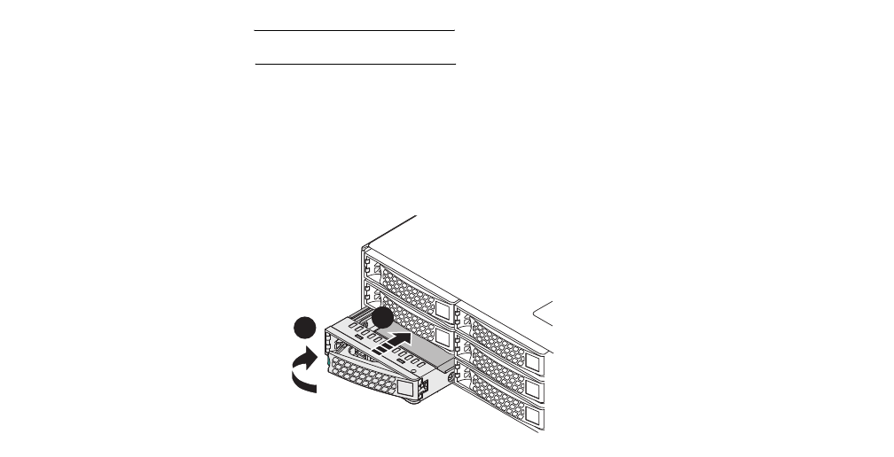
EMC Greenplum DCA Maintenance Guide Replace a drive in an Hadoop server
103
Replace a Disk Drive
EMC CONFIDENTIAL
IMPORTANT
Do not mix drives of different capacities within a server.
5. To replace a drive carrier in the server:
a. Insert the drive carrier into the drive bay until the carrier contacts the backplane.
b. Close the handle to lock the drive carrier in place. The LED on the drive turns green
and blinks while it automatically starts the Copyback operation.
Figure 24 Replacing a drive in a Hadoop Master server
After the replacement drive is inserted the RAID controller automatically begins the rebuild
process and writes data to the replacement drive, as indicated by a slowly blinking amber
LED on the drive. Do not interrupt the rebuild process.
Verify the state of the
RAID group rebuild
process.
6. To determine whether the RAID group is still being rebuilt, issue the following
command:
# CmdTool2 -pdlist -aall | egrep "Adapter|Enclosure|Slot Number|Firmware state"
Example output is shown below. Focus on the items in bold.
Adapter #0
Enclosure Device ID: 21
Slot Number: 0
Enclosure position: 0
Firmware state: Rebuild
In the example output above, note that the firmware state indicates that the rebuild is
still in progress.
• If the firmware state of the replacement drive is shown as Rebuild, the rebuild is
in progress.
• If the firmware state of the replacement drive is shown as Online, Spun Up the
rebuild is complete.
CL4983
A
B

EMC Greenplum DCA Maintenance Guide Replace a drive in an Hadoop server
104
Replace a Disk Drive
EMC CONFIDENTIAL
Monitor the
rebuild process.
7. To monitor the rebuild process, issue the following command. Change the values
shown in bold below to the actual values from your output. For example:
# CmdTool2 -pdrbld -progdsply -PhysDrv[21:0] -a0
The values in the above example refer to the following parameters:
•21 refers to the Enclosure Device ID.
•0 refers to the slot from which you removed the faulted drive and inserted a
replacement drive.
•-a0 refers to Adapter Number 0.
8. Issue the following command:
CmdTool2 -pdlist -aall | egrep "Adapter|Enclosure|Slot Number|Firmware state"
9. In the output verify that the firmware state of the drives is reported as:
Online, Spun Up
If necessary, manually
initiate the rebuild
process.
If the firmware state is reported as Unconfigured(Good) then the rebuild did not
occur automatically. In this unlikely event, you must initiate the rebuild manually by
issuing the following command:
# CmdTool2 -pdrbld -start -PhysDrv[21:0] -a0
Monitor the rebuild as described in step 7.
If the firmware state of the replacement drive is shown as Online, Spun Up, the
rebuild is complete.
Replace a failed Data Disk (2 through 11)
Data disks 2 through 11 are each configured as individual RAID 0 disks. Because data
from a RAID 0 cannot be recovered automatically by the server’s RAID controller, you must
recover it through the Hadoop software as described in this procedure.
1. Log in to the Primary Master Server as the user gpadmin (see “ Connect to the Master
Server using an SSH client” on page 178).
2. To locate the server, use the DCA Setup Utility to activate the green lightbar on the DCA
door and the blue server identification LED as the user root:
a. Launch the DCA Setup utility:
# dca_setup
b. Select option 2 to Modify DCA Settings.
c. Select option 18 for Light Bar Controls.
d. Select option 3 for Blink the light bar.
e. Enter the hostname of the server and press ENTER.
f. Enter X to exit the DCA Setup utility.

EMC Greenplum DCA Maintenance Guide Replace a drive in an Hadoop server
105
Replace a Disk Drive
EMC CONFIDENTIAL
The green lightbar on the DCA door and the blue server identification LED begin to
blink.
Note: If the DCA door does not have a lightbar, an error message displays. You can
safely ignore the error message. To identify the failed server, locate the blue server
identification LED.
3. Locate the failed data disk (see Figure 22). Make note of the drive position in the
format 0:0:X. where X is the slot number of the faulted data drive.
4. Remove the faulted drive from the server:
a. Press the button on the front of the drive carrier to release the drive handle.
b. Wait 10 seconds to allow the platter in the drive to stop spinning.
c. Pull the drive carrier out of the server.
5. Make sure that the capacity of the replacement drive matches the capacity of the
failed drive. The drive capacity is printed on the label on each drive.
IMPORTANT
Do not mix drives of different capacities within a server.
6. Install the replacement drive carrier in the server:
a. Insert the drive carrier into the drive bay until the carrier contacts the backplane.
b. Close the handle to lock the drive carrier in place. The LED on the drive turns green
and blinks while it automatically starts the Copyback operation.
7. Log in to the Primary Master Server as the user root (see “ Connect to the Master
Server using an SSH client” on page 178).
8. Connect as the user root to the server with the new disk. For example, if you replaced
a disk in hdw1:
$ ssh root@hdw1
Create a new virtual disk
9. Create a new virtual disk on the replacement drive:
a. For the disk that you replaced, determine the Enclosure Device ID of the server and
the Adapter Number :
# CmdTool2 -pdlist -aall | egrep "Adapter|Enclosure|Slot Number”
The following output is returned:
Adapter #0
Enclosure Device ID: 13
Slot Number: 0
Enclosure position: 0
. . .
Enclosure Device ID: 13
Slot Number: 11
Enclosure position: 0
EMC Greenplum DCA Maintenance Guide Replace a drive in an Hadoop server
106
Replace a Disk Drive
EMC CONFIDENTIAL
b. Using information from the output above, issue the command from Table 5 that
corresponds to the physical disk that you installed.
For example, to create a virtual disk on physical disk 0:0:11, issue:
# CmdTool2 -CfgLdAdd r0 '[13:11]' -a0
The values in the above command example refer to the following:
•r0 refers to the RAID level (which is always 0 for a Hadoop Worker data disk).
•13 refers to the Enclosure Device ID.
•11 refers to the Slot Number of the physical disk that you replaced.
•-a0 refers to the Adapter Number.
Table 6 below matches each physical disk in the server with its corresponding virtual
disk. Note that the virtual disk for physical disk 0:0:11 is 13.
Table 5 Virtual disk creation commands per physical disk slot
Physical Disk Command
0:0:0, 0:0:1 # CmdTool2 -CfgLdAdd r1 '[13:0,13:1]' -sz 102400 -a0
# CmdTool2 -CfgLdAdd r1 '[13:0,13:1]' -sz 65536 -a0
# CmdTool2 -CfgLdAdd r1 '[13:0,13:1]' -sz 102400 -a0
# CmdTool2 -CfgLdAdd r1 '[13:0,13:1]' -a0
0:0:2 # CmdTool2 -CfgLdAdd r0 '[13:2]' -a0
0:0:3 # CmdTool2 -CfgLdAdd r0 '[13:3]' -a0
0:0:4 # CmdTool2 -CfgLdAdd r0 '[13:4]' -a0
0:0:5 # CmdTool2 -CfgLdAdd r0 '[13:5]' -a0
0:0:6 # CmdTool2 -CfgLdAdd r0 '[13:6]' -a0
0:0:7 # CmdTool2 -CfgLdAdd r0 '[13:7]' -a0
0:0:8 # CmdTool2 -CfgLdAdd r0 '[13:8]' -a0
0:0:9 # CmdTool2 -CfgLdAdd r0 '[13:9]' -a0
0:0:10 # CmdTool2 -CfgLdAdd r0 '[13:10]' -a0
0:0:11 # CmdTool2 -CfgLdAdd r0 '[13:11]' -a0
0:0:11
is used as the
example replacement drive
throughout this procedure.
Table 6 Disk attributes in a Hadoop Worker server
Physical Disk Virtual Disk Mount (Device name) Label
0:0:0, 0:0:1 0 /sda1 /boot
1 /sda2 /
2 /sdbswap swap
3 /sdc1 crash
0:0:2 4 /sde /data1

EMC Greenplum DCA Maintenance Guide Replace a drive in an Hadoop server
107
Replace a Disk Drive
EMC CONFIDENTIAL
Determine the
automatically-assigned
device name.
10. Confirm the device name that was assigned to the new virtual disk. When issuing the
following command, change the values in bold below with the values specific to your
situation:
# CmdTool2 -LDInfo -L13 -a0
The values in the above command example refer to the following:
•13 refers to the virtual disk created on physical disk 0:0:11.
•0 refers to the Adapter Number (i.e., the RAID controller).
Virtual Drive: 13 (Target Id: 13)
Name :sdn
RAID Level : Primary-0, Secondary-0, RAID Level Qualifier-0
Size : 2.727 TB
Parity Size : 0
State : Optimal
Strip Size : 256 KB
Number Of Drives : 1
Span Depth : 1
Default Cache Policy: WriteBack, ReadAdaptive, Direct, No Write Cache
if Bad BBU
Current Cache Policy: WriteBack, ReadAdaptive, Direct, No Write Cache
if Bad BBU
Default Access Policy: Read/Write
Current Access Policy: Read/Write
Disk Cache Policy : Disk's Default
Encryption Type : None
PI type: No PI
Is VD Cached: No
In the example output above, note the value next to Name. This is the device name
that you will use in step 11 to format a filesystem on the new virtual disk.
0:0:3 5 /sdf /data2
0:0:4 6 /sdg /data3
0:0:5 7 /sdh /data4
0:0:6 8 /sdi /data5
0:0:7 9 /sdj /data6
0:0:8 10 /sdk /data7
0:0:9 11 /sdl /data8
0:0:10 12 /sdm /data9
0:0:11 13 /sdn /data10
Table 6 Disk attributes in a Hadoop Worker server
Physical Disk Virtual Disk Mount (Device name) Label

EMC Greenplum DCA Maintenance Guide Replace a drive in an Hadoop server
108
Replace a Disk Drive
EMC CONFIDENTIAL
If the name does not appear in your output as it did in the above example, refer to Table 6
on page 106 and look up the device name value that corresponds to the physical disk that
you replaced. Then issue the following command to set the device name. For example, to
set the virtual disk device name of physical disk 11 to sdn (as specified in Table 6 on
page 106):
# CmdTool2 -ldsetprop -name sdn -L13 -a0
11. Format and label the filesystem on the new virtual disk. Replace the text in bold with
values from the Label column and the Mount/Device name column in Table 6 that
correspond to the physical disk that you replaced.
# mkfs -t xfs -L /data10 -f /dev/sdn
# mount /data10
If for any reason you eject and then reseat an
existing
drive, you may have put the drive
into a foreign state. If so, you must clear the state of the drive.
a. To check the state of the drive in this case, switch to the user root and then issue
the following command:
# CmdTool2 -pdlist -aall | egrep "Adapter|Enclosure|Slot Number|Firmware state|Foreign State"
Example output for a drive with a foreign state would look like this:
Enclosure Device ID: 13
Slot Number: 11
Enclosure position: 0
Firmware state: foreign
b. Examine the output carefully. If the output shows the drive state to be foreign,
clear the state by issuing the following command, making sure to replace the
Enclosure Device and Slot Number shown in bold below with the Enclosure Device
ID and Slot Number given in your output.
# CmdTool2 -PDMakeGood -PhysDrv[13:11]-Force -aALL
c. Then, issue the following command. Change the values in bold with the Enclosure
Device ID and Slot Number given in your output:
# CmdTool2 -PDClear -Start -PhysDrv[13:11]-a0
d. Wait 5 minutes, then issue the following command, making sure to change the
values in bold with the Enclosure Device ID and Slot Number given in your output:
# CmdTool2 -PDClear -Stop -PhysDrv[13:11]-a0
Introduce the
replacement drive to the
Hadoop cluster and
restart Hadoop
12. Make the following directories on the replacement drive:
mkdir /data10/hadoop
mkdir /data10/hadoop/data
mkdir /data10/hadoop/local
If necessary, clear
the state of the disk
EMC Greenplum DCA Maintenance Guide Replace a drive in an Hadoop server
109
Replace a Disk Drive
EMC CONFIDENTIAL
13. Set permissions on the new directories that you made in the previous step:
# chown hdfs:hadoop /datat10/hadoop/data
# chown mapred:hadoop /datat10/hadoop/local
14. Set permissions on Hadoop to 755:
# chmod 755 /data10/hadoop
# chmod 755 /data10/hadoop/local
15. Restart Hadoop on the recovered Hadoop Worker node:
# service hadoop-datanode restart
# service hadoop-tasktracker restart
16. Connect to the host hdm1 :
# ssh hdm1
17. Switch to the user hdfs and verify that the Hadoop filesystem is healthy:
# su - hdfs
$ hadoop fsck /
The following message in the output indicates a healthy filesystem:
The filesystem under path '/' is HEALTHY
EMC Greenplum DCA Maintenance Guide Replace a Power Supply in a Server
110
EMC CONFIDENTIAL
CHAPTER 5
Replace a Power Supply in a Server
This chapter describes how to replace power supplies in DCA UAP servers.
Power supply LEDs
Each server in the UAP DCA has two power supplies that share the power load and provide
redundancy. When the power load is below a certain threshold, only one power supply in
each server is active and its LED is solid green to reflect the active state. The other power
supply is in standby mode and its LED flashes green to reflect the standby state.
Replace a power supply in a server
The servers in the DCA rack are powered by dual redundant hot-swappable power supplies
located in the rear of the appliance. To replace a power supply in a server, perform the
following procedure.
1. Log in to the Primary Master Server as the user root (see “Connect to the Master
Server using an SSH client” on page 178).
2. To locate the server, use the DCA Setup Utility to activate the green lightbar on the DCA
door and the blue server identification LED as the user root:
a. Launch the DCA Setup utility:
# dca_setup
b. Select option 2 to Modify DCA Settings.
c. Select option 18 for Light Bar Controls.
d. Select option 3 for Blink the light bar.
e. Enter the hostname of the server and press ENTER.
f. Enter X to exit the DCA Setup utility.
The green lightbar on the DCA door and the blue server identification LED begin to
blink.
Table 7 Power supply LED behavior
LED behavior Definition
Solid green Active mode
Blinking green, slow Standby mode
Blinking green, rapid Power supply firmware updating
Off No AC power to both power supplies in the server
Amber No AC power to this power supply, other power supply has AC power
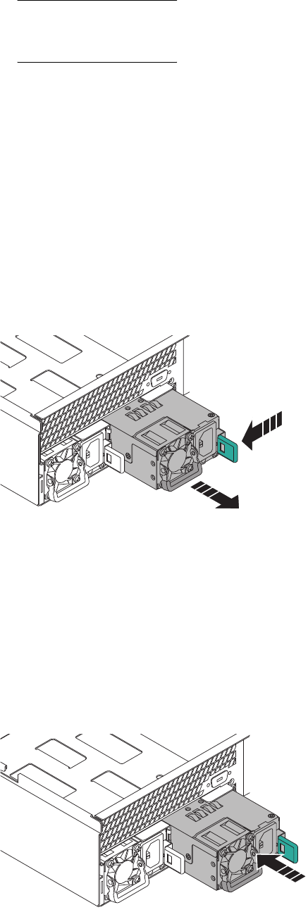
EMC Greenplum DCA Maintenance Guide Replace a power supply in a server
111
Replace a Power Supply in a Server
EMC CONFIDENTIAL
Note: If the DCA door does not have a lightbar, an error message displays. You can
safely ignore the error message. To identify the failed server, locate the blue server
identification LED.
3. Locate the failed power supply in the server.
The LED on a failed power supply is either amber or, if the power supply has
completely failed, the LED is off.
4. Verify that the LED on the functioning (redundant) power supply is solid green.
5. Check the connection of the AC power cable. Make sure that both ends of the cable are
securely connected.
6. If the power supply still appears to be failed, try a known-good power cable.
7. If the power supply still appears to be failed, disengage the retaining clip that secures
the AC power cable, and then disconnect the AC power cable from the power supply.
8. While pressing the green release latch leftward, pull on the handle to slide the power
supply out of the chassis.
Figure 25 Remove a server power supply
9. Make sure that the replacement power supply is the correct part number:
EMC P/N 105-000-244
The part number is located on the packaging, not on the power supply itself. Both
power supplies in a server must provide the same maximum output power.
10. Install the replacement power supply in the chassis.
Slide the replacement power supply into the chassis until the power supply is fully
seated and the release latch clicks into place.
Figure 26 Insert a server power supply
CL5013
EMC Greenplum DCA Maintenance Guide Replace a power supply in a server
112
Replace a Power Supply in a Server
EMC CONFIDENTIAL
11. Connect the AC power cable to the power supply and secure it with the retaining clip.
12. Verify that the power supply LED indicator is solid or blinking greeTurn off the green
lightbar on the DCA door and the blue server identification LED:
a. If you are not already in it, start the DCA Setup utility as the user root:
# dca_setup
b. Select option 2 to Modify DCA Settings.
c. Select option 18 for Light Bar Controls.
d. Select option 2 for Turn off the light bar.
e. Enter the hostname of the server and press ENTER. For example, sdw1.
The lightbar on the DCA door and the blue server identification LED stop blinking.
13.

EMC Greenplum DCA Maintenance Guide Replace a Fan Assembly or Power Supply in an Arista Switch
113
EMC CONFIDENTIAL
CHAPTER 6
Replace a Fan Assembly or Power Supply in an
Arista Switch
Refer to the appropriate section to replace a fan assembly or a power supply in an Arista
switch.
Replace a Fan Assembly in an Arista Switch
The Admin, Interconnect, and Aggregate switches (Arista 7048/7050 series) in a DCA rack
are cooled by their four modular fan assemblies that can be replaced individually upon
failure as shown in Figure 20. The fans provide rear-to-front airflow.
Leave any failed fan assembly installed until the point where it can be immediately
replaced.
Do not remove a fan assembly from the chassis until you are ready to replace it.
Follow ESD precautions, including the use of a wrist grounding strap, when you
replace components.
The cooling system requires pressurized air in order to function properly. Do not leave
any fan assembly slot unoccupied for longer than two minutes when the appliance is
operating.
Fan Assembly Replacement Order Information
Use the following information to order the Arista Fan Assembly for the 7048T and 7050S
Switch:
Description: Fan Assembly for the Arista Switch (rear-to-front air flow)
Model Number: FAN-7000-R
EMC Part Number: 105-000-313
Tools
The procedure only requires a wrist grounding strap (there are no screws to remove).
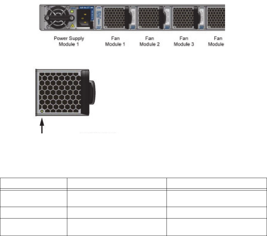
EMC Greenplum DCA Maintenance Guide Replace a Fan Assembly in an Arista Switch
114
Replace a Fan Assembly or Power Supply in an Arista Switch
EMC CONFIDENTIAL
Identify the Failed Fan Assembly
1. Once on site, you must locate the DCA rack and confirm the switch physical location
within the cabinet top level assembly (TLA) serial number reported in the service
request. Arista switches (7050S) function as server interconnect or rack aggregation
and are mounted mid-point in the 40RU rack height. The Admin (7048T) switch is
mounted at the top of the rack.
2. You must confirm that the fan assembly specified for replacement is the failed fan
assembly, and that the LED on the other fans are operational green and lit steadily
(Figure 20 and Figure 21). Access to the fans is from the front of the rack.
Figure 27 Four fan assemblies in the Arista switch
Figure 28 Fan Status LED location
3. Analyze the failure using Table 8 or possible actions.
Table 8 Fan assembly LED Indicators
LED Behavior Possible State Action
No light Fan assembly is not receiving power. Verify that the fan assembly is seated
correctly, and there is no air movement.
Steady Green Fan assembly is operating normally. No action
Steady Red or Amber Fan has failed or power supply was
removed from switch.
Failed and must be replaced.
EMC Greenplum DCA Maintenance Guide Replace a Fan Assembly in an Arista Switch
115
Replace a Fan Assembly or Power Supply in an Arista Switch
EMC CONFIDENTIAL
Remove the Failed Fan Assembly and Install the Replacement Part
The cooling system relies on pressurized air. Do not leave any of the Fan assembly slots
empty longer than two minutes when the switch is in operation.
1. Remove the fan assembly. While pressing on the black release latch leftward, grip the
blue pull-ring and slide the fan assembly out of the chassis.
2. Slide the new Fan assembly into the chassis until the unit is fully seated, and the
release latch snaps back into its original position.
Do not force the insertion as damage can occur. If it resists, ensure that it is oriented
correctly for a smooth slide and fit.
3. Verify that the Fan status LED is lit (steady green) to indicate normal operation.
Parts Return
1. Locate the Parts Return Label package. Fill out the shipping label. Apply the shipping
label to the box for return to EMC.
2. Read enclosed
Shipping Instructions
sheet.
3. Apply other labels for the box appropriate to this returning part, including the Failure
Analysis (FA) tag which is currently required for all DCA replacement parts.
4. Securely tape the box and ship the failed part back to EMC.
5. Send questions regarding this return shipment to:
CS_Logistics_IC@emc.com
This completes the fan assembly replacement.

EMC Greenplum DCA Maintenance Guide Replace a Power Supply in an Arista Switch
116
Replace a Fan Assembly or Power Supply in an Arista Switch
EMC CONFIDENTIAL
Replace a Power Supply in an Arista Switch
The Admin, Interconnect, and Aggregate switches (Arista 7048/7050 series) in a DCA rack
are powered by dual redundant modular power supply assemblies that can be replaced
individually upon failure as shown in Figure 22.
Leave any failed power supply installed until the point where it can be immediately
replaced.
Follow ESD precautions, including the use of a wrist grounding strap, when you
replace components.
The cooling system requires pressurized air in order to function properly. Do not leave
any power supply slot unoccupied for longer than two minutes when the appliance is
operating.
Power Supply Assembly Replacement Order Information
Use the following information to order the Arista Power Supply Assembly for the 7048T
and 7050S switch:
Description: Power Supply Assembly for the Arista Switch, 460W AC (rear-to-front air
flow)
Model Number: PWR-460AC-R
EMC Part Number: 105-000-314
Tools
The procedure only requires a wrist grounding strap (there are no screws to remove).
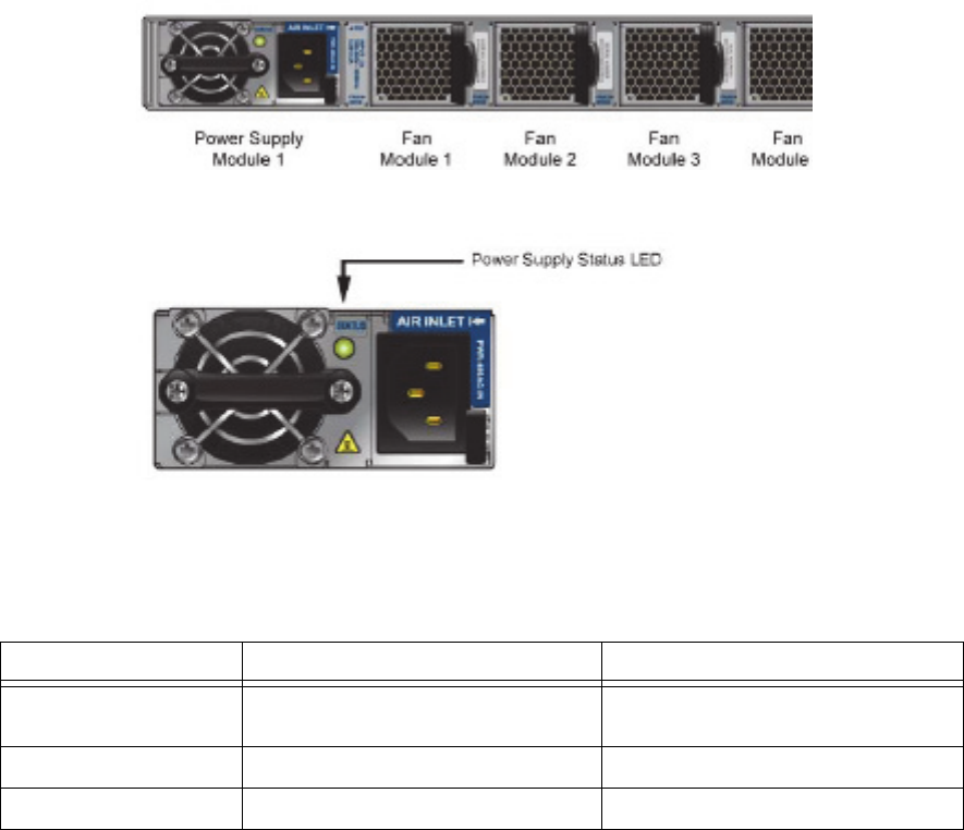
EMC Greenplum DCA Maintenance Guide Replace a Power Supply in an Arista Switch
117
Replace a Fan Assembly or Power Supply in an Arista Switch
EMC CONFIDENTIAL
Identify the Failed Power Supply
1. Once on site, you must locate the DCA rack and confirm the switch physical location
within the cabinet top level assembly (TLA) serial number reported in the service
request. Arista switches (7050S) function as server interconnect or rack aggregation
and are mounted mid-point in the 40RU rack height. The Admin (7048T) switch is
mounted at the top of the rack.
2. You must confirm that the power supply specified for replacement is not working, and
that the LED on the other power supplies are operational green and lit steadily (Figure
30). Access to the power supplies is from the front of the rack.
Figure 29 Dual power supply assemblies in the Arista switch
Figure 30 Power Supply Status LED location
3. Analyze the failure using Table 9 for possible actions.
Table 9 Power Supply LED indicators
LED Behavior Possible State Action
No light Power supply is not connected to rack AC
power source, or not inserted fully.
Remove and reinsert firmly.
Steady Green Power supply is operating normally. No action
Steady Red or Amber Power supply overheated or has failed. Failed and must be replaced.
EMC Greenplum DCA Maintenance Guide Replace a Power Supply in an Arista Switch
118
Replace a Fan Assembly or Power Supply in an Arista Switch
EMC CONFIDENTIAL
Remove the Failed Power Supply and Install the Replacement Part
The cooling system relies on pressurized air. Do not leave any of the power supply slots
empty longer than two minutes when the switch is in operation.
1. Unplug the AC power cable from the power supply you intend to remove (see Figure
30).
2. Locate the black release latch (lower right). While pressing on the release latch
leftward, grip the blue pull-ring and slide the power supply out of the chassis.
3. Slide the new power supply into the chassis until it is fully seated. The release latch
snaps into place.
Do not force the insertion as damage can occur. If it resists, ensure that it is oriented
correctly for a smooth slide and fit.
4. Reconnect the AC power cable to the power supply.
Note: When applying power to a new power supply, allow for the system to recognize the
power supply and determine its status. The power supply status indicator turns green to
signify that it is functioning properly.
5. Verify that the power supply status LED is lit to indicate normal operation.
Parts Return
1. Locate the Parts Return Label package. Fill out the shipping label. Apply the shipping
label to the box for return to EMC.
2. Read enclosed
Shipping Instructions
sheet.
3. Apply other labels for the box appropriate to this returning part, including the Failure
Analysis (FA) tag which is currently required for all DCA replacement parts.
4. Securely tape the box and ship the failed part back to EMC.
5. Send questions regarding this return shipment to:
CS_Logistics_IC@emc.com
This completes the fan assembly replacement.
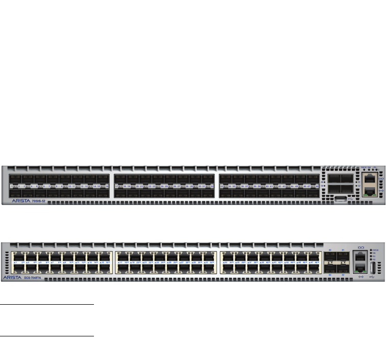
EMC Greenplum DCA Maintenance Guide Replace a Switch in the DCA
119
EMC CONFIDENTIAL
CHAPTER 7
Replace a Switch in the DCA
This chapter describes how to replace Arista 7048T and 7050S-52 switches in a DCA. It
also describes how you can use the DCA Setup Utility to upload switch configuration files
from the Master server to switches. Switch types include:
Interconnect and Aggregation (10GB; SWCH-AR1U-7050S-52)
Administration (1GB; SWCH-AR1U-7048T)
Note: Beginning in DCA 2.0.0.0, you cannot use the DCA Setup Utility to back up switch
configuration files to the Master server.
Major topics include:
Requirements ....................................................................................................... 120
Switch hostnames and IP addresses ..................................................................... 120
Replace an Arista 7050S Interconnect or Aggregation Switch................................. 122
Replace an Arista 7048T Administration Switch ..................................................... 127
EMC Greenplum DCA Maintenance Guide Requirements
120
Replace a Switch in the DCA
EMC CONFIDENTIAL
Requirements
Wrist grounding strap
9-Pin serial cable (RJ-45 to 9-pin d-sub connector)
IMPORTANT
If your laptop does not have a serial port, you must use a USB-to-serial adapter cable.
Materials to label 20 cables
Phillips #2 screwdriver
1/4-inch flathead screwdriver
Switch hostnames and IP addresses
You must configure the replacement switch with the correct hostname and IP address for
the type of rack it inhabits and its position within the rack, as detailed in Table 10 below.
For a table containing IP addresses for all configurations, see Appendix A, “Network
Configuration Information.”
Table 10 Switch hostnames and IP addresses (page 1 of 2)
Rack Hostname IP Address
Arista 7050S Interconnect switches (10GB)
SYSRACK
(Rack 1)
i-sw-2 (Upper switch) 172.28.0.180
i-sw-1 (Lower switch) 172.28.0.170
AGGREG
(Rack 2)
i-sw-4 (Upper switch) 172.28.0.181
i-sw-3 (Lower switch) 172.28.0.171
EXPAND
(Rack 3)
i-sw-6 (Upper switch) 172.28.0.182
i-sw-5 (Lower switch) 172.28.0.172
EXPAND
(Rack 4)
i-sw-8 (Upper switch) 172.28.0.183
i-sw-7 (Lower switch) 172.28.0.173
EXPAND
(Rack 5)
i-sw-10 (Upper switch) 172.28.0.184
i-sw-9 (Lower switch) 172.28.0.174
EXPAND
(Rack 6)
i-sw-12 (Upper switch) 172.28.0.185
i-sw-11 (Lower switch) 172.28.0.175
EXPAND
(Rack 7)
i-sw-14 (Upper switch) 172.28.0.186
i-sw-13 (Lower switch) 172.28.0.176
EXPAND
(Rack 8)
i-sw-16 (Upper switch) 172.28.0.187
i-sw-15 (Lower switch) 172.28.0.177

EMC Greenplum DCA Maintenance Guide Switch hostnames and IP addresses
121
Replace a Switch in the DCA
EMC CONFIDENTIAL
EXPAND
(Rack 9)
i-sw-18 (Upper switch) 172.28.0.188
i-sw-17 (Lower switch) 172.28.0.178
EXPAND
(Rack 10)
i-sw-20 (Upper switch) 172.28.0.189
i-sw-19 (Lower switch) 172.28.0.179
EXPAND
(Rack 11)
i-sw-22 (Upper switch) 172.28.1.180
i-sw-21 (Lower switch) 172.28.1.170
Arista 7050S Aggregation switches (10GB)
AGGREG
(Rack 2 only)
aggr-sw-2 (Upper switch) 172.28.0.249
aggr-sw-1 (Lower switch) 172.28.0.248
Arista 7048T Administration switches (1GB)
SYSRACK
(Rack 1)
a-sw-1 172.28.0.190
AGGREG
(Rack 2)
a-sw-2 172.28.0.191
EXPAND
(Rack 3)
a-sw-3 172.28.0.192
EXPAND
(Rack 4)
a-sw-4 172.28.0.193
EXPAND
(Rack 5)
a-sw-5 172.28.0.194
EXPAND
(Rack 6)
a-sw-6 172.28.0.195
EXPAND
(Rack 7)
a-sw-7 172.28.0.196
EXPAND
(Rack 8)
a-sw-8 172.28.0.197
EXPAND
(Rack 9)
a-sw-9 172.28.0.198
EXPAND
(Rack 10)
a-sw-10 172.28.0.199
EXPAND
(Rack 11)
a-sw-11 172.28.1.190
Table 10 Switch hostnames and IP addresses (page 2 of 2)
Rack Hostname IP Address
EMC Greenplum DCA Maintenance Guide Replace an Arista 7050S Interconnect or Aggregation Switch
122
Replace a Switch in the DCA
EMC CONFIDENTIAL
Replace an Arista 7050S Interconnect or Aggregation Switch
Summary of main tasks:
When installing a replacement switch, identify the firmware version on the new switch
(as well as the versions already running in the DCA). Then upgrade so that all switches
reflect the same firmware levels.
Go to http://support.emc.com to obtain the pertinent firmware upgrade instructions.
The upgrade instructions provide information on how to access and install the
firmware upgrade package.
Remove the failed switch and install the replacement switch
Establish a serial connection and log in to the replacement switch
Configure the switch management port and password
Check the current firmware version
Update the firmware if necessary
Upload the switch configuration through DCA Setup
Check the health of the GPDB
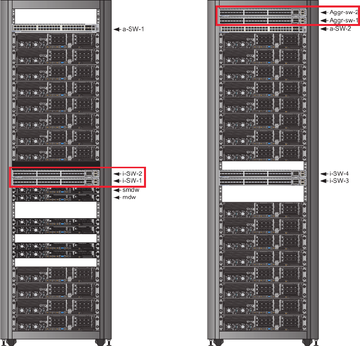
EMC Greenplum DCA Maintenance Guide Replace an Arista 7050S Interconnect or Aggregation Switch
123
Replace a Switch in the DCA
EMC CONFIDENTIAL
1. Identify the type and location of the switch that you are going to replace.
Figure 31 Location of Interconnect and Aggregation switches
2. Connect your service laptop to the red service cable located on the laptop tray in
Rack 1. The red service cable is connected to port 48 on the Administration switch in
the Rack 1 (see “Connect a workstation to the DCA” on page 176).
3. To prevent false dial home messages from being sent to EMC Support during service,
stop the healthmon daemon to disable health monitoring:
# dca_healthmon_ctl -d
Remove the failed switch
and install the
replacement switch
4. Label all cables connected to the switch.
On the label, include the server and server port from which each cable originates and
the switch and switch port to which each cable connects. For connectivity details, see
the following:
•Interconnect Switch cabling—see “” on page 152.
•Aggregation Switch cabling—see “Aggregation switch reference” on page 163.
Interconnect switches
in the System Rack
Aggregation switches
in the Aggregation Rack
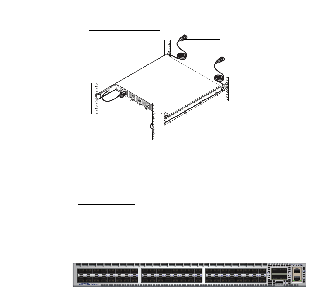
EMC Greenplum DCA Maintenance Guide Replace an Arista 7050S Interconnect or Aggregation Switch
124
Replace a Switch in the DCA
EMC CONFIDENTIAL
5. Power off the switch by removing both AC power cables from the power supplies on
the back of the switch.
6. Make sure that the interconnect cables are labeled as described in step 4 above, and
then remove the interconnect cables from the Interconnect switch.
7. Remove the failed switch and install the replacement switch (see “Install a Switch in a
Rack” on page 200).
8. Connect all data cables to the correct ports on the switch.
Refer to the labels for the correct connectivity information. For more information, see
“Network and cabling configurations” on page 152.
9. Power on the switch by connecting the AC power cables to the power supplies on the
back of the replacement switch. The switch powers up as soon as AC power is applied
Verify that the power supply LEDs are solid green after a few seconds.
IMPORTANT
Each switch power supply should be connected to a separate AC power zone on the
rack. See “Power supply reference” on page 146.
Figure 32 Connecting switch power cords to AC power
Note: Because the replacement switch was configured at the factory, it is not yet
accessible through SSH, so you must configure the replacement switch through a serial
connection as described in “Connect to an Interconnect or Administration switch using
PuTTY” on page 181.
Establish a serial
connection and log in to
the replacement switch
10. Connect your service laptop to the serial console port on the replacement switch using
a native RJ-45 serial cable. If you do not have a native RJ-45 serial cable, use a
DB-9-to-RJ45 or USB-to-RJ45 serial adapter.
CL5041
To Power Zone B PDU
To Power Zone A PDU
Front of rack
Rear of rack
Serial console port

EMC Greenplum DCA Maintenance Guide Replace an Arista 7050S Interconnect or Aggregation Switch
125
Replace a Switch in the DCA
EMC CONFIDENTIAL
Figure 33 Arista 7050S serial port location
11. Using a terminal emulator such as Hyperterminal, log in to the switch as user admin
and no password with the following settings:
• Connection type: serial
• Data rate: 9600
•Data bits: 8
• Parity: none
• Stop bits: 1
• Hardware flow control: none
12. At the localhost prompt, issue the following commands to disable the Arista zerotouch
feature:
# enable
# zerotouch cancel
Wait as the switch reboots.
13. When the switch is finished booting, log in again as user admin and no password.
Configure the switch
management port
and password;
hostname, and IP
address
14. At the localhost prompt, issue the following commands to configure the management
port:
Note: Change the IP address shown in bold below as appropriate for the type and
location of the switch you are configuring. For details see “Switch hostnames and IP
addresses” on page 120.
# enable
# conf t
# hostname i-sw-1
(config)# interface management 1
(config-if-Ma1)# ip address 172.28.0.170/21
(config-if-Ma1)# exit
(config)# user admin secret 0 changeme
(config)# write mem
(config)# exit
15. Connect all data cables to the correct ports and the ethernet cable to the management
port of the switch.
16. Determine whether you need to update the Extensible Operating System (EOS)
firmware on the switch:
# show boot-config
In the output, focus on the value shown in bold below:
Software image: flash:/EOS-4.9.3.2.swi
•If 4.9.3.2 is returned, you do not need to update the switch firmware. Proceed to
step 18 to complete the switch configuration.
•If 4.9.3.2 is not returned, you must update the switch firmware. Proceed to
step 17.
EMC Greenplum DCA Maintenance Guide Replace an Arista 7050S Interconnect or Aggregation Switch
126
Replace a Switch in the DCA
EMC CONFIDENTIAL
Update the firmware
if necessary
17. If you determined in the previous step that you need to update the switch firmware:
a. Before proceeding, back up the current switch configuration. Please read
Appendix G for instructions on backing up the switch configurations.
b. Download the Arista firmware from http://support.emc.com and place in
/opt/dca/etc/arista_fw/
You may need to create the directory if it does not exist.
c. Next, download the current switch configuration. Customizing the switches is a
common practice. This procedure will reload the switches with default
configurations. Backing up the switch configurations allows for easy restoration
after installing the new firmware.
d. Issue the following commands to copy the EOS firmware file from the Primary
Master Server to the switch:
# copy scp://root@172.28.4.250/opt/dca/etc/arista_fw/EOS-4.9.3.2.swi flash:/EOS-4.9.3.2.swi
e. When prompted, enter password changeme.
root@172.28.4.250's password:
# conf t
(config)# boot system flash:/EOS-4.9.3.2.swi
(config)# exit
f. Check the EOS firmware version that you installed.
# show boot-config
The following output is returned:
Software image: flash:/EOS-4.9.3.2.swi
Console speed: (not set)
Aboot password (encrypted): (not set)
g. Save the EOS configuration and reload. The switch reboots.
# write mem
# reload
h. Recover the switch config using the instructions in Appendix G.
18. Disconnect the serial cable.
19. Connect your service laptop to the red service cable located on the laptop tray in
Rack 1 and log in to the Primary Master as the user root (see “Connect a workstation
to the DCA” on page 176).
Check the health
of the GPDB
20. Log in to the Primary Master as gpadmin and issue the following command to verify
that the database is healthy:
$ gpstate -m
Verify that all segments are reported as Synchronized:
Mirror Datadir Port Status Data Status
sdw2-2 /data2/mirror/gpseg0 50003 Acting as Primary Synchronized
21. Re-enable health monitoring:
EMC Greenplum DCA Maintenance Guide Replace an Arista 7048T Administration Switch
127
Replace a Switch in the DCA
EMC CONFIDENTIAL
# dca_healthmon_ctl -e
Replace an Arista 7048T Administration Switch
Summary of main tasks:
When installing a replacement switch, identify the firmware version on the new switch
(as well as the versions already running in the DCA). Then upgrade so that all switches
reflect the same firmware levels.
Go to http://support.emc.com to obtain the pertinent firmware upgrade instructions.
The upgrade instructions provide information on how to access and install the
firmware upgrade package.
Remove the failed switch and install the replacement switch
Establish a serial connection and log in to the replacement switch
Configure the switch management port
Configure the switch password
Check the current firmware version
Update the firmware if necessary
Upload the switch configuration through DCA Setup
Check the health of the GPDB
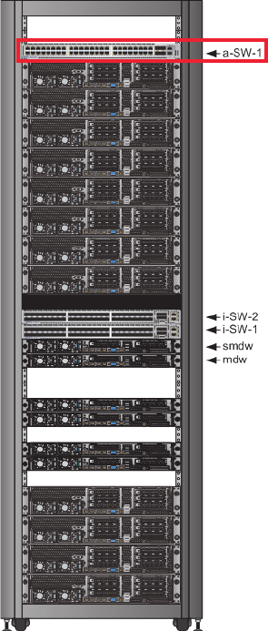
EMC Greenplum DCA Maintenance Guide Replace an Arista 7048T Administration Switch
128
Replace a Switch in the DCA
EMC CONFIDENTIAL
1. Identify the Administration switch the rack.
Figure 34 Location of the Aggregation switch
2. To prevent false dial home messages from being sent to EMC Support during service,
stop the healthmon daemon to disable health monitoring:
# dca_healthmon_ctl -d
Remove the failed switch
and install the
replacement switch
3. Label all cables connected to the switch.
On the label, include the server and server port from which each cable originates and
the switch and switch port to which each cable connects. For connectivity details, see
“Administration switch reference” on page 159.
4. Power off the switch by removing both AC power cables from the power supplies on
the back of the switch.
5. Make sure that the cables are labeled as described in step above, and then remove
the interconnect cables from the Interconnect switch.
6. Remove the failed switch and install the replacement switch (see “Install a Switch in a
Rack” on page 200).
Administration switch
in the System Rack
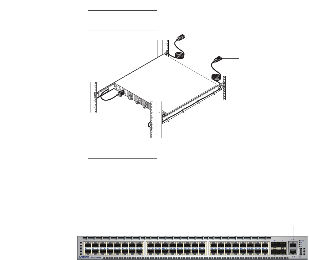
EMC Greenplum DCA Maintenance Guide Replace an Arista 7048T Administration Switch
129
Replace a Switch in the DCA
EMC CONFIDENTIAL
7. Connect all data cables to the correct ports on the switch.
Refer to the labels for the correct connectivity information. For more information, see
“Network and cabling configurations” on page 152.
8. Power on the switch by connecting the AC power cables to the power supplies on the
back of the replacement switch. The switch powers up as soon as AC power is applied
Verify that the power supply LEDs are solid green after a few seconds.
IMPORTANT
Each switch power supply should be connected to a separate AC power zone on the
rack. See “Power supply reference” on page 146.
IMPORTANT
Because the replacement switch was configured at the factory, it is not yet accessible
through SSH, so you must configure it through a serial connection as described in
“Connect to an Interconnect or Administration switch using PuTTY” on page 181.
Establish a serial
connection and log in to
the replacement switch
9. Connect your service laptop to the serial console port on the replacement switch using
a native RJ-45 serial cable. If you do not have a native RJ-45 serial cable, use a
DB-9-to-RJ45 or USB-to-RJ45 serial adapter.
Figure 35 Arista 7048T serial port location
10. Using a terminal emulator such as Hyperterminal, log in to the switch as user admin
and no password with the following settings:
• Connection type: serial
• Data rate: 9600
•Data bits: 8
• Parity: none
CL5041
To Power Zone B PDU
To Power Zone A PDU
Front of rack
Rear of rack
Serial console port

EMC Greenplum DCA Maintenance Guide Replace an Arista 7048T Administration Switch
130
Replace a Switch in the DCA
EMC CONFIDENTIAL
• Stop bits: 1
• Hardware flow control: none
11. At the localhost prompt, issue the following commands to disable the Arista zerotouch
feature:
# enable
# zerotouch cancel
Wait as the switch reboots.
12. When the switch is finished booting, log in again as user admin and no password.
Configure the switch
VLAN port service,
hostname, and IP
address
13. At the localhost prompt, issue the following commands to set the VLAN port service:
Change the hostname and IP address shown in bold below as appropriate for the
switch you are configuring. For details see “Switch hostnames and IP addresses” on
page 120.
IMPORTANT
This step differs slightly according to the specific Administration switch that you are
replacing.
Administration switch in Rack 1 (a-sw-1)
# enable
# conf t
(config)# hostname a-sw-1
(config)# interface vlan 3
The following output displays:
! Access VLAN does not exist. Creating vlan 3
Continue:
(config-if-Vl3)# ip address 172.28.0.190/21
(config-if-Vl3)#interface ethernet 1-48
(config-if-Et1-48)#switchport access vlan 3
Administration switch in Rack 2 (a-sw-2)
# enable
# conf t
(config)# hostname a-sw-2
(config)# interface vlan 3
The following output displays:
! Access VLAN does not exist. Creating vlan 3
Continue:
(config-if-Vl3)# ip address 172.28.0.191/21
(config-if-Vl3)#interface ethernet 1-48
(config-if-Et1-48)#switchport access vlan 3
(config-if-Et1-48)#interface port-Channel 1000
(config-if-Po1000)#switchport mode trunk
(config-if-Po1000)#switchport trunk group mlagpeerlink
(config-if-Po1000)#interface ethernet 45-46

EMC Greenplum DCA Maintenance Guide Replace an Arista 7048T Administration Switch
131
Replace a Switch in the DCA
EMC CONFIDENTIAL
(config-if-Et45-46)#channel-group 1000 mode active
Administration switch in Racks 3 to 12 (a-sw-3 to a-sw-12)
Change the hostname and IP address shown in bold below as appropriate for the specific
Administration switch you are configuring. For details see Appendix A, “Network
Configuration Information.”
# enable
# conf t
(config)# hostname a-sw-3
(config)# interface vlan 3
The following output displays:
! Access VLAN does not exist. Creating vlan 3
Continue:
(config-if-Vl3)# ip address 172.28.0.192/21
(config-if-Vl3)#interface ethernet 1-48
(config-if-Et1-48)#switchport access vlan 3
(config)#interface port-Channel 900
(config-if-Po900)#switchport access vlan 3
(config-if-Po900)#interface ethernet 45-46
(config-if-Et45-46)#channel-group 900 mode active
14. Verify the that the ports were added to vlan 3:
(config-if-Et1-48)#show vlan
The following output displays:
VLAN Name Status Ports
----- ----- ----- -----
1 default active
3 VLAN0003 active Cpu, Et1, Et2, Et3, Et4, Et5, Et6, Et7, Et8,
Et17, Et18, Et19, Et20
Note: Only active ports display in the above output. You may see different output.
Configure the
switch password
15. Configure the switch password:
(config-if-Et1-48)# exit
(config)# user admin secret 0 changeme
(config)# write mem
(config)# exit
16. Connect all data cables to the correct ports and the ethernet cable to the management
port of the switch.
17. Determine whether you need to update the Extensible Operating System (EOS)
firmware on the switch:
# show boot-config
In the output, focus on the value shown in bold below:
Software image: flash:/EOS-4.9.3.2.swi

EMC Greenplum DCA Maintenance Guide Replace an Arista 7048T Administration Switch
132
Replace a Switch in the DCA
EMC CONFIDENTIAL
•If 4.9.3.2 is returned, you do not need to update the switch firmware. Proceed to
step 19 to complete the switch configuration.
•If 4.9.3.2 is not returned, you must update the switch firmware. Proceed to
step 18.
Update the firmware
if necessary
18. If you determined in the previous step that you need to update the switch firmware:
a. Before proceeding, back up the current switch configuration. Please read
Appendix G for instructions on backing up the switch configurations.
b. Download the Arista firmware from http://support.emc.com and place in
/opt/dca/etc/arista_fw/
You may need to create the directory if it does not exist.
c. Next, download the current switch configuration. Customizing the switches is a
common practice. This procedure will reload the switches with default
configurations. Backing up the switch configurations allows for easy restoration
after installing the new firmware.
d. Issue the following commands to copy the EOS firmware file from the Primary
Master Server to the switch:
# copy scp://root@172.28.4.250/opt/dca/etc/arista_fw/EOS-4.9.3.2.swi flash:/EOS-4.9.3.2.swi
e. When prompted, enter password changeme.
root@172.28.4.250's password:
# conf t
(config)# boot system flash:/EOS-4.9.3.2.swi
(config)# exit
f. Check the EOS firmware version that you installed.
# show boot-config
The following output is returned:
Software image: flash:/EOS-4.9.3.2.swi
Console speed: (not set)
Aboot password (encrypted): (not set)
g. Save the EOS configuration and reload. The switch reboots.
# write mem
# reload
h. Recover the switch config using the instructions in Appendix G.
19. Disconnect the serial cable.
20. Connect your service laptop to the red service cable located on the laptop tray in
Rack 1 and log in to the Primary Master as the user root (see “Connect a workstation
to the DCA” on page 176).
Check the health
of the GPDB
21. Log in to the Primary Master as gpadmin and issue the following command to verify
that the database is healthy:
$ gpstate -m
Verify that all segments are reported as Synchronized:
Mirror Datadir Port Status Data Status
sdw2-2 /data2/mirror/gpseg0 50003 Acting as Primary Synchronized
EMC Greenplum DCA Maintenance Guide Replace an Arista 7048T Administration Switch
133
Replace a Switch in the DCA
EMC CONFIDENTIAL
22. Re-enable health monitoring:
# dca_healthmon_ctl -e
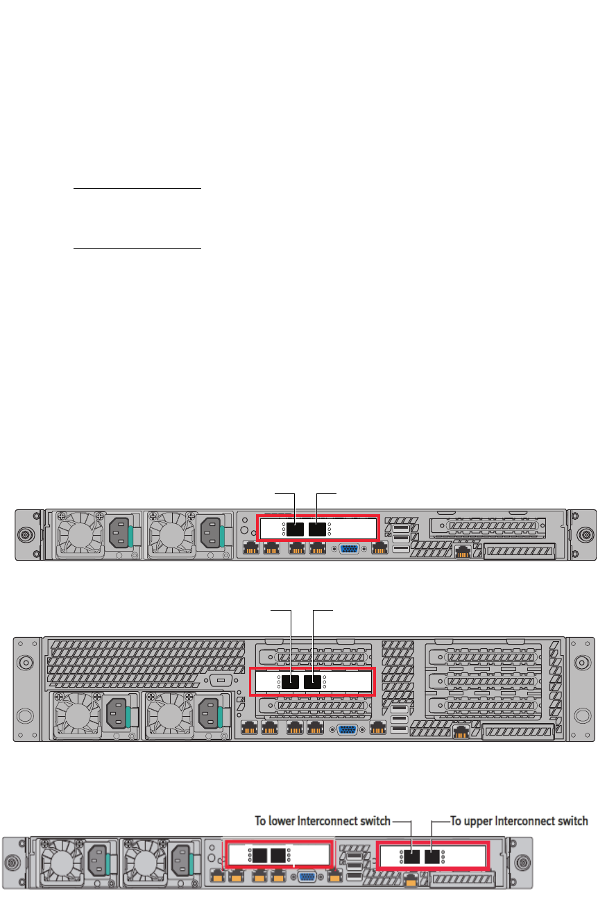
EMC Greenplum DCA Maintenance Guide Replace an Interconnect Switch Cable
134
EMC CONFIDENTIAL
CHAPTER 8
Replace an Interconnect Switch Cable
This chapter describes how to replace a twin-ax cable used to connect servers and
interconnect switches in the DCA.
Note: Some failed cables may be part of a cable bundle. Plan for multiple systems losing
connectivity. It is recommended to disable the database and healthmon until cables are
replaced.
Locate and replace the failed cable
1. Log in to the Primary Master server as the user
root
. Refer to “Connect to the Master
Server using an SSH client” on page 178 for details.
2. Activate the server identification LED on the server with the failed cable. For example,
on
sdw8
:
# dca_blinker -h
sdw8
-a ON
3. From the rear of the system, locate the Converged Network Adapter (CNA) card in the
server's expansion slot.
Figure 36 CNA card location in DCA servers
Figure 37 Master server with extra 10Gb NICs
AF004142a
To upper Interconnect switch
AF004061a
To upper Interconnect switch
Master or DIA server; Hadoop Compute server
Segment server; Hadoop master and worker servers
To lower Interconnect switch
To lower Interconnect switch

EMC Greenplum DCA Maintenance Guide
135
Replace an Interconnect Switch Cable
EMC CONFIDENTIAL
4. Observe the
Link
and
Act
LEDs adjacent to each port on the card. A single, steadily
flashing LED indicates that the attached cable has failed. If both LEDs are flashing,
further diagnosis is required. DO NOT replace the cables in this case. Instead, contact
EMC technical support services for assistance.
Figure 38 Interconnect switch CNA port LEDs
5. Before connecting the replacement cable the database will need to be shutdown. This
is due to the new cabling bundling introduced in release 2.0.2.0. Shutting down the
database will prevent false dial home messages from being sent to EMC Support
during service.
To shutdown the database:
a. Disable health monitoring by stopping the healthmon daemon:
# dca_healthmon_ctl -d
b. Switch to the user gpadmin:
# su - gpadmin
c. When prompted for the password, enter changeme.
If the default password changeme was changed; enter the current password.
d. Stop the Greenplum Database:
$ gpstop -af
e. Switch to the user root:
$ su -
6. Disconnect both ends of the cable and remove the cable from the cable bundle. For
Interconnect cable diagrams, refer to “” on page 152.
7. Connect one end of the new cable to the CNA port on the server and the other end to
the correct port on the appropriate Interconnect switch.
8. Verify that the
Link
LED on the CNA card is solid green.
9. Secure the cable back into the cable bundle.
10. Verify that the eth4 interface on the affected server is UP and RUNNING:
# ifconfig eth4
The following output should be returned:
eth4 Link encap:Ethernet HWaddr 8C:7C:FF:20:93:32
UP BROADCAST RUNNING SLAVE MULTICAST MTU:1500 Metric:1
RX packets:921818 errors:0 dropped:0 overruns:0 frame:0
TX packets:908966 errors:0 dropped:0 overruns:0 carrier:0
collisions:0 txqueuelen:1000
RX bytes:129140405 (123.1 MiB) TX bytes:88721575 (84.6 MiB)
Memory:ec440000-ec47ffff
EMC Greenplum DCA Maintenance Guide
136
Replace an Interconnect Switch Cable
EMC CONFIDENTIAL
If eth4 is not UP, bring it up by issuing:
# ifup eth4
11. Once all of the connections are fixed, the database may be started up.

EMC Greenplum DCA Maintenance Guide System Information and Configuration
137
EMC CONFIDENTIAL
APPENDIX A
System Information and Configuration
This appendix includes the following sections:
Greenplum DCA configurations
Power supply reference
Network and cabling configuration
Network hostname and IP configuration
Multiple-rack cabling reference
Configuration files
Default passwords
New firmware updates for DCA software version 2.0.3.0
Customers can apply optional firmware updates prior to upgrading to DCA software
version 2.0.3.0 as follows:
Arista 7050S-52 and Arista 7048T switches
• New firmware version EOS-4.9.8.swi
• Field personnel can access the EOS-4.9.8.swi.zip firmware upgrade
package from:
ftp://ftp.aristanetworks.com/emc/certifiedeos/EOS-4.9.8.swi
Field personnel can obtain the following document available on
http://support.emc.com for step-by-step instructions:
EMC Greenplum DCA Firmware Upgrade Instructions for the Interconnect Switch
(Arista 7050S-52) and Administration Switch (Arista 7048T)
Intel Servers (Kylin with eight drives, Dragon 12 with twelve drives, and Dragon 24
with 24 drives)
• New BIOS upgrade revision level SE5C600.86B.02.01.0002
• Field personnel can access both the BIOS upgrade package, and the
EMC Greenplum DCA Intel BIOS Upgrade Instructions for Intel Servers
from
http://support.emc.com.
EMC Greenplum DCA Maintenance Guide
138
System Information and Configuration
EMC CONFIDENTIAL
Identify the version of the installed DCA software
DCA documentation is tied to a specific version of the DCA software. To identify the version
of the software running on a particular DCA, perform this procedure:
1. Log in to the Primary Master server as the user root.
2. View the contents of the /opt/dca/etc/dca-build-info.txt file.
For example:
# cat opt/dca/etc/dca-build-info.txt
In the output see the ISO_Version information.
## =============================================
ISO_BUILD_DATE="Wed Oct 15 21:59:56 PST 2013"
ISO_VERSION="2.0.2.0"
ISO_BUILD_VERSION="4"
ISO_INSTALL_TYPE="iso"
## =============================================

EMC Greenplum DCA Maintenance Guide
139
System Information and Configuration
EMC CONFIDENTIAL
DCA configuration rules
Manufacturing ships three basic types of racks for the UAP DCA:
System - DCA2-SYSRACK
Aggregation - DCA2-AGGREG
Expansion - DCA2-EXPAND
Supported DCA modules
Racking order
All master nodes and switches are racked first. All other nodes are racked in the following
order.
Module type Server/drive types and quantities
Greenplum Database (GPDB) Four Dragon 24 servers:
• Compute: x24 300GB drives per server
• Standard: x24 900GB drives per server
• Compute High Memory: x24 300GB drives per server,
256GB of Memory
• Two Kylin servers: x6 300GB drives per server
Data Integration Accelerator (DIA)
(One of these items)
• Two Kylin servers: x6 300GB drives per server
• Two Dragon 12 servers: x12 3TB drives per server
• Two Dragon 24 servers: 256GB of memory
• Two DIA High Memory servers: x24 300GB drives per
server (256GB of memory)
Hadoop (HD) (master or worker) Four Dragon 12 servers: x12 3TB drives per server
Hadoop Compute option (referred to as
HD-C module and used for Hadoop with
Isilon)
Two Kylin servers: x6 300GB drives per server
Table 11 Approved DCA Racking Sequence
SKU Rack Priority (when present)
Dragon 24, 900GB disks, 64GB RAM
(100-585-031-07)
First
Dragon 24, 300GB disks, 64GB RAM
(100-585-035-06)
Second
Dragon 12, 3TB disks, 64GB RAM
HDM, HDW, or DIA
(100-585-030-06)
Third
Dragon 24, 900GB disks, 256GB RAM
SDW or DIA
(100-585-055-01)
Fourth
Kylin, 64GB RAM
DIA, HDC, or HDM
(100-585-029-05)
Fifth
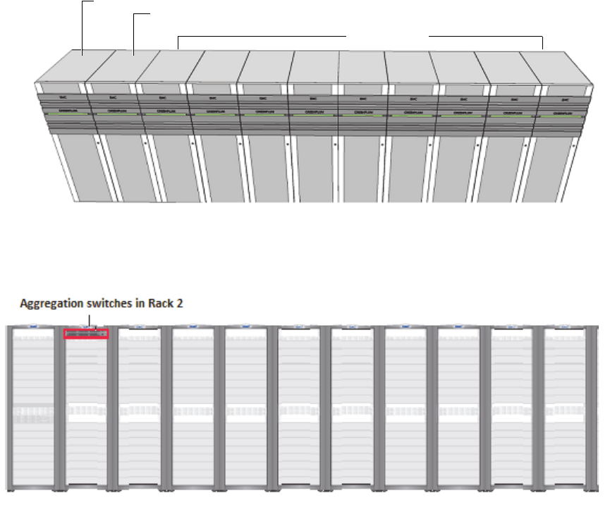
EMC Greenplum DCA Maintenance Guide
140
System Information and Configuration
EMC CONFIDENTIAL
Racking guidelines
GPDB Compute, Standard, or High Memory modules must not occupy the same DCA.
The minimum Hadoop configuration must include two Hadoop modules, one serving
as the Hadoop Master module (hdm) and a second serving as the Hadoop Worker
(data) module (hdw). For Hadoop Compute with Isilon the minimum requirements are
8 Kylins (4 x2 Hadoop Compute modules).
The 2nd rack (if present) is always an Aggregation rack.
Racks 3 through 11 (if present) are Expansion racks.
Any rack containing even one 100-585-055-01 is limited to thirty rack units for
servers. Switches remain in the standard locations. Racks with High Memory servers
should not exceed 30U.
Figure 39 11-rack configuration
Figure 40 Aggregation switch locations in a multi-rack DCA
Expansion
Aggregation
System
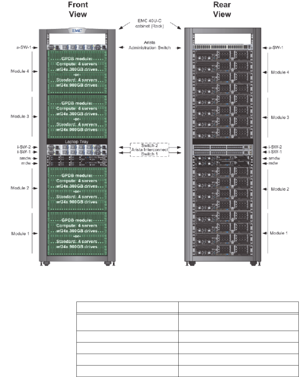
EMC Greenplum DCA Maintenance Guide
141
System Information and Configuration
EMC CONFIDENTIAL
Mixed System rack components
Figure 41 Greenplum DCA2-SYSRACK
Table 12 Greenplum DCA2-SYSRACK - System rack components
DCA Component Quantity
Hadoop Servers (Dragon 12, 2U) 16 (8 minimum, 4 hdw + 4 hdm) or 12 High
Memory Systems
Master Servers (Kylin, 1U) 2 (1 Primary + 1 Standby)
GPDB (Segment) Servers (Dragon 24, 2U) 16 or 12 High Memory Systems
Interconnect Switches (Arista 7050S-52) 2
Administration Switches (Arista 7048T-A) 1
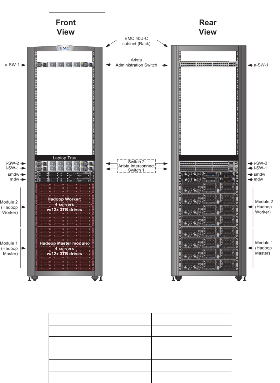
EMC Greenplum DCA Maintenance Guide
142
System Information and Configuration
EMC CONFIDENTIAL
Hadoop-only System Rack components (minimum config.)
Note: Supported in DCA version 2.0.1.0 and later.
Figure 42 Hadoop-only System rack
Table 13 Hadoop-only System Rack components
DCA Component Quantity
Hadoop Master Servers (hdm) 4 minimum
Hadoop Worker Servers (hdw) 4 minimum
Master Servers (Kylin, 1U) 2
Interconnect Switches (Arista 7050S-52) 2
Administration Switch (Arista 7048T-A) 1
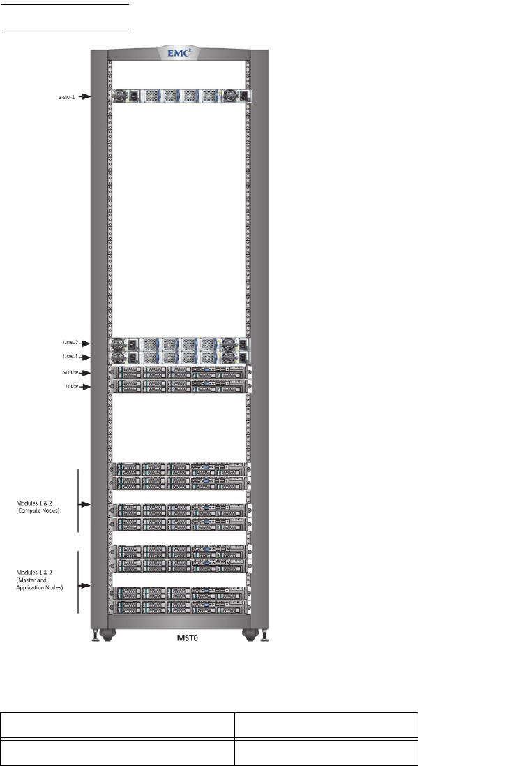
EMC Greenplum DCA Maintenance Guide
143
System Information and Configuration
EMC CONFIDENTIAL
HD-Compute System Rack components (minimum config.)
Note: Supported in DCA version 2.0.2.0 and later.
Figure 43 HDC-Compute System rack
Table 14 HDC-Compute System rack components
DCA Component Quantity
Hadoop Compute Servers (hdc) 8 minimum, 22 maximum
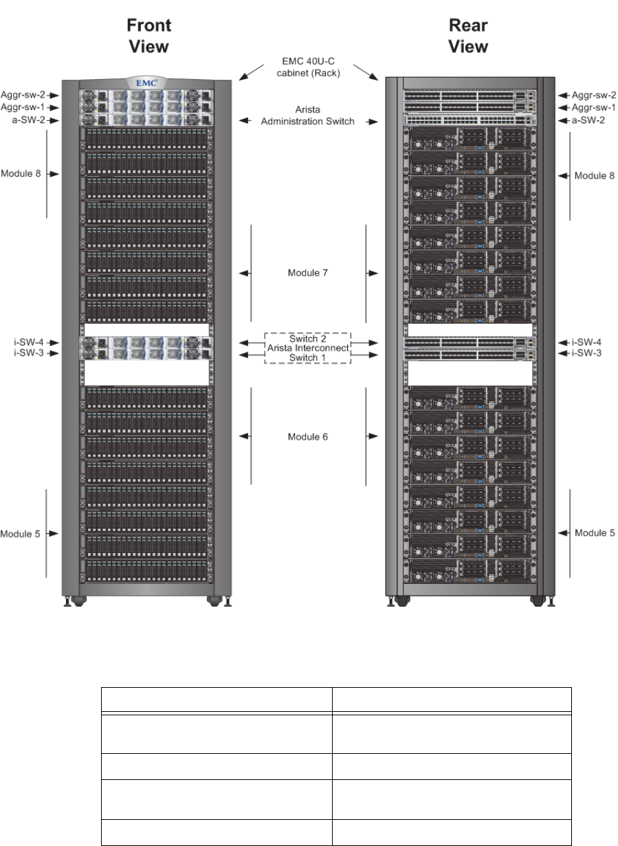
EMC Greenplum DCA Maintenance Guide
144
System Information and Configuration
EMC CONFIDENTIAL
Aggregation rack components
Figure 44 Greenplum DCA2-AGGREG
Table 15 Greenplum DCA2-AGGERG - Aggregation rack components
DCA Component Quantity
Segment Servers 16 maximum (or 12 maximum with High
Memory Modules)
Master Servers (Kylin, 1U) 0
Interconnect Switches (Arista 7050S-52) 4 (2 for the Interconnect network; 2 for the
Aggregation network)
Administration Switch (Arista 7048T-A) 1
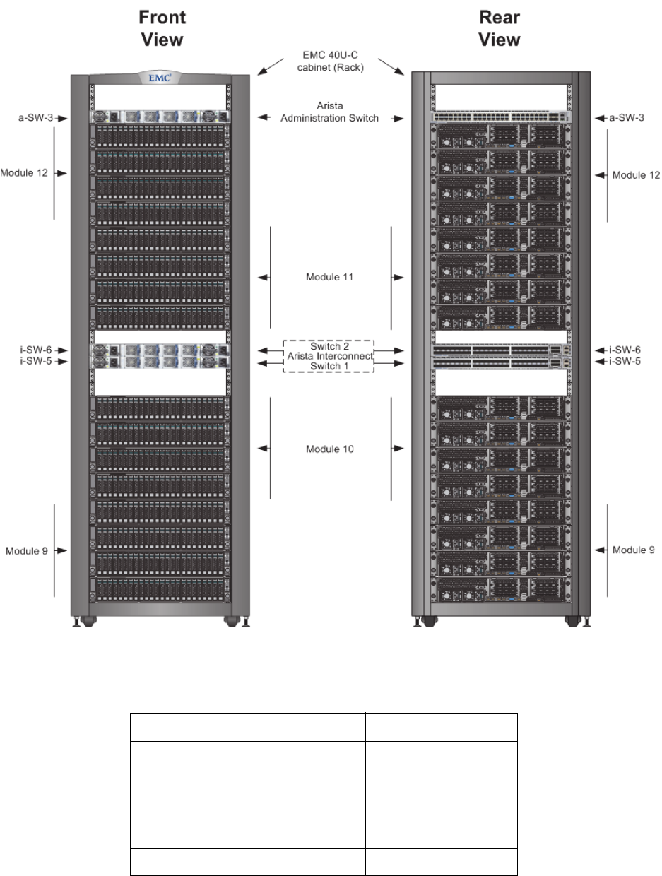
EMC Greenplum DCA Maintenance Guide
145
System Information and Configuration
EMC CONFIDENTIAL
Expansion rack components
Figure 45 Greenplum DCA2-EXPAND
Table 16 Greenplum DCA2-EXPAND - Expansion rack components
Component Quantity
Segment Servers 16 maximum (or 12
maximum with High Mem
Module)
Master Servers (Kylin, 1U) 0
Interconnect Switches (Arista 7050S-52) 2
Administration Switch (Arista 7048T-A) 1
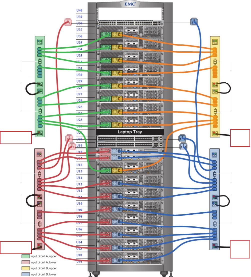
EMC Greenplum DCA Maintenance Guide Power supply reference
146
System Information and Configuration
EMC CONFIDENTIAL
Power supply reference
Figure 46 shows four external customer-supplied power input circuits connected to DCA
Power Distribution Units (PDUs). The figure shows a full System rack.
Figure 46 Greenplum DCA power cable configuration, full System rack
Power
switches
Customer-supplied
power
Upper Zone A
input
Power
switches
Customer-supplied
power
Lower Zone A
input
Power
switches
Power
switches
Customer-
supplied power
Lower
Zone B
input
Customer-
supplied power
Upper
Zone B
input
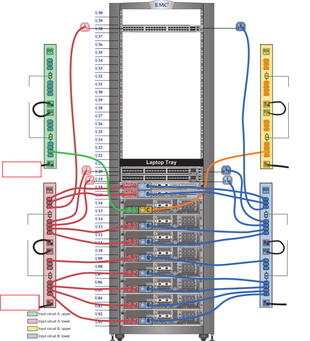
EMC Greenplum DCA Maintenance Guide Power supply reference
147
System Information and Configuration
EMC CONFIDENTIAL
Figure 47 Greenplum DCA power cable configuration, 1/2 System rack
Power
switches
Customer-supplied
power
Lower Zone A
input
Power
switches
Customer-
supplied power
Lower
Zone B
input
Power
switches
Customer-supplied
power
Upper Zone A
input
Power
switches
Customer-
supplied power
Upper
Zone B
input
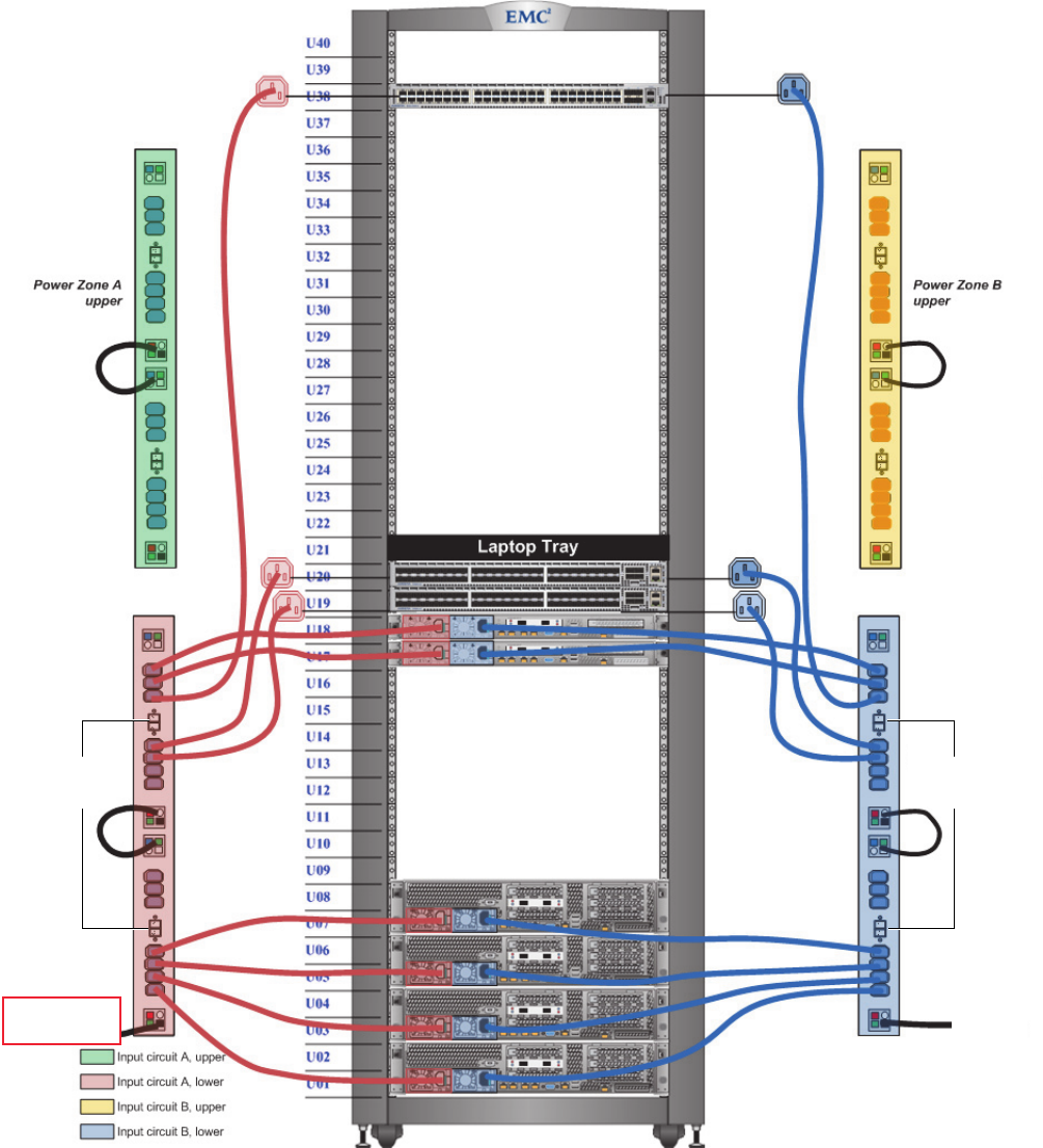
EMC Greenplum DCA Maintenance Guide Power supply reference
148
System Information and Configuration
EMC CONFIDENTIAL
Figure 48 Greenplum DCA power cable configuration, 1/4 System rack
Power
switches
Customer-supplied
power
Lower Zone A
input
Power
switches
Customer-
supplied power
Lower
Zone B
input
Customer-supplied
power not needed
to upper Zone A
in 1/4 rack
Customer-supplied
power not needed
to upper Zone B
in 1/4 rack
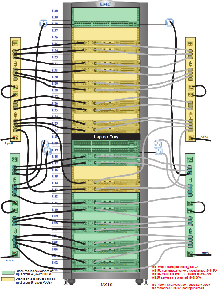
EMC Greenplum DCA Maintenance Guide Power supply reference
149
System Information and Configuration
EMC CONFIDENTIAL
Figure 49 Dense rack configuration
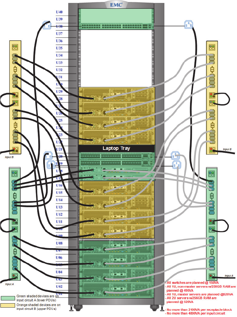
EMC Greenplum DCA Maintenance Guide Power supply reference
150
System Information and Configuration
EMC CONFIDENTIAL
Figure 50 High memory system rack configuration

EMC Greenplum DCA Maintenance Guide BMC Controller interface functionality
151
System Information and Configuration
EMC CONFIDENTIAL
BMC Controller interface functionality
The baseboard management controller (BMC) is a built-in interface included in most
DCA servers. The BMC provides out-of-band system management facilities. The
controller integrates its own processor, memory, battery, network connection, and
access to the system bus. Key features (available through a supported web browser)
include:
Power management
Virtual media access
Remote console capabilities
BMC gives system administrators the ability to manage a machine as if they were
sitting at the local console.
BMC Controller LED indicators and meanings
Table 17 lists BMC LED states and components to check.
Table 17 BMC LED indictor status and possible required action
Color State Criticality Description
Green Solid On Normal No action required by Field Support.
BMC is operating in a healthy state.
Green Blink (1 per second) Degraded Redundancy is lost or a non-critical warning/error
Check for these possible issues:
• Redundancy loss such as power-supply or fan
• Correctable ECC memory error
• Non-critical threshold crossed (Temp, Voltage, input power)
Amber Solid On Non-critical Non-fatal alarm
Check for critical thresholds surpassed on:
•Temp
•Voltage
•Input power
• Hard Drives
• Fans (minimum number of fans not present)
Amber Blink (1 per second) Critical Critical error
Check for:
•Power fault
• Insufficient memory present
• CPU thermal trip
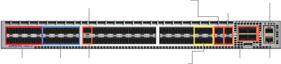
EMC Greenplum DCA Maintenance Guide Network and cabling configurations
152
System Information and Configuration
EMC CONFIDENTIAL
Network and cabling configurations
This section describes the network cabling configurations for the Interconnect and
administration switches.
Interconnect cabling reference
Each rack in the DCA contains two Interconnect switches which provide the Greenplum
Interconnect network. Topics in this section include:
“Lower Interconnect switch cabling reference”
“Upper Interconnect switch cabling reference”
“Dense rack switch cabling reference”
“Dense rack Interconnect 2 configuration (dual NIC)”
Figure 51 Interconnect switch port map
Serial consolePorts 45-46 to lower
Aggregation switch
(aggr-sw-1)
Ports 47-48 to upper
Aggregation switch
(aggr-sw-2)
Ports 9-16 to
servers
sdw9-sdw16
Port 18 to Standby
Master Server smdw
Port 17 to Primary
Master Server (mdw)
mLAG peer connections
to the other Interconnect
switch in the rack.
To Administration
switch
Ports 1-8 to
servers
sdw1-sdw8
Ports 41-44 to customer
network (single rack DCA only)
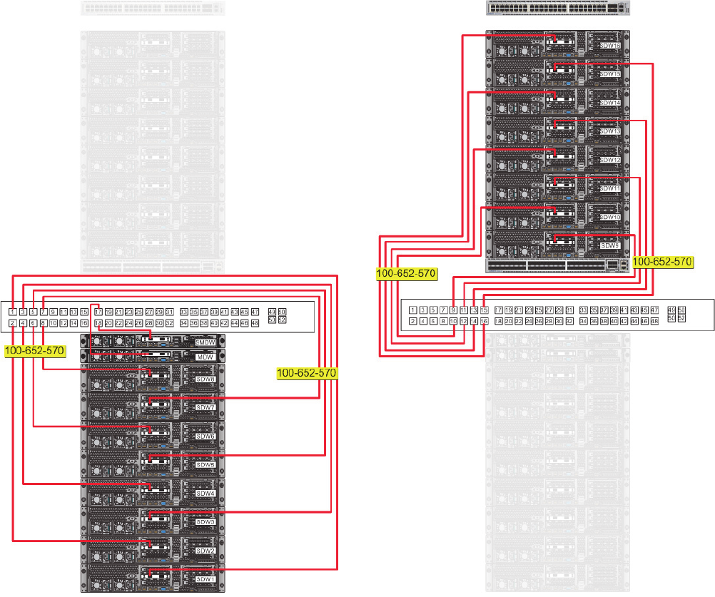
EMC Greenplum DCA Maintenance Guide Network and cabling configurations
153
System Information and Configuration
EMC CONFIDENTIAL
Lower Interconnect switch cabling reference
The lower Interconnect switch connects servers to the first Interconnect. Lower
Interconnect switches are always odd-numbered hostnames (for example, i-sw-1, i-sw-3,
i-sw-5, etc.).
Figure 52 Lower Interconnect switch cabling reference
EMC Greenplum DCA Maintenance Guide Network and cabling configurations
154
System Information and Configuration
EMC CONFIDENTIAL
Upper Interconnect switch cabling reference
The upper Interconnect Switch connects servers to the second Interconnect. Upper
Interconnect switches are always even-numbered hostnames (for example, i-sw-2, i-sw-4,
i-sw-6, etc.).
Figure 53 Upper Interconnect switch cabling reference
EMC Greenplum DCA Maintenance Guide Network and cabling configurations
155
System Information and Configuration
EMC CONFIDENTIAL
Dense rack switch cabling reference
Figure 54 Dense rack Interconnect 1 configuration (dual NIC)
EMC Greenplum DCA Maintenance Guide Network and cabling configurations
156
System Information and Configuration
EMC CONFIDENTIAL
Dense rack Interconnect 2 configuration (dual NIC)
Figure 55 Dense rack Interconnect 2 configuration (dual NIC)

EMC Greenplum DCA Maintenance Guide Network and cabling configurations
157
System Information and Configuration
EMC CONFIDENTIAL
Table 18 Interconnect switch cable routing, 3-rack DCA (page 1 of 2)
SYS-RACK AGGR-RACK EXPAND-RACK
IC switch
port
i-sw-1 i-sw-2 i-sw-3 i-sw-4 i-sw-5 i-sw-6
Server
CNA port 0
Server
CNA port 1
Server
CNA port 0
Server
CNA port 1
Server
CNA port 0
Server
CNA port 1
1 server 1 server 1 server 1 server 1 server 1 server 1
2 server 2 server 2 server 2 server 2 server 2 server 2
3 server 3 server 3 server 3 server 3 server 3 server 3
4 server 4 server 4 server 4 server 4 server 4 server 4
5 server 5 server 5 server 5 server 5 server 5 server 5
6 server 6 server 6 server 6 server 6 server 6 server 6
7 server 7 server 7 server 7 server 7 server 7 server 7
8 server 8 server 8 server 8 server 8 server 8 server 8
9 server 9 server 9 server 9 server 9 server 9 server 9
10 server 10 server 10 server 10 server 10 server 10 server 10
11 server 11 server 11 server 11 server 11 server 11 server 11
12 server 12 server 12 server 12 server 12 server 12 server 12
13 server 13 server 13 server 13 server 13 server 13 server 13
14 server 14 server 14 server 14 server 14 server 14 server 14
15 server 15 server 15 server 15 server 15 server 15 server 15
16 server 16 server 16 server 16 server 16 server 16 server 16
17 mdw mdw server 17 server 17 server 17 server 17
18 smdw smdw server 18 server 18 server 18 server 18
19 server 17 server 17 server 19 server 19 server 19 server 19
20 server 18 server 18 server 20 server 20 server 20 server 20
21 server 19 server 19
22 server 20 server 20
23 to 40
41 to 44 Customer network (in single-rack DCA)
45 aggr-sw-1 port 1 aggr-sw-1 port 3 aggr-sw-1 port 5 aggr-sw-1 port 7 aggr-sw-1 port 9 aggr-sw-1 port 11
46 aggr-sw-1 port 2 aggr-sw-1 port 4 aggr-sw-1 port 6 aggr-sw-1 port 8 aggr-sw-1 port 10 aggr-sw-1 port 12
47 aggr-sw-2 port 1 aggr-sw-2 port 3 aggr-sw-2 port 5 aggr-sw-2 port 7 aggr-sw-2 port 9 aggr-sw-2 port 11
48 aggr-sw-2 port 2 aggr-sw-2 port 4 aggr-sw-2 port 6 aggr-sw-2 port 8 aggr-sw-2 port 10 aggr-sw-2 port 12
49 mLAG peer link: i-sw-1 to i-sw-2 mLAG peer link: i-sw-3 to i-sw-4 mLAG peer link: i-sw-5 to i-sw-6

EMC Greenplum DCA Maintenance Guide Network and cabling configurations
158
System Information and Configuration
EMC CONFIDENTIAL
50 mLAG peer link: i-sw-1 to i-sw-2 mLAG peer link: i-sw-3 to i-sw-4 mLAG peer link: i-sw-5 to i-sw-6
51 mLAG peer link: i-sw-1 to i-sw-2 mLAG peer link: i-sw-3 to i-sw-4 mLAG peer link: i-sw-5 to i-sw-6
52 mLAG peer link: i-sw-1 to i-sw-2 mLAG peer link: i-sw-3 to i-sw-4 mLAG peer link: i-sw-5 to i-sw-6
Table 18 Interconnect switch cable routing, 3-rack DCA (page 2 of 2)
SYS-RACK AGGR-RACK EXPAND-RACK

EMC Greenplum DCA Maintenance Guide Network and cabling configurations
159
System Information and Configuration
EMC CONFIDENTIAL
Administration switch reference
The DCA contains one Administration switch per rack. The Administration switch routes
management traffic, connects all of the servers and switches in a DCA, and provides
service connectivity through a red service cable.
Topics in this section include:
“Rack 1 Administration switch cabling reference”
“Dense rack Interconnect 2 configuration (dual NIC)”
“Dense rack Interconnect 2 configuration (dual NIC)”
Figure 56 Administration switch port map, single rack DCA
Ports 1-8: to servers
1 through 8
Ports 9-16: to servers
9 through 16
Port 44: to upper
Interconnect switch
Ports 45 and 46: to
a-sw-1 to a-sw-2
in multi-rack DCA
Other Administration switches
in a multi-rack DCA
Port 43: to lower
Interconnect switch
Port 18: to Standby Master
server (smdw)
Port 17: to Primary Master
server (mdw)
Serial console
Serial console
Port 48: red service cable
for cluster management
(a-sw-1 only)
Other Administration switches
in a multi-rack DCA

EMC Greenplum DCA Maintenance Guide Network and cabling configurations
160
System Information and Configuration
EMC CONFIDENTIAL
Rack 1 Administration switch cabling reference
Figure 57 Rack 1 Administration switch cabling reference
Port 47: Customer Admin
network access (optional)
Port 48: Cluster Management
(red service cable)
EMC Greenplum DCA Maintenance Guide Network and cabling configurations
161
System Information and Configuration
EMC CONFIDENTIAL
Dense rack Administration switch port mapping reference
Figure 58 Dense rack Administration switch port mapping to servers 9 - 16

EMC Greenplum DCA Maintenance Guide Network and cabling configurations
162
System Information and Configuration
EMC CONFIDENTIAL
Administration switch cabling routing reference
Note: A dash (-) indicates cable connections that vary depending on the specific type(s) and quantity of servers and racks in the DCA.
Table 19 Administration switch cable routing
Admin
Switch Port
a-sw-1 in
SYS-RACK
a-sw-2 in
AGGR-RACK
a-sw-3 in
EXPAND-RACK
Admin
Switch Port
a-sw-1 in
SYS-RACK
a-sw-2 in
AGGR-RACK
a-sw-3 in
EXPAND-RACK
1 server 1 server 1 server 1 25 a-sw-3, port 45 a-sw-3, port 46 n/a
2 server 2 server 2 server 2 26 a-sw-4, port 45 a-sw-4, port 46 n/a
3 server 3 server 3 server 3 27 a-sw-5, port 45 a-sw-5, port 46 n/a
4 server 4 server 4 server 4 28 a-sw-6, port 45 a-sw-6, port 46 n/a
5 server 5 server 5 server 5 29 a-sw-7, port 45 a-sw-7, port 46 n/a
6 server 6 server 6 server 6 30 a-sw-8, port 45 a-sw-8, port 46 n/a
7 server 7 server 7 server 7 31 a-sw-9, port 45 a-sw-9, port 46 n/a
8 server 8 server 8 server 8 32 a-sw-10, port 45 a-sw-10, port 46 n/a
9 server 9 server 9 server 9 33 a-sw-11, port 45 a-sw-11, port 46 n/a
10 server 10 server 10 server 10 34 a-sw-12, port 45 a-sw-12, port 46 n/a
11 server 11 server 11 server 11 35 n/a n/a n/a
12 server 12 server 12 server 12 36 n/a n/a n/a
13 server 13 server 13 server 13 37 n/a n/a n/a
14 server 14 server 14 server 14 38 n/a n/a n/a
15 server 15 server 15 server 15 39 n/a n/a n/a
16 server 16 server 16 server 16 40 n/a n/a n/a
17 mdw server 17 server 17 41 n/a n/a n/a
18 smdw server 18 server 18 42 n/a n/a n/a
19 server 17 server 19 server 19 43 Lower Interconnect switch <...> port
20 server 18 server 20 server 20 44 Upper Interconnect switch <...> port
21 server 19 — — 45 a-sw-2
peer
a-sw-1
peer
a-sw-1,
port 25
22 server 20 — n/a 46 a-sw-2
peer
a-sw-1
peer
a-sw-2,
port 25
23 — — n/a 47 Customer Admin
network access
(optional)
Customer Admin
network access
(optional)
n/a
24 — — n/a 48 Cluster
management
(red service cable)
n/a n/a
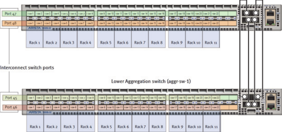
EMC Greenplum DCA Maintenance Guide Network and cabling configurations
163
System Information and Configuration
EMC CONFIDENTIAL
Aggregation switch reference
Servers in a multiple-rack configuration communicate through the two Aggregation
switches located in Rack 2. The following diagram and table show the proper connectivity.
Figure 59 Aggregation switch port map
EMC Greenplum DCA Maintenance Guide Network and cabling configurations
164
System Information and Configuration
EMC CONFIDENTIAL
Interconnect switch-to-Aggregation switch port mapping
Table 20 Interconnect switch-to-Aggregation switch port mapping (page 1 of 6)
Rack 1
Expansion
Upper
Interconnect
switch (i-sw-2)
Ports Ports
Rack 2
AGGR Rack
47 <.......>3 Upper
Aggregation
switch (aggr-sw-2)
48 <.......>4
Ports Ports
45 <.......>3 Lower
Aggregation
switch (aggr-sw-1)
46 <.......>4
Lower
Interconnect
switch (i-sw-1)
Ports Ports
47 <.......>1 Upper
Aggregation
switch (aggr-sw-2)
48 <.......>2
Ports Ports
45 <.......>1 Lower
Aggregation
switch (aggr-sw-1)
46 <.......>2
Rack 2
AGG Rack
Upper
Interconnect
switch (i-sw-4)
Ports Ports
Rack 2
AGGR Rack
47 <.......>7 Upper
Aggregation
switch (aggr-sw-2)
48 <.......>8
Ports Ports
45 <.......>7 Lower
Aggregation
switch (aggr-sw-1)
46 <.......>8
Lower
Interconnect
switch (i-sw-3)
Ports Ports
47 <.......>5 Upper
Aggregation
switch (aggr-sw-2)
48 <.......>6
Ports Ports
45 <.......>5 Lower
Aggregation
switch (aggr-sw-1)
46 <.......>6
EMC Greenplum DCA Maintenance Guide Network and cabling configurations
165
System Information and Configuration
EMC CONFIDENTIAL
Rack 3
Expansion
Upper
Interconnect
switch (i-sw-6)
Ports Ports
Rack 2
AGGR Rack
47 <.......>11 Upper
Aggregation
switch (aggr-sw-2)
48 <.......>12
Ports Ports
45 <.......>11 Lower
Aggregation
switch (aggr-sw-1)
46 <.......>12
Lower
Interconnect
switch (i-sw-5)
Ports Ports
47 <.......>9 Upper
Aggregation
switch (aggr-sw-2)
48 <.......>10
Ports Ports
45 <.......>9 Lower
Aggregation
switch (aggr-sw-1)
46 <.......>10
Table 20 Interconnect switch-to-Aggregation switch port mapping (page 2 of 6)
EMC Greenplum DCA Maintenance Guide Network and cabling configurations
166
System Information and Configuration
EMC CONFIDENTIAL
Rack 4
Expansion
Upper
Interconnect
switch (i-sw-8)
Ports Ports
Rack 2
AGGR Rack
47 <.......>15 Upper
Aggregation
switch (aggr-sw-2)
48 <.......>16
Ports Ports
45 <.......>15 Lower
Aggregation
switch (aggr-sw-1)
46 <.......>16
Lower
Interconnect
switch (i-sw-7)
Ports Ports
47 <.......>13 Upper
Aggregation
switch (aggr-sw-2)
48 <.......>14
Ports Ports
45 <.......>13 Lower
Aggregation
switch (aggr-sw-1)
46 <.......>14
Rack 5
Expansion
Upper
Interconnect
switch (i-sw-10)
Ports Ports
Rack 2
AGGR Rack
47 <.......>19 Upper
Aggregation
switch (aggr-sw-2)
48 <.......>20
Ports Ports
45 <.......>19 Lower
Aggregation
switch (aggr-sw-1)
46 <.......>20
Lower
Interconnect
switch (i-sw-9)
Ports Ports
47 <.......>17 Upper
Aggregation
switch (aggr-sw-2)
48 <.......>18
Ports Ports
45 <.......>17 Lower
Aggregation
switch (aggr-sw-1)
46 <.......>18
Table 20 Interconnect switch-to-Aggregation switch port mapping (page 3 of 6)
EMC Greenplum DCA Maintenance Guide Network and cabling configurations
167
System Information and Configuration
EMC CONFIDENTIAL
Rack 6
Expansion
Upper
Interconnect
switch (i-sw-12)
Ports Ports
Rack 2
AGGR Rack
47 <.......>23 Upper
Aggregation
switch (aggr-sw-2)
48 <.......>24
Ports Ports
45 <.......>23 Lower
Aggregation
switch (aggr-sw-1)
46 <.......>24
Lower
Interconnect
switch (i-sw-11)
Ports Ports
47 <.......>21 Upper
Aggregation
switch (aggr-sw-2)
48 <.......>22
Ports Ports
45 <.......>21 Lower
Aggregation
switch (aggr-sw-1)
46 <.......>22
Rack 7
Expansion
Upper
Interconnect
switch (i-sw-14)
Ports Ports
Rack 2
AGGR Rack
47 <.......>27 Upper
Aggregation
switch (aggr-sw-2)
48 <.......>28
Ports Ports
45 <.......>27 Lower
Aggregation
switch (aggr-sw-1)
46 <.......>28
Lower
Interconnect
switch (i-sw-13)
Ports Ports
47 <.......>25 Upper
Aggregation
switch (aggr-sw-2)
48 <.......>26
Ports Ports
45 <.......>25 Lower
Aggregation
switch (aggr-sw-1)
46 <.......>26
Table 20 Interconnect switch-to-Aggregation switch port mapping (page 4 of 6)

EMC Greenplum DCA Maintenance Guide Network and cabling configurations
168
System Information and Configuration
EMC CONFIDENTIAL
Rack 8
Expansion
Upper
Interconnect
switch (i-sw-16)
Ports Ports
Rack 2
AGGR Rack
47 <.......>31 Upper
Aggregation
switch (aggr-sw-2)
48 <.......>32
Ports Ports
45 <.......>31 Lower
Aggregation
switch (aggr-sw-1)
46 <.......>32
Lower
Interconnect
switch (i-sw-15)
Ports Ports
47 <.......>29 Upper
Aggregation
switch (aggr-sw-2)
48 <.......>30
Ports Ports
45 <.......>29 Lower
Aggregation
switch (aggr-sw-1)
46 <.......>30
Rack 9
Expansion
Upper
Interconnect
switch (i-sw-18)
Ports Ports
Rack 2
AGGR Rack
47 <.......>35 Upper
Aggregation
switch (aggr-sw-2)
48 <.......>36
Ports Ports
45 <.......>35 Lower
Aggregation
switch (aggr-sw-1)
46 <.......>36
Lower
Interconnect
switch (i-sw-17)
Ports Ports
47 <.......>33 Upper
Aggregation
switch (aggr-sw-2)
48 <.......>34
Ports Ports
45 <.......>33 Lower
Aggregation
switch (aggr-sw-1)
46 <.......>34
Table 20 Interconnect switch-to-Aggregation switch port mapping (page 5 of 6)

EMC Greenplum DCA Maintenance Guide Network and cabling configurations
169
System Information and Configuration
EMC CONFIDENTIAL
Rack 10
Expansion
Upper
Interconnect
switch (i-sw-20)
Ports Ports
Rack 2
AGGR Rack
47 <.......>39 Upper
Aggregation
switch (aggr-sw-2)
48 <.......>40
Ports Ports
45 <.......>39 Lower
Aggregation
switch (aggr-sw-1)
46 <.......>40
Lower
Interconnect
switch (i-sw-19)
Ports Ports
47 <.......>37 Upper
Aggregation
switch (aggr-sw-2)
48 <.......>38
Ports Ports
45 <.......>37 Lower
Aggregation
switch (aggr-sw-1)
46 <.......>38
Rack 11
Expansion
Upper
Interconnect
switch (i-sw-22)
Ports Ports
Rack 2
AGGR Rack
47 <.......>43 Upper
Aggregation
switch (aggr-sw-2)
48 <.......>44
Ports Ports
45 <.......>43 Lower
Aggregation
switch (aggr-sw-1)
46 <.......>44
Lower
Interconnect
switch (i-sw-21)
Ports Ports
47 <.......>41 Upper
Aggregation
switch (aggr-sw-2)
48 <.......>42
Ports Ports
45 <.......>41 Lower
Aggregation
switch (aggr-sw-1)
46 <.......>42
Table 20 Interconnect switch-to-Aggregation switch port mapping (page 6 of 6)

EMC Greenplum DCA Maintenance Guide Network hostname and IP configuration
170
System Information and Configuration
EMC CONFIDENTIAL
Network hostname and IP configuration
Table 21 DCA network configuration (page 1 of 3)
Rack Component hostname
BMC IP
host-sp
NIC 1 IP
host-cm Interconnect
Reserved for DHCP n/a n/a 172.28.6.170
through
172.28.6.179
n/a
Rack 1 Administration Switch a-sw-1 172.28.0.190
Rack 2 Administration Switch a-sw-2 172.28.0.191
Rack 3 Administration Switch a-sw-3 172.28.0.192
Rack 4 Administration Switch a-sw-4 172.28.0.193
Rack 5 Administration Switch a-sw-5 172.28.0.194
Rack 6 Administration Switch a-sw-6 172.28.0.195
Rack 7 Administration Switch a-sw-7 172.28.0.196
Rack 8 Administration Switch a-sw-8 172.28.0.197
Rack 9 Administration Switch a-sw-9 172.28.0.198
Rack 10 Administration Switch a-sw-10 172.28.0.199
Rack 11 Administration Switch a-sw-11 172.28.1.190
Rack 1 Interconnect Switch, lower i-sw-1 172.28.0.170
Interconnect Switch, upper i-sw-2 172.28.0.180
Rack 2 Interconnect Switch, lower i-sw-3 172.28.0.171
Interconnect Switch, upper i-sw-4 172.28.0.181
Rack 3 Interconnect Switch, lower i-sw-5 172.28.0.172
Interconnect Switch, upper i-sw-6 172.28.0.182
Rack 4 Interconnect Switch, lower i-sw-7 172.28.0.173
Interconnect Switch, upper i-sw-8 172.28.0.183
Rack 5 Interconnect Switch, lower i-sw-9 172.28.0.174
Interconnect Switch, upper i-sw-10 172.28.0.184
Rack 6 Interconnect Switch, lower i-sw-11 172.28.0.175
Interconnect Switch, upper i-sw-12 172.28.0.185
Rack 7 Interconnect Switch, lower i-sw-13 172.28.0.176
Interconnect Switch, upper i-sw-14 172.28.0.186
Rack 8 Interconnect Switch, lower i-sw-15 172.28.0.177
Interconnect Switch, upper i-sw-16 172.28.0.187

EMC Greenplum DCA Maintenance Guide Network hostname and IP configuration
171
System Information and Configuration
EMC CONFIDENTIAL
Rack 9 Interconnect Switch, lower i-sw-17 172.28.0.178
Interconnect Switch, upper i-sw-18 172.28.0.188
Rack 10 Interconnect Switch, lower i-sw-19 172.28.0.179
Interconnect Switch, upper i-sw-20 172.28.0.189
Rack 11 Interconnect Switch, lower i-sw-21 172.28.1.170
Interconnect Switch, upper i-sw-22 172.28.1.180
Rack 2 Aggregation Switch, lower aggr-sw-1 172.28.0.248
Aggregation Switch, upper aggr-sw-2 172.28.0.249
Rack 1 Primary Master Server, lower server mdw 172.28.0.250 172.28.4.250 172.28.8.250
Standby Master Server, upper server smdw 172.28.0.251 172.28.4.251 172.28.8.251
Table 21 DCA network configuration (page 2 of 3)
Rack Component hostname
BMC IP
host-sp
NIC 1 IP
host-cm Interconnect

EMC Greenplum DCA Maintenance Guide Network hostname and IP configuration
172
System Information and Configuration
EMC CONFIDENTIAL
GPDB Segment Server 1-160 sdw# 172.28.0.# 172.28.4.# 172.28.8.#
GPDB Segment Server 161-176 sdw# 172.28.1.1
-
172.28.1.16
172.28.5.1
-
172.28.5.16
172.28.9.1
-
172.28.9.16
DIA Server 1-16 etl# 172.28.0.20# 172.28.4.20# 172.28.8.20#
DIA Server 17-32 etl# 172.28.1.201
-
172.28.1.216
172.28.5.201
-
172.28.5.216
172.28.9.201
-
172.28.9.216
DIA Server 33-48 etl# 172.28.2.231
-
172.28.2.246
172.28.6.231
-
172.28.6.246
172.28.10.231
-
172.28.10.246
DIA Server 49-64 etl# 172.28.3.231
-
172.28.3.246
172.28.7.231
-
172.28.7.246
172.28.11.231
-
172.28.11.246
Hadoop Master Node 1-8 hdm1
hdm2
hdm3
hdm4
hdm5
hdm6
hdm7
hdm8
172.28.1.250
172.28.1.251
172.28.1.252
172.28.1.253
172.28.2.250
172.28.2.251
172.28.3.250
172.28.3.251
172.28.5.250
172.28.5.251
172.28.5.252
172.28.5.253
172.28.6.250
172.28.6.251
172.28.7.250
172.28.7.251
172.28.9.250
172.28.9.251
172.28.9.252
172.28.9.253
172.28.10.250
172.28.10.251
172.28.11.250
172.28.11.251
Hadoop Worker Node 1-160 hdw1-160 172.28.2.# 172.28.6.# 172.28.10.#
1Hadoop Worker Node 161-320 hdw161-320 172.28.3.#
# = node
number minus
160. Example:
hdw162-sp =
172.28.3.2
172.28.7.#
# = node
number minus
160. Example:
hdw162 -cm=
172.28.7.2
172.28.11.#
# = node
number minus
160. Example:
hdw162-1 =
172.28.11.2
Hadoop Compute Node 1-60 hdc1-60 172.28.2.170
-
172.28.2.229
172.28.6.170
-
172.28.6.229
172.28.10.170
-
172.28.10.229
Hadoop Compute Node 61-120 hdc61-120 172.28.3.170
-
172.28.3.229
172.28.7.170
-
172.28.7.229
172.28.11.170
-
172.28.11.229
2 IP Addresses reserved for Isilon
1. Hadoop Worker nodes are numbered 1-320. In order to accommodate the required number of hosts, the third IP address octet is
incremented by 1 and the fourth octet restarts at 1 when the node number reaches 161. For example, the host hdw160-sp uses a
third octet of 2 and a fourth octet of 160 - host hdw-161-sp uses a third octet of 3 and a fourth octet of 1. To see a complete list of
IP addresses and hostnames, view the /etc/hosts file.
2.) 172.28.8.217 through 172.28.8.246 and 172.28.9.217 through 172.28.9.246
Table 21 DCA network configuration (page 3 of 3)
Rack Component hostname
BMC IP
host-sp
NIC 1 IP
host-cm Interconnect
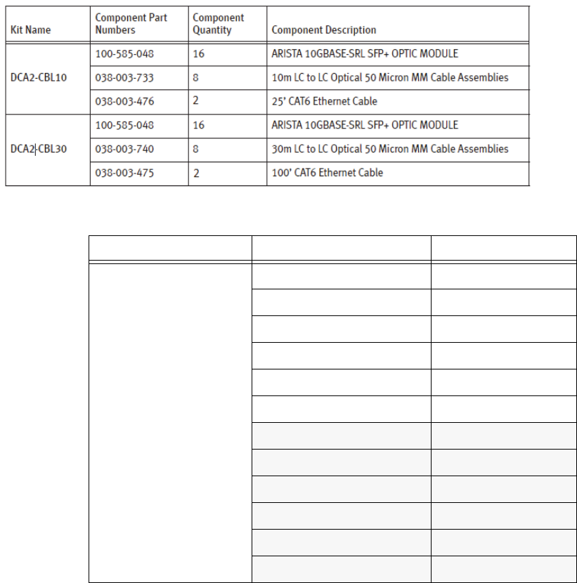
EMC Greenplum DCA Maintenance Guide Multiple-rack cabling reference
173
System Information and Configuration
EMC CONFIDENTIAL
Multiple-rack cabling reference
Table 22 Cabling kit contents and part numbers
Table 23 Cable kits for a 7-to-11-rack DCA
Connect from: To: Use cable kit:
Rack 2 - AGGREG
Rack 1 - SYSRACK DCA2-CBL10
Rack 2 - AGGREG DCA2-CBL10
Rack 3 - 1st EXPAND DCA2-CBL10
Rack 4 - 2nd EXPAND DCA2-CBL10
Rack 5 - 3rd EXPAND DCA2-CBL10
Rack 6 - 4th EXPAND DCA2-CBL10
Rack 7 - 5th EXPAND DCA2-CBL30
Rack 8 - 6th EXPAND DCA2-CBL30
Rack 9 - 7th EXPAND DCA2-CBL30
Rack 10 - 8th EXPAND DCA2-CBL30
Rack 11 - 9th EXPAND DCA2-CBL30

EMC Greenplum DCA Maintenance Guide Configuration files
174
System Information and Configuration
EMC CONFIDENTIAL
Configuration files
Configuration files are text files that contain the hostnames of servers that occupy quarter,
half, or full rack configurations. The file used depends on the desired function. Refer to the
table below for a description of each configuration and host file. The hostfiles are located
at $ /home/gpadmin/gpconfigs:
Location of old core files
(
Applies to DCA version 2.0.1.0 and later
) Old core files are moved automatically to a
separate directory to prevent them from being sent to Support following a healthmon
restart. For example, for sdw1, old core files are moved to /var/crash/user
.
[root@sdw1 user-processed]# ls -l /var/crash/user
Table 24 Hostfiles created by the DCA Setup utility
File Description
gpexpand_map Expansion MAP file created during the dca_setup
option
Expand the DCA
. It’s purpose is to during GPDB
reallocate primary and mirror instances on the new
hardware.
gpinitsystem_map MAP file used during installation of GPDB blocks to
assign primary and mirror segments to each server.
hostfile Contains one hostname per server for ALL servers in the
system. Includes GPDB, DIA and HD (if present).
hostfile_segments Contains the hostnames of the segment servers of all
GPDB blocks.
hostfile_gpdb Contains the hostnames for GPDB servers.
hostfile_dia Contains the hostnames of the DIA servers.
hostfile_hadoop Contains the hostnames of the Hadoop servers.
hostfile_hdm Contains the hostnames of all Hadoop Master servers.
hostfile_hdw Contains the hostnames of all Hadoop Worker servers.
hostfile_hdc Contains the hostnames of all Hadoop Compute
servers.

EMC Greenplum DCA Maintenance Guide Default passwords
175
System Information and Configuration
EMC CONFIDENTIAL
Default passwords
The following table lists default passwords for all the components in a DCA.
Table 25 Default user names and passwords
Component User Password
Master Servers BMC root user For a new unconfigured server:
password
For an existing configured server:
sephiroth
root changeme
gpadmin changeme
Interconnect,
Adminstration, and
Aggregation switches
admin changeme

EMC Greenplum DCA Maintenance Guide Connect a workstation to the DCA
176
EMC CONFIDENTIAL
APPENDIX B
Connect a workstation to the DCA
This section describes how to connect a workstation to the DCA in prepration for
performing various maintenance tasks. Administration is always performed from the
Primary Master server (hostname
mdw
). A Windows laptop with the PuTTY application
installed is required.
Laptop prerequisites
The laptop you use to connect to the Greenplum DCA must have the following capabilities
in order to perform Greenplum DCA administration:
RJ-45 Ethernet port
Administrator access on the laptop
An
ssh
client such as PuTTY or Cygwin with the OpenSSH package enabled
An
scp
client such as WinSCP, PuTTY PSCP or Cygwin with the OpenSSH package
enabled
Configure your laptop to connect to the DCA
Perform the appropriate procedure to configure your laptop to connect to the DCA
Administration Network.
Configure a Windows 7 laptop
1. Locate the red service cable on the laptop tray. The cable is connected to port 48 of
the first administration switch (a-sw-1). Connect the service cable to your laptop.
2. Click Start > Control Panel > Network and Internet > Network Sharing Center.
3. On the left pane click Change adapter settings.
4. Right-click the connection that you want to change, and then click Properties. If you
are prompted for an administrator password or confirmation, type the password or
provide confirmation.
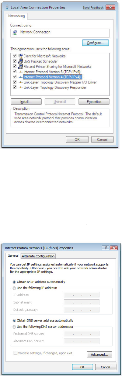
EMC Greenplum DCA Maintenance Guide Configure your laptop to connect to the DCA
177
Connect a workstation to the DCA
EMC CONFIDENTIAL
5. From the Networking tab select Internet Protocol Version 4 (TCP/IPv4), and then click
Properties.
6. Click Properties.
7. Select Use the following IP address, and then type the following IP address and subnet
mask:
•IP address: 172.28.3.253
•Subnet mask: 255.255.248.0
Note: Leave the Default gateway field blank. Do not configure a gateway.
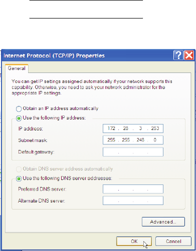
EMC Greenplum DCA Maintenance Guide Connect to the Master Server using an SSH client
178
Connect a workstation to the DCA
EMC CONFIDENTIAL
8. Click OK.
9. Click Close.
Configure a Windows XP laptop
1. Locate the red service cable on the laptop tray. The cable is connected to port 48 of
the first administration switch (a-sw-1). Connect the service cable to your laptop.
2. On your Windows laptop, open Control Panel.
3. Double-click Network Connections.
4. Right-click Local Area Connection and then select Properties.
5. Select Internet Protocol (TCP/IP) and then click Properties.
6. Enter the IP address and subnet mask:
•IP address: 172.28.3.253
•Subnet mask: 255.255.248.0
Note: Leave the Default gateway field blank. Do not configure a gateway.
7. Click OK.
Connect to the Master Server using an SSH client
The method you use to establish an ssh connection to the Master Server depends on your
chosen ssh client (PuTTY, Cygwin, etc.). Regardless of the ssh client, connect using the
following values:
hostname: 172.28.4.250
username: root
root password: changeme (or whatever the customer’s root password is)
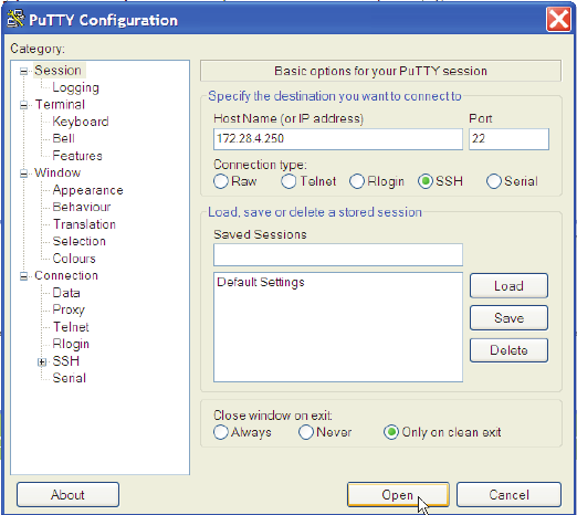
EMC Greenplum DCA Maintenance Guide Copy a file to the Master Server using an SCP client
179
Connect a workstation to the DCA
EMC CONFIDENTIAL
PuTTY example
1. Open PuTTY and enter 172.28.4.250 in the Host Name (or IP address) field. Select
SSH as the Connection type.
2. Click Open.
3. If this is the first time you have connected to this server, a security alert will display.
Click Yes to continue.
4. At the SSH Login window, enter your username and password. For example:
login as: root
root@172.28.4.250 password: changeme
Cygwin example
To use Cygwin, you must have enabled the OpenSSH package when you installed Cygwin.
Open a Cygwin terminal window and type the following at the prompt:
$ ssh root@172.28.4.250
When prompted, type the root password (default is changeme).
Copy a file to the Master Server using an SCP client
The method you use to copy a file from your local laptop to the Greenplum master server
depends on your chosen scp client (WinSCP, Cygwin, etc.). Regardless of the scp client,
connect using the following values:
hostname: 172.28.4.250
username: gpadmin
root password: changeme (or whatever the customer’s root password is)
Destination on the master: /home/gpadmin
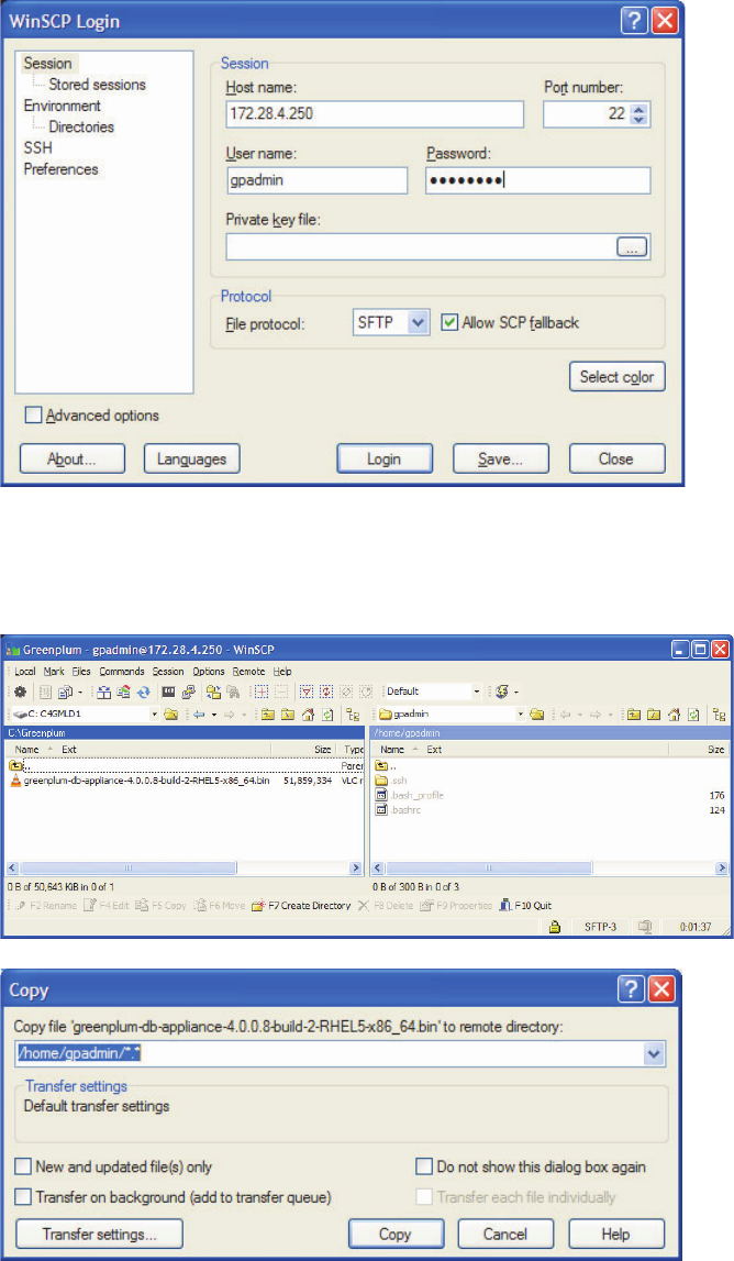
EMC Greenplum DCA Maintenance Guide Copy a file to the Master Server using an SCP client
180
Connect a workstation to the DCA
EMC CONFIDENTIAL
WinSCP Example
1. Log in to the master host IP
172.28.4.250
as user
gpadmin
. Select SFTP as the File
protocol.
2. On your local host, locate the file you want to copy and then choose the
/home/gpadmin directory on the master server.
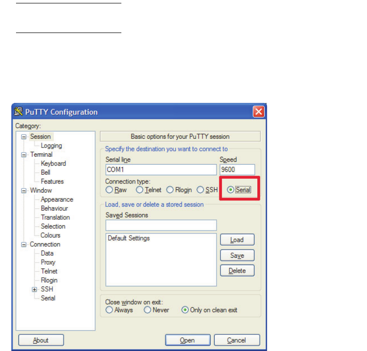
EMC Greenplum DCA Maintenance Guide Connect to an Interconnect or Administration switch using PuTTY
181
Connect a workstation to the DCA
EMC CONFIDENTIAL
3. Click Copy.
Cygwin example
1. To use Cygwin, you must have enabled the OpenSSH package when you installed
Cygwin. Open a Cygwin terminal window and type the following at the prompt:
$ cd <
local_location_of_file
>
$ scp <
file_name
> gpadmin@172.28.4.250:/home/gpadmin
2. When prompted, type the
gpadmin
password (the default is
changeme
).
Connect to an Interconnect or Administration switch using PuTTY
This section describes how to connect your service laptop to a serial port on an
Interconnect or Administration switch. You must perform this procedure if the switch
contains factory settings or cannot be accessed by telnet or ssh through the DCA
Administration network.
1. Connect one end of a serial cable from the serial port on the switch. Connect the other
end of the cable to your workstation.
Note: If the service laptop or workstation does not have a serial port, you can use a
USB-to-Serial Adapter.
2. Launch the PuTTY application.
3. Select Serial in Basic Options under the Session section.
Serial option in a PuTTY session
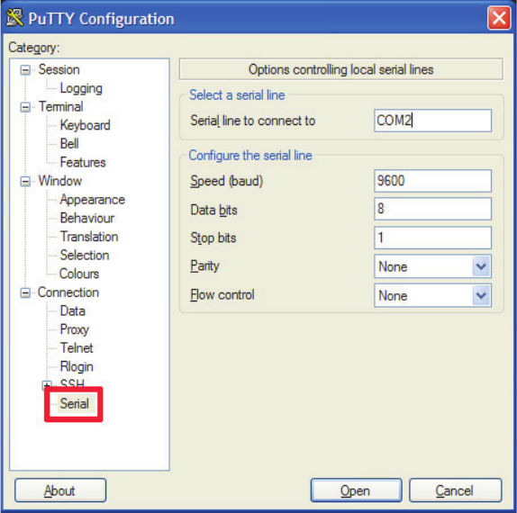
EMC Greenplum DCA Maintenance Guide Connect to an Interconnect or Administration switch using PuTTY
182
Connect a workstation to the DCA
EMC CONFIDENTIAL
4. Expand the connection section and select Serial. Verify that the settings for the COM
port are 9600 Baud, 8 data bits, and no hardware flow control.
5. Click Open to connect.
6. Press <Enter> to display the login prompt.

EMC Greenplum DCA Maintenance Guide Power Off the DCA
183
EMC CONFIDENTIAL
APPENDIX C
Power Off the DCA
To safely shut down and power off Greenplum DCA hardware and software, perform the
following tasks in sequence:
Task 1: Connect to the Greenplum DCA Master Server............................................ 184
Task 2: Stop the Greenplum Database software and shut down the OS.................. 185
Task 3: Place the PDU power switches in the OFF position ..................................... 187
IMPORTANT
Stop all running queries and data loading before you power down the DCA.
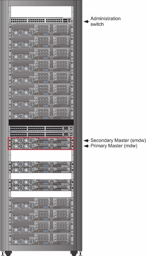
EMC Greenplum DCA Maintenance Guide Connect to the Greenplum DCA Master Server
184
Power Off the DCA
EMC CONFIDENTIAL
Task 1: Connect to the Greenplum DCA Master Server
The fastest method to shut down a DCA is to SSH in to a Master Server through an external
network connection.
If the external conection is not available and you have a service laptop, connect to the DCA
as described in this procedure. This procedure assumes you are using the Windows
Operating System.
1. Locate the system rack of the DCA.
The systm rack contains the Primary and Standby Master servers. Master servers are
highlighted in red in Figure 60.
Figure 60 Master Servers in the System rack
2. Locate the red service cable on the laptop tray and connect it to your laptop. The red
service cable is connected to port 48 on the Administration switch.
EMC Greenplum DCA Maintenance Guide Stop the Greenplum Database software and shut down the OS
185
Power Off the DCA
EMC CONFIDENTIAL
3. From your Windows laptop navigate to Start > Control Panel > Network and Internet >
Network Sharing Center.
4. On the left pane click Change adapter settings..
5. Right-click Local Area Connection and select Properties.
6. From the Networking tab select Internet Protocol Version 4 (TCP/IPv4).
7. Click Properties.
8. Select Use the following IP address, and then enter the following IP address and
subnet mask:
•IP address: 172.28.3.253
•Subnet mask: 255.255.248.0
9. Click OK.
10. Click Close.
11. Open an SSH client (such as PuTTY) and enter:
•Host Name (or IP address): 172.28.4.250
•Connection type: SSH
12. Click Open.
If this is the first time you have connected to this server, a security alert will display.
13. Click Yes to continue.
14. Log in as the user root with password changeme.
If the default password changeme was changed, enter the current password.
Task 2: Stop the Greenplum Database software and shut down the OS
To ensure data consistency across primary and mirror segments, you must stop the
Greenplum Database software correctly.
1. To prevent false dial home messages from being sent to EMC Support during service,
disable health monitoring by stopping the healthmon daemon:
# dca_healthmon_ctl -d
2. Switch to the user gpadmin:
# su - gpadmin
3. When prompted for the password, enter changeme.
If the default password changeme was changed, enter the current password.
4. Stop the Greenplum Database:
$ gpstop -af
5. Stop Greenplum Command Center:
$ gpcmdr --stop
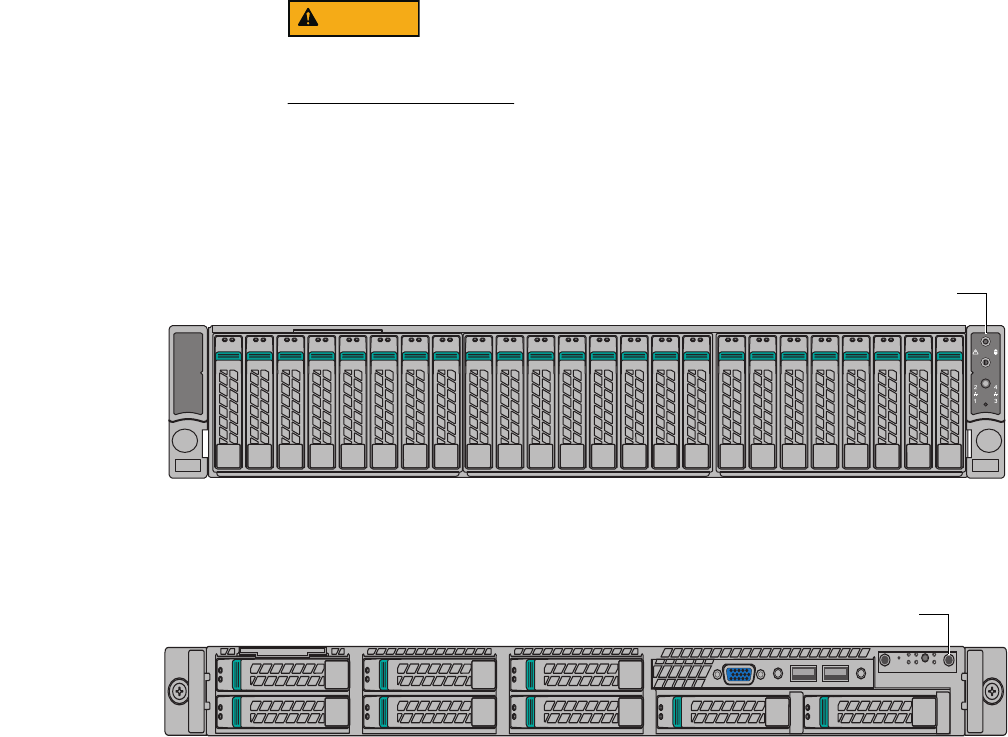
EMC Greenplum DCA Maintenance Guide Stop the Greenplum Database software and shut down the OS
186
Power Off the DCA
EMC CONFIDENTIAL
6. Switch to the user root:
$ su -
7. Start the DCA Shutdown utility:
Issuing the shutdown command immediately shuts down the DCA. Make sure that
you are ready to shut down the DCA before you issue this command.
# dca_shutdown
8. Verify that the green LED on the power button on each server turns off after 1-2
minutes (see Figure 61 and Figure 62).
9. If a server does not power off, power it off manually by pressing the power button.
Figure 61 Location of power button on a GPDB server (applies also to Hadoop Masters & Workers)
Figure 62 Location of power button on a Master, DIA, and Hadoop Compute servers
{
Procedure continues on next page
}
AF004297
Power button
Power button

EMC Greenplum DCA Maintenance Guide Place the PDU power switches in the OFF position
187
Power Off the DCA
EMC CONFIDENTIAL
Task 3: Place the PDU power switches in the OFF position
When the Greenplum Database is stopped and the operating system is shut down on each
server, it is safe to power off the system via the eight PDU power switches in each rack.
1. Starting from the rear of the System rck (Rack 1), locate the power switches in the
upper and lower Power Zones A and B (see Figure 63).
Figure 63 Rack power switch locations
Power
switches
Customer-supplied
power
Upper Zone A
input
Power
switches
Customer-supplied
power
Lower Zone A
input
Power
switches
Power
switches
Customer-
supplied power
Lower
Zone B
input
Customer-
supplied power
Upper
Zone B
input
{Procedure continues on next page)
EMC Greenplum DCA Maintenance Guide Place the PDU power switches in the OFF position
188
Power Off the DCA
EMC CONFIDENTIAL
2. First place the power switches in
lower
Power Zones A and B in the OFF position, and
then place the power switches in
upper
Power Zones A and B in the OFF position.
3. Power off the remaining racks in the same way, one rack at a time, first placing the
power switches in the lower zone and then the upper zone in the OFF position.
After a few seconds, there should be no lit LEDs on any components in the system.
Shutdown is complete.

EMC Greenplum DCA Maintenance Guide Linux and vi Command Reference
189
EMC CONFIDENTIAL
APPENDIX D
Linux and vi Command Reference
This appendix is a quick reference of basic Red Hat Linux commands, Greenplum-specific
Linux commands, and common Vi text editor commands.
Common Linux command reference
Table 26 Common Linux commands (page 1 of 2)
Linux command Description
Moving Around
/ refers to the root directory
.. refers to the parent directory
Up/down arrows repeats the last (up arrow) or next (down arrow) command you typed
pwd displays the current directory
cd name changes to the named directory
cd returns you to your home directory
Basic Commands
ls lists the contents of the current directory
ls dir_name lists the content of the named directory
ls -l lists the content of the named directory in long format; this includes
file permissions, ownership information, and file size
ls -a lists all the files in the named directory including files that start with
a period (“.)”
cat filename prints the content of the named file to the screen, one page at a time
more filename prints the content of the named file to the screen, with scrolling and
search facilities
cp source destination copies the source file to the named destination
for example:
cp /
misc
/
temp
.
copies a file called
temp
located in the
misc
directory, to the
current directory (“.”)
mv source destination moves the source file or directory to the named destination
for example:
mv /
misc
/
temp
.
this moves a file called
temp
located in the
misc
directory, to the
current directory (“.”)
rm filename deletes (removes) the named file
mkdir dir_name creates a new directory
rmdir dir_name removes the specified directory (directory must be empty)
source source path information

EMC Greenplum DCA Maintenance Guide Common Linux command reference
190
Linux and vi Command Reference
EMC CONFIDENTIAL
su assume the super user (root) identity
tar untars a tape archived and compressed file
unzip extracts compressed files from a ZIP archive
grep string filename prints all the lines in a file that contain the specified string
su temporarily become the superuser - useful for system administration
tasks
passwd allows you to change the password used to access your user
account. You are prompted to enter your current password, then
enter a new one.
who displays a list of users currently logged onto this computer
Getting Help
man command displays a (manual page (man) about the specified command,
possible options and switches, and more detailed information
about using that command
Shutting down and rebooting a Linux machine
/sbin/shutdown - r now reboots the machine immediately
/sbin/shutdown - h now shuts down the machine immediately
Greenplum Linux Commands
gpcheck verifies and validates Greenplum Database platform settings
gpexpand expands an existing Greenplum Database across new hosts in the
array
gpinitsystem initializes a Greenplum Database system by using configuration
parameters specified in the gp_init_config file
gpinitstandby adds and/or initializes a standby master host for a Greenplum
Database system
gpseginstall installs the Greenplum Database software on multiple hosts
gpscp copies files between multiple hosts at the same time
gpssh-exkeys provides ssh access to multiple hosts at the same time
gpstate verifies the DCA master server status
Table 26 Common Linux commands (page 2 of 2)
Linux command Description

EMC Greenplum DCA Maintenance Guide vi Quick Reference
191
Linux and vi Command Reference
EMC CONFIDENTIAL
vi Quick Reference
The following is a quick reference for the vi editor.
Table 27 Common vi commands
vi command Description
Inserting/Deleting Text
(To exit insert mode, press the [ESC] key)
aappend text, after the cursor
i insert text, before the cursor
R enter overtype mode
xdelete character
dd delete current line
Moving Cursor
h, [BACKSPACE] left one character
l, [SPACE] right one character
wforward one word
bback one word
eend of word
jdown one line
kup one line
?pattern search backward for pattern
/pattern search forward for pattern
n repeat last search
N repeat last search in the opposite direction
Saving File and Exiting
:wq save file and quit
:q! force quit the editor, do not save changes
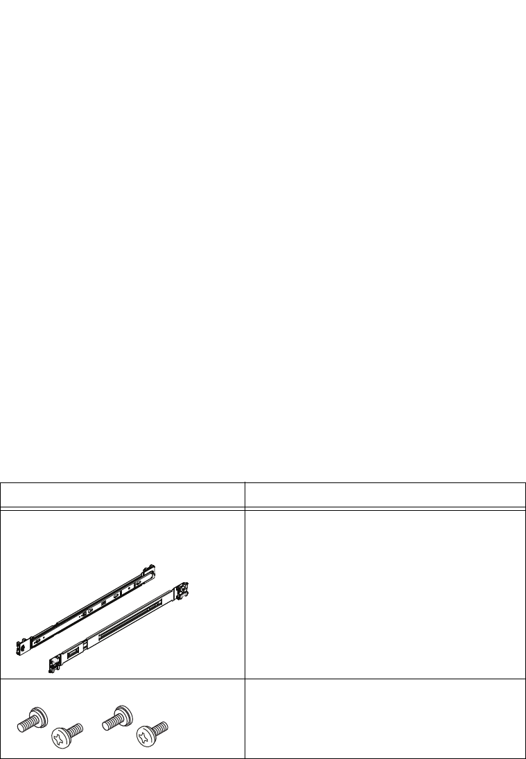
EMC Greenplum DCA Maintenance Guide Replace a Server in the Greenplum DCA Rack
192
EMC CONFIDENTIAL
APPENDIX E
Replace a Server in the Greenplum DCA Rack
This appendix describes how to replace the servers in a DCA 40U rack. Server types
include:
1U servers—Master, DIA, and Hadoop compute servers (EMC SVR-I1U-1208)
2U servers—GPDB (EMC SVR-I2U-R2224) and Hadoop Master and Worker servers
(EMC SVR-I2U-R2312)
This appendix includes the following sections:
Mounting kit parts................................................................................................. 192
Task 1: Remove the server from the rack................................................................ 193
Task 2: Remove the inner rails from the original server .......................................... 195
Task 3: Attach the inner rails to the replacement server ......................................... 195
Task 4: Install the server in the rack....................................................................... 196
Mounting kit parts
The server mounting kit includes rails and screws as listed in the following table. Verify
that these parts are included with the replacement server.
You need a # 2 Phillips-head screwdriver to complete the installation of the rails and
server.
Component Use
2 universal rail assemblies
(consists of slide rails for connection to the
rack and inner rails for connection to server)
Attach back to front on either side between rack
channels
Four Phillips pan-head 8-32 x 0.35 in screws Stabilize the server and rail mounting
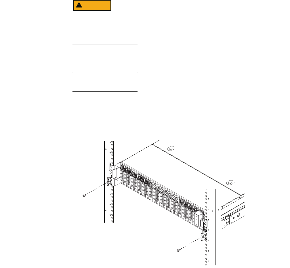
EMC Greenplum DCA Maintenance Guide Remove the server from the rack
193
Replace a Server in the Greenplum DCA Rack
EMC CONFIDENTIAL
Task 1: Remove the server from the rack
The enclosure is heavy and should be installed into or removed from a rack by two
people. To avoid personal injury and/or damage to the equipment, do not attempt to lift
and install the enclosure into a rack without a mechanical lift and/or help from another
person.
Procedure:
IMPORTANT
When removing the server from the rack, do not hold the server up by its power/control
module, which is on the right side of the front of the server.
1. Unplug all power and I/O cables from the back of the server, and label the cables so
you can easily identify them when you need to connect them to the replacement
server.
2. Remove the stabilizing screw behind the latch bracket on each side (Figure 64).
Figure 64 Remove the stabilizer screws
CL5020

EMC Greenplum DCA Maintenance Guide Remove the server from the rack
194
Replace a Server in the Greenplum DCA Rack
EMC CONFIDENTIAL
3. Pull the server forward until it locks in place (Figure 65).
Figure 65 Slide server out of the rack to the locked position
4. Slide the blue disconnect tabs forward to release the inner rails from the slide rails
(Figure 66).
Once you release the server from the inner rails, you must support the full weight of
the server.
5. Be prepared to support the full weight of the server, and then slowly pull the server
forward and remove it from the rack (Figure 66).
Figure 66 Release the inner rail locks and remove the server from the rack
CL5023
CL5019
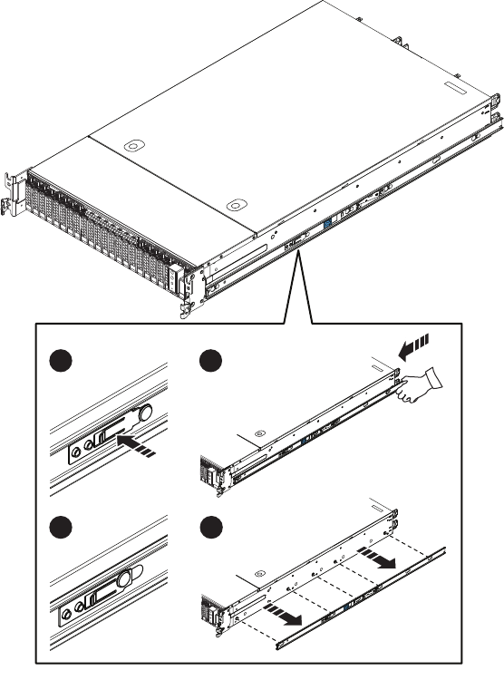
EMC Greenplum DCA Maintenance Guide Remove the inner rails from the original server
195
Replace a Server in the Greenplum DCA Rack
EMC CONFIDENTIAL
Task 2: Remove the inner rails from the original server
1. On the middle of the inner rail, push in and hold the metal latch.
2. Push the rail forward to release the connection studs from the small end of the rail
notches.
3. When the connections studs are in the large end of the rail notches, release the metal
latch.
4. Pull the inner rails away from the server.
Figure 67 Release the inner rails from the server
Task 3: Attach the inner rails to the replacement server
1. Align the large end of the rail notches on the inner rail with the connection studs on
the side of the server.
2. Push the flat side of the inner rail onto connection studs.
3. Slide the inner rail backwards along the server until the studs fit securely into the
small end of the rail notches.
An audible click indicates that the rail is secure.
CL5017
3
1
4
2
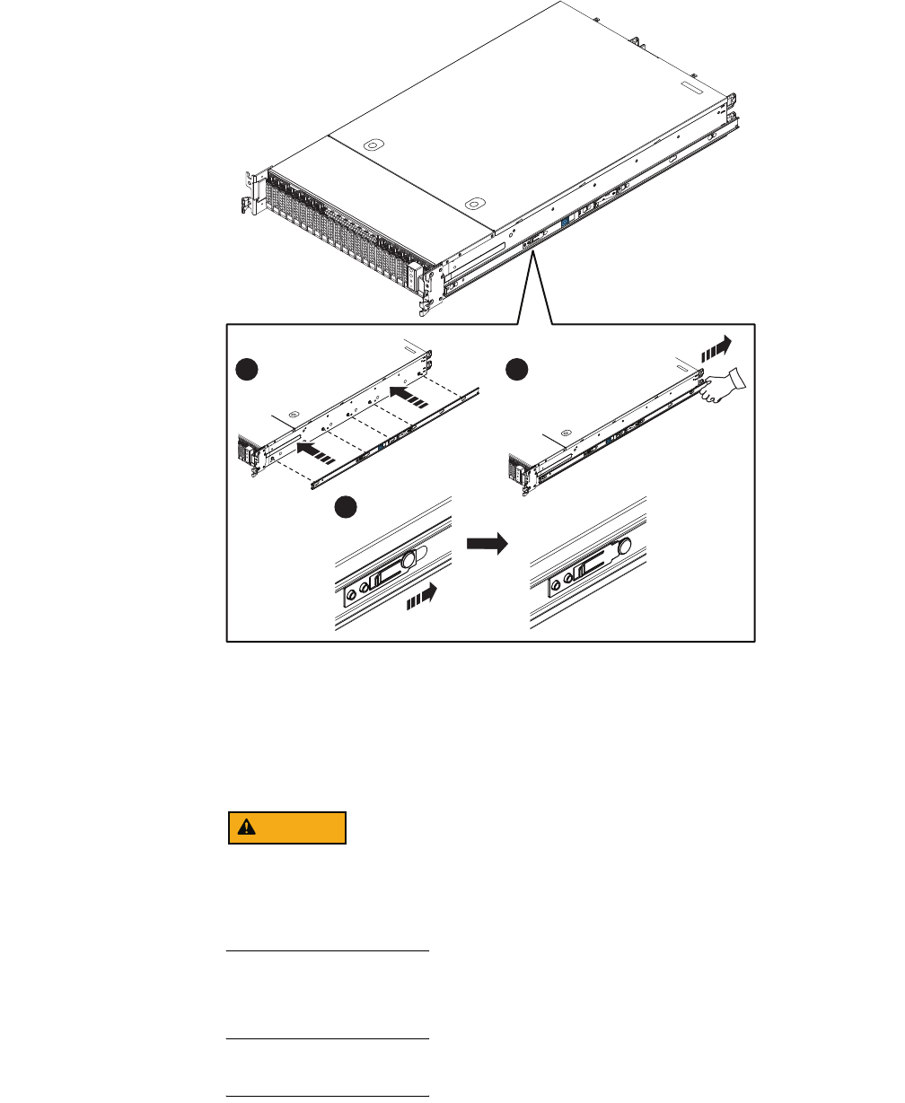
EMC Greenplum DCA Maintenance Guide Install the server in the rack
196
Replace a Server in the Greenplum DCA Rack
EMC CONFIDENTIAL
Figure 68 Attach an inner rail to the server
Task 4: Install the server in the rack
The enclosure is heavy and should be installed into or removed from a rack by two
people. To avoid personal injury and/or damage to the equipment, do not attempt to lift
and install the enclosure into a rack without a mechanical lift and/or help from another
person.
Procedure:
IMPORTANT
When installing the server in the rack, do not pick the server up by the rotating power
console on the front right side of the server and do not push on the power console.
3
1 2
CL5016
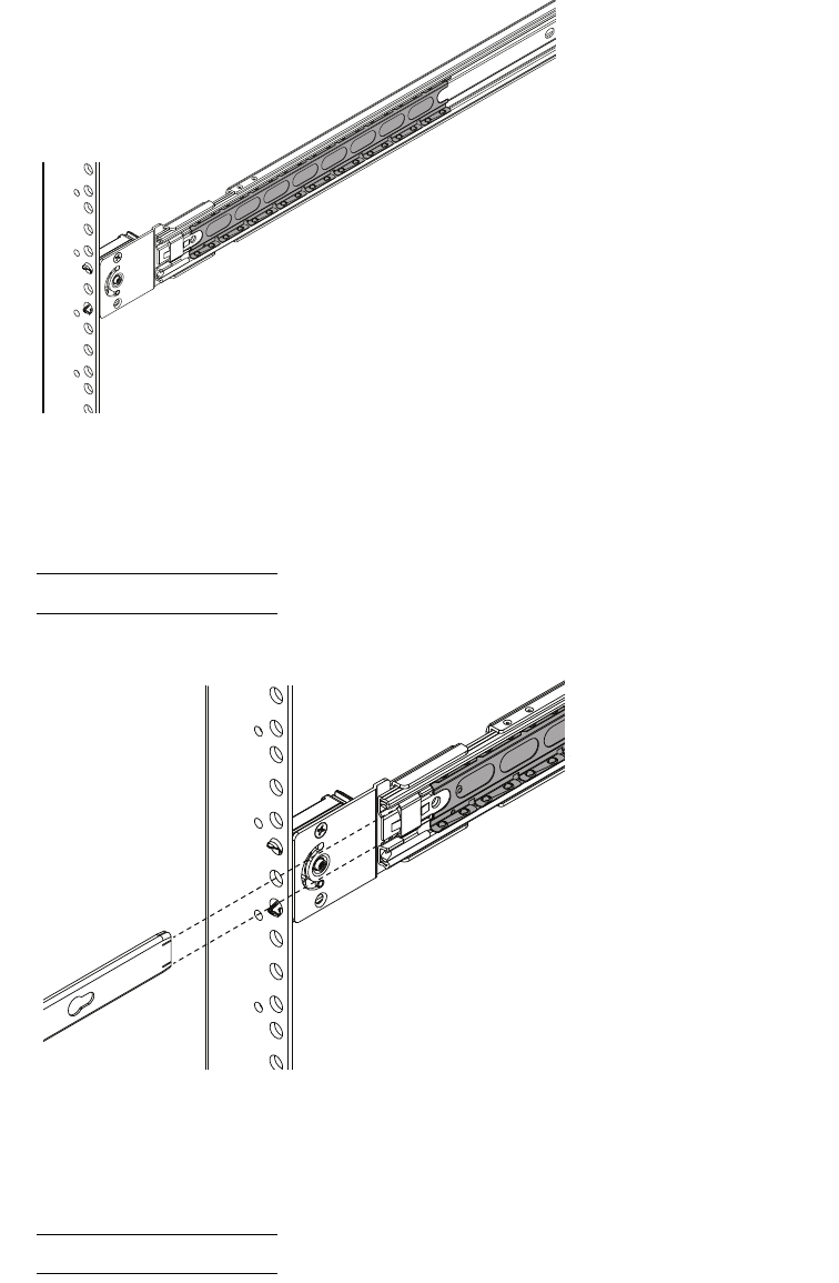
EMC Greenplum DCA Maintenance Guide Install the server in the rack
197
Replace a Server in the Greenplum DCA Rack
EMC CONFIDENTIAL
1. On each slide rail bring the ball bearing retainer assembly fully to the front, so it rides
onto the security knob (Figure 69).
Figure 69 Correct location for ball bearing retainer assembly
2. From the front of the rack, align the inner rails attached to the server with the white
plastic guide block front inside of each slide rail (Appendix EFigure 70).
Note: For clarity Figure 70 shows the inner rail without the server attached.
Figure 70 Align the inner rail with white plastic guide block
3. Slide the server into the chassis so the inner rails extend over the plastic guide blocks
and the first part of the ball bearing retainer assemblies (Figure 71).
Note: For clarity Figure 71 shows the inner rail without the server attached.
CL5092
CL5093
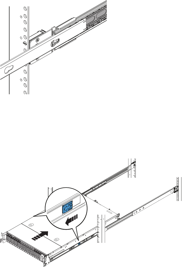
EMC Greenplum DCA Maintenance Guide Install the server in the rack
198
Replace a Server in the Greenplum DCA Rack
EMC CONFIDENTIAL
Figure 71 Inner rail over the first part of ball bearing retainer assembly
4. Once the inner rails are properly engaged with the ball bearing retainer assemblies,
push the server into into the rack until the slide rails are engaged and locked.
An audible click indicates that the slide rails are engaged and locked.
5. On the outside of each rail assembly, slide the blue disconnect tab forward to unlock
the server, and push the server completely into the rack (Figure 72).
Figure 72 Inserting the server completely into the rack
CL5094
CL5018
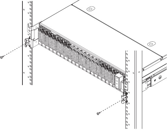
EMC Greenplum DCA Maintenance Guide
199
Replace a Server in the Greenplum DCA Rack
EMC CONFIDENTIAL
6. To further secure the rail assembly and server in the rack, insert and tighten a small
stabilizer screw directly behind each bezel latch (Figure 73).
Figure 73 Installing the stabilizer screws
7. Reconnect data and power cables as described in the server replacement procedure.
CL5020
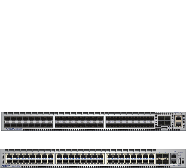
EMC Greenplum DCA Maintenance Guide Install a Switch in a Rack
200
EMC CONFIDENTIAL
APPENDIX F
Install a Switch in a Rack
This appendix describes how to replace the switches in a DCA 40U rack. It includes the
following major sections:
Switch mounting kit parts ..................................................................................... 201
Replace the switch in the rack ............................................................................... 201
Replace an optical SFP module.............................................................................. 208
Switch types include:
Interconnect and Aggregation (10GB; SWCH-AR1U-7050S-52)
Administration (1GB; SWCH-AR1U-7048T)
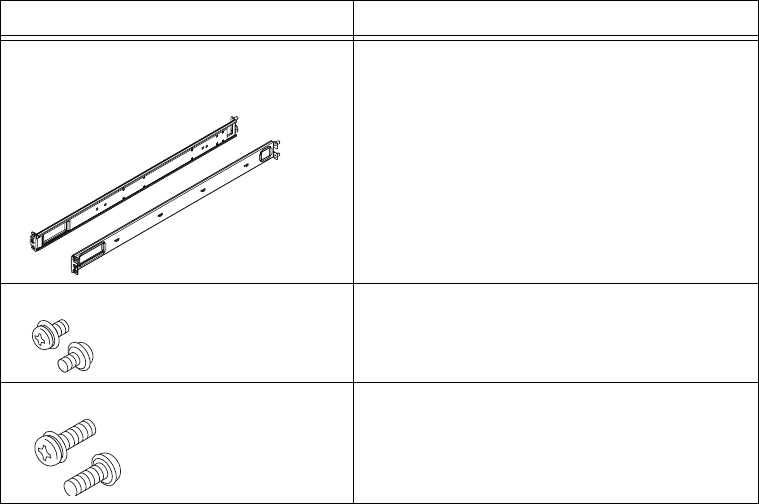
EMC Greenplum DCA Maintenance Guide Switch mounting kit parts
201
Install a Switch in a Rack
EMC CONFIDENTIAL
Switch mounting kit parts
The switch mounting kit includes rail assemblies and screws as listed below.
You need a Phillips-head screwdriver to complete the installation of the rails and switch.
Replace the switch in the rack
Replacement of non-FRU switch components by unauthorized personnel may void service
warranties. If any non-FRU component fail you must replace the entire switch.
Replacing the switch consists of the following steps:
“Task 1: Unpack the replacement switch” on page 201
“Task 2: Remove the old switch from the rack” on page 201
“Task 3: Transfer any optical SFP modules” on page 203
“Task 4: Transfer the inner rails to the replacemet switch” on page 204
“Task 6: Install the switch in the rack” on page 206
Task 1: Unpack the replacement switch
Unpack the replacement switch and place it on a clean, static-free surface near the rack
with the faulted switch.
Task 2: Remove the old switch from the rack
1. From the back of the rack:
a. Unplug all cables from the switch, and label the cables for easy identification when
you need to plug them into the replacement switch.
Component Use
2 rail assemblies
(consists of outer rails for connection to the
rack and inner rails for connection to switch)
Attach back to front on either side between rack
channels and to the switch.
Eight Phillips pan-head 4M x 6 mm screws Attach inner rails to switch (4 per rail)
Six Phillips pan-head 5M x 16 mm screws Stabilize the rail mounting (3 per rail)
CL5032
CL5033
CL5034
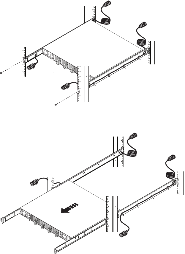
EMC Greenplum DCA Maintenance Guide Replace the switch in the rack
202
Install a Switch in a Rack
EMC CONFIDENTIAL
b. Unplug both switch power cords from the rack’s power distribution unit(s).
2. From the front of the rack:
a. Unplug both power cords from the switch.
b. Push the end of each power cord through the large hole in the front of the each rail
assembly so you will be able to slide the switch forward.
c. Remove the
middle
stabilizing screw from the front of each rail assembly
(Figure 74).
d. Pull the switch out of the rack and place it near the replacement switch
(Figure 75).
Figure 74 Removing the middle stabilizer screws
Figure 75 Removing the switch from the rack
CL5040
CL5043
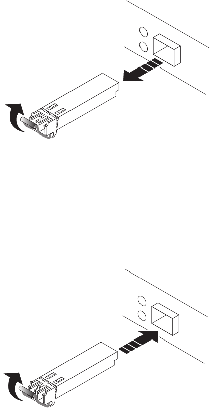
EMC Greenplum DCA Maintenance Guide Replace the switch in the rack
203
Install a Switch in a Rack
EMC CONFIDENTIAL
Task 3: Transfer any optical SFP modules
You must transfer any optical SFP modules from the switch ports in the faulted switch to
the same numbered switch ports in the replacement switch.
For
each
optical SPF module in a port on the faulted switch:
1. Remove the optical SFP module (Figure 76):
a. On the SPF module, gently pull down on the spring release latch up.
b. While still holding onto the latch, gently pull out the SFP module.
Figure 76 Removing an optical SFP module from a switch port
2. On the replacement switch, install the optical SFP module in the port with the same
number as the port from which you removed it (Figure 77):
a. On the SPF module, push the spring release latch up.
b. Align the replacement SPF module with the switch port.
c. Slide the SFP module into the switch port until it is securely connected.
Figure 77 Installing an optical SFP module in a switch port
CL5042
CL5031
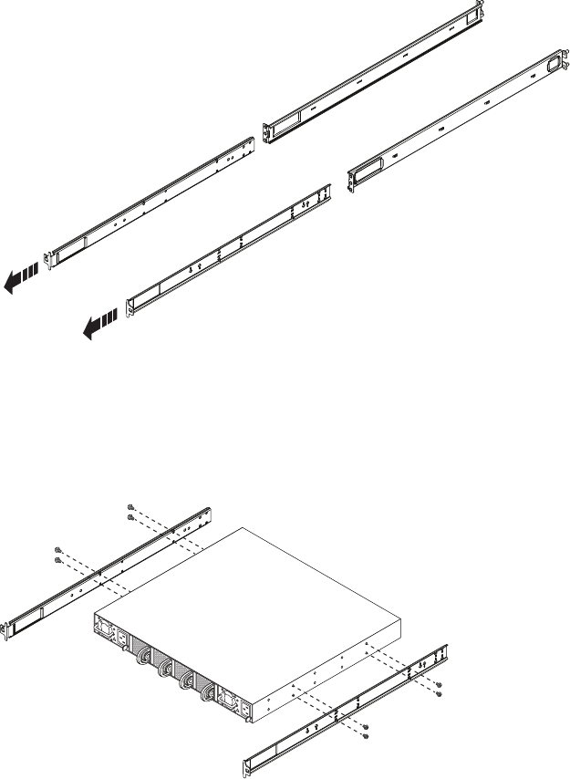
EMC Greenplum DCA Maintenance Guide Replace the switch in the rack
204
Install a Switch in a Rack
EMC CONFIDENTIAL
Task 4: Transfer the inner rails to the replacemet switch
Transfer the inner rails from the faulted switch to the replacement switch.
1. Unscrew the four screws attaching each inner rail to the faulted switch.
Each rail assembly consists of an inner rail and an outer rail.
2. Attach an inner rail to each side of the replacement switch:
a. Slide the rail sections apart to separate the inner rail from the outer rail (Figure 78).
Figure 78 Removing the inner rail from the outer rail
b. Align the holes labelled on the inner rail with the holes on the side of the
replacement switch and secure the inner rail to the replacement switch with four
M4 x 6mm screws (Figure 79).
Figure 79 Attaching an inner rail to the switch
CL5035
CL5036
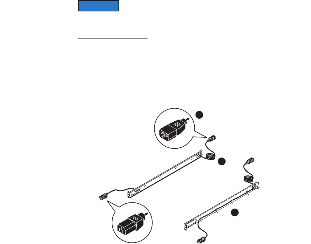
EMC Greenplum DCA Maintenance Guide Replace the switch in the rack
205
Install a Switch in a Rack
EMC CONFIDENTIAL
Task 5: Attach the outer rails to the rack (if necessary)
In most service situations that you encounter the outer rails will already be attached to the
rack and you will not have to perform this procedure. This procedure is provided here
mainly for reference.
1. Attach a switch power cord to
each
outer rail (Figure 80):
a. At the rear of the outer rail (the end with the alignment pins), feed the male (prong)
end of a switch power cord through small hole on the outer rail from the outside to
the inside of the rail.
b. Pull enough of the power cord through the hole to allow the cable to be plugged
into the AC power outlet in the rack.
Figure 80 Attaching power cord the outer rail
c. Attach the cord loosely to the rail with plastic ties. Anchor the plastic ties through
the metal loops on the outside of the rail.
The outside of the rail is the side with the two posts.
CL5037
Rear
Front
A
B
C
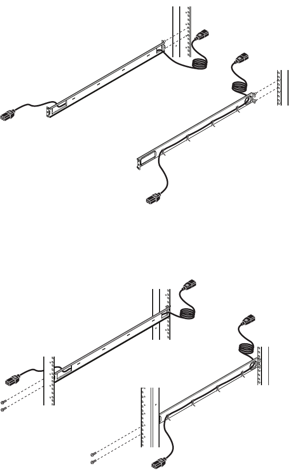
EMC Greenplum DCA Maintenance Guide Replace the switch in the rack
206
Install a Switch in a Rack
EMC CONFIDENTIAL
2. Attach the outer rails to the rack channels:
a. From the front of the rack, align rail alignment posts with the
rear
channel holes for
the selected 1 U (1.75 in) of rack space, and insert the rail alignment posts
securely into the holes (Figure 81).
Figure 81 Inserting the rail alignment posts in the rear channel holes
b. Secure the rail to the front channel with two small stablizer screws in the top and
bottom holes, leaving the screws slightly loose (Figure 82).
Figure 82 Securing the rails to the front channel
Task 6: Install the switch in the rack
1. Install the switch in the rack (Figure 83):
a. At the front of the rack, align the rails attached to the switch with the channels of
the outer rails.
CL5044
CL5038

EMC Greenplum DCA Maintenance Guide Replace the switch in the rack
207
Install a Switch in a Rack
EMC CONFIDENTIAL
b. Slide the switch into the outer rails and push the switch into the rack.
Figure 83 Installing the switch in the rack
2. Secure the rails in the rack by threading a small stabilizer screw through the front rack
channel and into the middle hole of each rail (Figure 84).
Figure 84 Installing the middle stablizer screws
3. Firmly tighten the three small stabilizing screws that you previously installed on front
of each rail.
CL5039
CL5040
EMC Greenplum DCA Maintenance Guide Replace an optical SFP module
208
Install a Switch in a Rack
EMC CONFIDENTIAL
4. At the front of the rack, feed the female end of each switch power cord through the
large hole in each rail assembly, and plug the cord into a power connector on the
switch (Appendix FFigure 85).
Figure 85 Plugging the switch power cords into the switch
5. At the back of the rack attach the required power and Ethernet cables as described in
“Replace a Switch in the DCA” on page 119.
Replace an optical SFP module
1. Unpack the replacement optical SFP module and place it on a clean, static-free surface
near the switch.
2. Identify the faulted SFP optical module in the switch.
Consult your product documentation for information on identifying a faulted SFP
module.
3. Remove the faulted optical SFP module (Figure 86):
a. If a cable is connected to the SFP module, disconnect it.
b. On the SPF module, gently pull down on the spring release latch.
c. While still holding onto the latch, gently pull out the SFP module.
Figure 86 Removing an optical SFP module from a switch port
CL5041
To Power Zone B PDU
To Power Zone A PDU
Front of the rack
CL5042
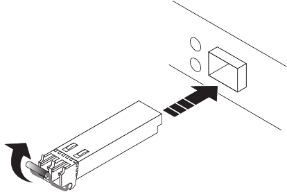
EMC Greenplum DCA Maintenance Guide Replace an optical SFP module
209
Install a Switch in a Rack
EMC CONFIDENTIAL
4. Install the replacement optical SFP module (Figure 87):
a. On the replacement SFP module, push spring release latch up.
b. Align the replacement SPF module with the switch port that contained the faulted
module.
c. Slide the SFP module into the switch port until it is securely connected.
Figure 87 Installing an optical SFP module in a switch port
CL5031

EMC Greenplum DCA Maintenance Guide Switch Configuration: Backup and Recovery
210
EMC CONFIDENTIAL
APPENDIX G
Switch Configuration: Backup and Recovery
This appendix explains how to cause the DCA to export the current switch configurations
of all switches in the cluster. All switches need to be accessible and have ssh keys
exchanged. Cases where there is a failure in this procedure should be reported as a new
support ticket.
Create Two Files for Switch Recovery
First, create two files for each switch as follows.
1. Log into the master as root.
2. Run the command dca_setup.
3. Select options 2, 13, 4.
4. Enter /root as the location for the switch backups.
5. In the /root folder on the master node, two files for each switch (the running configs
and the startup configs) will be created that can be used to recover the current
configuration after this process is complete.
Recover the Switch Configurations
Complete these steps to recover the previous configuration of a switch.
1. Log into the switch as user admin:
# ssh admin@[switch hostname]
For example, to connect to the lowest switch in the first rack:
# ssh admin@i-sw-1
2. Copy the correct switch configuration to the startup configuration with the copy
command:
[switch]#copy
scp://root@172.28.4.250/root/[switch].startup_config
startup-config
Note: If the switches were backed up to the stand-by master, use 172.27.4.251 instead of
172.28.4.250.
For example, if uploading to i-sw-1 from a file stored in /root on mdw:
i-sw-1#copy scp://root@172.28.4.250/root/i-sw-1.startup_config
startup-config
EMC Greenplum DCA Maintenance Guide Recover the Switch Configurations
211
Switch Configuration: Backup and Recovery
EMC CONFIDENTIAL
3. Type the root password per the prompt. The startup-config is updated:
root@172.28.4.250's password:
i-sw-1.startup_config 100% 8302 8.1KB/s 00:00
4. Type the reload command to reload the switch.
If prompted, answer no to saving changes as this will overwrite the startup-config with
what is in the running-config. The switch will reboot and come up with the recovered
configuration.
5. Repeat these steps for each switch to be recovered.

EMC Greenplum DCA Maintenance Guide DCA Part Numbers
212
EMC CONFIDENTIAL
APPENDIX H
DCA Part Numbers
This appendix lists the part numbers for all field replaceable units (FRU) in a DCA.
Refer to this appendix when ordering replacement parts.
Table 28 DCA Server replacement part numbers and specifications (page 1 of 2)
Module Type and
EMC Internal
Server Name
Official Description Part Number (SKU) Disks Memory
Volume
Name
DIA Module
(Kylin)
PV V2 SVR 1NIC C1U-6 300GB HDD 64GB MEM 100-585-029-xx
(covers each Rev from
-01 thru -xx)
6x300GB 64GB etl1, ….
HD-Compute
Module
(Kylin)
PV V2 SVR 1NIC C1U-6 300GB HDD 64GB MEM 100-585-029-xx
(covers each Rev from
-01 thru -xx)
6x300GB 64GB hdc1, ...
Master Server
(Kylin)
PV V2 SVR 1NIC C1U-6 300GB HDD 64GB MEM 100-585-029-xx
(covers each Rev from
-01 thru -xx)
6x300GB 64GB mdw, smdw
*DIA 3TB Disk
Module
(Dragon 12)
*Requires DCA
software 2.0.2.0
or greater
PV V2 SERVER D2U-12 3TB HDD 64GB MEM 100-585-030-xx
(covers each Rev from
-01 thru -xx)
12x3TB 64GB etl1, …
Hadoop (HD)
Master Module
(Dragon 12)
PV V2 SERVER D2U-12 3TB HDD 64GB MEM 100-585-030-xx
(covers each Rev from
-01 thru -xx)
12x3TB 64GB hdm1,
hdm2,
hdm3,
hdm4
Hadoop (HD)
Data Module
(Dragon 12)
PV V2 SERVER D2U-12 3TB HDD 64GB MEM 100-585-030-xx
(covers each Rev from
-01 thru -xx)
12x3TB 64GB hdw1, …
GPDB UAP
Standard Module
(Dragon 24)
PV V2 SERVER D2U-24 900GB HDD 64GB MEM 100-585-031-xx
(covers each Rev from
-01 thru -xx)
24x900GB 64GB sdw1, …

EMC Greenplum DCA Maintenance Guide
213
DCA Part Numbers
EMC CONFIDENTIAL
Table 29 Additional DCA FRU part numbers
GPDB UAP
Compute Module
(Dragon 24)
PV V2 SERVER D2U-24 300GB HDD 64GB MEM 100-585-035-xx
(covers each Rev from
-01 thru -xx)
24x300GB 64GB sdw1, …
*Master Server
with additional
NIC
(Kylin)
*Requires DCA
software 2.0.2.0
or greater
PV V2 SVR 2NIC C1U-6 300GB HDD 64GB MEM 100-585-049-xx
(covers each Rev from
-01 thru -xx)
6x300GB 64GB mdw, smdw
*GPDB Memory
Module
(Dragon 24)
*Requires DCA
software 2.0.2.0
or greater
PV V2 SERVER D2U-24 300GB HDD 256GB MEM 100-585-055-xx
(covers each Rev from
-01 thru -xx)
24x300GB 256GB sdw1, …
Table 28 DCA Server replacement part numbers and specifications (page 2 of 2)
Module Type and
EMC Internal
Server Name
Official Description Part Number (SKU) Disks Memory
Volume
Name
Part Number Description Official Description
100-585-043
100-585-062
(sub)
10GB Ethernet Switch ARISTA 7050S-52 10GB ETHERNET SWITCH
100-585-045
100-585-063
(sub)
1GB Ethernet Switch ARISTA 7048T-A 1GB ETHERNET SWITCH
100-585-043
100-585-062
(sub)
10GB Ethernet Switch ARISTA 7050S-52 10GB ETHERNET SWITCH
100-585-045
100-585-063
(sub)
1GB Ethernet Switch ARISTA 7048T-A 1GB ETHERNET SWITCH
105-000-244 750W Power Supply INTEL 750W POWER SUPPLY ROMLEY
100-585-043 Interconnect / Aggregation Switch, 52-port ARISTA 7050S-52 10GB ETHERNET SWITCH
100-585-062 Interconnect / Aggregation Switch, 52-port ARISTA 7050S-52 10GB ETHERNET SWITCH (CCC certified)
100-585-045 Administration Switch, 48-port ARISTA 7048T-A 1GB ETHERNET SWITCH
100-585-063 Administration Switch, 48-port ARISTA 7048T-A 1GB ETHERNET SWITCH (CCC certified)
100-585-048 Arista 10GBASE-SRL SFP+ OPTIC MODULE ARISTA 10GBASE-SRL SFP+ OPTIC MODULE
105-000-313 Fan assembly, Arista switch ARISTA FAN ASSEMBLY FOR 7048T, 7050S SWITCH

EMC Greenplum DCA Maintenance Guide
214
DCA Part Numbers
EMC CONFIDENTIAL
105-000-314 Power supply, Arista switch ARISTA POWER SUPPLY, 460W AC, FOR 7048T, 7050S
SWITCH
105-000-222 Disk drive assembly for Hadoop Masters & Workers INTEL DISK ASSEMBLY/3.5” SATA/3TB/7.2K/512BPS
105-000-237 Disk drive assembly for GPDB Compute, Master
servers, DIA server, Hadoop Compute server
INTEL DISK ASSEMBLY/2.5” SAS/300GB/10K/512BPS
105-000-228 Disk drive assembly for GPDB Standard server INTEL DISK ASSEMBLY/2.5” SAS/900GB/10K/512BPS
105-000-244 Power supply for Masters, GPDB Standard & Capacity,
DIA, Hadoop Masters & Workers
INTEL 750W POWER SUPPLY ROMLEY
100-563-477 Power Distribution Unit (PDU) PDU: TITAN-D RACK:SINGLE PHASE
038-004-176 1 Meter Interconnect Cable ACTIVE SFP+ TO SFP+ 1M 8G/10G CABLE
038-004-177 3 Meter Interconnect Cable ACTIVE SFP+ TO SFP+ 3M 8G/10G CABLE
038-004-186 12 INCH PDU JUMPER CABLE
038-003-733 10 Meter Optical Cable 10M OM3 LC to LC 50μm OPTICAL CABLE
038-003-347 30 Meter Optical Cable 30m LC to LC OPTICAL 50 MICRON MM CABLE ASSEMBLIES
038-004-224 PWR CORD 24A SP 15FT 56PA332 BL 4PPP
038-004-293 CBL, 15 FT SINGLE PHASE, GRAY, N. AMERICA
038-004-294 CBL, 15 FT SINGLE PHASE, GRAY, IEC, PIN & SLEEVE
038-004-295 CBL, 15 FT SINGLE PHASE, GRAY, AUSTRALIA
038-004-296 CBL, 15 FT SINGLE PHASE, GRAY, RUSSELLSTOLL 3750DP
038-004-223 SINGLE POER INLET CORD OPTION IEC-309-332P6
INTERNATIONAL 15'
038-004-222 SINGLE POWER INLET CORD OPTION WITH HUBBELL L6-30P
CONNECTOR, NORTH AMERICA/JAPAN 15'
038-004-228 HUBBELL L6-30R to RUSSELLSTOLL 3750DP CABLE 15'
038-003-888 Service Cable - Administration Switch-to-Laptop ETHERNET CABLE, 71 INCHES, RED
Part Number Description Official Description
