1000 Series Grid Interchange Guide
User Manual: GridInterchangeGuide
Open the PDF directly: View PDF ![]() .
.
Page Count: 5
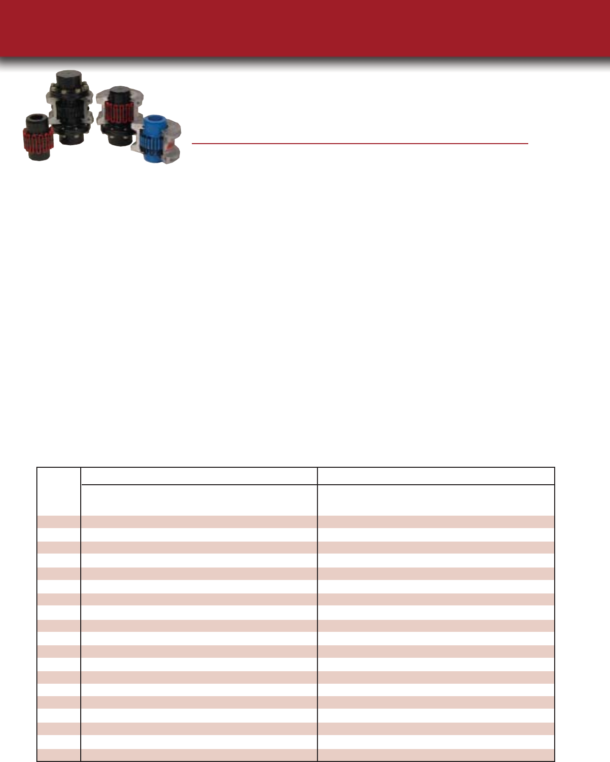
The Lovejoy 1000 Series Grid Coupling
Lovejoy®Falk®Morse/Browning®Dodge®Kop-Flex®Falk®Morse/Browning®Dodge®Kop-Flex®
Size Steelflex®Grid-Flex®Grid-Lign®Kop-Grid®Steelflex®Grid-Flex®Grid-Lign®Kop-Grid®
1020 1020T10 GF2020H 1020T10 1020H 1020T20 GF2020V 1020T20 1020V
1030 1030T10 GF2030H 1030T10 1030H 1030T20 GF2030V 1030T20 1030V
1040 1040T10 GF2040H 1040T10 1040H 1040T20 GF2040V 1040T20 1040V
1050 1050T10 GF2050H 1050T10 1050H 1050T20 GF2050V 1050T20 1050V
1060 1060T10 GF2060H 1060T10 1060H 1060T20 GF2060V 1060T20 1060V
1070 1070T10 GF2070H 1070T10 1070H 1070T20 GF2070V 1070T20 1070V
1080 1080T10 GF2080H 1080T10 1080H 1080T20 GF2080V 1080T20 1080V
1090 1090T10 GF2090H 1090T10 1090H 1090T20 GF2090V 1090T20 1090V
1100 1100T10 GF2100H 1100T10 1100H 1100T20 GF2100V 1100T20 1100V
1110 1110T10 GF2110H 1110T10 1110H 1110T20 GF2110V 1110T20 1110V
1120 1120T10 GF2120H 1120T10 1120H 1120T20 GF2120V 1120T20 1120V
1130 1130T10 GF2130H 1130T10 1130H 1130T20 GF2130V 1130T20 1130V
1140 1140T10 GF2140H 1140T10 1140H 1140T20 GF2140V 1140T20 1140V
1150 1150T10
1160 1160T10
1170 1170T10
1180 1180T10
1190 1190T10
1200 1200T10
Horizontal — Split Cover
Interchange Chart
Vertical — Split Cover
With readily available full assemblies and
interchangeable components, Lovejoy's new
line of grid couplings gives you the ability to
avoid lengthy shutdowns. Our grid couplings
combine high-torque, high-horsepower opera-
tion with vibration, shock and misalignment
capabilities not provided by other metallic cou-
pling types. Ten standard model sizes feature
an advanced design with high-tensile alloy grids
that reduce vibration by as much as 30 percent.
Our larger grid couplings meet the demands
of tough applications like crushers, conveyors,
and pulverizers commonly found in aggregate
industries.
Benefits of Lovejoy Grid Couplings:
✔
Interchangeable with industry
standard hubs and grid springs –
all the way up to size 1200!
✔
Clearance fit hubs available in sizes
1020-1090 have two set screws standard
✔
The tooth profile of the grid hub is shot
blasted for added strength and longer life
✔
Puller holes are standard for interference
fit hubs, sizes 1100 through 1200
✔
Cover fasteners are available in either
metric or imperial sizes
✔
Grease packets are included with cover
sets through size 1090
✔
Standard hubs accommodating
Taper-Lock®bushings are standard
Fully Interchangeable
with the industry standard
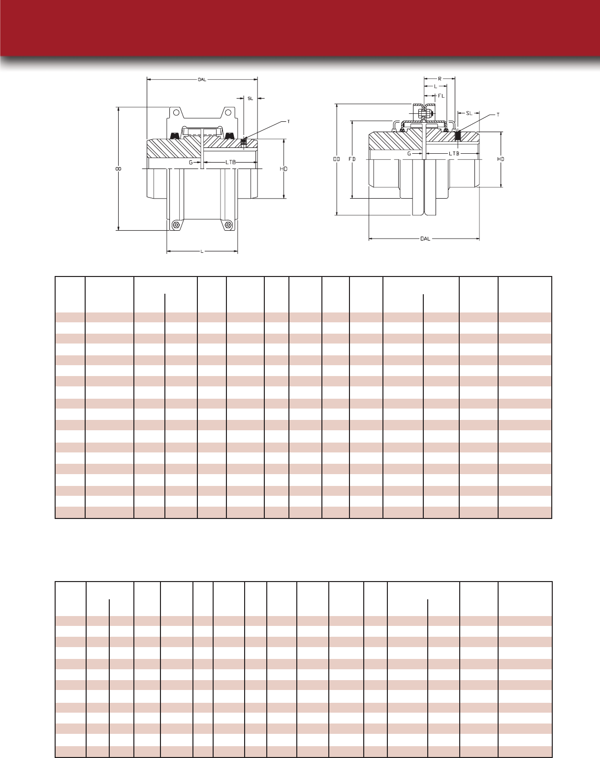
Maximum Outer Overall Gap Length Hub Length Weight Moment
Torque Dia Length Thru Dia Location Size lbs of Inertia
Bore Solid WR2lb-in2
Size in-lbs Min Max OD OAL G LTB HD L SL T Solid
1020 422 0.500 1.125 4.00 3.88 0.13 1.88 1.56 2.63 0.50 #8-32 4.2 4.830
1030 1,200 0.500 1.375 4.38 3.88 0.13 1.88 1.94 2.69 0.31 #8-32 5.7 7.610
1040 2,000 0.500 1.625 4.63 4.13 0.13 2.00 2.25 2.75 0.44 #10-24 7.4 11.190
1050 3,500 0.500 1.875 5.44 4.88 0.13 2.38 2.63 3.13 0.62 #10-24 12.0 24.850
1060 5,500 0.750 2.125 5.94 5.13 0.13 2.50 3.00 3.63 0.44 #10-24 16.0 40.660
1070 8,000 0.750 2.500 6.38 6.13 0.13 3.00 3.44 3.75 0.88 1/4-20 23.0 63.180
1080 16,500 1.000 3.000 7.63 7.13 0.13 3.50 4.13 4.56 0.94 1/4-20 39.0 154.000
1090 30,000 1.000 3.500 8.38 7.88 0.13 3.88 4.88 4.81 1.03 5/16-18 56.0 269.000
1100 50,500 1.625 4.000 9.88 9.69 0.19 4.75 5.59 6.13 93.0 609.000
1110 75,000 1.625 4.500 10.63 10.19 0.19 5.00 6.31 6.36 120.0 923.000
1120 110,000 2.375 5.000 12.13 12.00 0.25 5.88 7.06 7.55 179.0 1,755.000
1130 160,000 2.625 6.000 13.63 13.00 0.25 6.38 8.56 7.69 266.0 3,375.000
1140 230,000 2.625 7.000 15.13 14.75 0.25 7.25 10.00 7.92 392.0 6,306.000
1150 320,000 3.000 8.000 17.84 14.64 0.25 7.20 10.60 8.42 523.0
1160 457,000 4.188 9.000 19.74 15.83 0.25 7.80 12.00 10.43 720.0
1170 600,000 4.188 10.000 22.30 17.24 0.25 8.50 14.00 11.85 1,022.5
1180 830,000 5.125 11.000 24.80 19.04 0.25 9.40 15.50 12.24 1,341.7
1190 1,100,000 6.000 12.000 26.60 20.64 0.25 10.20 17.20 12.80 1,710.0
1200 1,500,000 6.000 13.000 29.80 22.24 0.25 11.00 19.60 14.00 2,331.0
Horizontal Style 1000 Series Grid Couplings
Larger Sizes Give You Greater Options
Outer Overall Gap Length Hub Flange Length Flange Max Moment
Dia Length Thru Dia Dia Length Location Size Weight of Inertia
Bore lbs WR2lb-in2
Size Min Max OD OAL G LTB HD FD L FL R SL T Solid Solid
1020 0.500 1.125 4.38 3.88 0.13 1.88 1.56 2.50 0.96 0.38 1.88 0.50 #8-32 4.3 5.320
1030 0.500 1.375 4.75 3.88 0.13 1.88 1.94 2.88 1.00 0.38 1.88 0.31 #8-32 5.7 7.990
1040 0.500 1.625 5.06 4.13 0.13 2.00 2.25 3.25 1.03 0.38 2.00 0.44 #10-24 7.4 11.990
1050 0.500 1.875 5.81 4.88 0.13 2.38 2.63 3.88 1.24 0.47 2.38 0.62 #10-24 12.0 25.760
1060 0.750 2.125 6.38 5.13 0.13 2.50 3.00 4.38 1.27 0.50 2.50 0.44 #10-24 16.0 41.160
1070 0.750 2.500 6.81 6.13 0.13 3.00 3.44 4.88 1.33 0.50 2.63 0.88 1/4-20 23.0 61.680
1080 1.000 3.000 7.13 7.13 0.13 3.50 4.13 5.88 1.74 0.50 3.50 0.94 1/4-20 39.0 148.000
1090 1.000 3.500 7.88 7.88 0.13 3.88 4.88 6.63 1.86 0.50 3.75 1.03 5/16-18 56.0 272.000
1100 1.625 4.000 9.69 9.69 0.19 4.75 5.59 7.75 2.38 0.63 4.75 93.0 608.000
1110 1.625 4.500 11.25 10.19 0.19 5.00 6.31 8.50 2.50 0.63 4.88 120.0 930.000
1120 2.375 5.000 12.56 12.00 0.25 5.88 7.06 9.63 2.94 0.68 5.63 180.0 1611.000
1130 2.625 6.000 14.88 13.00 0.25 6.38 8.56 11.13 3.00 0.82 5.75 270.0 3568.000
1140 2.625 7.000 16.38 14.75 0.25 7.80 10.00 12.63 3.13 0.82 6.13 397.0 6431.000
Vertical Style 1000 Series Grid Couplings
Bore Set Screw
Horizontal Style
Notes: 1. Maximum bores are less than shown above when an Interference Fit and Set Screw are required, refer to Lovejoy Application Engineering.
Sizes 1020 through 1090 are Clearance Fit with 2 Set Screws at 90º. Sizes 1100 and larger are an Interference Fit with no Set Screw.
2. Based on application data, larger bores may be possible - contact Lovejoy Application Engineering.
Bore Set Screw
Vertical Style
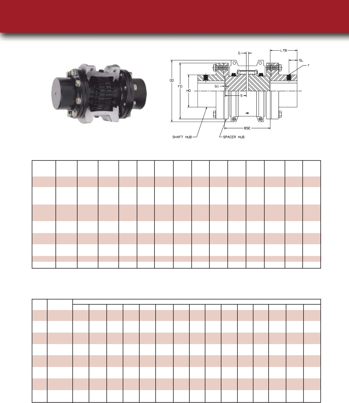
Spacer Grid Type
Spacer Styles
Coupling Torque Max Max
Size Rating Speed Bore LTB OD FD G HD OAL BSE S T SL G1
in-lbs RPM inch inch inch inch inch inch inch inch inch inch inch inch
1020 422 3,600 1.375 1.38 4.00 3.38 0.19 2.06 6.26 3.50 1.63 # 8-32 0.30 0.03
7.76 5.00 2.38
1030 1200 3,600 1.625 1.62 4.38 3.69 0.19 2.34 6.74 3.50 1.63 # 8-32 0.38 0.03
8.24 5.00 2.38
10.49 7.25 3.50
1040 2000 3,600 2.125 2.12 4.62 4.44 0.19 3.09 7.74 3.50 1.63 # 10-24 1.04 0.03
9.24 5.00 2.38
11.49 7.25 3.50
1050 3500 3,600 2.375 2.38 5.44 4.94 0.19 3.44 9.76 5.00 2.38 # 10-24 0.78 0.03
12.01 7.25 3.50
1060 5500 3,600 2.875 2.88 5.94 5.69 0.19 4.06 10.76 5.00 2.34 # 10-24 1.18 0.06
13.01 7.25 3.47
1070 8000 3,600 3.125 3.12 6.38 6.00 0.19 4.31 11.24 5.00 2.34 # 1/4-20 1.28 0.06
13.49 7.25 3.47
1080 16,500 3,600 3.500 3.50 7.62 7.00 0.19 4.81 14.25 7.25 3.47 # 1/4-20 1.54 0.06
1090 30,000 3,600 4.000 4.00 8.38 8.25 0.19 5.62 15.25 7.25 3.47 # 5/16-18 1.76 0.06
Cplg Spacer
Size Hubs Dim 3.500 3.938 4.250 4.375 4.688 5.000 5.219 5.375 5.656 5.813 5.969 6.125 6.938 7.094 7.250
1020 S 1.625 1.625 1.625 2.062 2.062 2.375
S 1.625 2.062 2.375 2.062 2.375 2.375
1030 S 1.625 1.625 1.625 2.062 2.062 2.375 1.625 2.062 2.375 3.500
S 1.625 2.062 2.375 2.062 2.375 2.375 3.500 3.500 3.500 3.500
1040 S 1.625 1.625 1.625 2.062 2.062 2.375 1.625 1.625 2.062 2.062 2.375 2.375 3.444 3.444 3.500
S 1.625 2.062 2.375 2.062 2.375 2.375 3.344 3.500 3.344 3.500 3.344 3.500 3.344 3.500 3.500
1050 S 2.062 2.062 2.375 2.062 2.062 2.375 2.375 3.344 3.344 3.500
S 2.062 2.375 2.375 3.344 3.500 3.344 3.500 3.344 3.500 3.500
1060 S 2.344 2.344 3.469
S 2.344 3.469 3.469
1070 S 2.344 2.344 3.469
S 2.344 3.469 3.469
1080 S 3.469
S 3.469
1090 S 3.469
S 3.469
BSE
Standard Full Spacer Style 1000 Series Grid Coupling
Spacer Hubs For Full Spacer Coupling - Available BSE - Inch
Note: 1. To achieve the Between Shaft End dimension shown, use the two spacer hubs with the specified “S” lengths. To obtain the Between Shaft
End dimension, use the two spacer hub lengths and the G and two G1 Dimensions. Assembly includes 2 spacer hubs, 2 shaft hubs, and
cover/grid assembly.
Notes: 1. Couplings supplied to American Gear Manufacturers Association (AGMA) standard clearance fit and 2 set screws @ 90 degrees.
2. For sizes larger than 1090, consult Lovejoy Application Engineering.
Horizontal Vertical
Size 100 1200 1800 3600 in-lbs Nm inch mm Max RPM Max RPM
1020 0.67 8.04 12.06 24.12 422 48 1.125 27 4500 6000
1030 1.88 22.56 33.84 67.68 1,200 136 1.375 35 4500 6000
1040 3.22 38.64 57.96 115.92 2,000 226 1.625 44 4500 6000
1050 5.49 65.88 98.82 197.64 3,500 395 1.875 51 4500 6000
1060 8.71 104.52 156.78 313.56 5,500 621 2.125 57 4350 6000
1070 12.73 152.76 229.14 458.28 8,000 904 2.500 68 4125 5500
1080 26.13 313.56 470.34 940.68 16,500 1,864 3.000 83 3600 4750
1090 47.57 570.84 856.26 1712.52 30,000 3,390 3.500 95 3600 4000
1100 80.00 960.00 1440.00 50,500 5,706 4.000 108 2440 3250
1110 119.00 1428.00 2142.00 75,000 8,474 4.500 117 2250 3000
1120 175.50 2106.00 3159.00 110,000 12,428 5.000 137 2025 2700
1130 253.30 3039.60 4559.40 160,000 18,078 6.000 165 1800 2400
1140 364.50 4374.00 6561.00 230,000 25,987 7.000 184 1650 2200
1150 509.58 6114.96 320,000 36,300 8.000 200 1500
1160 724.14 8689.68 457,000 51,600 9.000 228 1350
1170 952.11 11425.32 600,000 67,800 10.000 254 1225
1180 1314.18 830,000 93,600 11.000 280 1100
1190 1750.00 1,100,000 124,278 12.000 305 1050
1200 2385.00 1,500,000 169,470 13.000 330 900
Basic HP Ratings @ Varying RPM
Torque and Horsepower Ratings
Maximum BoreTorque Ratings
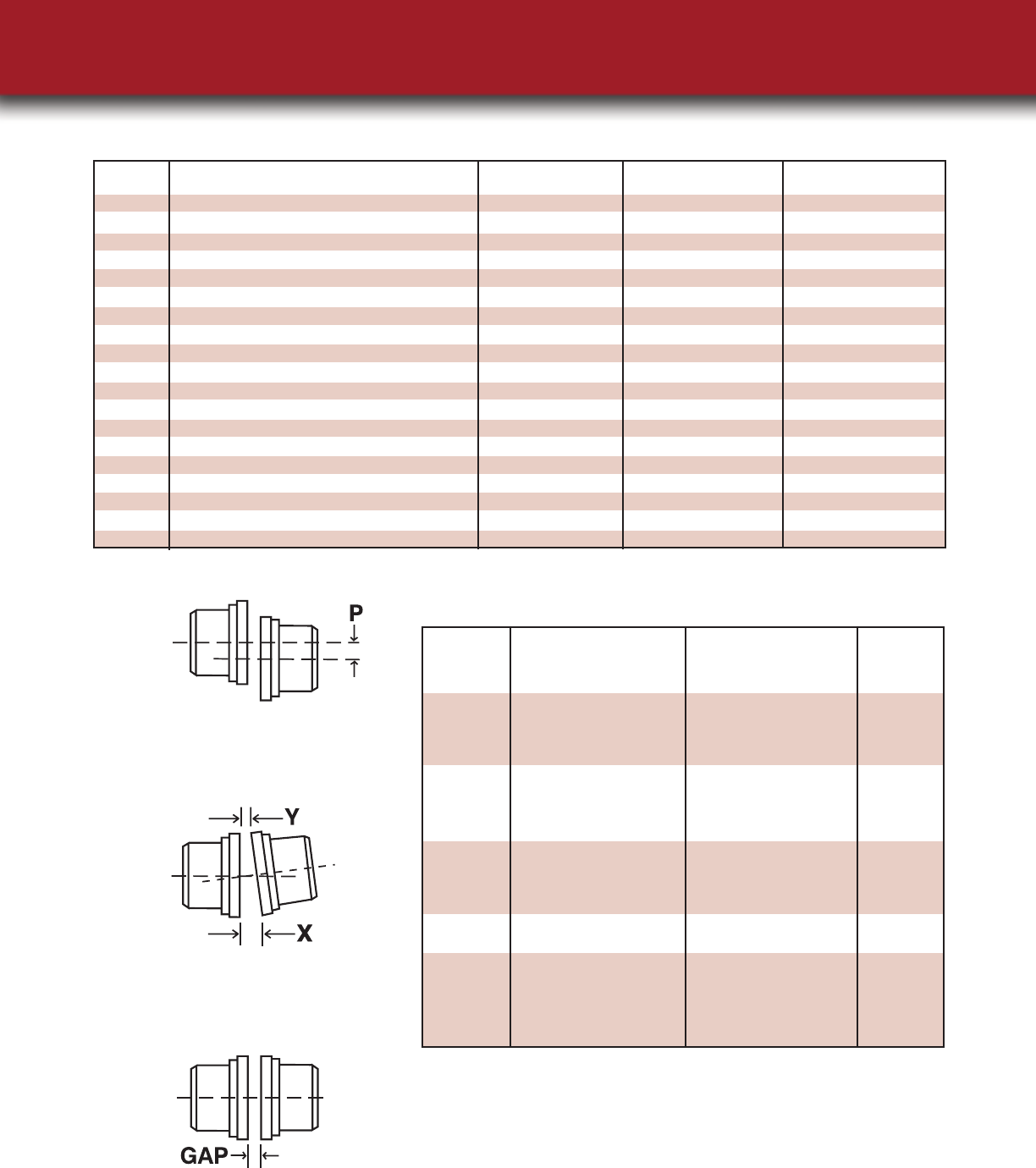
Coupling Parallel Angular Parallel Angular 10%
Size P X-Y P X-Y G
1020 0.006 0.002 0.012 0.010 0.118
1030 0.006 0.003 0.012 0.011 0.118
1040 0.006 0.003 0.012 0.013 0.118
1050 0.008 0.004 0.016 0.015 0.118
1060 0.008 0.004 0.016 0.018 0.118
1070 0.008 0.005 0.016 0.020 0.118
1080 0.008 0.006 0.016 0.024 0.118
1090 0.008 0.007 0.016 0.028 0.118
1100 0.010 0.008 0.020 0.032 0.177
1110 0.010 0.009 0.020 0.035 0.177
1120 0.011 0.010 0.022 0.040 0.236
1130 0.011 0.012 0.022 0.047 0.236
1140 0.011 0.013 0.022 0.053 0.236
1150 0.012 0.015 0.024 0.061 0.236
1160 0.012 0.017 0.024 0.070 0.236
1170 0.012 0.020 0.024 0.079 0.236
1180 0.015 0.022 0.030 0.089 0.236
1190 0.015 0.024 0.030 0.096 0.236
1200 0.015 0.027 0.030 0.107 0.236
Max Installation
Misalignment Max Installation
Misalignment Normal
Gap
Misalignment Capacity
Note: 1. Misalignment ratings pertain to both standard and spacer grid couplings.
The movement of the grid in the hub grooves
accommodates parallel misalignment and still
permits full functioning of the grid-groove
action in damping out shock and vibration.
Under angular misalignment, the grid-groove
design permits a rocking and sliding action of
the grid and hubs without any loss of power
through the resilient grid.
End float is permitted for both driving and
driven members because the grid slides freely
in the grooves.
Parallel
Angular
Axial
Service Factors
Electric Motor w/
Standard Torque
Reciprocating
Engines-4/5 Cylinder
Reciprocating
Engines-6 or more Cyl
Service Factors
Electric Motor w/
Standard Torque
Reciprocating
Engines-4/5 Cylinder
Reciprocating
Engines-6 or more Cyl
Applications That Benefit From Grid Couplings
Aerator . . . . . . . . . . . . . . . . .2.00 3.00 2.50
Agitators
Vertical/Horizontal Screw
Propeller, Paddle . . . . . . . . .1.00 2.00 1.50
Barge Haul Puller . . . . . . . . .1.50 2.50 2.00
Blowers
Centrifugal . . . . . . . . . . . . .1.00 2.00 1.50
Lobe, Vane . . . . . . . . . . . . .1.25 2.25 1.75
Car Dumpers . . . . . . . . . . . . .2.50 * *
Car Pullers . . . . . . . . . . . . . . .1.50 2.50 2.00
Clarifier, Classifier . . . . . . . .1.00 2.00 1.50
Compressors
Centrifugal,Rotary,
Screw . . . . . . . . . . . . . . . . . .1.00 2.00 1.50
Rotary,Lobe or Vane . . . . . .1.25 2.25 1.75
Reciprocating with
Flywheel and Gear between
Compressor and Prime
Mover 4 or more Cyl.
Single or Double Acting . . .1.75 2.75 2.25
Reciprocating with
Flywheel and Gear
between Compressor
and Prime Mover Cyl.
Double Acting . . . . . . . . . . .2.00 3.00 2.50
Reciprocating with
Flywheel and Gear
between Compressor
and Prime Mover 1/2
Cyl. Single/Double
Acting and 3 Cyl.
Single Acting . . . . . . . . . . . .3.00 * *
Reciprocating Direct
Connected, Without
Flywheels . . . . . . . . . .Refer to Lovejoy
Conveyors2
Apron, Assembly,
Belt, Chain, Flight,
Screw . . . . . . . . . . . . . . . . . .1.00 2.00 1.50
Bucket . . . . . . . . . . . . . . . . .1.25 2.25 1.75
Live Roll, Shaker,
Reciprocating . . . . . . . . . . .3.00 * *
Cranes, Hoist 1,2
Slope . . . . . . . . . . . . . . . . . .1.50 2.50 2.00
Main or Skip Hoist, Bridge,
Travel, Trolley2 . . . . . . . . . . .1.75 2.75 2.25
Dynamometer . . . . . . . . . . .1.00 2.00 1.50
Elevators2
Bucket, Centrifugal, Discharge,
Gravity Discharge . . . . . . . .1.25 2.25 1.75
Freight or Passenger . .Not Approved
Escalators . . . . . . . . . . .Not Approved
Exciter, Generator . . . . . . . .1.00 2.00 1.50
Extruder, Plastic . . . . . . . . . .1.50 2.50 2.00
Fans
Centrifugal, Forced Draft
Motor Driven thru Fluid
or Electric Slip Clutch . . . . .1.00 2.00 1.50
Induced Draft with
Damper Control or
Blade Cleaner . . . . . . . . . . .1.25 2.25 1.75
Forced Draft-Across the Line
start, Gas Recirculating . . . .1.50 2.50 2.00
Cooling Tower, Induced Draft
without Controls . . . . . . . . .2.00 3.00 2.50
Feeders
Apron, Belt, Disc, Screw . . .1.00 2.00 1.50
Reciprocating . . . . . . . . . . .2.50 * *
Generators
Even Load . . . . . . . . . . . . . .1.00 2.00 1.50
Hoist or Railway Service . . .1.50 2.50 2.00
Welder Load . . . . . . . . . . . .2.00 3.00 2.50
Hammermill . . . . . . . . . . . . .1.75 2.75 2.25
Laundrywasher or
Tumbler . . . . . . . . . . . . . . . . .2.00 3.00 2.50
Line Shafts
Any Processing Machinery .1.50 2.50 2.00
Machine Tools
Auxiliary Processing
Machinery . . . . . . . . . . . . . .1.00 2.00 1.50
Main Drive . . . . . . . . . . . . .1.50 2.50 2.00
Bending Roll, Notching Press .
Punch Press,Planer, Plate
Reversing . . . . . . . . . . . . . . .1.75 2.75 2.25
Manlifts . . . . . . . . . . . .NOT APPROVED
Metal Forming Machines
Slitters . . . . . . . . . . . . . . . . .1.00 2.00 1.50
Wire Winder, Coilers,
Uncoilers . . . . . . . . . . . . . . .1.50 2.50 2.00
Wire Drawing, Flattening . .1.75 2.75 2.25
Draw Bench Carriage, Main
Drive, Extruder, Forming
Machine, Forming Mills . . .2.00 3.00 2.50
Mixers ( see Agitators)
Muller . . . . . . . . . . . . . . . . .1.50 2.50 2.00
Concrete . . . . . . . . . . . . . . .1.75 2.75 2.25
Printing Press . . . . . . . . . . . .1.50 2.50 2.00
Pug Mill . . . . . . . . . . . . . . . . .1.75 2.75 2.25
Pulverizers
Roller . . . . . . . . . . . . . . . . . .1.50 2.50 2.00
Hammermill, Hog . . . . . . . .1.75 2.75 2.25
Pumps
Centrifugal
Constant Speed . . . . . . . . . .1.00 2.00 1.50
Centrifugal Frequent Speed
Changes under Load,
Descaling, w/ Accumulators,
Gear, Rotary, Vane . . . . . . .1.25 2.25 1.75
Reciprocating, 3 or more
Cylinders . . . . . . . . . . . . . . .1.50 2.50 2.00
Reciprocating, 2 Cyl.
Double Acting . . . . . . . . . . .1.75 2.75 2.25
Reciprocating 2 Cyl.
Single Acting . . . . . . . . . . . .2.00 3.00 2.50
Reciprocating 1 Cyl.
Single/Double Acting . . . . .3.00 * *
Screens
Air Washing, Water . . . . . .1.00 2.00 1.50
Rotary Coal, Sand . . . . . . . .1.50 2.50 2.00
Grizzly . . . . . . . . . . . . . . . . .2.00 3.00 2.50
Vibrating . . . . . . . . . . . . . . .2.50 * *
Ski Tows, Lifts . . . . . . .NOT APPROVED
Steering Gear . . . . . . . . . . . .1.00 2.00 1.50
Stoker . . . . . . . . . . . . . . . . . .1.00 2.00 1.50
Tumbling Barrel . . . . . . . . . .1.75 2.75 2.25
Winch, Maneuvering
Dredge, Marine . . . . . . . . . .1.50 2.50 2.00
Windlass . . . . . . . . . . . . . . . .1.50 2.50 2.00
Woodworking Machinery . .1.00 2.00 1.50
Work Lift Platforms . .NOT APPROVED
Notes: 1. For high peak load applications, consult Lovejoy engineering.
2. If people are transported, Lovejoy does not recommond and will not warranty the use of the coupling.
* Indicates that Lovejoy Application Engineering should be consulted with specific requirements.
Caution: Applications involving reciprocating engines and reciprocating driven devices are subject to critical rotational speeds which may damage the
coupling and/or connected equipment. Contact Lovejoy Application Engineering with specific requirements.
Service Factor Chart
Service Factors By Application Type
Service Factors
Electric Motor w/
Standard Torque
Reciprocating
Engines-4/5 Cylinder
Reciprocating
Engines-6 or more Cyl
where the world turns
for couplings
Lovejoy, Inc. USA
Corporate Headquarters
2655 Wisconsin Avenue
Downers Grove, IL 60515 USA
Phone: (630) 852-0500
Fax: (630) 852-2120
info@lovejoy-inc.com
Lovejoy Canada
lovejoycanada@lovejoy-inc.com
Lovejoy Europe
lovejoyeurope@lovejoy-inc.com
Raja-Lovejoy
sales@raja-lovejoy.com
www.lovejoy-inc.com
Lovejoy and Raja-Lovejoy are registered trademarks of Lovejoy,Inc.All other trademarks, brands, and names mentioned
in this publication are property of their respective owners. ©Lovejoy, Inc.2004 Printed 3-04 Item # 685144 75195
