OM, FS6600D, FS6800D, FS9900D, LCD Display, Electronic Controls, Husqvarna, EN, 2009 12 FS 6600 D HCPO2009 EUen APen 115159727
User Manual: FS 6600 D
Open the PDF directly: View PDF ![]() .
.
Page Count: 30
1
Operator’s manual
Read these instructions carefully and make sure you
understand them before using the FS 6600 D / FS 8400 D.
Manuel d’utilisation
Veuillez lire attentivement ces instructions et assurez-vous de bien les
comprendre avant d’utiliser la machine modèle FS 6600 D / FS 8400 D.
Manual
del operador
Lea cuidadosamente estas instrucciones y asegúrese de que
las comprende bien antes de usar el FS 6600 D / FS 8400 D.
Electronic Controls /
LCD Display
FS 6600 D, FS 6800 D, FS 8400 D, FS 9900 D
™ Tier 3 Engine with Electronic Controls, LCD Display
and Self Diagnostics
Tier 3/IT4 Engine
In order to comply with the US EPA Tier 3/Interim Tier 4
and European Stage IIIA and Stage IIIB exhaust
emissions regulations governing Off Road Industrial
Combustion Ignition engines, it has become necessary
for engine manufacturers to make significant design
changes to their diesel engine products. Husqvarna
Construction Products uses the John Deere PE4024 HF
295 and PE5030 HF 285 Diesel engines on it large Flat
Saw products.
The most notable changes to the engines from the
previous Tier 2 Engines are the Charge Air Cooling (CAC)
which cools the charge air after it leaves the turbo charger
but before it enters the engine intake manifold. The CAC
is essentially another section on the radiator. Operation
of the Flat Saw is not affected by the CAC but it
dramatically reduces the Nitrous Oxide Emissions from
the diesel exhaust.
The other major design change is the Full Authority Electronic Engine Control. Engine performance is
governed and monitored by an Electronic Control Unit (ECU). The diesel injector timing and duration
is directly controlled electronically. The engine has no throttle cable or linkage. It has no mechanical
governor. Electronic Engine data is collected and processed in the ECU and broadcast onto the
Control Area Network Bus. (aka CANBus). The CANBus broadcast is to the SAE J1939 standard.
On the control panel of the saw is the CANplus™ 600 (CP600™) (1F) display panel to monitor the
electronically governed diesel engines. Graphical gauge pages or a single large analog gauge are
displayed on the 4.25” diagonal LCD. Virtually any SAE J1939 parameter reported by the ECU
(Engine Control Unit) can be displayed including RPM, coolant temperature, oil pressure, engine
hours, voltage and alarms, diagnostic codes and saw service indicators. The backlit display is clearly
readable in both bright sunlight as well as total darkness and housed in a rugged IP67 rated housing.
The engine RPM is controlled by the rocker switch (1E). It broadcasts a CANBus signal back to the
ECU which then controls engine RPM.
Current alarm conditions are displayed in plain language on popup messages and can be viewed in
the alarm list. Various diagnostic screens allow detailed investigation of the CANbus data stream. By
accessing the Configuration Menu, users can customize displayed data to show metric or US units,
display language and various other parameters such as the full-scale reading of gauges.
Five buttons access a context dependent button bar when
any button from 1 to 4 is pressed. The graphical menu
structure uses easily understood icons to indicate the
button’s current function. After 5 seconds of inactivity the
button bar disappears.
Electronics
2
Button 1 Button 2 Button 3 Button 4 Button 5
Analog Gauge
Pages
Repeated presses
cycle through two
pages of analog
gauges (6 total).
Digital Gauge
Pages
Repeated presses
cycle through two
pages of digital
gauges (6 total).
Single Analog
Gauge
Repeated presses
cycle through two
analog gauges.
Blade RPM and
engine RPM.
Active Alarm
Page
Displays active
alarms codes a
plain language
description.
Exit Return Enter
Allows fast return
to previous screen
or exiting menu or
access to higher
level functions.
Note
Most problems with electronically controlled engines can be pinpointed via ECU
diagnostic messages. Use the display or ECU diagnostic tool to view fault codes.
All engine state information and diagnostic codes
displayed by the CANplus display are provided via the CANbus.
Throttle Control
The standard ramp throttle uses a momentary rocker switch (1E) to adjust the integral throttle control.
All throttle commands are sent directly to the engine using CANbus throttle control.
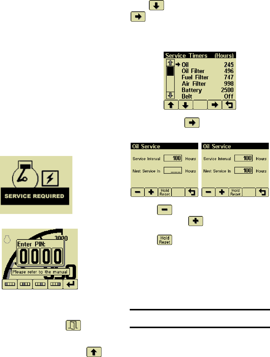
Service Timers
The CP600 panel provides sixteen (16) service timers to alert the operator to needed maintenance.
The time interval for each of the timers can be adjusted in 10 hour increments. A popup message is
displayed after the display self test if a timer has expired alerting the user that service is required. The
popup message continues to be displayed at power up until the timer is disabled or reset. To reset
service timers, you must access higher level function by entering a Personal Identification Number
(PIN). See Pin Entry section.

3
Important Safety Information
The warnings in this publication are not all inclusive.
Husqvarna cannot anticipate every potential hazard.
Appropriate safety rules and precautions should be followed with any tool,
work method or operating procedure.
Improper procedures, tools and materials may cause damage or
make the equipment unsafe to operate.
Only persons with appropriate training, skills and tools should perform these functions.
Improper operation, maintenance or repair of this product can be
dangerous and may result in injury or death.
Do not operate or perform any maintenance or repair on this product until all operation,
maintenance and repair information is read and understood.
The information, specifications and illustrations in this publication are based on
information available at the time of publication.
All items are subject to change at any time without notice.
Electronics
4
Operation
Turning the control system key (1C) to the run position energizes
the ECU and displays a start-up screen while the display performs
a self test. If the display beeps for longer than 1 second, it
indicates a self test fault. Users can attempt to rectify the fault by
restoring factory defaults (see Configuration Menu for details).
Contact LOFA Industries for assistance if the fault persists.
After the start-up screen disappears, the display shows readings
on its virtual gauges. Initially the analog gauges are displayed but
the display uses the screen last displayed on subsequent startups
(see Preferred Screen Store for details).
If the ECU is preheating the engine when the key switch is turned
to the run position, the ENGINE PREHEATING popup message
will display. Preheat time varies with atmospheric and engine
conditions. After waiting for the Preheat message to expire, the
engine is cranked by turning and holding the key switch (1C) in
the start position until the engine starts. The engine exhaust will
be virtually smoke free.
Note
The ECU will not preheat unless conditions warrant. If necessary, starting the engine
may be attempted by turning the key to the start position without waiting for preheat to
expire.
The key switch is spring loaded to return automatically to the run position when released. The key
switch is equipped with a mechanical start locking device. An attempt to re-crank the engine can only
be made by turning the key switch to the off position to reset the start locking mechanism.
CANplus Display (1F) CP600
Soft buttons simplify the operator interface by displaying a button bar above the buttons when any of
the first 4 buttons (buttons 1 to 4, starting from the left) are pressed. Icons on the button bar
representing the current function of each button. The button bar disappears after 5 seconds if no
further buttons are pressed.
E
ENGINE PREHEATING
WAIT TO START
5
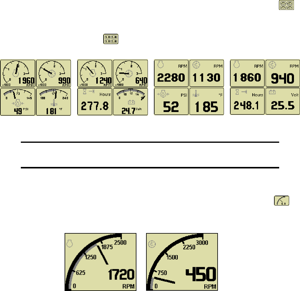
Analog Gauge and Digital Gauge Pages
Analog Gauge Pages provide two independent pages of analog gauges. To enable Analog Gauge
Pages, press any of the first 4 buttons to show the top level button bar and then press button 1 .
Alternate pages are selected by repeated pressing of button 1. The two standard gauge pages are
shown below left. Digital Gauge Pages display the same data as the Analog Gauge Pages but in
digital format. To enable Digital Gauge Pages, press any of the first 4 buttons to show the top level
button bar and then press button 2 . Alternate pages are selected by repeated pressing of button
2. The two standard gauge pages are shown below right.
Note
Engine Hours are displayed as a digital value even on Analog Gauge Pages.
The Top Left Gauge will always display Engine RPM.
The Top Right gauge will always display Blade RPM.
Single Analog Gauge
Single Analog Gauge uses the entire display for a single large analog gauge. This mode is enabled
by pressing any of the first 4 buttons to show the top level button bar and then press button 3 .
The gauge displayed is selectable by repeatedly pressing button 3 while in the Single Analog Gauge
mode while the menu bar is visible. Engine RPM and Blade RPM are the only Parameters available in
this mode.
Electronics
6
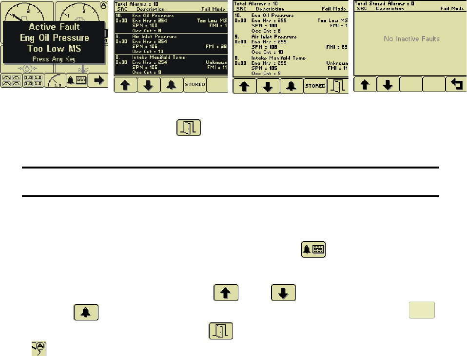
Active Alarms, Faults and Diagnostic Trouble Codes (DTC)
In addition to the quad gauges monitoring critical engine parameters, a flashing popup window is
overlaid on the current screen when an active alarm is received from the ECU. The popup includes a
plain language description in addition to the standard Fault Codes known as SPN-FMI (Suspect
Parameter Number- Fault Mode Indicator)) number pair defined by the SAE J1939 standard.
Additionally the beeper sounds as an audible cue. Depending on the severity of the fault, the engine
may shut down or go to a low idle mode or a de-rated power mode. Most Faults are minor and
operation may continue after the fault is acknowledged and cleared from the screen. Severe Faults
Must Be Fixed. See Diagnostic Trouble Code List Page __
Pop Up Alarm Alarm List with SPN _ FMI Acknowledged Alarm List Stored Faults
After acknowledgement, the exit button becomes active.
Note
Standard J1939 abbreviations are used for alarms.
MS = Most Severe, MOD= Moderately Severe, LS = Least Severe.
Read and Clear Alarm List
The Alarm List is accessed by pressing any button while an Popup Alarm is displayed or by pressing
any of the first 4 buttons to show the button bar and then button 4 . Alarms not yet acknowledged
are shown in grey on black while acknowledged alarms are shown in black on grey. The list also
indicates when the alarm occurred if engine hours. The most recent alarm is displayed at the top of
the list. The list can be scrolled using buttons 1 and 2 and alarms acknowledged by
pressing button 3 . Past inactive Stored Faults can be viewed by pressing button 4.
STORED
The
Alarm List can be closed by pressing Button 5 once the alarms are acknowledged. An alarm
indicator is displayed near the upper right corner of the display as long as alarms are active. The
indicator and alarm messages in the list are automatically removed when the alarm is no longer
received for a few seconds.
Alarms monitor engine parameters but are also used to self diagnose electrical problems with sensor
and wires batteries and the ECU itself. See the Listing of Diagnostic Trouble Codes (DTCs).
When contacting John Deere or Husqvarna Service, it is necessary to provide Engine Serial Number,
SPN and FMI Codes. This information is vital to receive prompt assistance.
7
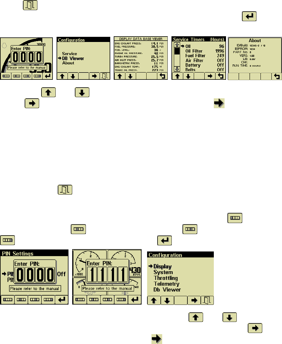
Other Functions
The CP600 Display has more functions to read all the data broadcast on the CANBus and custom
configure the display as the operator prefers. To Access the higher level functions, press and hold
button 5 for 3 seconds and the following screen will display. To view the view the Service Timer
and DB Viewer, a Personal Identification Number (PIN) is not needed. Press button 5 to see the
Configuration Page.
Press button 1 and 2 allow you to choose from Service or Db Viewer or About. Pressing
button 4 selects the chosen menu item indicated in bold and the arrow . Data Base Viewer
displays every parameter broadcast on the CANBus. Most Parameters listed are not broadcast and
will display____ instead of a number. Service Timers will display the number of hours until a required
service is due. Only 4 parameters are factory preset. When a Service Timer expires, the screen will
display a Pop Up Alarm “SERVICE REQUIRED”. A PIN will be needed to reset Service Timers. See
Section On PIN and Servicer Timer. About screen is the software and hardware Version of the
CP600 Display.
Personal Identification Number (PIN)
This Configuration Menu allows the user to set various operating parameters such as US or metric
units, scale limits for tachometer and service timers. The configuration menu is entered by pressing
and holding button 5 (the right hand button) in any mode for at least 3 seconds. The PIN entry is
enabled and the correct PIN must be entered to access the configuration menu.
The factory preset PIN must be entered (default is 1111) as a security feature. The digits of the PIN
are entered by using the buttons corresponding to the digits of the PIN. Button 1 adjusts the first
digit of the PIN. Button 2 adjusts the second digit, button 3 the third digit and button 4
the fourth digit. The PIN is entered using button 5 .
The top level configuration menu is displayed as shown. Buttons 1 and 2 allow you to
choose from Display, System, Throttling, Telemetry or Db Viewer. Pressing button 4 selects
the chosen menu item indicated in bold and the arrow . Each item is described in detail on the
following pages. Settings are automatically stored when exiting the current menu even when power is
removed.
Electronics
8
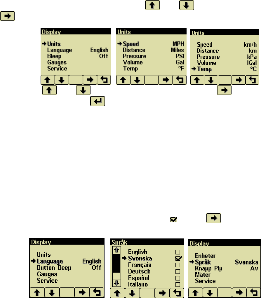
Units Menu
This menu allows the user to set the units used for pressure, volume and temperature independently.
Distance and speed are not used. . Use Buttons 1 and 2 to select Units. Press button 4
to display Units Screen.
Use Buttons 1 and 2 to select the unit to change. Press Button 4 to change the
selected value. Press Button 5 to return to Display menu.
Temperature °F (Fahrenheit)
°C (Celsius).
Pressure PSI (pounds per square inch)
bar (barometric units)
kPa (kilopascals)
Volume Gal (US gallons)
IGal (Imperial gallons)
Liters
Language Menu
From the display menu using button 1 and 2 select Language. Press Button 4. This menu allows the
user to choose between English, Swedish, French, German, Spanish, Italian, Dutch and Portuguese.
The currently selected value is indicated by the check mark . Button 4 selects the highlighted
value. Press Button 5 and all menus will be in the selected language as seen on the right below.
9
Electronics
10
Display Menu
The Display Menu allows the user to configure items affecting how information is displayed.
Beep
The soft buttons emit an audible beep when
this item is On. Button beep is disabled by
setting this item to Off. The audible beep still
sounds when an alarm occurs.
Popup Messages and
Alerts
Service Required
Users can set up to sixteen service timers in
hours in the Configuration menu. The
SERVICE REQUIRED popup is displayed at
power up when one or more service timers has
expired. Pressing any button removes the
popup. If no button is pressed the Pop Up
closes in approximately 5 seconds.
Pop-up warnings of SERVICE REQUIRED.
When service popup alarms occur, perform
required service. Then access the service
interval resets function. From any gauge
screen, Press and Hold Button 5 for 3
seconds for the PIN Pop Up. Enter Current
PIN. (1111 factory default) Select Display.
From the Display Menu, use Buttons 1
and 2 to select Service. Press button 4
to display the sixteen (16) service
intervals in hours and reset the service timers.
Use Buttons 1 and 2 to select the desired
Service Timer.
Pressing Button 4 allows adjusting the
selected service timer.
Button 1 decreases the service interval
time while Button 2 increases the service
interval time in 10 hour increments. Holding
Button 3 for approximately 3 seconds
resets Next Service In to the current Service
Interval. Only 4 service timers are preset at
the factory. Operators and service technicians
can set more alarms as needed. Setting the
service interval to 0 disables the timer and the
word Off is displayed.
Note
PIN number is needed to reset to reset service
timers.
11
System Menu
The System Menu allows the user to configure items affecting how the system functions. The user is
locked out of changing any function except the PIN settings.
Demo
Mode 0 disables Demo Mode. Demo is
automatically set to 0 (Off) if live data is
received.
Restore Defaults
This allows resetting all configuration
information to default US or Metric
units. Additionally the display is reset to the
initial configuration.
Com Viewer
Displays last CANbus messages received and
engine configuration transmitted by the ECU.
J1939 Viewer
This screen provides a hexadecimal dump of
the last messages received on the CANbus.
This viewer displays the raw data. To see the
decoded data use the Db Viewer.
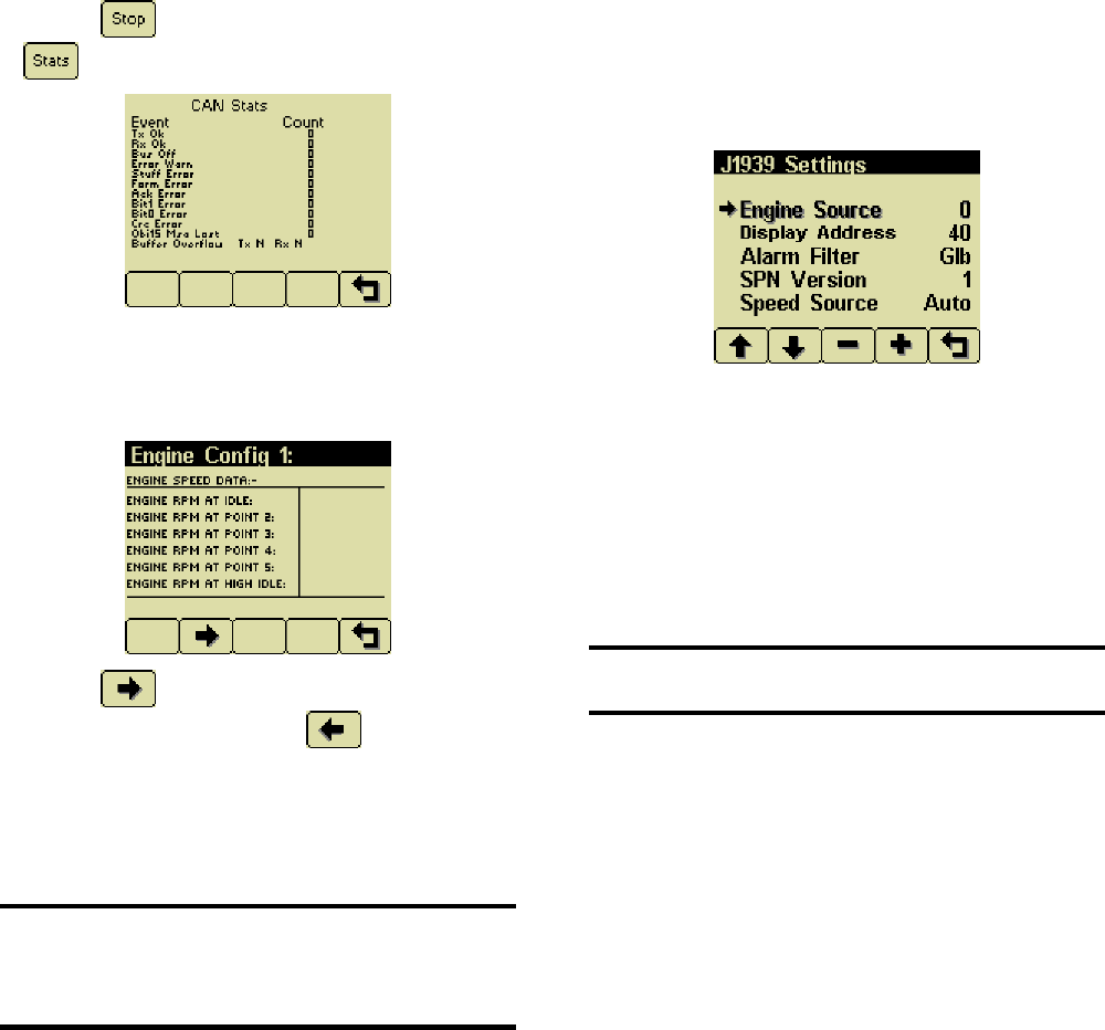
Electronics
12
Button 1 freezes the display while button
2 shows CANbus data statistics screen.
Engine Config
This screen displays the engine configuration
information received from the ECU.
Button 2 selects the next page of engine
configuration while button 1 select the
previous page.
J1939 Settings
Note
All J1939 settings are preset. No adjustments
are needed. Incorrectly configuring the Engine
Source address will result in no data available
for display.
This screen allows adjustments specific to the
J1939 data link. Factory Preset. Do not
change.
Engine Source
Factory Preset, Do Not change. Engine
Source is set at address 0.
Display Address
Factory Preset 40. Do Not Change
Warning
Incorrectly configuring the Display Address can
result in data collisions on the CANbus.
Alarm Filter
This setting specifies whether the display will
display alarms from all sources (Glb or global)
or only the source address specified in the
Engine Source setting (Src or source).
SPN Version
Selects the default SPN (Suspect Parameter
Number) Version 4 is automatically detected.
Speed Source
Factory Preset to Auto.
13
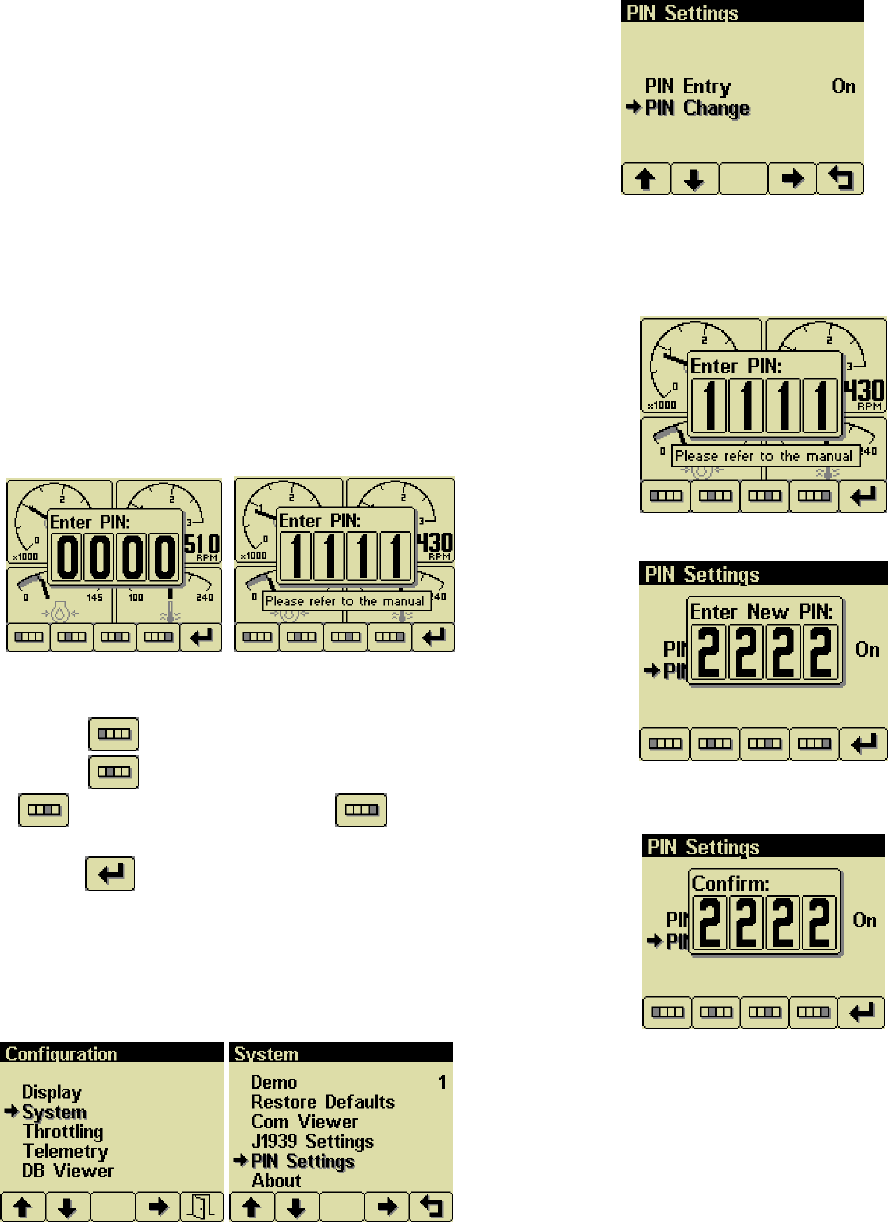
Changing PIN Number
By default, the PIN security is enabled. The
user is prompted to enter a PIN every time the
Configuration Menu is accessed since this
feature is enabled.
PIN Entry
PIN Entry is set to On to prevent unauthorized
users from accessing system settings and
resetting service timers. An authorized
maintenance technician may want to prevent
operators from accessing the service minders.
The PIN number can be changed as needed.
From any gauge screen, Press and Hold
Button 5 for 3 seconds until the Enter Pin Pop
UP appears. The current pin must be entered
(default is 1111) as a security feature.
The digits of the PIN are entered by using the
buttons corresponding to the digits of the PIN.
Button 1 adjusts the first digit of the PIN.
Button 2 adjusts the second digit, button
3 the third digit and button 4 the
fourth digit. The PIN is entered by pressing
button 5 .
Once the PIN has been entered Configuration
menu is displayed. Using buttons 1 and 2
select System and Press Button 4. Again use
Buttons 1 and 2 to select PIN Settings. Press
Button 4 to enter Pin Settings.
Select PIN Change and press button 4.
PIN Change
This allows changing the PIN. The user is
prompted for the current PIN
The user is prompted for the new PIN.
The new PIN must be confirmed before the
PIN is changed.
Electronics
14
If the new PINs match a confirmation screen is
displayed.
If the two PINs entered do not match an error
message is displayed and the PIN is
unchanged.
Note
Cannot Remember or Lost PIN number. Call
Husqvarna Construction Products Technical
Services for assistance.
About
Displays the following product information:
ID/Build Serial number of the display
EEPROM Number of writes on
EEPROM
PART No Unit part number
VERS Software version number
CHK Flash memory checksum
SOURCE The source of received data
LIB1 Low level system library
version
LIB2 Low level Graphical Display
Interface library version (if
used)
Note
This screen can not be exited until the
checksum calculation is complete. Checksum
calculation takes approximately 10 seconds
and is complete when the checksum value
changes from “Calculating…” to a hexadecimal
value such as “0x704E – OK”
15
Throttling Menu Not used
Electronics
16
Telemetry Menu
Not Used
Db Viewer
The Database Viewer displays and decodes all data monitored by the display. This diagnostic tool allows
viewing data not normally displayed. PIN is not needed to View Data Base Viewer.
The list can be scrolled using buttons 1 and 2 and closed by pressing Button 5 .
Note
The Database Viewer is always in English regardless of language selected.
Preferred Screen Store
The display automatically stores the current screen as the preferred page after a delay of approximately
15 seconds. The display will use the last stored screen on the next power-up.
Note
Selecting Restore Defaults restores the Analog Gauge Pages and default gauges.
.
17
Data Communications Failure
The data communications failure popup icon flashes if the display does not detect data. The warning
disappears and normal operation resumes once data is detected.
Note
Incorrectly configuring the Engine Source address will result in no data available for display.
Data Not Available
Gauges and the Db Viewer will display if the desired data is not available. The display value returns
to normal when parameter data is received.
Adjusting Lighting and Contrast
Pressing button 5 (the right-hand button) when there is no menu bar
opens the lighting and contrast menu bar. The display has a number of
back-lighting levels that allow the display to be read in the dark. The level is
adjusted by pressing buttons 1 decrease or button 2 to increase
illumination. Contrast is adjusted in the same manner using
buttons 3 and 4 .
Note
The display adjusts the contrast with ambient temperature.
Manual contrast adjustments are only necessary with extreme climate change.
The menu is exited by pressing button 5 . The lighting and contrast settings are retained after the unit
is switched off.
Note
If the contrast has been adjusted poorly, the factory setting is restored by pressing
buttons 1 thru 4 simultaneously. This action does not change other user-configured
settings.
Note
The CANplus display only reports when the ECU is requesting preheat..
Note
ECU programming determines the response to warnings and failures.
The ECU is programmed to shutdown, derate or run to failure.
The CANplus display only reports CANbus conditions.

Electronics
18
Battery Circuit Requirements
Warning
Do not reverse the battery polarity. Attempting to crank the engine when the polarity of the
battery connections is reversed may damage the control system.
Warning
Disconnecting the battery while the engine is running may damage electrical components.
Voltage Drop
If control system voltage drops below 6 volts for more than one tenth of a second, the control system may
reset causing the self test to reactivate. Resetting the control system is equivalent to quickly turning the
key switch to off and back to run without starting the engine. Voltage drops can be caused by a discharged
battery. If battery becomes old and weak, replace battery.

19
Welding on Equipment with Electronic Controls
Proper welding procedures are required to avoid damage to electronic controls, sensors and associated
components. The component should be removed for welding if possible.
The following procedure must be followed if the component must be welded while installed on equipment
with electronic controls. This procedure will minimize the risk of component damage.
Warning
Do not ground the welder to electrical components such as the control ground or sensors!
Improper grounding can cause damage to electrical components!
Clamp the ground cable from the welder to the component being welded.
Place the clamp as close as possible to the weld to reduce the possibility of damage.
1. Stop the engine. Turn the key switch to the OFF position.
2. Disconnect the negative battery cable from the battery.
3. Open any installed battery disconnect switch.
4. Unplug the control system if possible.
5. Connect the welding ground cable as close as possible to the area to be welded.
6. Protect the wiring harness from welding debris and spatter.
7. Use standard welding methods to weld the materials.

Electronics
20
General Troubleshooting
For additional information, refer to engine manufacturer troubleshooting guide.
No response from starter motor
Possible Cause Possible Remedy
No battery voltage to starter Verify wiring and battery connection (power and ground)
Battery discharged Charge or replace battery, verify alternator charging
Tripped over current
protection
Correct fault, replace FUSE
No signal from ECU No power to ECU, CHECK ECU and Fuses
Defective starter solenoid Replace starter solenoid
Defective starter motor Replace starter motor
Engine will crank but not start
Possible Cause Possible Remedy
Engine not getting fuel Check fuel level, filter, fuel pump, verify no air in fuel lines
ECU is not functioning See Engine Troubleshooting
Blown Fuse Correct fault, replace fuse.
No preheat (cold condition) Check Relay Check ECU
Engine runs and shuts down
Possible Cause Possible Remedy
ECU shutdown Use display to view ECU diagnostic codes, use ECU diagnostic tool for
more detailed information
Circuit overload protection
tripped
Correct overload, keep control system from overheating
(over 167° F or 75° C)
Alternator not charging battery
Possible Cause Possible Remedy
Broken or slipping alternator
drive belt
Adjust or replace alternator drive belt
Alternator not excited Verify excitation circuit connected, replace faulty regulator
Alternator output not
connected
Install charge wire
Alternator not grounded Clean or add ground connection
Alternator faulty Replace faulty alternator
21
Engine Troubleshooting
Note
Most problems with ECU controlled engines can be pinpointed via the ECU diagnostic messages.
Use the display or ECU diagnostic tool to view fault codes.
All engine state information and diagnostic codes shown
by the CP600 display are broadcast via the CANbus.
ECU does not power-up
Possible Cause Possible Remedy
No power to ECU Locate reason for lack of power and correct (Circuit overloaded? Faulty
wiring?)
Blown Fuse Correct fault, replace Fuse
Faulty ECU Replace ECU
Emergency-Stop engaged Disengage Emergency-Stop
Engine not getting fuel
Possible Cause Possible Remedy
Empty fuel tank Fill Fuel Tank with #2 Diesel Fuel. Low Sulfur Only
Clogged Fuel Filter Replace Fuel Filter
Air in fuel lines Bleed fuel lines
Low fuel pressure Replace faulty fuel pump and/or clogged filter
Faulty fuel pump Replace fuel pump.
Preheat Troubleshooting
Engine is hard to start in cold conditions
Possible Cause Possible Remedy
Start attempt before preheat
complete
Wait for preheat time to elapse, crank as soon as time elapses
Heater faulty Replace heater
Heater relay faulty Replace relay
Preheat control not
functioning
Correct wiring, correct ECU configuration
Faulty control system Repair or replace ECU
Engine produces excessive white smoke after starting
Possible Cause Possible Remedy
Afterglow not enabled Reconfigure ECU
Heater faulty Replace heater
Heater relay faulty Replace relay
Preheat control not
functioning
Correct wiring, correct ECU configuration
Faulty control system Repair or replace ECU
Electronics
22
Control System Troubleshooting
Control system does not perform self test
Possible Cause Possible Remedy
Blown Fuse Correct fault, replace Fuse
Faulty connection to battery Correct battery connections (see Battery Circuit Requirements)
Faulty control system Repair or replace control system
Display does not display data
Possible Cause Possible Remedy
Display lost power Turn on key, verify display plugged into harness
Engine Source address
incorrect
Change Engine Address in Configuration
Display Address incorrect Change Display Address to 40 (default)
Display configuration problem Reset display using Restore Defaults
CANbus failure Check CANbus (see Testing CANbus)
ECU not sending data Repair or replace ECU
Testing CANbus
Most information provided to the CP600 display is sent by the ECU via the CANbus. CANbus is an
international data bus used to support SAE J1939. If this connection is broken or improperly terminated,
the CP600 display cannot show ECU parameters such as engine hours, oil pressure and diagnostic
codes. This test procedure helps identify the problem location.
1. Disconnect the battery.
Warning
This test should be completed with the battery disconnected! Failure to disconnect the
battery may cause ECU, panel or test equipment damage!
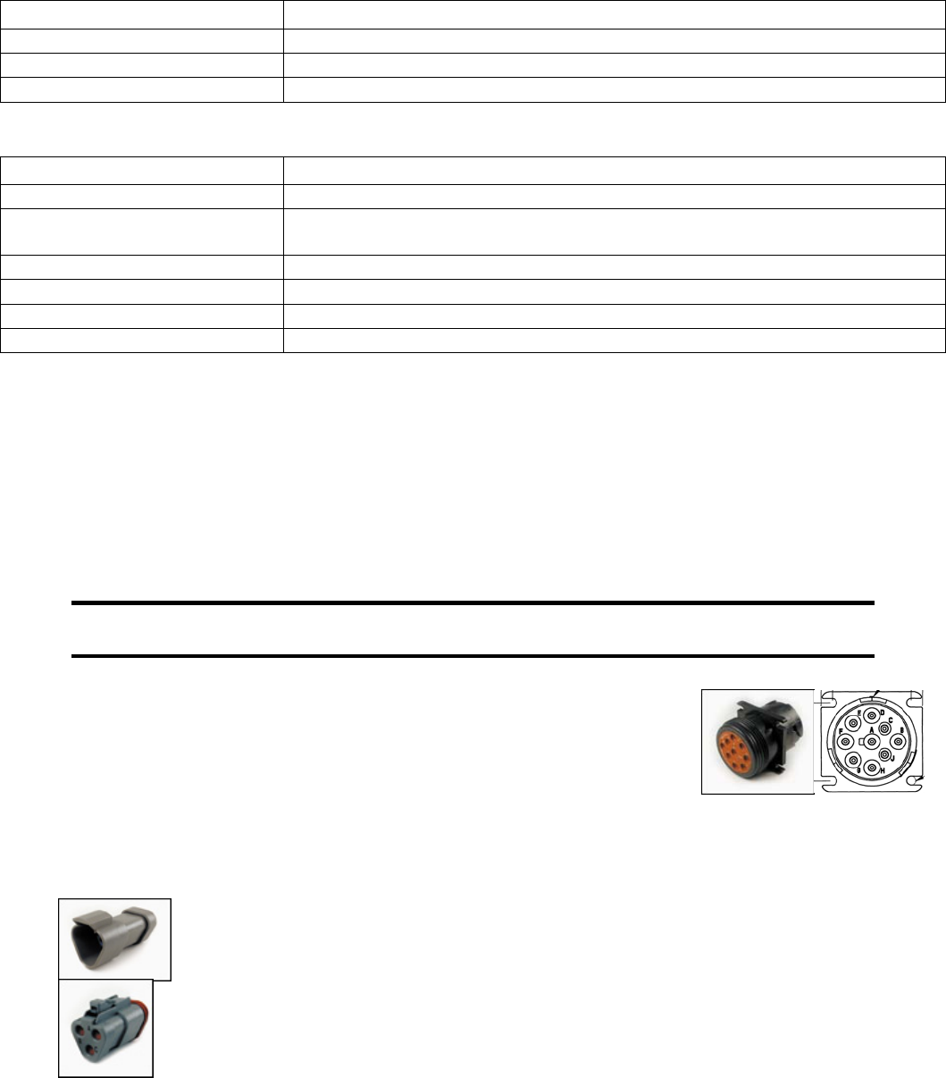
2. Identify the engine diagnostic plug. Plug is on right side of engine
near the Oil filter. Remove Cap. Connect an ohmmeter across the
CANbus pins of the diagnostic plug. Pin # C and D. Wires are green
and Yellow
3. A reading of 60Ω indicates both ends of the bus are terminated and the
bus is intact.
4. A reading of 120Ω indicates only one end of the bus is terminated. Identify the CANbus terminator
on the engine harness and remove and remove plug.
a. An ohmmeter reading of 120Ω indicates the bus to the terminator in the
panel is complete and the problem is between the panel and the
engine terminator.
b. An open circuit ohmmeter reading indicates the bus to the engine
terminator is complete and the problem is between the panel and the
diagnostic plug.
23
5. Reinstall the terminator resistor and reconnect the battery.
a. If the ECU diagnostic tool (John Deere Service Advisor)is available, use it to verify the ECU
is transmitting CANbus data. Refer to ECU documentation to identify and correct the error.
b. If another panel is available for testing, replace the panel to determine if the error is in the
panel.
Electronics
24
Diagnostic Trouble Codes (DTC) List
CANbus Diagnostic Trouble Codes are a pair of numbers; the Suspect Parameter Number (SPN) and
Failure Mode Identifier (FMI). The SPN indicates the faulting subsystem and the FMI identifies the type of
failure. Provide SPN and FMI numbers when contacting service dealers.
Standard SPN and FMI codes are defined by SAE J1939-71. Not all standard codes are used by this
ECU. Manufacturers may add additional SPN codes beyond the codes identified in J1939-71. Refer to
ECU documentation for supported SPN and FMI codes.
Diagnostic Trouble Code (DTC) Group Location Index Use By Deere Engines
SPN .FMI Description Group Corrective Action Engine Group Ref
029 .03 Throttle #2 Signal Out of Range High Not Used
029 .04 Throttle #2 Signal Out of Range Low Not Used
091 .03 Throttle #1 Signal Out of Range High Not Used , Contact Service 167
091 .04 Throttle #1 Signal Out of Range Low Not Used , Contact Service 167
091 .07 Throttle #1 Not Responding Not Used , Contact Service 167
091 .13 Throttle #1 Out of Calibration Not Used , Contact Service 167
094 .03 Low Pressure Fuel Signal Out of Range High Check Fuel Pressure Sender/Wiring 165
094 .04 Low Pressure Fuel Signal Out of Range Low Check Fuel Pressure Sender/Wiring 165
094 .17 Low Pressure Fuel Signal Slightly Low Contact Deere Service 165
097 .00 Water in Fuel (WIF) Detected Drain Fuel and water from Fuel Filter 165
097 .03 WIF Indicator Voltage High Check WIF Sender/Wiring 165
097 .04 WIF Indicator Voltage Low Check WIF Sender/Wiring 165
097 16 Water in Fuel (WIF) Detected Drain Fuel and Water from Fuel Filter 165
097 16 Water in Fuel (WIF) Detected Drain Fuel and Water from Fuel Filter 165
100 .01 Engine Oil Pressure Signal Extremely Low Check Engine Oil Level 164
100 04 Engine Oil Pressure Signal Out of Range Low Check Oil Pressure Sender/Wiring 164
105 .00 Intake Manifold Air Temperature Signal Extremely High * Check Air Cleaner After Cooler Air Temp 162
105 .03 Intake Manifold Air Temperature Signal Out of Range High Check intake Manifold Sensor and Wiring 162
105 .04 Intake Manifold Air Temperature Signal Out of Range Low Check intake Manifold Sensor and Wiring 162
105 .15 Intake Manifold Air Temperature Signal Slightly High Check Air Cleaner After Cooler Air Temp 162
105 .16 Intake Manifold Air Temperature Signal Moderately High Check Air Cleaner After Cooler Air Temp 162
108 .02 Barometric Pressure Signal Invalid Contact Deere Service 166
110 .00 Engine Coolant Temperature Signal Extremely High ** Check Cooling System Reduce Power 163
110 .03 Engine Coolant Temperature Signal Out of Range High Check Cooling Sensor and Wiring 163
110 .04 Engine Coolant Temperature Signal Out of Range Low Check Cooling Sensor and Wiring 163
110 .15 Engine Coolant Temperature Signal Slightly High Check Cooling System Reduce Power 163
110 .16 Engine Coolant Temperature Signal Moderately High * Check Cooling System Reduce Power 163
111 .16 Blade Coolant Flow to Low ** Set Water Safety Switch, Check water 163
158 .17 ECU Power Down Error Contact Deere Service 166
174 .00 Fuel Temperature High ** Check/Clean Fuel Cooler, Add Fuel 165
174 .02 Fuel Temperature Sensor Defective Replace Fuel Temp Sensor 165
174 .03 Fuel Temperature Signal Out of Range High Check Fuel Temp Sensor /Wiring 165
174 .04 Fuel Temperature Signal Out of Range Low Check Fuel Temp Sensor /Wiring 165
189 .00 Engine Speed De-rate Condition Exists Check Fault Codes /Contact Service 166
611 .03 Injector Shorted to Power Check Wiring 165
611 .04 Injector Shorted to Ground Check Wiring 165
627 .01 All Injector Circuits Have High Resistance Check Battery Voltage and Wiring 165
627 .18 Battery Voltage Moderately Low Charge Battery Contact Service 166
629 .12 ECU EEPROM Error Contact Deere Service 166
25
629 .13 ECU Boot Block Error Contact Deere Service 166
636 .02 Camshaft Sensor Signal Invalid Check Camshaft Sensor and Wiring 161
636 .05 Camshaft Sensor Circuit Has High Resistance Contact Deere Service 161
636 .06 Camshaft Sensor Circuit Has Low Resistance Contact Deere Service 161
636 .08 Camshaft Sensor Signal Missing Check Camshaft Sensor and Wiring 161
636 .10 Camshaft Sensor Signal Rate of Change Abnormal Check Camshaft Sensor and Wiring 161
637 .02 Engine Timing Sensor Signal Invalid Check Crankshaft Sensor and Wiring 161
637 .05 Engine Position Sensor Circuit Has High Resistance Contact Deere Service 161
637 .06 Engine Position Sensor Circuit Has Low Resistance Contact Deere Service 161
637 .07 Engine Timing and Position Signals Out of Sync Check Crankshaft Sensor and Wiring 161
637 .08 Engine Timing Sensor Signal Missing Check Crankshaft Sensor and Wiring 161
637 .10 Engine Timing Signal Rate of Change Abnormal Check Crankshaft Sensor and Wiring 161
651 .05 Injector #1 Circuit Has High Resistance Check Injector Wiring and Solenoid 165
651 .06 Injector #1 Circuit Has Low Resistance Check Injector Wiring and Solenoid 165
651 .13 Injector #1 Calibration Fault Contact Deere Service 165
652 .05 Injector #2 Circuit Has High Resistance Check Injector Wiring and Solenoid 165
652 .06 Injector #2 Circuit Has Low Resistance Check Injector Wiring and Solenoid 165
652 .13 Injector #2 Calibration Fault Contact Deere Service 165
653 .05 Injector #3 Circuit Has High Resistance Check Injector Wiring and Solenoid 165
653 .06 Injector #3 Circuit Has Low Resistance Check Injector Wiring and Solenoid 165
653 13 Injector #3 Calibration Fault Contact Deere Service 165
654 .05 Injector #4 Circuit Has High Resistance Check Injector Wiring and Solenoid 165
654 .06 Injector #4 Circuit Has Low Resistance Check Injector Wiring and Solenoid 165
654 .13 Injector #4 Calibration Fault Contact Deere Service 165
655 .05 Injector #5 Circuit Has High Resistance Check Injector Wiring and Solenoid 165
655 .06 Injector #5 Circuit Has Low Resistance Check Injector Wiring and Solenoid 165
655 .13 Injector #5 Calibration Fault Contact Deere Service 165
676 .03 Glow Plugs Signal Received When Not Expected Contact Deere Service 165
676 .05 Glow Plugs Signal Not Received When Expected Contact Deere Service 165
676 .05 Glow Plugs Signal Not Received When Expected Contact Deere Service 165
970 .31 Auxiliary Shut Down Low Fuel ** Check /Add Fuel 166
1110 .00 Engine Protection Shutdown Check Fault Codes 166
1136 .00 ECU Temperature High, Most Severe Contact Deere Service 166
1136 .16 ECU Temperature High Moderately Severe Contact Deere Service 166
1569 .31 Engine in De-rate Condition (reduced Power) Check Fault Codes 166
2003 .09 No CAN Message Received From Source Address
17 Within Time Out Period Contact Deere Service 168
2023 .09 Message ETCP 1 from ICC is timed out Contact Deere Service 168
3509 .03 Sensor Supply #1 Voltage Out of Range High Contact Deere Service 166
3509 .04 Sensor Supply #1 Voltage Out of Range Low Contact Deere Service 166
3510 .03 Sensor Supply #2 Voltage Out of Range High Contact Deere Service 166
3510 .04 Sensor Supply #2 Voltage Out of Range Low Contact Deere Service 166
3511 .03 Sensor Supply #3 Voltage Out of Range High Contact Deere Service 166
3511 .04 Sensor Supply #3 Voltage Out of Range Low Contact Deere Service 166
3597 .01 Injector Power Supply Voltage Extremely Low Check Battery Contact Deere Service 168
3597 .18 Injector Power Supply Voltage Moderately Low Check Battery Contact Deere Service 168
524037 .02 MFWD Switch Circuit Fault Contact Deere Service 168
524223 .03 Rear Axle Differential Lock Circuit Fault Contact Deere Service 168
524225 .31 Engine Start Protection Bypass Detected Contact Deere Service 168
524235 .03 MFWD Solenoid Circuit Voltage High Contact Deere Service 168
524235 .04 MFWD Solenoid Circuit Voltage Low Contact Deere Service 168
Electronics
26
Data Parameters Monitored
This table lists the engine parameters that are monitored via the CANbus on this John Deere Engine. The
parameters are displayed on gauge pages or the single analog gauge or the Data Base Viewer. The
complete database can be accessed on the display via the Configuration menu DB Viewer .
Icon Parameter Gauge Pages Single Analog Database
Electrical (Volts or Amps)
Battery Potential Switched z z z
Fuel (L, Gal, lGal) or (L/h, Gal/h IGal/h) or (km/L, MPG or IMPG)
Fuel Rate z z z
Total Fuel Used z z z
Pressure (kPa, PSI or bar)
Fuel Delivery Pressure z z z
Engine Oil Pressure z z z
Temperature (ºC or ºF)
Engine Coolant Temperature z z z
Fuel Temperature z z z
Intake Manifold 1 Temperature z z z
Percentage (%)
Drivers Demand Percent Torque z z
Actual Engine Percent Torque z z z
Torque Use at RPM z z z
Speed (RPM)
Output Shaft Speed z
Engine Speed z z z
Engine Desired Operating Speed z
Time (h)
Total Engine Hours z z
Service Hours z
Abbreviations
The units MPG and Gal denote US gallons. For non-US US gallons (UK, Canada, etc) the units are
denoted as IMPG or IGal.
Note
If a parameter is not available it will not be possible to select it.
If a parameter becomes unavailable while in view is displayed.
Glossary
CAN Controller Area Network (also referred to as CANbus); serial communications
protocol for electronic engines use
DTC Diagnostic Trouble Code; the combination of SPN and FMI that identifies a
specific error
ECU Engine Control Unit; electronic device responsible for controlling and monitoring
engine operation
FMI Failure Mode Identifier; defines the type of failure detected in the subsystem
identified by the SPN

27
ISO International Standard Organization; an international organization working with the
United Nations that maintains technology standards for global industry
J1939 SAE engine data protocol using CAN 2.0B
LCD Liquid Crystal Display; a display technology that uses electric current to align
crystals in a special liquid. When current is applied the crystals change their
orientation creating a darker area.
RS-232 Standard electrical interface for serial communications
RS-485 Standard differential electrical interface for serial communications
SAE Society of Automotive Engineers; professional association of transportation
industry engineers that sets most auto-industry standards for the testing,
measuring, and designing of automobiles and their components
Soft buttons Push buttons whose function changes according to use
SPN Suspect Parameter Number; a number used to identify a particular element,
component or parameter associated with an ECU
Note
The messages, icons and error codes displayed
conform to J1939 standards wherever possible.
A copy of the relevant standards documents may be accessed and purchased at:
http://www.sae.org/standardsdev/groundvehicle/j1939a.htm
463-3000-07 Initial - 3-Mar-2009

2009-12
115 15 97-27
Printed In U.S.A.
