HP Color LaserJet 4730mfp Service Manual ENWW 4730 MFP
User Manual: HP Laserjet 4730 MFP shared.swissparts.ch - /Manuals/HP/LaserJet/Mono Laserjet/
Open the PDF directly: View PDF ![]() .
.
Page Count: 922 [warning: Documents this large are best viewed by clicking the View PDF Link!]
- Product information
- HP Color LaserJet 4730mfp series configurations
- Features and benefits of the MFP
- MFP parts and accessories
- Site requirements
- MFP specifications
- Media specifications
- Printing on special media
- Regulatory information
- Declaration of conformity (HP Color LaserJet 4730mfp)
- Service approach
- Installation and configuration
- Installation checklist
- Unpacking the MFP
- Loading detectable standard-sized media into Tray 2, 3, and 4
- Loading undetectable standard-sized media into Tray 2, 3, and 4
- Connecting power
- Installing print cartridges
- Installing a new control panel overlay
- Testing the MFP operation
- Sleep delay
- Connecting to a computer or network
- Printer software
- Printer drivers
- Printer drivers for Macintosh computers
- Software for Macintosh computers
- Network configuration
- Security features
- Optional output and input devices
- Maintenance
- Using the cleaning page
- Cleaning the MFP
- Calibrating the scanner
- Performing preventive maintenance
- Managing print cartridges
- Approximate replacement intervals for supplies
- ETB life under different circumstances
- Changing print cartridges
- Replacing supplies
- MFP memory and fonts
- Installing memory and fonts
- Setting the real-time clock
- Configuring and verifying an IP address
- Upgrading the firmware
- Theory of operation
- Basic operation
- Formatter system
- Engine control system
- DC controller PCB
- Motors, fans, and environment sensor
- Failure detection
- Drum motor failure detection
- Fuser motor failure detection
- ETB motor failure detection
- Rear exhaust fan failure detection
- Cartridge fan failure detection
- Delivery fan failure detection
- Power supply fan failure detection
- Scanner fan failure detection
- ADF fan failure detection
- Control fans #1 and #2 failure detection
- Sub power supply fan failure detection
- ETB fan failure detection
- Low-voltage power supply
- Heater temperature control
- Temperature protective function
- Temperature failure detection
- High-voltage power supply
- Sub power supply assembly
- Video interface control
- Laser/scanner system
- Image formation system
- Image formation process
- Electrostatic latent image formation block
- Development block
- Transfer block
- Fusing block
- Cleaning block
- Print cartridges
- Cartridge presence detection
- ETB (electrostatic transfer/transport belt)
- Transfer roller (Y, C, M) engagement/disengagement detection
- Transfer roller engagement/disengagement control
- Calibration and cleaning
- Color misregistration detection
- Image stabilization control
- Pickup/feed system
- Scanner system
- 2 X 500-sheet paper feeder
- Output devices
- Removal and replacement
- Removal and replacement strategy
- User-replaceable parts
- Print cartridges
- Control panel overlays
- Control panel
- Intermediate paper transfer unit (IPTU)
- Stapler/stacker
- Staple cartridge
- 3-bin mailbox
- ETB assembly, removing
- MP tray pickup assembly
- Trays 2, 3, and 4
- ADF input tray
- ADF pickup and feed rollers
- ADF separation pad
- ADF delivery guide (clear mylar sheet)
- Face-down tray assembly
- Fuser
- Tray 2, 3, or 4 pickup and feed rollers
- MP tray pickup roller
- Tray 2 separation roller
- Tray 3 or 4 separation rollers
- Scanner filter cover and scanner filter
- ADF hinge flap
- Formatter board
- Hard drive
- DIMMs
- Flash memory card (firmware)
- Fax accessory
- Covers, doors, and external panels
- Face-down tray assembly
- Delivery cover assembly
- Rear cover assembly
- Left cover assembly
- Front cover assembly
- Tray 1
- Right lower cover assembly
- Delivery upper cover assembly
- Right front inner lower cover assembly
- Left rear inner cover assembly
- Right front inner upper cover assembly
- Right rear inner cover assembly
- Main assembly (internal assemblies)
- Motors and fans
- PCBs
- Switches, contacts, and sensors
- ADF and scanner components
- ADF components
- 2 X 500-sheet paper input assembly components
- Rear cover
- Right front cover
- Left front cover
- Right cover
- Left cover
- Right lower cover assembly
- Pickup motor assembly
- Upper lifter drive assembly
- Lower lifter drive assembly
- Upper pickup drive assembly
- Lower pickup drive assembly
- Upper pickup assembly
- Lower pickup assembly
- Paper feeder door-open switch
- Paper feeder driver PCB
- Intermediate paper transfer unit (IPTU)
- Troubleshooting
- Introduction
- Troubleshooting process
- Control panel messages
- Accessory lights for the 3-bin mailbox and stapler/stacker
- Formatter lights
- Replacement parts configuration
- Paper path troubleshooting
- Jam locations
- Paper jam recovery
- Clearing jams in the right covers
- Jam in Tray 1
- Jam in Tray 2, 3, or 4
- Jam in the stapler/stacker
- Staple jams
- Jam in the 3-bin mailbox
- Other jams in the output accessory bridge
- Jam in the ADF
- Solving repeated jams
- Persistent jams
- Jams in the ADF
- Jams in the IPTU
- Jams in the stapler/stacker
- Jams in the 3-bin mailbox
- Using the paper path test
- Using the scanner tests
- Correcting print quality and copy quality problems
- Print quality problems associated with media
- Overhead transparency defects
- Print quality problems associated with the environment
- Print quality problems associated with jams
- Understanding color variations
- Using color
- Color options
- Adjusting color balance
- Color selection process
- Matching colors
- Print quality troubleshooting pages
- Print quality troubleshooting tool
- Image defects
- Light image
- Light color
- Dark image
- Dark color
- Completely blank image
- All black or solid color
- Dots in vertical lines
- Dirt on the back of the paper
- Dirt on the front of the paper
- Vertical lines
- White vertical lines
- Horizontal lines
- White horizontal lines
- Missing color
- Blank spots
- Poor fusing
- Distortion or blurring
- Smearing
- Misplaced image
- Repetitive defects troubleshooting
- Repetitive defect ruler
- Image defect examples
- Cleaning the scanner glass
- Calibrating the MFP
- Media transport problems
- E-mail problems
- Fax problems
- Network connectivity problems
- Functional checks
- MFP resets
- Control panel troubleshooting
- Tools for troubleshooting
- Diagrams for troubleshooting
- Parts and diagrams
- Index

HP Color LaserJet 4730mfp
Service Manual

HP Color LaserJet 4730mfp series
Service Manual
Copyright and License
© 2005 Copyright Hewlett-Packard
Development Company, L.P.
Reproduction, adaptation, or translation
without prior written permission is
prohibited, except as allowed under the
copyright laws.
The information contained in this document
is subject to change without notice.
The only warranties for HP products and
services are set forth in the express
warranty statements accompanying such
products and services. Nothing herein
should be construed as constituting an
additional warranty. HP shall not be liable
for technical or editorial errors or omissions
contained herein.
Part number Q7517-91020
Edition 1, 11/2005
Trademark Credits
Adobe® is a trademark of Adobe Systems
Incorporated.
Corel® and CorelDRAW™ are trademarks
or registered trademarks of Corel
Corporation or Corel Corporation Limited.
Energy Star® and the Energy Star logo®
are U.S. registered marks of the United
States Environmental Protection Agency.
Microsoft® is a U.S. registered trademark
of the Microsoft Corporation.
Netscape Navigator is a U.S. trademark of
Netscape Communications.
PANTONE® Colors generated may not
match PANTONE-identified standards.
Consult current PANTONE Publications for
accurate color. PANTONE® and other
Pantone, Inc. trademarks are the property
of Pantone, Inc. © Pantone, Inc., 2000.
PostScript® is a trademark of Adobe
Systems.
TrueType™ is a U.S. trademark of Apple
Computer, Inc.
UNIX® is a registered trademark of The
Open Group.
Windows®, MS Windows®, and Windows
NT® are U.S. registered trademarks of
Microsoft Corporation.
Table of contents
1 Product information
HP Color LaserJet 4730mfp series configurations..................................................................................2
HP Color LaserJet 4730mfp (Q7517A)...................................................................................2
HP Color LaserJet 4730x mfp (Q7518A)................................................................................3
HP Color LaserJet 4730xs mfp (Q7519A)..............................................................................3
HP Color LaserJet 4730xm mfp (Q7520A).............................................................................4
Features and benefits of the MFP...........................................................................................................5
Functions.................................................................................................................................5
Speed and throughput............................................................................................................5
Resolution...............................................................................................................................5
Memory...................................................................................................................................5
User interface..........................................................................................................................5
Language and fonts ...............................................................................................................6
Copying and sending..............................................................................................................6
Print cartridges........................................................................................................................6
Paper handling........................................................................................................................6
Connectivity.............................................................................................................................7
Environmental features...........................................................................................................7
Security features.....................................................................................................................7
Minimum system requirements for e-mail functionality..........................................................8
MFP parts and accessories.....................................................................................................................9
MFP parts................................................................................................................................9
Interface ports.......................................................................................................................11
Model and serial numbers....................................................................................................11
Accessories and supplies.....................................................................................................12
Parts compatibility with other HP LaserJet products............................................................13
Moving the MFP....................................................................................................................14
Site requirements...................................................................................................................................15
Physical specifications..........................................................................................................15
Environmental specifications................................................................................................15
MFP specifications................................................................................................................................16
Electrical specifications.........................................................................................................16
Acoustic specifications..........................................................................................................17
Image area............................................................................................................................17
Skew specifications...............................................................................................................17
Media specifications..............................................................................................................................18
Printing and paper storage environment..............................................................................18
Envelopes.............................................................................................................................19
Envelopes that have double side seams.............................................................20
Envelopes that have adhesive strips or flaps......................................................20
ENWW iii
Envelope margins................................................................................................20
Envelope storage.................................................................................................20
Labels....................................................................................................................................21
Label construction................................................................................................21
Transparencies.....................................................................................................................21
Supported types and sizes of print media............................................................................22
Printing on special media......................................................................................................................27
Transparencies.....................................................................................................................27
Glossy paper.........................................................................................................................27
Colored paper.......................................................................................................................28
Envelopes.............................................................................................................................28
Labels....................................................................................................................................28
Heavy paper..........................................................................................................................29
HP LaserJet Tough paper.....................................................................................................29
Preprinted forms and letterhead...........................................................................................29
Recycled paper.....................................................................................................................30
Weight equivalence table......................................................................................................30
Regulatory information..........................................................................................................................32
FCC and Telecom regulations..............................................................................................32
FCC regulations...................................................................................................32
Telecom................................................................................................................32
Environmental Product Stewardship program......................................................................33
Protecting the environment..................................................................................33
Ozone production.................................................................................................33
Energy consumption............................................................................................33
HP LaserJet printing supplies..............................................................................33
Disposal of waste equipment by users in private households in the
European Union...................................................................................................35
Material safety data sheet....................................................................................35
For more information............................................................................................35
Country/region-specific safety statements............................................................................36
Laser safety statement.........................................................................................36
Canadian DOC statement....................................................................................36
Japanese VCCI statement...................................................................................36
Korean EMI statement.........................................................................................37
Japanese cordset statement................................................................................37
Taiwan safety statement......................................................................................37
Finnish laser statement........................................................................................38
Australia...............................................................................................................38
Declaration of conformity (HP Color LaserJet 4730mfp)......................................................................39
2 Service approach
Service approach...................................................................................................................................42
Parts and supplies.................................................................................................................................43
Ordering parts, supplies, and accessories over the Internet................................................43
Ordering directly through the embedded Web server (for MFPs with network
connections)..........................................................................................................................43
Exchange program................................................................................................................43
Supplies................................................................................................................................43
World Wide Web...................................................................................................................43
iv ENWW
HP Service Parts Information...............................................................................................44
HP available services............................................................................................................................45
Hewlett-Packard Limited Warranty Statement......................................................................................47
Print Cartridge Limited Warranty Statement.........................................................................................48
HP maintenance agreements................................................................................................................49
Priority Onsite Service..........................................................................................................49
Next business day.................................................................................................................49
Installation and maintenance kit replacement......................................................................49
3 Installation and configuration
Installation checklist...............................................................................................................................52
Unpacking the MFP...............................................................................................................................54
Loading detectable standard-sized media into Tray 2, 3, and 4...........................................................58
Loading undetectable standard-sized media into Tray 2, 3, and 4.......................................................60
Connecting power..................................................................................................................................63
Installing print cartridges........................................................................................................................64
Installing a new control panel overlay...................................................................................................66
Testing the MFP operation....................................................................................................................67
Sleep delay............................................................................................................................................68
Setting Sleep delay...............................................................................................................68
Disabling/enabling Sleep mode............................................................................................68
Connecting to a computer or network...................................................................................................69
Network connection..............................................................................................................69
Parallel connection................................................................................................................69
Fax connection......................................................................................................................70
Analog faxing........................................................................................................70
Connecting the fax accessory to a phone line....................................70
Configuring and using the fax features...............................................71
Digital faxing.........................................................................................................71
Printer software......................................................................................................................................72
Software................................................................................................................................72
Software features.................................................................................................72
Driver Autoconfiguration.......................................................................................72
Update Now..........................................................................................................72
HP Driver Preconfiguration..................................................................................73
Installing the printing system software..................................................................................73
Installing Windows printing system software for direct connections....................73
Installing Windows printing system software for networks..................................74
Setting up a Windows computer to use the network MFP with Windows-
sharing..................................................................................................................75
Installing the software after the parallel or USB cable has been connected.......75
Uninstalling the software.......................................................................................................75
Removing software from Windows operating systems........................................76
Software for networks...........................................................................................................76
HP Web Jetadmin................................................................................................76
UNIX.....................................................................................................................77
Utilities...................................................................................................................................77
HP Easy Printer Care Software...........................................................................77
Embedded Web server........................................................................................77
Features..............................................................................................78
ENWW v
Other components and utilities............................................................................78
Printer drivers........................................................................................................................................79
Supported printer drivers......................................................................................................79
Additional drivers..................................................................................................................79
Selecting the correct printer driver........................................................................................80
Printer driver Help (Windows)...............................................................................................80
Gaining access to Windows printer drivers..........................................................................81
Printer drivers for Macintosh computers................................................................................................82
Supported Macintosh printer drivers.....................................................................................82
Gaining access to Macintosh printer drivers.........................................................................82
Software for Macintosh computers........................................................................................................84
Installing Macintosh printing system software for networks.................................................84
Installing Macintosh printing system software for direct connections (USB)........................85
To remove software from Macintosh operating systems......................................................86
Network configuration............................................................................................................................87
Configuring TCP/IP parameters............................................................................................87
To manually configure TCP/IP parameters from the MFP control panel.............87
Setting an IP address...........................................................................................87
Setting the subnet mask.......................................................................................88
Setting the default gateway..................................................................................88
Disabling network protocols (optional).................................................................89
Disabling IPX/SPX...............................................................................................89
Disabling DLC/LLC...............................................................................................89
Disabling AppleTalk.............................................................................................90
Security features....................................................................................................................................91
Securing the embedded Web server....................................................................................91
To secure the embedded Web server..................................................................91
Foreign Interface Harness (FIH)...........................................................................................91
Requirements.......................................................................................................91
Using the FIH.......................................................................................................91
To enable the FIH portal......................................................................91
To disable the FIH portal.....................................................................92
Secure Disk Erase................................................................................................................92
Data affected........................................................................................................92
Gaining access to Secure Disk Erase..................................................................93
Additional Information..........................................................................................93
Job storage features.............................................................................................................93
DSS authentication...............................................................................................................93
Locking the control panel menus..........................................................................................93
Locking the formatter cage...................................................................................................94
Optional output and input devices.........................................................................................................95
4 Maintenance
Using the cleaning page........................................................................................................................98
Cleaning the MFP..................................................................................................................................99
Cleaning the outside of the MFP..........................................................................................99
Cleaning the touchscreen.....................................................................................................99
Cleaning the scanner glass..................................................................................................99
Cleaning the ADF delivery system........................................................................................99
To clean the ADF delivery system.....................................................................100
vi ENWW
To clean the ADF rollers....................................................................................101
Cleaning the mylar strip......................................................................................................104
To clean the mylar strip......................................................................................104
Calibrating the scanner........................................................................................................................106
To print the calibration target..............................................................................................106
Performing preventive maintenance....................................................................................................107
ADF maintenance kit...........................................................................................................107
Managing print cartridges....................................................................................................................108
HP print cartridges..............................................................................................................108
Changing print cartridges....................................................................................................108
Replacing a print cartridge.................................................................................108
Non-HP print cartridges......................................................................................................111
Print cartridge authentication..............................................................................................111
Print cartridge storage........................................................................................................112
Print cartridge life expectancy.............................................................................................112
Checking the supply level...................................................................................................112
Using the product control panel.........................................................................112
Using the embedded Web server......................................................................112
Using HP Web Jetadmin....................................................................................112
Printing a supplies status page..........................................................................112
Approximate replacement intervals for supplies.................................................................................114
ETB life under different circumstances................................................................................................115
Changing print cartridges....................................................................................................................116
Replacing print cartridges...................................................................................................116
Replacing supplies..............................................................................................................................117
Locating supplies................................................................................................................117
Supply replacement guidelines...........................................................................................117
Making room around the MFP for replacing supplies.........................................................118
Replacing the ETB..............................................................................................................118
Replacing the fuser.............................................................................................................119
Replacing the stapler cartridge...........................................................................................119
MFP memory and fonts.......................................................................................................................121
Installing memory and fonts.................................................................................................................122
Installing DDR memory DIMMs..........................................................................................122
Installing a flash memory card............................................................................................128
Enabling memory................................................................................................................132
To enable memory for Windows 98 and Windows Me......................................132
To enable memory for Windows 2000 and Windows XP..................................132
Setting the real-time clock...................................................................................................................133
Setting the date and time....................................................................................................133
To set the date format........................................................................................133
To set the date...................................................................................................133
To set the time format........................................................................................133
To set the time...................................................................................................134
Setting the wake time.........................................................................................................134
To set the wake time..........................................................................................134
Setting the Sleep delay.......................................................................................................135
To set the Sleep delay.......................................................................................135
Configuring and verifying an IP address.............................................................................................136
TCP/IP assignment.............................................................................................................136
ENWW vii
Automatic discovery...........................................................................................136
Dynamic host configuration protocol (DHCP)....................................................136
Verifying the TCP/IP configuration.....................................................................................136
Changing an IP address.....................................................................................................136
To change an IP address by using HP Web Jetadmin......................................136
To change an IP address by using the embedded Web server........................137
To change an IP address by using the control panel........................................137
Upgrading the firmware.......................................................................................................................139
Determining the current level of firmware...........................................................................139
Downloading the new firmware from the HP Web site.......................................................139
Transferring the new firmware to the MFP.........................................................................139
Using FTP to upload the firmware through a browser.......................................139
To use a browser for firmware update..............................................139
Using FTP to upgrade the firmware on a network connection...........................140
To upgrade the firmware on a network connection by using FTP....140
Using HP Web Jetadmin to upgrade the firmware............................................141
Using MS-DOS commands to upgrade the firmware........................................142
Upgrading the HP Jetdirect firmware..................................................................................143
5 Theory of operation
Basic operation....................................................................................................................................146
Operation sequence............................................................................................................147
Operation sequence (scanner)...........................................................................................147
Power on sequence............................................................................................................148
Formatter system.................................................................................................................................150
Sleep mode.........................................................................................................................150
Image Resolution Enhancement technology (REt)............................................................151
Input/Output........................................................................................................................151
Parallel interface................................................................................................151
USB 2.0 connector.............................................................................................151
ACC accessory port...........................................................................................151
Flash...................................................................................................................152
Hard disk............................................................................................................152
CPU....................................................................................................................152
FIH (foreign interface harness)..........................................................................152
MFP memory......................................................................................................................152
Read-only memory.............................................................................................152
Random-access memory...................................................................................152
DIMM slots..........................................................................................................................152
Flash memory....................................................................................................152
Nonvolatile memory...........................................................................................153
PJL overview.......................................................................................................................153
PML.....................................................................................................................................153
Control panel.......................................................................................................................153
Scanner interface................................................................................................................153
Engine control system.........................................................................................................................154
DC controller PCB...............................................................................................................154
Block operation..................................................................................................156
Motors, fans, and environment sensor...............................................................................156
Failure detection.................................................................................................................158
viii ENWW
Drum motor failure detection..............................................................................159
Fuser motor failure detection.............................................................................159
ETB motor failure detection...............................................................................159
Rear exhaust fan failure detection.....................................................................159
Cartridge fan failure detection............................................................................159
Delivery fan failure detection..............................................................................159
Power supply fan failure detection.....................................................................160
Scanner fan failure detection.............................................................................160
ADF fan failure detection....................................................................................160
Control fans #1 and #2 failure detection............................................................160
Sub power supply fan failure detection..............................................................160
ETB fan failure detection....................................................................................160
Low-voltage power supply..................................................................................................160
Fuser control circuit............................................................................................161
Low-voltage power supply circuit.......................................................................163
Protective functions...........................................................................164
Safety................................................................................................164
Sleep mode.......................................................................................164
Power supply recognition..................................................................164
Heater temperature control.................................................................................................164
Initial rotation temperature control.....................................................................165
Start-up temperature control..............................................................................165
Print temperature control....................................................................................166
Between-sheets temperature control.................................................................166
Temperature protective function.........................................................................................166
Protective function by the CPU..........................................................................166
Protective function by the fuser heater safety circuit.........................................166
Protective function by the thermoswitch............................................................167
Temperature failure detection.............................................................................................167
Start-up failure (warm-up failure).......................................................................167
Abnormal low temperature of main thermistor (no conduction).........................167
Abnormal high temperature of main thermistor.................................................167
Abnormal low temperature of sub thermistor (no conduction)...........................167
Abnormal high temperature of sub thermistor...................................................168
Drive circuit abnormality.....................................................................................168
High-voltage power supply.................................................................................................168
Generation of biases..........................................................................................169
Sub power supply assembly...............................................................................................171
Video interface control........................................................................................................171
Laser/scanner system.........................................................................................................................173
Laser control.......................................................................................................................174
Scanner control...................................................................................................................175
Image formation system......................................................................................................................177
Image formation process....................................................................................................178
Electrostatic latent image formation block..........................................................................180
Step 1: Pre-exposure.........................................................................................180
Step 2: Primary charging....................................................................................181
Step 3: Laser beam exposure............................................................................181
Development block.............................................................................................................181
Step 4: Development..........................................................................................181
ENWW ix
Transfer block.....................................................................................................................182
Step 5: Attraction................................................................................................182
Step 6: Transfer.................................................................................................182
Step 7: Separation.............................................................................................183
Fusing block........................................................................................................................183
Step 8: Fusing....................................................................................................183
Cleaning block....................................................................................................................184
Step 9: Drum cleaning........................................................................................184
Print cartridges....................................................................................................................184
Memory tag........................................................................................................186
Cartridge presence detection..............................................................................................186
Memory tag detection.........................................................................................186
Photosensitive drum detection...........................................................................186
Developing cylinder disengaging control...........................................................187
ETB (electrostatic transfer/transport belt)...........................................................................187
Transfer roller (Y, C, M) engagement/disengagement detection.......................................189
Transfer roller engagement/disengagement control...........................................................189
Calibration and cleaning.....................................................................................................190
ETB cleaning......................................................................................................191
Color misregistration corrective control.............................................................192
Color misregistration detection...........................................................................................193
Image stabilization control..................................................................................................194
Environmental change control...........................................................................195
Image density calibration control (DMAX).........................................................196
Image halftone calibration control (DHALF).......................................................196
Image density detection.....................................................................................196
Pickup/feed system.............................................................................................................................198
Pickup/feed unit..................................................................................................................203
Cassette detection and cassette media size detection......................................203
Cassette pickup operation.................................................................................204
Media lifting operation........................................................................................204
Initial lift..............................................................................................205
Lift-up during printing.........................................................................205
Multiple-feed prevention.....................................................................................206
Skew correction..................................................................................................207
Media detection..................................................................................................208
Feed speed control............................................................................................209
Fusing and delivery block...................................................................................................210
Loop control........................................................................................................211
Fusing pressure release mechanism.................................................................212
Duplex feed unit..................................................................................................................213
Duplexing reverse/duplexing feed operation.....................................................214
Jam detection......................................................................................................................216
Pickup delay jam................................................................................................217
Pickup stationary jam.........................................................................................217
Delivery delay jam..............................................................................................217
Door open jam....................................................................................................217
Residual paper jam............................................................................................218
Reversing unit jam 1..........................................................................................218
Reversing unit jam 2..........................................................................................218
x ENWW
Duplexing pickup unit jam 1...............................................................................218
Automatic delivery function................................................................................218
Scanner system...................................................................................................................................219
Electrical system.................................................................................................................219
Motors and fans..................................................................................................................220
Optical assembly.................................................................................................................221
ADF feed system................................................................................................................222
ADF jam detection..............................................................................................................223
Residual media jam............................................................................................................223
ADF pickup jam...................................................................................................................223
ADF jam..............................................................................................................................223
Registration sensor jam.....................................................................................224
Read sensor jam................................................................................................224
Exit sensor jam...................................................................................................224
ADF cover-open jam...........................................................................................................224
ADF open jam.....................................................................................................................224
2 X 500-sheet paper feeder.................................................................................................................225
Pickup and feed operations................................................................................................226
2 X 500-sheet jam detection...............................................................................................228
Output devices.....................................................................................................................................229
IPTU....................................................................................................................................229
IPTU transfer operation......................................................................................230
IPTU jam detection.............................................................................................232
Pickup delay jam...............................................................................232
Pickup stationary jam........................................................................232
Delivery delay jam.............................................................................232
Delivery stationary jam......................................................................232
3-bin mailbox.......................................................................................................................232
Stacker mode.....................................................................................................234
Mailbox mode.....................................................................................................234
Function separator mode...................................................................................234
3-bin mailbox jam detection...............................................................................234
Feed delay jam..................................................................................234
Feed stationary jam...........................................................................235
Residual media jam...........................................................................235
Stapler/stacker....................................................................................................................235
Staple mode.......................................................................................................237
Stacker mode.....................................................................................................237
Staple jam detection...........................................................................................237
Feed delay jam..................................................................................237
Feed stationary jam...........................................................................238
Delivery stationary jam......................................................................238
Residual media jam...........................................................................238
Stapler unit........................................................................................238
6 Removal and replacement
Removal and replacement strategy.....................................................................................................242
Required tools.....................................................................................................................242
Before performing service...................................................................................................243
Removal and replacement sequencing..............................................................................243
ENWW xi
After completing service.....................................................................................................245
Screws used in the MFP.....................................................................................................246
User-replaceable parts........................................................................................................................247
Print cartridges....................................................................................................................248
Control panel overlays........................................................................................................250
Control panel.......................................................................................................................250
Intermediate paper transfer unit (IPTU)..............................................................................252
Stapler/stacker....................................................................................................................253
Staple cartridge...................................................................................................................255
3-bin mailbox.......................................................................................................................257
ETB assembly, removing....................................................................................................258
MP tray pickup assembly....................................................................................................261
Trays 2, 3, and 4.................................................................................................................261
ADF input tray.....................................................................................................................262
ADF pickup and feed rollers...............................................................................................264
ADF separation pad............................................................................................................266
ADF delivery guide (clear mylar sheet)..............................................................................268
Face-down tray assembly...................................................................................................270
Fuser...................................................................................................................................271
Tray 2, 3, or 4 pickup and feed rollers................................................................................272
MP tray pickup roller...........................................................................................................273
Tray 2 separation roller.......................................................................................................275
Tray 3 or 4 separation rollers..............................................................................................277
Scanner filter cover and scanner filter................................................................................278
ADF hinge flap....................................................................................................................279
Formatter board..................................................................................................................280
Hard drive...........................................................................................................................282
DIMMs.................................................................................................................................284
Flash memory card (firmware)............................................................................................287
Fax accessory.....................................................................................................................288
Covers, doors, and external panels.....................................................................................................291
Face-down tray assembly...................................................................................................293
Delivery cover assembly.....................................................................................................293
Rear cover assembly..........................................................................................................294
Left cover assembly............................................................................................................296
Front cover assembly..........................................................................................................297
Tray 1..................................................................................................................................300
Right lower cover assembly................................................................................................303
Delivery upper cover assembly...........................................................................................306
Right front inner lower cover assembly..............................................................................307
Left rear inner cover assembly...........................................................................................307
Right front inner upper cover assembly..............................................................................308
Right rear inner cover assembly.........................................................................................310
Main assembly (internal assemblies)..................................................................................................313
Paper feed assembly..........................................................................................................316
Pickup drive assembly........................................................................................................320
Lifter drive assembly...........................................................................................................321
Disengaging drive assembly...............................................................................................323
Main drive assembly...........................................................................................................325
Rail holder assembly...........................................................................................................333
xii ENWW
Rail guide assembly............................................................................................................335
Formatter case assembly...................................................................................................338
Laser/scanner components................................................................................................343
Duplexing assembly............................................................................................................351
Delivery assembly...............................................................................................................353
Fuser drive assembly..........................................................................................................361
Motors and fans...................................................................................................................................362
Drum motors.......................................................................................................................362
Fuser motor.........................................................................................................................363
Fuser pressure release motor.............................................................................................364
Developing disengaging motor...........................................................................................369
Pickup motor assembly.......................................................................................................370
Power supply fan................................................................................................................371
Cartridge fan.......................................................................................................................373
Sub power supply fan.........................................................................................................374
Delivery fan.........................................................................................................................376
Control fan 1.......................................................................................................................377
Control fan 2.......................................................................................................................378
Rear exhaust fan.................................................................................................................379
ETB fan...............................................................................................................................380
PCBs....................................................................................................................................................384
DC controller PCB...............................................................................................................384
Toner level PCB..................................................................................................................389
High-voltage power supply PCB.........................................................................................389
Low-voltage power supply PCB..........................................................................................395
Memory controller PCB.......................................................................................................400
Sub power supply PCB.......................................................................................................401
Fan drive PCB.....................................................................................................................403
Switches, contacts, and sensors.........................................................................................................404
High-voltage contacts.........................................................................................................404
E-label memory contacts and cable...................................................................................405
Power switch assembly......................................................................................................406
Door-open switch assembly................................................................................................408
Environment sensor............................................................................................................409
ADF and scanner components............................................................................................................411
ADF assembly.....................................................................................................................411
Top covers..........................................................................................................................413
Scanner assembly..............................................................................................................414
Scanner left cover...............................................................................................................416
Scanner right cover.............................................................................................................417
Scanner glass.....................................................................................................................418
Optical assembly.................................................................................................................419
Scanner bulb.......................................................................................................................425
Inverter PCB.......................................................................................................................427
Scanner fan.........................................................................................................................428
Scanner home position sensor...........................................................................................429
Scanner controller PCB......................................................................................................431
ADF components.................................................................................................................................432
ADF output bin extension...................................................................................................433
ADF white mylar backing....................................................................................................434
ENWW xiii
ADF front cover...................................................................................................................437
ADF rear cover ...................................................................................................................438
ADF left side cover..............................................................................................................440
ADF jam access cover and latch........................................................................................441
ADF leading-edge and paper-present sensors..................................................................443
ADF hinges.........................................................................................................................444
2 X 500-sheet paper input assembly components..............................................................................446
Rear cover..........................................................................................................................447
Right front cover..................................................................................................................448
Left front cover....................................................................................................................449
Right cover..........................................................................................................................450
Left cover............................................................................................................................452
Right lower cover assembly................................................................................................454
Pickup motor assembly.......................................................................................................455
Upper lifter drive assembly.................................................................................................456
Lower lifter drive assembly.................................................................................................457
Upper pickup drive assembly..............................................................................................459
Lower pickup drive assembly..............................................................................................459
Upper pickup assembly......................................................................................................460
Lower pickup assembly......................................................................................................466
Paper feeder door-open switch...........................................................................................469
Paper feeder driver PCB.....................................................................................................471
Intermediate paper transfer unit (IPTU)...............................................................................................472
Front cover and front door..................................................................................................472
IPTU rear cover...................................................................................................................475
Connector cover assembly.................................................................................................476
IPTU driver PCB.................................................................................................................477
IPTU driver motors..............................................................................................................478
7 Troubleshooting
Introduction..........................................................................................................................................482
Troubleshooting process.....................................................................................................................483
Initial troubleshooting checklist...........................................................................................483
Troubleshooting checklist..................................................................................483
Troubleshooting flowchart...................................................................................................485
Power-on checks................................................................................................................487
Power-on troubleshooting overview...................................................................487
Control panel messages......................................................................................................................488
Using the MFP help system................................................................................................488
Resolving control panel messages.....................................................................................488
Accessory lights for the 3-bin mailbox and stapler/stacker.................................................................531
Accessory lights..................................................................................................................531
Formatter lights....................................................................................................................................532
HP Jetdirect LEDs...............................................................................................................532
Heartbeat LED....................................................................................................................532
Fax LED..............................................................................................................................533
Replacement parts configuration.........................................................................................................534
Formatter and DC controller ..............................................................................................534
Formatter (new or previously installed in another MFP) ....................................................534
DC controller (new or previously installed in another MFP) ..............................................534
xiv ENWW
Paper path troubleshooting.................................................................................................................536
Jam locations......................................................................................................................536
Paper jam recovery.............................................................................................................538
To disable paper jam recovery...........................................................................539
Clearing jams in the right covers........................................................................................539
Jam in Tray 1......................................................................................................................544
Jam in Tray 2, 3, or 4..........................................................................................................545
Jam in the stapler/stacker...................................................................................................547
Staple jams.........................................................................................................................548
Jam in the 3-bin mailbox.....................................................................................................550
Other jams in the output accessory bridge.........................................................................552
Jam in the ADF...................................................................................................................553
Solving repeated jams........................................................................................................555
Persistent jams...................................................................................................................556
Basic troubleshooting for jams...........................................................................556
Data collection....................................................................................................556
General paper path troubleshooting..................................................................556
Paper path checklist...........................................................................................557
Jams in Tray 1....................................................................................................557
Jams in tray 2.....................................................................................................558
Jams in Tray 3....................................................................................................559
Jams in Tray 4....................................................................................................560
Jams in the paper path.......................................................................................560
Jams in the right upper cover.............................................................................561
Jams in the duplex path.....................................................................................562
Jams in the ADF.................................................................................................................562
Jams in the IPTU................................................................................................................563
Jams in the stapler/stacker.................................................................................................563
Jams in the 3-bin mailbox...................................................................................................564
Using the paper path test....................................................................................................565
Using the scanner tests......................................................................................................565
Correcting print quality and copy quality problems.............................................................................566
Print quality problems associated with media.....................................................................566
Overhead transparency defects..........................................................................................566
Print quality problems associated with the environment....................................................567
Print quality problems associated with jams.......................................................................567
Understanding color variations...........................................................................................567
Common causes of color variation.....................................................................567
Using color..........................................................................................................................568
HP ImageREt 3600............................................................................................568
Paper selection..................................................................................................568
sRGB..................................................................................................................568
Color options.......................................................................................................................569
Restricting color printing.....................................................................................569
Print in grayscale................................................................................................569
Automatic or manual color adjustment..............................................................570
Manual color options..........................................................................................570
Halftone options.................................................................................................570
Neutral grays......................................................................................................570
Edge control.......................................................................................................570
ENWW xv
RGB color...........................................................................................................571
Adjusting color balance.......................................................................................................571
To adjust color balance......................................................................................571
Color selection process......................................................................................................572
Matching colors...................................................................................................................572
PANTONE® color matching...............................................................................572
Swatch book color matching..............................................................................572
Print quality troubleshooting pages....................................................................................572
Print quality troubleshooting tool.........................................................................................573
Image defects.....................................................................................................................573
Light image.........................................................................................................574
Light color...........................................................................................................575
Dark image.........................................................................................................575
Dark color...........................................................................................................576
Completely blank image.....................................................................................576
All black or solid color........................................................................................576
Dots in vertical lines...........................................................................................577
Dirt on the back of the paper..............................................................................577
Dirt on the front of the paper..............................................................................578
Vertical lines.......................................................................................................579
White vertical lines.............................................................................................579
Horizontal lines...................................................................................................580
White horizontal lines.........................................................................................580
Missing color......................................................................................................580
Blank spots.........................................................................................................581
Poor fusing.........................................................................................................582
Distortion or blurring...........................................................................................582
Smearing............................................................................................................583
Misplaced image................................................................................................584
Repetitive defects troubleshooting.....................................................................584
Repetitive defect ruler........................................................................................585
Image defect examples.......................................................................................................586
Cleaning the scanner glass................................................................................................591
Calibrating the MFP............................................................................................................591
Media transport problems....................................................................................................................593
E-mail problems...................................................................................................................................595
To validate the SMTP gateway address.............................................................................595
To validate the LDAP gateway address.............................................................................595
Fax problems.......................................................................................................................................596
Network connectivity problems............................................................................................................596
Troubleshooting network printing problems........................................................................596
Loopback test......................................................................................................................597
Ping test..............................................................................................................................597
Functional checks................................................................................................................................598
Engine test..........................................................................................................................598
Formatter test......................................................................................................................599
MFP resets..........................................................................................................................................600
Cold reset............................................................................................................................600
NVRAM initialization...........................................................................................................600
Hard-disk initialization.........................................................................................................601
xvi ENWW
Control panel troubleshooting.............................................................................................................602
Control panel layout............................................................................................................602
Control panel features........................................................................................................603
Home-screen navigation.....................................................................................................604
Help system........................................................................................................................604
What is This? Help.............................................................................................604
Show Me How Help............................................................................................605
Menu map...........................................................................................................................605
Retrieve job menu...............................................................................................................605
Information menu................................................................................................................606
Fax menu............................................................................................................................607
Paper handling menu..........................................................................................................607
Configure device menu.......................................................................................................609
Originals submenu.............................................................................................610
Copying submenu..............................................................................................611
Enhancement submenu.....................................................................................612
Sending submenu..............................................................................................612
Printing submenu...............................................................................................613
PCL submenu....................................................................................................616
Print quality submenu.........................................................................................617
System setup submenu......................................................................................618
Copy/send settings.............................................................................................622
MBM-3 Configuration submenu.........................................................................623
Stapler/stacker submenu...................................................................................624
I/O submenu.......................................................................................................624
Embedded Jetdirect submenu...........................................................................625
Resets submenu................................................................................................628
Diagnostics menu...............................................................................................................629
Tools for troubleshooting.....................................................................................................................633
Using the embedded Web server.......................................................................................633
Opening the embedded Web server..................................................................633
Information tab...................................................................................................634
Settings tab........................................................................................................634
Digital Sending tab.............................................................................................635
Networking tab...................................................................................................635
Other links..........................................................................................................635
Using the HP Easy Printer Care Software..........................................................................636
Supported operating systems............................................................................636
To use the HP Easy Printer Care Software.......................................................636
HP Easy Printer Care Software sections...........................................................637
Using HP Web Jetadmin software......................................................................................639
Information pages...............................................................................................................640
To print an information page..............................................................................640
Menu map..........................................................................................................640
Configuration pages...........................................................................................641
Configuration page............................................................................641
HP embedded Jetdirect page............................................................643
Paper handling configuration page...................................................643
Fax accessory page..........................................................................644
Finding important information on the configuration pages................646
ENWW xvii
Supplies status page..........................................................................................648
Usage page........................................................................................................650
PCL or PS font list..............................................................................................652
Individual component diagnostics.......................................................................................653
LED diagnostics ................................................................................................653
Engine diagnostics.............................................................................................654
Diagnostics mode..............................................................................654
Diagnostics that put the engine into the special diagnostics mode. .654
Diagnostic tests.................................................................................655
Paper path sensor test.......................................................................................656
Manual sensor test.............................................................................................657
Scanner tests.....................................................................................................659
Component tests................................................................................................659
Service menu......................................................................................................................662
Service ID...........................................................................................................................664
Converting the service ID to an actual date.......................................................664
Troubleshooting the embedded HP Jetdirect print server..................................................665
Firmware-stack trace..........................................................................................................665
Diagrams for troubleshooting..............................................................................................................666
DC controller connections...................................................................................................666
Scanner controller PCB connections..................................................................................669
Locations of major components..........................................................................................670
Sensors and switches........................................................................................672
Sensors and switches.......................................................................672
Motors, fans, and solenoids...............................................................................674
Motors and solenoids........................................................................674
Fans...................................................................................................677
PCBs..................................................................................................678
Scanner and ADF components..........................................................................679
ADF and scanner sensors.................................................................679
ADF pickup assembly sensors..........................................................680
ADF motors, fans, and solenoids......................................................680
2 X 500-sheet feeder..........................................................................................682
IPTU...................................................................................................................683
General timing chart............................................................................................................684
General circuit diagrams.....................................................................................................685
8 Parts and diagrams
Introduction..........................................................................................................................................700
Ordering parts and supplies................................................................................................................701
Parts that wear....................................................................................................................701
Parts....................................................................................................................................701
Customer support...............................................................................................................701
Supplies and accessories...................................................................................................701
Assembly locations..............................................................................................................................706
Major components..............................................................................................................706
External covers and panels.................................................................................................................710
Internal components............................................................................................................................722
ADF components.................................................................................................................................766
Scanner components...........................................................................................................................788
xviii ENWW
2 X 500-sheet feeder components......................................................................................................810
Optional devices..................................................................................................................................830
Stapler/stacker....................................................................................................................830
3-bin mailbox.......................................................................................................................832
Intermediate paper transfer unit (IPTU)..............................................................................834
Alphabetical parts list...........................................................................................................................840
Numerical parts list..............................................................................................................................854
Index....................................................................................................................................................................869
ENWW xix
xx ENWW
List of tables
Table 1-1 Parts compatibility..........................................................................................................................13
Table 1-2 Product dimensions........................................................................................................................15
Table 1-3 Product dimensions........................................................................................................................15
Table 1-4 Environmental specifications..........................................................................................................15
Table 1-5 Power requirements.......................................................................................................................16
Table 1-6 Power consumption (average, in watts).........................................................................................16
Table 1-7 Sound power and pressure level (Product Name: X)....................................................................17
Table 1-8 Supported types of media..............................................................................................................22
Table 1-9 Tray 1 media sizes.........................................................................................................................22
Table 1-10 Tray 2, 3, and 4 media sizes..........................................................................................................23
Table 1-11 Automatic duplex printing (two-sided printing)...............................................................................24
Table 1-12 Optional 3-bin mailbox or stacker part of the stapler/stacker supported sizes..............................24
Table 1-13 Stapler part of the optional stapler/stacker supported sizes..........................................................26
Table 1-14 Supported heavy paper types........................................................................................................29
Table 1-15 Weight equivalence table...............................................................................................................30
Table 3-1 HP Color LaserJet 4730mfp installation.........................................................................................52
Table 3-2 Supported printer drivers................................................................................................................79
Table 3-3 Gaining access to Windows printer drivers....................................................................................81
Table 3-4 Gaining access to Macintosh printer drivers..................................................................................82
Table 5-1 Basic operation sequence............................................................................................................147
Table 5-2 Function of motors, fans, and environment sensor......................................................................157
Table 5-3 Fuser temperatures......................................................................................................................162
Table 5-4 Calibration timing and duration....................................................................................................191
Table 5-5 Cleaning timing and duration.......................................................................................................191
Table 5-6 Paper tray media size detection...................................................................................................203
Table 5-7 Paper size detection switch settings............................................................................................209
Table 6-1 Common fasteners used in this MFP...........................................................................................246
Table 7-1 Troubleshooting flowchart............................................................................................................485
Table 7-2 Error messages and associated jam locations............................................................................537
Table 7-3 Causes for jams in Tray 1............................................................................................................557
Table 7-4 Causes for jams in Tray 2............................................................................................................558
Table 7-5 Causes for jams in Tray 3............................................................................................................559
Table 7-6 Causes for jams in Tray 4............................................................................................................560
Table 7-7 Causes for jams in the paper path...............................................................................................560
Table 7-8 Causes for jams in the right upper cover.....................................................................................561
Table 7-9 Causes for jams in the duplex path..............................................................................................562
Table 7-10 Causes of jams in the ADF..........................................................................................................562
Table 7-11 Causes for jams in the IPTU........................................................................................................563
Table 7-12 Causes for jams in the stapler/stacker.........................................................................................563
Table 7-13 Causes for jams in the 3-bin mailbox...........................................................................................564
ENWW xxi
Table 7-14 Image defects...............................................................................................................................573
Table 7-15 Causes for light images................................................................................................................574
Table 7-16 Causes for light color....................................................................................................................575
Table 7-17 Causes for dark images...............................................................................................................575
Table 7-18 Causes for dark colors.................................................................................................................576
Table 7-19 Causes for a completely blank image..........................................................................................576
Table 7-20 Causes for an all black or solid colored image............................................................................577
Table 7-21 Causes for vertical lines of white dots..........................................................................................577
Table 7-22 Causes for dirt on the back of the paper......................................................................................578
Table 7-23 Causes for dirt on the front of the paper......................................................................................578
Table 7-24 Causes for vertical lines...............................................................................................................579
Table 7-25 Causes for white vertical lines......................................................................................................579
Table 7-26 Causes for horizontal lines...........................................................................................................580
Table 7-27 Causes for white horizontal lines.................................................................................................580
Table 7-28 Causes for a missing color...........................................................................................................580
Table 7-29 Causes for blank spots.................................................................................................................581
Table 7-30 Causes for poor fusing.................................................................................................................582
Table 7-31 Causes for distortion or blurring...................................................................................................582
Table 7-32 Causes for smearing....................................................................................................................583
Table 7-33 Causes for misplaced image........................................................................................................584
Table 7-34 Defects that can occur during printing.........................................................................................586
Table 7-35 Defects that can occur when using the ADF................................................................................590
Table 7-36 Important information on the configuration pages.......................................................................646
Table 7-37 Tray 2 paper size codes...............................................................................................................656
Table 7-38 Manual sensor test letter designations........................................................................................657
Table 7-39 Service menu...............................................................................................................................662
Table 8-1 Technical support Web sites and related documentation............................................................701
Table 8-2 Supplies and accessories............................................................................................................701
Table 8-3 Major components........................................................................................................................707
Table 8-4 External covers and panels..........................................................................................................711
Table 8-5 Right lower cover assembly.........................................................................................................713
Table 8-6 Multipurpose tray assembly.........................................................................................................715
Table 8-7 Right upper door assembly..........................................................................................................717
Table 8-8 Left cover assembly.....................................................................................................................719
Table 8-9 Face-down tray assembly............................................................................................................721
Table 8-10 Internal components (1 of 8)........................................................................................................723
Table 8-11 Internal components (2 of 8)........................................................................................................725
Table 8-12 Internal components (3 of 8)........................................................................................................727
Table 8-13 Internal components (4 of 8)........................................................................................................729
Table 8-14 Internal components (5 of 8)........................................................................................................731
Table 8-15 Internal components (6 of 8)........................................................................................................733
Table 8-16 Internal components (7 of 8)........................................................................................................735
Table 8-17 Internal components (8 of 8)........................................................................................................737
Table 8-18 Paper pickup drive assembly.......................................................................................................739
Table 8-19 Pickup motor assembly................................................................................................................741
Table 8-20 Disengaging drive assembly........................................................................................................743
Table 8-21 Lifter drive assembly....................................................................................................................745
Table 8-22 Cassette.......................................................................................................................................747
Table 8-23 Multipurpose pickup assembly.....................................................................................................749
Table 8-24 ETB assembly..............................................................................................................................751
xxii ENWW
Table 8-25 Delivery assembly........................................................................................................................753
Table 8-26 Fuser drive assembly...................................................................................................................755
Table 8-27 Duplexing unit (1 of 2)..................................................................................................................757
Table 8-28 Duplexing unit (2 of 2)..................................................................................................................759
Table 8-29 Duplex feed assembly..................................................................................................................761
Table 8-30 Fuser assembly............................................................................................................................763
Table 8-31 PCB assembly..............................................................................................................................765
Table 8-32 ADF assembly..............................................................................................................................767
Table 8-33 ADF internal components (1 of 3)................................................................................................769
Table 8-34 ADF internal components (2 of 3)................................................................................................771
Table 8-35 ADF internal components (3 of 3)................................................................................................773
Table 8-36 ADF input tray..............................................................................................................................775
Table 8-37 ADF separation pad.....................................................................................................................777
Table 8-38 ADF separation pad case.............................................................................................................779
Table 8-39 ADF pickup-roller assembly.........................................................................................................781
Table 8-40 ADF pickup-roller cover................................................................................................................783
Table 8-41 ADF mylar holder assembly.........................................................................................................785
Table 8-42 ADF mylar replacement kit...........................................................................................................787
Table 8-43 Scanner glass and cover..............................................................................................................789
Table 8-44 Scanner base components..........................................................................................................791
Table 8-45 Scanner flatbed unit assembly.....................................................................................................793
Table 8-46 Scanner covers............................................................................................................................795
Table 8-47 Scanner carriage lock assembly..................................................................................................797
Table 8-48 Scanner-open sensor assembly...................................................................................................799
Table 8-49 Scanner motor fan........................................................................................................................801
Table 8-50 Scanner motor..............................................................................................................................803
Table 8-51 Scanner belt and pulley assembly...............................................................................................805
Table 8-52 Scanner slide rail..........................................................................................................................807
Table 8-53 Scanner optical assembly............................................................................................................809
Table 8-54 2 X 500-sheet feeder external components.................................................................................813
Table 8-55 2 X 500-sheet paper feeder internal components (1 of 2)...........................................................815
Table 8-56 2 X 500-sheet paper feeder internal components (2 of 2)...........................................................817
Table 8-57 500-sheet feeder lifter drive assembly.........................................................................................819
Table 8-58 Upper paper pickup drive assembly.............................................................................................821
Table 8-59 Lower paper pickup drive assembly.............................................................................................823
Table 8-60 2 X 500-sheet paper feeder cassette...........................................................................................825
Table 8-61 Upper paper pickup assembly......................................................................................................827
Table 8-62 Lower paper pickup assembly......................................................................................................829
Table 8-63 Stapler/stacker accessory............................................................................................................831
Table 8-64 3-bin mailbox accessory...............................................................................................................833
Table 8-65 External covers and panels..........................................................................................................835
Table 8-66 Internal components (1 of 2)........................................................................................................837
Table 8-67 Internal components (2 of 2)........................................................................................................839
Table 8-68 Alphabetical parts list...................................................................................................................840
Table 8-69 Numerical parts list.......................................................................................................................854
ENWW xxiii
xxiv ENWW
List of figures
Figure 4-1 ETB total page count according to average job length................................................................115
Figure 4-2 Supply item locations...................................................................................................................117
Figure 4-3 Supplies replacement clearance diagram....................................................................................118
Figure 5-1 Basic system operation................................................................................................................146
Figure 5-2 Power on sequence......................................................................................................................149
Figure 5-3 Formatter system.........................................................................................................................150
Figure 5-4 Engine control system..................................................................................................................154
Figure 5-5 DC controller PCB........................................................................................................................155
Figure 5-6 Motors and fans............................................................................................................................157
Figure 5-7 Low-voltage power supply circuits...............................................................................................161
Figure 5-8 Fuser power supply circuit...........................................................................................................161
Figure 5-9 Low-voltage power supply circuit.................................................................................................163
Figure 5-10 Heater temperature control circuit................................................................................................165
Figure 5-11 High-voltage power supply block diagram...................................................................................169
Figure 5-12 Video interface control..................................................................................................................171
Figure 5-13 Laser/scanner assembly..............................................................................................................173
Figure 5-14 Laser control circuit block diagram...............................................................................................175
Figure 5-15 Scanner motor circuit diagram.....................................................................................................176
Figure 5-16 Image formation system...............................................................................................................177
Figure 5-17 Image formation process..............................................................................................................179
Figure 5-18 Electrostatic latent image formation block...................................................................................180
Figure 5-19 Pre-exposure................................................................................................................................180
Figure 5-20 Laser beam exposure...................................................................................................................181
Figure 5-21 Attaching the media to the ETB...................................................................................................182
Figure 5-22 Toner transfer...............................................................................................................................183
Figure 5-23 Separation....................................................................................................................................183
Figure 5-24 Fusing...........................................................................................................................................184
Figure 5-25 Print cartridge...............................................................................................................................185
Figure 5-26 Memory tag...................................................................................................................................186
Figure 5-27 Photosensitive drum detection.....................................................................................................187
Figure 5-28 ETB...............................................................................................................................................188
Figure 5-29 Transfer roller engagement/disengagement control....................................................................190
Figure 5-30 ETB cleaning................................................................................................................................192
Figure 5-31 Color misregistration detection.....................................................................................................194
Figure 5-32 Image stabilization control............................................................................................................195
Figure 5-33 Image density detection...............................................................................................................197
Figure 5-34 Pickup/feed system (1 of 2)..........................................................................................................199
Figure 5-35 Pickup/feed system (2 of 2)..........................................................................................................201
Figure 5-36 Pickup/feed system......................................................................................................................202
Figure 5-37 Cassette pickup............................................................................................................................204
ENWW xxv
Figure 5-38 Media lifting..................................................................................................................................206
Figure 5-39 Media lifting..................................................................................................................................207
Figure 5-40 Skew correction............................................................................................................................208
Figure 5-41 Media detection............................................................................................................................209
Figure 5-42 Loop control..................................................................................................................................212
Figure 5-43 Fusing pressure release...............................................................................................................213
Figure 5-44 Duplex feed unit...........................................................................................................................214
Figure 5-45 Duplexing driver PCB signal flow.................................................................................................214
Figure 5-46 Duplexing feed.............................................................................................................................215
Figure 5-47 Paper skew correction..................................................................................................................216
Figure 5-48 ADF mechanical structure............................................................................................................219
Figure 5-49 Scanner assembly electrical structure.........................................................................................220
Figure 5-50 Scan carriage components..........................................................................................................221
Figure 5-51 Scan carriage movement.............................................................................................................222
Figure 5-52 ADF paper path and sensors.......................................................................................................223
Figure 5-53 2 X 500-sheet feeder paper path.................................................................................................225
Figure 5-54 2 X 500-sheet feeder I/O block diagram......................................................................................226
Figure 5-55 2 X 500-sheet feeder pickup and feed diagram...........................................................................227
Figure 5-56 IPTU paper path...........................................................................................................................229
Figure 5-57 IPTU PCB flow.............................................................................................................................230
Figure 5-58 IPTU transfer operation................................................................................................................231
Figure 5-59 3-bin mailbox operation................................................................................................................233
Figure 5-60 Media flow when using the stacker mode....................................................................................234
Figure 5-61 Stapler/stacker operation.............................................................................................................236
Figure 5-62 Jogger operation (top view)..........................................................................................................237
Figure 5-63 Stapler unit operation...................................................................................................................239
Figure 6-1 Removal and replacement sequencing tree diagram..................................................................244
Figure 6-2 Remove the print cartridges (1 of 3).............................................................................................248
Figure 6-3 Remove the print cartridges (2 of 3).............................................................................................249
Figure 6-4 Remove the print cartridges (3 of 3).............................................................................................249
Figure 6-5 Remove the control panel overlays..............................................................................................250
Figure 6-6 Remove the control panel (1 of 3)................................................................................................250
Figure 6-7 Remove the control panel (2 of 3)................................................................................................251
Figure 6-8 Remove the control panel (3 of 3)................................................................................................251
Figure 6-9 Remove the IPTU (1 of 3)............................................................................................................252
Figure 6-10 Remove the IPTU (2 of 3)............................................................................................................252
Figure 6-11 Remove the IPTU (3 of 3)............................................................................................................253
Figure 6-12 Remove the stapler/stacker (1 of 5).............................................................................................253
Figure 6-13 Remove the stapler/stacker (2 of 5).............................................................................................254
Figure 6-14 Remove the stapler/stacker (3 of 5).............................................................................................254
Figure 6-15 Remove the stapler/stacker (4 of 5).............................................................................................255
Figure 6-16 Remove the stapler/stacker (5 of 5).............................................................................................255
Figure 6-17 Replace the staple cartridge (1 of 3)............................................................................................256
Figure 6-18 Replace the staple cartridge (2 of 3)............................................................................................256
Figure 6-19 Replace the staple cartridge (3 of 3)............................................................................................257
Figure 6-20 Remove the 3-bin mailbox (1 of 3)...............................................................................................257
Figure 6-21 Remove the 3-bin mailbox (2 of 3)...............................................................................................258
Figure 6-22 Remove the 3-bin mailbox (3 of 3)...............................................................................................258
Figure 6-23 Remove the ETB assembly (1 of 4).............................................................................................259
Figure 6-24 Remove the ETB assembly (2 of 4).............................................................................................259
xxvi ENWW
Figure 6-25 Remove the ETB assembly (3 of 4) — right lever.......................................................................260
Figure 6-26 Remove the ETB assembly (4 of 4) — left lever..........................................................................260
Figure 6-27 Remove the MP tray pickup assembly (1 of 2)............................................................................261
Figure 6-28 Remove the MP tray pickup assembly (2 of 2)............................................................................261
Figure 6-29 Remove the ADF input tray (1 of 3).............................................................................................262
Figure 6-30 Remove the ADF input tray (2 of 3).............................................................................................262
Figure 6-31 Remove the ADF input tray (3 of 3).............................................................................................263
Figure 6-32 Remove the ADF pickup and feed rollers (1 of 3)........................................................................264
Figure 6-33 Remove the ADF pickup and feed rollers (2 of 3)........................................................................264
Figure 6-34 Remove the ADF pickup and feed rollers (3 of 3)........................................................................265
Figure 6-35 Remove the ADF separation pad (1 of 4)....................................................................................266
Figure 6-36 Remove the ADF separation pad (2 of 4)....................................................................................266
Figure 6-37 Remove the ADF separation pad (3 of 4)....................................................................................267
Figure 6-38 Remove the ADF separation pad (4 of 4)....................................................................................267
Figure 6-39 Remove the ADF delivery guide (1 of 3)......................................................................................268
Figure 6-40 Remove the ADF delivery guide (2 of 3)......................................................................................268
Figure 6-41 Remove the ADF delivery guide (3 of 3)......................................................................................269
Figure 6-42 Reinstall the clear mylar sheet.....................................................................................................269
Figure 6-43 Remove the face-down tray assembly.........................................................................................270
Figure 6-44 Remove the fuser (1 of 2)............................................................................................................271
Figure 6-45 Remove the fuser (2 of 2)............................................................................................................271
Figure 6-46 Remove the tray 2, 3, or 4 pickup and feed rollers (1 of 2)..........................................................272
Figure 6-47 Remove the tray 2, 3, or 4 pickup and feed rollers (2 of 2)..........................................................272
Figure 6-48 Remove the MP tray pickup roller (1 of 3)...................................................................................273
Figure 6-49 Remove the MP tray pickup roller (2 of 3)...................................................................................273
Figure 6-50 Remove the MP tray pickup roller (3 of 3)...................................................................................274
Figure 6-51 Replace the MP tray pickup roller................................................................................................274
Figure 6-52 Replace the tray cover.................................................................................................................275
Figure 6-53 Remove the tray 2 separation roller (1 of 3)................................................................................275
Figure 6-54 Remove the tray 2 separation roller (2 of 3)................................................................................276
Figure 6-55 Remove the tray 2 separation roller (3 of 3)................................................................................276
Figure 6-56 Remove the tray 3 or 4 separation rollers (1 of 2).......................................................................277
Figure 6-57 Remove the tray 3 or 4 separation rollers (2 of 2).......................................................................277
Figure 6-58 Remove the scanner filter (1 of 2)................................................................................................278
Figure 6-59 Remove the scanner filter (2 of 2)................................................................................................278
Figure 6-60 Remove the ADF hinge flap.........................................................................................................279
Figure 6-61 Remove the formatter (1 of 2)......................................................................................................281
Figure 6-62 Remove the formatter (2 of 2)......................................................................................................281
Figure 6-63 Remove the hard drive (1 of 2)....................................................................................................283
Figure 6-64 Remove the hard drive (2 of 2)....................................................................................................283
Figure 6-65 Remove the DIMM (2 of 3)...........................................................................................................284
Figure 6-66 Remove the DIMM (3 of 3)...........................................................................................................284
Figure 6-67 Remove the DIMM (4 of 5)...........................................................................................................285
Figure 6-68 Remove the flash memory card (1 of 2).......................................................................................287
Figure 6-69 Remove the flash memory card (2 of 2).......................................................................................287
Figure 6-70 Remove the fax accessory (1 of 5)..............................................................................................288
Figure 6-71 Remove the fax accessory (2 of 5)..............................................................................................288
Figure 6-72 Remove the fax accessory (3 of 5)..............................................................................................289
Figure 6-73 Remove the fax accessory (4 of 5)..............................................................................................289
Figure 6-74 Remove the fax accessory (5 of 5)..............................................................................................290
ENWW xxvii
Figure 6-75 Cover, door, and panel locations (1 of 2).....................................................................................291
Figure 6-76 Cover, door, and panel locations (2 of 2).....................................................................................292
Figure 6-77 Remove the face-down tray assembly.........................................................................................293
Figure 6-78 Remove the delivery cover assembly..........................................................................................293
Figure 6-79 Remove the rear cover assembly (1 of 4)....................................................................................294
Figure 6-80 Remove the rear cover assembly (2 of 4)....................................................................................294
Figure 6-81 Remove the rear cover assembly (3 of 4)....................................................................................295
Figure 6-82 Remove the rear cover assembly (4 of 4)....................................................................................295
Figure 6-83 Remove the left cover..................................................................................................................296
Figure 6-84 Remove the front cover (1 of 5)...................................................................................................297
Figure 6-85 Remove the front cover (2 of 5)...................................................................................................298
Figure 6-86 Remove the front cover (3 of 5)...................................................................................................298
Figure 6-87 Remove the front cover (4 of 5)...................................................................................................299
Figure 6-88 Remove the front cover (5 of 5)...................................................................................................299
Figure 6-89 Remove tray 1 (1 of 7)..................................................................................................................300
Figure 6-90 Remove tray 1 (2 of 7)..................................................................................................................300
Figure 6-91 Remove tray 1 (3 of 7)..................................................................................................................301
Figure 6-92 Remove tray 1 (4 of 7)..................................................................................................................301
Figure 6-93 Remove tray 1 (5 of 7)..................................................................................................................302
Figure 6-94 Remove tray 1 (6 of 7)..................................................................................................................302
Figure 6-95 Remove tray 1 (7 of 7)..................................................................................................................303
Figure 6-96 Remove the right lower cover assembly (1 of 5)..........................................................................303
Figure 6-97 Remove the right lower cover assembly (2 of 5)..........................................................................304
Figure 6-98 Remove the right lower cover assembly (3 of 5)..........................................................................304
Figure 6-99 Remove the right lower cover assembly (4 of 5)..........................................................................305
Figure 6-100 Remove the right lower cover assembly (5 of 5)..........................................................................305
Figure 6-101 Remove the delivery upper cover assembly................................................................................306
Figure 6-102 Remove the right front lower inner cover.....................................................................................307
Figure 6-103 Remove the left rear inner cover..................................................................................................308
Figure 6-104 Remove the right front inner cover assembly (1 of 3)..................................................................309
Figure 6-105 Remove the right front inner cover assembly (2 of 3)..................................................................309
Figure 6-106 Remove the right front inner cover assembly (3 of 3)..................................................................310
Figure 6-107 Remove the right rear inner cover assembly (1 of 4)...................................................................310
Figure 6-108 Remove the right rear inner cover assembly (2 of 4)...................................................................311
Figure 6-109 Remove the right rear inner cover assembly (3 of 4)...................................................................311
Figure 6-110 Remove the right rear inner cover assembly (4 of 4)...................................................................312
Figure 6-111 Locations of main assemblies (1 of 3).........................................................................................313
Figure 6-112 Locations of main assemblies (2 of 3).........................................................................................314
Figure 6-113 Locations of main assemblies (3 of 3).........................................................................................315
Figure 6-114 Paper feed assembly sensor........................................................................................................316
Figure 6-115 Remove the paper feed assembly (1 of 6)...................................................................................317
Figure 6-116 Remove the paper feed assembly (2 of 6)...................................................................................317
Figure 6-117 Remove the paper feed assembly (3 of 6)...................................................................................318
Figure 6-118 Remove the paper feed assembly (4 of 6)...................................................................................318
Figure 6-119 Remove the paper feed assembly (5 of 6)...................................................................................319
Figure 6-120 Remove the paper feed assembly (6 of 6)...................................................................................319
Figure 6-121 Remove the pickup drive assembly (1 of 2).................................................................................320
Figure 6-122 Remove the pickup drive assembly (2 of 2).................................................................................320
Figure 6-123 Remove the lifter drive assembly (1 of 3)....................................................................................321
Figure 6-124 Remove the lifter drive assembly (2 of 3)....................................................................................321
xxviii ENWW
Figure 6-125 Remove the lifter drive assembly (3 of 3)....................................................................................322
Figure 6-126 Remove the disengaging drive assembly (1 of 3)........................................................................323
Figure 6-127 Remove the disengaging drive assembly (2 of 3)........................................................................324
Figure 6-128 Remove the disengaging drive assembly (3 of 3)........................................................................324
Figure 6-129 Remove the main drive assembly (1 of 9)...................................................................................325
Figure 6-130 Remove the main drive assembly (2 of 9)...................................................................................326
Figure 6-131 Remove the main drive assembly (3 of 9)...................................................................................326
Figure 6-132 Remove the main drive assembly (4 of 9)...................................................................................327
Figure 6-133 Remove the main drive assembly (5 of 9)...................................................................................327
Figure 6-134 Remove the main drive assembly (6 of 9)...................................................................................328
Figure 6-135 Remove the main drive assembly (7 of 9)...................................................................................328
Figure 6-136 Remove the main drive assembly (8 of 9)...................................................................................329
Figure 6-137 Remove the main drive assembly (9 of 9)...................................................................................329
Figure 6-138 Reinstallation tips (1 of 5).............................................................................................................330
Figure 6-139 Reinstallation tips (2 of 5).............................................................................................................331
Figure 6-140 Reinstallation tips (3 of 5).............................................................................................................331
Figure 6-141 Reinstallation tips (4 of 5).............................................................................................................332
Figure 6-142 Reinstallation tips (5 of 5).............................................................................................................333
Figure 6-143 Remove the rail holder assembly (1 of 3)....................................................................................334
Figure 6-144 Remove the rail holder assembly (2 of 3)....................................................................................334
Figure 6-145 Remove the rail holder assembly (3 of 3)....................................................................................335
Figure 6-146 Remove the rail guide assembly (1 of 7).....................................................................................335
Figure 6-147 Remove the rail guide assembly (2 of 7).....................................................................................336
Figure 6-148 Remove the rail guide assembly (3 of 7).....................................................................................336
Figure 6-149 Remove the rail guide assembly (4 of 7).....................................................................................337
Figure 6-150 Remove the rail guide assembly, connector cover claw detail (5 of 7)........................................337
Figure 6-151 Remove the rail guide assembly (6 of 7).....................................................................................338
Figure 6-152 Remove the rail guide assembly (7 of 7).....................................................................................338
Figure 6-153 Remove the formatter case (2 of 10)...........................................................................................339
Figure 6-154 Remove the formatter case (3 of 10)...........................................................................................339
Figure 6-155 Remove the formatter case (4 of 10)...........................................................................................340
Figure 6-156 Remove the formatter case (5 of 10)...........................................................................................340
Figure 6-157 Remove the formatter case (6 of 10)...........................................................................................341
Figure 6-158 Remove the formatter case (7 of 10)...........................................................................................341
Figure 6-159 Remove the formatter case (8 of 10)...........................................................................................342
Figure 6-160 Remove the formatter case (9 of 10)...........................................................................................342
Figure 6-161 Remove the formatter case (10 of 10).........................................................................................343
Figure 6-162 Remove screws at corners of MFP..............................................................................................344
Figure 6-163 Remove laser/scanner components (1 of 12)..............................................................................345
Figure 6-164 Remove the laser/scanner components (2 of 12)........................................................................345
Figure 6-165 Remove the laser/scanner components (3 of 12)........................................................................346
Figure 6-166 Remove the laser/scanner components (4 of 12)........................................................................346
Figure 6-167 Remove the laser/scanner components (5 of 12)........................................................................347
Figure 6-168 Remove the laser/scanner components (6 of 12)........................................................................347
Figure 6-169 Remove the laser/scanner components (7 of 12)........................................................................348
Figure 6-170 Remove the laser/scanner components (8 of 12)........................................................................348
Figure 6-171 Remove the laser/scanner components (9 of 12)........................................................................349
Figure 6-172 Remove the laser/scanner components (10 of 12)......................................................................349
Figure 6-173 Remove the laser/scanner components (11 of 12)......................................................................350
Figure 6-174 Remove laser/scanner components (12 of 12)............................................................................350
ENWW xxix
Figure 6-175 Remove the duplexing assembly (1 of 5).....................................................................................351
Figure 6-176 Remove the duplexing assembly (2 of 5).....................................................................................352
Figure 6-177 Remove the duplexing assembly (3 of 5).....................................................................................352
Figure 6-178 Remove the duplexing assembly (4 of 5).....................................................................................353
Figure 6-179 Remove the duplexing assembly (5 of 5).....................................................................................353
Figure 6-180 Remove the delivery assembly (1 of 15)......................................................................................354
Figure 6-181 Remove the delivery assembly (2 of 15)......................................................................................354
Figure 6-182 Remove the delivery assembly (3 of 15)......................................................................................355
Figure 6-183 Remove the delivery assembly (4 of 15)......................................................................................355
Figure 6-184 Remove the delivery assembly (5 of 15)......................................................................................356
Figure 6-185 Remove the delivery assembly (6 of 15)......................................................................................356
Figure 6-186 Remove the delivery assembly (7 of 15)......................................................................................357
Figure 6-187 Remove the delivery assembly (8 of 15)......................................................................................357
Figure 6-188 Remove the delivery assembly (9 of 15)......................................................................................358
Figure 6-189 Remove the delivery assembly (10 of 15)....................................................................................358
Figure 6-190 Remove the delivery assembly (11 of 15)....................................................................................359
Figure 6-191 Remove the delivery assembly (12 of 15)....................................................................................359
Figure 6-192 Remove the delivery assembly (13 of 15)....................................................................................360
Figure 6-193 Remove the delivery assembly (14 of 15)....................................................................................360
Figure 6-194 Remove the delivery assembly (15 of 15)....................................................................................361
Figure 6-195 Remove the fuser drive assembly................................................................................................361
Figure 6-196 Remove drum motor.....................................................................................................................362
Figure 6-197 Remove the fuser motor (1 of 2)..................................................................................................363
Figure 6-198 Remove the fuser motor (2 of 2)..................................................................................................363
Figure 6-199 Remove the fuser pressure release motor (1 of 8)......................................................................364
Figure 6-200 Remove the fuser pressure release motor (2 of 8)......................................................................365
Figure 6-201 Remove the fuser pressure release motor (3 of 8)......................................................................365
Figure 6-202 Remove the fuser pressure release motor (4 of 8)......................................................................366
Figure 6-203 Remove the fuser pressure release motor, connector cover claw detail (5 of 8)........................366
Figure 6-204 Remove the fuser pressure release motor (6 of 8)......................................................................367
Figure 6-205 Remove the fuser pressure release motor (7 of 8)......................................................................367
Figure 6-206 Remove the fuser pressure release motor (8 of 8)......................................................................368
Figure 6-207 Remove the developing disengaging motor.................................................................................369
Figure 6-208 Remove the pickup motor assembly (1 of 3)...............................................................................370
Figure 6-209 Remove the pickup motor assembly (2 of 3)...............................................................................370
Figure 6-210 Remove the pickup motor assembly (3 of 3)...............................................................................371
Figure 6-211 Remove the power supply fan (1 of 2).........................................................................................371
Figure 6-212 Remove the power supply fan (2 of 2).........................................................................................372
Figure 6-213 Reinstall the power supply fan.....................................................................................................372
Figure 6-214 Remove the cartridge fan.............................................................................................................373
Figure 6-215 Installation guidelines...................................................................................................................374
Figure 6-216 Remove the sub power supply fan (1 of 3)..................................................................................374
Figure 6-217 Remove the sub power supply fan (2 of 3)..................................................................................375
Figure 6-218 Remove the sub power supply fan (3 of 3)..................................................................................375
Figure 6-219 Installation guidelines...................................................................................................................376
Figure 6-220 Remove the delivery fan (1 of 2)..................................................................................................376
Figure 6-221 Remove the delivery fan (2 of 2)..................................................................................................377
Figure 6-222 Remove control fan #1.................................................................................................................377
Figure 6-223 Installation guidelines...................................................................................................................378
Figure 6-224 Remove control fan #2.................................................................................................................378
xxx ENWW
Figure 6-225 Installation guidelines...................................................................................................................379
Figure 6-226 Remove the rear exhaust fan (1 of 2)..........................................................................................379
Figure 6-227 Remove the rear exhaust fan (2 of 2)..........................................................................................380
Figure 6-228 Installation guidelines...................................................................................................................380
Figure 6-229 Remove the ETB fan (1 of 4).......................................................................................................381
Figure 6-230 Remove the ETB fan (2 of 4).......................................................................................................381
Figure 6-231 Remove the ETB fan (3 of 4).......................................................................................................382
Figure 6-232 Remove the ETB fan (4 of 4).......................................................................................................382
Figure 6-233 Installation guidelines...................................................................................................................383
Figure 6-234 Remove the DC controller (1 of 2)...............................................................................................385
Figure 6-235 Remove the DC controller (2 of 2)...............................................................................................385
Figure 6-236 DC controller component connections.........................................................................................386
Figure 6-237 Remove the toner level PCB........................................................................................................389
Figure 6-238 Remove the high-voltage power supply PCB (1 of 9)..................................................................390
Figure 6-239 Remove the high-voltage power supply PCB (2 of 9)..................................................................390
Figure 6-240 Remove the high-voltage power supply PCB (3 of 9)..................................................................391
Figure 6-241 Remove the high-voltage power supply PCB (4 of 9)..................................................................391
Figure 6-242 Remove the high-voltage power supply PCB (5 of 9)..................................................................392
Figure 6-243 Remove the high-voltage power supply PCB (6 of 9)..................................................................392
Figure 6-244 Remove the high-voltage power supply PCB (7 of 9)..................................................................393
Figure 6-245 Remove the high-voltage power supply PCB (8 of 9)..................................................................394
Figure 6-246 Remove the high-voltage power supply PCB (9 of 9)..................................................................394
Figure 6-247 Remove the low-voltage power supply PCB (1 of 9)...................................................................395
Figure 6-248 Remove the low-voltage power supply PCB (2 of 9)...................................................................395
Figure 6-249 Remove the low-voltage power supply PCB (3 of 9)...................................................................396
Figure 6-250 Remove the low-voltage power supply PCB (4 of 9)...................................................................396
Figure 6-251 Remove the low-voltage power supply PCB (5 of 9)...................................................................397
Figure 6-252 Remove the low-voltage power supply PCB (6 of 9)...................................................................397
Figure 6-253 Remove the low-voltage power supply PCB (7 of 9)...................................................................398
Figure 6-254 Remove the low-voltage power supply PCB (8 of 9)...................................................................398
Figure 6-255 Remove the low-voltage power supply PCB (9 of 9)...................................................................399
Figure 6-256 Remove the memory controller PCB............................................................................................400
Figure 6-257 Remove the sub power supply PCB (1 of 4)................................................................................401
Figure 6-258 Remove the sub power supply PCB (2 of 4)................................................................................401
Figure 6-259 Remove the sub power supply PCB (3 of 4)................................................................................402
Figure 6-260 Remove the sub power supply PCB (4 of 4)................................................................................402
Figure 6-261 Remove the fan drive PCB...........................................................................................................403
Figure 6-262 Remove the high-voltage contacts...............................................................................................404
Figure 6-263 Remove the E-label contacts (1 of 2)...........................................................................................405
Figure 6-264 Remove the E-label contacts (2 of 2)...........................................................................................406
Figure 6-265 Remove the power switch (1 of 3)................................................................................................406
Figure 6-266 Remove the power switch (2 of 3)................................................................................................407
Figure 6-267 Remove the power switch (3 of 3)................................................................................................407
Figure 6-268 Remove the door-open switch assembly (1 of 3).........................................................................408
Figure 6-269 Remove the door-open switch assembly (2 of 3).........................................................................408
Figure 6-270 Remove the door-open switch assembly (3 of 3).........................................................................409
Figure 6-271 Remove the environment sensor.................................................................................................410
Figure 6-272 Remove the ADF assembly (1 of 3).............................................................................................411
Figure 6-273 Remove the ADF assembly (2 of 3).............................................................................................412
Figure 6-274 Remove the ADF assembly (3 of 3).............................................................................................412
ENWW xxxi
Figure 6-275 Remove the top covers (1 of 2)....................................................................................................413
Figure 6-276 Remove the top covers (2 of 2)....................................................................................................413
Figure 6-277 Remove the scanner assembly (1 of 5).......................................................................................414
Figure 6-278 Remove the scanner assembly (2 of 5).......................................................................................414
Figure 6-279 Remove the scanner assembly (3 of 5).......................................................................................415
Figure 6-280 Remove the scanner assembly (4 of 5).......................................................................................415
Figure 6-281 Remove the scanner assembly (5 of 5).......................................................................................416
Figure 6-282 Remove the scanner left cover (1 of 2)........................................................................................416
Figure 6-283 Remove the scanner left cover (2 of 2)........................................................................................417
Figure 6-284 Remove the scanner right cover (1 of 2)......................................................................................417
Figure 6-285 Remove the scanner right cover (2 of 2)......................................................................................418
Figure 6-286 Remove the scanner glass (1 of 2)..............................................................................................418
Figure 6-287 Remove the optical assembly (1 of 10)........................................................................................419
Figure 6-288 Remove the optical assembly (2 of 10)........................................................................................420
Figure 6-289 Remove the optical assembly (3 of 10)........................................................................................421
Figure 6-290 Remove the optical assembly (4 of 10)........................................................................................421
Figure 6-291 Remove the optical assembly (5 of 10)........................................................................................422
Figure 6-292 Remove the optical assembly (6 of 10)........................................................................................422
Figure 6-293 Remove the optical assembly (7 of 10)........................................................................................423
Figure 6-294 Remove the optical assembly (8 of 10)........................................................................................423
Figure 6-295 Remove the optical assembly (9 of 10)........................................................................................424
Figure 6-296 Remove the optical assembly (10 of 10)......................................................................................424
Figure 6-297 Remove the scanner bulb (1 of 3)................................................................................................425
Figure 6-298 Remove the scanner bulb (2 of 3)................................................................................................426
Figure 6-299 Remove the scanner bulb (3 of 3)................................................................................................426
Figure 6-300 Remove the inverter PCB............................................................................................................427
Figure 6-301 Remove the scanner fan..............................................................................................................428
Figure 6-302 Remove the scanner home position sensor.................................................................................430
Figure 6-303 Reinstalling the scanner home position sensor...........................................................................430
Figure 6-304 Remove the scanner controller PCB (1 of 2)...............................................................................431
Figure 6-305 Remove the scanner controller PCB (2 of 2)...............................................................................431
Figure 6-306 Remove the ADF output bin extension (1 of 2)............................................................................433
Figure 6-307 Remove the ADF output bin extension (2 of 2)............................................................................433
Figure 6-308 Remove the ADF white mylar backing (1 of 3)............................................................................434
Figure 6-309 Remove the ADF white mylar backing (2 of 3)............................................................................434
Figure 6-310 Remove the ADF white mylar backing (3 of 3)............................................................................435
Figure 6-311 Reinstall the ADF white mylar backing springs (1 of 2)...............................................................435
Figure 6-312 Reinstall the ADF white mylar backing springs (2 of 2)...............................................................436
Figure 6-313 Remove the ADF front cover (1 of 2)...........................................................................................437
Figure 6-314 Remove the ADF front cover (2 of 2)...........................................................................................437
Figure 6-315 Remove the ADF rear cover (1 of 3)............................................................................................438
Figure 6-316 Remove the ADF rear cover (2 of 3)............................................................................................438
Figure 6-317 Remove the ADF rear cover (3 of 3)............................................................................................439
Figure 6-318 Remove the ADF left cover (1 of 2)..............................................................................................440
Figure 6-319 Remove the ADF left cover (2 of 2)..............................................................................................440
Figure 6-320 Remove the ADF jam access cover and latch (1 of 3)................................................................441
Figure 6-321 Remove the ADF jam access cover and latch (2 of 3)................................................................441
Figure 6-322 Remove the ADF jam access cover and latch (3 of 3)................................................................442
Figure 6-323 Remove the ADF leading-edge and paper-present sensors (1 of 2)...........................................443
Figure 6-324 Remove the ADF leading-edge and paper-present sensors (2 of 2)...........................................443
xxxii ENWW
Figure 6-325 Remove the ADF hinges (1 of 3)..................................................................................................444
Figure 6-326 Remove the ADF hinges (2 of 3)..................................................................................................444
Figure 6-327 Remove the ADF hinges (3 of 3)..................................................................................................445
Figure 6-328 Remove the 2 X 500-sheet paper input assembly rear cover.....................................................447
Figure 6-329 Remove the 500-sheet feeder rear cover (1 of 2)........................................................................448
Figure 6-330 Remove the 500-sheet feeder rear cover (2 of 2)........................................................................448
Figure 6-331 Remove the 500-sheet feeder left front cover (1 of 2).................................................................449
Figure 6-332 Remove the 500-sheet feeder left front cover (2 of 2).................................................................449
Figure 6-333 Remove the right cover (1 of 3)....................................................................................................450
Figure 6-334 Remove the right cover (2 of 3)....................................................................................................450
Figure 6-335 Remove the right cover (3 of 3)....................................................................................................451
Figure 6-336 Remove the left cover (1 of 3)......................................................................................................452
Figure 6-337 Remove the left cover (2 of 3)......................................................................................................452
Figure 6-338 Remove the left cover (3 of 3)......................................................................................................453
Figure 6-339 Remove the right lower cover assembly......................................................................................454
Figure 6-340 Remove the pickup motor assembly............................................................................................455
Figure 6-341 Remove the upper lifter drive assembly (1 of 3)..........................................................................456
Figure 6-342 Remove the upper lifter drive assembly (2 of 3)..........................................................................456
Figure 6-343 Remove the upper lifter drive assembly (3 of 3)..........................................................................457
Figure 6-344 Remove the lower lifter drive assembly (1 of 3)...........................................................................457
Figure 6-345 Remove the lower lifter drive assembly (2 of 3)...........................................................................458
Figure 6-346 Remove the lower lifter drive assembly (3 of 3)...........................................................................458
Figure 6-347 Remove the upper pickup drive assembly...................................................................................459
Figure 6-348 Remove the lower pickup drive assembly....................................................................................460
Figure 6-349 Remove the upper pickup assembly (1 of 10).............................................................................460
Figure 6-350 Remove the upper pickup assembly (2 of 10).............................................................................461
Figure 6-351 Remove the upper pickup assembly (3 of 10).............................................................................461
Figure 6-352 Remove the upper pickup assembly (4 of 10).............................................................................462
Figure 6-353 Remove the upper pickup assembly (5 of 109)...........................................................................462
Figure 6-354 Remove the upper pickup assembly (6 of 10).............................................................................463
Figure 6-355 Remove the upper pickup assembly (7 of 10).............................................................................463
Figure 6-356 Remove the upper pickup assembly (8 of 10).............................................................................464
Figure 6-357 Remove the upper pickup assembly (9 of 10).............................................................................464
Figure 6-358 Remove the upper pickup assembly (10 of 10)...........................................................................465
Figure 6-359 Remove the lower pickup assembly (1 of 7)................................................................................466
Figure 6-360 Remove the lower pickup assembly (2 of 7)................................................................................466
Figure 6-361 Remove the lower pickup assembly (3 of 7)................................................................................467
Figure 6-362 Remove the lower pickup assembly (4 of 7)................................................................................467
Figure 6-363 Remove the lower pickup assembly (5 of 7)................................................................................468
Figure 6-364 Remove the lower pickup assembly (6 of 7)................................................................................468
Figure 6-365 Remove the lower pickup assembly (7 of 7)................................................................................469
Figure 6-366 Remove the paper feeder door-open switch (1 of 2)...................................................................470
Figure 6-367 Remove the paper feeder door-open switch (2 of 2)...................................................................470
Figure 6-368 Remove the 2 X 500-sheet feeder driver PCB.............................................................................471
Figure 6-369 Remove the IPTU front cover and front door (1 of 6)..................................................................472
Figure 6-370 Remove the IPTU front cover and front door (2 of 6)..................................................................473
Figure 6-371 Remove the IPTU front cover and front door (3 of 6)..................................................................473
Figure 6-372 Remove the IPTU front cover and front door (4 of 6)..................................................................474
Figure 6-373 Remove the IPTU front cover and front door (5 of 6)..................................................................474
Figure 6-374 Remove the IPTU front cover and front door (6 of 6)..................................................................475
ENWW xxxiii
Figure 6-375 Remove the IPTU rear cover.......................................................................................................475
Figure 6-376 Remove the IPTU connector cover (1 of 3).................................................................................476
Figure 6-377 Remove the IPTU connector cover (2 of 3).................................................................................476
Figure 6-378 Remove the IPTU connector cover (3 of 3).................................................................................477
Figure 6-379 Remove the IPTU driver PCB......................................................................................................477
Figure 6-380 Remove the IPTU driver motors (1 of 3)......................................................................................478
Figure 6-381 Remove the IPTU driver motors (2 of 3)......................................................................................479
Figure 6-382 Remove the IPTU driver motors (3 of 3)......................................................................................479
Figure 7-1 Paper jam locations......................................................................................................................536
Figure 7-2 Light images.................................................................................................................................574
Figure 7-3 Light color.....................................................................................................................................575
Figure 7-4 Dots in vertical lines.....................................................................................................................577
Figure 7-5 Vertical lines.................................................................................................................................579
Figure 7-6 Horizontal lines.............................................................................................................................580
Figure 7-7 Blank spots...................................................................................................................................581
Figure 7-8 Poor fusing...................................................................................................................................582
Figure 7-9 Smearing......................................................................................................................................583
Figure 7-10 Misplaced image..........................................................................................................................584
Figure 7-11 Engine test print switch................................................................................................................598
Figure 7-12 Formatter LED..............................................................................................................................654
Figure 7-13 Tray 2 paper size switch arrangement.........................................................................................656
Figure 7-14 DC controller component connections.........................................................................................666
Figure 7-15 Scanner controller PCB component connections........................................................................669
Figure 7-16 Sensors and switches..................................................................................................................672
Figure 7-17 Motors...........................................................................................................................................674
Figure 7-18 Solenoids......................................................................................................................................676
Figure 7-19 Fans..............................................................................................................................................677
Figure 7-20 Main assembly PCBs...................................................................................................................678
Figure 7-21 ADF output bin-full sensor............................................................................................................679
Figure 7-22 ADF pickup sensors.....................................................................................................................680
Figure 7-23 ADF motors, fans, and solenoids.................................................................................................680
Figure 7-24 2 X 500-sheet feeder components...............................................................................................682
Figure 7-25 IPTU components.........................................................................................................................683
Figure 7-26 General timing chart.....................................................................................................................684
Figure 7-27 General circuit diagram (1 of 2)....................................................................................................685
Figure 7-28 General circuit diagram (2 of 2)....................................................................................................686
Figure 7-29 Circuit diagram for the 2 X 500-sheet feeder...............................................................................687
Figure 7-30 Circuit diagram for the scanner....................................................................................................688
Figure 7-31 Circuit diagram for the IPTU.........................................................................................................689
Figure 7-32 List of signals for the DC controller (1 of 9)..................................................................................690
Figure 7-33 List of signals for the DC controller (2 of 9)..................................................................................691
Figure 7-34 List of signals for the DC controller (3 of 9)..................................................................................692
Figure 7-35 List of signals for the DC controller (4 of 9)..................................................................................693
Figure 7-36 List of signals for the DC controller (5 of 9)..................................................................................694
Figure 7-37 List of signals for the DC controller (6 of 9)..................................................................................695
Figure 7-38 List of signals for the DC controller (7 of 9)..................................................................................696
Figure 7-39 List of signals for the DC controller (8 of 9)..................................................................................697
Figure 7-40 List of signals for the DC controller (9 of 9)..................................................................................698
Figure 8-1 HP Color LaserJet 4730mfp major components (1 of 2).............................................................706
Figure 8-2 HP Color LaserJet 4730mfp major components (2 of 2).............................................................707
xxxiv ENWW
Figure 8-3 External covers and panels..........................................................................................................710
Figure 8-4 Right lower cover assembly.........................................................................................................712
Figure 8-5 Multipurpose tray assembly.........................................................................................................714
Figure 8-6 Right upper door assembly..........................................................................................................716
Figure 8-7 Left cover assembly.....................................................................................................................718
Figure 8-8 Face-down tray assembly............................................................................................................720
Figure 8-9 Internal components (1 of 8)........................................................................................................722
Figure 8-10 Internal components (2 of 8)........................................................................................................724
Figure 8-11 Internal components (3 of 8)........................................................................................................726
Figure 8-12 Internal components (4 of 8)........................................................................................................728
Figure 8-13 Internal components (5 of 8)........................................................................................................730
Figure 8-14 Internal components (6 of 8)........................................................................................................732
Figure 8-15 Internal components (7 of 8)........................................................................................................734
Figure 8-16 Internal components (8 of 8)........................................................................................................736
Figure 8-17 Paper pickup drive assembly.......................................................................................................738
Figure 8-18 Pickup motor assembly................................................................................................................740
Figure 8-19 Disengaging drive assembly........................................................................................................742
Figure 8-20 Lifter drive assembly....................................................................................................................744
Figure 8-21 Cassette.......................................................................................................................................746
Figure 8-22 Multipurpose pickup assembly.....................................................................................................748
Figure 8-23 ETB assembly..............................................................................................................................750
Figure 8-24 Delivery assembly........................................................................................................................752
Figure 8-25 Fuser drive assembly...................................................................................................................754
Figure 8-26 Duplexing unit (1 of 2)..................................................................................................................756
Figure 8-27 Duplexing unit (2 of 2)..................................................................................................................758
Figure 8-28 Duplex feed assembly..................................................................................................................760
Figure 8-29 Fuser assembly............................................................................................................................762
Figure 8-30 PCB assembly..............................................................................................................................764
Figure 8-31 ADF assembly..............................................................................................................................766
Figure 8-32 ADF internal components (1 of 3)................................................................................................768
Figure 8-33 ADF internal components (2 of 3)................................................................................................770
Figure 8-34 ADF internal components (3 of 3)................................................................................................772
Figure 8-35 ADF input tray..............................................................................................................................774
Figure 8-36 ADF separation pad.....................................................................................................................776
Figure 8-37 ADF separation pad case.............................................................................................................778
Figure 8-38 ADF pickup-roller assembly.........................................................................................................780
Figure 8-39 ADF pickup-roller cover................................................................................................................782
Figure 8-40 ADF mylar holder assembly.........................................................................................................784
Figure 8-41 ADF mylar replacement kit...........................................................................................................786
Figure 8-42 Scanner glass and cover..............................................................................................................788
Figure 8-43 Scanner base components..........................................................................................................790
Figure 8-44 Scanner flatbed unit assembly.....................................................................................................792
Figure 8-45 Scanner covers............................................................................................................................794
Figure 8-46 Scanner carriage lock assembly..................................................................................................796
Figure 8-47 Scanner-open sensor assembly...................................................................................................798
Figure 8-48 Scanner motor fan........................................................................................................................800
Figure 8-49 Scanner motor..............................................................................................................................802
Figure 8-50 Scanner belt and pulley assembly...............................................................................................804
Figure 8-51 Scanner slide rail..........................................................................................................................806
Figure 8-52 Scanner optical assembly............................................................................................................808
ENWW xxxv
Figure 8-53 2 X 500-sheet paper feeder assembly locations..........................................................................810
Figure 8-54 2 X 500-sheet feeder external components.................................................................................812
Figure 8-55 2 X 500-sheet paper feeder internal components (1 of 2)...........................................................814
Figure 8-56 2 X 500-sheet paper feeder internal components (2 of 2)...........................................................816
Figure 8-57 2 X 500-paper feeder lifter drive assembly..................................................................................818
Figure 8-58 Upper paper pickup drive assembly.............................................................................................820
Figure 8-59 Lower paper pickup drive assembly.............................................................................................822
Figure 8-60 2 X 500-sheet paper feeder.........................................................................................................824
Figure 8-61 Upper paper pickup assembly......................................................................................................826
Figure 8-62 Lower paper pickup assembly......................................................................................................828
Figure 8-63 Stapler/stacker accessory............................................................................................................830
Figure 8-64 3-bin mailbox accessory...............................................................................................................832
Figure 8-65 External covers and panels..........................................................................................................834
Figure 8-66 Internal components (1 of 2)........................................................................................................836
Figure 8-67 Internal components (2 of 2)........................................................................................................838
xxxvi ENWW

1 Product information
This chapter contains information about the following topics:
●HP Color LaserJet 4730mfp series configurations
●Features and benefits of the MFP
●MFP parts and accessories
●Site requirements
●MFP specifications
●Media specifications
●Printing on special media
●Regulatory information
●Declaration of conformity (HP Color LaserJet 4730mfp)
ENWW 1
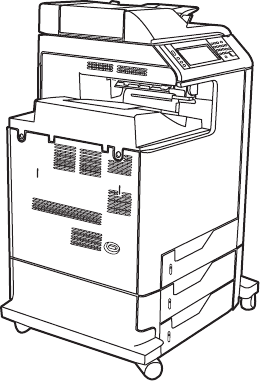
HP Color LaserJet 4730mfp series configurations
The HP Color LaserJet 4730mfp series is available in the following configurations.
HP Color LaserJet 4730mfp (Q7517A)
The HP Color LaserJet 4730mfp comes standard with the following items:
●100-sheet multipurpose input tray (tray 1)
●Three 500-sheet input trays
●Automatic document feeder (ADF) that holds up to 50 pages
●Duplexer
●HP Jetdirect embedded print server for connecting to a 10/100Base-T network
●256 megabytes (MB) synchronous dynamic random access memory (SDRAM)
●Hard drive
2 Chapter 1 Product information ENWW
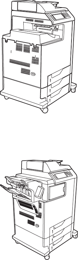
HP Color LaserJet 4730x mfp (Q7518A)
The HP Color LaserJet 4730x mfp has the same features as the base model and also includes an
analog fax accessory.
HP Color LaserJet 4730xs mfp (Q7519A)
The HP Color LaserJet 4730xs mfp has the same features as the base model and also includes the
following items:
●Analog fax accessory
●Stapler/stacker accessory
●Output accessory bridge
ENWW HP Color LaserJet 4730mfp series configurations 3
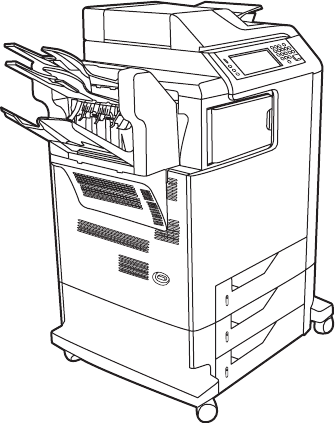
HP Color LaserJet 4730xm mfp (Q7520A)
The HP Color LaserJet 4730xm mfp has the same features as the base model and also includes the
following items:
●Analog fax accessory
●3-bin mailbox accessory
●Output accessory bridge
4 Chapter 1 Product information ENWW
Features and benefits of the MFP
The HP Color LaserJet 4730mfp series is designed to be shared by a workgroup. Use the MFP to
copy and print color and black-and-white documents or to digitally send color and black-and-white
documents. The MFP is a standalone copier that does not require connection to a computer. With
the optional HP LaserJet analog fax accessory 300 (included with some models), the MFP can also
send and receive faxes. Digital sending can be selected from the control panel.
Functions
●Two-sided printing and copying (duplexing)
●Image modification
●Color digital sending
●Document finishing
Speed and throughput
●Up to 31 pages per minute (ppm) when printing and copying on letter-size paper; up to 30 ppm
when printing and copying on A4-size paper
●25% to 400% scalability when using the scanner glass
●25% to 200% scalability when using the automatic document feeder (ADF)
●First page prints in less than 10 seconds
●Transmit Once, Raster Image Processing (RIP) ONCE technology
●Duty cycle of up to 85,000 pages per month
●533-megahertz (MHz) microprocessor
Resolution
●600 dots per inch (dpi) with Resolution Enhancement technology (REt)
●HP FastRes and HP Resolution Enhancement technology (REt) for 1200 by 1200 effective dpi
at full engine speed
Memory
●256 MB of random-access memory (RAM), expandable to 512 MB by using industry-standard
100-pin double data rate dual inline memory modules (DDR DIMMs)
●Memory Enhancement technology (MEt) that automatically compresses data to use RAM more
efficiently
User interface
●Graphic display on the control panel
●HP Easy Printer Care software (a Web-based status and troubleshooting tool)
ENWW Features and benefits of the MFP 5
●Internet-enabled supply-ordering capabilities using HP Easy Printer Care software
●Embedded Web server to gain access to support and to order supplies (for network-connected
products)
Language and fonts
●HP Printer Command Language (PCL) 6
●HP PCL 5e for compatibility
●Printer Management Language
●PDF
●XHTML
●80 scalable TrueType typefaces
●HP PostScript
®
3 emulation (PS)
Copying and sending
●Modes for text, graphics, and mixed text and graphics formats
●Job-interrupt feature (at copy boundaries)
●Multiple pages per sheet
●Operator attendance animations (for example, jam recovery)
●E-mail compatibility
●Energy-saving Sleep mode
●Automatic duplex (two-sided) scanning
Print cartridges
●Each print cartridge prints up to 12,000 pages at 5% coverage
●No-shake cartridge design
●Authentic HP print cartridge detection
●Automatic toner strip removal
Paper handling
●Input
●Tray 1 (multipurpose tray): A multipurpose tray for paper, transparencies, labels, and
envelopes. Holds up to 100 sheets of paper or 10 envelopes.
●Trays 2, 3, and 4: 500-sheet trays. These trays automatically detect standard paper sizes
up to legal and allow printing on custom-size paper.
●Automatic document feeder (ADF): Holds up to 50 sheets of paper.
6 Chapter 1 Product information ENWW

●Duplex printing and copying: Two-sided printing and copying (printing on both sides of
the paper).
●ADF duplex scanning: The ADF has an automatic duplexer for scanning two-sided
documents.
●Output
●Standard output bin: The standard output bin is located on the left side of the MFP. This
bin can hold up to 500 sheets of paper.
●ADF output bin: The ADF output bin is underneath the ADF input tray. The bin holds up to
50 sheets of paper, and the MFP automatically stops when this bin is full.
●Optional stapler/stacker: The stapler/stacker staples up to 30 sheets and stacks up to
500 sheets.
●Optional 3-bin mailbox: One bin stacks up to 500 sheets, and two bins stack up to
100 sheets each for a total capacity of 700 sheets.
Connectivity
●IEEE 1284C-compliant parallel connection
●Foreign Interface Harness (FIH) connection (AUX) for connecting other devices
●Local area network (LAN) connector (RJ-45) for the embedded HP Jetdirect print server
●Optional analog fax card
●Optional HP Digital Sending Software (DSS)
●Optional enhanced input/output (EIO) cards
●USB 2.0
●ACC port (accessory port with USB host capabilities)
●AUX port (auxiliary port for connecting third-party devices)
Environmental features
●The Sleep setting saves energy (meets ENERGY STAR
®
guidelines, Version 1.3).
NOTE See Protecting the environment on page 33 for more information.
Security features
●Foreign Interface Harness (FIH)
●Secure Disk Erase
●Security lock
●Job retention
●DSS authentication
ENWW Features and benefits of the MFP 7
Minimum system requirements for e-mail functionality
To use the e-mail functionality, the MFP must be connected to an IP-based network that has a
simple mail transfer protocol (SMTP) server. This server can either be on the local area network or at
an outside Internet service provider (ISP). HP recommends that the MFP be located on the same
local area network (LAN) as the SMTP server. If using an ISP, connect to the ISP by using a digital
subscriber line (DSL) connection. If obtaining e-mail services from an ISP, ask the ISP to provide the
correct SMTP address. Dial-up connections are not supported. If an SMTP server is not on the
network, third-party software is available that allows the creation of an SMTP server. However,
purchase and support of this software is the purchaser's responsibility.
8 Chapter 1 Product information ENWW
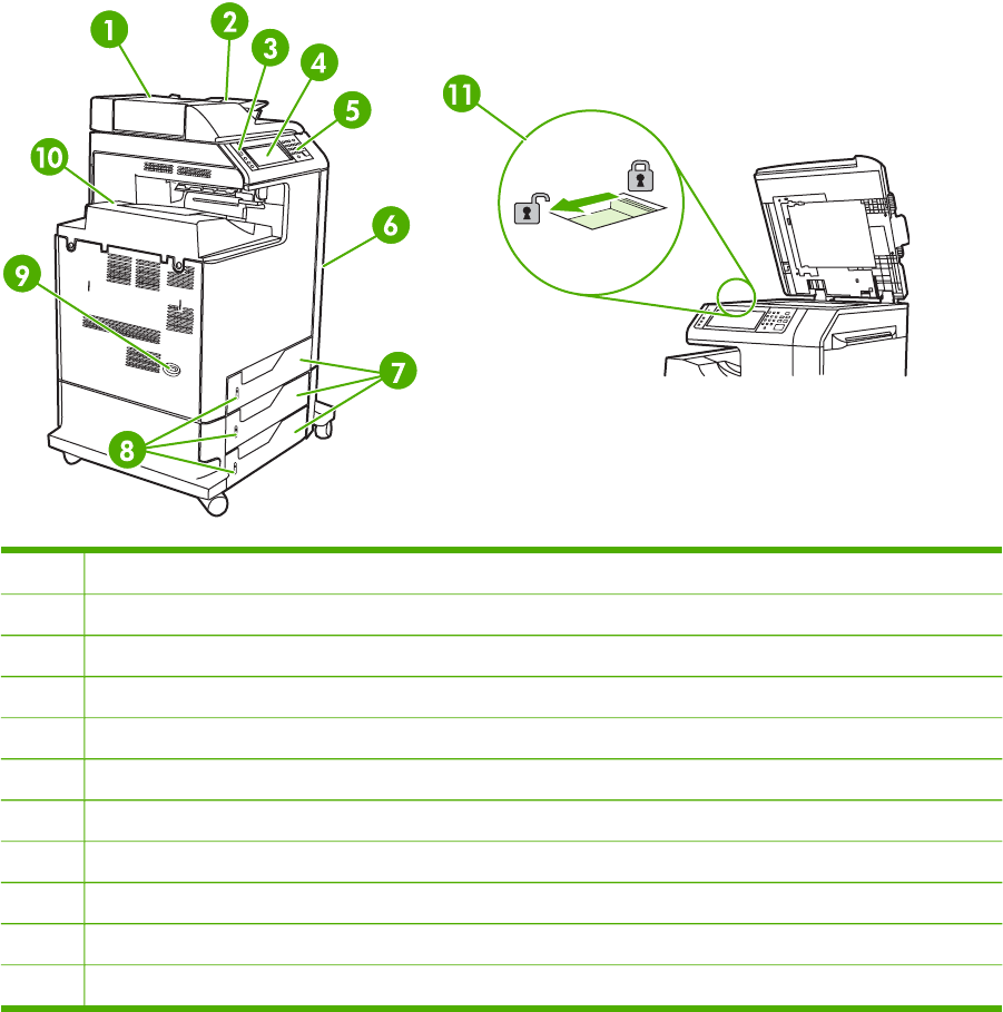
MFP parts and accessories
Before using the MFP, become familiar with the parts of the MFP.
MFP parts
1Automatic document feeder (ADF) top cover
2ADF input tray for copy/scan/fax originals
3Control panel status lights
4Control panel display with touch-screen functionality
5Control panel keypad
6Right-side covers (provides access to the print cartridges and other consumables)
7Trays 2, 3, and 4
8Paper level indicators
9On/off switch
10 Output bin
11 Scanner lock
ENWW MFP parts and accessories 9

1Output bin
2Interface ports
3On/off switch
4Power connection
10 Chapter 1 Product information ENWW
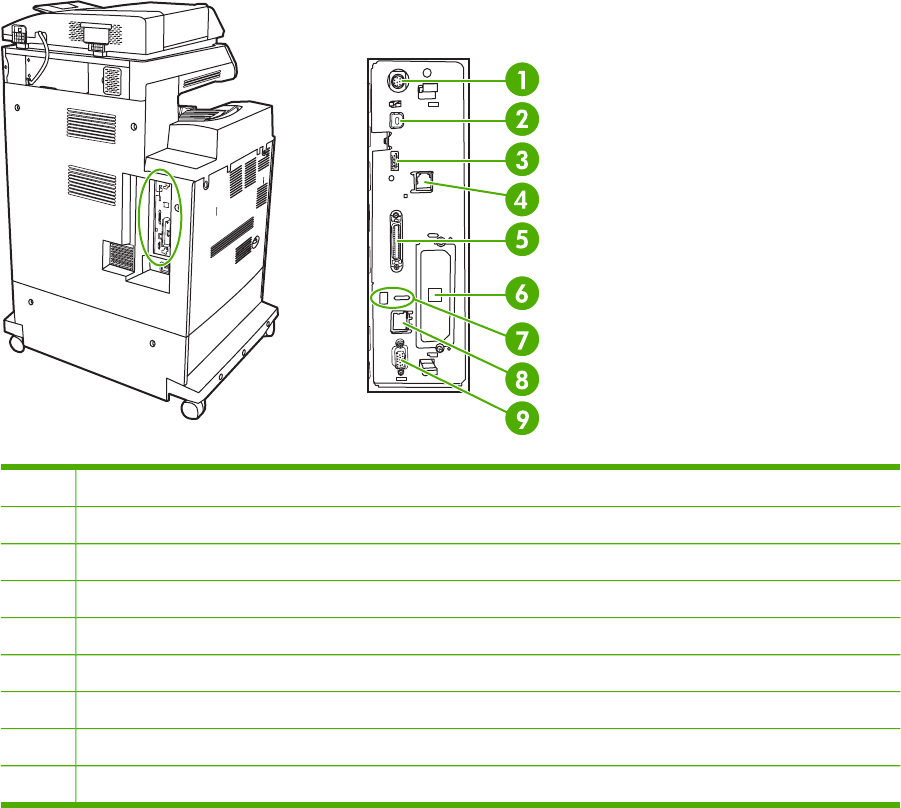
Interface ports
The MFP has eight ports for connecting to a computer or a network. The ports are at the left rear
corner of the MFP.
1Foreign interface harness (FIH)
2USB 2.0
3ACC (accessory port uses host USB protocol)
4Fax connection (for connecting to an optional analog fax accessory)
5Parallel port
6EIO interface expansion slot
7Access port for Kensington lock
8Network connection (embedded Jetdirect print server)
9AUX port
Model and serial numbers
The model numbers and serial numbers are located underneath the top cover, at the rear of the MFP.
ENWW MFP parts and accessories 11
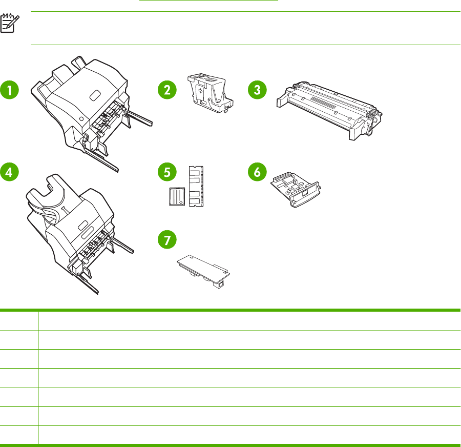
Accessories and supplies
Increase the capabilities of the MFP by adding optional accessories. For information about ordering
accessories and supplies, see Parts and supplies on page 43.
NOTE Use the accessories and supplies that have been specifically designed for the MFP in
order to ensure optimum performance.
1Stapler/stacker (Q7521A); includes an output accessory bridge
2Staple cartridge (C8091A)
3Print cartridge (four print cartridges) (Q6460A, Q6461A, Q6462A, and Q6463A)
43-bin mailbox (Q7523A); includes an output accessory bridge
5Memory DIMMS and flash memory cards
6 HP Jetdirect print server (EIO card)
7HP LaserJet analog fax accessory 300 (Q3701A)
12 Chapter 1 Product information ENWW

Parts compatibility with other HP LaserJet products
Some parts and accessories for this MFP are compatible with the HP Color LaserJet 4700. Table 1-1
Parts compatibility on page 13 indicates which parts and accessories can be installed on other
products. It also indicates which parts from other products are not compatible with this MFP.
Table 1-1 Parts compatibility
Part Description Product number HP Color
LaserJet 4700
Print cartridges Black (12,000 pages)
Cyan (12,000 pages)
Yellow (12,000 pages)
Magenta (12,000 pages)
Q6460A
Q6461A
Q6462A
Q6463A
No
No
No
No
DIMMs 128 MB DDR DIMM
256 MB DDR DIMM
512 MB DDR DIMM
Q7721A
Q7722A
Q7723A
Yes
Yes
Yes
HP Jetdirect EIO cards USB, serial, and LocalTalk
620n Fast Ethernet 10/100Base-TX
J4135A
J7934A
Yes
Yes
Hard disk J6054B No
Fuser kit 110 volt
220 volt
Q7502A
Q7503A
Yes
Yes
ETB kit Q7504A Yes
ADF maintenance kit Q5597A No
ENWW MFP parts and accessories 13

Moving the MFP
Before moving the MFP, be sure to lock the scanner. The scanner lock is underneath the scanner lid,
to the left of the scanner glass.
NOTE After moving the MFP, unlock the scanner. The MFP cannot initialize correctly when
the scanner is locked.
14 Chapter 1 Product information ENWW

Site requirements
Place the MFP on a level floor or sturdy surface, away from direct sunlight. Allow enough space
around the MFP to open the doors and trays.
Physical specifications
Table 1-2 Product dimensions
Product Height Depth Width Weight
1
HP Color LaserJet 4730mfp 1153 mm
(45.4 inches)
639 mm
(25.2 inches)
788 mm
(31 inches)
124 kg (273 lb)
HP Color LaserJet 4730x mfp 1153 mm
(45.4 inches)
639 mm
(25.2 inches)
788 mm
(31 inches)
124 kg (273 lb)
HP Color LaserJet 4730xs mfp 1153 mm
(45.4 inches)
639 mm
(25.2 inches)
1106 mm
(43.5 inches)
136 kg (298 lb)
HP Color LaserJet 4730xm mfp 1153 mm
(45.4 inches)
639 mm
(25.2 inches)
1106 mm
(43.5 inches)
136 kg (298 lb)
1
Without print cartridge
Table 1-3 Product dimensions
Product Width Depth Height
HP Color LaserJet 4730mfp 788 mm (31 inches) 639 mm (25.2 inches) 1153 mm (45.4 inches)
HP Color LaserJet 4730x mfp 788 mm (31 inches) 639 mm (25.2 inches) 1153 mm (45.4 inches)
HP Color LaserJet 4730xs mfp 1106 mm (43.5 inches) 639 mm (25.2 inches) 1153 mm (45.4 inches)
HP Color LaserJet 4730xm mfp 1106 mm (43.5 inches) 639 mm (25.2 inches) 1153 mm (45.4 inches)
Environmental specifications
Table 1-4 Environmental specifications
Environmental condition Recommended Allowed Storage/standby
Temperature (MFP and print
cartridge)
17° to 25°C (62.6° to 77°F) 15° to 30°C (59° to 78°F) -20° to 40°C (-4° to 104°F)
Relative humidity 30% to 70% relative
humidity (RH)
10% to 80% RH 10% to 90%
Altitude N/A 0 meters (0 feet) to 2600
meters (8530 feet)
N/A
ENWW Site requirements 15

MFP specifications
Electrical specifications
WARNING! Power requirements are based on the country/region where the MFP is sold. Do
not convert operating voltages. This can damage the MFP and void the product warranty.
Table 1-5 Power requirements
Specification 110-volt models 230-volt models
Power requirements 110 to 127 volts (± 10%)
50/60 Hz (± 2 Hz)
220 to 240 volts (± 10%)
50/60 Hz (± 2 Hz)
Rated current 9.0 Amps 4.5 Amps
Table 1-6 Power consumption (average, in watts)
Product model
1
,
2
Copying
3
Printing
3
Ready
4
,
6
On
5
Off
HP Color LaserJet 4730mfp 615 W 604 W 83 W 24 W 0.5 W
HP Color LaserJet 4730x mfp 615 W 604 W 83 W 24 W 0.5 W
HP Color LaserJet 4730xs mfp 615 W 604 W 83 W 24 W 0.5 W
HP Color LaserJet 4730xm mfp 640 W 626 W 86 W 25 W 0.5 W
1
Values subject to change. See http://www.hp.com/support/clj4730mfp for current information.
2
Power numbers are the highest values measured using all standard voltages.
3
HP Color LaserJet 4730mfp printing and copying speeds are 31 ppm letter size and 30 ppm A4 size.
4
Default time from Ready mode to Sleep mode is 45 minutes.
5
Recovery time from Sleep mode to start of printing is less than 20 seconds.
6
Heat dissipation in Ready mode = 288 BTU/hour.
16 Chapter 1 Product information ENWW

Acoustic specifications
Table 1-7 Sound power and pressure level
1
(Product Name: X)
Sound power level Declared per ISO 9296
Printing
2
L
WAd
= 6.7 Bels (A) [67 dB(A)]
Copying
3
L
WAd
= 6.8 Bels (A) [68 dB(A)]
Ready L
WAd
= 5.8 Bels (A) [58 dB(A)]
Sound pressure level Declared per ISO 9296
Printing
2
L
pAm
=50 dB (A)
Copying
3
L
pAm
=52 dB (A)
Ready L
pAm
=37 dB (A)
1
Values subject to change. See http://www.hp.com/support/clj4730mfp for current information.
2
HP Color LaserJet 4730mfp series speed is 30 ppm A4 size. Configuration tested (HP Color LaserJet 4730mfp): Base
model, simplex printing with A4 paper size.
3
Configuration tested (HP Color LaserJet 4730mfp): Base model, simplex copying from ADF with A4 paper size.
Image area
The MFP can place printed or copied images on the page within the following margins:
●Printing: 4.23 mm (0.17 inches) from each edge
●Copying (standard): 4.23 mm (0.17 inches) from each edge
NOTE Margins vary when using digital sending. The margins depend on the type of file
being sent and its dpi resolution.
Skew specifications
The MFP has the following skew specifications:
●Print engine (cut-sheet paper; simplex and duplex): less than 1.5 mm (0.06 inches) over a 260
mm (10.24 inches) length
●Print engine (envelopes): less than 3.3 mm (0.13 inches) over a 220 mm (8.66 inches) length
●ADF and scanner glass (cut-sheet paper): less than 0.6%
ENWW MFP specifications 17

Media specifications
This section provides comprehensive information on supported media types.
Category Specifications
Acid content 5.5 pH to 8.0 pH
Caliper 0.094 mm (3.0 to 7.0 mils)
Curl in ream Flat within 5 mm (0.02 inches)
Cut edge conditions Cut with sharp blades that create no visible fray
Fusing compatibility Must not scorch, melt, offset, or release hazardous
emissions when heated to 200°C (392°F) for 0.1 second
Grain Long grain
Moisture content 3% to 9% by weight
Smoothness 100 to 250 Sheffield
Printing and paper storage environment
Ideally, the printing and paper storage environment should be at or near room temperature, and not
too dry or too humid. Remember that paper is hygroscopic; it absorbs and loses moisture rapidly.
Heat works with humidity to damage paper. Heat causes the moisture in paper to evaporate, while
cold causes it to condense on the sheets. Heating systems and air conditioners remove most of the
humidity from a room. As paper is opened and used, it loses moisture, causing streaks and
smudging. Humid weather or water coolers can cause the humidity to increase in a room. As paper is
opened and used it absorbs any excess moisture, causing light print and dropouts. Also, as paper
loses and gains moisture it can distort. This can cause jams.
As a result, paper storage and handling are as important as the paper-making process itself. Paper
storage environmental conditions directly affect the feed operation.
Care should be taken not to purchase more paper than can be easily used in a short time (about
3 months). Paper stored for long periods might experience heat and moisture extremes, which can
cause damage. Planning is important to prevent damage to a large supply of paper.
Unopened paper in sealed reams can remain stable for several months before use. Opened
packages of paper have more potential for environmental damage, especially if they are not wrapped
with a moisture-proof barrier.
The paper storage environment should be properly maintained to ensure optimum MFP
performance. The required condition is 20° to 24°C (68° to 75°F), with a relative humidity of
45% to 55%. The following guidelines should be helpful when evaluating the paper storage
environment:
●Paper should be stored at or near room temperature.
●The air should not be too dry or too humid (due to the hygroscopic properties of paper).
●The best way to store an opened ream of paper is to rewrap it tightly in its moisture-proof
wrapping. If the MFP environment is subject to extremes, unwrap only the amount of paper to
be used during the day's operation to prevent unwanted moisture changes.
18 Chapter 1 Product information ENWW

Envelopes
Envelope construction is critical. Envelope fold lines can vary considerably, not only between
manufacturers, but also within a box from the same manufacturer. Successful printing on envelopes
depends upon the quality of the envelopes. When selecting envelopes, consider the following
components:
●Weight: The weight of the envelope paper should not exceed 105 g/m
2
(28 lb) or jamming might
occur.
●Construction: Prior to printing, envelopes should lie flat with less than 6 mm (0.25 inches) curl,
and should not contain air.
●Condition: Envelopes should not be wrinkled, nicked, or otherwise damaged.
●Temperature: Use envelopes that are compatible with the heat and pressure of the MFP.
●Size: Use only envelopes that are within the following size ranges:
●Minimum: 76 x 127 mm (3 x 5 inches)
●Maximum: 216 x 356 mm (8.5 x 14 inches)
NOTE Use only tray 1 to print on envelopes. Some jams might occur when using any media
with a length less than 178 mm (7 inches). This might be caused by paper that has been
affected by environmental conditions. For optimum performance, make sure to store and
handle the paper correctly. Select envelopes in the printer driver.
ENWW Media specifications 19
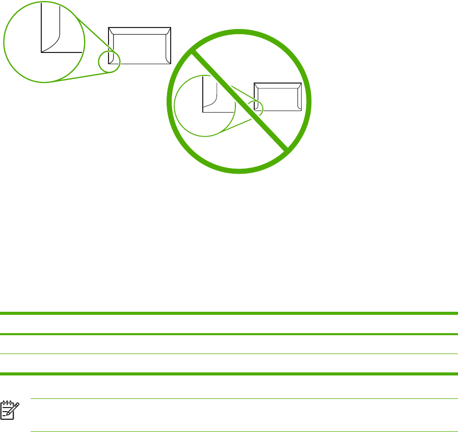
Envelopes that have double side seams
Double side-seam construction has vertical seams at both ends of the envelope rather than diagonal
seams. This style might be more likely to wrinkle. Be sure that the seam extends all the way to the
corner of the envelope, as illustrated.
Envelopes that have adhesive strips or flaps
Envelopes that have a peel-off adhesive strip or with more than one flap that folds over to seal must
use adhesives that are compatible with the heat and pressure in the MFP. The extra flaps and strips
might cause wrinkling, creasing, or jams, and might even damage the fuser.
Envelope margins
The following table shows typical address margins for a commercial #10 or DL envelope.
Type of address Top margin Left margin
Return address 15 mm (0.6 inches) 15 mm (0.6 inches)
Delivery address 51 mm (2 inches) 89 mm (3.5 inches)
NOTE For the best print quality, position margins no closer than 15 mm (0.6 inches) from the
edges of the envelope. Avoid printing over the area where the envelope seams meet.
Envelope storage
Proper storage of envelopes helps contribute to print quality. Envelopes should be stored flat. If air is
trapped in an envelope, creating an air bubble, then the envelope might wrinkle during printing.
20 Chapter 1 Product information ENWW

Labels
CAUTION To avoid damaging the MFP, use only labels that are recommended for use in
laser printers. Never print on the same sheet of labels more than once or print on a partial
sheet of labels.
Label construction
When selecting labels, consider the quality of each component:
●Adhesives: The adhesive material should be stable at 200°C (392°F), the MFP's fusing
temperature.
●Arrangement: Only use labels that have no exposed backing between them. Labels can peel
off sheets that have spaces between the labels, causing serious jams.
●Curl: Prior to printing, labels must lie flat with no more than 13 mm (0.5 inches) of curl in any
direction.
●Condition: Do not use sheets of labels that have wrinkles, bubbles, or other indications of
separation.
NOTE Select labels in the printer driver.
Transparencies
Transparencies used in the MFP must be able to withstand 200°C (392°F), the MFP's fusing
temperature.
CAUTION To avoid damaging the MFP, use only transparencies recommended for use in
HP LaserJet printers, such as HP-brand transparencies.
NOTE Select transparencies in the printer driver.
ENWW Media specifications 21

Supported types and sizes of print media
The following table lists the types of media that the MFP supports.
Table 1-8 Supported types of media
Type of media Tray 1 Trays 2, 3, and 4 Duplexer 3-bin mailbox
or stacker
Stapler
Plain X X X X X
Preprinted X X X X X
Letterhead X X X X X
Transparency X X X
Prepunched X X X X X
Labels X X X
Bond X X X X X
Recycled X X X X X
Color X X X X X
Cardstock X X
12
Rough X X X X X
Envelope X X
12
1
Face-down delivery only.
2
If a 3-bin mailbox is installed, select the bottom bin when printing on cardstock. Media weights that are 200 g/m
2
(53 lb) or
heavier are supported only in the bottom bin.
Table 1-9 Tray 1 media sizes
Tray 1 Dimensions Weight or thickness Capacity
Paper and cardstock,
standard sizes (letter/A4,
legal, executive, JIS B5, A5);
custom sizes
Range:
76 x 127 mm (3 x 5 inches) to
216 x 356 mm (8.5 x 14 inches)
Range:
60 g/m
2
(16 lb) bond to
220 g/m
2
(60 lb) bond
Maximum stack height:
10 mm (0.6 inches)
Equivalent to 100 sheets
of 75 g/m
2
(20 lb) bond
Glossy paper (letter/A4,
legal, executive, JIS B5, A5)
NOTE Do not use
inkjet papers in this
MFP.
Range:
76 x 127 mm (3 x 5 inches) to
216 x 356 mm (8.5 x 14 inches)
Range:
75 g/m
2
(20 lb) bond to
220 g/m
2
(60 lb) bond
Maximum stack height:
10 mm (0.6 inches)
Transparencies (letter/A4),
suitable for use in color laser
printers
Letter: 216 x 279 mm
(8.5 x 11 inches)
A4: 210 x 297 mm
(8.27 x 11.7 inches)
Minimum 0.13 mm
(0.005 inches) thick
Maximum stack height:
10 mm (0.6 inches)
HP Tough paper (letter/A4) Letter: 216 x 279 mm
(8.5 x 11 inches)
0.13 mm (0.005 inches) thick Maximum stack height:
10 mm (0.6 inches)
22 Chapter 1 Product information ENWW

Tray 1 Dimensions Weight or thickness Capacity
A4: 210 x 297 mm
(8.27 x 11.7 inches)
HP Color Laser Glossy
Photo Paper (letter/A4)
NOTE Do not use
inkjet papers in this
MFP.
Letter: 216 x 279 mm
(8.5 x 11 inches)
A4: 210 x 297 mm
(8.27 x 11.7 inches)
220 g/m
2
(60 lb) bond Maximum stack height:
10 mm (0.6 inches)
Envelopes (Com 10,
Monarch, C5, DL, B5)
Range:
60 g/m
2
(16 lb) bond to 90 g/
m
2
(24 lb) bond
20 envelopes
Labels (letter/A4, legal,
executive, JIS B5, A5),
suitable for use in color laser
printers
Range:
76 x 127 mm (3 x 5 inches) to
216 x 356 mm (8.5 x 14 inches)
Maximum 0.23 mm
(0.009 inches) thick
Maximum stack height:
10 mm (0.6 inches)
Table 1-10 Tray 2, 3, and 4 media sizes
1
Trays 2, 3, and 4 Dimensions Weight or thickness Capacity
Paper, standard sizes (letter/
A4, legal, executive, JIS B5,
A5); custom sizes
Range:
148 x 210 mm
(5.83 x 8.27 inches) to
216 x 356 mm
(8.5 x 14 inches)
Range:
60 g/m
2
(16 lb) bond to
120 g/m
2
(32 lb) bond
Maximum stack height:
56 mm (2.2 inches)
Equivalent to 530 sheets of
75 g/m
2
(20 lb) bond
Glossy paper (letter/A4,
legal, executive, JIS B5, A5)
NOTE Do not use
inkjet papers in this
MFP.
Range:
148 x 210 mm
(5.83 x 8.27 inches) to
216 x 356 mm
(8.5 x 14 inches)
Range:
75 g/m
2
(20 lb) bond to
120 g/m
2
(32 lb) bond
Maximum stack height:
56 mm (2.2 inches)
HP Color Laser Glossy
Photo & Imaging Paper
(letter/A4)
NOTE Do not use
inkjet papers in this
MFP.
Letter: 216 x 279 mm
(8.5 x 11 inches)
A4: 210 x 297 mm
(8.27 x 11.7 inches)
120 g/m
2
(32 lb) bond Maximum stack height:
56 mm (2.2 inches)
Transparencies (letter/A4),
suitable for use in color laser
printers
Letter: 216 x 279 mm
(8.5 x 11 inches)
A4: 210 x 297 mm
(8.27 x 11.7 inches)
Minimum:
0.13 mm (0.005 inches) thick
Maximum stack height:
56 mm (2.2 inches)
HP Tough Paper (letter/A4) Letter: 216 x 279 mm
(8.5 x 11 inches)
A4: 210 x 297 mm
(8.27 x 11.7 inches)
Maximum:
0.13 mm (0.005 inches) thick
Maximum stack height:
56 mm (2.2 inches)
Table 1-9 Tray 1 media sizes (continued)
ENWW Media specifications 23

Trays 2, 3, and 4 Dimensions Weight or thickness Capacity
Labels (letter/A4 and custom
sizes), suitable for use in
color laser printers
Range:
148 x 210 mm
(5.83 x 8.27 inches) to
216 x 356 mm
(8.5 x 14 inches)
Maximum:
0.13 mm (0.005 inches) thick
Maximum stack height:
56 mm (2.2 inches)
1
Trays 2, 3, and 4 use custom sizes specifically for B5 ISO. These trays do not support the range of custom sizes that can
be used in tray 1.
Table 1-11 Automatic duplex printing (two-sided printing)
Automatic duplex printing Dimensions Weight or thickness
Paper Standard sizes:
Letter: 216 x 279 mm
(8.5 x 11 inches)
A4: 210 x 297 mm
(8.27 x 11.7 inches)
8.5 x 13: 216 x 330.2 mm
(8.5 x 13 inches)
Legal: 216 x 356 mm
(8.5 x 14 inches)
Executive:
184.2 x 266.7 mm
(7.25 x 10.5 inches)
JIS B5: 182 x 257 mm
(7.17 x 10.12 inches)
Range:
60 g/m
2
(16 lb) bond to
120 g/m
2
(32 lb) bond
Glossy paper (A4/letter,
13 x 8.5 in, legal, executive,
JIS B5)
NOTE Do not use
inkjet papers in this
MFP.
See above for standard
sizes supported
Range:
75 g/m
2
(20 lb) bond to
120 g/m
2
(32 lb) bond
HP Color Laser Glossy
Photo & Imaging Paper (A4/
letter)
NOTE Do not use
inkjet papers in this
MFP.
Standard sizes:
Letter: 216 x 279 mm
(8.5 x 11 inches)
A4: 210 x 297 mm
(8.27 x 11.7 inches)
120 g/m
2
(32 lb) bond
Table 1-12 Optional 3-bin mailbox or stacker part of the stapler/stacker supported sizes
Size Dimensions
1
Weight Capacity
2
Letter 216 x 279 mm
(8.5 x 11 inches)
For plain media: 60 g/m
2
(16 lb) to 120 g/m
2
(32 lb)
For the stacker on the
stapler/stacker or the lower
Table 1-10 Tray 2, 3, and 4 media sizes (continued)
24 Chapter 1 Product information ENWW

Size Dimensions
1
Weight Capacity
2
For thick media: 128 g/m
2
(34 lb) to 199 g/m
2
(53 lb)
bin on the 3-bin mailbox:
500 sheets of 75 g/m
2
(20 lb) paper.
For the top two bins on the 3-
bin mailbox: each can hold
100 sheets of 75 g/m
2
(20 lb) paper.
A4 210 x 297 mm
(8.27 x 11.7 inches)
Executive 184.2 x 266.7 mm
(7.25 x 10.5 inches)
Legal 216 x 356 mm
(8.5 x 14 inches)
B5 (JIS) 182 x 257 mm
(7.17 x 10.12 inches)
A5 148 x 210 mm
(5.8 x 8.3 inches)
Statement 140 x 216 mm
(5.5 x 8.5 inches)
8.5x13 216 x 330 mm
(8.5 x 13 inches)
Executive (JIS) 216 x 330 mm
(8.5 x 13 inches)
DPostcard (JIS) 148 x 200 mm
(5.8 x 7.9 inches)
16K 197 x 273 mm
(7.75 x 10.75 inches)
Envelope #10
1
105 x 241 mm
(4.1 x 9.5 inches)
Envelope Monarch #7
1
98 x 191 mm
(3.9 x 7.5 inches)
Envelope C5 ISO
1
162 x 229 mm
(6.4 x 9.0 inches)
Envelope DL ISO
1
110 x 220 mm
(4.3 x 8.7 inches)
Envelope B5 ISO
1
176 x 250 mm
(6.7 x 9.8 inches)
Custom Minimum: 76 x 127 mm
(3 x 5 inches)
Maximum: 216 x 356 mm
(8.5 x 14 inches)
Table 1-12 Optional 3-bin mailbox or stacker part of the stapler/stacker supported sizes (continued)
ENWW Media specifications 25

Size Dimensions
1
Weight Capacity
2
Cardstock, transparencies,
and labels are supported
only in the third bin of the 3-
bin mailbox.
1
The MFP supports a wide range of sizes. Check the MFP software for supported sizes.
2
Capacity can vary depending on paper weight and thickness, as well as environmental conditions.
3
Face-down delivery only.
Table 1-13 Stapler part of the optional stapler/stacker supported sizes
Size Dimensions Weight Capacity
Letter 216 x 279 mm
(8.5 x 11 inches)
For plain media: 60 g/m
2
(16 lb) to 120 g/m
2
(32 lb)
For thick media: 128 g/m
2
(34 lb) to 199 g/m
2
(53 lb)
For plain media: 30 sheets
of 75 g/m
2
(20 lb) paper.
For glossy media: 20 sheets
For thick media: the stack
height must not exceed
7 mm (0.27 inches)
A4 210 x 297 mm
(8.27 x 11.7 inches)
Legal 216 x 356 mm
(8.5 x 14 inches)
8.5x13 216 x 330 mm
(8.5 x 13 inches)
Executive(JIS) 216 x 330 mm
(8.5 x 13 inches)
Table 1-12 Optional 3-bin mailbox or stacker part of the stapler/stacker supported sizes (continued)
26 Chapter 1 Product information ENWW

Printing on special media
Use these guidelines when printing on special types of media.
NOTE Special media such as envelopes, transparencies, custom-size media, or heavy
media greater than 120 g/m
2
should only be used in Tray 1.
To print on any special media, use the following procedure:
1. Load the media in Tray 1.
2. When the MFP prompts you for the paper type, select the correct media type for the media
loaded in the tray. For example, select PHOTO GLOSS when loading HP Color LaserJet Glossy
Photo Paper.
3. In the software application or the printer driver, set the media type to match the media type that
is loaded in the media tray.
NOTE For the best print quality, always verify that the media type selected on the MFP
control panel and the media type selected in the application or printer driver match the type of
media loaded in the tray.
Transparencies
When printing on transparencies, use the following guidelines:
●Handle transparencies using the edges. Oils from your fingers deposited on the transparency
can cause print quality problems.
●Use only overhead transparencies recommended for use in this MFP. Hewlett-Packard
recommends using HP Color LaserJet Transparencies. HP products are designed to work
together for optimum printing results.
●In either the software application or the driver, select TRANSPARENCY as the media type, or
print from a tray that is configured for transparencies.
CAUTION Transparencies not designed for HP Color LaserJet printing might melt in the
printer or wrap around the fuser, causing damage to the MFP.
Glossy paper
●In either the software application or the driver, select GLOSSY, HEAVY GLOSSY, or
INTERMEDIATE90-104 as the media type, or print from a tray that is configured for glossy paper.
●Use the control panel to set the media type to GLOSSY for the input tray being used.
●Because this affects all print jobs, it is important to return the MFP to its original settings once
the job has printed.
NOTE Hewlett-Packard recommends using HP Color LaserJet Glossy Photo Paper and soft
glossy papers designed for use in HP Color LaserJet printers. HP products are designed to
work together for optimum printing results. If other types of glossy media are used, print
quality could be compromised.
ENWW Printing on special media 27

Colored paper
●Colored paper should be of the same high quality as white xerographic paper.
●Pigments used in colored media must be able to withstand the MFP’s fusing temperature of 190°
C (374°F) for 0.1 second without deterioration.
●The MFP creates colors by printing patterns of dots, overlaying and varying their spacing to
produce various colors. Varying the shade or color of the paper will affect the shades of the
printed colors.
Envelopes
NOTE Envelopes can be printed only from Tray 1. Set the tray’s media size to the specific
envelope size.
Adhering to the following guidelines will help ensure proper printing on envelopes and help prevent
paper jams:
●Do not load more than 20 envelopes into Tray 1.
●The weight rating of envelopes should not exceed 90 g/m
2
(24 lb bond).
●Envelopes should be flat.
●Do not use envelopes with windows or clasps.
●Envelopes must not be wrinkled, nicked, or otherwise damaged.
●Envelopes with peel-off adhesive strips must use adhesives that can withstand the heat and
pressures of the MFP’s fusing process.
●Envelopes should be loaded face-down and with the postage end feeding into the MFP first.
Labels
NOTE For printing labels, set the tray’s media type to LABELS in the MFP control panel.
When printing labels, use the following guidelines:
●Verify that the labels’ adhesive material can tolerate temperatures of 190°C (374°F) for
0.1 second.
●Verify that there is no exposed adhesive material between the labels. Exposed areas can cause
labels to peel off during printing, which can cause paper jams. Exposed adhesive can also
cause damage to MFP components.
●Do not re-feed a sheet of labels.
●Verify that the labels lie flat.
●Do not use labels that are wrinkled, bubbled, or otherwise damaged.
28 Chapter 1 Product information ENWW

Heavy paper
The following heavy paper types can be used with the HP Color LaserJet 4730mfp series MFP.
Table 1-14 Supported heavy paper types
Paper type Paper weight
Heavy and extra-heavy stock 105-163 g/m
2
(28-43 lb)
Cardstock 164-220 g/m
2
(43-58 lb)
Intermediate 90-105 g/m
2
(24-28 lb)
HP Tough paper 5 mil
When printing on heavy paper types, use the following guidelines:
●Use Tray 1 for paper that is heavier than 120 g/m
2
(32 lb).
●For optimum results when printing on heavy paper, use the MFP control panel to set the media
type for the tray to the appropriate paper type listed in Table 1-14 Supported heavy paper types
on page 29.
●In either the software application or the driver, select the appropriate paper type as the media
type, or print from a tray that is configured for heavy paper.
●Because this setting affects all print jobs, it is important to return the MFP back to its original
settings once the job has printed.
CAUTION In general, do not use paper that is heavier than the media specification
recommended for this MFP. Doing so can cause misfeeds, paper jams, reduced print quality,
and excessive mechanical wear.
HP LaserJet Tough paper
When printing on HP LaserJet Tough paper, use the following guidelines:
●Handle HP LaserJet Tough paper only by the edges. Oils from your fingers deposited on
HP LaserJet Tough paper can cause print quality problems.
●Use only HP LaserJet Tough paper with this MFP. HP products are designed to work together
for optimum printing results.
●In either the software application or the driver, select TOUGH PAPER as the media type, or
print from a tray that is configured for HP LaserJet Tough paper.
Preprinted forms and letterhead
Observe the following guidelines for best results with preprinted forms and letterhead:
●Forms and letterhead must be printed with heat-resistant inks that will not melt, vaporize, or
release undesirable emissions when subjected to the MFP’s fusing temperature of
approximately 190°C (374°F) for 0.1 second.
●Inks must be non-flammable and should not adversely affect any printer rollers.
ENWW Printing on special media 29

●Forms and letterhead should be sealed in a moisture-proof wrapping to prevent changes during
storage.
●Before loading preprinted paper such as forms and letterhead, verify that the ink on the paper is
dry. During the fusing process, wet ink can come off of preprinted paper.
●To load pre-printed forms and letterhead into Tray 1, load them face down with the top edge of
the page facing toward you.
●To load pre-printed forms and letterhead into Tray 2 or an optional tray, load them face up with
the top edge of the page facing away from you.
●When duplex printing, load pre-printed forms and letterhead into Tray 2 or an optional 500-sheet
tray face down with the top edge of the page towards you.
Recycled paper
This MFP supports the use of recycled paper. Recycled paper must meet the same specifications as
standard paper. Hewlett-Packard recommends that recycled paper contain no more than 5% ground
wood.
Weight equivalence table
The weight equivalence table shows equivalent weights for different grades of paper. A boldface type
value indicates a commonly available standard weight for that grade.
NOTE Text and book grades marked with an asterisk (*) actually calculate to 51, 61, 71, and
81 but are rounded to standard book or text weights of 50, 60, 70, and 80.
Table 1-15 Weight equivalence table
Bond weight Text/Book
weight
Cover weight Bristol weight Index weight Tag weight Metric weight
16 41 22 27 33 37 60 g/m
2
17 43 24 29 35 39 64 g/m
2
20 50* 28 34 42 46 75 g/m
2
21 54 30 36 44 49 80 g/m
2
24 60* 33 41 50 55 90 g/m
2
27 68 37 45 55 61 100 g/m
2
28 70* 39 49 58 65 105 g/m
2
29 74 41 50 61 68 110 g/m
2
32 80* 44 55 67 74 120 g/m
2
36 90 50 62 75 83 135 g/m
2
39 100 55 67 82 91 148 g/m2
40 101 55 68 83 92 150 g/m
2
43 110 60 74 90 100 163 g/m2
45 115 63 77 94 104 170 g/m
2
30 Chapter 1 Product information ENWW

Bond weight Text/Book
weight
Cover weight Bristol weight Index weight Tag weight Metric weight
47 119 65 80 97 108 176 g/m2
51 128 70 86 105 117 190 g/m
2
53 134 74 90 110 122 199 g/m
2
54 137 75 93 113 125 203 g/m
2
58 146 80 98 120 133 216 g/m
2
65 165 90 111 135 150 244 g/m
2
66 169 92 114 138 154 250 g/m
2
67 171 94 115 140 155 253 g/m
2
70 178 98 120 146 162 264 g/m
2
72 183 100 123 150 166 271 g/m
2
Table 1-15 Weight equivalence table (continued)
ENWW Printing on special media 31

Regulatory information
FCC and Telecom regulations
FCC regulations
This equipment has been tested and found to comply with the limits for a Class A digital device,
pursuant to Part 15 of the FCC Rules. These limits are designed to provide reasonable protection
against harmful interference when the equipment is operated in a commercial environment. This
equipment generates, uses and can radiate radio frequency energy and, if not installed and used in
accordance with the instruction manual, may cause harmful interference to radio communications.
Operation of this equipment in a residential area is likely to cause harmful interference, in which case
the user will be required to correct the interference at his own expense. The end user of this product
should be aware that any changes or modifications made to this equipment without the approval of
Hewlett-Packard could result in the product not meeting the Class A limits, in which case the FCC
could void the user's authority to operate the equipment.
NOTE Any changes or modifications to the MFP that are not expressly approved by HP
could void the user’s authority to operate this equipment.
Telecom
This product is intended to be connected to the analog Public Switched Telecommunication
Networks (PSTN) of European Economic Area (EEA) countries/regions. It meets requirements of EU
R Directive 1999/5/EC (Annex II) and carries appropriate CE conformity marking. For more details
see the Declaration of conformity (HP Color LaserJet 4730mfp) on page 39 issued by the
manufacturer.
However, due to differences between individual national PSTNs, the product may not guarantee
unconditional assurance of successful operation on every PSTN termination point. Network
compatibility depends on the correct setting being selected by the customer in preparation of its
connection to the PSTN. Please follow the instructions provided in the user manual. If you
experience network compatibility issues, please contact your equipment supplier or Hewlett-Packard
help desk in the country/region of operation.
Connecting to a PSTN termination point may be the subject of additional requirements set out by the
local PSTN operator.
32 Chapter 1 Product information ENWW

Environmental Product Stewardship program
Protecting the environment
Hewlett-Packard Company is committed to providing quality products in an environmentally sound
manner. This product has been designed with several attributes to minimize impacts on our
environment.
Ozone production
This product generates no appreciable ozone gas (O
3
).
Energy consumption
Power usage drops significantly while in Sleep mode, which saves natural resources and saves
money without affecting the high performance of this product. This product qualifies for ENERGY
STAR
®
(Multifunctional devices, Version 3.0), which is a voluntary program to encourage the
development of energy-efficient office products.
ENERGY STAR
®
and the ENERGY STAR mark are U.S. registered service marks. As an ENERGY
STAR partner, Hewlett-Packard Company has determined that this product meets ENERGY STAR
Guidelines for energy efficiency. For more information, see http://www.energystar.gov.
Paper use
This product's automatic duplex feature (two-sided printing) and n-up printing (multiple pages printed
on one page) capabilities can reduce media usage and the resulting demands on natural resources.
Plastics
Plastic parts over 25 grams are marked according to international standards that enhance the ability
to identify plastics for recycling purposes at the end of the product's life.
HP LaserJet printing supplies
It is easy to return and recycle your empty HP LaserJet print cartridges—free of charge—with
HP Planet Partners. HP is committed to providing inventive, high-quality products and services that
are environmentally sound, from product design and manufacturing to distribution, operation and
recycling processes. We ensure your returned HP LaserJet print cartridges are recycled properly,
processing them to recover valuable plastics and metals for new products and diverting millions of
tons of waste from landfills. Since this cartridge is being recycled and used in new materials, it will
not be returned to you. Your empty HP LaserJet print cartridges are recycled responsibly when you
participate in the HP Planet Partners program. Thank you for being environmentally responsible!
HP Printing Supplies Returns and Recycling Program Information
In many countries/regions, this product’s printing supplies (print cartridges, fuser, and transfer unit)
can be returned to HP through the HP Printing Supplies Returns and Recycling Program. An easy-to-
use and free takeback program is available in over 35 countries/regions. Multilingual program
ENWW Regulatory information 33

information and instructions are included in every new HP LaserJet print cartridge and supplies
package.
Since 1992, HP has offered HP LaserJet supplies return and recycling free of charge. In 2004,
HP Planet Partners for LaserJet Supplies was available in 85% of the world market where
HP LaserJet supplies are sold. Postage-paid and pre-addressed labels are included within the
instruction guide in most HP LaserJet print cartridge boxes. Labels and bulk boxes are also available
through the Web site at http://www.hp.com/recycle.
Use the label to return empty, original HP LaserJet print cartridges only. Please do not use this label
for non-HP cartridges, refilled or remanufactured cartridges, or warranty returns. Printing supplies or
other objects inadvertently sent to the HP Planet Partners program cannot be returned.
More than 10 million HP LaserJet print cartridges were recycled globally in 2004 through the
HP Planet Partners supplies recycling program. This record number represents 26 million pounds of
print cartridge materials diverted from landfills. Worldwide, in 2004, HP recycled an average of 59%
of the print cartridge by weight consisting primarily of plastic and metals. Plastics and metals are
used to make new products such as HP products, plastic trays and spools. The remaining materials
are disposed of in an environmentally responsible manner.
Paper
This product is capable of using recycled papers according to EN 12281:2002. HP recommends the
use of recycled papers that contain not more than 5% ground wood, such as HP Office Recycled
paper.
Material restrictions
This HP product contains mercury in the fluorescent lamp of the control panel liquid crystal display
that might require special handling at end of life.
●U.S. returns For a more environmentally responsible return of used cartridges and supplies, HP
encourages the use of bulk returns. Simply bundle two or more cartridges together and use the
single, pre-paid, and pre-addressed UPS label that is supplied in the package. For more
information in the U.S., call 1-800-340-2445 or visit the HP Web site at http://www.hp.com/recycle.
●Non-U.S. returns Non-U.S. customers should visit the http://www.hp.com/recycle Web site for
information regarding availability of the HP Supplies Returns and Recycling Program.
This HP product contains a battery that might require special handling at end of life.
Type Carbon monofluoride lithium battery
Weight 8 grams
Location Formatter board
User removable No
For recycling information, you can contact http://www.hp.com/go/recycle or contact your local
authorities or the Electronics Industry Alliance at http://www.eiae.org.
34 Chapter 1 Product information ENWW

Disposal of waste equipment by users in private households in the European
Union
This symbol on the product or on its packaging indicates that this product must not be disposed of
with your other household waste. Instead, it is your responsibility to dispose of your waste equipment
by handing it over to a designated collection point for the recycling of waste electrical and electronic
equipment. The separate collection and recycling of your waste equipment at the time of disposal will
help to conserve natural resources and ensure that it is recycled in a manner that protects human
health and the environment. For more information about where you can drop off your waste
equipment for recycling, please contact your local city office, your household waste disposal service
or the shop where you purchased the product.
Material safety data sheet
Material Safety Data Sheets (MSDS) can be obtained by contacting the HP LaserJet Supplies Web
site at http://www.hp.com/hpinfo/community/environment/productinfo/safety.htm.
For more information
To obtain information about the following environmental topics, visit http://www.hp.com/go/
environment or http://www.hp.com/hpinfo/community/environment/productinfo/safety.
●Product environmental profile sheet for this and many related HP products
●HP's commitment to the environment
●HP's environmental management system
ENWW Regulatory information 35
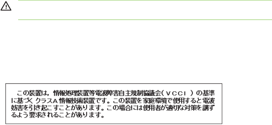
●HP's end-of-life product return and recycling program
●Material Safety Data Sheets (MSDS)
Country/region-specific safety statements
Laser safety statement
The Center for Devices and Radiological Health (CDRH) of the U.S. Food and Drug Administration
has implemented regulations for laser products manufactured since August 1, 1976. Compliance is
mandatory for products marketed in the United States. The MFP is certified as a "Class 1" laser
product under the U.S. Department of Health and Human Services (DHHS) Radiation Performance
Standard according to the Radiation Control for Health and Safety Act of 1968.
Since radiation emitted inside the MFP is completely confined within protective housings and
external covers, the laser beam cannot escape during any phase of normal user operation.
WARNING! Using controls, making adjustments, or performing procedures other than those
specified in this user guide may result in exposure to hazardous radiation.
Canadian DOC statement
Complies with Canadian EMC Class B requirements.
«Conforme à la classe B des normes canadiennes de compatibilité électromagnétiques (CEM).»
Japanese VCCI statement
36 Chapter 1 Product information ENWW
Korean EMI statement
Japanese cordset statement
Taiwan safety statement
ENWW Regulatory information 37
Finnish laser statement
LASERTURVALLISUUS
LUOKAN 1 LASERLAITE
KLASS 1 LASER APPARAT
HP LaserJet 4370mfp, HP LaserJet 4730x mfp, HP LaserJet 4730xs mfp, HP LaserJet
4730xm mfp -laserkirjoitin on käyttäjän kannalta turvallinen luokan 1 laserlaite.
Normaalissa käytössä kirjoittimen suojakotelointi estää lasersäteen pääsyn laitteen
ulkopuolelle.
Laitteen turvallisuusluokka on määritetty standardin EN60825-1 (1994) mukaisesti.
VAROITUS!
Laitteen käyttäminen muulla kuin käyttöohjeessa mainitulla tavalla saattaa altistaa
käyttäjän turvallisuusluokan 1 ylittävälle näkymättömälle lasersäteilylle.
VARNING!
Om apparaten används på annat sätt än i bruksanvisning specificerats, kan användaren
utsättas för osynlig laserstrålning, som överskrider gränsen för laserklass 1.
HUOLTO
HP LaserJet 4370mfp, HP LaserJet 4730x mfp, HP LaserJet 4730xs mfp, HP LaserJet
4730xm mfp -kirjoittimen sisällä ei ole käyttäjän huollettavissa olevia kohteita. Laitteen saa
avata ja huoltaa ainoastaan sen huoltamiseen koulutettu henkilö. Tällaiseksi
huoltotoimenpiteeksi ei katsota väriainekasetin vaihtamista, paperiradan puhdistusta tai
muita käyttäjän käsikirjassa lueteltuja, käyttäjän tehtäväksi tarkoitettuja ylläpitotoimia, jotka
voidaan suorittaa ilman erikoistyökaluja.
VARO!
Mikäli kirjoittimen suojakotelo avataan, olet alttiina näkymättömälle lasersäteilylle laitteen
ollessa toiminnassa. Älä katso säteeseen.
VARNING!
Om laserprinterns skyddshölje öppnas då apparaten är i funktion, utsättas användaren för
osynlig laserstrålning. Betrakta ej strålen.
Tiedot laitteessa käytettävän laserdiodin säteilyominaisuuksista:
Aallonpituus 770-800 nm
Teho 5 mW
Luokan 3B laser
Australia
This equipment complies with Australian EMC requirements.
38 Chapter 1 Product information ENWW
Declaration of conformity (HP Color LaserJet 4730mfp)
Declaration of Conformity
according to ISO/IEC Guide 22 and EN 45014
Manufacturer's Name: Hewlett-Packard Company
Manufacturer's Address: 11311 Chinden Boulevard,
Boise, Idaho 83714-1021, USA
declares that the product
Product Name: HP Color LaserJet 4730 MFP, 4730x MFP, 4730xs MFP, 4730xm MFP
Product Numbers: Q7517A, Q7518A, Q7519A, Q7520A
Including accessories: Q7521A, Q7522A, Q7523A, BOISB-0308-00
Regulatory Model Number: BOISB-0503-00
4)
Product Options: ALL
Toner Cartridge: Q6460A, Q6461A, Q6462A, Q6463A
conforms to the following Product Specifications:
Safety: IEC 60950-1:2001 / EN60950-1: 2001
IEC 60825-1:1993 +A1 +A2 / EN 60825-1:1994 +A11 +A2 (Class 1 Laser/LED Product)
GB4943-2001
EMC: CISPR 22:1997 / EN 55022:1998 - Class A
1)
EN 61000-3-2:2000
EN 61000-3-3:1995 + A1:2001
EN 55024:1998+A1:2001
FCC Title 47 CFR, Part 15 Class A / ICES-003, Issue 4
2)
GB9254-1998
TELECOM: TBR-21:1998; EG 201 121:1998
Supplementary Information:
The product herewith complies with the requirements of the EMC Directive 89/336/EEC and the Low Voltage Directive 73/23/EEC, the
R&TTE Directive 1999/5/EC (Annex II) and carries the CE-Marking accordingly.
1) The product was tested in a typical configuration with Hewlett-Packard Personal Computer Systems. Compliance testing of product to
standard with exception of Clause 9.5, which is not yet in effect.
2) This Device complies with Part 15 of the FCC Rules. Operation is subject to the following two conditions: (1) this device may not cause
harmful interference, and (2) this device must accept any interference received, including interference that may cause undesired operation.
3) For regulatory purposes, this product is assigned a Regulatory model number (BOISB-0503-00). This number should not be confused
with the product name or the product number(s).
4) All worldwide modular approvals for analog fax accessory obtained by Hewlett-Packard under the regulatory model number
BOISB-0308–00 incorporate the Multi-Tech Systems MT5634SMI Socket Modem Module.
Boise, Idaho 83713, USA
21 December, 2004
For regulatory topics only:
Australia Contact: Product Regulations Manager, Hewlett-Packard Australia Ltd.,, 31-41 Joseph Street, Blackburn, Victoria 3130,
Australia
European Contact: Your Local Hewlett-Packard Sales and Service Office or Hewlett-Packard GmbH, Department HQ-TRE /
Standards Europe, Herrenberger Strasse 140, D-71034 Böblingen, Germany, (FAX: +49-7031-14-3143)
USA Contact: Product Regulations Manager, Hewlett-Packard Company, PO Box 15, Mail Stop 160, Boise, ID 83707-0015,
USA, (Phone: 208-396-6000)
ENWW Declaration of conformity (HP Color LaserJet 4730mfp) 39
40 Chapter 1 Product information ENWW

Service approach
MFP repair normally begins by using the MFP internal diagnostics and the following three-step
process.
1. Isolate the problem to the major system (for example, the host computer, the network or server,
or the MFP system).
2. Determine if the problem is located in the accessories, the scanner assembly, or in the MFP
engine.
3. Troubleshoot the problem using the procedures in Chapter 7.
After a faulty part is located, the MFP can usually be repaired at the assembly level by replacing field
replaceable units (FRUs). Some mechanical assemblies might need to be repaired at the
subassembly level. Hewlett-Packard does not support replacement of components on the printed
circuit assembles.
42 Chapter 2 Service approach ENWW

Parts and supplies
Field-replaceable part and accessory part numbers are found in chapter 8 of this manual. Order
replacement parts from Hewlett-Packard Customer Support-Americas (HPCS-A) or Hewlett-Packard
Customer Support-Europe (HPCS-E).
CAUTION Use only accessories specifically designed for this MFP. Accessories can be
ordered from an authorized service or support provider.
Ordering parts, supplies, and accessories over the Internet
To order supplies in the US, contact http://www.hp.com/go/ljsupplies. To order supplies worldwide,
see http://www.hp.com/ghp/buyonline.html. To order accessories, see http://www.hp.com.
Ordering directly through the embedded Web server (for MFPs
with network connections)
Use the following steps to order printing supplies directly through the embedded Web server.
1. In the Web browser on the computer, type the IP address for the MFP. The MFP status window
appears. Or, go to the URL provided in the alert email.
2. Click Other Links.
3. Click Order Supplies. The browser opens to a page in which you can choose to send
information about the MFP to HP. You also have the option to order supplies without sending
the MFP information to HP.
4. Select the part numbers you want to order and follow the instructions on the screen.
Exchange program
HP offers remanufactured assemblies for some parts. These are identified in chapter 8 and can be
ordered from Hewlett-Packard Customer Support-Americas (HPCS-A) or Hewlett-Packard Customer
Support-Europe (HPCS-E).
Supplies
Paper and print cartridges can be ordered directly from Hewlett-Packard. See chapter 8 for ordering
information.
World Wide Web
Printer drivers, updated HP printer software, and product and support information can be obtained
from the following URL:
In the U.S.: http://www.hp.com/support/clj4730mfp
Printer drivers can be obtained from the following sites:
In China: ftp://www.hp.com.cn/support/clj4730mfp
In Japan: ftp://www.jpn.hp.com/support/clj4730mfp
In Korea: http://www.hp.co.kr/support/clj4730mfp
ENWW Parts and supplies 43


HP available services
Online services
For 24-hour access to information using a modem or Internet connection:
World Wide Web URL: for the HP Color LaserJet 4730mfp series MFPs, updated HP printer
software, product and support information, and printer drivers in several languages can be obtained
from http://www.hp.com/support/clj4730mfp. (Sites are in English.)
Visit: http://www.hp.com/support/net_printing for information about network printing using
HP Jetdirect print servers.
HP Instant Support Professional Edition (ISPE) is a suite of Web-based troubleshooting tools for
desktop computing and printing products. ISPE helps you quickly identify, diagnose, and resolve
computing and printing problems. The ISPE tools may be accessed from http://instantsupport.hp.com.
Telephone support
HP provides free telephone support during the warranty period. When you call, you will be connected
to a responsive team waiting to help you. For the telephone number for your country/region, see the
flyer that shipped in the box with the product, or visit http://welcome.hp.com/us/en/wwcontact.html.
Before calling HP have the following information ready: product name and serial number, date of
purchase, and description of the problem.
You can also find support on the Internet at http://www.hp.com. Click the support & drivers block.
Software utilities, drivers, and electronic information
Visit: http://www.hp.com/go/clj4730mfp_software for the HP Color LaserJet 4730mfp series MFPs.
The Web page for the drivers might be in English, but you can download the drivers themselves in
several languages.
Call: See the flyer that shipped in the box with the MFP.
HP direct ordering for accessories or supplies
In the United States, supplies can be ordered from http://www.hp.com/sbso/product/supplies. In
Canada, supplies can be ordered from http://www.hp.ca/catalog/supplies. In Europe, supplies can be
ordered from http://www.hp.com/go/ljsupplies. In Asia-Pacific, supplies can be ordered from
http://www.hp.com/paper/.
Accessories can be ordered from http://www.hp.com/go/accessories.
HP service information
To locate HP-authorized dealers, call 1-800-243-9816 (U.S.) or 1-800-387-3867 (Canada). For
service for your product, call the customer support number for your country/region. See the flyer that
shipped in the box with the MFP.
HP service agreements
Call: 1-800-835-4747 (U.S.) or 1-800-268-1221 (Canada).
Extended Service: 1-800-446-0522
HP support and information for Macintosh computers
ENWW HP available services 45


Hewlett-Packard Limited Warranty Statement
HP product Duration of Limited Warranty
HP Color LaserJet 4730mfp
HP Color LaserJet 4730x mfp
HP Color LaserJet 4730xs mfp
HP Color LaserJet 4730xm mfp
1 year, on-site
HP warrants HP hardware, accessories, and supplies against defects in materials and workmanship
for the period specified above. If HP receives notice of such defects during the warranty period, HP
will, at its option, either repair or replace products which prove to be defective. Replacement
products may be either new or like-new.
HP warrants that HP software will not fail to execute its programming instructions, for the period
specified above, due to defects in material and workmanship when properly installed and used. If HP
receives notice of such defects during the warranty period, HP will replace software media which
does not execute its programming instructions due to such defects.
HP does not warrant that the operation of HP products will be uninterrupted or error free. If HP is
unable, within a reasonable time, to repair or replace any product to a condition as warranted,
customer will be entitled to a refund of the purchase price upon prompt return of the product.
HP products may contain remanufactured parts equivalent to new in performance or may have been
subject to incidental use.
Warranty does not apply to defects resulting from (a) improper or inadequate maintenance or
calibration, (b) software, interfacing, parts or supplies not supplied by HP, (c) unauthorized
modification or misuse, (d) operation outside of the published environmental specifications for the
product, or (e) improper site preparation or maintenance.
TO THE EXTENT ALLOWED BY LOCAL LAW, THE ABOVE WARRANTIES ARE EXCLUSIVE AND
NO OTHER WARRANTY, WHETHER WRITTEN OR ORAL, IS EXPRESSED OR IMPLIED AND HP
SPECIFICALLY DISCLAIMS THE IMPLIED WARRANTIES OR CONDITIONS OF
MERCHANTABILITY, SATISFACTORY QUALITY, AND FITNESS FOR A PARTICULAR PURPOSE.
TO THE EXTENT ALLOWED BY LOCAL LAW, THE REMEDIES IN THIS WARRANTY
STATEMENT ARE THE CUSTOMER’S SOLE AND EXCLUSIVE REMEDIES. EXCEPT AS
INDICATED ABOVE, IN NO EVENT WILL HP OR ITS SUPPLIERS BE LIABLE FOR LOSS OF
DATA OR FOR DIRECT, SPECIAL, INCIDENTAL, CONSEQUENTIAL (INCLUDING LOST PROFIT
OR DATA), OR OTHER DAMAGE, WHETHER BASED IN CONTRACT, TORT, OR OTHERWISE.
FOR CONSUMER TRANSACTIONS IN AUSTRALIA AND NEW ZEALAND; THE WARRANTY
TERMS CONTAINED IN THIS STATEMENT, EXCEPT TO THE EXTENT LAWFULLY PERMITTED,
DO NOT EXCLUDE, RESTRICT OR MODIFY AND ARE IN ADDITION TO THE MANDATORY
STATUTORY RIGHTS APPLICABLE TO THE SALE OF THIS PRODUCT TO YOU.
The warranty period begins on the date of the delivery or on the date of installation if installed by HP.
If customer schedules or delays HP installation more than 30 days after delivery, warranty begins on
the 31st day from delivery.
ENWW Hewlett-Packard Limited Warranty Statement 47
Print Cartridge Limited Warranty Statement
This HP Print Cartridge is warranted to be free from defects in materials and workmanship.
This warranty does not apply to print cartridges that (a) have been refilled, refurbished,
remanufactured or tampered with in any way, (b) experience problems resulting from misuse,
improper storage, or operation outside of the published environmental specifications for the printer
product or (c) exhibit wear from ordinary use.
To obtain warranty service, please return the product to place of purchase (with a written description
of the problem and print samples) or contact HP customer support. At HP’s option, HP will either
replace products that prove to be defective or refund your purchase price.
TO THE EXTENT ALLOWED BY LOCAL LAW, THE ABOVE WARRANTY IS EXCLUSIVE AND NO
OTHER WARRANTY OR CONDITION, WHETHER WRITTEN OR ORAL, IS EXPRESSED OR
IMPLIED AND HP SPECIFICALLY DISCLAIMS ANY IMPLIED WARRANTIES OR CONDITIONS OF
MERCHANTABILITY, SATISFACTORY QUALITY, AND FITNESS FOR A PARTICULAR PURPOSE.
TO THE EXTENT ALLOWED BY LOCAL LAW, IN NO EVENT WILL HP OR ITS SUPPLIERS BE
LIABLE FOR DIRECT, SPECIAL, INCIDENTAL, CONSEQUENTIAL (INCLUDING LOST PROFIT
OR DATA), OR OTHER DAMAGE, WHETHER BASED IN CONTRACT, TORT, OR OTHERWISE.
THE WARRANTY TERMS CONTAINED IN THIS STATEMENT, EXCEPT TO THE EXTENT
LAWFULLY PERMITTED, DO NOT EXCLUDE, RESTRICT OR MODIFY AND ARE IN ADDITION
TO THE MANDATORY STATUTORY RIGHTS APPLICABLE TO THE SALE OF THIS PRODUCT
TO YOU.
48 Chapter 2 Service approach ENWW

HP maintenance agreements
HP has several types of maintenance agreements that meet a wide range of support needs.
Maintenance agreements are not part of the standard warranty. Support services vary by location.
Contact HP Customer Care or go to http://www.hp.com/services/carepack to determine the services
that are available and for more information about maintenance agreements. In general, the MFP will
have the following maintenance agreements:
Priority Onsite Service
This agreement provides 4-hour service response to the customer's site for calls made during normal
HP business hours.
Next business day
This agreement provides next-business-day service, Monday through Friday. This service agreement
comes standard with the MFP for a period of one year. The customer can purchase an extension of
this agreement.
Installation and maintenance kit replacement
An HP-authorized service or support provider will come to the customer's site to install the MFP or to
replace the maintenance kits.
ENWW HP maintenance agreements 49
50 Chapter 2 Service approach ENWW

3 Installation and configuration
This chapter contains information about the following topics:
●Installation checklist
●Unpacking the MFP
●Loading detectable standard-sized media into Tray 2, 3, and 4
●Loading undetectable standard-sized media into Tray 2, 3, and 4
●Connecting power
●Installing print cartridges
●Installing a new control panel overlay
●Testing the MFP operation
●Sleep delay
●Connecting to a computer or network
●Printer software
●Printer drivers
●Printer drivers for Macintosh computers
●Software for Macintosh computers
●Network configuration
●Security features
●Optional output and input devices
ENWW 51

Installation checklist
When setting up the MFP for the first time, perform the following tasks to ensure that the MFP is
installed correctly.
Table 3-1 HP Color LaserJet 4730mfp installation
Item Details
Verify that the MFP is connected to an
adequate power source.
A minimum of 10A (110V) or 5A (220V) circuit
required. Uninterruptible Power Supplies (UPS)
are not recommended. Do not use a power
strip. Any devices attached to the same power
source can lead to intermittent problems.
Verify that MFP resides in an adequate space. Adequate space so that the MFP may be
accessed from all sides. Tight space makes the
system difficult to access for jam clearing and
service.
Verify that surface has adequate, level support. Ensure the MFP is on a level and stable
surface. Ensure wheel locks are engaged.
Verify that all orange tape and packaging
materials have been removed.
See details in the HP Color LaserJet 4730mfp
series Getting Started Guide.
Verify that the print cartridges and paper have
been installed in the MFP.
Use known good quality paper.
Verify the I/O cable, such as a LAN, USB, or
parallel cable, has been connected to the
corresponding I/O port on the MFP.
See details in the HP Color LaserJet 4730mfp
series Getting Started Guide.
Verify the scanner shipping lock has been
moved to the unlocked position.
See details in the HP Color LaserJet 4730mfp
series Getting Started Guide.
Verify the correct language and date/time are
set.
See details in the HP Color LaserJet 4730mfp
series Getting Started Guide.
Configure the e-mail gateways. Press Menu, scroll to and touch Configure
Device, Sending, E-MAIL, and FIND
GATEWAYS. If auto-discovery does not find
the e-mail gateways, obtain the addresses from
your network administrator and manually
configure these on the MFP.
If the fax accessory is installed, ensure it is
properly configured.
Press Menu, scroll to and touch Fax, and then
FAX SETUP SETTINGS. Fill in the date/time,
location and fax header information. See
details in the HP LaserJet Analog Fax
Accessory 300 User Guide.
Print the configuration pages. Press Menu, touch Information, and then touch
PRINT CONFIGURATION.
On the configuration page printouts, verify the
following:
●LDAP gateway address displays.
●SMTP gateway address displays.
●All optional devices display (for example,
the stapler/stacker or the 3-bin mailbox).
The HP Color LaserJet 4730mfp information
and training CD provides detailed information
on how to read the configuration page.
52 Chapter 3 Installation and configuration ENWW

Item Details
●If the fax accessory is installed, the
modem status reads Operational/Enabled.
●On the Embedded Jetdirect Page, verify
that the status reads I/O Card Ready and
that you have a valid IP address.
Verify you can copy from the copier glass of
the MFP.
Place configuration page face down on copier
glass and press Start.
Verify you can copy from the Automatic
Document Feeder (ADF).
Place configuration page face up in ADF and
press Start.
Verify you can send a fax from the MFP, if the
fax accessory is installed.
Place document face-up in the ADF and use
the keypad to send to a known functioning fax
number.
Verify you can send an e-mail. Place document face-up in the ADF, and use
the keypad to enter an e-mail address (LDAP
must be configured for this to function).
Verify you can print to the MFP. After loading the printing system software on a
networked computer, print a test page from the
driver.
Verify that all users have access to the User
Training.
http://www.hp.com/go/usemymfp
Table 3-1 HP Color LaserJet 4730mfp installation (continued)
ENWW Installation checklist 53
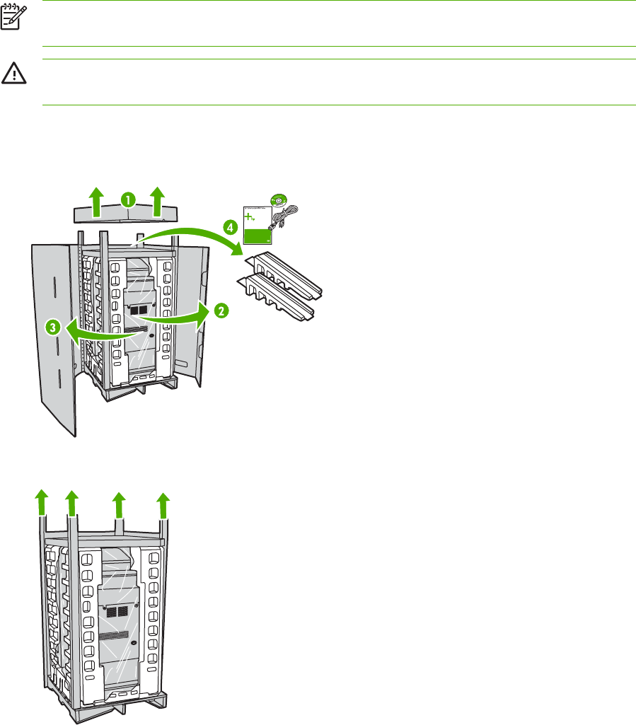
Unpacking the MFP
NOTE Save all the packing materials in case you need to repack and transport the MFP at a
later date.
WARNING! The HP Color LaserJet 4730mfp series MFP weighs approximately 124 kg
(273 lb). HP recommends having three or more people move or position the MFP.
1. Remove the top of the box and remove the outer cardboard wrapping from the sides of the
MFP. Remove the ramps, power supply cord, CD-ROM, and user documentation from the top of
the packing box.
2. Remove the corner brackets.
54 Chapter 3 Installation and configuration ENWW
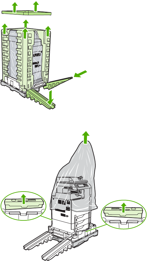
3. Remove the inner cardboard frame and foam corner packaging, and install the ramps.
4. Remove the shipping blocks and plastic bag that surround the MFP.
ENWW Unpacking the MFP 55
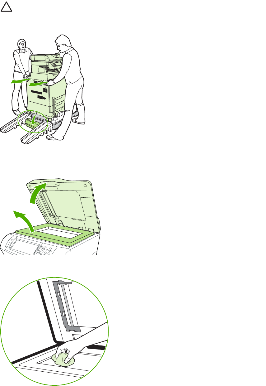
5. Roll the MFP down the ramps into the prepared location.
CAUTION Do not attempt to move the MFP by yourself. At least two people must move
the MFP into the prepared location. While two people can move the MFP, using three or
four people to unpack and install the MFP is easier and safer.
6. Remove the packing tape from the front and rear of the MFP.
7. Open the scanner glass and remove the foam packaging.
8. Clean the scanner glass by wiping it gently with a clean, slightly damp, lint-free cloth.
56 Chapter 3 Installation and configuration ENWW
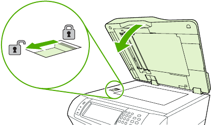
9. Unlock the scanner.
ENWW Unpacking the MFP 57
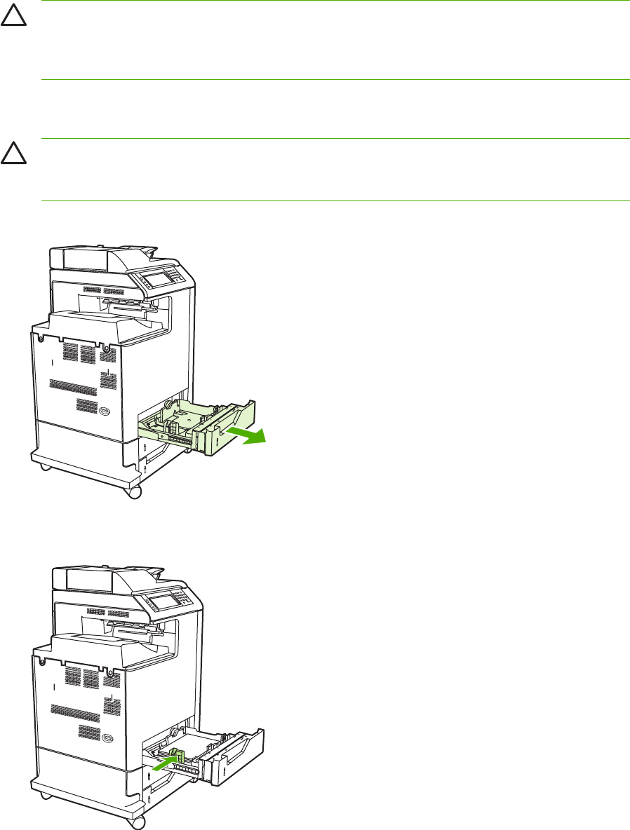
Loading detectable standard-sized media into Tray 2, 3,
and 4
CAUTION If paper is loaded in Trays 2 through 4 when the MFP is in Sleep mode, the new
paper will not be sensed when the MFP comes out of Sleep mode. This could cause the
wrong paper to be used for a print job. Be sure to wake the MFP before loading paper in these
trays.
The following detectable standard-sized media is supported in Trays 2 through 4: letter, legal,
executive, A4, A5, and (JIS) B5.
CAUTION Do not print cardstock, envelopes, heavy or extra-heavy paper, or unsupported
sizes of media from the 500-sheet trays. Print on these types of media only from Tray 1. Do
not overfill the input tray or open it while it is in use. Doing so can cause jams in the MFP.
1. Slide open the tray from the MFP.
2. Adjust the rear media-length guide by squeezing the guide adjustment latch and sliding the
back of the tray to the length of the media being used.
58 Chapter 3 Installation and configuration ENWW
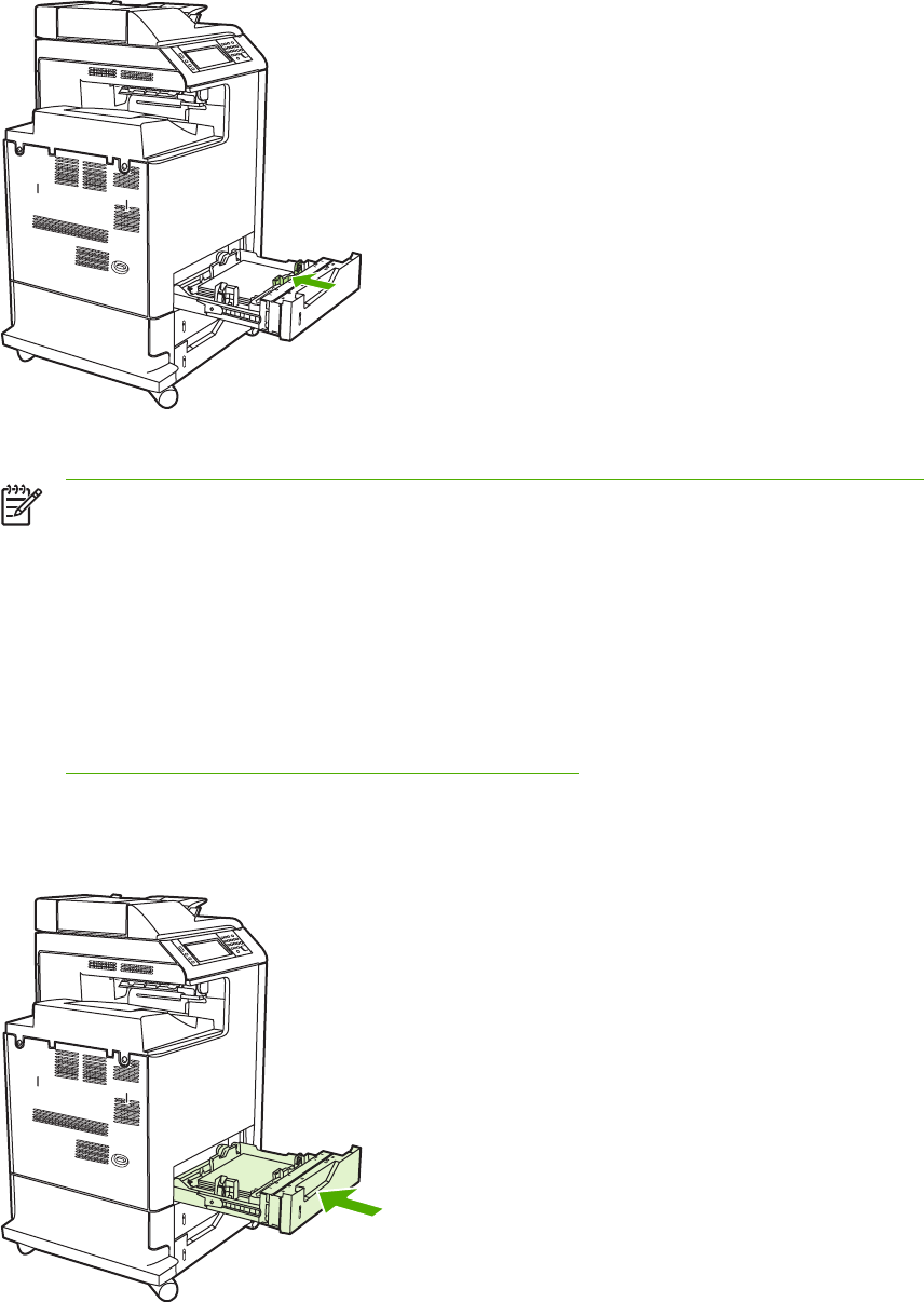
3. Slide the media-width guides open to the size for the media you are using.
4. Load media into the tray face up.
NOTE For best performance, load the tray completely full without splitting or fanning the
ream of paper. Splitting or fanning the ream might cause a multi-feed problem, which
could result in a paper jam. The capacity of the paper tray can vary. For example, if using
75 g/m
2
(20 lb) paper, the tray holds a full ream of 500 sheets. If the media is heavier
than 75 g/m
2
(20 lb), the tray will not hold a full ream, and the number of sheets must be
reduced accordingly. Do not overfill the tray because the MFP might not pick up the paper.
NOTE If the tray is not properly adjusted, the MFP might display an error message or
the media might jam.
NOTE If duplex printing, place the paper face-down.
5. Slide the tray into the MFP. The MFP will display the tray’s media type and size. If the
configuration is not correct, press OK on the product control panel. If the configuration is correct,
touch Exit.
ENWW Loading detectable standard-sized media into Tray 2, 3, and 4 59
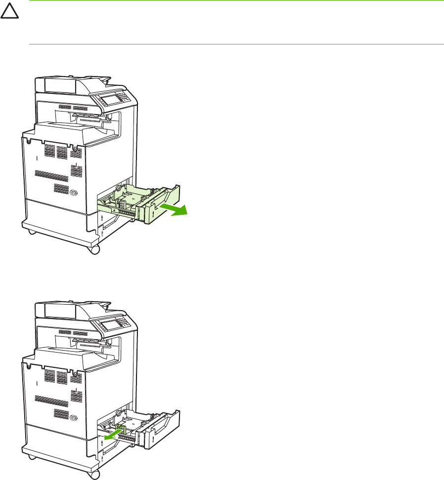
Loading undetectable standard-sized media into Tray 2,
3, and 4
Undetectable standard-sized media sizes are not marked in the tray, but are listed in the Size menu
for the tray.
The following undetectable standard-sized media is supported in the 500-sheet trays: executive
(JIS), 8.5 x 13, double Japan postcard, and 16K.
CAUTION Do not print cardstock, envelopes, heavy or extra-heavy paper, or unsupported
sizes of media from the 500-sheet trays. Print on these types of media only from Tray 1. Do
not overfill the input tray or open it while it is in use. Doing so can cause paper jams.
1. Slide open the tray from the MFP.
2. Adjust the rear media-length guide by squeezing the guide adjustment latch and sliding the
back of the tray to the length of the media being used.
60 Chapter 3 Installation and configuration ENWW
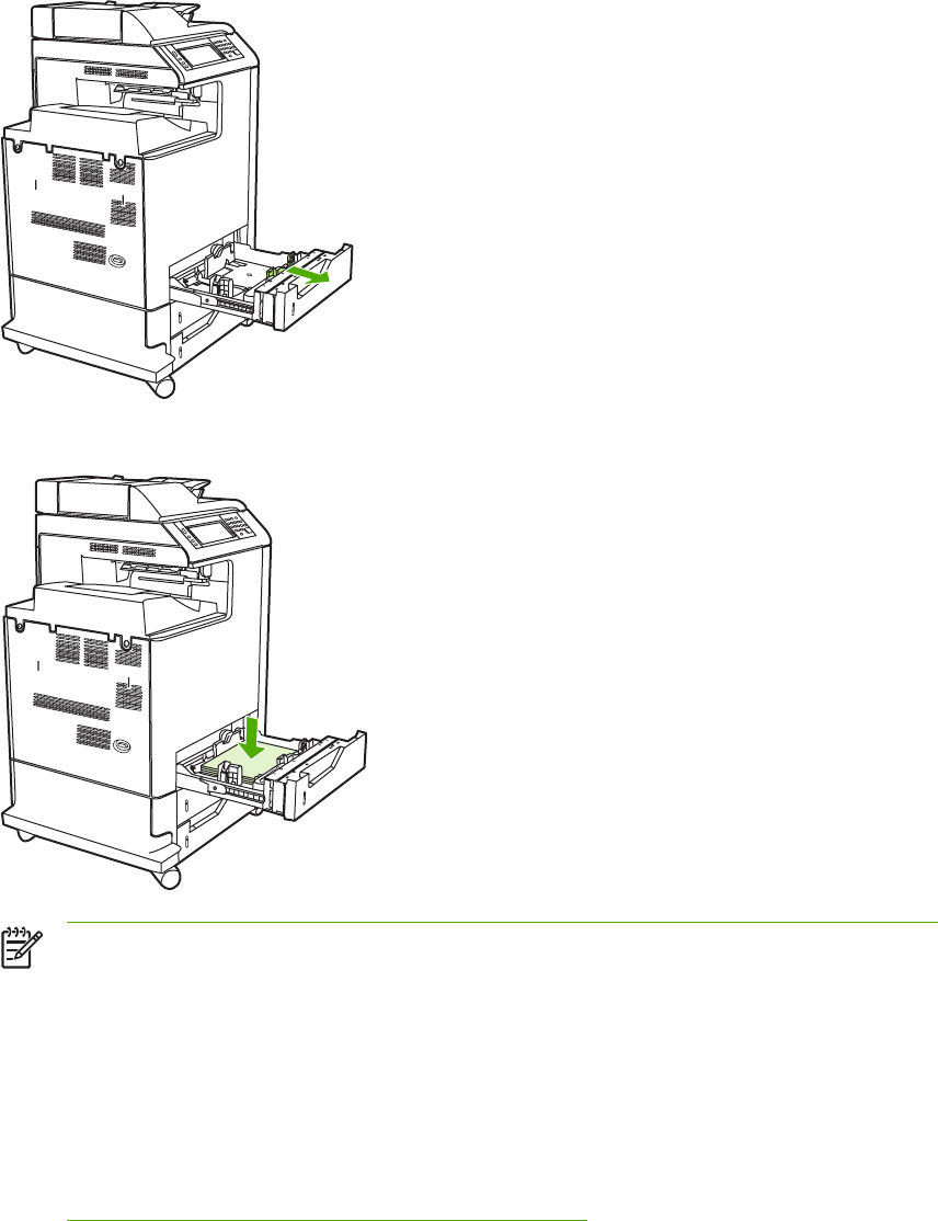
3. Slide the media-width guides open to the size for the media you are using.
4. Load media into the tray face-up.
NOTE For best performance, load the tray completely full without splitting or fanning the
ream of paper. Splitting or fanning the ream might cause a multi-feed problem, which
could result in a paper jam. The capacity of the paper tray can vary. For example, if using
75 g/m
2
(20 lb) paper, the tray holds a full ream of 500 sheets. If the media is heavier
than 75 g/m
2
(20 lb), the tray will not hold a full ream, and the number of sheets must be
reduced accordingly. Do not overfill the tray because the MFP might not pick up the paper.
NOTE If the tray is not properly adjusted, the MFP might display an error message or
the media might jam.
NOTE If duplex printing, place the paper face-down.
ENWW Loading undetectable standard-sized media into Tray 2, 3, and 4 61
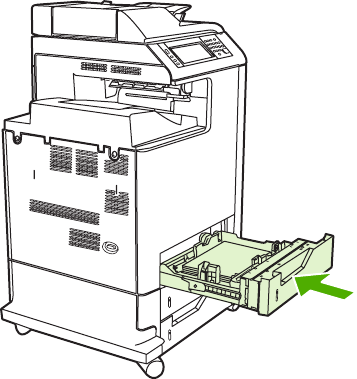
5. Slide the tray into the MFP. The MFP will display the tray’s media type and size. If the
configuration is not correct, touch OK on the product control panel and select the correct size.
62 Chapter 3 Installation and configuration ENWW
Connecting power
1. Plug the AC power cord into the MFP and into the power outlet.
2. Turn the MFP on.
ENWW Connecting power 63
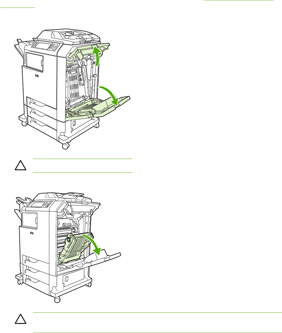
Installing print cartridges
For additional information on installing and managing print cartridges, see Managing print cartridges
on page 108.
1. Open the covers on the right side of the MFP.
CAUTION The fuser might be hot.
2. Grasp the green handle and pull down the ETB.
CAUTION Do not place any item on the transfer belt while it is open. If the belt is
punctured, print quality problems could result.
64 Chapter 3 Installation and configuration ENWW
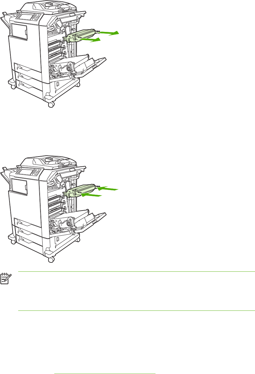
3. Remove the used print cartridge from the MFP.
4. Remove the new print cartridge from the bag. Place the used print cartridge in the bag for
recycling.
5. Align the print cartridge with the tracks inside the MFP and insert the cartridge until it is
completely seated.
NOTE The print cartridge tape seal is removed automatically when the print cartridge is
installed in the MFP.
NOTE If a cartridge is in the wrong slot, the product control panel will display the
message INCORRECT [COLOR] CARTRIDGE.
6. Close the front cover and then close the top cover. After a short while, the product control panel
should display Ready.
7. Installation is complete. Place the used print cartridge in the box in which the new cartridge
arrived. See the enclosed recycling guide for recycling instructions.
8. If a non-HP print cartridge was installed, check the product control panel for further instructions.
For additional help, go to http://www.hp.com/support/clj4730mfp.
ENWW Installing print cartridges 65

Installing a new control panel overlay
Some MFP models are shipped without the product control panel overlay installed or a different
overlay may be used from the one that is installed. Overlays are available for several languages. If
setting up an MFP for a language other than English, follow this procedure.
1. Remove the backing from the adhesive side of the label.
2. Position the new label over the top of the product control panel.
3. Press the label firmly down onto the control panel.
NOTE When applying the overlay, start at the center and press the overlay into place
towards the edges of the control panel.
4. Press Menu to enter the MENUS.
5. Scroll to and touch Configure Device.
6. Scroll to and touch SYSTEM SETUP.
7. Scroll to and touch LANGUAGE.
8. Scroll to and touch the desired language.
9. Press Menu.
66 Chapter 3 Installation and configuration ENWW

Testing the MFP operation
Print a configuration page to ensure that the MFP is working correctly.
1. Press Menu to enter the MENUS.
2. Scroll to and touch Information.
3. Scroll to and touch PRINT CONFIGURATION.
The message Printing... CONFIGURATION appears on the display until the MFP finishes printing
the configuration page. The MFP returns to the Ready state after printing the configuration page.
NOTE If the MFP is configured with an HP Jetdirect print server or a paper handling device,
an additional configuration page will print that provides information about those devices.
ENWW Testing the MFP operation 67

Sleep delay
The adjustable Sleep mode feature reduces power consumption when the MFP has been inactive for
an extended period. The length of time before the MFP enters Sleep mode can be set to 1 MINUTE,
15 MINUTES, 30 MINUTES, 45 MINUTES, 60 MINUTES, 90 MINUTES, 2 HOURS, or 4 HOURS.
The default setting is 30 MINUTES.
NOTE The MFP display dims when the MFP is in Sleep mode. This mode does not affect
MFP warm-up time.
Setting Sleep delay
1. Press Menu to enter the MENUS.
2. Scroll to and touch Configure Device.
3. Scroll to and touch SYSTEM SETUP.
4. Scroll to and touch SLEEP DELAY.
5. Scroll to and touch the desired sleep-delay period. The settings are saved and the control panel
returns to the SYSTEM SETUP menu.
6. Press Menu.
CAUTION If paper is loaded in Trays 2, 3, or 4 when the MFP is in Sleep mode, the
new paper will not be sensed when the MFP comes out of Sleep mode. This could cause
the wrong paper to be used for a print job. Be sure to wake the MFP before loading
paper in these trays.
Disabling/enabling Sleep mode
1. Press Menu to enter the MENUS.
2. Scroll to and touch Configure Device.
3. Scroll to and touch RESETS.
4. Press SLEEP MODE.
5. Scroll to and touch ON or OFF. The settings are saved.
6. Press Menu.
68 Chapter 3 Installation and configuration ENWW
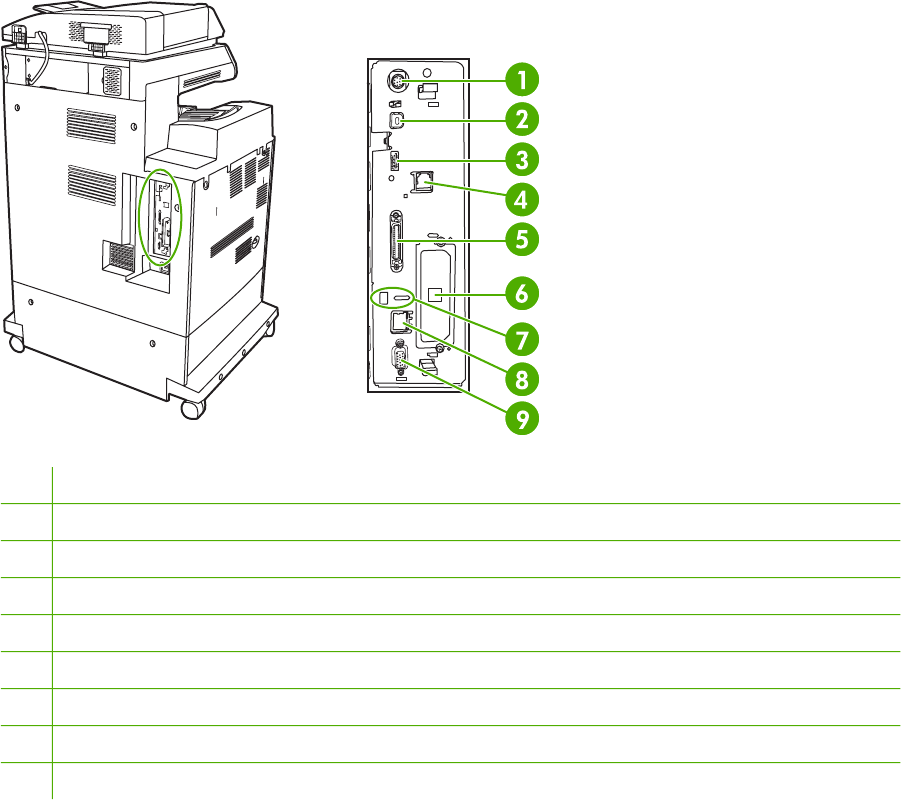
Connecting to a computer or network
The MFP has eight ports for connecting to a computer or a network. The ports are at the right rear
corner of the MFP.
1Foreign interface harness (FIH)
2USB 2.0
3Host USB (This accessory port uses host USB protocol.)
4Fax connection (for connecting to an optional analog fax accessory)
5Parallel port
6EIO interface expansion slot
7Kensington lock
8Network connection (embedded HP Jetdirect print server)
9Accessory port
Network connection
When installing the MFP on a network, connect the network cable to the embedded HP Jetdirect
print server before installing the MFP software.
For complete information about installing the MFP on a network, see the network installation guide
that was included with the MFP.
Parallel connection
Install the MFP software before connecting the MFP directly to a computer or to a print server with a
parallel cable.
For complete information about installing connecting the MFP directly to a print server, see the
network installation guide that was included with the MFP.
ENWW Connecting to a computer or network 69

Fax connection
The HP Color LaserJet 4730x mfp, HP Color LaserJet 4730xs mfp, and HP Color LaserJet
4730xm mfp models are equipped with an HP LaserJet analog fax accessory already installed.
Windows users can also install the optional HP Digital Sending Software (HP DSS), which provides
digital faxing services.
For complete instructions for configuring the fax accessory and for using the fax features, see the
HP LaserJet Analog Fax Accessory 300 User Guide. A printed copy of this guide is provided with the
HP Color LaserJet 4730x mfp, HP Color LaserJet 4730xs mfp, and HP Color LaserJet 4730xm mfp.
Analog faxing
When the analog fax accessory is installed, the MFP can function as a standalone fax machine.
The HP Color LaserJet 4730x mfp, HP Color LaserJet 4730xs mfp, and HP Color LaserJet
4730xm mfp models are equipped with an HP LaserJet analog fax accessory already installed. For
the HP Color LaserJet 4730mfp (base model), this accessory can be ordered as an option.
Connecting the fax accessory to a phone line
When connecting the fax accessory to a phone line, ensure that the phone line being used for the fax
accessory is a dedicated line that is not used by any other devices. Also, this line should be an
analog line because the fax will not function correctly if it is connected to some digital PBX systems.
If unsure whether an analog or digital phone line is to be used, contact your telecom provider.
NOTE HP recommends using the phone cord that comes with the fax accessory to ensure
that the accessory functions correctly.
70 Chapter 3 Installation and configuration ENWW
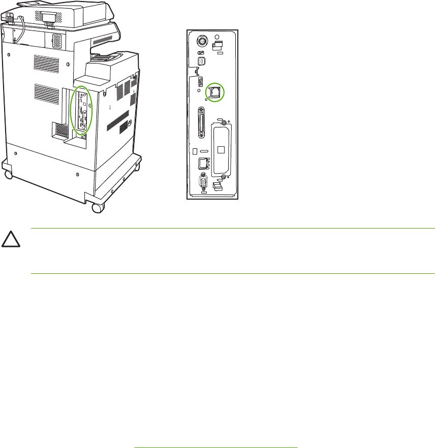
Follow these instructions to connect the fax accessory to a phone jack.
1. Locate the phone cord that is included with the fax accessory kit. Connect one end of the phone
cord into the fax accessory phone jack that is on the formatter. Push the connector until it clicks.
CAUTION Be sure to connect the phone line to the fax accessory port, which is located
in the center of the formatter. Do not connect the phone line to the HP Jetdirect port,
which is nearer the bottom of the formatter.
2. Connect the other end of the phone cord into the phone jack on the wall. Push the connector
until it clicks.
Configuring and using the fax features
Before the fax features can be used, configure them in the product control panel menus. For
complete information about configuring and using the fax accessory and for information about
troubleshooting problems with the fax accessory, see the HP LaserJet Analog Fax Accessory 300
User Guide provided with the fax accessory.
Digital faxing
Digital faxing is available when installing the optional HP Digital Sending Software. For information
about ordering this software, go to http://www.hp.com/go/digitalsending.
With digital faxing, the MFP does not need to be connected directly to a phone line. Instead, the MFP
can send a fax in one of three ways:
●LAN fax sends faxes through a third-party fax provider.
●Microsoft Windows 2000 fax is a fax modem and Digital Sender Module on a computer that
allows the computer to operate as a turnkey gateway fax.
●Internet fax uses an Internet fax provider to process faxes, and the fax is delivered on a
traditional fax machine or sent to the user’s e-mail.
For complete information about using digital faxing, see the documentation that is provided with the
HP Digital Sending Software.
ENWW Connecting to a computer or network 71

Printer software
Included with the MFP is a CD-ROM containing the printing system software. The software
components and printer drivers on this CD-ROM help to use the MFP to its fullest potential. See the
Getting Started Guide for installation instructions.
NOTE For the latest information about the printing system software components, refer to the
readme file on the Web at http://www.hp.com/support/clj4730mfp. For information about
installing the printer software, view the Install Notes on the CD-ROM included with the MFP.
This section summarizes the software included on the CD-ROM. The printing system includes
software for end users and network administrators operating in the following operating environments:
●Microsoft Windows 98 and Windows Me
●Microsoft Windows 2000, XP (32-bit), and Server 2003 (32-bit)
●Apple Mac OS 9.1 and later and Mac OS 10.2 and later
NOTE For a list of the network environments supported by the network administrator
software components, see Network configuration on page 87.
NOTE For a list of printer drivers, updated HP printer software, and product support
information, go to http://www.hp.com/support/clj4730mfp.
Software
Software features
Automatic Configuration, Update Now, and Preconfiguration features are available with the HP Color
LaserJet 4730mfp series MFP.
Driver Autoconfiguration
The HP LaserJet PCL 6 and PCL 5c drivers for Windows and the PS drivers for Windows 2000 and
Windows XP feature automatic discovery and driver configuration for MFP accessories at the time of
installation. Some accessories that Driver Autoconfiguration supports are the duplexing unit, optional
paper trays, and dual inline memory modules (DIMMs). If the environment supports bidirectional
communication, the installer presents Driver Autoconfiguration as an installable component by
default for a Typical Installation and for a Custom Installation.
Update Now
If the configuration of the HP Color LaserJet 4730mfp MFP has been modified since installation, the
driver can be automatically updated with the new configuration in environments that support
bidirectional communication. Click the Update Now button to automatically reflect the new
configuration in the driver.
NOTE The Update Now feature is not supported in environments where shared
Windows 2000 or Windows XP clients are connected to Windows 2000 or Windows XP hosts.
72 Chapter 3 Installation and configuration ENWW

HP Driver Preconfiguration
HP Driver Preconfiguration is a software architecture and set of tools that allows HP software to be
customized and distributed in managed corporate printing environments. Using HP Driver
Preconfiguration, information technology (IT) administrators can preconfigure the printing and device
defaults for HP printer drivers before installing the drivers in the network environment. For more
information, see the HP Driver Preconfiguration Support Guide, which is available at
http://www.hp.com/support/clj4730mfp.
Installing the printing system software
The following sections contain instructions for installing the printing system software.
The MFP comes with printing system software and printer drivers on a CD-ROM. The printing system
software on the CD-ROM must be installed to take full advantage of the MFP features.
If a CD-ROM drive is not available, download the printing system software from the Internet at
http://www.hp.com/support/clj4730mfp.
NOTE Obtain Model Scripts for UNIX® and Linux by downloading them from the Internet or
by requesting them from an HP-authorized service or support provider. For Linux support see
http://www.hp.com/go/linux. For UNIX support see http://www.hp.com/go/jetdirectunix_software.
Download the latest software free of charge at http://www.hp.com/support/clj4730mfp.
Installing Windows printing system software for direct connections
This section explains how to install the printing system software for Microsoft Windows 98,
Windows Me, Windows 2000, and Windows XP.
When installing the printing software in a direct-connect environment, always install the software
before connecting the parallel or USB cable. If the parallel or USB cable was connected before the
software installation, see Installing the software after the parallel or USB cable has been connected
on page 75.
Either a parallel or USB cable can be used for the direct connection. However, parallel and USB
cables cannot be connected at the same time. Use an IEEE 1284-compatible cable or a standard 2-
meter USB cable.
Installing the printing system software
1. Close all software programs that are open or running.
2. Insert the MFP CD-ROM into the CD-ROM drive.
If the welcome screen does not open, start it by using the following procedure:
●On the Start menu, click Run.
●Type the following: X:\setup (where X is the letter of the CD-ROM drive).
●Click OK.
3. When prompted, click Install Printer and follow the instructions on the computer screen.
4. Click Finish when the installation has completed.
ENWW Printer software 73

5. The computer may need to be restarted.
6. Print a Test Page or a page from any software program to make sure that the software is
correctly installed.
If installation fails, reinstall the software. If this fails, check the installation notes and readme files on
the MFP CD-ROM or the flyer that came with the product, or go to http://www.hp.com/support/
clj4730mfp for help or more information.
Installing Windows printing system software for networks
The software on the MFP CD-ROM supports network installation with a Microsoft network. For
network installation on other operating systems, go to http://www.hp.com/support/clj4730mfp.
The HP Jetdirect embedded print server in the HP Color LaserJet 4730mfp includes a 10/100 Base-
TX network port. For other available HP Jetdirect print servers, see Parts and supplies on page 43 or
go to http://www.hp.com/support/clj4730mfp.
The installer does not support MFP installation or MFP object creation on Novell servers. It supports
only direct-mode network installations between Windows computers and an MFP. To install the MFP
and create objects on a Novell server, use an HP utility (such as HP Web Jetadmin) or a Novell utility
(such as NWAdmin).
Installing the printing system software
1. If installing the software on Windows 2000 or Windows XP, administrative privileges are required.
2. Make sure that the HP Jetdirect print server and MFP are properly connected to the network.
Print a configuration page (see Testing the MFP operation on page 67). On the second page of
the configuration page, locate the IP address that is currently configured. This address may be
needed to initially identify the MFP on the network and complete the installation.
3. Close all software programs that are open or running.
4. Insert the MFP CD-ROM into the CD-ROM drive.
If the welcome screen does not open, start it by using the following procedure:
●On the Start menu, click Run.
●Type the following: X:\setup (where X is the letter of the CD-ROM drive).
●Click OK.
5. When prompted, click Install Printer and follow the instructions on the computer screen.
6. Click Finish when installation has completed.
7. The computer may need to be restarted.
8. Print a Test Page or a page from any software program to make sure that the software is
correctly installed.
If installation fails, reinstall the software. If this fails, check the installation notes and readme
files on the MFP CD-ROM or the flyer that came with the product, or go to http://www.hp.com/
support/clj4730mfp for help or more information.
74 Chapter 3 Installation and configuration ENWW

Setting up a Windows computer to use the network MFP with Windows-sharing
If the computer will print directly to the MFP, share the MFP on the network so that other network
users can print to it.
See the Windows documentation that came with the operating system to enable Windows-sharing.
After the MFP is shared, install the printer software on all computers that share the MFP.
Installing the software after the parallel or USB cable has been connected
If you have already connected a parallel or USB cable to a Windows computer, the New Hardware
Found dialog box appears when you turn on the computer.
Installing the software for Windows 98 or Windows Me
1. In the New Hardware Found dialog box, click Search CD-ROM drive.
2. Click Next.
3. Follow the instructions on the computer screen.
4. Print a Test Page or a page from any software program to make sure that the software is
correctly installed.
If installation fails, reinstall the software. If this fails, check the installation notes and readme
files on the MFP CD-ROM or the flyer that came with the product, or go to http://www.hp.com/
support/clj4730mfp for help or more information.
Installing the software for Windows 2000 or Windows XP
1. In the New Hardware Found dialog box, click Search.
2. On the Locate Driver Files screen, select the Specify a Location check box, clear all other
check boxes, and then click Next.
3. Type the letter for the root directory. For example, X:\ (where "X:\" is the letter of the root
directory on the CD-ROM drive).
4. Click Next.
5. Follow the instructions on the computer screen.
6. Click Finish when installation has completed.
7. Select a language and follow the instructions on the computer screen.
8. Print a Test Page or a page from any software program to make sure that the software is
correctly installed.
If installation fails, reinstall the software. If this fails, check the installation notes and readme
files on the MFP CD-ROM or the flyer that came with the product, or go to http://www.hp.com/
support/clj4730mfp for help or more information.
Uninstalling the software
This section explains how to uninstall the printing system software.
ENWW Printer software 75
Removing software from Windows operating systems
Use the Uninstaller in the HP Color LaserJet 4730mfp/Tools program group to select and remove
any or all of the Windows HP printing system components.
1. Click Start and then click Programs.
2. Point to HP Color LaserJet 4730mfp and then click Tools.
3. Click Uninstaller.
4. Click Yes.
5. Follow the instructions on the computer screen to complete the uninstallation.
Software for networks
For a summary of available HP network installation and configuration software solutions, see the
HP Jetdirect Print Server Administrator’s Guide. You can find this guide on the CD-ROM included
with the MFP.
HP Web Jetadmin
HP Web Jetadmin allows users to manage HP Jetdirect-connected printers within their intranet using
a Web browser. HP Web Jetadmin is a browser-based management tool, and should be installed
only on a single network administration server. It can be installed and run on these systems:
●Fedora Core and SuSe Linux
●Windows 2000 Professional, Server, and Advanced Server
●Windows XP Professional Service Pack 1
●Windows Server 2003
When installed on a host server, HP Web Jetadmin can be accessed by any client through a
supported web browser, such as Microsoft Internet Explorer 5.5 and 6.0 or Netscape Navigator 7.0.
HP Web Jetadmin has the following features:
●Task-oriented user interface provides configurable views, saving network managers significant
time.
●Customizable user profiles let network administrators include only the function viewed or used.
●Instant e-mail notification of hardware failure, low supplies, and other MFP problems can be
routed to different people.
●Remote installation and management from anywhere using only a standard Web browser.
●Advanced autodiscovery locates peripherals on the network, without manually entering each
printer into a database.
●Simple integration into enterprise management packages.
●Ability to quickly find peripherals based on parameters such as IP address, color capability, and
model name.
76 Chapter 3 Installation and configuration ENWW

●Ability to easily organize peripherals into logical groups, with virtual office maps for easy
navigation.
●Ability to manage and configure multiple printers at once.
To download a current version of HP Web Jetadmin and to see the latest list of supported host
systems, visit HP Customer Care Online at http://www.hp.com/go/webjetadmin.
UNIX
The HP Jetdirect Printer Installer for UNIX is a simple printer installation utility for HP-UX and Solaris
networks. It is available for download from HP Customer Care Online at http://www.hp.com/go/
jetdirectunix_software.
Utilities
The HP Color LaserJet 4730mfp is equipped with several utilities, which make it easy to monitor and
manage the MFP on a network.
HP Easy Printer Care Software
The HP Easy Printer Care Software is a software program that you can use for the following tasks:
●Viewing color usage information
●Checking the printer status
●Checking the supplies status
●Setting up alerts
●Viewing printer documentation
●Gaining access to troubleshooting and maintenance tools
You can view the HP Easy Printer Care Software when the printer is directly connected to your
computer or when it is connected to a network. Perform a complete software installation in order to
use the HP Easy Printer Care Software.
For more information on HP Easy Printer Care Software, see Using the HP Easy Printer Care
Software on page 636 or visit http://www.hp.com/go/easyprintercare.
Embedded Web server
This MFP is equipped with an embedded Web server, which allows access to information about the
MFP and network activities. A Web server provides an environment in which web programs may run,
much in the same way that an operating system, such as Windows, provides an environment for
programs to run on your computer. The output from these programs can then be displayed by a Web
browser, such as Microsoft Internet Explorer or Netscape Navigator.
When a Web server is "embedded", that means it resides on a hardware device (such as a printer) or
in firmware, rather than as software that is loaded on a network server.
The advantage of an embedded Web server is that it provides an interface to the MFP that anyone
can access with a network-connected computer or a standard Web browser. There is no special
software to install or configure. For more information about the HP embedded Web server, see the
Embedded Web Server User Guide. This guide is on the CD-ROM included with the MFP.
ENWW Printer software 77

Features
The HP embedded Web server allows users to view MFP and network card status and manage
printing functions from their computer. With the HP embedded Web server, users can do the following:
●View MFP status information.
●Determine the remaining life on all supplies and order new ones.
●View and change tray configurations.
●View and change the MFP product control panel menu configuration.
●View and print internal pages.
●Receive notification of MFP and supplies events.
●Add or customize links to other Web sites.
●Select the language in which to display the embedded Web server pages.
●View and change network configuration.
●Restrict access to color printing.
For a complete explanation of the features and functionality of the embedded Web server, see
Embedded Web server on page 77.
Other components and utilities
Several software applications are available for Windows and Mac OS users, as well as for network
administrators.
Windows Mac OS Network administrator
●Software installer — automates
the printing system installation
●Online Web registration
●PostScript Printer Description files
(PPDs) — for use with the Apple
PostScript drivers that come with
the Mac OS
●HP LaserJet Utility (available from
the Internet) — a printer
management utility for Mac OS
users
●HP Web Jetadmin— a browser-
based system management tool.
See http://www.hp.com/go/
webjetadmin for the latest
HP Web Jetadmin software
●HP Jetdirect Printer Installer for
UNIX — available for download
from http://www.hp.com/support/
net_printing
78 Chapter 3 Installation and configuration ENWW

Printer drivers
The product comes with software that allows the computer to communicate with the product (by
using a printer language). This software is called a printer driver. Printer drivers provide access to
product features, such as printing on custom-sized paper, resizing documents, and inserting
watermarks.
Supported printer drivers
The following printer drivers are provided for the product. If the desired printer driver is not on the
product CD-ROM or is not available on http://www.hp.com, contact the manufacturer or distributor of
the program that is being used, and request a driver for the product.
NOTE The most recent drivers are available at http://www.hp.com. Depending on the
configuration of Windows-based computers, the installation program for the product software
automatically checks the computer for Internet access in order to obtain the latest drivers.
Table 3-2 Supported printer drivers
Operating system
1
PCL 6 printer
driver
PCL 5 printer
driver
PS printer driver PPD
2
printer
driver
Microsoft Windows 98
Windows Millennium (Me)
X
X
X
X
X
X
Windows 2000
Windows XP
Windows Server 2003
X
X
X
X
X
X
X
X
X
Mac OS 9.1 or later
Mac OS 10.2 or later
X
X
X
X
1
Not all product features are available from all drivers or operating systems. See the context-sensitive help in the printer
driver for available features.
2
PostScript (PS) Printer Description files (PPDs)
Additional drivers
The following drivers are not included on the CD-ROM, but are available from the Internet.
●OS/2 PCL printer driver.
●OS/2 PS printer driver.
●UNIX model scripts.
●Linux drivers.
●HP OpenVMS drivers.
NOTE The OS/2 printer drivers are available from IBM.
ENWW Printer drivers 79

Obtain Model Scripts for UNIX
®
and Linux by downloading them from the Internet or by requesting
them from an HP-authorized service or support provider. For Linux support see http://www.hp.com/
go/linux. For UNIX support see http://www.hp.com/go/jetdirectunix_software.
Selecting the correct printer driver
Select a printer driver based on the operating system that is being used and the way that the product
is to be used. See the printer driver Help for the features that are available.
●The PCL 6 printer driver can provide the best overall performance and access to MFP features.
●The PCL 5 printer driver is recommended for general office monochrome and color printing.
●Use the PostScript (PS) driver if printing primarily from PostScript-based programs such as
Adobe PhotoShop
®
and CorelDRAW
®
, for compatibility with PostScript Level 3 needs, or for PS
flash font support.
NOTE The product automatically switches between PS and PCL printer languages.
Printer driver Help (Windows)
Printer driver Help is separate from program Help. The printer driver Help provides explanations for
the buttons, check boxes, and drop-down lists that are in the printer driver. It also includes
instructions for performing common printing tasks, such as printing on both sides, printing multiple
pages on one sheet, and printing the first page or covers on different paper.
Activate the printer driver Help screens in one of the following ways:
●Click the Help button.
●Press the F1 key on the computer keyboard.
●Click the question-mark symbol in the upper-right corner of the printer driver.
●Right-click on any item in the driver, and then click What's This?.
80 Chapter 3 Installation and configuration ENWW

Gaining access to Windows printer drivers
Use one of the following methods to open the printer drivers from the computer:
Table 3-3 Gaining access to Windows printer drivers
Operating System To change the settings for all
print jobs until the software
program is closed
To change the print job
default settings (for example,
turn on Print on Both Sides
by default)
To change the configuration
settings (for example, add a
tray or enable/disable Manual
Duplexing)
Windows 98 and
Windows
Millennium (Me)
1. On the File menu in the
software program, click
Print.
2. Select the HP Color
LaserJet 4730mfp, and
then click Properties.
The steps can vary; this
procedure is most common.
1. Click Start, click Settings,
and then click Printers.
2. Right-click the HP Color
LaserJet 4730mfp icon,
and then select Properties
(Windows 98 and Me).
1. Click Start, click Settings,
and then click Printers.
2. Right-click the HP Color
LaserJet 4730mfp icon,
and then select Properties.
3. Click the Configure tab.
Windows 2000, XP,
and Server 2003
1. On the File menu in the
software program, click
Print.
2. Select the HP Color
LaserJet 4730mfp, and
then click Properties or
Preferences.
The steps can vary; this
procedure is most common.
1. Click Start, click Settings,
and then click Printers or
Printers and Faxes.
2. Right-click the HP Color
LaserJet 4730mfp icon,
and then select Printing
Preferences.
1. Click Start, click Settings,
and then click Printers or
Printers and Faxes.
2. Right-click the HP Color
LaserJet 4730mfp icon,
and then select Properties.
3. Click the Device Settings
tab.
ENWW Printer drivers 81

Printer drivers for Macintosh computers
The MFP comes with printer driver software that uses a printer language to communicate with the
MFP. Printer drivers provide access to MFP features, such as printing on custom-sized paper,
resizing documents, and inserting watermarks.
Supported Macintosh printer drivers
A Macintosh printer driver and the necessary PPD files are included with the MFP. If the desired
printer driver is not on the MFP CD, check the installation notes and the late-breaking readme files to
see if the printer driver is supported. If it is not supported, contact the manufacturer or distributor of
the software program being used, and request a driver for the MFP.
NOTE The most recent drivers are available at http://www.hp.com.
Gaining access to Macintosh printer drivers
Use one of the following methods to open the printer drivers from the computer.
Table 3-4 Gaining access to Macintosh printer drivers
Operating System To change the settings for all
print jobs until the software
program is closed
To change the print job
default settings (for example,
turn on Print on Both Sides
by default)
To change the configuration
settings (for example, add a
physical option such as a
tray, or turn on or off a driver
feature such as Allow Manual
Duplexing)
Mac OS v9.1 or later 1. On the File menu, click
Print.
2. Change settings on the
various pop-up menus.
1. On the File menu, click
Print.
2. As settings are changed
on the pop-up menu, click
Save Settings.
1. Click the desktop printer
icon.
2. From the Printing menu,
click Change Setup.
82 Chapter 3 Installation and configuration ENWW

Operating System To change the settings for all
print jobs until the software
program is closed
To change the print job
default settings (for example,
turn on Print on Both Sides
by default)
To change the configuration
settings (for example, add a
physical option such as a
tray, or turn on or off a driver
feature such as Allow Manual
Duplexing)
Mac OS X v10.2 1. On the File menu, click
Print.
2. Change settings on the
various pop-up menus.
1. On the File menu, click
Print.
2. Change the settings on
the various pop-up
menus, and then, on the
Presets pop-up menu,
click Save as and type a
name for the preset.
These settings are saved in the
Presets menu. To use the new
settings, select the saved
preset option every time a
program is opened and a job is
printed.
1. In the Finder, on the Go
menu, click Applications.
2. Open Utilities, and then
open Print Center.
3. Click on the print queue.
4. On the Printers menu,
click Show Info.
5. Click the Installable
Options menu.
NOTE Configuration
settings might not be
available in Classic
mode.
Mac OS X v10.3 1. On the File menu, click
Print.
2. Change settings on the
various pop-up menus.
1. On the File menu, click
Print.
2. Change settings on the
various pop-up menus,
and then, on the Presets
pop-up menu, click Save
as and type a name for
the preset.
These settings are saved in the
Presets menu. To use the new
settings, select the saved
preset option every time you
open a program and print.
1. Open Printer Setup
Utility by selecting the
hard drive, clicking
Applications, clicking
Utilities, and then double-
clicking Printer Setup
Utility.
2. Click on the print queue.
3. On the Printers menu,
click Show Info.
4. Click the Installable
Options menu.
Table 3-4 Gaining access to Macintosh printer drivers (continued)
ENWW Printer drivers for Macintosh computers 83

Software for Macintosh computers
The HP installer provides PostScript® Printer Description (PPD) files, Printer Dialog
Extensions (PDEs), and the HP Printer Utility for use with Macintosh computers.
If both the MFP and the Macintosh computer are connected to a network, use the MFP embedded
Web server (EWS) to configure the MFP. For more information, see Embedded Web server
on page 77.
Installing Macintosh printing system software for networks
This section describes how to install Macintosh printing system software. The printing system
software supports Mac OS v9.1 and later and Mac OS X v10.2 and later.
The printing system software includes the following components:
●PostScript Printer Description (PPD) files
The PPDs, in combination with the Apple PostScript printer drivers, provide access to MFP
features. An installation program for the PPDs and other software is provided on the compact
disc (CD) that came with the MFP. Use the Apple PostScript printer driver that comes with the
computer.
●HP Printer Utility
The HP Printer Utility provides access to features that are not available in the printer driver. Use
the illustrated screens to select MFP features and complete the following tasks with the MFP:
●Name the MFP.
●Assign the MFP to a zone on the network.
●Assign an internet protocol (IP) address to the MFP.
●Download files and fonts.
●Configure and set the MFP for IP or AppleTalk printing.
Use the HP Printer Utility when the MFP uses a universal serial bus (USB) or is connected to a
TCP/IP-based network.
NOTE The HP Printer Utility is supported for Mac OS X v10.2 or later.
For more information about using the HP Printer Utility, see Software for Macintosh computers
on page 84.
To install printer drivers for Mac OS v9.1 and later
1. Connect the network cable between the HP Jetdirect print server and a network port.
2. Insert the CD into the CD-ROM drive. The CD menu runs automatically. If the CD menu does
not run automatically, double-click the CD icon on the desktop.
3. Double-click the Installer icon in the HP LaserJet Installer folder.
4. Follow the instructions on the computer screen.
84 Chapter 3 Installation and configuration ENWW

5. On the computer hard drive, open Applications, open Utilities, and then open Desktop
Printer Utility.
6. Double-click Printer (AppleTalk).
7. Next to AppleTalk Printer Selection, click Change.
8. Select the MFP, click Auto Setup, and then click Create.
NOTE The icon on the desktop looks generic. All of the print panels appear in the print
dialog box with each software program.
To install printer drivers for Mac OS X v10.2 and later
1. Connect the network cable between the HP Jetdirect print server and a network port.
2. Insert the CD into the CD-ROM drive.
The CD menu runs automatically. If the CD menu does not run automatically, double-click the
CD icon on the desktop.
3. Double-click the Installer icon in the HP LaserJet Installer folder.
4. Follow the instructions on the computer screen.
5. On the computer hard drive, open Applications, open Utilities, and then open Print Center or
Printer Setup Utility.
NOTE If you are using Mac OS X v10.3, then the Printer Setup Utility has replaced
the Print Center.
6. Click Add Printer.
7. Select Rendezvous as the connection type.
8. Select the MFP from the list.
9. Click Add Printer.
10. Close the Print Center or the Printer Setup Utility by clicking the close button in the upper-left
corner.
Installing Macintosh printing system software for direct
connections (USB)
NOTE Macintosh computers do not support parallel port connections.
This section explains how to install the printing system software for Mac OS v9.1 and later and
Mac OS X v10.2 and later.
The Apple PostScript driver must be installed in order to use the PPD files. Use the Apple PostScript
driver that came with your Macintosh computer.
ENWW Software for Macintosh computers 85

To install the printing system software
1. Connect a USB cable between the USB port on the MFP and the USB port on the computer.
Use a standard 2-meter (6.56-foot) USB cable.
2. Insert the MFP CD into the CD-ROM drive and run the installer.
The CD menu runs automatically. If the CD menu does not run automatically, double-click the
CD icon on the desktop.
3. Double-click the Installer icon in the HP LaserJet Installer folder.
4. Follow the instructions on the computer screen.
5. For Mac OS v9.1 and later:
a. On the computer hard drive, open Applications, open Utilities, and then open Print Center.
b. Double-click Printer (USB), and then click OK.
c. Next to USB Printer Selection, click Change.
d. Select the MFP, and then click OK.
e. Next to Postscript Printer Description (PPD) File, click Auto Setup, and then click Create.
f. On the Printing menu, click Set Default Printer.
For Mac OS X v10.2 and later: USB queues are created automatically when the MFP is
attached to the computer. However, the queue will use a generic PPD if the installer has not
been run before the USB cable is connected. To change the queue PPD, open the Print Center
or Printer Setup Utility, select the correct printer queue, and then click Show Info to open the
Printer Info dialog box. In the pop-up menu, select Printer Model, and then, in the pop-up
menu in which Generic is selected, select the correct PPD for the MFP.
6. Print a test page or a page from any software program to make sure that the software is
correctly installed.
If installation fails, reinstall the software. If this fails, see the installation notes or late-breaking
readme files on the MFP CD or the flyer that came with the product, or go to http://www.hp.com/
support/clj4730mfp for help or more information.
NOTE The icon on the Mac OS v9.x desktop looks generic. All of the print panels appear in
the Print dialog box with each software program.
To remove software from Macintosh operating systems
To remove the software from a Macintosh computer, drag the PPD files to the trash can.
86 Chapter 3 Installation and configuration ENWW

Network configuration
Configure certain network parameters on the MFP as needed. Configure these parameters from
installation software, the MFP product control panel, the embedded Web server, or management
software, such as HP Web Jetadmin or the HP LaserJet Utility for Macintosh.
NOTE For more information about using the embedded Web server, see Embedded Web
server on page 77.
For more information about supported networks and network configuration tools, see the
HP Jetdirect Print Server Administrator’s Guide. The guide comes with MFPs in which an
HP Jetdirect print server is installed.
This section contains the following instructions for configuring network parameters from the MFP
product control panel:
●Configuring TCP/IP parameters.
●Disabling unused network protocols.
Configuring TCP/IP parameters
Use the MFP product control panel to configure these TCP/IP parameters:
●IP address (4 bytes)
●Subnet mask (4 bytes)
●Default gateway (4 bytes)
To manually configure TCP/IP parameters from the MFP control panel
Use manual configuration to set an IP address, subnet mask, and default gateway.
Setting an IP address
1. Press Menu to enter the MENUS.
2. Scroll to and touch Configure Device.
3. Scroll to and touch I/O.
4. Scroll to and touch JETDIRECT MENU.
5. Scroll to and touch TCP/IP.
6. Scroll to and touch CONFIG METHOD.
7. Scroll to and touch MANUAL or MANUAL SETTINGS.
8. Scroll to and touch IP Address: X.
9. Use the right and left arrows to select each byte of the IP address, and then use the numeric
keypad to enter the value of each byte.
10. Touch OK.
ENWW Network configuration 87

Setting the subnet mask
1. Press Menu to enter the MENUS.
2. Scroll to and touch Configure Device.
3. Scroll to and touch I/O.
4. Scroll to and touch JETDIRECT MENU.
5. Scroll to and touch TCP/IP.
6. Scroll to and touch CONFIG METHOD.
7. Scroll to and touch MANUAL.
Scroll to and touch MANUAL SETTINGS.
8. Scroll to and touch SUBNET MASK
NOTE The first three sets of numbers are highlighted.
9. Use the right and left arrows to select each byte of the subnet mask, and then use the numeric
keypad to enter the value of each byte.
10. Touch OK.
Setting the default gateway
1. Press Menu to enter the MENUS.
2. Scroll to and touch Configure Device.
3. Scroll to and touch I/O.
4. Scroll to and touch JETDIRECT MENU.
5. Scroll to and touch TCP/IP.
6. Scroll to and touch CONFIG METHOD.
7. Scroll to and touch MANUAL or MANUAL SETTINGS.
8. Scroll to and touch DEFAULT GATEWAY.
NOTE The first set of 3 numbers shows the default settings. If there is not a number
highlighted, a highlighted empty underscore appears.
9. Use the right and left arrows to select each byte of the default gateway, and then use the
numeric keypad to enter the value of each byte.
10. Touch OK.
88 Chapter 3 Installation and configuration ENWW

Disabling network protocols (optional)
By factory default, all supported network protocols are enabled. Disabling unused protocols has the
following benefits:
●Decreases MFP-generated network traffic.
●Prevents unauthorized users from printing to the MFP.
●Provides only pertinent information on the configuration page.
●Allows the MFP control panel to display protocol-specific error and warning messages.
NOTE TCP/IP configuration cannot be disabled on the HP Color LaserJet 4730mfp.
Disabling IPX/SPX
NOTE Do not disable this protocol if Windows 95/98, Windows NT, Me, 2000, and XP users
will be printing to the MFP using direct-mode IPX/SPX.
1. Press Menu to enter the MENUS.
2. Scroll to and touch Configure Device.
3. Scroll to and touch I/O.
4. Scroll to and touch JETDIRECT.
5. Scroll to and touch IPX/SPX.
6. Scroll to and touch ENABLE.
7. Scroll to and touch ON or OFF.
8. Touch OK.
Disabling DLC/LLC
1. Press Menu to enter the MENUS.
2. Scroll to and touch Configure Device.
3. Scroll to and touch I/O.
4. Scroll to and touch JETDIRECT.
5. Scroll to and touch DLC/LLC.
6. Scroll to and touch ENABLE.
7. Scroll to and touch ON or OFF.
8. Press OK.
ENWW Network configuration 89
Disabling AppleTalk
1. Press Menu to enter the MENUS.
2. Scroll to and touch Configure Device.
3. Scroll to and touch I/O.
4. Scroll to and touch JETDIRECT.
5. Scroll to and touch APPLETALK.
6. Scroll to and touch ENABLE.
7. Scroll to and touch ON or OFF.
8. Press OK.
90 Chapter 3 Installation and configuration ENWW

Security features
Several important security features are available for the MFP. Use the information in this section to
configure these features to meet the user's needs.
Securing the embedded Web server
Assign a password for access to the embedded Web server so that unauthorized users cannot
change the MFP settings.
To secure the embedded Web server
1. Open the embedded Web server by entering the IP address.
2. Click the Settings tab.
3. On the left side of the window, click Security.
4. Type the password next to New Password, and type it again next to Verify Password.
5. Click Apply. Make note of the password, and store it in a safe place.
Foreign Interface Harness (FIH)
The Foreign Interface Harness (FIH) provides a portal on the MFP. By using the FIH and third-party
equipment, information about copies that are made on the MFP can be tracked.
Requirements
●Windows 9X, Windows Me, Windows 2000, or Windows XP
●Access to third-party accounting hardware solutions, such as Equitrac or Copitrak devices
Using the FIH
To use the FIH, download and install the FIH software. The software is available from
http://www.hp.com/support/clj4730mfp. The software is used to enable or disable the FIH portal. Use
the software to set and change the administrator personal identification number (PIN).
Administrators can use the PIN option to configure the FIH to prevent any unauthorized changes.
Changes can be made only with the correct PIN authentication.
NOTE It is important to remember the PIN that is assigned to the FIH administration
software. The PIN is required to make any changes to the FIH.
To enable the FIH portal
1. Double-click the FIH.EXE file. The Foreign Interface Harness dialog box appears.
2. Click OK.
3. Click Enable.
4. If a PIN has not been previously entered, click No. If a PIN was entered previously, click Yes. If
clicking No, type and confirm the PIN, and then click OK. If clicking Yes, type the PIN and click
OK.
ENWW Security features 91

NOTE The PIN must be numeric.
5. Click the appropriate button for the type of connection: Direct or Network. If selecting Direct,
type the MFP port. If selecting Network, type the IP address and port for the MFP.
NOTE The IP address for the MFP can be found on the configuration page. Print a
configuration page from the product control panel by touching Menu, touching
Information, and then touching PRINT CONFIGURATION.
If an incorrect IP address is typed, an error message will display. Otherwise, the portal is enabled.
To disable the FIH portal
1. Double-click the FIH.EXE file. The Foreign Interface Harness dialog box appears.
2. Click OK.
3. Click Disable.
4. Type the PIN and click OK.
5. Click the appropriate button for the type of connection: Direct or Network. If Direct is selected,
type the MFP port and click OK. If Network is selected, type the IP address and port for the
MFP, and then click OK. The portal is disabled.
NOTE If the PIN number is lost and the portal needs to be disabled, try using the default PIN
that is listed to disable it. For assistance, use the HP Instant Support service, which is
available through the embedded Web server or at http://instantsupport.hp.com.
Secure Disk Erase
To protect deleted data from unauthorized access on the MFP hard drive, use Secure Disk Erase.
Secure Disk Erase is a security feature that securely erases print and copy jobs from the hard drive.
Secure Disk Erase offers the following levels of disk security:
●Non-Secure Fast Erase. This is a simple file-table erase function. Access to the file is
removed, but actual data is retained on the disk until it is overwritten by subsequent data-
storage operations. This is the fastest mode. Non-Secure Fast Erase is the default erase mode.
●Secure Fast Erase. Access to the file is removed, and the data is overwritten with a fixed
identical character pattern. This is slower than Non-Secure Fast Erase, but all data is
overwritten. Secure Fast Erase meets the U.S. Department of Defense 5220-22.M requirements
for the clearing of disk media.
●Secure Sanitizing Erase. This level is similar to the Secure Fast Erase mode. In addition, data
is repetitively overwritten by using an algorithm that prevents any residual data persistence. This
mode will impact performance. Secure Sanitizing Erase meets the U.S. Department of Defense
5220-22.M requirements for the sanitization of disk media.
Data affected
Data affected (covered) by the Secure Disk Erase feature includes stored jobs, proof and hold jobs,
disk-based fonts, disk-based macros (forms), and temporary files that are created during the print
and copying process.
92 Chapter 3 Installation and configuration ENWW

NOTE Stored jobs will be securely overwritten only when they have been deleted through
the RETRIEVE JOB menu on the MFP after the appropriate erase mode has been set.
This feature will not impact data that is stored on flash-based product non-volatile RAM (NVRAM)
that is used to store default settings, page counts, and similar data. This feature does not affect data
that is stored on a system RAM disk (if one is used). This feature does not impact data that is stored
on the flash-based system boot RAM.
Changing the Secure Disk Erase mode does not overwrite previous data on the disk, nor does it
immediately perform a full-disk sanitization. Changing the Secure Disk Erase mode changes how the
MFP cleans up temporary data for jobs after the erase mode has been changed.
Gaining access to Secure Disk Erase
Use HP Web Jetadmin to gain access to and set the Secure Disk Erase feature.
Additional Information
For additional information about the HP Secure Disk Erase feature, see the HP support flyer or go to
http://www.hp.com/go/webjetadmin/.
Job storage features
Several job storage features are available for this MFP. These features include printing private jobs,
storing print jobs, quick-copying jobs, and proofing and holding jobs.
For more information about job storage features, see Job storage features on page 93.
DSS authentication
Optional Digital Sending Software (DSS) for the MFP is available for purchase separately. The
software provides an advanced sending program that contains an authentication process. This
process requires users to type a user identification and a password before they can use any of the
DSS features that require authentication.
See Parts and supplies on page 43 for ordering information.
Locking the control panel menus
To prevent someone from changing MFP configuration, the control panel menus can be locked. This
prevents unauthorized users from changing the configuration settings such as the SMTP server. The
following procedure describes how to restrict access to the control panel menus by using the
HP Web Jetadmin software. (See Using HP Web Jetadmin software on page 639.)
To lock the control panel menus
1. Open the HP Web Jetadmin program.
2. Open the DEVICE MANAGEMENT folder in the drop-down list in the Navigation panel.
Navigate to the DEVICE LISTS folder.
3. Select the MFP.
4. In the Device Tools drop-down list, select Configure.
ENWW Security features 93
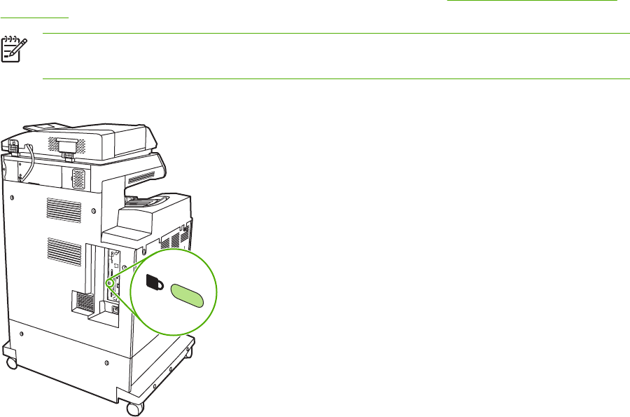
5. Select Security from the Configuration Categories list.
6. Type a Device Password.
7. In the Control Panel Access section, select Maximum Lock. This prevents unauthorized users
from gaining access to configuration settings.
Locking the formatter cage
A Kensington lock can be placed on the formatter cage to prevent unauthorized access to
components on the formatter. If interested in purchasing a Kensington locking accessory for the
formatter cage on an HP Color LaserJet 4730mfp, please contact HP at http://www.hp.com/support/
clj4730mfp.
NOTE A Kensington lock is typically used for locking laptop computers in order to prevent
theft.
The following figure indicates where the lock should be placed.
94 Chapter 3 Installation and configuration ENWW
Optional output and input devices
Optional paper-handling devices are available for the MFP.
●3-bin mailbox with output accessory bridge
●Stapler/stacker with output accessory bridge
Each of these accessories comes with an installation guide that explains how to install it. After
installing an accessory, print a configuration page to verify that the accessory was installed
successfully. If the accessory is installed correctly, it is listed on the configuration page in the section
for Paper trays and options.
ENWW Optional output and input devices 95
96 Chapter 3 Installation and configuration ENWW

4 Maintenance
This chapter contains information about the following topics:
●Using the cleaning page
●Cleaning the MFP
●Calibrating the scanner
●Performing preventive maintenance
●Managing print cartridges
●Approximate replacement intervals for supplies
●ETB life under different circumstances
●Changing print cartridges
●Replacing supplies
●MFP memory and fonts
●Installing memory and fonts
●Setting the real-time clock
●Configuring and verifying an IP address
●Upgrading the firmware
ENWW 97

Using the cleaning page
During printing, toner and dust particles can accumulate inside the MFP. Over time, this buildup can
cause print quality problems, such as toner specks or smearing. This MFP has a cleaning mode that
can correct and prevent these problems.
Processing a cleaning page
1. Press Menu to enter the MENUS.
2. Scroll to and touch Configure Device.
3. Scroll to and touch PRINT QUALITY.
4. Scroll to and touch PROCESS CLEANING PAGE.
NOTE The MFP prints a cleaning page with a pattern and provides further instructions.
98 Chapter 4 Maintenance ENWW

Cleaning the MFP
To maintain print quality, clean the MFP thoroughly whenever print-quality problems occur and every
time you replace the print cartridge.
WARNING! Avoid touching the fusing area when cleaning the MFP. It can be hot.
CAUTION To avoid permanent damage to the print cartridge, do not use ammonia-based
cleaners on or around the MFP except as directed.
Cleaning the outside of the MFP
●Clean the outside of the MFP if it is visibly marked.
●Use a soft, lint-free cloth dampened with water, or with water and a mild detergent.
Cleaning the touchscreen
Clean the touchscreen whenever it is necessary to remove fingerprints or dust. Wipe the
touchscreen gently with a clean, water-dampened, lint-free cloth.
CAUTION Use water only. Solvents or cleaners can damage the touchscreen. Do not pour
or spray water directly onto the touchscreen.
Cleaning the scanner glass
●Clean the scanner glass only if dirt is visible, or if experiencing a decrease in copy quality, such
as streaking.
●Clean the scanner glass by wiping it gently with a clean, slightly damp, lint-free cloth. Use an
ammonia-based surface cleaner only when a water-dampened cloth does not clean the scanner
glass. Spray or pour the cleaner onto the cleaning cloth. Do not spray or pour the cleaner onto
the scanner glass.
CAUTION Do not pour or spray liquids directly onto the scanner glass. Do not press hard on
the glass surface. (The glass could break.)
Cleaning the ADF delivery system
Clean the ADF only if it is visibly marked or dirty, or if you are experiencing a decrease in copy
quality (such as streaking).
ENWW Cleaning the MFP 99
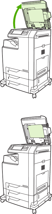
To clean the ADF delivery system
1. Open the scanner lid.
2. Locate the white vinyl ADF backing.
3. Clean the ADF backing with a clean, damp, lint-free cloth. Use an ammonia-based surface
cleaner only when a water-dampened cloth does not clean the ADF components.
4. Clean the scanner glass by wiping it gently with a clean, slightly damp, lint-free cloth. Use an
ammonia-based surface cleaner only when a water-dampened cloth does not clean the scanner
glass.
100 Chapter 4 Maintenance ENWW
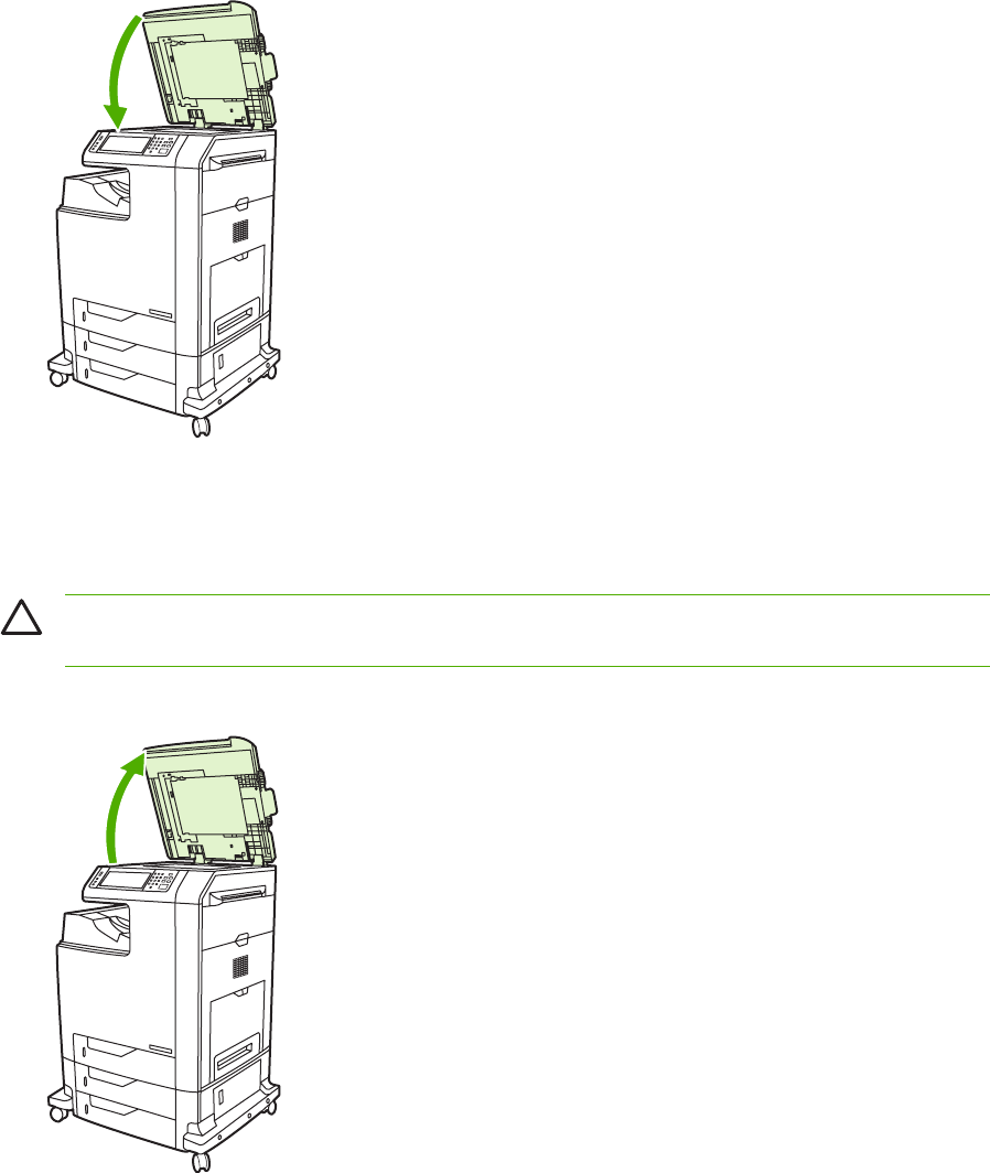
5. Close the scanner lid.
To clean the ADF rollers
You should clean the rollers in the ADF if you are experiencing misfeeds or if your originals show
marks as they exit the ADF.
CAUTION Clean the rollers only if experiencing misfeeds or marks on the originals, and dust
is on the rollers. Cleaning the rollers frequently could introduce dust into the device.
1. Open the scanner lid.
ENWW Cleaning the MFP 101
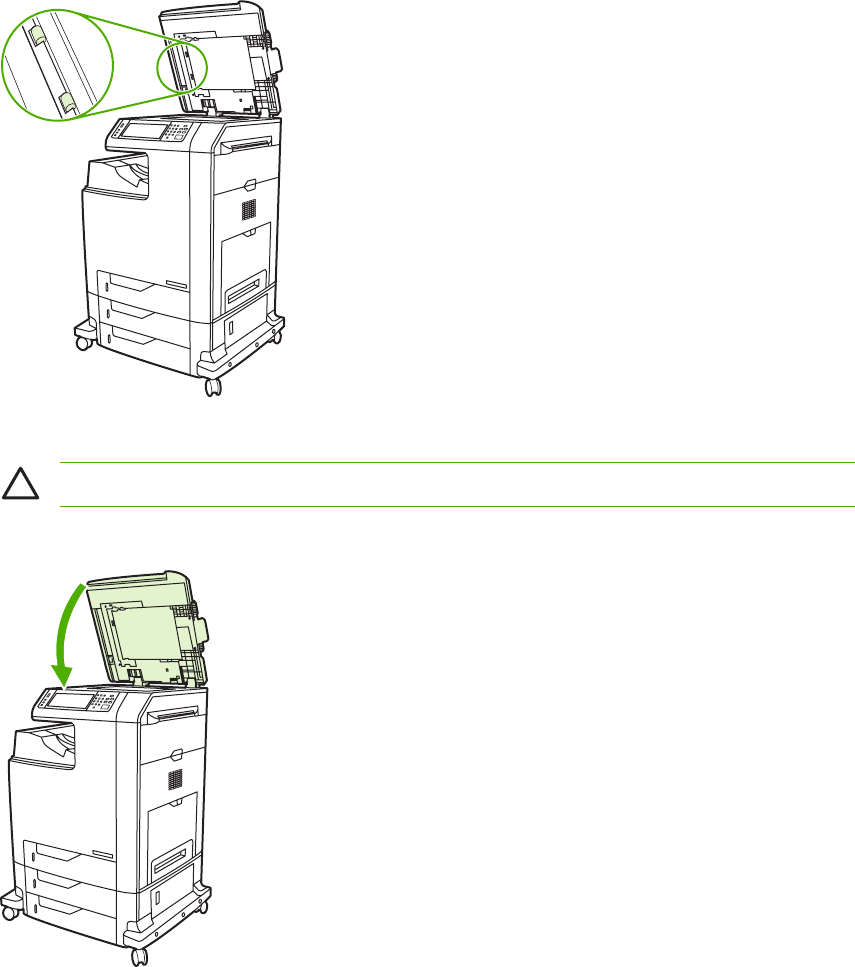
2. Locate the rollers adjacent to the white vinyl ADF backing.
3. Wipe the rollers gently with a clean, water-dampened, lint-free cloth.
CAUTION Do not pour water directly onto the rollers. Doing so might damage the device.
4. Close the scanner lid.
102 Chapter 4 Maintenance ENWW
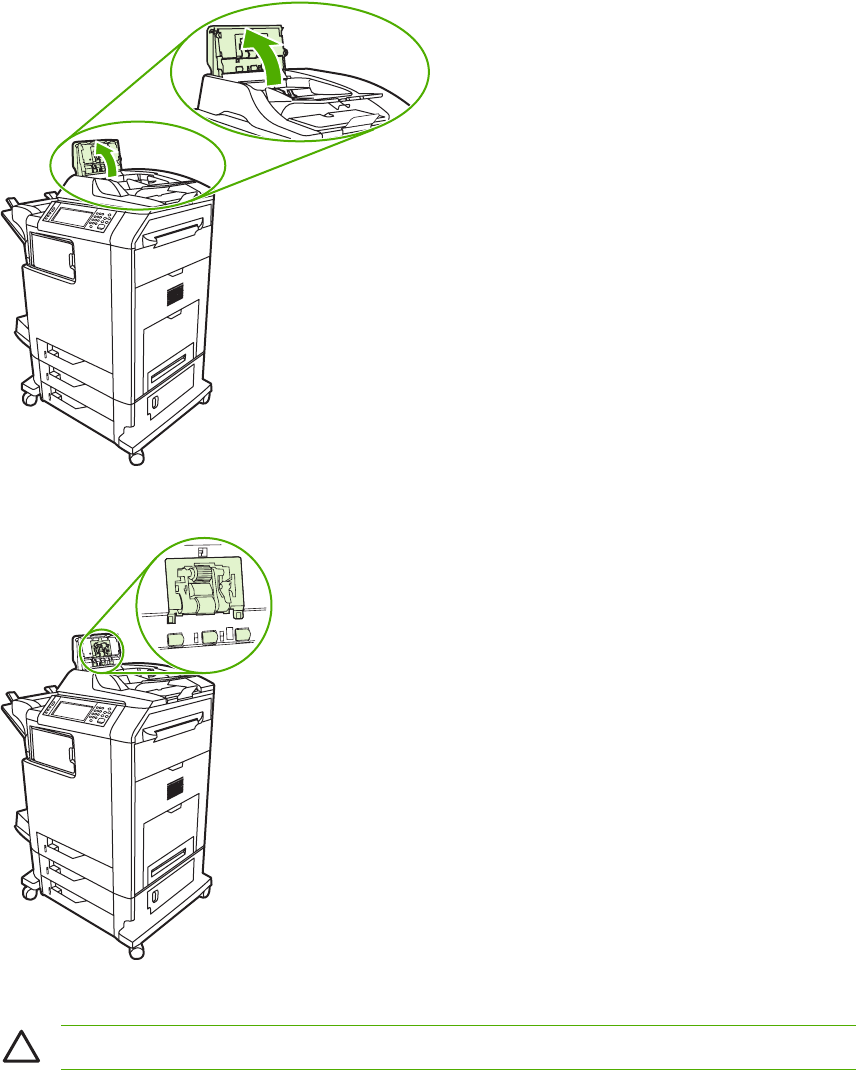
5. Pull the release lever to open the ADF cover.
6. Locate the rollers.
7. Wipe the rollers with a clean, water-dampened, lint-free cloth.
CAUTION Do not pour water directly onto the rollers. Doing so might damage the device.
ENWW Cleaning the MFP 103
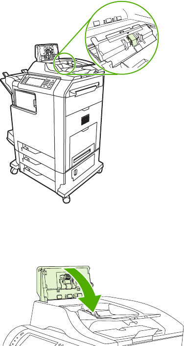
8. Locate the separation pad.
9. Wipe the pad with a clean, water-dampened, lint-free cloth.
10. Close the ADF cover.
Cleaning the mylar strip
Clean the mylar strips on the underside of the scanner lid only if you are experiencing a decrease in
copy quality (such as vertical lines) during copying using the ADF.
To clean the mylar strip
1. Open the scanner lid.
104 Chapter 4 Maintenance ENWW
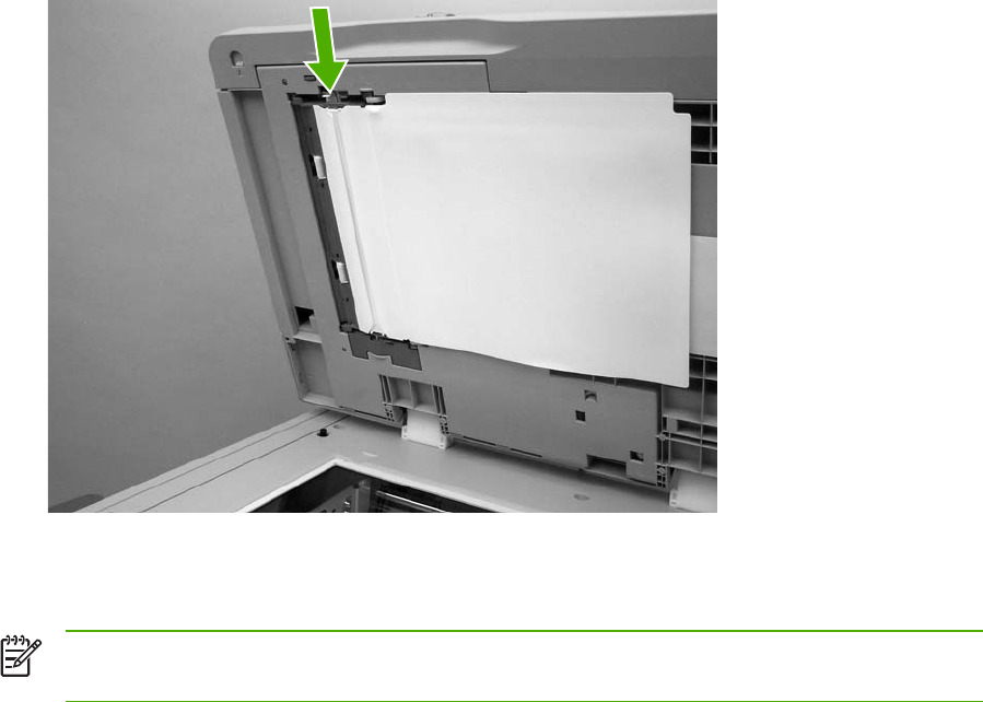
2. Locate the mylar strip.
3. Clean the mylar strip with a clean, damp, lint-free cloth.
4. Close the scanner lid.
NOTE Replacement mylar strips are stored in an envelope that is underneath the white vinyl
ADF backing. Follow the instructions that are in the envelope.
ENWW Cleaning the MFP 105

Calibrating the scanner
Calibrate the scanner to compensate for offsets in the scanner imaging system (carriage head) for
ADF and flatbed scans. Because of mechanical tolerances, the scanner's carriage head might not
read the position of the image accurately. During the calibration procedure, scanner offset values are
calculated and stored. The offset values are then used when producing scans so that the correct
portion of the document is captured.
Scanner calibration should be carried out only if experiencing offset problems with the scanned
images. The scanner is calibrated before it leaves the factory. It needs to be calibrated again only
rarely.
Before calibrating the scanner, print the calibration target.
To print the calibration target
1. Place letter or A4-size paper in tray 1, and adjust the side guides.
2. Press Menu to enter the MENUS.
3. Scroll to and touch DIAGNOSTICS.
4. Scroll to and touch CALIBRATE SCANNER.
5. Touch OK to print the first pass of the calibration target.
6. Place the first pass of the calibration target face-down in tray 1 so that the arrows are facing into
the MFP.
7. Touch OK to print the second pass. The final calibration target must look like the following figure.
CAUTION If the calibration target does not look like the figure shown here, the
calibration process will fail and the quality of scans will be degraded. The black areas
must extend completely to the short edges of the page. If they do not, use a black marker
to extend the black areas to the edge of the page. Press Stop to cancel the calibration.
8. Place the calibration target face-up into the ADF, and adjust the side guides. Touch OK to
continue.
9. After the calibration target has passed through the ADF once, place it in the ADF face down.
Touch OK to continue.
10. Place the calibration target face-down on the scanner glass and touch OK. After this pass, the
calibration is complete.
The product control panel displays the message Scanner calibration successful to indicate
success or the message Scanner calibration failed to indicate that the calibration failed.
106 Chapter 4 Maintenance ENWW
Performing preventive maintenance
The MFP requires periodic maintenance to maintain optimum performance. A product control panel
message alerts you when it is time to purchase the preventive maintenance kit.
ADF maintenance kit
After feeding 90,000 pages through the ADF, a Replace Document Feeder Kit message appears
on the product control panel display. This message appears approximately one month before the kit
needs to be replaced. Order a new kit when this message appears.
The ADF maintenance kit includes the following items:
●One pickup roller assembly
●One separation pad
●One mylar sheet kit
●An instruction sheet
Follow the instructions that come with the kit to install it.
After replacing the kit, reset the ADF maintenance kit count.
To reset the ADF maintenance kit count
1. Turn the MFP off and then on.
2. When XXXMB appears on the product control panel display, press and hold 6 until all three
LEDs flash once and then stay on. (This might take up to 20 seconds.)
3. Release 6 and then press 3 twice.
4. Press 6 to select NEW DOCUMENT FEEDER KIT.
5. The MFP completes its initialization sequence. The ADF maintenance kit counter is
automatically reset.
ENWW Performing preventive maintenance 107

Managing print cartridges
This section provides information about HP print cartridges, their life expectancies, how to store
them, and how to identify genuine HP supplies. Information also appears about non-HP print
cartridges.
HP print cartridges
When a genuine HP print cartridge is used, several types of information are available, such as the
following:
●Amount of toner remaining
●Estimated number of pages remaining
●Number of pages printed
Changing print cartridges
When a print cartridge approaches the end of its useful life, the product control panel displays a
message recommending that a replacement be ordered. The MFP can continue to print using the
current print cartridge until the product control panel displays a message instructing the user to
replace the cartridge.
The MFP uses four colors and has a different print cartridge for each color: black (K), magenta (M),
cyan (C), and yellow (Y).
Replace a print cartridge when the MFP product control panel displays a REPLACE <COLOR>
CARTRIDGE message. The product control panel display will also indicate the color that should be
replaced (if a genuine HP cartridge is currently installed).
Replacing a print cartridge
CAUTION If toner gets on clothing, wipe it off with a dry cloth and wash the clothes in cold
water. Hot water sets toner into fabric.
NOTE For information about recycling used print cartridges, visit the HP LaserJet Supplies
Web site at http://www.hp.com/go/recycle.
108 Chapter 4 Maintenance ENWW
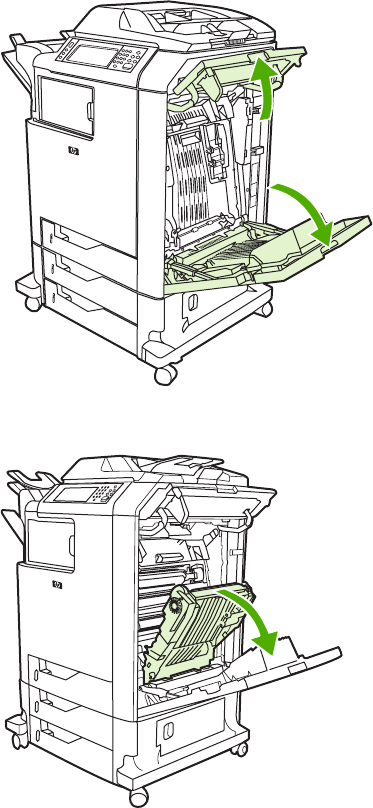
To replace the print cartridge
1. Using the handles, open the covers on the right side of the MFP.
2. Grasp the green handle on the transfer unit and pull down to open it.
ENWW Managing print cartridges 109
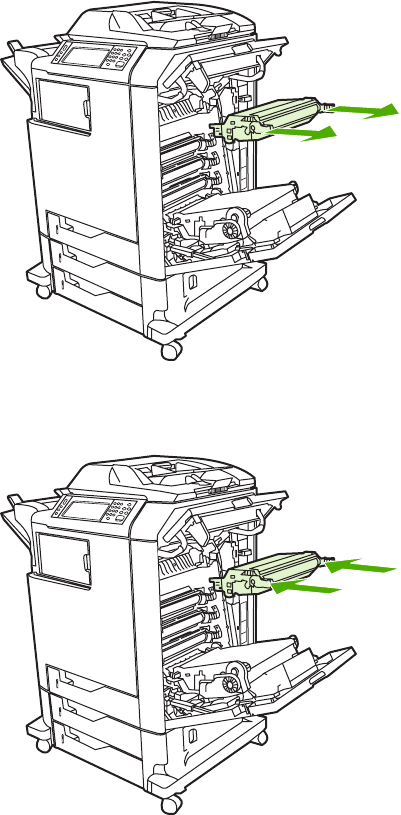
3. Remove the used print cartridge from the MFP.
4. Remove the new print cartridge from the bag. Place the used print cartridge in the bag for
recycling.
5. Align the print cartridge with the tracks inside the MPF and insert the print cartridge until it is
completely seated.
110 Chapter 4 Maintenance ENWW

6. Close the transfer unit.
7. Close the covers on the right side of the MFP. After a short while, the product control panel
should display Ready.
Non-HP print cartridges
Hewlett-Packard Company cannot recommend use of non-HP print cartridges, either new or
remanufactured. Because they are not HP products, HP cannot influence their design or control their
quality. Service or repair that is required as a result of using a non-HP print cartridge will not be
covered under the MFP warranty.
When a non-HP print cartridge is used, certain features, such as remaining toner volume data may
not be available.
Using genuine HP supplies ensures the availability of all HP printing features.
Print cartridge authentication
The MFP will let users know if a print cartridge is not a genuine HP print cartridge when the cartridge
is inserted into the MFP. If you believe that you purchased a genuine HP supply, go to
http://www.hp.com/go/anticounterfeit.
ENWW Managing print cartridges 111

Print cartridge storage
Do not remove the print cartridge from its package until you are ready to use it.
Always store the print cartridge in the proper environment. The storage temperature should be
between -20°C and 40°C (-4°F to 104°F). The relative humidity should be between 10% and 90%.
CAUTION To prevent damage to the print cartridge, do not expose it to light for more than a
few minutes.
Print cartridge life expectancy
The life of the print cartridge depends on the amount of toner that print jobs require and the length of
life for the components inside the cartridge. When printing text at approximately 5% coverage (typical
for a business letter), the HP print cartridge lasts an average of 12,000 pages. The page-yield
specification that HP provides is a general guideline. Actual yield can vary according to usage
conditions.
At any time, you can verify life expectancy by checking the supply level, as described below.
Checking the supply level
Check the supply (toner) level by using the product control panel, embedded Web server, or
HP Web Jetadmin, or by printing a supplies status page.
Using the product control panel
1. Press Menu to enter the MENUS.
2. Scroll to and touch Information.
3. Scroll to and touch SUPPLIES STATUS.
Using the embedded Web server
1. In a browser, enter the IP address for the MFP home page. This goes to the MFP status page.
2. On the left side of the screen, click Supplies Status. This goes to the supplies status page,
which provides print cartridge information.
Using HP Web Jetadmin
In HP Web Jetadmin, select the MFP. The device status page shows print cartridge information.
Printing a supplies status page
Use the supplies status page to obtain information about the print cartridge that is installed in the
MFP, the amount of toner that remains in the print cartridge, and the number of pages and jobs that
have been processed. The page also lets users know when they should schedule the next preventive
maintenance for each maintenance kit.
1. Press Menu to enter the MENUS.
2. Scroll to and touch Information.
112 Chapter 4 Maintenance ENWW
3. Scroll to and touch PRINT SUPPLIES STATUS PAGE.
4. Touch OK.
ENWW Managing print cartridges 113

Approximate replacement intervals for supplies
The following table lists the estimated replacement intervals for supplies and the control panel
messages that prompt when to replace each item. Usage conditions and print patterns can cause
results to vary.
Item Control panel message Page count Approximate time period
2
Black cartridges REPLACE BLACK
CARTRIDGE
12,000 pages
1
3 months
Color cartridges REPLACE <COLOR>
CARTRIDGE
12,000 pages
1
3 months
Transfer kit REPLACE TRANSFER KIT 120,000 pages
3
40 months
Fuser kit REPLACE FUSER KIT 150,000 pages
3
50 months
1
Approximate average A4-/letter-size page count based on 5% coverage of individual colors.
2
Approximate transfer unit life is based on 4,000 pages per month.
3
Approximate fuser unit life is based on 4,000 pages per month.
Use the embedded Web server to order supplies. For more information, see Using the
embedded Web server on page 112.
114 Chapter 4 Maintenance ENWW

ETB life under different circumstances
Depending on the MFP workload, the customer will need to replace the ETB once or twice in the life
of the MFP. In order to help plan supplies purchases, the HP Color LaserJet 4730mfp MFP
calculates an estimated remaining number of pages that can be printed with the ETB.
The number of pages the ETB can print is a function of two factors:
●The number of times the belt goes from a stationary to a rotating state (spins up)
●The number of pages that have been printed on the belt
Unless print jobs are queued back to back, each print job requires the belt to spin up.
Think of the ETB as having a limited number of wear units. It has 200,000 wear units when it is new.
Each time the belt spins up, it uses two wear units. Each time it prints a page, the belt uses one wear
unit.
Because most print jobs are not queued, the average number of pages per job, or job length, is a
factor in how fast the ETB will wear out. The shorter the average job, the more quickly the ETB will
wear out.
Figure 4-1 ETB total page count according to average job length on page 115 shows how many pages
an ETB can print, given various average job lengths.
Figure 4-1 ETB total page count according to average job length
The MFP assumes an average print job length of three pages to estimate how many pages are
remaining on the ETB. With an average job length of three pages, the ETB will print 120,000 pages.
If all print jobs are exactly three pages long, for each page printed the number of estimated pages
remaining would decrease by one, beginning with the maximum 120,000 pages. If the job length is
less than three pages, the estimated-pages-remaining number decreases more quickly than the rate
at which the number of pages actually printed increases. If the job length is greater than three pages,
the number of pages remaining decreases less quickly than the rate at which the actual number of
pages printed increases.
ENWW ETB life under different circumstances 115

Changing print cartridges
When a print cartridge approaches the end of its useful life, the product control panel displays a
message recommending that a replacement be ordered. The MFP can continue to print using the
current print cartridge until the product control panel displays a message instructing users to replace
the cartridge.
The MFP uses four colors and has a different print cartridge for each color: black (K), magenta (M),
cyan (C), and yellow (Y).
Replace a print cartridge when the MFP control panel displays a REPLACE <COLOR> CARTRIDGE
message. The product control panel display will also indicate the color that should be replaced (if a
genuine HP cartridge is currently installed).
Replacing print cartridges
For instructions on replacing print cartridges, see Replacing a print cartridge on page 108.
CAUTION If toner gets on clothing, wipe it off with a dry cloth and wash the clothes in cold
water. Hot water sets toner into fabric.
NOTE For information about recycling used print cartridges, visit the HP LaserJet Supplies
Web site at http://www.hp.com/go/recycle.
116 Chapter 4 Maintenance ENWW
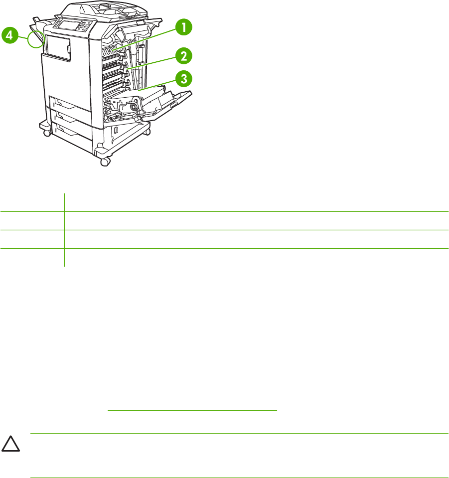
Replacing supplies
When using genuine HP supplies, the MFP automatically notifies you when supplies are nearly
depleted. The notification to order supplies allows ample time to order new supplies before they need
to be replaced.
Locating supplies
Supplies are identified by their labeling and their blue plastic handles.
The following figure illustrates the location of each supply item.
Figure 4-2 Supply item locations
1Fuser
2Print cartridges
3ETB (image transfer unit)
4Stapler cartridge
Supply replacement guidelines
To facilitate the replacement of supplies, keep the following guidelines in mind when setting up the
MFP.
●Allow sufficient space above and in the front of the MFP for removing supplies.
●The MFP should be located on a flat, sturdy surface.
For instructions on installing supplies, see the installation guides provided with each supply item or
see more information at http://www.hp.com/support/clj4730mfp. When you connect, select Solve a
Problem.
CAUTION HP recommends the use of genuine HP products in this MFP. Use of non-
HP products may cause problems requiring service that is not covered by the HP extended
warranty or service agreements.
ENWW Replacing supplies 117

Making room around the MFP for replacing supplies
The following illustration shows the clearance necessary in front of, above, and to the side of the
MFP for replacing supplies.
Figure 4-3 Supplies replacement clearance diagram
11160 mm (45.7 inches); if stapler/stacker or 3-bin mailbox is installed: 1460 mm (47.5 inches)
2980 mm (38.6 inches)
31050 mm (41.4 inches)
Replacing the ETB
Replace the ETB when a REPLACE TRANSFER KIT message appears on the product control panel
display.
1. Turn the MFP off.
2. Open the right upper and lower covers.
3. Lower the ETB by pulling the green handle at the top of the unit downward.
4. Press the small blue latches located on either side of the bottom of the ETB and lift the unit out
of the MFP.
5. Install the new ETB.
6. Close the right upper and lower covers.
7. Supplies ordering information is also available from the embedded Web server. See Using the
embedded Web server on page 112 for more information.
118 Chapter 4 Maintenance ENWW
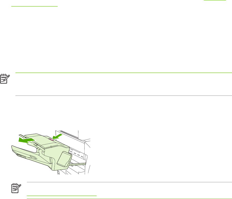
Replacing the fuser
Replace the fuser when a REPLACE FUSER KIT message appears on the product control panel
display.
1. Turn the MFP off.
2. Open the right upper cover.
3. Grasp the purple handles on the fuser.
4. Remove the old fuser from the MFP.
5. Install the new fuser.
6. Close the right upper cover.
7. Supplies ordering information is also available from the embedded Web server. See Parts and
supplies on page 43 for more information.
Replacing the stapler cartridge
The stapler cartridge contains 5,000 staples.
Replace the stapler cartridge if the MFP control panel display prompts users with a STAPLER LOW
ON STAPLES message (at this point, the stapler cartridge has 20 to 50 staples left) or a STAPLER
OUT OF STAPLES message. If the stapler runs out of staples and the stapler/stacker is configured
to CONTINUE, jobs continue to print to the stapler/stacker, but they are not stapled. If the stapler/
stacker is configured to stop, printing stops until a new stapler cartridge is loaded.
NOTE HP recommends replacing the stapler cartridge as soon as the STAPLER OUT OF
STAPLES message is displayed. Although some usable staples remain in the cartridge, they
could fall into the stapler mechanism and cause product failure.
Loading a new stapler cartridge
1. Press and hold the release button on the top of the stapler/stacker. Pull the stapler/stacker
away from the MFP.
NOTE For information on ordering a new stapler cartridge (part number C8091A), see
Parts and supplies on page 43.
ENWW Replacing supplies 119
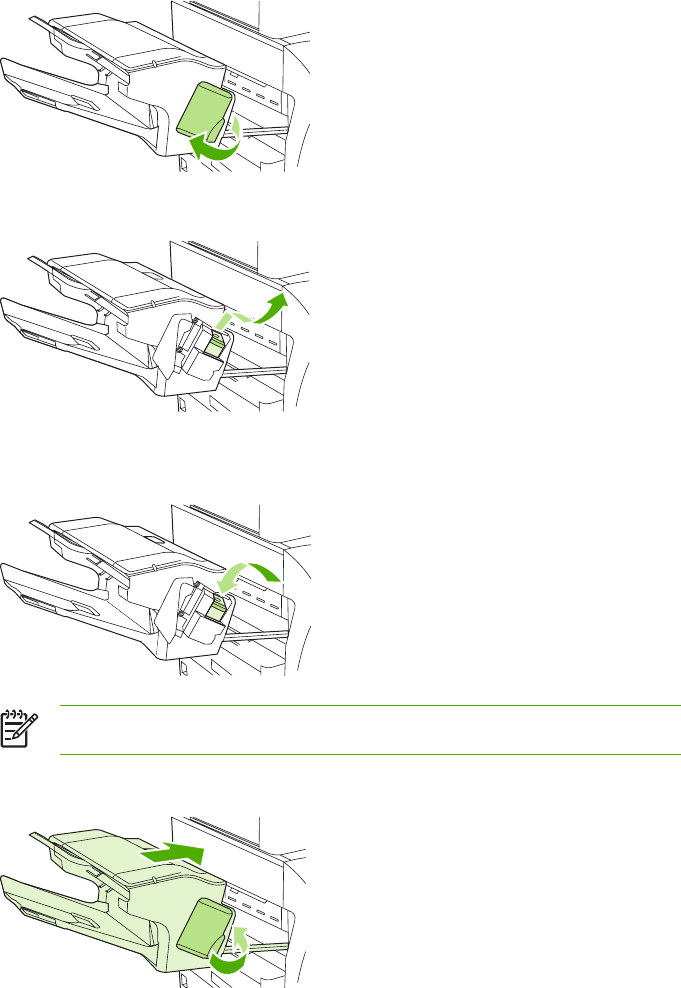
2. Open the staple cartridge cover.
3. Grasp the green staple cartridge handle and pull the old staple cartridge out of the stapler unit.
4. Insert the new staple cartridge into the stapler unit and push down on the green handle until the
unit snaps into place.
NOTE To obtain a new stapler cartridge, order part number C8091A.
5. Close the staple cartridge cover, and slide the stapler/stacker into the MFP.
120 Chapter 4 Maintenance ENWW

MFP memory and fonts
The MFP has 256 MB of synchronous dynamic random-access memory (RAM) expandable to
512 MB by using industry-standard 100-pin double data rate dual inline memory modules (DDR
DIMMS).
NOTE Memory specification: HP Color LaserJet 4730mfp uses 100-pin small outline dual
inline memory modules (SODIMM) that support 128 or 256 MB of RAM.
The MFP also has three flash memory card slots for MFP firmware, fonts, and other solutions.
●The first flash memory card is reserved for MFP firmware.
NOTE Use the first flash memory card slot for firmware only. The slot is marked
"Firmware Slot".
●The two additional flash memory card slots enable the user to add fonts and third-party
solutions, such as signatures and personalities. The slots are marked "Slot 2" and "Slot 3”. For
more information about types of solutions available, go to http://www.hp.com/go/gsc.
NOTE Flash memory cards adhere to Compact Flash specifications and size.
CAUTION Do not insert a flash memory card that is designed for use with a digital camera
into the MFP. The MFP does not support photo printing directly from a flash memory card. If a
camera-type flash memory card is installed, the product control panel displays a message
asking if the flash memory card should be reformatted. If the card is reformatted, all data on
the card will be lost.
Add more memory to the MFP to support printing of complex graphics or PostScript documents, or
use of many downloaded fonts. Additional memory also allows the MFP to print multiple collated
copies at maximum speed.
NOTE Single inline memory modules (SIMMs) / dual in-line memory modules (DIMMs) used
on previous HP LaserJet MFPs are not compatible with this MFP.
NOTE To order SODIMMs, see Parts and supplies on page 43.
Before ordering additional memory, see how much memory is currently installed by printing a
configuration page.
Printing a configuration page
1. Press Menu to enter the MENUS.
2. Scroll to and touch Information.
3. Scroll to and touch PRINT CONFIGURATION.
4. Touch OK to print the configuration page.
ENWW MFP memory and fonts 121
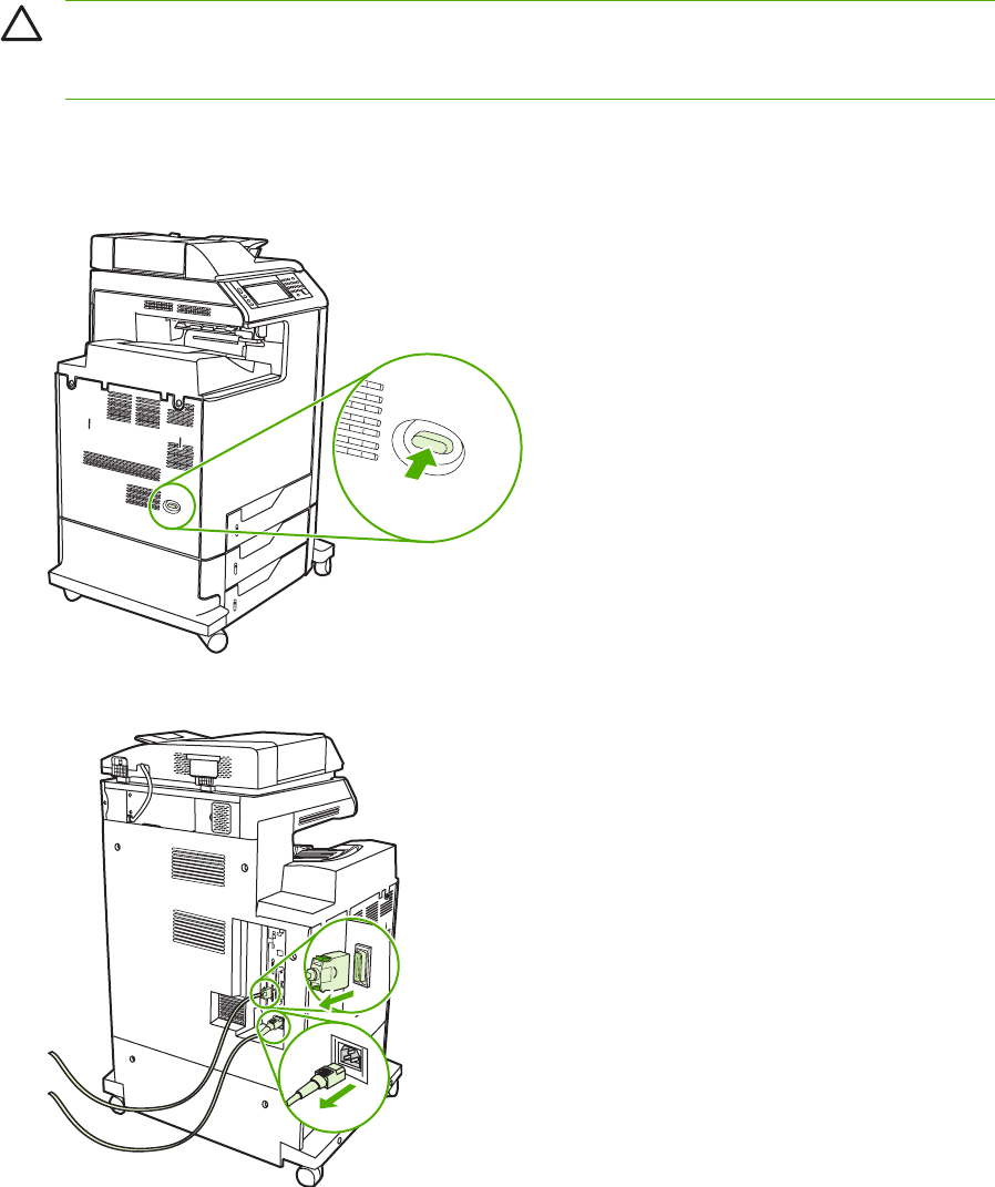
Installing memory and fonts
Additional memory can be installed in the MFP. A font card that will allow the MFP to print characters
for languages such as Chinese or the Cyrillic alphabet can also be installed.
CAUTION Static electricity can damage DIMMs. When handling DIMMs, either wear an
antistatic wrist strap, or frequently touch the surface of the DIMM antistatic package and then
touch bare metal on the MFP.
Installing DDR memory DIMMs
1. Turn the MFP off.
2. Disconnect all power and interface cables.
122 Chapter 4 Maintenance ENWW

3. Locate the formatter board in the rear of the MFP.
4. Locate the gray formatter pressure release tabs on the formatter board in the rear of the MFP.
5. Gently squeeze the tabs and pull them out of the formatter.
ENWW Installing memory and fonts 123
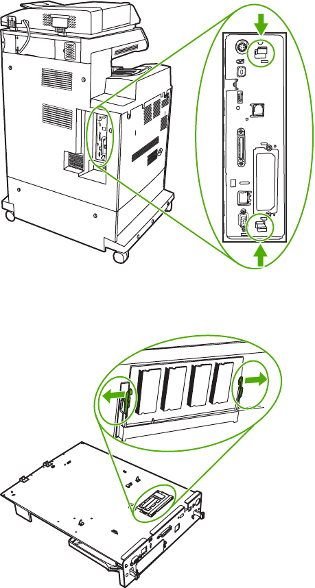
6. Gently pull on the black tabs at the top and bottom of the formatter board and pull the formatter
board from the MFP. Place the formatter board on a clean, flat, grounded surface.
7. To replace a DDR DIMM that is currently installed, spread the latches apart on each side of the
DIMM holder on the rear of the formatter.
124 Chapter 4 Maintenance ENWW
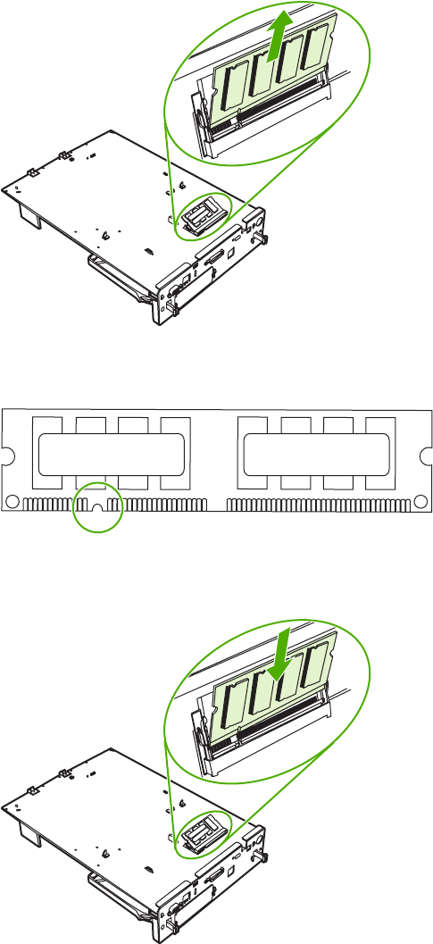
8. Lift the DDR DIMM up at an angle, and pull it out.
9. Remove the new DIMM from the antistatic package. Locate the alignment notch on the bottom
edge of the DIMM.
10. Holding the DIMM by the edges, insert it into the DIMM holder on the rear of the formatter.
When installed correctly, the metal contacts are not visible.
ENWW Installing memory and fonts 125
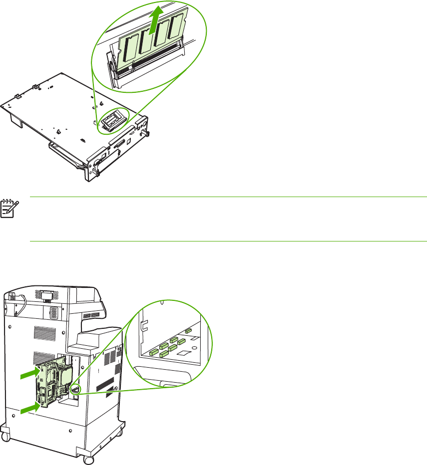
11. Push the DIMM holder flat against the back of the formatter.
NOTE If there is difficulty when inserting the DIMM, make sure the notch on the bottom
of the DIMM is aligned with the bar in the slot. If the DIMM still does not go in, confirm
that the correct type of DIMM is being installed.
12. Align the formatter board in the tracks at the top and bottom of the slot, and then slide the board
back into the MFP.
126 Chapter 4 Maintenance ENWW

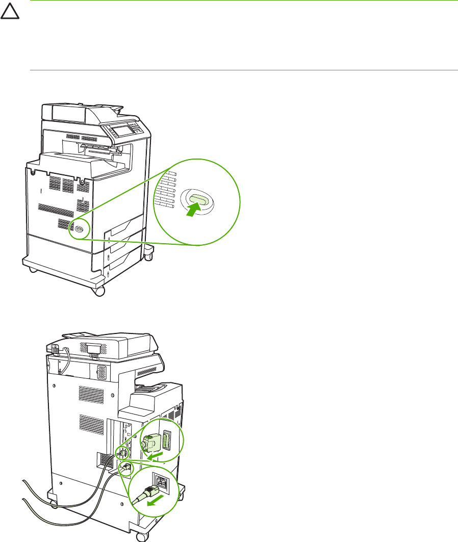
Installing a flash memory card
CAUTION Do not insert a flash memory card that is designed for use with a digital camera
into the MFP. The MFP does not support photo printing directly from a flash memory card. If a
camera-type flash memory card is installed, the product control panel displays a message
asking if the flash memory card should be reformatted. If the card is reformatted, all data on
the card will be lost.
1. Turn the MFP off.
2. Disconnect all power and interface cables.
128 Chapter 4 Maintenance ENWW
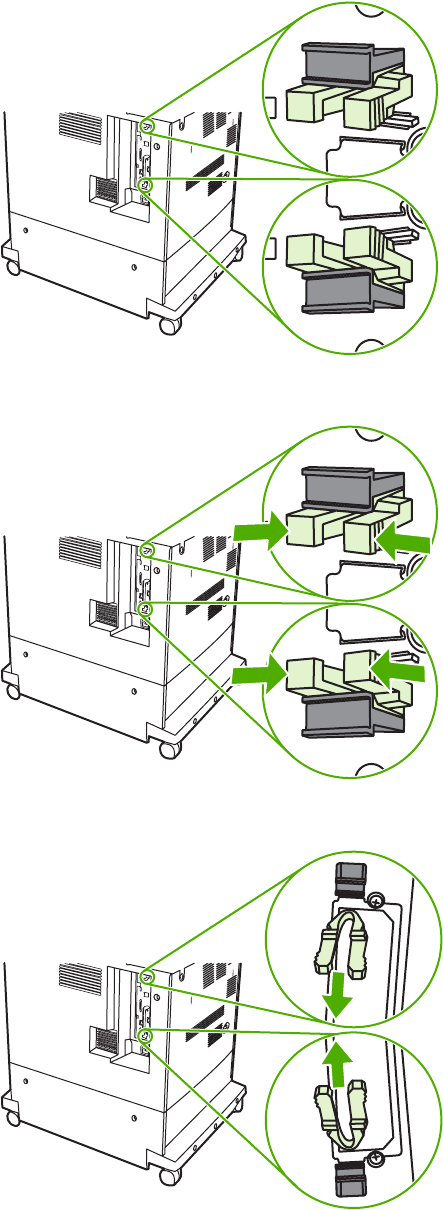
3. Locate the formatter board in the rear of the MFP.
4. Locate the gray formatter pressure release tabs on the formatter board in the rear of the MFP.
5. Gently squeeze the tabs and pull them out of the formatter.
ENWW Installing memory and fonts 129
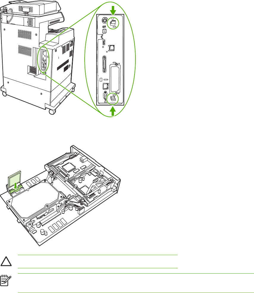
6. Gently pull on the black tabs at the top and bottom of the formatter board and pull the formatter
board from the MFP. Place the formatter board on a clean, flat, grounded surface.
7. Align the groove on the side of the flash memory card with the notches in the connector and
push it in the slot until it is fully seated.
CAUTION Do not insert the flash memory card at an angle.
NOTE The first flash memory slot marked "Firmware Slot" is reserved for firmware only.
Slots 2 and 3 should be used for all other solutions.
130 Chapter 4 Maintenance ENWW
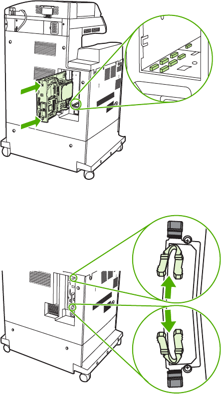
8. Align the formatter board in the tracks at the top and bottom of the slot, and then slide the board
back into the MFP.
9. Reinsert the formatter pressure release tabs into the formatter.
ENWW Installing memory and fonts 131
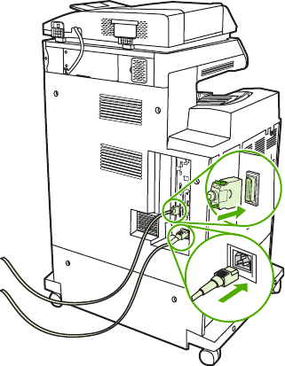
10. Reconnect the power cable and interface cables, and turn the MFP on.
Enabling memory
After a new memory DIMM is installed, set the printer driver to recognize the newly added memory.
To enable memory for Windows 98 and Windows Me
1. On the Start menu, point to Settings, and click Printers.
2. Right-click the MFP and select Properties.
3. On the Configure tab, click More.
4. In the Total Memory field, type or select the total amount of memory that is now installed.
5. Click OK.
To enable memory for Windows 2000 and Windows XP
1. On the Start menu, point to Settings, and click Printers or Printers and Faxes.
2. Right-click the MFP and select Properties.
3. On the Device Settings tab, click Printer Memory (in the Installable Options section).
4. Select the total amount of memory that is now installed.
5. Click OK.
132 Chapter 4 Maintenance ENWW

Setting the real-time clock
Use the real-time clock feature to set the date and time settings. The date and time information is
attached to stored print, fax, and digital-send jobs, so that the most recent versions of stored print
jobs can be identified. The MFP can also be set to automatically warm up and prepare for use at a
specified time each day.
Setting the date and time
When setting the date and time you can set the date format, date, time format, and time.
To set the date format
1. Press Menu.
2. Scroll to and touch Configure Device.
3. Scroll to and touch SYSTEM SETUP.
4. Scroll to and touch DATE/TIME.
5. Scroll to and touch DATE FORMAT.
6. Scroll to and touch the appropriate format. The settings are saved and the product control panel
returns to the DATE/TIME submenu.
7. Scroll to and touch Exit to exit the menu.
To set the date
1. Press Menu.
2. Scroll to and touch Configure Device.
3. Scroll to and touch SYSTEM SETUP.
4. Scroll to and touch DATE/TIME.
5. Scroll to and touch DATE.
6. Scroll to and touch the appropriate options to set the correct month, day of the month, and the
year.
NOTE The order of modifying the month, date of the month, and year depends upon
the date-format setting.
7. The settings are saved and the product control panel returns to the DATE/TIME submenu.
8. Touch Exit to exit the menu.
To set the time format
1. Press Menu.
2. Scroll to and touch Configure Device.
3. Scroll to and touch SYSTEM SETUP.
ENWW Setting the real-time clock 133

4. Scroll to and touch DATE/TIME.
5. Scroll to and touch TIME FORMAT.
6. Touch the appropriate format. The settings are saved and the product control panel returns to
the DATE/TIME submenu.
7. Scroll to and touch Exit to exit the menu.
To set the time
1. Press Menu.
2. Scroll to and touch Configure Device.
3. Scroll to and touch SYSTEM SETUP.
4. Scroll to and touch DATE/TIME.
5. Scroll to and touch TIME.
6. Touch the appropriate options to set the correct hour, minute, and AM/PM setting.
NOTE The order of modifying the hour, minute, and AM/PM setting depends upon the
time-format setting.
7. The settings are saved and the product control panel returns to the DATE/TIME submenu.
8. Touch Exit to exit the menu.
Setting the wake time
Use the wake time feature to wake the MFP at a set time each day. If a wake time is set, use an
extended Sleep-delay period. See Setting the Sleep delay on page 135.
To set the wake time
1. Press Menu.
2. Scroll to and touch Configure Device.
3. Scroll to and touch SYSTEM SETUP.
4. Scroll to and touch WAKE TIME.
5. Touch the day of the week for which the wake time is being set.
6. Scroll to and touch CUSTOM.
7. Touch the appropriate options to set the correct hour, minute, and AM/PM setting.
8. To wake the MFP at the same time each day, on the APPLY TO ALL DAYS screen, touch YES.
-or-
To set the time for individual days, touch NO, and repeat steps 5 through 7 for each day.
134 Chapter 4 Maintenance ENWW

9. The settings are saved and the product control panel returns to the WAKE TIME submenu.
10. Touch Exit to exit the menu.
Setting the Sleep delay
Use the Sleep-delay feature to set the period of time that the MFP must be idle before it enters the
Sleep mode.
NOTE If the Sleep-delay feature is turned off in the RESETS menu, the MFP never enters
the Sleep mode. Selecting a Sleep-delay value automatically turns the Sleep feature on. The
default value for the Sleep-delay setting is 45 minutes.
To set the Sleep delay
1. Press Menu to enter the MENUS.
2. Scroll to and touch Configure Device.
3. Scroll to and touch SYSTEM SETUP.
4. Touch SLEEP DELAY.
5. Scroll to and touch the Sleep-delay setting that you want.
6. The settings are saved and the product control panel returns to the SYSTEM SETUP submenu.
7. Touch Exit to exit the menu.
ENWW Setting the real-time clock 135

Configuring and verifying an IP address
Use any of three options to assign and configure TCP/IP addresses on an HP Jetdirect print server:
●HP Web Jetadmin
●Embedded Web server
●Control panel
TCP/IP assignment
The system administrator or primary user is responsible for determining the TCP/IP address for a
specific print server. To confirm the TCP/IP address or to learn how to use TCP/IP on a network, go
to the HP Web site at http://www.hp.com. Click Search in the upper-left corner of the Web page and
search for TCP/IP Overview.
Automatic discovery
The product is equipped with an HP Jetdirect embedded print server. If a BootP or DHCP server is
available during product installation, the print server is automatically assigned an IP address for use
on the network. The print server defaults to 192.0.0.192 (Legacy default) or to 169.254.x.x (Auto IP)
if the print server cannot obtain an IP address over the network from a BootP or DHCP server. The
default that is assigned depends on the particular network (small/private or enterprise) by using
sensing algorithms.
To determine the new IP address, print a configuration page and check the TCP/IP status and
address.
Dynamic host configuration protocol (DHCP)
When the product is turned on, the HP Jetdirect print server broadcasts DHCP requests. The DHCP
automatically downloads an IP address from a network server. The DHCP servers maintain a fixed
set of IP addresses and only loan an IP address to the print server. Consult the operating system
documentation to set up a DHCP service on your network.
Verifying the TCP/IP configuration
Print a configuration page at the product control panel. Check the TCP/IP status and the TCP/
IP addresses. If the information is incorrect, check the hardware connections (cables, hubs, routers,
or switches) and reconfirm the validity of the IP address.
Changing an IP address
Use the following procedures to change the product TCP/IP address.
To change an IP address by using HP Web Jetadmin
Open HP Web Jetadmin. Type the TCP/IP address in the Quick Device Search field and click Go.
At the top menu bar, follow this procedure for discovery options.
1. In the drop-down menu, click Devices.
2. In the drop-down menu, click New Devices. Click Go.
136 Chapter 4 Maintenance ENWW
3. Click the appropriate column header (such as IP address or Device Model) to arrange the list of
available devices in ascending or descending order.
4. Highlight the product to configure, and click Open Device.
5. From the sub-menu at the top of the HP Web Jetadmin screen, click Configuration.
6. Click the network link located on the left side of the configuration screen.
7. Type the new IP information. Scroll down for more options.
8. Click Apply to save the settings.
9. Click the Refresh button located next to the question mark on the right side of the screen.
10. Verify the IP information by clicking Status Diagnostics or by printing a configuration page.
To change an IP address by using the embedded Web server
The MFP has an embedded Web server that can be used to modify the TCP/IP parameters. In order
to use the embedded Web server, the HP Jetdirect print server must have an IP address already
configured. On a network, this is done automatically during initial product installation.
1. In a supported Web browser, type the current IP address of the HP Jetdirect print server as the
URL. The Device Status page of the embedded Web server appears.
2. Click Networking. Use this page to modify the MFP network configuration.
To change an IP address by using the control panel
To manually configure or verify the IP address by using the product control panel, follow the
instructions below.
1. Press Menu to enter the MENUS.
2. Scroll to and touch Configure Device.
3. Scroll to and touch I/O.
4. Scroll to and touch EMBEDDED JETDIRECT MENU.
5. Touch TCP/IP.
6. Scroll to and touch CONFIG METHOD.
7. Scroll to and touch MANUAL.
8. Scroll to and touch MANUAL SETTINGS.
9. Scroll to and touch IP Address: X.
10. Touch the left and right arrows to select each byte of the IP address.
11. Use the numeric keypad to enter the value of each byte.
12. Touch OK to save the IP address.
13. Scroll to and touch SUBNET MASK.
14. Touch the left and right arrows to select each byte of the subnet mask.
ENWW Configuring and verifying an IP address 137
15. Use the numeric keypad to enter the value of each byte of the subnet mask.
16. Touch OK to save the subnet mask.
17. Scroll to and touch DEFAULT GATEWAY.
18. Touch the left and right arrows to select each byte of the default gateway.
19. Use the numeric keypad to enter the value of each byte of the default gateway.
20. Touch OK to save the default gateway.
138 Chapter 4 Maintenance ENWW

Upgrading the firmware
The MFP has remote firmware update (RFU) capability. Use the information in this section to
upgrade the MFP firmware. The overall process involves the following steps:
1. Determine the current level of firmware that is installed on the MFP.
2. Go to the HP Web site and find out whether a firmware update is available. If an update is
available, download the latest firmware to the computer.
3. Transfer the new firmware from the computer to the MFP.
Determining the current level of firmware
To determine the current level of firmware, view the configuration information on the MFP control
panel. To view the configuration information, follow these instructions.
1. Press Menu.
2. Touch Information.
3. Touch PRINT CONFIGURATION. The configuration page prints.
4. The firmware datecode is listed in the section called Device Information. The firmware
datecode has this format: YYYYMMDD XX.XXX.X. The first string of numbers is the date, where
YYYY represents the year, MM represents the month, and DD represents the date. For
example, a firmware datecode of 20040225 represents February 25, 2004.
Downloading the new firmware from the HP Web site
To find the most recent firmware upgrade for the MFP, go to http://www.hp.com/go/
clj4730mfp_software. This page provides instructions for downloading the new firmware version.
Transferring the new firmware to the MFP
Use one of the following methods to update the firmware.
Using FTP to upload the firmware through a browser
Follow these steps to update the MFP firmware by using FTP through a browser.
To use a browser for firmware update
NOTE These instructions can be used for both Windows and Macintosh operating systems.
1. Print a configuration page and note the TCP/IP address shown on the EIO Jetdirect page.
2. Open a browser window.
3. In the address line of the browser, type ftp://<ADDRESS>, where <ADDRESS> is the
address of the MFP. For example, if the TCP/IP address is 192.168.0.90, type
ftp://192.168.0.90.
ENWW Upgrading the firmware 139

4. Locate the downloaded .RFU file for the MFP.
5. Drag and drop the .RFU file onto the PORT1 icon in the browser window.
NOTE The MFP turns off and then on automatically to activate the update. When the update
process is complete, a Ready message displays on the MFP control panel.
Using FTP to upgrade the firmware on a network connection
NOTE The MFP can receive an .RFU file update as long as it is in a Ready state.
The elapsed time for an update depends on the I/O transfer time, as well as the time that it takes for
the MFP to reinitialize. The I/O transfer time depends on a number of things, including the speed of
the host computer that is sending the update. If the remote firmware update process is interrupted
before the firmware is downloaded (while Receiving upgrade appears on the product control panel
display), the firmware file must be sent again. If power is lost during the flash DIMM update (while the
Performing upgrade message appears on the control panel display), the update is interrupted and
the message Resend upgrade appears (in English only) on the control panel display. In this case,
you must send the upgrade by using the parallel port. Finally, any jobs that are ahead of the RFU job
in the queue are completed before the update is processed.
Follow these instructions to perform the upgrade by using FTP.
NOTE The firmware update involves a change in the format of nonvolatile random-access
memory (NVRAM). Any menu settings that are changed from the default settings might return
to default settings and must be changed again if you want settings that are different from the
defaults.
To upgrade the firmware on a network connection by using FTP
1. Take note of the IP address on the HP Jetdirect page. The HP Jetdirect page is the second
page that prints when you print the configuration page.
NOTE Before upgrading the firmware, make sure that the MFP is not in Sleep mode.
Also make sure that any error messages are cleared from the product control panel
display.
2. Open an MS-DOS command prompt on your computer.
3. Go to the folder where the firmware file is stored.
4. Type: ftp <TCP/IP address>. For example, if the TCP/IP address is 192.168.0.90, type
ftp 192.168.0.90.
5. Press Enter on the keyboard.
6. When prompted for the user name, press Enter.
7. When prompted for the password, press Enter.
8. Type bin at the command prompt.
9. Press Enter. The message 200 Types set to I, Using binary mode to transfer files appears in
the command window.
140 Chapter 4 Maintenance ENWW

10. Type put and then the file name (for example, if the file name is 4730mfp.efn, type put
4730mfp.efn.
11. The following series of messages appears in the command window:
200 PORT command successful
150 Opening BINARY mode data connection
226 Ready
-or-
226 Processing Job
-or-
226 Transfer complete
-or-
12. The download process begins and the firmware is updated on the MFP. This can take
approximately five minutes. Let the process finish without further interaction with the MFP or
computer.
NOTE The MFP automatically turns off and then on again after processing the upgrade.
13. At the command prompt, type: bye to exit the ftp command.
14. At the command prompt, type: exit to return to the Windows interface.
Using HP Web Jetadmin to upgrade the firmware
This procedure requires that HP Web Jetadmin Version 7.0 or later be installed on the computer.
See Using HP Web Jetadmin software on page 639. Complete the following steps to update a single
device through HP Web Jetadmin after downloading the .RFU file from the HP Web site.
1. Start HP Web Jetadmin.
2. Open the Device Management folder in the drop-down list in the Navigation panel. Navigate to
the Device Lists folder.
3. Expand the Device Lists folder and select All Devices. Locate the MFP in the list of devices,
and then click to select it.
To upgrade the firmware for multiple HP LaserJet 4730mfps, select all of them by pressing the
Ctrl key while clicking the name of each MFP.
4. Locate the drop-down box for Device Tools in the upper-right corner of the window. Select
Update Printer Firmware from the action list.
5. If the name of the .RFU file is not listed in the All Available Images box, click Browse in the
Upload New Firmware Image dialog box and navigate to the location of the .RFU file that you
downloaded from the Web at the start of this procedure. If the filename is listed, select it.
6. Click Upload to move the .RFU file from your hard drive to the HP Web Jetadmin server. After
the upload is complete, the browser window refreshes.
ENWW Upgrading the firmware 141

7. Select the .RFU file from the Printer Firmware Update drop-down menu.
8. Click Update Firmware. HP Web Jetadmin sends the selected .RFU file to the MFP. The
product control panel shows messages that indicate the progress of the upgrade. At the end of
the upgrade process, the control panel shows the Ready message.
Using MS-DOS commands to upgrade the firmware
To update the firmware by using a network connection, follow these instructions.
1. From a command prompt or in an MS-DOS window, type the following: copy /B
<FILENAME> \\<COMPUTERNAME>\<SHARENAME>, where <FILENAME> is the name of
the .RFU file (including the path), <COMPUTERNAME> is the name of the computer from which
the MFP is being shared, and <SHARENAME> is the MFP share name. For example: C:
\>copy /b C:\9200fW.RFU \\YOUR_SERVER\YOUR_COMPUTER.
NOTE If the file name or path includes a space, you must enclose the file name or path
in quotation marks. For example, type: C:\>copy /b "C:\MY DOCUMENTS
\3500FW.RFU" \\YOUR_SERVER\YOUR_COMPUTER.
2. Press Enter on the keyboard. The product control panel shows a message that indicates the
progress of the firmware upgrade. At the end of the upgrade process, the product control panel
shows the Ready message. The message 1 file(s) copied displays on the computer screen.
142 Chapter 4 Maintenance ENWW

Upgrading the HP Jetdirect firmware
The HP Jetdirect network interface in the MFP has firmware that can be upgraded separately from
the MFP firmware. This procedure requires that you install HP Web Jetadmin Version 7.0 or later on
the computer. See Using HP Web Jetadmin software on page 639. Complete the following steps to
update the HP Jetdirect firmware by using HP Web Jetadmin.
1. Open the HP Web Jetadmin program.
2. Open the Device Management folder in the drop-down list in the Navigation panel. Navigate to
the Device Lists folder.
3. Select the device that you want to update.
4. In the Device Tools drop-down list, select Jetdirect Firmware Update.
5. Under Jetdirect firmware version the HP Jetdirect model number and current firmware version
are listed. Make a note of these.
6. Go to http://www.hp.com/go/wja_firmware.
7. Scroll down to the list of HP Jetdirect model numbers and find the model number you wrote
down.
8. Look at the current firmware version for the model, and see if it is later than the version you
wrote down. If it is, right-click on the firmware link, and follow the instructions on the Web page
to download the new firmware file. The file must be saved into the <drive>:\PROGRAM FILES
\HP WEB JETADMIN\DOC\PLUGINS\HPWJA\FIRMWARE\JETDIRECT folder on the computer
that is running the HP Web Jetadmin software.
9. In HP Web Jetadmin, return to the main device list and select the digital sender again.
10. In the Device Tools drop-down list, select Jetdirect Firmware Update again.
11. On the HP Jetdirect firmware page, the new firmware version is listed under Jetdirect
Firmware Available on HP Web Jetadmin. Click the Update Firmware Now button to update
the Jetdirect firmware.
ENWW Upgrading the firmware 143
144 Chapter 4 Maintenance ENWW

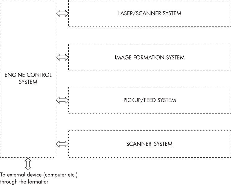
Basic operation
The HP Color LaserJet 4730mfp functions are divided into the following systems:
●Engine control system
●Laser/scanner system
●Image formation system
●Pickup/feed system
●Scanner system
●2 X 500-sheet paper feeder
●Output devices
The engine control system controls the laser/scanner system, the image formation system, and the
pickup/feed system. The engine control system performs the printing operation after receiving a print
command from the external device through the formatter. The engine control system also receives
status from each system and sends necessary information back to the formatter.
This chapter describes each of these four systems thoroughly.
Figure 5-1 Basic system operation
146 Chapter 5 Theory of operation ENWW

Operation sequence
A microcomputer in the engine control system controls the operation sequence for the MFP. The
basic operation sequence (see Table 5-1 Basic operation sequence on page 147) describes the main
operational periods from the point when the MFP is turned on until a print operation is completed and
each motor stops rotating.
NOTE In the following table, “ETB” stands for “electrostatic transfer/transport belt.”
Table 5-1 Basic operation sequence
Period Purpose Remark
WAIT (wait period) From the time the power
switch is turned on until the
ETB cleaning is completed.
To clear a potential on the
drum surface and to clean
the ETB.
During this period, the MFP
checks the toner level and
detects whether the
cartridges are present. The
MFP also executes the
pulse width modulation
adjustment, color
registration adjustment, and
image density calibration
control as required.
STBY (standby period) From the end of the WAIT or
LSTR period or last rotation
until the formatter inputs a
print command or until the
power is turned off.
To keep the MFP ready to
print.
When the formatter sends a
Sleep command, the MFP
enters Sleep mode.
INTR (initial rotation period) From immediately after the
formatter inputs a print
command until the TOP
signal is sent to the formatter.
To stabilize the
photosensitive drum
sensitivity in preparation for
a print operation.
When the formatter sends a
print command in
preparation for printing.
PRINT (print period) From the end of the INTR
period until the leading edge
detection sensor detects
paper and then turns off the
transfer positive bias.
To form an image on the
photosensitive drum
according to the video signal
input from the formatter and
to transfer the toner image
to the paper.
After the power is turned on,
the cartridge is cleaned
every 35 pages and the ETB
is cleaned every 100 pages.
LSTR (last rotation period) From the end of the PRINT
period until the drum motor
stops.
To deliver the paper out of
the MFP and to clean the
ETB.
The last rotation period lasts
until the instant the formatter
sends a print command.
Then the initial rotation
period starts again.
Operation sequence (scanner)
Period (sequence) Description
Power on During this time, the scanner motors rotate, the MFP checks the status of all the sensors,
the scanner lamp is illuminated, the optical scan head moves from its home position, the
scanner calibrates, and then the optical scan head returns to its home position.
Initialization The period of time after the initial power-on sequence and before the MFP is ready to scan
or copy. During this time, the scanner and ADF initialization is completed, scanner
calibration is performed, and the ADF checks for media in the input tray.
ENWW Basic operation 147

Period (sequence) Description
Standby The period of time from the end of the initialization sequence until a request for a scan.
During this time, the MFP might go into Sleep mode and the scan carriage rests in its home
position.
Scan The period of time immediately following a request for a scan. The scanner fan turns on,
the scan start position is adjusted, the MFP performs the scan, and data is sent to the
formatter.
Power on sequence
The power on sequence initializes the MFP and checks for possible malfunctions or paper jams.
Figure 5-2 Power on sequence on page 149 shows the MFP status from power on to standby mode.
148 Chapter 5 Theory of operation ENWW
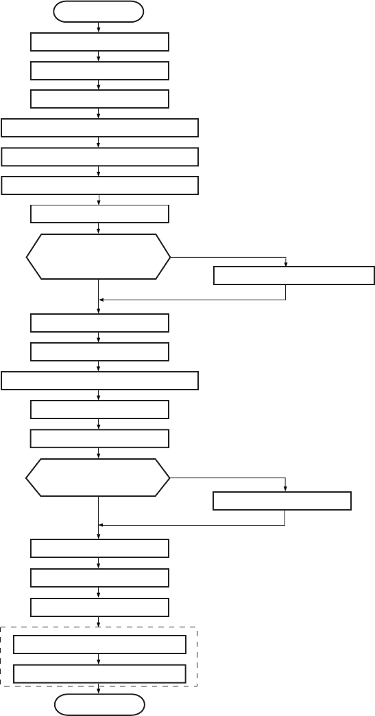
Power ON
CPU Initialization
ASIC Initialization
Start-up Fan
Video interface communication start
Internal communication start
Cartridge presence check
Residual paper jam check
Pressurize fixing unit
Developing roller
engagement/diseng
agement check Disengage developing roller
Engaged
Disengaged
Environment detection
Motors initial drive
Residual paper check
Scanner initial drive
Transfer roller position
detection
Shift home position
Out of home position
Home position
Color misregistration correction
Drum phase adjustment
Image stabilization control
Standby
Toner level detection
ETB cleaning
Figure 5-2 Power on sequence
ENWW Basic operation 149
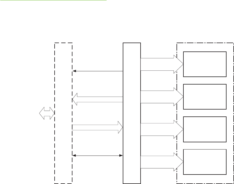
Formatter system
The formatter PCB is responsible for the following actions:
●Receiving and processing print data from the various MFP interfaces
●Monitoring control panel inputs and relaying MFP status information (through the product control
panel and the bidirectional I/O)
●Developing and coordinating data placement and timing with the print engine
●Storing font information
●Communicating with the host computer through the bidirectional interface
●Controlling the Sleep mode
The formatter monitors the MFP continuously through the video interface. When the MFP is ready to
print, the formatter sends a signal to the DC controller, which turns the laser on or off based on the
signal. Figure 5-3 Formatter system on page 150 shows the formatter system.
The formatter also provides the electrical interface and mounting locations for an EIO card, two
memory DIMMs, two additional flash memory cards (a third slot is reserved for firmware), hard disk,
and optional analog fax accessory.
SC
VDO, /VDO
/TOP
/BD
External devices
(host computer, etc.)
Formatter DC controller PCB Laser/Scanner unit
Bk laser driver
M laser driver
C laser driver
Y laser driver
VIDEO signals
VIDEO signals
VIDEO signals
VIDEO signals
Figure 5-3 Formatter system
Sleep mode
This feature conserves power after the MFP has been idle for an adjustable length of time. Set the
time length in the Configure Device menu, under SYSTEM SETUP. When the MFP is in Sleep
mode, the product control panel backlight is turned off, but the MFP retains all printer settings,
150 Chapter 5 Theory of operation ENWW

downloadable fonts, and macros. The default setting is 30 MINUTES. You can turn Sleep mode off in
the Configure Device menu, under RESETS.
The MFP exits Sleep mode and enters the warm-up cycle when any of the following occurs:
●A print job, valid data, or a PML or PJL command is received at the parallel port, EIO card, or
USB 2.0 connector.
●A product control panel button is pressed.
●The right upper and lower covers are opened.
●The engine test button is pressed.
NOTE MFP error messages override the Sleep mode on message. The MFP enters Sleep
mode at the appropriate time, but the error message continues to appear.
Image Resolution Enhancement technology (REt)
The formatter contains circuitry for Image Resolution Enhancement technology (REt), which modifies
the standard video dot data on its way to the DC controller PCB to produce “smoothed” line edges.
The REt can be turned on or off from the product control panel or from some software programs. The
default setting is medium.
NOTE The REt settings that are sent from software programs or printer drivers override the
control panel settings.
Input/Output
This section explains the MFP input/output (I/O) capabilities.
Parallel interface
The formatter receives incoming data through its bidirectional interface (IEEE-1284). The I/O
provides high-speed and two-way communication between the MFP and the host, allowing the user
to change MFP settings and monitor MFP status from the host computer. The user can configure the
HIGH SPEED item on the control panel menu. (This item is found by navigating to the Configure
Device menu, navigating to the I/O menu, and selecting PARALLEL INPUT.) The default setting,
YES, allows the I/O to run at the higher speeds supported by most newer computers. When set to
NO, the parallel interface runs at the slower mode that is compatible with older computers. The user
can also configure the ADVANCED FUNCTIONS item. The default setting, ON, allows for two-way
parallel communications. The OFF mode disables the advanced functionality. The I/O is compatible
with the bidirectional parallel interface standard.
USB 2.0 connector
The HP Color LaserJet 4730mfp supports a USB 2.0 connector on the back of the MFP. You must
use an A-to-B type USB cable.
ACC accessory port
This MFP also includes a third-party accessory (ACC) port that uses USB host protocol.
ENWW Formatter system 151

Flash
Optional flash is available in 4 MB flash memory DIMMs for storing forms, fonts, and signatures.
Hard disk
The hard disk is mounted in an EIO slot on the formatter. The hard disk is used to create multiple
original prints (mopies) and store forms, fonts, and signatures.
CPU
The HP LaserJet 4730mfp formatter incorporates a 533 MHz RISC processor.
FIH (foreign interface harness)
The FIH allows connection to third-party devices, such as copy counters and biometric security
devices.
MFP memory
If the MFP encounters difficulty managing available memory, a clearable warning message will
appear on the product control panel.
Some MFP messages are affected by the auto-continue and clearable warning settings from the
Configure Device menu, under SYSTEM SETUP. If Clearable Warning = Job is set on the product
control panel, warning messages appear on the control panel display until the end of the job from
which they were generated. If Clearable Warning = On is set, warning messages appear on the
control panel until is pressed. If an error occurs that prevents printing and Autocontinue = Off is
set, the message appears until Ignore is touched.
Read-only memory
Besides storing microprocessor control programs, the read-only memory (ROM) stores dot patterns
of internal character sets (fonts).
Random-access memory
The random-access memory (RAM) contains the page, I/O buffers, and the font storage area. It
stores printing and font information received from the host system, and can also serve to temporarily
store a full page of print-image data before the data is sent to the print engine. Memory capacity can
be increased by adding DIMMs to the formatter. Note that adding memory (DIMMs) might also
increase the print speed for complex graphics.
DIMM slots
The DIMM slots can be used to add memory, fonts, or firmware upgrades.
Flash memory
To upgrade MFP firmware, upload a new firmware image to the MFP.
152 Chapter 5 Theory of operation ENWW
Nonvolatile memory
The MFP uses nonvolatile memory (NVRAM) to store I/O and information about the print
environment configuration. The contents of NVRAM are retained when the MFP is turned off or
disconnected.
PJL overview
Printer job language (PJL) is an integral part of configuration, in addition to the standard printer
command language (PCL). With standard cabling, PJL allows the MFP to perform the following
functions:
●Two-way communication with the host computer through a bidirectional parallel connection. The
MFP can tell the host about such things as the control panel settings, and the control panel
settings can be changed from the host.
●Dynamic I/O switching allows the MFP to be configured with a host on each I/O. The MFP can
receive data from more than one I/O simultaneously, until the I/O buffer is full. This can occur
even when the MFP is offline.
●Context-sensitive switching allows the MFP to automatically recognize the personality (PS or
PCL) of each job and configure itself to serve that personality.
●Isolation of print environment settings from one print job to the next. For example, if a print job is
sent to the MFP in landscape mode, the subsequent print jobs print in landscape only if they are
formatted for landscape printing.
PML
The printer management language (PML) allows remote configuration and status readback through
the I/O ports.
Control panel
The formatter sends and receives MFP status and command data to and from a control panel board.
Scanner interface
The formatter receives data from the scanner to produce copies and to send scanned data in e-mail
format.
ENWW Formatter system 153
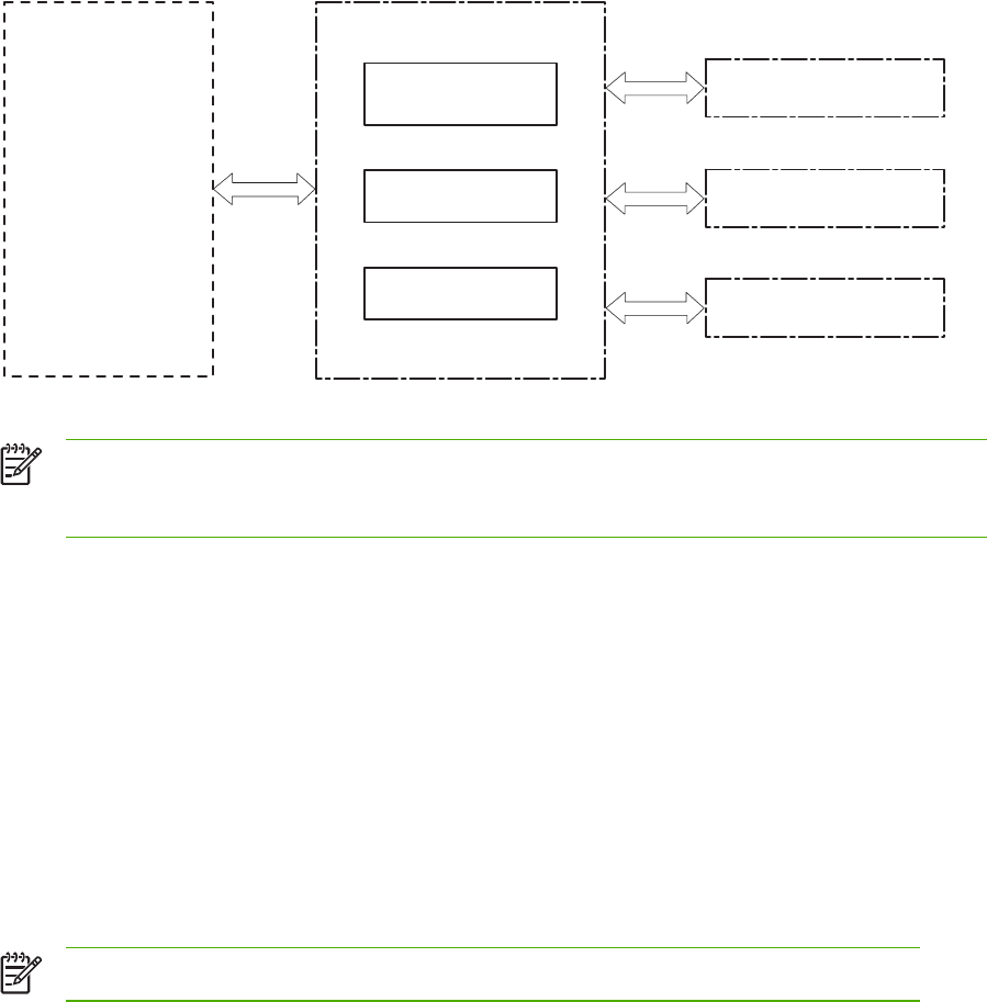
Engine control system
The engine control system is the brain of the HP Color LaserJet 4730mfp. It controls all the other
systems according to commands from the formatter. The engine control system consists of the
following:
●DC controller PCB
●High-voltage PCB
●Low-voltage power supply PCB
●Formatter
Each of these components is described in this chapter.
Laser/Scanner system
Image formation system
Pick-up/Feed system
Engine control system
DC controller PCB
Low-voltage power
supply unit
High-voltage power
supply PCB
Formatter
Figure 5-4 Engine control system
NOTE In this manual, the abbreviation "PCB" stands for "printed circuit board". Components
described as a PCB can consist of a single circuit board or a circuit board plus other parts,
such as cables and sensors.
DC controller PCB
The DC controller controls the print operation sequence for the MFP. The sequence of events is as
follows:
1. Power is turned on.
2. The low-voltage power supply PCB supplies DC power to the DC controller.
3. The CPU in the DC controller starts to control MFP operations.
4. The MFP enters the standby period.
5. Based on the print command and the image data input from the formatter, the CPU sends a
signal to drive the laser diode, the motors, and the solenoids.
NOTE See the general circuit diagram for detailed information about the MFP circuitry.
154 Chapter 5 Theory of operation ENWW
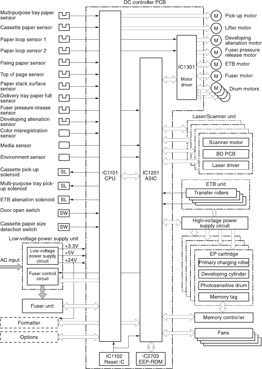
Figure 5-5 DC controller PCB
ENWW Engine control system 155

Block operation
The blocks that make up the DC controller PCB include:
●CPU. The CPU is a single-chip microcomputer with built-in ROM and RAM. It controls the MFP
engine sequence, ASIC, fuser, pickup motor and lifter motor, solenoids, sensors, and switches.
●ASIC. Interfaces with the IC, memory, and external devices.
●Motor driver ASIC. Controls each motor in response to commands from the CPU.
●Reset IC. Monitors voltage and resets the CPU and ASIC when the power is turned on.
●EEPROM. Stores backup data.
Motors, fans, and environment sensor
The MFP has ten motors, ten fans, and one environment sensor. Seven of the motors are DC
motors; the other three are stepping motors. Figure 5-6 Motors and fans on page 157 shows the
locations of the motors and fans. Table 5-2 Function of motors, fans, and environment sensor
on page 157 explains the function of each component.
Two of the stepping motors and six of the seven DC motors are used for paper feeding and image
formation. The remaining stepping motor is the developing disengaging motor. The remaining two
DC motors are fan motors.
Since the MFP transfers an image in four colors in line onto the media, small changes in the
rotational speed of the motor are likely to cause color misalignment. The DC motors used for image
formation are precisely controlled to account for rotational speed fluctuation.
156 Chapter 5 Theory of operation ENWW
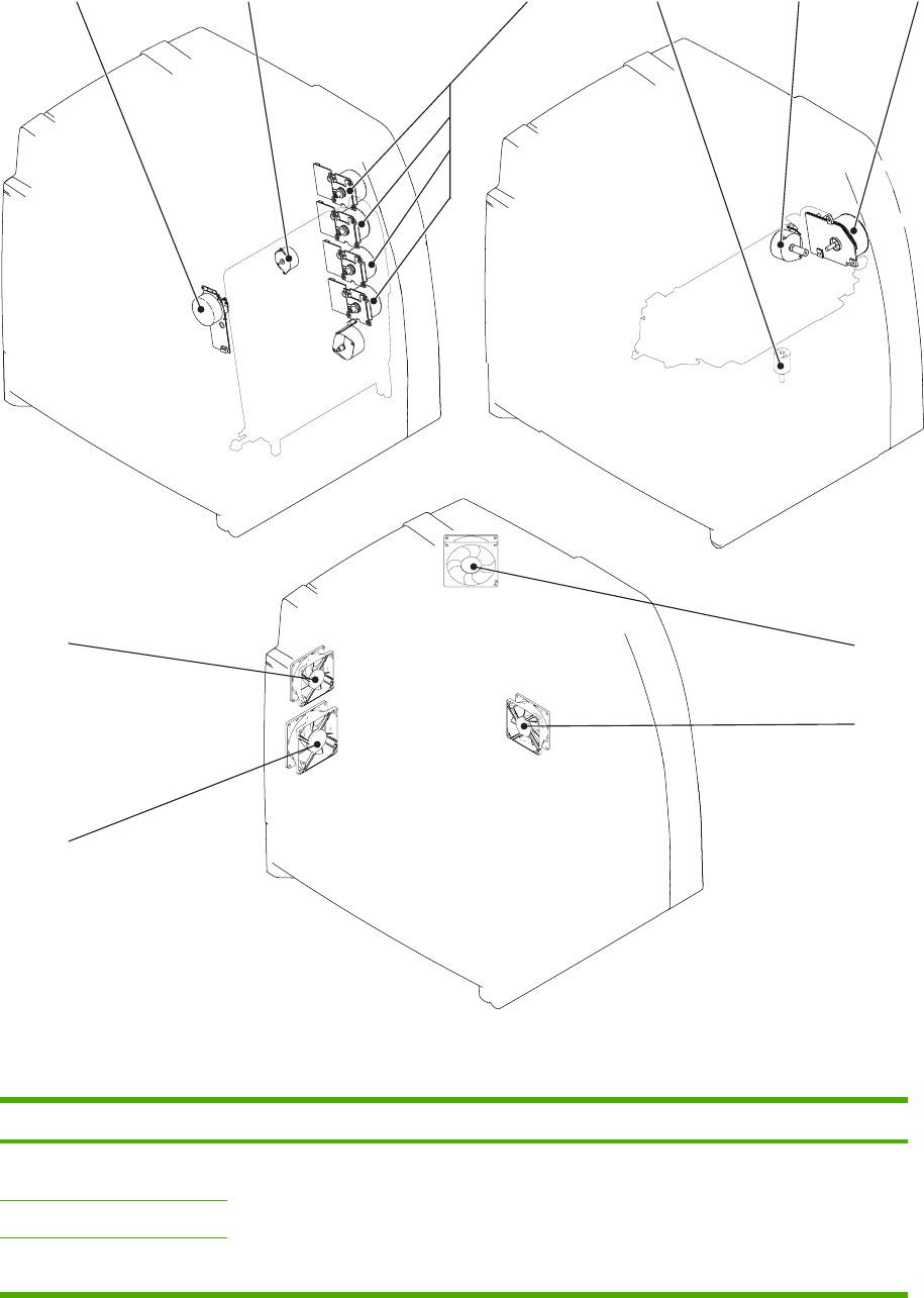
+, -./0
1
2
3
+*
Figure 5-6 Motors and fans
Table 5-2 Function of motors, fans, and environment sensor
Name Function Type Failure detection
M1: Yellow (Y) cartridge
motor
Drives the photosensitive
drum, developing cylinder,
and stirrer plate
DC motor Yes
M2: Cyan (C) cartridge motor
M3: Magenta (M) cartridge
motor
ENWW Engine control system 157

Name Function Type Failure detection
M4: Black (K) cartridge motor
M5: Fuser motor Drives the fuser pressure
roller and delivery roller
DC motor Yes
M6: Fuser pressure release
motor
Drives the fuser pressure
release mechanism
Stepping motor No
M7: ETB motor Drives the ETB DC motor Yes
M8: Developing alienation
motor
Disengages the
photosensitive drums from
the developing cylinder
Stepping motor No
M9: Pickup motor Drives the pickup roller and
feed roller
Stepping motor No
M10: Lifter motor Moves the lifters DC motor No
FAN1: Rear exhaust fan Exhausts heat around the
ETB, drum motors, and
formatter
DC motor Yes
FAN2: Cartridge fan Exhausts heat around the
fuser and cartridges
DC motor Yes
FAN3: Delivery fan Exhausts heat around fuser
and delivery unit
DC motor Yes
FAN4: Power supply fan Exhausts heat around the
pickup motor and low-
voltage power supply
DC motor Yes
Duplexer fan Exhausts heat around the
duplexer
DC motor Yes
ETB fan Exhausts heat around the
ETB assembly
DC motor Yes
Fuser fan Exhausts heat around the
fuser
DC motor Yes
Control fan #1 Exhausts heat around the
formatter and DC controller
DC motor Yes
Control fan #2 Exhausts heat around the
formatter and DC controller
DC motor Yes
Sub power supply fan Exhausts heat around the
sub power assembly
DC motor Yes
Environment sensor Detects the temperature and
humidity levels inside the
MFP
NA Yes
Failure detection
The DC controller can detect motor and fan failures as described below.
Table 5-2 Function of motors, fans, and environment sensor (continued)
158 Chapter 5 Theory of operation ENWW

Drum motor failure detection
The DC controller determines the drum motor failure and notifies the formatter of an error status
when it encounters the following conditions.
NOTE The drum motor failure detection operates in the same manner for each color
separately.
●Drum motor start-up abnormality. The interval of the drum motor speed detection signal does
not reach the specified interval after 1.5 seconds of the drum motor drive start.
●Drum motor rotation abnormality. The interval of the drum motor speed detection signal stays
at an irregular interval for two seconds and longer after it has reached the specified interval.
Fuser motor failure detection
The DC controller determines the fuser motor failure and notifies the formatter of an error status
when it encounters the following conditions.
●Fuser motor start-up abnormality. The interval of the fuser motor speed detection signal does
not reach the specified interval after 1.5 seconds of the fuser motor drive start.
●Fuser motor rotation abnormality. The interval of the fuser motor speed detection signal stays
at an irregular interval for two seconds and longer after it has reached the specified interval.
ETB motor failure detection
The DC controller determines the ETB motor failure and notifies the formatter of an error status when
it encounters the following conditions.
●ETB motor start-up abnormality. The interval of the ETB motor speed detection signal does
not reach the specified interval after 1.5 seconds of the ETB motor drive start.
●ETB motor rotation abnormality. The interval of the ETB motor speed detection signal stays
at an irregular interval for two seconds and longer after it has reached the specified interval.
Rear exhaust fan failure detection
The DC controller detects a rear exhaust fan failure and notifies the formatter of an error status when
the rear exhaust fan lock detection signal is input for ten seconds continuously.
Cartridge fan failure detection
The DC controller detects a cartridge fan failure and notifies the formatter of an error status when the
cartridge fan lock detection signal is input for ten seconds continuously.
Delivery fan failure detection
The DC controller detects a temporary locked status when the delivery fan lock detection signal is
input for 0.5 seconds continuously after 0.1 seconds of delivery fan drive start. The DC controller
starts the drive delivery fan for four seconds at the time of temporary locked status determination. If
the delivery fan lock detection signal is input for four seconds, it detects a delivery fan failure and
notifies the formatter of an error status.
ENWW Engine control system 159

Power supply fan failure detection
The DC controller detects a power supply fan failure and notifies the formatter of an error status
when the power supply fan lock detection signal is input for ten seconds continuously.
Scanner fan failure detection
The DC controller detects a scanner fan failure and notifies the formatter of an error status when the
scanner fan lock detection signal is input.
ADF fan failure detection
The DC controller detects a ADF fan failure and notifies the formatter of an error status when the
ADF fan lock detection signal is input.
Control fans #1 and #2 failure detection
The DC controller detects a control fan failure and notifies the formatter of an error status when the
control fan lock detection signal.
Sub power supply fan failure detection
The DC controller detects a sub power supply fan failure and notifies the formatter of an error status
when the sub power supply fan lock detection signal is input.
ETB fan failure detection
The DC controller detects an ETB fan failure and notifies the formatter of an error status when the
ETB fan lock detection signal is input.
Other fan failures can also be detected.
Low-voltage power supply
The low voltage power supply unit generates DC power and controls the fuser. The low voltage
power supply unit consists of the following circuits:
●Fuser control circuit. Controls the fuser heater temperature in the fuser.
●Low-voltage power supply circuit. Generates the DC power required in the MFP.
Figure 5-7 Low-voltage power supply circuits on page 161 shows each circuit of the low voltage power
supply unit.
160 Chapter 5 Theory of operation ENWW


The fuser power supply system has three main components:
●Fuser heater. A ceramic heater heats the fuser sleeve. The heater has a U-shaped heating
element on its surface.
●Thermistors. Two thermistors are in the fuser sleeve: one in the center, and the other at the
end. Each thermistor monitors the temperature in the fuser sleeve.
●Main thermistor. The main thermistor controls print temperature and between-sheets
temperature. It contacts the inside surface of the fuser sleeve at the center and detects the
fuser sleeve temperature.
●Sub thermistor. The sub thermistor detects the one-sided temperature rise of the fuser
heater, the initial rotation temperature control, and the start-up temperature control. It
contacts the one side of the fuser heater and detects the fuser heater temperature.
●Thermoswitch. The thermoswitch prevents the fuser heater temperature from rising abnormally
high. It is located above the center of the fuser sleeve. If the fuser heater temperature rises
abnormally high, the contact is broken to cut off the power supply to the heater.
These temperature controls are performed by the fuser control circuit and the fuser heater
safety circuit according to the commands from the CPU in the DC controller.
Table 5-3 Fuser temperatures
Media Temperature Engine speed
Any Auto Auto
Plain Auto Auto
Preprinted ~ 195°C (383°F) Full
Letterhead ~ 195°C (383°F) Full
Overhead transparencies ~ 180°C (356°F) 1/3
Prepunched ~ 195°C (383°F) Full
Labels ~ 180°C (356°F) 1/2
Bond ~ 195°C (383°F) Full
Recycled ~ 195°C (383°F) Full
Color ~ 195°C (383°F) Full
Light ~ 175°C (347°F) Full
Intermediate ~ 180°C (356°F) 1/2
Heavy ~ 180°C (356°F) 1/2
Extra heavy ~ 170°C (338°F) 1/2
Cardstock ~ 170°C (338°F) 1/2
Rough ~ 180°C (356°F) 1/2
Glossy ~ 180°C (356°F) 1/2
Heavy glossy ~ 165°C (329°F) 1/3
Extra heavy glossy ~ 180°C (356°F) 1/3
162 Chapter 5 Theory of operation ENWW
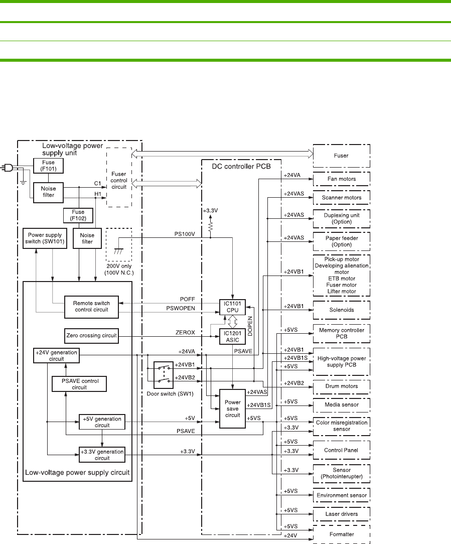
Media Temperature Engine speed
Tough paper ~ 180°C (356°F) 1/3
Envelopes ~ 180°C (356°F) 1/2
Low-voltage power supply circuit
The low-voltage power supply circuit converts AC power from the wall receptacle into DC power to
cover the DC loads.
Figure 5-9 Low-voltage power supply circuit
The AC power is supplied to the low-voltage power supply circuit by turning on the power switch
(SW101). The AC power is then converted into +24V, +5V and +3.3V to serve the DC power load
requirements.
Table 5-3 Fuser temperatures (continued)
ENWW Engine control system 163

Protective functions
Two fuses, FU101 and FU102, protect against overcurrent and overvoltage to prevent failures in the
power supply circuit. If there is a supply error, such as a short-circuit or overvoltage, the low-voltage
system automatically cuts off the output voltage. The fuses blow and cut off the AC power, once AC
overcurrent flows into the AC line.
If DC voltage is not being supplied from the low-voltage power supply circuit, turn off the power
switch (SW101). Do not turn the power on again until the root cause is found. If the cause is not at
the load side, the protective function may still work.
NOTE If the low-voltage power supply is shut down for protection, turn the power off (by
switching off or unplugging the MFP) and leave the MFP off for approximately three minutes.
Then turn the MFP on.
Safety
For safety, the +24V is divided into two: +24VA and +24VB (+24VB1 and +24VB2). The +24VA is
supplied from the DC controller, whereas +24VB stops when the door switch (SW1) is cut off. The
high-voltage power supply PCB and motors are supplied with the +24VB. They stop when the front
cover is opened. This is to protect users and service technicians from injury. The +24VB also
functions as the DOOR OPEN DETECTION signal (DOPEN). The CPU determines that the door is
open when the +24VB supply stops.
Sleep mode
Sleep mode reduces power consumption during periods of inactivity. When the DC controller
receives a Sleep command from the formatter, the controller stops the supply of +24V and +5V
power by operating the power-save circuit. At the same time, it sends a POWER SAVE MODE signal
(PSAVE) to the low-voltage power supply circuit. The low-voltage power supply circuit implements
PSAVE upon receiving the /PSAVE signal. The MFP returns to the WAIT period once it receives a
command from the formatter ending Sleep mode.
Power supply recognition
The low-voltage power supply circuit recognizes the voltage specification (100V or 200V) that the
MFP uses and the CPU switches the temperature control firmware for the fuser accordingly. The
CPU monitors the 100V POWER SUPPLY DETECTION signal (PS100V). When the MFP is
connected to the 100V power source, the temperature control firmware is switched for the 100V
specification. In the same way, when the MFP is connected to the 200V power source, it is switched
for the 200V specification.
Heater temperature control
The heater temperature control detects the surface temperature of the fuser sleeve and controls the
current flowing to the induction heating coil. The heater temperature control circuit is shown in Figure
5-10 Heater temperature control circuit on page 165.
164 Chapter 5 Theory of operation ENWW
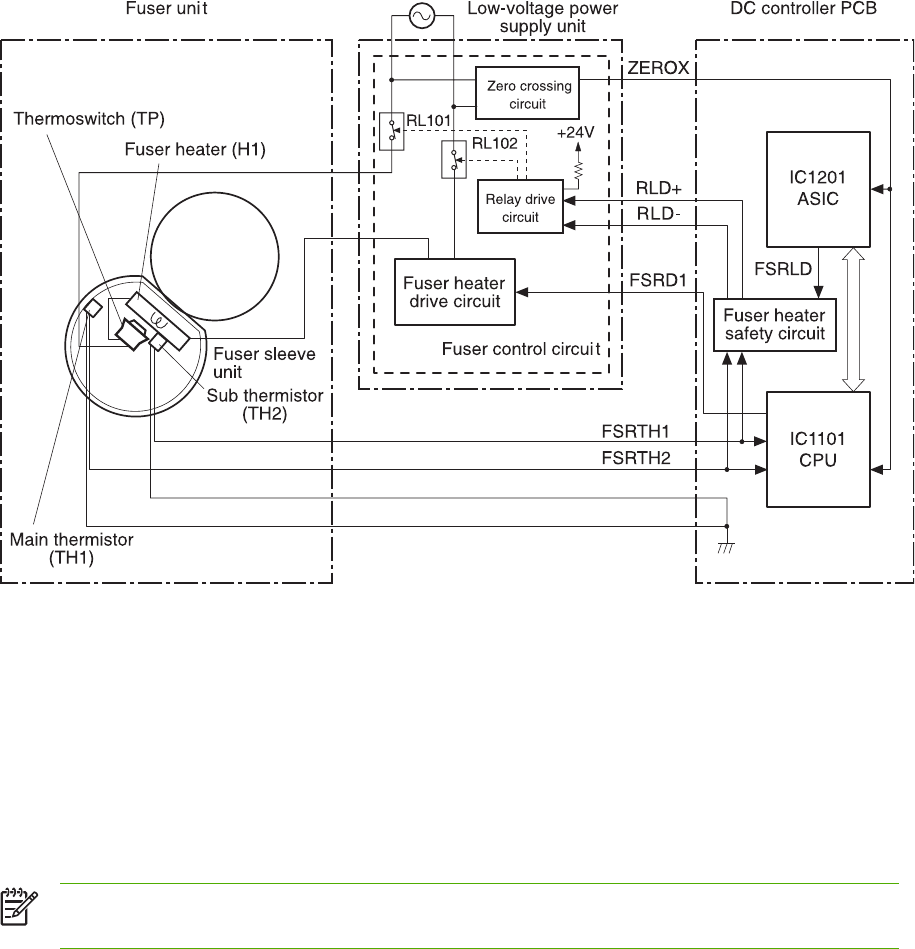
Figure 5-10 Heater temperature control circuit
The fuser heater temperature is monitored by two thermistors: the main thermistor (TH1) and the sub
thermistor (TH2). The main thermistor controls the print temperature and the between-sheets
temperature. The sub thermistor detects the one-sided temperature rise of the fuser heater, and
controls the initial rotation temperature and the start-up temperature.
The CPU (IC1101) on the DC controller monitors the voltage of the fuser heater temperature signals.
The CPU sends the fuser heater drive signal (FSRD1) according to the voltage level. The fuser
heater control circuit controls the fuser temperature so the heater remains at the target temperature.
The fuser temperature control is divided into the following four sequences.
NOTE During standby, the fuser temperature is maintained at about 76.7°C (170°F) to
accommodate a first-print time of less than 15 seconds.
Initial rotation temperature control
This control melts the grease inside the fuser sleeve and lubricates the sleeve when the power is
turned on to prevent sleeve damage. If the sub thermistor detects the temperature of below 50°C
(122°F) at power-on, the CPU turns on the fuser heater for a prescribed time period before it drives
the fuser motor.
Start-up temperature control
This control determines the start-up power provided to the fuser heater according to the temperature
detected by the sub thermistor at heater energization. If the heater is energized within 30 seconds
after the previous print completion, the heater control starts at this temperature point.
ENWW Engine control system 165
Print temperature control
This control maintains the temperature of the fuser sleeve at its targeted temperature during the
printing operation. The CPU gradually raises the targeted temperature in one printing process. This
prevents the fuser temperature from falling while the media goes through the fuser roller. The
targeted temperature also varies according to the number of prints when continuous printing. The
targeted temperature varies depending on the media types.
Between-sheets temperature control
This control maintains the temperature of the fuser heater below its normally targeted temperature
during continuous printing. This prevents the excessive temperature rise of the fuser pressure roller
while uncovering the paper portion of between-sheets with low-speed mode. The targeted
temperature varies according to the between-sheets intervals and the media types.
Temperature protective function
This function detects an abnormal temperature rise of the fuser and interrupts power supply to the
fuser heater. The following three protective components prevent an abnormal temperature rise of the
fuser heater.
●CPU
●Fuser heater safety circuit
●Thermoswitch
Protective function by the CPU
The CPU always monitors the output voltage of the main and sub thermistors (FSRTH1, FSRTH2). If
the voltage of the FSRTH1 is approximately 0.9V and lower (equivalent to 230°C (446°F) and
higher), or the voltage of the FSRTH2 is approximately 0.46V and higher (equivalent to 285°C (545°
F) and higher), the CPU detects a fuser failure and then performs the following sequence:
1. The CPU sets the fuser heater drive signal (FSRD1) to inactive and turns the heater off.
2. The CPU sets the relay drive signal (FSRLD) to stop through the ASIC.
3. The fuser heater safety circuit sets the main thermistor relay drive signal (RLD-) to inactive.
4. The fuser heater safety circuit sets the sub thermistor relay drive signal (RLD+) to inactive.
5. The relay drive circuit releases the relays (RL101 and RL102) to interrupt power supply to the
fuser heater.
Protective function by the fuser heater safety circuit
The fuser heater safety circuit monitors the output voltage of the main and sub thermistors (FSRTH1,
FSRTH2). If the voltage of the FSRTH1 is approximately 0.8V and lower (equivalent to 240°C (464°
F) and higher), or the voltage of the FSRTH2 is approximately 0.41V and higher (equivalent to 293°C
(559°F) and higher), the circuit detects a fuser failure and performs the following sequence:
1. The fuser heater safety circuit makes the main thermistor relay drive signal (RLD-) inactive.
2. The fuser heater safety circuit makes the sub thermistor relay drive signal (RLD+) inactive.
3. The relay drive circuit releases the relays (RL101 and RL102) to interrupt power supply to the
fuser heater.
166 Chapter 5 Theory of operation ENWW

Protective function by the thermoswitch
When the temperature of the fuser heater rises abnormally high and the detected temperature of the
thermoswitch (TP) exceeds approximately 250°C (482°F), the thermoswitch is disconnected and the
power supply to the fuser heater is immediately cut off.
NOTE The actual temperature of the fuser heater is about 30° higher than the thermoswitch,
as the thermoswitch is not contact with the fuser heater.
Temperature failure detection
The CPU determines the fuser failure, stops the MFP engine, and notifies the formatter of an fuser
failure when it encounters the following conditions:
Start-up failure (warm-up failure)
The CPU determines a start-up failure:
●If the detected temperature of the main thermistor does not reach 185°C (365°F) within 30
seconds of heater energization during the wait period.
●If the heater does not enter the Ready mode within 30 seconds of heater energization during
the initial rotation period.
Abnormal low temperature of main thermistor (no conduction)
The CPU presumes the main thermistor has no conduction:
●If the detected temperature of the main thermistor is kept 40°C (104°F) or lower for four
seconds continuously, from heater energization until the heater is turned off during the wait
period.
●If the detected temperature of the main thermistor is kept 70°C (158°F) or lower for four
seconds continuously, from initial rotation start until the media reaches the fuser during the
initial rotation period.
●If the detected temperature of the main thermistor is kept 130°C (266°F) or lower for 0.5
seconds continuously, from when the media reaches the fuser until the heater is turned off
during the print period.
Abnormal high temperature of main thermistor
The CPU presumes an abnormal high temperature of the main thermistor if the detected temperature
of the main thermistor is kept 230°C (446°F) and higher for 0.1 seconds continuously.
Abnormal low temperature of sub thermistor (no conduction)
The CPU presumes the sub thermistor has no conduction:
●If the detected temperature of the sub thermistor is kept 60°C (140°F) or lower for four seconds
continuously, from heater energization until the heater is turned off during the wait period.
●If the detected temperature of the main thermistor is kept 90°C (194°F) or lower for 2.5 seconds
continuously, from initial rotation start until the media reaches the fuser during the initial rotation
period.
ENWW Engine control system 167
●If the detected temperature of the main thermistor is kept 120°C (248°F) or lower for 0.5
seconds continuously, from when the media reaches the fuser until the heater is turned off
during the print period.
●If the detected temperature of sub thermistor is kept 50°C (122°F) or lower for 0.5 seconds
continuously during the standby period.
Abnormal high temperature of sub thermistor
The CPU determines the abnormal high temperature of sub thermistor if the detected temperature of
the sub thermistor is kept 285°C (545°F) and higher for 0.1 seconds continuously.
Drive circuit abnormality
The CPU determines the drive circuit abnormality if the ZERO CROSSING signal (ZEROX) is not
detected for the specified time period.
High-voltage power supply
The high-voltage power supply PCB produces the voltage biases that are applied to the primary
charging roller, developing cylinder, developing blade, attraction roller, and transfer roller. There are
two types of biases: DC positive bias and DC negative bias. The high-voltage power supply PCB is
controlled by the DC controller.
168 Chapter 5 Theory of operation ENWW
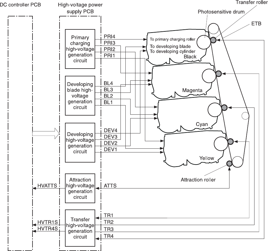
Figure 5-11 High-voltage power supply block diagram
Generation of biases
Generation of primary charging bias: The primary charging bias is the DC negative bias that is
generated to apply negative potential to the photosensitive drum in preparation for image formation.
This bias is generated for each color (Y, C, M, K) in the primary charging high-voltage power supply
circuit. The high-voltage power supply PCB applies the primary charging bias (PRI1, PRI2, PRI3,
PRI4) to the primary charging rollers in each cartridge at the specified timing. The value of the
primary charging bias varies in response to commands from the DC controller.
Generation of developing bias: The developing bias is the DC negative bias that is generated to
adhere toner to an electrostatic latent image formed on the photosensitive drum. This bias is
generated for each color. The high-voltage power supply PCB applies the developing biases (DEV1,
DEV2, DEV3, DEV4) to the developing cylinders in each cartridge at the specified timing. The value
of the developing bias varies in response to commands from the DC controller.
ENWW Engine control system 169
The developing voltage (bias) causes the toner to adhere to the electrostatic image that the laser/
scanner assembly created on the photosensitive drum. Two types of developing biases are used: the
developing DC negative bias and the developing AC bias. The high-voltage circuit on the power
supply generates both biases. These biases are superimposed on one another and then applied to
the primary charging roller, which transfers the biases to the drum. The biased developing cylinder
picks up toner particles and deposits them onto the electrostatic image on the photosensitive drum.
The image is now visible on the drum.
Generation of developing blade bias: The developing blade bias (BL) is the DC negative bias that
is generated to charge the toner. This bias is generated for each color in the developing blade high-
voltage power supply circuit in the high-voltage power supply PCB. The high-voltage power supply
PCB applies the developing blade biases (BL1, BL2, BL3, BL4) to the developing blade in each
cartridge at specified timing. The value of the developing blade bias varies in response to the
command from the DC controller.
Generation of attraction bias: The attraction bias is generated to attract paper to the ETB and to
transfer toner onto the paper efficiently. Both DC positive and DC negative biases are generated
when attracting paper and cleaning the ETB. The high-voltage power supply PCB applies the
attraction biases (ATTS) to the attraction roller in the ETB unit at the specified timing. The value of
the attraction bias varies in response to the command from the DC controller. The DC controller
changes the value of the attraction bias and regulates it in constant current control in response to the
ATTRACTION CURRENT VALUE RETURN signal (HVATTS) sent from the high-voltage power
supply PCB. The following are the printing sequences.
●Attraction charging bias: This bias charges the paper positively or negatively and makes the
negatively charged toner transfer easily.
●Between-sheets bias: This bias prevents the residual toner on the ETB from adhering to the
attraction roller in the between-sheets during continuous printing.
●Cleaning bias: This bias prevents the residual toner on the ETB from adhering to the attraction
roller during ETB cleaning.
Generation of transfer bias: The transfer bias is generated to transfer toner onto the paper. Both
DC positive and DC negative biases are generated in the transfer high-voltage power supply circuit
in the high-voltage power supply PCB. The DC positive bias is generated when transferring toner,
and the DC negative bias is generated when cleaning the ETB. The high-voltage power supply PCB
applies the transfer biases (TR1, TR2, TR3, TR4) to the transfer roller in the ETB unit according to
the print sequences. The value of the transfer bias varies in response to the command from the DC
controller. The DC controller changes the value of the transfer bias and regulates it in constant
current control in response to the TRANSFER CURRENT VALUE RETURN signals (HVTR1S,
HVTR4S) and the HVATTS signal sent from the high-voltage power supply PCB. The following are
the printing sequences.
●Print bias: This bias transfers toner on the photosensitive drum surface onto the paper during
printing. The transfer roller is applied with the DC positive bias.
●Between-sheets bias: This bias prevents the residual toner on the ETB from adhering to the
attraction roller in the between-sheets during continuous printing.
●Cleaning bias: This bias cleans the ETB by returning any toner remaining on the ETB surface
to the photosensitive drum. The transfer rollers in the yellow and magenta cartridges (first and
third colors) are applied with DC negative bias. The rollers in cyan and black cartridges (second
and fourth colors) are applied with DC positive bias.
170 Chapter 5 Theory of operation ENWW
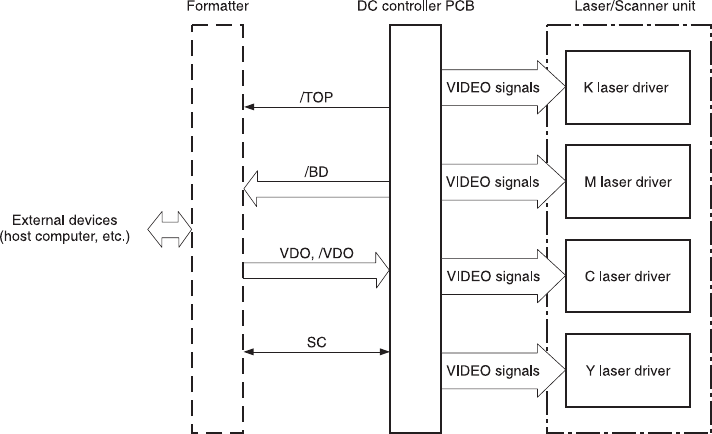
Sub power supply assembly
The sub power assembly provides power to the ADF and the image scanner. It is connected to the
low-voltage power supply and the DC controller.
Video interface control
The video interface allows communication between the formatter and the DC controller. The
formatter always monitors the status of the MFP by using the video interface. It sends the VIDEO
signals to the DC controller through the video interface when the MFP is ready to print. The DC
controller turns the laser on or off based on the signals it receives.
Figure 5-12 Video interface control
The VIDEO INTERFACE signal is exchanged during printing operations, as described below.
1. When the MFP engine is ready to print, the DC controller notifies the formatter using the
STATUS COMMAND signal (SC).
2. The formatter sends a print command as a SC signal to the DC controller when the MFP engine
and the data for one page are ready.
3. The DC controller drives the scanner motor and sends the HORIZONTAL SYNCHRONOUS
signals to the formatter after receiving the print command.
4. The printer engine starts a pickup operation. When the paper arrives at the top of page sensor
(SR12), the DC controller sends the VERTICAL SYNCHRONOUS signal (/TOP) to the formatter.
5. The formatter sends VIDEO signals in synchronization with the HORIZONTAL
SYNCHRONOUS signals to the DC controller upon a reception of the /TOP signal.
6. The DC controller controls each color’s laser driver circuit and turns the laser on and off
according to the VIDEO signals. This forms an electrostatic latent image on the photosensitive
drums of each color.
ENWW Engine control system 171
7. The latent images on the photosensitive drums are developed by toner and transferred onto
paper in this order: Y (yellow), C (cyan), M (magenta), and K (black).
8. The toner is fused to the paper in the fuser and the paper is delivered to the delivery tray.
Printing continues if the DC controller receives another print command from the formatter during
the printing operation.
172 Chapter 5 Theory of operation ENWW
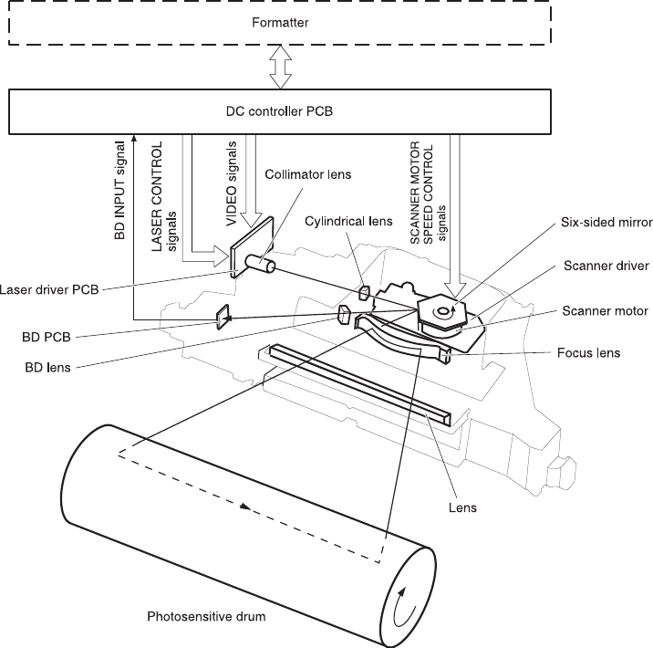
Laser/scanner system
The laser/scanner system forms the latent electrostatic image on the photosensitive drum according
to video signals sent from the formatter. The main components of each laser/scanner assembly are
the laser driver, scanner motor, mirrors, and focusing lenses. Each color has its own laser/scanner
assembly unit, which is controlled by the DC controller.
Figure 5-13 Laser/scanner assembly
The laser/scanner system uses two laser diodes in one scanning operation to write two lines
simultaneously for high-speed laser scanning. The process is summarized below:
1. After receiving the print command from the formatter, the DC controller activates the scanner
motor to rotate the six-faced scanner mirror.
2. When the scanner motor starts to rotate, the DC controller allows the laser to emit light and
maintains the scanner motor rotation at a constant speed.
3. When the scanner motor reaches its specified speed, the formatter sends video signals to the
laser driver PCB through the DC controller. The laser driver emits two laser diodes according to
these signals.
4. The laser beams pass through the collimator lens and the cylindrical lens, and enter the six-
faced mirror that is rotating at a constant speed.
ENWW Laser/scanner system 173

5. The laser beams are reflected by the six-faced mirror, pass through the focusing lens and the
reflecting mirror that is in front of the six-faced mirror, and focus the photosensitive drum.
6. While the six-faced mirror rotates at a constant speed, the laser beams on the photosensitive
drum scan the drum.
7. As the photosensitive drum rotates and the laser beams scan on the photosensitive drum, both
at a constant speed, a latent image is formed the drum.
Laser control
The laser control circuit allows the laser driver IC to turn the laser diodes LD1 and LD2 on and off
according to the image data signals sent by the DC controller.
The DC controller sends video signals (VDODAT11, /VDODAT11, VDODAT12, and /VDODAT12)
and laser control signals (LDCTRL10, (LDCTRL11, and (LDCTRL12) to the logic circuit on the laser
driver IC. The laser driver IC controls the laser according to the combination of the laser control
signals.
Figure 5-14 Laser control circuit block diagram on page 175 illustrates the laser control system.
174 Chapter 5 Theory of operation ENWW
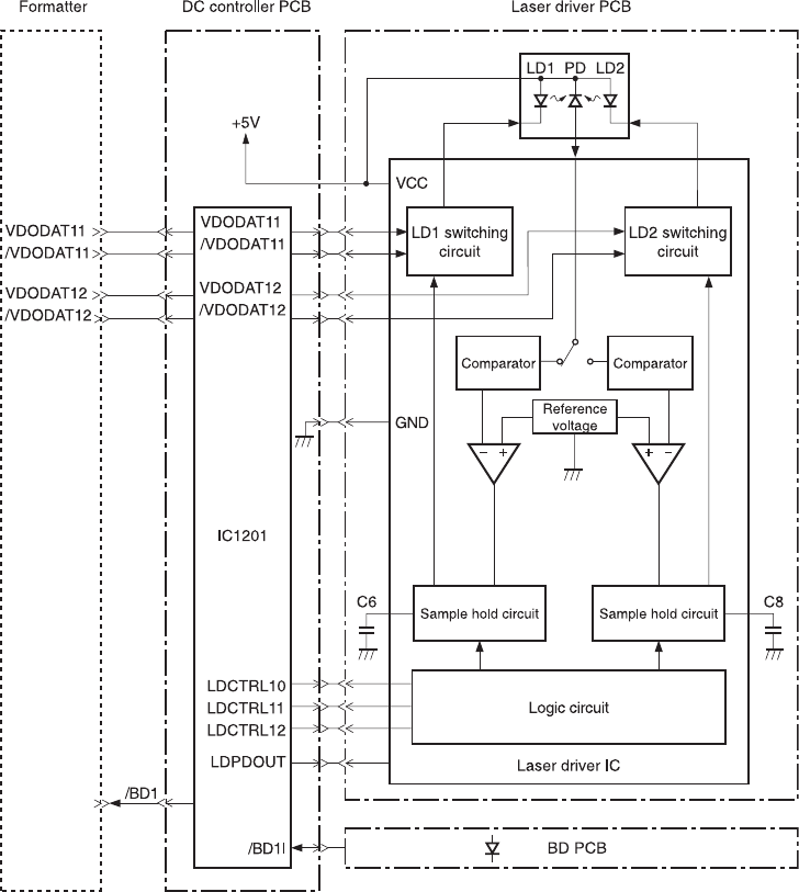
Figure 5-14 Laser control circuit block diagram
The laser control circuit manages the following control and detection functions:
●Laser emission control. Allows the laser diodes to turn on and off according to the video signals
sent by the formatter.
●Automatic power control (APC). Allows the laser diodes to emit light at a constant intensity.
●Horizontal synchronous control. Aligns the starting position in the horizontal direction.
●Image masking control. Regulates laser beam emission in non-image area except during the
unblanking interval.
●Failure detection. Detects failures in the laser diodes.
Scanner control
The scanner motor control rotates the scanner motor in order to strike the laser beam at the correct
position on the photosensitive drum.
ENWW Laser/scanner system 175
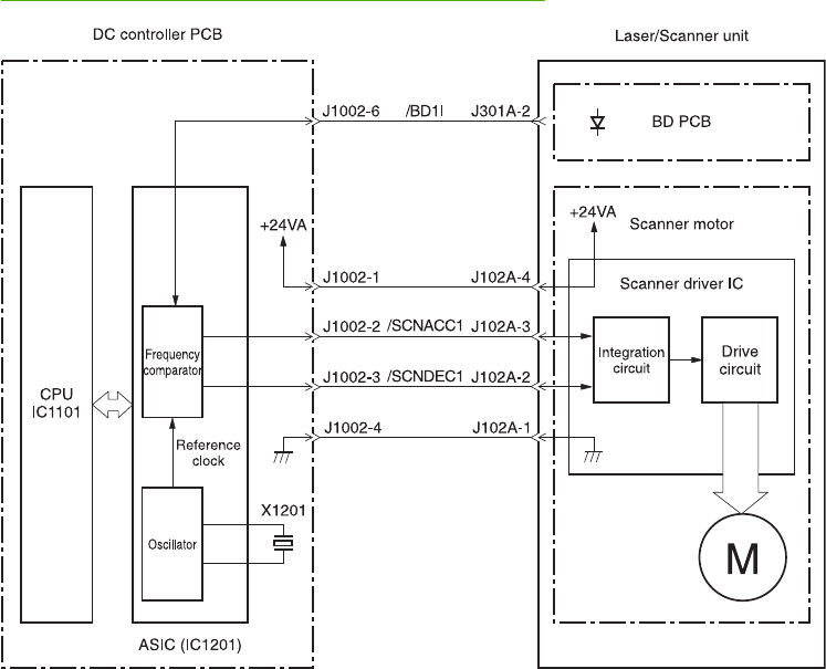
The DC controller divides the oscillation frequency of the oscillator (X1201) and generates the
reference clock signal. It compares the intervals between the reference clock signal and the BD input
signal (/BD1I) with the frequency comparator, and monitors the rotational count of the scanner motor.
The DC controller controls rotational speed by sending an acceleration signal (/SCNACC1) or
deceleration signal (/SCNDEC1) to the scanner motor driver based on the detected rotational speed.
Figure 5-15 Scanner motor circuit diagram on page 176 illustrates the scanner motor control system.
Figure 5-15 Scanner motor circuit diagram
The scanner motor control circuit manages the following control and detection functions:
●Speed control. Maintains the rotational speed of the scanner motor at a constant speed.
●Phase control. Prevents color misregistration by eliminating rotational variations in each color's
scanner motor and adjusts the phase of the scanner motor.
●Failure detection. Monitors the frequency comparator in the ASIC and determines whether the
scanner motor is rotating at its specified rotational count.
176 Chapter 5 Theory of operation ENWW
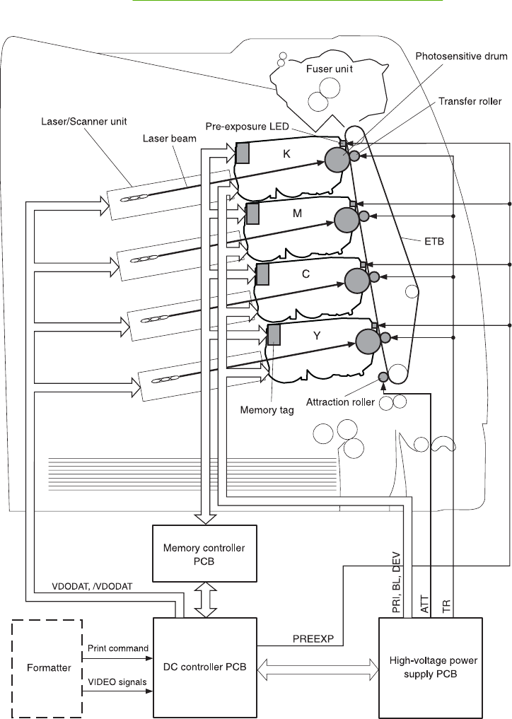
Image formation system
The image formation system is the central hub of the MFP. It also forms the toner image on the media.
The image formation system consists of four cartridges, the ETB, and the fuser, which are controlled
by the DC controller. Figure 5-16 Image formation system on page 177 shows the image formation
system.
Figure 5-16 Image formation system
ENWW Image formation system 177

Image formation process
The image formation process consists of nine steps divided among five functional blocks:
1. Electrostatic latent image formation block. Forms an electrostatic latent image on the
photosensitive drum.
Step 1: Pre-exposure
Step 2: Primary charging
Step 3: Laser beam exposure
2. Development block. Makes the electrostatic latent image on the photosensitive drum surface
visible by applying toner.
Step 4: Development
3. Transfer block. Transfers toner image on the photosensitive drum onto the media.
Step 5: Attraction
Step 6: Transfer
NOTE Toner is transferred onto a sheet of media in the order of yellow (Y), cyan (C),
magenta (M), and black (K) in one printing operation.
Step 7: Separation
4. Fusing block. Fuses the toner image on the media.
Step 8: Fusing
5. Cleaning block. Cleans the residual toner on the photosensitive drum.
Step 9: Drum cleaning
178 Chapter 5 Theory of operation ENWW
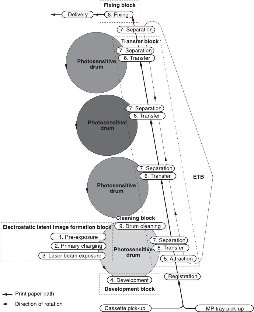
Figure 5-17 Image formation process
ENWW Image formation system 179
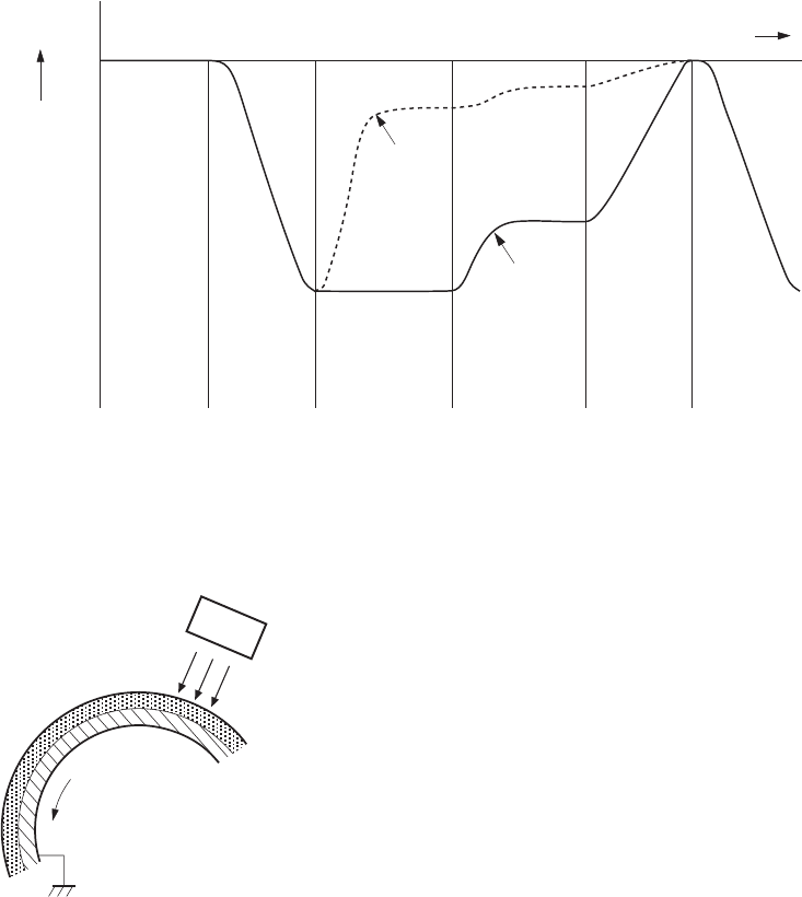
Electrostatic latent image formation block
The image formation process begins in the electrostatic latent image formation block. This block
consists of three steps that results in forming an electrostatic latent image on the photosensitive drum:
●Pre-exposure
●Primary charging
●Laser beam exposure
When the last step in this block is complete, areas of the drum surface that have not been exposed
to the laser beam retain a negative charge. The areas that have been exposed to the laser are
neutralized. This neutralized image is called an electrostatic latent image because it is invisible to the
eye.
0Time (t)
Exposed area
Unexposed area
Laser beam
exposure (step3)
Transfer (step6)Primary
charging
(step2)
Pre-exposure
(step1)
Surface
potential
(V)
Primary
charging
(step2)
Pre-exposure
(step1)
Figure 5-18 Electrostatic latent image formation block
Step 1: Pre-exposure
To prepare for primary charging, light from the pre-exposure LED strikes the photosensitive drum
surface. This eliminates any residual charge on the drum surface to avoid density unevenness.
Photosensitive drum
LED
Figure 5-19 Pre-exposure
180 Chapter 5 Theory of operation ENWW
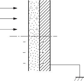
Step 2: Primary charging
To prepare for latent image formation, the surface of the photosensitive drum is charged with a
uniform negative potential.
The charging method of this MFP is to charge directly to the photosensitive drum surface from the
primary charging roller, which is interlocked with the drum. The primary charging roller is made of a
conductive rubber. To charge the drum surface negatively, the DC bias is applied to the primary
charging roller.
Step 3: Laser beam exposure
In this step, the latent image is formed on the photosensitive drum by the laser beam. As the laser
beam scans on the negatively charged photosensitive drum, the potential on the exposed area is
neutralized and the negative potential is removed from the drum surface. This area forms an
electrostatic latent image.
Laser beam
Unexposed area
Exposed area
Figure 5-20 Laser beam exposure
Development block
The second part of the image formation process is the development block, where toner is transferred
onto the electrostatic latent image on the surface of the photosensitive drum to create a visible
image. This MFP uses a contact development method that keeps the developing cylinder in contact
with the drum, pushing the toner against the drum surface for development. The toner is non-
magnetic and consists of resins.
Step 4: Development
In this step, the toner adheres to the electrostatic latent image on the photosensitive drum surface.
The toner (developing material) has an insulating property and is charged with a negative potential
by the friction force with the rotating developing cylinder and the developing blade surface. This
negatively charged toner contacts with the photosensitive drum, after the potential is adjusted to be
uniform. As the area of the drum surface where the laser beam exposed has higher potential than
the developing cylinder, the toner charged with almost the same potential with the developing
cylinder adheres to this area. This phenomenon is called contact development and it visualizes the
electrostatic latent image on the drum surface.
ENWW Image formation system 181
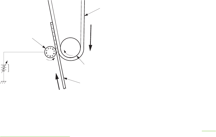
Transfer block
The third part of the image formation process is the transfer block, in which the toner image is
transferred from the photosensitive drum to the media. This block consists of three steps:
●Attraction
●Transfer
●Separation
Step 5: Attraction
To feed the media vertically, it is necessary to push the media against the ETB. The picked up media
is fed as it is pushed against the ETB by the attraction roller. The positive DC bias is applied to the
attraction roller, which charges the media positively to make the negatively charged toner easier to
transfer onto the media during the transfer operation.
ETB
ETB engaged roller
Paper
Attraction roller
DC bias
Figure 5-21 Attaching the media to the ETB
Step 6: Transfer
A positive bias is applied to the transfer charging roller, which is directly opposite the photosensitive
drum. As the ETB passes the transfer charging roller, it picks up a positive charge. The negatively
charged toner on the photosensitive drum is transferred to the positively charged print media. Figure
5-22 Toner transfer on page 183 illustrates this step. This process is repeated for each color as the
ETB carries the media from the bottom cartridge to the top (C, Y, M, K).
In full-color printing, as four colors of toner are piled up on the media, the holding force of the toner
weakens as the transfer process progresses. To counteract this effect, the DC controller increases
the positive DC bias that is applied to the transfer charging roller for each successive color.
182 Chapter 5 Theory of operation ENWW
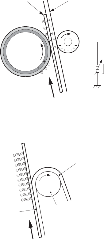
DC bias
Paper ETB
Photosensitive
drum
Transfer roller
Figure 5-22 Toner transfer
Step 7: Separation
The elasticity of media separates the media from the photosensitive drum and the ETB.
Paper
ETB
ETB feed roller
Figure 5-23 Separation
Fusing block
The fourth part of the image formation process is the fusing block, in which the toner image is fused
to the media, making a permanent image that cannot be smeared. This block consists of one step:
fusing.
Step 8: Fusing
This MFP uses the ceramic heater with lower heat capacity to fuse the toner to the media. This
method warms up quickly and does not require the power supply during standby period, resulting in
shortened wait time and reduced power consumption.
ENWW Image formation system 183
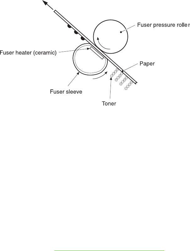
Figure 5-24 Fusing
Cleaning block
The fifth and final part of the image formation process is the cleaning block, in which the
photosensitive drums are cleaned, preparing them for the next print. In the transfer block, not all of
the toner is transferred from the photosensitive drum onto the media, but some remains on the drum
surface. This remaining toner is called residual toner or waste toner. The cleaning block cleans the
photosensitive drum surface to keep a clear image in the next print.
Step 9: Drum cleaning
The cleaning blade scrapes off the leftover toner on the drum surface. The residual (waste) toner is
collected in the waste toner container by the waste toner feed plate.
Print cartridges
The MFP has four different print cartridges, one for each color. However, they share the same
structure, shown in Figure 5-25 Print cartridge on page 185.
184 Chapter 5 Theory of operation ENWW
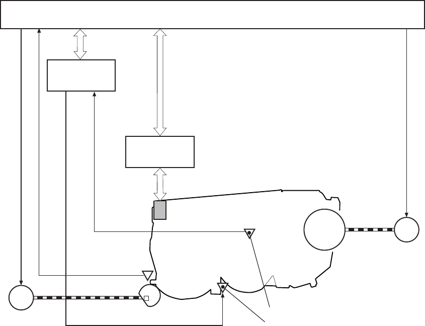
M8
Photosensitive
drum
Toner level sensor (light receiver)
Toner level sensor (light emitter)
DC controller PCB
DEVELOPING ALIENATION MOTOR CONTROL signal
DRUM MOTOR
DRIVE signal
Toner level PCB
LED DRIVE signal
TONER LEVEL signal
Developing alienation block
Memory controller
PCB
Cartridge data
DEVELOPING ALIENATION signal
Developing alienation
sensor
Drum motor
Developing alienation motor
SR11
Memory tag
M
Figure 5-25 Print cartridge
The following are the physical components inside the print cartridge:
●Photosensitive drum
●Primary charging roller
●Developing cylinder
●Toner charging roller
●Stirrers
●Waste-toner transfer plate
The photosensitive drum rotation drives the primary charging roller. All other components are driven
by the drum motor.
The developing disengaging motor drives the developing disengaging block, which causes the
developing cylinder to engage with or disengage from the photosensitive drum.
The DC controller uses an LED and a photo diode to monitor the level of toner inside the cartridge. It
stores this information on a memory tag that is built into each cartridge.
ENWW Image formation system 185
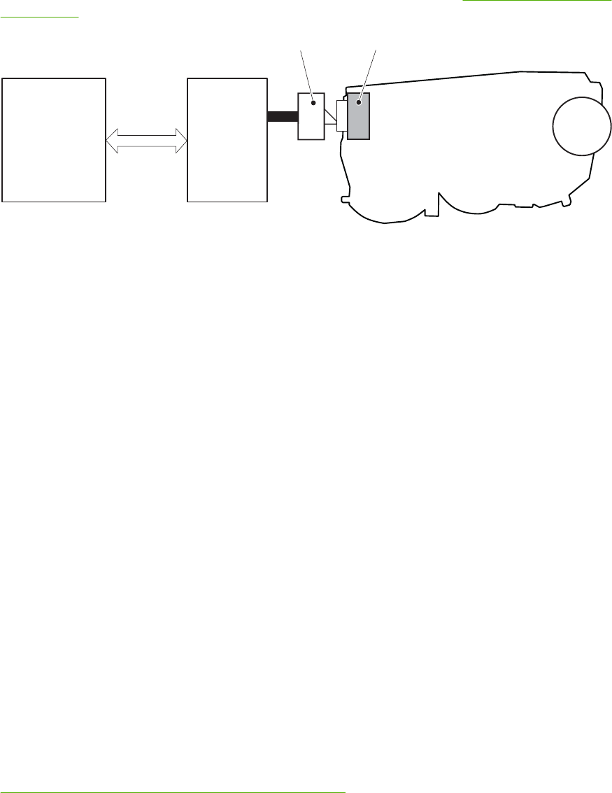
Memory tag
The memory tag is a nonvolatile memory that is built into the print cartridge. It stores information
about the amount of toner in the cartridge and estimates the remaining life. Figure 5-26 Memory tag
on page 186 illustrates how the memory tag operates.
Memory tag
Memory data
Cartridge
DC controller PCB
Memory tag contact
Memory
controller PCB
Figure 5-26 Memory tag
The DC controller reads information from the memory tag whenever the MFP is turned on, whenever
the top cover is closed, and whenever it receives a read command from the formatter.
The DC controller writes information to the memory tag at specified times during a print operation,
whenever it receives a write command from the formatter, and after print completion.
If the DC controller is unable to either read to or write from the memory tag four times in a row, the
DC controller alerts the formatter of a memory tag abnormality.
Cartridge presence detection
The MFP detects the presence of print cartridges when the power is turned on or the door is closed.
There are two procedures to the cartridge presence detection:
●Memory tag detection
●Photosensitive drum detection
Memory tag detection
The DC controller reads the data in the memory tag and determines the cartridge presence. If the
reading fails, the DC controller goes to the next procedure, photosensitive drum detection.
Photosensitive drum detection
The DC controller measures the torque of the photosensitive drum. The DC controller stops the drum
motor after driving it for the prescribed period of time. If the motor stops rotating within the specified
period after the stoppage command is sent, the DC controller detects the cartridge presence based
on the large load torque. If it takes more than the prescribed period of time for the motor to stop, the
DC controller detects the cartridge absence based on the small load torque.
When the DC controller detects the cartridge absence, it stops the engine and notifies the formatter.
Figure 5-27 Photosensitive drum detection on page 187 illustrates the drum detection procedure.
186 Chapter 5 Theory of operation ENWW

Motor stop
time
Time (t)
Motor rotation (rpm)
Motor ON
< Cartridge presence >
Motor ON Motor OFF
< Cartridge absence >
Motor OFF
Predetermined
time
Specified time (T) Specified time (T)
Time (t)
Motor rotation (rpm)
Figure 5-27 Photosensitive drum detection
Developing cylinder disengaging control
The developing cylinder is engaged or disengaged when the DC controller drives the developing
alienation motor. When the developing motor rotates clockwise by a command from the DC controller
during power on, printing operation stopped, cleaning cartridges, and monochrome print, the
developing alienation cam rotates. Accordingly, the rear bottom of the cartridge is raised and the
developing cylinder is disengaged from the photosensitive drum with a principle of leverage. The
developing alienation sensor (SR11) detects the position of the developing alienation block.
NOTE Only the developing cylinders in the color cartridges (C, Y, M) are disengaged in
monochrome print, and all of the developing cylinders in any other case.
If the cam stays at its home position for the prescribed period of time or longer during the developing
cylinder disengagement operation, or it does not return to the home position within the prescribed
period of time after alienation is completed, the DC controller detects the developing alienation motor
abnormality, stops the printer engine, and notifies the formatter of the developing alienation motor
abnormality.
ETB (electrostatic transfer/transport belt)
The ETB feeds the media through the MFP and helps transfer toner onto the media. Figure 5-28 ETB
on page 188 illustrates the ETB.
ENWW Image formation system 187
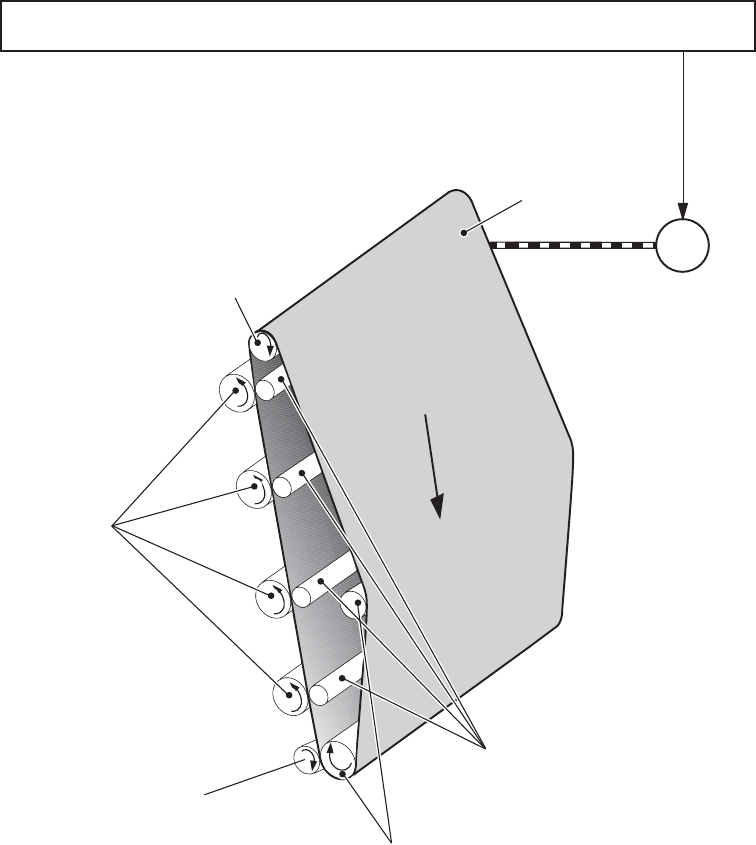
ETB engaged roller
M7 ETB motor
DC controller PCB
ETB
Photosensitive drums
ETB feed roller
Attraction roller
ETB MOTOR
CONTROL signal
Transfer roller
Figure 5-28 ETB
The following are the components of the ETB:
●ETB belt
●ETB feed roller
●ETB engaged roller
●Attraction roller
●Transfer roller
The ETB motor drives the ETB feed roller, causing the belt to rotate. All other rollers are driven by
the belt rotation.
During the printing operation, the picked up media is conveyed between the ETB and the
photosensitive drum. Simultaneously the toner image is transferred onto the media. The ETB is also
188 Chapter 5 Theory of operation ENWW
used for the color misregistration and image stabilization control. The pattern image for the color
misregistration or image density determination is transferred onto the ETB.
The ETB also controls the following:
●Transfer roller (Y, C, M) engagement/disengagement detection
●Transfer roller alienation
●ETB cleaning
Transfer roller (Y, C, M) engagement/disengagement detection
When the power is turned on, the DC controller applies biases to the transfers roller for yellow and
black, and detects the value of current flown through the ETB according to the current return signals.
The DC controller obtains information on the transfer roller (Y, M, C) engagement and
disengagement. Accordingly, the DC controller executes the transfer roller engage or disengage
control depending on the situation and engages the transfer rollers (Y, M, C).
Transfer roller engagement/disengagement control
This control disengages the transfer rollers (Y, M, C) from the photosensitive drums so that only
black toner is transferred onto the ETB during monochrome printing. The ETB motor (M7) performs
this control by driving the ETB alienation solenoid (SL3) while the motor is rotating according to a
command from the DC controller.
The following is the operational sequence of the transfer roller engagement/disengagement control.
1. The transfer roller engaging/disengaging cam inside the ETB holds up the transfer roller holder
that contains the Y, M, and C transfer rollers. This brings the ETB into contact with the
photosensitive drums.
2. When a monochrome print starts, the DC controller turns on the ETB alienation solenoid (SL3)
to rotate the transfer roller engaging/disengaging cam.
3. The rotation of the transfer roller engaging/disengaging cam pushes the Y, M, and C transfer
rollers down, disengaging the ETB from the photosensitive drums.
When allowing the ETB to engage back with the photosensitive drums, the DC controller turns on the
ETB alienation solenoid (SL3) again. The transfer roller engaging/disengaging cam rotates and
pushes the transfer roller holder. Accordingly, the transfer rollers push the ETB into contact with the
photosensitive drums.
ENWW Image formation system 189
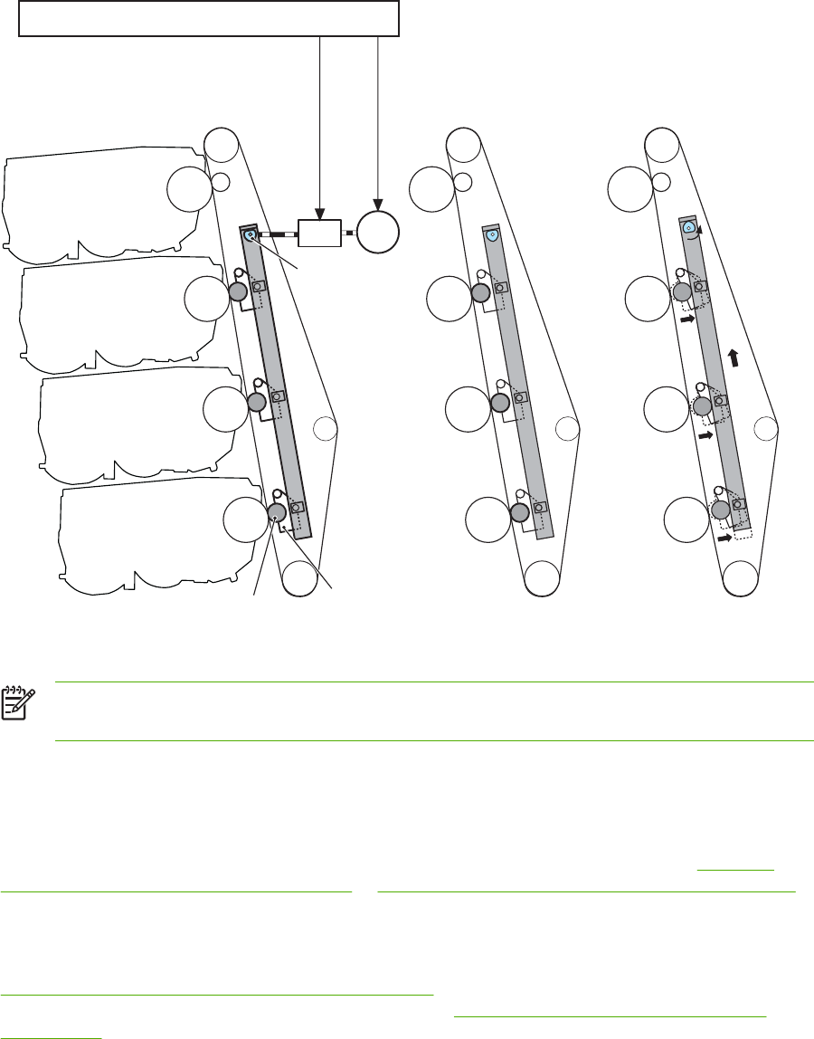
Transfer roller
engaging cam
< Transfer roller engaged > < Transfer roller disengaged >
Transfer roller holder
Transfer roller
Bk cartridge
C cartridge
M cartridge
Y cartridge
DC controller PCB
ETB MOTOR
DRIVE signal
ETB ALIENATION
SOLENOID DRIVE
signal
M7
SL3
Figure 5-29 Transfer roller engagement/disengagement control
NOTE The Y, M, and C photosensitive drums opposite the transfer rollers stop rotating when
the rollers are disengaged.
Calibration and cleaning
The MFP automatically calibrates and cleans itself at various times to maintain the best print quality.
You can also force the MFP to calibrate by selecting QUICK CALIBRATE NOW or CALIBRATE
NOW from the PRINT QUALITY menu. For information about calibrating the MFP, see Table 5-4
Calibration timing and duration on page 191 or Table 5-5 Cleaning timing and duration on page 191 for
more information.
While the MFP is calibrating or cleaning, it pauses printing. For most calibrations and cleaning, the
MFP does not interrupt a print job, but waits for the job to complete before calibrating or cleaning.
Table 5-4 Calibration timing and duration on page 191 shows when the MFP calibrates, the duration
of the calibration, and the type of calibration that occurs. Table 5-5 Cleaning timing and duration
on page 191 shows when the MFP cleans and the duration of the cleaning. The sections that follow
discuss calibration and cleaning in more detail.
190 Chapter 5 Theory of operation ENWW

Table 5-4 Calibration timing and duration
Calibration occurrence Duration Type of calibration
When you turn the MFP on. 75 seconds for calibration, but because
of other initialization activities, the MFP
takes a total of 2 minutes to be ready
for printing
DMAX, DHALF
When you install one or more print
cartridges that have not previously
been installed in the MFP.
150 seconds (2 minutes, 30 seconds) DMAX, DHALF, color-plane registration
(CPR)
When 50 pages have been printed
since installing a print cartridge. The
MFP will finish printing the current job
before calibrating.
75 seconds DMAX, DHALF
When 1,000 pages have printed since
the last calibration. The MFP will finish
printing the current job before
calibrating.
75 seconds DMAX, DHALF
When eight hours have passed since
the last calibration, but not while the
MFP is in Sleep mode. Typically, this
calibration occurs during the first job or
any control panel interaction after an
overnight idle period.
75 seconds DMAX, DHALF
When you request calibration from the
control panel (QUICK CALIBRATE
NOW and CALIBRATE NOW).
280 seconds (4 minutes, 40 seconds) DMAX, DHALF, CPR, drum phase
Table 5-5 Cleaning timing and duration
Cleaning occurrence Duration Type of cleaning
When the MFP continuously prints
(with no idle period or spin down) for
51 pages.
either 5 seconds or 21 seconds
(5 seconds is the most common)
primary and toner charging rollers
At intervals of 90 and 140 pages. The
MFP will finish printing the current job
before cleaning.
16 seconds ETB
ETB cleaning
During this step, all toner particles that remain on the ETB are returned to the photosensitive drums
in each print cartridge. Figure 5-30 ETB cleaning on page 192 illustrates this step.
This control is performed by the DC controller under the following conditions:
●The power is turned on
●During operation of the color misregistration corrective control
●During operation of the image stabilization control
●The door is closed
ENWW Image formation system 191
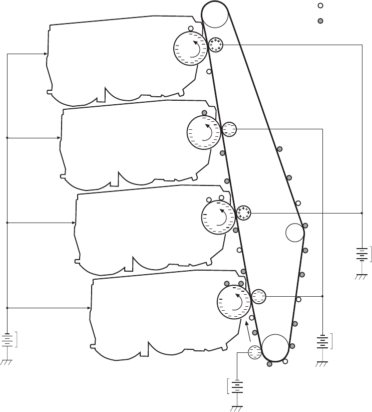
●After completion in every prescribed number of printings
●During pickup operation specified by universal size
Negative potential waste toner
Positive potential waste toner
Y cartridge
C cartridge
M cartridge
Bk cartridge
DC negative bias
DC positive bias
DC negative bias
DC negative bias
To primary charging
roller
Figure 5-30 ETB cleaning
The DC controller applies negative bias to the photosensitive drum and both negative and positive
biases to each of the four color transfer rollers. This brings a potential difference between the
photosensitive drum and the ETB, so that both positive and negative charged residual toner on the
ETB is returned to the photosensitive drum at once. The developing cylinder is disengaged from the
photosensitive drum during the cleaning operation to prevent toner in the toner container from
transferring onto the ETB.
Color misregistration corrective control
This control corrects a color misregistration caused by the variation inherent in the laser/scanner unit
and each cartridge. The color misregistration corrective control corrects the horizontal scanning
magnification, the horizontal scanning start position, and the vertical scanning start position.
192 Chapter 5 Theory of operation ENWW

The DC controller controls the color misregistration unit under the following conditions:
●At power on or door close after cartridge replacement
●After job completion in every specified number of printings
●At a command from the formatter
The following is the operational sequence of the color misregistration corrective control:
1. The DC controller forms two pattern images for color misregistration detection with four colors
on the ETB when the color misregistration corrective control starts. The two pattern images are
the same pattern, one formed on the left side and the other on the right side.
2. The DC controller measures the position of each pattern image and calculates the
misregistration amount of each color by controlling the color misregistration unit.
3. The calculated misregistration information of each color is sent to the formatter.
4. The formatter controls each color’s video signals according to this information and optimizes the
main-scanning start position, the main-scanning scale, and the sub-scanning start position.
The color misregistration in sub-scanning direction is corrected at printer engine side by the DC
controller controlling the speed of the scanner motor.
NOTE Horizontal magnification is the size of the image in the horizontal direction. Every
color has its own photosensitive drum in each cartridge in this MFP. The positions of each
drum differ and the laser beam lengths vary because of the variations among the cartridges,
so the horizontal scanning area depends on the color. This causes a color misregistration at
the edge of image.
Color misregistration detection
In this MFP, the positions of each color’s misregistration pattern images formed on the ETB are
detected to measure the misregistration amount. The DC controller controls the color misregistration
unit during the foregoing color misregistration corrective control. The color misregistration unit is
placed under the ETB and consists of two detection sensors, each one having a light emitter (LED)
and a light receiver (PD).
The following is the operational sequence of the color misregistration detection.
1. The DC controller allows the LED to emit light by sending the LED DRIVE signal when the color
misregistration detection starts.
2. The ETB reflects the light from the LED and the PD in the color misregistration sensor receives
the light. This reflected light intensity differs depending on whether the light is reflected from the
area of toner.
3. The light receiver converts the received light intensity into voltage and sends it in the form of the
color misregistration signal to the DC controller.
4. The DC controller detects the positions of the pattern images according to the timing of the color
misregistration signal.
Figure 5-31 Color misregistration detection on page 194 illustrates this process.
ENWW Image formation system 193
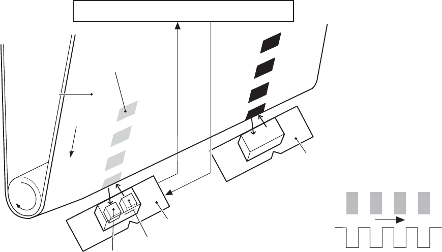
DC controller PCB
ETB
Color misregistration
pattern image
Light emitter (LED)
Light receiver (PD)
Color misregistration
sensor (L)
COLOR MISREGISTRATION signal
LED DRIVE signal
Color misregistration sensor (R)
Pattern image
COLOR
MISREGISTRATION
signal
Figure 5-31 Color misregistration detection
The DC controller notifies the formatter of each error when the following errors are found during the
color misregistration detection. The initial value is reset to the new color misregistration correction
value whenever an error occurs.
●Color misregistration sensor abnormality warning: The light receiver does not receive light at all.
●Color misregistration measurement out of range warning: The measurement value is out of
specified range.
Image stabilization control
This controls the variation of the image density caused by an environmental change or deterioration
of the photosensitive drum, toner, etc.
There are three types of image stabilization control. These controls operate when necessary.
●Environmental change control. The environment condition sensor controls the bias according
to the environment conditions.
●Image density control (D-max). The color misregistration sensor (PS12) calibrates the bias
value when the image density is at max.
●Image halftone control (D-half). The color misregistration sensor (PS12) calibrates the
halftone data in the formatter.
194 Chapter 5 Theory of operation ENWW
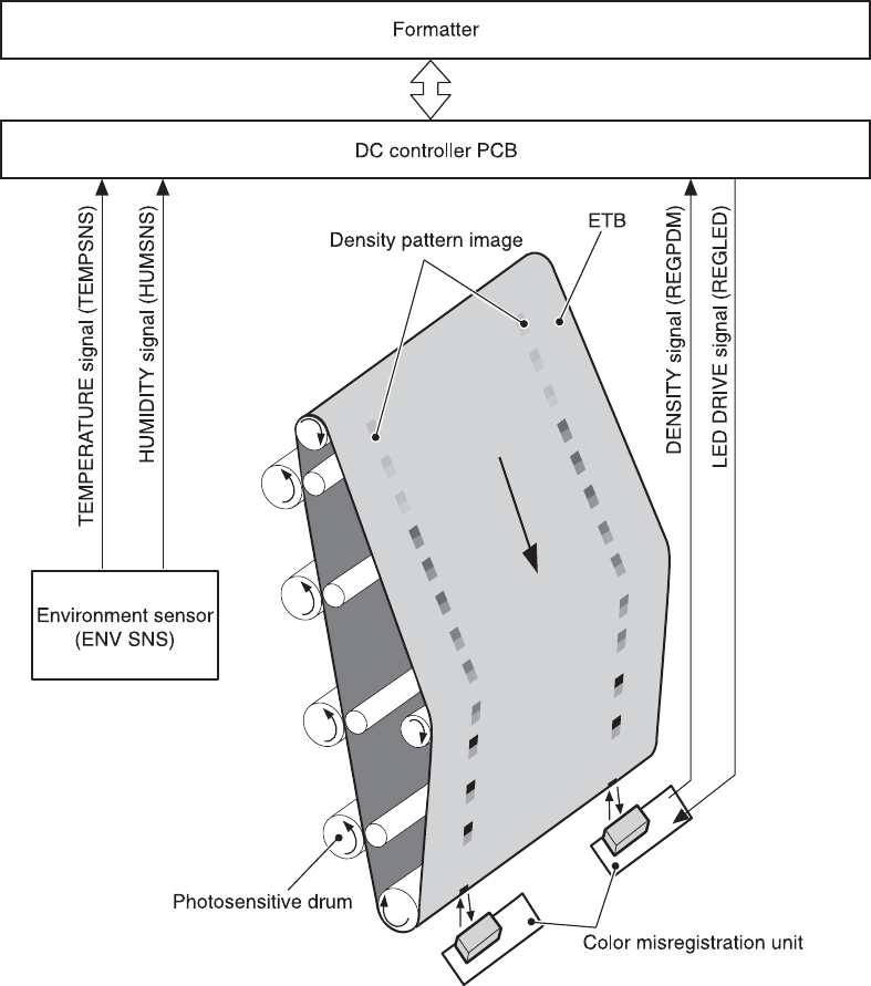
Figure 5-32 Image stabilization control
Environmental change control
This control calibrates each bias to obtain the best image possible according to environmental
changes.
The environmental sensor detects the temperature and the humidity. The sensor sends this
information to the DC controller in the form of the temperature detection signal (TEMSNS) and the
humidity detection signal (HUMSNS).
The DC controller monitors the environmental conditions of the MFP based on these two signals.
ENWW Image formation system 195

The DC controller controls the following biases to prevent image defects when it detects an
environmental change:
●Developing bias
●Primary transfer bias
●Secondary transfer bias
If the environment sensor detects a temperature of below -30ºC (22ºF) or over 80ºC (176ºF), the DC
controller determines this is an "environment sensor abnormality" and sends an error message to the
formatter.
Image density calibration control (DMAX)
This control stabilizes image density by calibrating the values of the developing bias whenever one of
the following events occurs:
●The detected temperature of the sub thermistor is below 50ºC (122ºF) when the MFP is turned
on.
●The door is closed after a print cartridge or ETB is replaced.
●A set number of pages is printed.
●The specified value of environmental conditions has changed since the last image density
corrective control.
●The formatter sends an operation command.
Image halftone calibration control (DHALF)
This control measures halftone density output from the formatter and returns the measurements to
the formatter so it can perform halftone calibration. Image density calibration must always be
performed before image halftone calibration.
Image halftone calibration control consists of three steps:
1. The DC controller forms density patterns on the photosensitive drum in each color using the
optimum developing bias determined during image density calibration.
2. These density patterns are transferred to the ETB, and the color-registration detection unit
measures the image density of these patterns. Image data is returned to the formatter.
3. The formatter uses the image data to perform a halftone calibration to obtain an ideal halftone
image.
Image density detection
Each of the image stabilization controls uses the color registration unit at the top of the ETB to
measure image density. The image density detection is performed by the DC controller, which
controls the color misregistration unit during the D-half control. The color misregistration unit is
placed under the ETB and consists of two detection sensors, each having one light emitter (LED)
and one light receiver (PD). Figure 5-33 Image density detection on page 197 illustrates this process.
196 Chapter 5 Theory of operation ENWW
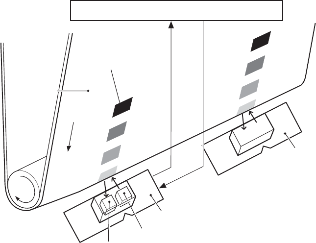
The following is the operational sequence of the image density control:
1. The DC controller allows the LED to emit light by sending the LED drive signal. The image
density detection control starts.
2. The density pattern images on the ETB reflect the light from the LED and the PD in the sensor
receives the light. This reflected light intensity differs depending on the toner density.
3. The light receiver converts the received light intensity into voltage and sends it as a toner
density signal to the DC controller.
4. The DC controller converts the toner density signal (analog) into a density value (digital) and
stores it.
The DC controller notifies the formatter of each error when the following errors are found during the
image density detection. When it fails to detect image density, it zeros the density data and notifies
the formatter.
●Image density sensor abnormality warning: detected ETB surface density is improper.
●Failed image density detection warning: detected density is improper.
DC controller PCB
ETB
Color misregistration
pattern image
Light emitter (LED)
Light receiver (PD)
Color misregistration sensor (L)
COLOR MISREGISTRATION signal
LED DRIVE signal
Color misregistration sensor (R)
Figure 5-33 Image density detection
ENWW Image formation system 197

Pickup/feed system
The pickup/feed system consists of various feed rollers that pick up and feed media. This MFP has
four pickup sources: the MP tray, tray 2, and the two trays of the 2 X 500-sheet paper feeder. The
primary delivery source is the face-down tray. The IPTU and stapler/stacker or 3-bin mailbox can
also be used for output.
The multipurpose tray paper sensor (SR4) detects the media presence in the multipurpose tray, and
the cassette paper sensor (SR9) detects the media presence in the cassette. The paper stack
surface sensor (SR10) in the cassette monitors the pickup position of the media stack surface. When
the SR10 detects that the pickup position lowers to a certain level, the DC controller lifts the lifting
plate up to maintain the media stack surface at a specified height. Figure 5-34 Pickup/feed system (1
of 2) on page 199 illustrates this system.
The media size in the cassette and presence of the cassette installed in the MFP are detected by the
cassette paper size detection switch (CSIZE SW). The cassette paper size detection switch consists
of three switches.
The DC controller controls ten motors: pickup motor, ETB motor, four drum motors, fuser motor,
fuser pressure release motor, reversing motor, and lifter motor. There are three solenoids: cassette
pickup solenoid, MP tray pickup solenoid, and duplexing solenoid, for the pickup operation.
There are five photo interrupters: top of page sensor, fuser paper sensor, paper loop sensor 1, paper
loop sensor 2, and paper reversing sensor, on the paper transport path to detect media arrival and
passage. If the media does not reach or pass these sensors within the specified period of time, the
microcomputer (CPU) on the DC controller determines the paper jam and notifies the formatter.
Figure 5-34 Pickup/feed system (1 of 2) on page 199 and Figure 5-35 Pickup/feed system (2 of 2)
on page 201 illustrate this system.
198 Chapter 5 Theory of operation ENWW

Figure 5-34 Pickup/feed system (1 of 2)
ENWW Pickup/feed system 199
The pickup/feed system consists of the following motors and solenoids:
●M1: Yellow (Y) drum motor
●M2: Cyan (C) drum motor
●M3: Magenta (M) drum motor
●M4: Black (K) drum motor
●M5: Fuser motor
●M6: Fuser pressure release motor
●M7: ETB motor
●M9: Pickup motor
●M10: Lifter motor
●M8001: Reversing motor
●SL1: Multipurpose tray pickup solenoid
●SL2: Cassette pickup solenoid
●SL8001: Duplexing solenoid
200 Chapter 5 Theory of operation ENWW
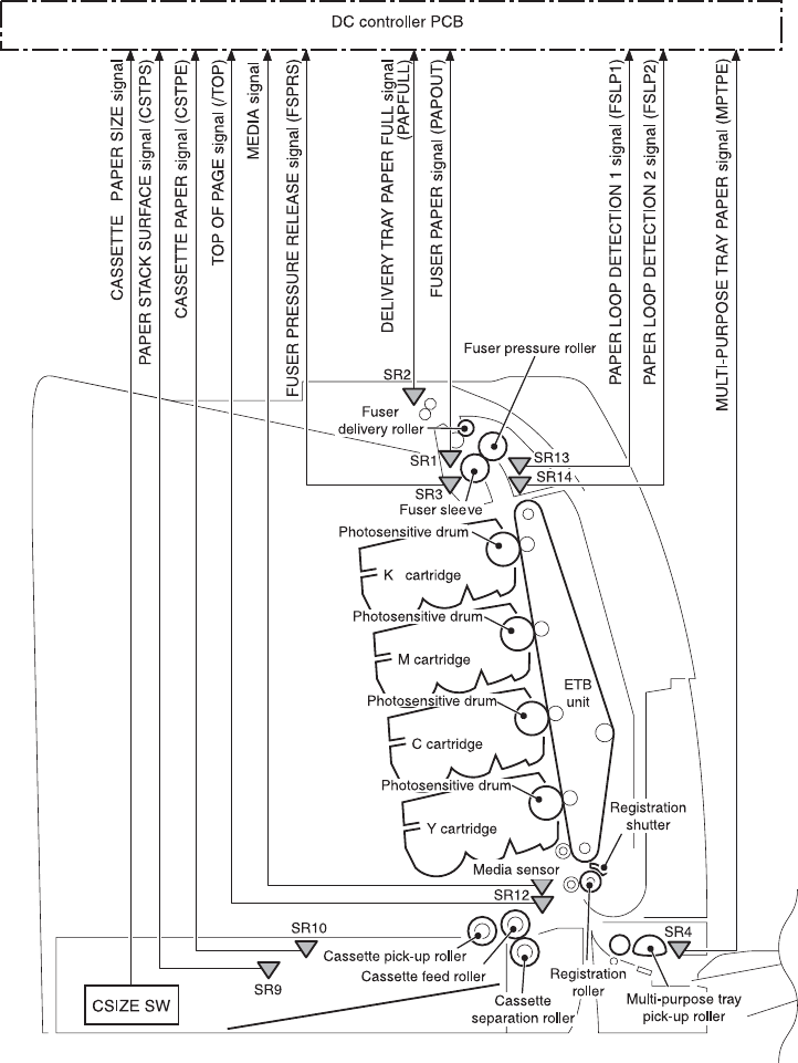
Figure 5-35 Pickup/feed system (2 of 2)
The pickup/feed system consists of the following sensors and switches:
●SR1: Fuser paper sensor
●SR2: Delivery tray paper full sensor
●SR3: Fuser pressure release sensor
●SR4: Multipurpose tray paper sensor
●SR9: Cassette paper sensor
●SR10: Paper stack surface sensor
ENWW Pickup/feed system 201
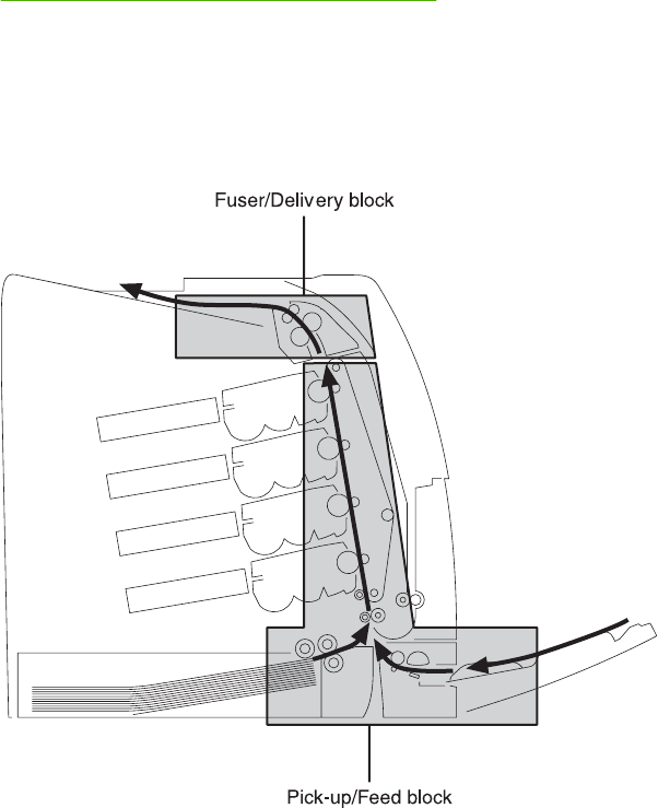
●SR12: Top of page sensor
●SR13: Paper loop sensor 1
●SR14: Paper loop sensor 2
●SR8001: Paper reversing sensor
●Media sensor
●CNT0: Cassette paper size detection switch
●CNT1: Cassette paper size detection switch
●CNT2: Cassette paper size detection switch
Figure 5-36 Pickup/feed system on page 202 illustrates the pickup/feed system, which can be divided
into three units:
●Pickup/feed unit. From the point the media is picked from the tray until it reaches the fuser.
●Fuser/delivery unit. From the fuser to the face-down tray or other output device.
●Duplex feed unit. From the duplexing reverse inlet unit to the registration roller.
Figure 5-36 Pickup/feed system
202 Chapter 5 Theory of operation ENWW

Pickup/feed unit
The pickup/feed block is structured with two blocks. One is the pickup block, which picks up media
from the cassette or the multipurpose tray into the MFP one by one. The other one is the feed block,
which feeds the picked-up media to the fuser. The following sequence of events occurs:
1. The DC controller rotates the pickup motor (M9), drum motors (M1, M2, M3, M4), ETB motor
(M7), and fuser motor (M5) after receiving a print command from the formatter.
2. The feed roller and the registration roller rotate as the pickup motor starts to rotate. The
cassette separation roller also begins to rotate. However, the separation roller does not rotate.
3. Media is picked from the cassette. The cassette pickup solenoid (SL2) is turned on after a
specified time after 'scanner ready'. This rotates the cassette pickup roller and cassette feed
roller to pick up media in the cassette.
Media is picked from the MP tray. The MP pickup solenoid (SL1) is turned on after a specified
time after 'scanner ready'. This rotates the MP tray pickup roller to pick up media in the tray.
4. Any multiple-fed media is removed by the cassette paper separation roller (paper separation
pad for the MP tray) and a single sheet is fed to the registration roller.
5. The skew of the media is corrected by the registration shutter. The media is then fed at its
prescribed speed. The formatter specifies the feed speed depending on the media type.
6. Toner is transferred to the media on the ETB, and the media is fed to the fuser/delivery block.
Cassette detection and cassette media size detection
The MFP can sense whether a cassette is installed correctly, and it can sense the size of the media
in the cassette. Paper-size detection switches at the back of the cassette send this information to the
DC controller. The DC controller determines which size is loaded by reading various switches. See
Table 5-6 Paper tray media size detection on page 203.
Table 5-6 Paper tray media size detection
Paper size Paper-size detection switch
CNT0 CNT1 CNT2
A4 on off off
B5 on on off
A5 off on off
Letter on off on
Legal off on on
Executive off off on
Custom on on on
No paper tray off off off
Although the cassette determines the media size by reading the switches, the user could select a
different size from what is loaded, creating an error in media-size detection.
ENWW Pickup/feed system 203
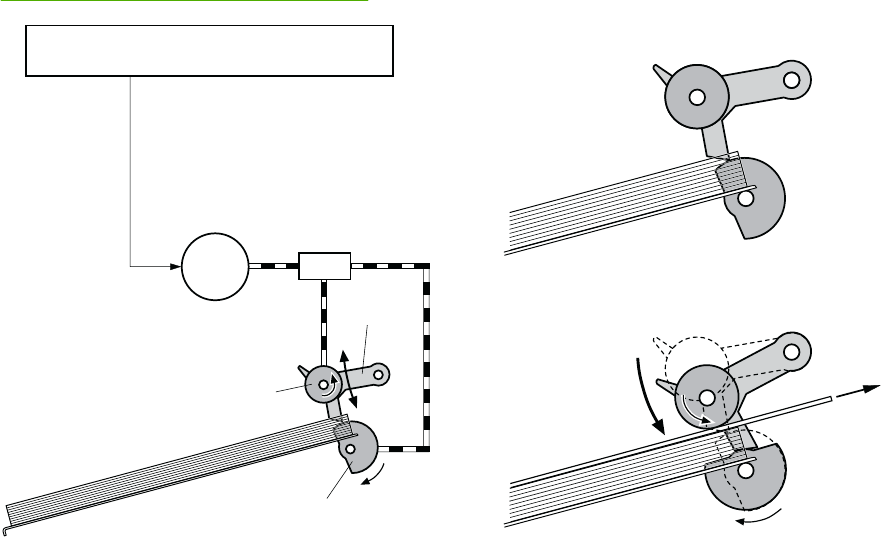
The paper leading-edge sensor detects when the leading edge and the trailing edge of a sheet pass
it. By measuring the time between the passing of the leading edge and trailing edge, the sensor can
determine the actual size of the sheet. If this measured size differs from the size specified by the
formatter or the switch combination, the DC controller determines a mismatch. The sheet is ejected
from the MFP, and the MFP stops.
Cassette pickup operation
This MFP uses the pickup arm method for high-speed media pickup. The pickup arm presses the
pickup roller down on the media stack to feed the media one by one. The pickup roller is attached to
the pickup arm and it is normally held at the original position by the pickup arm. When the pickup
solenoid (SL2) is turned on, the pickup cam rotates and lowers the pickup roller onto the media.
The following is the operational sequence of the cassette pickup mechanism.
1. When the DC controller turns the cassette pickup solenoid (SL2) on during the cassette pickup
operation, the driving force of the pickup motor (M9) causes the cassette pickup roller and the
pickup cam to rotate.
2. As the pickup cam rotates, the pickup arm goes down and the rotating cassette pickup roller
touches the media surface. The media in the cassette is fed into the MFP one sheet at a time.
3. The pickup cam rotation allows the pickup arm to go up and the cassette pickup roller
disengages from the media surface.
4. The cassette pickup roller stops rotating.
Figure 5-37 Cassette pickup on page 204 illustrates this process.
M9 SL2
DC controller PCB
Cassette pick-up roller
Pick-up cam
Pick-up arm
Pick-up motor Cassette
pick-up solenoid
PICK-UP MOTOR
CONTROL signal
Lifting plate
Figure 5-37 Cassette pickup
Media lifting operation
This operation maintains the position of the media stack surface at a specified height for a stable
pickup operation. The DC controller rotates the lifter motor (M10) and raises the lifting plate on which
204 Chapter 5 Theory of operation ENWW

the media stack is loaded. The DC controller monitors the cassette paper sensor (SR9) and the
media stack surface sensor (SR10) when the MFP is turned on, the cassette is installed, and during
the printing operation.
The media lifting operation is divided into two procedures:
●Initial lift
●Lifting during printing
Initial lift
The initial lift begins when the cassette is installed in the MFP and the lifting plate remains in the
bottom of the cassette. The DC controller continues driving the M10 until the SR10 detects media.
The SR10 lifts the stack surface up to the pickup position under the following conditions:
●The SR9 and SR10 detect no media when the power is turned on.
●The SR10 detects no media when the cassette is installed.
The DC controller stops this operation when the SR10 detects media before the SR9 detects media.
Lift-up during printing
The lifting during printing starts when the stack level reaches a specified level according to the
pickup operation. The DC controller drives the M10 when the SR10 detects no media during the
printing operation. The SR10 then lifts the stack surface up to the pickup position. Figure 5-38 Media
lifting on page 206 illustrates this process.
NOTE The paper lifting operation is also available for the 2 X 500-sheet paper feeders. The
initial lift for the cassette and paper feeders does not occur at the same time because of the
DC power supply limit. The operation starts from the bottom paper feeder and moves upwards.
ENWW Pickup/feed system 205
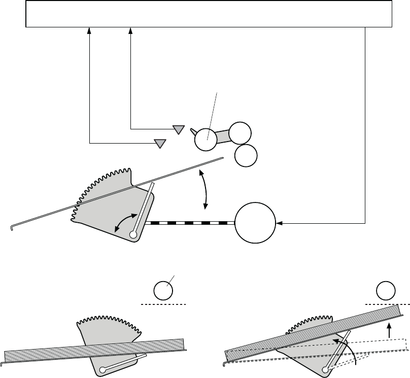
M10
SR9
SR10
Cassette pick-up roller
Cassette feed roller
Cassette separation roller
<Before lift-up> <After lift-up>
Cassette pick-up roller
Lifting plate
Lifter
DC controller PCB
LIFTER MOTOR DRIVE signal
PAPER STACK SURFACE
signal (CSTPS)
CASSETTE PAPER signal
(CSTPE)
Pick-up positionPick-up position
Figure 5-38 Media lifting
Multiple-feed prevention
This MFP uses the paper separation roller method to prevent multiple feeds. The cassette paper
separation roller rotates in the same direction as the cassette feed roller. The paper separation roller
is imparted with a rotational force, transmitted through the torque limiter. If a multiple feed occurs, the
second paper is pushed back to the cassette and only one sheet is fed into the MFP.
Normally, the cassette paper separation roller is imparted with a rotational force in the same direction
to the cassette feed roller. However, since the paper separation roller touches the feed roller, driving
torque from the feed roller brings the torque limiter functions. The torque limiter shuts the rotational
force from the separation roller. The paper separation roller follows the rotational direction of the feed
roller, in the opposite direction. When the paper is not multiple-fed, the driving force from the feed
roller transmits through the single paper and allows the paper separation roller to rotate in the
opposite direction.
During a multi-feed, the rotational force of the cassette feed roller transmitted to the cassette paper
separation roller becomes weak because of the low friction between the sheets. The torque limiter
does not function and the paper separation roller rotates in the direction of the drive gear, causing
206 Chapter 5 Theory of operation ENWW
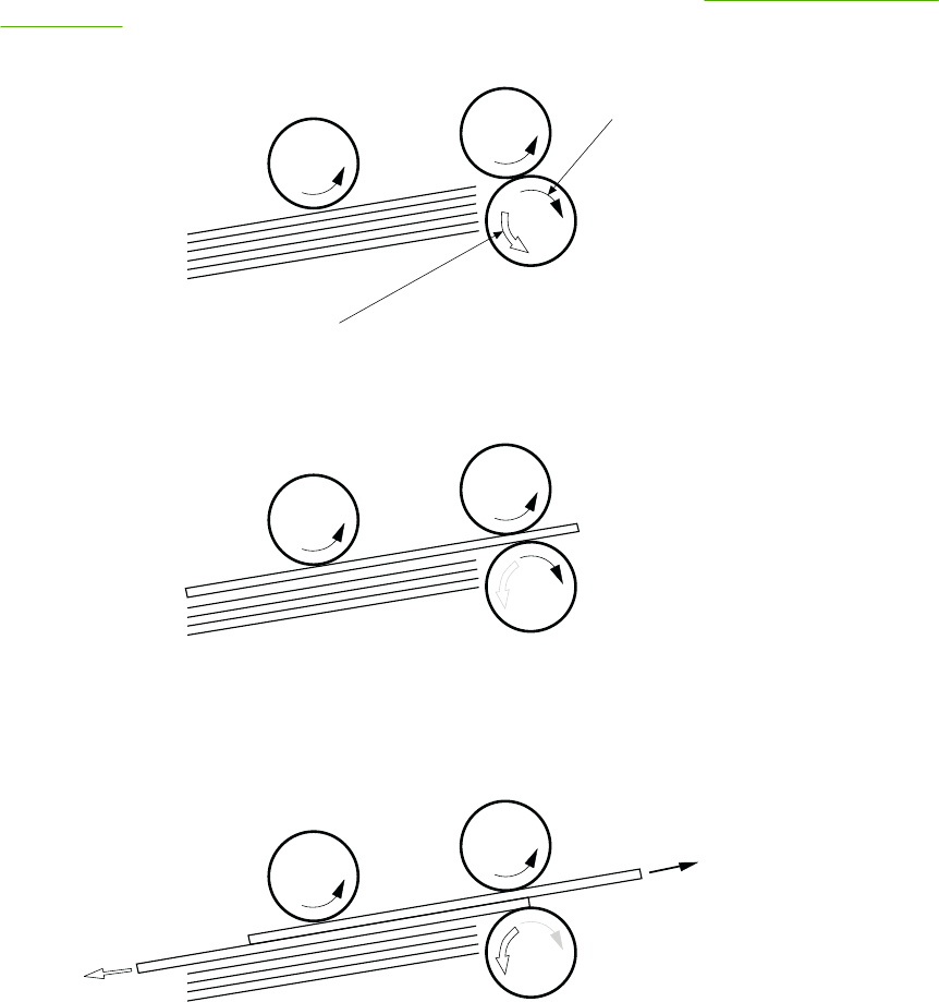
the multiple-fed media to be separated and pushed back to the cassette. Figure 5-39 Media lifting
on page 207 illustrates this process.
Cassette pick-up roller
Cassette feed roller
Driving force transmitted
from cassette feed roller
Driving force transmitted
from the pick-up motor through the torque limiter
Cassette separation roller
Normally
Multiple-feed
Paper
Figure 5-39 Media lifting
Skew correction
The skew correction mechanism compensates for the skew of feeding media. This MFP uses the
registration shutter method to avoid decreasing throughput.
1. When the media is fed to the registration roller, the leading edge of the media hits the
registration shutter to compensate for the skew feeding.
2. The media is warped as the feed roller keeps pushing the media with the condition that the
media hit the registration shutter.
3. The stiffness of the media being warped lifts up the registration shutter and the media goes
through the shutter. The skew-feed is corrected without decreasing throughput.
ENWW Pickup/feed system 207
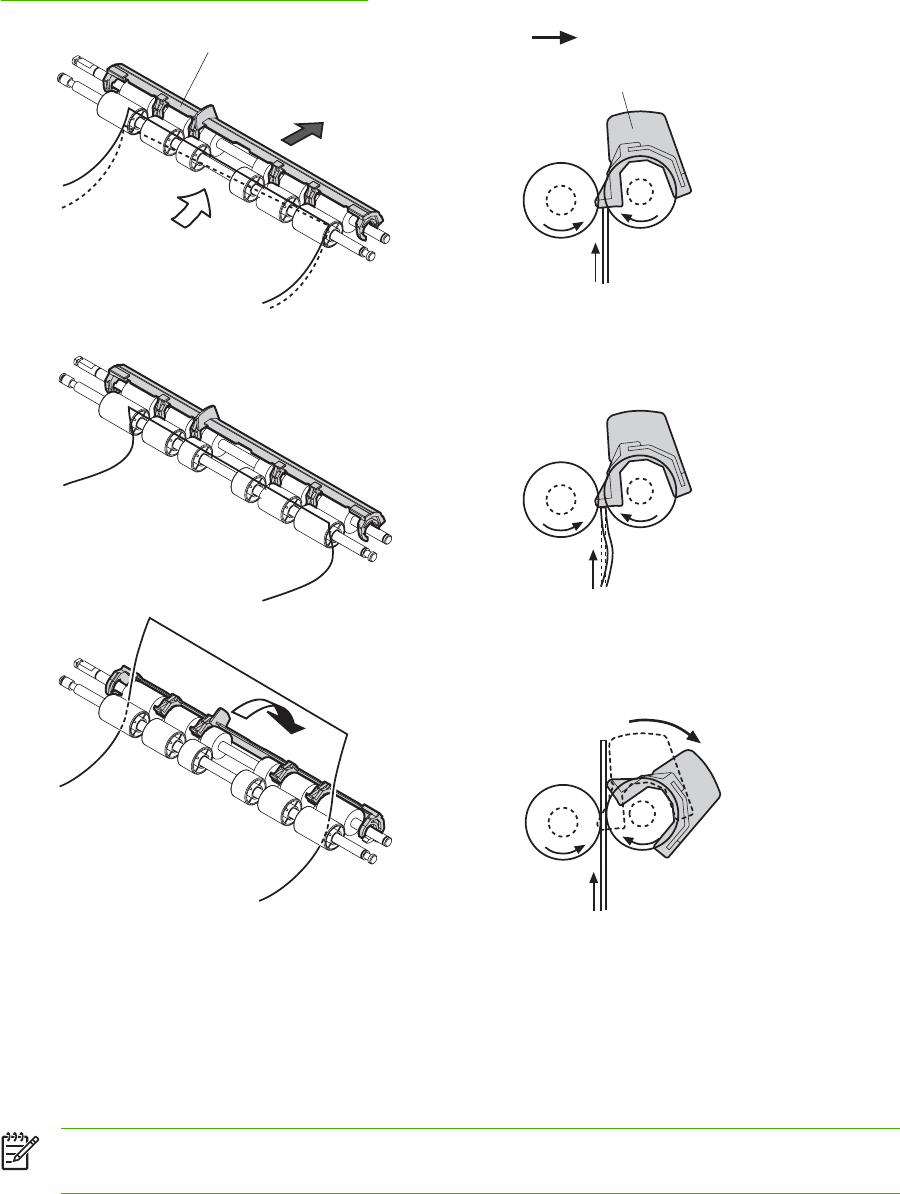
Figure 5-40 Skew correction on page 208 illustrates this process.
Registration shutter
Paper
Paper
Front side of printer
Registration shutter Front side of printer
1)
2)
3)
Figure 5-40 Skew correction
Media detection
This MFP detects the media types to select the optimum print mode automatically. The DC controller
controls the media sensor during the printing operation for this detection. The media sensor contains
a light emitter (LED) and a light receiver. The light from the emitter is reflected off the media surface
or transmitted through the media. Each light is received at the light receiver.
NOTE The light receiver can detect even a slight difference in the light intensity because the
high-density pixels are integrated in a very small area.
The DC controller turns the media sensor on when the picked-up media passes through the
registration roller. Then it detects the roughness of the media surface, transmitted light intensity, and
thickness according to the patterns (luminance distribution within specified area) of the detected light
208 Chapter 5 Theory of operation ENWW
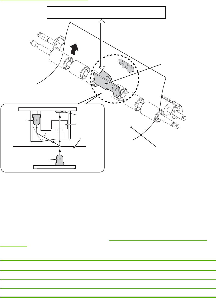
by the receiver. Accordingly, the DC controller identifies the media type: either plain paper, thin
paper, thick paper, gloss paper, gloss film, or overhead transparency, and notifies the formatter.
Figure 5-41 Media detection on page 209 illustrates this process.
Media
Lens
Light
receiver
LED
Media
Media sensor
DC controller PCB
LED
Figure 5-41 Media detection
The DC controller switches the media feeding speed according to the detected media type when the
detected media type does not match the selected print mode.
If the DC controller fails to communicate with the media sensor during the media detection, it detects
a media sensor failure and outputs a media sensor abnormality warning to the formatter.
Feed speed control
The type of media in the paper path dictates the speed at which it is fed. The DC controller can
change the feed speed according to type of media. Table 5-7 Paper size detection switch settings
on page 209 shows the relationship between media type and feed speed.
Table 5-7 Paper size detection switch settings
Print mode Media type Feed speed
Normal Plain paper Normal speed
Normal gloss Plain paper 1/2 speed
Rough Rough paper 1/2 speed
ENWW Pickup/feed system 209

Print mode Media type Feed speed
Thin Plain paper Normal speed
Thin rough Rough paper 1/2 speed
Envelope Envelope 1/2 speed
Label Label 1/2 speed
Thick 1 Thick card/postcard 1/2 speed
Thick 2 Thick paper 1/3 speed
Gloss 1 Gloss paper 1/2 speed
Gloss 2 and 3 Gloss paper 1/3 speed
Overhead transparency OHT film 1/3 speed
Gloss film Gloss film 1/3 speed
Automatic Plain paper, thin paper, thick paper,
gloss paper, gloss film, overhead
transparency
N/A
The DC controller performs the following controls depending on the specified print mode.
●OHT mode. If plain paper, other than OHT is detected, the DC controller determines a media
misprint. The DC controller lets the printing operation continue under the OHT mode only when
it detects the OHT. The same applies to the following sheets in a continuous printing. When the
DC controller outputs the wrong media, it notifies the formatter, cuts off the secondary transfer
bias, delivers the media, and then stops the printer engine.
●Automatic mode. When automatic mode is selected, the MFP starts the printing operation in
the normal mode. If plain paper, thin paper, thick paper, gloss paper, gloss film, or OHT is
detected, the DC controller switches the print mode to the appropriate mode and executes the
printing operation. In continuous printing, the print mode will not change from the one selected
for the first sheet. However, if the DC controller detects media different from the first page, it
outputs a media misprint.
●All other print modes. If media other than OHT is detected, the DC controller continues the
printing operation with the selected print mode. It outputs a media misprint only when it detects
OHT. The same applies to the following sheets in the continuous printing.
Fusing and delivery block
The fuser/delivery unit is structured with two blocks. One is the fuser block that fuses toner on the
media. The other is the delivery block, which delivers the fused media to the face-down tray or output
device. The following is the operational sequence of the fuser/delivery unit.
1. The media with toner transferred on the ETB is fed to the fuser.
2. The paper warp is adjusted with the fuser motor speed control. The feeding speed differs
between the ETB and the fuser, as different motors are used to drive them. This control keeps
the media with a specified warp to prevent image defects and media transport defects.
Table 5-7 Paper size detection switch settings (continued)
210 Chapter 5 Theory of operation ENWW

3. The fusing sleeve and the fusing pressure roller fuse the toner onto the media. The media is
then delivered from the fuser.
4. The image fusing media sensor (SR1) detects the media delivered from the fuser, and then
delivers the media to the face-down tray or other output device.
NOTE If the face-down tray is full of media, the delivery tray paper-full sensor (SR2) detects
that it is full. The DC controller determines the face-down tray media is full, notifies the
formatter, delivers the media currently printing from the MFP, and stops the printer engine.
When the stack of media on the face-down tray is removed, the SR2 detects the media
absence and the printing operation resumes.
Loop control
The media is delivered from the ETB to the fusing pressure roller maintaining the specified warp for
the media type, to prevent image and media transport defects.
The feeding speed of the fusing pressure roller and the ETB are not exactly the same. The following
problems might occur when the media is fed into the fuser.
●If the rotational speed of the fusing pressure roller is slower than that of the ETB, the media
warp increases and an image defect or media crease might occur.
●If the rotational speed of the fusing pressure roller is faster than that of the ETB, the media warp
decreases and a color misregistration in the sub-scanning direction occurs as the fusing
pressure roller pulls the media.
To resolve these issues, two sensors are used depending on the media type specified by the
formatter. The sensors bifurcate the warp amount for thick paper and thin paper. The DC controller
monitors the paper loop sensor 1 (SR13) and the paper loop sensor 2 (SR14) to maintain the paper
warp at specified amount by changing the rotational speed of the fusing pressure roller.
Figure 5-42 Loop control on page 212 illustrates this process.
ENWW Pickup/feed system 211
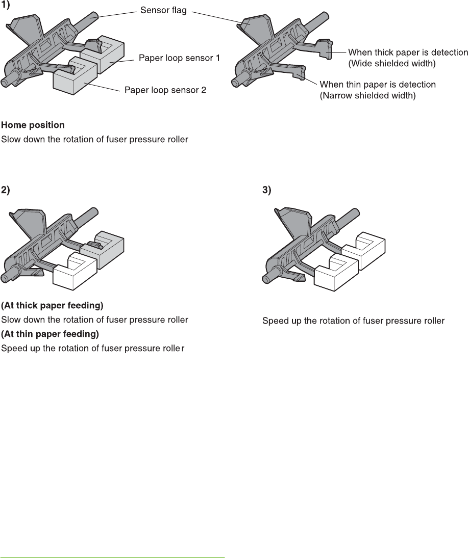
Figure 5-42 Loop control
Fusing pressure release mechanism
This mechanism automatically releases the fusing pressure to improve media removal and prevent
fusing pressure roller deformation.
The DC controller rotates the cam driven by the fuser pressure release motor (M6) at the prescribed
timing. The lifting plate is pushed down and the fusing pressure roller is released. The fusing
pressure is released under the following conditions:
●When a paper jam occurs
●When the power is turned off
●When Sleep mode is ON/OFF
Figure 5-43 Fusing pressure release on page 213 illustrates this process.
212 Chapter 5 Theory of operation ENWW
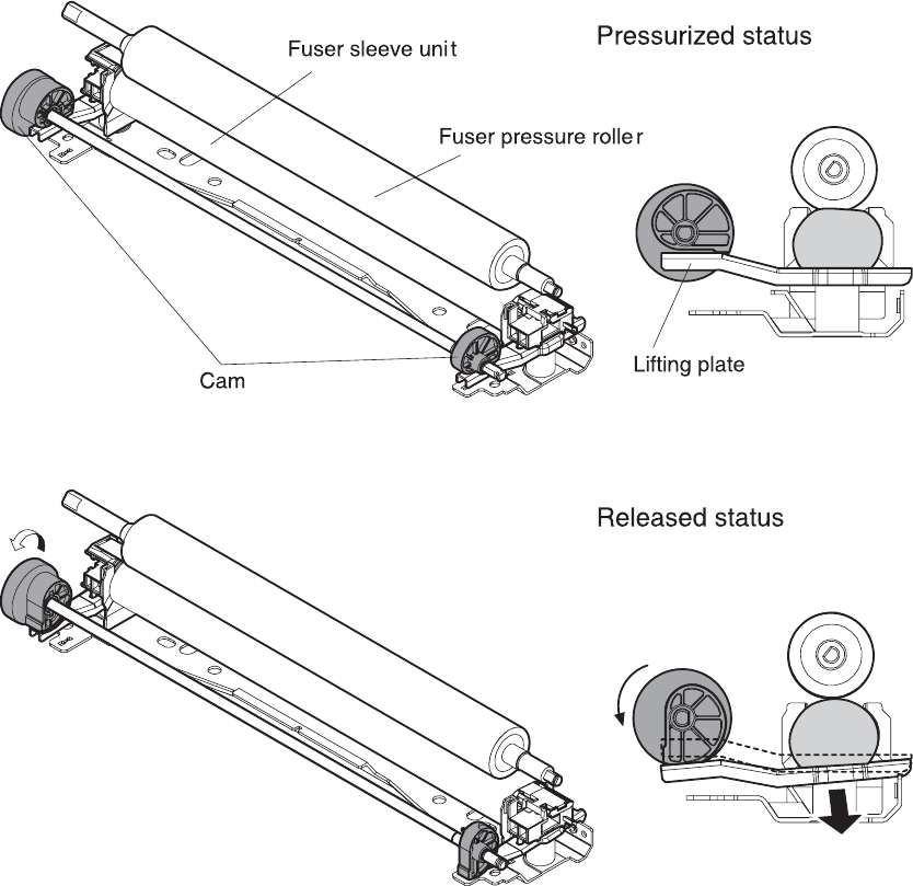
Figure 5-43 Fusing pressure release
Duplex feed unit
This MFP is equipped with an integrated duplexing unit. The duplexing reverse/duplexing feed unit is
structured into two blocks.
One is the duplexing reverse block, that reverses paper in preparation for duplex printing. The
second is the duplexing feed block, which delivers the reversed paper to the registration roller.
ENWW Pickup/feed system 213
Duplexing unit
Figure 5-44 Duplex feed unit
The duplexing driver PCB controls the duplexing unit. An 8-bit microcomputer in the duplexing driver
PCB controls the sequences of the duplexing unit and serial communication with the DC controller.
The DC controller sends a command to the duplexing driver PCB at the necessary time. The
duplexing driver PCB drives each load, such as motors and solenoids, depending on these
commands. The duplexing driver PCB relays the status information of the duplexing unit to the DC
controller.
The MFP supplies +24VDC to the duplexing unit. The +3.3VDC is generated by +24V DC in the
duplexing driver PCB, which works for the component devices such as sensors and ICs. Figure 5-45
Duplexing driver PCB signal flow on page 214 shows the signal flow in the duplexing driver PCB.
Duplexing driver PCB
Paper reversing sensor
Duplexing solenoid
Reversing motor
DC controller PCB
M
Duplexing unit fan
SL
+24V
Figure 5-45 Duplexing driver PCB signal flow
Duplexing reverse/duplexing feed operation
The media fed to the duplexing unit goes to the opposite direction and proceeds hitting along the
right plate by the oblique roller. This corrects the paper skew and the media is fed into the MFP. The
operational sequence of the duplexing feed is described in Figure 5-46 Duplexing feed on page 215.
214 Chapter 5 Theory of operation ENWW
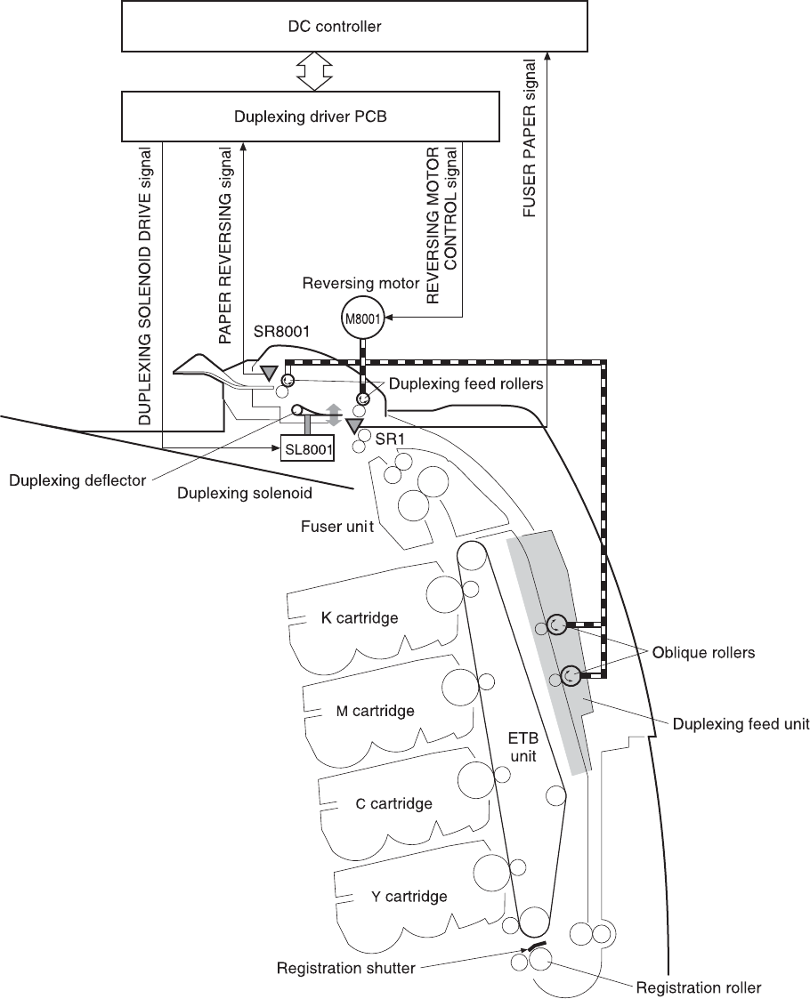
Figure 5-46 Duplexing feed
1. Media that has been printed on one side passes through the fuser.
2. The DC controller sends the reversing command to the duplexing driver at the specified time
after the top of page sensor (SR12) detects the leading edge of paper. The prescribed time is
when the media arrives at the fuser.
ENWW Pickup/feed system 215
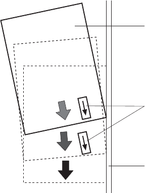
3. When the duplexing driver receives the reversing command, it turns on the duplexing solenoid
(SL8001) to move the duplexing deflector. The duplexing driver also rotates the reversing motor
(M8001) clockwise to feed the media to the duplexing unit.
4. The DC controller sends the duplexing pickup command to the duplexing driver after the
prescribed time from when the fuser paper sensor (SR1) detected the trailing edge of paper.
The prescribed time is when the media passes through the duplexing deflector.
5. The duplexing driver rotates the reversing motor (M8001) counter clockwise (CCW) to reverse
the media and feed it to the duplexing feed unit when it receives the duplexing pickup command.
6. The media is fed while hitting its edge to the right guide by the oblique roller in the duplexing
feed unit. Consequently, the paper skew is corrected and the starting position of the image in
main-scanning is determined.
Oblique rollers
Paper
Right guide
Figure 5-47 Paper skew correction
7. The paper skew is again corrected by the registration shutter. Then the media is printed on the
other side and fed to the face-down tray or other output device.
The MFP can use the following three duplexing modes depending on the paper size and the print
mode. The formatter specifies each duplexing print operation. However, it cannot specify the
operation other than the printable size (LTR, legal, executive, A4, B5-JIS) and the print mode
(normal, thick paper, thin paper, gloss paper, gloss film) for the duplexing print.
1. Single sheet mode. Duplexing of one sheet at a time (all paper sizes).
2. Dual sheet mode. Duplexing of two sheets moving at once (all paper sizes print except legal).
3. Alternating complex mode. Duplexing of three sheets moving at once (all paper sizes print
except legal).
Jam detection
The MFP uses the following sensors to detect the presence of media and to check whether media is
being fed correctly or has jammed:
●Top-of-page sensor (SR12)
●Fuser paper sensor (SR1)
216 Chapter 5 Theory of operation ENWW

●Delivery tray paper-full sensor (SR2)
●Reversing paper sensor (SR8001)
The microprocessor on the DC controller checks for jams by timing the media as it moves past these
sensors. If the media does not pass the sensor in a specific period of time, the transport process is
stopped (the motors are turned off and the rollers no longer rotate) and a jam message displays on
the product control panel display.
Pickup delay jam
If the top-of-page sensor (SR12) does not detect the leading edge of the media within a specific
period of time after the media is picked up, the microprocessor on the DC controller PCB determines
that a pickup jam has occurred.
NOTE The MFP attempts to pick up the media several times before determining that a
pickup jam exists. The number of pickup attempts depends on the source (for example, four
attempts occur if tray 1 is the source).
The transport process stops and a 13.%1$2:02X.%2$1:X%3$1:X FUSER JAM message displays on
the product control panel display. For more information about jam messages, see Resolving control
panel messages on page 488.
Pickup stationary jam
If the top-of-page sensor (SR12) continues to detect the leading edge of the media after a specific
period of time has elapsed, the microprocessor on the DC controller PCB determines that a pickup
stationary jam has occurred.
The transport process stops and a 13.%1$2:02X.%2$1:X%3$1:X FUSER JAM message displays on
the product control panel display. For more information about jam messages, see Resolving control
panel messages on page 488.
Delivery delay jam
If the fuser paper sensor (SR1) does not detect the leading edge of the media within a specific period
of time after the top-of-page sensor detects the media, the microprocessor on the DC controller PCB
determines that a delivery delay jam has occurred.
The transport process stops and a 13.%1$2:02X.%2$1:X%3$1:X FUSER JAM message displays on
the product control panel display. For more information about jam messages, see Resolving control
panel messages on page 488.
Door open jam
If the upper right cover, ETB cover, tray 1, IPTU door, or the 2 x 500-sheet paper deck door is
opened during printing, the microprocessor on the DC controller PCB determines that a door open
jam has occurred.
The transport process stops and a 13.%1$2:02X.%2$1:X%3$1:X FUSER JAM message appears on
the product control panel display. For more information about jam messages, see Resolving control
panel messages on page 488.
ENWW Pickup/feed system 217

Residual paper jam
If the fuser paper sensor (SR1) detects paper during the WAIT or INTR period, or if the top-of-page
sensor or fuser paper sensor detect paper during the automatic delivery period, the microprocessor
on the DC controller PCB determines that a residual paper jam has occurred.
The transport process stops and a 13.%1$2:02X.%2$1:X%3$1:X FUSER JAM message displays on
the product control panel display. For more information about jam messages, see Resolving control
panel messages on page 488.
Reversing unit jam 1
If the paper reversing sensor (SR8001) does not detect the leading edge of the media within a
specified period after the duplexing driver receives a reversing command from the MFP, the
microprocessor on the DC controller PCB determines that a reversing unit jam 1 has occurred.
The transport process stops and a 13.%1$2:02X.%2$1:X%3$1:X FUSER JAM message displays on
the product control panel display. For more information about jam messages, see Resolving control
panel messages on page 488.
Reversing unit jam 2
If the paper reversing sensor (SR8001) continues to detect media for a specified period after it
initially detects the media, the microprocessor on the DC controller PCB determines that a reversing
unit jam 2 has occurred.
The transport process stops and a 13.%1$2:02X.%2$1:X%3$1:X FUSER JAM message appears on
the product control panel display. For more information about jam messages, see Resolving control
panel messages on page 488.
Duplexing pickup unit jam 1
If the top-of-page sensor (SR12) fails to detect the leading edge of media within the specified period
after the duplexing driver receives a duplexing pickup command from the MFP, the microprocessor
on the DC controller PCB determines that a duplexing pickup unit jam 1 has occurred.
The transport process stops and a 13.%1$2:02X.%2$1:X%3$1:X FUSER JAM message displays on
the product control panel display. For more information about jam messages, see Resolving control
panel messages on page 488.
Automatic delivery function
Any residual paper within the MFP is automatically delivered when the power is turned on or when
printing starts. If the top-of-page sensor (SR12) detects paper during the WAIT period, the DC
controller PCB detects that residual paper is present, notifies to the formatter, and stops printing. The
controller drives the motors and delivers the residual paper to the MFP when it receives an automatic
delivery command from the formatter.
218 Chapter 5 Theory of operation ENWW
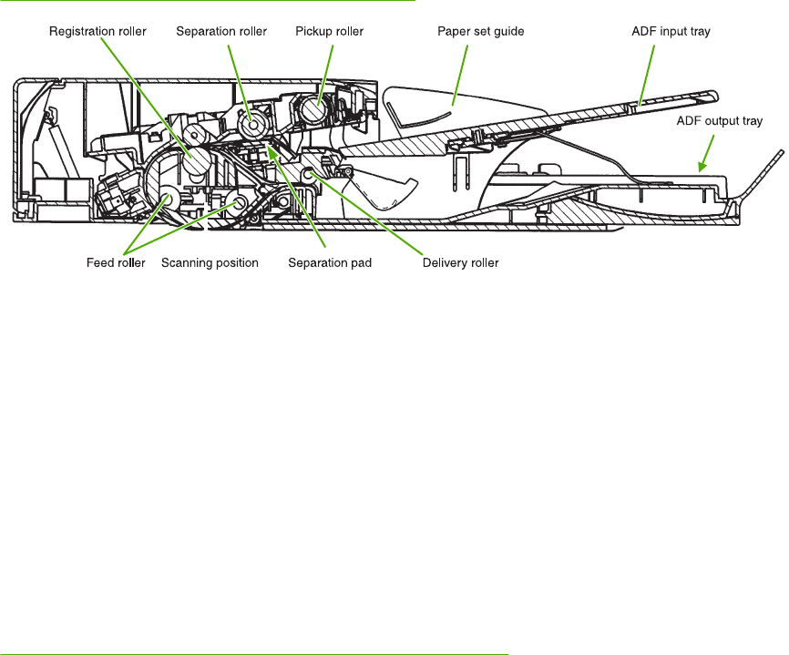
Scanner system
The scanner system adds copying and sending functions to the standard MFP printing function. The
scanner assembly consists of an automatic document feeder (ADF) and a flatbed scanner glass
surface.
Original documents that are fed through the ADF are delivered to the ADF output bin, which is
underneath the ADF input tray. Printed copies are delivered to the output device that is attached to
the print engine.
The scanner unit has built-in duplexing capability for scanning two-sided documents.
Figure 5-48 ADF mechanical structure on page 219 shows a cross-section of the ADF.
Figure 5-48 ADF mechanical structure
Electrical system
The scanner assembly electrical system consists of the following components:
●Charged coupled device (CCD) PCB
●Inverter PCB
●Scanner PCB
●ADF PCB
●ADF LED PCB
The scanner assembly is connected to the print engine formatter through a flat, flexible cable.
Figure 5-49 Scanner assembly electrical structure on page 220 shows the scanner assembly electrical
structure.
ENWW Scanner system 219
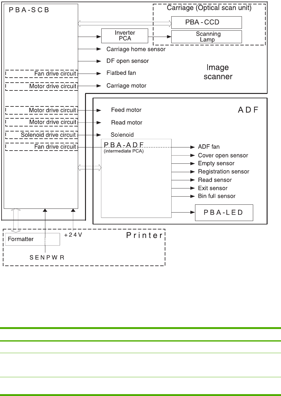
Figure 5-49 Scanner assembly electrical structure
Motors and fans
The scanner assembly has five motors and two fans. Three of the motors are stepping motors, which
drive the components inside the scanner assembly. The remaining two motors are DC motors, which
drive the two fans.
Name Purpose Type Rotation Failure detection
Carriage motor Drives the carriage unit Stepping motor Varies No
Feed motor Drives the pickup,
separation, and
registration rollers
Stepping motor Varies No
Read motor Drives the feed and
delivery rollers
Stepping motor Counterclockwise No
220 Chapter 5 Theory of operation ENWW
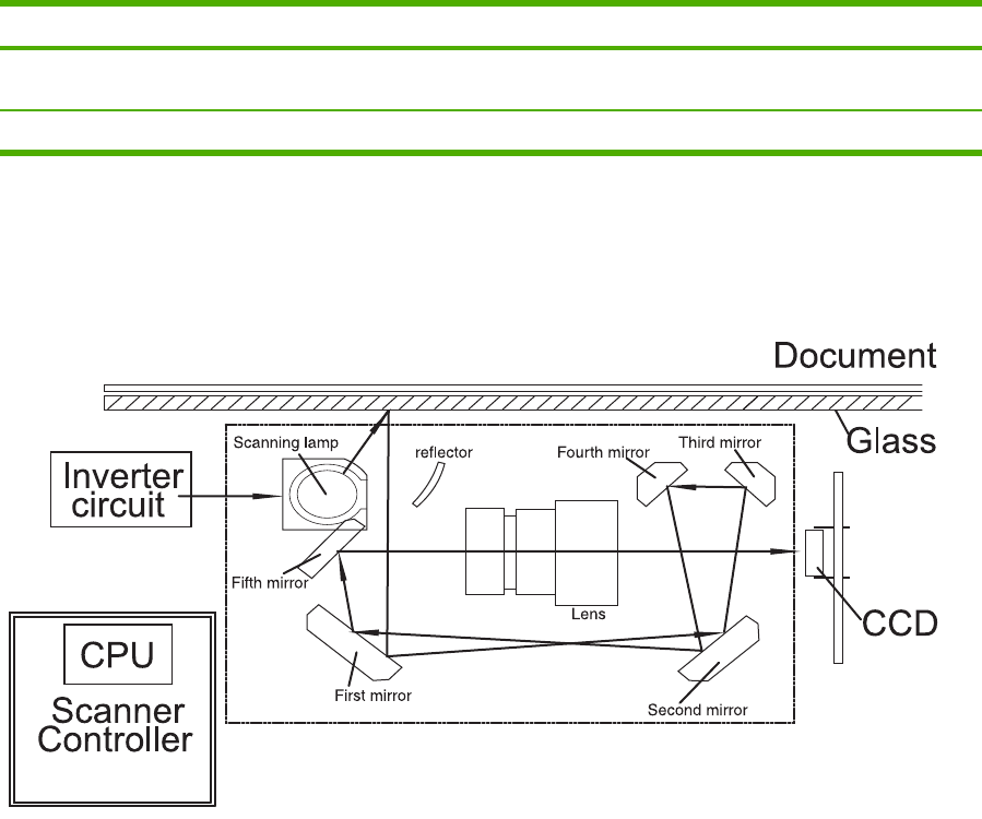
Name Purpose Type Rotation Failure detection
Flatbed fan Cools the scanner
lamp and the CCD
DC motor Clockwise Yes
ADF fan Cools the motors DC motor Clockwise Yes
Optical assembly
The optical assembly contains the scan carriage and the scanner glass. The scan carriage contains
the lamp, five mirrors, a lens, and the CCD.
Figure 5-50 Scan carriage components
The scanner lamp illuminates a small strip of the document (called the raster line). The mirrors direct
the light through the lens to the CCD. The CCD senses and records the light, creating an analog
representation of the raster line. If the ADF is being used, the document then advances in the ADF to
the next raster line. If the flatbed is being used, the carriage advances to the next raster line. This
advancing and collection process continues to the end of the sheet.
The image data is collected on the scanner controller PCB, where it is processed and sent to the
formatter.
ENWW Scanner system 221
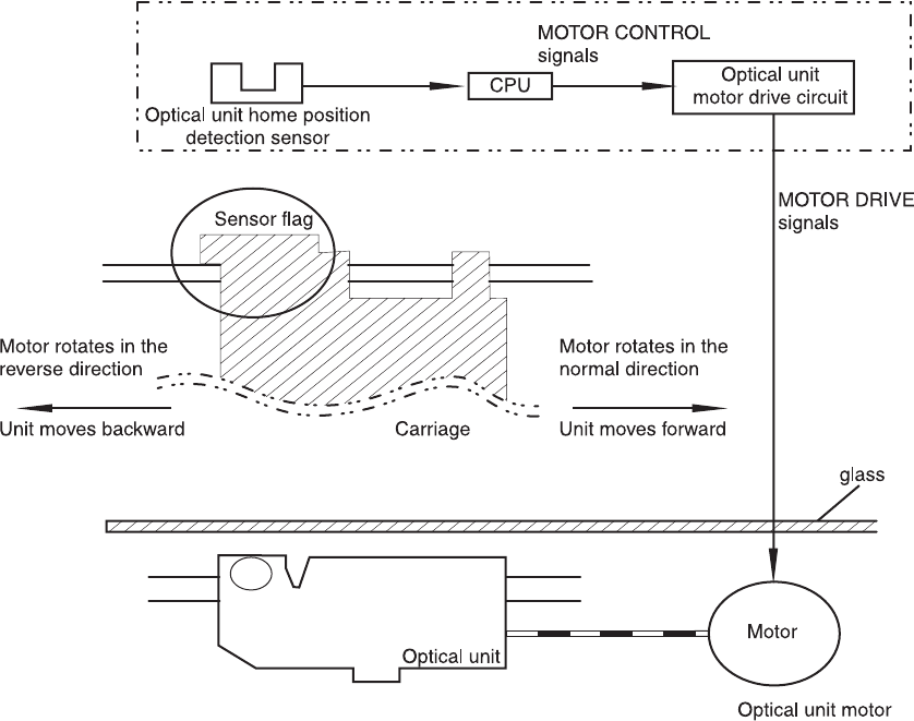
Figure 5-51 Scan carriage movement
ADF feed system
Pages from the original document enter the ADF from the ADF input tray. A separation roller and
separation pad work together to separate the top sheet from the stack. The page passes through a
set of registration rollers and two sets of feed rollers that advance the page. A set of delivery rollers
delivers the page to the ADF output bin. A bin-full sensor detects when the ADF output bin is full, and
stops the feed mechanism until the bin is emptied.
222 Chapter 5 Theory of operation ENWW
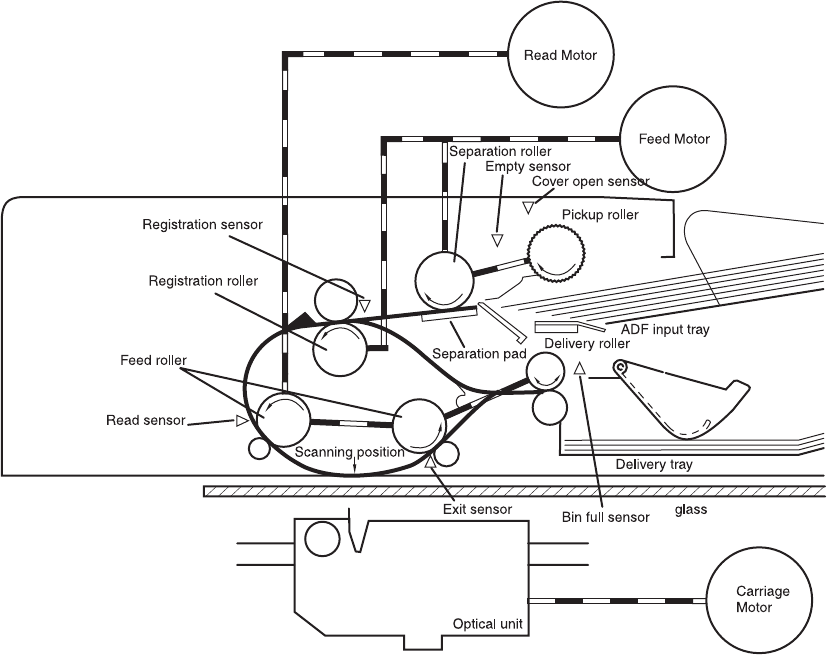
Figure 5-52 ADF paper path and sensors
ADF jam detection
When the sensors inside the ADF detect a jam, the feed and read motors immediately stop and send
a signal to the scanner controller PCB, which notifies the formatter. An ADF Paper Jam message
displays on the product control panel display.
To clear a jam, open the jam access cover and remove the media. If no sensors detect media after
the jam access cover is closed, the jam message is cleared from the product control panel display.
Residual media jam
During the initialization sequence or after the ADF jam cover has been opened and closed, the
registration sensor, read sensor, and exit sensor are checked for residual media jams. If a sensor
detects the presence of media, the scanner controller PCB detects a residual media jam.
ADF pickup jam
If the leading edge of the media did not reach the registration sensor within a specific period of time,
the scanner controller PCB determines that an ADF pickup jam has occurred.
ADF jam
Jams can occur in three places inside the ADF: at the registration sensor, read sensor, and exit
sensor.
ENWW Scanner system 223
Registration sensor jam
If the registration sensor does not detect the trailing edge of the media after the leading edge
reaches the scan ready position, the scanner controller PCB determines that an ADF paper jam has
occurred.
Also, when the scanner duplexer is being used, if the registration sensor does not detect the leading
edge of the media after a specific period of time after media enters the duplexer, the scanner
controller PCB determines that a jam has occurred.
Read sensor jam
If the read sensor does not detect the leading edge of the media within a specific period of time, or if
the read sensor does not detect the trailing edge of the media within a specific period of time after it
detects the leading edge, the scanner controller PCB determines that a jam has occurred.
Exit sensor jam
If the exit sensor does not detect the leading edge of the media within a specific period of time after
the leading edge reaches the read sensor, or if the exit sensor does not detect the trailing edge of
the media within a specific period of time after the read sensor detects the trailing edge, the scanner
controller PCB determines that a jam has occurred.
ADF cover-open jam
If the ADF jam access cover is opened while media is feeding through the ADF, a jam occurs.
ADF open jam
If the ADF is opened while media is feeding through the ADF, a jam occurs.
224 Chapter 5 Theory of operation ENWW
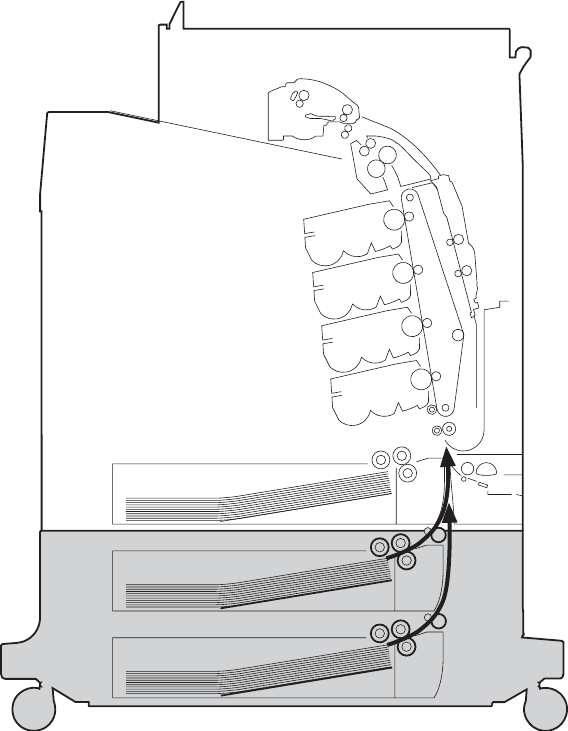
2 X 500-sheet paper feeder
The MFP includes a 500-sheet paper tray (tray 2) and a larger paper deck that contains two 500-
sheet feeders (trays 3 and 4). The paper path is shown below.
Figure 5-53 2 X 500-sheet feeder paper path
The paper feeder driver PCB controls the 2 X 500-sheet feeder operation sequences. The
microprocessor in the paper feeder driver controls the 2 X 500-sheet feeder sequences and the
communication with the DC controller PCB.
The paper feeder driver drives the solenoid in response to the pickup command. The paper feeder
driver also reports the paper feeder status to the DC controller PCB.
The MFP delivers a charge of +24 V to the paper feeder, which then generates +3.3 V for the
integrated circuits.
ENWW 2 X 500-sheet paper feeder 225
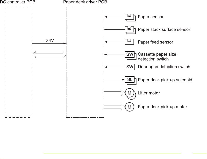
Figure 5-54 2 X 500-sheet feeder I/O block diagram
Pickup and feed operations
The paper pickup and feeding processes for the 2 X 500-sheet feeder are identical to the processes
used for tray 2. See Figure 5-54 2 X 500-sheet feeder I/O block diagram on page 226. The Figure
5-55 2 X 500-sheet feeder pickup and feed diagram on page 227 identifies the components of the
2 X 500-sheet feeder.
226 Chapter 5 Theory of operation ENWW
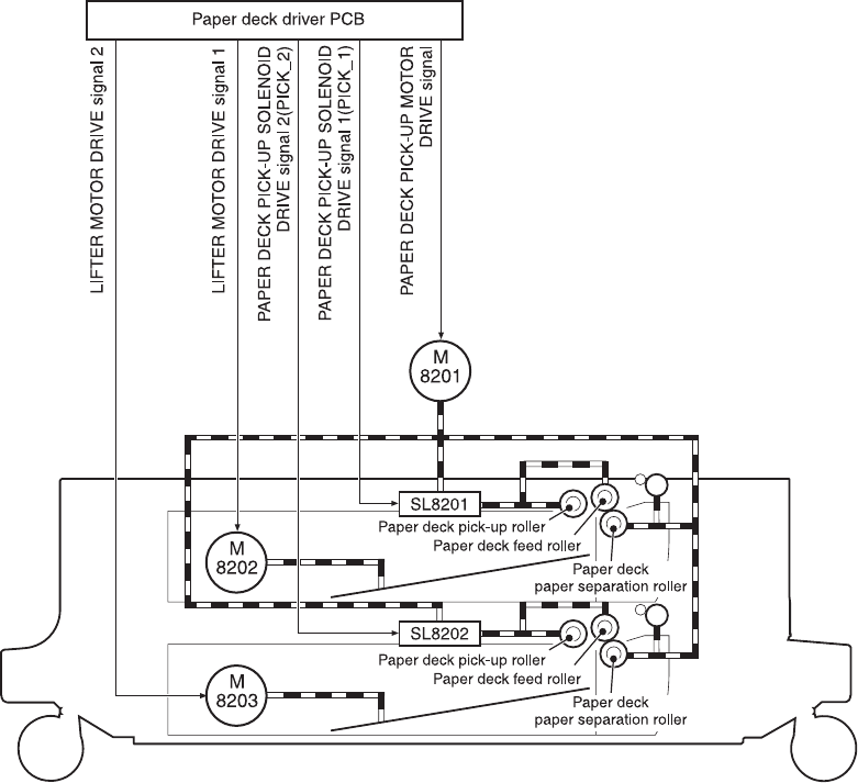
Figure 5-55 2 X 500-sheet feeder pickup and feed diagram
1. The DC controller receives a print command from the formatter and sends a pickup command to
the paper feeder driver.
2. The paper feeder driver rotates the pickup motor (M8101) in the paper feeder, and the feed
roller and the paper feeder separation roller start to rotate.
3. The DC controller sends the paper feeder pickup start command to the paper deck driver PCB
after the scanner is ready.
4. The paper deck driver PCB then rotates the paper deck pickup motor (M8201) clockwise to
rotate the paper deck feed roller.
5. The paper deck driver PCB turns on the paper feeder pickup solenoids (SL8201 and SL8202) to
rotate the paper deck pickup roller and the paper feeder feed roller. At the same time, the PCB
lowers the paper feeder pickup roller. As the pickup roller lowers, it contacts the media surface
and media in the cassette is fed into the MFP.
6. The separation roller eliminates extra sheets, and a single piece of media enters the feed path.
7. If the paper stack level goes down to the specified level according to the pickup operation, the
paper lifting operation is performed.
ENWW 2 X 500-sheet paper feeder 227

NOTE Paper-size detection, multiple-feed prevention, and jam detection for the 2 X 500-
sheet feeder function in the same manner as the rest of the MFP.
NOTE Paper lifting operation for the 2 X 500-sheet feeder is the same as that of tray 2,
except that the paper feeder driver PCB controls this operation instead of the DC controller.
2 X 500-sheet jam detection
The paper feed sensor (SR8201) detects abnormal feed operation in the 500-sheet paper feeder.
These jams can occur:
●Paper deck pickup delay jam: If the paper feed sensor (SR8201) does not detect the leading
edge of the media within a specified period after the paper is picked up, the microprocessor on
the DC controller PCB determines that a pickup jam has occurred.
●Paper deck pickup stationary jam: If the paper feed sensor (SR8201) continues to detect
paper after a specific period of time has elapsed, the microprocessor on the DC controller PCB
determines that a paper deck pickup stationary jam has occurred.
For other jams, see Jam detection on page 216.
228 Chapter 5 Theory of operation ENWW
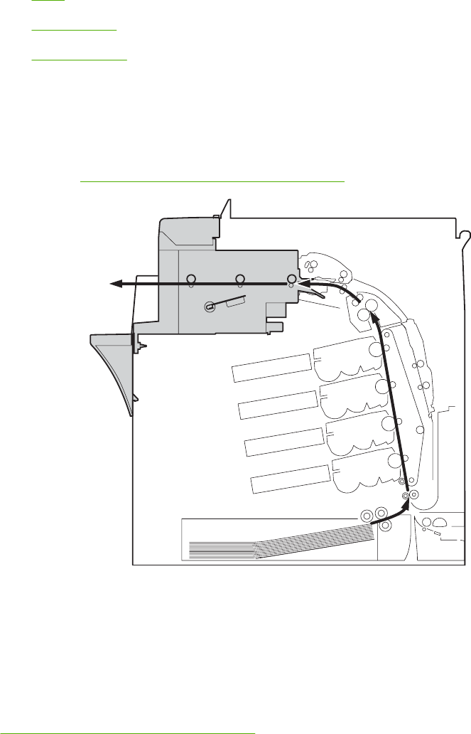
Output devices
This section describes the theory of operation for these components:
●IPTU
●3-bin mailbox
●Stapler/stacker
IPTU
The IPTU (intermediate paper transfer unit) is installed at the face-down delivery area of the MFP. Its
function is to transfer paper to the installed output device, such as the stapler/stacker and the 3-bin
mailbox. The standard face-down tray should be removed when installing the IPTU. Paper flow is
illustrated in Figure 5-56 IPTU paper path on page 229.
To delivery options
Figure 5-56 IPTU paper path
The IPTU is controlled by the intermediate paper transfer driver PCB (IPTD PCB). The IPTD PCB
controls the IPTU sequencing and communicates with the DC controller. The DC controller sends
commands to the IPTD PCB at appropriate points in the printing process and the IPTD PCB drives
motors in response to these commands. The IPTD PCB submits status information to the DC
controller.
The MFP supplies +24VDC to the IPTU. The +3.3V for IC is generated by +24V in the IPTD PCB.
Figure 5-57 IPTU PCB flow on page 230 shows the signal flow in the IPTD PCB.
ENWW Output devices 229
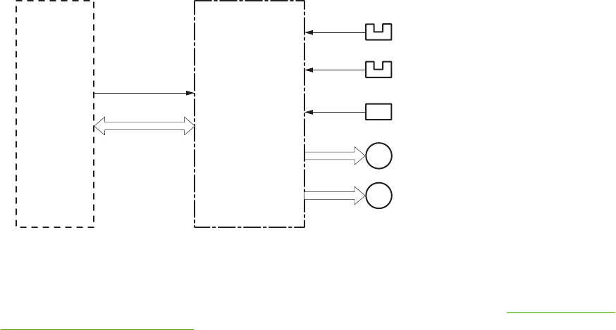
Intermediate paper transfer
driver PCB
Top of page sensor
Delivery sensor
Feed motor 1
DC controller PCB
M
Feed motor 2
M
+24V
Door open detection switch
SW
Figure 5-57 IPTU PCB flow
IPTU transfer operation
The IPTU delivers the fused paper to the output device in the operation shown in Figure 5-58 IPTU
transfer operation on page 231.
230 Chapter 5 Theory of operation ENWW
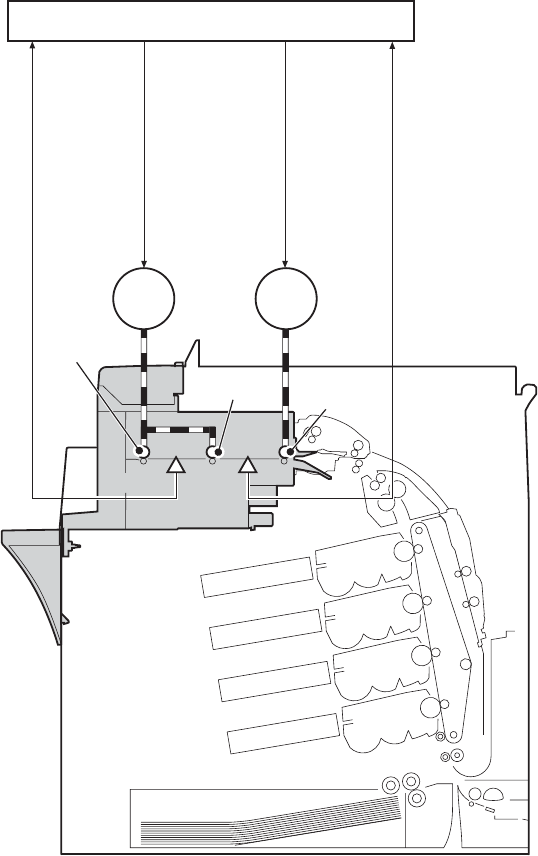
;10-/ ;10-.
A=>=7>
286 QJIMEK +>@<@D7,
7665 ;=A=?
5?9B6 QJIMEK .
7665 ;=A=?
5?9B6 QJIMEK /
56:9B6?C QJIMEK +>@<@D?,
@?10-/ @?10-.
9MRGPLGFJERG OEOGP RPEMQHGP FPJSGP >43
7GGF PNKKGP
7GGF PNKKGP 7GGF PNKKGP
Figure 5-58 IPTU transfer operation
1. The paper, which has completed the fusing operation, is transferred to the IPTU.
2. The DC controller sends the drive start command to the IPTD when the fusing paper sensor
(SR1) detects the leading edge of the paper.
3. The IPTD turns feed motor 1 (M8301) and feed motor 2 (M8302) ON to rotate the feed rollers
upon receiving the drive start command.
4. The feed rollers deliver the paper to the output device.
ENWW Output devices 231
IPTU jam detection
The IPTU is equipped with paper detection sensors to detect the presence of paper and to determine
operational status:
●Top of page sensor (SR8301)
●Delivery sensor (SR8302)
The CPU on the IPTD PCB determines a paper jam by checking whether paper is present at the
sensors at the checking timing. The checking timing is stored in the memory of the CPU. If the CPU
determines a jam, it stops the intermediate paper transfer operation and notifies the MFP of the jam.
Pickup delay jam
The CPU determines a pickup delay jam when the top-of-page sensor (SR8301) does not detect the
paper within the specified period after the cassette pickup solenoid (SL2) or the MP tray pickup
solenoid (SL1) is turned ON.
Pickup stationary jam
The CPU determines a pickup stationary jam when the top-of-page sensor (SR8301) does not detect
the trailing edge of the paper within the specified period after the top-of-page sensor (SR8301)
detects the leading edge.
Delivery delay jam
The CPU determines a delivery delay jam when the delivery sensor (SR8302) does not detect the
leading edge of the paper within the specified period after the top-of-page sensor (SR8301) detects
the trailing edge.
Delivery stationary jam
The CPU determines a delivery stationary jam when the delivery sensor (SR8302) does not detect
the trailing edge of the paper within the specified period after the top-of-page sensor (SR8301)
detects the trailing edge.
3-bin mailbox
When the 3-bin mailbox (MBM) is installed, it receives printed media from the print engine and
delivers it to one of its three bins. The 3-bin mailbox has the following components:
●One feed motor that drives the rollers
●Two solenoids that operate the inlet deflector and the bin deflector
●Six sensors that detect the presence of print media and the stack height in the output bins
●One switch that determines whether the 3-bin mailbox is attached to the MFP correctly
●One fan that cools components inside the 3-bin mailbox
The 3-bin mailbox has three operating modes: stacker mode, mailbox mode, and function separator
mode.
The MBM driver PCB controls all functions in the 3-bin mailbox. To deliver media to the different
bins, the inlet deflector and the bin deflector change position as required.
232 Chapter 5 Theory of operation ENWW
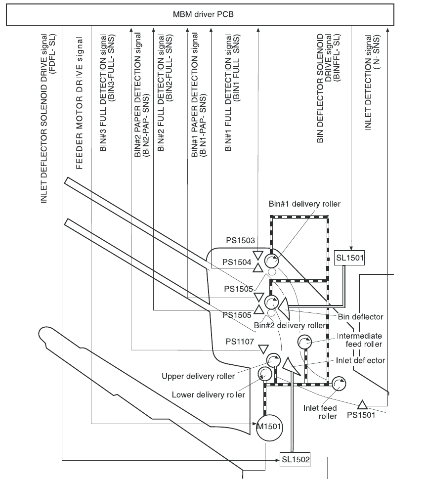
Figure 5-59 3-bin mailbox operation
ENWW Output devices 233

Stacker mode
When configured for stacker mode, the 3-bin mailbox fills the bottom output bin (bin 3) first and then
fills the next highest bin.
Figure 5-60 Media flow when using the stacker mode
Mailbox mode
When configured for mailbox mode, the 3-bin mailbox stacks print media in each bin as determined
by the print job specifications. For example, one user might have all jobs delivered to the bottom bin,
and another user might have all jobs delivered to the top bin.
Function separator mode
When configured for function separator mode, the 3-bin mailbox delivers print media to each bin as
specified by the job type. For example, all copy jobs might be delivered to the top bin, and all faxes
might be delivered to the middle bin.
3-bin mailbox jam detection
The 3-bin mailbox uses the inlet sensor (PS1501) to detect jams. The microprocessor on the MBM
driver PCB determines a jam situation if the sensor indicates that media is present at an unexpected
time or that media is not present at the expected time. The microprocessor on the MBM driver PCB
notifies the formatter that a jam has occurred.
When a jam is detected, the transport process stops and a 13.%1$2:02X.%2$1:X%3$1:X FUSER
JAM message displays on the product control panel display. For more information about jam
messages, see Resolving control panel messages on page 488.
Feed delay jam
If the inlet sensor (PS1501) does not detect the leading edge of the media within a specific time
period after receiving a delivery notice command, the microprocessor on the MBM driver PCB
determines that a feed delay jam has occurred. The time interval is longer for face-up delivery than
for face-down delivery.
234 Chapter 5 Theory of operation ENWW
Feed stationary jam
If the inlet sensor (PS1501) does not detect the trailing edge of the media within a specific time
period after it detects the leading edge, the microprocessor on the MBM driver PCB determines that
a feed stationary jam has occurred.
Residual media jam
If the inlet sensor (PS1501) detects the presence of media during the initial WAIT period, the
microprocessor on the MBM driver PCB determines that a residual media jam has occurred.
Stapler/stacker
When the stapler/stacker is installed, it receives print media from the print engine and delivers it to
the stapler or stacks it in the output bin. The stapler/stacker has the following components:
●Four motors that operate the paddle, the jogger, the feed mechanism, and the stapler unit
●One clamp solenoid
●Nine sensors that detect the media position and guide positions
●One switch that detects when the stapler door is open
The stapler/stacker has two operating modes: staple mode and stacker mode.
The stapler/stacker driver PCB controls all functions in the stapler/stacker.
ENWW Output devices 235
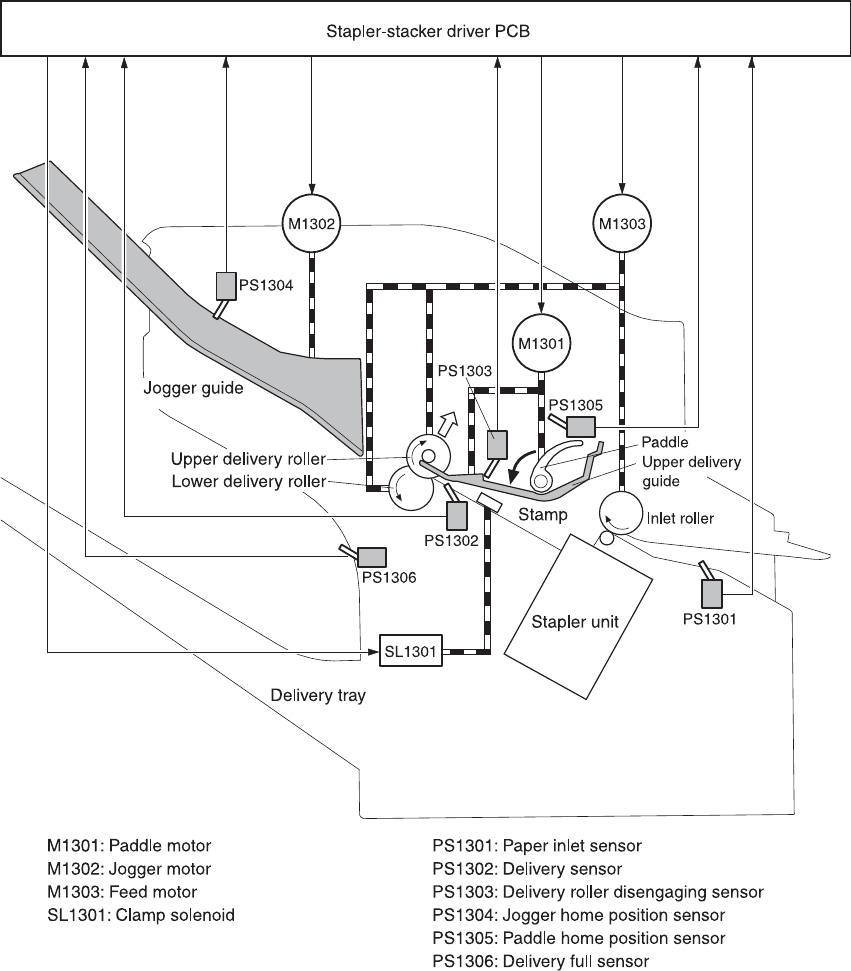
Figure 5-61 Stapler/stacker operation
236 Chapter 5 Theory of operation ENWW

Staple mode
When the print job specifications require stapling, the pages of the document are gathered inside the
unit. A jogger aligns the pages horizontally, and a paddle aligns the pages vertically. When all pages
of a job are gathered, a clamp compresses the stack and a staple is attached.
After the document is stapled, the jogger guides spread apart to release the stack, and the stapled
document falls into the stacker bin.
Figure 5-62 Jogger operation (top view)
Stacker mode
The stacker mode collates multiple-page print jobs without stapling them.
When the print job requires no stapling, the pages of the document are gathered inside the unit. A
jogger aligns the pages horizontally, and a paddle aligns the pages vertically. When all pages of a
job are gathered, the jogger guides spread apart, releasing the stack, and the document falls into the
stacker bin without being stapled.
Staple jam detection
The stapler/stacker uses the inlet sensor (PS1301) and the delivery sensor (PS1302) to detect jams.
The microprocessor on the stapler/stacker driver PCB determines a jam situation if the sensor
indicates that paper is present at an unexpected time or that paper is not present at the expected
time. The microprocessor on the stapler/stacker driver PCB notifies the formatter that a jam has
occurred.
When a jam is detected, the transport process stops and a 13.%1$2:02X.%2$1:X%3$1:X FUSER
JAM message displays on the product control panel display. For more information about jam
messages, see Resolving control panel messages on page 488.
Feed delay jam
If the inlet sensor (PS1301) does not detect the leading edge of the media within a specific time
period after receiving a delivery notice command, the microprocessor on the MBM driver PCB
determines that a feed delay jam has occurred.
ENWW Output devices 237
Feed stationary jam
If the inlet sensor (PS1301) does not detect the trailing edge of the media within a specific time
period after it detects the leading edge, the microprocessor on the MBM driver PCB determines that
a feed stationary jam has occurred.
Delivery stationary jam
If the delivery sensor (PS1302) does not detect the trailing edge of the media within a specific time
period after the feed motor has begun rotating, the microprocessor on the MBM driver PCB
determines that a delivery stationary jam has occurred.
Residual media jam
If the inlet sensor (PS1301) detects the presence of media during the initial WAIT period, the
microprocessor on the MBM driver PCB determines that a residual media jam has occurred.
Stapler unit
The stapler unit holds the staple cartridge and the staple motor. The staple cartridge contains up to
10,000 staples. The stapler unit also has three sensors that detect the presence of staples and
staple jams.
●The staple home position sensor (PHOI1) detects when the stapler is in the correct position. If
the stapler is in the incorrect position, the staple/stacker driver PCB notifies the formatter that a
staple jam has occurred.
●The staple ready sensor (PHOI2) detects when the stapler is self-primed after a new staple
cartridge is installed. If the sensor determines that the self-priming function was unsuccessful,
the staple/stacker driver PCB notifies the formatter that a staple jam has occurred.
●The staple presence sensor (PHOI3) detects the number of staples in the staple cartridge.
When the number of staples in the cartridge is 20 or fewer, the stapler/stacker driver PCB
notifies the formatter. A STAPLER LOW ON STAPLES message displays on the product
control panel display.
238 Chapter 5 Theory of operation ENWW
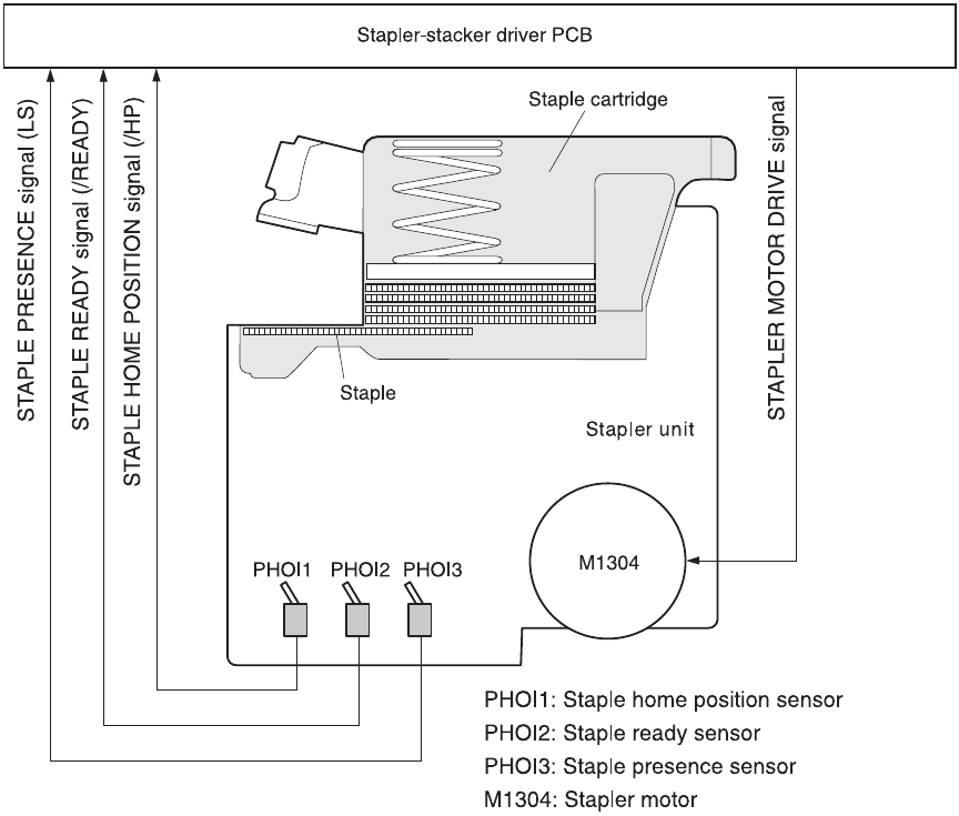
Figure 5-63 Stapler unit operation
ENWW Output devices 239
240 Chapter 5 Theory of operation ENWW

6 Removal and replacement
This chapter contains information about the following topics:
●Removal and replacement strategy
●User-replaceable parts
●Covers, doors, and external panels
●Main assembly (internal assemblies)
●Motors and fans
●PCBs
●Switches, contacts, and sensors
●ADF and scanner components
●ADF components
●2 X 500-sheet paper input assembly components
●Intermediate paper transfer unit (IPTU)
ENWW 241

Removal and replacement strategy
This chapter describes how to remove, replace, and reassemble the major assemblies of the MFP.
Replacement is generally the reverse of removal. Notes are provided to assist with any difficult
replacement procedures.
To identify the left side and right side of the MFP, face the product control panel.
WARNING! Unplug the power cord from the power outlet (at the wall receptacle) before
attempting to service the MFP. If you do not follow this warning, severe injury can result.
Certain functional checks during troubleshooting might require power to be supplied to the
MFP. However, all power should be turned off and the MFP should be unplugged when you
remove any MFP assemblies or components. Never operate or service the MFP when the
protective cover is removed from the laser/scanner assembly. The reflected beams, although
invisible, can damage your eyes.
CAUTION The MFP contains components that are sensitive to electrostatic discharge
(ESD). Always perform service work at an ESD-protected workstation. If an ESD-protected
workstation is not available, discharge body static by grasping the MFP chassis before
touching an ESD-sensitive component. Ground the MFP chassis before servicing the MFP.
Required tools
●#2 Phillips screwdriver (shaft length of at least 152.4 mm (6 inches) and a shaft diameter of no
more than 6.25 mm (0.25 inches)
●Short #2 Phillips screwdriver (shaft length of 76 mm (3 inches))
●Right-angle #2 Phillips screwdriver
●Small flat-blade screwdriver
●Stubby Phillips screwdriver (shaft length of 38 mm (1.5 inches)
●Needle-nose pliers
●ESD mat (if available; see the preceding ESD caution)
●Penlight (optional)
●Clear tape (optional)
CAUTION A posidrive screwdriver can damage screw heads on the MFP. Use a #2 Phillips
screwdriver.
242 Chapter 6 Removal and replacement ENWW

Before performing service
●If possible, print a menu map and configuration page. See Information pages on page 640.
●Remove all of the accessories and print media, the print cartridges, and tray 2 from the MFP.
●Unplug the power cord from the power outlet at the wall receptacle.
●Perform the work at an ESD-protected workstation, if one is available. If an ESD-protected
workstation is not available, discharge body static by grasping the MFP chassis before touching
an ESD-sensitive component. Ground the MFP chassis before servicing the MFP.
Removal and replacement sequencing
Use the following tree diagram to determine the prerequisite steps needed for specific removal and
replacement procedures.
ENWW Removal and replacement strategy 243
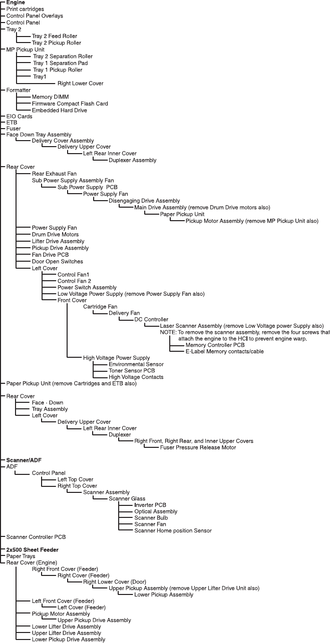
Figure 6-1 Removal and replacement sequencing tree diagram
244 Chapter 6 Removal and replacement ENWW

After completing service
●Reinstall the print cartridges.
CAUTION Do not transport the MFP while the print cartridges are installed.
●Reconnect all cables to the MFP.
●Replace all of the accessories and load the media.
●Print a configuration page and verify that the latest firmware is installed on the MFP.
ENWW Removal and replacement strategy 245
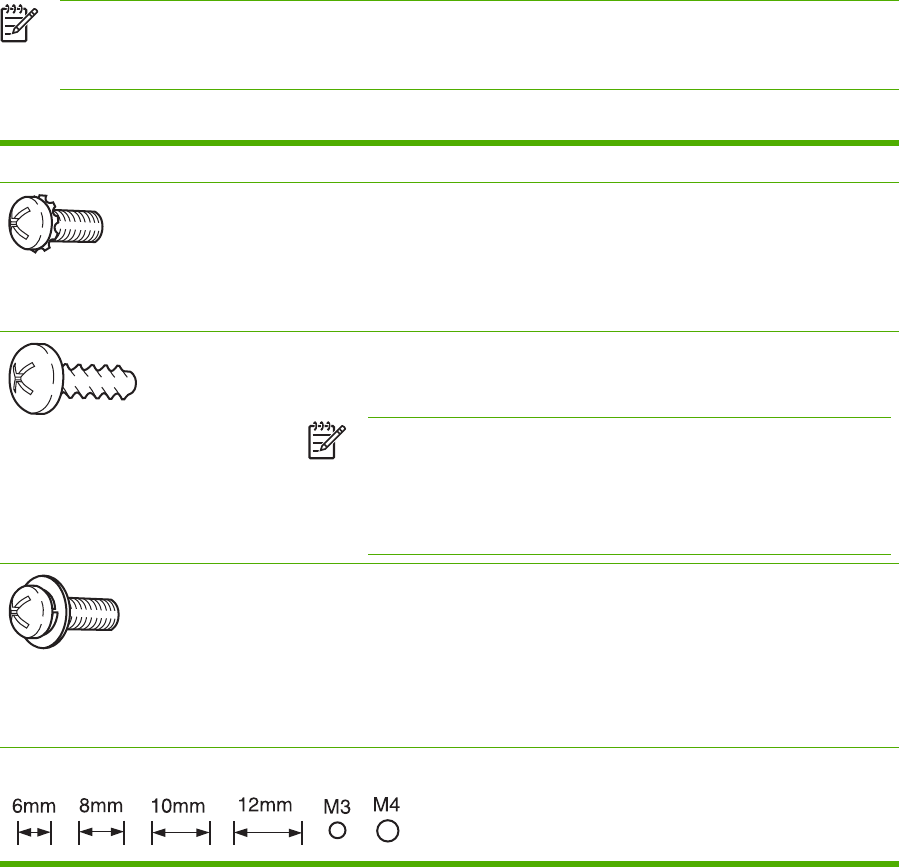
Screws used in the MFP
The following table describes the screws that are used in the MFP and provides guidelines to help
determine where each type of screw is used. The screws can vary in length depending on the
thickness of the material that is being fastened. Always note where each type of screw is located and
replace each one in its original location.
NOTE When you are disassembling the MFP, place the screws into the chassis holes from
which they were removed. This prevents their loss, and ensures that the correct type and
length of screw for each location is used when the MFP is reassembled.
Table 6-1 Common fasteners used in this MFP
Drawing and description Purpose
Phillips-head machine screw with
captive star washer
This screw is used to fasten metal to metal when good electrical contact is
needed. This screw also provides high resistance to loosening.
Phillips-head screw with self-tapping
threads
This screw is used to fasten sheet metal or plastic to plastic frames (the deep,
coarsely spaced threads provide an increased holding capability while decreasing
the possibility of stripping the target hole).
NOTE To install a self-tapping screw, first turn it counterclockwise to
align it with the existing thread pattern, and then carefully turn it
clockwise to tighten it. You will feel resistance and hear the screw click
when it engages the existing threads in the hole. Do not overtighten the
screw. If a self-tapping screw-hole becomes stripped, repair the screw-
hole or replace the affected assembly.
Phillips washer-head machine screw
with a broad, flat washer attached to
the screw head
This screw is used to fasten sheet metal parts to the sheet metal chassis. It spans
large clearance holes and distributes the load by increasing the bearing surface.
Screw measurement guide
246 Chapter 6 Removal and replacement ENWW

User-replaceable parts
The procedures in this section describe the removal and replacement of the following user-
replaceable parts:
●Print cartridges
●Control panel overlays
●Control panel
●Intermediate paper transfer unit (IPTU)
●Stapler/stacker
●Staple cartridge
●3-bin mailbox
●ETB assembly, removing
●MP tray pickup assembly
●Trays 2, 3, and 4
●ADF input tray
●ADF pickup and feed rollers
●ADF separation pad
●ADF delivery guide (clear mylar sheet)
●Face-down tray assembly
●Fuser
●Tray 2, 3, or 4 pickup and feed rollers
●MP tray pickup roller
●Tray 2 separation roller
●Tray 3 or 4 separation rollers
●Scanner filter cover and scanner filter
●ADF hinge flap
●Formatter board
●Hard drive
●DIMMs
●Flash memory card (firmware)
●Fax accessory
ENWW User-replaceable parts 247
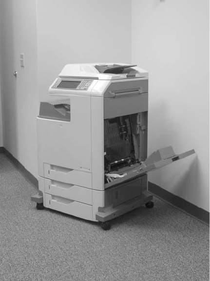
Print cartridges
1. Open the right lower cover.
Figure 6-2 Remove the print cartridges (1 of 3)
248 Chapter 6 Removal and replacement ENWW
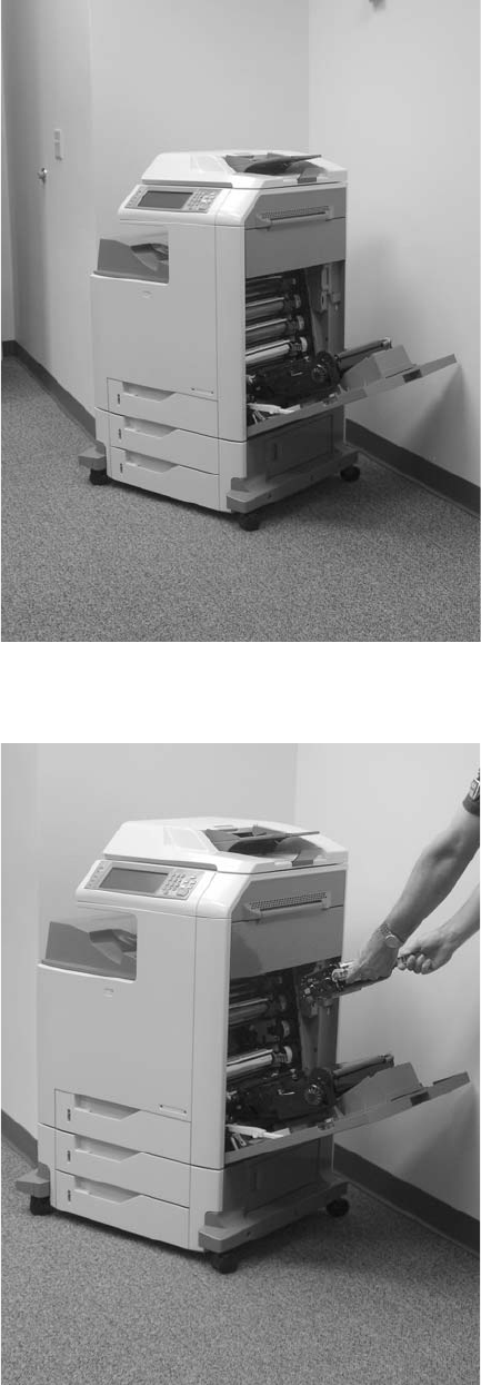
2. Open the ETB.
Figure 6-3 Remove the print cartridges (2 of 3)
3. Grasp each print cartridge by the blue handles, and remove it from the MFP.
Figure 6-4 Remove the print cartridges (3 of 3)
ENWW User-replaceable parts 249
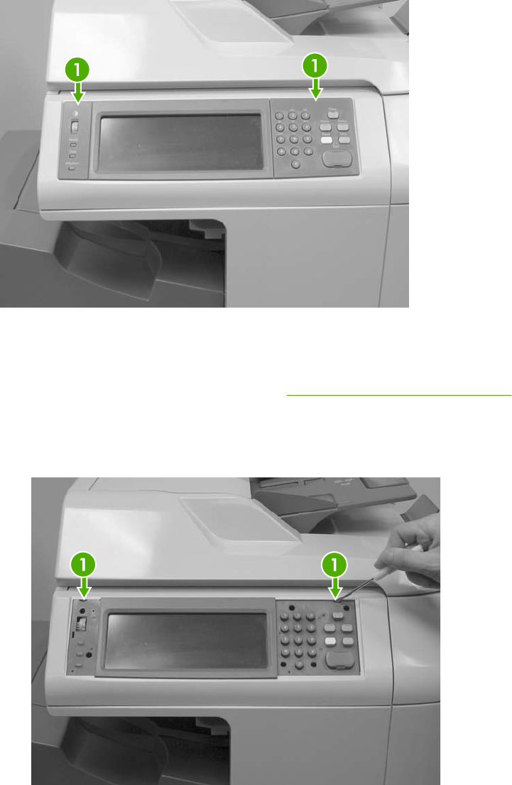
Control panel overlays
Use a small, flat-blade screwdriver to release the two product control panel overlays (callout 1).
Figure 6-5 Remove the control panel overlays
Control panel
1. Remove the control panel overlays. See Control panel overlays on page 250.
2. Use a flat-blade screwdriver to remove the product control panel. Insert the blade of the
screwdriver into the tabs (callout 1) and twist gently to release the top of the control panel. Lift
the control panel upward to release it from the MFP.
Figure 6-6 Remove the control panel (1 of 3)
250 Chapter 6 Removal and replacement ENWW
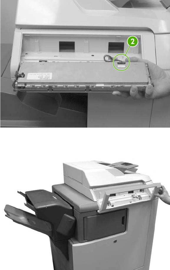
3. Disconnect one connector (callout 2).
Figure 6-7 Remove the control panel (2 of 3)
4. Grasp the control panel surround and lift it toward you.
Figure 6-8 Remove the control panel (3 of 3)
ENWW User-replaceable parts 251
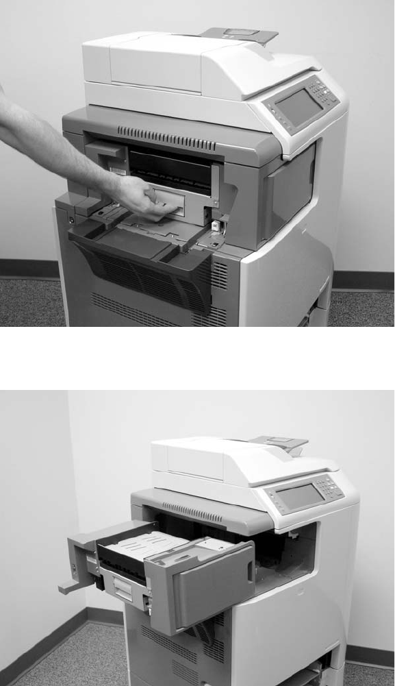
Intermediate paper transfer unit (IPTU)
1. Lift the handle on the IPTU.
Figure 6-9 Remove the IPTU (1 of 3)
2. Slide the IPTU outward.
Figure 6-10 Remove the IPTU (2 of 3)
252 Chapter 6 Removal and replacement ENWW
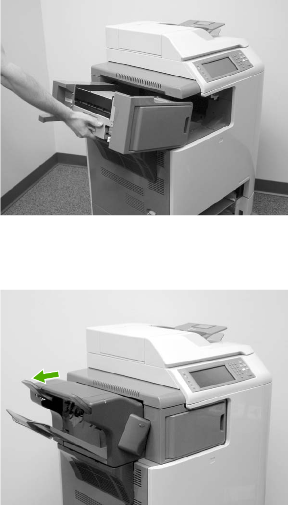
3. Lift the IPTU upward and remove it from the MFP.
Figure 6-11 Remove the IPTU (3 of 3)
Stapler/stacker
1. Press and hold the release button on the top of the stapler/stacker.
Figure 6-12 Remove the stapler/stacker (1 of 5)
ENWW User-replaceable parts 253
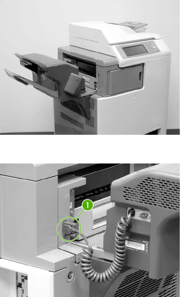
2. Pull the stapler/stacker outward.
Figure 6-13 Remove the stapler/stacker (2 of 5)
3. Disconnect the connector (callout 1) from the MFP.
Figure 6-14 Remove the stapler/stacker (3 of 5)
254 Chapter 6 Removal and replacement ENWW
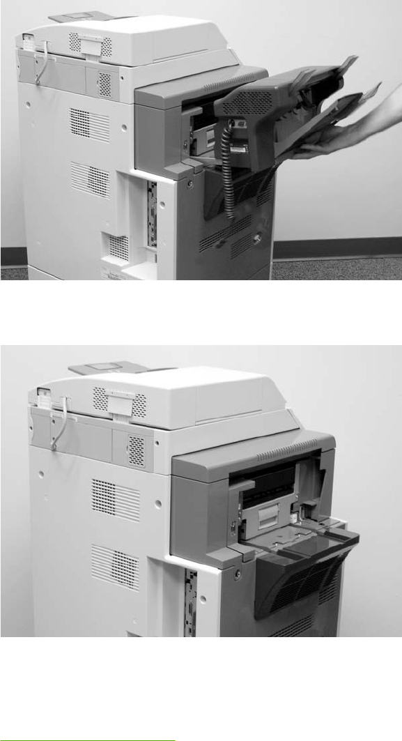
4. Lift the stapler/stacker slightly and remove it from the MFP.
Figure 6-15 Remove the stapler/stacker (4 of 5)
5. The IPTU remains in place.
Figure 6-16 Remove the stapler/stacker (5 of 5)
Staple cartridge
1. Press down the release button on the stapler/stacker and pull the assembly outward. See
Stapler/stacker on page 253.
ENWW User-replaceable parts 255
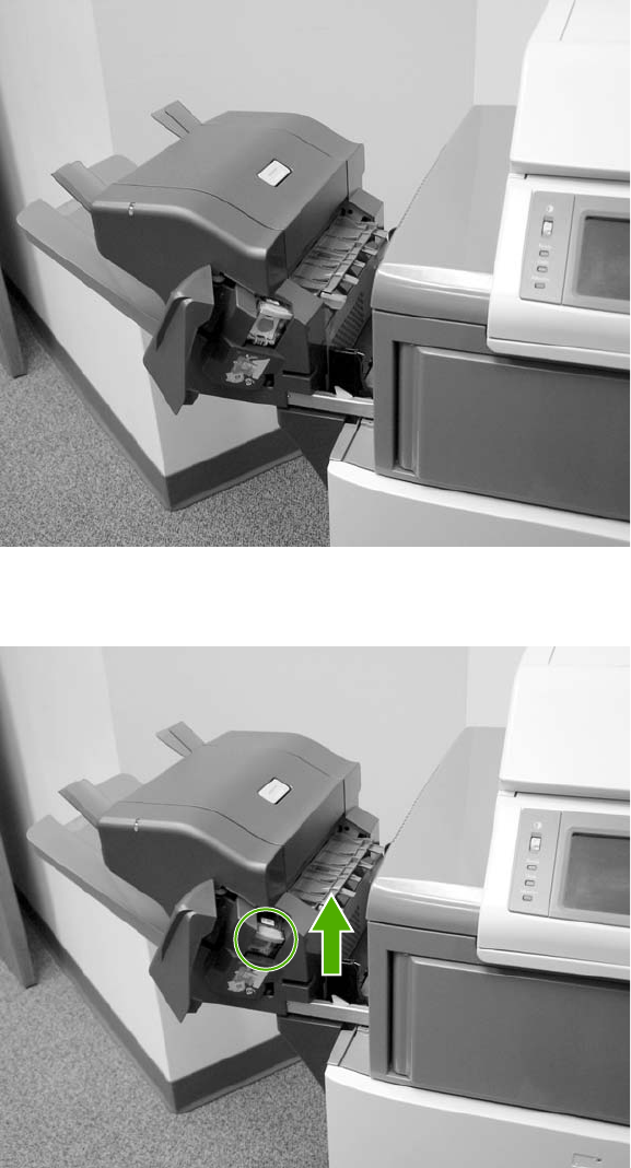
2. Open the staple cartridge cover.
Figure 6-17 Replace the staple cartridge (1 of 3)
3. Grasp the green staple cartridge handle and pull the old staple cartridge upward.
Figure 6-18 Replace the staple cartridge (2 of 3)
256 Chapter 6 Removal and replacement ENWW
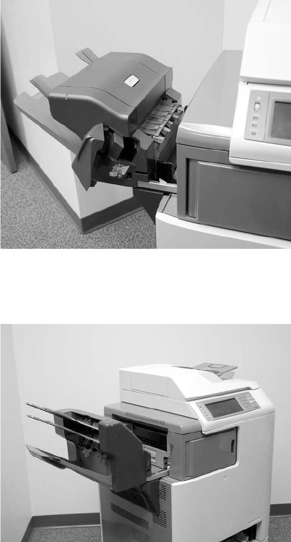
4. Pull the old staple cartridge out of the stapler assembly. Insert the new staple cartridge into the
stapler assembly and push down on the green handle until the assembly snaps into place.
Close the staple cartridge cover, and slide the stapler/stacker into the MFP.
Figure 6-19 Replace the staple cartridge (3 of 3)
3-bin mailbox
1. Slide the assembly outward.
Figure 6-20 Remove the 3-bin mailbox (1 of 3)
ENWW User-replaceable parts 257
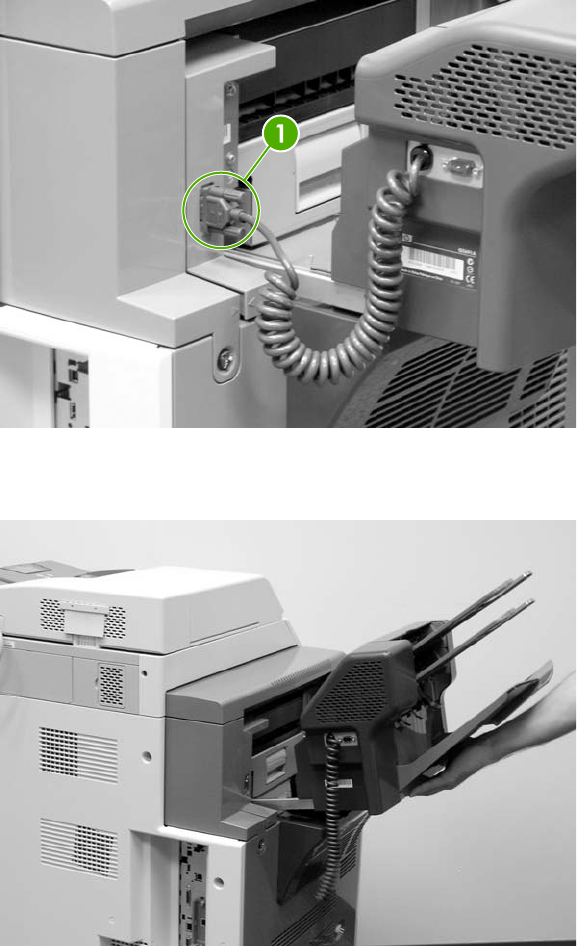
2. Disconnect the cable (callout 1).
Figure 6-21 Remove the 3-bin mailbox (2 of 3)
3. Lift the 3-bin mailbox, tilt it upward, and pull to remove it from the MFP.
Figure 6-22 Remove the 3-bin mailbox (3 of 3)
ETB assembly, removing
1. Open the right lower cover.
258 Chapter 6 Removal and replacement ENWW
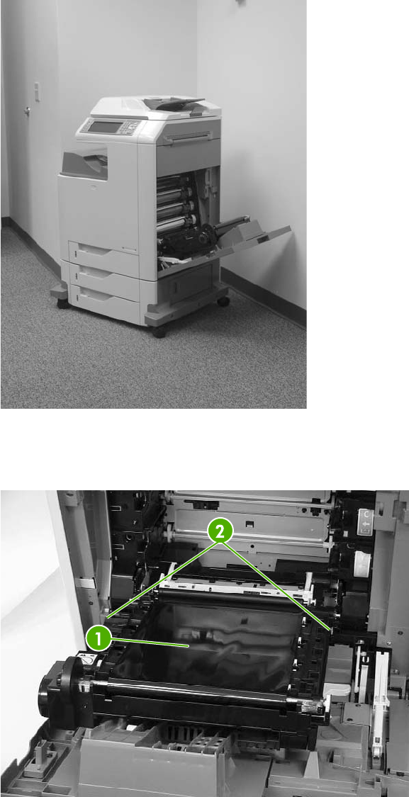
2. Open the ETB assembly by pulling the green handle.
Figure 6-23 Remove the ETB assembly (1 of 4)
3. Depress the blue tabs on the right and left sides of the ETB (callout 2), and then lift the ETB
(callout 1) out of the MFP.
Figure 6-24 Remove the ETB assembly (2 of 4)
ENWW User-replaceable parts 259
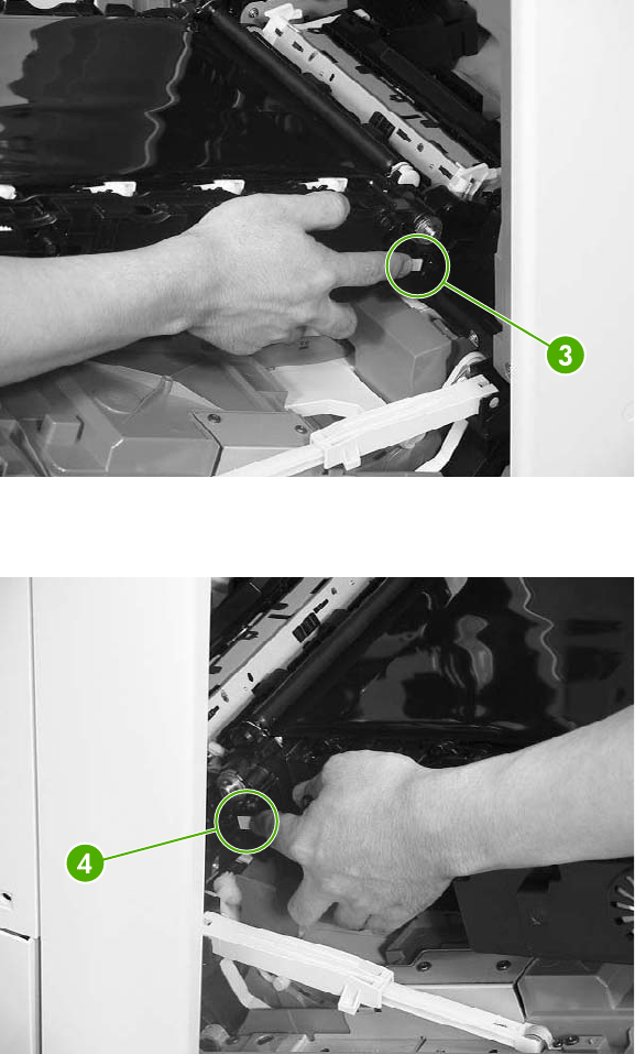
4. Detail of right lever (callout 3).
Figure 6-25 Remove the ETB assembly (3 of 4) — right lever
5. Detail of left lever (callout 4).
Figure 6-26 Remove the ETB assembly (4 of 4) — left lever
260 Chapter 6 Removal and replacement ENWW
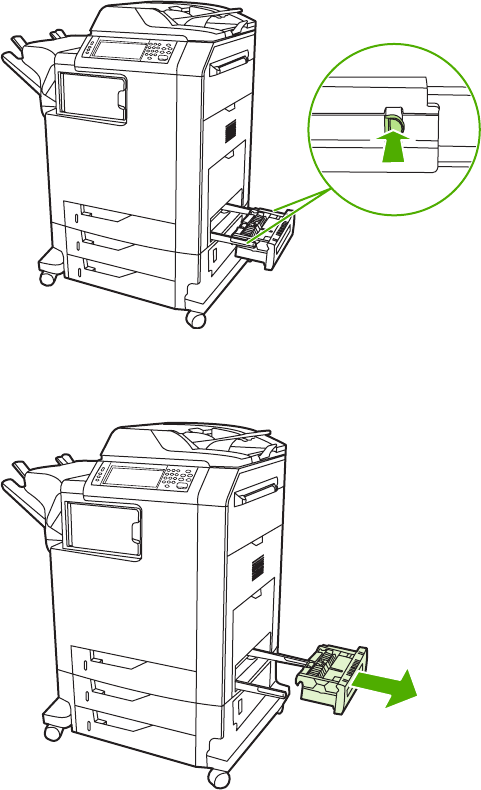
MP tray pickup assembly
1. Open the MP tray pickup assembly.
2. Press the two metal tabs on either side to unlock the tray.
Figure 6-27 Remove the MP tray pickup assembly (1 of 2)
3. Slide the assembly off the rails.
Figure 6-28 Remove the MP tray pickup assembly (2 of 2)
Trays 2, 3, and 4
1. Open the tray until it stops.
2. Tilt the front of the tray up. The tray rails automatically retract to free the tray.
ENWW User-replaceable parts 261
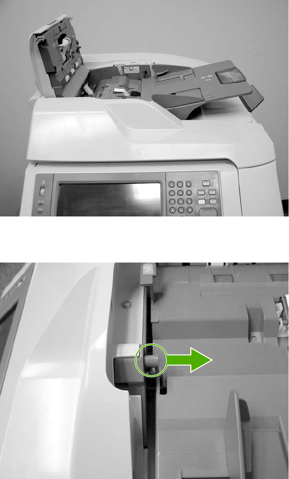
ADF input tray
1. Open the ADF top cover.
Figure 6-29 Remove the ADF input tray (1 of 3)
2. Flex the pivot pin (near the control panel) away from the mounting hole in the ADF chassis.
Figure 6-30 Remove the ADF input tray (2 of 3)
262 Chapter 6 Removal and replacement ENWW
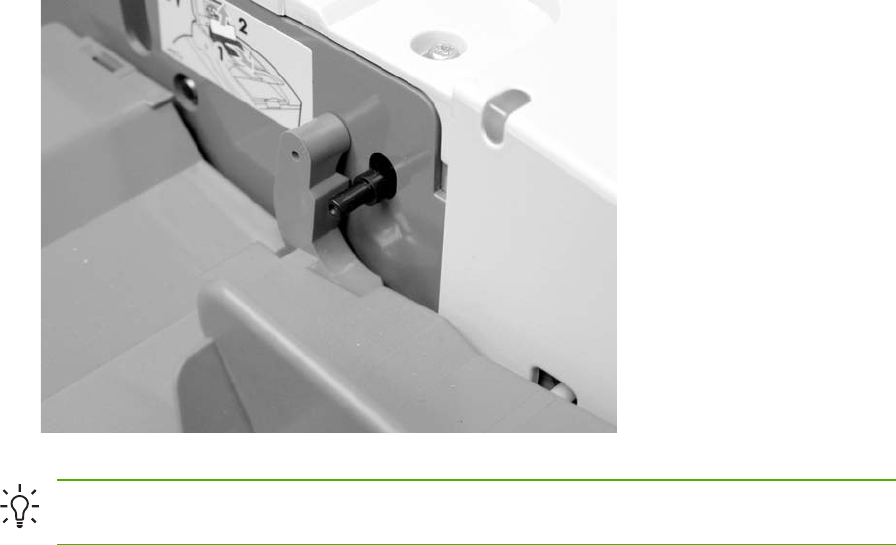
3. Pull the tray away from the pivot pin at the right side of the input tray, and remove the ADF input
tray.
Figure 6-31 Remove the ADF input tray (3 of 3)
Hint When reinstalling the ADF input tray, insert the rear pin first, as shown in the following
photograph. Be sure that the pin goes under the black panel.
ENWW User-replaceable parts 263
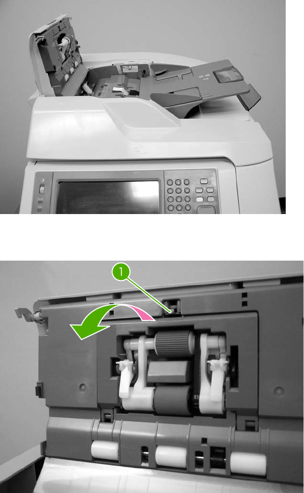
ADF pickup and feed rollers
1. Open the ADF top cover.
Figure 6-32 Remove the ADF pickup and feed rollers (1 of 3)
2. Push down on the locking tab (callout 1), and rotate the top of the assembly away from the ADF.
Figure 6-33 Remove the ADF pickup and feed rollers (2 of 3)
264 Chapter 6 Removal and replacement ENWW
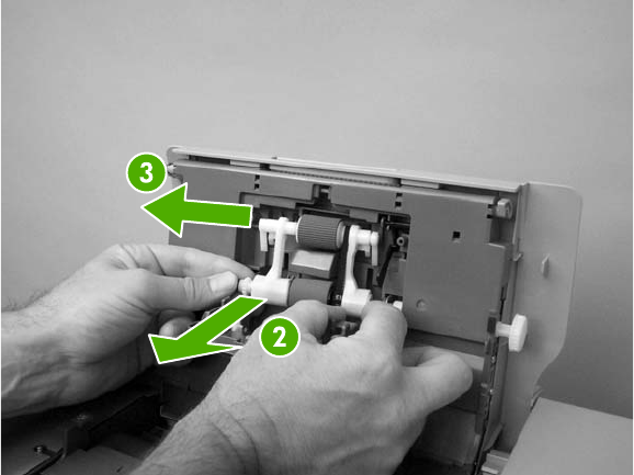
3. Release the front (gear end) of the roller assembly drive shaft (callout 2), and slide (callout 3)
the assembly toward the front of the MFP to remove it.
Figure 6-34 Remove the ADF pickup and feed rollers (3 of 3)
ENWW User-replaceable parts 265
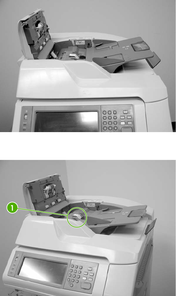
ADF separation pad
1. Open the ADF top cover.
Figure 6-35 Remove the ADF separation pad (1 of 4)
2. Locate the ADF separation pad (callout 1).
Figure 6-36 Remove the ADF separation pad (2 of 4)
266 Chapter 6 Removal and replacement ENWW
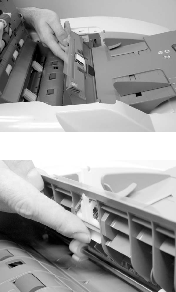
3. Raise the separation pad frame assembly using the green lever, and push the bottom edge
(white plastic) of the separation pad away from the frame.
Figure 6-37 Remove the ADF separation pad (3 of 4)
4. Push the separation pad out of the frame.
Figure 6-38 Remove the ADF separation pad (4 of 4)
ENWW User-replaceable parts 267
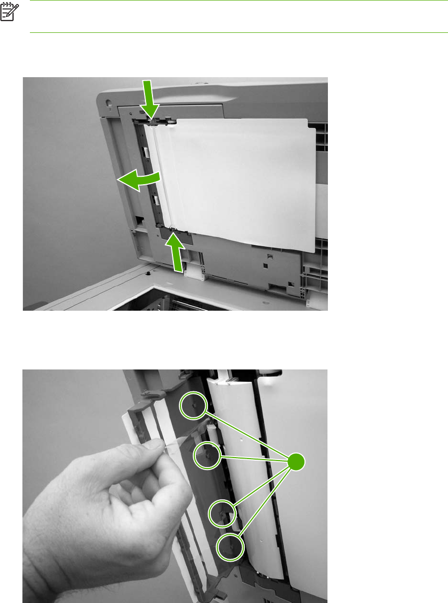
ADF delivery guide (clear mylar sheet)
NOTE Replacement ADF delivery guide mylar sheets are located in an envelope behind the
white mylar sheet.
1. Open the ADF/scanner assembly and release the two tabs at the top and bottom of the ADF
delivery guide cover.
Figure 6-39 Remove the ADF delivery guide (1 of 3)
2. Carefully unhook the clear mylar sheet from the four tabs on the ADF delivery guide cover
(callout 1), and then remove the mylar sheet.
1
Figure 6-40 Remove the ADF delivery guide (2 of 3)
268 Chapter 6 Removal and replacement ENWW
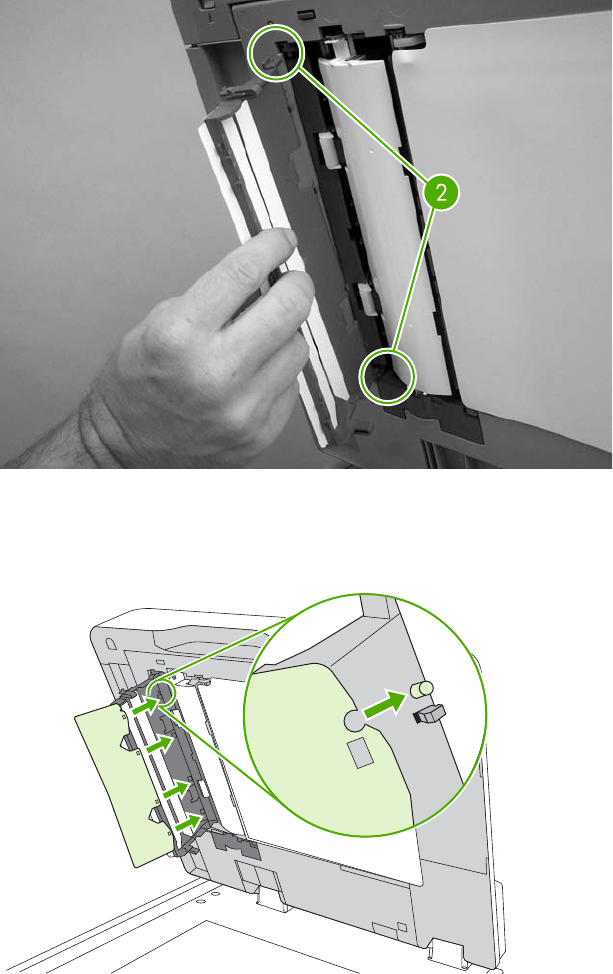
3. If it is difficult to replace the mylar strips, pull the ADF delivery guide cover hinges off the hinge
pins (callout 2) to remove the cover.
Figure 6-41 Remove the ADF delivery guide (3 of 3)
4. Reinstallation tip: The clear mylar sheet is keyed with a small notch at the top. Be sure to align
the notch with the round pin that is on the holder.
Figure 6-42 Reinstall the clear mylar sheet
ENWW User-replaceable parts 269
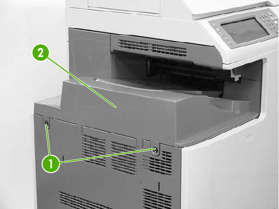
Face-down tray assembly
Loosen the two captive screws (callout 1) and remove the face-down tray (callout 2).
Figure 6-43 Remove the face-down tray assembly
270 Chapter 6 Removal and replacement ENWW
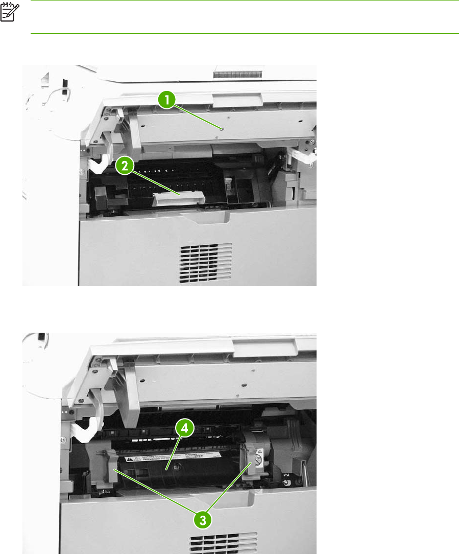
Fuser
NOTE Do not attempt to disassemble the fuser sleeve assembly. This part cannot be
serviced in the field.
1. Open the right top cover (callout 1) and the fuser cover (callout 2).
Figure 6-44 Remove the fuser (1 of 2)
2. Gently lift the two purple handles (callout 3). Then pull the fuser (callout 4) out of the MFP.
Figure 6-45 Remove the fuser (2 of 2)
ENWW User-replaceable parts 271
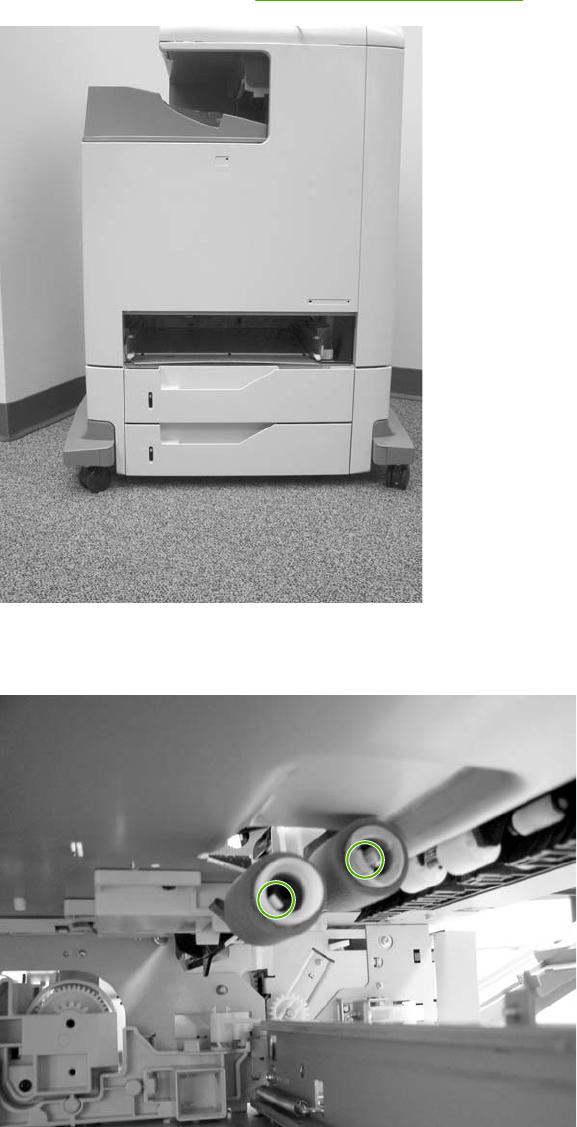
Tray 2, 3, or 4 pickup and feed rollers
1. Remove the paper tray. See Trays 2, 3, and 4 on page 261.
Figure 6-46 Remove the tray 2, 3, or 4 pickup and feed rollers (1 of 2)
2. Squeeze the tabs to release the pickup roller (left) and feed roller (right).
Figure 6-47 Remove the tray 2, 3, or 4 pickup and feed rollers (2 of 2)
3. Slide the rollers off the shaft.
272 Chapter 6 Removal and replacement ENWW
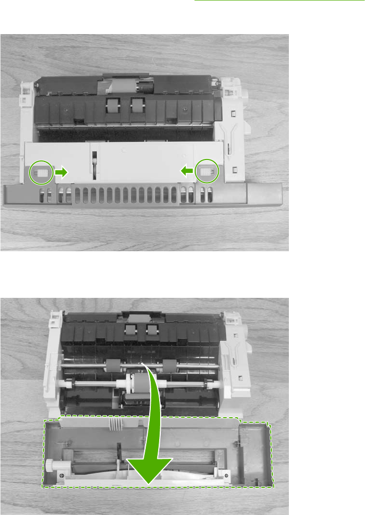
MP tray pickup roller
1. Remove the MP tray pickup assembly. See MP tray pickup assembly on page 261.
2. Slide the white tabs to the middle.
Figure 6-48 Remove the MP tray pickup roller (1 of 3)
3. Rotate the front cover away from the tray.
Figure 6-49 Remove the MP tray pickup roller (2 of 3)
ENWW User-replaceable parts 273
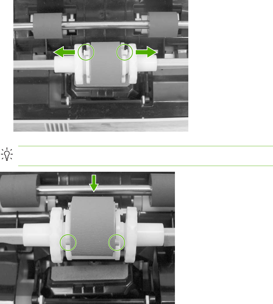
4. Remove the pickup roller by pulling the tabs outward and lifting the roller from the shaft.
Figure 6-50 Remove the MP tray pickup roller (3 of 3)
Hint When reinstalling the MP tray pickup roller, insert the round tabs toward the front of the
tray.
Figure 6-51 Replace the MP tray pickup roller
274 Chapter 6 Removal and replacement ENWW
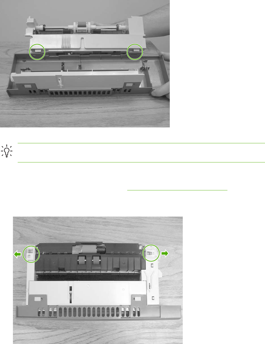
Figure 6-52 Replace the tray cover
Hint When reinstalling the tray front cover, insert the slots into the tabs, rotate the cover
upward, and snap it into place.
Tray 2 separation roller
1. Remove the MP tray pickup assembly. See MP tray pickup assembly on page 261.
2. Release the two locking tabs on the MP tray pickup assembly and open the tray 2 separation
roller cover.
Figure 6-53 Remove the tray 2 separation roller (1 of 3)
ENWW User-replaceable parts 275
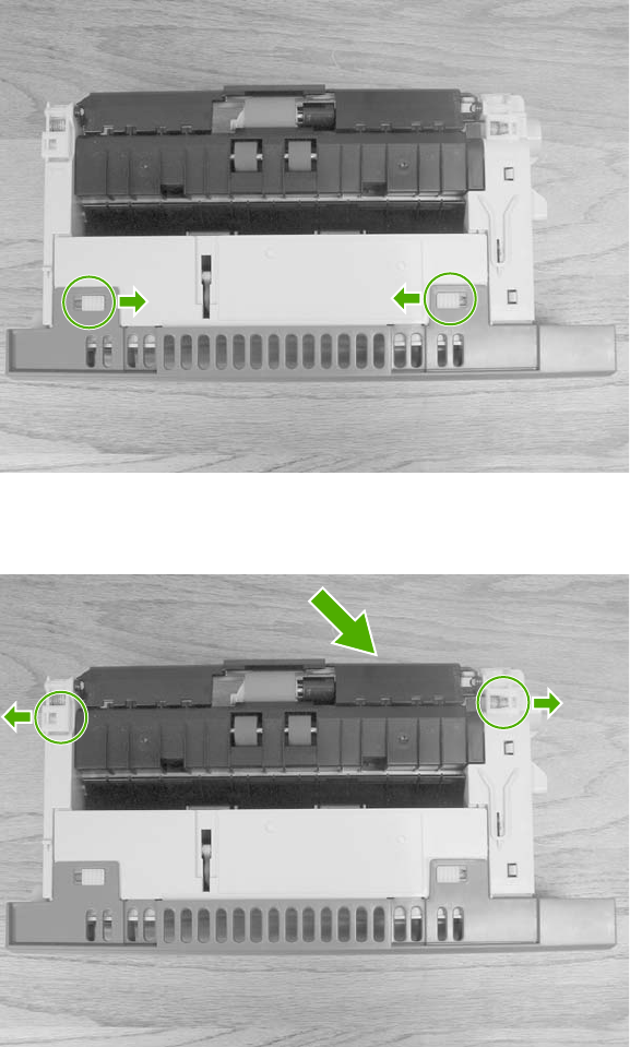
3. Remove the tray 2 separation roller by depressing the blue tab and removing it from the shaft.
Replace the tray 2 separation roller.
Figure 6-54 Remove the tray 2 separation roller (2 of 3)
4. Close the separation roller cover by sliding the tabs outward before closing the cover.
Figure 6-55 Remove the tray 2 separation roller (3 of 3)
276 Chapter 6 Removal and replacement ENWW
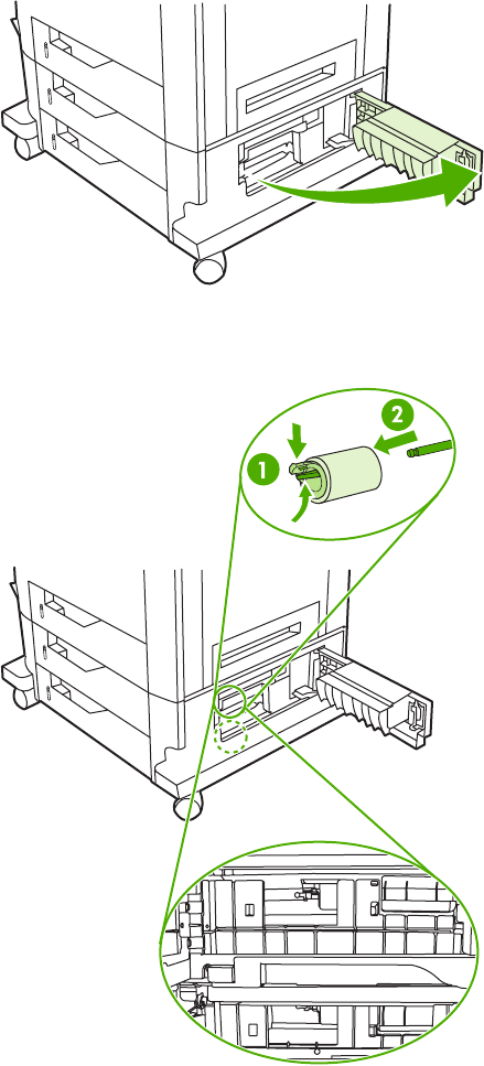
Tray 3 or 4 separation rollers
1. Open tray 3 or 4.
2. Open the lower jam access door.
Figure 6-56 Remove the tray 3 or 4 separation rollers (1 of 2)
3. Remove the separation roller by depressing the blue tab and removing the roller from the shaft.
Figure 6-57 Remove the tray 3 or 4 separation rollers (2 of 2)
ENWW User-replaceable parts 277
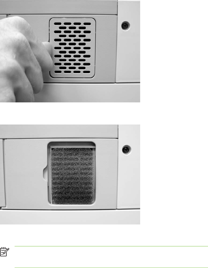
Scanner filter cover and scanner filter
1. Using the thumb notch at the top of the filter cover plate, remove the scanner filter cover at the
rear of the MFP.
Figure 6-58 Remove the scanner filter (1 of 2)
2. Remove the filter.
Figure 6-59 Remove the scanner filter (2 of 2)
3. Clean the filter and replace it in the frame. Snap the filter cover into place.
NOTE The filter can be cleaned by tapping it against a hard surface, vacuuming, or
rinsing with clean water. If it is rinsed, be sure it is completely dry before reinstalling it in
the frame.
278 Chapter 6 Removal and replacement ENWW
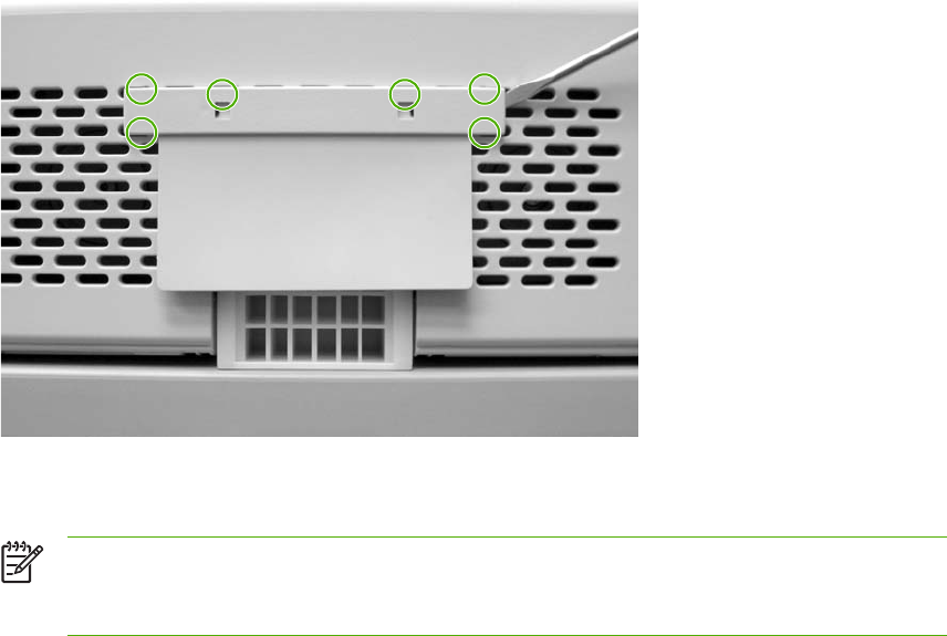
ADF hinge flap
1. Use a small, flat-blade screwdriver to release the six locking tabs along the top of the ADF hinge
flap.
Figure 6-60 Remove the ADF hinge flap
2. Pull the ADF hinge flap away from the MFP to remove it.
NOTE To position the ADF hinge flap correctly when reinstalling it, insert the locator
pins situated in the middle of the plastic mounting bracket into the first row of slots above
the ADF hinge.
ENWW User-replaceable parts 279
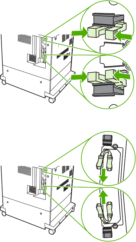
Formatter board
1. Locate the gray formatter pressure release tabs on the formatter board in the rear of the MFP.
2. Gently squeeze the tabs and pull them out of the formatter.
280 Chapter 6 Removal and replacement ENWW
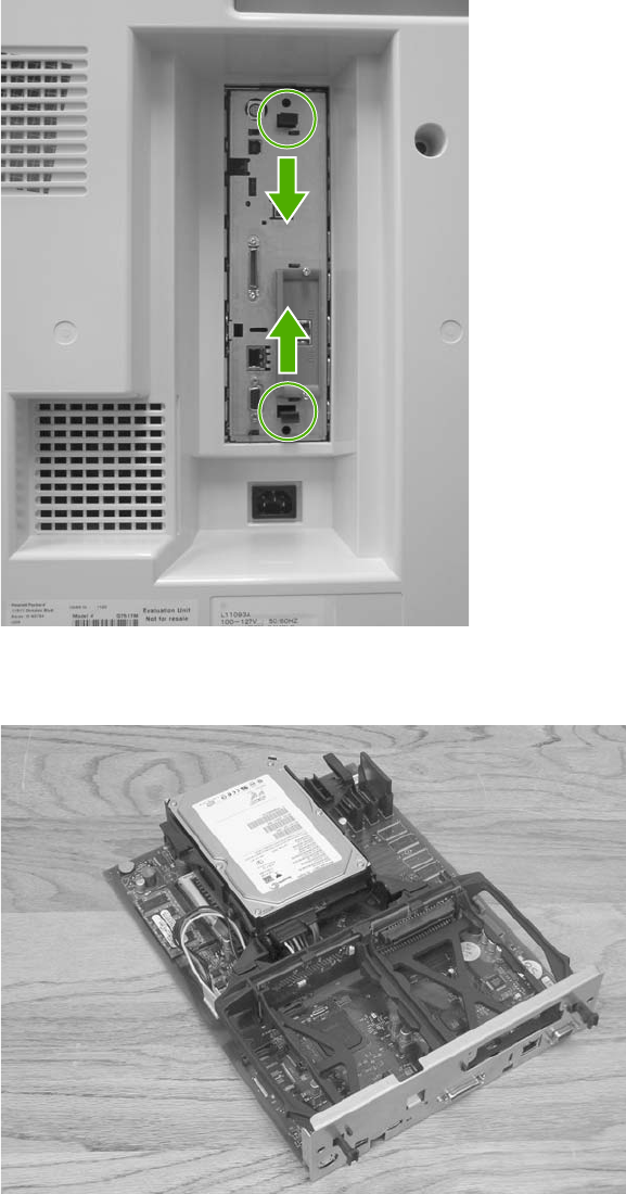
3. Gently pull on the black tabs at the top and bottom of the formatter board to pull the board from
the MFP.
Figure 6-61 Remove the formatter (1 of 2)
4. Place the formatter board on a clean, flat, grounded surface.
Figure 6-62 Remove the formatter (2 of 2)
ENWW User-replaceable parts 281
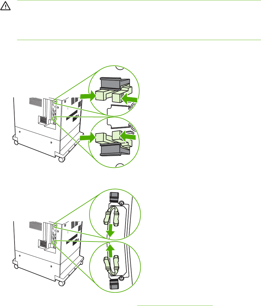
Hard drive
WARNING! DELETE EDITORIAL NOTE The MFP contains components that are sensitive
to electrostatic discharge (ESD). Always perform service work at an ESD-protected
workstation. If an ESD-protected workstation is not available, discharge body static by
grasping the MFP chassis before touching an ESD-sensitive component. Ground the MFP
chassis before servicing the MFP.
1. DELETE STEP Locate the gray formatter pressure release tabs on the formatter board in the
rear of the MFP.
2. DELETE STEP Gently squeeze the tabs and pull them out of the formatter.
3. Remove the formatter board from the MFP. See Formatter board on page 280.
282 Chapter 6 Removal and replacement ENWW
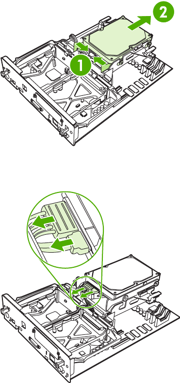
4. Push the two black tabs toward each other and slide the hard drive toward the rear of the
formatter.
Figure 6-63 Remove the hard drive (1 of 2)
5. Disconnect the cable and remove the hard drive.
Figure 6-64 Remove the hard drive (2 of 2)
ENWW User-replaceable parts 283
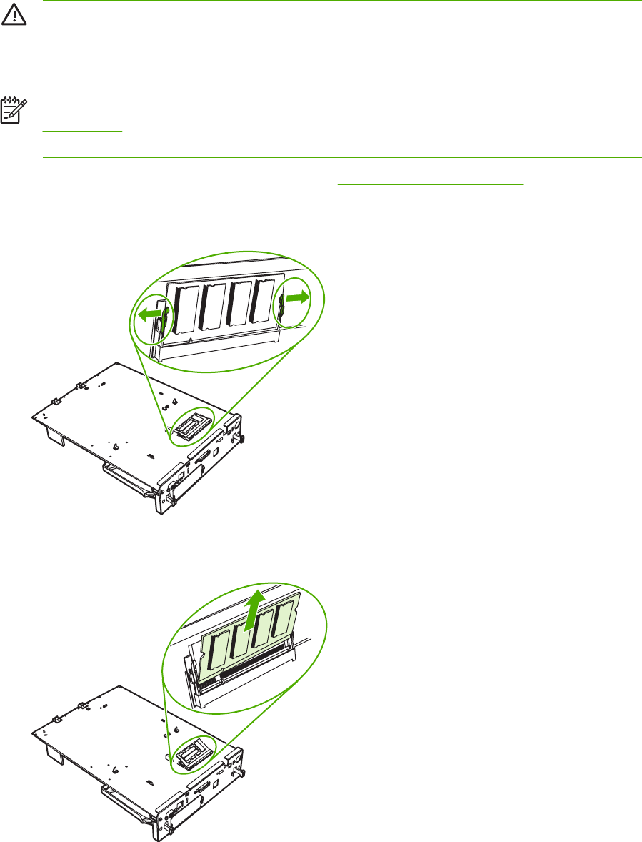
DIMMs
WARNING! The MFP contains components that are sensitive to electrostatic discharge
(ESD). Always perform service work at an ESD-protected workstation. If an ESD-protected
workstation is not available, discharge body static by grasping the MFP chassis before
touching an ESD-sensitive component. Ground the MFP chassis before servicing the MFP.
NOTE If possible, print a menu map and a configuration page. See Information pages
on page 640. Use the information on the these pages to restore any user-set MFP
configuration options after you install the replacement DIMMs.
1. Remove the formatter board from the MFP. See Formatter board on page 280.
2. To remove the DIMM on the rear of the formatter board, spread the latches on either side of the
DIMM slot apart.
Figure 6-65 Remove the DIMM (2 of 3)
3. Lift the DDR DIMM at an angle, and pull it out.
Figure 6-66 Remove the DIMM (3 of 3)
284 Chapter 6 Removal and replacement ENWW
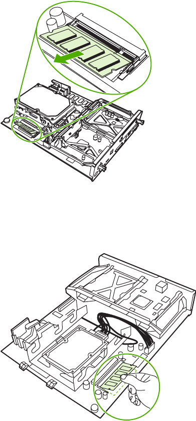
4. To remove the DIMM on the formatter board itself, spread the latches on either side of the
DIMM slot apart. Lift the DIMM up at an angle, and pull it out.
Figure 6-67 Remove the DIMM (4 of 5)
5. Holding the DIMM by the edges, align the notch on the DIMM with the bar in the DIMM slot at an
angle and firmly press the DIMM into the slot until it is fully seated. When installed correctly, the
metal contacts are not visible.
ENWW User-replaceable parts 285
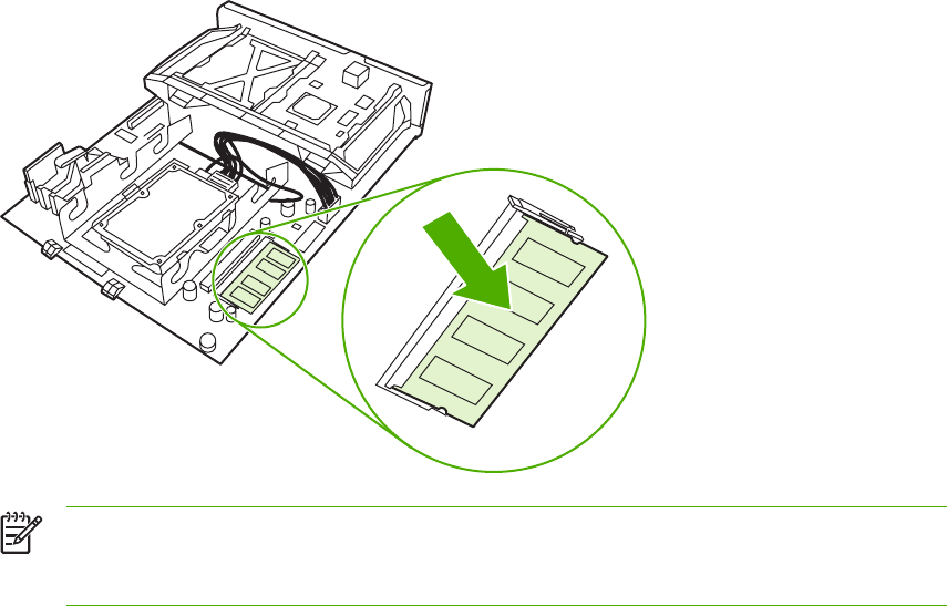
6. Push down on the DIMM until both latches engage the DIMM.
NOTE If you have difficulty inserting the DIMM, make sure the notch on the bottom of
the DIMM is aligned with the bar in the slot. If the DIMM still does not go in, make sure
you are using the correct type of DIMM.
286 Chapter 6 Removal and replacement ENWW
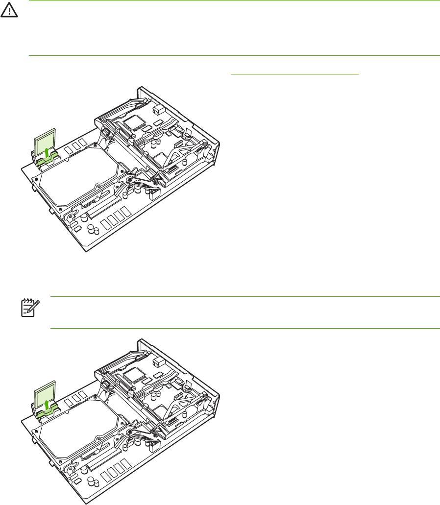
Flash memory card (firmware)
WARNING! The MFP contains components that are sensitive to electrostatic discharge
(ESD). Always perform service work at an ESD-protected workstation. If an ESD-protected
workstation is not available, discharge body static by grasping the MFP chassis before
touching an ESD-sensitive component. Ground the MFP chassis before servicing the MFP.
1. Remove the formatter board from the MFP. See Formatter board on page 280.
Figure 6-68 Remove the flash memory card (1 of 2)
2. Grasp the flash memory card, and then pull it out of the formatter cage.
NOTE When reinstalling the firmware flash memory card, it must be installed in the slot
marked FIRMWARE SLOT.
Figure 6-69 Remove the flash memory card (2 of 2)
ENWW User-replaceable parts 287
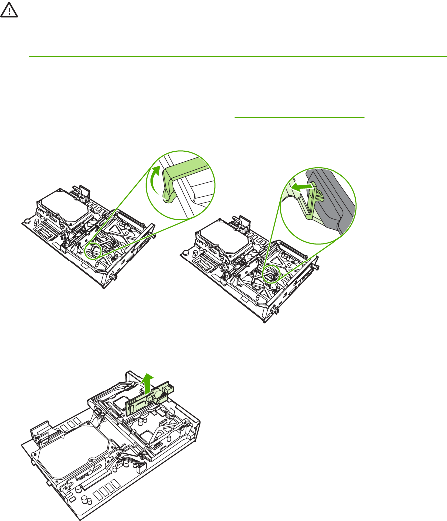
Fax accessory
WARNING! The MFP contains components that are sensitive to electrostatic discharge
(ESD). Always perform service work at an ESD-protected workstation. If an ESD-protected
workstation is not available, discharge body static by grasping the MFP chassis before
touching an ESD-sensitive component. Ground the MFP chassis before servicing the MFP.
Use this procedure to install or replace the analog fax accessory.
1. Turn off the MFP, and disconnect all cables.
2. Remove the formatter board from the MFP. See Formatter board on page 280.
3. If a fax accessory is in place, unhook the restraining strap and set it aside.
Figure 6-70 Remove the fax accessory (1 of 5)
4. Grasp the card and pull upward to remove it from the formatter board.
Figure 6-71 Remove the fax accessory (2 of 5)
5. Remove the fax accessory from its antistatic pouch.
288 Chapter 6 Removal and replacement ENWW
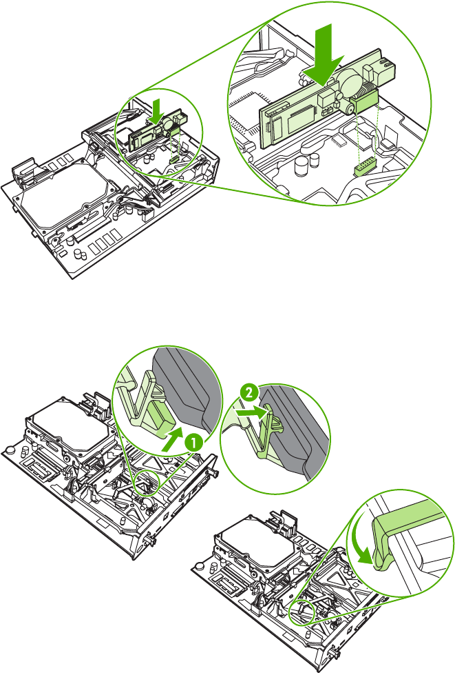
6. Push the fax accessory into place, and make sure that the fax accessory is securely connected
to the formatter.
Figure 6-72 Remove the fax accessory (3 of 5)
7. Reinstall the fax restraining strap.
Figure 6-73 Remove the fax accessory (4 of 5)
ENWW User-replaceable parts 289
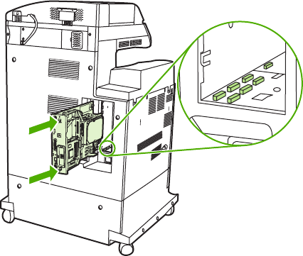
8. Align the formatter board in the tracks at the top and bottom, and slide the board back into the
MFP.
Figure 6-74 Remove the fax accessory (5 of 5)
290 Chapter 6 Removal and replacement ENWW
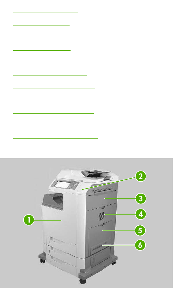
Covers, doors, and external panels
The procedures in this section describe the removal and replacement of the following components:
●Face-down tray assembly
●Delivery cover assembly
●Rear cover assembly
●Left cover assembly
●Front cover assembly
●Tray 1
●Right lower cover assembly
●Delivery upper cover assembly
●Right front inner lower cover assembly
●Left rear inner cover assembly
●Right front inner upper cover assembly
●Right rear inner cover assembly
The covers, doors, and panels are located as shown in the figures below.
Figure 6-75 Cover, door, and panel locations (1 of 2)
ENWW Covers, doors, and external panels 291
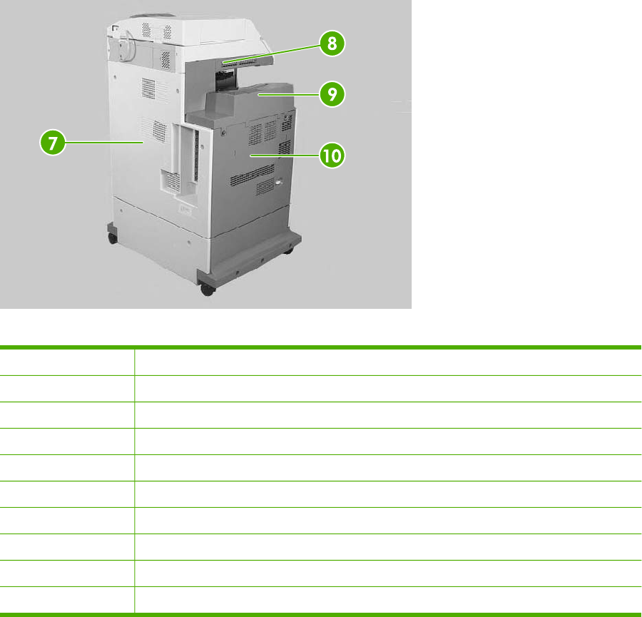
Figure 6-76 Cover, door, and panel locations (2 of 2)
1Front cover
2Upper right cover
3Right upper door
4Right lower cover
5Multipurpose tray
6Multipurpose pickup unit
7Rear cover
8Delivery upper cover
9Face-down tray assembly
10 Left cover
292 Chapter 6 Removal and replacement ENWW
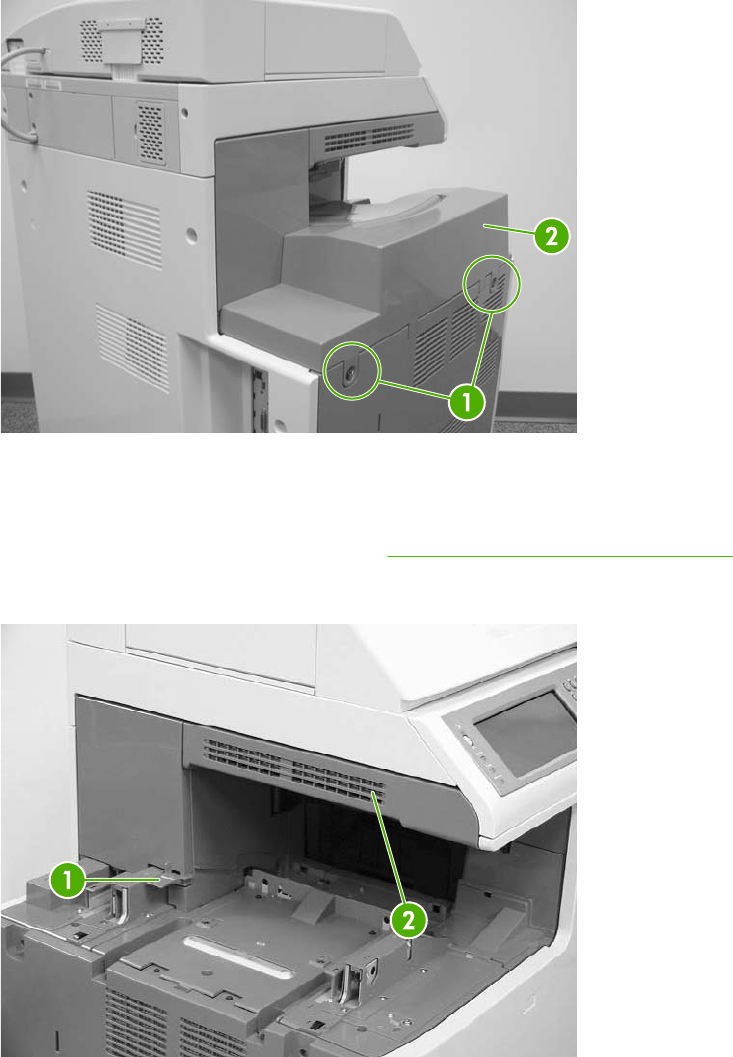
Face-down tray assembly
Loosen the two captive screws (callout 1) and remove the face-down tray (callout 2).
Figure 6-77 Remove the face-down tray assembly
Delivery cover assembly
1. Remove the face-down tray assembly. See Face-down tray assembly on page 293.
2. Pinch the projection (callout 1) and slide the delivery cover assembly (callout 2) forward.
Figure 6-78 Remove the delivery cover assembly
ENWW Covers, doors, and external panels 293
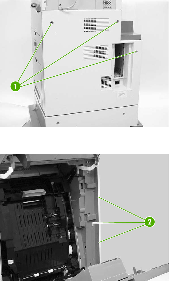
Rear cover assembly
1. Remove the three screws (callout 1).
Figure 6-79 Remove the rear cover assembly (1 of 4)
2. Unhook the three claws (callout 2).
Figure 6-80 Remove the rear cover assembly (2 of 4)
294 Chapter 6 Removal and replacement ENWW
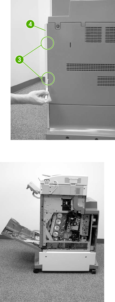
3. Unhook the claws (callout 3), and then remove the rear cover assembly (callout 4).
Figure 6-81 Remove the rear cover assembly (3 of 4)
Orientation view of rear of MFP with rear cover removed and side covers open.
Figure 6-82 Remove the rear cover assembly (4 of 4)
ENWW Covers, doors, and external panels 295
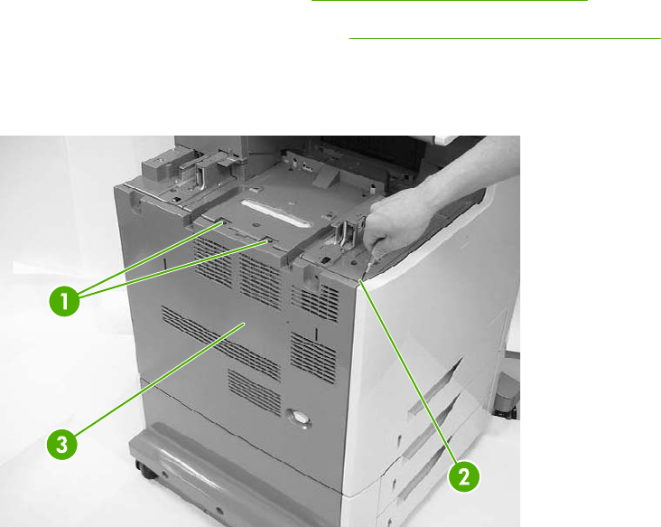
Left cover assembly
1. Remove the rear cover assembly. See Rear cover assembly on page 294.
2. Remove the face-down tray assembly. See Face-down tray assembly on page 293.
3. Remove the two screws (callout 1).
4. Unhook the claw (callout 2), and remove the left cover assembly (callout 3).
Figure 6-83 Remove the left cover
296 Chapter 6 Removal and replacement ENWW
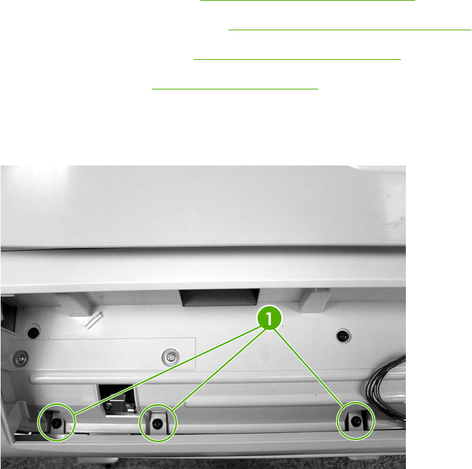
Front cover assembly
1. Remove the following assemblies.
●Rear cover assembly. See Rear cover assembly on page 294.
●Face-down tray assembly. See Face-down tray assembly on page 293.
●Left cover assembly. See Left cover assembly on page 296.
●Control panel. See Control panel on page 250.
2. Open the right upper and lower covers.
3. Remove the three screws (callout 1).
Figure 6-84 Remove the front cover (1 of 5)
ENWW Covers, doors, and external panels 297
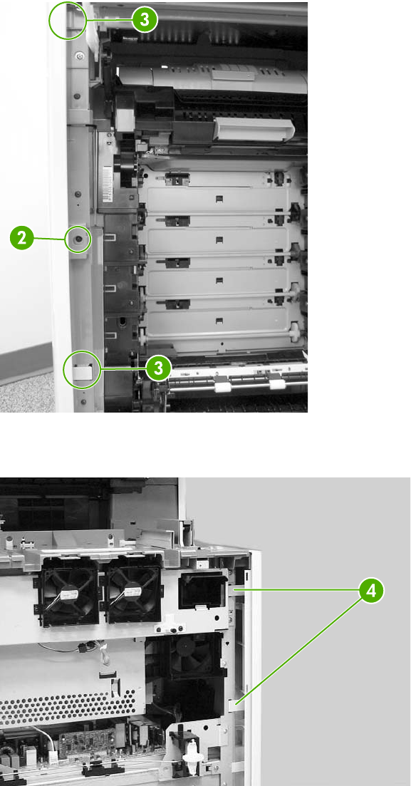
4. Remove one screw (callout 2) and unhook the two claws (callout 3) from the right side of the
MFP.
Figure 6-85 Remove the front cover (2 of 5)
5. Unhook the two claws (callout 4) on the left side of the MFP.
Figure 6-86 Remove the front cover (3 of 5)
298 Chapter 6 Removal and replacement ENWW
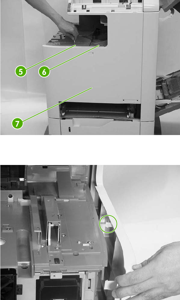
6. Unhook the claw by inserting the blade of a small screwdriver into the hole (callout 5) and
pushing to the right. Unhook the second claw (callout 6) and remove the cover (callout 7).
Figure 6-87 Remove the front cover (4 of 5)
Detail of claw (callout 5).
Figure 6-88 Remove the front cover (5 of 5)
ENWW Covers, doors, and external panels 299
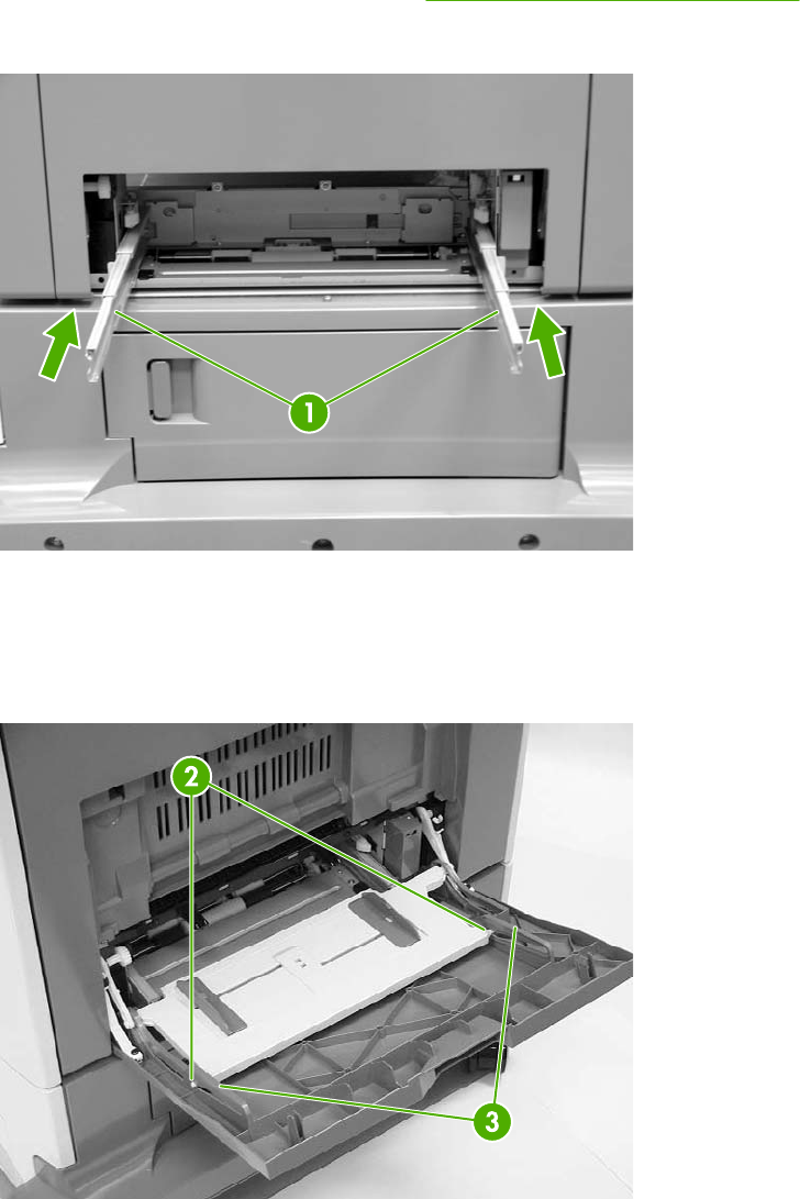
Tray 1
1. Remove the MP tray pickup assembly. See MP tray pickup assembly on page 261.
2. Push the slip rails (callout 1) back into the MFP.
Figure 6-89 Remove tray 1 (1 of 7)
3. Open tray 1.
4. Stretch the left and right sides of the tray guide (callout 2) outward to unhook the two bosses
(callout 3).
Figure 6-90 Remove tray 1 (2 of 7)
300 Chapter 6 Removal and replacement ENWW
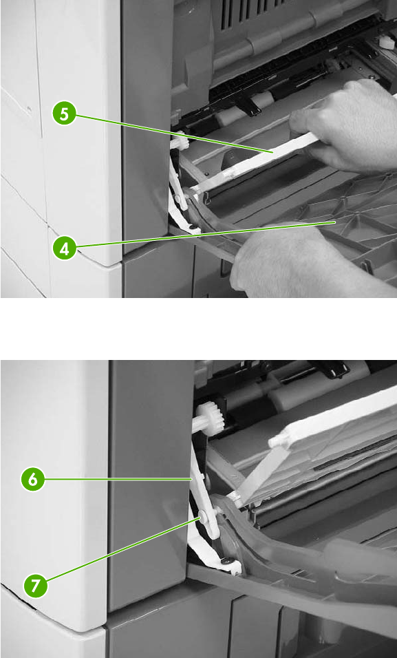
5. Lift the MP tray (callout 4) upward slightly and slide the tray back into the MFP while holding the
MP tray guide (callout 5).
Figure 6-91 Remove tray 1 (3 of 7)
6. Warp the link arm (callout 6) outward to unhook the left boss (callout 7).
Figure 6-92 Remove tray 1 (4 of 7)
ENWW Covers, doors, and external panels 301
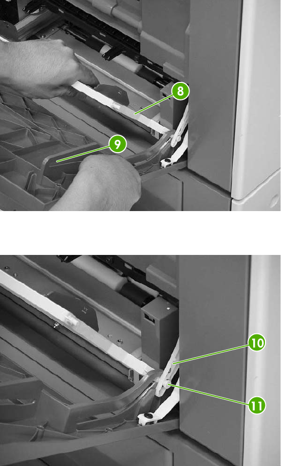
7. Lift the MP tray (callout 8) upward slightly and slide the tray back into the MFP while holding the
MP tray guide (callout 9).
Figure 6-93 Remove tray 1 (5 of 7)
8. Warp the link arm (callout 10) outward to unhook the right boss (callout 11).
Figure 6-94 Remove tray 1 (6 of 7)
302 Chapter 6 Removal and replacement ENWW
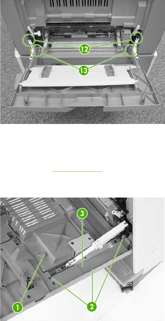
9. Pinch and release the two tabs (callout 12) on the end of each retaining strap to release the
strap ends.
Figure 6-95 Remove tray 1 (7 of 7)
10. Lift up the tray slightly and push the hinges inward to unhook them from the bosses (callout 13).
Right lower cover assembly
1. Remove tray 1. See Tray 1 on page 300.
2. Open the lower right cover (callout 1). Unhook the three claws (callout 2), and then remove the
cable cover (callout 3).
Figure 6-96 Remove the right lower cover assembly (1 of 5)
ENWW Covers, doors, and external panels 303
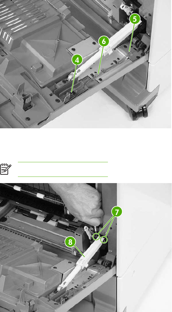
3. Disconnect the connector (callout 4) and remove the cable (callout 5) from the cable guide
(callout 6).
Figure 6-97 Remove the right lower cover assembly (2 of 5)
4. Open the shaft holder (callout 7) on the right side and rotate it counterclockwise to release the
arm (callout 8).
NOTE The arm is spring-loaded.
Figure 6-98 Remove the right lower cover assembly (3 of 5)
304 Chapter 6 Removal and replacement ENWW
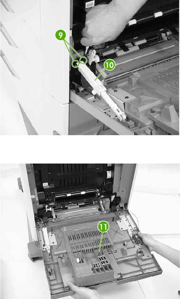
5. Open the shaft holder (callout 9) on the left side and rotate it clockwise to remove the arm
(callout 10).
Figure 6-99 Remove the right lower cover assembly (4 of 5)
6. Pull the right lower cover (callout 11) out of the MFP toward you.
Figure 6-100 Remove the right lower cover assembly (5 of 5)
ENWW Covers, doors, and external panels 305
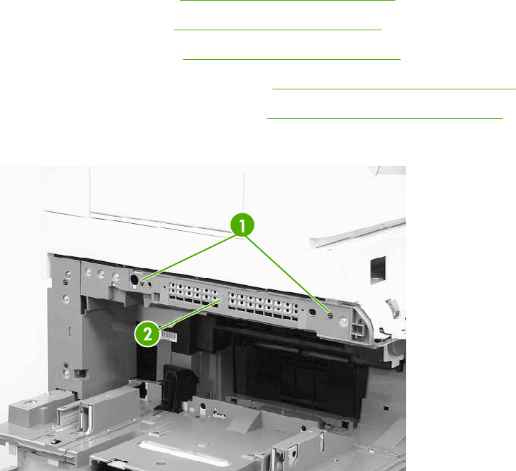
Delivery upper cover assembly
1. Remove the rear cover. See Rear cover assembly on page 294.
2. Remove the left cover. See Left cover assembly on page 296.
3. Remove the front cover. See Front cover assembly on page 297.
4. Remove the face-down tray assembly. See Face-down tray assembly on page 293.
5. Remove the delivery cover assembly. See Delivery cover assembly on page 293.
6. Remove the two screws (callout 1) and the delivery upper cover (callout 2).
Figure 6-101 Remove the delivery upper cover assembly
306 Chapter 6 Removal and replacement ENWW
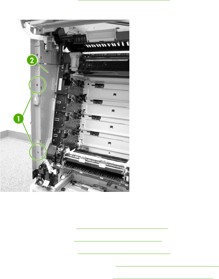
Right front inner lower cover assembly
1. Remove the front cover. See Front cover assembly on page 297.
2. Remove the two black screws (callout 1) and the right front inner lower cover (callout 2).
Figure 6-102 Remove the right front lower inner cover
Left rear inner cover assembly
1. Remove the rear cover. See Rear cover assembly on page 294.
2. Remove the left cover. See Left cover assembly on page 296.
3. Remove the front cover. See Front cover assembly on page 297.
4. Remove the face-down tray assembly. See Face-down tray assembly on page 293.
5. Remove the delivery cover assembly. See Delivery cover assembly on page 293.
ENWW Covers, doors, and external panels 307
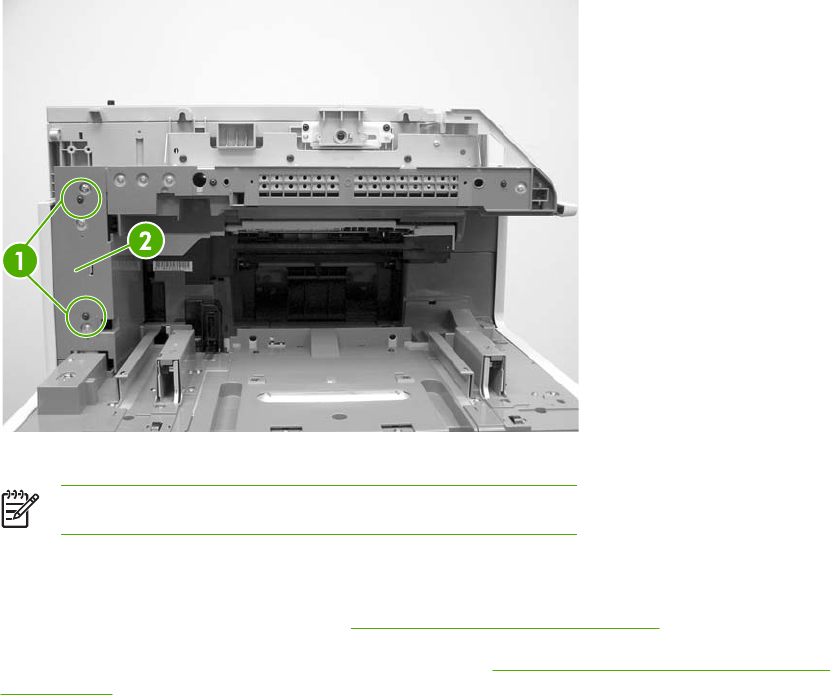
6. Remove the two black screws (callout 1) and the left rear inner cover (callout 2).
Figure 6-103 Remove the left rear inner cover
NOTE Unclip the tab at the front below the control panel.
Right front inner upper cover assembly
1. Remove the front cover assembly. See Front cover assembly on page 297.
2. Remove the right front inner lower cover assembly. See Right front inner lower cover assembly
on page 307.
3. Open the right upper door.
308 Chapter 6 Removal and replacement ENWW
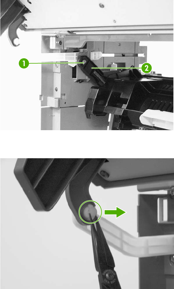
4. Unhook the claw (callout 1) and release the door link (callout 2).
Figure 6-104 Remove the right front inner cover assembly (1 of 3)
5. Unhook the arm and push it back toward the MFP.
Figure 6-105 Remove the right front inner cover assembly (2 of 3)
ENWW Covers, doors, and external panels 309
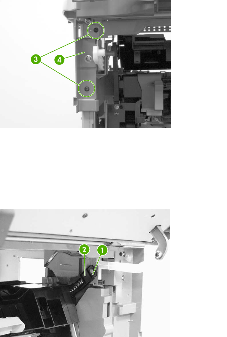
6. Remove the two screws (callout 3). Then lift up the right front inner upper cover (callout 4) and
shift it gently to remove it.
Figure 6-106 Remove the right front inner cover assembly (3 of 3)
Right rear inner cover assembly
1. Remove the rear cover assembly. See Rear cover assembly on page 294.
2. Open the right upper door.
3. Remove the right lower cover assembly. See Right lower cover assembly on page 303.
4. Unhook the claw (callout 1) and release the door link (callout 2).
Figure 6-107 Remove the right rear inner cover assembly (1 of 4)
310 Chapter 6 Removal and replacement ENWW
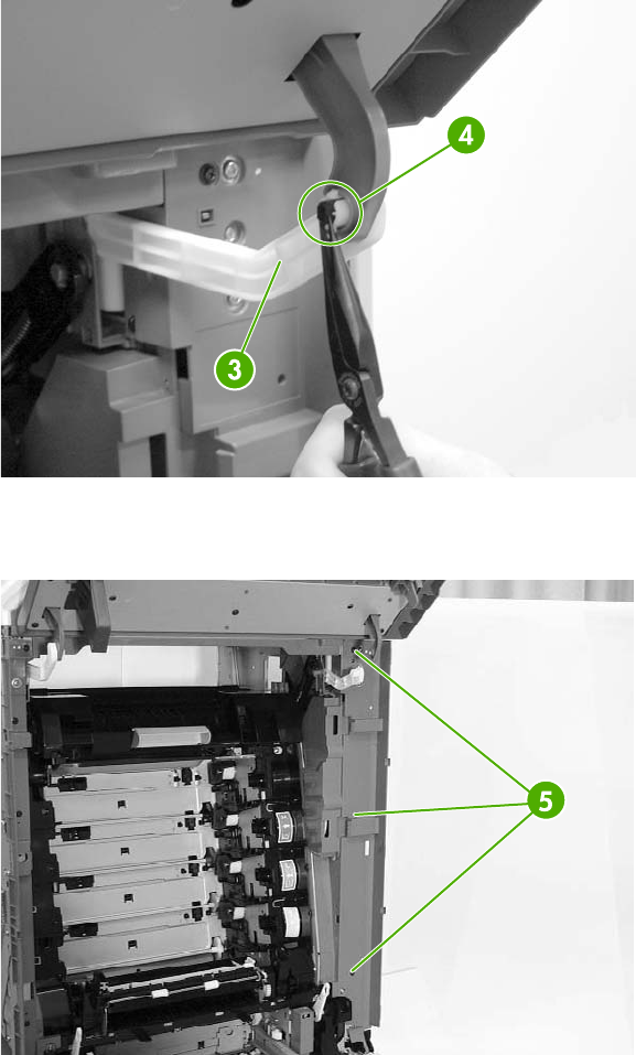
5. Push the link arm (callout 3) backwards by pressing the tabs (callout 4).
Figure 6-108 Remove the right rear inner cover assembly (2 of 4)
6. Remove the three screws (callout 5).
Figure 6-109 Remove the right rear inner cover assembly (3 of 4)
ENWW Covers, doors, and external panels 311
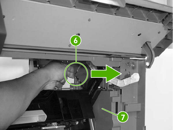
7. Push the right rear inner cover assembly from the back (callout 6) and then remove the right
rear inner cover (callout 7).
Figure 6-110 Remove the right rear inner cover assembly (4 of 4)
312 Chapter 6 Removal and replacement ENWW
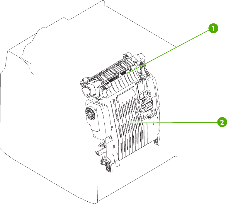
Main assembly (internal assemblies)
The figures below identify the names and locations of the MFP main assemblies.
Figure 6-111 Locations of main assemblies (1 of 3)
ENWW Main assembly (internal assemblies) 313
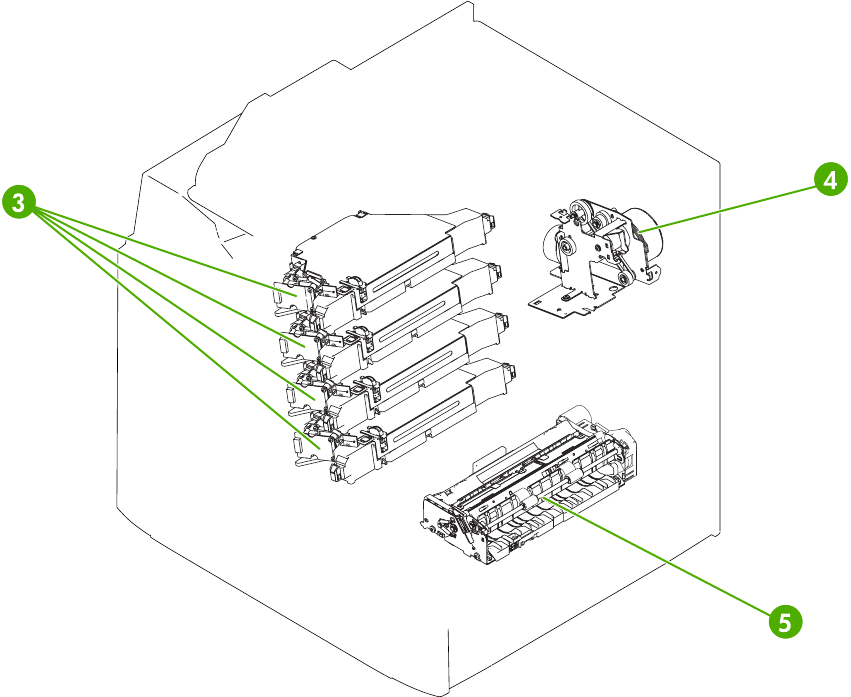
Figure 6-112 Locations of main assemblies (2 of 3)
314 Chapter 6 Removal and replacement ENWW
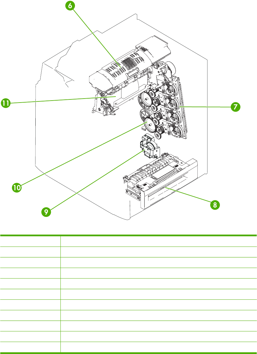
Figure 6-113 Locations of main assemblies (3 of 3)
1 Fuser
2 ETB
3Laser/scanner assembly
4Fuser drive assembly
5Paper feed assembly
6Duplexing assembly
7Main drive assembly
8MP tray pickup assembly
9Lifter drive assembly
10 Developing alienation drive assembly
11 Delivery assembly
ENWW Main assembly (internal assemblies) 315
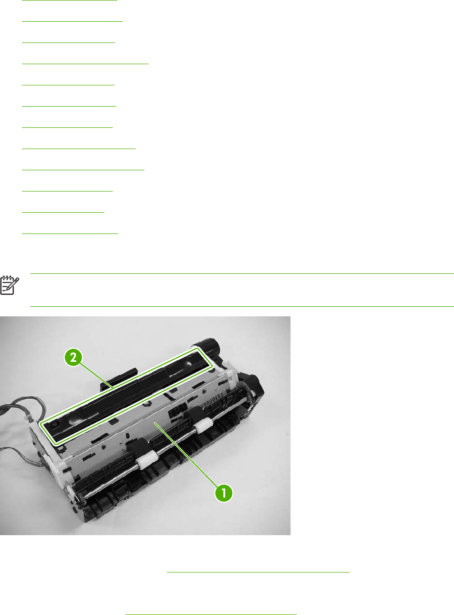
The procedures in this section describe the removal and replacement of the following components:
●Paper feed assembly
●Pickup drive assembly
●Lifter drive assembly
●Disengaging drive assembly
●Main drive assembly
●Rail holder assembly
●Rail guide assembly
●Formatter case assembly
●Laser/scanner components
●Duplexing assembly
●Delivery assembly
●Fuser drive assembly
Paper feed assembly
NOTE Do not disassemble the paper feed assembly (callout 1). It contains an integral media
sensor (callout 2) that is adjusted at the factory. It cannot be adjusted in the field.
Figure 6-114 Paper feed assembly sensor
1. Open the right lower cover. See Right lower cover assembly on page 454.
2. Remove the print cartridges.
3. Remove the ETB. See ETB assembly, removing on page 258.
316 Chapter 6 Removal and replacement ENWW
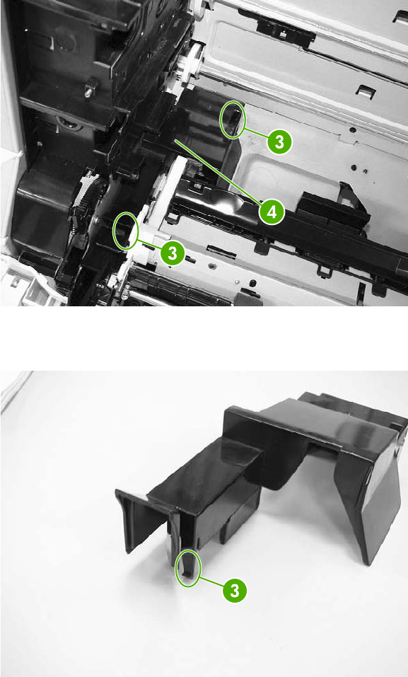
4. Unhook the two claws (callout 3), and then remove the cable cover (callout 4).
Figure 6-115 Remove the paper feed assembly (1 of 6)
5. Detail of cable cover front claw 1 of 2 (callout 3).
Figure 6-116 Remove the paper feed assembly (2 of 6)
ENWW Main assembly (internal assemblies) 317
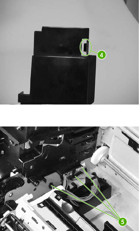
6. Detail of cable cover rear claw (callout 3).
Figure 6-117 Remove the paper feed assembly (3 of 6)
7. Disconnect the three connectors (callout 5).
Figure 6-118 Remove the paper feed assembly (4 of 6)
318 Chapter 6 Removal and replacement ENWW
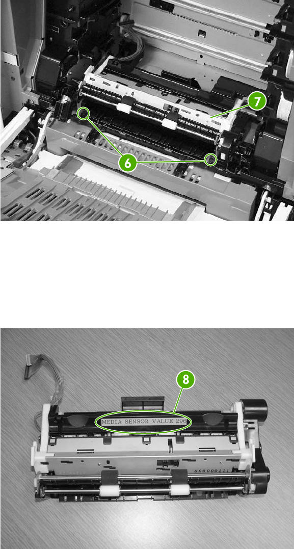
8. Remove the two screws (callout 6), and then remove the paper feed assembly (callout 7).
Figure 6-119 Remove the paper feed assembly (5 of 6)
9. The paper feed assembly contains a media sensor that is calibrated at the factory. When
replacing the paper feed assembly, you must enter the new media sensor value into the MFP
control panel. The media sensor value is located on the label attached to the paper feed
assembly (callout 8). After replacing the paper feed assembly, turn on the MFP, press Menu,
scroll to and touch Service. Enter the service password and touch OK. Scroll to and touch
MEDIA SENSOR VALUE, enter the new value shown on the label, and touch OK.
Figure 6-120 Remove the paper feed assembly (6 of 6)
ENWW Main assembly (internal assemblies) 319
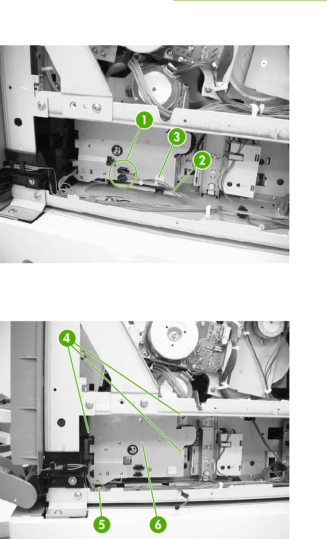
Pickup drive assembly
1. Remove the rear cover assembly. See Rear cover assembly on page 294.
2. Disconnect the two connectors (callout 1) and remove the cable (callout 2) from the cable
guides (callout 3).
Figure 6-121 Remove the pickup drive assembly (1 of 2)
3. Remove the three screws (callout 4) and unhook the cable from the cable stay (callout 5). Then
remove the pickup drive assembly (callout 6).
Figure 6-122 Remove the pickup drive assembly (2 of 2)
320 Chapter 6 Removal and replacement ENWW
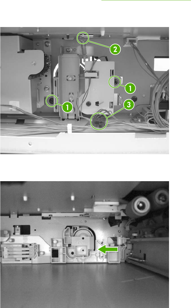
Lifter drive assembly
1. Remove the paper trays.
2. Remove the rear cover assembly. See Rear cover assembly on page 294.
3. Remove two screws (callout 1). Remove the spring (callout 2) and disconnect the connector
(callout 3).
Figure 6-123 Remove the lifter drive assembly (1 of 3)
4. Remove the paper tray rear bracket, which is located inside the paper tray.
Figure 6-124 Remove the lifter drive assembly (2 of 3)
ENWW Main assembly (internal assemblies) 321
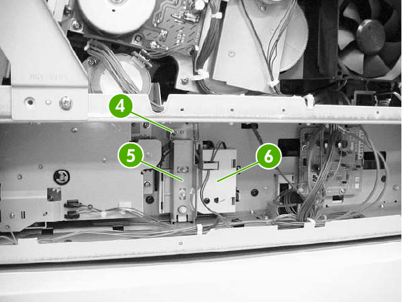
5. Remove one screw (callout 4) and remove the lifter drive bracket (callout 5) and the lifter drive
assembly (callout 6).
Figure 6-125 Remove the lifter drive assembly (3 of 3)
322 Chapter 6 Removal and replacement ENWW
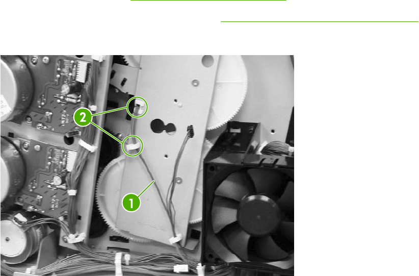
Disengaging drive assembly
1. Remove the rear cover. See Rear cover assembly on page 294.
2. Remove the developing disengaging motor. See Developing disengaging motor on page 369.
3. Remove the cable (callout 1) from the cable guides (callout 2).
Figure 6-126 Remove the disengaging drive assembly (1 of 3)
ENWW Main assembly (internal assemblies) 323
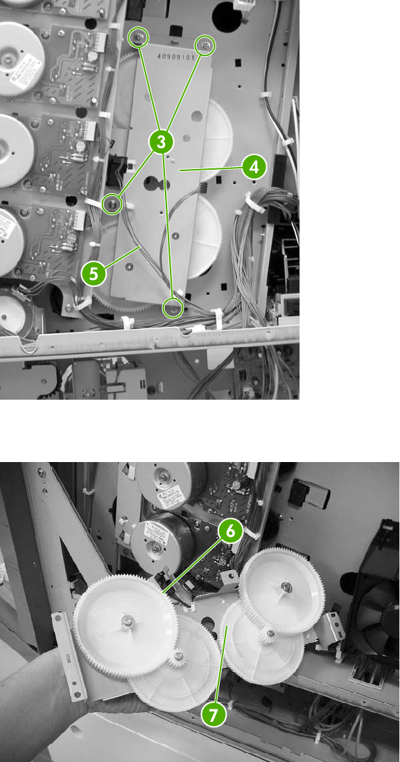
4. Remove four screws (callout 3). Tilt the developing alienation drive assembly (callout 4) and the
cable (callout 5) forward together.
Figure 6-127 Remove the disengaging drive assembly (2 of 3)
5. Disconnect the connector (callout 6) from the developing alienation drive assembly (callout 7).
Figure 6-128 Remove the disengaging drive assembly (3 of 3)
324 Chapter 6 Removal and replacement ENWW
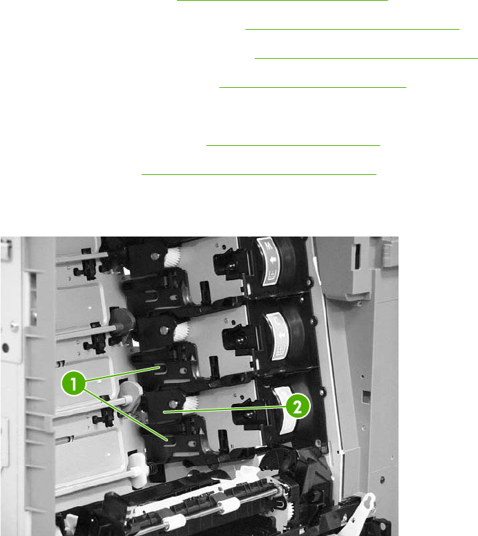
Main drive assembly
1. Remove the rear cover. See Rear cover assembly on page 294.
2. Remove the sub power supply fan. See Sub power supply fan on page 374.
3. Remove the sub power supply PCB. See Sub power supply PCB on page 401.
4. Remove the power supply fan. See Power supply fan on page 371.
5. Open the right lower door.
6. Remove the print cartridges. See Print cartridges on page 248.
7. Remove the ETB. See ETB assembly, removing on page 258.
8. Using a small flat-blade screwdriver, unhook the two claws (callout 1), and then remove the
cartridge lower guide assembly (callout 2) by pulling it forward.
Figure 6-129 Remove the main drive assembly (1 of 9)
ENWW Main assembly (internal assemblies) 325
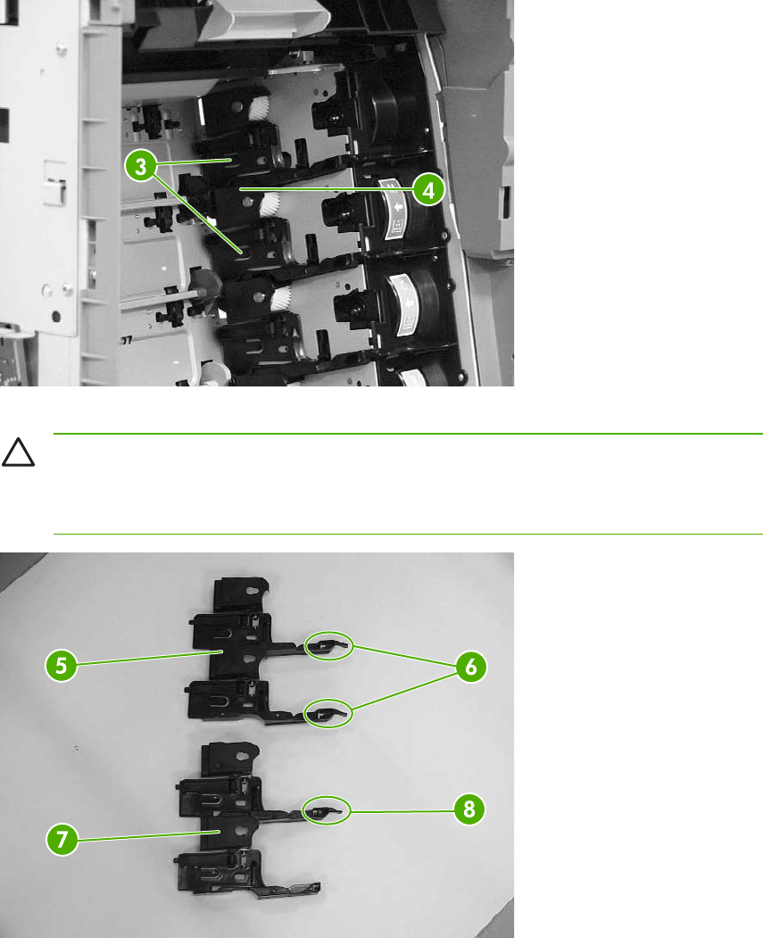
9. Using a small flat-blade screwdriver, unhook the two claws (callout 3), and then remove the
cartridge upper guide assembly (callout 4) by pulling it forward.
Figure 6-130 Remove the main drive assembly (2 of 9)
CAUTION Be careful when reassembling the upper and lower cartridge guides. They
are very similar in appearance. If they are not assembled correctly, the ETB will not
position correctly. The cartridge upper guide assembly (callout 5) has two projections
(callout 6). The cartridge lower guide assembly (callout 7) has one projection (callout 8).
Figure 6-131 Remove the main drive assembly (3 of 9)
326 Chapter 6 Removal and replacement ENWW
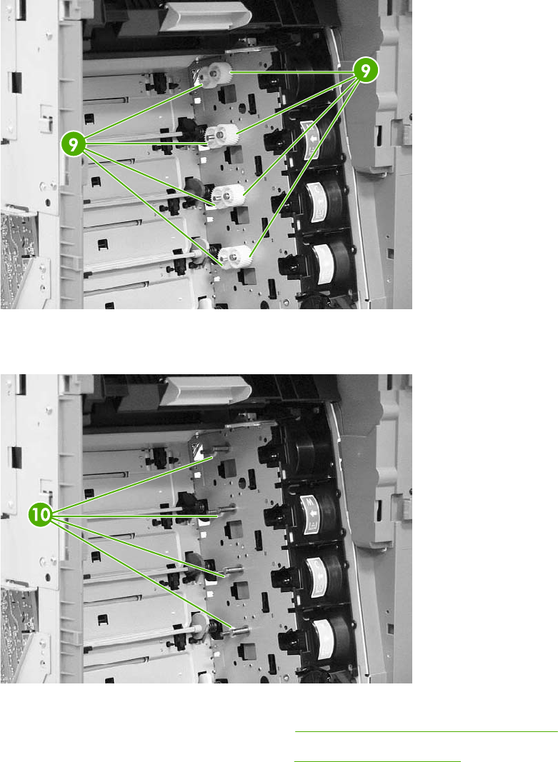
10. Remove the eight gears (callout 9).
Figure 6-132 Remove the main drive assembly (4 of 9)
11. Remove the four bushings (callout 10).
Figure 6-133 Remove the main drive assembly (5 of 9)
12. Remove the disengaging drive assembly. See Disengaging drive assembly on page 323.
13. Remove the four drum motors (Y/C/M/K). See Drum motors on page 362.
ENWW Main assembly (internal assemblies) 327
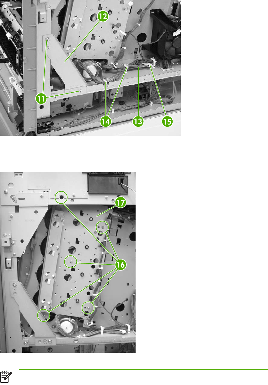
14. Remove the two screws (callout 11) and the plate (callout 12). Remove the cable (callout 13)
from the cable guides (callout 14) and disconnect one connector (callout 15).
Figure 6-134 Remove the main drive assembly (6 of 9)
15. Remove the five screws (callout 16), and then remove the main drive assembly (callout 17).
Note that the uppermost screw is recessed.
Figure 6-135 Remove the main drive assembly (7 of 9)
NOTE Remove only the screws indicated in the figure. Do not remove any other screws.
328 Chapter 6 Removal and replacement ENWW
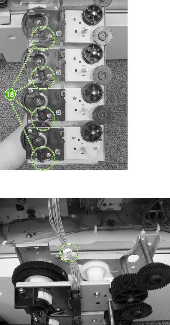
16. Disconnect eight connectors (callout 18) (two connectors per gear).
Figure 6-136 Remove the main drive assembly (8 of 9)
17. Remove the main wiring cable harness from the cable guide.
Figure 6-137 Remove the main drive assembly (9 of 9)
The following are seven reinstallation tips for the main drive assembly.
ENWW Main assembly (internal assemblies) 329
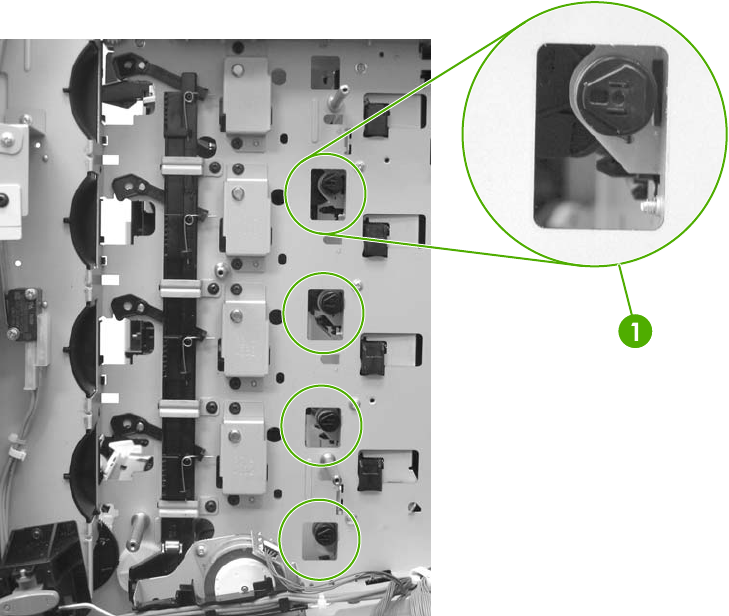
Reinstallation tips
1. When connecting or disconnecting the inside connectors of the sensors, be careful not to
dislodge the sensors.
2. When reconnecting the cable, start at the K (black) cartridge and route from there.
3. Make sure that the developing clutch gears (callout 1) are aligned with the arrow on the metal
sheet.
Figure 6-138 Reinstallation tips (1 of 5)
330 Chapter 6 Removal and replacement ENWW
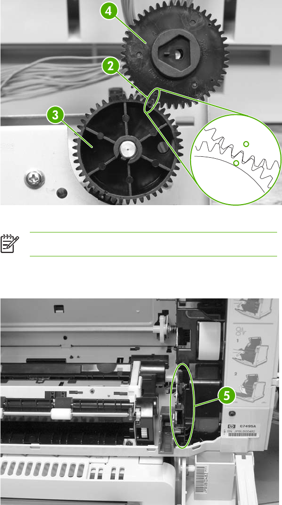
4. Align the four positioning dent marks (callout 2) of the developing clutch gears (callout 3) and
the developing alienation gear (callout 4).
Figure 6-139 Reinstallation tips (2 of 5)
NOTE Make sure to adjust all four gears the same way.
5. Make sure that the cartridge interlock rod is in the up position (callout 5). This guide is located
just above and to the right of the ETB guide.
Figure 6-140 Reinstallation tips (3 of 5)
ENWW Main assembly (internal assemblies) 331
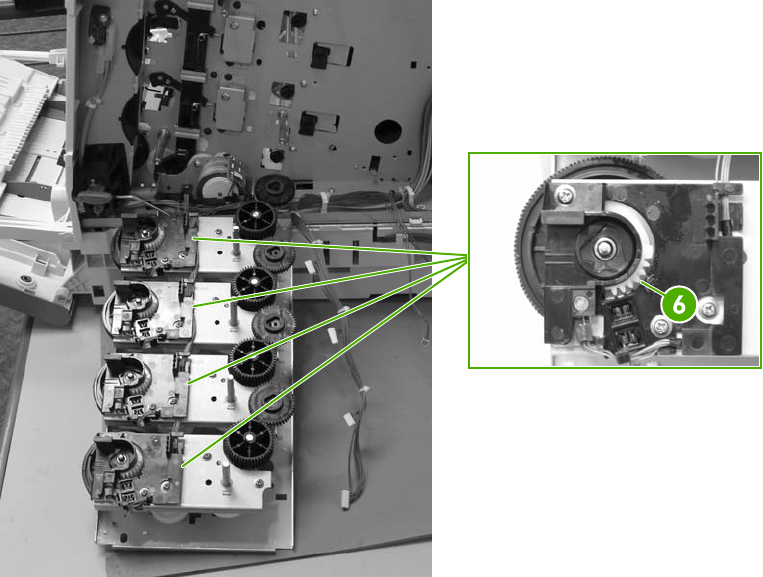
6. Make sure to rotate the white gears as shown (callout 6) before placing the main drive assembly
back into position.
Figure 6-141 Reinstallation tips (4 of 5)
332 Chapter 6 Removal and replacement ENWW
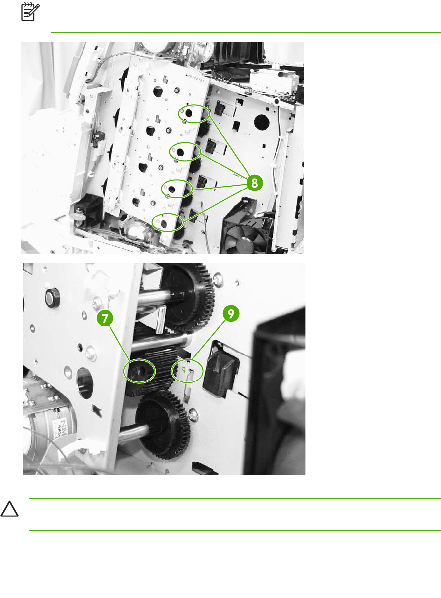
7. Make sure to align the four positioning marks (callout 7) of all developing alienation gears
(callout 8) with the marks (callout 9) on the printer.
NOTE There is a little dimple on the right side of the bigger hole (callout 7). This needs
to match up with the arrow in callout 9.
Figure 6-142 Reinstallation tips (5 of 5)
CAUTION Be sure to reinstall the disengaging drive assembly before putting the gears and
the cartridge guides back together inside the printer.
Rail holder assembly
1. Remove the rear cover assembly. See Rear cover assembly on page 294.
2. Remove the face-down tray assembly. See Face-down tray assembly on page 293.
ENWW Main assembly (internal assemblies) 333
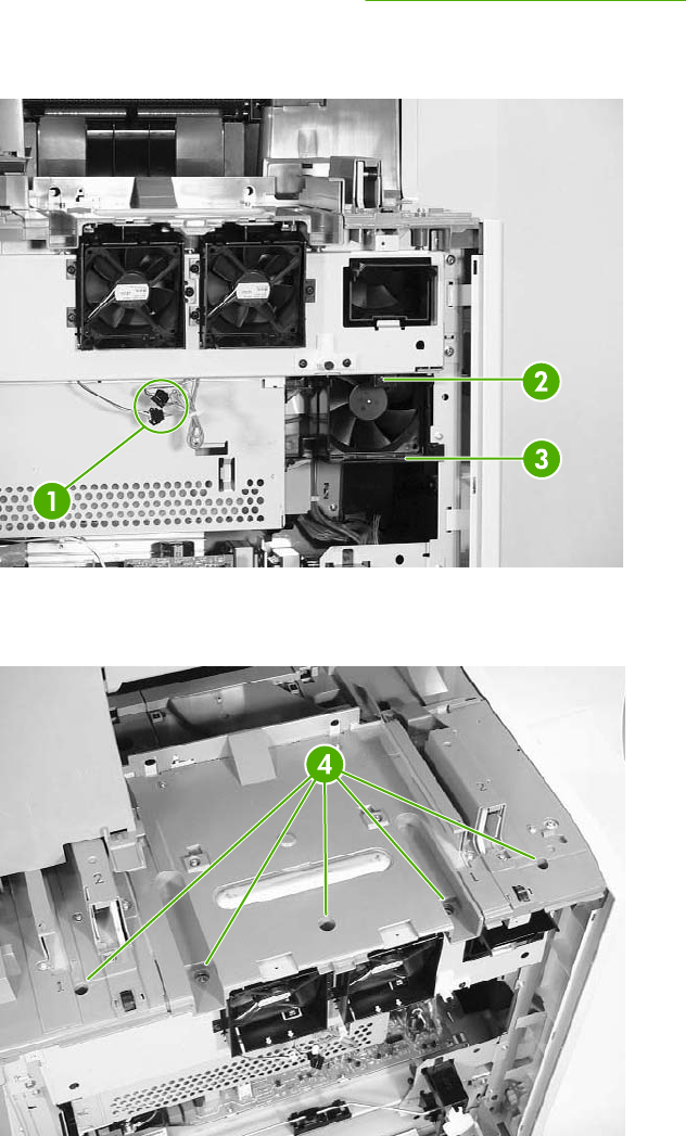
3. Remove the left cover assembly. See Left cover assembly on page 296.
4. Disconnect the two connectors (callout 1). Remove one screw (callout 2) and the fan duct
(callout 3).
Figure 6-143 Remove the rail holder assembly (1 of 3)
5. Remove the five screws (callout 4).
Figure 6-144 Remove the rail holder assembly (2 of 3)
334 Chapter 6 Removal and replacement ENWW
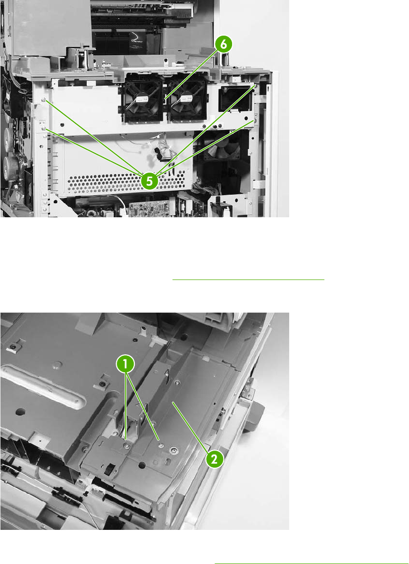
6. Remove the four screws (callout 5) and the rail holder assembly (callout 6).
Figure 6-145 Remove the rail holder assembly (3 of 3)
Rail guide assembly
1. Remove the rail holder assembly. See Rail holder assembly on page 333.
2. Remove the two screws (callout 1), and then remove the front guide cover (callout 2).
Figure 6-146 Remove the rail guide assembly (1 of 7)
3. Remove the left rear inner cover assembly. See Left rear inner cover assembly on page 307.
ENWW Main assembly (internal assemblies) 335
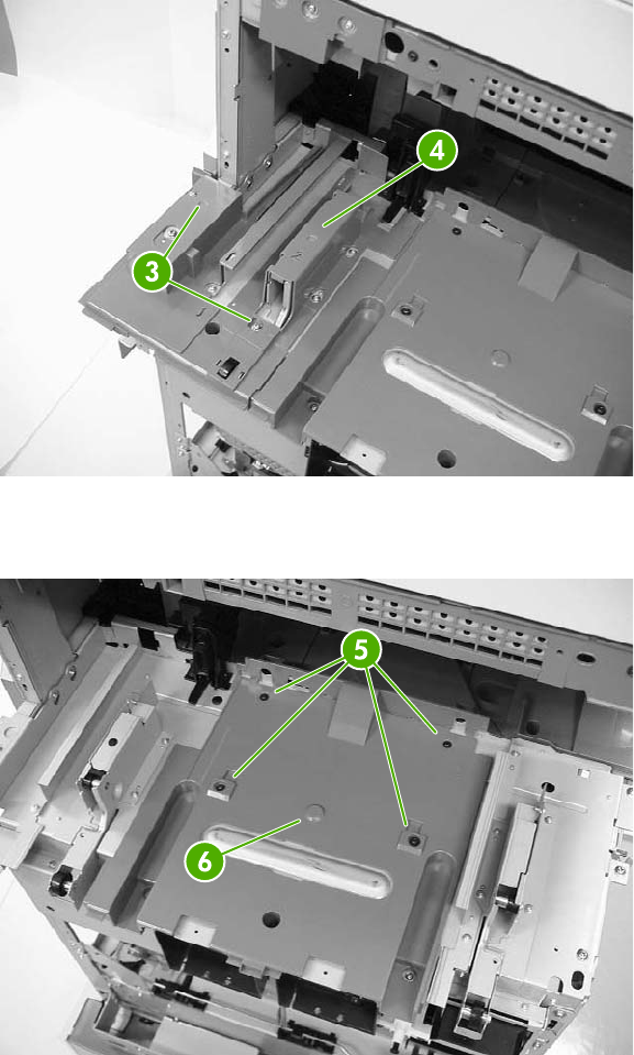
4. Remove the two screws (callout 3), and then remove the rear guide cover (callout 4).
Figure 6-147 Remove the rail guide assembly (2 of 7)
5. Remove the four screws (callout 5), and then remove the center guide cover (callout 6).
Figure 6-148 Remove the rail guide assembly (3 of 7)
336 Chapter 6 Removal and replacement ENWW

6. Unhook the two claws (callout 7), and then remove the connector cover (callout 8).
Figure 6-149 Remove the rail guide assembly (4 of 7)
Figure 6-150 Remove the rail guide assembly, connector cover claw detail (5 of 7)
ENWW Main assembly (internal assemblies) 337
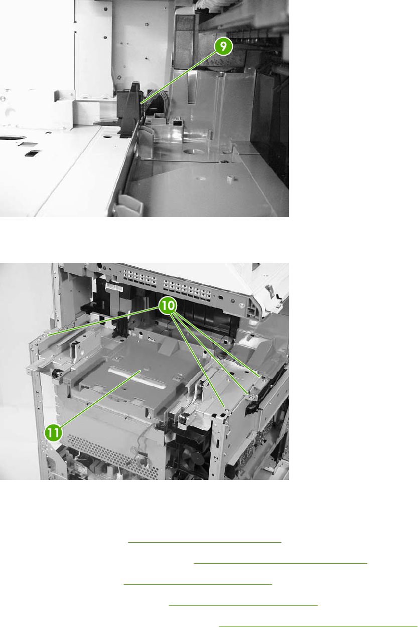
7. Disconnect the connector (callout 9).
Figure 6-151 Remove the rail guide assembly (6 of 7)
8. Remove the four screws (callout 10), and then remove the rail guide assembly (callout 11).
Figure 6-152 Remove the rail guide assembly (7 of 7)
Formatter case assembly
1. Remove the rear cover. See Rear cover assembly on page 294.
2. Remove the face-down tray assembly. See Face-down tray assembly on page 293.
3. Remove the left cover. See Left cover assembly on page 296.
4. Remove the rail guide assembly. See Rail guide assembly on page 335.
5. Remove the low-voltage power supply PCB. See Low-voltage power supply PCB on page 395.
338 Chapter 6 Removal and replacement ENWW
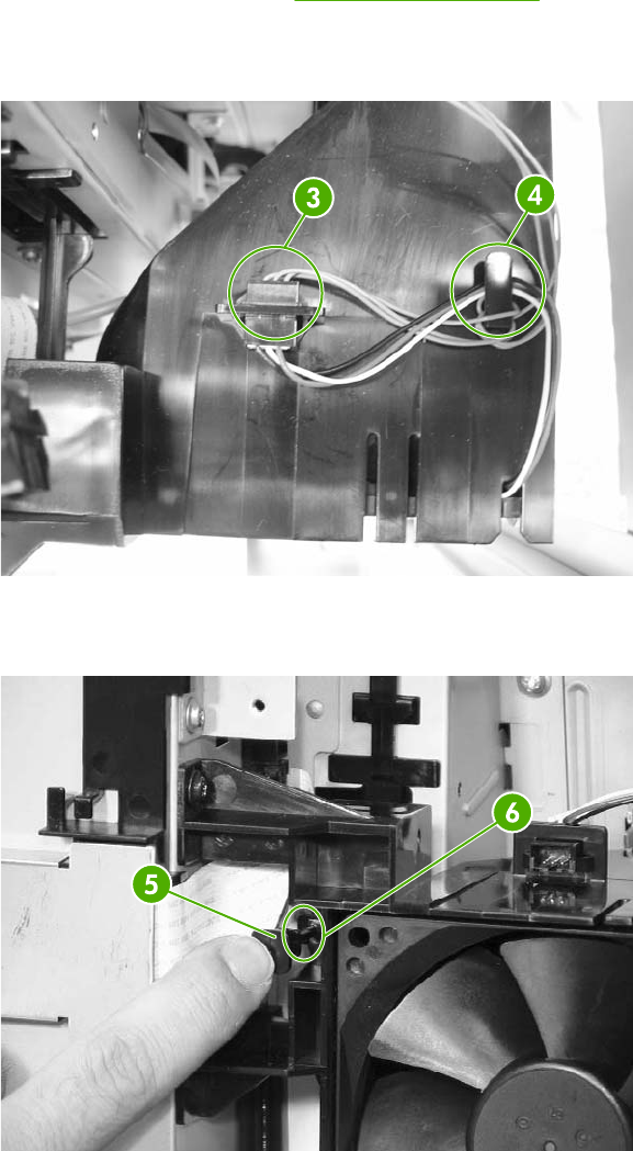
6. Remove the delivery fan. See Delivery fan on page 376.
7. Disconnect the purple connector (callout 3) from the fan, and remove the cable from the cable
guide (callout 4).
Figure 6-153 Remove the formatter case (2 of 10)
8. Remove the test print pin (callout 5) from the fan holder (callout 6) by pushing it to the left.
Figure 6-154 Remove the formatter case (3 of 10)
ENWW Main assembly (internal assemblies) 339
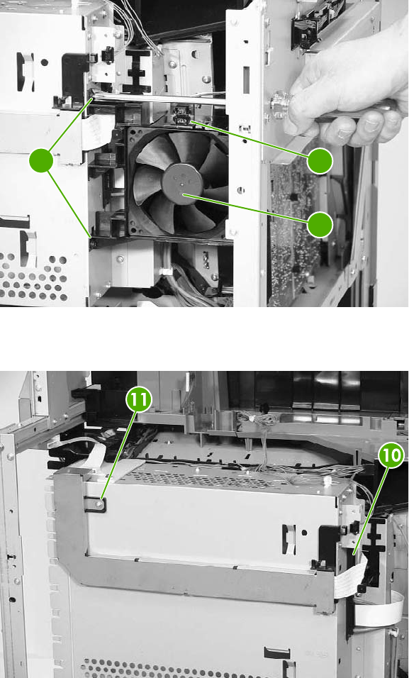
9. Remove the two screws (callout 7), and then remove the fan holder (callout 8) and the cartridge
fan (callout 9) together.
7
9
8
Figure 6-155 Remove the formatter case (4 of 10)
10. Disconnect the upper flat cable (callout 10) and remove one screw (callout 11).
Figure 6-156 Remove the formatter case (5 of 10)
340 Chapter 6 Removal and replacement ENWW
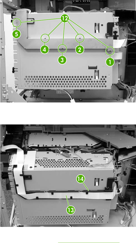
11. Unhook the five tabs (callout 12) in the order shown to release the shield cover. Two tabs are
located on the underside of the shield cover.
Figure 6-157 Remove the formatter case (6 of 10)
12. Remove the cable (callout 13) from the cable guide (callout 14).
Figure 6-158 Remove the formatter case (7 of 10)
13. Remove the formatter. See Formatter board on page 280.
ENWW Main assembly (internal assemblies) 341
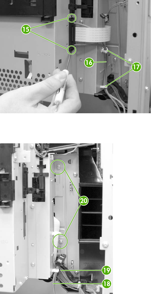
14. Remove the connector (callout 15) and then unhook the cables (callout 16) from the cable
guides (callout 17).
Figure 6-159 Remove the formatter case (8 of 10)
15. Remove the cables (callout 18) from the cable guide (callout 19). Remove the two screws
(callout 20).
Figure 6-160 Remove the formatter case (9 of 10)
342 Chapter 6 Removal and replacement ENWW
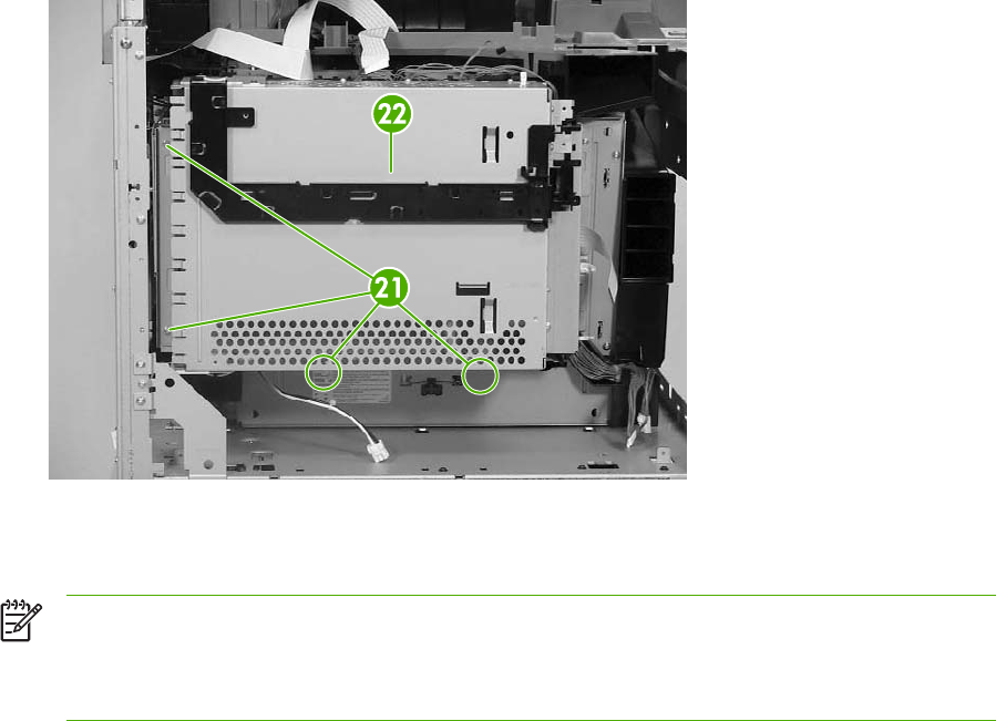
16. Remove the four screws (callout 21), and then remove the formatter case assembly (callout 22).
Figure 6-161 Remove the formatter case (10 of 10)
Laser/scanner components
NOTE Before removing the laser/scanner assembly, remove the screws on the four corners
(callout 1) that join the MFP and the 2 X 500 sheet paper deck. Otherwise, the frame might
become twisted, which could distort the flatness of the laser mounting. Replace the screws
after the laser/scanner assembly has been replaced.
ENWW Main assembly (internal assemblies) 343
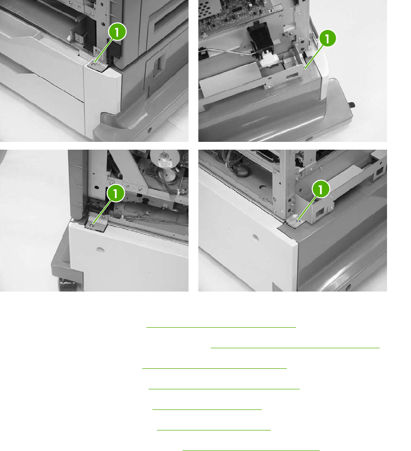
Figure 6-162 Remove screws at corners of MFP
1. Remove the rear cover. See Rear cover assembly on page 294.
2. Remove the face-down tray assembly. See Face-down tray assembly on page 293.
3. Remove the left cover. See Left cover assembly on page 296.
4. Remove the front cover. See Front cover assembly on page 297.
5. Remove the delivery fan. See Delivery fan on page 376.
6. Remove the cartridge fan. See Cartridge fan on page 373.
7. Remove the DC controller PCB. See DC controller PCB on page 384.
344 Chapter 6 Removal and replacement ENWW
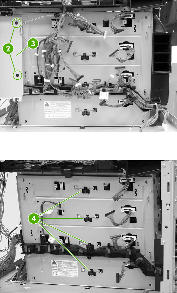
8. Remove all cables from the cable guides. Remove two screws (callout 2) and the formatter plate
(callout 3).
Figure 6-163 Remove laser/scanner components (1 of 12)
9. Remove the springs (callout 4).
Figure 6-164 Remove the laser/scanner components (2 of 12)
ENWW Main assembly (internal assemblies) 345
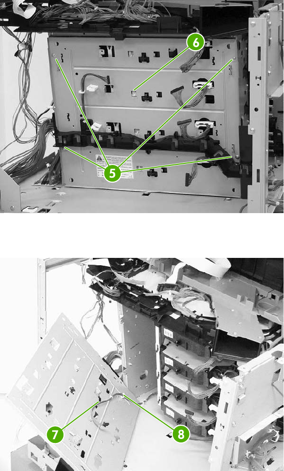
10. Remove the four screws (callout 5), and then remove the rear plate assembly (callout 6).
Figure 6-165 Remove the laser/scanner components (3 of 12)
11. Remove the cable (callout 7) from the cable guide (callout 8).
Figure 6-166 Remove the laser/scanner components (4 of 12)
346 Chapter 6 Removal and replacement ENWW
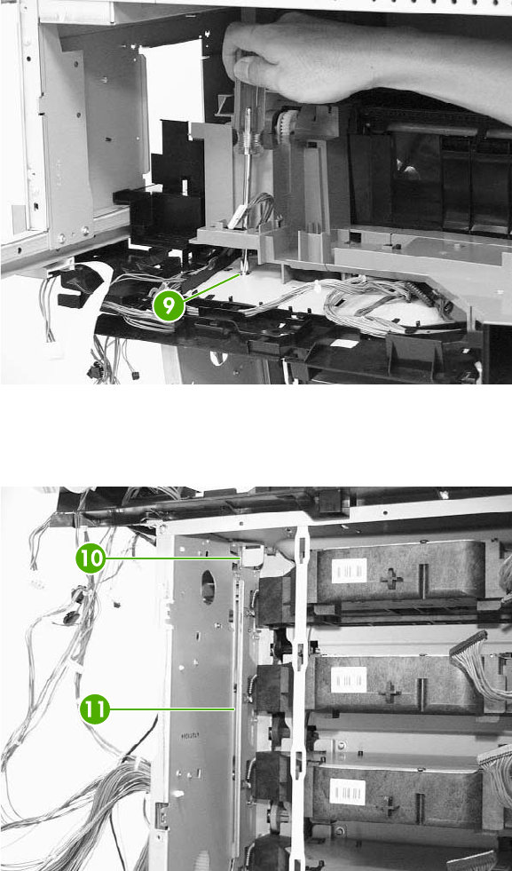
12. Remove one screw (callout 9).
Figure 6-167 Remove the laser/scanner components (5 of 12)
13. Push the knob (callout 10) in and to the right. Then remove the scanner holder assembly
(callout 11) by pushing it from the side.
Figure 6-168 Remove the laser/scanner components (6 of 12)
ENWW Main assembly (internal assemblies) 347
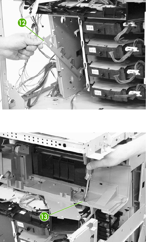
14. Pull out the laser/scanner retaining arm (callout 12).
Figure 6-169 Remove the laser/scanner components (7 of 12)
15. Remove the recessed screw (callout 13).
Figure 6-170 Remove the laser/scanner components (8 of 12)
348 Chapter 6 Removal and replacement ENWW
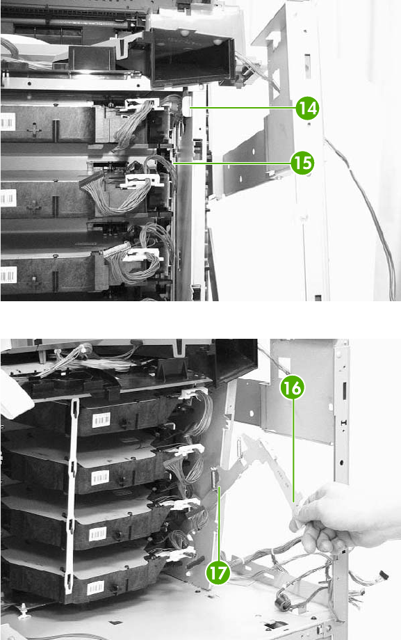
16. Push the knob (callout 14) in and to the left and remove the rear scanner holder assembly
(callout 15) by sliding if toward the front (callouts 16 and 17).
Figure 6-171 Remove the laser/scanner components (9 of 12)
Figure 6-172 Remove the laser/scanner components (10 of 12)
ENWW Main assembly (internal assemblies) 349
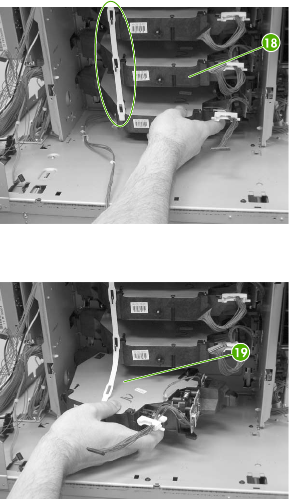
17. Unhook the laser/scanner assemblies from the white retaining strip (callout 18).
Figure 6-173 Remove the laser/scanner components (11 of 12)
18. Remove the laser/scanner assemblies (callout 19) by lifting and sliding them to the left and
rotating them outward.
Figure 6-174 Remove laser/scanner components (12 of 12)
350 Chapter 6 Removal and replacement ENWW
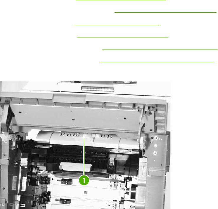
Duplexing assembly
1. Remove the rear cover. See Rear cover assembly on page 294.
2. Remove the face-down tray assembly. See Face-down tray assembly on page 293.
3. Remove the left cover. See Left cover assembly on page 296.
4. Remove the front cover. See Front cover assembly on page 297.
5. Remove the delivery upper cover. See Delivery upper cover assembly on page 306.
6. Remove the left rear inner cover. See Left rear inner cover assembly on page 307.
7. Open the duplexing door (callout 1).
Figure 6-175 Remove the duplexing assembly (1 of 5)
ENWW Main assembly (internal assemblies) 351
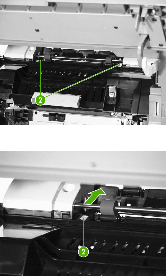
8. Slide the right and left duplexing locks (callout 2) backward.
Figure 6-176 Remove the duplexing assembly (2 of 5)
9. Detail of left duplexing lock.
Figure 6-177 Remove the duplexing assembly (3 of 5)
352 Chapter 6 Removal and replacement ENWW
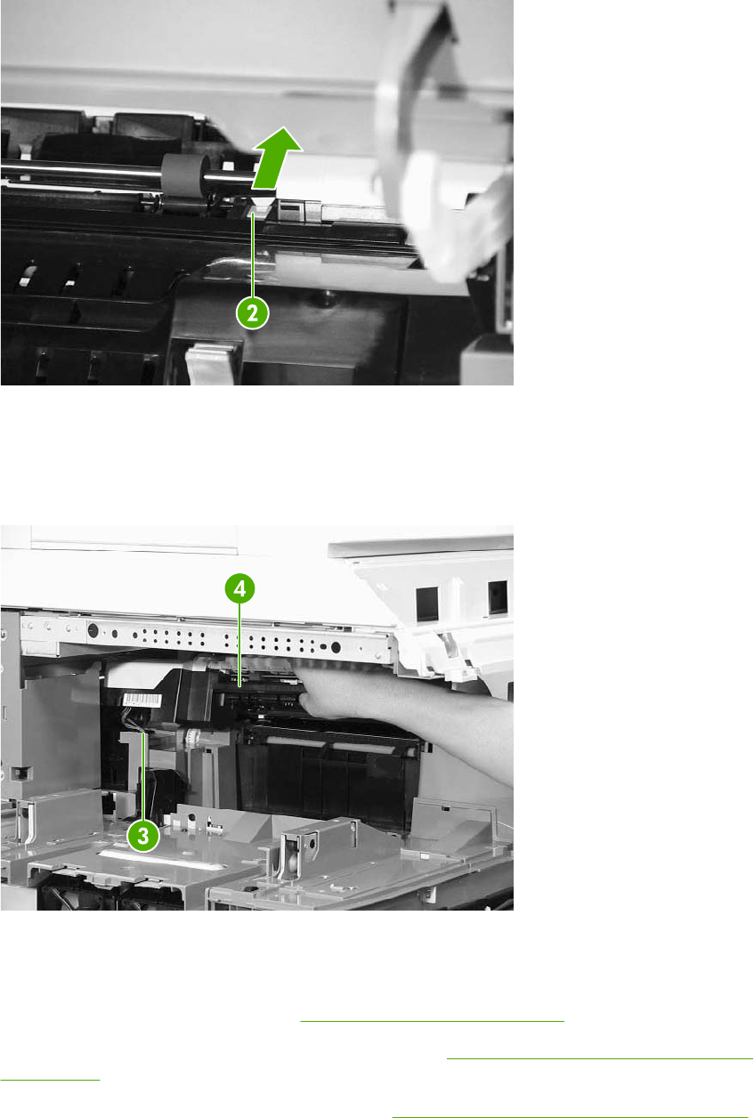
10. Detail of right duplexing lock.
Figure 6-178 Remove the duplexing assembly (4 of 5)
11. From the left side of the MFP, lift up the duplexer. Disconnect the connector (callout 3) while
supporting the duplexing assembly (callout 4).
12. Remove the duplexing assembly (callout 4).
Figure 6-179 Remove the duplexing assembly (5 of 5)
Delivery assembly
1. Remove the rail guide assembly. See Rail guide assembly on page 335.
2. Remove the right front inner upper cover assembly. See Right front inner upper cover assembly
on page 308.
3. Remove the right rear inner cover assembly. See Right rear inner cover assembly on page 310.
ENWW Main assembly (internal assemblies) 353
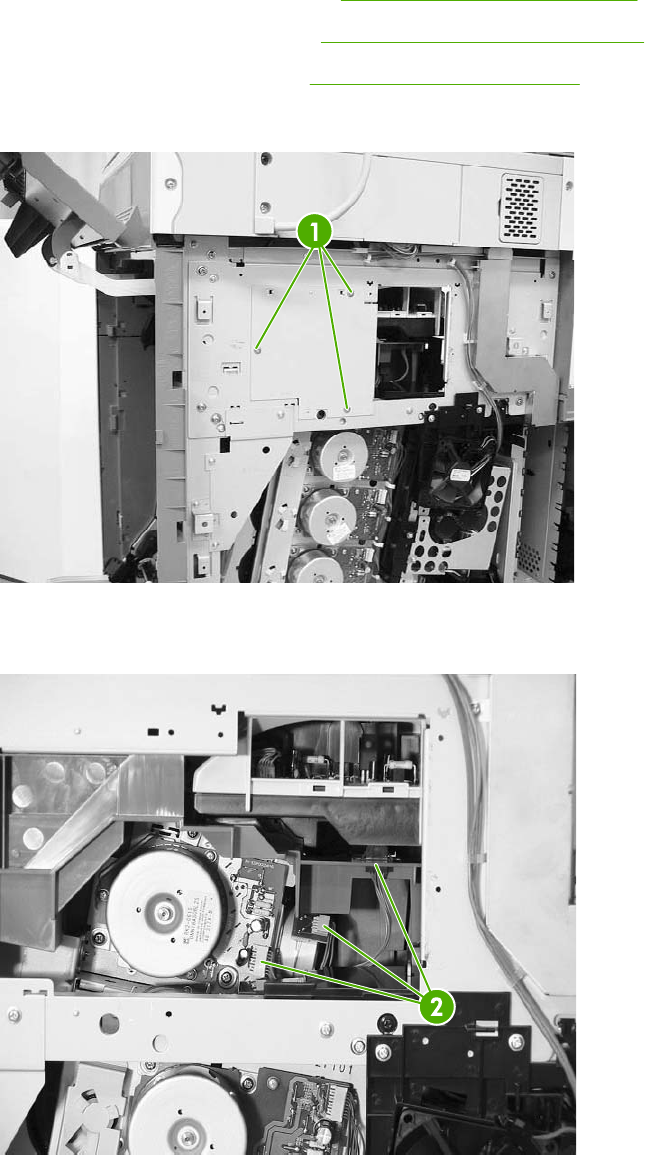
4. Remove the duplexing assembly. See Duplexing assembly on page 351.
5. Remove the sub power supply. See Sub power supply PCB on page 401.
6. Remove the rear exhaust fan. See Rear exhaust fan on page 379.
7. Remove the three screws (callout 1) and remove the metal side access cover plate.
Figure 6-180 Remove the delivery assembly (1 of 15)
8. Remove the three connectors (callout 2).
Figure 6-181 Remove the delivery assembly (2 of 15)
354 Chapter 6 Removal and replacement ENWW
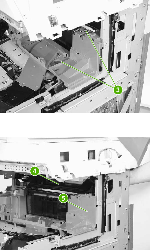
9. Remove the two screws (callout 3) at the front of the MFP.
Figure 6-182 Remove the delivery assembly (3 of 15)
10. Remove the fuser door assembly (callout 4) and the front upper inner cover (callout 5).
Figure 6-183 Remove the delivery assembly (4 of 15)
ENWW Main assembly (internal assemblies) 355
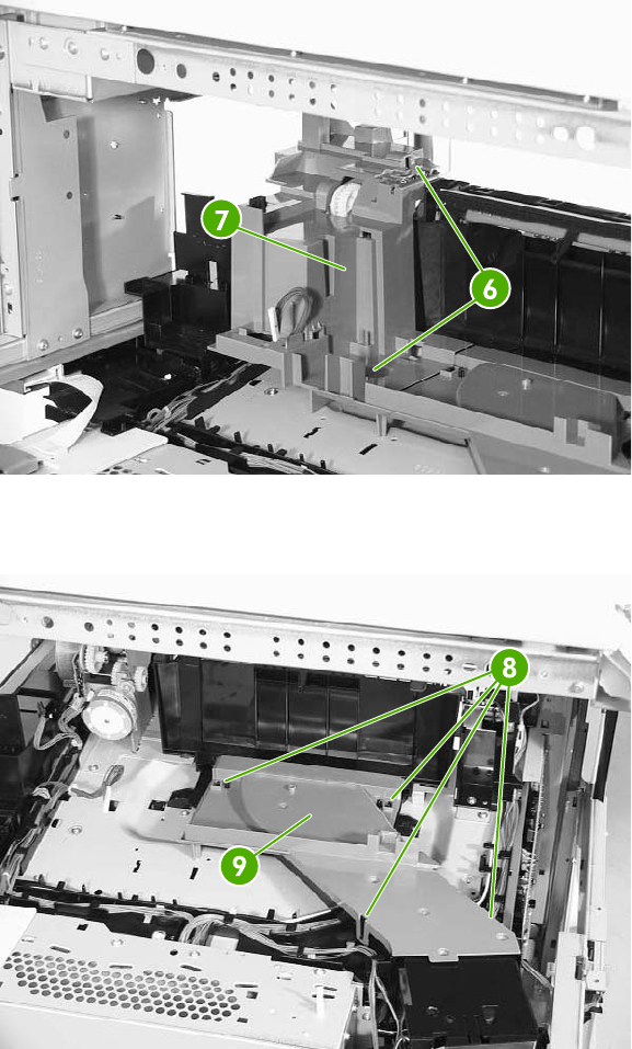
11. Remove the two screws (callout 6), and then remove the front upper inner cover (callout 7).
Figure 6-184 Remove the delivery assembly (5 of 15)
12. Unhook the four claws (callout 8) and then remove the fan duct (callout 9).
Figure 6-185 Remove the delivery assembly (6 of 15)
356 Chapter 6 Removal and replacement ENWW
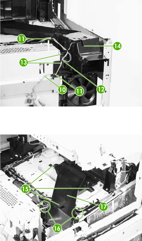
13. Remove the cable (callout 10) from the cable guides (callout 11) and disconnect the connector
(callout 12). Then remove the two screws (callout 13) and the delivery fan assembly (callout 14).
Figure 6-186 Remove the delivery assembly (7 of 15)
14. Remove the three screws (callout 15), remove the cable from the cable guides (callout 16), and
then remove the fan duct (callout 17).
Figure 6-187 Remove the delivery assembly (8 of 15)
ENWW Main assembly (internal assemblies) 357
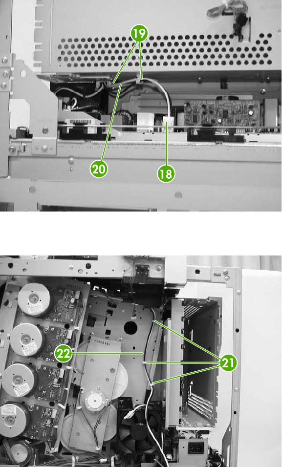
15. Disconnect the connector (callout 18). Remove the cable (callout 19) from the cable guide
(callout 20).
Figure 6-188 Remove the delivery assembly (9 of 15)
16. Remove the cable (callout 21) from the cable guide (callout 22).
Figure 6-189 Remove the delivery assembly (10 of 15)
358 Chapter 6 Removal and replacement ENWW
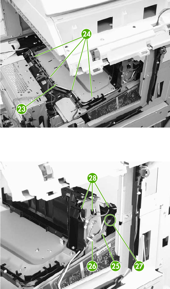
17. Remove the cable (callout 23) from the cable guides (callout 24).
Figure 6-190 Remove the delivery assembly (11 of 15)
18. Remove the cable (callout 25) from the cable guide (callout 26). Disconnect the connectors
(callouts 27 and 28). Note that callout 27 includes two connectors.
Figure 6-191 Remove the delivery assembly (12 of 15)
ENWW Main assembly (internal assemblies) 359
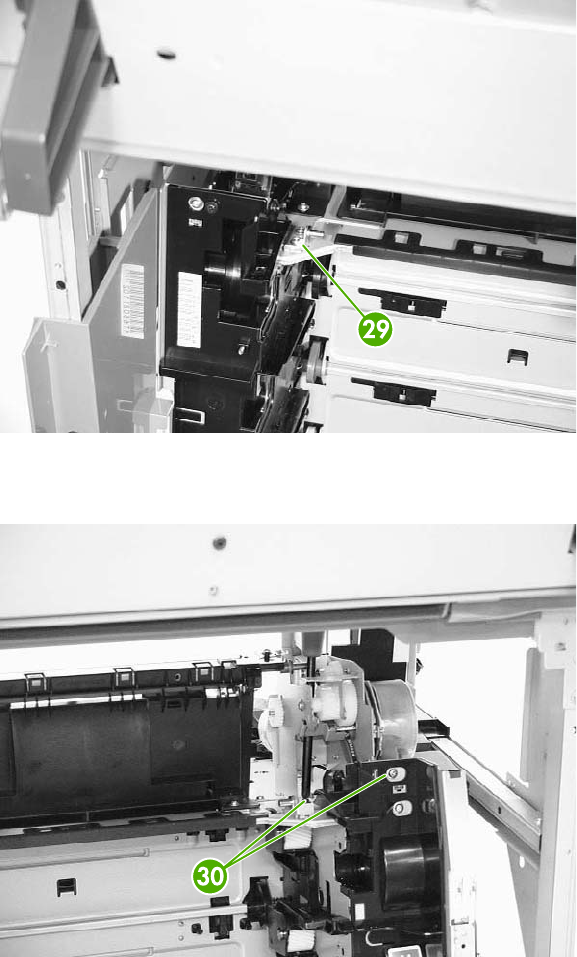
19. Remove one screw (callout 29).
Figure 6-192 Remove the delivery assembly (13 of 15)
20. Remove the two screws (callout 30).
Figure 6-193 Remove the delivery assembly (14 of 15)
360 Chapter 6 Removal and replacement ENWW
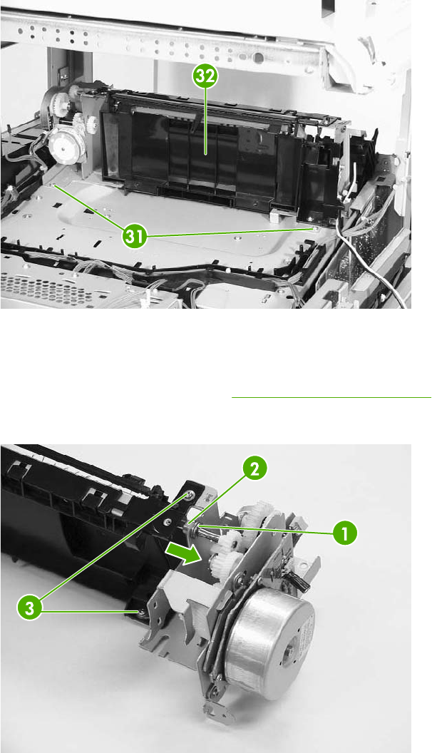
21. Remove the two screws (callout 31), and then remove the delivery assembly (callout 32).
Figure 6-194 Remove the delivery assembly (15 of 15)
Fuser drive assembly
1. Remove the delivery assembly. See Delivery assembly on page 353.
2. Remove the E-ring (callout 1).
Figure 6-195 Remove the fuser drive assembly
3. Slide the bushing (callout 2) in the direction of the arrow.
4. Remove the two screws (callout 3), and then remove the fuser drive assembly.
ENWW Main assembly (internal assemblies) 361

Motors and fans
The procedures in this section describe the removal and replacement of the following components:
●Drum motors
●Fuser motor
●Fuser pressure release motor
●Developing disengaging motor
●Pickup motor assembly
●Power supply fan
●Cartridge fan
●Sub power supply fan
●Delivery fan
●Control fan 1
●Control fan 2
●Rear exhaust fan
●ETB fan
Drum motors
1. Remove the rear cover assembly. See Rear cover assembly on page 294.
2. Disconnect the connector (callout 1). Remove the four screws (callout 2), and then remove the
drum motor (callout 3).
Figure 6-196 Remove drum motor
362 Chapter 6 Removal and replacement ENWW
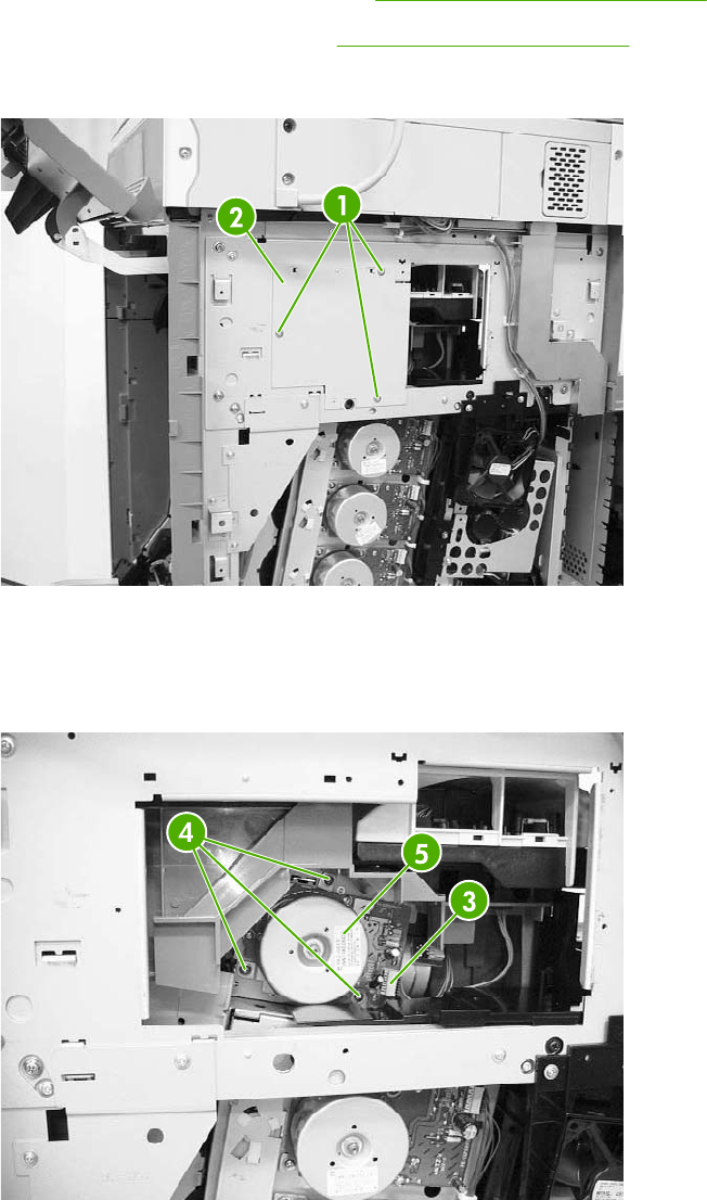
Fuser motor
1. Remove the rear cover assembly. See Rear cover assembly on page 294.
2. Remove the rear exhaust fan. See Rear exhaust fan on page 379.
3. Remove the three screws (callout 1) and the plate (callout 2).
Figure 6-197 Remove the fuser motor (1 of 2)
4. Disconnect the connector (callout 3).
5. Remove the three screws (callout 4) and then remove the fuser motor (callout 5).
Figure 6-198 Remove the fuser motor (2 of 2)
ENWW Motors and fans 363
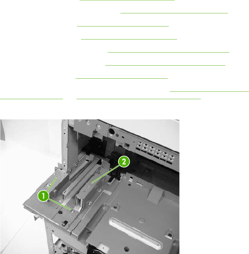
Fuser pressure release motor
1. Remove the rear cover. See Rear cover assembly on page 294.
2. Remove the face-down tray assembly. See Face-down tray assembly on page 293.
3. Remove the left cover. See Left cover assembly on page 296.
4. Remove the front cover. See Front cover assembly on page 297.
5. Remove the delivery upper cover. See Delivery upper cover assembly on page 306.
6. Remove the left rear inner cover. See Left rear inner cover assembly on page 307.
7. Remove the duplexer. See Duplexing assembly on page 351.
8. Remove the right front and right rear inner upper covers. See Right front inner upper cover
assembly on page 308 and Right rear inner cover assembly on page 310.
9. Remove the two screws (callout 1), and then remove the rear guide cover (callout 2).
Figure 6-199 Remove the fuser pressure release motor (1 of 8)
364 Chapter 6 Removal and replacement ENWW
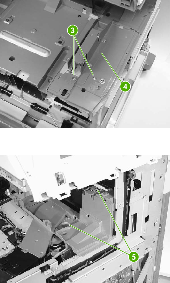
10. Remove two screws (callout 3) and then remove the front guide cover (callout 4).
Figure 6-200 Remove the fuser pressure release motor (2 of 8)
11. Remove two screws (callout 5) at the front of the MFP and remove the cover.
Figure 6-201 Remove the fuser pressure release motor (3 of 8)
ENWW Motors and fans 365
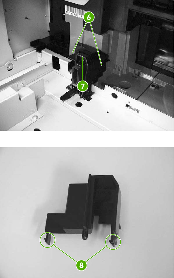
12. Unhook the two claws (callout 6), and then remove the connector cover (callout 7).
Figure 6-202 Remove the fuser pressure release motor (4 of 8)
Figure 6-203 Remove the fuser pressure release motor, connector cover claw detail (5 of 8)
366 Chapter 6 Removal and replacement ENWW
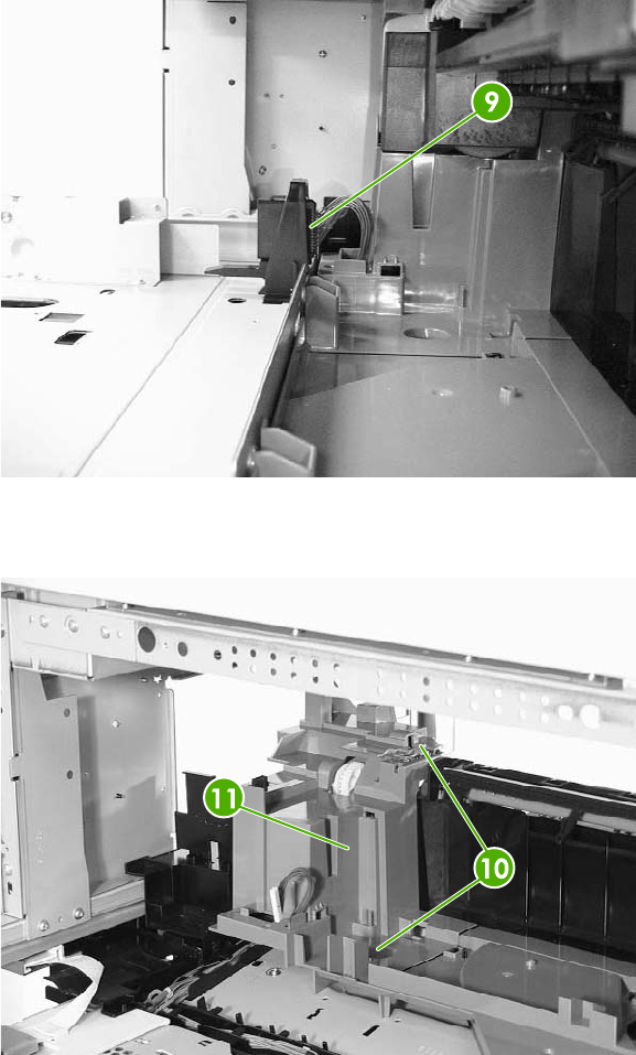
13. Disconnect the connector (callout 9).
Figure 6-204 Remove the fuser pressure release motor (6 of 8)
14. Remove two screws (callout 10) and lift off the plastic fuser drive assembly cover (callout 11).
Figure 6-205 Remove the fuser pressure release motor (7 of 8)
ENWW Motors and fans 367
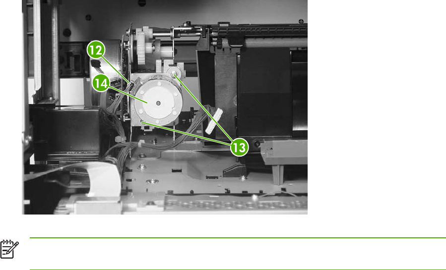
15. Disconnect one connector (callout 12), remove the two screws (callout 13), and then remove the
fuser pressure release motor (callout 14).
Figure 6-206 Remove the fuser pressure release motor (8 of 8)
NOTE After reinstalling the fuser pressure release motor, rotate the pressure release gears
to ensure that they engage with the worm gear on the motor.
368 Chapter 6 Removal and replacement ENWW
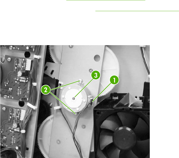
Developing disengaging motor
1. Remove the rear cover. See Rear cover assembly on page 294.
2. Remove the sub power supply PCB. See Sub power supply PCB on page 401.
3. Disconnect the connector (callout 1).
4. Remove the two screws (callout 2), and then remove the developing disengaging motor (callout
3).
Figure 6-207 Remove the developing disengaging motor
ENWW Motors and fans 369
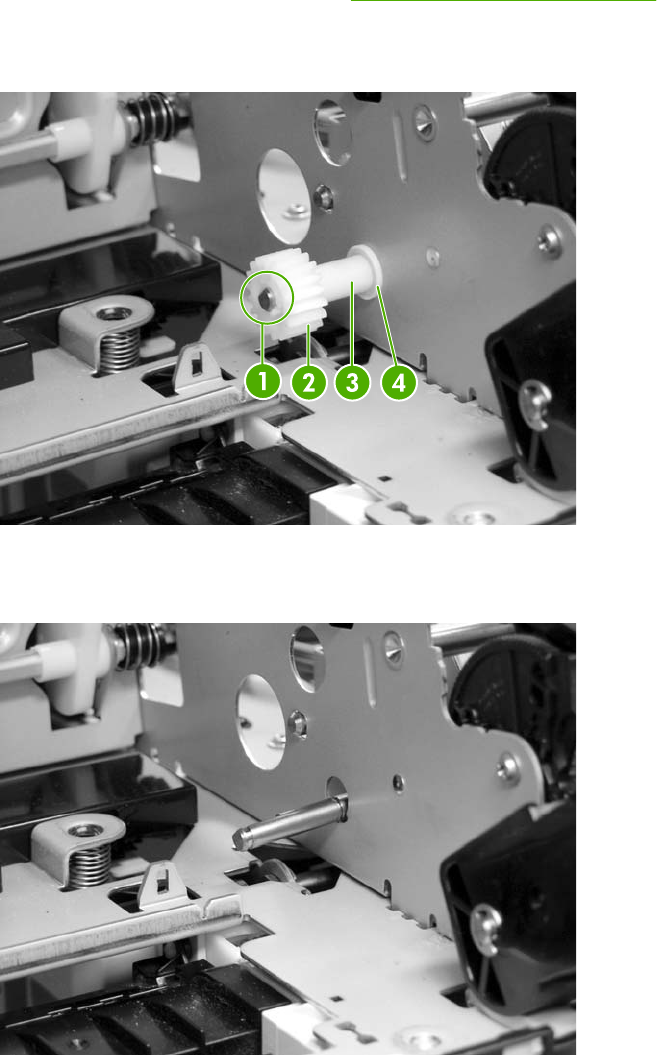
Pickup motor assembly
1. Remove the paper feed assembly. See Paper feed assembly on page 316.
2. Using a small flat-blade screwdriver, pinch the tab (callout 1) and slide the gear (callout 2),
cylinder (callout 3), and bushing (callout 4) off the shaft.
Figure 6-208 Remove the pickup motor assembly (1 of 3)
Gear removed.
Figure 6-209 Remove the pickup motor assembly (2 of 3)
370 Chapter 6 Removal and replacement ENWW
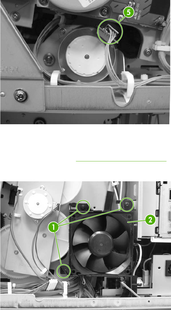
3. Disconnect the connector (callout 5), remove the two screws, and then remove the pickup motor
by angling it around the main drive assembly.
Figure 6-210 Remove the pickup motor assembly (3 of 3)
Power supply fan
1. Remove the rear cover. See Rear cover assembly on page 294.
2. Remove the three screws (callout 1) and remove the power supply fan (callout 2).
Figure 6-211 Remove the power supply fan (1 of 2)
ENWW Motors and fans 371
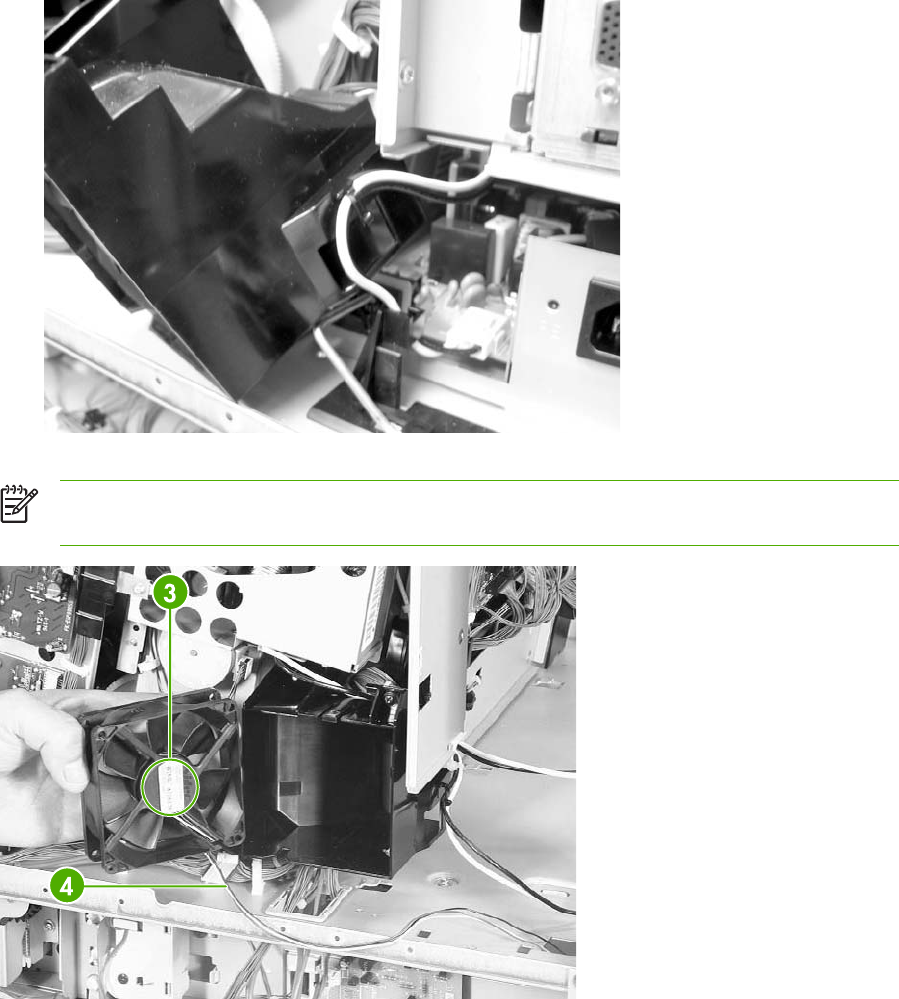
3. Disconnect the connector. (Currently this disconnects at the DC controller. Changes will be
implemented prior to product introduction.)
Figure 6-212 Remove the power supply fan (2 of 2)
NOTE When installing the power supply fan, install the fan so that the label (callout 3) faces
into the MFP. Install the cable (callout 4) as shown in the figure.
Figure 6-213 Reinstall the power supply fan
372 Chapter 6 Removal and replacement ENWW
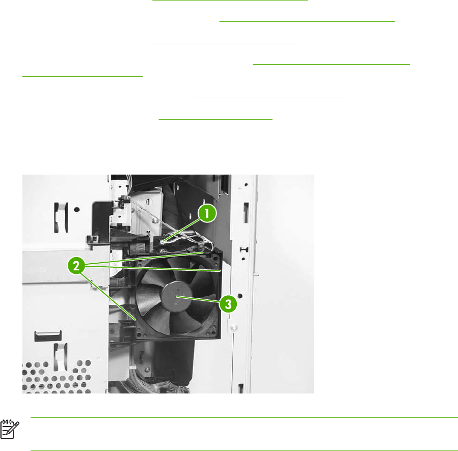
Cartridge fan
1. Remove the rear cover. See Rear cover assembly on page 294.
2. Remove the face-down tray assembly. See Face-down tray assembly on page 293.
3. Remove the left cover. See Left cover assembly on page 296.
4. Remove the front cover and the control panel. See Front cover assembly on page 297 and
Control panel on page 250.
5. Remove the rail guide assembly. See Rail guide assembly on page 335.
6. Remove the delivery fan. See Delivery fan on page 376.
7. Disconnect the connector (callout 1).
8. Unhook the three claws (callout 2) and remove the cartridge fan (callout 3).
Figure 6-214 Remove the cartridge fan
NOTE When installing the cartridge fan, install the fan so that the label (callout 4) faces into
the MFP. Install the cable (callout 5) as shown in the figure.
ENWW Motors and fans 373
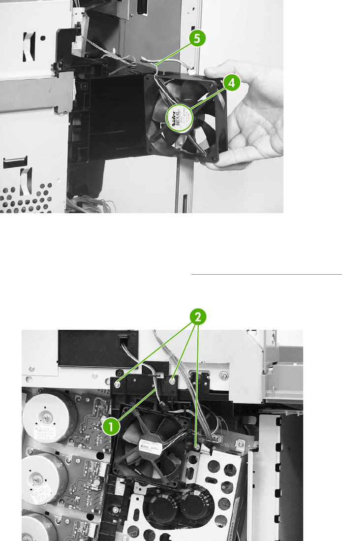
Figure 6-215 Installation guidelines
Sub power supply fan
1. Remove the rear cover assembly. See Rear cover assembly on page 294.
2. Unhook the cable from the cable guide (callout 1) and remove the three screws (callout 2).
Figure 6-216 Remove the sub power supply fan (1 of 3)
374 Chapter 6 Removal and replacement ENWW
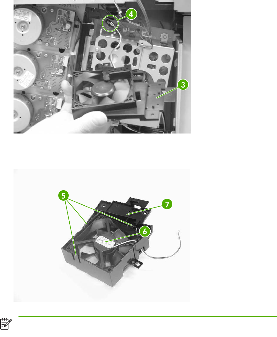
3. Remove the fan holder (callout 3) and the sub power supply fan together. Disconnect the
connector (callout 4).
Figure 6-217 Remove the sub power supply fan (2 of 3)
4. Unhook the three claws (callout 5), and then remove the sub power supply fan (callout 6) from
the fan holder (callout 7).
Figure 6-218 Remove the sub power supply fan (3 of 3)
NOTE When installing the sub power supply fan, install the fan so that the label (callout 8)
faces into the MFP. Install the cable (callout 9) as shown in the figure.
ENWW Motors and fans 375
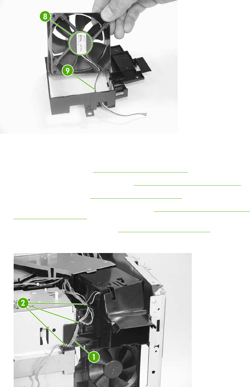
Figure 6-219 Installation guidelines
Delivery fan
1. Remove the rear cover. See Rear cover assembly on page 294.
2. Remove the face-down tray assembly. See Face-down tray assembly on page 293.
3. Remove the left cover. See Left cover assembly on page 296.
4. Remove the front cover and the control panel. See Front cover assembly on page 297 and
Control panel on page 250.
5. Remove the rail guide assembly. See Rail guide assembly on page 335.
6. Remove the cable (callout 1) from the cable guides (callout 2).
Figure 6-220 Remove the delivery fan (1 of 2)
376 Chapter 6 Removal and replacement ENWW
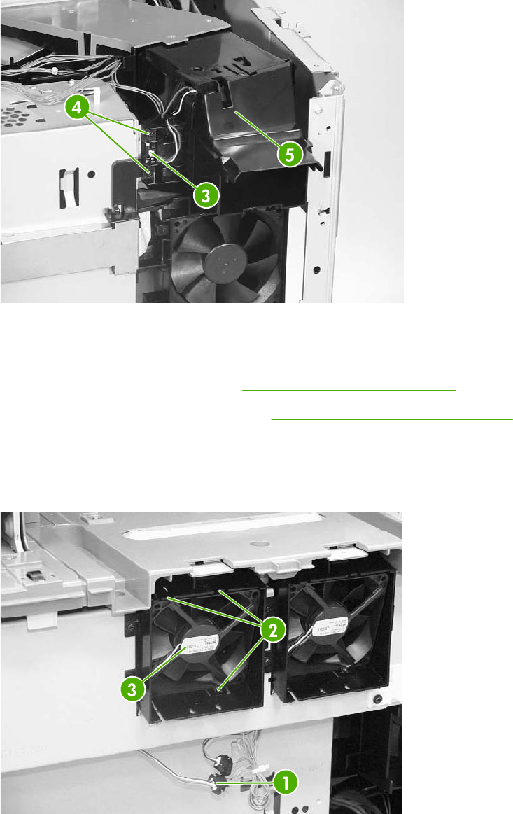
7. Disconnect the connector (callout 3) and remove the two screws (callout 4). Then remove the
delivery fan assembly (callout 5).
Figure 6-221 Remove the delivery fan (2 of 2)
Control fan 1
1. Remove the rear cover assembly. See Rear cover assembly on page 294.
2. Remove the face-down tray assembly. See Face-down tray assembly on page 293.
3. Remove the left cover assembly. See Left cover assembly on page 296.
4. Disconnect the connector (callout 1). Unhook the three claws (callout 2) and remove control fan
#1 (callout 3).
Figure 6-222 Remove control fan #1
ENWW Motors and fans 377
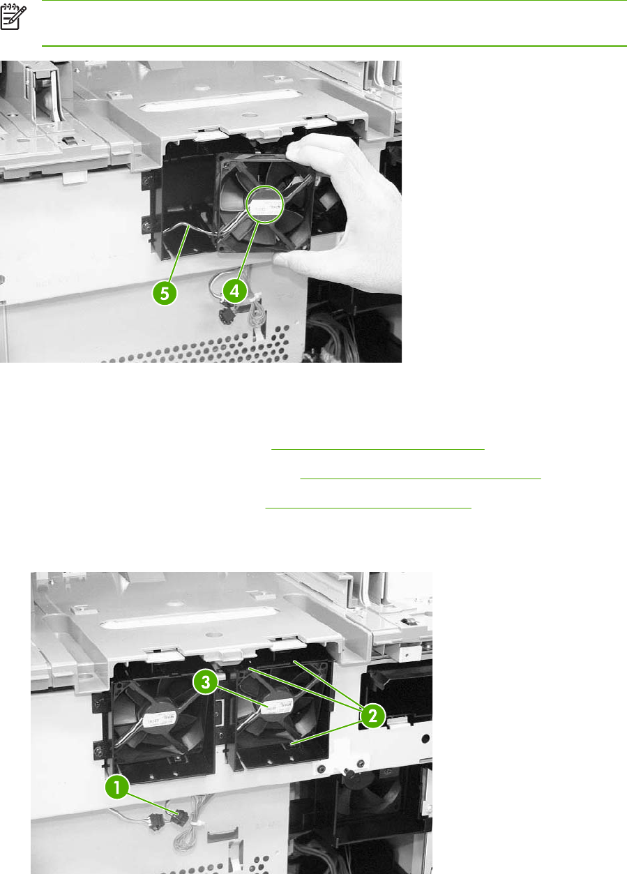
NOTE When installing the control fan, install the fan so that the label (callout 4) faces
outward. Install the cable (callout 5) as shown in the figure.
Figure 6-223 Installation guidelines
Control fan 2
1. Remove the rear cover assembly. See Rear cover assembly on page 294.
2. Remove the face-down tray assembly. See Face-down tray assembly on page 293.
3. Remove the left cover assembly. See Left cover assembly on page 296.
4. Disconnect the connector (callout 1). Unhook the three claws (callout 2) and remove control fan
#2 (callout 3).
Figure 6-224 Remove control fan #2
378 Chapter 6 Removal and replacement ENWW
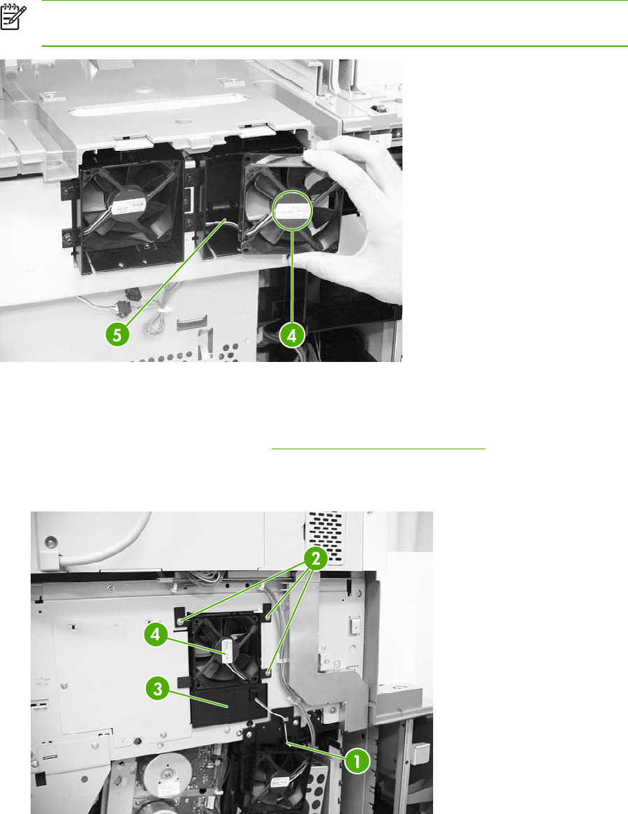
NOTE When installing the control fan, install the fan so that the label (callout 4) faces
outward. Install the cable (callout 5) as shown in the figure.
Figure 6-225 Installation guidelines
Rear exhaust fan
1. Remove the rear cover assembly. See Rear cover assembly on page 294.
2. Disconnect the connector (callout 1). Remove the three screws (callout 2), and then remove the
fan holder (callout 3) and the fuser fan (callout 4) together.
Figure 6-226 Remove the rear exhaust fan (1 of 2)
ENWW Motors and fans 379
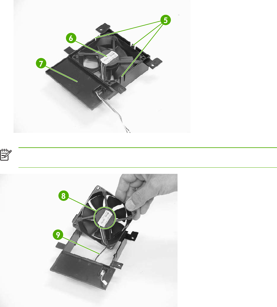
3. Unhook the three claws (callout 5) and remove the rear exhaust fan (callout 6) from the fan
holder (callout 7).
Figure 6-227 Remove the rear exhaust fan (2 of 2)
NOTE When installing the sub power supply fan, install the fan so that the label (callout 8)
faces outward. Install the cable (callout 9) as shown in the figure.
Figure 6-228 Installation guidelines
ETB fan
1. Open the right lower cover.
380 Chapter 6 Removal and replacement ENWW
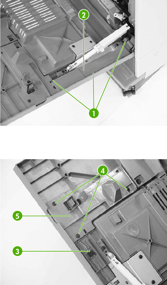
2. Unhook the three claws (callout 1) and remove the cable cover (callout 2).
Figure 6-229 Remove the ETB fan (1 of 4)
3. Disconnect the connector (callout 3) for the red, white, and black cable. Remove the three
screws (callout 4) and the cable cover (callout 5).
Figure 6-230 Remove the ETB fan (2 of 4)
ENWW Motors and fans 381
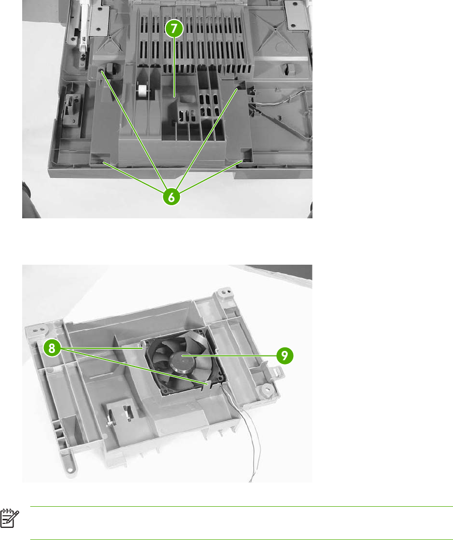
4. Remove the four screws (callout 6) and the duplexing feed guide assembly (callout 7).
Figure 6-231 Remove the ETB fan (3 of 4)
5. Unhook the two claws (callout 8) and remove the ETB fan (callout 9).
Figure 6-232 Remove the ETB fan (4 of 4)
NOTE When installing the ETB fan, install the fan so that the label (callout 10) faces into the
duplexing feed guide assembly. Install the cable (callout 11) as shown in the figure.
382 Chapter 6 Removal and replacement ENWW
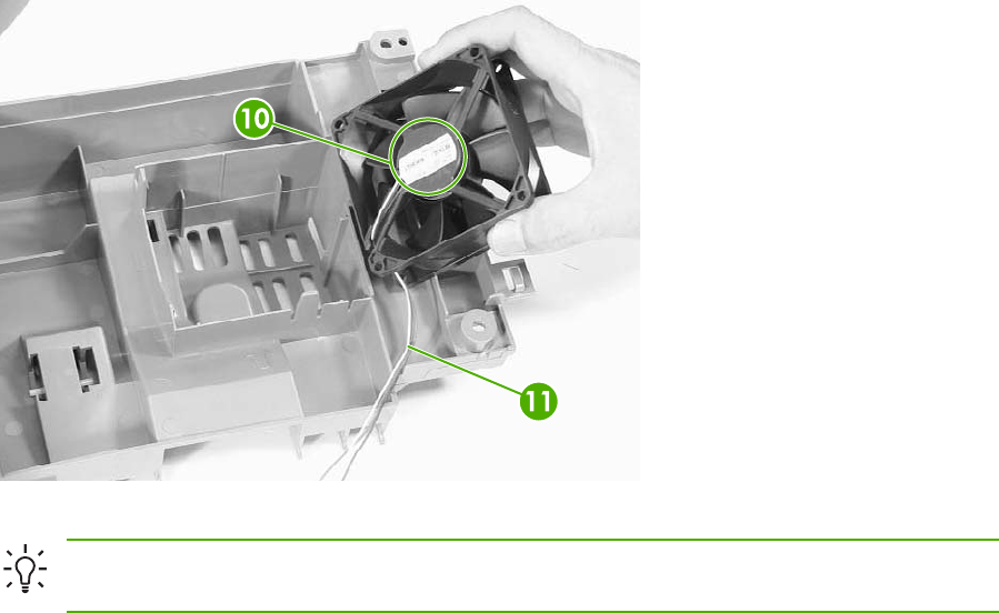
Figure 6-233 Installation guidelines
Hint When reinstalling the ETB fan, install the cable in the cable guides first to avoid
pinching the cables during later steps.
ENWW Motors and fans 383

PCBs
The procedures in this section describe the removal and replacement of the following components:
●DC controller PCB
●Toner level PCB
●High-voltage power supply PCB
●Low-voltage power supply PCB
●Memory controller PCB
●Sub power supply PCB
●Fan drive PCB
DC controller PCB
NOTE The DC controller has flashable firmware. To upgrade the controller, flashing might
be sufficient.
1. Remove the rear cover. See Rear cover assembly on page 294.
2. Remove the face-down tray assembly. See Face-down tray assembly on page 293.
3. Remove the left cover. See Left cover assembly on page 296.
4. Remove the front cover and the control panel. See Front cover assembly on page 297 and
Control panel on page 250.
5. Remove the delivery fan. See Delivery fan on page 376.
6. Remove the cartridge fan. See Cartridge fan on page 373.
7. Remove the formatter case. See Formatter case assembly on page 338.
384 Chapter 6 Removal and replacement ENWW
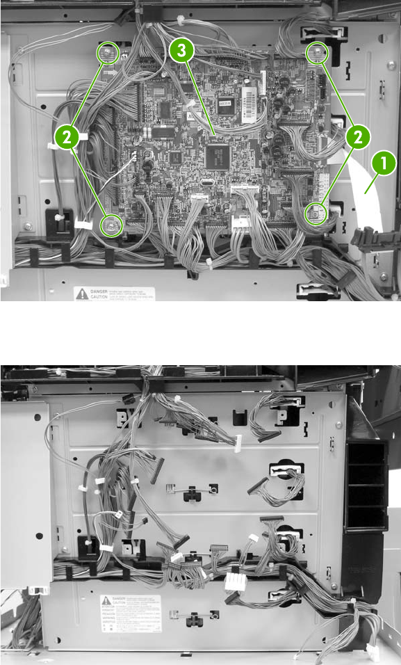
8. Disconnect all connectors and remove the flat connector from the DC controller (callout 1).
Remove four screws (callout 2), and then remove the DC controller PCB (callout 3).
Figure 6-234 Remove the DC controller (1 of 2)
9. DC controller removed.
Figure 6-235 Remove the DC controller (2 of 2)
The locations of the DC controller connections are shown on the following figure.
ENWW PCBs 385
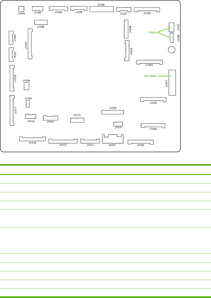
Figure 6-236 DC controller component connections
Connector Pins Component
J1002 17 Laser scanner Y
J1003 17 Laser scanner C
J1004 17 Scanner motor M
J1005 17 Scanner motor K
J1024 12 Fusing motor (M5)
Fuser pressure release motor (M6)
J1026 10 Fuser paper sensor (SR1)
Delivery tray full sensor (SR2)
Fuser pressure release sensor (SR3)
J1037 4 Not connected
J1038 5 Not connected
J1034 3 Power supply fan
J1006 16 High-voltage power supply
J1010 4 Environmental sensor
386 Chapter 6 Removal and replacement ENWW

Connector Pins Component
J1014 9 Toner level PCB
MP tray paper sensor
J1022 20 Drum home position sensor
J1016 6 Cassette paper sensor (SR9)
Paper stack surface sensor (SR10)
J1012 19 Color misregistration sensor
Transmission LED
Top of page sensor (SR12)
J1013 10 Media sensor
J1019 3 Developing disengaging sensor (SR11)
J1015 17 MP tray pickup motor solenoid (SL1)
Cassette pickup solenoid (SL2)
Lifter motor (M10)
Cassette paper size detection switch
Additional trays
J1018 18 M and K drum motors (M3 and M4)
J1017 20 Y and C motors (M1 and M2)
J1020 8 Pickup motor (M9)
Developing disengaging motor (M8)
J1021 9 Memory controller PCB
J1025 12 Paper loop sensors (SR13 and SR14)
Fuser unit
J1009 17 Low-voltage power supply PCB
J1001 45 Formatter
J1011 12 ETB unit
ETB motor (M7)
ETB separation solenoid (SL3)
J1027 9 Control panel
J1033 13 Cartridge fan
Delivery fan
Right exhaust fan
J1039 6 Fan driver PCB
Sub power supply assembly fan
ENWW PCBs 387

Connector Pins Component
Control fans 1 and 2
ETB fan
J1007 5 Door switch
J1028 14 IPTU
Jet Link (stapler/stacker and 3-bin mailbox)
Sub power supply PCB
ADF/scanner
388 Chapter 6 Removal and replacement ENWW
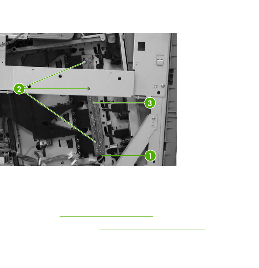
Toner level PCB
1. Remove the high-voltage power supply PCB. See High-voltage power supply PCB on page 389.
2. Disconnect the connector (callout 1).
3. Remove the three screws (callout 2), and then remove the toner level PCB (callout 3).
Figure 6-237 Remove the toner level PCB
High-voltage power supply PCB
1. Remove the following assemblies:
●Rear cover. See Rear cover assembly on page 294.
●Face-down tray assembly. See Face-down tray assembly on page 293.
●Left cover assembly. See Left cover assembly on page 296.
●Front cover assembly. See Front cover assembly on page 297.
●Control panel. See Control panel on page 250.
ENWW PCBs 389
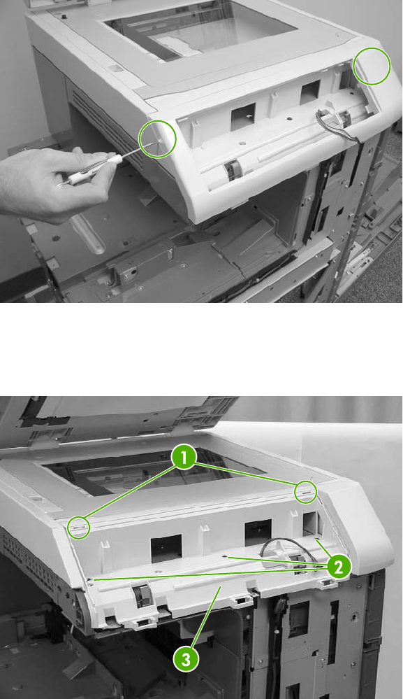
2. Remove the control panel cover by prying up both sides of the cover.
Figure 6-238 Remove the high-voltage power supply PCB (1 of 9)
3. Remove the inner cover by prying up at the tabs (callout 1) with a flat-blade screwdriver.
4. Remove the three screws (callout 2) and then remove the panel holder (callout 3).
Figure 6-239 Remove the high-voltage power supply PCB (2 of 9)
390 Chapter 6 Removal and replacement ENWW
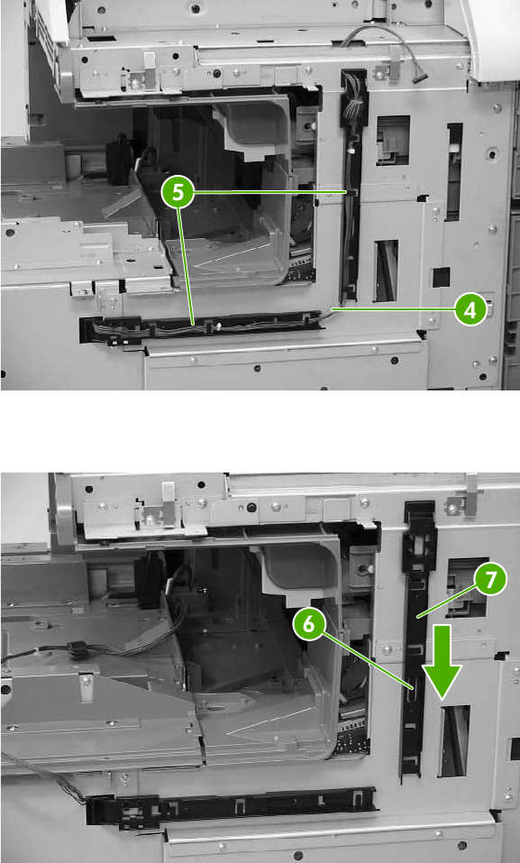
5. Remove the cable (callout 4) from the cable guides (callout 5).
Figure 6-240 Remove the high-voltage power supply PCB (3 of 9)
6. Unhook the claw (callout 6) and slide the cable guide down to remove it (callout 7).
Figure 6-241 Remove the high-voltage power supply PCB (4 of 9)
ENWW PCBs 391
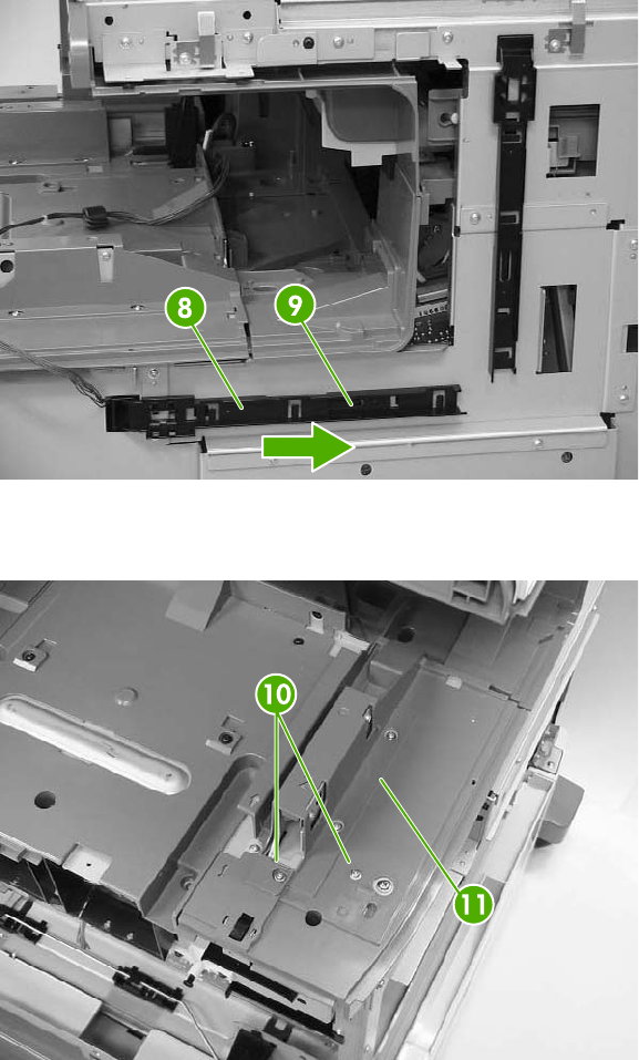
7. Unhook the claw (callout 8) and slide the cable guide to the right to remove it (callout 9).
Figure 6-242 Remove the high-voltage power supply PCB (5 of 9)
8. Remove the two screws (callout 10), and then remove the front guide cover (callout 11).
Figure 6-243 Remove the high-voltage power supply PCB (6 of 9)
392 Chapter 6 Removal and replacement ENWW
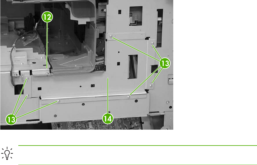
9. Remove one M4 screw (callout 12) and the seven M3 screws (callout 13). Then remove the
plate (callout 14).
Figure 6-244 Remove the high-voltage power supply PCB (7 of 9)
Hint When reinstalling the high-voltage power supply PCB, be sure to replace the M4
screw.
ENWW PCBs 393
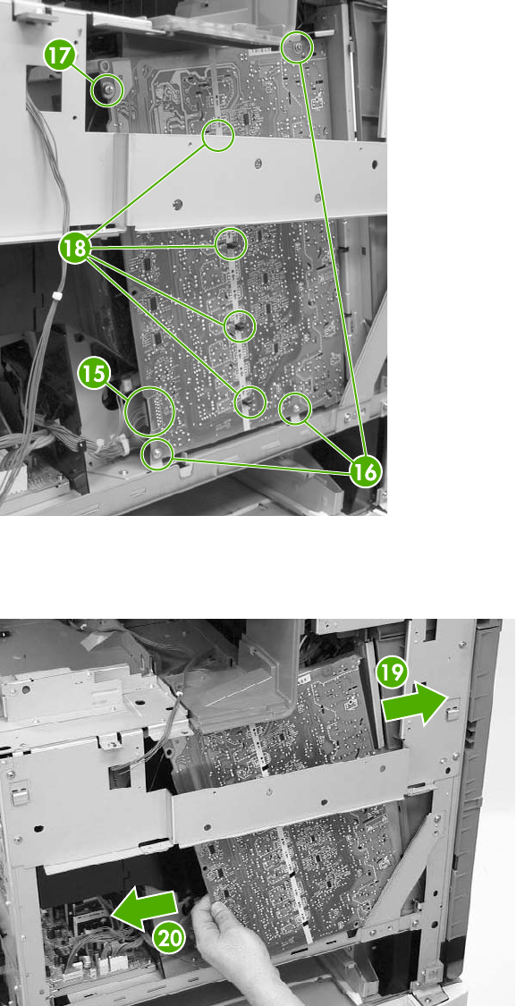
10. Disconnect the connector (callout 15). Remove the three M3 screws (callout 16) and the single
M4 screw (callout 17). Then unhook the four claws (callout 18). Pinch the four clips to release
the high-voltage power supply.
Figure 6-245 Remove the high-voltage power supply PCB (8 of 9)
11. Shift the high-voltage power supply PCB (callout 19) to the right, and then shift it to the left
(callout 20) to remove it.
Figure 6-246 Remove the high-voltage power supply PCB (9 of 9)
394 Chapter 6 Removal and replacement ENWW
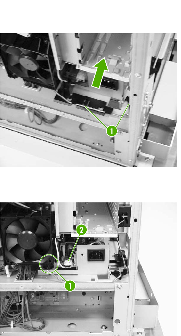
Low-voltage power supply PCB
1. Remove the rear cover. See Rear cover assembly on page 294.
2. Remove the left cover. See Left cover assembly on page 296.
3. Remove the power supply fan. See Power supply fan on page 371.
Figure 6-247 Remove the low-voltage power supply PCB (1 of 9)
4. Lift the rod arm (callout 1) to detach it from the power switch, and unhook the cable from the
cable guide. Disconnect the connector (callout 2).
Figure 6-248 Remove the low-voltage power supply PCB (2 of 9)
ENWW PCBs 395
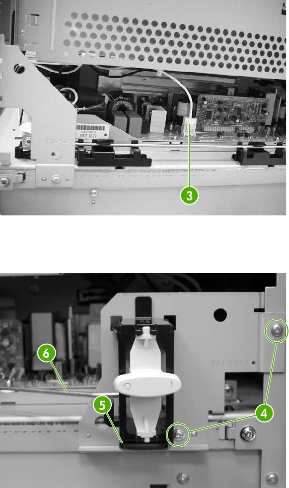
5. Disconnect the connector (callout 3) at the left of the MFP.
Figure 6-249 Remove the low-voltage power supply PCB (3 of 9)
6. Remove the two screws (callout 4). Then remove the power switch assembly (callout 5) and the
rod arm (callout 6) together.
Figure 6-250 Remove the low-voltage power supply PCB (4 of 9)
396 Chapter 6 Removal and replacement ENWW
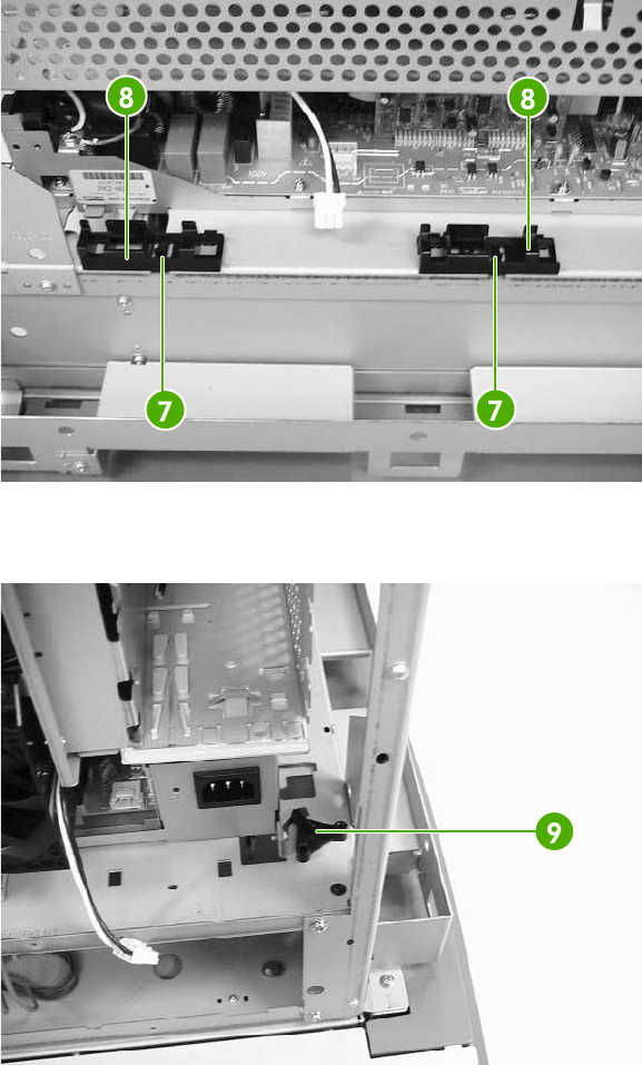
7. Unhook the claws (callout 7), and remove the rod guides (callout 8).
Figure 6-251 Remove the low-voltage power supply PCB (5 of 9)
8. Remove the link (callout 9) by turning it clockwise and lifting it up and out.
Figure 6-252 Remove the low-voltage power supply PCB (6 of 9)
ENWW PCBs 397
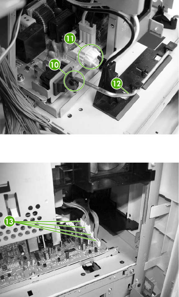
9. Remove the rear link arm (callout 10), unhook the cable (callout 11), and remove the rod guide
(callout 12).
Figure 6-253 Remove the low-voltage power supply PCB (7 of 9)
10. Disconnect the four connectors (callout 13).
Figure 6-254 Remove the low-voltage power supply PCB (8 of 9)
398 Chapter 6 Removal and replacement ENWW
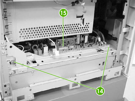
11. Remove the two screws (callout 14), and then remove the low-voltage power supply PCB
(callout 15) through the left side of the MFP.
Figure 6-255 Remove the low-voltage power supply PCB (9 of 9)
ENWW PCBs 399
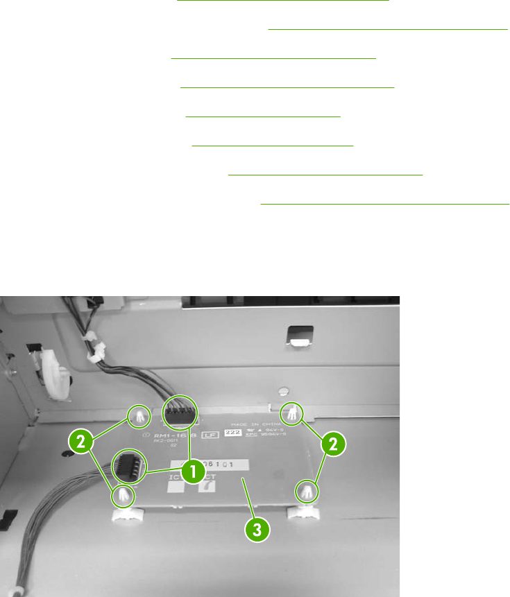
Memory controller PCB
1. Remove the rear cover. See Rear cover assembly on page 294.
2. Remove the face-down tray assembly. See Face-down tray assembly on page 293.
3. Remove the left cover. See Left cover assembly on page 296.
4. Remove the front cover. See Front cover assembly on page 297.
5. Remove the delivery fan. See Delivery fan on page 376.
6. Remove the cartridge fan. See Cartridge fan on page 373.
7. Remove the DC controller PCB. See DC controller PCB on page 384.
8. Remove the laser scanner assembly. See Laser/scanner components on page 343.
9. Disconnect the two connectors (callout 1).
10. Remove the four PCB holding pins (callout 2), and then remove the memory controller PCB
(callout 3).
Figure 6-256 Remove the memory controller PCB
400 Chapter 6 Removal and replacement ENWW
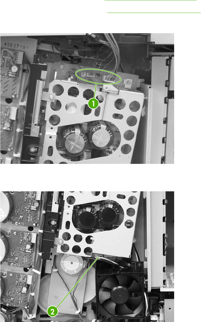
Sub power supply PCB
1. Remove the rear cover assembly. See Rear cover assembly on page 294.
2. Remove the sub power supply fan. See Sub power supply fan on page 374.
3. Disconnect the four connectors (callout 1).
Figure 6-257 Remove the sub power supply PCB (1 of 4)
4. Disconnect the connector (callout 2).
Figure 6-258 Remove the sub power supply PCB (2 of 4)
ENWW PCBs 401
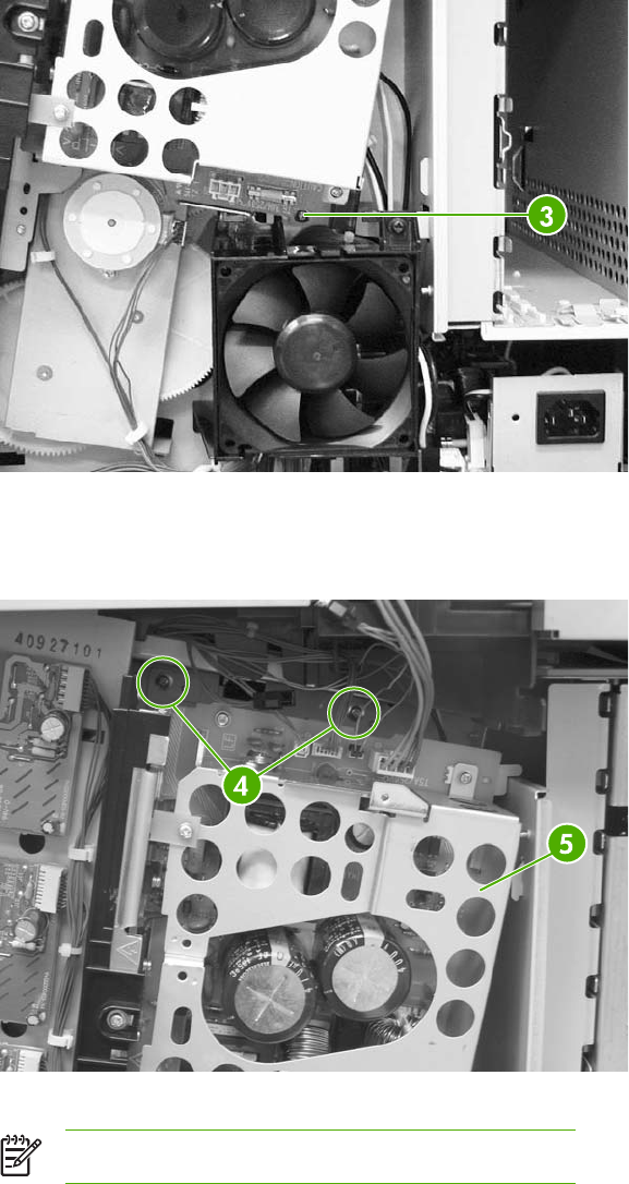
5. Remove the lower screw (callout 3). Note that this screw is recessed.
Figure 6-259 Remove the sub power supply PCB (3 of 4)
6. Remove the upper two screws (callout 4), and then remove the sub power supply PCB
assembly (callout 5).
Figure 6-260 Remove the sub power supply PCB (4 of 4)
NOTE Do not remove the screws on the PCB itself.
402 Chapter 6 Removal and replacement ENWW

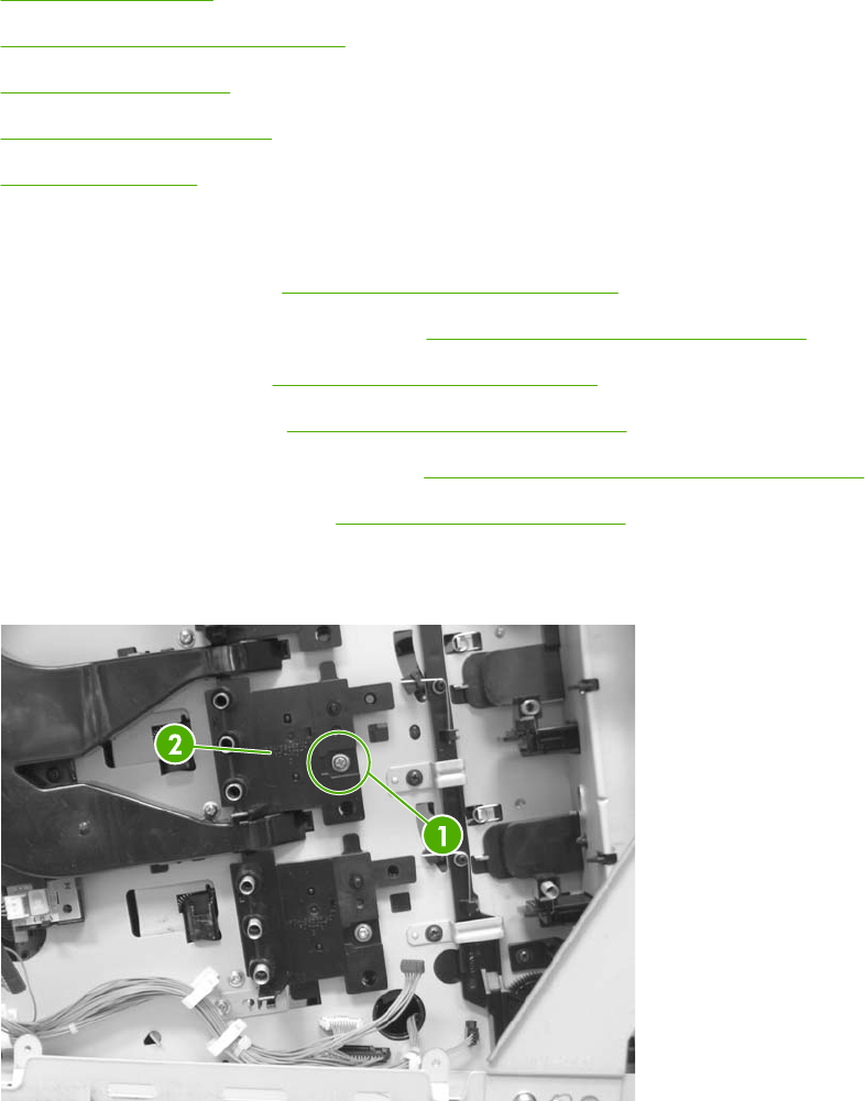
Switches, contacts, and sensors
The procedures in this section describe the removal and replacement of the following components:
●High-voltage contacts
●E-label memory contacts and cable
●Power switch assembly
●Door-open switch assembly
●Environment sensor
High-voltage contacts
1. Remove the rear cover. See Rear cover assembly on page 294.
2. Remove the face-down tray assembly. See Face-down tray assembly on page 270.
3. Remove the left cover. See Left cover assembly on page 296.
4. Remove the front cover. See Front cover assembly on page 297.
5. Remove the high-voltage supply PCB. See High-voltage power supply PCB on page 389.
6. Remove the toner level PCB. See Toner level PCB on page 389.
7. Remove one screw (callout 1) for the high-voltage contact to be removed. There are four sets of
high-voltage contacts, one for each color. Remove the contact (callout 2).
Figure 6-262 Remove the high-voltage contacts
404 Chapter 6 Removal and replacement ENWW
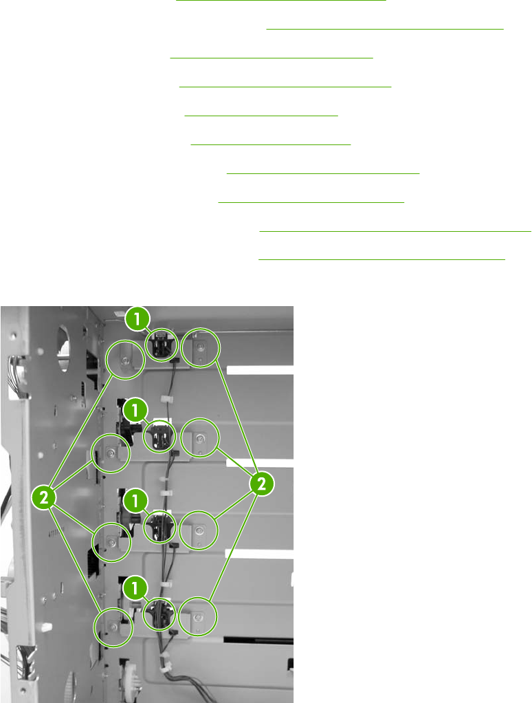
E-label memory contacts and cable
1. Remove the rear cover. See Rear cover assembly on page 294.
2. Remove the face-down tray assembly. See Face-down tray assembly on page 270.
3. Remove the left cover. See Left cover assembly on page 296.
4. Remove the front cover. See Front cover assembly on page 297.
5. Remove the delivery fan. See Delivery fan on page 376.
6. Remove the cartridge fan. See Cartridge fan on page 373.
7. Remove the DC controller PCB. See DC controller PCB on page 384.
8. Remove the power supply fan. See Power supply fan on page 371.
9. Remove the low-voltage supply PCB. See Low-voltage power supply PCB on page 395.
10. Remove the laser/scanner assembly. See Laser/scanner components on page 343.
11. Disconnect the connectors (callout 1) and remove the eight screws (callout 2).
Figure 6-263 Remove the E-label contacts (1 of 2)
ENWW Switches, contacts, and sensors 405
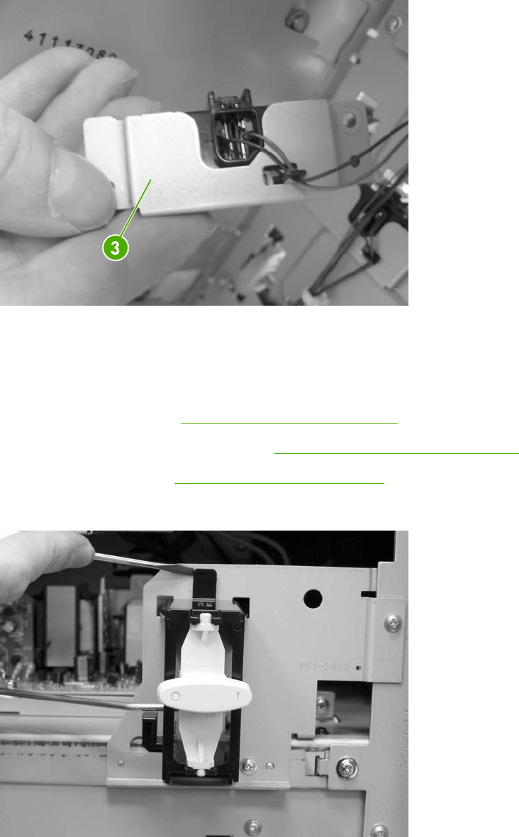
12. Lift the metal stay up and out (callout 3).
Figure 6-264 Remove the E-label contacts (2 of 2)
13. Remove the contact and cable from all four metal stays and cable guides.
Power switch assembly
1. Remove the rear cover. See Rear cover assembly on page 294.
2. Remove the face-down tray assembly. See Face-down tray assembly on page 270.
3. Remove the left cover. See Left cover assembly on page 296.
4. Using a flat-blade screwdriver, pry the switch assembly loose as shown.
Figure 6-265 Remove the power switch (1 of 3)
406 Chapter 6 Removal and replacement ENWW
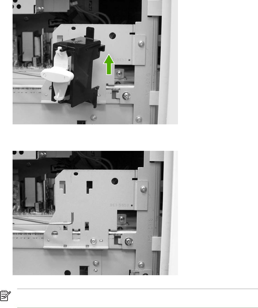
5. Lift the power switch assembly up and rotate it outward.
Figure 6-266 Remove the power switch (2 of 3)
6. Remove the rod from the switch assembly.
Figure 6-267 Remove the power switch (3 of 3)
NOTE During reassembly, be sure to route the metal rod through the guides and hook the
two tabs on the assembly back onto the MFP.
ENWW Switches, contacts, and sensors 407
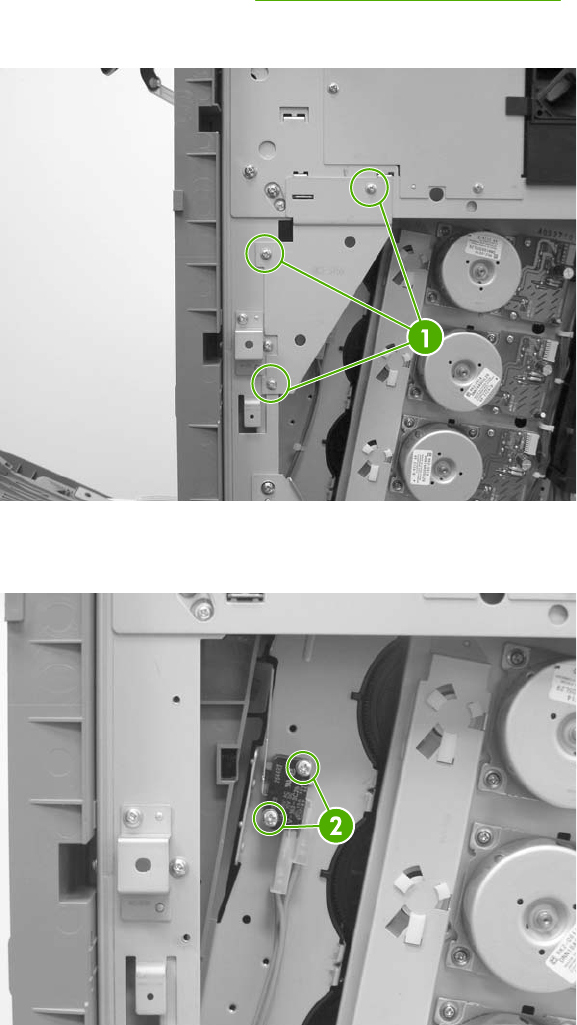
Door-open switch assembly
1. Remove the rear cover. See Rear cover assembly on page 294.
2. Remove three screws (callout 1) and remove the corner plate.
Figure 6-268 Remove the door-open switch assembly (1 of 3)
3. Remove two screws (callout 2) to release the door-open switch.
Figure 6-269 Remove the door-open switch assembly (2 of 3)
408 Chapter 6 Removal and replacement ENWW
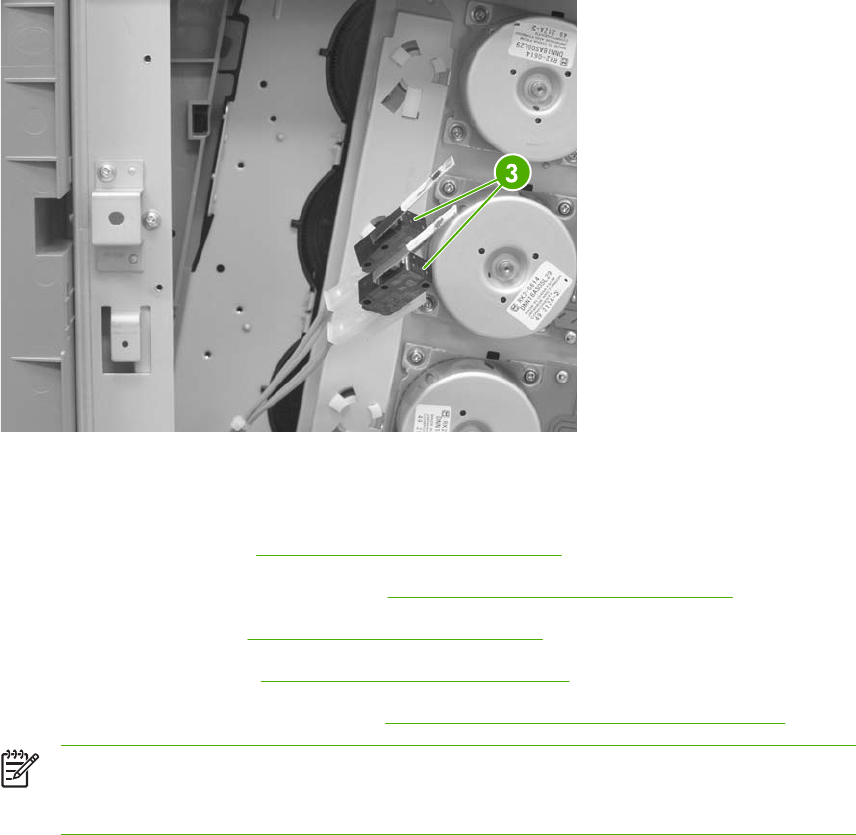
4. Disconnect four connectors callout 3).
Figure 6-270 Remove the door-open switch assembly (3 of 3)
Environment sensor
1. Remove the rear cover. See Rear cover assembly on page 294.
2. Remove the face-down tray assembly. See Face-down tray assembly on page 270.
3. Remove the left cover. See Left cover assembly on page 296.
4. Remove the front cover. See Front cover assembly on page 297.
5. Remove the high-voltage supply PCB. See High-voltage power supply PCB on page 389.
NOTE The environment sensor is located under the fan duct on the left side of the
MFP. You will be able to locate the sensor after the high-voltage power supply PCB is
removed.
ENWW Switches, contacts, and sensors 409
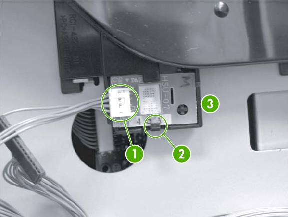
6. Disconnect one connector (callout 1).
Figure 6-271 Remove the environment sensor
7. Push down on (callout 2) with your finger while inserting a flat-blade screwdriver to release the
sensor (callout 3).
8. Lift out the environment sensor using the screwdriver.
410 Chapter 6 Removal and replacement ENWW
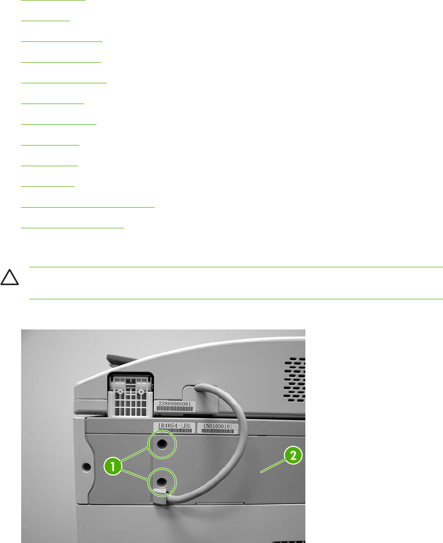
ADF and scanner components
The procedures in this section describe the removal and replacement of the following components:
●ADF assembly
●Top covers
●Scanner assembly
●Scanner left cover
●Scanner right cover
●Scanner glass
●Optical assembly
●Scanner bulb
●Inverter PCB
●Scanner fan
●Scanner home position sensor
●Scanner controller PCB
ADF assembly
CAUTION When you remove the ADF assembly, do not use the ADF cable to lift or move
the ADF assembly.
1. Remove two screws (callout 1), and then remove the scanner controller cover (callout 2).
Figure 6-272 Remove the ADF assembly (1 of 3)
ENWW ADF and scanner components 411
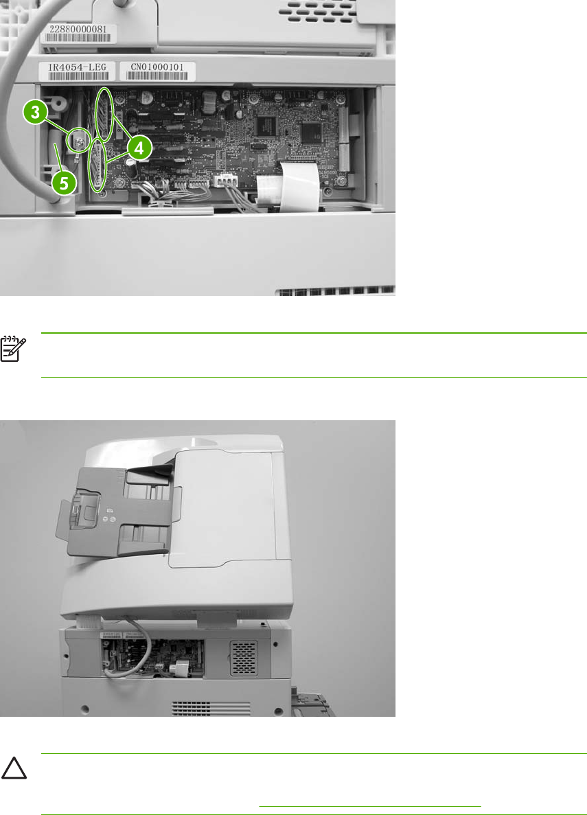
2. Remove one grounding screw (callout 3), disconnect two cables (callout 4), and remove the
cable (callout 5) from the cable stays.
Figure 6-273 Remove the ADF assembly (2 of 3)
NOTE When reinstalling the ADF, make sure that the ADF cable is correctly routed
through the cable holder into the scanner bed.
3. Open the ADF assembly, and lift it up and off of the scanner.
Figure 6-274 Remove the ADF assembly (3 of 3)
CAUTION The ADF assembly is calibrated to work with the scanner on which it is
installed. If the ADF is installed on another scanner, that scanner needs to be calibrated
to work correctly with the ADF. See Calibrating the scanner on page 106.
412 Chapter 6 Removal and replacement ENWW
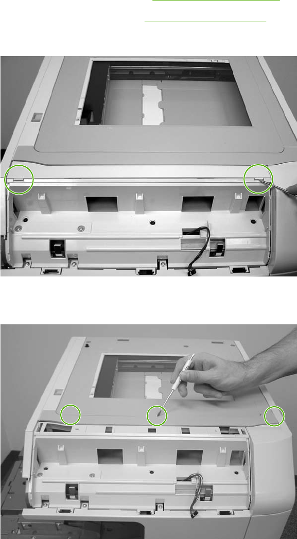
Top covers
1. Remove the ADF assembly. See ADF assembly on page 411.
2. Remove the control panel. See Control panel on page 250.
3. Use a flat-blade screwdriver to pry off the outer frame.
Figure 6-275 Remove the top covers (1 of 2)
4. Use a flat-blade screwdriver to pry off the inner frame.
Figure 6-276 Remove the top covers (2 of 2)
ENWW ADF and scanner components 413
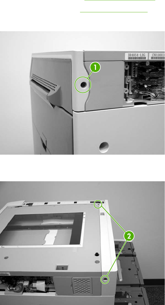
Scanner assembly
1. Remove the ADF assembly. See ADF assembly on page 411.
2. Remove the control panel. See Control panel on page 250.
3. Remove one screw (callout 1), and remove the right scanner cover.
Figure 6-277 Remove the scanner assembly (1 of 5)
4. Remove two screws (callout 2) and remove the left scanner cover.
Figure 6-278 Remove the scanner assembly (2 of 5)
414 Chapter 6 Removal and replacement ENWW
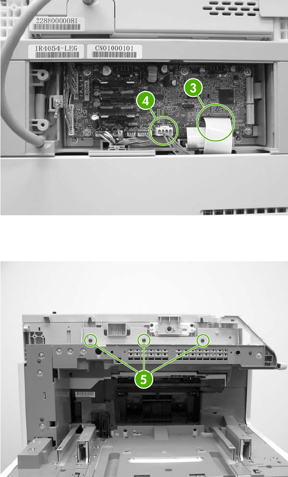
5. Disconnect one flat cable (callout 3) and one connector (callout 4).
Figure 6-279 Remove the scanner assembly (3 of 5)
6. Remove three screws from the left side of the scanner (callout 5).
Figure 6-280 Remove the scanner assembly (4 of 5)
ENWW ADF and scanner components 415
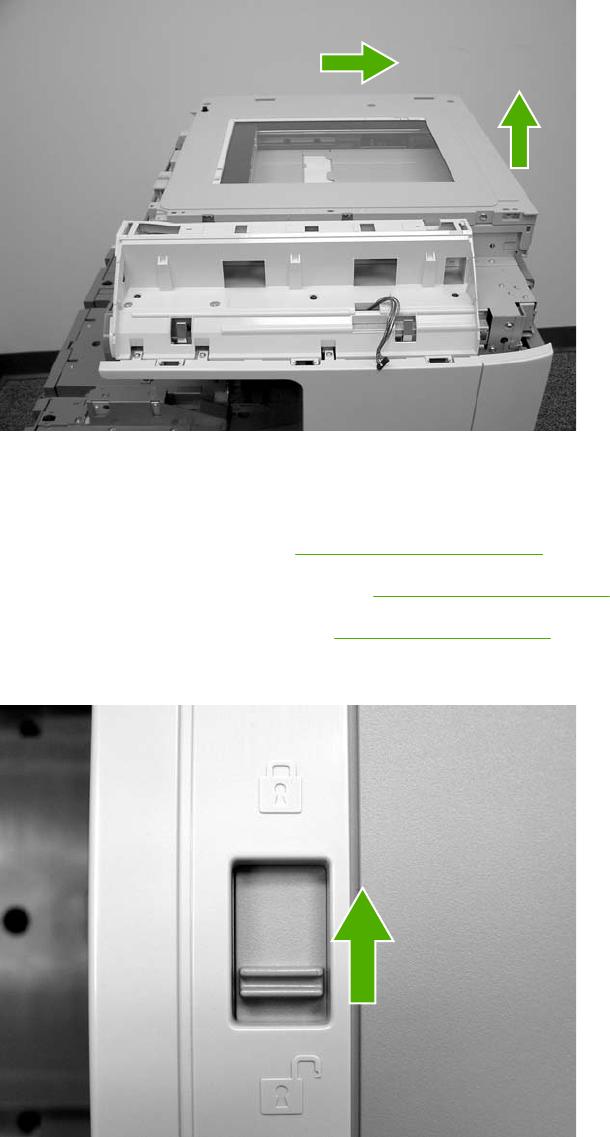
7. Slide the scanner to the right and lift it up and off the MFP.
Figure 6-281 Remove the scanner assembly (5 of 5)
Scanner left cover
1. Remove the ADF assembly. See ADF assembly on page 411.
2. Remove the control panel and cover. See Control panel on page 250.
3. Remove the scanner top covers. See Top covers on page 413.
4. Move the scanner lock switch into the locked position.
Figure 6-282 Remove the scanner left cover (1 of 2)
416 Chapter 6 Removal and replacement ENWW
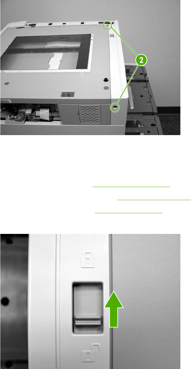
5. Remove two screws.
Figure 6-283 Remove the scanner left cover (2 of 2)
6. Lift off the ADF left top cover.
Scanner right cover
1. Remove the ADF assembly. See ADF assembly on page 411.
2. Remove the control panel and cover. See Control panel on page 250.
3. Remove the scanner frames. See Top covers on page 413.
4. Move the scanner lock switch into the locked position.
Figure 6-284 Remove the scanner right cover (1 of 2)
ENWW ADF and scanner components 417
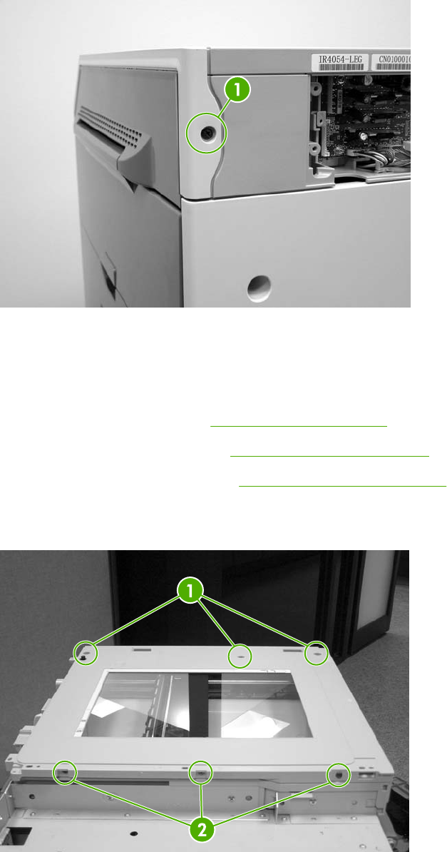
5. Remove one screw (callout 1).
Figure 6-285 Remove the scanner right cover (2 of 2)
6. Pull toward the front of the MFP and lift off the scanner right cover.
Scanner glass
1. Remove the ADF assembly. See ADF assembly on page 411.
2. Remove the scanner left cover. See Scanner left cover on page 416.
3. Remove the scanner right cover. See Scanner right cover on page 417.
4. Remove three screws from the top of the scanner (callout 1) and three screws from the front of
the scanner (callout 2). Lift the scanner glass frame up and off the MFP.
Figure 6-286 Remove the scanner glass (1 of 2)
418 Chapter 6 Removal and replacement ENWW
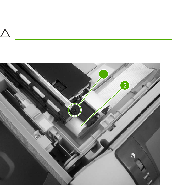
Optical assembly
1. Remove the following assemblies:
●ADF assembly. See ADF assembly on page 411.
●Control panel. See Control panel on page 250.
●Scanner glass. See Scanner glass on page 418.
CAUTION Do not use lubricant on the optical assembly guide rod.
2. Remove one screw (callout 1) to release the FFC cable guide, and disconnect the FFC
(callout 2).
Figure 6-287 Remove the optical assembly (1 of 10)
ENWW ADF and scanner components 419
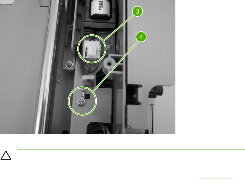
3. Disconnect one scanner lamp connector (callout 3), and remove one grounding screw
(callout 4). Remove the scanner lamp cable from the cable guide.
Figure 6-288 Remove the optical assembly (2 of 10)
CAUTION When reinstalling the optical assembly, make sure that the cable is correctly
routed through the cable guide to ensure that the optical assembly can move freely in the
scanner bed. Also note the location of the mark on the cable. When reinstalling the
scanner bulb, align the mark with the grooves on the plastic frame. See Figure 6-296
Remove the optical assembly (10 of 10) on page 424.
4. Unlock the scanner.
420 Chapter 6 Removal and replacement ENWW
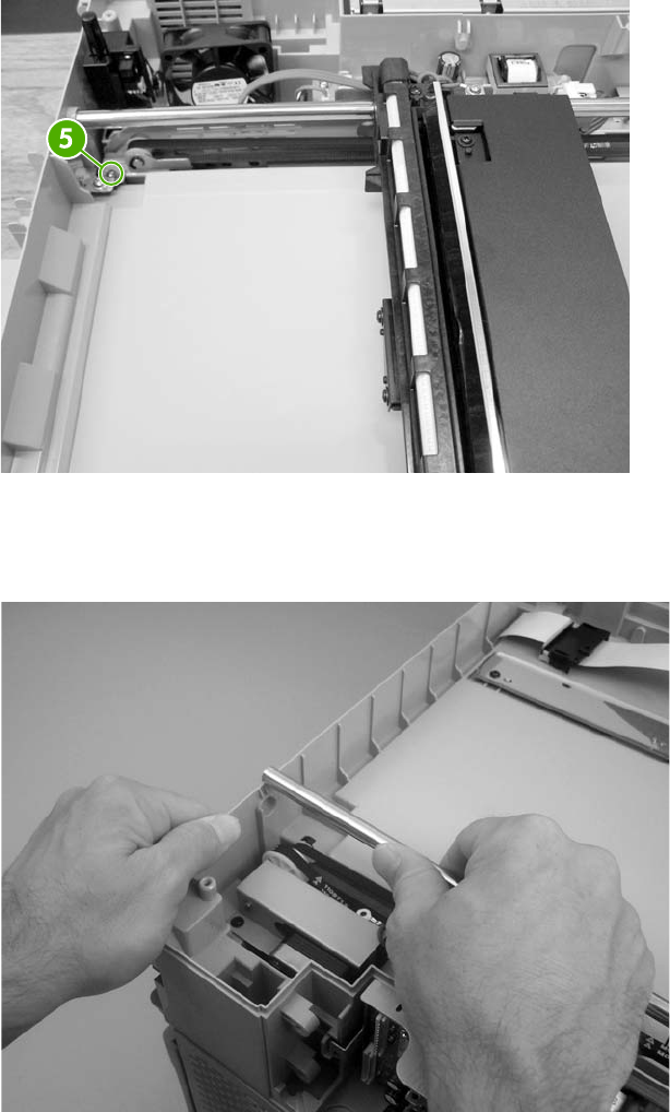
5. Slide the optical assembly to the right and loosen one screw (callout 5) to release the tension on
the drive belt.
Figure 6-289 Remove the optical assembly (3 of 10)
6. Flex the side of the scanner chassis to release the optical assembly guide rod from the scanner
chassis.
Figure 6-290 Remove the optical assembly (4 of 10)
ENWW ADF and scanner components 421
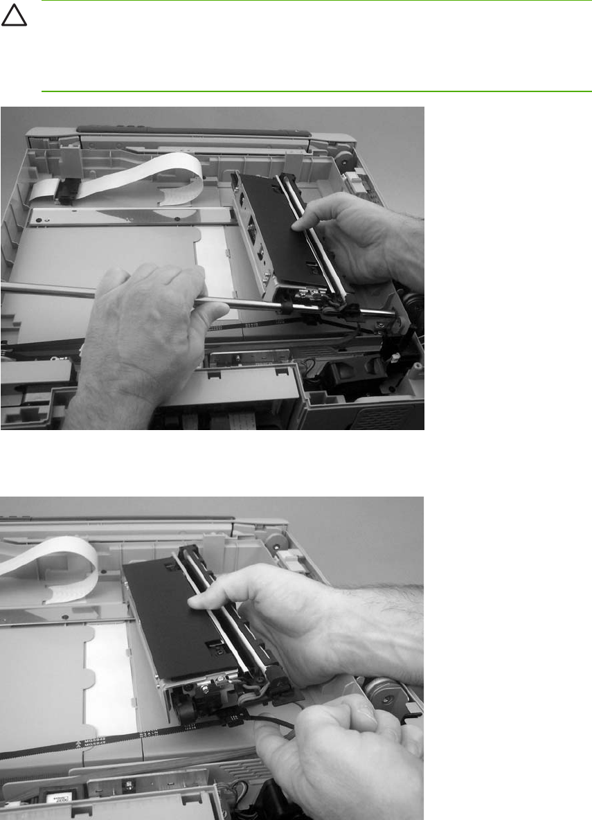
7. Tilt the optical assembly up, and slide the guide rod out of the mounting hole in the chassis and
through the optical assembly.
CAUTION To avoid breaking the optical assembly sensor flag, slide the optical
assembly towards the center of the guide rod before tilting the optical assembly up.
Do not touch the lamp. Skin oils and fingerprints cause image-quality problems, and the
lamp might burn and be damaged when the MFP power is turned on.
Figure 6-291 Remove the optical assembly (5 of 10)
8. Disengage and disconnect the drive belt, and then remove the optical assembly.
Figure 6-292 Remove the optical assembly (6 of 10)
422 Chapter 6 Removal and replacement ENWW
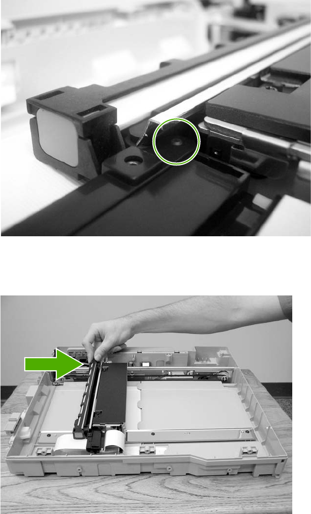
9. When the FCC cable guide is reinstalled, make sure that the alignment hole on the guide is
correctly positioned on the chassis locator pin.
Figure 6-293 Remove the optical assembly (7 of 10)
10. To adjust the scanner belt tension, move the optical assembly to the center of the scanner
assembly.
Figure 6-294 Remove the optical assembly (8 of 10)
11. Attach the belt to the carriage.
ENWW ADF and scanner components 423
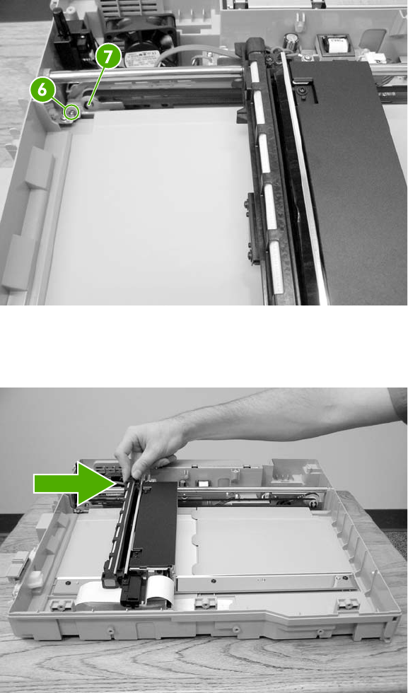
12. Loosen the screw situated below the rod (callout 6). To provide slack in the belt, push the belt
tension assembly three times toward the opposing end of the bar. Push the belt tension
assembly at the location shown in callout 7.
Figure 6-295 Remove the optical assembly (9 of 10)
13. Move the optical assembly to a point approximately 4 inches away from the home position
sensor.
Figure 6-296 Remove the optical assembly (10 of 10)
14. To remove slack from the belt, push the belt tension assembly once in the direction of the pulley
assembly. Tighten the screw.
424 Chapter 6 Removal and replacement ENWW
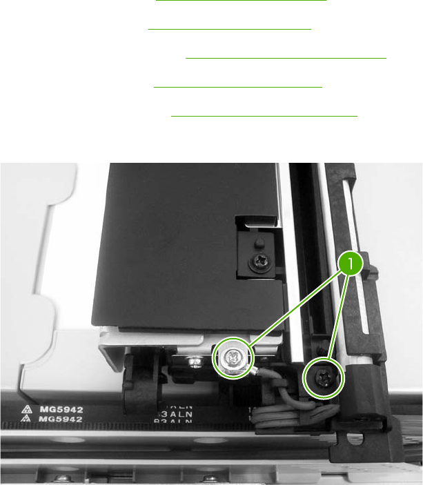
Scanner bulb
1. Remove the following assemblies:
●ADF assembly. See ADF assembly on page 411.
●Control panel. See Control panel on page 250.
●Scanner right cover. See Scanner right cover on page 417.
●Scanner glass. See Scanner glass on page 418.
●Optical assembly. See Optical assembly on page 419.
2. Remove the two screws (callout 1).
Figure 6-297 Remove the scanner bulb (1 of 3)
ENWW ADF and scanner components 425
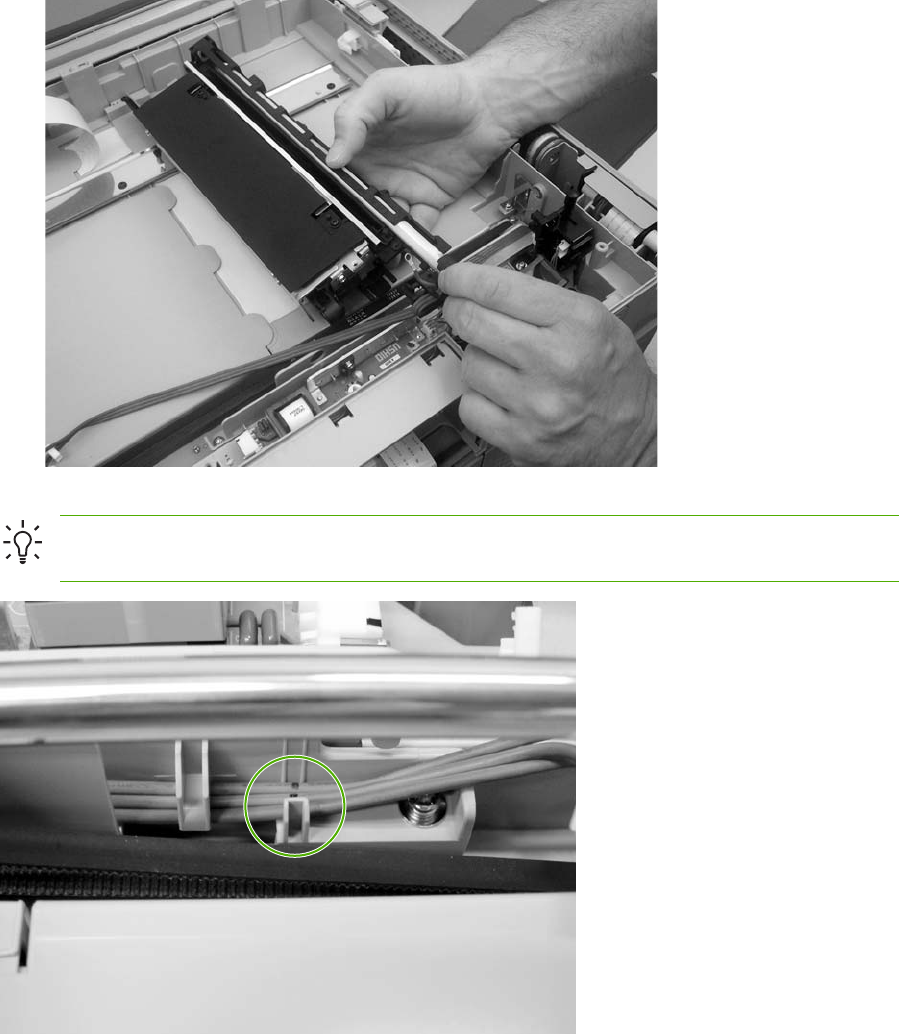
3. Grasp the scanner bulb, and carefully slide it out of the optical assembly (towards the cable end).
Figure 6-298 Remove the scanner bulb (2 of 3)
Hint When reinstalling the scanner bulb, align the mark on the cable with the grooves on the
plastic frame.
Figure 6-299 Remove the scanner bulb (3 of 3)
426 Chapter 6 Removal and replacement ENWW
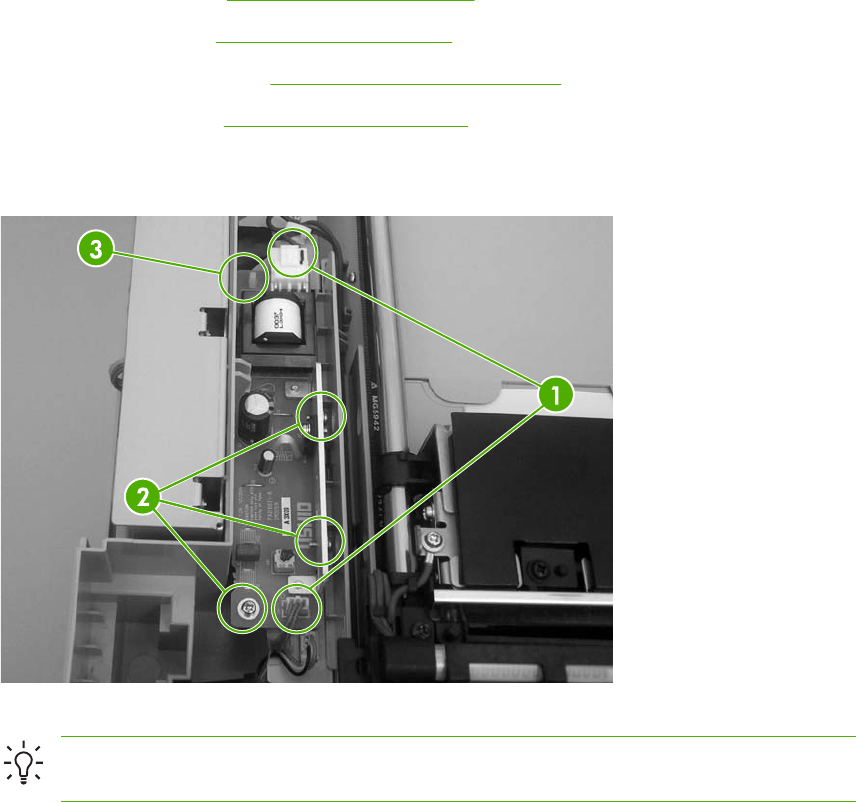
Inverter PCB
1. Remove the following assemblies:
●ADF assembly. See ADF assembly on page 411.
●Control panel. See Control panel on page 250.
●Scanner right cover. See Scanner right cover on page 417.
●Scanner glass. See Scanner glass on page 418.
2. Remove two connectors (callout 1) and three screws (callout 2). Use needle-nose pliers to
squeeze the PCB retainer (callout 3), and remove the inverter PCB.
Figure 6-300 Remove the inverter PCB
Hint When reinstalling the inverter PCB, slide the assembly in until it engages the pins
and then snap it downward into place.
ENWW ADF and scanner components 427
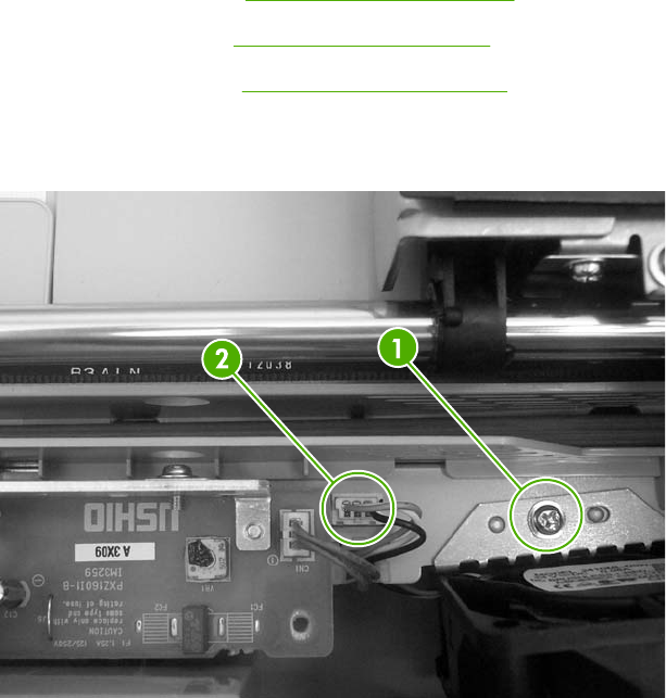
Scanner fan
1. Remove the following assemblies:
●ADF assembly. See ADF assembly on page 411.
●Control panel. See Control panel on page 250.
●Scanner glass. See Scanner glass on page 418.
2. Remove one screw (callout 1), and then remove one connector (callout 2). Remove the cable
from the cable stay and remove the scanner fan.
Figure 6-301 Remove the scanner fan
428 Chapter 6 Removal and replacement ENWW

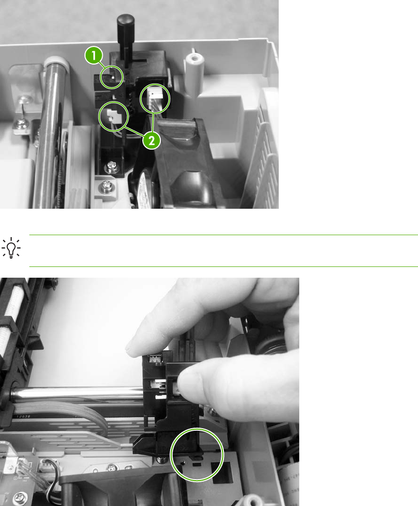
2. Remove one screw (callout 1), and then disconnect two connectors (callout 2). Remove the
scanner home position sensor.
Figure 6-302 Remove the scanner home position sensor
Hint When reinstalling the scanner home position sensor, make sure that the tab at the
bottom of the sensor bracket is correctly positioned in the slot in the chassis.
Figure 6-303 Reinstalling the scanner home position sensor
430 Chapter 6 Removal and replacement ENWW
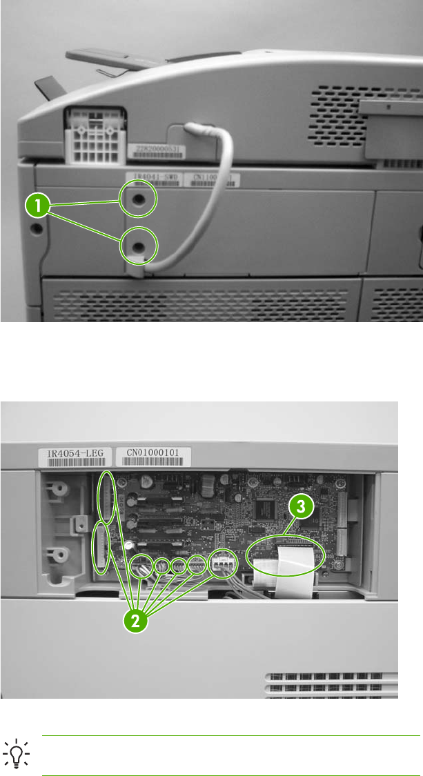
Scanner controller PCB
1. Remove two screws (callout 1), and then remove the scanner controller PCB cover.
Figure 6-304 Remove the scanner controller PCB (1 of 2)
2. Disconnect seven scanner controller PCB connectors (callout 2) and two flat cables (callout 3),
and then remove five screws. Remove the scanner controller PCB.
Figure 6-305 Remove the scanner controller PCB (2 of 2)
Hint The scanner controller PCB has two empty connectors.
ENWW ADF and scanner components 431

ADF components
The procedures in this section describe the removal and replacement of the following components:
●ADF output bin extension
●ADF white mylar backing
●ADF front cover
●ADF rear cover
●ADF left side cover
●ADF jam access cover and latch
●ADF leading-edge and paper-present sensors
●ADF hinges
432 Chapter 6 Removal and replacement ENWW
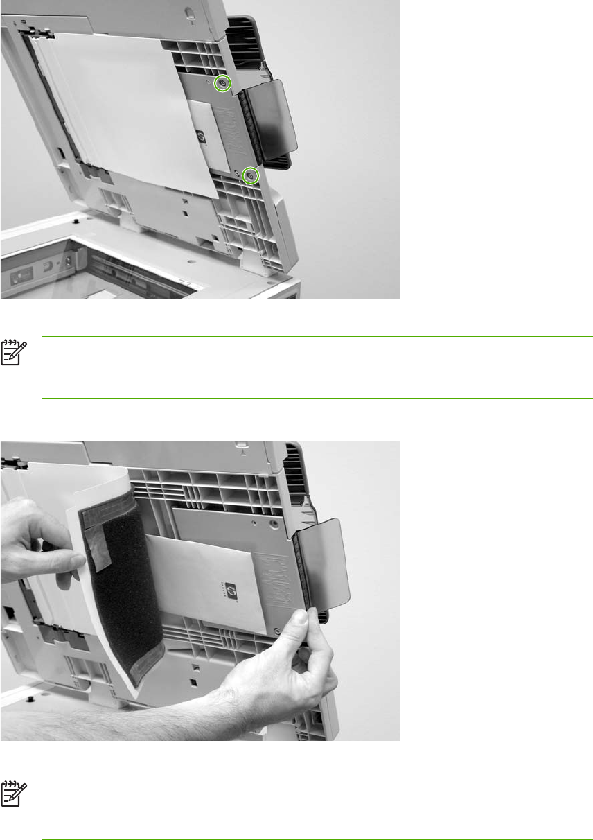
ADF output bin extension
1. Open the ADF and remove two screws.
Figure 6-306 Remove the ADF output bin extension (1 of 2)
NOTE Make sure that you store the envelope that contains the clear mylar sheets
beneath the ADF white vinyl scan background after you install the replacement ADF
output bin extension.
2. Peel back the ADF white vinyl scan background, and then remove the ADF output bin extension.
Figure 6-307 Remove the ADF output bin extension (2 of 2)
NOTE When the two screws are removed, the ADF output bin extension is not captive.
Make sure that you support the ADF output bin extension as you peel back the ADF
white vinyl scan background.
ENWW ADF components 433
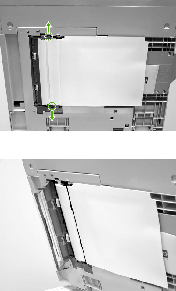
ADF white mylar backing
1. Open the ADF, release two locking tabs and then open the mylar holder assembly.
Figure 6-308 Remove the ADF white mylar backing (1 of 3)
2. Unsnap the mylar holder assembly hinges from the hinge pins.
Figure 6-309 Remove the ADF white mylar backing (2 of 3)
434 Chapter 6 Removal and replacement ENWW
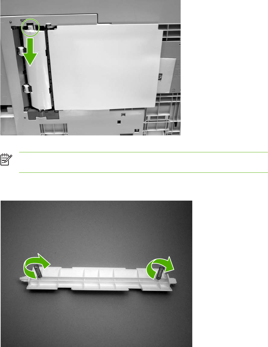
3. Release the ADF white mylar backing locking tab, and lift the assembly up and out of the ADF.
Figure 6-310 Remove the ADF white mylar backing (3 of 3)
NOTE The springs behind the ADF white mylar backing assembly are not captive. Do
not lose the springs when you remove the ADF white mylar backing assembly.
4. Reinstallation tip: When reinstalling the ADF white mylar backing assembly, compress and
twist the springs to make sure that they grip the pedestals on the back of the assembly.
Figure 6-311 Reinstall the ADF white mylar backing springs (1 of 2)
ENWW ADF components 435
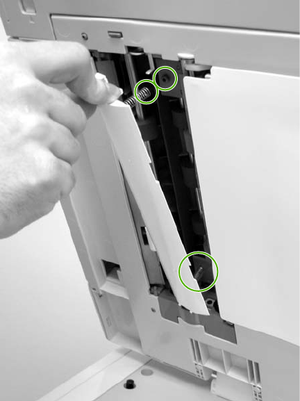
5. Reinstallation tip: Place the springs over the pins when replacing the backing assembly.
Figure 6-312 Reinstall the ADF white mylar backing springs (2 of 2)
436 Chapter 6 Removal and replacement ENWW
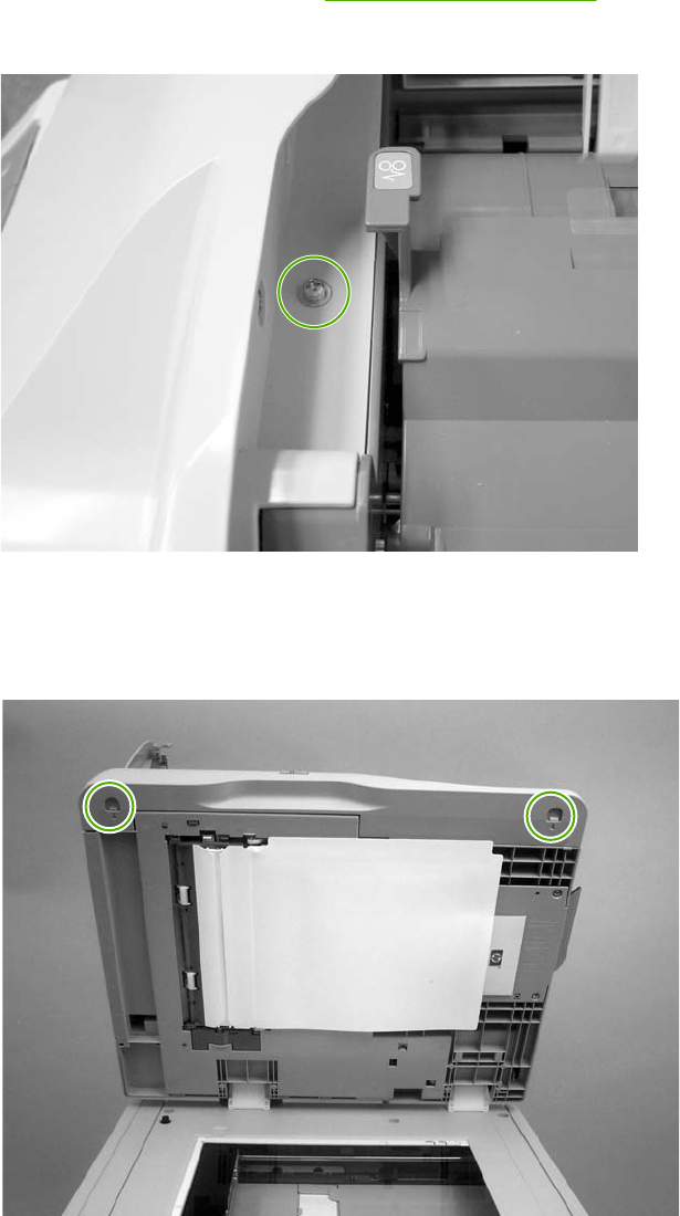
ADF front cover
1. Remove the ADF input tray. See ADF input tray on page 262.
2. Open the ADF top cover and remove one screw.
Figure 6-313 Remove the ADF front cover (1 of 2)
3. Open the scanner cover.
4. Release the two ADF front cover locking buttons, and then remove the ADF front cover.
Figure 6-314 Remove the ADF front cover (2 of 2)
ENWW ADF components 437
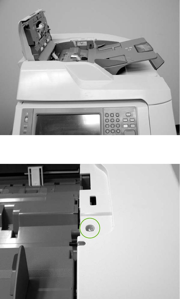
ADF rear cover
1. Open the ADF top cover.
Figure 6-315 Remove the ADF rear cover (1 of 3)
2. Remove one screw.
Figure 6-316 Remove the ADF rear cover (2 of 3)
438 Chapter 6 Removal and replacement ENWW
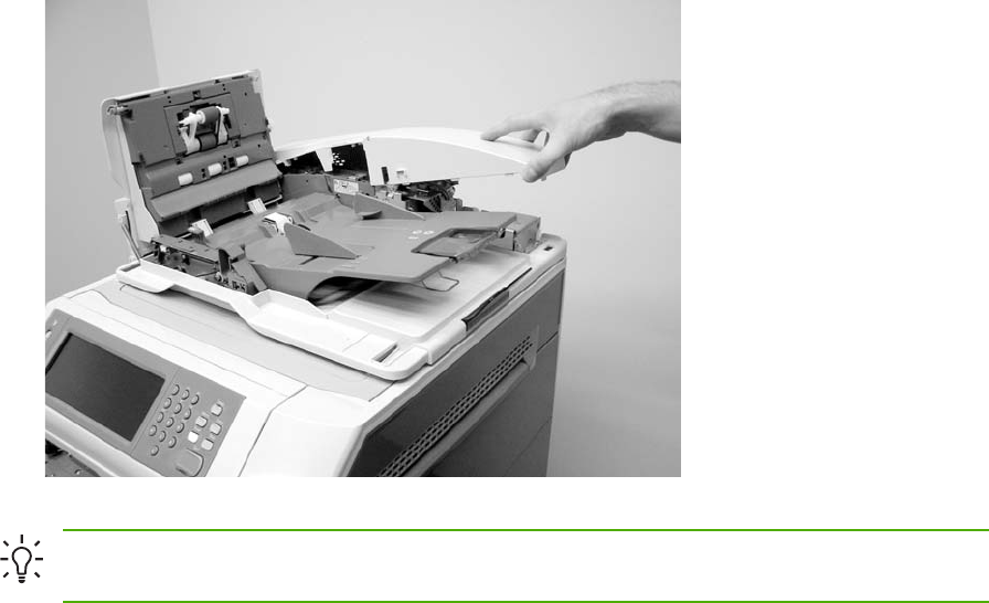
3. Holding it by the front, lift the ADF rear cover off the ADF.
Figure 6-317 Remove the ADF rear cover (3 of 3)
Hint Reinstall the ADF rear cover by inserting the tabs of the back of the cover into the slots
and pressing downward.
ENWW ADF components 439
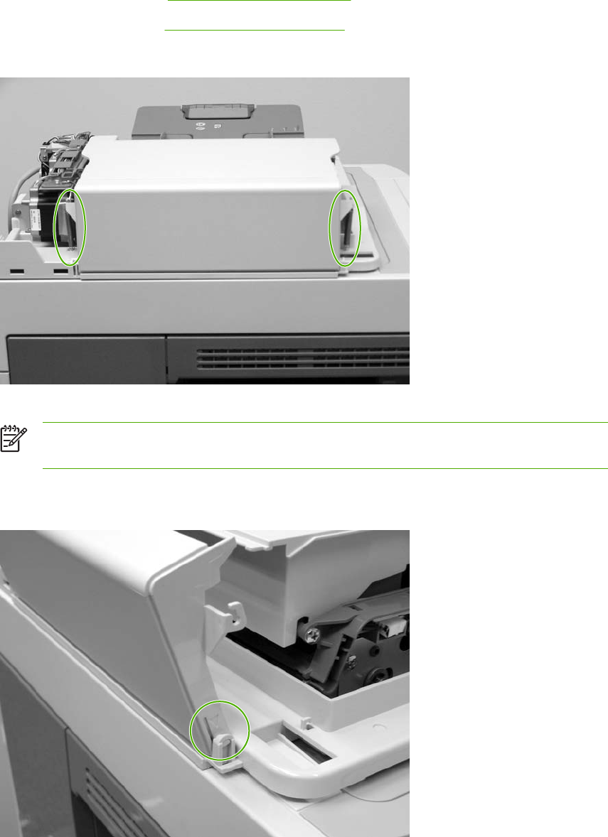
ADF left side cover
1. Remove the following assemblies:
●ADF front cover. See ADF front cover on page 437.
●ADF rear cover. See ADF rear cover on page 438.
2. Release two springs.
Figure 6-318 Remove the ADF left cover (1 of 2)
NOTE The left cover tension springs are not captive. Do not lose the springs when you
remove the ADF left cover.
3. Flex the locking tab on the hinge at the control panel end of the cover to release the hinge.
Remove the ADF left cover.
Figure 6-319 Remove the ADF left cover (2 of 2)
440 Chapter 6 Removal and replacement ENWW
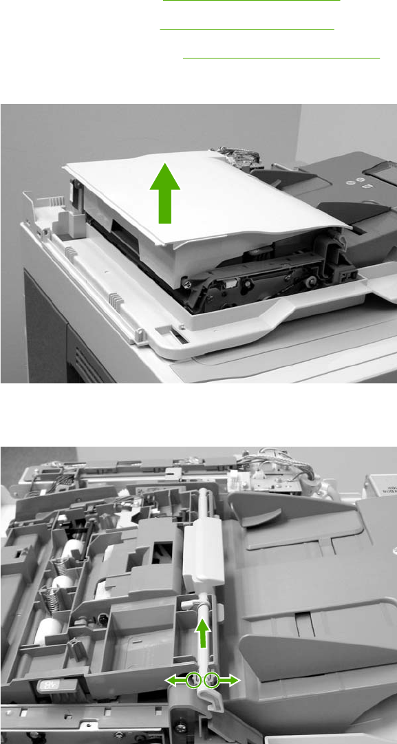
ADF jam access cover and latch
1. Remove the following assemblies:
●ADF front cover. See ADF front cover on page 437.
●ADF rear cover. See ADF rear cover on page 438.
●ADF left side cover. See ADF left side cover on page 440.
2. Pull up on the left side of the cover to release it, and then remove the ADF jam access cover.
Figure 6-320 Remove the ADF jam access cover and latch (1 of 3)
3. To remove the latch, spread the two clips, and slide the latch rod toward the rear of the ADF.
Figure 6-321 Remove the ADF jam access cover and latch (2 of 3)
ENWW ADF components 441
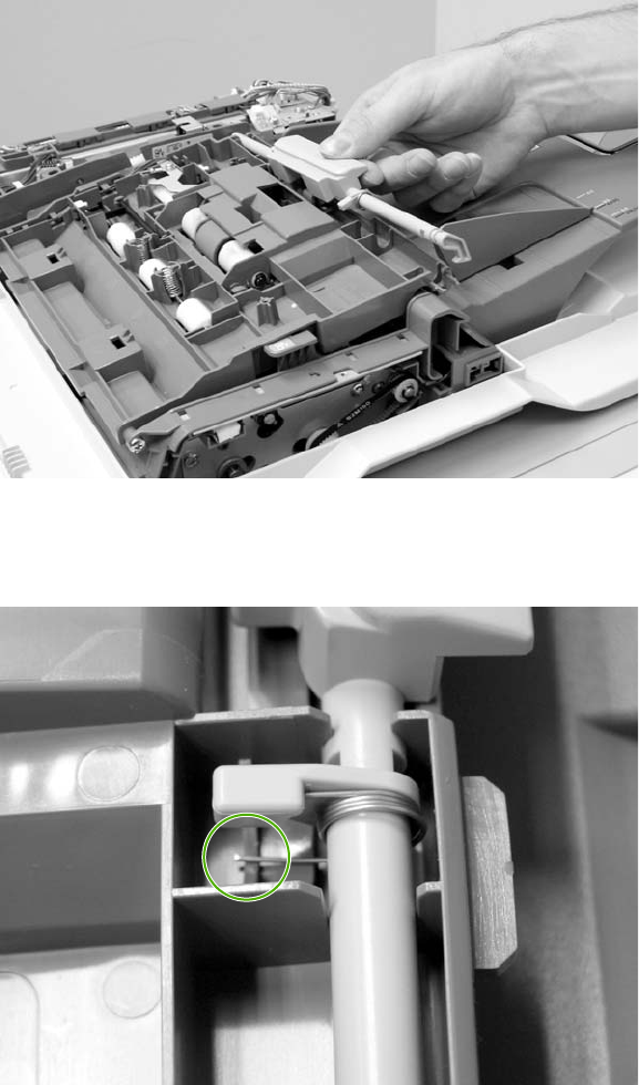
4. Lift the rod out of the ADF assembly.
Figure 6-322 Remove the ADF jam access cover and latch (3 of 3)
5. Reinstallation tip: Make sure that you wind the spring around the latch rod and hold it in place
until the rod snaps into place.
442 Chapter 6 Removal and replacement ENWW
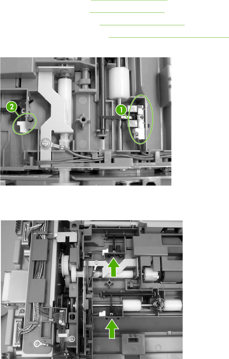
ADF leading-edge and paper-present sensors
1. Remove the ADF front cover. See ADF front cover on page 437.
2. Remove the ADF rear cover. See ADF rear cover on page 438.
3. Remove the ADF left side cover. See ADF left side cover on page 440.
4. Remove the ADF jam access cover. See ADF jam access cover and latch on page 441.
5. Locate the ADF leading-edge sensor (callout 1) and the ADF paper-present sensor (callout 2).
Figure 6-323 Remove the ADF leading-edge and paper-present sensors (1 of 2)
6. Squeeze the retainer tabs, and push the sensor out of the mounting frame. Disconnect the
connector, and then remove the sensors.
Figure 6-324 Remove the ADF leading-edge and paper-present sensors (2 of 2)
ENWW ADF components 443
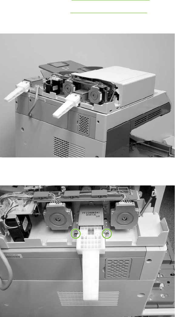
ADF hinges
1. Remove the following assemblies:
●ADF front cover. See ADF front cover on page 437.
●ADF rear cover. See ADF rear cover on page 438.
2. Lift the ADF assembly and unhook the hinges from the scanner assembly.
Figure 6-325 Remove the ADF hinges (1 of 3)
3. Remove two screws from the left-side hinge, and then remove the left-side hinge.
Figure 6-326 Remove the ADF hinges (2 of 3)
444 Chapter 6 Removal and replacement ENWW
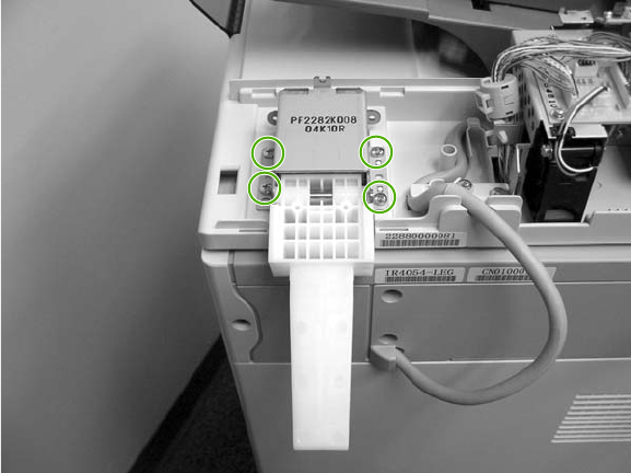
4. Remove four screws from the right-side hinge, and then remove the right-side hinge.
Figure 6-327 Remove the ADF hinges (3 of 3)
ENWW ADF components 445

2 X 500-sheet paper input assembly components
The procedures in this section describe the removal and replacement of the following components:
●Rear cover
●Right front cover
●Left front cover
●Right cover
●Left cover
●Right lower cover assembly
●Pickup motor assembly
●Upper lifter drive assembly
●Lower lifter drive assembly
●Upper pickup drive assembly
●Lower pickup drive assembly
●Upper pickup assembly
●Lower pickup assembly
●Paper feeder door-open switch
●Paper feeder driver PCB
446 Chapter 6 Removal and replacement ENWW
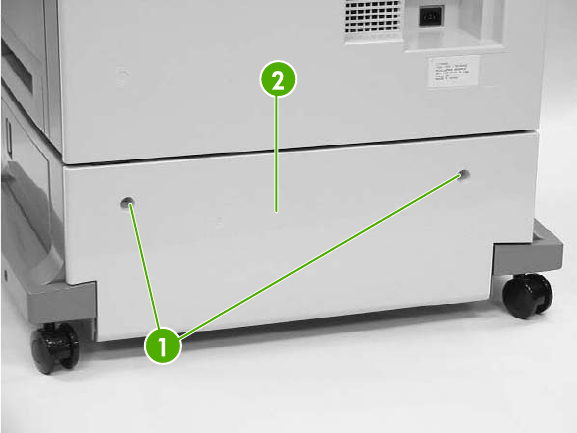
Rear cover
1. Remove all paper trays.
2. Remove two screws (callout 1) and then remove the rear cover (callout 2).
Figure 6-328 Remove the 2 X 500-sheet paper input assembly rear cover
ENWW 2 X 500-sheet paper input assembly components 447
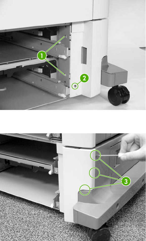
Right front cover
1. Remove all paper trays.
2. Unhook the two claws (callout 1) and remove one screw (callout 2).
Figure 6-329 Remove the 500-sheet feeder rear cover (1 of 2)
3. Unhook the three claws (callout 3), and then remove the right front cover.
Figure 6-330 Remove the 500-sheet feeder rear cover (2 of 2)
448 Chapter 6 Removal and replacement ENWW
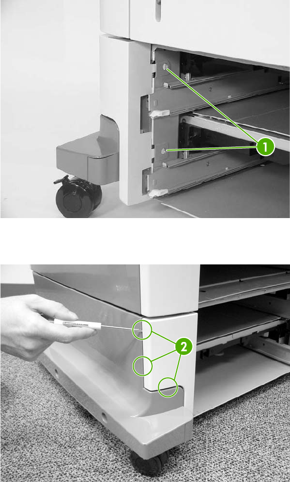
Left front cover
1. Remove all paper trays.
2. Unhook the two claws (callout 1).
Figure 6-331 Remove the 500-sheet feeder left front cover (1 of 2)
3. Unhook the three claws (callout 2), and remove the left front cover.
Figure 6-332 Remove the 500-sheet feeder left front cover (2 of 2)
ENWW 2 X 500-sheet paper input assembly components 449
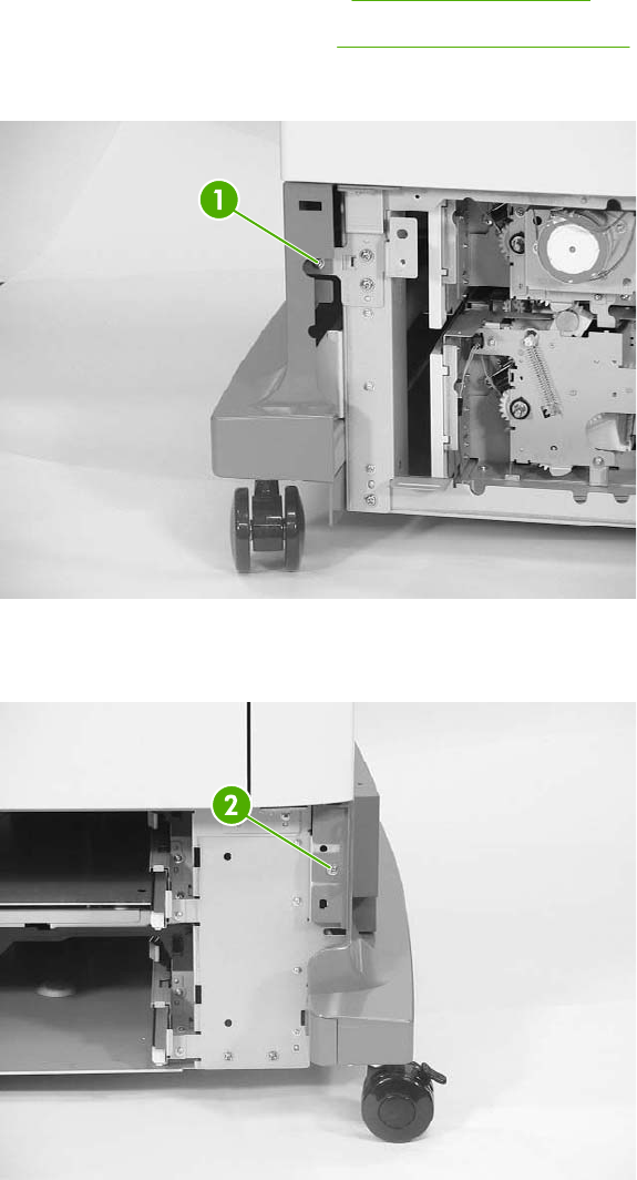
Right cover
1. Remove all paper trays.
2. Remove the feeder rear cover. See Rear cover on page 447.
3. Remove the right front cover. See Right front cover on page 448.
4. Remove one screw (callout 1).
Figure 6-333 Remove the right cover (1 of 3)
5. Remove one screw (callout 2).
Figure 6-334 Remove the right cover (2 of 3)
450 Chapter 6 Removal and replacement ENWW
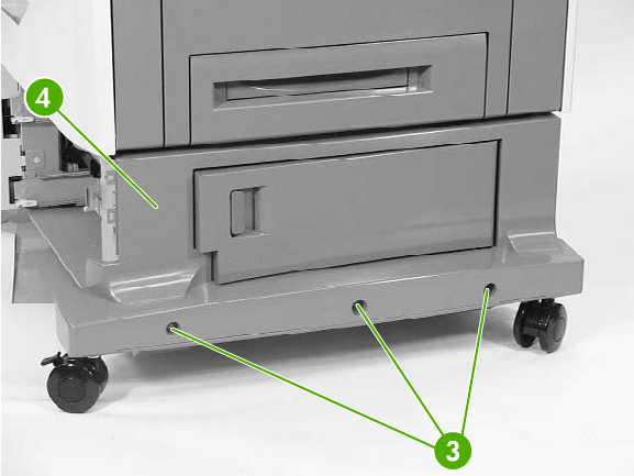
6. Remove the three screws (callout 3) and the right cover (callout 4).
Figure 6-335 Remove the right cover (3 of 3)
ENWW 2 X 500-sheet paper input assembly components 451
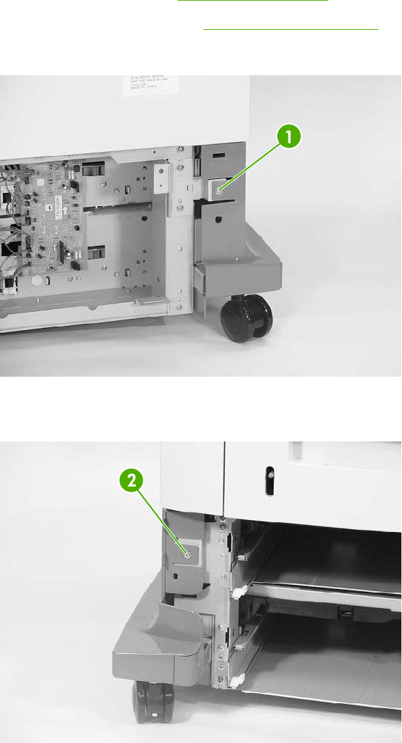
Left cover
1. Remove all paper trays.
2. Remove the rear cover. See Rear cover on page 447.
3. Remove the left front cover. See Left front cover on page 449.
4. Remove one screw (callout 1).
Figure 6-336 Remove the left cover (1 of 3)
5. Remove one screw (callout 2).
Figure 6-337 Remove the left cover (2 of 3)
452 Chapter 6 Removal and replacement ENWW
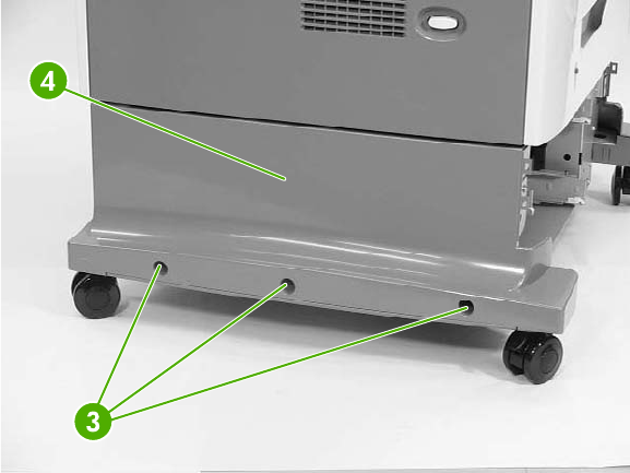
6. Remove three screws (callout 3), and then remove the left cover (callout 4).
Figure 6-338 Remove the left cover (3 of 3)
ENWW 2 X 500-sheet paper input assembly components 453
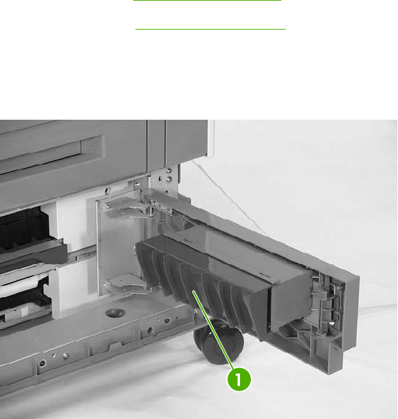
Right lower cover assembly
1. Remove all paper trays.
2. Remove the following assemblies:
●Rear cover. See Rear cover on page 447.
●Right cover. See Right cover on page 450.
3. Open the right lower cover.
4. While holding the right lower cover assembly (callout 1), lift up on the hinges to remove the
assembly.
Figure 6-339 Remove the right lower cover assembly
454 Chapter 6 Removal and replacement ENWW
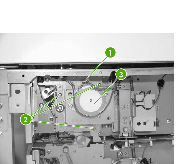
Pickup motor assembly
1. Remove the 500-sheet feeder rear cover. See Rear cover on page 447.
2. Disconnect one connector (callout 1).
3. Remove three screws (callout 2), and then remove the pickup motor assembly (callout 3).
Figure 6-340 Remove the pickup motor assembly
ENWW 2 X 500-sheet paper input assembly components 455
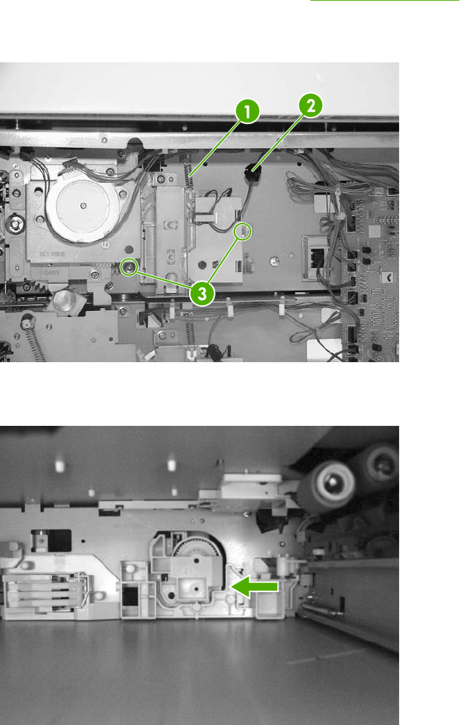
Upper lifter drive assembly
1. Remove the 2 X 500-sheet feeder rear cover. See Rear cover on page 447.
2. Remove the spring (callout 1) and disconnect the connector (callout 2). Remove two screws
(callout 3).
Figure 6-341 Remove the upper lifter drive assembly (1 of 3)
3. Remove the paper tray rear bracket, which is located inside the paper tray.
Figure 6-342 Remove the upper lifter drive assembly (2 of 3)
456 Chapter 6 Removal and replacement ENWW
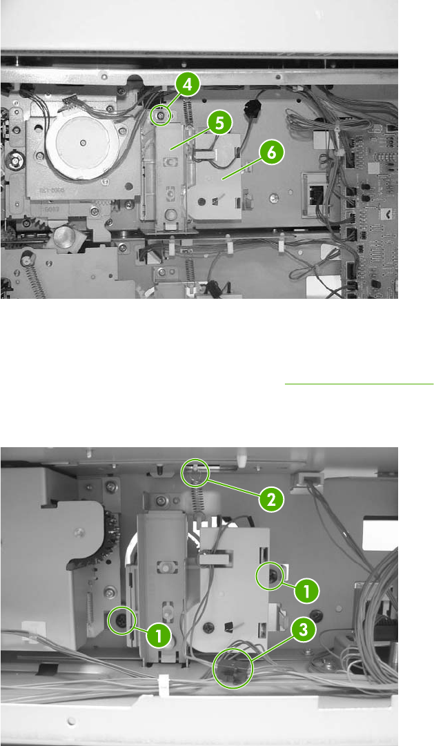
4. Remove one screw (callout 4) and then remove the upper lifter drive bracket (callout 5).
Remove the upper lifter drive assembly (callout 6).
Figure 6-343 Remove the upper lifter drive assembly (3 of 3)
Lower lifter drive assembly
1. Remove the 500-sheet feeder rear cover. See Rear cover on page 447.
2. Remove two screws (callout 1). Remove the spring (callout 2) and disconnect one connector
(callout 3).
Figure 6-344 Remove the lower lifter drive assembly (1 of 3)
ENWW 2 X 500-sheet paper input assembly components 457
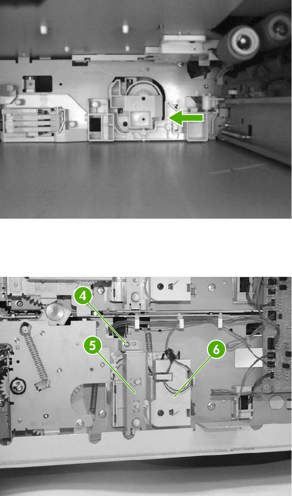
3. Remove the paper tray rear bracket, which is located inside the paper tray.
Figure 6-345 Remove the lower lifter drive assembly (2 of 3)
4. Remove one screw (callout 4. Remove the lower lifter drive bracket (callout 5) and the lower
lifter drive assembly (callout 6).
Figure 6-346 Remove the lower lifter drive assembly (3 of 3)
458 Chapter 6 Removal and replacement ENWW
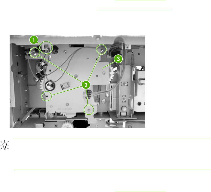
Upper pickup drive assembly
1. Remove the 2 X 500-sheet feeder rear cover. See Rear cover on page 447.
2. Remove the pickup motor assembly. See Pickup motor assembly on page 455.
3. Disconnect the connector (callout 1).
4. Remove four screws (callout 2), and then remove the upper pickup drive assembly (callout 3).
Figure 6-347 Remove the upper pickup drive assembly
Hint When reinstalling the upper pickup drive assembly, align the D-shaped shaft on the
assembly to fit through the hole in the chassis.
To allow the black arm on the assembly to lift, install tray 3 (filled with paper). As you install
the tray, manually lift the bin-full flag up over the tray.
Lower pickup drive assembly
1. Remove the 2 X 500-sheet feeder rear cover. See Rear cover on page 447.
2. Disconnect one connector (callout 1).
ENWW 2 X 500-sheet paper input assembly components 459
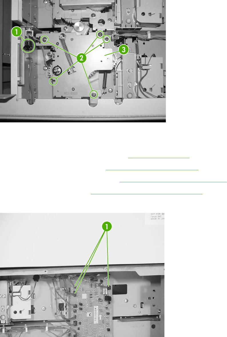
3. Remove the five screws (callout 2), and then remove the lower pickup drive assembly (callout 3).
Figure 6-348 Remove the lower pickup drive assembly
Upper pickup assembly
1. Remove the 2 X 500-sheet feeder rear cover. See Rear cover on page 447.
2. Remove the pickup motor assembly. See Pickup motor assembly on page 455.
3. Remove the upper pickup drive assembly. See Upper pickup drive assembly on page 459.
4. Remove the door-open switch. See Paper feeder door-open switch on page 469.
5. Disconnect three connectors (callout 1).
Figure 6-349 Remove the upper pickup assembly (1 of 10)
460 Chapter 6 Removal and replacement ENWW
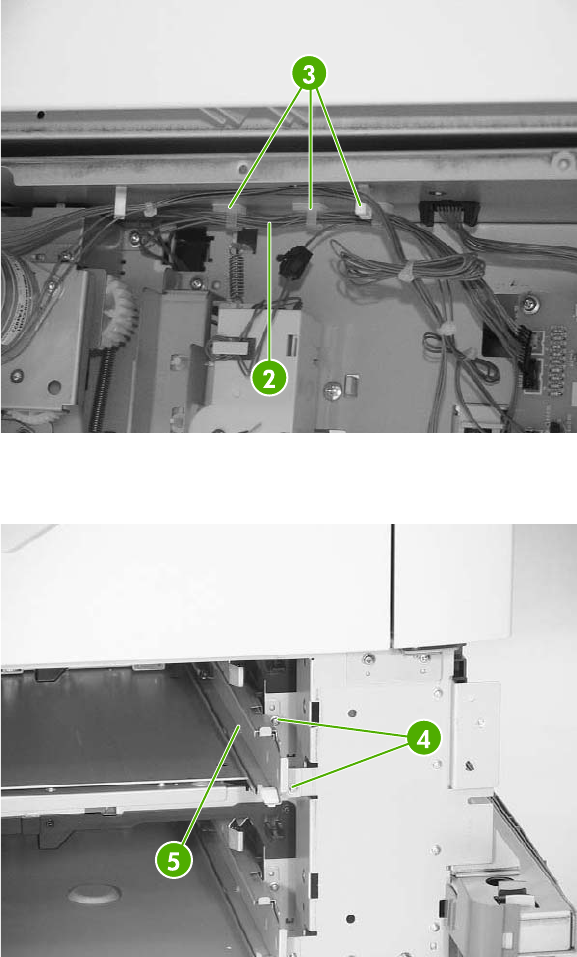
6. Remove one cable (callout 2) from the cable guides (callout 3).
Figure 6-350 Remove the upper pickup assembly (2 of 10)
7. Remove two screws (callout 4) and the right cassette rail assembly (callout 5).
Figure 6-351 Remove the upper pickup assembly (3 of 10)
ENWW 2 X 500-sheet paper input assembly components 461
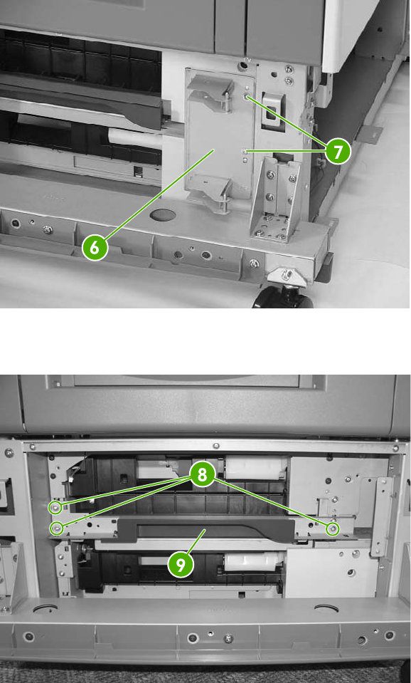
8. Remove the two screws (callout 6) and the hinge plate (callout 7).
Figure 6-352 Remove the upper pickup assembly (4 of 10)
9. Remove three screws (callout 8) and remove the crossmember (callout 9).
Figure 6-353 Remove the upper pickup assembly (5 of 109)
462 Chapter 6 Removal and replacement ENWW
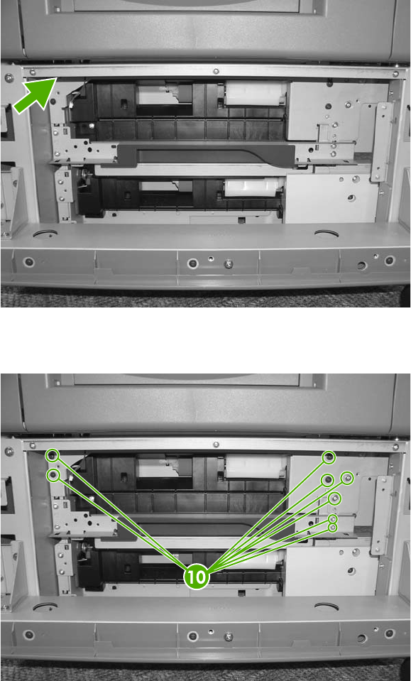
10. Loosen one screw situated behind the frame and inside the black foot.
Figure 6-354 Remove the upper pickup assembly (6 of 10)
11. Remove eight screws (callout 10) and remove both metal brackets.
Figure 6-355 Remove the upper pickup assembly (7 of 10)
ENWW 2 X 500-sheet paper input assembly components 463
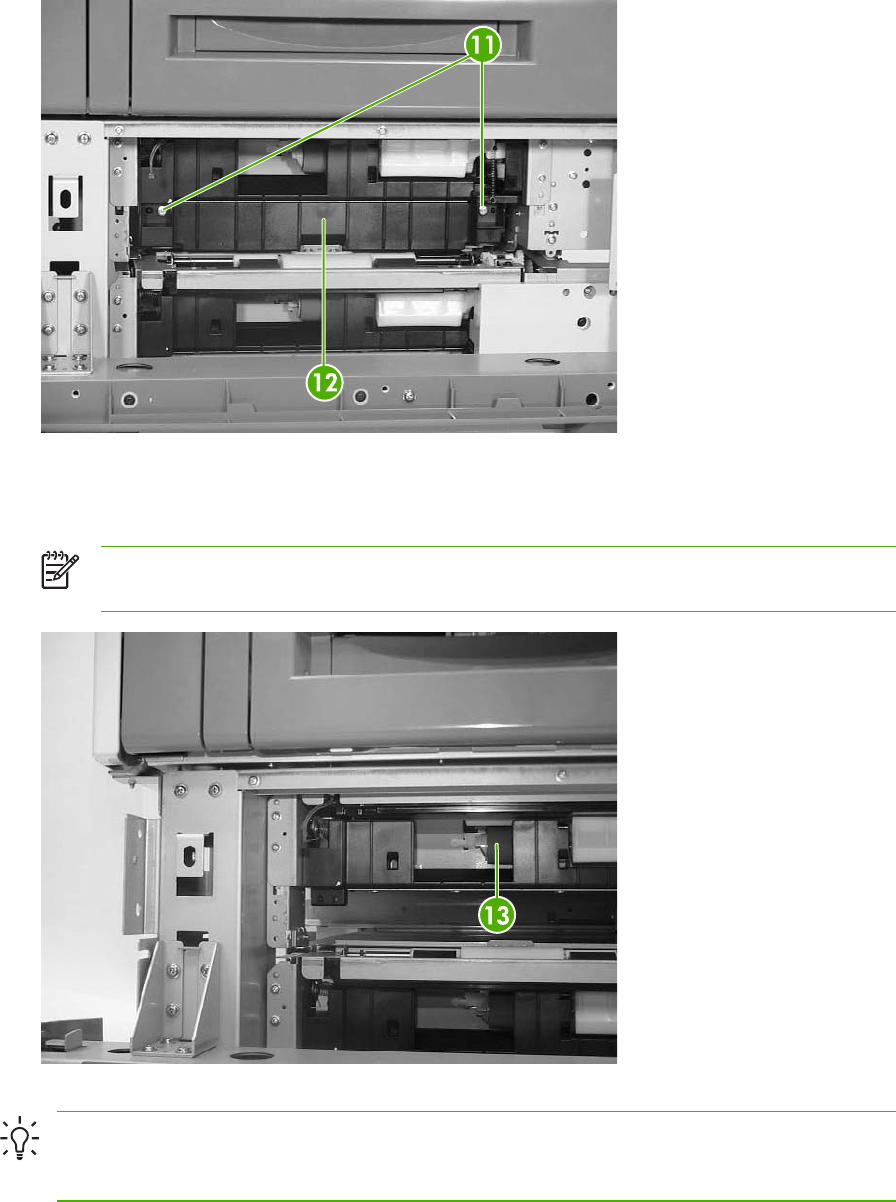
12. Remove two screws (callout 11) and the lower pickup guide (callout 12).
Figure 6-356 Remove the upper pickup assembly (8 of 10)
13. Pull the upper pickup assembly (callout 13) out. Be sure to guide the cables through the hole in
the rear of the chassis.
NOTE The gear can easily be removed from the pickup assembly (callout 15). Before
reinstalling the pickup assembly, be sure the gear is present.
Figure 6-357 Remove the upper pickup assembly (9 of 10)
Hint When reinstalling the upper pickup assembly, use the alignment pins on either side as
a guide to align the assembly with the holes in the frame. Be sure that the gears on the right
side of the upper pickup assembly align properly.
464 Chapter 6 Removal and replacement ENWW
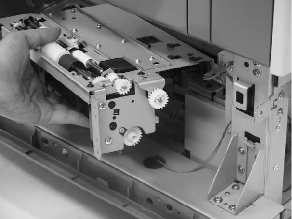
Figure 6-358 Remove the upper pickup assembly (10 of 10)
ENWW 2 X 500-sheet paper input assembly components 465
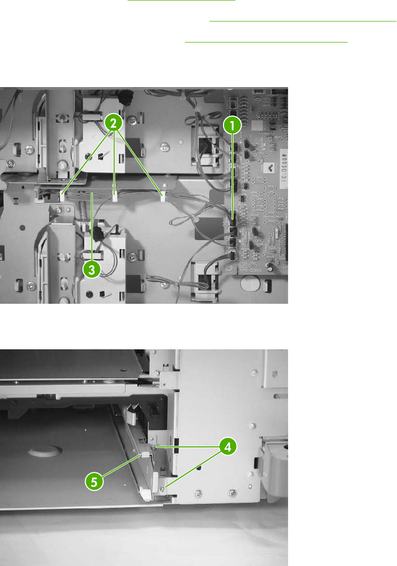
Lower pickup assembly
1. Remove the rear cover. See Rear cover on page 447.
2. Remove the upper pickup drive assembly. See Upper pickup drive assembly on page 459.
3. Remove the upper pickup assembly. See Upper pickup assembly on page 460.
4. Disconnect the connector (callout 1), and remove the cable (callout 3) from the cable guides
(callout 2).
Figure 6-359 Remove the lower pickup assembly (1 of 7)
5. Remove the two screws (callout 4) and the right lower cassette rail assembly (callout 5).
Figure 6-360 Remove the lower pickup assembly (2 of 7)
466 Chapter 6 Removal and replacement ENWW
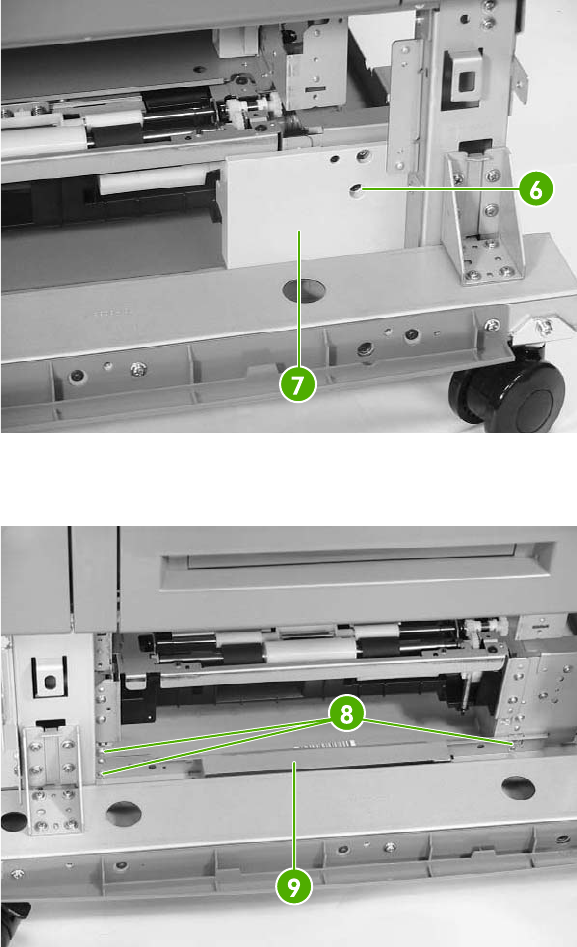
6. Remove one screw (callout 6) and the jam inner cover (callout 7).
Figure 6-361 Remove the lower pickup assembly (3 of 7)
7. Remove the three screws (callout 8) and the right crossmember (callout 9).
Figure 6-362 Remove the lower pickup assembly (4 of 7)
ENWW 2 X 500-sheet paper input assembly components 467
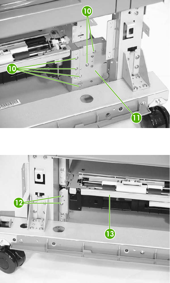
8. Remove the six screws (callout 10) and the plate (callout 11).
Figure 6-363 Remove the lower pickup assembly (5 of 7)
9. Remove the two screws (callout 12) and pull out the lower pickup assembly (callout 13).
Figure 6-364 Remove the lower pickup assembly (6 of 7)
468 Chapter 6 Removal and replacement ENWW
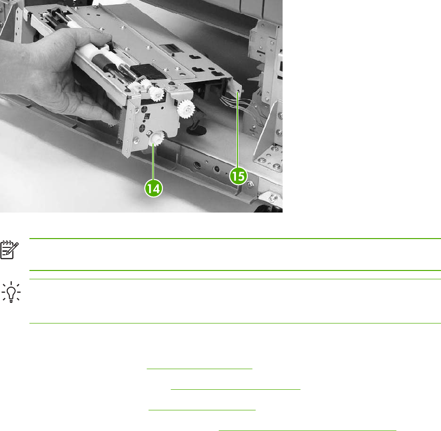
Figure 6-365 Remove the lower pickup assembly (7 of 7)
NOTE The gear (callout 14) can easily be removed from the pickup assembly. Before
installing the pickup assembly, be sure the gear is present.
Hint When reinstalling the lower pickup assembly, use the alignment pins (callout 15) on
either side as a guide to align the assembly with the holes in the frame. Be sure that the gears
on the right side of the lower pickup assembly align properly.
Paper feeder door-open switch
1. Remove the rear cover. See Rear cover on page 447.
2. Remove the right front cover. See Right front cover on page 448.
3. Remove the right cover. See Right cover on page 450.
4. Remove the right lower cover assembly. See Right lower cover assembly on page 454.
ENWW 2 X 500-sheet paper input assembly components 469
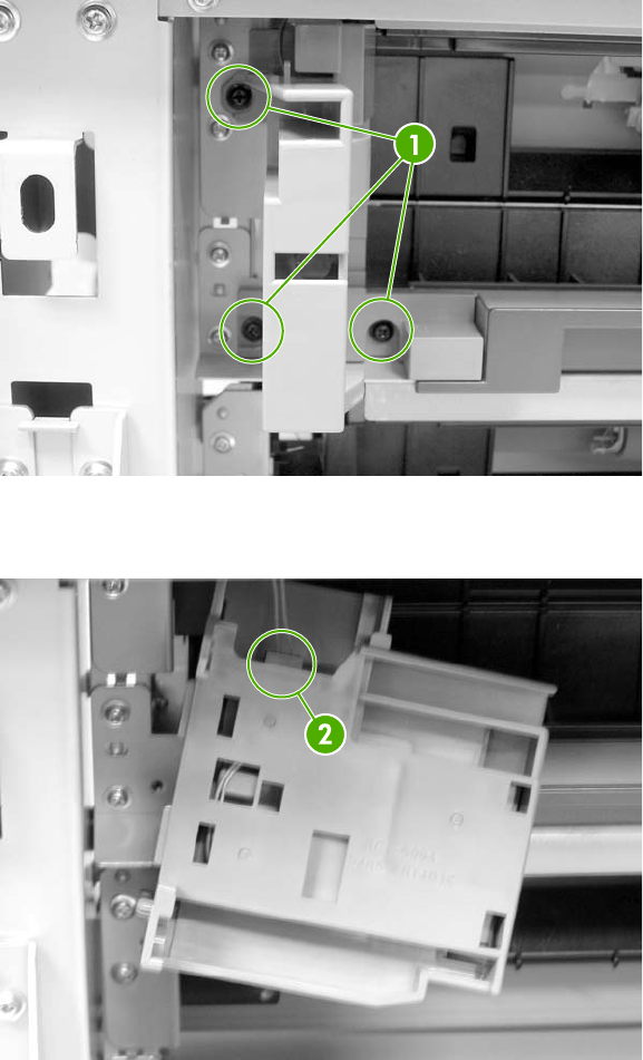
5. Remove three screws (callout 1) and lift out the door-open switch.
Figure 6-366 Remove the paper feeder door-open switch (1 of 2)
6. Disconnect the connector (callout 2) and remove the door-open switch.
Figure 6-367 Remove the paper feeder door-open switch (2 of 2)
470 Chapter 6 Removal and replacement ENWW
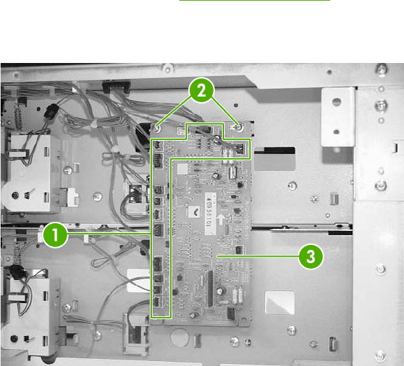
Paper feeder driver PCB
1. Remove the rear cover. See Rear cover on page 447.
2. Disconnect twelve connectors (callout 1). Remove two screws (callout 2) and lift out the 2 X 500-
sheet feeder driver PCB (callout 3).
Figure 6-368 Remove the 2 X 500-sheet feeder driver PCB
ENWW 2 X 500-sheet paper input assembly components 471
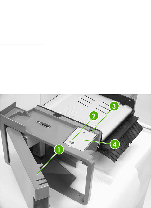
Intermediate paper transfer unit (IPTU)
The optional intermediate paper transfer unit (IPTU) allows the MFP to deliver printed copies to the
optional stapler/stacker or the 3-bin mailbox. This section addresses the following IPTU components:
●Front cover and front door
●IPTU rear cover
●Connector cover assembly
●IPTU driver PCB
●IPTU driver motors
Front cover and front door
1. Open the front door (callout 1) of the IPTU.
2. Remove the M4 screw (callout 2) and the M3 screw (callout 3), and then remove the plate
(callout 4).
Figure 6-369 Remove the IPTU front cover and front door (1 of 6)
472 Chapter 6 Removal and replacement ENWW
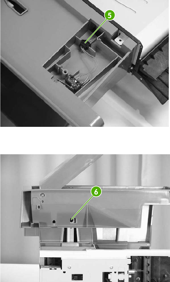
3. Disconnect the connector (callout 5).
Figure 6-370 Remove the IPTU front cover and front door (2 of 6)
4. Remove one screw (callout 6).
Figure 6-371 Remove the IPTU front cover and front door (3 of 6)
ENWW Intermediate paper transfer unit (IPTU) 473
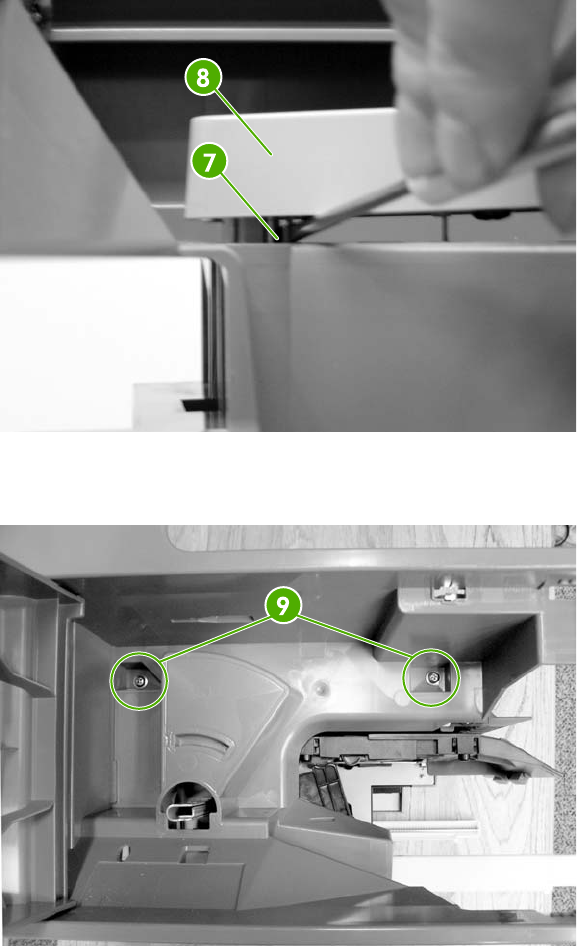
5. Unhook the claw (callout 7) and remove the jam lever (callout 8).
Figure 6-372 Remove the IPTU front cover and front door (4 of 6)
6. Remove the two screws (callout 9) inside the front door.
Figure 6-373 Remove the IPTU front cover and front door (5 of 6)
474 Chapter 6 Removal and replacement ENWW
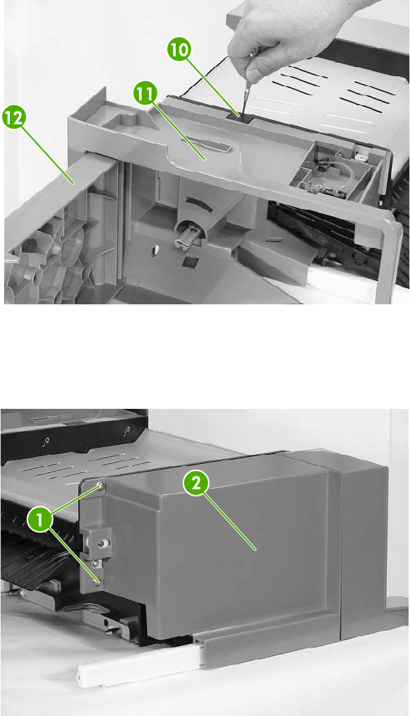
7. Push on the tab through the small hole (callout 10). Then remove the front cover (callout 11)
and the front door (callout 12) together.
Figure 6-374 Remove the IPTU front cover and front door (6 of 6)
IPTU rear cover
Remove the two screws (callout 1) and the rear cover (callout 2).
Figure 6-375 Remove the IPTU rear cover
ENWW Intermediate paper transfer unit (IPTU) 475
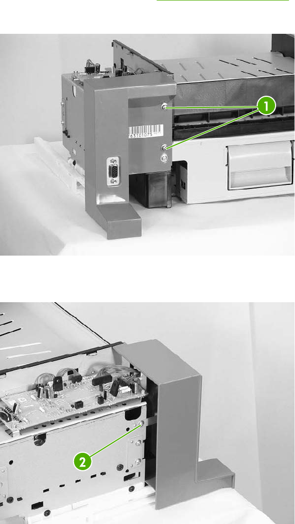
Connector cover assembly
1. Remove the IPTU rear cover. See IPTU rear cover on page 475.
2. Remove the two screws (callout 1).
Figure 6-376 Remove the IPTU connector cover (1 of 3)
3. Remove one screw (callout 2).
Figure 6-377 Remove the IPTU connector cover (2 of 3)
4. Disconnect the connector (callout 3).
476 Chapter 6 Removal and replacement ENWW
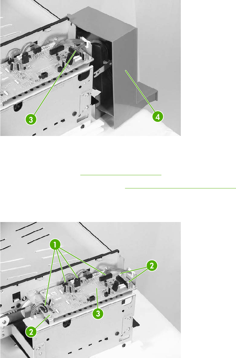
5. Remove the connector cover assembly (callout 4).
Figure 6-378 Remove the IPTU connector cover (3 of 3)
IPTU driver PCB
1. Remove the rear cover. See IPTU rear cover on page 475.
2. Remove the connector cover assembly. See Connector cover assembly on page 476.
3. Disconnect the four connectors (callout 1).
4. Remove the three screws (callout 2), and then remove the IPTU driver PCB (callout 3).
Figure 6-379 Remove the IPTU driver PCB
ENWW Intermediate paper transfer unit (IPTU) 477
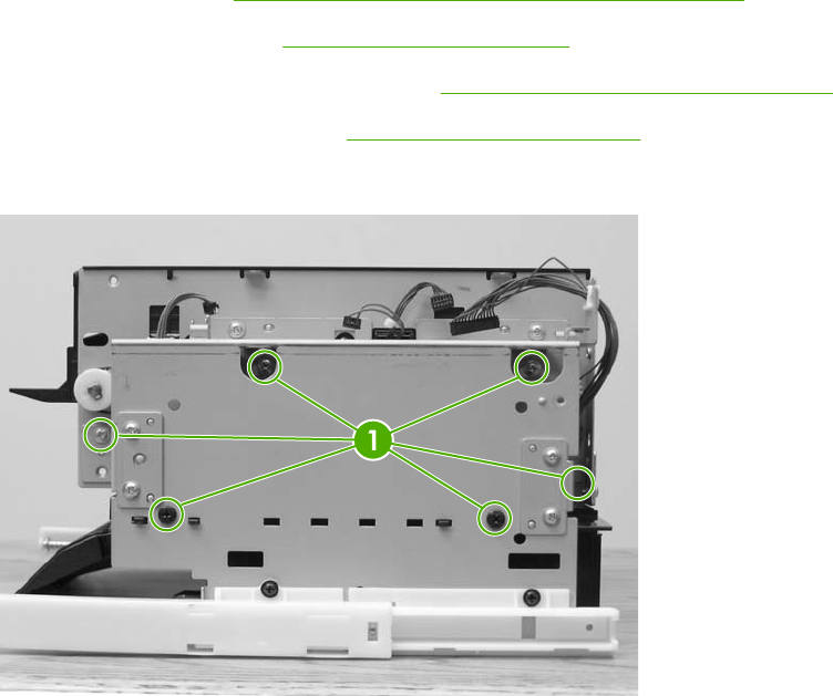
IPTU driver motors
1. Remove the IPTU. See Intermediate paper transfer unit (IPTU) on page 252.
2. Remove the rear cover. See IPTU rear cover on page 475.
3. Remove the connector cover assembly. See Connector cover assembly on page 476.
4. Remove the IPTU driver PCB. See IPTU driver PCB on page 477.
5. Remove the six screws (callout 1) and remove the cover.
Figure 6-380 Remove the IPTU driver motors (1 of 3)
478 Chapter 6 Removal and replacement ENWW
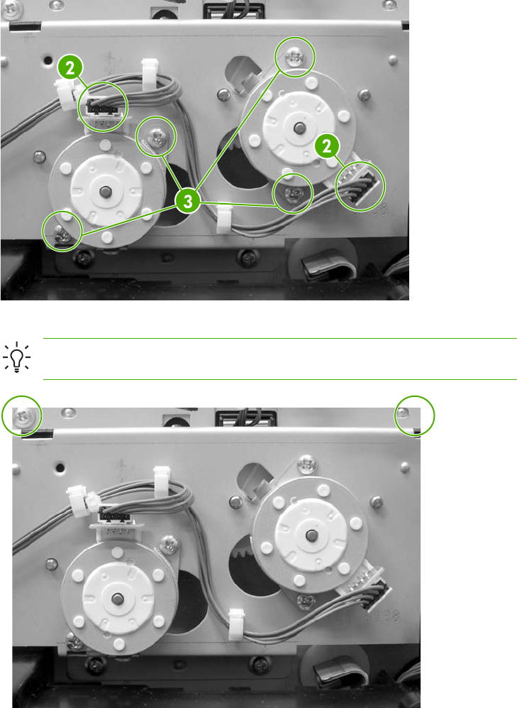
6. Remove the connectors (callout 2) from each motor.
Figure 6-381 Remove the IPTU driver motors (2 of 3)
Hint To remove the right motor, remove two screws and loosen the cover.
Figure 6-382 Remove the IPTU driver motors (3 of 3)
7. Remove two screws (callout 3) for each motor and remove the motors.
ENWW Intermediate paper transfer unit (IPTU) 479
480 Chapter 6 Removal and replacement ENWW

7 Troubleshooting
In order to use the information in this chapter, you should have a basic understanding of the
HP LaserJet printing process. Explanations of each mechanical assembly, the MFP systems, and the
basic theory of operation are contained in chapter 5 of this manual. Do not perform any of these
troubleshooting processes unless you understand the function of each MFP component.
This chapter contains information about the following topics:
●Introduction
●Troubleshooting process
●Control panel messages
●Accessory lights for the 3-bin mailbox and stapler/stacker
●Formatter lights
●Replacement parts configuration
●Paper path troubleshooting
●Correcting print quality and copy quality problems
●Media transport problems
●E-mail problems
●Fax problems
●Network connectivity problems
●Functional checks
●MFP resets
●Control panel troubleshooting
●Tools for troubleshooting
●Diagrams for troubleshooting
ENWW 481
Introduction
The information in this troubleshooting chapter is presented with the assumption that the reader has
a basic understanding of the color laser-printing process. Explanations of each mechanical
assembly, printer systems, and the basic theory of operation are provided in chapter 5. Do not
perform any of these troubleshooting processes without fully understanding the function of each
mechanism.
This chapter contains the following sections:
●Troubleshooting process includes a pre-troubleshooting checklist and a troubleshooting
flowchart. These tools contain information about common printer errors that can inhibit proper
operation or create print quality problems. These tools also include recommendations for solving
the cause of the error.
●Control panel messages explains each control panel-display message and suggests
recommendations for clearing the cause of each message. When the printer message indicates
a failure for which the root cause is not obvious, use the printer error troubleshooting section
and the troubleshooting tools section in this chapter to solve the problem.
●Replacement parts configuration
●Paper path troubleshooting provides techniques to solve feed problems. Explanations are
provided about print media checks, troubleshooting jams, and the differences between jams
caused by media and those caused by the MFP.
●Paper path troubleshooting
●Output devices provides troubleshooting information for the IPTU, stapler/stacker, and the 3-
bin mailbox.
●Image formation troubleshooting suggests methods for solving print quality problems.
●Interface troubleshooting provides techniques for isolating communication problems to the
MFP hardware, printer configuration, network configuration, or software program.
●Control panel troubleshooting provides procedures for printing a menu map from the MFP
control panel. It also describes the control panel menus, the items within each menu, and the
possible values for the menu items.
●Fax, e-mail, and network connectivity problems
●Troubleshooting tools help isolate the cause of MFP failures. This section includes
explanations of the MFP configuration page and the event log.
●Diagnostics provides instructions about how to gain access to and use the diagnostic tools that
are incorporated into the MFP.
●Test pages provides information on printing test pages to help diagnose problems.
●MFP resets
●Service menu provides procedures for opening the service menu and performing service-
oriented tasks. These tasks include counts for entering the serial number, service ID, transfer
unit maintenance, fuser maintenance, color page, and total page, and clearing the event log.
●Diagrams provides graphical locations and tables for the MFP's internal assemblies and
sensors.
482 Chapter 7 Troubleshooting ENWW

Troubleshooting process
When the MFP malfunctions or encounters an unexpected situation, information on the control panel
alerts you to the situation. This section contains an initial troubleshooting checklist that helps to
eliminate many possible causes of the problem. The subsequent troubleshooting flowchart helps you
to diagnose the cause of the problem. The remainder of the chapter provides steps for correcting the
problems that have been identified.
●Use the initial troubleshooting checklist to evaluate the source of the problem and to reduce the
number of steps that are required to fix the problem.
●Use the troubleshooting flowchart to pinpoint the cause of malfunctions. The flowchart lists the
section within this chapter that provides steps for correcting the malfunction.
Before beginning any troubleshooting procedure, check the following:
●Are supply items (for example, the print cartridge, fuser, and rollers) within their rated life?
Does the configuration page reveal any configuration problems? See Information pages
on page 640.
NOTE The customer is responsible for checking and maintaining supplies, and for using
supplies that are in good condition. The customer is responsible for media and print-cartridge
supplies. The customer is also responsible for replacing the fuser, transfer roller, and all paper
pickup, feed, and separation rollers (tray 1 has a separation pad instead of a roller) that are at
or near the end of their 225,000-page rated life.
Initial troubleshooting checklist
If the MFP is not responding correctly, complete the steps in the following checklist, in order. If the
MFP does not pass a step, follow the corresponding troubleshooting suggestions. If a step resolves
the problem, you can stop without performing the other steps on the checklist.
Troubleshooting checklist
1. Make sure the MFP Ready light is on and the display says Ready. If no lights are on, see
Power-on checks on page 487.
2. Check the cabling.
a. Check the cable connection between the MFP and the computer or network port. Make
sure that the connection is secure.
b. Make sure that the cable itself is not faulty by using a different cable, if possible.
c. Check the network connection. See Network connectivity problems on page 596.
3. Ensure that the print media that you are using meets specifications. See Media specifications
on page 18.
4. Print a configuration page (see Information pages on page 640.) If the MFP is connected to a
network, an HP Jetdirect page also prints.
a. If the pages do not print, check that at least one tray contains print media.
b. If the page jams in the MFP, see Paper path troubleshooting on page 536.
ENWW Troubleshooting process 483

5. If the configuration page prints, check the following items.
a. If the page prints correctly, then the MFP hardware is working. The problem is with the
computer that you are using, with the printer driver, or with the program.
b. If the page does not print correctly, the problem is with the MFP hardware. See Functional
checks on page 598.
6. Does the image quality meet the user's requirements? If yes, go to step 7. If no, check the
following items:
●Print the print quality troubleshooting pages. See Print quality troubleshooting pages
on page 572.
●Solve the print quality problems, and then go to step 7.
7. At the computer, check to see if the print queue is stopped, paused, or set to print offline.
Windows: Click Start, click Settings, and then click Printers or Printers and Faxes. Double-
click HP Color LaserJet 4730mfp.
-or-
Mac OS X: Open Print Center (or Printer Setup Utility for Mac OS X v.10.2), and double-click
the line for the HP Color LaserJet 4730mfp.
8. Verify that you have installed the HP Color LaserJet 4730mfp series printer driver. Check the
program to make sure that you are using an HP Color LaserJet 4730mfp series printer driver.
9. Print a short document from a different program that has worked in the past. If this solution
works, then the problem is with the program that you are using. If this solution does not work
(the document does not print) complete these steps:
a. Try printing the job from another computer that has the MFP software installed.
b. If you connected the MFP to the network, connect the MFP directly to a computer with a
parallel cable. Redirect the MFP to the correct port, or reinstall the software, selecting the
new connection type that you are using.
484 Chapter 7 Troubleshooting ENWW

Troubleshooting flowchart
This flowchart highlights the general processes that you can follow to quickly isolate and solve MFP
hardware problems.
Each row depicts a major troubleshooting step. A “yes” answer to a question allows you to proceed
to the next major step. A “no” answer indicates that additional testing is needed. Proceed to the
appropriate section in this chapter, and follow the instructions there.
After completing the instructions, proceed to the next major step in this troubleshooting flowchart.
Table 7-1 Troubleshooting flowchart
1
Power on
Is the MFP on and does a readable
message appear?
Follow the power-on troubleshooting checks. See Power-on
checks on page 487.
After the control panel display is functional, go to step 2.
Yes No
2
control panel
messages
Does the message Ready appear on the
control panel display?
If an error message displays, see Resolving control panel
messages on page 488.
After the errors have been corrected, go to step 3.
Yes No
3
Event log
Open the DIAGNOSTICS menu and print
an event log to see the history of errors with
this MFP.
Does the event log print?
If the event log does not print, see Engine test on page 598.
If paper jams inside the MFP, see Paper path troubleshooting
on page 536.
If error messages appear on the control panel display when you
try to print an event log, see Resolving control panel messages
on page 488.
After successfully printing and evaluating the event log, go to
step 4.
Yes No
4
Information pages
Open the Information menu and print the
configuration pages to verify that all of the
accessories are installed.
Are all of the accessories installed?
If accessories that are installed are not listed on the configuration
page, remove the accessory and reinstall it.
For more information about optional output devices, see
Accessory lights for the 3-bin mailbox and stapler/stacker
on page 531.
After evaluating the configuration pages, go to step 5.
Yes No
5
Copy/scan
Can you successfully make a copy from
both the ADF and the scanner glass?
If paper jams inside the ADF, see Paper path troubleshooting
on page 536.
If you cannot make a copy from the scanner glass, see Scanner
tests on page 659.
After you can successfully copy, go to step 6.
Yes No
6
Image quality
Does the print quality meet the customer's
requirements?
Compare the images with the sample defects in the image defect
tables. See Image defect examples on page 586.
After the print quality is acceptable, go to step 7.
Yes No
7
Interface
Can the customer print successfully from
the host computer?
Verify that all I/O cables are connected correctly and that a valid
IP address is listed on the Jetdirect configuration page.
Yes. This is the end of
the troubleshooting
process.
No
ENWW Troubleshooting process 485

See Network connectivity problems on page 596. Also see
Configuring and verifying an IP address on page 136 in chapter 3
of this manual.
If error messages appear on the control panel display, see
Resolving control panel messages on page 488.
When the customer can print from the host computer, this is the
end of the troubleshooting process.
Table 7-1 Troubleshooting flowchart (continued)
486 Chapter 7 Troubleshooting ENWW

Power-on checks
The basic MFP functions should start up as soon as the MFP is plugged into an electrical outlet and
the power switch is pushed to the on position. If the MFP does not start, use the information in this
section to isolate and solve the problem.
Power-on troubleshooting overview
Turn on the MFP power. If the control panel display remains blank, random patterns appear, or
asterisks remain on the display, perform power-on checks to locate the cause of the problem.
During normal operation, the main cooling fan begins to spin briefly after the MFP power is turned
on. Place your hand over the holes in the rear cover, above the formatter. If the fan is operating, you
will feel a slight vibration and feel air passing into the MFP. You can also lean close to the MFP and
hear the fan operating. When this fan is operational, the DC side of the power supply is functioning
correctly.
After the fan is operating, the main motor turns on (unless the top cover is open, a jam condition is
sensed, or the paper-path sensors are damaged). You should be able to visually and audibly
determine if the main motor is turned on.
If the fan and main motor are operating correctly, the next troubleshooting step is to isolate print
engine, formatter, and control panel problems. Perform an engine test (see Engine test on page 598).
If the formatter is damaged, it might interfere with the engine test. If the engine test page does not
print, try removing the formatter and then performing the engine test again. If the engine test is then
successful, the problem is almost certainly with the formatter, the control panel, or the cable that
connects them.
If the control panel is blank when you turn on the MFP, check the following items.
1. Make sure that the MFP is plugged into an active electrical outlet that delivers the correct voltage.
2. Make sure that the power switch is in the on position.
3. Make sure that the fan runs briefly, which indicates that the power supply is operational.
4. Make sure that the formatter is seated properly.
5. Make sure that the control panel display wire harness is connected. See Control panel
on page 250.
6. Make sure that the firmware flash memory card and the formatter are seated and operating
correctly. See Flash memory card (firmware) on page 287.
7. Remove any HP Jetdirect or other EIO cards, and then try to turn the MFP on again.
NOTE If the control panel display is blank, but the main cooling fan runs briefly after the
MFP power is turned on, try printing an engine test page to determine whether the problem is
with the control panel display, formatter, or other MFP components. See Engine test
on page 598.
ENWW Troubleshooting process 487

Control panel messages
Messages that appear on the control panel display relay the normal status of the MFP (such as
Processing job.), or an error condition (such as CLOSE TOP COVER) that needs attention.
Resolving control panel messages on page 488 lists messages that require attention, or that might
raise questions. Messages are listed in alphabetical order, with numeric messages at the end of the
list. Not all messages are listed because some (such as Ready) are self-explanatory.
NOTE Some messages are affected by the AUTO CONTINUE and CLEARABLE
WARNINGS settings on the Configure Device menu, SYSTEM SETUP submenu, on the
control panel.
Using the MFP help system
This MFP features a help system on the control panel that provides instructions for resolving most
MFP errors. Certain control panel messages alternate with instructions about using the help system.
Whenever a ? appears in an error message or a message alternates with FOR HELP TOUCH ?,
touch the (Help) button to view the help.
To exit the help system, touch the (Help) button.
Resolving control panel messages
Control panel message Description Recommended action
10.XX.YY SUPPLY
MEMORY ERROR
alternates with
For help press ?
The supplies gauge will display the
consumption levels of print cartridges.
NOTE Where noted, the
message appears only on the
event log, not on the control panel.
A 10.XX.YY error indicates either an error
with a print cartridge or a notification of
OVERRIDE AT OUT / COLOR SUPPLY
OUT settings.
The values of YY are:
00 = black print cartridge
01 = cyan print cartridge
02 = magenta print cartridge
03 = yellow print cartridge
The values of XX are:
00 = memory error on supply
10 = memory tag missing
30 = non-HP supply in use
32 = unauthorized supply in use
For errors 70 through 92, the message
appears only in the event log and is not
10.00.YY, 10.10.YY, 10.30.YY, 10.32.YY
procedure:
1. Turn the MFP off then on.
2. Swap the cartridge for the color
indicated with a cartridge in another
slot to determine whether the error
follows the cartridge or stays with the
slot. If the error follows the cartridge,
replace that cartridge. Otherwise,
proceed to step 3.
3. Reseat the connectors between the
memory PCB (J4001) and DC
controller (J1021).
4. Replace the memory controller PCB.
5. Replace the DC controller PCB.
Calibrate the printer after replacing the
DC controller.
488 Chapter 7 Troubleshooting ENWW

Control panel message Description Recommended action
posted on the control panel. The control
panel message is indicated in parentheses.
70 = Cartridge Out Override activated
(override in use)
71 = Monochrome printing after color
cartridge out activated (printing black only)
80 = Cartridge Out Override deactivated
because user limit reached (override not in
use)
81 = Monochrome printing after color
cartridge out deactivated (not printing black
only)
88 = Cartridge Out Override deactivated
because maximum use/wear limit reached
(override not in use)
89 = Cartridge Out Override deactivated
because cartridge is out of toner (override
not in use)
90 = Replace cartridge (Replace <color>
cartridge)
92 = Cartridge not engaged
10.70.YY, 10.80.YY, 10.88.YY, 10.89.YY
procedure:
1. When OVERRIDE AT OUT is selected
in the REPLACE SUPPLIESmenu
and a print cartridge reaches an Out
state, a 10.70.YY message is posted
in the event log and the MFP
continues to print.
2. When the print cartridge subsequently
reaches one of the three thresholds
set for Override, one of the following
events is posted to the event log and
the MFP will not continue to print.
●10.80.YY = user limit
●10.88.YY = HP pre-defined
maximum use/wear
●10.89.YY = out of toner
10.71.YY, 10.81.YY procedure:
1. When AUTOCONTINUE BLACK is
selected in the COLOR SUPPLY
OUTmenu and a color print cartridge
reaches an Out state, a 10.71.YY
message is posted in the event log
and the MFP continues to print in
black-only mode.
2. When the black cartridge
subsequently reaches Out, a 10.81.YY
message is posted to the event log
and the MFP will not continue to print
unless OVERRIDE AT OUT is set.
10.90.YY, 10.92.YY procedure:
1. Turn the MFP off then on.
2. Reseat the print cartridge.
3. Replace the indicated print cartridge.
11.X INTERNAL CLOCK ERROR
To continue touch OK
This message is displayed when there is a
problem with the real-time clock on the
formatter board.
XX=01 Dead clock battery
XX=02 Dead real-time clock
Touch OK to continue. If this error occurs,
the MFP will continue to track the time and
date using the processor clock until the
MFP is turned off. Unless the error is
corrected, you will be prompted to reset the
date and time whenever the MFP is turned
off then on.
If the error persists, the formatter might
need to be replaced.
ENWW Control panel messages 489

Control panel message Description Recommended action
13.01.00 JAM INSIDE DRAWER BELOW
TRAY 1
Paper is jammed inside the drawer. 1. Follow the onscreen help to clear the
jam. Touch OK to continue.
2. It might be a no-pick jam. Check the
tray 3 and 4 paper pickup and paper
feed rollers. Reseat the rollers if
necessary. Replace the rollers if they
are worn or damaged.
3. Ensure that paper is loaded correctly
in the paper tray.
4. Try exchanging paper trays to isolate
the problem.
13.02.00 JAM INSIDE RIGHT DOORS Paper is jammed inside the right doors. The
trailing edge was not detected by sensor
SR12 after the specified time.
1. Follow the onscreen help to clear the
jam. Touch OK to continue.
2. Check for obstructions in the paper
feed assembly.
3. Ensure that paper is loaded correctly
in the paper tray.
4. Try exchanging paper trays to isolate
the problem.
5. If paper jams in the paper feed
assembly, replace the assembly after
checking for any obstruction.
13.12.00 JAM INSIDE
UPPER RIGHT DOOR
Paper is jammed in the fuser. 1. Follow the onscreen help to clear the
jam. Touch OK to continue.
2. Check for obstructions in the fuser.
3. Check for obstructions in the duplexer.
13.12.00 JAM INSIDE
UPPER RIGHT DOOR
Paper is jammed inside the upper right
door. There is a jam in the oblique roller
area between sensor SR8001 (paper
reversing sensor) and SR12 (top of page
sensor).
1. Follow the onscreen help to clear the
jam. Touch OK to continue.
2. Ensure that media meets specifications.
3. Ensure that the ETB rollers roll freely.
4. Ensure that there is no obstruction at
the bottom of the ETB.
13.JJ.NT JAM IN
PAPER PATH
Paper is jammed between the registration
sensor and the yellow drum.
The specific error could be either:
●13.20.00
●13.21.00
1. Follow the onscreen help to clear the
jam. Touch OK to continue.
2. Check for obstructions in the paper
feed assembly.
3. Ensure that the paper is loaded
correctly in the paper tray and that it
meets specifications.
4. Check for obstructions in the
attachment roller on the ETB.
490 Chapter 7 Troubleshooting ENWW

Control panel message Description Recommended action
5. Replace the paper feed assembly
after it has been checked for
obstructions.
6. Replace the ETB.
13.JJ.NT JAM IN TRAY 1 The MP tray pickup solenoid might be
defective.
Remove any jammed paper from tray 1.
Follow the instructions on the control panel.
See Jams in Tray 1 on page 557.
If the message persists, open the
DIAGNOSTICS menu and touch
COMPONENT TEST. Run the test for MP
TRAY SOLENOID. If the solenoid is
defective, replace it. See Component tests
on page 659.
For more information, see Persistent jams
on page 556.
13.JJ.NT JAM IN TRAY X Paper is jammed in the specified tray. Follow the instructions on the control panel.
See Jams in tray 2 on page 558.
If the message persists, see Persistent
jams on page 556.
13.JJ.NT JAM INSIDE LOWER RIGHT
DOOR
Paper is jammed inside the lower right door. 1. Follow the onscreen help to clear the
jam. Touch OK to continue.
2. It might be a no-pick jam. Check the
tray 3 and 4 paper pickup and paper
feed rollers. Reseat the rollers if
necessary. Replace the rollers if they
are worn or damaged.
3. Ensure that paper is loaded correctly
in the paper tray.
4. Try exchanging paper trays to isolate
the problem.
13.JJ.NT JAM INSIDE OUTPUT
ACCESSORY BRIDGE
Paper is jammed inside the output
accessory bridge.
1. Follow the onscreen help to clear the
jam. Touch OK to continue.
2. Check for obstructions inside the
output accessory bridge.
3. Try printing a simplex job to isolate the
issue.
4. Remove and reinstall the output
accessory bridge. Check for paper
after removal.
13.JJ.NT JAM INSIDE RIGHT DOORS Paper is jammed inside the right doors. The
front edge did not reach sensor SR1 within
the specified time after reaching sensor
SR12.
1. Follow the onscreen help to clear the
jam. Touch OK to continue.
2. Check for obstructions near the fuser
inlet.
3. Ensure that paper is loaded correctly
in the paper tray.
ENWW Control panel messages 491

Control panel message Description Recommended action
4. Try exchanging paper trays to isolate
the problem.
5. Replace the fuser.
13.JJ.NT JAM INSIDE SMALL FRONT
DOOR
Paper is jammed inside the small front door. 1. Follow the onscreen help to clear the
jam. Touch OK to continue.
2. Check for obstructions inside the
output accessory bridge.
3. Try printing a simplex job to isolate the
issue.
4. Remove and reinstall the output
accessory bridge. Check for paper
after removal.
13.JJ.NT JAM INSIDE TRAY 1 There is a jam inside tray 1. 1. Remove any jammed paper in tray 1.
2. Ensure that paper is loaded properly.
3. Inspect the pickup roller and
separation pad. Replace if necessary.
13.XX.X JAM IN
LEFT ACCESSORY
Paper is jammed in an external paper
handling device.
Clear the jam and then touch OK.
13.XX.YY JAM IN
TOP OUTPUT BIN
Paper is jammed in the output bin.
Use this list to determine the exact location
of the jam:
●13.12.07 = staple cartridge
●13.12.08 = output bin paper-present
sensor (paper is stuck)
●13.12.09 = output bin inlet sensor
(paper is stuck)
●13.12.10 = output bin inlet sensor
(paper did not reach the sensor at the
appropriate time)
●13.12.11 = paper present in the output
bin when the MFP is turned on
●13.31.00 = paper jammed in the
reversing assembly
1. Clear all jammed paper.
2. Verify that the connector J50 on the
DC controller PCB is firmly seated.
See Figure 6-234 Remove the DC
controller (1 of 2) on page 385.
3. Verify that the two connectors on the
rear of the reversing assembly are
installed. See Figure 6-234 Remove
the DC controller (1 of 2) on page 385.
4. Use the component diagnostics test to
test three motors: switchback motor,
intermediate switchback motor, and
output motor. See Component tests
on page 659.
5. Use the component diagnostics test to
test two sensors: face-up/face-down
solenoid and alienation solenoid. See
Component tests on page 659.
6. Use the manual sensor test to test two
sensors: paper delivery sensor and
reversing-paper sensor. See Manual
sensor test on page 657.
7. If any of these components fail,
replace the reversing assembly.
13.XX.YY JAM IN STAPLER Paper is jammed inside the stapler. See Staple jams on page 548.
492 Chapter 7 Troubleshooting ENWW

Control panel message Description Recommended action
20 INSUFFICIENT MEMORY
For help press ?
alternates with
20 INSUFFICIENT MEMORY
To continue touch OK
The MFP has received more data from the
computer than fits in available memory.
1. Touch OK to continue printing.
CAUTION A loss of data will
occur.
2. Reduce the complexity of the print job
to avoid this error in the future.
3. Adding memory to the MFP may allow
printing of more complex pages.
22 EIO X
BUFFER OVERFLOW
To continue touch OK
The EIO card in card slot X has overflowed
its I/O buffer during a busy state.
1. Touch OK to continue printing.
CAUTION A loss of data will
occur.
2. Check the host configuration. If the
message persists, replace the device
in the EIO slot.
22 EMBEDDED I/O
BUFFER OVERFLOW
To continue touch OK
Too much data was sent to the embedded
HP Jetdirect print server.
Touch OK to continue. When this error
occurs, data might be lost. If necessary,
resend the job to the MFP.
22 PARALLEL I/O
BUFFER OVERFLOW
For help press ?
alternates with
22 PARALLEL I/O
BUFFER OVERFLOW
To continue touch OK
The parallel buffer has overflowed during a
busy state.
1. Touch OK to resume printing.
NOTE A loss of data will
occur.
2. If the message persists, disconnect
the parallel cable at both ends and
reconnect.
3. Ensure that a high-quality cable is
being used. Some non-HP parallel
cables might be missing pin
connections or might not conform to
the IEEE-1284 specification.
4. Replace the parallel cable.
5. Leave the PC connected and attempt
to connect to another printer. If the
connection fails, replace the formatter.
22 USB I/O
BUFFER OVERFLOW
To continue touch OK
The USB buffer has overflowed during a
busy state.
1. Touch OK to continue printing.
NOTE A loss of data will
occur.
2. If the message persists, disconnect
the USB cable at both ends and
reconnect.
3. Ensure that a high-quality USB cable
is being used.
ENWW Control panel messages 493

Control panel message Description Recommended action
4. Replace the USB cable.
5. Leave the PC connected and attempt
to connect to another printer. If the
connection fails, replace the formatter.
30.00.01 Check Cables Check Scanner
Lock
The scanner cables might be loose, or the
scanner lock might be incorrectly set.
1. To continue, turn the MFP off then on.
2. Check the cables and the scanner lock.
3. Check the scanner fan.
30.01.06 SCANNER FAILURE This is a scanner fan error. This fan is
located in the base of the scanner
assembly. It operates whenever the
scanner lamp is illuminated or whenever
the scanner flatbed motor is rotating. This
fan also operates during the MFP
initialization sequence.
1. During the MFP initialization
sequence, listen to the fan to
determine if it is operating.
2. Verify that the connector CN108 on
the scanner controller PCB is firmly
seated. See Scanner controller PCB
connections on page 669. Also make
sure that the connection for the fan in
the base of the scanner assembly is
firmly seated.
3. If all the connections are secure but
the fan is not operating, replace the
fan. See Scanner fan on page 428.
30.01.08 SCANNER FAILURE This is a scanner calibration error. The
scanner might be locked, or a cable might
not be connected correctly.
During the MFP initialization sequence, the
scanner optical assembly moves from its
home position to the calibration strip. If this
movement does not occur, this error
appears.
1. Raise the ADF and ensure that the
scanner lock is in the unlocked position.
2. Turn on the MFP and watch to see if
the optical assembly moves. If it does
not move, remove the scanner glass
to see if anything is hindering the
optical assembly from moving.
3. Ensure that the optical assembly drive
belt is installed correctly.
4. Verify that the connector CN106 on
the scanner controller PCB is firmly
seated. See Figure 7-20 Main
assembly PCBs on page 678. Also see
Scanner controller PCB connections
on page 669.
5. Verify that the connector CN109 on
the scanner controller PCB is firmly
seated. Also verify that the connector
for the scanner home position sensor
is firmly seated. See Figure 7-15
Scanner controller PCB component
connections on page 669.
30.01.10 SCANNER FAILURE The ADF fan is not operating.
The ADF fan operates only during the scan
process.
1. Remove the ADF rear cover and
watch the fan during a scan from the
ADF.
2. Verify that the fan connection on the
ADF intermediate PCB is firmly seated.
3. If the fan does not rotate, replace the
ADF. See ADF assembly on page 411.
494 Chapter 7 Troubleshooting ENWW

Control panel message Description Recommended action
30.01.YY SCANNER FAILURE An error has occurred in the scanner. Use
the following list to identify specific errors:
●30.01.01 = The scanner cover is open.
●30.01.02 = A jam has occurred in the
ADF.
●30.01.03 = The ADF could not pick up
the paper.
●30.01.06 = An error has occurred at
the scanner fan. (See the separate
entry for this error.)
●30.01.07 = A communication error has
occurred in the scanner.
●30.01.08 = A scanner calibration error
has occurred. (See the separate entry
for this error.)
●30.01.10 = An error has occurred at
the ADF fan. (See the separate entry
for this error.)
●30.01.15 = Scanner initialization failed.
●30.01.17 = The scanner carriage is
locked.
●30.01.18 = An error occurred on the
scanner PCB.
●30.01.19 = An error occurred at the
scanner lamp.
●30.01.22 = A fatal hardware error has
occurred in the scanner.
●30.01.23 = A scanner calibration error
has occurred.
●30.01.24 = The ADF jam access door
is open.
●30.01.25 = A general error has
occurred in the scanner or ADF. This
error is most likely a memory
corruption.
●30.01.29 = The ADF output bin is full.
●30.01.36 = The scanning firmware
upgrade failed. The MFP automatically
tries to upgrade the firmware again the
next time the MFP is turned on.
1. Turn the MFP off and then on to try to
clear the message.
2. If the message indicates that a jam
has occurred, clear the jam. See Jams
in the ADF on page 562.
3. Verify that the cable between the print
engine and the scanner is securely
connected. See Scanner controller
PCB connections on page 669.
4. Upgrade the firmware.
5. If you are unable to resolve the
problem, replace the scanner
assembly. See Scanner assembly
on page 414.
40 Bad Serial Transmission
To continue touch OK
A serial data error (parity, framing, or line
overrun) occurred as data was being sent
by the computer.
Touch OK to clear the error message.
(Data will be lost.)
40 EIO X BAD The connection between the MFP and the
EIO card has been broken.
Touch OK to continue printing.
ENWW Control panel messages 495

Control panel message Description Recommended action
TRANSMISSION
To continue touch OK
40 EMBEDDED I/O BAD
TRANSMISSION
To continue touch OK
A connection with the embedded Jetdirect
print server has been broken.
Turn the MFP off then on.
If the message persists, the embedded
Jetdirect print server might be damaged.
Replace the formatter. See Formatter board
on page 280.
41.3 UNEXPECTED
SIZE IN TRAY X
For help press ?
alternates with
LOAD TRAY XX
[TYPE] [SIZE]
To use another
tray touch OK
The paper that is loaded is longer or shorter
in the feed direction than the size
configured for the tray.
1. If the incorrect size was selected,
cancel the job or press to access
help.
OR
2. Touch OK to select another tray.
3. Run paper path diagnostics to ensure
that the sensors are functioning
properly.
4. Replace the paper feed unit.
41.5 UNEXPECTED
TYPE IN TRAY X
For help press ?
alternates with
LOAD TRAY XX
[TYPE] [SIZE]
To use another
tray touch OK
The MFP senses a different paper type in
the paper path than configured in the tray.
1. If the incorrect type was selected,
cancel the job or press to access
help.
OR
2. Touch OK to select another tray.
3. Run the paper path diagnostics to
ensure that the sensors are
functioning properly.
4. Replace the paper feed unit.
44.1 USB ACCESSORY
ERROR
For help press ?
This message appears when a connected
USB accessory draws too much power.
When this happens, the ACC port is
disabled and printing stops.
●Use the scroll bar to step through the
instructions.
●Remove the USB accessory.
49.XX.XX PRINTER ERROR
PRINTER ERROR
To continue
turn off then on
A critical firmware error has occurred that
caused the processor on the formatter to
abort operation. This type of error can be
caused by invalid print commands, corrupt
data, or invalid operations. In some cases,
electrical noise in the cable can corrupt
data during transmission to the printer.
Other causes include poor-quality parallel
cables, poor connections, or homegrown
programs. On rare occasions, the formatter
is at fault, which is usually indicated by a 79
Service Error.
1. Turn the MFP off then on.
2. Press Stop to clear the print job from
memory.
3. Turn the MFP off then on.
4. Try printing a job from a different
software program. If the job prints, go
back to the first program and try
printing a different file. If the message
appears only with a certain software
program or print job, contact the
software vendor for assistance.
496 Chapter 7 Troubleshooting ENWW

Control panel message Description Recommended action
5. If the message persists with different
software programs and print jobs,
disconnect all of the cables to the
MFP that connect it to the network or
computer.
6. Turn the MFP off.
7. Remove all memory DIMMs or third-
party DIMMs from the MFP. (Do not
remove the firmware DIMM.)
8. Remove all EIO devices from the MFP.
9. Turn the MFP on.
10. If the error no longer exists, reinstall
each DIMM and EIO device one at a
time, making sure to turn the MFP off
and on again as you install each
device.
11. Replace a DIMM or EIO device if you
determine that it causes the error.
12. Remember to reconnect all of the
cables that connect the MFP to the
network or computer.
13. If the error persists, upgrade the
firmware before replacing the DC
controller.
14. Replace the formatter and calibrate
the MFP. See Calibrating the MFP
on page 591.
50.X FUSER ERROR
For help press ?
A fuser error has occurred.
The error might be due to an inadequate
power supply, inadequate line voltage, or a
problem with the fuser.
The following are specific fuser errors:
50.1: A low fuser temperature error has
occurred in the main thermistor.
50.2: A fuser warm-up service error has
occurred.
50.3: A high fuser temperature error has
occurred in the main thermistor.
50.6: An open fuser error has occurred.
50.7: A fuser pressure release mechanism
has failed.
50.8: A low fuser temperature error has
occurred in the sub thermistor.
50.9: A high fuser temperature error has
occurred in the sub thermistor.
1. Turn the MFP off then on.
2. Reinstall the fuser and check the fuser
connection (J5001) with the DC
controller. If the connector is
damaged, replace it.
3. Replace the fuser.
4. Replace the low-voltage PCB.
5. Replace the DC controller.
ENWW Control panel messages 497

Control panel message Description Recommended action
51.1Y PRINTER ERROR
PRINTER ERROR
For help press ?
alternates with
51.1Y PRINTER ERROR
To continue
turn off then on
A beam detect error has occurred.
The values of Y are:
Y Description
0 - Black
1 - Cyan
2 - Magenta
3 - Yellow
1. Turn the MFP off then on.
2. If possible, run the scanner test
diagnostic for the laser scanner
indicated.
3. Verify that the scanner is properly
connected at the DC controller.
4. Replace the scanner.
51.2Y
PRINTER ERROR
For help press ?
alternates with
51.2Y
PRINTER ERROR
To continue
turn off then on
A laser error has occurred.
The values of Y are:
Y Description
0 - Black
1 - Cyan
2 - Magenta
3 - Yellow
1. Turn the MFP off then on.
2. If possible, run the scanner test
diagnostic for the laser scanner
indicated.
3. Verify that the scanner is properly
connected at the DC controller.
4. Replace the scanner.
52.XY PRINTER ERROR
alternates with
To continue
turn off then on
A scanner error has occurred. 1. Restart the MFP.
2. Scan from the flatbed and from the
ADF.
3. Reseat the formatter.
53.XY.ZZ CHECK RAM
DIMM SLOT X
A memory error has occurred.
X DIMM type
1 -
Y Device location
1 - DIMM Slot 1
2 - DIMM Slot 2
ZZ Error number
00 - Unsupported memory
01 - Unrecognized memory
02 - Unsupported memory size
03 - Failed RAM test
04 - Exceeded maximum RAM size
05 - Invalid DIMM speed
If prompted to do so, touch OK to continue.
The MFP should come to the Ready state,
but will not make full use of all memory
installed.
Otherwise:
1. Turn the MFP off.
2. Verify that all memory meets
specifications and is correctly seated.
3. Turn the MFP on.
4. If the problem persists, replace the
DIMM card in the slot indicated.
498 Chapter 7 Troubleshooting ENWW

Control panel message Description Recommended action
MAY BE DELETE54.X PRINTER ERROR
To continue
turn off then on
Printing cannot continue. There is a sensor
malfunction.
Values of X are:
01 - Humidity/temperature sensor
15 - Yellow
16 - Magenta
17 - Cyan
18 - Black
1. Turn the MFP off then on.
2. Check connector J501 on the toner
level PCB or J5201 on the
environmental sensor.
3. Check connector J1014 or connector
J1010 on the DC controller.
4. Replace the environmental sensor or
the toner level PCB.
5. Replace the DC controller.
54.XX
PRINTER ERROR
54 errors indicate sensor abnormalities.
Sensor abnormalities are caused by failed
or black sensors, or sensors that report
results outside of an expected range.
NOTE Some 54 errors do not
stop the printing process and are
noted on the event log but not on
the control panel.
XX description:
01 = environmental temperature sensor
output is abnormal (appears only in the
event log)
05 = Media sensor failure (appears only in
the event log)
NOTE Errors 07 through 0F
appear only in the event log and
printing continues.
07 = yellow drum phase (home) position
sensor
08 = magenta drum phase (home) position
sensor
09 = cyan drum phase (home) position
sensor
0A = black drum phase (home) position
sensor
0B = Density Sensor Out of Range
0C = Halftone Calibration
0D = Halftone Calibration Diffusion
0F = CPR Out of Range
54.01 procedure:
1. Check that all of the environmental
requirements are met.
2. Turn the MFP off then on.
3. Check connector J5201 on the
environmental sensor and connector
J1010 on the DC controller.
4. Replace the environmental sensor.
5. Replace the DC controller.
54.05 procedure:
1. Check connector J4201 on the paper
feed assembly and connector J1013
on the DC controller.
2. Replace the paper feed assembly.
3. Replace the DC controller.
54.07, 54.08, 54.09, 54.0A procedure:
1. Check connector J1022 on the DC
controller to the drum home position
sensor for the color indicated.
2. Replace the main drive assembly.
3. Replace the DC controller.
54.0B, 54.0C, 54.0D, 54.0F procedure:
ENWW Control panel messages 499

Control panel message Description Recommended action
The last two digits indicate the color (00 =
black, 01 = cyan, 02 = magenta, 03 = yellow)
1. Check for correct formation of the
calibration swatches on the ETB. If the
swatches are light or missing a color,
check the primary transfer
components (cartridge, main drive
assembly, HVPS) for the missing or
light color.
2. Check the cartridge and replace if
necessary.
3. Check connectors J4401A/J4401B on
the color misregistration sensor to
J1012 on the DC controller.
4. Replace the paper feed assembly.
5. Replace the DC controller.
55.XX.YY DC
CONTROLLER ERROR
An printer command error has occurred.
XX Description
01 = Memory error
02 = Memory error
03 = No engine response
04 = Communication error
05 = RFU error
55.04.55 = ADF fan error
1. Turn the MFP power off then on.
2. For 01 and 02 errors, replace the DC
controller.
3. For 03 and 04 errors, check all
connections with the DC controller.
4. Upgrade the DC controller firmware.
5. For 05 errors, upgrade the DC
controller.
6. Replace the DC controller.
56.XX
PRINTER ERROR
To continue
turn off then on
An MFP error has occurred.
XX Description
01 - Input device
02 - Output device
1. Turn the MFP off then on.
2. Remove and reinstall all input and
output devices.
3. Check all connectors to input and
output devices. Replace any defective
connectors.
57.0X
PRINTER ERROR
To continue
turn off then on
An MFP fan error has occurred.
Description
57.0A - Power supply fan
57.05A - Duplex fan
57.09 - Fuser fan (top back)
57.08 - ETB fan
57.03 - Sub power supply fan
57.07 - Control fan 1 (rearmost)
1. Turn the MFP off then on.
2. Check the fan for obstructions.
3. Ensure that the fan rotates.
4. Ensure that the fan connector is
seated properly.
5. Replace the fan.
500 Chapter 7 Troubleshooting ENWW

Control panel message Description Recommended action
57.06 - Control fan 2
57.04 - Cartridge fan (bottom left)
57.01 - Delivery fan (top left)
58.0X
PRINTER ERROR
For help press ?
alternates with
58.0X
PRINTER ERROR
To continue
turn off then on
A memory tag error was detected.
Description
03 - Memory controller PCB (CPU)
04 - Memory controller PCB (power)
1. Turn the MFP off then on.
2. Check the power supply.
3. Check connectors J4001 and J9630
on the memory controller PCB and
J1021 on the DC controller PCB.
4. Replace the memory controller PCB.
5. Replace the e-label contacts.
6. Replace the DC controller.
59.XY
PRINTER ERROR
For help press ?
alternates with
59.XY
PRINTER ERROR
To continue
turn off then on
An MFP motor error has occurred.
X Description
0 Motor error
1 Motor startup error
2 Motor rotation error
3 Fuser motor startup error
4 Fuser motor rotation error
5 Image drum motor startup error
6 Image drum motor rotation error
9 ETB motor startup error
A ETB motor rotation error
B Developing disengaging motor startup
error
C Developing disengaging motor rotation
error
Y Description
0 - Black or N/A
1 - Cyan
2 - Magenta
3 - Yellow
1. Turn the MFP off then on.
NOTE Note: This message
might also appear if the
transfer unit is missing or
incorrectly installed.
2. Ensure that the transfer unit is
correctly installed.
1. Turn the printer off then on.
2. Note: This message might also appear
if the transfer unit is missing or
incorrectly installed. Ensure that the
transfer unit is correctly installed.
ETB motor error
1. Run the component test to verify that
the ETB is working correctly. See
Component tests on page 659.
2. Clean the ETB unit intermediate
connector J4613.
3. Reconnect the connector J4613
between the ETB and the printer, and
J1011 on the DC controller PCB.
4. Replace the ETB.
5. Replace the DC controller PCB. See
DC controller PCB on page 384.
Calibrate the printer after replacing the
DC controller. See Calibrating the
MFP on page 591.
ENWW Control panel messages 501

Control panel message Description Recommended action
Fuser motor error
1. Reconnect the connectors J4605 for
the fuser motor and J1024 on the DC
controller PCB.
2. Run the component test to verify that
the fuser motor is working correctly.
See Component tests on page 659.
3. Replace the fuser motor.
4. Replace the DC controller PCB. See
DC controller PCB on page 384.
Calibrate the printer after replacing the
DC controller. See Calibrating the
MFP on page 591.
Print cartridge motor error
1. Run the component test to verify that
the print cartridge motor is working
correctly. See Component tests
on page 659.
2. Reconnect the print cartridge
connector on the DC controller PCB
(J1018 for magenta and black, J1017
for cyan and yellow). On the motor
itself, reconnect the connectors
(J4603 for magenta, J4604 for black,
J4601 for yellow, and J4602 for cyan).
3. Replace the drum drive assembly for
the indicated print cartridge.
4. Replace the DC controller PCB. See
DC controller PCB on page 384.
Calibrate the printer after replacing the
DC controller. See Calibrating the
MFP on page 591.
Developing disengaging motor error
1. Run the component test to verify that
the print developing disengaging
motor is working correctly. See
Component tests on page 659.
2. Reconnect the connectors J468 and
J1020 between the developing
disengaging motor and the DC
controller PCB.
3. Replace the developing disengaging
motor. See Developing disengaging
motor on page 369.
4. Replace the DC controller PCB. See
DC controller PCB on page 384.
Calibrate the printer after replacing the
DC controller. See Calibrating the
MFP on page 591.
502 Chapter 7 Troubleshooting ENWW

Control panel message Description Recommended action
60.X
PRINTER ERROR
alternates with
To continue
turn off then on
A tray lifting error has occurred, where X is
the number of the tray.
02 - tray 2
03 - tray 3
04 - tray 4
1. Turn the MFP off then on.
2. For tray 2, verify that connector J93 on
the DC controller is firmly seated. This
connector is for the lift motor.
3. Verify that connector J4618 is
securely connected, and then check
connector J1015 on the DC controller.
4. For trays 3 and 4, verify that
connectors J8226 and 8211 on the
paper deck driver PCB are securely
connected.
5. If a loud clicking sound is heard while
the MFP restarts, reinstall the lifter
motor assembly and ensure that the
gears are seated properly. Also
ensure that the cassette pickup roller
is properly installed. If the lifter motor
assembly is damaged, replace the
assembly and check for any
obstruction.
6. Replace the DC controller.
62 NO SYSTEM
To continue
turn off then on
No system was found. 1. Turn the MFP off then on.
2. Reseat the firmware compact flash
and ensure that it is the first slot (the
slot is marked firmware).
3. Replace the firmware compact flash.
4. Replace the formatter.
65.X.X OUTPUT
DEVICE CONDITION
An external output device has a condition
that needs attention before printing can
resume.
1. Turn the MFP off then on. If
necessary, reseat the output device.
Ensure that the output device is
connected and the cable is tightened.
2. Ensure that no error lights are
illuminated on the output device.
66.XX.YY OUTPUT
DEVICE FAILURE
An error occurred in an external paper-
handling accessory.
●66.00.15 = The output device was
removed and then replaced while the
MFP power was on.
●66.12.01 = Output-lift roller or paddle-
motor error
●66.12.02 = Jogger-motor error
●66.12.03 = Stapler motor error
1. Turn the MFP power off.
2. Check that the accessory is properly
seated on and connected to the MFP,
without any gaps between the MFP
and the accessory. If the accessory
uses cables, disconnect and
reconnect them.
3. Turn the MFP power on.
4. If this message persists, replace the
output device.
ENWW Control panel messages 503

Control panel message Description Recommended action
68.X PERMANENT
STORAGE FULL
For help press ?
alternates with
68.X PERMANENT
STORAGE FULL
To continue
turn off then on
A non-volatile storage device is full.
Touching OK should clear the message.
Printing can continue, but there may be
unexpected behavior.
X Description
68.0 - Onboard NVRAM
68.1 - Removable disk or flash
1. Touch OK to continue.
2. For 68.0 errors, initialize the NVRAM.
3. For 68.1 errors:
●Use HP Web Jetadmin to delete
files from the hard disk or flash
card.
●Reinitialize the hard disk. See
Hard-disk initialization on page 601.
●Replace the hard disk. See Hard
drive on page 282.
●Replace the formatter. See
Formatter board on page 280.
68.X PERMANENT
STORAGE WRITE FAIL
To continue touch OK
The MFP NVRAM is full. Some settings that
are saved in the NVRAM might have been
reset to the factory defaults. Printing can
continue, but some unexpected functions
might occur if an error occurred in
permanent storage
X Description
68.0 - Onboard NVRAM failure
68.1 - Memory DIMM or hard disk failure
1. Touch OK to continue.
2. For 68.0 errors, perform an NVRAM
initialization.
3. For 68.1 errors:
●Use HP Web Jetadmin to delete
files from the hard disk or flash
card.
●Reinitialize the hard disk. See
Hard-disk initialization on page 601.
●Replace the hard disk. See Hard
drive on page 282.
●Replace the formatter. See
Formatter board on page 280.
4. For 6810 errors that persist, reinitialize
the hard disk or flash card.
68.X STORAGE ERROR
SETTINGS CHANGED
For help press ?
alternates with
68.X STORAGE ERROR
SETTINGS CHANGED
To continue touch OK
One or more MFP settings saved in the non-
volatile storage device is invalid and has
been reset to its factory default. Touching
OK should clear the message. Printing can
continue, but there may be unexpected
behavior.
0 - NVRAM
1 - Disk or flash
1. Touch OK to continue.
2. If the message persists, turn the MFP
off then on.
3. For 68.0 errors, reinitialize the NVRAM.
69.X PRINTER ERROR
For help press ?
alternates with
69.X PRINTER ERROR
An MFP error has occurred.
X - 0, 1
Duplex unit is not functioning.
1. Turn the MFP off then on. Press for
more information.
2. Check the duplex connection to
ensure that it is connected to the
duplexer.
504 Chapter 7 Troubleshooting ENWW

Control panel message Description Recommended action
To continue
turn off then on
3. Ensure that connector J1030 is
connected at the DC controller.
4. Upgrade the firmware.
5. Replace the duplexer.
Replace the DC controller.
8X.YYYY
EIO X ERROR
The I/O accessory card in slot X has
encountered a critical error.
X Description
1: error in slot 1
1. Turn the MFP off then on.
2. If the problem persists, reseat the EIO
card.
3. Replace the EIO card.
8X.YYYY EMBEDDED
JET DIRECT ERROR
This message is generated by a failure of
the embedded Jetdirect print server. Turn the MFP off then on. Press for
more information.
If the message persists, see
Troubleshooting the embedded
HP Jetdirect print server on page 665.
[Binname] FULL The specified output bin is full. <Binname> =
Unknown
Standard output bin
Left output bin
Optional bin
Empty the bin to continue.
[FS] DEVICE
FAILURE
To clear touch OK
FS = ROM disk, RAM disk, card slot X,
internal disk, EIO X disk, or USB.
1. To clear the message, touch OK.
2. Turn the MFP off then on.
3. If the message persists, remove and
replace the affected component if
possible.
[FS] FILE
OPERATION FAILED
To clear touch OK
alternates with
Ready
The MFP received a PJL file system
command that attempted to perform an
illogical operation (for example, to
download a file to a non-existent directory).
1. To clear the message, touch OK.
2. If the message persists, turn the MFP
off then on.
3. If the message reappears, there may
be a problem with the software
application.
[FS] FILE
SYSTEM IS FULL
To clear touch OK
The component is full. 1. Use HP Web Jetadmin to remove files
from the affected component and try
again.
2. If the error persists, turn the MFP off
then on.
[FS] IS
WRITE PROTECTED
To clear touch OK
The component is write-protected. 1. To enable writing to the affected
component, turn off write protection
using HP Web Jetadmin.
2. Turn the MFP off then on.
ENWW Control panel messages 505

Control panel message Description Recommended action
[FS] NOT
INITIALIZED
To clear touch OK
alternates with
Current status message
The Flash file system has not been
initialized. It must be initialized before it can
be used.
Touch OK to continue.
Use HP Web Jetadmin to initialize the
device or use DISKINIT from the control
panel.
CAUTION All data on all disk
devices is lost when performing a
DISKINIT from the control panel.
A0B1C1D0...
alternates with
To exit press STOP
This message is displayed when a paper
path sensor test or a paper path test is run.
The alphabetical value indicates which
sensor is being checked. See Diagnostic
tests on page 655.
No action necessary.
Access Denied
MENUS LOCKED
An attempt has been made to modify a
menu item while the control panel security
mechanism is enabled by the MFP
administrator. The message will disappear
shortly, and the MFP will return to Ready
state.
Use PJL commands or HP Web Jetadmin
to unlock the control panel.
ADF Cover Open The ADF cover is open. The ADF cover-open sensor is located
directly above the ADF feed motor. See
ADF and scanner sensors on page 679.
When the ADF jam access cover is closed,
a plastic protrusion on the bottom of this
cover blocks the sensor, and the scanner
controller PCB detects that the cover is
closed.
If you recently disassembled the ADF,
ensure that all of the covers are installed
correctly and that the wiring to the sensor is
firmly seated. Verify that CN105 on the
scanner controller PCB is firmly seated.
Open the DIAGNOSTICS menu, and touch
SCANNER TESTS and then sensors. Open
and close the ADF jam access covers and
observe whether the status changes on the
control panel display. If the status does not
change, ensure that the connectors are
firmly seated. Clean or replace the sensor if
necessary.
ADF Output Bin Full The ADF output bin holds 50 sheets of
paper. The MFP stops when the bin is full.
This message usually clears when the
output bin is emptied. If the message
persists, check the following:
1. Verify that the ADF output-bin-full
sensor flag can move freely.
2. Verify that the connector for the
sensor flag is seated correctly.
Use the SCANNER TESTS in the
DIAGNOSTICS menu to test this sensor.
See Scanner tests on page 659. Lift up on
the sensor to simulate the output bin being
506 Chapter 7 Troubleshooting ENWW

Control panel message Description Recommended action
full. Observe whether the status changes
on the control panel display. If the status
does not change, ensure that the
connectors are firmly seated. Clean or
replace the sensor if necessary.
ADF Paper Jam Paper is jammed in the ADF. Clear the jam. For more information, see
Paper path troubleshooting on page 536.
Also see Persistent jams on page 556.
The ADF-read motor might be defective.
Observe the motor to see if it is rotating or
attempting to pull paper through the paper
path. See Figure 7-15 Scanner controller
PCB component connections on page 669.
You can use the SCANNER TESTS in the
DIAGNOSTICS menu to test this motor.
See Scanner tests on page 659. Run the
ADF READ MOTOR test and the ADF
READ MOTOR REVERSE test. If the motor
does not rotate, verify that connector
CN103 is seated correctly on the scanner
controller PCB and that the connector on
the motor is seated correctly. If the motor is
defective, replace the ADF. See ADF
assembly on page 411.
The ADF paper-present sensor might be
defective. See Figure 7-20 Main assembly
PCBs on page 678. Make sure that the
sensor flag can move freely. You can use
the SCANNER TESTS in the
DIAGNOSTICS menu to test this sensor.
See Scanner tests on page 659. Manually
move the flag and observe whether the
status changes on the control panel
display. If the status does not change,
make sure that the wiring for the sensor is
firmly seated. Clean or replace the sensor if
necessary.
ADF Pick Error The ADF experienced an error while
picking paper.
Clear the jam. See Jams in the ADF
on page 562. Also see Solving repeated
jams on page 555.
If the message persists, ensure that the
ADF mylar sheet, ADF pickup roller
assembly, and ADF separation pad are
installed correctly. If any of these
components is dirty or worn, replace the
component.
The ADF input motor might be defective.
Observe the motor to see if it is rotating or
attempting to pull paper through the paper
path. See Figure 7-23 ADF motors, fans,
and solenoids on page 680. You can use the
SCANNER TESTS in the DIAGNOSTICS
menu to test this motor. See Scanner tests
on page 659. Run the ADF INPUT MOTOR
test and the ADF INPUT MOTOR
ENWW Control panel messages 507

Control panel message Description Recommended action
REVERSE test. If the motor does not
rotate, verify that the connector CN103 is
seated correctly on the scanner controller
PCB and that the connector on the motor is
seated correctly. If the motor is defective,
replace the ADF. See ADF assembly
on page 411.
ADF Skew Error Paper is skewed in the ADF. Make sure that the paper guides are
aligned on the sides of the originals, and
that all of the originals are the same size.
Remove the remaining paper from the ADF
and close the ADF cover. Follow the
instructions in the onscreen dialog box.
Attachment Too Big The scanned documents have exceeded
the size limit of the server.
Send the job again using a lower resolution,
smaller file size settings, or fewer pages.
See Using the embedded Web server
on page 633 to learn how to reduce the size
of the attachment. Contact the network
administrator to enable sending the
scanned documents by using multiple e-
mails.
BAD DUPLEXER
CONNECTION
alternates with
For help press ?
The duplexer is not connected properly and
must be reinserted before printing can
continue.
1. Turn the MFP off then on.
2. Reconnect the duplexer and ensure
that the connector is not damaged.
If necessary, replace the duplexer.
Blown Lamp Fuser Error The scanner lamp fuser has failed. 1. Turn the MFP off then on.
2. Replace the fuser.
Blown Motor Fuser Error The scanner motor fuser has failed. 1. Turn the MFP off then on.
2. Replace the fuser.
Calibrating... The MFP is calibrating. No action necessary.
CALIBRATION FAILED The scanner failed the calibration process. 1. Turn the MFP off then on.
2. Copy a document on the flatbed.
3. Perform the calibration again,
following the instructions carefully.
Canceling. The MFP is in the process of canceling a
job. The message will continue to be
displayed while the job is stopped, the
paper path flushed, and any remaining
incoming data on the active data channel is
received and discarded.
No action necessary.
CARD SLOT X NOT
FUNCTIONAL
The flash card in slot X is not working
correctly.
1. Turn the MFP off then on.
2. Remove the card from the slot
indicated and replace with a new card.
508 Chapter 7 Troubleshooting ENWW

Control panel message Description Recommended action
Check Cables
Then turn off then on
The cable that connects the scanner to the
MFP is experiencing an error.
1. Lift up the ADF assembly and check
the scanner lock to ensure that it is in
the unlocked position.
2. Verify that the connector CN102 (DC
power connection) on the scanner
controller PCB is firmly seated.
3. Verify that the connector CN104
(optical head connection) on the
scanner controller PCB is firmly seated.
4. Verify that the connector CN101
(formatter connection) on the scanner
controller PCB is firmly seated.
5. Also see the entry in this table for
30.1.8 SCAN FAILURE.
Check Cables Check Scanner Lock
To continue turn off then on
The scanner might be locked or the
interface cable might be seated incorrectly.
1. Lift up the ADF assembly and check
the scanner lock to ensure that it is in
the unlocked position.
2. Verify that the 256-MB memory board
is installed on the back of the formatter.
3. Verify that the connector CN102 (DC
power connection) on the scanner
controller PCB is firmly seated.
4. Verify that the connector CN104
(optical head connection) on the
scanner controller PCB is firmly seated.
5. Verify that the connector CN101
(formatter connection) on the scanner
controller PCB is firmly seated.
6. Also see the entry in this table for
30.1.8 SCAN FAILURE.
Check Output Device An error has occurred with the output device. Remove and reinstall the ouptut device.
Observe the LED on the device. If it is
flashing or is amber, see Accessory lights
for the 3-bin mailbox and stapler/stacker
on page 531.
Check the glass and remove any
paper then press Start
A digital send or copy job has been
performed from the scanner glass, but the
original document needs to be removed.
Remove the original document from the
scanner glass and press Start.
Checking paper path The engine is turning its rollers to check for
possible paper jams.
No action necessary.
Checking printer The engine is doing an internal test. No action necessary.
CHOSEN PERSONALITY
NOT AVAILABLE
To continue touch OK
alternates with
PJL encountered a request for a personality
that did not exist in the MFP. The job is
aborted and no pages will be printed.
1. Press for detailed information.
2. Use the scroll bar to step through the
instructions.
ENWW Control panel messages 509

Control panel message Description Recommended action
CHOSEN PERSONALITY
NOT AVAILABLE
For help press ?
3. Reprint using the correct driver for the
device.
4. Reprint using a printer driver for a
different printer language, or add the
requested printer language to the MFP
if possible. To see a list of available
personalities, print a configuration
page.
CLEANING DISK X% COMPLETE A storage device is being cleaned. Do not
turn the MFP off. When the process is
complete, the MFP will automatically restart.
No action necessary.
Cleaning... A cleaning page is being processed. No action necessary.
Clearing event log This message is displayed while the event
log is cleared. The MFP will exit the
MENUS once the event log has been
cleared.
No action necessary.
Clearing paper path The MFP jammed or detected misplaced
paper when turned on. The MFP is
attempting to eject jammed pages
automatically.
No action necessary.
CLOSE DRAWER
BELOW TRAY 1
This message is displayed when the drawer
situated below tray 1 is open.
1. Close the drawer.
2. Check the switch. Replace the switch
if necessary.
CLOSE LOWER RIGHT DOOR This message is displayed when the lower
right door is open.
1. Close the door.
2. Check the switch. Replace the switch
if necessary.
CLOSE RIGHT DOORS This message is displayed when the upper
right or middle door is open.
1. Close the door.
2. Check the switch. Replace the switch
if necessary.
CLOSE SMALL FRONT DOOR This message is displayed when the small
front door of the IPTU is open.
1. Close the door.
2. Check the switch. Replace the switch
if necessary.
Creating... CLEANING PAGE This message is displayed while a cleaning
page is being generated. When the page is
complete, the control panel display backs
up one screen to the PRINT QUALITY
menu.
No action necessary.
When the page is printed, follow the
instructions printed on the cleaning page to
process the page.
DATA RECEIVED
To print last page touch OK
alternates with
Ready
The MFP received data and is waiting for a
form feed. When the MFP receives another
file, the message should disappear.
Touch OK to continue printing.
DATE/TIME Prompt for setting the MFP date and time.
Default format is [YYYY]/[MMM]/[DD] [HH]-
[MM].
To change, touch OK and follow the time
and date prompts.
510 Chapter 7 Troubleshooting ENWW

Control panel message Description Recommended action
DELETING PRIVATE JOBS The MFP is deleting a private stored job. A
PIN is required to delete a private job.
No action necessary.
Deleting... X The MFP is currently deleting the stored job. No action necessary.
Digital Send Communications Error An error has occurred during a digital send
task.
Contact the network administrator.
Digital Send Server Error The MFP cannot communicate with the
server.
Verify the network connection. Contact the
network administrator.
DUPLEXER ERROR REMOVE DUPLEXER
Install duplexer with power off
The duplexer has been removed. 1. Turn the MFP off then on.
2. Check the duplexer connection to
ensure that it is connected properly to
the duplexer.
3. Ensure that connector J1030 is
connected at the DC controller.
4. Upgrade the firmware.
5. Replace the duplexer.
6. Replace the DC controller.
E-mail Gateway did not
respond. Job failed.
A gateway has exceeded the time out value. Validate the SMTP IP address. See E-mail
problems on page 595.
EIO X DISK
NOT FUNCTIONAL
For help press ?
The EIO disk in slot X is not working
correctly.
1. Turn the MFP off.
2. Remove the EIO disk from the slot
indicated and replace with a new EIO
disk drive.
EIO X disk
initializing
The EIO disk device in slot X is initializing. No action necessary.
EIO X disk
spinning up
The EIO disk device in slot X is spinning up
its platter.
No action necessary.
Error executing Digital Send job. Job
failed.
A digital send job has failed and cannot be
delivered.
Try to send the job again.
Event Log Empty SHOW EVENT LOG was selected from the
control panel, and the event log is empty.
No action necessary.
FLASH OR [FS]
DEVICE FAILURE
To clear touch OK
alternates with
Ready
A device failure has occurred on the
specified drive. Printing can continue for
jobs that do not require the Flash DIMM.
1. To clear the message, touch OK.
2. If the message persists, remove and
re-install the EIO disk drive.
3. Turn the MFP back on.
4. If the message still persists, replace
the Flash DIMM.
ENWW Control panel messages 511

Control panel message Description Recommended action
FLASH OR [FS]
FILE SYSTEM IS FULL
To clear touch OK
alternates with
Ready
The MFP received a PJL file system
command that attempted to store
something on the file system but was
unsuccessful because the file system is full.
1. Use HP Web Jetadmin software to
delete files from the Flash Memory
and try again.
2. To clear the message, touch OK.
3. If the message persists, turn the MFP
off then on.
FLASH OR [FS]
IS WRITE PROTECTED
To clear touch OK
alternates with
Ready
The file system device is protected and no
new files can be written to it.
1. To enable writing to the Flash
Memory, turn off write protection,
using HP Web Jetadmin.
2. To clear the message, touch OK.
3. If the message persists, turn the MFP
off then on.
Folder list is full. To add a folder, you
must first delete a folder.
The MFP limits the number of folders that
can be established.
Delete an unused folder to add a new folder
Front Side Optical System Error The scanner has experienced an error. 1. Turn the MFP off then on.
2. To temporarily clear the message so
you can send a fax or send to e-mail,
touch Ignore.
Genuine HP supplies installed A new HP cartridge has been installed. The
MFP returns to the Ready state after
approximately 10 seconds.
No action necessary.
HARD DISK NOT INSTALLED The system hard disk is not installed. 1. Turn the MFP off then on.
2. Check the hard disk connection with
the formatter.
3. Ensure that the formatter is properly
connected to the engine.
4. Replace the hard disk.
5. Replace the formatter.
HP Digital Sending: Delivery Error A digital send job has failed and cannot be
delivered.
Try to send the job again.
INCORRECT [COLOR]
CARTRIDGE
alternates with
For help press ?
The supplies gauge will display the
consumption levels of print cartridges.
A cartridge is installed in the wrong slot and
the cover is closed.
[COLOR]= Black, Cyan, Magenta, or Yellow
1. Open the top and front covers.
CAUTION The ETB can be
easily damaged.
2. Open the ETB.
3. Remove the incorrect print cartridge.
4. Install the correct print cartridge.
5. Close ETB and then close the top and
front covers.
512 Chapter 7 Troubleshooting ENWW

Control panel message Description Recommended action
Incorrect PIN The wrong PIN was entered. After three
incorrect PIN entries, the MFP will return to
Ready.
Re-enter PIN correctly.
Incorrect supplies
For status touch OK
The supplies gauge will display the
consumption levels of print cartridges.
At least one supply item is incorrectly
positioned in the MFP and another supply
item is missing, incorrectly placed, out, or
low.
1. Touch OK to access the SUPPLIES
STATUS menu.
2. Use the scroll bar to highlight the
specific supply that has a problem.
3. Press to view help for the supply.
4. Use the scroll bar to step through the
instructions.
Initializing
permanent storage
Displayed when the MFP is turned on to
show that permanent storage is being
initialized.
No action necessary.
Initializing... This message is displayed when the MFP
is turned on, as soon as the individual tasks
begin initialization.
No action necessary.
INSERT OR CLOSE
TRAY X
For help press ?
Tray X must be inserted or closed before
the current job can be printed.
1. Close the tray indicated.
2. Verify that the paper size detection
sensors are functioning properly.
3. Verify that the cassette paper size
levers are functioning properly.
4. Replace the cassette or paper size
detection sensor.
5. Replace the DC controller.
INSTALL <COLOR> CARTRIDGE The specified cartridge is not installed. 1. Install the specified cartridge.
2. Ensure that the cartridge guide is
installed correctly.
3. Ensure that the e-label contact is
making proper contact.
4. Replace the cartridge.
5. Replace the e-label contact.
6. Replace the memory PCB.
7. Replace the DC controller.
INSTALL FUSER The fuser is not installed or is not installed
correctly.
1. Turn the MFP off then on.
2. Confirm that the fuser is installed in
the MFP and is fully seated.
3. Confirm that the fuser connector
J5001 is intact. Replace if damaged.
4. Check the DC controller connector
J1025.
ENWW Control panel messages 513

Control panel message Description Recommended action
5. Replace the fuser.
6. Replace the DC controller.
Install supplies
For status touch OK
The supplies gauge will display the
consumption levels of print cartridges.
At least one supply item is missing or is not
correctly seated in the MFP and another
supply item is missing, incorrectly placed,
out, or low. Insert the supply item or make
sure the installed supply item is fully seated.
1. Press Menu to access the SUPPLIES
STATUS menu.
2. Touch Information.
3. Use the scroll bar to highlight the
specific supply that has a problem.
4. Press to view help for the supply.
5. For more information, see Install
Fuser, Install Transfer Unit, and Install
[Color] Cartridge messages.
INSTALL TRANSFER UNIT The transfer unit is not installed or is not
installed correctly.
1. Use the scroll bar to access the
SUPPLIES STATUS menu.
2. Scroll to and select the transfer unit.
3. Press to view help.
4. Use the scroll bar to step through the
instructions.
5. Use the scroll bar to step through the
instructions.
6. Replace the ETB.
7. Replace the DC controller.
INSUFFICIENT MEMORY
TO LOAD FONTS/DATA [DEVICE]
For help press ?
alternates with
[DEVICE]
To continue touch OK
The device does not have enough memory
to load the data, such as fonts or macros
from the location specified. Device X: can
be one of the following:
INTERNAL = ROM directly on the formatter
board
CARD SLOT X = font card in slot X DIMMs
Internal disk = Non-removable hard disk
(other than EIO)
EIO X DISK = removable hard disk installed
in EIO slot X
External source # or USB device X - USB
fonts
1. To use the device without the data,
touch OK.
2. To solve the problem, add more
memory to the device. DDR SDRAM
memory: 128 MB (Q7721A), 256 MB
(Q7722A), 512 MB (Q7723A).
Internal disk initializing The internal disk device is initializing. No action necessary.
INTERNAL DISK NOT FUNCTIONAL The internal disk is not working correctly. 1. Turn the MFP off then on.
2. Ensure that the internal disk is seated
properly.
3. Replace the internal disk.
4. Replace the formatter.
514 Chapter 7 Troubleshooting ENWW

Control panel message Description Recommended action
Internal disk spinning up The internal disk is spinning up. This
message generally displays for
approximately 15 seconds when the MFP
emerges from Sleep mode. Jobs can still
print, but jobs that require disk access,
such as quick copy jobs, must wait until the
disk is initialized.
No action necessary.
JAM IN DOCUMENT FEEDER Paper is jammed in the ADF. If any scanner components were replaced
recently, ensure that they were installed
correctly.
If the message persists after all jams have
been cleared, a sensor might be stuck or
broken. Open the DIAGNOSTICS menu
and touch SCANNER TESTS. Test all of
the components to isolate the problem.
LDAP Server is not responding
Contact administrator
The LDAP server has exceeded the time
out value for an address request.
Verify the LDAP server address. See E-
mail problems on page 595. Contact the
network administrator.
LOAD TRAY 1:
<TYPE> <SIZE>
For help press ?
This message appears when tray 1 is
selected but is not loaded, and no other
paper trays are available for use.
1. Load the correct paper in tray 1.
2. Confirm that the media guides are in
the correct position.
3. If prompted, confirm the size and type
of paper loaded.
LOAD TRAY 1:
<TYPE> <SIZE>
To continue touch OK
alternates with
LOAD TRAY 1:
<TYPE> <SIZE>
For help press ?
tray 1 is loaded and configured for a type
and size other than the one specified in the
job.
1. If the correct paper is loaded, touch OK.
2. Otherwise, remove the incorrect paper
and load tray 1 with the specified paper.
3. If prompted, confirm the size and type
of paper loaded.
4. Confirm that the media guides are in
the correct position.
5. To use another tray, remove paper
from tray 1 and then touch OK.
LOAD TRAY 1:
<TYPE> <SIZE>
To use another
tray touch OK
Alternates with
LOAD TRAY 1:
<TYPE> <SIZE>
For help press ?
This message appears when tray 1 is
selected but is not loaded, and other paper
trays are available for use.
1. Load the correct paper in tray 1.
2. Confirm that the media guides are in
the correct position.
3. If prompted, confirm the size and type
of paper loaded.
4. To use another tray, remove paper
from tray 1 and then touch OK.
ENWW Control panel messages 515

Control panel message Description Recommended action
LOAD TRAY XX
[TYPE] [SIZE]
For help press ?
This message appears when Tray XX is
selected but is not loaded, and no other
paper trays are available for use.
1. Load the correct paper in the tray and
touch OK to continue.
2. Confirm that the media guides are in
the correct position.
3. If prompted, confirm the size and type
of paper loaded.
4. Check the paper size sensors. If they
are damaged, replace them.
5. Swap trays to determine if the tray is
the problem. Replace the tray if
necessary.
LOAD TRAY XX
[TYPE] [SIZE]
To use another
tray touch OK
alternates with
LOAD TRAY XX
[TYPE] [SIZE]
For help press ?
Tray XX is either empty or configured for a
type and size other than specified in the
job, and another tray is available.
1. Load the paper tray with the specified
paper.
2. Confirm that the media guides are in
the correct position.
3. If prompted, confirm the size and type
of paper loaded.
4. To use another tray, touch OK.
5. Check the paper size sensors. If they
are damaged, replace them.
6. Swap trays to determine if the tray is
the problem. Replace the tray if
necessary.
Loading
program X
Do not power off
Programs and fonts can be stored on the
MFP’s file system and are loaded into RAM
when the MFP is turned on. The number
XX specifies a sequence number indicating
the current program being loaded.
No action necessary. Do not turn the MFP
off.
MANUALLY FEED
alternates with
MANUALLY FEED
To use another
tray touch OK
The job specifies MANUAL FEED, but
tray 1 is empty. Another tray is available.
Add paper to tray 1 or touch OK to select
another tray.
MANUALLY FEED
To continue touch OK
A job was sent specifying MANUAL FEED
and tray 1 is empty.
No other tray is available.
1. Load the correct paper in tray 1 and
touch OK to continue.
2. If prompted, confirm size and type of
paper loaded.
MANUALLY FEED
To continue touch OK
The job specifies MANUAL FEED, but
tray 1 is already loaded and configured for
a type or size other than that specified in
the job.
1. If the correct paper is loaded in tray 1,
touch OK to print.
2. Otherwise, remove the incorrect paper
and load tray 1 with the specified paper.
516 Chapter 7 Troubleshooting ENWW

Control panel message Description Recommended action
alternates with
MANUALLY FEED
For help press ?
3. Confirm that the media guides are in
the correct position.
4. To use another tray, remove paper
from tray 1 and then touch OK.
MANUALLY FEED
To use another
tray touch OK
alternates with
MANUALLY FEED
For help press ?
A job was sent that specified MANUAL
FEED and tray 1 is empty. Another tray is
available.
1. Load tray 1 with the specified paper.
2. If prompted, confirm size and type of
paper loaded.
3. Otherwise, touch OK to select another
tray.
MANUALLY FEED
OUTPUT STACK
alternates with
Then touch OK to
print second sides
The even-numbered pages of a manual two-
sided document have been printed and the
MFP is waiting for the output stack to be
inserted for the odd-numbered pages to be
printed.
Follow the instructions on the Print on
Both Sides instruction dialog box at the
computer.
OR
Press for help at the MFP.
Mechanical Error The ADF has experienced a mechanical
error.
Turn the MFP off then on. To temporarily
clear this message, touch Ignore.
MIXED PAPER SIZES IN
JOB TO STAPLE
To continue without stapling touch OK
The job contains different paper sizes and
cannot be stapled. The status light is solid
green.
Use a uniform paper size when sending
jobs to the stapler.
Moving solenoid
To exit press Stop
The MFP is executing a component test
and the component selected is a solenoid.
No action necessary.
Moving solenoid and motor
To exit press Stop
The MFP is executing a component test
and the components selected are the
solenoid and the motor.
No action necessary.
Network connection required for Digital
Sending
Contact administrator
A digital-sending feature has been
configured, but a network connection is not
detected.
Verify the network connection. See Network
connectivity problems on page 596. Contact
the network administrator.
No job to cancel There are no stored jobs that can be
cancelled.
No action necessary.
No stored jobs No jobs stored on the EIO disk. This
message is displayed when the user enters
the RETRIEVE JOB menu and there are no
jobs to retrieve.
No action necessary.
NON HP SUPPLY
INSTALLED
The MFP has detected that a non-HP print
cartridge is currently installed.
If you believe you purchased an
HP cartridge, please call the HP fraud
ENWW Control panel messages 517

Control panel message Description Recommended action
alternates with
Ready
The supplies gauge will display the
consumption levels of print cartridges, but
the level of any refilled cartridge will not be
shown.
hotline (1-877-219-3183, toll-free in North
America).
CAUTION Any MFP repair
required as a result of using non-
HP cartridges is not covered under
HP warranty.
Novell Login Required Novell authentication has been enabled for
this location.
Enter Novell network credentials to access
the copy and fax features.
ORDER [COLOR]
CARTRIDGE
The supplies gauge will display the
consumption levels of print cartridges.
alternates with
Ready
The supplies gauge will display the
consumption levels of print cartridges.
The identified print cartridge is nearing the
end of its useful life. The MFP is ready and
will continue for the estimated number of
pages indicated. Estimated pages
remaining is based upon the historical page
coverage of this MFP.
Printing will continue until a supply needs to
be replaced.
1. Press to view help for the message.
2. Print cartridge part numbers:
●Black - Q6460A
●Cyan - Q6461A
●Yellow - Q6462A
●Magenta - Q6463A
3. Order a print cartridge.
NOTE Supplies ordering
information is also available from
the embedded Web server. See
Using the embedded Web server
on page 633 for more information.
Order Document Feeder Kit The document feeder kit (ADF maintenance
kit) needs to be replaced. The MFP will
continue to print for the estimated number
of pages indicated.
Printing will continue until a supply needs to
be replaced.
1. Press to view help for the message.
2. Document feeder kit part number -
Q5997A.
3. Order the document feeder kit.
NOTE Supplies ordering
information is also available from
the embedded Web server. See
Using the embedded Web server
on page 633 for more information.
ORDER FUSER KIT
LESS THAN X PAGES
For help press ?
alternates with
Ready
The fuser is near the end of its life. The
MFP is ready and will continue for the
estimated number of pages indicated.
Printing will continue until a supply needs to
be replaced.
1. Press to view help for the message.
2. Fuser kit part numbers:
●110 volt - Q5702A
●220 volt - Q5703A
3. Order the fuser kit.
NOTE Supplies ordering
information is also available from
the embedded Web server. See
Using the embedded Web server
on page 633 for more information.
518 Chapter 7 Troubleshooting ENWW

Control panel message Description Recommended action
Order Supplies
alternates with
Ready
For help press ?
The supplies gauge will display the
consumption levels of print cartridges.
More than one supply item is low.
Printing will continue until a supply needs to
be replaced.
1. Press Menu to access the menus.
2. Touch Information.
3. Touch SUPPLIES STATUS.
4. Touch the supply name that needs to
be ordered.
5. Press to access help for the supply.
6. Obtain a part number for the supply.
7. Order the supply.
8. Repeat the previous steps as
necessary for each supply that needs
to be ordered.
9. Supplies ordering information is also
available from the embedded Web
server. See Using the
embedded Web server on page 633 for
more information.
ORDER TRANSFER KIT
LESS THAN X PAGES
For help press ?
alternates with
Ready
The transfer unit is near end of life.
Printing can continue.
1. Press to view help for the message.
2. Obtain the transfer kit part number
from help.
3. Order the transfer kit.
NOTE Supplies ordering
information is also available from
the embedded Web server. See
Using the embedded Web server
on page 633 for more information.
OUTPUT ACCESSORY BRIDGE
ATTACHED
The IPTU is attached. No action required.
OUTPUT ACCESSORY BRIDGE
DISCONNECTED
The IPTU is disconnected. Verify that the IPTU connection is secure. If
necessary, remove and then reinstall the
IPTU.
OUTPUT ACCESSORY BRIDGE
FAILURE
The IPTU has failed. Turn the MFP off, verify that the IPTU
connection is secure, and turn the MFP on.
If necessary, remove and then reinstall the
IPTU.
OUTPUT PAPER PATH OPEN The path between the MFP and the output
device is open and must be closed before
printing can continue.
1. If you have a 3-bin mailbox installed,
make sure the jam access door is
closed.
2. If you have a stapler/stacker installed,
make sure the staple cartridge is
snapped into position and that the
staple cartridge door is closed.
.
ENWW Control panel messages 519

Control panel message Description Recommended action
Password or name is incorrect. Please
enter correct login.
FAILURE
The user name or password was typed
incorrectly.
Retype the user name or password.
Paused
To return to Ready
press RESUME key
The MFP is paused, and there are no error
messages pending at the display. The I/O
continues receiving data until memory is full.
Press the Stop key.
Performing
PRINT/STOP TEST
The MFP is performing a print/stop test. No action necessary.
Performing
upgrade
A firmware upgrade is in process. Do not turn the MFP off until the MFP
returns to Ready.
Performing...
PAPER PATH TEST
The MFP is performing a paper path test. No action necessary.
Phone Book is full. To add a phone
number, you must first delete a phone
number.
FAILURE
The MFP limits the number of phone
numbers that can be stored.
Delete an unused phone number to add a
new one.
PIN is incorrect. Please re-enter PIN. The PIN was typed incorrectly. Retype the PIN.
PIN is invalid. Please enter a 4-digit
number.
FAILURE
The PIN format is incorrect. Type the four-digit PIN.
Please wait The MFP is in the process of clearing data. No action necessary.
PRINTING STOPPED A print/stop test was in process when time
expired.
No action necessary.
PRINTING STOPPED
To continue touch OK
This message is displayed when a Print/
Stop Test is run and time expires.
Touch OK to continue printing.
Printing...
CMYK SAMPLES
This message displays while the MFP
CMYK samples page is being generated.
No action necessary.
Printing...
CONFIGURATION
The MFP is generating the configuration
page. The MFP will return to the online
Ready state when the page is completed.
No action necessary.
Printing...
DEMO PAGE
The MFP is generating the demo page. The
MFP will return to the online Ready state
when the page is completed.
No action necessary.
Printing...
DIAGNOSTICS PAGE
The MFP is generating the diagnostics
page. The MFP will return to the online
Ready state when the page is completed.
No action necessary.
Printing...
ENGINE TEST
The MFP is generating the engine test
page. The MFP will return to the online
Ready state when the page is completed.
No action necessary.
520 Chapter 7 Troubleshooting ENWW

Control panel message Description Recommended action
Printing...
Event Log
The MFP is generating the event log page.
The MFP will return to the online Ready
state when the page is completed.
No action necessary.
Printing...
FILE DIRECTORY
The MFP is generating the mass storage
directory page. The MFP will return to the
Ready state when the page is completed.
No action necessary.
Printing...
FONT LIST
The MFP is generating either the PCL or
PS personality typeface list. The MFP will
return to the Ready state when the page is
completed.
No action necessary.
Printing...
MENU MAP
The MFP is generating the MFP menu
map. The MFP will return to the Ready
state when the page is completed.
No action necessary.
Printing...
PQ TROUBLESHOOTING
The MFP is generating the print quality
troubleshooting pages. The MFP will return
to the Ready state when the pages are
printed.
Follow the instructions on the printed pages.
Printing...
REGISTRATION PAGE
The MFP is generating the registration
page. The MFP will return to the SET
REGISTRATION menu when the page is
completed.
Follow the instructions on the printed pages.
Printing...
RGB Samples
This message displays while the MFP RGB
samples page is being generated.
No action necessary.
Printing...
SUPPLIES STATUS
The MFP is generating the supplies status
page. The MFP will return to the online
Ready state when the page is completed.
No action necessary.
Printing...
usage page
The MFP is generating the usage page.
The MFP will return to the online Ready
state when the page is completed.
No action necessary.
Processing Digital Send Job A send job is in process. No action necessary.
Processing... The MFP is currently processing a job but
is not yet picking pages. When paper
motion begins, this message will be
replaced by a message that indicates which
tray the job is being printed from.
No action necessary.
Processing...
copy <X> of <Y>
The MFP is currently processing or printing
collated copies. The message indicates that
copy X of Y total copies is currently being
processed.
No action necessary.
Processing...
from tray xx
The MFP is actively processing a job from
the designated tray.
No action necessary.
Processing...
INTERMITTENT MODE
For help press ?
This message might be displayed during
periods of heavy usage if the MFP
becomes overheated. If this occurs, the
MFP enters a mode in which it prints for
one minute and pauses for one minute.
This cycle continues until the operating
temperature stabilizes.
Use the scroll bar to step through the
instructions.
ENWW Control panel messages 521

Control panel message Description Recommended action
RAM DISK
SYSTEM IS FULL
To continue touch OK
alternates with
Ready
The MFP received a PJL file system
command that attempted to store
something on the file system but was
unsuccessful because the file system is full.
●To clear the message, touch OK.
●If the message persists, turn the MFP
off then on.
NOTE This will also delete any
files saved in RAM.
RAM DISK DEVICE
FAILURE
To continue touch OK
alternates with
Ready
A device failure has occurred on the
specified drive.
If prompted to do so, touch OK to continue.
The MFP should come to the Ready state,
but will not make full use of all memory
installed.
Otherwise:
1. Turn the MFP off.
2. Verify that all memory meets
specifications and is correctly seated.
3. Turn the MFP on.
4. If the problem persists, replace the
appropriate DIMM card.
RAM DISK FILE
OPERATION FAILED
To continue touch OK
alternates with
Ready
The MFP received a PJL file system
command that attempted to perform an
illogical operation (for example, to
download a file to a non-existent directory).
Printing may continue.
If prompted to do so, touch OK to continue.
The MFP should come to the Ready state,
but will not make full use of all memory
installed.
Otherwise:
1. Turn the MFP off.
2. Verify that all memory meets
specifications and is properly seated.
3. Turn the MFP on.
4. If the problem persists, replace the
appropriate DIMM card.
RAM DISK IS
WRITE PROTECTED
To continue touch OK
alternates with
Ready
The file system device is protected and no
new files can be written to it.
1. To enable writing to the RAM disk,
turn off write protection, using HP Web
Jetadmin software.
2. To clear the message, touch OK.
3. If the message persists, turn the MFP
off then on.
Ready
The supplies gauge will display the
consumption levels of print cartridges.
The MFP is online and ready for data. No
status or device attendance messages are
pending at the display.
No action necessary.
Ready
Diagnostics mode
To exit press Stop
The MFP is in a special diagnostics mode. Press the Stop key to exit the special
diagnostics mode.
OR
No action is necessary.
522 Chapter 7 Troubleshooting ENWW

Control panel message Description Recommended action
Ready
IP Address: X
The MFP is online and ready. No action necessary.
Ready
Replace pages in ADF and press Start
A paper jam, pick error, or skew error might
have occurred.
Correct the error. Replace the pages in the
ADF and press Start.
REATTACH OUTPUT BIN The standard output bin was detached
when the MFP was turned on, or the cable
on the stapler/stacker or the 3-bin mailbox
is not connected to the MFP.
Turn the MFP off. If you are using the
stapler/stacker or the 3-bin mailbox, make
sure that the cable is connected to the
MFP. Reattach the output bin, and then
turn the MFP on. Observe the LED on the
output device. If it is flashing or amber, see
Accessory lights for the 3-bin mailbox and
stapler/stacker on page 531.
Receiving
upgrade
A firmware upgrade is in progress. Do not turn the MFP off until the MFP
returns to Ready.
REINSTALL OUTPUT DEVICE The output-bin-detection switch, SW103,
has detected that no output device is
installed. WRONG SWITCH
Make sure the output bin, 3-bin mailbox, or
stapler/stacker is correctly installed on the
MFP.
Turn the MFP off. If you are using the
stapler/stacker or the 3-bin mailbox, make
sure that the cable is connected to the
MFP. Reattach the output bin, and then
turn the MFP on. Observe the LED on the
output device. If it is flashing or amber, see
Accessory lights for the 3-bin mailbox and
stapler/stacker on page 531.
REMOVE ALL
PRINT CARTRIDGES
To exit press Stop
The MFP is executing a component test
and the component selected is Belt Only.
Remove all print cartridges.
Remove at least one
print cartridge.
To exit press Stop
The MFP is executing a disable cartridge
check or component test where the
component selected is the cartridge motor.
Remove one print cartridge.
REPLACE <COLOR>
CARTRIDGE
The supplies gauge will display the
consumption levels of print cartridges.
The identified print cartridge has reached
the end of life and the COLOR SUPPLY
OUT setting in the SYSTEM SETUP menu
is set to STOP AT OUT. Printing cannot
continue until the print cartridge is replaced.
To hide this message and continue to use
fax and e-mail features, touch Ignore.
1. Order the appropriate print cartridge.
2. To continue, touch OK.
3. Open the right covers and then open
the ETB.
CAUTION The transfer belt
can be easily damaged.
4. Remove the specified print cartridge.
5. Install a new print cartridge.
ENWW Control panel messages 523

Control panel message Description Recommended action
6. Close the ETB and then close the right
covers.
7. Supplies ordering information is also
available from the embedded Web
server. See Using the
embedded Web server on page 633 for
more information.
REPLACE <COLOR>
CARTRIDGE
The supplies gauge will display the
consumption levels of print cartridges.
alternates with
To continue touch OK
The supplies gauge will display the
consumption levels of print cartridges.
The identified print cartridge has reached
the end of life and the COLOR SUPPLY
OUT setting in the SYSTEM SETUP menu
is set to STOP AT LOW. Printing can
continue.
1. Order the appropriate print cartridge.
2. To continue, touch OK.
3. Open the right covers and then open
the ETB.
CAUTION The transfer belt
can be easily damaged.
4. Remove the specified print cartridge.
5. Install a new print cartridge.
6. Close the ETB and then close the right
covers.
7. Supplies ordering information is also
available from the embedded Web
server. See Using the
embedded Web server on page 633 for
more information.
REPLACE DOCUMENT FEEDER
KIT
alternates with
Current status message
The document feeder kit needs to be
replaced.
Replace the feeder kit.
REPLACE FUSER KIT
For help press ?
The fuser kit has reached the end of its life.
Replace the fuser kit. Printing can continue
but print quality might be reduced.
1. Open the top cover.
2. Grasp the purple handles on the fuser
unit.
3. Remove the old fuser unit from the
MFP.
4. Install a new fuser unit and secure
with thumb screws.
5. Close the top cover.
6. Supplies ordering information is also
available from the embedded Web
server. See Using the
embedded Web server on page 633 for
more information.
524 Chapter 7 Troubleshooting ENWW

Control panel message Description Recommended action
REPLACE FUSER KIT
For help press ?
alternates with
REPLACE FUSER KIT
To continue touch OK
The fuser is nearing the end of its useful life
and the REPLACE SUPPLIES setting in
the SYSTEM SETUP menu is set to STOP
AT LOW. Printing can continue.
1. Order the fuser kit.
2. To continue printing, touch OK.
3. To replace the fuser kit, perform the
following steps:
●Open the top cover.
●Grasp the purple handles on the
fuser unit.
●Remove the old fuser unit from
the MFP.
●Install the new fuser unit.
●Close the top cover.
●Supplies ordering information is
also available from the
embedded Web server. See
Using the embedded Web server
on page 633 for more information.
REPLACE STAPLE CARTRIDGE ●The staple cartridge contains fewer
than 30 staples and should not be
used. The staple cartridge needs to be
replaced.
●There is no staple cartridge installed.
●Replace the staple cartridge. Part
number - QQ8091A.
●Install a staple cartridge.
REPLACE SUPPLIES
For status touch OK
The supplies gauge will display the
consumption levels of print cartridges.
Multiple supplies are at the end of their
useful life. If the supplies affected are
cartridges only, printing has stopped
because the REPLACE SUPPLIES setting
in the SYSTEM SETUP menu is set to
STOP AT OUT. If the affected supplies are
cartridges only, printing cannot continue.
1. Touch SUPPLIES STATUS menu.
2. Scroll to the specific supply that has a
problem.
3. Touch to view help for the supply.
4. Use the scroll bar to step through the
instructions.
5. Supplies ordering information is also
available from the embedded Web
server. See Using the
embedded Web server on page 633 for
more information.
REPLACE SUPPLIES
To continue touch OK
The supplies gauge will display the
consumption levels of print cartridges.
Multiple supplies are at the end of their
useful life and the REPLACE SUPPLIES
setting in the SYSTEM SETUP menu is set
to STOP AT LOW.
1. Touch SUPPLIES STATUS menu.
2. Scroll to the specific supply that has a
problem.
3. Touch to view help for the supply.
4. Use the scroll bar to step through the
instructions.
5. Supplies ordering information is also
available from the embedded Web
server. See Using the
embedded Web server on page 633 for
more information.
ENWW Control panel messages 525

Control panel message Description Recommended action
REPLACE SUPPLIES - Override in use,
press Status
alternates with
Current status message
The MFP is set to continue printing even
though a print cartridge has reached end of
life.
CAUTION Using the Override
mode compromises print quality.
HP does not recommend use of
the Override mode. Replace the
print cartridge as soon as possible.
Use the scroll bar to step through the
instructions.
REPLACE SUPPLIES - Using black,
press Status
Using black only
alternates with
Current status message
This message is generated when a print
cartridge (or print cartridges) has reached
the out condition and the MFP is set to
AUTOCONTINUE BLACK.
Use the scroll bar to step through the
instructions.
REPLACE TRANSFER KIT
alternates with
Current status message
The transfer unit is at end of life. Printing
can continue but print quality might be
reduced.
1. Open the top and side covers.
2. Lower the transfer unit by pulling the
green handle at the top of the unit
downward.
3. Depress the small blue latches located
on either side of the bottom of the
transfer unit and lift the unit out of the
MFP.
4. Install the new transfer unit.
5. Close the front and top covers.
6. Supplies ordering information is also
available from the embedded Web
server. See Using the
embedded Web server on page 633 for
more information.
REPLACE TRANSFER KIT
For help press ?
alternates with
REPLACE TRANSFER KIT
To continue touch OK
The transfer unit is nearing the end of its
useful life and the REPLACE SUPPLIES
setting in the SYSTEM SETUP menu is set
to STOP AT LOW.
1. Order the transfer kit. Part number -
Q7504A.
2. To continue printing, touch OK.
3. To replace the transfer kit, perform the
following steps:
●Open the top and side covers.
●Lower the transfer unit by pulling
the green handle at the top of the
unit downward.
●Depress the small blue latches
located on either side of the
bottom of the transfer unit and lift
the unit out of the MFP.
●Install the new transfer unit.
526 Chapter 7 Troubleshooting ENWW

Control panel message Description Recommended action
●Close the front and top covers.
●Supplies ordering information is
also available from the
embedded Web server. See
Using the embedded Web server
on page 633 for more information.
Request accepted
please wait
The MFP has accepted a request to print
an internal page, but the current job must
finish printing before the internal page will
print.
No action necessary.
Resend
upgrade
The firmware upgrade was not completed
successfully.
Attempt upgrade again.
Restoring...
[accessory #]
The MFP is restoring external accessory
settings in response to a user request.
No action necessary.
Restoring... The MFP is restoring settings. This
message is displayed during the execution
of a restore action, such as RESTORE
COLOR VALUES.
No action necessary.
Restoring...
factory settings
The MFP is restoring factory settings. No action necessary.
Rotating <COLOR>
motor
To exit press Stop
A component test is in progress; the
component selected is the <color> cartridge
motor.
Press Stop when ready to stop this test.
Rotating motor
To exit press Stop
The MFP is executing a component test
and the component selected is a motor.
Press Stop when ready to stop this test.
SANITIZING DISK X% COMPLETE
Do not power off
A storage device is being sanitized. Do not
turn the MFP off. When the process is
complete, the MFP will automatically restart.
No action necessary.
SCAN CARRIAGE LOCKED
Check lock switch, cycle power.
The flatbed scanner carriage is locked for
shipping.
Turn off the MFP, unlock the scanner
carriage, and turn on the MFP.
SCAN FAILURE
Press Start to rescan
The scan was unsuccessful and the
document needs to be rescanned.
If necessary, reposition the document to
rescan it, and then press Start.
Scanning This message appears while the MFP is
performing a scan. However, if the
message appears for a long time, the ADF
fan might be broken or blocked.
1. Turn the MFP off and then on. Listen
for the ADF fan to turn on briefly
during the initialization sequence.
2. If the ADF fan does not turn on during
the initialization sequence, replace the
fan.
Scanning page from glass This message appears while an image is
being scanned.
No action necessary.
Scanning page X This message appears while an image is
being scanned.
No action necessary.
ENWW Control panel messages 527

Control panel message Description Recommended action
Searching... Please wait This message appears while the MFP is
searching for SOMETHING.
No action necessary.
Setting saved A menu selection has been saved. No action necessary.
SIZE MISMATCH IN TRAY [XX]
For help press ?
alternates with
Ready
The tray is loaded with paper that is longer
or shorter in the feed direction than the size
configured for the tray.
1. Adjust the side and rear media guides
against the paper.
2. If necessary, touch OK after the tray is
closed to change the paper size or
type configuration to match the size or
type of paper loaded in the tray.
3. Exchange the tray with a different tray.
If the error persists, check the paper
size sensor.
4. Replace the paper size sensor if it is
damaged.
5. Replace the DC controller.
Sleep mode on The MFP is in Sleep mode. A button press,
receipt of printable data, or an error
condition will clear this message.
No action necessary.
STACKER COVER OPEN The top cover of the stacker unit is open.
The unit cannot function.
Close the top cover and resend the job.
STAPLER DOOR OPEN The stapler module door is open. The
stapler/stacker cannot operate in this
condition. The amber light on the stapler/
stacker is blinking.
Close the stapler module door.
STAPLER DOOR OPEN The top cover of the stapler unit is open.
The unit cannot function.
Close the top cover and resend the job.
STAPLER LOW
ON STAPLES
Fewer than 50 usable staples remain in the
stapler cartridge. The status light is solid
green.
Order and install a new stapler cartridge.
STAPLES OUT The stapler in the stapler/stacker is out of
staples. The MFP behavior depends on
how STAPLES OUT is configured in the
STAPLER/STACKERsubmenu.
●If STAPLES OUT=STOP, the MFP
stops printing until you refill the stapler
or touch OK. This is the default setting.
●If STAPLES OUT=CONTINUE, the
MFP continues, but the job is not
stapled.
Replace the stapler cartridge.
The Digital Sending Service at <IP
Address> does not service this MFP.
Contact administrator.
The MFP cannot communicate with the
specified IP address.
Verify the IP address. Contact the network
administrator.
The Digital Sending Service must be
upgraded to support this version of the
MFP firmware. Contact administrator.
The Digital Sending Service is not
supported by the version of the firmware
that is currently installed for the MFP.
Check the firmware version. Contact the
network administrator.
TOO MANY PAGES
IN JOB TO STAPLE
The maximum number of sheets that the
stapler can staple is 30, regardless of paper
type or weight. The print job finishes
printing but is not stapled.
Manually staple print jobs that contain more
than 30 sheets.
528 Chapter 7 Troubleshooting ENWW

Control panel message Description Recommended action
TOP BIN The output bin is full. The amber light on
the stapler/stacker is blinking.
Remove paper from the output bin.
TOP DOOR OPEN The jam access door is open. The stapler/
stacker cannot operate in this condition.
The amber light on the stapler/stacker is
blinking.
Close the jam access door.
Transfer unit can
be easily damaged.
alternates with
For help press ?
The supplies gauge will display the
consumption levels of print cartridges.
The cartridge is either not installed or not
correctly installed in the MFP.
1. Open the top and side covers and
then open the ETB.
CAUTION The transfer belt
can be easily damaged.
2. Insert the print cartridge and make
sure that it is fully seated.
3. Close the ETB and then close the top
and side covers.
TRAY X EMPTY
[TYPE] [SIZE]
alternates with
Ready
The specified tray is empty and the current
job does not need this tray to print.
1. Refill the tray at a convenient time.
2. Check the paper stack sensor.
Replace the sensor if necessary.
3. Replace the DC controller.
TRAY X OPEN
For help press ?
alternates with
Ready
The specified tray is open or not closed
completely.
1. Close the tray.
2. Check the paper size sensors and the
paper tray sensor. Replace the
sensors if necessary.
3. If possible, install a different paper tray
and check performance.
4. Replace the cassette tray.
5. Replace the DC controller.
TRAY XX SIZE= <SIZE>
Setting saved
The size selected from the menu has been
saved.
No action is necessary.
TYPE MISMATCH IN
TRAY X=[TYPE]
For help press ?
alternates with
Ready
The paper type loaded in the tray does not
match the paper type configured for the tray.
1. Reinsert the tray.
2. If necessary, touch OK after the tray is
closed to change the paper type
configuration to match the paper
loaded in the tray.
3. Replace the paper feed unit.
Unable to connect The MFP was unable to connect. To temporarily hide this message in order
to fax or send to e-mail, touch IGNORE. If
this message persists, make sure that the
cable between the print engine and the
scanner assembly is connected correctly.
Replace the scanner assembly if
necessary. See Scanner assembly
on page 414.
ENWW Control panel messages 529

Control panel message Description Recommended action
UNABLE TO COPY The MFP was unable to copy the document. To temporarily hide this message in order
to fax or send to e-mail, touch IGNORE. If
this message persists, make sure that the
cable between the print engine and the
scanner assembly is connected correctly.
Replace the scanner assembly if
necessary. See Scanner assembly
on page 414.
Unable To Mopy Job
alternates with
Processing...
The print job cannot be mopied because of
a memory, disk, or configuration problem.
Only one copy will be produced.
Install additional memory in the MFP or
install a disk drive in the MFP.
UNABLE TO SEND The MFP was unable to send the fax. To temporarily hide this message in order
to fax or send to e-mail, touch IGNORE.
Unable to send Fax. The MFP was unable to send the fax. Contact the network administrator.
UNABLE TO SEND JOB The MFP was unable to send the fax. To temporarily hide this message in order
to fax or send to e-mail, touch IGNORE.
Unable To Store Job
Job Name
alternates with
Processing...
A job cannot be stored because of a
memory, disk, or configuration problem.
Install additional memory in the MFP, or
install a disk drive into the MFP. If a disk
drive is installed, delete previously stored
print jobs.
USE TRAY X
[TYPE] [SIZE]
To change touch NEXT
To use touch OK
The MFP is offering a selection of alternate
paper to use for the print job.
1. View tray configurations (type and
size) using the scroll bar.
2. Touch OK to select a tray.
3. To return to the previous message,
touch Back.
User name or password is incorrect.
Please re-enter.
The user name or password was typed
incorrectly.
Retype the user name or password.
User Name, Job Name, or PIN is missing. One or more of the required items has not
been selected or typed.
Select the correct user name and job name,
and type the correct PIN.
Wait for printer
to reinitialize
RAM disk settings have been changed
before the MFP automatically restarts, or
external device modes have changed or the
MFP is coming out of the diagnostics mode
and will automatically restart.
No action necessary.
Waiting for
tray X to lift
The MFP is waiting for tray 2 or an optional
tray to lift.
No action necessary.
Warming up The MFP is coming out of Sleep mode.
Printing will continue as soon as warmup is
completed.
No action necessary.
530 Chapter 7 Troubleshooting ENWW

Accessory lights for the 3-bin mailbox and stapler/stacker
The following table lists errors that can occur in the 3-bin mailbox or stapler/stacker and that are
reported by the accessory lights and on the control panel display.
Accessory lights
Light Explanation and solution
Solid green ●The accessory is receiving power and is ready.
●The stapler is low on staples. STAPLER LOW ON STAPLES appears on the control panel
display. Fewer than 20 staples remain in the staple cartridge. Replace the staple cartridge.
●The number of pages in the job exceeds the 30-page limit for stapling. TOO MANY PAGES IN
JOB TO STAPLE appears on the MFP control panel display. For jobs that have more than 30
pages, staple the pages manually.
Solid amber ●The accessory is experiencing a hardware malfunction. 66.XX.YY OUTPUT DEVICE FAILURE
appears on the control panel display.
Blinking amber ●The accessory has a staple jam. 13.XX JAM IN STAPLER appears on the control panel display.
●The accessory has a paper jam, or a sheet needs to be removed from the unit, even if the sheet
is not jammed. 13.XX.YY JAM IN TOP OUTPUT BIN appears on the control panel display.
●The bin is full. STACKER BIN FULL appears on the control panel display.
●The stapler is out of staples. REPLACE STAPLE CARTRIDGE appears on the control panel
display.
●The jam access cover is open. OUTPUT PAPER PATH OPEN appears on the control panel
display.
●The stapler unit is open. OUTPUT PAPER PATH OPEN appears on the control panel display.
Make sure the staple cartridge cover is completely closed.
●The firmware is corrupt. CORRUPT FIRMWARE IN EXTERNAL ACCESSORY appears on the
control panel display.
Off ●The MFP might be in Sleep mode. Press any button on the control panel.
●The accessory is not receiving power. Turn the MFP power off. Check that the accessory is
properly seated on and connected to the MFP, without any gaps between the MFP and the
accessory. Turn the MFP power on.
●The accessory might have been disconnected and reconnected while the MFP power was on.
REINSTALL OUTPUT DEVICE appears on the control panel display. Reconnect the cable on the
accessory.
●The job might have stalled between the MFP and the accessory. Processing job. appears on the
control panel display. Turn the MFP power off and then on.
ENWW Accessory lights for the 3-bin mailbox and stapler/stacker 531
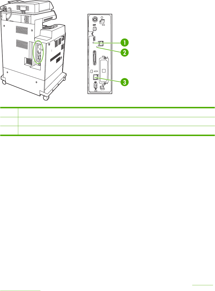
Formatter lights
Three LEDs on the formatter indicate that the MFP is functioning correctly.
1Heartbeat LED
2Fax LED
3Embedded Jetdirect LED
HP Jetdirect LEDs
The embedded HP Jetdirect print server has two LEDs. The yellow LED indicates network activity,
and the green LED indicates the link status. A blinking yellow LED indicates network traffic. If the
green LED is off, a link has failed.
For link failures, check all of the network cable connections. In addition, you can try to manually
configure the link settings on the embedded print server by using the MFP control panel menus.
1. Touch Menu.
2. Touch Configure Device.
3. Touch I/O.
4. Touch EMBEDDED JETDIRECT MENU.
5. Touch LINK SPEED. Select the appropriate link speed.
Heartbeat LED
The heartbeat LED indicates that the formatter is functioning correctly. While the MFP is initializing
after you turn it on, the LED blinks rapidly, and then turns off. When the MFP has finished the
initialization sequence, the heartbeat LED pulses on and off.
If the heartbeat LED is off, the formatter might have a problem. Replace the formatter. See Formatter
board on page 280.
532 Chapter 7 Troubleshooting ENWW
Fax LED
The LED on the fax accessory indicates that it is functioning correctly. If the LED is off, see the
HP LaserJet Analog Fax Accessory 300 User Guide for information about solving the problem.
ENWW Formatter lights 533

Replacement parts configuration
When the following parts are replaced, perform the procedures in this section.
●Formatter and DC controller
●Formatter (new or previously installed in another MFP)
●DC controller (new or previously installed in another MFP)
NOTE The HP Color LaserJet 4730mfp stores MFP configuration information in the compact
flash memory. Always print a configuration page before and after (wait five minutes after the
MFP power is turned on) installing the parts in the above list to verify that the MFP
configuration information is restored from the compact flash memory to the NVRAM.
Formatter and DC controller
WARNING! Do not replace the formatter and the DC controller at the same time. If the
formatter and DC controller must both be replaced, install a replacement formatter first and
make sure that you install the compact flash memory from the removed formatter on the
replacement formatter before you turn the MFP power on.
If the formatter and DC controller need to be replaced, install a replacement formatter first. The
HP Color LaserJet 4730mfp stores MFP configuration information in the compact flash memory. The
compact flash memory from the removed formatter must be installed on the replacement formatter,
so that MFP configuration information (for example, the duplexing option, page counts, and serial
number) can be restored to the formatter and DC controller. After replacing the formatter and
installing the compact flash, turn the MFP power on. When the Ready message appears on the
control panel display, you must wait five minutes before using the MFP so that the MFP configuration
information can be restored from the compact flash memory to the NVRAM.
Turn the MFP power off, and replace the DC controller. Turn the MFP power on. When the Ready
message appears on the control panel display, wait five minutes before using the MFP so that the
MFP configuration information can be restored from the compact flash memory to the NVRAM.
After installing the replacement formatter and DC controller, perform a full calibration procedure three
times. See Calibrating the MFP on page 591.
Formatter (new or previously installed in another MFP)
The HP Color LaserJet 4730mfp stores MFP configuration information in the compact flash memory.
The compact flash memory from the removed formatter must be installed on the replacement
formatter, so that MFP configuration information (for example, the duplexing option, page counts,
and serial number) can be restored to the formatter and DC controller. After replacing the formatter
and installing the compact flash, turn the MFP power on. When the Ready message appears on the
control panel display, you must wait five minutes before using the MFP so that the MFP configuration
information can be restored from the compact flash memory to the NVRAM.
After installing the replacement formatter, perform a full calibration procedure three times. See
Calibrating the MFP on page 591.
DC controller (new or previously installed in another MFP)
After replacing the DC controller, turn the MFP power on. When the Ready message appears on the
control panel display, you must wait five minutes before using the MFP so that the MFP configuration
534 Chapter 7 Troubleshooting ENWW

information (for example, the duplexing option, page counts, and serial number) can be restored from
the compact flash memory to the NVRAM.
After installing the replacement DC controller, perform a quick calibration procedure three times. See
Calibrating the MFP on page 591.
ENWW Replacement parts configuration 535
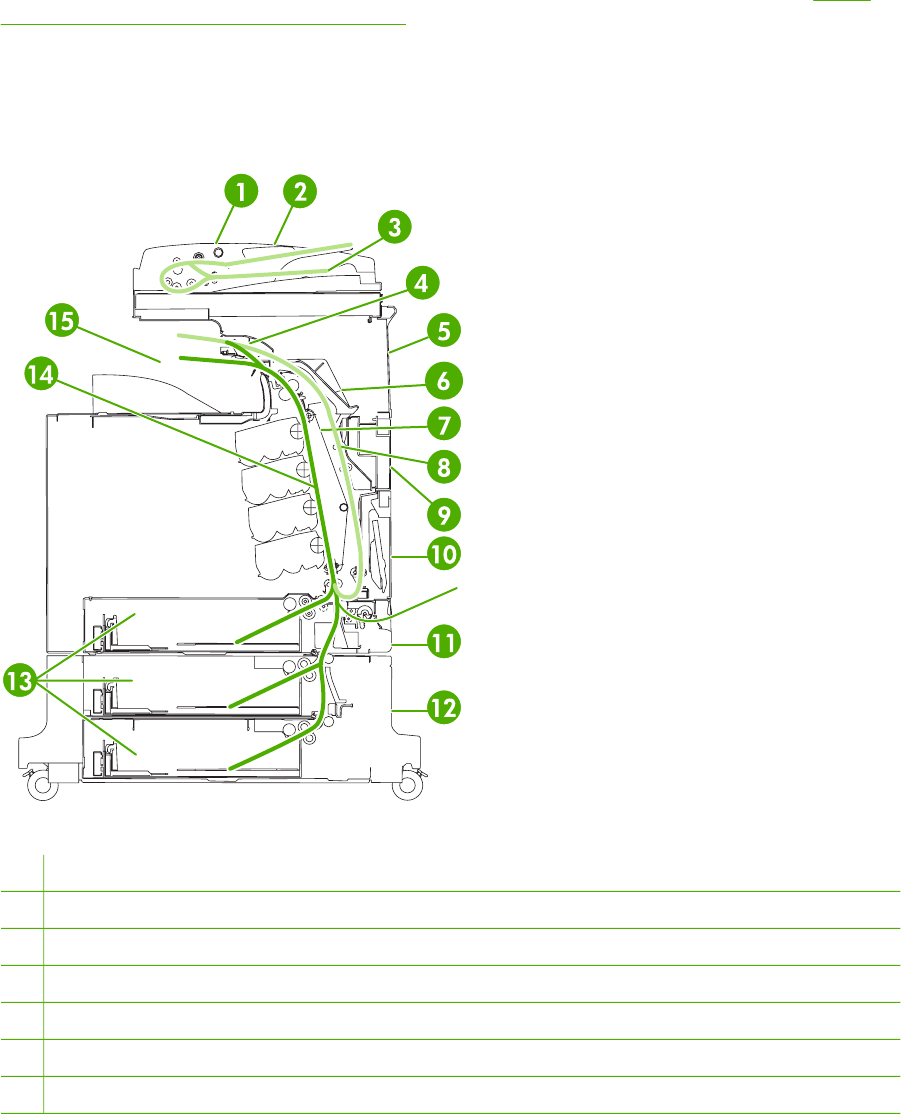
Paper path troubleshooting
Use this information in this section to troubleshoot errors in the paper path.
Jam error messages occur if media fails to arrive at or clear the paper path sensors in the allowed
time. Dedicated paper sensors detect whether media is present in the sensor and whether media is
feeding normally. When the DC controller detects a jam, it immediately stops the printing process
and the appropriate jam message appears for the sensor that detects the jam. The diagram Figure
5-35 Pickup/feed system (2 of 2) on page 201 shows the locations of all the sensors in the MFP.
Jam locations
If a jam message appears on the control panel display, look for jammed paper or other print media in
the locations that are indicated in the following figure.
Figure 7-1 Paper jam locations
1ADF access cover
2ADF input tray
3ADF output tray
4Duplexer cover
5Upper right door
6Fuser cover
7Transfer unit
536 Chapter 7 Troubleshooting ENWW

8Duplex paper path
9Middle right door
10 Paper tray 1 (multipurpose tray)
11 Drawer below tray 1
12 Lower right door
13 Paper trays 2, 3, and 4
14 Paper path
15 Output area
The following table lists the jam messages that might appear on the control panel display. For
information about clearing the jam, see the section that is indicated. You might need to look for
media in locations other than those that are indicated in the jam message. If the location of the jam is
not obvious, look first in the area of the print cartridges.
Table 7-2 Error messages and associated jam locations
Error message Procedure for clearing the jam Action
13.01.00 JAM INSIDE DRAWER
BELOW TRAY 1
See Jam in Tray 1 on page 544.A 13.01.00 jam occurs when the paper
is late in arriving at the paper leading-
edge sensor (SR12) in the paper
pickup assembly. This event could be a
no pick resulting in the absence of
media in the paper path, or could be a
sheet that was delayed and jammed
somewhere in the feed area between
the specified tray and the paper pickup
assembly.
If the jam occurs during a multiple-
page document, media might arrive in
the fuser, but the jam is still a result of
the media arriving late to the paper
leading-edge sensor (SR12) from the
specified tray. The MFP will not boot
up if a 13.01.00 jam occurs.
13.02.00 JAM INSIDE RIGHT DOORS See Clearing jams in the right covers
on page 539.
A 13.02.00 jam occurs when the paper
leading-edge sensor (SR12) has been
triggered, but never clears. The media
remains in the registration assembly.
After opening and closing the front
covers and ETB, the MFP can boot up
when a 13.02.00 error exists, if the
sensor is stuck or media remains in the
sensor.
13.09.00 JAM INSIDE RIGHT UPPER
DOOR
See Clearing jams in the right covers
on page 539.
A 13.09.00 jam occurs when the media
has successfully left the paper pick
unit, cleared the paper leading-edge
sensor (SR12), and arrived at the
fuser, triggering the fuser paper sensor
(SR1). If SR1 does not detect the end
ENWW Paper path troubleshooting 537

Error message Procedure for clearing the jam Action
of page within a specified time, this will
cause a 13.09.00 error message.
WARNING! The fuser is hot,
wait 10 minutes for it to cool
down.
13.0A.00 See Clearing jams in the right covers
on page 539.
A 13.0A.00 jam occurs when the MFP
is trying to deliver sheets to the output
bin for a simplex job or, for a duplex
turnaround, when the paper was late
leaving or never left the fuser delivery
sensor (SR1). The media might have
been incorrectly loaded in the paper
trays, something in the fuser might be
obstructing the media, or the sensor
could be stuck or broken.
WARNING! The fuser is hot,
wait 10 minutes for it to cool
down.
13.12.00 JAM INSIDE UPPER RIGHT
DOOR
See Clearing jams in the right covers
on page 539.
A 13.12.00 jam occurs when the MFP
is trying to print a duplex print job after
the media has entered the fuser and
started back down the paper path, but
has never arrived at or was late getting
to the paper leading-edge sensor
(PS12). The media might have been
disturbed by an outside source, (for
example, someone might have
grabbed the media while it was turning
around), or something might be in the
fuser that is obstructing the media.
When clearing jams, be very careful not to tear jammed media. If a small piece of media is left in the
MFP, it could cause additional jams. If jams are a recurring problem, see Solving repeated jams
on page 555.
NOTE Loose toner might remain in the MFP after a jam and cause temporary print-quality
problems. These problems should clear up within a few pages.
Paper jam recovery
This MFP automatically provides paper jam recovery, a feature that allows you to set whether the
MFP should attempt to automatically reprint jammed pages. The options are:
●AUTO: MFP will attempt to reprint jammed pages.
●OFF: MFP will not attempt to reprint jammed pages.
●ON: MFP will attempt to reprint jammed pages.
NOTE During the recovery process, the MFP might reprint several good pages that were
printed before the paper jam occurred. Be sure to remove any duplicated pages.
Table 7-2 Error messages and associated jam locations (continued)
538 Chapter 7 Troubleshooting ENWW
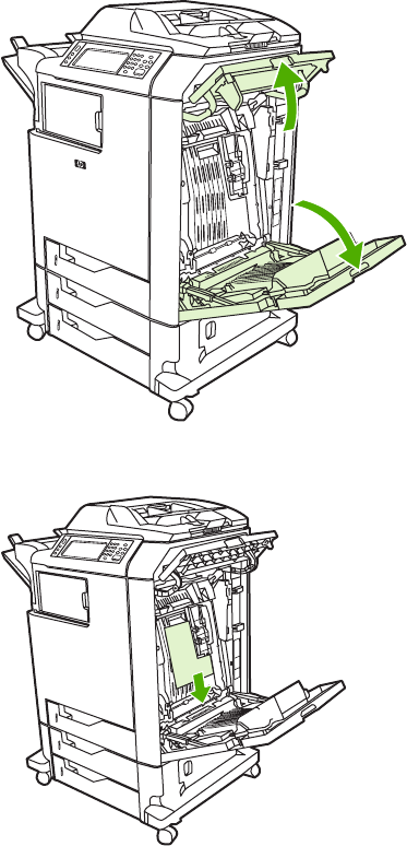
To disable paper jam recovery
1. Press Menu to enter the MENUS.
2. Touch Configure Device.
3. Touch SYSTEM SETUP.
4. Touch JAM RECOVERY.
5. Touch OFF.
6. Touch Exit.
To improve print speed and increase memory resources, you might want to disable paper jam
recovery. If paper jam recovery is disabled, the pages involved in a jam will not be reprinted.
Clearing jams in the right covers
1. Using the handles, open the covers on the right side of the MFP.
2. If media is present in the upper area, grasp the media by both corners and pull down.
ENWW Paper path troubleshooting 539
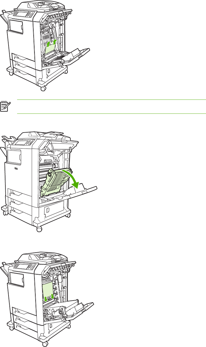
3. If media is present in the lower area, grasp the media by both corners and pull up.
NOTE If no media is present at these locations, continue to the next step.
4. Grasp the green handle on the transfer unit and pull down to open it.
5. If media is present in the upper area, grasp the media by both corners and pull down.
540 Chapter 7 Troubleshooting ENWW
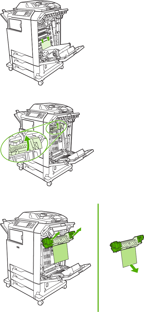
6. If media is present in the lower area, grasp the media by both corners and pull up.
7. Lift the green handle on the fuser cover to open the cover.
8. Pull the fuser upward to remove any paper.
ENWW Paper path troubleshooting 541
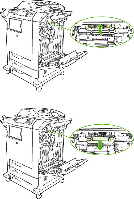
9. Lift the green handle on the duplexer cover to open it.
10. Remove any jammed paper.
542 Chapter 7 Troubleshooting ENWW
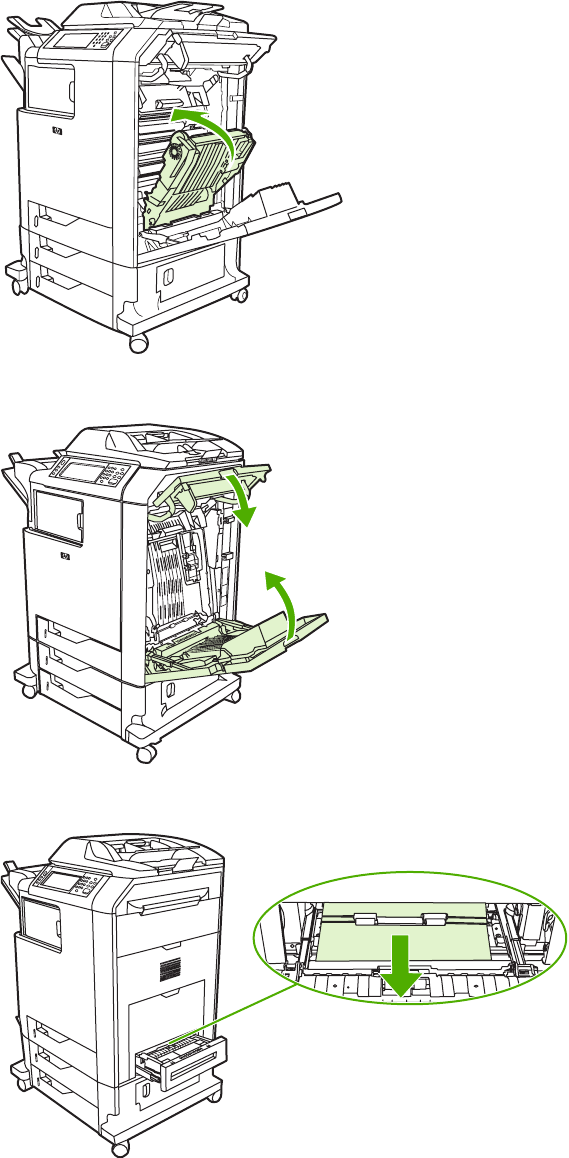
11. Close the transfer unit.
12. Close the covers on the right side of the MFP.
13. If the jam has not cleared, open the drawer below Tray 1 and remove any jammed paper.
14. Close the drawer.
ENWW Paper path troubleshooting 543
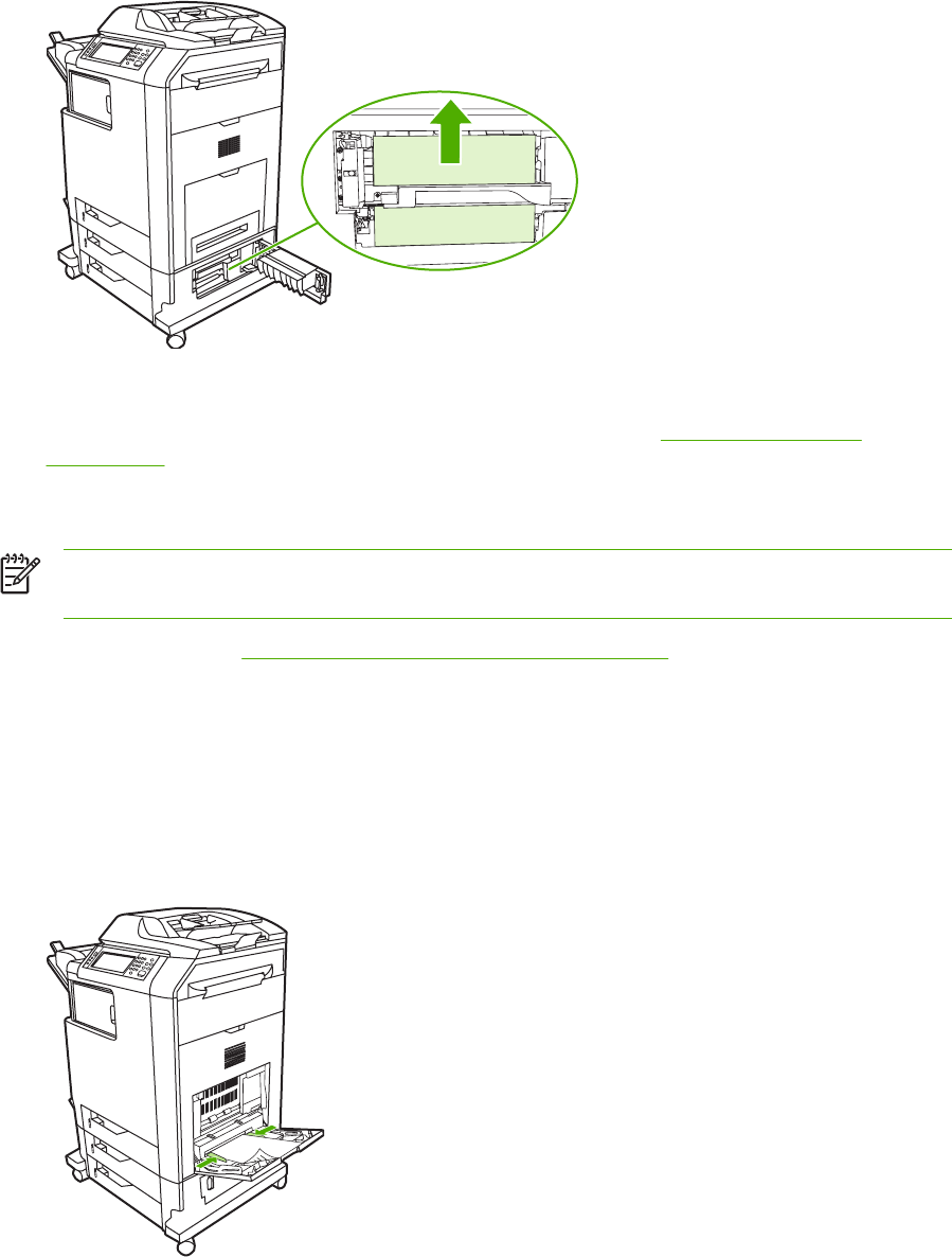
15. If the jam still has not cleared, open the lower access door and remove any jammed paper.
16. Close the lower access door. If the jam has cleared, the print job will continue.
17. If the jam is still not cleared and you are printing from Tray 1, see Jam in Tray 2, 3, or 4
on page 545.
Jam in Tray 1
NOTE If the protective insert does not eject properly when the MFP is first installed, follow
this procedure to clear the jam.
1. Perform the steps in Clearing jams in the right covers on page 539.
2. Remove loaded media.
3. Remove any jammed paper from the tray.
4. Reload the media.
5. Verify that the media is located correctly and is not above the fill tabs.
6. Confirm that the guides are in the correct position.
544 Chapter 7 Troubleshooting ENWW
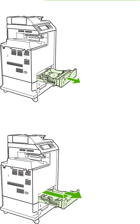
Jam in Tray 2, 3, or 4
1. Perform the steps in Clearing jams in the right covers on page 539.
2. Slide the indicated tray out and remove any jammed paper.
3. Close the tray. If the jam is cleared, the print job will continue.
4. If the paper jam still does not clear, lift the tray and remove it from the MFP. The following
diagram shows an example of removing Tray 2.
ENWW Paper path troubleshooting 545
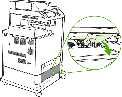
5. Remove any paper jam behind the tray. The following diagram shows a possible paper jam
behind Tray 2. Remove jams in Trays 3 and 4 following the same procedure.
6. Insert the paper tray.
546 Chapter 7 Troubleshooting ENWW
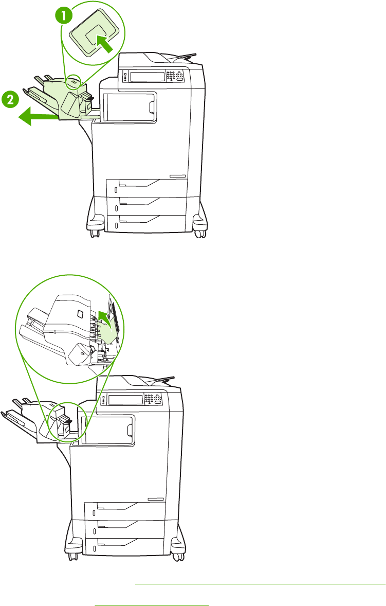
Jam in the stapler/stacker
1. Push the release lever on the top of the stapler/stacker.
2. Slide the stapler/stacker out.
3. Remove any media between the stapler/stacker and the MFP.
4. If the jam does not clear, see Other jams in the output accessory bridge on page 552.
To clear staple jams, see Staple jams on page 548.
ENWW Paper path troubleshooting 547
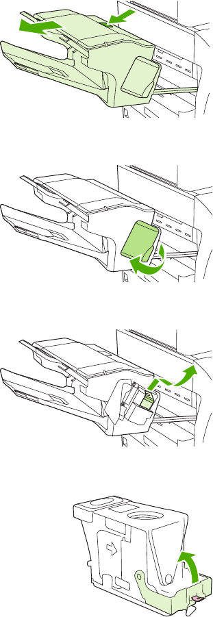
Staple jams
Occasionally, staples become jammed in the stapler/stacker. If jobs are not being stapled correctly or
are not being stapled at all, use this procedure to clear staple jams.
1. Turn off the MFP.
2. Press and hold the release button on the top of the stapler/stacker. Pull the stapler/stacker
away from the MFP.
3. Open the staple cartridge cover.
4. To remove the staple cartridge, pull up on the green handle and pull out the staple cartridge.
5. Lift up on the small lever at the back of the staple cartridge.
548 Chapter 7 Troubleshooting ENWW
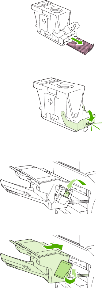
6. Remove the staples that protrude from the staple cartridge.
7. Close the lever at the back of the staple cartridge. Be sure that it snaps into place.
8. Reinsert the staple cartridge into the staple cartridge holder, and push down on the green
handle until it snaps into place.
9. Close the staple cartridge cover, and slide the stapler/stacker into the MFP.
ENWW Paper path troubleshooting 549
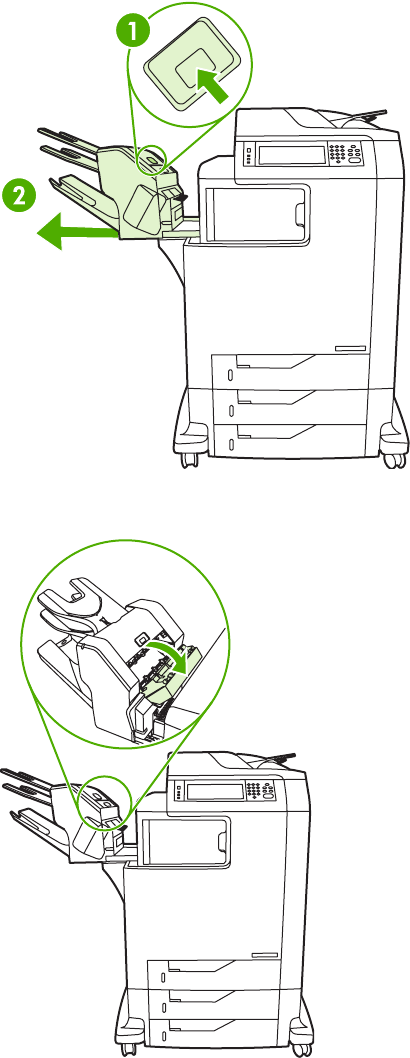
Jam in the 3-bin mailbox
1. Push the release button on the top of the 3-bin mailbox.
2. Slide the 3-bin mailbox out from the MFP.
3. Open the cover on the top of the 3-bin mailbox.
550 Chapter 7 Troubleshooting ENWW
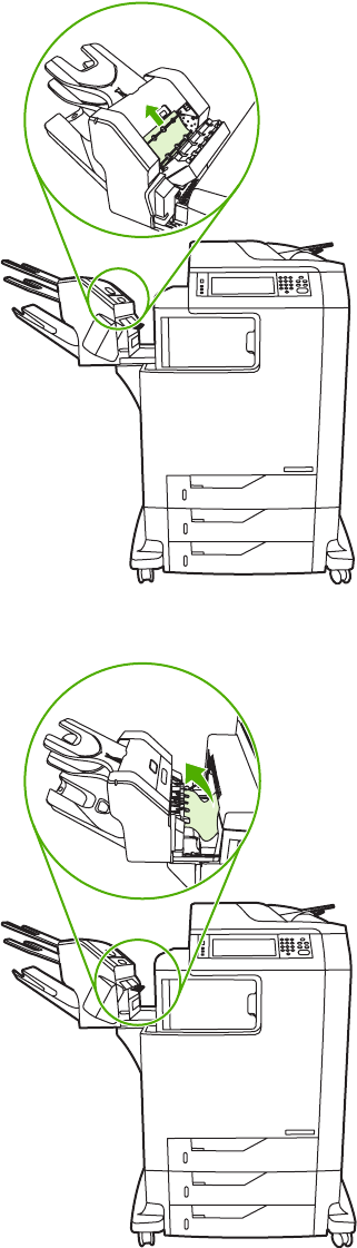
4. Remove any media inside the cover.
5. Close the door and remove any media between the MFP and the 3-bin mailbox.
ENWW Paper path troubleshooting 551
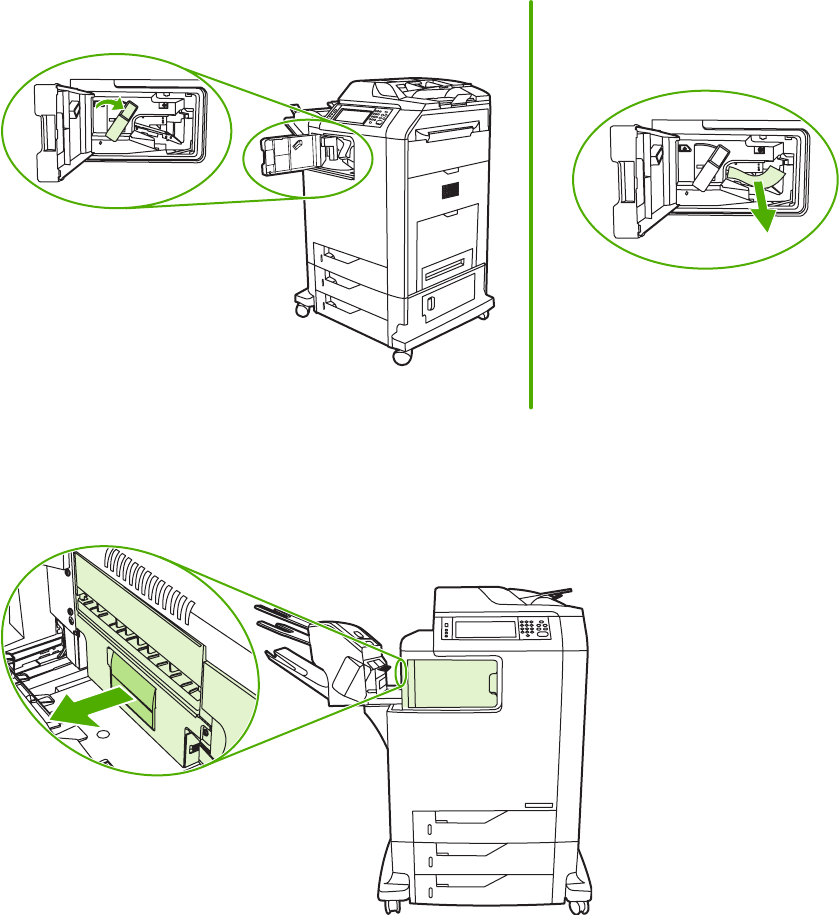
Other jams in the output accessory bridge
If a 3-bin mailbox or a stapler/stacker is installed on the MFP, complete the following procedure to
clear a jam in the output accessory bridge.
1. Open the cover to the output accessory bridge.
2. Push down on the green lever, remove any media inside the output accessory bridge, and push
the green lever up.
3. Close the cover to the output accessory bridge.
4. If the jam still does not clear, grasp the handle on the output accessory bridge and slide the
output accessory bridge away from the MFP.
552 Chapter 7 Troubleshooting ENWW
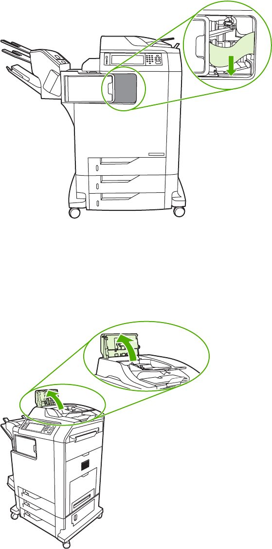
5. Look for paper on top of the output accessory bridge.
6. Slide the output accessory bridge back into the MFP.
7. Slide the 3-bin mailbox or stapler/stacker back into the MFP.
Jam in the ADF
1. Open the ADF cover.
ENWW Paper path troubleshooting 553
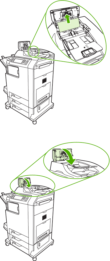
2. Remove any jammed media.
3. Close the ADF cover.
554 Chapter 7 Troubleshooting ENWW

Solving repeated jams
Situation Solution
General repeated jam problems 1. Make sure that the media is loaded correctly in the trays and that all width
guides are set correctly.
2. Make sure that the tray is set for the size of media that is installed and that
the tray is not overloaded.
3. Try turning over the stack of media in the tray. If you are using prepunched
or letterhead paper, try printing from tray 1.
4. Do not use media that has been printed on previously or torn, worn, or
irregular media. See Media specifications on page 18.
5. Check the media specifications. (See Media specifications on page 18.) If
media is outside of the recommended specifications, problems can occur.
6. The MFP might be dirty. Clean the MFP as described in Cleaning the MFP
on page 99.
7. Check that all damaged or jammed media is removed from MFP.
Repeated jams in the ADF 1. The ADF might be dirty. Clean the ADF as described in Cleaning the ADF
delivery system on page 99.
2. Make sure that the media is loaded squarely and that the media-width
guides are adjusted to the sides of the media stack.
3. Make sure that no more than 50 sheets of 75 g/m
2
(20 lb) bond paper are
loaded in the ADF.
4. Make sure that the paper is within the range of supported weight for the
ADF: 60–120 g/m
2
(16–32 lb).
5. If the original document that is being copied has been folded or stapled,
flatten it as much as you can and smooth any wrinkles. Make sure the pages
are not stuck together where the staple was.
6. Media that has been pre-punched or perforated in any way might be difficult
to feed through the ADF. If the leading edge of the document is excessively
worn or frayed, try rotating the document 180 degrees before copying.
7. Make sure that the media is being stored correctly. If the media is too dry,
the sheets might stick together. See Media specifications on page 18.
ENWW Paper path troubleshooting 555

Persistent jams
If jams occur repeatedly, use the information in this section to diagnose the root cause of the
problem. The tables in this section list possible causes and recommended solutions for jams in each
area of the paper path. Items are listed in the order that you should use to investigate. In general,
items at the beginning of the list are relatively minor repairs. Items at the end of the list are more
complex repairs.
Basic troubleshooting for jams
Use the following basic troubleshooting process for jams:
1. Gather data.
2. Identify the cause of the problem.
3. Fix the problem.
Data collection
To troubleshoot jams, gather the following information:
●The exact jam error code that appears on the control panel display
●The location of the leading edge of the media that is in the paper path
●Whether media is in the paper path when the jam occurs or in the input tray
●Whether the jam occurs at power-up or while media is moving
●Whether the media is damaged and, if it is, where the damage occurs on the paper and where
in the paper path the sheet stops
●Whether the jam occurs when feeding from one particular tray
●Whether the jam occurs only when using duplex printing
●Whether a particular type of media is jamming or not jamming
●Whether any of the supplies are non-HP (non-HP supplies are known to cause jams)
●Whether the customer is storing the media correctly, overloading the trays, damaging the edge
of the media during loading, or using media that has already been fed through the MFP
General paper path troubleshooting
Use the following suggestions to isolate the cause of the problem. After you have identified the
cause, use the tables in this section to find a recommended solution.
NOTE Use the paper path test in the DIAGNOSTICS menu to print pages while
troubleshooting.
●View or print the event log and determine if a particular jam error occurs more often than others.
Try to identify a pattern.
●Use the event log to determine the frequency of a particular jam. If a jam occurs repeatedly at
approximately the same page count, consider it a single jam that the customer tried to clear.
556 Chapter 7 Troubleshooting ENWW

●Try printing from all available input trays to identify whether the problem is isolated to one tray.
●Print the job in both simplex and duplex modes to identify whether the problem occurs only in
one mode or the other.
●Try printing on media from an unopened ream that has been stored correctly. If the jam does
not occur with this media, then the customer's media might be causing the problem.
●If the jam occurs from when the MFP is turned on, check the paper path for small, torn pieces of
media. Also check for broken sensors or flags, and check for loose or defective connections.
●If the media is torn, folded, or wrinkled (typically along the leading edge), inspect the paper path
for items that could be causing the damage.
●If the user is using non-HP supplies, try replacing those supplies with genuine HP supplies to
see if the problem goes away.
●If necessary, instruct the user about proper media storage, correct loading technique, and MFP
operation. Make sure the user knows not to grab paper in the output bin during duplex printing.
Paper path checklist
●Verify that media is correctly loaded in the input trays and that all length and width guides are
set correctly.
●Clean the MFP. Toner and paper dust in the paper path can inhibit the free movement of media
through the MFP and can block the sensors.
●Use the paper path test in the DIAGNOSTICS menu to vary the input selections of the MFP to
determine if the problem is associated with a particular area of the MFP.
●Worn rollers or separation pads can cause multifeeds. Check the condition of the pickup rollers
and separation pads. Bent separation tabs (on the front corners of the input trays) can cause
misfeeds and multifeeds. Replace the tray if necessary.
●Defective paper-tray switches can cause jams by communicating the wrong paper size to the
formatter.
●Defective paper sensors along the paper path might falsely signal a jam.
●Scraps of media that remain in the paper path can cause intermittent jams. Always check that
the paper path is clear when cleaning the MFP and when clearing jams. Also, remove the fuser
and carefully check it for debris from jams.
Jams in Tray 1
The following table describes the cause of and solution for jams in Tray 1.
Table 7-3 Causes for jams in Tray 1
Cause Solution
The pickup roller is dirty, worn, or damaged. Clean the pickup roller. If it is still dirty after cleaning, or if it
is worn or damaged, replace the pickup roller.
The separation pad is defective. Clean the separation pad. If it is still dirty after cleaning, or if
it is worn or damaged, replace the separation pad.
ENWW Paper path troubleshooting 557

Cause Solution
The drive gears are damaged. Check the drive gears in the paper pickup unit. Replace the
pickup drive assembly if the gears are damaged.
The MP tray paper sensor (SR4) or the sensor lever is
defective.
Replace the MP tray pickup unit.
The MP tray pickup solenoid (SL1) is defective. 1. Run the component test to verify that the solenoid is
functioning correctly. See Component tests
on page 659. If the solenoid does not activate during the
test, replace it.
2. Disconnect the connector J1015 for the MP tray pickup
solenoid from the DC controller PCB.
3. Measure the resistance between the cable-side
connectors J1015–1 and J1015–2.
4. If the measured resistance is not about 160 ohms,
replace the MP tray pickup solenoid.
The pickup motor is defective. Replace the pickup motor assembly.
The MP tray pickup assembly is defective. Replace the MP tray pickup assembly.
The DC controller PCB is defective. 1. Upgrade the DC controller firmware by using the RFU
process.
2. If necessary, replace the DC controller PCB. Calibrate
the MFP after replacing the DC controller. See
Calibrating the MFP on page 591.
Jams in tray 2
The following table describes the cause of and solutions for jams in tray 2, 3, or 4.
Table 7-4 Causes for jams in Tray 2
Cause Solution
The separation roller is worn or damaged. Clean the separation tab or replace if it is worn.
The pickup roller is worn or damaged. Replace the pickup roller.
The feed roller is dirty, worn, or damaged. Clean the feed roller. If it is still dirty after cleaning, or if it is
worn or damaged, replace the feed roller.
The gears in the paper pickup drive assembly might be
damaged.
Check the drive gears in the paper pickup drive assembly.
Replace the pickup drive assembly if the gears are damaged.
The tray 2 pickup solenoid (SL2) is damaged. 1. Run the component test to verify that the solenoid is
functioning correctly. See Component tests
on page 659. If the solenoid does not activate during the
test, replace it.
2. Disconnect the connector for the pickup solenoid
(J1015) from the DC controller PCB.
3. Measure the resistance between the cable-side
connectors J1015–3 and J1015–4.
4. If the measured resistance is not about 160 ohms,
replace the cassette pickup solenoid.
Table 7-3 Causes for jams in Tray 1 (continued)
558 Chapter 7 Troubleshooting ENWW

Cause Solution
The pickup motor is defective. Replace the paper pickup drive assembly.
The paper pickup assembly is defective. Replace the paper pickup assembly.
The lifter drive assembly might be defective. Replace the lifter drive assembly.
The DC controller PCB is defective. 1. Upgrade the DC controller firmware by using the RFU
process.
2. If necessary, replace the DC controller PCB. Calibrate
the MFP after replacing the DC controller. See
Calibrating the MFP on page 591.
Jams in Tray 3
The following table describes the cause of and solutions for jams in Tray 3.
Table 7-5 Causes for jams in Tray 3
Cause Solution
The separation roller is worn or damaged. Clean the separation tab or replace if it is worn.
The pickup roller is worn or damaged. Replace the pickup roller.
The feed roller is dirty, worn, or damaged. Clean the feed roller. If it is still dirty after cleaning, or if it is
worn or damaged, replace the feed roller.
The gears in the upper pickup drive assembly might be
damaged.
Check the drive gears in the upper pickup drive assembly.
Replace the upper pickup drive assembly if the gears are
damaged.
The tray 3 pickup solenoid is damaged. 1. Run the component test to verify that the solenoid is
functioning correctly. See Component tests
on page 659. If the solenoid does not activate during
the test, replace it.
2. Disconnect the connector for the pickup solenoid
(1015) from the paper deck delivery PCB.
3. Measure the resistance between the cable-side
connectors J8206–1 and J8206–2.
4. If the measured resistance is not about 160 ohms,
replace the cassette pickup solenoid.
The tray 3 pickup motor assembly is defective. Replace the tray 3 pickup motor assembly.
The tray 3 pickup motor assembly is defective. Replace the tray 3 pickup motor assembly.
The upper paper pickup assembly is defective. Replace the upper paper pickup assembly.
The DC controller PCB is defective. 1. Upgrade the DC controller firmware by using the RFU
process.
2. If necessary, replace the DC controller PCB. Calibrate
the MFP after replacing the DC controller. See
Calibrating the MFP on page 591.
Table 7-4 Causes for jams in Tray 2 (continued)
ENWW Paper path troubleshooting 559

Jams in Tray 4
The following table describes the cause of and solutions for jams in Tray 4.
Table 7-6 Causes for jams in Tray 4
Cause Solution
The separation roller is worn or damaged. Clean the separation tab or replace if it is worn.
The pickup roller is worn or damaged. Replace the pickup roller.
The feed roller is dirty, worn, or damaged. Clean the feed roller. If it is still dirty after cleaning, or if it is
worn or damaged, replace the feed roller.
The gears in the lower pickup drive assembly might be
damaged.
Check the drive gears in the lower pickup drive assembly.
Replace the lower pickup drive assembly if the gears are
damaged.
The tray 4 pickup solenoid (SL8201) is damaged. 1. Run the component test to verify that the solenoid is
functioning correctly. See Component tests
on page 659. If the solenoid does not activate during
the test, replace it.
2. Disconnect the connector for the pickup solenoid
(J8210) from the paper deck delivery PCB.
3. Measure the resistance between the cable-side
connectors J8210–1 and J8210–2.
4. If the measured resistance is not about 160 ohms,
replace the cassette pickup solenoid.
The tray 4 pickup motor assembly is defective. Replace the tray 4 pickup motor assembly.
The tray 4 pickup motor assembly is defective. Replace the tray 4 pickup motor assembly.
The lower paper pickup assembly is defective. Replace the lower paper pickup assembly.
The DC controller PCB is defective. 1. Upgrade the DC controller firmware by using the RFU
process.
2. If necessary, replace the DC controller PCB. Calibrate
the MFP after replacing the DC controller. See
Calibrating the MFP on page 591.
Jams in the paper path
The following table describes the cause of and solution for jams in the paper path.
Table 7-7 Causes for jams in the paper path
Cause Solution
The drive gears are damaged.
(This applies to jams that occur in advance of the
registration roller.)
Check the drive gears in the paper pickup unit. Replace the
pickup drive assembly if the gears are damaged.
The registration roller and registration sub roller are dirty,
worn, or damaged.
(This applies to jams that occur in advance of the
registration roller.)
Clean the registration roller or registration sub-roller if it is
dirty. If it is still dirty after cleaning, or if it is worn or
damaged, replace the paper feed assembly.
560 Chapter 7 Troubleshooting ENWW

Cause Solution
The media attaching roller (MAR) is damaged.
(This applies to jams in which media is crumpled into an
accordion when it enters the ETB.)
Make sure that the MAR is clean and undamaged. If it is
damaged, replace the ETB. Calibrate the MFP after
replacing the ETB. See Calibrating the MFP on page 591.
The cartridge shutter open/close mechanism is damaged.
(This applies to jams in which media is crumpled into an
accordion fold somewhere on the ETB belt.)
The shutters in each print cartridge should open as you
close the ETB. If a shutter does not open, replace that print
cartridge. Also check for a damaged shutter mechanism in
the MFP.
The cartridge drive motor assembly is damaged. 1. Run the component test to verify that all cartridge
motors are functioning correctly. See Component tests
on page 659. Replace any defective drum drive motors.
2. Inspect the main drive assembly. If it is damaged,
replace it.
The top of page sensor (SR12) is defective. Replace the paper feed assembly.
The DC controller PCB is defective. 1. Upgrade the DC controller firmware by using the RFU
process.
2. Replace the DC controller PCB. Calibrate the MFP
after replacing the DC controller. See Calibrating the
MFP on page 591.
Jams in the right upper cover
The following table describes the causes of and solutions for jams in the right upper cover.
Table 7-8 Causes for jams in the right upper cover
Cause Solution
The fuser paper sensor (SR1) or sensor lever is defective. 1. Make sure that the fuser paper sensor lever moves
smoothly and is in place.
2. Run the component test. See Component tests
on page 659.
3. Replace the sensor if it is defective.
The fuser sleeve or pressure roller does not rotate smoothly. If the fuser drive gears are worn or damaged, replace the
fuser.
The fuser inlet guide is dirty or is covered with toner. Clean the fuser inlet guide.
The fuser sleeve or pressure roller is dirty, worn, or damaged. Clean the fuser sleeve or pressure roller. If it is damaged,
replace the fuser.
The fuser pressure release motor is damaged. Run the component test. See Component tests on page 659.
If the motor fails, replace it.
The delivery tray paper-full sensor (SR2) or sensor lever is
defective.
1. Make sure that the delivery paper-full sensor lever
moves smoothly and is set in place. Replace the lever
if it is damaged.
2. Run the component test. See Component tests
on page 659.
3. Replace the sensor if it is defective.
Table 7-7 Causes for jams in the paper path (continued)
ENWW Paper path troubleshooting 561

Cause Solution
The fuser delivery roller is worn. Replace the fuser.
The fuser delivery roller drive gears are worn or damaged. Replace the fuser.
The face-down delivery roller is defective. Replace the fuser.
The paper loop sensors (SR13 and SR14) might be defective. 1. Make sure that the sensor levers move smoothly.
2. Run the component test. See Component tests
on page 659.
3. Replace the sensor if it is defective.
The DC controller PCB is defective. 1. Upgrade the DC controller firmware by using the RFU
process.
2. Replace the DC controller PCB. Calibrate the MFP
after replacing the DC controller. See Calibrating the
MFP on page 591.
Jams in the duplex path
The following table describes the causes of and solution for jams in the duplex path.
Table 7-9 Causes for jams in the duplex path
Cause Solution
The oblique rollers are worn or damaged. Replace the ETB.
The oblique roller drive gears are worn or damaged. Replace the ETB. Calibrate the MFP after replacing the
ETB. See Calibrating the MFP on page 591.
The duplex feed guide is damaged. Replace the ETB. Calibrate the MFP after replacing the
ETB. See Calibrating the MFP on page 591.
The reversing sensor (SR8001) or the sensor lever is
defective.
1. Run the component test. See Component tests
on page 659.
2. Replace the duplexer assembly if it is defective.
The duplexer connector is unplugged or not seated properly. Reseat the connector.
Jams in the ADF
Table 7-10 Causes of jams in the ADF
Cause Solution
The clear mylar sheet in the ADF might be installed
incorrectly.
Make sure that all four alignment holes on the mylar sheet
are secured over the tabs. The small notch on the sheet
should be aligned with the round pin at the top of the mylar
sheet holder. See the instructions that came with the mylar
sheet replacement kit.
The ADF pickup roller assembly might be installed incorrectly. Make sure the roller assembly is correctly seated and that
the paper-present flag and the registration flag can move
freely.
Table 7-8 Causes for jams in the right upper cover (continued)
562 Chapter 7 Troubleshooting ENWW

Cause Solution
The ADF separation pad might be installed incorrectly. Make sure the ADF separation pad is seated correctly. If it is
excessively dirty or worn, replace it.
Specific components inside the ADF might not be
functioning correctly.
From the DIAGNOSTICS menu, run the SCANNER TESTS
to verify that each of these components is functioning
correctly:
●ADF input motor (forward and reverse)
●ADF read motor (forward and reverse)
●ADF duplex solenoid
●ADF input-tray-empty sensor
●ADF registration sensor
If the MFP passes all of the diagnostic tests but ADF jams
still persist, replace the ADF. See ADF assembly on page 411.
Jams in the IPTU
The following table describes the cause of and solutions for jams in the IPTU.
Table 7-11 Causes for jams in the IPTU
Cause Solution
The IPTU might be improperly installed and seated. Reinstall or reseat the IPTU if necessary.
The top of page sensor (SR8301) or sensor lever is defective. 1. Make sure that the sensor lever moves smoothly.
2. Run the component test. See Component tests
on page 659.
3. Replace the IPTU sensor if it is defective.
The delivery sensor (SR8302) or sensor lever is defective. 1. Make sure that the sensor lever moves smoothly.
2. Run the component test. See Component tests
on page 659.
3. Replace the IPTU sensor if it is defective.
One of the feed motors (M8301 and M8302) is defective. 1. Run the component test. See Component tests
on page 659.
2. If the motor fails, replace it.
Jams in the stapler/stacker
The following table describes the cause of and solutions for jams in the stapler/stacker.
Table 7-12 Causes for jams in the stapler/stacker
Cause Solution
The stapler/stacker might be improperly installed and seated. Reinstall or reseat the stapler/stacker if necessary.
Table 7-10 Causes of jams in the ADF (continued)
ENWW Paper path troubleshooting 563

Cause Solution
The top of page sensor (SR12) or sensor lever is defective. 1. Make sure that the sensor lever moves smoothly.
2. Run the component test. See Component tests
on page 659.
3. Replace the stapler/stacker sensor if it is defective.
The delivery sensor (SR8302) or sensor lever is defective. 1. Make sure that the sensor lever moves smoothly.
2. Run the component test. See Component tests
on page 659.
3. Replace the stapler/stacker delivery sensor if it is
defective.
Jams in the 3-bin mailbox
The following table describes the cause of and solutions for jams in the 3-bin mailbox.
Table 7-13 Causes for jams in the 3-bin mailbox
Cause Solution
The 3-bin mailbox might be improperly installed and seated. Reinstall or reseat the 3-bin mailbox if necessary.
The top of page sensor (SRxxxx) or sensor lever is defective. 1. Make sure that the sensor lever moves smoothly.
2. Run the component test. See Component tests
on page 659.
3. Replace the 3-bin mailbox sensor if it is defective.
The delivery sensor (SRxxxx) or sensor lever is defective. 1. Make sure that the sensor lever moves smoothly.
2. Run the component test. See Component tests
on page 659.
3. Replace the 3-bin mailbox delivery sensor if it is
defective.
Table 7-12 Causes for jams in the stapler/stacker (continued)
564 Chapter 7 Troubleshooting ENWW

Using the paper path test
The paper-path test can be used to verify that various paper paths are working correctly or to
troubleshoot problems with tray configuration.
To start the paper path test
1. Press Menu.
2. Scroll to and touch DIAGNOSTICS.
3. Scroll to and touch PAPER PATH TEST.
4. Select the input tray that you want to test, the output bin, the duplex printing accessory (if
available), and number of copies, touching OK after you set the value for each. After selecting
the last option, touch PRINT TEST PAGE.
Using the scanner tests
The scanner test can be used to verify that various scanner components are working correctly .
For more information about the scanner tests, see Scanner tests on page 659.
To start the scanner tests
1. Press Menu.
2. Scroll to and touch DIAGNOSTICS.
3. Scroll to and touch SCANNER TESTS.
4. Select the scanner component that you want to test, and follow the instructions on the control
panel display.
ENWW Paper path troubleshooting 565

Correcting print quality and copy quality problems
This section helps to define print quality problems and how to correct them. Often print quality
problems can be handled easily by making sure that the MFP is properly maintained, using print
media that meets HP specifications, or running a cleaning page.
Print quality problems associated with media
Some print quality problems arise from use of inappropriate media.
●Use paper that meets HP paper specifications. See Media specifications on page 18.
●The surface of the media is too smooth. Use media that meets HP paper specifications. See
Media specifications on page 18.
●The printer driver setting might be incorrect. Be sure that you have selected the correct driver
setting for the paper that you are using.
●The print mode might be set incorrectly, or the paper might not meet recommended
specifications. For more information, see Media specifications on page 18.
●The transparencies you are using are not designed for proper toner adhesion. Use only
transparencies designed for HP Color LaserJet printers.
●The moisture content of the paper is uneven, too high, or too low. Use paper from a different
source or from an unopened ream of paper.
●Some areas of the paper reject toner. Use paper from a different source or from an unopened
ream of paper.
●The letterhead you are using is printed on rough paper. Use a smoother, xerographic paper. If
this solves your problem, consult with the printer of your letterhead to verify that the paper used
meets the specifications for this MFP. See Media specifications on page 18.
●The media sensing feature might not be selected. Select the feature at the control panel.
Overhead transparency defects
Overhead transparencies might display any of the image quality problems that any other type of
media could display, as well as defects specific to transparencies. In addition, because
transparencies are pliable while in the print path, they are subject to being marked by the media-
handling components.
NOTE Allow transparencies to cool at least 30 seconds before handling them.
●On the printer driver’s Paper tab, select Transparency as the media type. Also, make sure that
the tray is correctly configured for transparencies.
●Check that the transparencies meet the specifications for this MFP. See Media specifications
on page 18.
●Handle transparencies by the edges. Skin oil on the surface of transparencies can cause spots
and smudges.
●Small, random dark areas on the trailing edge of solid fill pages might be caused by
transparencies sticking together in the output bin. Try printing the job in smaller batches.
566 Chapter 7 Troubleshooting ENWW

●The selected colors are undesirable when printed. Select different colors in the software
application or printer driver.
●If you are using a reflective overhead projector, use a standard overhead projector instead.
●The media sensing feature might not be selected. Select the feature at the control panel.
Print quality problems associated with the environment
The MFP is operating in excessively humid, dusty, or dry conditions. Verify that the printing
environment is within specifications. See Environmental specifications on page 15.
Print quality problems associated with jams
●Make sure that all media is cleared from the paper path. See Paper jam recovery on page 538.
●The MFP recently jammed. Print two to three pages to clean the MFP.
●The media does not pass through the fuser, causing image defects to appear on subsequent
documents. Print two to three pages to clean the MFP. If the problem persists, see the next
section.
●The media sensing feature might not be selected. Select the feature at the control panel.
Understanding color variations
The printed output might not match the computer screen, and the colors printed on successive pages
might not match. While color variations are inherent in this printing method, they can indicate
changes in the printing environment, print media, or MFP components.
Common causes of color variation
The following list outlines the major causes of color variations between computers, programs, and
output devices.
●Halftone patterns that are produced on monitors and the types of patterns that are used in the
print jobs are different and might cause variations in the printed output.
●The printed output differs from the image on the monitor because the monitor and the print
media have different reference values of black and white. The monitor screen has charcoal gray
for the black level, and the white on the monitor screen is actually blue. Black on the print media
is limited only by the fill capability of the printer, and most good-quality paper has a very high
white level. In addition, phosphor (used in color monitors) and toner have entirely different
spectra characteristics and different color-rendering capabilities. Differences between output are
common. Blues generally match better than reds.
●The color of the ambient light changes the perception of color. Fluorescent light lacks many
colors that are present in incandescent light, and the color range of natural light is broader than
any artificial light. When comparing color, choose a standard light source for reference and
understand that the perceived color will change as the light changes.
●Long-term color variations occur as paper ages. Use high-quality paper and protect the paper
from sunlight to help minimize discoloration.
ENWW Correcting print quality and copy quality problems 567

●Environmental changes can cause color variation. The development process places a high
potential across an air gap to attract toner to the imaging drum. Changes in relative humidity
vary the point at which the toner travels to the imaging drum.
●All consumable components have a finite life span. As these components reach the end of their
useful life, their ability to produce consistent print quality diminishes.
●Paper roughness can cause colors to look different. Use standard paper.
Using color
HP ImageREt 3600
HP ImageREt 3600 print technology is a system that HP developed to deliver superior print quality
and technological innovation. The HP ImageREt system incorporates technology that optimizes each
element of the print system.
Several categories of HP ImageREt have been developed that meet a variety of user needs. The
system is comprised of key laser technologies for color printing, including image enhancements,
smart supplies, and high-resolution imaging. The ImageREt core technologies are refined in higher
level systems for more advanced system users, and additional technologies are integrated.
The HP ImageREt 3600 is a complete HP proprietary printing solution. HP now offers superior image
enhancements for general office and marketing documents. HP ImageREt 3600 performs well in
different environmental conditions and with a variety of media, and the image mode is optimized for
printing on HP High Gloss Laser Paper.
Paper selection
For the best color and image quality, select the appropriate media type from the MFP menu or the
MFP control panel.
sRGB
Standard red-green-blue (sRGB) is a world-wide color standard originally developed by HP and
Microsoft as a common color language for monitors, input devices (scanners, digital cameras), and
output devices (printers, plotters). It is the default color space used for HP products, Microsoft
operating systems, the World Wide Web, and most office software that is sold today. sRGB is
representative of the typical Windows computer monitor today and the convergence standard for
high-definition television.
NOTE Factors such as the type of monitor you use and the room's lighting can affect the
appearance of colors on your screen. For more information, see Matching colors on page 572.
The latest versions of Adobe
®
PhotoShop
®
, CorelDRAW
®
, Microsoft Office, and many other
programs use sRGB to communicate color. Most importantly, as the default color space in Microsoft
operating systems, sRGB has gained broad adoption as a means to exchange color information
between programs and devices using a common definition that assures typical users will experience
greatly improved color matching. sRGB improves your ability to match colors among the printer, the
computer monitor and other input devices (scanner, digital camera) automatically, without the need
to become a color expert.
568 Chapter 7 Troubleshooting ENWW

Color options
Color options enable optimal color output automatically for diverse types of documents.
Color options use object tagging, which allows optimal color and halftone settings to be used for
different objects (text, graphics, and photos) on a page. The printer driver determines which objects
are used on a page and uses halftone and color settings that provide the best print quality for each
object. Object tagging, combined with optimized default settings, produces great color out of the box.
In the Windows environment, the Automatic and Manual color options are on the Color tab in the
printer driver.
Setting color options to Automatic will typically produce the best possible print quality for color
documents. However, situations might occur when you want to print a color document in grayscale
(black and white) or want to change one of the color options.
●Using Windows, print in grayscale or change the color options by using settings on the Color
tab in the printer driver.
●Using a Macintosh computer, print in grayscale or change the color options by using the Color
Matching pop-up menu in the Print dialog box.
Restricting color printing
The HP Color LaserJet 4730mfp includes a Restrict Color Use setting for networked printers. A
network administrator can use the setting to restrict user access to the color printing features in order
to conserve color toner. If you are unable to print in color, see your network administrator.
1. Press Menu.
2. Scroll to and touch PRINT QUALITY.
3. Scroll to and touch SYSTEM SETUP.
4. Scroll to and touch Restrict Color Use.
5. Scroll to and select one of the following options:
●DISABLE COLOR: This setting denies the printer color capabilities to all users.
●ENABLE COLOR: This is the default setting, which allows all users to use the printer color
capabilities.
●COLOR IF ALLOWED: This setting allows the network administrator to allow color use for
select users. Use the embedded Web server to designate users who can print in color.
6. Press OKto save the setting.
The network administrator can monitor color usage for a specific HP Color LaserJet 4730mfp by
printing a color usage job log. See Testing the MFP operation on page 67.
Print in grayscale
Selecting the Print in Grayscale option from the printer driver prints a document by using black
toner. This option is useful for previewing preliminary copies of slides and hardcopy output, or for
printing color documents that will be photocopied or faxed.
ENWW Correcting print quality and copy quality problems 569

Automatic or manual color adjustment
The Automatic color adjustment option optimizes the neutral gray color treatment, halftones, and
edge enhancements used for each element in a document. For more information, see your printer
driver online Help.
NOTE Automatic is the default setting and is recommended for printing all color documents.
Use the Manual color adjustment option to adjust the neutral gray color treatment, halftones, and
edge enhancements for text, graphics and photographs. To gain access the Manual color options, on
the Color tab, select Manual, and then select Settings.
Manual color options
Use manual color adjustment to adjust the Color (or Color Map) and Halftone options individually for
text, graphics, and photographs.
NOTE Some programs convert text or graphics to raster images. In these cases, the
Photographs settings also controls text and graphics.
Halftone options
Halftone options affect the resolution and clarity of your color output. You can select halftone settings
for text, graphics, and photographs independently. The two halftone options are Smooth and Detail.
●The Smooth option provides better results for large, solid-filled print areas. It also enhances
photographs by smoothing out fine color gradations. Choose this option when uniform and
smooth area fills are top priority.
●The Detail option is useful for text and graphics that require sharp distinctions among lines or
colors, or images that contain a pattern or a high level of detail. Choose this option when sharp
edges and details are top priority.
Neutral grays
The Neutral grays setting determines the method used for creating gray colors used in text,
graphics, and photographs.
Two values are available for the Neutral grays setting:
●Black Only generates neutral colors (grays and black) using only black toner. This guarantees
neutral colors without a color cast.
●4-Color generates neutral colors (grays and black) by combining all four toner colors. This
method produces smoother gradients and transitions to non-neutral colors, and it produces the
darkest black.
Edge control
The Edge Control setting determines how edges are rendered. Edge control has two components:
adaptive halftoning and trapping. Adaptive halftoning increases edge sharpness. Trapping reduces
the effect of incorrect color plane registration by overlapping the edges of adjacent objects slightly.
570 Chapter 7 Troubleshooting ENWW

Four levels of edge control are available:
●Maximum is the most aggressive trapping setting. Adaptive halftoning is on for this setting.
●Normal is the default trapping setting. Trapping is at a medium level and adaptive halftoning is
on.
●Light sets trapping at a minimal level, and adaptive halftoning is on.
●Off turns off both trapping and adaptive halftoning.
RGB color
Two values are available for the RGB Color setting:
●Default instructs the printer to interpret RGB color as sRGB. sRGB is the accepted standard of
Microsoft and the World Wide Web Organization (www).
●Vivid instructs the printer to increase the color saturation in the midtones. Less colorful objects
are rendered more colorfully. This value is recommended for the printing business graphics.
●Device instructs the printer to print RGB data in raw device mode. To render photographs
properly with this selection, you must manage image color in the program or operating system.
Adjusting color balance
This MFP features automatic color calibration to provide high-quality color output. In situations that
require critical color control, you can manually adjust the density balance of the four toner colors. The
available range for each color is from -5 to +5. The default value is 0.
CAUTION This procedure should only be performed by your network administrator.
Performing this procedure changes the color balance of the MFP by altering halftones, and
affects all print jobs.
To adjust color balance
1. Press Menu to enter the MENUS.
2. Scroll to and touch Configure Device.
3. Scroll to and touch PRINT QUALITY.
4. Scroll to and touch ADJUST COLOR.
5. Touch HIGHLIGHTS MIDTONES, or SHADOWS.
6. Scroll to and touch the correct density setting.
7. Touch to adjust the density for the next color.
8. After setting the density for each color, touch Exit.
NOTE Touch RESTORE COLOR VALUES to restore the factory defaults.
ENWW Correcting print quality and copy quality problems 571

Color selection process
The user selects the color in the program, but the operating system might convert or modify some
characteristics of the color before sending the information to the printer driver. The printer driver
might also modify color characteristics depending upon the selected output mode.
Any color characteristics that the printer driver or programs do not address are set to the printer
default. The default color might not match the color the user selected.
Matching colors
PANTONE
®
color matching
PANTONE
®
has multiple color-matching systems. PANTONE
®
Matching System is very popular and
uses solid inks to generate a wide range of color hues and tints. See http://www.hp.com for details
about how to use PANTONE
®
Matching System with this printer.
Swatch book color matching
The process for matching printer output to preprinted swatch books and standard color references is
complex. In general, you can obtain a reasonably good match to a swatch book if the inks that are
used to create the swatch book are cyan, magenta, yellow, and black. These are usually referred to
as process color swatch books.
Some swatch books are created from spot colors. Spot colors are specially created colorants. Many
of these spot colors are outside of the gamut of the printer. Most spot color swatch books have
companion process swatch books that provide CMYK approximations to the spot color.
Most process swatch books have a note about what process standards were used to print the swatch
book. In most cases they will be SWOP, EURO, or DIC. To get optimal color matching to the process
swatch book, select the corresponding ink emulation from the printer menu. If you cannot identify the
process standard, use SWOP ink emulation.
Print quality troubleshooting pages
The print quality troubleshooting pages provide information on aspects of the MFP that affect print
quality.
1. Press Menu to enter the MENUS.
2. Scroll to and touch DIAGNOSTICS.
3. Scroll to and touch PQ TROUBLESHOOTING.
The message Printing... PQ troubleshooting appears on the display until the MFP finishes printing
the print quality troubleshooting information. The MFP returns to the Ready state after printing the
print quality troubleshooting information.
The print quality troubleshooting information includes one page for each color (black, magenta, cyan,
and yellow), a blank page, MFP statistics related to print quality, instructions on interpreting the
information, and procedures to solve print quality problems.
If following the procedures recommended by the print quality troubleshooting pages do not improve
print quality, go to http://www.hp.com/support/clj4730mfp.
572 Chapter 7 Troubleshooting ENWW

Print quality troubleshooting tool
The print quality troubleshooting tool helps you identify and troubleshoot print quality issues for the
HP Color LaserJet 4730 MFP. The tool includes solutions for many print quality issues, using
standard images to provide a common diagnostic environment. It is designed to provide intuitive,
step-by-step directions for printing troubleshooting pages that are used to isolate print quality
problems and provide possible solutions.
To find the print quality troubleshooting tool, go to the following quick URL: http://www.hp.com/go/
printquality/clj4730mfp
Image defects
If specific defects occur repeatedly, print a Print Quality Troubleshooting page and follow the
instructions on the page. If you are unable to resolve the problem, use the information in this section
to identify the root cause of the problem.
Image defects fall into the categories that are listed in Table 7-14 Image defects on page 573.
Possible causes and recommended solutions for each of these categories are listed in the tables that
follow. In general, the items are listed in order from minor repairs to major repairs. Check the items in
the order in which they appear.
Table 7-14 Image defects
Image defect Description More information
Light image A very light image is printed. See Light image on page 574.
Light color One color is light in an image. See Light color on page 575.
Dark image A very dark image is printed. See Dark image on page 575.
Dark color One color is dark in an image. See Dark color on page 576.
Completely blank No image is printed. See Completely blank image on page 576.
All black/solid color An all black or solid colored image is
printed.
See All black or solid color on page 576.
Dots in vertical lines Vertical lines of white dots appear in
the image.
See Dots in vertical lines on page 577.
Dirt on back of paper The back (non-printed) side of the
paper is dirty.
See Dirt on the back of the paper
on page 577.
Dirt on front of paper The front (printed) sided of the paper is
dirty.
See Dirt on the front of the paper
on page 578.
Vertical lines Vertical lines are printed. See Vertical lines on page 579.
White vertical lines White vertical lines appear in the image. See White vertical lines on page 579.
Horizontal lines Horizontal lines are printed. See Horizontal lines on page 580.
White horizontal lines White horizontal lines appear in the
image.
See White horizontal lines on page 580.
Missing color One of the four toner colors is not
printing.
See Missing color on page 580.
Blank spots The image has blank spots. See Blank spots on page 581.
Poor fusing Toner is loose on the printed image. See Poor fusing on page 582.
ENWW Correcting print quality and copy quality problems 573

Image defect Description More information
Distortion or blurring The image appears distorted, or colors
seem out of alignment.
See Distortion or blurring on page 582.
Smearing The image is smeared or dirty. See Smearing on page 583.
Misplaced image The image is placed incorrectly on the
page.
See Misplaced image on page 584.
Light image
Figure 7-2 Light images
This table contains information about the causes of and solutions for light images.
Table 7-15 Causes for light images
Cause Solution
The image density is not adjusted correctly. Increase the density for the affected color.
A print cartridge may be low Replace the print cartridge for the affected color.
A print cartridge may not be installed properly. Ensure that the print cartridge is properly installed. Reinstall
if necessary.
A poor contact in the attaching bias contacts between the
ETB and the high-voltage PCB.
Clean the contacts. Replace them if they are still dirty or are
damaged.
The media attaching roller is worn or damaged. Replace the ETB. Calibrate the printer after replacing the
ETB. See Calibrating the MFP on page 591.
The high-voltage PCB is defective or the connection is loose. 1. Check the connection.
2. Replace the high-voltage PCB.
The DC controller PCB is defective or the connection to the
high-voltage power supply is loose.
1. Upgrade the firmware.
2. Check the connection on the DCC (J1006)
3. Replace the DC controller PCB. Calibrate the MFP
after replacing the DC controller. See Calibrating the
MFP on page 591.
Table 7-14 Image defects (continued)
574 Chapter 7 Troubleshooting ENWW

Light color
Figure 7-3 Light color
This table contains information about the causes of and solutions for light color.
Table 7-16 Causes for light color
Cause Solution
A poor contact exists in the transfer bias contacts between
the ETB and the MFP.
Clean the contacts for the affected color. If the contacts are
still dirty after cleaning or if they are damaged, replace the
contacts or the ETB. Calibrate the MFP after replacing the
ETB. See Calibrating the MFP on page 591.
The transfer charging roller is worn or damaged. Replace the ETB. Calibrate the MFP after replacing the
ETB. See Calibrating the MFP on page 591.
The photosensitive drum is worn. Replace the print cartridge for the affected color.
The high-voltage PCB is defective or the connection is loose. Replace the high-voltage PCB.
The laser/scanner unit is defective. Replace the laser/scanner for the affected color. See
Calibrating the MFP on page 591.
The DC controller PCB is defective or the connection to the
high-voltage power supply is loose.
Replace the DC controller PCB. Calibrate the MFP after
replacing the DC controller. See Calibrating the MFP
on page 591.
The ETB alienation system is defective. 1. Run a component test (ETB Contact/Alienation
Component Test). See Component tests on page 659.
2. Replace the ETB.
Dark image
This table contains information about the causes of and solutions for dark images.
Table 7-17 Causes for dark images
Cause Solution
The image density is not adjusted correctly. Decrease the density for the affected color.
The color misregistration detection unit is dirty. Clean the lens on the color misregistration detection unit.
ENWW Correcting print quality and copy quality problems 575

Cause Solution
The color misregistration detection unit is defective. Replace the paper feed assembly.
The DC controller PCB is defective or the connection to the
high-voltage power supply is loose.
1. Check the connector (J1012) on the DCC.
2. Upgrade the firmware using the RFU process.
3. Replace the DC controller PCB. Calibrate the MFP
after replacing the DC controller. See Calibrating the
MFP on page 591.
Dark color
This table contains information about the causes of and solutions for dark color.
Table 7-18 Causes for dark colors
Cause Solution
A poor contact exists in the drum ground, primary charging
bias, and developing bias contacts of the high-voltage PCB
and the print cartridge.
Clean the contacts on the cartridge for the affected color. If
they are still dirty after cleaning, or if they are damaged,
replace the affected cartridge.
The high-voltage contacts are damaged. Replace the high-voltage contacts for the affected color.
The high-voltage PCB is defective. Replace the high-voltage PCB.
The DC controller PCB is defective or the connection to the
high-voltage power supply is loose.
Replace the DC controller PCB. Calibrate the MFP after
replacing the DC controller. See Calibrating the MFP
on page 591.
Completely blank image
This table contains information about the causes of and solutions for completely blank pages.
Table 7-19 Causes for a completely blank image
Cause Solution
The high-voltage PCB is defective or the connection is loose. 1. Reseat the connection.
2. Replace the high-voltage PCB.
The DC controller PCB is defective or the connection to the
high-voltage power supply is loose.
Replace the DC controller PCB. Calibrate the MFP after
replacing the DC controller. See Calibrating the MFP
on page 591.
All black or solid color
This table contains information about the causes of and solutions for all black or solid color.
Table 7-17 Causes for dark images (continued)
576 Chapter 7 Troubleshooting ENWW

Table 7-20 Causes for an all black or solid colored image
Cause Solution
A poor contact exists in the drum ground, primary charging
bias, and developing bias contacts of the high-voltage PCB
and the print cartridge.
Clean the contacts on the cartridge for the affected color. If
they are still dirty after cleaning, or if they are damaged,
replace the cartridge.
The high-voltage contacts are damaged. Replace the high-voltage contacts for the affected color.
The primary charging roller is defective. Replace the print cartridge for the affected color.
The high-voltage PCB is defective. Replace the high-voltage PCB.
The DC controller PCB is defective or the connection to the
high-voltage power supply is loose.
Replace the DC controller PCB. Calibrate the MFP after
replacing the DC controller. See Calibrating the MFP
on page 591.
The Laser/scanner unit is defective. Replace the affected laser/scanner.
Dots in vertical lines
Figure 7-4 Dots in vertical lines
This table contains information about the causes of and solutions for dots in vertical lines.
Table 7-21 Causes for vertical lines of white dots
Cause Solution
The transfer charging roller is worn or damaged. Replace the ETB. Calibrate the MFP after replacing the
ETB. See Calibrating the MFP on page 591.
The charge roller in the cartridge is damaged or
contaminated.
Replace the cartridge.
Dirt on the back of the paper
This table contains information about the causes of and solutions for dirt on the back of the paper.
ENWW Correcting print quality and copy quality problems 577

Table 7-22 Causes for dirt on the back of the paper
Cause Solution
One or more of the rollers are dirty. See Repetitive defects troubleshooting on page 584 for
information about identifying the roller that might be dirty.
Clean the indicated roller. If the roller is still dirty after
cleaning, replace the appropriate roller, cartridge, or
assembly.
The pickup roller is dirty. Clean the roller. If the roller is still dirty after cleaning,
replace the pickup roller assembly.
A poor contact exists in the attaching bias contacts between
the ETB and the high-voltage PCB.
Clean the contacts. Replace them if they are still dirty or are
damaged.
The high-voltage PCB is defective or the connection is loose. 1. Check the connection.
2. Replace the high-voltage PCB.
The DC controller PCB is defective. defective or the
connection to the high-voltage power supply is loose.
Replace the DC controller PCB. Calibrate the MFP after
replacing the DC controller. See Calibrating the MFP
on page 591.
Dirt on the front of the paper
This table contains information about the causes of and solutions for dirt on the front of the paper.
Table 7-23 Causes for dirt on the front of the paper
Cause Solution
One or more of the rollers are dirty. See Repetitive defects troubleshooting on page 584 for
information about identifying the roller that might be dirty.
Clean the indicated roller. If the roller is still dirty after
cleaning, replace the appropriate roller, cartridge, or
assembly.
The pickup roller is dirty. Clean the roller. If is still dirty after cleaning, replace the
pickup roller assembly.
A poor contact exists in the attaching bias contacts between
the ETB and the high-voltage PCB.
Clean the contacts. Replace them if they are still dirty or are
damaged.
The high-voltage PCB is defective or the connection is loose. 1. Check the connection.
2. Replace the high-voltage PCB.
The DC controller PCB is defective. defective or the
connection to the high-voltage power supply is loose.
Replace the DC controller PCB. Calibrate the MFP after
replacing the DC controller. See Calibrating the MFP
on page 591.
578 Chapter 7 Troubleshooting ENWW

Vertical lines
Figure 7-5 Vertical lines
This table contains information about the causes of and solutions for vertical lines.
Table 7-24 Causes for vertical lines
Cause Solution
The photosensitive drum has grooves around the
circumference.
Replace the cartridge that indicates the color of the vertical
lines.
The fuser sleeve has grooves around the circumference. Replace the fuser.
White vertical lines
This table contains information about the causes of and solutions for white vertical lines.
Table 7-25 Causes for white vertical lines
Cause Solution
The developing cylinder has grooves around the
circumference.
Replace the print cartridge for the color in which the white
lines appear.
The photosensitive drum has grooves around the
circumference.
Replace the print cartridge for the color in which the white
lines appear.
The laser is blocked by a foreign substance. Inspect the laser source and shutter for the affected color,
and remove any debris that might be blocking it.
The cartridge has a foreign substance blocking the laser. Check the rear of the affected cartridge and remove any
foreign substance.
The lens in the laser/scanner unit is dirty. Replace the laser/scanner for the color in which the white
lines appear. Calibrate the MFP after replacing the laser/
scanner. See Calibrating the MFP on page 591.
The fuser sleeve has grooves around the circumference. (All
colors are affected.)
Replace the fuser.
ENWW Correcting print quality and copy quality problems 579

Horizontal lines
Figure 7-6 Horizontal lines
This table contains information about the causes of and solutions for horizontal lines.
Table 7-26 Causes for horizontal lines
Cause Solution
The photosensitive drum has scars that run from end to end. Replace the print cartridge for the affected color.
The fuser sleeve has scars that run from end to end. Replace the fuser.
White horizontal lines
This table contains information about the causes of and solutions for white horizontal lines.
Table 7-27 Causes for white horizontal lines
Cause Solution
The photosensitive drum has scars that run from end to end. Replace the print cartridge for the affected color.
The ETB belt has horizontal scars. Replace the ETB. Calibrate the MFP after replacing the
ETB. See Calibrating the MFP on page 591.
Missing color
This table contains information about the causes of and solutions for missing color.
Table 7-28 Causes for a missing color
Cause Solution
The primary charging roller is defective. Replace the print cartridge for the missing color.
A poor contact exists in the developing bias contacts of the
high-voltage PCB and the print cartridge.
Clean the contacts. If they are still dirty after cleaning, or if
they are damaged, replace the print cartridge or the high-
voltage contacts. Replace the high-voltage PCB.
The laser/scanner unit is defective. Replace the laser/scanner for the missing color. Calibrate
the MFP after replacing the laser/scanner. See Calibrating
the MFP on page 591.
580 Chapter 7 Troubleshooting ENWW

Cause Solution
The high-voltage PCB is defective or the connection is loose. Replace the high-voltage PCB.
The DC controller PCB is defective or the connection to the
high-voltage power supply is loose.
1. Check the connection.
2. Replace the DC controller PCB. Calibrate the MFP
after replacing the DC controller. See Calibrating the
MFP on page 591.
Blank spots
Figure 7-7 Blank spots
This table contains information about the causes of and solutions for blank spots.
Table 7-29 Causes for blank spots
Cause Solution
The high-voltage PCB is defective or the connection is loose. 1. Check the connection.
2. Replace the high-voltage PCB.
The DC controller PCB is defective or the connection to the
high-voltage power supply is loose.
Replace the DC controller PCB. Calibrate the MFP after
replacing the DC controller. See Calibrating the MFP
on page 591.
Table 7-28 Causes for a missing color (continued)
ENWW Correcting print quality and copy quality problems 581

Poor fusing
Figure 7-8 Poor fusing
This table contains information about the causes of and solutions for poor fusing.
Table 7-30 Causes for poor fusing
Cause Solution
The media is not within specifications. For example, media
that is too thick causes poor fusing.
Use media that meets specifications. See chapter 1.
The fuser pressure roller is dirty. Clean the dirty pressure roller. If the dirt cannot be removed,
replace the fusing unit.
The fuser is not within nip-width specifications. Replace the fuser.
The fuser sleeve is scarred or damaged. Replace the fuser.
The pressure roller is scarred or damaged. Replace the fuser.
The thermistor has deteriorated. Replace the fuser.
The fuser pressure release motor is defective. Check the connector and then replace if necessary.
The DC controller PCB is defective or the connection to the
high-voltage power supply is loose.
1. Upgrade the firmware using the RFU process.
2. Check connectors J1024 and J1025 on the DCC.
3. Replace the DC controller PCB. Calibrate the MFP
after replacing the DC controller. See Calibrating the
MFP on page 591.
Distortion or blurring
This table contains information about the causes of and solutions for distortion or blurring.
Table 7-31 Causes for distortion or blurring
Cause Solution
The color-plane registration is out of specification. Calibrate the MFP from the PRINT QUALITY menu. See
Calibrating the MFP on page 591.
The ETB is defective. If the ETB belt does not rotate smoothly, replace the ETB.
Calibrate the MFP after replacing the ETB. See Calibrating
the MFP on page 591.
582 Chapter 7 Troubleshooting ENWW

Cause Solution
The ETB motor drive gear is worn or damaged. Replace the ETB motor.
The drum motor drive gear is worn or damaged. Replace the drum motor for the affected color.
The color-registration detection unit is defective. Replace the color registration detection unit.
The laser/scanner unit is defective. Replace the laser/scanner for the affected color. Calibrate
the MFP after replacing the laser/scanner. See Calibrating
the MFP on page 591.
The DC controller PCB is defective. Replace the DC controller PCB. Calibrate the MFP after
replacing the DC controller. See Calibrating the MFP
on page 591.
Smearing
Figure 7-9 Smearing
This table contains information about the causes of and solutions for smearing.
Table 7-32 Causes for smearing
Cause Solution
A poor contact exists in the printer ground and cartridge
ground contacts.
Clean each print-cartridge ground contact and the printer
ground contact. If they are still dirty after cleaning, or if they
are damaged, replace the cartridge, or replace the printer
ground contact.
The fuser inlet guide is dirty or contains debris. Clean the fuser inlet guide.
The cartridge shutters are not opening. Make sure the cartridge shutter bar is operating correctly.
Table 7-31 Causes for distortion or blurring (continued)
ENWW Correcting print quality and copy quality problems 583

Misplaced image
Figure 7-10 Misplaced image
This table contains information about the causes of and solutions for misplaced images.
Table 7-33 Causes for misplaced image
Cause Solution
The media is skewed. See Table 7-35 Defects that can occur when using the ADF
on page 590 to resolve the skew.
The color-plane registration is out of specification. Calibrate the MFP from the PRINT QUALITY menu. See
Calibrating the MFP on page 591.
The oblique rollers are worn (this issue applies to duplex
printing only).
Replace the ETB.
The duplex feed roller may be worn (duplex pages only). Replace the duplex unit.
The DC controller PCB is defective or the laser scanner
connection is loose.
1. Upgrade the firmware using the RFU process.
2. Check connectors J1002 for yellow, J1003 for cyan,
J1004 for magenta, and J1005 for black.
3. Replace the DC controller PCB. Calibrate the MFP
after replacing the DC controller. See Calibrating the
MFP on page 591.
Repetitive defects troubleshooting
Defects on printer rollers can cause image defects to appear at regular intervals on the page. Use
the repetitive defects ruler on the next page (Repetitive defect ruler on page 585) to measure the
distance between defects that recur on a page. To resolve the problem, try cleaning the rollers first. If
the rollers are still dirty after cleaning or are damaged, replace the defective roller.
CAUTION Do not use solvents or oils to clean rollers. Instead, rub the roller with lint-free
paper. If dirt is difficult to remove, rub the roller with lint-free paper that has been dampened
with rubbing alcohol.
NOTE Defects on the cassette or the MP tray pickup roller cause defects only on the leading
edge of the image.
584 Chapter 7 Troubleshooting ENWW

Repetitive defect ruler
If defects repeat at regular intervals on the page, use this ruler to identify the cause of the defect.
Place the top of the ruler at the first defect. The marking that is beside the next occurrence of the
defect indicates which component needs to be replaced.
1First occurrence of the defect (the distance from the top of the page to the defect might vary.
2Print cartridge (34.3 mm (1.35 inches)
3Print cartridge or transfer roller (if the defect occurs in only one color, the defective part is the print
cartridge; if the defect occurs in all colors, the defective part is the ETB) (37.7 mm (1.48 inches)
4Print cartridge (42.7 mm (1.68 inches)
5ETB (75 mm (2.95 inches)
6Fuser (76.0 mm (2.99 inches)
7Fuser (81.0 mm (3.19 inches)
8Print cartridge (94.2 mm (3.71 inches)
To confirm that a print cartridge is the problem, insert a print cartridge from another HP Color
LaserJet 4730mfp MFP, if one is available, before ordering a new print cartridge.
If the defect repeats at 94.0 mm (3.75 inches) intervals, try replacing the print cartridge before
replacing the fuser.
ENWW Correcting print quality and copy quality problems 585

Image defect examples
This section contains two tables: one table shows examples of common print quality problems, and
the other table shows examples of common copy quality problems that can occur when using the
ADF. These tables also contain remedies for correcting the problem.
Table 7-34 Defects that can occur during printing
Horizontal lines or streaks
●Make sure that the
operation and location
requirements of the
MFP are met.
●Print the Print Quality
Troubleshooting Pages
(see Calibrating the
MFP on page 591) and
follow the diagnostic
procedure listed on the
first page to help isolate
the defect to a
particular component.
Misaligned colors
●Calibrate the MFP. See
Calibrating the MFP
on page 591 and follow
the instructions.
Vertical lines
●Print the Print Quality
Troubleshooting Pages
(see Calibrating the
MFP on page 591) and
follow the diagnostic
procedure listed on the
first page to help isolate
the defect to a
particular component.
Repetitive defects
●Make sure that the
operation and location
requirements of the
MFP are met.
●Print the Print Quality
Troubleshooting Pages
(see Calibrating the
MFP on page 591) and
follow the diagnostic
procedure listed on the
first page to help isolate
the defect to a
particular component.
Color fade in all colors
●Make sure that the
operation and location
requirements of the
MFP are met.
●Calibrate the MFP.
Color fade in one color
●Make sure that the
operation and location
requirements of the
MFP are met.
●Calibrate the MFP.
●Print the Print Quality
Troubleshooting Pages
(see Calibrating the
MFP on page 591) and
follow the diagnostic
procedure listed on the
first page to help isolate
the defect to a
particular component.
586 Chapter 7 Troubleshooting ENWW

Fingerprints and media
dents
●Make sure to use
supported media.
●Make sure that the
media you are using
does not have any
wrinkles or dents from
handling, and that the
media is not
contaminated with
visible fingerprints or
other foreign
substances.
●Print the Print Quality
Troubleshooting Pages
(see Calibrating the
MFP on page 591) and
follow the diagnostic
procedure listed on the
first page to help isolate
the defect to a
particular component.
Loose toner
●Make sure that the
operation and location
requirements of the
MFP are met.
●Make sure to use
supported media.
●Make sure that the
media type and size for
the tray are set
correctly in the control
panel for the media that
you are using.
●Make sure that the
media is loaded
correctly and that the
size guides are
touching the edges of
the stack of media.
Make sure that the
media you are using
does not have any
wrinkles or dents from
handling, and that the
media is not
contaminated with
visible fingerprints or
other foreign
substances.
Smeared toner
●Make sure to use
supported media.
White areas (dropouts) on
page
●Make sure that the
operation and location
requirements of the
MFP are met.
●Make sure to use
supported media.
●Make sure that the
media you are using
does not have any
wrinkles or dents from
handling, and that the
media is not
contaminated with
visible fingerprints or
other foreign
substances.
●Make sure that the
media type and size for
the tray are set
correctly in the control
panel for the media that
you are using.
Table 7-34 Defects that can occur during printing (continued)
ENWW Correcting print quality and copy quality problems 587

●Calibrate the MFP.
●Print the Print Quality
Troubleshooting Pages
(see Calibrating the
MFP on page 591) and
follow the diagnostic
procedure listed on the
first page to help isolate
the defect to a
particular component.
Table 7-34 Defects that can occur during printing (continued)
588 Chapter 7 Troubleshooting ENWW

Media damage (wrinkles,
curl, creases, tears)
●Make sure that the
operation and location
requirements of the
MFP are met.
●Make sure to use
supported media.
●Make sure that the
media is loaded
correctly.
●Make sure that the
media type and size for
the tray are set
correctly in the control
panel for the media that
you are using.
●Make sure that the
media you are using
does not have any
wrinkles or dents from
handling, and that the
media is not
contaminated with
visible fingerprints or
other foreign
substances.
●Make sure that the
following supplies are
seated correctly:
●fuser
●transfer belt
●Inspect the jam areas
and remove any
undetected jammed or
torn media.
Specks or stray toner
●Make sure that the
operation and location
requirements of the
MFP are met.
●Make sure to use
supported media.
●Make sure that the
media type and size for
the tray are set
correctly in the control
panel for the media that
you are using.
●Calibrate the MFP.
●Print the Print Quality
Troubleshooting Pages
(see Calibrating the
MFP on page 591) and
follow the diagnostic
procedure listed on the
first page to help isolate
the defect to a
particular component.
Skewed, stretched, or off-
center page
●Make sure that the
operation and location
requirements of the
MFP are met.
●Make sure to use
supported media.
●Make sure that the
media is loaded
correctly.
●For problems with page
skew, turn over the
stack of media and
Table 7-34 Defects that can occur during printing (continued)
ENWW Correcting print quality and copy quality problems 589
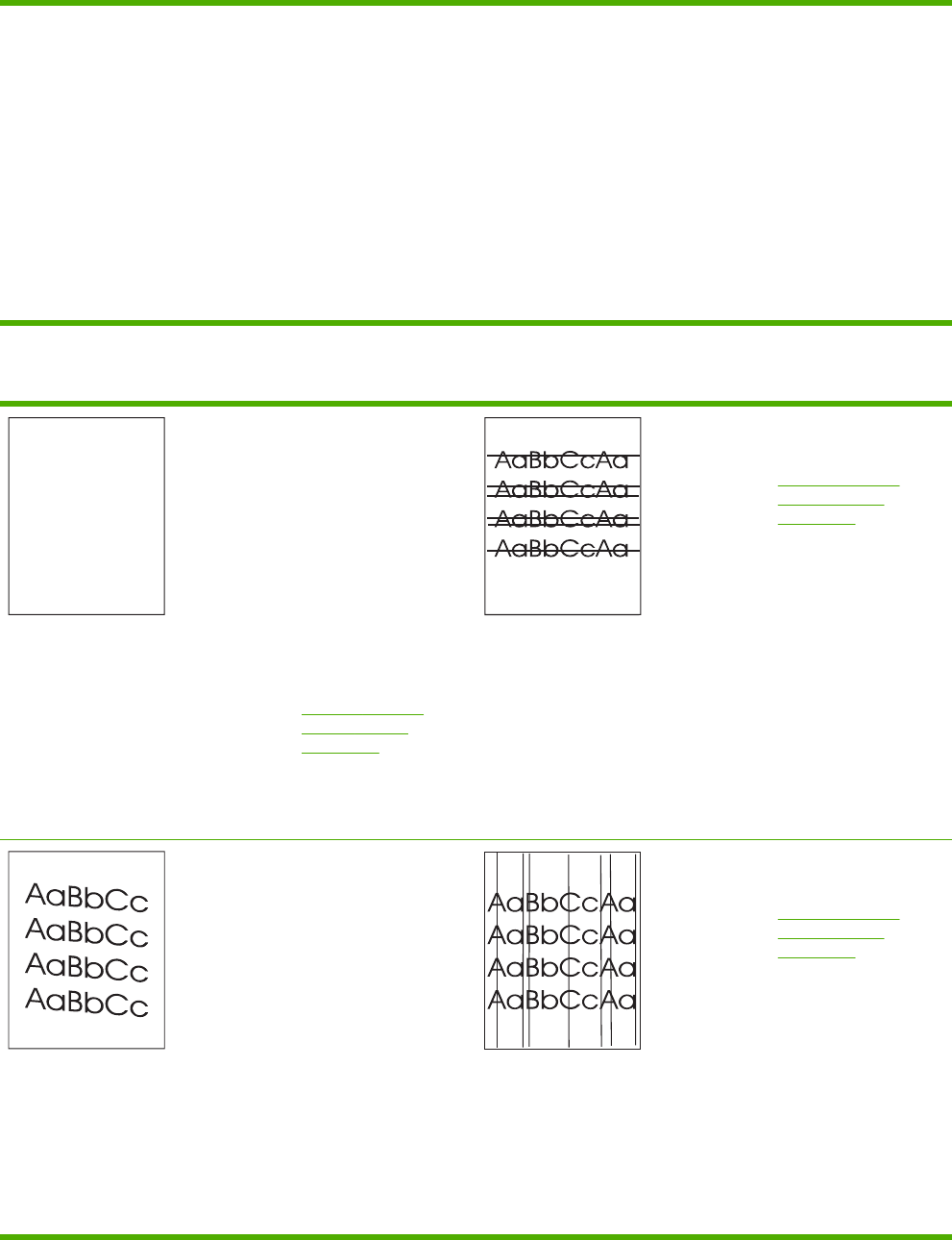
rotate the stack 180
degrees.
●Make sure that the
fuser and transfer belt
are seated correctly.
●Inspect the jam areas
and remove any
undetected jammed or
torn media.
●If printing from the
multipurpose tray,
make sure that the side
guides are set correctly.
Table 7-35 Defects that can occur when using the ADF
Blank page
1. Remove and then
reinsert the original
page into the ADF,
making sure it is placed
face-up.
2. If several pages are
feeding at the same
time, check the ADF
separation pad and
rollers for damage. If
the rollers are dirty,
clean them. See
Cleaning the ADF
delivery system
on page 99. If the ADF
separation pad or
rollers are worn,
replace them.
Horizontal lines
1. Clean the ADF. See
Cleaning the ADF
delivery system
on page 99.
2. Verify that no paper is
on top of the scanner
glass or stuck to the
bottom of the scanner
lid.
3. If the mylar strip is dirty
or worn, clean or
replace it. Replacement
mylar strips are stored
in an envelope that is
underneath the white
vinyl ADF backing.
Follow the instructions
that are in the envelope.
Page skew
1. Make sure the ADF
input tray guides are
adjusted so that they
are lightly touching the
sides of the paper stack.
2. If the mylar strip is
dislodged, folded, or
misinstalled, verify it is
correctly installed. If the
mylar strip is worn,
replace it. Replacement
mylar strips are stored
in an envelope that is
underneath the white
vinyl ADF backing.
Follow the instructions
that are in the envelope.
Vertical lines
1. Clean the ADF. See
Cleaning the ADF
delivery system
on page 99.
2. Verify that no paper is
on top of the scanner
glass or stuck to the
bottom of the scanner
lid.
3. If the mylar strip is dirty
or worn, clean or
replace it. Replacement
mylar strips are stored
in an envelope that is
underneath the white
vinyl ADF backing.
Table 7-34 Defects that can occur during printing (continued)
590 Chapter 7 Troubleshooting ENWW

3. Clean the ADF rollers.
See Cleaning the ADF
delivery system
on page 99.
4. If the problem persists,
calibrate the scanner.
See Calibrating the
scanner on page 106.
Follow the instructions
that are in the envelope.
Image shifted
An image that is shifted on
the page horizontally,
vertically, or both ways
indicates that the scanner is
incorrectly calibrated. See
Calibrating the scanner
on page 106.
Unexpected image
If the copy does not look at
all like the original
document, make sure that
no media is on the flatbed
glass from a previous copy
job.
Cleaning the scanner glass
Clean the scanner glass only if dirt is visible, or if you are experiencing a decrease in copy quality,
such as streaking.
Clean the scanner by wiping it gently with a clean, slightly damp, lint-free cloth. Use an ammonia-
based surface cleaner only when a water-dampened cloth does not clean the scanner glass. Spray
or pour the cleaner onto the cleaning cloth. Do not spray or pour the cleaner onto the scanner glass.
Calibrating the MFP
The MFP automatically calibrates and cleans at various times to maintain the highest level of print
quality. The user might also request the MFP to calibrate via the MFP’s control panel, using QUICK
CALIBRATE NOW or FULL CALIBRATE NOW located in the CALIBRATION and PRINT QUALITY
menu. QUICK CALIBRATE NOW is used for D-Half color tone calibration. If color density or tone
seems wrong, Quick Calibration can be run. Full Calibration includes the Quick Calibrate routines
and adds Drum Phase Calibration, Color Plane Registration (CPR), and copy parameter calibration
routines. If color layers (black, magenta, cyan, and yellow) on the printed page seem to be shifted
from one another, FULL CALIBRATE NOW should be run.
The HP Color LaserJet 4730 MFP incorporates a new feature to skip calibration when appropriate,
thereby making the MFP available more quickly. For example, if the MFP is powered off and on
quickly (within 20 seconds), calibration is not needed and will be skipped. In this case, the MFP will
reach the Ready state approximately one minute sooner.
While the MFP is calibrating and cleaning, the MFP will pause printing for the amount of time it takes
to complete the calibration or cleaning. For most calibrations and cleaning, the MFP will not interrupt
a print job, but will wait for the job to complete before calibrating or cleaning.
1. Press Menu to enter the MENUS.
2. Scroll to and touch Configure Device.
3. Scroll to and touch PRINT QUALITY.
4. Scroll to and touch QUICK CALIBRATE NOW.
Table 7-35 Defects that can occur when using the ADF (continued)
ENWW Correcting print quality and copy quality problems 591
OR
To perform a full calibration, use FULL CALIBRATE NOW instead of QUICK CALIBRATE NOW in
steps 3 and 4.
592 Chapter 7 Troubleshooting ENWW

Media transport problems
The following issues can cause media transport problems
Multiple pages feed.
Cause Solution
The tray 1 separation pad is worn. Replace the separation pad assembly.
Too much media (particularly envelopes) is loaded in tray 1. Remove some of the media and resend the print job.
The separation and feed rollers in the tray are worn or
damaged
Replace the rollers.
The media edges are locked together. Flex the media stack before loading it into the MFP. Do not
fan the media.
The media is wrinkled or folded.
Cause Solution
The feed rollers or registration rollers are dirty or defective. Replace the affected rollers.
The paper path contains foreign substances or dirt. Remove any foreign substances or dirt from the paper path.
The cartridge shutter open/close mechanism is damaged.
(This can cause jams in which the media is crumpled into an
accordion fold under the print cartridge.)
The shutter in the print cartridge should open as you insert
the cartridge. If a shutter does not open, replace the print
cartridge.
NOTE To diagnose the cause of wrinkled or
folded media, use the Print/Stop test in the
DIAGNOSTICS menu. Adjust the stop time to stop
the media before it enters the fuser.
The media is skewed.
Cause Solution
The paper dust or dirt has accumulated in the cassette feed
roller or registration roller.
Clean the rollers.
The cassette feed roller and registration roller are worn
irregularly.
Replace the paper pickup assembly.
The separation roller is worn or damaged (Tray 2 or 2 X
500-sheet feeder)
Clean or replace the separation roller. If necessary, replace
the paper cassette.
The registration shutter is defective. Clean or replace the separation roller. If necessary, replace
the paper cassette.
ENWW Media transport problems 593

The top margin is misaligned.
Cause Solution
Make sure that the registration shutter moves smoothly, its
spring is in place, and it is clean. If the registration shutter is
damaged, replace the paper pickup assembly.
1. Press the test print switch, and make several test
prints. See Engine test on page 598.
2. On each test print, measure the distance from the
leading edge of the paper to the print pattern. Calculate
the average distance. The optimal distance is 5 mm
(0.2 inches).
3. On the DC controller PCB, adjust the variable resistor
VR830 clockwise to increase the distance, or turn it
counterclockwise to decrease the distance.
4. Repeat the procedure until the distance measures
5 mm (0.2 inches).
The pages feed incorrectly through the ADF.
Cause Solution
The media guides are not adjusted correctly. Make sure that the guides in the ADF input tray gently touch
the sides of the original document.
594 Chapter 7 Troubleshooting ENWW

E-mail problems
If you are unable to send e-mails by using the digital send feature, you might need to reconfigure the
SMTP gateway address or the LDAP gateway address. Print a configuration page to find the current
SMTP and LDAP gateway addresses. See Information pages on page 640. Use the following
procedures to check if the SMTP and LDAP gateway addresses are valid.
To validate the SMTP gateway address
NOTE This procedure is for Windows operating systems.
1. Open an MS-DOS command prompt: click Start, click Run, and then type cmd.
2. Type telnet followed by the SMTP gateway address and then the number 25, which is the
port over which the MFP is communicating. For example, type telnet 123.123.123.123
25 where "123.123.123.123" represents the SMTP gateway address.
3. Press Enter. If the SMTP gateway address is not valid, the response contains the message
Could not open connection to the host on port 25: Connect Failed.
4. If the SMTP gateway address is not valid, contact the network administrator.
To validate the LDAP gateway address
NOTE This procedure is for Windows operating systems.
1. Open Windows Explorer. In the address bar, type LDAP:// immediately followed by the LDAP
gateway address. For example, type LDAP://12.12.12.12 where "12.12.12.12" represents
the LDAP gateway address.
2. Press Enter. If the LDAP gateway address is valid, the Find People dialog box opens.
3. If the LDAP gateway address is not valid, contact the network administrator.
ENWW E-mail problems 595

Fax problems
For complete information about troubleshooting fax problems, see the HP LaserJet Analog Fax
Accessory 300 User Guide
Network connectivity problems
Troubleshooting network printing problems
NOTE HP recommends that you use the MFP CD-ROM to install and set up the MFP on a
network.
1. Make sure that the network cable is securely seated into the MFP's RJ45 connector.
2. Make sure that the Jetdirect LED on the formatter is lit. See Formatter lights on page 532.
3. Make sure that the I/O card is ready. Print a configuration page. See Information pages
on page 640. If an HP Jetdirect print server is installed, printing a configuration page also prints a
second page that shows the network settings and status.
NOTE The HP Jetdirect embedded print server supports various network protocols
(TCP/IP, IPX/SPX, Novell/Netware, AppleTalk, and DCL/LLC). Make sure that the correct
protocol is enabled for your network.
4. On the HP Jetdirect configuration page, verify the following items for your protocol:
a. Under HP Jetdirect Configuration, the status is "I/O Card Ready".
b. The status is "Ready".
c. An IP address is listed.
d. The configuration method (Config by:) is listed correctly. See the network administrator if
you are not sure which method is correct.
e. The domain name is correct.
5. Perform a loopback test to verify that the firmware is functioning correctly and that the hardware
that is on the formatter is functioning correctly. See Loopback test on page 597.
6. Perform a ping test to verify that the MFP is communicating with other devices on the network.
See Ping test on page 597.
7. Try printing the job from another computer.
8. To verify that an MFP works with a computer, use a parallel cable to connect it directly to a
computer. You will have to reinstall the printing software. Print a document from a program that
has printed correctly in the past. If this works, a problem with the network might exist.
9. For advanced troubleshooting, see Troubleshooting the embedded HP Jetdirect print server
on page 665.
596 Chapter 7 Troubleshooting ENWW

Loopback test
Use the loopback test to verify that the firmware is functioning correctly and that the hardware that is
on the formatter is functioning correctly. This test causes the formatter to send data to itself.
To perform the loopback test
1. Disconnect the network cable.
2. Press Menu.
3. Touch Configure Device.
4. Touch I/O, touch EMBEDDED JETDIRECT MENU, touch DIAGNOSTICS, and then touch
LOOPBACK TEST.
5. Let the test run for several hours or overnight.
6. If the test fails, an error message appears on the control panel display. Replace the formatter.
See Formatter board on page 280.
7. To stop the test, turn the MFP off and then on. Make sure that you reconnect the network cable.
Ping test
Use the ping test to verify that the MFP is communicating over the network. Before performing the
ping test, obtain the IP address for a target destination, such as a computer, that is on the same
network as the MFP. Consult the network administrator for help with obtaining the IP address.
To perform the ping test
1. Press Menu.
2. Touch Configure Device.
3. Touch I/O, touch EMBEDDED JETDIRECT MENU, touch DIAGNOSTICS, and then touch PING
TEST.
4. Set the appropriate options for each of the menu items that follow:
●DESTINATION IP = XXX.XXX.XXX.XXX
●PACKET SIZE = 64
●Timeout = 1 second
●Count = 4
●PRINT RESULTS = YES
●EXECUTE = YES
5. After setting EXECUTE= YES, the ping test starts automatically. If you selected to print the
results, a page prints that lists the ping statistics. If the page prints, the test was successful.
ENWW Network connectivity problems 597
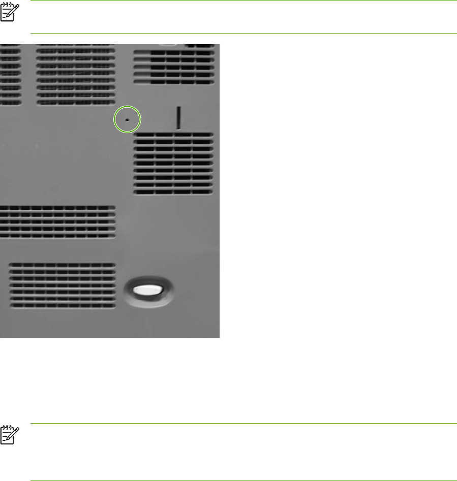
Functional checks
Use the following procedures to help diagnose and solve problems that occur in the print engine.
Engine test
To verify that the print engine (all components except the formatter, formatter DIMMs, EIO products,
and the stacker or stapler/stacker) is functioning, print an engine test page. Use a small, non-
metallic, pointed object to depress the engine-test switch, which is located on the back of the MFP.
NOTE The standard output bin must be installed in order for the engine-test page to print. If
either the stapler/stacker or the 3-bin mailbox is installed, a jam occurs.
Figure 7-11 Engine test print switch
The test page should have a series of vertical lines. The test page prints from the last tray that you
used. However, if the MFP has been turned off and then on since the most recent print job, the page
prints from tray 2. The MFP continuously prints test pages as long as the test-page switch is
depressed. The MFP cannot print a test page if it is in Sleep mode.
NOTE A damaged formatter might interfere with the engine test. If the engine-test page does
not print, try removing the formatter and performing the engine test again. If the engine test is
then successful, the problem is almost certainly with the formatter, the control panel, or the
cable that connects them.
598 Chapter 7 Troubleshooting ENWW

Formatter test
To verify that the formatter is functioning correctly, print a configuration page. See Information pages
on page 640. If the page prints, the formatter is functioning.
The heartbeat LED on the formatter also indicates whether the formatter is functioning. See
Formatter lights on page 532.
ENWW Functional checks 599

MFP resets
Use the following information to perform system-wide reset procedures. Customers do not have
access to this information.
Cold reset
A cold reset unlocks menus that have been previously locked and resets all control panel menu
items to the factory defaults. A cold reset does not clear the values in the service menu, such as the
serial number and the page counts.
NOTE Before performing a cold reset, print a menu map and a configuration page. See
Information pages on page 640. Use the information on these pages to reset customer-specific
settings.
CAUTION All HP Jetdirect settings are also reset. Be sure to print a configuration page
before performing a cold reset. Make note of the IP address that is listed on the Jetdirect
configuration page. You will need to restore the IP address after performing a cold reset. See
Configuring and verifying an IP address on page 136.
To perform a cold reset
1. Turn the MFP off and then on.
2. When the memory count appears on the control panel display, press and hold 6 until all three
LEDs flash once and then stay on. This might take up to 20 seconds.
3. Press 3 four times until COLD RESET appears on the control panel display.
4. Press 6 one time. The MFP continues its initialization sequence.
NVRAM initialization
NOTE If an analog fax accessory is installed, performing an NVRAM initialization can cause
the MFP to violate local telephone regulations. Reset the language and country/region after
performing NVRAM initialization. For more information, see the HP LaserJet Analog Fax
Accessory 300 User Guide.
Before performing an NVRAM initialization, print a menu map and a configuration page. See
Information pages on page 640. Use the information on these pages to reset any customer-
specific settings.
CAUTION All HP Jetdirect settings are also reset. Be sure to print a configuration page
before performing a cold reset. Make note of the IP address that is listed on the Jetdirect
configuration page. You will need to restore the IP address after performing a cold reset. See
Configuring and verifying an IP address on page 136.
Performing an NVRAM initialization resets the following settings and information:
●All menu settings are reset to factory default values, including the fax header and company
name.
●All faxes in memory are erased.
600 Chapter 7 Troubleshooting ENWW

●All speed-dials, group-dials, and phonebook entries are erased.
●All localization settings, including language and country/region, are reset.
After performing an NVRAM initialization, reconfigure any computers that print to this MFP so that
the computers can recognize the MFP.
To perform an NVRAM initialization
1. Turn the MFP off and then on.
2. When the memory count appears on the control panel display, press and hold 9 until all three
LEDs flash once and then stay on. This might take up to 20 seconds.
3. Press 3 one time, and then press Start.
4. Press 3 two times until NVRAM INIT appears on the control panel display.
5. Press 6 one time, and wait while the MFP completes its initialization sequence.
Hard-disk initialization
A hard-disk initialization erases and reformats the hard disk. Perform a hard-disk initialization only if
an error message on the control panel indicates a disk error. Always try initializing the hard disk
before replacing it.
NOTE Before performing a hard-disk initialization, print a menu map and a configuration
page. See Information pages on page 640. Use the information on these pages to reset any
customer-specific settings.
CAUTION A hard-disk initialization deletes the following information: all stored copy jobs, the
local address book (e-mail addresses), the speed-dial list (fax numbers), and the Java™
applet files.
To perform a hard-disk initialization
1. Turn the MFP off and then on.
2. When the memory count appears on the control panel display, press the right-hand side of the
Start button until all three LEDs are lit. Release the Start button.
3. Press 5 one time. INITIALIZE DISK appears on the control panel display.
4. Press 6 one time. A series of asterisks appears on the control panel display. Wait for the MFP to
complete its initialization sequence.
ENWW MFP resets 601
Control panel troubleshooting
When you press Menu to open the menus, the high-level menus appear in the following order:
●PAUSE
●RETRIEVE JOB
●Information
●Fax (if installed)
●PAPER HANDLING
●Configure Device
●DIAGNOSTICS
●Service
Control panel layout
The control panel includes a touchscreen graphical display, job control buttons, a numeric keypad,
and three light-emitting diode (LED) status lights.
602 Chapter 7 Troubleshooting ENWW
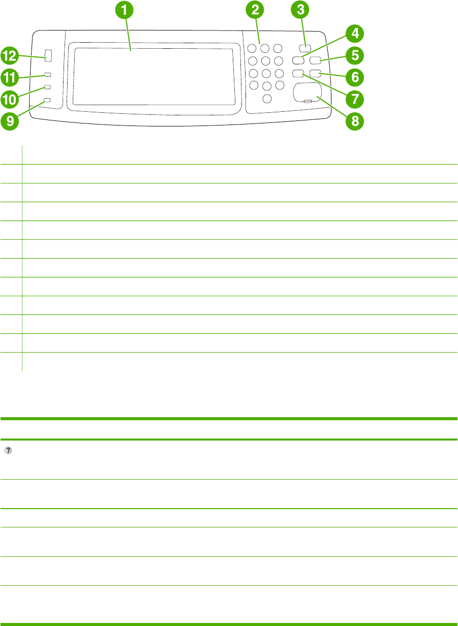
1Touchscreen graphical display
2Numeric keypad
3Sleep button
4Menu button
5Status button
6stop button
7Reset button
8Start button
9Attention! light
10 Data light
11 Ready light
12 Display contrast adjustment
Control panel features
Features/buttons Function
Provides access to What is This?, Show Me How, and
Help for Status Help. This function is embedded in the
touchscreen menus.
Reset Resets the job settings to factory or user-defined default
values.
STOP Cancels the active job.
Start Begins a copy job, starts digital sending, or continues a job
that has been interrupted.
Numeric keypad Allows you to type numeric values for number of copies
required and other numeric values.
Sleep If the MFP is inactive for a long period of time, it
automatically enters a sleep mode. To place the MFP into
sleep mode or to reactivate the MFP, press the Sleep button.
ENWW Control panel troubleshooting 603
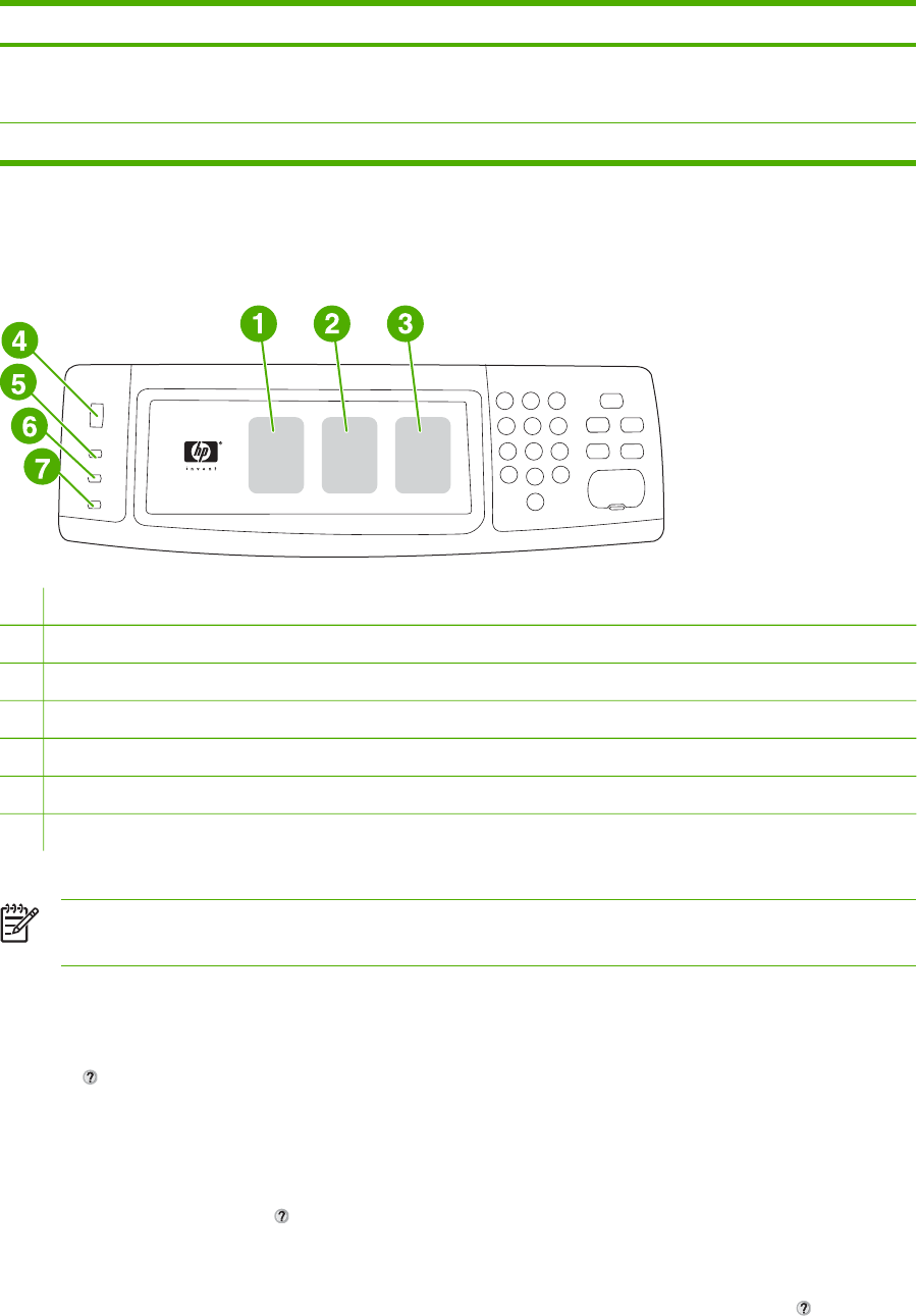
Features/buttons Function
Status Opens the SUPPLIES STATUS menu. From this menu, you
can retrieve the status of the print cartridges, the fuser, and
the transfer unit.
Menu Opens the MFP menus.
Home-screen navigation
Use the following control panel elements in the graphical display to gain access to MFP features.
1Touch this to use the Copy screen.
2Touch this to use the E-mail screen.
3Touch this to use the Fax screen. For more information, see the HP LaserJet Analog Fax Accessory 300 User Guide.
4Rotate this dial to increase or decrease screen brightness.
5The Ready light indicates that the MFP is ready.
6The Data light indicates that the MFP is receiving data.
7The Attention! light indicates that the MFP has a problem and requires user intervention.
NOTE If you install the optional HP Digital Sending Software (DSS), additional fields appear
on the control panel display. You might need to scroll down to see all the fields.
Help system
At any time, you can gain access to the help system on the touchscreen of the graphical display by
touching .
What is This? Help
The MFP provides information about any topic on the touchscreen of the graphical display.
On the top level screen, touch (Help button), and then touch What is This?. After touching an item,
a pop-up dialog box opens and displays information about the item you touched. After reading the
information, touch any other area on the screen to remove the What is This? pop-up dialog box.
On other levels of the touchscreen, you can gain access to the Help system by touching (Help
button), which is located in the upper-left corner of each screen.
604 Chapter 7 Troubleshooting ENWW

Show Me How Help
The Show Me How Help contains information about how to use the MFP features.
1. On the graphical touchscreen display on the control panel, touch (Help button).
2. Touch Show Me How. Choose a topic from the What is This? screen by touching an item. You
can use the scroll bar to display more topics. After touching an item, an instruction sheet will
print.
3. Touch OK to go back to the main window.
Show Me How also appears in a What is This? pop-up dialog box if the item that you select is a
function that includes instructions. For example, if you touch What is This? Help, and then touch
mopies, you see a Show Me How button in the pop-up dialog box. Touch the Show Me How button
for information about how to enhance your copies.
Menu map
To see the current settings for the menus and items that are available in the control panel, print a
control panel menu map:
1. Press Menu.
2. Touch Information.
3. Touch PRINT MENU MAP.
Many of these values can be overridden from the driver or program. You might want to store the
menu map near the MFP for reference.
The content of the menu map varies, depending on the options currently installed in the MFP. For a
complete list of control panel items and possible values, see the sections for each menu in this
chapter.
Retrieve job menu
The Retrieve job menu contains options for retrieving proof and hold jobs, private jobs, quick copy
job, and stored jobs, The following table displays the options available in the Retrieve job menu.
Item Values Explanation
USER JOB Allows you to select the job to be
retrieved. After selecting the job, the
Print and Delete X? options display.
Select Print to enter the number of
copies. Select Delete X? to delete the
job. If you are retrieving a secured job,
both the Print and Delete X? options
contain a dialog box where you must
enter the PIN number.
ENWW Control panel troubleshooting 605

NOTE If no private, stored, quick copy, or proof-and-hold jobs are stored on the MFP hard
disk or in RAM memory, the message No stored jobs appears when the menu is selected.
1. A list of user names appears on the control panel display.
2. Press Menu.
3. Touch RETRIEVE JOB.
4. Touch a user name, and then a list of stored jobs for that user appears.
5. Touch a job name, and then print or delete the job. If a job requires a PIN to print, (lock
symbol) appears next to the Print command and a PIN must be provided. If a job requires a PIN
to delete, appears next to the Delete X? command and a PIN must be provided.
6. If you touch Print, the MFP prompts for the number of copies to print (1 to 32,000).
Information menu
To print an information page, scroll to and touch the information page(s) that you want.
Item Explanation
PRINT MENU MAP Generates a menu map that shows layout and current
settings of the control menu items.
The MFP will return to the Ready state when the page is
completed.
PRINT CONFIGURATION Generates a page detailing the current configuration of the
MFP.
The MFP will return to the online Ready state when the
page is completed.
PRINT SUPPLIES STATUS PAGE Generates a page that shows the number of pages
remaining for each supply in the MFP.
The MFP will return to the online Ready state when the
page is completed.
SUPPLIES STATUS This page does not print. It displays status only.
PRINT USAGE PAGE Generates a page that contains information that could be
used for cost accounting.
The MFP will return to the online Ready state when the
page is completed.
PRINT DEMO Generates a demonstration page.
The MFP will return to the online Ready state when the
page is completed.
PRINT RGB SAMPLES Generates a page that displays RGB colors.
The MFP will return to the online Ready state when the
page is completed.
PRINT CMYK SAMPLES Generates a page that displays CMYK colors.
606 Chapter 7 Troubleshooting ENWW

Item Explanation
The MFP will return to the online Ready state when the
page is completed.
PRINT FILE DIRECTORY Generates a directory page containing information for all
installed mass storage devices.
The MFP will return to the online Ready state when the
page is completed.
PRINT PCL FONT LIST Generates a typeface list of all PCL fonts available on the
MFP.
The MFP will return to the online Ready state when the
page is completed.
PRINT PS FONT LIST Generates a typeface list of all PS fonts available on the
MFP.
The MFP will return to the online Ready state when the
page is completed.
Fax menu
This menu will appear only if the HP LaserJet analog fax accessory 300 is installed. For information
about the fax menu, see the HP LaserJet Analog Fax Accessory 300 User Guide. A printed copy of
this guide is provided with the HP LaserJet 4730x MFP, HP LaserJet 4730xs MFP, and HP LaserJet
4730xm MFP.
Paper handling menu
When paper-handling settings are correctly configured through the control panel, you can print by
selecting the type and size of paper from the driver or software application.
Some items in the paper handling menu (such as duplex and manual feed) are available from a
software program, or from the printer driver (if the correct printer driver is installed). Printer-driver and
software-program settings override control panel settings.
NOTE Items that have an asterisk (*) are the default values.
Item Values Explanation
TRAY 1 SIZE ANY SIZE*
LETTER
LEGAL
EXECUTIVE
STATEMENT
8.5X13
A4
A5
Allows you to set the media size for
tray 1.
ENWW Control panel troubleshooting 607

Item Values Explanation
B5(JIS)
EXECUTIVE(JIS)
DPOSTCARD(JIS)
DPostcard (JIS)
16K
ENVELOPE #10
ENVELOPE MONARCH
ENVELOPE C5
ENVELOPE DL
ENVELOPE B5
CUSTOM
TRAY 1 TYPE ANY TYPE*
PLAIN
PREPRINTED
LETTERHEAD
TRANSPARENCY
PREPUNCHED
LABELS
BOND
RECYCLED
COLOR
LIGHT <75 G/M2
INTERMEDIATE90-104
HEAVY 105-120 G/M2
EXTRA HEAVY120-163
CARDSTOCK >163
ROUGH 90-105 G/M2
GLOSSY 75-105 G/M2
HEAVYGLOSSY120-160
EXTRA HEAVY GLOSSY
TOUGH PAPER
ENVELOPE
Allows you to specify the type of media
in tray 1.
TRAY <N> SIZE ANY SIZE Allows you to set the media size for
tray 2, tray 3, and tray 4. Substitute the
tray number for <N>.
608 Chapter 7 Troubleshooting ENWW

Item Values Explanation
LETTER*
LEGAL
EXECUTIVE
8.5X13
A4
A5
B5(JIS)
EXECUTIVE(JIS)
16K
CUSTOM
ANY CUSTOM
TRAY <N> TYPE ANY TYPE
PLAIN*
PREPRINTED
LETTERHEAD
TRANSPARENCY
PREPUNCHED
LABELS
BOND
RECYCLED
COLOR
LIGHT <75 g/m2
INTERMEDIATE90-104
HEAVY 105-120 G/M2
ROUGH 90-105 G/M2
GLOSSY 75-105 G/M2
TOUGH PAPER
Allows you to specify the type of media
in each tray. Substitute the tray number
for <N>.
Configure device menu
This menu contains all of the administrative functions.
NOTE Items that have an asterisk (*) are the default values.
ENWW Control panel troubleshooting 609

Originals submenu
Although you can gain access to each item using the touchscreen graphical display, you can also
select copying and sending items through the MFP menus. To gain access to this menu, touch
Configure Device, and then touch ORIGINALS.
Item Values Explanation
PAPER SIZE EXECUTIVE
LETTER*
LEGAL
A5
A4
B5(JIS)
8.5X13
STATEMENT
MIXED LTR/LGL
Sets the paper size of the original
document.
NUMBER OF SIDES 1*
2
Indicates whether one side or both
sides of the original document are
scanned.
The MFP prompts you to turn the page
over if 2 is selected and the original is
placed on the flatbed.
ORIENTATION PORTRAIT*
LANDSCAPE
Indicates whether the orientation of the
original is portrait (short-edge top) or
landscape (long-edge top).
CONTENT TEXT
PHOTO
GLOSSY PHOTO
MIXED*
Describes the type of image on the
original.
Select PHOTO if the original consists
of graphic images, or TEXT if the
image consists of text only.
Select GLOSSY PHOTO for
continuous tone originals.
Select MIXED if the original contains
graphics and text. Describe the TEXT/
PHOTO MIX with a value from 0 to 8,
where 0 represents mostly text, and 8
represents mostly graphics.
NOTE You can override any
of these settings for a
particular job by using the
Copy screen.
DENSITY 0 to 8
Default=4
Specifies the contrast and brightness
of the image. You can choose from
nine increments.
610 Chapter 7 Troubleshooting ENWW

Item Values Explanation
0=darkest
8=lightest
Copying submenu
To gain access to this menu, touch Configure Device, and then touch Copying.
Item Values Explanation
COLOR MODE COLOR COPIES
BLACK COPIES
Indicates whether copies should be printed in
color or black-and-white.
NUMBER OF SIDES 1*
2
Indicates whether images should be printed on
one side or both sides of the copy.
COLLATE OFF
ON*
Indicates whether copies should be collated or
not collated.
PAPER DESTINATION Output Bin 1*
Output Bin 2*
Output Bin 3*
Select the output bin on the optional 3-bin
mailbox.
Output Bin 1 is the default bin for copying.
Output Bin 2 is the default bin for faxing.
Output Bin 3 is the default bin for printing.
NOTE This item appears only if an
optional 3-bin mailbox is installed.
COPIES 1–999 Indicates the number of copies made when you
press Start without selecting the number of
copies by using the numeric keypad.
STAPLE NONE*
1-EDGE
To enable stapling, select 1-EDGE.
NOTE This item is available only if the
stapler/stacker is installed.
FIRST COPY SPEED NO EARLY WARM UP*
EARLY WARM UP
Select NO EARLY WARM UP to disable the Fast
First Copy feature. Using the Fast First Copy
feature can cause excessive wear on the MFP.
This is the default setting.
Select EARLY WARM UP to enable the Fast
First Copy feature, which decreases the time that
the MFP requires to make a copy when it has
been idle for awhile.
ENWW Control panel troubleshooting 611

Enhancement submenu
To gain access to this menu, touch Configure Device, and then touch Enhancement.
Item Values Explanation
SHARPNESS 0 to 4Specifies the sharpness setting.
0=minimum sharpness
4=maximum sharpness
DEFAULT=2
BACKGROUND REMOVAL 0 to 8Controls the amount of background
material from the original that is
eliminated on the copy. Background
removal is useful when you copy both
sides and do not want the material on
the first side to be visible on the
second side of the copy.
0=minimum background removal (more
background is visible)
8=maximum background removal (less
background is visible)
DEFAULT=2
Sending submenu
To gain access to this menu, touch Configure Device, and then touch Sending.
Item Values Options Explanation
E-MAIL SCAN PREFERENCE BLACK AND WHITE
COLOR*
Determines whether the
document is scanned in
color or black and white.
FILE TYPE PDF*
M-TIFF
TIFF
JPEG
Specifies the file format of
the e-mail attachment.
FILE SIZE SMALL
STANDARD*
LARGE
Specifies the compression of
a file, which determines the
file size.
RESOLUTION 75 DPI
150 dpi*
200 dpi
300 dpi
Specifies the resolution of a
document or image; a lower
DPI setting results in a
smaller file size, but image
quality might be affected.
612 Chapter 7 Troubleshooting ENWW

Item Values Options Explanation
ADDRESS VALIDATION OFF
ON*
Enables the MFP to check e-
mail syntax. Valid e-mail
addresses require the "@"
sign and a ".".
FIND GATEWAYS The MFP searches the
network for SMTP and
LDAP gateways that the
MFP can use to send e-mail.
SMTP GATEWAY The IP address of the SMTP
server used to send e-mail.
LDAP GATEWAY The IP address of the LDAP
gateway that the MFP uses
to look up e-mail information.
TEST SEND GATEWAYS Tests the configured
gateways to see if they are
functional.
REPLICATE MFP Copies the send settings
from one MFP to another.
NOTE This feature
might not work with
older MFPs.
Printing submenu
Some items in the Printing submenu are available in a software program, or in the printer driver (if
the correct printer driver is installed). Driver and program settings override control panel settings.
To gain access to this menu, touch Configure Device, and then touch PRINTING.
Item Values Explanation
COPIES 1 to 32,000 Set the default number of copies by
selecting any number from 1 to
32,000. Use the numeric keypad to
select the number of copies.
NOTE It is recommended
that you set the number of
copies in the printer driver or
in the software program.
(Printer driver settings and
software program settings
override control panel
settings.)
DEFAULT PAPER SIZE LETTER*
LEGAL
EXECUTIVE
Set the default image size for paper
and envelopes. (The item name will
change from paper to ENVELOPE
as you scroll through the available
sizes.)
ENWW Control panel troubleshooting 613

Item Values Explanation
STATEMENT
8.5X13
A4
A5
B5(JIS)
EXECUTIVE(JIS)
16K
ENVELOPE #10
ENVELOPE MONARCH
ENVELOPE C5
ENVELOPE DL
ENVELOPE B5
CUSTOM
DEFAULT CUSTOM PAPER SIZE UNIT OF MEASURE
X DIMENSION
Y DIMENSION
Allows you to set a custom paper
size for any of the installed trays.
Substitute the tray number for <N>.
Select the X and Y dimensions of the
custom paper size. The X
dimensions are 76-216 mm
(3-8.5 inches). The Y Dimensions are
127-356 mm (5-14 inches).
PAPER DESTINATION Output Bin 1*
Output Bin 2
Output Bin 3
Select the output bin on the optional
3-bin mailbox.
NOTE This item appears
only if an optional 3-bin
mailbox is installed, and if it
is not configured for stacker
mode.
DUPLEX OFF
ON*
DUPLEX BINDING
Set the value to ON to print on both
sides (duplex) or OFF to print on one
side (simplex) of a sheet of paper.
DUPLEX BINDING allows you to
select LONG EDGE or SHORT
EDGE*. This item displays only if
DUPLEX is set to ON.
OVERRIDE A4/LETTER NO
YES*
This command is used to print on
Letter-size media when an A4 job is
sent but no A4-size media is loaded
in the MFP (or to print on A4-size
media when a Letter job is sent, but
no Letter-size media is loaded in the
MFP).
MANUAL FEED OFF* Feed the paper manually from tray 1,
rather than automatically from a tray.
614 Chapter 7 Troubleshooting ENWW

Item Values Explanation
ON When MANUAL FEED=ON and
tray 1 is empty, the MFP goes offline
when it receives a print job. It then
displays MANUALLY FEED
<PAPER SIZE>.
COURIER FONT REGULAR*
DARK
Select the version of Courier font to
use:
REGULAR: The internal Courier font
available on the HP LaserJet 4 series
printers.
DARK: The internal Courier font
available on the HP LaserJet III
series printers.
Both fonts are not available at the
same time.
WIDE A4 NO*
YES
The Wide A4 setting changes the
number of characters that can be
printed on a single line of A4 paper.
YES: Up to 80 10-pitch characters
can be printed on one line.
NO: Up to 78 10-pitch characters can
be printed on one line.
PRINT PS ERRORS OFF*
ON
Select ON to print the PS error page
when PS errors occur.
PRINT PDF ERRORS OFF*
ON
Select ON to print the PDF error
page when PDF errors occur.
PCL For information about this option, see
PCL submenu on page 616.
ENWW Control panel troubleshooting 615

PCL submenu
To gain access to this menu, touch Configure Device, touch PRINTING, and then touch PCL
submenu.
Item Values Explanation
FORM LENGTH 5 to 128
Default=60
Sets vertical spacing from 5 to 128 lines for
default paper size. Enter the value by using the
numeric keypad.
ORIENTATION PORTRAIT*
LANDSCAPE
Select the default page orientation.
NOTE It is recommended that you set
the page orientation in the printer driver
or in the software program. (Printer-
driver settings and software-program
settings override control panel settings.)
FONT SOURCE INTERNAL X*
CARD SLOT X:
INTERNAL X: Internal fonts.
CARD SLOT 1, CARD SLOT 2, or CARD
SLOT 3: Fonts stored in one of the three flash
memory slots.
FONT NUMBER 0 to 102 The MFP assigns a number to each font and
lists them on the PCL Font List (see Information
pages on page 640). The font number appears in
the Font # column of the printout.
FONT PITCH 0.44 to 99.99 Use the numeric keypad to enter a value. This
item might not appear, depending on the font
selected.
Default=10.00
FONT POINT SIZE 4.00 to 999.75 Use the numeric keypad to enter a value.
Default=12.00
SYMBOL SET Variety of available
symbol sets
Select any one of several available symbol sets
at the MFP control panel. A symbol set is a
unique grouping of all the characters in a font.
PC–8 or PC–850 is recommended for line-draw
characters.
APPEND CR TO LF NO*
YES
Select YES to append a carriage return to each
line feed that is encountered in backward-
compatible PCL jobs (pure text, no job control).
Some environments, such as UNIX, indicate a
new line by using only the line-feed control
code. This option allows the user to append the
required carriage return to each line feed.
SUPPRESS BLANK PAGES NO*
YES
When set to YES, form feeds are ignored if the
page is blank.
MEDIA SOURCE MAPPING STANDARD*
CLASSIC
The PCL5 MEDIA SOURCE MAPPING
command selects an input tray by a number
that maps to the available trays and feeders.
616 Chapter 7 Troubleshooting ENWW

Print quality submenu
You can gain access to some of the items in this menu in either a software program, or in the printer
driver (if the correct printer driver is installed). Printer driver settings and software program settings
override control panel settings.
To gain access to this menu, touch Configure Device, and then touch PRINT QUALITY.
Item Values Explanation
ADJUST COLOR HIGHLIGHTS
MIDTONES
SHADOWS
RESTORE COLOR VALUES
This item allows you to adjust the color
from +5 to –5.
Each value allows you to adjust CYAN
DENSITY, MAGENTA DENSITY,
YELLOW DENSITY, and BLACK
DENSITY
RESTORE COLOR VALUES removes
any color adjustments and returns the
color to the original value.
SET REGISTRATION PRINT TEST PAGE
SOURCE
ADJUST TRAY N
Shift the margin alignment to center the
image on the page from top to bottom,
and left to right. You can also align the
image on the front, with the image
printed on the back.
AUTO SENSE MODE TRAY 1 SENSING
TRAY 2-N SENSING
Allows you to set trays to automatically
sense the type of paper that is loaded.
PRINT MODES PLAIN
PREPRINTED
LETTERHEAD
TRANSPARENCY
PREPUNCHED
LABELS
BOND
RECYCLED
COLOR
LIGHT <75 G/M2
INTERMEDIATE90-104
HEAVY 105-120 G/M2
EXTRA HEAVY120-163
CARDSTOCK >163
ROUGH 90-105 G/M2
GLOSSY 75-105 G/M2
Allows you to associate each media
type with a specific print mode.
ENWW Control panel troubleshooting 617

Item Values Explanation
HEAVYGLOSSY120-160
EXTRA HEAVY GLOSSY
TOUGH PAPER
ENVELOPE
RESTORE MODES
OPTIMIZE EXTRA HEAVY120-163
HIGH GLOSS IMAGES
BACKGROUND 1
BACKGROUND 2
TRANSPARENCY
MEDIA TYPE
REGISTRATION
LONG PAPER
PRE-ROTATION
RE-TRANSFER
FUSER TEMP
TRAY1
RESTORE OPTIMIZE
This item optimizes a number of MFP
parameters for all jobs rather than by
media type. The default setting for
each value is OFF.
RESTORE OPTIMIZE resets all of the
optimize parameters to the default
settings.
QUICK CALIBRATE NOW N/A. Performs partial printer calibrations.
FULL CALIBRATE NOW N/A Performs full printer calibrations.
COLOR RET OFF
ON*
The COLOR RET menu item allows
you to turn on or turn off the printer REt
(Resolution Enhancement Technology)
setting. The default is ON.
System setup submenu
Items in this menu affect the MFP function. Configure the MFP according to your printing needs.
To gain access to this menu, touch Configure Device, and then touch SYSTEM SETUP.
Item Values Explanation
DATE/TIME DATE
DATE FORMAT
TIME
TIME FORMAT
Sets the start date and time for the MFP.
The DATE format is YEAR 2004–2087;
JAN, FEB, MAR; DAY 1–31
The DATE FORMAT is YYYY/MMM/
DD*; MMM/DD/YYYY; DD/MMM/YYYY
618 Chapter 7 Troubleshooting ENWW

Item Values Explanation
The TIME format is HOUR 1–12,
MINUTE 0–59, AM, and PM
The TIME FORMAT is 12 HR or 24
HR. This item defaults to 12 HR.
JOB STORAGE LIMIT 1 to 100 Specifies the number of QuickCopy
and Proof-and-Hold jobs that can be
stored on the MFP hard-disk accessory.
Default=32
JOB HELD TIMEOUT OFF*
1 HOUR
4 HOURS
1 DAY
1 WEEK
Sets the amount of time that
QuickCopy and proof-and-hold jobs are
kept before being automatically deleted
from the queue.
If you change the Job Held Timeout
value, only jobs that are stored after
this change are affected by the
change. Any jobs that were stored
before you changed the value will
retain the original timeout setting.
SHOW ADDRESS AUTO
OFF*
This item defines whether the
IP address is shown on the control
panel display next to the Ready
message.
The default setting is OFF.
COLOR/BLACK MIX AUTO*
MOSTLY COLOR PAGES
MOSTLY BLACK PAGES
This menu item establishes how the
printer switches from color to
monochrome (black and white) mode
for maximum performance and print
cartridge life.
AUTO resets the printer to the factory
default settings. The default is AUTO.
Select MOSTLY COLOR PAGES if
nearly all of your print jobs are color
with high page coverage.
Select MOSTLY BLACK PAGES if you
print mostly monochrome jobs, or a
combination of color and monochrome
jobs.
TRAY BEHAVIOR USE REQUESTED TRAY
MANUALLY FEED PROMPT
PS DEFER MEDIA
SIZE/TYPE PROMPT
USE ANOTHER TRAY
DUPLEX BLANK PAGES
IMAGE ROTATION
Specifies the behavior of the tray by
indicating which tray the MFP should
print from.
USE REQUESTED TRAY sets the tray
that the MFP should print from for
specified jobs. The values for this
menu item are EXCLUSIVELY
(default) or FIRST.
MANUALLY FEED PROMPT
determines whether or not the MFP
prompts the user when a job does not
ENWW Control panel troubleshooting 619

Item Values Explanation
match a requested configured tray. The
values for this menu item are Always
(default) or UNLESS LOADED.
PS DEFER MEDIA determines
whether the paper-handling model is
based on PostScript rules or HP rules.
The values for this menu item are
ENABLED (follows the HP rules) or
Disabled.
SIZE/TYPE PROMPT controls whether
the tray configuration message and its
prompts are shown whenever a tray is
configured for a type or size other than
the type or size that is loaded in the tray.
USE ANOTHER TRAY determines
whether the MFP uses paper from
another tray of the designated tray is
empty.
DUPLEX BLANK PAGES determines
whether blank pages are duplexed.
IMAGE ROTATION determines if
images are rotated. The default is
STANDARD.
SLEEP DELAY 1 MINUTE
15 MINUTES
30 MINUTES
45 MINUTES
60 MINUTES*
90 MINUTES
2 HOURS
4 HOURS
Sets how long the MFP remains idle
before it enters sleep mode.Using
sleep mode offers the following
advantages:
●Minimizes the amount of power
that the MFP consumes when it is
idle
●Reduces wear on electronic
components in the MFP
NOTE Sleep mode turns off
the backlight on the display,
but the display is still readable.
The MFP automatically exits sleep
mode when you send a print job, open
or close a paper tray, receive a fax,
touch any button on the control panel,
touch any part of the touchscreen,
open the scanner lid, or load media
into the ADF.
To enable or disable sleep mode, see
Resets submenu on page 628.
WAKE TIME List of days of the week
OFF*
CUSTOM
Sets the time that the MFP
automatically comes out of sleep
mode. This feature can be set for a
different time for each day of the week.
Or, if you wish to apply the same
620 Chapter 7 Troubleshooting ENWW

Item Values Explanation
settings to each day, select APPLY TO
ALL DAYS
Each day displays the following values:
Hour 1–12, Minute 0–59, AM, and PM.
COPY/SEND SETTINGS For information about these settings,
see the separate table Copy/send
settings on page 622.
PERSONALITY AUTO*
PCL
PDF
PS
Select the default MFP language
(personality). Possible values are
determined by which valid languages
are installed in the MFP.
Normally you should not change the
product language (the default is
AUTO). If you change the setting to a
specific product language, the MFP
does not automatically switch from one
language to another unless specific
software commands are sent to the
MFP.
CLEARABLE WARNINGS JOB*
ON
Set the amount of time that a clearable
warning appears on the MFP control
panel.
JOB: Warning messages appear on
the control panel until the end of the
job from which they were generated.
ON: Warning messages appear on the
control panel until they are cleared.
AUTO CONTINUE OFF
ON*
This item determines how the MFP
reacts to errors.
OFF: If an error prevents printing, the
message remains on the display, and
the MFP does not print until you touch
CONTINUE.
ON: If an error prevents printing, the
message is displayed, and the MFP
goes offline for 10 seconds before
returning online.
REPLACE SUPPLIES STOP AT OUT*
&STOP AT LOW;
OVERRIDE AT OUT
Sets printer behavior when a cartridge
is low. The default is STOP AT OUT.
This option allows the printer to
continue printing until a color supply is
exhausted. When the printer is set to
STOP AT LOW, printing pauses until
the color supply is replaced.
OVERRIDE AT OUT allows printing to
continue when a color supply is out,
but displays a warning the supply is out
and must be replaced.
ORDER AT 0–100 Default=15
ENWW Control panel troubleshooting 621

Item Values Explanation
COLOR SUPPLY OUT STOP*
AUTOCONTINUE BLACK
Determine how the MFP behaves
when toner is out.
STOP: The MFP goes offline and waits
until the cartridge is replaced.
AUTOCONTINUE BLACK: The MFP
displays REPLACE CARTRIDGE until
the cartridge is replaced. The MFP
continues to print.
JAM RECOVERY AUTO*
OFF
ON
Determine how the MFP functions
when a jam occurs.
AUTO: The MFP automatically selects
the best mode for jam recovery
(usually ON). This is the default setting.
OFF: The MFP does not reprint pages
following a jam. Printing performance
might be increased with this setting.
ON: The MFP automatically reprints
pages after a jam is cleared.
LANGUAGE List of available languages Sets the language of the control panel.
Copy/send settings
This table lists the options that are available for the COPY/SEND SETTINGS, which are part of the
SYSTEM SETUP submenu.
Item Values Explanation
INACTIVITY TIMEOUT 10–300 SECONDS Defines the amount of time until the copy settings return to
the default settings after any control panel activity is
completed. If you reset the MFP, the value resets to the
default.
Default=60
AUTO SETTINGS RESET OFF*
ON
Allows automatic reset of copy/send settings after the
defined timeout. When set to OFF, you are prompted to
reset the settings or continue with the same settings. If this
item is set to ON, the settings are automatically reset after
each send job. The default is OFF.
TIMEOUT AFTER SEND 10–300 SECONDSDefines the amount of time before the send settings return
to the default settings after any control panel activity is
completed. This item displays only when AUTO SETTINGS
RESET is OFF.
Default=20
HOLD OFF PRINT JOB OFF
ON*
Prevents network print jobs from starting within a specified
period after a copy is completed.
HOLD OFF TIME 0–300 SECONDS Defines the amount of time that print jobs must wait if HOLD
OFF PRINT JOB is set to ON.
622 Chapter 7 Troubleshooting ENWW

Item Values Explanation
Default=15
SCAN AHEAD OFF
ON*
Allows a copy job to be scanned even if the MFP is printing
another job. The job will be scanned and held until it can be
printed. If this setting is set to OFF, the job is not scanned
until the print job is completed.
AUTO JOB INTERRUPT OFF*
ON
Allows a copy job to automatically interrupt any currently
printing network print job. The copy job is placed between
full copies of the job that is currently printing. If this setting is
set to OFF, the job is not printed until all copies of the print
job are completed.
COPY JOB INTERRUPT OFF*
ON
Allows you to interrupt the current copy job to make a
different copy. When you press the Start button, the MFP
shows a message that asks if you want to interrupt the
current copy job.
EDGE-TO-EDGE COPIES OFF*
ON
Indicates whether copies are printed edge-to-edge (within
2 mm (0.08 inches), of the edge of the paper) or whether
they have the normal, unprintable border (6.35 mm
(0.25 inches).
AUDIBLE FEEDBACK OFF
ON*
Gives an audible indication when you press a button or
when you touch an interactive area of the touchscreen.
COLOR COPY OPTION ENABLE*
DISABLE
Allows an administrator to set the color lockout feature.
MBM-3 Configuration submenu
Use the items in this menu to set up the output bins on the 3-bin mailbox.
To gain access to this menu, touch Configure Device, and then touch MBM3 CONFIGURATION.
NOTE This menu appears only when the 3-bin mailbox is installed.
Item Values Explanation
OPERATION MODE JOB SEPARATION MODE*
MAILBOX MODE
STACKER MODE
Select the operation mode that you
want to use.
NOTE The MFP restarts
automatically whenever the
operation mode is changed.
ENWW Control panel troubleshooting 623

Stapler/stacker submenu
Use the items in this menu to configure the stapling options.
To gain access to this menu, touch Configure Device, and then touch STAPLER/STACKER.
NOTE This menu appears only when the stapler/stacker is installed.
Item Values Explanation
STAPLES NONE*
ONE
To enable stapling, select ONE.
NOTE Printer-driver settings
override control panel settings.
STAPLES OUT STOP
CONTINUE*
Use this item to configure the MFP to
either stop or continue when the staple
cartridge is empty. If you select
CONTINUE, jobs are stacked in the
output bin, but they are not stapled.
Default=15
I/O submenu
Items in the I/O (input/output) submenu affect the communication between the MFP and the computer.
To gain access to this menu, touch Configure Device, and then touch I/O.
Item Values Explanation
I/O TIMEOUT 5 to 300 Use this to select the I/O timeout
period in seconds. (I/O timeout refers
to the time, measured in seconds, that
the MFP waits before ending a print job.)
Use this setting to adjust timeout for
best performance. If data from other
ports appear in the middle of your print
job, increase the timeout value.
Default = 15
PARALLEL INPUT HIGH SPEED
ADVANCED FUNCTIONS
HIGH SPEED accepts faster parallel
communications used for connections
with newer computers. This item
contains NO and YES* options.
ADVANCED FUNCTIONS turns the
bidirectional parallel communication on
or off. The default is set for a
bidirectional parallel port (IEEE-1284).
This setting allows the MFP to send
status readback messages to the
computer. (Turning the parallel
advanced functions on might slow
language switching.) This item contains
OFF and ON* options.
624 Chapter 7 Troubleshooting ENWW

Item Values Explanation
FIND GATEWAYS No value to select This item searches the network for
both SMTP and LDAP gateways that
can be used to send e-mail.
SMTP GATEWAY No value to select This is the IP address of the SMTP
Gateway that is used for sending e-mail.
LDAP GATEWAY No value to select This is the IP address of the LDAP
Gateway that is used for looking up e-
mail address information.
JETDIRECT See submenu below. JETDIRECT allows you to configure
network settings.
TEST SEND GATEWAYS No value to select Tests the configured gateways to
ensure that they are functional.
Embedded Jetdirect submenu
To gain access to this menu, touch Configure Device, and then touch I/O and then touch JETDIRECT.
Item Options Values Explanation
TCP/IP ENABLE ON
OFF
ON: (default) Enable the TCP/IP
protocol.
OFF: Disable the TCP/IP protocol.
HOST NAME An alphanumeric string, up to 32
characters, that is used to identify
the device. This name is listed on
the Jetdirect configuration page.
The default host name is
NPIxxxxxx, where xxxxxx is the last
six digits of the LAN hardware
(MAC) address.
CONFIG METHOD BOOTP
DHCP*
AUTO IP
MANUAL
Select BOOTP (Bootstrap Protocol)
for automatic configuration from a
BootP server.
Select DHCP (Dynamic Host
Configuration Protocol) for
automatic configuration from a
DHCP server.
Select AUTO IP for automatic link-
local IP addressing. An address in
the form 169.254.x.x will be
automatically assigned.
Use the MANUAL settings menu to
configure TCP/IP parameters.
DHCP RELEASE YES
NO*
If DHCP is used and a DHCP lease
exists, selecting NO saves the
current lease. Selecting YES
releases the current DHCP lease
and the leased IP address.
ENWW Control panel troubleshooting 625

Item Options Values Explanation
DHCP RENEW YES
NO*
This menu appears if CONFIGURE
METHOD was set to DHCP and a
DHCP lease for the print server
exists.
●NO (default): The current
DHCP lease is saved.
●YES: The current DHCP lease
along with the leased IP
address are released.
MANUAL SETTINGS (Available only if CONFIG
METHOD is set to MANUAL)
Configure parameters directly from
the printer control panel:
IP Address: X (n.n.n.n.) The
unique IP address of the printer,
where n is a value from 0 to 255.
SUBNET MASKm.m.m.m.: The
subnet mask for the printer, where
m is a value from 0 to 255.
SYSLOG SERVERn.n.n.n.: The IP
address of the syslog server used
to receive and log syslog messages.
DEFAULT GATEWAYn.n.n.n: The
IP address of the gateway or router
used for communications with other
networks.
IDLE TIMEOUT: The time period,
in seconds, after which an idle TCP
print data connection is closed
(default is 270 seconds, 0 disables
the timeout).
DEFAULT IP
(parameters are
AUTO IP and
LEGACY)
Specify the IP address to default to
when the print server is unable to
obtain an IP address from the
network during a forced TCP/IP
reconfiguration (for example, when
manually configured to use BootP
or DHCP).
●AUTO IP: A link-local IP
address 169.254.x.x will be set.
●LEGACY: The address
192.0.0.192 will be set,
consistent with older Jetdirect
products.
PRIMARY DNS Specify the IP address (n.n.n.n) of
the Primary Domain Name System
(DNS) Server.
SECONDARY DNS Specify the IP address (n.n.n.n) of
the Secondary Domain Name
System (DNS) Server.
626 Chapter 7 Troubleshooting ENWW

Item Options Values Explanation
PROXY SERVER Specifies the proxy server to be
used by embedded applications in
your printer/MFP. A proxy server is
typically used by network clients for
Internet access. It caches Web
pages, and provides a degree of
Internet security, for those clients.
To specify a proxy server, enter its
IP address or fully-qualified domain
name. The name can be up to 64
characters.
For some networks, you may need
to contact your Independent
Service Provider (ISP) for the proxy
server address.
PROXY PORT Enter the port number used by the
proxy server for client support. The
port number identifies the port
reserved for proxy activity on your
network, and can be a value from 0
to 65535.
IPX/SPX ENABLE ON*
OFF
ON: Enable the IPX/SPX protocol.
OFF: Disable the IPX/SPX protocol.
FRAME TYPE AUTO
EN_8023
EN_II
EN_8022
EN_SNAP
Select the frame-type setting for
your network.
AUTO: (default) Automatically sets
and limits the frame type to the first
one detected.
EN_8023, EN_II, EN_8022, and
EN_SNAP: Frame type selections
for Ethernet networks.
APPLETALK ENABLE ON*
OFF
Enable or disable the AppleTalk
protocol.
DLC/LLC ENABLE ON*
OFF
Enable or disable the DLC/LLC
protocol.
SECURE WEB HTTPS REQUIRED
HTTPS OPTIONAL*
SECURE WEB: Specify whether
the embedded Web server accepts
communications by using only
secure HTTP (HTTPS) or by using
both HTTP and HTTPS.
DIAGNOSTICS DIAGNOSTICS: Provides tests to
help diagnose network hardware or
TCP/IP network connection
problems.
ENWW Control panel troubleshooting 627

Item Options Values Explanation
RESET SECURITY YES
NO*
RESET SECURITY: Specifies
whether the current security
settings on the print server are
saved or reset to factory defaults.
LINK SPEED AUTO
10T HALF
10T FULL
100TX HALF
100TX FULL
The print server will automatically
configure itself to match the
network link speed and
communication mode. If this
process fails, either 100TX HALF
or 10T HALF is set.
10T HALF: 10 Mbps, half-duplex
operation.
10T FULL: 10 Mbps, full-duplex
operation.
100TX HALF: 100 Mbps, half-
duplex operation.
100TX FULL: 100 Mbps, full-duplex
operation.
Resets submenu
To gain access to this menu, touch Configure Device, and then touch RESETS.
NOTE Use this menu with caution. You can lose buffered page data or MFP configuration
settings when you select these items. Reset the MFP only under the following circumstances:
●You want to restore the MFP default settings.
●Communication between the MFP and computer has been interrupted, and you are not able to
resolve the problem by any other method. See Network connectivity problems on page 596.
●You are having problems with a port.
The items in the Resets submenu will clear all memory in the MFP, while pressing the Reset button
clears only the current job.
Item Values Explanation
RESTORE FACTORY SETTINGS No value to select This item restores all control panel
settings to the original factory settings.
SLEEP MODE OFF
ON*
Turns sleep mode on or off. Using sleep
mode offers the following advantages:
●Minimizes the amount of power that
the MFP consumes when it is idle
●Reduces wear on electronic
components in the MFP
The MFP automatically exits sleep mode
when you send a print job, receive a fax,
628 Chapter 7 Troubleshooting ENWW

Item Values Explanation
touch any button on the control panel,
touch any part of the touchscreen, open
the scanner lid, or load media into the
ADF.
You can set how long the MFP remains
idle before it enters sleep mode. See the
SLEEP DELAY information in the System
setup submenu on page 618.
LOCK CARRIAGE No value to select This item must be selected before
engaging the Scanner Head Lock. It
moves the carriage into a position where
it can be locked.
CLEAR ADDRESS BOOK No value to select This item clears all addresses from the
address book.
Diagnostics menu
Item Options Values Explanation
PRINT EVENT LOG Generates a localized list of
the 50 most recent entries
in the error log. For each
entry, the printed event log
shows the error number,
page count, error code, and
description or personality.
PQ TROUBLESHOOTING This item prints a series of
8 pages that include
instructions, pages for each
color, demo page, and
configuration page. These
pages can help isolate print
quality problems.
SHOW EVENT LOG At the control panel, scroll
through the contents of the
event log, which lists the 50
most recent events.
CALIBRATE SCANNER Use this item to calibrate
the scanner. You might
need to calibrate the
scanner if it is not capturing
the correct sections of
scanned documents.
PRINT DIAGNOSTICS PAGE Allows you to print a page
that can assist in
diagnosing printer problems.
DISABLE CARTRIDGE
CHECK
Allows you to remove a
print cartridge to help
determine which print
cartridge is the source of a
problem.
ENWW Control panel troubleshooting 629

Item Options Values Explanation
PAPER PATH SENSORS Initiates a paper path
sensor test. You can then
enter the menus to print
internal pages (including
the paper path test), set
menu items, and send jobs
from the computer. The
sensors are updated as
paper passes each sensor,
but no messages are
generated this state.
PAPER PATH TEST PRINT TEST PAGE Generates a test page that
is useful for testing the
paper handling features of
the MFP.
Specifies which paper paths
are tested.
SOURCE ALL TRAYS
TRAY 1
TRAY 2*
TRAY3
TRAY4
Specifies to print a test
page from a specific tray or
from all trays.
DESTINATION ALL BINS
Output Bin 1*
Output Bin 2
Output Bin 3
Specify which output bin to
use during the paper path
test.
This menu displays only if
the output bin is installed.
DUPLEX OFF*
ON
Specifies if the duplexer is
included when the test is
performed.
COPIES 1*
10
50
100
500
Specifies how many sheets
of paper from the specified
source are sent when the
test is performed.
MANUAL SENSOR TEST Tests the paper path
sensors and switches for
correct operation. During
this test, the MFP is offline.
On the control panel
display, each sensor is
represented by a string of
alphabetic letters followed
by a corresponding status
for each sensor.
630 Chapter 7 Troubleshooting ENWW

Item Options Values Explanation
MANUAL SENSOR TEST 2 Performs tests to determine
whether the paper path
sensors are operating
correctly.
COMPONENT TEST TRANSFER MODE
BELT ONLY
IMAGE DRUM MOTORS
BLACK LASER SCANNER
CYAN LASER SCANNER
MAGENTA LASER
SCANNER
YELLOW LASER
SCANNER
FUSER MOTOR
FUSER PRESSURE
RELEASE MOTOR
ALIENATION MOTOR
ETB CONTACT /
ALIENATION
TRAY 1 PICKUP
SOLENOID
TRAY 1 PICKUP MOTOR
TRAY 3 PICKUP
SOLENOID
TRAY 2 PICKUP MOTOR
TRAY 3 PICKUP
SOLENOID
TRAY 3 PICKUP MOTOR
TRAY 4 PICKUP
SOLENOID
TRAY 4 PICKUP MOTOR
DUPLEXER PICKUP
MOTOR
REPEAT
This menu item is used by a
service technician to
exercise individual parts of
the MFP to isolate the
source of any problems.
PRINT/STOP TEST STOP TIME 0 to 60000 This menu item is used by a
service technician to isolate
the potential source of print-
quality problems with the
MFP. The time is expressed
in milliseconds.
ENWW Control panel troubleshooting 631

Item Options Values Explanation
COLOR BAND TEST PRINT TEST PAGE
COPIES
1–30 PRINT TEST PAGE option
generates a test page that
is useful for testing the color
band features of the MFP.
The COPIES option allows
you to select the number of
test pages to be printed.
Default = 1.
SCANNER TESTS LOWER LAMP
ADF INPUT MOTOR
ADF INPUT MOTOR
REVERSE
FLATBED MOTOR
ADF READ MOTOR
ADF READ MOTOR
REVERSE
ADF DUPLEX SOLENOID
ADF LED INDICATOR
This menu item is used by a
service technician to
diagnose potential
problems with the MFP
scanner.
CONTROL PANEL LEDs
DISPLAY
BUTTONS
TOUCHSCREEN
This menu item is used by a
service technician to
diagnose potential
problems with the MFP
control panel.
632 Chapter 7 Troubleshooting ENWW

Tools for troubleshooting
The MFP has built-in tools that can help diagnose problems.
Using the embedded Web server
Use the embedded Web server to view MFP and network status and to manage printing functions
from your computer instead of from the MFP control panel. The following are examples of what you
can do using the embedded Web server:
NOTE When the printer is directly connected to a computer, use the HP Easy Printer Care
Software to view the printer status.
●View MFP status information.
●Set the type of media that is loaded in each tray.
●Determine the remaining life for all supplies and order new ones.
●View and change tray configurations.
●View and change the MFP control panel menu configuration.
●View and print internal pages.
●Receive notification of MFP and supplies events.
●View and change network configuration.
The embedded Web server feature requires at least 48 MB of RAM and an HP Jetdirect print server
in order to connect to your network.
To use the embedded Web server, you must have Microsoft Internet Explorer 5.01 or later or
Netscape 6.2 or later for Windows, Mac OS, and Linux (Netscape only). Netscape Navigator 4.7 is
required for HP-UX 10 and HP-UX 11. The embedded Web server works when the MFP is
connected to an IP-based network. The embedded Web server does not support IPX-based MFP
connections. You do not have to have Internet access to open and use the embedded Web server.
When the MFP is connected to the network, the embedded Web server is automatically available.
NOTE For complete information about using the embedded Web server, see the Embedded
Web Server User Guide, which is on the HP Color LaserJet 4730mfp software CD-ROM.
Opening the embedded Web server
1. In a supported Web browser on your computer, type the IP address for the MFP. To find the
IP address, print a configuration page.
NOTE After you open the URL, you can bookmark it so that you can return to it quickly
in the future.
2. The embedded Web server has four tabs that contain settings and information about the MFP:
the Information tab, the Settings tab, the Digital Sending tab, and the Networking tab. Click
the tab that you want to view.
3. See the following sections for more information about each tab.
ENWW Tools for troubleshooting 633
Information tab
The Information pages group consists of the following pages.
●Device Status. This page shows the MFP status and shows the life remaining of HP supplies,
with 0% representing that a supply is empty. The page also shows the type and size of print
media set for each tray. To change the default settings, click Change Settings.
●Configuration page. This page shows the information that is found on the MFP configuration
page.
●Supplies Status. This page shows the life remaining of HP supplies, with 0% representing that
a supply is empty. This page also provides supplies part numbers. To order new supplies, click
Order Supplies in the Other Links area of the window. To visit any Web site, you must have
Internet access.
●Event log. This page shows a list of all MFP events and errors.
●Usage page. This page details the total usage of the MFP.
●Device information. This page shows the MFP network name, address, and model information.
To change these entries, click Device Information on the Settings tab.
●Control panel. View the current status of the MFP control panel.
●Print. Select a file on your network or on the Web, and send it to the MFP to be printed. The
document must be a print-ready document, such as a .PS, .PDF, .PCL, or .TXT file.
Settings tab
Use this tab to configure the MFP from your computer. The Settings tab can be password protected.
If this MFP is networked, always consult with the system administrator before changing settings on
this tab.
The Settings tab contains the following pages.
●Configure Device. Configure all MFP settings from this page. This page contains the traditional
menus found on the control panel display. These menus include Information, Fax, Paper
Handling, Configure Device, and Diagnostics.
●E-mail Server. Use this page to set up the SMTP server that will be used to send MFP e-mail
alerts (set up on the Alerts page).
●Alerts. Network only. Set up to receive e-mail alerts for various MFP and supplies events.
These alerts can be sent to a list of up to 20 e-mail, mobile device, or Web site destinations.
●AutoSend. Use the AutoSend screen to send MFP-configuration and usage information
periodically to your service provider. This feature establishes a relationship with Hewlett-
Packard Company or another service provider to provide you with services that include support
agreements and usage tracking.
●Security. Set a password that must be typed in order to gain access to the Settings, Digital
Sending, and Networking tabs. Turn on and off certain features of the EWS.
●Edit Other Links. Add or customize a link to another Web site. This link is shown in the Other
Links area on all embedded Web server pages. These permanent links always appear in the
Other Links area: HP Instant Support, Order Supplies, and Product Support.
634 Chapter 7 Troubleshooting ENWW

●Device Information. Name the MFP and assign an asset number to it. Type the name of the
primary contact who will receive information about the MFP.
●Language. Determine the language in which to show the embedded Web server information.
●Date & Time. Use this page to set the correct date and time for the device. Once the time is set,
the device's real-time clock maintains the accurate time.
●Wake Time page. Wake Time can be set to wake the MFP at a certain time on a daily basis.
Only one wake time can be set per day; however, each day can have a different wake time. You
can also set the time delay for Sleep Mode on this page.
●Restrict color. Set user color print job restrictions.
Digital Sending tab
Use the pages on the Digital Sending tab to configure the digital-sending features.
NOTE If the MFP is configured to use the optional HP Digital Sending Software, the options
on these tabs are not available. Instead, all digital-sending configuration is performed by using
the HP Digital Sending Software.
●General page. Set up contact information for the system administrator.
●Send to E-mail page. Configure the e-mail settings for digital sending. You can specify the
SMTP server, the default "From" address, and the default subject. You can also set the
maximum file size that is allowed for attachments.
●Addressing page. Configure the LDAP server settings for digital sending. The LDAP server
can be used to retrieve e-mail addresses for digital sending. Select the check box at the top of
this page to enable this feature. Click Find Server to find the LDAP server on your network,
then click Test near the bottom of the page to test access to the server. Contact your network
administrator for more information about using the LDAP server.
●Address Book page. Use this page to import e-mail addresses, in the form of a Comma-
Separated Value (CSV) file into the MFP internal address book. This process is necessary only
if you are not using an LDAP server to find e-mail addresses.
●Activity Log page. View the digital-sending activity log for the MFP. The log contains digital-
sending job information, including any errors that occur.
●Preferences page. Configure digital-sending defaults such as the default page-size and the
default settings-reset delay. You can also configure these settings by using the MFP control
panel menus.
Networking tab
The network administrator can use this tab to control network-related settings for the MFP when it is
connected to an IP-based network. This tab does not appear if the MFP is directly connected to a
computer, or if the MFP is connected to a network with anything other than an HP Jetdirect print
server.
Other links
This section contains links that connect you to the Internet. You must have Internet access in order
to use any of these links. If you use a dial-up connection and did not connect when you first opened
ENWW Tools for troubleshooting 635

the embedded Web server, you must connect before you can visit these Web sites. Connecting
might require that you close the embedded Web server and reopen it.
●HP Instant Support. Connects you to the HP Web site to help you find solutions. This service
analyzes your MFP error log and configuration information to provide diagnostic and support
information specific to your MFP.
●Order Supplies. Click this link to connect to an ordering Web site and order genuine
HP supplies, such as print cartridges and media.
●Product Support. Connects to the support site for the HP Color LaserJet 4730mfp. Then, you
can search for help regarding general topics.
Using the HP Easy Printer Care Software
The HP Easy Printer Care Software is an application that you can use for the following tasks:
●View color usage information.
●Check the printer status.
●Check supplies status.
●Set up alerts.
●Gain access to troubleshooting and maintenance tools.
You can use the HP Easy Printer Care Software when the printer is directly connected to your
computer or when it is connected to a network. You must perform a complete software installation to
use the HP Easy Printer Care Software. For more information, visit http://www.hp.com/go/
easyprintercare.
NOTE You do not have to have Internet access to open and use the HP Easy Printer Care
Software. However, if you click a Web-based link, you must have Internet access to go to the
site associated with the link.
For more information on HP Easy Printer Care Software, visit http://www.hp.com/go/easyprintercare.
Supported operating systems
The HP Easy Printer Care Software is supported for Windows 2000, Windows 2003, and Windows
XP.
To use the HP Easy Printer Care Software
Use one of the following methods to open HP Easy Printer Care Software:
●On the Start menu, select Programs, select HP, and then select HP Easy Printer Care
Software.
●In the Windows system tray (in the lower right-hand corner of the desktop), double-click the HP
Easy Printer Care Software icon.
●Double-click the desktop icon.
636 Chapter 7 Troubleshooting ENWW

HP Easy Printer Care Software sections
The HP Easy Printer Care Software contains the sections described in the table below.
Section Description
Overview tab
Contains basic status
information for the
printer.
●Device list: Shows the printers that you can select.
●Device Status section: Shows printer status information. This section will indicate printer
alert conditions, such as an empty print cartridge. It also shows device-identification
information, control-panel messages, and print-cartridge levels. After you correct a problem
with the printer, click Refresh to update the section.
●Supplies Status section: Shows detailed supplies status, such as the percentage of toner
remaining in the print cartridges and the status of the media that is loaded in each tray.
●Supplies Details link: Opens the supplies status page to view more detailed information
about printer supplies, ordering information, and recycling information.
Support tab
Provides help
information and links.
●Printer usage reports — to track printer usage.
●Software updates — automatic updates for the latest HP drivers.
●Online diagnostics.
●Online user documentation.
●Online support.
NOTE If you use a dial-up connection and did not connect to the Internet when you
first opened the HP Easy Printer Care Software, you must connect before you can visit
these Web sites.
Supplies Ordering
window
Provides access to
online or e-mail supplies
ordering.
●Ordering list: Shows the supplies that you can order for each printer. If you want to order a
certain item, click the Order check box for that item in the supplies list.
●Shop Online for Supplies button: Opens the HP supplies Web site in a new browser
window. If you have checked the Order check box for any items, the information about
those items can be transferred to the Web site.
●Print Shopping List button: Prints the information for the supplies that have the Order
check box selected.
●Email Shopping List button: Creates a text list of items that have the Order check box
selected. The list can be copied into an e-mail message that you send to your supplier.
Alert Settings window
Allows you to configure
the printer to
automatically notify you
of printer issues.
●Alerts on or off: Activates or deactivates the alerts feature for a certain printer.
●When alerts appear: Sets when you want alerts to appear—either when you are printing to
that particular printer, or anytime there is a printer event.
●Alert event type: Sets whether you want alerts for only critical errors, or for any error,
including continuable errors.
●Notification type: Sets what type of alert should appear (pop-up message or system tray
alert, and e-mail message).
Device List tab
Shows information
about each printer in the
Devices list.
●Printer information, including printer name, make, and model
●An icon (if the View as drop-down box is set to Tiles, which is the default setting)
●Any current alerts for the printer
ENWW Tools for troubleshooting 637

Section Description
If you click a printer in the list, the HP Easy Printer Care Software opens the Overview tab for
that printer.
Device List tab information includes the following:
Find Other Printers
window
Allows you to add more
printers to your printer
list.
Clicking the Find Other Printers link in the Devices list opens the Find Other Printers window.
The Find Other Printers window provides a utility that detects other network printers so that you
can add them to the Devices list and then monitor those printers from your computer.
638 Chapter 7 Troubleshooting ENWW

Using HP Web Jetadmin software
HP Web Jetadmin is a Web-based software solution for remotely installing, monitoring, and
troubleshooting network-connected peripherals. The intuitive browser interface simplifies cross-
platform management of a wide range of devices, including HP and non-HP printers. Management is
proactive, allowing network administrators the ability to resolve printer issues before users are
affected. Download this free, enhanced-management software at http://www.hp.com/go/
webjetadmin_software.
To obtain plug-ins to HP Web Jetadmin, click plug-ins, and then click the download link that is next
to the name of the plug-in that you want. The HP Web Jetadmin software can automatically notify
you when new plug-ins are available. On the Product Update page, follow the directions to
automatically connect to the HP Web site.
If installed on a host server, HP Web Jetadmin is available to any client through a supported Web
browser, such as Microsoft Internet Explorer 6.0 for Windows or Netscape Navigator 7.1 for Linux.
Browse to the HP Web Jetadmin host.
NOTE Browsers must be Java-enabled. Browsing from an Apple Macintosh computer is not
supported.
ENWW Tools for troubleshooting 639
Information pages
From the control panel, you can print pages that give details about the MFP and its current
configuration. The following information pages are described here:
●PRINT MENU MAP
●PRINT CONFIGURATION PAGE
●PRINT SUPPLIES STATUS PAGE
●SUPPLIES STATUS (this page does not print)
●PRINT USAGE PAGE
●PRINT DEMO
●PRINT RGB SAMPLES
●PRINT CMYK SAMPLES
●PRINT FILE DIRECTORY (this page does not print)
●PRINT PCL FONT LIST
●PRINT PS FONT LIST
Use the following procedure to print these information pages. Then, see the following sections for
more information about each page.
To print an information page
1. Press Menu.
2. Touch Information.
3. Scroll to the information page that you want, and touch the appropriate page. The page
automatically prints.
Menu map
To see the current settings for the menus and items that are available in the control panel, print a
control panel menu map.
Many of these values can be overridden from the driver or program. You might want to store the
menu map near the MFP for reference.
The content of the menu map varies, depending on the options that are currently installed in the MFP.
640 Chapter 7 Troubleshooting ENWW
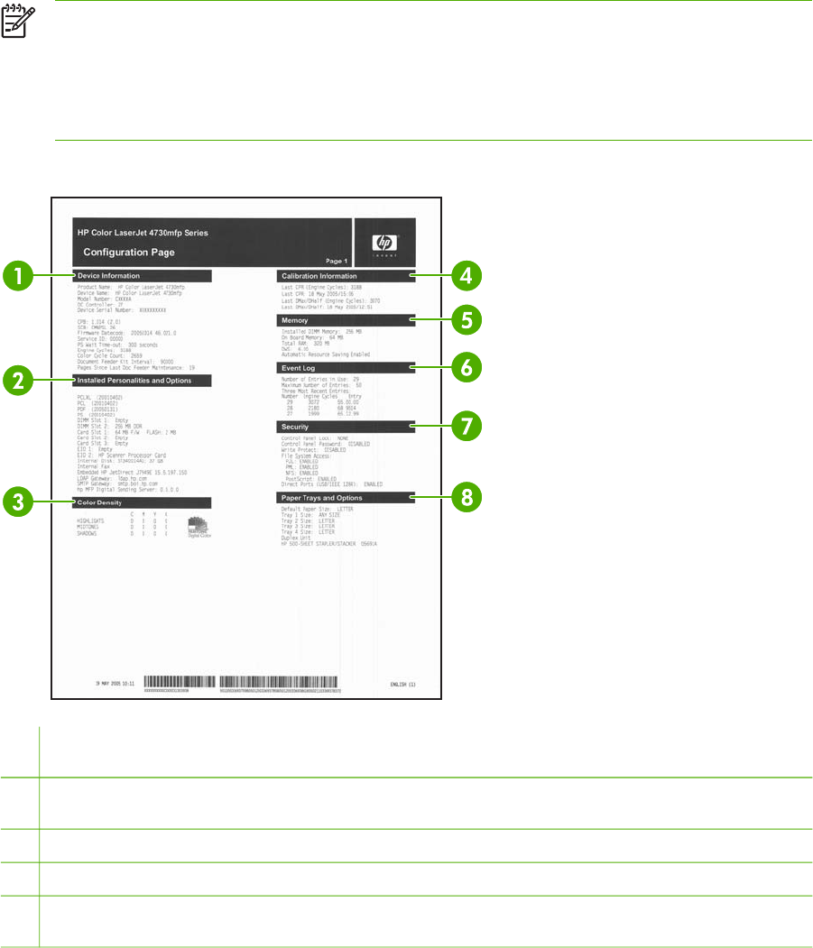
Configuration pages
Depending on the model, up to four pages print when you select PRINT CONFIGURATION. In
addition to the main configuration page, an embedded Jetdirect configuration page prints as well as a
page for the fax accessory and a page for the optional paper-handling options.
Configuration page
Use the configuration page to view current MFP settings, to help troubleshoot MFP problems, or to
verify installation of optional accessories, such as memory (DIMMs), trays, and printer languages.
NOTE If an optional 3-bin mailbox or stapler/stacker is installed, a page also prints for that
device.
NOTE If an analog fax accessory is installed, a fax accessory page also prints. See the
HP LaserJet Analog Fax Accessory 300 User Guide for information about understanding the
fax accessory page.
The MFP configuration page contains the following information:
1Device Information lists the model and serial number, engine cycles, firmware datecodes, maintenance kit counts,
calibration information, color density, and other information for the MFP.
2Installed Personalities and Options lists all MFP languages that are installed (such as PCL and PS), and lists
options that are installed in each DIMM slot and EIO slot.
3Color Density shows current settings for highlights, midtones, and shadows.
4Calibration Information lists the last CPR and last DMax/DHalf calibrations.
5Memory lists the MFP memory information, PCL Driver Work Space (DWS), and I/O buffering and Resource Saving
information.
ENWW Tools for troubleshooting 641

6Event Log lists the number of entries in the log, the maximum number of entries viewable, and the last three entries.
The second page of the event log is the manufacturer page. This page contains information that might assist
HP Customer Care representatives in solving possible MFP problems.
7Security lists the status of the control panel lock, control panel password, and disk drive.
8Paper Trays and Options lists the size settings for all trays and lists paper-handling accessories that are installed.
NOTE The content of the configuration page varies, depending on the options that are
currently installed in the MFP.
642 Chapter 7 Troubleshooting ENWW
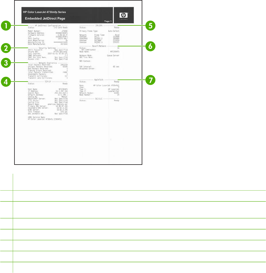
HP embedded Jetdirect page
The second configuration page is the HP embedded Jetdirect page, which contains the following
information:
1HP Jetdirect Configuration indicates the MFP status, model number, hardware firmware version, port select, port
configuration, auto negotiation, manufacturing identification, and manufactured date.
2Security Settings information
3Network Statistics indicates the total packets received, unicast packets received, bad packets received, framing
errors received, total packets transmitted, unsendable packets, transmit collisions, and transmit late collisions.
4TCP/IP information, including the IP address
5IPX/SPX information
6Novell/NetWare information
7AppleTalk information
8DLC/LLC information
Always make sure the status line under the HP Jetdirect configuration lines indicates "I/O Card
Ready".
Paper handling configuration page
The paper handling configuration page contains the following information on any installed paper
handing device:
ENWW Tools for troubleshooting 643
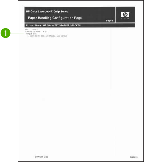
Callout 1
●model number
●firmware datecode
●bins and trays
Fax accessory page
The fax accessory page contains the following information on the fax accessory, if installed:
644 Chapter 7 Troubleshooting ENWW
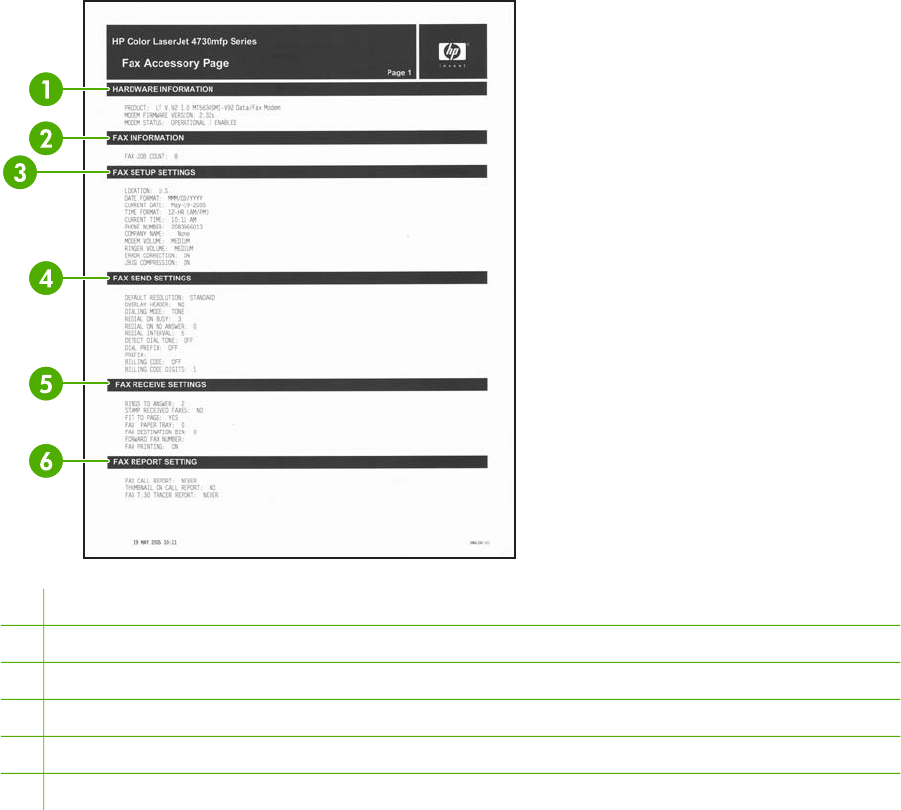
1Hardware information indicates the model, hardware firmware version, and modem status.
2Fax information provides a fax job count.
3Fax setup settings outlines the settings assigned to the fax accessory.
4Fax send settings outlines the send settings assigned to the fax accessory.
5Fax receive settings outlines the receive settings assigned to the fax accessory.
6Fax report setting outlines the reporting settings assigned to the fax accessory.
ENWW Tools for troubleshooting 645

Finding important information on the configuration pages
Certain information, such as the firmware date codes, the IP address, and the e-mail gateways, is
especially helpful while servicing the MFP. This information is on the various configuration pages.
Table 7-36 Important information on the configuration pages on page 646 describes where to look for
this information.
Table 7-36 Important information on the configuration pages
Type of information Specific information Configuration page
Firmware date codes
When you use the remote firmware
upgrade procedure, all of these firmware
components are upgraded. For more
information see Upgrading the firmware
on page 139.
DC controller Look on the main configuration page,
under “Device Information.”
Copy board version (CPB) Look on the main configuration page,
under “Device Information.”
Scan board version (SCB) Look on the main configuration page,
under “Device Information.”
Firmware datecode Look on the main configuration page,
under “Device Information.”
Stapler/stacker or 3-bin mailbox
firmware datecode
Look on the paper-handling
configuration page, under “Product
Name.”
Modem firmware version (when a fax
accessory is installed)
Look on the fax accessory page,
under “Hardware Information.”
Embedded Jetdirect firmware version Look on the embedded Jetdirect
page, under “HP Jetdirect
Configuration.”
E-mail gateway information
E-mail gateway addresses appear only if
the MFP is configured for sending to e-mail.
If you are using the embedded e-mail
function, addresses should be shown for
the LDAP and SMTP gateways, and the
digital sending server address should be
blank.
If you are using the optional HP Digital
Sending Software, the LDAP and SMTP
addresses should be blank, and an address
for the digital sending software should be
shown.
LDAP gateway Look on the main configuration page,
under “Installed Personalities and
Options.”
SMTP gateway Look on the main configuration page,
under “Installed Personalities and
Options.”
HP MFP digital-sending server Look on the main configuration page,
under “Installed Personalities and
Options.”
Accessories and internal storage
All optional devices that are installed on the
MFP should be listed on the main
configuration page.
In addition, separate pages print for the
optional paper-handling devices and the fax
accessory. These pages list more-detailed
information for those devices.
Internal disk Look on the main configuration page,
under “Installed Personalities and
Options.” Shows model and capacity.
Internal fax (presence) Look on the main configuration page,
under “Installed Personalities and
Options.”
Embedded HP Jetdirect Look on the main configuration page,
under “Installed Personalities and
Options.” Shows model and ID.
Total RAM Look on the main configuration page,
under “Memory.”
646 Chapter 7 Troubleshooting ENWW

Type of information Specific information Configuration page
Duplex unit Look on the main configuration page,
under “Paper Trays and Options.”
Additional 500-sheet feeders and
optional output devices
Look on the main configuration page,
under “Paper Trays and Options.”
Engine cycles and event logs
Total page counts and maintenance kit
counts are important for ongoing MFP
maintenance.
The configuration page lists only the three
most recent errors. To see a list of the 50
most recent errors, print an event log from
the DIAGNOSTICS menu.
Engine cycles Look on the main configuration page,
under “Device Information.”
Pages since Last Doc Feeder Maintenance
(ADF maintenance count)
Look on the main configuration page,
under “Device Information.”
Event-log information Look on the main configuration page,
under “Event log.”
Table 7-36 Important information on the configuration pages (continued)
ENWW Tools for troubleshooting 647

Supplies status page
Use the supplies status page to obtain information about the print cartridges that are installed in the
MFP, the amount of toner that remains in the print cartridges, and the number of pages and jobs that
have been processed. The page also lets you know when you should schedule the next preventive
maintenance for each maintenance kit.
NOTE The MFP has two separate maintenance kits: one is for the print engine, and the
other is for the ADF. For more information, see Performing preventive maintenance
on page 107.
The supplies status page contains the following information:
648 Chapter 7 Troubleshooting ENWW
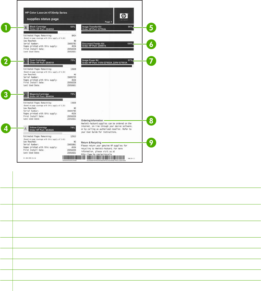
1Black Cartridge indicates the part number, amount of toner remaining in the print cartridge, estimated pages
remaining, total number of pages and jobs processed, print cartridge serial number, and date installed and last used.
2Cyan Cartridge indicates the part number, amount of toner remaining in the print cartridge, estimated pages
remaining, total number of pages and jobs processed, print cartridge serial number, and date installed and last used.
3Magenta Cartridge indicates the part number, amount of toner remaining in the print cartridge, estimated pages
remaining, total number of pages and jobs processed, print cartridge serial number, and date installed and last used.
4Yellow Cartridge indicates the part number, amount of toner remaining in the print cartridge, estimated pages
remaining, total number of pages and jobs processed, print cartridge serial number, and date installed and last used.
5Image Transfer Kit indicates the part number and status.
6Document Feeder Kit indicates the part number and status.
7Image Fuser Kit indicates the part number and status.
8Ordering Information provides information on ordering new HP MFP supplies.
9Return & Recycling provides information on recycling HP MFP supplies.
ENWW Tools for troubleshooting 649
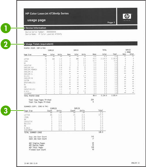
Usage page
The usage page provides information about the page sizes and number of pages printed, copied,
and sent.
The usage page contains the following information:
650 Chapter 7 Troubleshooting ENWW
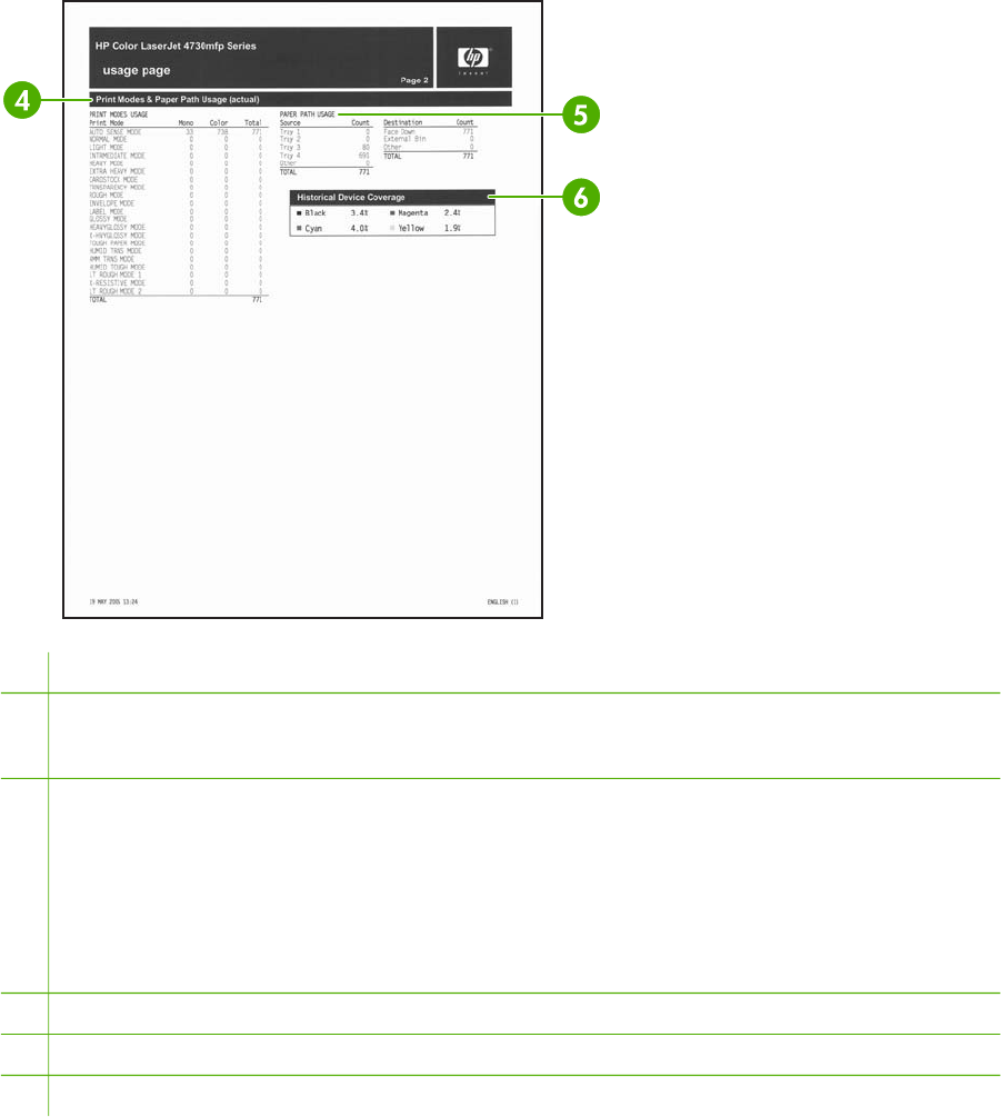
1Device Information indicates the device name and serial number.
2Usage Totals: Printed (Print, Copy & Fax) indicates types of pages that have been printed; the number of single-
sided pages that have been printed; the number of duplexed pages that have been printed; the total number of copies
made; and the total number of fax pages printed.
3Usage Totals: Printed and Scanned (Copy, Send & Fax) indicates types of pages that have been scanned; the
number of single-sided and duplexed pages that have been scanned; copy and send job counts; and pages scanned
by scanner mode.
●Units: equivalent number of letter or A4 pages
●Total is calculated by multiplying the mono units and units from simplex, multiplying the mono units and units
from duplex, and adding the results together. The same process is used for color. These totals are added to the
totals of the other page sizes to provide the total printer usage.
4Print Modes shows the number of pages that have been printed with each print mode.
5Paper Path Usage shows the number of pages have been printed from each input tray and to each output bin.
6Historical Device Coverage indicates the average percentage of toner used on all pages that have been printed.
ENWW Tools for troubleshooting 651
PCL or PS font list
Use the font lists to see which fonts are currently installed in the MFP. (The font lists also show which
fonts are resident on a hard disk or flash DIMM.)
The PS font list shows the PS fonts installed, and gives a sample of those fonts. The following
describes the information that can be found on the PCL font list:
●Font gives the font names and samples.
●Pitch/Point indicates the pitch and point size of the font.
●Escape Sequence (a PCL 5e programming command) is used to select the designated font.
(See the legend at the bottom of the font list page.)
●Font # is the number used to select fonts from the control panel (not the software application).
Do not confuse the font # with the font ID (see the following information). The number indicates
the DIMM slot where the font is stored.
●Soft: Downloaded fonts that stay resident in the MFP until other fonts are downloaded to
replace them or until the MFP is turned off.
●Internal: Fonts that permanently reside in the MFP.
●Font ID is the number you assign to soft fonts when you download them through software.
652 Chapter 7 Troubleshooting ENWW

Individual component diagnostics
From the diagnostics menu, you can run tests to check the status of various components in the MFP.
During many of the diagnostic tests, the MFP enters a special diagnostics mode, which allows you to
send print jobs and interact with the menus. The MFP stays in this mode until you press Stop and
then touch EXIT DIAGNOSTICS at the top of the DIAGNOSTICS menu. In some cases, the MFP
must re-initialize after performing a component-level diagnostic test.
LED diagnostics
Use the following procedure to help identify the cause of high-level printer problems. These problems
are indicated by abnormalities in the printer's power-on sequence. The LED that the procedure refers
to is on the formatter. This is a “heartbeat” LED that blinks on and off when the formatter is operating
correctly. Use Figure 7-12 Formatter LED on page 654 to locate the formatter LED.
1. Does the LED blink with four fast bursts at power on? If no, then perform the following checks.
●Check the firmware.
●Check the memory.
●Check the formatter.
2. Does the LED blink at a fast, steady rate during memory testing (one blink per 8 MB)? If no,
then perform the following checks.
●Check the control panel display for an error code.
●Check the memory.
●Check the formatter.
3. Is the LED off for about eight seconds, while the boot code is decompressing, before the display
turns on? If no, then perform the following checks.
●Check the firmware.
●Check the control panel display for correct connections and operation.
●Check the control panel display for an error code.
4. Does the LED blink at a steady rate of one blink per second? If no, then perform the following
checks.
●Check the firmware.
●Check the formatter.
●Check the control panel display for an error code.
5. If the control panel display does not illuminate, perform an engine test to check the engine. You
must have paper loaded in Tray 2 for the engine test.
ENWW Tools for troubleshooting 653

Figure 7-12 Formatter LED
Engine diagnostics
This section provides an overview of the engine diagnostics that are available in the HP Color
LaserJet 4730mfp series MFP. The MFP contains extensive internal diagnostics that help in
troubleshooting print quality, paper path, noise, component, and timing issues.
Diagnostics mode
Some of the diagnostic tests automatically put the MFP into a special diagnostics mode. During the
special diagnostics mode the MFP can perform actions that would normally cause the MFP to enter
an error state. Always follow the control panel directions in the DIAGNOSTICS menu to exit the
special diagnostics mode correctly and return the MFP to a normal state.
Diagnostics that put the engine into the special diagnostics mode
Four diagnostic tests put the engine into a special state:
●Disable cartridge check
●Sensor test
●Manual sensor test
●Component test
While the MFP is in the special diagnostics mode, the following message should appear:
Ready Diagnostics mode
To exit press STOP
When the MFP is in the special diagnostics mode, these four tests appear in the menu and are
available to be run. To gain access into other diagnostic tests or to leave the special state, press
Stop, and then select EXIT DIAGNOSTICS. The MFP will reset itself, and then return to the normal
state.
NOTE You need to have a good understanding of how the MFP operates in order to use the
engine diagnostics successfully. Before proceeding with these diagnostic tests, make sure
that you understand the information in chapter 5 of this manual.
654 Chapter 7 Troubleshooting ENWW

Diagnostic tests
Different tests can be used to isolate different types of issues. For component or noise isolation, you
can run the diagnostic test after removing the covers. Removing the covers provides a better view of
the areas that are being tested. To operate the MFP with the covers removed, the door switch (SW4,
callout 1) lever must be depressed (this is the door-closed position).
WARNING! Be careful when performing MFP diagnostics to avoid risk of injury. Only trained
service personnel should open and run the diagnostics with the covers removed. Never touch
any of the power supplies when the MFP is turned on.
NOTE Any time a cartridge is installed or removed while the covers are removed, the door
interlock must be cycled to simulate opening and closing the top cover in order for the engine
to recognize the change. The ETB must be closed and its connector must be depressed
before cycling the door switch, or the MFP will generate a 59.90 Printer Error. When the
covers are installed, the door switch and ETB connector are automatically operated. When the
covers are removed, you must perform these steps manually.
ENWW Tools for troubleshooting 655

Paper path sensor test
The paper path sensor test checks for the presence of media at each of the sensors along the paper
path. After you have selected this test from the DIAGNOSTICS menu, you can print internal pages or
send a print job from a computer. As the media passes each sensor, the sensor's state is updated.
On the control panel display, each sensor is represented by a string of alphabetic letters followed by
a corresponding status for each sensor. Use Table 7-38 Manual sensor test letter designations
on page 657 to associate the letters that are shown on the control panel display with the sensor that
they represent. A “0” next to the letter indicates that no media is present. A “1” indicates that media is
present. Press Stop to stop the job, and then touch EXIT DIAGNOSTICS to exit the special
diagnostics mode.
Figure 7-13 Tray 2 paper size switch arrangement
Table 7-37 Tray 2 paper size codes
Size code Switch state Paper size
SW1 SW2 SW3
0On On On Custom (see
note below)
1 On Off On Letter
2 Off On Off A5
3 Off On On Legal
4 On On Off B5 (JIS)
5 Off Off On Executive
6 On Off Off A4
7 Off Off Off tray not
installed
NOTE Depressing all three switches of the Tray 2 paper size levers causes the CUSTOM
PAPER menu to appear on the control panel display. Touch Back to return to the sensor
diagnostic screen.
656 Chapter 7 Troubleshooting ENWW

Manual sensor test
The manual sensor test indicates the status of the sensors and switches in the MFP. On the control
panel display, each sensor is represented by a string of letters followed by a corresponding status for
each sensor. Except for the paper size switches, a “0” next to the letter indicates that no media is
present or the switch is open. A “1” indicates that media is present or the switch is closed. For the
paper size switches, the number ranges from 0 to 7 to indicate the state of the three switches. Use
Table 7-38 Manual sensor test letter designations on page 657 to associate the letters that appear on
the control panel display with the switch or sensor that they represent. Note that both uppercase and
lowercase letters are used.
Table 7-38 Manual sensor test letter designations
Letter Component Letter Component
ATop sensor OTray 2 size sensors 1, 2, 3
BFuser inlet sensor 1 PTray 3 paper sensor
CFuser inlet sensor 2 QTray 3 paper surface sensor
DDelivery sensor RTray 3 paper size sensors 1, 2, 3
EDuplexer switchback sensor STray 4 paper sensor
FOutput bin full sensor TTray 4 paper surface sensor
GDeveloping alienation sensor UTray 4 paper size sensors 1, 2, 3
HFuser pressure release sensor VIPTU1 sensor
IMedia sensor (see Values for I (media sensor)
on page 657)
WIPTU2 sensor
JMedia type misprint sensor
KDoor sensor
LTray 1 paper sensor
MTray 2 paper sensor
NTray 2 paper surface sensor
MANUAL SENSOR TEST operates sensors A, B, C, D, E, F, G, H, I, J, K, L, M, N, V, and W.
MANUAL SENSOR TEST 2 operates sensors P, Q, R, S, T, and U.
PAPER PATH SENSOR TEST operates sensors A, B, C, D, E, F, G, H, I, J, V, and W.
Values for I (media sensor)
●0 = unknown
●1 = normal
●3 = recommended overhead transparency
●4 = glossy media
●5 = gloss film
ENWW Tools for troubleshooting 657
●7 = heavy
●8 = light
●A = extra heavy glossy
658 Chapter 7 Troubleshooting ENWW
Scanner tests
Use the scanner tests to verify that specific components in the scanner assembly are operating
correctly. For most of the components, you must observe or listen to the component in order to verify
that it is functioning as stated on the control panel display. For the scanner sensors, you must
activate the sensor and watch the condition indicator on the control panel display to see if it changes.
Component tests
Use the component tests to exercise individual parts one at a time, so that you can determine the
cause of noise inside the MFP. For most of the components, you must observe or listen to the
component in order to verify that it is functioning as stated on the control panel display.
Print event log
1. Press Menu.
2. Scroll to and touch DIAGNOSTICS.
3. Touch PRINT EVENT LOG.
View event log from control panel
1. Press Menu.
2. Scroll to and touch DIAGNOSTICS.
3. Touch SHOW EVENT LOG.
Print the print quality troubleshooting pages
1. Press Menu.
2. Scroll to and touch DIAGNOSTICS.
3. Touch PQ TROUBLESHOOTING.
Disable cartridge check
1. Press Menu.
2. Scroll to and touch DIAGNOSTICS.
3. Touch DISABLE CARTRIDGE CHECK.
Paper path sensors
1. Press Menu.
2. Scroll to and touch DIAGNOSTICS.
3. Touch PAPER PATH SENSORS.
Paper path test
1. Press Menu.
2. Scroll to and touch DIAGNOSTICS.
ENWW Tools for troubleshooting 659
3. Touch PAPER PATH TEST.
4. Select SOURCE, DUPLEX (On or Off), and COPIES.
5. Touch PRINT TEST PAGE.
Finishing paper path test
1. Press Menu.
2. Scroll to and touch DIAGNOSTICS.
3. Touch Finishing Paper Path Test.
4. Select Finishing Options, Media Size, MEDIA TYPE, COPIES, and DUPLEX.
5. Touch PRINT TEST PAGE.
Manual sensor test
1. Press Menu.
2. Scroll to and touch DIAGNOSTICS.
3. Scroll to and touch MANUAL SENSOR TEST.
Manual sensor test 2
1. Press Menu.
2. Scroll to and touch DIAGNOSTICS.
3. Scroll to and touch MANUAL SENSOR TEST 2.
Component test
1. Press Menu.
2. Scroll to and touch DIAGNOSTICS.
3. Scroll to and touch COMPONENT TEST.
4. Select the appropriate test (transfer motors, belt only, cartridge motors, black laser scanner,
cyan laser scanner, magenta laser scanner, yellow laser scanner, fuser motor, fuser pressure
release motor, alienation motor, ETB contact/alienation, MP tray pickup solenoid, Tray 2 pickup
motor, Tray 2 pickup solenoid, Tray 3 pickup motor, Tray 3 pickup solenoid, Tray 4 pickup
motor, Tray 4 pickup solenoid, duplexer pickup motor, paper transport motor, repeat).
Print/stop test
1. Press Menu.
2. Scroll to and touch DIAGNOSTICS.
3. Scroll to and touch PRINT/STOP TEST.
4. Select the appropriate number of milliseconds and then touch Ok.
660 Chapter 7 Troubleshooting ENWW
Color band test
1. Press Menu.
2. Scroll to and touch DIAGNOSTICS.
3. Scroll to and touch COLOR BAND TEST.
4. Select the number of copies and touch PRINT TEST PAGE.
Scanner tests
1. Press Menu.
2. Scroll to and touch DIAGNOSTICS.
3. Scroll to and touch SCANNER TESTS.
4. Select the appropriate test (lower lamp, sensors, ADF input motor, ADF input reverse, flatbed
motor, ADF read motor, ADF read motor reverse, ADF duplex solenoid, and ADF LED indicator).
Component test
1. Press Menu.
2. Scroll to and touch DIAGNOSTICS.
3. Scroll to and touch COMPONENT TEST.
4. Select the appropriate test (transfer motors, belt only, cartridge motors, black laser scanner,
cyan laser scanner, magenta laser scanner, yellow laser scanner, fuser motor, fuser pressure
release motor, alienation motor, ETB contact/alienation, MP tray pickup solenoid, Tray 2 pickup
motor, Tray 2 pickup solenoid, Tray 3 pickup motor, Tray 3 pickup solenoid, Tray 4 pickup
motor, Tray 4 pickup solenoid, duplexer pickup motor, paper transport motor, repeat).
Control panel test
1. Press Menu.
2. Scroll to and touch DIAGNOSTICS.
3. Scroll to and touch CONTROL PANEL.
4. Select the appropriate test (LEDs, display, buttons, and touchscreen).
ENWW Tools for troubleshooting 661

Service menu
Authorized HP service technicians can use this menu to gain access to MFP settings that are
reserved for service personnel. The service menu is protected by a personal identification number
(PIN). When you select Service from the list of menus, you are prompted to type an eight-digit PIN
code.
The PIN code for this MFP is 09473005.
NOTE The MFP automatically exits the service menu after about one minute if no menu
items are selected or changed.
Table 7-39 Service menu
Item Explanation
CLEAR EVENT LOG Select this item to clear (reset to zero) the internal event log.
MONO CYCLE COUNT Select this item to set the total number of monochrome pages that have been
printed to date. Typically this is required only when the formatter is replaced.
COLOR CYCLE COUNT Select this item to set the total number of color pages that have been printed to
date. Typically this is required only when the formatter is replaced.
REFURBISH PAGE COUNT Select this item to set the page count if you need to send the MFP for
refurbishment. This page count is stored in memory so that the correct Service ID
can be restored after the MFP is refurbished.
DOCUMENT FEEDER KIT COUNT Select this item to set the number of pages that have been printed since the last
document-feeder kit was installed or the total number of pages that have been
printed on this MFP if a document-feeder kit has not yet been installed (during the
first 225,000 pages).
Document Feeder Kit Interval: X Select this item to specify the number of pages that can be printed before a
Replace Document Feeder Kit message appears on the control panel display to
indicate that a document-feeder kit is required.
TRANSFER KIT COUNT This item allows the service technician to reset the page count if the value is lost.
This is set initially at the factory to 0. A cleaning kit interval is set at the factory
that cannot be set in any menu item. The interval for the transfer kit is 200000
(the expected transfer kit life). This value is reset to 0 if the user sets the menu
item NEW TRANSFER KIT to YES in the RESETS menu
FUSER KIT COUNT This item allows the service technician to reset the page count if the value is lost.
This is set initially at the factory to 0. A cleaning kit interval is set at the factory
that cannot be set in any menu item. The interval for the fuser is 100000 (the
expected fuser life). Because color products stop when the kit count reaches the
interval, the user can only enter a value that is less than the fuser kit interval. This
value is reset to 0 if the user sets the menu item NEW FUSER KIT to YES in the
RESETS menu.
ADF COUNT Select this item to set the total number of pages that have been fed through the
ADF.
FLATBED COUNT Select this item to set the number of pages that have been scanned on the
flatbed glass.
ADF SIMPLEX COUNT Select this item to set the number of simplex pages that have been fed through
the ADF.
ADF DUPLEX COUNT Select this item to set the number of duplex pages that have been fed through the
ADF.
COPY SCAN COUNT Select this item to set the number of copy pages that have been scanned.
662 Chapter 7 Troubleshooting ENWW

Item Explanation
SEND SCAN COUNT Select this item to set the number of scanned pages that have been sent to e-mail.
COPY PAGES COUNT Select this item to set the number of scanned pages that have been printed.
Scanner settings CAUTION The Scanner settings are used for factory adjustments and
should not be used by service personnel. Use the scanner calibration
routine to adjust the scanner settings if necessary. See Calibrating the
scanner on page 106.
Cartridge Serial Number: X Select this item to update the serial number if you replace the formatter.
Service ID Service ID. Select this item to specify the date when the MFP was first used,
rather than the date when a replacement formatter is installed.
NOTE This should occur automatically if the formatter is replaced
without also replacing the DC controller. If the DC controller is also
replaced, ensure that the engine is rebooted between replacement of the
formatter and the DC controller.
COLD RESET PAPER Select this item to reset the default paper size when you replace the formatter or
restore factory settings. When you replace a formatter or restore factory settings
in a country/region that uses A4 as the standard paper size, use this item to reset
the default paper size to A4. Letter and A4 are the only cold-reset values available.
RESTORE ACCESSORY DATA NOW This item appears when only one external device is attached to the print engine.
When selected, data is immediately restored. This option is used to restore
external device settings following repair. The old accessory information must be
restored before 10 pages have been printed with the new accessory, or the old
data will be overwritten.
RESTORE DATA FOR ACCESSORY This item appears when more than one external device is attached to the print
engine. When selected, a list of devices for which data can be restored is
displayed. This option is used to restore external device settings following repair.
The old accessory information must be restored before 10 pages have been
printed with the new accessory, or the old data will be overwritten.
MEDIA SENSOR VALUE Set this value to the value shown on the replacement paper feed assembly label
when the paper feed assembly is replaced.
Table 7-39 Service menu (continued)
ENWW Tools for troubleshooting 663
Service ID
This information appears on the configuration page, which eliminates the need for customers to keep
paper receipts for proof of the warranty.
Converting the service ID to an actual date
You can use the MFP Service ID number to determine whether the MFP is still under warranty. Use
the following procedure to convert the Service ID into the installation date.
1. Add 1990 to YY to determine the actual year that the MFP was installed.
2. Divide DDD by 30, and add 1 to the whole-number part of the quotient. The total is the month.
3. The remainder from the calculation in step 2 is the day of the month.
Using the Service ID 12287 as an example, the date conversion is as follows:
1. 12 + 1990 = 2002, so the year is 2002.
2. 287 divided by 30 = 9 with a remainder of 17. Add 1 to 9 to get 10, so the month is October.
3. The remainder (from the above calculation) is 17, so that is the day of the month.
4. The complete date is 17-October-2002.
664 Chapter 7 Troubleshooting ENWW

Troubleshooting the embedded HP Jetdirect print server
If network-connection errors occur, you can disable the HP Jetdirect print server in order to
determine if the problem is with the print server or with the network. This procedure requires that you
temporarily install an optional EIO HP Jetdirect print server card while disabling the embedded
HP Jetdirect print server.
To disable the embedded HP Jetdirect print server
1. Turn the MFP off and then on.
2. When the memory count appears on the control panel display, press and hold 6 until all three
LEDs flash once and then stay on. This might take up to 20 seconds.
3. Release 6, and then press and release 3 until EMBEDDED LAN DISABLE appears on the
control panel display.
4. Press 6 one time, and wait for the MFP to complete its initialization sequence.
NOTE To enable the HP Jetdirect print server again, perform this same procedure.
EMBEDDED LAN ENABLE appears on the control panel display instead of EMBEDDED
LAN DISABLE.
Firmware-stack trace
In rare instances, you might need to work with a call-center escalation agent to find the source of a
49.XX.XX PRINTER ERROR. Use the firmware-stack trace procedure to collect data that the agent
might need. A firmware-stack trace indicates which firmware commands were executing at the time
of the error. The firmware-stack trace procedure does not produce a report. Instead, you must write
down the firmware instructions that appear on the control panel display and relay them to the agent.
To perform a firmware-stack trace
1. When the error message appears on the control panel display, press 6 and then press 5.
2. Press 9 to scroll through each line of the firmware-stack trace.
ENWW Tools for troubleshooting 665
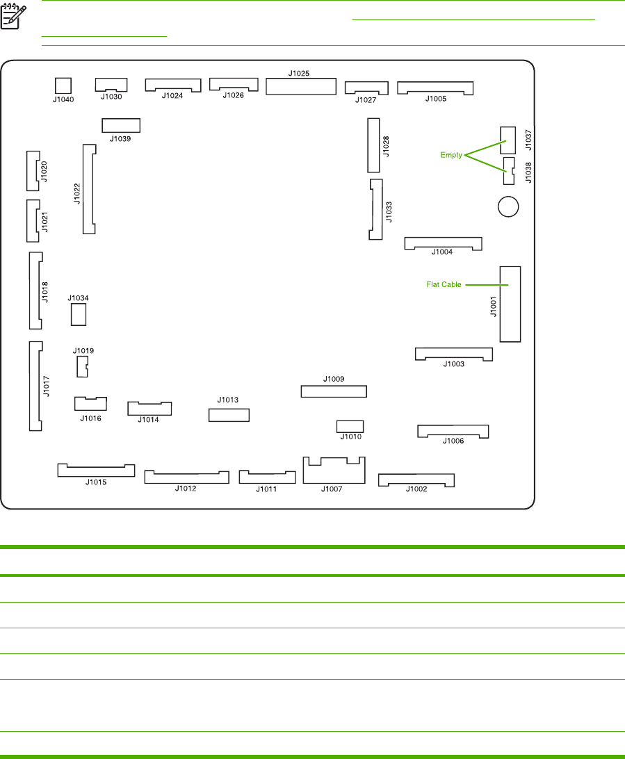
Diagrams for troubleshooting
Use the diagrams in this section to identify MFP components.
DC controller connections
Each of the connections on the DC controller PCB is indicated in the following figure.
NOTE See also the photo of the DC controller in Figure 6-234 Remove the DC controller
(1 of 2) on page 385.
Figure 7-14 DC controller component connections
Connector Pins Component
J1002 17 Laser scanner Y
J1003 17 Laser scanner C
J1004 17 Scanner motor M
J1005 17 Scanner motor K
J1024 12 Fusing motor (M5)
Fuser pressure release motor (M6)
J1026 10 Fuser paper sensor (SR1)
666 Chapter 7 Troubleshooting ENWW

Connector Pins Component
Delivery tray full sensor (SR2)
Fuser pressure release sensor (SR3)
J1037 4 Not connected
J1038 5 Not connected
J1034 3 Power supply fan
J1006 16 High-voltage power supply
J1010 4 Environmental sensor
J1014 9 Toner level PCB
MP tray paper sensor
J1022 20 Drum home position sensor
J1016 6 Cassette paper sensor (SR9)
Paper stack surface sensor (SR10)
J1012 19 Color misregistration sensor
Transmission LED
Top of page sensor (SR12)
J1013 10 Media sensor
J1019 3 Developing disengaging sensor (SR11)
J1015 17 MP tray pickup motor solenoid (SL1)
Cassette pickup solenoid (SL2)
Lifter motor (M10)
Cassette paper size detection switch
Additional trays
J1018 18 M and K drum motors (M3 and M4)
J1017 20 Y and C motors (M1 and M2)
J1020 8 Pickup motor (M9)
Developing disengaging motor (M8)
J1021 9 Memory controller PCB
J1025 12 Paper loop sensors (SR13 and SR14)
Fuser unit
J1009 17 Low-voltage power supply PCB
J1001 45 Formatter
J1011 12 ETB unit
ETB motor (M7)
ETB separation solenoid (SL3)
ENWW Diagrams for troubleshooting 667

Connector Pins Component
J1027 9 Control panel
J1033 13 Cartridge fan
Delivery fan
Right exhaust fan
J1039 6 Fan driver PCB
Sub power supply assembly fan
Control fans 1 and 2
ETB fan
J1007 5 Door switch
J1028 14 IPTU
Jet Link (stapler/stacker and 3-bin mailbox)
Sub power supply PCB
ADF/scanner
668 Chapter 7 Troubleshooting ENWW
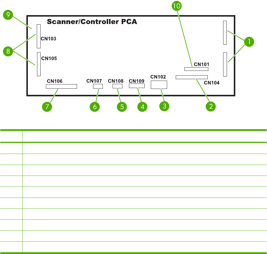
Scanner controller PCB connections
Figure 7-15 Scanner controller PCB component connections
Item Component
1Not used
2Optical head assembly
3Power supply
4Cover-closed switch and home-position sensor
5Scanner fan
6Inverter PCB
7Flatbed motor
8To ADF
9To ADF feed and read motors
10 Formatter PCB
ENWW Diagrams for troubleshooting 669

Locations of major components
The diagrams in this section identify the locations of major components in the MFP.
Component Figure
SR1 - fuser paper sensor See Figure 7-16 Sensors and switches on page 672.
SR2 - delivery tray paper full sensor See Figure 7-16 Sensors and switches on page 672.
SR3 - fuser pressure release sensor See Figure 7-16 Sensors and switches on page 672.
SR4 - multipurpose tray paper sensor See Figure 7-16 Sensors and switches on page 672.
SR9 - cassette paper sensor See Figure 7-16 Sensors and switches on page 672.
SR10 - paper stack surface sensor See Figure 7-16 Sensors and switches on page 672.
SR11 - developing disengaging sensor See Figure 7-16 Sensors and switches on page 672.
SR12 - top of page sensor See Figure 7-16 Sensors and switches on page 672.
SR13 - paper loop sensor 1 See Figure 7-16 Sensors and switches on page 672.
SR14 - paper loop sensor 2 See Figure 7-16 Sensors and switches on page 672.
Media sensor See Figure 7-16 Sensors and switches on page 672.
SR8001 - paper reversing sensor See Figure 7-16 Sensors and switches on page 672.
Environmental sensor See Figure 7-16 Sensors and switches on page 672.
Drum home position sensor See Figure 7-16 Sensors and switches on page 672.
CNT0 - cassette paper size detection switch See Figure 7-16 Sensors and switches on page 672.
CNT1 - cassette paper size detection switch See Figure 7-16 Sensors and switches on page 672.
CNT2 - cassette paper size detection switch See Figure 7-16 Sensors and switches on page 672.
M1 - Yellow (Y) drum motor See Figure 7-17 Motors on page 674.
M2 - Cyan (C) drum motor See Figure 7-17 Motors on page 674.
M3 - Magenta (M) drum motor See Figure 7-17 Motors on page 674.
M4 - Black (K) drum motor See Figure 7-17 Motors on page 674.
M5 - Fuser motor See Figure 7-17 Motors on page 674.
M6 - Fuser pressure release motor See Figure 7-17 Motors on page 674.
M7 - ETB motor See Figure 7-17 Motors on page 674.
M8 - Developing disengaging motor See Figure 7-17 Motors on page 674.
M9 - Pickup motor See Figure 7-17 Motors on page 674.
M10 -Lifter motor See Figure 7-17 Motors on page 674.
M8001 - Reversing motor See Figure 7-17 Motors on page 674.
SL1 - Multipurpose tray pickup solenoid See Figure 7-18 Solenoids on page 676.
SL2 - Cassette pickup solenoid See Figure 7-18 Solenoids on page 676.
SL3 - ETB separation solenoid See Figure 7-18 Solenoids on page 676.
670 Chapter 7 Troubleshooting ENWW

Component Figure
SL8001 - Duplexing solenoid See Figure 7-18 Solenoids on page 676.
FM 1 - Power supply fan See Figure 7-19 Fans on page 677.
FM 2 - Cartridge fan See Figure 7-19 Fans on page 677.
FM 4 - Delivery fan See Figure 7-19 Fans on page 677.
FM 7 - Fuser fan/right exhaust fan See Figure 7-19 Fans on page 677.
FM 3 - Sub power supply fan See Figure 7-19 Fans on page 677.
FM 5 and FM 6 - Control fans 1 and 2 See Figure 7-19 Fans on page 677.
FM 8 - ETB fan See Figure 7-19 Fans on page 677.
ADF bin-full flag See Figure 7-21 ADF output bin-full sensor on page 679.
ADF pickup assembly See Figure 7-22 ADF pickup sensors on page 680.
ADF paper-present sensor See Figure 7-22 ADF pickup sensors on page 680.
ADF top-of-page sensor See Figure 7-22 ADF pickup sensors on page 680.
ADF fan See Figure 7-23 ADF motors, fans, and solenoids on page 680.
Scanner controller PCB See Figure 7-23 ADF motors, fans, and solenoids on page 680.
ADF LED PCB See Figure 7-23 ADF motors, fans, and solenoids on page 680.
ADF solenoid See Figure 7-23 ADF motors, fans, and solenoids on page 680.
ADF motors See Figure 7-23 ADF motors, fans, and solenoids on page 680.
ENWW Diagrams for troubleshooting 671
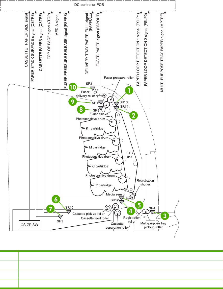
Sensors and switches
The diagrams in this section show the locations of the sensors and switches in the MFP print engine.
Sensors and switches
Figure 7-16 Sensors and switches
1SR13 - Paper loop sensor
2SR14 - Paper loop sensor
3SR4 - multipurpose tray paper sensor
4Paper inlet sensor
672 Chapter 7 Troubleshooting ENWW

5Media sensor
6SR10 - paper stack surface sensor
7SR9 - cassette paper sensor
8SR3 - fuser pressure release sensor
9SR1 - fuser paper sensor
10 SR2 - delivery tray paper-full sensor
ENWW Diagrams for troubleshooting 673
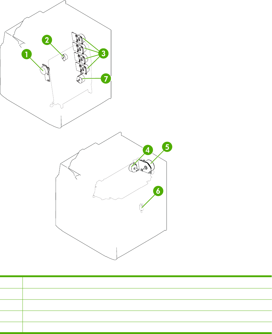
Motors, fans, and solenoids
The diagrams in this section show the locations of the motors, fans, and solenoids in the MFP print
engine.
Motors and solenoids
Figure 7-17 Motors
1M7: ETB motor
2M8: Developing disengaging motor
3M1, M2, M3, M4: Drum motors (Y/C/M/K)
4M6: Fuser pressure release motor
5M5: Fuser motor
674 Chapter 7 Troubleshooting ENWW

6M10: Lifter motor
7M9: Pickup motor
ENWW Diagrams for troubleshooting 675
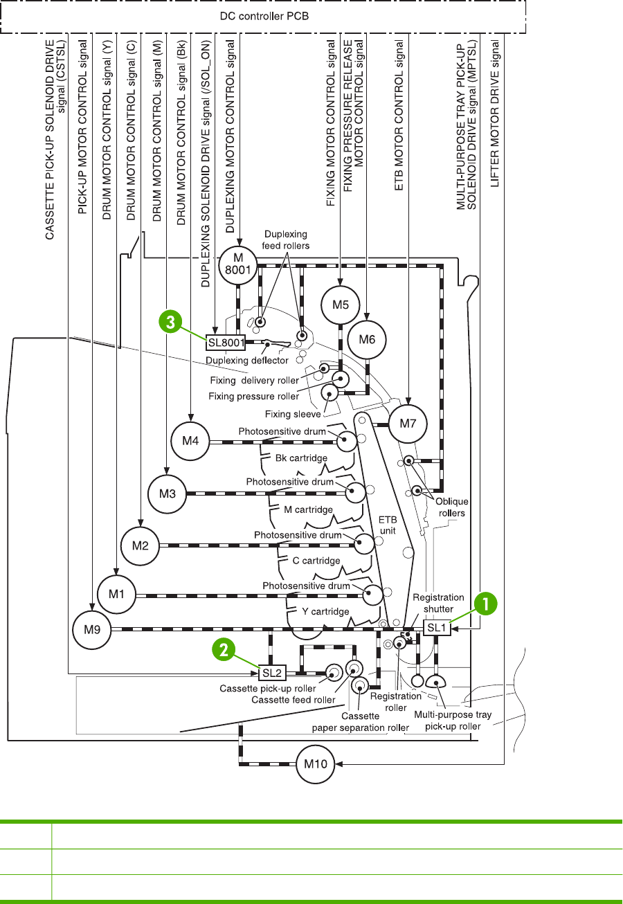
Figure 7-18 Solenoids
1 SL1 - Multipurpose tray pickup solenoid
2 SL2 - Cassette tray pickup solenoid
3 SL8001 - Duplexing solenoid
676 Chapter 7 Troubleshooting ENWW
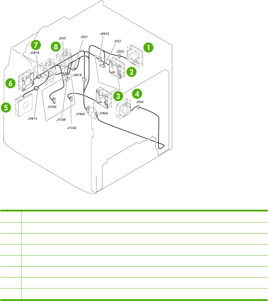
Fans
Figure 7-19 Fans
1FM7: Fuser fan
2FM3: Sub power supply fan
3FM1: Power supply fan
4FM8: ETB fan
5FM2: Cartridge fan
6FM4: Delivery fan
7FM6: Control fan #2
8FM5: Control fan #1
ENWW Diagrams for troubleshooting 677

PCBs
The diagram in this section shows the locations of the main assembly PCBs.
Figure 7-20 Main assembly PCBs
1DC controller PCB
2Sub power supply PCB
3Fan driver PCB
4Memory controller PCB
5Toner sensor PCB
6High-voltage power supply PCB
7 Low-voltage power supply PCB
678 Chapter 7 Troubleshooting ENWW
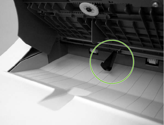
Scanner and ADF components
The diagrams and photos in this section show the locations of the scanner and ADF components.
ADF and scanner sensors
Figure 7-21 ADF output bin-full sensor
ENWW Diagrams for troubleshooting 679
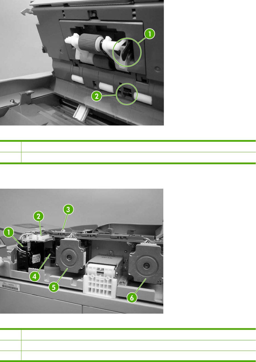
ADF pickup assembly sensors
Figure 7-22 ADF pickup sensors
1ADF paper-present sensor
2ADF top-of-page sensor
ADF motors, fans, and solenoids
Figure 7-23 ADF motors, fans, and solenoids
1ADF fan
2Scanner controller PCB
3ADF LED PCB
680 Chapter 7 Troubleshooting ENWW

4 Solenoid
5Pickup motor
6Feed motor
ENWW Diagrams for troubleshooting 681
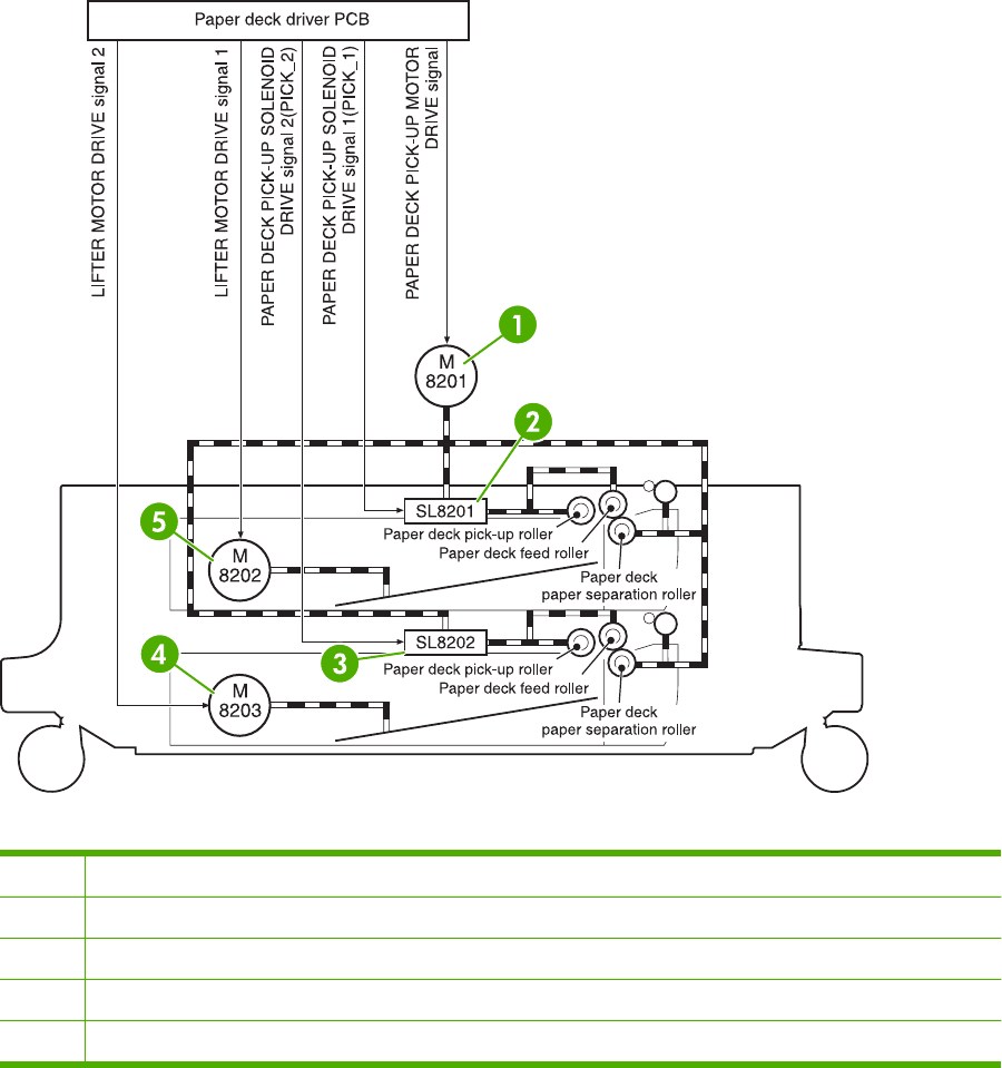
2 X 500-sheet feeder
The diagram in this section shows the locations of the 2 X 500-sheet feeder components.
Figure 7-24 2 X 500-sheet feeder components
1M8201 - Paper deck pickup motor
2SL8201 - Paper deck pickup solenoid
3SL8202 - Paper deck pickup solenoid
4M8203 - Lifter motor
5M8202 - Lifter motor
682 Chapter 7 Troubleshooting ENWW
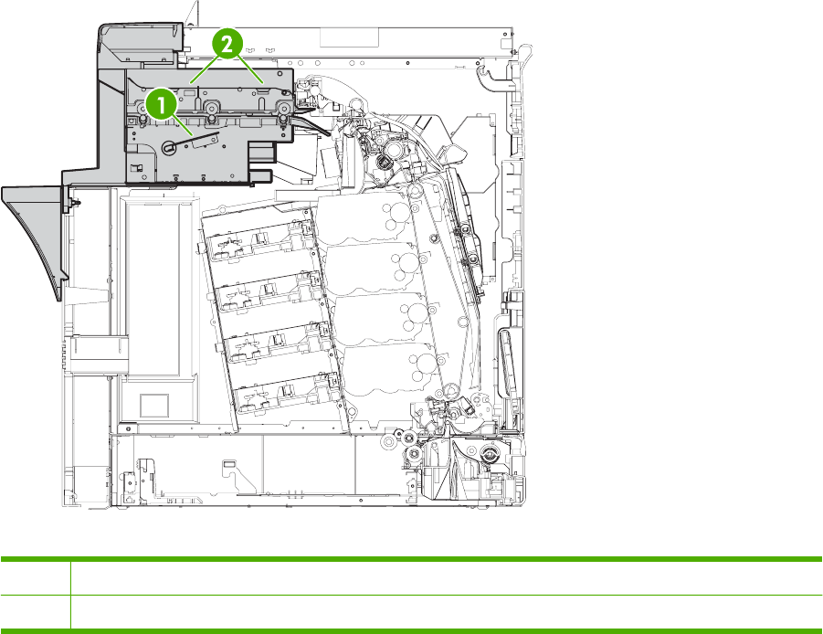
IPTU
The diagram in this section shows the locations of the IPTU components.
Figure 7-25 IPTU components
1IPTU PCB
2IPTU motors
ENWW Diagrams for troubleshooting 683
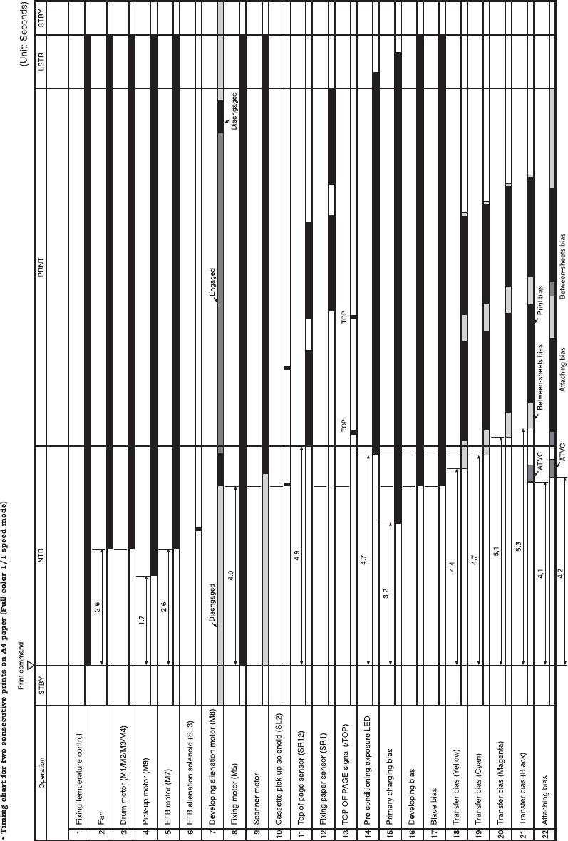
General timing chart
Figure 7-26 General timing chart
684 Chapter 7 Troubleshooting ENWW
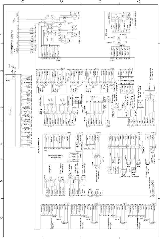
General circuit diagrams
Figure 7-27 General circuit diagram (1 of 2)
ENWW Diagrams for troubleshooting 685

Figure 7-28 General circuit diagram (2 of 2)
686 Chapter 7 Troubleshooting ENWW
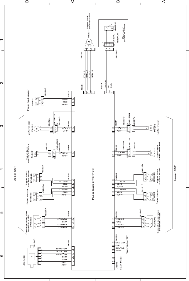
Figure 7-29 Circuit diagram for the 2 X 500-sheet feeder
ENWW Diagrams for troubleshooting 687
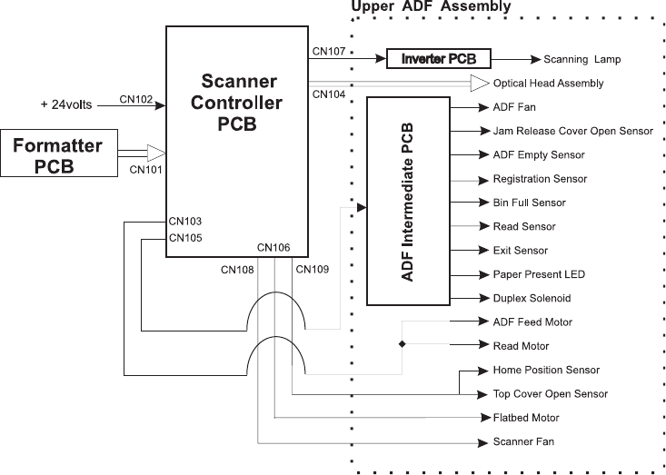
Figure 7-30 Circuit diagram for the scanner
688 Chapter 7 Troubleshooting ENWW
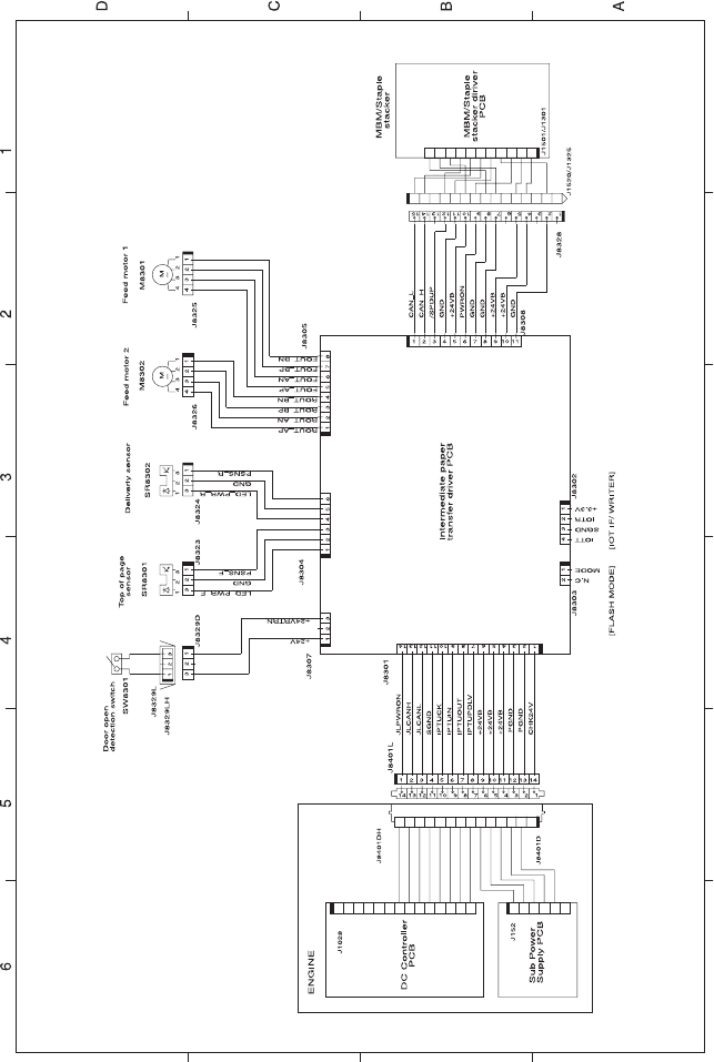
Figure 7-31 Circuit diagram for the IPTU
ENWW Diagrams for troubleshooting 689
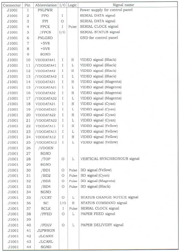
Figure 7-32 List of signals for the DC controller (1 of 9)
690 Chapter 7 Troubleshooting ENWW
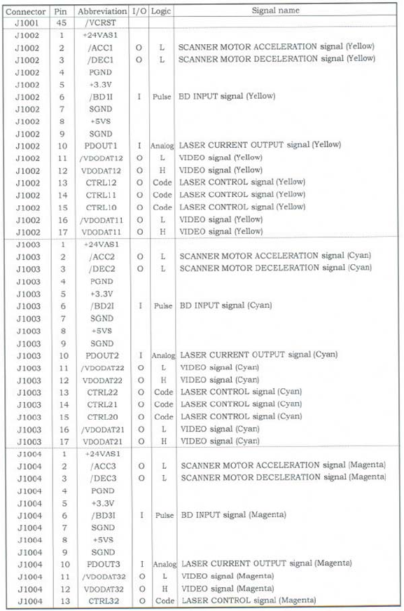
Figure 7-33 List of signals for the DC controller (2 of 9)
ENWW Diagrams for troubleshooting 691
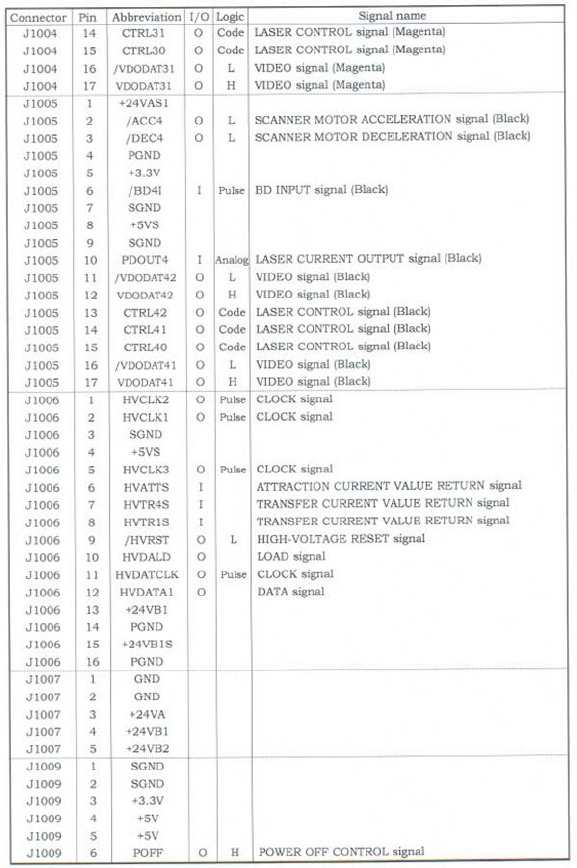
Figure 7-34 List of signals for the DC controller (3 of 9)
692 Chapter 7 Troubleshooting ENWW
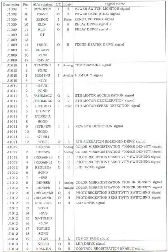
Figure 7-35 List of signals for the DC controller (4 of 9)
ENWW Diagrams for troubleshooting 693
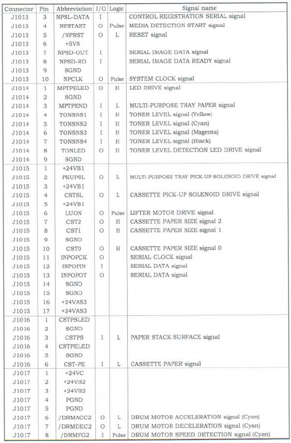
Figure 7-36 List of signals for the DC controller (5 of 9)
694 Chapter 7 Troubleshooting ENWW
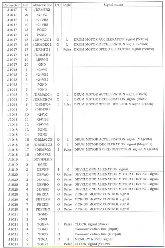
Figure 7-37 List of signals for the DC controller (6 of 9)
ENWW Diagrams for troubleshooting 695
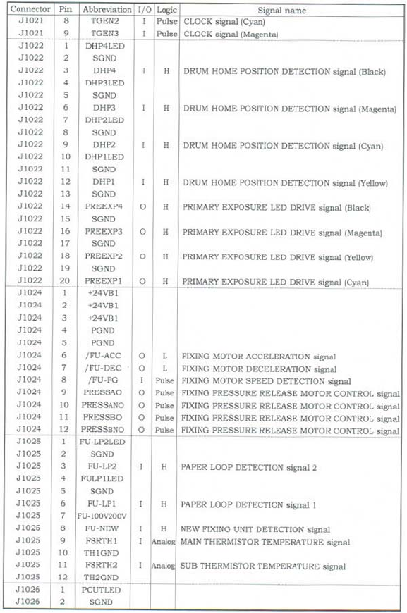
Figure 7-38 List of signals for the DC controller (7 of 9)
696 Chapter 7 Troubleshooting ENWW
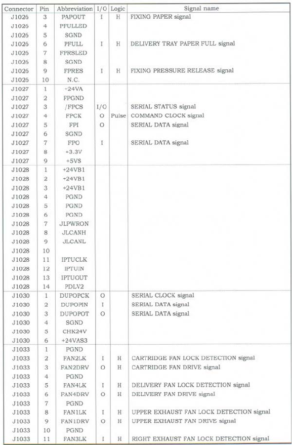
Figure 7-39 List of signals for the DC controller (8 of 9)
ENWW Diagrams for troubleshooting 697
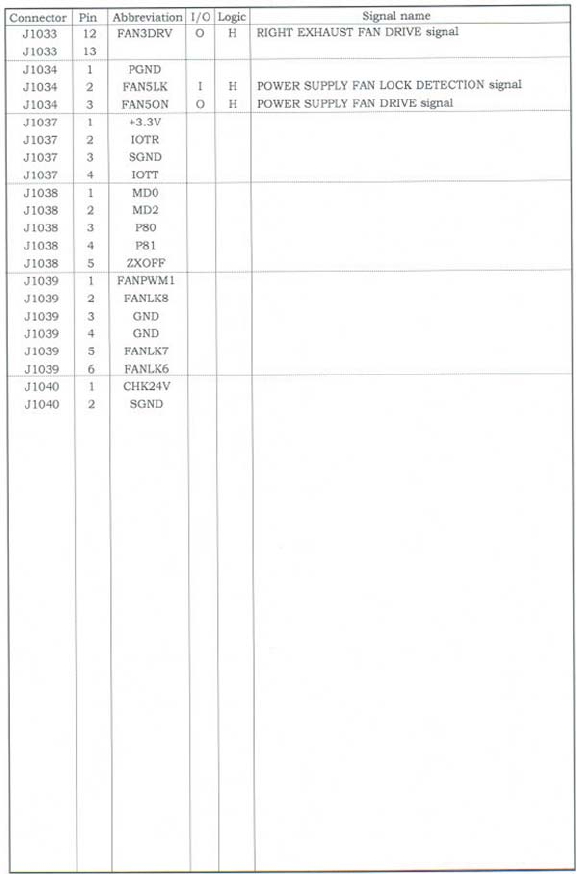
Figure 7-40 List of signals for the DC controller (9 of 9)
698 Chapter 7 Troubleshooting ENWW

8 Parts and diagrams
This chapter contains information about ordering parts, supplies, and accessories. It includes
diagrams of the major subassemblies of the MFP and includes the part numbers for replaceable parts.
●Introduction
●Ordering parts and supplies
●Assembly locations
●External covers and panels
●Internal components
●ADF components
●Scanner components
●2 X 500-sheet feeder components
●Optional devices
●Alphabetical parts list
●Numerical parts list
ENWW 699

Introduction
The figures in this chapter illustrate the major field replaceable unit (FRU) assemblies and
subassemblies in the MFP. A table (parts number list) follows each assembly diagram. The tables list
a reference number for each specific part, the part number, and a brief description of the part.
NOTE In this manual, the abbreviation "PCB" stands for "printed circuit board." Components
described as a PCB may consist of a single circuit board or a circuit board plus other parts,
such as cables and sensors.
NOTE Parts that do not have a reference number or part number are not FRUs, and cannot
be ordered as individual replacement parts. However, all serviceable parts should be available
as part of a larger operable subassembly.
The following lists of supplies and accessories were current at the time of printing. Availability
of accessories might change during the life of the MFP.
CAUTION When looking for an electrical part, pay careful attention to the voltage that is
listed in the part description column to ensure that the component part number that you select
is for the correct MFP model.
700 Chapter 8 Parts and diagrams ENWW

Ordering parts and supplies
Parts that wear
The parts on the product that need replacement at regular intervals are listed in Approximate
replacement intervals for supplies on page 114. Parts are available directly from HP at the following
Web site: http://www.hp.com/buy/parts.
Parts
Order replacement parts from the following Web site: http://www.hp.com/go/HPparts.
Customer support
Product documentation and software support can be found at the Web sites listed in the table below.
Table 8-1 Technical support Web sites and related documentation
HP Connect Online
(for HP partners)
Go to http://www.connect-online.hp.com
HP Customer Care Call Centers
Information about contacting HP call centers in specific
countries/regions.
Go to http://www.hp.com/support/callcenters
HP Online Technical Support
(for HP partners)
Software drivers, support documentation, and answers to
frequently asked questions
Go to http://www.hp.com/support
HP Technical Training (North America)
Classes and schedules
Go to http://www.compaq.com/training
NOTE Select your country/region in the "select a
country or region" field at the top, right corner of the
page.
HP Parts
Parts information
Go to http://www.partsurfer.hp.com (parts ordering)
Go to http://www.hp.com/go/HPparts (parts reference guide)
Supplies and accessories
Use the following table to order supplies and accessories for the product.
Table 8-2 Supplies and accessories
Product number Part number Description
Accessories
J7960A ?HP Jetdirect 625n Gigabit Ethernet
(10/100/1000Base-T) print server (EIO card)
Q5692A Q5692–60503 3-bin mailbox
ENWW Ordering parts and supplies 701

Product number Part number Description
Q5691A Q5691–60501 Stapler/stacker
Q3701A Q3701–67901 (new)
Q3701–69001 (exchange)
HP LaserJet analog fax accessory 300
Cables
C2946A IEEE-1284 compliant parallel cable, 3 meters
(approximately 10 feet) long, with 25-pin male/
micro 36-pin male (c-type) connector
92215S Macintosh DIN-8 printer cable
92215N HP LocalTalk cable kit
8121-0539 2-meter USB cable
8121-0549 2-foot USB cable
Media
C2934A HP Color LaserJet Transparencies (letter) 50
sheets
C2936A HP Color LaserJet Transparencies (A4) 50 sheets
C4179A HP LaserJet Soft Gloss paper (letter) 200 sheets
C4179B HP LaserJet Soft Gloss paper (A4) 200 sheets
Q1298A HP LaserJet Tough paper (letter)
Q1298B HP LaserJet Tough paper (A4)
HPU1132 HP Premium Choice LaserJet paper (letter)
CHP410 HP Premium Choice LaserJet paper (A4)
HPJ1124 HP LaserJet paper (letter)
CHP310 HP LaserJet paper (A4)
Memory
Q7517A Q7517–67907 Printer hard drive
Q2626A Q2626–67951 100-pin DDR memory DIMM (dual inline memory
module), 128 MB
Q2627A Q2627–67961 100-pin DDR memory DIMM, 256 MB
Q2628A Q2628–67951 100-pin DDR memory DIMM, 512 MB
Q7726A Q7726–67901 Firmware Compact flash
Control panel and labels
Q7517–60101 Control panel
Q7517–60103 English label
Q7517-60104 French label
Q7517–60106 German label
Q7517–60105 Italian label
Table 8-2 Supplies and accessories (continued)
702 Chapter 8 Parts and diagrams ENWW

Product number Part number Description
Q7517–60107 Spanish label
Q7517–60113 Danish label
Q7517–60108 Dutch label
Q7517–60112 Finnish label
Q7517–60110 Norwegian label
Q7517–60109 Portuguese label
Q7517–60111 Swedish label
Q7517–60116 Czech label
Q7517–60117 Hungarian label
Q7517–60114 Polish label
Q7517–60115 Russian label
Q7517–60112 Turkish label
Q7517–60125 Arabic label
Q7517–60124 Greek label
Q7517–60123 Hebrew label
Q7517–60121 Japanese label
Q7517–60120 Korean label
Q7517–60126 Thai label
Q7517–60119 Simplified Chinese label
Q7517–60118 Traditional Chinese label
Reference materials
5963-7863 HP LaserJet Printer Family Paper Specifications
Guide
5021-0330 PCL/PJL Technical Reference Package
Q7491-90932 HP Color LaserJet 4730 series printer service
manual
Q7517-60127 HP Color LaserJet 4730mfp series software CD,
Americas
Q7517-60128 HP Color LaserJet 4730mfp series software CD,
Western Europe
Q7517-60129 HP Color LaserJet 4730mfp series software CD,
Northern Europe
Q7517-60130 HP Color LaserJet 4730mfp series software CD,
Eastern Europe
Q7517-60131 HP Color LaserJet 4730mfp series software CD,
Asia
MKTNG-00473 Customer in-box training CD, English only
Table 8-2 Supplies and accessories (continued)
ENWW Ordering parts and supplies 703

Product number Part number Description
C3942–60133 Service and support training CD
MKTNG-00472 HP Digital Sending Software CD (trial version)
Supplies
Q6460A Q6460-67901 Black print cartridge
Q6461A Q6461-67901 Cyan print cartridge
Q6462A Q6462-67901 Yellow print cartridge
Q6463A Q6463-67901 Magenta print cartridge
Q8091A C8085–60541 5,000-staple cartridge
Replacement kits
Q5704A RM1-3161-000CN Image transfer (ETB) kit
Q5702A RM1-3131-000CN Image fuser kit (110 volt)
Q5703A RM1-3146-000CN Image fuser kit (220 volt)
Q3999A Q7517–69001 (exchange)
Q7517–67901 (new)
Formatter
Q7517–67904 MP pickup rollers
RM1-2199-000CN MP pickup unit replacement
Q5997A Q5997–67901 ADF maintenance kit
Q6496–67901 ADF mylar replacement kit
Q7517–67905 Cassette pickup roller replacement kit
Q7491-67905 Formatter pressure release tab kit
Q7517–60101 Control panel replacement
Table 8-2 Supplies and accessories (continued)
704 Chapter 8 Parts and diagrams ENWW
ENWW Ordering parts and supplies 705
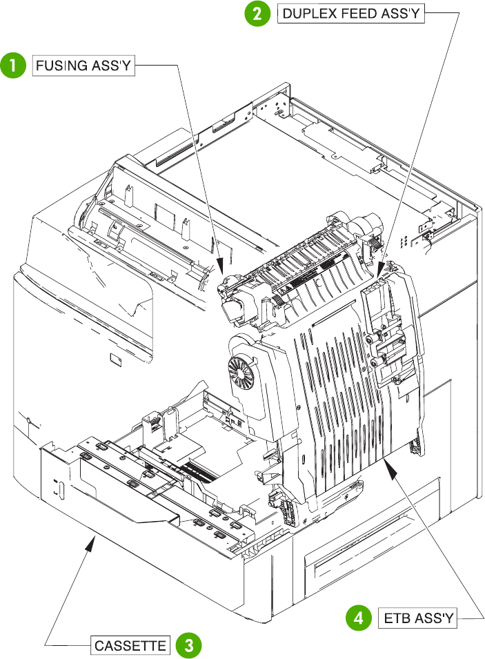
Assembly locations
The following illustrations and parts tables list the field replaceable units (FRU) for the HP Color
LaserJet 4730mfp series. The end of this chapter contains an alphabetical and numerical master
parts list.
Major components
Figure 8-1 HP Color LaserJet 4730mfp major components (1 of 2)
706 Chapter 8 Parts and diagrams ENWW
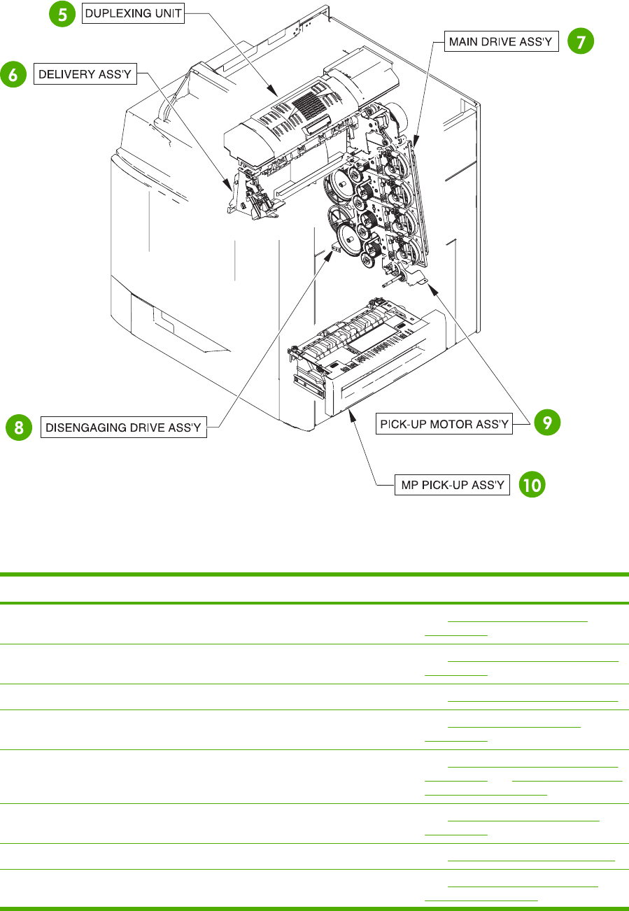
Figure 8-2 HP Color LaserJet 4730mfp major components (2 of 2)
Table 8-3 Major components
Reference number Description Details
1Fuser assembly See Figure 8-29 Fuser assembly
on page 762.
2Duplex feed assembly See Figure 8-28 Duplex feed assembly
on page 760.
3 Cassette See Figure 8-21 Cassette on page 746.
4ETB assembly See Figure 8-23 ETB assembly
on page 750.
5Duplexing unit See Figure 8-26 Duplexing unit (1 of 2)
on page 756 and Figure 8-27 Duplexing
unit (2 of 2) on page 758.
6Delivery assembly See Figure 8-24 Delivery assembly
on page 752.
7Main drive assembly See Internal components on page 722.
8 Disengaging drive assembly See Figure 8-19 Disengaging drive
assembly on page 742.
ENWW Assembly locations 707

ENWW Assembly locations 709
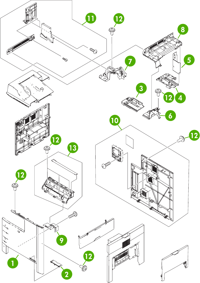
External covers and panels
Figure 8-3 External covers and panels
710 Chapter 8 Parts and diagrams ENWW

Table 8-4 External covers and panels
Ref Description Part number Qty
1 Front cover RC1-5694-000CN 1
2 Front cover plate RC1-5695-000CN 1
3 Face-down front guide RC1-5865-000CN 1
4 Face-down rear guide RC1-5866-000CN 1
5 Inner rear cover RC1-5873-000CN 1
6 Inner top cover RC1-5877-000CN 1
7 Inner top, rear cover RC1-5878-000CN 1
8 Paper delivery upper cover RC1-5880-000CN 1
9 Front cover plate RC1-5696-000CN 1
10 Rear cover assembly RM1-2118-000CN 1
11 Paper delivery cover assembly RM1-2179-000CN 1
12 Screw, RS M3X8 XA9-1504-000CN 12
13 Operation panel holder assembly RM1-2117-000CN 1
ENWW External covers and panels 711
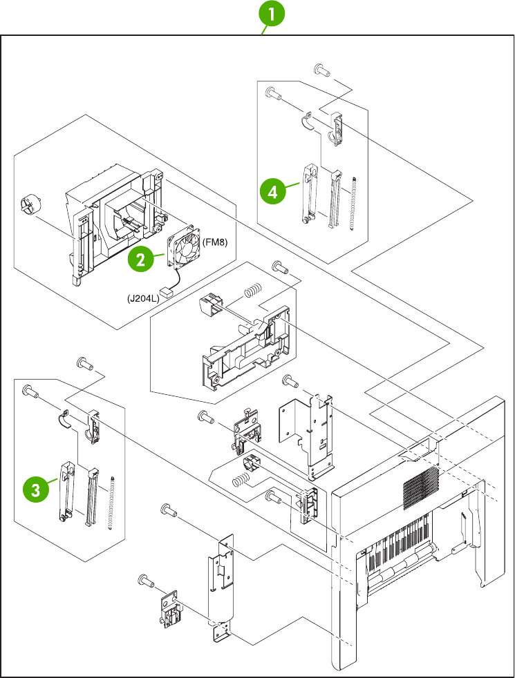
Figure 8-4 Right lower cover assembly
712 Chapter 8 Parts and diagrams ENWW

Table 8-5 Right lower cover assembly
Ref Description Part number Qty
1 Right lower cover assembly RM1-2105-000CN 1
2 Fan RK2-0622-000CN 1
3 Cover arm RC1-4846-000CN 1
4 Cover arm RC1-4864-000CN 1
ENWW External covers and panels 713
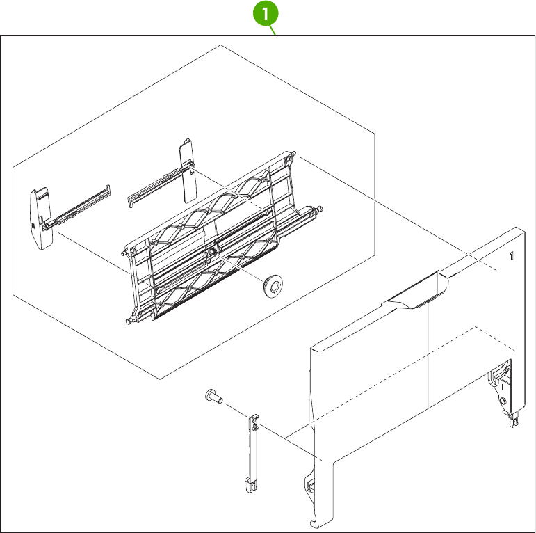
Figure 8-5 Multipurpose tray assembly
714 Chapter 8 Parts and diagrams ENWW

Table 8-6 Multipurpose tray assembly
Ref Description Part number Qty
1 Multipurpose tray assembly RM1-2109-000CN 1
ENWW External covers and panels 715
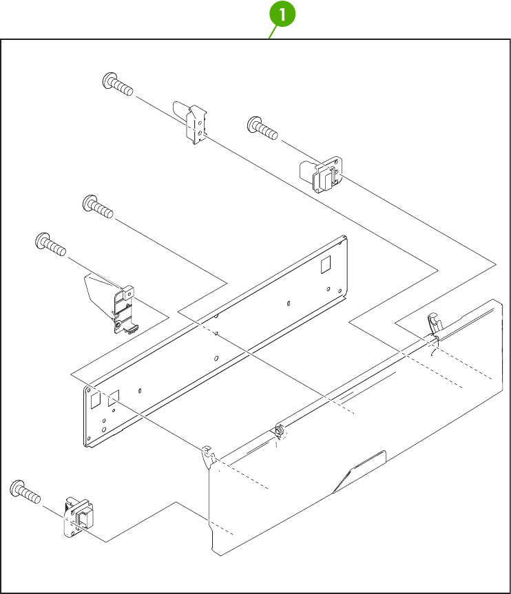
Figure 8-6 Right upper door assembly
716 Chapter 8 Parts and diagrams ENWW

Table 8-7 Right upper door assembly
Ref Description Part number Qty
1 Right upper door assembly RM1-2111-000CN 1
ENWW External covers and panels 717
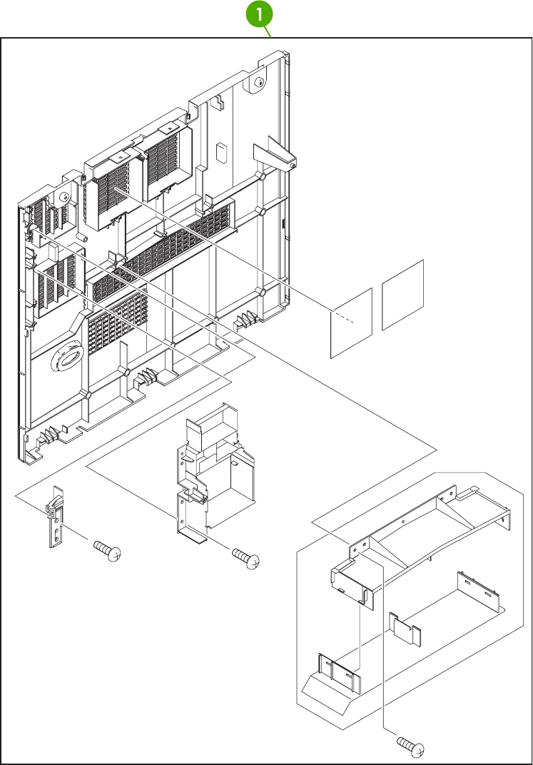
Figure 8-7 Left cover assembly
718 Chapter 8 Parts and diagrams ENWW

Table 8-8 Left cover assembly
Ref Description Part number Qty
Left cover assembly RM1-2115-000CN 1
ENWW External covers and panels 719
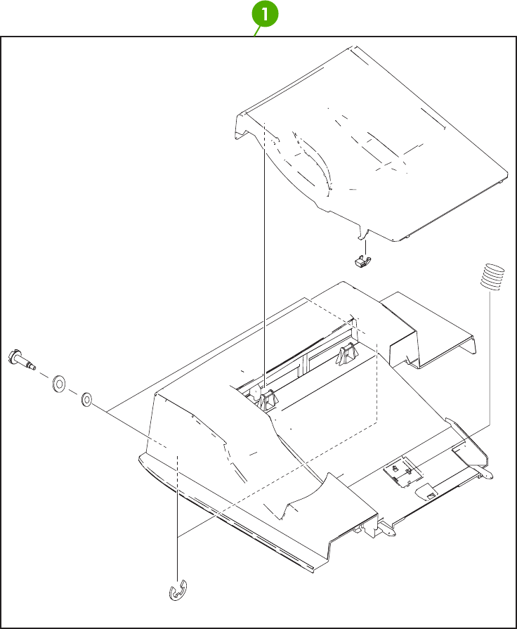
Figure 8-8 Face-down tray assembly
720 Chapter 8 Parts and diagrams ENWW

Table 8-9 Face-down tray assembly
Ref Description Part number Qty
Face-down tray assembly RM1-2180-000CN 1
ENWW External covers and panels 721
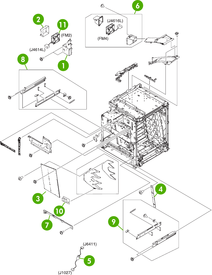
Internal components
Figure 8-9 Internal components (1 of 8)
722 Chapter 8 Parts and diagrams ENWW
(12) - GEAR 17T
RB2-8628-000CN
White gear next to
the link arm for the
MP tray

Table 8-10 Internal components (1 of 8)
Ref Description Part number Qty
1 Fan holder RC1-4314-000CN 1
2 Fan duct RC1-5711-000CN 1
3 High-voltage power supply PCB RM1-1608-000CN 1
4 Toner sensor PCB assembly RM1-1609-000CN 1
5 Control panel cable assembly RM1-2354-000CN 1
6 Fan assembly RM1-2178-000CN 1
7 Inner front cover RC1-5988-000CN 1
8 Left rail assembly RM1-2227-000CN 1
9 Right rail assembly RM1-2228-000CN 1
10 Humidity sensor unit WP2-5187-000CN 1
11 Fan RK2-0623-000CN 1
ENWW Internal components 723
12 GEAR 17T RB2-8628-000CN 1
White gear next to the link arm for the MP tray
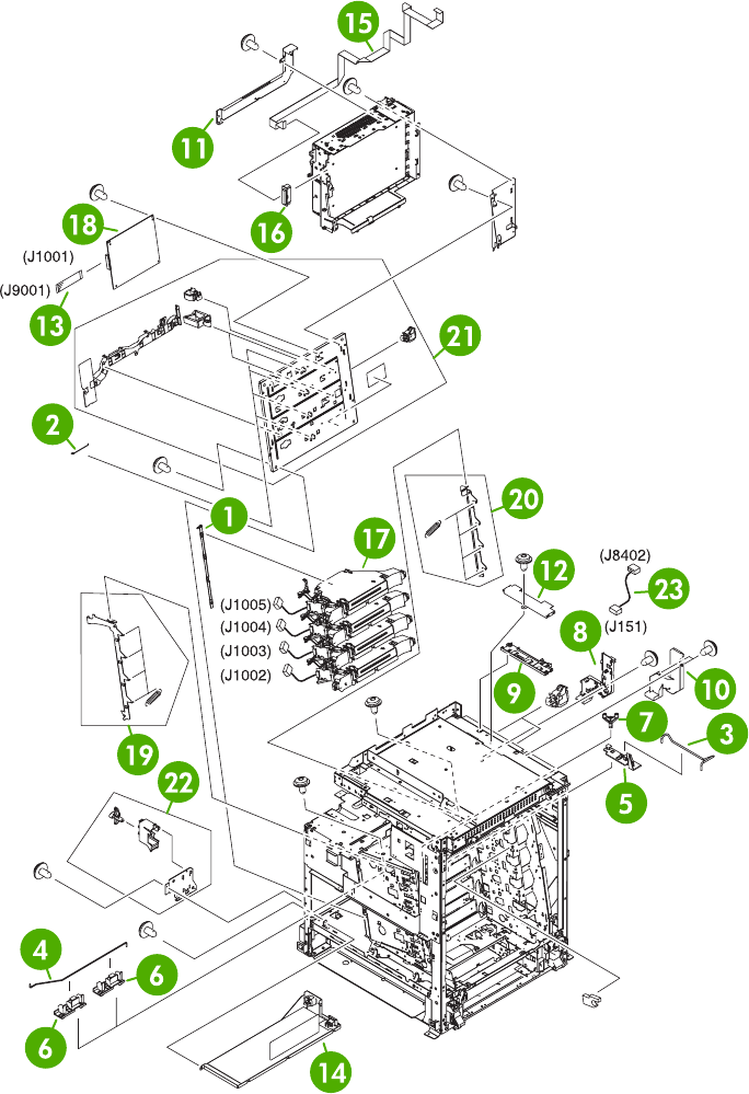
Figure 8-10 Internal components (2 of 8)
724 Chapter 8 Parts and diagrams ENWW

Table 8-11 Internal components (2 of 8)
Ref Description Part number Qty
1 Scanner support RC1-4312-000CN 1
2 Scanner support spring RC1-4313-000CN 4
3 Switching arm RC1-5646-000CN 1
4 Switching arm RC1-5647-000CN 1
5 Switching arm guide RC1-5648-000CN 2
6 Switching arm guide RC1-5649-000CN 1
7 Switching arm link RC1-5650-000CN 1
8 Cable holder RC1-5771-000CN 1
9 Cable holder RC1-5773-000CN 1
10 Shield cover RC1-5776-000CN 1
11 Shield cover RC1-5778-000CN 1
12 Shield cover RC1-5779-000CN 1
13 Flat cable RK2-1171-000CN 1
14 Low–voltage power PCB assembly 110V RK2-0627-000CN 1
14 Low–voltage power PCB assembly 220V RK2-0628-000CN 1
15 Flat cable RK2-0802-000CN 1
16 Flat cable connection 23P RK2-0816-000CN 1
17 Laser/Scanner assembly RM1-1591-000CN 4
18 DC controller assembly RM1-2346-000CN 1
19 Left scanner retaining assembly RM1-1664-000CN 1
20 Right scanner retaining assembly RM1-1665-000CN 1
21 Rear plate assembly RM1-1679-000CN 1
22 Power supply switch assembly RM1-2099-000CN 1
23 Power cable assembly RM1-2353-000CN 1
ENWW Internal components 725
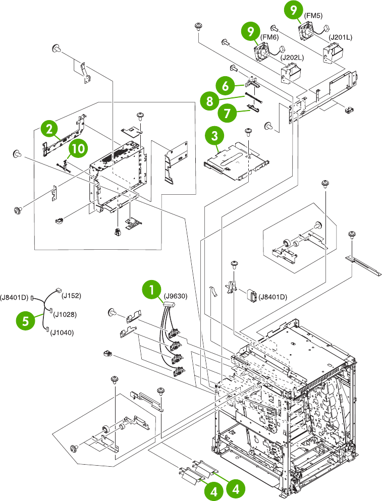
Figure 8-11 Internal components (3 of 8)
726 Chapter 8 Parts and diagrams ENWW

Table 8-12 Internal components (3 of 8)
Ref Description Part number Qty
1 Memory contact cable RM1-1653-000CN 1
2 Cable holder RC1-5772-000CN 1
3 Face down center guide RC1-5864-000CN 1
4 Fan duct RC1-5867-000CN 2
5 Feed unit connect cable assembly RM1-2355-000CN 1
6 Test print upper guide RC1-5728-000CN 1
7 Test print lower guide RC1-5759-000CN 1
8 Test print rod RC1-5760-000CN 1
9 Fan RK2-0621-000CN 2
10 Test print button RC1-4345-000CN 1
ENWW Internal components 727
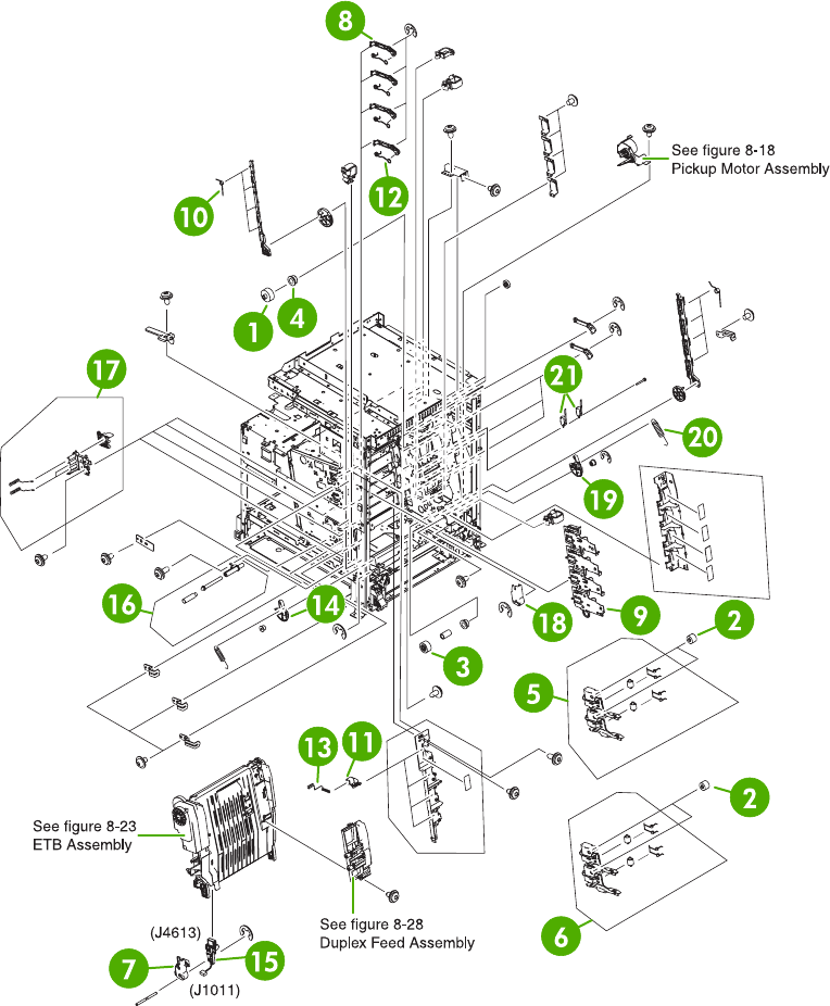
Figure 8-12 Internal components (4 of 8)
728 Chapter 8 Parts and diagrams ENWW

Table 8-13 Internal components (4 of 8)
Ref Description Part number Qty
1 30T gear RC1-4309-000CN 4
2 29T gear RC1-4310-000CN 4
3 18T gear RC1-4324-000CN 1
4 Bushing RC1-4325-000CN 5
5 Cartridge guide assembly, right upper RM1-2142-000CN 1
6 Cartridge guide assembly, right lower RM1-2143-000CN 1
7 Left cap RC1-4386-000CN 1
8 Cartridge pressure left lever RC1-4387-000CN 4
9 Cartridge left guide RC1-5766-000CN 1
10 Tension spring RC1-4393-000CN 4
11 HV terminal block RC1-4394-000CN 4
12 Tension spring RC1-4395-000CN 4
13 Compression spring RC1-4396-000CN 4
14 Pressure plate RC1-4397-000CN 1
15 Connector guide assembly RM1-1675-000CN 1
16 Attraction contact assembly RM1-1676-000CN 1
17 HV terminal mount assembly RM1-2144-000CN 4
18 Right cap RC1-4352-000CN 1
19 Pressure plate RC1-4360-000CN 1
20 Tension spring RC1-4423-000CN 1
21 Switch WC4-5188-000CN 2
ENWW Internal components 729
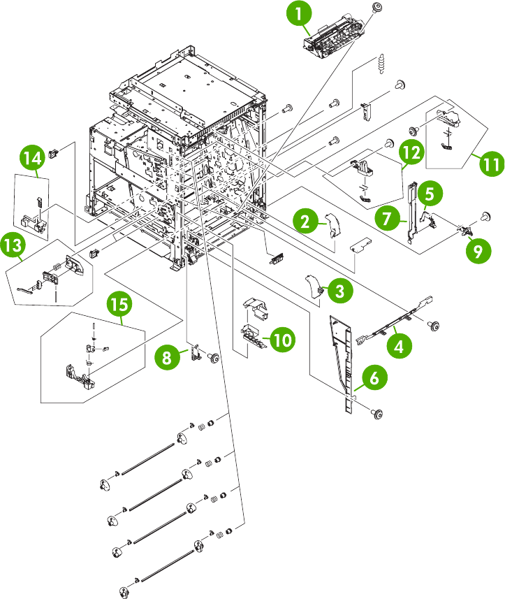
Figure 8-13 Internal components (5 of 8)
730 Chapter 8 Parts and diagrams ENWW

Table 8-14 Internal components (5 of 8)
Ref Description Part number Qty
1 Paper feed assembly RM1-1756-000CN 1
2 Lower right cover RC1-4322-000CN 1
3 Lower left cover RC1-4323-000CN 1
4 Base plate edge cover RC1-5644-000CN 1
5 Cable guide RC1-5645-000CN 1
6 Inner cover RC1-5658-000CN 1
7 Door cable cover RC1-5677-000CN 1
8 Front door hinge shaft RC1-5692-000CN 1
9 Rear door hinge shaft RC1-5693-000CN 1
10 Cable guide RC1-5904-000CN 1
11 Right ETB lever assembly RM1-1662-000CN 1
12 Left ETB lever assembly RM1-1663-000CN 1
13 Size sensing assembly RM1-0041-020CN 1
14 Left reg. adjustment assembly RM1-1007-000CN 1
15 Kicker assembly RM1-1008-000CN 1
ENWW Internal components 731
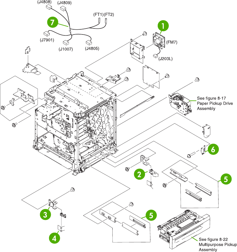
Figure 8-14 Internal components (6 of 8)
732 Chapter 8 Parts and diagrams ENWW

Table 8-15 Internal components (6 of 8)
Ref Description Part number Qty
1 Fan RK2-0621-000CN 1
2 Lock lever RC1-5926-000CN 2
3 Lock plate RC1-5927-000CN 2
4 Torsion spring RC1-5953-000CN 2
5 MPU rail assembly RM1-2203-000CN 2
6 Microswitch RK2-0804-000CN 1
7 Door cable assembly RM1-2356-000CN 1
ENWW Internal components 733
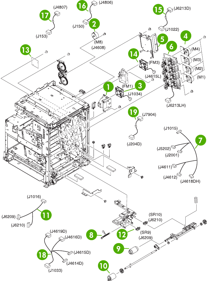
Figure 8-15 Internal components (7 of 8)
734 Chapter 8 Parts and diagrams ENWW

Table 8-16 Internal components (7 of 8)
Ref Description Part number Qty
1 Fan holder RC1-4316-000CN 1
2 DC stepping motor RK2-0618-000CN 1
3 Fan RK2-0622-000CN 1
4 Drum motor assembly RM1-1659-000CN 4
5 Sub power supply assembly RM1-2119-000CN 1
7 Main drive assembly RM1-2137-000CN 1
8 Pickup cable assembly RM1-2361-000CN 1
9 Sensor lever RC1-6013-000CN 1
10 Paper pickup roller assembly RM1-0036-020CN 1
11 Paper feed roller assembly RM1-0037-020CN 1
12 Paper sensor cable assembly RM1-2350-000CN 1
13 Photo interrupter, TLP1243 WG8-5696-000CN 2
14 Fan driver PCB assembly RM1-2345-000CN 1
15 Fan RK2-0621-000CN 1
16 Drive sensor cable assembly RM1-2349-000CN 1
17 MFP power cable assembly RM1-2351-000CN 1
18 Power save cable assembly RM1-2352-000CN 1
19 Fan connecting cable assembly RM1-2357-000CN 1
20 Fan connecting cable assembly RM1-2358-000CN 1
ENWW Internal components 735
MP/Tray 1 link arm - Left side: RC1-4441-000CN
MP/Tray 1 link arm - Right side: RC1-4439-000CN
Torsion spring - Provides tension for MP Tray link arms - One used per side: RC1-4440-000CN
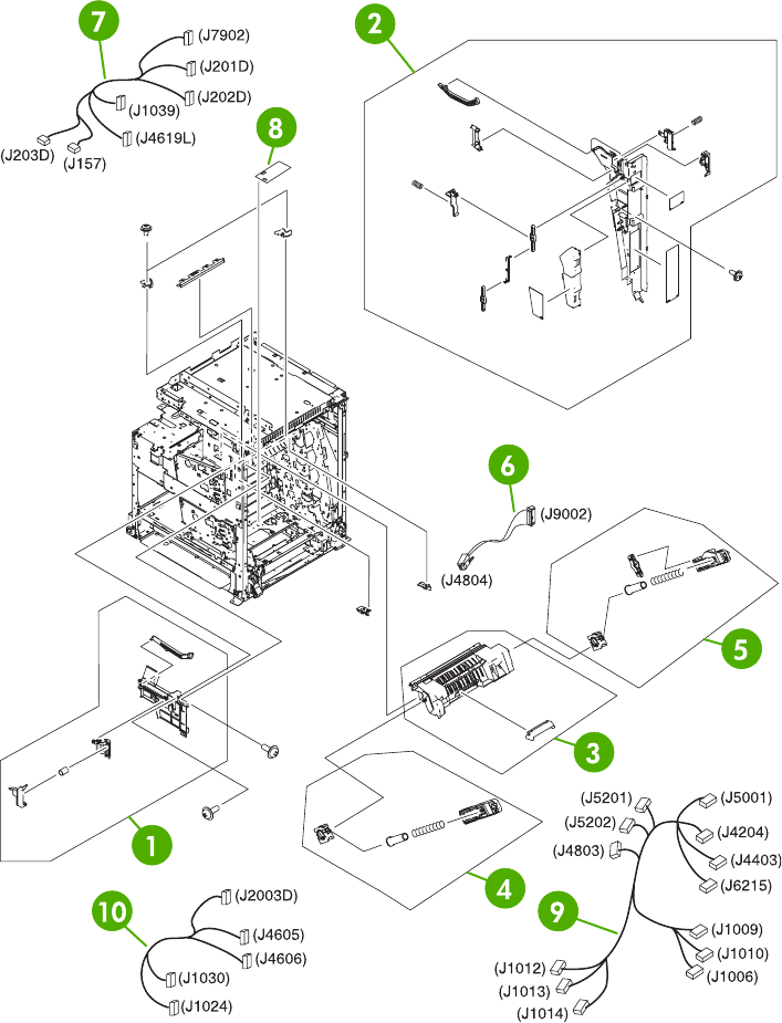
Figure 8-16 Internal components (8 of 8)
736 Chapter 8 Parts and diagrams ENWW

Table 8-17 Internal components (8 of 8)
Ref Description Part number Qty
1 Front inner cover assembly RM1-2100-000CN 1
2 Rear inner cover assembly RM1-2101-000CN 1
3 Fuser door assembly RM1-2102-000CN 1
4 Front fuser door link assembly RM1-2103-000CN 1
5 Rear fuser door link assembly RM1-2104-000CN 1
6 Formatter power cable assembly RM1-1642-000CN 1
7 Fan connecting cable assembly RM1-2360-000CN 1
8 Memory PCB assembly RM1-1618-000CN 1
9 Main cable assembly RM1-1627-000CN 1
10 Fuser motor cable assembly RM1-1631-000CN 1
ENWW Internal components 737
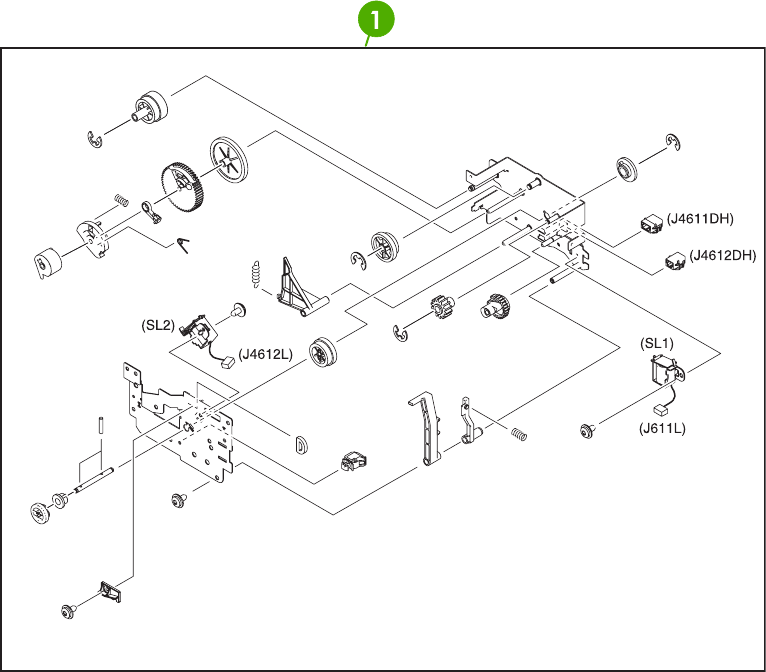
Figure 8-17 Paper pickup drive assembly
738 Chapter 8 Parts and diagrams ENWW

Table 8-18 Paper pickup drive assembly
Ref Description Part number Qty
1 Paper pickup drive assembly RM1-2198-000CN 1
ENWW Internal components 739
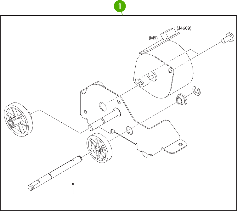
Figure 8-18 Pickup motor assembly
740 Chapter 8 Parts and diagrams ENWW

Table 8-19 Pickup motor assembly
Ref Description Part number Qty
1 pickup motor assembly RM1-2189-000CN 1
ENWW Internal components 741
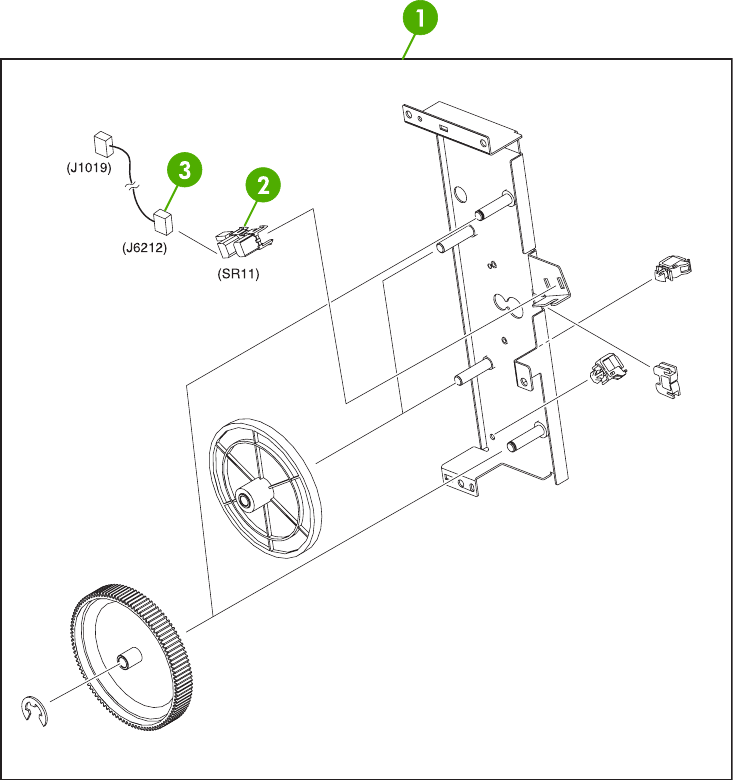
Figure 8-19 Disengaging drive assembly
742 Chapter 8 Parts and diagrams ENWW

Table 8-20 Disengaging drive assembly
Ref Description Part number Qty
1 Disengaging Drive Assembly RM1-1717-000CN 1
2 Photo Interrupter TLP1243 WG8-5696-000CN 1
3 Developing disengaging sensor cable RM1-1644-000CN 1
ENWW Internal components 743
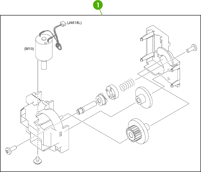
Figure 8-20 Lifter drive assembly
744 Chapter 8 Parts and diagrams ENWW

Table 8-21 Lifter drive assembly
Ref Description Part number Qty
1 Lifter drive assembly RM1-1750-000CN 1
ENWW Internal components 745
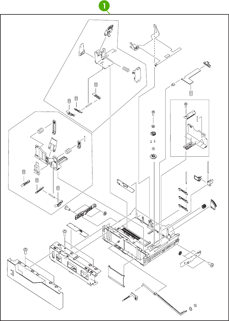
Figure 8-21 Cassette
746 Chapter 8 Parts and diagrams ENWW

Table 8-22 Cassette
Ref Description Part number Qty
1 Cassette RM1-2219-000CN 1
ENWW Internal components 747
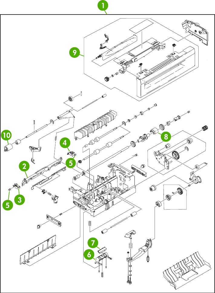
Figure 8-22 Multipurpose pickup assembly
748 Chapter 8 Parts and diagrams ENWW

Table 8-23 Multipurpose pickup assembly
Ref Description Part number Qty
1 Multipurpose pickup assembly RM1-2199-000CN 1
2 Retard guide RC1-5940-000CN 1
3 Retard guide pin RC1-5938-000CN 1
4 Retard guide pin RC1-5939-000CN 1
5 Compression spring RU5-2514-000CN 2
6 Base separation pad RB2-8386-000CN 1
7 Separation pad RF5-3750-020CN 1
8 pickup roller RL1-0019-000CN 1
9 Cst. Cover assembly, B RM1-2200-000CN 1
10 Paper feed roller assembly RM1-0037-020CN 1
ENWW Internal components 749
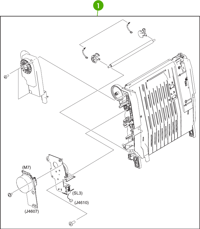
Figure 8-23 ETB assembly
750 Chapter 8 Parts and diagrams ENWW

Table 8-24 ETB assembly
Ref Description Part number Qty
1 ETB assembly RM1-3161-000CN 1
ENWW Internal components 751
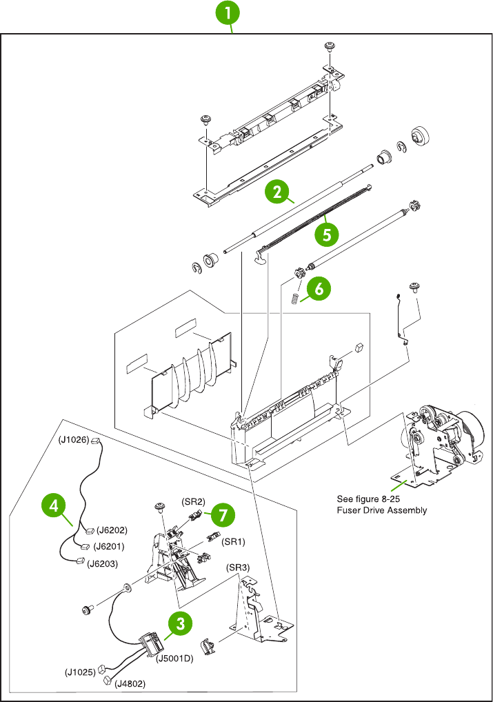
Figure 8-24 Delivery assembly
752 Chapter 8 Parts and diagrams ENWW

Table 8-25 Delivery assembly
Ref Description Part number Qty
1 Delivery assembly 110-127V (new) RM1-1730-000CN 1
1 Delivery assembly 220-240V (new) RM1-1737-000CN 1
2 Delivery roller 110-127V RC1-4874-000CN 1
2 Delivery roller 220-240V RC1-4875-000CN 1
3 Fuser drive cable assembly RM1-1634-000CN 1
4 Fuser drive cable assembly RM1-1638-000CN 1
5 Full sensor flag RL1-0612-000CN 1
6 Compression spring RC1-4803-000CN 1
7 Photo interrupter, TLP1243 WG8-5696-000CN 3
ENWW Internal components 753
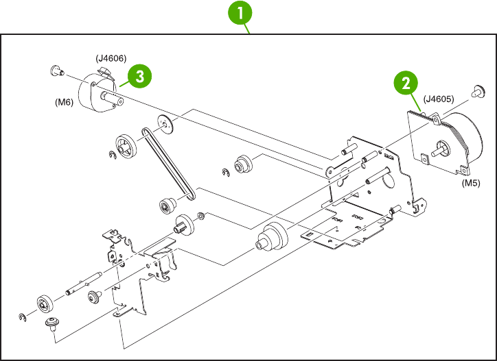
Figure 8-25 Fuser drive assembly
754 Chapter 8 Parts and diagrams ENWW

Table 8-26 Fuser drive assembly
Ref Description Part number Qty
1 Fuser drive assembly RM1-1729-000CN 1
2 DC motor RK2-0615-000CN 1
3 DC stepping motor RK2-0619-000CN 1
ENWW Internal components 755
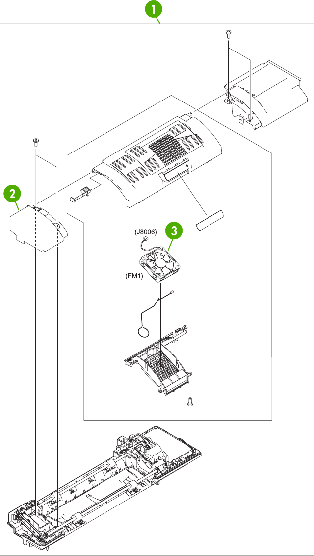
Figure 8-26 Duplexing unit (1 of 2)
756 Chapter 8 Parts and diagrams ENWW

Table 8-27 Duplexing unit (1 of 2)
Ref Description Part number Qty
1 Duplexing unit RM1-2112-000CN 1
2 Solenoid cover RL1-0654-000CN 1
3 Fan RK2-0648-000CN 1
ENWW Internal components 757
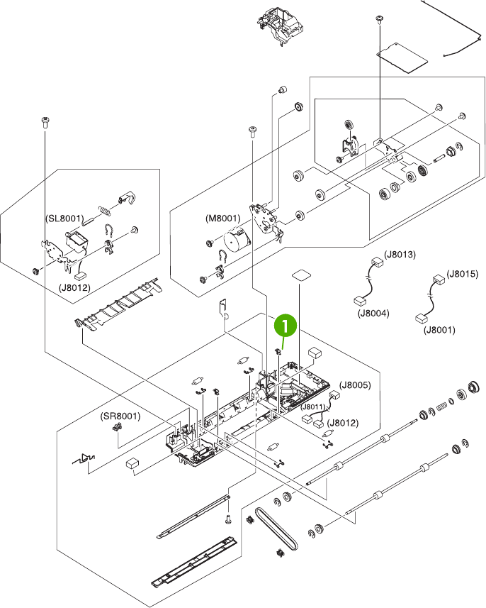
Figure 8-27 Duplexing unit (2 of 2)
758 Chapter 8 Parts and diagrams ENWW

Table 8-28 Duplexing unit (2 of 2)
Ref Description Part number Qty
1 Duplex lock RC1-5020-000CN 2
ENWW Internal components 759
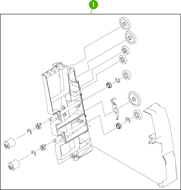
Figure 8-28 Duplex feed assembly
760 Chapter 8 Parts and diagrams ENWW

Table 8-29 Duplex feed assembly
Ref Description Part number Qty
1 Duplex feed assembly RM1-1785-000CN 1
ENWW Internal components 761
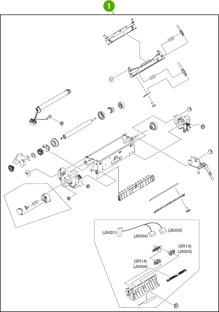
Figure 8-29 Fuser assembly
762 Chapter 8 Parts and diagrams ENWW

Table 8-30 Fuser assembly
Ref Description Part number Qty
1 Fuser assembly (110-127V) RM1-3131-000CN 1
1 Fuser assembly (220-240V) RM1-3146-000CN 1
ENWW Internal components 763
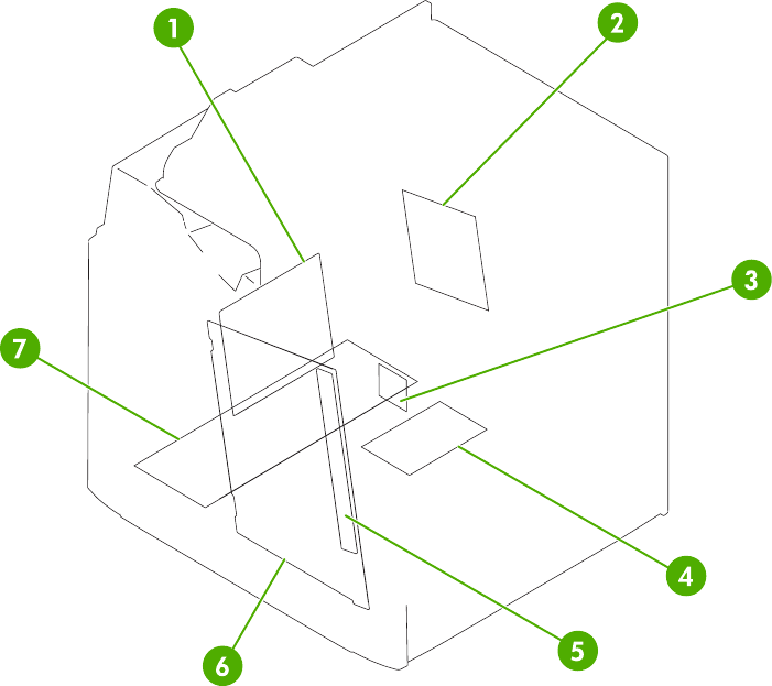
Figure 8-30 PCB assembly
764 Chapter 8 Parts and diagrams ENWW

Table 8-31 PCB assembly
Ref Description Part number Qty
1 DC controller PCB assembly RM1-2346-000CN 1
2 Sub power supply assembly RM1-2119-000CN 1
3 Fan driver PCB assembly RM1-2345-000CN 1
4 Memory PCB assembly RM1-1618-000CN 1
5 Toner sensor PCB assembly RM1-1609-000CN 1
6 High-voltage power PCB assembly RM1-1608-000CN 1
7 Low-voltage power PCB assembly 110-127V RK2-0627-000CN 1
7 Low-voltage power PCB assembly 220-240V RK2-0628-000CN 1
ENWW Internal components 765
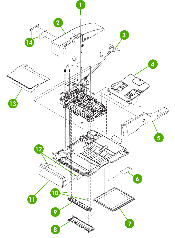
ADF components
Figure 8-31 ADF assembly
766 Chapter 8 Parts and diagrams ENWW

Table 8-32 ADF assembly
Ref Description Part number Qty
1 ADF assembly (without skins) PF2288-SVPNI 1
2 ADF rear cover PF2288P044NI 1
3 ADF to SCB cable PF2282K165NI 1
4 ADF input tray PF2282K042NI 1
5 ADF front cover assembly PF2288K001NI 1
6 ADF mylar replacement kit Q6496-67901 1
7 ADF white scan background PF2282P339NI 1
8 ADF mylar holder assembly PF2282K043NI 1
9 ADF window background PF2282P025NI 1
10 ADF spring for window background PF2282P343NI 2
11 ADF left cover PF2288P058NI 1
12 ADF springs for left cover PF2282P352NI 2
13 ADF jam-access cover PF2282P041NI 1
14 ADF mud flap assembly PF2282K166NI 1
ENWW ADF components 767
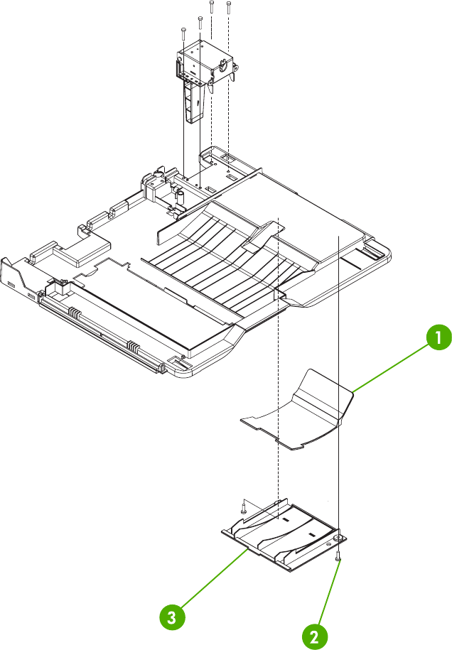
Figure 8-32 ADF internal components (1 of 3)
768 Chapter 8 Parts and diagrams ENWW

Table 8-33 ADF internal components (1 of 3)
Ref Description Part number Qty
1 ADF output bin paper stop PF2282P061NI 1
2 ADF screw, M3X8 IR4041P021NI 7
3 ADF output bin base cover PF2282P060NI 1
ENWW ADF components 769
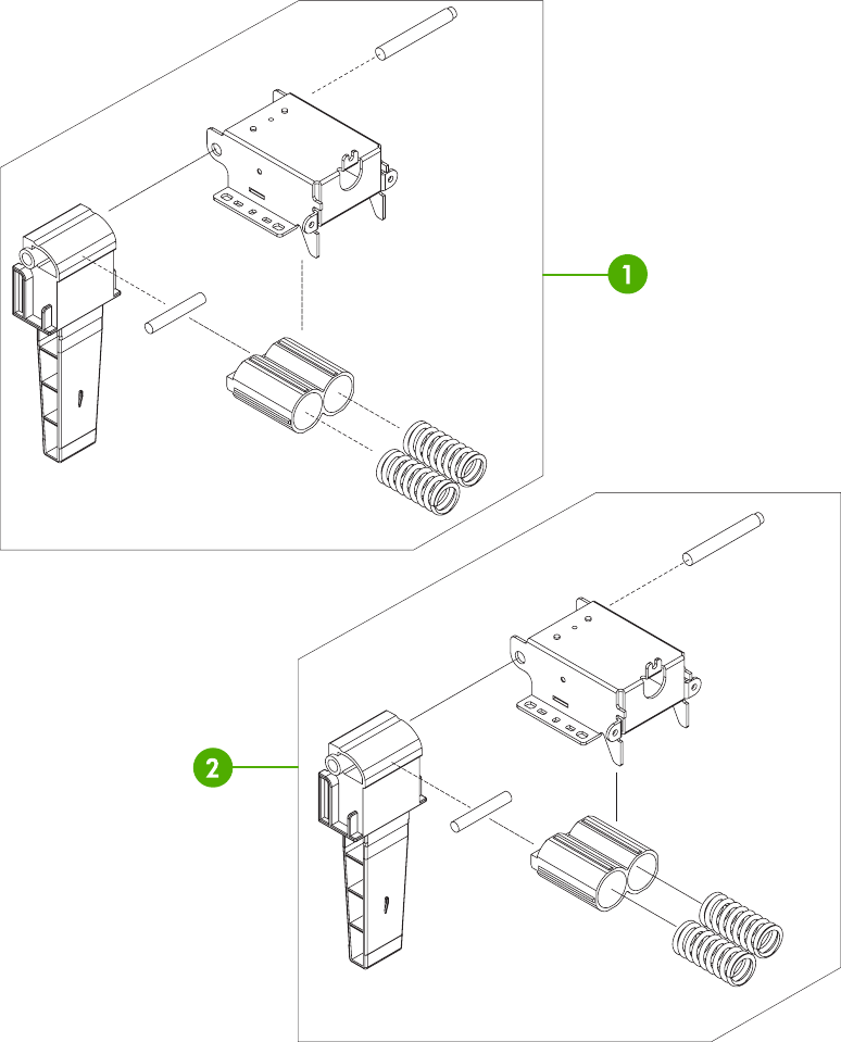
Figure 8-33 ADF internal components (2 of 3)
770 Chapter 8 Parts and diagrams ENWW

Table 8-34 ADF internal components (2 of 3)
Ref Description Part number Qty
1 ADF left hinge assembly PF2288K041NI 1
2 ADF right hinge assembly PF2282K008NI 1
ENWW ADF components 771
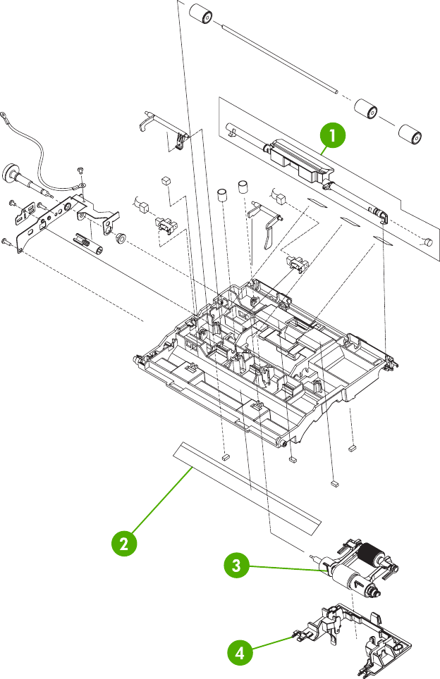
Figure 8-34 ADF internal components (3 of 3)
772 Chapter 8 Parts and diagrams ENWW

Table 8-35 ADF internal components (3 of 3)
Ref Description Part number Qty
1 ADF jam access latch PF2282K164NI 1
2 ADF duplex path mylar PF2282P353NI 1
3 ADF pickup roller assembly PF2282K039NI 1
4 ADF pickup roller holder assembly PF2282K040NI 1
ENWW ADF components 773
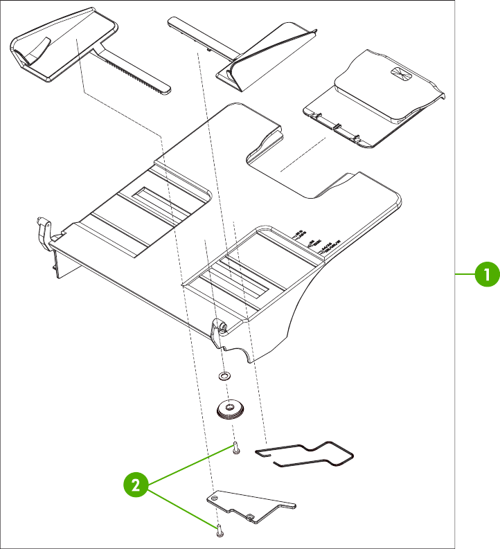
Figure 8-35 ADF input tray
774 Chapter 8 Parts and diagrams ENWW

Table 8-36 ADF input tray
Ref Description Part number Qty
1 ADF input tray assembly PF2282K042NI 1
2 ADF button screw M3x8 IR4041P021NI 2
ENWW ADF components 775
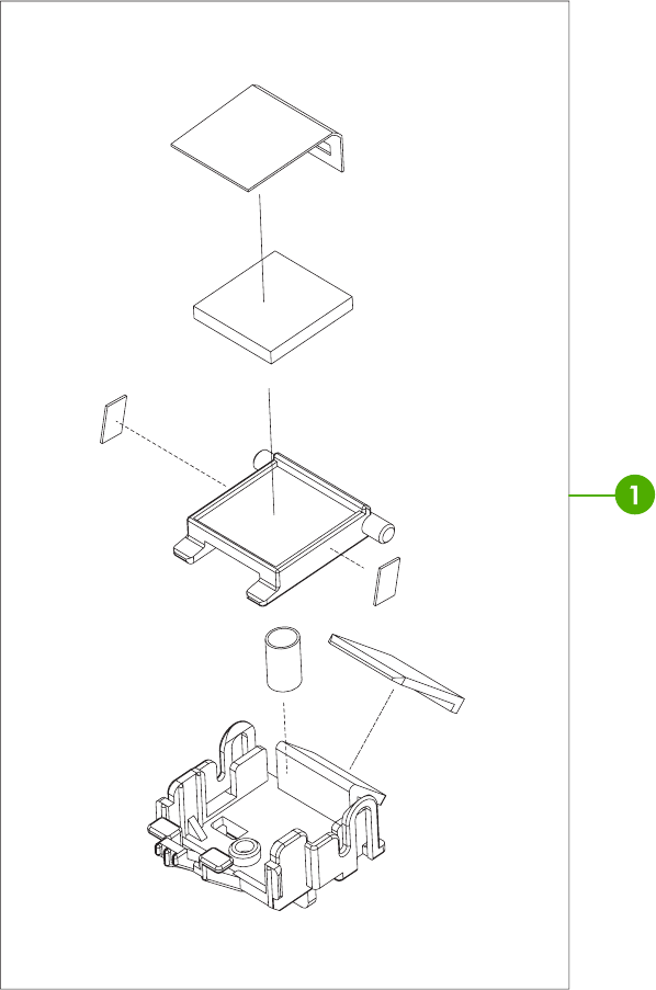
Figure 8-36 ADF separation pad
776 Chapter 8 Parts and diagrams ENWW

Table 8-37 ADF separation pad
Ref Description Part number Qty
1 ADF separation pad assembly PF2282K035NI 1
ENWW ADF components 777
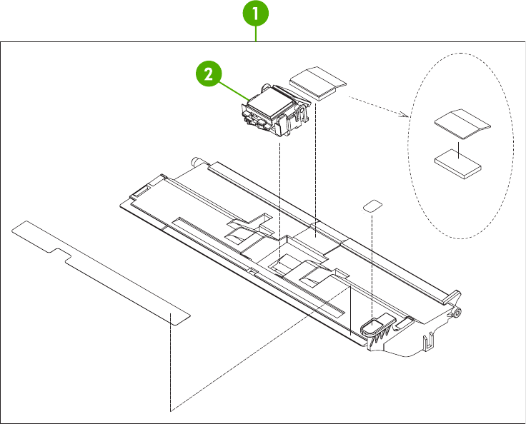
Figure 8-37 ADF separation pad case
778 Chapter 8 Parts and diagrams ENWW

Table 8-38 ADF separation pad case
Ref Description Part number Qty
1 ADF upper paper path assembly PF2282K034NI 1
2 ADF separation pad assembly PF2282K035NI 1
ENWW ADF components 779
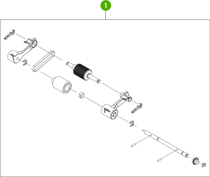
Figure 8-38 ADF pickup-roller assembly
780 Chapter 8 Parts and diagrams ENWW

Table 8-39 ADF pickup-roller assembly
Ref Description Part number Qty
1 ADF pickup roller assembly PF2282K039NI 1
ENWW ADF components 781
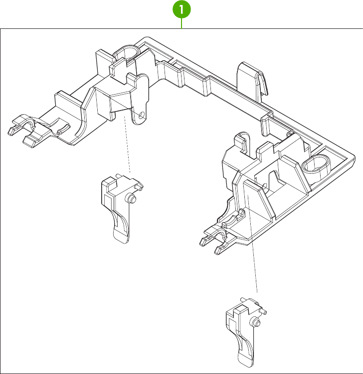
Figure 8-39 ADF pickup-roller cover
782 Chapter 8 Parts and diagrams ENWW

Table 8-40 ADF pickup-roller cover
Ref Description Part number Qty
1 ADF pickup roller cover assembly PF2282K040NI 1
ENWW ADF components 783
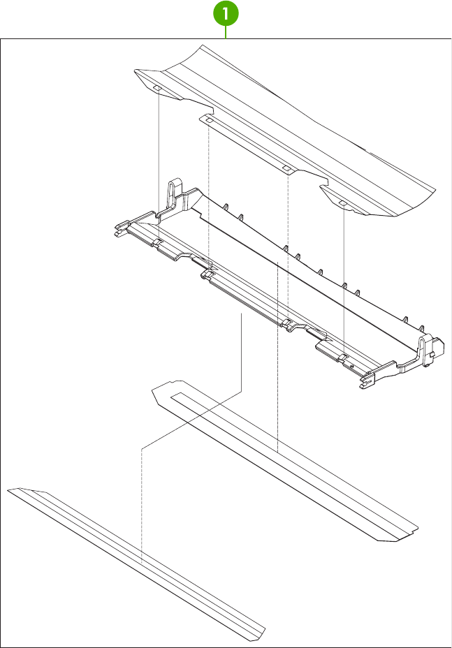
Figure 8-40 ADF mylar holder assembly
784 Chapter 8 Parts and diagrams ENWW

Table 8-41 ADF mylar holder assembly
Ref Description Part number Qty
1 ADF mylar holder assembly PF2282K043NI 1
ENWW ADF components 785
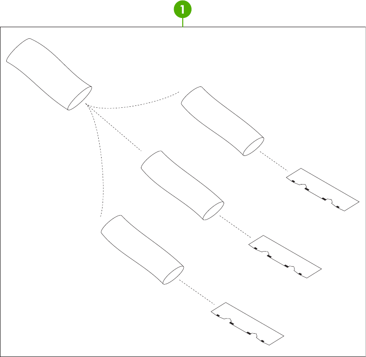
Figure 8-41 ADF mylar replacement kit
786 Chapter 8 Parts and diagrams ENWW

Table 8-42 ADF mylar replacement kit
Ref Description Part number Qty
1 ADF mylar replacement kit Q6496-67901 1
ENWW ADF components 787
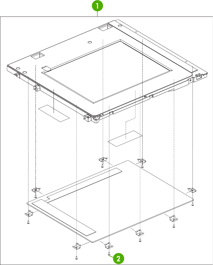
Scanner components
Figure 8-42 Scanner glass and cover
788 Chapter 8 Parts and diagrams ENWW

Table 8-43 Scanner glass and cover
Ref Description Part number Qty
1 Scanner glass and cover IR4054K111NI 1
2 Scanner screw M3x8 IR4041P021NI 9
ENWW Scanner components 789
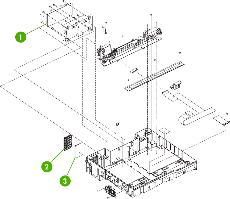
Figure 8-43 Scanner base components
790 Chapter 8 Parts and diagrams ENWW

Table 8-44 Scanner base components
Ref Description Part number Qty
1 Scanner controller PCB IR4041K512NI 1
2 Scanner fan filter cover IR4054P217NI 1
3 Scanner fan filter IR4041P007NI 1
ENWW Scanner components 791
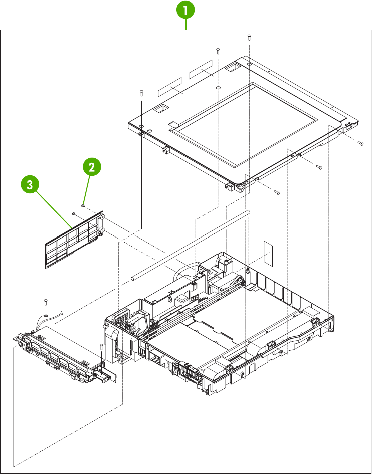
Figure 8-44 Scanner flatbed unit assembly
792 Chapter 8 Parts and diagrams ENWW

Table 8-45 Scanner flatbed unit assembly
Ref Description Part number Qty
1 Scanner flatbed unit assembly IR4054-SVPNI 1
2 Scanner screw flatbed 040100FNBBNI ?
3 Scanner rear cover IR4054P216NI 1
ENWW Scanner components 793
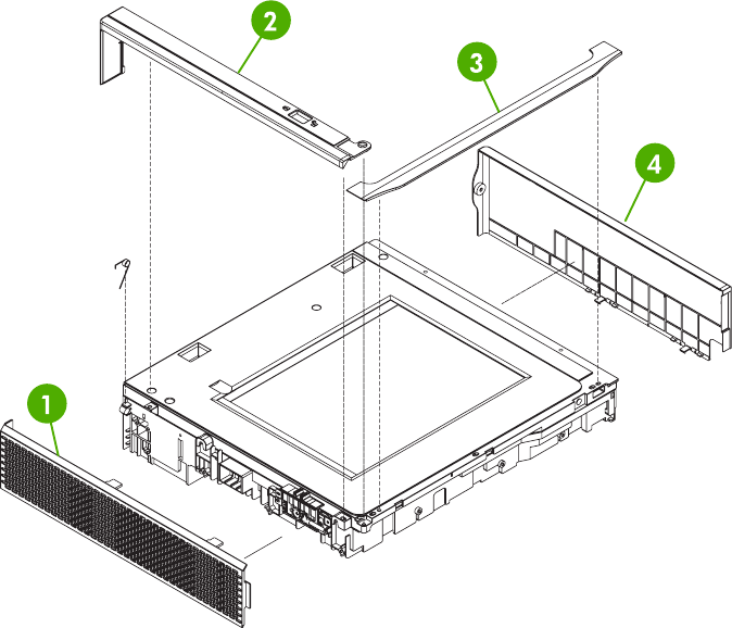
Figure 8-45 Scanner covers
794 Chapter 8 Parts and diagrams ENWW

Table 8-46 Scanner covers
Ref Description Part number Qty
1 Scanner left cover IR4054P226NI 1
2 Scanner cartridge lock cover IR4041P214NI 1
3 Scanner top cover flatbed flange IR4054P215NI 1
4 Scanner right cover assembly IR4054K100NI 1
ENWW Scanner components 795
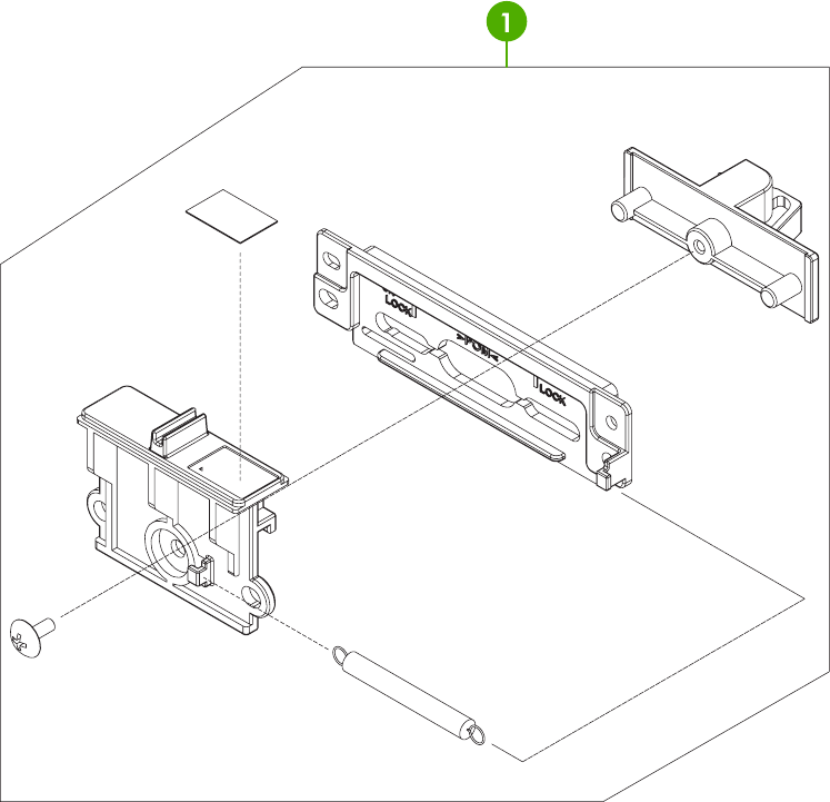
Figure 8-46 Scanner carriage lock assembly
796 Chapter 8 Parts and diagrams ENWW

Table 8-47 Scanner carriage lock assembly
Ref Description Part number Qty
1 Scanner cartridge lock assembly IR4041K102NI 1
ENWW Scanner components 797
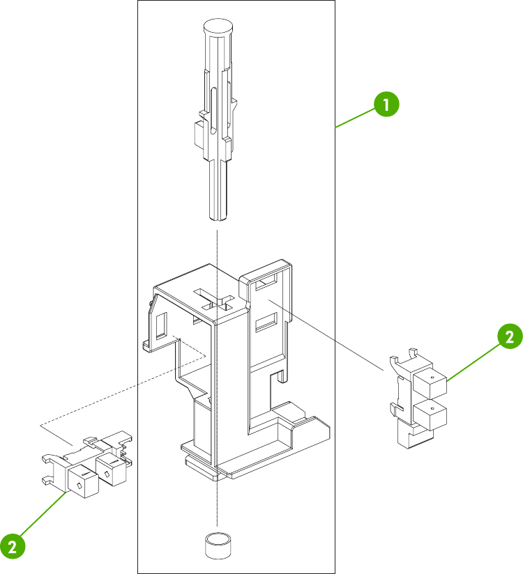
Figure 8-47 Scanner-open sensor assembly
798 Chapter 8 Parts and diagrams ENWW

Table 8-48 Scanner-open sensor assembly
Ref Description Part number Qty
1 Scanner open sensor holder assembly IR4041K105NI 1
2 Scanner open sensor E314000619NI 2
ENWW Scanner components 799
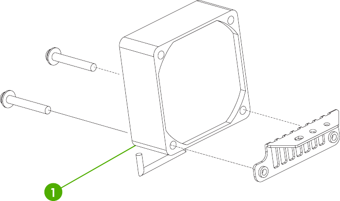
Figure 8-48 Scanner motor fan
800 Chapter 8 Parts and diagrams ENWW

Table 8-49 Scanner motor fan
Ref Description Part number Qty
1 Scanner motor fan IR4041P521NI 1
ENWW Scanner components 801
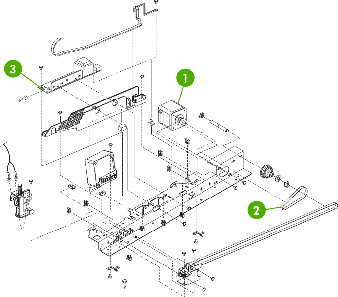
Figure 8-49 Scanner motor
802 Chapter 8 Parts and diagrams ENWW

Table 8-50 Scanner motor
Ref Description Part number Qty
1 Scanner motor IR4041K520NI 1
2 Scanner motor belt INS-BLT00290NI 1
3 Scanner lamp inverter IR4041P522NI 1
ENWW Scanner components 803
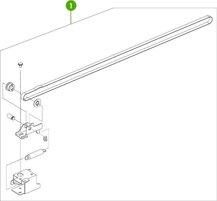
Figure 8-50 Scanner belt and pulley assembly
804 Chapter 8 Parts and diagrams ENWW

Table 8-51 Scanner belt and pulley assembly
Ref Description Part number Qty
1 Scanner belt and pulley assembly IR4041K107NI 1
ENWW Scanner components 805
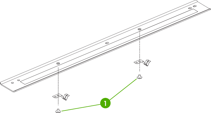
Figure 8-51 Scanner slide rail
806 Chapter 8 Parts and diagrams ENWW

Table 8-52 Scanner slide rail
Ref Description Part number Qty
1 Scanner slide rail and screw 030040FNITNI 1
ENWW Scanner components 807
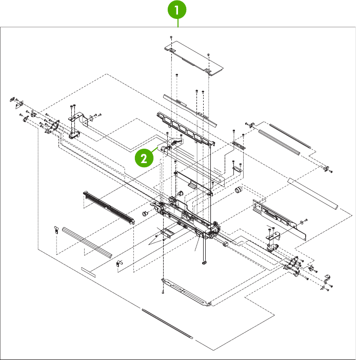
Figure 8-52 Scanner optical assembly
808 Chapter 8 Parts and diagrams ENWW

Table 8-53 Scanner optical assembly
Ref Description Part number Qty
1 Scanner optical assembly IR4041K121NI 1
2 Scanner lamp IR4041K151NI 1
ENWW Scanner components 809
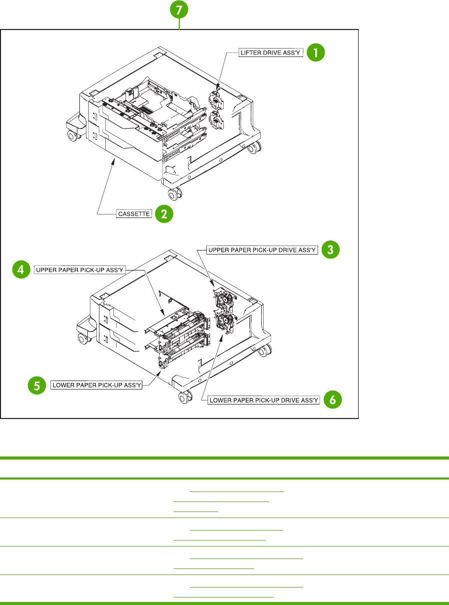
2 X 500-sheet feeder components
Figure 8-53 2 X 500-sheet paper feeder assembly locations
Item Assembly name Details Part number
1Lifter-drive assembly See Figure 8-57 2 X 500-paper
feeder lifter drive assembly
on page 818.
RM1–1750–000CN
2 Cassette See Figure 8-60 2 X 500-sheet
paper feeder on page 824.
RM1–2219–000CN
3Upper paper pickup assembly See Figure 8-61 Upper paper pickup
assembly on page 826.
RM1–2232–000CN
4 Upper paper pickup drive assembly See Figure 8-58 Upper paper pickup
drive assembly on page 820.
RM1–2229–000CN
810 Chapter 8 Parts and diagrams ENWW

Item Assembly name Details Part number
5Lower paper pickup assembly See Figure 8-62 Lower paper pickup
assembly on page 828.
RM1–2240–000CN
6Lower paper pickup drive assembly See Figure 8-59 Lower paper pickup
drive assembly on page 822.
RM1–2238–000CN
7 2 X 500-sheet paper feeder
assembly (complete assembly)
See Figure 8-53 2 X 500-sheet
paper feeder assembly locations
on page 810.
R96–5062–000CN
ENWW 2 X 500-sheet feeder components 811
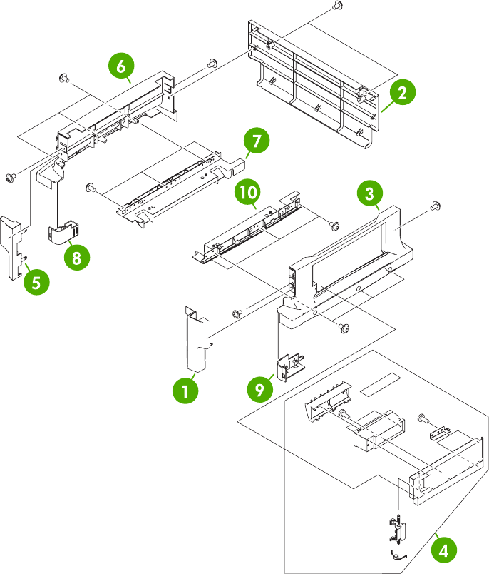
Figure 8-54 2 X 500-sheet feeder external components
812 Chapter 8 Parts and diagrams ENWW

Table 8-54 2 X 500-sheet feeder external components
Ref Description Part number Qty
1 Right front cover RC1-6047-000CN 1
2 Rear cover RC1-6048-000CN 1
3 Right cover RC1-6044-000CN 1
4 Right lower cover assembly RM1-2241-000CN 1
5 Left front cover RC1-6046-000CN 1
6 Left cover RC1-6042-000CN 1
7 Left lower cover RC1-6043-000CN 1
8 Left caster cover RC1-6067-000CN 1
9 Right caster cover RC1-6068-000CN 1
10 Right lower cover RC1-6045-000CN 1
ENWW 2 X 500-sheet feeder components 813
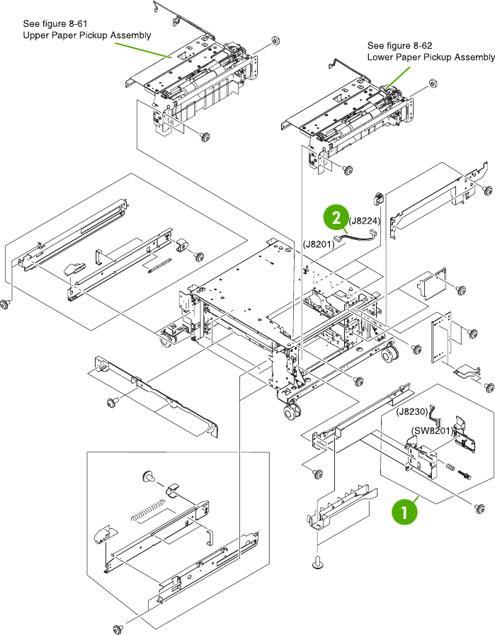
Figure 8-55 2 X 500-sheet paper feeder internal components (1 of 2)
814 Chapter 8 Parts and diagrams ENWW

Table 8-55 2 X 500-sheet paper feeder internal components (1 of 2)
Ref Description Part number Qty
1 Right switch assembly RM1-2226-000CN 1
2 Cable interface RM1-2373-000CN 1
ENWW 2 X 500-sheet feeder components 815
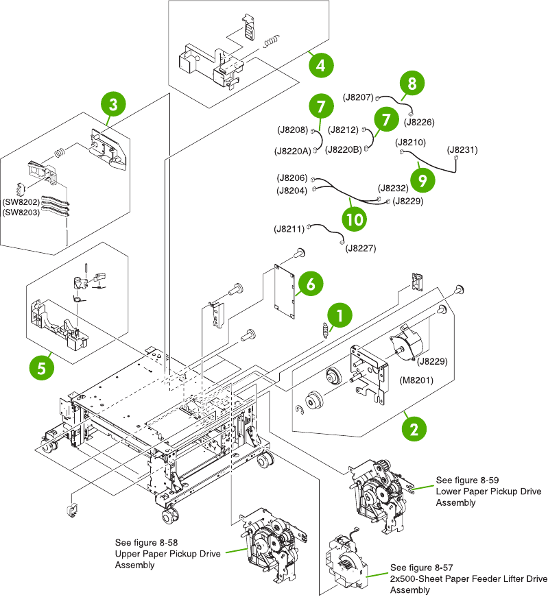
Figure 8-56 2 X 500-sheet paper feeder internal components (2 of 2)
816 Chapter 8 Parts and diagrams ENWW

Table 8-56 2 X 500-sheet paper feeder internal components (2 of 2)
Ref Description Part number Qty
1 Spring tension RC1-0198-000CN 2
2 Motor assembly RM1-2231-000CN 1
3 Size sensing assembly RM1-0041-000CN 2
4 Left reg. adjustment assembly RM1-1007-000CN 2
5 Kicker assembly RM1-1008-000CN 2
6 Paper feeder driver PCB assembly RM1-2365-000CN 1
7 Cassette size cable RM1-2366-000CN 2
8 Motor cable RM1-2369-000CN 2
9 Solenoid cable RM1-2368-000CN 1
10 Solenoid cable RM1-2371-000CN 1
ENWW 2 X 500-sheet feeder components 817
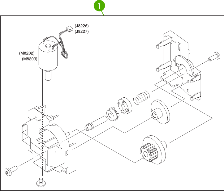
Figure 8-57 2 X 500-paper feeder lifter drive assembly
818 Chapter 8 Parts and diagrams ENWW

Table 8-57 500-sheet feeder lifter drive assembly
Ref Description Part number Qty
1 Lifter-drive assembly RM1-1750-000CN 2
ENWW 2 X 500-sheet feeder components 819
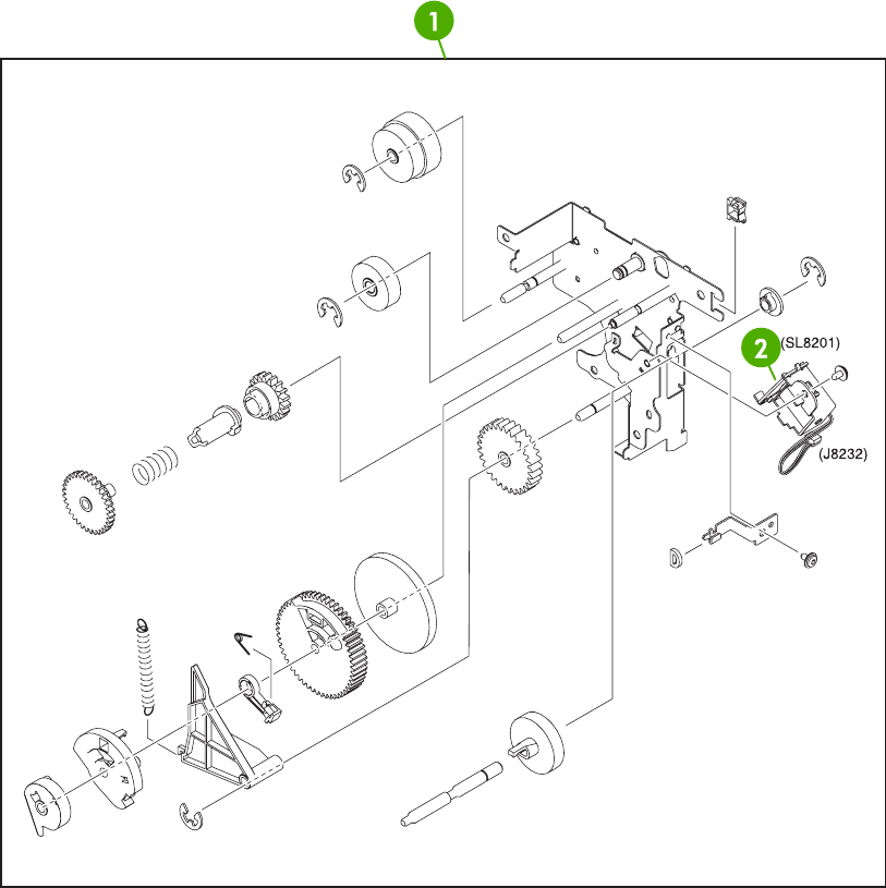
Figure 8-58 Upper paper pickup drive assembly
820 Chapter 8 Parts and diagrams ENWW

Table 8-58 Upper paper pickup drive assembly
Ref Description Part number Qty
1 Upper paper pickup drive assembly RM1-2229-000CN 1
2 Solenoid RK2-0624-000CN 1
ENWW 2 X 500-sheet feeder components 821
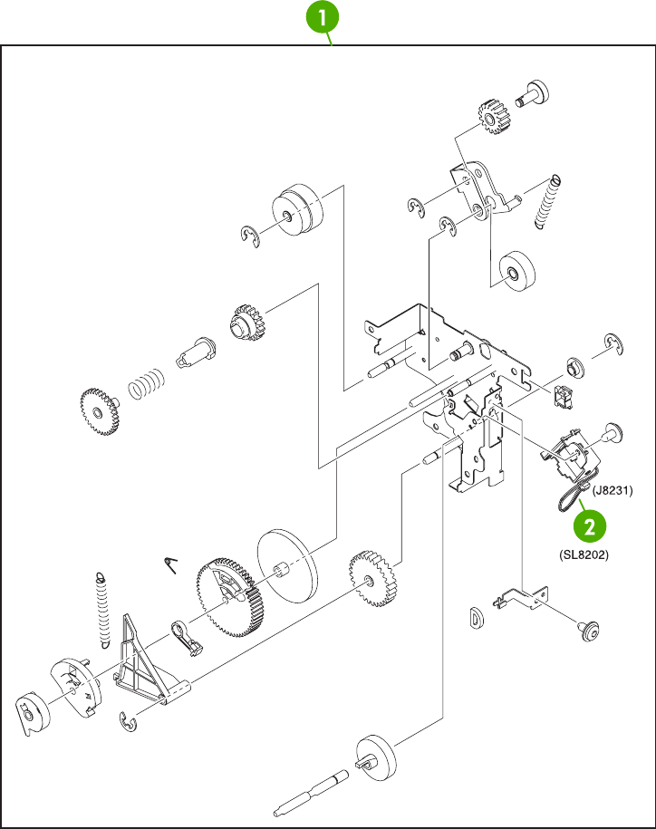
Figure 8-59 Lower paper pickup drive assembly
822 Chapter 8 Parts and diagrams ENWW

Table 8-59 Lower paper pickup drive assembly
Ref Description Part number Qty
1 Lower pickup drive assembly RM1-2238-000CN 1
2 Solenoid RK2-0624-000CN 1
ENWW 2 X 500-sheet feeder components 823
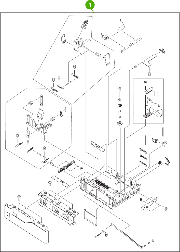
Figure 8-60 2 X 500-sheet paper feeder
824 Chapter 8 Parts and diagrams ENWW

Table 8-60 2 X 500-sheet paper feeder cassette
Ref Description Part number Qty
1 2 X 500-sheet paper feeder cassette case unit RM1-2219-000CN 1
ENWW 2 X 500-sheet feeder components 825
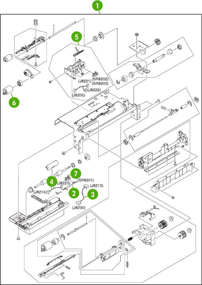
Figure 8-61 Upper paper pickup assembly
826 Chapter 8 Parts and diagrams ENWW

Table 8-61 Upper paper pickup assembly
Ref Description Part number Qty
1 Upper paper pickup assembly RM1-2232-000CN 1
2 Jam sensor flag RC1-6012-000CN 1
3 Door switch cable RM1-2370-000CN 1
4 Paper feed sensor cable RM1-2372-000CN 1
5 Paper sensor unit RM1-2249-000CN 1
6 Paper feed roller assembly RM1-0037-020CN 1
7 Photo interrupter, TLP1243 WG8-5696-000CN 1
ENWW 2 X 500-sheet feeder components 827
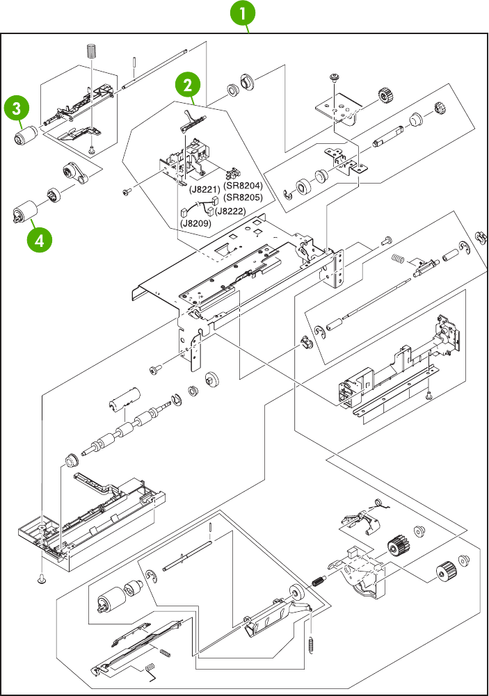
Figure 8-62 Lower paper pickup assembly
828 Chapter 8 Parts and diagrams ENWW

Table 8-62 Lower paper pickup assembly
Ref Description Part number Qty
1 Lower paper pickup assembly RM1-2240-000CN 1
2 Paper sensor unit RM1-2249-000CN 1
3 Paper pickup roller assembly RM1-0036-020CN 1
4 Paper feed roller assembly RM1-0037-020CN 1
ENWW 2 X 500-sheet feeder components 829
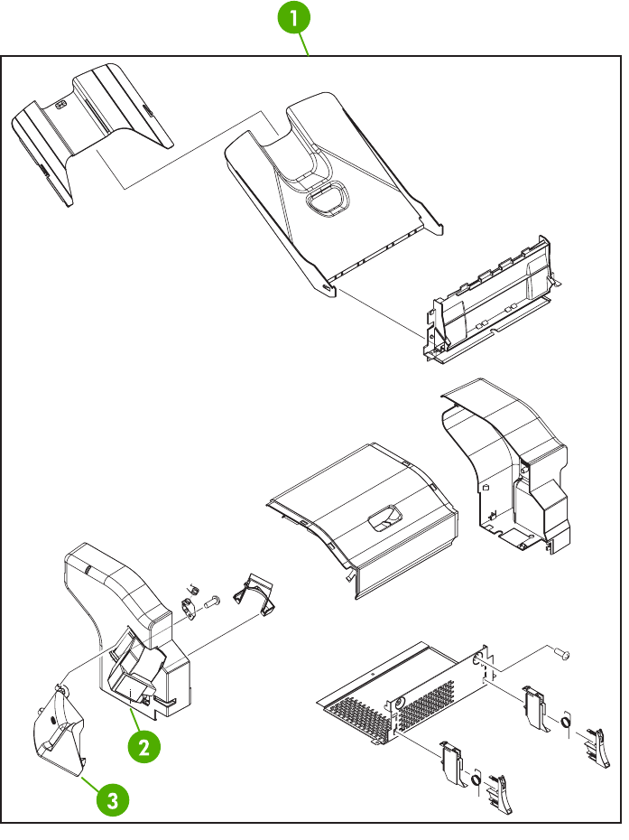
Optional devices
Stapler/stacker
Figure 8-63 Stapler/stacker accessory
830 Chapter 8 Parts and diagrams ENWW

Table 8-63 Stapler/stacker accessory
Ref Description Part number Qty
1 Stapler/stacker accessory Q5691-60501 1
2 Staple cartridge C8085-60541 1
3 Stapler/stacker jam access door RC1-2597-000CN 1
ENWW Optional devices 831
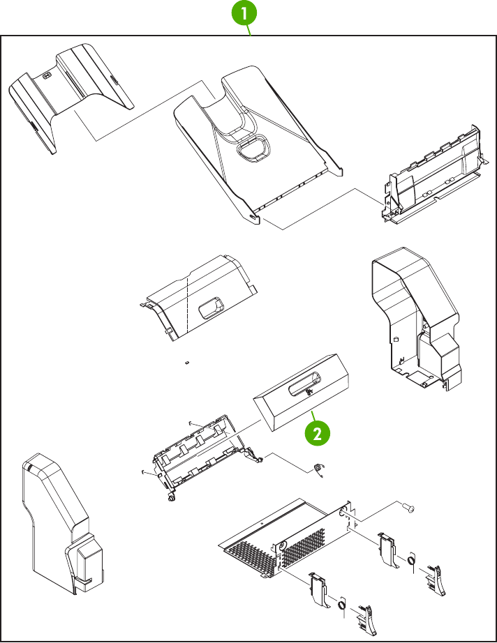
3-bin mailbox
Figure 8-64 3-bin mailbox accessory
832 Chapter 8 Parts and diagrams ENWW

Table 8-64 3-bin mailbox accessory
Ref Description Part number Qty
1 3-bin mailbox accessory Q5692-60503 1
2 3-bin mailbox jam access door RM1-0981-000CN 1
ENWW Optional devices 833
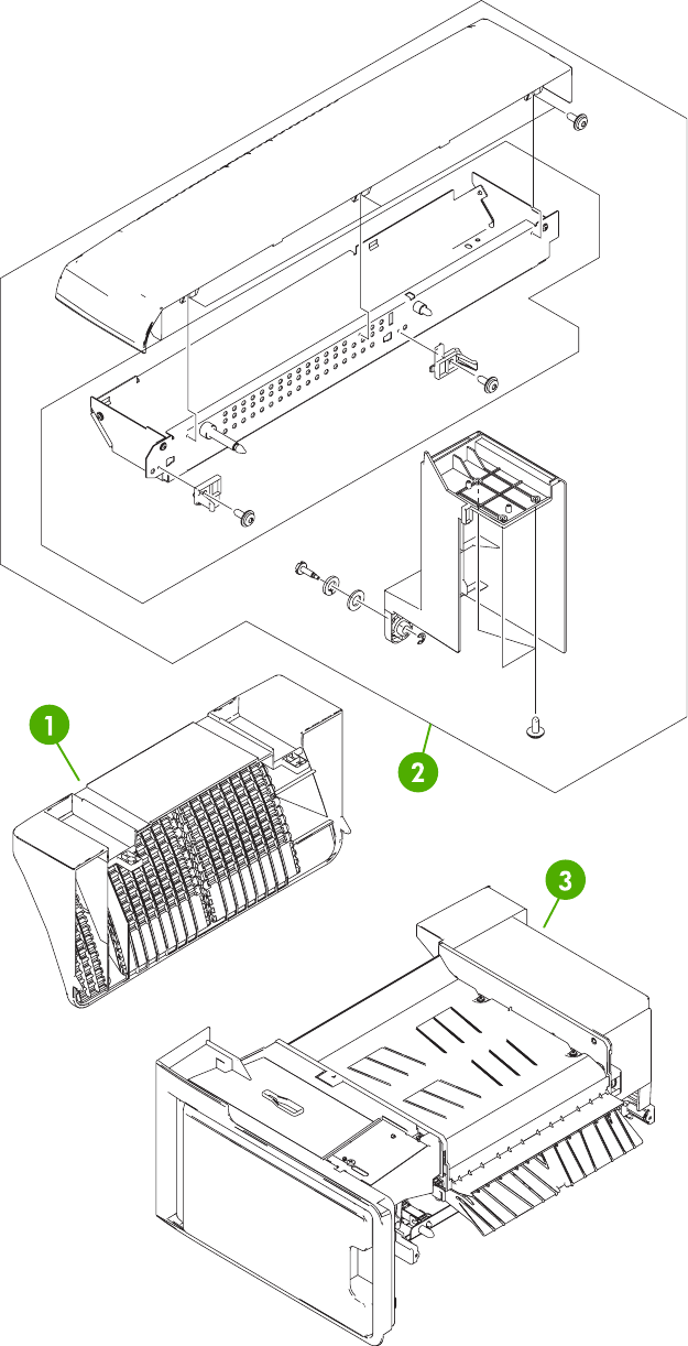
Intermediate paper transfer unit (IPTU)
Figure 8-65 External covers and panels
834 Chapter 8 Parts and diagrams ENWW

Table 8-65 External covers and panels
Ref Description Part number Qty
1 Lower cover RL1-0891-000CN 1
2 Top cover assembly RM1-2295-000CN 1
3 Intermediate feed assembly RM1-2279-000CN 1
ENWW Optional devices 835
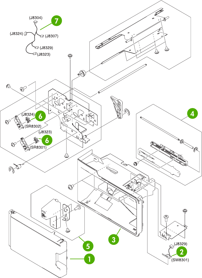
Figure 8-66 Internal components (1 of 2)
836 Chapter 8 Parts and diagrams ENWW

Table 8-66 Internal components (1 of 2)
Ref Description Part number Qty
1 Front door RC1-6158-000CN 1
2 Door switch RK2-0807-000CN 1
3 Front cover RL1-0892-000CN 1
4 Front rail assembly RM1-2291-000CN 1
5 Jam clearing lever assembly RM1-2294-000CN 1
6 Photo interrupter WG8-5696-000CN 2
7 Paper sensor cable assembly RM1-2383-000CN 2
ENWW Optional devices 837
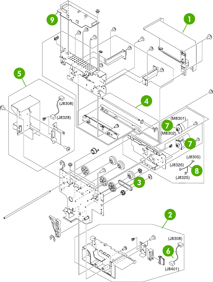
Figure 8-67 Internal components (2 of 2)
838 Chapter 8 Parts and diagrams ENWW

Table 8-67 Internal components (2 of 2)
Ref Description Part number Qty
1 Rear cover RC1-6154-000CN 1
2 Drawer connector assembly RM1-2288-000CN 1
3 Timing belt XF2-1108-440CN 1
4 Rear rail assembly RM1-2290-000CN 1
5 Connector cover assembly RM1-2293-000CN 1
6 Drawer connector cable assembly RM1-2384-000CN 1
7 DC stepping motor RK2-0812-000CN 2
8 Motor cable assembly RM1-2381-000CN 1
9 IPTU driver PCB assembly RM1-2380-000CN 1
ENWW Optional devices 839

Alphabetical parts list
Table 8-68 Alphabetical parts list
Description Part number Table and page
18T gear RC1-4324-000CN Internal components (4 of 8)
on page 729
29T gear RC1-4310-000CN Internal components (4 of 8)
on page 729
2 X 500-sheet paper feeder cassette case unit RM1-2219-000CN 2 X 500-sheet paper feeder
cassette on page 825
3-bin mailbox accessory Q5692-60503 3-bin mailbox accessory
on page 833
3-bin mailbox jam access door RM1-0981-000CN 3-bin mailbox accessory
on page 833
30T gear RC1-4309-000CN Internal components (4 of 8)
on page 729
ADF assembly (without skins) PF2288-SVPNI ADF assembly on page 767
ADF button screw M3x8 IR4041P021NI ADF input tray on page 775
ADF duplex path mylar PF2282P353NI ADF internal components (3
of 3) on page 773
ADF front cover assembly PF2288K001NI ADF assembly on page 767
ADF input tray PF2282K042NI ADF assembly on page 767
ADF input tray assembly PF2282K042NI ADF input tray on page 775
ADF jam access latch PF2282K164NI ADF internal components (3
of 3) on page 773
ADF jam-access cover PF2282P041NI ADF assembly on page 767
ADF left cover PF2288P058NI ADF assembly on page 767
ADF left hinge assembly PF2288K041NI ADF internal components (2
of 3) on page 771
ADF mud flap assembly PF2282K166NI ADF assembly on page 767
ADF mylar holder assembly PF2282K043NI ADF assembly on page 767
ADF mylar holder assembly PF2282K043NI ADF mylar holder assembly
on page 785
ADF mylar replacement kit Q6496-67901 ADF assembly on page 767
ADF mylar replacement kit Q6496-67901 ADF mylar replacement kit
on page 787
ADF output bin base cover PF2282P060NI ADF internal components (1
of 3) on page 769
ADF output bin paper stop PF2282P061NI ADF internal components (1
of 3) on page 769
ADF pickup roller assembly PF2282K039NI ADF internal components (3
of 3) on page 773
840 Chapter 8 Parts and diagrams ENWW

Description Part number Table and page
ADF pickup roller assembly PF2282K039NI ADF pickup-roller assembly
on page 781
ADF pickup roller cover assembly PF2282K040NI ADF pickup-roller cover
on page 783
ADF pickup roller holder assembly PF2282K040NI ADF internal components (3
of 3) on page 773
ADF rear cover PF2288P044NI ADF assembly on page 767
ADF right hinge assembly PF2282K008NI ADF internal components (2
of 3) on page 771
ADF screw, M3X8 IR4041P021NI ADF internal components (1
of 3) on page 769
ADF separation pad assembly PF2282K035NI ADF separation pad
on page 777
ADF separation pad assembly PF2282K035NI ADF separation pad case
on page 779
ADF spring for window background PF2282P343NI ADF assembly on page 767
ADF springs for left cover PF2282P352NI ADF assembly on page 767
ADF to SCB cable PF2282K165NI ADF assembly on page 767
ADF upper paper path assembly PF2282K034NI ADF separation pad case
on page 779
ADF white scan background PF2282P339NI ADF assembly on page 767
ADF window background PF2282P025NI ADF assembly on page 767
Attraction contact assembly RM1-1676-000CN Internal components (4 of 8)
on page 729
Base plate edge cover RC1-5644-000CN Internal components (5 of 8)
on page 731
Base separation pad RB2-8386-000CN Multipurpose pickup assembly
on page 749
Bushing RC1-4325-000CN Internal components (4 of 8)
on page 729
Cable guide RC1-5645-000CN Internal components (5 of 8)
on page 731
Cable guide RC1-5904-000CN Internal components (5 of 8)
on page 731
Cable holder RC1-5771-000CN Internal components (2 of 8)
on page 725
Cable holder RC1-5773-000CN Internal components (2 of 8)
on page 725
Cable holder RC1-5772-000CN Internal components (3 of 8)
on page 727
Cable interface RM1-2373-000CN 2 X 500-sheet paper feeder
internal components (1 of 2)
on page 815
Table 8-68 Alphabetical parts list (continued)
ENWW Alphabetical parts list 841

Description Part number Table and page
Cartridge guide assembly, right lower RM1-2143-000CN Internal components (4 of 8)
on page 729
Cartridge guide assembly, right upper RM1-2142-000CN Internal components (4 of 8)
on page 729
Cartridge left guide RC1-5766-000CN Internal components (4 of 8)
on page 729
Cartridge pressure left lever RC1-4387-000CN Internal components (4 of 8)
on page 729
Cassette RM1-2219-000CN Cassette on page 747
Cassette size cable RM1-2366-000CN 2 X 500-sheet paper feeder
internal components (2 of 2)
on page 817
Compression spring RC1-4396-000CN Internal components (4 of 8)
on page 729
Compression spring RU5-2514-000CN Multipurpose pickup assembly
on page 749
Compression spring RC1-4803-000CN Delivery assembly on page 753
Connector cover assembly RM1-2293-000CN Internal components (2 of 2)
on page 839
Connector guide assembly RM1-1675-000CN Internal components (4 of 8)
on page 729
Control panel cable assembly RM1-2354-000CN Internal components (1 of 8)
on page 723
Cover arm RC1-4846-000CN Right lower cover assembly
on page 713
Cover arm RC1-4864-000CN Right lower cover assembly
on page 713
Cst. Cover assembly, B RM1-2200-000CN Multipurpose pickup assembly
on page 749
DC controller assembly RM1-2346-000CN Internal components (2 of 8)
on page 725
DC controller PCB assembly RM1-2346-000CN PCB assembly on page 765
DC motor RK2-0615-000CN Fuser drive assembly
on page 755
DC stepping motor RK2-0618-000CN Internal components (7 of 8)
on page 735
DC stepping motor RK2-0619-000CN Fuser drive assembly
on page 755
DC stepping motor RK2-0812-000CN Internal components (2 of 2)
on page 839
Delivery assembly 110-127V (new) RM1-1730-000CN Delivery assembly on page 753
Delivery assembly 220-240V (new) RM1-1737-000CN Delivery assembly on page 753
Delivery roller 110-127V RC1-4874-000CN Delivery assembly on page 753
Table 8-68 Alphabetical parts list (continued)
842 Chapter 8 Parts and diagrams ENWW

Description Part number Table and page
Delivery roller 220-240V RC1-4875-000CN Delivery assembly on page 753
Developing disengaging sensor cable RM1-1644-000CN Disengaging drive assembly
on page 743
Disengaging Drive Assembly RM1-1717-000CN Disengaging drive assembly
on page 743
Door cable assembly RM1-2356-000CN Internal components (6 of 8)
on page 733
Door cable cover RC1-5677-000CN Internal components (5 of 8)
on page 731
Door switch RK2-0807-000CN Internal components (1 of 2)
on page 837
Door switch cable RM1-2370-000CN Upper paper pickup assembly
on page 827
Drawer connector assembly RM1-2288-000CN Internal components (2 of 2)
on page 839
Drawer connector cable assembly RM1-2384-000CN Internal components (2 of 2)
on page 839
Drive sensor cable assembly RM1-2349-000CN Internal components (7 of 8)
on page 735
Drum motor assembly RM1-1659-000CN Internal components (7 of 8)
on page 735
Duplex feed assembly RM1-1785-000CN Duplex feed assembly
on page 761
Duplex lock RC1-5020-000CN Duplexing unit (2 of 2)
on page 759
Duplexing unit RM1-2112-000CN Duplexing unit (1 of 2)
on page 757
ETB assembly RM1-3161-000CN ETB assembly on page 751
Face down center guide RC1-5864-000CN Internal components (3 of 8)
on page 727
Face-down front guide RC1-5865-000CN External covers and panels
on page 711
Face-down rear guide RC1-5866-000CN External covers and panels
on page 711
Face-down tray assembly RM1-2180-000CN Face-down tray assembly
on page 721
Fan RK2-0622-000CN Right lower cover assembly
on page 713
Fan RK2-0623-000CN Internal components (1 of 8)
on page 723
Fan RK2-0621-000CN Internal components (3 of 8)
on page 727
Fan RK2-0621-000CN Internal components (6 of 8)
on page 733
Table 8-68 Alphabetical parts list (continued)
ENWW Alphabetical parts list 843

Description Part number Table and page
Fan RK2-0622-000CN Internal components (7 of 8)
on page 735
Fan RK2-0621-000CN Internal components (7 of 8)
on page 735
Fan RK2-0648-000CN Duplexing unit (1 of 2)
on page 757
Fan assembly RM1-2178-000CN Internal components (1 of 8)
on page 723
Fan connecting cable assembly RM1-2357-000CN Internal components (7 of 8)
on page 735
Fan connecting cable assembly RM1-2358-000CN Internal components (7 of 8)
on page 735
Fan connecting cable assembly RM1-2360-000CN Internal components (8 of 8)
on page 737
Fan driver PCB assembly RM1-2345-000CN Internal components (7 of 8)
on page 735
Fan driver PCB assembly RM1-2345-000CN PCB assembly on page 765
Fan duct RC1-5711-000CN Internal components (1 of 8)
on page 723
Fan duct RC1-5867-000CN Internal components (3 of 8)
on page 727
Fan holder RC1-4314-000CN Internal components (1 of 8)
on page 723
Fan holder RC1-4316-000CN Internal components (7 of 8)
on page 735
Feed unit connect cable assembly RM1-2355-000CN Internal components (3 of 8)
on page 727
Flat cable RK2-1171-000CN Internal components (2 of 8)
on page 725
Flat cable RK2-0802-000CN Internal components (2 of 8)
on page 725
Flat cable connection 23P RK2-0816-000CN Internal components (2 of 8)
on page 725
Formatter power cable assembly RM1-1642-000CN Internal components (8 of 8)
on page 737
Front cover RC1-5694-000CN External covers and panels
on page 711
Front cover RL1-0892-000CN Internal components (1 of 2)
on page 837
Front cover plate RC1-5695-000CN External covers and panels
on page 711
Front cover plate RC1-5696-000CN External covers and panels
on page 711
Table 8-68 Alphabetical parts list (continued)
844 Chapter 8 Parts and diagrams ENWW

Description Part number Table and page
Front door RC1-6158-000CN Internal components (1 of 2)
on page 837
Front door hinge shaft RC1-5692-000CN Internal components (5 of 8)
on page 731
Front fuser door link assembly RM1-2103-000CN Internal components (8 of 8)
on page 737
Front inner cover assembly RM1-2100-000CN Internal components (8 of 8)
on page 737
Front rail assembly RM1-2291-000CN Internal components (1 of 2)
on page 837
Full sensor flag RL1-0612-000CN Delivery assembly on page 753
Fuser assembly (110-127V) RM1-3131-000CN Fuser assembly on page 763
Fuser assembly (220-240V) RM1-3146-000CN Fuser assembly on page 763
Fuser door assembly RM1-2102-000CN Internal components (8 of 8)
on page 737
Fuser drive assembly RM1-1729-000CN Fuser drive assembly
on page 755
Fuser drive cable assembly RM1-1634-000CN Delivery assembly on page 753
Fuser drive cable assembly RM1-1638-000CN Delivery assembly on page 753
Fuser motor cable assembly RM1-1631-000CN Internal components (8 of 8)
on page 737
High-voltage power PCB assembly RM1-1608-000CN PCB assembly on page 765
High-voltage power supply PCB RM1-1608-000CN Internal components (1 of 8)
on page 723
Humidity sensor unit WP2-5187-000CN Internal components (1 of 8)
on page 723
HV terminal block RC1-4394-000CN Internal components (4 of 8)
on page 729
HV terminal mount assembly RM1-2144-000CN Internal components (4 of 8)
on page 729
Inner cover RC1-5658-000CN Internal components (5 of 8)
on page 731
Inner front cover RC1-5988-000CN Internal components (1 of 8)
on page 723
Inner rear cover RC1-5873-000CN External covers and panels
on page 711
Inner top cover RC1-5877-000CN External covers and panels
on page 711
Inner top, rear cover RC1-5878-000CN External covers and panels
on page 711
Intermediate feed assembly RM1-2279-000CN External covers and panels
on page 835
Table 8-68 Alphabetical parts list (continued)
ENWW Alphabetical parts list 845

Description Part number Table and page
IPTU driver PCB assembly RM1-2380-000CN Internal components (2 of 2)
on page 839
Jam clearing lever assembly RM1-2294-000CN Internal components (1 of 2)
on page 837
Jam sensor flag RC1-6012-000CN Upper paper pickup assembly
on page 827
Kicker assembly RM1-1008-000CN Internal components (5 of 8)
on page 731
Kicker assembly RM1-1008-000CN 2 X 500-sheet paper feeder
internal components (2 of 2)
on page 817
Laser/Scanner assembly RM1-1591-000CN Internal components (2 of 8)
on page 725
Left cap RC1-4386-000CN Internal components (4 of 8)
on page 729
Left caster cover RC1-6067-000CN 2 X 500-sheet feeder external
components on page 813
Left cover RC1-6042-000CN 2 X 500-sheet feeder external
components on page 813
Left cover assembly RM1-2115-000CN Left cover assembly
on page 719
Left ETB lever assembly RM1-1663-000CN Internal components (5 of 8)
on page 731
Left front cover RC1-6046-000CN 2 X 500-sheet feeder external
components on page 813
Left lower cover RC1-6043-000CN 2 X 500-sheet feeder external
components on page 813
Left rail assembly RM1-2227-000CN Internal components (1 of 8)
on page 723
Left reg. adjustment assembly RM1-1007-000CN Internal components (5 of 8)
on page 731
Left reg. adjustment assembly RM1-1007-000CN 2 X 500-sheet paper feeder
internal components (2 of 2)
on page 817
Left scanner retaining assembly RM1-1664-000CN Internal components (2 of 8)
on page 725
Lifter drive assembly RM1-1750-000CN Lifter drive assembly
on page 745
Lifter-drive assembly RM1-1750-000CN 500-sheet feeder lifter drive
assembly on page 819
Lock lever RC1-5926-000CN Internal components (6 of 8)
on page 733
Lock plate RC1-5927-000CN Internal components (6 of 8)
on page 733
Table 8-68 Alphabetical parts list (continued)
846 Chapter 8 Parts and diagrams ENWW

Description Part number Table and page
Low-voltage power PCB assembly 110-127V RK2-0627-000CN PCB assembly on page 765
Low-voltage power PCB assembly 220-240V RK2-0628-000CN PCB assembly on page 765
Lower cover RL1-0891-000CN External covers and panels
on page 835
Lower left cover RC1-4323-000CN Internal components (5 of 8)
on page 731
Lower paper pickup assembly RM1-2240-000CN Lower paper pickup assembly
on page 829
Lower pickup drive assembly RM1-2238-000CN Lower paper pickup drive
assembly on page 823
Lower right cover RC1-4322-000CN Internal components (5 of 8)
on page 731
Low–voltage power PCB assembly 110V RK2-0627-000CN Internal components (2 of 8)
on page 725
Low–voltage power PCB assembly 220V RK2-0628-000CN Internal components (2 of 8)
on page 725
Main cable assembly RM1-1627-000CN Internal components (8 of 8)
on page 737
Main drive assembly RM1-2137-000CN Internal components (7 of 8)
on page 735
Memory contact cable RM1-1653-000CN Internal components (3 of 8)
on page 727
Memory PCB assembly RM1-1618-000CN Internal components (8 of 8)
on page 737
Memory PCB assembly RM1-1618-000CN PCB assembly on page 765
MFP power cable assembly RM1-2351-000CN Internal components (7 of 8)
on page 735
Microswitch RK2-0804-000CN Internal components (6 of 8)
on page 733
Motor assembly RM1-2231-000CN 2 X 500-sheet paper feeder
internal components (2 of 2)
on page 817
Motor cable RM1-2369-000CN 2 X 500-sheet paper feeder
internal components (2 of 2)
on page 817
Motor cable assembly RM1-2381-000CN Internal components (2 of 2)
on page 839
MPU rail assembly RM1-2203-000CN Internal components (6 of 8)
on page 733
Multipurpose pickup assembly RM1-2199-000CN Multipurpose pickup assembly
on page 749
Multipurpose tray assembly RM1-2109-000CN Multipurpose tray assembly
on page 715
Table 8-68 Alphabetical parts list (continued)
ENWW Alphabetical parts list 847

Description Part number Table and page
Operation panel holder assembly RM1-2117-000CN External covers and panels
on page 711
Paper delivery cover assembly RM1-2179-000CN External covers and panels
on page 711
Paper delivery upper cover RC1-5880-000CN External covers and panels
on page 711
Paper feed assembly RM1-1756-000CN Internal components (5 of 8)
on page 731
Paper feed roller assembly RM1-0037-020CN Internal components (7 of 8)
on page 735
Paper feed roller assembly RM1-0037-020CN Multipurpose pickup assembly
on page 749
Paper feed roller assembly RM1-0037-020CN Upper paper pickup assembly
on page 827
Paper feed roller assembly RM1-0037-020CN Lower paper pickup assembly
on page 829
Paper feed sensor cable RM1-2372-000CN Upper paper pickup assembly
on page 827
Paper feeder driver PCB assembly RM1-2365-000CN 2 X 500-sheet paper feeder
internal components (2 of 2)
on page 817
Paper pickup drive assembly RM1-2198-000CN Paper pickup drive assembly
on page 739
Paper pickup roller assembly RM1-0036-020CN Internal components (7 of 8)
on page 735
Paper pickup roller assembly RM1-0036-020CN Lower paper pickup assembly
on page 829
Paper sensor cable assembly RM1-2350-000CN Internal components (7 of 8)
on page 735
Paper sensor cable assembly RM1-2383-000CN Internal components (1 of 2)
on page 837
Paper sensor unit RM1-2249-000CN Upper paper pickup assembly
on page 827
Paper sensor unit RM1-2249-000CN Lower paper pickup assembly
on page 829
Photo interrupter WG8-5696-000CN Internal components (1 of 2)
on page 837
Photo Interrupter TLP1243 WG8-5696-000CN Disengaging drive assembly
on page 743
Photo interrupter, TLP1243 WG8-5696-000CN Internal components (7 of 8)
on page 735
Photo interrupter, TLP1243 WG8-5696-000CN Delivery assembly on page 753
Photo interrupter, TLP1243 WG8-5696-000CN Upper paper pickup assembly
on page 827
Table 8-68 Alphabetical parts list (continued)
848 Chapter 8 Parts and diagrams ENWW

Description Part number Table and page
Pickup cable assembly RM1-2361-000CN Internal components (7 of 8)
on page 735
pickup motor assembly RM1-2189-000CN Pickup motor assembly
on page 741
pickup roller RL1-0019-000CN Multipurpose pickup assembly
on page 749
Power cable assembly RM1-2353-000CN Internal components (2 of 8)
on page 725
Power save cable assembly RM1-2352-000CN Internal components (7 of 8)
on page 735
Power supply switch assembly RM1-2099-000CN Internal components (2 of 8)
on page 725
Pressure plate RC1-4397-000CN Internal components (4 of 8)
on page 729
Pressure plate RC1-4360-000CN Internal components (4 of 8)
on page 729
Rear cover RC1-6048-000CN 2 X 500-sheet feeder external
components on page 813
Rear cover RC1-6154-000CN Internal components (2 of 2)
on page 839
Rear cover assembly RM1-2118-000CN External covers and panels
on page 711
Rear door hinge shaft RC1-5693-000CN Internal components (5 of 8)
on page 731
Rear fuser door link assembly RM1-2104-000CN Internal components (8 of 8)
on page 737
Rear inner cover assembly RM1-2101-000CN Internal components (8 of 8)
on page 737
Rear plate assembly RM1-1679-000CN Internal components (2 of 8)
on page 725
Rear rail assembly RM1-2290-000CN Internal components (2 of 2)
on page 839
Retard guide RC1-5940-000CN Multipurpose pickup assembly
on page 749
Retard guide pin RC1-5938-000CN Multipurpose pickup assembly
on page 749
Retard guide pin RC1-5939-000CN Multipurpose pickup assembly
on page 749
Right cap RC1-4352-000CN Internal components (4 of 8)
on page 729
Right caster cover RC1-6068-000CN 2 X 500-sheet feeder external
components on page 813
Right cover RC1-6044-000CN 2 X 500-sheet feeder external
components on page 813
Table 8-68 Alphabetical parts list (continued)
ENWW Alphabetical parts list 849

Description Part number Table and page
Right ETB lever assembly RM1-1662-000CN Internal components (5 of 8)
on page 731
Right front cover RC1-6047-000CN 2 X 500-sheet feeder external
components on page 813
Right lower cover RC1-6045-000CN 2 X 500-sheet feeder external
components on page 813
Right lower cover assembly RM1-2105-000CN Right lower cover assembly
on page 713
Right lower cover assembly RM1-2241-000CN 2 X 500-sheet feeder external
components on page 813
Right rail assembly RM1-2228-000CN Internal components (1 of 8)
on page 723
Right scanner retaining assembly RM1-1665-000CN Internal components (2 of 8)
on page 725
Right switch assembly RM1-2226-000CN 2 X 500-sheet paper feeder
internal components (1 of 2)
on page 815
Right upper door assembly RM1-2111-000CN Right upper door assembly
on page 717
Scanner belt and pulley assembly IR4041K107NI Scanner belt and pulley
assembly on page 805
Scanner cartridge lock assembly IR4041K102NI Scanner carriage lock
assembly on page 797
Scanner cartridge lock cover IR4041P214NI Scanner covers on page 795
Scanner controller PCB IR4041K512NI Scanner base components
on page 791
Scanner fan filter IR4041P007NI Scanner base components
on page 791
Scanner fan filter cover IR4054P217NI Scanner base components
on page 791
Scanner flatbed unit assembly IR4054-SVPNI Scanner flatbed unit assembly
on page 793
Scanner glass and cover IR4054K111NI Scanner glass and cover
on page 789
Scanner lamp IR4041K151NI Scanner optical assembly
on page 809
Scanner lamp inverter IR4041P522NI Scanner motor on page 803
Scanner left cover IR4054P226NI Scanner covers on page 795
Scanner motor IR4041K520NI Scanner motor on page 803
Scanner motor belt INS-BLT00290NI Scanner motor on page 803
Scanner motor fan IR4041P521NI Scanner motor fan
on page 801
Table 8-68 Alphabetical parts list (continued)
850 Chapter 8 Parts and diagrams ENWW

Description Part number Table and page
Scanner open sensor E314000619NI Scanner-open sensor
assembly on page 799
Scanner open sensor holder assembly IR4041K105NI Scanner-open sensor
assembly on page 799
Scanner optical assembly IR4041K121NI Scanner optical assembly
on page 809
Scanner rear cover IR4054P216NI Scanner flatbed unit assembly
on page 793
Scanner right cover assembly IR4054K100NI Scanner covers on page 795
Scanner screw flatbed 040100FNBBNI Scanner flatbed unit assembly
on page 793
Scanner screw M3x8 IR4041P021NI Scanner glass and cover
on page 789
Scanner slide rail and screw 030040FNITNI Scanner slide rail on page 807
Scanner support RC1-4312-000CN Internal components (2 of 8)
on page 725
Scanner support spring RC1-4313-000CN Internal components (2 of 8)
on page 725
Scanner top cover flatbed flange IR4054P215NI Scanner covers on page 795
Screw, RS M3X8 XA9-1504-000CN External covers and panels
on page 711
Sensor lever RC1-6013-000CN Internal components (7 of 8)
on page 735
Separation pad RF5-3750-020CN Multipurpose pickup assembly
on page 749
Shield cover RC1-5776-000CN Internal components (2 of 8)
on page 725
Shield cover RC1-5778-000CN Internal components (2 of 8)
on page 725
Shield cover RC1-5779-000CN Internal components (2 of 8)
on page 725
Size sensing assembly RM1-0041-020CN Internal components (5 of 8)
on page 731
Size sensing assembly RM1-0041-000CN 2 X 500-sheet paper feeder
internal components (2 of 2)
on page 817
Solenoid RK2-0624-000CN Upper paper pickup drive
assembly on page 821
Solenoid RK2-0624-000CN Lower paper pickup drive
assembly on page 823
Solenoid cable RM1-2368-000CN 2 X 500-sheet paper feeder
internal components (2 of 2)
on page 817
Table 8-68 Alphabetical parts list (continued)
ENWW Alphabetical parts list 851

Description Part number Table and page
Solenoid cable RM1-2371-000CN 2 X 500-sheet paper feeder
internal components (2 of 2)
on page 817
Solenoid cover RL1-0654-000CN Duplexing unit (1 of 2)
on page 757
Spring tension RC1-0198-000CN 2 X 500-sheet paper feeder
internal components (2 of 2)
on page 817
Staple cartridge C8085-60541 Stapler/stacker accessory
on page 831
Stapler/stacker accessory Q5691-60501 Stapler/stacker accessory
on page 831
Stapler/stacker jam access door RC1-2597-000CN Stapler/stacker accessory
on page 831
Sub power supply assembly RM1-2119-000CN Internal components (7 of 8)
on page 735
Sub power supply assembly RM1-2119-000CN PCB assembly on page 765
Switch WC4-5188-000CN Internal components (4 of 8)
on page 729
Switching arm RC1-5646-000CN Internal components (2 of 8)
on page 725
Switching arm RC1-5647-000CN Internal components (2 of 8)
on page 725
Switching arm guide RC1-5648-000CN Internal components (2 of 8)
on page 725
Switching arm guide RC1-5649-000CN Internal components (2 of 8)
on page 725
Switching arm link RC1-5650-000CN Internal components (2 of 8)
on page 725
Tension spring RC1-4393-000CN Internal components (4 of 8)
on page 729
Tension spring RC1-4395-000CN Internal components (4 of 8)
on page 729
Tension spring RC1-4423-000CN Internal components (4 of 8)
on page 729
Test print button RC1-4345-000CN Internal components (3 of 8)
on page 727
Test print lower guide RC1-5759-000CN Internal components (3 of 8)
on page 727
Test print rod RC1-5760-000CN Internal components (3 of 8)
on page 727
Test print upper guide RC1-5728-000CN Internal components (3 of 8)
on page 727
Table 8-68 Alphabetical parts list (continued)
852 Chapter 8 Parts and diagrams ENWW

Description Part number Table and page
Timing belt XF2-1108-440CN Internal components (2 of 2)
on page 839
Toner sensor PCB assembly RM1-1609-000CN Internal components (1 of 8)
on page 723
Toner sensor PCB assembly RM1-1609-000CN PCB assembly on page 765
Top cover assembly RM1-2295-000CN External covers and panels
on page 835
Torsion spring RC1-5953-000CN Internal components (6 of 8)
on page 733
Upper paper pickup assembly RM1-2232-000CN Upper paper pickup assembly
on page 827
Upper paper pickup drive assembly RM1-2229-000CN Upper paper pickup drive
assembly on page 821
Table 8-68 Alphabetical parts list (continued)
ENWW Alphabetical parts list 853

Numerical parts list
Table 8-69 Numerical parts list
Part number Description Table and page
030040FNITNI Scanner slide rail and screw Scanner slide rail on page 807
040100FNBBNI Scanner screw flatbed Scanner flatbed unit assembly
on page 793
C8085-60541 Staple cartridge Stapler/stacker accessory
on page 831
E314000619NI Scanner open sensor Scanner-open sensor
assembly on page 799
INS-BLT00290NI Scanner motor belt Scanner motor on page 803
IR4041K102NI Scanner cartridge lock assembly Scanner carriage lock
assembly on page 797
IR4041K105NI Scanner open sensor holder assembly Scanner-open sensor
assembly on page 799
IR4041K107NI Scanner belt and pulley assembly Scanner belt and pulley
assembly on page 805
IR4041K121NI Scanner optical assembly Scanner optical assembly
on page 809
IR4041K151NI Scanner lamp Scanner optical assembly
on page 809
IR4041K512NI Scanner controller PCB Scanner base components
on page 791
IR4041K520NI Scanner motor Scanner motor on page 803
IR4041P007NI Scanner fan filter Scanner base components
on page 791
IR4041P021NI ADF screw, M3X8 ADF internal components (1
of 3) on page 769
IR4041P021NI ADF button screw M3x8 ADF input tray on page 775
IR4041P021NI Scanner screw M3x8 Scanner glass and cover
on page 789
IR4041P214NI Scanner cartridge lock cover Scanner covers on page 795
IR4041P521NI Scanner motor fan Scanner motor fan
on page 801
IR4041P522NI Scanner lamp inverter Scanner motor on page 803
IR4054-SVPNI Scanner flatbed unit assembly Scanner flatbed unit assembly
on page 793
IR4054K100NI Scanner right cover assembly Scanner covers on page 795
IR4054K111NI Scanner glass and cover Scanner glass and cover
on page 789
IR4054P215NI Scanner top cover flatbed flange Scanner covers on page 795
854 Chapter 8 Parts and diagrams ENWW

Part number Description Table and page
IR4054P216NI Scanner rear cover Scanner flatbed unit assembly
on page 793
IR4054P217NI Scanner fan filter cover Scanner base components
on page 791
IR4054P226NI Scanner left cover Scanner covers on page 795
PF2282K008NI ADF right hinge assembly ADF internal components (2
of 3) on page 771
PF2282K034NI ADF upper paper path assembly ADF separation pad case
on page 779
PF2282K035NI ADF separation pad assembly ADF separation pad
on page 777
PF2282K035NI ADF separation pad assembly ADF separation pad case
on page 779
PF2282K039NI ADF pickup roller assembly ADF internal components (3
of 3) on page 773
PF2282K039NI ADF pickup roller assembly ADF pickup-roller assembly
on page 781
PF2282K040NI ADF pickup roller holder assembly ADF internal components (3
of 3) on page 773
PF2282K040NI ADF pickup roller cover assembly ADF pickup-roller cover
on page 783
PF2282K042NI ADF input tray ADF assembly on page 767
PF2282K042NI ADF input tray assembly ADF input tray on page 775
PF2282K043NI ADF mylar holder assembly ADF assembly on page 767
PF2282K043NI ADF mylar holder assembly ADF mylar holder assembly
on page 785
PF2282K164NI ADF jam access latch ADF internal components (3
of 3) on page 773
PF2282K165NI ADF to SCB cable ADF assembly on page 767
PF2282K166NI ADF mud flap assembly ADF assembly on page 767
PF2282P025NI ADF window background ADF assembly on page 767
PF2282P041NI ADF jam-access cover ADF assembly on page 767
PF2282P060NI ADF output bin base cover ADF internal components (1
of 3) on page 769
PF2282P061NI ADF output bin paper stop ADF internal components (1
of 3) on page 769
PF2282P339NI ADF white scan background ADF assembly on page 767
PF2282P343NI ADF spring for window background ADF assembly on page 767
PF2282P352NI ADF springs for left cover ADF assembly on page 767
PF2282P353NI ADF duplex path mylar ADF internal components (3
of 3) on page 773
Table 8-69 Numerical parts list (continued)
ENWW Numerical parts list 855

Part number Description Table and page
PF2288-SVPNI ADF assembly (without skins) ADF assembly on page 767
PF2288K001NI ADF front cover assembly ADF assembly on page 767
PF2288K041NI ADF left hinge assembly ADF internal components (2
of 3) on page 771
PF2288P044NI ADF rear cover ADF assembly on page 767
PF2288P058NI ADF left cover ADF assembly on page 767
Q5691-60501 Stapler/stacker accessory Stapler/stacker accessory
on page 831
Q5692-60503 3-bin mailbox accessory 3-bin mailbox accessory
on page 833
Q6496-67901 ADF mylar replacement kit ADF assembly on page 767
Q6496-67901 ADF mylar replacement kit ADF mylar replacement kit
on page 787
RB2-8386-000CN Base separation pad Multipurpose pickup assembly
on page 749
RC1-0198-000CN Spring tension 2 X 500-sheet paper feeder
internal components (2 of 2)
on page 817
RC1-2597-000CN Stapler/stacker jam access door Stapler/stacker accessory
on page 831
RC1-4309-000CN 30T gear Internal components (4 of 8)
on page 729
RC1-4310-000CN 29T gear Internal components (4 of 8)
on page 729
RC1-4312-000CN Scanner support Internal components (2 of 8)
on page 725
RC1-4313-000CN Scanner support spring Internal components (2 of 8)
on page 725
RC1-4314-000CN Fan holder Internal components (1 of 8)
on page 723
RC1-4316-000CN Fan holder Internal components (7 of 8)
on page 735
RC1-4322-000CN Lower right cover Internal components (5 of 8)
on page 731
RC1-4323-000CN Lower left cover Internal components (5 of 8)
on page 731
RC1-4324-000CN 18T gear Internal components (4 of 8)
on page 729
RC1-4325-000CN Bushing Internal components (4 of 8)
on page 729
RC1-4345-000CN Test print button Internal components (3 of 8)
on page 727
Table 8-69 Numerical parts list (continued)
856 Chapter 8 Parts and diagrams ENWW

Part number Description Table and page
RC1-4352-000CN Right cap Internal components (4 of 8)
on page 729
RC1-4360-000CN Pressure plate Internal components (4 of 8)
on page 729
RC1-4386-000CN Left cap Internal components (4 of 8)
on page 729
RC1-4387-000CN Cartridge pressure left lever Internal components (4 of 8)
on page 729
RC1-4393-000CN Tension spring Internal components (4 of 8)
on page 729
RC1-4394-000CN HV terminal block Internal components (4 of 8)
on page 729
RC1-4395-000CN Tension spring Internal components (4 of 8)
on page 729
RC1-4396-000CN Compression spring Internal components (4 of 8)
on page 729
RC1-4397-000CN Pressure plate Internal components (4 of 8)
on page 729
RC1-4423-000CN Tension spring Internal components (4 of 8)
on page 729
RC1-4803-000CN Compression spring Delivery assembly on page 753
RC1-4846-000CN Cover arm Right lower cover assembly
on page 713
RC1-4864-000CN Cover arm Right lower cover assembly
on page 713
RC1-4874-000CN Delivery roller 110-127V Delivery assembly on page 753
RC1-4875-000CN Delivery roller 220-240V Delivery assembly on page 753
RC1-5020-000CN Duplex lock Duplexing unit (2 of 2)
on page 759
RC1-5644-000CN Base plate edge cover Internal components (5 of 8)
on page 731
RC1-5645-000CN Cable guide Internal components (5 of 8)
on page 731
RC1-5646-000CN Switching arm Internal components (2 of 8)
on page 725
RC1-5647-000CN Switching arm Internal components (2 of 8)
on page 725
RC1-5648-000CN Switching arm guide Internal components (2 of 8)
on page 725
RC1-5649-000CN Switching arm guide Internal components (2 of 8)
on page 725
RC1-5650-000CN Switching arm link Internal components (2 of 8)
on page 725
Table 8-69 Numerical parts list (continued)
ENWW Numerical parts list 857

Part number Description Table and page
RC1-5658-000CN Inner cover Internal components (5 of 8)
on page 731
RC1-5677-000CN Door cable cover Internal components (5 of 8)
on page 731
RC1-5692-000CN Front door hinge shaft Internal components (5 of 8)
on page 731
RC1-5693-000CN Rear door hinge shaft Internal components (5 of 8)
on page 731
RC1-5694-000CN Front cover External covers and panels
on page 711
RC1-5695-000CN Front cover plate External covers and panels
on page 711
RC1-5696-000CN Front cover plate External covers and panels
on page 711
RC1-5711-000CN Fan duct Internal components (1 of 8)
on page 723
RC1-5728-000CN Test print upper guide Internal components (3 of 8)
on page 727
RC1-5759-000CN Test print lower guide Internal components (3 of 8)
on page 727
RC1-5760-000CN Test print rod Internal components (3 of 8)
on page 727
RC1-5766-000CN Cartridge left guide Internal components (4 of 8)
on page 729
RC1-5771-000CN Cable holder Internal components (2 of 8)
on page 725
RC1-5772-000CN Cable holder Internal components (3 of 8)
on page 727
RC1-5773-000CN Cable holder Internal components (2 of 8)
on page 725
RC1-5776-000CN Shield cover Internal components (2 of 8)
on page 725
RC1-5778-000CN Shield cover Internal components (2 of 8)
on page 725
RC1-5779-000CN Shield cover Internal components (2 of 8)
on page 725
RC1-5864-000CN Face down center guide Internal components (3 of 8)
on page 727
RC1-5865-000CN Face-down front guide External covers and panels
on page 711
RC1-5866-000CN Face-down rear guide External covers and panels
on page 711
RC1-5867-000CN Fan duct Internal components (3 of 8)
on page 727
Table 8-69 Numerical parts list (continued)
858 Chapter 8 Parts and diagrams ENWW

Part number Description Table and page
RC1-5873-000CN Inner rear cover External covers and panels
on page 711
RC1-5877-000CN Inner top cover External covers and panels
on page 711
RC1-5878-000CN Inner top, rear cover External covers and panels
on page 711
RC1-5880-000CN Paper delivery upper cover External covers and panels
on page 711
RC1-5904-000CN Cable guide Internal components (5 of 8)
on page 731
RC1-5926-000CN Lock lever Internal components (6 of 8)
on page 733
RC1-5927-000CN Lock plate Internal components (6 of 8)
on page 733
RC1-5938-000CN Retard guide pin Multipurpose pickup assembly
on page 749
RC1-5939-000CN Retard guide pin Multipurpose pickup assembly
on page 749
RC1-5940-000CN Retard guide Multipurpose pickup assembly
on page 749
RC1-5953-000CN Torsion spring Internal components (6 of 8)
on page 733
RC1-5988-000CN Inner front cover Internal components (1 of 8)
on page 723
RC1-6012-000CN Jam sensor flag Upper paper pickup assembly
on page 827
RC1-6013-000CN Sensor lever Internal components (7 of 8)
on page 735
RC1-6042-000CN Left cover 2 X 500-sheet feeder external
components on page 813
RC1-6043-000CN Left lower cover 2 X 500-sheet feeder external
components on page 813
RC1-6044-000CN Right cover 2 X 500-sheet feeder external
components on page 813
RC1-6045-000CN Right lower cover 2 X 500-sheet feeder external
components on page 813
RC1-6046-000CN Left front cover 2 X 500-sheet feeder external
components on page 813
RC1-6047-000CN Right front cover 2 X 500-sheet feeder external
components on page 813
RC1-6048-000CN Rear cover 2 X 500-sheet feeder external
components on page 813
RC1-6067-000CN Left caster cover 2 X 500-sheet feeder external
components on page 813
Table 8-69 Numerical parts list (continued)
ENWW Numerical parts list 859

Part number Description Table and page
RC1-6068-000CN Right caster cover 2 X 500-sheet feeder external
components on page 813
RC1-6154-000CN Rear cover Internal components (2 of 2)
on page 839
RC1-6158-000CN Front door Internal components (1 of 2)
on page 837
RF5-3750-020CN Separation pad Multipurpose pickup assembly
on page 749
RK2-0615-000CN DC motor Fuser drive assembly
on page 755
RK2-0618-000CN DC stepping motor Internal components (7 of 8)
on page 735
RK2-0619-000CN DC stepping motor Fuser drive assembly
on page 755
RK2-0621-000CN Fan Internal components (3 of 8)
on page 727
RK2-0621-000CN Fan Internal components (6 of 8)
on page 733
RK2-0621-000CN Fan Internal components (7 of 8)
on page 735
RK2-0622-000CN Fan Right lower cover assembly
on page 713
RK2-0622-000CN Fan Internal components (7 of 8)
on page 735
RK2-0623-000CN Fan Internal components (1 of 8)
on page 723
RK2-0624-000CN Solenoid Upper paper pickup drive
assembly on page 821
RK2-0624-000CN Solenoid Lower paper pickup drive
assembly on page 823
RK2-0627-000CN Low–voltage power PCB assembly 110V Internal components (2 of 8)
on page 725
RK2-0627-000CN Low-voltage power PCB assembly 110-127V PCB assembly on page 765
RK2-0628-000CN Low–voltage power PCB assembly 220V Internal components (2 of 8)
on page 725
RK2-0628-000CN Low-voltage power PCB assembly 220-240V PCB assembly on page 765
RK2-0648-000CN Fan Duplexing unit (1 of 2)
on page 757
RK2-0802-000CN Flat cable Internal components (2 of 8)
on page 725
RK2-0804-000CN Microswitch Internal components (6 of 8)
on page 733
RK2-0807-000CN Door switch Internal components (1 of 2)
on page 837
Table 8-69 Numerical parts list (continued)
860 Chapter 8 Parts and diagrams ENWW

Part number Description Table and page
RK2-0812-000CN DC stepping motor Internal components (2 of 2)
on page 839
RK2-0816-000CN Flat cable connection 23P Internal components (2 of 8)
on page 725
RK2-1171-000CN Flat cable Internal components (2 of 8)
on page 725
RL1-0019-000CN pickup roller Multipurpose pickup assembly
on page 749
RL1-0612-000CN Full sensor flag Delivery assembly on page 753
RL1-0654-000CN Solenoid cover Duplexing unit (1 of 2)
on page 757
RL1-0891-000CN Lower cover External covers and panels
on page 835
RL1-0892-000CN Front cover Internal components (1 of 2)
on page 837
RM1-0036-020CN Paper pickup roller assembly Internal components (7 of 8)
on page 735
RM1-0036-020CN Paper pickup roller assembly Lower paper pickup assembly
on page 829
RM1-0037-020CN Paper feed roller assembly Internal components (7 of 8)
on page 735
RM1-0037-020CN Paper feed roller assembly Multipurpose pickup assembly
on page 749
RM1-0037-020CN Paper feed roller assembly Upper paper pickup assembly
on page 827
RM1-0037-020CN Paper feed roller assembly Lower paper pickup assembly
on page 829
RM1-0041-000CN Size sensing assembly 2 X 500-sheet paper feeder
internal components (2 of 2)
on page 817
RM1-0041-020CN Size sensing assembly Internal components (5 of 8)
on page 731
RM1-0981-000CN 3-bin mailbox jam access door 3-bin mailbox accessory
on page 833
RM1-1007-000CN Left reg. adjustment assembly Internal components (5 of 8)
on page 731
RM1-1007-000CN Left reg. adjustment assembly 2 X 500-sheet paper feeder
internal components (2 of 2)
on page 817
RM1-1008-000CN Kicker assembly Internal components (5 of 8)
on page 731
RM1-1008-000CN Kicker assembly 2 X 500-sheet paper feeder
internal components (2 of 2)
on page 817
Table 8-69 Numerical parts list (continued)
ENWW Numerical parts list 861

Part number Description Table and page
RM1-1591-000CN Laser/Scanner assembly Internal components (2 of 8)
on page 725
RM1-1608-000CN High-voltage power supply PCB Internal components (1 of 8)
on page 723
RM1-1608-000CN High-voltage power PCB assembly PCB assembly on page 765
RM1-1609-000CN Toner sensor PCB assembly Internal components (1 of 8)
on page 723
RM1-1609-000CN Toner sensor PCB assembly PCB assembly on page 765
RM1-1618-000CN Memory PCB assembly Internal components (8 of 8)
on page 737
RM1-1618-000CN Memory PCB assembly PCB assembly on page 765
RM1-1627-000CN Main cable assembly Internal components (8 of 8)
on page 737
RM1-1631-000CN Fuser motor cable assembly Internal components (8 of 8)
on page 737
RM1-1634-000CN Fuser drive cable assembly Delivery assembly on page 753
RM1-1638-000CN Fuser drive cable assembly Delivery assembly on page 753
RM1-1642-000CN Formatter power cable assembly Internal components (8 of 8)
on page 737
RM1-1644-000CN Developing disengaging sensor cable Disengaging drive assembly
on page 743
RM1-1653-000CN Memory contact cable Internal components (3 of 8)
on page 727
RM1-1659-000CN Drum motor assembly Internal components (7 of 8)
on page 735
RM1-1662-000CN Right ETB lever assembly Internal components (5 of 8)
on page 731
RM1-1663-000CN Left ETB lever assembly Internal components (5 of 8)
on page 731
RM1-1664-000CN Left scanner retaining assembly Internal components (2 of 8)
on page 725
RM1-1665-000CN Right scanner retaining assembly Internal components (2 of 8)
on page 725
RM1-1675-000CN Connector guide assembly Internal components (4 of 8)
on page 729
RM1-1676-000CN Attraction contact assembly Internal components (4 of 8)
on page 729
RM1-1679-000CN Rear plate assembly Internal components (2 of 8)
on page 725
RM1-1717-000CN Disengaging Drive Assembly Disengaging drive assembly
on page 743
RM1-1729-000CN Fuser drive assembly Fuser drive assembly
on page 755
Table 8-69 Numerical parts list (continued)
862 Chapter 8 Parts and diagrams ENWW

Part number Description Table and page
RM1-1730-000CN Delivery assembly 110-127V (new) Delivery assembly on page 753
RM1-1737-000CN Delivery assembly 220-240V (new) Delivery assembly on page 753
RM1-1750-000CN Lifter drive assembly Lifter drive assembly
on page 745
RM1-1750-000CN Lifter-drive assembly 500-sheet feeder lifter drive
assembly on page 819
RM1-1756-000CN Paper feed assembly Internal components (5 of 8)
on page 731
RM1-1785-000CN Duplex feed assembly Duplex feed assembly
on page 761
RM1-2099-000CN Power supply switch assembly Internal components (2 of 8)
on page 725
RM1-2100-000CN Front inner cover assembly Internal components (8 of 8)
on page 737
RM1-2101-000CN Rear inner cover assembly Internal components (8 of 8)
on page 737
RM1-2102-000CN Fuser door assembly Internal components (8 of 8)
on page 737
RM1-2103-000CN Front fuser door link assembly Internal components (8 of 8)
on page 737
RM1-2104-000CN Rear fuser door link assembly Internal components (8 of 8)
on page 737
RM1-2105-000CN Right lower cover assembly Right lower cover assembly
on page 713
RM1-2109-000CN Multipurpose tray assembly Multipurpose tray assembly
on page 715
RM1-2111-000CN Right upper door assembly Right upper door assembly
on page 717
RM1-2112-000CN Duplexing unit Duplexing unit (1 of 2)
on page 757
RM1-2115-000CN Left cover assembly Left cover assembly
on page 719
RM1-2117-000CN Operation panel holder assembly External covers and panels
on page 711
RM1-2118-000CN Rear cover assembly External covers and panels
on page 711
RM1-2119-000CN Sub power supply assembly Internal components (7 of 8)
on page 735
RM1-2119-000CN Sub power supply assembly PCB assembly on page 765
RM1-2137-000CN Main drive assembly Internal components (7 of 8)
on page 735
RM1-2142-000CN Cartridge guide assembly, right upper Internal components (4 of 8)
on page 729
Table 8-69 Numerical parts list (continued)
ENWW Numerical parts list 863

Part number Description Table and page
RM1-2143-000CN Cartridge guide assembly, right lower Internal components (4 of 8)
on page 729
RM1-2144-000CN HV terminal mount assembly Internal components (4 of 8)
on page 729
RM1-2178-000CN Fan assembly Internal components (1 of 8)
on page 723
RM1-2179-000CN Paper delivery cover assembly External covers and panels
on page 711
RM1-2180-000CN Face-down tray assembly Face-down tray assembly
on page 721
RM1-2189-000CN pickup motor assembly Pickup motor assembly
on page 741
RM1-2198-000CN Paper pickup drive assembly Paper pickup drive assembly
on page 739
RM1-2199-000CN Multipurpose pickup assembly Multipurpose pickup assembly
on page 749
RM1-2200-000CN Cst. Cover assembly, B Multipurpose pickup assembly
on page 749
RM1-2203-000CN MPU rail assembly Internal components (6 of 8)
on page 733
RM1-2219-000CN Cassette Cassette on page 747
RM1-2219-000CN 2 X 500-sheet paper feeder cassette case unit 2 X 500-sheet paper feeder
cassette on page 825
RM1-2226-000CN Right switch assembly 2 X 500-sheet paper feeder
internal components (1 of 2)
on page 815
RM1-2227-000CN Left rail assembly Internal components (1 of 8)
on page 723
RM1-2228-000CN Right rail assembly Internal components (1 of 8)
on page 723
RM1-2229-000CN Upper paper pickup drive assembly Upper paper pickup drive
assembly on page 821
RM1-2231-000CN Motor assembly 2 X 500-sheet paper feeder
internal components (2 of 2)
on page 817
RM1-2232-000CN Upper paper pickup assembly Upper paper pickup assembly
on page 827
RM1-2238-000CN Lower pickup drive assembly Lower paper pickup drive
assembly on page 823
RM1-2240-000CN Lower paper pickup assembly Lower paper pickup assembly
on page 829
RM1-2241-000CN Right lower cover assembly 2 X 500-sheet feeder external
components on page 813
Table 8-69 Numerical parts list (continued)
864 Chapter 8 Parts and diagrams ENWW

Part number Description Table and page
RM1-2249-000CN Paper sensor unit Upper paper pickup assembly
on page 827
RM1-2249-000CN Paper sensor unit Lower paper pickup assembly
on page 829
RM1-2279-000CN Intermediate feed assembly External covers and panels
on page 835
RM1-2288-000CN Drawer connector assembly Internal components (2 of 2)
on page 839
RM1-2290-000CN Rear rail assembly Internal components (2 of 2)
on page 839
RM1-2291-000CN Front rail assembly Internal components (1 of 2)
on page 837
RM1-2293-000CN Connector cover assembly Internal components (2 of 2)
on page 839
RM1-2294-000CN Jam clearing lever assembly Internal components (1 of 2)
on page 837
RM1-2295-000CN Top cover assembly External covers and panels
on page 835
RM1-2345-000CN Fan driver PCB assembly Internal components (7 of 8)
on page 735
RM1-2345-000CN Fan driver PCB assembly PCB assembly on page 765
RM1-2346-000CN DC controller assembly Internal components (2 of 8)
on page 725
RM1-2346-000CN DC controller PCB assembly PCB assembly on page 765
RM1-2349-000CN Drive sensor cable assembly Internal components (7 of 8)
on page 735
RM1-2350-000CN Paper sensor cable assembly Internal components (7 of 8)
on page 735
RM1-2351-000CN MFP power cable assembly Internal components (7 of 8)
on page 735
RM1-2352-000CN Power save cable assembly Internal components (7 of 8)
on page 735
RM1-2353-000CN Power cable assembly Internal components (2 of 8)
on page 725
RM1-2354-000CN Control panel cable assembly Internal components (1 of 8)
on page 723
RM1-2355-000CN Feed unit connect cable assembly Internal components (3 of 8)
on page 727
RM1-2356-000CN Door cable assembly Internal components (6 of 8)
on page 733
RM1-2357-000CN Fan connecting cable assembly Internal components (7 of 8)
on page 735
RM1-2358-000CN Fan connecting cable assembly Internal components (7 of 8)
on page 735
Table 8-69 Numerical parts list (continued)
ENWW Numerical parts list 865

Part number Description Table and page
RM1-2360-000CN Fan connecting cable assembly Internal components (8 of 8)
on page 737
RM1-2361-000CN Pickup cable assembly Internal components (7 of 8)
on page 735
RM1-2365-000CN Paper feeder driver PCB assembly 2 X 500-sheet paper feeder
internal components (2 of 2)
on page 817
RM1-2366-000CN Cassette size cable 2 X 500-sheet paper feeder
internal components (2 of 2)
on page 817
RM1-2368-000CN Solenoid cable 2 X 500-sheet paper feeder
internal components (2 of 2)
on page 817
RM1-2369-000CN Motor cable 2 X 500-sheet paper feeder
internal components (2 of 2)
on page 817
RM1-2370-000CN Door switch cable Upper paper pickup assembly
on page 827
RM1-2371-000CN Solenoid cable 2 X 500-sheet paper feeder
internal components (2 of 2)
on page 817
RM1-2372-000CN Paper feed sensor cable Upper paper pickup assembly
on page 827
RM1-2373-000CN Cable interface 2 X 500-sheet paper feeder
internal components (1 of 2)
on page 815
RM1-2380-000CN IPTU driver PCB assembly Internal components (2 of 2)
on page 839
RM1-2381-000CN Motor cable assembly Internal components (2 of 2)
on page 839
RM1-2383-000CN Paper sensor cable assembly Internal components (1 of 2)
on page 837
RM1-2384-000CN Drawer connector cable assembly Internal components (2 of 2)
on page 839
RM1-3131-000CN Fuser assembly (110-127V) Fuser assembly on page 763
RM1-3146-000CN Fuser assembly (220-240V) Fuser assembly on page 763
RM1-3161-000CN ETB assembly ETB assembly on page 751
RU5-2514-000CN Compression spring Multipurpose pickup assembly
on page 749
WC4-5188-000CN Switch Internal components (4 of 8)
on page 729
WG8-5696-000CN Photo interrupter, TLP1243 Internal components (7 of 8)
on page 735
WG8-5696-000CN Photo Interrupter TLP1243 Disengaging drive assembly
on page 743
Table 8-69 Numerical parts list (continued)
866 Chapter 8 Parts and diagrams ENWW

Part number Description Table and page
WG8-5696-000CN Photo interrupter, TLP1243 Delivery assembly on page 753
WG8-5696-000CN Photo interrupter, TLP1243 Upper paper pickup assembly
on page 827
WG8-5696-000CN Photo interrupter Internal components (1 of 2)
on page 837
WP2-5187-000CN Humidity sensor unit Internal components (1 of 8)
on page 723
XA9-1504-000CN Screw, RS M3X8 External covers and panels
on page 711
XF2-1108-440CN Timing belt Internal components (2 of 2)
on page 839
Table 8-69 Numerical parts list (continued)
ENWW Numerical parts list 867
868 Chapter 8 Parts and diagrams ENWW
Index
Symbols/Numerics
2 X 500-sheet paper feeder
assembly locations 810
duplex printing 30
external components,
diagrams and part numbers
812
left cover, removing 452
lifter drive diagrams and part
numbers 818
lower feeder lifter drive,
removing 457
lower paper pickup assembly
and part numbers 828
lower paper pickup drive
assembly and part numbers
822, 826
lower pickup drive assembly,
removing 459
main body diagrams and part
numbers 814
models including 2
part numbers 701
PCB, removing 471
pickup motor assembly,
removing 455
pickup/feed operations 198
rear cover, removing 447
right cover, removing 450
right front cover, removing
448, 449
right lower cover assembly,
removing 454
rollers, replacing 272
selection settings 620
sensor tests 656, 657
sensors, diagrams 672
settings 608
tray jams 228
tray operations 225
upper feeder lifter drive,
removing 456
upper paper pickup drive
assembly and part numbers
820
upper pickup assembly,
removing 460
upper pickup drive assembly,
removing 459
usage page 650
3-bin mailbox
capacity 7
diagrams and part numbers
832
jam detection 234
jams, causes of 564
light status 531
media types supported 22
models including 4
operations 232
part number 12
3-bin mailbox, removing 257
A
accessories
lights 531
part numbers 12, 701
accounting hardware 91
acoustic specifications 17
adaptive halftoning 570
address books, e-mail
importing 635
ADF
assembly, removing 411
blank pages 590
capacity 6
cleaning delivery system 99
delivery guide (clear mylar
sheet), replacing 268
front cover, removing 437
hinge flap, replacing 279
hinges, removing 444
image shift, troubleshooting
591
input tray 774
input tray, replacing 262
internal components 768
jam access cover, removing
441
jam detection 223
jams, troubleshooting persistent
555, 562
left-side cover, removing 440
lines on copies 590
maintenance kit 107
motors and fans 220
motors, diagrams 679
mylar replacement kit 786
mylar-holder assembly 784
output bin capacity 7
output bin extension, removing
433
pickup-roller assembly 780
rear cover, removing 438
rollers, replacing 264
sensors, diagrams 679
sensors, removing 443
separation pad, diagrams and
part numbers 776
separation pad, replacing 266
skewed pages 590
white mylar backing, removing
434
adhesive labels. See labels
agreements, maintenance 49
anticounterfeit Web site 111
Australian EMC statement 38
auto continue 621
auto sense mode 617
automatic color settings 570
ENWW Index 869
AUX port 7
B
battery specifications 34
bin
capacities 7
usage page 650
blank images, troubleshooting 576
blank pages, troubleshooting 590
blank spots, troubleshooting 581
blurring, troubleshooting 582
browser requirements
embedded Web server 633
HP Web Jetadmin 639
bulb, replacing scanner 425
buttons, control panel 602, 603
C
cables
part numbers 701
calibrating scanner 106
calibration 190
Canadian DOC statement 36
capacity
3-bin mailbox 7
ADF 6
output bin 7
stapler/stacker 7
cartridge fan, removing 373
cartridge presence detection
operations 186
cartridge, staple
part numbers 12
cartridges
operations 184
ordering 43
part numbers 704
cartridges, print
life expectancy 112
non-HP 111
recycling 33
status, viewing with embedded
Web server 634
storing 112
supplies status page, printing
648
supply level, checking 112
warranty 48
cartridges, print, replacing 248
cassette
part numbers 706
pickup 204
checks 598
circuit diagrams 685
cleaning
about 99, 101
ADF delivery system 99
ADF rollers 101
glass 99
mylar strip 104
operations 184
outside of MFP 99
touchscreen 99
cleaning page
processing 98
clear mylar sheet, replacing 268
clearable warnings 152, 621
clock
setting 133
cold reset 600
color
automatic settings 570
balance, adjusting 571
dark, troubleshooting 576
edge control setting 570
halftone settings 570
HP ImageREt 568
light, troubleshooting 575
manual settings 570
matching 572
missing 580
neutral grays setting 570
print in grayscale 569
restricting color printing 569
RGB setting 571
solid, troubleshooting 576
sRGB 568
variation, troubleshooting 567
color misregistration detection 193
color print cartridges
part numbers 704
components
ADF 768
diagrams 670
part numbers 722
testing 659
configuration
DC controller 534
formatter 534
formatter and DC controller 534
models 2
configuration page
printing 67, 121
configure device menu 609
connections
DC controller 666
power cord 63
scanner controller PCB 669
connectivity 7
consumables. See supplies
contacts, removing 404
contracts, maintenance 49
control fan 1, removing 377
control fan 2, removing 378
control panel
buttons 602, 603
cleaning touchscreen 99
configure device menu 609
connections diagram 666
copy/send settings 622
copying submenu 611
diagnostics menu 629
embedded Jetdirect submenu
625
enhancement submenu 612
fax menu 607
help 604
help system 488
I/O submenu 624
information menu 606
jam messages 537
label part numbers 702
lights 602
locating 9
locking menus 93
menu map 605, 640
messages, settings 621
messages, troubleshooting 488
navigation 604
originals submenu 610
overlay part numbers 702
overlay, installing 66
overlays, replacing 250
paper handling menu 607
part number 702
PCL submenu 616
print cartridge supply level,
checking 112
print quality submenu 617
printing submenu 613
870 Index ENWW
resets submenu 628
retrieve job menu 606
sending submenu 612
service menu 662
system setup submenu 618
control panel labels 702
control panel, replacing 250
Copitrak devices 91
copy/send settings 622
copying
features 6
originals settings 610
quality, troubleshooting 566
speed specifications 5
usage page 650
copying submenu 611
counterfeit supplies 111
covers
ADF front, removing 437
ADF jam access, removing 441
ADF left-side, removing 440
ADF rear, removing 438
locating 9
part numbers 710
scanner 794
CPU 152
crooked pages 590
customer support
call centers 701
embedded Web server links
636
maintenance agreements 49
D
dark print, troubleshooting 575
date, setting 133
DC controller
connections, diagrams 666
operations 154
DC controller PCB, removing 384
DDR
part numbers 702
Declaration of Conformity 39
default settings, restoring 628
delay, Sleep 135
delivery assembly
operations 210
part numbers 706
delivery assembly, removing 353
delivery cover assembly, removing
293
delivery delay jam
jam detection 217
delivery fan, removing 376
delivery guide, replacing ADF 268
delivery upper cover assembly,
removing 306
density operations 194
developing cylinder operations
187
developing disengaging motor,
removing 369
development block operations 181
DHALF control 196
DHCP servers 136
diagnostics
engine 654
LED 653
diagnostics menu 629
diagrams
2 X 500-sheet paper feeder
810
ADF components 679
circuit 685
DC controller connections 666
motors and fans 674
sensors and switches 672
timing 684
dial-up connections 8
digital faxing 71
digital sending
embedded Web server settings
635
originals settings 610
settings 612
validating gateway addresses
595
digital sending tab, embedded
Web server 635
DIMMs
installing 122
operations 152
part numbers 12, 702
DIMMs, removing 284
dirty pages, troubleshooting 577,
578
disengaging drive assembly
part numbers 706
disengaging drive assembly,
removing 323
disk
features 152
Disk Erase feature 92
DLC/LLC settings 625
DMAX control 196
document feeder kit, replacing 107
documentation
manuals 703
door open jam
jam detection 217
door open switch assembly,
removing 408
dots, troubleshooting 577
driver autoconfiguration 72
drivers
accessing 81, 82
downloading 43
Help 80
selecting 80
drum
cleaning operations 184
detection 186
image formation operations
180
DSL connections 8
DSS authentication 93
duplex printing 30
duplexer
feed unit operations 213
jams, causes of 562
duplexing assembly, removing 351
duplexing pickup unit jam
jam detection 218
duty cycle 5
E
e-label memory contacts and
cable, removing 405
e-mail
embedded Web server settings
635
originals settings 610
settings 612
system requirements 8
validating gateway addresses
595
edge control settings 570
EIO cards
ENWW Index 871
part numbers 12
electrical specifications 16
electrostatic image formation block
180
embedded Jetdirect submenu 625
embedded Web server
description 77
digital sending tab 635
features 633
Information tab 634
IP address, changing 137
networking tab 635
opening 633
ordering supplies 43
other links tab 636
password 91
print cartridge supply level,
checking 112
settings tab 634
system requirements 633
energy consumption 33
energy specifications 16
ENERGY STAR compliance 33
engine control system operations
154
engine diagnostics 654
engine power supply
connections diagram 666
engine test 598
enhancement submenu 612
envelope feeder
settings 607
envelopes
caution 28
margins 20
specifications 19
storing 20
environment sensor
operations 156, 195
environment, specifications 15
environmental stewardship 33
Equitrac devices 91
erasing hard disk 92
error messages
clearable 152
jams 537
printing event log 629
settings 621
troubleshooting 488
ETB
part numbers 704
replacement intervals 115
ETB (transfer kit), replacing 118
ETB assembly
cleaning operations 184
operations 187
part numbers 706
ETB fan, removing 380
ETB kit
part numbers 704
event log 629
Explorer, versions supported
embedded Web server 633
HP Web Jetadmin 639
extended warranty 49
external covers
part numbers 710
external panels
part numbers 710
F
face-down tray assembly
part numbers 710
face-down tray assembly, removing
270, 293
factory default settings, restoring
628
fan drive PCB, removing 403
fans
connections diagram 666
diagrams 674
operations 156
scanner 220
scanner motor 800
scanner, removing 428
FAQ (frequently asked questions)
Web site 701
Fast InfraRed pod 701
fasteners, types used 246
fax accessory
configuration page 641
connecting phone line 70
information page 644
light status 533
models including 3
NVRAM initialization 600
part number 12
troubleshooting 596
user guide 70
fax accessory, removing 288
fax menu 607
faxing, digital 71
FCC statements 32
features 2, 5
feed rollers, replacing ADF 264
feed speed control 209
feeding operations 198
Finnish laser statement 38
FIR pod 701
firmware
removing flash memory card
287
updating 139
upgrading 139
firmware-stack trace 665
flash
part numbers 702
flash memory card
installing 128
flash memory card, removing 287
fonts
included 6
lists, printing 652
foreign interface harness (FIH)
locating 11, 69
using 91
formatter
connections diagram 666
LED 653
lights 532
locating 9
locking 94
operations 150
part numbers 704
service ID 664
testing 599
formatter board, removing 280
formatter case assembly, removing
338
front cover, removing 297
fuser
connections diagram 666
operations 183
power supply operations 161
troubleshooting 582
fuser assembly
part numbers 706
fuser drive assembly, removing
361
fuser kit
872 Index ENWW
part numbers 704
fuser motor, removing 363
fuser operations 210
fuser pressure release motor,
removing 364
fuser, removing 271
fuser, replacing 119
G
gateways
settings 612
validating addresses 595
glass, scanner
cleaning 99
diagrams and part numbers
788
glass, scanner, removing 418
graphical display, control panel
602, 604
gray settings
neutral grays 570
print in grayscale 569
H
halftone control 196
halftone settings 570
hard disk
part numbers 13
hard drive
erasing 92
features 152
font lists 652
initialization 601
part numbers 702
hard drive, replacing 282
heartbeat LED 532
heater temperature control 164
heavy paper
Tray 1 29
help
control panel 604
help system, control panel 488
Help, printer driver 80
high-voltage contacts, removing
404
high-voltage power supply PCB,
removing 389
HP customer care 45, 701
HP Easy Printer Care Software
using 77, 636
HP Easy Printer Care software
using 636
HP ImageREt 568
HP Jetdirect print server
configuration page 643
firmware updates 143
firmware-stack trace 665
IP address 136
lights 532
models including 2
part numbers 12, 701
settings 625
troubleshooting 665
HP OpenVMS drivers 79
HP Printing Supplies Returns and
Recycling Program 33
HP Technical Training 701
HP Web Jetadmin
browsers supported 639
downloading 639
firmware updates 141
IP address, changing 136
humidity
environment sensor operations
156, 195
requirements 15
I
I/O configuration
network configuration 87
I/O operations 151
I/O submenu 624
IBM OS/2 printer drivers 79
image area specifications 17
image formation operations 177,
180
image quality
after jams 538
image quality, troubleshooting
blank images 576
blank spots 581
blurring 582
color 567, 571, 575, 576, 580
dark print 575
defects 573
dirty pages 577, 578
dots 577
fusing, poor 582
horizontal lines lines 580
light print 574
lines 579
misplaced images 584
repetitive defects 584, 585
smearing 583
white horizontal lines lines 580
white vertical lines lines 579
image stabilization control 194
ImageREt 568
information menu 606
information pages
configuration page 67
Information tab, embedded Web
server 634
input/output operations 151
installation
checklist 52
connecting power cord 63
print cartridge 64
site requirements 15
unpacking the MFP 54
interface operations 151
interface ports
ACC 7
AUX 7
FIH 7
locating 11, 69
USB 7
internal assemblies 313
internal components
part numbers 722
Internet Explorer, versions
supported
embedded Web server 633
HP Web Jetadmin 639
Internet fax 71
INTR period 147
inverter PCB, removing 427
IP address
configuring 136
IPTU
connector cover assembly,
removing 476
diagrams and part numbers
834
front cover, removing 472
front door, removing 472
IPTU driver motors, removing
478
IPTU driver PCB, removing 477
jam detection 232
ENWW Index 873
jams, causes of 563
rear cover, removing 475
theory of operation 229
transfer operation 230
IPTU, removing 472
IPTU, replacing 252
IPX/SPX settings 625
J
jams
2 X 500-sheet paper feeder tray
228
3-bin mailbox 564
3-bin mailbox, detection 234
ADF access cover, removing
441
ADF, detection 223
control panel messages 537
detection operations 216
duplex path 562
frequent, troubleshooting 555
IPTU 563
IPTU, detection 232
locations 536
paper path 560
print-quality problems 538
recovery 538
recovery settings 622
repeated, troubleshooting 556
right upper cover 561
stapler/stacker 563
Tray 1 557
Tray 2 558
Tray 3 559
Tray 4 560
Japanese cordset statement 37
Japanese VCCI statement 36
Jetadmin
browsers supported 639
downloading 639
firmware updates 141
IP address, changing 136
Jetdirect print server
configuration page 643
firmware updates 143
firmware-stack trace 665
IP address 136
lights 532
models including 2
part numbers 12, 701
settings 625
troubleshooting 665
job storage
retrieve job menu 606
settings 618
K
Kensington locks 94
Korean EMI statement 37
L
label, control panel 702
labels
specifications 21
LAN connector 7
LAN fax 71
landscape orientation
originals settings 610
languages
control panel 702
control panel labels 702
control panel overlay 702
languages, printer
PJL 153
laser beam exposure operations
181
laser safety statements 36
laser/scanner assembly
connections diagram 666
laser control 174
operations 173
scanner control 175
laser/scanner components,
removing 343
LDAP servers
embedded Web server settings
635
settings 612
validating gateway addresses
595
LED, formatter 653
left cover assembly
part numbers 710
left cover assembly, removing 296
left rear inner cover assembly,
removing 307
lifter drive assembly, removing
321
light bulb, replacing scanner 425
light print, troubleshooting 574
lights
accessories 531
control panel 602
fax accessory 533
formatter 532
lines, troubleshooting 579, 580,
590
link speed, network 625
links
embedded Web server 636
Linux drivers 79
locking
control panel menus 93
formatter cage 94
log, event 629
loopback test 597
loose toner, troubleshooting 538
low-voltage power supply PCB,
removing 395
lower pickup assembly, removing
466
LSTR period 147
M
Macintosh
drivers, accessing 82
mailbox, 3-bin
capacity 7
diagrams and part numbers
832
jam detection 234
light status 531
media types supported 22
models including 4
operations 232
part numbers 12
main assemblies 313
main drive assembly, removing
325
maintenance agreements 49
maintenance kit
part numbers 13
supplies status page, printing
648
major components 706
manual color settings 570
manuals
service 703
technical reference 703
map, menu 605
874 Index ENWW
margins, envelopes 20
matching colors 567, 572
Material Safety Data Sheets
(MSDS) 35
media
detection 208
loading Tray 2 and optional trays
58
multifeeds, troubleshooting 593
part numbers 701, 702
pickup/feed operations 198
sensing 617
settings 613
size-detection operations 203
specifications 18
speed control 209
storing 18
tray settings 607
types supported 22
usage page 650
weight equivalence table 30
memory
enabling 132
features 5
included 2
MFP 121
NVRAM initialization 600
operations 152
part numbers 12
specifications 5
tag, print cartridges 186
memory controller PCB, removing
400
memory tag
detection 186
memory, removing 284
Menu button 602
menu map
control panel 605
menus, control panel
configure device 609
copy/send settings 622
copying 611
diagnostics 629
embedded Jetdirect 625
enhancement 612
Fax 607
I/O 624
information 606
locking 93
originals 610
paper handling 607
PCL 616
print quality 617
printing 613
resets 628
retrieve job 606
sending 612
service 662
system setup 618
mercury specifications 34
messages
clearable 152
jams 537
settings 621
troubleshooting 488
messages, control panel
printing event log 629
misplaced images, troubleshooting
584
models, features 2
monthly duty cycle 5
motors
ADF 679
connections diagram 666
diagrams 674
operations 156
pickup/feed system 200
scanner 220, 802
motors, drum, removing 362
MP pickup assembly, replacing
261
multifeeds, troubleshooting 593
multipurpose tray
part numbers 710
mylar replacement kit, ADF 786
mylar strip
cleaning 104
mylar-holder assembly, ADF 784
N
Netscape Navigator, versions
supported
embedded Web server 633
HP Web Jetadmin 639
networking tab, embedded Web
server 635
networks
administrative tools 78
cards, part numbers 12, 701
configuring 87
connectivity 7
default gateway 88
disabling AppleTalk 90
disabling DLC/LLC 89
disabling IPX/SPX 89
disabling protocols 89
e-mail system requirements 8
firmware-stack trace 665
HP embedded Jetdirect
configuration page 643
IP address 87, 136
print servers included 2
settings 625
software 76
subnet mask 88
TCP/IP parameters 87
troubleshooting HP Jetdirect
print server 665
troubleshooting printing 596
validating gateway addresses
595
neutral grays settings 570
noise specifications 17
non-HP print cartridges 111
nonvolatile memory
operations 153
number of copies 613
NVRAM
initialization 600
operations 153
O
on/off switch, locating 9
online help
control panel 604
operating environment
specifications 15
operations
3-bin mailbox 232
ADF jam detection 223
calibration 190
color misregistration detection
193
CPU 152
DC controller PCB 154
density control 194
duplexer 213
engine control system 154
environment sensor 195
ENWW Index 875
ETB (electrostatic transfer/
transport belt) 187
fans 156
formatter 150
fuser power supply 161
fuser/delivery unit 210
heater temperature control 164
image formation system 177,
180
image stabilization control 194
jam detection 216
laser/scanner system 173
memory 152
motors 156
parallel interface 151
pickup/feed system 198
PJL 153
print cartridges 184
Resolution Enhancement
technology (REt) 151
sequence of 147
Sleep mode 150
optical assembly, removing 419
optical unit
diagrams and part numbers
808
ordering parts and supplies 43
orientation, page
originals settings 610
originals submenu 610
OS/2 printer drivers 79
Other links
embedded Web server 636
output accessory bridge
models including 3, 4
output bin
capacities 7
delivery unit operations 210
locating 9
usage page 650
output quality
after jams 538
troubleshooting 566
output quality, troubleshooting
blank images 576
blank spots 581
blurring 582
color 567, 571, 575, 576, 580
dark print 575
defects 573
dirty pages 577, 578
dots 577
fusing, poor 582
horizontal lines 580
light print 574
lines 579
misplaced images 584
repetitive defects 584, 585
smearing 583
white horizontal lines 580
white vertical lines 579
overlay, control panel 66, 702
overlay, control panel, replacing
250
ozone specifications 33
P
page orientation
originals settings 610
pages per minute 5
PANTONE color matching 572
paper
multifeeds, troubleshooting 593
part numbers 702
pickup/feed operations 198
settings 613
size-detection operations 203
specifications 18
speed control 209
storing 18
tray settings 607
types supported 22
usage page 650
weight equivalence table 30
paper feed assembly, removing
316
paper handling configuration
information page 643
paper handling menu 607
paper jams
3-bin mailbox 550
ADF 553
output accessory bridge 552
right covers 539
staple jams 548
stapler/stacker 547
tray 1 544
trays 3, 3, 4 545
paper path
jams, causes of 560
testing 565, 629
paper path sensor test 656
paper pickup drive assembly
part numbers 706
paper type
heavy and extra heavy 29
intermediate 29
tough 29
parallel connection
operations 151
parallel connection cables
part numbers 701
parallel port
features 7
locating 11, 69
part numbers
2 X 500-sheet feeder 810
accessories 701
control panel overlay and label
702
covers 710
documentation manuals 703
internal components 722
media 702
reference material 703
service manuals 703
supplies 704
technical reference manuals
703
parts
compatibility among products
13
parts, replacing 242
password, embedded Web server
91
PCL drivers
selecting 80
PCL font list 652
PCL submenu 616
personalities
PJL 153
personality settings 621
phone line, connecting fax
accessory 70
phone support 701
physical specifications 15
pickup delay jam
jam detection 217
pickup drive assembly, removing
320
876 Index ENWW
pickup motor assembly
part numbers 706
pickup motor assembly, removing
370
pickup roller, replacing 264, 273
pickup stationary jam
jam detection 217
pickup-roller assembly, ADF 780
pickup/feed operations 198
PIN, service menu 662
ping test 597
PJL 153
PML 153
portrait orientation
originals settings 610
ports
locating 11, 69
power
consumption 33
specifications 16
troubleshooting 483, 487
power cord, connecting 63
power supply
connections diagram 666
fuser 161
power supply fan, removing 371
power switch assembly, removing
406
power switch, locating 9
power-on
operations 147
pre-exposure operations 180
preconfiguration 72
preventive maintenance kit
part numbers 13
primary charging operations 181
print cartridges
installing 64
life expectancy 112
non-HP 111
operations 184
ordering 43
part numbers 704
recycling 33
status, viewing with embedded
Web server 634
storing 112
supplies status page, printing
648
supply level, checking 112
warranty 48
print cartridges, replacing 108,
116, 248
print in grayscale 569
print media
colored paper 28
envelopes 28
glossy paper 27
heavy paper 29
labels 28
letterhead 29
preprinted forms 29
recycled paper 30
Tough paper 29
transparencies 27
print media supported 22
PRINT period 147
print quality
after jams 538
troubleshooting 566
print quality submenu 617
print quality, troubleshooting
blank images 576
blank spots 581
blurring 582
color 567, 571, 575, 576, 580
dark print 575
defects 573
dirty pages 577, 578
dots 577
fusing, poor 582
light print 574
lines 579, 580
misplaced images 584
repetitive defects 584, 585
smearing 583
printer
drivers 79, 82
printer languages
PJL 153
printer maintenance kit
part numbers 13
supplies status page, printing
648
printer software 72
printing
special media 27
speed specifications 5
usage page 650
printing submenu 613
priority onsite service 49
processor 152
processor speed 5
protocol settings 625
PS drivers
selecting 80
PS font list 652
Q
quality
after jams 538
troubleshooting 566
quality, troubleshooting
blank images 576
blank spots 581
blurring 582
color 567, 571, 575, 576, 580
dark print 575
defects 573
dirty pages 577, 578
dots 577
fusing, poor 582
horizontal lines 580
light print 574
lines 579
misplaced images 584
repetitive defects 584, 585
smearing 583
white horizontal lines 580
white vertical lines 579
R
rail guide assembly, removing 335
rail holder assembly, removing
333
rear cover assembly, removing
294
rear exhaust fan, removing 379
recycled paper 30
recycling
plastics 33
print cartridges 33
reference materials 703
registration, color 193
regulatory statements
Australian EMC 38
Canadian DOC statement 36
Declaration of Conformity 39
FCC 32
Finnish laser statement 38
ENWW Index 877
Japanese cordset statement 37
Japanese VCCI statement 36
Korean EMI statement 37
laser safety 36
Material Safety Data Sheets
(MSDS) 35
Taiwan safety statement 37
Telecom 32
remote firmware update (RFU)
139
removing parts 242
repetitive defects, troubleshooting
584, 585
replacement parts configuration
configuration, replacement parts
534
replacing
ETB 118
fuser kit 119
replacing parts 242
reset button 602, 603
reset, cold 600
resets submenu 628
residual paper jam
jam detection 218
resolution
operations 151
specifications 5
troubleshooting quality 566
Resolution Enhancement
technology (REt) 151
restoring default settings 628
restricting color printing 569
retention, job
retrieve job menu 606
retrieve job menu 606
reversing unit jam
jam detection 218
RGB color settings 571
right front inner cover lower
assembly, removing 307
right front inner upper cover
assembly, removing 308
right lower cover assembly
part numbers 710
right lower cover assembly,
removing 303
right rear inner cover assembly,
removing 310
right upper cover
jams, causes of 561
right upper door assembly
part numbers 710
rollers
2 X 500-sheet feeder trays,
replacing 272
ADF pickup assembly 780
ADF, replacing 264
cleaning ADF 101
image formation operations
180
MP tray pickup, replacing 273
pickup/feed system operations
198
repetitive defects,
troubleshooting 584, 585
tray 2 separation, replacing 275
tray 3 or 4 separation, replacing
277
S
scanner
calibration 106
interface 153
sequence of operations 147
testing 565
tests 629, 659
scanner assembly, removing 414
scanner bulb, removing 425
scanner controller PCB
connections, diagrams 669
scanner controller PCB, removing
431
scanner diagrams and part
numbers
base components 790
belt assembly 804
carriage lock assembly 796
covers 794
flatbed unit assembly 792
glass 788
motor 802
motor fan 800
open sensor assembly 798
optical assembly 808
slide rail 806
scanner fan, removing 428
scanner filter, replacing 278
scanner glass
cleaning 99
diagrams and part numbers
788
scanner glass, removing 418
scanner home position sensor,
removing 429
scanning to e-mail
embedded Web server settings
635
originals settings 610
settings 612
validating gateway addresses
595
scanning, speed specifications 5
screwdrivers, required 242
screws
types used 246
Secure Disk Erase 92
security
disk erase 92
features 7, 91
Foreign Interface Harness (FIH)
91
locking control panel menus 93
locking formatter cage 94
sending submenu 612
sending to e-mail
embedded Web server settings
635
originals settings 610
settings 612
validating gateway addresses
595
sensor test 629
sensors
3-bin mailbox jam detection
234
ADF diagrams 679
ADF jam detection 223
ADF, removing 443
connections diagram 666
diagrams 672
environment 156
environment, operations 195
image stabilization control 194
jam detection 216
manual test 657
paper path, testing 656
pickup/feed system 200, 201
scanner home position,
removing 429
878 Index ENWW
scanner, testing 659
sensors, removing 404
separation pad, ADF
diagrams and part numbers
776
separation pad, ADF, replacing
266
separation roller
replacing tray 2 275
replacing tray 3 or 4 277
sequence of operations 147
service agreements 49
service ID 664
service manuals 703
service menu 662
settings
cold reset 600
configuration page 641
restoring defaults 628
settings tab, embedded Web server
634
setup
checklist 52
site requirements 15
Show me how Help 604
site requirements 15
size detection, media 203
size, media
default settings 613
tray settings 607
skew
specifications 17
skewed pages 590
Sleep button 602
Sleep delay
changing settings 68
disabling 68
enabling 68
time 68
Sleep mode
operations 150
Sleep settings
delay 135
power specifications 16
wake time 134
smearing, troubleshooting 583
SMTP gateways
validating 595
software
applications 78
downloading 43
HP Easy Printer Care 77
installing 73
macintosh 84
networks 76
uninstalling 75
utilities 77
space requirements 15
special media
printing 27
specifications
acoustic 17
electrical 16
envelopes 19
features 5
image area 17
labels 21
operating environment 15
paper 18
site requirements 15
skew 17
transparencies 21
speed
feed control 209
speed specifications 5
sRGB color 568
standard output bin
capacity 7
staple cartridge
part numbers 12
staple cartridge, replacing 119,
255
staple jams 548
stapler/stacker
capacity 7
diagrams and part numbers
830
jams, causes of 563
light status 531
media types supported 22
models including 3
part number 12
stapler/stacker, removing 253
stapler/stacker, replacing 253
Start button 602, 603
status
Information tab, embedded
Web server 634
lights 531
Status button 602
STBY period 147
Stop button 602, 603
storage, job
retrieve job menu 606
settings 618
storing
envelopes 20
paper 18
print cartridges 112
sub power supply fan, removing
374
sub power supply PCB, removing
401
subnet mask 88
supplies
locating 117
non-HP 111
ordering 43
part numbers 12, 704
print cartridges, checking level
112
recycling 33
replacement intervals 114
status, viewing with embedded
Web server 634
supplies, replacing 117
support
customer 701
embedded Web server links
636
maintenance agreements 49
swatch book color matching 572
switches
connections diagram 666
diagrams 672
pickup/feed system 201
testing 657
switches, removing 404
system requirements
e-mail 8
embedded Web server 633
HP Web Jetadmin 639
system setup submenu 618
T
Taiwan safety statement 37
TCP/IP settings 136, 625
technical reference manuals 703
technical support
ENWW Index 879
embedded Web server links
636
maintenance agreements 49
Telecom statement 32
telephone support 701
temperature
environment sensor operations
156, 195
fuser operations 161
heater control 164
requirements 15
tests
component 659
engine 598, 654
firmware-stack trace 665
formatter 599
LED 653
paper path-sensor 656
scanner 659
sensor, manual 657
thermistors 161
third-party devices
using 152
time, setting 133
timing chart 684
toner
loose, troubleshooting 582
usage page 650
toner cartridges. See print
cartridges
toner level PCB, removing 389
tools, required 242
touchscreen, cleaning 99
training 701
transfer block operations 182
transfer kit (ETB)
replacement intervals 115
transfer kit (ETB), replacing 118
transparencies
part numbers 702
specifications 21
trapping 570
tray 1
envelopes 28
jams, causes of 557
loading paper 30
locating 9
media types supported 22
pickup roller, replacing 273
pickup/feed operations 198
selection settings 620
settings 607
usage page 650
tray 1, removing 300
tray 2
duplex printing 30
jams, causes of 558
loading paper 30
paper size-detection operations
203
pickup/feed operations 198
separation roller, replacing 275
tray 3
jams, causes of 559
tray 3 or 4
separation roller, replacing 277
tray 4
jams, causes of 560
trays
ADF input, replacing 262
cassette diagrams and part
numbers 824
included 2
jam detection 216
media types supported 22
rollers, replacing 272
selection settings 620
sensor tests 656, 657
sensors, diagrams 672
settings 607, 608
usage page 650
trays 2, 3, and 4, replacing 261
troubleshooting
about 482
accessories 531
ADF output quality 590
blank images 576
blank pages 590
blank spots 581
blurring 582
checklist 483
cold reset 600
color 567, 571, 575, 576, 580
component test 659
control panel messages 488
customer support 701
dark print 575
diagnostics 653
dirty pages 577, 578
dots 577
engine test 598
fax accessory 596
firmware-stack trace 665
flowchart 485
formatter test 599
fusing 582
gateway addresses 595
help system 488
horizontal lines 580
HP Jetdirect print server 665
jams, clearing 536
jams, frequent 555
light print 574, 584
lines 579, 590
multifeeds 593
network printing 596
network printing, loopback test
597
network printing. ping test 597
overhead transparencies 566
paper path 536
paper path test 565
paper path-sensor test 656
power 487
quality 566
repetitive defects 584, 585
scanner test 565, 659
sensor test, manual 657
skewed pages 590
smearing 583
white horizontal lines 580
white vertical lines 579
TrueType fonts included 6
typefaces
font lists 652
included 6
U
UNIX drivers 79
unpacking the MFP 54
Update Now 72
updating MFP firmware 139
upgrading firmware 139
usage page 650
USB connection cables
part numbers 701
user-replaceable parts
removal and replacement 247
880 Index ENWW
V
validating gateway addresses 595
video interface control 171
voltage specifications 16
W
WAIT period 147
wake time, setting 134
warning messages, clearable 152
warranty
extended 49
MFP 47
print cartridge 48
Web browser requirements
embedded Web server 633
Web Jetadmin
browsers supported 639
downloading 639
firmware updates 141
IP address, changing 136
Web sites
anticounterfeit 111
customer support 701
drivers, downloading 43
environmental information 35
frequently asked questions
(FAQ) 701
HP Web Jetadmin, downloading
639
Material Safety Data Sheets
(MSDS) 35
ordering supplies 43
paper specifications 18
recycling supplies 34
supplies 701
technical support 701
weight equivalence table, paper
30
What is this? Help 604
Windows
drivers, accessing 81
Windows 2000 fax 71
ENWW Index 881
882 Index ENWW

*Q7517-91020*
*Q7517-91020*
Q7517-91020
© 2005 Hewlett-Packard Development Company, L.P.
www.hp.com
