HR7E Electric Rostisserie Ovens Technical Manual
User Manual: HR7E
Open the PDF directly: View PDF ![]() .
.
Page Count: 80

Item # _____________________________________
Quantity ___________________________________
C.S.I. Section 11400
F-40096 – HRE Series Electric Rotary Oven Page 1 of 4
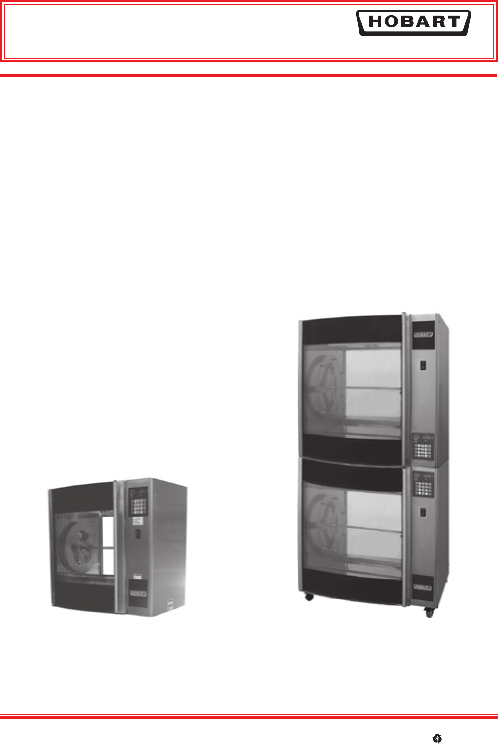
HRE SERIES
ELECTRIC ROTARY OVEN
701 S Ridge Avenue, Troy, OH 45374
1-888-4HOBART • www.hobartcorp.com
HRE SERIES ELECTRIC ROTARY OVEN
STANDARD FEATURES
■ Easy to Use Programmable Controls – up to
99 Programs
■ 4 Stage Cooking
■ NAFEM Protocol Controls
■ Large Curved, Tempered Glass Door
■ Double Pane Glass
■ Solid Back
■ Modular Construction
■ Single or Individual Connections
■ Removable Rotors, Spits and Drip Trays
■ Convection and Radiant Heat — Plus Self Basting
Action
■ Stainless Steel Interior
■ Stainless Steel Exterior
OPTIONS
❑ Double Pane Hinged Glass Back (Customer Side)
❑ Non-Stick Coated Interior
❑ Load/Unload Push Button (Customer Side)
ACCESSORIES
(Must be ordered separately — all models
shipped without spits)
HR7E:
❑ 7 Spits
❑ 7 V-Spits
❑ 7 Baskets
❑ 7 ThermoWave Spits
❑ 7 Four Position
Chicken Racks
❑ 7 Five Position
Chicken Racks
❑ Stand
❑ Handle Kit, Stand
❑ Handle Kit, Customer Door
❑ 4" Legs
❑ Stacking Kit
❑ Stacking Kit - Low Profile
❑ Low Profile Casters
❑ Spit Rack 7 x 2
MODEL
❑ HR5E — Single Section; 15-20 Chicken Capacity
❑ HR7E — Single Section; 28-35 Chicken Capacity
Specifications, Details and Dimensions on Inside and Back.
HR5E:
❑ 5 Spits
❑ 5 V-Spits
❑ 5 Baskets
❑ 5 Three Position
Chicken Racks
❑ Stacking Kit
❑ 4" Legs
HR7E Rotisserie Oven Technical Manual Page 3 of 80
701 S Ridge Avenue, Troy, OH 45374
1-888-4HOBART • www.hobartcorp.com
HRE SERIES
ELECTRIC ROTARY OVEN
Page 2 of 4 F-40096 – HRE Series Electric Rotary Oven
CASTER CONFIGURATION
Standard Stacking Kit: 2 rigid side to side casters on left; 2 locking swivel casters on right
Low Profile Stack Kit: 4 rigid front to back casters
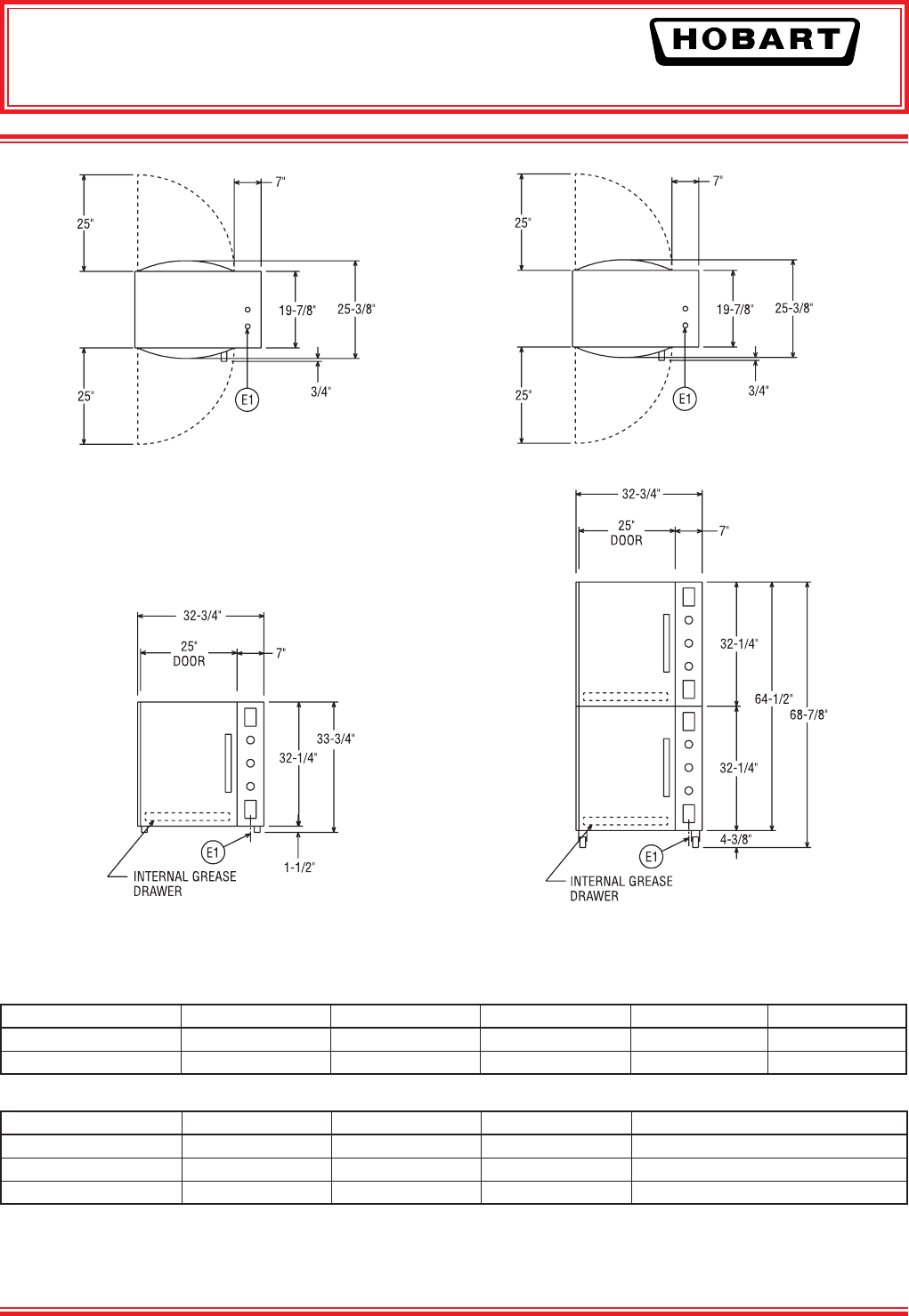
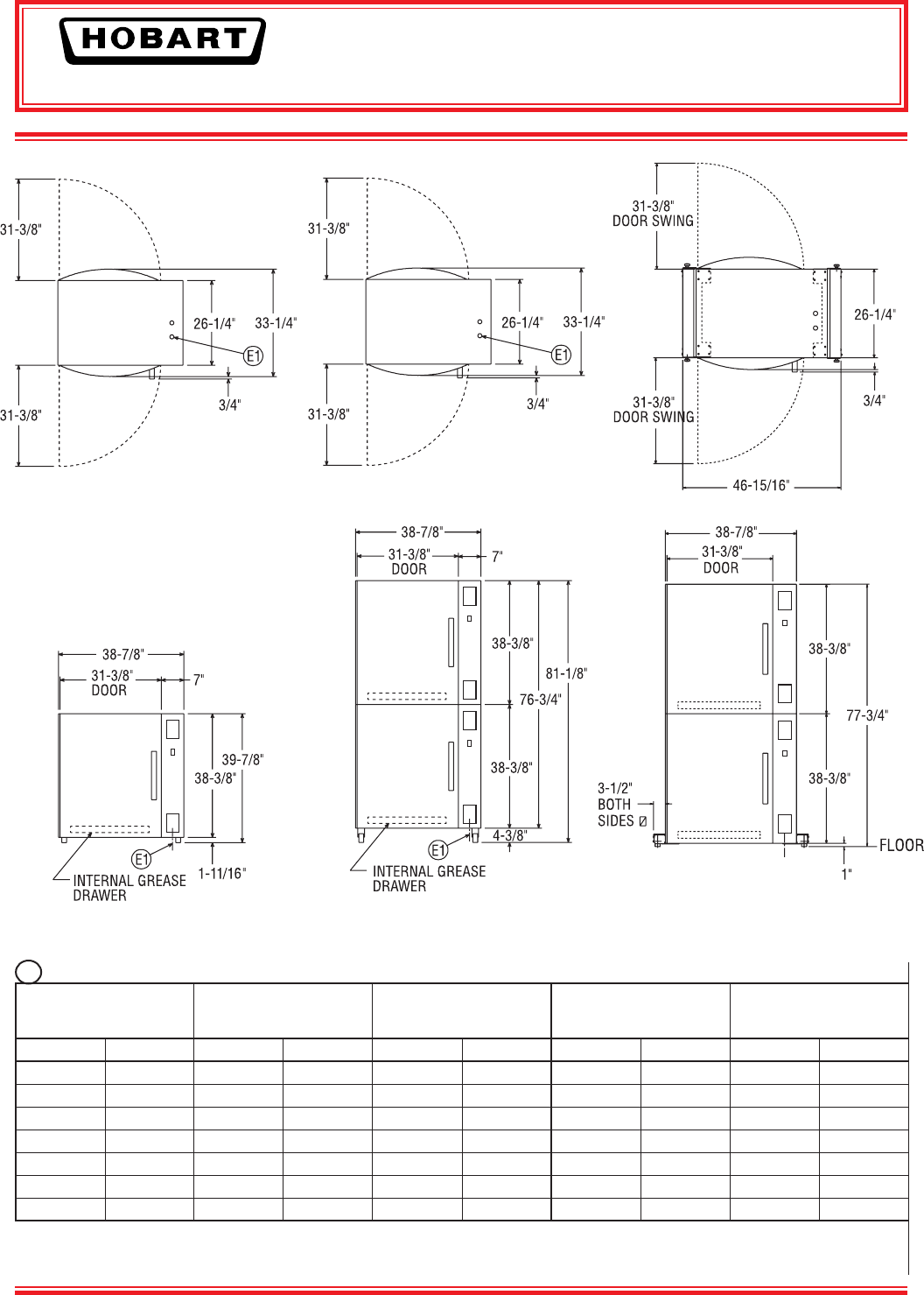
DIMENSIONS, WITHOUT LEGS OR CASTERS AND WEIGHTS:
MODEL DEPTH WIDTH HEIGHT NET WT. SHIPPING WT.
HR5E 253⁄8" 323⁄4" 321⁄4" 280 lbs. 335 lbs.
HR7E 331⁄4" 387⁄8" 383⁄8" 410 lbs. 465 lbs.
STACKED MODELS DIMENSIONS WITH CASTERS:
MODEL DEPTH WIDTH HEIGHT TYPE
HR5E + HR5E 253⁄8" 323⁄4" 687⁄8" STANDARD STACKING KIT
HR7E + HR7E 331⁄4" 387⁄8" 811⁄8" STANDARD STACKING KIT
HR7E + HR7E 331⁄4" 387⁄8" 773⁄4" LOW PROFILE STACKING KIT
HR5E ROTISSERIE HR5E ROTISSERIE with HR5E ROTISSERIE
USING STACKING KIT ACCESSORY
HR7E Rotisserie Oven Technical Manual Page 4 of 80
HRE SERIES
ELECTRIC ROTARY OVEN
701 S Ridge Avenue, Troy, OH 45374
1-888-4HOBART • www.hobartcorp.com
F-40096 – HRE Series Electric Rotary Oven Page 3 of 4
E1 ELECTRICAL:
50/60 HZ HR5E
HR5E/HR5E STACKED
MODELS USING SINGLE
POINT CONNECTION HR7E
HR7E/HR7E STACKED
MODELS USING SINGLE
POINT CONNECTION
VOLTAGE PHASE WATTAGE AMPERAGE WATTAGE AMPERAGE WATTAGE AMPERAGE WATTAGE AMPERAGE
208 1 6,000 26.9 12,000 53.8 9,300 42.8 N/A† N/A†
240 1 6,000 25.0 12,000 50.0 9,300 38.8 N/A† N/A†
208 3 6,000 15.5 12,000 31.0 9,300 24.7 18,600 49.4
240 3 6,000 14.4 12,000 28.8 9,300 22.4 18,600 44.8
220/380(4W) 3 6,000 8.4 12,000 16.8 9,300 12.9 18,600 25.8
230/400(4W) 3 6,000 8.7 12,000 17.4 9,300 13.4 18,600 26.9
240/415(4W) 3 6,000 9.0 12,000 18.0 9,300 14.1 18,600 28.2
Stacked units can be wired independently or can be wired with single point connection using the stacking kit accessory.
†Single point connection is not available for stacked HR7E/HR7E 1 phase units.
Full load amps measured at regulated voltage input.
HR7E ROTISSERIE with HR7E ROTISSERIE
USING LOW PROFILE STACKING
KIT ACCESSORY
HR7E ROTISSERIE HR7E ROTISSERIE with HR7E ROTISSERIE
USING STACKING KIT ACCESSORY
HR7E Rotisserie Oven Technical Manual Page 5 of 80
701 S Ridge Avenue, Troy, OH 45374
1-888-4HOBART • www.hobartcorp.com
Page 4 of 4 F-40096 – HRE Series Electric Rotary Oven
As continued product improvement is a policy of Hobart, specifi cations are subject to change without notice.
Printed On Recycled Paper
HRE SERIES
ELECTRIC ROTARY OVEN
F-40096 (REV. 2/06) LITHO IN U.S.A. (H-01)
SPECIFICATIONS:
HR7E/HR7E
shown with stacking kit accessory
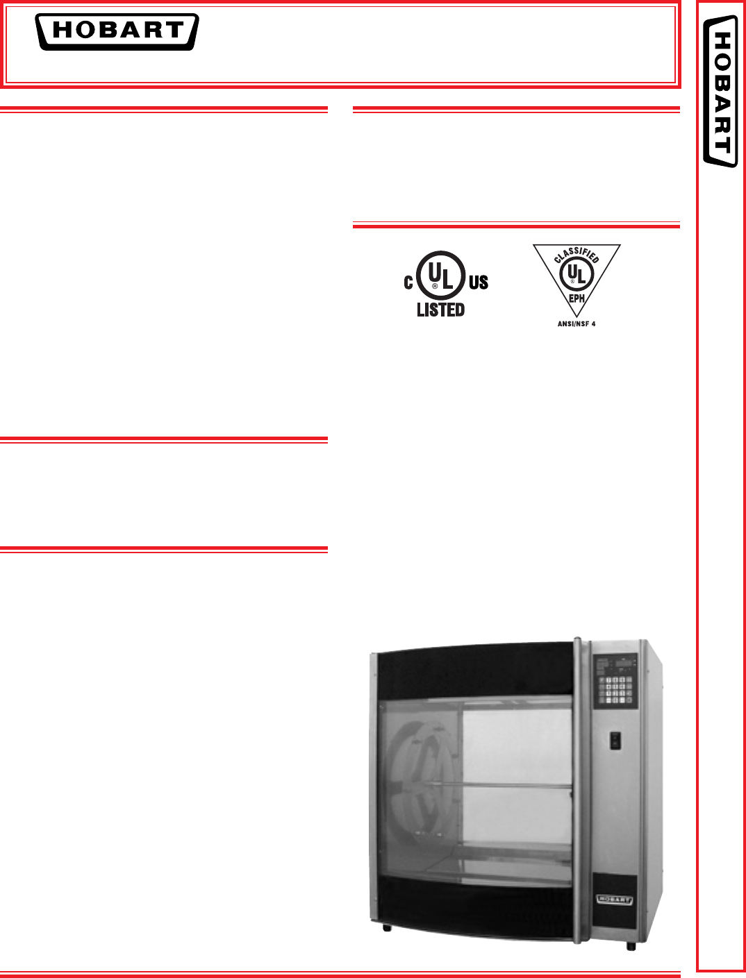
CAPACITY: HR5E: 20 chickens; HR7E: 35 chickens.
Units are standard with 111/16" legs. Stacked units are mounted
on nylon casters.
Top-mounted fans draw air from bottom of oven cavity over the
top mounted heating elements. Infrared heating lamps brown
product evenly on all sides.
Spit motor rotates at 2 RPM.
Stacked units can be wired independently or can be wired with
single point connection using the stacking kit accessory.
CONSTRUCTION: Outer shell is stainless steel. 1" Rockwool
insulation is applied to top and sides. Doors mounted on both
front and back feature large, full sized tempered double pane
glass for high visual impact. Each door swings open 180°.
Spits are easy to remove without the use of tools for product
removal and to facilitate cleaning. Oven interior is stainless steel
and non-stick coated. Drip trays slope downward to grease pan.
CONTROLS: Located on oven’s right front. Controls can be
moved from top to bottom and to customer side (for right hand
hinge operation).
Approx.
WEIGHT: Net. Wt. Ship Wt.
HR5E - Glass Back 280 335
HR7E - Glass Back 425 480
HR7E - Solid Back 410 465
(accessories shipped separately)
HR5E
HR7E Rotisserie Oven Technical Manual Page 6 of 80

HR7E ROTARY OVEN
NSTRUCTIONS
I
701 S. RIDGE AVENUE
TROY, OHIO 45374-0001
937 332-3000
www.hobartcorp.com
FORM 35511 (Feb. 2006)
MODEL HR5E & HR7E ROTARY OVENS
MODEL
HR7E
STAINLESS STEEL INTERIOR, GLASS BACK ML-132092
STAINLESS STEEL INTERIOR, SOLID BACK ML-132095
COATED INTERIOR, GLASS BACK ML-132093
COATED INTERIOR, SOLID BACK ML-132094
HR5E
STAINLESS STEEL INTERIOR, GLASS BACK ML-132096
COATED INTERIOR, GLASS BACK ML-132097
HR7E Rotisserie Oven Technical Manual Page 7 of 80

– 2 –
© HOBART 2006
TABLE OF CONTENT
GENERAL . . . . . . . . . . . . . . . . . . . . . . . . . . . . . . . . . . . . . . . . . . . . . . . . . . . . . . . . . . . 3
INSTALLATION . . . . . . . . . . . . . . . . . . . . . . . . . . . . . . . . . . . . . . . . . . . . . . . . . . . . . . . 4
Location . . . . . . . . . . . . . . . . . . . . . . . . . . . . . . . . . . . . . . . . . . . . . . . . . . . . . . . 4
Legs / Casters / Stand . . . . . . . . . . . . . . . . . . . . . . . . . . . . . . . . . . . . . . . . . . . . 4
Electrical Connections . . . . . . . . . . . . . . . . . . . . . . . . . . . . . . . . . . . . . . . . . . . . 4
Single Ovens / Stacked Ovens. . . . . . . . . . . . . . . . . . . . . . . . . . . . . . . . 4
Electrical Data HR5E, HR7E . . . . . . . . . . . . . . . . . . . . . . . . . . . . . . . . . 5
Before First Use . . . . . . . . . . . . . . . . . . . . . . . . . . . . . . . . . . . . . . . . . . . . . . . . . 6
Placing the Rotor in the Oven (HR5E) . . . . . . . . . . . . . . . . . . . . . . . . . . . . . . . 6
Placing the Rotor in the Oven (HR7E) . . . . . . . . . . . . . . . . . . . . . . . . . . . . . . . 7
OPERATION . . . . . . . . . . . . . . . . . . . . . . . . . . . . . . . . . . . . . . . . . . . . . . . . . . . . . . . . . 8
CONTROLS . . . . . . . . . . . . . . . . . . . . . . . . . . . . . . . . . . . . . . . . . . . . . . . . . . . . 8
Initial Startup . . . . . . . . . . . . . . . . . . . . . . . . . . . . . . . . . . . . . . . . . . . . . . . . 9
Power On . . . . . . . . . . . . . . . . . . . . . . . . . . . . . . . . . . . . . . . . . . . . . . . 9
Idle Mode . . . . . . . . . . . . . . . . . . . . . . . . . . . . . . . . . . . . . . . . . . . . . . . 9
Setting the Clock . . . . . . . . . . . . . . . . . . . . . . . . . . . . . . . . . . . . . . . . . 9
Changing Temperature Readings to Celsius . . . . . . . . . . . . . . . . . . . 9
Saving or Verifying a Cook Program (Program 1 – 9) . . . . . . . . . . . . . 10
Programmed Cooking (Program 1 – 9) . . . . . . . . . . . . . . . . . . . . . . . . . 12
Manual Cooking (Program 0) . . . . . . . . . . . . . . . . . . . . . . . . . . . . . . . . . 13
Holding Cycle (Silencing the 'End of Cycle' Alarm . . . . . . . . . . . . . . . . 14
Stopping a Cycle . . . . . . . . . . . . . . . . . . . . . . . . . . . . . . . . . . . . . . . . . . . . 14
Pausing a Cycle . . . . . . . . . . . . . . . . . . . . . . . . . . . . . . . . . . . . . . . . . . . . 14
Adding Cook Time. . . . . . . . . . . . . . . . . . . . . . . . . . . . . . . . . . . . . . . . . . 15
99 Program Feature . . . . . . . . . . . . . . . . . . . . . . . . . . . . . . . . . . . . . . . . 15
Operator ID Feature . . . . . . . . . . . . . . . . . . . . . . . . . . . . . . . . . . . . . . . . 15
Suggested Roasting Guidelines. . . . . . . . . . . . . . . . . . . . . . . . . . . . . . . . 16
Preparing, Tying & Spitting — Chickens on V-Spits . . . . . . . . . . . . 18
Spitting / Loading — HR5E . . . . . . . . . . . . . . . . . . . . . . . . . . . . . . . . 20
Spitting / Loading — HR7E . . . . . . . . . . . . . . . . . . . . . . . . . . . . . . . . 21
Loading (HR5E) . . . . . . . . . . . . . . . . . . . . . . . . . . . . . . . . . . . . . . . . 22
Loading (HR7E) . . . . . . . . . . . . . . . . . . . . . . . . . . . . . . . . . . . . . . . . 23
Personal Protective Equipment . . . . . . . . . . . . . . . . . . . . . . . . . . . . . . . . 24
Unloading Accessories From Oven . . . . . . . . . . . . . . . . . . . . . . . . . . . . 24
Emptying the Grease Drawer . . . . . . . . . . . . . . . . . . . . . . . . . . . . . . . . . 24
CLEANING . . . . . . . . . . . . . . . . . . . . . . . . . . . . . . . . . . . . . . . . . . . . . . . . . . . . 25
Cleaning — Grease Drawer and Oven Interior / Exterior . . . . . . . . . 25
Cleaning Stainless Steel Surfaces . . . . . . . . . . . . . . . . . . . . . . . . . . . . 26
Cleaning Guidelines for Nonstick Coated Surfaces . . . . . . . . . . . . . 26
Cleaning Quartz Lamps . . . . . . . . . . . . . . . . . . . . . . . . . . . . . . . . . . . . 27
Cleaning the Temperature Probe . . . . . . . . . . . . . . . . . . . . . . . . . . . . 27
Weekly Cleaning — HR5E Ovens . . . . . . . . . . . . . . . . . . . . . . . . . . . . 28
Weekly Cleaning — HR7E Oven With Rear Glass Door . . . . . . . . . 30
Weekly Cleaning — HR7E Oven With Solid Back . . . . . . . . . . . . . . 34
MAINTENANCE . . . . . . . . . . . . . . . . . . . . . . . . . . . . . . . . . . . . . . . . . . . . . . . . . . . . . 40
TROUBLESHOOTING . . . . . . . . . . . . . . . . . . . . . . . . . . . . . . . . . . . . . . . . . . . . . . . . 40
Service . . . . . . . . . . . . . . . . . . . . . . . . . . . . . . . . . . . . . . . . . . . . . . . . . . . . . . 40
HR7E Rotisserie Oven Technical Manual Page 8 of 80
– 3 –
Installation, Operation and Care of
MODEL HR5E & HR7E ROTARY OVENS
SAVE THIS MANUAL FOR FUTURE REFERENCE
GENERAL
The HR5E and HR7E Ovens are five-spit and seven-spit rotary ovens that feature a full view tempered
glass door and quartz lighting that promote visual appeal and stimulate customer interest. The solid
back model (HR7E only) is used when the oven is positioned against a wall. The glass back model
provides an identical rear glass for customer viewing; with the handle kit accessory the rear glass can
be used for pass-through operation. The HR5E and HR7E rotary ovens are available with stainless
steel or nonstick coated interior for ease of cleaning. The oven’s grease drawer has a drain valve for
elimination of excess fat; the grease drawer can be completely removed for cleaning. The oven
provides evenly cooked, appealingly roasted product with combination convection and radiant heat.
Only one type of accessory is intended to be used in the oven at a time. Do not mix accessory types.
HR5E ACCESSORIES
Type of Spit Qty Whole Chicken Capacity
V-Spit 5 15 - 20
Meat Fork Spit 5 15 - 20
3-Position Rack 5 15
Baskets 5 NA
HR7E ACCESSORIES
Type of Spit Qty Whole Chicken Capacity
V-Spit 7 21 - 28
Thermo-Wave Spit 7 21 - 28
Meat Fork Spit 7 28 - 35
5-Position Rack 7 35
4-Position Rack 7 28
Baskets 7 NA
HR7E Rotisserie Oven Technical Manual Page 9 of 80

– 4 –
ELECTRICAL CONNECTIONS
WARNING: ELECTRICAL AND GROUNDING CONNECTIONS MUST COMPLY WITH THE
APPLICABLE PORTIONS OF THE NATIONAL ELECTRICAL CODE AND / OR OTHER LOCAL
ELECTRICAL CODES.
WARNING: DISCONNECT ELECTRICAL POWER SUPPLY TO THE MACHINE AND FOLLOW
LOCKOUT / TAGOUT PROCEDURES.
Single Oven
Access the electrical connection point by removing the side panel where the controls are located. Make
sure that the electrical power supply agrees with the specifications on the oven data plate and complies
with the wiring diagram located on the inside of the side panel.
Stacked Ovens
Refer to the Stacking Kit Installation Instruction included with the stacking kit.
Attach the power supply conduit to bottom of oven. Connect the power supply to the terminal block
as shown on the wiring diagram. Inspect and check all wiring and terminal connections for tightness
and proper routing away from any moving parts or pinch points. Carefully replace side panels.
INSTALLATION
Immediately after unpacking the oven, check for possible shipping damage. If the oven is found to be
damaged, save the packaging material and contact the carrier within 15 days of delivery.
Prior to installation, test the electrical service to assure that it agrees with the specifications on the
machine data plate located behind the left-hand hinged door.
LOCATION
The oven must be installed on a level surface. The installation location must allow adequate
clearances for servicing and for proper operation). Minimum clearance for sides and back is 0.0"
(0.0 cm). The rotary oven is not recommended for installation in high-moisture environments such as
meat rooms or where high pressure cleaning is used.
LEGS / CASTERS / STAND
Each oven is furnished on 111⁄16" (4.3 cm) legs. Casters are included with the stacking kit accessory. An
oven stand is available (HR7E only); the oven is mounted on top of the stand. Tethering is required
for units on a stand or stacked when equipped with casters. Refer to the Stand or Stacking Kit
Instructions.
HR7E Rotisserie Oven Technical Manual Page 10 of 80
– 5 –
ELECTRICAL DATA
HR5E HR5E / HR5E *
VOLTAGE HZ PHASE AMPERAGE WATTAGE AMPERAGE
208(2W) 50/60 1 26.9 6000 53.8
240(2W) 50/60 1 25.0 6000 50.0
208(3W) 50/60 3 15.5 6000 31.0
240(3W) 50/60 3 14.4 6000 28.8
220/380(4W) 50/60 3 8.4 6000 16.8
230/400(4W) 50/60 3 8.7 6000 17.4
240/415(4W) 50/60 3 9.0 6000 18.0
Full load Amperage is measured at regulated voltage input.
* Stacked units can be wired independently or with single point connection using the stacking kit accessory.
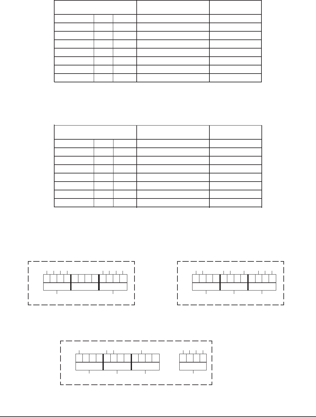
SINGLE PHASE CONNECTION — 208V or 240V
TB1
12345678 9101112
123
L1 L2 L3
12331745661
(3W) THREE PHASE CONNECTION — 208V or 240V
TB1
12345678 9101112
123
L1 L2 L3
1234 3317495661
(4W) THREE PHASE CONNECTION — 220/380, 230/400, 240/415 VOLT
TB1
12345678 9101112
123
L1 L2 L3
134331795
1234
1
N
24661
TB4
ELECTRICAL DATA
HR7E HR7E / HR7E *
VOLTAGE HZ PHASE AMPERAGE WATTAGE AMPERAGE
208(2W) 50/60 1 42.8 9300 NA**
240(2W) 50/60 1 38.8 9300 NA**
208(3W) 50/60 3 24.7 9300 49.4
240(3W) 50/60 3 22.4 9300 44.8
220/380(4W) 50/60 3 12.9 9300 25.8
230/400(4W) 50/60 3 13.4 9300 26.8
240/415(4W) 50/60 3 14.1 9300 28.2
Full load Amperage is measured at regulated voltage input.
* Stacked units can be wired independently or with single point connection using the stacking kit accessory.
** Single point connection is not available for stacked HR7E / HR7E single phase units.
HR7E Rotisserie Oven Technical Manual Page 11 of 80
– 6 –
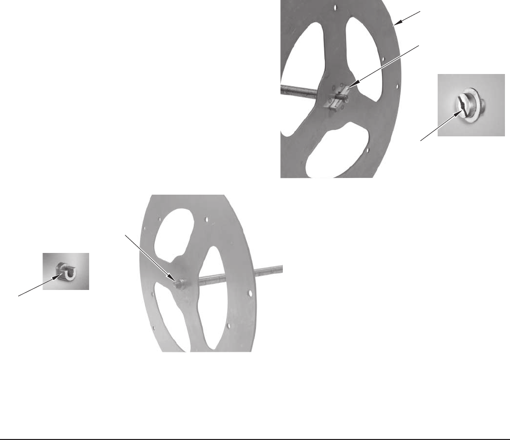
PLACING THE ROTOR IN THE OVEN (HR5E)
The rotor must properly engage with the drive mechanism. Orient the rotor so that the end plate with
the drive pin is aligned with the slotted drive hub.
STEP 1: Place the drive end of the rotor shaft into
the slotted drive hub (Fig. 1).
STEP 2: Place the rotor shaft on the support
bearing on the non-drive side of the oven
(Fig. 2).
Fig. 1
Fig. 2
BEFORE FIRST USE
WARNING: DISCONNECT ELECTRICAL POWER SUPPLY TO THE MACHINE AND FOLLOW
LOCKOUT / TAGOUT PROCEDURES BEFORE CLEANING OR SERVICING.
Oven must be burned in to release any odors that might result from heating the new oven surfaces.
1. Clean oven and accessories, both inside and outside. Refer to CLEANING, pages 25 — 39, for
further instructions.
2. Operate oven at maximum temperature setting of 482°F (250°C) for 45 minutes. Smoke with an
unpleasant odor will normally be given off during this burn-in period.
DRIVE SIDE
ROTOR
DRIVE PIN
SLOTTED DRIVE HUB
NON-DRIVE SIDE
SUPPORT BEARING
ROTOR SHAFT
HR7E Rotisserie Oven Technical Manual Page 12 of 80
– 7 –
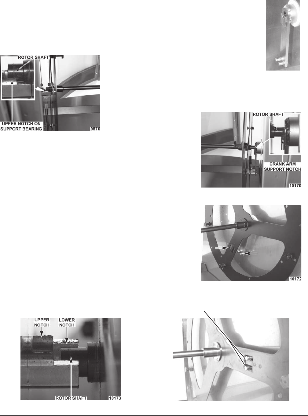
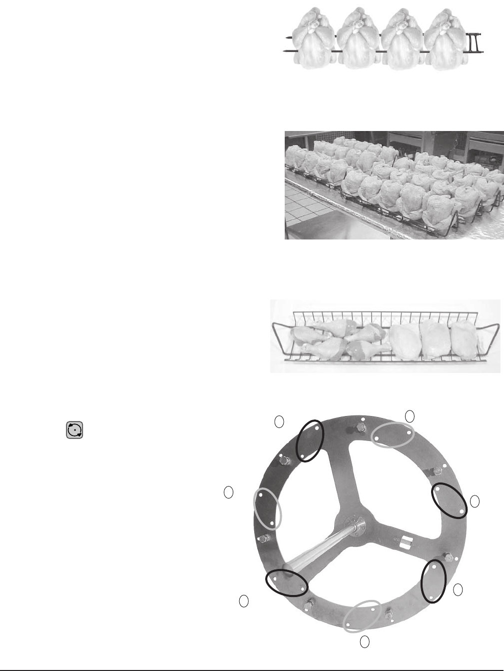
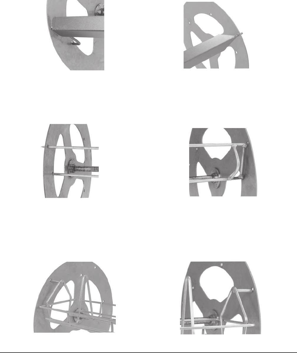
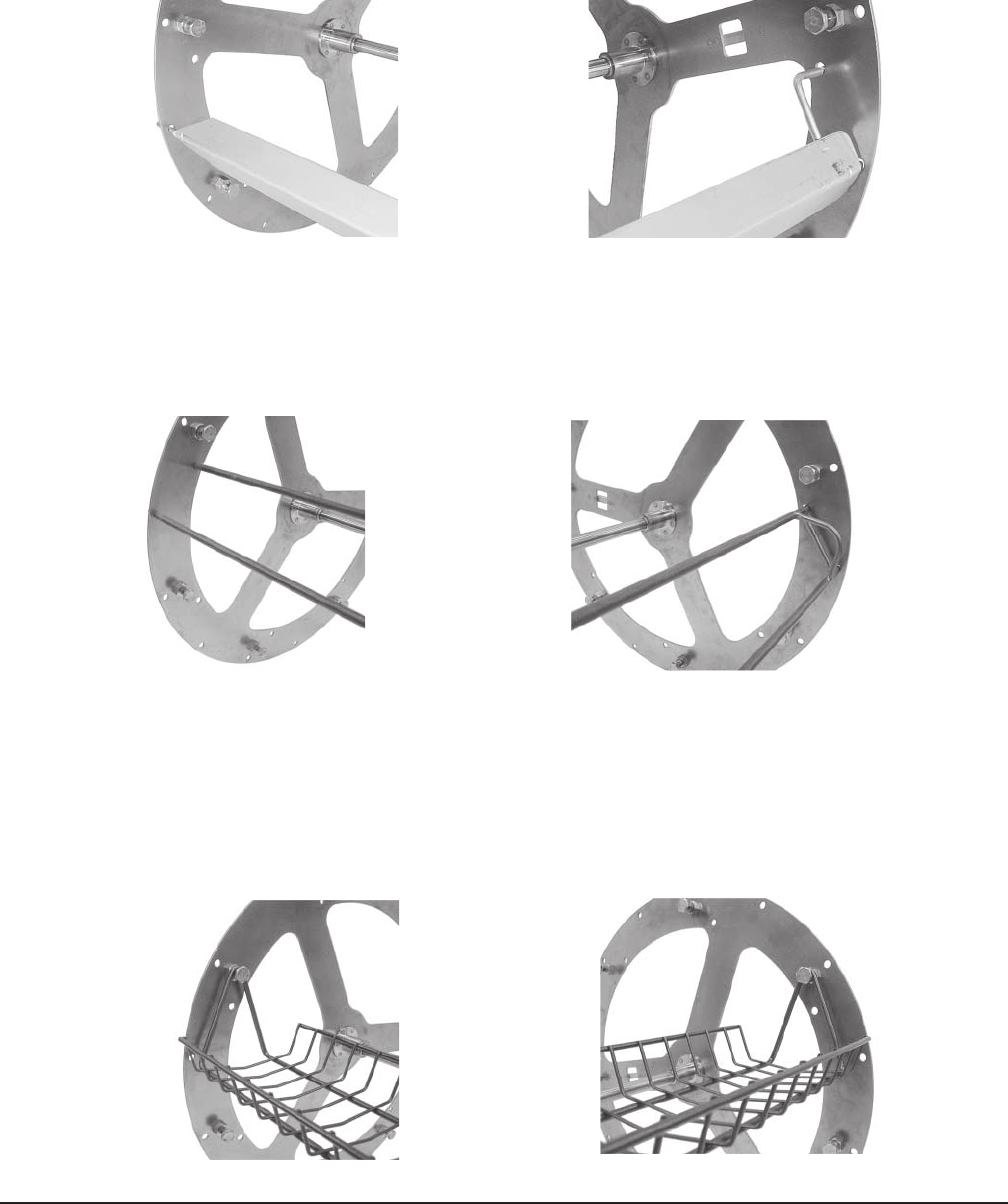
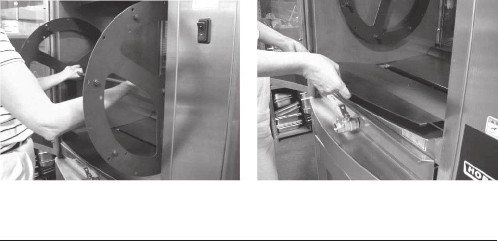
PLACING THE ROTOR IN THE OVEN (HR7E)
The rotor must properly engage with the drive mechanism. Orient the rotor so that
the end plate with square drive slots is on the same side of the oven as the drive arm.
STEP 1: Stop the drive arm so it is in the down position (Fig. 3).
Fig. 3
Fig. 4
Fig. 5
Fig. 6
Fig. 8Fig. 7
STEP 3: Place the drive side of the rotor shaft on the drive arm
support notch (Fig. 5).
STEP 4: Turn the rotor, lining up the square drive slots on the
rotor end plate with the pins on the drive arm (Fig.6).
STEP 5: Nudge rotor toward the drive arm. Non-drive end of
rotor shaft falls into the lower portion of support
bearing hub (Fig. 7). Drive end of rotor shaft is
driven into center hole of drive arm.
STEP 6: Rotor is now in normal operating position (Fig. 8).
STEP 2: Place the rotor shaft onto upper notch of support
bearing on the non-drive side of the oven (Fig. 4).
MOTOR DRIVE PINS THROUGH DRIVE
SLOTS ON ROTOR END PLATE
HR7E Rotisserie Oven Technical Manual Page 13 of 80
– 8 –
OPERATION
WARNING: HOT GLASS, GREASE AND PARTS CAN CAUSE BURNS. USE CARE WHEN
OPERATING AND SERVICING THE OVEN.
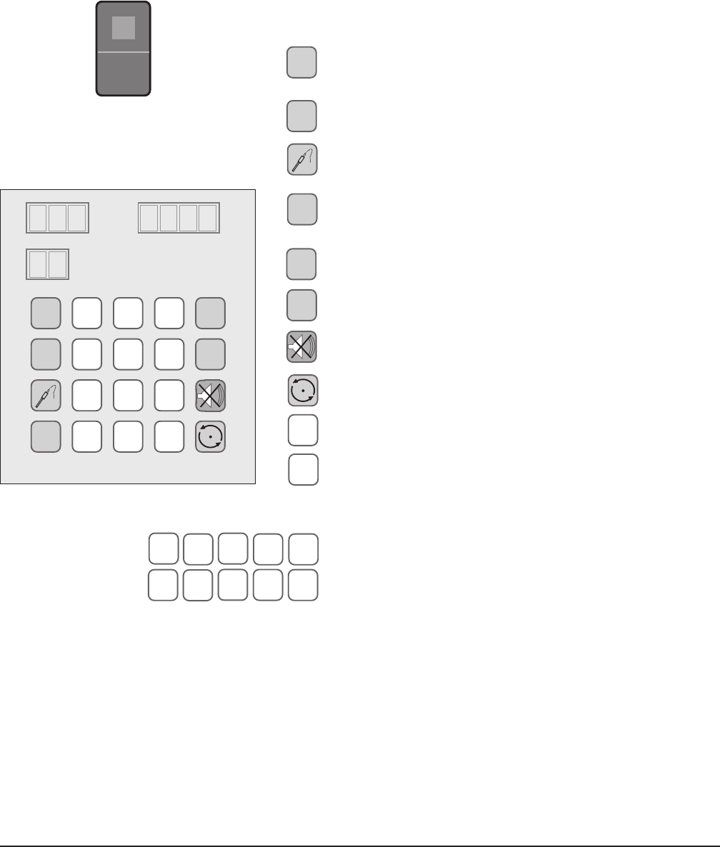
CONTROLS (Fig. 9)
MAIN POWER SWITCH — Turns oven and controls on or off.
PROGRAM — Enters program mode to modify a cook
program; press P for 3 seconds.
CLOCK — Sets the clock for time of day.
PROBE — Displays temperature, external meat
probe.
ADD 5 MIN — Adds 5 minutes to current step of program
in process each time it is pressed.
START — Begins cooking cycle.
STOP — Stops cycle.
SILENCE — Silences beeper.
ROTATE — Rotor on/off, pauses cooking cycle.
CLEAR — Clears time or temperature entry .
ENTER — Accepts time or temperature entry.
0 — 9 — Enter numeric value(s).
t— Service use only.
P
CLOCK
ADD
5 MIN
START
STOP
CLEAR
ENTER
041 23
567 8 9
Fig. 9
P789
456
123
0ENTERCLEAR
START
CLOCK
ADD
5 MIN
STOP
TEMPERATURE TIME
•F
•C
t
PROGRAM
•AM
•PM
STEP
4•
3•
2•
1•
ON
OFF
HR7E Rotisserie Oven Technical Manual Page 14 of 80

– 9 –
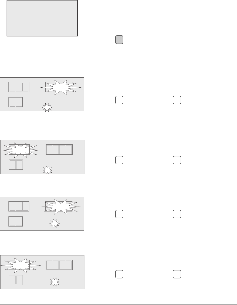
INITIAL STARTUP
Power On
Toggle the Main Power switch on the front panel of the oven to the ON position; the red indicator light
on the switch comes on (Fig. 9).
Idle Mode
When the oven is first turned on, the display shows the time of day and the last operated program
number. Any programmed steps for the selected program are indicated by illuminated step LEDs. The
interior oven lights are off.
Setting the Clock
The oven's clock is preprogrammed for 12-hour operation as standard. The oven can be reprogrammed
for 24-hour operation by your local Hobart Service office.
Begin from idle mode.
To set the time of day, press
CLOCK
.
The time display goes blank.
The AM or PM light blinks.
• Enter the time of day (HH:MM) using the number keys.
• Press
CLOCK
to toggle A.M. or P.M. (not necessary if clock
is programmed for 24-hour operation).
• Press
ENTER
to accept a valid entry. The control returns to
idle mode.
• If a nonvalid value such as 10:95 is in the time display
when
ENTER
is pressed, the beeper sounds twice and the
time display goes blank.
Changing Temperature Readings to Celsius
The oven is preprogrammed for temperatures to read in Fahrenheit degrees as standard. The oven
can be reprogrammed for Celsius temperature readings by your local Hobart Service office.
P789
456
123
0ENTERCLEAR
START
CLOCK
ADD
5 MIN
STOP
TEMPERATURE TIME
F
•C
t
PROGRAM
AM
•PM
STEP
4•
3•
2o
1o
P0
9:25
HR7E Rotisserie Oven Technical Manual Page 15 of 80
– 10 –
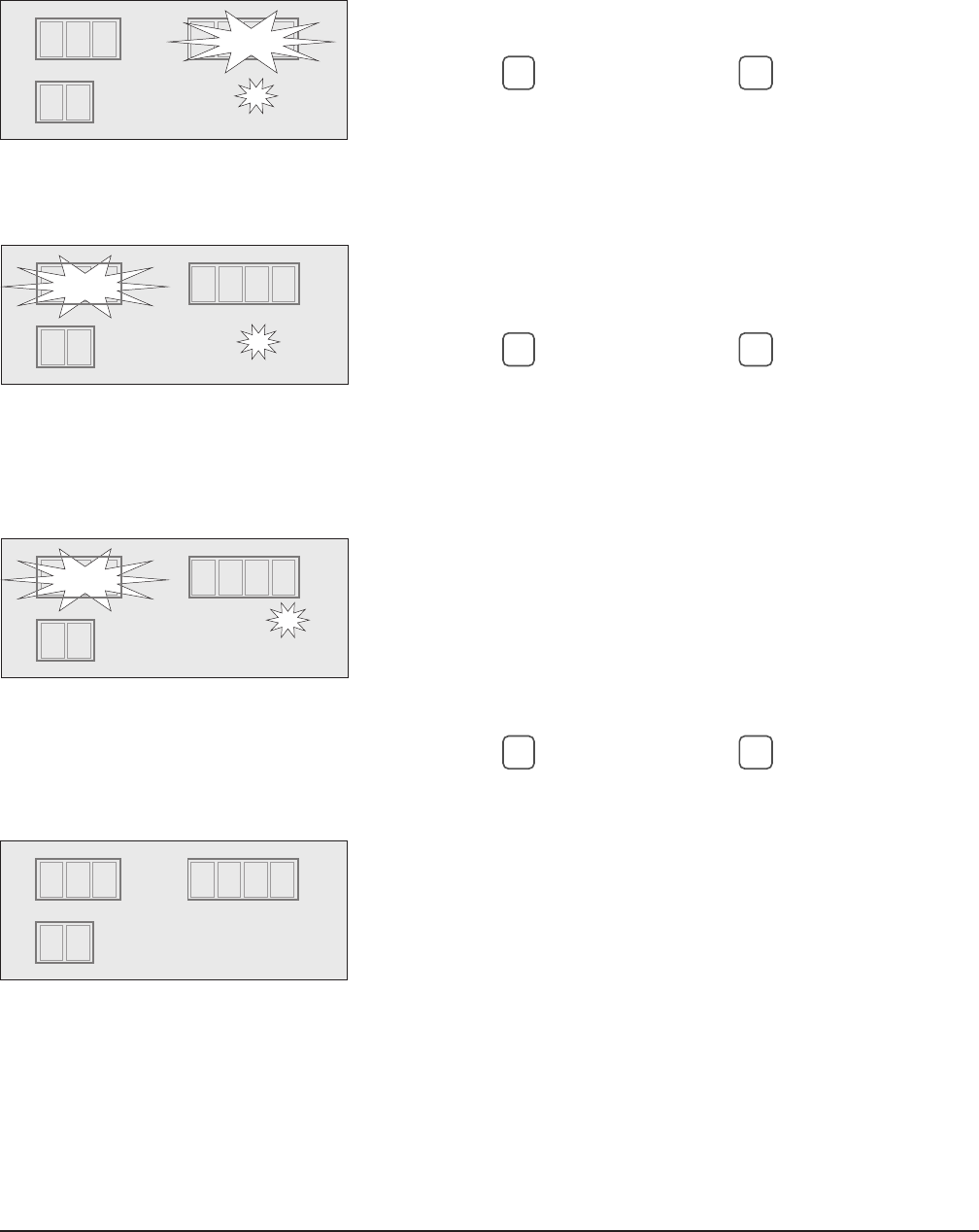
SAVING OR VERIFYING A COOK PROGRAM (PROGRAM 1 – 9)
Begin from Idle Mode.
Program display shows last operated program (0 – 9).
• Select a program (1 – 9).
Program 0 is Manual Mode and cannot be saved into
memory.
• Press
P
for 3 seconds to enter programming mode.
The program display shows the program/number being
modified or verified (1 – 9).
Cooking 'Step 1' LED is lit.
Time display blinks.
• Enter the desired cook time from 0:01 (1 minute) to 6:00
(6 hours).
• Press
ENTER
to accept (or, press CLEAR to void and reenter).
An invalid entry produces a double beep.
Entering 0:00 for the time turns step 1 off and skips to
step 2.
Temperature display blinks.
• Enter the desired cook temperature from 180 to 482 (degrees
Fahrenheit).
• Press
ENTER
to accept (or, press CLEAR to void and reenter).
An invalid entry produces a double beep.
Cooking 'Step 2' LED is lit.
Time display blinks.
• Enter the desired cook time from 0:01 (1 minute) to 6:00
(6 hours).
• Press
ENTER
to accept (or, press CLEAR to void and reenter).
An invalid entry produces a double beep.
Entering 0:00 for the time turns step 2 off and skips to
step 3.
Temperature display blinks.
• Enter the desired cook temperature from 180 to 482 (degrees
Fahrenheit).
• Press
ENTER
to accept (or, press CLEAR to void and reenter).
An invalid entry produces a double beep.
TEMPERATURE TIME
F
•C
t
PROGRAM
•AM
•PM
STEP
P1
0:05
425
4•
3o
2
1
TEMPERATURE
F
•C
t
PROGRAM
P1
0 AM
•PM
STEP
TIME
0:05
4•
3o
2
1
TEMPERATURE TIME
F
•C
t
PROGRAM
•AM
•PM
STEP
P1
375
4•
3o
2o
1
EXAMPLE PROGRAM
Temperature Time
Step 1 375 1:20
Step 2 425 0:05
Step 3 325 0:05
Step 4 200 HOLd
TEMPERATURE
F
•C
t
PROGRAM
P1
0 AM
•PM
STEP
TIME
1:20
4•
3o
2o
1
1:20
HR7E Rotisserie Oven Technical Manual Page 16 of 80
– 11 –
Cooking 'Step 3' LED is lit.
Time display blinks.
• Enter the desired cook time from 0:01 (1 minute) to 6:00
(6 hours).
• Press
ENTER
to accept (or, press CLEAR to void and reenter).
An invalid entry produces a double beep.
Entering 0:00 for the time turns step 3 off and skips to
step 4.
Temperature display blinks.
• Enter the desired cook temperature from 180 to 482
(degrees Fahrenheit).
• Press
ENTER
to accept (or, press CLEAR to void and reenter).
An invalid entry produces a double beep.
HOLd 'Step 4' LED is lit.
Time displays HOLd. 'HOLd' time is infinite and cannot be
set.
Temperature display blinks.
• Enter the desired Hold temperature from 140 to 230
(degrees Fahrenheit).
An invalid entry produces a double beep.
An entry of 000 for the temperature turns HOLd off.
• Press
ENTER
to accept (or, press CLEAR to void and reenter).
An invalid entry produces a double beep.
The controller returns to Idle Mode, any programmed steps
for the selected program are indicated by illuminated LEDs.
Step 1 LED is lit – indicates cook step 1 is programmed.
Step 2 LED is lit – indicates cook step 2 is programmed.
Step 3 LED is lit – indicates cook step 3 is programmed.
Step 4 LED is lit – indicates HOLd, step 4, is programmed.
No Step LEDs are lit — program is cleared.
TEMPERATURE
F
•C
t
PROGRAM
P1
0 AM
•PM
STEP
TIME
0:05
4•
3
2o
1
TEMPERATURE TIME
F
•C
t
PROGRAM
•AM
•PM
STEP
P1
0:05325
4•
3
2o
1
TEMPERATURE TIME
F
•C
t
PROGRAM
•AM
•PM
STEP
P1
HOLd
200
4
3
2
1
TEMPERATURE TIME
F
•C
t
PROGRAM
AM
•PM
STEP
4
3
2
1
P1
9:30
HR7E Rotisserie Oven Technical Manual Page 17 of 80

– 12 –
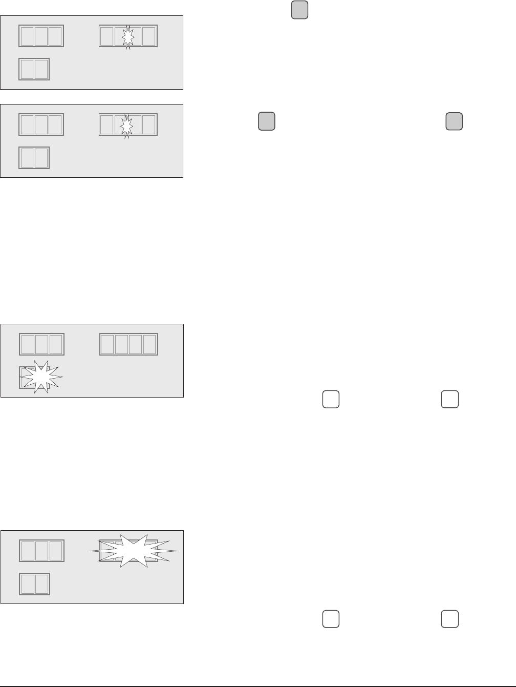
PROGRAMMED COOKING (Program 1 – 9)
Begin from Idle Mode.
The Program display shows the last operated
program (0 – 9).
• Select a saved cook program (1 – 9).
Any programmed steps for the selected program
are indicated by lit step LEDs.
• Press
START
to run a preprogrammed cook cycle.
While running a cooking program . . .
The controller displays the number of the program
in operation.
The LED for the cook step currently in process
blinks.
The temperature setting of the cook step in process
displays.
The total combined cook time (for all programmed
steps) displays. The time colon blinks to indicate
time is counting down.
Both oven lights come on (one light will cycle on
and off with the thermostat's demand for heat).
Heaters and fans come on.
TEMPERATURE TIME
F
•C
t
PROGRAM
AM
•PM
STEP
P1
9:30
4
3
2
1
TEMPERATURE TIME
F
•C
t
PROGRAM
•AM
•PM
STEP
1
375 1:30
4•
3o
2o
1
HR7E Rotisserie Oven Technical Manual Page 18 of 80
– 13 –
MANUAL COOKING (Program 0) Begin from Idle Mode.
The Program display shows the last operated program (0 – 9).
• Select manual mode by selecting program 0: [0, ENTER].
Cook Step 1 LED is lit. Time display blinks.
• Enter the desired cook time from 0:01 (1 minute) to 6:00
(6 hours).
• Press
ENTER
to accept (or, press
CLEAR
to void and reenter).
An invalid entry produces a double beep.
An entry of 0:00 for the time clears manual mode settings
and returns contol to idle mode.
Temperature display blinks.
• Enter the desired cook temperature from 180 to 482
(degrees Fahrenheit).
• Press
ENTER
to accept (or, press CLEAR to void and reenter).
An invalid entry produces a double beep.
HOLd, Step 4 LED, is lit. HOLd displays in the Time display.
(Steps 2 and 3 are not available in manual mode.) HOLd
time is infinite and cannot be set.
Temperature display blinks.
• Enter the desired HOLd temperature from 140 to 230
degrees Fahrenheit.
An invalid entry produces a double beep.
An entry of 000 for the temperature turns HOLd off.
• Press
ENTER
to accept (or, press CLEAR to void and reenter).
An invalid entry produces a double beep.
Controller returns to Idle Mode, Manual Mode 'step' LEDs are lit.
If Step 1 LED is lit — it indicates Cook only.
If Step 1 & Step 4 LEDs are lit — it indicates Cook & Hold.
If no Step LEDs are lit — it indicates Manual Mode is
cleared and that no steps have been entered.
Press
START
to run Manual Cook cycle (Program 0).
While running the manual cook cycle . . .
The controller displays program number 0.
The LED for the cook step currently in process blinks.
The cook temperature of the cook step in process displays.
The cook time displays and begins to count down.
Both oven lights come on (one of them cycles on and off).
Heaters and Fans come on.
TEMPERATURE TIME
F
•C
t
PROGRAM
AM
•PM
STEP
P04
3
2
1
1:30
0
TEMPERATURE TIME
F
•C
t
PROGRAM
AM
•PM
STEP
P0
375 1:30
4
3
2
1
TEMPERATURE TIME
F
•C
t
PROGRAM
AM
•PM
STEP
P04
3
2
1
9:30
TEMPERATURE TIME
F
•C
t
PROGRAM
•AM
•PM
STEP
4
3
2
1
0
HOLd
200
TEMPERATURE TIME
F
•C
t
PROGRAM
AM
•PM
STEP
P04
3
2
1
1:30
375
HR7E Rotisserie Oven Technical Manual Page 19 of 80
– 14 –
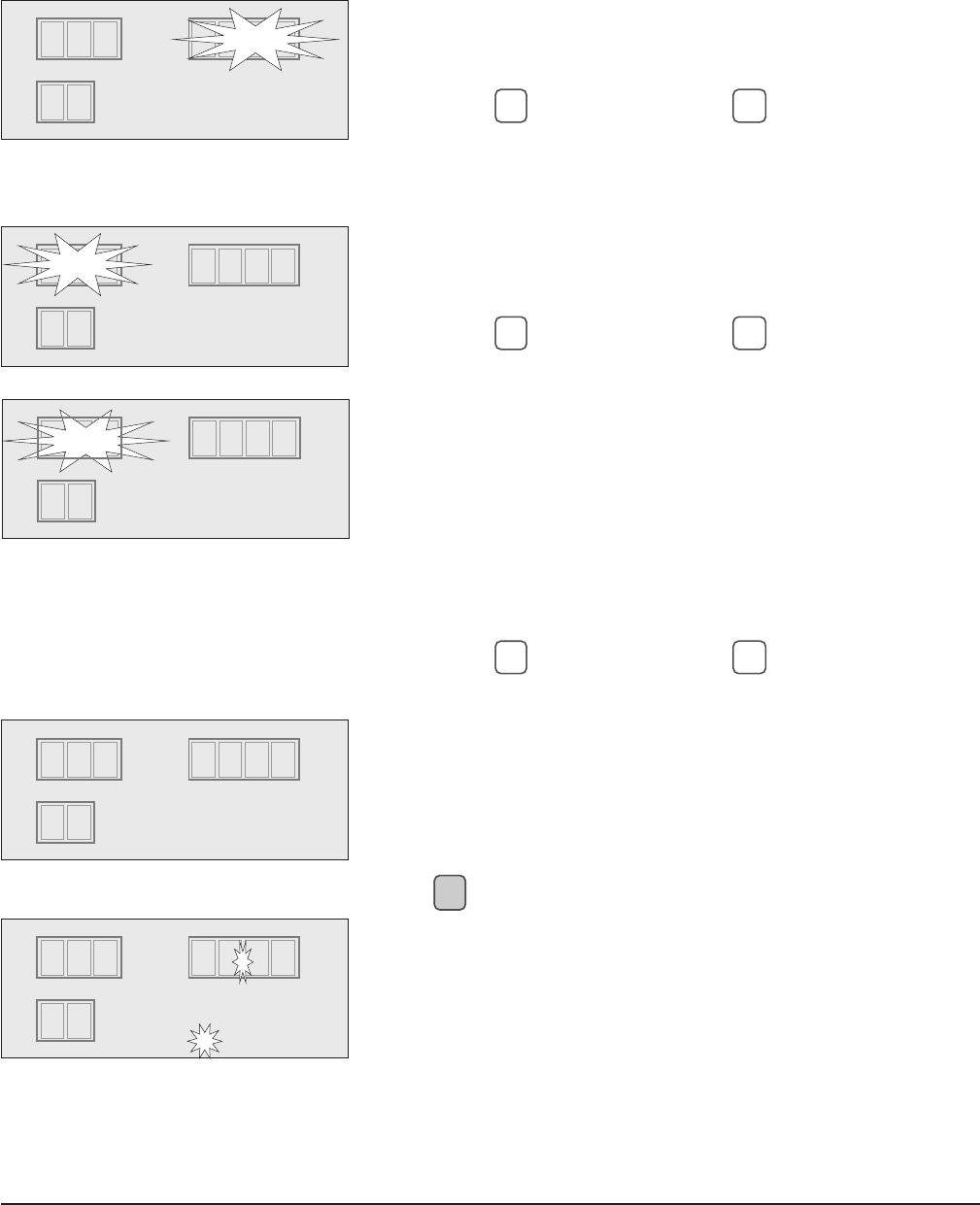
HOLDING CYCLE (SILENCING THE 'END OF CYCLE' ALARM)
After a cook cycle has been completed, the beeper sounds
and the oven automatically executes the Hold cycle (Step 4
of the cooking program).
The Hold cycle will not execute if it was programmed 'off',
using Hold Temp = 000.
• Press to silence the beeper.
• Program displays "H" to indicate that the oven is in
a Hold cycle.
• The oven retains heat during a Hold cycle. Avoid
overcooking by unloading when cooking is done.
STOPPING A CYCLE During a Cook or Hold cycle,
• Press
STOP
to stop the cycle. The lights, fan and
heaters turn off and the controller returns to Idle
Mode.
If
STOP
is pressed after a cook cycle has been
completed, the oven will not execute the Hold
cycle.
PAUSING A CYCLE During a Cook or Hold cycle,
• Press to pause the cycle.
The Time and Temperature displays blink.
Controller stops counting down. Heaters and Fan
turn off. Interior heat lamp(s) stay on.
The controller beeps a reminder alarm if the cycle
has been paused for over 3 minutes.
• Press to restart a cycle.
TEMPERATURE TIME
F
•C
t
PROGRAM
•AM
•PM
STEP
4
3
2
1
11:05
1
TEMPERATURE TIME
F
•C
t
PROGRAM
•AM
•PM
STEP
4
3
2o
1
0:00
325
1
TEMPERATURE TIME
F
•C
t
PROGRAM
AM
•PM
STEP
4
3
2o
1
11:00
200
H
TEMPERATURE TIME
F
•C
t
PROGRAM
•AM
•PM
STEP
4•
3
2o
1
1
1:29
425
HR7E Rotisserie Oven Technical Manual Page 20 of 80
– 15 –
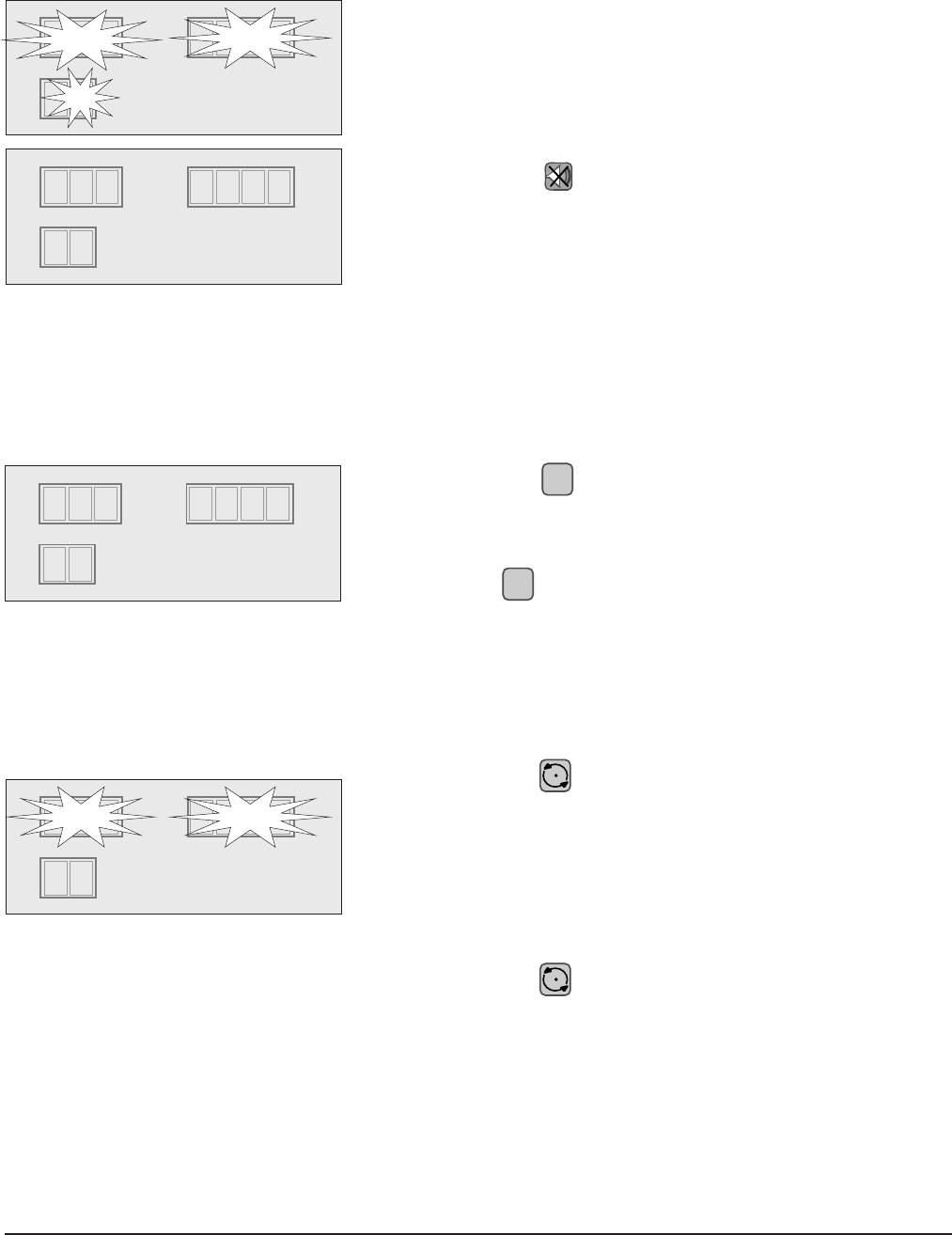
ADDING COOK TIME
• Press
ADD
5 MIN
during a cooking cycle to add 5 minutes
of cook time to the current step of the program in
process. Press during the end of cycle buzzer or
during Hold cycle to add 5 minutes of cook time to
the last step of the last operated program. Press
multiple times to add as much as desired up to a
maximum total cook time of 6 hours.
•
ADD
5 MIN
is not active in Idle Mode after
STOP
has been
pressed.
99 PROGRAM FEATURE
The oven is preprogrammed with 9 programs as standard. The oven can be reprogrammed to enable
all 99 programs by your local Hobart Service office.
The Program display shows the last operated
program (0 – 99).
• To select a program, enter the desired
program number from 0 to 99.
• Program display flashes.
• Press
ENTER
to accept (or, press
CLEAR
to void and
reenter).
OPERATOR ID FEATURE
The oven is preprogrammed with Operator ID "off" as standard. The oven can be reprogrammed to
enable Operator ID "on" by your local Hobart Service office.
After main power switch is toggled on. . .
Temperature displays "Id" and Time display blinks.
• Enter Operator ID number from from 0 to
9999.
• Press
ENTER
to accept (or, press CLEAR to void and
reenter).
The control returns to idle mode.
TEMPERATURE TIME
F
•C
t
PROGRAM
•AM
•PM
STEP
4•
3
2o
1
1
325
TEMPERATURE TIME
F
•C
t
PROGRAM
•AM
•PM
STEP
4•
3
2o
1
1
325
0:0 5
0:1 0
TEMPERATURE TIME
F
•C
t
PROGRAM
•AM
•PM
STEP
4
3
2o
1
9:30
325
1
TEMPERATURE TIME
F
•C
t
PROGRAM
•AM
•PM
STEP
4
3
2o
1
0
3Id
HR7E Rotisserie Oven Technical Manual Page 21 of 80
– 16 –
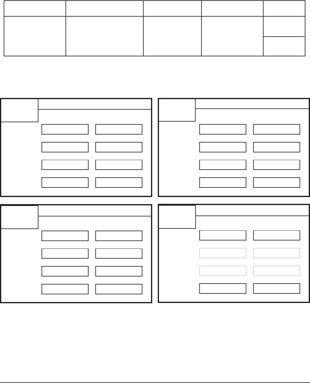
SUGGESTED ROASTING GUIDELINES
The suggested cooking times and temperatures in the table may require adjustment for proper
doneness depending on initial product temperature, weight, size, shape and other factors.
STEP 1
STEP 2
STEP 3
STEP 4
TEMPERATURE TIME
PROGRAM #
STEP 1
STEP 2
STEP 3
STEP 4
TEMPERATURE TIME
STEP 1
STEP 2
STEP 3
STEP 4
TEMPERATURE TIME
Entering Recipe Data
The recipe cards, below, are provided to allow you to pencil in your own cooking recipe(s).
STEP 1
STEP 2
STEP 3
STEP 4
TEMPERATURE TIME
(HOLD) (HOLD)
(HOLD) (HOLD)
PROGRAM #
PROGRAM # PROGRAM #
Oven Cook Time Final Internal Capacity
Product Temperature Setting HH:MM Temperature
Chicken, Whole, 350 – 375 °F 1:10 to 1:30 180 – 185 °FHR7E
3.0 — 3.5 lb. (177 – 195 °C) (82 – 85 °C) 21 – 35
(1.4 — 1.6 kg)HR5E
15 – 20
HR7E Rotisserie Oven Technical Manual Page 22 of 80
– 17 –
STEP 1
STEP 2
STEP 3
STEP 4
TEMPERATURE TIME
STEP 1
STEP 2
STEP 3
STEP 4
TEMPERATURE TIME
STEP 1
STEP 2
STEP 3
STEP 4
TEMPERATURE TIME
STEP 1
STEP 2
STEP 3
STEP 4
TEMPERATURE TIME
STEP 1
STEP 2
STEP 3
STEP 4
TEMPERATURE TIME
STEP 1
STEP 2
STEP 3
STEP 4
TEMPERATURE TIME
STEP 1
STEP 2
STEP 3
STEP 4
TEMPERATURE TIME
STEP 1
STEP 2
STEP 3
STEP 4
TEMPERATURE TIME
(HOLD)
(HOLD)
(HOLD)
(HOLD)
(HOLD)
(HOLD)
(HOLD)
(HOLD)
PROGRAM #
PROGRAM #
PROGRAM #
PROGRAM # PROGRAM #
PROGRAM #
PROGRAM #
PROGRAM #
HR7E Rotisserie Oven Technical Manual Page 23 of 80
– 18 –
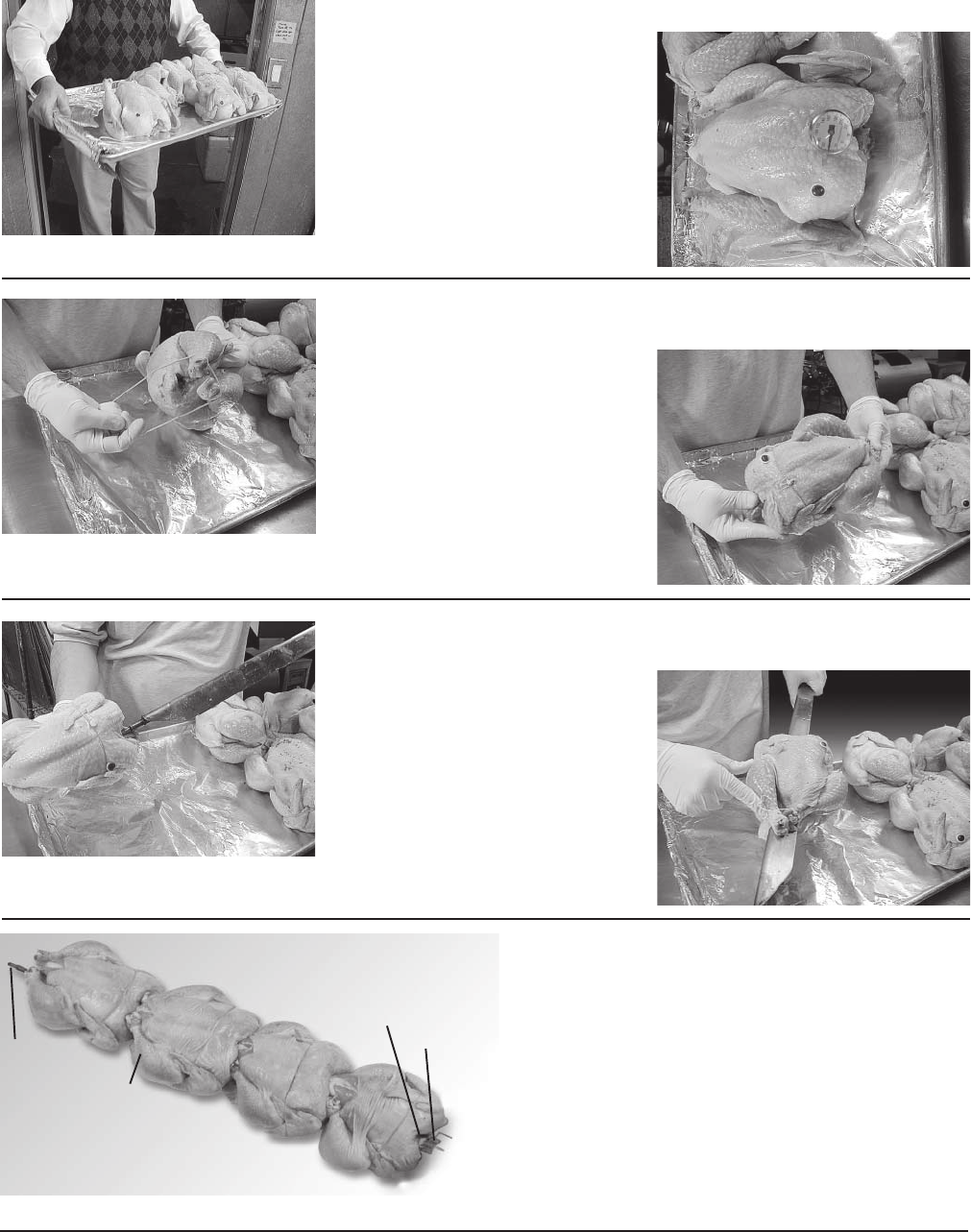
Bring chickens from cooler.
Check temperature —
range should be
from 37°F to 42°F.
Insert approved popper,
if available; it will pop out
when chicken is done.
PREPARING, TYING & SPITTING — CHICKENS ON V-SPITS
The rotary oven is not designed to roast frozen foods. Use only fresh or previously thawed product.
Using an approved tie, wrap
around legs, pulling tie along
the back, criss-cross
over back.
Tie comes over front
holding wings to
side of chicken.
Insert V-Spit through neck first.
V-Spit complete with four birds ready for
loading into rotisserie.
Continue until all spits are completed, all
birds are properly spitted.
The flat side of spit must be
parallel with breast bone.
Legs and thighs on same
side as breast.
Pointed
end
Chicken legs
toward
pointed end
Neck
toward
drive
end
Drive end
HR7E Rotisserie Oven Technical Manual Page 24 of 80
– 19 –
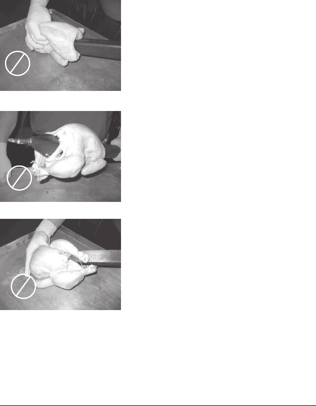
INCORRECT SPITTING — CHICKENS ON V-SPITS
WRONG — Angle of spit is in line with breast. This will split
the backbone and could possibly result in falling off the spit
during cooking.
WRONG — Legs and thighs are not on same side as
breast. This could cause legs to fall off during cooking.
WRONG — Legs are being inserted first. This could result
in birds moving along spits during cooking.
➤
➤
➤
HR7E Rotisserie Oven Technical Manual Page 25 of 80
– 20 –
WARNING: SPITS ARE SHARP. USE CARE WHEN LOADING PRODUCT.
SPITTING — CHICKENS ON FORK SPITS (HR5E)
Press pointed ends of spits into whole poultry so points
go through the chest-wing and leg-thigh regions (Fig.10).
Load three or four chickens on each fork spit.
Fig. 10
LOADING — CHICKENS ON RACKS (HR5E)
Place chicken cavity over spindle, legs down, neck up
and breast forward (Fig. 11). Fold and cross legs; hook
leg ends under side rods of rack. Break wings at top joint;
fold wings behind bird. Load three chickens per rack.
Load five racks.
LOADING — CHICKEN PIECES IN BASKETS (HR5E)
Load chicken pieces in basket in any appropriate
arrangement (Fig. 12).
Fig. 12
LOADING ACCESSORIES ON THE ROTOR (HR5E)
• Using , load accessory into position 1, skip
position 2, load position 3, etc. (Fig. 13).
• Chickens must clear top of oven; no parts can
stick out.
• Do not mix different types of accessories on
the rotor at the same time.
Fig. 13
Fig. 11
1 Load
2 Skip
4 Skip
3 Load
5 Load
HR7E Rotisserie Oven Technical Manual Page 26 of 80
– 21 –
Fig. 15
1 Load
2 Skip
4 Skip
5 Load 6 Skip
7 Load
3 Load
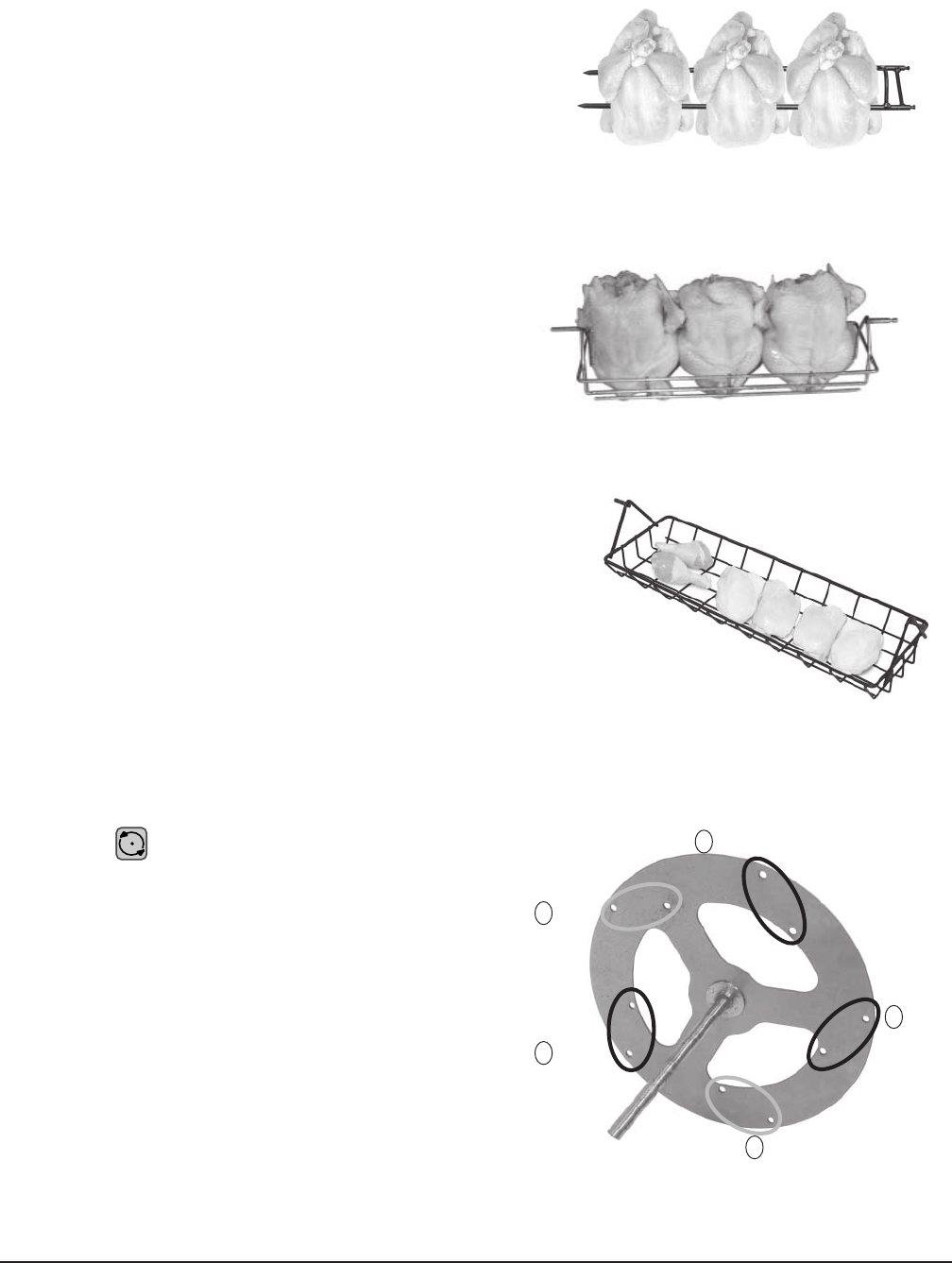
WARNING: SPITS ARE SHARP. USE CARE WHEN LOADING PRODUCT.
SPITTING — CHICKENS ON FORK SPITS (HR7E)
Press pointed ends of spits into whole poultry so
points go through the chest-wing and leg-thigh regions
(Fig. 14). Load four or five chickens on each fork spit.
Fig. 14
SPITTING — CHICKENS ON THERMO-WAVE SPITS (HR7E)
After tying chickens, insert thermo-wave spit through
neck first. Load three or four chickens on each
thermo-wave spit.
LOADING — CHICKENS ON RACKS (HR7E)
Place chicken cavity over spindle, legs down, neck
up and breast forward (Fig. 15). Fold and cross legs;
hook leg ends under side rods of rack. Break wings
at top joint; fold wings behind bird. Load four- or five-
chickens per rack, depending on rack. Load seven
racks.
LOADING — CHICKEN PIECES IN BASKETS (HR7E)
Load chicken pieces in basket in any appropriate
arrangement (Fig. 16).
Fig. 16
LOADING ACCESSORIES ON THE ROTOR (HR7E)
• Using , load accessory into
position 1, skip position 2, load
position 3, etc. (Fig. 17).
• Chickens must clear top of oven;
no parts can stick out.
• Do not mix different types of
accessories on the rotor at the same
time.
Fig. 17
HR7E Rotisserie Oven Technical Manual Page 27 of 80
– 22 –
Loading V-Spits or Thermo-Wave Spits on the Rotor (HR5E)
1. Place pointed end of V-spit into outside hole on drive side of rotor (Fig. 19).
2. Fit notched end of V-spit into appropriate holes on non-drive side of rotor (Fig. 18).
3. Make sure the spit is level. If the spit is not level, you might be using the wrong holes.
NON-DRIVE SIDE DRIVE SIDE
Fig. 18 Fig. 19
Loading Fork Spits on the Rotor (HR5E)
1. Place pointed ends of fork spit into appropriate holes on the non-drive side of the rotor (Fig. 20).
2. Fit the notched end of fork spit into appropriate holes on the drive side of the rotor (Fig. 21).
NON-DRIVE SIDE DRIVE SIDE
Fig. 20 Fig. 21
Loading Chicken Racks or Baskets on the Rotor (HR5E)
1. Place non-notched end of Rack or Basket into outside hole on non-drive side of rotor (Fig. 22).
2. Fit notched end of Rack or Basket into appropriate holes on drive side of the rotor (Fig. 23).
Ensure accessory is level.
NON-DRIVE SIDE DRIVE SIDE
Fig. 22 Fig. 23
HR7E Rotisserie Oven Technical Manual Page 28 of 80
– 23 –
Loading V-Spits or Thermo-Wave Spits on the Rotor (HR7E)
1. Place pointed end of V-spit into outside hole on non-drive side of rotor (Fig. 24).
2. Fit notched end of V-spit into appropriate holes on drive side of rotor (Fig. 25).
3. Make sure the spit is level. If the spit is not level, you might be using the wrong holes.
NON-DRIVE SIDE DRIVE SIDE
Fig. 24 Fig. 25
Loading Fork Spits on the Rotor (HR7E)
1. Place pointed ends of fork spit into appropriate holes on the non-drive side of the rotor (Fig. 26).
2. Fit the notched end of fork spit into appropriate holes on the drive side of the rotor (Fig. 27).
NON-DRIVE SIDE DRIVE SIDE
Fig. 26 Fig. 27
Loading Chicken Racks or Baskets on the Rotor (HR7E)
Chicken Racks and Chicken Baskets hang on studs on the left and right sides of the rotor.
1. Hang the left end of a Rack or Basket on a stud on the left side of the rotor (Fig. 28).
2. Hang the right end of the Rack or Basket on the corresponding stud on the right side of the rotor
at the same height (Fig. 29). The accessory must be level.
NON-DRIVE SIDE DRIVE SIDE
Fig. 28 Fig. 29
HR7E Rotisserie Oven Technical Manual Page 29 of 80
– 24 –
PERSONAL PROTECTIVE EQUIPMENT
Chickens and accessories are hot. Use care during unloading by using appropriate personal protective
equipment such as 18" insulated gloves, an apron, long sleeved clothing and closed toed shoes.
UNLOADING ACCESSORIES FROM OVEN
Opening the door does not stop the rotor, heaters or fan.
1. Press
STOP
to stop rotation and cooking. Press to allow rotor to advance to unloading position.
Press again to stop rotation.
2. Use insulated gloves.
• Carefully remove accessory from rotor. Remove chickens from accessory.
• Place chickens in proper containers. Place chicken containers in warming cabinet.
3. Repeat step 1; stagger unloading by skipping past the next accessory to the following one.
4. Repeat step 2 and 3 until unloading is complete.
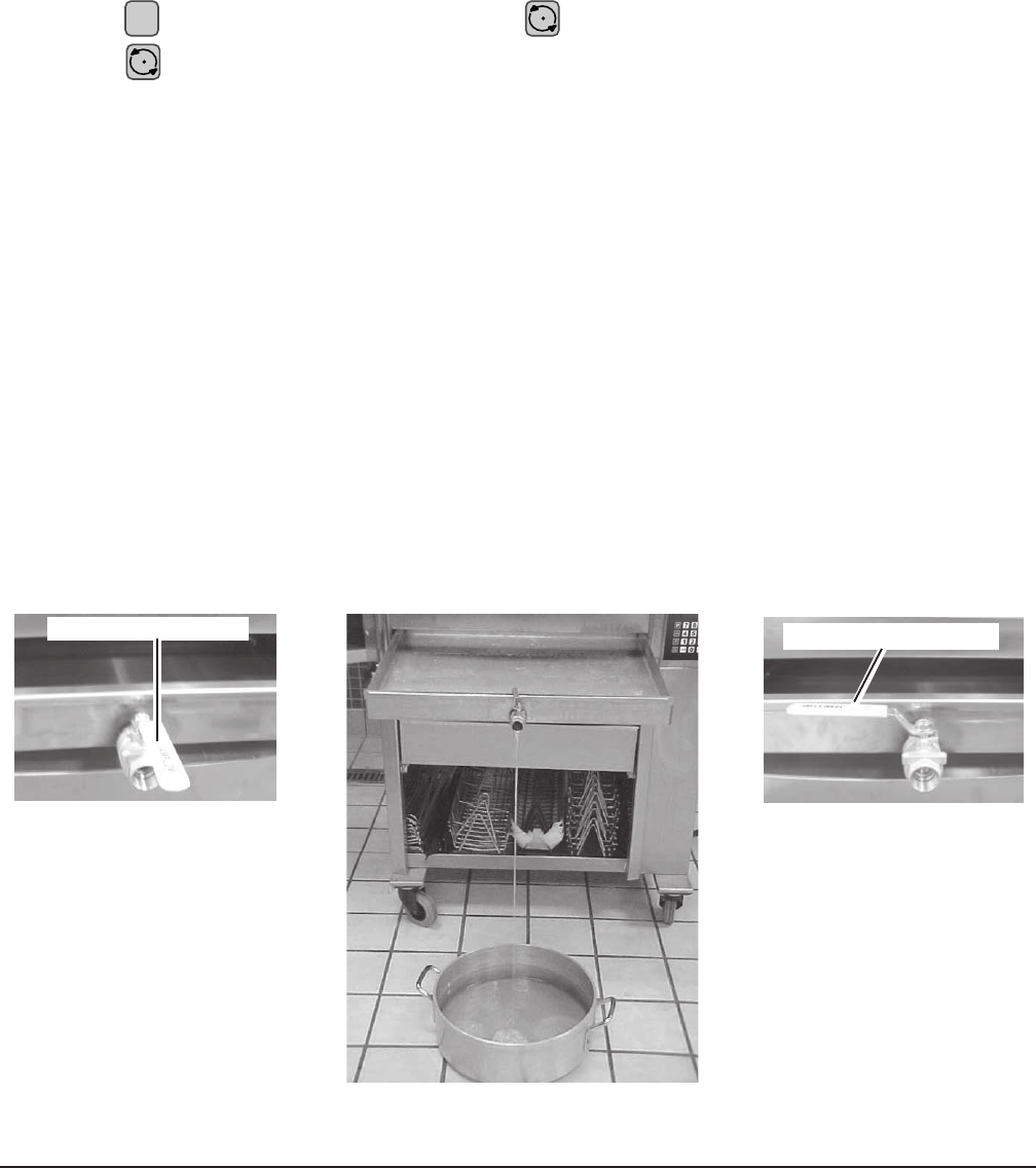
EMPTYING THE GREASE DRAWER
Empty the grease drawer when necessary.
• Use care, grease can be hot.
1. Open door. Slide grease drawer out about five inches.
2. Place a bucket or vessel large enough for the grease underneath the drain valve.
3. Open valve on grease drawer (Fig. 30). Empty fat into suitable container (Fig. 31). Close grease
valve when drawer is empty or when container is full (Fig. 32).
4. Slide grease drawer shut. Close oven door.
Fig. 31
GREASE VALVE OPEN
Fig. 30
GREASE VALVE CLOSED
Fig. 32
HR7E Rotisserie Oven Technical Manual Page 30 of 80
– 25 –
CLEANING
WARNING: DISCONNECT THE ELECTRICAL POWER SUPPLY TO THE MACHINE AND
FOLLOW LOCKOUT / TAGOUT PROCEDURES BEFORE CLEANING OR SERVICING.
Proper cleaning prolongs the life and productivity of the oven. The oven should be routinely cleaned
throughout the day and thoroughly cleaned at the end of the day.
Allow oven to cool before cleaning. Do not hose down.
CAUTION: Do not clean with a high pressure hose.
Cleaning — Grease Drawer and Oven Interior / Exterior
1. Empty grease drawer (refer to page 24).
2. Remove drawer, rotor and drip plates.
3. Clean drawer, rotor and drip plates. Refer to Cleaning Guidelines for Nonstick Coated Surfaces
on page 26.
4. Clean oven interior and exterior.
5. Wash door(s) and inside glass with warm soapy water, rinse and dry or use a commercial glass
cleaner.
6. With door open, pull inside glass away from door to clean.
Take extra care when cleaning outside surface of inner glass door because of its special
reflective coating. Do not remove glass from door.
7. Clean control panel with a damp cloth only.
8. Return drawer, rotor and drip plates to proper locations.
Fig. 33 Fig. 34
HR7E Rotisserie Oven Technical Manual Page 31 of 80

– 26 –
CLEANING STAINLESS STEEL SURFACES
1. Wash stainless steel parts with warm soapy water.
2. Rinse parts thoroughly.
3. Dry with a soft clean cloth.
CLEANING GUIDELINES FOR NONSTICK COATED SURFACES
Abrasion and aggressive chemicals reduce the life of the nonstick coating. With proper care,
the nonstick coated surface should provide a long life of easy-to-clean service.
DO NOT do the following:
• DO NOT use abrasive cleaning aids such as steel wool.
NOTE: Abrasive pads remove the coating over time, significantly reducing the life of the
coating.
• DO NOT use sharp instruments such as knives, forks, scrapers or metal objects of any
kind.
• DO NOT use agressive chemicals such as oven cleaners.
NOTE: If cleaner requires gloves, it can’t be used.
CAUTION: The chemical components of some cleaner/sanitizers can attack the nonstick
surface causing the coating to peel. Always dilute to recommended strength.
• DO NOT attempt to burn off or bake off surface contamination.
• DO NOT operate more than eight hours without cleaning.
How to Clean Nonstick Coated Surfaces:
• DO use a mild dish washing soap in warm water
• DO use a soft cloth or sponge to remove grease and food residue.
NOTE: For removal of heavy buildup, the only pad acceptible for use is the Scotch-Brite
Power Pad 2000.
• DO rinse and let dry.
HR7E Rotisserie Oven Technical Manual Page 32 of 80

– 27 –
CLEANING QUARTZ LAMPS
CAUTION: Do not clean the quartz lamps in the top of the oven with soap and water.
Be very careful when cleaning lamps. Lamps can be broken by mishandling.
• Clean lamps with a cloth soaked in alcohol.
•Do Not touch lamps with your bare hands. Touching the quartz lamp could shorten the life of the
bulb.
CLEANING THE TEMPERATURE PROBE (Optional Accessory)
Clean after every use.
1. Remove the probe from the probe holder.
2. Unplug probe cord from the probe holder (if needed).
3. Wipe the probe with a cloth moistened in a solution of detergent and water, rinse in clean water
and allow to dry. Dry with a soft cloth.
4. Carefully plug probe cord back into the probe holder (if needed).
5. Place probe back in probe holder.
HR7E Rotisserie Oven Technical Manual Page 33 of 80
– 28 –
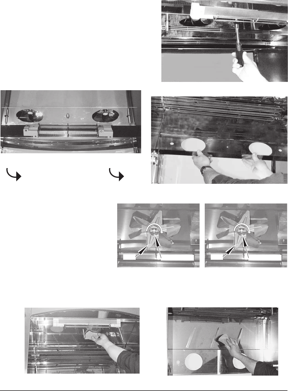
WEEKLY CLEANING — HR5E OVENS
Clean ceiling of oven interior to remove potential grease
build-up.
Excessive grease build-up on convection fan blade
and / or vent-grate will decrease oven's cooking
performance over time.
NOTE: For ease of cleaning, replacement fan blade(s) are
available from Hobart Service Parts.
1. Open door and remove rotor. Using a
nutdriver, unscrew the 7/16" nuts on both
sides of the vent-grate (Fig. 35).
2. Lower and remove vent-grate (Figs. 36, 37).
Fig. 38
Fig. 37
3. Remove fan blade by unscrewing center
nut (clockwise) (Fig. 38).
CENTER NUT
FAN
Fig. 35
Fig. 36
HR7E Rotisserie Oven Technical Manual Page 34 of 80
– 29 –
4 Clean ceiling area around the elements
and convection fan (Figs. 39, 40).
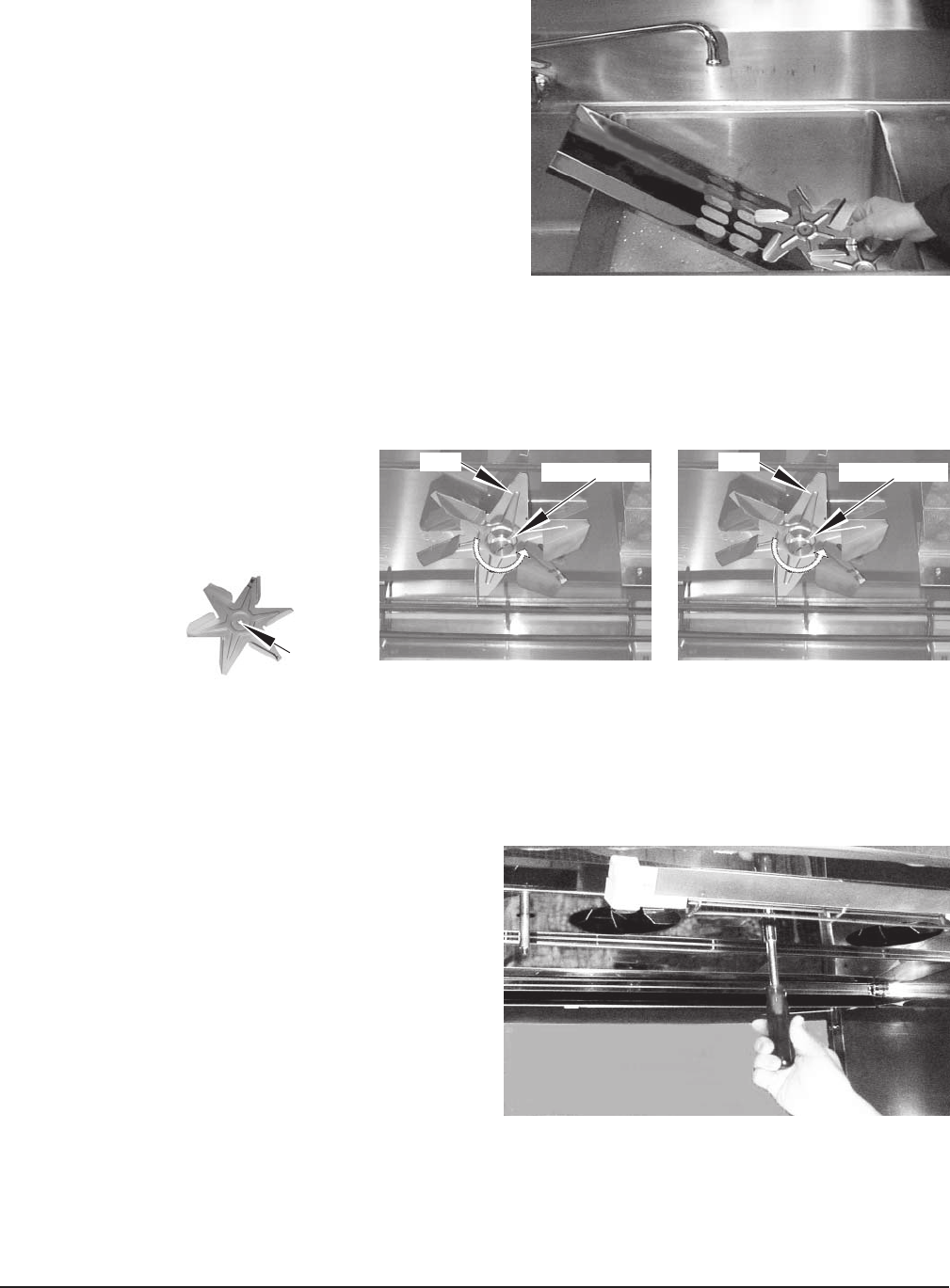
5. Wash vent-grate and fan blade in a sink
with warm soapy water (Fig. 41).
6. Rinse and allow to dry.
7. After cleaning, reinstall fan blade by
mating D-shaped fan onto D-shaped
shaft and then tightening center nut
counterclockwise (Fig. 42).
8. Reinstall vent-grate; tighten nuts using
7/16" nutdriver (Fig. 43).
Fig. 39 Fig. 40
Fig. 41
Fig. 42
Fig. 43
CENTER NUT
FAN
D HOLE
HR7E Rotisserie Oven Technical Manual Page 35 of 80
– 30 –
Fig. 46
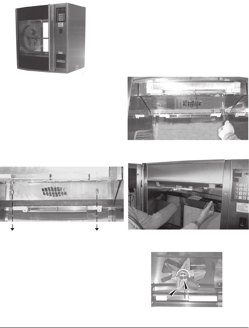
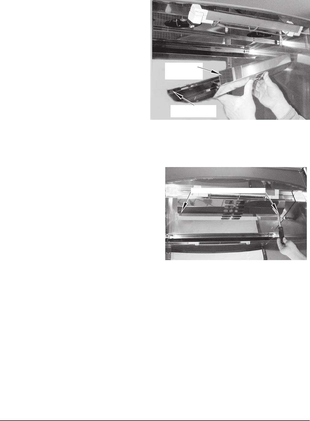
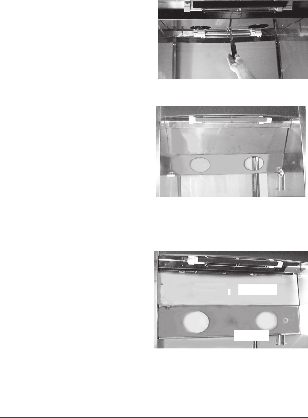
WEEKLY CLEANING — HR7E OVEN WITH REAR GLASS DOOR, ACCESS FROM REAR
Clean ceiling of oven interior to remove potential grease
build-up.
Excessive grease build-up on convection fan blade(s)
and / or vent-grate will decrease oven's cooking
performance over time.
NOTE: For ease of cleaning, replacement fan blade(s) are
available from Hobart Service Parts.
1. Open rear glass door. Make sure drive arm is in the
downward position (Fig. 44).
2. Remove the vent-grate: Use a 7/16"
nutdriver to unscrew two 7/16" nuts, one
on each side of the vent (Figs. 45, 46).
Fig. 45
Fig. 44
Fig. 37
UNSCREW 2 NUTS
REAR DOOR
HR7E Rotisserie Oven Technical Manual Page 36 of 80
– 31 –
Fig. 50
Fig. 51 Fig. 52
Fig. 49
Fig. 48
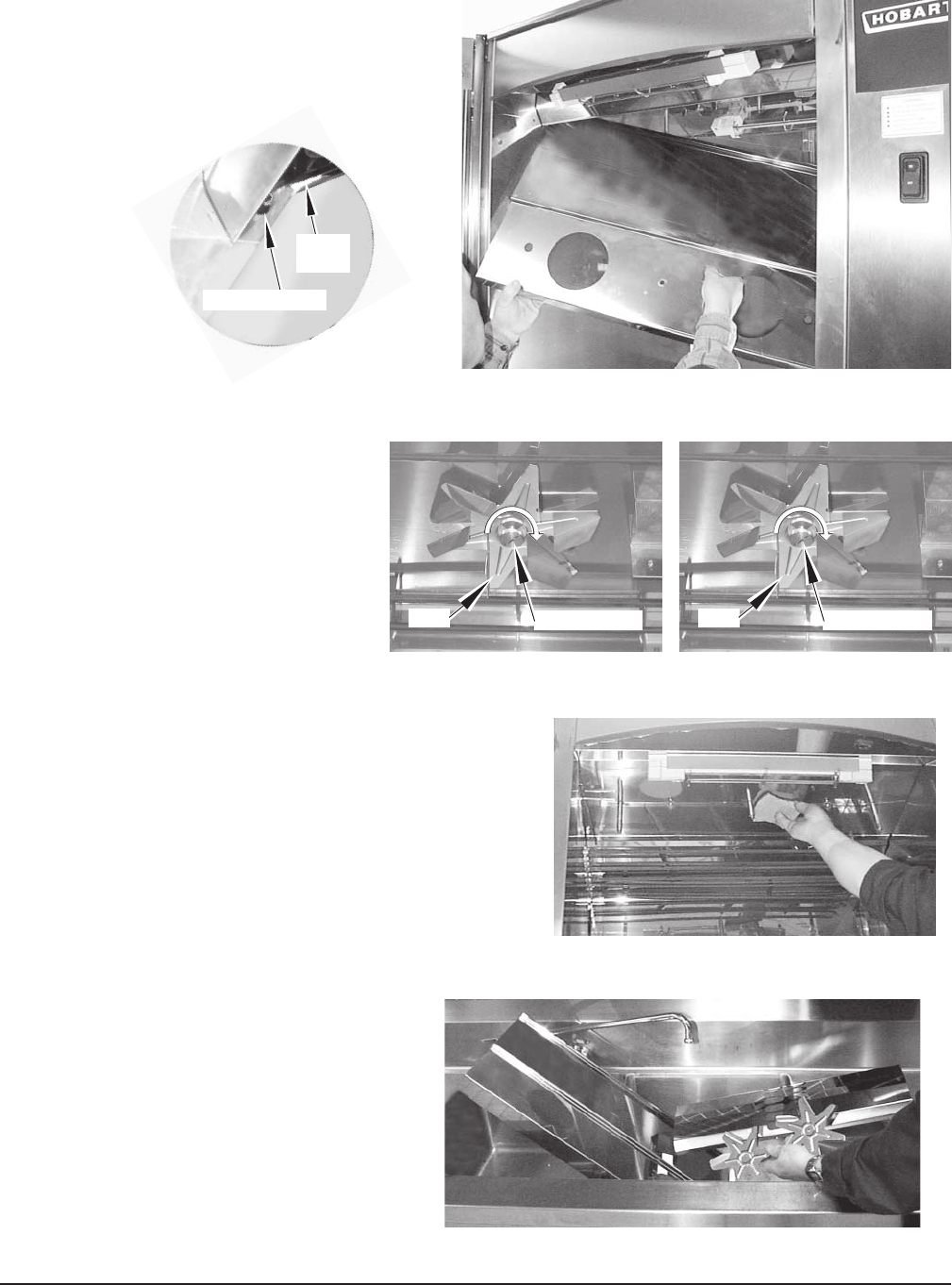
3. Remove the center nut that secures the
element cover using a 7/16" nutdriver (Fig. 47).
4. Allow the element cover to swing down
(Figs. 48, 49).
5. Remove both fan blades.
Unscrew the center nut on each
fan blade (clockwise, Fig. 50).
6. Clean ceiling of oven interior around elements and convection fan shafts (Fig. 51).
7. Clean element cover while it hangs down (Fig. 52).
CENTER NUT
FAN CENTER NUT
FAN
Fig. 47
HR7E Rotisserie Oven Technical Manual Page 37 of 80
– 32 –
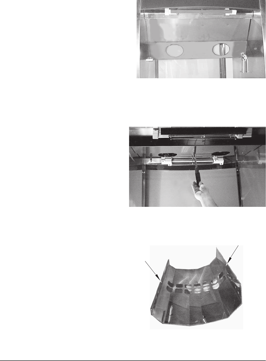
8. Clean the vent-grate and fan blades (Fig. 53).
Rinse and allow to dry.
9. After cleaning, reinstall 2 fan
blades: Mate D-shaped hole on
fan onto D-shaped shaft; then
tighten nut (counterclockwise)
(Fig. 54).
10. Swing element cover up until all 3 studs
protrude through cover. Reinstall element
cover: Tighten center nut using a 7/16"
nutdriver (Fig. 55).
Fig. 53
Fig. 54
Fig. 55
CENTER NUT
FAN CENTER NUT
FAN
D HOLE
HR7E Rotisserie Oven Technical Manual Page 38 of 80
– 33 –
Fig. 56
11. Working from rear of oven, position high
side of vent-grate toward rear of oven,
short side faces center of oven (Fig. 56).
12. Reinstall vent-grate: Tighten 7/16" nuts on
each side of vent grate using a 7/16" nutdriver
(Fig. 57).
Fig. 57
THREAD NUTS ON BOTH SIDES
HIGH SIDE
TOWARD REAR
OF OVEN
SHORT SIDE
TOWARD CENTER
HR7E Rotisserie Oven Technical Manual Page 39 of 80
– 34 –
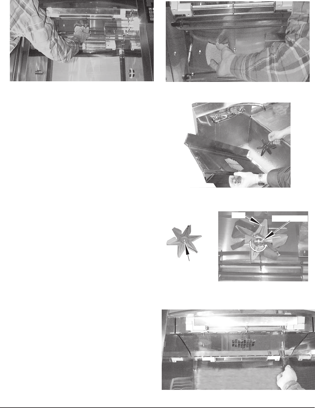
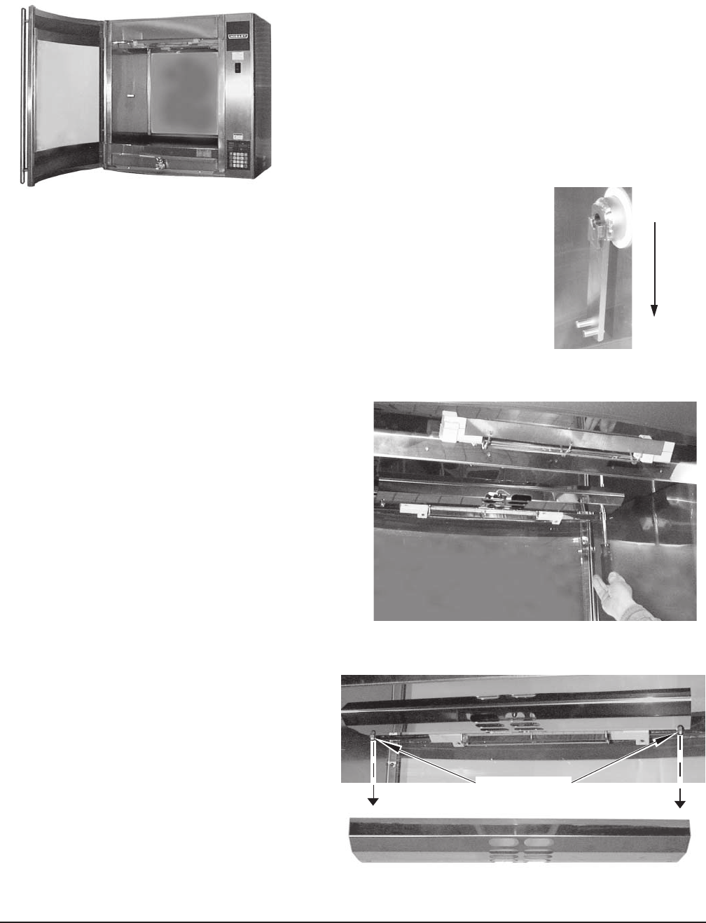
WEEKLY CLEANING — HR7E OVENS WITH SOLID BACK, ACCESS FROM FRONT
Clean ceiling of oven interior to remove potential grease
build-up.
Excessive grease build-up on convection fan blade(s)
and / or vent-grate will decrease oven's cooking
performance over time.
NOTE: For ease of cleaning, replacement fan blade(s)
are available from Hobart Service Parts.
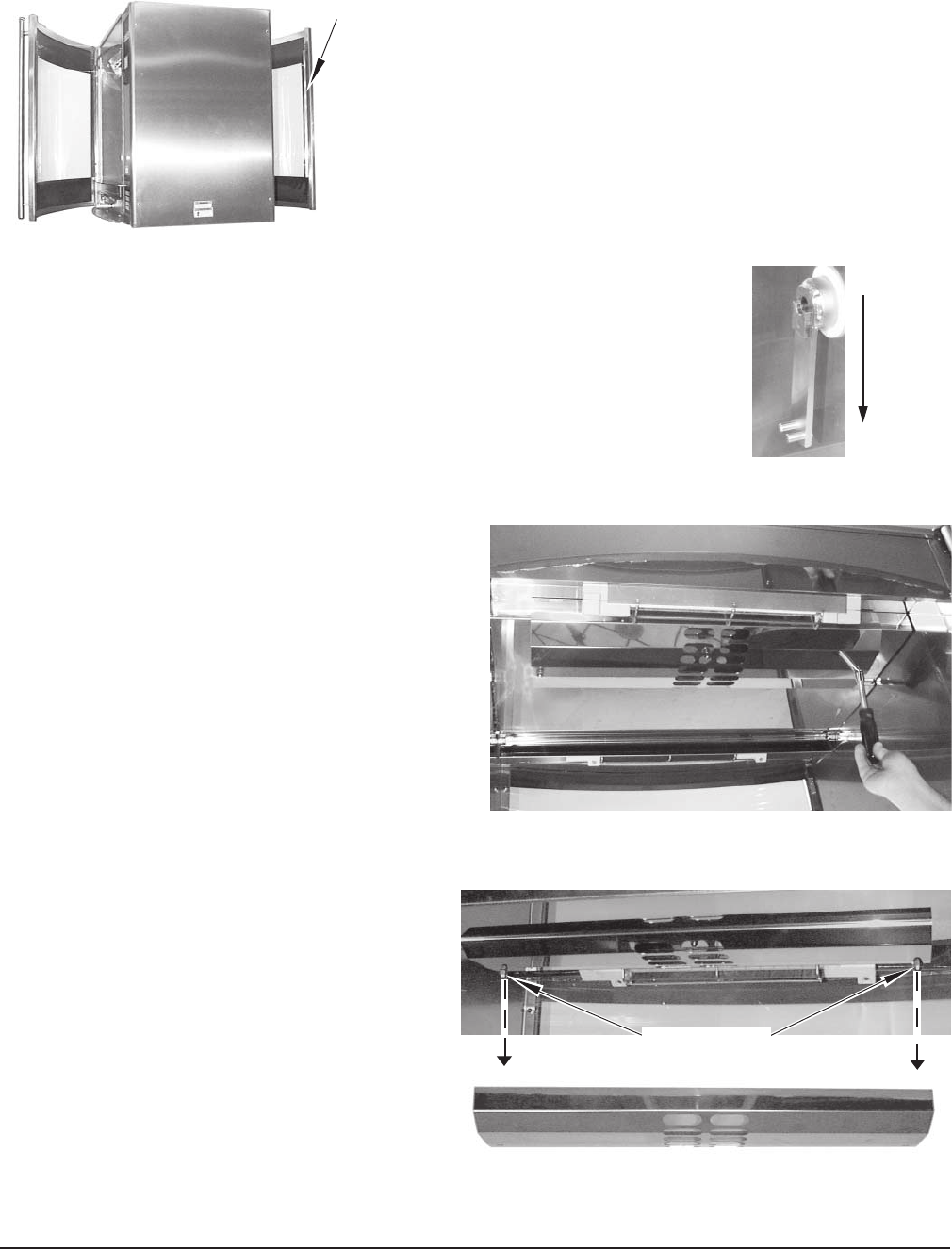
1. Open front door. Remove rotor. Make sure drive arm is in
the downward position (Fig. 58).
2. Use a 7/16" nutdriver and unscrew two 7/16"
nuts, one on each side of the vent-grate.
Remove the vent-grate (Figs. 59, 60).
Fig. 58
Fig. 59
Fig. 60
Fig. 37
UNSCREW 2 NUTS
HR7E Rotisserie Oven Technical Manual Page 40 of 80
– 35 –
3. Using a 7/16" nutdriver, remove the center
nut that secures the element cover (Fig. 61).
Allow the element cover to swing down toward
you (Fig. 62).
4. Raise element cover up and swing toward
front of oven to clear rotor support and
rotor arm (Fig. 63). Continue to swing
element cover to forwardmost position.
Fig. 61
Fig. 62
Fig. 63
⇑RAISE ELEMENT
COVER UP
CLEAR ROTOR
SUPPORT
➥
➥
HR7E Rotisserie Oven Technical Manual Page 41 of 80
– 36 –
Fig. 67
5. With element cover in forwardmost
position, lift up right side to clear right
hinge pin; then lower right side and lift
up left corner until left hinge clears left
hinge pin (Fig. 64).
Fig. 65
CENTER NUT
FAN CENTER NUT
FAN
Fig. 64
6. Remove two fan blades by
unscrewing center nut on fan
blades (clockwise, Fig. 65).
8. Clean vent-grate, element cover and
fan blades in a sink (Fig. 67). Rinse and
allow to dry.
7. Clean ceiling of oven interior around elements
and convection fan shafts (Fig. 66).
Fig. 66
LEFT HINGE PIN
LEFT
HINGE
HR7E Rotisserie Oven Technical Manual Page 42 of 80

– 37 –
9. After cleaning, reinstall 2 fan
blades: Mate D-shaped hole on
fan onto D-shaped shaft; then
tighten nut (counterclockwise)
(Fig. 68).
Fig. 68
CENTER NUT
FAN
CENTER NUT
FAN
D HOLE
10. Reinstall element cover: Raise
left hinge (end of U-chanel) up
around left hinge pin (Fig. 69).
LEFT HINGE PIN
LEFT
HINGE
Fig. 69
11. Raise right side of element cover up and swing toward front of
oven. The right-hinge (end of U-channel) should hang from the
right-hinge pin. Element cover should hang straight down from
left- and right-hinge pins (Fig. 70).
Fig. 70
⇑
RAISE UP AND
SWING FORWARD
➥
➥
RIGHT
HINGE PIN
RIGHT
HINGE
➥
➥
⇑
RAISE UP AND
SWING FORWARD
HR7E Rotisserie Oven Technical Manual Page 43 of 80
– 38 –
Fig. 73
HIGH SIDE
TOWARD REAR
SHORT SIDE
TOWARD CENTER
Fig. 71
Fig. 72
12. Swing element cover back and raise up to
clear rotor support and rotor arm (Fig. 71).
Continue swinging element cover back until
mounting studs protrude through three holes
in element cover.
13. Reinstall element cover: Tighten 7/16"
center nut using 7/16" nutdriver
(Fig. 72).
14. Working from front of oven, position
high side of vent-grate toward rear of
oven, short side faces center of oven
(Fig. 73).
HR7E Rotisserie Oven Technical Manual Page 44 of 80

– 39 –
15. Reinstall vent-grate: Tighten 7/16" nuts
on each side of vent grate using a 7/16"
nutdriver (Fig. 74).
Fig. 74
THREAD NUTS ON BOTH SIDES
HR7E Rotisserie Oven Technical Manual Page 45 of 80

– 40 –
FORM 35511 (Feb. 2006) PRINTED IN U.S.A.
TROUBLESHOOTING
PROBLEM POSSIBLE CAUSE
1. Control does not light up. 1. ON-OFF switch is not pressed ON.
2. Electric supply is interrupted; check circuit breaker.
2. Cooking too slow. 1. Fan blade(s) and ventilation area require routine cleaning.
SERVICE
Contact your local Hobart office.
MAINTENANCE
WARNING: DISCONNECT ELECTRICAL POWER SUPPLY TO THE MACHINE AND FOLLOW
LOCKOUT / TAGOUT PROCEDURES BEFORE CLEANING OR SERVICING.
WARNING: HOT GLASS, GREASE, AND PARTS CAN CAUSE BURNS. USE CARE WHEN
OPERATING AND SERVICING THE OVEN.
HR7E Rotisserie Oven Technical Manual Page 46 of 80
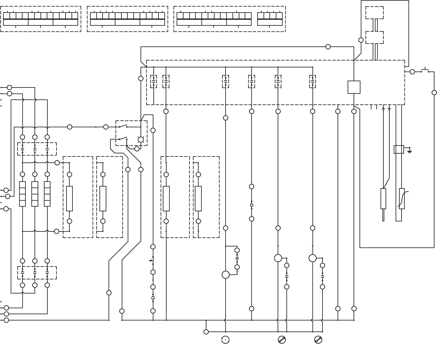
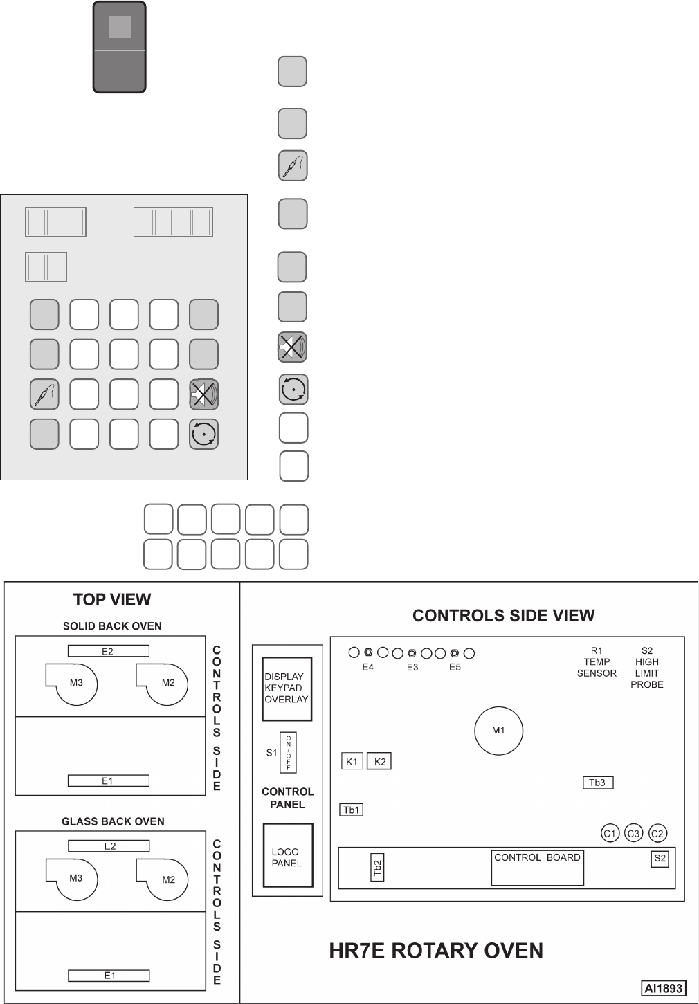
NOTE 2. E1 LIGHT POSITION IS LOCATED FARTHEST FROM BLOWER MOTORS M2, M3.
E2 LIGHT POSITION IS LOCATED CLOSEST TO BLOWER MOTORS M2, M3.
NOTE 1. GLASS BACK OVEN MODIFIED WITH CONTROLS RELOCATED
IS WIRED THE SAME AS SOLID BACK OVEN.
*
TB2.4
CR3
TB4
TB2.1
TB2.8TB2.8
T2
L2
5
55
11
12
6
61
10
9
TB1
5
TB2.6
T1
L1
4
44
6
66
L3
T3
13
34
TB2.1 TB2.1
36
TB2.1 TB2.1
A1
A2
38
37
19
TB3.2
17
BLK
RED
TB3.1
40W
M1
WHT
42
41
TB3.4
HEAT
2100W
22
E3
T2
L2
2
7
6
TB1
5
8
31
3
4
3
4
TB1
1
34
TB1
2
1
2
1
1
1
2
2
L1
E2
*
2100W
E5
56
11
3100W
33
E4
HEAT HEAT
23
T1
L1
13
T3
L3
7
8
TB2.7
31
13
L
3
87
67
E1
*
20
50
TB2.7
10
TB2.5
2
5
S1
34
12
61
9
31
L2
56
3
7
2
8
4
L3
11
6
3
10
5
15
8
79
4
L1
4
31
2
1
3
23
1
1
56
TB1
2
ROTATE
HEAT
SPARE
LIGHT
TB2.2
TB2.3
7
8
E1
TB2.3
TB2.2
40
20
50
40
25
*
A1
18
19
A2
18
E2
*
16
16
SWITCHED AC IN
4
L1
1
23
TB1
CR6 CR5
11
6
L2
3
10
5
12
61
1
1
12
CR4
9
L2
2
56
331
8
7
L3
10
3
5
11
TB3.5
M3
TB3.2
BLK
BLUE
TB3.3 TB3.3
27
46
BRN
TB3.7
BLUE
BLK
M2
TB3.8
TB2.2TB2.2
TB3.2
TB3.6
26
45
BRN
28 29
+
EXT BUZZER
FAN 1
SNUBBER COMMON
NEUT
GND
FAN 2
24
24
21
21 28 29
CR2
N
2
1
1
42
34
661
75
AC IN
CR1
85
MEAT PROBE
OVEN TEMP
-
KEYPAD
76
77
HR7E ELECTICAL WIRING SCHEMATIC
DERIVED FROM 00-877996 AI 3370
HR7E Rotisserie Oven Technical Manual Page 47 of 80
MAIN POWER SWITCH — Turns oven and controls on or off.
PROGRAM — Enters program mode to modify a cook
program; press P for 3 seconds.
CLOCK — Sets the clock for time of day.
PROBE — Displays temperature, external meat
probe.
ADD 5 MIN — Adds 5 minutes to a program step each
time it is pressed.
START — Begins cooking cycle.
STOP — Stops cycle.
SILENCE — Silences beeper.
ROTATE — Rotor on/off, pauses cooking cycle.
CLEAR — Clears time or temperature entry .
ENTER — Accepts time or temperature entry.
0 — 9 — Enter numeric value(s).
t — Service use only. When pressed, oven cavity
current temperature will display.
P
CLOCK
ADD
5 MIN
START
STOP
CLEAR
ENTER
041 23
567 8 9
P789
456
123
0ENTERCLEAR
START
CLOCK
ADD
5 MIN
STOP
TEMPERATURE TIME
•F
•C
t
PROGRAM
•AM
•PM
STEP
4•
3•
2•
1•
ON
OFF
AI 1679
CONTROL EXPANATION
HR7E Rotisserie Oven Technical Manual Page 48 of 80

Controls
Timers
Motors
Lights
Power cord
Door latches
Door
Door seals
Blower fan
Review error codes
Operate
COOKING EQUIPMENT
HR5 & HR7 SERIES ROTISSERIE OVENS
MISCELLANEOUS
PREVENTIVE MAINTENANCE CHECKLISTS
CHECK FOR PROPER OPERATION
Switches - manual
Thermostat calibration
General hardware
CLEAN
Blower fan circulation
Oven racks and suppo
CHECK FOR PROPER FIT
CHECK FOR WEAR AND PROPER
HR7E Rotisserie Oven Technical Manual Page 49 of 80
CATALOG OF
REPLACEMENT
PARTS
HR7E ROTISSERIE OVENS
ML-132092
ML-132093
ML-132094
ML-132095
A product of HOBART 701 S. RIDGE AVENUE TROY, OHIO 45374-0001
FORM 43102 (May 2005)
HR7E Rotisserie Oven Technical Manual Page 50 of 80

- 2 -
HR7E ROTISSERIE OVEN REPLACEMENT PARTS
F-43102 (May 2005) © HOBART
HR7E Rotisserie Oven Technical Manual Page 51 of 80

- 3 -
HR7E ROTISSERIE OVEN REPLACEMENT PARTS
F-43102 (May 2005)
Table of Contents
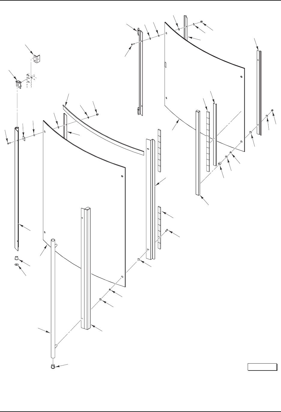
5 OVEN DOORS
7 STEEL OVEN BACK (ML-132094 & ML-132095)
9 OVEN FRAME AND PANELS
11 CONTROLS AND COMPONENTS
13 HEATING AND VENTING
15 ROTISSERIE AND DRIVE MOTOR
17 STACKING KIT
19 ACCESSORIES
HR7E Rotisserie Oven Technical Manual Page 52 of 80
- 4 -
HR7E ROTISSERIE OVEN REPLACEMENT PARTS
F-43102 (May 2005)
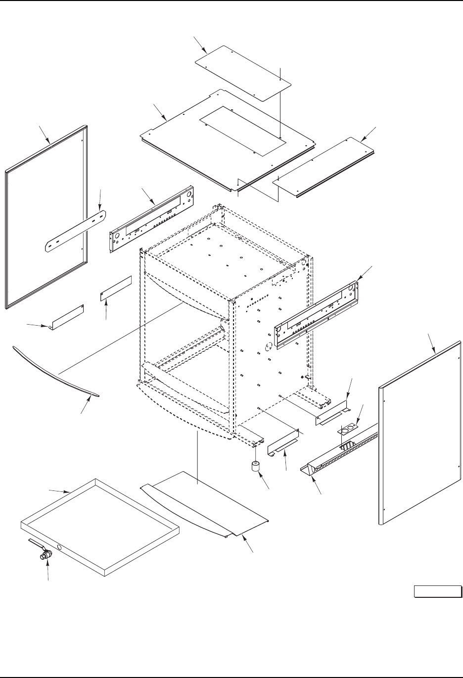
OVEN DOORS
16
22
20
37
38
39
36
35
34
33
32
41
40
42-43
23
24
25
26
27
28
29
15
17
19
18
9
8
76
5
4
3
2
1
14
13
12
11
10
PL-57716
21
30
31
44
45
HR7E Rotisserie Oven Technical Manual Page 53 of 80

- 5 -
HR7E ROTISSERIE OVEN REPLACEMENT PARTS
F-43102 (May 2005)
OVEN DOORS
ILLUS. PART NO. NAME OF PART AMT.
PL-57716
1 SC-118-22 Mach. Screw 10-24 x 5/8 Phil. Truss Hd. ................................................................................... 2
2 00-425900-00028 Hinge Assy. (Inner Door) ............................................................................................................ 1
3 00-425900-00187 Washer ....................................................................................................................................... 2
4 00-425900-00192 Spacer – Inner Glass ................................................................................................................. 2
5 00-425900-00187 Washer ....................................................................................................................................... 2
6 NS-025-01 Crown Nut 10-24 (SST) ............................................................................................................. 2
7 WS-019-20 Washer ....................................................................................................................................... 2
8 00-877954 Support – Inner Hinge ................................................................................................................ 1
9 00-877954 Support – Inner Hinge ................................................................................................................ 1
10 NS-025-01 Crown Nut 10-24 (SST) ............................................................................................................. 2
11 WS-019-20 Washer ....................................................................................................................................... 2
12 00-425900-00187 Washer ....................................................................................................................................... 2
13 00-425900-00192 Spacer – Inner Glass ................................................................................................................. 2
14 00-425900-00187 Washer ....................................................................................................................................... 2
15 00-425900-00191 Spacer – Magnet Holder ............................................................................................................. 2
16 00-425900-00098 Holder – Magnet Assy. ............................................................................................................... 1
17 00-891068 Kit – Inner Door Glass ................................................................................................................ 1
18 00-360128 Magnet – Door ........................................................................................................................... 10
19 00-425900-00099 Section – Magnet Filler ............................................................................................................... 1
20 00-877967 Grip – Handle Attachment .......................................................................................................... 1
21 00-360128 Magnet – Door ........................................................................................................................... 14
22 SC-118-22 Mach. Screw 10-24 x 5/8 Phil. Truss Hd. ................................................................................... 2
23 00-425900-00187 Washer ....................................................................................................................................... 2
24 00-425900-00188 Spacer – Outer Glass ................................................................................................................ 2
25 00-425900-00187 Washer ....................................................................................................................................... 2
26 00-425900-00042 Section – Magnet Assy. ............................................................................................................. 1
27 00-474831 Plug – Handle .............................................................................................................................. 2
28 00-877862 Handle Assy. (Incls. Item 27) ..................................................................................................... 1
29 00-891064 Kit – Outer Door Assy. (Incls. Items 32 thru 39) ........................................................................ 1
30 00-425900-00027 Hinge Assy. ................................................................................................................................ 1
31 00-877808 Hinge Assy. (Rear) (Outer Door) ............................................................................................... 1
32 SC-118-22 Mach. Screw 10-24 x 5/8 Phil. Truss Hd. ................................................................................... 2
*33 - Tape – Foam ............................................................................................................................. AR
34 00-425900-00188 Spacer – Outer Glass ................................................................................................................ 2
35 00-425900-00187 Washer ....................................................................................................................................... 2
36 00-425900-00096 Support – Outer Hinge ............................................................................................................... 1
37 NS-025-01 Crown Nut 10-24 (SST) ............................................................................................................. 2
38 WS-019-20 Washer ....................................................................................................................................... 2
*39 - Protection – Edge ....................................................................................................................... 2
40 00-877964 Hinge Assy. (RH) ........................................................................................................................ 1
41 00-877963 Hinge Assy. (LH) ........................................................................................................................ 1
42 00-425900-00142 Retainer – Hinge (Adjustable) .................................................................................................... 1
43 SC-110-13 Mach. Screw 10-32 x 5/8 Phil. Rd. Hd. ....................................................................................... 1
44 00-877953 Bearing – Bushing .................................................................................................................... AR
45 WS-005-42 Washer ..................................................................................................................................... AR
* No Service Part Available, Included In Kit 00-891064.
HR7E Rotisserie Oven Technical Manual Page 54 of 80
- 6 -
HR7E ROTISSERIE OVEN REPLACEMENT PARTS
F-43102 (May 2005)
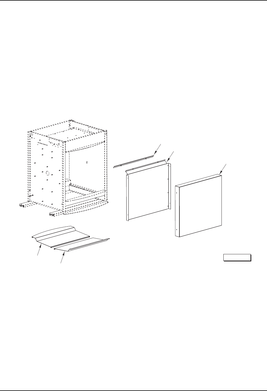
STEEL OVEN BACK (ML-132094 & ML-132095)
1
2-3
5-6
7-8
4
PL-57717
HR7E Rotisserie Oven Technical Manual Page 55 of 80

- 7 -
HR7E ROTISSERIE OVEN REPLACEMENT PARTS
F-43102 (May 2005)
STEEL OVEN BACK (ML-132094 & ML-132095)
ILLUS. PART NO. NAME OF PART AMT.
PL-57717
1 00-877922 Cover Assy. (SST) ..................................................................................................................... 1
2 00-877912-00001 Panel – Inside (SST) ................................................................................................................... 1
3 00-877912-00002 Panel – Inside (Coated) .............................................................................................................. 1
4 00-877911 Panel – Spacer Assy. ................................................................................................................. 1
5 00-877915-00001 Shield – Drip (Back) (SST) ......................................................................................................... 1
6 00-877915-00002 Shield – Drip (Back) (Coated) .................................................................................................... 1
7 00-877947-00001 Shield – Drip (SST) ..................................................................................................................... 1
8 00-877947-00002 Shield – Drip (Coated) ................................................................................................................ 1
HR7E Rotisserie Oven Technical Manual Page 56 of 80
- 8 -
HR7E ROTISSERIE OVEN REPLACEMENT PARTS
F-43102 (May 2005)
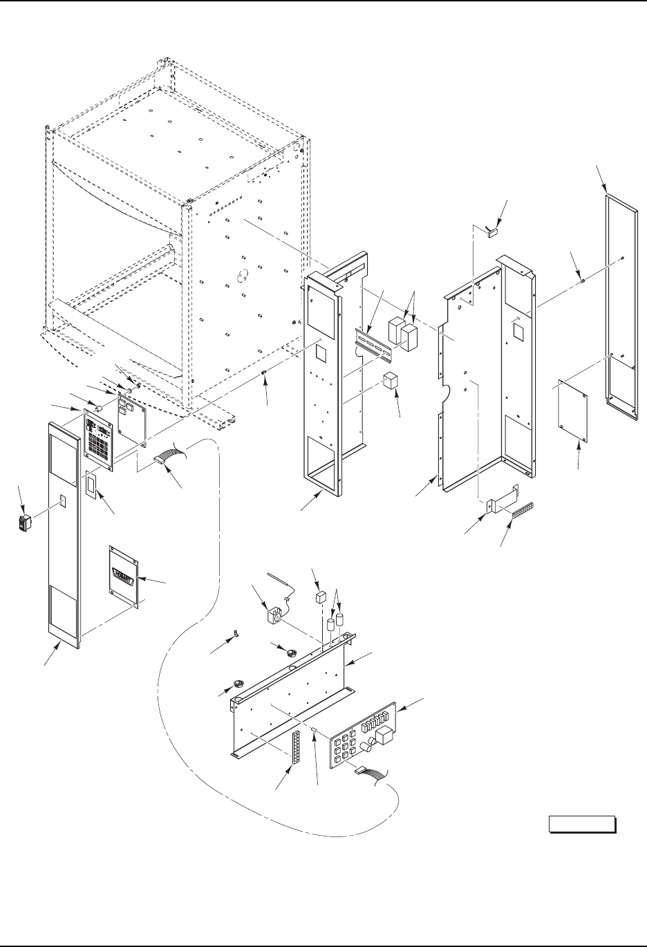
OVEN FRAME AND PANELS
1
23
4
5
6
7
10
11
12
13
14-15
18
20 19
8
9
PL-57719
17
16
HR7E Rotisserie Oven Technical Manual Page 57 of 80

- 9 -
HR7E ROTISSERIE OVEN REPLACEMENT PARTS
F-43102 (May 2005)
OVEN FRAME AND PANELS
ILLUS. PART NO. NAME OF PART AMT.
PL-57719
1 00-425900-00026 Panel – Outer (LH) ..................................................................................................................... 1
2 00-877905 Retainer - Insulation ................................................................................................................... 1
3 00-877796 Plate – Upper Support ................................................................................................................ 1
4 00-425900-00093 Panel – Outer (Top) .................................................................................................................... 1
5 00-425900-00125 Cover – Vent Hatch .................................................................................................................... 1
6 00-425900-00094 Cover – Electrical ....................................................................................................................... 1
7 00-877796 Plate – Upper Support ................................................................................................................ 1
8 00-877798 Guard – Lower Right ................................................................................................................. 1
9 00-425900-00137 Plate – Power Conduits.............................................................................................................. 1
10 00-425900-00026 Panel – Outer (RH) ..................................................................................................................... 1
11 00-425900-00136 Bin – Spark ................................................................................................................................. 1
12 00-877797 Guard – Lower Left ................................................................................................................... 1
13 00-877807 Foot (Rubber) ............................................................................................................................. 4
14 00-877947-00001 Shield – Drip (Bottom) (ML-132092) .......................................................................................... 2
15 00-877947-00002 Shield – Drip (Bottom) (Coated) (ML-132093) ........................................................................... 2
16 00-877933 Valve – Drain .............................................................................................................................. 1
17 00-877932 Pan – Drain Assy. ....................................................................................................................... 1
18 00-425900-00206 Gasket ........................................................................................................................................ 1
19 00-877797 Guard – Lower Left ................................................................................................................... 1
20 00-877798 Guard – Lower Right ................................................................................................................. 1
HR7E Rotisserie Oven Technical Manual Page 58 of 80
- 10 -
HR7E ROTISSERIE OVEN REPLACEMENT PARTS
F-43102 (May 2005)
CONTROLS AND COMPONENTS
PL-57720
25
24
23
14
13
15
8
7
6
4
3
5
16
20 17
18
19
12
22
21
29
30
26-27
31
32 33
28
9
10
11
2
1
34
35
HR7E Rotisserie Oven Technical Manual Page 59 of 80

- 11 -
HR7E ROTISSERIE OVEN REPLACEMENT PARTS
F-43102 (May 2005)
CONTROLS AND COMPONENTS
ILLUS. PART NO. NAME OF PART AMT.
PL-57720
1 00-877889 Din Rail ........................................................................................................................................ 1
2 00-877888 Contactor (3-Pole) ...................................................................................................................... 2
3 00-356946 Sensor – Temperature ............................................................................................................... 1
4 00-047939 Standoff .................................................................................................................................... AR
5 00-877872 Panel – Instrument Assy. (Back) ................................................................................................ 1
6 00-891067 Kit – Panel Assy. ........................................................................................................................ 1
7 00-877917-00001 Block – Terminal (9-Position) ...................................................................................................... 1
8 00-877944 Bracket – Terminal Block ............................................................................................................ 1
9 00-877854-00002 Box – Electrical (RH) .................................................................................................................. 1
10 00-877916-00001 Block – Power (3-Pole) .............................................................................................................. 1
11 00-877854-00001 Box – Electrical (LH) .................................................................................................................. 1
12 00-360145 Thermostat (High Limit) .............................................................................................................. 1
13 00-877887 Capacitor (2.3 uf) (Rotor Motor) ................................................................................................ 1
14 00-877885 Capacitor (1.5 uf) (Blower Motor) ............................................................................................. 2
15 00-425900-00105 Plate – Mounting ......................................................................................................................... 1
16 00-877881 Controller (CPU).......................................................................................................................... 1
17 00-042808 Support – Circuit Board .............................................................................................................. 6
18 00-877989 Support – Dual Locking (PCB) ................................................................................................... 6
19 00-877993 Standoff – PCB ........................................................................................................................... 2
20 00-877950 Block – Terminal (9-Position) ...................................................................................................... 1
21 PB-005-22 Plug – Button 11/4 (32 mm) .......................................................................................................... 1
22 PB-005-23 Plug – Button 11/2 (38 mm) .......................................................................................................... 1
23 FE-023-88 Lug – Ground ............................................................................................................................. 1
24 00-891067 Kit – Logo Panel Assy. ............................................................................................................... 1
25 00-877871 Panel – Instrument Assy. (Front) ............................................................................................... 1
26 00-877913-00001 Switch – Power ......................................................................................................................... 1
27 00-877913-00002 Bezel – Power Switch ............................................................................................................... 1
28 00-877938 Spacer – Power Switch............................................................................................................. 1
29 00-877884 Cable – Ribbon ........................................................................................................................... 1
30 00-047939 Standoff .................................................................................................................................... AR
31 00-891066 Panel – Membrane Keypad Assy. .............................................................................................. 1
32 00-877966 Standoff ...................................................................................................................................... 4
33 00-877882 Controller – Display .................................................................................................................... 1
34 WL-013-05 Lockwasher #6 Internal ............................................................................................................. 4
35 NS-011-07 Nut 6-32 Hex (SST) .................................................................................................................... 4
00-877868 Nut – Tinnerman ....................................................................................................................... AR
00-042287 Clamp – Cable ............................................................................................................................. 1
00-877994 Tie – Screw Mount ................................................................................................................... AR
00-877945 Holder – Flat Tie........................................................................................................................ AR
00-877902 Harness – Contactor .................................................................................................................. 1
00-877903 Harness – CPU ........................................................................................................................... 1
HR7E Rotisserie Oven Technical Manual Page 60 of 80
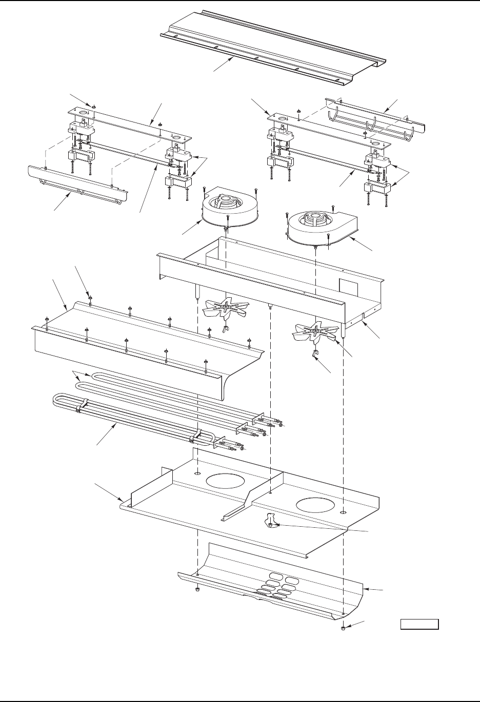
- 12 -
HR7E ROTISSERIE OVEN REPLACEMENT PARTS
F-43102 (May 2005)
HEATING AND VENTING
PL-57718
2
6
24
25
7
45
1
23
8
9
10
11
22
3
16-17
20
21
18-19
15
12
13
14
HR7E Rotisserie Oven Technical Manual Page 61 of 80

- 13 -
HR7E ROTISSERIE OVEN REPLACEMENT PARTS
F-43102 (May 2005)
HEATING AND VENTING
ILLUS. PART NO. NAME OF PART AMT.
PL-57718
1 00-359460-00066 Strip – Lamp Holder Mounting .................................................................................................... 1
2 00-360854 Holder – Quartz Lamp Cap & Base............................................................................................ 2
3 00-877799 Cover – Heater Insulation........................................................................................................... 1
4 00-359460-00066 Strip – Lamp Holder Mounting .................................................................................................... 1
5 00-891065 Kit – Lamp Guard Assy. ............................................................................................................. 1
6 00-360854 Holder – Quartz Lamp Cap & Base............................................................................................ 2
7 00-360155 Lamp – Quartz............................................................................................................................ 1
8 00-359460-00025 Blower (With Fan Blade) ............................................................................................................ 1
9 00-425900-00038 Vent – Chassis Assy. ................................................................................................................. 1
10 00-360127-00002 Fan Blade ................................................................................................................................... 2
11 00-422905-00108 Nut (LH Thread).......................................................................................................................... 2
12 NS-025-04 Crown Nut .................................................................................................................................. 1
13 00-359460-00017 Plate – Air Deflector ................................................................................................................... 1
14 NS-025-04 Crown Nut .................................................................................................................................. 2
15 00-359460-00022 Plate – Ventilating ....................................................................................................................... 1
16 00-359460-00046 Element – Heating (208 V., 3100 Watts) .................................................................................... 2
17 00-359460-00047 Element – Heating (240 V., 3100 Watts) .................................................................................... 2
18 00-356894 Element – Heating (208 V., 2100 Watts) .................................................................................... 1
19 00-357813 Element – Heating (240 V., 2100 Watts) .................................................................................... 1
20 00-877875 Shield – Heat Assy. .................................................................................................................... 1
21 NS-038-13 Lock Nut 10-24 Hex .................................................................................................................. 10
22 00-359460-00025 Blower (With Fan Blade) ............................................................................................................ 1
23 00-360155 Lamp – Quartz............................................................................................................................ 1
24 00-891065 Kit – Lamp Guard Assy. ............................................................................................................. 1
25 NS-038-13 Lock Nut 10-24 Hex ................................................................................................................... 2
HR7E Rotisserie Oven Technical Manual Page 62 of 80
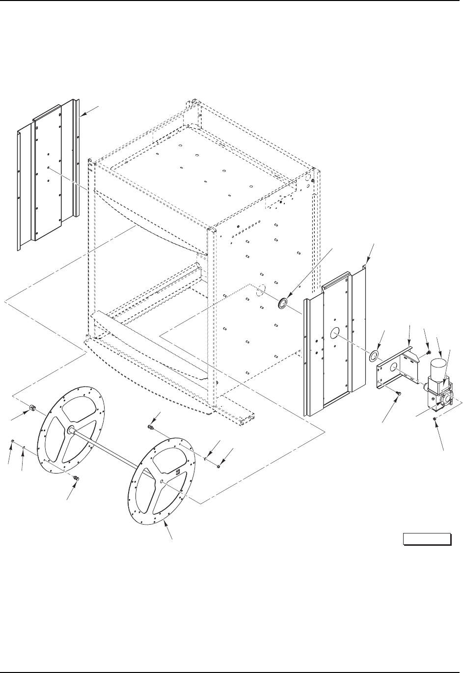
- 14 -
HR7E ROTISSERIE OVEN REPLACEMENT PARTS
F-43102 (May 2005)
ROTISSERIE AND DRIVE MOTOR
PL-57721
1
2
3
45
7
6
8
10
9
11
15
14
12-13
17
18
19
20
16
HR7E Rotisserie Oven Technical Manual Page 63 of 80

- 15 -
HR7E ROTISSERIE OVEN REPLACEMENT PARTS
F-43102 (May 2005)
ROTISSERIE AND DRIVE MOTOR
ILLUS. PART NO. NAME OF PART AMT.
PL-57721
1 00-877790 Plate – Support (Pivot Side) ....................................................................................................... 1
2 00-877941 Seal – Ring ................................................................................................................................. 1
3 00-877789 Plate – Support (Motor Side) ...................................................................................................... 1
4 00-359460-00049 Seal – Outside Motor Shaft ........................................................................................................ 1
5 00-877920 Bracket – Motor Assy. ................................................................................................................ 1
6 SC-117-91 Cap Screw 1/4-20 x 1 Hex Hd. ................................................................................................... 4
7 00-891061 Drive Motor (W/Cap) .................................................................................................................. 1
8 00-891060 Gear Speed Reducer ................................................................................................................. 1
9 NS-038-04 Lock Nut 1/4-20 Hex .................................................................................................................... 4
10 00-891062 Gearbox Drive Arm .................................................................................................................... 1
11 SC-121-61 Mach. Screw 1/4-20 x 5/8 Hex Washer Hd. .................................................................................4
12 00-877923-00001 Disc – Rotor Assy. (Incls. Items 14 thru 20) (SST) ................................................................... 1
13 00-877923-00002 Disc – Rotor Assy. (Incls. Items 14 thru 20) (Coated)............................................................... 1
14 NS-015-11 Nut 5/16-18 Hex (SST) .................................................................................................................. 7
15 SL-005-09 Spring – Loading ........................................................................................................................ 7
16 00-877940 Pin – Support .............................................................................................................................. 7
17 00-877940 Pin – Support .............................................................................................................................. 7
18 SL-005-09 Spring – Loading ........................................................................................................................ 7
19 NS-015-11 Nut 5/16-18 Hex (SST) .................................................................................................................. 7
20 00-877988 Support – Bearing ...................................................................................................................... 1
HR7E Rotisserie Oven Technical Manual Page 64 of 80
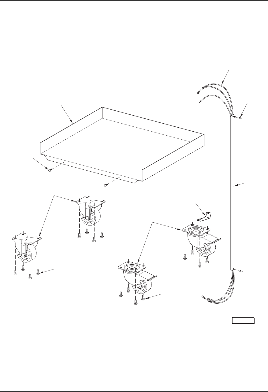
- 16 -
HR7E ROTISSERIE OVEN REPLACEMENT PARTS
F-43102 (May 2005)
STACKING KIT
PL-57724
2
1
3-4
9
11
5
6
7
8
10
HR7E Rotisserie Oven Technical Manual Page 65 of 80

- 17 -
HR7E ROTISSERIE OVEN REPLACEMENT PARTS
F-43102 (May 2005)
STACKING KIT
ILLUS. PART NO. NAME OF PART AMT.
PL-57724
1 00-877968 Bracket – Tether ......................................................................................................................... 1
2 00-877985 Harness – Stacking Kit ............................................................................................................... 1
3 WS-005-42 Washer ....................................................................................................................................... 2
4 NS-038-13 Lock Nut 10-24 Hex ................................................................................................................... 2
5 00-877972 Guide – Wire Assy. .................................................................................................................... 1
6 00-877970 Protector – Fat............................................................................................................................ 1
7 SD-039-33 Self-Tapping Screw ................................................................................................................... 2
8 00-891071 Caster – Rigid ............................................................................................................................. 2
9 SC-117-92 Cap Screw 5/16-18 x 3/4 Hex Hd. ................................................................................................. 8
10 00-891071 Caster – W/Brake ....................................................................................................................... 2
11 SC-117-92 Cap Screw 5/16-18 x 3/4 Hex Hd. ................................................................................................. 8
SC-110-39 Mach. Screw 10-24 x 7/8 Hex Hd. .............................................................................................. 4
WS-019-10 Washer ....................................................................................................................................... 4
NS-038-13 Lock Nut 10-24 Hex ................................................................................................................... 4
00-877892-00002 Plate – Conduit Mounting (Stack Kit) .......................................................................................... 1
00-515194-00002 Sealer (RTU) (Alum.) .................................................................................................................. 1
HR7E Rotisserie Oven Technical Manual Page 66 of 80
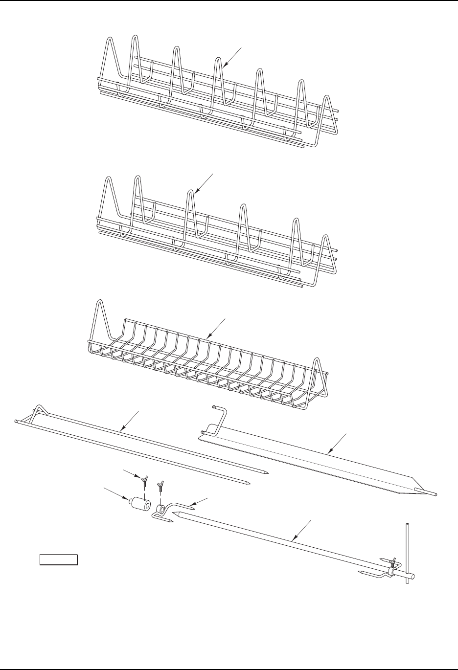
- 18 -
HR7E ROTISSERIE OVEN REPLACEMENT PARTS
F-43102 (May 2005)
ACCESSORIES
PL-57725
1-2
3-4
5-6
13
14
12
11
9-10
7-8
HR7E Rotisserie Oven Technical Manual Page 67 of 80

- 19 -
HR7E ROTISSERIE OVEN REPLACEMENT PARTS
F-43102 (May 2005)
ACCESSORIES
ILLUS. PART NO. NAME OF PART AMT.
PL-57725
1 00-425900-00277 Rack – Chicken (W/O Pins) (5 Position) .................................................................................... 1
2 00-425900-00238 Rack – Chicken (W/O Pins) (5 Position) (Coated) ..................................................................... 1
3 00-425900-00278 Rack – Chicken (W/O Pins) (4 Position) .................................................................................... 1
4 00-425900-00239 Rack – Chicken (W/O Pins) (4 Position) (Coated) ..................................................................... 1
5 00-425900-00276 Basket – Meat (W/O Pins) .......................................................................................................... 1
6 00-425900-00237 Basket – Meat (W/O Pins) (Coated) .......................................................................................... 1
7 00-425900-00317 Fork – Meat ................................................................................................................................. 7
8 00-425900-00318 Fork – Meat (Coated) ................................................................................................................. 7
9 00-359580 Spit – V ....................................................................................................................................... 1
10 00-425900-00236 Spit – V (Coated) ........................................................................................................................ 1
11 00-360386 Sleeve – Spit ............................................................................................................................... 1
12 00-360297 Screw – Wing M5 .................................................................................................................... AR
13 00-360387 Fork – Spit ................................................................................................................................... 2
14 00-425900-00255 Shaft – Spit ................................................................................................................................. 1
00-425774-00032 Spit – Turkey Assy. (Incls. Items 11 thru 14) ............................................................................. 1
00-357553-00158 Saltshaker .................................................................................................................................. 1
00-357553-00159 Gloves (Set of 2) ....................................................................................................................... 1
HR7E Rotisserie Oven Technical Manual Page 68 of 80

FORM 43102 MAY 2005 PRINTED IN U.S.A.
HR7E ROTISSERIE OVEN REPLACEMENT PARTS
HR7E Rotisserie Oven Technical Manual Page 69 of 80

User Guide
Next
select
SMARTPARTS
From
hobartservice.com
select
PARTS
Web Browser Pop-up blocker must be turned off for this site in order for SmartParts to operate
HR7E Rotisserie Oven Technical Manual Page 71 of 80
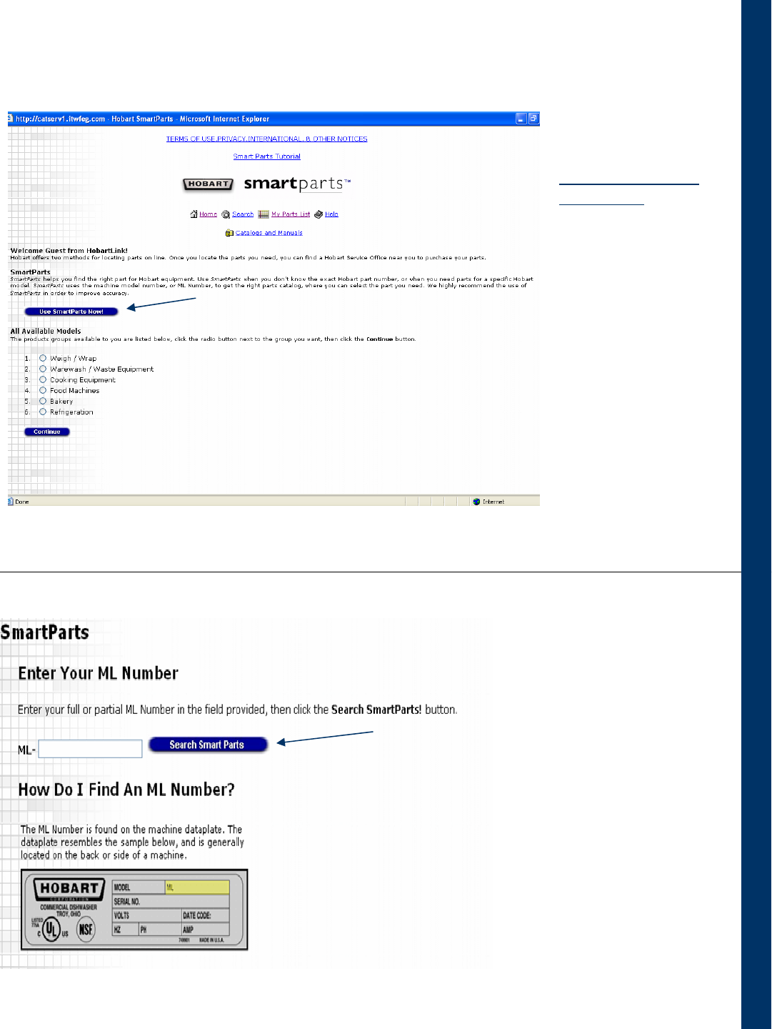
This is SmartParts
home page
If the ML Number of
the Equipment is
known,
select
Use SmartParts Now
(We’ll explain what to
do if the ML number of
the Equipment is not
known in Section 2)
Enter the ML number
and click on
Search SmartParts
For this example, the part needed is a Water
Pressure Gauge used on the LX 30 Undercounter
Dishwasher
The ML number of this dishwasher is 104352
104352
104352
Section 1 – If Equipment ML Number is known
HR7E Rotisserie Oven Technical Manual Page 72 of 80
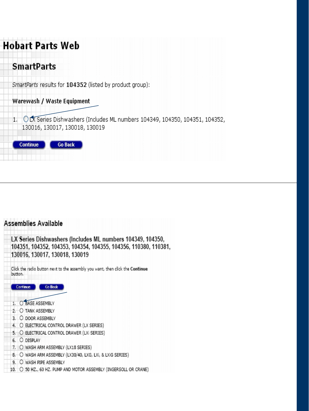
•
Click on the
Radio button
to select the
Parts Catalog
Then click on
Continue
The Water Pressure Gauge is
on the Base Assembly
Select Base Assembly
Then click on Continue
Section 1 – If Equipment ML Number is known
HR7E Rotisserie Oven Technical Manual Page 73 of 80
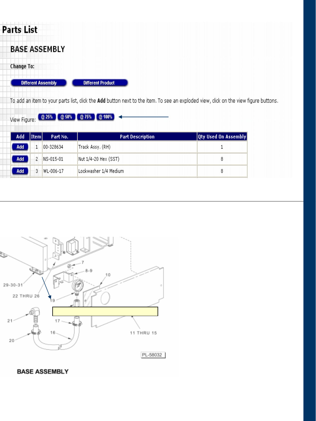
•
Select an appropriate figure size
Locate the part needed (Water
Pressure Gauge) on the drawing
Placing the cursor on the number
will display the Description of the
Part
Click on the number pointing to
the part
Section 1 – If Equipment ML Number is known
19: Gauge – Water Pressure (LX30/40, LXG, & LXiG Series)
HR7E Rotisserie Oven Technical Manual Page 74 of 80
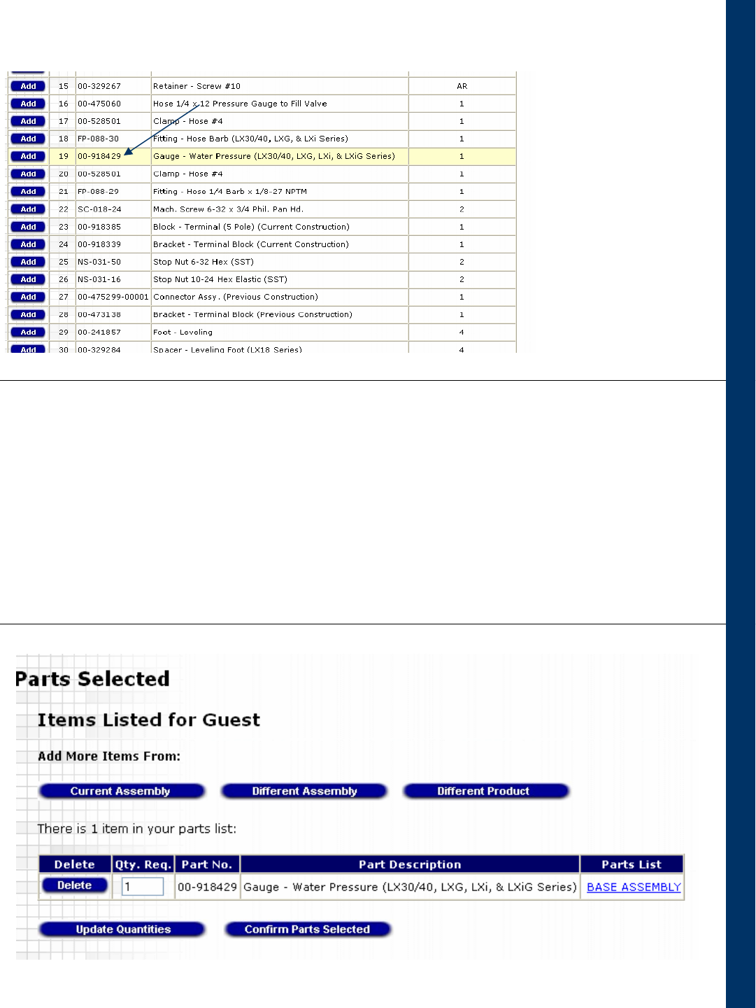
•Selecting the part on the figure causes the part to be highlighted on the parts list
•Click on the Add button to add the part to the shopping cart
•You can add more parts or change the quantity of the parts already in the cart
•When finished, click on the Confirm Parts Selected and then on Print Parts List if
you want to print
Section 1 – If Equipment ML Number is known
Use SMARTPARTS Now
HR7E Rotisserie Oven Technical Manual Page 75 of 80
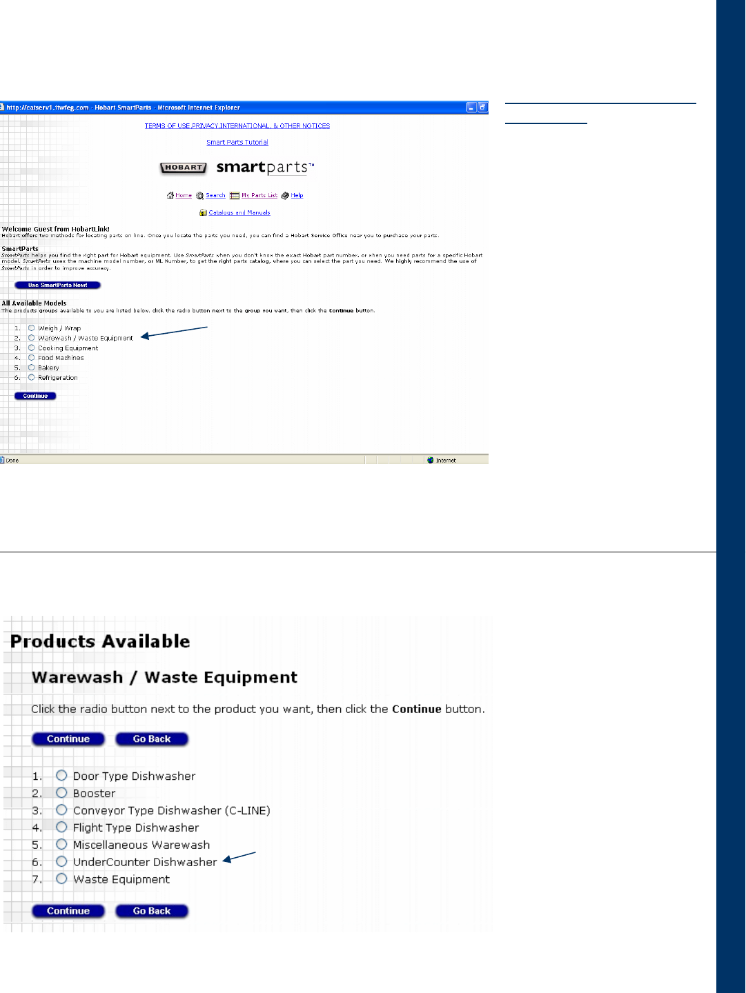
Section 2 – If Equipment ML Number is not known
This (again) is SmartParts
home page
For this example, the part
needed is a Water
Pressure Gauge used on
the LX 30 Undercounter
Dishwasher
If the ML Number of the
Equipment is not known,
click on the Radio button
to select Warewash /
Waste Equipment
Then click on Continue
(Go to Section 1 if you do know
the ML number of the
Equipment)
Click on the Radio button
to select UnderCounter
Dishwasher
Then click on
Continue
HR7E Rotisserie Oven Technical Manual Page 76 of 80
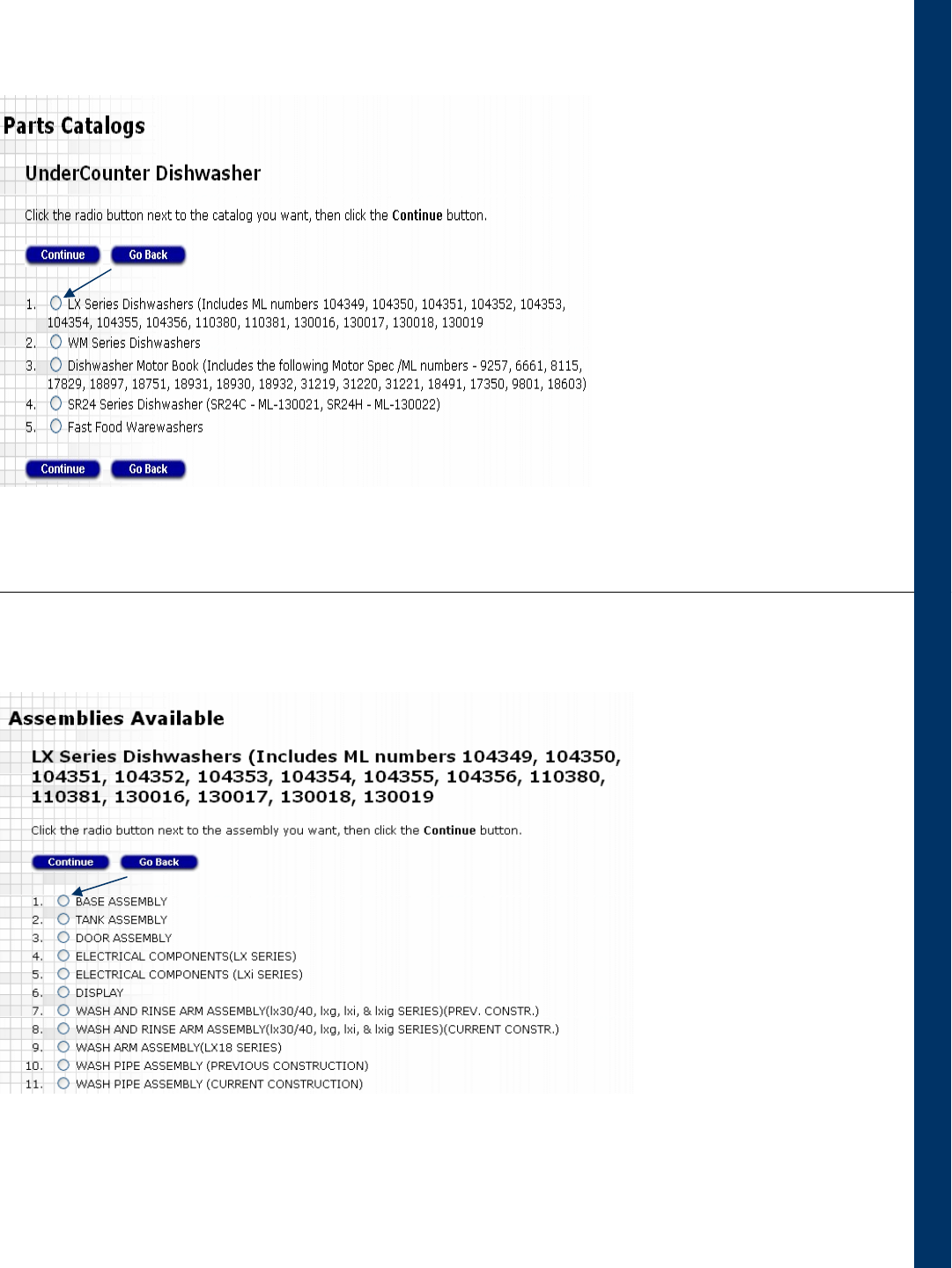
Click on the Radio button
to select LX Series
Dishwashers
Then click on
Continue
Section 2 – If Equipment ML Number is not known
The Water Pressure Gauge
is on the Base Assembly
Select Base Assembly
Then click on Continue
HR7E Rotisserie Oven Technical Manual Page 77 of 80
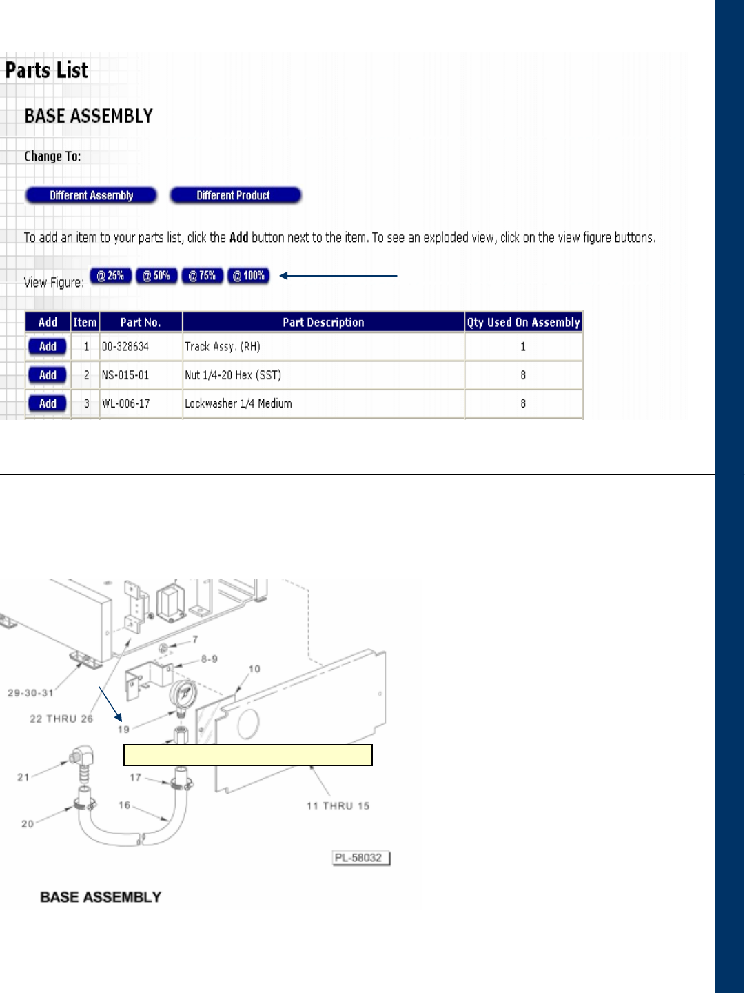
Locate the part needed (Water
Pressure Gauge) on the
drawing
Placing the cursor on the
number will display the
Description of the Part
Click on the number pointing to
the part
Section 2 – If Equipment ML Number is not known
19: Gauge – Water Pressure (LX30/40, LXG, & LXiG Series)
Select an appropriate figure size
HR7E Rotisserie Oven Technical Manual Page 78 of 80
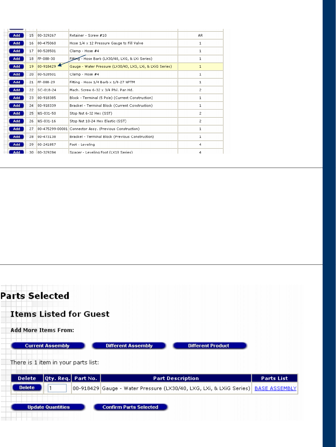
•Selecting the part on the figure causes the part to be highlighted on the parts list
•Click on the Add button to add the part to the shopping cart
•You can add more parts or change the quantity of the parts already in the cart
•When finished, click on the Confirm Parts Selected and then on Print Parts List if
you want to print
Section 2 – If Equipment ML Number is not known
Use SMARTPARTS Now
HR7E Rotisserie Oven Technical Manual Page 79 of 80
HR7E Rotary Ovens
April 2012
PRODUCT SERVICE DEPARTMENT TROY, OH. 45374-0001
RECOMMENDED SPARE PARTS LIST
HR7E Rotary Ovens
Qty
Part Number
Description
2
00-913102-00172
Kit, Fan, Motor And Blade
2
00-877885
Capacitor Blower Motor,1.5uf
1
00-877887
Capacitor, 40W Rotor Motor, 2.3uf
1
00-877888
Contactor
1
00-877882
Display Bd.
2
00-356894
Element 2100W 208 Volt - HR7E
2
00-357813
Element 2100W 240 Volt - HR7E
1
00-359460-46
Element 3100W 208 Volt - HR7E
1
00-359460-47
Element 3100W 240 Volt - HR7E
1
00-891060
Gear Speed Reducer With Serial No. Before 46-2006-865
1
00-891062
Gearbox/Drive Arm With Serial No. Before 46-2006-865
1
00891417
Gearbox/Drive Arm With Serial No. After 46-2006-865
1
00-877881
Main Control Bd.
1
00-877913-1
Main Power Switch
2
00-360155
Quartz Heater 1000w
1
00-877884
Ribbon Cable
1
00-891061
Rotor Motor, 40W (includes Capacitor)
1
00-356946
Temperature Probe
1
00-360145
Thermostat ( hi-limit)
1
00-891066
Touch Pad Assy.
HR7E Rotisserie Oven Technical Manual Page 80 of 80
