Operating Manual TNC 151 A/P, 155 A/P Heidenhain AP Conversational Programming
User Manual: Heidenhain-TNC-151-AP-Conversational-Programming Bridgeport == Series II Interact 2
Open the PDF directly: View PDF ![]() .
.
Page Count: 316 [warning: Documents this large are best viewed by clicking the View PDF Link!]
HEIDENHAIN
Optics and Electronics
Precision Graduations
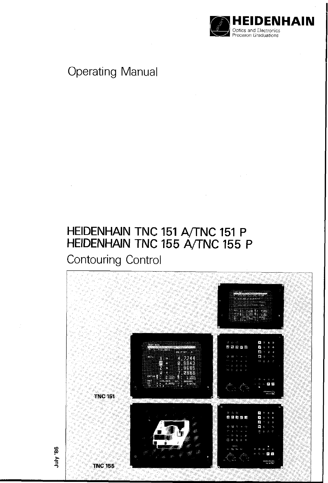
Operating Manual
HEIDENHAIN TNC 151 A/TNC 151 P
HEIDENHAIN TNC 155 A/TNC 155 P
Contouring Control
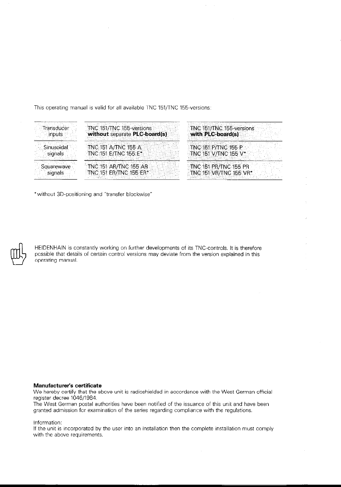
This operating manual is valid for all available TNC lSl/TNC 155.versions:
*without 3D-positioning and “transfer biockwisev
HEIDENHAIN is constantly working on further developments of its TNC-controls. It is therefore
possible that details of certain control versions may deviate from the version explained in this
operating manual.
Manufacturer’s certificate
We hereby certify that the above unit is radioshielded in accordance with the West German official
register decree 104611984.
The West German postal authorities have been notified of the issuance of this unit and have been
granted admission for examination of the series regarding compliance with the regulations.
Information:
If the unit is incorporated by the user into an installation then the complete installation must comply
with the above reauirements.
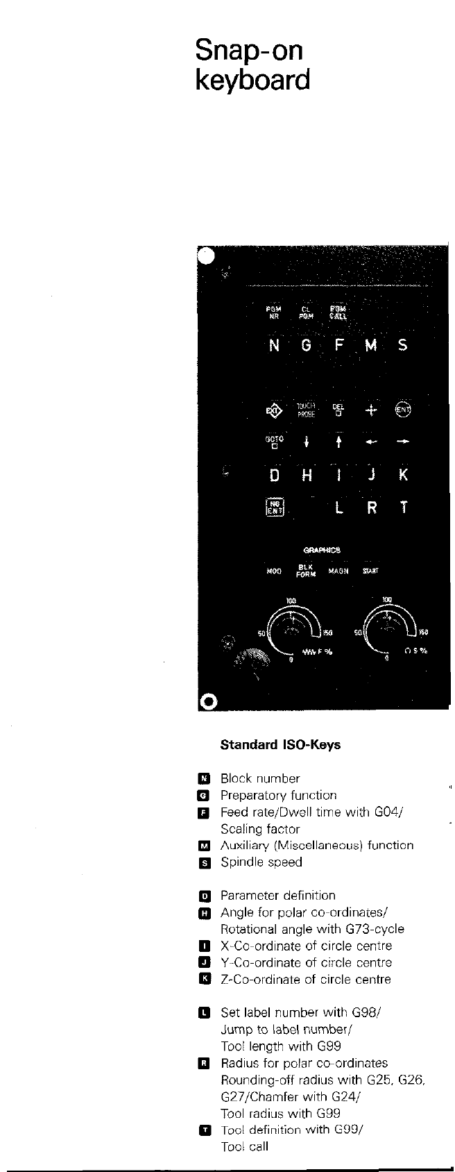
Snap-on
keyboard
Standard ISO-Keys
q
Block number
q
Preparatory function
q
Feed rate/Dwell time with G04/
Scaling factor
q
Auxiliary (Miscellaneous) function
q
Spindle speed
0 Parameter definition
Q Angle for polar co-ordinates/
Rotational angle with G73-cycle
0 X-Co-ordinate of circle centre
q
Y-Co-ordinate of circle centre
q
Z-Co-ordinate of circle centre
0 Set label number with G98/
Jump to label number/
Tool length with G99
0 Radius for polar co-ordinates
Rounding-off radius with G25. G26.
G27/Chamfer with G24/
Tool radius with G99
0 Tool definition with G99/
Tool call
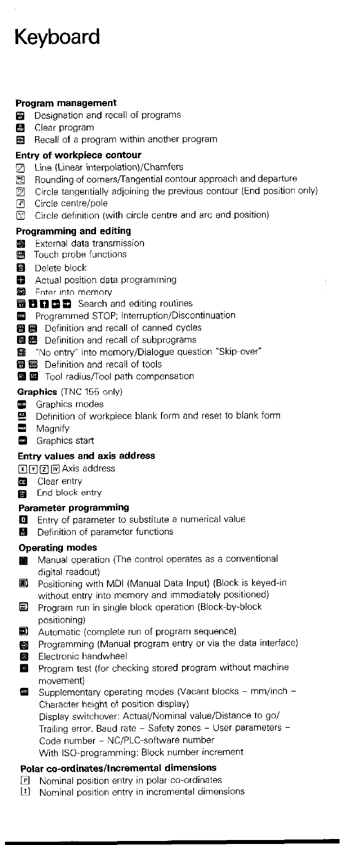
Keyboard
Program management
q
Designation and recall of programs
q Clear program
H Recall of a program within another program
Entry of workpiece contour
q
Line (Linear interpolation)/Chamfers
a Rounding of cornersflangential contour approach and departure
q
Circle tangentially adjoining the previous contour (End position or
q
Circle centre/pole
q
Circle definition (with circle centre and arc end position)
Programming and editing
External data transmission
Touch probe functions
q
Delete block
Actual position data programming
Enter into memory
H FI 0 0 0 Search and editing routines
q
Programmed STOP; Interruption/Discontinuation
q q
Definition and recall of canned cycles
!#! E# Definition and recall of subprograms
q
-No entry” into memory/Dialogue question “Skip-over”
m
q
Definition and recall of tools
q
@ Tool radiusflool path compensation
Graphics
(TNC 155 only)
m Graphics modes
&! Definition of workpiece blank form and reset to blank form
0 Magnify
q
Graphics start
Entry values and axis address
q
a B @ Axis address
0 Clear entry
q
End block entry
Parameter programming
0 Entry of parameter to substitute a numerical value
q
Definition of parameter functions
Operating modes
Ip Manual operation (The control operates as a conventional
digital readout)
q
Positioning with MDI (Manual Data Input) (Block is keyed-in
without entry into memory and immediately positioned)
•I Program run in single block operation (Block-by-block
positioning)
q
Automatic (complete run of program sequence)
q
Programming (Manual program entry or via the data interface)
Electronic handwheel
q
Program test (for checking stored program without machine
movement)
q
Supplementary operating modes (Vacant blocks - mm/inch -
Character height of position display)
Display switchover: Actual/Nominal value/Distance to go/
Trailing error. Baud rate - Safety zones - User parameters -
Code number NC/PLC-software number
With ISO-programming: Block number increment
Polar co-ordinates/Incremental dimensions
l?l Nominal position entry in polar co-ordinates
m Nominal position entry in incremental dimensions
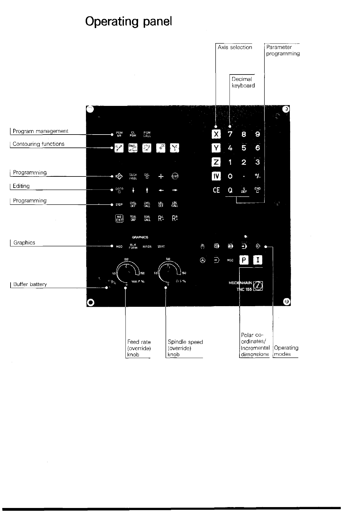
Operating panel
I lkcvboard I
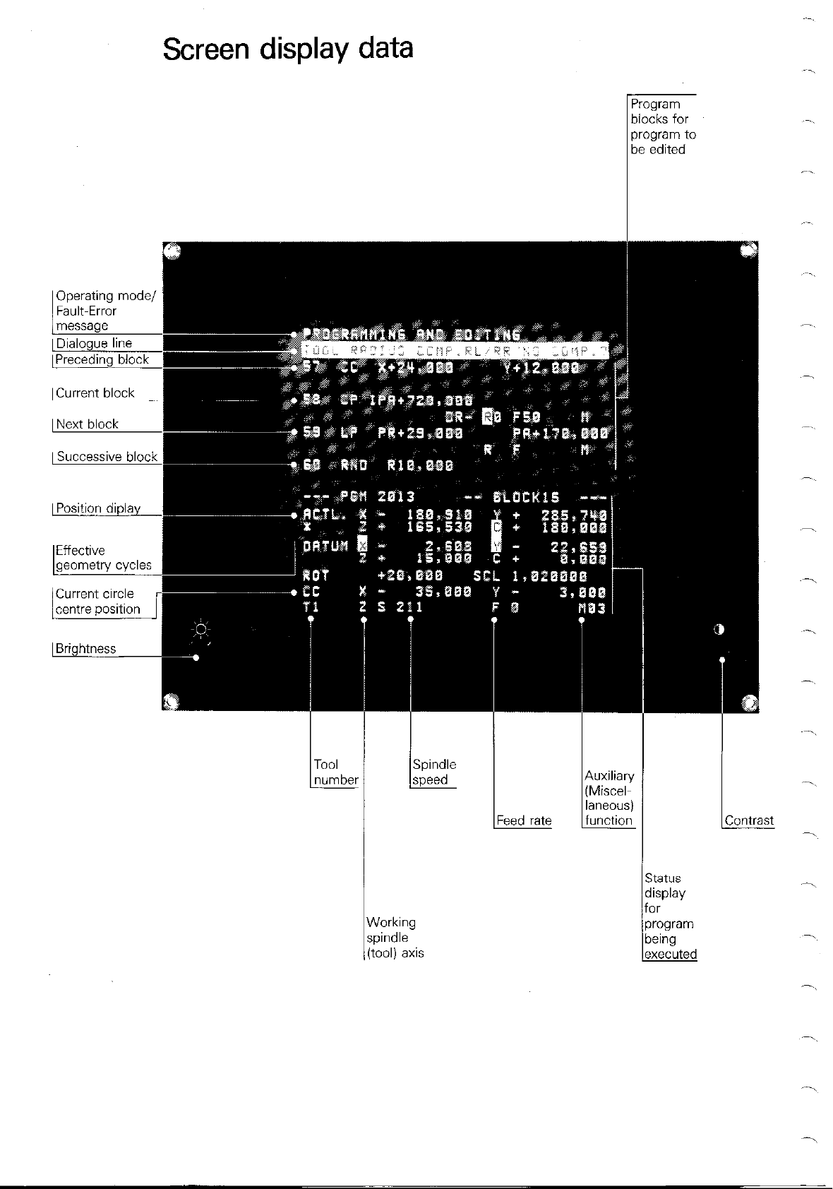
Screen display data
be edited
I Dialogue line
[Preceding block
I Current block I
I Next block I
I Successive block
I Position diplav
1 Brightness
iiorking
DindIe
OOlj
List of contents
Introduction E
Manual operation M
Co-ordinate system and dimensions K
Programming with HEIDENHAIN plain language dialogue P
Program entry in ISO-format (G-codes) D
Touch probe system A
External data transmission via V.24/RS-232-C-interface V
Technical description and specifications, Index T
Brief description
TNC 151/TNC 155 Control
Control type The HEIDENHAIN TNC 151/TNC 155 is a con-
touring control for 4 axes. Axes X. Y and Z are
linear axes and axis IV can be used optionally for
the connection of a rotary table or a further linear
axis. The fourth axis can be switched on or off as
is required.
This 4-axis control permits:
0 linear interpolation in any 3 axes
l
circular interpolation in two linear axes
With the aid of parameter programming, com-
plex contours can be machined.
Program entry Program entry can be either in
0 HEIDENHAIN plain language dialogue
0 in standard format to IS0 6983 (G-codes).
Dialogues. entry values. the machining program.
fault/error messages and position data are dis-
played on the VDU-screen. The program memory
has a capacity for 32 programs with a total of
3100 blocks.
Entry of the machining program is either by
manual key-in or “electronically” via a data inter-
face.
The “transfer blockwise- mode permits transfer
and execution of machining programs from an
external data store.
During execution of a machining program. a fur-
ther program may be manually entered via the
background programming feature.
Magnetic tape The HEIDENHAIN magnetic tape units ME lOl/
cassette units ME 102 are available for external storage of a
program on magnetic tape cassettes. These units
each have two interfaces for connections of a
peripheral unit (e.g. a printer) in addition to the
TNC 151ITNC 155.
EZ
Brief description
TNC 151/TNC 155 Control
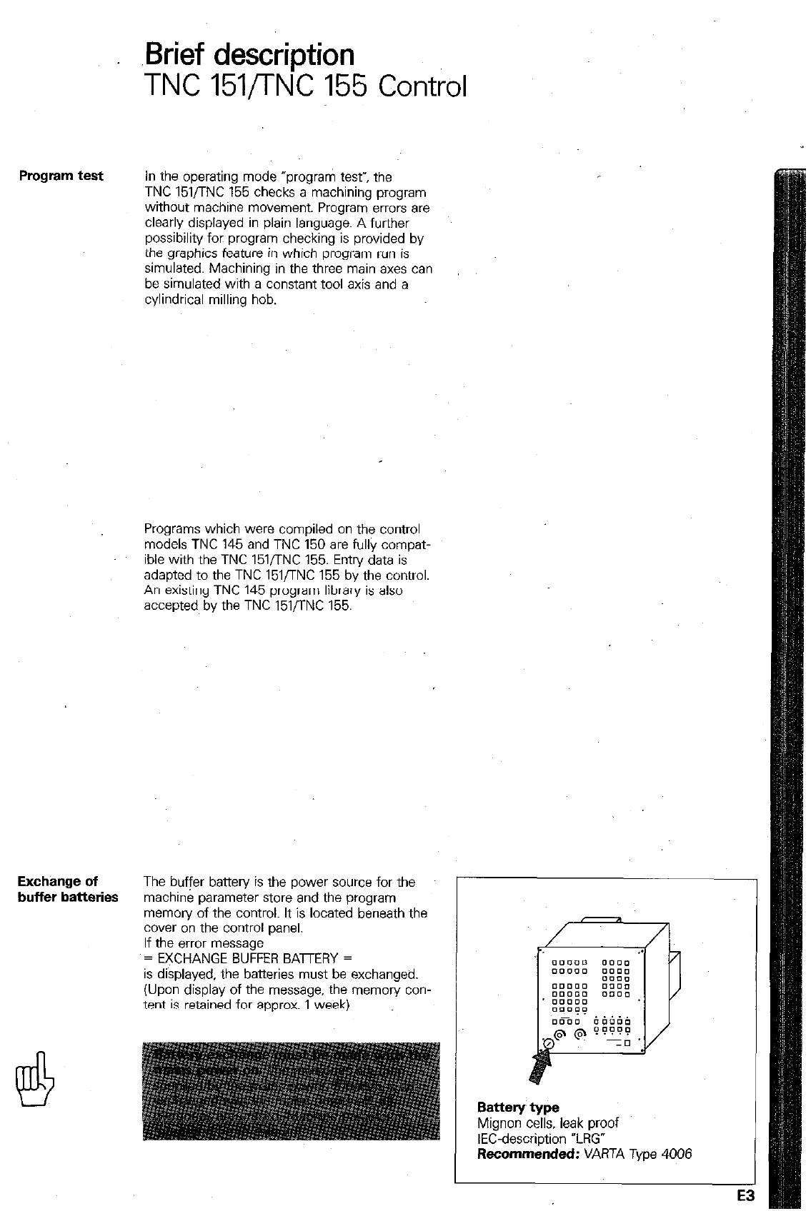
Program test In the operating mode “program test”, the
TNC 151/TNC 155 checks a machining program
without machine movement. Program errors are
clearly displayed in plain language. A further
possibility for program checking is provided by
the graphics feature in which program run is
simulated. Machining in the three main axes can
be simulated with a constant tool axis and a
cylindrical milling hob.
Programs which were compiled on the control
models TNC 145 and TNC 150 are fullv comoat-
ible with the TNC 151,‘TNC 155. Entn/ data is
adapted to the TNC 151/TNC 155 by the control.
An existing TNC 145 program library is also
accepted by the TNC 151flNC 155.
Exchange of
buffer batteries The buffer battery is the power source for the
machine parameter store and the program
memory of the control. It is located beneath the
cover on the control panel.
If the error message
= EXCHANGE BUFFER BAmERY =
is displayed, the batteries must be exchanged.
(Upon display of the message. the memory con-
tent is retained for approx. 1 week)
Battery type
Mignon cells, leak proof
IEC-description “LRG”
Recommended: VARTA Type 4006
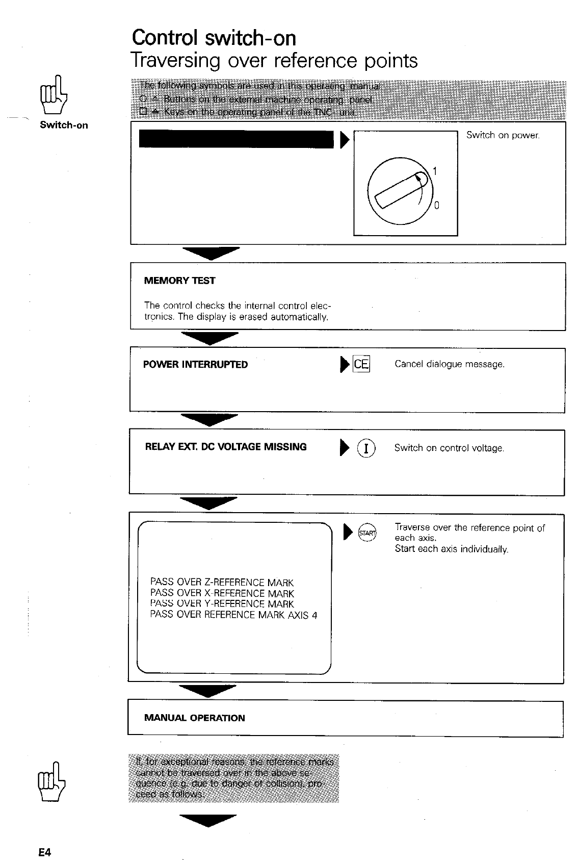
Control switch-on
Traversing over reference points
Switch-on Switch on power.
MEMORY TEST
The control checks the internal control elec-
trpnics. The display is erased automatically.
POWER INTERRUPTED Cancel
dialogue message.
RELAY WEAGE MlSSlNG ) @
Switch on control voltage.
/
\
PASS OVER Z-REFERENCE MARK
PASS OVER X-REFERENCE MARK
PASS OVER Y-REFERENCE MARK
PASS OVER REFERENCE MARK AXIS 4
MANUAL OPERATION
E4
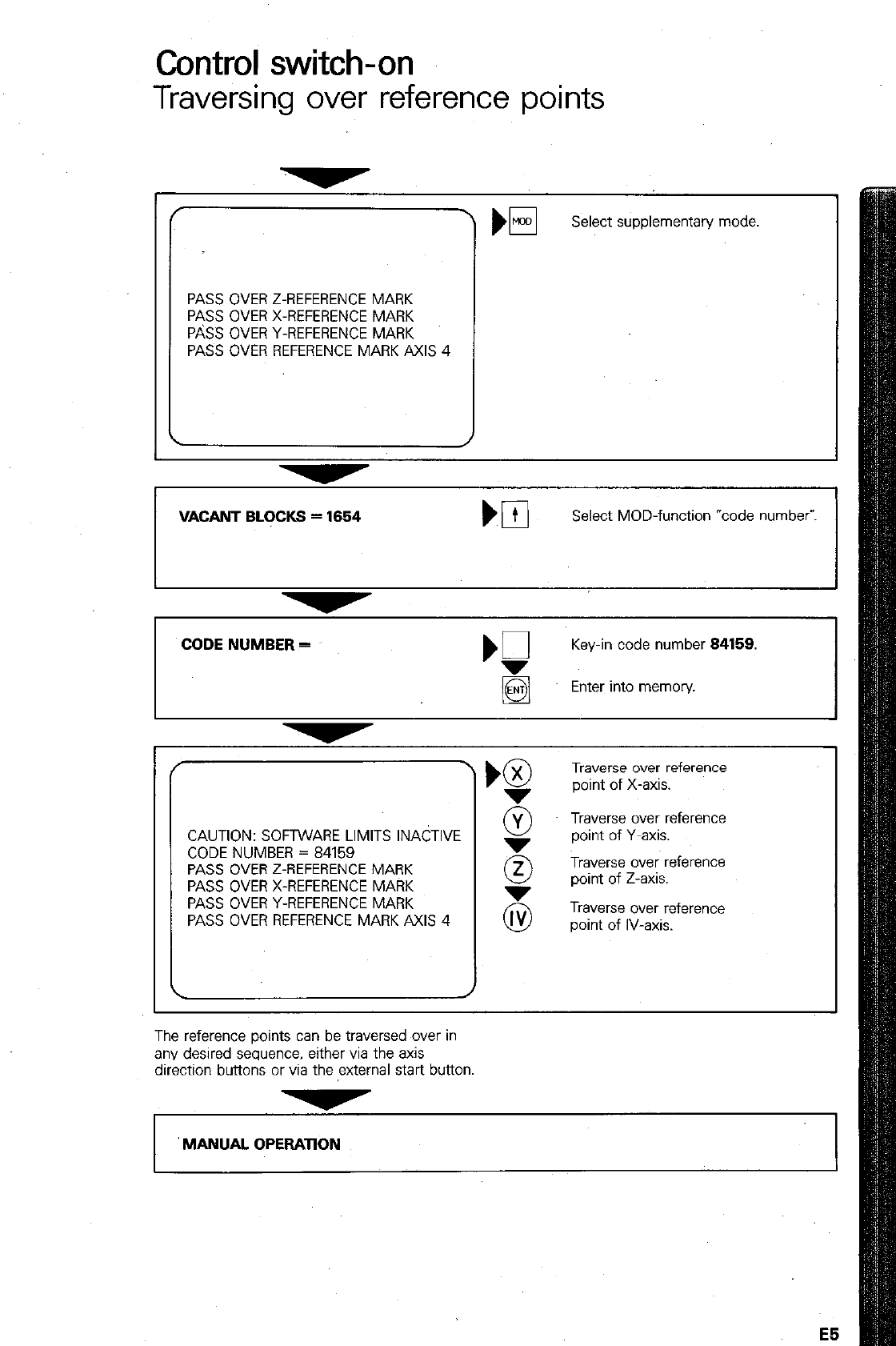
Control switch-on
Traversing over reference points
PASS OVER Z-REFERENCE MARK
PASS OVER X-REFERENCE MARK
P&S OVER Y-REFERENCE MARK
PASS OVER REFERENCE MARK AXIS 4
El
Select supplementary mode
VACANT BLOCKS = 1664 Select MOD-function “code number-.
CODE NUMBER =
‘Q
Key-in code number 84158.
Enter into memov.
CAUTION: SOFTWARE LIMITS INACTIVE
CODE NUMBER = 84159
PASS OVER Z-REFERENCE MARK
PASS OVER X-REFERENCE MARK
PASS OVER Y-REFERENCE MARK
PASS OVER REFERENCE MARK AXIS 4
Traverse over reference
point of X-axis.
@ T$rsyer~ference
5 Traverse over reference
point of Z-axis.
Traverse over reference
point of IV-axis.
The reference points can be traversed over in
any desired sequence, either via the axis
direction buttons or via the external start button
v
‘MANUAL OPERATION
E5
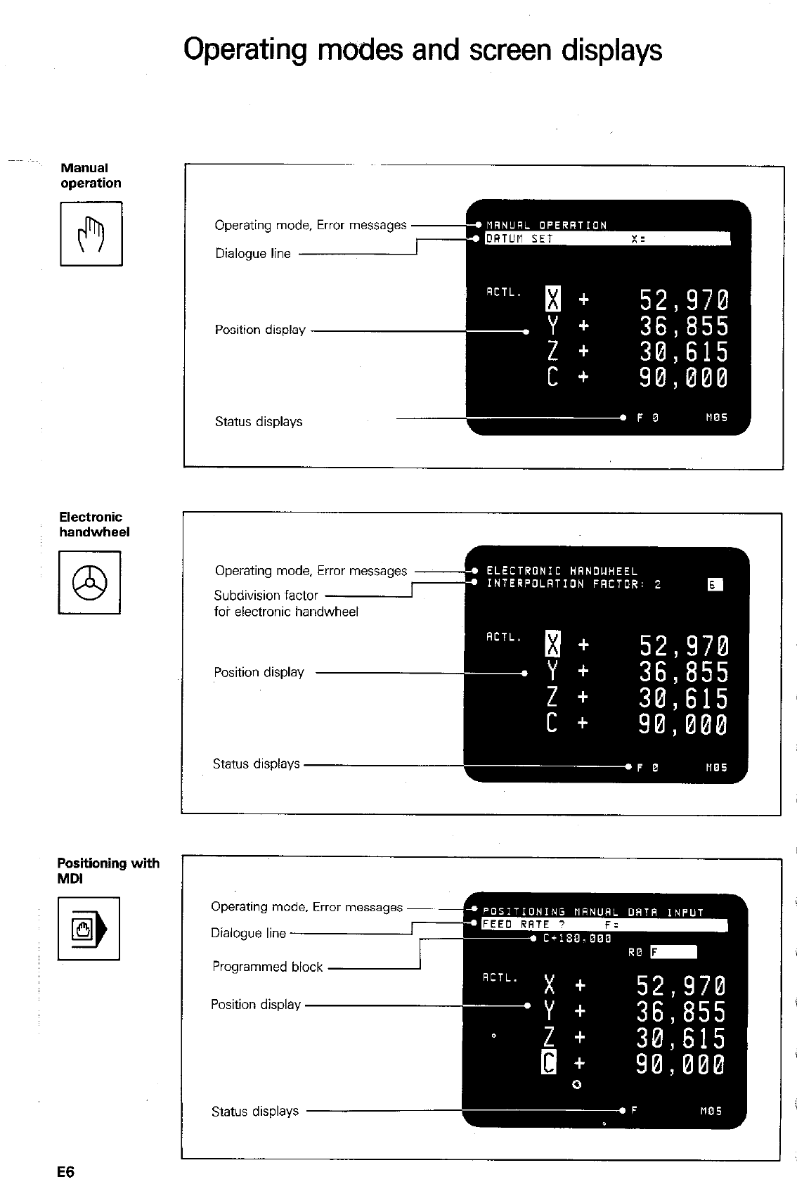
Operating modes and screen displays
MWllJal
operation
Electronic
handwheel
Positioning with
MDI
I 1
M
IEil
Operating mode, Error massages
Status displays
Operating mode, Error messages
Subdivision factor
foi electronic hand
Operating mode. Error messages
Programmed block
E6
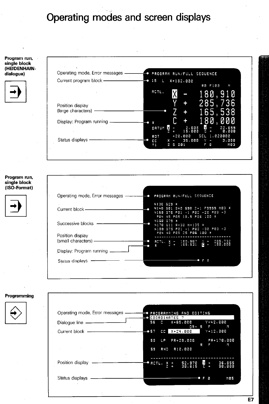
Operating modes and screen displays
Program run,
single block
(HEIDENHAIN-
dialogue)
Program run,
single block
(ISO-Format)
Programming
El
+
3
Operating mode, Error messages
Current program block
Position display
(large characters)
Display: Program running
Status displays
Operating mode, Error messages
Successive blocks
(small characters)
~Display: Program running
Operating mode, Error messages
Current block
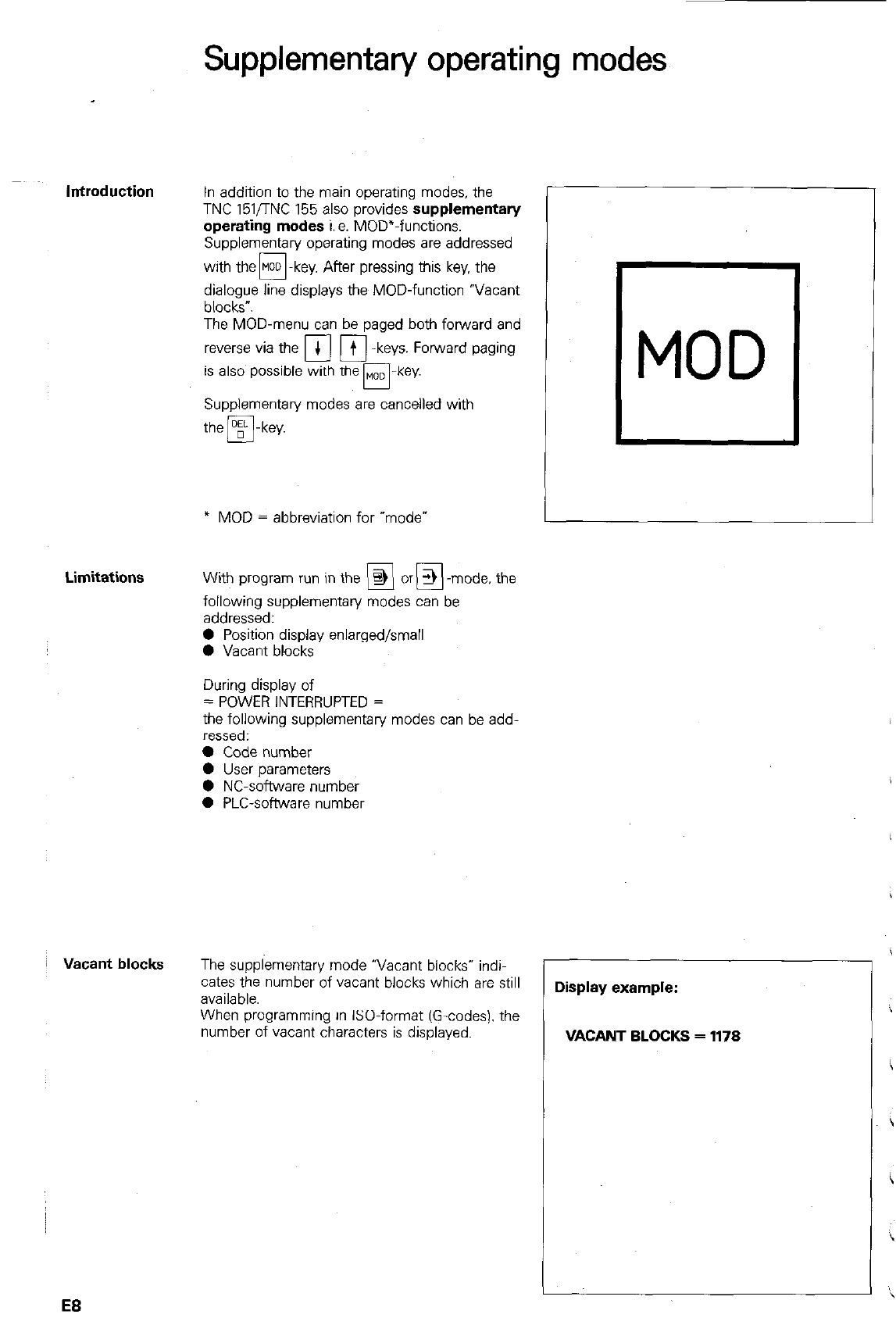
Supplementary operating modes
In addition to the main operating modes, the
TNC 151nNC 155 also provides
supplementary
operating modes
i. a. MOD”-functions.
Supplementary operating modes are addressed
with the@-key. After pressing this key. the
dialogue line displays the MOD-function “Vacant
blocks”.
The MOD-menu can be paged both forward and
reverse via the +
cl
q
-keys. Forward paging
is also possible with the MOD
n-key.
Supplementary modes are cancelled with
the m-key.
* MOD = abbreviation for “mode*
With program run in the @ or > -mode, the
UEI
following supplementary modes can be
addressed:
0 Position display enlarged/small
0 Vacant blocks
During display of
= POWER INTERRUPTED =
the following supplementary modes can be add-
ressed:
l
Code number
0 User parameters
0 NC-software number
0 PLC-software number
The supplementary mode “Vacant blocks” indi-
cates the number of vacant blocks which are still
available
When programming in &O-format (G-codes). the
number of vacant characters is displayed.
MOD I
L
Display example:
VACANT BLOCKS = 1178
EB
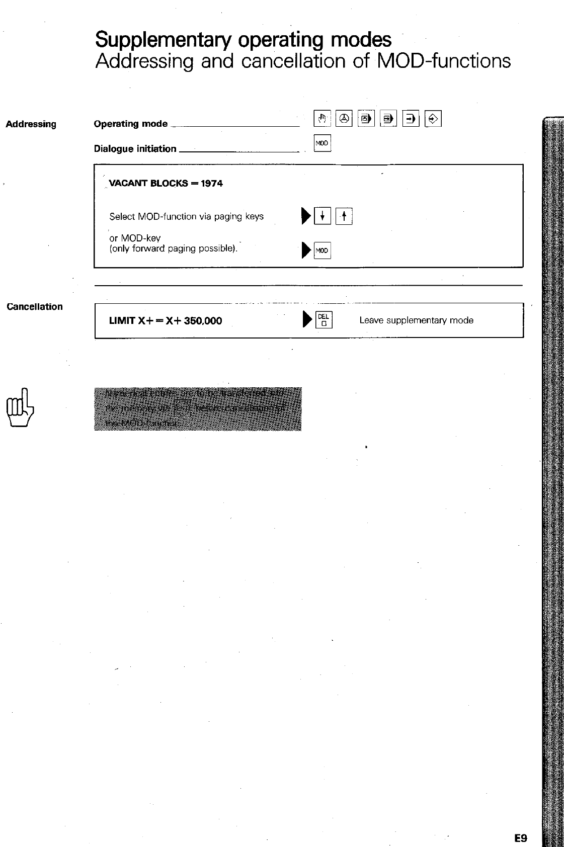
Supplementary operating modes
Addressing and cancellation of MOD-functions
Addressing Operating mode - -
Dialogue initiation
Cancellation
VACANT BLOCKS = 1974
Select MOD-function via paging keys
or MOD-key
(only forward paging possible).
LIMIT X+ = X+ 350,000
Leave supplementary mode
E9
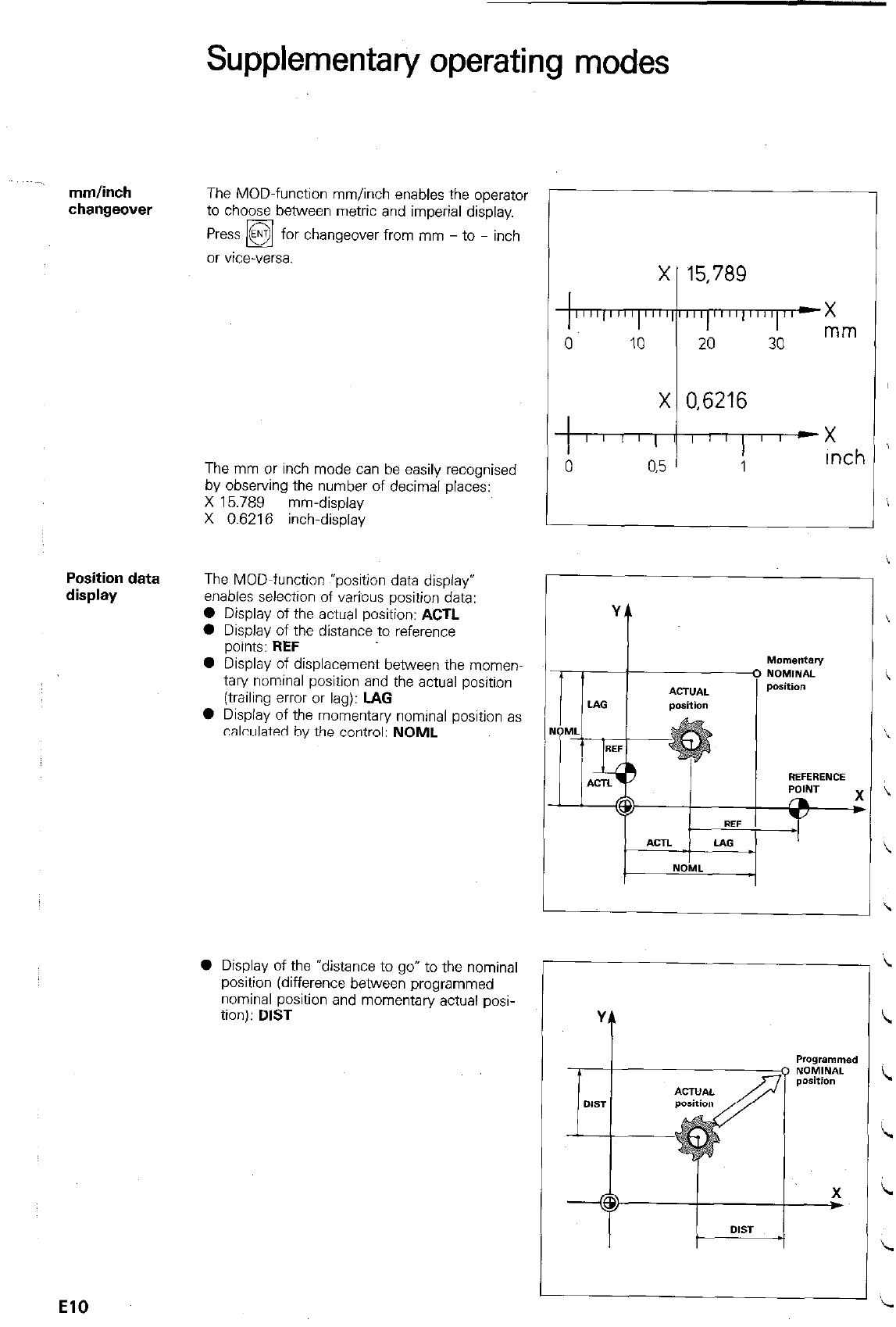
mm/inch
changeover
Position data
display
Supplementary operating modes
The MOD-function mm/inch enables the operator
to choose between metric and imperial display.
changeover from mm - to - inch
The mm or inch mode can be easily recognised
by observing the number of decimal places:
X 15.789 mm-display
X 0.6216 inch-display
The MOD-function exposition data display”
enables selection of varjous position data:
0 Display of the actual position: ACTL
0 Display of the distance to reference
points: REF
l
Display of displacement between the momen-
tary nominal position and the actual position
(trailing error or lag): LAG
0 Display of the momentary nominal position as
calculated by the control: NOML
0 Display of the *distance to go” to the nominal
position (difference between programmed
nominal position and momentary actual posi-
tion): DIST
Y
t
El0
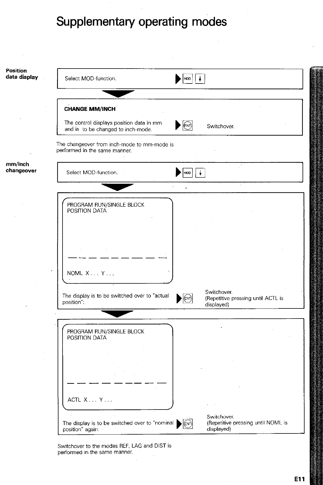
Supplementary operating modes
Position
data display
Select MOD-function. Nml
CiWUGE MM/INCH
The control displays position data in mm
and is to be chanaed to inch-mode. Switchover.
The changeover from inch-mode to mm-mode is
performed in the sa~me manner.
mm/inch
changeover
Select MOD-function.
I I
c
f
PROGRAM RUN/SINGLE BLOCK
POSITION DATA
---------
NOML X Y
f PROGRAM RUN/SINGLE BLOCK
POSITION DATA
___------
ACTL X Y
The display is to be switched over to *actual
position”:
\
TI
P’
?e display is to be switched wer to “nominal
xition” again:
until NOML is
Switchover to the modes REF.~ LAG and DIST is
performed in the same manner.
El1
Supplementary operating modes
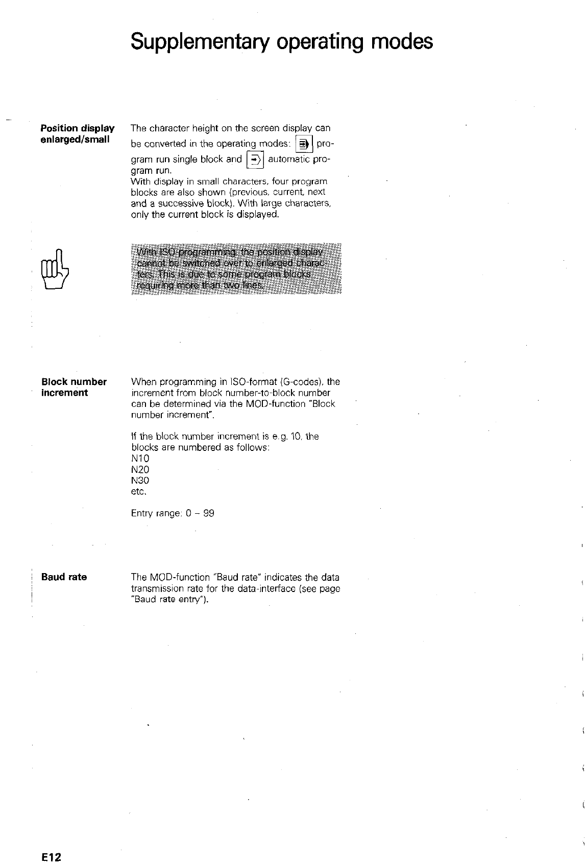
Position display
The character height on the screen display can
enlarged/small
be converted in the operating modes:
q
pro-
gram run single block and 3 automatic pro-
gram run. 0
With display in small characters. four program
blocks are also shown (previous. current. next
and a successive block). With large characters.
only the current block is displayed.
Block number
increment
When programming in ISO-format (G-codes). the
increment from block number-to-block number
can be determined via the MOD-function *Block
number wxrement”.
If the block number increment is e.g. IO. the
blocks are numbered as follows:
NlO
N20
N30
etc.
Entry range: 0 - 99
Baud rate
The MOD-function “Baud rate* indicates the data
transmission rate for the data-interlace (see page
“Baud rate entry’).
El2
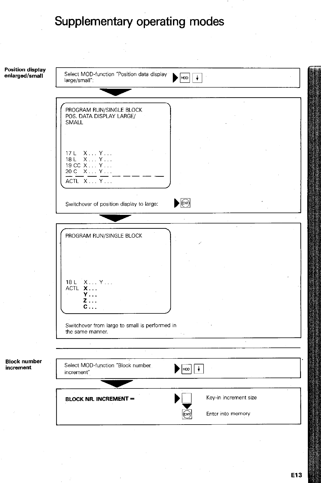
Position display
enlarged/small
Block number
increment
Supplementary operating modes
PROGRAM RUN/SINGLE BLOCK
POS. DATA DISPLAY LARGE/
SMALL
17L x.. Y..
18L X... Y...
19cc x... Y...
2oc x.. Y...
_--------
ACTL X Y
Select MOD-function *Position data display
large/small”: )wpj
I
Switchover of position display to large: w
PROGRAM RUN/SINGLE BLOCK
18L X...Y
ACTL X..
Y...
if...
C..
Switchover from large to small is performed in
the same manner.
Select MOD-function “Block number
Increment”
BLOCK NR INCREMENT =
‘3
Key-in increment SW
Enter into memory
El3
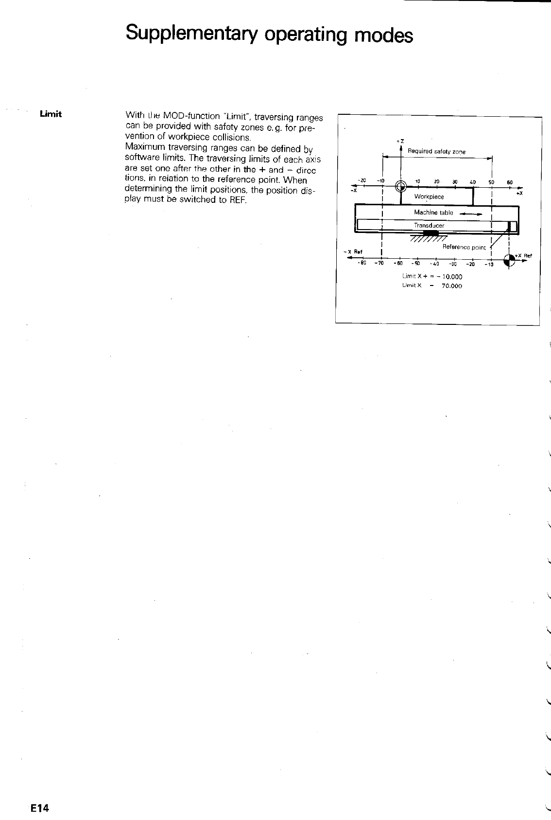
Limit
Supplementary operating modes
With the MOD-function “Limit”, traversing ranges
can be provided with safety zones e.g. for pre-
venton of workpiece collisions.
Maximum traversing ranges can be defined by
software limits. The traversing limits of each axis
are set one after the other in the + and - direc-
tions. in relatio~n to the reference point. When
determining the limit positions, the position dis-
play must be switched to REF.
El4
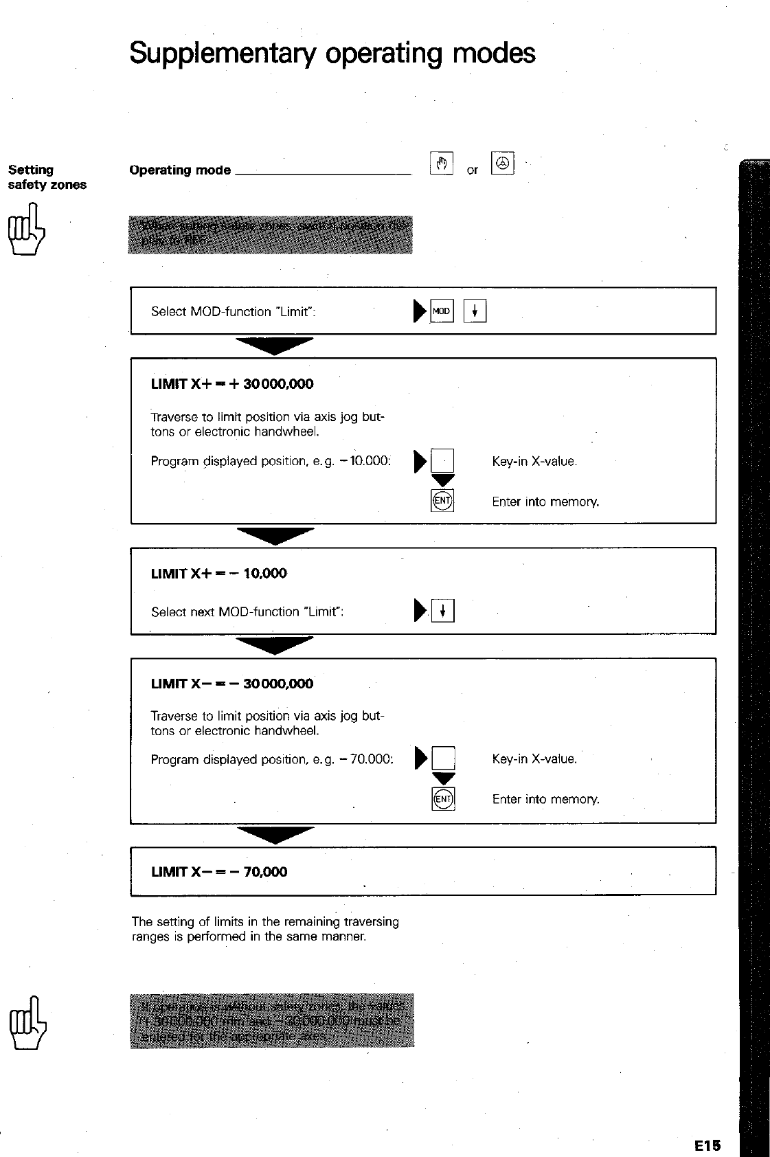
Supplementary operating modes
Setting
safety zones Operating mode
Select MOD-function wLimit”:
LIMIT X+ = + 30000,000
Traverse to limit position via axis jog but-
tons or electronic handwheel.
Program displayed position, e.g. -Ib.OOO: ) 0 Key-in X-value.
5 Enter into memon/
I
LIMIT X+ = - 10,000
Select next MOD-function “Limit”:
LIMIT X- = - 30000,000
Traverse to limit position via axis jog but-
tons or electronic handwheel.
Program displayed position. e.g. - 70.000: ) 0 Key-in X-value.
Enter into memory.
LIMIT X- = - 70,000
The setting of limits in the rernainin$ traversing
ranges is performed in the same manner.
El!3
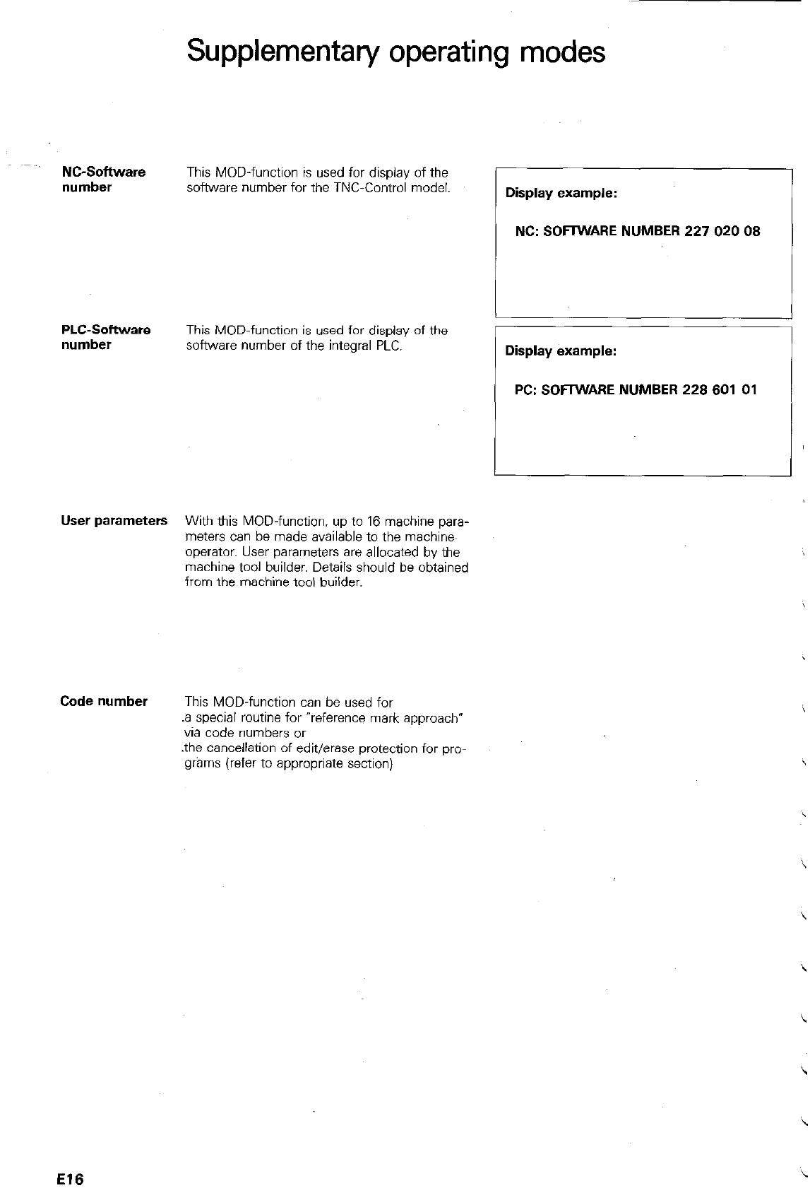
Supplementary operating modes
- NC-Software
This MOD-function is used for display of the
number software number for the TNC-Control model. Display example:
/ NC: SOFIWARE NUMBER 227 020 08
1
PLC-Sofhware
number This MOD-function is used for display of the
software number of the integral PLC. Display example:
PC: SOFIWAFIE NUMBER 228 601 01
User parameters With this MOD-function. up to 16 machine para-
meters can be made available to the machire
operator. User parameters are allocated by the
machine tool builder. Details should be obtained
from the machine tool builder.
Code number This MOD-function can be used for
.a special routine for “reference mark approach*
via code numbers or
.the cancellation of edit/erase protection for pm
grams (refer to appropriate section)
El6
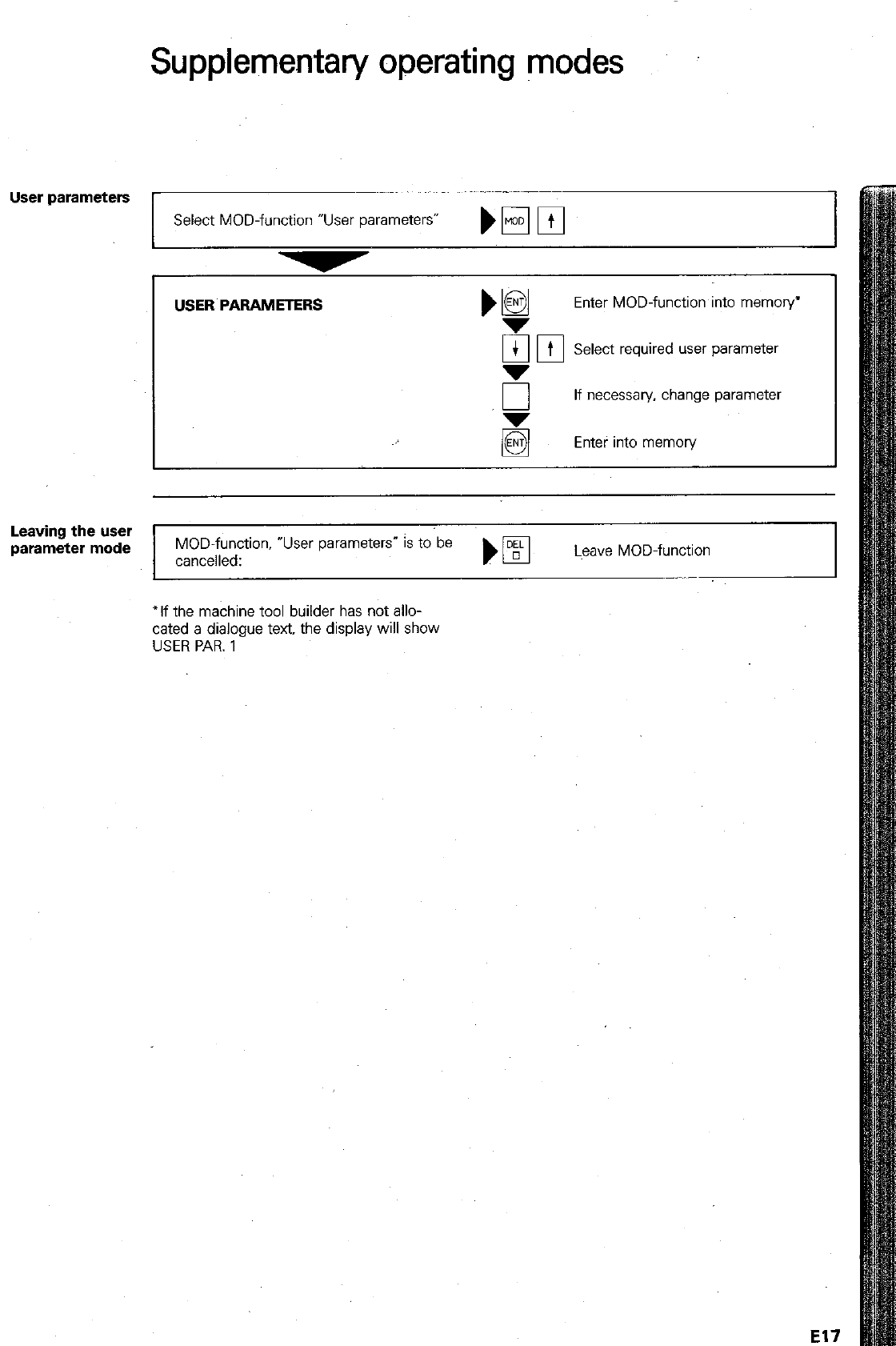
Supplementary operating modes
User parameters
Select MOD-function “User parameters” bE3rn
I
USER PARAMETERS
Enter MOD-function into memory’
ran
--
Select required user parameter
I
I I
“r
If necessary. change parameter
El
Enter into memory
Leaving the user
parameter mode
MOD-function, *User parameters” is to be
cancelled: )
q
Lwxe MOD-function I
‘If the machine tool builder has not allo-
cated a dialogue text. the display will show
USER PAR. 1
El7
Remarks
Axis jog
Continuous
operation
Feed rate
Spindle speed
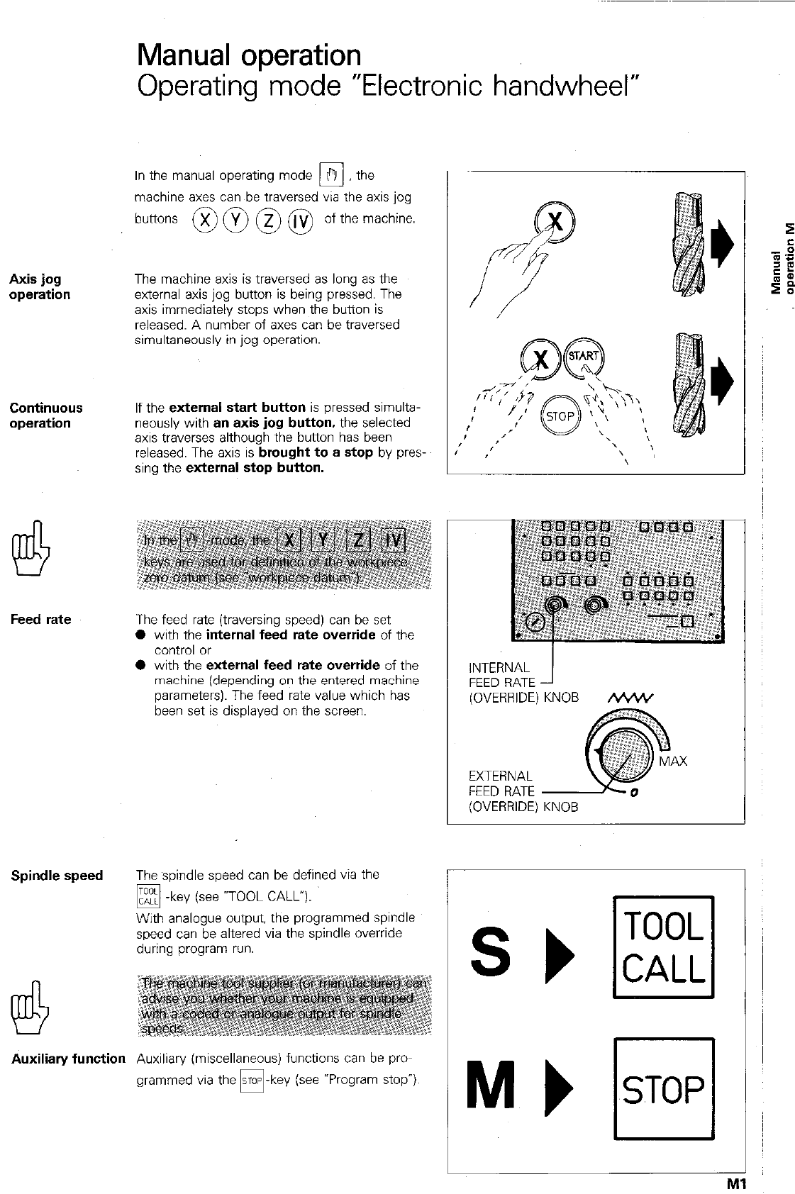
Manual operation
Operating mode “Electronic handwheel”
In the manual operating mode ?I the
0
machine axes can be traversed via the axis jog
buttons @ @ @ @ of the machine.
The machine axis is traversed as long as the
external axis jog button is being pressed. The
axis immediately stops when the button is
released. A number of axes can be traversed
simultaneously in jog operation.
If the external
start button
is pressed simulta-
neously with
an axis jog button,
the selected
axis traverses although the button has been
released. The axis is
brought to a stop
by pres-
sing the
external stop button.
The feed rate (traversing speed) can be set
0 with the
internal feed rate override
of the
control or
0 with the
external feed rate override
of the
machine (depending on the entered machine
parameters). The feed rate value which has
been set is displayed on the screen.
The spindle speed can be defined via the
q -
key (see -TOOL CALL”).
With analogue output, the programmed spindle
speed can be altered via the spindle override
during program run.
Auxiliary function
Auxiliary (miscellaneous) functions can be pro-
grammed via the -key (see *Program stop”)
INTERNAL
FEED RATE
(OVERRIDE) KNOB &%+V
AX
EXTERNAL
FEED RATE
(OVERRIDE) KNOB
TOOL
CALL
Interpolation
factor
Manual operation
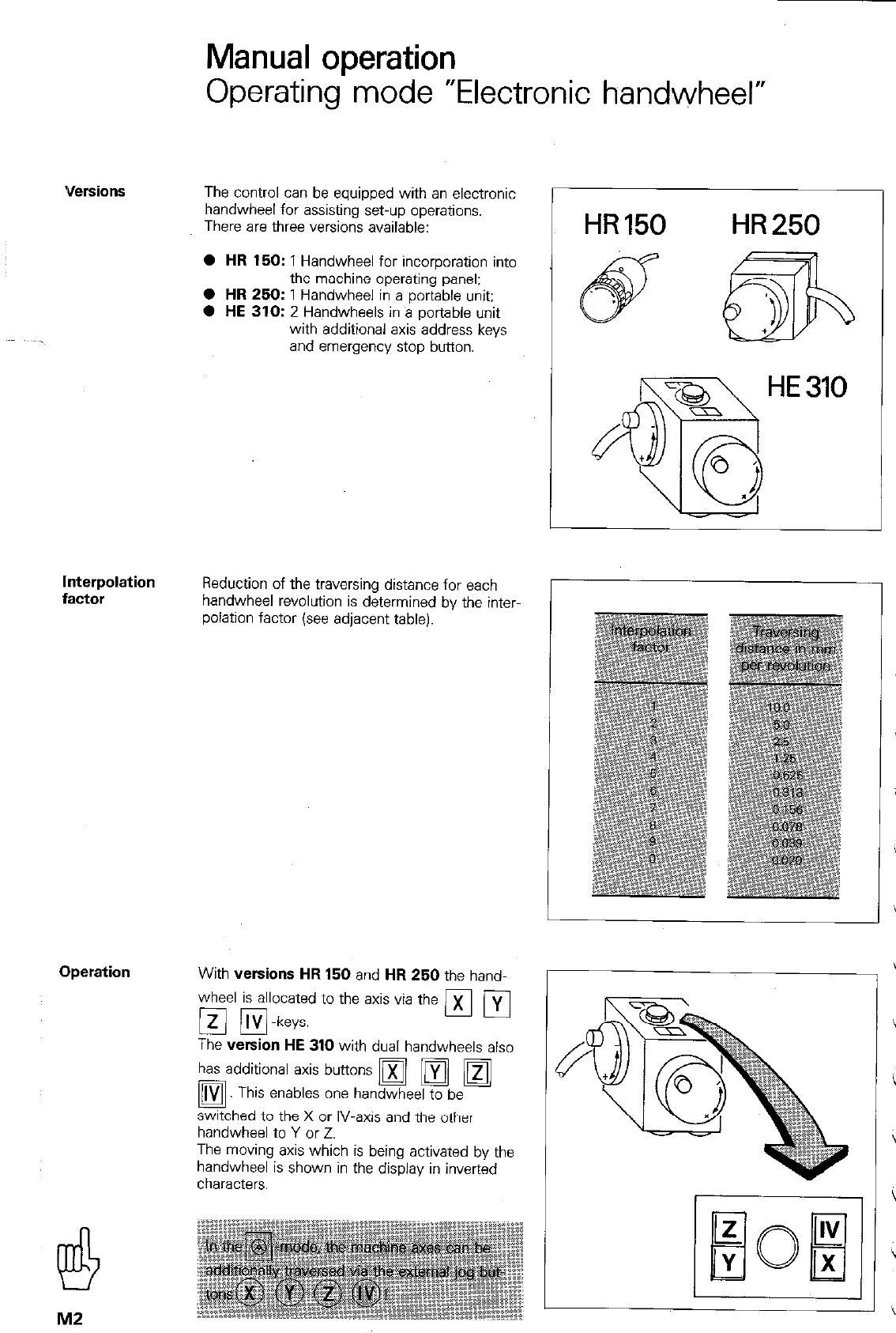
Operating mode “Electronic handwheel”
The control can be equipped with an electronic
handwheel for assisting set-up operations.
There are three versions available:
l HR 150:
1 Handwheel for incorporation into
the machine operating panel:
0
HR
250: 1 Handwheel in a portable unit;
0
HE 310:
2 Handwheels in B portable unit
with additional axis address keys
and emergency stop button.
Reduction of the traversing distance for each
handwheel revolution is determined by the inter-
polation factor (see adjacent table).
Operation
With
versions HR
150 and
HR 250
the hand-
wheel is allocated to the axis via the
[q m-keys. nlvl
x
The
version HE 310
with dual handwheels also
has additional axis buttons Di In/ m
q . Th’
IS enables one handwheel to be
switched to the X or IV-axis and the other
handwheel to Y or Z.
The moving axis which is being activated by the
handwheel is shown in the display in inverted
characters.
M2
HR 150 HR 250
HE 310
Manual operation
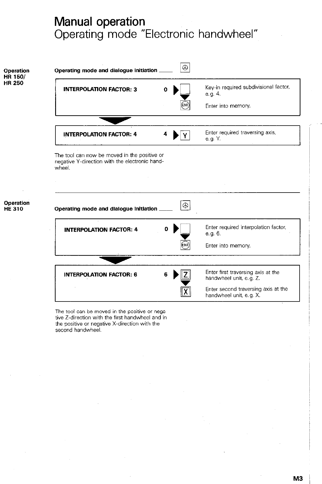
Operating mode “Electronic handwheel”
Operation
HR 1501
HR 250
Operating mode and dialogue initiation ~
INTERPOLATION FACTOR: 3 O ‘g
Key-in required subdivision8 factor.
e.g. 4.
Enter into memory
INTERPOLATION FACTOR: 4
Enter required traversing axis,
The tool can now be moved in the positive or
negative Y-direction with the electronic hand-
wheel.
Operation
HE 310 Operating mode and dialogue initiation ~
INTERPOLATION FACTOR: 4
Enter required interpolation factor,
e.g. 6.
El Enter into memory
INTERPOLATION FACTOR: 6 6 ml
Enter first traversing axis at the
handwheel unit, e.g. 2.
Enter second traversing axis at the
handwheel unit. a. g. X.
The tool can. be moved in the positive or nega-
tive Z-direction with the first handwheel and in
the positive or negative X-direction with the
second handwheel.
M3 !
Co-ordinate system and dimensioning
An NC-machine is only able to machine a work-
piece if all machining operations have been corn-
pletely defined by the NC-program. For complete
machining operation, the nominal positions of the
tool in relationship to the workpiece - must be
defined within the NC-program. A reference sys-
tem i.e. co-ordinate system. is necessary for
defining the nominal position of the tool.
Depending on the job. the TNC permits the use
of either right-angled co-ordinates or polar co-
ordinates.
Right-angled
or
Cartesian*)
co-ordinate
system
A right-angled co-ordinate system is formed
either by two axes in a plane and 3-axes in
space. These axes intersect at one point and are
also perpendicular to each other. The intersecting
point is referred to as the origin or zero-point of
the co-ordinate system. Each axis is designated
with a letter X. Y or Z.
The axes are each allocated with an imaginative
scale, the zero-point of which, coincides with the
origin of the co-ordinate system. The arrows
indicate the positive counting directions of the
scales.
* Named after the french mathematician F&n&
Descartes, lat. Renatus Cartesius (1596-1650)
Example With the aid of the Cartesian co-ordinates sys-
tern, random points of a workpiece can be locat-
ed by stating the appropriate X. Y and Z-co-ordi-
nates:
PI x = 20 abbreviated:
Y= 0 PI (20: 0: 0)
P2 (20; 35; 0)
P3 (40; 35; -10)
P4 (40; 0; -20)
P&W
co-ordinates
Entry range
Angle reference
axis
Co-ordinate system and dimensioning
The Cartesian co-ordinate system is particularly
convenient if the working drawing is dimen-
sioned as per the adjacent example.
Definition of positions on workpieces incorporat-
ing circular elements or angle dimensions is easi-
er with polar co-ordinates.
The polar co-ordinate system is used for defining
points in one plane. System reference is via the
pole (= zero-point of co-ordinate system) and
the direction (= reference axis for the specific
angle).
Points are described as follows:
by specifying the polar co-ordinate radius PR
(= distance between the pole and point PI) and
the angle PA between the reference direction
(+X-axis. in the adjacent drg.) and the connect-
ing line: pole - point Pl.
The polar co-ordinates angle PA is entered in
degrees (O).
Entry range: absolute -360° to +360°
incremental -5400° to +5400°
PA positive: Angle clockwise
PA negative: Angle counter-clockwise
The angle reference axis (0°-axis) is
the +X-axis in the XY-plane.
the +Y-axis in the YZ-plane,
the +Z-axis in the M-plane.
The sign for the angle PA can be determined in
accordance with the adjacent drawing.
K2
Co-ordinate system and dimensioning
Example
The polar co-ordinate system is particularly use-
ful for defining a workpiece if the working draw-
ing contains a number of angle dimensions as
shown in the adjacent example.
Relative tool
movement
When machining a workpiece, it is irrespective
whether the
tool
moves or the
workpiece
moves with the tool remaining~ stationary.
Only the relative movement is considered when
compiling a program.
This means a. g.:
if the milling machine table carrying the work-
piece traverses to the left, the relative movement
of the tool is towards the right.
If table motion is upwards, the relative tool
motion is downwards.
Actual tool motion only takes place if the spindle
head is moving, i. a. machine movement always
corresponds to the relative tool motion.
Correlation of
In order that workpiece co-ordinates within the
machine slide
machining program can be correctly interpreted
movements and
by the control, two factors must be clarified:
co-ordinate
system
0 which slide will traverse parallel to the co-
ordinate axis (correlation of machine axis to
co-ordinate axis)
0 which relationship exists between machine
slide positions and co-ordinate data of the
program.
The three
main axes
The correlation of the three main co-ordinate
axes to the appropriate machine slides is defined
by the standard IS0 841 for various machine
tools. Traversing directions can be easily remem-
bered by applying the “right-hand rule”.
Programmed
relative tool movement
to the right
Table movement
to the left
Co-ordinate system and dimensioning
The fourth axis
The machine tool builder will determine whether
the fourth axis when switched on - is to be
used as a
rotary table or linear axis (e.g. a
controlled quill) and how it is to be designated
on the VDU-screen.
An additional linear axis with a movement paral-
lel to the X, Y or Z-axis is designated with U. V
or w.
When programming rotary table movements. the
rotation angle is entered for A. B or C-values in
degrees (“).
This axis is referred to as an A, B or C-axis, each
rotating about the X. Y or Z-axis.
K4
Co-ordinate- system and dimensioning
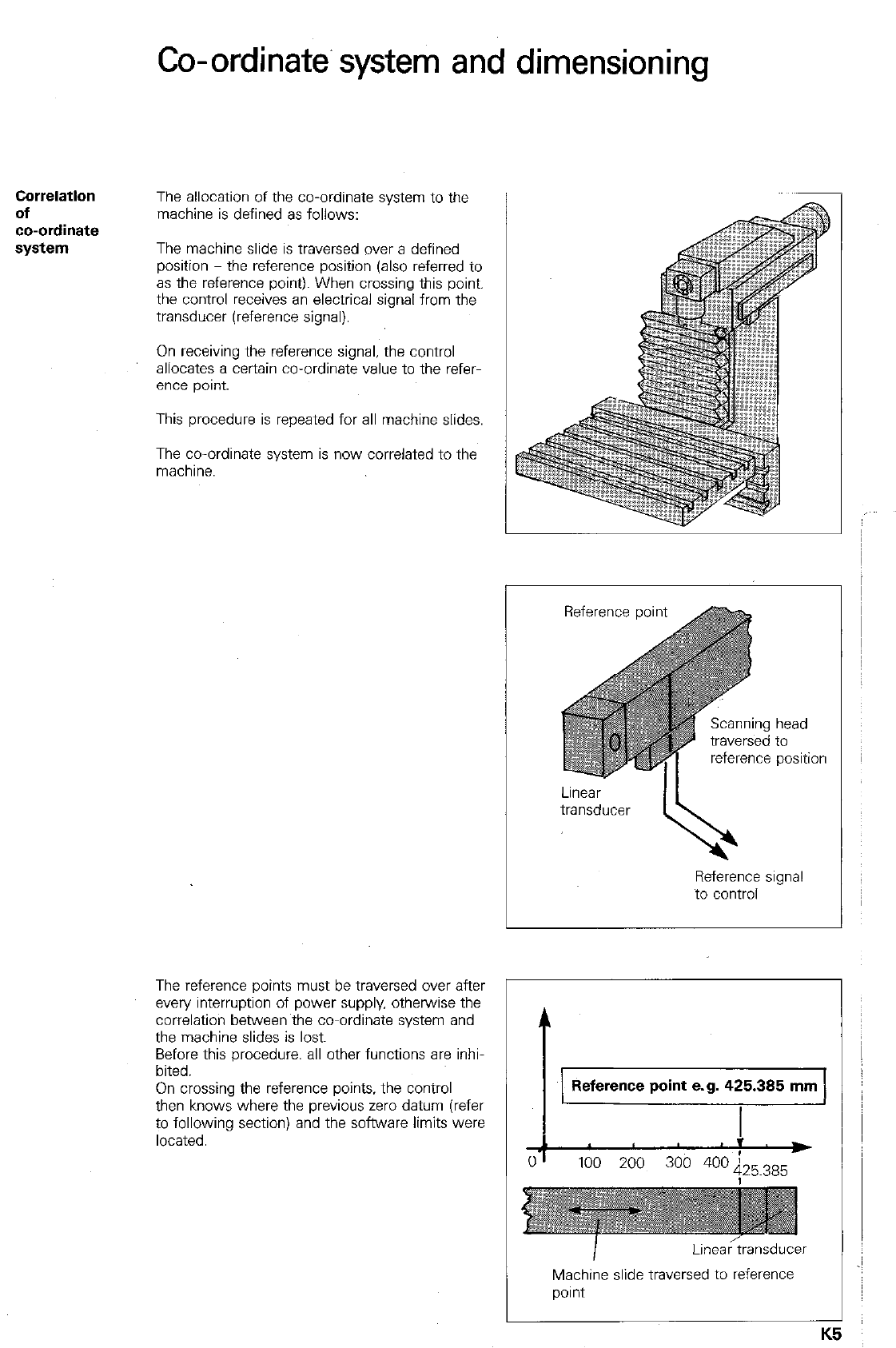
Correlation
of
co-ordinate
system
The allocation of the co-ordinate system to the
machine is defined as follows:
The machine slide is traversed over a defined
position - the reference position (also referred to
as the reference point). When crossing this point,
the control receives an electrical signal from the
transducer (reference signal).
On receiving the reference signal, the control
allocates a certain co-ordinate value to the refer
ence point.
This procedure is repeated for all machine slides.
The co-ordinate system is now correlated to the
machine.
The reference points must be traversed over after
every interruption of power supply. otherwise the
correlation between the co-ordinate system and
the machine slides is lost.
Before this procedure, all other functions are inhi-
bited.
On crossing the reference points, the control
then knows where the previous zero datum (refer
to following section) and the software limits were
located.
reference position
Reference signal
to control
Reference point e.g. 425.385 mm
Machine slide traversed to reference
point
K!
5
Co-ordinate system and dimensioning
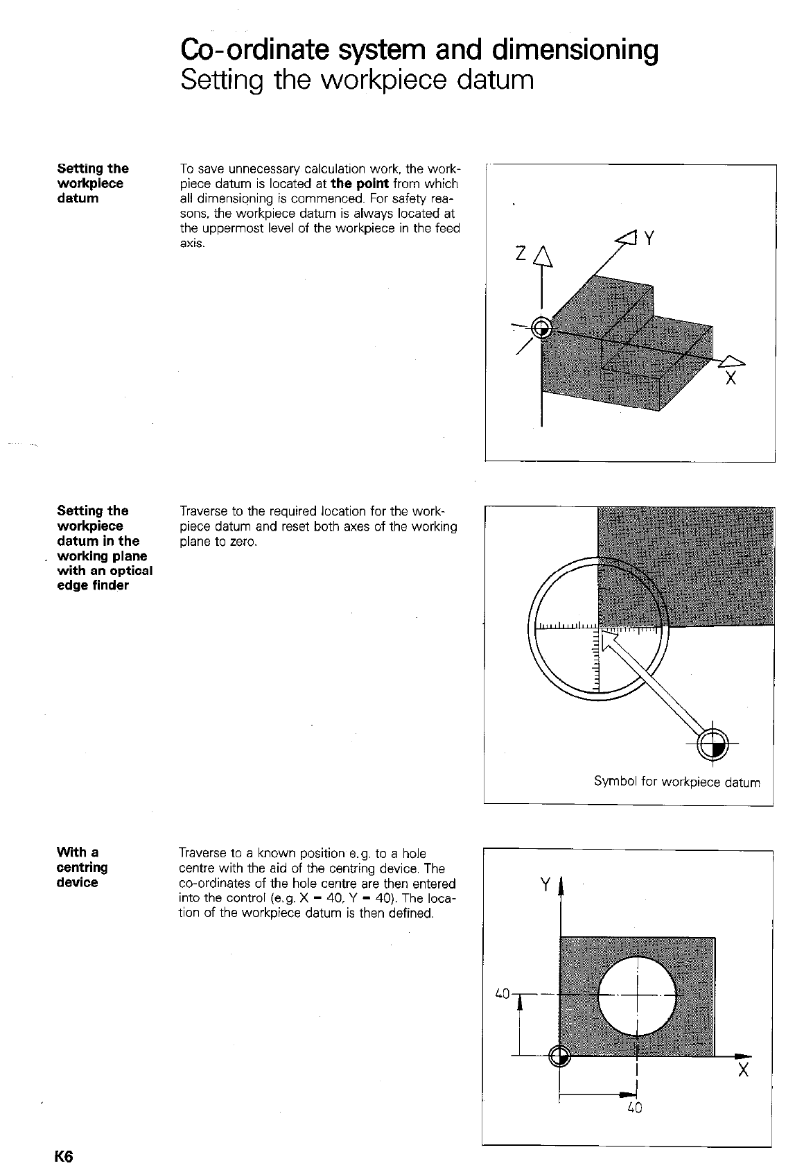
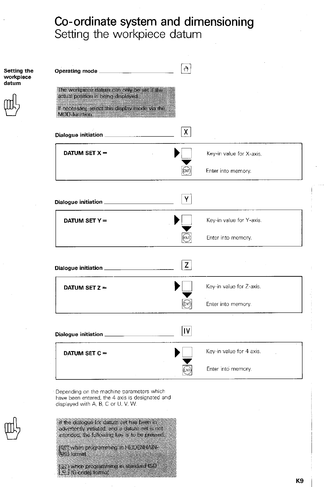
Setting the workpiece datum
Setting the
workpiece
datum
To save unnecessary calculation work. the work-
piece datum is located at
the point
from which
all dimensiqning is commenced. For safety rea-
sons, the workpiece datum is always located at
the uppermost level of the workpiece in the feed
axis.
Setting the
workpiece
datum in the
working plane
with en optical
edge finder
Traverse to the required location for the work-
piece datum and reset both axes of the working
plane to zero.
Symbol for workpiece datum
With a
centring
device
Traverse to a known position e.g. to a hole
centre with the aid of the centring device. The
co-ordinates of the hole centre are then entered
into the control (e.g. X = 40, Y = 40). The loca-
tion of the workpiece datum is then defined.
K6
Co-ordinate system and dimensioning
Setting the workpiece datum
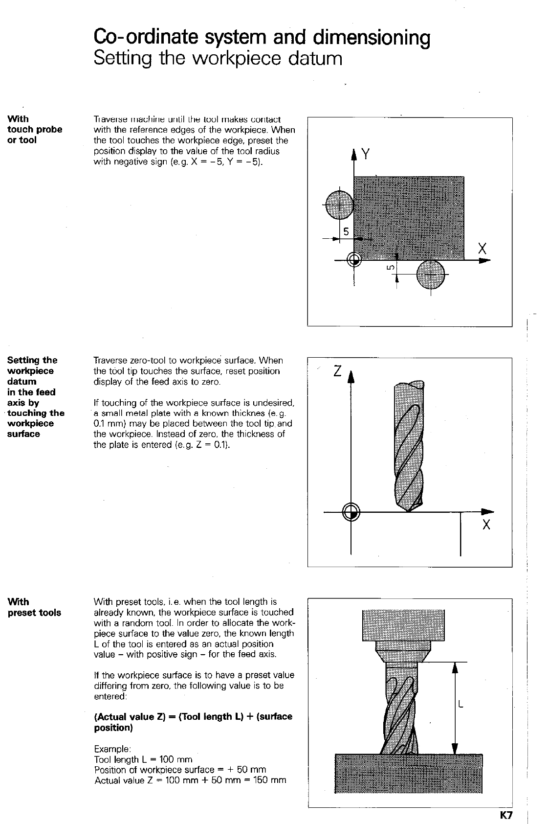
Wdh
touch probe
or
tool
Traverse machine until the tool makes contact
with the reference edges of the workpiece. When
the tool touches the workpiece edge. preset the
position display to the value of the tool radius
with negative sign (e.g. X = - 5, Y = - 5).
Setting the
workpiece
datum
in the feed
axis by
touching the
workpiece
sulfaface
Wfih
preset tools
Traverse zero-tool to workpiece surface. When
the tdol tip touches the surface, reset position
display of the feed axis to zero.
If touching of the workpiece surface is undesired.
a small metal plate with a known thicknes (e.g.
0.1 mm) may be placed between the tool tip,and
the workpiece. Instead of zero. the thickness of
the plate is entered (e.g. Z = 0.1).
With preset tools. i.e. when the tool length is
already known, the workpiece surface is touched
with a random tool. In order to allocate the work-
piece surface to the value zero. the known length
L of the tool is entered as an actual position
value - with positive sign - for the feed axis.
If the workpiece surface is to have a preset value
differing from zero. the following value is to be
entered:
(Actual value 2) = (Tool length L) + (surface
position)
Example:
Tool length L = 100 mm
Position of workpiece surface = + 50 mm
Actual value Z = 100 mm + 50 mm = 150 mm
-
Co-ordinate system and dimensioning
Setting the workpiece datum
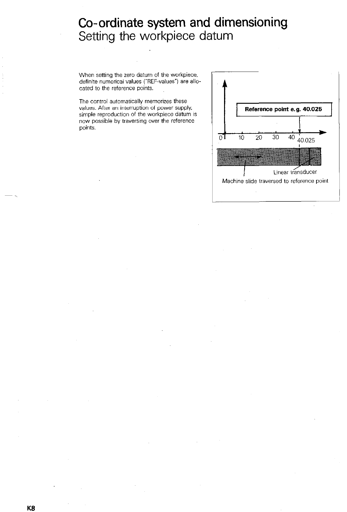
When settina the zero datum of the worki%ce.
definite numerical values (“REF-valuesv) are allo-
cated to the reference points.
The control automatically memorizes these
values. After an interruption of power supply,
simple reproduction of the workpiece datum is
now possible by traversing over the reference
ooints.
t
Reference point e.g. 40.025
I
I ,
0-I *
10 20
3o 4o 40.025
I
Linear t&sducar
Machine slide traversed to reference point
KS
Co-ordinate system and dimensioning
Setting the workpiece datum
Operating mode Es
Dialogue initiation El
DATUM SET X =
Key-in value for X-axis.
Enter into memory.
Dialogue initiation
q
DATUM SETY =
‘G
Key-in value for Y-axis
~@
Enter into memory
Dialogue initiation El
I
I
DATUM SET Z =
Key-in value for Z-axis.
Enter into memory.
Dialogue initiation ~
DATUM SET C =
Key-in value for 4 axis.
Enter intd memory
Depending on the machine parameters which
have been entered. the 4 axis is designated and
displayed with A, B, C or U. V. W.
K9
Co-ordinate system and dimensioning
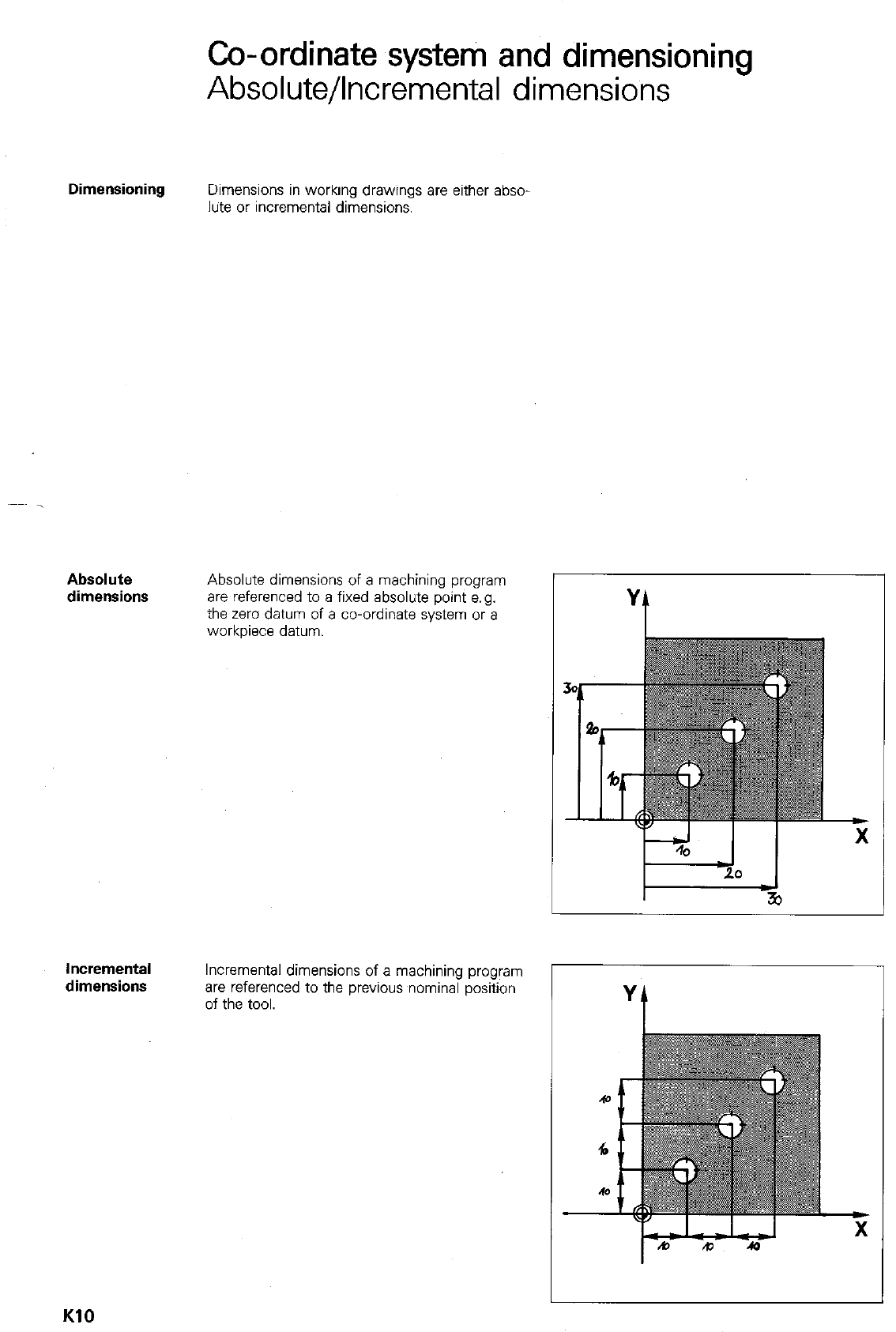
Absolute/Incremental dimensions
Dimensioning Dimensions in working drawings are either abso-
lute or incremental dimensions.
Absolute
dimensions Absolute dimensions of a machining program
are referenced to a fixed absolute point e.g.
the zero datum of a co-ordinate system or a
workpiece datum.
Incremental
dimensions Incremental dimensions of a machining program
are referenced to the previous wminal position
of the tool.
KlO
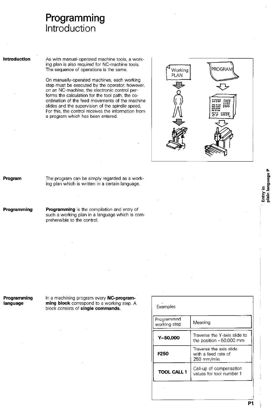
Programming
Introduction
As with manual-operated machine tools. a work-
ing plan is also required for NC-machine tools.
The sequence of operations is the same.
On manually-operated machines, each working
step must be executed by the operator: however,
on an NC-machine, the electronic control per-
forms the calculation for the tool path, the co-
ordination of the feed movements of the machine
slides and the supervision of the spindle speed.
For this. the control receives the information from
a program which has been entered.
Program
The program can be simply regarded as a work-
ing plan which is written in a certain language.
Programming Programming
is the compilation and entry of
such a working plan in a language which is corn
prehensible to the control.
Pmgramming
language
In a machining program
every NC-pmgmm-
ming block
correspond to a working step. A
block consists of
single commands.
Ex&plas
Programmed
working step Meaning 1
TOOL cALL , Call-up of compensation
values for tool number 1
Pl
Programming
Pro&-am
A program which is used for the manufacture of
a workpiece can be subdivided into the following
sections:
0 Approach to tool change position
l Insert t001.
0 Approach to workpiece contour,
0 Machine workpiece contour.
0 Depart from workpiece contour
0 Return to tool change position.
Each program section comprises individual pro-
gram blocks.
Block number
The control automatically allocates a block num-
ber to each block. The
block number
desig-
nates the program block within a machining pro-
gram.
When erasing a block, the block number remains
and the subsequent block then shifts to the allo-
cation of the erased block.
Program
7
L z - 20,000
8
L x - 12,000
9 L
x + 20.000
10
RND R + 5.000
11
L
x + 50.000
12 cc x -
10.000
13 c x + 70,000
DR +
14
cc x+150.000
15 c x + 90.000
DR +
18 L x + 120,000
RO F9999 MO3
Y + 60.000
RO F9999 M
Y + 60.000
RR F40 M
Y + 20.000
RR F40 M
Y + 80.000
Y + 51.715
RR F40 M
Y + 80.000
Y + 20,000
RR F40 M
Y + 20,000
RR F40 M
Dialogue
prompting
Programming is guided by a prompting routine.
i.e. during program entry. the control asks for the
necessary data in plain language.
With every block, a sequence of dialogues is
opened by pressing the dialogue initiation key
I
e.g. DEF (the control subsequently asks for the
q
tool number and then the tool length etc.). First dialoaue
The operator is made aware of entry errors via
the plain language display. incorrect data can be
amended immediately during program entry. - I- I
11 Second dialogue /. 11 1 Respond to 1 1
P2
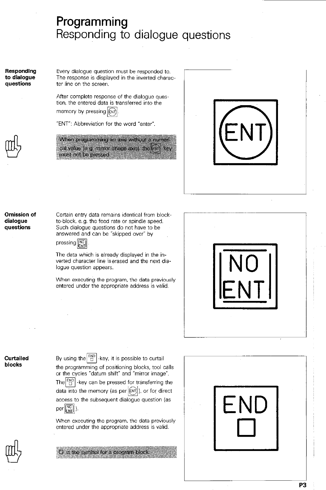
Responding
to dialogue
questions
Omission of
dialogue
questions
Curtailed
blocks
Programming
Responding to dialogue questions
Every dialogue question must be responded to.
The response is displayed in the inverted charac-
ter line on the screen.
After complete response of the dialogue quas-
tion. the entered data is transferred into the
memory by pressing
q
.
“ENT”: Abbreviation for the word “enter”.
Certain entry data remains identical from block-
to-block, e.g. the feed rate or spindle speed.
Such dialogue questions do not have to be
answered and can be “skipped over” by
pressing
q
.
The data which is already displayed in the in-
verted character line iserased and the next dia-
logue question appears.
When executing the program. the data previously
entered under the appropriate address is valid.
possible to curtail
the programming of positioning blocks, tool calls
or the cycles “datum shift” and “mirror imagev.
Them -key can be pressed for transferring the
data into the memory (as par
access to the subseauent dialoaue auestion ias
When executing the program. the data previously
entered under the appropriate address is valid.
r
NO
ENT
END
cl
P3
Programming
Entry of numerical values
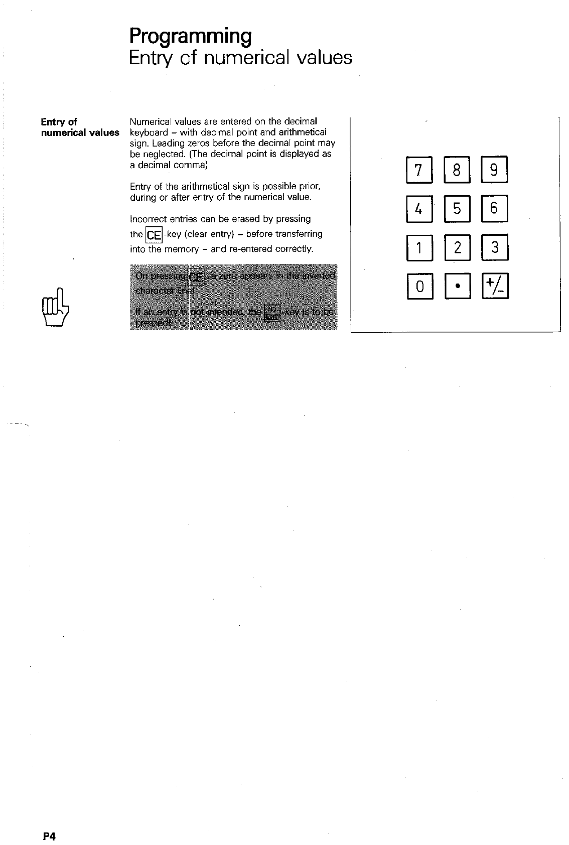
IEntry of
Numerical values are entered on the decimal
numerical values keyboard - with decimal point and arithmetical
sign. Leading zeros before the decimal point may
be neglected. (The decimal point is displayed as
a decimal comma)
Entry of the arithmetical sign is possible prior,
during or after entry of the numerical value.
Incorrect entries can be erased by pressing
the CE -key (clear entry) - before transferring
0
into the memory - and reentered correctly.
P4
Remarks
P5
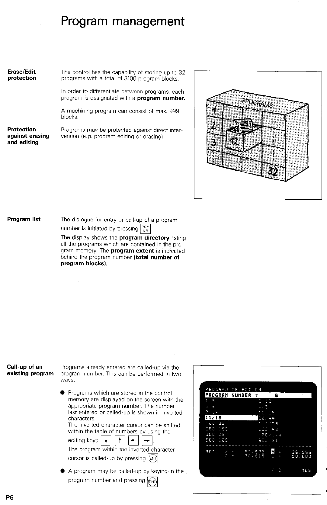
Erase/Edit The control has the capability of storing up to 32
protection programs with a total of 3100 program blocks.
Protection
against erasing
and editing
Program management
In order to differentiate between programs. each
program is designated with a program number.
A machining program can consist of max. 999
blocks.
Programs may be protected against direct inter
vention (e.g. program editing or erasing).
Program list The dialogue for entry or call-up of a program
number is initiated by pressing
q
The display shows the program directory listing
all the programs which are contained in the pro-
gram memory. The program extent is indicated
behind the program number (total number of
program blocks).
Call-up of an Programs already entered are called-up via the
existing program program number. This can be performed in two
‘W3yS:
0 Programs which are stored in the control
memory are displayed on the screen with the
appropriate program number. The number
last entered or called-up is shown in inverted
characters.
The inverted character cursor can be shifted
within the table of numbers by using the
editing keys Fi pl Fi Ei~
The program within the inverted character
cursor is called-up by pressing
q
0 A program may be called-up by keying-in the
program number and pressing ENT
D.
P6
I
’
I
I
I I
!
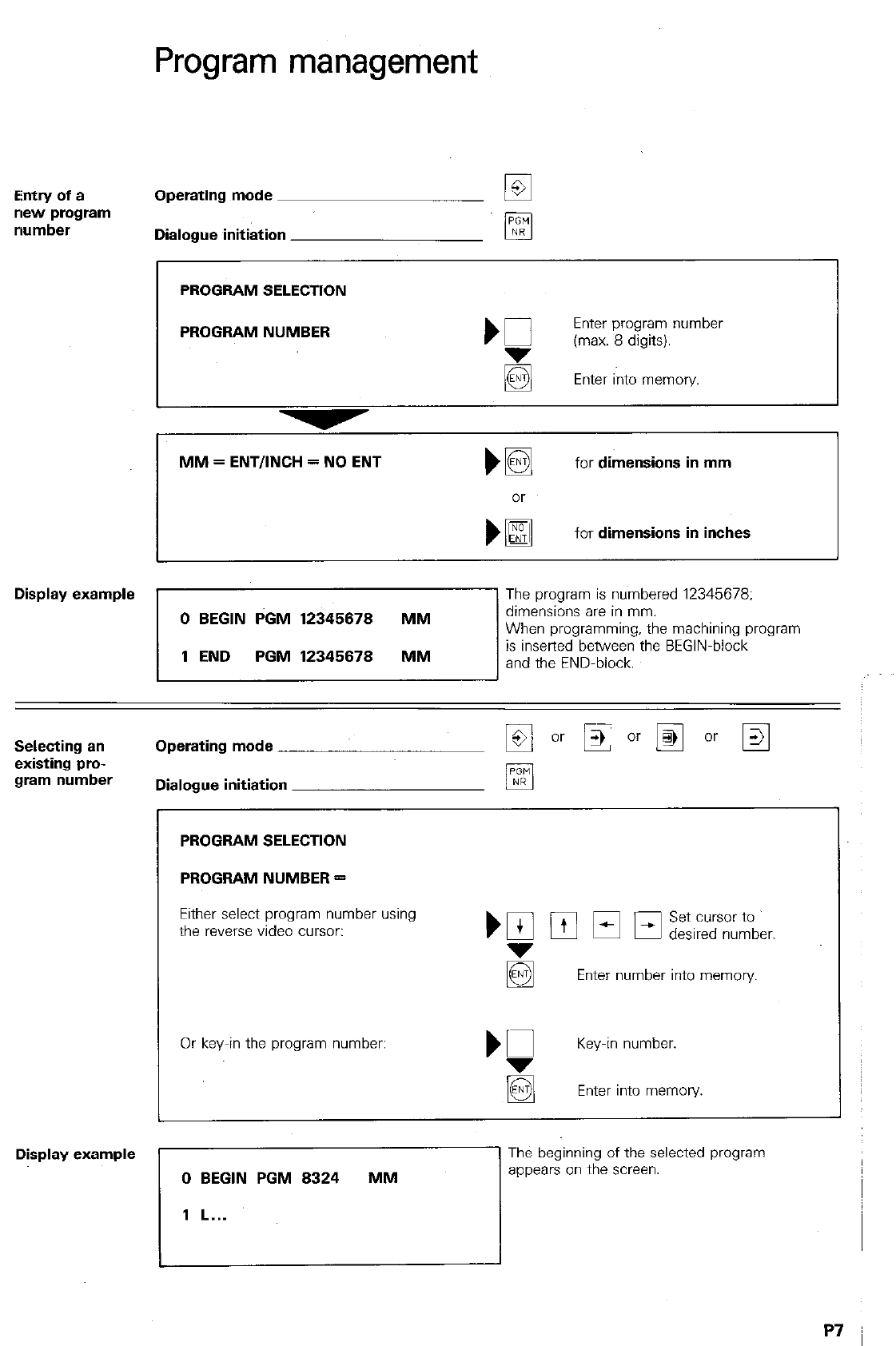
Program management
Entry of a
new program
number
Operating mode
Dialogue initiation
PROGRAM SELECTION
1
PROGRAM NUMBER
MM = ENTIINCH = NO ENT Ma
for
dimensions in mm
for
dimensions in inches
Display example
The program is numbered 12345678:
Selecting an
existing pro-
gram number
Operating mode
Dialogue initiation
PROGRAM SELECTION
PROGRAM NUMBER =
Either select program number using
the reverse video cursor:
Or key-in the program number:
‘Q
Key-in number.
la Enter into memory.
Display example
0 BEGIN PGM 8324 MM
1 L...
The beginning of the selected program
appears on the screen.
Program management
Programs with edit protection
IEraselEdit
lprotection
After program compilation, an entry can be
made for erase/edit protection. Programs having
protection against erasing and editing are
marked with the letter P at the beginning and
end of the program.
A protected program can only be erased if the
erase/edit protection has been cancelled. This
can be done by addressing the program and
entering the code number 86357.
IP8
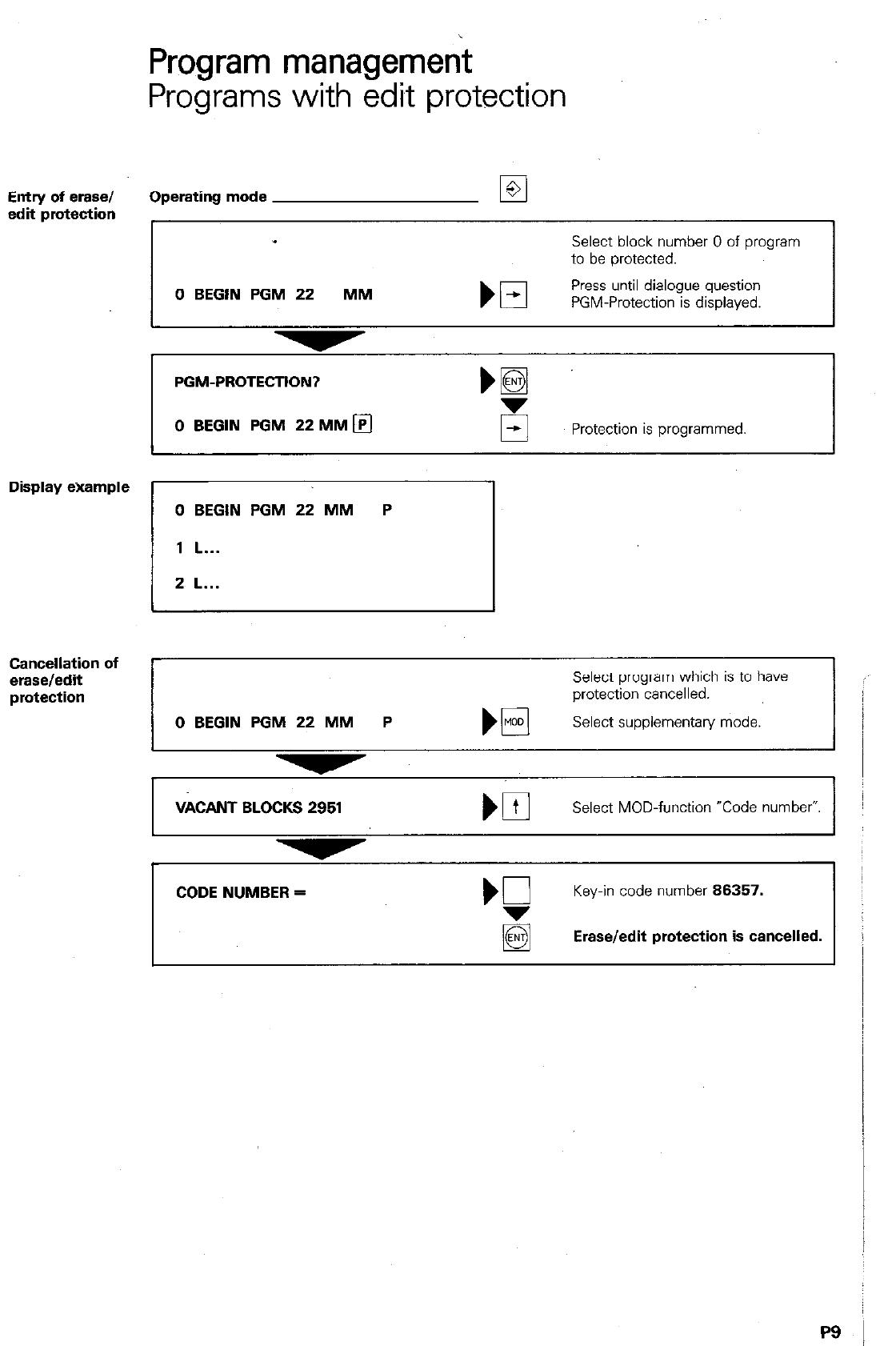
Entry of erase/
edit protection
Display example
Cancellation of
erase/edit
Program management
Programs with edit protection
Operating mode El
Select block number 0 of program
to be protected.
0 BEGIN PGM 22 MM
El
Press until dialogue question
PGM-Protection is displayed.
PGM-PROTECTION?
0 BEGIN PGM 22MMm
Protection is programmed
0 BEGIN PGM 22 MM P
1 L...
2 L...
Select program which is to have
protection cancelled.
0 BEGIN PGM 22 MM P El
Select supplementary mode.
VkANT BLOCKS 2951
Select MOD-function “Code number”
CODE NUMBER =
‘7
Key-in code number 86357.
Erase/edit protection is cancelled.
PS
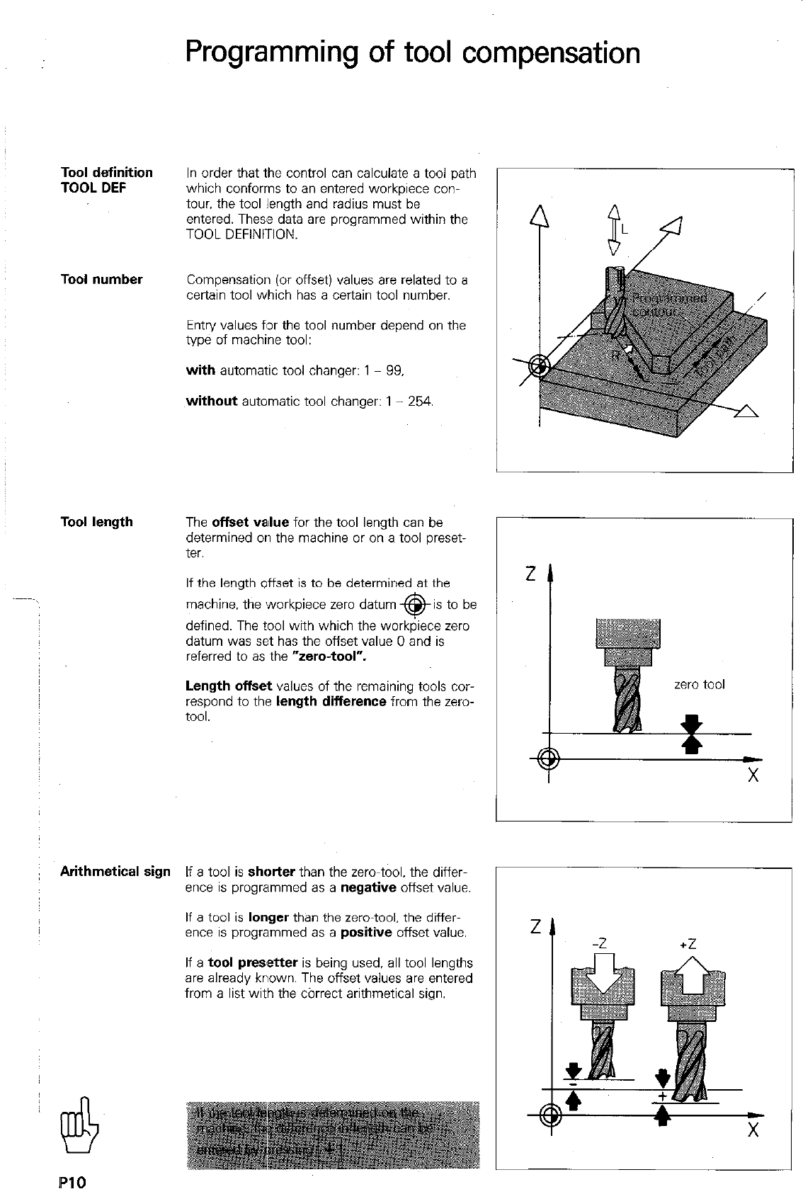
Programming of tool compensation
Tool definition
TOOL DEF In order that the control can calculate a tool path
which conforms to an entered workpiece con-
tour. the tool length and radius must be
entered. These data are programmed within the
TOOL DEFINITION.
Tool number Compensation (or offset) values are related to a
certain tool which has a certain tool number.
Entry values for the tool number depend on the
type of machine tool:
with automatic tool changer: 1 - 99,
without automatic tool changer: 1 - 254.
Tool length The offset value for the tool length can be
determined on the machine or on a tool preset-
ter.
If the length offset is to be determined at the
machine, the workpiece zero datum @is to be
defined. The tool with which the workpiece zero
datum was set has the offset value 0 and is
referred to as the “zero-tool”.
Length offset values of the remaining tools cor-
respond to the length difference from the zero-
tool.
Arithmetical sign If a tool is shatter than the zero-tool. the differ-
ence is programmed as a negative offset value.
If a tool is longer than the zero-tool. the differ-
ence is programmed as a positive offset value.
If a tool presetter is being used. all tool lengths
are already known. The offset values are entered
from a list with the cbrrect arithmetical sign.
X
C
Programming the workpiece contour
Tool radius
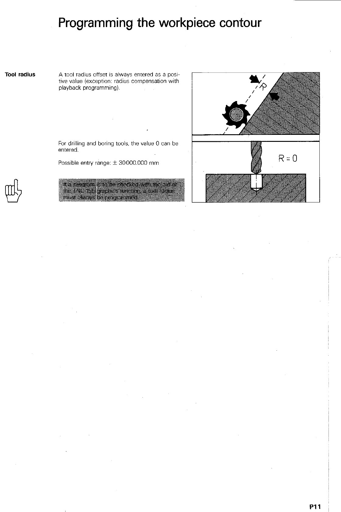
A tool radius offset is always entered as a posi-
tive value (exception: radius compensation with
playback programming).
For drilling and boring tools. the value 0 can be
entered.
Possible entry range: + 30000.000 mm
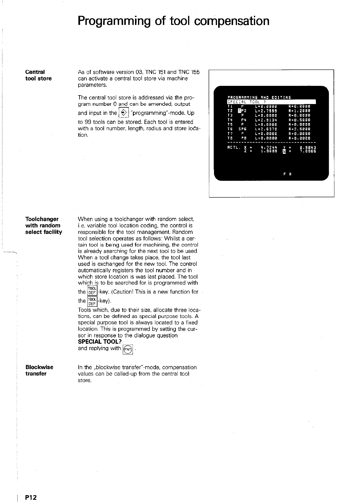
Central
tool store
Toolchanger
with random
select facility
~ Ho&wise
transfer
Programming of tool compensation
As of software version 03. TNC 151 and TNC 155
can activate a central tool store via machine
parameters.
The central tool store is addressed via the pro-
gram number 0 and can be amended, output
and input in the 3 “programming”-mode. Up
El
to 99 tools can be stored. Each tool is entered
with a tool number. length. radius and store loca-
tion.
When using a toolchanger with random select.
i.e. variable tool location coding. the control is
responsible for the tool management. Random
tool selection operates as follows: Whilst a cer-
tain tool is being used for machining, the control
is already searching for the next tool to be used.
When a tool change takes place. the tool last
used is exchanged for the new tool. The control
automatically registers the tool number and in
which store location is was last placed. The tool
which is to be searched for is programmed with
the DEF -key. (Caution! This is a new function for
pq
-
the m-key)
Y
Tools which, due to their size, allocate three loca-
tions, can be defined as special purpose tools. A
special purpose tool is always located to a fixed
location. This is programmed by seaing the cur-
sor in response to the dialogue question
SPECIAL TOOL?
and replying with
q
In the ..blockwise transfer”-mode, compensation
values can be called-up from the central tool
store.
Programming of tool compensation
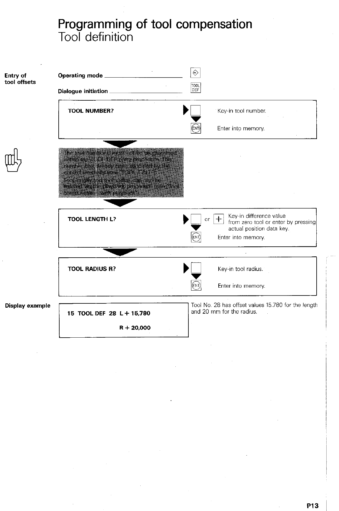
Tool definition
Operating mode
q
Dialogue initiation pEj
TOOL NUMBER?
Key-in tool number.
Enter into memory.
1
TOOL LENGTH L?
Key-in difference value
from zero tool or enter by pressing
actual position data key.
Enter into memory
,
TOOL RADIUS R?
Key-in tool radius.
@
Enter into memory
PI3
Programming of tool compensation
Tool call
ICalling-up
is
tool
‘rooL
CALL
With TOOL CALL, a new tool and the corres~
ponding compensation values for length and
radius are called-up.
In addition to the
tool number,
the control must
also know in which axis the spindle will operate,
in order to apply both-the length compensation
in the correct axis-and the radius compensation
in the correct plane.
After specification of the working spindle axis,
the
spindle speed
must be entered.
If a spindle speed lies outside of the permissible
range for the machine, the followina error mes-
sage is displayed during program &I:
= WRONG RPM =
Tool change
Program
Tool change takes place in a definite
tool
change position.
The control therefore positions
the tool to a position with
non-compensated
nominal values
for execution of tool change.
For this, the compensation data for the tool cur-
rently in operation must be cancelled.
This is done via a
TOOL CALL 0:
The tool is positioned to the required non-com-
pensated nominal position which is programmed
in the following block.
Traverses to the tool change position can be
executed via M91. M92 (Auxiliary functions M) or
via a PLC-positioning command. (Information can
be obtained from the machine tool supplier).
When performing a manual tool change, the pro-
gram must be stopped. A STOP-command is
therefore required before the TOOL CALL-com-
mand. The program remains in a stopped condi-
tion until the external start button is pressed.
If a tool call is only programmed for the purpose
of speed-change, the programmed STOP may be
neglected.
An
automatic tool change
does not require a
programmed STOP. Program run is continued
when the tool change procedure is final&d.
1
TOOL CHANGE
TOOL CALL 0
TOOL CHANGE
IP14
Programming of tool compensation
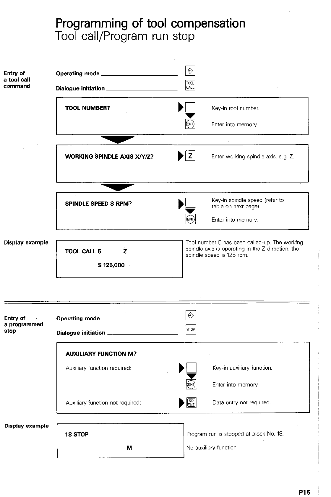
Tool call/Program run stop
Entry of
a tool Cdl
clommand
Operating mode
Dialogue initiation
TOOL NUMBER? b0
Key-in tool number.
g Enter into memory.
WORKING SPINDLE AXIS x/y/z?
Enter working spindle axis, e.g. Z
SPINDLE SPEED S RPM?
‘f
Key-in spindle speed (refer to
table on next page).
Enter into memoly
Display example
Tool number 5 has been called-up. The working
spindle axis is operating in the Z-direction; the
pri spindle speed is 12: rpm.
Entry of
a programmed
stop
Operating mode
Dialogue initiation
AUXILIARY FUNCTION M?
Auxiliary function required: Key-in auxiliary function
Enter into memory.
Auxiliary fwction not required:
)H
Data entry not required
Display example
Program run is stopped at block No. 18,
71 No auxiliary function.
P15
Tool call
Spindle speeds
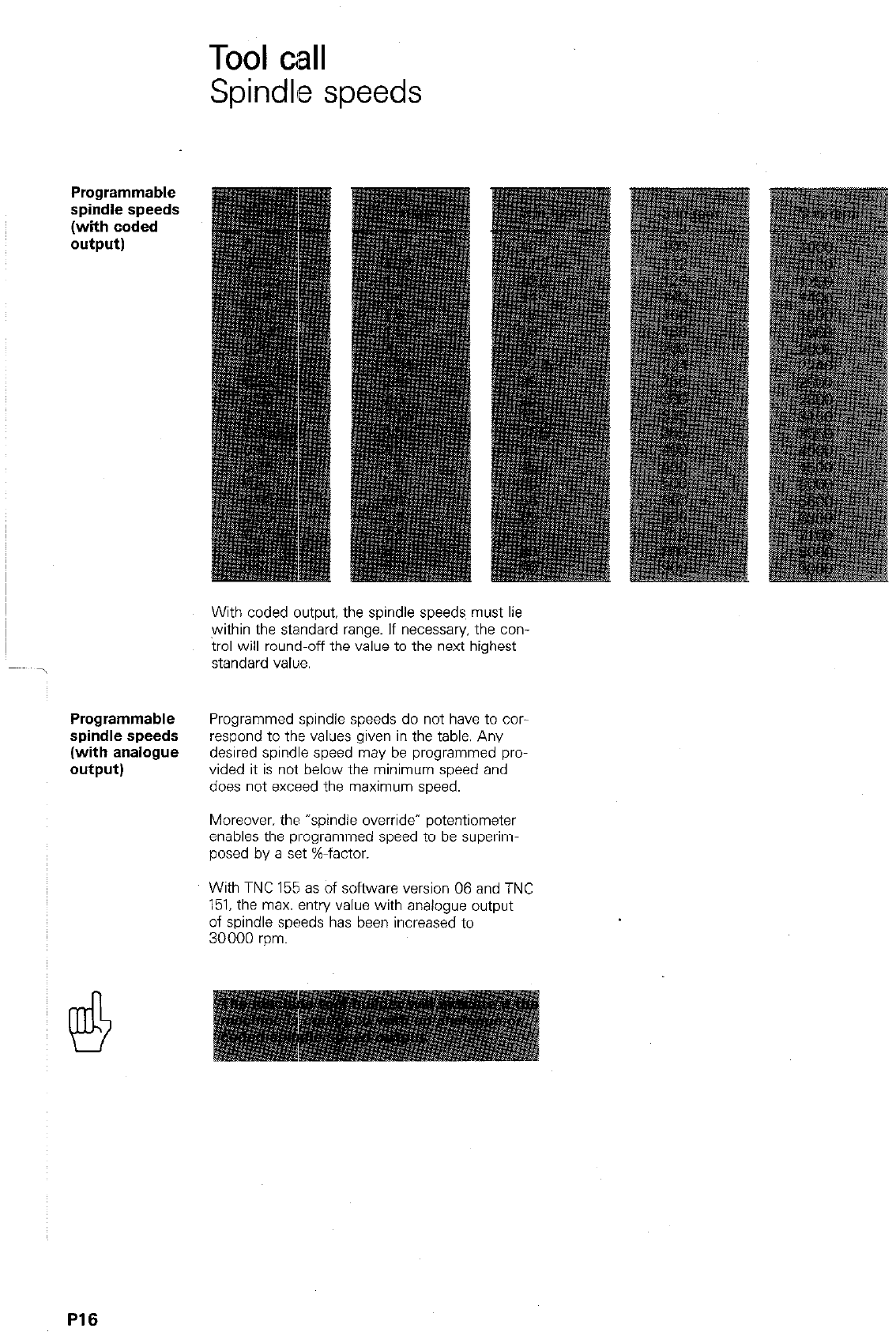
Programmable
spindle speeds
(with coded
output)
With coded output, the spindle speeds must lie
within the standard range. If necessary. the con
trol will round-off the value to the next highest
standard value.
spiidle speeds
(with analogue
output)
Programmed spindle speeds do not have to COT-
respond to the values given in the table. Any
desired spindle speed may be programmed pro-
vided it is not below the minimum speed and
does not exceed the maximum speed.
Moreover. the “spindle override- potentiometer
enables the programmed speed to be superim-
posed by a set %-factor.
With TNC 155 as of software version 06 and TNC
151. the max. entry value with analogue output
of spindle speeds has been increased to
30000 rpm.
P16
Programming of workpiece contours
Contour
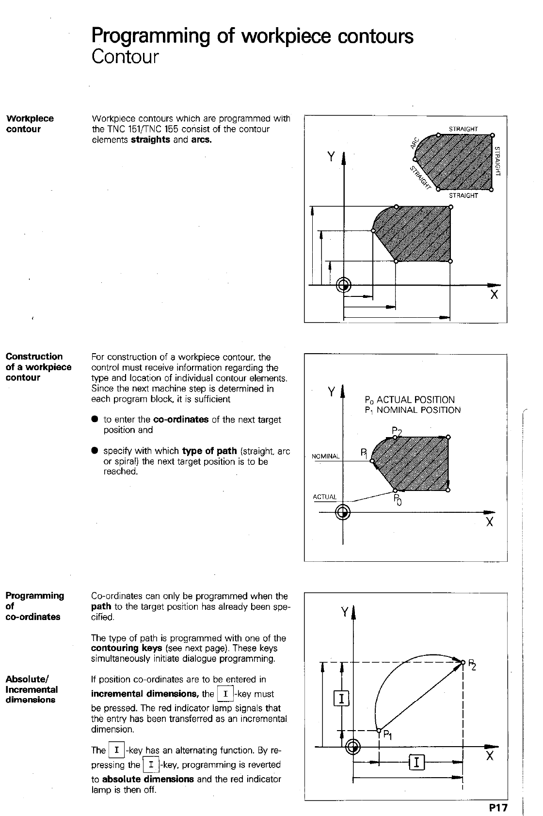
Workpiece
c’mtour Workpiece contours which are programmed with
the TNC 151/TNC 155 corisist of the contour
elements
straights
and arcs.
Construction
of a workpiece
contour
For construction of a workpiece contour, the
control must receive information regarding the
type and location of individual contour elements.
Since the next machine step is determined in
each program block, it is sufficient
l
to enter the
co-ordinates
of the next target
position and
0 specify with which
type of path
(straight, arc
or spiral) the next target position is to be
reached.
Programming
of
w-ordinates
Co-ordinates can only be programmed when the
path
to the target position has already been spe-
cified.
The type of path is programmed with one of the
contouring keys (see
next page). These keys
simultaneously initiate dialogue programming.
Absolute/
If position co-ordinates are to be entered in
incremental dimensions,
the I
q
-key must
be pressed. The red indicator lamp signals that
the entry has been transferred as an incremental
dimension.
The M-key has an alternating function. By re-
pressing the I -key, programming is reverted
q
to
absolute dimensions
and the red indicator
lamp is then off.
Y
t
PO ACTUAL POSITION
P, NOMINAL POSITION
i
i
1
I
Programming of workpiece contours
Contouring keys/Cartesian co-ordinates
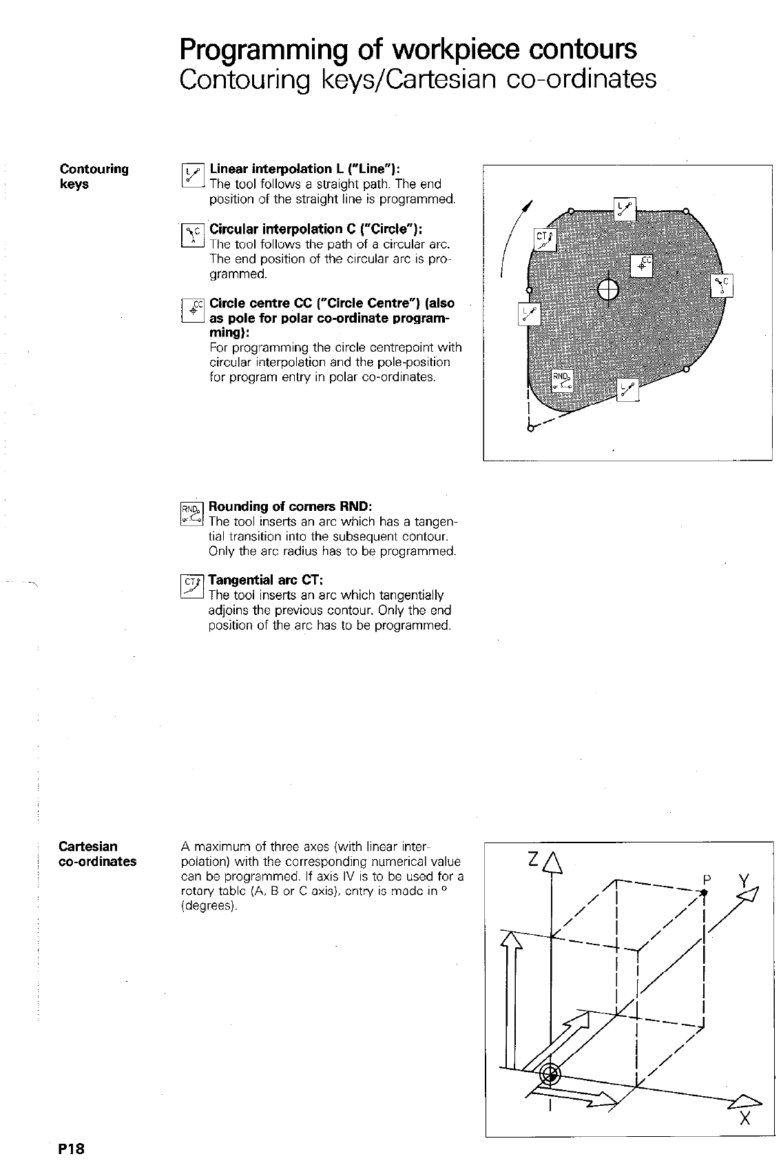
Contouring
keys pJ’ Linear interpolation L (“Line”):
The tool follows a straight path. The end
position of the straight line is programmed.
bl’
c Cwcular interpolation C (“Circle”):
The tool follows the path of a circular arc.
The end position of the circular arc is pro-
grammed.
q ’
cc Ctrcle centre CC (“Circle Centre”) (also
as pole for polar co-ordinate program-
ming):
For programming the circle centrepoint with
circular interpolation and the pole-position
for program entry in polar co-ordinates.
Rounding of corners RND:
The tool inserts an arc which has a tangen-
tial transition into the subsequent contour.
Only the arc radius has to be programmed.
q
Tangentjal arc CT:
The tool Inserts an arc which tangentially
adjoins the previous contour. Only the end
position of the arc has to be programmed.
Cartesian
co-ordinates
A maximum of three axes (with linear inter-
r
polation) with the corresponding numerical value
can be programmed. If axis IV is to be used for a
rotary table (A. B or C-axis). entry is made in O
(degrees).
PI8
Programming of workpiece contours
Cartesian co-ordinates
E,ntry of
~Cartesian
co-ordinates
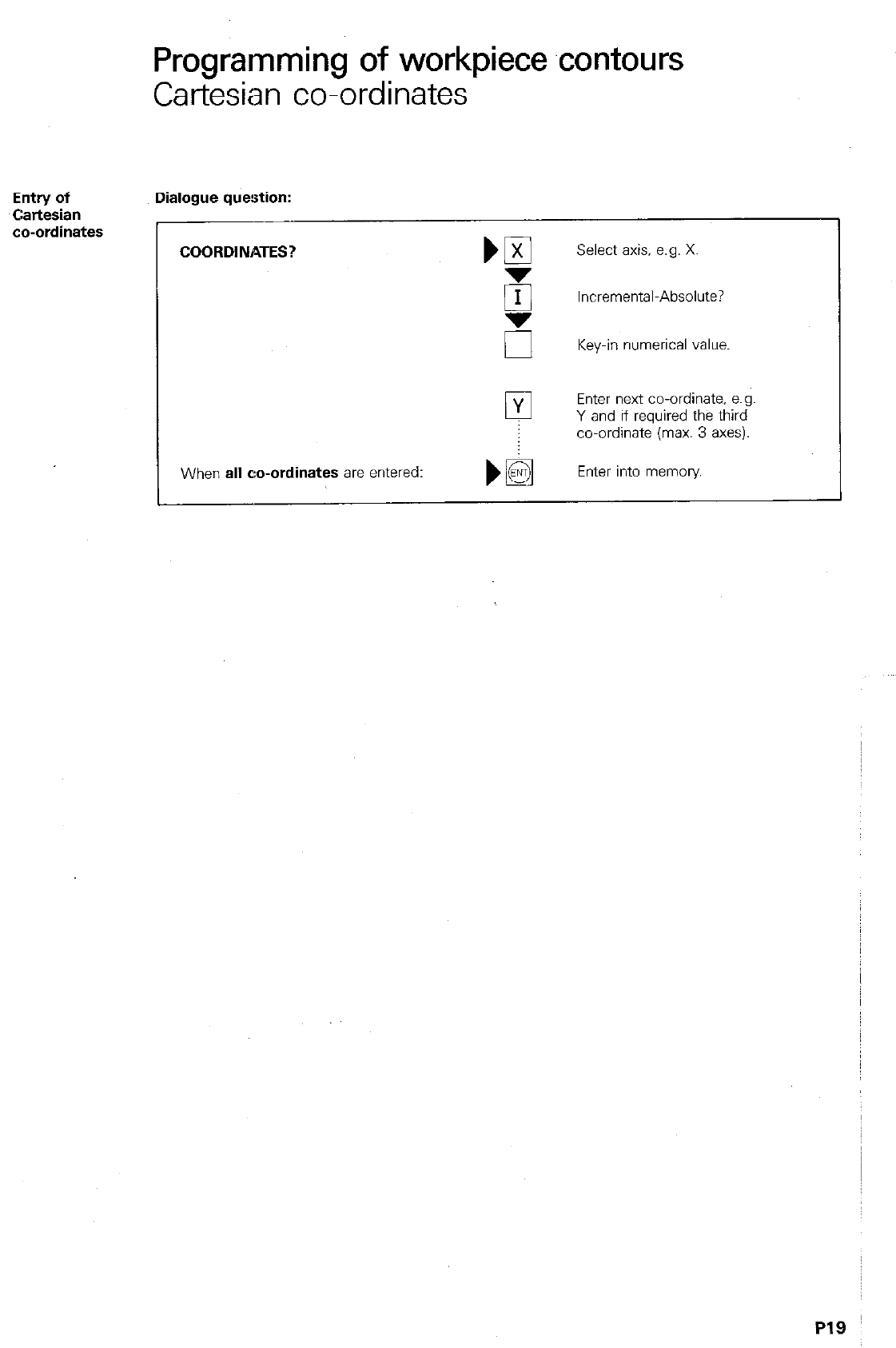
Dialogue question:
COORDINATES?
Select axis. e.g. X.
Incremental-Absolute?
u
Key-in numerical value.
0 Enter next co-ordinate, e.g.
Y and if required the third
co-ordinate (max. 3 axes).
When
all co-ordinates are
entered: Enter into memory
Programming of workpiece contours
Polar co-ordinates/Pole
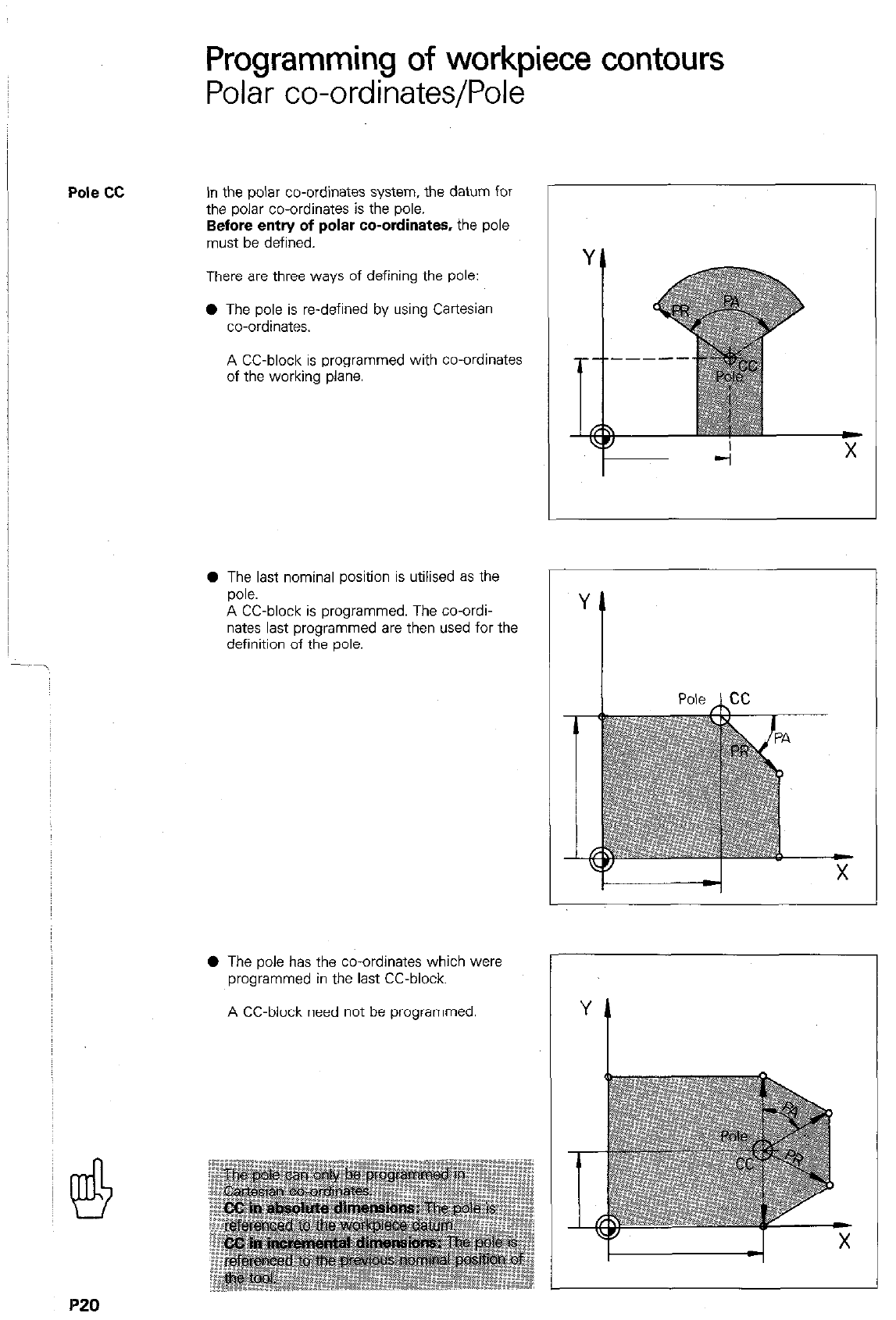
Pole cc
In the polar co-ordinates system, the datum for
the polar co-ordinates is the pole.
Before entry of polar co-ordinates, the pole
must be defined.
There are three ways of defining the pole:
0 The pole is re-defined by using Cartesian
co-ordinates.
A CC-block is programmed with co-ordinates
of the working plane.
0 The last nominal position is utilised as the
pole.
A CC-block is programmed. The co-ordi-
nates last programmed are then used for the
definition of the oole.
0 The pole has the co-ordinates which were
programmed in the last CC-block.
A CC-block need not be programmed.
P20
Pro&-amming of workpiece contours
Polar co-ordinates/Pole
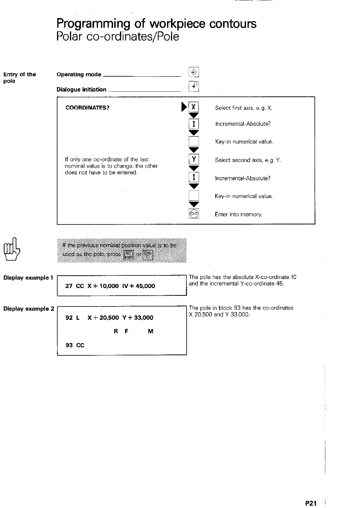
Elntry of the
PIOk Operating mode
Dialogue initiation
COORDINATES? Select first axis. e.g. X
Incremental-Absolute?
Key-in numerical value.
If only one co-ordinate of the last
nominal value is to change. the other
does not have to be entered.
PI Select second axis. a. g. Y
5 Incremental-Absolute?
5 Key-in numerical value.
Enter into memory
Display example 1 The pole has the absolute X-co-ordinate 10
27 CC X -I- 10,000 IV + 45,000 and the incremental Y-co-ordinate 45.
The pole I” block 93 has the co-ordinates
Disp’ay examp’e 2 rr.5Oiand Y 33.000.
Programming of workpiece contours
Polzi- co-ordinates
Polar
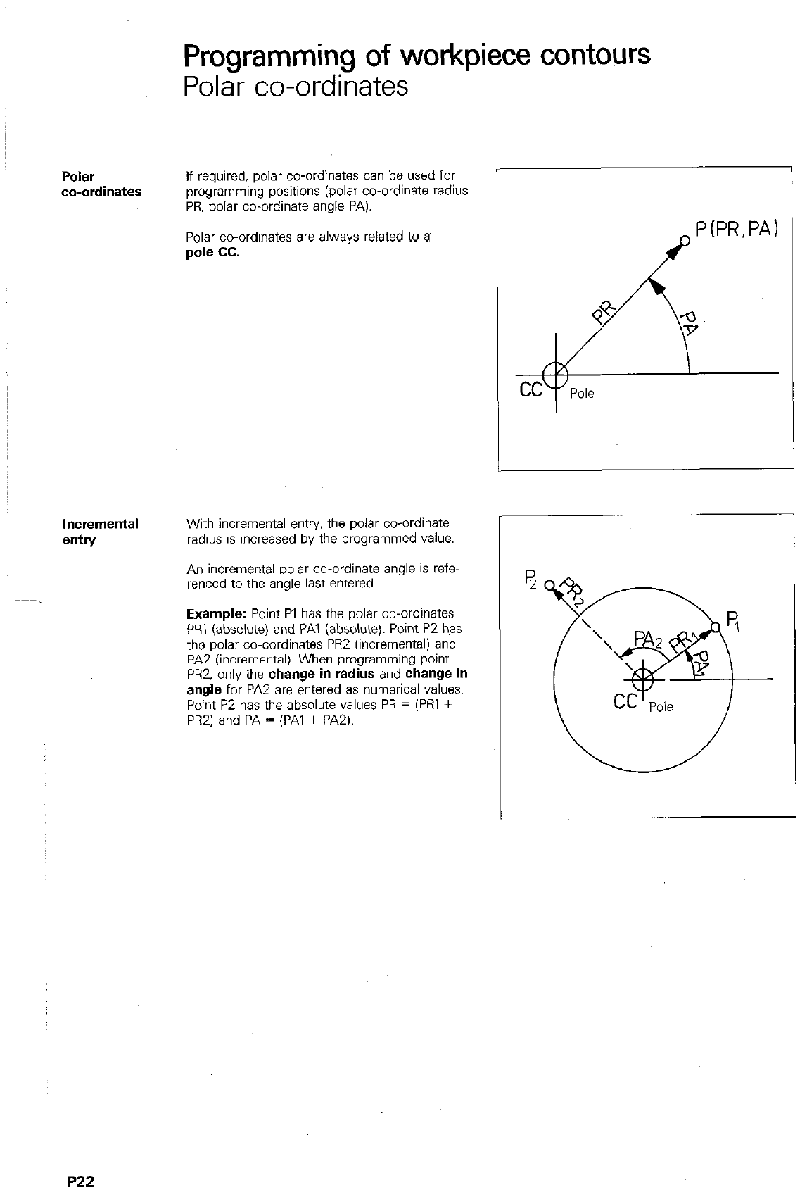
co-ordinates
If required, polar co-ordinates can be used for
programming positions (polar co-ordinate radius
PR. polar co-ordinate angle PA).
Polar co-ordinates are always related to a~
pole cc.
Incremental
entry
With incremental entry. the polar co-ordinate
radius is increased by the programmed value.
An incremental polar co-ordinate angle is refe-
renced to the angle last entered.
Example:
Point PI has the polar co-ordinates
PRI (absolute) and PA1 (absolute). Point P2 has
the polar co-cordinates PR2 (incremental) and
PAZ (incremental). When programming point
PRZ. only the
change in radius
and
change in
angle
for PA2 are entered as numerical values.
Point P2 has the absolute values PR = (Pi31 +
PRZ) and PA = (PA1 + PA2).
P22
Programming of workpiece contours
Polar co-ordinates
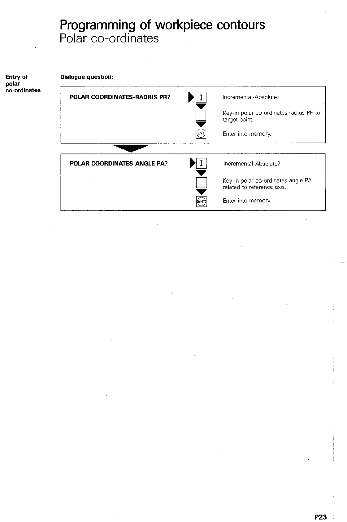
Ehtry of Dialogue question:
Qolar
c:o-ordinates
POLAR COORDINATES-RADIUS PR? ) fl Incremental-Absolute?
E Key-in polar co-ordinates radius PR to
target point.
Enter into memory
POLAR COORDINATES-ANGLE PA? Incremental-Absolute?
0 Key-in polar co-ordinates angle PA
related to reference axis.
Enter into memory
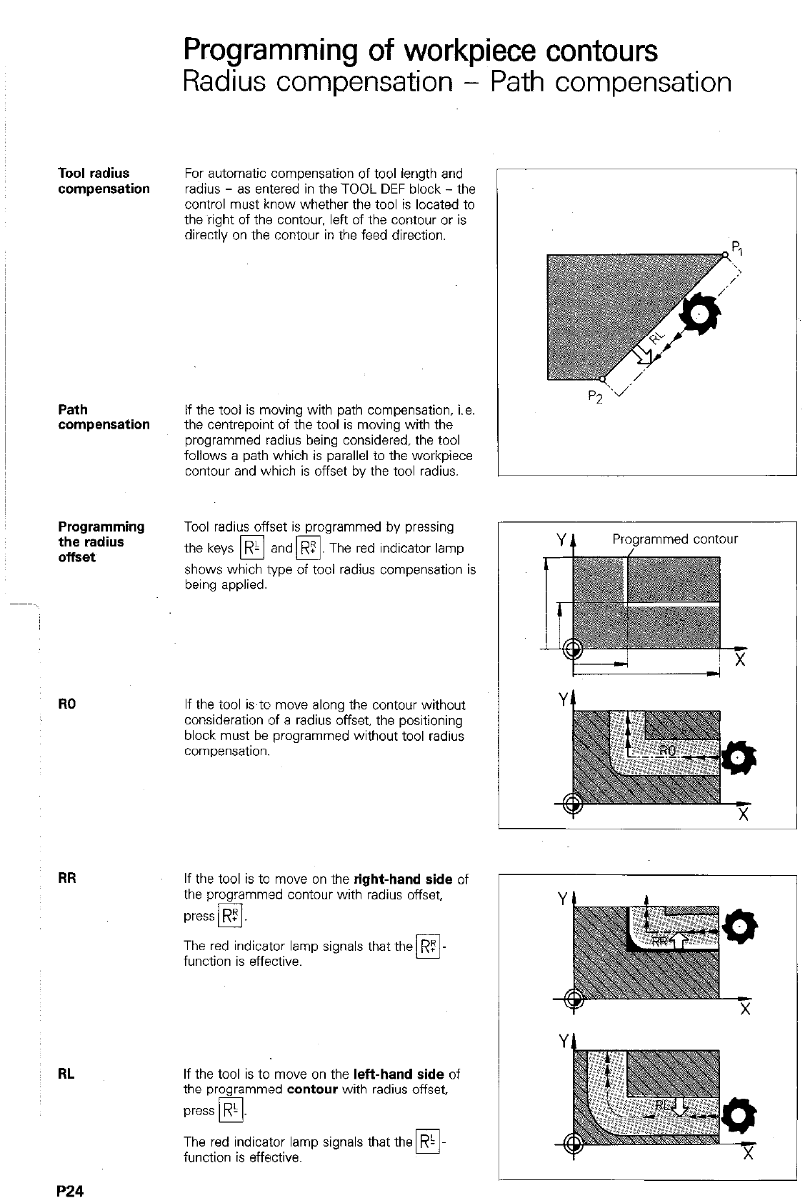
Tool radius
Path
compensation
Programming
the radius
offset
RO
RR
RL
1’24
Programming of workpiece contours
Radius compensation - Path compensation
For automatic compensation of tool length and
radius - as entered in the TOOL DEF block - the
control must know whether the
tool
is located to
the right of the contour. left of the contour or is
directly on the contour in the feed direction.
If the tool is moving with path compensation, i.e.
the centrepoint of the tool is moving with the
programmed radius being considered, the tool
follows a path which is parallel to the workpiece
contour and which is offset by the tool radius.
Tool radius offset is programmed by pressing
the keys R- and
q
. The red indicator lamp
q
shows which type of tool radius compensation is
being applied.
If the tool is to move along the contour without
consideration of a radius offset, the positioning
block must be programmed without tool radius
compensation.
If the tool is to move on the right-hand side of
the programmed contour with radius offset,
press R5
cl
The red indicator lamp signals that the RZ
function is effective. 0
If the tool is to move on the left-hand side of
the programmed contour with radius offset,
press
R-
PI
The red indicator lamp signals that the R-
function is effective. 0
Programmed contour
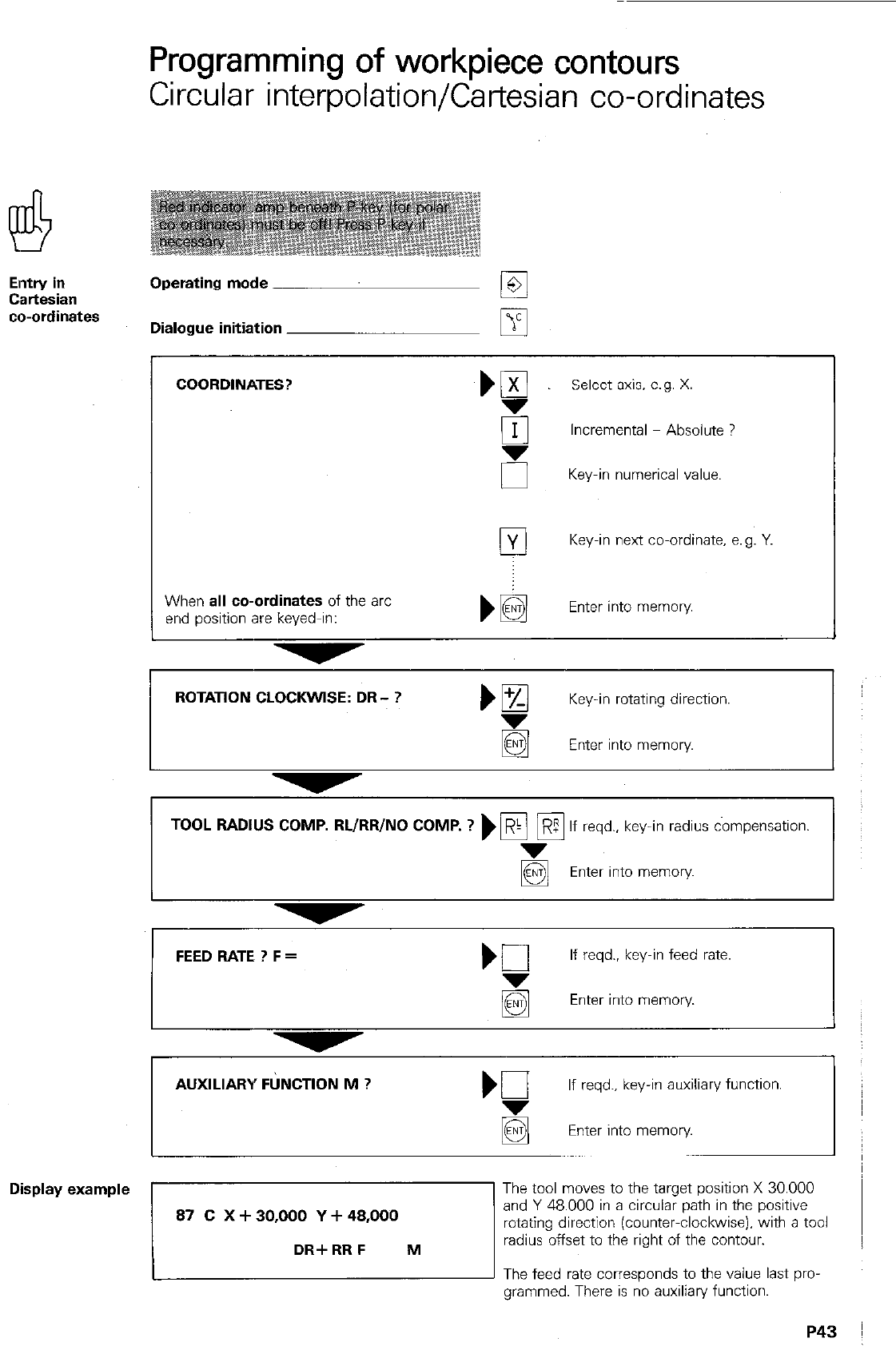
Programming of workpiece contours
Radius compensation
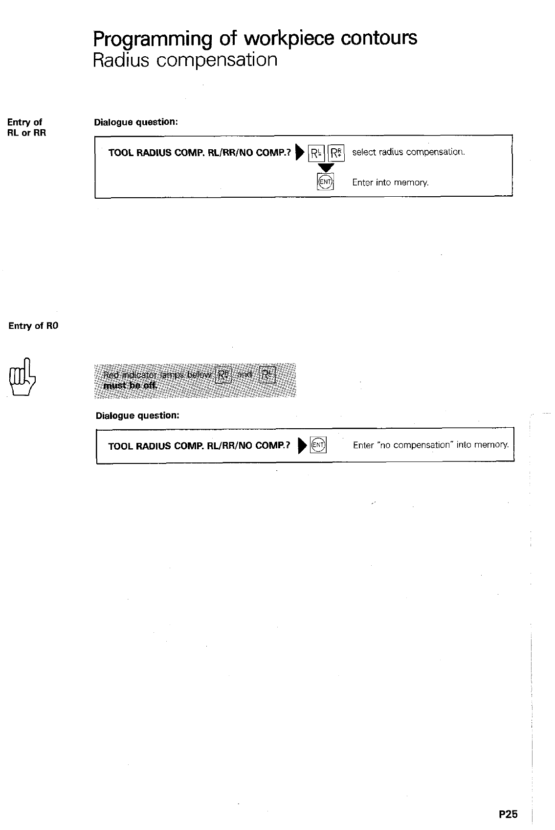
Entry of
RL or RR Dialogue question:
TOOL RADIUS COMP. RL/RR/NO COMP.?
) p\ [El select radius compensation.
Enter into memory.
Entry of RO
Dialogue question:
TOOL RADIUS COMP. RL/RR/NO COMP.? )
q
Enter “no compensation” into memob’
Path
compensation
on internal
cornets
Path
Correction
of path
with M97
Programming of workpiece contours
Path compensation
On internal corners, the control automatically
calculates the intersection S of the milling tool
path which is parallel to the workpiece contour.
This prevents workpiece damage through back
cuimg.
When radius compensation has been pro-
grammed, the control applies a transitional arc
which enables the tool to “roll: around the COT-
ner.
In most cases. the tool is guided around the car-
ner at a constant feed rate. If. however. the pro-
grammed feed rate is too high for the transitional
arc. the feed rate is automatically reduced to a
lower value (ensuring contour precision). The
limit value is permanently programmed within the
control.
Automatic feed rate reduction can be cancelled
by programming the auxiliary function M90 (see
“Feed rate”) if required.
If the tool radius is larger than a step within
the contour, the transitional arc can cause
workpiece damage on an external comer.
This is then indicated by the error message
= TOOL RADIUS TOO LARGE = and the cove-
sponding positioning block is not executed.
The auxiliary function PA97 prevents the insertion
of a transitional arc. The control then calculates
a further path intersection S and guides the
tool via this point, thereby preventing damage to
the contour.
Error message:
TOOL RADIUS TOO LARGE
J7
program
contour
withoul
M97
Programming of workpiece contours
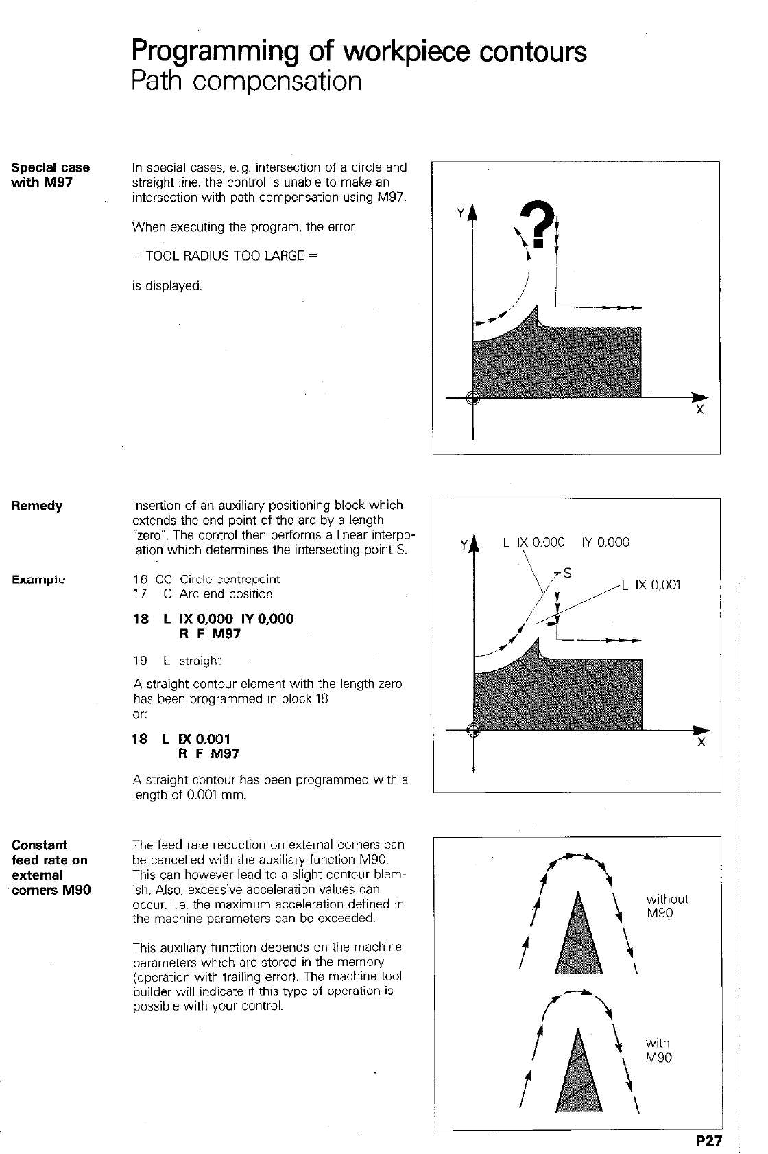
Path compensation
Special case
with M97
In special cases. e.g. intersection of a circle and
straight line, the control is unable to make an
intersection with path compensation using M97.
When executing the program. the error
= TOOL RADIUS TOO LARGE =
is displayed.
Remedy
Insertion of an auxiliary positioning block which
extends the end point of the arc by a length
“zero”. The control then performs a linear interpo-
lation which determines the intersecting point S.
16 CC Circle centrepoint
17 C Arc end position
18 L IX 0,OQO IY 0,000
R F M97
19 L straight
A straight contour element with the length zero
has been programmed in block 18
Or:
18 L IXO.001
R F M97
A straight contour has been programmed with a
length of 0.001 mm.
Constant
feed rate on
external
‘corners M90
The feed rate reduction on external comers can
be cancelled with the auxiliary function M90.
This can however lead to a slight contour blem-
ish. Also, excessive acceleration values can
occur, i.e. the maximum acceleration defined in
the machine parameters can be exceeded.
This auxiliary function depends on the machine
parameters which are stored in the memory
(operation with trailing error). The machine tool
builder will indicate if this type of operation is
possible with your control.
4
L 1; 0,000 IY 0,000
1
P
Y
L IX 0,001
i-
I
f
without
M9Q
f \
-
with
M90
P2
7
Termination
of path
compensation
M98
Line-by-line
milling with
I’498
Example
Programming of workpiece contours
Path comper%ation -
The auxiliary function M98 ensures that a con-
tour element is completely executed. If a further
contour has been programmed, as shown in the
adjacent example, the first contour position is
approached with tool radius compensation, as a
result of M98, and is completely executed (see
also “Departure command”).
A further example for application of M98 is line-
by-line milling with downfeed in Z.
Lz -10 R F9999 M
Lx x20 Y-IO RR F20 M
L YIIO R F M98
Lz -20 R F9999 M
L Y-110 RL F20 M
L Y-IO R F M98
without M98 with M98
P28
, ,., .
Programming of workpiece contours
Feed rate F/Auxiliary functions M
Feed rate The feed rate. i.e. tool path speed is pro-
grammed in mm/min. or 0.1 inch/min.
With rotary tables (A. 6 or C-axis) the entry value
is in O/min.
The feed rate override on the control operating
panel can van/ the feed rate from 0 to 150%.
Max. entry values (rapid) for the feed rate are
0 15999 mm/min. or
0 6299/10 inch/min.
The max. feed rate of the individual machine
axes is determined through machine parameters
by the machine tool builder.
F
Auxiliaty
functions For control of special machine functions (e.g.
spindle “on”) and tool path behaviour, auxiliary
(miscellaneous) functions can be programmed.
Auxiliary functions have the address letter M
and a code number.
When programming, it must be noted that cer-
tain M-functions are effective at the beginning of
a block (e.g. MO3 spindle “on”, clockwise) and
others at the block-end (e.g. MO5 Spindle
‘stop”).
A list of all M-functions is given on the following
pages.
P30
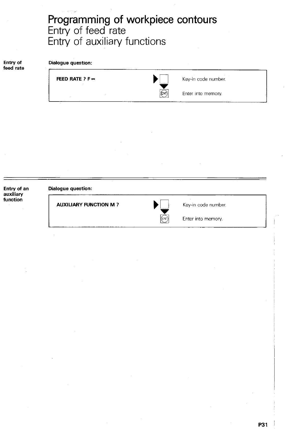
Progr&nming of workpiece contours
Entry off feed rate
Entry of auxiliary functions
Entry of
feed rate Dialogue question:
FEED RATE ? F = Key-in code number.
Enter into memory
Entry of a”
auxiliary
function
Dialogue question:
AUXILIARY FUNCTION M ? Key-in code number.
Enter into memory
P31
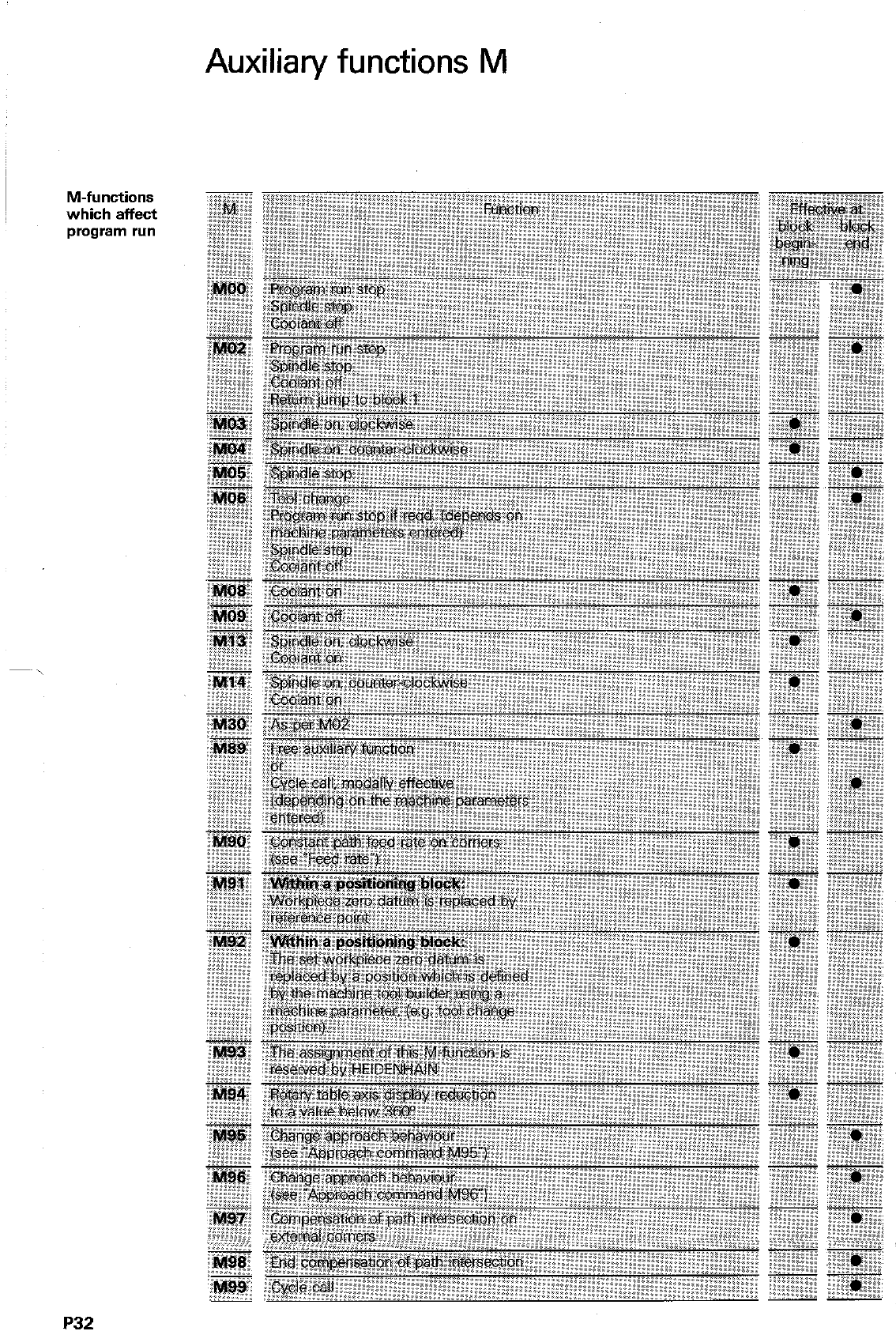
Auxiliary functions M
M-functions
which affect
program run
P32
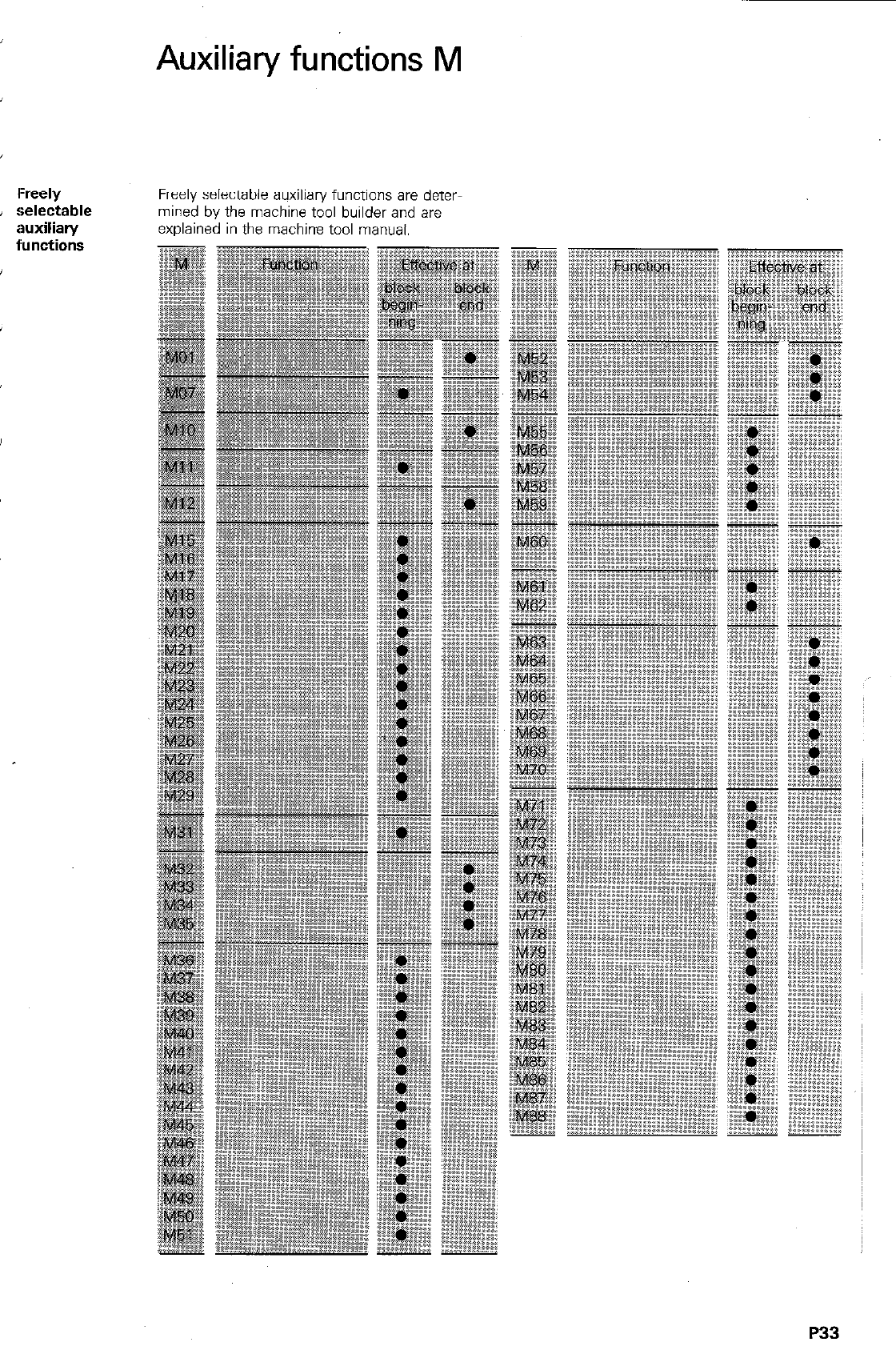
I-reely
selectable
iwxiliary
l’unctions
Auxiliary functions M
Freely selectable auxiliary functions are deter
mined by the machine tool builder and are
explained in the machine tool manual.
P33
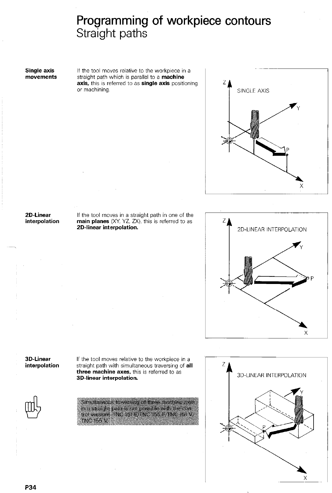
Programming of workpiece contours
Straight paths
Single axis
movements If the tool moves relative to the workpiece in a
straight path which is parallel to a machine
axis, this is referred to as single axis positioning
or machining.
ZD-Linear
interpolation If the tool moves in a straight path in one of the
main planes (XY, YZ. ZX). this is referred to as
2D-linear interpolation.
z
t
SINGLE AXIS
2
t
ZD-LINEAR INTERPOLATION
3D-Linear
interpolation If the tool moves relative to the workpiece in a
straight path with simultaneous traversing of all
three machine axes, this is referred to as
3D-linear interpolation.
P34
Programming of workpiece contours
Straight paths
Straight
line L
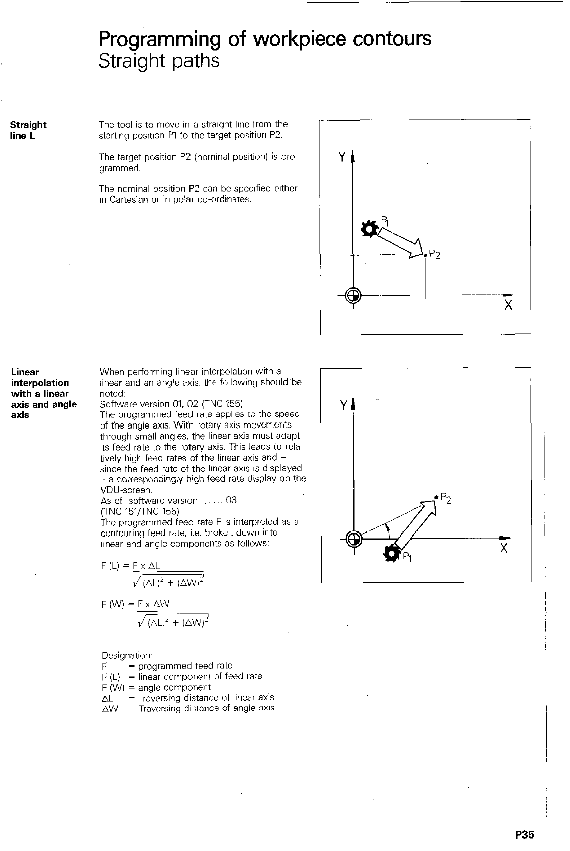
The tqol is to mcwe in a straight line from the
starting position Pl to the target position P2.
The target position P2 (nominal position) is pro-
grammed.
The nominal position P2 can be specified either
in Cartesian or in polar co-ordinates.
Y
t
9”
if
93
l
p2
CD
X
Linear
interpolation
with a linear
axis and angle
axis
When performing linear interpolation with a
linear and an angle axis, the following should be
noted:
software version 01. 02 (TNC 155)
The programmed feed rate applies to the speed
of the anale axis. With rotary ax? movements
through small angles, the lit&r axis must adapt
its feed rate to the rotary axis. This leads to rela-
tively high feed rates of the linear axis and -
since the feed rate of the linear axis is displayed
- a correspondingly high feed rate display on the
VDU-screen.
As of software version 03
(TNC 151flNC 155)
The programmed feed rate F is interpreted as a
contouring feed rate. i.e. broken down into
linear and angle components as follows:
F(L) = F x AL
/(AL)’ + (AW)’
F(W)=FxAW
J(ALj’ + (AW)i’
Designation:
F = programmed feed rate
F (L) = linear component of feed fate
F (W) = angle component
AL = Traversing distance of linear
aXiS
AW = Traversing distance of angle axls
P35
Remarks
lP36
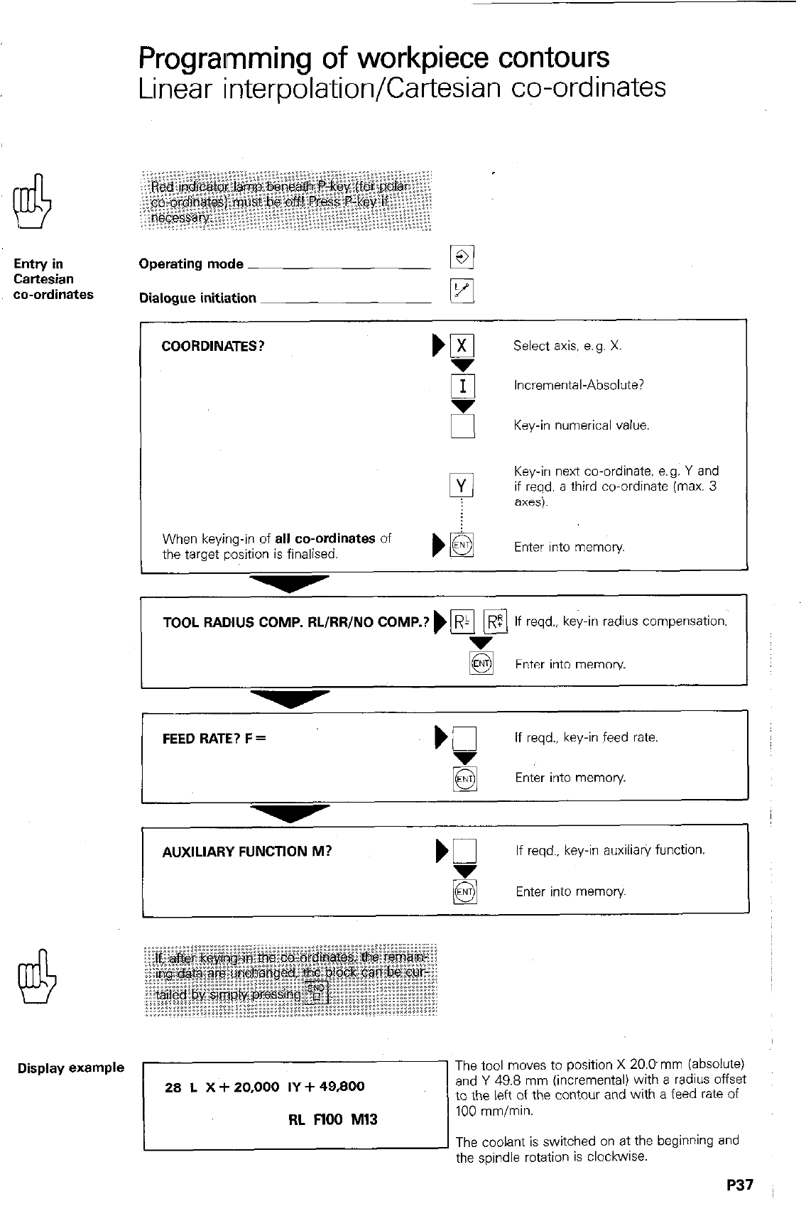
Entry in
Cartesian
co-ordinates
Display example
Programming of workpiece contours
Linear interpolation/Cartesian co-ordinates
Operating mode
q
Dialogue initiation k!
COORDINATES?
Select axis, e.g. X.
El Incremental-Absolute?
I
I u
Key-in numerical value
Key-in next co-ordinate, e.g. Y and
if reqd. a third co-ordinate (max. 3
When keying-in of
all co-ordinates
of
the target position is finalised. Enter into memory
I
TOOL RADIUS COMP. RL/RR/NO COMP.? ) pi pq
R If reqd., key-in radius compensation.
Enter into memory
FEED RATE? F =
I
if reqd.. key-in feed rate.
Enter into memory.
I I
t
AUXILIARY FUNCTlON M?
If reqd., key-in auxiiia@ function.
Enter into memory
The tool moves to position X 20.Dmm (absolute)
and Y 49.8 mm (incremental) with a radius offset
to the left of the contour and with a feed rate of
100 mmlmin.
The coolant is switched on at the beginning and
the spindle rotation is clockwise.
Programming of workpiece contours
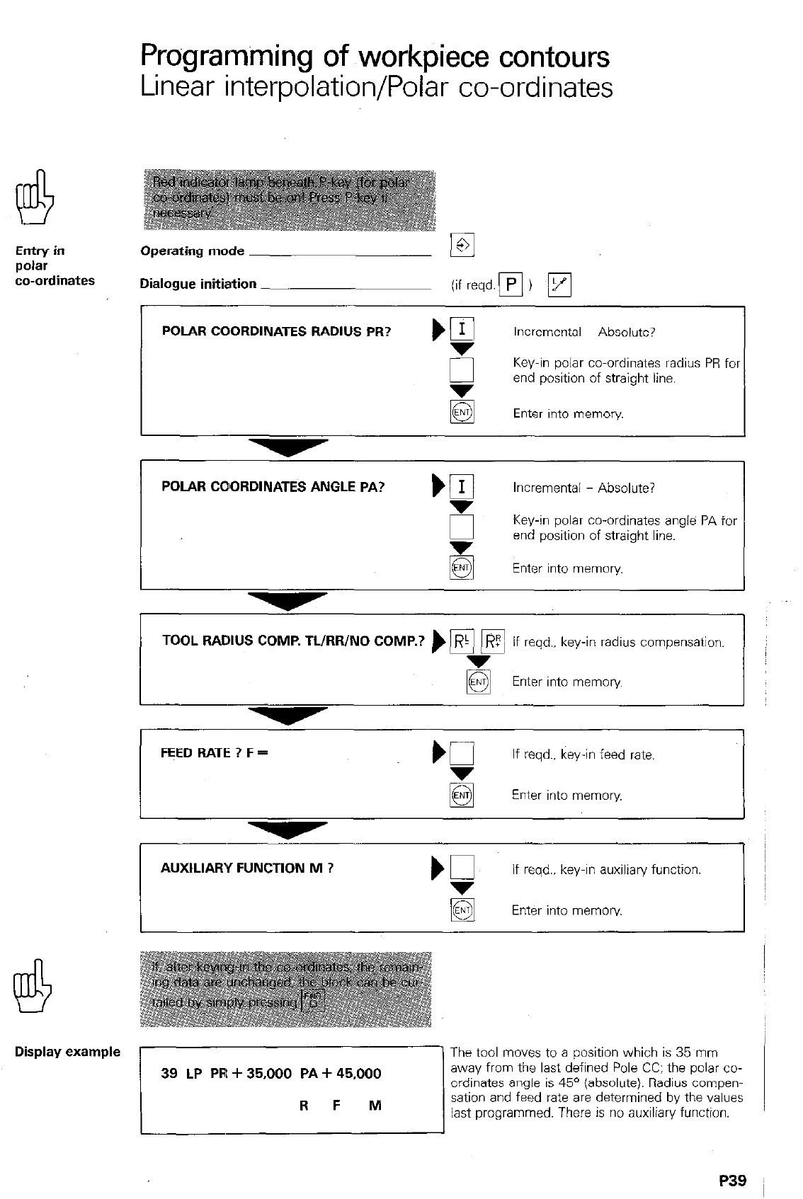
Linear interpolation/Polar co-ordinates
EntrY in Operating mode
p&r
co-ordinates Dialogue initiation
I
POLAR COORDINATES RADIUS PR? ) g Incremental Absolute?
0 Key-in polar co-ordinates radius PR fol
end position of straight line.
Enter into memory.
POLAR COORDINATES ANGLE PA? )
q
Incremental - Absolute?
6 Key-in polar co-ordinates angle PA for
z
end position of straight line.
Enter into memory
TOOL RADIUS COMP. TL/RR/NO COMP.? ) pi
q
7 If reqd., key-in radius compensation.
Enter into memory
FEED RATE ? F = If reqd.. key-in feed rate.
Enter into memory
AUXILIARY FUNCTION M ? if reqd., key-in auxiliary function.
q
Enter into memory.
Display example
r
The tool moves to a position which is 35 mm
away from the last defined Pole CC: the polar co-
ordinates angle is 45’ (absolute). Radius cornpen-
sation and feed rate are determined by the values
last programmed. There is no auxiliary function.
P39
Programming of workpiece contours
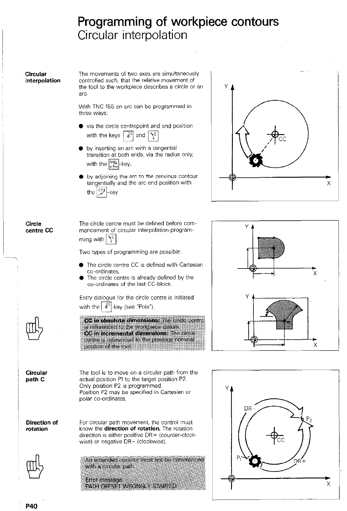
Circular interpolation
circular
interpolation
Circle
centre cc
Circular
path C
Direction of
rotation
The movements of two axes are simultaneously
controlled such. that the relative movement of
the tool to the workpiece describes a circle or an
arc.
With TNC 155 an arc can be programmed in
three ways:
l via the circle centrepoint and end position
with the keys m and
q
0 by inserting an arc with a tangential
transition at both ends. via the radius only.
with the yk -key.
0
0 by adjoining the arc to the previous contour
tangentially and the arc end position with
the m-key
The circle centre must be defined before com-
mencement of circular interpolation-program-
ming with j’
0
Two types of programming are possible:
0 The circle centre CC is defined with Cartesian
r-
co-ordinates.
0 The circle centre is alreadv defined bv the
co-ordinates of the last CC-block.
Entry dialogue for the circle centre is initiated
with the $
r7 -key (see “Pole*).
The tool is to move on a circular path from the
actual position Pl to the target position PZ.
Only position P2 is programmed.
Position P2 may be specified in Cartesian or
polar co-ordinates.
For circular path movement. the control must
know the direction of rotation. The rotation
direction is either positive DR+ (counter-clock.
wise) or negative DR- (clockwise).
r
P40
Programming of workpiece contours
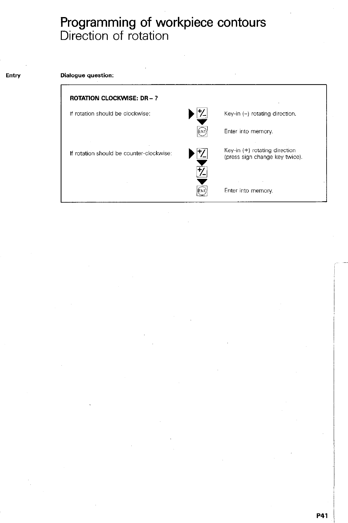
Direction of rotation
Eintry Dialogue question:
ROTATION CLOCKWISE: DR - ?
If rotation should be clockwise: Key-in (-) rotating direction.
Enter into memory
If rotation should be countwclockwise: Key-in (+) rotating direction
z
(press sign change key twice)
Enter into memory
P41 1
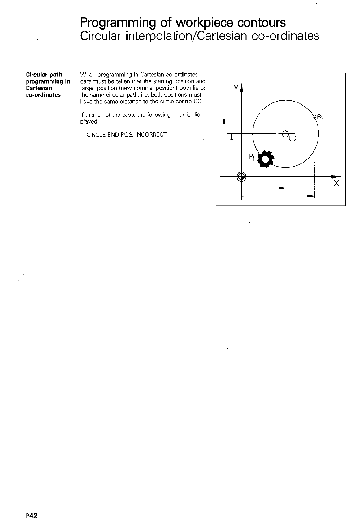
Circular path
:programming
Cartesian
co-ordinates
Programming of workpiece contours
Circular interpolation/Cartesian co-ordinates
When programming in Cartesian co-ordinates
I in
care must be taken that the starting position and
target position (new nominal position) both lie on
the same circular path, i.e. both positions must
have the same distance to the circle centre CC.
If this is not the case. the following error is dis-
played:
= CIRCLE END POS. INCORRECT =
IP42
Programming of workpiece contours
Circular interpolation/Cartesian co-ordinates
Elntry in Operating mode
Cartesian
co-ordinates Dialogue initiation IT
COORDINATES? ‘g
Select axis. e.g. X.
0 Incremental - Absolute ?
Key-in numerical value.
Lg
Key-in next co-ordinate, e.g. Y.
When
all co-ordinates
of the arc
end position are keyed-in: Enter into memory
ROTATlON CLOCKWISE: DR- ? bI%
Key-in rotating direction.
g Enter into memory
TOOL RADIUS COMP. RL/RR/NO COMP. ? ) Fi pi
R If reqd., key-in radius compensation.
E Enter into memory
FEED RATE ? F = Kl
If reqd.. key-in feed rate.
Enter into memory.
AUXILIARY FtiNCTlON M ?
If reqd., key-in auxiliary function.
Enter into memory
Display example
)“““‘“,:.,:*“.
The tool moves to the target position X 30.000
and Y 48.000 in a circular path in the positive
rotating direction (counter-clockwise). with a tool
radius offset to the right of the contour.
The feed rate corresponds to the value last pro-
grammed. There is no auxiliary function.
P43
Circular path
programming
in polar
co-ordinates
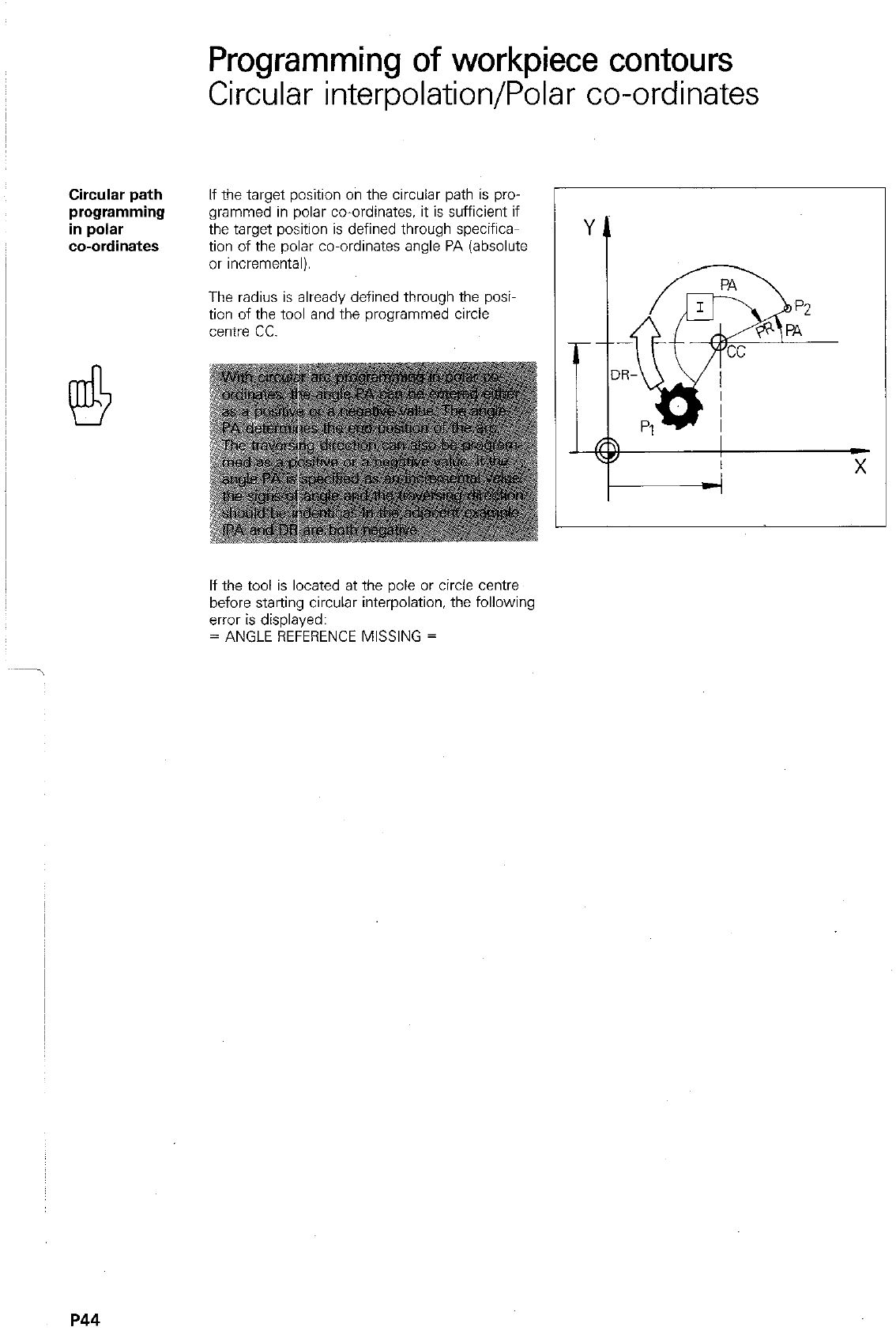
Programming of workpiece contours
Circular interpolation/Polar co-ordinates
If the target position on the circular path is pro-
grammed in polar co-ordinates, it is sufficient if
the target position is defined through specific+
tion of the polar co-ordinates angle PA (absolute
or incremental).
The radius is already defined through the posi
tion of the tool and the programmed circle
centre cc.
If the tool is located at the pole or circle centre
before starting circular interpolation, the following
error is displayed:
= ANGLE REFERENCE MISSING =
P44
Programming of workpiece contours
Circular interpolation/Polar co-ordinates
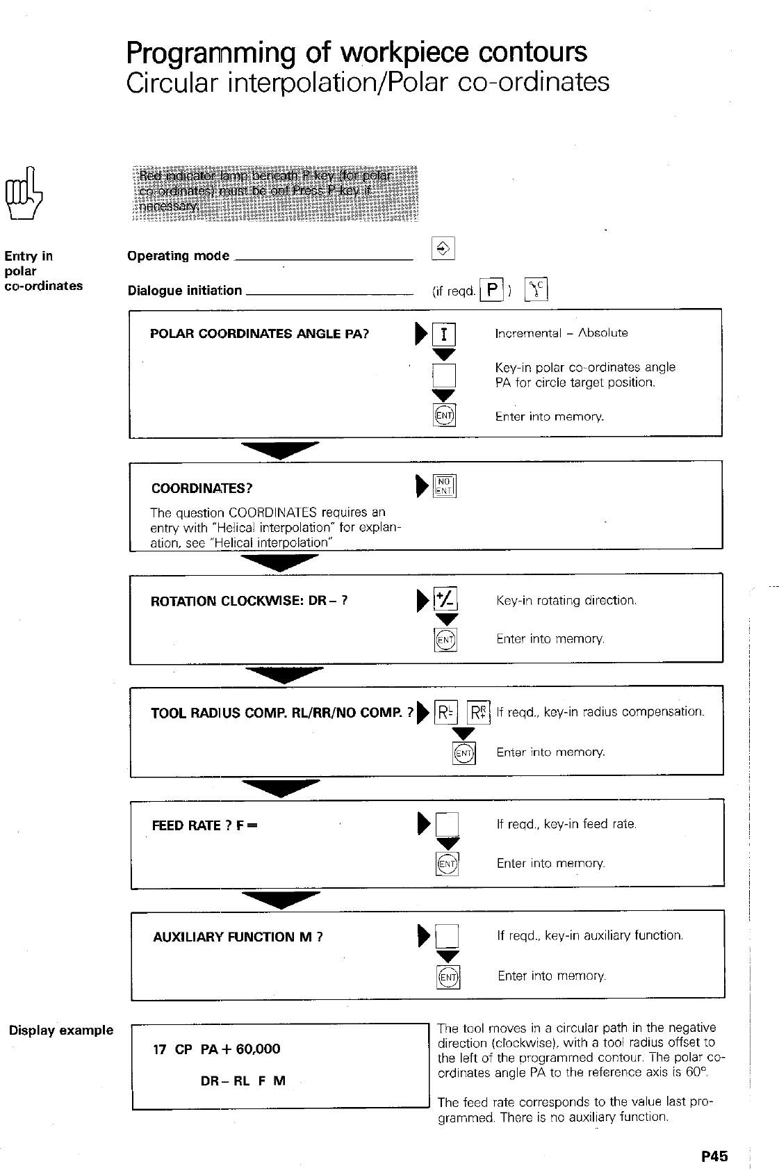
Entry in
p0lar
cwordinates
Operating mode
Dialogue initiation (if reqd.
q
)
q
POLAR COORDINATES ANGLE PA? )
q
Incremental - Absolute
,_i
Key-in polar co-ordinates angle
PA for circle target position.
Enter into memory
COORDINATES?
The question COORDINATES requires an
entry with “Helical interpolationw for explanm
ation, see “Helical interpolation”
ROTATION CLOCKWISE: DR- ? )!%I Key-in rotating direction.
g Enter into memory.
TOOL RADIUS COMP. RL/RR/NO COMP. ?) pi Fi ? If reqd., key-in radius compensation.
Enter into memory
FEED RATE ? F = If reqd., key-in feed rate.
Enter into memory
AUXILIARY FUNCTION M ? If reqd.. key-in auxiliary function.
Display example
The feed rate corresponds to the value last pro-
grammed. There is no auxiliary function.
P45
Programming of workpiece contours
Adjoining arcs
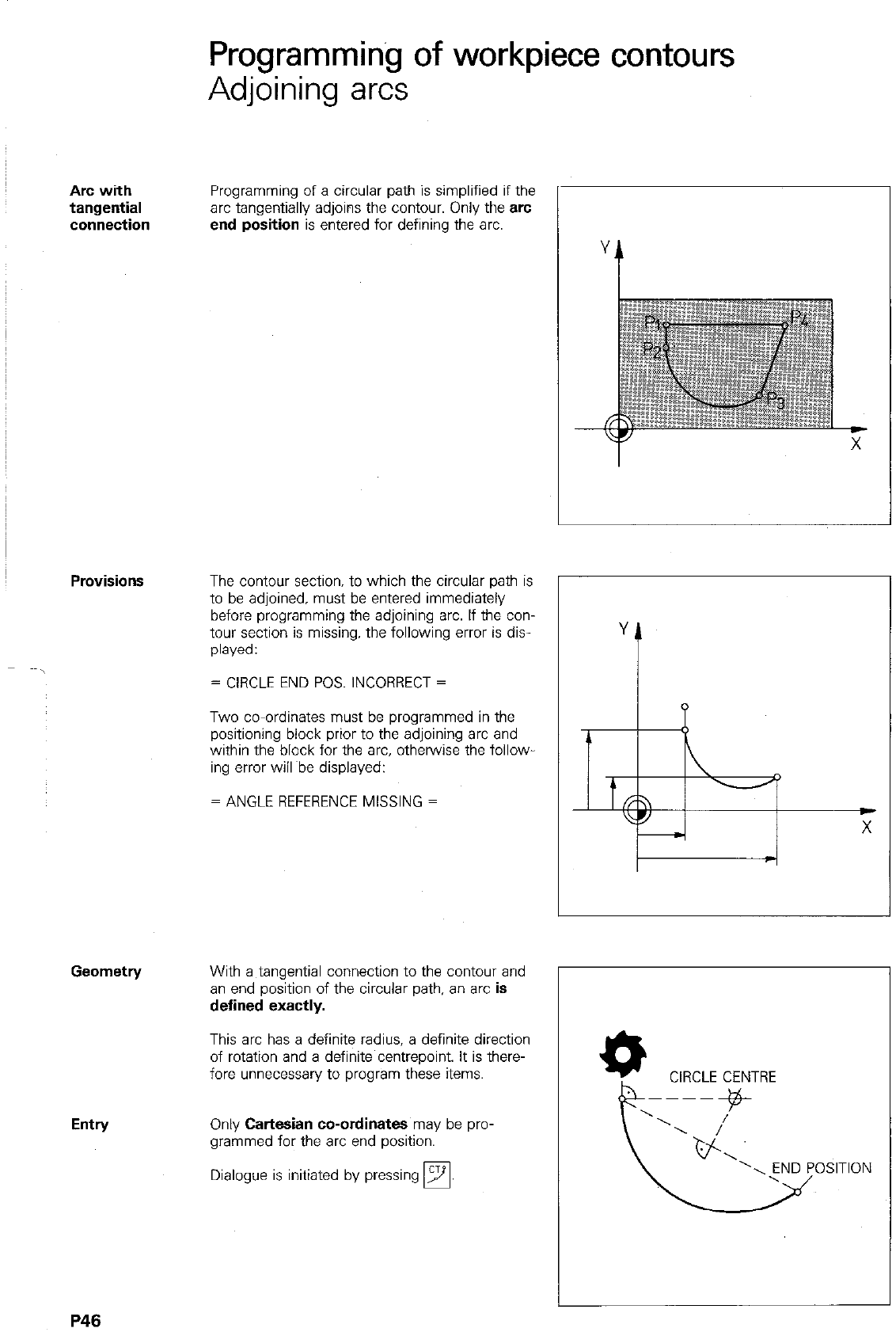
Arc with Programming of a circular path is simplified if the
tangential arc tangentially adjoins the contour. Only the arc
connection end position is entered for defining the arc.
Entry
The contour section. to which the circular path is
to be adjoined. must be entered immediately
before programming the adjoining arc. If the con-
tour section is missing, the following error is dis-
played:
= CIRCLE END POS. INCORRECT =
Two co-ordinates must be programmed in the
positioning block prior to the adjoining arc and
within the block for the arc, otherwise the follow
ing error will Abe displayed:
= ANGLE REFERENCE MISSING =
With a tangential connection to the contour and
an end position of the circular path, an arc is
defined exactly.
This arc has a definite radius, a definite direction
of rotation and a definite centrepoint. It is there-
fore unnecessary to program these items.
Only Cartesian co-ordinates may be pro-
grammed for the arc end position.
Dialogue is initiated by pressing
q
YA
CIRCLE CENTRE
P46
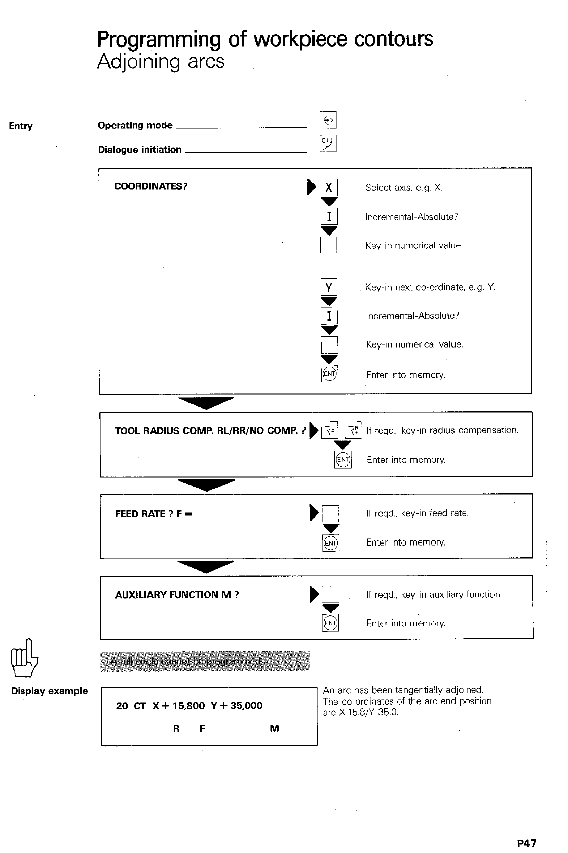
Programming of workpiece Contours
Adjoining arcs
Eintry Operating mode ET
Dialogue initiation
q
COORDINATES?
Select axis. e.g. X.
q
Incremental~Absolute?
5 Key-in numerical value.
9
Key-in next co-ordinate. e.g. Y.
g
Incremental-Absolute?
0 Key-in numerical value.
3 Enter into memory
TOOL RADIUS COMP. RL/RR/NO COMP. ? ) \Ei F
,R If reqd.. key-in radius compensation.
g Enter into memory
FEED RATE ? F = )Z
If reqd.. key-in feed rate.
g Enter into memory
AUXILIARY FUNCTION M ? m
If reqd., key-in auxiliary function.
Enter into memory.
Display example
7
An arc has been tangentially adjoined. I
The co-ordinates of the arc end position
are X 15.8/Y 35.0.
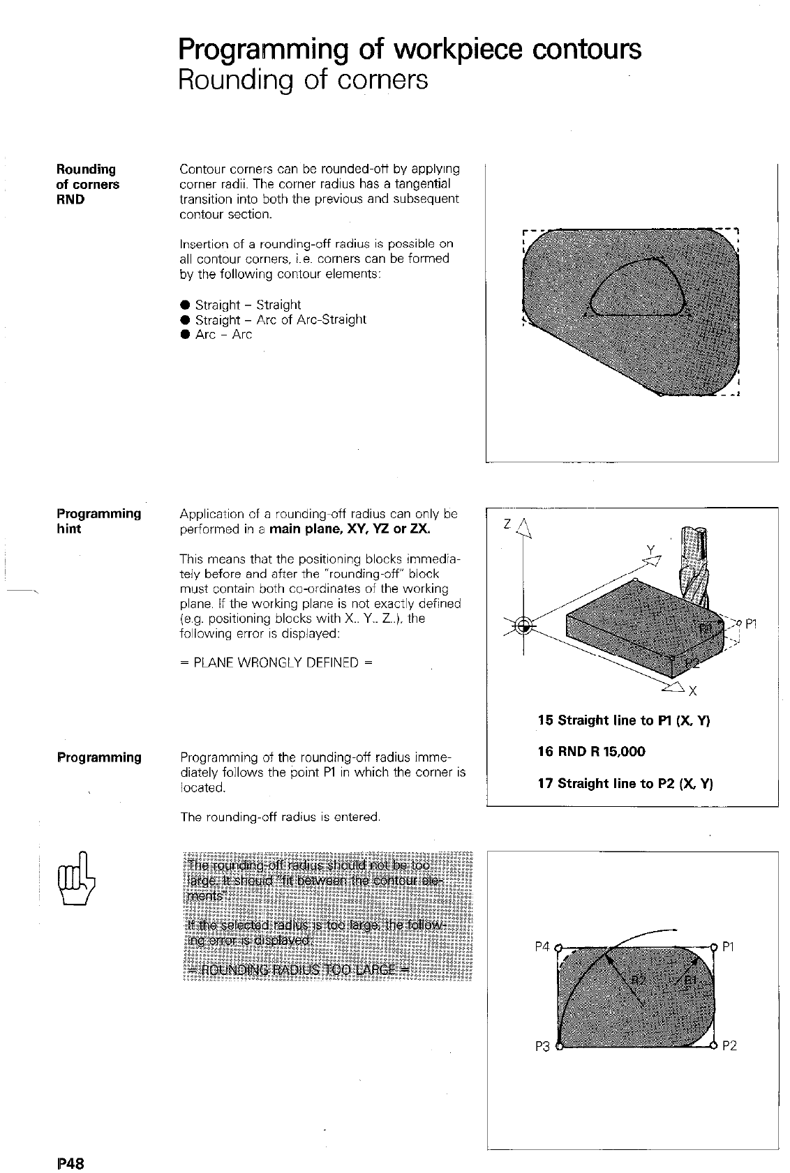
Programming of workpiece contours
Rounding of corners
Rounding
of comers
RND
Contour comers can be rounded-off by applying
comer radii. The comer radius has a tangential
transition into both the previous and subsequent
contour section.
Insertion of a rounding-off radius is possible on
all contour corners. i.e. comers can be formed
by the following contour elements:
0 Straight - Straight
0 Straight - Arc of Arc-Straight
0 Arc - Arc
Programming
hint
Application of a rounding-off radius can only be
performed in a
main plane, XY, Y2 or 2X.
This means that the positioning blocks immedia-
tely before and after the *rounding-w? block
must contain both co-ordinates of the working
plane. If the working plane is not exactly defined
(e.g. positioning blocks with X.. Y.. Z..). the
following error is displayed:
= PLANE WRONGLY DEFINED =
:Q Pi
..j
_,
/
15 Straight line to Pl (X, Y)
Programming
Programming of the rounding-off radius imme-
diately follows the point Pl in which the comer is
located.
16 RND R 15,000
17 Straight line to P2 (X, Y)
The rounding-off radius is entered.
P4
P3
PI
P2
IP48
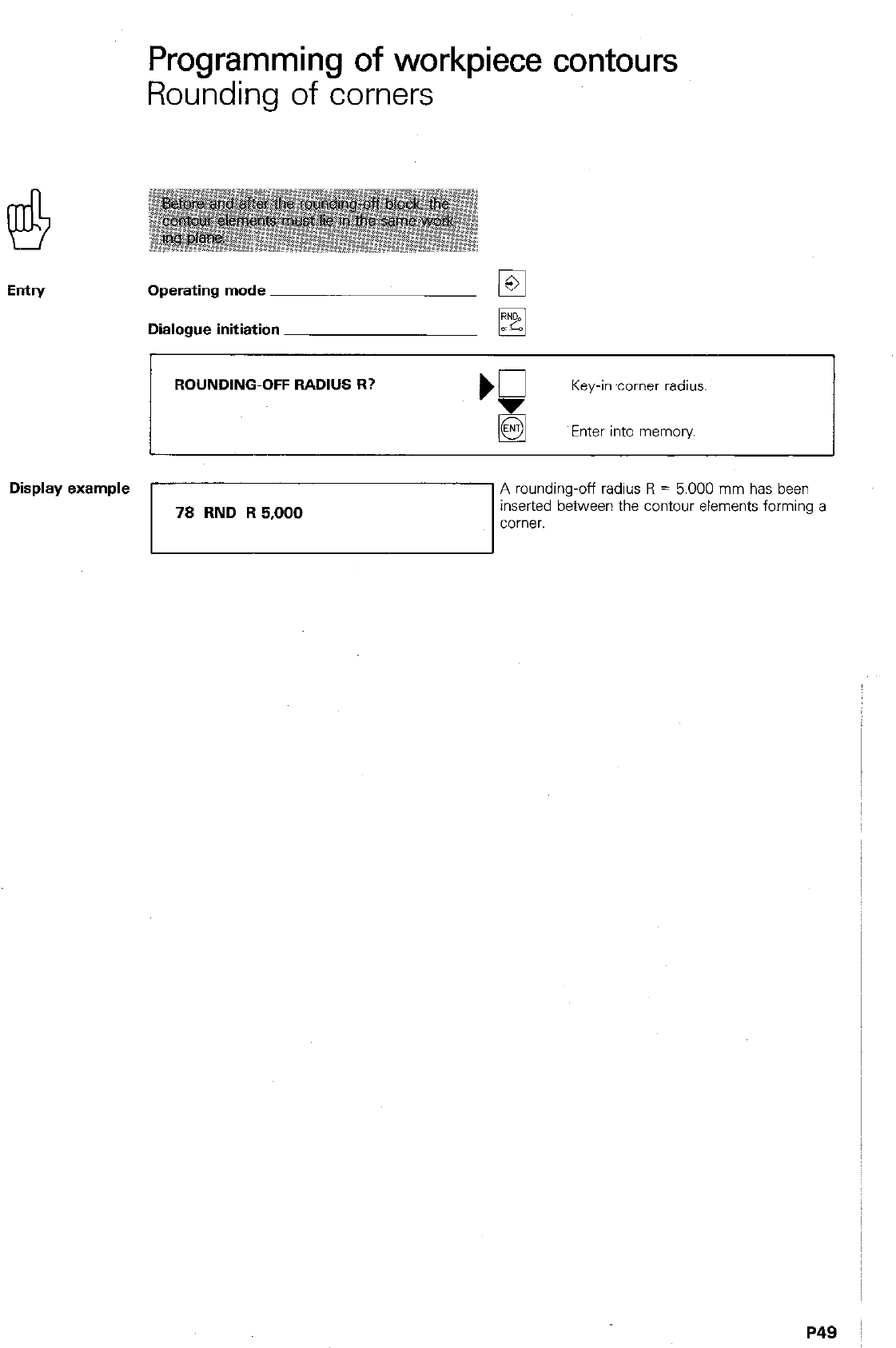
Entry
Programming of workpiece contours
Rounding of corners
Operating mode
Dialogue initiation
ROUNDING-OFF RADIUS R?
Key-in ‘corner radius
Enter into memory
Display example 1
1 A rounding-off radius R = 5.000 mm has been
78
RND R 5,000
inserted between the contour elements forming a
corner.
P49 I
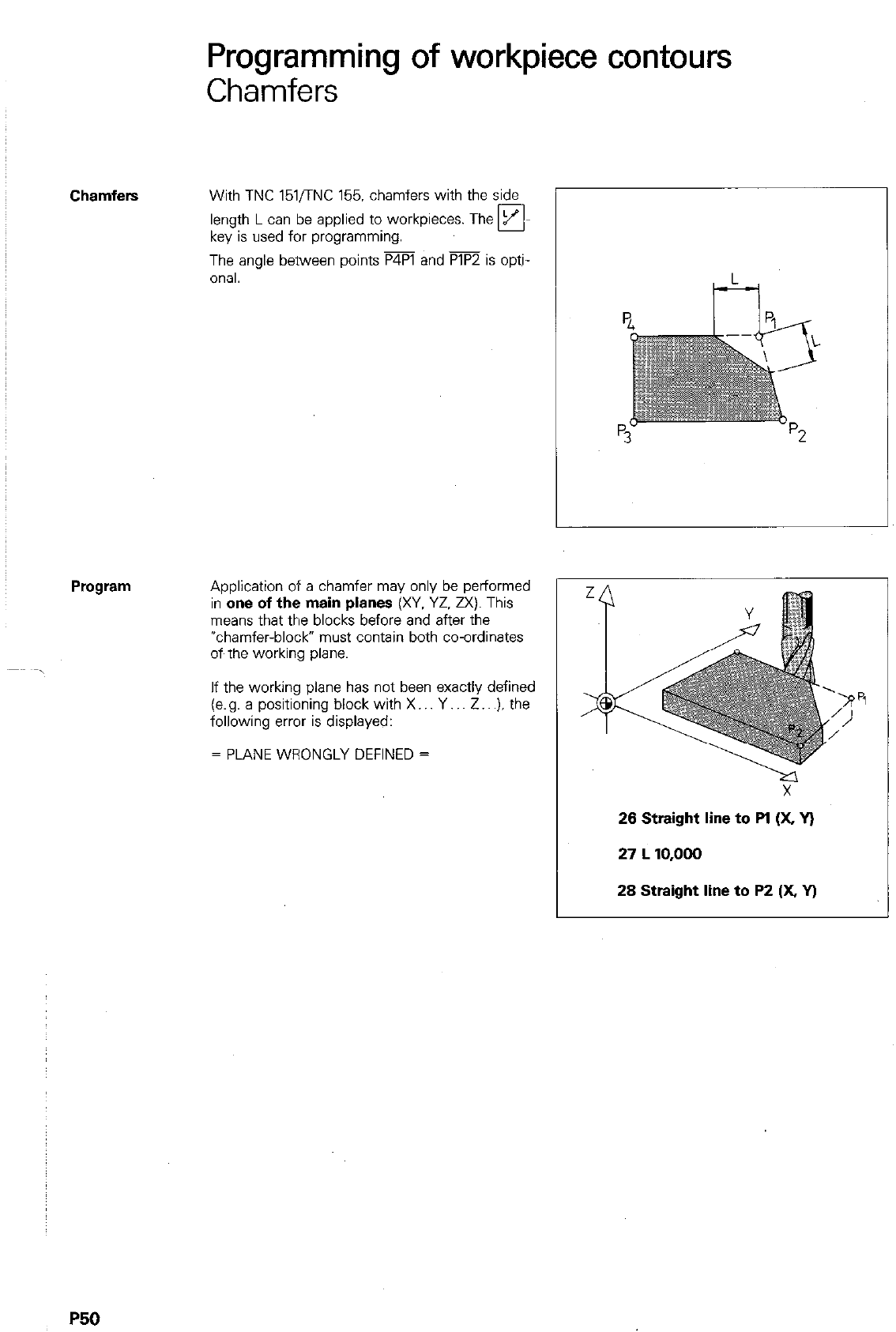
Programming of workpiece contours
Chamfers
Chamfers
With TNC 151,‘TNC 155. chamfers with the side
-
length L can be applied to workpieces. The H-
key is used for programming.
The angle between points P4Pl and PlP2 is opti-
onal.
Application of a chamfer may only be performed
in one
of the main planes
(XV. YZ. ZX). This
means that the blocks before and after the
*chamfer-block” must contain both co-ordinates
oft the working plane.
If the working plane has not been exactly defined
(e.g. a positioning block with X.. Y.. Z.. .). the
following error is displayed:
= PLANE WRONGLY DEFINED =
26 Straight line to Pl (X, v)
27
L 10,000
28 Straight line to P2 (X v)
P50
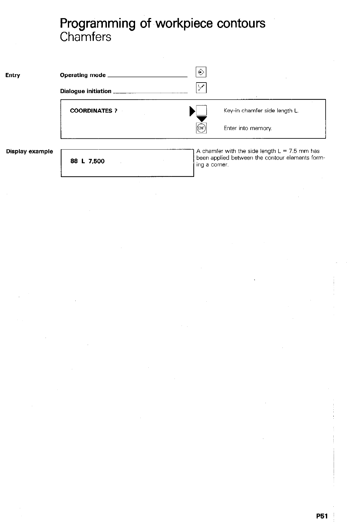
Entry
Programming of workpiece contours
Chamfers
Operating mode
Dialogue initiation
COORDINATES ? Key-in chamfer side length L.
Enter into memory
Display example
88 L 7,500
A chamfer with the side length L = 7.5 mm has
been applied between the contour elements form-
1”g a corner.
Programming of workpiece contours
Helix
Helical interpolation -
With circular interpolation, two axes are simulta-
neously traversed such, that a circle is described
in one of the main planes (XY. YZ. 2X).
If the circular interpolation is superimposed with
a linear movement in the third axis (= tool axis),
the tool will follow a helical path.
Helical interpolation can be used for manufacture
of large-diameter, internal and external threads as
well as lubrication grooves.
Entry data A helix can only be programmed in polar co-ordi-
nates. As with circular interpolation, the circle
centre CC must already be defined before-
hand.
The total rotation,al angle of the tool (= number
of thread
turns
2) is entered as the polar co-
ordinates angle PA in degrees:
PA = Number of turns x 360°
For angles greater than 360’. PA must be speci-
fied incrementally. The total height/depth is
entered in response to the dialogue request for
co-ordinates.
This value depends on the required pitch.
H=PxA H = Total height/depth
P = Pitch
A = Number of thread turns
The total height/depth can also be programmed
as an absolute or incremental value.
Radius
compensation The tool radius compensation depends on
l
the direction of rotation,
0 the type of thread (internal/external)
l
milling direction (pos./neg. axis direction):
Z
IV
’ Starting position
I’52
Emtn/
Programming of workpiece contours
Helical interpolation
Operating mode
Dialogue initiation
POLAR COORDINATES ANGLE PA
? )
q
Incremental - Absolute ?
Key-in total rotational angle.
COORDINATES ? m
Select feed axis.
5 Incremental - Absolute ?
‘0 Key-in height or depth.
Enter into memory
ROTATION CLOCKWISE: DR- ?
Key-in rotating direction.
5 Enter. into memory
TOOL RADIUS COMP. RL/RR/NO COMP. ? )Fi pj
Key-in radius compensation.
Enter into memory
If reqd.. key-in feed rate.
Enter into memory
AUXlLkY FUNCTION M ? Kl
If reqd.. key-in auxiliary function.
Enter into memory
Display example
P53
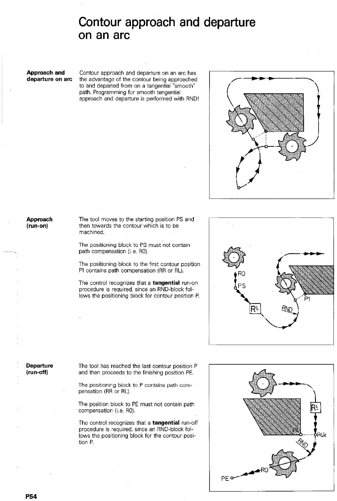
Contour approach and departure
on an arc
Approach and Contour approach and departure on an arc has
departure on arc the advantage of the contour being approached
to and departed from on a tangential “smooth*
path. Programming for smooth tangential
approach and departure is performed with RND!
,r’--‘a.7
/ \
Approach
(run-on)
The tool moves to the starting position PS and
then towards the contour which is to be
machined.
The positioning block to PS must not contain
path compensation (i.e. 130).
The positioning block to the first contour position
Pl contains path compensation (RR or RL).
The control recognizes that a tangential run-on
procedure is required, since an RND-block fol-
lows the positioning block for contour position P.
Departure The tool has reached the last contour position P
(run-offj and then proceeds to the finishing position PE.
The positioning block to P contains path com-
pensation (RR or RL).
The position block to PE must not contain path
compensation (i.e. RO).
The control recognizes that a tangential run-off
procedure is required, since an RND-block fol-
lows the positioning block for the contour posi-
tion P.
1
P54
Contour approach and departure
on an arc
Programming
for approach
(run-on)
20 L x + 100,000 Y + 50,000
RO F15999 M
21 L X + 65,000 Y + 40,000
RR F 50 Ml3
22 FIND R 10,000
23 L X + 65,000 Y + 100,000
R F M
Positioning block to starting position PS with
RO.
Positioning block to first contour position PI with
path compensation
RR.
Specification of
tangential run-on radius.
Positioning block to next contour position P2
Programming
for departure
(run-off)
30 L X + 50,000 Y + 65,000
RR F50 M
Positioning block to last contour position P with
path compensation
RR.
31 RND R 15,000
Specification of
tangential run-off radius.
32 L X + 100,000 Y + 85,000
RO F 15999 MOO
Positioning block to finishing position PE with
RO.
Caution, when entering F15999.
For tangential approach: The starting point PS
must be located within the quadrant I,. II or Ill.
The ~quadrants are formed by the starting direc-
tion in PI’ and the its perpendicular (tangential
direction with arcs) also passing through PI’.
If the starting direction is located within quadrant
IV. a clockwise arc will be formed thus dama-
ging the workpiece.
Pl = First contour position
PI’ = First compensated contour position
PS = Starting position (with radius RO)
RNDl = Rounding-off arc for quadrants I, II
RND2 = Rounding-off arc for quadrants ill, IV
P5!
Contour approach and departure in a
straight path
Introduction
contour
The tool is to move to the position PS and then
approach and
run-on to the contour. After the machining proce-
departure in
due. the tool is to run-off the contour and pro-
a straight path
teed to the position PE.
Path angle a
Run-on and run-off behaviour depends on the
path angle CI. This angle is related to the angle
which is formed between
0 the approach-straight and the first
contour element and
0 the departure-straight and the last
contour element.
There are normally three cases which can be
considered:
0 Path angle (1 = 180”
0 Path angle CI less than 180”
0 Path angle CI greater than 180°
P56
Contour approach and departure in a
straight path
Path angle
a
equal to 180°
Path angle
a = 1800 If the path angle (1 is equal to 180°, the starting
and finishing position is located on the extension
of the last position of a straight contour or the
tangent of the first/last contour position with cir-
cular shaped contours.
The starting and finishing position must be pro-
grammed
with radius compensation
(RL or RR).
Approach
(Run-on) The tool moves in a straight path to the compen-
sated position PSk of contour position PS and
then proceeds to the position Plk on a compen-
sated path.
The tool moves from the compensated position
P5k of contour point P5 in a compensated path
to position PEk.
PSk-
Interpreted by the
control as a
contour element.
PS
I
PEk I
Path angle
With CI greater than 1804 the starting and finish~
13 greater
ing position must be programmed with
radius
than 180° compensation
(RL or RR).
Contour approach and departure in a
straight path
Path angle a greater than 180'
The first and last contour position is assumed as
being an external corner. The control implements
path compensation for an external comer and
inserts a transitional arc.
The control considers the starting position PS as
being the first contour position.
The tool moves to position PSk and then on a
compensated path to position Plk.
Departure
(Run-off)
The control considers the finishing position PE as
being the last contour position.
The tool moves to the finishing position PEk on a
compensated path.
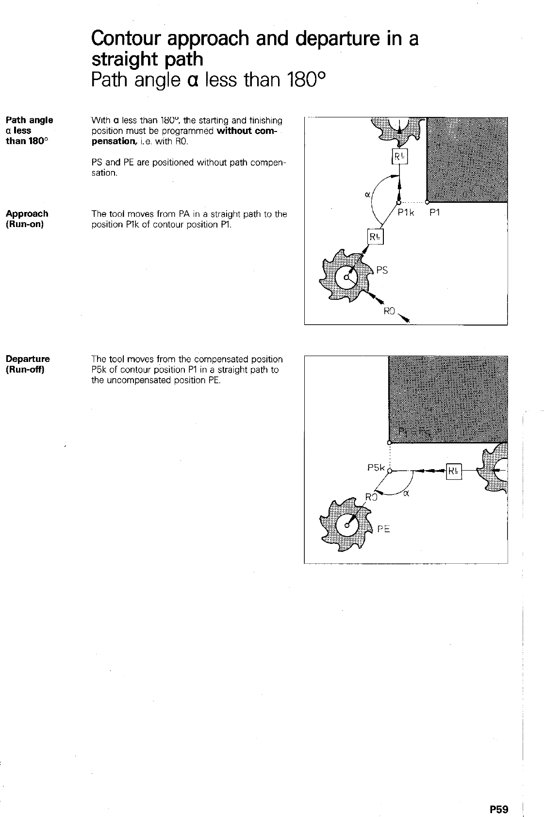
Contour approach and departure in a
straight path
Path angle a less than 180°
Path angle
a less
than 180”
With CI less than 1809 the starting and finishing
position must be programmed
without corn-
pensation,
i.e. with RO.
PS and PE are positioned without path compen-
sation.
Approach
The tool moves from PA in a straight path to the
(Run-on)
position Plk of contour position PI.
Departure
(Run-off) The tool moves from the compensated position
P5k of contour position Pl in a straight path to
the uncompensated position PE.
P59 1
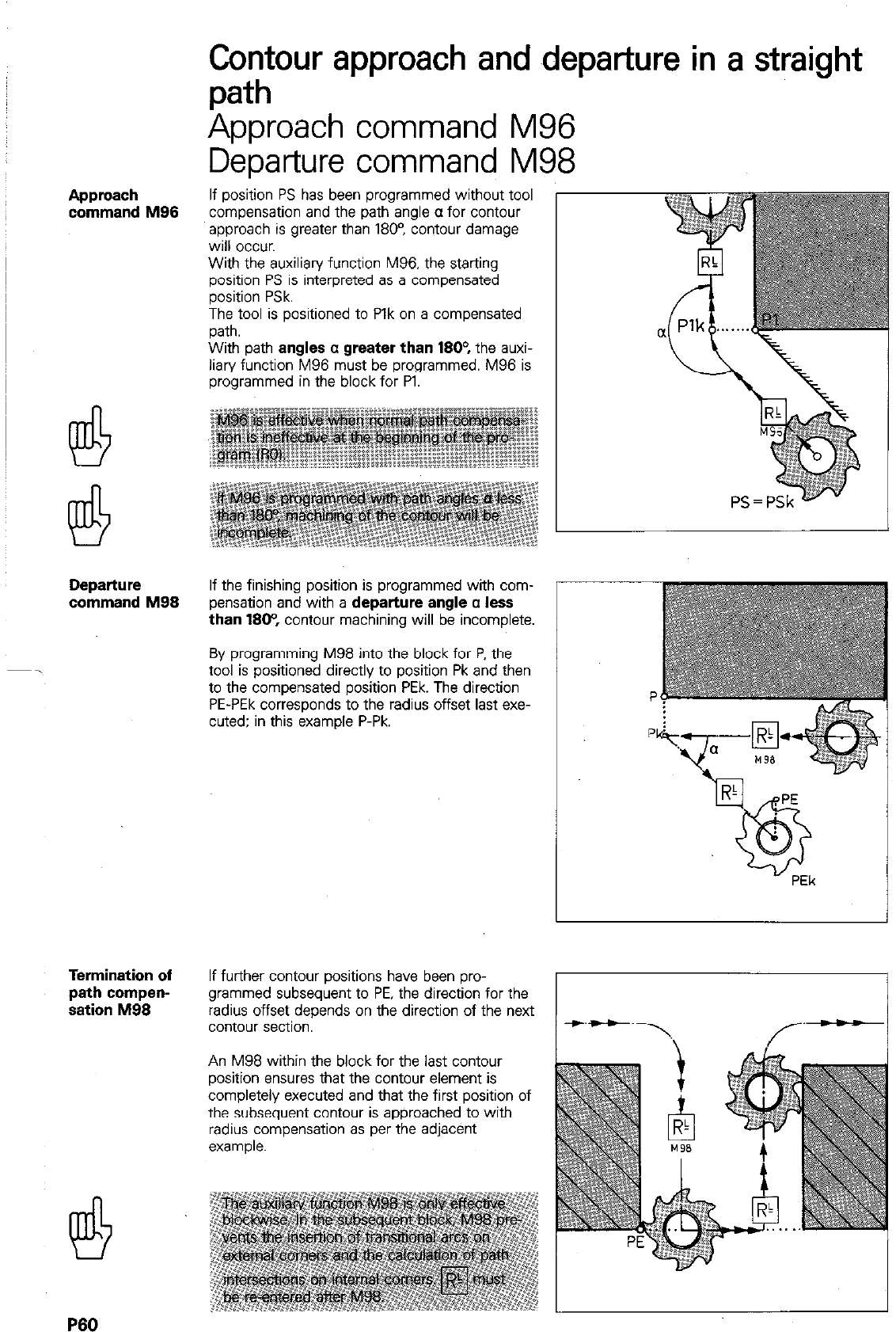
Approach
command M96
Departure
command M99
Termination of
path compen-
sation M96
Contour approach and ~departure
in a straight
path
Approach command M96
Departure command M98
If position PS has been programmed without tool
compensation and the path angle CL for contour
approach is greater than 1809 contour damage
will occur.
With the auxiliary function M96, the starting
position PS is interpreted as a compensated
position PSk.
The tool is positioned to Plk on a compensated
path.
With path
angles c greater than 1604
the auxi-
liary function M96 must be programmed. M96 is
programmed in the block for Pl.
If the finishing position is programmed with com-
pensation and with a
departure angle c less
than 1904
contour machining will be incomplete.
By programming M98 into the block for P, the
tool is positioned directly to position Pk and then
to the compensated position PEk. The direction
PE-PEk corresponds to the radius offset last exe-
cuted: in this example P-Pk.
If further contour positions have been pro-
grammed subsequent to PE, the direction for the
radius offset depends on the direction of the next
contour section.
An M98 within the block for the last contour
position ensures that the contour element is
completely executed and that the first position of
the subsequent contour is approached to with
radius compensation as per the adjacent
example.
P60
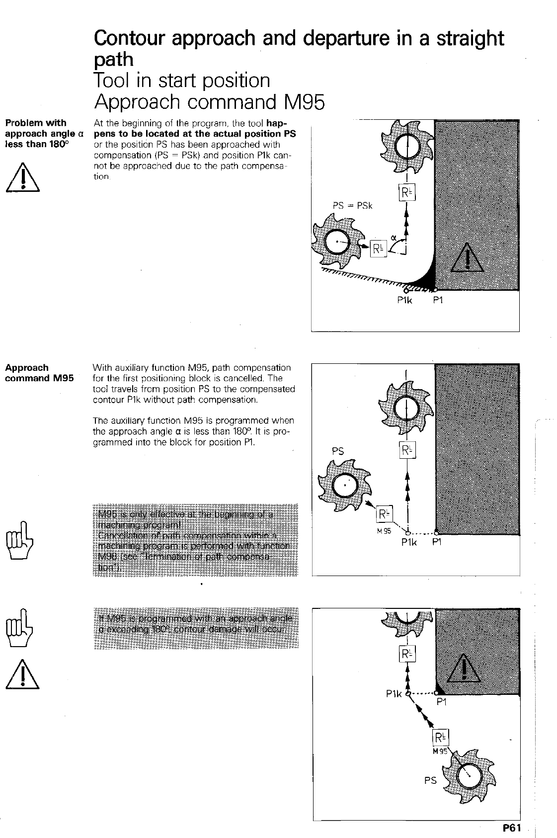
Plroblem with
approach angle a
less than 180°
L’ !l
.
Contour approach and departure in a straight
path
Tool in stat-t position
Approach command M95
At the beginning of the program. the tool hap-
pens to be located at the actual position PS
or the position PS has been approached with
compensation (PS = PSk) ,and position Plk can-
not be approached due to the path compensa-
tion.
P:k PI
Approach With auxiliary function M95, path compensation
command M95 for the first positioning block is cancelled. The
tool travels from position PS to the compensated
contour Plk without path compensation.
The auxiliary function M95 is programmed when
the approach angle a is less than 1800 It is pro-
grammed into the block for position PI.
Plk PI I
L!!t
A
!
P61
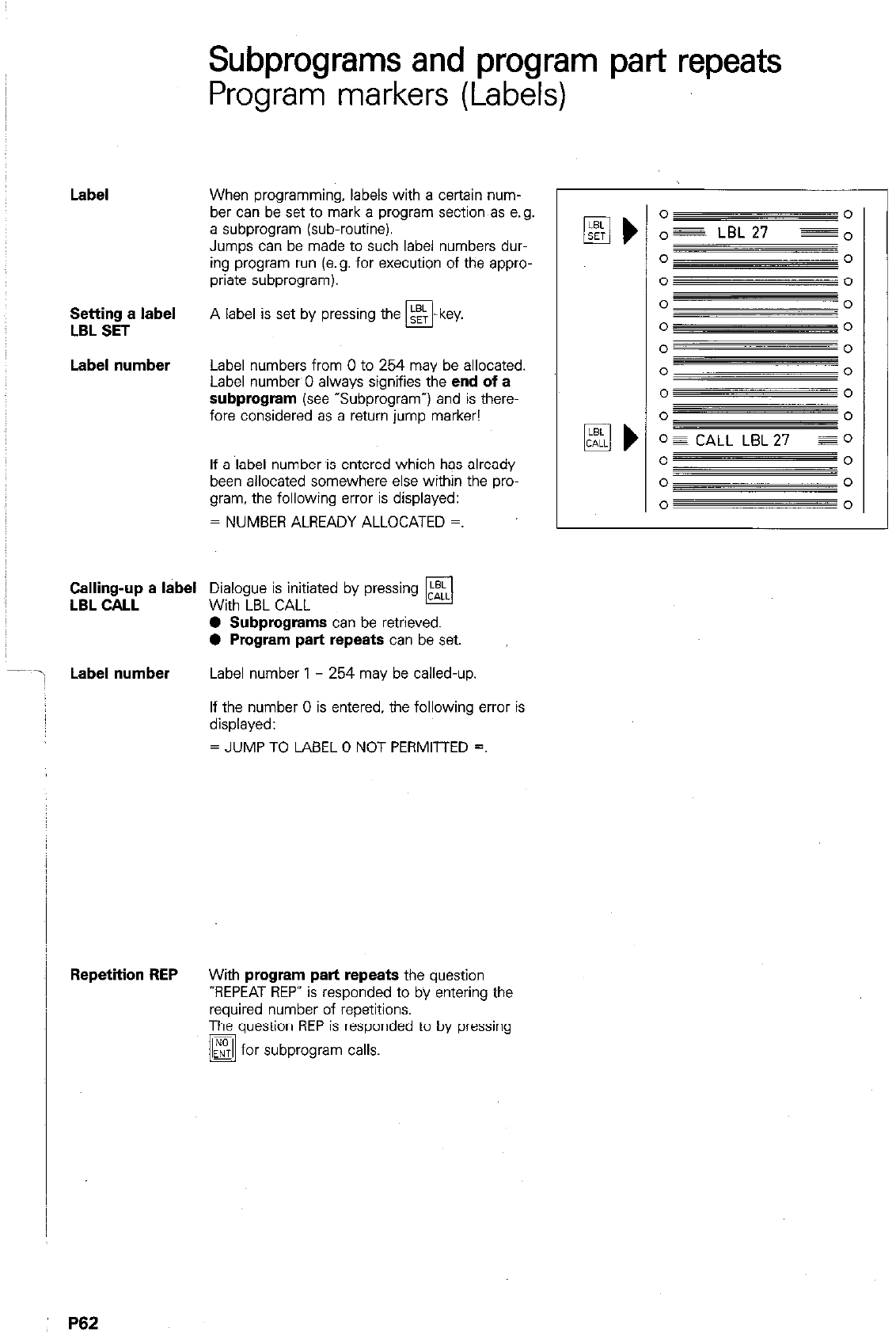
Subprograms and program part repeats
Program markers (Labels)
Label
When programming, labels with a certain num-
ber can be set to mark a program section as e.g.
a subprogram (sub-routine).
Jumps can be made to such label numbers dur-
ing program run (e.g. for execution of the appro-
priate subprogram).
Setting a label
LSL SET
A label is set by pressing the m-key.
Label number
Label numbers from 0 to 254 may be allocated.
Label numbw0 always signifies the
end of a
subprogram (see
“Subprogram”) and is there-
fore considered as a return jump marker!
If a label number is entered which has already
been allocated somewhere else within the pro-
gram. the following error is displayed:
= NUMBER ALREADY ALLOCATED =.
Calhg;~ a label
Di&guui;~;atac by pressing
q
0 Subprograms
can be retrieved.
0 Program part repeats
can be set.
Label number
Label number 1 - 254 may be called-up,
If the number 0 is entered, the following error is
displayed:
= JUMP TO LABEL 0 NOT PERMITTED =.
q )
o = CALL LBL 27 Eel
0 0
0 0
0 0
Repetiiion REP
With
program part repeats
the question
-REPEAT REP” is responded to by entering the
required number of repetitions.
The question REP is responded to by pressing
/@ for subprogram calls.
P62
Subprograms and program part repeats
Labels
Betting a label Operating mode LE
Dialogue initiation
LABEL NUMBER?
Key-in label number.
Enter into memory.
Display example
/
Label number 27 has been allocated to block 118.
Label call Operating mode El
Dialogue initiation
REPEAT REP?
If a
program part repeat
is to be entered: Kl Key-in the number of repetitions.
g Enter into memory
If
a subprogram call
is to be entered: Entry not required.
LABEL NUMBER?
Keyin label number to be called-up.
Enter into memory
Display
example 1
The subprogram having label number 27 is called-
up (continuation of machining with block number
Display
example 2
A program part is repeated two times. The “urn- ~
ber after the dash is a countdown indicating the
number of repetitions which are still to be execut-
ed. This number is reduced by 1 after completion ~
of each program part
Subprograms and program part repeats
Program part repeat
Program part
repeat
A program section which has been executed can
be repeated if required. This is referred to as a
program loop or
program part repeat.
The beginning of the program part which is to be
repeated is marked with a
label number.
The end of the program part is formed by
a LBL
CALL
in conjunction with the
number of
repeats REP.
Program run
The control executes the main program (includ-
ing the appropriate program part) until call-up of
the label number.
A jump is then made to th‘e program label and
the program part is repeated.
The display countdown reduces the number of
repetitions by 1 : REP 2/l.
After a new jump. the program part is repeated
agan.
When all programmed repetitions have been exe-
cuted, (display: REP Z/O). the main program is
continued.
-
Y Y
0 -0
0 0
0 0
Infinite loop
If no
entry
is made (by pressing I,“,” ) in
El
response to the question concerning the number
of repeats
REP, an
endless loop will take place:
the
call-up
of the label number is
repeated
constantly.
During program run and a test run. an infinite
loop is indicated after 8 iepetitions by the error
message:
= EXCESSIVE SUBPROGRAMMING =.
I
o=
zik+iE
0
O3-E
0
OF LBLll EO
0 0
o=,
0
PROGRAM
PART
.
,D . . .
P64
Subprograms and program part repeats
Subproijram
Subprogram If a program part is required at another location
within the machining program. this program sec-
tion is referred to as a sub-routine or subpro-
gram.
The beginning of the subprogram is labelled
with a label number. The end of subprogram
is always labelled with the label number 0.
The subprogram is retrieved via a LBL CALL
command. LBL CALL can be made at any loca
tion within the program.
After execution of the subprogram, a return jump
is made to the main program.
Program run The control works through the main program
until the subprogram call-up (CALL LBL 27 REP).
A jump is then made to the label called
The subprogram is executed until label number 0
(subprogram end).
Finally, a return jump is made into the main pro-
g’am.
The main program is continued from the block
immediately after the subprogram call.
A subprogram can only be executed once via a
call-up command! When retrieving a subprogram
via LBL CALL, the dialogue question REPEAT
REP? must be responded to by pressing
u ”
0 0
0 c’
0 0
0 0
0 0
0 cl
” n
LBLO =
0
0 0
I
SUB-
PROGRAM
0s LBL2J z”
o=
~
0
0
0
0
0
0 0
V
P65
Program run
with repetition
Program run
with
subprograms
P66
Subprograms and program part repeats
Nesting
A further subprogram or program part repeat can
be called-up within an existing subprogram or
program part repeat. This procedure is referred
to as
nesting.
(Illustrative example: set of boxes
or tables etc. fitting one inside another).
Program parts
and
subprograms
can be nest-
ed up to 8 times. i.e. the
nesting
level totals 8.
If the nesting level has been exceeded. the fol-
lowing error is displayed:
= EXCESSIVE SUBPROGRAMMING =.
The main program is executed until a jump is
made to LBL 17.
The program part is repeated twice.
Afterwards, the control continues program exe-
cution until a jump to LBL 15. The program part
is repeated once until CALL LBL 17 REP 2/2 and
the nested program part twice in addition. The
program part last programmed is then continued
to CALL LBL 17.
The main program is executed until the jump
command CALL LBL 17.
Afterwards, the subprogram is executed from
LBL 17 to the next call-up CALL LBL 53 etc. The
last subprogram within the series of nests is exe-
cuted without interruption.
Before the end of the last subprogram (LBL 0). a
return jump is made to each previous subpro-
gram until the main program is reached again.
I
-0g LBL 15 EOI
I 0
0
I
B
oz LBLI7 qo
0 0
o CALL LBL I? REP@O
II
0 0
-O CALL
LBL 15 REPIll
o -
r
1
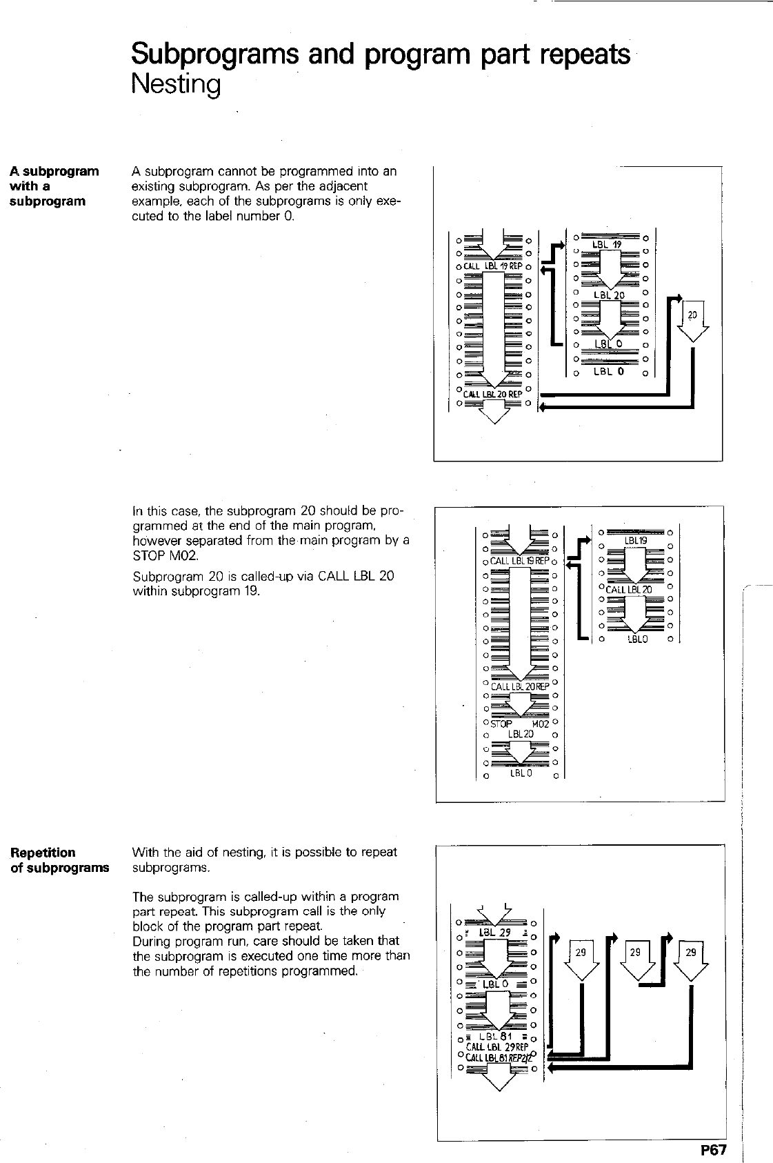
Subprograms and program part repeats
Nesting
A subprogram
with a
subprogram
A subprogram cannot be programmed into an
existing subprogram. As per the adjacent
example, each of the subprograms is only exe-
cuted to the label number 0.
In this case. the subprogram 20 should be pro-
grammed at the end of the main program.
however separated from the main program by a
STOP M02.
Subprogram 20 is called-up via CALL LBL 20
within subprogram 19.
Repetition
With the aid of nesting, it is possible to repeat
of subprograms
subprograms.
The subprogram is called-up within a program
part repeat. This subprogram call is the only
block of the program part repeat.
During program run, care should be taken that
the subprogram is executed one time more than
the number of repetitions programmed.
P67
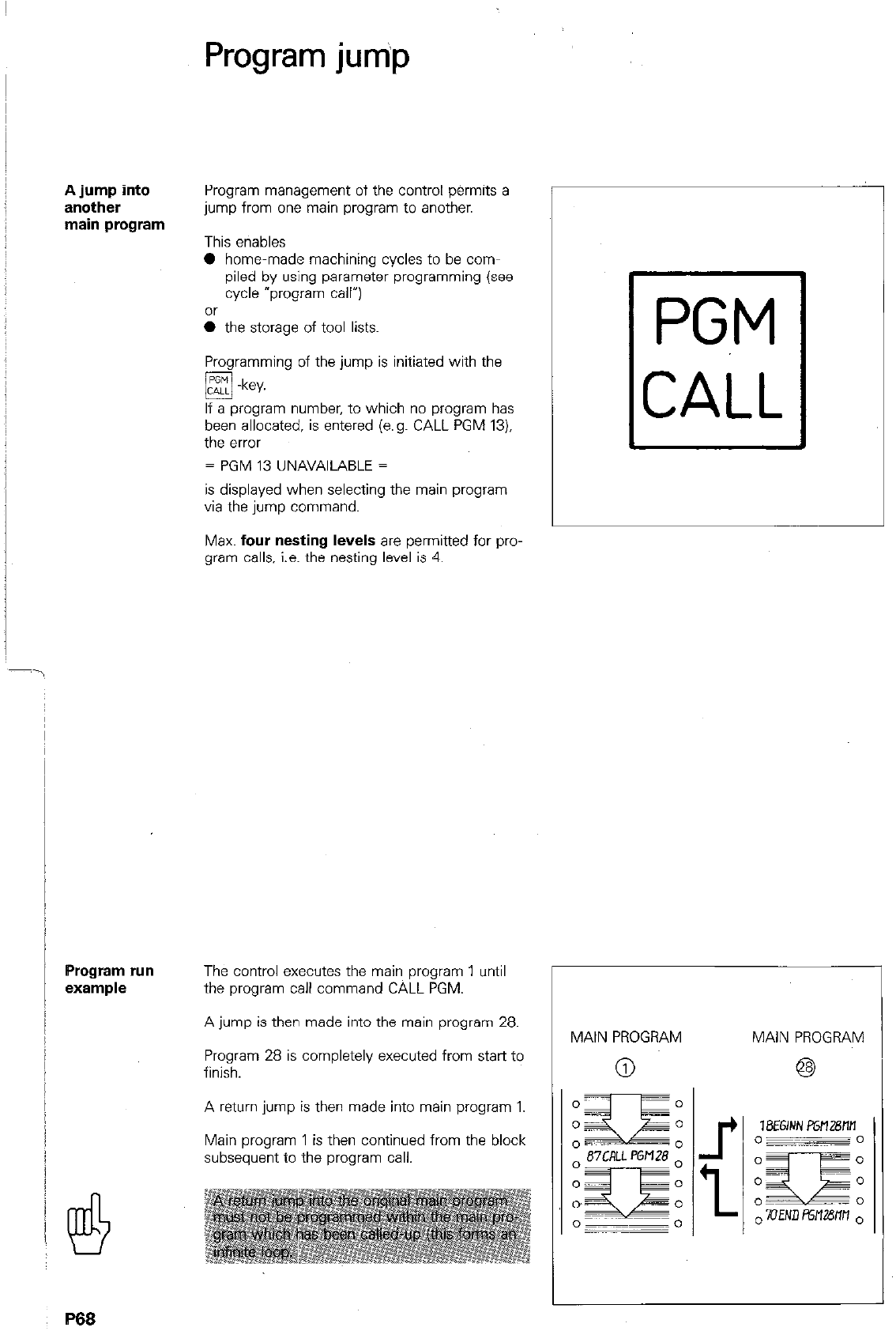
Program jum‘p
A jump into
another
main program
Program run
example
/
Program management of the control permits a
jump from one main program to another.
This etiables
0 home-made machining cycles to be com-
piled by using parameter programming (see
cycle “program call”)
0 the storage of tool lists.
Programming of the jump is initiated with the
q -key.
If a program number, to which no program has
been allocated, is entered (e.g. CALL PGM 13).
the error
= PGM 13 UNAVAlL4BLE =
is displayed when selecting the main program
via the jump command.
Max. four nesting levels are permitted for pro.
gram calls, i.e. the nesting level is 4.
The control executes the main program 1 until
the program call command CALL PGM.
A jump is then made into the main program 28.
Program 28 is completely executed from start to
finish.
A return jump is then made into main program 1.
Main program 1 is then continued from the block
subsequent to the program call.
B66
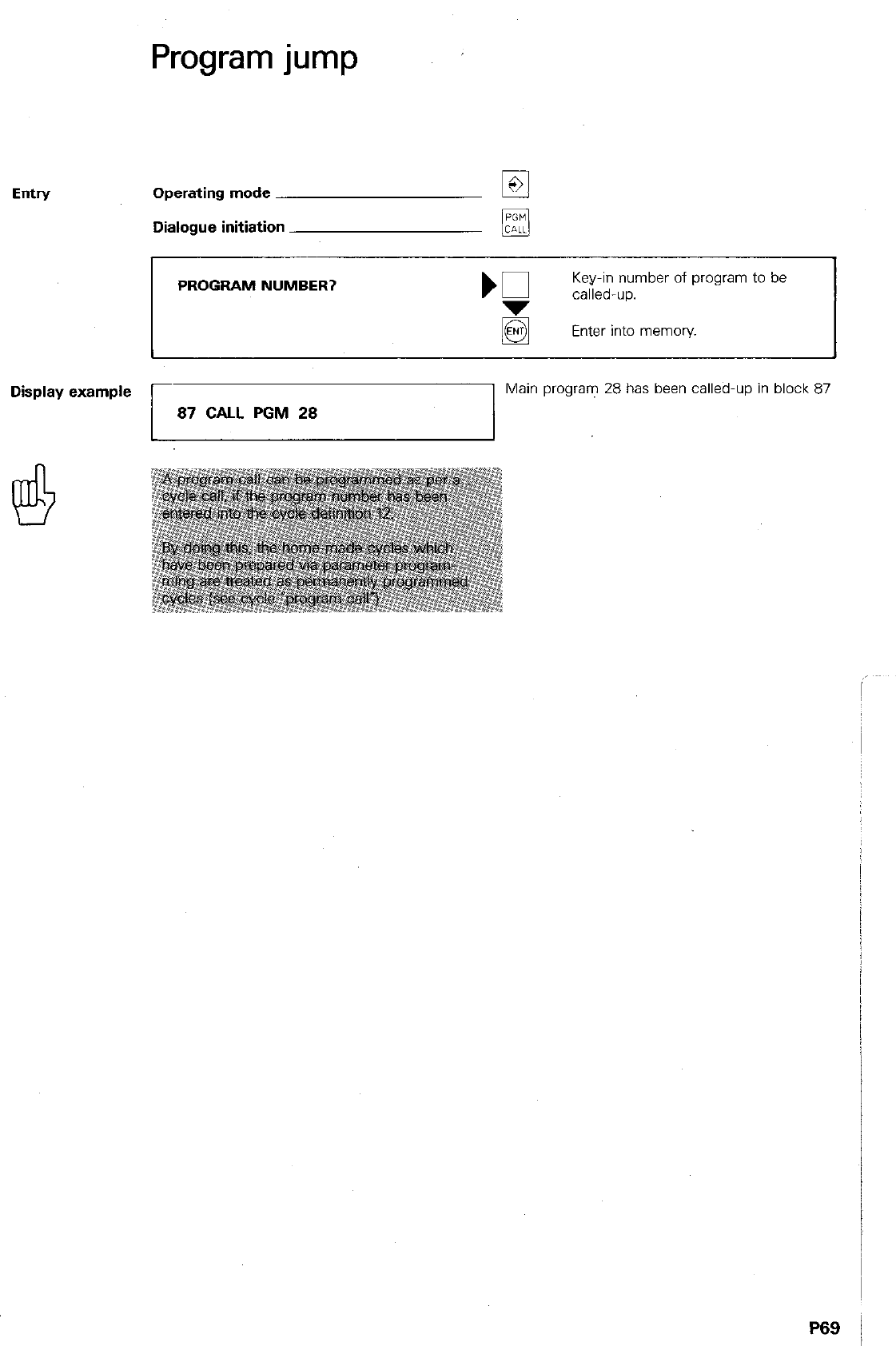
Entry
Program jump
Operating mode
Dialogue initiation
PROGRAM NUMBER?
K
Key-in number of program to be
called-up.
Enter into memory.
Display example
87 CALL PGM 28
Main program 28 has been called-up in block 87
P69 j
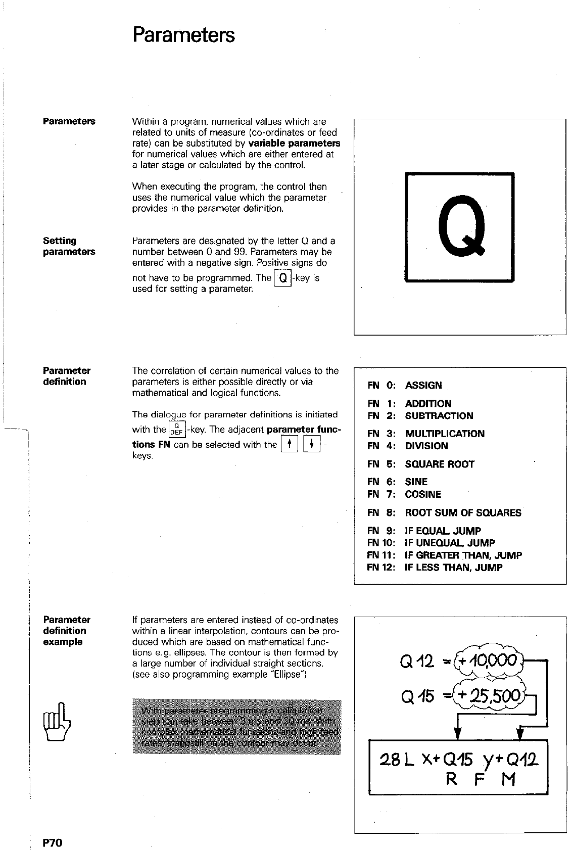
Parameters
Parameters
Within a program, numerical values which are
related to units of measure (co-ordinates or feed
rate) can be substituted by
variable parameters
for numerical values which are either entered at
a later stage or calculated by the control.
When executing the program. the control then
uses the numerical value which the parameter
provides in the parameter definition.
Setting
parameters
Parameters are designated by the letter Cl and a
number between 0 and 99. Parameters may be
entered with a negative sign. Positive signs do
not have to be programmed. The m-key is
used for setting a parameter.
Parameter
definition
Parameter
definition
I!4
P70
The correlation of certain numerical values to the
parameters is either possible directly or via
mathematical and logical functions.
The dialogue for parameter definitions is initiated
with the
q
- key The adjacent
parameter func-
;ysy
FN
can be selected with the [Fi p]
If parameters are entered instead of co-ordinates
within a linear interpolation, contours can be pro-
duced which are based on mathematical func-
tions e.g. ellipses. The contour is then formed by
a large number of individual straight sections.
(see also programming example “Ellipse”)
Q
FN 0: ASSIGN
FN 1: ADDlTlON
FN 2: SUBTRACTlON
FN 3: MULTlPLlCATlON
FN 4: DlVlSlON
FN 5: SQUARE ROOT
FN 6: SINE
FN 7: COSINE
FN 6: ROOT SUM OF SQUARES
FN 9: IFEQUAL, JUMP
FN 10: IF UNEQUAL, JUMP
FN 11: IF GREATER THAN, JUMP
FN 12: IF LESS THAN, JUMP
Q12
Q
45
28
L X+GPl5 yfQ42
R F M
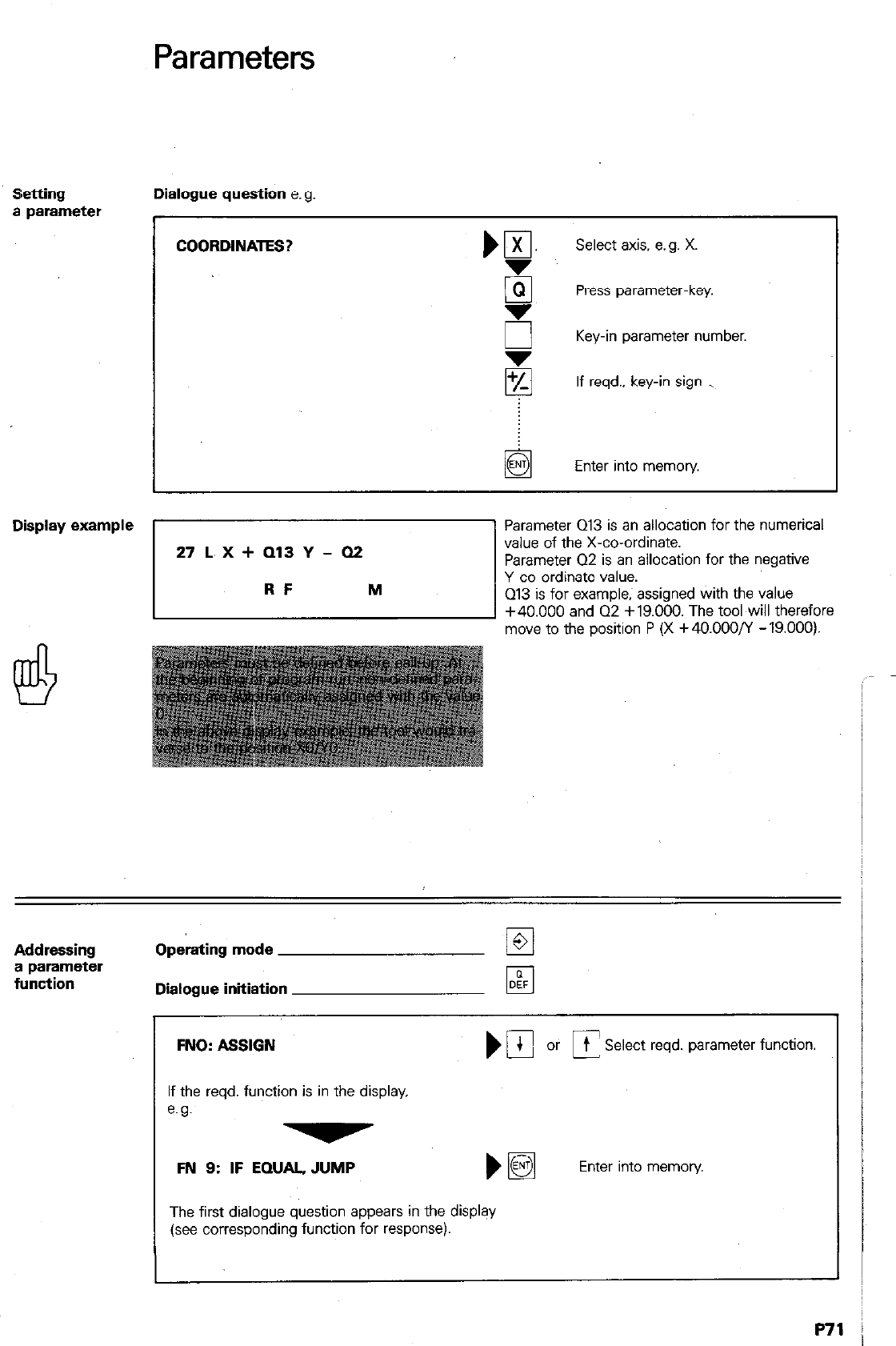
Parameters
Setting Dialogue question e.g.
a parameter
COORDINATES? m ,,
Select axis. e.g. X.
i5 Press parameter-key.
E Key-in parameter number.
$ If reqd., key-in sign _
Enter into memory.
Display example
“‘“*:‘:‘“.
Parameter 013 is an allocation for the numerical
value of the X-co-ordinate.
Parameter 02 is an allocation for the negative
Y-co-ordinate value.
Q13 is for example; assigned with the value
+40.000 and Q2 +19.000. The tool will therefore
move to the position P (X +40.000/Y -19.000).
Addressing
a parameter
function
Operating mode
Dialogue initiation
FNO: ASSIGN NIbfC
t Select reqd. parameter function.
If the reqd. function is in the display.
e.g.
FN 9: IF EQUAL, JUMP
The first dialogue question appears in the display
(see corresponding function for response).
Enter into memory
P71
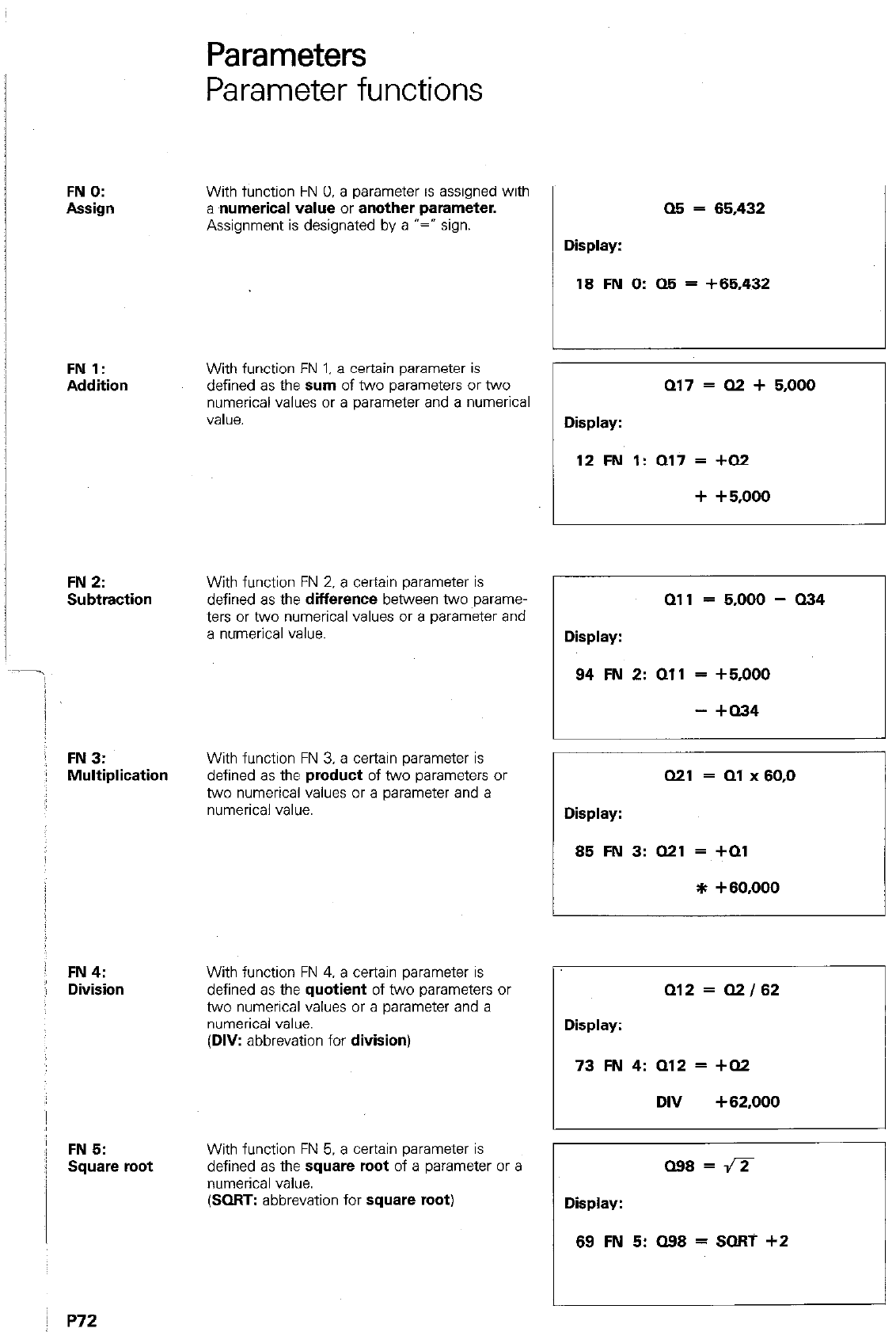
Parameters
Parameter functions
FN 0:
Assign
FN 1:
Addition
FN 2:
Subtraction
j FN3:
Multiplication
: FN4:
j Division
:! FN 5:
: Square root
I
With function FN 0. a parameter is assigned with
a numerical value or another parameter.
Assignment is designated by a “=” sign.
With function FN 1. a certain parameter is
defined as the sum of two parameters or two
numerical values or a parameter and a numerical
value.
With function FN 2. a certain parameter is
defined as the
difference
between two ~parame-
ters or two numerical values or a parameter and
a numerical value.
With function FN 3. a certain parameter is
defined as the
product
of two parameters or
two numerical values or a parameter and a
numerical value.
With function FN 4. a certain parameter is
defined as the
quotient
of two parameters or
two numerical values or a parameter and a
numerical value.
(DIV:
abbrevation for
division)
With function FN 5. a certain parameter is
defined as the
square root
of a parameter or a
numerical value.
(SORT: abbrevation for
square root)
Display:
05 = 65,432
18 FN 0: Q5 = +65,432
Display:
a17 = Q2 + 5,000
12 FN 1: Q17 = +Q2
+ +5x)00
Qll = 5,000 - 034
Display:
94 FN 2: 011 = +5,000
- +Q34
Q21 = Ql x 60.0
Display:
85 FN 3: Q21 = +Ql
* +60,000
Q12 = Q2/62
Display:
73 FN 4: Q12 = +Q2
DIV +62,000
098 = a
Display:
69 FN 5: 098 = SORT +2
: p72
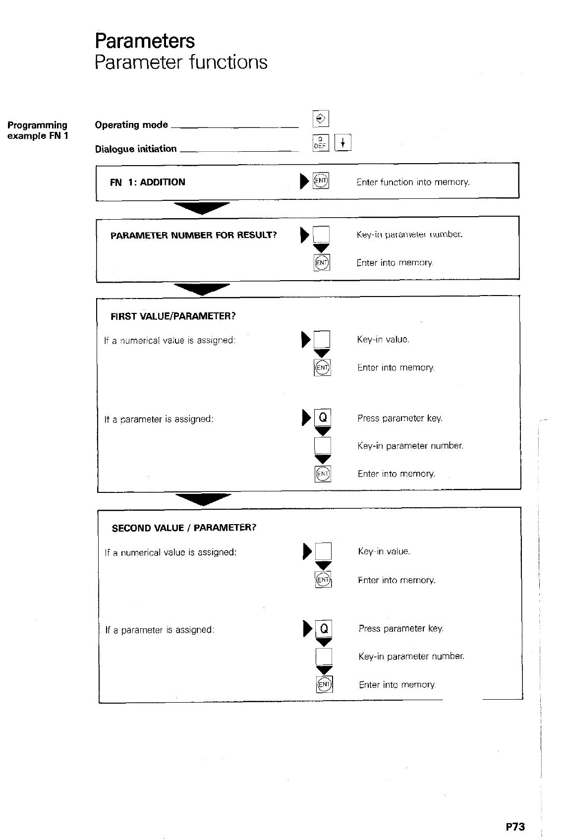
Parameters
Parameter functions
Programming
example FN 1 Operating mode
Dialogue initiation
FN 1: ADDITION
PAMETER NUMBER FOR RESULT? ) g
Key-in parameter number.
Enter into memory
FIRST VALUE/PARAMETER?
If a numerical value is assigned: Key-in value.
g Enter into memory
If a parameter is assigned: ‘g Press parameter key.
g
Key-in parameter number.
q
Enter into memory.
SECOND VALUE I PARAMETER?
If a numerical value is assigned: K Key-in value.
g Enter into memory.
If a parameter is assigned: bgl Press parameter key.
g
Key-in parameter number.
Enter into memory
P73

Trigonometrical
functions
Definition of
trigonometrical
functions
Parameters
Parameter functions
Sine and cosine functions form a mathematical
relationship between an angle and a side length
of a right-angled triangle. Trigonometrical func-
tions are programmed with
FN 6: sine and
FN 7: cosine
Opposite side a
“” a = Hypothenuse = :
Adjacent side b
c’s = = Hypothenuse = :
Trigonometrical
functions within
a right-angled
triangle
xp = R x cos a
Yp = R x $1” cl
FN 6:
sine
FN7:
cosine
With function FN 6 sine. a certain parameter is
defined as the sine of an angle (in degrees (“)).
The angle can be a numerical value or a para-
meter.
With function FN 7 cosine, a certain parameter is
defined as the cosine of an angle (in degrees
(“)). The angle can be a numerical value or a
parameter.
~, fija = Opposite
b = Adjacent c
X
010 = sin QS
Display:
113 FN 6: QlO = SIN + QS
081 - cos (-a55)
Display:
911FN7:091=cos-a55
P74
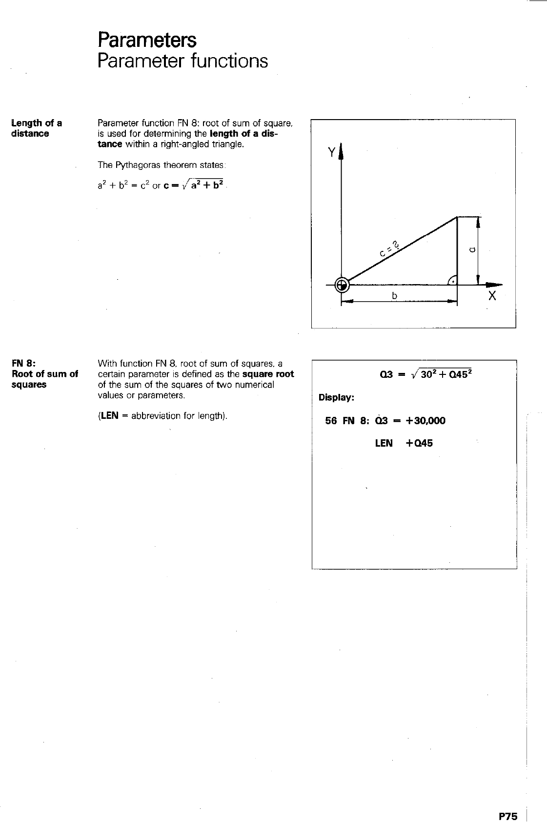
Parameters
Parameter functions
Length of a
distance
Parameter function FN 8: root of sum of square.
is used for determining the
length of a dis-
tance within a right-angled triangle.
The Pythagoras theorem states:
FN 8:
Root of sum of
squares
With function FN 8. root of sum of squares. a
certain parameter is defined as the square root
of the sum of the squares of two numerical
values or parameters.
(LEN
= abbreviation for length)
a3 = J302+a452
Display:
56 FN 8: 03 = +30,000
LEN +Q45
1
P75 I
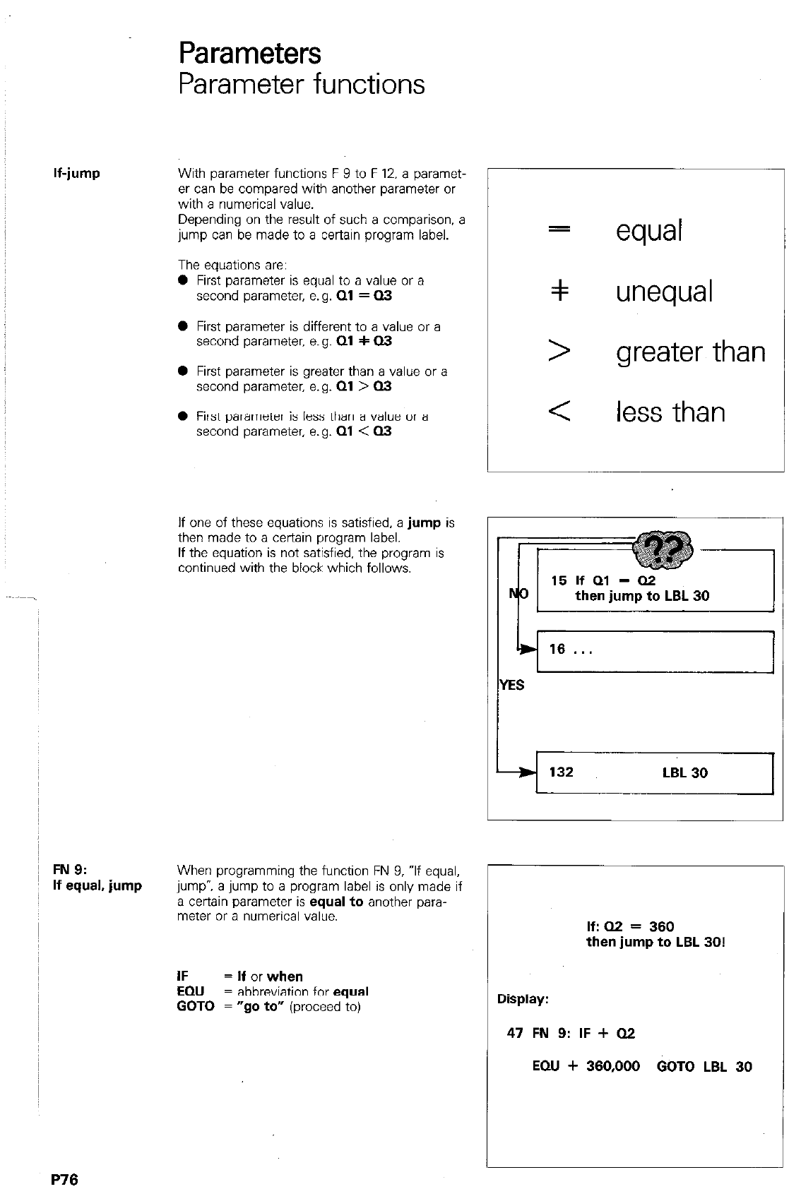
If-jump
FN 9:
If equal, jump
Parameters
Parameter functions
With parameter functions F 9 to F 12. a paramet-
er can be compared with another parameter or
with a numerical value.
Depending on the result of such a comparison, a
jump can be made to a certain program label.
The equations are:
0 First parameter is equal to a value or a
second parameter, e.g.
Ql = 03
0 First parameter is different to a value or a
second parameter. e.g.
01 + 03
0 First parameter is greater than a value or a
second parameter, e.g.
Ql > Q3
0 First parameter is less than a value or a
second parameter, e.g.
Ql < 03
If one of these equations is satisfied,
a jump
is
then made to a certain program label.
If the equation is not satisfied, the program is
continued with the block which follows.
When programming the function FN 9, If equal,
jump-, a jump to a program label is only made if
a certain parameter is
equal to
another para-
meter or a numerical value.
=
equal
=I unequal
> greater than
< less than
132 132 LBL 30 LBL 30 1 1
IF = If or when
EQU
= abbreviation for
equal
GOT0 = “go to”
(proceed to)
L
If: 02 = 360
then jump to LBL 30!
Display:
47 FN 9: IF + QZ
EQU + 360,000 GOT0 LBL 30
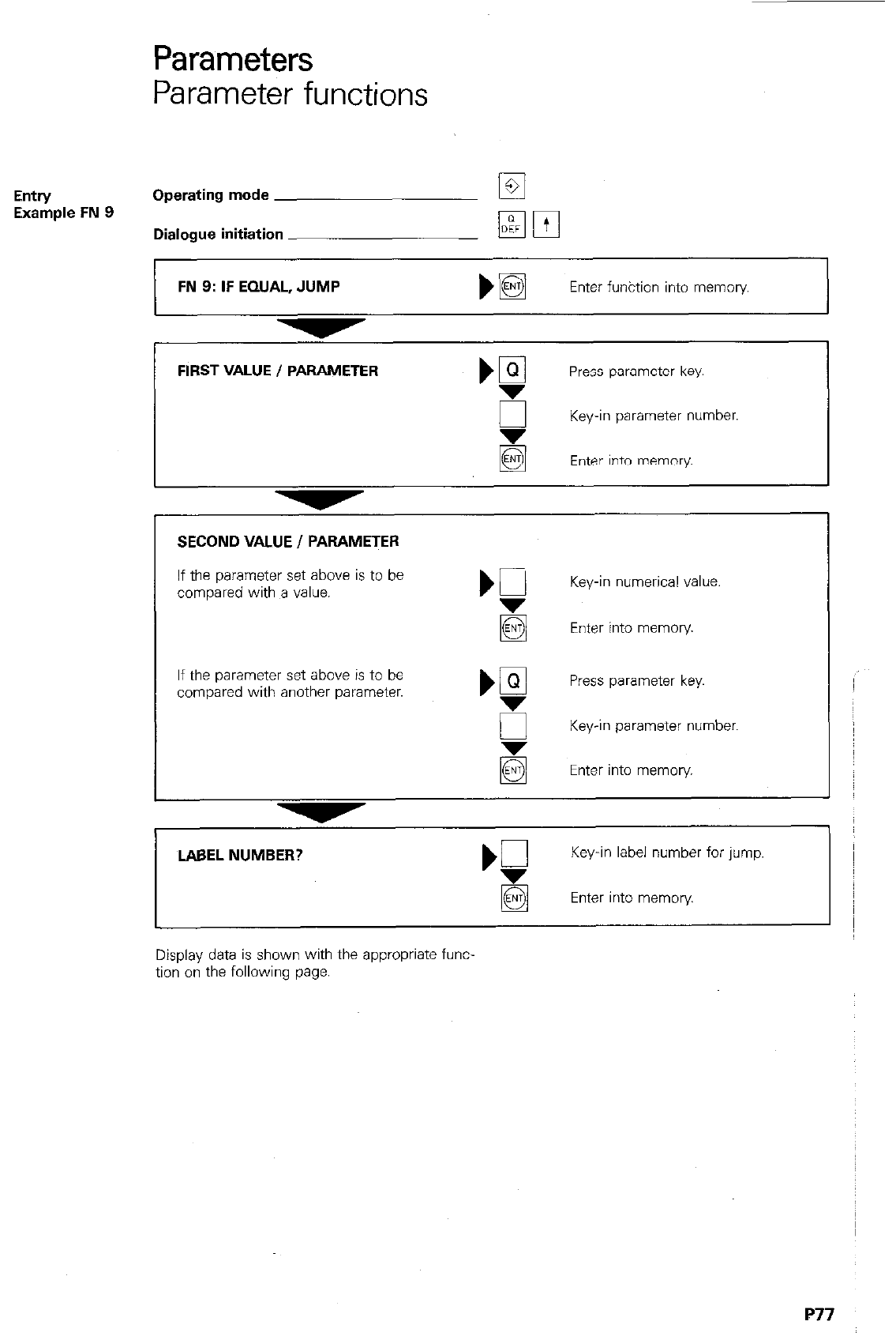
Parameters
Parameter functions
Entry
Operating mode la
Example FN 9
Dialogue initiation
FIRST VALUE / PARAMETER Press parameter key.
E Key-in parameter number.
Enter into memory.
FN 9: IF EQUAL, JUMP bE3l Enter funktion into memory
If the parameter set above is to be
compared with a value. Key-in numerical value.
Enter into memory.
If the parameter set above is to be
compared with another parameter. Press parameter key.
5 Key-in parameter number,
Enter into memory
SECOND VALUE I PARAMETER
LABEL NUMBER? Key-in label number for jump.
q
Enter into memory
Display data is shown with the appropriate func-
tion on the following page.
P77
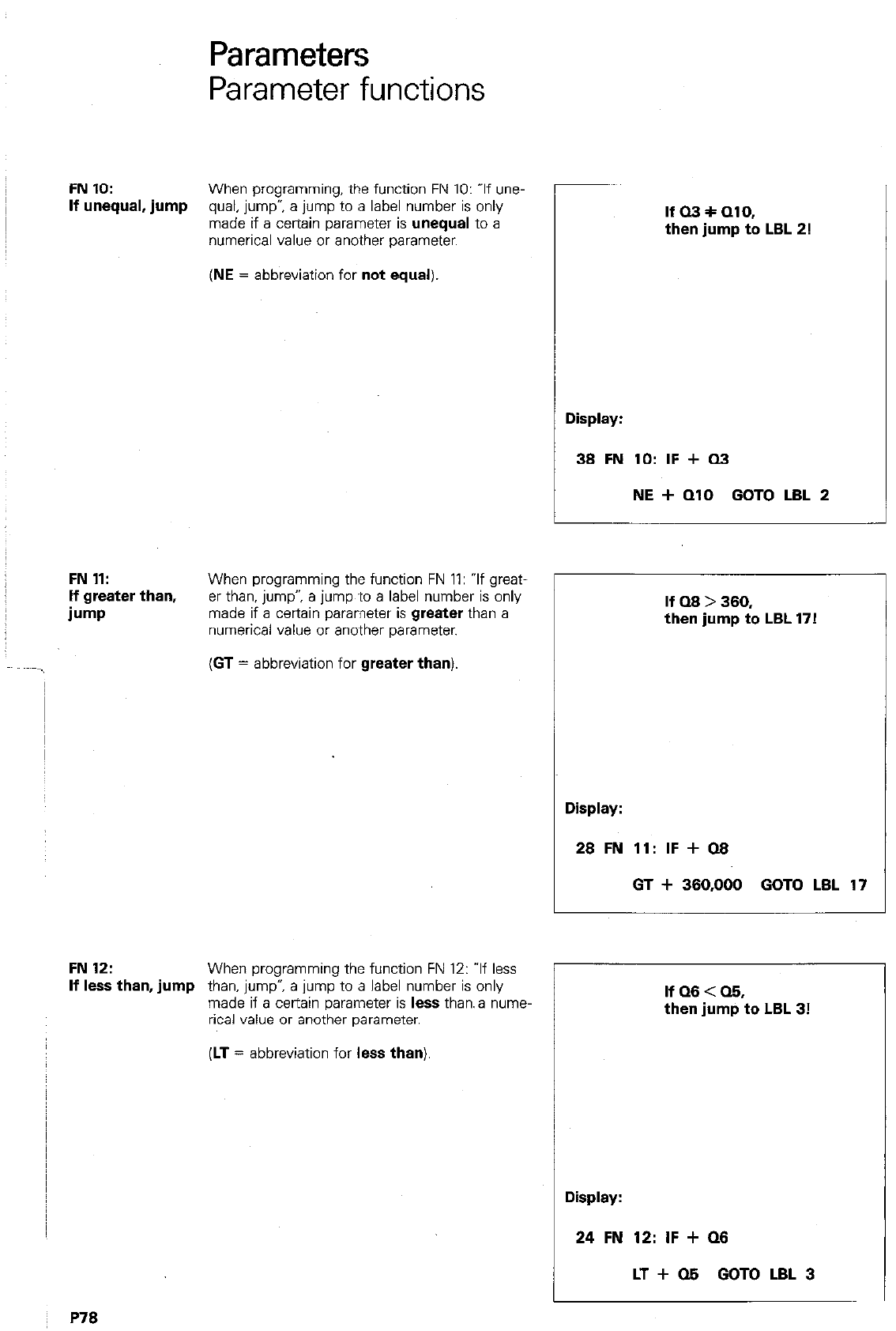
Parameters
Parameter functions
FN 10:
When programming, the function FN 10: If une-
If unequal, jump
qual, jump”, a jump to a label number is only
made if a certain parameter is
unequal to a
numerical value or another parameter.
(NE
= abbreviation for
not equal).
FN 11:
When programming the function FN 11: “If great-
If greater than,
er than, jump”, a jump ‘to a label number is only
b-w made if a certain parameter is
greater
than a
numerical value or another parameter.
(GT
= abbreviation for
greater than)
FN 12:
When programming the function FN 12: ‘If less
If less than, jump
than. jump”, a jump to a label number is only
made if a certain parameter is
less
than. a rune,
rical value or another parameter.
P78
If 03 + 010,
then jump to LBL 2!
Display:
1 38 FN 10: IF + Q3
I
NE + QlO GOT0 LBL 2
If Q8 > 380,
then jump to LBL 17!
(LT
= abbreviation for
less than)
r
Display:
28 FN 11: IF + 08
GT + 380,000 GOT0 LBL 17
IfQ8<Q8,
then jump to LBL 3!
Display:
24 FN 12: IF + Q8
LT + 05 GOT0 LBL 3
Remarks
Parameters
Parameter
definition
Parameter programming
(Example)
Programming with parameters can be explained
in the example of an ellipse.
The
ellipse
is described according to the adjac-
ent formula (math. parameter form of the ellipse).
Even/ angle o has an X and Y-co-ordinate.
Beginning at CI = 0’ and proceeding~to CI = 360’
in small increments. a number of individual
points are obtained forming an ellipse.
These points are adjoined by straight lines to
form a closed contour.
X = a cos a
Y = b sin CI
a, b : semi-axes of the ellipse
The program consists of 4 maln SectIons:
0 Parameter deflnitlon
0 Positioning (linear interpolation) for milling of
ellipse
0 Increase of angular step
0 Parameter comparison and program con-
tinuation until the ellipse is completed.
The following are defined as parameters:
0 Angular step 020:
The angle is to increase
in increments of 2’; 020 = + 2.000
4
Starting
angle 021: The first contour point
has the anale 0°: 021 = 0.000
0 Semi;lxis”in X-direction Q23:
Q23 = + 50.000
0 Semi-axis in Y-direction 022:
X
I L
Q23 J
0 X-co-ordinate 025:
The numerical value of
the C-co-ordinate is assigned to parameter
Q25.
Q22=+30.000 ~ 1
0 Y-co-ordinate
024: The numerical value of
the Y-co-ordinate is assigned to parameter
Q24.
Parameters Q25 and Q24 are defined according
to the above mentionecl formula: Q20 = + 2.000 I
(X=) 025 = Q23 * cm Q21:
(Y=) Q24 = Q22* sin Q21:
Q21 = + 0.000
Q22 = + 30.000
Both equations must be converted. since they
cannot be entered in this way. therefore:
first:
then:
Q14 = sin Q21
Q15 = cos 021
Q24 = Q14 * Q22
Q25 = 015 * Q23
Q14 = SIN + Q21
015 = COS + 021
Q24=+014 * tQ22
P80
Parameters
Parameter programming
(Example)
Positioning block
Milling of the ellipse is programmed within a
block with linear interpolation.
Increase of
New angle Q21 =
angular step
Old angle Q21 + angular step Q20
Parameter
For a repetition, a label must be set prior to the
comparison and
parameter definition for Q25 and Q24: LBL 1.
program repeat
The repetition is governed by the following con-
dition:
If angle Q21 is less than 360.19 (however greater
than 360”. but smaller than 360” plus the angular
step) then jump to LBL 1:
IF + Q21
LT + 360.100 GOT0 LBL 1.
Q14 = SIN + Q21
Q15=COS+Q21
Q24=iQ14 * +Q22
RR FZOO M
Q14 = SIN + 021
015 = COS + Q21
Q24 = t Q14 * + 022
a21 =+a21 ++Q20 I
-
Q20 = + 2,000
Q21 = + 0.000
Q14 = SIN + Q21
Q15=COS+Q21
Q24=+014 * tQ22
Q21 = + Q21 + +~Q20
P8
Canned cycles
Introduction
Canned cycles To simplify and speed-up programming, reoccur-
ring machining routines and certain co-ordinate
transformations are pre-programmed as fixed -
or canned - cycles. E.g. the milling of pockets or
the shifting of a workpiece datum to another
location.
Cycle definition With the cycle definition, the control is informed
of the necessary data for the cycle. e.g. side
length of the pocket. Dialogue for cycle definition
is initiated with the DEF -key. Cycles can be
PI
addressed with the m m -keys.
Breakdown of Cycles 1 to 5 are machining cycles, i.e.
available cycles machining routines are executed on the work-
piece.
With cycle 9, a dwell time can be programmed
and a program can be called-up via cycle 12.
The remaining cycles are used for various types
of co-ordinate transformations.
cycle call The cycle call enables .the cycle and the dwell
time which has been previously defined, to be
executed.
Co-ordinate transformations do not require a
special call-up; they are active immediately after
cycle definition.
There are three programming possibilities for
CYCL DEF 1 Peck drill
CYCL DEF 2 Tapping
CYCL DEF 3 Slot milling I Machining
r\,r,es
C’I (CL DEF 4 Pocket milling
CYCL DEF 5 Circular pocket
CYCL DEF 7 Datum shift
CYCL DEF 8 Mirror imaae
CYCL DEF 10 Co-ordinate
system rotation
CYCL DEF 11 Scaling
Co-ordinate
trans-
formations
CYCL DEF 12 Program call
CYCL DEF 9 Dwell time
0 Call-up with a CYCL CALL-block
0 Call-up via auxiliary function M99
0 Call-up via auxiliary function M89 (depending
on the machine parameters entered)
Call-up M89 is modally effective. this means a
cail~up of the machining cycle last ~programmed
is made with each subsequent positioning block.
M89 is cancelled either by the entry of M99 or a
CYCL CALL-block.
P82
Canned cycles
Cycle definition
Cycle call
Definition
of a cycle Operating mode
Dialogue initiation
CYCL DEF 1 PECKING
1
DIB j Select required machining cycle.
The cycle is displayed e.g
CYCL DEF 4 POCK!3 MILLING bH Enter cycle into memory
The display shows the first dialogue question
of the selected cycle. (See appropriate cycle
definition for response).
Call-up of a cycle Operating mode
Dialogue initiation
AUXILIARY FUNCTlON M? If reqd., key-in auxiliary
function.
Enter into memory
Display example
/ g5 Gym CALL MD3 The cycle last defined is called-up.
I,
The spindle rotates clockwise.
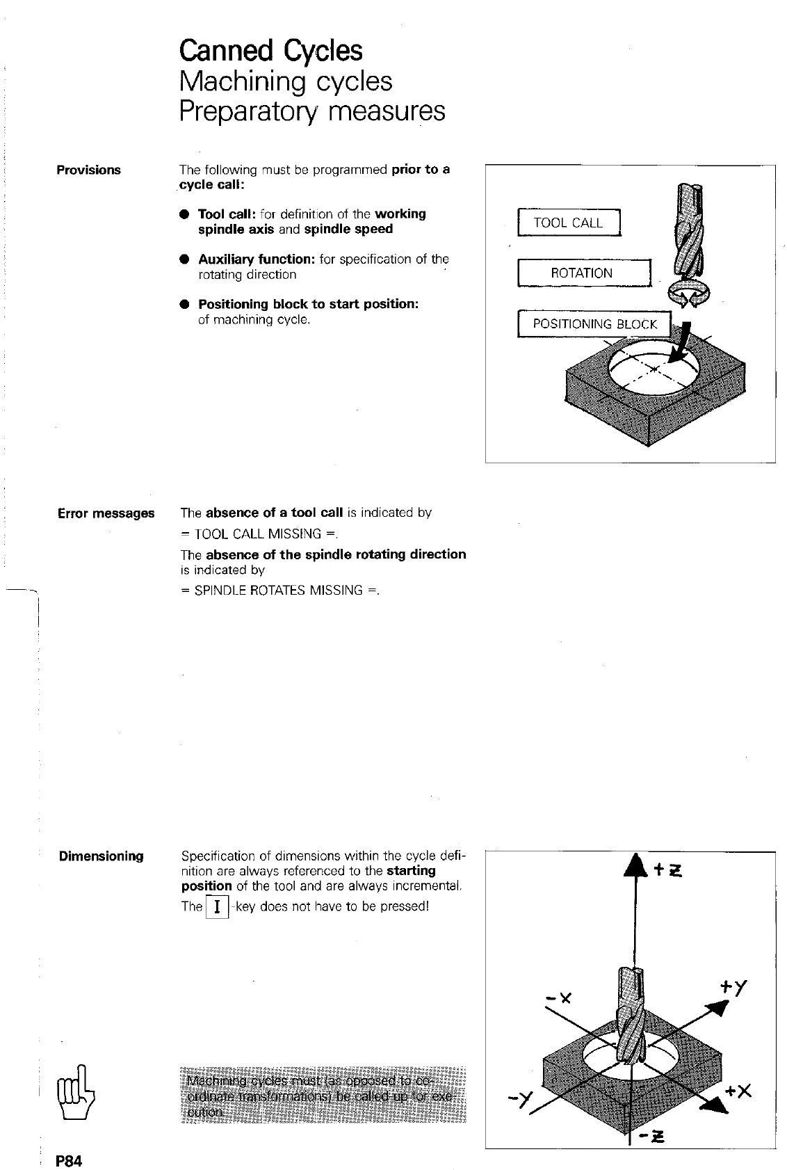
Canned Cycles
Machining cycles
Preparatory measures
Provisions The following must be programmed prior to a
cycle call:
l
Tool call: for definition of the working
spindle axis and spindle speed
0 Auxilian/ function: for specification of the
rotating direction
0 Positioning block to start position:
of machining cycle.
Error messages The absence of a tool call is indicated by
= TOOL CALL MISSING =.
The absence of the spindle rotating direction
is indicated by
= SPINDLE ROTATES MISSING =.
Dimensioning Specification of dimensions within the cycle defi-
nition are always referenced to the starting
position of the tool and are always incremental.
The m-key does not have to be pressed!
t”
Y!!$ . . . . . . . . . . . . . . . . . .--...* .-- ..,,
P84
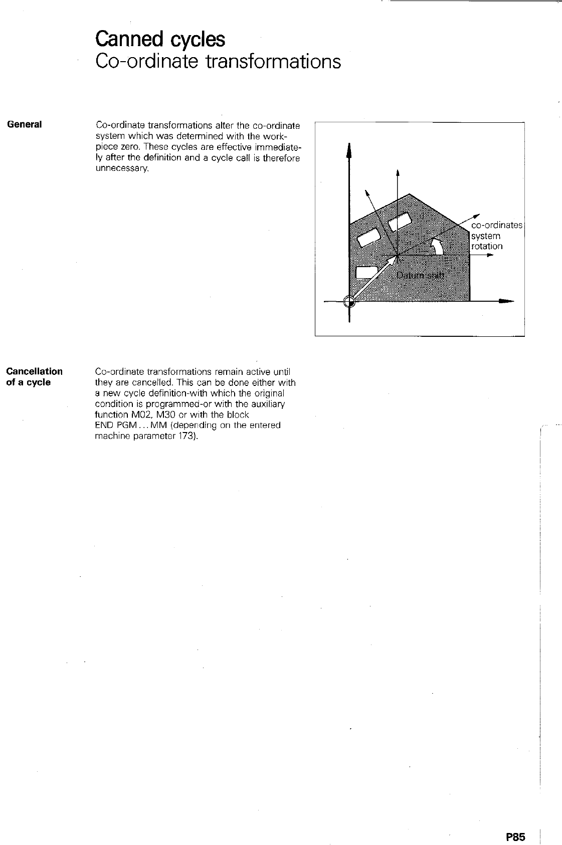
Canned cycles
Co-ordinate transformations
Gefle~~l
Co-ordinate transformations alter the co-ordinate
system which was determined with the work-
piece zero. These cycles are effective immediate-
ly after the definition and a cycle call is therefore
unnecessary
Cancellation
of a cycle
Co-ordinate transformations remain active until
they are canceiled. This can be done either with
a new cycle definltlon-with which the original
condition is programmed-or with the auxiliary
function M02. M30 or with the block
END PGM.. MM (depending on the entered
machine parameter 173).
P85 I
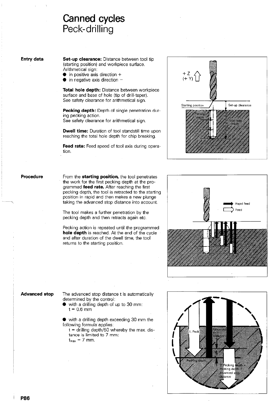
Entry data
Advanced stop
P88
Canned cycles
Peck-drilling
Set-up clearance: Distance between tool tip
(starting position) and workpiece surface.
Arithmetical sign:
0 in positive axis direction +
0 in negative axis direction -
Total hole depth: Distance between workpiece
surface and base of hole (tip of drill-taper).
See safety clearance for arithmetical sign.
Pecking depth: Depth of single penetration dur-
ing pecking action.
See safety clearance for arithmetical sign.
Dwell time: Duration of tool standstill time upon
reaching the total hole depth for chip breaking.
Feed rate: Feed speed of tool axis during opera-
tion.
From the starting position, the tool penetrates
the work for the first pecking depth at the pro-
grammed feed rate. After reaching the first
pecking depth, the tool is retracted to the starting
position in rapid and then makes a new plunge
taking the advanced stop distance into account.
The tool makes a further penetration by the
pecking depth and then retracts again etc.
Pecking action is repeated until the programmed
hole depth is reached. At the end of the cycle
and after duration of the dwell time, the tool
returns to the starting position.
The advanced stop distance t is automatically
determined by the control:
0 with a drilling depth of up to 30 mm:
t = 0.6 mm
0 with a drilling depth exceeding 30 mm the
following formula applies:
t = drilling depth/50 whereby the max. dis-
tance is limited to 7 mm:
t
“ax = 7 mm.
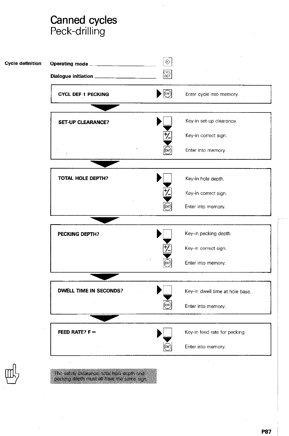
Canned cycles
Peck-drilling
Cycle definition Operating mode
q
Dialogue initiation
CYCL DEF.l PECKING
Enter cycle into memory
TOTAL HOLE DEPTH? Kl
Key-in hole depth.
8 Key-in correct sign.
Enter into memory
PECKING DEPTH?
Key-in pecking depth.
8 Key-in correct sign.
Enter into memory.
DWELL TIME IN SECONDS?
Key-in dwell time at hole base.
Enter into memory
‘5 Key-in feed rate for pecking.
Enter into memory
P87
Remarks
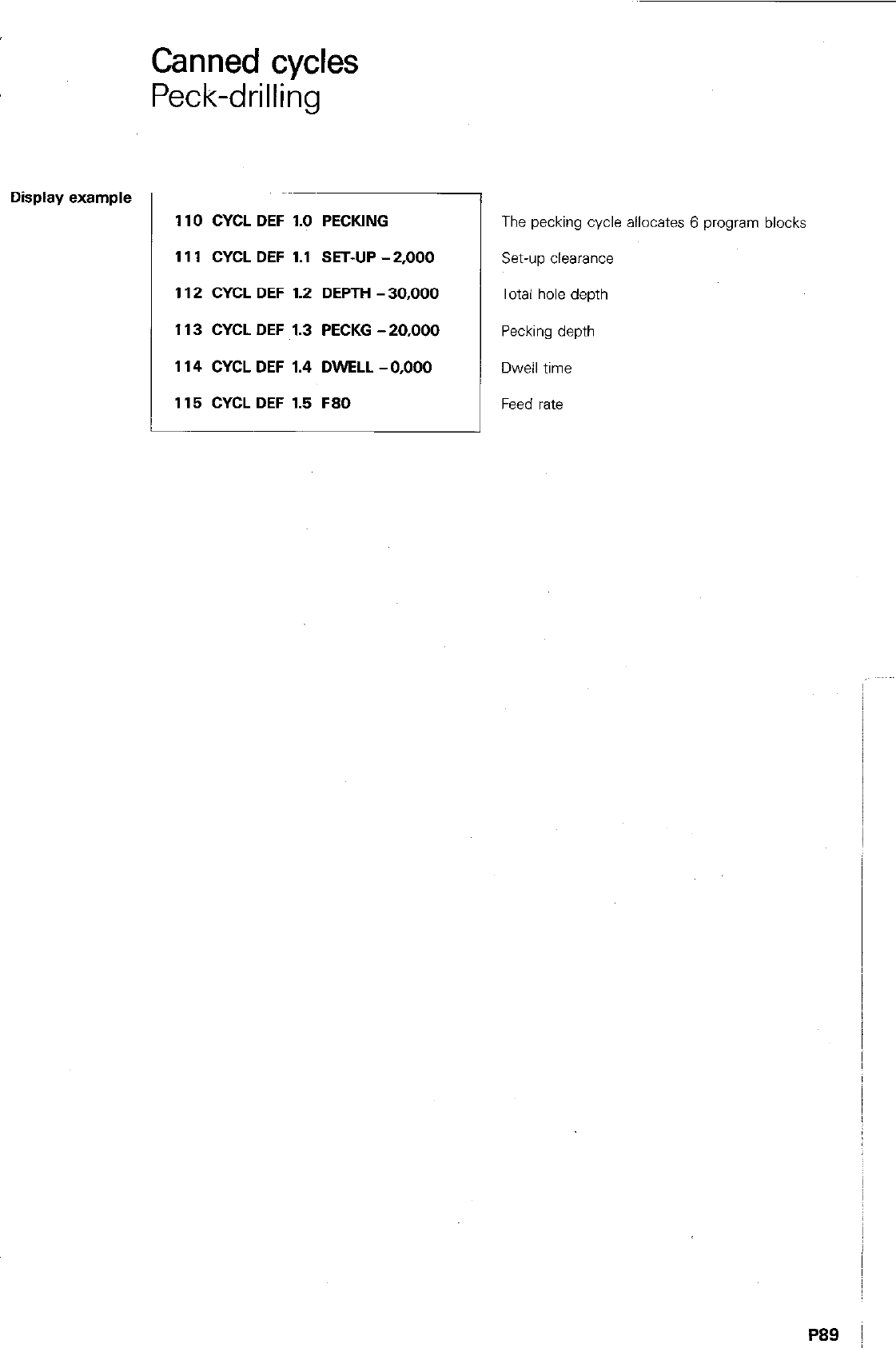
Display example
Canned cycles
Peck-drilling
110 CYCL DEF 1.0 PECKING
111 CYCL DEF 1.1 SET-UP -2,000
1 I2 CYCL DEF I.2 DEPTH - 30,000
I I3 CYCL DEF 1.3 PECKG -20,000
I I4 CYCL DEF 1.4 DWELL -0,000
I I5 CYCL DEF I.5 F80
The pecking cycle allocates 6 program blocks
set-up clearance
Total hole depth
Pecking depth
Dwell time
Feed rate
P89 I
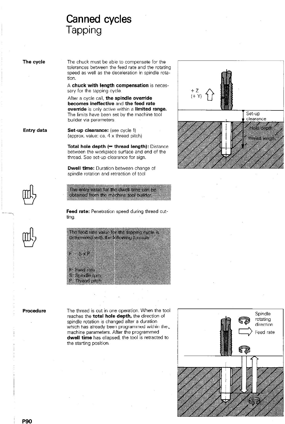
The cycle
Entry data
Procedure
P90
Canned cycles
Tapping
The chuck must be able to compensate for the
tolerances between the feed rate and the rotating
speed as well as the deceleration in spindle rota-
tion.
A
chuck with length compensation
is neces-
sary for the tapping cycle.
After
a
cycle call,
the spindle override
becomes ineffective
and
the feed rate
override
is only active within
a limited range.
The limits have been set bv the machine tool
builder via parameters.
Set-up clearance: (see cycle
1)
(approx. value: ca. 4 x thread pitch)
Total hole depth (= .thread length):
Distance
between the workpiece surface and end of the
thread. See set-up clearance for sign.
Dwell time:
Duration between change of
spindle rotation and retraction of tool
Feed rate:
Penetration speed during thread cut.
ting.
The thread is cut in one operation. When the tool
reaches the
total hole depth,
the direction of
spindle rotation is changed after a duration
which has already been programmed within the.
machine parameters. After the programmed
dwell time
has ellapsed, the tool is retracted to
the starting position.
Spindle
rotating
direction
Feed rate
Canned cycles
Tapping
cycle
definition Operating mode
Dialogue initiation
CYCL DEF 2 TAPPING
Enter cycle into memory.
SET-UP? CLEARANCE?
‘C
Key-in set-up clearance.
q
Key-in correct sign.
8 ‘Enter into memory
TOTAL HOLE DEPTH?
Key-in thread depth.
q
Key-in correct sign.
Enter into memory.
Key-in dwell time between spindle
,g
rotation change-over and rotation.
Enter into memory.
FEED RATE? F = K
Enter calculated feed rate.
Enter into memory
Display example
80 CYCL DEF 2.0 TAPPING
81 CYCL DEF 2.1 SET-UP -2,000
82 CYCL DEF 2.2 DEPTH -30,000
83 CYCL DEF 2.3 DWELL 0,000
84 CYCL DEF 2.4 F 180
The cycle definition Yapping” allocates
blocks
Set-up clearance
Total hole depth
Dwell time
5 program ’
Feed rate
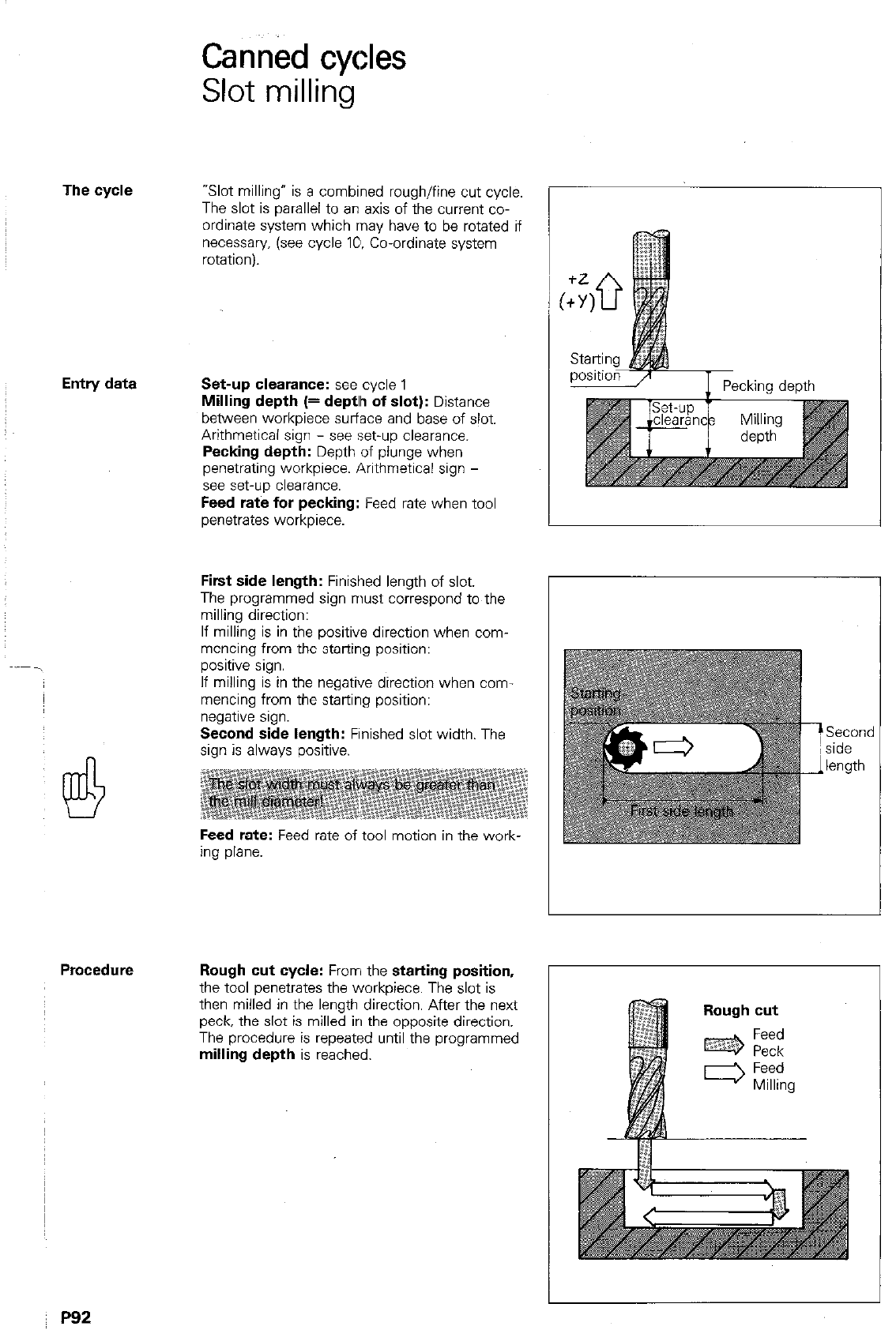
Canned cycles
Slot milling
The cycle
“Slot milling” is a combined rough/fine cut cycle.
The slot is parallel to an axis of the current co-
ordinate system which may have to be rotated if
necessary. (see cycle IO. Co-ordinate system
rotationi.
Entry data Set-up clearance: see
cycle 1
Milling depth (= deptlh of slot):
Distance
between workpiece surface and base of slot.
Arithmetical sign - see set-up clearance.
Pecking depth:
Depth of plunge when
penetrating workpiece Arithmetical sign -
see set-up clearance.
Feed rate for pecking:
Feed rate when tool
penetrates workpiece.
First side length:
Finished length of slot.
The programmed sign must correspond to the
milling direction:
If milling is in the positive direction when com-
mencing from the starting position:
positive sign.
If milling is in the negative direction when corn
mencing from the starting position:
negative s,gn.
Second side length:
Finished slot width. The
sign is always positive.
Feed rate:
Feed rate of tool motion in the work-
ing plane.
Second
side
length
Procedure Rough cut cycle:
From the
starting position,
the tool wznetrates the workDiece. The slot is
then milled in the length dir&ion. After the next
peck, the slot is milled in the opposite direction.
The procedure is repeated until the programmed
milling depth
is reached.
P92
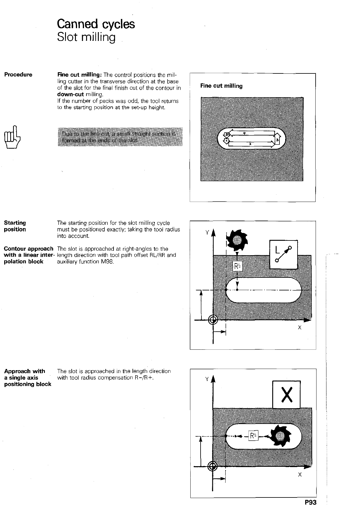
Procedure
Canned cycles
Slot milling
Fine cut milling: The control positions the mil-
ling cutter in the transverse direction at the base
of the slot for the final finish cut of the contour in
down-cut milling.
If the number of pecks was odd. the tool returns
to the starting position at the set-up height.
Starting
position The starting position for the slot milling cycle
must be positioned exactly; taking the tool radius
Into account.
Contour approach The slot is approached at right-angles to the
with a linear inter- length direction with tool path offset RL/RR and
polation block auxiliaw function M98.
Approach with The slot is approached in the length direction
a single axis with tool radius compensation R-/R+.
positioning block
Fine cut milling
P9:
Remarks
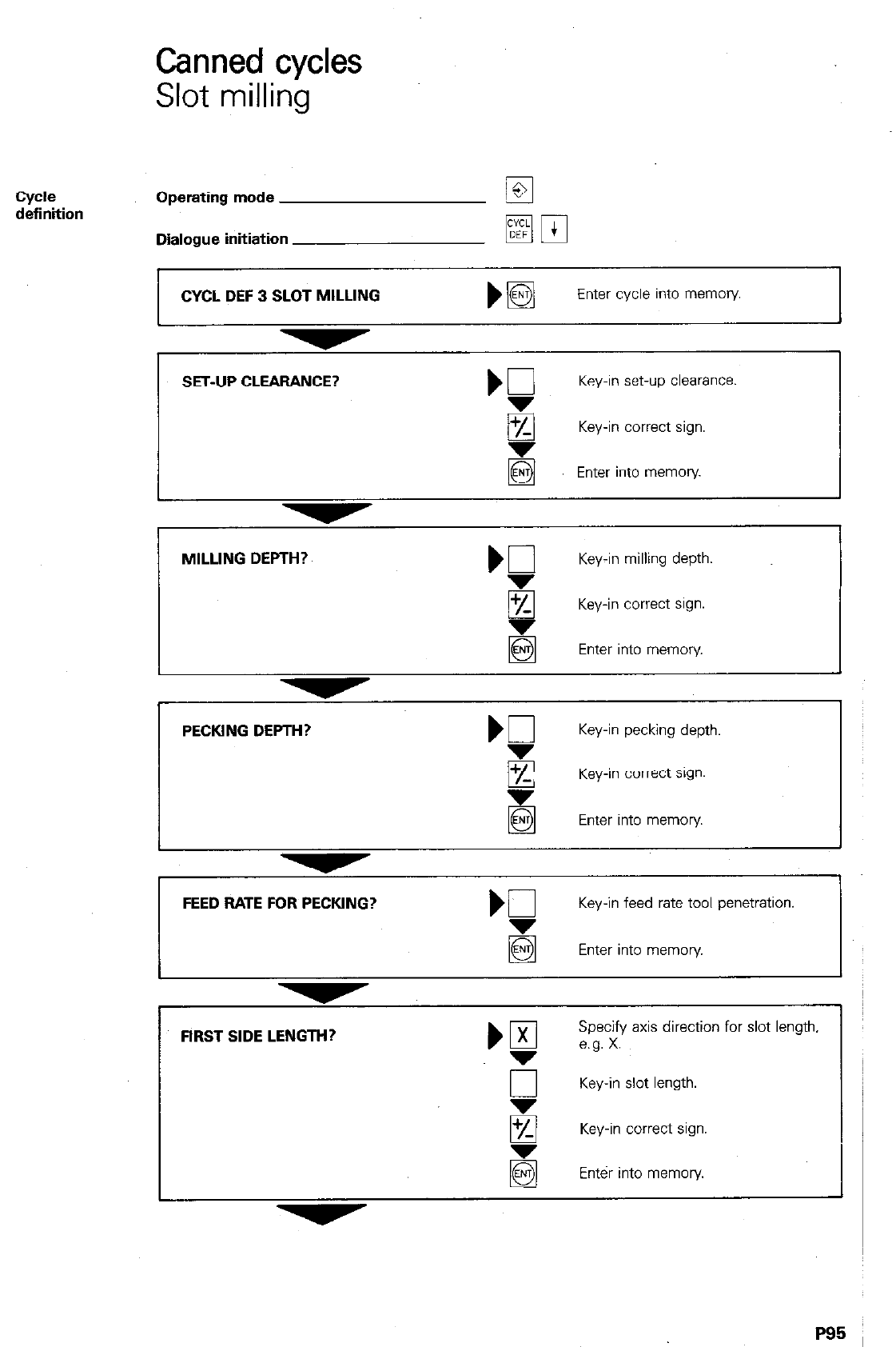
Canned cycles
Slot milling
cycle
definition Operating mode
Dialogue initiation
CYCL DEF 3 SLOT MILLING
mm
)B
Enter cycle into memory
I
SET-UP CLEARANCE?
Key-in set-up
clearance.
Key-in correct sign.
@
Enter into memory
MILLING DEPTH?
Key-in milling depth.
q
Key-in correct sign.
5 Enter into memory
PECKING DEPTH? Kl
Key-in pecking depth.
E Key-in correct sign.
E Enter into memory
FEED RATE FOR PECKING? b0
Key-in feed rate tool penetration.
Enter into memory.
FIRST SIDE LENGTH?
Key-in slot length.
Key-in correct sign.
@
Enter into memory.
P95
Remarks
P96
Canned cycles
Slot milling
Display example
SECOND SIDE LENGTH?
Specify axis for slot width, e.g. Y.
ij Key-in slot width with positive sign.
Enter into memory
FEED RATE? F =
‘f
Key-in feed rate for milling of slot.
E3 Enter into memory
100 CYCL DEF 3.0 SLOT MILLING
The slot milling cycle allocates 7 program blocks
101 CYCL DEF 3.1 SET-UP -2,000
set-up clearance
102 CYCL DEF 3.2 DEPTH -40,000
Milling depth
103 CYCL DEF 3.3 PECKING -20,000
Pecking depth
F80
Feed rate for pecking
104 CYCL DEF 3.4 X - 120,000
Length of slot
105 CYCL DEF 3.5 Y + 21,000
Width of slot
106 CYCL DEF 3.6 FlOO
Feed rate
P97 ,
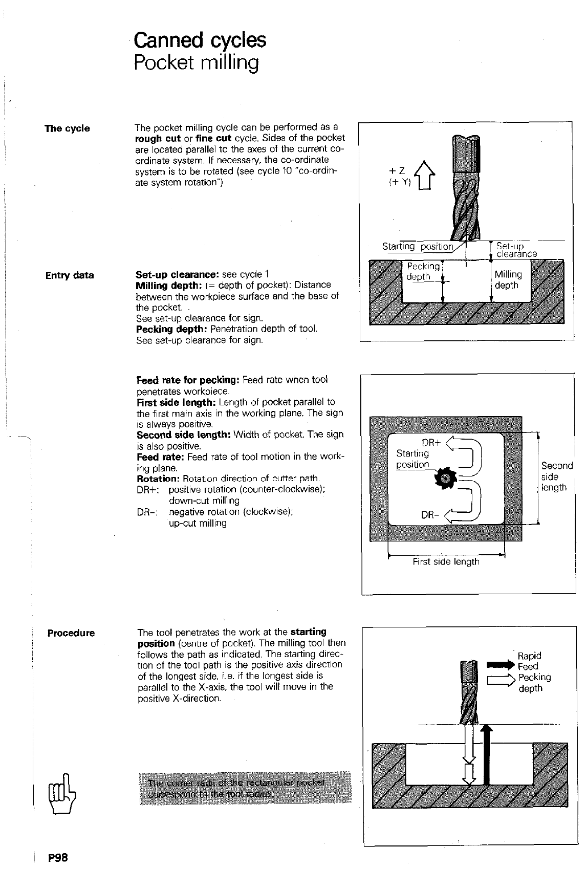
Canned cycles
Pocket milling
The cycle
Entry data
Procedure
The pocket milling cycle can be performed as a
rough cut
or
fine cut
cycle. Sides of the pocket
are located parallel to the axes of the current co-
ordinate system. If necessary, the co-ordinate
system is to be rotated (see cycle 10 “co-ordin-
ate system rotationw)
Set-up clearance: see cycle 1
Milling depth:
(= depth of pocket): Distance
between the workpiece surface and the base of
the pocket.
See set-up clearance for sign.
Pecking depth:
Penetration depth of tool.
See set-up clearance for sign.
Feed rate for pecking:
Feed rate when tool
penetrates workpiece.
First side length:
Length of pocket parallel to
the first main axis in the working plane. The sign
is always positive.
Second side length:
Width of pocket. The sign
is also positive.
Feed rate:
Feed rate of tool motion in the work-
ing plane.
Rotation:
Rotation direction of cutter path.
DR+: positive rotation (counter-clockwise):
down-cut milling
DR-: negative rotation (clockwise):
up-cut milling
L
The tool penetrates the work at the
starting
position
(centre of pocket). The milling tool then
follows the path as indicated. The starting direc-
tion of the tool path is the positive axis direction
of the longest side. i.e. if the longest side is
parallel to the X-axis, the tool will move in the
positive X-direction.
Second
side
length ’
First side length -I
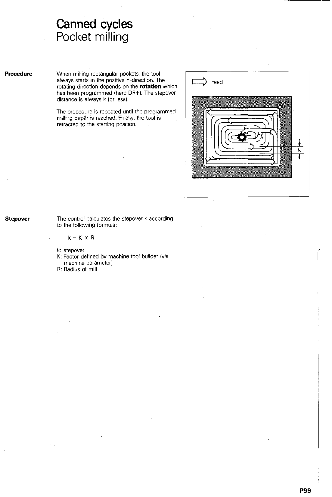
Canned tiycles
Pocket milling
When milling rectangular pockets, the tool
always starts in the positive Y-direction. The
rotating direction depends on the
rotation
which
has been programmed (here DR+). The stepover
distance is always k (or less).
The procedure is repeated until the programmed
milling depth is reached. Finally, the tool is
retracted to the starting position.
stepover
The control calculates the stepover k according
to the following formula:
k=Kx R
k: stepover
K: Factor defined by machine tool builder (via
machine parameter)
R: Radius of mill
P99 i
,.,.
Canned cycles
Pocket milling
Cydl?
definition Operating mode
Dialogue initiation
: Q~ljP~~?#Q&rIjQE~; :. :,, :: ~~
Key-in set-up clearance.
5 Key-in correct sign.
Enter into memory.
+/-
8
Key-in correct sign.
@ Enter into memory.
FEED W?J$ FOR~PbCJNG?
Key-in feed rate for tool penetration.
q
Enter into memory
k-l@ST~~:S;D~~~&~NOtCl$
I ’ .~ ~ ) q
Specify axis of first side
5
,ength .,lx,
Key-in first side length with
&
positive sign.
Enter into memory.
~ @#,$fj,,J@~~~~ :&.j@“.j) ~’ ‘:,:- ”
-“~! ’ e
Specify axis of second side
length e.g. Y.
u
Key-in second side length with
positive sign.
El Enter into memory.
-,
PlOl
Remarks
P102
Display example
Canned cycles
Pocket milling
FEED RATE? F = m
Key-in feed rate for milling of pocket.
Enter into memory
ROTATION CLOCKWISE: DR-?
Key-in tool path rotation.
Enter into memory.
250 CVCL DEF 4.0 POCKET MILLING
251 CVCLDEF 4.1 SET-UP-2,000
252 CVCL DEF 4.2 DEPTH -30,000
253 CVCL DEF 4.3 PECKING -10,000
F80
254 CVCL DEF 4.4 X +80,000
255 CVCL DEF 4.5 V +40x)00
258 CVCL DEF 4.8 F 100 DR+
The cycle definition pocket milling
allocates 7 program blocks
Set-up clearance
Milling depth
Pecking depth
Feed rate for pecking
First side length
Second side length,
Feed rate/Path rotation
P103
i
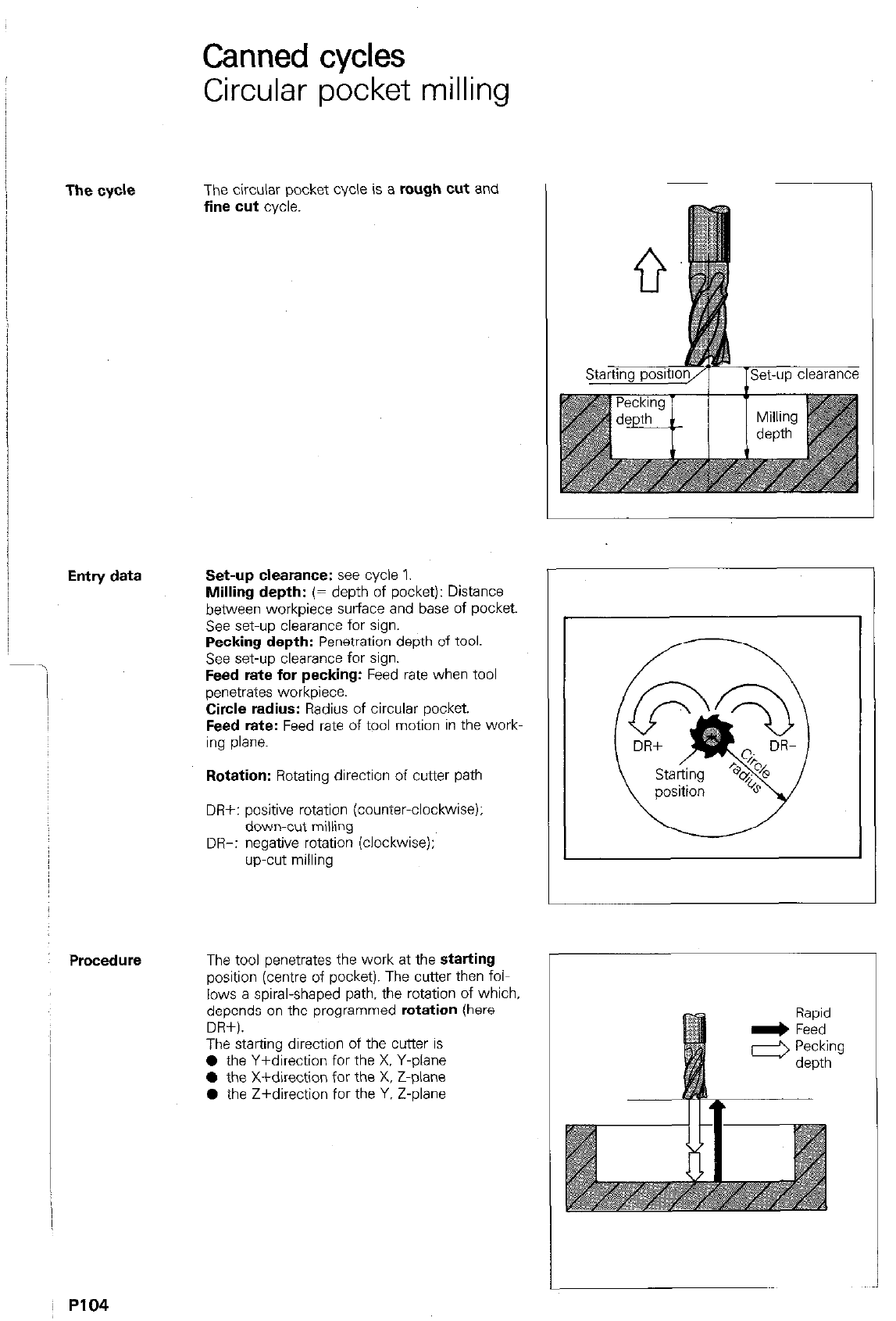
The cycle
Entry data
i
Procedure
Canned cycles
Circular pocket milling
The circular pocket cycle is a rough cut and
fine cut cycle.
Set-up clearance: see cycle 1.
Milling depth: (= depth of pocket): Distance
between workpiece surface and base of pocket.
See set-up clearance for sign.
Pecking depth: Penetration depth of tool.
See set-up clearance for sign.
Feed rate for pecking: Feed rate when tool
penetrates workpiece.
Circle radius: Radius of circular pocket.
Feed rate: Feed rate of tool motion in the work-
ing plane.
Rotation: Rotating direction of cutter path
DR+: positive rotation (countwclockwise):
down-cut milling
DR-: negative rotation (clockwise);
up-cut milling
The tool penetrates the work at the starting
position (centre of pocket). The cutter then folL
lows a spiral-shaped path, the rotation of which,
depends on the oroarammed rotation (here
DPi+).
_
The starting direction of the cutter is
0 the Y+direction for the X. Y-Diane
l
the X+direction for the X. Z-&e
0 the Z+direction for the Y. Z-plane
P104
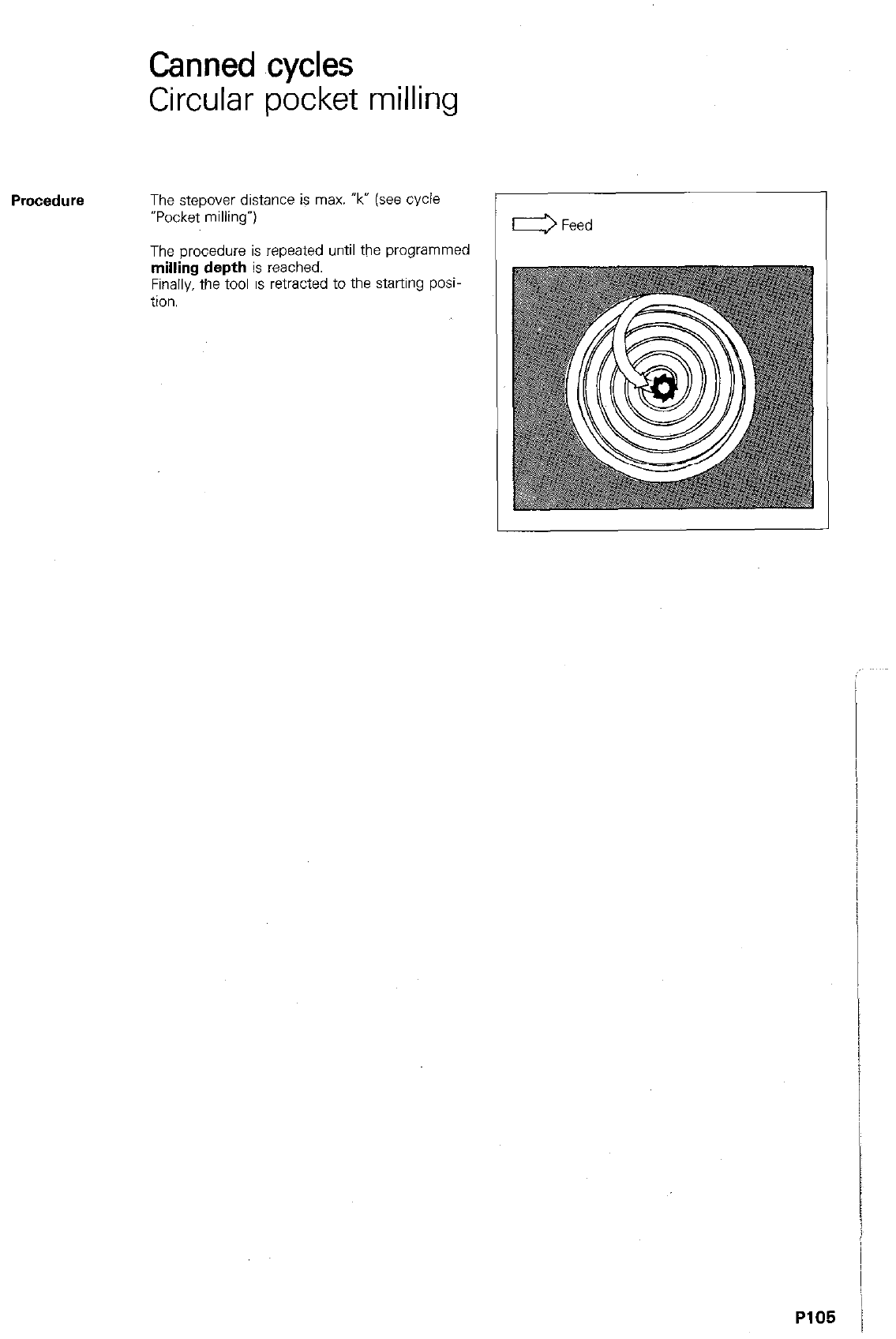
Canned cycles
Circular pocket milling
Procedure
The stepover distance is max. ‘k” (see cycle
“Pocket milling”)
The orocedure is repeated until the uroarammed
n&g depth
is rexhed.
Finally. the tool is retracted to the starting posi
tion.
P105 /
Remarks
PI06
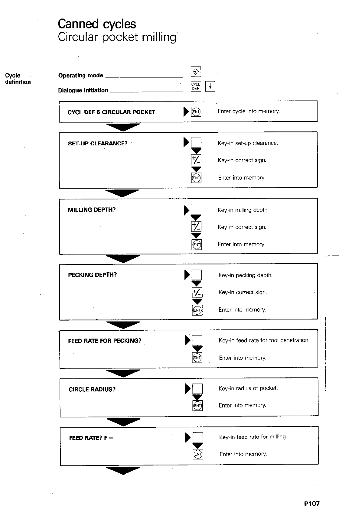
Canned cycles
Circular pocket milling
Cyde
definition Operating mode
Dialogue initiation
CYbL DEF 5 CIRCULAR POCKET
Enter cycle into memory
SET-UP CLEARANCE?
Key-in set-up clearances
8 Key-in correct sign.
Enter into memory
MILLING DEPTH?
‘P
Key-in milling depth.
g Key-in correct sign.
q
Enter into memory.
I
Key-in pecking depth.
q
Key-in correct sign.
Enter into memory
I
I I
FEED RATE FOR PECKING? Kl
Key-in feed rate for tool penetration.
5 Enter into memory
CIRCLE RADIUS? b0
Key-in radius of pocket.
Enter into memory
FEED RATE? F =
Key-in feed rate for milling.
Enter into memory.
I I
P107
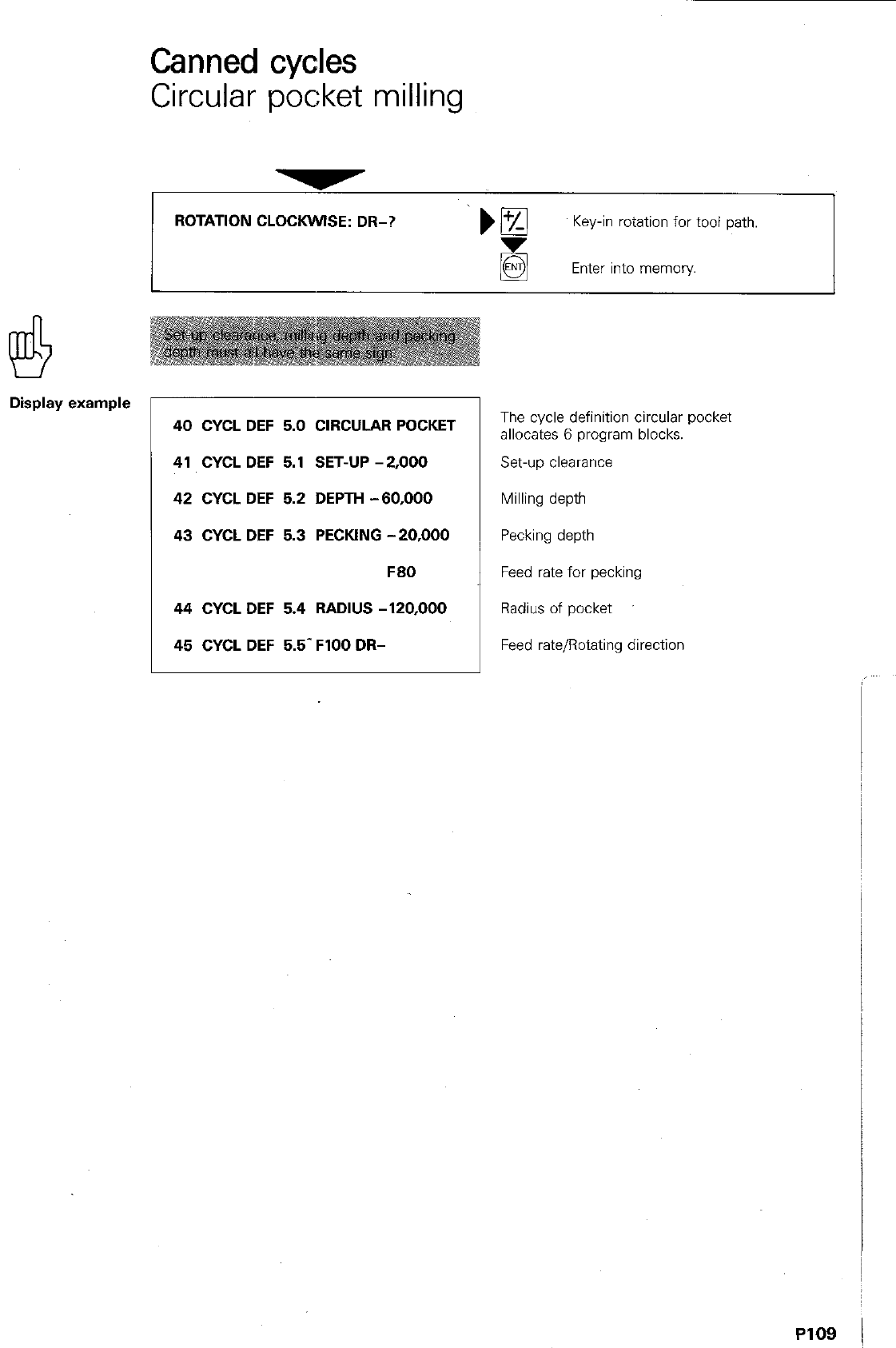
Canned cycles
Circular pocket milling
ROTATION CLOCKWISE: DR-? ‘)B
Key-in rotation for tool path.
Enter into memory
Display example
40 CYCL DEF 5.0 CIRCULAR POCKET
41 CYCL DEF 5.1 SET-UP -2,000
42 CYCL DEF 5.2 DEPTH -60,000
43 CYCL DEF 5.3 PECKING -20,000
F60
44 CYCL DEF 5.4 RADIUS -120,000
45 CYCL DEF 5.5- FlOO DR-
The cycle definition circular pocket
allocates 6 program blocks.
Set-up clearance
Milling depth
Pecking depth
Feed rate for pecking
Radius of pocket
Feed rate/Rotating direction
PI09 j
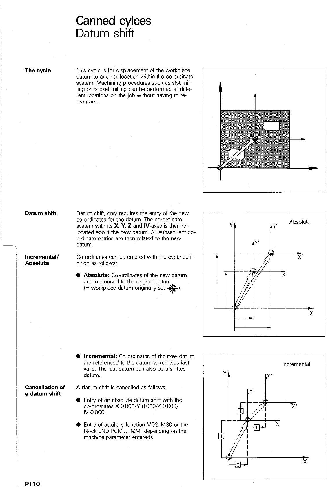
Canned cylces
Datum shift
The cycle
Datum shift
Incremental/
Absolute
Cancellation of
a datum shift
This cycle is for displacement of the workpiece
datum to another location within the co-ordinate
system. Machining procedures such as slot mil-
ling or pocket milling can be performed at diffe-
rent locations on the job without having to ra-
program.
Datum shift, only requires the entry of the new
co-ordinates for the datum. The co-ordinate
system with its X, Y, i! and
IV-axes
is then re-
located about the new datum. All subsequent co-
ordinate entries are then related to the new
datum.
Co-ordinates can be entered with the cycle defi-
nition as follows:
0
Absolute:
Co-ordinates of the new datum
are referenced to the original datum.
(= workpiece datum originally set @I-
@
Incremental:
Co-ordinates of the new datum
are referenced to the datum which was last
valid. The last datum can also be a shifted
datum.
A datum shift is cancelled as follows:
0 Entry of an absolute datum shift with the
co-ordinates X 0.000/Y 0.00012 O.OOO/
IV 0.000:
0 Entry of auxiliary function MOZ. M30 or the
block END PGM MM (depending on the
machine parameter entered).
Incremental
1
PllO
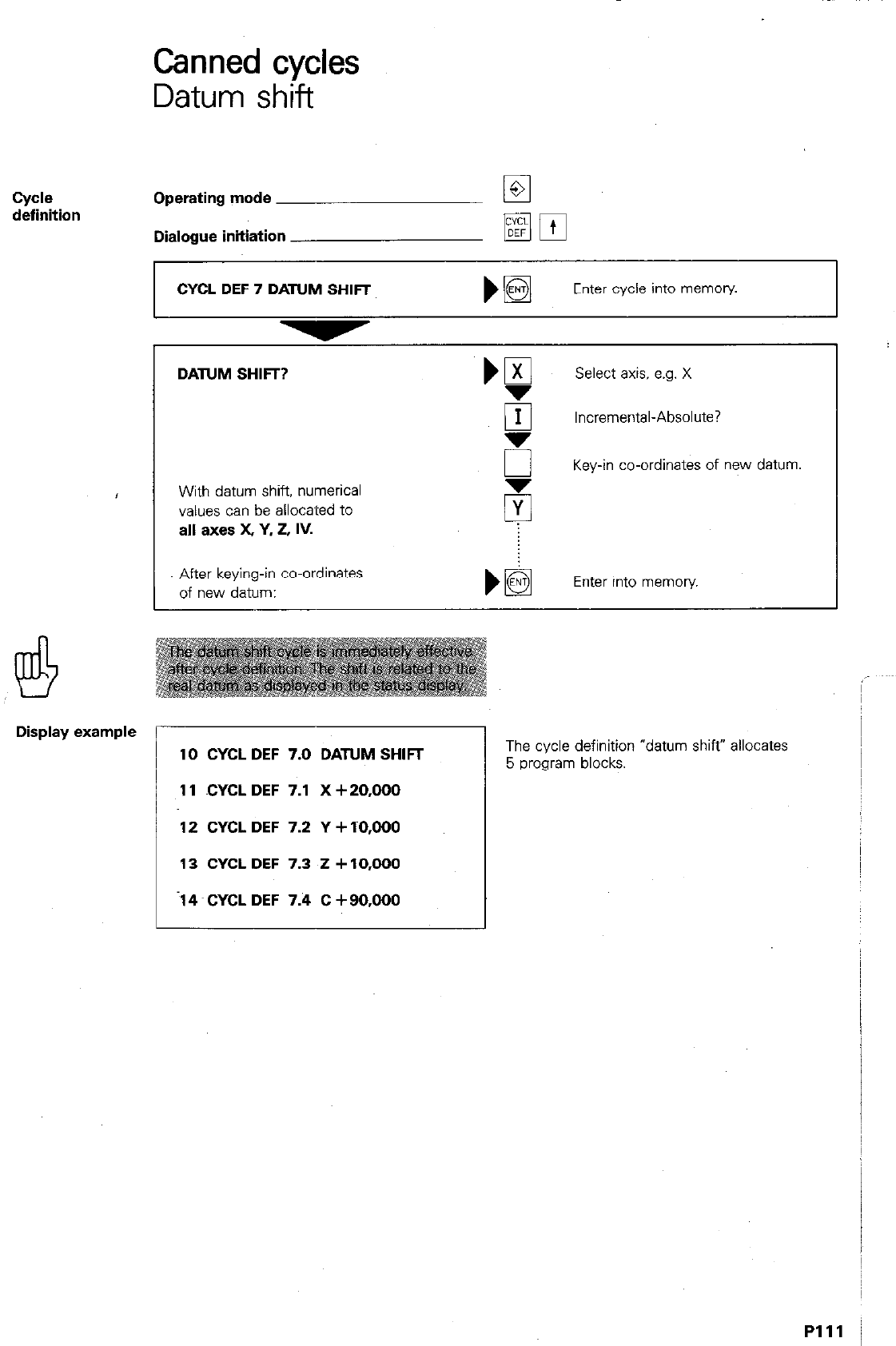
Canned cycles
Datum shift
cycle
definition Operating mode
Dialogue initiation
DATUM SHIFT?
With datum shift, numerical
values can be allocated to
all axea X, Y, 2. IV.
‘gl
Select axis, e.g. X
El Incremental-Absolute?
5 Key-in co-ordinates of new datum
CYCL DEF 7 DATUM SHIFT
Enter cycle into memory
After keying-in co-ordinates
of new datum: Enter into memory.
Display example
10 CYCL DEF 7.0 DATUM SHIFT
11 CYCL DEF 7.1 X +20,000
12 CYCL DEF 7.2 Y + TO.000
13 CYCL DEF 7.3 i! + 10,000
-14 CYCL DEF 7.4 C +90,000
The cycle definition “datum shift’ allocates
5 program blocks.
Plll /
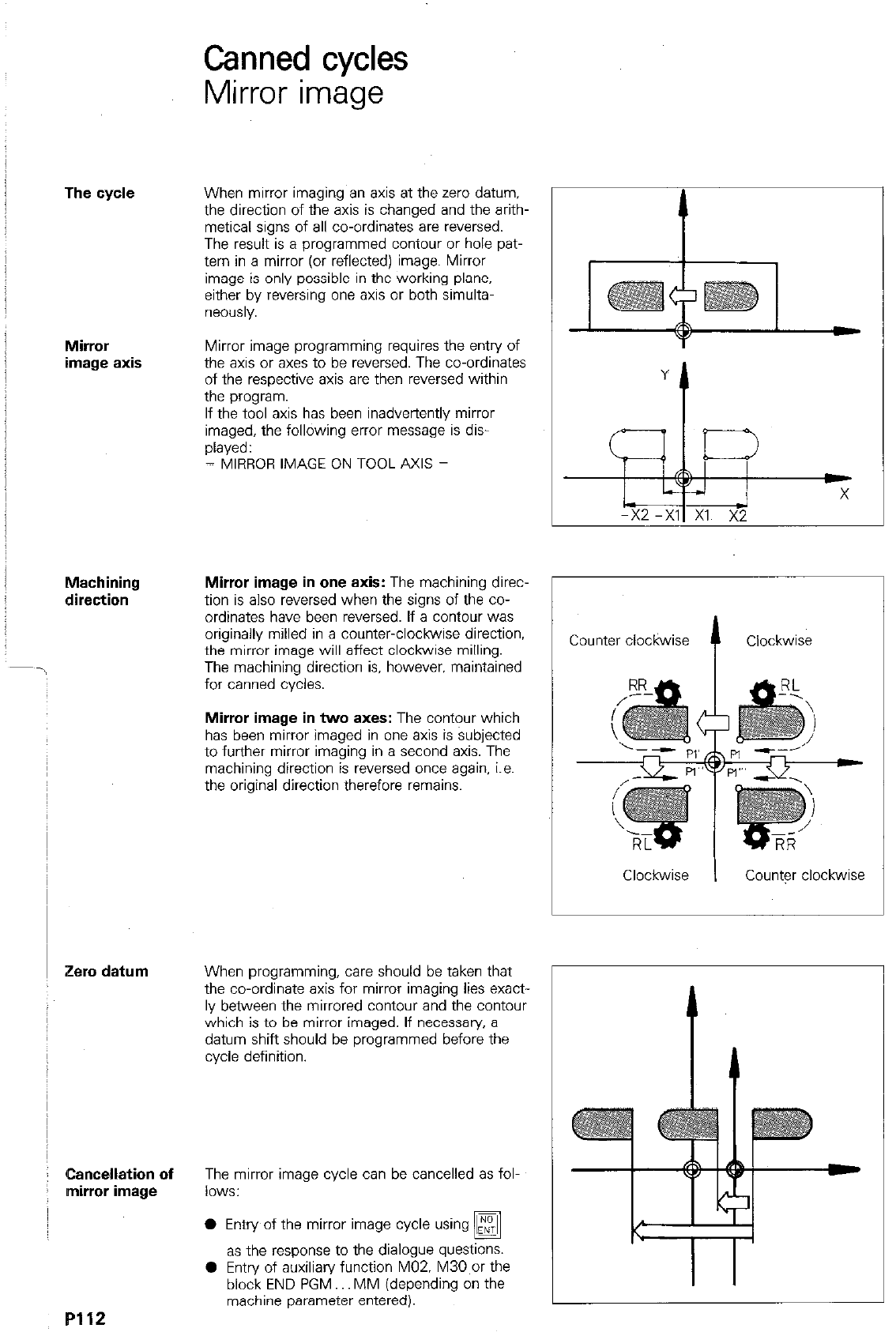
Canned cycles
Mirror image
The cycle
Mirror
image axis
Machining
direction
Zero datum
Cancellation of
mirror image
When mirror imaging an axis at the zero datum.
the direction of the axis is changed and the arith-
metical signs of all co-ordinates are reversed.
The result is a programmed contour or hole pat-
tern in a mirror (or reflected) image. Mirror
image is only possible in the working plane.
either by reversing one axis or both simulta-
n6YXlSly.
Mirror image programming requires the entry of
the axis or axes to be reversed. The co-ordinates
of the respective axis are then reversed within
the program.
If the tool axis has been inadvertently mirror
imaged, the following error message is dis-
played:
= MIRROR IMAGE ON TOOL AXIS =
Mirror image in one axis:
The machining direc-
tion is also reversed when the signs of the co-
ordinates have been reversed. If a contour was
originally milled in a counter-clockwise direction,
the mirror image will affect clockwise milling.
The machining direction is. however. maintained
for canned cycles.
Mirror image in
two
axes:
The contour which
has been mirror imaged in one axis is subjected
to further mirror imaging in a second axis. The
machining direction is reversed once again, i.e.
the original direction therefore remains.
When programming, care should be taken that
the co-ordinate axis for mirror imaging lies exact-
ly between the mirrored contour and the contour
which is to be mirror imaged. If necessary, a
datum shift should be programmed before the
cycle defmltlon.
The mirror image cycle can be cancelled as fol-
lows:
0 Entry of the mirror image cycle using
q
as the response to the dialogue questIons.
0 Entry of auxiliary function M02. M30,or the
block END PGM.. MM (depending on the
machine parameter entered).
Counter clockwise
f
Clockwise
Clockwise I County clockwise
P112
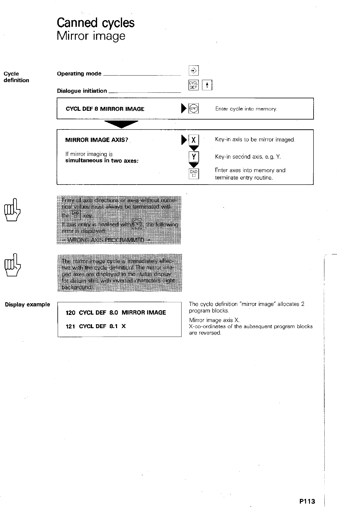
Canned cycles
Mirror image
Cydl?
definition Operating mode ~
Dialogue initiation
CYCL DEF 8 MIRROR IMAGE Enter cycle into memory
MIRROR IMAGE AXIS?
If mirror imaging is
simultaneous in two axes:
NE Key-in axis to be mirror imaged.
5 Key-in se&d axis, e.g. Y.
Enter axes into memory and
terminate entry routine.
Display example The cycle definition “mirror image” allocates 2
P113
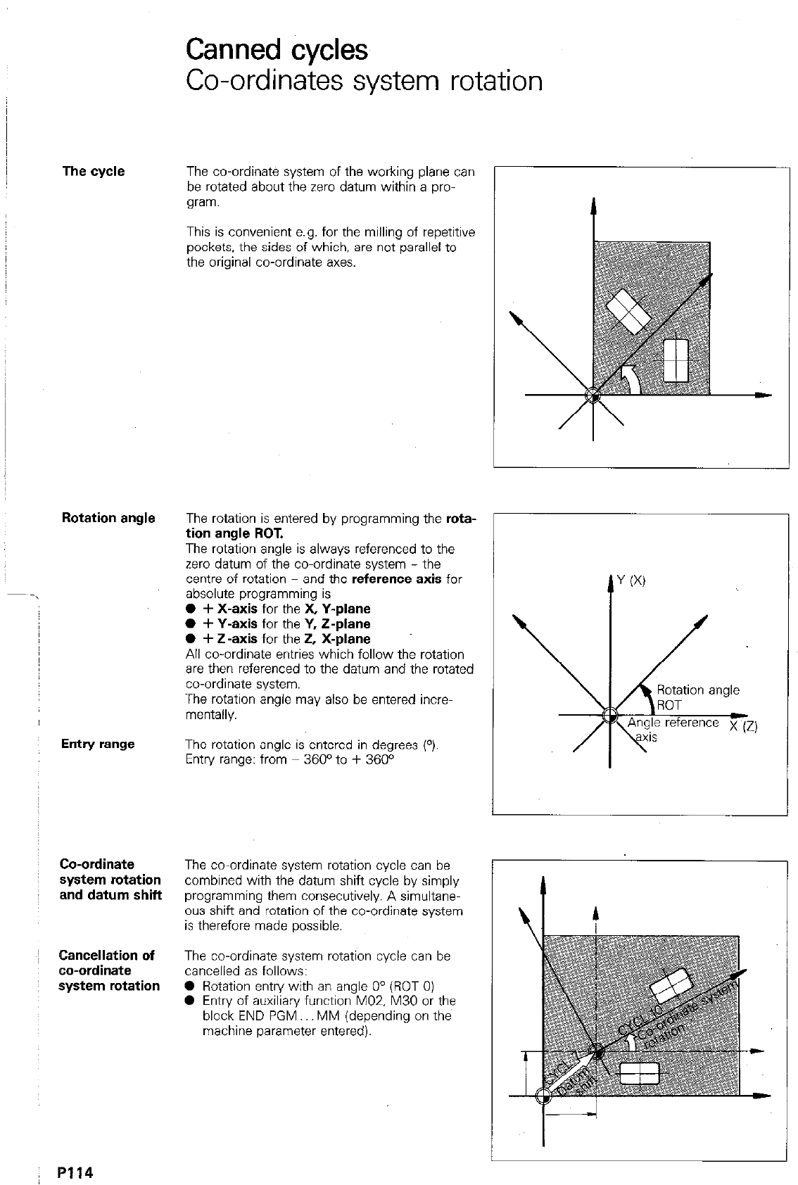
The cycle
Entry range
Co-ordinate
system rotation
and datum shift
~ Cancellation of
co-ordinate
: system rotation
Canned cycles
Co-ordinates system rotation
The co-ordinate system of the working plane can
be rotated about the zero datum within a pro-
gram.
This is convenient e.g. for the milling of repetitive
pockets, the sides of which, are not parallel to
the original co-ordinate axes.
The rotation is entered by programming the
rota-
tion angle ROT.
The rotation angle is always referenced to the
zero datum of the co-ordinate system - the
centre of rotation - and the reference
axis
for
absolute programming is
0 + X-axis
for the X
Y-plane
0 + Y-axis
for the
Y, Z-plane
0 + Z-axis
for the
2, X-plane
All co-ordinate entries which follow the rotation
are then referenced to the datum and the rotated
co-ordinate system.
The rotation angle may also be entered incre-
mentally.
The rotation angle is entered in degrees (“).
Entry range: from 360° to + 360°
The co-ordinate system rotation cycle can be
combined with the datum shift cycle by simply
programming them consecutively. A simultane
ous shift and rotation of the co-ordinate system
is therefore made possible.
The co-ordinate system rotation cycle can be
cancelled as follows:
0 Rotation entn/ with an angle O0 (ROT 0)
0 Entry of auxiliary function MO2 M30 or the
block END PGM MM (depending on the
machine parameter entered).
R114
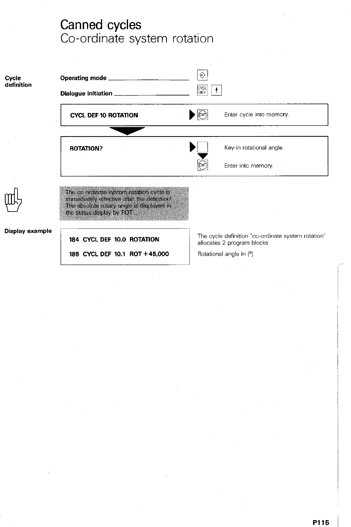
Canned cycles
Co-ordinate system rotation
Cyde
definition Operating mode
Dialogue initiation -
CYCL DEF 10 ROTATION
Enter cycle into memory
ROTATION?
Key-in rotational angle.
Enter into memory
Display example
184 CYCL DEF 10.0 ROTATION
The cycle definition “co-ordinate system rotation”
allocates 2 program blocks
185 CYCL DEF lO.‘l ROT +45,000
Rotational angle in (O)
PI15 I
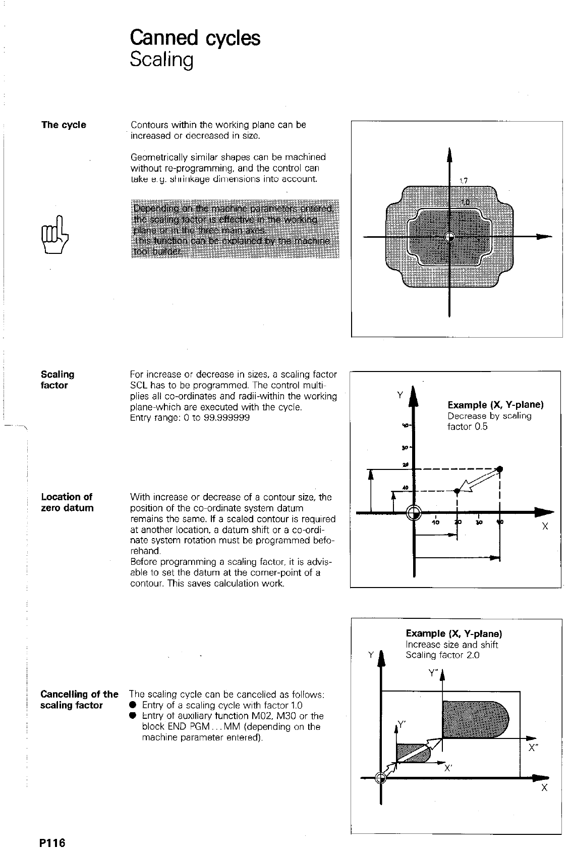
Canned cycles
Scaling
The cycle Contours within the working plane can be
increased or decreased in size.
Geometrically similar shapes can be machined
without reprogramming. and the control can
take e.g. shrinkage dimensions into account.
Scaling
factor For increase or decrease in sizes. a scaling factor
SCL has to be programmed. The control multi-
plies all co-ordinates and radii-within the working
plane-which are executed with the cycle.
Entry range: 0 to 99.999999
ILocation of
zero datum With increase or decrease of a contour size, the
position of the co-ordinate system datum
remains the same. If a scaled contour is required
at another location, a datum shift or a co-ordi-
nate system rotation must be programmed befo-
rehand.
Before programming a scaling factor, it is advis-
able to set the datum at the corner-point of a
contour. This saves calculation work.
Cancelling of the The scaling cycle can be cancelled as follows:
scaling factor 0 Entry of a scaling cycle with factor 1.0
0 Entry of auxiliary function MOZ. M30 or the
block END PGM MM (depending on the
machine parameter entered).
Y
t
Example (X, Y-plane)
Decrease by scaling
*D- factor 0.5
Example (X, Y-plane)
Increase size and shift
Y t Scali y,,actor 2.0 ,
PI16
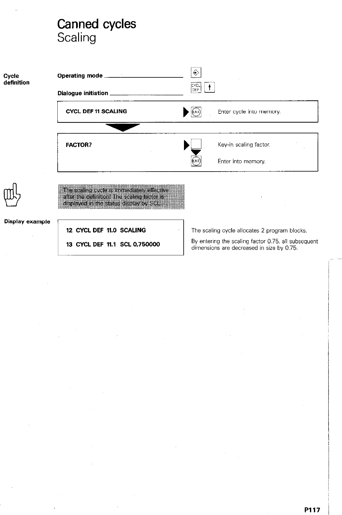
Canned cycles
Scaling
cycle
definition Operating mode
Dialogue initiation
CYCL DEF 11 SCALING
m pj
Enter cycle into memory.
FACTOR?
Display example
12 CYCL DEF 11.0 SCALING
The scaling cycle allocates 2 program blocks
13 CYCL DEF 11.1 SCL 0.750000
By entering the scaling factor 0.75, all subsequent
dimensions are decreased in size by 0.75.
I
I
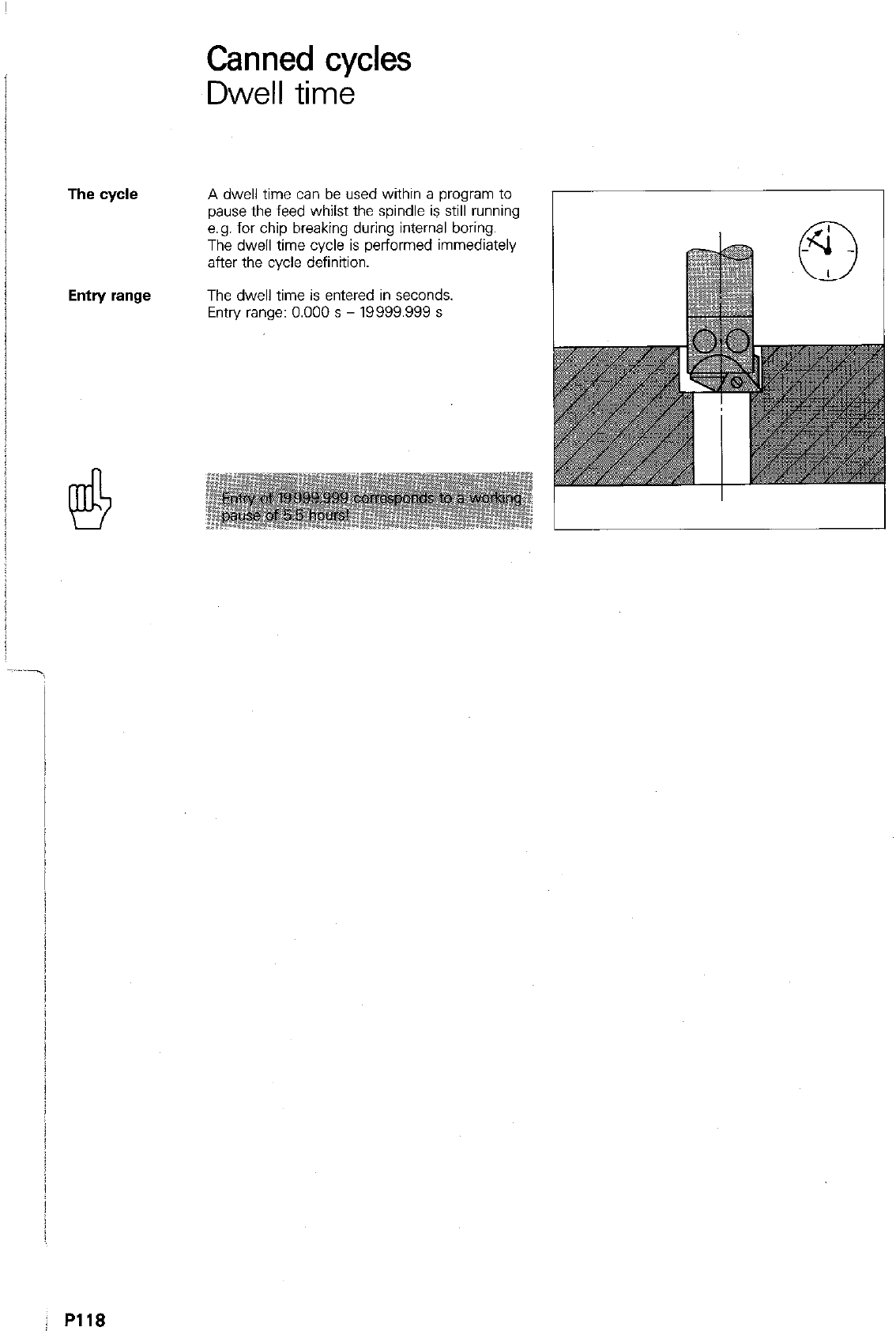
The cycle
Entry range
Canned cycles
Dwell time
A dwell time can be used within a program to
pause the feed whilst the spindle is still running
e.g. for chip breaking during internal boring.
The dwell time cycle is performed immediately
after the cycle definition.
The dwell time is entered in seconds.
Entry range: 0.000 s - 19999.999 s
j R118
CyIAe
definition
Display example
Canned cycles
Dwell time
Operating mode iE
Dialogue initiation
CYCL DEF 9 DWELL TIME
Enter cycle into memory
DWELL TIME IN SECS.
‘P
Key-in reqd. dwell time.
Enter into memory.
97 CYCL DEF 9.0 DWELL TIME
98 CYCL DEF 9.1 DWELL 10,000
1
The dwell time cycle allocates
‘2 program blocks.
Canned cycles
Freely programmable cycles (Program call)
The cycle
The “program call” cycle permits simple call-up
of programs (with CYC- CALL M89 and M99)
which have been compiled with the aid of para-
meter functions, e.g. zig-zag milling. These freely
programmable cycles therefore have the same
status as pre-programmed canned cycles.
; P120
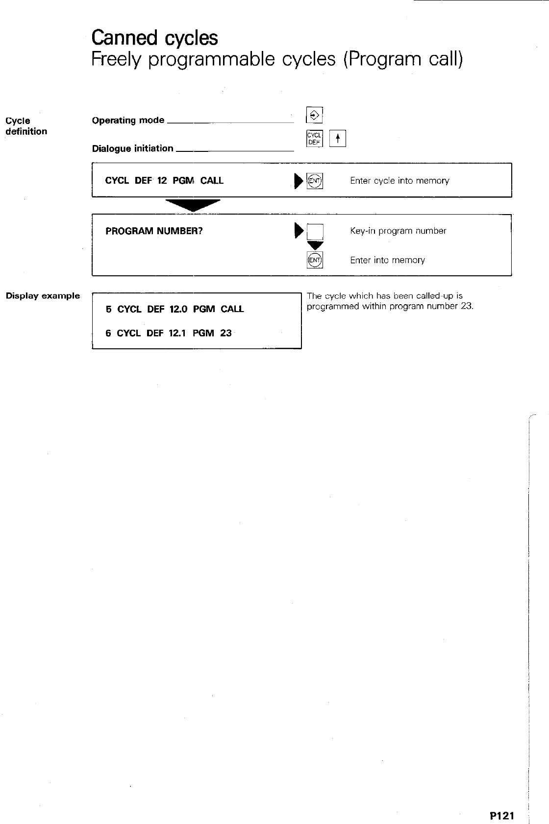
Canned cycles
Freely programmable cycles (Program call)
Cycle
definition Operating mode ~
Dialogue initiation -
CYCL DEF 12 PGM: CALL )B
Enter cycle into memory
PROGRAM NUMBER?
Key-in program number
Enter into memory
Display example
5 CYCL DEF 12.0 PGM CALL
6 CYCL DEF 12.1 PGM 23
The cycle which has been called-up is
programmed within program number 23
/
I
P121 :
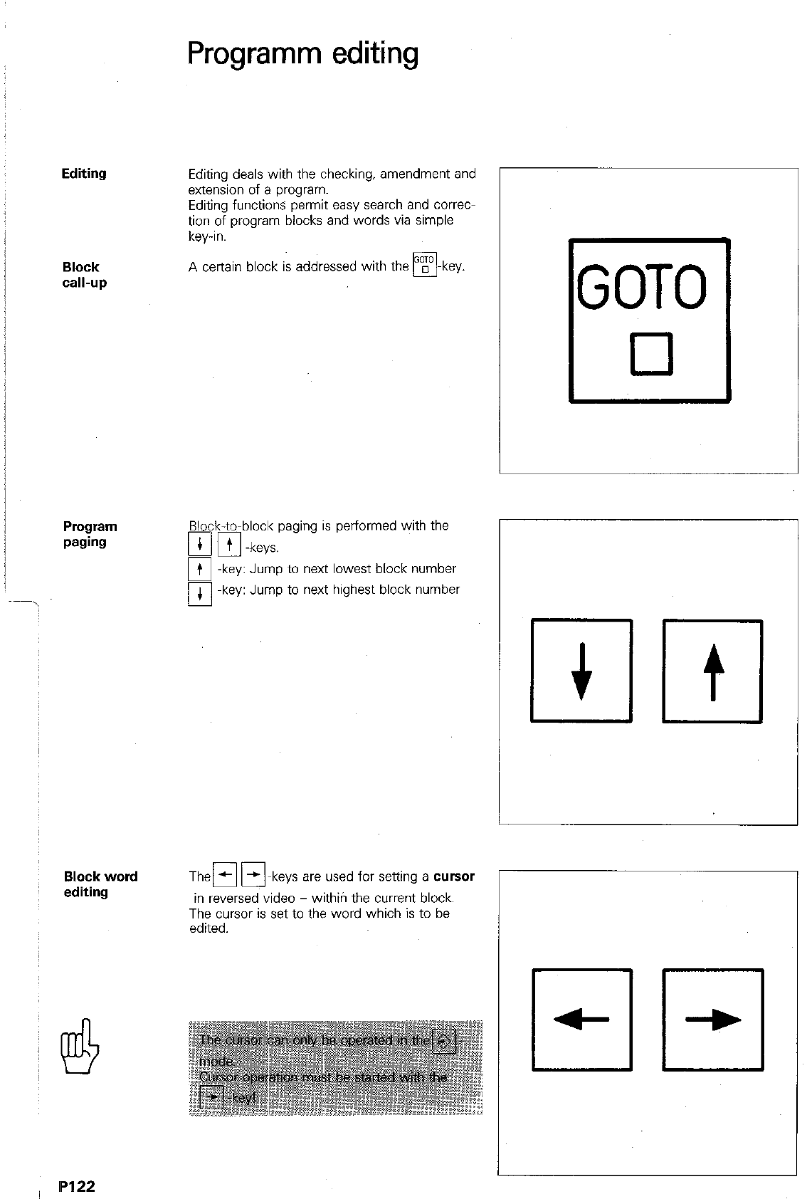
Programm editing
Editing
Block
Cdl-UP
Program
paging
Block word
editing
Editing deals with the checking, amendment and
extension of a program.
Editing functions permit easy search and correct
tion of program blocks and words via simple
key-in.
A certain block is addressed with the w
q
-key.
Block-to-block paging
a pi -keys.
is performed with the
Jump to next lowest block number
Jump to next highest block number
Then mm keys are used for setting a cursor
in reversed video - withiri the current block.
The cursor is set to the word which is to be
edited.
GOT0
cl
ml
P122
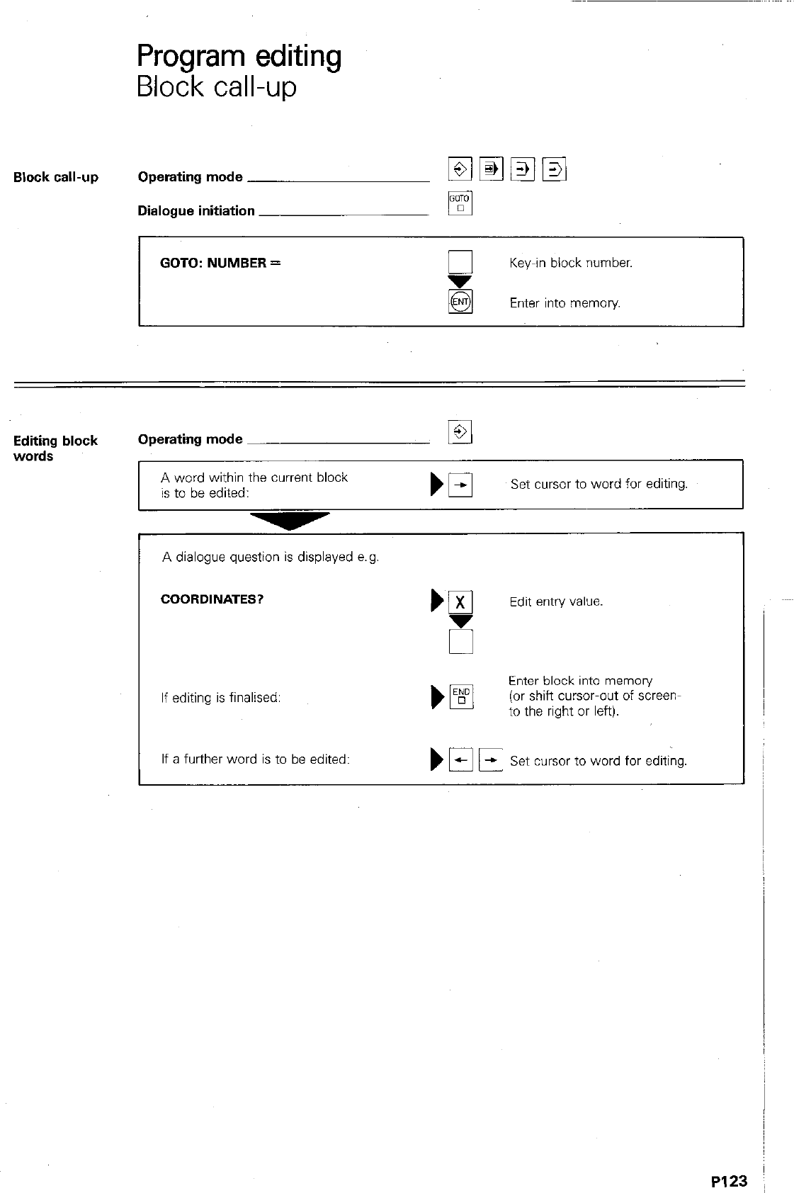
Program editing
Block call-up
Block call-up Operating mode
Dialogue initiation
GOTO: NUMBER =
Key-in block number.
Enter into memory
Editing block Operating mode El
words
A word within the current block
is to be edited: Set cursor to word for editing.
A dialogue question is displayed e.g
COORDINATES?
If editing is final&d:
Enter block into memory
)pFJ (or shift cursor-out of screen-
to the right or left).
If a further word is to be edited: Set cursor to word for editing.
PI2
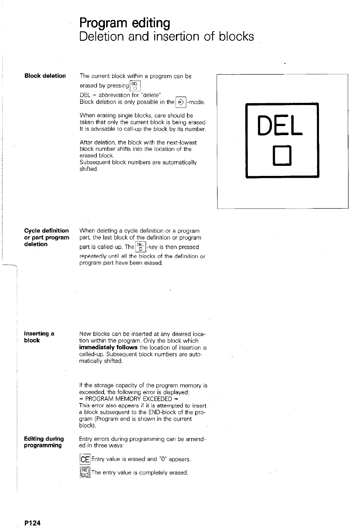
Cycle definition
or part program
deletion
Inserting a
block
Editing during
programming
PI24
Program editing
Deletion and insertion of blocks
The current block within a program can be
erased by pressingB.
DEL = abbreviation for -delete’
Block deletion is only possible in them-mode.
When erasing single blocks, care should be
taken that only the current block is being erased.
It is advisable to call-up the block by its number.
After deletion. the block with the next-lowest
block number shifts into the location of the
erased block.
Subsequent block numbers are automatically
shifted.
When deleting a cycle definition or a program
part, the last block of the definition or program
part is called-up. Them-key is then pressed
repeatedly until all the blocks of the definition or
program part have been erased.
New blocks can be inserted at any desired loca-
tion within the program. Only the block which
immediately follows the location of insertion is
called-up. Subsequent block numbers are auto-
matically shifted.
If the storage capacity of the program memory is
exceeded, the following error is displayed:
= PROGRAM MEMORY EXCEEDED =
This errcx also appears if it is attempted to insert
a block subsequent to the END-block of the pro-
gram (Program end is shown in the current
block).
Entry errors during programming can be amend-
ed in three ways:
Entry value is erased and 7” appears.
The entry value is completely erased.
DEL
0
Program amendments
Block deletion
Deleting a
block Operating mode
The current program block is to be deleted. )
q
Press for deletion
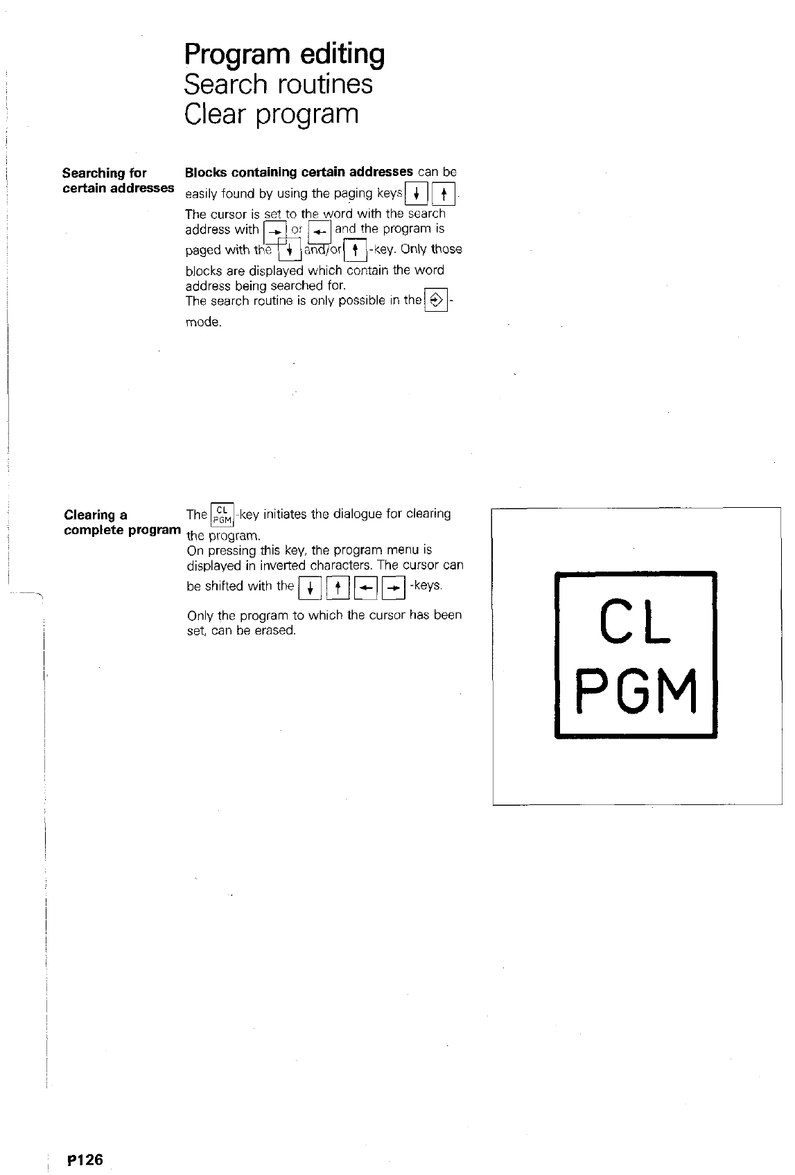
Program editing
Search routines
Clear program
Searching for Blocks containing certain addresses can be
certain addresses easily found by using the paging keyspi m.
The cursor is set to the word with the search
blocks are displayed which contain the word
address being searched for.
The search routine is only possible in the 9
17
mode.
Clearing a The m-key initiates the dialogue for clearing
complete program the program.
On pressing this key, the program menu IS
displayed in inverted characters. The cursor can
beshiftedwiththemmmm-keys.
Only the program to which the cursor has been
set, can be erased.
~ PI26
Program editing
Search routines
Clear program
Finding certain Operating mode w
search addresses
All blocks containing the address M
are to be displayed:
El
Set cursor to a word
with the search address.
Clearing Operating mode M
a program m
Dialogue initiation
CLEAR PROGRAM = ENTIEND = NOENT
If the program is to be cleared:
Do not clear program
or terminate clear program-routine.
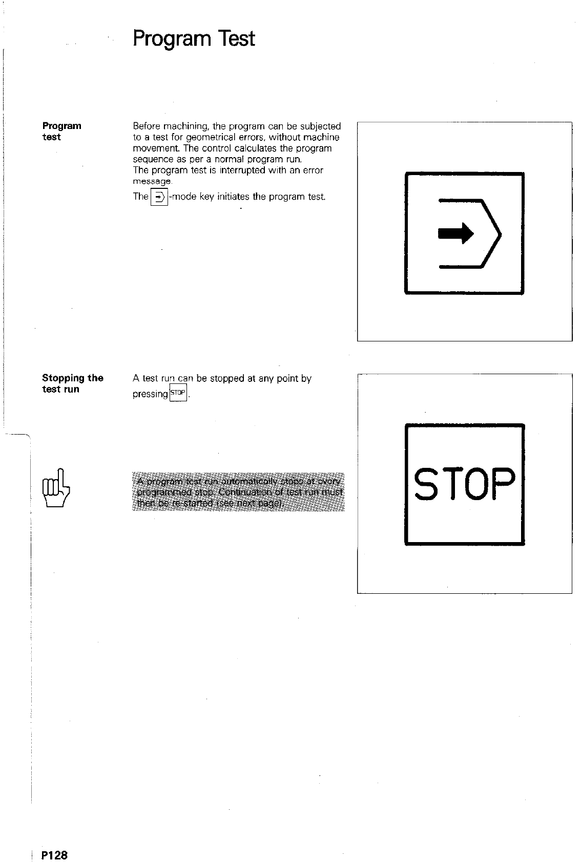
Program
test
Stopping the
test run
PI28
Program Test
Before machining, the program can be subjected
to a test for geometrical errors. without machine
movement. The control calculates the program
sequence as per a normal program run.
The program test is interrupted with an error
message.
the program test.
A test run can be stopped at any point by
pressing@.
Ll
*
3
El
STOP
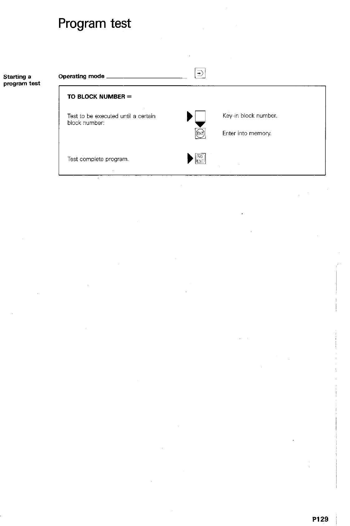
Program test
Starting a Operating mode
q
program test
TO BLOCK NUMBER =
Test to be executed until a certain
block number:
Test complete program,
Key-in block number..
Enter into memory
P129 ;
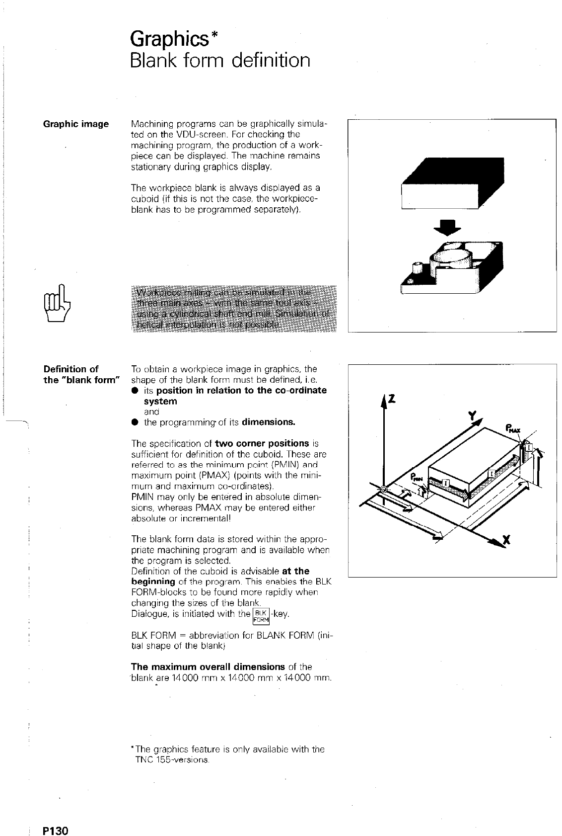
Graphics*
Blank form definition
Graphic image Machining programs can be graphically simula
ted on the VDU-screen. For checking the
machining program. the production of a work-
piece can be displayed. The machine remains
stationary during graphics display.
The workpiece blank is always displayed as a
cuboid (if this is not the case. the workpiece-
blank has to be programmed separately).
Definition of To obtain a workpiece image in graphics, the
the “blank form” shape of the blank form must be defined, i.e.
l
its position in relation to the co-ordinate
system
and
l
the programming of its dimensions.
The specification of two corner positions is
sufficient for definition of the cuboid. These are
referred to as the minimum point (PMIN) and
maximum point (PMAX) (points with the mini-
mum and maximum co-ordinates).
PMIN may only be entered in absolute dimen-
sions, whereas PMAX may be entered either
absolute or incremental!
The blank form data is stored within the appro-
priate machining program and is available when
the program is selected.
Definition of the cuboid is advisable at the
beginning of the program. This enables the BLK
FORM-blocks to be found more rapidly when
changing the sizes of the blank.
Dialogue, is initiated with the ELK -key.
w
BLK FORM = abbreviation for BLANK FORM (ini
tial shape of the blank)
The maximum overall dimensions of the
‘blank are 14000 mm x 14000 mm x 14000 mm.
*The graphics feature is only available with the
TNC 155.versions.
~ P130
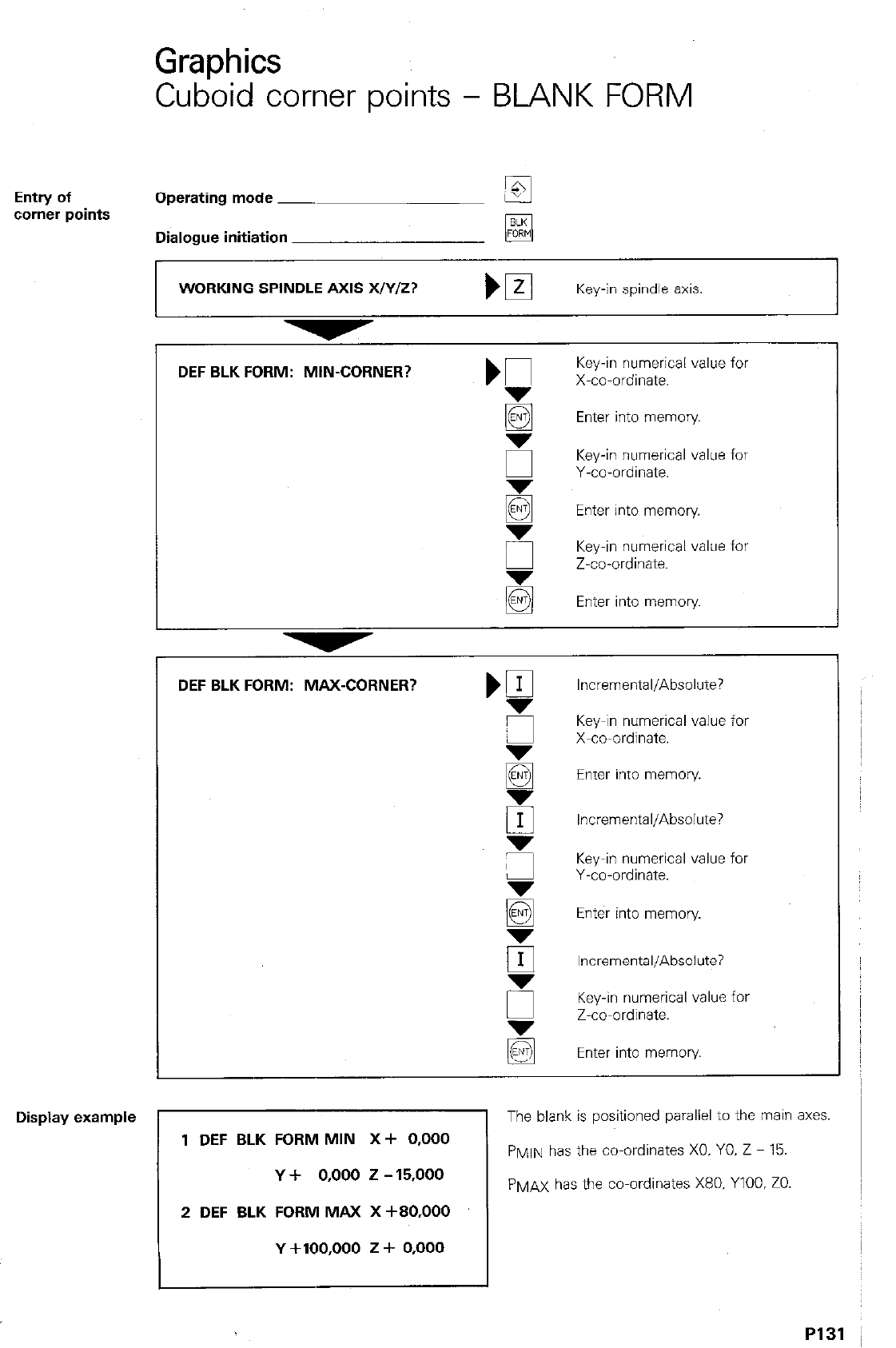
GraDhics
Cub’oid corner points - BLANK FORM
Entry of Operating mode ~
corner points
Dialogue initiation _
q
WORKING SPINDLE AXIS WY/z?
Key-in spindle axis.
-
Display example
DEF BLK FORM: MIN-CORNER?
5
E
E
5
E
DEF BLK FORM: MAX-CORNER? ,a
Key-in numerical value for
X-co-ordinate.
Enter into memory
Key-in numerical value for
Y-co-ordinate.
Enter into memory
Key-in numerical value for
Z-co-ordinate.
Enter into memory
Incremental/Absolute?
Key-in numerical value for
X-co-ordinate.
Enter into memory.
Incremental/Absolute?
Key-in numerical value for
Y-co-ordinate.
Enter into memory
Incremental/Absolute?
Key-in numerical value for
Z-co-ordinate.
Enter into memory
1 DEF BLK FORM MIN X+ 0,000
Y + 0,000 2 - 15,000
2 DEF BLK FORM MAX X +BO.OOO
Y +100,000 z + 0,000
The blank is positioned parallel to the main axes.
P~li\l has the co-ordinates X0. YO. Z - 15.
PMAX has the co-ordinates X80. YlOO. ZO.
PI31 ~
Graphics
Image projections
Operating mode
A machining proqram can be graphically dis- I
Gkphics-
played in the’op&ting modes.
‘and
I
+) PROGRAM RUN/FULL SEQUENCE
0
@ PROGRAM RUN/SINGLE BLOCK
Graphics display is only possible if the program
is stored within the memory
A menu showing the types of image projections
which are available is called-up by pressing the
m-key
twice.
Then m-k y e s are used for setting the cursor
to the required projection mode. Press H for
transfer into memory.
GRAPHICS
BLK
FORM
11
MAGN START
Image
projection
These are four types of image projection.
I 3D-View
Program execution is display in a three-dimen-
sional image. The workpiece can be rotated
about the vertical axis by pressing
HoOr
tilted about the horizontal axis by pressing
q - 0
The attitude of the co-ordinate system is indi-
cated by an angle in the top left-hand comer of
the screen (working plane).
View in
three planes
Program execution is displayed with a plan view
and two &oss-sections, similar to a working
drawing. The sectional planes can be shifted with
the H
q q
a-keys.
As of software version 06:
The view in three planes can be switched from
the standard DIN-projection to the U.S.-standard
third angle projection. A symbol to DIN 6 indi-
cates the projection as follows:
DIN-standard w
U.S.-standard w
PI32
Graphics
Image projections
Plan view 1 The program is executed in a plan view with 5
grades of depth shading. The darker - the
deeper.
Plan view 2 As per plan view 1, however with 17 grades of
depth shading. The image resolution in the
other two axes is however. less suwrior.
r
Fast image
generation A finished workpiece can be displayed on the
Screen after fast image data processing.
The control “develops’ the workpiece in accor-
dance with the program without displaying the
various stages of progress.
Only the blobk number is displayed.
PI3
3
Graphics
Operatior
1
start
After selecting the required graphics mode, pro-
gram run is started by pressing H.
stop
Graphics simulation can be stopped at any time
by pressing STOP. The current block is however,
0
cornDIeted.
Reset to
blank form
After stopping graphics program run. the dis-
played workpiece can be reset to the blank form
(original cuboid) by pressing
q .
L
P134
Graphics
Graphics start
Starting of Operating mode ~
graphics r
Select required progmm.
Select graphics mode.
Set cmor to required projection.
e.g. 3D-view
Start graphics sequence.
P135
Remarks
P136
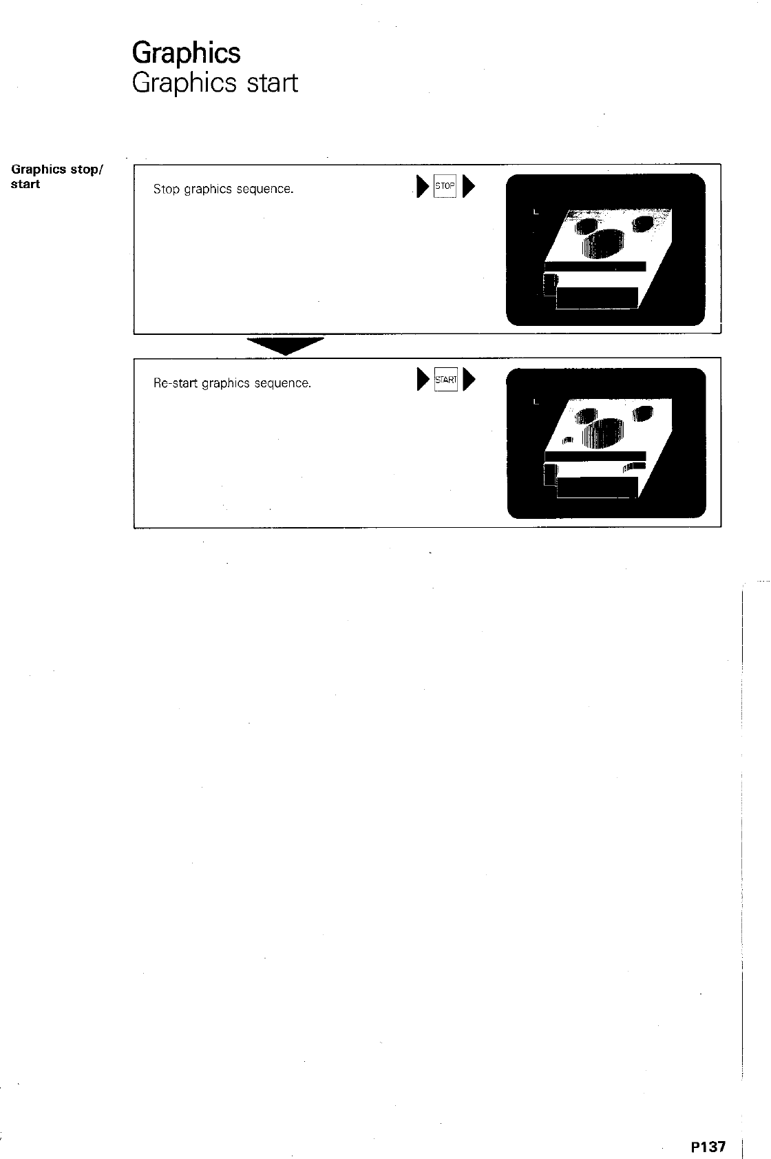
Graphics
Graphics start
Graphics stop/
start
Stop graphics sequence.
Re-start graphics sequence. bEi+
Remarks
P138
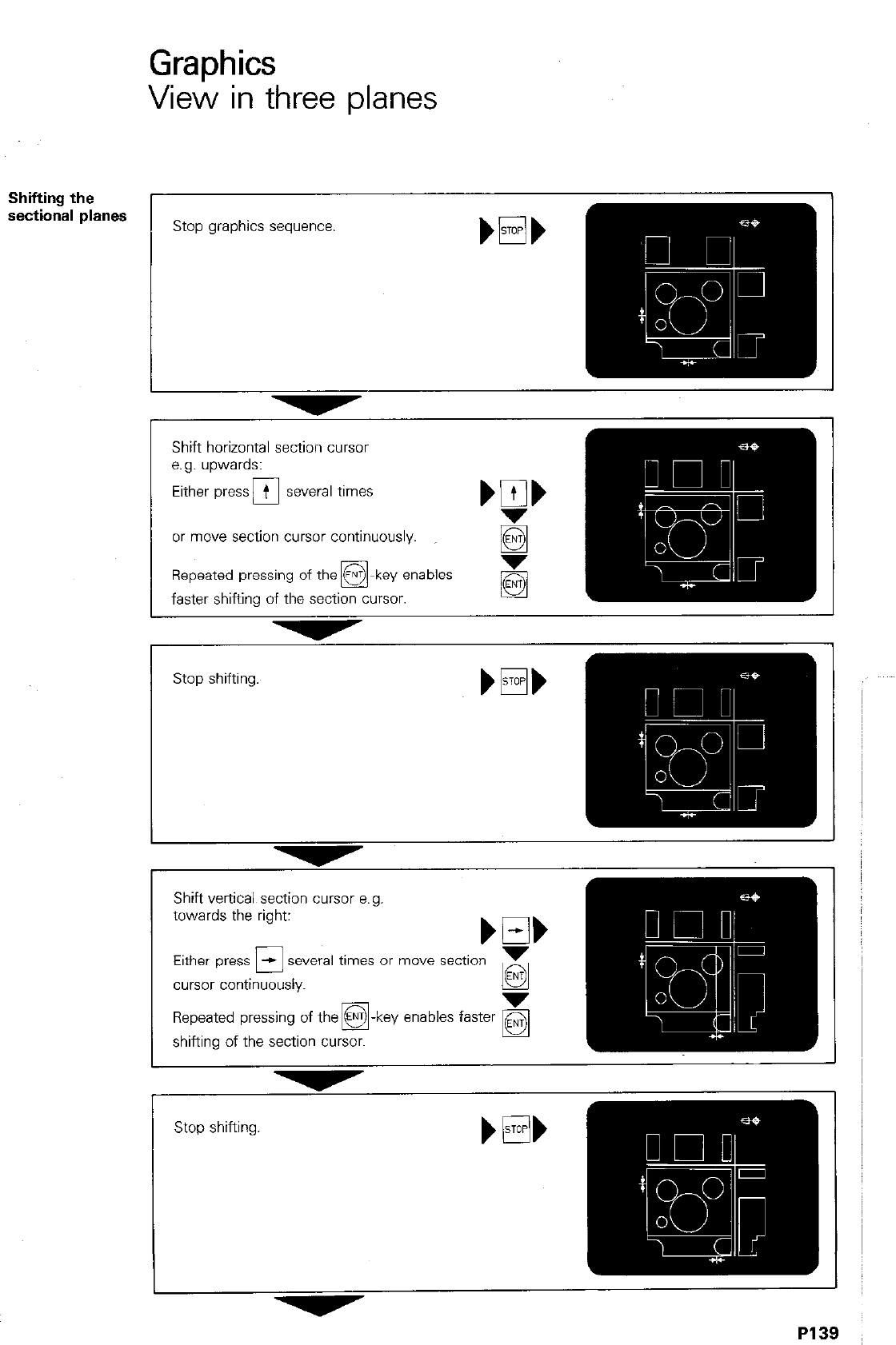
Graphics
View in three planes
Shifting the
sectional planes
Shift horizontal section cursor
e.g. upwards:
or move section cursor continuously.
Repeated pressing of the @-key enables
0
faster shifting of the section cursor.
Stop shifting.
-
Shift vertical section cursor e.a. I
towards the right:
Either press El several times or move section
cursor continuously. g
Repeated pressing of the @-key enables faster
q
shifting of the section cursor.
P139
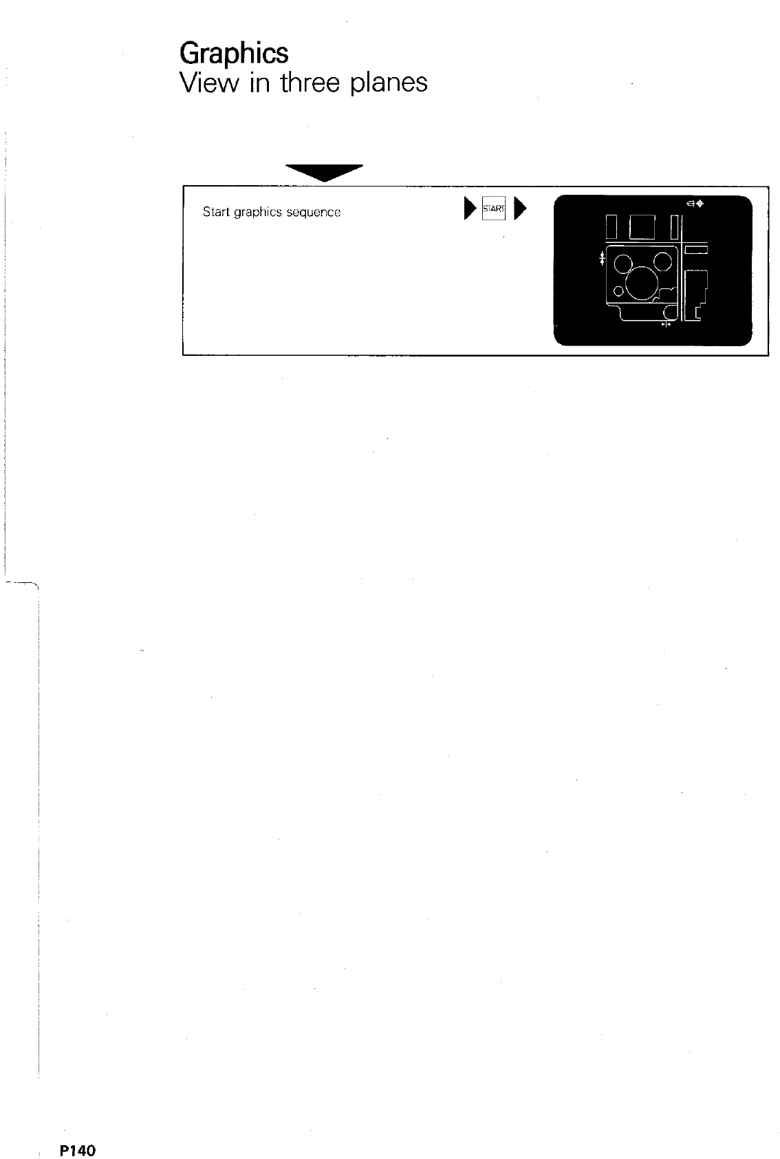
GraDhics
Viei in three planes
Start graphics sequence
P140
Graphics
3D-View
Rotation
and
tilting
L
Stop graphics sequence.
Tilt image, e.g. upwards. bob
Rotate image. e.g. to the right.
Start graphics sequence.
P141.
Graphics
Magnify
Magnifying The magnifying function is used for enlarging any
function desired detail of the workpiece.
q
MAGN
Limitation of A workpiece detail is limited by means of cuboid
workpiece detail frame which appears in the ti&eft-hand comer
Definition of
next limit
Entry of
selected detail
of the screen after pressing WGN
u
The hatched face can be shifted left and right (or
forwards/reverse. upwards/downwards) with the
mm-ken
&%&s shifting is perform&with thea
key and stopped by pressing m
The next limit (right-hand face) is defined with
0.
By doing this, all faces can be selected and shift
ed one at a time.
The 0 + -key enables a return-jump to the
previous face.
After defining the last limiting face (upper face),
the detail can be entered by repressing
and finally H. 0 +
The display then shows an enlarged cuboid
blank of the detail. The magnified detail, com-
plete with contour is obtained with a graphics
run start in any one of the normal graphics
modes.
Graphics
Magnify
Limitation of
detail and
magnification
Stop shifting and enter
I
-
Select next limiting face (right)
P143
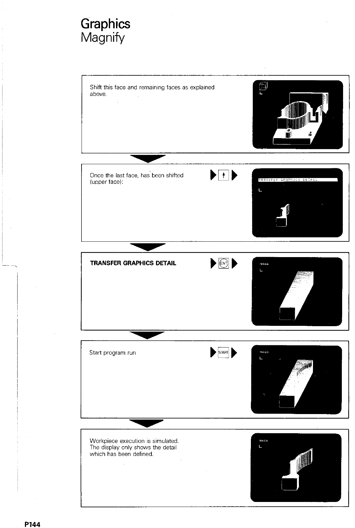
Graphics
Magnify
Once the last face. has. been shifted
(upper face):
TRANSFER GRAPHICS DETAIL mlb
I
Workpiece execution is simulated.
The display only shows the detail
which has been defined.
P144
,-
“.
,-
,._
.,.
,-
.
,,..
,-
,-
,-
,-
-
_.I
-
.
.
.
-
,-
-
-
.,.
,..
.
.
-
-
-
,,
-
-
.
.
-
.
.
-
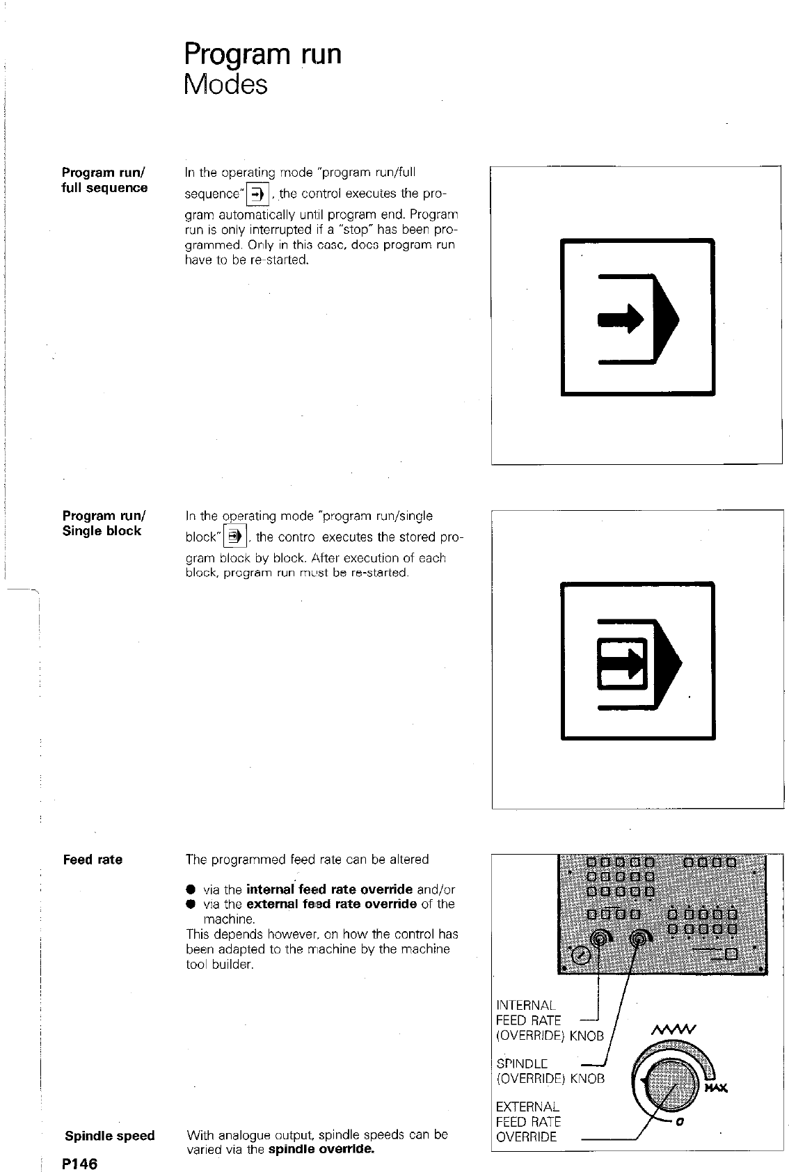
Program run
Modes
Program run/
full sequence
Program run/
Single block
Feed rate
Spindle speed
I P146
In the operating mode “program run/full
-
sequence” 3 the control executes the pro-
u
gram automatically uni:il program end. Program
run is only interrupted if a “stop” has been pro-
grammed. Only in this case. does program run
have to be r-started.
In the operating mode “program run/single
block- @ the contra executes the stored pm
0
gram block by block. After execution of each
block. program run mL#st be re-started.
The programmed feed rate can be altered
0 via the internal feed rate override and/or
0 via the external fead rate override of the
machine.
This depends however. on how the control has
been adapted to the rrlachine by the machine
tool builder.
With analogue output, spindle speeds can be
varied via the spindle override.
INTERNAL
FEED RATE
(OVERRIDE)
SPINDLE
(OVERRIDE)
EXTERNAL
FEED RATE
OVERRIDE
KNOB
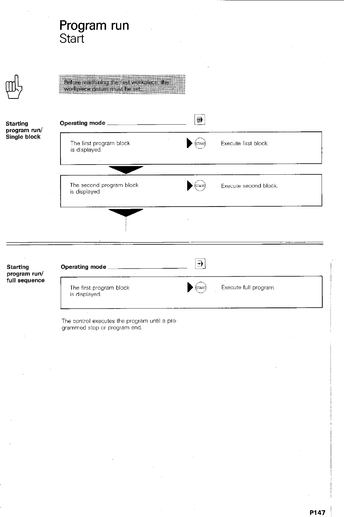
Program run
Start
Starting
program run/
Single block
Operating mode Ei
The first program block The first program block
is displayed. is displayed. Execute first block. Execute first block.
The second program block
is displayed. Execute second block.
Starting
program run/
full sequence
Operating mode -
The first program block
is displayed.
Execute full program.
The control executes the program until a pro-
grammed stop or program end.
P147 I
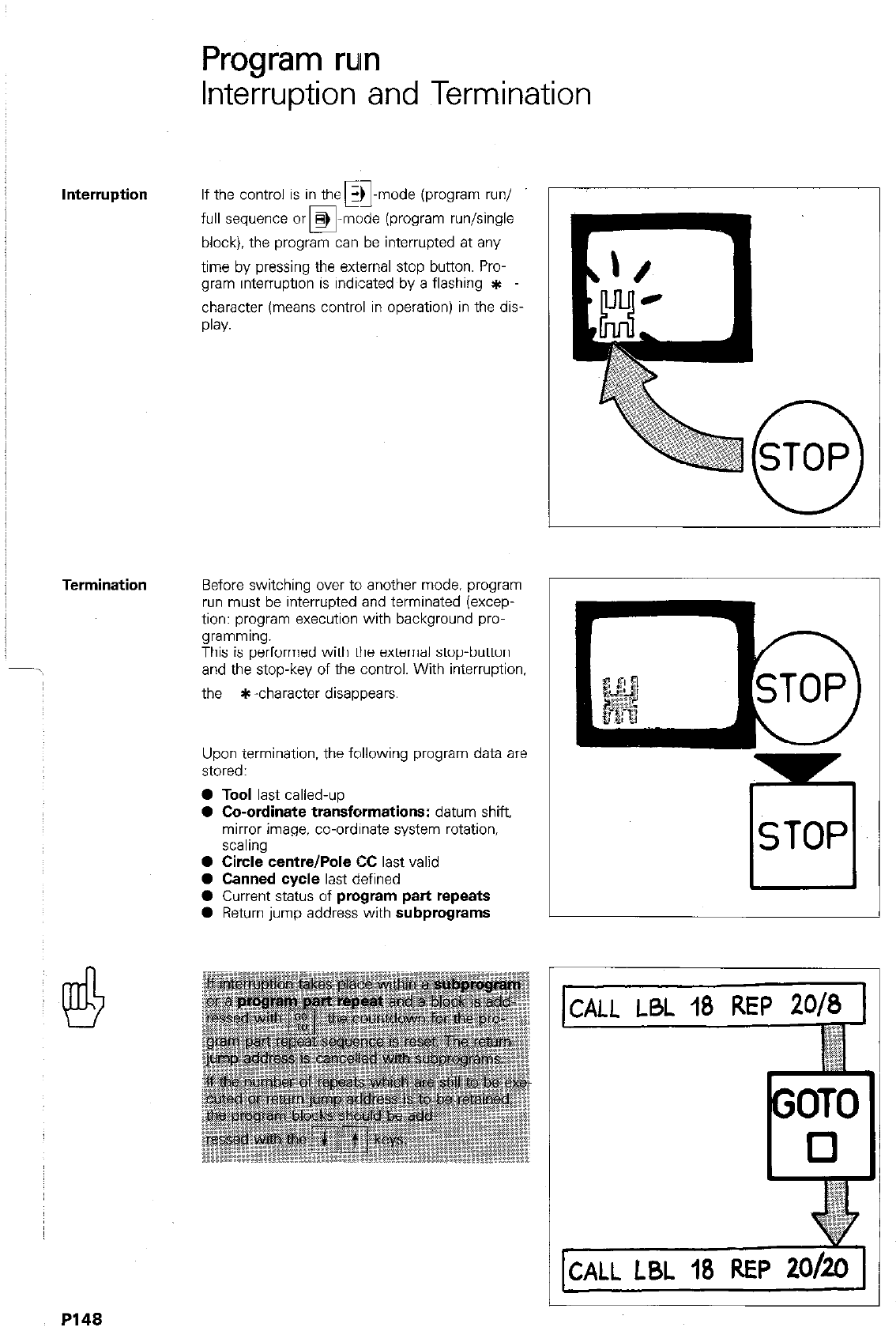
Program
rum
Interruption and Termination
lnterru~tion If the control is in the GA-mode ioroaram run/ i
0
r.1 ” ”
full sequence or HJ -mode (program run/single
block), the program can be interrupted at any
time by pressing the external stop button. Pro-
gram interruption is indicated by a flashing *
character (means control in operation) in the dis-
play.
krmination Before switching over to another mode. program
run must be interrupted and terminated (excep-
tion: program execution with background pro-
gramming.
This is performed with the external stop-button
and the stop-key of the control. With interruption,
the *-character disappears
Upon termination, the following program data are
stored:
l
Tool last called-up
0 Co-ordinate transformations: datum shift,
mirror image. co-ordinate system rotation.
scaling
0 Circle centre/Pole CC last valid
l
Canned cycle last defined
0 Current status of program part repeats
0 Return jump address with subprograms
r
ISTOP
L
OTO
0
P148
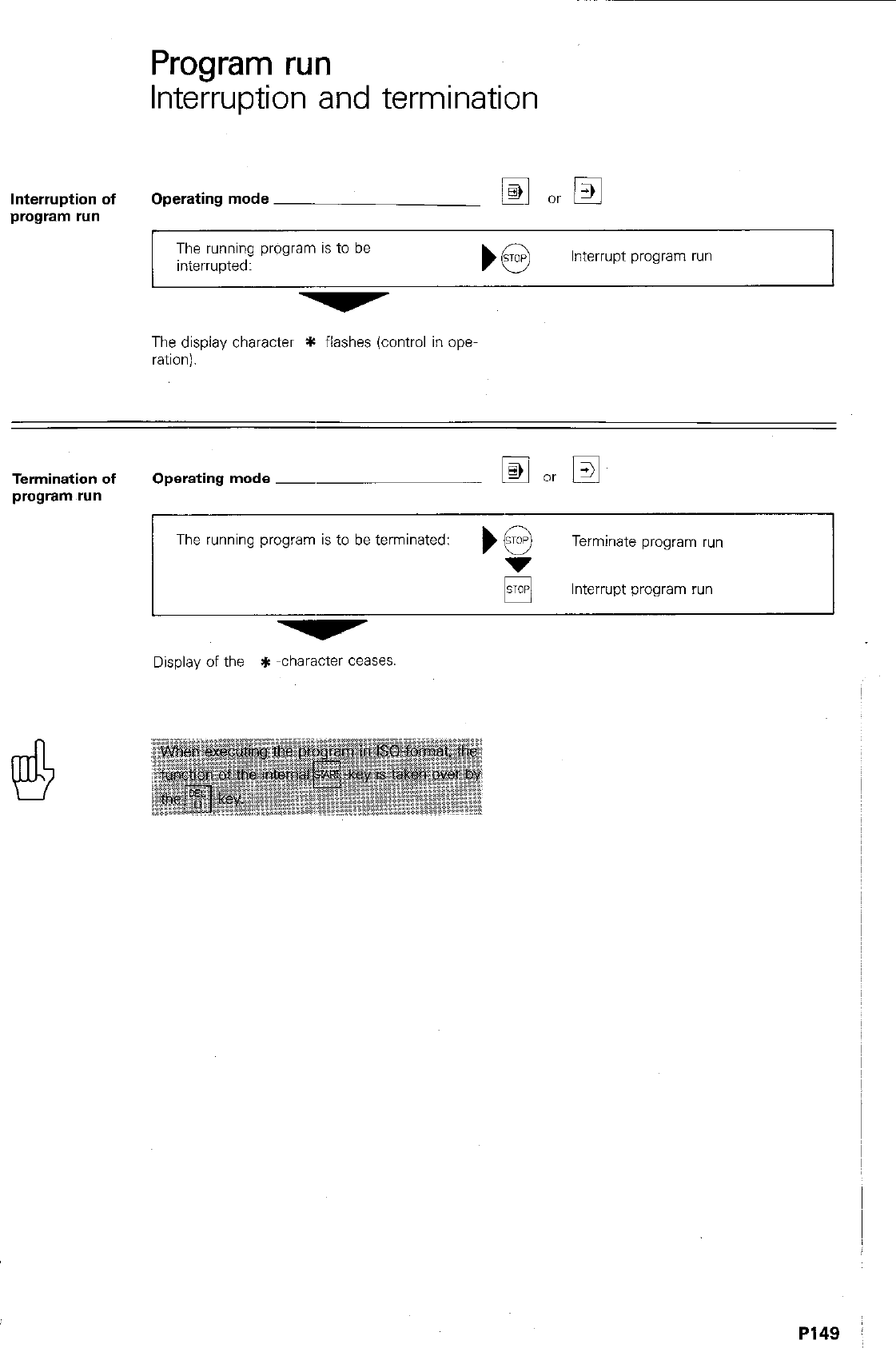
Program run
Interruption and termination
Interruption of
program run
Operating mode
The running program is to be
interrupted: Interrupt program run
The display character * flashes (control in Opel
ration).
Termination of Operating mode ~
program run
The running program is to be terminated: Terminate program run
pj Interrupt program run
Display of the * -character ceases.
PI49 :
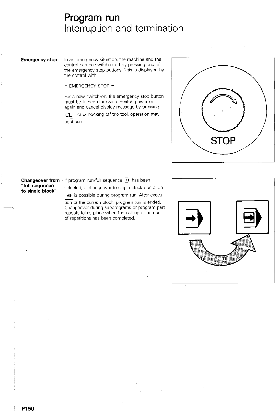
Program run
Interruption and termination
Emergency stop In an emergency situation, the machine and the
control can be switched off by pressing one of
the emergency stop buttons. This is displayed by
the control with
= EMERGENCY STOP =
For a new switch-on, the emergency stop button
must be turned clockwise. Switch power on
again and cancel display message by pressing
backing-off the tool. operation may
Changeover from If program run/full sequence 3 has been
n
r
“full &quence
to single block” selected, a changeover to single block operation
0,
8> IS possible during program run. After execu-
tion of the current block, program run is ended.
Changeover during subprograms or program part
repeats takes place when the call-up or number
of repetitions has been completed.
~ PI50
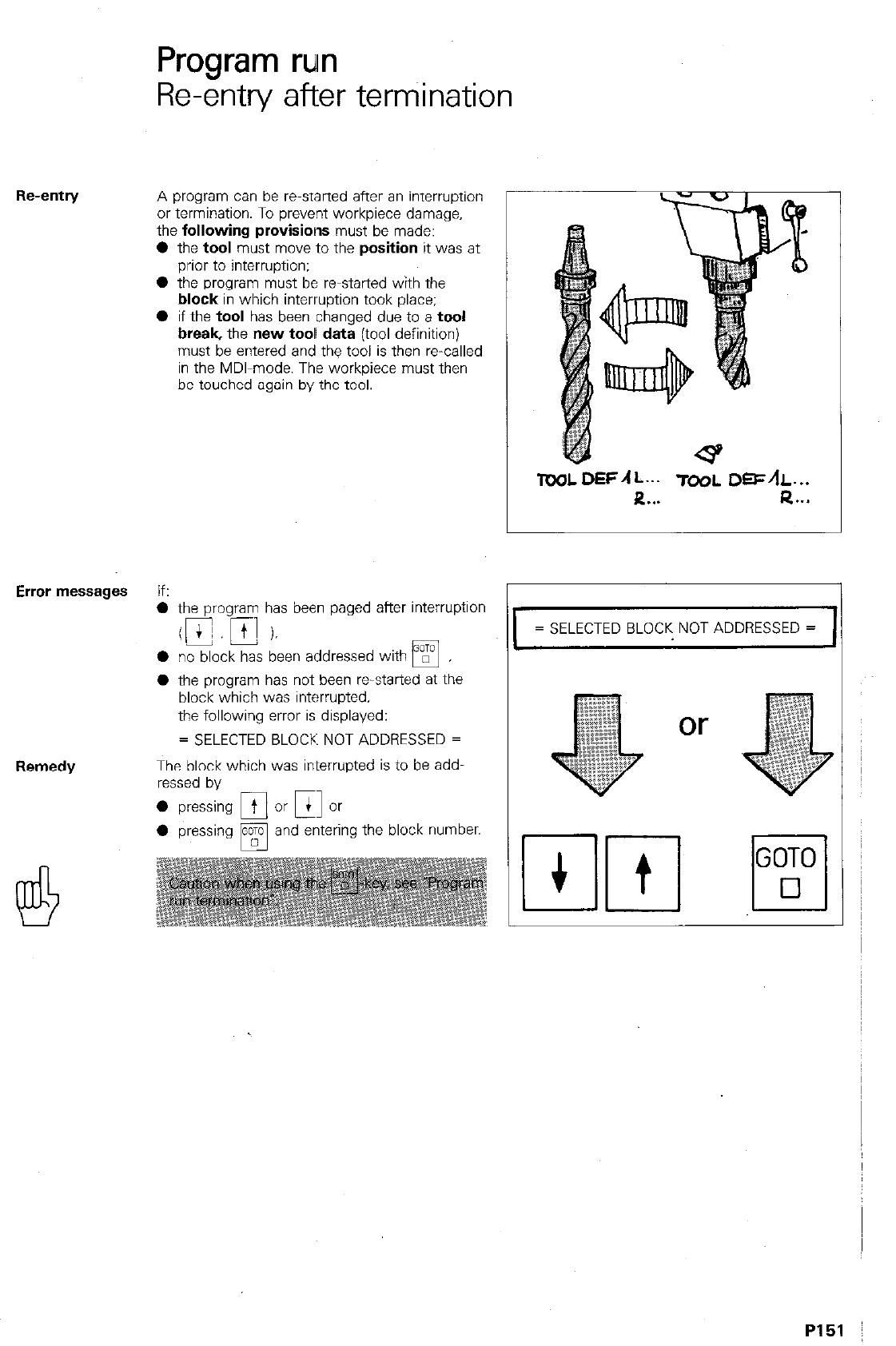
Re-entry
Program run
Re-entry after terniination
A program can be re-started after an interruption
or termination. To prevent workpiece damage,
the
following provisions
must be made:
0
the
tool
must
move
to the
position
it was at
prior to interruption:
l
the program must be re-started with the
block
in which interruption took place:
0 if the tool has been changed due to a
tool
break,
the new
tool data
(tool definition)
must be entered and the tool is then re-called
in the MDI-mode. The workpiece must then
be touched again by the tool.
Error messages
If:
0 the program has been paged after interruptlon
- -.
0 no block has been addressed with
q ,
l
the program has not been restarted at the
block which was interrupted.
the following error is displayed:
= SELECTED BLOCK NOT ADDRESSED =
Remedy
The block which was in~terrupted is to be add,
ressed by
0 pressing /@? and enteri ng the block number.
TOOLDEFAL... TO&I.
DEFAL...
R . . . Q...
= SELECTED BLOCK NOT ADDRESSED =
or
PI51
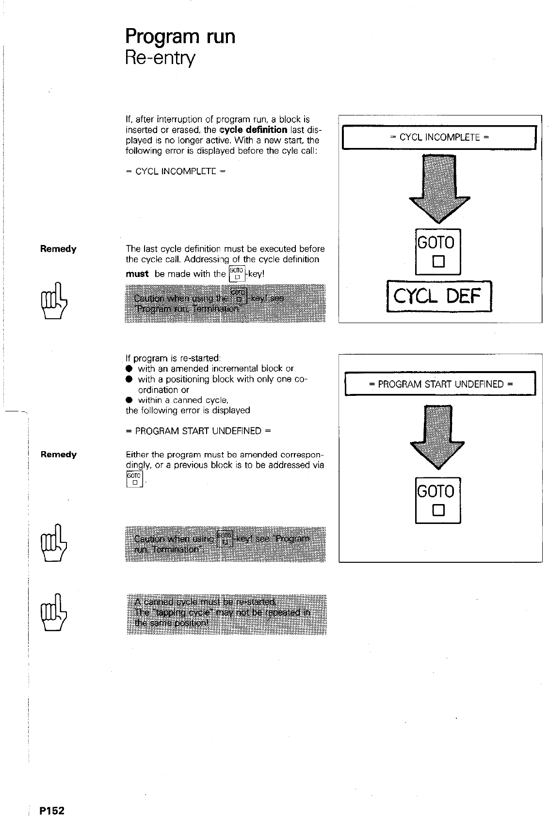
Program run
Re-entry
If. after interruption of program run. a block is
inserted
or
erased, the
cycle definition
last dis-
played is no longer active. With a new start, the
following error is displayed before the cyle call:
= CYCL INCOMPLETE =
The last cycle definition must be executed before
the cycle call. Addressing of the cycle definition
must be made with the mkev!
If program is re-started:
0 with an amended incremental block or
0 with a positioning block with only one co
ordination or
0 within a canned cycle.
the following error is displayed
= PROGRAM START UNDEFINED =
Either the program must be amended correspon-
dingly, or a previous block is to be addressed via
q .
= CYCL INCOMPLETE =
= PROGRAM START UNDEFINED = I
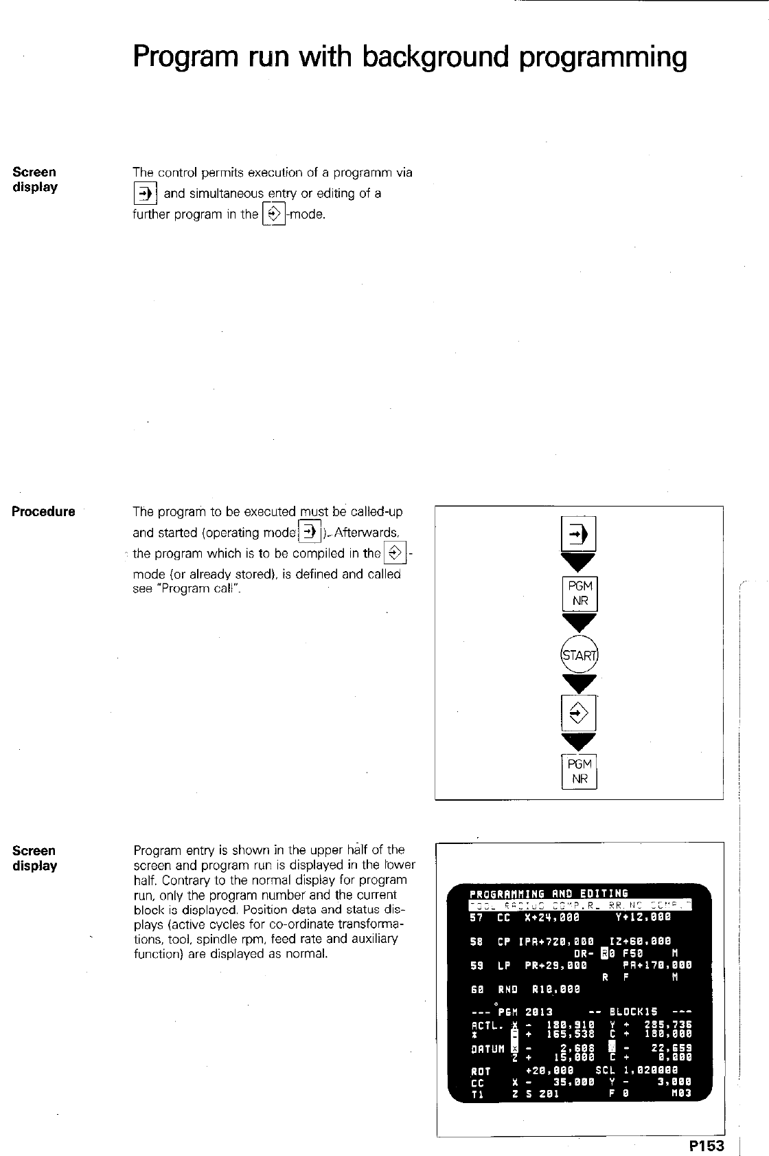
Program run with background programming
SCWX?ll
display
The control permits execution of a programm via
E!
> and simultaneous entry or editing of a
further program in the k&ode.
The program to be executed must be called-up
and started (operating modes 1 ).-Afterwards.
c q
: the program which is to be compiled in the 9
mode (or already stored), is defined and called
see “Program call”.
SCPSll
display
Program entry is shown in the upper half of the
screen and program run is displayed in the lower
half. Contrary to the normal display for program
run, only the program number and the current
block is displayed. Position data and status dis-
plays (active cycles for co-ordinate transforma-
tions, tool. spindle rpm, feed rate and auxiliary
function) are displayed as normal.
r
PI5
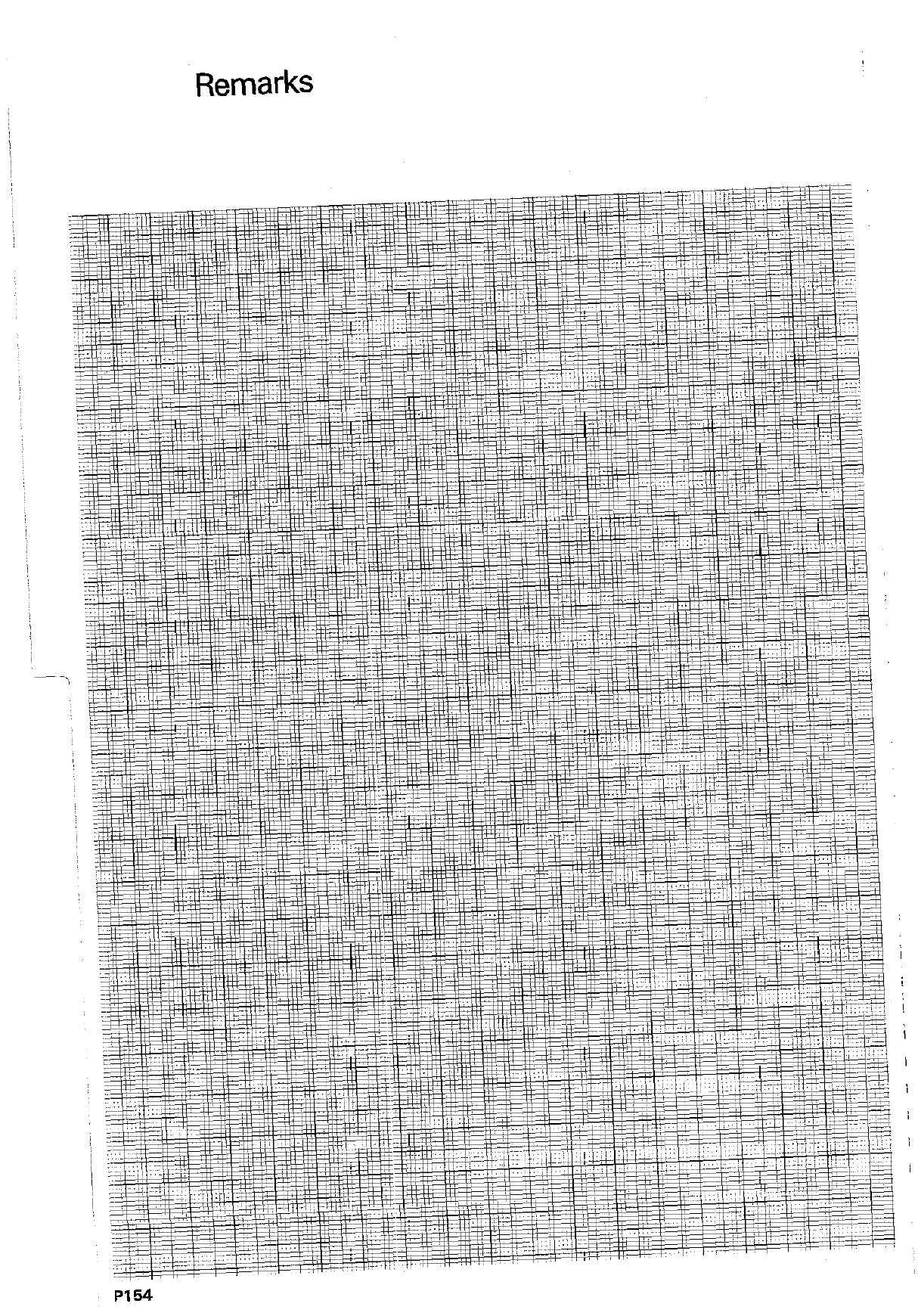
,_. -..
Single axis machining
Programming via axis address keys
Dialogue
initiation
Entry of single axis positioning blocks can be
simplified:
Entry dialogue is immediately initiated with the
axis address keys~](yl~~~l.
r
Nominal
position value
The co-ordinate of the appropriate axis is entered
as
the
nominal position.
The numerical value
can be specified either as an absolute value (i.e.
referenced to the workpiece datum) or an incre-
mental value (referenced to the last nominal
position).
In both cases. the tool moves from its momen-
tary actual position to the target position, in a
path which is parallel to ~the selected axis.
Tool radius
When programming, the tool radius compensa-
compensation
tion is to be understood as follows:
0 The traversing distance is
decreased
by the
tool radius, RI -key; display R-.
0
0 The traversing distance is
increased
by the
tool radius.
RT
-key; display R+.
u
l
The tool traversed to the programmed
nominal position: display RO.
If R+/R- is programmed for the position of the
tool axis, no compensation
is considered.
When using the
IV axis as rotary axis,
tool
radius compensation is also neglected.
PI 5!
5
PI 56
Single axis machining
Programming via axis ~address keys
I
16 L X+15,000 Y+ZO,OOO
RR F MO3
17 Y+40,000
R- FICOM
18 L X+50,000 Y+57,000
RR F M
Single axis positioning blocks, which have been
entered via axis keys, may be inserted between
positioning blocks with RO (no compensation)
which have been programmed via contouring
functions. ,
CORRECT
18 L X+15,000 Y+20,000
RO F M
19 L X+lO,OOO Y+10,000
ROF M
20 x+40,000
R+ F M
21 L x+50,000 Y+20,000
RO F M
Single axis machining
Programming via axis address keys
Entry of
single axis
movements
Operating mode
Dialogue initiation
POSITION VALUE?
El
EC or El or El or El
‘gl
Incremental-Absolute?
0 Key-in numerical value.
Enter into memory.
TOOL RADIUS COMP. R+/R-/NO COMP.? ) pi [%I
If reqd. key-in radius compensation.
g Enter into memory.
FEED RATE? F = m
If reqd., key-in feed rate.
g Enter into memory.
AUXILIARY FUNCTlON M?
‘Q
If reqd., key-in auxiliary function.
H Enter into memory.
Display example
In block No. 119 the tool is moved by + 46.0 mm
parallel to the X-axis plus the tool radius. The feed
rate is 60 mm/min. and the spindle rotates clock-
PI57 :
Single axis machining
Playback programming
If the tool has been positioned manually (hand-
wheel or via axis key). the actual position data
can be transferred into the program as a nominal
position. This type of programming is referred to
as playback.
Playback programming is only advisable with
single axis operation. This type of programming
should be avoided on complex contours.
The tool is positioned to the required position
either via the electronic handwheel or the axis
key. In the 3 -mode. the actual position value is
E!
transferred es a nominal position value by pres-
I’
POSITION VALUE?
I9 x+i?ooo
F M
‘Tool radius
compensation The actual position value already contains the
length and radius data for the tool which was
used. Therefore, the compensation values L = 0
and R = 0 must be entered in the too definition.
When programming positioning blocks with play-
back, the correct tool radius compensation Fif or
R- or RO is to be entered. In the event of a tool
break or tool change, the new tool data can be
considered.
I
TOOL DEF L=O
R=O
P158

Single axis machining
Playback programming
TOOI
The new compensation values are determined as
compensation
follows:
R=R NEW - ROLD
R Radius comoensation value for TOOL DEF
RNEW RNEW
RNEW Radius of nek tool
RoLo Radius of original tool
The new compensation values are entered into
the tool definition of the original tool
(R = 0. L = 0).
A compensation value can be
positive or nega-
tive,
depending on the radius of the new tool
being larger (+) or smaller (-).
Length
compensation
The compensation value for the new tool length
is determined as per TOOL DEF. In this case. the
“zero tool” is the original tool.
L
r
R=O R pas. R neg.
TOOL DEF TOOL DEF TOOL DEF
R=O R=+... R=-...
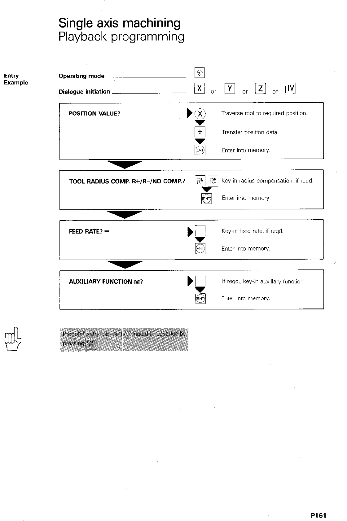
Single axis machining
Playback programming
Entry
Example Operating mode ~
Dialogue initiation
POSITION VALUE?
Traverse tool to required position.
E Transfer position data.
Enter into memory I
TOOL RADIUS COMP. W/R-/NO COMP.? p&?? KY_-
e in radius compensation. if reqd.
Enter into memory.
I
FEED RATE? =
‘f
Key-in feed rate. if reqd.
q
Enter into memory.
I I
AUXILIARY FUNCTION M? K
If reqd.. key-in auxiliary function.
Enter into memory.
PI61
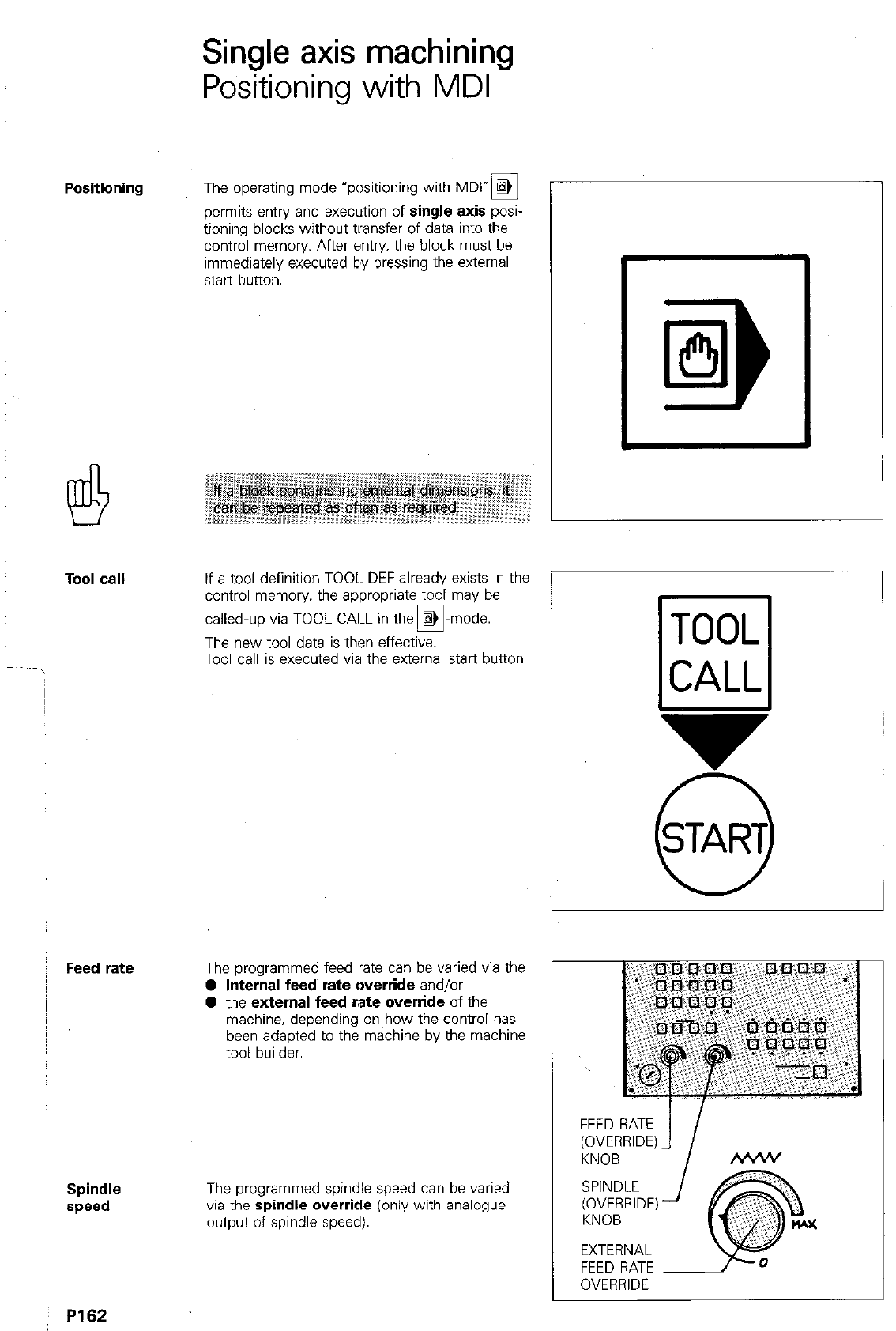
Positioning
Tool call
Feed rate
!
~ Spindle
speed
P162
Single axis machining
Positioning with MDI
The operating mode “positioning with MDl”a
permits entry and execution of single axis posi-
tioning blocks without transfer of data into the
control memory. After entry, the block must be
immediately executed by pressing the external
start button.
If a tool definition TOOL DEF already exists in the
control memory. the appropriate tool may be
called-up via TOOL CAI-L in the @
0 mode.
The new tool data is then effective.
Tool call is executed via the external start button.
The programmed feed rate can be varied via the
l
internal feed rate override and/or
l
the external feed rate override of the
machine, depending on how the control has
been adapted to the machine by the machine
tool builder.
The programmed spindle speed can be varied
via the spindle override (only with analogue
output of spindle speed).
v
0
START
FEED RATE
(OVERRIDE)
KNOB
SPINDLE
(OVERRIDE)
KNOB
EXTERNAL
FEED RATE
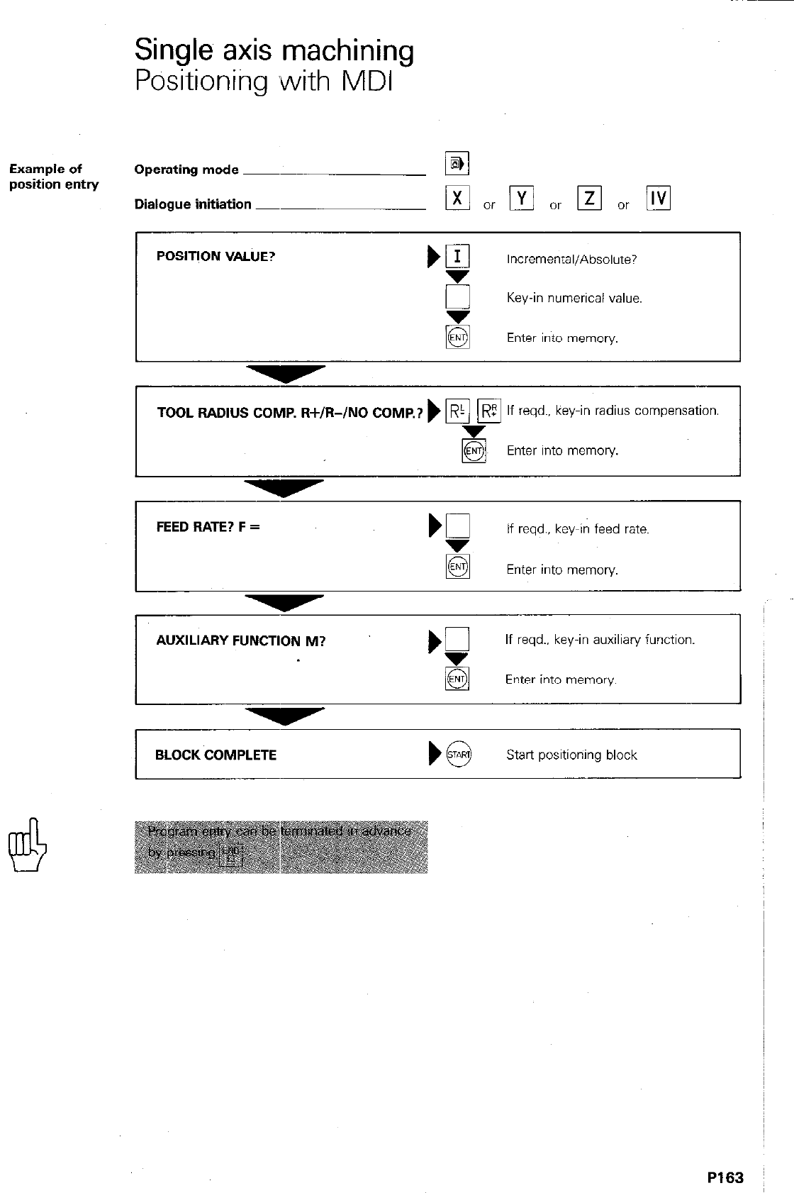
Single axis machining
Positioning ,with MDI
Example of
position entrY Operating mode ~
Dialogue initiation _
POSlTlON VALUE?
Incremental/Absolute?
sr Key-in numerical value.
Enter into memory.
TOOL RADIUS COMP. R+/R-/NO COMP.? ) F/ Fi
R If reqd.. key-in radius compensation.
Enter into memory.
FEED BATE? F =
‘5
If reqd.. key-in feed rate.
El Enter into memory.
AUXILIARY FUNCTION M?
If reqd.. key-in auxiliary function.
q
Enter into memory
BLOCK COMPLETE
Start positioning block
P163
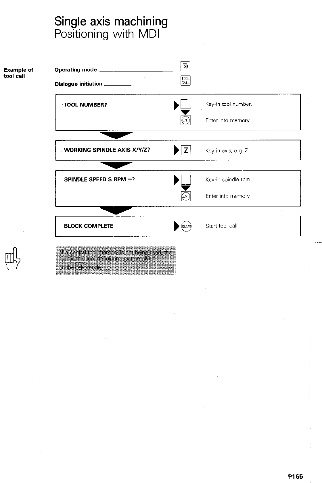
Single axis machining
Positioning with MDI
Example of
tool call Operating mode ~
Dialogue initiation
,TOOL NUMBER?
Key-in tool number.
q
Enter into memory
WORKING SPINDLE AXIS WY/Z?
SPINDLE SPEED S RPM =?
Key-in axis, e.g. Z 1
b0
Key-in spindle rpm
Enter into memory
BLOCK COMPLETE
)@ start tooi call
P165
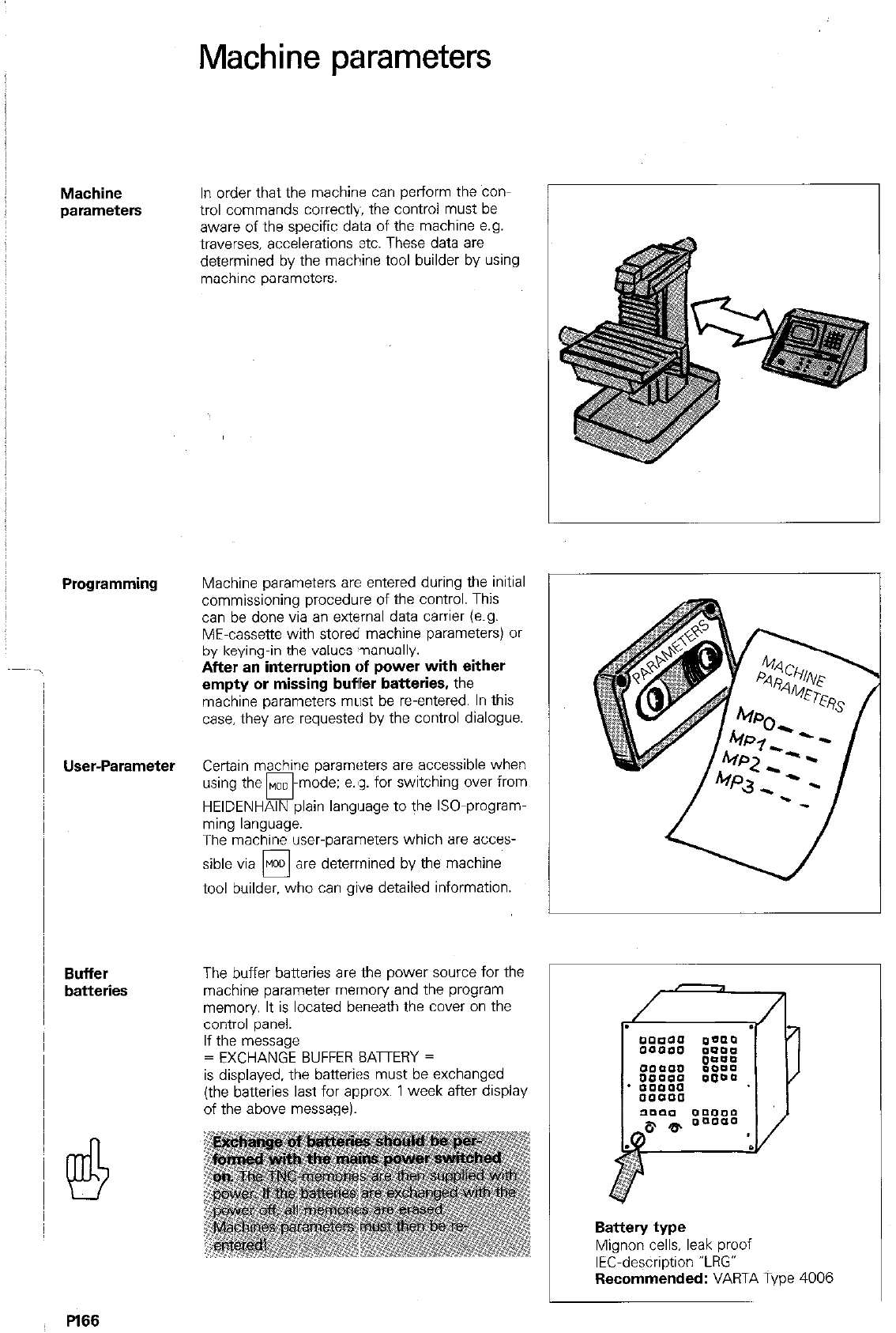
Machine parameters
Machine
parameters
Programming
User-Parameter
Buffer
batteries
In order that the machine can perform the con-
trol commands correctly, the control must be
aware of the specific data of the machine e.g.
traverses. accelerations ztc. These data are
determined by the machine tool builder by using
machine parameters.
Machine parameters are entered during the initial
commissioning procedure of the control. This
can be done via an external data carrier (e.g.
ME-cassette with stored machine parameters) or
by keying-in the values ~nanually.
After an interruption of power with either
empty or missing buffer batteries, the
machine parameters must be reentered. In this
case. they are requested by the control dialogue.
Certain machine parameters are accessible when
using the MOD
cl -mode; e.8~. for switching over from
HEIDENHAIN plain langllage to the ISO-program-
ming language.
The machine user-parameters which are acces-
sible via MOD are determined by the machine
0
tool builder. who can gPve detailed information.
The buffer batteries are the power source for the
machine parameter memory and the program
memory It is located beneath the cover on the
control panel.
If the message
= EXCHANGE BUFFER EATERY =
is displayed. the batteries must be exchanged
(the batteries last for approx. 1 week after display
of the above message).
Battery type
Mignon cells, leak proof
IEC-description “LRG”
Recommended: VARTA Type 4006
.
/
Pl66
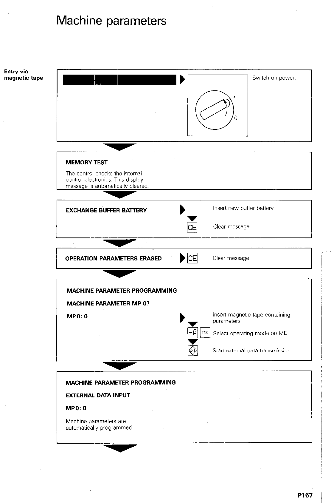
Machine parameters
Entry
via
magnetic tape
I
Switch on power.
MEMORY TEST
The control checks the internal
control electronics. This display
message is automatically cleared.
EXCHANGE BUFFER BATTERY b
Insert new buffer battery
Clear message
OPEiATlON PARAMETERS ERASED El
Clear message
MACHINE PARAMETER PROGRAMMING
MACHINE PARAMETER MP O?
MPO: 0
insert magnetic tape containing
parameters
Em UK Select operating mode on ME
Start external data transmission
MACHINE PARAMETER PROGRAMMING
EXTERNAL DATA INPUT
MPO: 0
Machine parameters are
automatically programmed.
PI 67
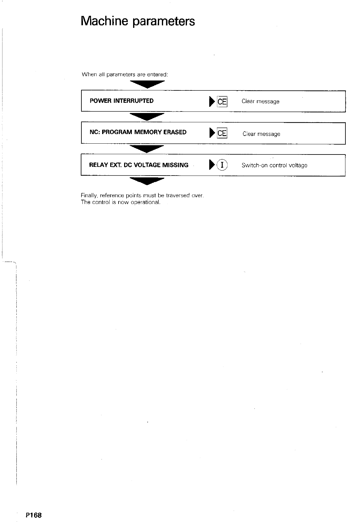
Machine parameters
When all parameters are entered:
POWER INTERRUPTED
1
NC: PROGRAM MEMORY ERASED Clear message
RELAY EXT. DC VOLTAGE MISSING
Finally, reference points must be traversed over.
The control is now ooerational.
P168
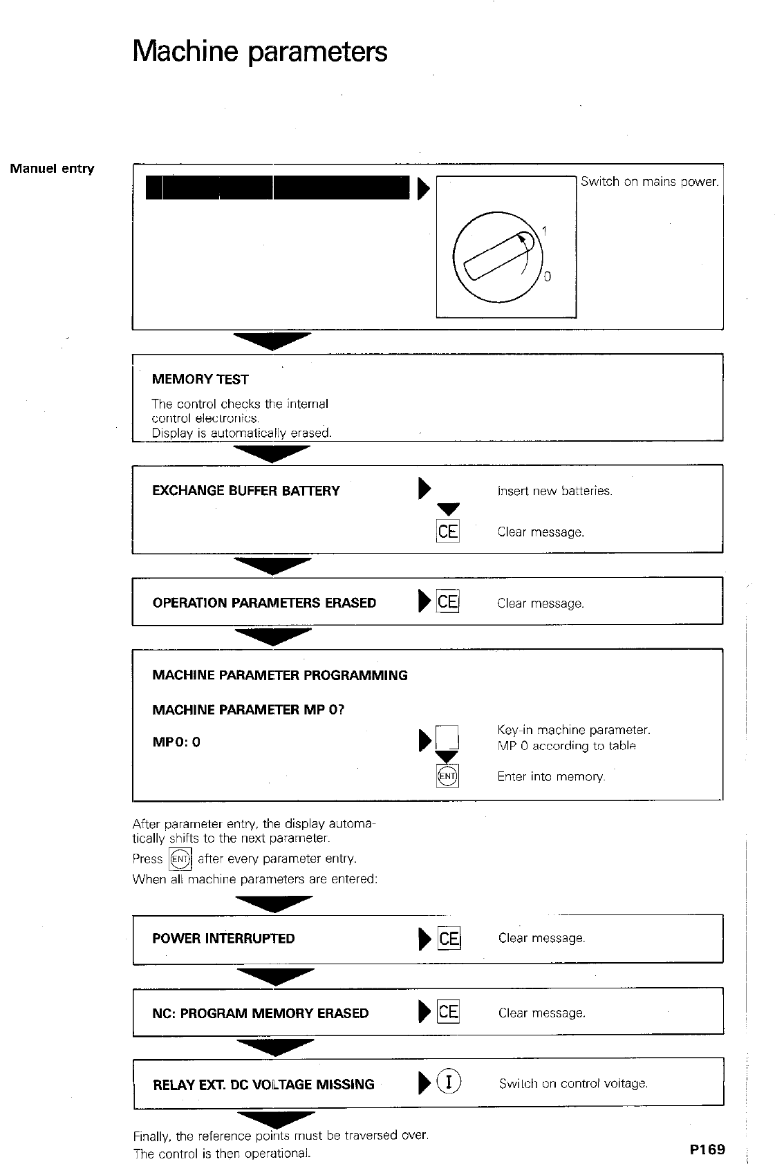
Machine parameters
Manuel entry
L
Switch on mains power
I
MEMORY TEST
The control checks the internal
control electronics.
Display is automatically erased.
EXCHANGE BUFFER BAlTERY b
Insert new batteries.
Clear message.
1 OPERATION PARAMETERS ERASED ) m
Clear message
MACHINE PARAMETER PROGRAMMING
MACHINE PARAMETER MP O?
MPO: 0 ‘F
Key-in machine parameter.
MP 0 according to table.
q
Enter into memory.
After parameter entry. the display automa-
tically shifts to the next parameter.
Press @ after every parameter entry
q
When all machine parameters are entered:
POWER INTERRUPTED
NC: PROGRAM MEMORY ERASED
Clear message.
RELAY EXT. DC VOLTAGE MISSING
Switch on control voltage
I
Fin& the reference points must be traversed over.
The control is then operational.
P169
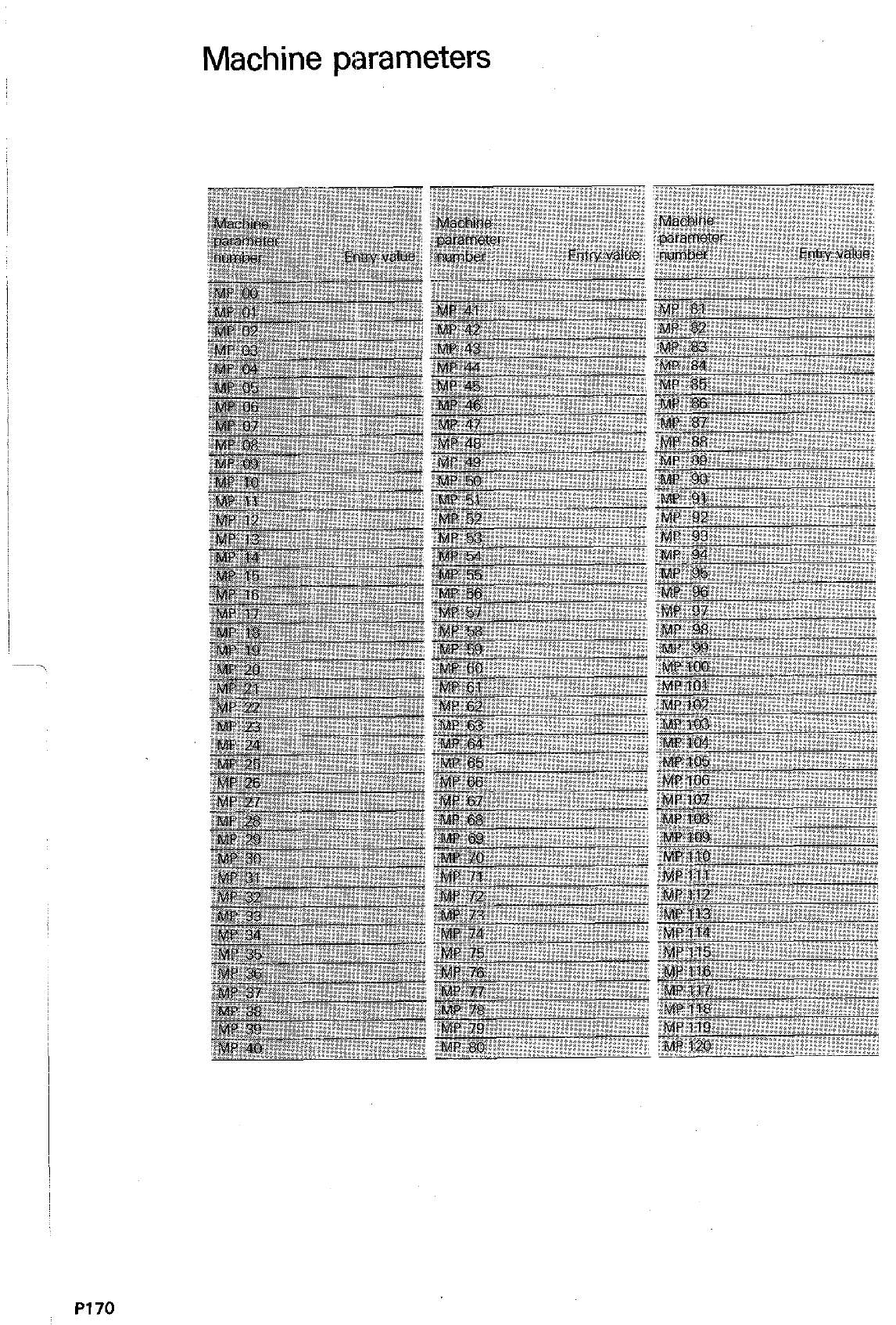
Machine parameters
PI70
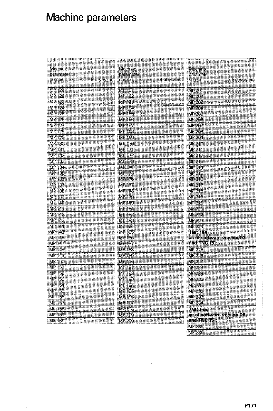
Machine parameters
P171
Snap-on
keyboard
Program entry in GO-format
lntroducti6n
The TNC 151/TNC 155 permits program entry in
either the HEIDENHAIN-conception with operator
prompting via plain language dialogue or to
standard format as per IS0 6983. Programming
in ISO-format is advantageous when program-
ming from an external computer.
An overlay keyboard with standard key-designa-
tions is provided for ISO-programming. The key-
board is simply placed over the existing key-
board. It is secured via small magnets.
The snap-on keyboard is immediately effective
after
switchover
from HEIDENHAIN plain lan-
guage dialogue to standard format.
Block
structure,
Positioning
blocks
Block structure
Canned cycles
Error messages
Program entry in ISO-format is partially dialogue
guided. Entry sequence for single block word
information is optional. The control automatically
arranges these commands into the correct order
at the end of each block entry.
Errors in program entry and program execution
are displayed in plain language.
Positioning blocks
may contain:
0 8 G-functions
of different groups (see G-
functions) and an additional G90 or G91
before each co-ordinate;
0 3 co-ordinates
(X, Y. Z. IV) and an additional
Circle Centre/Pole-co-ordinates (I, J, K):
0 1
Feed rate
(max. 5 digits):
0
1
auxiliary function
M
0
1
spindle rpm S
(max. 4 digits);
0
1
tool number
(max. 3 digits).
Block with canned cycles
may contain
0 all
individual data
for the cycle
(cycle parameter P);
0
1
auxiliary function
M:
0
1
spindle rpm S:
l
1
tool number
(see G-functions) (tool
l 1 positioning block:
0
1
feed rate
F:
0
1
cycle call;
call);
Errors within block structure are indicated durina
block entry. e.g.:
= G-CODE GROUP ALREADY ASSIGNED =
or. after end of block entry, e.g.
= BLOCK FORMAT INCORRECT =
Program entry in GO-format
Control switchover
Switchover from Switchover from HEIDENHAIN-programming lan-
HEIDENHAIN- guage to ISO-format is performed via machine
programming to parameters. These machine parameters can be
IS0 altered via the MOD-function “user parameters”.
“User parameters” are defined by the machine
tool builder who can give you detailed informa-
tion.
j D2
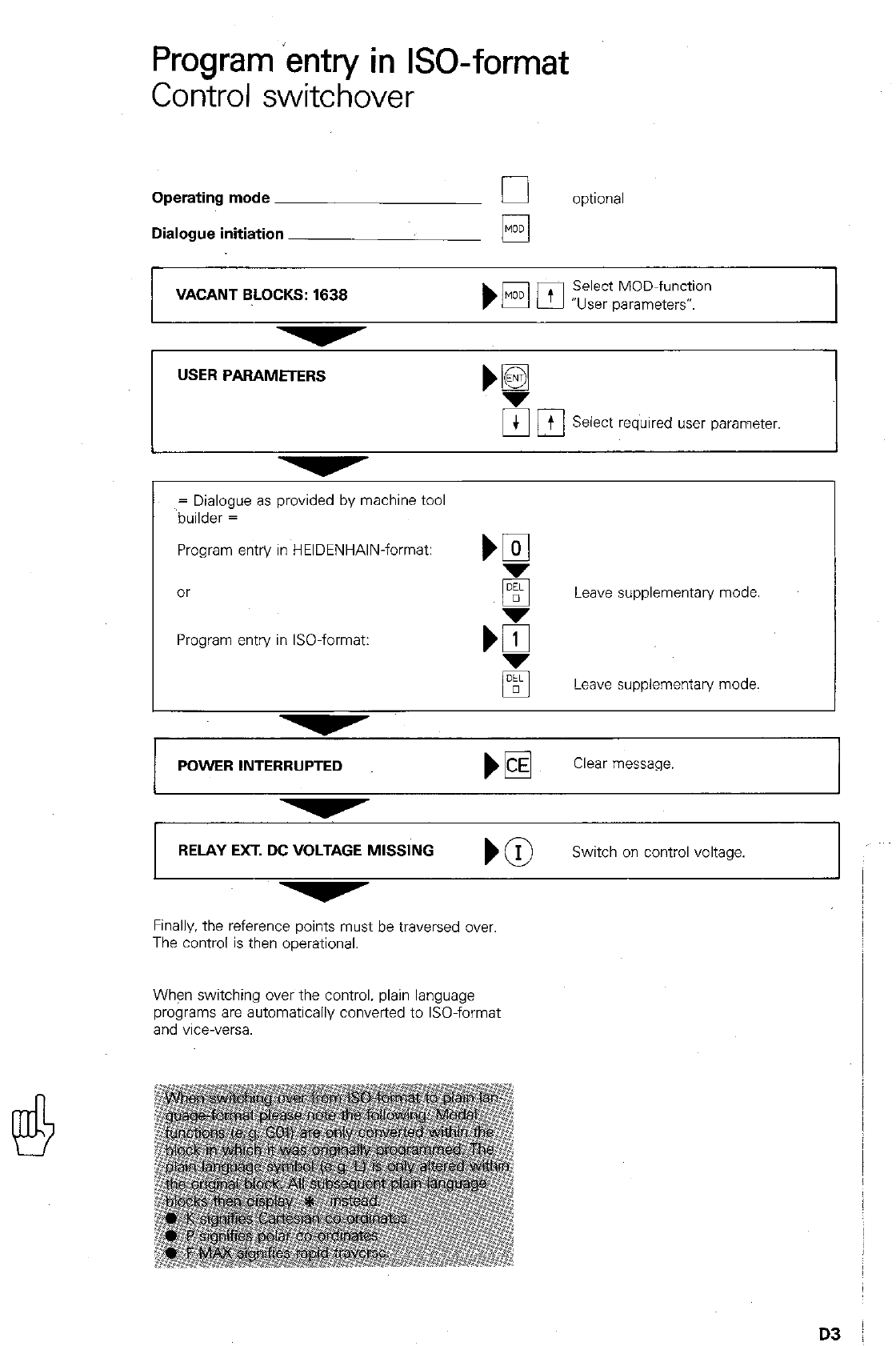
Program ‘entry in ISO-format
Control switchover
Operating mode 0 optional
Dialogue initiation /y
/
VACANT BLOCKS: 1638 Select MOD-function
“User parameters”.
USER PARAMETERS
UC
t t Select required user parameter.
= Dialogue as provided by machine tool
builder =
Program entry in HEIDENHAIN-format: m
or Leave supplementary mode
Program entry in ISO-format:
Leave supplementary mode.
I
POWER INTERRUPTED WE Clear message. I
I I
RELAY EXT. D~MISS,., ) @ Switch on control voltage.
Finally, the reference points must be traversed over
The control is then operational.
When switching over the control. plain language
programs are automatically converted to ISO-format
and vice-versa.
D3
Program entry in GO-format
Operating the control
Entry of Single commands consist of an address and
single commands supplementary data.
A single command is entered by first pressing
the address letter and the supplementary data
via the decimal keyboard.
Single command entry is automatically finalised
with the address letter of the following com-
mand.
If block entry can be curtailed, simply press 0
PI
Editing Program editing can be performed immediately
after a block entry or entry of the complete pro-
used for editing (see “Program editing”).
As opposed to HEIDENHAIN plain language for-
mat. the cursor can be set in ISO-format by
--
pressing M or l_lrl
If the cuwx is located at a single command
within a block, themm-keys may be used
for the search routine. Editing is ended by shift-
key out of the display towards block
towards block end or
Supplementary data which has been inadver-
tently entered can be cleared with the
SINGLE COMMAND
GO1
T
L SUPPLEMENTARY DATA
(code number)
L ADDRESS
x
-10
ll_ SUPPLEMENTARY DATA
(dimension)
ADDRESS
‘N20 GO2 .X*68 Y+$Q Ill
,
El
Erroneously entered address letters or com-
plete commands are deleted with
q ,
DELETE SINGLE
COMMAND
d”FI
DELETE BLOCK
D4
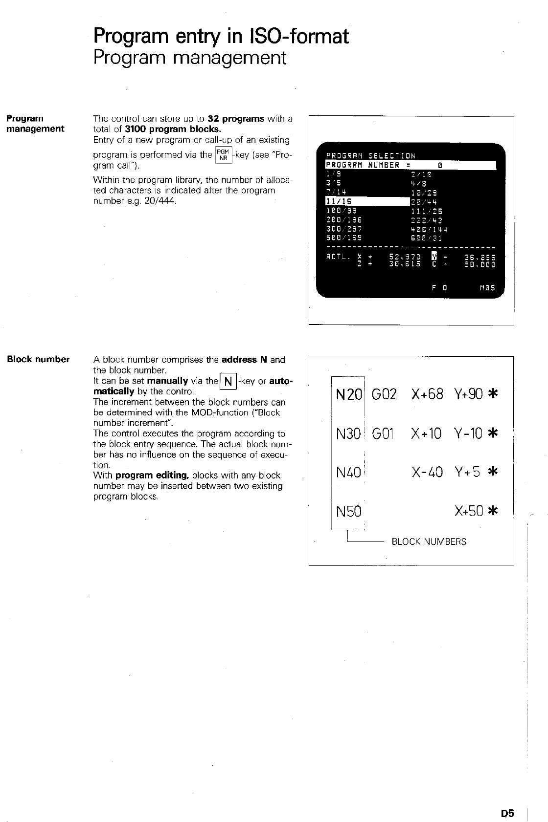
Program
Program entry in ISO-format
Program management
The control can store up to 32 programs with a
total of
3100 program blocks.
Entry of a new program or call-up of an existing
program is performed via the m-key (see “Pro-
gram call”).
Within the program library, the number of alloca
ted characters is indicated after the program
number e.g. 201444.
Block number
A block number comprises the
address N
and
the block number.
It can be set
manually
via the N -key or
auto-
matically
by the control. Cl
The increment between the block numbers can
be determined with the MOD-function (“Block
number increment”.
The control executes the program according to
the block entry sequence. The actual block num-
ber has no influence on the sequence of execu-
tion.
With program
editing,
blocks with any block
number may be inserted between two existing
program blocks.
7
N20 GO2 X+68 Y+90 *
N30; GO1 X+10 Y-IO *
N40/ x-40 Y+5 *
N50 x+50*
!
BLOCK NUMBERS
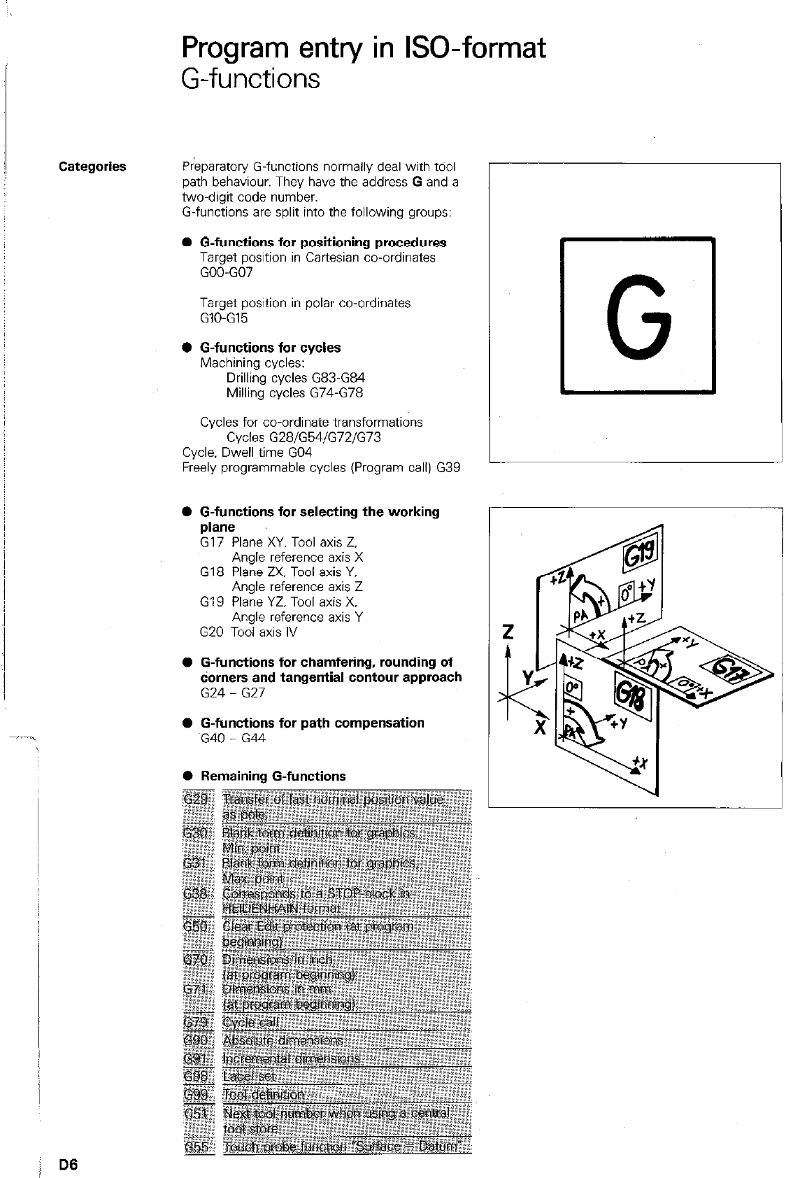
Program entry in GO-format
G-functions
Categories
Preparatory G-functions normally deal with tdol
path behaviour. They have the address G and a
two-digit code number.
G-functions are split into the following groups:
l G-functions for positioning procedures
Target position in Cartesian co-ordinates
GOO-GO7
Target position in polar co-ordinates
GIO-GE
0 G-functions for cycles
Machining cycles:
Drilling cycles G83-G84
Milling cycles G74-G78
Cycles for co-ordinate transformations
Cycles G28/G54/G72/G73
Cycle, Dwell time GO4
Freely programmable cycles (Program call) G39
l G-functions for selecting the working
plane
G17 Plane XY. Tool axis Z.
Angle reference axis X
G18 Plane ZX, Tool axis Y,
Angle reference axis Z
G19 Plane YZ, Tool axis X.
Angle reference axis Y
G20 Tool axis IV
l G-functions for chamfering, rounding of
darners and tangential contour approach
G24 - G27
l G-functions for path compensation
G40 - G44
L
r
l Remaining G-functions
0 G
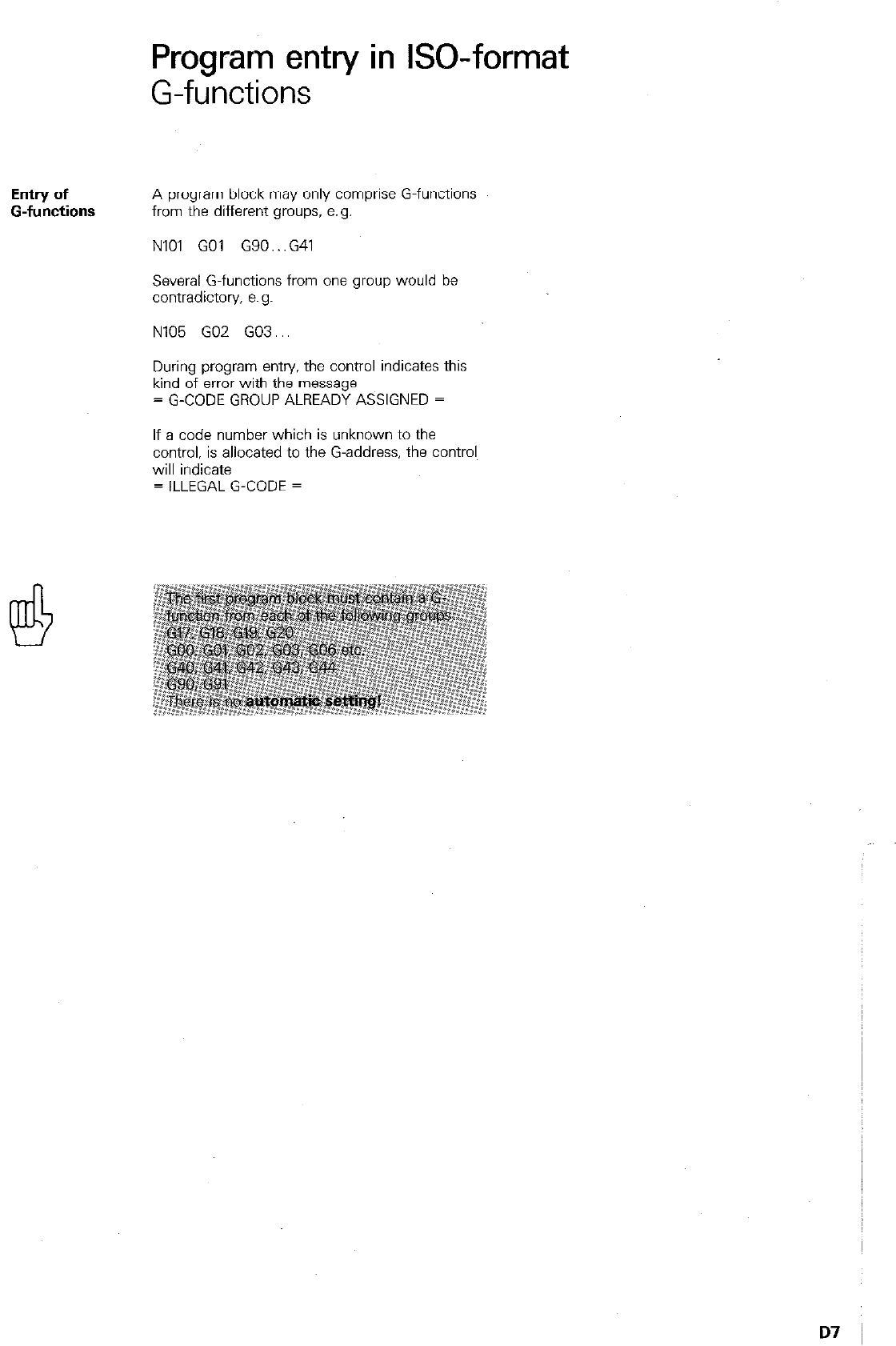
Program entry in ISO-format
G-functions
Entry of
G-functions
A program block may only comprise G-functions
from the different groups, e.g.
NlOl GO1 G90...G41
Several G-functions from one group would be
contradictory, e.g.
N105 GO2 G03...
During program entry. the control indicates this
kind of error with the message
= G-CODE GROUP ALREADY ASSIGNED =
If a code number which is unknown to the
control, is allocated to the G-address, the control
will indicate
= ILLEGAL G-CODE =
Program entry in ISO-format
Dimensions in inch/mm
Erase/Edit protection
Dimensions
in inch/mm 670 Dimensions in inch (dialogue-guided) /
671 Dimensions in mm (dialogue-guided)
After dialogue initiation with the NR -key and
•I
response to the dialogue question:
PROGRAM NUMBER
the following dialogue question is displayed:
MM = G71 / INCH = G70
Respond to dialogue question by entering G71 or
G70.
Block structure (example)
% 2 671
% Program beginning
2 Program number
G71 Dimensions in mm
Erase/Edit
protection 650 Erase/Edit protection (dialogue guided)
If the dialogue question PGM PROTECTION? is
selected via the E y- keys with the first
block (e.g. % 2 G71) of a completely entered pro-
gram. protection against erasing and editing can
be provided by entering G50
Block structure (example)
% 2 671650
%
Program beginning
2 Program number
G71 Dimensions in mm
G50 Edit/Erase protection
Edit/Erase protection is cancelled by entering the
code number 86357.
Explanation, see -Erase/Edit protection.-
D8
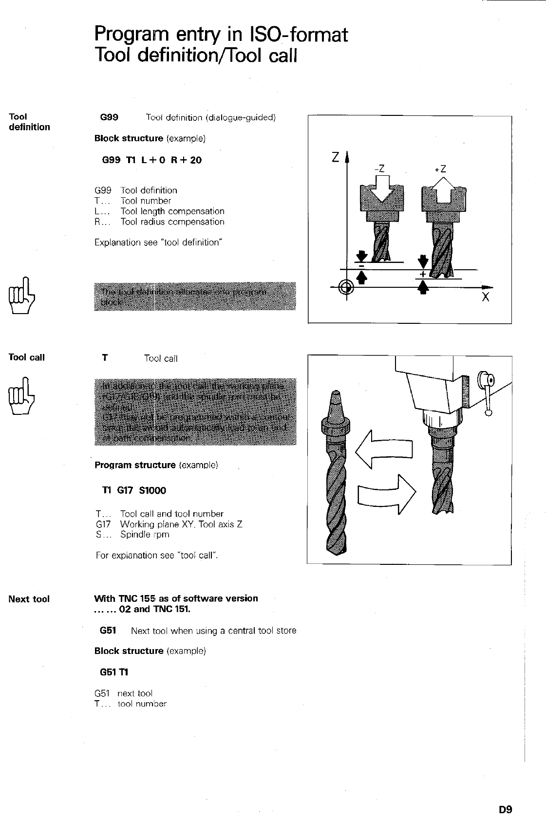
TOOI
definition
Tool call T
Tool call
Program entry in ISO-format
Tool definition/Tool call
G99
Tool definition (dialogue-guided)
Block structure
(example)
G99 Tl L+O R+ZO
G99 Tool definition
T.. Tool number
L.. Tool length compensation
R.. Tool radius compensation
Explanation see “tool definition”
Program structure
(example)
Tl 617
SlOOO
T.. Tool call and tool number
G17 Working plane XY. Tool axis Z
S Spindle rpm
For explanation see “tool call”.
Next tool With TNC 155 as of software version
.
02
and TNC 151.
G51
Next tool when using a central tool store
Block structure
(example)
651 Tl
G51 next tool
T.. tool numlxx
D9
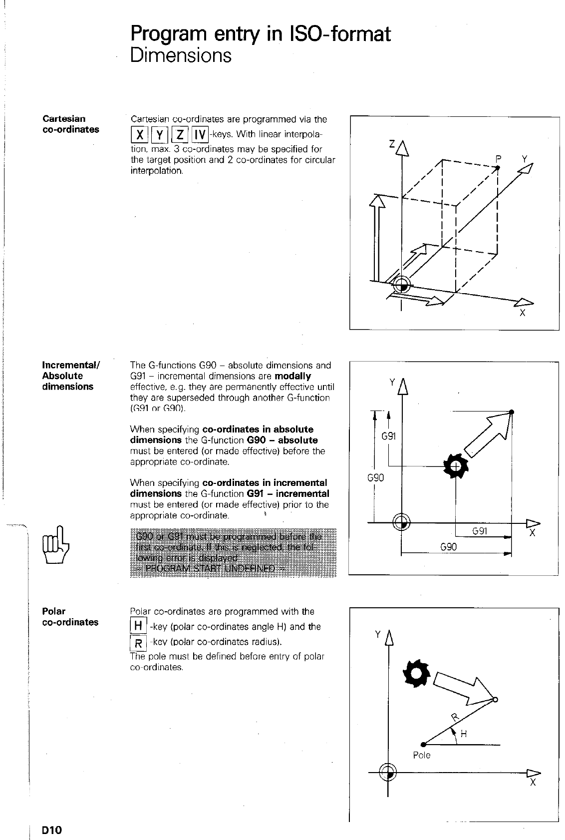
Program entry in ISO-format
Dimensions -
Cartesian
co-ordinates
Incremental/
Absolute
dimensions
Polar
co-ordinates
Cartesian co-ordinates are programmed via the
tion. max. 3 co-ordinates may be specified for
the target position and 2 co-ordinaies for circular
interpolation.
The G-functions G90 - absolute dimensions and
G91 - incremental dimensions are modally
effective. e.g. they are permanently effective until
they are superseded through another G-function
(G91 or G90).
When specifying co-ordinates in absolute
dimensions the G-function G90 - absolute
must be entered (or made effective) before the
appropriate co-ordinate.
When specifying co-ordinates in incremental
dimensions the G-function G91 - incremental
must be entered (or made effective) prior to the
appropriate co-ordinate. 1
Polar co-ordinates are programmed with the
q -
H
key (polar co-ordinates angle H) and the
o-
R key (polar co-ordinates radius).
The pole must be defined before entry of polar
co-ordinates.
L
Y
_ G91
D
X
G90
t
Y
0
2
+
H
Pole
D
X
L
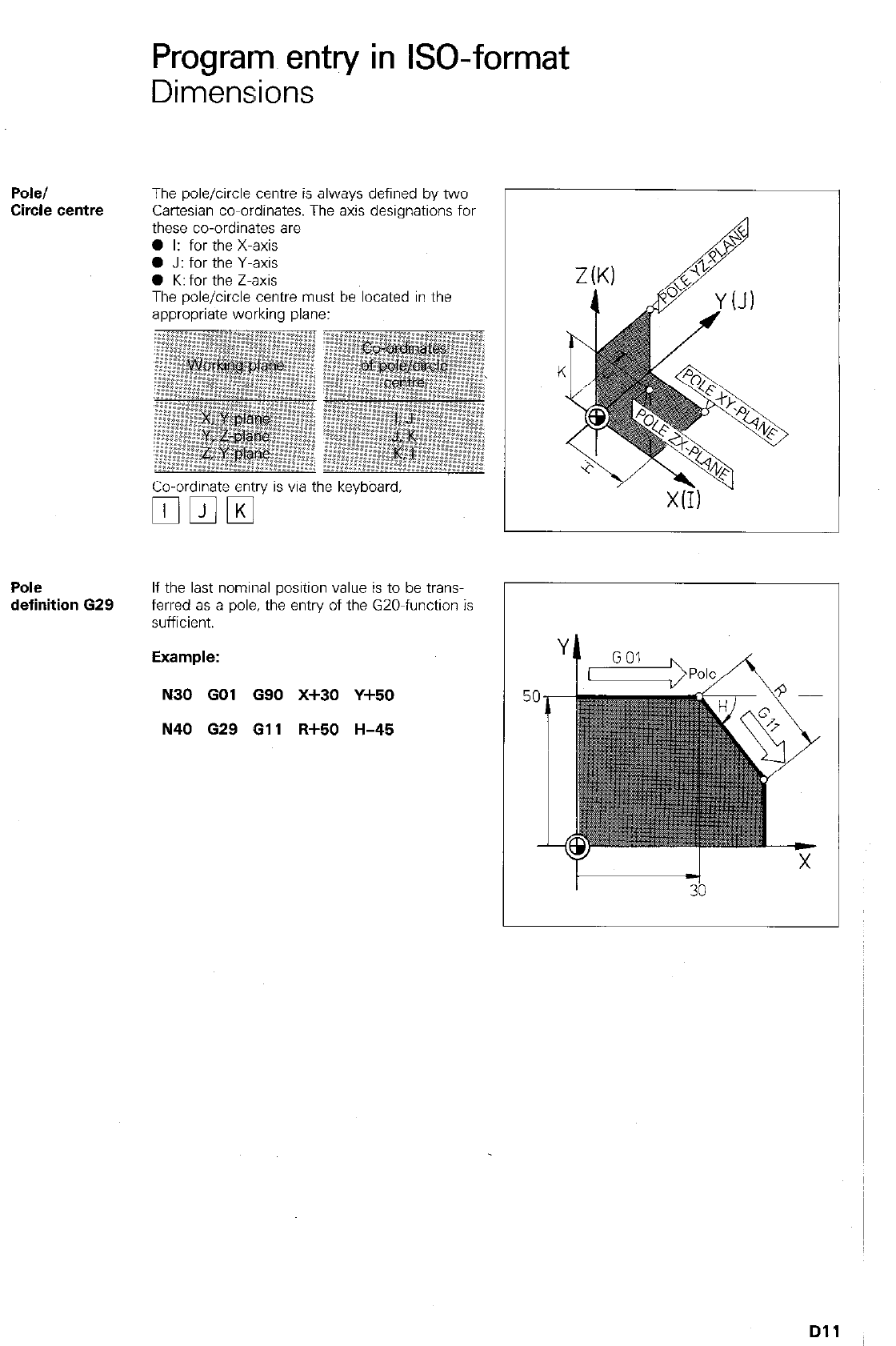
Programs entry in GO-format
Dimensions
Pole/
Circle centre
The pole/circle centre is always defined by two
Cartesian co-ordinates. The axis designations for
these co-ordinates are
0 I: for the X-axis
0 J: for the Y-axis
0 K: for the Z-axis
The pole/circle centre must be located in the
appropriate working plane:
Co-ordinate ent:ry is via the keyboard,
q mm
Pole
definition 629
If the last nominal position value is to be trans-
ferred as a pole, the entry of the GZO-function is
sufficient.
N30 GO1 G90 X+30 Y+50
N40 629 611 R+50 H-45
I t -1
33
Dll
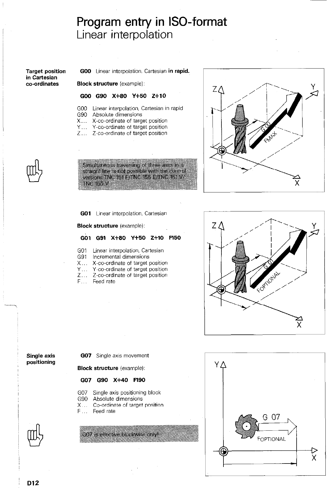
Target position
in Cartesian
co-ordinates
Single axis
positioning
Program entry in ISO-format
Linear interpolation
GO0 Linear interpolation. Cartesian in rapid.
Block structure (example):
GO0 G90 X+80 Y+50 Z+lO
GO0 Linear interpolation, Cartesian in rapid
G90 Absolute dimensions
X.. X-co-ordinate of target position
Y.. Y-co-ordinate of target position
Z Z-co-ordinate of target position
I
GO1 Linear interpolation. Cartesian
Block structure (example):
Gbl 091 X+80 Y-l-50 2+10 Fl50
GO1 Linear interpolation. Cartesian
G91 Incremental dimensions
X.. X-co-ordinate of target position
Y.. Y-co-ordinate of target position
Z.. Z-co-ordinate of target position
F.. Feed rate
GO7 Single axis movement
Block structure (example):
GO7 090 X-MO Fl90
GO7 Single axis positioning block
G90 Absolute dimensions
X.. Co-ordinate of target position
F Feed rate
Y
i
1
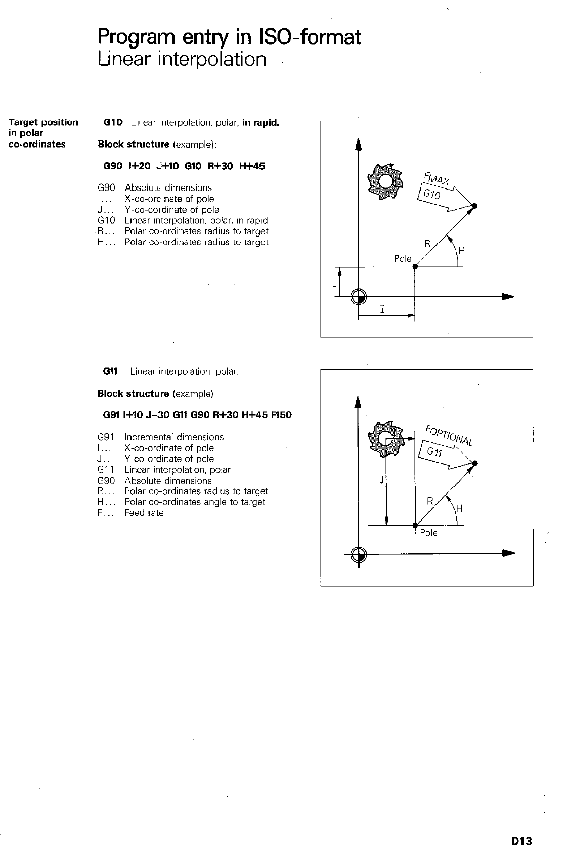
Program entry in ISO-format
Linear interpolation
Target position GlO
Linear interpolation, polar.
in rapid.
in polar
co-ordinates Block structure
(example):
G90 I+20 J+lO GlO R+30 H+45
G90 Absolute dimensions
I.. X-co-ordinate of pole
J Y-co-cordinate of pole
GIO Linear interpolation, polar. in rapid
OR.. Polar co-ordinates radius to target
H Polar co-ordinates radius to target
Gll
Linear interpolation, polar.
Block structure
(example):
G91 I+10 J-30 Gll G90 R+30 H+45 !=l50
G91 Incremental dimensions
I.. X-co-ordinate of pole
J.. Y-co-ordinate of pole
Gl 1 Linear interpolation, polar
G90 Absolute dimensions
Fl.. Polar co-ordinates radius to target
H.. Polar co-ordinates angle to target
F. Feed rate
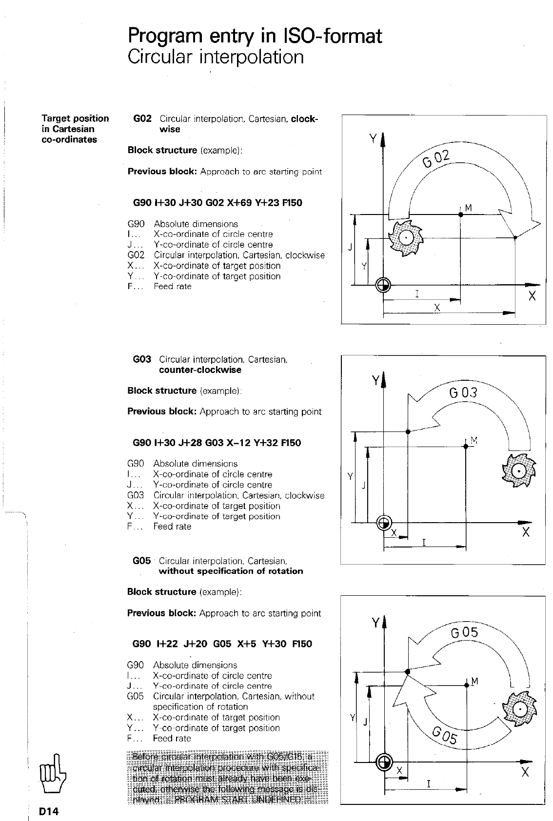
Program entry in GO-format
Circular interpolation
Target position
in Cartesian
co-ordinates
GO2 Circular interpolation, Cartesian, clock-
wise
Block structure (example):
Previous block: Approach to arc starting point
G90
I+30 Jf30 GO2
X-f-69
Y+23 !=I50
G90 Absolute dimensions
I.. X-co-ordinate of circle centie
J Y-co-ordinate of circle centre
GO2 Circular interpolation. Cartesian. clockwise
X.. X-co-ordinate of target position
Y.. Y-co-ordinate of target position
F. Feed rate
GO3 Circular interpolation, Cartesian,
counter-clockwise
Block structure (example):
Previous block: Approach to arc starting point
G90
I+30 J+28 GO3 X-l 2 Y+32 Fl50
GSO Absolute dimensions
I.. X-co-ordinate of circle centre
J Y-co-ordinate of circle centre
GO3 Circular interpolation, Cartesian, clockwise
X.. X-co-ordinate of target position
Y.. Y-co-ordinate of target position
F.. Feed rate
GO5 Circular interpolation, Cartesian.
without specification of rotation
Block structure (example):
Previous block: Approach to arc starting point
G90
I+22 J+20 GO6 X+5 Y+30 !=l50
G90 Absolute dimensions
I X-co-ordinate of circle centre
J.. Y-co-ordinate of circle centre
GO5 Circular interpolation, Cartesian. without
specification of rotation
X.. X-co-ordinate of target position
Y.. Y-co-ordinate of target position
F.. Feed rate
Y
6
Y
J
CD X
I I -i
D14
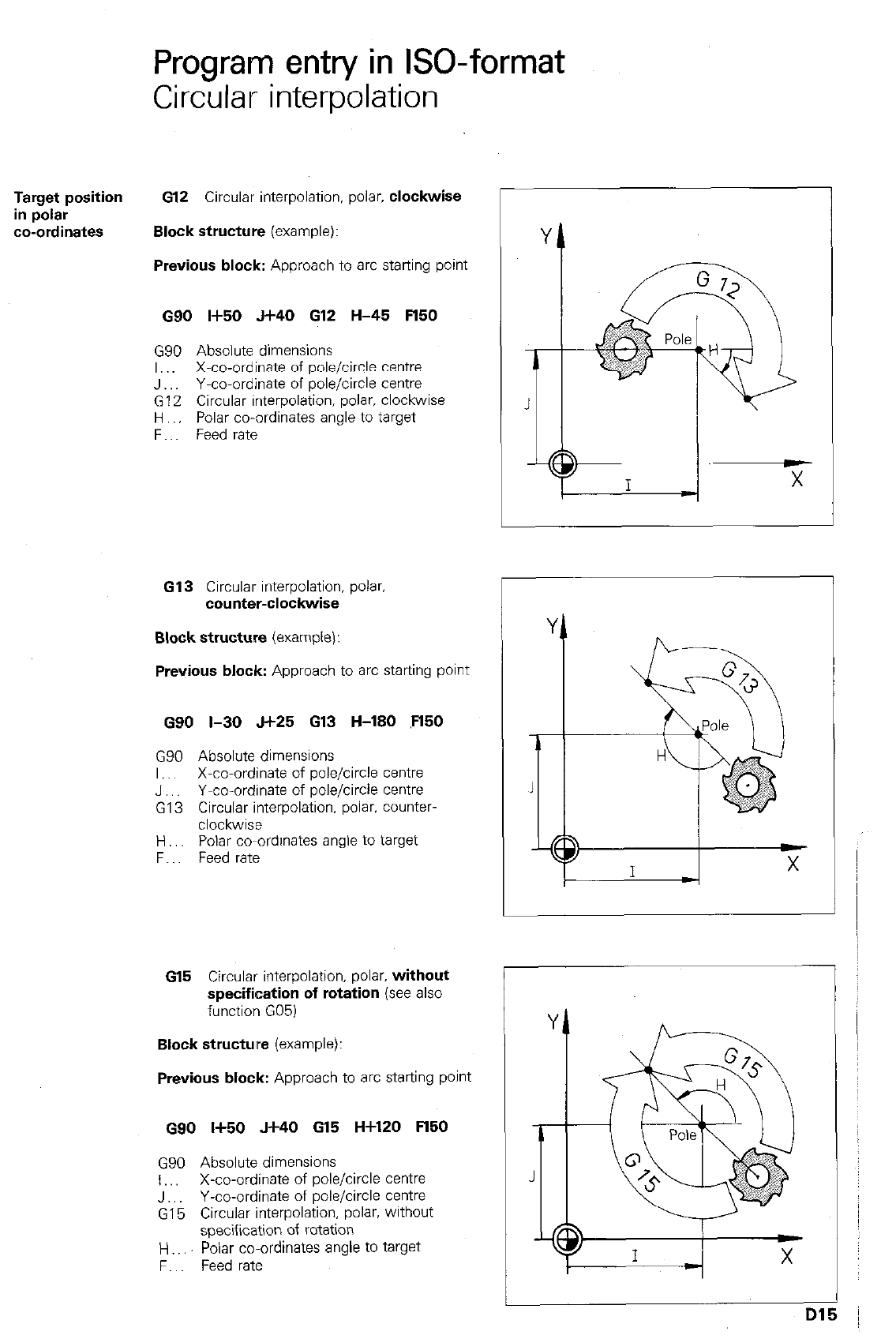
Program entry in ISO-format
Circular interpolation
Target position 612 Circular interpolation. polar. clockwise
in polar
co-ordinates Block structure (example):
Previous block: Approach to arc starting point
G90 I+50 J+40 612 H-45 Fl50
G90 Absolute dimensions
I,. X-co-ordinate of pole/circle centre
J Y-co-ordinate of pole/circle centre
G12 Circular interpolation. polar, clockwise
H Polar co-ordinates angle to target
F.. Feed rate
G13 Circular interpolation, polar
counter-clockwise
Block structure (example):
Previous block: Approach to arc startrng point
G90 I-30 J+25 G13 H-180 ,Fl50
G90 Absolute dimensions
I.. X-co-ordinate of pole/circle centre
J,, Y-co-ordinate of pole/circle Centre
G13 Circular interpolation, polar. counter-
clockwise
H., Polar co-ordinates angle to target
F.. Feed rate
615 Circular interpolation. polar. without
specification of rotation (see also
function G05)
Block structure (example):
Previous block: Approach to arc starting point
G90 Ii50 J+40 615 H+120 Fl50
GSO Absolute dimensions
I,, X-co-ordinate of pole/circle centre
J.. Y-co-ordinate of pole/circle centre
G15 Circular interpolation, polar, without
specification of rotation
H Polar co-ordinates angle to target
F.. Feed rate
r
1
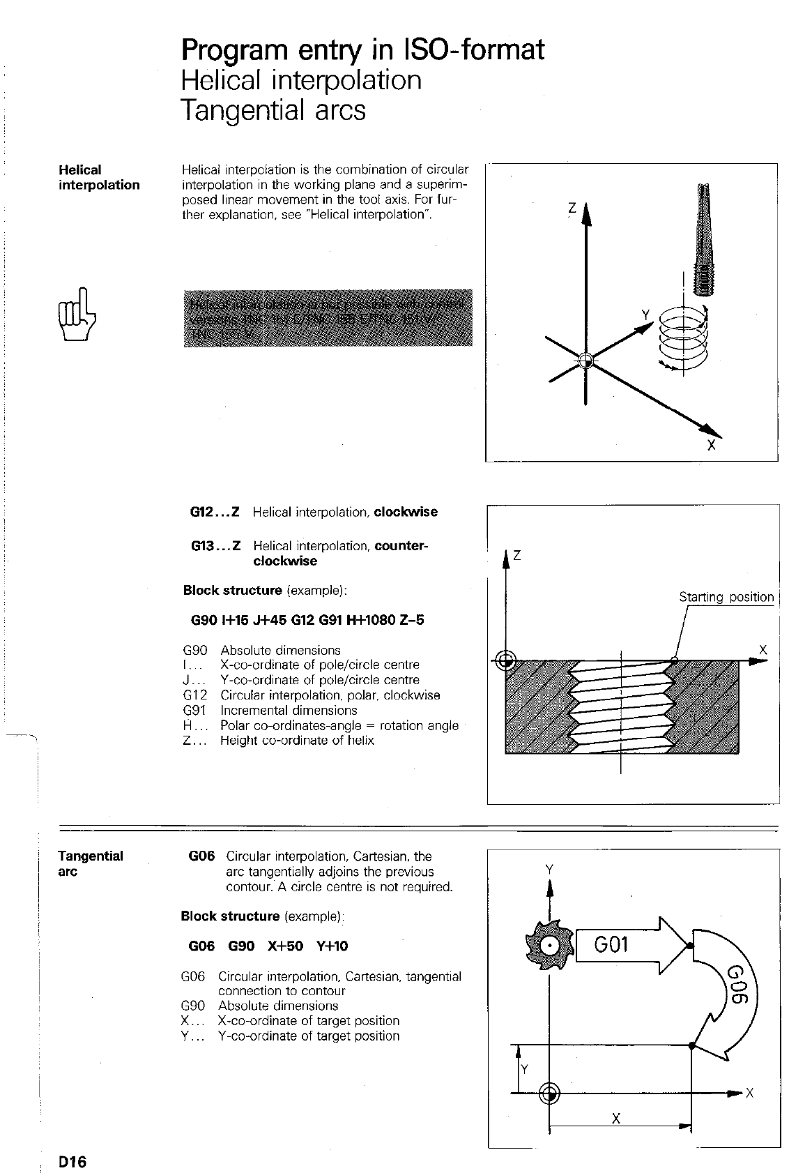
Program entry in ISO-format
Helical interpolation
Tangential arcs
Helical
interpolation
Helical interpolation is the combination of circular
interpolation in the working plane and a superim-
posed linear movement in the tool axis. For fur-
ther explanation, see “Helical interpolation”.
612.
..Z Helical interpolation.
clockwise
Gl3...2 Helical interpolation,
counter-
clockwise
Block structure
(example):
090 I+15 J+45 612 GQl H+lOSO 2-5
G90 Absolute dimensions
I,. X-co-ordinate of pole/circle centre
J Y-co-ordinate of pole/circle centre
G12 Circular interpolation. polar, clockwise
G91 Incremental dimensions
fl.. Polar co-ordinates-angle = rotation angle
Z.. Height co-ordinate of helix
I-
Tangential
arc
GO6 Circular interpolation, Cartesian, the
arc tangentially adjoins the previous
contour. A circle centre is not required.
Block structure
(example):
GO6 GQO X+60 Y+lO
GO6 Circular interpolation. Cartesian. tangential
connection to contour
G90 Absolute dimensions
X.. X-co-ordinate of target position
Y.. Y-co-ordinate of target position
I
D16
r
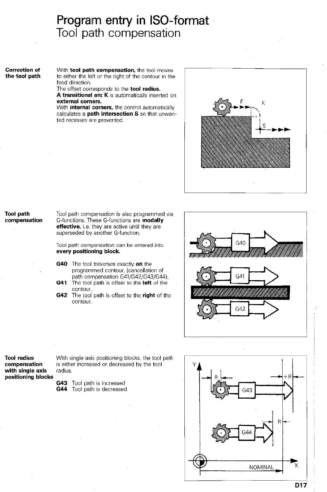
Prograim entry in GO-format
Tool path compensation
Correction of
the tool path With tool path compensation, the tool moves
to either the l&t or the right of the contour in the
feed direction.
The offset corresponds to the tool radius.
A transitional arc K is automatically inserted on
external comers.
With internal corners, the control automatically
calculates a path intersection S so that unwan-
ted recesses are prevented.
Tool path
compensation Tool path compensation is also programmed via
G-functions. These G-functions are modally
effective, i.e. they are active until they are
superseded by another G-function.
Tool path compensation can be entered into
every positioning block
640 The tool traverses exactly on the
programmed contour, (cancellation of
path compensation G41/G42/G43/G44).
641 The tool path is offset to the left of the
contour.
642 The tool path is offset to the right of the
contour.
Tool radius With single axis positioning blocks, the tool path
compensation is either increased or decreased by the tool
with single axis radius.
positioning blocks 643 Tool path is increased
644 Tool path is decreased
Dl: 7
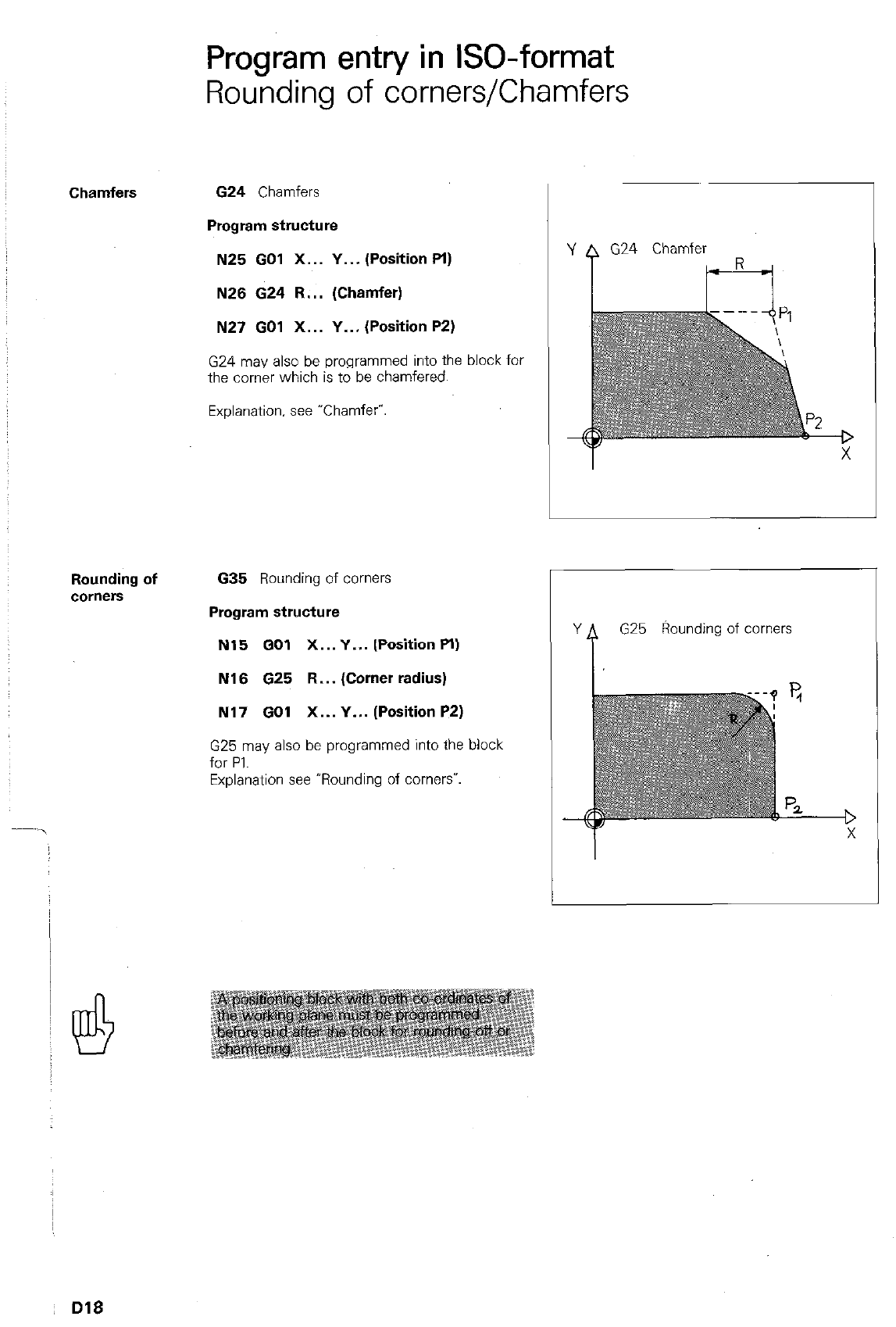
Program entry in ISO-format
Rounding of corners/Chamfers
Chamfers
624 Chamfers
Program structure
N25 GO1 X... Y... (Position Pl)
N26 624 R... (Chamfer)
N27 GO1 X... Y... (Position P2)
G24 may also be programmed into the block for
the comer which is to be chamfered.
Explanation. see “Chamfer”
Rounding of
COr”CXS
635
Rounding of corners
Program structure
N15 GO1 X...Y... (PositionPI)
N16 625 R... (Corner radius)
N17 GO1 X... Y... (Position P2)
G25 may also be programmed into the block
for PI.
Explanation see ‘Rounding of comersw.
G24
Chamfer
G25
Rounding of corners
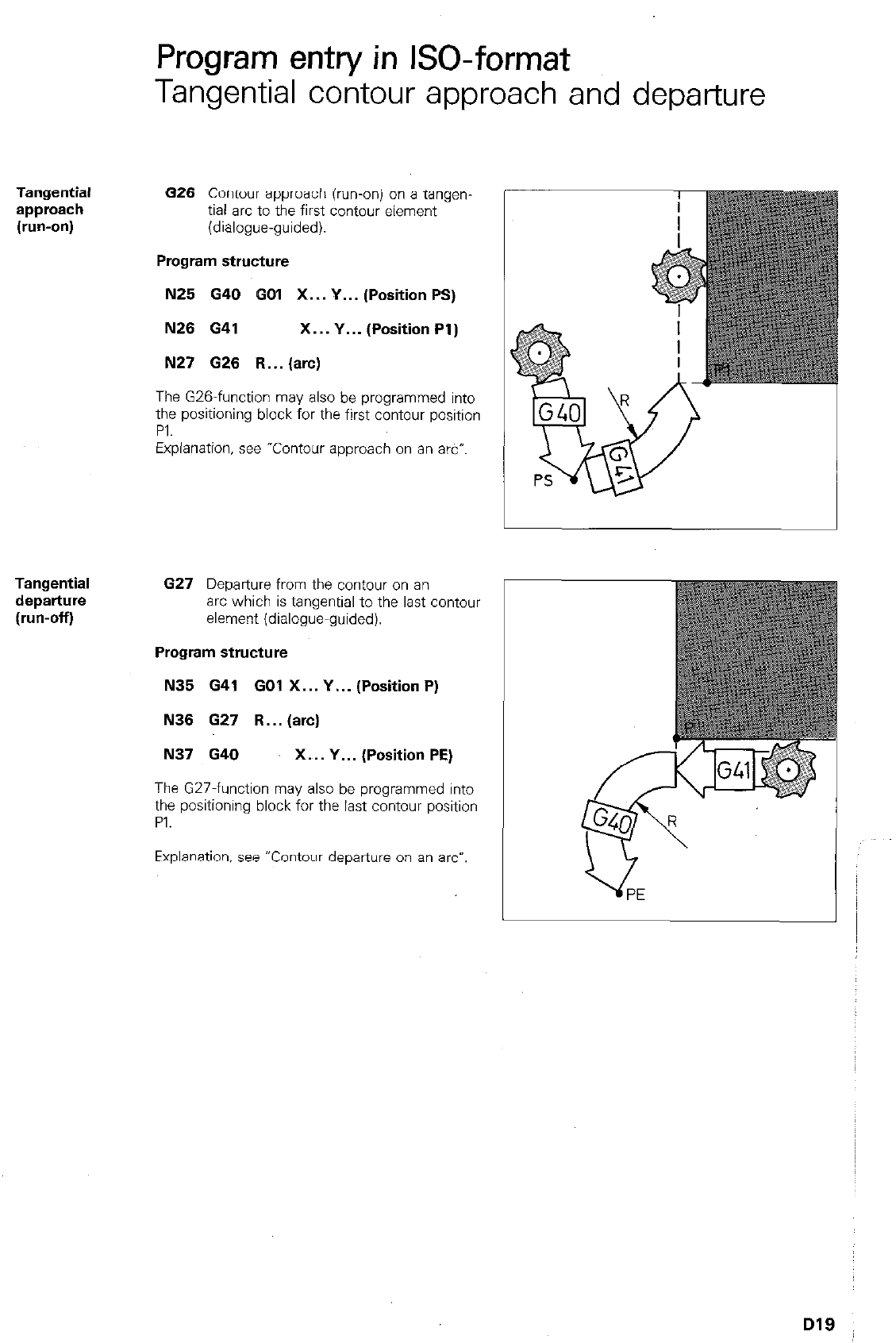
Program entry in ISO-format
Tangential contour approach and departure
Tangential
approach
(run-on)
626 Contour approach (run-onj on a tangen-
tiai arc to the first contour element
(dialogue-guided).
Program structure
N25 G40 GO1 X... Y... (Position PS)
N26 G41 X... Y... (Position Pl)
N27 626 R...(arc)
Tangential
departure
(run-off)
The G26-function may also be programmed into
the positioning block for the first contour position
PI.
Explanation, see “Contour approach on an arc-.
627
Departure from the contour on an
arc which is tangential to the last contour
element (dialogue-guided).
Program structure
N35 641 GO1 X... Y... (Position P)
N36 G27 R... (arc)
N37 G40 X... Y... (Position PE)
The G27-function may also be programmed into
the positioning block for the last contour position
PI.
Explanation, see “Contour departure on an arc-.
D19
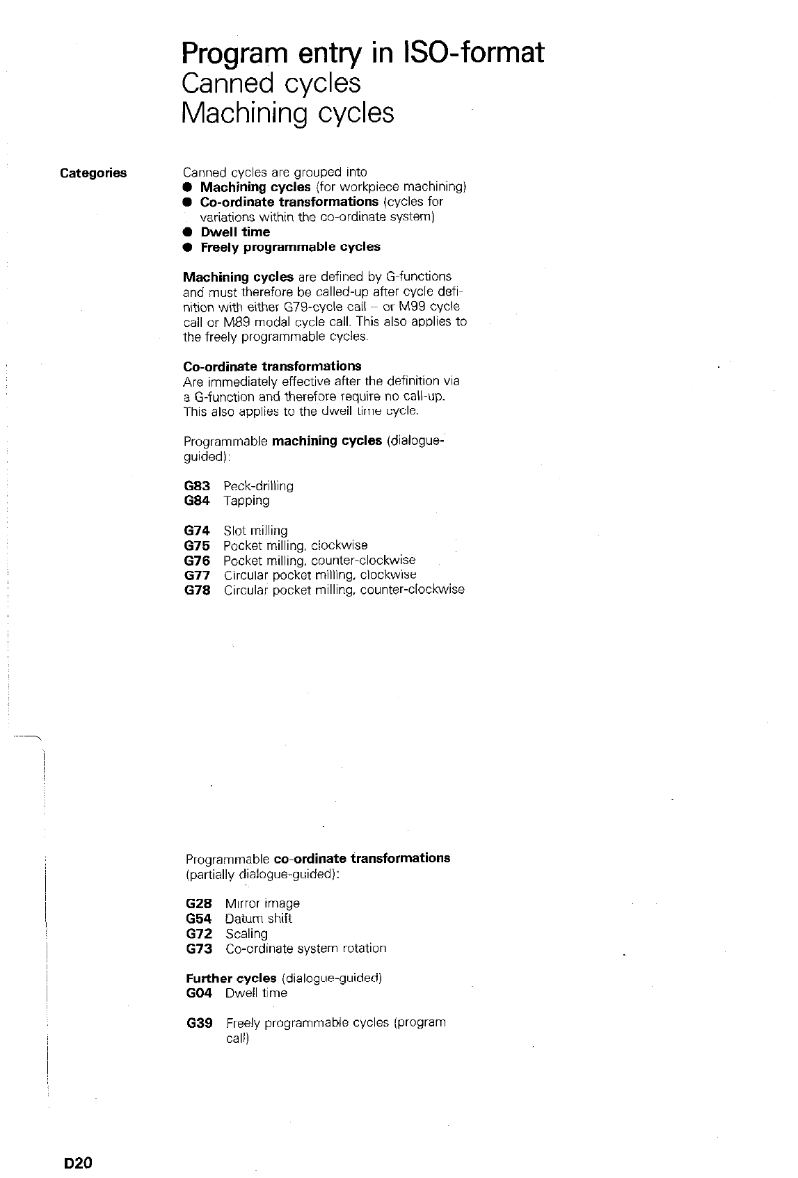
Program entry in ISO-format
Canned cycles
Machining cycles
Categories Canned cycles are grouped into
0 Machining cycles (for workpiece machining)
0 Co-ordinate transformations (cycles for
variations within the co-ordinate system/
0 Dwell time
0 Freely programmable cycles
Machining cycles are defined by G-functions
and must therefore be called-up after cycle defi-
nition with either G79-cycle call - or M99 cycle
call or M89 modal cycle call. This also applies to
the freely programmable cycles.
Co-ordinate transformations
Are immediately effective after the definition via
a G-function and therefore require no call-up.
This also applies to the dwell time cycle.
Programmable machining cycles (dialogue-
guided):
G83 Peck-drilling
G84 Tamw
674 Slot milling
675 Pocket milling, clockwise
676 Pocket milling, counter-clockwse
677 Circular pocket milling. clockwise
678 Circular pocket milling, counter-clockwise
Programmable co-ordinate transformations
(partially dialogue-guided):
G28 Mirror image
G54 Datum shift
G72 Scaling
G73 Co-ordinate system rotation
Further cycles (dialogue-guided)
GO4 Dwell time
G39 Freely programmable cycles (program
call)
D20
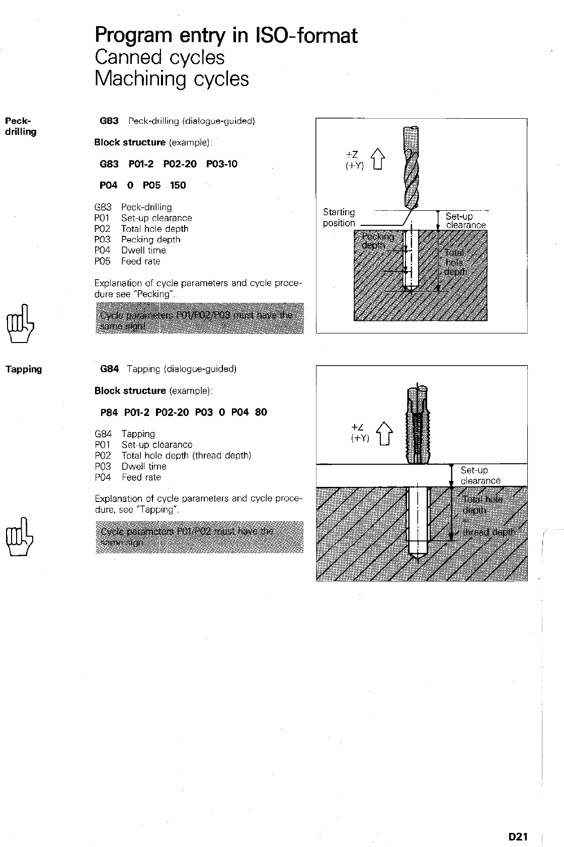
Program entry in GO-format
Canned cycles
Machining cycles
Peck-
drilling
683 Peck-drilling (dialogue-guided)
Block structure
(example):
G83 POl-2 PO2-20 PO3-10
PO4 0 PO5 150
G83 Peck-drilling
PO1 set-up clearance
PO2 Total hole depth
PO3 Pecking depth
PO4 Dwell time
PO5 Feed rate
Explanation of cycle parameters and cycle proce-
dure see “Pecking-‘.
Tapping
G84 Tapping (dialogue-guided)
Block structure
(example):
P84 POl-2 PO2-20 PO3 0 PO4 80
G84 Tapping
PO1 Set-up clearance
PO2 Total hole death ithread depth)
PO3 Dwell time
PO4 Feed rate
Explanation of cycle parameters and cycle proce-
dure, see ‘Tapping7
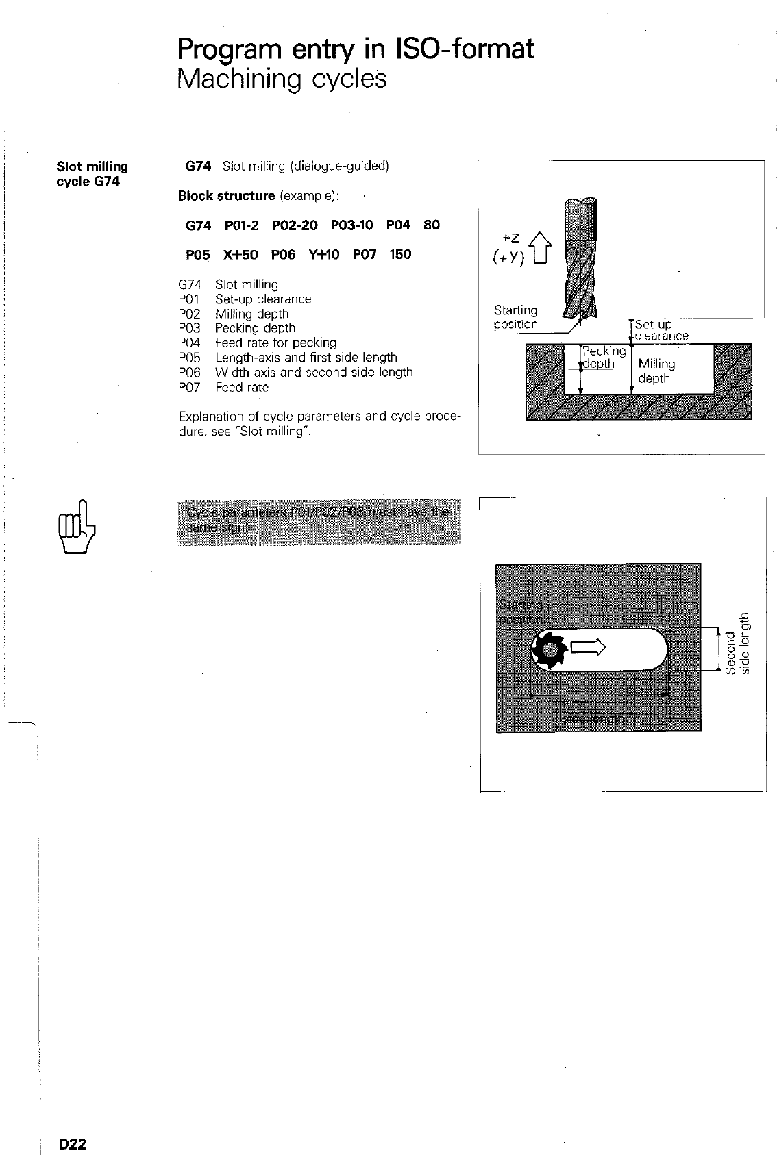
Program entry in ISO-format
Machining cycles
Slot milling
cycle 674
674 Slot milling (dialogue-guided)
Block structure
(example):
674 PO12 PO2-20 PO3-10 PO4 80
PO5 x+50 PO6 Y+lo PO7 150
G74 Slot milling
PO1 set-up clearance
PO2 Milling depth
PO3 Pecking depth
PO4 Feed rate for pecking
PO5 Length-axis and first side length
PO6 Width-axis and second side length
PO7 Feed rate
Explanation of cycle parameters and cycle prow
due. see “Slot milling”.
D22
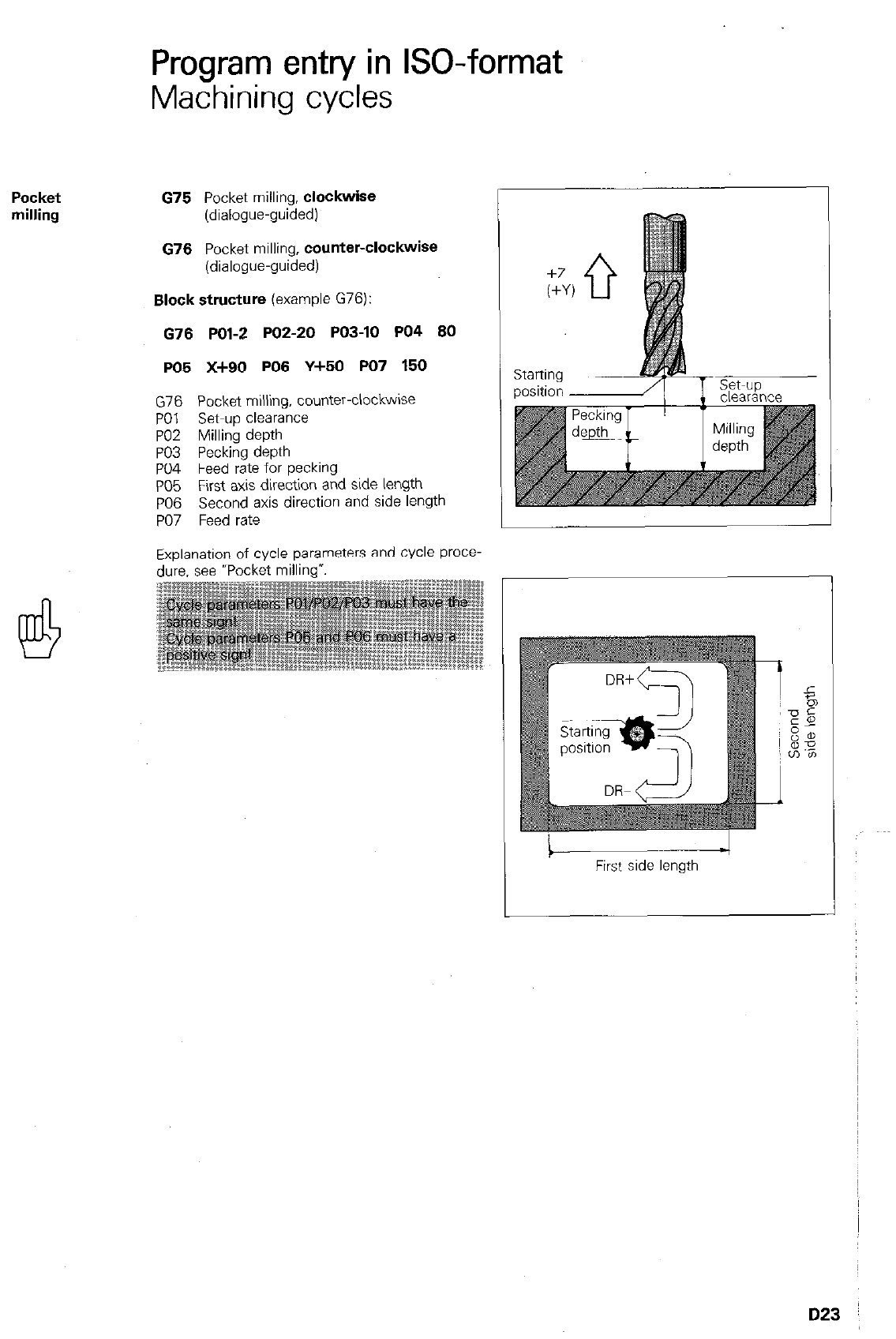
Pocket
milling
Program entry in GO-format
Machining cycles
675 Pocket milling, clockwise
(dialogue-guided)
676 Pocket milling, counter-ClockWiSe
(dialogue-guided)
Block structure (example G76):
676 POl-2 PO2-20 PO3-10 PO4 80
PO5 X+90 PO6 Y+50 PO7 160
G76 Pocket milling, counter-clockwise
PO1 Set-up clearance
PO2 Milling depth
PO3 Pecking depth
PO4 Feed rate for pecking
PO5 First axis direction and side length
PO6 Second axis direction and side length
PO7 Feed rate
Exulanation of Explanation of cycle parameters and cycle proce-
dure. see -Pocket milling*.
due. see -Pocket mllllng”.
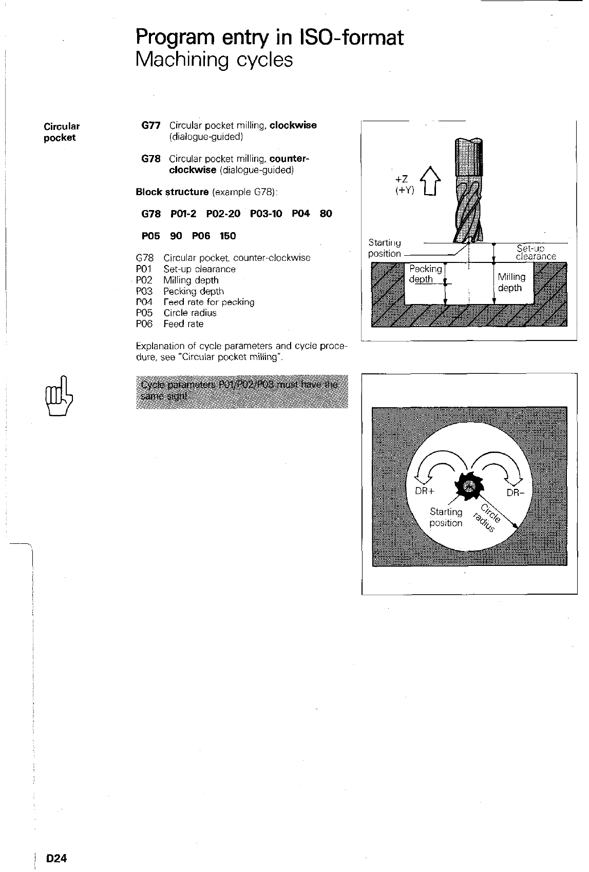
Program entry in ISO-format
Machining cycles
Circular
677 Circular pocket milling,
clockwise
pocket
(dialogue-guided)
678 Circular pocket milling,
counter-
clockwise
(dialogue-guided)
Block structure
(example G78):
678 POl-2 PO2-20 PO3-10 PO4 80
PO5 90 PO8 150
G78 Circular pocket, counter-clockwise
PO1 Set-up clearance
PO2 Milling depth
PO3 Pecking depth
PO4 Feed rate for pecking
PO5 Circle radius
PO6 Feed rate
Explanation of cycle parameters and cycle proce-
dure, see Tircular pocket millingv.
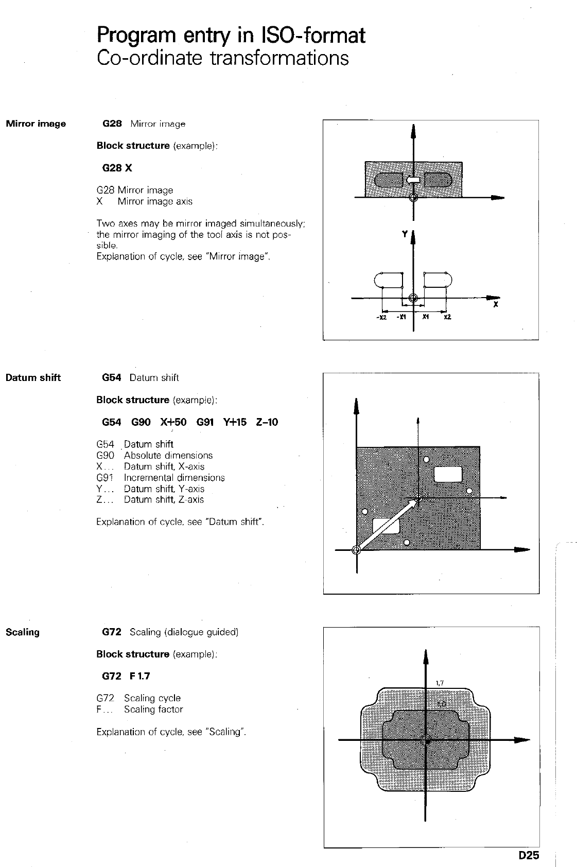
Program entry in ISO-format
Co-ordinate transformations
Mirror image 628 Mirror image
Block structure (example):
629 X
G28 Mirror image
X Mirror image axis
Two axes may be mirror imaged simultaneously:
the mirror imaging of the tool axis is not pos-
sible.
Explanation of cycle, see *Mirror image”.
Datum shift 654 Datum shift
Block structure (example):
654 G90 X+50 G91 Y+15 Z-10
G54 Datum shift
G90 Absolute dimensions
X.. Datum shift, X-axis
G91 Incremental dimensions
Y.. Datum shift, Y-axis
Z.. Datum shift, Z-axis
Explanation of cycle, see “Datum shift?
L
Scaling 672 Scaling (dialogue guided)
Block structure (example):
G72 F 1.7
G72 Scaling cycle
F.. Scaling factor
Explanation of cycle, see “Scaling-
D2!
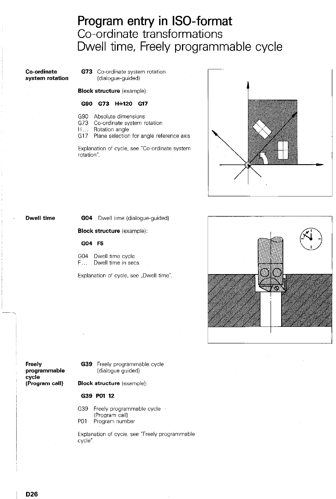
Co-ordinate
system rotation
Dwell time
Freely
programmable
cycle
(Program call)
Program entry in ISO-format
Co-ordinate transformations
Dwell time, Freely programmable cycle
673 Co-ordinate system rotation
(dialogue-guided)
Block structure (example):
G90 673 H+120 617
G90 Absolute dimensions
G73 Co-ordinate system rotation
H Rotation angle
G17 Plane selection for angle reference axis
Explanation of cycle. see “Co-ordinate system
rotatIm”.
GO4 Dwell time (dialogue-guided)
Block structure (example):
GO4 F5
GO4 Dwell time cycle
F.. Dwell time in sets.
Explanation of cycle, see ,,Dwell time”.
639 Freely programmable cycle
(dialogue guided)
Block structure (example):
639 PO1 12
G39 Freely programmable cycle
(Program call)
PO1 Program number
Explanation of cycle. see *Freely programmable
cycle”.
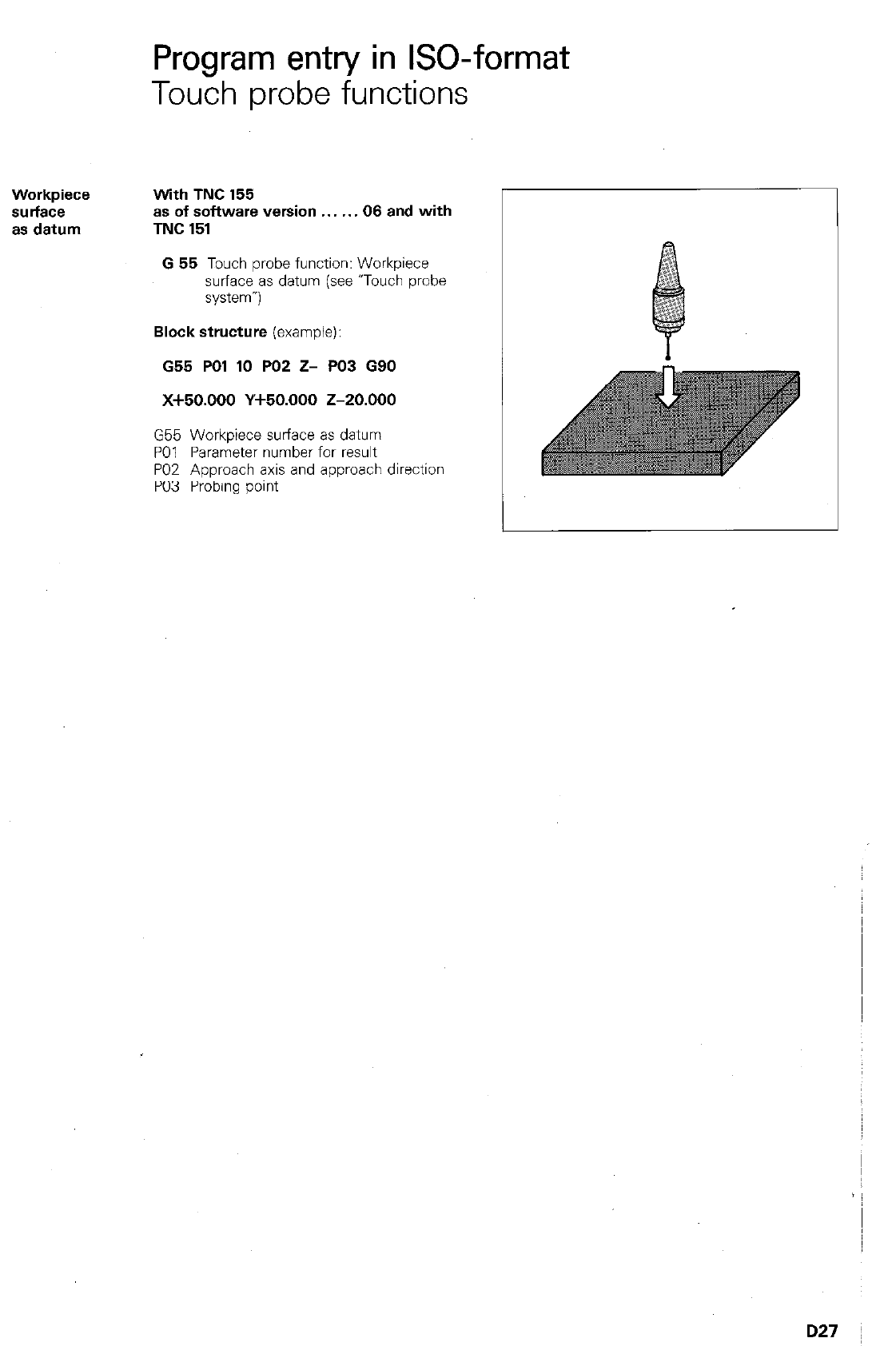
Program entry in ISO-format
Touch probe functions
With TNC 155
as of software version 06 and with
TNC 151
Workpiece
surface
as datum
G 65 Touch probe function: Workpiece
surface as datum (see uTouch probe
system-)
Block structure (example):
G55 PO1 10 PO2 Z- PO3 G90
x+50.000 Y+50.000 z-20.000
G55 Workpiece surface as datum
PO1 Parameter number for result
PO2 Approach axis and approach direction
PO3 Probing point
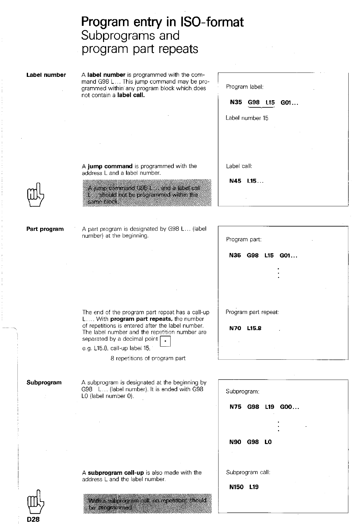
Program entry in ISO-format
Subprograms and
program part repeats
A
label number
is programmed with the com-
mand G98 L.. This jump command may be pro-
grammed within any program block which does
not contain a
label call.
Program label:
N35 G98 L15 GOl...
Label number 15
A
jump command
is programmed with the
address Land a label number.
Label call:
Part program
A part program is designated by G98 L.. (label
number) at the beginning.
The end of the program part repeat has a call-up
L.. With
program part repeats,
the number
of repetitions is entered after the label number.
The label number and the repetition number are
separated by a decimal point
e.g. 115.8. call-up label 15. 0
8 repetitions of program part
Subprogram
A subprogram is designated at the beginning by
G98 L.. (label number). It is ended with G98
LO (label number 0).
A
subprogram call-up
is also made with the
address Land the label number.
@
D28
Program part:
N35 698 L15 GOl...
Program part repeat:
N70 L15.8
r
Subprogram:
N75 688 Ll9 GOO...
N90 G98 LO
Subprogram call:
N150 LlS
Program entry in ISO-format
Jump into another main program/STOP-block
Jump into
another main
program
Programming of a jump into another main pro-
gram is performed with the m-key.
The control displays a jump into e.g. PGM 29 as
follows:
N127 % 29
Further explanations, see “Program call”.
For controls with software version 08:
STOP-block 638 corresponds to a STOP-block in
HEIDENHAIN plain language format
Block structure example:
638
D29
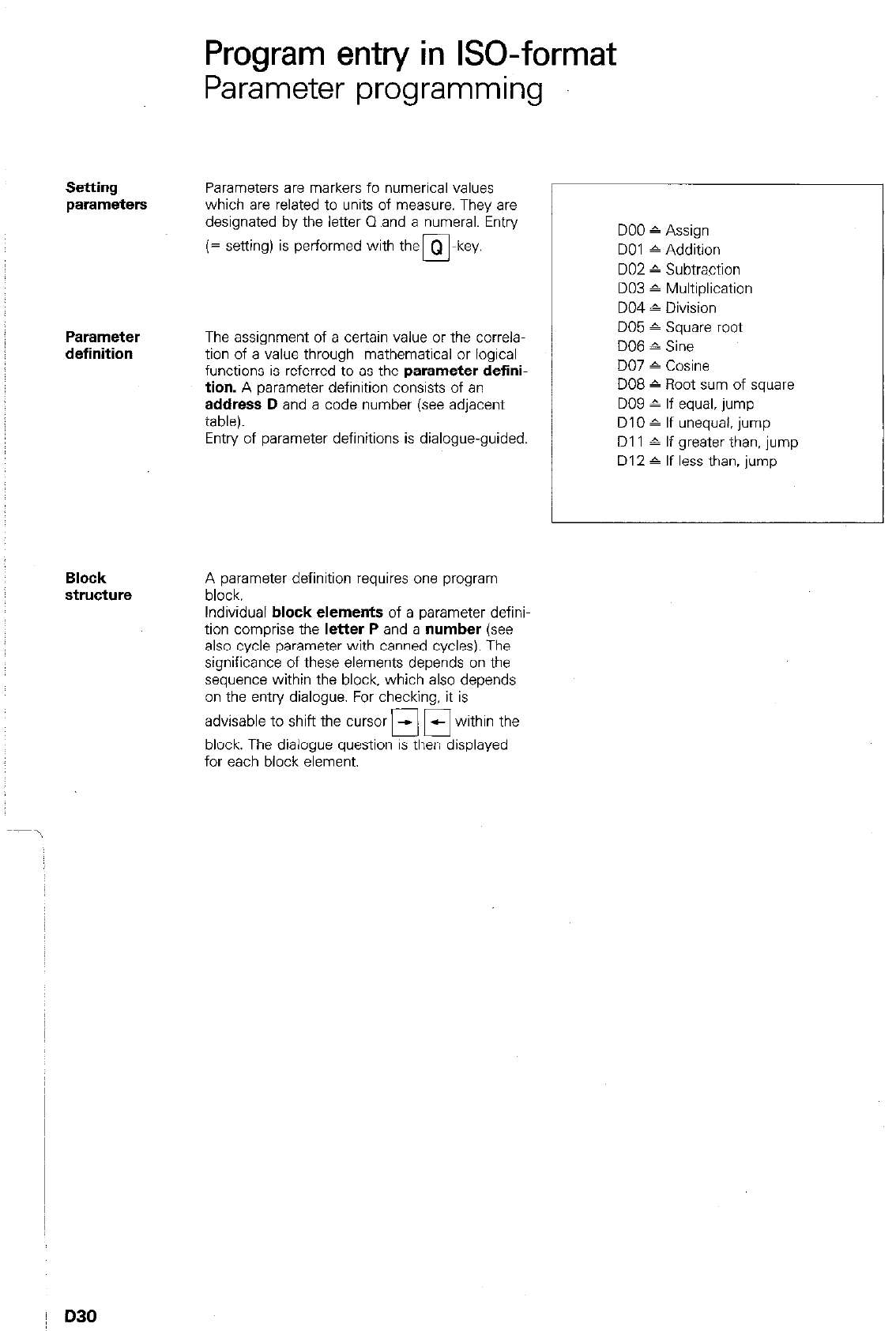
Program entry in ISO-format
Parameter programming
Setting
parameters
Parameters are markers fo numerical values
which are related to units of measure. They are
designated by the letter 0 and a numeral. Entry
(= setting) is performed with the
Parameter
definition
The assignment of a certain value or the correla-
tion of a value through mathematical or logical
functions is referred to
as
the
parameter defini-
tion.
A parameter definition consists of an
address D
and a code number (see adjacent
table).
Entry of parameter definitions is dialogue-guided.
Block
structure
A parameter definition requires one program
block.
Individual
block elements
of a parameter defini-
tion comprise the
letter P
and a
number (see
also cycle parameter with canned cycles). The
significance of these elements depends on the
sequence within the block, which also depends
on the entry dialogue. For checking, it is
advisable to shift the cursor fl 17 within the
block. The dialogue question is then displayed
for each block element.
DO0 ^ Assign
DO1 6 Addition
DO2 ” Subtraction
DO3 ^ Multiplication
DO4 1 Division
DO5 ^ Square root
DO6 ^ Sine
DO7 - Cosine
DO8 c Root sum of square
DO9 ^ If equal, jump
DIO A If unequal. jump
Dl 1 A If greater than, jump
D12 ^ If less than, jump
D30
Program entry in ISO-format
Parameter programming
Example 1: Q98 = 16??
DO5 Q68 PO1 +2
DO5 Square root
098 Parameter to which result is assigned
PO1 Parameter or numerical value within the
square root
Example 2: Q12 = Q2x62
DO3 Q12 PO1 +Q2 PO2 +62
DO3 Multiplication
Q12 Parameter to which result is assigned
PO1 First factor (parameter or
numeriCal vahe)
PO2 Second factor (parameter or numerical
VdW)
Example 3: IF 06 < Q5. jump to LBL 3
D12 PO1 +Q6 PO2 +05 PO3 3
D12 If less than. jump
PO1 First comparison value or parameter
PO2 Second comparison value or parameter
PO3 Label number (jump address)
D31
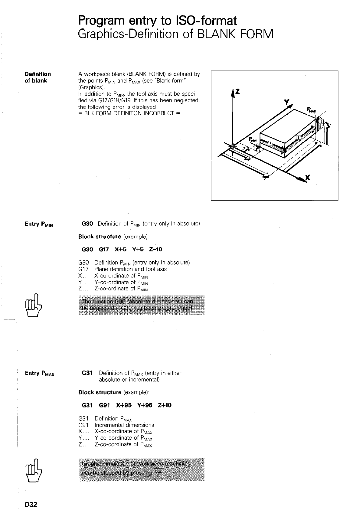
Program entry to GO-format
Graphics-Definition of BLANK FORM
Definition
of blank
A workpiece blank (BLANK FORM) is defined by
the points P,,, and P,,,,Ax (see “Blank form”
(Graphics).
In addition to PMIn, the tool axis must be speci-
fied via G17/G18/G19. If this has been neglected,
the following error is displayed:
= BLK FORM DEFINITON INCORRECT =
630 Definition of PlvllN (entry only in absolute)
Block structure
(example):
630 617 X+5 Y+5 Z-10
G30 Definition PNIIN (entry only in absolute)
G17 Plane definition and tool axis
X.. X-co-ordinate of PiVIIN
Y.. Y-co-ordinate of PNIIN
Z.. Z-co-ordinate of PlvllN
631
Definition of PMm (entry in either
absolute or incremental)
Block structure
(example):
631 G91 X+95 Y+95 Z+lO
G31 Definition P,,,,a
G91 Incremental dimensions
X X-co-cordinate of PMAX
Y Y-co-cordinate of PMulnx
Z.. Z-co-cordinate of PNlax
D32
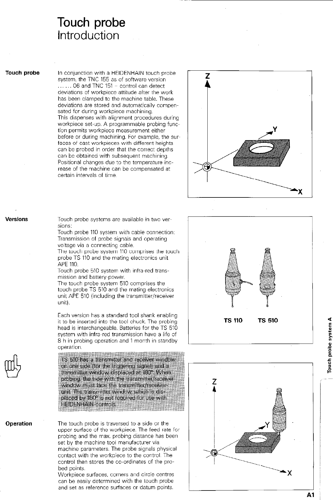
Touch probe
Introduction
Touch probe
In conjunction with a HEIDENHAIN touch probe
system, the TNC 155 as of software version
06 and TNC 151 control can detect
deviations of workpiece attitude after the work
has been clamped to the machine table. These
deviations are stored and automatically compen-
sated for during workpiece machining.
This dispenses with alignment procedures during
workpiece set-up. A programmable probing func-
tion permits workpiece measurement either
before or during machining. For example, the sw
faces of cast workpieces with different heights
can be probed in order that the correct depths
can be obtained with subsequent machining.
Positional changes due to the temperature inc-
rease of the machine can be compensated at
certain intervals of time.
L
Touch probe systems are available in two ver-
sions:
Touch probe 110 system with cable connection:
Transmission of probe signals and operating
voltage via a connecting cable.
The touch probe system 110 comprises the touch
probe TS 110 and the mating electronics unit
APE 110.
Touch probe 510 system with infra-red trans-
mission and battery-power.
The touch probe system 510 comprises the
touch probe TS 510 and the mating electronics
unit APE 510 (including the transmitter/receiver
unit).
Each version has a standard tool shank enabling
it to be inserted into the tool chuck. The probing
head is interchangeable. Batteries for the TS 510
system with infra-red transmission have a life of
8 h in probing operation and 1 month in standby
--^.^A:--
The touch probe is traversed to a side or the
upper surface of the workpiece. The feed rate for
probing and the max. probing distance has been
set by the machine tool manufacturer via
machine parameters. The probe signals physical
contact with the workpiece to the control. The
control then stores the co-ordinates of the pro-
bed points.
Workpiece surfaces. comers and circle centres
can de easily determined with the touch probe
and set as reference surfaces or datum points.
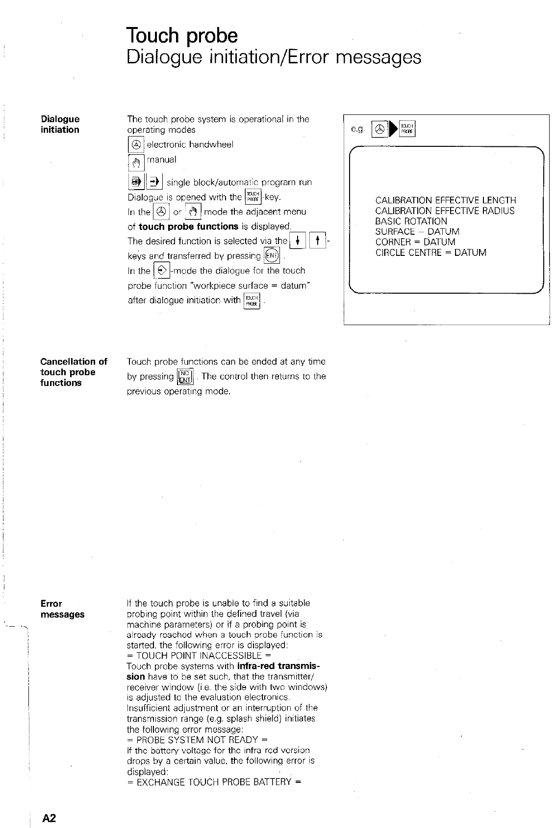
Touch probe
Dialogue initiation/Error messages
,Dialogue
iinitiation
The touch probe system is operational in the
operating modes
1 zxtct;;ic handwheel
block/automatic program run
Dialogue is opened with the m-key.
mode the adjacent menu
of
touch probe functions
is displayed.
The desired function is selected via then Fi-
keys and transferred by pressing
q
-mode the dialogue for the touch
probe function “workpiece surface = datum”
after dialogue initiation with Es!
Cancellation of
Touch probe functions can be ended at any time
touch probe
ffunctions
by pressing
q
Th e control then returns to the
previous operating mode.
ErrOr
messages
If the touch probe is unable to find a suitable
probing point within the defined travel (via
machine parameters) or if a probing point is
already reached when a touch probe function is
started, the following error is displayed:
= TOUCH POINT INACCESSIBLE =
Touch probe systems with
infra-red transmis-
sion
have to be set such, that the transmitter/
receiver window (i.e. the side with two windows)
is adjusted to the evaluation electronics.
Insufficient adjustment or an interruption of the
transmission range (e.g. splash shield) initiates
the following error message:
= PROBE SYSTEM NOT READY =
If the battery voltage for the infra-red version
drops by a certain value. the following error is
displayed:
= EXCHANGE TOUCH PROBE BATTERY =
r
CALIBRATION EFFECTIVE LENGTH
CALIBRATION EFFECTIVE RADIUS
BASIC ROTATION
SURFACE = DATUM
CORNER = DATUM
CIRCLE CENTRE = DATUM
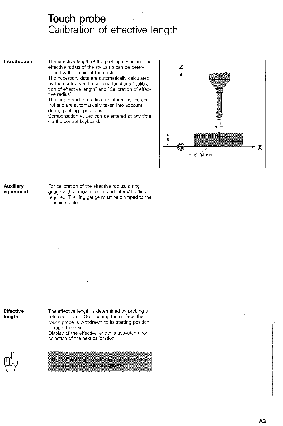
Touch probe
Calibration of effective length
Introduction The effective length of the probing stylus and the
effective radius of the SWIM tip can be deter-
mined with the aid of the control.
The necessary data are automatically calculated
by the control via the probing functions YXalibra-
tion of effective length” and “Calibration of effec-
tive radius*.
The length and the radius are stored by the con-
trol and are automatically taken into account
during probing operations.
Compensation values can be entered at any time
via the control keyboard.
Ring gauge
Auxiliary
equipment For calibration of the effective radius, a ring
gauge with a known height and internal radius is
required. The ring gauge must be clamped to the
machine table.
Effective
length The effective length is determined by probing a
reference plane. On touching the surface. the
touch probe is withdrawn to its starting position
in rapid traverse.
Display of the effective length is activated upon
selection of the next calibration.
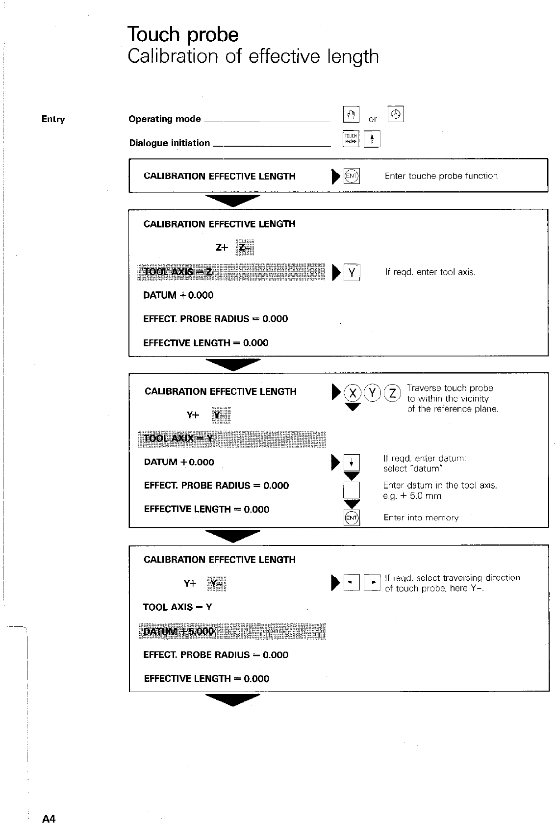
Touch probe
Calibration of effective length
Operating mode -
Dialogue initiation _
CALIBRATION EFFECTIVE LENGTH )I3 Enter touche probe function
CALIBRATION EFFECTIVE LENGTH
DATUM + 0.000
If wd. enter toOI axis.
EFFECT. PROBE RADIUS = 0.000
EFFECTIVE LENGTH = 0.000
CALIBRATION EFFECTIVE LENGTH
Y+
TOOL AXIS = Y
If reqd. select traversing direction
of touch probe, here Y-.
EFFECT. PROBE RADIUS = 0.000
EFFECTIVE LENGTH = 0.000
A4
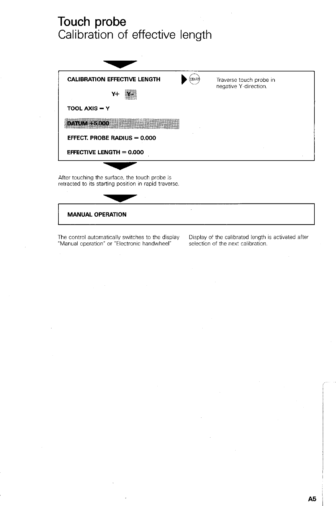
Touch probe
Calibration of effective length
CALIBRATION EFFECTWE LENGTH
Traverse touch probe in
negative Y-direction.
TOOL AXIS = Y
EFFECT. PROBE RADIUS = 0.000
EFFECTIVE LENGTH = 0.000
After touching the surface, the touch probe is
retracted to its starting position in rapid traverse.
MANUAL OPERATION
The control automatically switches to the display Display of the calibrated length is activated ,aftel
“Manual operation” or Wectronic handwheel- selection of the next calibration.
A5 j
Remarks
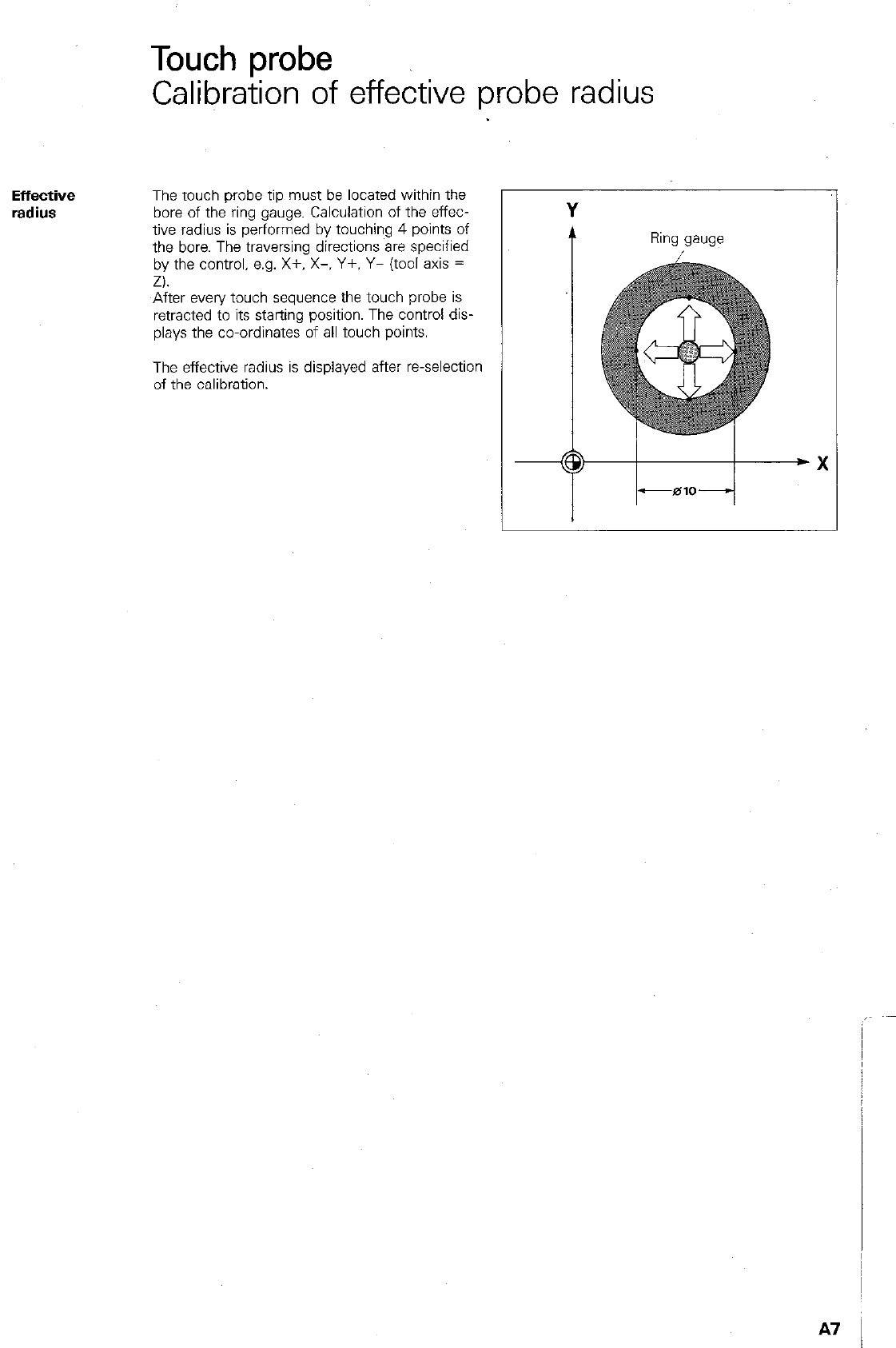
Touch probe
Calibration of effective probe radius
Effective
radius
The touch probe tip must be located within the
bore of the ring gauge. Calculation of the effec-
tive radius is performed by touching 4 points of
the bore. The traversing directions are specified
by the control, e.g. X+, X-. Y+. Y- (tool axis =
Z).
After every touch sequence the touch probe is
retracted to its starting position. The control dis-
plays the co-ordinates of all touch points.
The effective radius is displayed after r-selection
of the calibration.
Ring gauge
A7
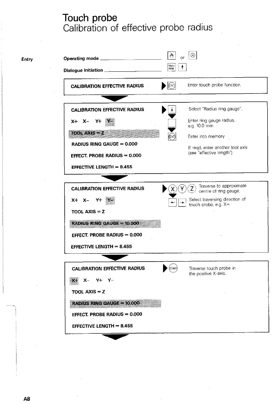
Touch probe
Calibration of effective probe radius
Entry Operating mode
Dialogue initiation _
CALlBRATlON EFFECTIVE RADIUS
pj m
Enter touch probe function.
CALlBRATlON EFFECTIVE RADIUS
RADIUS RING GAUGE = 0.000
EFFECT. PROBE RADIUS = 0.000
EFFECTWE LENGTH = 8.455
Select Vadius ring gauge”.
EInge;;.0ng;;uge radius.
Enter into memory
If reqd. enter another tool 8x1s
(see -effective length”)
CALIBRATION EFFECTIVE RADIUS boo@ Traverse to approximate
centre of ring gauge.
x-l- x- Y+ ; 5r;l Select traversing direction of
touch probe. e.g. Xf.
TOOL AXIS = 2
;j” .iiii,..“p::::
~*z~z~@$“~~
-.--* ..__...‘..
EFFECT. PROBE RADIUS = D.DDD
EFFECTIVE LENGTH = 8.455
CALIBRATION EFFECTWE RADIUS
x- Y+ Y-
Traverse touch probe in
the positive X-8x1s.
TOOL AXIS = 2
EFFECT. PROSE RADIUS = D.DDD
EFFECTIVE LENGTH = 8.455
A8
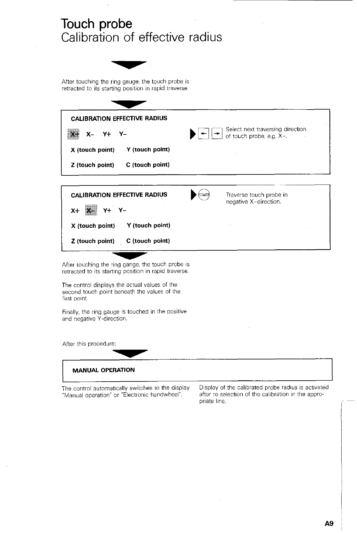
Touch probe
Calibration bf effective radius
After touching the ring gauge. the touch probe is
retracted to its starting position in rapid traverse.
,
CALIBRATION EFFECTIVE RADIUS I
Select next traversing direction
of touch probe, e.g. X-. I
X (touch point) Y (touch point)
Z (touch point) C (touch point)
CALIBRATION EFFECTWE RADIUS
x+ i; Y-k Y-
X (touch point) Y (touch point)
Z (touch point) C (touch point)
Traverse touch probe in
negative X-direction.
After touching the ring gange. the touch probe is
retracted to its starting position in rapid traverse.
The control displays the actual values of the
second touch point beneath the values of the
first point.
Finally. the ring gauge is touched in the positive
and negative Y-direction.
After this procedure:
MANUAL OPERATION
The control automatically switches to the display Display of the calibrated probe radius is activated
“Manual operation” or “Electronic handwheel”. after re~selection of the calibration in the appro-
wate line.
A9
Remarks
” A10
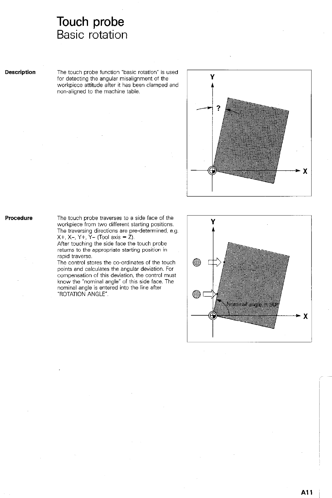
Touch probe
Basic rotation
Description
The touch probe function rbasic rotation* is used
for detecting the angular misalignment of the
workpiece attitude after it has been clamped and
non-aligned to the machine table. i
The touch probe traverses to a side face of the
workpiece from two different starting positions.
The traversing directions are pre-determined. e.g.
X+. X-, Y+, Y- (Tool axis = Z).
After touching the side face the touch probe
returns to the appropriate starting position in
rapid traverse.
The control stores the co-ordinates of the touch
points and calculates the angular deviation. For
compensation of this deviation, the control must
know the “nominal angle” of this side face. The
nominal angle is entered into the line after
-ROTATION ANGLE’.
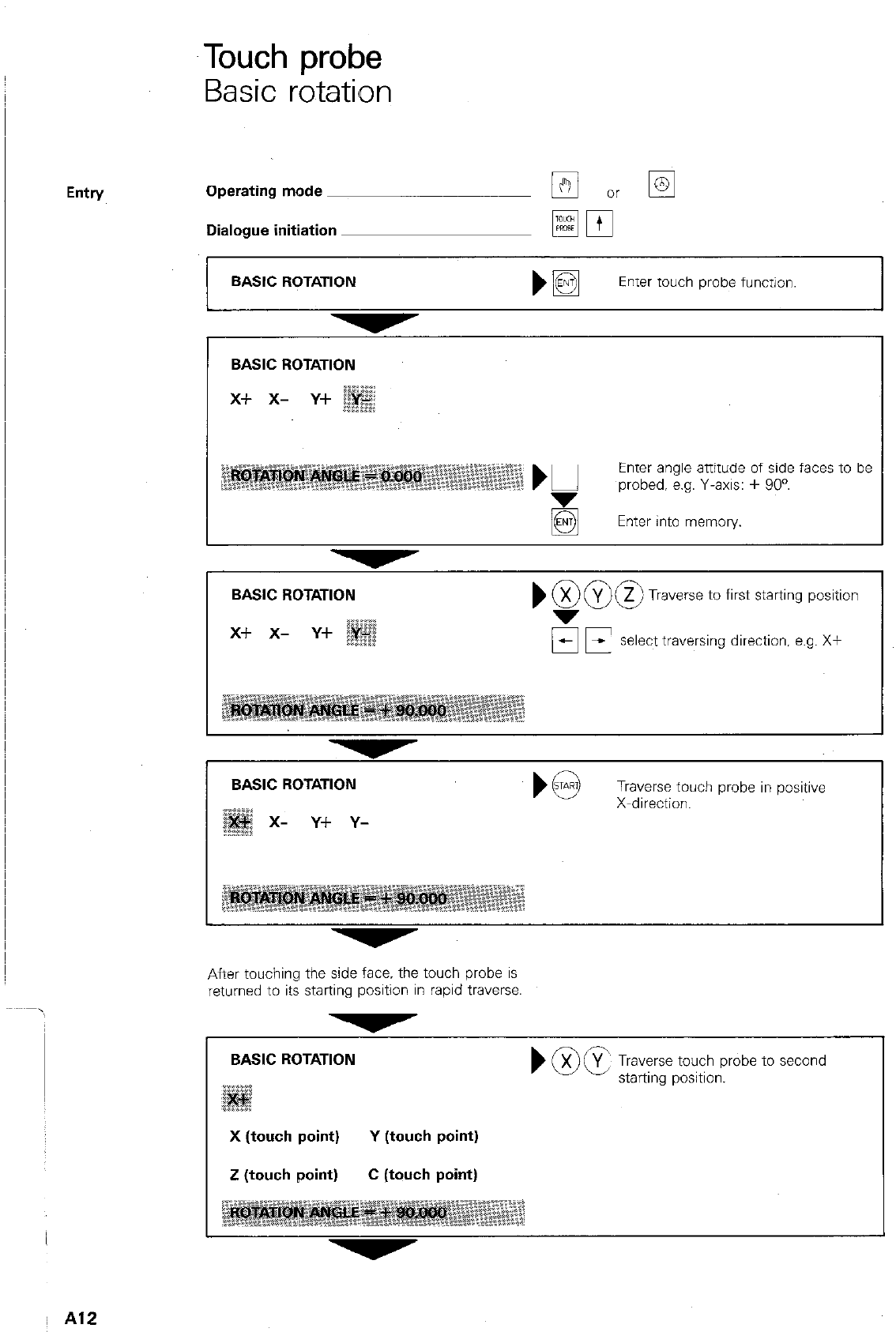
Touch probe
Basic rotation
I
Entry Operating mode
BASIC ROTATION
Enter angle attitude of side faces to be
probed. e.g. Y-axis: + 90”.
Enter into memory.
Dialogue initiation
BASIC ROTATION
mpp
1
bE$j
Enter touch probe function.
BASIC ROTATION
Traverse to first starting position
OF select traversing direction, e.g. X+
. . . . . .
BASIC ROTATION
x- Y+ Y-
Traverse touch probe in positive
X-direction.
After touching the side face. the touch probe is
returned to its starting position in rapid traverse
BASIC ROTATION
) @)g, k/e;ept;;ou;;robe to second
X (touch point) Y (touch point)
Z (touch point) C (touch point)
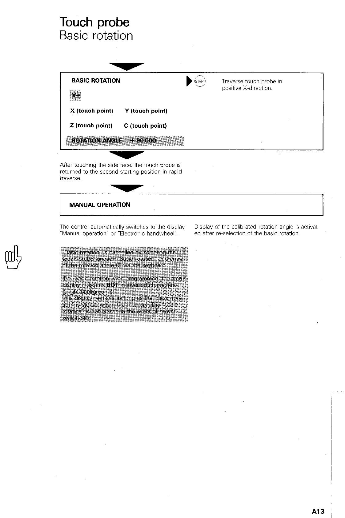
Touch probe
Basic rotation
BASIC ROTATION
Traverse touch probe in
wsitive X-direction.
X (touch point) Y (touch point)
i! (touch point) C (touch point)
After touching the side face. the touch probe is
returned to the second starting position in rapid
traverse.
MANUAL OPERATION I
The control automatically switches to the display Display of the calibrated rotation angle is activat-
“Manual operation” or “Electronic handwheel? ed after reselection of the basic rotation.
Al3
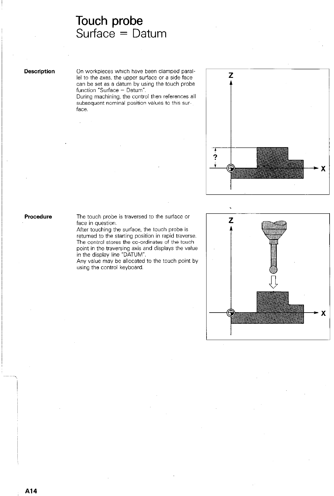
Touch probe
Surface = Datum
On workpieces which have been clamped paral-
lel to the axes. the upper surface or a side face
can be set as a datum by using the touch probe
function “Surface = Datum”
During machining, the control then references all
subsequent nominal position values to this SW
face.
Procedure The touch probe is traversed to the surface or
face in question.
After touching the surface. the touch probe is
returned to the starting position in rapid traverse.
The control stores the co-ordinates of the touch
point in the traversing axis and displays the value
in the display line “DATUM”.
Any value may be allocated to the touch point by
using the control keyboard.
Al4
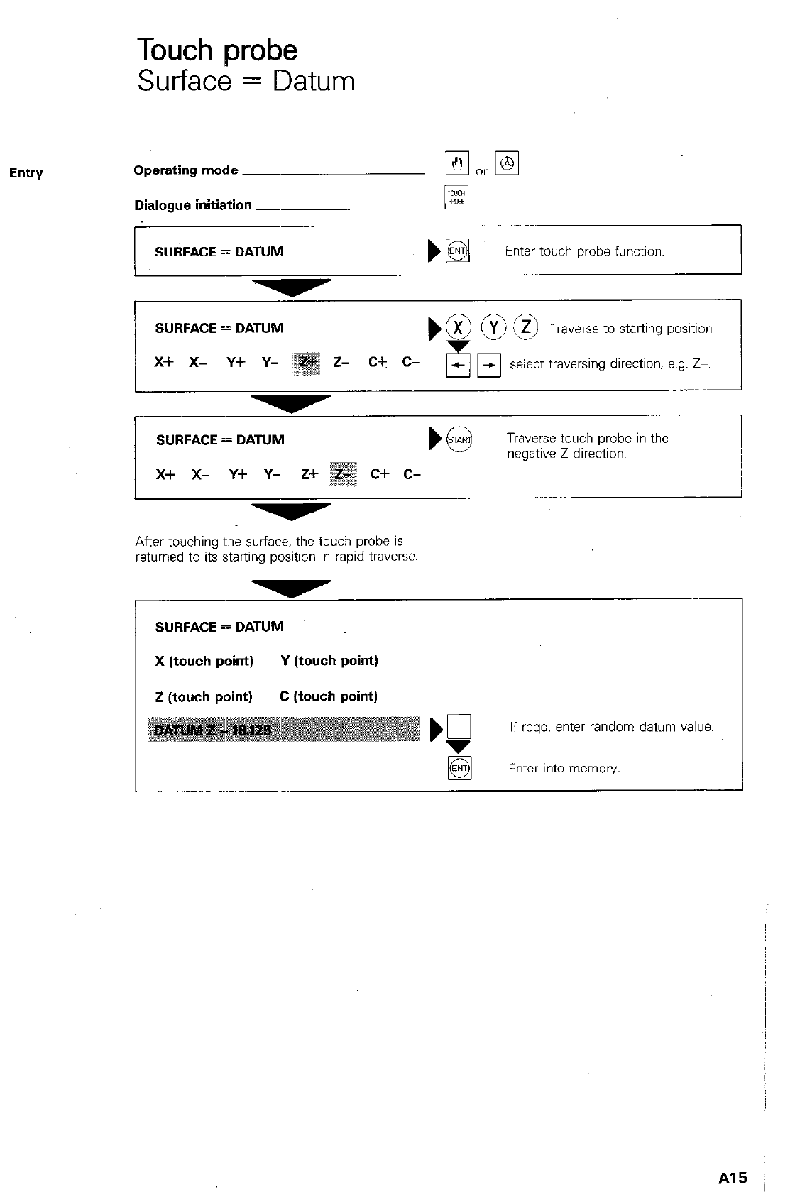
Touch probe
Surface = Datum
Entry Operating mode
Dialogue initiation
SURFACE = DATUM
q
)B
Enter touch probe function.
SURFACE = DATUM
x+ x- Y+ Y-
Traverse to starting position
select traversing direction, e.g. Z-.
SURFACE = DATUM
Traverse touch probe in the
negative Z-direction.
x+ x- y+ y- z+
After touching the surface, the touch probe is
returned to its starting position in rapid traverse.
SURFACE = DATUM
X (touch point) Y (touch point)
Z (touch point) C (touch point)
If reqd. enter random datum value.
q
Enter into memory.
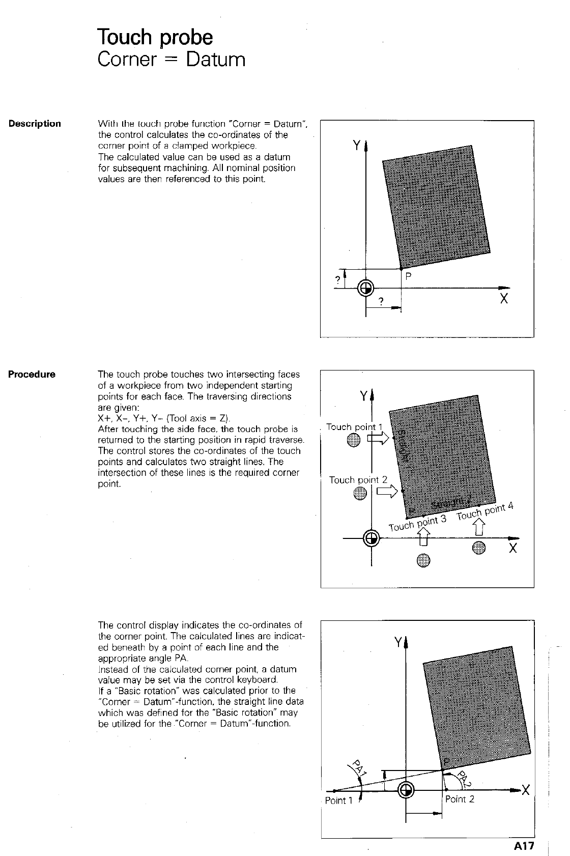
Touch probe
Corner = Datum
Description
With the touch probe function uComer = Datum”,
the control calculates the co-ordinates of the
comer point of a clamped workpiece.
The calculated value can be used as a datum
for subsequent machining. All nominal position
values are then referenced to this point.
PrOCedlKe
The control display indicates the co-ordinates of
the comer point. The calculated lines are indicat-
ed beneath by a point of each line and the
appropriate angle PA.
Instead of the calculated comer point. a datum
value may be set via the control keyboard.
If a “Basic rotation* was calculated prior to the
“Corner = Datum”-function. the straight line data
which was defined for the “Basic rotation” may
be utilized for the ~“Corner = Datum”-function.
The touch probe touches two intersecting faces
of a workpiece from two independent starting
points for each face. The traversing directions
are g,ven:
Xf. X-, Y+. Y- (Tool axis = Z).
After touching the side face, the touch probe is
returned to the starting position in rapid traverse.
The control stores the co-ordinates of the touch
points and calculates two straight lines. The
intersection of these lines is the required comer
point.
A
!?--r;
% r
Point 1 /Point 2 ‘.
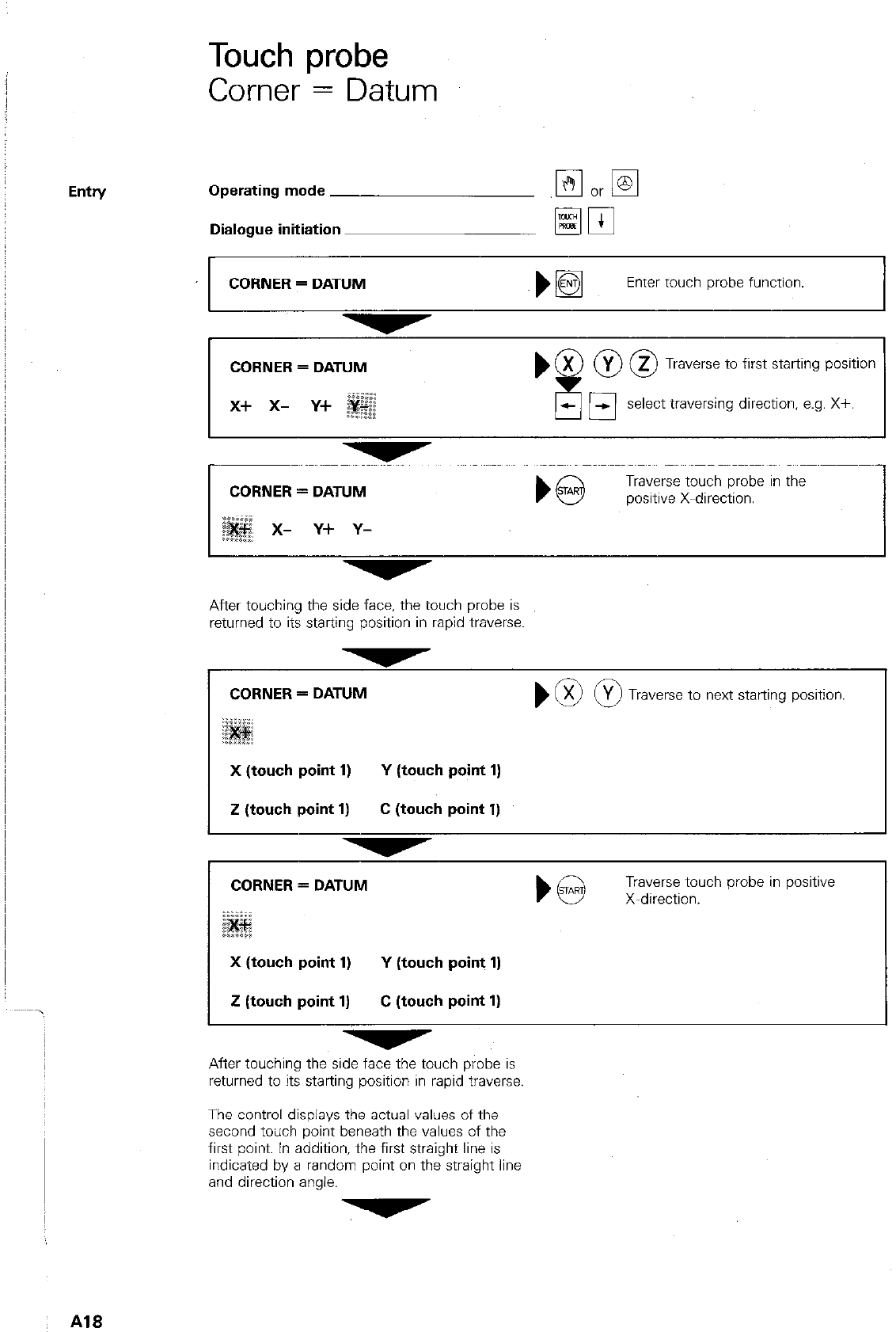
Touch probe
Corner = Datum
Entry Operating mode
Dialogue initiation
CORNER = DATUM
Elm
~)I@ Enter touch probe function.
CORNER = DATUM
x+ x- y+
bx OOT
!
raverse to first starting position
-El select traversing direction, e.g. X+.
CORNER = DATUM
x- Y+ Y-
b@
Traverse touch probe in the
positive X-direction.
After touching the side face, the touch probe is
returned to its starting position in rapid traverse.
CORNER = DATUM m 0 raverse to next starting position.
X (touch point 1) Y (touch point 1)
Z (touch point 1) C (touch point 1)
CORNER = DATUM Traverse touch probe in positive
) @ X-direction.
X (touch point 1) Y (touch point 1)
2 (touch point 1) C (touch point 1)
After touching the side face the touch probe is
returned to its starting position in rapid traverse.
The control displays the actual values of the
second toilch point beneath the values of the
first point. In addition, the first straight line is
indicated by a random point on the straight line
and direction angle.
Al8
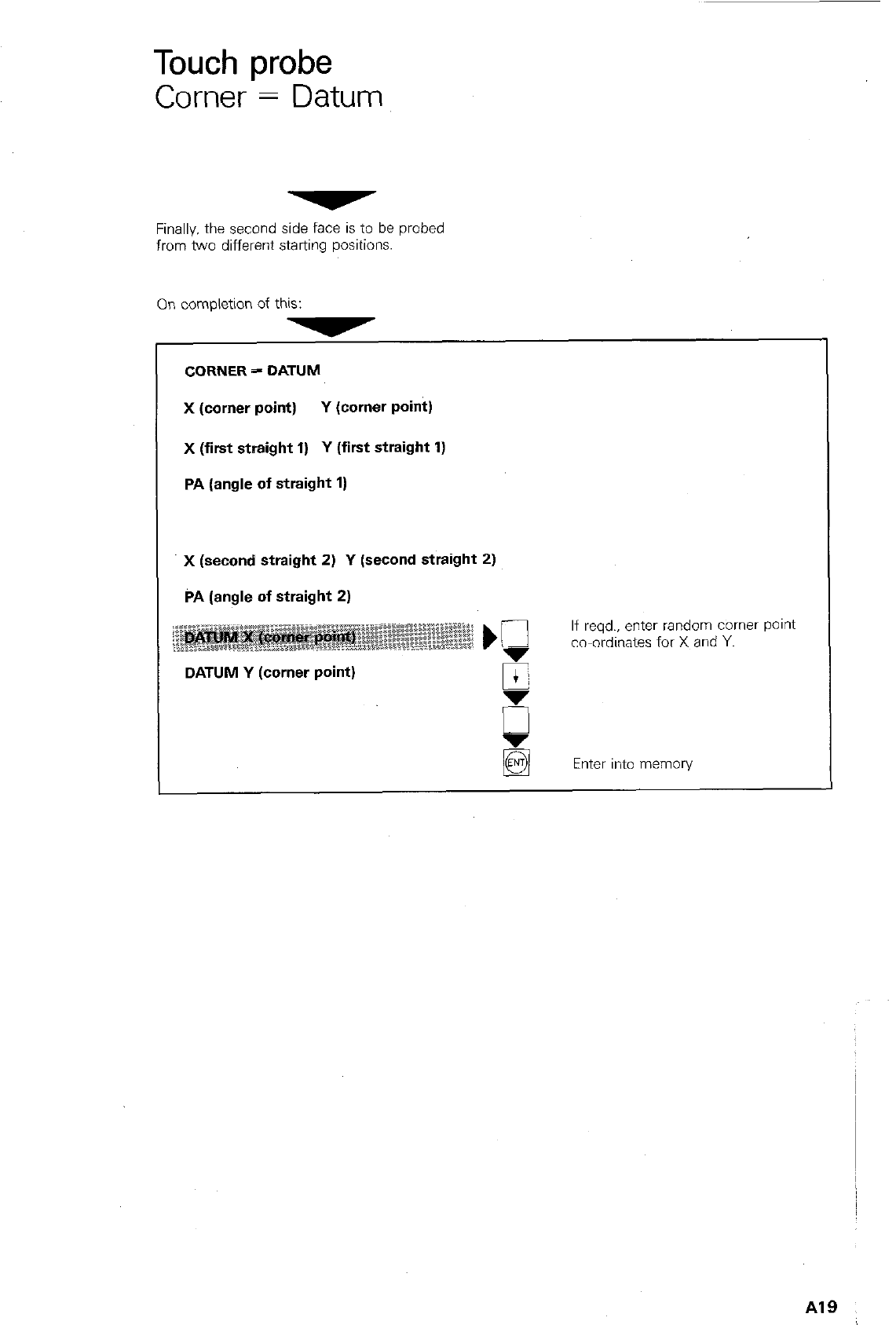
Touch probe
Corner = Datum
Finally. the second side face is to be probed
from two different starting positions.
On completion of this:
CORNER = DATUM
X (corner point) Y (cornar point)
X (first straight 1) Y (first straight 1)
PA (angle of straight 1)
x (second straight 2) Y (second straight 2)
PA (angle of straight 2)
If reqd., enter random comer pant
co-ordinates for X and Y.
DATUM Y (corner point)
Enter into memory
A19
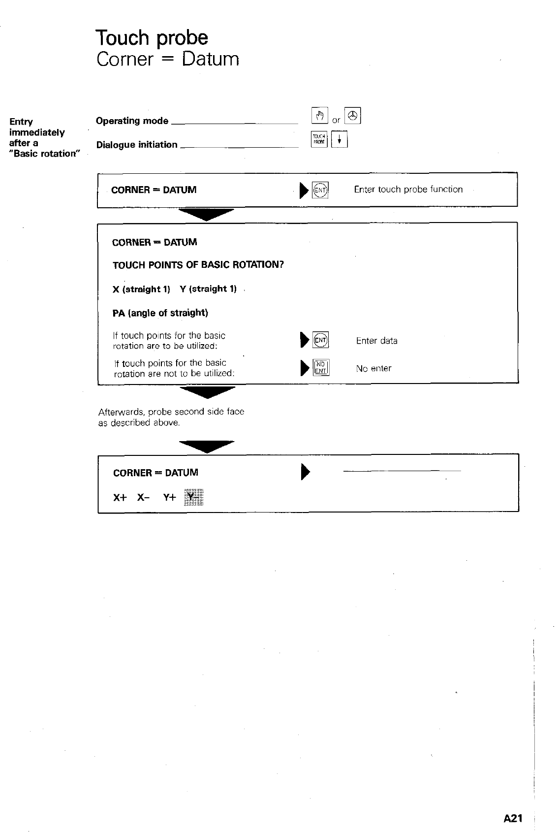
Touch probe
Corner = Datum
Entry Operating mode
immediately
after a
“Basic rotation” Dialogue initiation
CORNER = DATUM
TOUCH POINTS OF BASIC ROTATION?
X (straight 1) Y (straight 1)
PA (angle of straight)
Enter data
No enter
CORNER = DATUM
Enter touch probe function
I
If touch points for the basic
rotation are to be utilized:
if touch points for the basic
rotation are not to be utilized:
Afterwards, probe second side face
as described above.
CORNER = DATUM b
A21
,,. ., ,,,,,I,,, ,, .,/,,,,,,, .I,..,,,,,,> ,.I,,
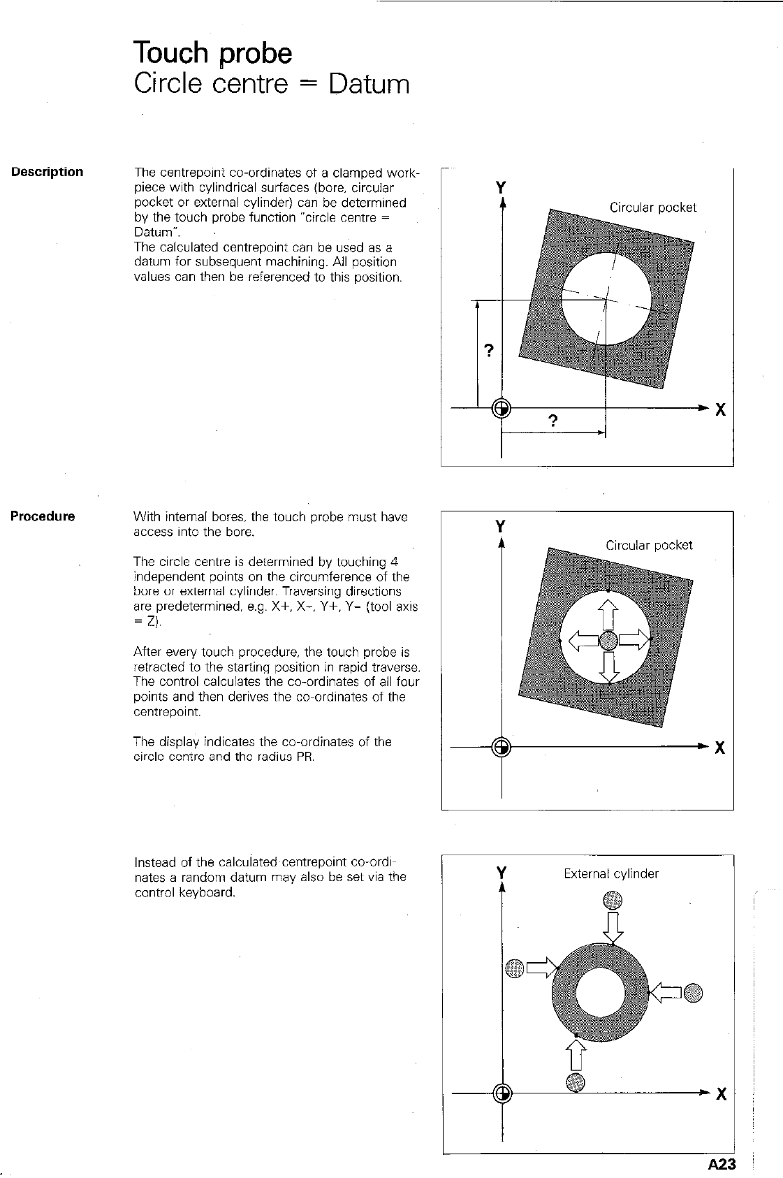
Touch probe
Circle centre = Datum
The centrepoint co-ordinates of a clamped work-
piece with cylindrical surfaces (bore, circular
pocket or external cylinder) can be determined
by the touch probe function “circle centre =
Datum-.
The calculated centrepoint can be used as a
datum for subsequent machining. All position
values can then be referenced to this position.
-
I
-
Procedure
With internal bores, the touch probe nwst have
access into the bore.
The circle centre is determined by touching 4
independent points on the circumference of the
bore or external cylinder. Traversing directions
are predetermined, e.g. X+. X-. Y+. Y- (tool axis
= Z).
After every touch procedure, the touch probe is
retracted to the starting position in rapid traverse.
The control calculates the co-ordinates of all four 1 I
points and then derives the co-ordinates of the
centrepoint.
The display indicates the co-ordinates of the
circle centre and the radius PR.
Instead of the calculated~centrepoint co-ordi-
nates a random datum may also be set via the
control keyboard.
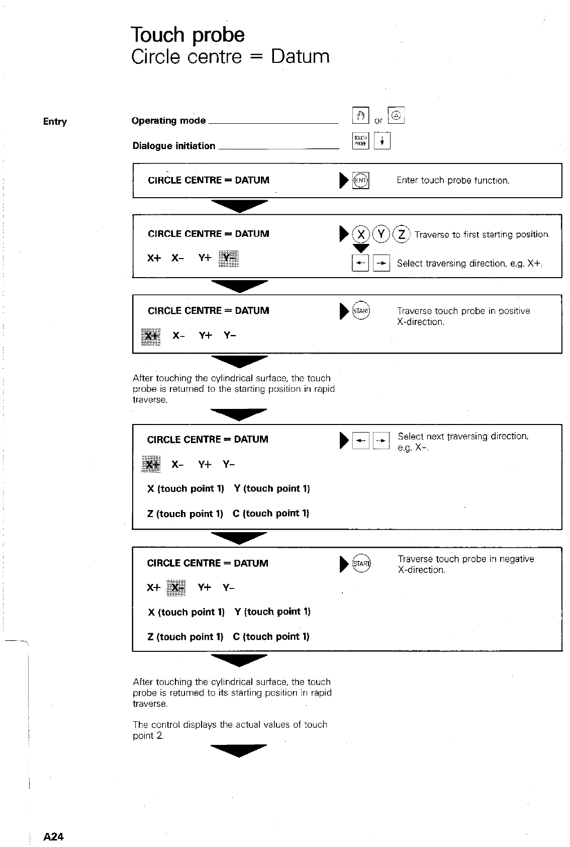
Entry
Touch probe
Circle centre = Datum
Operating mode
Dialogue initiation
CIRCLE CENTRE = DATUM
Enter touch probe function.
CIRCLE CENTRE = DATUM
x+ x- y+
,900
X Y z Traverse to first starting position.
Select~traversing direction, e.g. X+.
CIRCLE CENTRE = DATUM
x- Y+ Y-
Traverse touch probe in positive
X-direction.
After touching the cylindrical surface, the touch
probe is returned to the starting position in rapid
traverse.
CIRCLE CENTRE = DATUM
x- Y+ Y-
Select next traversing direction.
b Ef El e.g. x-.
X (touch point 1) Y (touch point 1)
Z (touch point 1) C (touch point 1)
CIRCLE CENTRE = DATUM
Y+ Y-
) @ X-direction.
Traverse touch probe in negative
X (touch point 1) Y (touch point 1)
Z (touch point 1) C (touch point 1)
After touching the cylindrical surface, the touch
probe is returned to its starting position in rapid
traverse.
The control displays the actual values of touch
point 2.
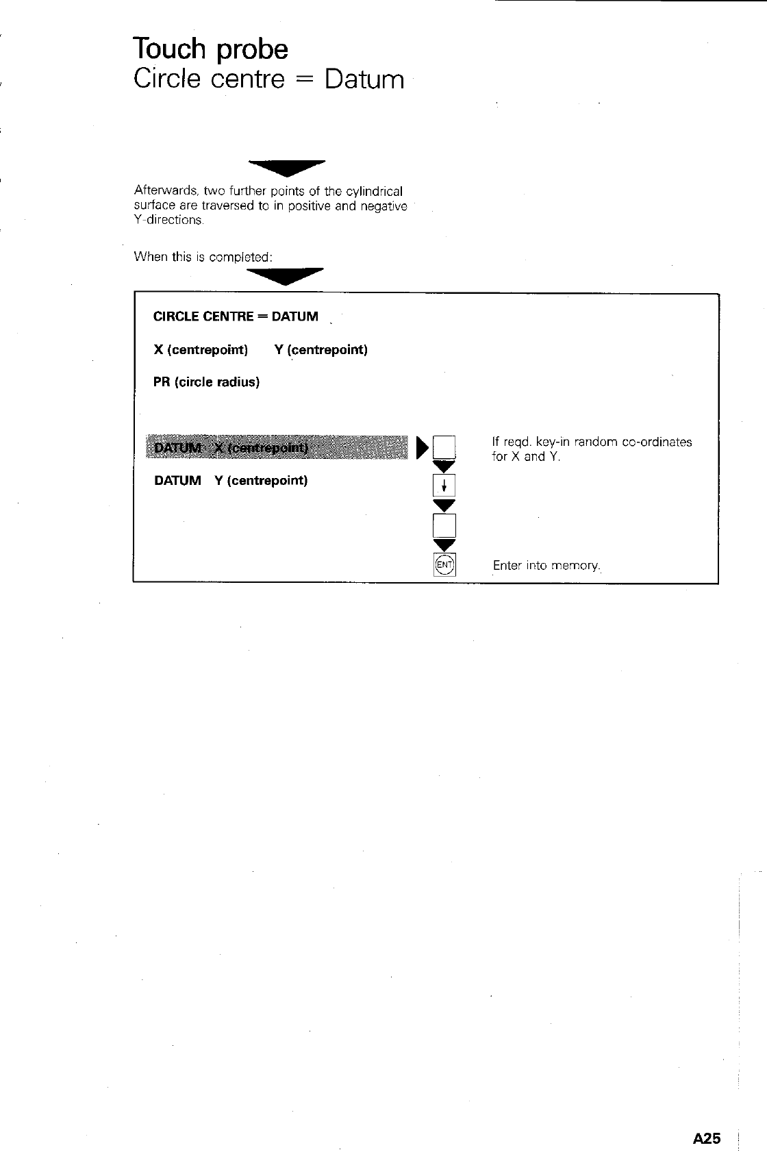
Touch probe
Circle centre = Datum
Afterwards. two further points of the cylindrical
surface are traversed to in positive and negative
Y-directions.
When this is completed:
CIRCLE CENTRE = DATUM
X (centrepoint) Y (centrepoint)
PR (circle radius)
DATUM Y (centrepoint)
If reqd. key-in random co-ordinates
for X and Y.
B
Enter into memory.
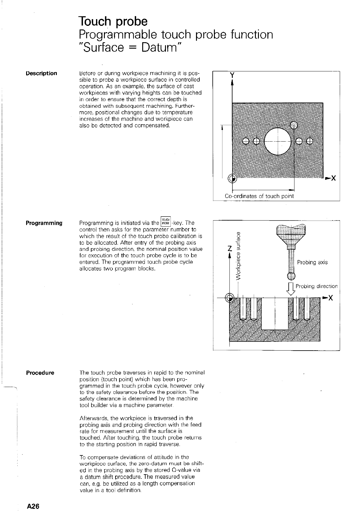
Touch probe
Programmable touch probe function
“Surface = Datum”
Before or during workpiece machining it is pos-
sible to probe a workpiece surface in controlled
operation. As an example, the surface of cast
workpieces with varying heights can be touched
in order to ensure that the correct depth is
obtained with subsequent machining. Further-
more, positional changes due to temperature
increases of the machine and workpiece can
also be detected and compensated.
Programming Programming is initiated via the R=CS -key. The
FE
control then asks for the parameter number to
which the result of the t&h probe calibration is
to be allocated. After entry of the probing axis
and probing direction, the nominal position value
for execution of the touch probe cycle is to be
entered. The programmed touch probe cycle
allocates two program blocks.
Procedure The touch probe traverses in rapid to the nominal
position (touch point) which has been pro-
grammed in the touch probe cycle, however only
to the safety clearance before the position. The
safety clearance is determined by the machine
tool builder via a machine parameter.
Afterwards, the workpiece is traversed in the
probing axis and probing direction with the feed
rate for measurement until the surface is
touched. After touching, the touch probe returns
to the starting position in rapid traverse.
To compensate deviations of attitude in the
workpiece surface. the zero-datum must be shift-
ed in the probing axis by the stored Q-value via
a datum shift procedure. The measured value
can, e.g. be utilized as a length compensation
value in a tool definition.
A26
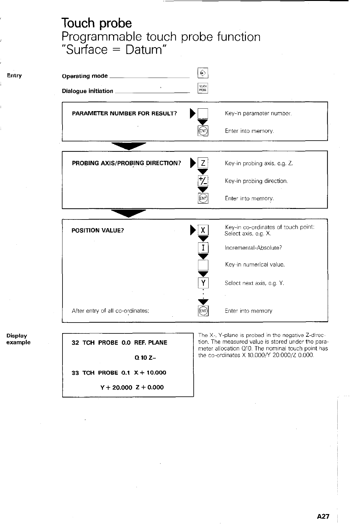
Display
%Wllple
Touch probe
Programmable touch probe function
“Surface = Datum”
Operating mode @I
Dialogue initiation FE
PARAMETER NUMBER FOR RESULT? ) 0 Key-in parameter number.
g Enter into memory.
PROBING AXIS/PROBING DIRECTION? ‘@ Key-in probing axis. e.g. Z.
/Q Key-in probing direction.
Enter into memory.
POSITION VALUE? ‘gl Key-in co-ordinates of touch pant:
Select axis, e.g. X.
Fr Incremental-Absolute?
6 Key-in numerical value.
5 Select next axis, e.g. Y.
After entry of all co-ordinates: Enter into memory
32 TCH PROBE 0.0 REF. PLANE
QlOZ-
I------
33 TCH PROBE 0.1 X+ 10.000
Y + 20.000 2 + 0.000
The X-. Y-plane is probed in the negative Z-direc-
tion. The measured value is stored under the para-
meter allocation QIO. The nominal touch point has
the co-ordinates X 10.000/Y 20.000/Z 0.000.
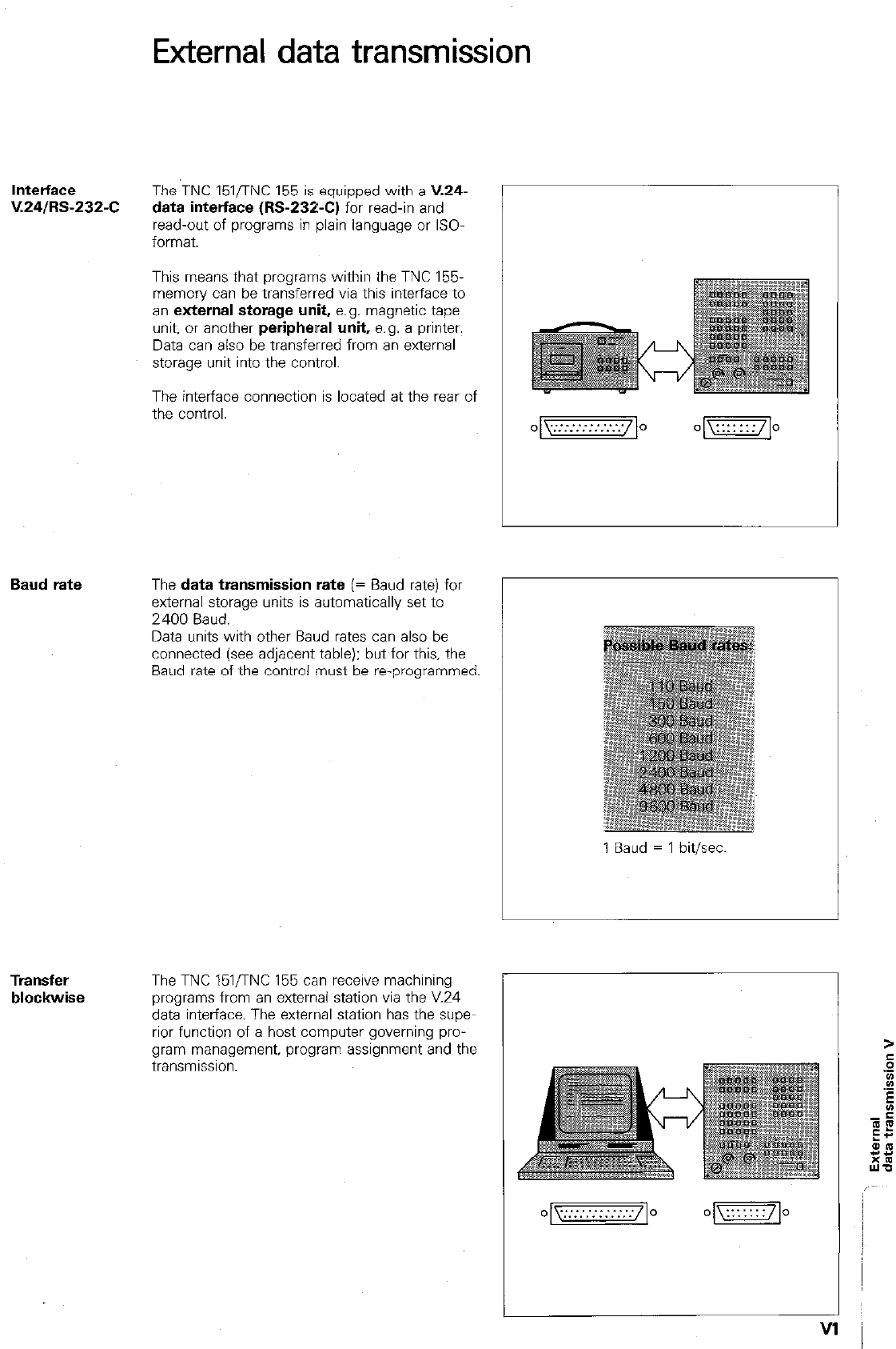
External data transmission
lntetface
V.24/RS-232-C The TNC 151flNC 155 is equipped with a V.24-
data interface (M-232-C) for read-in and
read-out of programs in plain language or ISO-
format.
This means that programs within the TNC 155.
memory can be transferred via this interface to
an external storage unit, e.g. magnetic tape
unit, or another peripheral unit, e.g. a printer.
Data can also be transferred from an external
storage unit into the control.
The interface connection is located at the rear of
the control.
Baud rate The data transmission rate (= Baud rate) for
external storage units is automatically set to
2400 Baud.
Data units with other Baud rates can also be
connected (see adjacent table): but for this, the
Baud rate of the control must be reprogrammed.
I
1 Baud = 1 bit/xc
Transfer
blockwise
The TNC 151,TNC 155 can receive machining
programs from an external station via the V.24
data interface. The external station has the supe
rior function of a host computer governing pro-
gram management, program assignment and the
transmlsslon.
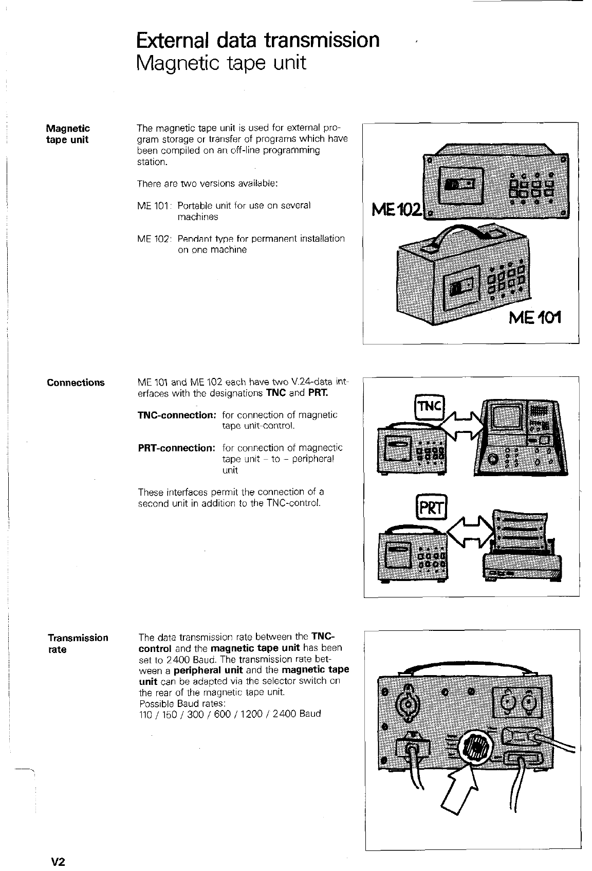
Magnetic
tape unit
Connections
Transmission
rate
External data transmission r
Magnetic tape unit
The magnetic tape unit is used for external pro-
gram storage or transfer of programs which have
been compiled on an off-line programming
statlon.
There are two versions available:
ME 101: Portable unit for use on several
machines
ME 102: Pendant type for permanent installation
on one machine
ME 101 and ME 102 each have two XL&data int-
erfaces with the designations TNC and PRT.
TNC-connection: for connection of magnetic
tape unit-control.
PRT-connection: for connection of magnectic
tape unit to - peripheral
unit
These interfaces permit the connection of a
second unit in addition to the TNC-control.
The data transmission rata between the TNC-
control and the magnetic tape unit has been
sat to 2400 Baud. The transmission rate bet-
ween a peripheral unit and the magnetic tape
unit can be adapted via the selector switch on
the rear of the magnetic tape unit.
Possible Baud rates:
110/150/300/600/1200/2400 Baud
v2
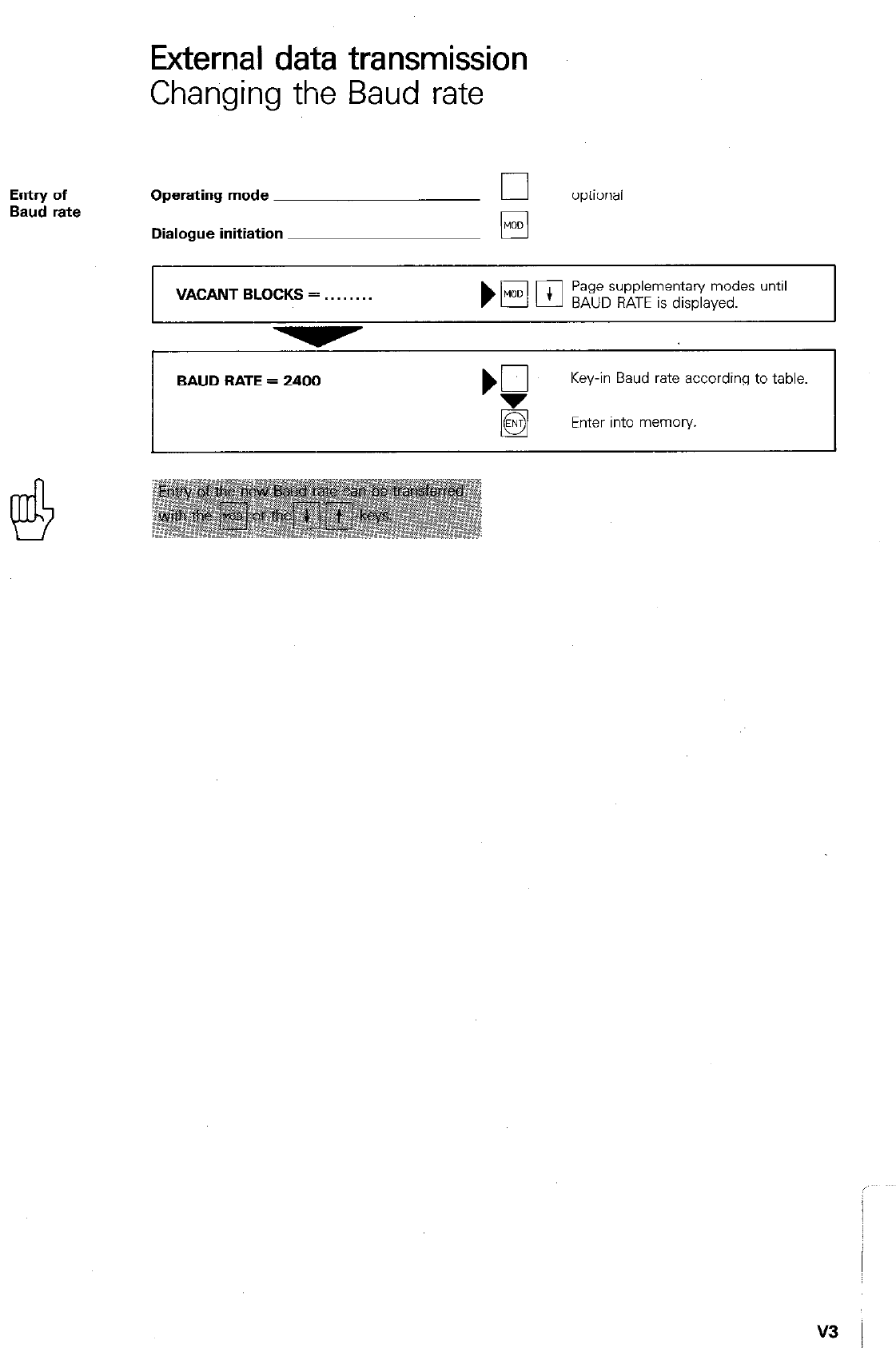
External data transmission
Changing the Baud rate
Entry of
Baud rate Operating mode
Dialogue initiation
optional
q
VACANT BLOCKS = . .
Page supplementary modes until
BAUD RATE is displayed.
BAUD BATE = 2400
Key-in Baud rate according to table.
Enter into memory.
v3 I
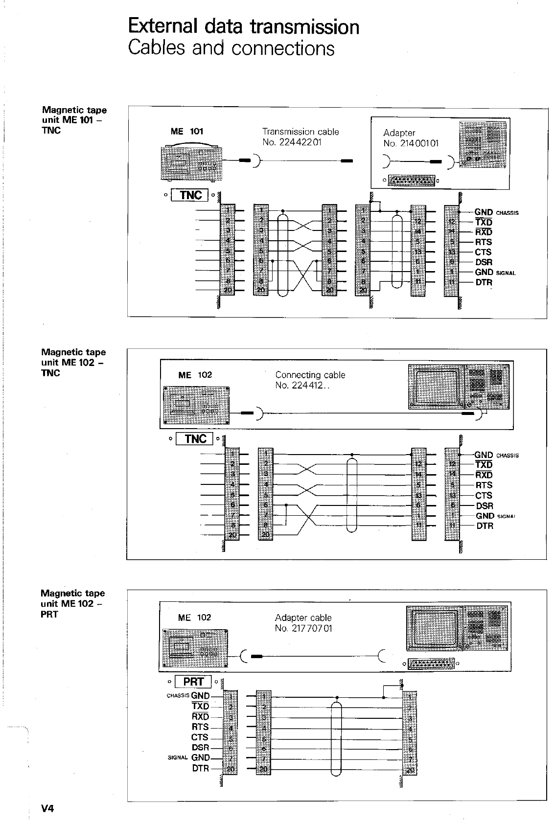
Magnetic tape
unit ME 101 -
TNC
Magnetic tape
unit ME 102 -
TNC
Magnetic tape
unit ME 102 -
PRT
External data transmission
Cables and connections
ME 101 Transmission cable
No.22442201 No. 21400101
No.21770701
v4
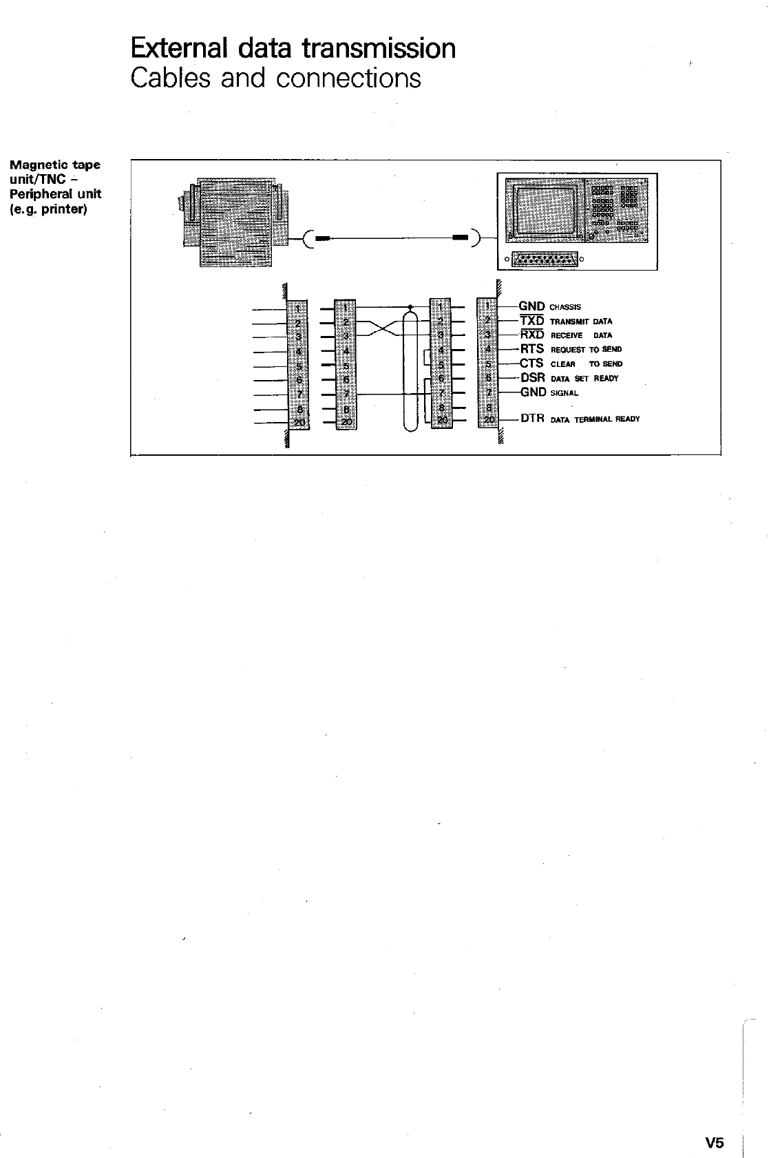
External data transmission
Cables and connections
Magnetic tape
unit/TNC -
Peripheral unit
(e.g. printer)
TXD
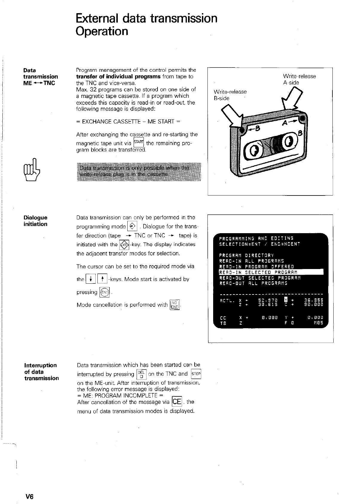
Data
transmission
ME --TNC
Dialogue
initiation
Interruption
of data
transmission
External data transmission
Operation
Program management of the control permits the
transfer of individual programs from tape to
the TNC and vice-versa.
Max. 32 programs can be stored on one side of
a magnetic tape cassette. If a program which
exceeds this capacity is read-in or read-out, the
following message is displayed:
= EXCHANGE CASSETTE - ME START =
After exchanging the cassette and restarting the
magnetic tape unit via STAm the remaining pro-
0
gram blocks are transferred.
Data transmission can only be performed in the
programming mode 3 Dialogue for the Vans-
0
fer direction (tape - l-NC or TNC + tape) is
-key. The display indicates
the adjacent transfer modes for selection.
The cursor can be set to the required mode via
the 4 m-keys. Mode start is activated by
0
Mode cancellation is performed with
q
.
Write-release
Write~release
A-side
Data transmission which has been started can be
interrupted by pressing
q
on the TNC and H
on the ME-unit. After interruption of transmission.
the following error message is displayed:
= ME: PROGRAM INCOMPLETE =
After cancellation of the message via
CE
the
0
menu of data transmission modes is displayed.
V6
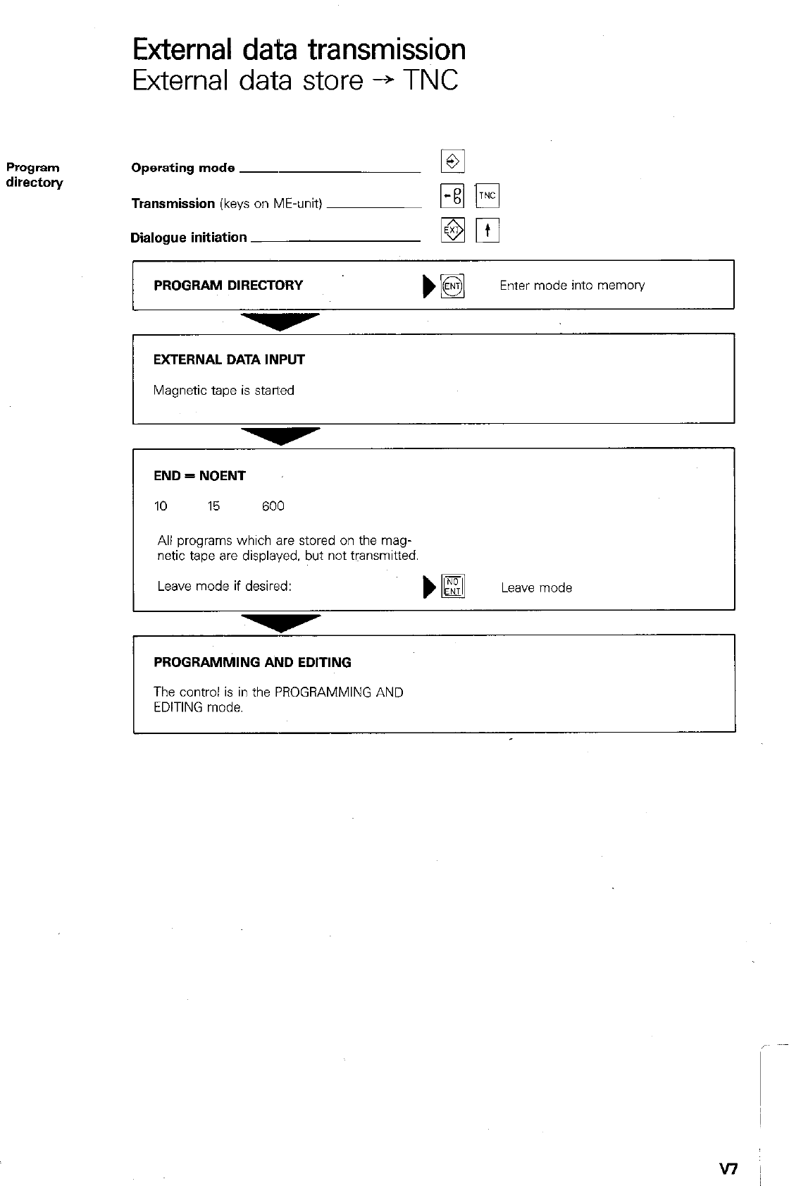
External data transmission
External data store -+ TNC
Program
directon/ Operating mode ~
Transmission (keys on ME-unit)
Dialogue initiation
PROGRAM DIRECTORY
b@
Enter mode into memon/
EXTERNAL DATA INPUT
Magnetic tape is stalled
I I
-
END = NOENT
10 15 600
All programs which are stored on the mag-
netic tape are displayed. but not transmitted.
Leave mode if desired:
)a
Leave mode
PROGRAMMING AND EDITING
The control is in the PROGRAMMING AND
EDITING mode.
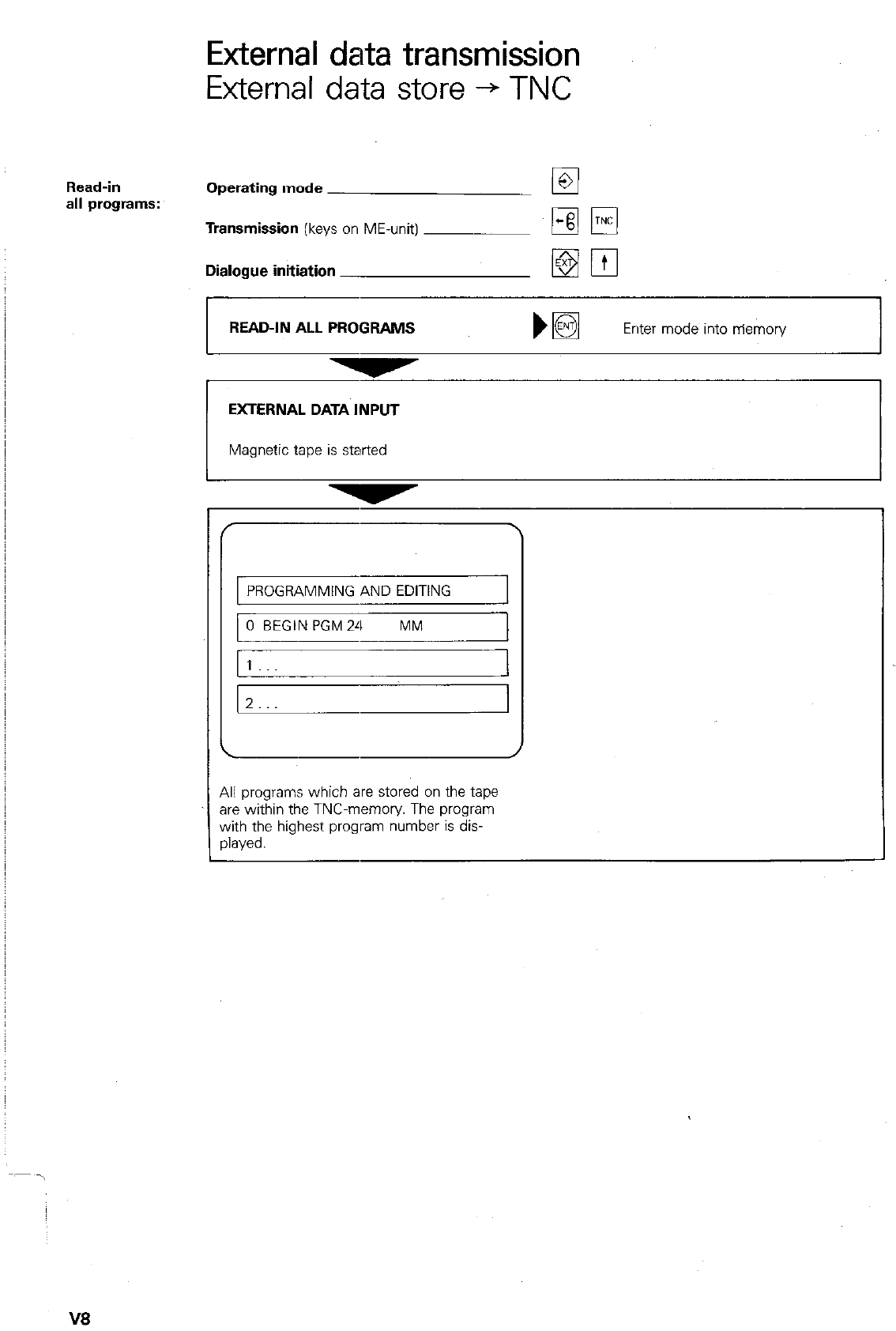
External data transmission
External data store -+ TNC
Read-in
all programs: Operating mode
Transmission
(keys on ME-unit)
Dialogue initiation
READ-IN ALL PROGRAMS
EXTERNAL DATA INPUT
Magnetic tape is started
PROGRAMMING AND EDITING
0 BEGIN PGM24 MM
1
z...
All programs which are stored on the tape
are within the TNC-memory The program
with the highest program number is dis-
played.
V8
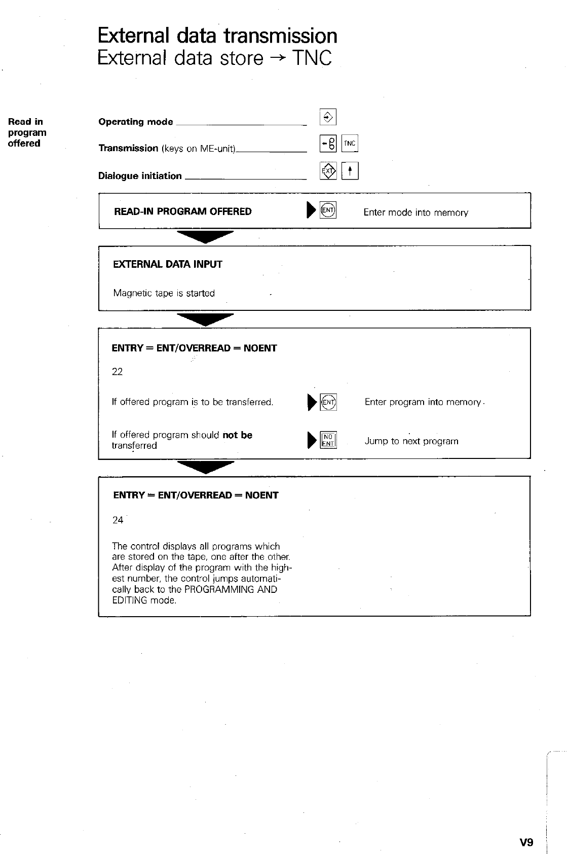
External data transmission
External data store + TNC
Operating mode
Transmission
(keys on ME-unit)
Dialogue initiation
READ-IN PROGRAM OFFERED bm
Enter mode into memory
EXTERNAL DATA INPUT
Magnetic tape is started
ENTRY = ENTIOMRREAD = NOENT
22
If offered program is to be transferred. Enter program into memory
If offered program should
not be
transferred Jump to n&t program
ENTRY=ENT/OVERREAD=NOENT
24
The control displays all programs which
are stored on the tape, one after the other.
After display of the program with the high-
est number, the control jumps automati-
cally back to the PROGRAMMING AND
EDITING mode.
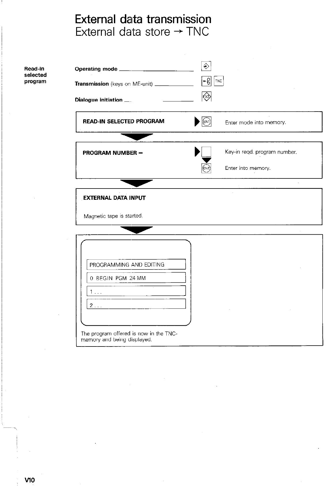
External data transmission
External data store + TNC
Read-in
selected
program
Operating mode -
Transmission
(keys on ME-unit)
Dialogue initiation
READ-IN SELECTED PROGRAM
Enter mode into memoiy.
PROGRAM NUMBER =
Key-in reqd. program number.
Enter into memory.
EXTERNAL DATA INPUT
PROGRAMMING AND EDITING
The program offered is now in the TNC.
memory and being displayed.
VlO
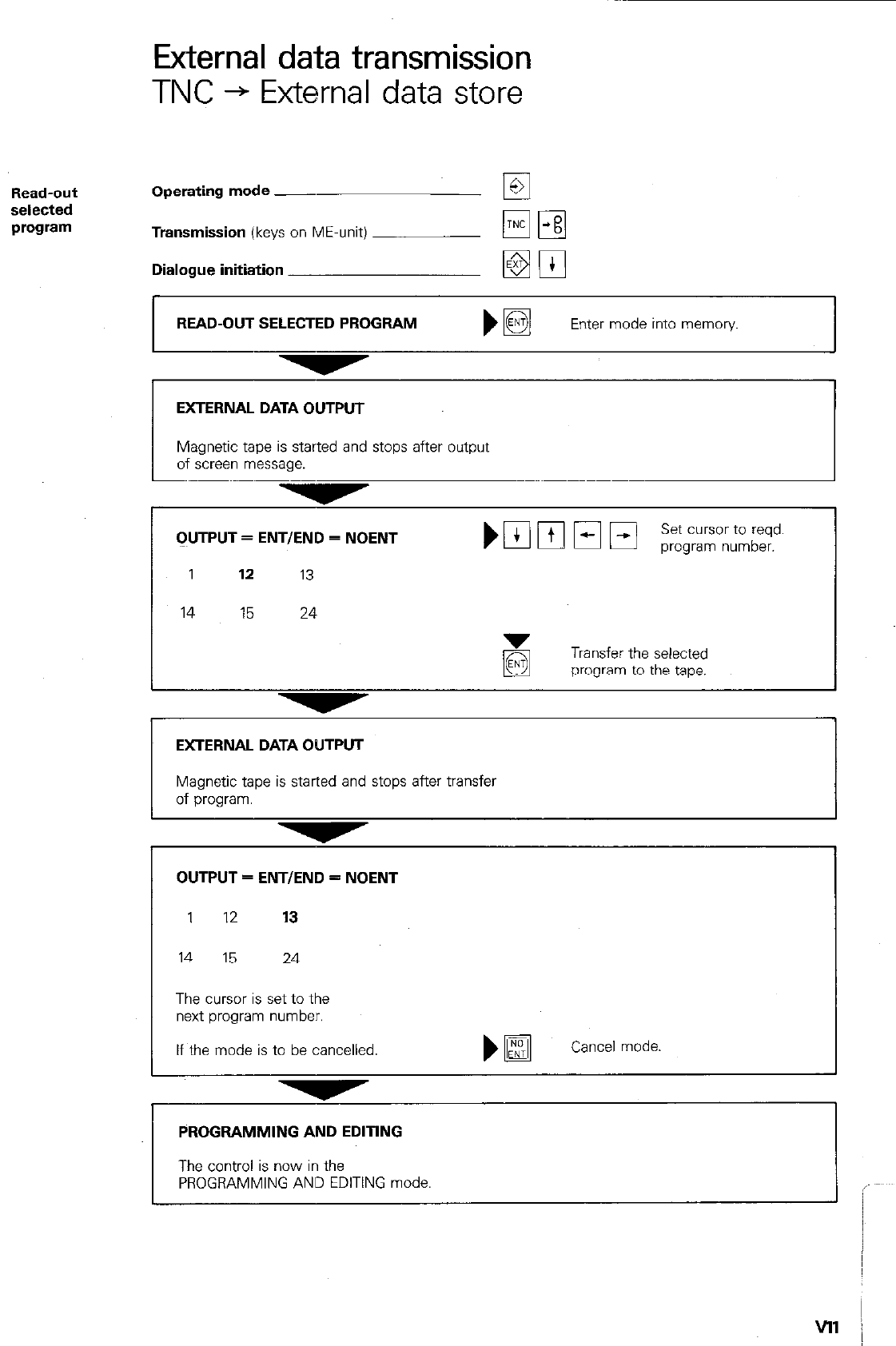
External data transmission
TNC + External data store
Operating mode __
Transmission (keys on ME-unit)
Dialogue initiation
READ-OUT SELECTED PROGRAM
EXTERNAL DATA OUTPUT
Magnetic tape is started and stops after output
of screen message.
CIUTPUT = ENTIEND = NOENT
1 17. 13
14 15 24
Transfer the selected
program to the tape.
EXTERNAL DATA OUTPUT
Magnetic tape is started and stops after transfer
of program.
OUTPUT = ENTIEND = NOENT
1 12 13
14 15 24
The cursor is set to the
next program number.
If the mode is to be cancelled
)@
Cancel mode
PROGRAMMING AND EDITING
The control is now in the
PROGRAMMING AND EDITING mode.
vll /
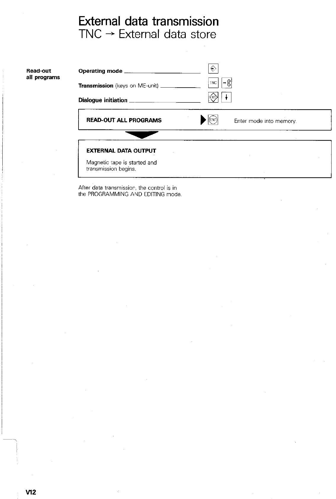
External data transmission
TNC + External data store
Read-out
all programs Operating mode
Transmission
(keys on ME-unit)
Dialogue initiation _
READ-OUT ALL PROGRAMS bm
Enter mode into memory
EXTERNAL DATA OUTPUT
transmission begins.
After data transmissior, the control is in
the PROGRAMMING AllD EDITING mode.
v12
Execution
from an
external store
Data interface
Starting of
“Transfer
blockwise”
External data transmission
Transfer blockwise
In the “transfer blockwise mode*, machining pro-
grams can be transferred and executed from an
external store via the series data interface V.24.
(R-232-C). It is therefore possible to execute
programs which exceed the storage capacity of
the control.
The data interface is programmable via machine
parameters. A detailed description of the inter-
face signals and necessary software adaptation
of the computer is given in the manual *Interface
description TNC 151flNC 155”.
Data transmission from an external store can be
started with the m-key in the modes:
“Single block/Automatic program run” and ‘Test
run”. The control stores the program blocks in
the memory available and interrupts data trans-
mission if the memory capacity is exceeded.
The display shows no program blocks until either
the available memory is full or the complete pro-
gram has been transferred.
Although program blocks are not being dis-
played, program run can be started by pressing
the external STY
Q -button.
,When operating via an external store. only short
positionings are normally executed. In order to
prevent an unnecessary interruption after starting.
a substantial buffer of program blocks should be
stored. It is therefore advantageous to wait until
the available memory is full.
After starting, the executed blocks are automati-
cally erased and further blocks are called-up
from the external store.
\
v14
External data transmission
Transfer blockwise
Overreading If
q
q .
IS pressed and a block number entered
program blocks prior to the starting of “transfer blockwise*, all
blocks prior to the entered block number are
overread.
Interruption
of program
execution
Interruption of execution is possible:
0 by pressing the external stop button and
internal STOP-key.
The display TRANSFER BLOCKWISE remains
after interruption of execution. It is erased if
0 a new program number is called-up
01
0 a mode changeover is made from single
block/Automatic program run to another
operating mode.
Program
structure In the “transfer blockwise- mode the following
applies for program structure:
0 Program calls, Subprogram calls, Program
part repeats and certain program jumps can-
not be executed.
l
Only the last defined tool can be called-up.
(exception: Operation with a central tool
store).
Block
number
The program which is being transferred may
contain blocks with numbers greater than 999.
The block numbers do not have to be consecu-
tive, but should not exceed the number 65534.
With plain language programs, 4.digit block
numbers are displayed in 2 lines on the screen.
VI5 j
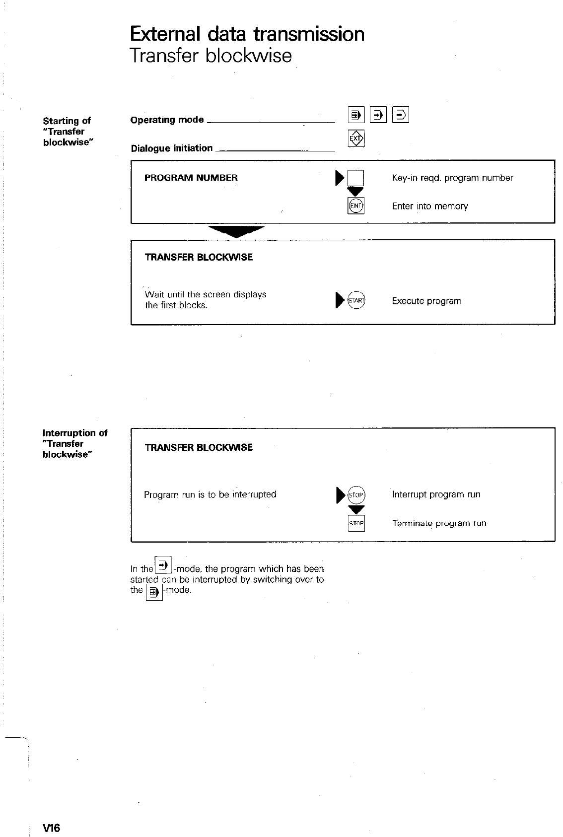
External data transmission
Transfer blockwise
Starting of
“TlWk3fer
blockwise”
Operating mode
Dialogue initiation
PROGRAM NUMBER Key-in reqd. program number
g Enter into memon/
TRANSFER BLOCKWISE
Wait until the screen displays
the first blocks. Execute program
Interruption of
“Transfer
blockwise” TRANSFER BLOCKWlSE
Program run is to be interrupted Interrupt program run
Terminate program run
In the 3 -mode. the program which has been
El
started can be interrupted by switching over to
the, > -mode.
El
W6
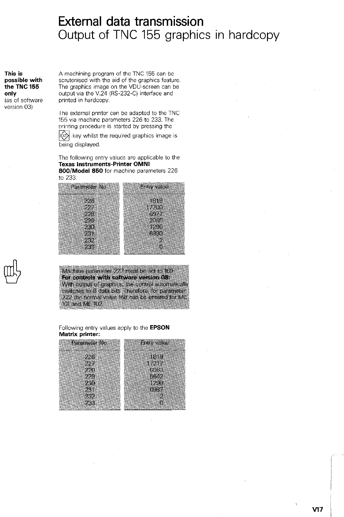
External data transmission
Output of TNC 155 gra.phics in hardcopy
This is
possible with
the TNC 155
only
(as of software
version 03)
A machining program of the TNC 155 can be
scrutenised with the aid of the graphics feature.
The graphics image on the VDU-screen can be
output via the V.24 (E-232-C) interface and
printed in hardcopy.
The external printer can be adapted to the TNC
155 via machine parameters 226 to 233. The
printing procedure is started by pressing the
!!!, displayed.
key whilst the required graphics image is
The following entry values are applicable to the
Texas Instruments-Printer OMNI
800lModel 850 for machine parameters 226
to 233:
Following entry values apply to the EPSON
Matrix printer:
v17 /
Remarks
Technical description/Specifications
Control
versions TNC 151
with visual display unit BE 111 (g-inch monochrome) or BE 211 (12.inch monochrome) including PLC for
external machine adaptation
TNC 151 A
without separate PLC-l/D-boards
TNC 151 P
inputs and outputs on 1 or 2 separate PLC-l/O-boards
TNC 155
with visual display unit BE 411 (12.inch monochrome) including PLC for machine adaptation
TNC 155 A
without separate PLC-I/O-boards
TNC 155 P
inputs and outputs on 1 or 2 separate PLC-l/O-boards
Control type Contouring control for 4 axes
Linear interpolation in 3 out of 4 axes, Circular interpolation in 2 out of 4 axes. Helical interpolation
Program entry and display either with HEIDENHAIN-plain language dialogue or to IS0 6983 standard
format (G-codes). mm/inch instant conversion for entry values and displays
Display step 0.005 mm or 0.0002 inch or optionally 0.001 mm or 0.0001 inch
Nominal positions (absolute or incremental) in Cartesian or Polar co-ordinates
Entry step down to 0.001 mm or 0.0001 inch or O.OO1°
Operator-
prompting and
displays
Plain language dialogue and fault/error indication (in various languages).
Display of current program block, previous block and 2 successive blocks
Actual position/Nominal position/Target distance/Trailing error display and status
display for ail important program data
Program memory Buffered semiconductor store for 32 NC-programs: Programmable erase/edit protection:
TNC 151
Optional 1200 or 3100 blocks
TNC 155
3100 blocks
Central
tool store
Up to 99 tools for automatic random select toolchangers with variable tool location coding
Operating
modes Manual/Electronic handwheel: Control operates as a digital readout
Positioning with MDI: Positioning block is keyed-in (without entry into memory) and immediately
positioned
Program run in single block: Block-by-block positioning with individual press of button
Automatic mode: After press of button, complete run of program sequence until *programmed
STOF or program end.
Programming (also during program run)
a) with linear or circular interpolation:
Manually (MDI) to program list or workpiece drawing
or externally via V.Z4/RS-232-C data interface (e.g. Magnetic tape unit ME 101/102 from
HEIDENHAIN or other peripheral unit)
b) with single axis operation: additionally by entering actual position data (playback) during
conventional manual machining.
Transfer blockwise: On line operation with a host computer. Programs which exceed the memon/
capacity of the control can be transferred from the host computer in data blocks and simultaneously
executed.
Additional operating modes: mm/inch, character height for position display, Safety zones. User-
parameters (defined by machine tool builder)
Displays for: Vacant blocks, Actual/Nominal position/Target distance/Trailing error. Baud rate. Block
number increment (with ISO-programming)
Tl
Technical description/Specifications
Programmable
functions Linear chamfer
Circular path by circle centre and end point of circular arc/Circular path with tangential run-on by end
point of circular arc/Circular path with tangential transition on both ends by radius only.
Tangential contour approach and departure
Tool number. tool length and radius compensation
Spindle speed
Rapid traverse
Feed rate
Call-up of programs into other programs (4 x nesting)
Subprograms/Program part repeats (8 x nesting)
Canned cycles for: Peclcing, Tapping, Slot milling, Rectangular pocket milling. Circular pocket
Co-ordinate transformarions:
Datum shift. Co-ordinate system rotation, Mirror image. Scaling
Dwell time
Auxiliary functions M
Program Stop
Parameter Mathematical functions (=, +. -, x. +. sine. cosine. Lm)
programming Parameter comparison (=, +, >. <)
Program test TNC 151iTNC 155: Analytical program test without graphics
without machine TNC 155 only: Graphics simulation of machining program
mO”Hlle”t Display modes: in three planes,
view with depth shading,
3D-view
Program editing Editing of block-words, inseition of program blocks, deletion of program blocks;
Search routines or finding blocks with common criteria within a program.
Program run conti- The control simplifies continuation of program run by storing all important program data.
nuation after inter-
ruption
Touch probe
functions For setting-up operatiorl in the “manual” or “electronic handwheel” mode.
Detection of workpiece attitude on the machine table through point probing.
Definition of a comer pOsition or centrepoint and workpiece rotation.
Programmable: Setting of a workpiece surface as datum.
Data
interface Standard series interface to CCIT-recommendation V.Z4/EIA-standard P&232-C
Programmable Baud rai:es: 110. 150, 300, 600. 1200. 2400. 4800. 9600 Baud
Extended interface with control character and block check character BCC for “transfer blockwise--
mode and “execution of machining programs”.
Monitoring
system The control monitors the functioning of important electronic subassemblies including positioning
systems. position transducers and important machine functions.
If a fault is discovered \lia this monitoring system. it is indicated in plain language on the visual display
unit (VDU) and the machine emergency stop is activated.
Reference After a power failure, automatic re-generation of datum setting by traversing over transducer reference
mark evaluation mark.
Max. traversing + 30 m or 1181 inches
distance
Max. traversing 16 m/min. or 630 incheslmin.
speed
Feed rate
and spindle
override
Two potentiomet&s on the control panel
T2
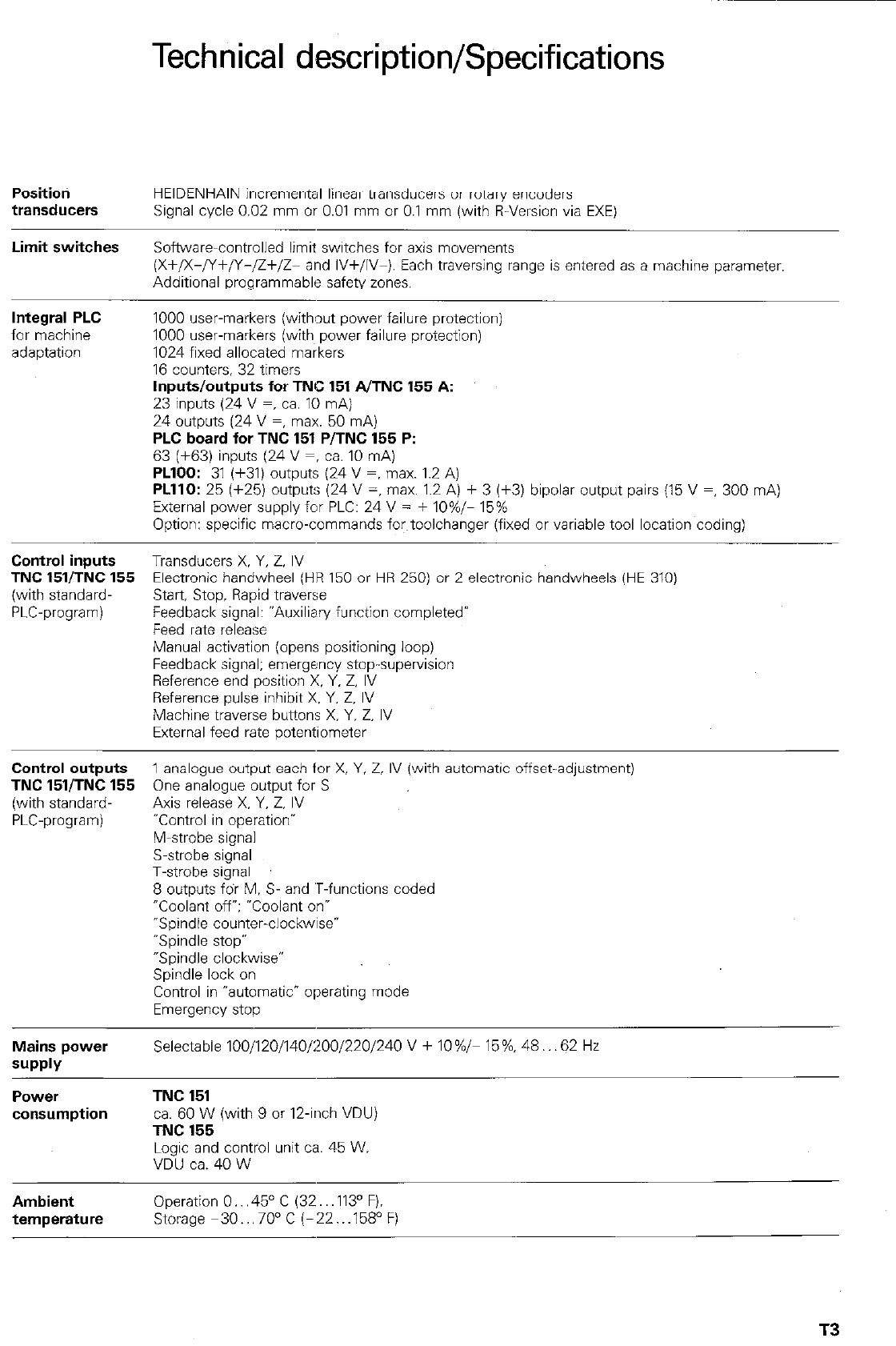
Technical description/Specifications
Positioti
transducers HEIDENHAIN incremental linear transducers or rotary encoders
Signal cycle 0.02 mm or 0.01 mm or 0.1 mm (with R-Version via EXE)
Limit switches Softwarecontrolled limit switches for axis movements
(X+/X-/Y+/Y-/Z+/Z- and IV+/IV-). Each traversing range is entered as a machine parameter.
Additional programmable safety zones.
Integral PLC
for machine
adaptation
1000 user-markers (without power failure protection)
1000 user-markers (with power failure protection)
1024 fixed allocated markers
16 counters, 32 timers
Inputs/outputs for TNC 151 AITNC 155 A:
23 inputs (24 V =, ca. 10 mA)
24 outputs (24 V =, max. 50 mA)
PLC board for TNC 151 P/TNC 155 P:
63 [+63) inuuts 124 V =, ;a. 10 mAi
PLlOO: 31 (+31) outputs (24 V =, max. 1.2 A)
PLllO: 25 (+25) outputs (24 V =, max. 1.2 A) + 3 (f3) bipolar output pairs (15 V =, 300 mA)
External power supply for PLC: 24 V = + IO%/- 15%
Option: specific macro-commands fwtoolchanger (fixed or variable tool location coding)
Control inputs Transducers X. Y, Z. IV
TNC 15VTNC 155 Electronic handwheel (HR 150 or HR 250) or 2 electronic handwheels (HE 310)
(with standard- Start Stoo. Ravid traverse
bLC-program) Feedback’sign81: “Auxiliary function completed’
Feed rate release
Manual activation (opens positioning loop)
Feedback signal; emergency stop-supervision
Reference end position X. Y. Z, IV
Reference pulse inhibit X. Y. Z. IV
Machine traverse buttons X. Y. Z. IV
External feed rate potentiometer
Control
outputs 1 analogue output each for X, Y. 2, IV (with automatic offset-adjustment)
TNC 15VTNC 155 One analogue output for S
(with standard- Axis release X. Y. Z. IV
PLC-program) -Control in operation-
M-strobe signal
S-strobe signal
T-strobe signal
8 outputs fdr M. S- and ‘T-functions coded
OCoolanr ofr; “Coolant on-
-Spindle counter-clockwise*
“Spindle stop”
“Spindle clockwise”
Spindle lock on
Control in “automatic* operating mode
Emergency stop
Mains power
SUPPlY
Selectable 100/120/140/200/220/240 V + IO%/- 15%. 48.. .62 Hz
PCWSr
consumption
TNC 151
ca. 60 W (with 9 or 12.inch VDU)
TNC 155
Logic and control unit ca. 45 W.
VDU ca. 40 W
Ambient Operation 0.. .45” C (32.. ,113’ F).
temperature Storage m30...70°C (-22...158’F)
T3
Technical description/Specifications
Weight
Control TNC 151,‘TNC 155: 12 kg (26 lb.)
Visual display unit BE ’ 11 (9 inch): 6.8 kg (15 lb.)
Visual display unit BE 211/BE 411 (12 inch): 10 kg (24 lb.),
PLC-board PL lOO/PL 110: 1.2 kg (2.6 lb.) (TNC 151 PflNC 155 P)
T4
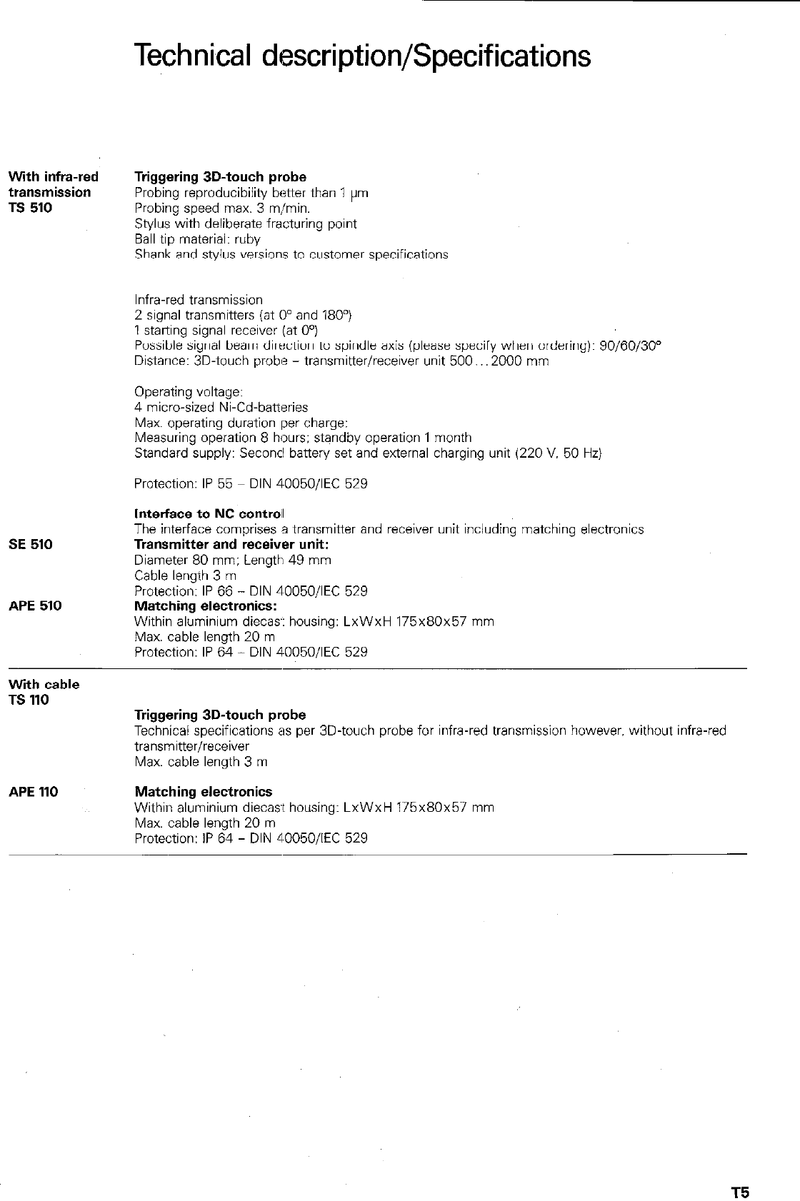
With infra-red
transmission
TS 510
SE 510
APE 510
With cable
TS 110
APE 110
Technkal description/Specifications
Triggering 3D-touch probe
Probing reproducibility better than 1 pm
Probing speed max. 3 mjmin.
Stylus with deliberate fracturing point
Ball tip material: ruby
Shank and stylus versions to customer specifications
Infra-red transmission
2 signal transmitters (at 0” and 180”)
1 st&ng signal receiver (at 0”)
Possible signal beam direction to spindle axis (please specify when ordering): 90/60/30”
Distance: 3D-touch probe - transmitter/receiver unit 500.. .2000 mm
Operating voltage:
4 micro-sized Ni-Cd-batteries
Max. operating duration per charge:
Measuring operation 8 hours: standby operation 1 month
Standard supply: Seconcl battery set and external charging unit (220 V. 50 Hz)
Protection: IP 55 DIN 40050/IEC 529
Interface to NC contrail
The interface comprises a transmitter and receiver unit including matching electronics
Transmitter and receiver unit:
Diameter 80 mm; Length 49 mm
Cable length 3 m
Protection: IP 66 - DIN 40050/IEC 529
Matching electronics:
Within aluminium diecas-: housing: LxWxH 175x80~57 mm
Max. cable length 20 m
Protection: IP 64 - DIN 400501lEC 529
Triggering 3D-touch probe
Technical specifications as per 3D-touch probe for infra-red transmission however. without infra-red
transmitter/receiver
Max. cable length 3 m
Matching electronics
Within aluminium diecast housing: LxWxH 175x80~57 mm
Max. cable length 20 m
Protection: IP 64 - DIN 40050/IEC 529
T5
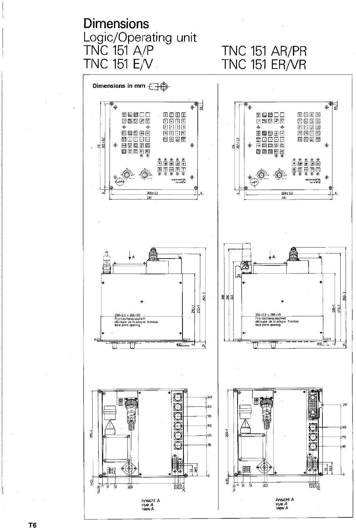
Dimensions
Logic/Operating unit
TNC 151 4/P TNC 151 AR/PR
TNC 151 E/V TNC 151 ER/VR
Dimensions in mm w
T6
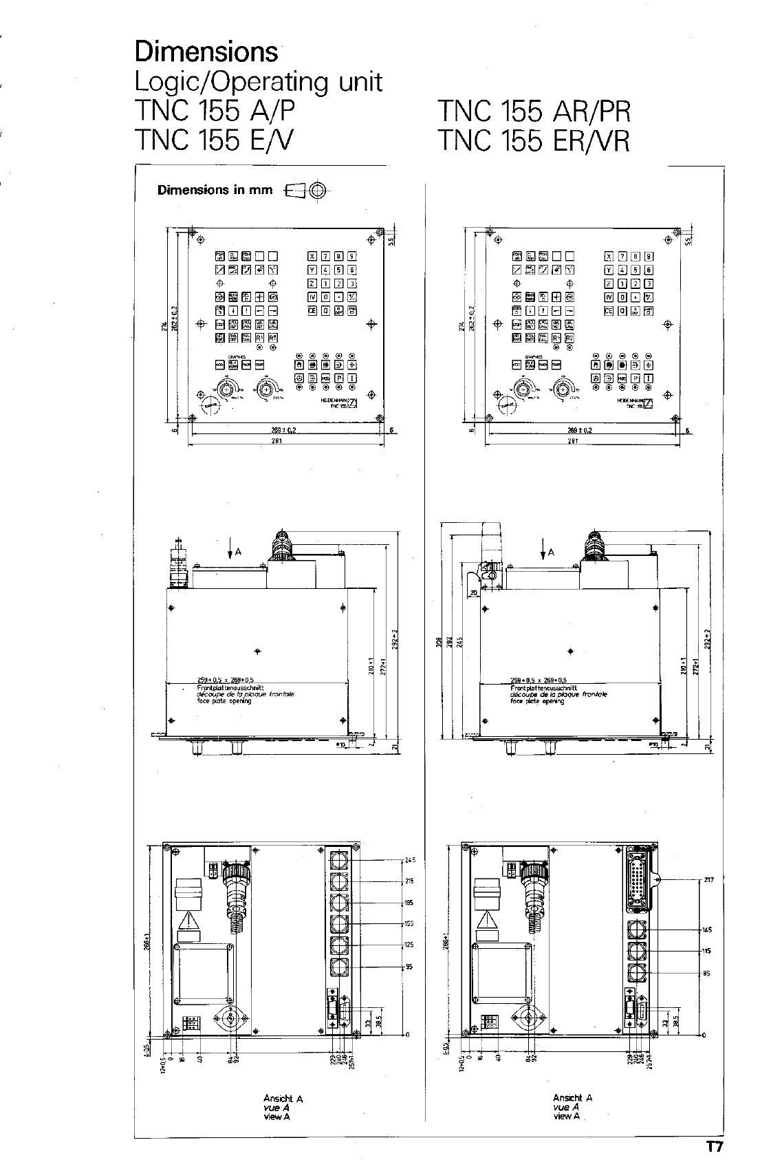
Dimensions
Logic/Operating unit
TNC 155 A/P TNC 155 AR/PR
TNC 155 E/V TNC 155 ER/VR
,-
Dimensions in mm @-
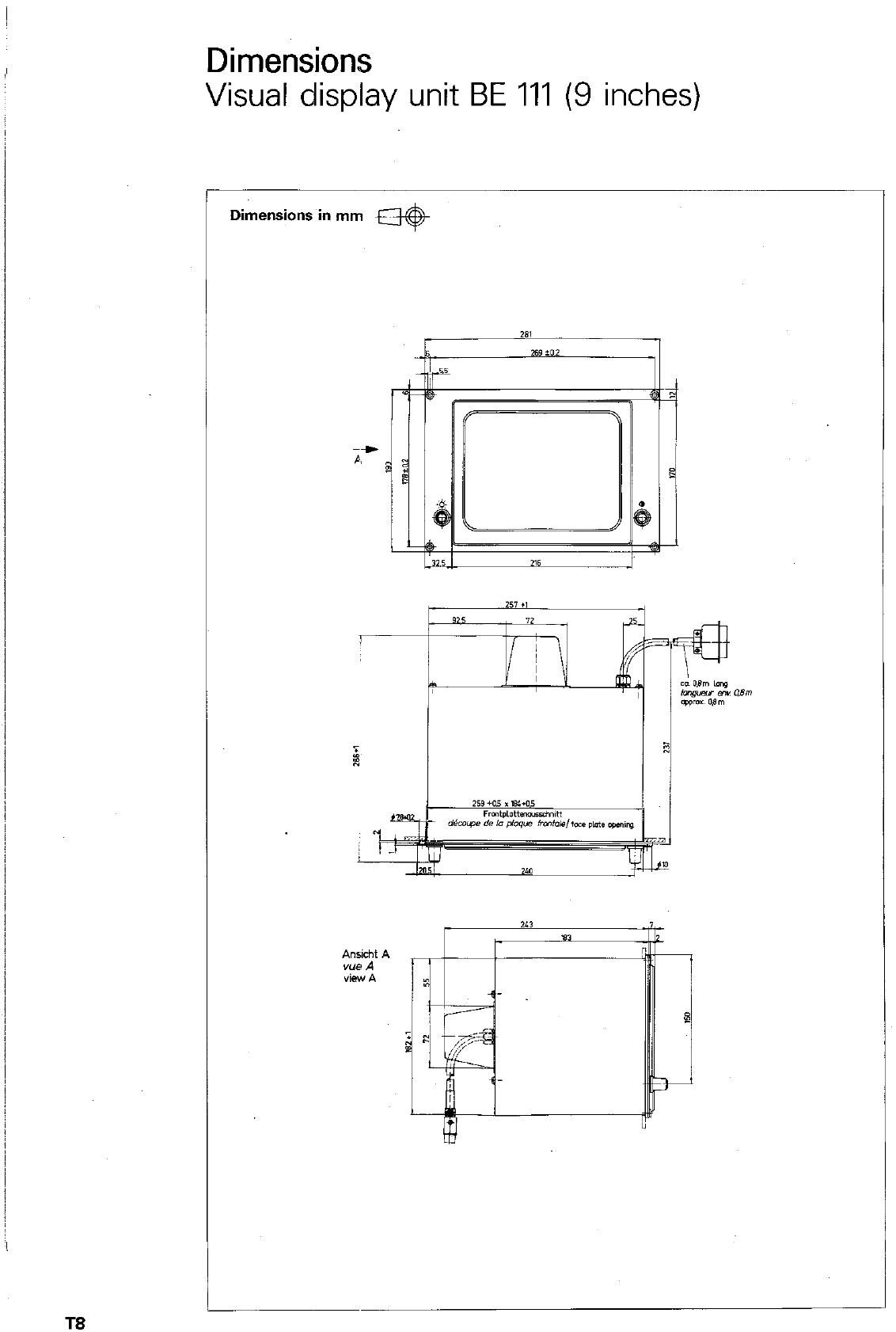
Dimensions
Visual display unit BE 111 (9 inches)
DiAznsions in mm *
2‘1
I
TS
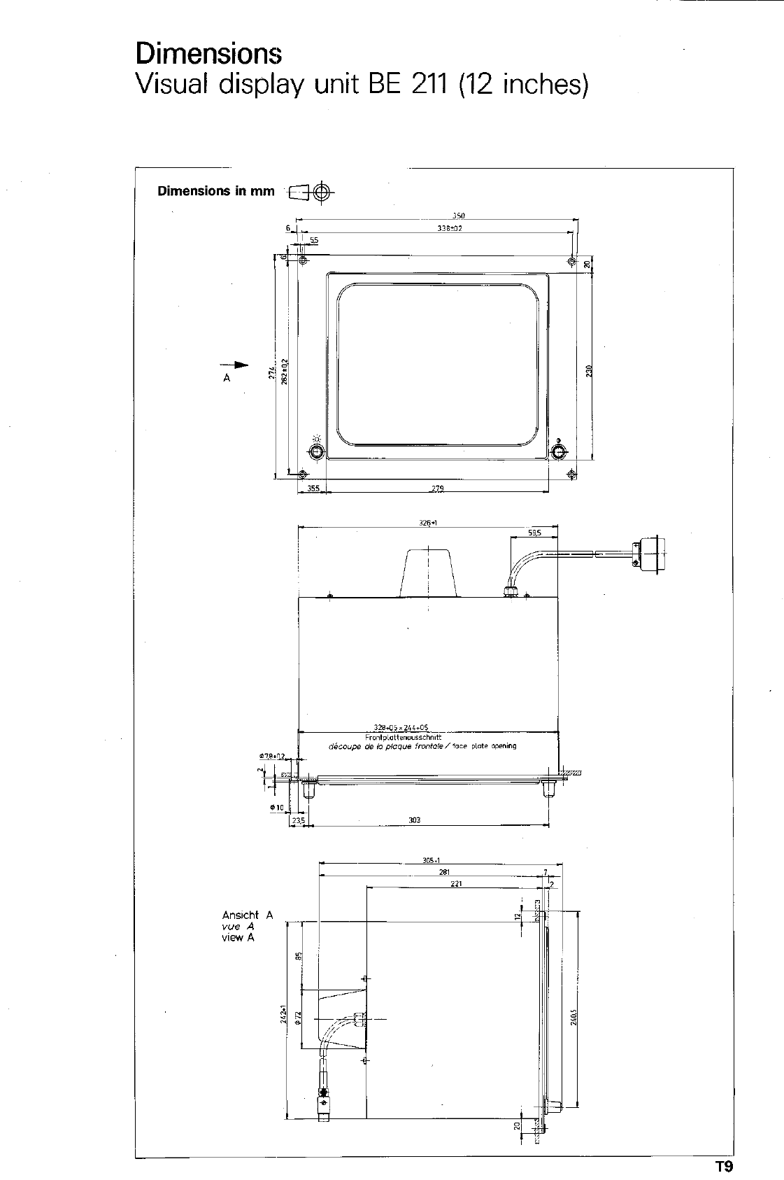
Dimensions
Visual display unit BE 211 (12 inches)
Dimensions in mm w
-
A
L
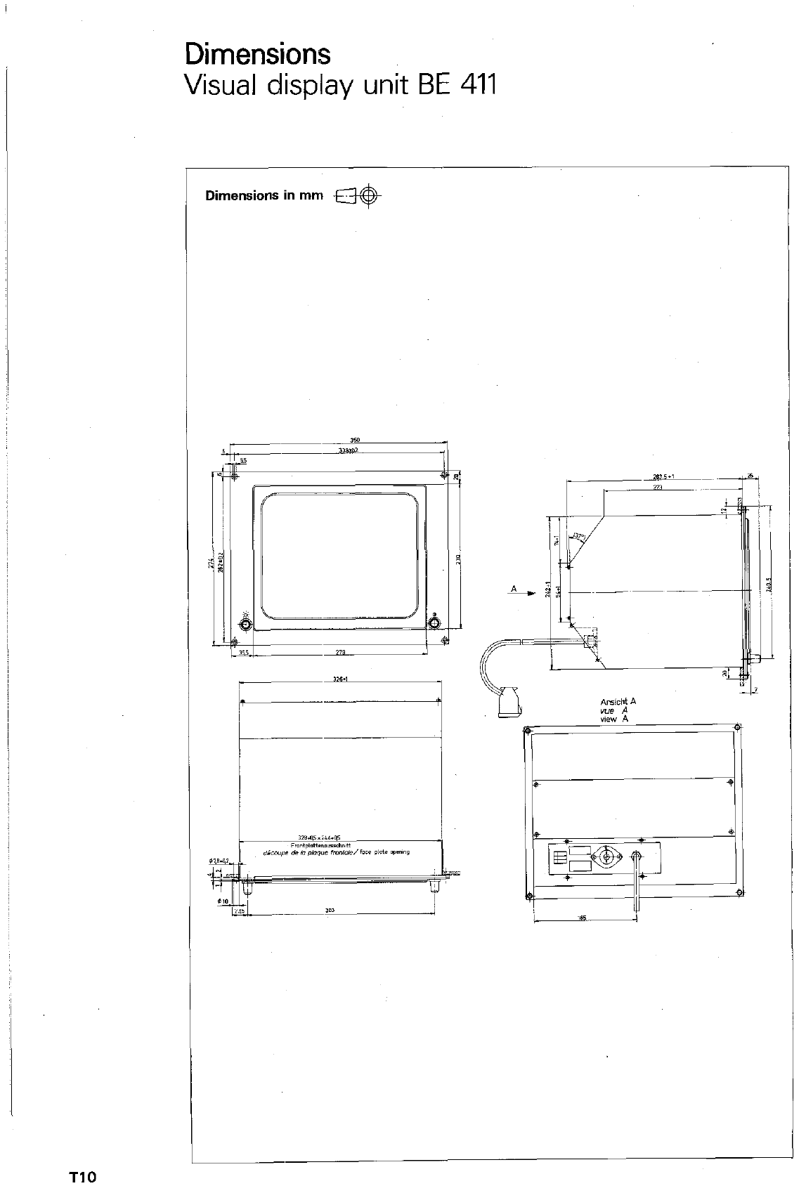
Dimensions
Visual display unit BE 411
Dimensions in mm @($&
T10
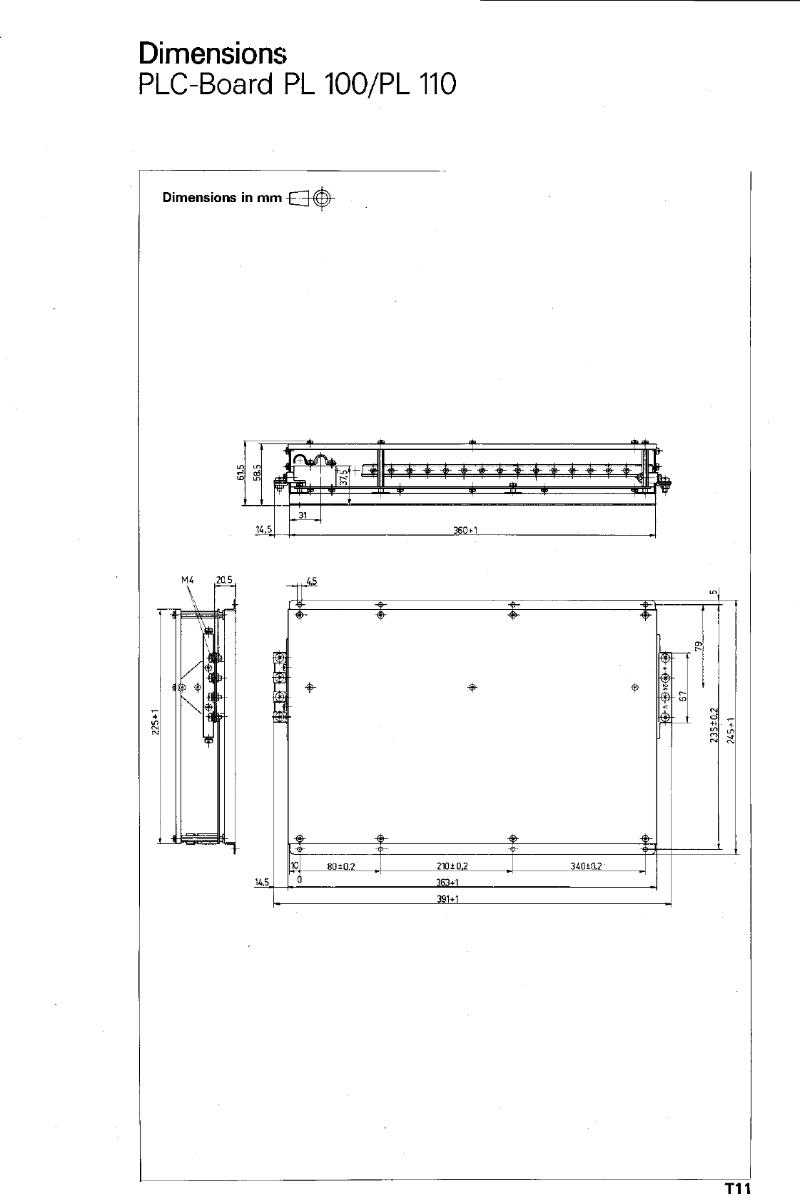
Dimensions
PLC-Board PL lOO/PL 110
c
bimensions in mm *
Tl
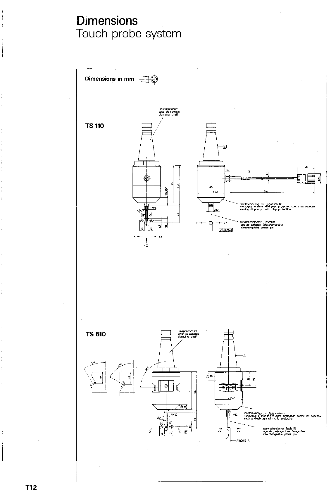
Dimensions
Touch probe system
7
TS 510
T12
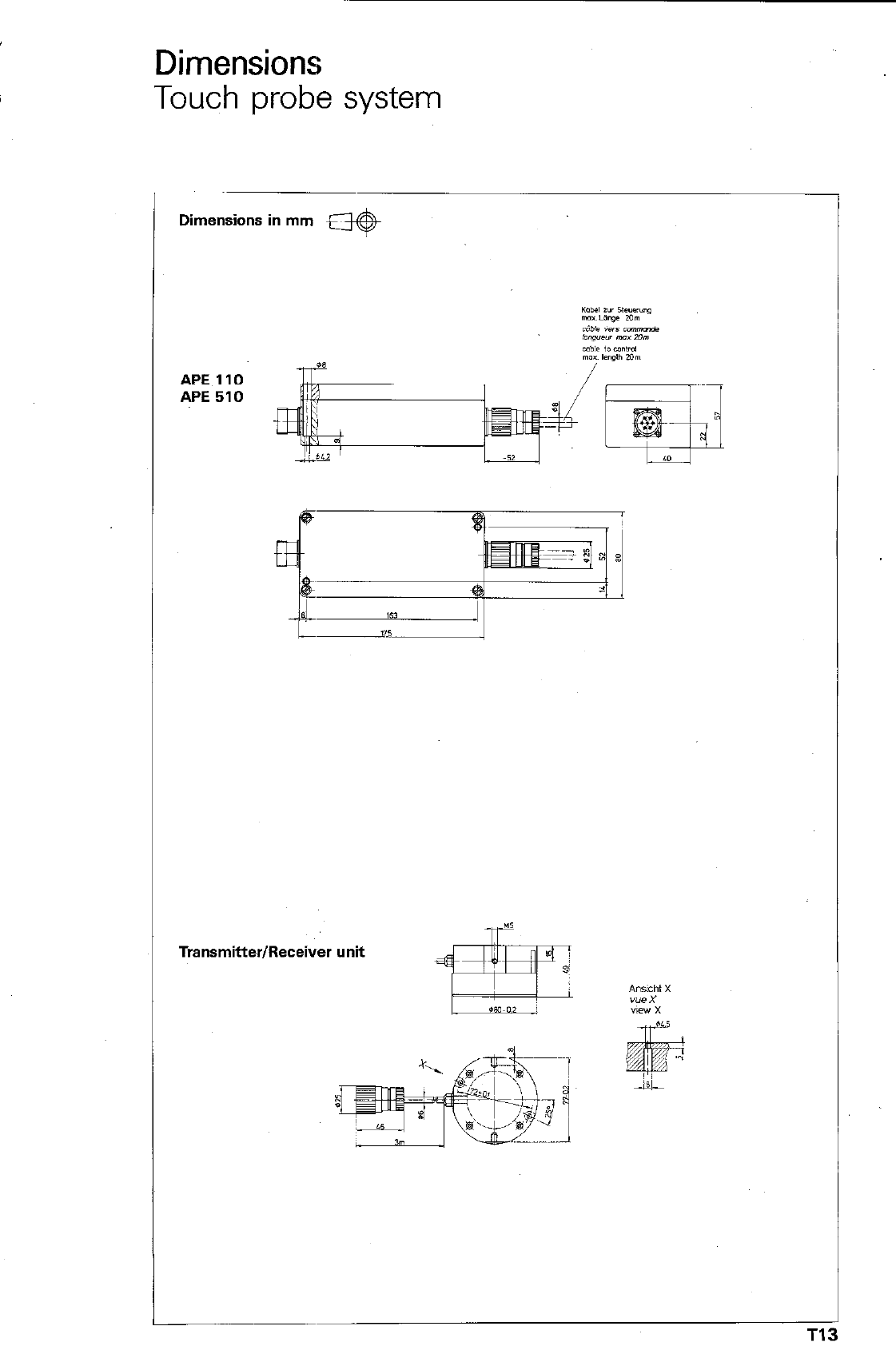
Dimensions
Touch probe system
Dimensions in mm M
Transmitter/Receiver unit
Index
A
Absolute dimensions KIO, P17, P22, DIO
0 IS0 DlO
0 Plain lanauaae PI7
Adjoining arcs _
0 IS0
0 Plain language -
Advanced stop distance t
Angle reference axis _
Approach command M95
Approach command M96
Approach command M98
Arc with tangential connection (see Adjoining arcs)
Auxiliary functions M _
0 freely selectable _
l
which affect program run
B
P46
D16
D47
P86
K2
P61
P60
P60
P46
P30
P33
P32
Basic rotation
- entry
Baud rate
- entry
Blank (Graphics) ~
BLK FORM (Blank form)
Block call-up
Block deletion ~
Block insertion ~
Block number ~
Block number increment
Buffer battery ~
Al 1
Al2
El2
V2
PI30
P130. PI 33
PI22
PI24
PI24
P2
E12, D5
VI6
C
C (see Circular interpoiation)
Calibration
- effective length -
-sentry
- effective radius _
entry
Canned cycles
CC (see Circle centre/Pole)
CE-key
Chain dimensions
Chamfers
l IS0
0 Plain language -
Circle centre
l IS0
0 Plain language _
Circle centre = Datum
- entry
Circular interpolation
0 IS0
0 Plain language _
Circular path
l IS0
0 Plain language _
Circular pocket ~
l IS0
0 Plain language
Code number ~
Connecting cable (ME:,
P40
A3
A3
A4
A7
A8
P82
P20, P40
P4
KIO, P17. P22, DIO
P50
D18
P51
P20, P40
D15
P21
A23
A24
P40
D14. D15, D16
P43. P45
P40
D14. D15. D16
P43. P45
PI04
D24
v4
El6
v4
T14
Index
C continued
Contour approach in a straight path P56
0 Path angle ” equal to 180” P57
0 Path angle ” greater than 180” P59
0 Path angle ” less than 180° P58
Contdur approach on a” arc P54
l IS0
D19
0 Plain language P55
Contouring keys ~ P18
Conversion mm/inch _ El0
Cosine (Parameter definition) P74
CT (see Adjoining arcs) P46
Co-ordinates Kl, P17
0 Cartesian Kl. P18
l
Polar (see Polar co-ordinates) K2. P22
0 Programming PI 9, P23
0 Right-angled Kl, PI8
Co-ordinate axes Kl
Co-ordinate system Kl
Co-ordinate system rotation PI14
0 IS0 D26
0 Plain language P115
Co-ordinate transformations P82
Corner = Datum ~ Al7
- entry Al8
QCk
P82
- call P82
cancellation P85
- definition P82
- deletion PI24
- parameters D21
D
D (Address letter)
Data transmission ~
Datum, setting
Datum shift
a IS0
0 Plain language ~
Deletion of block
Departing from a contour in a straight path
0 Path angle equal to 180°
0 Path angle greater than 180”
0 Path angle less tharl 180’
Departing from a contour on an arc
l
IS0
0 Plain language ~
Departure command M98
Dialogue prompting -
Direction of rotation -
0 Angle
l
Circular interpolation
l
Circular pocket milling
0 Pocket milling (rectangular)
DR (see Direction of rotation)
Dwell time
l
IS0
0 Plain language
l
Within a machining cycle
D30
Vl
K9
PI10
D25
Pl 11
P124
P56
P57
P59
P58
P54
D19
P55
P60
P2
P40
K2. PI 14
P40
PI04
P98
P40
PI18
D26
PI19
P86
T15
Index
E
Edit (see Erase/Edit prctection) P6
0 IS0 D8
l
Plain language
Editing of block words,
Electronic handwheel
Ellipse (programming example)
Emergency stop
END-key
Enlargement (Scaling) .
- Graphics
ENT-key
Erase (see Erase/Edit protection)
0 IS0
0 Plain language
Erase/Edit protection -
F
PI 42
P122
M2
P80
PI 50
P3
P117
P142
P3
P6
D8
PI42
P6
F (Address)
F (see Feed rate)
Fast image data processing (Graphics)
Feed rate
0 within a canned cycle
0 override
- constant on external corners M90
FN (see Parameter-function)
Freely programmable cycles (Program call)
l
IS0
0 Plain language -
D25, D26
P30. D12
PI 33
P30. D12
P86
Ml, P146. P162
P27
P70
PI20
D26
P121
G
G (Address)
G-functions
GOT0 (see Block call-up and Jump)
Graphics
0 Start
0 stop
H
D6
D6
P122
P130
P134. P135
P134, PI37
H (Address)
Helical interpolation
l IS0
0 Plain language
I
D13
P52
D16
P53
I (Adbress) D13
If equal. jump P76
If greater than. jump P78
If - jump P76
If less than. jump P78
If unequal. jump P78
Increase (Scaling) _ PI17
Incremental dimensions Kl 0. PI 7. P22. DIO
l
IS0 DlO
0 Plain language PI7
Infinite loop P64
Inserting a block - P124
Interpolation factor (Electronic handwheel) M2
Interruption of power E4
T16
Index
J
J (Address) D13
Jump (conditional) P76
l IS0
0 Plain language
Jump (unconditional) _
l
IS0
0 Plain language
K
D31
P77
P62
D28
P63
K (see Address)
k (see Stepover)
Keyboard
0 for IS0 (Fold-out page)
0 for plain language (Fold-out page)
D13
P99
Dl
Dl
Dl
L
L (see Linear interpolation)
Label
0 call
0 number
a set
LBL
LBL CALL
LBL SET
Limits (safety zones)
Linear interpolation
0 Three-dimensional (3D)
0 Two-dimensional (2D)
P34
P62
P62
P62
P62
P63
P63
P63
El4
P63
P34
P34
M (Address)
Machine axes
Machining cycles ~
0 IS0
0 Plain language ~
Machine parameters
0 table of
Magnetic tape u,nit
MAGN (see Magnify)
Magnify (Graphics) _
Manual operation
ME (see Magnetic tape unit)
M-function
Milling depth
Mirror image
0 IS0
0 Plain language
Miscellaneous function
mm/inch changeover
MOD-function
MP (see Machine parameters)
P30
K3
P82, P84
D19
P83
V16
PI68
v3
PI42
P142
Ml
v3
P30
P92. P98. PI 04
PI12
D25
PI13
P30
El0
E8
V16
N
N (Address)
NC: Software number
Nesting
NO ENT-key
D5
El6
P66
P3
T17
Index
0
Override Ml, P146, P162
- feed ride Ml, P146, PI62
- spindle speed - Ml, P146, P162
P
P (Address) (see Cycle parameter and Parameter definition)
P (Display and key) (see Polar co-ordinates)
Paging
- within definitions _
- within parameter definition
within cycle program
Parameters
- definition
e IS0
@ Plain language
- function
- Senlng
e IS0
@ Plain language
Path angle
Path/Radius compensation
e IS0
@ Plain language
- Correction of path intersection
- on external ccrners
on internal corners
- Termination M98 -
- with single axis positioning blocks
e IS0
@ Plain language -
Peck-drilling
e ISO
0 Plain language ~
Pecking depth
Peripheral unit ~
Plan view (Graphics) -
Playback
PLC: Software number
Pocket milling ~
e ISO
e Plain language
Polar co-ordinates -
Angle
e ISO
0 Plain language -
- Radius
0 IS0
0 Plain language
Pole
0 IS0
0 Plain language -
Position display ~
Position display enlarged/small
Positioning with MDI -
Power interrupted
Program
- amendments ~
call
- call (cycle)
0 IS0
0 Plain language -
DZI. D30
P23
P122
P83
P71
PI22
P70
P70
D30
P71
P70
P70
D30
P71
P56
P24
D17
P25
P26
P26
P26
P28. P60
PI 55
D17
P157
P86
D21
P87
P86. P98
VI
PI33
PI58
El6
P98
D23
PI01
K2, P22
P22
DIO
P23
P22
DlO
P23
P20
D13, D15
P21
El0
El2
PI 62
E4
PI
P122
P6
PI20
D26
PI 21
Index
P continued
- clearing P126
corrections (see Program editing) P122
- directory v7
- edit protection P6, P8
editing P3. PI22
- entry P6
l IS0 Dl
0 Plain language P7
- erase protection _ P126
- jump P7
0 if (conditional) _ P76
l * IS0 D31
00 Plain language P77
0 into another program P68
em IS0 D29
00 Plain language _ P69
l unconditional _ P62
l o IS0 D28
00 Plain language P63
- label P62
0 IS0 D28
l Plain language _ P63
- length P6
- number P6
- part repeat P64
l IS0 D28
0 Plain language P64
- protection P7
- run P146
0 automatic P146, D150
0 continuation P148. P151, P152
l interruption ~ PI48
0 single block ~ P146. P150
l termination ~ PI48
stop PI5
- supervision (see Program test and Search routines) P128, Pi 26
test P128
Program entry in ISO-format Dl
Program management P6. D5
Program menu ~ P6. V7
Protection (Erase/Edit) _ P6
l IS0 D8
0 Plain language PI42
Q
Q (Address)
0 DEFmkey P70
P70
R
R (Address)
Radius compensation -
- with normal program blocks
- with single axis milling
Rectangular Pocket (see Pocket milling)
Read-in program offerecl
Read-in selected prograin
Read-in tape contents
Read-out all programs
Read-out selected program
Reduction (Scaling) -
Reference mark ~
passing over ~
Pll. P22. P48. DIO. D18
P24
P24
P155
P98
v9
VI0
V8
VI2
VI 1
PI17
K5
E4
Tls
Index
Reference position _
Reference signal ~
Relative tool movement
REP (see Program repeat)
Repetition
RND (see Rounding of comers)
ROT (see Rotation angle)
Rotation angle ROT -
Rounding of comers -
a IS0
0 Plain language -
Rounding-off radius _
Run-off contour
Run-on contour ~
s
K5
K5
K3
P64
P64. P67
P49
‘PI15
PI14
P48
D18
P49
P48
P54. P56
P54. P56
S (Address) PI 5. D9
Scaling D25, P116, PI17
Scaling factor ~ PI16
l
IS0 D25
l
Plain language _ PI17
SCL (see Scaling factor) PI17
Screen display (opposite) El
Screen displays (modes E6
Search routines P126
Set-up clearance ~ P86
Sine (Parameter definition) P74
Single axis machining. PI55
0 IS0 D12
# Plain language - PI57
Slot milling P92
0 IS0 D22
0 Plain language ~ P95
Snap-on keyboard for IS0 Dl
Spindle axis PI4
Spindle override ~ Ml, P146. PI62
Spindle rotation direction (M-function) P32, P84
Square root (Parameter definition) P72
0 root of sum of square (Pythagoras) P75
0 square root ~ P72
Standard format (see Program entry in ISO-format) Dl
Stepover k P99
STOP PI5
Straight paths ~ P34
e IS0 D12, D13
0 Plain language - P37. P39
Subprogram P65
- repetiton P67
Subroutines (see SubpI-ogram) P65
Supplementary operating modes E8
Surface = Datum A14. A26
IS0 D27
- entry D27
- Plain language ~ A14. A26
entry A15. A27
Switch-on (control) - E4
Switchover lSO/Plain language and vice-versa D3
T20
Index
T
T (Address) D9
t (see Advanced stop) P86
Tapping P90
a IS0 D21
0 Plain language P91
Termination of path compensation M98 P60
Three dimensional (3D)+polation (see Linear interpolation) P34
Three dimensional (3D)-view P132
TOOI PlO
- call PI4
l
IS0 DS
0 Plain language P15
- compensation ~ PI0
a IS0 D9
0 Plain language P13, P15
0 with playback PI 59
- change PI4
definition PI0
l
IS0 D9
0 Plain language PI3
- length PI0
l
ISO- DS
0 Plain IangLlage PI3
number PIO. PI4
a IS0 DS
0 Plain language P13. PI5
- radius PI 1
l
IS0 DS
0 Plain language - PI3
TOOL axis PI4
TOOL CALL PI4
TOOL CALL 0 PI4
TOOL DEF _ PI0
Total hole depth (pecking) P86
Touch probe Al
Touch probe function, general A2
TOUCH PROBE-key _ A2
Transducer K5
Transfer blockwise (data) VI
Transmission rate for data (see Baud rate) v2
Two-D, (2D)-linear interpolation (see Linear interpolation) P34
U
Unconditional jump
l IS0
0 Plain language ~
User parameters ~
V
P62
D28
P63
El6
Vacant blocks
View in three planes (Graphics)
E8
PI32
T21
Index
w
Working spindle axis.
Workpiece
- COntOUr
datum (setting)
Write release ~
X
P14
P17
P17
K6. K9
V6
Y
z
Zero tooi PI0
T22
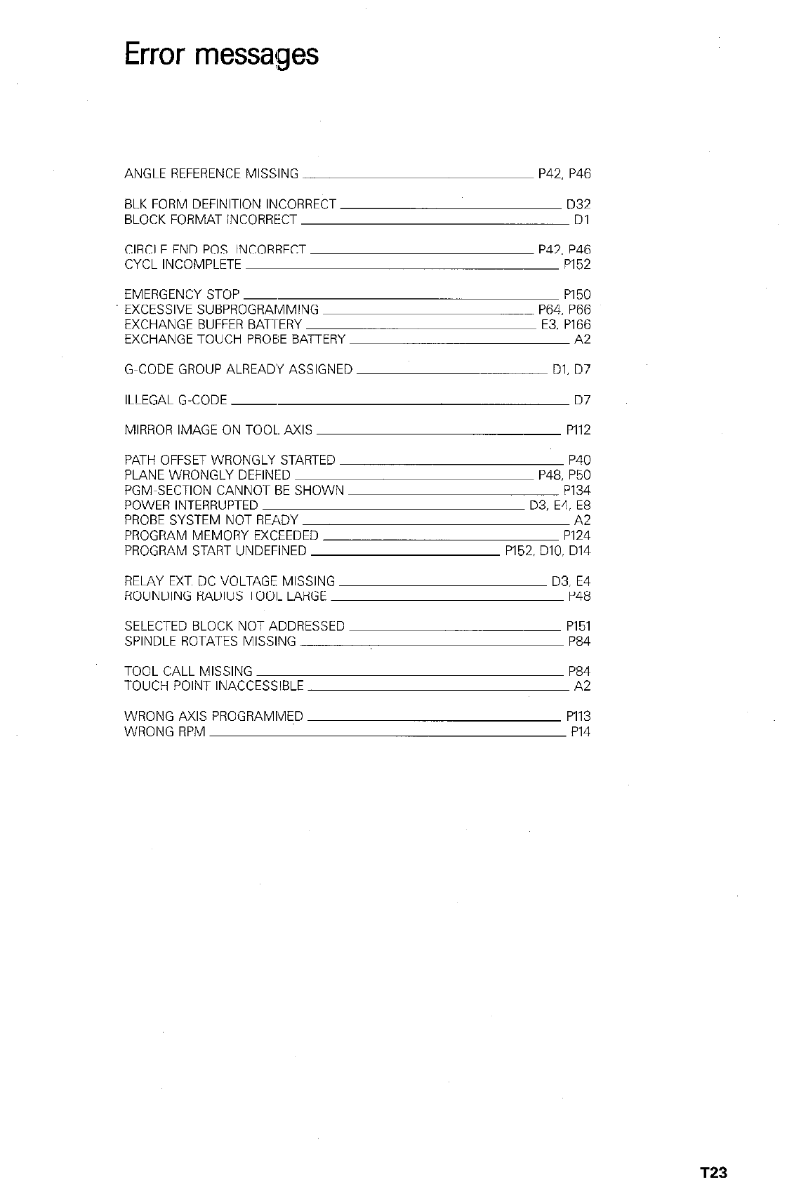
Error messages
ANGLE REFERENCE MISSING P42, P46
BLK FORM DEFINITION INCORRECT D32
BLOCK FORMAT INCORRECT Dl
CIRCLE END POS. INCORRECT P42. P46
CYCL INCOMPLETE PI52
EMERGENCY STOP ~ PI 50
P64. P66
E3. P166
A2
EXCESSIVE SUBPROGRAMMING
EXCHANGE BUFFER BATERY
EXCHANGE TOUCH PROBE BAiTERY
G-CODE GROUP ALREADY ASSIGNED
ILLEGAL G-CODE ~
MIRROR IMAGE ON TOOL. AXIS
Dl. D7
D7
PI12
PATH OFFSET WRONGLY STARTED
PLANE WRONGLY DEFINED
PGM-SECTION CANNOT BE SHOWN
POWER INTERRUPTED
PROBE SYSTEM NOT READY
PROGRAM MEMORY EXCEEDED
PROGRAM START UNDEFINED
P40
P48, P50
P134
D3, E4, E8
A2
PI24
P152. DIO. D14
RELAY EXT. DC VOLTAGE MISSING
ROUNDING RADIUS 7001. LARGE
SELECTED BLOCK NOT ADDRESSED
SPINDLE ROTATES MISSING
TOOL CALL MISSING
TOUCH POINT INACCESSIBLE
WRONG AXIS PROGRAMMED
WRONG RPM
D3. E4
P48
PI 51
P84
P84
A2
PI13
PI4
T23

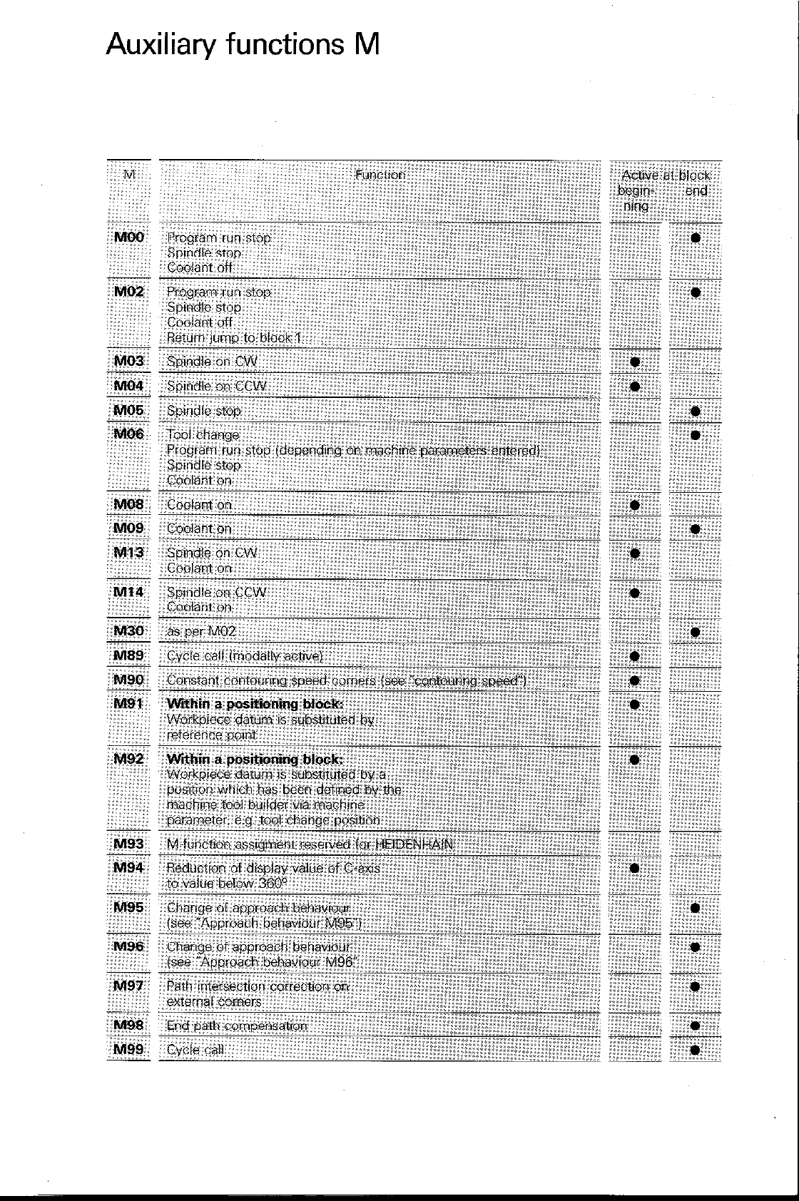
Auxiliary functions M
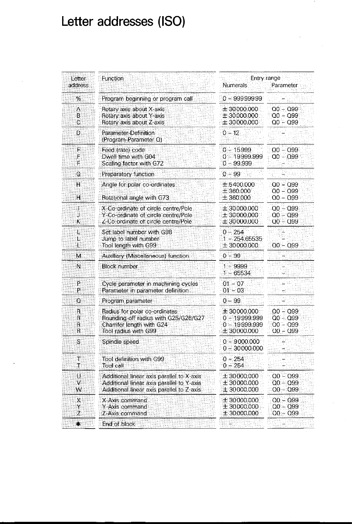
Letter addresses (ISO)
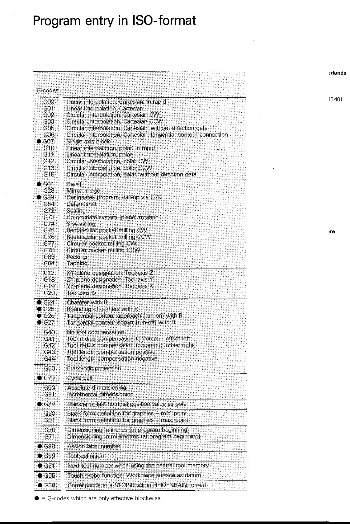
Program entry in ISO-format
?rlands
IO 481
l = G-codes which are onlv effective blockwise
HEIDENHAIN
DR. JOHANNES HEIDENHAlN GmbH
D-8225 Traunreut ‘Tel. (08669) 31-O
1
DBnemark Danemark Denmark
W. H. GRIB tt CO. A/S
Bredgade 34
DK-1260 Kmbenhavn K
Tel. (01) 139300, Telex 19300
T&fax (01) 119399
Niederlande Pays-&s Netherlands
HEIDENHAIN NEDERLAND B.“.
Landjuweel 5
I
Post Box 107
NL-3900 AC Veenendaal
Tel. (08385) 16509/16512. Telex30481
T&fax (08385) 17287
,
