FloBoss 107 Flow Manager Hoja Tecnica Sistemas Redundantes Control Wave PAC
User Manual: Hoja-Tecnica Sistemas-Redundantes-ControlWave-PAC
Open the PDF directly: View PDF ![]() .
.
Page Count: 6
CWPAC:RDN
July 2010
Technical Specifications
Remote Automation Solutions
Website: www.EmersonProcess.com/Remote
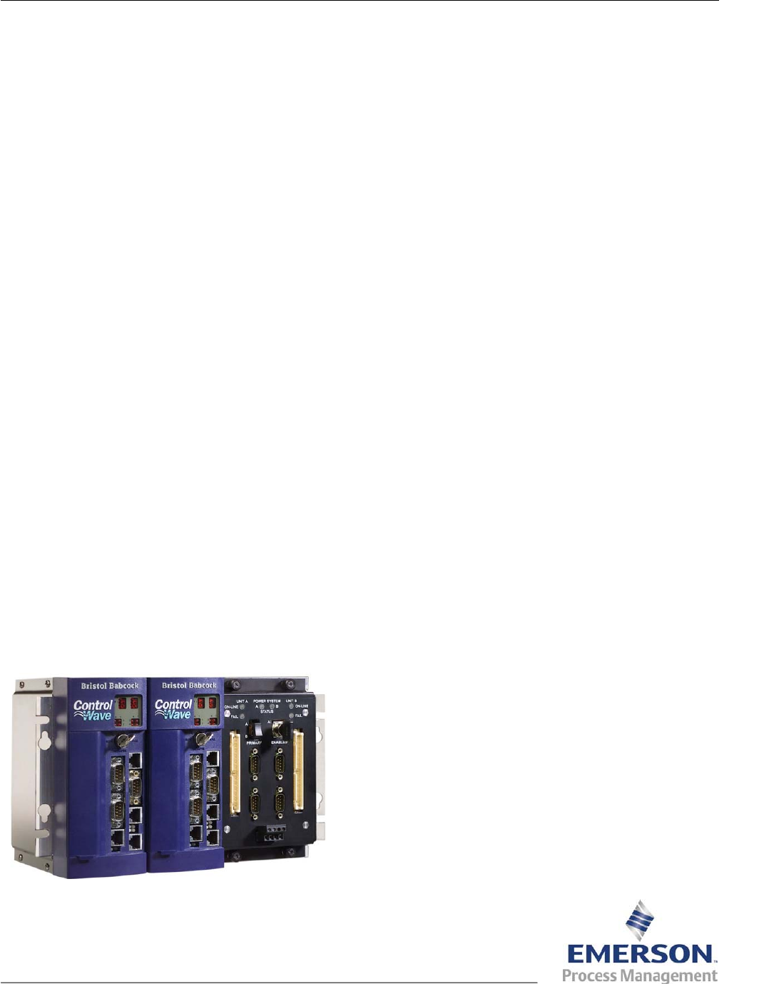
ControlWave® PAC Redundant Systems
The ControlWave® PAC redundant systems are
designed to prevent a single point of failure from
shutting down the entire system. Redundant
systems are ideal for use in critical processes and
harsh applications that require maximum
operational readiness and system availability. Two
types of redundant systems are available for the
ControlWave PAC: the redundant process control
and communications system and the redundant
input/output (I/O) system.
Redundant Process Control and
Communications System
The redundant process control and communications
system provides you with redundant process
control, multiple communication paths, and
automatic failure detection including switching of the
CPUs and communication paths.
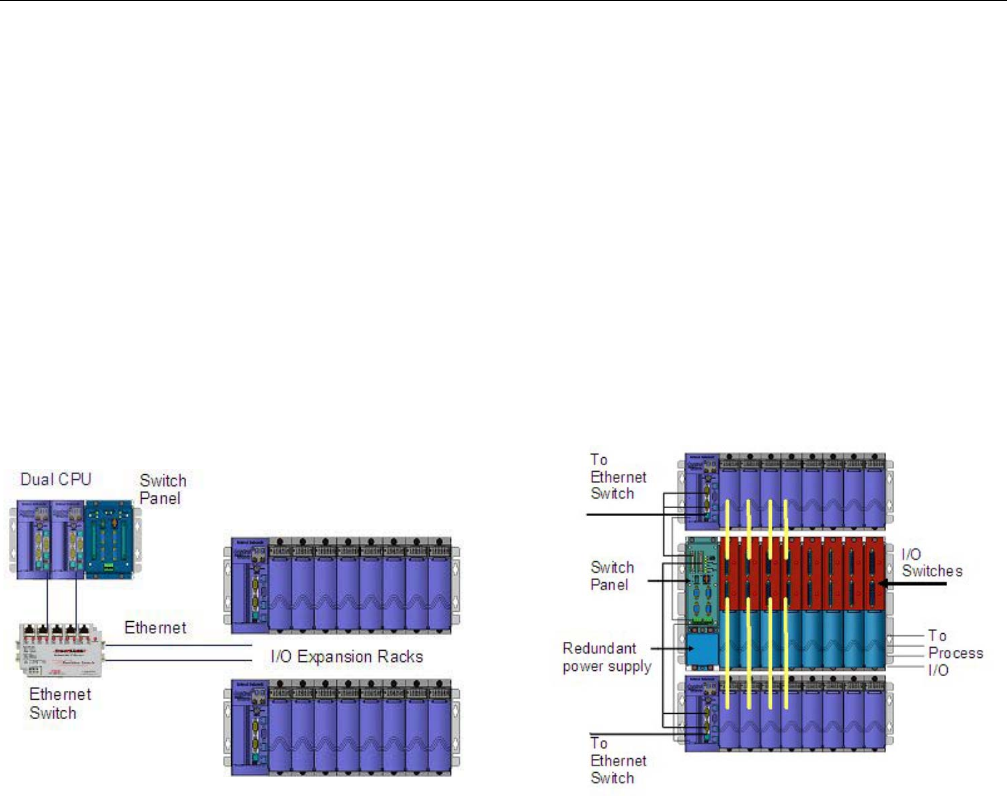
The redundant process control and communications
system consists of an aluminum chassis that
houses the primary and backup CPUs, primary and
backup Power Supply Sequencer modules
(PSSMs), and the CPU and Communications
Redundancy Switch panel (CCRS). This chassis is
then connected to ControlWave PAC I/O Expansion
Racks via Ethernet.
Both types of redundant systems provide you with
dual CPUs, dual power supplies, dual
communication paths, and automatic switching
between redundant components without any data
loss. The redundant I/O system adds an additional
layer of protection by automatically detecting
problems and switching between I/O racks if any
single module or point fails. Both designs deliver
redundant systems that provide high availability,
reliability, and safety.
Dual CPUs
The redundant process control and communications
system has two CPUs: a primary CPU and a
backup CPU. In the event of a primary CPU failure,
the system automatically switches to the backup
CPU. All process control and communication
functions automatically switch to the backup CPU.
This method offers a high degree of control
reliability and system availability at the most
economical cost.
Features
Process control redundancy and
communications redundancy.
Optional I/O redundancy.
Dual CPUs.
Dual power supply sequencers. Switch Panel
Automatic failure detection. The CPU and Communications Redundancy Switch
panel (CCRS) allows automatic and manual
selection of the primary CPU, PSSM, and up to four
serial communication ports. LEDs visually indicate
the operation and status of the redundant system.
Automatic switchover to hot standby controller.
No single point of failure.
Communication channel switching.
Alarm and historical data backup.
No programming required for redundancy data
transfer. Redundant I/O System
In addition to process control and communications
redundancy, the redundant I/O system adds an
additional layer of protection by automatically
detecting problems and switching between I/O
module racks.
The redundant I/O system consists of an aluminum
chassis that houses a Redundant Power Supply
Sequencer Module (RPSSM), the CPU and
Communications Redundancy Switch panel
(CCRS), and I/O switches connected to two
identical ControlWave PACs. Analog output (AO)
modules with read-back and digital output (DO)
modules with read-back provide further data
consistency verification.
D301305X012
ControlWave PAC Redundant Process Control
and Communication System
CWPAC:RDN
Page 2
Technical Specifications
I/O Switches Redundant Power Supply Sequencer Module
Each I/O switch is connected to two identical I/O
modules in two separate ControlWave PACs. The
I/O switch receives the process I/O signals from the
field. The signals from the field are passed through
the I/O switch to the primary I/O module. If a failure
is detected, the I/O switch sends the signal to the
backup I/O module and no data is lost.
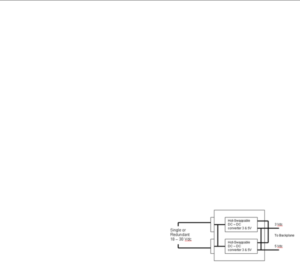
The Redundant Power Supply Sequencer module
(RPSSM) provides the ControlWave with dual
power supplies for operational redundancy. The
RPSSM includes two independent power supplies:
a primary power supply and a backup power supply.
Should the primary power supply fail, operations
automatically continue using the backup supply, and
you can hot-swap the failed power supply with a
spare unit without interrupting control operations.
The RPSSM also supports hot-swapping of I/O
modules. However, you cannot replace the RPSSM
itself without first turning off power to the
ControlWave.
Switch Panel
The CPU and Communications Redundancy Switch
panel (CCRS) allows automatic and manual
selection of the primary controller CPU, PSSM, I/O
rack, and up to four serial communication ports.
LEDs visually indicate operation and status of the
redundant system. When used as part of a redundant system, the
failure of one of the two power supplies in a RPSSM
would not force a failover to the other controller.
Only the loss of both power supplies on the RPSSM
would trigger a failover.
AO and DO Modules with Read-Back
Analog output (AO) modules with eight outputs are
available in two versions: standard AO or AO with
read-back functionality. AO modules with read-back
functionality monitor the values of their standby
counterpart to verify consistency. If the monitored
values are inconsistent, an alarm notification is set
and the ControlWave PAC can be configured to
prevent or allow switching to the failed backup I/O
hardware.
Each power supply on the RPSSM drives a solid
state relay contact closed during normal operation.
In a failure, this contact opens. You can optionally
wire the contact to a digital input (either externally or
internally sourced) to provide indication of a power
supply failure. Each power supply has a Power
Good indication LED
Digital output (DO) modules with read-back
functionality monitoring the values of their standby
counterpart to verify consistency. Digital output (DO)
modules with 16 outputs support read-back
functionality. If the monitored values are
inconsistent, an alarm notification is set and the
ControlWave PAC can be configured to prevent or
allow switching to the failed backup I/O hardware.
Standard AO and DO modules used in a redundant
system do not perform this monitoring, and the
potential exists to switch to a backup module with
failed hardware. For critical processes, we
recommend the AO and DO modules with read-
back capability.
Note: You must use the same module type in any
redundant pair. Do not install an AO/DO
module with read-back functionality in the
primary controller and a standard AO/DO
module as its redundant counterpart in the
backup controller, or vice versa.
.
Redundant Power Supply Sequencer Module
Redundant Switchover Control
Both ControlWave PAC redundant systems use
system and user-configured failure detection and
switchover. System failures are automatically
detected; no user programming is needed.
CWPAC:RDN
Technical Specifications Page 3
Possible system failures include: Data Backup
An application program running in the CPU
“crashes” due to a hardware or software fault. In order to provide a truly reliable redundant backup
system with seamless transfer, both ControlWave
PAC redundant systems automatically synchronize
the backup CPU database from the primary CPU.
Both ControlWave PAC Redundant Systems
provide a backup of retained data, port, user
configuration, alarm events, and the historical
database. This ensures that the backup CPU has
full capability to assume control without the loss of
any configuration or historical database information.
The backup function is pre-configured and no
control programming is required.
All tasks are suspended for more than a user-
configurable number of milliseconds.
A task watchdog occurs.
Hardware failures such memory or processor.
For even greater flexibility,you can configure (using
a ControlWave Designer REDUN_SWITCH function
block) virtually any user-created logic to detect a
particular failure (such as a local I/O or
communication failure).
Redundant Process Control and
Communication System Redundant I/O System

CWPAC:RDN
Page 4
Technical Specifications
Redundant Process Control and Communication System
System Components
Dual ControlWave PAC CPUs Two identical ControlWave PAC CPUs. Each CPU is connected to ControlWave or
ControlWave Micro I/O Expansion rack CPUs via Ethernet to an Ethernet switch. For
more information, refer to Technical Specifications CWPAC.
CPU and Communication
Redundancy Switch A/B Primary Controller Select Switch
A/B Mode Select Switch
Serial Communication Port Switching
On-Line Status Outputs – Contact rating 1A @ 30 Vdc
LED Status indicators
Dual Power Supply Sequencer
Modules (PSSM) Two identical individual Power Supply Sequencer Modules (PSSM). Each PSSM may
contain single or dual redundant power supplies. For more information , refer to
Technical Specifications CWPAC.
Chassis Aluminum chassis for dual CPUs, dual PSSM and CPU & Communication Redundancy
Switch.
Communications Redundancy Switch Panel
COM1 – COM2 Type RS-232
Connector 9-pin D-SUB connector
COM3 – COM4 Type RS-485
Connector 9-pin D-SUB connector
Data Backup
Retained Data, Alarm Events, and Historical Data are automatically backed up.
Physical
Dimensions (11.75 in. W by 7.1 in. H by 5 in. D)
Weight 8 lbs.
Wiring Serial communication cables to switch included
Environmental
Same as the ControlWave PAC. For more information, refer to Technical Specifications CWPAC.
Approvals
Same as the ControlWave PAC. For more information, refer to Technical Specifications CWPAC.

CWPAC:RDN
Page 5
Technical Specifications
Redundant I/O System
System Components
ControlWave PAC Units Two ControlWave PAC units with identical I/O setups: one primary unit and one backup
unit. Each I/O module is connected to an I/O switch. For more information, refer to
Technical Specifications CWPAC.
CPU and Communications
Redundancy Switch Panel A/B Primary Controller Select Switch
A/B Mode Select Switch
Serial Communication Port Switching
On-Line Status Outputs – Contact rating 1A @ 30 Vdc
LED Status indicators
I/O Switches Input and output switches with direct connections to the process I/O signals.
AO Modules with Read-Back Analog Output modules that monitor the value of the standby counterpart. For more
information, refer to Technical Specifications CWPAC.
DO Modules with Read-Back Digital Output modules that monitor the value of the standby counterpart. For more
information, refer to Technical Specifications CWPAC.
Redundant Power Supply
Sequencer Module Input Voltage
Range +20 to +30 Vdc (+24 Vdc nominal)
Output Voltage Isolated +5.2 Vdc
Communications Redundancy Switch Panel
COM1 – COM2 Type RS-232
Connector 9-pin D-SUB connector
COM3 – COM4 Type RS-485
Connector 9-pin D-SUB connector
I/O Switches
Digital Input Local or remote terminations
Digital Output Local or remote terminations
Analog Input Local or remote terminations
Analog Output Local or remote terminations
UDI (High Speed Counter) Local or remote terminations
Data Backup
Retained Data, Alarm Events, and Historical Data are automatically backed up.
Physical
Dimensions (19 in. W by 12.25 in. H by 5 in. D)
Weight > 10 lbs (varies upon configuration)
Wiring Up to 14 AWG at the removable terminal blocks
Environmental
Same as the ControlWave PAC. For more information, refer to Technical Specifications CWPAC.
Approvals
Same as the ControlWave PAC. For more information, refer to Technical Specifications CWPAC.

CWPAC:RDN
Page 6
Technical Specifications
Bristol, Inc., Bristol Canada, BBI SA de CV and Emerson Process Management Ltd, Remote Automation Solutions division (UK), are wholly
owned subsidiaries of Emerson Electric Co. doing business as Remote Automation Solutions (“RAS”), a division of Emerson Process
Management. FloBoss, ROCLINK, Bristol, Bristol Babcock, ControlWave, TeleFlow and Helicoid are trademarks of RAS. AMS, PlantWeb and
the PlantWeb logo are marks of Emerson Electric Co. The Emerson logo is a trademark and service mark of the Emerson Electric Co. All
other marks are property of their respective owners.
The contents of this publication are presented for informational purposes only. While every effort has been made to ensure informational
accuracy, they are not to be construed as warranties or guarantees, express or implied, regarding the products or services described herein
or their use or applicability. RAS reserves the right to modify or improve the designs or specifications of such products at any time without
notice. All sales are governed by RAS’ terms and conditions which are available upon request. RAS does not assume responsibility for the
selection, use or maintenance of any product. Responsibility for proper selection, use and maintenance of any RAS product remains solely
with the purchaser and end-user.
Emerson Process Management
Remote Automation Solutions
Marshalltown, IA 50158 U.S.A.
Houston, TX 77065 U.S.A.
Pickering, North Yorkshire UK Y018 7JA
© 2007-2010 Remote Automation Solutions, division of Emerson Process Management. All Rights Reserved.
