RIVR1041 HTC Apps Guide Hydraulic Torque Coupler Catalog
User Manual: Hydraulic-Torque-Coupler-Catalog
Open the PDF directly: View PDF ![]() .
.
Page Count: 8
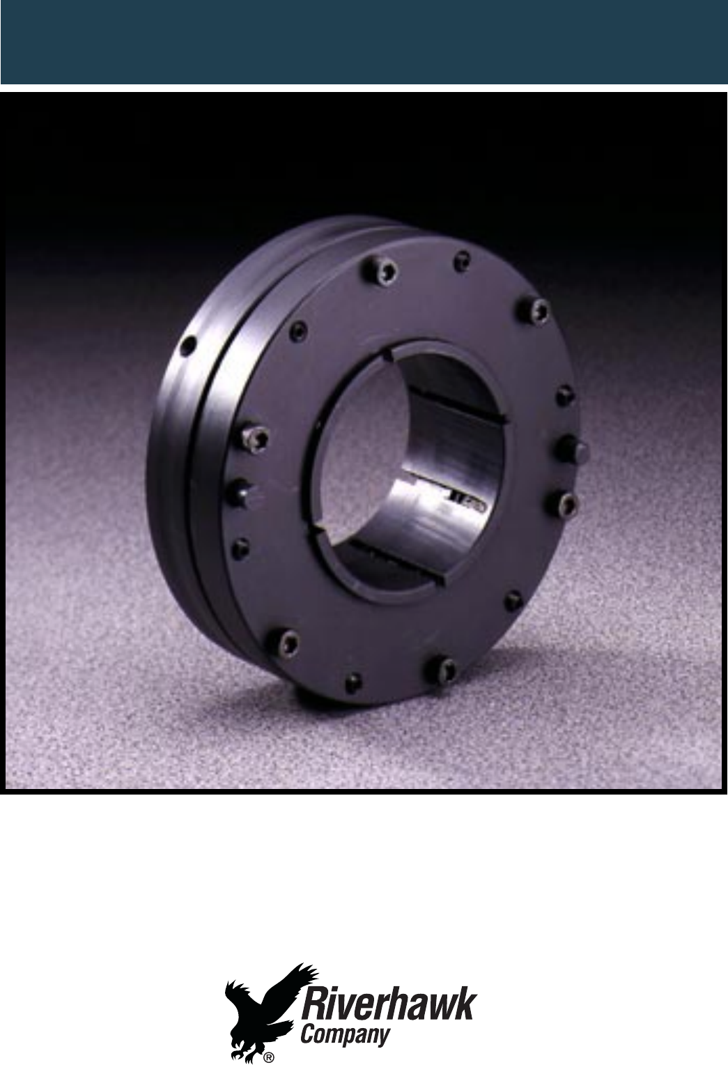
RIVERHAWK HYDRAULIC TORQUE COUPLER
APPLICATIONS GUIDE
Features and Benefits
• Eliminates keys, splines, and tapered shaft ends
• Allows for use of smaller diameter shafts
• Reduces overhung moment
• Custom designs to fit your envelope and shaft ends
Patented
Eliminates keys, splines and tapered shaft ends.
Keys and splines produce stress concentration in
machine shafts. Tapered shaft ends and bores are expen-
sive to produce and require special tooling. The Hydrau-
lic Torque Coupler shown in Figures 1 and 2 allows
designs using straight, cylindrical, slip fit surfaces
eliminating stress concentrations and reducing costs.
Allows for the use of smaller diameter shafts.
High squeeze capacity of Riverhawk Hydraulic Torque
Couplers translates into smaller shafting requirements.
Smaller shafts translate into smaller bearing require-
ments reducing overall cost and increased design flex-
ibility.
Reduces overhung moment.
In high power density applications it is the total over-
hung moment that impacts rotordynamics. The Hydraulic
Torque Coupler allows for designs with smaller shafts and
shorter interfaces. These factors translate into reduced
overall overhung moment.
Custom designs fit your envelope and shaft
In addition to a standard line, Riverhawk will modify a
standard product or engineer a custom solution for your
particular application.
Slip-Fit Components For Keyless Connections
The Hydraulic Torque Coupler provides high integrity
keyless fit joints using convenient, low cost slip-fit
designs. Our design eliminates heat at assembly as well
as keys, splines, tapered shafts, plug/ring gages, and
hydraulic maintenance equipment. Shaft ends are
simplified therefore reducing design, manufacturing, and
maintenance costs. In addition, maximum axial and
phase adjustment simplifies timing issues.
Hydraulically Applied Clamp Pressure For High
Torque Capacity
Select the Riverhawk Hydraulic Torque Coupler to meet
the high power density requirements of today’s high
performance equipment. Hydraulic coupling provides
ultra-secure clamping of shaft elements with reduced
shaft diameter.
Design, Existing Shaft Ends
Select the Riverhawk Hydraulic Torque Coupler to meet
the high power density requirements of today’s high
performance equipment. Hydraulic coupling provides
ultra-secure clamping of shaft elements with reduced
shaft diameter.
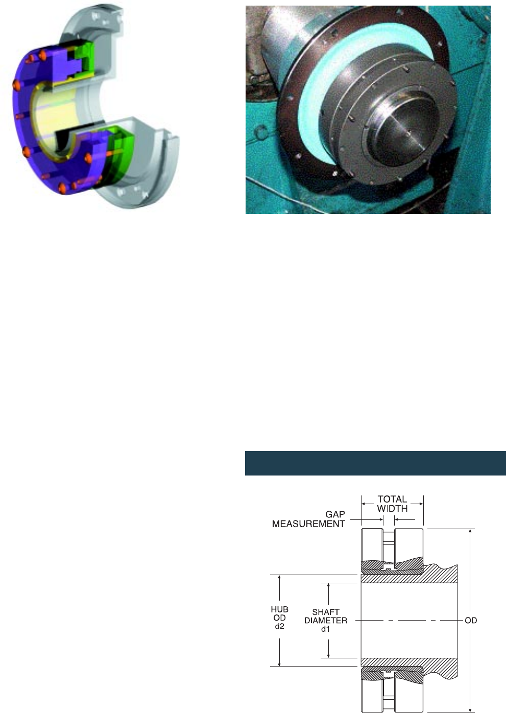
Figure 2 -
Hydraulic torque coupler mounted on high speed gear.
2
Figure 1 -
Cutaway View of HTC Hub Assembly
Dimensional Drawing
Figure 3

APPLICATION DATA
NOTES:
Contact Riverhawk Engineering for assistance in evaluating special
conditions and requirements.
1. Static slip torque values reflect hub and shaft machined with a
slip fit per AGMA 9002 class I fit for sizes up to 6.5 in. See
dimensional chart and Figures 6 and 7 for design clearances.
2. The application torque must always be less than the slip torque
at speed. Slip torque calculations are based on “steel on steel”
fits with a coefficient of friction of 0.15. The actual slip torque
may vary depending on hub & shaft materials and surface
condition.
Motor Torque/
Static
(1)
Speed Speed
Shaft Total Hub Slip Motor Hub Slip Reduction Limit
Size d1 Width OD Weight Torque, Ts Speed Torque, Tss Factor
(3)
, Fs Speed
Model (inches) (inches) (inches) (pounds) (in.-lb.)
(2)
(RPM) (in.-lb.) (in.-lb./krpm
2
)(RPM)
HTC020 1.500 1.640 4.250 3.5 15,100 3,600 15,000 9.2 23,900
1.750 23,000 3,600 22,800 11.8
1.875 27,700 3,600 27,500 13.2
2.000 32,900 3,600 32,700 14.5
HTC025 2.125 2.070 5.313 7.1 41,900 3,600 41,400 35.5 20,700
2.250 48,900 3,600 48,400 38.9
2.375 56,600 3,600 56,100 42.2
2.500 64,900 3,600 64,300 45.5
HTC030 2.625 2.430 6.375 12.1 78,000 3,600 76,800 91.3 19,500
2.750 88,500 3,600 87,200 98.2
2.875 99,700 3,600 98,300 105
3.000 111,700 3,600 110,000 110
HTC040 3.250 3.200 8.500 28.9 151,400 3,600 147,000 340 15,500
3.500 185,400 3,600 180,000 380
3.750 223,400 3,600 218,000 430
4.000 265,500 3,600 259,000 470
HTC050 4.250 4.000 10.625 56.7 334,900 1,800 331,200 1,135 13,800
4.500 391,300 1,800 387,300 1,243
4.750 452,700 1,800 448,300 1,350
5.000 519,300 1,800 514,600 1,456
HTC060 5.250 4.800 12.750 96.8 624,100 1,800 614,600 2,922 10,800
5.500 707,900 1,800 697,700 3,143
5.750 797,600 1,800 786,700 3,360
6.000 893,500 1,800 881,900 3,580
HTC075 6.500 6.000 15.938 189.1 1,187,800 1,800 1,159,000 8,780 8,800
7.000 1,451,200 1,800 1,419,000 9,860
7.500 1,745,100 1,800 1,710,000 10,920
HTC095 8.000 7.500 20.188 383.2 2,230,100 1,800 2,142,000 27,250 7,200
8.500 2,629,400 1,800 2,532,000 30,030
9.000 3,066,800 1,800 2,961,000 32,800
9.500 3,542,700 1,800 3,428,000 35,500
HTC120 10.000 9.500 25.500 774.7 4,371,600 1,200 4,247,000 86,400 5,500
10.500 4,993,200 1,200 4,859,000 93,500
11.000 5,662,800 1,200 5,518,000 100,600
12.000 7,148,000 1,200 6,982,000 114,500
HTC150 13.000 11.800 31.875 1513.2 9,502,000 1,200 9,097,000 281,100 4,700
14.000 11,609,900 1,200 11,160,000 315,600
15.000 13,960,900 1,200 13,460,000 349,400
3
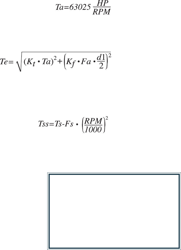
3. There are three ways to calculate slip torque at speed (Tss):
A. For motor speeds you can read Tss directly off the above table.
B. To estimate slip torque at any speed read Ts & Fs from the
Application Data table and “Speedfactor” from the graph
Figures 4 and 5. Calculate using the formula:
C. For precise slip torque calculation apply the formula:
At Riverhawk we always strive to improve the products we produce. For that reason the dimensions and specifications contained in this
catalog are subject to change without notice. Certified dimensions of ordered material can be furnished upon request.
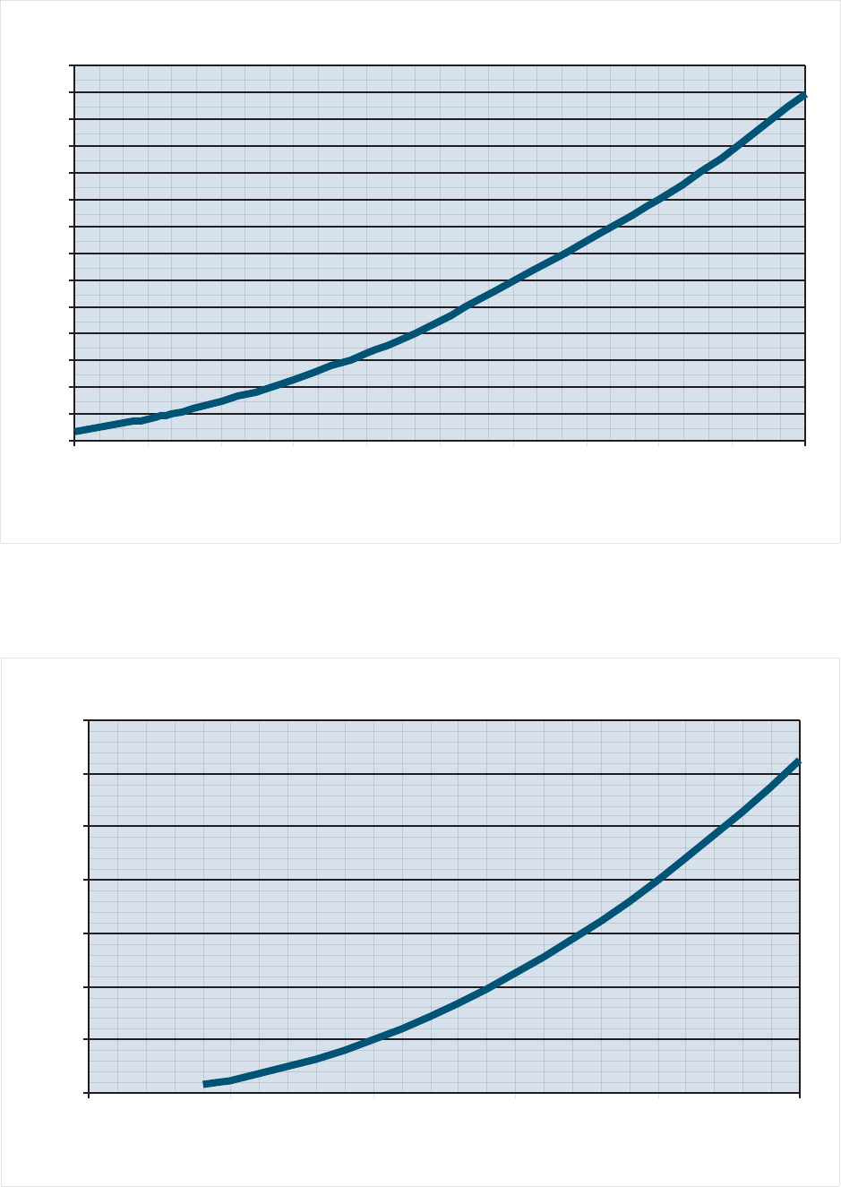
Speed Factor For Low Speeds
0
1
2
3
4
5
6
7
8
9
10
11
12
13
14
600 900 1200 1500 1800 2100 2400 2700 3000 3300 3600
RPM
Speed Factor
Speed Factor For High Speeds
0
100
200
300
400
500
600
700
0 5000 10000 15000 20000 25000
RPM
Speed Factor
4
Figure 5
Figure 4
1. Establish the loading requirements for your applica-
tion. Loading includes the application torque (Ta) and
axial force (Fa).
2. Establish service factors to account for uncertainties of
the application.
3. Calculate the total equivalent application torque (Te)
using the loading requirements and service factors you
have established.
SELECTION PROCEDURE
HP is the application horse power.
RPM is the application speed.
Application Torque
Equivalent Torque
At Speed Slip Torque
Ta is the application torque. (in-lb)
Kt is the service factor on torque
Fa is the application axial force. (lbf)
Kf is the service factor on axial force.
d1 is the shaft diameter.
Tss is the joint slip torque at speed (in-lb)
Ts is the static slip torque from the application data
chart (in-lb)
Fs is the torque/speed reduction factor from the applica-
tion data chart (in-lb)
4. Compare the calculated Te with Ts from the applica-
tion data chart to obtain the candidate selection.
5. For final size selection you will need to adjust the Ts
value of the candidate selection using the rotational
speed of your application. To do this, calculate the at
speed slip torque (Tss) using the formula below.
Important Note: Service Factor
The application torque Ta and application axial force Fa should be
the greatest values which the system is expected to transmit.
Establishing these may require evaluating several loading combi-
nations as dictated by the application.
The slip torque values supplied in the application chart are
limiting values. Exceeding these values will result in slip. The
application loading must always be below the slip capacity of the
joint. The selecting engineer is advised to apply a service factor to
the application loads to account for factors such as, start-up
conditions, peak loading conditions and service uncertainty.
5
Example Application
A fan is to be mounted on 5” shaft. It is to be powered
by an 9,000 HP, 3,560 RPM induction motor. The motor
can produce a peak torque of 2.5 times its rated torque
during start up. The fan can produce an axial force of
15,000 lbf. A factor of 1.25 will be added to both the
start up torque and the axial force to account for pos-
sible surges and vibration caused by wind gusts at the
intake.
Applying this data to the formulas above:
• The normal torque for the application is:
159,333 (in-lb)
• The start up torque is:
398,332 (in-lb)
• From these, Te becomes:
500,117 (in-lb)
• Comparing Te to the rating chart yields HTC050 as a
preliminary selection.
• Applying the operating speed to the static rating in
the table. The “at speed” slip torque Tss of HTC050
becomes:
500,847 (in-lb)
• Tss>Te, the HTC050 shrink disc meets the applica-
tion requirements as defined.
Design, Dimensions, and Fits
The Hydraulic Torque Coupler (HTC) design allows hub/
shaft fits to be designed with cylindrical slip fits. The
Suggested Fit Dimensions table provides suggested hub
bore and shaft outside dimensions (OD.) These fits were
derived from AGMA 9002 class 1. Larger sizes were
extrapolated. The HTC can accommodate hub/shaft fits
other than those supplied here such as cylindrical
interference fits and taper fits. In general, tighter fits
are preferable. Contact Riverhawk engineering for
assistance in evaluation of fits that are not listed here.
Surface finishes on hub and shaft diameters of 64
microinches or better are recommended. In general,
smoother surfaces are preferable. Rough surface finishes
tend to mask profile variations and other detrimental
defects.
A fillet as shown in Figures 6 and 7 between the hub OD
and the flange is recommended. The HTC can accommo-
date a fillet up to the values listed in the dimensional
chart.
When the HTC is activated, the material directly under it
is squeezed into a heavy interference with the shaft.
Other areas, such as that below the flange, will still have
a clearance. Machinery misalignment can cause a micro-
scopic rocking motion between the flange and the shaft.
A slight clearance under the flange such as shown in
Figures 6 and 7 will prevent the possibility of fretting in
this area.
A redundant mechanical stop, such as a shaft step or
shaft nut, should be considered in cases where the
equipment must accommodate large thrust loads, espe-
cially where axial slip would affect safe or reliable
operation.
Figures 6 and 7 show options where the HTC is mounted
with hardware and hydraulic access areas located away
from the flange. Access holes can be drilled in the flange
in cases that require the HTC to be mounted with the
hardware against the flange. Contact Riverhawk engi-
neering for recommendations for access solutions.
Design, Hub & Shaft Stress
Keyways, splines, and pins produce stress concentrations
in shafts. Stress concentrations greatly reduce a shaft’s
ability to endure varying loads such as bending and
varying torques. This fact forces the machinery designer
to design larger, heavier shafts than would otherwise be
needed. The Riverhawk Hydraulic Torque Coupler virtu-
ally eliminates these stress concentrations allowing for
more efficient machinery designs.
The hub and shaft material must be capable of accommo-
dating the clamping, torque, and bending loads produced
by the application. For the joint to be capable of trans-
mitting the full rated slip torque, the hub and shaft
material should have a yield strength of at least 45,000
psi, which represents 1040 steel as commonly used in
shafting. The Hydraulic Torque Coupler can be used for
applications with weaker materials by reducing the
clamping load. Contact Riverhawk engineering for
assistance with evaluating shaft and hub stresses.
Design, Balance
Balance level is an issue for high speed applications
utilizing machinery that is sensitive to vibration. River-
hawk Hydraulic Torque Couplers are designed and manu-
factured to tight tolerances in order to produce “as built”
balance level better than required by AGMA 9000 class 8.
Tighter balance requirements can be met with addition of
an assembly balance. Balanced and match-marked
assemblies can achieve balance repeatability levels per
AGMA 9000 class 10 and API 671.
6

SUGGESTED FIT DIMENSIONS
7
Figure 6 Figure 7
Shaft Suggested Suggested Net Model Hub OD d2 Hub OD Machined Maximum
Size d1 Shaft Bore Size Maximum Tolerance Hub OD Fillet R
Tolerance Tolerance Clearance Width W
1.5000 0.002 HTC020 2.440
1.750 +.001 0.002 2.440 1.650 0.062
1.875 +.000 0.002 2.440
2.000 0.002 2.440
2.125 0.0025 HTC025 3.050
2.250 0.0025 3.050 2.070 0.094
2.375 0.0025 3.050
2.500 0.0025 3.050
2.625 0.0025 HTC030 3.660 +.000
2.750 0.0025 3.660 -0.001 2.430 0.094
2.875 0.0025 3.660
3.000 0.0025 3.660
3.250 0.0025 HTC040 4.880
3.500 0.0025 4.880 3.200 0.156
3.750 +.000 0.0025 4.880
4.000 -.0010 0.0025 4.880
4.250 0.0025 HTC050 6.100
4.500 +.0015 0.0025 6.100 4.000 0.156
4.750 +.000 0.0025 6.100
5.000 0.0025 6.100
5.250 0.0025 HTC060 7.320
5.500 0.0025 7.320 4.800 0.188
5.750 0.0025 7.320 +.000
6.000 0.0025 7.320 -0.0015
6.500 0.0025 HTC075 9.150
7.000 0.003 9.150 6.000 0.250
7.500 0.003 9.150
8.000 0.003 HTC095 11.590 +.000
8.500 0.003 11.590 -0.002 7.500 0.313
9.000 0.003 11.590
9.500 0.003 11.590
10.000 +.000 0.003 HTC120 14.640
10.500 -.0015 0.004 14.640 +.000 9.500 0.375
11.000 +.0025 0.004 14.640 -0.0025
12.000 +.000 0.004 14.640
13.000 0.004 HTC150 18.300 +.000
14.000 0.004 18.300 -0.003 11.800 0.500
15.000 0.004 18.300
Installation Overview
1. Inspect hub and shaft to insure that they have been
machined to proper tolerances.
2. Clean the hub bore, hub OD and shaft OD. Make sure
that they are free of any debris or coatings. Clean
surfaces are essential for torque transmission.
3. Slide the HTC on to the hub. Take care to insure that
the screws and hydraulic ports are accessible.
4. Slide hub/HTC assembly on to the shaft and set axial
position. Rotate the HTC so that the ports are at the
12:00 and 6:00 positions.
5. Remove retraction screws but leave the retention
screws (socket set screws).
6. Attach hydraulic pressure source to the fitting located
at 6:00 and remove the plug at 12:00.
7. Bleed air out of hydraulics.
8. Apply 200 psi hydraulic pressure to HTC. This step
takes up assembly clearances. At this point the HTC and
hub should be lightly gripping the shaft.
9. Measure and record the gap at clamp outside diameter.
This becomes the initial gap. See Figure 3.
10. Refer to installation instructions for recommended
expansion.
11. Add the initial measured gap from step nine to the
recommended expansion gap from step ten to arrive at a
total gap necessary for proper installation.
12. In steps, apply hydraulic pressure and measure gap.
Stop pumping when the actual gap meets the number
calculated in step eleven. Stop pumping if either the pins
become flush with the torque coupler face OR you exceed
7,500 psi hydraulic pressure.
13. While holding hydraulic pressure, turn retaining
screws in until lightly seated and then release pressure.
14. Allow oil to drain and plug both hydraulic ports.
NOTE: Please refer to the formal installation and removal
manual for additional instructions.
Removal
1. Attach hydraulic pressure source to fitting.
2. Bleed air out of hydraulics. Plug upper port after
bleeding.
3. Slowly add hydraulic pressure, simultaneously apply
removal torque to the retaining screws.
4. Increase hydraulic pressure until retaining screws can
be turned. Screws should be free to rotate at a pressure
between 4,500 psi and 7,500 psi. Once the retaining
screws are free, stop increasing pressure and back off all
screws.
5. Release hydraulic pressure and clamp should retract
by itself. If it does not, retracting screws can be inserted
and turned to retract unit.
NOTE: Care should be taken to tighten jacking screws in
several stages by using approximate one-half turns
following either a clockwise or counterclockwise se-
quence.
6. Once closed, the parts will be free to be disassembled.
NOTE: Please refer to the formal installation and removal
manual for additional instructions.
Disclaimer
The information contained within this document is based upon certain
assumptions about equipment design and operation as foreseen at the
time of publication. The equipment designer is assumed to be familiar
with the equipment and its operation. For this reason the equipment
designer must assume responsibility for the proper application of the
Riverhawk HTC to the subject equipment.
We invite you to visit our web site at www.riverhawk.com
215 Clinton Road
New Hartford, NY 13413
Phone: 315-768-4855
Fax: 315-768-4941
E-mail: sales@riverhawk.com
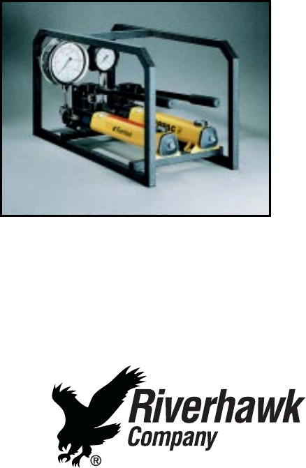
Installation Accessories
Riverhawk provides pressure kits complete with flexible
hoses as shown in Figure 8.
Figure 8 -Hydraulic Hand Pump
8Release date - 08/01 (1041)
