IFD9506_eng_cover_20081229 Network Device IFD9506 O EN 20081208
User Manual: Network Device IFD9506
Open the PDF directly: View PDF ![]() .
.
Page Count: 62

IFD9506
Ethernet Communication Module
Applicaton Manual

Ethernet Communication Module IFD9506
DVP-PLC Application Manual 1
Warning
3
Please read this instruction carefully before use and follow this instruction to operate the device in order to prevent
damages on the device or injuries to staff.
3
Switch off the power before wiring.
3
IFD9506 is an OPEN TYPE device and therefore should be installed in an enclosure free of airborne dust, humidity,
electric shock and vibration. The enclosure should prevent non-maintenance staff from operating the device (e.g.
key or specific tools are required for operating the enclosure) in case danger and damage on the device may occur.
3
IFD9506 is to be used for controlling the operating machine and equipment. In order not to damage it, only
qualified professional staff familiar with the structure and operation of IFD9506 can install, operate, wire and
maintain it.
3
DO NOT connect input AC power supply to any of the I/O terminals; otherwise serious damage may occur. Check
all the wirings again before switching on the power and DO NOT touch any terminal when the power is switched
on. Make sure the ground terminal is correctly grounded in order to prevent electromagnetic interference.
Table of Contents
1 INTRODUCTION...................................................................................................................................3
1.1 Features ......................................................................................................................................3
1.2 Specifications ..............................................................................................................................3
2 PRODUCT PROFILE & OUTLINE .......................................................................................................4
2.1 Dimension ...................................................................................................................................4
2.2 Product Profiles...........................................................................................................................5
2.3 LED Indicators.............................................................................................................................5
2.4 RJ-11 PIN Definition ....................................................................................................................5
2.5 RJ-11 PIN Definition ....................................................................................................................5
2.6 RJ-45 PIN Definition....................................................................................................................6
2.7 RS-232 PIN Definition .................................................................................................................6
2.8 Address Switch ...........................................................................................................................6
2.9 Data Format ................................................................................................................................6
2.10 Baud Rate for Modbus Communication ......................................................................................6
2.11 Feed-through Terminal PIN Definition .........................................................................................7
3 INSTALLATION & WIRING ..................................................................................................................7
3.1 How to Install...............................................................................................................................7
3.2 How to Connect IFD9506 to Network..........................................................................................7
4 REGISTERS IN IFD9506......................................................................................................................8
4.1 Basic Registers (BR)...................................................................................................................8
4.2 Explanations on BR.....................................................................................................................9
4.3 Alarm Registers (AL).................................................................................................................12

Ethernet Communication Module IFD9506
DVP-PLC Application Manual
2
5 MONITORING FUNCTIONS .............................................................................................................. 13
5.1 Monitor Bit Registers (MB) ....................................................................................................... 13
5.2 Monitor Word Registerss (MW) ................................................................................................ 14
6 SETTING UP DEVICE ADDRESS & RELAY ADDRESS IN SLAVE MODE ..................................... 15
7 MODBUS COMMUNICATION ........................................................................................................... 15
7.1 Function Codes Supported....................................................................................................... 15
7.2 Exception Codes Supported..................................................................................................... 16
7.3 Device Type & Device Address................................................................................................. 16
8 SETTING UP SOFTWARE................................................................................................................. 16
8.1 Setting up Communication & Searching for Modules in DCISoft.............................................. 16
8.2 Basic Settings........................................................................................................................... 19
8.3 Network Settings ...................................................................................................................... 20
8.4 Setting up E-Mails .................................................................................................................... 21
8.5 Monitoring Settings................................................................................................................... 23
8.6 IP Filter ..................................................................................................................................... 24
8.7 User Defined Format ................................................................................................................ 24
8.8 Virtual COM .............................................................................................................................. 26
8.9 Security Settings....................................................................................................................... 29
8.10 Returning to Default Settings.................................................................................................... 30
9 WEBPAGE SETTINGS ...................................................................................................................... 30
9.1 Webpage Connection ............................................................................................................... 30
9.2 Basic Settings........................................................................................................................... 31
9.3 Setting up E-Mails .................................................................................................................... 32
9.4 IP Filter ..................................................................................................................................... 32
9.5 Security Settings....................................................................................................................... 33
9.6 Returning to Default Settings.................................................................................................... 34
9.7 Monitor Table ............................................................................................................................ 34
9.8 User Define............................................................................................................................... 36
10 APPLICATION EXAMPLES – DCISOFT........................................................................................... 38
10.1 Setting up & Unlocking Password ............................................................................................ 38
10.2 Password Loss (Returning to Default Settings by RS-232)...................................................... 39
10.3 IP Filter Protection .................................................................................................................... 40
10.4 Application of E-Mail................................................................................................................. 41
10.5 Monitoring Mode....................................................................................................................... 43
10.6 Application of Modbus Slave .................................................................................................... 44
10.7 Application of Virtual COM Port ................................................................................................ 47
11 APPLICATION EXAMPLE – WPLSOFT ........................................................................................... 52
11.1 Setting up IP Through WPLSoft................................................................................................ 52
11.2 Connecting to IFD9506 Through LAN in PC............................................................................. 56

Ethernet Communication Module IFD9506
DVP-PLC Application Manual 3
1 Introduction
To ensure correct installation and operation of IFD9506, please read this chapter carefully before using your
IFD9506.
IFD9506 is an Ethernet communication module for remote setting through Delta’s DCISoft or remote setting and
communication through WPLSoft.
IFD9506 has 3 digital input contacts on it. They will send out messages to designated E-Mail addresses once
being triggered.
IFD9506 supports Modbus TCP protocol and can be used for remote monitoring with graphic control software or
human machine interface.
IFD9506 can be Modbus TCP master, sending out Modbus TCP commands and controlling the peripheral
equipment.
IFD9506 can be a slave as well, receiving Modbus commands sent out from another master and sending the
command to another Modbus communication network through Ethernet. In addition, in MDI/MDI-X auto-detect,
jump wire is not needed when you choose the network cable.
1.1 Features
z Auto-detects 10/100 Mbps transmission speed; MDI/MDI-X auto-detect.
z The monitor table temporarily stores the monitored data for you to fast save or acquire the data.
z Supports Modbus TCP protocol (both master and slave modes)
z Able to send out E-Mails when triggered.
z The station address, RS-485 communication format and baud rate can be set up externally.
1.2 Specifications
Ethernet interface
Interface RJ-45 with Auto MDI/MDIX
Number of ports 1 port
Transmission method IEEE802.3, IEEE802.3u
Transmission cable Category 5e
Transmission speed 10/100 Mbps Auto-Defect
Communication protocol ICMP, IP, TCP, UDP, DHCP, SMTP, Modbus TCP
COM1
Interface Mini Dim
Number of ports 1 port
Transmission method RS-232
Transmission cable DVPACAB215 / DVPACAB230 / DVPACAB2A30
Transmission speed 110/150/300/600/1200/2,400/4,800/9,600/19,200/38,400/57,600/115,200
Communication protocol Modbus, Delta Configuration, User Define
COM2
Interface RJ-11
Number of ports 1 port
Transmission method RS-485
Ethernet Communication Module IFD9506
DVP-PLC Application Manual
4
Transmission speed 110/150/300/600/1,200/2,400/4,800/9,600/19,200/38,400/57,600/115,200
Communication protocol Modbus, User Define
Terminal block
Interface Feed-through terminal 10PIN
Transmission method RS-485
Transmission distance 1,200m
Transmissioi speed 110/150/300/600/1,200/2,400/4,800/9,600/19,200/38,400/57,600/115,200
Communication protocol Modbus, User Define
Max. number of stations 32
Environment
Noise immunity
ESD (IEC 61131-2, IEC 61000-4-2): 8KV Air Discharge
EFT (IEC 61131-2, IEC 61000-4-4): Power Line:±2KV, Digital Input: ±2KV,
Communication I/O: ±2KV
RS (IEC 61131-2, IEC 61000-4-3): 80MHz~1GHz, 10V/m. 1.4GHz ~
2.0GHz, 10V/m
Conducted Susceptibility Test (EN61000-4-6, IEC61131-2 9.10): 150kHz ~
80MHz, 3V/m
Surge Test (Biwave IEC61132-2, IEC61000-4-5):
Power line 0.5KV DM, Ethernet 0.5KV CM, RS-485 0.5KV CM
Operation 0°C ~ 55 °C (temperature), 50% ~ 95% (humidity), pollution degree 2
Storage -25°C ~ 70°C (temperature), 5% ~ 95% (humidity)
Vibration/shock immunity Standard: IEC 61131-2, IEC 68-2-6 (TEST Fc)/IEC61131-2 & IEC 68-2-27
(TEST Ea)
Certificates IEC 61131-2, UL508
Electrical specification
Power supply voltage 24VDC (-15% ~ 20%) supplied by feed-through terminal
Power consumption 3W
Insulation voltage 500V
Weight 140g
2 Product Profile & Outline
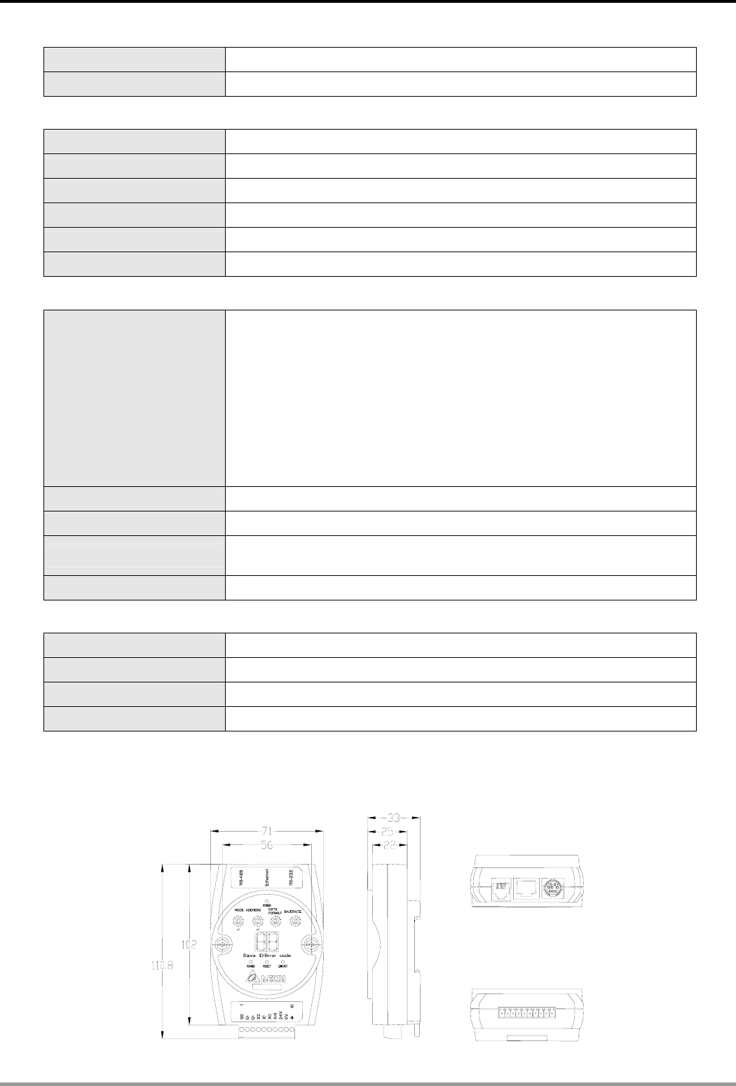
2.1 Dimension
Unit: mm
Ethernet Communication Module IFD9506
DVP-PLC Application Manual 5
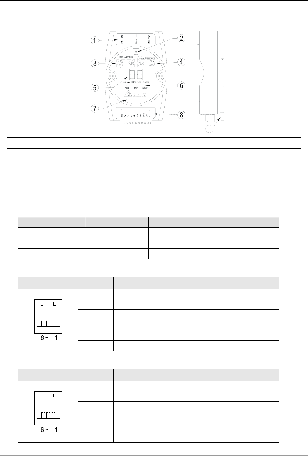
2.2 Product Profiles
9
c Communication ports: RS-485, Ethernet, RS-232 h RS-485 LED, Reset button, Ethernet LED
d POWER LED i Module name
e Address switch j RS-485 connector, digital input points, power
supply points, earth point
f Data format/baud rate switch k DIN rail connector
g Digital display
2.3 LED Indicators
Name Color Function
POWER Green Power supply indication
RS-485 Green Displaying the status of communication port
LINK/ACT Green Displaying the status of network
2.4 RJ-11 PIN Definition
RJ-11 sketch PIN. Signal Definition
1 -- N/C
2 -- N/C
3 D+ Positive pole for data
4 D- Negative pole for data
5 GND Ground
6 -- N/C
2.5 RJ-11 PIN Definition
RJ-11 sketch PIN. Signal Definition
1 -- N/C
2 -- N/C
3 D+ Positive pole for data
4 D- Negative pole for data
5 GND Ground
6 -- N/C
Ethernet Communication Module IFD9506
DVP-PLC Application Manual
6
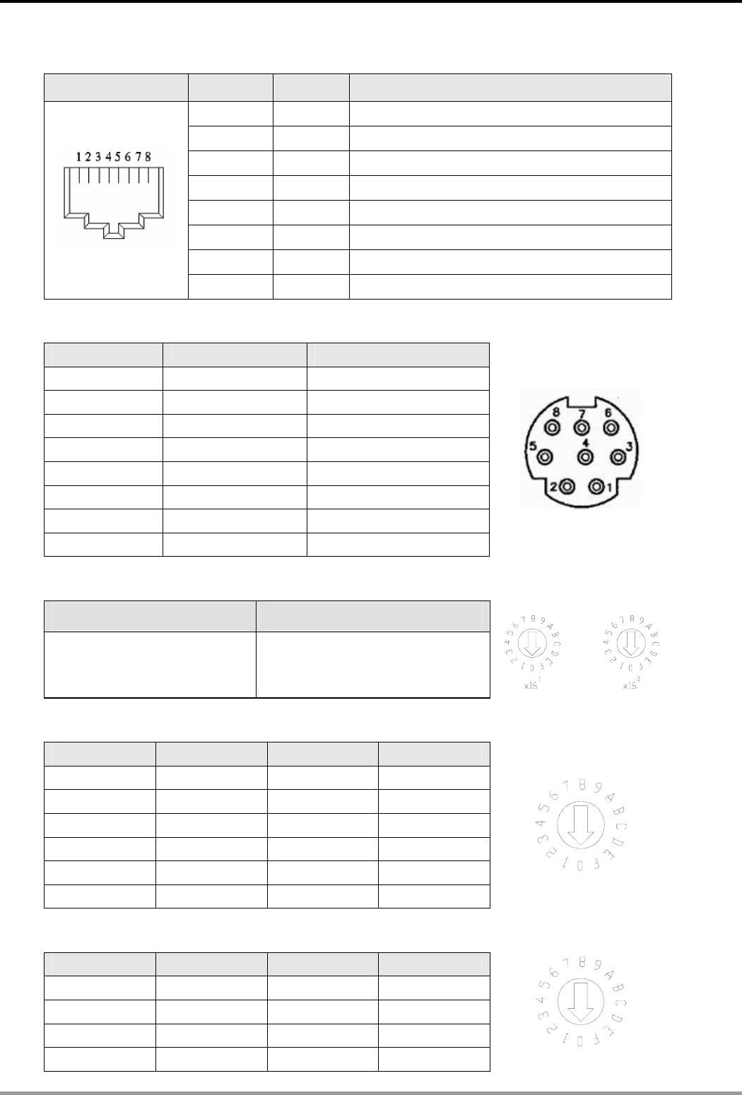
2.6 RJ-45 PIN Definition
RJ-45 sketch PIN Signal Definition
1 Tx+ Positive pole for data transmission
2 Tx- Negative pole for data transmission
3 Rx+ Positive pole for data receiving
4 -- N/C
5 -- N/C
6 Rx- Negative pole for data receiving
7 -- N/C
8 -- N/C
2.7 RS-232 PIN Definition
PIN Signal Definition
1 -- N/C
2 -- N/C
3 -- N/C
4 Rx Reception data
5 Tx Transmission
6 -- N/C
7 -- N/C
8 GND Ground
2.8 Address Switch
Switch setting Content
01…F7 Valid node address setting
2.9 Data Format
Switch setting Format Switch setting Format
0 7-N-1 8 7-N-2
1 8-N-1 9 8-N-2
2 7-O-1 A 7-O-2
3 8-O-1 B 8-O-2
6 7-E-1 E 7-E-2
7 8-E-1 F 8-E-2
2.10 Baud Rate for Modbus Communication
Switch setting Baud rate Switch setting Baud rate
1 110 7 4,000
2 150 8 9,600
3 300 9 19,200
4 600 A 38,400
Ethernet Communication Module IFD9506
DVP-PLC Application Manual 7
5 1,200 B 57,600
6 2,400 C 115,200
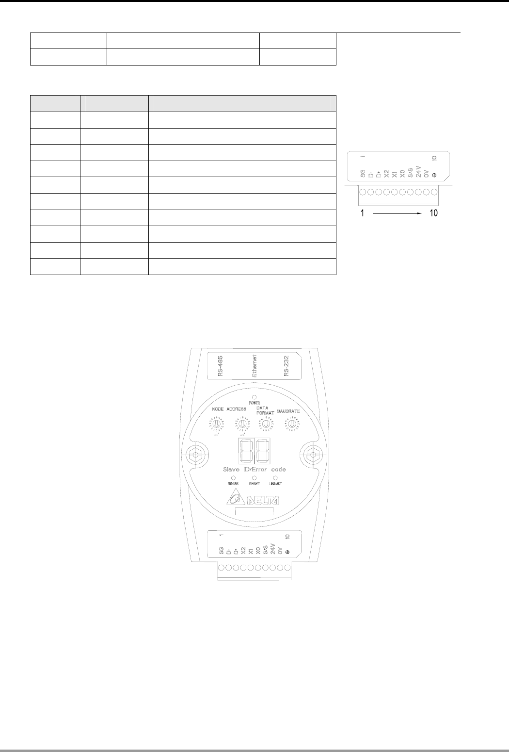
2.11 Feed-through Terminal PIN Definition
PIN Signal Definition
1 SG Reference ground of signal
2 D- Data-
3 D+ Data-
4 X2 Digital input 2
5 X1 Digital input 1
6 X0 Digital input 0
7 S/S Reference ground of digital input
8 24V +24V input
9 0V 0V input
10 Earth ground
3 Installation & Wiring
In this section, we will introduce how to connect IFD9506 to other devices and the network.
3.1 How to Install
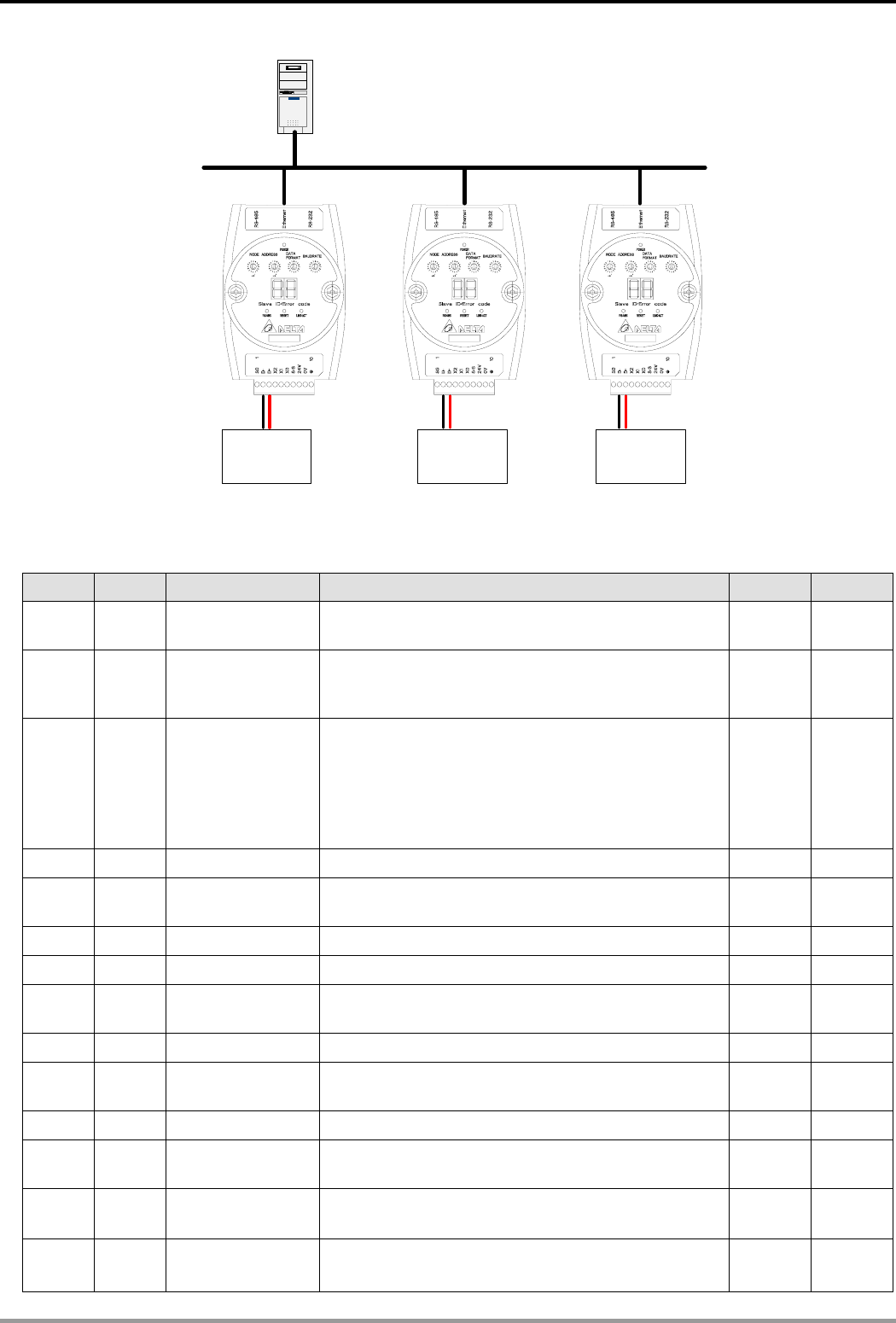
3.2 How to Connect IFD9506 to Network
Connect IFD9506 to the Ethernet hub by CAT-5e twisted pair. Since IFD9506 has Auto MDI/MDIX function,
CAT-5e twisted pair does not need to jump wire. See below for the connection between the PC and IFD9506
modules:
Ethernet Communication Module IFD9506
DVP-PLC Application Manual
8
Ethernet
PC Master
RS-485 (Master Mode) RS-485 (Slave Mode)
AC motor
driver
Temperature
controller
Human
machine
interface
RS-485 (Master Mode)
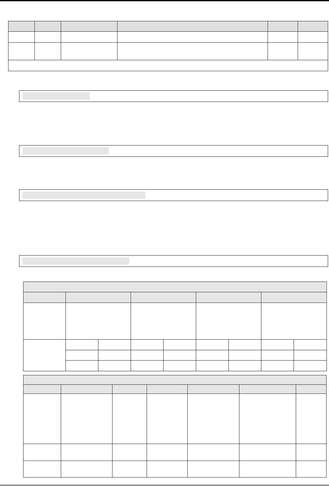
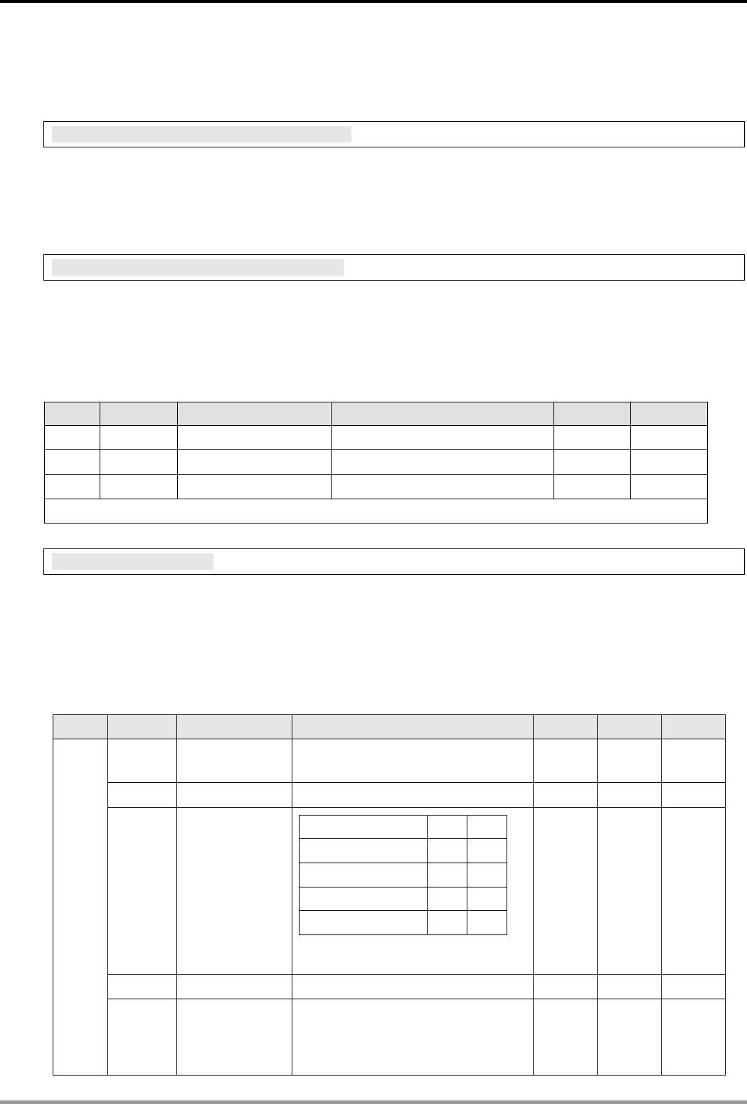
4 Registers in IFD9506
4.1 Basic Registers (BR)
BR# Attribute Content Explanation Default Latched
0 R Model name Set up by the system; read only. The model code of
IFD9506 = H’0200 Yes
1 R Firmware version
Displaying the current firmwawre version in hex,
e.g. V1.2 is indicated as high byte = 0x01 and low
byte = 0x20.
Yes
2 R
Release data of
the version
Displaying the data in decimal form. 10,000s digit
and 1,000s digit are for “month”; 100s digit and 10s
digit are for “day”. For 1s digit: 0 = morning; 1 =
afternoon.
Example: 12191 indicates the version released in
the afternoon of December 19.
Yes
3 Reserved
4 R/W
Communication
format
Please refer to the table of communication format
setting. No
5 R/W Baud rate Please refer to the table of baud rate setting. No
6 R/W Address For setting up the station address No
7 R
Number of DI/DO
points DI: high bytes; DO: low bytes 0x300 Yes
8 Reserved
9 R Error code Displaying the errors. Please refer to the table of
error codes. 0 No
10 Reserved
11 R/W
Communication
time-out
For setting up the communication time-out (ms) in
Modbus TCP mode. 5,000 Yes
12 R/W
Communication
delay time
For setting up the minimum interval time between
every communication datum.。 0 Yes
13 R/W
TCP connection
idle time
For setting up idle time for TCP communication
Unit: second 30 Yes
Ethernet Communication Module IFD9506
DVP-PLC Application Manual 9
BR# Attribute Content Explanation Default Latched
14 ~ 32 Reserved
33 R/W
Returning to
default setting 0 No
Symbol “R” refers to read only; “R/W” refers to read and write.
4.2 Explanations on BR
BR#0: Model Name
Explanations:
1. Model code of IFD9506 = H’0200.
2. You can read the model code in the program to see if the extension module exists.
BR#1: Firmware Version
Explanations:
The firmware version of IFD9506 is displayed in hex, e.g. H’0100 indicates version V1.00.
BR#2: Release Date of the Version
Explanations:
Displaying the data in decimal form. 10,000s digit and 1,000s digit are for “month”; 100s digit and 10s digit are
for “day”. For 1s digit: 0 = morning; 1 = afternoon.
Example: 12191 indicates the version released in the afternoon of December 19.
BR#4: Communication Format
Explanations:
BR#4 low byte
b7 ~ b4 b3 b2 ~ b1 b0
Explanation Reserved
Stop bit
0: 1 stop bit
1: 2 stop bits
Parity bit
00: None parity bit
01: Odd parity bit
11: Even parity bit
Data bit
0: 7 data bits
1: 8 data bits
0000 (0) 7-N-1 0011 (3) 8-O-1 1000 (8) 7-N-2 1011 (B) 8-O-2
0001 (1) 8-N-1 0110 (6) 7-E-1 1001 (9) 8-N-2 1110 (E) 7-E-2
Content
0010 (2) 7-O-1 0111 (7) 8-E-1 1010 (A) 7-O-2 1111 (F) 8-E-2
BR4 High byte
B7 B6~B4 B3 B2 B1 B0
Explanation
RS-485 User
Define
0: Disable
1: Enable
Reserved
RS-232
User Define
0: Disable
1: Enable
COM2 RS-485
setting
0: Serial Master
Ethernet Server
1: Serial Slave
Ethernet Client
COM1 RS-232
setting
0: Delta
Configuration
1: Modbus
Mode
0: ASCII
1: RTU
Content 00000000 (0) Disable Disable Serial Master Delta
configuration
ASCII
00000001 (1) Disable Disable Serial Master Delta
configuration
RTU
Ethernet Communication Module IFD9506
DVP-PLC Application Manual
10
BR4 High byte
B7 B6~B4 B3 B2 B1 B0
00000010 (2) Disable Disable Serial Master Modbus ASCII
00000011 (3) Disable Disable Serial Master Modbus RTU
00000100 (4) Disable Disable Serial Slave Delta
configuration
ASCII
00000101 (5) Disable Disable Serial Slave Delta
configuration
RTU
00000110 (6) Disable Disable Serial Slave Modbus ASCII
00000111 (7) Disable Disable Serial Slave Modbus RTU
00001000 (8) Disable Enable Serial Master Delta
configuration
ASCII
: : : : : :
10000111 (135) Enable Disable Serial Slave Modbus RTU
10001000 (136) Enable Enable Serial Master Delta
configuration
ASCII
10001001 (137) Enable Enable Serial Master Delta
configuration
RTU
10001010 (138) Enable Enable Serial Master Modbus ASCII
10001011 (139) Enable Enable Serial Master Modbus RTU
10001100 (140) Enable Enable Serial Slave Delta
configuration
ASCII
10001101 (141) Enable Enable Serial Slave Delta
configuration
RTU
10001110 (142) Enable Enable Serial Slave Modbus ASCII
10001111 (143) Enable Enable Serial Slave Modbus RTU
BR#5: Baud Rate
Explanations:
BR#5 low byte for baud rate of COM1
Communication
interface Explanation
Data Baud rate
(bps) Data Baud rate
(bps) Data Baud rate
(bps)
0x01 110 0x06 2,400 0x0B 57,600
0x02 150 0x07 4,800 0x0C 115,200
0x03 300 0x08 9,600
0x04 600 0x09 19,200
Content
RS-232
0x05 1,200 0x0A 38,400
BR#5 high byte for baud rate of COM2
Content RS-485 same as low byte
BR#6: Address
Explanations:
For filling in or reading the Modbus address. The address will be displayed in the message display after being
set up.
Ethernet Communication Module IFD9506
DVP-PLC Application Manual 11
BR#7: Number of DI/DO Points
Explanations:
Read the number of DI/DO points from BR#7.
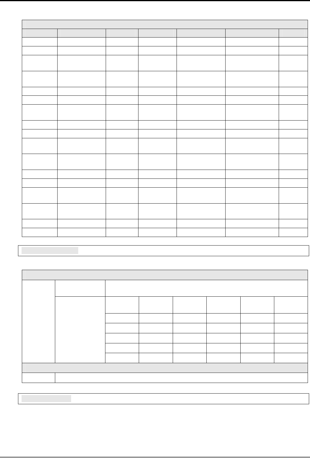
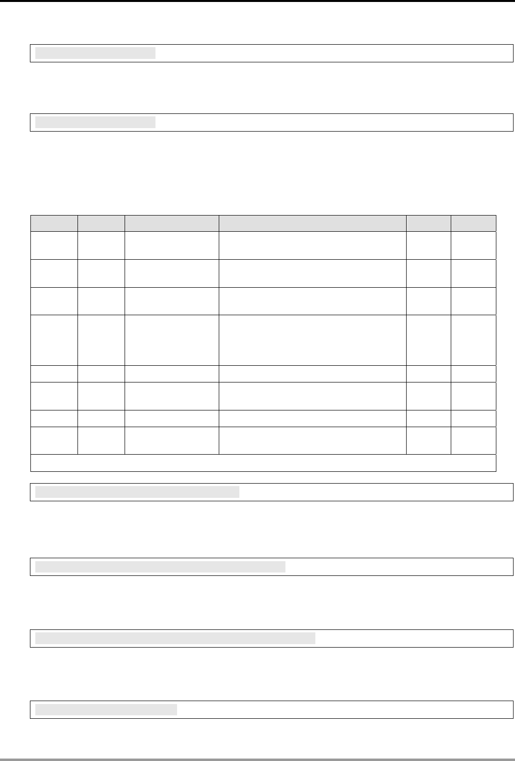
BR#9: Error Code
Explanations:
Error code = 0 refers to no error occurring.
Code Indication How to correct
01 ~ F7 Node address of the scan module
(when operating normally) --
F0 Returning to default setting --
F1 IFD9506 being powered --
F2 Power supply in low voltage Check if the power supply of the module works normally.
F3 Internal memory detection error
1. Re-power IFD9506. If the errir still exists, try step 2.
2. Reset IFD9506. If the error still exists, send the
module back to the manufacturer for repair.
F4 Internal error. Manufacturing error
1. Re-power IFD9506. If the error still exists, try step 2.
2. Reset IFD9506. If the error still exists, send the
module back to the manufacturer for repair.
F5 Network connection error Check if IFD9506 is connected normally to the network.
F6 Full number of devices connected
in the network. Check if the number is too much.
F7 UART setting error. Check if the RS-485, RS-232 communication format is
correct.
E1 Alarm 1 triggered Check alarm point 1.
E2 Alarm 2 triggered Check alarm point 2.
E3 Alarm 3 triggered Check alarm point 3.
01 Incorrect Modbus function Check if the Modbus instruction is correct.
02 Incorrect address Check if the Modbus instruction is correct.
03 Incorrect data Check if the Modbus instruction is correct.
04 CRC error
1. Check if IFD9506 is normally connected to RS-485.
2. Make sure the transmission speed of IFD9506 is
consistent with that of other nodes on the network.
0B No response from the station
1. Check if IFD9506 is normally connected to RS-485.
2. Make sure the transmission speed of IFD9506 is
consistent with that of other nodes on the network.
BR#11: Communication Time-out (ms)
Explanations:
For setting up the communication time-out. Default = 5,000ms. For example, if you wish to set up the
communication time-out to 7 seconds manually, write 7000 into BR#11.
BR#12: Communication Delay Time (ms)
Explanations:
Ethernet Communication Module IFD9506
DVP-PLC Application Manual
12
For setting up the minimum interval time between every Modbus communication datum. Default = 0ms. For
example, if you wish to set up the communication delay time to 100ms manually, write 100 into BR#12.
BR#13: TCP Connection Idle Time (s)
Explanations:
For setting up the TCP Connection Idle time. Default = 30s. For example, if you wish to set up the idle time to 7
seconds manually, write 7 into BR#13.
BR#33: Returning to Default Setting
Explanations:
IFD9506 will return to default setting when "1" is written into BR#33. BR#33 will be cleared to “0"
automatically after the returning.
4.3 Alarm Registers (AL)
AL# Attribute Content Explanation Default Latched
0 R/W Alarm point 1 0 Yes
1 R/W Alarm point 2 0 Yes
2 R/W Alarm point 3 0 Yes
Symbol “R” refer to read only; “R/W” refers to read and write.
AL#0: Alarm Point 1
Explanations:
You can designate 1 RX extension point as the alarm point by setting up the AL register in IFD9506. When the
alarm point is triggered, IFD9506 will execute its corresponding function. When b15 of AL#0 is set to “1”, the
gateway will execute the event immediately. When RX point is triggered, the gateway will only execute the
triggered event once.
Device Function Setting Attribute Default Latched
b15 Enabling the
function
b15 = 1: Enabling
b15 = 0: Disabling R/W 0 Yes
b4 ~ b14 Reserved R/W 0 No
b2 ~ b3
Type of event
enabled when
RX alarm point
is triggered
b3 b2
Reserved 0 0
Trigger E-Mail 0 1
Reserved 1 0
Reserved 1 1
The setting will be invalid when
thealarm function is being executed.
R/W 0 Yes
b1 Reserved Reserved
AL#0
b0 Condition for
triggering RX
b0 = 0: Triggered when RX input
point is low
b0 = 1: Triggered when RX input
point is high
R/W 0 Yes
Ethernet Communication Module IFD9506
DVP-PLC Application Manual 13
AL#1: Alarm Output 2
Explanations:
The settings for AL#1 are the same as those in AL#0.
AL#2: Alarm Output 3
Explanations:
The settings for AL#2 are the same as those in AL#0.
5 Monitoring Functions
5.1 Monitor Bit Registers (MB)
MB# Attribute Content Explanation Default Latched
0 R/W
Number of devicees
monitored
Cache mode normally enabled (b15=1),
monitoring data in max. 16 slaves. 0 Yes
1 R/W
No. of station
monitored No. of the station to be monitored 0 Yes
2 R/W
Address of the
device monitored
Recording the address of the device
monitored. 0 Yes
3 ~ 32 R/W
No. of station
monitored, address
of the device
monitored
No. of the station to be monitored;
recording the address of the device
monitored.
0 Yes
33 ~ 200 R/W Reserved
201 R Monitored value
Every MB records the value in the 16-bit
device. 0 No
202 ~ 213 R Reserved
214 R Monitored status
Every MB records the status in the 16-bit
device. 1 = normal; 0 = abnormal 0 No
Symbol “R” refer to read only; “R/W” refers to read and write.
MB#0: Number of Devices Monitored
Explanations:
For setting up the number of devices to be monitored. Max. data in 16 slaves can be monitored.
b15 is read only (Default =1: normally enabled cache mode)
MB# (Odd Number): No. of Station Monitored
Explanations:
MB#1, MB#3, MB#5…MB#33 are for setting up the station No. (0 ~ 255) to be monitored.
MB# (Even Number): Address of Device Monitored
Explanations:
MB#2, MB#4, MB#6…MB#34 are for setting up the address of the device to be monitored.
MB#201: Monitored Value
Explanations:
Ethernet Communication Module IFD9506
DVP-PLC Application Manual
14
Every MB records the values in the 16-bit device.
b15 b14 b13 b12 b11 b10 b9 b8 b7 b6 b5 b4 b3 b2 b1 b0
Device
16
Device
15
Device
14
Device
13
Device
12
Device
11
Device
10
Device
9
Device
8
Device
7
Device
6
Device
5
Device
4
Device
3
Device
2
Device
1
MB#214: Monitored Status
Explanations:
Every MB records the status in the 16-bit device. 1 = normal; 0 = abnormal.
b15 b14 b13 b12 b11 b10 b9 b8 b7 b6 b5 b4 b3 b2 b1 b0
Device
16
Device
15
Device
14
Device
13
Device
12
Device
11
Device
10
Device
9
Device
8
Device
7
Device
6
Device
5
Device
4
Device
3
Device
2
Device
1
5.2 Monitor Word Registerss (MW)
MW# Attribute Content Explanation Default Latched
0 R/W
Number of devices
monitored
Cache mode normally enabled (b15=1),
monitoring data in max. 16 slaves. 0 Yes
1 R/W
No. of station
monitored No. of the station to be monitored 0 Yes
2 R/W
Address of the
device monitored
Recording the address of the device
monitored 0 Yes
3 ~ 32 R/W
No. of station
monitored, address
of the device
monitored
No. of the station to be monitore; recording
the address of the device monitored. 0 Yes
33 ~ 200 R/W Reserved
201 ~ 216 R Monitored value Every MW records the monitored value in 1
register 0 No
216 ~ 300 R Reserved
301 R Monitored status
Every MW records the status in a 16-bit
register. 1 = normal; 0 = abnormal 0 No
Symbol “R” refers to read only; “R/W” refers to read and write.
MW#0: Number of Devices Monitored
Explanations:
For setting up the number of devices to be monitored. Max. data in 16 slaves can be monitored.
b15 is read only (Default =1: normally enabled cache mode)
MW# (Odd Number): No. of Station Monitored
Explanations:
MW#1, MW#3, MW#5…MW#33 are for setting up the station No. (0 ~ 255) to be monitored.
MW# (Even Number): Address of Device Monitored
Explanations:
MW32, MW34, MW#36…MW#34 are for setting up the address of the device to be monitored.
Ethernet Communication Module IFD9506
DVP-PLC Application Manual 15
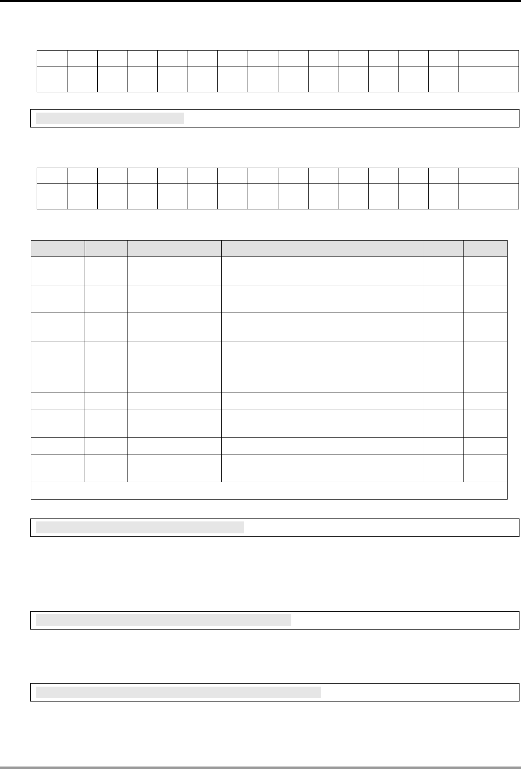
MW#201~#216: Monitored Value
Explanations:
Every MW records the values in 1 register.
MW#201 MW#202 MW#203 MW#204 MW#205 MW#206 MW#207 MW#208 MW#209 MW#210
Device 1 Device 2 Device 3 Device 4 Device 5 Device 6 Device 7 Device 8 Device 9 Device 10
MW#211 MW#212 MW#213 MW#214 MW#215 MW#216
Device
11
Device
12
Device
13
Device
14
Device
15
Device
16
MW#301: Monitored Status
Explanations:
Every MW records the status in a 16-bit register. 1 = normal; 0 = abnormal.
b15 b14 b13 b12 b11 b10 b9 b8 b7 b6 b5 b4 b3 b2 b1 b0
Device
16
Device
15
Device
14
Device
13
Device
12
Device
11
Device
10
Device
9
Device
8
Device
7
Device
6
Device
5
Device
4
Device
3
Device
2
Device
1
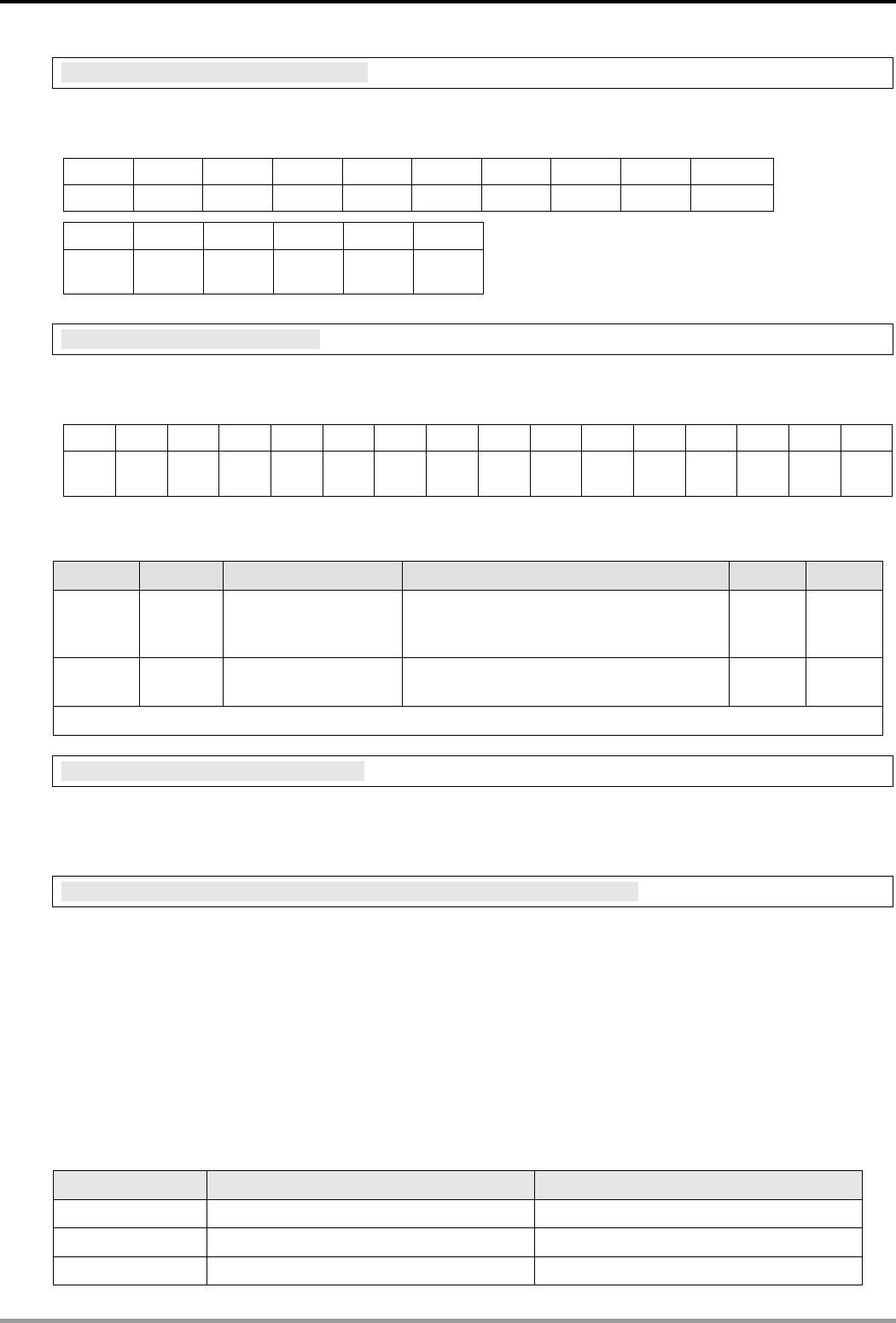
6 Setting up Device Address & Relay Address in Slave Mode
MIP# Attribute Content Explanation Default Latched
0 ~ 50 R/W Corresponding
address
Max. 100 addresses are allowed. High
byte for 1 address and low byte for 1
address.
0 YES
50 ~ 249 R/W Relay IP address Total 100 IPs. Every address (1 byte)
corresponds to 1 IP address (4 bytes). 0 YES
Symbol “R” refers to read only; “R/W” refers to read and write.
MIP#0: Corresponding Address
Explanations:
The low byte of MIP#0 are for the first address, and the high byte are for the second address, and so on.
MIP#51 ~ #52: Corresponding IP for the 1st Device Address
Explanations:
Example 1: If you wish to convert “192.168.0.1” into “COA80001” (hex), write A8C0 into MIP#50 and H0100
into MIP#51.
Example 2: Data in address 1 have to correspond to 192.168.0.8. Data in address 2 have to correspond to
192.168.0.6. To complete such settings, write H0201 into MIP#0, A8C0 into MIP#50, H0800 into MIP#51,
A8C0 into MIP#52 and H0600 into MIP#53.
7 Modbus Communication
7.1 Function Codes Supported
Function code Explanation Devices supported
0x02 Read discrete input RX
0x03 Read holding register BR, AL, MB, MW, MIP
0x06 Write single holding register BR, AL, MB, MW, MIP

Ethernet Communication Module IFD9506
DVP-PLC Application Manual
16
Function code Explanation Devices supported
0x10 Write multiple holding registers BR, AL, MB, MW, MIP
0x17 Read/write multiple holding registers BR, AL, MB, MW, MIP
7.2 Exception Codes Supported
Exception code Explanation
0x01 Illegal function
0x02 Illegal data addresss
0x03 Illegal data value
0x04 Slave device failure
0x0A Gateway path unavailable
0x0B Gateway target device failed to respond
7.3 Device Type & Device Address
Discrete input
Device
type
Modbus address
(Hex) 5-digit Modbus address (Dec) 6-digit Modbus address
(Dec) Number
RX 0x0400 ~ 0x0402 11025 ~ 11027 101025 ~ 101027 3
Holding register
Device
type
Modbus address
(Hex) 5-digit Modbus address (Dec) 6-digit Modbus address
(Dec) Number
BR 0x0000 ~ 0x00FF 40001 ~ 40256 400001 ~ 400256 64
AL 0x0200 ~ 0x0202 40513 ~ 40515 400513 ~ 400515 3
MB 0x2000 ~ 0x20FF 48193 ~ 48448 408193 ~ 408448 256
MW 0x2200 ~ 0x23FF 48705 ~ 49216 408705 ~ 409216 512
MIP 0x2400 ~ 0x24FF 49217 ~ 49471 409217 ~ 409471 256
8 Setting up Software
This section gives instructions on how to set up IFD9506 by DCISoft and explanations on each setup page.
IFD9506 is set up by UDP port 20006; therefore, you have to be aware of the relevant settings of the firewall.
See the explanations below on the software.
8.1 Setting up Communication & Searching for Modules in DCISoft
Broadcast search
1. Open DCISoft on the PC and click on the “IP Search” icon.
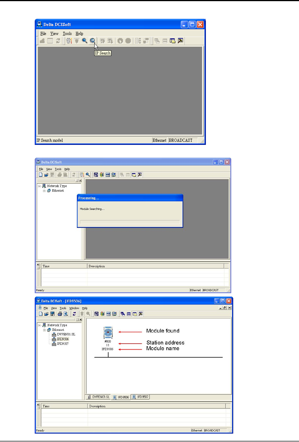
Ethernet Communication Module IFD9506
DVP-PLC Application Manual 17
2. You will see the network modules found.
Ethernet Communication Module IFD9506
DVP-PLC Application Manual
18
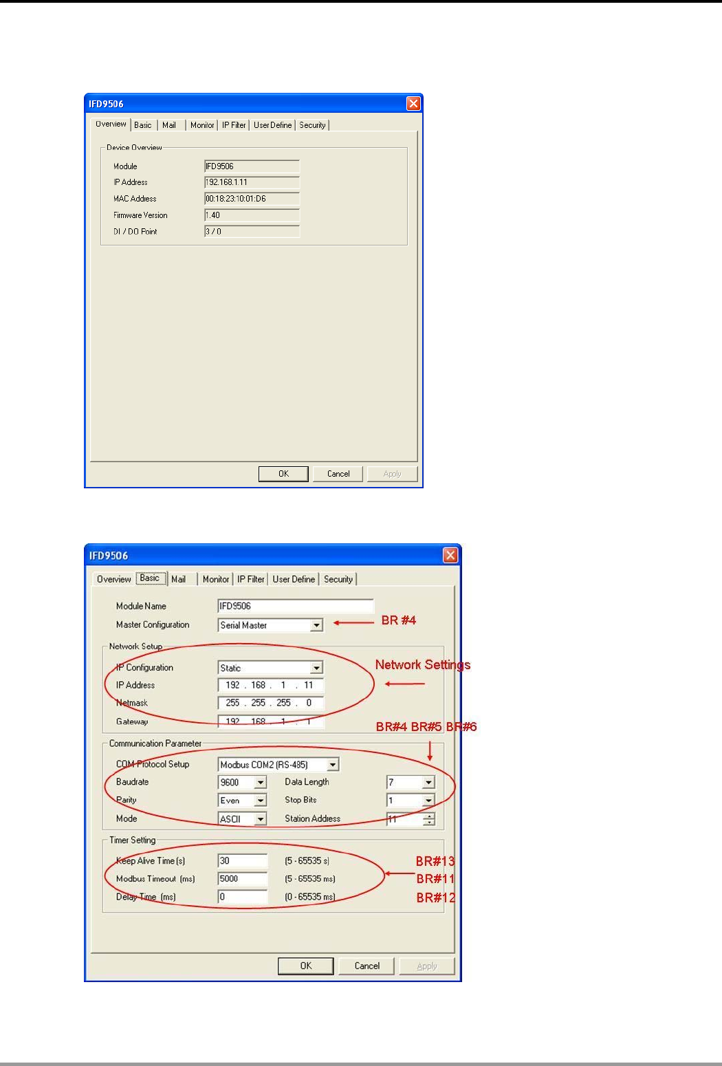
3. Double-click on the module to be set up to enter the setup page. The first page overviews the basic status
of the module.
4. The next page is for basic network setup. Consult your ISP for relevant network settings. For other setting,
see BR#4 ~ BR#6 and BR#11 ~ BR#13.
Ethernet Communication Module IFD9506
DVP-PLC Application Manual 19
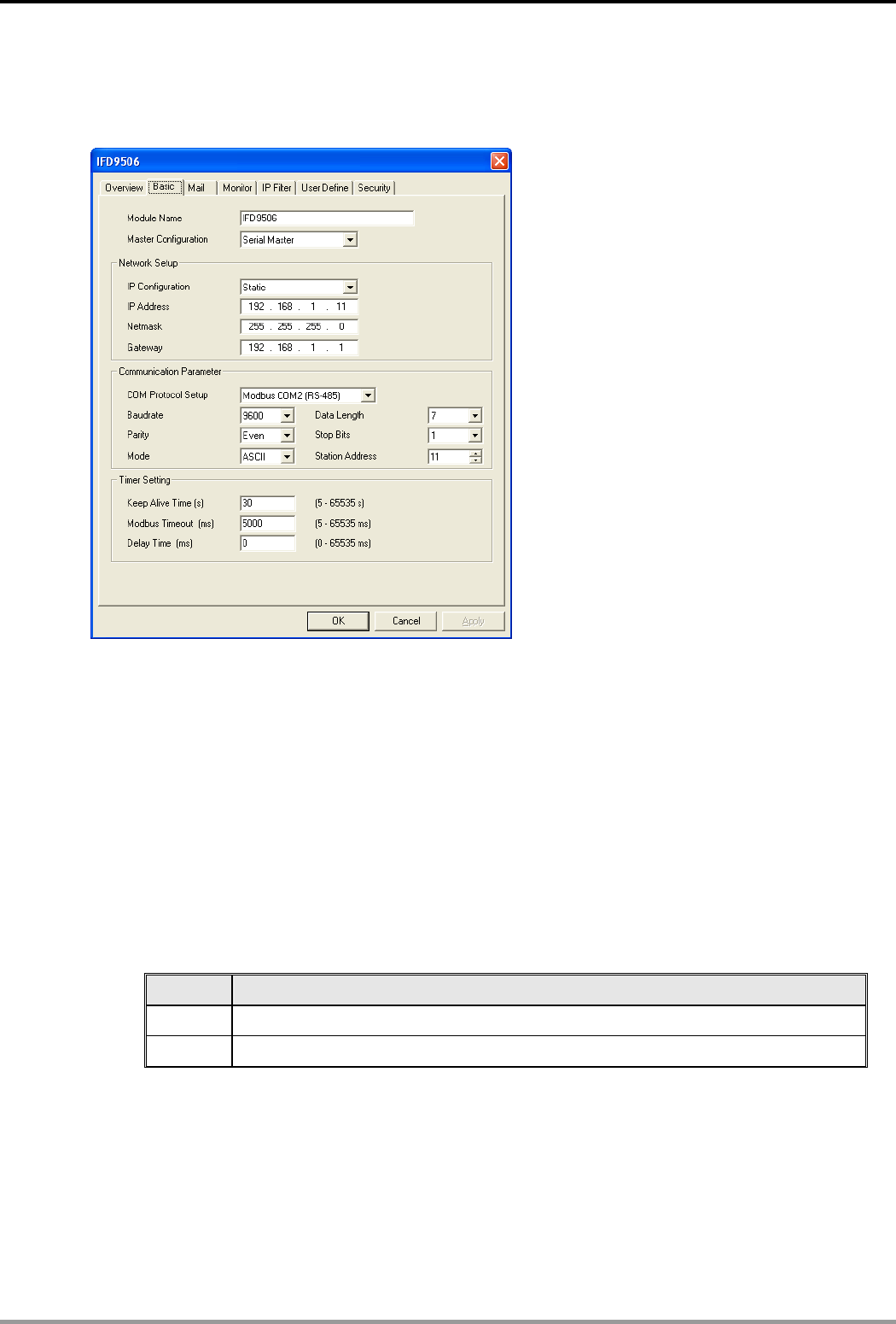
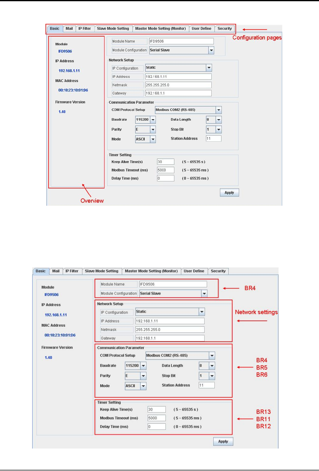
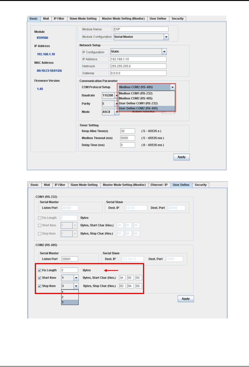
8.2 Basic Settings
The basic settings include parameters such as module name, network settings and serial communication.
The basics
1. Module name:
There can be many IFD9506 modules on the network. Thus, you can set up a module name for each
module to identify the module when you need to use them.
2. Master configuration:
Open “Serial Master” mode or “Serial Slave” mode.
3. Network settings:
Enable DHCP or static IP. Consult your ISP for other relevant settings.
A. IP configuration:
There are 2 types of IP, static IP and DHCP.
Static IP: Preset or manually modified by the user.
DHCP: Automatically updated by the server. There has to be a server in the LAN.
IP Explanation
Static The user enters the IP address, subnet mask and gateway.
DHCP DHCP server offers the IP address, subnet mask and gateway.
B. IP address:
IP address os the location of the equipment on the network. Every equipment connected to the
network has to have an IP address. Incorrect IP address will result in connection failure. Consult
your ISP for how to set up IP address. The default IP for IFD9506 is 192.168.1.5.
C. Subnet mask:
Subnet mask is an important parameter for setting up the subnet, used for seeing if the destination
IP and the locak equipment are in the same subnet. If not, the equipment will send the packet to the
Ethernet Communication Module IFD9506
DVP-PLC Application Manual
20
gateway, and the gateway will send the packet to another subnet. Incorrect setting may cause the
destination equipment unable to communicate to IFD9506. To see if your setting is correct, conduct
bitwise AND operations between your IP and subnet mask and destination IP and subnet mask. If
the two values obtained are the same, the two IPs are in the same subnet. The default subnet mask
of IFD9506 is 255.255.255.0.
D. Gateway:
Gateway is the window for two different subnets, allowing the two ends in different subnets to
communicate. For example, if the LAN has to be connected to WAN, it will need a gateway to
bridge the communication. The IP of the gateway has to be in the same subnet as IFD9506. The
default gateway of IFD9506 is 192.168.1.254.
4. Communication parameter setting:
Please refer to explanations on BR#4, BR#5, and BR#6.
5. Timer setting:
For setting up TCP connection idle time, Modbus time-out and minimum communication delay time for
every communication data. Please refer to explanations on BR#11, BR#12, and BR#13.
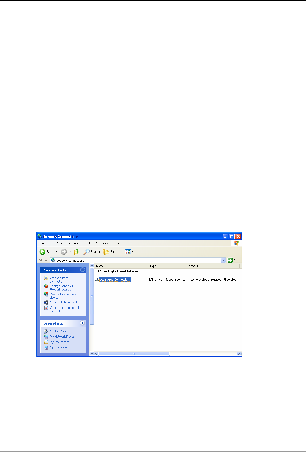
8.3 Network Settings
The first step for all the equipment to connect to the network is to have its own IP (Internet Protocol) address.
The IP address is like a number for every equipment to be identified on the network.
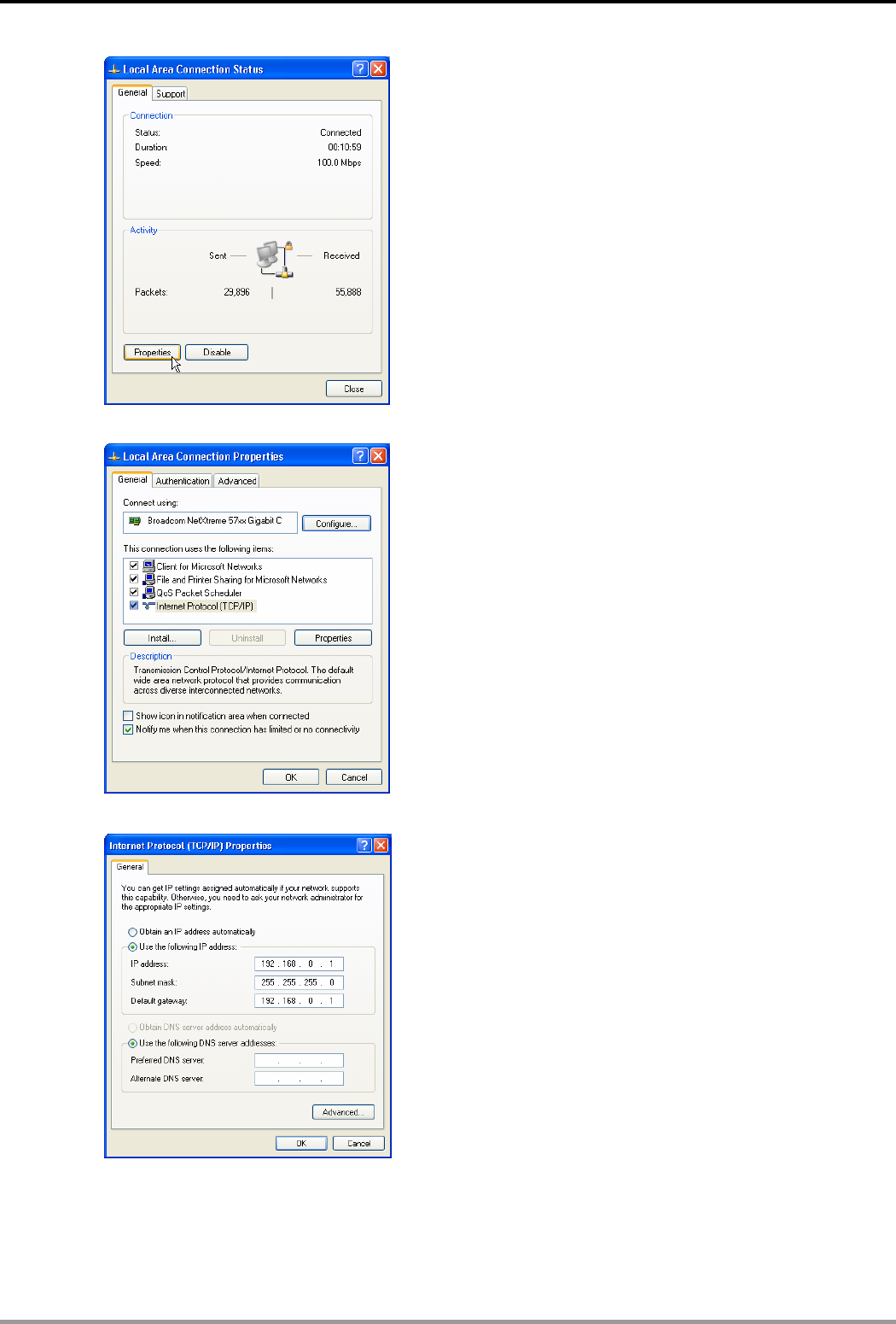
Setting up static IP of the PC
1. Enter Control Panel → Network Connection → click on “Local Area Connection”.
2. You will see the “Local Area Connection Status” window. Click on “Properties”.
Ethernet Communication Module IFD9506
DVP-PLC Application Manual 21
3. Click on “Internet Protocol (TCP/IP)".
4. Enter “192.168.0.1” into IP address. Click on “OK” to complete the IP address setting of the PC.
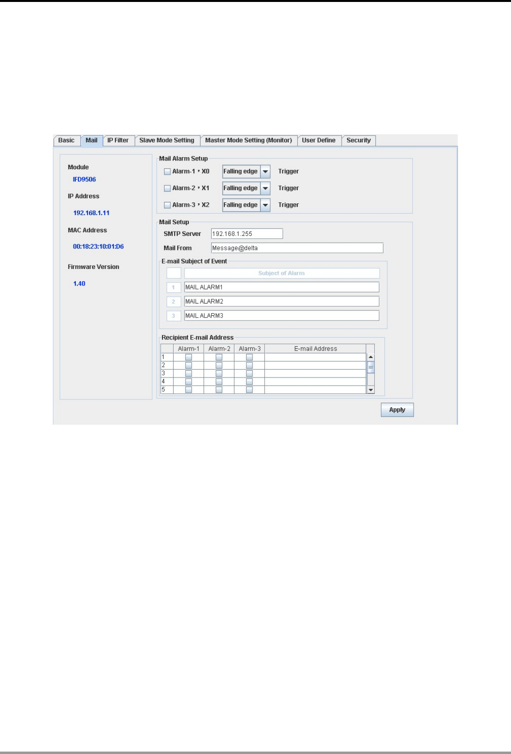
8.4 Setting up E-Mails
E-Mail is the abbreviation of electronic mail which transmits mails through the network. IFD9506 has E-Mail
functions for the user to pre-save a segment of text message, which can be a descriptive message or error
message, into the subject of the E-Mail. When the E-Mail is triggered, IFD9506 will send the messages to the
Ethernet Communication Module IFD9506
DVP-PLC Application Manual
22
user by E-Mail.
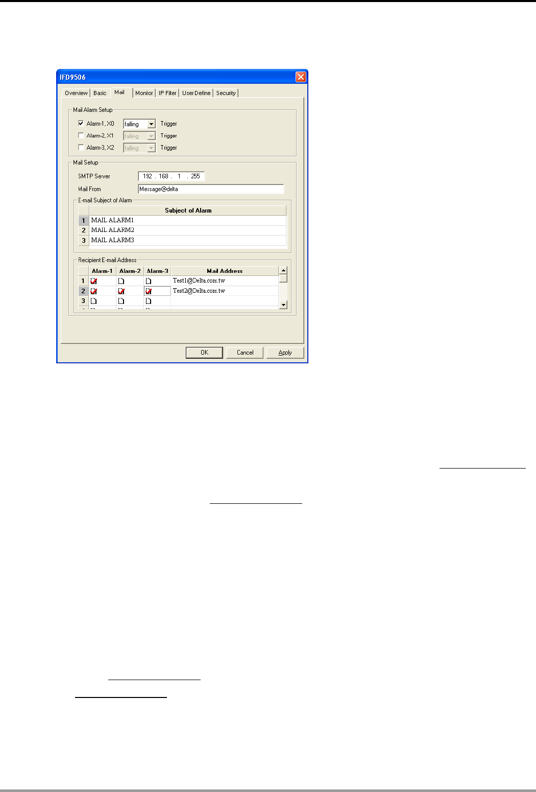
Mail settings
1. Mail alarm setup:
There are 3 mail alarms to be set up. Check the boxes to enable the alarms. The alarm can be
triggered by “low" and “high”.
2. SMTP server:
When Alarm 1 is triggered, the E-Mail will first be sent to SMTP server, and SMTP server will send it
to the designated address. For example, assume there is an E-Mail to be sent to Test@delta.com.tw,
and SMTP server is 192.168.0.1, the E-Mail will be sent to SMTP server first, and the server will
further send it to the recipient Test1@delta.com.tw.
3. E-Mail of sender:
Maximum 63 Engligh characters are allowed.
4. Subject of E-Mail:
You can enter the text message in the column, and the message will be placed in the subject of the
E-Mail and sent to the recipient. IFD9506 is able to contain 1~3 E-Mail subjects. Max. 63 English
characters are allowed for each subject.
5. E-Mail of recipient:
One mail can be sent to 10 addresses according to the alarm setting. Every address allows Max. 63
English characters. For example, (see the figure above) when Alarm 1 is triggered, the E-Mail will be
sent to Test1@delta.com.tw. When Alarm 2 is triggered, the E-Mail will be sent to
Test2@delta.com.tw.
Note:
To correctly send out E-Mails, there has to be a SMTP server in the network. When we send out an
E-Mail, the mail will be sent to SMTP server first, and the server will further send the mail to the
designated address.
Ethernet Communication Module IFD9506
DVP-PLC Application Manual 23
8.5 Monitoring Settings
You can read data in designated addresses in different equipment in the network by setting up IFD9506. The
data can be temporarily stored in IFD9506 for fast storing and acquisition.
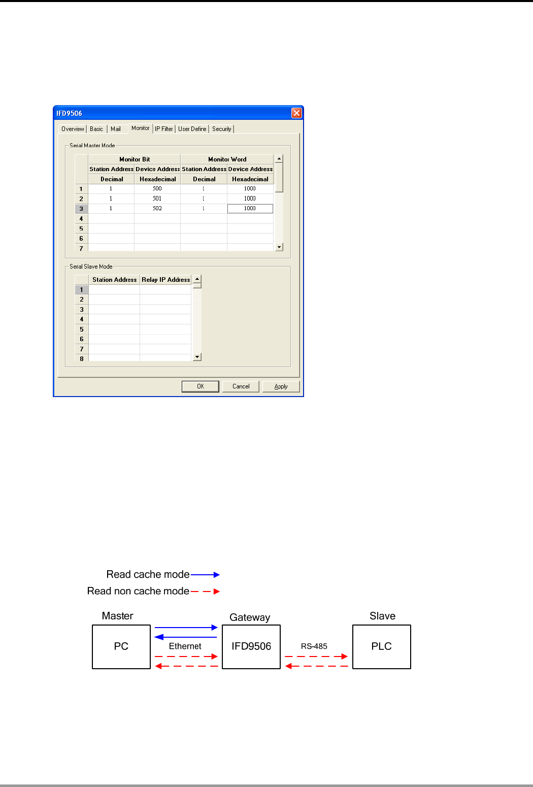
Setting up monitoring functions
1. Monitor bit:
Device addresses for setting up the bit status of serial slave; able to read the content in the
corresponding address of the designated slave.
2. Monitor word:
Device addresses for setting up the word status of serial slave; able to read the content in the
corresponding address of the designated slave.
Note:
Cache mode normally enabled, and Max. data in 16 slaves can be monitored. When the cache mode
is enabled, the data you would like to read will be sent back directly from the register in IFD9506.
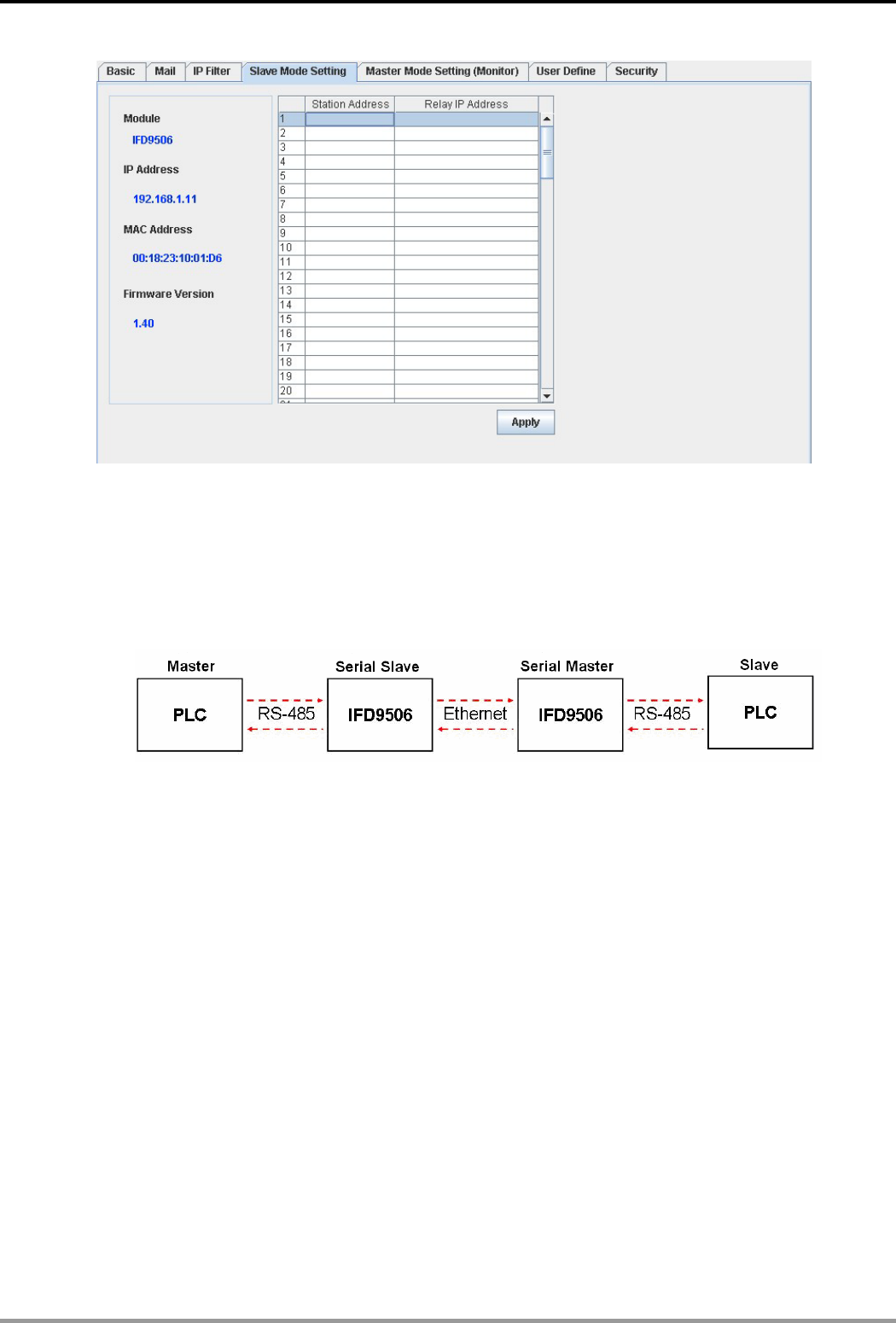
3. Serial slave mode:
The instruction sent from the master is received and transferred to the network. Please designate the
station address and relay IP address.
Device address: Address of the slave PLC
Relay IP address: IP of the serial master
Ethernet Communication Module IFD9506
DVP-PLC Application Manual
24
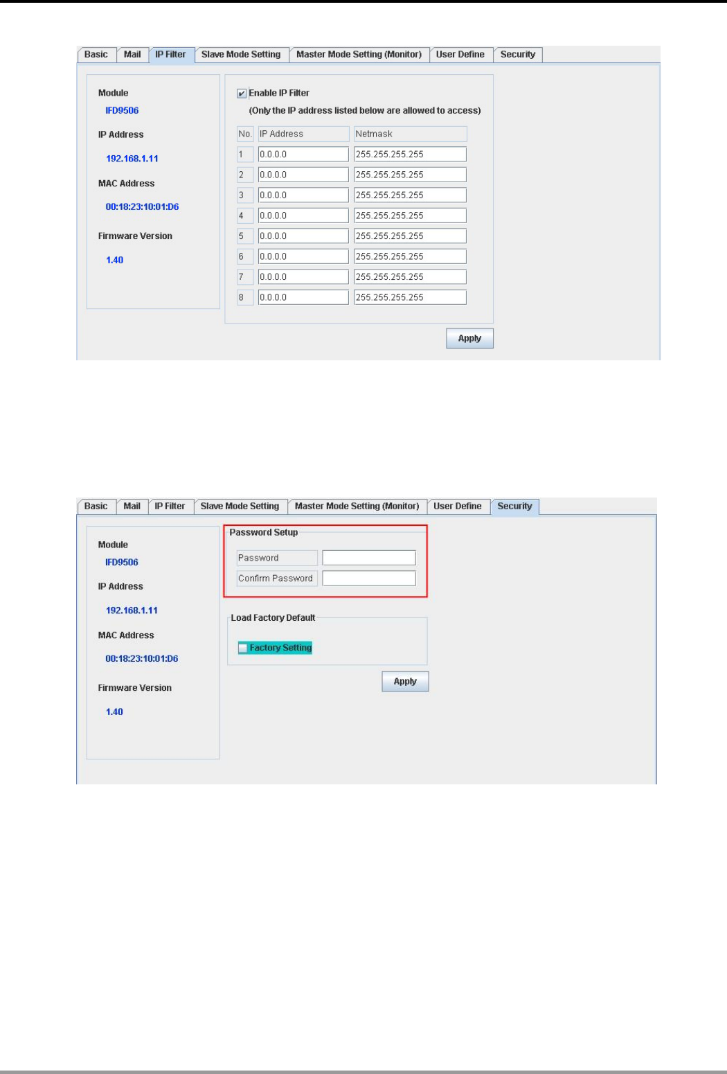
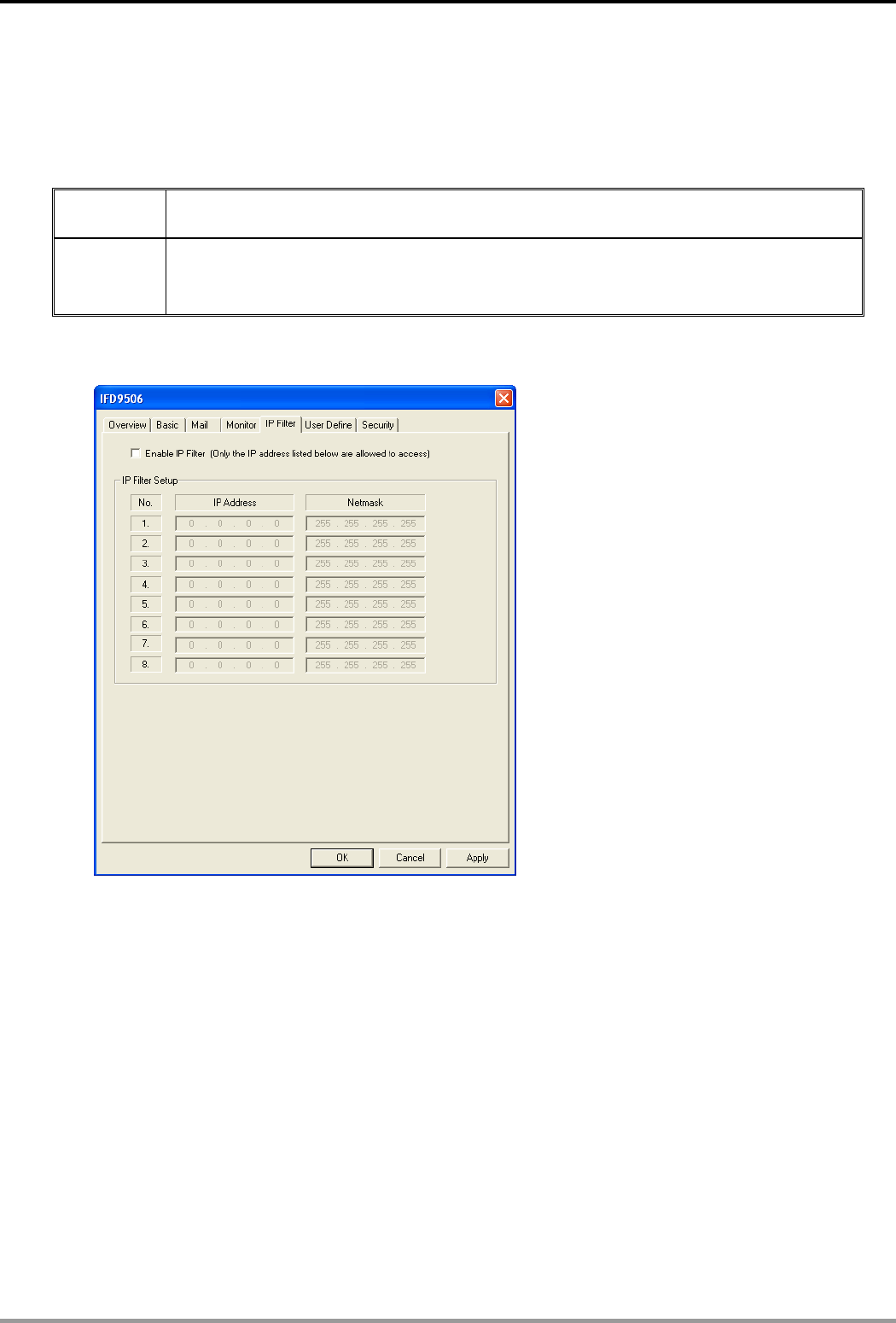
8.6 IP Filter
The IP filter is used for restricting the connection of the network in case some uncertain UP will cause errors.
Only the IP set within a certain range can establish a connection. Other IPs will be rejected.
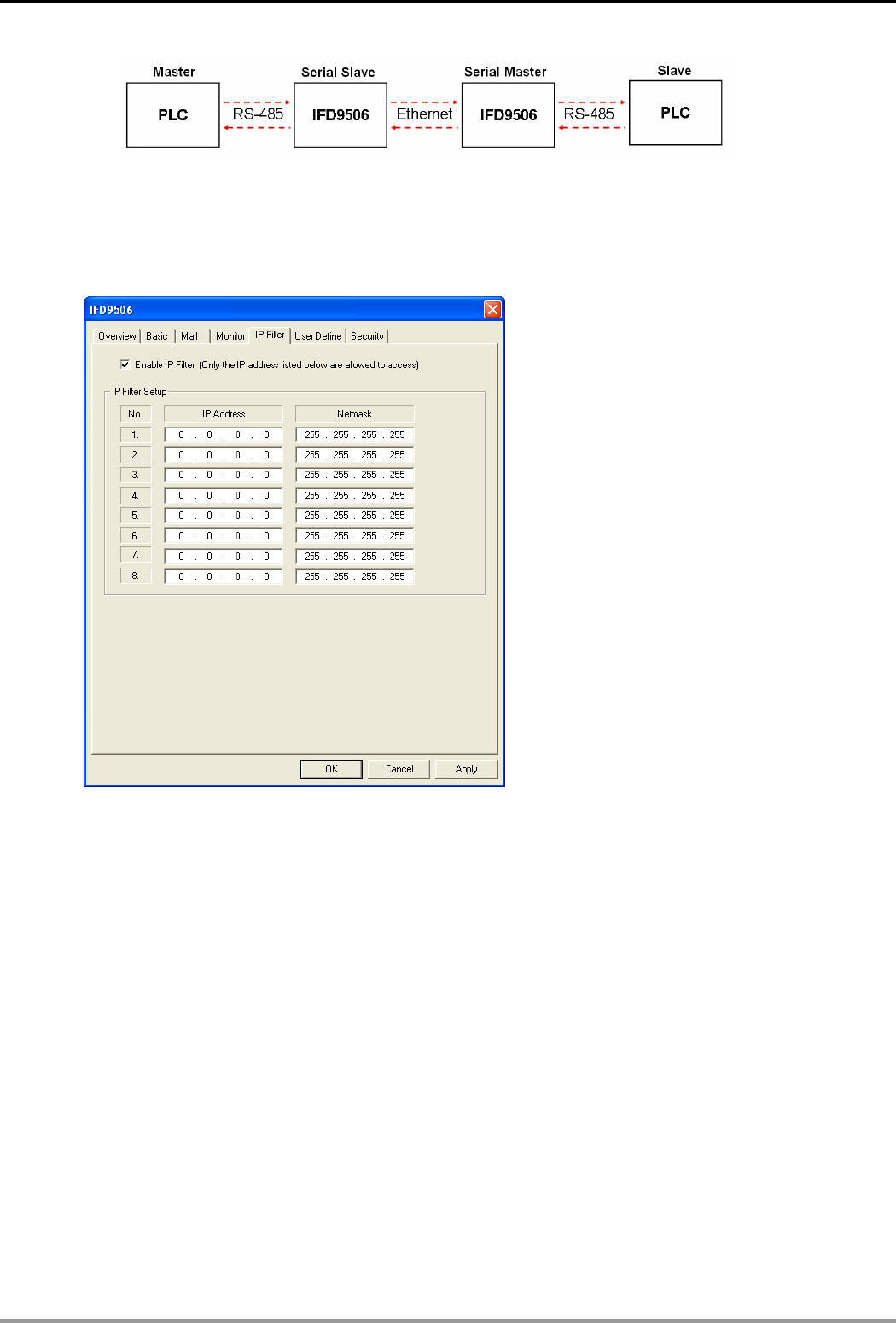
Setting up IP filter
1. Enable IP filter function:
Check the box to enable IP filter.
2. IP address:
IP addresses that are allowed to establish connections. Max. 8 IPs are allowed.
3. Netmask:
Subnet mask of the UP that is allowed to establish a connection. To see whether the subnet mask is
allowed, conduct bitwise AND operation between the allowed IP and subnet mask and destination IP
and subnet mask. If the two values obtained are the same, the subnet mask is allowed by the network.
For example, assume the IP is 192.168.0.1 and subnet mask 255.255.255.0, the IPs allowed to
establish connections will become 192.168.0.0 ~ 192.168.0.255.
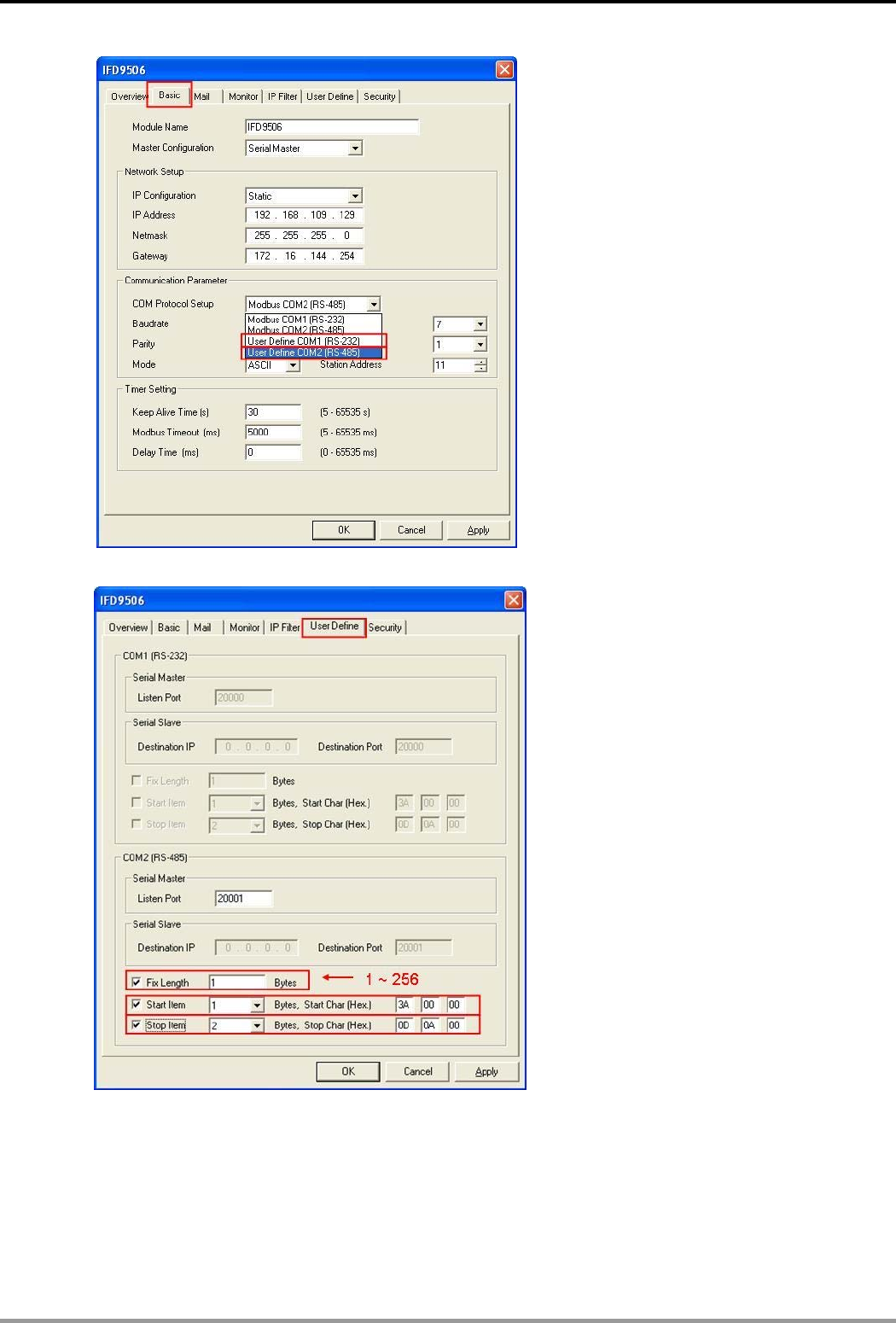
8.7 User Defined Format
You can define your own format for the data to be transmitted. The items to be defined include the fixed length,
start item and stop item.
Select RS-232 or RS-485 to connect the device
Ethernet Communication Module IFD9506
DVP-PLC Application Manual 25
Switch to “User Define” page to set up the “Fix Length”, “Start Item” and “Stop Item".
1. Listen Port/Destination Port:
Range: 1024 ~ 65535.
2. Fix Length:
When this is set, IFD9506 will transmit data following the fixed length.
3. Start Item:
The start item of data. Range: 1 ~ 3
Ethernet Communication Module IFD9506
DVP-PLC Application Manual
26
4. Stop Item:
The stop item of data. Range: 1 ~ 3
When the start item and stop item are set, IFD9506 will transmit data following the start item and
stop item. If the transmission time exceeds the Modbus time-out, IFD9506 will dispose of
incomplete data.
Note:
When using two IFD9506 modules as Mater and Slave and its user define functions, the settings
of the fixed length, start item and stop item have to be consistent. If not, the data will be filtered
automatically.
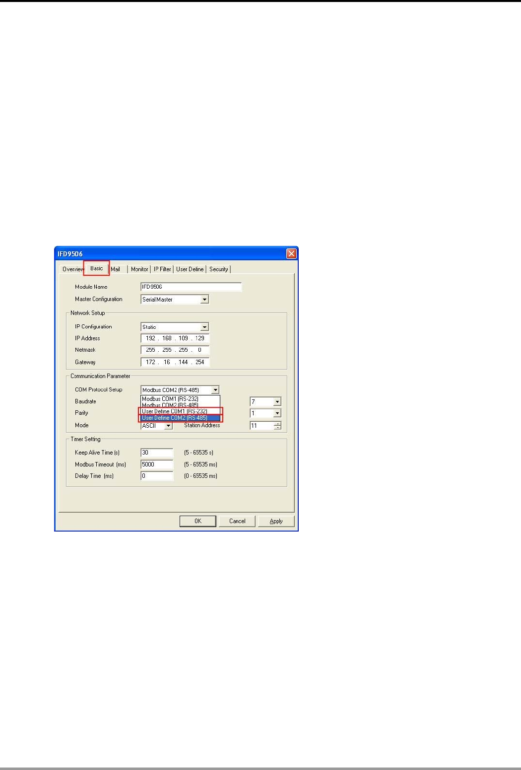
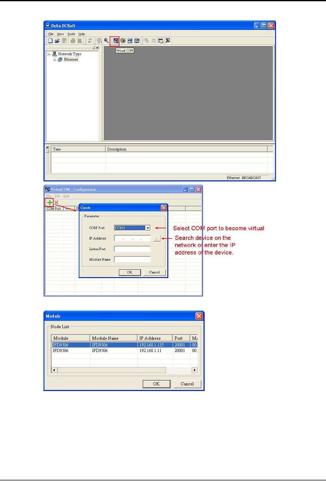
8.8 Virtual COM
Virtual COM converts the data transmitted to RS-232 to Ethernet.
Select “User Define COM”.
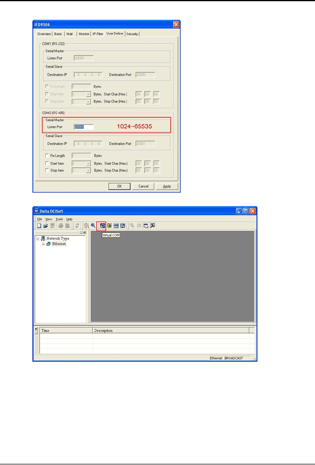
Switch to “User Define” page and “Listen Port”.
Ethernet Communication Module IFD9506
DVP-PLC Application Manual 27
Open Virtual COM setup page
Ethernet Communication Module IFD9506
DVP-PLC Application Manual
28
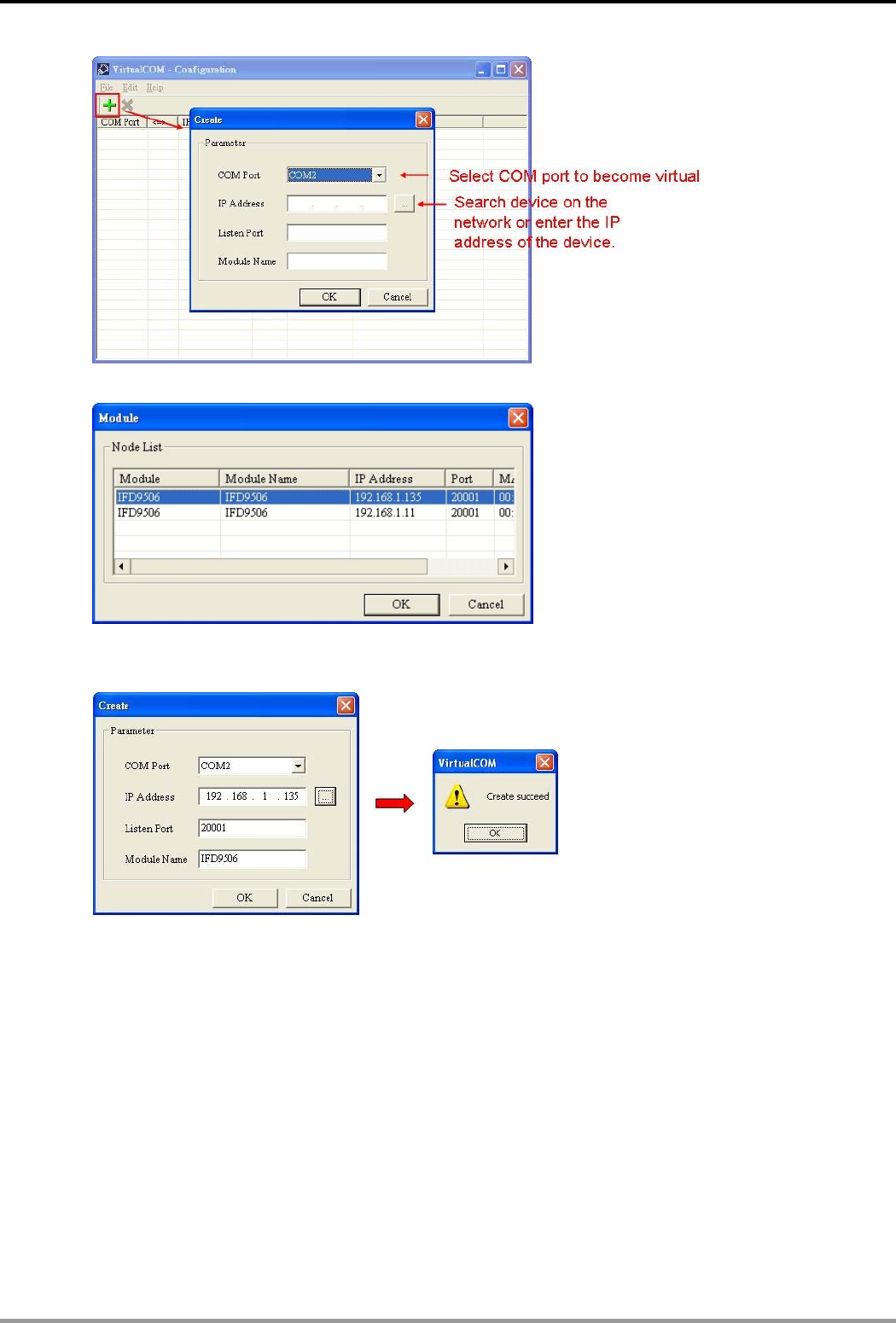
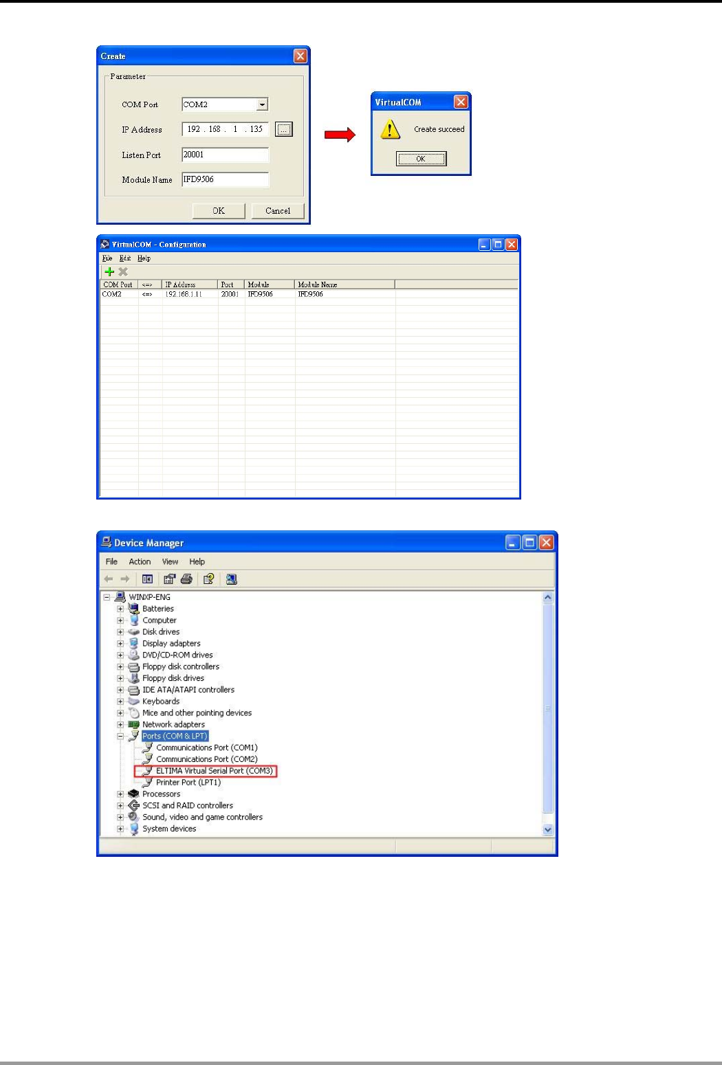
Press “OK”, and you will see all the devices connected on the network.
Select the module you need and press “OK”. Relevant information of the device will be imported
automatically. Press “OK” to complete the setup.
Once the setup is successful, you can see the virtual COM you set in the Device Manager.
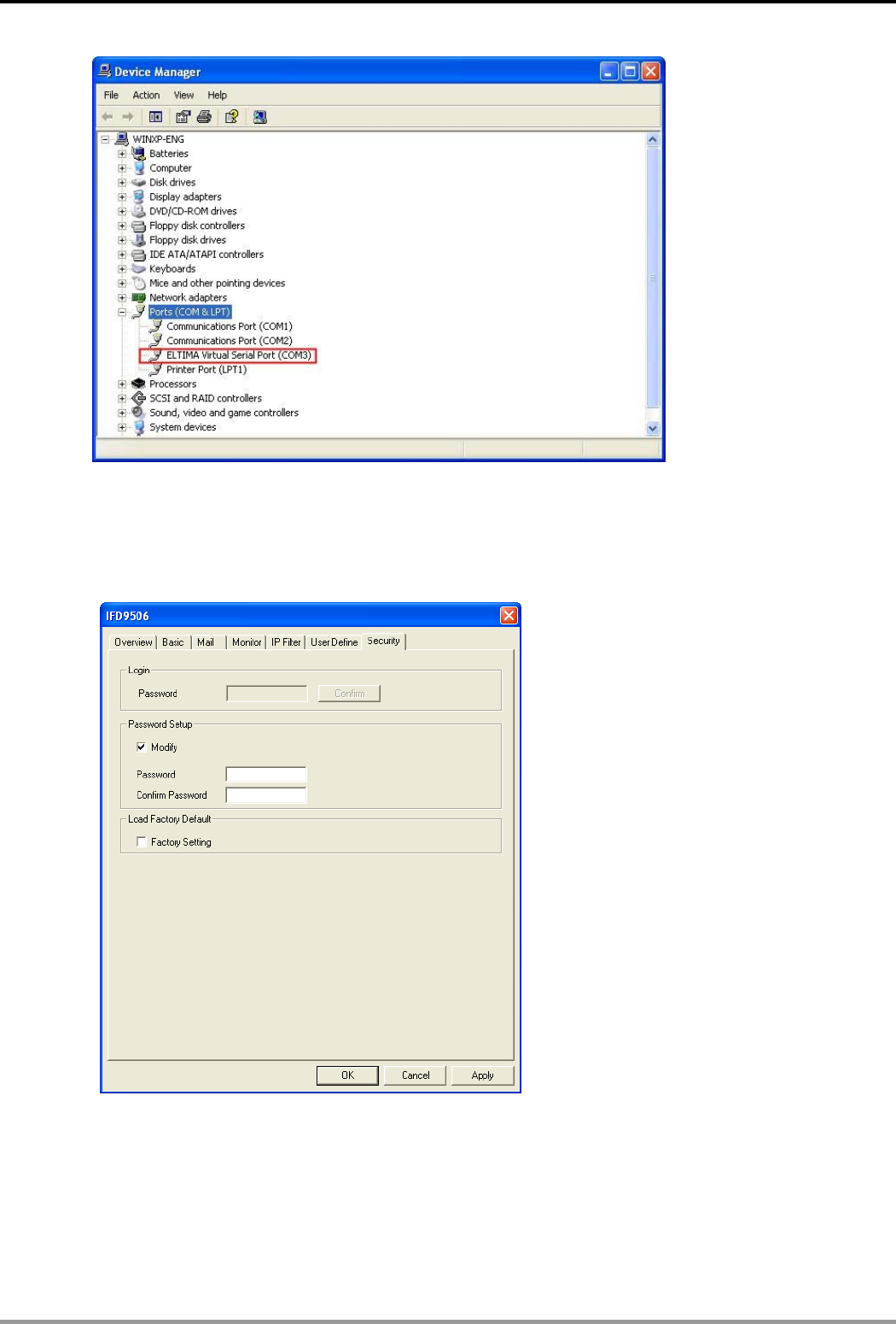
Ethernet Communication Module IFD9506
DVP-PLC Application Manual 29
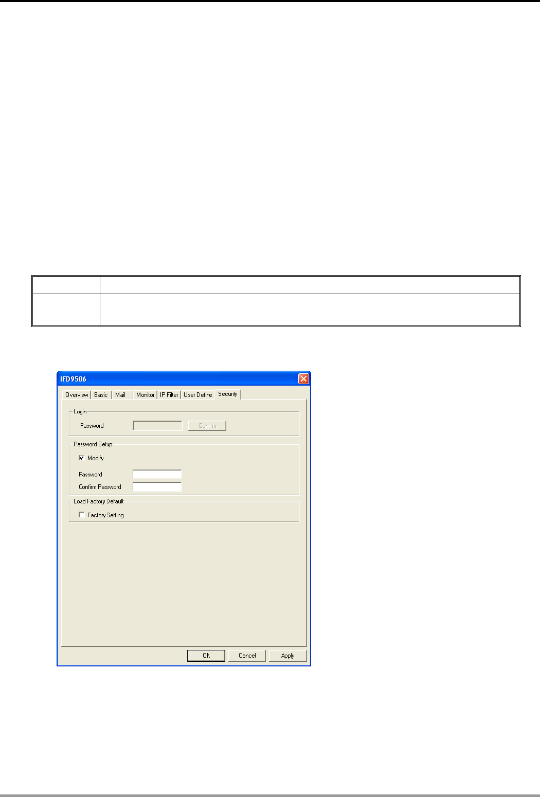
8.9 Security Settings
To prevent the set values in IFD9506 from being modified, you can set up passwords to lock the settings in
IFD9506.
Setting up password
1. Password setup:
Check the "Modify” box to set up the password.
2. Password:
Max. 4 characters.
3. Confirm password:
Enter the new password again.
4. See “10.1 Application Examples” for more details.
Ethernet Communication Module IFD9506
DVP-PLC Application Manual
30
Note:
Once the password is locked, all the pages cannot be set up unless you unlock the password.
However, if you set up IFD9506 by RS-232, you can return the setting to default one whether the
password is locked or not. For example, if you have locked IFD9506 but forget the password, you
have to return IFD9506 to default setting by RS-232, and all the settings will return to default ones.
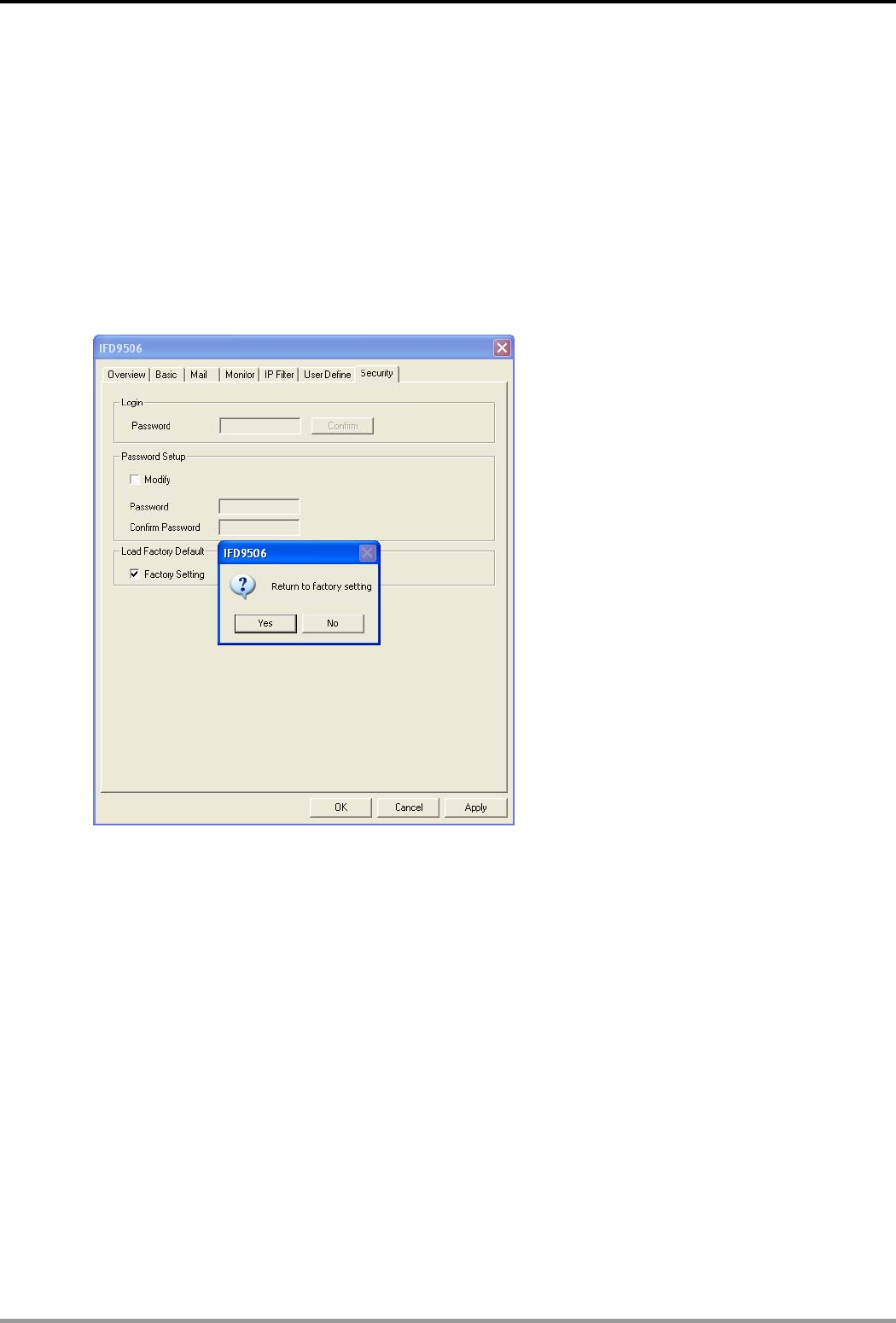
8.10 Returning to Default Settings
If you need to clear all the settings after many modifications on the settings and return the settings to default
ones, check the “Factory Setting” box.
Returning to default settings
Check “Factory Setting” box and click on “Yes”.
Note:
If you set up IFD9506 by RS-232, you can return to settings to default ones whether the password is
locked or not. It will take approximately 10 seconds to return to default settings, so DO NOT switch off
the power within the 10 seconds. Besides, you can also press “Reset” button for 2 seconds to return
to default settings.
9 Webpage Settings
This section introduces how to set up IFD9506 through webpages and explains how to set up columns in each
page. IFD9506 is set up by UDP port 20006. Please be aware of the relevant settings for the firewall.
9.1 Webpage Connection
Enable webpage function
1. Open the webpage browser and enter the IP address of IFD9506 in the address column.
2. See below for the items to be set up. The block on the left hand side shows the basis status of
IFD9506.
Ethernet Communication Module IFD9506
DVP-PLC Application Manual 31
9.2 Basic Settings
The basic settings include parameters as module name, network functions and serial communication. For
network settings, please consult your Internet service provider. For other settings, please refer to BR#4 ~ BR#6
and BR#11 ~ BR#13.
The basics
For how to set, see 8.2.
Ethernet Communication Module IFD9506
DVP-PLC Application Manual
32
9.3 Setting up E-Mails
E-Mail is the abbreviation of electronic mail which transmits mails through the network. IFD9506 has E-Mail
functions for the user to pre-save a segment of text messages, which can be a descriptive message or error
message, into the subject of the E-Mail. When the E-Mail is triggered, IFD9506 will send the messages to the
user by E-Mail.
E-Mail settings
1. Mail Alarm:
There are 3 mail alarms available. Check the alarm to enable that alarm. Every alarm can be
triggered by falling edge or rising edge.
2. For how to set up SMTP server, E-mail subject and recipients, see 8.4.
9.4 IP Filter
The IP filter is used for restricting the connection of the network in case some uncertain IP will cause errors.
Only the IP set within a certain range can establish a connection. Other IPs will be rejected.
Setting up IP filter
Ethernet Communication Module IFD9506
DVP-PLC Application Manual 33
For how to set, see 8.6.
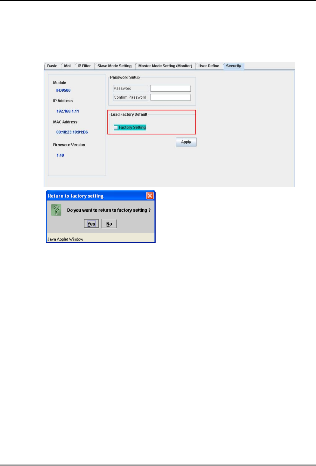
9.5 Security Settings
To prevent the set values in IFD9506 from being improperly modified in a well designed network environment,
you can set up passwords to lock the settings in IFD9506.
How to set up passwords
1. Setting up password:
You can enter maximum 4 characters in the password column to set up the password. Leave
the column blank to unlock the password protection.
2. Confirming password:
Enter the new password again.
Note:
Once IFD9506 is locked by the password, all the pages can only be set up after the password
is unlocked. However, if IFD9506 is set up through RS-232 COM port, you can return all
settings to default settings no matter IFD9506 is locked by the password or not. For example,
supposed your IFD9506 is locked but you forget the password, you can return all the settings
to default settings through RS-232 COM port.
Ethernet Communication Module IFD9506
DVP-PLC Application Manual
34
9.6 Returning to Default Settings
You can easily return all the settings to default ones on the page after you have modified those settings several
times.
How to return to default settings
Check “Factory Setting” and press (Y), all the settings in IFD9506 will return to default
settings.
Note:
Returning all the settings in IFD9506 to default ones through RS-232 COM port can be done no
matter IFD9506 is locked by the password or not. The entire process will take approximately 10
seconds, and please DO NOT switch off the power during this 10 seconds. To return to default
settings, you can also press the “Reset” button for 2 seconds.
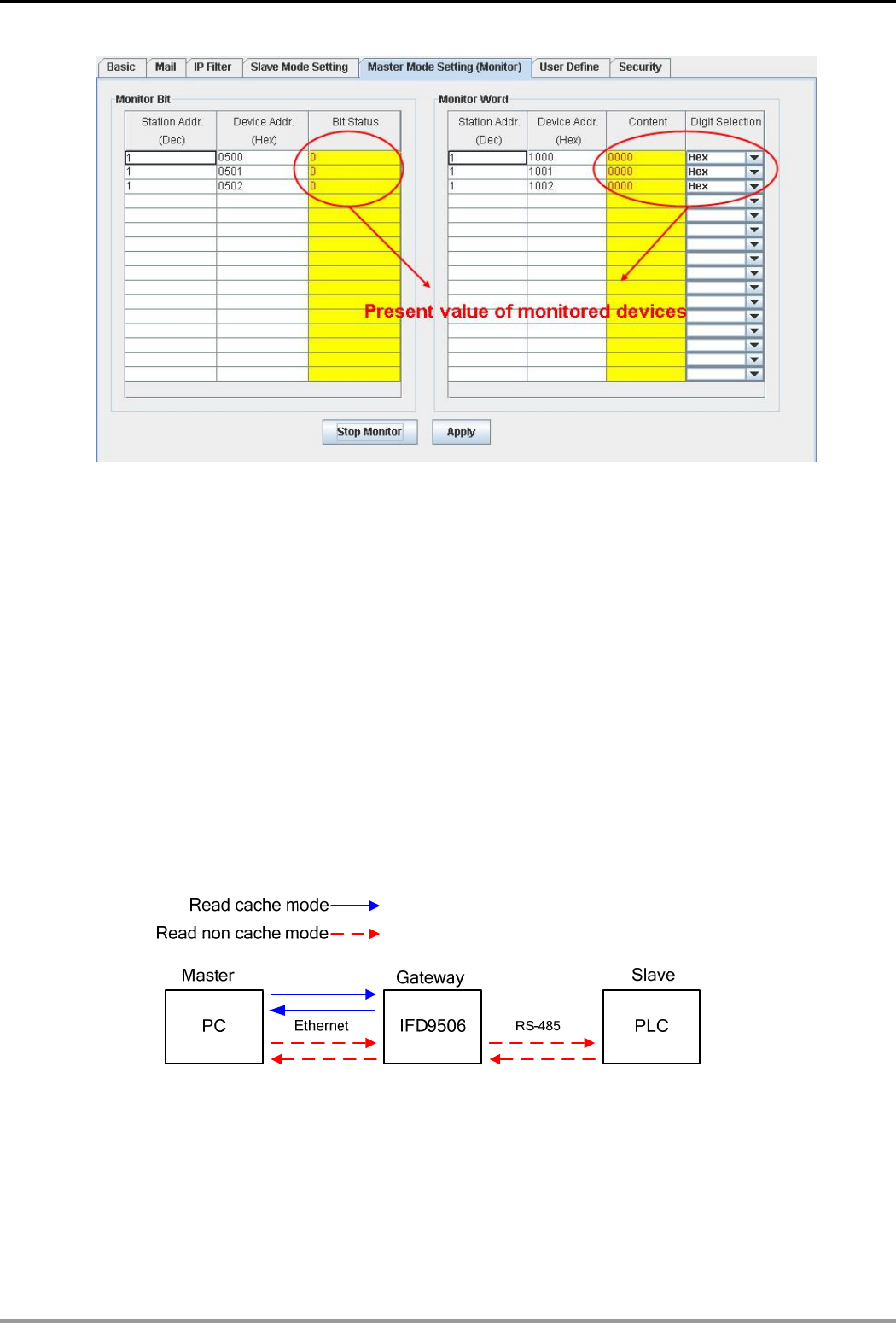
9.7 Monitor Table
By setting up IFD9506, you will be able to read data in specific addresses on the network and store the data
temporarily in IFD9506. This realizes fast data storage and retrieval.
How to monitor master
Ethernet Communication Module IFD9506
DVP-PLC Application Manual 35
1. Monitor Bit:
For setting up the address of the bit-type serial slave, and for you to read the content in the
designated slave.
2. Monitored content:
Displaying the value monitored in the address.
3. Monitored value status:
The value monitored can be disaplayed in hex or decimal forms.
4. Monitor Word:
For setting up the address of the word-type serial slave, and for you to read the content in the
designated slave.
Note:
Cache mode normally enabled, and Max. data in 16 slaves can be monitored. When the cache
mode is enabled, the data you would like to read will be sent back directly from the register in
IFD9506.
How to monitor slave
Ethernet Communication Module IFD9506
DVP-PLC Application Manual
36
1. Serial slave mode (Used when the communication protocol is Modbus TCP):
The instruction sent from the master is received and transferred to the network. Please designate
the station address and relay IP address.
Device address: Slave PLC address (The Gateway address and PLC address cannot be the
same)
Relay IP address: Serial mater IP
9.8 User Define
You can define your own format for data to be transmitted. The items to be defined include the fixed length, start
item and stop item.
Select RS-232 or RS-485 to connect the device
Ethernet Communication Module IFD9506
DVP-PLC Application Manual 37
Switch to “User Define” page to set up the “Fix Length”, “Start Item” and “Stop Item”.
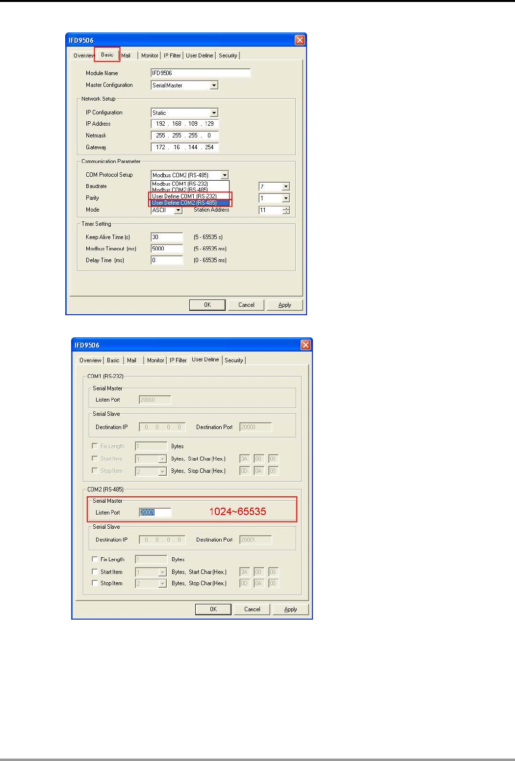
1. Listen Port/Destination Port:
Range: 1024 ~ 65535.
5. Fix Length:
When this is sest, IFD9506 will transmit data following the fixed length.
1 ~ 256
Ethernet Communication Module IFD9506
DVP-PLC Application Manual
38
6. Start Item:
The start item of data. Range: 1 ~ 3
7. Stop Item:
The stop item of data. Range: 1 ~ 3
When the start item and stop item are set, IFD9506 will transmit data following the start item and
stop item. If the transmission time exceeds the Modbus time-out, IFD9506 will dispose of
incomplete data.
Note:
When using two IFD9506 modules as Mater and Slave and its user define functions, the settings
of the fixed length, start item and stop item have to be consistent. If not, the data will be filtered
automatically.
10 Application Examples – DCISoft
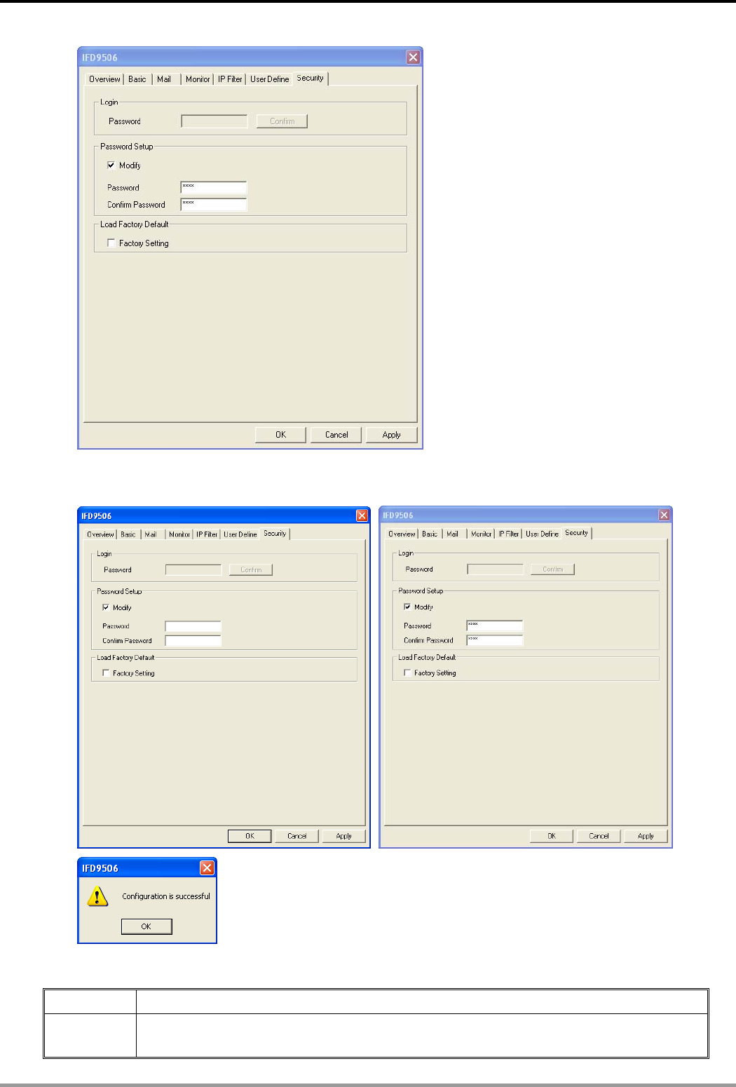
10.1 Setting up & Unlocking Password
Application Setting up password by IFD9506 configuration
Steps (1) Set up password in IFD9506.
(2) Unlock IFD9506.
1. See 8.1 for the connection and how to set up the communication.
2. Open the setup page and switch to “Security" page.
3. Check “Modify” and enter “aabb” in “Password” and “Confirm Password” columns. Click on “OK” to save the
password.
Ethernet Communication Module IFD9506
DVP-PLC Application Manual 39
4. Open the setup page again, and IFD9506 is now locked by the password. You cannot open any of the
settings now. To unlock the password, check “Unlock” and enter your original password.
10.2 Password Loss (Returning to Default Settings by RS-232)
Application Returning to default settings by RS-232.
Steps (1) Set up password in IFD9506.
(2) Supposed the password is forgotten, return to default settings through RS-232.
Ethernet Communication Module IFD9506
DVP-PLC Application Manual
40
1. Use DVPACAB2A30 cable to connect the PC and IFD9506. Open the setup page.
2. Check “Factory Setting” box and the warning dialog box will appear. Click on “Yes” to return to default
settings (in approx. 5 ~ 10 seconds), and the password will be cleared as well.
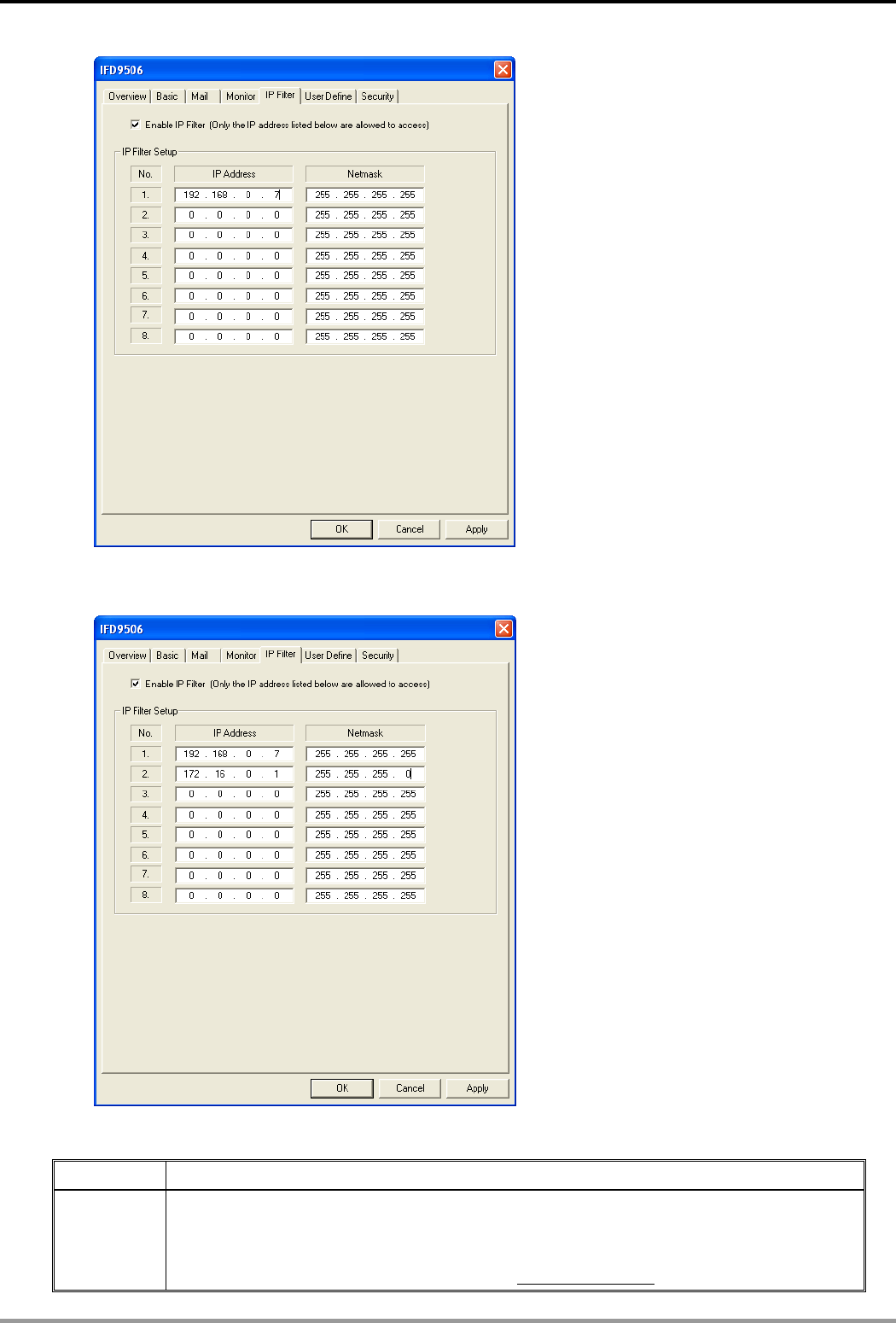
10.3 IP Filter Protection
Application Setting up IP filter protection. Only connections to 192.168.0.7 and 172.16.0.1 ~
172.16.0.255 are allowed.
Steps
(1) Check "Enable IP Filter” box.
(2) Set up IP address to “192.168.0.7” and netmask to “255.255.255.255”.
(3) Set up IP addres to “172.16.0.1” and netmask to “255.255.255.0”.
1. See 8.1 for the connection and how to set up the communication.
2. Open the setup page and switch to “IP Filter” page.
3. Check “Enable IP Filter” box. Enter “192.168.0.7” into No. 1 IP and “255.255.255.255” in all “Netmask”
columns.
Ethernet Communication Module IFD9506
DVP-PLC Application Manual 41
4. Enter “172.16.0.1” in No. 2 IP and “255.255.255.0” in No. 2 Netmask column. Click on “OK” to complete the
setting. Only the equipment within the UP range can be connected.
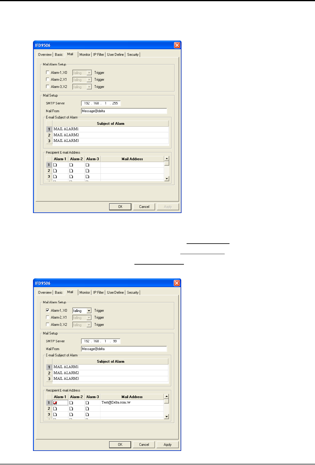
10.4 Application of E-Mail
Application Sending E-Mail to notify the administrator when Alarm 1 is triggered.
Steps
(1) Check “Alarm 1” to enable it.
(2) Set the IP of SMTP server to ”192.168.1.99” and "Mail From” to “Message@Delta”
(3) Set the E-mail Subject of Event to “MAIL ALARM”.
(4) Set the E-mail addres of administrator to test@sample.com.
Ethernet Communication Module IFD9506
DVP-PLC Application Manual
42
1. See 8.1 for the connection and how to set up the communication.
2. Open the setup page and switch to “Mail” page.
3. Setting up “Mail” page and check “Mail Alarm Setup”.
Enter SMTP server address, “Mail From” column, “Subject of Event”and “Recipient E-mail Address”. For
example, when Alarm 1 is triggered, the mail will be sent to test@Delta.com. Trigger Alarm 1 by “low”. Enter
192.168.1.99 into “SMTP Server” column and Mail From Message@Delta. Enter “MAIL EVENT” as the
subject and recipient e-mail address as test@delta.com.tw. Check “Alarm 1” and press “OK” to complete the
settings.
Ethernet Communication Module IFD9506
DVP-PLC Application Manual 43
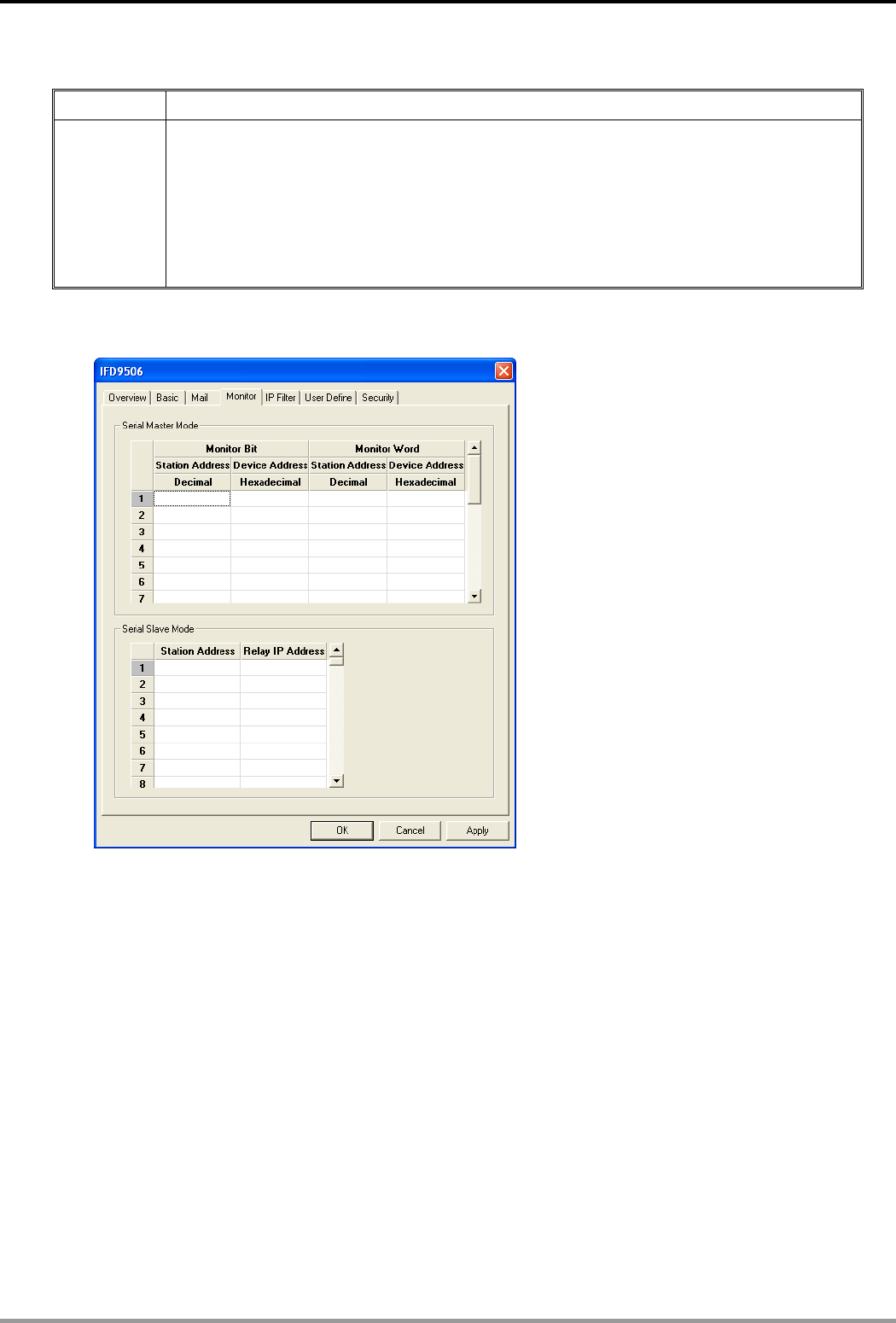
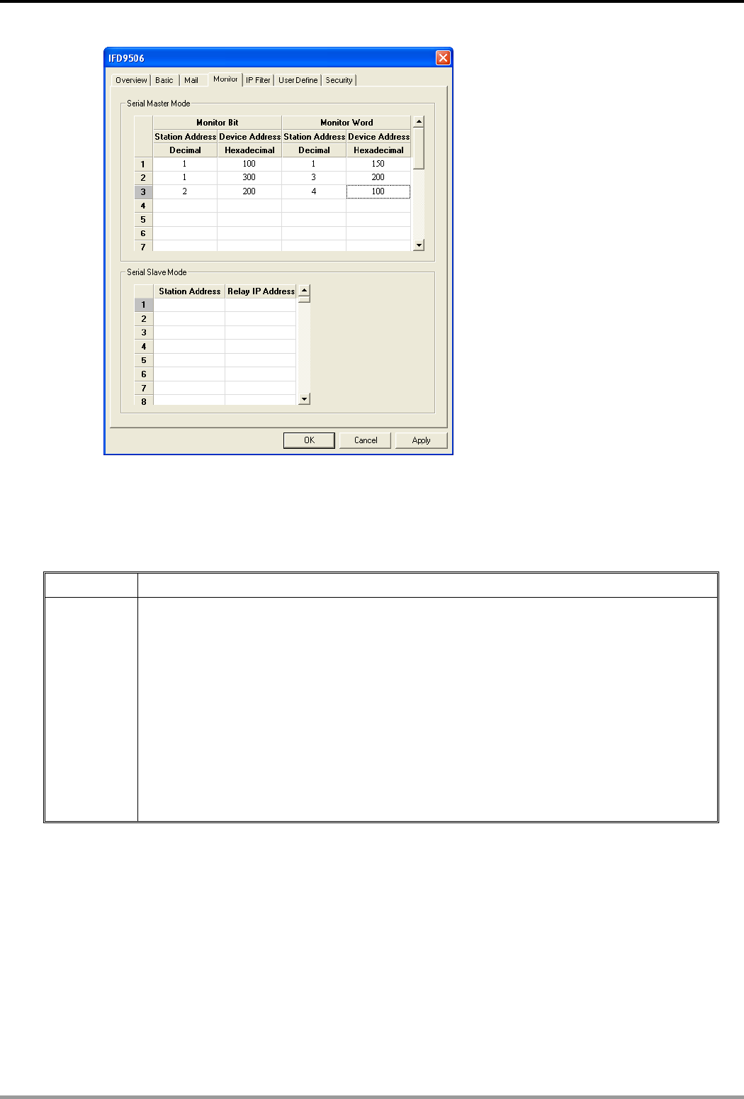
10.5 Monitoring Mode
Application Writing the address of the device to be monitored into the monitor table.
Steps (1) Use monitor bit and monitor word functions.
(2) Monitor bit data in station address 1, H100 and H300, and word data in station address
1 H150.
(3) Monitor bit data in station address 2, H200.
(4) Monitor word data in station address 3, H200.
(5) Monitor wird data in station address 4, H100.
(6) Monitor bit quantity: 3; monitor word quantity: 3
1. See 8.1 for how to set up communication.
2. Open IFD9506 Configuration page and switch to “Monitor” page.
3. The settings:
Ethernet Communication Module IFD9506
DVP-PLC Application Manual
44
Note:
When the cache mode is enabled, all the read data will be read from IFD9506. In this way, the read
speed can be enhanced.
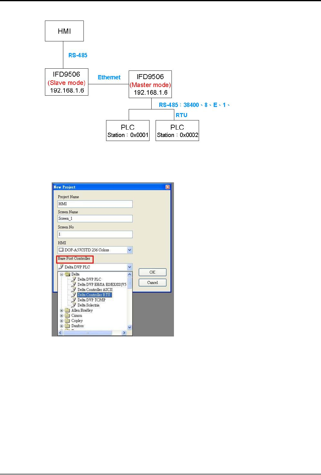
10.6 Application of Modbus Slave
Application Giving Modbus command from HMI to remote device.
Steps
(1) HMI sends out the instruction.
(2) Set the IP of slave IFD9506 to “192.168.1.6”, station address to “7” and communication
format to “38400, 8, E, 1, RTU”.
(3) In the IFD9506 serial slave mode table, set the device address to “1” and “3”, the two
relay IPs to “192.168.1.5”.
(4) Set the IP of master of IFD9506 to “192.168.1.5", station address to “8” and
communication format to “38400, 8, E, 1, RTU”.
(5) HMI master and IFD9506 slave transmit data through RS-485.
(6) IFD9506 slave and IFD9506 master transmit data through Ethernet.
(7) The RS-485 terminal on IFD9506 master is connected to two devices, which are PLC at
station address 0x0001 and PLC at station address 0x0003. Assume the communication
format is “38400, 8, E, 1, RTU”.
1. The wiring:
Ethernet Communication Module IFD9506
DVP-PLC Application Manual 45
2. Setting up HMI editing software, Screen Editor:
Step 1: Open Screen Editor, “File" Æ “New”. In the “Base Port Controller” column, select “Delta Controller
RTU”.
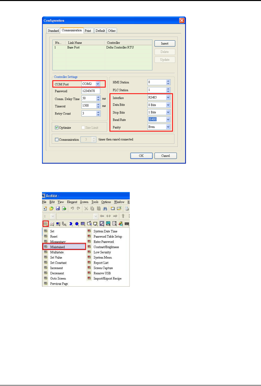
Step 2: “Option” Æ “Configuration”. Set up the communication format in “Communication” page. As below,
set it to RS-485 communication mode.
Ethernet Communication Module IFD9506
DVP-PLC Application Manual
46
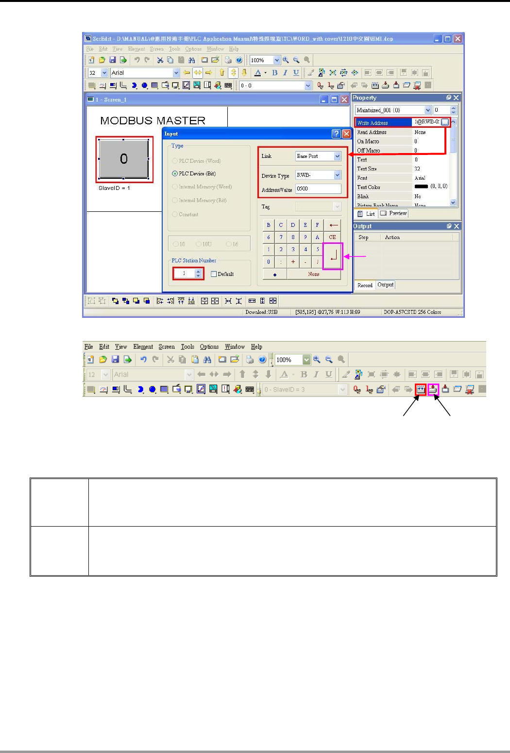
Step 3: If you want to control the On/Off of Y0 (Y0 address: 0500) of PLC at station address 0x0001 and
On/Off of Y0 (Y0 address: 0500) of PLC at station address 0x0003, select “Maintained” button and
create the button on the screen.
Step 4: Create two “Maintained” buttons.
(a) Click on the button on the left hand side first. You will see the information of the button in the
“Property” window on the right hand side of the screen. Click on “Write Address” to set up the
address of Y0 (0500) and the address of the PLC (1). Select “Base Port” in “Link” column and
“RWB-“ in “Device Type” column.
(b) Next, set up the button on the right hand side. Follow (a) step and modify the address of the
PLC as “3”.
Ethernet Communication Module IFD9506
DVP-PLC Application Manual 47
Step 5: “Compile” first and “Download Screen and Recipe” to complete the setups in the HMI.
10.7 Application of Virtual COM Port
Application
Through the virtual COM port, IFD9506 is able to transmit the data sent to RS-232 to the
Ethernet by connencting to the software supporing serial ports, e.g. Delta’s WPLSoft,
VFDSoft and ASDA-Soft. See the example below for how to connect IFD9506 to VFD-E AC
motor drive through the virtual COM port by VFDSoft.
Steps (1) Select “User Define” protocol and set the parameters in the serial master and serial slave
to the ones consistent with those in VFD-E.
(2) Open Delta VFDSoft, set up the communication format (COM Setup) and establish the
connection.
1. Setting up Virtual COM Port
For the COM setting, select “User Define” and set the communication parameters to the ones
consistent with those in VFD-E.
Press it to complete
the setu
p
.
Compile Download
Screen and
Recipe
Ethernet Communication Module IFD9506
DVP-PLC Application Manual
48
Switch to “User Define” page and select “Listen Port”.
Open Virtual COM setup page
Ethernet Communication Module IFD9506
DVP-PLC Application Manual 49
Press “OK”, and you will see all the devices connected on the network.
Select the module you need and press “OK”. Relevant information of the device will be imported
automatically. Press “OK” to complete the setup.
Ethernet Communication Module IFD9506
DVP-PLC Application Manual
50
Once the setup is successful, you can see the virtual COM you set in the Device Manger.
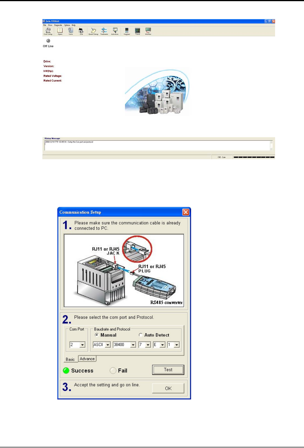
2. Using Virtual COM in Delta VFDSoft
Open Delta VFDSoft.
Ethernet Communication Module IFD9506
DVP-PLC Application Manual 51
Set up communication format (COM Setup)
Enter the virtual COM (COM2) set in the previous steps to “Com Port” column. Next, enter the
communication format of VFD-E (38400, 7, E, 1) and press “Test" button. Once the “Success” light is
ON, the communication test is regarded successful.
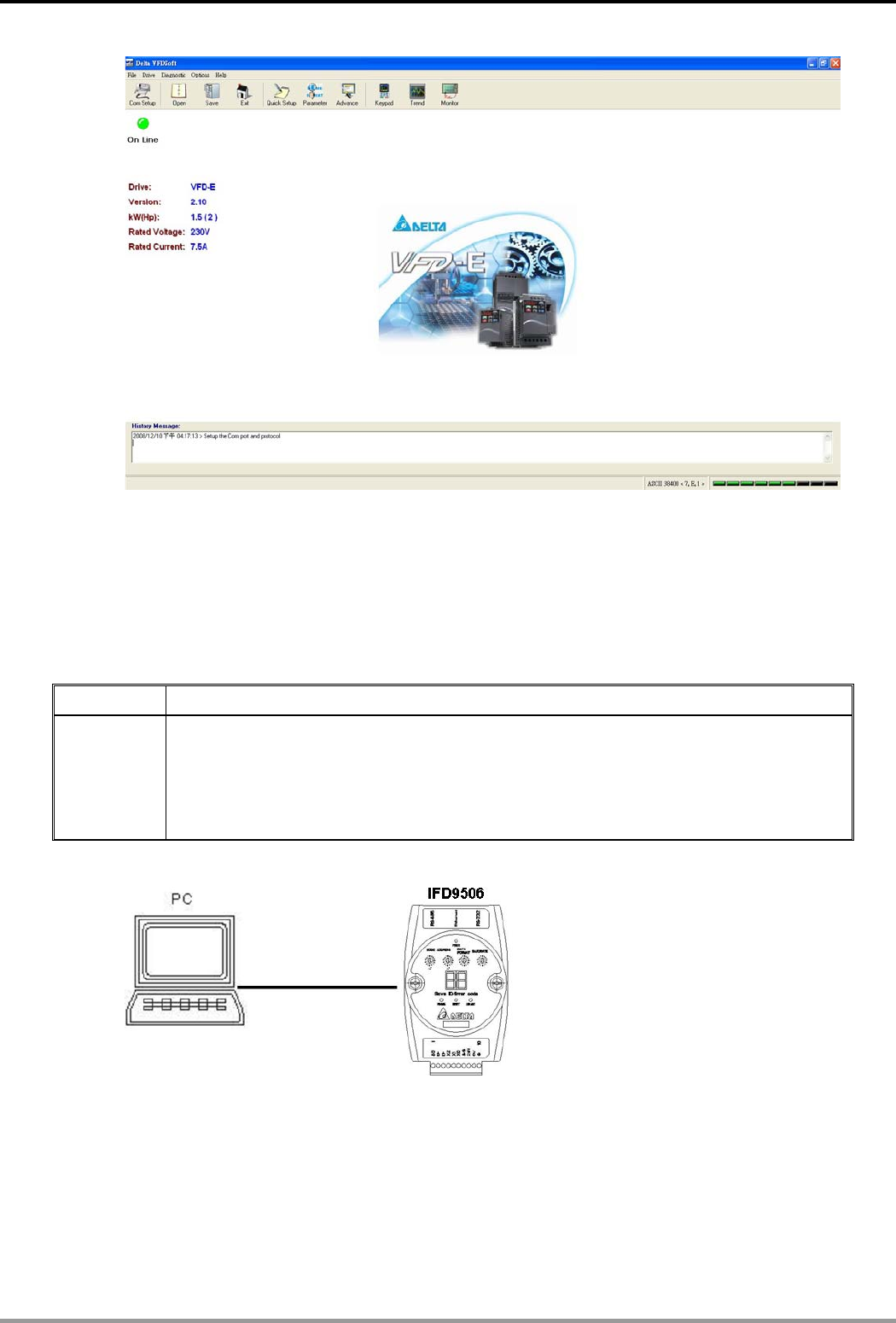
Press “OK”, and IFD9506 will be able to communicate with VFD-E by VFDSoft.
Ethernet Communication Module IFD9506
DVP-PLC Application Manual
52
11 Application Example – WPLSoft
You can set up IFD9506 by WPLSoft software. See the examples below for how to set up the communication
connection. Columns in every setup page in WPLSoft are the same as those in DCISoft. Please refer to section
10 for relevant settings.
11.1 Setting up IP through WPLSoft
Application Setting up network parameters of IFD9506 directly from the PC.
Steps
(1) The IP of the PLC executing WPLSoft is “192.168.1.2”.
(2) Subnet mask: 255.255.255.0; Gateway: 192.168.1.254
(3) Modify the network parameter of IFD9506.
(4) Connecting the PC and IFD9506 by RJ-45 network cable.
Note: Both PC and IFD9506 cannot adopt DHCP but static IP.
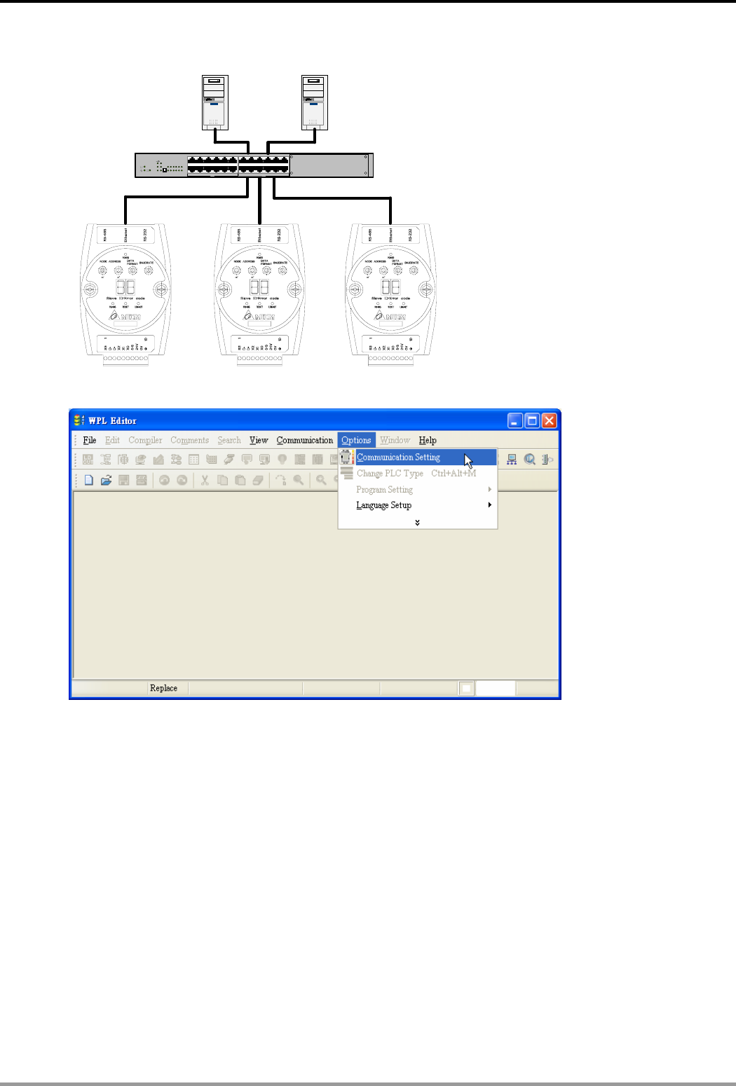
1. The connections:
2. Open “Communication Setting” in WPLSoft.
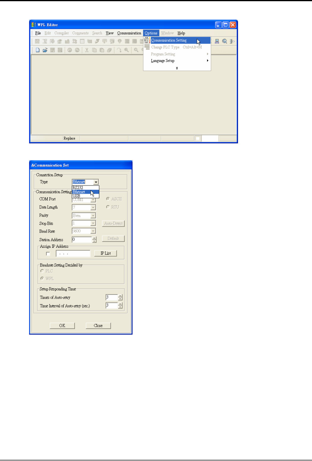
Ethernet Communication Module IFD9506
DVP-PLC Application Manual 53
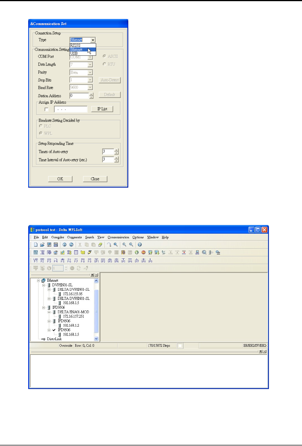
3. Select “Ethernet” and press “OK”.
4. Press “broadcast” icon to search for all IFD9506 modules on the network.
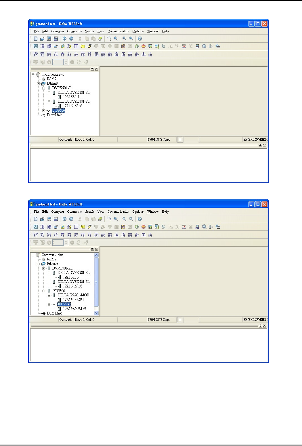
Ethernet Communication Module IFD9506
DVP-PLC Application Manual
54
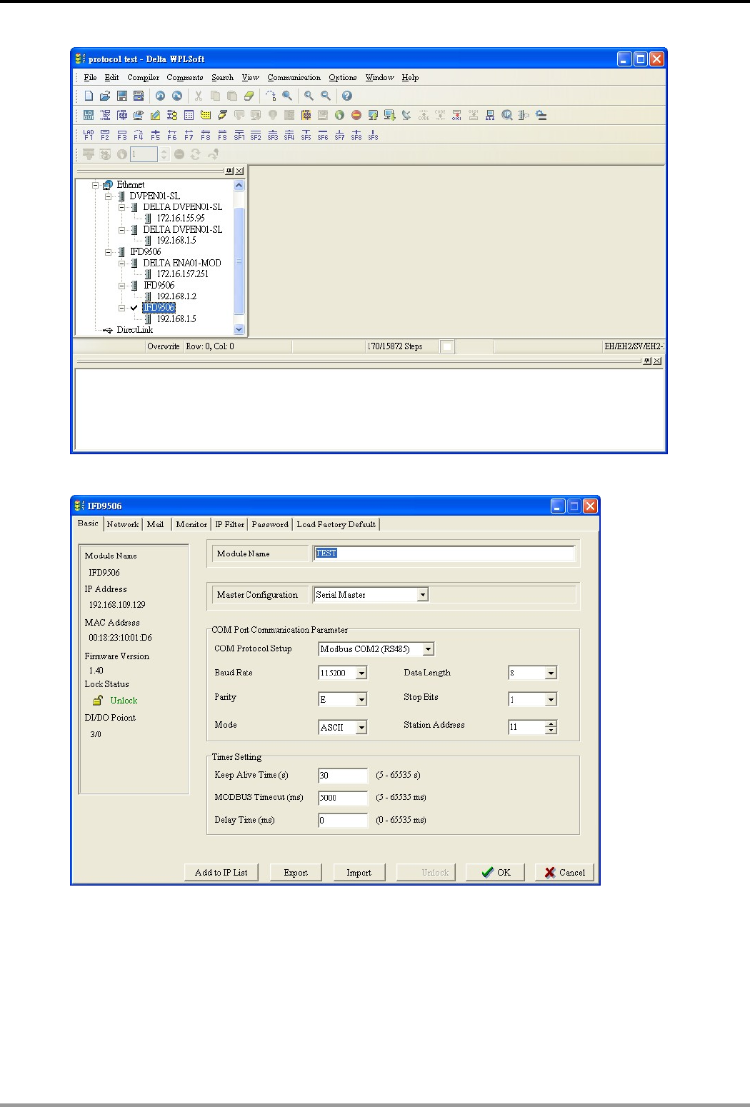
5. Designate an IFD9506 module and double click on it to open the setup page.
6. You will first see the “Basic” page.
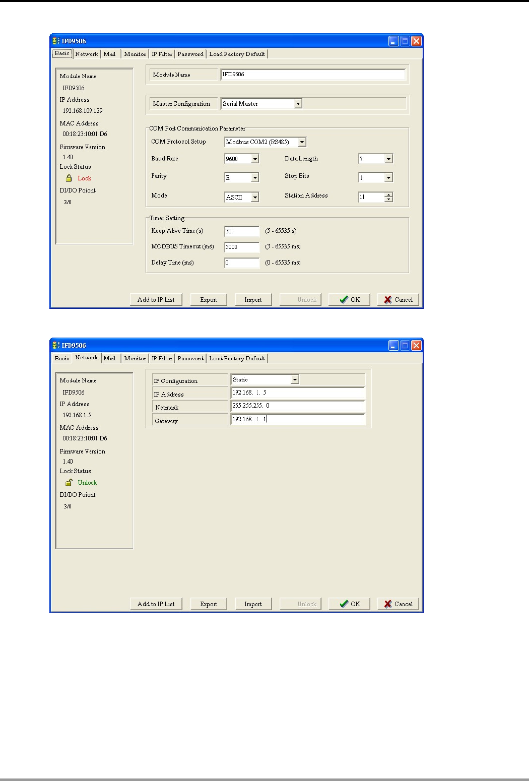
Ethernet Communication Module IFD9506
DVP-PLC Application Manual 55
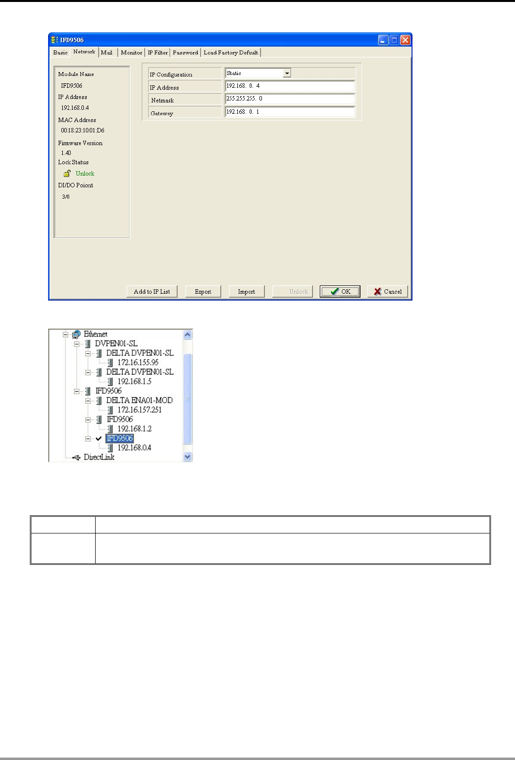
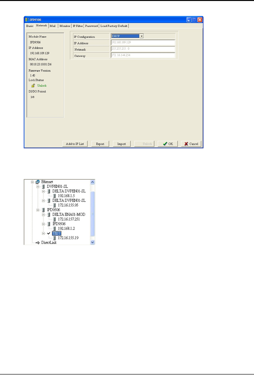
7. Switch to “Network” page.
8. Enter “IP Address: 192.168.0.4”, “Netmask: 255.255.255.0”and “Gateway:“192.168.0.1”. Press “OK” to save
the settings into IFD9506, and WPLSoft will search for IFD9506 automatically again.
Ethernet Communication Module IFD9506
DVP-PLC Application Manual
56
9. You will see the IP address of IFD9506 has been modified to 192.168.0.4.
10. Click on DELTA IFD9506, and it will be able to communicate to MPU through WPLSoft.
11.2 Connecting to IFD9506 through LAN in PC
Application Setting up network parameters of IFD9506 through LAN in WPLSoft.
Steps (1) Connect IFD9506 to PC through KAN by using DHCP server.
Note: You can use RJ-45 network cable with/without jump wire.
1. The connection:
Ethernet Communication Module IFD9506
DVP-PLC Application Manual 57
Ethernet
PC1 Master PC2 Master
123456
789101112
AB
12x
6x
8x
2x
9x
3x
10x
4x
11x
5x
7x
1x
Ethernet
A
12x
6x
8x
2x
9x
3x
10x
4x
11x
5x
7x
1x
C
Ethernet
Ethernet
2. Open “Communication Setting” in WPLSoft.
3. Select “Ethernet” and press “OK”.
Ethernet Communication Module IFD9506
DVP-PLC Application Manual
58
4. Press “broadcast” icon to search for all IFD9506 modules on the network. The IFD9506 module will be
detected in “View → Workspace → Communication” window or “View → Workspace → Project” window.
(The default module name is DELTA IFD9506, IP:192.168.1.5)
5. Designate IFD9506 module and double click on it to open the setup page.
Ethernet Communication Module IFD9506
DVP-PLC Application Manual 59
6. In “Basic” page, you can modify the module name for easier identification.
7. Next, set up the new IP address of IFD9506. In “Network” page, select DHCP in “IP Configuration” if there is
DHCP server in LAN. If not, select static IP, but please be noted that the subnet mask and gateway settings
have to be the same as the settings in the same LAN.
Ethernet Communication Module IFD9506
DVP-PLC Application Manual
60
Press “OK” to save the settings into IFD9506.
8. WPLSoft will search for IFD9506 automatically again. You will see the IP address of IFD9506 has been
modified to 172.16.155.19.
9. Click on DELTA IFD9506, and it will be able to communicate to MPU (e.g. upload/download of program,
monitoring device).
