Product Manual, Control Cabinet IRC5P Trouble Shooting Manual 3HNA009834 001
User Manual:
Open the PDF directly: View PDF ![]() .
.
Page Count: 220 [warning: Documents this large are best viewed by clicking the View PDF Link!]
- Go to Menu
- Table of Contents
- Product Manual, Control Cabinet IRC5P
- 1 Introduction
- 2 Safety
- 3 System Description
- 4 Technical Specifications
- 5 Installation and Commissioning
- 5.1 Introduction
- 5.2 Component Installation
- 5.3 System Interconnections
- 5.4 Robot Safety System Connections
- 5.5 Cabin Safety System Connections
- 5.6 Encoder and Sync Switch Installation
- 5.7 Misc. System Connections
- 5.8 Power Connections
- 5.9 Concluding Activities
- 6 Preventive Maintenance
- 7 Repair
- 7.1 Introduction
- 7.2 Replacement of Control Panel Board, CPB
- 7.3 Replacement of System LED Board, ALED
- 7.4 Replacement of Door Fan Unit
- 7.5 Replacement of Axis Computer, PDB, PIB, SIB, MIB, SCB
- 7.6 Replacement of Pendant Interface Board, TIB
- 7.7 Replacement of I/O Units
- 7.8 Replacement of Computer Unit
- 7.9 Replacement of Computer Unit Mother Board
- 7.10 Replacement of PCI Boards in Computer Unit Slots
- 7.11 Replacement of Fieldbus Adapter
- 7.12 Replacement of Compact Flash
- 7.13 Replacement of Computer Fan Unit
- 7.14 Replacement of Drive System 09 Components
- 7.15 Replacement of Drive System 04 Components
- 7.16 Replacement of Servo Fan Unit
- 7.17 Replacement of Brake Resistor Bleeders
- 7.18 Replacement of Transformer
- 7.19 Replacement of Choke Filter
- 7.20 Replacement of Measuring System Battery
- 8 Trouble Shooting
- 8.1 Introduction
- 8.2 General Description and Hints
- 8.3 Fault Symptoms and Malfunctions
- 8.3.1 Types of Symptoms
- 8.3.2 Normal Start-Up Sequence
- 8.3.3 Start-Up Failures
- 8.3.4 Controller Dead
- 8.3.5 Controller Performance Slow
- 8.3.6 Pendant Dead
- 8.3.7 Pendant does not Communicate
- 8.3.8 Erratic Event Messages on Pendant
- 8.3.9 No Voltage in Service Outlet
- 8.3.10 The Joysticks do not Work
- 8.3.11 Reflashing Firmware Failed
- 8.3.12 Inconsistent Path Accuracy
- 8.3.13 Consistent Path Inaccuracy
- 8.3.14 Oil or Grease Stains on Motors and/or Gearboxes
- 8.3.15 Mechanical Noise
- 8.3.16 Manipulator Collapses on Power-Down
- 8.3.17 Robot Brakes do not Release
- 8.4 Trouble Shooting Instructions per Unit
- 8.5 LED Indicator Panel
- 9 Decommissioning
- 10 Reference Information
- Manual Status
- List of Imported Graphics

Product Manual
Control Cabinet, IRC5P
3HNA009834-001 en Rev.06
First Edition: 10 Dec. 2007
Last Revised: 08 October 2010
Product Manual, Control Cabinet IRC5P

The information in this document is subject to change without notice and should not be
construed as a commitment by ABB. ABB assumes no responsibility for any errors that may
appear in this document.
Except as may be expressly stated anywhere in this document, nothing herein shall be
construed as any kind of guarantee or warranty by ABB for losses, damages to persons or
property, fitness for a specific purpose or the like.
In no event shall ABB be liable for incidental or consequential damages arising from use of
this document or of the software and hardware described in this document.
We reserve all rights in this document and in the information contained therein.
Reproduction, use or disclosure to third parties without express authority is strictly forbidden.
Additional copies of this document may be obtained from ABB at its then current charge.
© Copyright 2007-2010 ABB All right reserved.
ABB AS Automation Technologies
Robotics
N-4341 Bryne
Norway

Product Manual, Control Cabinet IRC5P 3HNA009834-001 en Rev.06 5
Product Manual, Control Cabinet IRC5P Table of Contents
Table of Contents
Product Manual, Control Cabinet IRC5P
1 Introduction 11
2Safety 13
3 System Description 15
3.1 Introduction. . . . . . . . . . . . . . . . . . . . . . . . . . . . . . . . . . . . . . . . . . . . . . . . . . . . . . . . . . . . . . . . . . . . . . 15
3.2 Basic Design. . . . . . . . . . . . . . . . . . . . . . . . . . . . . . . . . . . . . . . . . . . . . . . . . . . . . . . . . . . . . . . . . . . . . 16
3.2.1 Front Components . . . . . . . . . . . . . . . . . . . . . . . . . . . . . . . . . . . . . . . . . . . . . . . . . . . . . . . . . 16
3.2.2 Internal Components . . . . . . . . . . . . . . . . . . . . . . . . . . . . . . . . . . . . . . . . . . . . . . . . . . . . . . . 18
3.2.3 Cabinet Labelling . . . . . . . . . . . . . . . . . . . . . . . . . . . . . . . . . . . . . . . . . . . . . . . . . . . . . . . . . . 21
3.2.4 Purge System. . . . . . . . . . . . . . . . . . . . . . . . . . . . . . . . . . . . . . . . . . . . . . . . . . . . . . . . . . . . . 22
3.2.5 Identification Labels . . . . . . . . . . . . . . . . . . . . . . . . . . . . . . . . . . . . . . . . . . . . . . . . . . . . . . . . 23
3.3 Control Panel Description. . . . . . . . . . . . . . . . . . . . . . . . . . . . . . . . . . . . . . . . . . . . . . . . . . . . . . . . . . . 27
3.4 Pendant Description . . . . . . . . . . . . . . . . . . . . . . . . . . . . . . . . . . . . . . . . . . . . . . . . . . . . . . . . . . . . . . . 29
4 Technical Specifications 31
4.1 Introduction. . . . . . . . . . . . . . . . . . . . . . . . . . . . . . . . . . . . . . . . . . . . . . . . . . . . . . . . . . . . . . . . . . . . . . 31
4.2 Controller Specifications . . . . . . . . . . . . . . . . . . . . . . . . . . . . . . . . . . . . . . . . . . . . . . . . . . . . . . . . . . . . 32
4.3 Pendant Specifications . . . . . . . . . . . . . . . . . . . . . . . . . . . . . . . . . . . . . . . . . . . . . . . . . . . . . . . . . . . . . 35
4.4 Purge Unit Specifications . . . . . . . . . . . . . . . . . . . . . . . . . . . . . . . . . . . . . . . . . . . . . . . . . . . . . . . . . . . 36
5 Installation and Commissioning 39
5.1 Introduction. . . . . . . . . . . . . . . . . . . . . . . . . . . . . . . . . . . . . . . . . . . . . . . . . . . . . . . . . . . . . . . . . . . . . . 39
5.1.1 General. . . . . . . . . . . . . . . . . . . . . . . . . . . . . . . . . . . . . . . . . . . . . . . . . . . . . . . . . . . . . . . . . . 39
5.1.2 Installation Guidelines . . . . . . . . . . . . . . . . . . . . . . . . . . . . . . . . . . . . . . . . . . . . . . . . . . . . . . 41
5.1.3 Controller Connections Overview. . . . . . . . . . . . . . . . . . . . . . . . . . . . . . . . . . . . . . . . . . . . . . 42
5.1.4 Safety Connection Board . . . . . . . . . . . . . . . . . . . . . . . . . . . . . . . . . . . . . . . . . . . . . . . . . . . . 44
5.1.5 External Connection Overview . . . . . . . . . . . . . . . . . . . . . . . . . . . . . . . . . . . . . . . . . . . . . . . . 45
5.2 Component Installation . . . . . . . . . . . . . . . . . . . . . . . . . . . . . . . . . . . . . . . . . . . . . . . . . . . . . . . . . . . . . 46
5.2.1 Introduction. . . . . . . . . . . . . . . . . . . . . . . . . . . . . . . . . . . . . . . . . . . . . . . . . . . . . . . . . . . . . . . 46
5.2.2 Lifting and Transporting the Controller . . . . . . . . . . . . . . . . . . . . . . . . . . . . . . . . . . . . . . . . . . 47
5.2.3 Cabinet Location. . . . . . . . . . . . . . . . . . . . . . . . . . . . . . . . . . . . . . . . . . . . . . . . . . . . . . . . . . . 48
5.2.4 Purge Unit Installation . . . . . . . . . . . . . . . . . . . . . . . . . . . . . . . . . . . . . . . . . . . . . . . . . . . . . . 49
5.3 System Interconnections . . . . . . . . . . . . . . . . . . . . . . . . . . . . . . . . . . . . . . . . . . . . . . . . . . . . . . . . . . . 51
5.3.1 Electrical Interconnections IRB 5500 . . . . . . . . . . . . . . . . . . . . . . . . . . . . . . . . . . . . . . . . . . . 52
5.3.2 Electrical Interconnections IRB 52, IRB 5400, IRB 580, IRB 540. . . . . . . . . . . . . . . . . . . . . . 55
5.3.3 IS-Ground Connection . . . . . . . . . . . . . . . . . . . . . . . . . . . . . . . . . . . . . . . . . . . . . . . . . . . . . . 59
5.3.4 Connectors. . . . . . . . . . . . . . . . . . . . . . . . . . . . . . . . . . . . . . . . . . . . . . . . . . . . . . . . . . . . . . . 61
5.4 Robot Safety System Connections . . . . . . . . . . . . . . . . . . . . . . . . . . . . . . . . . . . . . . . . . . . . . . . . . . . . 64
5.4.1 Introduction. . . . . . . . . . . . . . . . . . . . . . . . . . . . . . . . . . . . . . . . . . . . . . . . . . . . . . . . . . . . . . . 64
5.4.2 Safety System Standards . . . . . . . . . . . . . . . . . . . . . . . . . . . . . . . . . . . . . . . . . . . . . . . . . . . . 65
5.4.3 Safety System Connection Overview . . . . . . . . . . . . . . . . . . . . . . . . . . . . . . . . . . . . . . . . . . . 67
5.4.4 Emergency Stop Chain. . . . . . . . . . . . . . . . . . . . . . . . . . . . . . . . . . . . . . . . . . . . . . . . . . . . . . 70
5.4.5 Run Chain. . . . . . . . . . . . . . . . . . . . . . . . . . . . . . . . . . . . . . . . . . . . . . . . . . . . . . . . . . . . . . . . 73
5.4.6 Emergency Brake Release Switch . . . . . . . . . . . . . . . . . . . . . . . . . . . . . . . . . . . . . . . . . . . . . 77
5.5 Cabin Safety System Connections . . . . . . . . . . . . . . . . . . . . . . . . . . . . . . . . . . . . . . . . . . . . . . . . . . . . 78
5.5.1 Introduction. . . . . . . . . . . . . . . . . . . . . . . . . . . . . . . . . . . . . . . . . . . . . . . . . . . . . . . . . . . . . . . 78
5.5.2 Cabin Safety Connection Overview . . . . . . . . . . . . . . . . . . . . . . . . . . . . . . . . . . . . . . . . . . . . 79
5.5.3 Cabin Interlock . . . . . . . . . . . . . . . . . . . . . . . . . . . . . . . . . . . . . . . . . . . . . . . . . . . . . . . . . . . . 80
5.5.4 High Voltage Interlock. . . . . . . . . . . . . . . . . . . . . . . . . . . . . . . . . . . . . . . . . . . . . . . . . . . . . . . 81
5.5.5 System 2 Interlock . . . . . . . . . . . . . . . . . . . . . . . . . . . . . . . . . . . . . . . . . . . . . . . . . . . . . . . . . 82
5.5.6 Process Interlock . . . . . . . . . . . . . . . . . . . . . . . . . . . . . . . . . . . . . . . . . . . . . . . . . . . . . . . . . . 83
5.5.7 Emergency Shut Down Valve. . . . . . . . . . . . . . . . . . . . . . . . . . . . . . . . . . . . . . . . . . . . . . . . . 85
5.6 Encoder and Sync Switch Installation. . . . . . . . . . . . . . . . . . . . . . . . . . . . . . . . . . . . . . . . . . . . . . . . . . 86
5.6.1 Introduction. . . . . . . . . . . . . . . . . . . . . . . . . . . . . . . . . . . . . . . . . . . . . . . . . . . . . . . . . . . . . . . 86
5.6.2 Encoder Specifications. . . . . . . . . . . . . . . . . . . . . . . . . . . . . . . . . . . . . . . . . . . . . . . . . . . . . . 87
5.6.3 Sync Switch Specifications. . . . . . . . . . . . . . . . . . . . . . . . . . . . . . . . . . . . . . . . . . . . . . . . . . . 89

6 3HNA009834-001 en Rev.06 Product Manual, Control Cabinet IRC5P
Table of Contents Product Manual, Control Cabinet IRC5P
5.6.4 Connection Overview . . . . . . . . . . . . . . . . . . . . . . . . . . . . . . . . . . . . . . . . . . . . . . . . . . . . . . . 90
5.6.5 Encoder Installation . . . . . . . . . . . . . . . . . . . . . . . . . . . . . . . . . . . . . . . . . . . . . . . . . . . . . . . . 91
5.6.6 Sync. Switch Installation. . . . . . . . . . . . . . . . . . . . . . . . . . . . . . . . . . . . . . . . . . . . . . . . . . . . . 94
5.7 Misc. System Connections . . . . . . . . . . . . . . . . . . . . . . . . . . . . . . . . . . . . . . . . . . . . . . . . . . . . . . . . . . 97
5.7.1 Introduction. . . . . . . . . . . . . . . . . . . . . . . . . . . . . . . . . . . . . . . . . . . . . . . . . . . . . . . . . . . . . . . 97
5.7.2 Digital I/O Connection. . . . . . . . . . . . . . . . . . . . . . . . . . . . . . . . . . . . . . . . . . . . . . . . . . . . . . . 98
5.7.3 Remote Panel Connections . . . . . . . . . . . . . . . . . . . . . . . . . . . . . . . . . . . . . . . . . . . . . . . . . . 99
5.7.4 Ethernet Communication . . . . . . . . . . . . . . . . . . . . . . . . . . . . . . . . . . . . . . . . . . . . . . . . . . . . 101
5.7.5 Pendant Connection. . . . . . . . . . . . . . . . . . . . . . . . . . . . . . . . . . . . . . . . . . . . . . . . . . . . . . . . 103
5.7.6 Cabinet Cooler Installation . . . . . . . . . . . . . . . . . . . . . . . . . . . . . . . . . . . . . . . . . . . . . . . . . . . 105
5.7.7 Servo Disconnect . . . . . . . . . . . . . . . . . . . . . . . . . . . . . . . . . . . . . . . . . . . . . . . . . . . . . . . . . . 109
5.7.8 Home Position Switch. . . . . . . . . . . . . . . . . . . . . . . . . . . . . . . . . . . . . . . . . . . . . . . . . . . . . . . 110
5.7.9 Purge Unit w/Connector Box . . . . . . . . . . . . . . . . . . . . . . . . . . . . . . . . . . . . . . . . . . . . . . . . . 111
5.8 Power Connections. . . . . . . . . . . . . . . . . . . . . . . . . . . . . . . . . . . . . . . . . . . . . . . . . . . . . . . . . . . . . . . . 114
5.8.1 Introduction. . . . . . . . . . . . . . . . . . . . . . . . . . . . . . . . . . . . . . . . . . . . . . . . . . . . . . . . . . . . . . . 114
5.8.2 Mains Power Connection . . . . . . . . . . . . . . . . . . . . . . . . . . . . . . . . . . . . . . . . . . . . . . . . . . . . 115
5.8.3 Transformer Wiring. . . . . . . . . . . . . . . . . . . . . . . . . . . . . . . . . . . . . . . . . . . . . . . . . . . . . . . . . 117
5.8.4 Supply for Internal Light . . . . . . . . . . . . . . . . . . . . . . . . . . . . . . . . . . . . . . . . . . . . . . . . . . . . . 118
5.8.5 Internal Supply for Service Outlet. . . . . . . . . . . . . . . . . . . . . . . . . . . . . . . . . . . . . . . . . . . . . . 119
5.8.6 24 VDC for External Use . . . . . . . . . . . . . . . . . . . . . . . . . . . . . . . . . . . . . . . . . . . . . . . . . . . . 120
5.9 Concluding Activities. . . . . . . . . . . . . . . . . . . . . . . . . . . . . . . . . . . . . . . . . . . . . . . . . . . . . . . . . . . . . . . 122
6 Preventive Maintenance 123
6.1 Introduction. . . . . . . . . . . . . . . . . . . . . . . . . . . . . . . . . . . . . . . . . . . . . . . . . . . . . . . . . . . . . . . . . . . . . . 123
6.2 Maintenance Chart . . . . . . . . . . . . . . . . . . . . . . . . . . . . . . . . . . . . . . . . . . . . . . . . . . . . . . . . . . . . . . . . 124
6.3 General Maintenance . . . . . . . . . . . . . . . . . . . . . . . . . . . . . . . . . . . . . . . . . . . . . . . . . . . . . . . . . . . . . . 125
6.4 Clean/Replace Filter . . . . . . . . . . . . . . . . . . . . . . . . . . . . . . . . . . . . . . . . . . . . . . . . . . . . . . . . . . . . . . . 126
6.5 Checking the Measuring System Battery . . . . . . . . . . . . . . . . . . . . . . . . . . . . . . . . . . . . . . . . . . . . . . . 127
6.6 Check the Cooler . . . . . . . . . . . . . . . . . . . . . . . . . . . . . . . . . . . . . . . . . . . . . . . . . . . . . . . . . . . . . . . . . 128
7Repair 129
7.1 Introduction. . . . . . . . . . . . . . . . . . . . . . . . . . . . . . . . . . . . . . . . . . . . . . . . . . . . . . . . . . . . . . . . . . . . . . 129
7.2 Replacement of Control Panel Board, CPB . . . . . . . . . . . . . . . . . . . . . . . . . . . . . . . . . . . . . . . . . . . . . 131
7.3 Replacement of System LED Board, ALED . . . . . . . . . . . . . . . . . . . . . . . . . . . . . . . . . . . . . . . . . . . . . 133
7.4 Replacement of Door Fan Unit . . . . . . . . . . . . . . . . . . . . . . . . . . . . . . . . . . . . . . . . . . . . . . . . . . . . . . . 135
7.5 Replacement of Axis Computer, PDB, PIB, SIB, MIB, SCB . . . . . . . . . . . . . . . . . . . . . . . . . . . . . . . . . 137
7.6 Replacement of Pendant Interface Board, TIB . . . . . . . . . . . . . . . . . . . . . . . . . . . . . . . . . . . . . . . . . . . 139
7.7 Replacement of I/O Units . . . . . . . . . . . . . . . . . . . . . . . . . . . . . . . . . . . . . . . . . . . . . . . . . . . . . . . . . . . 141
7.8 Replacement of Computer Unit . . . . . . . . . . . . . . . . . . . . . . . . . . . . . . . . . . . . . . . . . . . . . . . . . . . . . . 143
7.9 Replacement of Computer Unit Mother Board . . . . . . . . . . . . . . . . . . . . . . . . . . . . . . . . . . . . . . . . . . . 145
7.10 Replacement of PCI Boards in Computer Unit Slots . . . . . . . . . . . . . . . . . . . . . . . . . . . . . . . . . . . . . 147
7.11 Replacement of Fieldbus Adapter. . . . . . . . . . . . . . . . . . . . . . . . . . . . . . . . . . . . . . . . . . . . . . . . . . . . 149
7.12 Replacement of Compact Flash . . . . . . . . . . . . . . . . . . . . . . . . . . . . . . . . . . . . . . . . . . . . . . . . . . . . . 151
7.13 Replacement of Computer Fan Unit . . . . . . . . . . . . . . . . . . . . . . . . . . . . . . . . . . . . . . . . . . . . . . . . . . 153
7.14 Replacement of Drive System 09 Components . . . . . . . . . . . . . . . . . . . . . . . . . . . . . . . . . . . . . . . . . 155
7.15 Replacement of Drive System 04 Components . . . . . . . . . . . . . . . . . . . . . . . . . . . . . . . . . . . . . . . . . 157
7.16 Replacement of Servo Fan Unit . . . . . . . . . . . . . . . . . . . . . . . . . . . . . . . . . . . . . . . . . . . . . . . . . . . . . 159
7.17 Replacement of Brake Resistor Bleeders. . . . . . . . . . . . . . . . . . . . . . . . . . . . . . . . . . . . . . . . . . . . . . 161
7.18 Replacement of Transformer . . . . . . . . . . . . . . . . . . . . . . . . . . . . . . . . . . . . . . . . . . . . . . . . . . . . . . . 163
7.19 Replacement of Choke Filter . . . . . . . . . . . . . . . . . . . . . . . . . . . . . . . . . . . . . . . . . . . . . . . . . . . . . . . 165
7.20 Replacement of Measuring System Battery . . . . . . . . . . . . . . . . . . . . . . . . . . . . . . . . . . . . . . . . . . . . 167
8 Trouble Shooting 169
8.1 Introduction. . . . . . . . . . . . . . . . . . . . . . . . . . . . . . . . . . . . . . . . . . . . . . . . . . . . . . . . . . . . . . . . . . . . . . 169
8.2 General Description and Hints . . . . . . . . . . . . . . . . . . . . . . . . . . . . . . . . . . . . . . . . . . . . . . . . . . . . . . . 170
8.2.1 Trouble Shooting Strategies . . . . . . . . . . . . . . . . . . . . . . . . . . . . . . . . . . . . . . . . . . . . . . . . . . 170
8.2.2 Documentation and References. . . . . . . . . . . . . . . . . . . . . . . . . . . . . . . . . . . . . . . . . . . . . . . 171
8.2.3 Work Systematically . . . . . . . . . . . . . . . . . . . . . . . . . . . . . . . . . . . . . . . . . . . . . . . . . . . . . . . . 172
8.2.4 Keep Track of History. . . . . . . . . . . . . . . . . . . . . . . . . . . . . . . . . . . . . . . . . . . . . . . . . . . . . . . 173

Product Manual, Control Cabinet IRC5P 3HNA009834-001 en Rev.06 7
Product Manual, Control Cabinet IRC5P Table of Contents
8.2.5 Upgrading, Downgrading and Compatibilities . . . . . . . . . . . . . . . . . . . . . . . . . . . . . . . . . . . . 174
8.3 Fault Symptoms and Malfunctions . . . . . . . . . . . . . . . . . . . . . . . . . . . . . . . . . . . . . . . . . . . . . . . . . . . . 175
8.3.1 Types of Symptoms . . . . . . . . . . . . . . . . . . . . . . . . . . . . . . . . . . . . . . . . . . . . . . . . . . . . . . . . 175
8.3.2 Normal Start-Up Sequence. . . . . . . . . . . . . . . . . . . . . . . . . . . . . . . . . . . . . . . . . . . . . . . . . . . 176
8.3.3 Start-Up Failures. . . . . . . . . . . . . . . . . . . . . . . . . . . . . . . . . . . . . . . . . . . . . . . . . . . . . . . . . . . 177
8.3.4 Controller Dead . . . . . . . . . . . . . . . . . . . . . . . . . . . . . . . . . . . . . . . . . . . . . . . . . . . . . . . . . . . 178
8.3.5 Controller Performance Slow . . . . . . . . . . . . . . . . . . . . . . . . . . . . . . . . . . . . . . . . . . . . . . . . . 179
8.3.6 Pendant Dead. . . . . . . . . . . . . . . . . . . . . . . . . . . . . . . . . . . . . . . . . . . . . . . . . . . . . . . . . . . . . 180
8.3.7 Pendant does not Communicate . . . . . . . . . . . . . . . . . . . . . . . . . . . . . . . . . . . . . . . . . . . . . . 181
8.3.8 Erratic Event Messages on Pendant . . . . . . . . . . . . . . . . . . . . . . . . . . . . . . . . . . . . . . . . . . . 182
8.3.9 No Voltage in Service Outlet. . . . . . . . . . . . . . . . . . . . . . . . . . . . . . . . . . . . . . . . . . . . . . . . . . 183
8.3.10 The Joysticks do not Work . . . . . . . . . . . . . . . . . . . . . . . . . . . . . . . . . . . . . . . . . . . . . . . . . . 184
8.3.11 Reflashing Firmware Failed . . . . . . . . . . . . . . . . . . . . . . . . . . . . . . . . . . . . . . . . . . . . . . . . . 185
8.3.12 Inconsistent Path Accuracy . . . . . . . . . . . . . . . . . . . . . . . . . . . . . . . . . . . . . . . . . . . . . . . . . 186
8.3.13 Consistent Path Inaccuracy . . . . . . . . . . . . . . . . . . . . . . . . . . . . . . . . . . . . . . . . . . . . . . . . . 187
8.3.14 Oil or Grease Stains on Motors and/or Gearboxes. . . . . . . . . . . . . . . . . . . . . . . . . . . . . . . . 188
8.3.15 Mechanical Noise . . . . . . . . . . . . . . . . . . . . . . . . . . . . . . . . . . . . . . . . . . . . . . . . . . . . . . . . . 189
8.3.16 Manipulator Collapses on Power-Down . . . . . . . . . . . . . . . . . . . . . . . . . . . . . . . . . . . . . . . . 190
8.3.17 Robot Brakes do not Release. . . . . . . . . . . . . . . . . . . . . . . . . . . . . . . . . . . . . . . . . . . . . . . . 191
8.4 Trouble Shooting Instructions per Unit . . . . . . . . . . . . . . . . . . . . . . . . . . . . . . . . . . . . . . . . . . . . . . . . . 192
8.4.1 Trouble Shooting the Pendant . . . . . . . . . . . . . . . . . . . . . . . . . . . . . . . . . . . . . . . . . . . . . . . . 192
8.4.2 Trouble Shooting Power Supply, PDB . . . . . . . . . . . . . . . . . . . . . . . . . . . . . . . . . . . . . . . . . . 193
8.4.3 Trouble Shooting Communications . . . . . . . . . . . . . . . . . . . . . . . . . . . . . . . . . . . . . . . . . . . . 194
8.4.4 Trouble Shooting I/O Units . . . . . . . . . . . . . . . . . . . . . . . . . . . . . . . . . . . . . . . . . . . . . . . . . . . 195
8.4.5 Intermittent Errors. . . . . . . . . . . . . . . . . . . . . . . . . . . . . . . . . . . . . . . . . . . . . . . . . . . . . . . . . . 196
8.5 LED Indicator Panel . . . . . . . . . . . . . . . . . . . . . . . . . . . . . . . . . . . . . . . . . . . . . . . . . . . . . . . . . . . . . . . 197
8.5.1 Panel Overview . . . . . . . . . . . . . . . . . . . . . . . . . . . . . . . . . . . . . . . . . . . . . . . . . . . . . . . . . . . 197
8.5.2 LED Description . . . . . . . . . . . . . . . . . . . . . . . . . . . . . . . . . . . . . . . . . . . . . . . . . . . . . . . . . . . 198
9 Decommissioning 205
10 Reference Information 207
10.1 Cable Information . . . . . . . . . . . . . . . . . . . . . . . . . . . . . . . . . . . . . . . . . . . . . . . . . . . . . . . . . . . . . . . . 208
10.2 Connection Types. . . . . . . . . . . . . . . . . . . . . . . . . . . . . . . . . . . . . . . . . . . . . . . . . . . . . . . . . . . . . . . . 210
10.3 Bonding Information . . . . . . . . . . . . . . . . . . . . . . . . . . . . . . . . . . . . . . . . . . . . . . . . . . . . . . . . . . . . . . 211
10.4 Tightening Torques . . . . . . . . . . . . . . . . . . . . . . . . . . . . . . . . . . . . . . . . . . . . . . . . . . . . . . . . . . . . . . . 216


Product Manual, Control Cabinet IRC5P 3HNA009834-001 en Rev.06 9
Product Manual, Control Cabinet IRC5P
This manual provides information on the installation of the IRC5P control cabinet
and associated systems, and instructions for performing preventive maintenance and
repair.
WARNING! Before performing any work described in this manual, the Safety
Manual must be read and understood. Work must only be performed by skilled
personnel with the proper training.
The Safety Manual is included in the Software and Documentation DVD following
each robot, and is also shipped with the robot as paper copy, included in the control
cabinet.


1 Introduction
Product Manual, Control Cabinet IRC5P 3HNA009834-001 en Rev.06 11
1 Introduction
About This Manual This manual contains instructions for:
• Mechanical installation and electrical connections of the controller (control
cabinet), purge unit and electrical connection of various external systems.
• Maintenance of the controller.
• Mechanical and electrical repair of the controller (component replacement
instructions).
Usage This manual should be used during:
• Installation.
• Maintenance work.
•Repair work.
Who Should Read This
Manual? This manual is intended for:
• Installation personnel.
• Maintenance personnel.
• Repair personnel.
Prerequisites The reader should:
• Be a trained installer, maintenance an/or repair craftsman.
• Have the required knowledge of mechanical and electrical installation,
maintenance and repair work.
Organization of
Chapters The manual is organized in the following chapters:
#Chapter Description
1Introduction This chapter.
2Safety Safety information which must be studied before
performing any work on the system.
3System Description Information on design of the controller, pendant and
purge unit.
4Technical Specifications Specifications for controller, pendant and purge unit.
5Installation and Commissioning Information about installation of the controller, purge unit
and associated connections.
6Preventive Maintenance Information about maintenance work, including
maintenance schedules.
7Repair Information about replacing components in the controller.
8Trouble Shooting Description of LED indicators on controller front and
general trouble shooting information.
9Decommissioning General information for decommissioning the controller

1 Introduction
12 3HNA009834-001 en Rev.06 Product Manual, Control Cabinet IRC5P
References Following manuals are referred to in this manual.:
10 Reference Information Information about cables, connectors, bonding and screw
tightening torques
#Chapter Description
Safety Manual
3HNA008924-001
This manual must be read before any work on the robot is
performed.
Unit Description, IRC5P
3HNA009628-001
Includes technical description of the control system
electronics etc.
Unit Description, Paint
3HNA012856-001
Includes technical description of the units used in the paint
system.
Operator’s Manual, IRC5P
3HNA008861-001
Includes instructions for setting up conveyor tracking,
entering calibration data etc.

2 Safety
Product Manual, Control Cabinet IRC5P 3HNA009834-001 en Rev.06 13
2 Safety
Safety Information Before performing any work described in this manual, it is extremely important that
all safety information is observed!
There are general safety aspects that must be read through, as well as more specific
safety information that describes danger and safety risks when performing the
procedures. Read the Safety Manual before performing any service work.
WARNING! Before performing any work described in this manual, the Safety
Manual must be read and understood. Work must only be performed by skilled
personnel with the proper training.
Potential Hazards The following lists some of the most relevant hazards. The list is intended as a short
reference and is no substitute for reading the complete Safety Manual.
• The robot is a powerful machine. Always make sure that nobody is within the
reach of the robot when running the robot for test etc.
• Releasing the robot axis brakes can be potentially dangerous. Never release the
brakes unless you know the risks involved.
• The robot is normally installed in a hazardous area where there are risks of
explosion. Always consider these risks when working with the robot and
bringing tools and equipment into the area.
• The robot may be working with fluids which may be toxic, at high temperatures
and/or pressure. Always pay attention when working with such fluids.
• Always be aware of hazards associated with electric power when working with
the robot.
• Always be aware of hazards related to the applicator. These can be dangers
related to the electrostatic high voltage or the bell cup on the bell atomizer.


3 System Description
Product Manual, Control Cabinet IRC5P 3HNA009834-001 en Rev.06 15
3.1 Introduction
3 System Description
3.1 Introduction
About this Chapter This chapter provides an overview of the design of the control cabinet, pendant and
purge unit.
WARNING! Repair work on the control cabinet must only be performed in
accordance with procedures given in the Repair chapter in this manual.
References For detailed description of the function of the different control systems in the
control cabinet and purge unit, see ‘Unit Description, IRC5P’.
For detailed description of the operation of the pendant, see ‘Operator’s Manual,
IRC5P’.
3 System Description
3.2 Basic Design
16 3HNA009834-001 en Rev.06 Product Manual, Control Cabinet IRC5P
3.2 Basic Design
3.2.1 Front Components
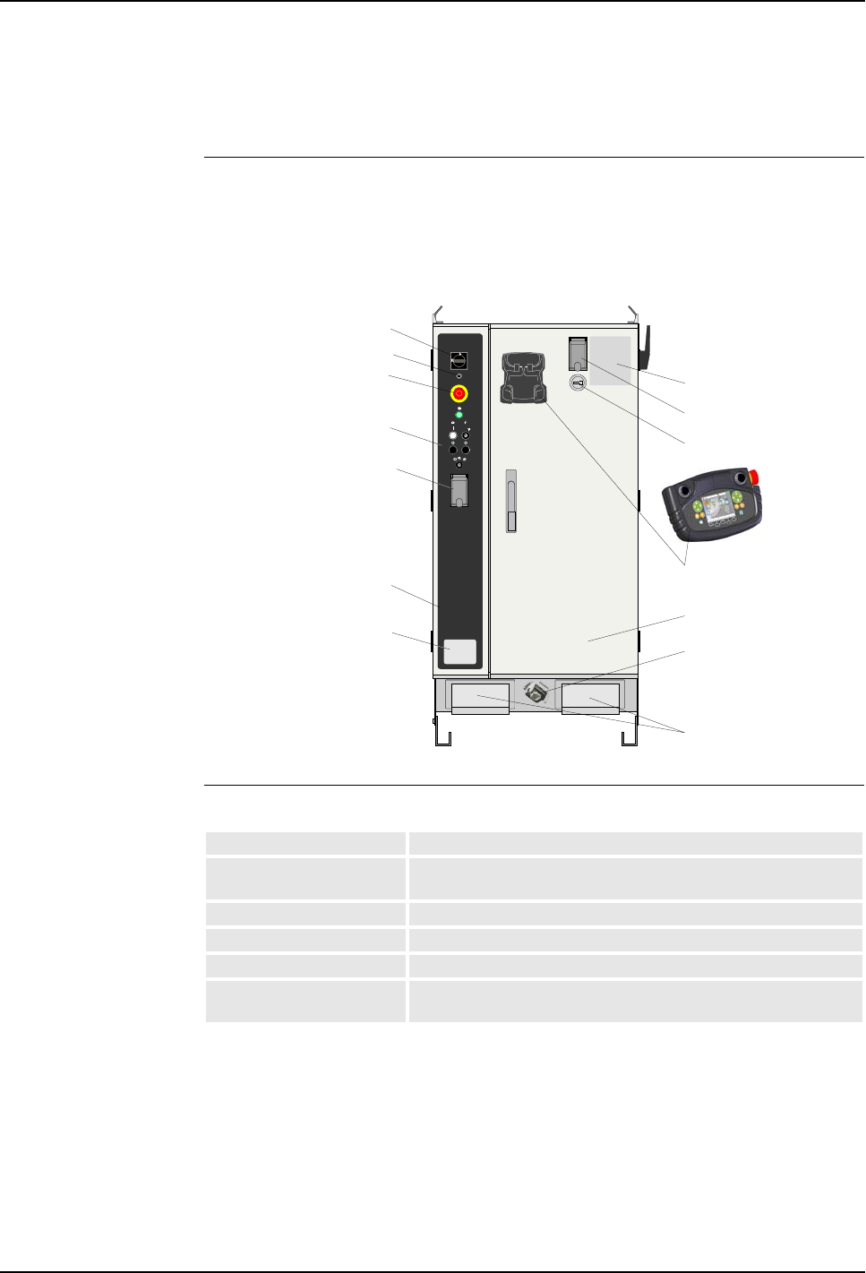
General The control cabinet is available in one version as shown in the illustration below.
The cabinet has a side panel at the left and a front door. Both panel and door can be
opened to get access to the cabinet internal components and connection points.
Figure 1 Control cabinet front
Control Panel The control panel includes following functions:
For detailed description of the control panel functions, see ’Control Panel
Description’ on page 27.
The robot may be supplied without control panel on the control cabinet. The reason
for this may be that the control panel is to be installed in an external control desk, or
that the robot is controlled from an external PLC via serial lines.
Side panel door
Mains switch
Emergency stop button
Control panel
LED indicator panel
Front door
Hour counter
Cable entrances
Pendant and
suspension
Service connections
Service outlet
(optional)
Identification plate
Pendant connection
Door interlock (optional)
Mains switch Switches mains power on/off to the robot
Emergency stop button Pressing the button will immediately stop the robot operation,
remove power from the axis motors and activate the axis brakes.
Purge OK indicator Indicates when the purge sequence is completed.
Motor on/off Apply / remove power to the axis motors.
High voltage on/off Apply / remove high voltage to the applicator (optional)
Mode selector Set the robot to Manual Reduced Speed mode, Manual High
Speed mode or Automatic mode.
3 System Description
Product Manual, Control Cabinet IRC5P 3HNA009834-001 en Rev.06 17
3.2 Basic Design
Service Outlet Optional power outlet for service (measuring instruments etc.).
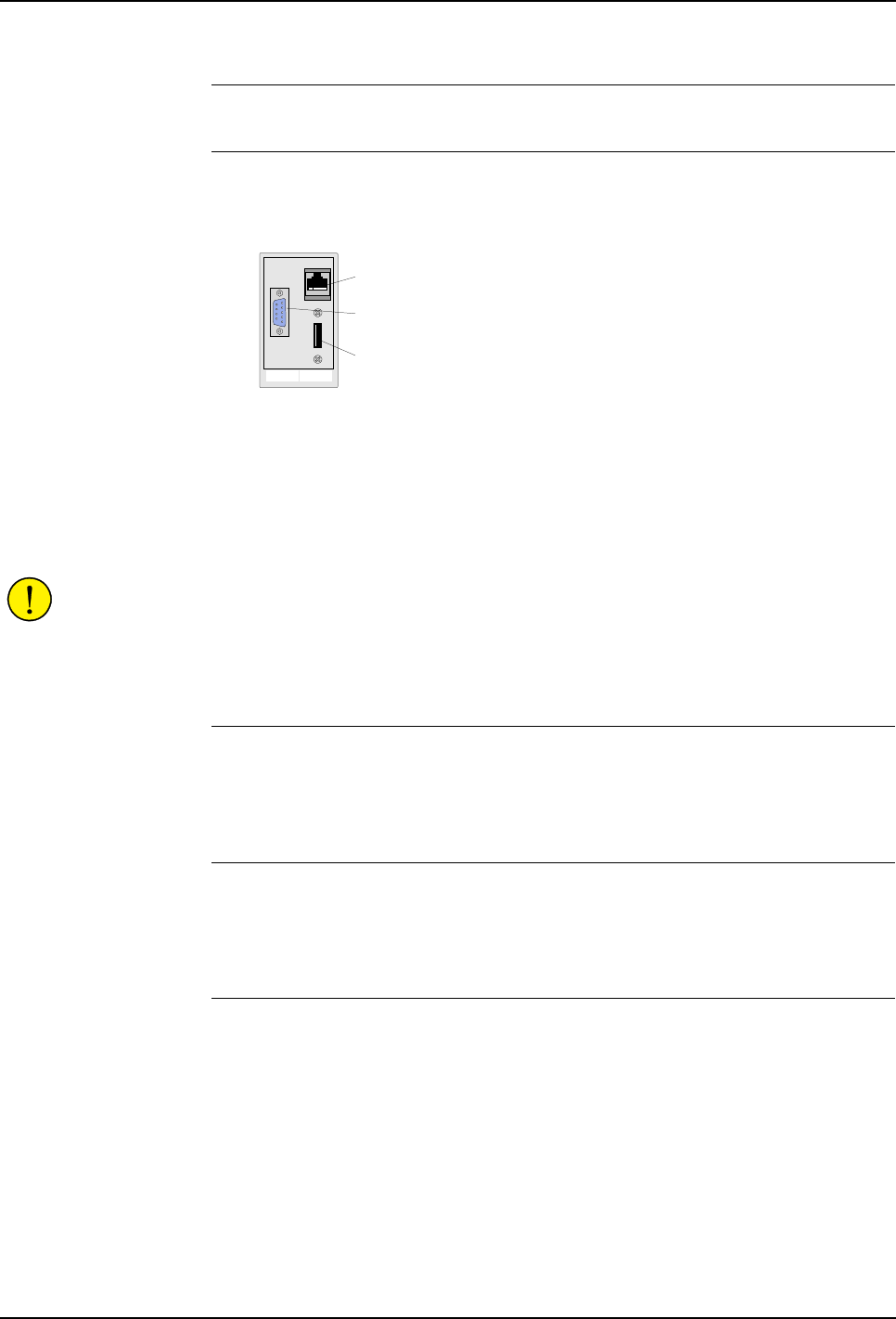
Service Connections The service connections include the following connections.
Figure 2 Service connections
– Ethernet connector for connection of a PC for loading programs, program
backup etc.
– PIB Console port for monitoring and debugging CAN nodes for service purposes
(typically IPS system). The connector is connected to PIB-X12.
– USB connector for connection of USB memory stick.
CAUTION! Only memory sticks recommended by ABB must be used. Using other
memory sticks than recommended may cause RobotWare system failure.
For more information on the service connections, see ‘Operator’s Manual, IRC5P’,
Installation and Commissioning / Connections.
Pendant The pendant (Paint Teach Pendant Unit, PTPU, or TPU) is used to perform
robot-near tasks, like jogging.
For description, see ’Pendant Description’ on page 29.
LED Indicator Panel The LEDs on the panel are used during service and operation to watch system
status.
For detailed description of the LEDs, see ’LED Indicator Panel’ on page 197.
Hour Counter The hour counter measures system running hours (when axis motors are ‘on’).
Ethernet
connection
USB
connection
Console port
3 System Description
3.2 Basic Design
18 3HNA009834-001 en Rev.06 Product Manual, Control Cabinet IRC5P
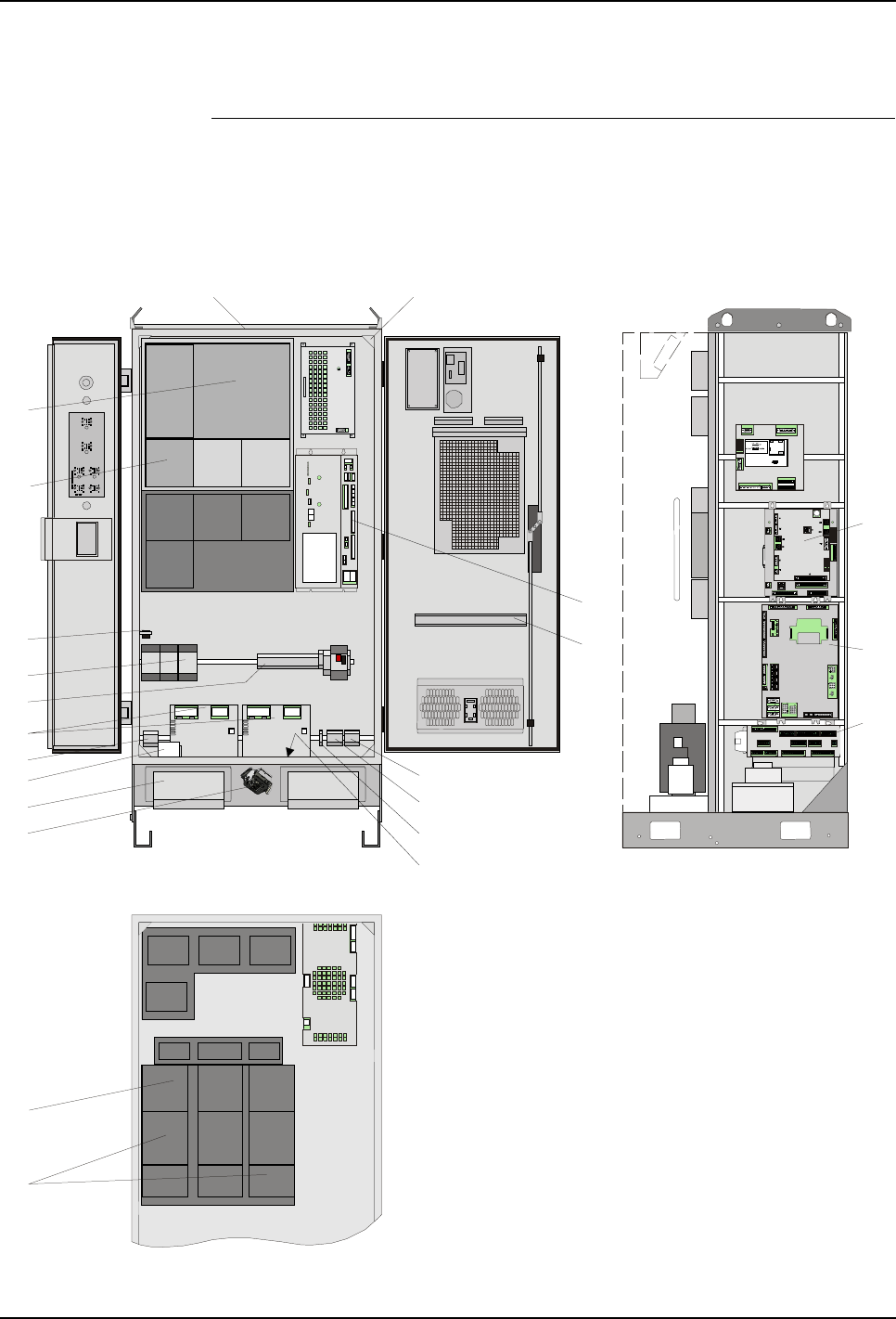
3.2.2 Internal Components
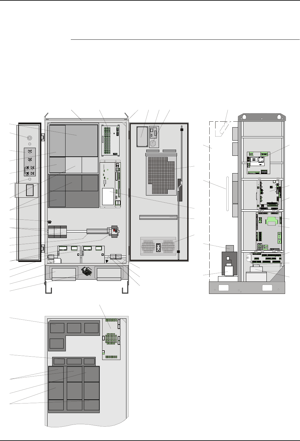
General The following description and illustration give a brief summary of the main
components.
For overview of connections in the control cabinet, see ’Controller Connections
Overview’ on page 42.
Figure 3 Control cabinet, component overview
Drive system 04
X20X21
X4
X12 X13 X10
X6
X7
X11
X14
X15
X16
X17
X18
X23
X2
X3
X5
X25
X24
X9 X8
X1
SCB-01
X5 X6 X2 X1
X3 X13 X4
X8 X9 X10
X11
X12
X7
X5 X6 X2 X1
X3 X13 X4
X8 X9 X 10
X11
X12
X7
X8X7X6
X5
X4
X21
X26
X27
X14
X15
X13
X12
X25
X10
X9
X11
X3
X16
X17
X18
X24
X23
X22
X1 X2
MIB-01
X19
X20
X18
X8X7X6
X5X4
X21
X26
X27
X14
X15
X13
X12
X25
X10
X9
X11
X3
X16
X17
X24
X23
X22
X1 X2
X19
X20
X18
MIB-01
SIB-01
X5
X1X10
X15X16
X17
X6
SIB-01
PIB-01
PIB-01
BCPU
SDI-03
Reserved for internal use
X1, X11, X14 - Debugging
and programming conn.
(for internal use)
MS
Status
X3X5
X2
X6
SERVO DRIVE INTERFACE
SDI-03 ABB AS, Robotics
Right side wall
1
2
3
4
5
6
7
8
9
10
11
12
13
14
15
16
19 20 21 22 23 24
25
26
27
28
29
30
31
32
33 35
37
38
39
40
41
42
43
44
36
17
18 34
50
45
46
47
48
49

3 System Description
Product Manual, Control Cabinet IRC5P 3HNA009834-001 en Rev.06 19
3.2 Basic Design
Motor Drivers The drive units and associated rectifiers are used for controlling the manipulator
axis motors (axis motor drivers) and non I-Drive paint pumps (pump motor drivers).
The bleeder resistors are used for the drivers to bleed off excessive power.
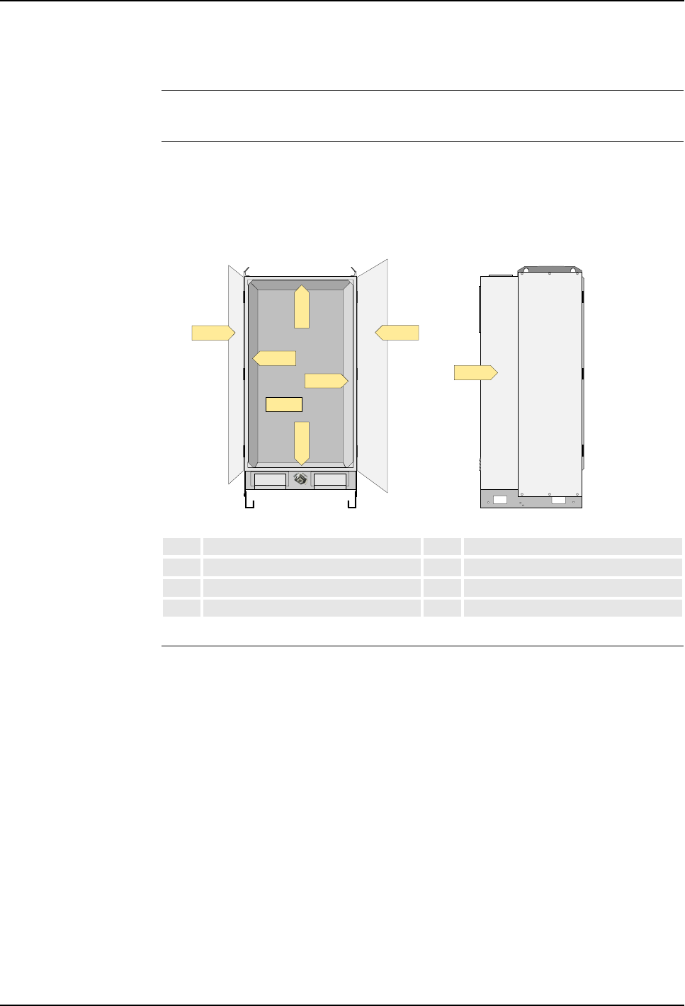
Fan Unit The fan unit provides for air circulation through the rear side of the control cabinet.
Air is sucked into the cabinet via a filter at the top and routed passed the motor
drivers, bleeder resistors and transformer. The components that produce the most
heat emission are located on the back panel.
Mains Power Units Mains power is entered into the controller via terminals on the mains fuse and noise
filter. The mains transformer located on the rear side provides the voltages needed
by the control systems.
Computer Systems The computer system for the robot consists of the main computer, mounted on the
front door, and the axis computer installed on the cabinet back wall.
1Main drive unit, MDU 26 Main computer unit
2Mains power switch 27 Brake resistor bleeders
3Control panel board, CPB 28 Power distribution board, PDB
4Additional rectifier unit, ARU 29 Rail for mounting optional units
5Additional drive unit, ADU, axis 7 30 Door fan unit
6Mode selector 31 Transformer
7Additional drive unit, ADU, axis 8 32 CAN1.2 for external distributed I/O
8CBS drive units 33 CAN1.1 for internal distributed I/O
9Manipulator connections 34 Ground rail
10 Motor relays robot / pump 35 Choke filter (IRB 5500)
11 CBS Purge relay (IRB 5500) 36 Servo fan unit
12 Transformer terminal board 37 Servo drive interface board, SDI
13 PDB fuse 38 Paint interface board, PIB
14 Optional I/O units (field bus nodes) 39 Safety interface board, SIB
15 Optional servo disconnect terminal 40 Measuring system battery
16 Mains fuse and connection 41 Manipulator interface board, MIB
17 Cable inlet 42 Safety connection board, SCB
18 Pendant connector and TIB board 43 Mains fuse
19 Optional internal light 44 Mains filter
20 Axis computer board, DSQC 668 45 CBS drive units / Non I-Drive pump motors
21 Door switch 46 Capacitor unit
22 System LED board, ALED 47 Axis 7/8 drive units
23 Service connections 48 Rectifier unit
24 Hour counter 49 Axis motor drive units
25 Cabinet rear housing 50 Axis computer board, DSQC 601

3 System Description
3.2 Basic Design
20 3HNA009834-001 en Rev.06 Product Manual, Control Cabinet IRC5P
Paint Interface Board,
PIB The Paint Interface Board PIB is the central interface between the control system
and the paint application equipment.
Safety Interface Board,
SIB The Safety Interface Board SIB contains most of the electromechanical parts of the
safety chains. The board acts as interconnection point between the Manipulator
Interface Board (MIB) and the Paint Interface Board (PIB).
Power Distribution
Board, PDB The Power Distribution Board PDB provides 24 V DC voltages for the robot control
system electronics with separate current limits.
Manipulator Interface
Board, MIB The Manipulator Interface Board MIB serves as interface between the control
system and manipulator / process equipment. The board is equipped with zener
barriers for purge sensor and battery supply for the manipulator (measuring system).
Safety Connection
Board, SCB The Safety Connection Board SCB includes connections for the various safety
functions for the robot and also connections for encoders and external panel. The
board includes only connectors and no active components.
Pendant Interface
Board, TIB The Pendant Interface board TIB is a connection board for routing signals between
the pendant and Safety Interface board SIB. The board also includes connection for
Exi Sync Signal.
Remote Service The control cabinet can optionally contain a remote service box. The box can be
installed on the inside of the door on the rail for mounting optional units. For more
information on remote service, see ‘Product Manual, Remote Service’.
Internal Light Optionally the control cabinet includes an internal LED light and associated adapter.
The light is switched on/off by the door switch.
Door Switch The door switch switches ‘on’ the optional internal light and switches ‘off’ the
optional cooler when the front door is opened.
3 System Description
Product Manual, Control Cabinet IRC5P 3HNA009834-001 en Rev.06 21
3.2 Basic Design
3.2.3 Cabinet Labelling
General Following naming conventions should be noted when working with the controller.
Control Cabinet Panels The different components, connectors and terminal boards are located on the cabinet
back wall and side wall etc. Each of these panels are labelled AC1, AC2, etc. as
described below.
Figure 4 Control cabinet panels
Connection Labelling Connectors are labelled X1, X2, etc., and terminal boards are labelled XT1, XT2,
etc.
A connector or terminal board located on one of the cabinet panels is labelled with
the designation of the panel in addition to the name of the connector (or terminal
board), e.g. +2-XT1 which means terminal board XT1 located on the cabinet back
wall AC2.
A connector or terminal board located on one of the units in the cabinet is labelled
with the name of the unit in addition to the name of the connector (or terminal
board), e.g. MIB-X22 which means connector X22 on the MIB unit.
AC1 Panel door AC5 Right side wall
AC2 Back wall AC6 Left side wall
AC3 Bottom plate AC7 Top plate
AC4 Front door AC8 Cabinet rear side
AC6
AC5
AC4
AC1
AC3AC7
AC2
AC8
3 System Description
3.2 Basic Design
22 3HNA009834-001 en Rev.06 Product Manual, Control Cabinet IRC5P
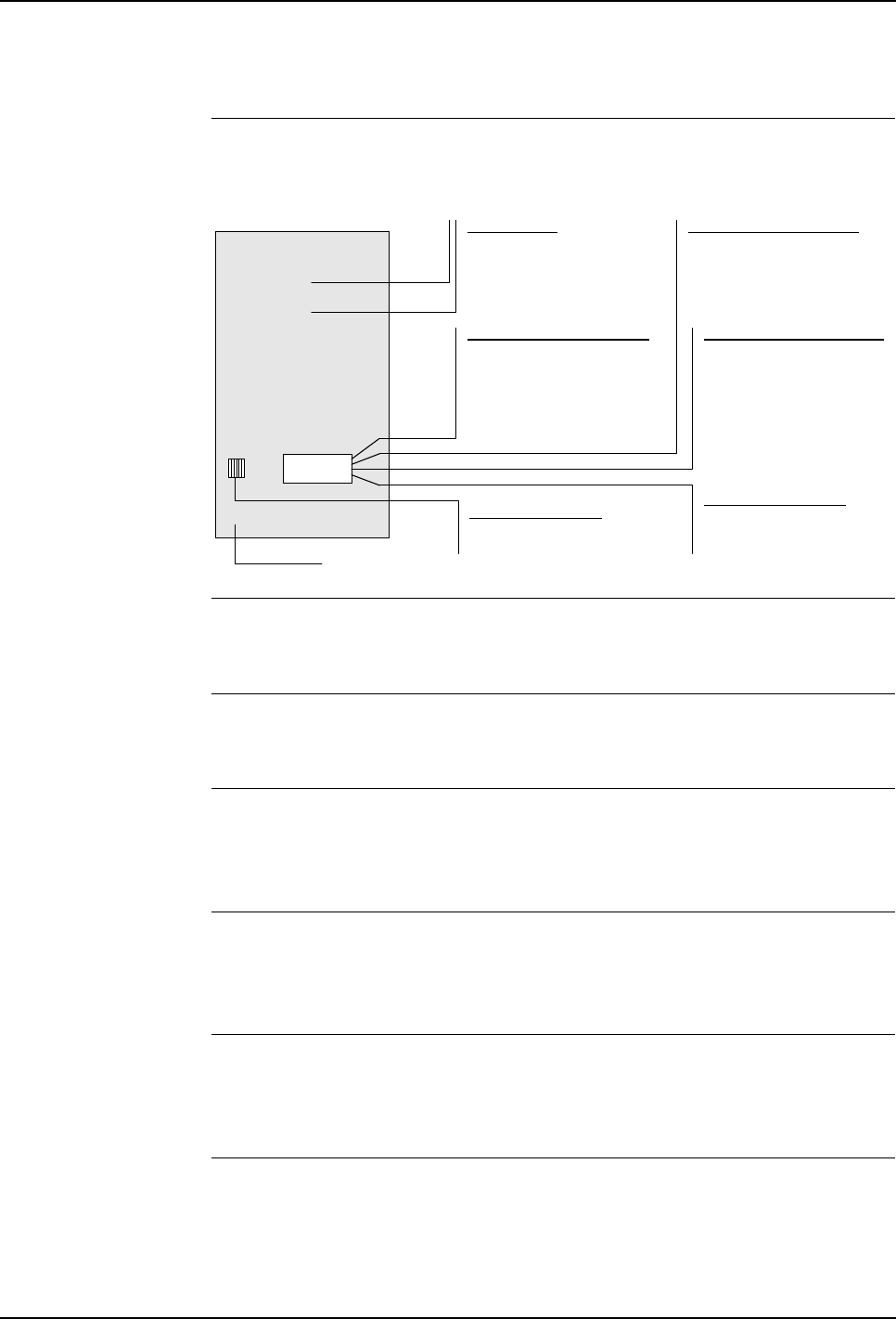
3.2.4 Purge System
General When the robot is installed in an area where explosion hazard is present, it is
equipped with a purge system. The purpose of this system is to apply compressed
air in the manipulator. The compressed air is kept at a higher pressure than the
atmospheric pressure and so preventing hazardous gases from entering the
manipulator interior.
For more details on the purge unit, see ‘Unit Description, IRC5P’, Purge System.
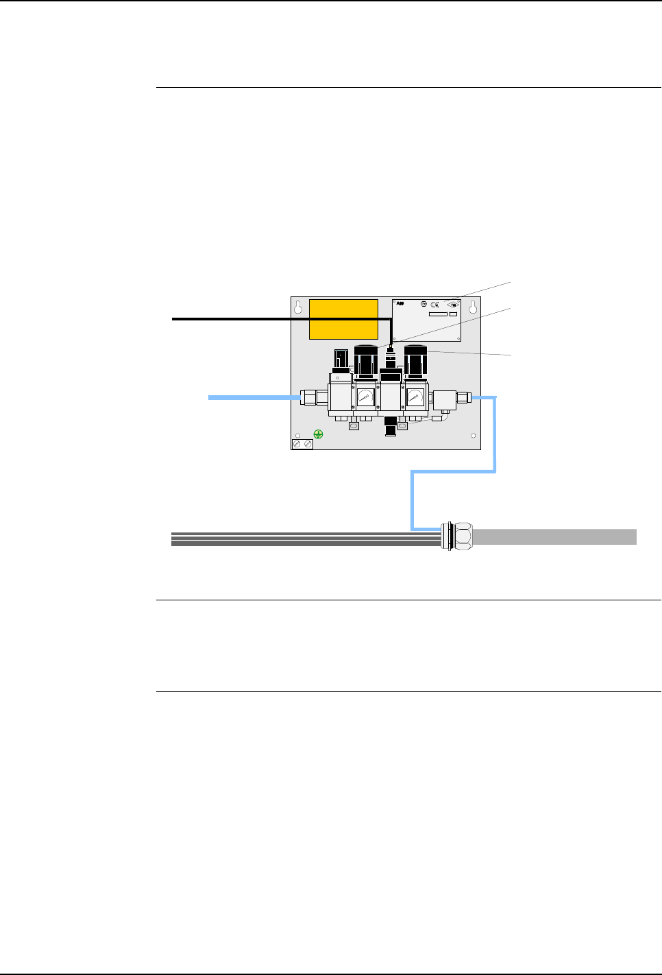
Figure 5 Purge unit design
Description The purge valve assembly includes various valves for controlling and regulating the
purge air supply to the robot. Supply air is connected to the purge unit and, via the
control valves, routed to the manipulator via the purge connector and flexible hose.
Versions Different versions of the purge unit are available:
The purge unit shown in the above illustration is used for all stand-alone robots.
For robots operating on a trolley, a different type of purge unit, called ‘Purge Unit
with Connector Box’, is used. This purge unit includes a purged chamber with cable
connections. The main reason for using this type is to provide flexible cables via the
trolley cable chain. For information on this purge unit type, see ’Purge Unit
w/Connector Box’ on page 111.
Purge supply to dry filtered
air only (instrumental air)
Purge pressure:
WARNING! PRESSURIZED AIR
Not e:
3 bar (45 psi)
Mainte nance p ressure: 0,5-1 bar
TURN OFF MAIN AIR-TAB BEFO RE
WORKING ON EQUIPMENT
Purge time: See machine specification
PO Box 265, N-4349 B ryne
ABB AS, Robotics 0470
APPROVED
Type:PURGE CONNECTOR BOX
Dwg.No.: 3HNM 01201-1
Part of :PU RGE SYSTEM Dwg.N o.3HNE 06486- 1
NEMKO 02AT EX189U
Protective gas :........................... Instrumental air
Purge Suppl y press ure :............ M in.3.0 max.5.0 bar
Maintenanc e Supply press ure :. M in.0. 5 max.1.0 bar
Leaquage C ompensation : ........... 5 -20 Nl/min.
Maintenanc e press ure :................. Min. 0.8 mbar
Enclosure Pressure :..................... Max. 500 mbar
BatchSerial No.
INTRINSICALLY SAFE SIGNALS Cl. I.II. Div. 1 , Gr. A - G
[EEx pib] IIB
II ( 2) G,D
Supply air
Flexible hose
to manipulator
Motor and
control signals
Purge valve
control signal
Purge connection
Purge valve assy' Purge air
hose
Purging (Flushing)
pressure regulator
Maintenance pressure
regulator
Identification label
3 System Description
Product Manual, Control Cabinet IRC5P 3HNA009834-001 en Rev.06 23
3.2 Basic Design
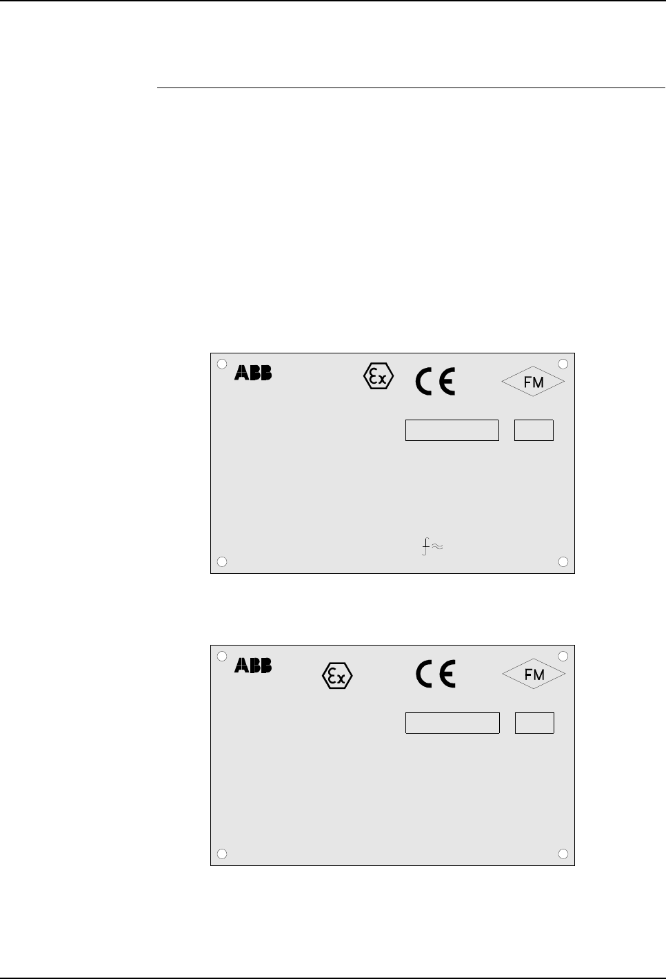
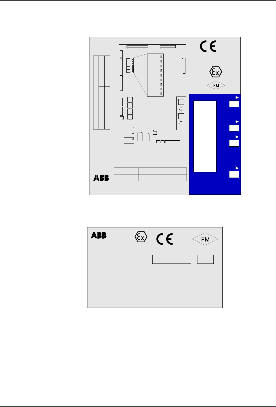
3.2.5 Identification Labels
Description Identification plates/labels indicating the type of device and serial number etc., are
found on the control cabinet, purge unit, pendant, Pendant Interface Board TIB,
Manipulator Interface Board MIB, Pressure Sensor Interface Board PSIB, Digital
Sensor Interface Board DSIB and manipulator.
The identification labels are located on the control cabinet front (Figure 1), purge
unit front (Figure 5), pendant rear (Figure 13), and on the boards.
Note: The identification labels shown in the illustrations below only serve as
examples. For exact identification, see labels on your devices.
Identification plate for manipulator is shown in ‘Product Manual, Manipulator’.
Figure 6 Control cabinet identification plate
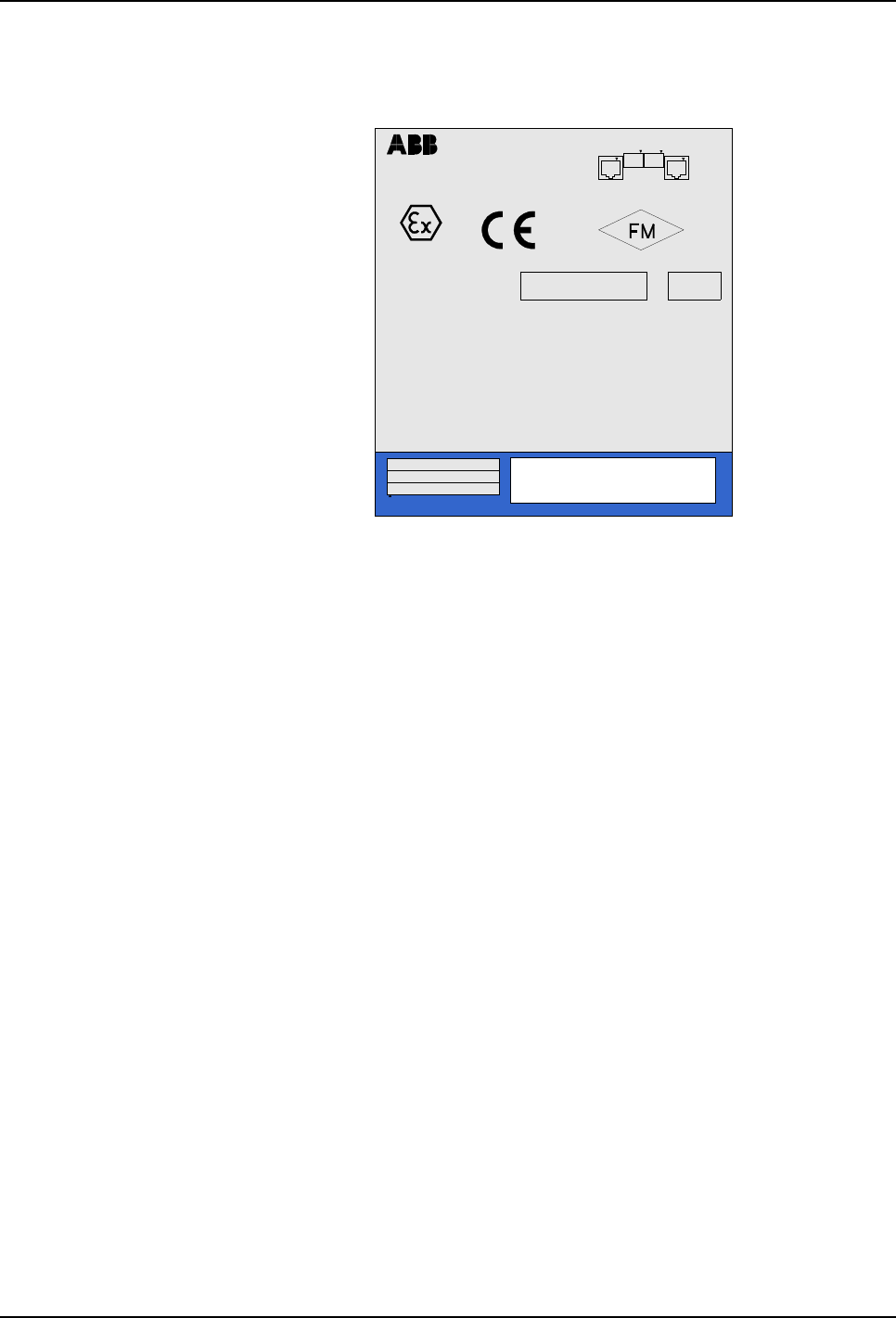
Figure 7 Purge unit identification plate
0470
APPROVED
Type:CONTROL CABINET IRC5P
NEMKO 02ATEX273U
Temperature :.............................
Supply Voltage :.........................
Supply Current :..........................
Consumption :.............................
BatchSerial No.
II (2) G [Ex ib px
Intrinsically Safe Outputs for Cl.I&Cl.II,Div.1,Gr.C,D&G.
Ref. Dwg. No.: 3HNA012652-001
PO Box 265, N-4349 Bryne
ABB AS, Robotics
II (2) D [Ex ibD pD
°C - +45 °C0
200-600VAC 50/60Hz
Max. 16A
Max. 6.5 kVA cos. o 0,9
] IIB
]
PO Box 265, N-4349 Bryne
NORWAY
ABB AS, Robotics 0470
APPROVED
Type:PURGE CONNECTOR BOX
Dwg.No.: 3HNM 01201-1
Part of :PURGE SYSTEM Dwg.No.3HNE 06486-1
NEMKO 02ATEX189U
Protective gas :..........................
Purge Supply pressure :............
Maintenance Supply pressure :.
Leaquage Compensation :........
Maintenance pressure :.............
Enclosure Pressure :.................
BatchSerial No.
INTRINSICALLY SAFE SIGNALS Cl. I.II. Div. 1 , Gr. C - G
[Ex px ib] IIB, [Ex pD ibD]
Instrumental air
Min.3.0 max.5.0 bar
Min.0.5 max.1.0 bar
5 -20 Nl/min.
Min. 0.8 mbar
Max. 500 mbar
II (2) G
II (2) D
3 System Description
3.2 Basic Design
24 3HNA009834-001 en Rev.06 Product Manual, Control Cabinet IRC5P
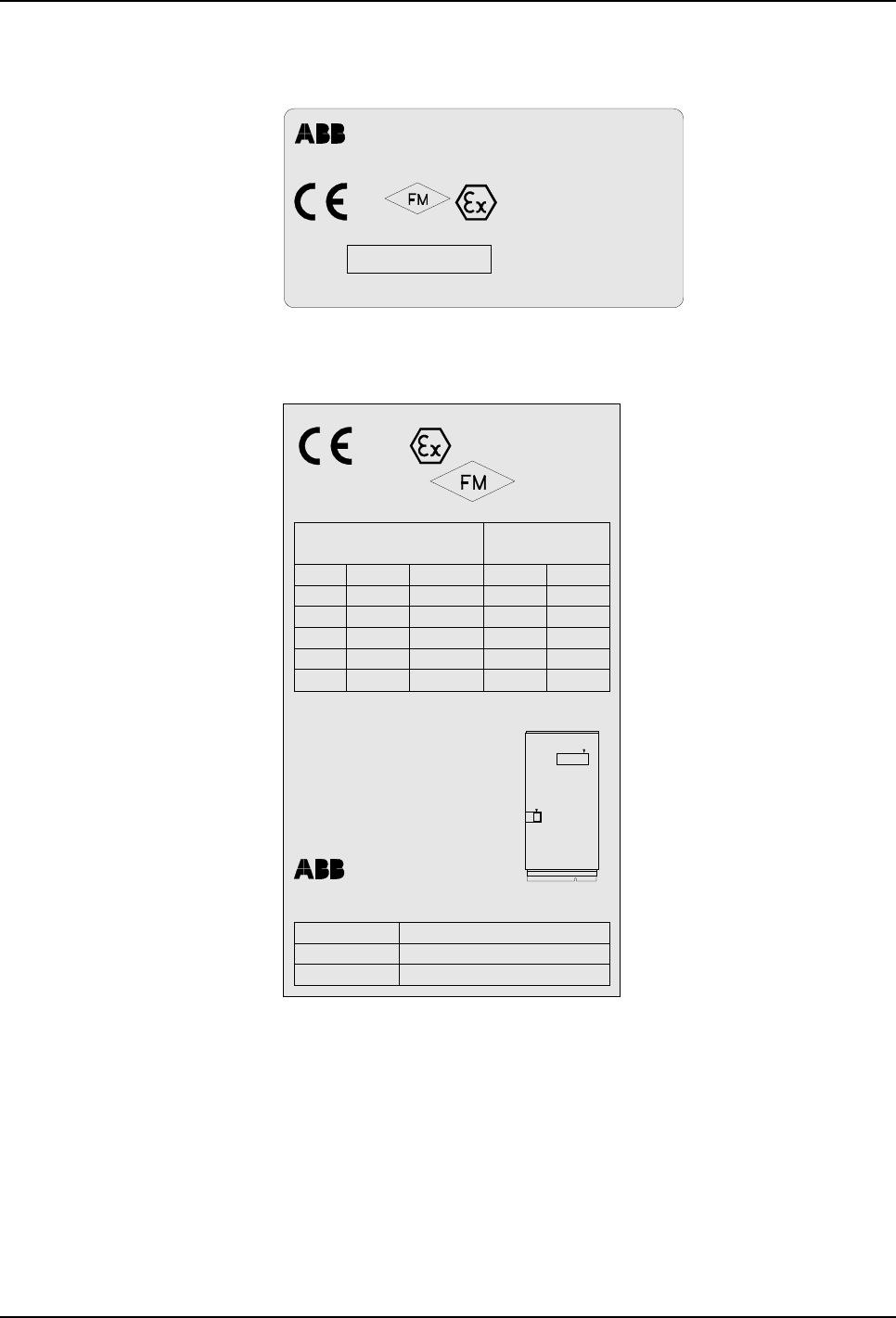
Figure 8 Pendant identification label
Figure 9 TIB adapter identification label
0470 APPROVED
SER.NO
N-4349 Bryne, Norway
AS Robotics
Nordlysvegen 3
WARNING! Substitution of components may impair intrinsic safety
PTPU-01 3HNA006148-001
Ta: 10°C....+40
NEMKO 08ATEX1188
IECEx NEM 08.0003
Instrinsically safe apparatus for
Cl. 1, Div. 1, Gr. C & D T4 135°C
II 2 G, Ex ib IIB T4
0470
APPROVED
NEMKO Nr.Ex 08ATEX1188
[Ex ib] IIB
for Cl.1, Div.1,Gr. C & D
Drawing 3HNA012823-001
II 2 G
Box 265, N-4349 Bryne, NORWAY
ABB AS, Robotics
Intrinsically Safe Outputs
in accordance with
U =50V
M
U1
C /uF
o
I A
o
U V
oL /mH
o
7V 0.07 300 25
IIB
U2 7V 0.0214 300 250
U3 13.8V 0.894 4.9 0.4
U4 14.8V 0.033 3.76 120
U5 14.8V 0.110 3.76 10
X4
X6
TYPE TIB
ITEM No. 3HNA006149-001
SERIAL No.
IECEx NEM 08.0003
3 System Description
Product Manual, Control Cabinet IRC5P 3HNA009834-001 en Rev.06 25
3.2 Basic Design
Figure 10 MIB adapter identification label
Figure 11 PSIB identification label
24 IO
24 EMY
N0
N1
N2
N3
STAT
HW
PWR
X11
02ATEX189U
APPROVED
0470
NEMKO:
Box 265, N-4349 Bryne, NORWAY
ABB AS, Robotics
Item No. 3HNA007719-001
Serial No.
WARNING:
SUBSTITUTION OF COMPONENTS MAY IMPAIR
INTRINSIC SAFETY
II(2)G [Ex px ib ]IIB, II(2)D [Ex pD ibD]
Cl.I&II, Div.1, Gr.C-G
INTRINSICALLY SAFE SIGNALS
X24
X23
X22
X21
MANIPULATOR INTERFACE BOARD
MIB
X10
X13
X12
X25
PART OF W/ CONTROL DRAWING
Purge System3HNE 06486-1
Measurement System3HNE 08898-1
X26
X27
X14
X15
X16
X17
X18
X4 X5
X6 X7 X8
X24
X23
X22
X21
X3
X20
X1 X2
X19
LEDS
X28
X9
- RS485_1
- RS485_2
- SPI f. master
- SPI to slave
- Dig.I/O
- CAN
- CAN
0470
APPROVED
Type: PSIB, 3HNA010414-001
NEMKO 04ATEX1243
BatchSerial No.
[EEx ib] IIB Tamb. 60°
Intrinsically Safe Outputs
Ref. Dwg. No.: 3HNA010016-001
II (2) G,D
PO Box 265, N-4349 Bryne
ABB AS, Robotics
FM Class I,II Div.1, Group C,D,G
Un=24VDC, In.sys=0.3A
Um=250V, Uo=10.6V, Io=62mA, Po=164mW
Group IIB, Ca/Co=16.2uF,La/Lo=35mH
Warning:
Substitution of components may impair intrinsic safety.
Must only be used with ABB Robots.
3 System Description
3.2 Basic Design
26 3HNA009834-001 en Rev.06 Product Manual, Control Cabinet IRC5P
Figure 12 DSIB identification label
0470
APPROVED
Type: DSIB
3HNA012319-001
BatchSerial No.
[EEx ib] IIB Tamb. 60°C, NEMKO 04ATEX1243
Intrinsically Safe Outputs,
Ref. Dwg. No.: 3HNA015815-001
II (2) G,D
PO Box 265, N-4349 Bryne NORWAY
ABB AS, Robotics
Class I,II Div.1,
Um=250V, Un=24VDC,
Vo=12.3V, Io=13.7mA,
Po=42mW
Group IIB, Ca/Co=16.2uF,
La/Lo=600mH
Warning:
Substitution of components may
impair intrinsic safety. Must only
be used with ABB Robots.
X6X7
X5 X1
X8
Group C,D,G
3 System Description
Product Manual, Control Cabinet IRC5P 3HNA009834-001 en Rev.06 27
3.3 Control Panel Description
3.3 Control Panel Description
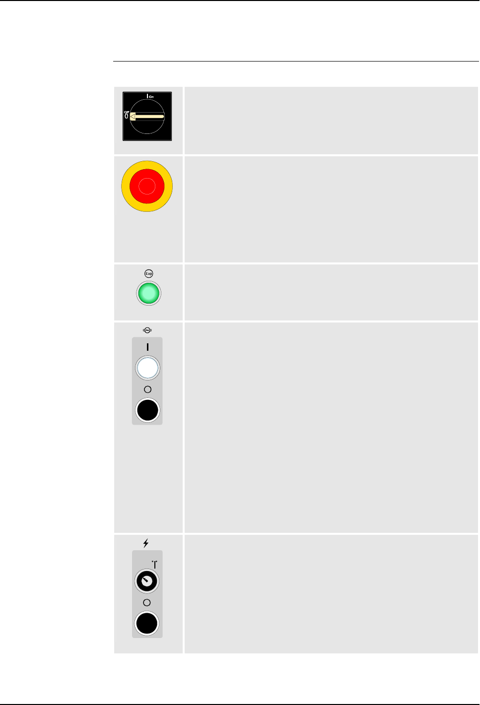
Panel Overview The following gives a description of the control panel switches and indicators.
Mains Power Switch, QS1
Switch for applying mains power to the robot system.
Emergency Stop Button, SB3
Push/pull button for instant stop of the robot regardless of operating mode.
To reactivate emergency stop chain, the button must be released (pulled out
or rotated clockwise), then the Motor On button must be used.
If pressed during a program, operation can not be resumed on the same
object.
Purging OK Indicator, HL1
Indicator lamp informing the user when the purge sequence is completed at
start-up and the robot is ready for operation.
Motor On/Off Switches, SH4/SB5
Used to enable (I) or disable (0) electrical power for the manipulator axis
motors.
The indicator in the ‘on’ button will be lit when power is applied. (Motor ‘on’ is
one of many conditions for applying power).
The Motor On switch is also used to reset the emergency stop chain and to
enable run chain in Manual mode.
Continuous light: Ready for program execution.
Fast flashing light: (4Hz): The robot is not calibrated or revolution counters are
not updated. The motors have been switched on. By fast flashing, call for
service assistance.
Slow flashing light: (1Hz): One of the spray booth safety switches is active.
The motors have been switched ‘off’.
High Voltage On/Off Key Switch, SA7/SB8
Toggle key switch used to switch power for high voltage equipment on (“I”),
and button used to switch power for high voltage equipment off (0).
Toggle key switch means that the switch returns to off position when released,
as indicated by the (“I”) notation.
The switch is only applicable if the robot is fitted with HV controller.
3 System Description
3.3 Control Panel Description
28 3HNA009834-001 en Rev.06 Product Manual, Control Cabinet IRC5P
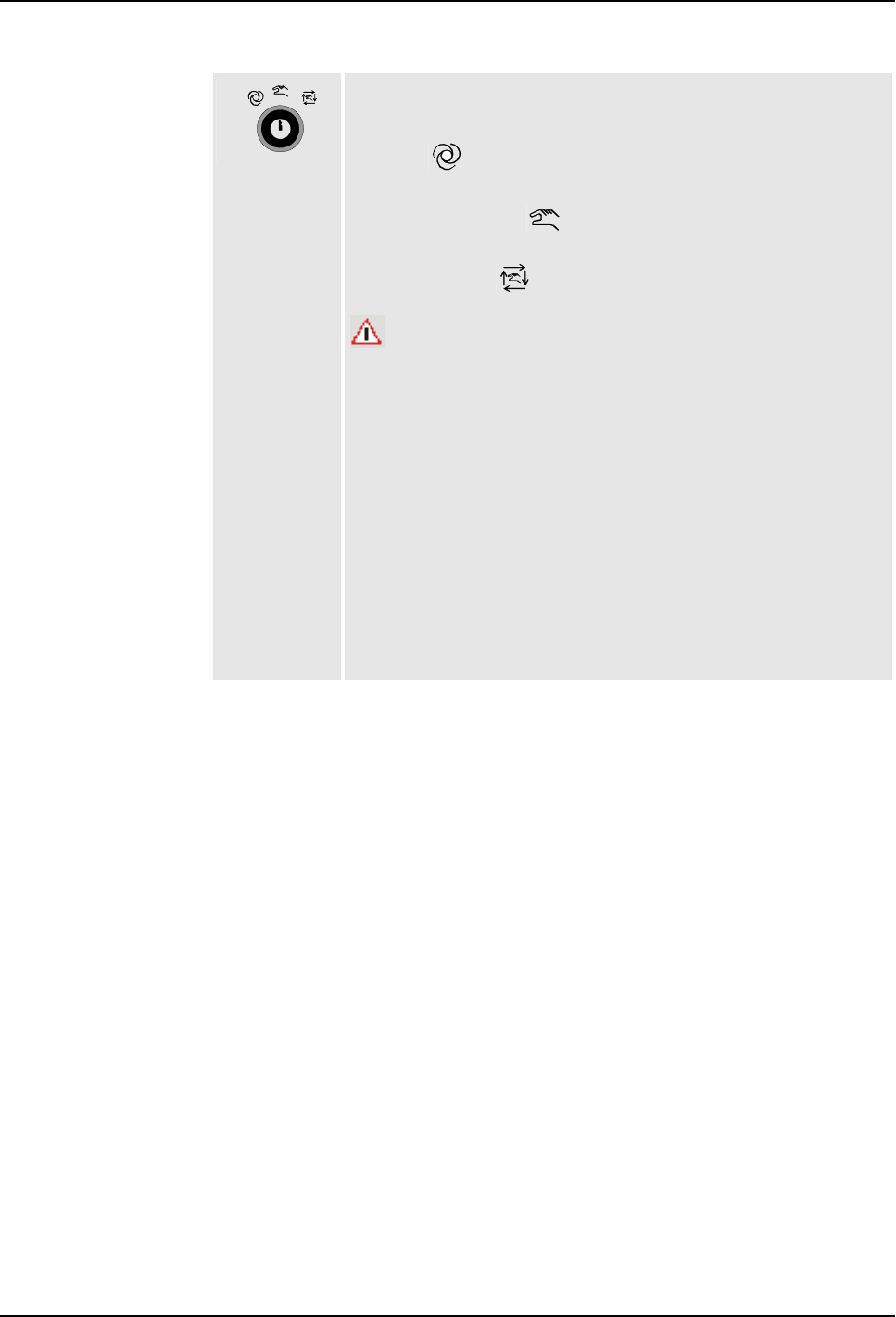
Operating Mode Selector, SA1
Key switch used to lock the robot in one of the following 3 operating modes:
Automatic / mode: Used for running ready-made programs in
production. Joystick can not be used.
Manual Reduced Speed / mode: Manual mode for programming and
setup. Max. speed: 250 mm/s (600 inches/min.)
Manual High Speed / mode: Manual mode for testing at full program
speed.
WARNING:
The Mode Selector is a key type switch, intended to increase personal safety.
When operating within the working area of the robot, the switch shall always
be in Manual mode, and the operator shall keep the key with him so it is not
possible for other persons to take over control of the robot.
IMPORTANT:
In Manual High Speed mode, the System Speed is by default set to a low
value. This is a safety feature to avoid a ‘high speed surprise’ in case the key
switch was set one notch too far when switching to programming mode. The
system speed must be set to 100% manually in order to obtain full speed.
Mode Change Acknowledge
When leaving Manual Reduced Speed mode, an Acknowledge input is
required. If operated from the pendant, a dialog for this purpose is shown. For
systems controlled by a PLC or RobView, there is a Paint Command available
for this purpose.
3 System Description
Product Manual, Control Cabinet IRC5P 3HNA009834-001 en Rev.06 29
3.4 Pendant Description
3.4 Pendant Description
Description The pendant (Paint Teach Pendant Unit, PTPU) is a device to perform robot-near
tasks, like jogging. The pendant may be placed in the pendant suspension on the
control cabinet front.
The pendant includes a display and control keys for operating the robot. In addition,
the pendant includes 2 joysticks, Emergency Stop button and on the rear an
Enabling Device.
For detailed description of the operation of the pendant, see ‘Operator’s Manual,
IRC5P’.
Figure 13 Pendant design
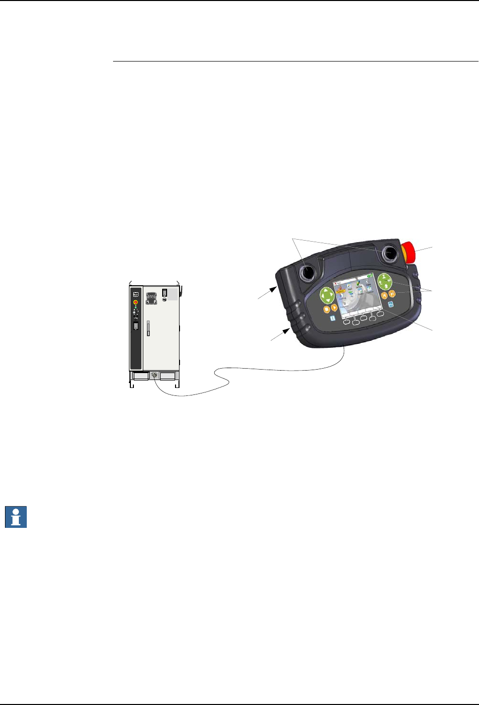
The pendant is connected to the pendant connector at the bottom front of the control
cabinet.
Optionally, the pendant may also be connected via hot plug connection or external
pendant connection. For further information, see ’Pendant Connection’ on page
103.
Important: If the pendant is not connected, a dummy connector must be installed in
its place to avoid breaking the emergency stop chain.
The pendant and connection are explosion protected Exi for operation in hazardous
areas.
Emergency
Stop button
Enabling device
(rear side)
Joysticks
Control keys
Display
Identification
label (rear side)


4 Technical Specifications
Product Manual, Control Cabinet IRC5P 3HNA009834-001 en Rev.06 31
4.1 Introduction
4 Technical Specifications
4.1 Introduction
About this Chapter This chapter provides technical specifications on the IRC5P Controller, Pendant and
Purge Unit.
WARNING! Repair work on the controller must only be performed in accordance
with procedures given in the Repairs chapter in this manual.

4 Technical Specifications
4.2 Controller Specifications
32 3HNA009834-001 en Rev.06 Product Manual, Control Cabinet IRC5P
4.2 Controller Specifications
General Specifications
Important: The max. ambient temperature for the controller does not apply under
the following circumstances: The controller is covered with plastic or other material
which restricts heat emission, the controller does not have sufficient clearance at the
back and sides (see ’Cabinet Location’ on page 48), more cabinets are installed
close together, the controller is installed close to a heat source, items (e.g. a ring
binder) are placed on top of the controller and acts as temperature insulation, the
controller is dirty, the controller fans are not running, the fan air inlet/outlet is
restricted, the robot is programmed with excessive acceleration etc.
Power Supply
Service Connections Service connections available on front of the cabinet door.
Dimensions See Figure 14
Weight: 180 - 200 Kg (Depending on supplied options)
Airborne noise level: < 70 dB (A) Leq (acc. to Machinery directive
MD 2006/42/EC)
(The sound pressure level outside the working space)
Color specification: Grey NCS 2502B
Ingress protection degree: IP54
Ambient temperature: Max. 48°C
Temperature for complete robot system
during transportation and storage:
-25°C - +55°C
Relative humidity: Max. 95% Non-condensing.
(Complete robot during transportation, storing and
operation)
Internal light: LED light (optional)
Mains voltage: 200-600VAC, three-phase, +10%, -15%
Mains fuse: Min. 16A (slow blow)
Mains frequency: 48.5 to 61.8 Hz
Power consumption:
- Stand by: <300 W
- Production (average): <700 - 1500 W
Absolute measurement backup: 7000 h (non-rechargeable battery)
Ethernet connector: 10Mbit/s: Shielded twisted pair (10 Base T STP)
100Mbit/s (<10m): CAT5E, 100 Base T STP
100Mbit/s (10-100m): CAT6, 100 Base T STP
ACA Console port: RS232 (Baud rate 9600Bd, flow control Xon/Xoff)
USB connector: USB memory stick (to be ordered from ABB)

4 Technical Specifications
Product Manual, Control Cabinet IRC5P 3HNA009834-001 en Rev.06 33
4.2 Controller Specifications
Inputs and Outputs Different types of distributed I/O units can be installed. The following table shows
the maximum number of physical signals that can be used on each unit. For more
details, see technical specifications for relevant unit in ‘Unit Description, IRC5P’,
Distributed I/O.
*1) The digital signals are supplied in groups, each group having 8 inputs or outputs.
*2) To calculate the number of logical signals, add 2 status signals for RIO unit and 1 for
Interbus-S, Profibus DP and CC-Link.
*3) Selectable voltage or current.
*4) Encoder inputs or digital inputs.
*5) The system has a limitation of 255 input/output signals for one unit. However, when
using the DSQC 378 together with the IPS, you can define 368 (*2) inputs and 368
outputs.
Type Name Function
AD Combi I/O DSQC 651 8 digital in / 8 digital out / 2 analog out
Digital I/O DSQC 652 16 digital in / 16 digital out *1
Relay I/O DSQC 653 8 digital in / 8 digital out
Digital I/O 120 VAC DSQC 654 8 digital in / 8 digital out
Analog interface board ANIB 8 analog in / 4 analog out / 4 digital out
Digital Sensor interface brd. DSIB 16 namur sensor inputs
Pressure sensor interf. brd. PSIB 8 pressure sersor inputs
Process I/O PIO 16 *4 digital in / 8 digital out /16 analog in *3 /12
analog out *3 / 4 encoder inputs *4
Digital I/O DSQC 328 16 digital in / 16 digital out
Analog I/O DSQC 355 4 analog in / 4 analog out
Profibus DP slave DSQC 352 128 *2 digital in / 128 digital out
Allen-Bradley Remote I/O DSQC 350 128 *2 digital in / 128 digital out
Interbus-S slave DSQC 351 64 *2 digital in / 64 digital out
CC-Link DSQC 378 176 *5 digital in / 176 digital out
Encoder unit DSQC 377 2 encoders / 2 sync signals
4 Technical Specifications
4.2 Controller Specifications
34 3HNA009834-001 en Rev.06 Product Manual, Control Cabinet IRC5P
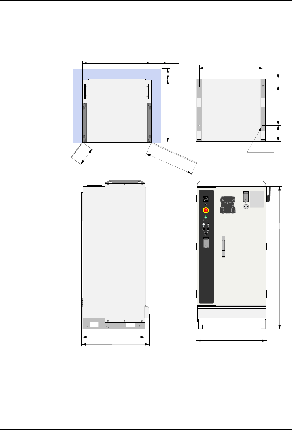
Dimensions Controller dimensions are shown in the illustration below.
Figure 14 Controller dimensions
725
650
500
190
Min.100
Min.100
Top view Bottom view
(foot print)
638
360
725
650 Side view
Front view
4 x Ø14
157.5
122.5
1450
710
All dimensions in mm
4 Technical Specifications
Product Manual, Control Cabinet IRC5P 3HNA009834-001 en Rev.06 35
4.3 Pendant Specifications
4.3 Pendant Specifications
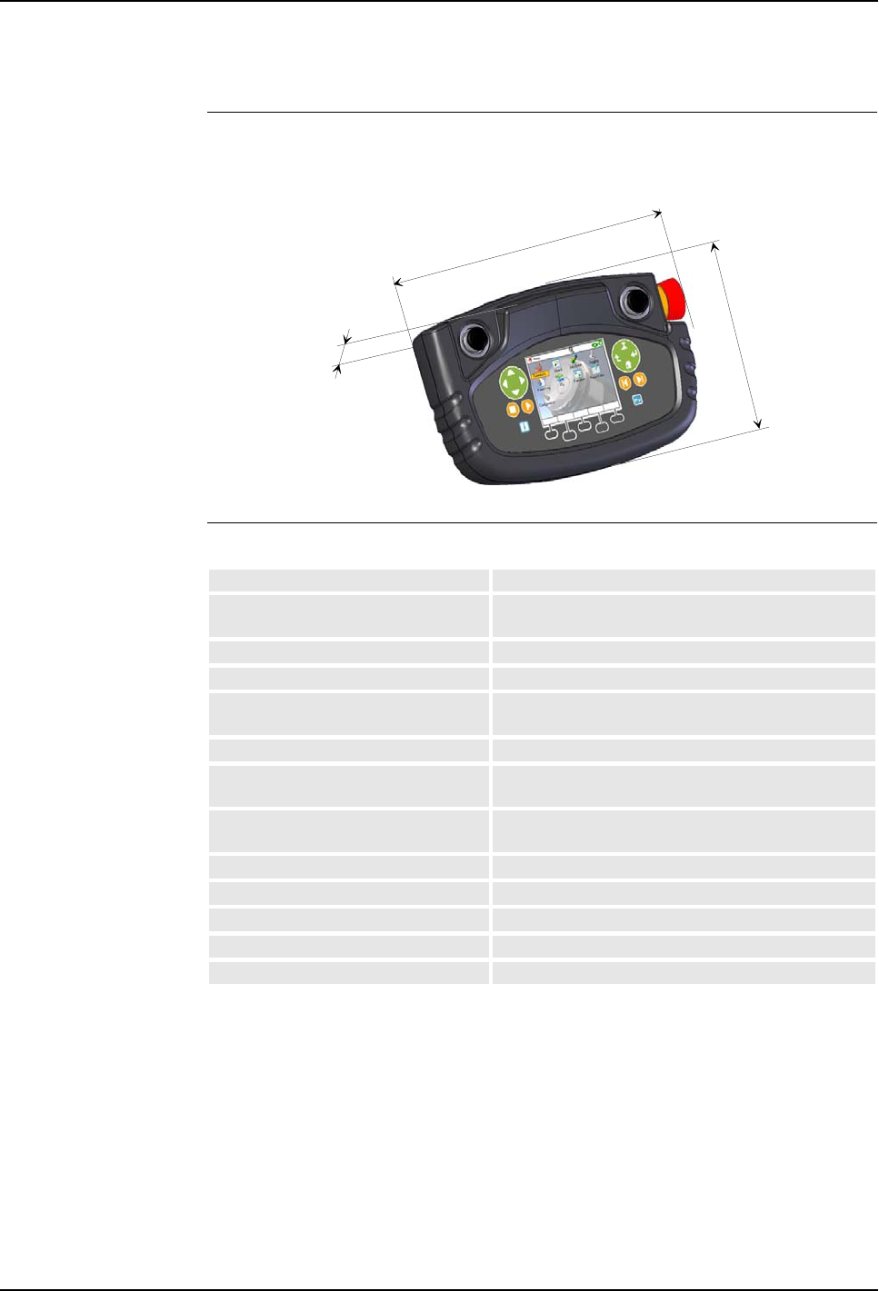
Dimensions Pendant dimensions are shown in the illustration below.
Figure 15 Pendant dimensions
General Specifications
235
75
145
Weight: 0.918Kg
Ex-approved Explosion protected Exi for installation in hazardous
area Zone 1 (Europe) and Division I, Class I & II.
Ingress protection degree IP54
Ambient temperature +10°C - +40°C
Display 3½ “ TFT-LCD dynamic color screen (RGB)
240 x 320 pixels, 8 - 22 vertical lines
Live handle Safety handle to enable the manipulator motion.
Emergency stop button Safety button for instantly stopping the manipulator
motion.
Thumb joysticks Two thumb operated joysticks to control the
manipulator axes.
Green key group Buttons for menu navigation.
Orange key group Buttons for manipulator motion.
Blue key group Buttons for information on the current operation.
Soft keys Buttons with functions that are indicated on the display.
Cable 10m standard

4 Technical Specifications
4.4 Purge Unit Specifications
36 3HNA009834-001 en Rev.06 Product Manual, Control Cabinet IRC5P
4.4 Purge Unit Specifications
Description The purge unit is used to supply compressed air to the manipulator when the
manipulator is installed in a hazardous area.
A special version of the purge unit, called ‘purge unit w/connector box’ is used for
trolley robots. This purge unit is described in section ’Purge Unit w/Connector Box’
on page 111.
General Specifications
Protection Gas
Air Pressure and
Consumption
Dimensions purge unit: See Figure 16
Dimensions purge unit w/connector box: See Figure 57
Purging sequence time: Depending on robot type. For information, see
manipulator identification label (‘Product Manual,
Manipulator’, System Description).
Dew point: < +2°C at 6 bar
Solid particle size: < 5 microns
Oil content < 1ppm (<1mg/m³)
Min. supply pressure: 3 bar
Air consumption during purging min. 500 NL/min.
Air consumption during maintenance 10-20 NL/min.
Air pressure purging: 3 bar
Air pressure maintenance: 0.5 - 1 bar
4 Technical Specifications
Product Manual, Control Cabinet IRC5P 3HNA009834-001 en Rev.06 37
4.4 Purge Unit Specifications
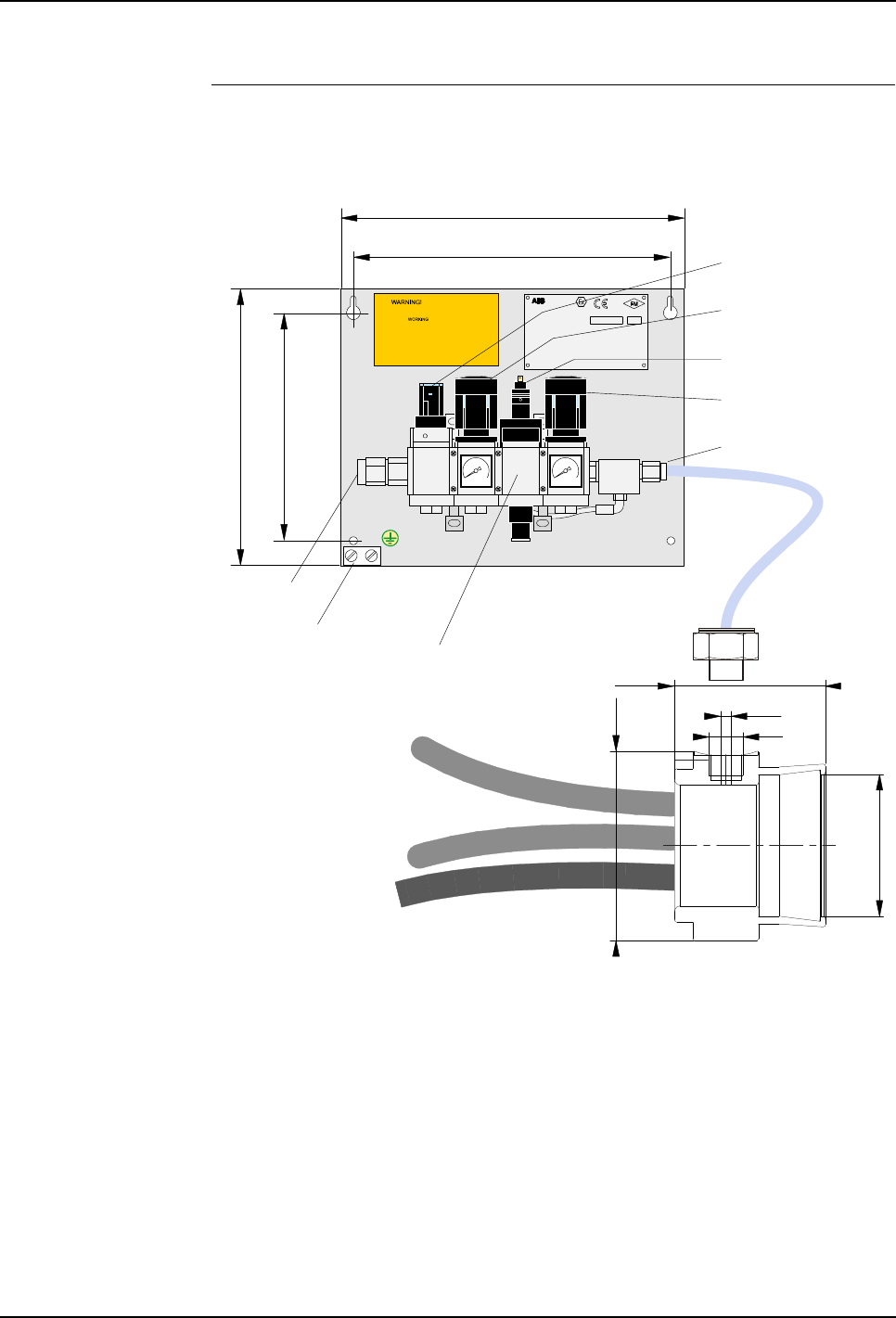
Dimensions Purge unit dimensions are shown in the illustration below. (Not applicable for
IRB 5500 slim arm and trolley robots).
Figure 16 Purge unit dimensions
Purge supply to dry filtered
air only (instrumental a ir)
Purge pressure:
Note:
3 bar (45 psi)
Maintenance pres sure: 0,5-1 bar
TURN OFF MAIN AIR-TAB BEFORE
Purge time: See machine sp ecification
PO Box 265, N-4349 B ryne
ABB AS, Robotics
0470
APPROVED
Type:PURGE CONNECTOR BOX
Dwg.No.: 3HNM 01201-1
Part of :PURGE SYSTEM Dwg.No.3HNE 06486-1
NEMKO 02ATEX189U
Protective gas :........................... Instrumental air
Purge Supply pressure :............ Min.3.0 max.5.0 bar
Maintenance Supply pressure :. Min.0.5 max.1.0 bar
Leaquage Compensation :........... 5 -20 Nl/min.
Maintenance pressure :................. Min. 0.8 mbar
Enclosure Pressure :..................... Max. 500 mbar
BatchSerial No.
INTRINSICALLY SAFE SIGNALS Cl. I.II. Div. 1 , Gr. A - G
[EEx pib] IIB
II (2) G,D
Ground clamp
PURGE VALVE ASSEMBLY
Purge control valve
connector
Purging (Flushing)
pressure regulator
Supply air
connection
Input pressure
on/off valve
Air out connection
for purge connection(s)
320
290
260
220
Purge control valve, YV1
Maintenance pressure
regulator
Purge
connection
46.7
All dimensions in mm
58.5
G 1/4"
Ø 4.1
Ø 73

5 Installation and Commissioning
Product Manual, Control Cabinet IRC5P 3HNA009834-001 en Rev.06 39
5.1 Introduction
5 Installation and Commissioning
5.1 Introduction
5.1.1 General
About this Chapter This chapter provides information and instructions for installation of the robot
controller and purge unit including interconnections to the purge unit and
manipulator.
The chapter includes information on lifting and locating the cabinet at the working
site, perform interconnection between controller and purge unit, etc. The chapter
also includes description for connecting safety systems, mains power, external I/O
functions, etc.
Important: This chapter only describes installation of the controller and associated
connections. For complete installation instructions, see also ‘Product Manual,
Manipulator’ for installation of the manipulator, ‘Unit Description, Paint’ for
connection of the paint system and ‘Operator’s Manual, IRC5P’ for starting up the
robot system.
Safety Information Before any work described in this chapter is commenced, it is extremely important
that all safety information is observed.
There are general safety aspects that must be read through, as well as more specific
safety information that describes danger and safety risks when performing the
procedures. Read the Safety Manual before performing any installation work.
WARNING! No installation work must be performed on the robot before the safety
guidelines in the Safety Manual have been read and understood. Work must only be
performed by skilled personnel with the proper training.
Welding Welding on the control cabinet, manipulator or any other components of the robot
system should be avoided as it can cause severe damage to the electronic
components in the system. If welding can not be avoided, ‘Welding Safety
Precautions’ found under ‘Safety Risks Related to Installation’ in the ‘Safety
Manual’ must be read before any welding activities are started.
Purge Unit Installation of the purge unit is described in this manual since the description is the
same for all robot models.
Non-ex Robot The following description applies for the explosion proof version of the robot
(ex-version). Non-ex robots come without purge unit. Connections to the purge unit
can be disregarded. The cable from the manipulator is to be routed to the control

5 Installation and Commissioning
5.1 Introduction
40 3HNA009834-001 en Rev.06 Product Manual, Control Cabinet IRC5P
cabinet instead of the purge unit as described in the guidelines. The points in spray
booth safety concerning explosion hazards can be disregarded for the non-ex robot.
Utility Need Following utilities will be required for the installation and operation of the robot and
paint equipment.
– Mains power
– Compressed air for purge system (ex-robots) and paint system
– Paint supply station
Environmental
Conditions For information on environmental conditions, see ‘Safety Manual’ and ’Controller
Specifications’ on page 32.
Other Information Other information which may be needed during the installation is available on the
supplied DVD-ROM. This is information such as various manuals, circuit diagrams
and spare parts catalogue. For complete information, see README file on
DVD-ROM.
Preparing the Installation
Site Before you start the installation, it is recommended that you make necessary
drawings to establish location of manipulator, control cabinet and other components
to be installed, designing a solid mounting base for the manipulator and plan the
location of process equipment, conduits for cables and hoses etc.
Check for Damage When unpacking the robot, control cabinet and associated components, check that it
has not been damaged during transportation. If any damage is found, immediately
contact the carrier for an inspection and filing of the ‘Arrival Quality Report’, found
in the ‘Documents on Delivery’ folder. Also check that all components are correctly
delivered in accordance with the packing list attached to the shipping crate.

5 Installation and Commissioning
Product Manual, Control Cabinet IRC5P 3HNA009834-001 en Rev.06 41
5.1 Introduction
5.1.2 Installation Guidelines
General The following sections detail the main steps on how to unload, transport, install and
connect the IRC5P controller and purge unit.
Installation Procedure
#Action Reference
1Prepare for installation. What you should be aware of before starting to
install the controller is described in section
’Introduction’ on page 39.
2Remove the controller from the
shipping crate and take it to the
installation site.
How to lift and transport the controller is described
in section ’Lifting and Transporting the Controller’
on page 47.
3Install controller at the working site. How to perform physical installation of the
controller is described in section ’Cabinet Location’
on page 48.
4Install purge unit. For information on installation of the purge unit, see
’Purge Unit Installation’ on page 49.
6Perform system interconnection. How to connect the manipulator and purge unit to
the controller is described in section ’System
Interconnections’ on page 51.
7Connect IS-Ground. For information on how to connect IS-Ground, see
’IS-Ground Connection’ on page 59.
8Connect safety system for
production or test.
How to perform required connections for the safety
system is described in ’Robot Safety System
Connections’ on page 64.
9Perform cabin safety system
connections.
How to perform required connections for the cabin
safety system is described in ’Cabin Safety System
Connections’ on page 78.
10 Install conveyor encoder and sync
switch for conveyor tracking.
’Encoder and Sync Switch Installation’ on page 86.
11 Perform optional external system
connections as required.
’Digital I/O Connection’ on page 98.
’Remote Panel Connections’ on page 99.
’External Connection’ on page 104.
12 Perform Field Bus connections as
required.
For information, see ‘Unit Description, IRC5P’,
Distributed I/O.
13 Connect mains power. For information on mains power connection, see
’Power Connections’ on page 114.
14 Install cooler if supplied. For information on installation of optional cooler,
see ’Cabinet Cooler Installation’ on page 105.
15 Conclude installation. ’Concluding Activities’ on page 122.
5 Installation and Commissioning
5.1 Introduction
42 3HNA009834-001 en Rev.06 Product Manual, Control Cabinet IRC5P
5.1.3 Controller Connections Overview
Description The following illustration and table show the connectors and terminal boards for
user connections in the control cabinet and reference to where in the manual the
connections are described.
Figure 17 Control cabinet, location of connections
Drive system 04
X20X21
X4
X12 X13 X10
X6
X7
X11
X14
X15
X16
X17
X18
X23
X2
X3
X5
X25
X24
X9 X8
X1
SCB-01
X5 X6 X2 X 1
X3 X13 X4
X8 X9 X10
X11
X12
X7
X5 X6 X2 X1
X3 X13 X4
X8 X9 X10
X11
X12
X7
X8X7X6
X5
X4
X21
X26
X27
X14
X15
X13
X12
X25
X10
X9
X11
X3
X16
X17
X18
X24
X23
X22
X1 X2
MIB-01
X19
X20
X18
X8X7X6
X5X4
X21
X26
X27
X14
X15
X13
X12
X25
X10
X9
X11
X3
X16
X17
X24
X23
X22
X1 X2
X19
X20
X18
MIB-01
SIB-01
X5
X1X10
X15X16
X17
X6
SIB-01
PIB-01
PIB-01
BCPU
SDI-03
Reserved for internal use
X1, X11, X14 - Debugging
and progr amming c onn.
(for i nternal us e)
MS
Status
X3X5
X2
X6
SERVO DRIVE INTERFAC E
SDI-03 ABB AS, Robotics
Right side wall
1
2
3
5
6
8
9
10
11 12
19
20
21
4
7
22
1
13
14
15
16
17
18

5 Installation and Commissioning
Product Manual, Control Cabinet IRC5P 3HNA009834-001 en Rev.06 43
5.1 Introduction
#Conn. Connection Reference
1X11 Drive unit axis 1 ’System Interconnections’ on page 51
X12 Drive unit axis 2 ’System Interconnections’ on page 51
X13 Drive unit axis 3 ’System Interconnections’ on page 51
X14 Drive unit axis 4 ’System Interconnections’ on page 51
X15 Drive unit axis 5 ’System Interconnections’ on page 51
X16 Drive unit axis 6 ’System Interconnections’ on page 51
2X2 Drive unit axis 7 ’System Interconnections’ on page 51
3X11, X12,
X111, X211
Manipulator & non I-Drive pump
motor power
’System Interconnections’ on page 51
’Connectors’ on page 61
4KA110 CBS Purge relay for CBS with
IRB 5500
’System Interconnections’ on page 51
5XT1 Transformer wiring ’Transformer Wiring’ on page 117
6Optional Systems ‘Unit Description, IRC5P, Distributed I/O.’
7XT5 Optional servo disconnect
terminal
’Servo Disconnect’ on page 109
8FR1 Mains power connection ’Mains Power Connection’ on page 115
XT1.1 External 115/230 VAC connection ’Supply for Internal Light’ on page 118
9Cable inlet ’System Interconnections’ on page 51
10 X20 Pendant connection ’Pendant Connection’ on page 103
11 Optional internal light ’Supply for Internal Light’ on page 118
12 Door switch ’Supply for Internal Light’ on page 118 and
’Cabinet Cooler Installation’ on page 105
13 PDB-X18 External 24V ’24 VDC for External Use’ on page 120
14 Optional field bus nodes ‘Unit Description, IRC5P’
15 XT65 CAN1.2 for external distributed I/O ‘Unit Description, IRC5P’, Distributed I/O
16 XT10 CAN1.1 for internal distributed I/O ‘Unit Description, IRC5P’, Distributed I/O
17 X1 Optional home position relay ’Home Position Switch’ on page 110
18 Ground rail ’IS-Ground Connection’ on page 59
19 PIB-X9 Communication pressure sensors ’System Interconnections’ on page 51
20 MIB-X21 SMU battery power ’System Interconnections’ on page 51
MIB-X22 Purge sensor ’System Interconnections’ on page 51
MIB-X23 SMU battery power ’System Interconnections’ on page 51
MIB-X24 Purge sensor ’System Interconnections’ on page 51
MIB-X4 Serial line to manipulator ’System Interconnections’ on page 51
MIB-X5 Serial line to pumps ’System Interconnections’ on page 51
MIB-X6 Purge valve ’System Interconnections’ on page 51
MIB-X7 Purge valve ’System Interconnections’ on page 51
21 SCB Safety system, Encoder etc. ’Safety Connection Board’ on page 44
22 X19 Drive unit axis 7 ’System Interconnections’ on page 51

5 Installation and Commissioning
5.1 Introduction
44 3HNA009834-001 en Rev.06 Product Manual, Control Cabinet IRC5P
5.1.4 Safety Connection Board
Connection Overview The following illustration and table show the connectors on the Safety Connection
Board, SCB.
Figure 18 Safety Connection Board, SCB
Conn. Connection Reference
SCB - X1 Emergency stop (Cat.0)
Auto mode stop (Cat.0)
Test mode stop (Cat.0)
’Robot Safety System Connections’ on page 64
SCB - X2 General mode stop (Cat.0)
Delayed stop (Cat.1)
Emy stop feedback
’Robot Safety System Connections’ on page 64
SCB - X3 Cabin interlock
System 2 interlock
Process interlock
’Cabin Safety System Connections’ on page 78
SCB - X4 Ext emy stop chain supply ’Robot Safety System Connections’ on page 64
SCB - X5 Encoder input 1 ’Encoder and Sync Switch Installation’ on page 86
SCB - X6 Encoder input 2 ’Encoder and Sync Switch Installation’ on page 86
SCB - X7 Encoder input 3 ’Encoder and Sync Switch Installation’ on page 86
SCB - X8 Remote panel connection ’Remote Panel Connections’ on page 99
SCB - X9 Remote panel connection ’Remote Panel Connections’ on page 99
SCB - X10 Remote panel connection ’Remote Panel Connections’ on page 99
SCB - X11 System connector System connection to SIB - X11
SCB - X12 System connector Panel connection to SIB - X10
SCB - X13 Emergency stop reset
High voltage interlock
’Robot Safety System Connections’ on page 64
’Cabin Safety System Connections’ on page 78
SCB-01
X5 X6 X2 X1
X3 X13 X4
X8 X9 X10
X11
X12
X7
X5 X6 X2 X1
X3 X13 X4
X8 X9 X10
X11
X12
X7
5 Installation and Commissioning
Product Manual, Control Cabinet IRC5P 3HNA009834-001 en Rev.06 45
5.1 Introduction
5.1.5 External Connection Overview
General Following external connections are available in the controller.
Figure 19 Connection overview
Safety System
Connections Connection of the robot safety system. These connections are described in section
’Robot Safety System Connections’ on page 64.
Cabin Safety
Connections Connection of the spray booth (cabin) safety systems. These connections are
described in section ’Robot Safety System Connections’ on page 64.
Remote Panel
Connections The robot may be controlled from a main panel on the controller, a remote panel or
from a PLC. Remote panel connections describe necessary connections if a remote
panel is used. Described under ’Remote Panel Connections’ on page 99.
Encoder Connections The encoder connections may be used for connection to the conveyor for the
tracking function and/or inputs from paint flow monitoring. For information on
connections, see ’Encoder and Sync Switch Installation’ on page 86.
Distributed I/O Different field bus nodes are available for connection of digital and analog I/O, field
bus nodes for communication with PLC etc. For information on connections etc, see
‘Unit Description, IRC5P’, Distributed I/O.
Ethernet Communication Ethernet can be used to connect a PC to the controller for download of robot
programs, configurations, backup etc. Ethernet can also be used for communication
between the controller and an external PC or for including one or more robots in an
Ethernet network. For information, see ’Ethernet Communication’ on page 101.
Safety System Connections
Emergency Stop
General Mode Stop
Delayed Stop
Emy Stop Chain Feedback
Emy Stop Chain Supply
Emy Stop Reset
Cabin Safety Connections
Cabin Interlock
System 2 Interlock
Process Interlock
High Voltage Interlock
Encoder Connections
Encoder 1
Encoder 2
Encoder 3
Remote Panel Connections
Emergency Stop
Motor On/Off
Emy Stop Reset
High Voltage Switch
Purge Lamp
Operating Mode Selector
Lamp Test
Safety Connection
Board, SCB
IRC5P Controller
General Purpose IO
2 Digital Inputs
2 Digital Outputs
Distributed IO
General IO Units
Process IO Units
Field Bus Units
Encoder Unit, etc.
CAN Bus
Ethernet
SPI Bus

5 Installation and Commissioning
5.2 Component Installation
46 3HNA009834-001 en Rev.06 Product Manual, Control Cabinet IRC5P
5.2 Component Installation
5.2.1 Introduction
About this Section This section provides information for installation of the control cabinet and purge
unit, and information for performing necessary system interconnections.
Following sections are available:
• Installing the control cabinet
• Installing the purge unit
• Perform system component interconnections
• IS Ground connection
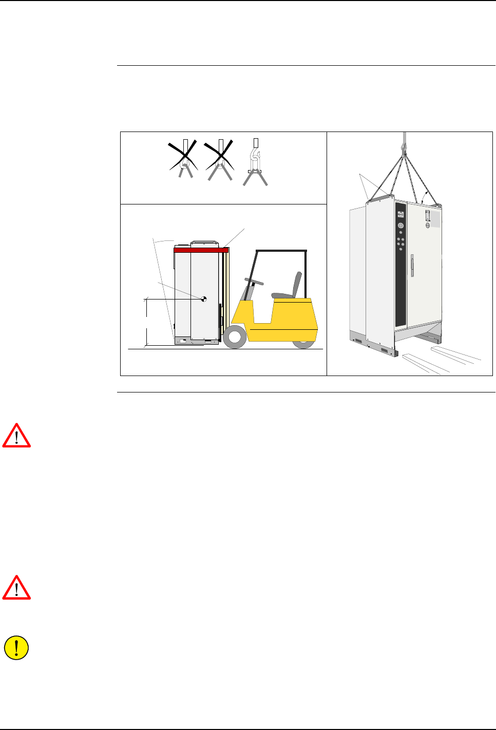
5 Installation and Commissioning
Product Manual, Control Cabinet IRC5P 3HNA009834-001 en Rev.06 47
5.2 Component Installation
5.2.2 Lifting and Transporting the Controller
General The control cabinet is shipped on a transportation pallet at an upright position.
Weight of the control cabinet is given in ’Controller Specifications’ on page 32.
Figure 20 Control cabinet lifting
Procedure This procedure describes how to lift and transport the control cabinet.
WARNING! Attach the top of the cabinet to the fork lift using a strap or similar to
prevent it from tipping over by braking etc. See Figure 20, lower left illustration.
1. After having unloaded the control cabinet crate from the lorry, use a fork lift
and transport the cabinet to the installation site or as close to the site as possible
before removing it from the pallet.
2. Unpack the supplied packages and check that the content is correct and
undamaged.
3. Place the cabinet on the floor and remove packing material.
WARNING! Do not walk under the hanging load.
4. Transport the cabinet to its permanent location using an overhead crane or fork
lift. See Figure 20, lower left and right illustration.
CAUTION! If lifting straps are used, they must be attached to all 4 lifting eyes.
For information on location of the cabinet and information on how to secure the
cabinet to the floor, etc., see ’Cabinet Location’ on page 48.
Lifting eyes
Min. 45°
Lifting by
fork lift
Max. 17.5° Safety strap
Transporting cabinet by fork lift
Lifting by
overhead crane
Lifting strap attachment to hook
Center
of gravity
Lifting the cabinet
1 meter

5 Installation and Commissioning
5.2 Component Installation
48 3HNA009834-001 en Rev.06 Product Manual, Control Cabinet IRC5P
5.2.3 Cabinet Location
General The control cabinet may be located at a convenient location outside the spray booth.
The cabinet should be placed in a manner which will provide proper cooling and
give space for entering cables via a cable conduit etc. The cables should be routed
under the cabinet from the back and entered into the cabinet via the bottom front
entrances. The cabinet should, for safety reasons, be secured to the floor using 4 e.a.
10 mm bolts. Access to the control cabinet interior is available from the front.
For information on controller dimensions, weight, footprint, etc, see ’Controller
Specifications’ on page 32.
Temperature
Requirements To meet the requirements of proper cooling, the cabinet must have a free space of
minimum 10 cm at the back and sides. This is especially important where the
ambient temperature approaches the specified maximum. For temperature higher
than specified maximum, additional cooling device is required.
For information on controller temperature range, see ’Controller Specifications’ on
page 32.
Cooler For installation of cooler, see ’Cabinet Cooler Installation’ on page 105.
Protection Standard The cabinet enclosure protects against dust, splashing water and contact with live
parts. Degree of protection rating is IP54 in accordance with EN IEC 60529 and
NEMA 12. Avoid however spraying the control cabinet with water or other liquids.
Vibration and Shock The control cabinet and its contents can withstand shocks due to the normal
transport in the workshop. If the floor on which the cabinet is to stand permanently
is subject to vibration, the cabinet should be mounted on shock-absorbing vibration
dampers.
Isolation Transformer If the plant has a history of extreme mains power transients and interference
voltages, an isolation transformer or an interference suppression device should be
installed.
5 Installation and Commissioning
Product Manual, Control Cabinet IRC5P 3HNA009834-001 en Rev.06 49
5.2 Component Installation
5.2.4 Purge Unit Installation
General The purge unit must be installed between the control cabinet and the robot to
provide compressed air inside of the robot to prevent hazardous gases from entering
into the robot interior.
The purge unit is available in a special version, called ‘Purge Unit with Connector
Box’, for use with trolley mounted robots. For installation of this purge unit, see
’Purge Unit w/Connector Box’ on page 111.
Non-ex robots may be supplied with a pressurized junction box substituting the
purge unit. The design of this box is the same as the purge unit, but it includes only
supply pressure on/off valve and maintenance pressure regulator and gauge.
Purge Unit Location The purge unit must be installed outside the hazardous area, e.g. on the cabin wall
(the cabin wall must be grounded).
The distance from the control cabinet to the purge unit and from the purge unit to
the manipulator must be planned in accordance to the length of the supplied cables.
The cables may be supplied in standard lengths or lengths specified by the customer.
It is recommended to install (locate) the purge unit preliminary and wait with
finding the final position until after the cables have been laid.
Flexible Hose Layout The flexible hose is normally laid in a cable conduit. The hose is resistant to
solvents.
CAUTION! The flexible hose must not be stretched as this will put strain on the
internal cables which can not be stretched in the same way. If the flexible hose is to
be installed in vertical direction, e.g. where the robot and purge unit are placed on
different floors, the flexible hose MUST be secured with suitable clamps at e.g.
600 mm distance to prevent the weight of the hose to apply strain to the internal
cables.
A flexible hose laying horizontally in a cable conduit does not need to be clamped.
Purge Unit Air
Connection The purge system must be connected to a clean air supply such as instrument air.
This is important to avoid internal contamination and corrosion. The air connection
must be able to supply approx. 30 m³/h during the purging sequence and 0.3 m³/h
during normal operation (maintenance pressure). The purging sequence time at
start-up is depending on the robot type as noted on the robot identification plate on
the manipulator, see ‘Product Manual, Manipulator’, System Description.
For specification of the purge air, see also ’Purge Unit Specifications’ on page 36.
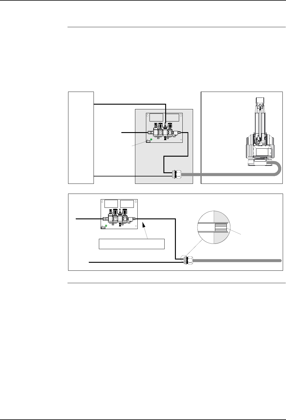
5 Installation and Commissioning
5.2 Component Installation
50 3HNA009834-001 en Rev.06 Product Manual, Control Cabinet IRC5P
Installation The purge unit consists of the purge valve assembly and a purge connection. The
purge valve assembly can be mounted on the cabin wall or at another suitable
location, and the purge connector(s) can be placed at a convenient location, either in
the cable conduit or fastened to the cabin wall etc. using a suitable clamp. For
dimensions, see ’Purge Unit Specifications’ on page 36.
Figure 21 Purge unit location and connections
Purge Air Hose
Connection The hose between the purge valve unit and purge connection must be maximum
10 meters, but can be cut to required length. If the hose needs cutting, make sure
that the end with the orifice inside the hose is not cut off. This is also marked on the
hose. The hose must not be joined in a manner which will restrict the air supply.
Spray booth
Hazardous area
Supply air
Purge unit
Control
cabinet
Flexible hose
Motor and
control signals
Purge valve
control signal
Purge valve assy'
Purge air
hose
Supply air
Flexible hose to manipulator
Motor and signal cables
Single purge connection
Purge valve unit
Purge air hose
Hose can be cut at this end
Flow reducing
orifice
Purge connection
Ground clamp

5 Installation and Commissioning
Product Manual, Control Cabinet IRC5P 3HNA009834-001 en Rev.06 51
5.3 System Interconnections
5.3 System Interconnections
General This section describes connections which apply for all robot types and
configurations.
CAUTION! Bonding connections of external electronic components must be
properly performed. - Ref: ’Bonding Information’ on page 211.
The electrical interconnections are depending on manipulator type. Connections for
the different manipulator types are described as follows:
–’Electrical Interconnections IRB 5500’ on page 52
–’Electrical Interconnections IRB 52, IRB 5400, IRB 580, IRB 540’ on page 55
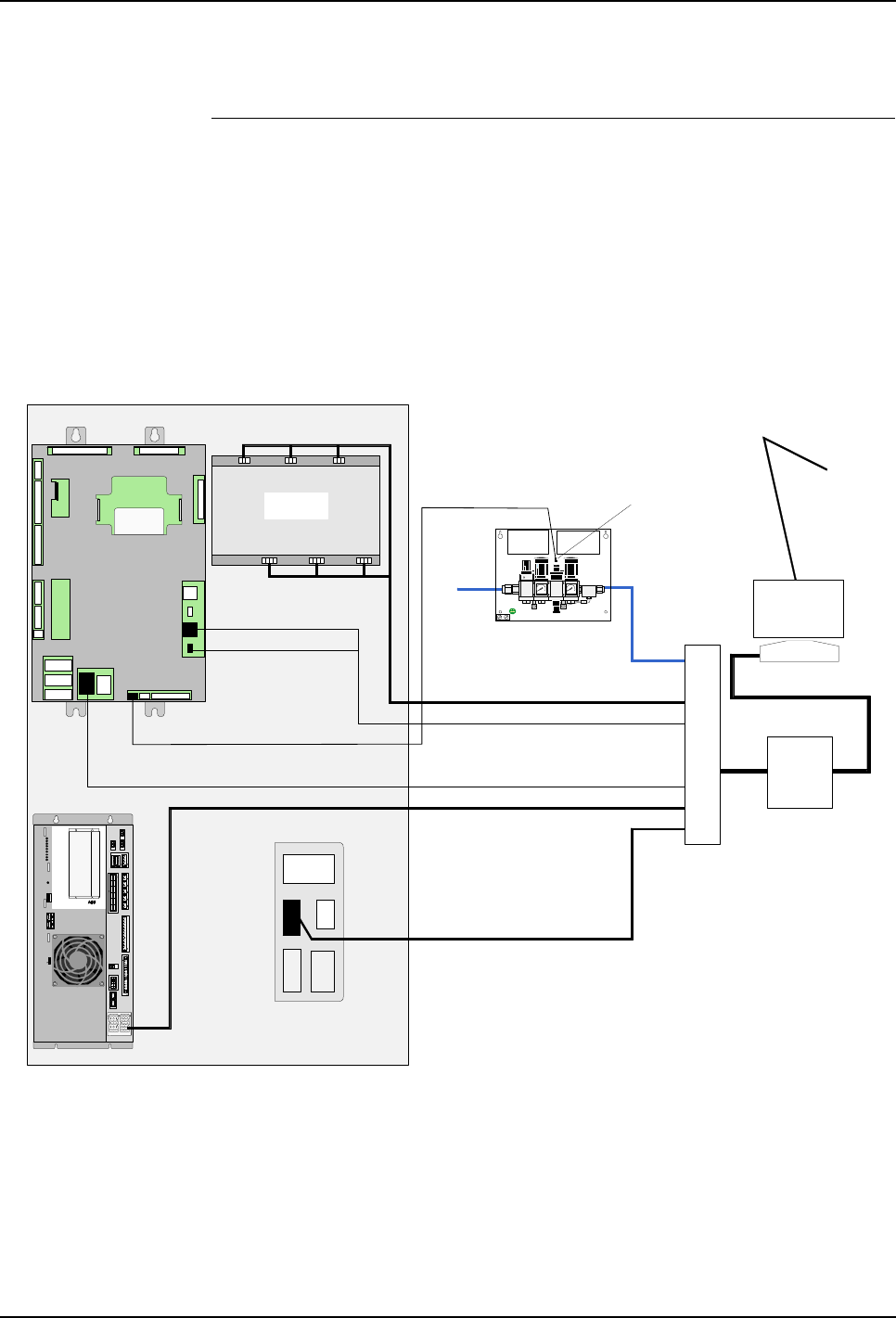
5 Installation and Commissioning
5.3 System Interconnections
52 3HNA009834-001 en Rev.06 Product Manual, Control Cabinet IRC5P
5.3.1 Electrical Interconnections IRB 5500
Procedure Perform following procedure to interconnect control cabinet, manipulator, purge
unit and if applicable pump system or CBS robot.
1. Open control cabinet front door.
2. Connect purge valve cable to connector AX1-YV1 on purge unit.
3. Route cables from purge connection unit through inlet in bottom of control
cabinet. Clamp cables to ground rail and connect as described in the following.
Figure 22 Electrical interconnections IRB 5500
4. Connect robot purge valve cable to connector MIB-X6.
5. Connect robot motor 1-6 driver cable directly to motor drivers, connector X11 -
X16.
6. Connect robot DC power cable to connector PDB-X20.
7. Connect communication robot cable to connector MIB-X4.
X20
X111
Communication robot
Purge valve
connector
AX1-YV1
Intrinsically safe signals
Purge unit
valve assembly
X6
Purge air hose
Robot DC power
Purge valve
X22
X4
MIB
Pump power
Control cabinet
*1 For non-ex process cabinet, the purge connection is
integrated in the process cabinet.
*2 Process cabinet is only applicable for IRB 5500 Slim Arm.
X21 SMU battery power
Purge sensor
Flexible hose
IRB 5500 Robot
Purge connection *1
Connector bracket on
cabinet left side wall
Air conn.
Process cabinet *2
PDB-01
X20X2 1
X17
X9
X8
X12 X 13 X1 0
X6
X7
X11
X14
X15
X1
X16
X4
X18
X23
X2
X3
X5
X25
X24
AC
TEMP
PC
SYS
I/O
FAN
BRAKE
ULTRA CAP
HV
POWER DI STRIBUTI ON BOARD
PDB ABB AS, Robotics
X12/ X13
X9
X10
X8
X17
X6
X7
X11
X14
X15
X1
X5
X2
X3
X18
X23
X16
X4
X25
X24
X21 X20
Power Distribution Board
PDB
PDB
X15
X11 X13
X16
X12
X14
Motor 1-6 driver
MDU

5 Installation and Commissioning
Product Manual, Control Cabinet IRC5P 3HNA009834-001 en Rev.06 53
5.3 System Interconnections
8. Connect robot intrinsically safe signals cable to connector MIB-X22 (purge
sensor) and X21 (SMU battery power).
9. If the robot is equipped with pumps, connect pump power cable to connector
X111.
10. If the paint robot is equipped with a CBS robot (see Figure 23):
Connect CBS purge valve cable to connector MIB-X7.
Connect CBS power cable to connector X211.
Connect CBS communication cable to connector MIB-X5.
Connect CBS intrinsically safe signals cable to connector MIB-X24 (purge
sensor) and X23 (SMU battery power).
Important: If you disconnect X21/23 (SMU battery power) after the robot has been
calibrated (revolution counter updated) you will have to re-calibrate the robot.
11. Fasten all screens to the cable inlet bracket.
CAUTION! All cables must be secured with strain relief clamps at the bottom
entrance and p-clips at connection point. - Ref: ’Clamping Cables’ on page 213.
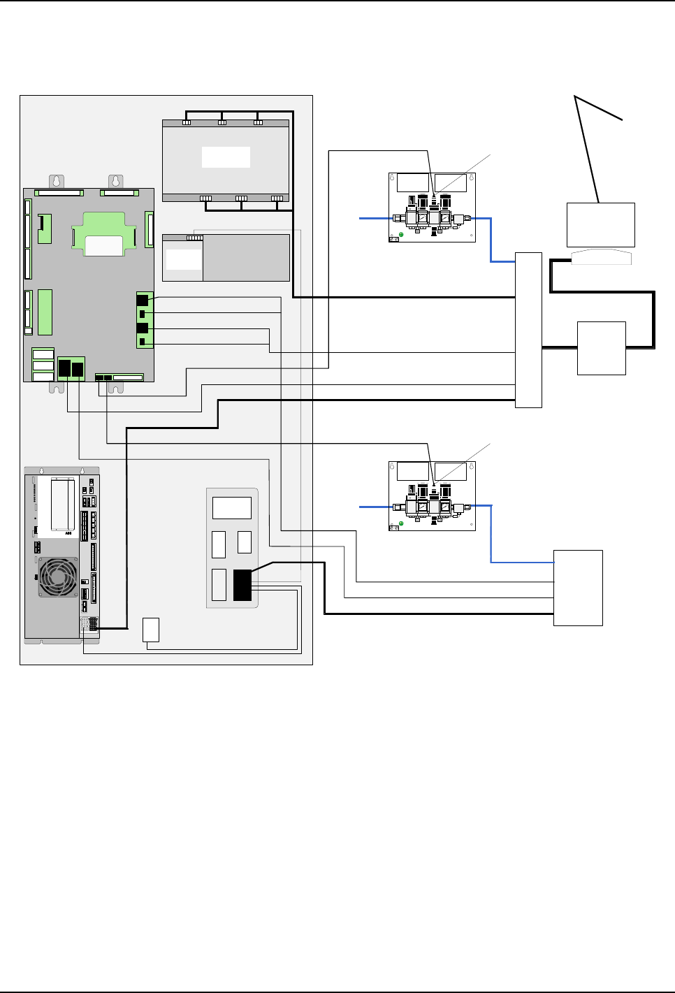
5 Installation and Commissioning
5.3 System Interconnections
54 3HNA009834-001 en Rev.06 Product Manual, Control Cabinet IRC5P
Figure 23 Electrical connections IRB 5500 with CBS robot
X20
X211
Communication robot
Purge valve
connector
AX1-YV1
Intrinsically safe signals
Purge unit
valve assembly
X6
Purge air hose
Robot power
Purge valve
X22
X4
MIB
X5
CBS power
Control cabinet
X21 SMU battery power
Purge sensor
Flexible hose
IRB 5500 Robot
Purge connection *1
Connector bracket on
cabinet left side wall
Air conn.
Process cabinet *2
PDB-01
X2 0X21
X17
X9
X8
X12 X 13 X1 0
X6
X7
X11
X14
X15
X1
X16
X4
X18
X23
X2
X3
X5
X25
X24
AC
TEMP
PC
SYS
I/O
FAN
BRAKE
ULTRA CAP
HV
POWER DISTRIBUTION BOARD
PDB ABB AS, Robotics
X12/ X13
X9
X10
X8
X17
X6
X7
X11
X14
X15
X1
X5
X2
X3
X18
X23
X16
X4
X25
X24
X21 X20
Power Distribution Board
PDB
PDB
Motor 1-6 driver
CBS Communication
CBS Robot *3
X2
(X19 Drive syst.04)
KA110
X21
ADU
Purge sensor
X24
Intrinsically safe signals
X23 SMU battery power
Purge valve
connector
AX1-YV1
Purge unit
valve assembly
Purge air hose
Purge valve
Air conn.
X7
*1 For non-ex process cabinet, the purge connection is
integrated in the process cabinet.
*2 Process cabinet is only applicable for IRB 5500 Slim Arm.
*3 Purge connection is integrated in the CBS robot.
X15
X11 X13
X16
X12
X14
MDU
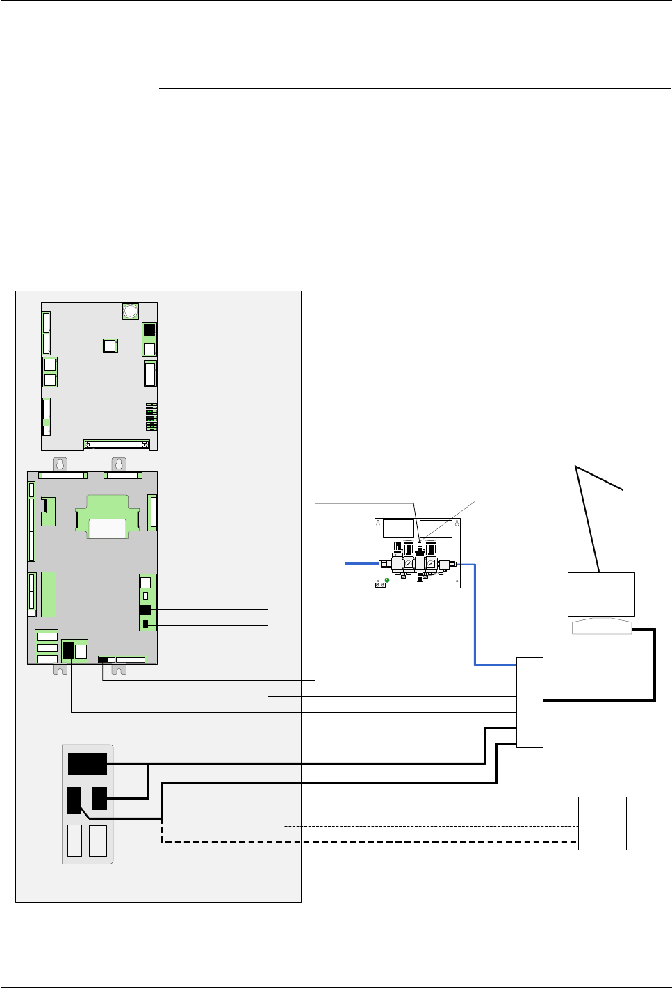
5 Installation and Commissioning
Product Manual, Control Cabinet IRC5P 3HNA009834-001 en Rev.06 55
5.3 System Interconnections
5.3.2 Electrical Interconnections IRB 52, IRB 5400, IRB 580, IRB 540
Procedure Perform following procedure to interconnect control cabinet, manipulator, purge
unit and if applicable pump system or CBS robot.
Note: If ‘purge unit w/connector box’ is used (trolley robot), connect cables from
robot in purge unit and purge sensor cable to connector AX1-X4 on purge unit as
described in ’Connecting Manipulator to Purge Unit’ on page 112.
1. Open control cabinet front door.
Figure 24 Electrical interconnections IRB 52, IRB 5400, IRB 580, IRB 540
2. Connect purge valve cable to connector AX1-YV1 on purge unit.
X12
X11
X111
Communication robot
Purge valve
connector
AX1-YV1
Intrinsically safe signals
Purge unit
valve assembly
X6
Purge air hose
Robot power
Purge valve
X22
X4
MIB
Pump power
Control cabinet
Pump power
Communication pressure sensors
*1 Connection for pumps in robot
*2 Connection for pumps in pump cabinet
X21 SMU battery power
Purge sensor
Flexible hose
Paint Robot
Purge connection
Pump cabinet
*1
*2
Connector bracket on
cabinet left side wall
Air conn.
PIB-01
Power
Ethernet 1
Ethernet 2
Ethernet 3
CAN1 MS/NS 3
CAN2 MS/NS 3
Ext SPI1
Ext SPI2
ALED SPI
X5
X7
X6
X3
X1
X11
X2
X9
X10
X12
X4
X17
X13
X15
X16
X18
BAR CODE AREA
3HNA 000000-001 NNNNNN
PIB-01
X5
X7
X6
X3
X1
X11
X2
X10
X12
X4
PIB
X9

5 Installation and Commissioning
5.3 System Interconnections
56 3HNA009834-001 en Rev.06 Product Manual, Control Cabinet IRC5P
3. Route cables from purge connection unit through inlet in bottom of control
cabinet. Clamp cables to ground rail and connect as described in the following.
4. Connect robot purge valve cable to connector MIB-X6.
5. Connect robot power cable to connector X11, X12.
6. Connect communication robot cable to connector MIB-X4.
7. Connect robot intrinsically safe signals cable to connector MIB-X22 (purge
sensor) and X21 (SMU battery power).
8. If the paint robot is equipped with pumps, connect pump power cable to
connector X111.
9. If the paint robot is equipped with a pump cabinet, connect pump power cable
to connector X111 and communication pressure sensors cable to connector
PIB-X9.
10. If the paint robot is equipped with an inline CBS robot (see Figure 25):
Connect CBS power cable to connector X211.
11. If the paint robot is equipped with a non-inline CBS robot (see Figure 26):
Connect CBS purge valve cable to connector MIB-X7.
Connect CBS power cable to connector X211.
Connect CBS communication cable to connector MIB-X5.
Connect CBS intrinsically safe signals cable to connector MIB-X24 (purge
sensor) and X23 (SMU battery power).
Important: If you disconnect X21/23 (SMU battery power) after the robot has been
calibrated (revolution counter updated) you will have to re-calibrate the robot.
12. Fasten all screens to the cable inlet bracket.
CAUTION! All cables must be secured with strain relief clamps at the bottom
entrance and p-clips at connection point. - Ref: ’Clamping Cables’ on page 213.
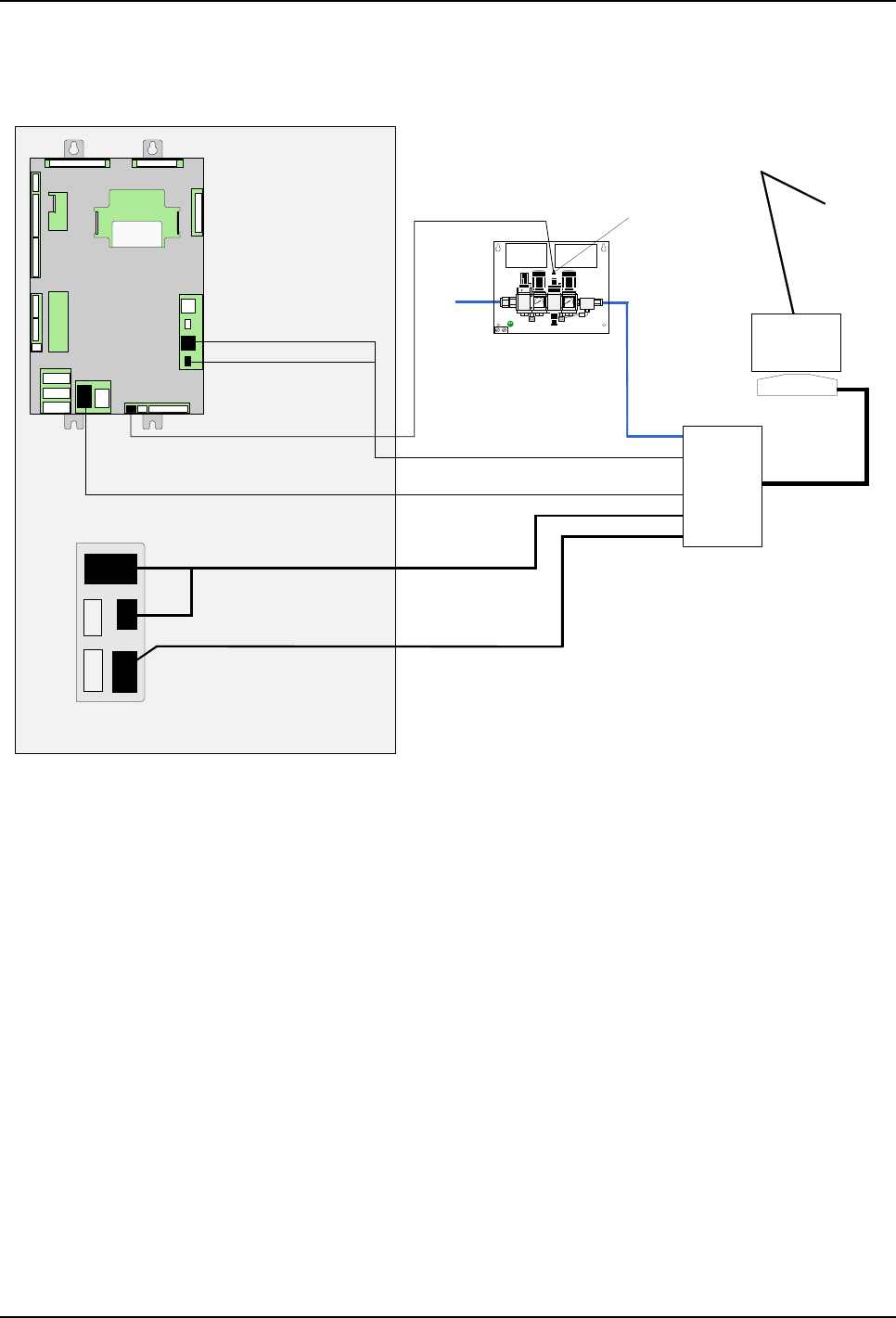
5 Installation and Commissioning
Product Manual, Control Cabinet IRC5P 3HNA009834-001 en Rev.06 57
5.3 System Interconnections
Figure 25 Electrical connections IRB 5400 with inline CBS robot
X12
X11
Communication robot + CBS
Purge valve
connector
AX1-YV1
Intrinsically safe signals
Purge unit
valve assembly
X6
Purge air hose
Robot power
Purge valve
X22
X4
MIB
Control cabinet
X21 SMU battery power
Purge sensor
Flexible hose
Paint Robot
Purge connection is integrated
in the CBS robot
Connector bracket on
cabinet left side wall
Air conn.
X211
CBS power
CBS Robot
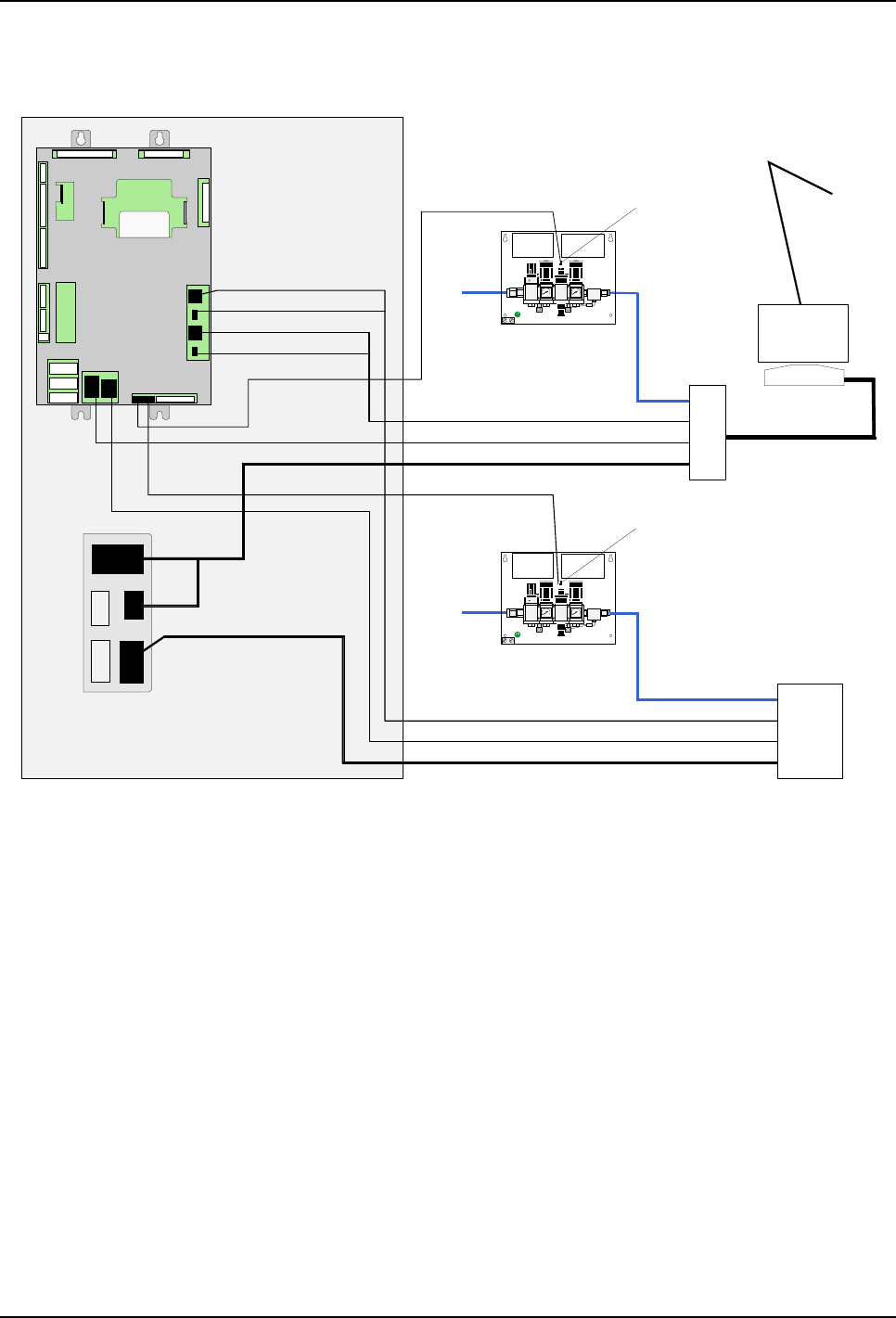
5 Installation and Commissioning
5.3 System Interconnections
58 3HNA009834-001 en Rev.06 Product Manual, Control Cabinet IRC5P
Figure 26 Electrical connections IRB 5400 with non-inline CBS robot
X12
X11
Communication robot
Purge valve
connector
AX1-YV1
Intrinsically safe signals
Purge unit
valve assembly
X6
Purge air hose
Robot power
Purge valve
X22
X4
MIB
X5
Control cabinet
X21 SMU battery power
Purge sensor
Flexible hose
Paint Robot
Purge connection
Connector bracket on
cabinet left side wall
Air conn.
X211
CBS power
CBS Communication
CBS Robot
Purge sensor
X24
Intrinsically safe signals
X23 SMU battery power
Purge connection is integrated
in the CBS robot
X7
Purge valve
connector
AX1-YV1
Purge unit
valve assembly
Purge air hose
Purge valve
Air conn.
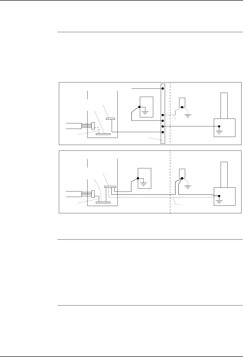
5 Installation and Commissioning
Product Manual, Control Cabinet IRC5P 3HNA009834-001 en Rev.06 59
5.3 System Interconnections
5.3.3 IS-Ground Connection
Description In an ex-installation using paint equipment, it is important that IS-ground
connections (Intrinsically Safe Ground) are installed. The connections must be
performed according to local standards, and following two examples must be
regarded as guidelines only.
Figure 27 Ground connections, factory PE-ground
For location of rails, see ’Controller Connections Overview’ on page 42.
Alternative A If a separate IS ground rail, connected to the factory IS-ground is available. Connect
an IS-ground wire of minimum 10mm² (AWG 6) between:
– Control cabinet IS-ground rail - factory IS-ground rail.
– Purge unit IS-ground screw - factory IS-ground rail
– Manipulator IS-ground screw - factory IS-ground rail.
– Remove connection in control cabinet between PE-ground rail and IS-ground
rail (Yellow/green wire marked blue).
Alternative B If a separate IS ground rail, connected to the factory IS-ground is not available.
Connect an IS-ground wire of minimum 10mm² (AWG 6) between IS-ground
screws as follows:
– Manipulator - purge unit - controller.
– Or alternatively, manipulator - controller and purge unit - controller.
Purge unit
Factory IS
ground rail
Hazardous area
Manipulator
Purge unit
Factory IS ground conn.
ALTERNATIVE B
PE-Ground rail
Control cabinet
Hazardous area
Manipulator
Factory mains
ALTERNATIVE A
PE-Ground rail
Control cabinet
IS-Ground rail
Factory
PE ground
Factory
PE ground
Factory mains
IS-Ground rail
External pendant
connection
Alternative
connection
Optional connection
External pendant
connection

5 Installation and Commissioning
5.3 System Interconnections
60 3HNA009834-001 en Rev.06 Product Manual, Control Cabinet IRC5P
Notes If the optional external pendant connection is used, the connector is grounded via a
ground wire in the cable. If required, an additional ground wire can be installed as
shown in Figure 27.
The PE-ground rail in the control cabinet is connected to the factory PE-ground by
means of the ground wire in the mains supply cable.
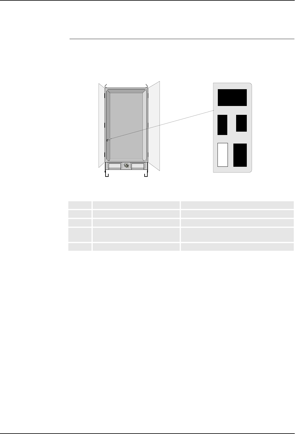
5 Installation and Commissioning
Product Manual, Control Cabinet IRC5P 3HNA009834-001 en Rev.06 61
5.3 System Interconnections
5.3.4 Connectors
Connector Overview This section shows the location of the connectors on connector brackets in the
control cabinet side wall.
Figure 28 Location of connectors
Identification of the signals in the above connectors can be found on the following
pages.
Conn. Description Comment
X11 Motor power for manipulator Standard connector (Not used for IRB 5500)
X12 +24VDC for manipulator Standard connector (Not used for IRB 5500)
X111 Paint pumps in manipulator / pump
cabinet or 8th axis connector
Optional connector
X211 CBS robot Optional connector
X211
X12
X11
Spare
X111
Connector bracket - top view
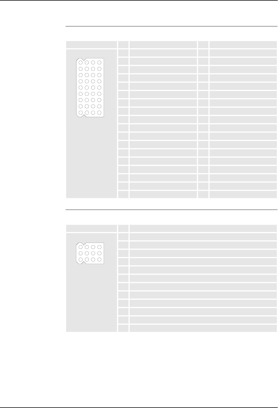
5 Installation and Commissioning
5.3 System Interconnections
62 3HNA009834-001 en Rev.06 Product Manual, Control Cabinet IRC5P
X11 Motor Power for Manipulator
X12 +24VDC for Manipulator
Connector #Signal name #Signal name
1M1-U1 19 M4-U
2M1-U2 20 M4-V
3M1-V1 21 M4-W
4M1-V2 22 M5-U
5M1-W1 23 M5-V
6M1-W2 24 M5-W
7M2-U1 25 M6-U
8M2-U2 26 M6-V
9M2-V1 27 M6-W
10 M2-V2 28 M7-U1
11 M2-W1 29 M7-U2
12 M2-W2 30 M7-V1
13 M3-U1 31 M7-V2
14 M3-U2 32 M7-W1
15 M3-V1 33 M7-W2
16 M3-V2 34
17 M3-W1 35 PE
18 M3-W2 36 PE
28
9
1
36
Connector #Signal name
1+24V Power MCOB
2+24V Power brake
3+24V Brake release emy. ext.
40V Brake release emy. ext.
50V Power MCOB
6+24V Power function
70V Power function
8Manipulator enable
9+24V High voltage controller supply
10 0V High voltage controller supply
11 SMU +24V SYS
12 SMU 0V SYS
101
312

5 Installation and Commissioning
Product Manual, Control Cabinet IRC5P 3HNA009834-001 en Rev.06 63
5.3 System Interconnections
X111 Paint Pumps in Manipulator / Pump Cabinet or 8th Axis
X211 CBS Robot
Connector #Signal name #Signal name
1PM1-U / M8-U1 8
2PM1-V / M8-U2 9
3PM1-W / M8-V1 10
4PM2-U / M8-V2 11
5PM2-V / M8-W1 12
6PM2-W / M8-W2 13
714
815 PE
1
3
13
15
Connector #Signal name #Signal name
1M1 U AXIS 1 13 POWER BRAKE RELEASE
EMY EXT.
2M1 V AXIS 1 14 GND
3M1 W AXIS 1 15 GND
4M2 U AXIS 2 16 POWER FUCTION
5M2 V AXIS 2 17 POWER SAFETY
6M2 W AXIS 2 18 NC
7M3 U DCU PUMP MOTOR 19 RUN CHAIN 1 OUT
8M3 V DCU PUMP MOTOR 20 RUN CHAIN 2 OUT
9M3 W DCU PUMP MOTOR 21 RUN CHAIN 1 IN
10 NC 22 RUN CHAIN 2 IN
11 24V POWER 23 NC
12 POWER BRAKE 24 PE
21
244
1

5 Installation and Commissioning
5.4 Robot Safety System Connections
64 3HNA009834-001 en Rev.06 Product Manual, Control Cabinet IRC5P
5.4 Robot Safety System Connections
5.4.1 Introduction
About this Section This section describes the function of the robot’s safety chains and includes
information on user connections in the chains.
All connections in the safety system are performed via connectors on the Safety
Connection Board, SCB. For location of the board, see ’Controller Connections
Overview’ on page 42.
WARNING! All connections in the safety system must be performed in accordance
with the following description.
The Safety Chains The system has 2 safety chains related to the robot as listed below.
• Emergency Stop Chain
• Run Chain
The function and connections in these chains are described in the following.
The system also has safety chains and interlock functions related to the cabin and
process equipment. These chains are described under ’Cabin Safety System
Connections’ on page 78.
Before any connections are made in the safety chains, section ’Safety System
Standards’ on page 65 must be read.
Tightening Torque All screw connections in the safety system must be tightened in accordance with
’Tightening Torques’ on page 216.
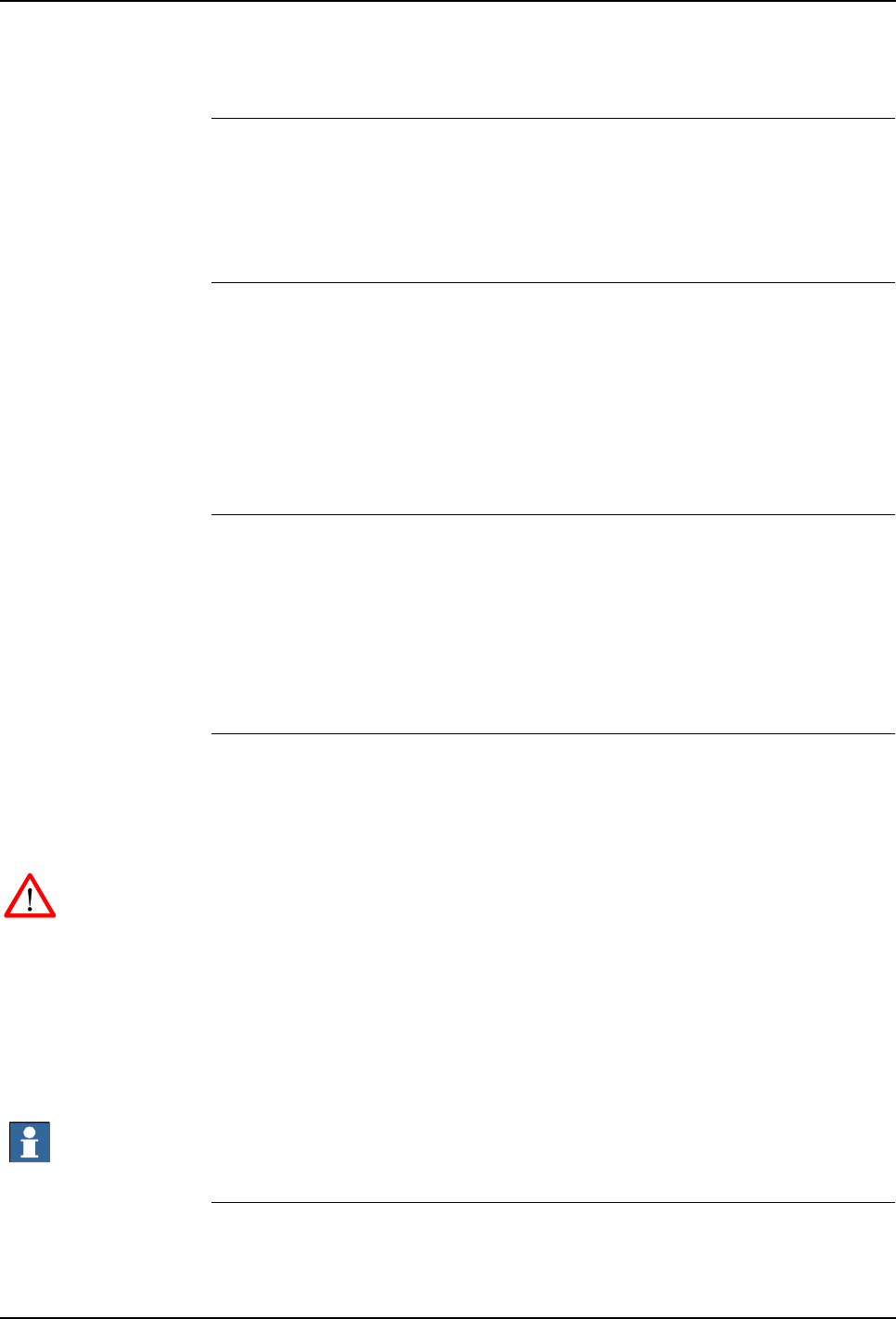
5 Installation and Commissioning
Product Manual, Control Cabinet IRC5P 3HNA009834-001 en Rev.06 65
5.4 Robot Safety System Connections
5.4.2 Safety System Standards
General Normal emergency stop standards require 2 different activities to be performed to
re-establish running mode after an emergency stop situation:
• The activated emergency stop switch must be manually released.
• Power must be re-applied to the robot’s axis motors.
The Safety Chains There are 2 safety chains in the system; the emergency stop chain and the run chain.
The Emergency Stop Chain includes the main panel emergency stop button, the
pendant emergency stop button and possibly one or more external emergency stop
buttons. All stops are category 0 stops.
The Run Chain includes auto mode stop, test mode stop, general mode stop and
delayed stop. All stops except delayed stop (category 1) are category 0 stops.
Emergency Stop Reset The emergency stop chain needs a reset signal to be applied after an emergency
stop. If the robot includes a control panel, this reset signal will be applied
automatically when pressing the Motor On button. If the panel is not available, an
external reset signal must be applied after breaking the emergency stop chain before
motor power can be re-applied.
The run chain does not require a reset signal.
Emergency Stop
Category 0 Emergency Stop Category 0 stops the robot by immediate removal of power to the
axis motors and activating the axis brakes. Different types of emergency stop
category 0 are available; External Emergency Stop, General Mode Stop and Auto
Mode Stop. Which type to use must be based on risk analyses for the installation.
WARNING! Emergency Stop Category 0 must not be used as a convenient way to
stop the robot in situations which are not emergency situations. Using emergency
stop category 0 will remove motor power and activate the axis brakes instantly,
causing unnecessary wear of the brake disks (depending on the speed of the robot
when the stop occurs).
Note: The axis brakes are primarily designed for holding the robot in position when
idle. The brakes are certified for 300 stops performed with category 0 stop before
worn to an extent where they can no longer hold the robot in position.
Important: Warranty claim will not be accepted for a damaged motor if the failure is
caused by excessively worn brake.
Emergency Stop
Category 1 Emergency Stop Category 1 is a controlled stop function which will allow the robot
control system to stop the motion of the robot while the robot is running in the
5 Installation and Commissioning
5.4 Robot Safety System Connections
66 3HNA009834-001 en Rev.06 Product Manual, Control Cabinet IRC5P
programmed path. After a category 1 stop (Delayed Stop), the robot can be re-
started and operation resumed after the cause for the emergency stop has been
removed. Stopping the robot by category 1 stop will cause the robot to stop
immediately using electrical power to brake and stop the motor speed and then
remove power and apply brakes after 2 seconds.
WARNING! Emergency stop category 1 must not be used as a convenient substitute
for emergency stop category 0 where emergency stop directly involves people
getting in contact with the robot and conveyor operation.
Stop Time The time for the robot to stop after an emergency stop category 0 are as shown in the
table below. Note that the indicated times are dependent on the weight of the
application equipment mounted on the robot.
Switch Type Connections for the emergency stop system in the robot emergency stop chain will
fulfil these requirements, provided that the correct types of switches are used. These
switches must be as follows:
• Switches used for Emergency Stop, General Mode Stop and Auto Mode Stop
must be of positive opening contact type according EN IEC 60204-1 and
EN IEC 60947-5-1. Additionally installed External Emergency Stop switch(es)
must be of a type which will be locked after operated, and re-opened by pulling /
rotating the switch knob.
• Any connections or use of switch types not complying with the description and
diagrams in this manual that will corrupt the function of the emergency stop
system will be the full responsibility of the user.
Dual Safety Chains The emergency stop-, run-, motor-, enabling device- and process (cabin interlock)
chains operate in a dual chain system, Chain 1 and Chain 2. Both chains must be
activated in order to obtain robot motion state.
Chain Monitoring The dual safety chains are monitored by software and hardware. If one of the chains
does not activate within a time T after the other chain is activated, an error will
occur. In this system, the time T is equal to 2 seconds.
Speed Stop time
500 mm/s 80 ms
1000 mm/s 100 ms
1500 mm/s 120 ms
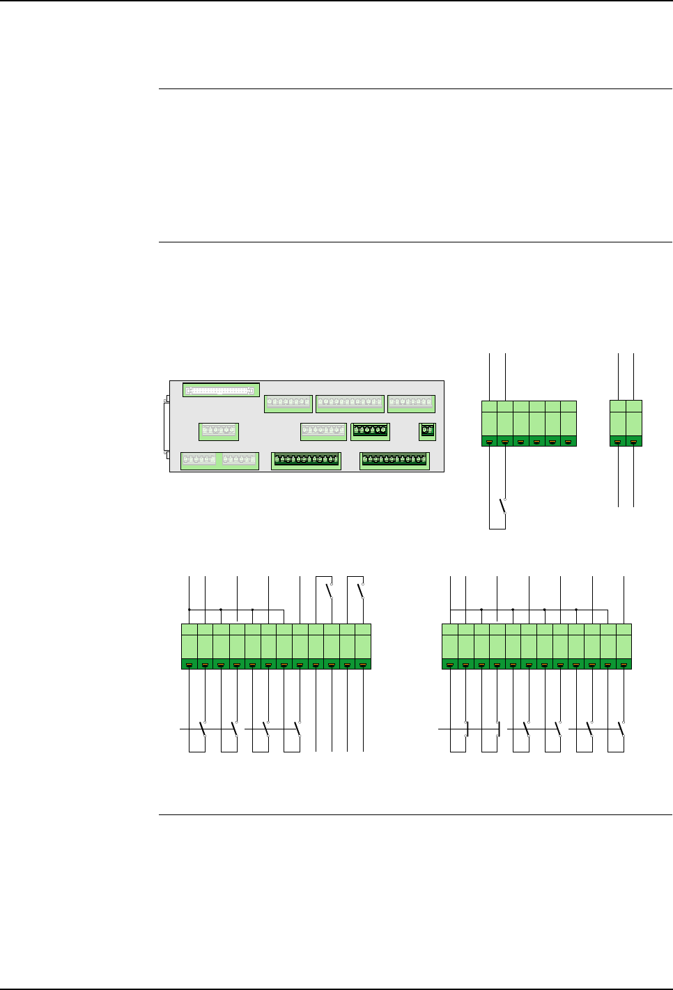
5 Installation and Commissioning
Product Manual, Control Cabinet IRC5P 3HNA009834-001 en Rev.06 67
5.4 Robot Safety System Connections
5.4.3 Safety System Connection Overview
General The following gives an overview of the connections needed for the safety system.
The connections are performed by removing links in the safety connectors and
install 2 pole switches in their place.
The safety system can also be set up for test run as described in section ’Connecting
Safety System for Test’ on page 69.
Connection Overview The illustration below shows the connections for the emergency stop chain and run
chain.
Figure 29 Safety system connections
Procedure 1. The emergency stop chain is as default connected for Internal +24VDC Supply.
If it is required to have the emergency stop chain operative when the robot is
switched ‘off’, the chain may be connected to External +24VDC Supply as
described in section ’Emergency Stop Chain Supply’ on page 70.
2. If required, install Emergency Stop Switch(es) (Category 0) in addition to the
Emergency Stop Switches on the main panel and pendant. For information, see
1 2 3 4 5 6
1 2 3 4 5 6 7 8 9 10 11 121 2 3 4 5 6 7 8 9 10 11 12
X4
+24V_EMY
X5 X6 X2 X1
X3 X13 X4
X8 X9 X10
X11
X12
X7 SCB-01
EXT_TMS1
EXT_TMS2
EXT_ES1
EXT_ES2
EXT_AMS1
EXT_AMS2
Emergency
Stop (Cat.0) Test Mode
Stop (Cat.0)
Auto Mode
Stop (Cat.0)
EXT_GMS1
EXT_GMS2
EXT_DS1
EXT_DS2
KA11
KA15
+24VDC
+24VDC
Ch1
Ch2
Ch1
Ch2
Ch1
Ch2
X2 X1
Ext Emy Stop
Chain Supply
X13
EXT_ES_RST
+24VDC
General Mode
Stop (Cat.0) Delayed
Stop (Cat.1) Emy Stop
Feedback
Ch1
Ch2
Ch1
Ch2
Ch1
Ch2
Emy Stop Reset
GND
1 2
+24VDC
GND

5 Installation and Commissioning
5.4 Robot Safety System Connections
68 3HNA009834-001 en Rev.06 Product Manual, Control Cabinet IRC5P
section ’External Emergency Stop (Category 0)’ on page 70. This type of
emergency stop is included in the emergency stop chain and is typically used in
a simple robot installation.
The emergency stop chain can also be implemented in the plant’s emergency
stop chain. For information on this connection, see ’Emergency Stop Feedback’
on page 71.
3. Install Auto Mode Stop (Category 0) switch to prevent people from entering the
robot working area while the robot is in operation. For connection information,
see section ’Auto Mode Stop (Category 0)’ on page 73.
4. If the Robot’s emergency stop system is to be implemented in the plant’s
emergency stop system, General Mode Stop (Category 0) or Delayed Stop
(Category 1) in the Run Chain may be used instead of the ‘normal’ Emergency
Stop function. For information on this connection, see section ’General Mode
Stop (Category 0)’ on page 74, alternatively ’Delayed Stop (Category 1)’ on
page 74.
5. If required, install External Emergency Stop Reset Button(s) or connect reset
input to the plants emergency stop system controller. For information on these
connections, see section ’Emergency Stop Reset’ on page 70.
6. If required, implement an Extra Enabling Device in addition to the enabling
device on the pendant. For information, see section ’Test Mode Stop
Category 0)’ on page 75.
7. If required, install Cabin Safety Switches. These functions can be used to
disable functions such as fluid pumps, spray-gun, bell, electrostatic high
voltage etc. for safety reasons. For information on these connections, see
section ’Cabin Safety System Connections’ on page 78.
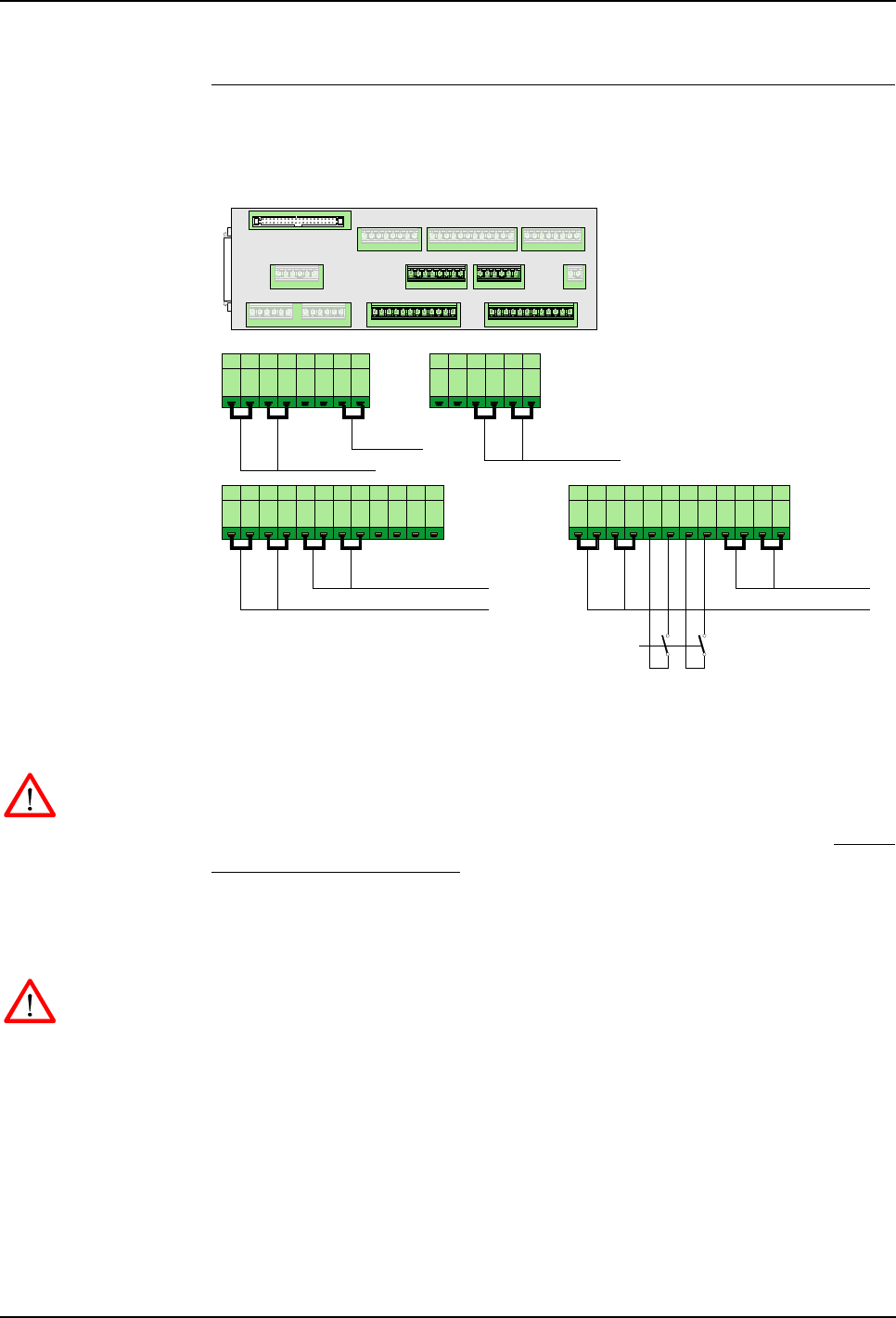
5 Installation and Commissioning
Product Manual, Control Cabinet IRC5P 3HNA009834-001 en Rev.06 69
5.4 Robot Safety System Connections
Connecting Safety
System for Test The robot may be set up for test run which is a mode where only the most essential
safety connections are performed.
Figure 30 Safety system links
To prepare the robot for this mode, jumpers have been installed for all safety chain
switches except Auto Mode Stop (Category 0) for chain 1 and chain 2.
WARNING! Running the robot for test using the links as described below must be
done in a safe manner. It is the full responsibility of the user to make sure that this is
obtained. Before setting the robot into normal operation, the safety switches MUST
BE PROPERLY INSTALLED.
1. Check that links are installed as shown in Figure 30.
2. Install a 2 pole switch for Auto Mode Stop as shown in Figure 30.
WARNING! The auto mode stop switch simulates the spray booth entrance door
interlock. The switch must be placed in conjunction with a fence etc. in such a way
that no person can get inside the working area for the robot (switch closed) without
breaking this connection (switch opened).
3. When the test period is completed, all jumpers must be removed and switches
installed in their place.
X5 X6 X2 X1
X3 X13 X4
X8 X9 X10
X11
X12
X7 SCB-01
1 2 3 4 5 6 7 8 9 10 11 121 2 3 4 5 6 7 8 9 10 11 12
X1X2
Emergency Stop (Cat.0)
Auto Mode Stop (Cat.0)
Test Mode
Stop (Cat.0)
General Mode Stop (Cat.0)
Delayed Stop (Cat.1)
Ch1 2 1 2 Ch1 2 1 2 1 2
1 2 3 4 5 61 2 3 4 5 6 7 8
X3 X13
Cabin Interlock
Ext high Voltage
Interlock
Ch1 2 Ch1 2
Process
Interlock

5 Installation and Commissioning
5.4 Robot Safety System Connections
70 3HNA009834-001 en Rev.06 Product Manual, Control Cabinet IRC5P
5.4.4 Emergency Stop Chain
General The emergency stop (emy stop) chain is a dual channel chain where all switches and
relay contacts in the chain must be closed to enable power to be applied to the axis
motors. Breaking the emergency stop chain will cause electric power to be removed
from the robot axis motors and activate the axis brakes (breaking the run chain).
Breaking the chain will also disable the paint system, switch off high voltage and
stop pump motors, etc. After having stopped the robot by breaking the emergency
stop chain, it is required that the emergency stop button is manually pulled out and
that emergency stop reset is activated before power can be re-applied to the robot.
The two chains are called Chain 1 (Ch1) and Chain 2 (Ch2).
A principle diagram of the run chain is shown in Figure 31.
Emergency Stop Chain
Supply The emergency stop chain 1 and 2 are supplied by the internal +24VDC in the
control cabinet.
The chain can also be supplied by an external +24VDC supply. The emergency stop
chain in the robot system will then be active also when the control cabinet main
switch is switched ‘off’. This function may be desired if the robot emergency stop
system is connected in the plant emergency stop system.
• External power for the emergency stop chain can be connected to connections
marked ‘Ext Emy Stop Chain Supply’ in connector SCB-X4 pin 1-2 as shown in
Figure 29 and in principle diagram in Figure 31.
External Emergency
Stop (Category 0) This is a connection where the user may implement one or more normally closed
(positive opening) switches in the robot’s emergency stop chain. This connection is
normally used in single robot installations. In more complex installations, the
General Mode Stop (category 0) or Delayed Stop (Category 1) function is normally
used. Which type to use must be based on risk analyses for the installation.
• To install Emergency Stop switch(es), remove 2 jumpers (for chain 1 and 2) and
install a 2 pole, normally closed switch at terminals marked ‘Emergency Stop’ in
connector SCB-X1 pin 1-4 as shown in Figure 29 and in principle diagram in
Figure 31. The switch must comply with ’Safety System Standards’ on page 65.
Emergency Stop Reset The emergency stop chain must be reset after the chain has been broken. To reset the
system, the cause for the emergency stop must first be removed and then a reset
signal must be applied.
An emergency stop reset signal is automatically applied when pressing the Motor
On button on the control panel, but the signal may also be applied from an external
PLC or reset switch. The emergency stop reset signal is also used to send an
acknowledge signal to various internal and external systems.
5 Installation and Commissioning
Product Manual, Control Cabinet IRC5P 3HNA009834-001 en Rev.06 71
5.4 Robot Safety System Connections
• To connect an external ‘Emergency Stop Reset’ signal, install a normally open
switch at terminals marked ‘Emergency Stop Reset’ in connector SCB-X13 pin
1-2 as shown in Figure 29 and in principle diagram in Figure 31.
Important: The emergency stop reset signal is part of the safety system and has for
this reason a time limit of max. 2.5 seconds. The length of the reset signal must for
this reason not exceed this limit. If exceeded, the enable chain will shut down.
Emergency Stop
Feedback The external emergency stop feedback connections (chain 1 and chain 2) can be
used to implement the robot’s emergency stop chains into the plant emergency stop
chain. An emergency stop in the robot can thereby be used to activate the plant
emergency stop. The relay switches to be used for this purpose are galvanically
isolated from the rest of the emergency stop chain in the robot. The switches are
closed when the robot emergency stop chains in the robot are OK.
• To include the robot’s emergency stop chain in an external chain, connect the
external chain at terminals marked ‘Emergency Stop Feedback’ (for chain 1 and
2) in connector SCB-X2 pin 9-12 as shown in Figure 29 and in principle diagram
in Figure 31. Supply voltage should be 24VDC, max 500mA. The external chain
connection must be non-capacitive.
WARNING! To avoid damage to the internal emergency stop chain in the IRC5P
controller and thereby violate the safety system, the customer must provide
individual monitoring of safety chain 1 and 2 and current limiting at 500mA in the
external chain.
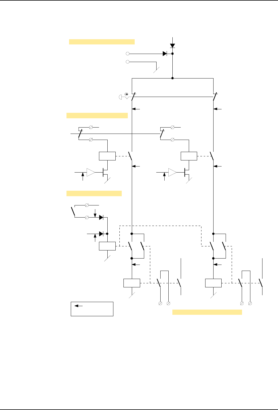
5 Installation and Commissioning
5.4 Robot Safety System Connections
72 3HNA009834-001 en Rev.06 Product Manual, Control Cabinet IRC5P
Figure 31 Two-channel emergency stop chain, principle diagram
SCB-X13:1
SCB-X13:2
24VDC
Emy stop panel
EXT_ES1
SCB-X1:1
SCB-X1:2
KA10
Pendant
emy stop
EXTERNAL EMY STOP (Cat.0)
KA12
Emy stop relays
KA1&9, KA11, KA28
Internal reset
+24VDC
Run chain 1
SCB-X2:9 SCB-X2:10
KA6&13
KA15
KA29
SCB-X2:11 SCB-X2:12
24VDC
EXT_ES2
KA14
Chain 1 Chain 2
SCB-X4:1
SCB-X4:2
EXT EMY STOP RESET
EXT EMY STOP CHAIN SUPPLY
24VDC
GND
+24VDC
SCB-X1:3
SCB-X1:4
KA11 KA15
Run chain 2
EMERGENCY STOP FEEDBACK
= Chain
monitoring points
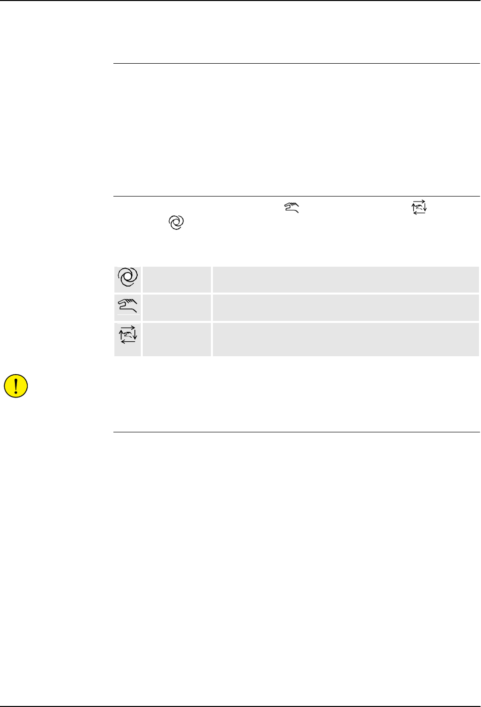
5 Installation and Commissioning
Product Manual, Control Cabinet IRC5P 3HNA009834-001 en Rev.06 73
5.4 Robot Safety System Connections
5.4.5 Run Chain
General The run chain is a dual channel chain where all switches must be closed to be able to
run the robot. Breaking the run chain will remove electric power from the robot axis
motors. By closing the run chain, power will be re-applied to the motors, and
operation can continue. The function of the run chain is depending on the position
of the Mode Selector on the main control panel. This section describes the
connections that can be made in the run chain.
A principle diagram of the run chain is shown in Figure 32.
Mode Selection Test modes, Manual Reduced Speed / - Manual High Speed / and
Automatic / mode, are operating modes selected by the mode selector key
switch on the main panel, and are part of the total safety concept for the robot
installation. The three operating modes are as follows:
CAUTION! The key in the mode selector must be brought to the operating site
together with the pendant to avoid another person from accidentally changing the
operating mode for the robot.
Auto Mode Stop
(Category 0) Operating the Auto Mode Stop function will remove power from the robot when the
mode selector is in Automatic mode. Typical use of this function is as safety switch
for the spray booth entrance door to allow for a person to enter the spray booth for
test or programming when the robot is in Manual Reduced / High Speed mode. If
the spray booth has more entrances, switches must be installed in series for all
entrances. Light grid / switches must also be installed at the conveyor entrance / exit
etc.
• To install the Auto Mode Stop switch, install a 2 pole switch at terminals marked
‘Auto Mode Stop’ (for chain 1 and 2) in connector SCB-X1 pin 5-8 as shown in
Figure 29 and in principle diagram in Figure 32. The switch must be of a type
which will be closed when activated (spray booth door closed etc.). The switch
must comply with ’Safety System Standards’ on page 65.
Note: To prevent running the robot without paying attention to the auto mode stop
switch, the robot is shipped without jumper installed in this position.
Automatic mode: Used to run the robot in production.
Manual Reduced
Speed mode:
Used for program teach and program optimizing purpose. Maximum
robot speed is restricted to 250 mm/sec.
Manual High
Speed Mode:
Used to run the program for test and program optimizing. Robot may
be running at full speed (no optimizing operations that can change the
path of the robot can be performed).

5 Installation and Commissioning
5.4 Robot Safety System Connections
74 3HNA009834-001 en Rev.06 Product Manual, Control Cabinet IRC5P
WARNING! It is the full responsibility of the user to make sure that all entrances to
the working area of the robot are protected by Auto Mode Stop switches. This is
essential to prevent personnel from entering the working area of the robot while the
robot is in operating mode (Auto).
General Mode Stop
(Category 0) Operating General Mode Stop will stop the robot and remove electric power from
the axis motors the same way as when breaking the emergency stop chain. The
difference between using the emergency stop and the general mode stop function is
that reset signal is not required to reset the stop condition. Power must be re-applied
to the axis motors by activating Motor On on the main panel or from an external
panel or PLC.
The General Mode Stop function is normally used in more complex installations
where the robot emergency stop system is integrated with the factory emergency
stop system.
• To install the General Mode Stop function, remove two jumpers (for chain 1 and
2) and install a 2 pole switch at terminals marked ‘General Mode Stop’ in
connector SCB-X2 pin 1-4 as shown in Figure 29 and in principle diagram in
Figure 32. The switch must be of a type which will be closed when activated.
The switch must comply with ’Safety System Standards’ on page 65.
Delayed Stop
(Category 1) Delayed Stop is a Category 1 stop, and is a controlled stop function which will
allow the robot control system to stop the motion of the robot while the robot is
running in the programmed path. After a category 1 stop, the robot can be re-started
and operation resumed after the cause for the stop has been removed. Stopping the
robot by category 1 stop will cause the robot to stop immediately and power to be
removed after 2 seconds.
Delayed Stop is typically used to protect entrance doors located at a distance from
the robot and conveyor or used in conjunction with plant emergency stops not
directly involving the robot operation.
WARNING! Emergency Stop Category 1 (delayed stop) must not be used as a
convenient substitute for emergency stop category 0 (general mode stop) where
emergency stop directly involves people getting in contact with the robot and
conveyor operation.
• To install the Delayed Stop function, remove two jumpers (for chain 1 and 2) and
install a 2 pole switch at terminals marked ‘Delayed Stop’ in connector SCB-X2
pin 5-8 as shown in Figure 29 and in principle diagram in Figure 32. The switch
must be of a type which will be closed when activated (spray booth door closed
etc.). The switch must comply with ’Safety System Standards’ on page 65.
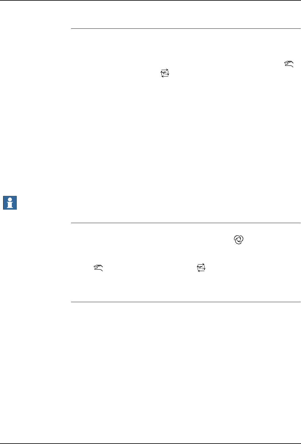
5 Installation and Commissioning
Product Manual, Control Cabinet IRC5P 3HNA009834-001 en Rev.06 75
5.4 Robot Safety System Connections
Test Mode Stop
Category 0) The test mode stop may be used to implement an enabling device in series with the
enabling device on the pendant. If used, both this enabling device and the enabling
device on the pendant must be operated to be able to apply power to the axis motors.
The enabling device function is only functioning in Manual Reduced Speed /
mode and Manual High Speed / mode. The extra enabling device may be used
as an extra safety function during programming and test. The device must be
designed in the same way as the device on the pendant, i.e. the handle must be held
in center position to be activated. Releasing the device or pressing too hard will
operate the stop function.
• To install the extra enabling device, remove two jumpers (for chain 1 and 2) and
install a 2 pole switch at terminals marked ‘Test Mode Stop’ in connector
SCB-X1 pin 9-12 as shown in Figure 29 and in principle diagram in Figure 32.
The switch must be of a type which will open when not activated (released or
pressed too hard). The switch must comply with ’Safety System Standards’ on
page 65.
The enabling device must comply with EN ISO 10218-1, 6.4.6.
Important: These connection points are not Ex protected. If used in a hazardous
area, the enabling device must fulfill the requirements for such use.
Hardware Motor On Hardware Motor-on is the signal which will apply power to the robot when all
conditions for starting the robot are correct. In Automatic / mode, the signal is
applied by pressing the motor-on button on the main control panel, but the signal
may also be applied from an external control desk or PLC etc. In Manual Reduced
Speed / mode and Manual High Speed / mode, the motor-on signal is
applied by activating the enabling device on the pendant. The power will remain
‘on’ until the enabling device is released or pressed too hard.
Software Motor On The software motor-on function is used to apply power to the robot from the
pendant or external control systems etc. As a part of the total safety concept, a
precondition for applying power by this function is that hardware motor-on has been
activated. An attempt to apply power to the robot from the pendant without having
activated the hardware motor-on will result in a warning message. Software will
always switch off this signal when hardware is not allowing motor-on.
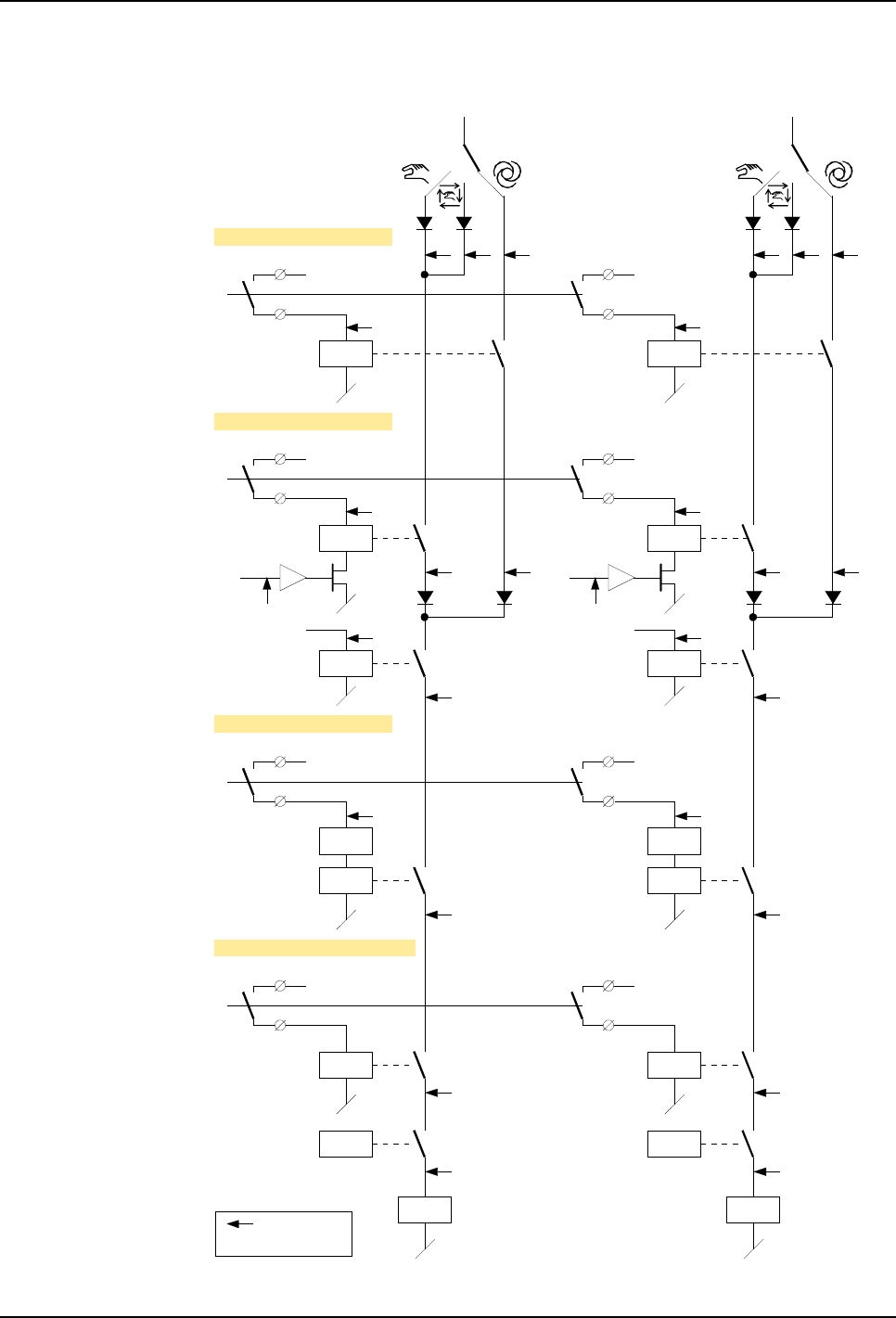
5 Installation and Commissioning
5.4 Robot Safety System Connections
76 3HNA009834-001 en Rev.06 Product Manual, Control Cabinet IRC5P
Figure 32 Two-channel run chain, principle diagram
Mode selector
+24VDC
Mode selector
+24VDC
EXT_TMS1
SCB-X1:9
SCB-X1:10
KA22
Pendant
enabling device
TEST MODE STOP (Cat.0)
+24VDC
EXT_TMS2
KA26
SCB-X1:11
SCB-X1:12
+24VDC
EXT_AMS1
SCB-X1:5
SCB-X1:6
KA18
AUTO MODE STOP (Cat.0)
+24VDC
EXT_AMS2
KA23
SCB-X1:7
SCB-X1:8
KA16 KA17
Motor on/off
+24VDC
EXT_DS1
SCB-X2:5
SCB-X2:6
KA19
DELAYED STOP (Cat.1)
+24VDC
EXT_DS2
KA24
SCB-X2:7
SCB-X2:8
+24VDC
EXT_GMS1
SCB-X2:1
SCB-X2:2
KA20
GENERAL MODE STOP (Cat.0)
+24VDC
EXT_GMS2
KA25
SCB-X2:3
SCB-X2:4
KA11 KA15
Emy stop
+24VDC
Chain 1 Chain 2
Motor control relays
DELAY DELAY
= Chain
monitoring points
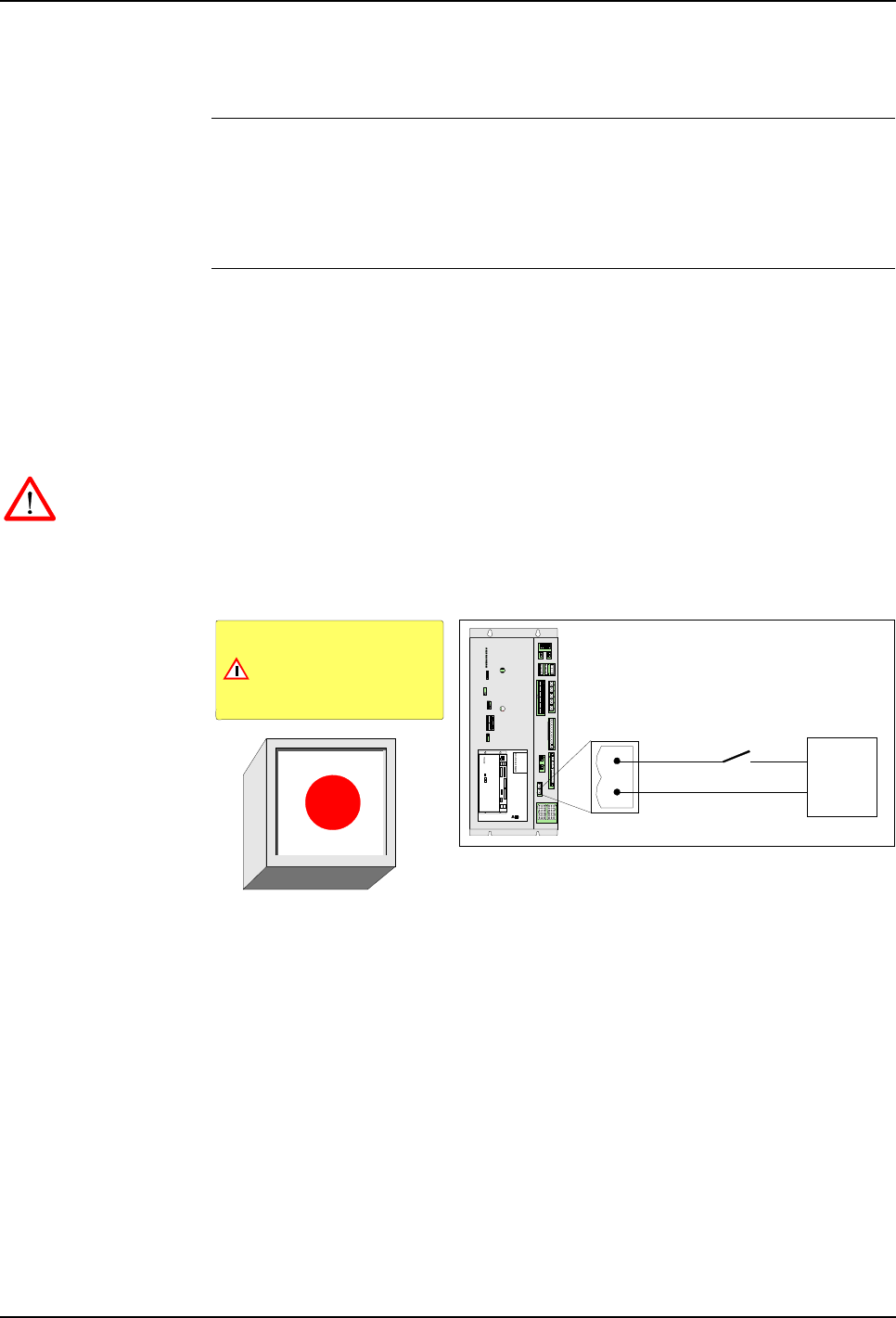
5 Installation and Commissioning
Product Manual, Control Cabinet IRC5P 3HNA009834-001 en Rev.06 77
5.4 Robot Safety System Connections
5.4.6 Emergency Brake Release Switch
General A switch may be installed to enable releasing the axis brakes for the robot in an
emergency situation. This may be a situation where a person is trapped by the robot
arm and brakes can not be released quickly by normal means, e.g. at power failure
or the pendant is not at hand.
Installation The emergency brake release switch should be a switch installed behind a breakable
glass (like a fire alarm) to prevent the switch from being used for normal brake
release purposes. The switch must be marked with a warning sign informing that
using the switch will violate the spray booth explosion safety functions.
The switch must be placed in a convenient location outside the spray booth with a
clear view of the robot.
WARNING! The emergency brake release switch will apply 24VDC to the axis
brakes even if the purge system is not active and must only be used in emergency
situations.
Figure 33 Emergency brake release switch design and connection
A 24VDC power supply, capable of supplying minimum 4 Ampere is required for
this function. If the switch is to work also by power failure, the power supply must
be battery backed.
1. Install a normally open switch and 24VDC power supply between pin 1 and 2
in connector X24 on the PDB board as shown in the figure above.
2. Install switch element inside a box with a breakable glass.
3. Make a sign similar to the one shown in the illustration and place it above or
beside the switch.
Brake glass and push switch
to release axis brakes.
Using the switch will violate the
cabin explosion safety system
WARNING
GND
+24VDC
Emergency brake
release switch
Emergency brake release switch
24VDC
power supply
X20X21
X4
X9 X8
X12 X13 X10
X6
X7
X11
X14
X15
X1
X16
X17
X18
PDB-01
X23
X2
X3
X5
X40
X25
X24
X20X21
X4
X12 X13 X10
X6
X7
X11
X14
X15
X16
X17
X18
X23
X2
X3
X5
X40
X25
X24
X9 X8
X1
X4
X9 X8
X10
X6
X7
X11
X14
X15
X1
X12 / X13
X5
X2
X3
LEDS
AC
TEMP
PC
SYS
I/O
FAN
BRAKE
ULTRA CAP
HV
LEDS PDB- 01
X18
X23
X20
X16
X17
X25
X24
X21
POWER DISTR IBUTION BO ARD
PDB-01 ABB AS, Robotic s 1
2
PDB-X24

5 Installation and Commissioning
5.5 Cabin Safety System Connections
78 3HNA009834-001 en Rev.06 Product Manual, Control Cabinet IRC5P
5.5 Cabin Safety System Connections
5.5.1 Introduction
About this Section This section describes the function of the cabin safety chains and cabin interlock
functions and includes information on user connections in the chains.
All connections in the safety system are performed via connectors on the Safety
Connection Board, SCB. For location of the board, see ’Controller Connections
Overview’ on page 42.
WARNING! All connections in the safety system must be performed in accordance
with the following description.
The Safety Chains The system has various safety chains and interlock functions related to the cabin and
the process equipment as listed below. The function and connections in these chains
are described in the following.
• Cabin Interlock
• High Voltage Interlock
• System 2 Interlock
• Process Interlock
• Emergency Shut Down Valve
The system also has 2 safety chains related to the robot which are the Emergency
Stop Chain and the Run Chain. These chains are described under ’Robot Safety
System Connections’ on page 64.
Before any connections are made in the safety chains, section ’Safety System
Standards’ on page 65 must be read.
Tightening Torque All screw connections in the safety system must be tightened in accordance with
’Tightening Torques’ on page 216.
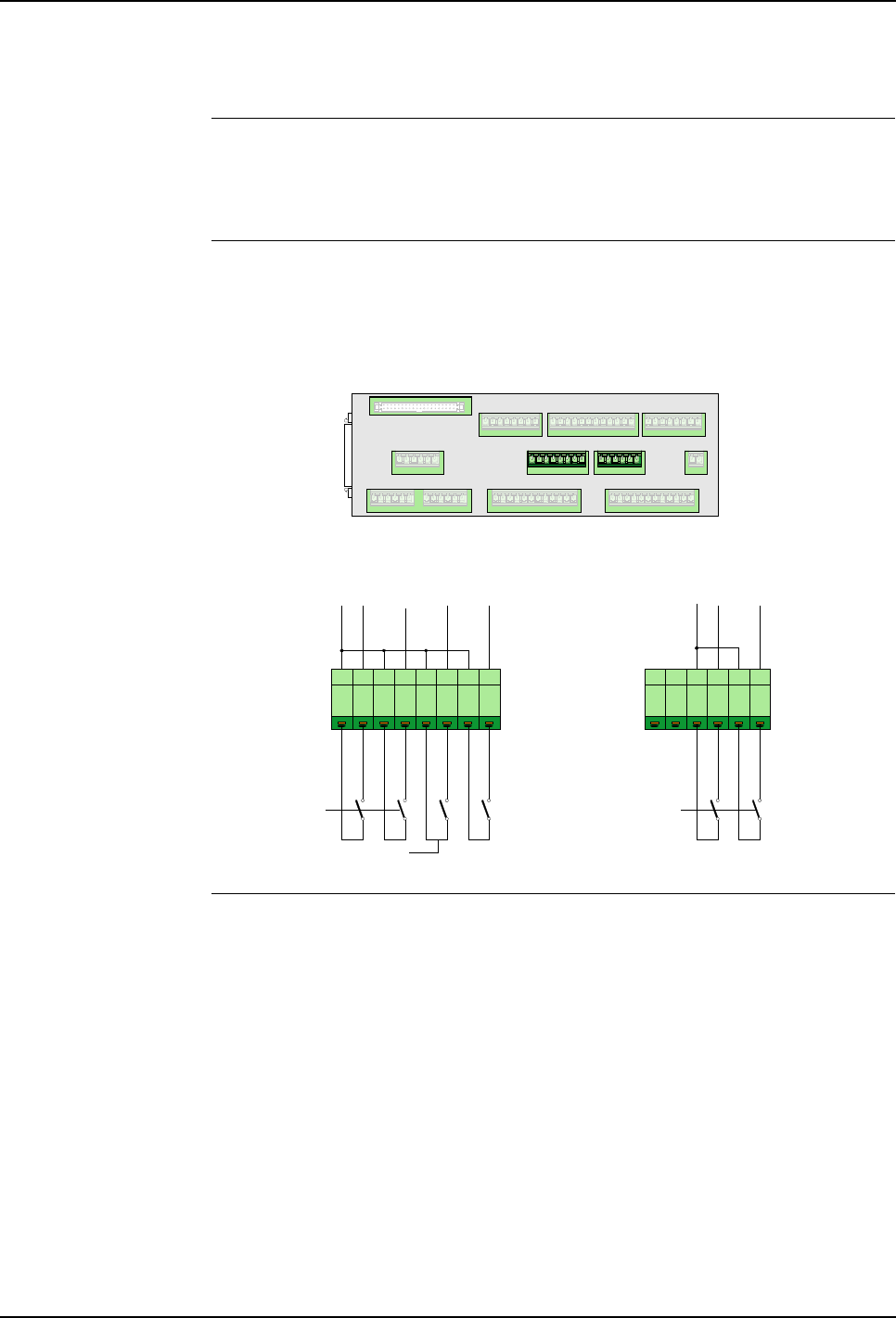
5 Installation and Commissioning
Product Manual, Control Cabinet IRC5P 3HNA009834-001 en Rev.06 79
5.5 Cabin Safety System Connections
5.5.2 Cabin Safety Connection Overview
General Cabin safety connections are a number of interlock functions which can/must be
installed to provide personnel safety and to ensure safe operation of the cabin and
robot paint systems.
Description The illustration below shows an overview of the cabin safety connections and the
procedure gives a short description of the connections which must/may be
connected with references to where complete information can be found.
Figure 34 Cabin interlock connections
Procedure 1. Connect Cabin Interlock switches in the cabin interlock chain to disable paint
functions when certain vital cabin functions are not present, like cabin
ventilation. For information, see ’Cabin Interlock’ on page 80.
2. Connect High Voltage Interlock switches on the cabin entrance door to prevent
people from entering the cabin when high voltage is ‘on’. For information, see
’High Voltage Interlock’ on page 81.
3. If required, install System 2 Interlock switch for bell applicator, paint pumps or
DCU (CBS). For information, see ’System 2 Interlock’ on page 82.
4. If required, connect Process Interlock switch for switching off all paint related
functions. For information, see ’Process Interlock’ on page 83.
5. If required, install Emergency Shut-Down valve in manipulator. For
information, see ’Emergency Shut Down Valve’ on page 85.
1 2 3 4 5 61 2 3 4 5 6 7 8
+24VDC
EXT_CAB_ILCK1
EXT_CAB_ILCK2
EXT_SYS_ILCK_IN
EXT_FIRE_ILCK
X5 X6 X2 X1
X3 X13 X4
X8 X9 X10
X11
X12
X7 SCB-01
X3 X13
EXT_HV_ILCK1
EXT_HV_ILCK2
+24VDC
High Voltage Interlock
Ch1
Ch2
Cabin
Interlock
System 2 Interlock
Process
Interlock
Ch1
Ch2

5 Installation and Commissioning
5.5 Cabin Safety System Connections
80 3HNA009834-001 en Rev.06 Product Manual, Control Cabinet IRC5P
5.5.3 Cabin Interlock
General The purpose of the cabin interlock chain is to disable paint functions which are
emitting flammable material (paint, solvent, etc.) into the cabin, if vital cabin
functions are not present, like the cabin ventilation (cabin fans), fire extinguishing
system. This is achieved by including dual switches on the cabin fan relay in the
cabin interlock chain.
Description When the cabin interlock chain is broken, +24V_FUNC will be disconnected from
the manipulator board and one of the VCD modules. Paint functions connected to
these modules (via pilot valves) will thereby be disabled. Paint functions which are
normally connected to these modules are spray-gun needle, shaping air, etc.
Paint functions connected to the other VCD modules, powered by +24V_MAN, will
not be affected by the cabin interlock chain. Typical connections to these modules
are color change, etc.
Which functions that are interlocked and not interlocked can be found in the Process
Diagram.
When breaking the cabin interlock chain, the system will use approx. 1/2 second to
make a controlled stop of the paint functions. When closing the chain, power will be
re-applied to the interlocked paint control functions, and operation can continue.
Following conditions must be present to close the cabin interlock chain.
– Cabin interlock chain must be closed. (Cabin ventilation fans must be running).
– The emergency stop- and enable chain must be closed.
– Robot must be purged (purge relay must be closed).
Installation To install the Cabin Interlock switch, install a 2 pole switch at terminals marked
‘Cabin Interlock’ (for chain 1 and 2) in connector SCB-X3 pin 1-4 as shown in
Figure 34 and in principle diagram in Figure 35. The switch must be of a Normal
Open fail safe type, which will be opened to disable paint functions.
The switch must comply with ’Safety System Standards’ on page 65.

5 Installation and Commissioning
Product Manual, Control Cabinet IRC5P 3HNA009834-001 en Rev.06 81
5.5 Cabin Safety System Connections
5.5.4 High Voltage Interlock
General The high voltage interlock chain is used to prevent personnel from entering the
cabin when the high voltage is ‘on’.
Description The personnel hazard related to the high voltage is accomplished by installing either
a manual interlock switch or a switch function controlled by the plant’s safety
supervision system, a PLC, cabin door, etc. The manual high voltage interlock
switch is typically used when the robot is supplied without main panel (or remote
panel) or if the high voltage interlock switch is not installed on the panel.
Following conditions must be present to close the high voltage interlock chain.
– High voltage interlock chain must be closed.
– Cabin interlock chain must be closed. (Cabin ventilation fans must be running).
– The emergency stop- and enable chain must be closed.
– Robot must be purged (purge relay must be closed).
Installation To install the High Voltage Interlock switch, install a 2 pole switch at terminals
marked ‘High Voltage Interlock’ (for chain 1 and 2) in connector SCB-X13 pin 3-6
as shown in Figure 34 and in principle diagram in Figure 35. The switch must be of
a Normal Open fail safe type which will be opened to switch off the high voltage.
The switch must comply with ’Safety System Standards’ on page 65.

5 Installation and Commissioning
5.5 Cabin Safety System Connections
82 3HNA009834-001 en Rev.06 Product Manual, Control Cabinet IRC5P
5.5.5 System 2 Interlock
General The System 2 Interlock chain can be used to interlock an optional system 2 and/or
bell turbine rotation.
System 2 is typically used for one of the following functions.
– Controlling paint pumps if material for the paint applicator is supplied by pumps.
– Controlling the DCU if the CBS system is used.
The system 2 interlock can also be used to interlock the bell cup rotation if the bell
applicator is used.
Description To activate the chain, following functions must be active in addition to the Manual
Pump Interlock switch:
– Cabin interlock A/B: Cabin interlock chain A and B must be closed.
– CPU pump & HW enable: Control systems are running and OK.
– Emergency stop: Emergency stop must not be activated.
– Pump fuse: Pump fuse must not have tripped.
Connections To install the System 2 Interlock switch, install a switch at terminals marked
‘System 2 Interlock’ in connector SCB-X3 pin 5-6 as shown in Figure 34 and in
principle diagram in Figure 35. The switch must be of a Normal Open fail safe type
which will be opened to disable system 2 functions.
The switch must comply with ’Safety System Standards’ on page 65.

5 Installation and Commissioning
Product Manual, Control Cabinet IRC5P 3HNA009834-001 en Rev.06 83
5.5 Cabin Safety System Connections
5.5.6 Process Interlock
General The process interlock chain is used to disable all paint related functions when the
process interlock switch is activated.
The function may be used in situations where it is required to shut down all
hazardous paint functions such as the valves controlling paint and solvent etc. (same
valves as are closed by the cabin interlock chain), the high voltage supply to the
paint applicator (same function as the high voltage interlock) and functions
controlled by the Safety 2 System Interlock.
The process interlock may be used by the plant’s control system for the cabin e.g. to
close all hazardous functions of the paint system in case of a fire etc.
Connections To install the Process Interlock switch, install a switch at terminals marked ‘Process
Interlock’ in connector SCB-X3 pin 7-8 as shown in Figure 34 and in principle
diagram in Figure 35. The switch must be of a Normal Open fail safe type which
will be opened to disable process functions.
The switch must comply with ’Safety System Standards’ on page 65.
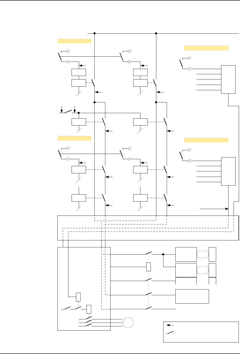
5 Installation and Commissioning
5.5 Cabin Safety System Connections
84 3HNA009834-001 en Rev.06 Product Manual, Control Cabinet IRC5P
Figure 35 Cabin Interlock chains
+24VDC
SCB-X3:1
SCB-X3:2
KA4
CABIN INTERLOCK
DELAY
+24VDC
SCB-X13:3
SCB-X13:4
KA2
HV INTERLOCK
+24VDC
KA3
Emy stop
chain 1
Manipulator Interface Board, MIB
High Voltage on/off
+24VDC
SCB-X3:3
SCB-X3:4
KA8
DELAY
SCB-X13:5
SCB-X13:6
KA5
+24VDC
KA7
Emy stop
chain 2
Cabin Interlock
Chain 1 Cabin Interlock
Chain 2
System 2
Interlock Chain
Process
Interlock Chain
High Voltage
Interlock Chain 2
High Voltage
Interlock Chain 1
+24V_IO
FUNC_PWR
Purge relay
SAFETY2_PWR
+24V_HV High Voltage
Controller, HVC
6 Cabin
interlocked
valves
8 Cabin
interlocked
valves
MCOB-02
VCD1
VCD2… General IO
controlled
valves
SAFETY1_PWR
Pump motors
DCU (CBS)
FlexShield, etc.
+24V_FUNC
+24V_MAN
Power Distribution Board, PDB
EXT_CAB_ILCK1
EXT_HV_ILCK1
EXT_CAB_ILCK2
EXT_HV_ILCK2
Purge
relay M
SYSTEM 2 INTERLOCK
SCB-X3:5
SCB-X3:6
+24VDC
EXT_SYS_ILCK_IN
HW ENABLE
SW ENABLE
PROCESS
ETC.
PROCESS INTERLOCK
SCB-X3:7
SCB-X3:8
+24VDC
EXT_PROC_ILCK
HW ENABLE
SW ENABLE
PROCESS
ETC.
= Contactors are normal closed
during operation
= Chain monitoring points
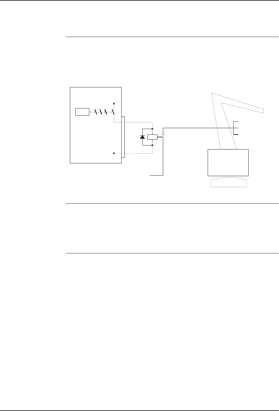
5 Installation and Commissioning
Product Manual, Control Cabinet IRC5P 3HNA009834-001 en Rev.06 85
5.5 Cabin Safety System Connections
5.5.7 Emergency Shut Down Valve
General Optionally an emergency shut down valve can be connected to the control system.
The purpose of the emergency shut down valve is to cut off all air supply to the
paint equipment on the manipulator or CBS in case of an emergency.
Figure 36 Emergency shut down valve, principle diagram
Basic Function To open the valve, following conditions must be present:
– Emergency stop must not be activated.
– Purging sequence must be completed and the robot ready for operation.
– The run chain must be closed.
Connections Install emergency shut down valve. Connect valve to terminal XT2: pin 1(+24VDC)
and 2 (GND). Install voltage suppression diode as shown in diagram above. Route
main air supply to the robot’s paint systems via the valve.
Air supply
Air distribution
Emy shut-
down valve
Control
cabinet +24VDC
0V
Mains
KM1 XT2
1
2

5 Installation and Commissioning
5.6 Encoder and Sync Switch Installation
86 3HNA009834-001 en Rev.06 Product Manual, Control Cabinet IRC5P
5.6 Encoder and Sync Switch Installation
5.6.1 Introduction
General Conveyor tracking is a function to be used when the robot is operating on objects on
a moving conveyor line. By using the tracking function, the robot programs will be
executed correctly in relation to the work object, independent on how the work
object moves on the conveyor.
To enable the tracking function, a conveyor encoder and a sync switch must be
installed on the conveyor and the robot must have been supplied with the tracking
function.
The following sections provide information on the installation and connection of the
encoder and sync switch. For information on how to enter the required data and
parameters for setting up the tracking function, see ‘Operator’s Manual, IRC5P’.
Important
Considerations To ensure good operation of the tracking function, following points must be
observed:
• The robot or robots (and trolley rail system if used) must be installed as
accurately as possible, which normally means at about +/- 0.5 mm maximum
deviation from theoretical positions.
• If robots are installed on both sides of the conveyor, the robots and rails must
also be installed symmetrically relative to the object, so that mirroring of robot
programs can be possible in the same part of the robot’s work envelopes.
• The conveyor must be able to run steadily at all speeds to avoid jerky or
swinging motions of the work objects on the conveyor.
• It must be possible to install an encoder at a location which will reflect the true
speed of the conveyor in front of the robot. This means a location as close to the
robot as practically possible.
• The distance between the encoder and the connection point for the encoder
(control cabinet) should be kept as short as practically possible to minimize the
effect of noise on the encoder signal.
• One encoder may be connected to serve more than one robot.
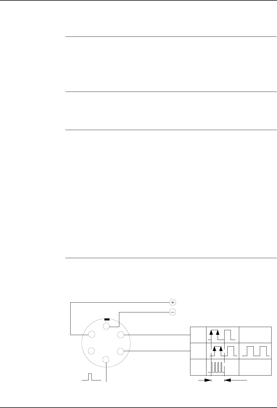
5 Installation and Commissioning
Product Manual, Control Cabinet IRC5P 3HNA009834-001 en Rev.06 87
5.6 Encoder and Sync Switch Installation
5.6.2 Encoder Specifications
General The encoder is used to inform the robot control system of the position (motion) of
the conveyor to enable the tracking function to run the robot program correctly in
relation to the work objects on the conveyor. The tracking function is obtained by
installing the encoder on the conveyor and enter the signal from the encoder to the
control system via terminals in the control cabinet.
Encoder Type The encoder must be of 2 phase type to enable registration of reverse conveyor
motion and to avoid ‘false counting’ related to vibration etc. when the conveyor is
not moving. The encoder can be PNP or NPN type.
Number of Pulses The number of pulses per meter must be selected in relation to the speed of the
conveyor and the gearing between the encoder and the conveyor. The parameter
value should be between 1250 and 5000 cycles per meter.
In the following, we use this notion: Counts = cycles = 4 * pulse transitions. The
robot motion controller uses all the pulse transitions, so that the number of
increments used will be 4 times the number of full cycles from the encoder. The
system specifies only one count per cycle in the parameter (see pulse diagram in
Figure 37). This means that the controller will read 5000 - 20000 pulses for the
encoder cycle ratio given above. Reducing the number of pulses below 5000 will
reduce the accuracy of the robot (5000 pulses/m = 0.2 mm/pulse). Increasing the
value beyond 10000 will have no significant effect as inaccuracies in robot and cell
calibration will be dominant. High values may however introduce a max. frequency
problem if long cables are used.
Recommended Encoder The recommended Lenord and Bauer encoder shown below includes connections
for supply voltage and 2 output phases with 90° phase shift. The sync pulse
connection is not used.
Figure 37 Encoder connection - Lenord & Bauer
N
(Not used)
AB
C
D
E
F
A+
B+
Encoder connector
(Mating face of connector
on encoder)
x4
2 phase
1 encoder cycle = 1 count
0°
90°
Single phase
(not used)
Internal used = 4 counts

5 Installation and Commissioning
5.6 Encoder and Sync Switch Installation
88 3HNA009834-001 en Rev.06 Product Manual, Control Cabinet IRC5P
Rotating Direction The physical rotating direction of the encoder after installation is dependent on the
design of the arrangement connecting the encoder to the conveyor. Basically, both
rotating directions can be equally used, but it is required that it counts ‘up’ when the
conveyor moves forwards and counts ‘down’ when the conveyor moves backwards.
The rotating direction of the encoder can be changed electrically by interchanging
the 2 phases (0° and 90°) of the output signals, - Ref: Figure 40.
For information on how to find encoder rotating direction, see ‘Operator’s Manual,
IRC5P’, chapter ‘Installation and Commissioning’.
Technical Specifications
* Maximum frequency is strongly dependent on cable quality and cable length.
Recommended cable is 3 pair screened cable.
Encoder Noise
Suppression The encoder must be connected using a screened cable. If this cable is long, the
inductance in the cable will produce spike pulses on the encoder signal which may,
over a period of time, damage the opto couplers in the control electronics. The spike
pulses (which can be of considerable amplitude), can be removed by installing a
capacitor between the signal wire and ground for each of the 2 phases. The
capacitors should be connected at the encoder end, not on the electronics end.
Typical capacitor value is 100 nF - 1 µF, depending on the length of the cable
(longer cable, larger capacitor). The correct capacitor can be found by viewing the
encoder signal using an oscilloscope.
Output signal: Open collector PNP or NPN output
Voltage: 10-30V (normally supplied by 24VDC from robot)
Current: Max. 10mA (for each connected robot)
Phase: 2 phase with 90 degrees phase shift
Duty cycle: 50%
Max. frequency: 40KHz *

5 Installation and Commissioning
Product Manual, Control Cabinet IRC5P 3HNA009834-001 en Rev.06 89
5.6 Encoder and Sync Switch Installation
5.6.3 Sync Switch Specifications
General The sync signal (synchronization signal, sometimes called start signal) is used to
enter the position of the work object on the conveyor into the robot control system.
The sync signal is entered by installing a sync switch on the conveyor. The sync
switch will detect each object as it passes the switch.
LEDs labelled Start 1 / 2 (Start 1 and Start 2) for sync switch 1 (and sync switch 2 if
two sync switches are installed) indicating the operation of the sync switch are
present on the control cabinet LED display.
Switch Specification The sync switch should be selected so that it provides a reliable and repeatable
signal for the work objects on the conveyor, regardless of conveyor speed. The
switch arrangement must be designed so that it only gives one signal for each work
object, and that it does not give any signal if the work object should happen to pass
the switch in backwards direction. (If the switch gives multiple signals when an
object passes, the parameter SyncFilter can be set so that only one signal is
accepted. For information, see ‘Operator’s Manual, IRC5P’).
Switch Types Different types of switching devices may be used. Most common is a limit switch,
but photocell with switch output or Namur initiator etc. may also be used.
Switch Location The sync switch may be installed in the hazardous area of the spray booth or in the
non-hazardous area outside the spray booth. Different requirements apply to the
switch and its connection to the control system in these situations. For information,
see ’Sync Switch Connection - General Information’ on page 95.
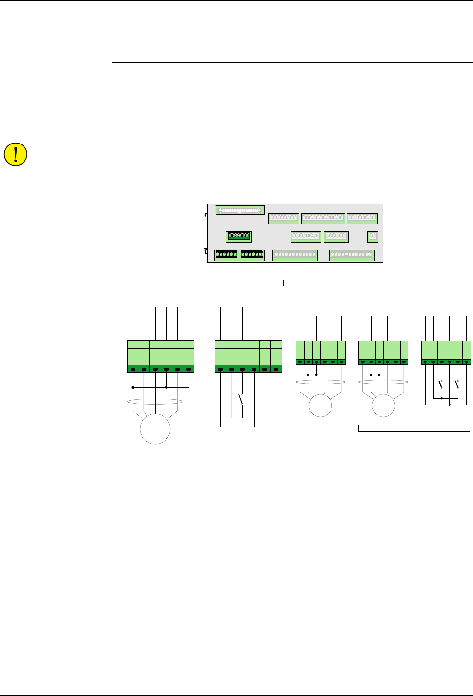
5 Installation and Commissioning
5.6 Encoder and Sync Switch Installation
90 3HNA009834-001 en Rev.06 Product Manual, Control Cabinet IRC5P
5.6.4 Connection Overview
Connector Description The illustration below shows the connections for 1, 2 or 3 encoders and sync switch.
Connections are made on the Safety Connection Board, SCB.
Connections for conveyor tracking will normally consist of one PNP encoder
connected to connector X5 and one sync switch connected to connector X7.
CAUTION! To avoid interference to encoder signals, 4 wire twisted pair screened
cables must be used for encoder connections.
Figure 38 Encoder and Sync Switch connection
Options The encoder inputs support both PNP and NPN type encoders. Optionally an NPN
encoder can be installed. Optionally connector X7 may be used for a third encoder
or for connection of a second sync switch, as shown in the illustration.
The optional components must be configured explicitly.
Note: The system supports 24VDC encoders. If RS422 encoders are used, a signal
converter such as BLE-01 must be used.
Extra encoders can be used for a second conveyor, a backup encoder, or for
monitoring of paint flow e.g. when using Küppers initiators. For more information
on monitoring paint flow, refer to the gear flow meter in the ‘Unit Description,
Paint’ manual.
X5 X6 X2 X1
X3 X13 X4
X8 X9 X10
X11
X12
X7 SCB-01
1 2 3 4 5 6
+24VDC
GND
ENC_1A+
ENC_1A-
ENC_1B+
ENC_1B-
PNP
Encoder 1
X5
1 2 3 4 5 6
+24VDC
GND
P_START_01+
P_START_01-
P_START_02+
P_START_02-
Sync Switch 1
X7
1 2 3 4 5 6
+24VDC
GND
ENC_2A+
ENC_2A-
ENC_2B+
ENC_2B-
1 2 3 4 5 6
+24VDC
GND
ENC_3A+
ENC_3A-
ENC_3B+
ENC_3B-
Encoder 3
X6 X7
NPN
1 2 3 4 5 6
+24VDC
GND
P_START_01+
P_START_01-
P_START_02+
P_START_02-
Sync Switch 1
X7
Sync Switch 2
Encoder 3 or
Sync Switch(es) connection
Encoder 2
NPN
OptionsStandard conveyor connections
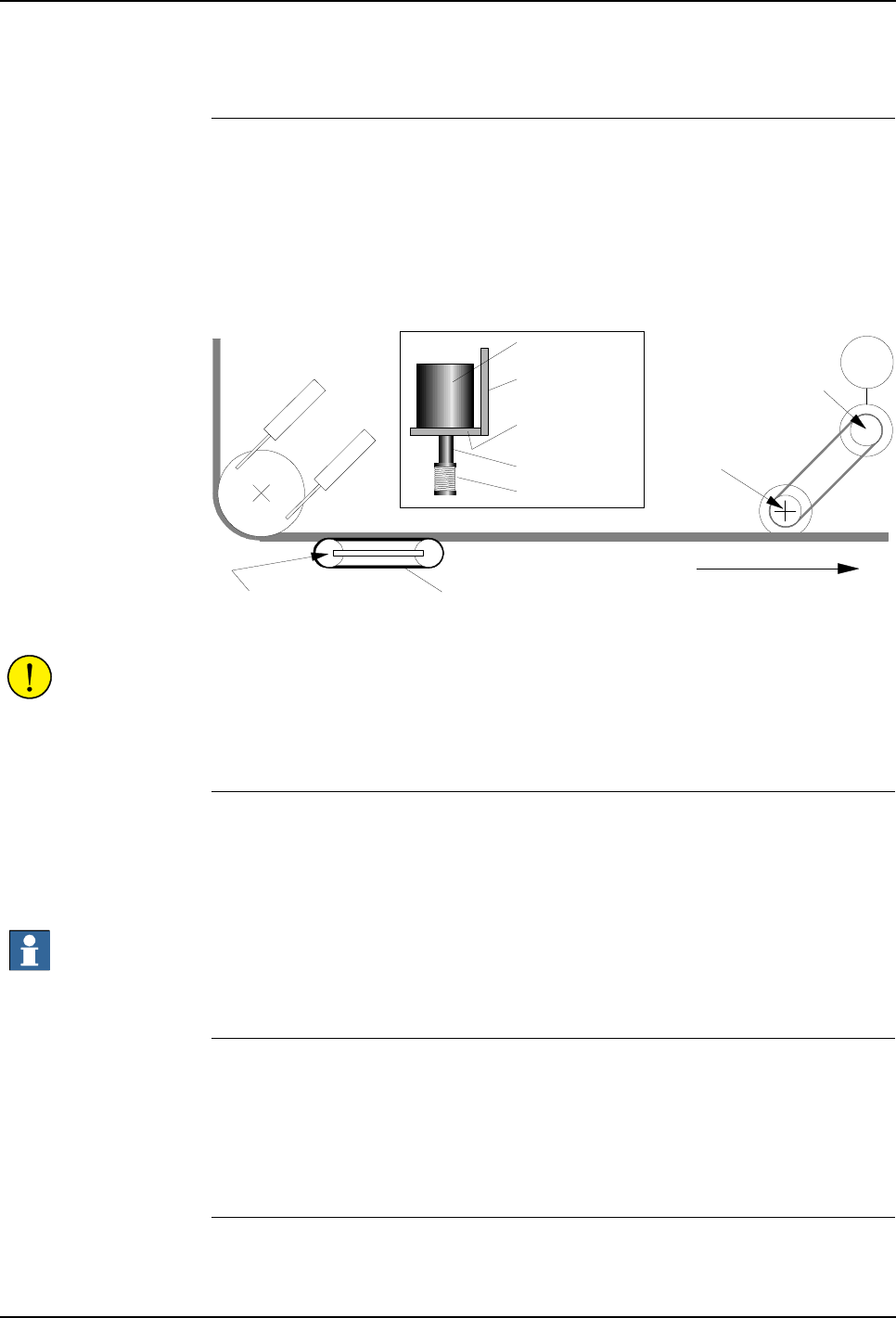
5 Installation and Commissioning
Product Manual, Control Cabinet IRC5P 3HNA009834-001 en Rev.06 91
5.6 Encoder and Sync Switch Installation
5.6.5 Encoder Installation
General The encoder must be installed in such a way that it gives a precise feedback of the
conveyor motion (reflects the true conveyor motion). This means that the encoder
should be installed as close to the robot as practically possible, typically not more
than 30 meters away, and that a good connection between the encoder shaft and the
conveyor should be made.
Figure 39 Conveyor and encoder, top view
CAUTION! The encoder is a sensitive measuring device and it is for this reason
important that no other forces than the shaft rotation is transferred from the
conveyor to the encoder, and that the encoder is mounted using shock absorbers to
prevent damage from vibration.
Mechanical Connection The encoder can be installed in conjunction with the conveyor drive unit or
connected via a chain system, called ‘auxiliary chain’, gripping into the conveyor
chain. The encoder shaft can be connected to the shaft of the conveyor drive wheel
or one of the wheels of the ‘auxiliary chain’.
Important: The encoder must not be connected directly to the conveyor drive unit
itself, as play in the drive belt will not be registered, and, if the drive belt should
break, the robot will operate as if the conveyor was still running.
Using Flexible Coupling The connection can be performed either directly to the shaft via a flexible coupling,
or more commonly via a drive belt, chain- or gear wheel arrangement. If a flexible
coupling is used, it must be a coupling specially designed for this purpose. A
coupling using a plastic/rubber hose should be avoided as it makes a connection
which is too stiff and thereby may cause damage to the encoder.
Conveyors with
‘Take-Up’ Station If a ‘Take-Up’ is used (used to keep tension in the conveyor chain), the encoder
must be placed on the same side of the ‘Take-Up’ station as the robot.
Chain or
drivebelt
Encoder
Encoder bracket
Encoder shaft
Flexible coupling
Encoder
attachment
Encoder must not be
connected to this shaft
Conveyor chain
'Take-Up station' M
Conveyor drive
motor and gear
Encoder connection
point on conveyor
drive
Encoder connection
point to auxiliary chain
Conveyor direction
Conveyor chain
'Auxiliary chain'
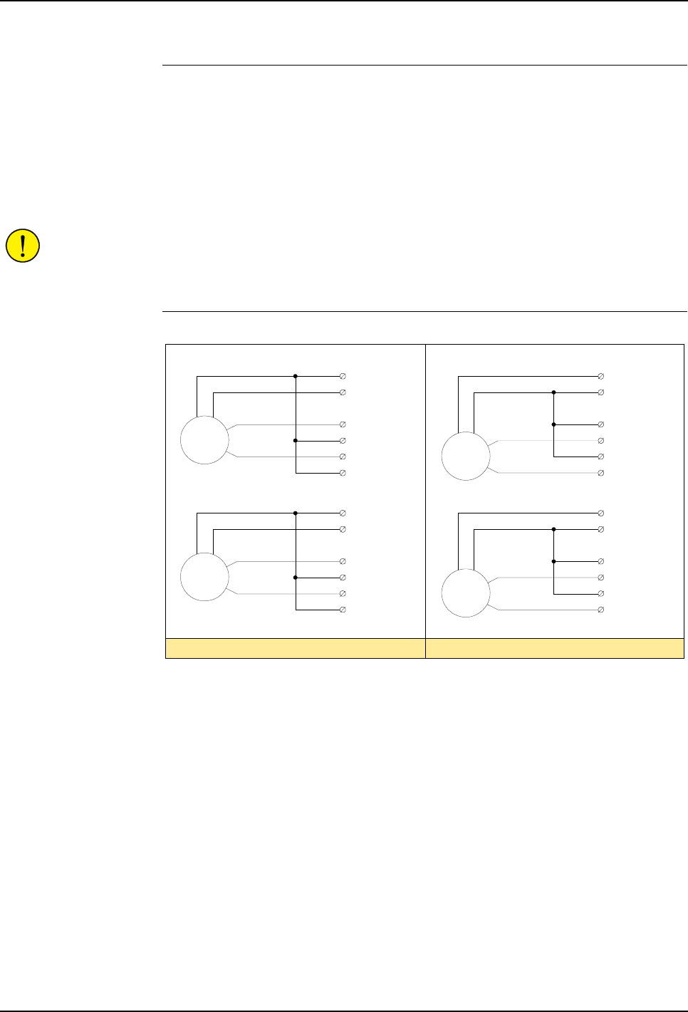
5 Installation and Commissioning
5.6 Encoder and Sync Switch Installation
92 3HNA009834-001 en Rev.06 Product Manual, Control Cabinet IRC5P
Encoder Connection -
General Information The encoder is connected to encoder inputs on the SCB board in the control cabinet.
The connection of the encoder may be performed in different ways as described in
the following:
• A single encoder for normal conveyor tracking.
• One encoder used to serve two or more robots.
• Two encoders to provide a backup encoder.
CAUTION! The encoder must be connected using a screened cable. If the cable is
long, special considerations concerning generated spike pulses must be taken. - Ref:
’Encoder Noise Suppression’ on page 88.
Connecting Encoder to
Control Cabinet Figure 40 Encoder connection in control cabinet
The encoder is connected to inputs on connector X5 - X7 on the SCB board in the
control cabinet as shown above and in Figure 38.
The 2 phases, A(0°) and B(90°), must be connected so that the encoder counts ‘up’
when the conveyor moves forwards and counts ‘down’ when the conveyor moves
backwards. For information on finding the rotating direction, see ’Rotating
Direction’ on page 88.
Connections for the second encoder shown above can only be used if the 2nd
encoder is to be used as backup.
The 2 LEDs for each of the encoders on the cabinet LED display will flash to show
the pulses from the encoder. By running the conveyor extremely slowly, these
indicators can be used to verify the pulses from the encoder.
Encoder 2
Encoder 1
Connection for PNP encoder Connection for NPN encoder
B (90°)
A (0°)
GND
24VDC
P_ENC1_A+
P_ENC1_ A–
P_ENC1_ B+
P_ENC1_ B–
0 Volt
+24 VDC
1
2
3
4
5
6
SCB-X5
Encoder 2
B (90°)
A (0°)
GND
24VDC
P_ENC2_A+
P_ENC2_ A–
P_ENC2_ B+
P_ENC2_ B–
0 Volt
+24 VDC
1
2
3
4
5
6
SCB-X6
B (90°)
A (0°)
GND
24VDC
P_ENC2_A+
P_ENC2_ A–
P_ENC2_ B+
P_ENC2_ B–
0 Volt
+24 VDC
1
2
3
4
5
6
SCB-X6
Encoder 1
B (90°)
A (0°)
GND
24VDC
P_ENC1_A+
P_ENC1_ A–
P_ENC1_ B+
P_ENC1_ B–
0 Volt
+24 VDC
1
2
3
4
5
6
SCB-X5
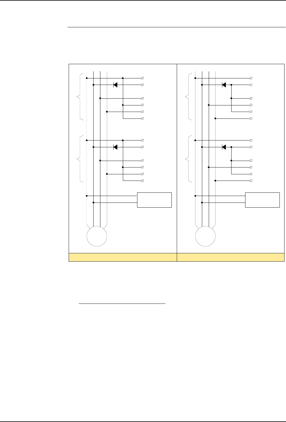
5 Installation and Commissioning
Product Manual, Control Cabinet IRC5P 3HNA009834-001 en Rev.06 93
5.6 Encoder and Sync Switch Installation
Connecting One
Encoder to More Robots One encoder can be used to control several robots. In this situation, power for the
encoder may be supplied by an external power supply, or by the robots.
Figure 41 Connecting one encoder to more robots
If the power supply is taken from the robot, the supply must be connected to all the
robots to make sure that the encoder will be operational even if one robot is
switched ‘off’. When supplying power from the robots in this way, it is important
that a diode is installed for each robot to prevent power from one of the robots
which is ‘on’ to be fed to a robot which is ‘off’.
If an external supply is used, the internal supply must not be connected.
Connection for PNP encoder Connection for NPN encoder
Encoder
+24 VDC
0 Volt
Robot 1
Robot 2
B (90°)
A (0°)
0V
24VDC
Encoder
Robot 1
Robot 2
B (90°)
A (0°)
0V
24VDC
P_ENC1_A+
P_ENC1_ A–
P_ENC1_ B+
P_ENC1_ B–
0 Volt
+24 VDC
Note: Do not connect
internal supply if
external supply is used
External power
supply
SCB-X5
P_ENC1_A+
P_ENC1_ A–
P_ENC1_ B+
P_ENC1_ B–
0 Volt
+24 VDC
+24 VDC
0 Volt
Note: Do not connect
internal supply if
external supply is used
External power
supply
1
2
3
4
5
6
P_ENC1_A+
P_ENC1_ A–
P_ENC1_ B+
P_ENC1_ B–
0 Volt
+24 VDC
SCB-X5
1
2
3
4
5
6
SCB-X5
1
2
3
4
5
6
P_ENC1_A+
P_ENC1_ A–
P_ENC1_ B+
P_ENC1_ B–
0 Volt
+24 VDC
SCB-X5
1
2
3
4
5
6
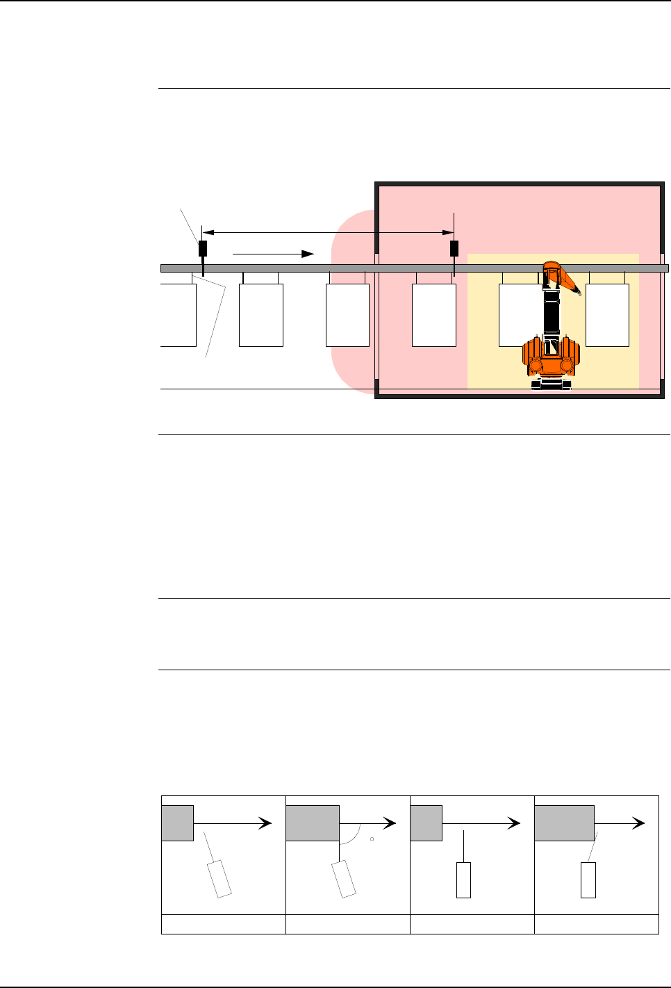
5 Installation and Commissioning
5.6 Encoder and Sync Switch Installation
94 3HNA009834-001 en Rev.06 Product Manual, Control Cabinet IRC5P
5.6.6 Sync. Switch Installation
General The sync switch may be positioned to detect the work object suspension or the work
object directly.
Figure 42 Location of sync switch in an installation
Location of Switch To reduce possible variation in the synchronization signal due to uneven conveyor
motion, swinging of work objects etc., the switch should be placed as close to the
robot as practically possible.
The switch may also be placed outside the hazardous area. This location must be
used if a non-ex switch and non-ex connection is used. The switch can be installed
on a bracket mounted on the conveyor.
Initiator Mounting If an initiator is used, the initiator should be installed to detect the object directly, or
detecting the object suspension (a flag on the suspension) etc.
‘Normal’ Switch
Mounting If a ‘normal’ switch is used, the switch arm must be in a perpendicular position in
relation to the work object when the switch is activated. If the switch is installed as
indicated in the two illustrations at the right, there is a risk that the work object (or
suspension) will slide on the switch arm, causing inaccurate switching.
Figure 43 Sync switch mounting
Robot
working
area
0.0 point
Non-ex
Sync switch
Sync switch
trig point
Queue tracking distance
Spray booth
Hazardous area
Hazardous area
outside entrance
Ex Sync switch
90
CorrectCorrect Not correct Not correct
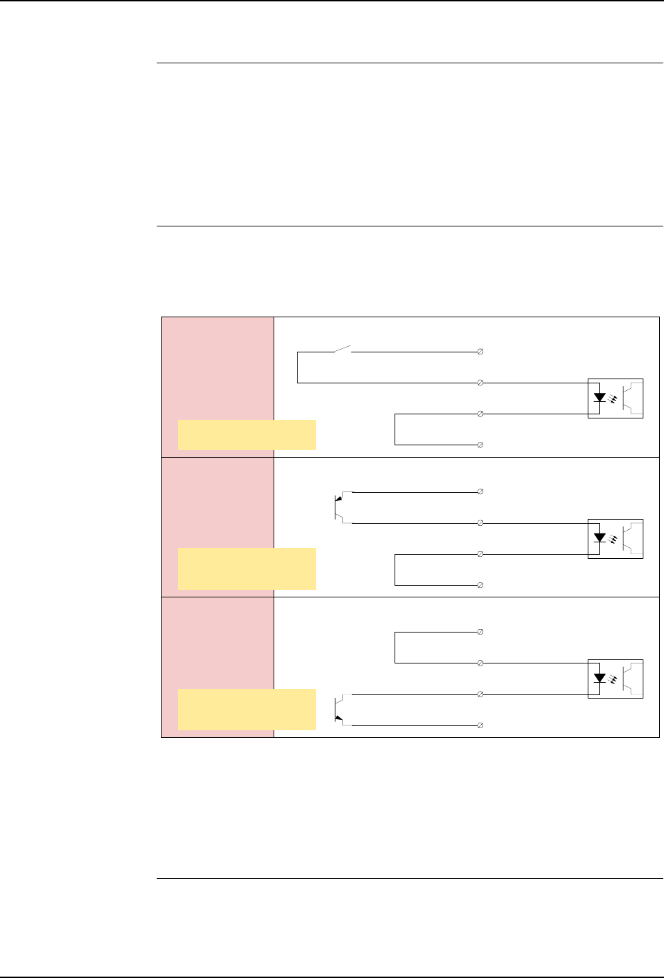
5 Installation and Commissioning
Product Manual, Control Cabinet IRC5P 3HNA009834-001 en Rev.06 95
5.6 Encoder and Sync Switch Installation
Sync Switch Connection
- General Information The sync switch should be connected to a digital input on the SCB board in the
control cabinet (non-ex connection) as described in the following.
The system has connections for 2 sync switches (non-ex connection only), where
switch 2 may be used in the rare cases when the robot works with ‘check point
functionality’ enabled. The following descriptions show connections for sync
switch 1.
Non-Ex Connection A non-ex sync switch can be connected directly to a digital input in the control
cabinet according to one of the following alternatives:
Figure 44 Non-ex sync switch connection alternatives
If a ‘normal’ switch, photocell or initiator with a switch output is used, the switch
must be connected as shown in Alternative A.
If a switch with open-collector transistor output is used, the output from the switch
should be connected as shown in Alternative B (PNP) or Alternative C (NPN).
Ex Connection An ex sync switch must be connected via a transformer isolated barrier to avoid
violating the explosion safety for the spray booth.
Control cabinet
SCB-X7
2
3
4
1
ENC_3A+
ENC_3A-
GND
+24 VDC
Sync switch
Non-hazardous areaHazardous area
Control cabinet
Non-hazardous areaHazardous area
Control cabinetNon-hazardous areaHazardous area
SCB-X7
2
3
4
1
ENC_3A+
ENC_3A-
GND
+24 VDC
SCB-X7
2
3
4
1
ENC_3A+
ENC_3A-
GND
+24 VDC
Alternative A:
Switch with switch output
Alternative C:
Switch with NPN
open-collector output
Alternative B:
Switch with PNP
open-collector output
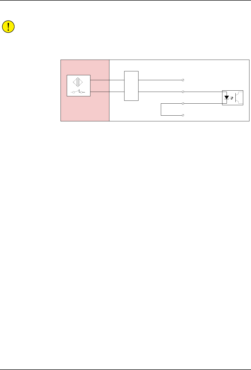
5 Installation and Commissioning
5.6 Encoder and Sync Switch Installation
96 3HNA009834-001 en Rev.06 Product Manual, Control Cabinet IRC5P
CAUTION! Placing the switch in the hazardous area means that the switch and its
connection MUST comply with the ex-regulations. Observe that the hazardous area
also includes areas just outside any spray booth opening as shown in Figure 42.
Figure 45 Ex sync switch connection
An ex type initiator may be used as alternative to a switch. Such a switch device in
conjunction with a transformer isolated barrier can be installed as shown in
Alternative B.
Initiator
Transformer
isolated barrier
Control cabinetNon-hazardous areaHazardous area
SCB-X7
2
3
4
1
ENC_3A+
ENC_3A-
GND
+24 VDC

5 Installation and Commissioning
Product Manual, Control Cabinet IRC5P 3HNA009834-001 en Rev.06 97
5.7 Misc. System Connections
5.7 Misc. System Connections
5.7.1 Introduction
About this Section This section provides information on how to connect various external functions and
systems to the controller. Which connections that are to be made will depend on the
installation.
Following external connections are described:
•’Digital I/O Connection’ on page 98
•’Remote Panel Connections’ on page 99
•’Ethernet Communication’ on page 101
•’Pendant Connection’ on page 103
•’Cabinet Cooler Installation’ on page 105
•’Servo Disconnect’ on page 109
•’Home Position Switch’ on page 110
•’Purge Unit w/Connector Box’ on page 111
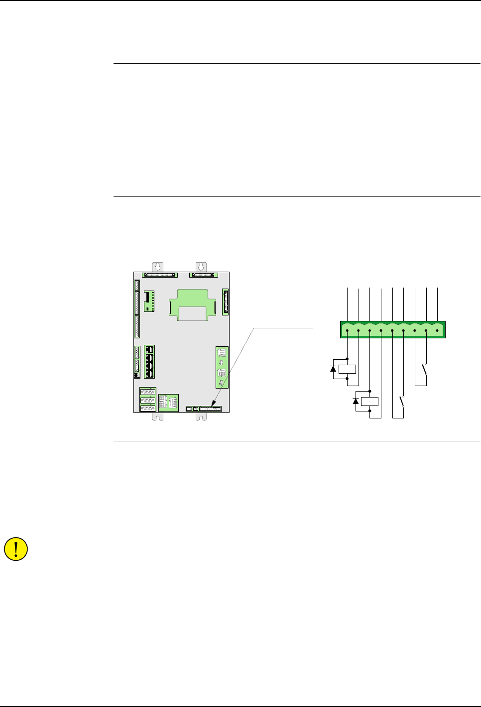
5 Installation and Commissioning
5.7 Misc. System Connections
98 3HNA009834-001 en Rev.06 Product Manual, Control Cabinet IRC5P
5.7.2 Digital I/O Connection
General In most installations, various digital (and analog) inputs and outputs will be needed
to control functions such as applicator control, color change etc. These inputs and
outputs are provided via various types of field bus nodes.
The control system offers also 2 digital inputs and 2 digital outputs which can be
used for test purposes or in simple robot installations where a greater number of I/O
is not required. Following description provides information for connections of these
inputs and outputs.
Connector Description Connections for the standard 2 digital inputs and outputs are available in connector
X8 on the MIB board as shown in the illustration below.
Figure 46 Standard digital I/O
Connection Install 1 or 2 digital input switches in MIB board connector X8 pin 5-6 and 7-8 as
shown in illustration above. For location of the MIB board, see ’Controller
Connections Overview’ on page 42.
Install 1 or 2 digital output loads in MIB board connector X8 pin 1-2 and 3-4 as
shown in illustration above. Max. output current 100mA (overload protection).
CAUTION! If an inductive load is connected to an output, a voltage suppression
diode as shown in Figure 46 must be installed to protect the control electronics from
voltage transients.
For information on tightening torque for terminal connections, see ’Tightening
Torques’ on page 216.
For information on cable dimension and screening, see ’Cable Information’ on page
208 and ’Bonding Information’ on page 211.
For information on how to setup the digital inputs and outputs in the control system,
see ‘Operator’s Manual, IRC5P, chapter ‘Installation and Commissioning’.
X8
GEN_DIN2
87
+24V_IO
9
GND
5
+24V_IO
6
GEN_DIN1
3
GEN_DOUT2
4
GND
1
GEN_DOUT1
2
GND
Digital Input 1
Digital Input 2
Digital Output 1
Digital Output 2
X8X7X6
X5
X4
X21
X26
X27
X14
X15
X13
X12
X25
X10
X9
X11
X3
X16
X17
X18
X24
X23
X22
X1 X2
MIB-01
+24V_SYS
LED1
+24V_IO
LED2
EXP_CTRL
LED3
LED4 N0
LED8
STATUS
LED5 N1
LED6 N2
LED7 N3
X19
X20
X18
X8X7X6
X5X4
X21
X26
X27
X14
X15
X13
X12
X25
X10
X9
X11
X3
X16
X17
X24
X23
X22
X1 X2
X19
X20
X18
MIB-01
Manipulator Interface
Board, MIB
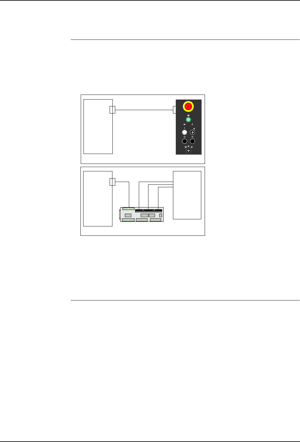
5 Installation and Commissioning
Product Manual, Control Cabinet IRC5P 3HNA009834-001 en Rev.06 99
5.7 Misc. System Connections
5.7.3 Remote Panel Connections
General The remote panel connections are used when the robot is to be controlled from an
external panel or PLC instead of the standard control panel on the control cabinet
front, as shown in the illustration below.
Figure 47 Cabinet control panel- / remote panel connections
All main control panel functions are available in connectors on the Safety
Connection Board, SCB.
Note: The robot can not be operated without cabinet control panel or remote panel /
PLC installed.
Remote Panel
Connections The following illustration shows the connections for remote panel.
Safety
Interface
Board, SIB
Remote panel
X10
X5 X6 X2 X1
X3 X13 X4
X8 X9 X10
X11
X12
X7 SCB-01
X12 Remote
panel
or PLC
Safety Connection
Board, SCB
Safety
Interface
Board, SIB
Cabinet control panel
X10 X1
Control Panel
Board, CPB
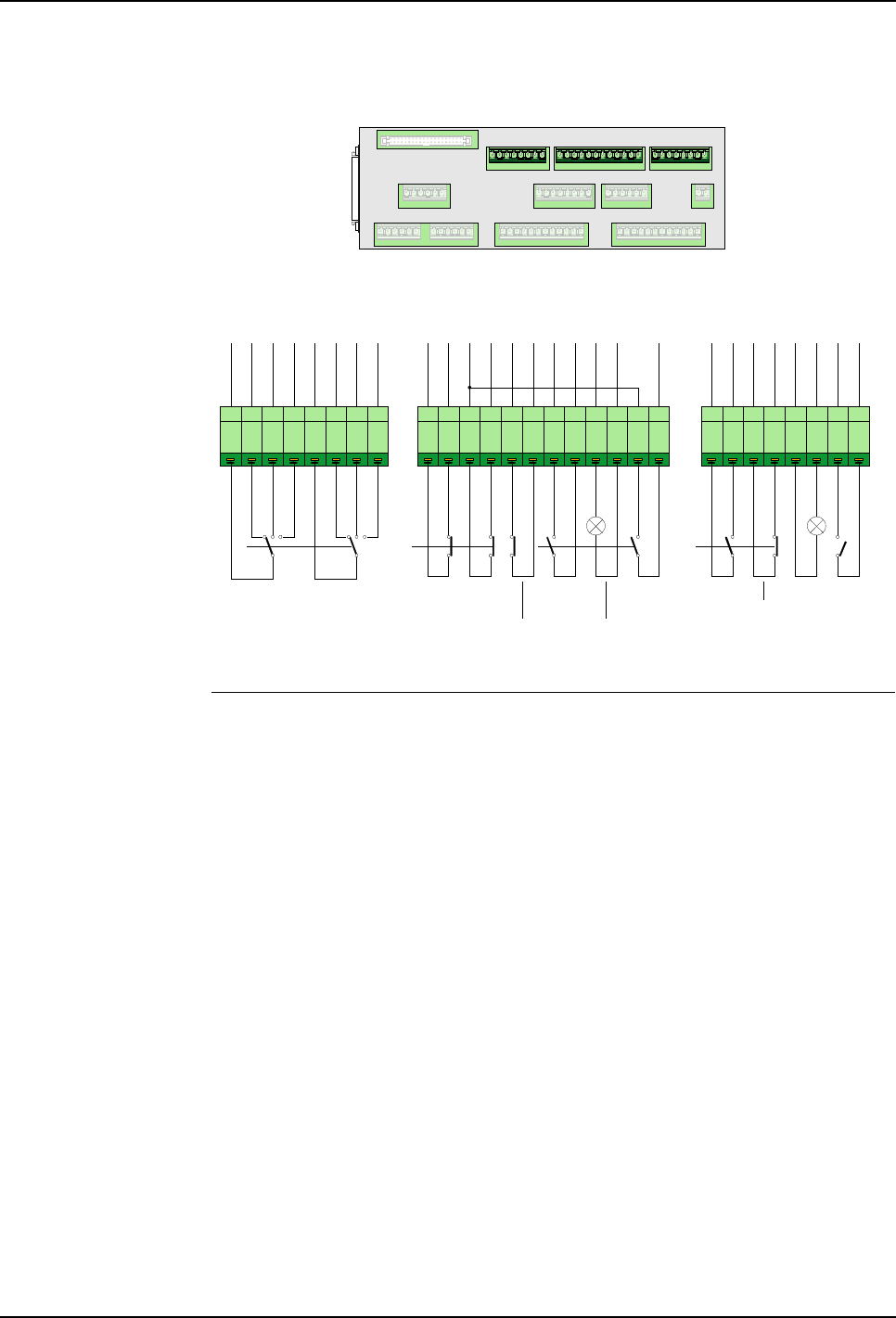
5 Installation and Commissioning
5.7 Misc. System Connections
100 3HNA009834-001 en Rev.06 Product Manual, Control Cabinet IRC5P
Figure 48 Remote panel connections
References For more details on the function of the switches, see ’Control Panel Description’ on
page 27. For control cabinet internal wiring information on the remote panel
functions, see circuit diagrams supplied with the robot.
1 2 3 4 5 6 7 8 1 2 3 4 5 6 7 81 2 3 4 5 6 7 8 9 10 11 12
X5 X6 X2 X1
X3 X13 X4
X8 X9 X10
X11
X12
X7 SCB-01
PNL_AUTO1
Safety_CH_Feed1
PNL_ES1_FEED
PNL_ES1
PNL_ES2_FEED
PNL_ES2
MON_ENA
PNL_MOF
PNL_MON
PNL_MOF1
PNL_LMP_MON
GND
PNL_ES_RST
PNL_HVOF1
PNL_HVON
PNL_HVOF
HV_PNL_HS
PNL_LMP_PUR
GND
PNL_MAN1
PNL_MANFS1
PNL_AUTO2
Safety_CH_Feed2
PNL_MAN2
PNL_MANFS2
Emergency
Stop
Motor Off
Ch1
Ch2
Ch1
Ch2
X9
HV On
X10
Motor
On
Ch2
Motor On Lamp
Emy Stop
Reset
Ch1
Ch2
HV Off
Purge
Lamp
X8
Ch2
Mode Selector
Ch1
PNL_LMP_TST
+24V_IO
Lamp
Test
Ch1
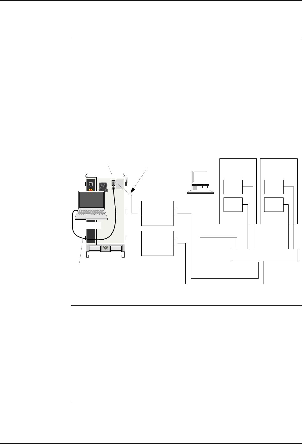
5 Installation and Commissioning
Product Manual, Control Cabinet IRC5P 3HNA009834-001 en Rev.06 101
5.7 Misc. System Connections
5.7.4 Ethernet Communication
General Ethernet communication is a standard function in the IRC5P control cabinet and
may be used for communication between the robot control cabinet and an external
PC etc., or for including one or more robots in an Ethernet network.
Several Ethernet connections are available; on the front door of the cabinet and
directly on the main computer unit as shown in Figure 49.
The connection on the cabinet front is used for services purposes such as connecting
an external PC for down-loading of programs, program backup etc. The connections
inside the control cabinet may be used for including the robot in an Ethernet
network.
Figure 49 Ethernet communication concept
Cable Information The cable used must be twisted-pair Ethernet (TPE), or as defined in
IEEE 802.3 : 10BASE-T. Local conditions such as electric environment determines
how cable layout is to be performed. The Ethernet connection has no termination for
cable screen. 10BASE-T is a point-to-point net, connected via a HUB switch.
Different transmission rates and cable lengths require different ethernet cables:
– 10Mbit/s: Shielded twisted pair (10 Base T STP)
– 100Mbit/s (<10m): CAT5E, 100 Base T STP
– 100Mbit/s (10-100m): CAT6, 100 Base T STP
References See Ethernet documentation.
Ethernet service
connection
Ethernet
Control
cabinet
Standard
cable
Note. Cable to computer
is a crossover cable
Main
Computer
Paint
Interface
board, PIB
Control
cabinet
PIB
Main
Cmp
PIB
Main
Cmp
HUB switch
Service PC
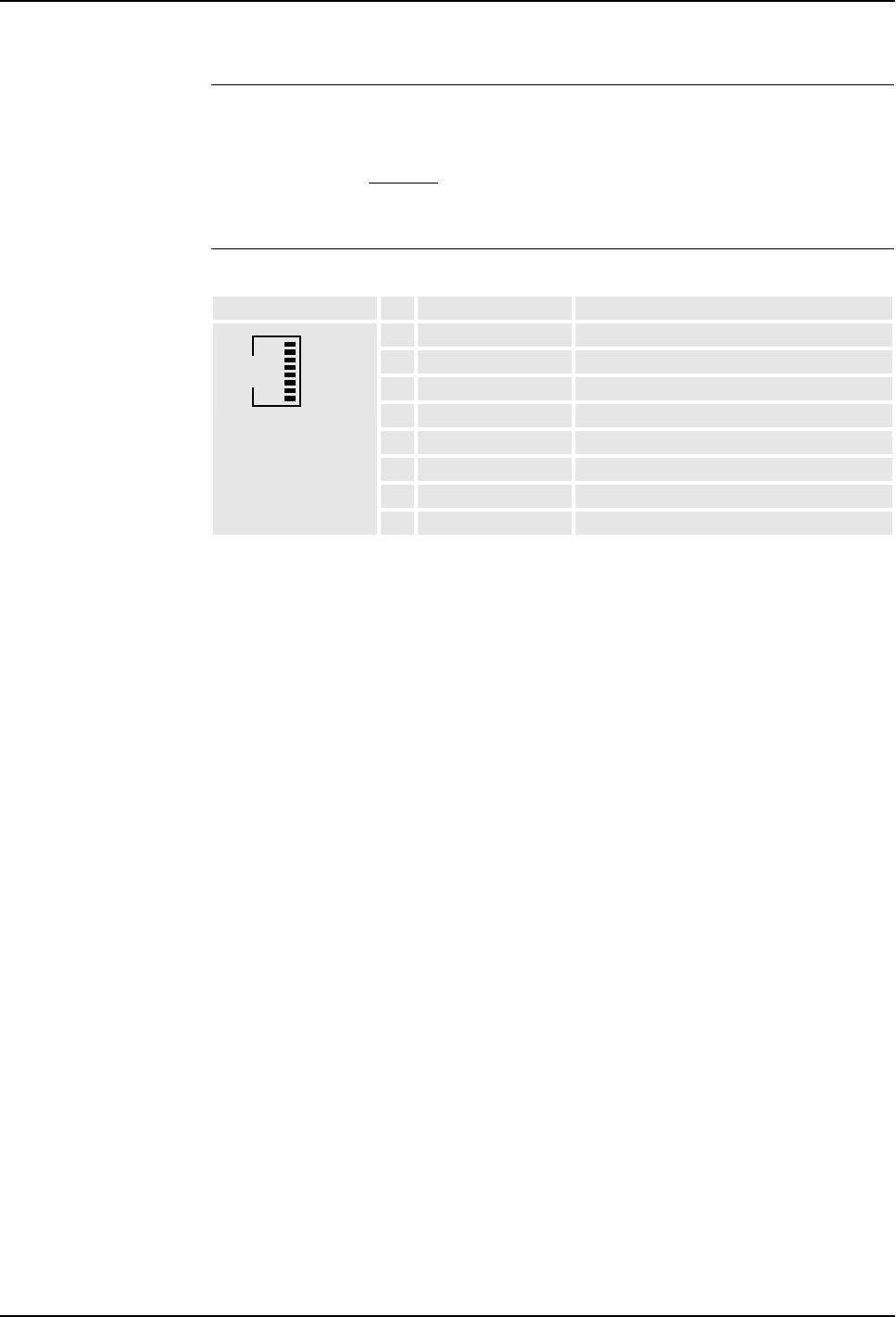
5 Installation and Commissioning
5.7 Misc. System Connections
102 3HNA009834-001 en Rev.06 Product Manual, Control Cabinet IRC5P
Setup Setting up the Ethernet is performed on the pendant.
Note: External computer for service purposes is connected to the cabinet service
connection using a standard Ethernet cable. The required crossing of the signals is
performed by the internal cable.
Ethernet TPE Connector Ethernet TPE Connector
Connector #Signal name Description
1TX+ Transmit data line +
2TX- Transmit data line -
3RX+ Receive data line +
4NC Not connected
5NC Not connected
6RX- Receive data line -
7NC Not connected
8NC Not connected
1
8
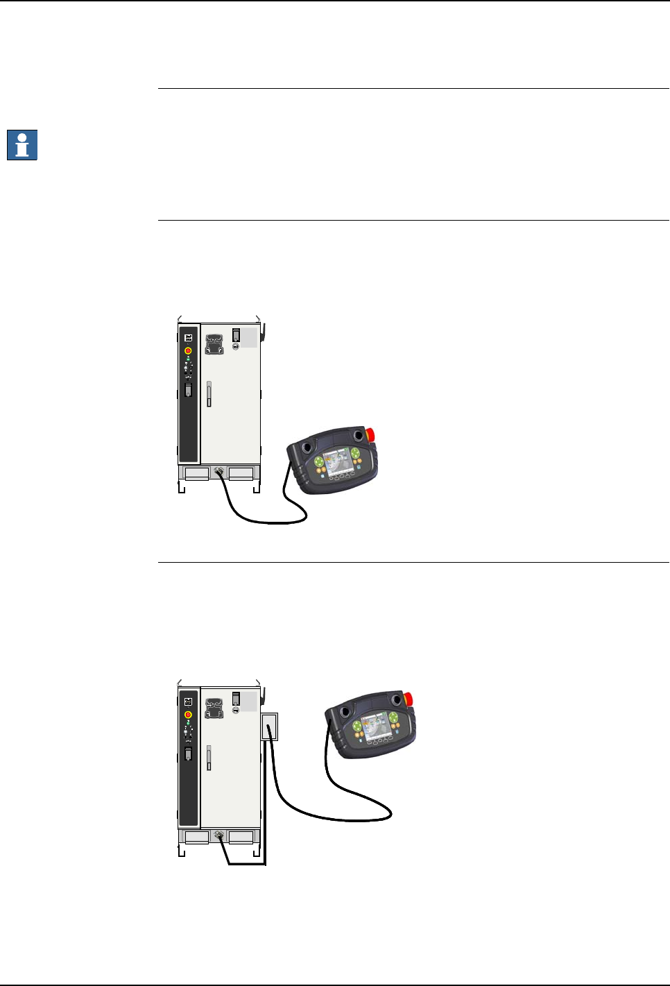
5 Installation and Commissioning
Product Manual, Control Cabinet IRC5P 3HNA009834-001 en Rev.06 103
5.7 Misc. System Connections
5.7.5 Pendant Connection
Installation Connect pendant cable to the pendant connector.
Important: If the pendant is not connected, a dummy connector must be installed in
its place to avoid braking the emergency stop chain.
Following configurations are available:
Standard Connection The pendant is connected to the control cabinet via pendant connector X20 at the
bottom front of the cabinet.
Figure 50 Pendant standard connection
Hot Plug Connection The hot plug connection is an optional connector located on the side of the cabinet,
to enable connecting and disconnecting the pendant during operation of the cabinet
without breaking the emergency stop chain.
Figure 51 Pendant hot plug connection
Hot Plug
Connector
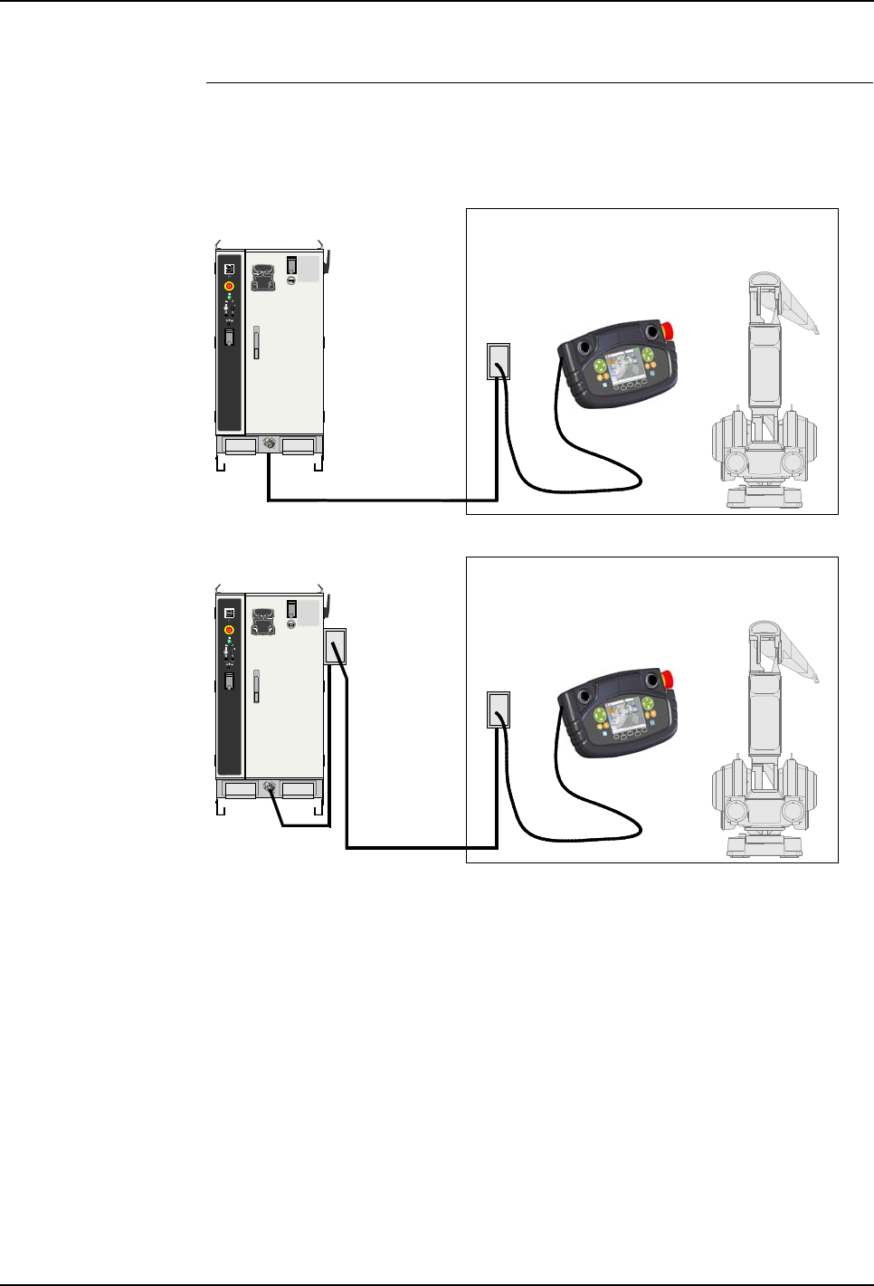
5 Installation and Commissioning
5.7 Misc. System Connections
104 3HNA009834-001 en Rev.06 Product Manual, Control Cabinet IRC5P
External Connection The external pendant connection is an optional hot plug connector which may be
installed to provide connection for the pendant inside the spray booth.
Figure 52 External pendant connection
The connector should be installed inside the spray booth at a convenient location for
connection of the pendant. A common location is just inside the spray booth
entrance door.
The connector is supplied with the extension cable. Connect other end of cable to
the pendant connector X20 at the bottom front of the cabinet, or to an optional hot
plug connector at the side of the cabinet.
Check that connector is connected to PE-ground as described in ’IS-Ground
Connection’ on page 59.
For information on the hot plug function, see ‘Operator’s Manual, IRC5P’,
Installation and Commissioning / Connections / Connecting the Paint Teach
Pendant Unit.
Spray booth
Hazardous area
Extension cable
Extension cable
Hot Plug
Connector
Hot Plug
Connector
Spray booth
Hazardous area
Hot Plug
Connector
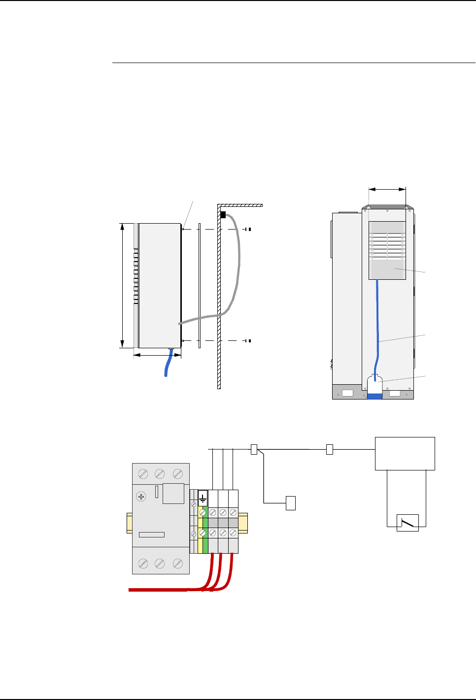
5 Installation and Commissioning
Product Manual, Control Cabinet IRC5P 3HNA009834-001 en Rev.06 105
5.7 Misc. System Connections
5.7.6 Cabinet Cooler Installation
General If the controller is to operate at higher temperatures (up to 55°C), a cooler may be
installed.
If the cooler is ordered at a later stage than the control cabinet, the installer must
prepare the cut-outs for the location of the cooler shown below. For drawing of
cut-out and holes, see manufacturer’s documentation, supplied with the cooler.
Figure 53 Cooler installation
Cooler cable
Drain hose
connection
Cooler unit
Cabinet side wall
Attachment
nut and washer
Electrical connection X79
Headless screw
Drain water
container
Drain hose
Cooler unit
All dimensions in mm
280
550
153
Mains overload
protection, FR1
Factory 115/230 VAC supply
L
N
P.E
Cooler
Door switch
Normal Closed
when door open
Optional
internal light
X78 X79
XT1.1

5 Installation and Commissioning
5.7 Misc. System Connections
106 3HNA009834-001 en Rev.06 Product Manual, Control Cabinet IRC5P
Installation Procedure This procedure describes how to install the cooler on the control cabinet.
If the cooler is ordered together with the robot and control cabinet, the cooler is
already installed and this installation procedure can be skipped. Continue with
’Installation Checks’ on page 106.
1. Remove cooler from box. Be careful when lifting cooler.
2. Remove paper on gasket adhesive surface. Place gasket on cabinet mounting
surface with adhesive side facing cabinet. Pay attention to get gasket correctly
positioned.
3. Place cooler on its side and install 8 supplied headless screws.
4. Open cabinet front door. Lift cooler onto side of cabinet. Guide headless screws
into attachment holes.
5. Install washers and nuts on screws from inside cabinet. Tighten nuts.
6. As the air inside the cabinet is cooled down, condensation arises in the cooler. It
is therefore important to make an arrangement as shown in the illustration to
lead the condensate from the cooler to the outside of the cabinet.
Important: To minimize condensation, it is important to set the internal temperature
(default 38°C) not lower than actually needed. To prevent condensation inside the
control cabinet, ensure that the control cabinet is a sealed enclosure, especially
watch cable inlets and door seals.
7. Install door switch. Cooling is switched off when control cabinet door is open.
8. Install connector X79 and terminal X78. The external 115 or 230 VAC is
connected to terminal board XT1.1, located beside the mains overload
protection, FR1, in the lower left bottom of the controller as shown in
Figure 17. See also ’Supply for Internal Light’ on page 118.
9. Insert electrical connector of the cooler into X79.
Installation Checks After the installation has been performed, and if the cooler has been installed before
shipment, it is important to check the following:
– To prevent condensation inside the control cabinet, ensure that the control
cabinet is a sealed enclosure, especially watch cable inlets and door seals.
– Ensure that the condensate from the cooler is lead to the outside of the control
cabinet.
– Ensure that the door switch is open when the control cabinet door is open. To
minimize condensation inside the control cabinet, cooling is switched off when
control cabinet door is open.
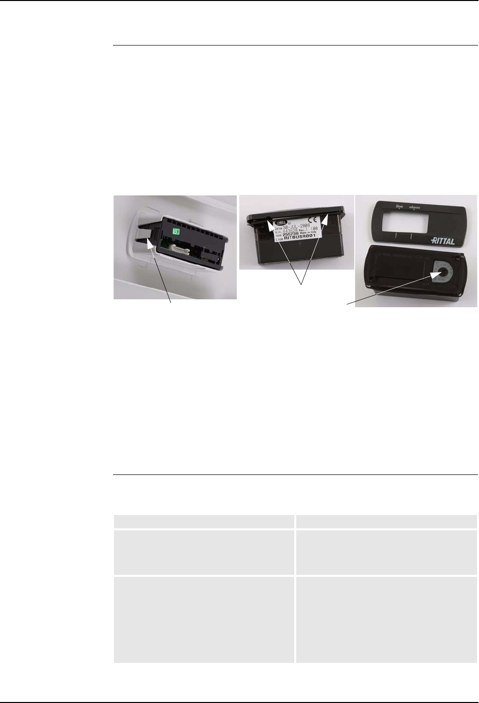
5 Installation and Commissioning
Product Manual, Control Cabinet IRC5P 3HNA009834-001 en Rev.06 107
5.7 Misc. System Connections
Temperature Adjustment This procedure describes how to change the temperature setting.
Important: To minimize condensation, it is important to set the internal temperature
not lower than actually needed.
1. Switch off power supply for cooler.
2. Remove louvred grill.
3. Release display lock (54/1) from behind and pull the display slightly forwards.
Figure 54 Display removal
4. Carefully raise cooler controller trim panel, e.g. using your thumb or a flat
screwdriver (54/2), and remove it.
5. Set required temperature on temperature setting device (54/3).
6. Carefully push cooler controller trim panel onto display until it snaps into
place.
7. Re-insert display into louvred grill.
8. Install louvred grill on cooler.
LED Indicators The following provides a description of the LED indicators on the cooler controller
trim panel.
1
2
3
Description Remedy / Source of fault
line
Green - Power supply on, OK
Blinking green - Door switch detects open
control cabinet door.
In order to avoid condensation, close door.
If door is closed, check door switch.
alarm
Red - The enclosure internal temperature is 5K
above the set temperature.
Blinking red - High pressure alarm in the
cooling circuit.
Check temperature setting.
Check condenser and clean if necessary.
Check filter and replace if necessary.
Check that the dissipated heat loss does not
exceed the useful cooling output of the cooler.
After rectifying the fault, you need to reset the
cooler controller manually, ref ’Resetting
Cooler Controller’ on page 108.

5 Installation and Commissioning
5.7 Misc. System Connections
108 3HNA009834-001 en Rev.06 Product Manual, Control Cabinet IRC5P
Resetting Cooler
Controller After rectifying a high pressure alarm, the cooler controller needs a manual reset.
1. Remove cooler controller trim panel as described in ’Temperature Adjustment’
on page 107.
2. Press reset button for at least 3 seconds.
3. The red LED is extinguished.
4. Reinstall the cooler controller trim panel, as described in ’Temperature
Adjustment’ on page 107.
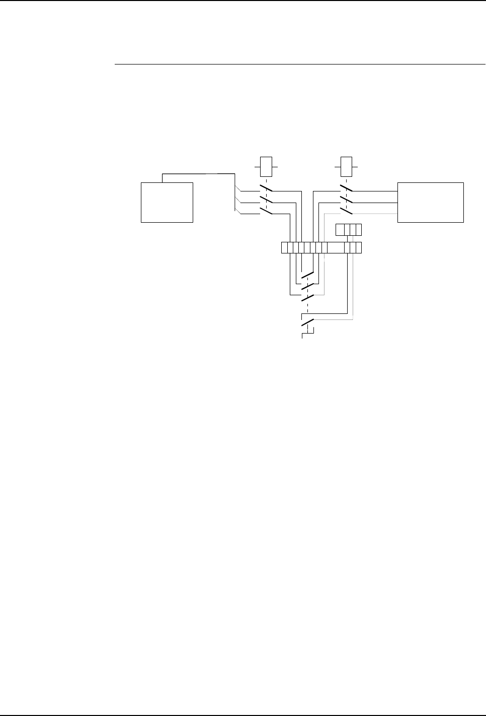
5 Installation and Commissioning
Product Manual, Control Cabinet IRC5P 3HNA009834-001 en Rev.06 109
5.7 Misc. System Connections
5.7.7 Servo Disconnect
General Servo disconnect remote on terminal is an option to remotely switch off the power
to the robot motors, while all other functions of the controller are still powered. The
principle diagram is shown in following illustration.
Figure 55 Servo disconnect remote on terminal, principle diagram
The terminal XT5 is located at the bottom of the controller, see Figure 17.
Max. cable length from control cabinet to external switch is 25 meter.
KM1 KM2
Optional servo disconnect
3 x 260/475VAC
Transformer Servo Drive
Unit axes 1-6
system 1
XT5 1423 56
MIB- X11
87
21

5 Installation and Commissioning
5.7 Misc. System Connections
110 3HNA009834-001 en Rev.06 Product Manual, Control Cabinet IRC5P
5.7.8 Home Position Switch
General Home position switch is an option that shows when the manipulator axis 1 is in a
determined home position. The manipulator is equipped with a namur switch on
axis 1. A relay is located in the control cabinet. The principle diagram is shown in
following illustration.
Figure 56 Home position switch, principle diagram
The relay with terminal X1 is located at the bottom of the controller, see Figure 17.
15
7
8
9
10
11
12
14
Control cabinet Manipulator
1
3
0V
+24VDC
Relay
X1 X1
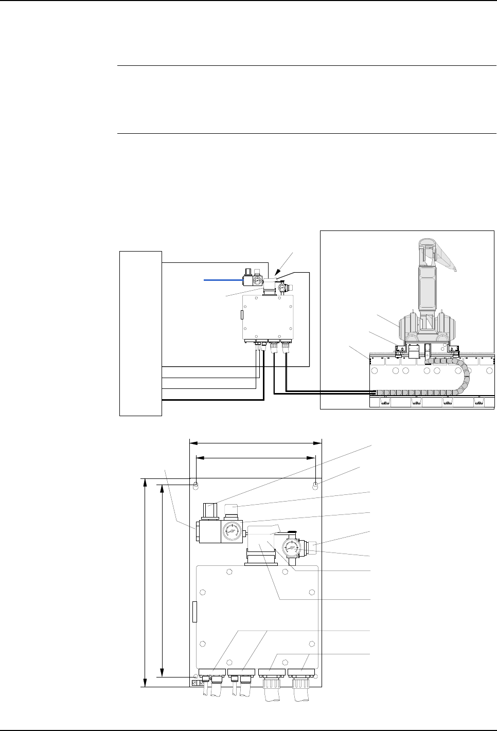
5 Installation and Commissioning
Product Manual, Control Cabinet IRC5P 3HNA009834-001 en Rev.06 111
5.7 Misc. System Connections
5.7.9 Purge Unit w/Connector Box
General The ‘Purge Unit w/Connector Box’ is a special purge unit used for robots mounted
on a trolley. The reason for the special purge unit is the special type of flexible cable
routed via the cable chain to the trolley and robot.
Installation Install purge unit on a convenient location, e.g. the cabin wall. Then connect cables
inside purged chamber as described in the following. For general installation
information see description of standard purge unit in section ’Purge Unit
Installation’ on page 49.
Figure 57 Purge unit location and connections
504
320
460
290 Input pressure on/off valve
Purging (flushing)
pressure regulator
Purging pressure gauge
Maintenance pressure
regulator
Maintenance pressure gauge
Purge sensor connector
Purge valve connector
(located behind purge
sensor connector)
Air supply
connection
Cables from control cabinet
Flexible hose to robot
Spray booth
Hazardous area
Controller
Flexible
hose(s) Cable chain
Manipulator
Trolley
Rail
Hole diameter 7 mm. Max. head
size 12 mm for M6 screws
Serial line robot
Purge sensor
Serial line pumps *1
Motor and pump power cable
Purge valve cable
Purge valve connector
AX1-YV1 (rear connector)
Purge sensor
connector
AX1-X4
Supply air
*1 Used for robots with pumps in manipulator
All dimensions in MM
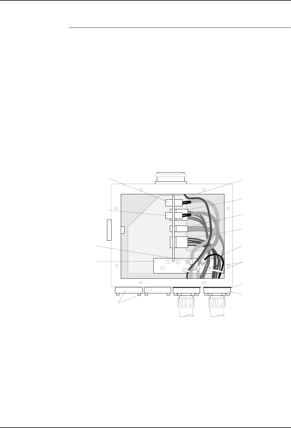
5 Installation and Commissioning
5.7 Misc. System Connections
112 3HNA009834-001 en Rev.06 Product Manual, Control Cabinet IRC5P
Connecting Manipulator
to Purge Unit The following procedure describes how to connect 1 or 2 flexible cables in the
purged chamber. The robot may have 1 or 2 flexible cables. Differences between the
single cable version and dual cable version will be pointed out throughout the
procedure.
Different number and types of connectors may be used, depending on robot type and
equipment installed in the robot. All these variants are not described in the
following, but correct connection is obtained by connecting the connectors
according to markings on connectors and receptacles.
CAUTION! All types of cables, including the flexible hose (hose with internal wires)
between purge unit and manipulator, must be laid in such a manner that they will not
be continuously exposed to solvent, e.g. by laying the cables in a conduit which will
drain solvent entering into it etc.
Figure 58 Purge unit connection box, front view
1. Route the flexible hose(s) from the manipulator through the spray booth wall
etc. to the purge unit.
Note: The lead-through for the cable in the cabin wall must be made in
accordance with the cabin safety regulations and ex-regulations, etc.
Note: The flexible hose must not be bent to a radius smaller than 250 mm.
2. Remove cover for purge unit connection box. Retain cover, screws and gasket
for later re-installation.
Cable flange
Gasket
Connector AX1-X11
Motor cable
Purge sensor cable
Inlet used for
single cable version
Cables from
control cabinet
Purge sensor connector
Ground rail
CAN bus and axis
measuring board
connection X13
Connector X113
for pump system
measuring board Connector AX1-X111
Pump motor cable
P-clip for
grounding
cable screen
Connector AX1-X12
Power cable
Ground wire
from manipulator
Inlet used for
second cable
Panduit strips on
wires which are not
secured with p-clips

5 Installation and Commissioning
Product Manual, Control Cabinet IRC5P 3HNA009834-001 en Rev.06 113
5.7 Misc. System Connections
3. Enter flexible hose into the right inlet on the purge unit for the single cable
version. For the dual cable version, enter motor cable in right inlet and signal
cable in the second inlet from the right as shown in Figure 58 (the signal cable
is the cable which includes screened cables).
4. Check that gasket(s) for the cable attachment is properly positioned and secure
cable flange(s) with 4 screws.
5. Route purge sensor cable and connector to hole on top of the purge unit
connection box. Enter connector through hole and secure with 4 screws.
6. Insert connectors from flexible hose(s) in receptacles for cables from control
cabinet according to markings on connectors and Figure 58.
7. The screened cables include a p-clip at a stripped-off section of the cable
insulation. Secure these p-clips to the ground rail as shown in Figure 58.
8. Secure loose wires using Panduit strips. Check that the wires are properly
secured so that they will not apply strain to the connectors.
9. Connect ground wire from manipulator to ground rail (not used on all versions).
10. Make sure that the gasket for the purge unit cover is properly positioned, install
cover and tighten attachment screws. Make sure that all screws are in place to
prevent air leakage.

5 Installation and Commissioning
5.8 Power Connections
114 3HNA009834-001 en Rev.06 Product Manual, Control Cabinet IRC5P
5.8 Power Connections
5.8.1 Introduction
About this Section This section provides information on how to connect the robot to the mains power,
including checking transformer wiring for correct voltage, connections for service
outlet, etc.
Following connections are described:
•’Mains Power Connection’ on page 115
•’Transformer Wiring’ on page 117
•’Supply for Internal Light’ on page 118
•’Internal Supply for Service Outlet’ on page 119
•’24 VDC for External Use’ on page 120
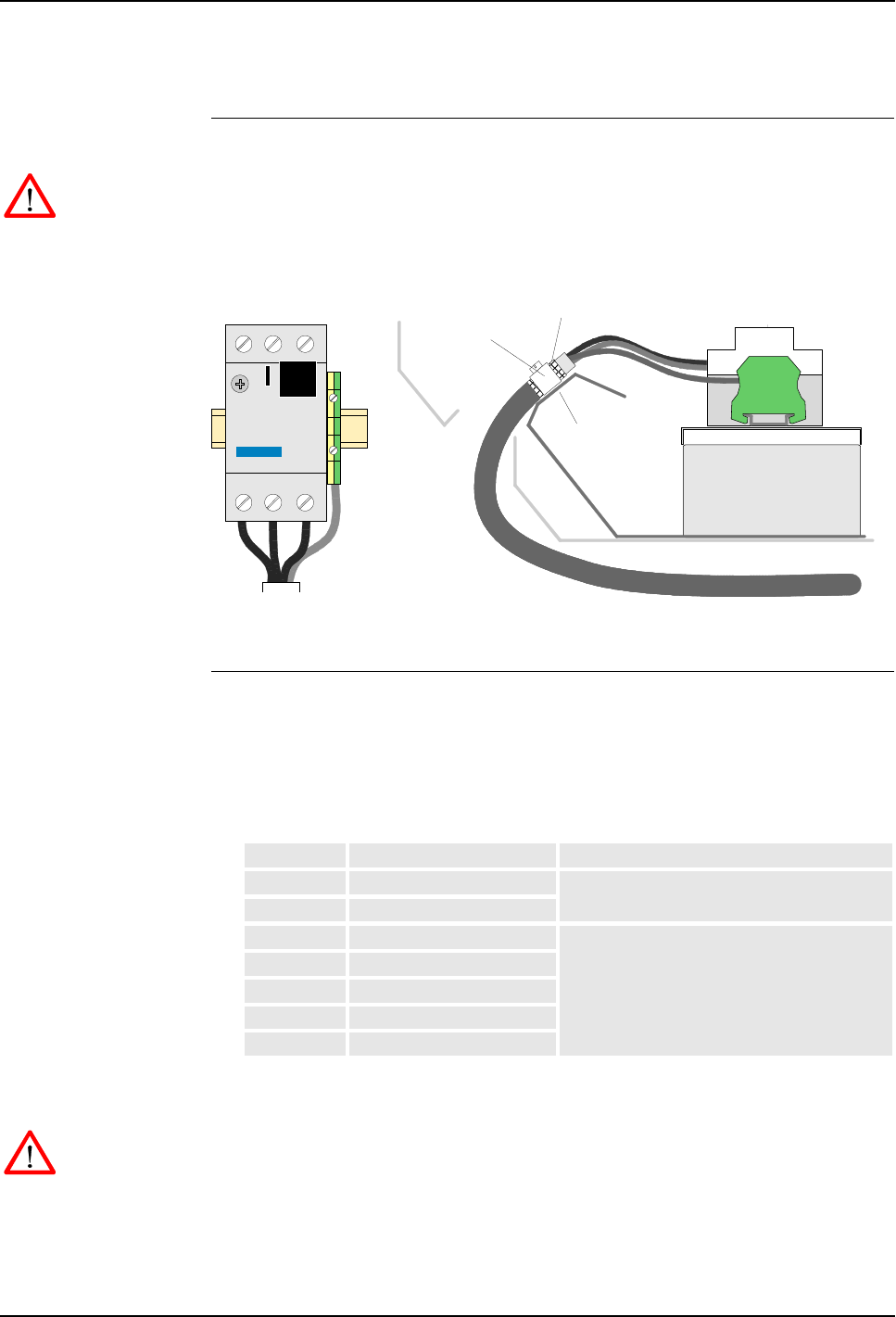
5 Installation and Commissioning
Product Manual, Control Cabinet IRC5P 3HNA009834-001 en Rev.06 115
5.8 Power Connections
5.8.2 Mains Power Connection
General This procedure describes how to connect the robot to the factory mains power.
WARNING! Before starting to connect the mains, make sure that the other end of the
cable is disconnected from the line voltage.
Figure 59 Mains power connections
Procedure 1. Check on transformer terminals that the transformer is wired for correct voltage
as noted in the ‘Documents on Delivery’ folder. If not correct, rewire
transformer as described in ’Transformer Wiring’ on page 117.
2. Check that the mains overload protection is set to correct current in accordance
with supply voltage as shown below.
3. Make sure that the mains switch is ‘off’. Remove mains fuses for robot supply.
WARNING! Make sure that mains fuses are removed before continuing.
4. Route mains power cable as shown in Figure 59. Dismantle cable and install
cable clamp. For location of power connection, see ’Controller Connections
Overview’ on page 42
Mains power cable
Screen
Screen rail /
strain relief
Dust seal
L1 L2 L3 Ground
connection
Screen clamp
Mains overload
protection, FR1
Power
connection
Mains filter
Voltage Current setting Overload protection type
200VAC 18A 13-18A
230VAC 16.8A
400VAC 9.6A 6.3-10A
440VAC 8.8A
475VAC 8.1A
525VAC 7.3A
600VAC 6.4A

5 Installation and Commissioning
5.8 Power Connections
116 3HNA009834-001 en Rev.06 Product Manual, Control Cabinet IRC5P
5. Connect mains power L1, L2, L3 to mains overload protection and PE ground
to ground terminal. For information on tightening torque for terminal
connections, see ’Tightening Torques’ on page 216.
– Mains: Iks10kA. Breaking capacity of cabinet = 100 kA (400-600V) / 50kA
(200-230V).
– Fuses: Min. In 16 Amp. D-Curve (slow blow). 10-20 x In or similar overload
protection with same slow blow characteristics.
– The mains cable must be min. 3 x 2.5mm² + PE (AWG 14)
– By mains 200V max length 85 meter (by 2.5mm²)
– By mains 400V max length 174 meter (by 2.5mm²)
– By longer supply lines, cable area must be increased, or fuse size reduced
6. Install mains fuses.
Important: Due to the autotransformer / drive system / mains filter configuration in
the IRC5P controller, an imbalance between the supply phases to the system can
occur during operation of the robot, and especially when switching the system ‘on’
and when applying power to the robots drive system (Motor On). This may cause
the earth fault protection to trip if a protection with too low release current is used,
and especially if more robots share the same earth fault protection.
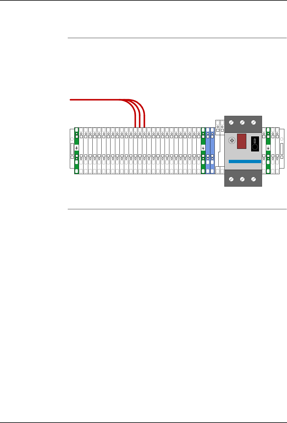
5 Installation and Commissioning
Product Manual, Control Cabinet IRC5P 3HNA009834-001 en Rev.06 117
5.8 Power Connections
5.8.3 Transformer Wiring
General Before connecting the robot to the mains power, it must be checked that the
transformer connection corresponds to the mains voltage to which the robot is to be
connected.
Figure 60 Transformer terminal board
Procedure This procedure describes how to check/change the connection of the transformer
and auto breaker setting.
1. Open the control cabinet front door.
2. Locate the transformer terminal board, located on the back wall inside the
controller as shown in ’Controller Connections Overview’ on page 42.
3. Check connection of transformer as shown in Figure 60.
4. If wiring is not correct, move wires for phase 1, 2 and 3 to correct terminal. For
information on tightening torque for terminal connections, see ’Tightening
Torques’ on page 216.
5. Check that supply overload protection is set to 16A.
Voltage rewiring terminal board.
Example shows wiring for 440V
Supply overload protection, FR2
To transformer
200V
200V
200V
230V
230V
230V
260V
260V
260V
400V
400V
400V
440V
440V
440V
475V
475V
475V
475V
475V
475V
525V
525V
525V
600V
600V
600V
6.3
3.15
0
ST1
ST1
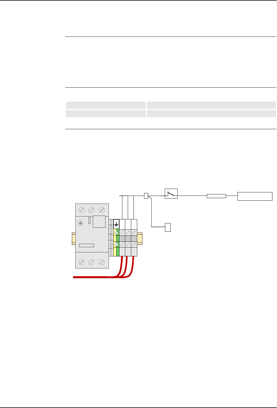
5 Installation and Commissioning
5.8 Power Connections
118 3HNA009834-001 en Rev.06 Product Manual, Control Cabinet IRC5P
5.8.4 Supply for Internal Light
General The controller may include a connection for a single phase 115/230 VAC for
internal light. This supply can also be used to supply an optional cooler unit.
The internal light includes a rectifier which makes it operate on supply voltages
from 90V to 250V.
Specification
Connections The external 115 or 230 VAC is connected to terminal board XT1.1, located beside
the mains overload protection, FR1, in the lower left bottom of the control cabinet
as shown in Figure 17. The AC power is connected to the rectifier via a door switch.
The light is switched on when the cabinet door is open.
Figure 61 115/230 VAC terminal board
Optionally the power may be connected to the control cabinet internal power
supply, which means that the light can only be switched on when the control cabinet
is switched on.
For information on tightening torque for terminal connections, see ’Tightening
Torques’ on page 216.
For connection for cooler, see ’Cabinet Cooler Installation’ on page 105.
Voltage 115 or 230 V
Supply line fuses Max. 10A
Mains overload
protection, FR1
Factory 115/230 VAC supply
L
N
P.E
Optional cooler
Internal light
Rectifier
Door switch
Normal Closed
when door open
X78
XT1.1
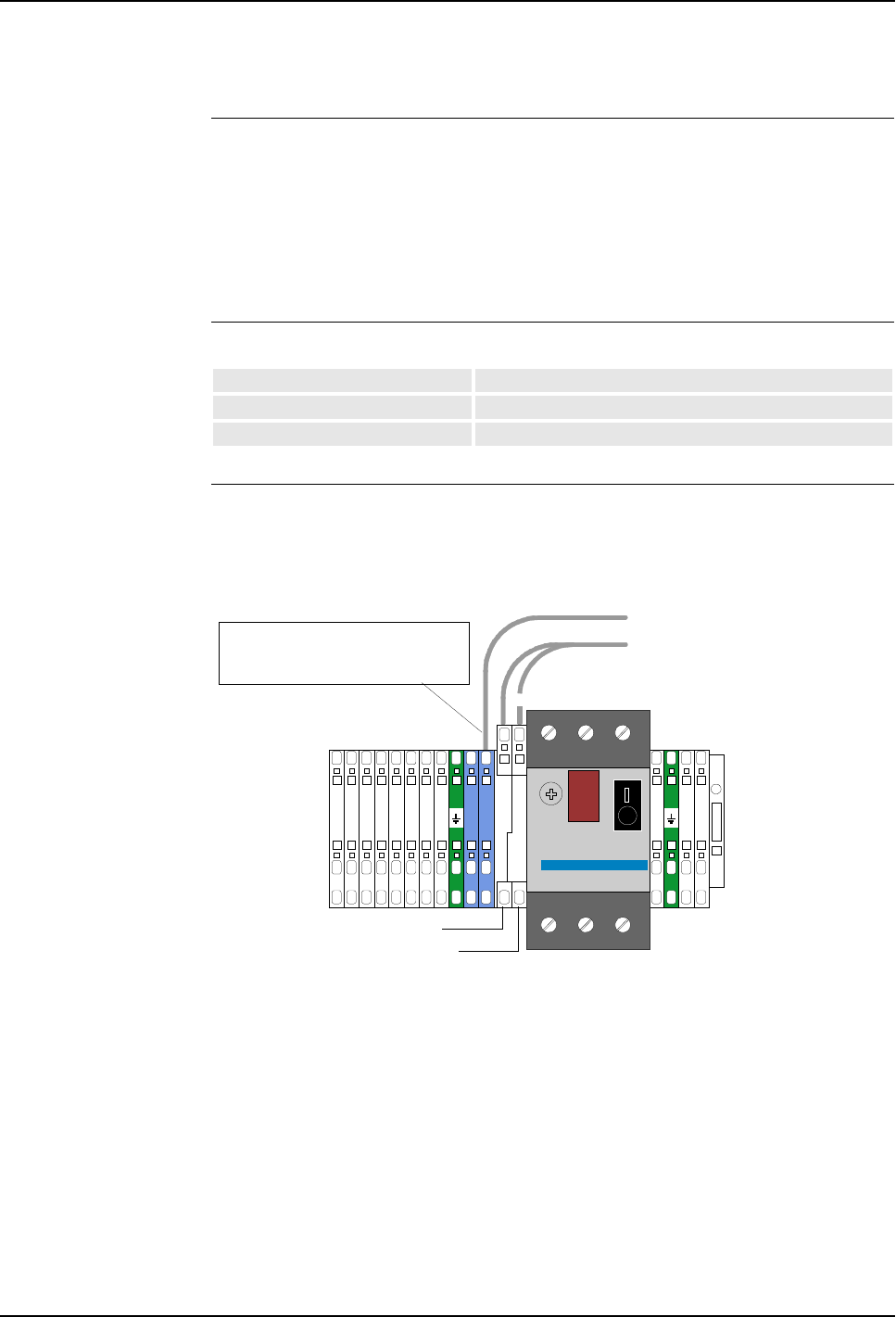
5 Installation and Commissioning
Product Manual, Control Cabinet IRC5P 3HNA009834-001 en Rev.06 119
5.8 Power Connections
5.8.5 Internal Supply for Service Outlet
General The robot has an AC supply available for external and internal use.
This voltage is used in the robot for supply of optional electric outlet, normally
located on the front of the control cabinet.
The AC supply is not galvanically separated from the rest of the controller voltages
(Common Neutral).
Specification
Connections AC supply is available for customer on the transformer terminal board as shown in
the illustration below.
Figure 62 115/230 VAC terminals
For information on tightening torque for terminal connections, see ’Tightening
Torques’ on page 216.
Voltage 115 or 230 V
Permitted customer load Max. 700 VA
Fuse size 3.15 A (230 V), 6.3 A (115 V)
Neutral
Supply overload
protection, FR2
475V
475V
525V
525V
525V
600V
600V
600V
6.3
3.15
0
ST1
ST1
Live (Connect to 230V
or 115V as required)
Fuse FU1 - 230V, 3.15A
Fuse FU2 - 115V, 6.3A
Note: If electric outlet on cabinet
front is fitted with fuse, live wire is
connected to other side of FU2/FU3
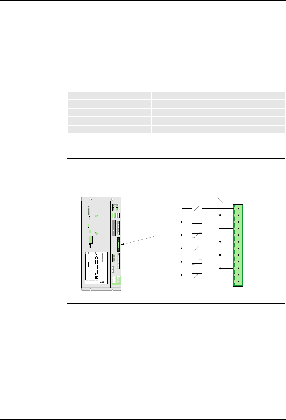
5 Installation and Commissioning
5.8 Power Connections
120 3HNA009834-001 en Rev.06 Product Manual, Control Cabinet IRC5P
5.8.6 24 VDC for External Use
General The robot has a 24VDC supply available for customer connections called 24V I/O.
The supply is a general purpose supply which can be used to supply digital inputs
and outputs or other external units connected to the robot control cabinet.
Specifications
24V I/O is not galvanically separated from the rest of the controller voltages
Connection Connections are available on circuit board PDB, connector X18 as shown below.
For location of the PDB board, see ’Controller Connections Overview’ on page 42.
Figure 63 24V I/O terminal board, +2-XT2
External 24 VDC Supply The internal supply can not be used in the following cases:
• When more power is needed than can be supplied by the internal supply.
• When the emergency stop circuits are to be independent of whether or not the
robot is powered.
• When there is a risk that major interferences can be carried over into the internal
24V supply.
An external supply is recommended to make use of the advantages offered by the
galvanic insulation on the I/O units.
The neutral wire in the external supply must be connected in such a way to prevent
the maximum permitted potential difference in the chassis earth from being
Voltage: 24.0 - 26.4V
Ripple: Max. 0.2V
Permitted customer load: Max. 5A - Max. 3A/channel
Current limit: Max. 10A ±20%
Short-circuit current: Max. 13A
X4
X9 X8
X10
X6
X7
X11
X14
X15
X1
X12 / X13
X5
X2
X3
LEDS
AC
TEMP
PC
SYS
I/O
FAN
BRAKE
ULTRA CAP
HV
LEDS PDB-01
X18
X23
X20
X16
X17
X25
X24
X21
POWER DISTR IBUTION BOARD
PDB-01 ABB AS, Robot ics
+24V_IO
3A Fuses 1
2
3
4
5
6
7
8
9
10
11
12
X18
Power Distribution
Borad, PDB
Customer
connection

5 Installation and Commissioning
Product Manual, Control Cabinet IRC5P 3HNA009834-001 en Rev.06 121
5.8 Power Connections
exceeded. For example, a neutral wire must be connected to the chassis earth of the
controller, or some other common earthing point. External supply must confirm to
following specifications.
Potential difference to chassis earth: Max. 60 V continuous
Permitted supply voltage: 19 - 35 V including ripple

5 Installation and Commissioning
5.9 Concluding Activities
122 3HNA009834-001 en Rev.06 Product Manual, Control Cabinet IRC5P
5.9 Concluding Activities
Description The controller is now installed and all required connections correctly made. Before
continuing the installation activities such as installing the manipulator and starting
up the system, all connections should be verified as required and the ‘Installation
Checklist’ supplied with the robot should be filled in.
6 Preventive Maintenance
Product Manual, Control Cabinet IRC5P 3HNA009834-001 en Rev.06 123
6.1 Introduction
6 Preventive Maintenance
6.1 Introduction
About this Chapter This chapter provides instructions for performing scheduled preventive
maintenance on the control cabinet.
The preventive maintenance is based on a maintenance chart with information about
required maintenance activities including intervals, and references to procedures for
the activities.
Note that the intervals described are recommended intervals. The intervals needed
for your installation may vary, depending on environmental conditions, number of
working hours etc. The maintenance routines in this description must be seen in
relation to the plant’s own maintenance routines for the paint equipment.
Safety Information Before any work described in this chapter is commenced, it is extremely important
that all information concerning safety is carefully studied.
There are general safety aspects that must be read through, as well as more specific
safety information that describes danger and safety risks when performing the
procedures. Read the Safety Manual before performing any service work.
WARNING! No maintenance work must be performed on the controller before the
safety guidelines in the ‘Safety Manual’ have been read and understood. Work must
only be performed by skilled personnel with the proper training.
General Considerations The prime objective of any preventive maintenance program is to ensure maximum
system availability. Each scheduled and properly performed preventive maintenance
activity should assist in realizing this objective. Preventive maintenance that does
not reduce system downtime is unnecessary and costly.
The robot and paint system is designed to be able to work under very demanding
conditions with a minimum of maintenance. Nevertheless, certain routine checks
and preventative maintenance must be carried out at given periodical intervals.
When performing routine maintenance or repair work, a number of precautions
must be kept in mind to avoid introducing additional errors into the system.
• Do not perform more than recommended preventive maintenance on equipment
which is working satisfactorily.
• Wipe all surfaces clean before starting maintenance procedures.
• To avoid unnecessary contamination by dust etc., always clean outside of control
cabinet and manipulator before opening the cabinet door.

6 Preventive Maintenance
6.2 Maintenance Chart
124 3HNA009834-001 en Rev.06 Product Manual, Control Cabinet IRC5P
6.2 Maintenance Chart
Maintenance Activity
Overview Perform activities described in the list.
*1 Interval strongly dependent on environmental conditions.
*2 Depending on robot operating hours and temperature.
No. Activity and reference Interval Sign.
1’General Maintenance’ on page 125. Daily *1
2’Clean/Replace Filter’ on page 126. 500 hours*1
3Replace the measuring system battery, as described in
’Replacement of Measuring System Battery’ on page 167. For
more information, see ’Checking the Measuring System Battery’
on page 127.
7,000 hours*2
4Replace fan units in control cabinet, as described in ’Replacement
of Door Fan Unit’ on page 135, ’Replacement of Computer Fan
Unit’ on page 153 and ’Replacement of Servo Fan Unit’ on page
159.
50,000 hours*1
5’Check the Cooler’ on page 128, if cooler is fitted. Monthly*1
2
3
5
4
4
4

6 Preventive Maintenance
Product Manual, Control Cabinet IRC5P 3HNA009834-001 en Rev.06 125
6.3 General Maintenance
6.3 General Maintenance
General Following points should be checked / attended to as often as required. The necessity
of maintenance is strongly dependent on the operating environment for the robot,
the type of operation performed, etc.
Cleaning the Controller The control cabinet should be cleaned as often as required. Strong and/or flammable
solvents such as acetone etc. should be avoided.
Check Controller Heat
Emission Check that controller heat emission is not restricted by any of the following:
• The controller is covered with plastic or other material.
• The controller does not have sufficient clearance at the back and sides.
• The controller is located close to a heat source.
• Items are placed on top of the controller.
• The controller is dirty.
• One or more cooling fans are not running.
• The fan air inlet and/or outlet is blocked.
• The air filter is dirty.
Important: The controller front door must always be kept closed when no work is
being performed inside the controller.
Cleaning the Pendant The pendant must be cleaned as often as required. Although the panel film is
resistant against most solvents, strong solvents such as acetone etc. should be
avoided. If practical, pendant should be disconnected and taken to a clean place
when not in use.
Indicator Lamps Replace defective light bulbs. If the plastic lens is cracked or worn, replace lens.
Cooler If the robot is fitted with cooler, empty drain water container as required. For
complete maintenance instructions for the cooler, please see producer’s
documentation, supplied with the cooler.
Cleaning the Controller
Interior The inside of the controller should be cleaned from time to time e.g. once a year
depending on environmental conditions. It is especially important that cooling fans
and air inlet / outlet are kept clean. When cleaning, use a dusting brush and a
vacuum cleaner to collect the dust brushed off. Do not clean components directly
with the vacuum cleaned as this may cause ESD discharge which may damage
components.
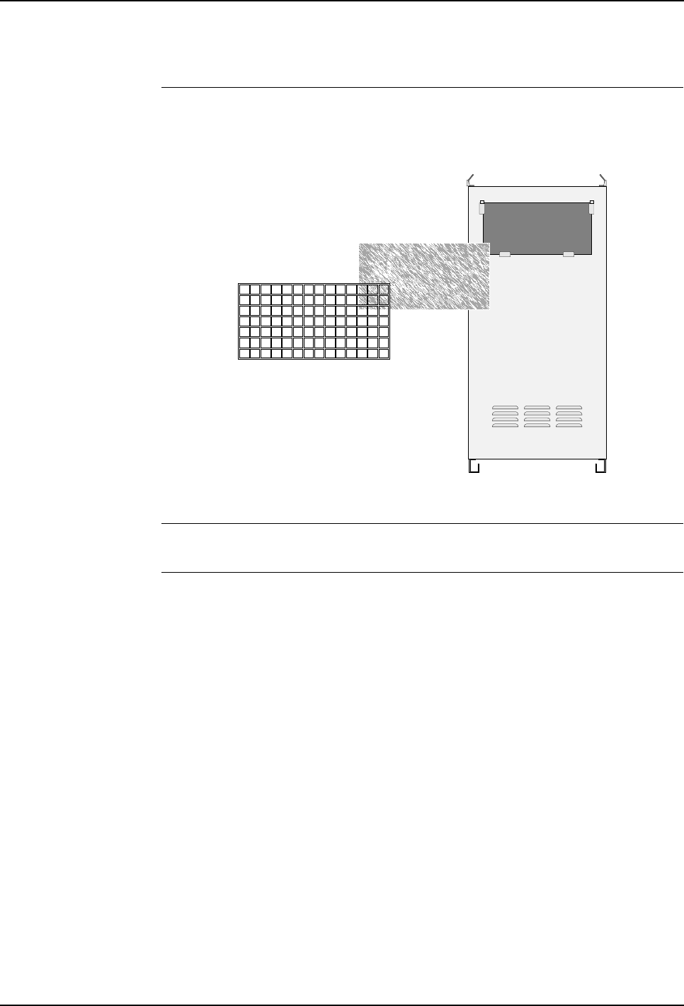
6 Preventive Maintenance
6.4 Clean/Replace Filter
126 3HNA009834-001 en Rev.06 Product Manual, Control Cabinet IRC5P
6.4 Clean/Replace Filter
Location The filter is located on the rear side of the cabinet.
Figure 64 Location of drive system cooling unit filter
Tools and Items – Filter (alternatively clean old filter).
Procedure 1. Locate filter on back of cabinet.
2. Lift filter holder up and out.
3. Remove old filter from filter holder.
4. Insert new filter in filter holder.
As an alternative to replacing the filter, the filter may be cleaned. Clean the
filter three or four times in 30-40°C water with washing-up detergent. The filter
must not be wrung out, but should be allowed to dry on a flat surface.
Alternatively, the filter can be blown clean with compressed air from the clean-
air side.
5. Slide filter holder with new filter in and down into position.
The cabinet can be operated without filter if the environment is clean.
Filter holder
Filter

6 Preventive Maintenance
Product Manual, Control Cabinet IRC5P 3HNA009834-001 en Rev.06 127
6.5 Checking the Measuring System Battery
6.5 Checking the Measuring System Battery
Description The measuring system battery is a disposable (non-rechargable) battery. When the
battery is due for replacement a message will appear in the message log. Life time
after this message is approx. 1800 hours. The battery is only used when the control
cabinet is switched ‘off’. The battery service life time is approx. 7000 hours.
It is recommended to replace the battery when the message appears. For information
on how to replace the battery, see ’Replacement of Measuring System Battery’ on
page 167.
Note: If the control cabinet controls a CBS unit in addition to the robot, or if the
robot is an 8 axis robot, the life time for the battery will be half the time described
above (2 e.a. SMU units are used).
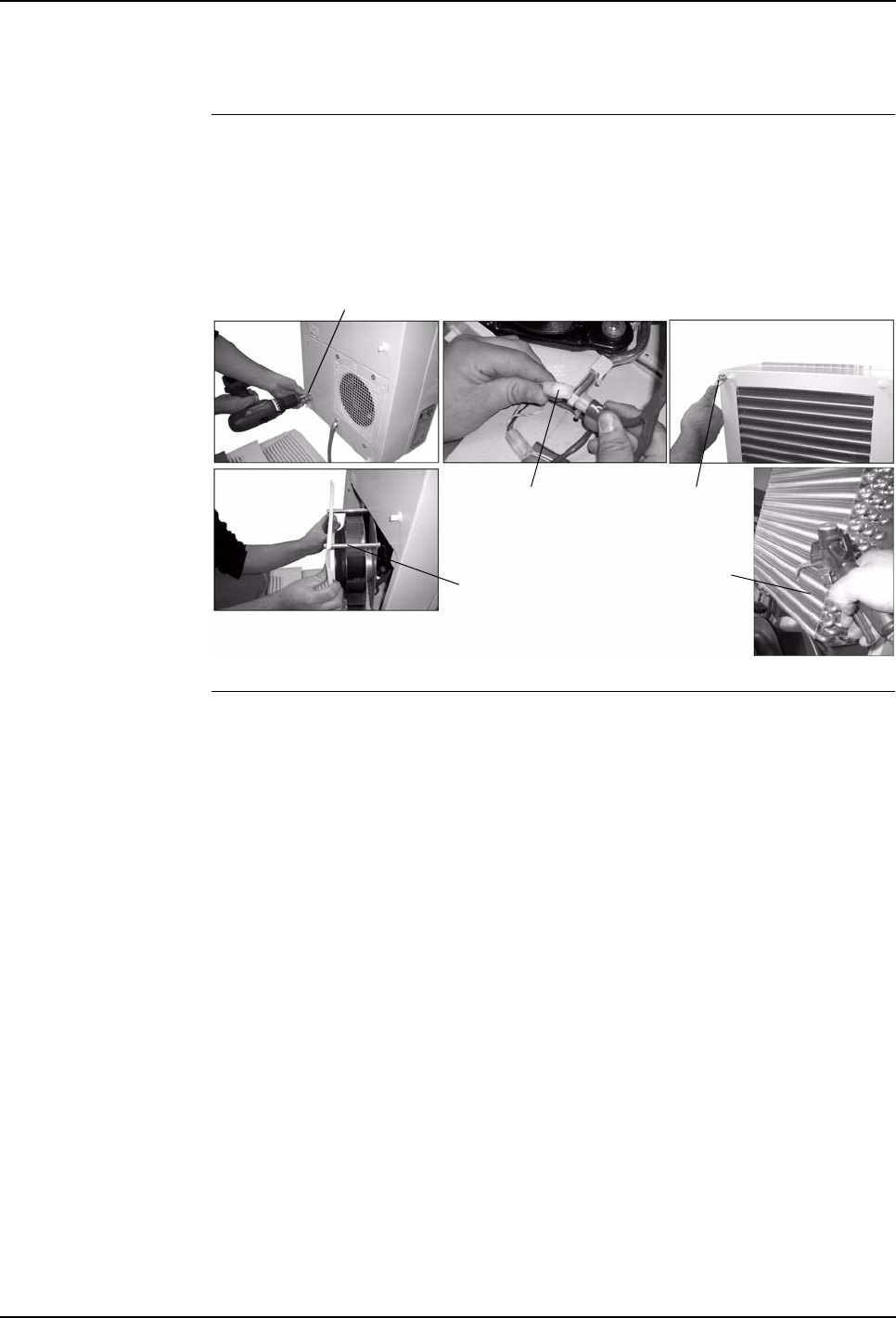
6 Preventive Maintenance
6.6 Check the Cooler
128 3HNA009834-001 en Rev.06 Product Manual, Control Cabinet IRC5P
6.6 Check the Cooler
Description The cooling circuit is designed in the form of a maintenance free, hermetically
sealed system. Periodically the components of the external air circuit must be
checked and cleaned as required.
With high ambient humidity check that water is running regularly out of the drain.
Figure 65 Cooler disassembly
Procedure 1. Remove louvered grill from the cooler enclosure and disconnect connector
from the display.
2. Remove filter from louvered grill, if installed. Clean filter with a vacuum
cleaner, or replace as required.
3. Remove the external circuit fan by removing 4 e.a. screws (65/1).
4. Remove the fan (65/2).
5. Disconnect the fan connectors (65/3).
6. Remove the cover by removing 4 e.a. screws (65/4).
7. Push back the display cable through the cable gland.
8. Remove the cover from the cooler enclosure.
9. Remove the earth cable, connecting the cover to the enclosure, from the
enclosure.
10. Clean the louvered grill, cover, fan, heat exchanger coil (65/5) and compressor
chamber, using a vacuum cleaner or compressed air. Any stubborn oil stains
may be removed using a nonflammable detergent, such as a degreaser.
For more information, see manufacturer’s documentation.
1
2
34
5
7 Repair
Product Manual, Control Cabinet IRC5P 3HNA009834-001 en Rev.06 129
7.1 Introduction
7 Repair
7.1 Introduction
About this Chapter This chapter details all repair activities recommended for the controller.
It is made up of separate procedures, each detailing a specific repair activity. Each
procedure contains all information required to perform the activity, such as required
tools and items.
Safety Information Before any work described in this chapter is commenced, it is extremely important
that all information concerning safety is carefully studied.
There are general safety aspects that must be read through, as well as more specific
safety information that describes danger and safety risks when performing the
procedures. Read the Safety Manual before performing any service work.
WARNING! No repair work must be performed on the robot before the safety
guidelines in the Safety Manual have been read and understood. Work must only be
performed by skilled personnel with the proper training.
Organization of
Procedures The procedures are divided into a procedure for removal and a procedure for
refitting. At the start of each procedure, a reference list shows information located
other places in the manual than in the procedure. If you want to print out a
procedure, you should also print the information referred to under reference to get
all information you need to perform the repair operation.
The manual describes the type of service work that can be carried out by the
Customer´s own service staff on site. Certain types of work, requiring special
experience or special aids, are not dealt with in the manual. In such cases, the
defective module or component should be replaced on site. The faulty item should
be sent to your local ABB organization for service.
Replacement Items Make sure that any replacement items are available before performing any repair
procedures. Use only replacement items listed in the spare parts catalogue.
Purge System During operation, the manipulator is supplied by compressed air (ex-version). For
this reason, the robot can not operate unless all covers are in place and properly
sealed. Missing screws will cause air leaks and result in increased air consumption
or failure in the purge system. This does not apply for non-ex robots.
Tightening Torque Generally, all screws must be tightened with correct torque, as described under
’Tightening Torques’ on page 216.

7 Repair
7.1 Introduction
130 3HNA009834-001 en Rev.06 Product Manual, Control Cabinet IRC5P
Tools All repair activities on the control cabinet can be performed with normal hand tools.
Illustration References References to illustrations are placed in brackets ( ) indicating figure number and
position in the figure. Example: (15/3) means figure 15 position 3.
Calibration Calibration of the robot must be performed after replacing mechanical parts, when a
resolver error has occurred or when the power supply between a measuring board
and resolver has been interrupted etc.
Calibrating the robot means to place the robot arm and wrist in a specific position
and enter resolver data for this position into the control system. To place the arm
and wrist in this position, a calibration fixture must be available.
For description of the calibration function and procedure for entering calibration
data, see ‘Operator’s Manual - IRC5P’.
ESD Precautions Electronic devices are sensitive to static electricity. If handled incorrectly, the unit
may be permanently damaged. Following precautions should be taken at all times
when handling sensitive electronic units.
• ALWAYS keep electronic units protected in static shielded plastic bags when not
installed in the robot. These bags are made from a special conductive material
which will prevent build-up of static electricity.
• ALWAYS wear wrist strap when installing or removing electronic units in the
controller. The strap is grounded on the control cabinet. The wrist strap includes
a 1Mohm resistor and is of no danger with respect to electric shock hazards. The
wrist strap is located inside the controller on the cabinet front door on left hand
side of the computer unit.
• NEVER place electronic components on a conductive surface such as an iron
plated table or the control cabinet top etc.
• NEVER store or place sensitive electronic devices near strong electrostatic,
magnetic or radioactive fields.
See also information on ESD precautions in the ‘Safety Manual’.
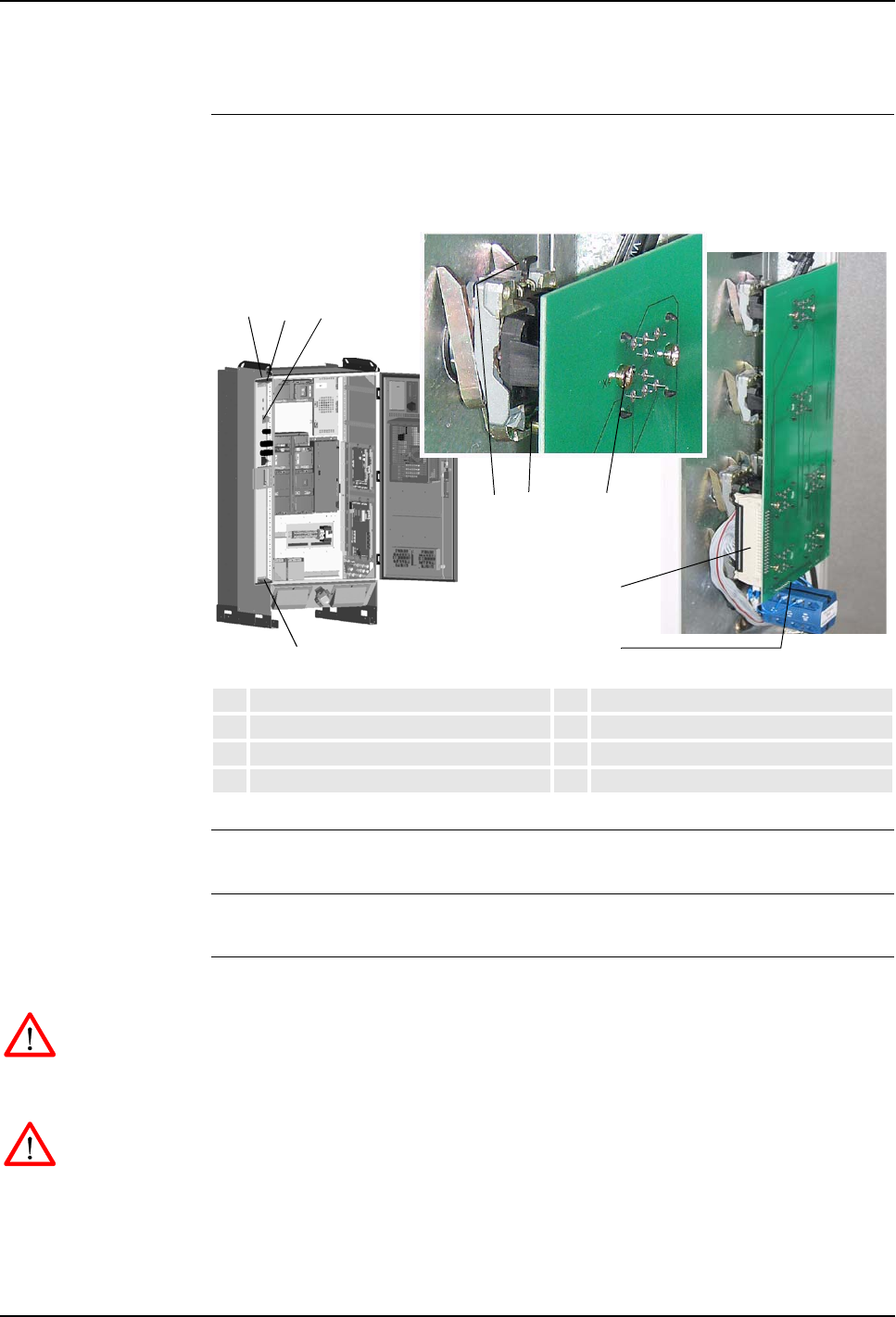
7 Repair
Product Manual, Control Cabinet IRC5P 3HNA009834-001 en Rev.06 131
7.2 Replacement of Control Panel Board, CPB
7.2 Replacement of Control Panel Board, CPB
Location The Control Panel Board is located on the panel door on the left side of the
controller front as shown below.
Figure 66 Control panel board, CPB
References – For information on the CPB board, see ‘Unit Description, IRC5P’
Tools and Items – Hand tools
Removal The procedure describes how to remove the control panel board.
WARNING! No repair work must be performed on the robot before the safety
regulations in ’Safety’ on page 13 have been read and understood.
1. Turn the electrical disconnect switch ‘off’ and lock switch in ‘off’ position.
WARNING! Make sure that the mains switch is ‘off’ and locked in ‘off’ position
before continuing. Also make sure that possible other connected systems are ‘off’.
2. Open controller front door.
3. Open panel door (66/2) by lifting upper- and lower door clamps (66/3).
1Control Panel Board, CPB 5Panel board connector
2Panel door 6Panel attachment screws
3Panel door clamps 7Button attachment screw
4Mode selector connector 8Button locking pin
12 3
34
5
68 7
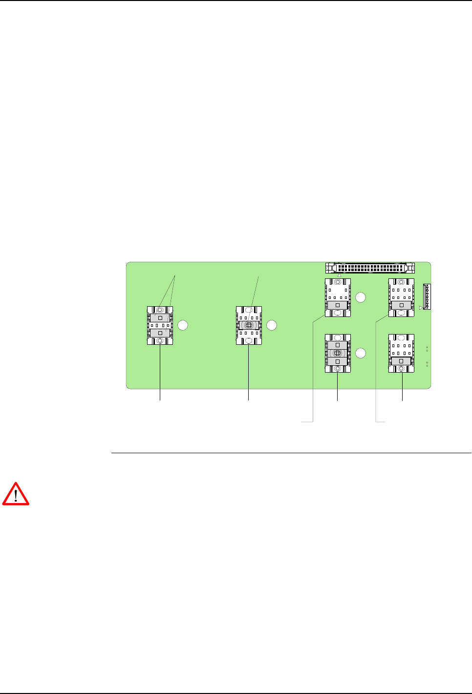
7 Repair
7.2 Replacement of Control Panel Board, CPB
132 3HNA009834-001 en Rev.06 Product Manual, Control Cabinet IRC5P
4. Locate the control panel board (66/1).
5. Disconnect panel board connector (66/5).
6. Remove screws (66/6) securing panel board to panel button bodies.
7. Carefully release panel board from button bodies.
8. Disconnect mode selector connector (66/4) and remove panel board.
9. If a panel button is to be replaced, loosen button attachment screw (66/7). Lift
button locking pin (66/8) and remove button.
10. If any of the button- or lamp elements located in the panel board connectors are
defective, replace element. Make sure that the new element is located in correct
position as shown in the illustration below.
Figure 67 Panel board, location of switches and lamps
Refitting The procedure describes how to re-install the control panel board.
WARNING! Refitting activities must only be performed when controller is switched
‘off’ and all safety precautions under ‘Removal’ have been read.
1. If a panel button was removed, install new button and tighten attachment screw.
2. Connect mode selector connector to board.
3. Place new panel board in position on panel button bodies and carefully push
panel into position.
4. Install panel attachment screws and tighten.
5. Connect panel board connector.
6. Close panel door and controller front door.
Purge Indicator lamp
X6X8
X7X9
X1
X2
X3
X10
X5
X4
Panel connector to SIB
High Voltage On High Voltage Off
Motor On and
indicator lamp
Motor OffEmergency Stop
Connector for
Mode Selector
Component side
Switch elements Indicator element
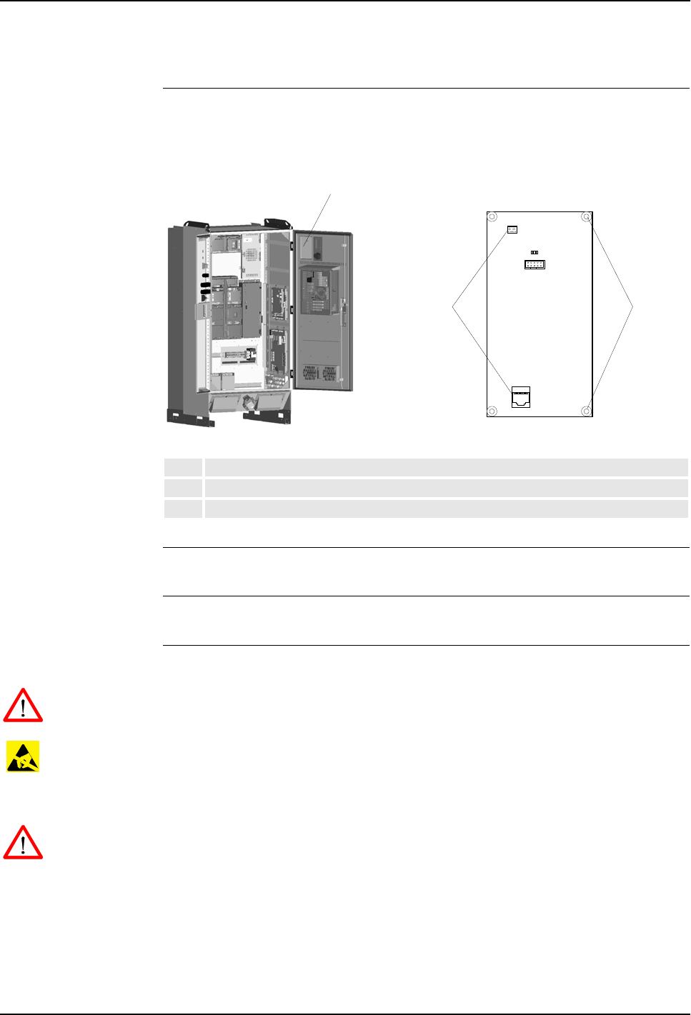
7 Repair
Product Manual, Control Cabinet IRC5P 3HNA009834-001 en Rev.06 133
7.3 Replacement of System LED Board, ALED
7.3 Replacement of System LED Board, ALED
Location The System LED Board is located at the upper right corner (front view) of the
controller front door as shown below.
Figure 68 System LED board, ALED
References – For information on the ALED board, see ‘Unit Description, IRC5P’
Tools and Items – Hand tools
Removal The procedure describes how to remove the system LED board.
WARNING! No repair work must be performed on the robot before the safety
regulations in ’Safety’ on page 13 have been read and understood.
CAUTION! The unit is sensitive to ESD. Before handling the unit, please observe
the safety information in ’ESD Precautions’ on page 130.
1. Turn the electrical disconnect switch ‘off’ and lock switch in ‘off’ position.
WARNING! Make sure that the mains switch is ‘off’ and locked in ‘off’ position
before continuing. Also make sure that possible other connected systems are ‘off’.
2. Open controller front door and locate the system LED board (68/1).
3. Disconnect connectors.
4. Remove 4 attachment screws. Retain screws for installation of new board.
5. Remove board. Note orientation of board.
1System Led Board, ALED
2Connectors
3Attachment screws
1
2 3

7 Repair
7.3 Replacement of System LED Board, ALED
134 3HNA009834-001 en Rev.06 Product Manual, Control Cabinet IRC5P
Refitting The procedure describes how to re-install the system LED board.
WARNING! Refitting activities must only be performed when controller is switched
‘off’ and all safety precautions under ‘Removal’ have been read.
1. Place the board in position over the attachment holes. Make sure the orientation
of the board is correct.
2. Install attachment screws and tighten.
3. Insert connectors.
4. Close controller front door.
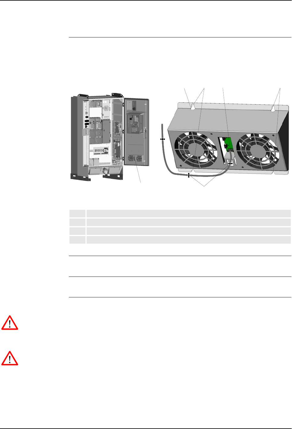
7 Repair
Product Manual, Control Cabinet IRC5P 3HNA009834-001 en Rev.06 135
7.4 Replacement of Door Fan Unit
7.4 Replacement of Door Fan Unit
Location The Door Fan Unit is used for internal circulation in the controller. The unit is
located at the lower end of the controller front door as shown below.
Figure 69 Door fan unit
References – No references
Tools and Items – Hand tools
Removal The procedure describes how to remove the fan unit on the front door.
WARNING! No repair work must be performed on the robot before the safety
regulations in ’Safety’ on page 13 have been read and understood.
1. Turn the electrical disconnect switch ‘off’ and lock switch in ‘off’ position.
WARNING! Make sure that the mains switch is ‘off’ and locked in ‘off’ position
before continuing. Also make sure that possible other connected systems are ‘off’.
2. Open controller front door and locate the fan unit (69/1).
3. Cut cable strap (69/2) securing cable to fan unit.
4. Disconnect connector (69/3).
1Door Fan Unit
2Cable strap
3Connector
4Upper and lower attachment screws
1
2344
2

7 Repair
7.4 Replacement of Door Fan Unit
136 3HNA009834-001 en Rev.06 Product Manual, Control Cabinet IRC5P
5. Loosen upper and lower attachment screws (69/4) a little.
6. Pull fan unit up and out.
Refitting The procedure describes how to re-install the fan unit.
WARNING! Refitting activities must only be performed when controller is switched
‘off’ and all safety precautions under ‘Removal’ have been read.
1. Place the fan unit in position over the attachment screws.
2. Slide the unit into position and tighten attachment screws.
3. Insert connector.
4. Secure cable with a new cable strap.
5. Close controller front door.
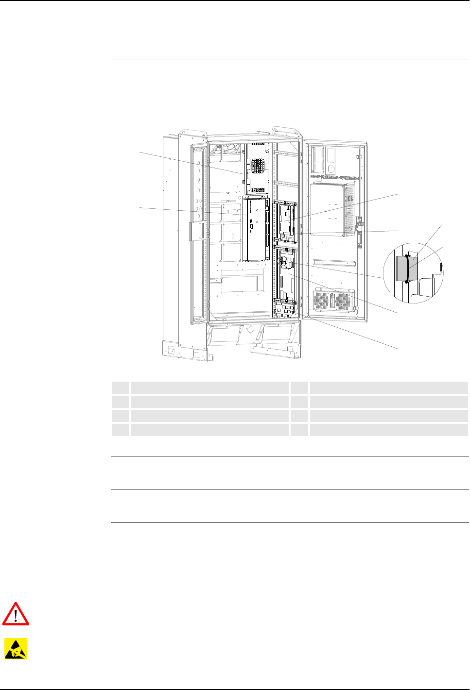
7 Repair
Product Manual, Control Cabinet IRC5P 3HNA009834-001 en Rev.06 137
7.5 Replacement of Axis Computer, PDB, PIB, SIB, MIB, SCB
7.5 Replacement of Axis Computer, PDB, PIB, SIB, MIB, SCB
Location The following procedure applies for several units which are all replaced in the same
manner. The illustration below shows the location of the included units.
Figure 70 Axis computer, PDB, PIB, SIB, MIB, SCB boards
References – For information on the boards, see ‘Unit Description, IRC5P’
Tools and Items – Hand tools
Removal The procedure describes how to remove any of the above mentioned units.
Note: When replacing the PIB board, the key chip must be moved to the new PIB
board. For information on the key chip, see ‘Unit Description, IRC5P’, section Paint
Control Module / Paint Interface Board, PIB.
WARNING! No repair work must be performed on the robot before the safety
regulations in ’Safety’ on page 13 have been read and understood.
CAUTION! The unit is sensitive to ESD. Before handling the unit, please observe
the safety information in ’ESD Precautions’ on page 130.
1Axis Computer 5Manipulator Interface Board, MIB
2Power Distribution Board, PDB 6Safety Connection Board, SCB
3Paint Interface Board, PIB 7Purge timer on MIB board
4Safety Interface Board, SIB 8Purge timer attachment o-ring
1
2
3
5
4
6
8
7
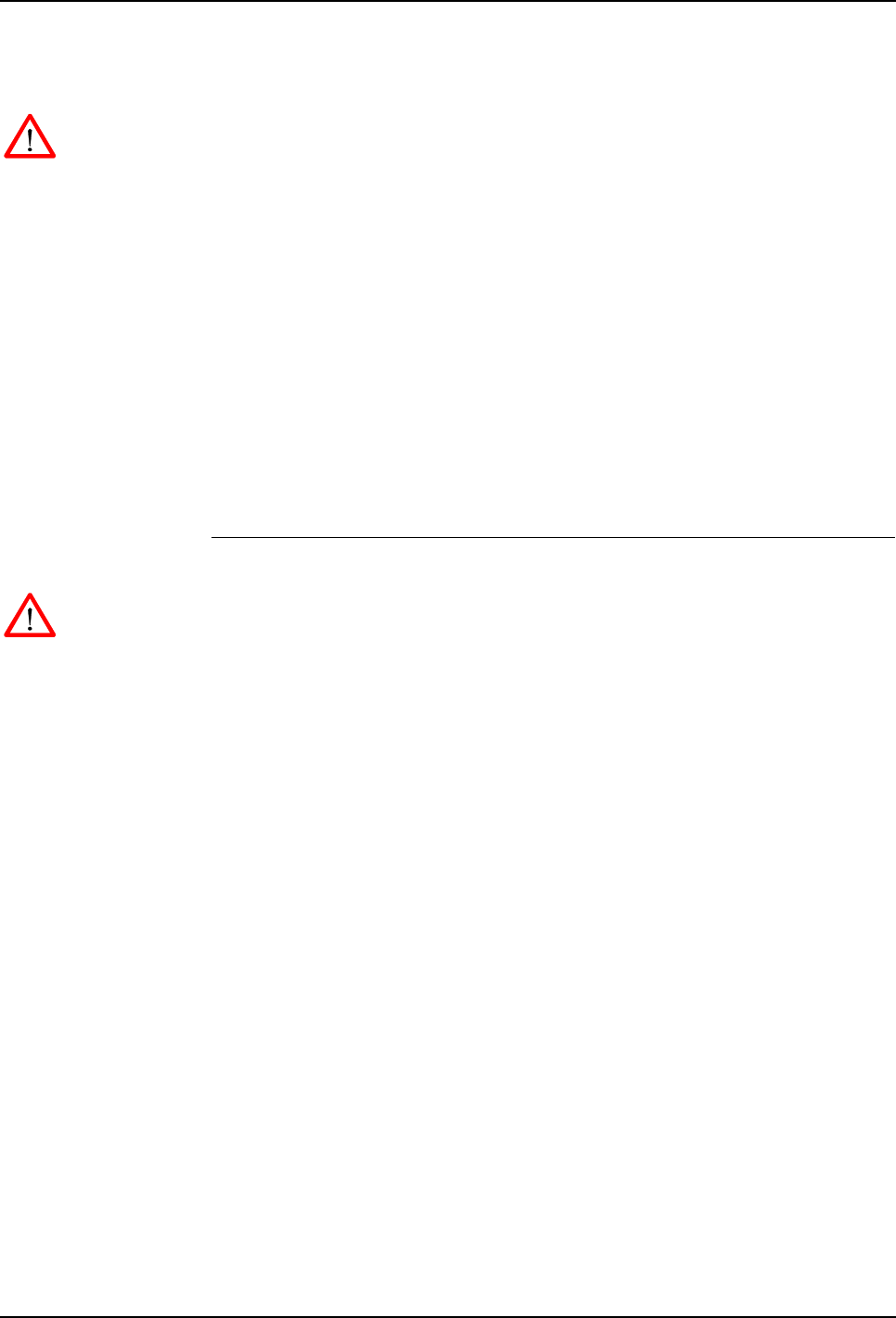
7 Repair
7.5 Replacement of Axis Computer, PDB, PIB, SIB, MIB, SCB
138 3HNA009834-001 en Rev.06 Product Manual, Control Cabinet IRC5P
1. Turn the electrical disconnect switch ‘off’ and lock switch in ‘off’ position.
WARNING! Make sure that the mains switch is ‘off’ and locked in ‘off’ position
before continuing. Also make sure that possible other connected systems are ‘off’.
2. Open controller front door and locate the unit to be replaced as shown in
Figure 70.
Note: The PIB board is mounted on top of the SIB board. Therefore, if the SIB
board is to be replaced, the PIB board must be removed first.
3. Disconnect all connectors. Note location of connectors to simplify re-
connection.
4. Slightly loosen attachment screws securing the board to the cabinet back- or
side panel. For the axis computer, the two screws on the left must be fully
removed.
5. Remove unit from controller.
Refitting The procedure describes how to re-install the board.
WARNING! Refitting activities must only be performed when controller is switched
‘off’ and all safety precautions under ‘Removal’ have been read.
Note: Make sure that the new unit is of the same type as the old unit. For
information on the different types used, see ‘Unit Description, IRC5P’.
1. Place new unit in position over the attachment screws.
2. Slide the unit into position and tighten attachment screws.
3. Insert connectors.
Note: If the SIB board was replaced, re-install PIB on top of the SIB board.
Note: If the MIB board was replaced, move battery unit from old MIB to new
MIB as required. For information, see ’Replacement of Measuring System
Battery’ on page 167. Also move purge timer (70/7) from old to new MIB
board. For more information, see ‘Unit Description, IRC5P’ manual.
4. Close controller front door.
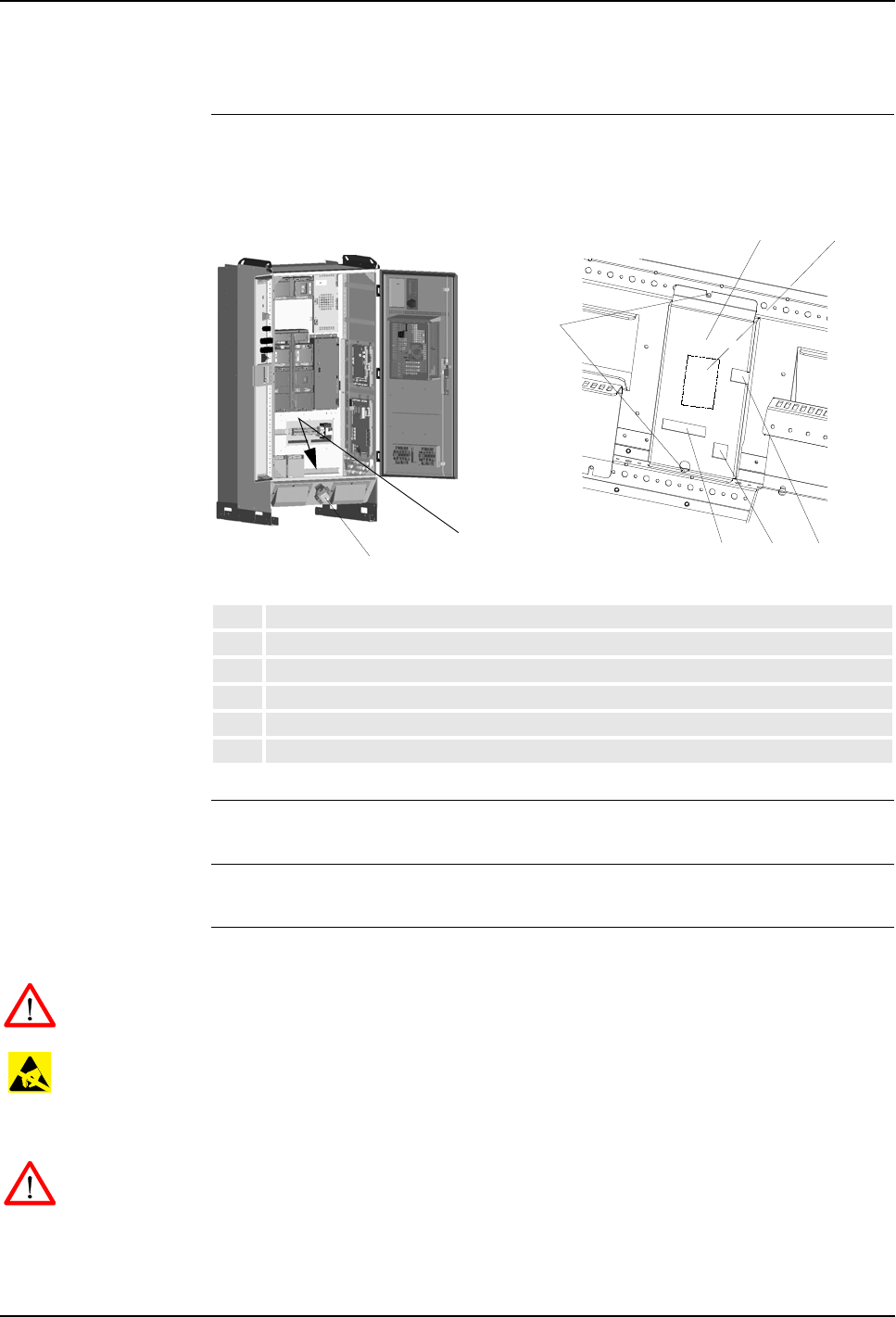
7 Repair
Product Manual, Control Cabinet IRC5P 3HNA009834-001 en Rev.06 139
7.6 Replacement of Pendant Interface Board, TIB
7.6 Replacement of Pendant Interface Board, TIB
Location The Pendant Interface Board assembly (TIB board and mounting plate) is located on
the cable entrance panel at the lower part of the controller front as shown below.
Figure 71 Pendant interface board, TIB
References – For information on the TIB board, see ‘Unit Description, IRC5P’
Tools and Items – Hand tools
Removal The procedure describes how to remove the TIB board.
WARNING! No repair work must be performed on the robot before the safety
regulations in ’Safety’ on page 13 have been read and understood.
CAUTION! The unit is sensitive to ESD. Before handling the unit, please observe
the safety information in ’ESD Precautions’ on page 130.
1. Turn the electrical disconnect switch ‘off’ and lock switch in ‘off’ position.
WARNING! Make sure that the mains switch is ‘off’ and locked in ‘off’ position
before continuing. Also make sure that possible other connected systems are ‘off’.
2. Open controller front door and locate the TIB board assembly (71/1).
1Pendant Interface Board assembly, TIB
2Pendant connector
3Upper and lower attachment screws
4TIB ribbon connector
5Ex sync signal connection
6Ground connection
2
1
12
3
456

7 Repair
7.6 Replacement of Pendant Interface Board, TIB
140 3HNA009834-001 en Rev.06 Product Manual, Control Cabinet IRC5P
3. Disconnect TIB ribbon cable (71/4), ex sync switch connection (71/5) (if used)
and ground wire connection (71/6).
4. Remove upper and lower attachment screws (71/3) securing TIB assembly
(cover and TIB board) to cabinet frame. Retain screws for re-installation. The
screws are accessed from the inside.
5. Remove TIB assembly by carefully moving board assembly out.
Note: The TIB board is inserted in the rear of the pendant connector (71/2) and
may therefore be a bit hard to remove.
Refitting The procedure describes how to re-install the TIB board.
WARNING! Refitting activities must only be performed when controller is switched
‘off’ and all safety precautions under ‘Removal’ have been read.
1. Place new TIB board assembly in position over the pendant connector inside
the cabinet.
2. Carefully press the unit into position on the connector.
3. Install attachment screws and tighten screws.
4. Insert connectors and connect ground wire.
5. Close controller front door.
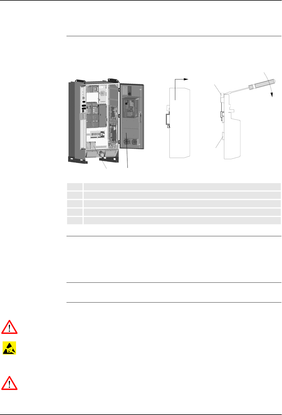
7 Repair
Product Manual, Control Cabinet IRC5P 3HNA009834-001 en Rev.06 141
7.7 Replacement of I/O Units
7.7 Replacement of I/O Units
Location A number of I/O units may be installed in the controller. The I/O units are located
on the door and/or lower part of the back wall inside the controller as shown below.
Figure 72 Distributed I/O units
References – For information on connections of the I/O unit, see ‘Unit Description, IRC5P’,
Distributed I/O.
– For information on configuration of the I/O units, see ‘Operating Manual,
RobotStudio’.
Tools and Items – Hand tools
Removal The procedure describes how to remove an I/O unit.
WARNING! No repair work must be performed on the robot before the safety
regulations in ’Safety’ on page 13 have been read and understood.
CAUTION! The unit is sensitive to ESD. Before handling the unit, please observe
the safety information in ’ESD Precautions’ on page 130.
1. Turn the electrical disconnect switch ‘off’ and lock switch in ‘off’ position.
WARNING! Make sure that the mains switch is ‘off’ and locked in ‘off’ position
before continuing. Also make sure that possible other connected systems are ‘off’.
2. Open controller front door and locate the I/O unit to be replaced (72/1,2).
1Location of I/O units
2Alternative location of I/O units
3Removing I/O unit type 1
4I/O unit type 2 spring loaded locking device
5I/O unit type 2 mounting rail
1
I/O Unit type 2I/O Unit type 1
34
5
2
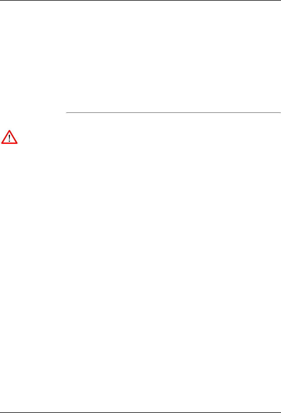
7 Repair
7.7 Replacement of I/O Units
142 3HNA009834-001 en Rev.06 Product Manual, Control Cabinet IRC5P
3. Disconnect all connectors from the unit. Note location of connectors to simplify
re-connection.
4. To remove I/O unit type 1, simply lift the unit up and out (72/3).
5. To remove I/O unit type 2, lift the spring loaded locking device with a
screwdriver until the upper claw (72/4), that holds the unit to the rail, is
released.
6. With the upper claw released, tip the unit away from the mounting rail (72/5)
and remove it.
Refitting The procedure describes how to re-install the I/O unit.
WARNING! Refitting activities must only be performed when controller is switched
‘off’ and all safety precautions under ‘Removal’ have been read.
1. Hook the unit back onto the mounting rail and snap it gently into position.
2. Reconnect all connectors disconnected during removal.
3. Close controller front door.

7 Repair
Product Manual, Control Cabinet IRC5P 3HNA009834-001 en Rev.06 143
7.8 Replacement of Computer Unit
7.8 Replacement of Computer Unit
Location The Computer Unit is located on the inside of the controller door as shown below.
Figure 73 Computer unit
References –’Replacement of Compact Flash’ on page 151
Tools and Items – Hand tools
Removal The procedure describes how to remove the complete computer unit, either to
replace the unit itself, or for replacing components inside the computer unit.
Note: For all procedures describing replacement of internal components, the
computer unit cover needs to be removed. This is performed by removing 4
attachment screws (73/4), lift off the cover (73/3) and disconnect the fan connector
(73/6).
WARNING! No repair work must be performed on the robot before the safety
regulations in ’Safety’ on page 13 have been read and understood.
CAUTION! The unit is sensitive to ESD. Before handling the unit, please observe
the safety information in ’ESD Precautions’ on page 130.
1. Turn the electrical disconnect switch ‘off’ and lock switch in ‘off’ position.
1Computer Unit 6Cover attachment screws
2Computer unit top cover 7Connectors
3Top cover attachment screws 8Cooling fan connector
4Attachment hooks 9Compact Flash card
5Computer unit cover
1
45
4
6
78
9
3
2
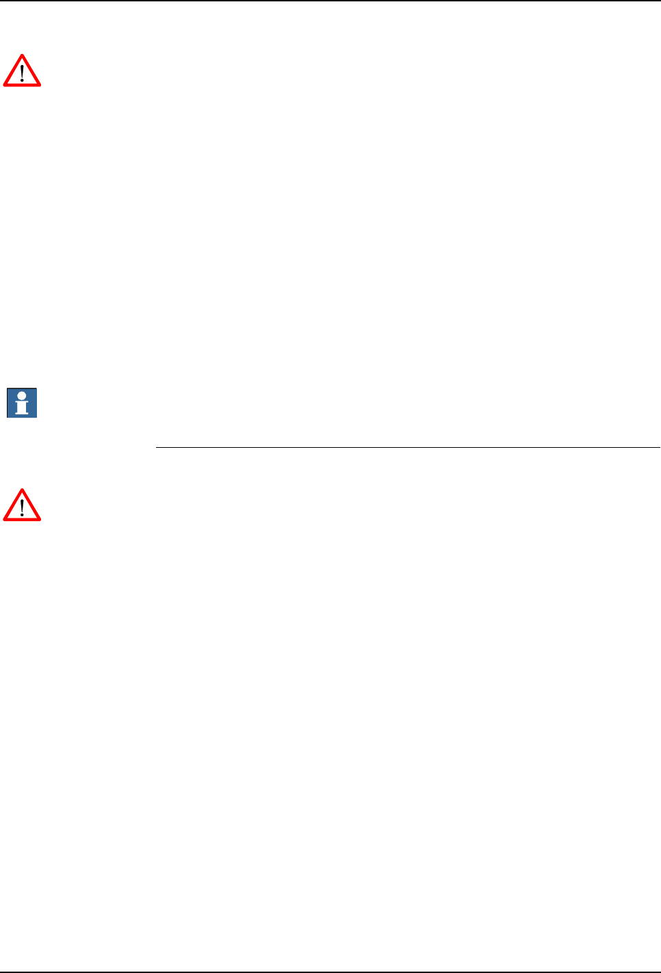
7 Repair
7.8 Replacement of Computer Unit
144 3HNA009834-001 en Rev.06 Product Manual, Control Cabinet IRC5P
WARNING! Make sure that the mains switch is ‘off’ and locked in ‘off’ position
before continuing. Also make sure that possible other connected systems are ‘off’.
2. Open the controller front door and locate the computer unit on the inside of the
door (73/1).
3. Remove computer unit top cover (73/2) by loosening cover attachment screws
(73/3).
4. Disconnect all connectors (73/7) from the computer unit. Note position of
connectors to simplify re-connection.
5. Remove Compact Flash card from computer unit (73/9). For description, see
’Replacement of Compact Flash’ on page 151.
6. Lift the complete computer unit up and out.
7. If further activities are to be performed, such as replacing a PCI card, place the
computer unit on a clean work bench and continue to the relevant procedure.
Important: When placing the computer unit on a table etc., pay attention to the
attachment hooks to avoid bending the hooks or scratching the table.
Refitting The procedure describes how to re-install the computer unit.
WARNING! Refitting activities must only be performed when controller is switched
‘off’ and all safety precautions under ‘Removal’ have been read.
1. Lift the computer unit into position.
2. Guide the attachment hooks (73/4) of the computer unit into the slots in the
controller door.
3. Lower the unit into position.
4. Re-install Compact Flash card. For description, see ’Replacement of Compact
Flash’ on page 151.
5. Reconnect all connectors to the computer unit.
6. Re-install top cover.
7. Close controller front door.
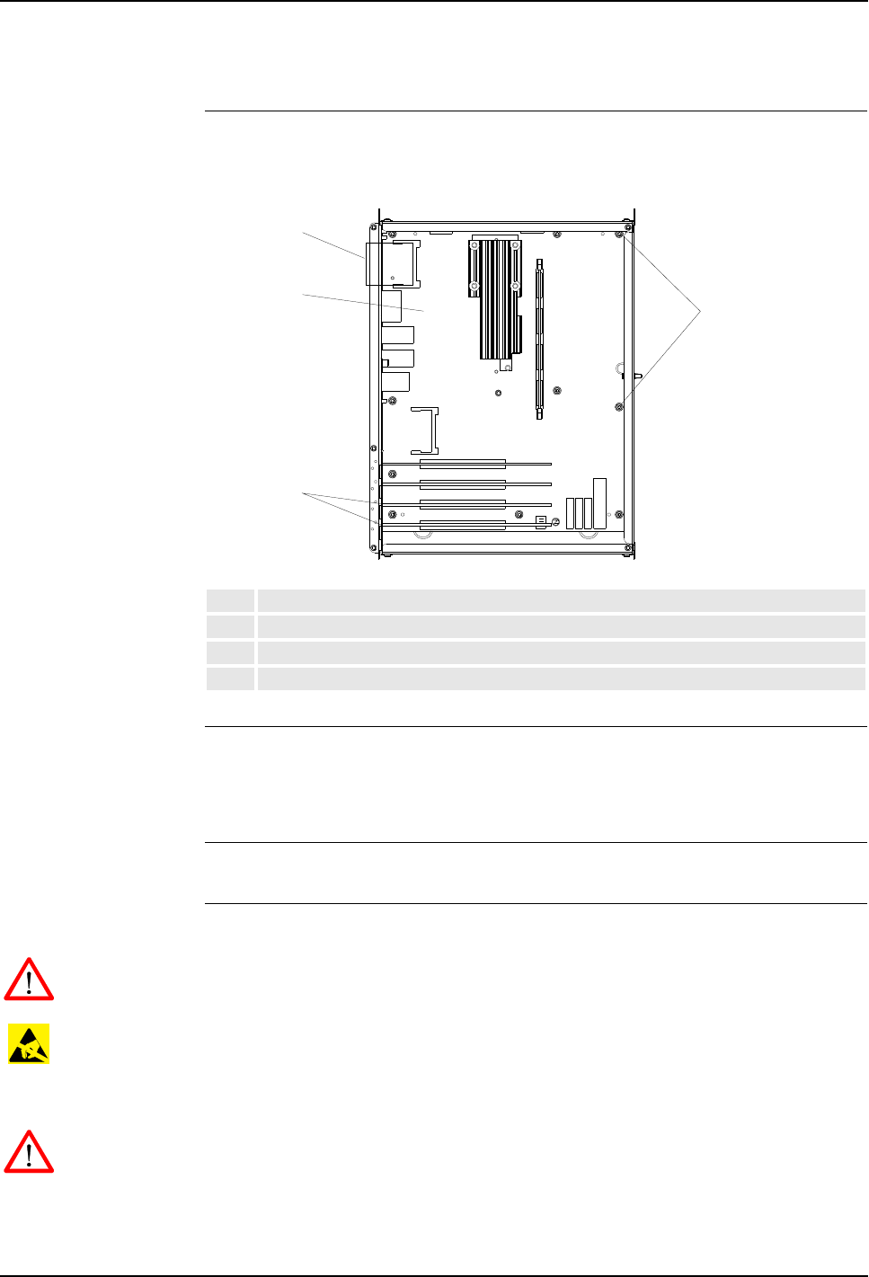
7 Repair
Product Manual, Control Cabinet IRC5P 3HNA009834-001 en Rev.06 145
7.9 Replacement of Computer Unit Mother Board
7.9 Replacement of Computer Unit Mother Board
Location The Mother Board is located inside the computer unit as shown below.
Figure 74 Computer unit, location of mother board
References –’Replacement of Computer Unit’ on page 143
–’Replacement of PCI Boards in Computer Unit Slots’ on page 147
–’Replacement of Compact Flash’ on page 151
Tools and Items – Hand tools
Removal The procedure describes how to remove the mother board from the computer unit.
WARNING! No repair work must be performed on the robot before the safety
regulations in ’Safety’ on page 13 have been read and understood.
CAUTION! The unit is sensitive to ESD. Before handling the unit, please observe
the safety information in ’ESD Precautions’ on page 130.
1. Turn the electrical disconnect switch ‘off’ and lock switch in ‘off’ position.
WARNING! Make sure that the mains switch is ‘off’ and locked in ‘off’ position
before continuing. Also make sure that possible other connected systems are ‘off’.
2. Remove the Computer Unit assembly as described in procedure ’Replacement
of Computer Unit’ on page 143.
1Computer Unit Mother Board
2Mother board attachment screws
3Compact Flash card
4PCI boards
12
4
3

7 Repair
7.9 Replacement of Computer Unit Mother Board
146 3HNA009834-001 en Rev.06 Product Manual, Control Cabinet IRC5P
3. Remove cover attachment screws, remove cover and disconnect fan unit.
4. Remove Compact Flash card from computer unit (74/3). For description, see
’Replacement of Compact Flash’ on page 151.
5. Remove any PCI cards (74/4) fitted to the mother board as described in
procedure ’Replacement of PCI Boards in Computer Unit Slots’ on page 147.
6. Remove mother board attachment screws (74/2).
7. Gently lift the mother board (74/1) out, gripping the board around the edges to
avoid damaging the board or its components.
Note: Immediately put the board in an ESD safe bag or similar.
Refitting The procedure describes how to re-install the computer unit mother board.
WARNING! Refitting activities must only be performed when controller is switched
‘off’ and all safety precautions under ‘Removal’ have been read.
1. Gently lift the mother board out of the ESD safe bag and place it into position
in the computer module.
Note: Be careful not to bend the LEDs when inserting the board.
2. Secure the board with the attachment screws.
3. Refit any PCI boards to the mother board as described in procedure
’Replacement of PCI Boards in Computer Unit Slots’ on page 147.
4. Refit the computer unit cover by connecting fan unit connector, placing cover
in position and installing attachment screws.
5. Re-install Compact Flash card. For description, see ’Replacement of Compact
Flash’ on page 151.
6. Re-install the computer unit as described in procedure ’Replacement of
Computer Unit’ on page 143.
7. Close controller front door.
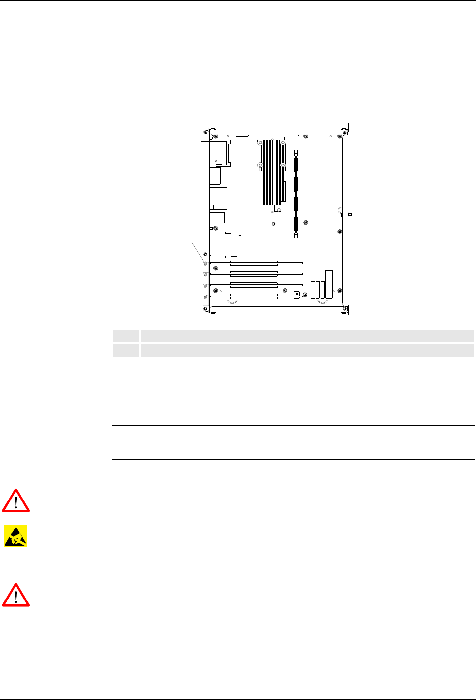
7 Repair
Product Manual, Control Cabinet IRC5P 3HNA009834-001 en Rev.06 147
7.10 Replacement of PCI Boards in Computer Unit Slots
7.10 Replacement of PCI Boards in Computer Unit Slots
Location The PCI boards, if used, are located in slots inside the computer unit as shown
below. In most cases no PCI boards are installed.
Figure 75 Computer unit, location of PCI boards
References –’Replacement of Computer Unit’ on page 143
– For information on the PCI boards, see ‘Unit Description, IRC5P’ manual
Tools and Items – Hand tools
Removal The procedure describes how to remove a PCI board.
WARNING! No repair work must be performed on the robot before the safety
regulations in ’Safety’ on page 13 have been read and understood.
CAUTION! The unit is sensitive to ESD. Before handling the unit, please observe
the safety information in ’ESD Precautions’ on page 130.
1. Turn the electrical disconnect switch ‘off’ and lock switch in ‘off’ position.
WARNING! Make sure that the mains switch is ‘off’ and locked in ‘off’ position
before continuing. Also make sure that possible other connected systems are ‘off’.
1. Remove the Computer Unit assembly as described in procedure ’Replacement
of Computer Unit’ on page 143.
2. Remove cover attachment screws, disconnect fan unit connector and remove
cover.
1-4 PCI board slot 1 - 4
5Board attachment screw
5
1
2
3
4

7 Repair
7.10 Replacement of PCI Boards in Computer Unit Slots
148 3HNA009834-001 en Rev.06 Product Manual, Control Cabinet IRC5P
3. Identify the card to be replaced.
The barcode sticker contains information on type designation.
4. Disconnect any cables on the card. Note position of connectors to simplify re-
connection.
5. Remove the attachment screw on top of the card bracket.
6. Gently lift the card out, gripping the card around the edges to avoid damaging
the card or its components.
Note: Immediately put the board in an ESD safe bag or similar.
Refitting The procedure describes how to re-install the computer unit power supply.
WARNING! Refitting activities must only be performed when controller is switched
‘off’ and all safety precautions under ‘Removal’ have been read.
1. Fit the card in position by pushing the card into the socket on the mother board.
Secure it with its attachment screw.
2. Connect any additional cables to the card. Reconnect as noted on disassembly.
3. Refit the computer unit cover by connecting fan unit connector, placing cover
in position and installing attachment screws.
4. Refit the computer unit as described in procedure ’Replacement of Computer
Unit’ on page 143.
5. Close controller front door.
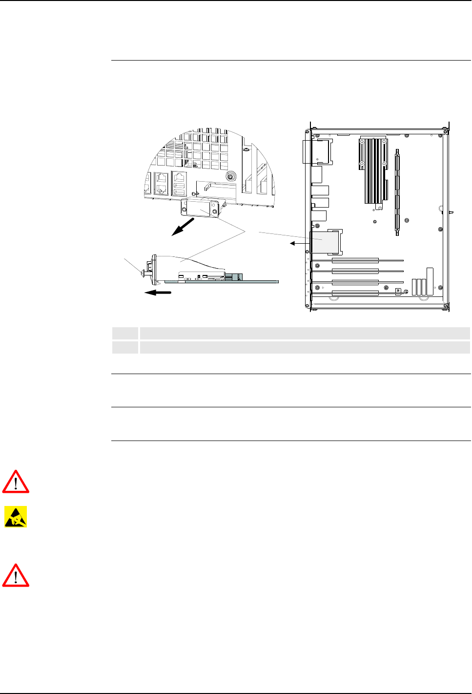
7 Repair
Product Manual, Control Cabinet IRC5P 3HNA009834-001 en Rev.06 149
7.11 Replacement of Fieldbus Adapter
7.11 Replacement of Fieldbus Adapter
Location The EtherNet/IP or Profibus fieldbus adapter, if used, is located in the compact flash
slot inside the computer unit as shown below.
Figure 76 Computer unit, location of fieldbus adapter
References –’Replacement of Computer Unit’ on page 143
Tools and Items – Hand tools
Removal The procedure describes how to remove a fieldbus adapter.
WARNING! No repair work must be performed on the robot before the safety
regulations in ’Safety’ on page 13 have been read and understood.
CAUTION! The unit is sensitive to ESD. Before handling the unit, please observe
the safety information in ’ESD Precautions’ on page 130.
1. Turn the electrical disconnect switch ‘off’ and lock switch in ‘off’ position.
WARNING! Make sure that the mains switch is ‘off’ and locked in ‘off’ position
before continuing. Also make sure that possible other connected systems are ‘off’.
1. Remove the Computer Unit assembly as described in procedure ’Replacement
of Computer Unit’ on page 143.
2. Remove cover attachment screws, disconnect fan unit connector and remove
cover.
1Fieldbus adapter
2Attachment screws fieldbus adapter
1
2
7 Repair
7.11 Replacement of Fieldbus Adapter
150 3HNA009834-001 en Rev.06 Product Manual, Control Cabinet IRC5P
3. Identify the fieldbus adapter to be replaced.
The barcode sticker contains information on type designation.
4. Disconnect the cable from the fieldbus adapter.
5. Loosen the 2 e.a. attachment screws from the fieldbus adapter to release the
fastening mechanism.
Note: Only loosen the attachment screws. Do not remove them.
6. Grip the loose attachment screws and gently pull the fieldbus adapter out, in the
arrow direction.
CAUTION! Always grip the fieldbus adapter around the edges to avoid damage to
the adapter or its components.
Refitting The procedure describes how to re-install the fieldbus adapter in the computer unit.
WARNING! Refitting activities must only be performed when controller is switched
‘off’ and all safety precautions under ‘Removal’ have been read.
1. Grip the fieldbus adapter around the edges.
CAUTION! Make sure that the adapter is pushed straight onto the rails.
2. Fit the fieldbus adapter in position by pushing the fieldbus adapter along the
rails on the mother board.
Note: Push carefully so no pins are damaged.
3. Secure it with its attachment screws on the front.
4. Connect the cable to the fieldbus adapter.
5. Refit the computer unit cover by connecting fan unit connector, placing cover
in position and installing attachment screws.
6. Refit the computer unit as described in procedure ’Replacement of Computer
Unit’ on page 143.
7. Close controller front door.
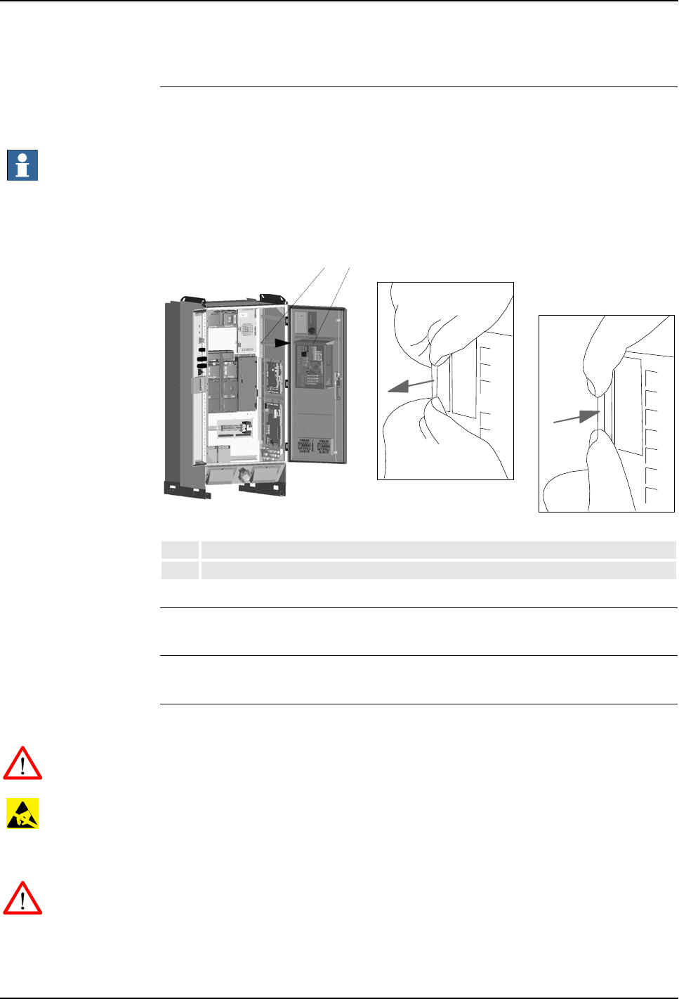
7 Repair
Product Manual, Control Cabinet IRC5P 3HNA009834-001 en Rev.06 151
7.12 Replacement of Compact Flash
7.12 Replacement of Compact Flash
Location The Compact Flash card is located on the computer unit mother board as shown
below. The card is accessible without removing the computer unit cover.
Important: The compact flash card supplied by ABB is an Industrial Standard card
which includes software to enable it to work with the robot system. Cheaper
Consumer Standard cards will not work with the robot.
Figure 77 Computer unit, location of compact flash
References – No references.
Tools and Items – No tools required.
Removal The procedure describes how to remove the compact flash from the computer unit.
WARNING! No repair work must be performed on the robot before the safety
regulations in ’Safety’ on page 13 have been read and understood.
CAUTION! The unit is sensitive to ESD. Before handling the unit, please observe
the safety information in ’ESD Precautions’ on page 130.
1. Turn the electrical disconnect switch ‘off’ and lock switch in ‘off’ position.
WARNING! Make sure that the mains switch is ‘off’ and locked in ‘off’ position
before continuing. Also make sure that possible other connected systems are ‘off’.
2. Open controller front door and locate the computer unit (77/1). Locate the
compact flash card at the upper left corner of the computer unit (77/2).
1Computer unit
2Compact Flash card location
21
Remove card
Insert card
7 Repair
7.12 Replacement of Compact Flash
152 3HNA009834-001 en Rev.06 Product Manual, Control Cabinet IRC5P
3. Make sure that the two status LEDs on the computer unit just above the flash
disk are extinguished.
4. Grip the compact flash card as shown in Figure 77.
5. Carefully pull out the card.
Refitting The procedure describes how to install the compact flash in the computer unit.
WARNING! Refitting activities must only be performed when controller is switched
‘off’ and all safety precautions under ‘Removal’ have been read.
1. Carefully position the compact flash card in the guides which are located at the
inner end of the compact flash slot.
Important: Be careful when inserting the compact flash. If you loose the grip, the
card may fall down, inside the computer unit.
2. Gently glide the card into position against the connector.
CAUTION! Be careful when performing next step as you may damage the contact
pins in the connector.
3. Make sure that the card is correctly positioned and then place one finger at each
end of the card as shown in Figure 77. Then press the card carefully into the
connector.
4. Close controller front door.
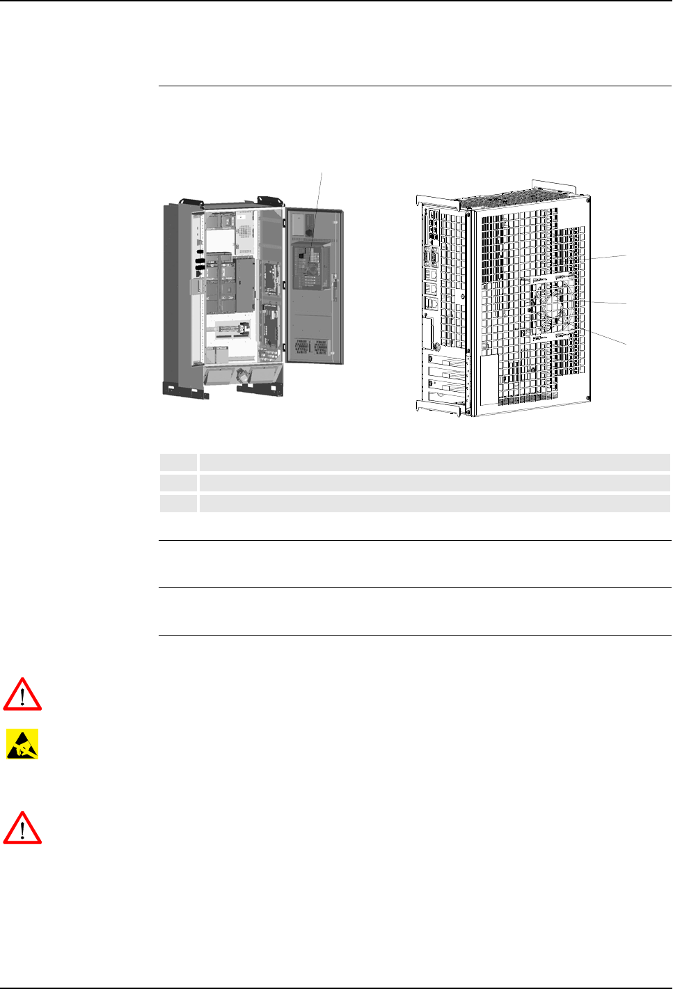
7 Repair
Product Manual, Control Cabinet IRC5P 3HNA009834-001 en Rev.06 153
7.13 Replacement of Computer Fan Unit
7.13 Replacement of Computer Fan Unit
Location The Computer Fan Unit is located inside the computer unit as shown below.
Figure 78 Computer unit, location of fan unit
References –’Replacement of Computer Unit’ on page 143
Tools and Items – Hand tools
Removal The procedure describes how to remove the computer fan unit.
WARNING! No repair work must be performed on the robot before the safety
regulations in ’Safety’ on page 13 have been read and understood.
CAUTION! The unit is sensitive to ESD. Before handling the unit, please observe
the safety information in ’ESD Precautions’ on page 130.
1. Turn the electrical disconnect switch ‘off’ and lock switch in ‘off’ position.
WARNING! Make sure that the mains switch is ‘off’ and locked in ‘off’ position
before continuing. Also make sure that possible other connected systems are ‘off’.
2. Remove the Computer Unit assembly as described in procedure ’Replacement
of Computer Unit’ on page 143.
3. Remove cover attachment screws, disconnect fan unit connector (78/2) and
remove cover.
1Computer fan unit
2Fan connector
3Fan attachment screws
1
2
3
1

7 Repair
7.13 Replacement of Computer Fan Unit
154 3HNA009834-001 en Rev.06 Product Manual, Control Cabinet IRC5P
4. Remove fan unit attachment screw (78/3).
5. Remove fan unit (78/1).
Refitting The procedure describes how to re-install the fan unit.
WARNING! Refitting activities must only be performed when controller is switched
‘off’ and all safety precautions under ‘Removal’ have been read.
1. Install new fan unit.
2. Refit the attachment screw.
3. Refit the computer unit cover by connecting fan unit connector, placing cover
in position and installing attachment screws.
4. Refit the computer unit as described in procedure ’Replacement of Computer
Unit’ on page 143.
5. Close controller front door.
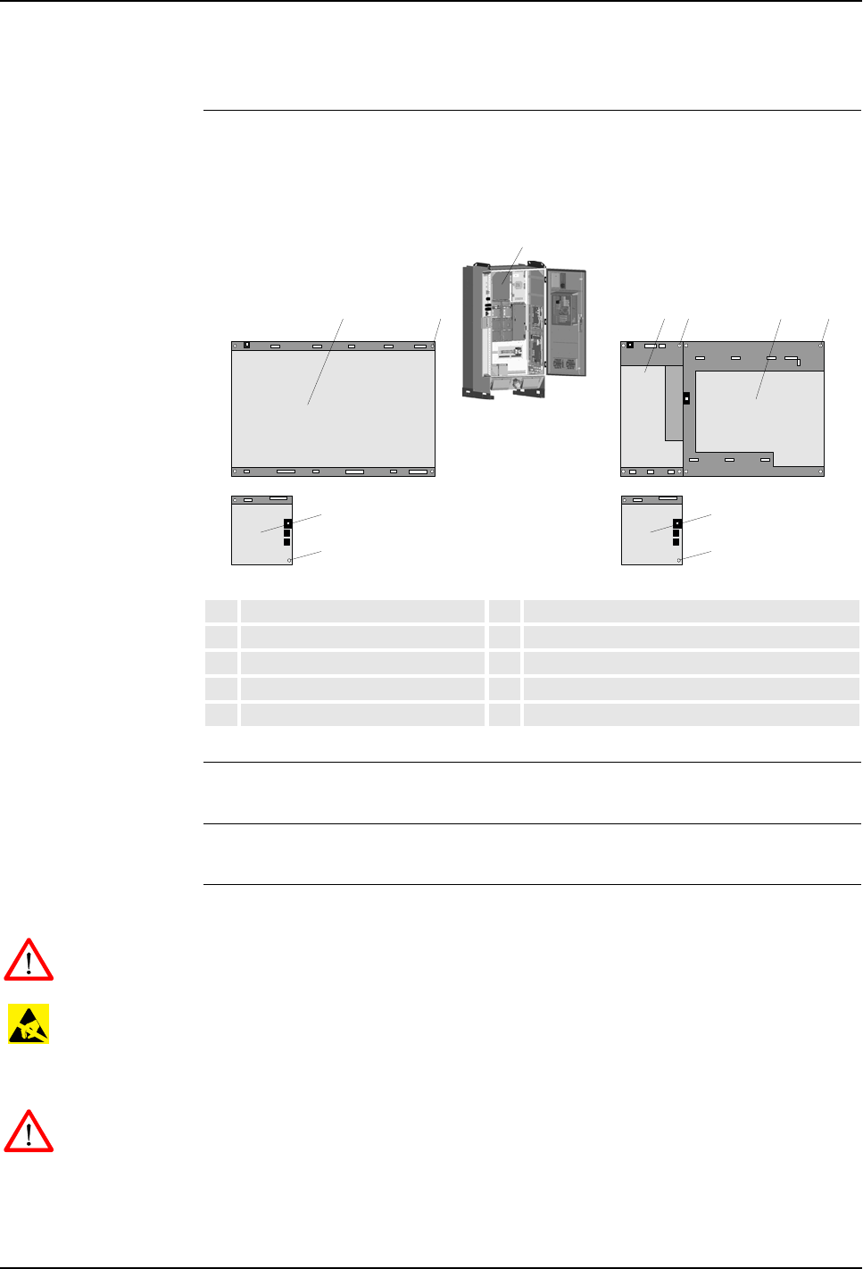
7 Repair
Product Manual, Control Cabinet IRC5P 3HNA009834-001 en Rev.06 155
7.14 Replacement of Drive System 09 Components
7.14 Replacement of Drive System 09 Components
Location The drive units, consisting of motor drive units for the robot axis motors and
possible rectifier, are located on the back panel in the controller.
Figure 79 Motor drive unit assembly
References – For information on drive unit types etc, see ‘Unit Description, IRC5P’
Tools and Items – Hand tools
Removal The procedure describes how to remove a drive unit or the rectifier unit.
WARNING! No repair work must be performed on the robot before the safety
regulations in ’Safety’ on page 13 have been read and understood.
CAUTION! The unit is sensitive to ESD. Before handling the unit, please observe
the safety information in ’ESD Precautions’ on page 130.
1. Turn the electrical disconnect switch ‘off’ and lock switch in ‘off’ position.
WARNING! Make sure that the mains switch is ‘off’ and locked in ‘off’ position
before continuing. Also make sure that possible other connected systems are ‘off’.
2. Open controller front door and locate the unit to be replaced.
3. Remove connectors from the unit that shall be removed.
1Motor drive unit assembly 6Main drive unit MDU430A
2Main drive unit MDU790A 7MDU430A attachment screw
3MDU790A attachment screw 8Additional drive unit ADU
4Additional rectifier unit ARU 9ADU attachment screw
5ARU attachment screw
2345 67
8
9
8
9
1

7 Repair
7.14 Replacement of Drive System 09 Components
156 3HNA009834-001 en Rev.06 Product Manual, Control Cabinet IRC5P
4. Unscrew attachment screws for drive unit (79/3,7,9) or rectifier (79/5).
5. Remove unit.
WARNING! Drive units and rectifier (depending on robot type) may contain residual
power. These units must only be opened by qualified personnel.
Refitting The procedure describes how to re-install a drive unit or the rectifier unit.
WARNING! Refitting activities must only be performed when controller is switched
‘off’ and all safety precautions under ‘Removal’ have been read.
Note: Make sure that the new unit is of the same type as the old unit. For
information on the different types used, see ‘Unit Description, IRC5P’.
1. Fit the new unit in its intended position and orientation.
2. Secure unit with attachment screws.
3. Reconnect connections removed during removal.
4. Close controller front door.
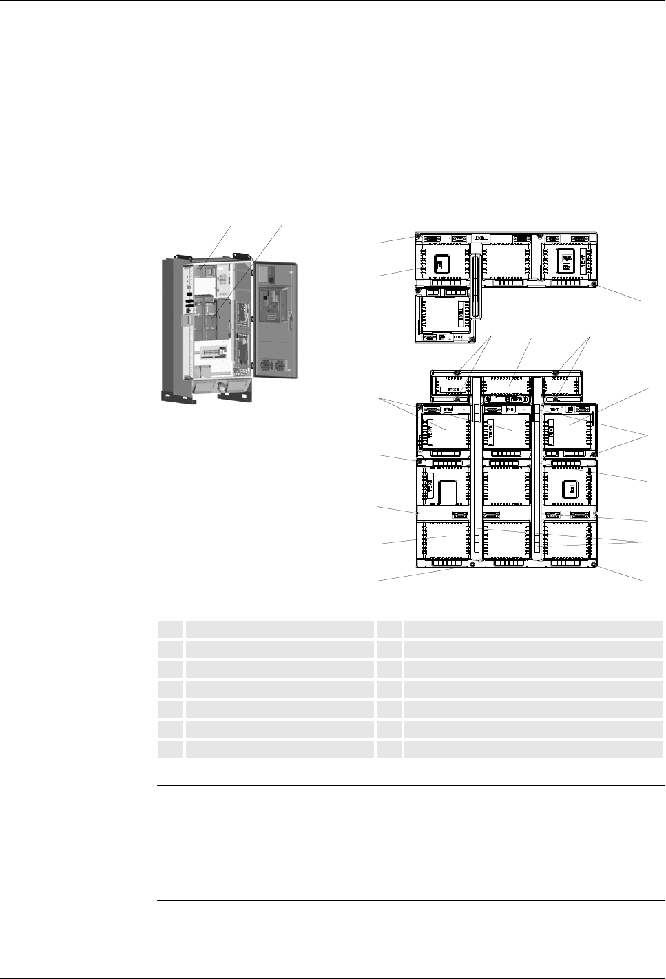
7 Repair
Product Manual, Control Cabinet IRC5P 3HNA009834-001 en Rev.06 157
7.15 Replacement of Drive System 04 Components
7.15 Replacement of Drive System 04 Components
Location The drive unit assembly, consisting of motor drive units for the robot axis motors,
rectifier and capacitor, is located on the back panel in the controller as shown below.
An additional drive unit, located above the drive unit assembly includes drivers for
paint pump motors and CBS if used.
Figure 80 Controller and drive unit assembly
References – For information on location of the individual drive units, drive unit types etc, see
‘Unit Description, IRC5P’
Tools and Items – Hand tools
Removal The procedure describes how to remove a drive unit, the rectifier unit or the
capacitor.
1Motor drive unit assembly 8Motor drive 6 pack attachment screws
2Pump drive unit assembly 9Motor drive 3 pack attachment screws
3Capacitor unit 10 Motor drive 3 & 6 pack attachment screws
4Capacitor unit attachment screws 11 Bus bars
5Rectifier unit 12 Axis 7/8 drive units, dummy or cover plate
6Rectifier unit attachment screws 13 Pump motor / CBS drive units
7Motor drive units 14 Pump motor / CBS drive unit attachment screws
12
3
11
6
9
44
10 10
8
8
9
12 5
7
14
14
13
7 Repair
7.15 Replacement of Drive System 04 Components
158 3HNA009834-001 en Rev.06 Product Manual, Control Cabinet IRC5P
WARNING! No repair work must be performed on the robot before the safety
regulations in ’Safety’ on page 13 have been read and understood.
CAUTION! The unit is sensitive to ESD. Before handling the unit, please observe
the safety information in ’ESD Precautions’ on page 130.
1. Turn the electrical disconnect switch ‘off’ and lock switch in ‘off’ position.
WARNING! Make sure that the mains switch is ‘off’ and locked in ‘off’ position
before continuing. Also make sure that possible other connected systems are ‘off’.
2. Open controller front door and locate the unit to be replaced.
3. Remove connectors from the unit that shall be removed.
4. Remove busbar (79/11) between units.
5. Unscrew attachment screws for drive unit (79/8,9,14), rectifier (79/6) or
capacitor (79/4).
6. Remove unit.
WARNING! Capacitor or Capacitor-Rectifier units (depending on robot type) may
contain residual power. These units must only be opened by qualified personnel.
Refitting The procedure describes how to re-install a drive unit, the rectifier unit or the
capacitor.
WARNING! Refitting activities must only be performed when controller is switched
‘off’ and all safety precautions under ‘Removal’ have been read.
Note: Make sure that the new unit is of the same type as the old unit. For
information on the different types used, see ‘Unit Description, IRC5P’.
1. Fit the new unit in its intended position and orientation.
2. Secure unit with attachment screws.
3. Reconnect busbar between units.
4. Reconnect connections removed during removal.
5. Close controller front door.
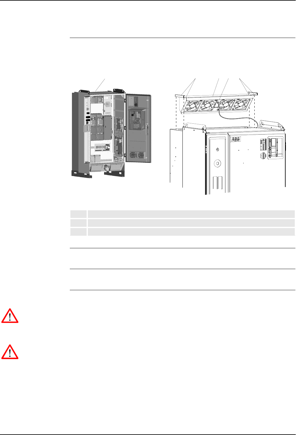
7 Repair
Product Manual, Control Cabinet IRC5P 3HNA009834-001 en Rev.06 159
7.16 Replacement of Servo Fan Unit
7.16 Replacement of Servo Fan Unit
Location The Servo Fan unit is located on the back panel in the controller as shown below.
Figure 81 Servo fan unit
References – No references
Tools and Items – Hand tools
Removal The procedure describes how to remove the fan unit servo.
WARNING! No repair work must be performed on the robot before the safety
regulations in ’Safety’ on page 13 have been read and understood.
1. Turn the electrical disconnect switch ‘off’ and lock switch in ‘off’ position.
WARNING! Make sure that the mains switch is ‘off’ and locked in ‘off’ position
before continuing. Also make sure that possible other connected systems are ‘off’.
2. Locate fan unit servo (81/1) located on the top of the cabinet rear housing.
3. Remove attachment screws (81/2) securing fan unit to cabinet. Retain screws
for installation of new unit.
4. Pull fan unit assembly up.
5. Disconnect connector (81/3).
1Fan Unit Servo
2Attachment screws
3Connector
1
2123

7 Repair
7.16 Replacement of Servo Fan Unit
160 3HNA009834-001 en Rev.06 Product Manual, Control Cabinet IRC5P
6. Remove fan unit.
Refitting The procedure describes how to re-install the fan unit servo.
WARNING! Refitting activities must only be performed when controller is switched
‘off’ and all safety precautions under ‘Removal’ have been read.
1. Insert fan unit connector.
2. Slide fan unit into position. Make sure that the unit is installed in correct
orientation as shown in Figure 81.
3. Install attachment screws and tighten.
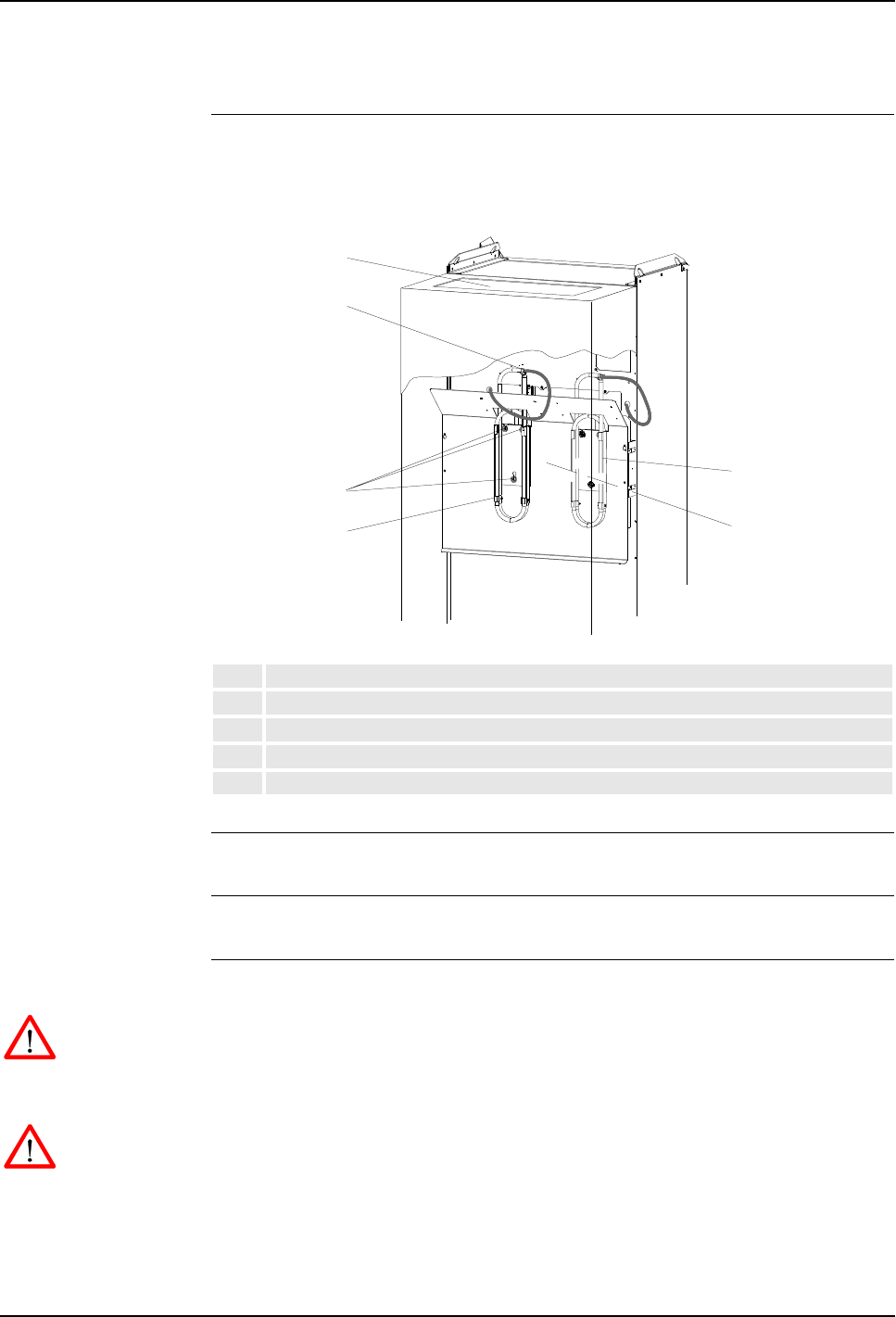
7 Repair
Product Manual, Control Cabinet IRC5P 3HNA009834-001 en Rev.06 161
7.17 Replacement of Brake Resistor Bleeders
7.17 Replacement of Brake Resistor Bleeders
Location One or two Brake Resistor Bleeders are located on the rear side of the controller as
shown below.
Figure 82 Brake resistor bleeders, controller rear view
References –’Replacement of Servo Fan Unit’ on page 159
Tools and Items – Hand tools
Removal The procedure describes how to remove the brake resistor bleeders.
WARNING! No repair work must be performed on the robot before the safety
regulations in ’Safety’ on page 13 have been read and understood.
1. Turn the electrical disconnect switch ‘off’ and lock switch in ‘off’ position.
WARNING! Make sure that the mains switch is ‘off’ and locked in ‘off’ position
before continuing. Also make sure that possible other connected systems are ‘off’.
2. Remove servo fan unit as described in ’Replacement of Servo Fan Unit’ on
page 159.
1Brake resistor bleeder 1
2Servo fan unit access hole
3Attachment screws and slots
4Connector (inside cabinet)
5Location for brake resistor bleeder 2 (used for pumps or CBS)
2
3
4
5
14
7 Repair
7.17 Replacement of Brake Resistor Bleeders
162 3HNA009834-001 en Rev.06 Product Manual, Control Cabinet IRC5P
3. Locate bleeder (82/1) to be replaced through hole (82/2) left by removed fan
unit (normally, only bleeder 1 is used).
4. Remove rectifier unit (to replace bleeder 1) as described in ’Replacement of
Drive System 09 Components’ on page 155. You may also need to remove
drive unit pack below rectifier to get access to all bleeder attachment screws.
5. Disconnect electrical connection (82/4) for bleeder. The connector is located on
the front side of the cabinet back wall.
6. Remove wires from connector using a pin extraction tool or a small
screwdriver.
7. Pull wires through hole in cabinet back wall.
8. Loosen bleeder attachment screws (82/3) a little.
9. Lift bleeder up and out.
10. Remove bleeder.
Refitting The procedure describes how to re-install the brake resistor bleeders.
WARNING! Refitting activities must only be performed when controller is switched
‘off’ and all safety precautions under ‘Removal’ have been read.
1. Slide new bleeder into position in the attachment screw holes.
2. Tighten attachment screws.
3. Route wires through hole in cabinet back wall.
4. Insert wires into connector.
5. Reconnect connector.
6. Re-install rectifier unit (and possibly drive units) as described in ’Replacement
of Drive System 09 Components’ on page 155.
7. Re-install fan unit as described in ’Replacement of Servo Fan Unit’ on page
159.
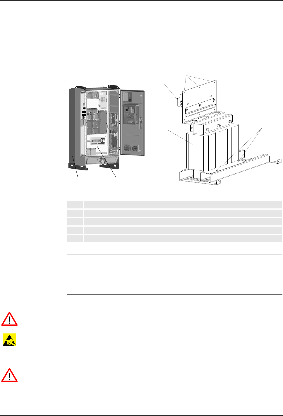
7 Repair
Product Manual, Control Cabinet IRC5P 3HNA009834-001 en Rev.06 163
7.18 Replacement of Transformer
7.18 Replacement of Transformer
Location The Transformer is located on the rear side of the controller as shown below.
Figure 83 Transformer
References – For information on the transformer, see ‘Unit Description, IRC5P’
Tools and Items – Hand tools
Removal The procedure describes how to remove the transformer unit.
WARNING! No repair work must be performed on the robot before the safety
regulations in ’Safety’ on page 13 have been read and understood.
CAUTION! The unit is sensitive to ESD. Before handling the unit, please observe
the safety information in ’ESD Precautions’ on page 130.
1. Turn the electrical disconnect switch ‘off’ and lock switch in ‘off’ position.
WARNING! Make sure that the mains switch is ‘off’ and locked in ‘off’ position
before continuing. Also make sure that possible other connected systems are ‘off’.
2. Remove control cabinet rear housing (83/2).
1Transformer (on rear side)
2Cabinet rear housing
3Transformer connections and supply overload protection
4Transformer bracket attachment screws
5Transformer attachment screws
1
3
Rear view
4
5
1
2
7 Repair
7.18 Replacement of Transformer
164 3HNA009834-001 en Rev.06 Product Manual, Control Cabinet IRC5P
3. Open controller front door and disconnect all electrical wires connected to the
top of the transformer terminal board and overload protection (83/3). Note
position of wires and main supply voltage to ensure correct re-connection. See
also ’Transformer Wiring’ on page 117 and ’Internal Supply for Service Outlet’
on page 119.
4. Remove 6 transformer bracket attachment screws (83/4) from inside of the
cabinet.
5. Remove 2 transformer attachment screws (83/5) at the back securing the
transformer to the cabinet bottom plate or use alternative method described
below.
CAUTION! The transformer is heavy (approx. 60kg). For this reason, be careful
when performing the next step.
6. Remove transformer.
Refitting The procedure describes how to re-install the transformer unit.
WARNING! Refitting activities must only be performed when controller is switched
‘off’ and all safety precautions under ‘Removal’ have been read.
1. Lift transformer into position on the cabinet rear bottom plate. Be careful not to
damage terminal board and overload protection while guiding through hole in
cabinet back wall.
2. Insert 2 transformer attachment screws and tighten.
3. Insert 6 transformer bracket attachment screws. Tighten screws.
4. Connect electric wires to terminal board and overload protection.
CAUTION! Make sure that the wiring is correct in relation to mains supply voltage.
5. Re-install control cabinet rear housing.
6. Check that the supply overload protection is set to 16A.
7. Close controller front door.
Alternative method If there is room behind the controller for a pallet truck, a better way to replace the
transformer is to position the pallet truck under the transformer assembly, remove
the 4 attachment screws for the complete assembly and pull the assembly
backwards. The transformer can then be easily replaced with less risk of damaging
the transformer bracket. If a choke filter is installed beside the transformer, the
wires for the choke filter must be disconnected before the assembly can be removed.

7 Repair
Product Manual, Control Cabinet IRC5P 3HNA009834-001 en Rev.06 165
7.19 Replacement of Choke Filter
7.19 Replacement of Choke Filter
Location The Choke Filter is used if the controller is equipped with ‘high voltage’ drive
system (IRB 5500). The filter (if used) is connected between the power relay and
the rectifier AC power inlet. The filter is located beside the transformer on the rear
side of the controller as shown below.
Figure 84 Transformer
References – For information on the choke filter, see ‘Unit Description, IRC5P’
Tools and Items – Hand tools
Removal The procedure describes how to remove the choke filter unit.
WARNING! No repair work must be performed on the robot before the safety
regulations in ’Safety’ on page 13 have been read and understood.
1. Turn the electrical disconnect switch ‘off’ and lock switch in ‘off’ position.
WARNING! Make sure that the mains switch is ‘off’ and locked in ‘off’ position
before continuing. Also make sure that possible other connected systems are ‘off’.
2. Remove control cabinet rear housing (84/2).
1Choke filter (on rear side)
2Cabinet rear housing
3Choke filter connections
4Choke filter attachment screws
1
3
Rear view
4
1
2

7 Repair
7.19 Replacement of Choke Filter
166 3HNA009834-001 en Rev.06 Product Manual, Control Cabinet IRC5P
3. Disconnect electrical wires connected to terminal board (84/3) on top of the
choke filter. Note position of wires and main supply voltage to ensure correct
re-connection.
4. Disconnect ground connection.
5. Remove 2 choke filter attachment screws (84/4) securing the unit to the cabinet
bottom plate.
6. Remove choke filter.
Refitting The procedure describes how to re-install the choke filter unit.
WARNING! Refitting activities must only be performed when controller is switched
‘off’ and all safety precautions under ‘Removal’ have been read.
1. Lift choke filter into position on the cabinet rear bottom plate.
2. Insert 2 filter attachment screws and tighten.
3. Connect electric wires to terminal board.
4. Connect ground wire.
5. Re-install control cabinet rear housing.
6. Close controller front door.
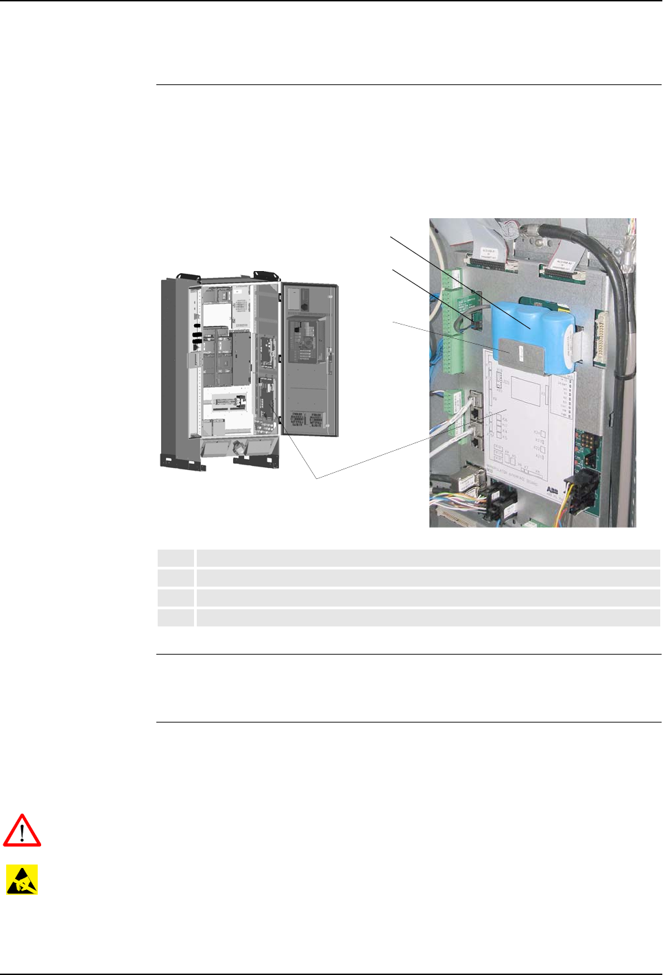
7 Repair
Product Manual, Control Cabinet IRC5P 3HNA009834-001 en Rev.06 167
7.20 Replacement of Measuring System Battery
7.20 Replacement of Measuring System Battery
Location The Measuring System Battery is located on the MIB board inside the control
cabinet as shown in the illustration below.
For information on the measuring system battery life time, see ’Checking the
Measuring System Battery’ on page 127.
Figure 85 Location of battery
Tools and Items – 13Ah litium battery
– Hand tools
Removal The procedure describes how to remove the measuring system battery.
Note: Before performing this procedure, it is recommended to place the robot into
calibration position (markings on the axes).
WARNING! No repair work must be performed on the robot before the safety
regulations in ’Safety’ on page 13 have been read and understood.
CAUTION! The unit is sensitive to ESD. Before handling the unit, please observe
the safety information in ’ESD Precautions’ on page 130.
Note: The battery may also be replaced in ‘power on’ mode. It is then not necessary
to perform any calibration. Necessary safety precautions must be observed.
1Manipulator Interface Board, MIB
2Battery
3Connector
4Battery holder
2
2
1
3
4
7 Repair
7.20 Replacement of Measuring System Battery
168 3HNA009834-001 en Rev.06 Product Manual, Control Cabinet IRC5P
1. Turn the electrical disconnect switch ‘off’ and lock switch in ‘off’ position.
WARNING! Make sure that the mains switch is ‘off’ and locked in ‘off’ position
before continuing. Also make sure that possible other connected systems are ‘off’.
2. Open controller front door and locate the battery (85/2) on the manipulator
interface board (85/1).
3. Disconnect the battery connector (85/3).
4. If a strap is used to secure the battery, remove strap.
5. Lift the old battery (85/2) out of the battery holder (85/4).
Refitting The procedure describes how to re-install the measuring system battery.
WARNING! Refitting activities must only be performed when controller is switched
‘off’ and all safety precautions under ‘Removal’ have been read.
1. Place the new battery in the holder.
2. Connect the battery connector.
3. Close controller front door.
4. Perform calibration as described in ‘Operator’s Manual, IRC5P’.
WARNING! Only batteries specified by ABB must be used. Old batteries must
always be handled as hazardous waste. A battery may explode if damaged or
disposed off in fire. Do not short-circuit battery.

8 Trouble Shooting
Product Manual, Control Cabinet IRC5P 3HNA009834-001 en Rev.06 169
8.1 Introduction
8 Trouble Shooting
8.1 Introduction
About this Chapter This chapter contains information, procedures and descriptions for trouble shooting
IRC5P based robot systems. The information should be used when the robot
operation is interrupted by malfunction, regardless of whether an error event log
message is issued or not.
The chapter is divided into 4 sections as follows:
• General description of trouble shooting routines and valuable hints on how to
perform trouble shooting.
• Listing of some relevant fault symptoms and malfunctions.
• Trouble Shooting instructions for some individual units.
• Description of the LED indicators on the controller front.
For description of the LED indicators on the separate units inside the controller, see
descriptions of the different boards and units in ‘Unit Description, IRC5P’.
Note: The trouble shooting described in this chapter must be used in combination
with the event messages described in the ‘Operating Manual, Trouble Shooting’.

8 Trouble Shooting
8.2 General Description and Hints
170 3HNA009834-001 en Rev.06 Product Manual, Control Cabinet IRC5P
8.2 General Description and Hints
8.2.1 Trouble Shooting Strategies
General Trouble shooting complex technical systems such as robot systems requires a
systematic approach. The personnel must be trained and qualified to perform the
task, and will be helped by using the correct tools and methods.
Isolate the Fault Any fault may give rise to a number of symptoms, for which error event log
messages may or may not be created. In order to effectively eliminate the problem,
it is vital to distinguish the original symptom from the consequential ones.
A help in isolating the fault may be creating a historical fault log as specified in
section ’Keep Track of History’ on page 173.
Split the Fault Chain When trouble shooting any system, a good practice is to split the event chain in two.
This means:
• Identify the complete chain of events.
• Decide and measure the expected value at the middle of the chain.
• Use this to determine in which half the fault is caused.
• Split this half into two new halves, etc.
• Finally, a single component may be isolated, the faulty one.
Check Communication
Parameters and Cables The most common causes of errors in serial communication are:
• Faulty cables (e.g. send and receive signals are mixed up).
• Transfer rates (baud rates).
• Data widths that are incorrectly set.
Check Software
Versions Make sure the RobotWare and other software are the correct versions. Some SW
versions are not compatible with certain hardware components.
Also, make a note of all software versions, since this will be useful information for
service and support.

8 Trouble Shooting
Product Manual, Control Cabinet IRC5P 3HNA009834-001 en Rev.06 171
8.2 General Description and Hints
8.2.2 Documentation and References
General A great deal of effort was put into writing the event log messages as well as the
technical documentation. The messages can never be perfect, but they may give
vital clues. They are also constantly being upgraded.
Read the Documentation Reading the manual should be done not only as a last resort.
Product documentation is available electronically as pdf files on the DVD-ROM
supplied with the robot.
Study the Circuit
Diagram The complete electrical circuitry of the controller and manipulator is available on
the DVD-ROM shipped with the robot. These circuit diagrams contain a lot of
useful, or even essential, information to a trained trouble shooter.
Read the Logs. The event logs contain lots of information about operations and malfunctions
detected by the system. For information on operating the logs, see the ‘Operator’s
Manual IRC5P’, section ‘Running in Production’ / ‘Logging and Diagnostics’.
Check LED Indicators Check the LED indicators on the LED panel on the controller front for information
on possible malfunction.
Faults caused by electronic units are indicated by the LEDs on the unit front. These
LEDs are described under the different boards and units in ‘Unit Description,
IRC5P’.

8 Trouble Shooting
8.2 General Description and Hints
172 3HNA009834-001 en Rev.06 Product Manual, Control Cabinet IRC5P
8.2.3 Work Systematically
Do Not Replace Units
Randomly Before replacing any part at all, it is important to establish a probable cause for the
fault, thus determining which unit to replace.
Randomly replacing units may sometimes solve the acute problem, but also leaves
the trouble shooter with a number of units that may or may not be perfectly
functional.
Replace one Component
at a Time When replacing a presumably faulty unit that has been isolated, it is important that
only one unit is replaced at a time.
Always replace components according to procedures in the Repair chapter of the
product manual for the manipulator and controller at hand.
Test the system after replacing to see if the problem has been solved.
If replacing several units at once:
• It is impossible to determine which of the units was causing the fault.
• It greatly complicates ordering a new spare part.
• It may introduce new faults to the system.
Take a Look Around Often, the cause may be evident by visual inspection. In the area of the unit acting
erroneously, be sure to check:
• Are the attachment screws secured?
• Are all connectors secured?
• Are all cabling free from damage?
• Are the units clean (especially electronic units)?
• Is the correct unit fitted?
Check for Tools Left
Behind Some repair and maintenance work require use of special tools to be fitted to the
robot equipment. If these are left behind (e.g. a signal cable to a computer unit used
for measuring purposes), they may cause erratic robot behavior.
Make sure all tools are removed when maintenance work is completed.

8 Trouble Shooting
Product Manual, Control Cabinet IRC5P 3HNA009834-001 en Rev.06 173
8.2 General Description and Hints
8.2.4 Keep Track of History
Make a Historical Error
Log In some cases, a particular installation may give rise to faults not encountered in
others. Therefore, a log of each installation may give valuable assistance to the
trouble shooter.
To facilitate trouble shooting, a log of the circumstances surrounding the fault gives
the following advantages:
• It enables the trouble shooter to see patterns in causes and consequences not
apparent at each individual fault occurrence.
• It may point out a specific event always taking place just before the fault, for
example a certain part of the work cycle being run.
• When an error occurs, keep track of the last operations done by the robot.
Check Up the History Make sure you always consult the historical log if it is used. Also remember to
consult the person who was observing the problem.
At What Stage did the
Fault Occur What to look for during trouble shooting depends greatly on when the fault
occurred: Was the robot just freshly installed? Was it recently repaired?
The table gives specific hints to what to look for in specific situations:
If the system has just: then:
been installed Check:
– the configuration files
– connections
– options and their configuration
been repaired Check:
– all connections to the replaced part
– power supplies
– that the correct part has been fitted
had a software upgrade Check:
– software versions
– compatibilities between hardware and software
– options and their configuration
– memory requirements
been moved from one site to
another (an already working robot)
Check:
– connections
– mechanical damage

8 Trouble Shooting
8.2 General Description and Hints
174 3HNA009834-001 en Rev.06 Product Manual, Control Cabinet IRC5P
8.2.5 Upgrading, Downgrading and Compatibilities
Overview Each part of the system is of a specific release, software as well as hardware.
Changing to a later release is called upgrading and changing to an earlier is
downgrading.
Upgrading and downgrading may cause compatibility problems, for instance a
specific circuit board may work well with one release but not with another.
Since the robot system is complex, and since the system often works in connection
with a large number of additional equipment, keeping track of each
hardware/software combination is difficult.
Technical Service
Information Each software release is accompanied by a Technical Service Information, TSI,
which includes a description of how to perform an upgrade/downgrade, and a list of
known incompatibilities.
For information about a specific TSI, please contact your local ABB organization.

8 Trouble Shooting
Product Manual, Control Cabinet IRC5P 3HNA009834-001 en Rev.06 175
8.3 Fault Symptoms and Malfunctions
8.3 Fault Symptoms and Malfunctions
8.3.1 Types of Symptoms
Symptoms A fault in the robot system first appears as a symptom, which may be:
• An event log message, which may be viewed using the pendant, RobView 5 or
RobotStudio. A complete listing of these messages is presented in ‘Operating
Manual, Trouble Shooting’ / Event Log Messages.
• The system performing poorly or displaying mechanical disturbances. These
faults are described in section ’Start-Up Failures’ on page 177.
• The system does not start or displays irrational behavior during startup. These
faults are described in section ’Start-Up Failures’ on page 177. A normal start-up
sequence is described in section ’Normal Start-Up Sequence’ on page 176.
• Indications on the LED panel indicators on the front of the control cabinet. The
significance of each LED is described in chapter ’LED Indicator Panel’ on page
197.
• Indications on the hardware components, such as LEDs. The significance of each
LED in the controller is described under the different boards and units in ‘Unit
Description, IRC5P’.
• Production stops caused by e.g. work envelope limitations.
• Rapid execution errors, e.g. unknown program requested in the job queue.

8 Trouble Shooting
8.3 Fault Symptoms and Malfunctions
176 3HNA009834-001 en Rev.06 Product Manual, Control Cabinet IRC5P
8.3.2 Normal Start-Up Sequence
Description This section describes a normal start-up sequence as shown on the indicators on the
LED indicator panel on the front of the control cabinet. For information on the
general start-up procedure, see ‘Operator’s Manual, IRC5P’, Installation and
Commissioning / Switch on Mains Power.
Start-Up Sequence When the mains power switch is switched ‘on’, power is supplied to the robot
system.
1. The robot performs its self-test on both the hardware and software. The LEDs
are flashing alternating red and green.
2. The Enable PIB LED is blinking red during loading of the FPGA.
3. The SPI LED is red during SPI initialization.
4. The indicators on the LED indicator panel show the normal status, LEDs are
green, and the robot is up and running.

8 Trouble Shooting
Product Manual, Control Cabinet IRC5P 3HNA009834-001 en Rev.06 177
8.3 Fault Symptoms and Malfunctions
8.3.3 Start-Up Failures
Description This section details possible faults at start-up, and specifies recommended actions
for each case.
Consequences The system does not start, or starts incorrectly.
Symptoms and Causes A number of symptoms are possible:
• No LED indicators are lit on the LED indicator panel and on any unit.
• The system software does not load properly.
• The pendant is ‘dead’.
• The pendant starts up, but does not respond to any input.
Recommended Actions,
No LED Indications Step Action Comment
1Make sure the main transformer is correctly
connected for the mains voltage levels at hand.
How to connect the transformer is found
under ’Mains Power Connection’ on
page 115.
2Make sure the mains switch is switched on.
3Make sure the mains power supply to the
system is present and within specified limits.
The installation documentation may
provide this as well as other vital
information.
4Make sure that the supply voltages from the
PDB board are present and within the specified
limits.
If required, trouble shoot PDB, described
in ’Trouble Shooting Power Supply, PDB’
on page 193, and associated systems.
For information, see ‘Power Distribution
Board, PDB’ in ‘Unit Description,
IRC5P’.
5If the system seems to be totally ‘dead’. Proceed as described in section
’Controller Dead’ on page 178.
6The pendant appears to be ‘dead’. Proceed as described in section
’Pendant Dead’ on page 180.
7If the pendant starts, but does not seem to
communicate with the controller.
Proceed as described in section
’Pendant does not Communicate’ on
page 181.
8If you encounter problems trying to download
system software, please proceed to the
‘Operators Manual, IRC5P’.

8 Trouble Shooting
8.3 Fault Symptoms and Malfunctions
178 3HNA009834-001 en Rev.06 Product Manual, Control Cabinet IRC5P
8.3.4 Controller Dead
Description The robot controller is completely or intermittently ‘dead’.
No indicators are lit and no operation is possible.
Consequences The system can not be operated.
Possible Causes The symptom may be caused by (the causes are listed in order of probability):
• The controller is not connected to the mains power supply.
• The main transformer is malfunctioning or not connected correctly.
• The mains overload protection (FR1) may have tripped.
Recommended Actions
Step Action Comment
1Make sure the mains power supply in the shop
is working and that the voltage level matches
that of the controller requirement.
The installation documentation may
provide this as well as other vital
information.
2Make sure the main transformer has been
correctly connected for the mains voltage level
at hand.
How to connect the transformer is found
under ’Mains Power Connection’ on
page 115..
3Make sure the mains overload protection, FR1
has not tripped. If it has, reset it.
For information, see ‘Unit Description,
IRC5P’, Power Module / Fuses and
Overload Protections.
4Check that the other fuses in the power supply
system are OK.
For information, see ‘Unit Description,
IRC5P’, Power Module / Fuses and
Overload Protections.
5If the system does not start although the
controller seems to be working, make sure all
connections have been made correctly
between the modules.

8 Trouble Shooting
Product Manual, Control Cabinet IRC5P 3HNA009834-001 en Rev.06 179
8.3 Fault Symptoms and Malfunctions
8.3.5 Controller Performance Slow
Description The controller performance is slow, and seems to work irrationally.
The controller it not completely ‘dead’. If it is, please proceed as described in
section ’Controller Dead’ on page 178.
Consequences These symptoms may be observed:
• Program execution is sluggish, seemingly irrational and sometimes stalls.
Possible Causes The computer system is experiencing too high load, which may be due to one or
more of the following:
• Programs containing too many logical instructions without Wait or Move-
instructions, causing too fast program loops and in turn, overload the processor.
• The poll rate of the I/O units is set too low, overloading the I/O system.
• Internal system cross connections and logical functions are used too frequently.
• An external PLC, or other supervisory computer, is addressing the system too
frequently, overloading the system.
Recommended Actions
Step Action Comment
1Check whether the program contains almost
only logical instructions (or other instructions
that take ‘no time’ to execute), since such
programs may cause the execution to loop if no
conditions are fulfilled. To avoid such loops, you
may test by adding one or more WAIT
instructions. Use only short WAIT times, to
avoid slowing the program down unnecessarily.
Suitable places to add WAIT instructions
may be:
– In a WHILE/FOR/GOTO loop,
preferably at the end, close to the
ENDWHILE/ENDFOR etc. part of the
instruction.
– In an auto-looping background task,
ref. Rapid OverView/Multitasking
2Make sure the poll rate value for each I/O board
is not too low. These values are changed using
RobotStudio. I/O units not requiring to be polled
regularly may be switched to ‘change of state’
operation as described in the RobotStudio
manual.
ABB recommends these poll rates [ms]:
– DSQC 651: 1000
– DSQC 652: 1000
– DSQC 653: 1000
– DSQC 377: 20-40
– All others: >100
3Check whether there is a large amount of cross
connections or I/O communication between
PLC and robot system. If required, try to reduce
the communication.
Too much communication with PLCs or
other external computers will load the
robot system main computer.
4Make sure there is little unnecessary
communication between any supervisory PLCs
or other computer. Make sure the PLC is
programmed in such a way that it does not, for
example, request robot system state changes
that are not allowable, by letting the PLC
monitor robot system state through a digital
input. Also make sure, that such state change
requests are not issued too often.
The robot system have a number of
fixed system inputs and outputs that may
be used for this purpose. Too much
communication with PLCs or other
external computers will load the robot
system main computer.

8 Trouble Shooting
8.3 Fault Symptoms and Malfunctions
180 3HNA009834-001 en Rev.06 Product Manual, Control Cabinet IRC5P
8.3.6 Pendant Dead
Description The robot pendant is completely or intermittently ‘dead’.
No entries are possible, and no functions are available.
If the pendant starts up, but does not display any screen, proceed as described in
section ’Pendant does not Communicate’ on page 181.
Consequences The system may not be operated using the pendant.
Possible Causes The symptom may be caused by (the causes are listed in order of probability):
• The system has not been switched on.
• The pendant is not connected to the controller.
• The cable from the controller is damaged.
• The cable connector is damaged.
• The pendant is faulty.
• Pendant power supply from controller is faulty.
Recommended Actions
Step Action Comment
1Make sure the system is switched on and that
the pendant is connected to the controller.
How to connect the pendant to the
controller is described in ’Pendant
Connection’ on page 103.
2Inspect the pendant cable for any visible
damage. If possible, test by connecting a
different pendant to eliminate the pendant and
cable as error sources. Also test the pendant at
hand on a different controller if possible.
If faulty, replace the pendant.
3Check that power is supplied to the pendant. For information, see ‘Pendant Interface
Board, TIB’ in ‘Unit Description, IRC5P’.

8 Trouble Shooting
Product Manual, Control Cabinet IRC5P 3HNA009834-001 en Rev.06 181
8.3 Fault Symptoms and Malfunctions
8.3.7 Pendant does not Communicate
Description The pendant starts up, but does not display any proper screen.
No operator input is possible, and no functions are available.
The pendant is not completely ‘dead’. If it is ‘dead’, proceed as described in section
’Pendant Dead’ on page 180.
Consequences The system may not be operated using the pendant.
Possible Causes The symptom may be caused by (the causes are listed in order of probability):
• The main computer has lost its power supply.
• Communication lines between pendant and main computer not ok.
Recommended Actions
Step Action Comment
1Make sure the pendant has been correctly
connected to the controller.
How to connect the pendant is described
in ’Pendant Connection’ on page 103.
2Make sure the power supply is OK and
communication lines are OK.
Check power supply system and signal
lines.
3Check LED indicators on the front panel. For description, see ’LED Indicator
Panel’ on page 197.
4Make sure all connections and supplies to the
TIB board are OK.
For information, see ‘Pendant Interface
Board, TIB’ in ‘Unit Description, IRC5P’.
5Make sure the Ethernet cable between pendant
and TIB is OK.
For information, see ‘Pendant Interface
Board, TIB’ in ‘Unit Description, IRC5P’.
6If all cables and supplies are OK, and nothing
else seems to solve the problem: Check SIB
board, PIB board and Main Computer.
How to replace the units are described in
chapter ’Repair’ on page 129’.

8 Trouble Shooting
8.3 Fault Symptoms and Malfunctions
182 3HNA009834-001 en Rev.06 Product Manual, Control Cabinet IRC5P
8.3.8 Erratic Event Messages on Pendant
Description The event messages displayed on the pendant are erratic and do not seem to
correspond to any actual malfunctions of the robot. Several types of messages may
be displayed, seemingly erroneously.
This type of symptom may occur after major manipulator disassembly or overhaul,
if not performed correctly.
Consequences Major operational disturbances due to the constantly appearing messages.
Possible Causes The symptom may be caused by:
• Internal manipulator cabling not correctly performed. Causes may be: faulty
connection of connectors, cable loops too tight causing the cabling to get
strained during manipulator movements, cable insulation worn or damaged by
rubbing short circuiting signals to ground.
Recommended Actions
Step Action Comment
1Inspect all internal manipulator cabling,
especially all cabling disconnected, connected
re-routed or bundled during recent repair work.
Refit any cabling. See ‘Product Manual,
Manipulator’.
2Inspect all cable connectors to make sure these
are correctly connected and tightened.
3Inspect all cable insulation for damage. Replace any faulty cabling as required.
4Inspect all grounding and shielding devices and
check for proper operation.

8 Trouble Shooting
Product Manual, Control Cabinet IRC5P 3HNA009834-001 en Rev.06 183
8.3 Fault Symptoms and Malfunctions
8.3.9 No Voltage in Service Outlet
Description Some controllers are fitted with service voltage outlet sockets, and this information
applies to these modules only.
No voltage is available in the controller service outlet for powering external service
equipment.
Consequences Equipment connected to the controller service outlet does not work.
Probable Causes The symptom may be caused by (the causes are listed in order of probability):
• Blown fuse, FU2 (230VAC) or FU3 (115VAC).
• Mains power supply loss.
• Transformers incorrectly connected.
Recommended Actions
Step Action Comment
1Make sure the fuse is not blown. Make sure any equipment connected to
the service outlet does not consume too
much power, causing the fuse to blow.
2Make sure the power supply to the robot
system is within specifications.
Refer to the plant documentation for
voltage values.
3Make sure the transformer supply for the outlet
is correctly connected.
See transformer wiring diagram under
‘Mains Transformer’ in ‘Unit Description,
IRC5P’..

8 Trouble Shooting
8.3 Fault Symptoms and Malfunctions
184 3HNA009834-001 en Rev.06 Product Manual, Control Cabinet IRC5P
8.3.10 The Joysticks do not Work
Description The system can be started but one or both of the joysticks on the pendant do not
seem to work.
Consequences The robot can not be jogged manually.
Possible Causes The problem may be caused by:
• The system is not in Manual Mode (Key switch).
• The Live Handle is not operated properly.
• Run Chain is broken by Emy Stop, or the Motor On button has not been
operated.
• Joysticks have not been calibrated.
• The pendant is not connected correctly or the cable is damaged.
• The power supply to the pendant does not work correctly.
• The pendant is malfunctioning.
• Joysticks are damaged.
Recommended Actions
Step Action Comment
1Check that the system has been switched on. Ref. ‘Operator’s Manual, IRC5P’.
2Check that Key Switch is in Manual Reduced
Speed Mode.
If NOT, proceed as described in the
‘Operator’s Manual, IRC5P’.
3Check that all Emergency stop buttons are
released and then Press Motor On-button to
close Run Chain.
4Check that Live Handle is operated properly. Ref. ‘Operator’s Manual, IRC5P’.
5Check that the joysticks have been calibrated. Ref. ‘Operator’s Manual, IRC5P’.
6Does the pendant work at all? If NOT, proceed as described in section
’Pendant Dead’ on page 180.
7Make sure the pendant is connected correctly
to the controller.
For information, see ’Pendant
Connection’ on page 103.
8Make sure the pendant cable has not been
damaged.
Check cable.
9Make sure the power supply is OK and
communication lines are OK.
Check power supply system.
10 If nothing else works, replace the pendant.

8 Trouble Shooting
Product Manual, Control Cabinet IRC5P 3HNA009834-001 en Rev.06 185
8.3 Fault Symptoms and Malfunctions
8.3.11 Reflashing Firmware Failed
Description When reflashing firmware, the automatic process may fail.
Consequences The automatic reflashing process is interrupted and the system stops.
Possible Causes This fault most often occurs due to a lack of compatibility between hardware and
software.
Consequences
Step Action Comment
1Check the event log for a message specifying
which unit failed.
For information on event log messages,
see ‘Operating Manual, Trouble
Shooting’ / Event Log Messages.
2Was the relevant unit recently replaced? If
YES, make sure the versions of the old and
new unit is identical. If NOT, check the software
versions.
3Check with your local ABB organization for a
firmware version compatible with your
hardware/software combination.

8 Trouble Shooting
8.3 Fault Symptoms and Malfunctions
186 3HNA009834-001 en Rev.06 Product Manual, Control Cabinet IRC5P
8.3.12 Inconsistent Path Accuracy
Description The path of the robot TCP is not consistent. It varies from time to time, and this may
sometimes be accompanied by noise emerging from bearings, gearboxes or other
locations.
Consequences Production is not possible.
Possible Causes The symptom may be caused by:
• Mechanical joint between motor and gearbox damaged, often causing noise.
• Bearings damaged or worn (especially if the path inconsistency is coupled with
clicking or grinding noises from one or more bearings).
• The brakes may not be releasing correctly.
Recommended Actions
Step Action Comment
1Locate a faulty bearing by tracking the noise. Replace faulty bearing. See ‘Product
Manual, Manipulator’.
2Locate the faulty motor by tracking the noise.
Study the path of the robot TCP to establish
which axis, and thus which motor, may be
faulty.
Replace the faulty motor/gearbox. See
‘Product Manual, Manipulator’.
3Make sure the robot brakes work properly. Proceed as described in section ’Robot
Brakes do not Release’ on page 191.

8 Trouble Shooting
Product Manual, Control Cabinet IRC5P 3HNA009834-001 en Rev.06 187
8.3 Fault Symptoms and Malfunctions
8.3.13 Consistent Path Inaccuracy
Description The path of the robot TCP is consistently inaccurate.
Consequences Production is not possible.
Possible Causes • Robot not calibrated correctly.
• Robot TCP not correctly defined.
• Robot Base Frame, Object Frame or similar not correctly defined.
• Wrong robot type may be connected to the controller.
Recommended Actions
Step Action Comment
1Make sure the robot Tool is correctly defined. How to define the TCP is described in
the ‘Operator's Manual, IRC5P’.
2Check the revolution counter. If required, update revolution counter as
described in ‘Operator's Manual,
IRC5P’.
3If required, re-calibrate the robot axes. Make sure the robot is calibrated as
described in ‘Operator's Manual,
IRC5P’.
4Check that all Frames are correctly defined. How to configure frames is described in
‘Operator's Manual, IRC5P’.
4Make sure the correct robot type is connected
as specified in the configuration files.
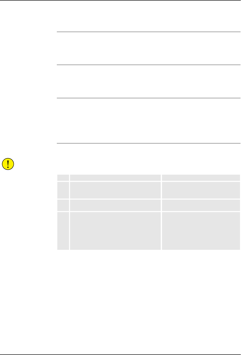
8 Trouble Shooting
8.3 Fault Symptoms and Malfunctions
188 3HNA009834-001 en Rev.06 Product Manual, Control Cabinet IRC5P
8.3.14 Oil or Grease Stains on Motors and/or Gearboxes
Description The area surrounding the motor or gearbox shows signs of oil leaks. This may be at
the base, closest to the mating surface, or at the furthest end of the motor at the
resolver.
Consequences Except for the dirty appearance, in some cases there are no serious consequences.
However, in some cases the leaking oil lubricates the motor brake, causing the
manipulator to collapse at power-down.
Possible Causes The symptom may be caused by (the causes are listed in order of probability):
• Leaking seal between gearbox and motor.
• Gearbox overfilled with oil.
• Gearbox oil too hot.
Recommended Actions
CAUTION! Parts of the manipulator may be hot and care must be taken to avoid
touching these components before they have been allowed to cool down.
Step Action Comment
1Inspect all seals and gaskets between motor
and gearbox. The different manipulator models
use different types of seals.
Replace seals and gaskets. See
‘Product Manual, Manipulator’.
2Check the gearbox oil level. Correct oil level . See ‘Product Manual,
Manipulator’.
3Too hot gearbox oil may be caused by:
– Oil quality or level used is incorrect.
– The robot work cycle runs a specific axis too
hard. Investigate whether it is possible to
program small ‘cooling periods’ into the
application.
– High pressure created inside gearbox.
Check the recommended oil level and
type. See ‘Product Manual, Manipulator’.
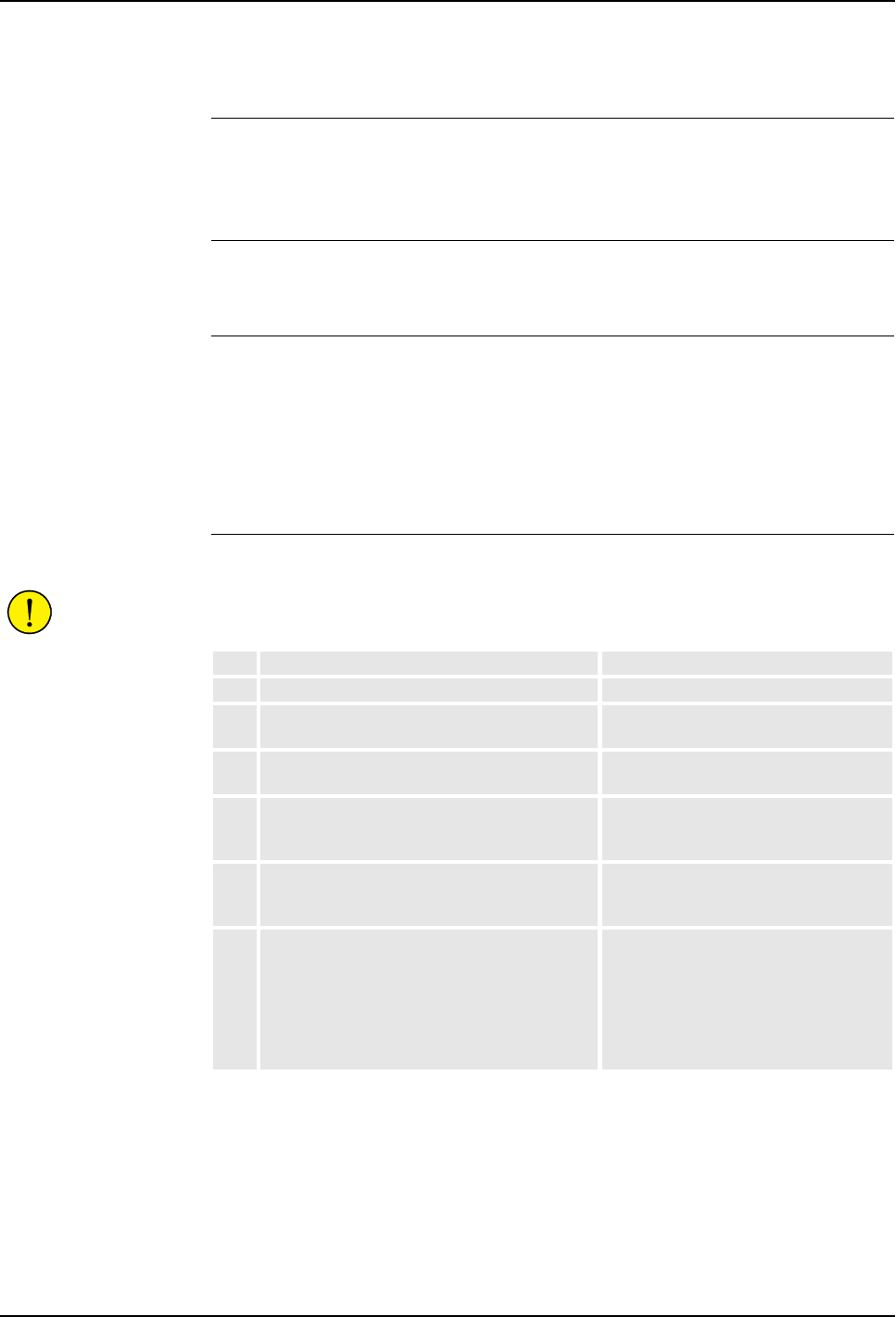
8 Trouble Shooting
Product Manual, Control Cabinet IRC5P 3HNA009834-001 en Rev.06 189
8.3 Fault Symptoms and Malfunctions
8.3.15 Mechanical Noise
Description During operation, no abnormal mechanical noise should be heard from motors,
gearboxes, bearings or similar. A faulty bearing often makes scraping, grinding or
clicking noises shortly before failing.
Consequences Failing bearings cause the path accuracy to become inconsistent, and in severe
cases, the joint may be completely damaged.
Possible Causes The symptom may be caused by:
• Worn bearings.
• Contaminations have entered the bearing races.
• Loss of lubrication in bearings.
• Overheating (If the noise comes from a gearbox).
Recommended Actions
CAUTION! Parts of the manipulator may be hot and care must be taken to avoid
touching these components before they have been allowed to cool down.
Step Action Comment
1Determine which bearing is causing the noise.
2Make sure the bearing has sufficient
lubrication, and is not contaminated.
See ‘Product Manual, Manipulator’.
3If possible, disassemble the joint and measure
the clearance.
See ‘Product Manual, Manipulator’.
4Bearings inside motors are not to be replaced
individually; The complete motor must be
replaced.
Replace faulty motors. See ‘Product
Manual, Manipulator’.
5Make sure the bearings are fitted correctly. See ‘Product Manual, Manipulator’ for
general information on how to handle
bearings.
6Too hot gearbox oil may be caused by:
– Oil quality or level used is incorrect.
– The robot work cycle runs a specific axis too
hard. Investigate whether it is possible to
program small ‘cooling periods’ into the
application.
– High pressure created inside gearbox.
Check the recommended oil level and
type as specified in ‘Product Manual,
Manipulator’.

8 Trouble Shooting
8.3 Fault Symptoms and Malfunctions
190 3HNA009834-001 en Rev.06 Product Manual, Control Cabinet IRC5P
8.3.16 Manipulator Collapses on Power-Down
Description The manipulator is able to work correctly while Motors ON is active, but when
Motors are off, it collapses under its own weight.
The holding brake, integral to each motor, is not able to hold the weight of the
manipulator arm.
Consequences The fault may cause severe injuries or death to personnel working in the area or
severe damage to the manipulator and/or surrounding equipment.
Possible Causes The symptom may be caused by:
• Faulty brake.
• Grease or oil on brakes.
• Brakes worn causing dust to be accumulated on the brake discs.
Note: It is not normal for the brakes to become worn, as they shall become engaged
only when the motor is not turning. Exception: Emergency stop. Therefore, do not
use Emergency stop for normal stops.
Recommended Actions
Step Action Comment
1Determine which motor(s) causes the robot to
collapse.
2Check the brake power supply to the collapsing
motor during the Motors OFF state.
For information, see relevant
manipulator board in ‘Unit Description,
IRC5P’.
3Check brakes e.g. by moving robot arm
manually.
If found faulty, the motor must be
replaced as a complete unit. See
‘Product Manual, Manipulator’.

8 Trouble Shooting
Product Manual, Control Cabinet IRC5P 3HNA009834-001 en Rev.06 191
8.3 Fault Symptoms and Malfunctions
8.3.17 Robot Brakes do not Release
Description When starting robot operation or jogging the robot, the internal robot brakes must
release in order to allow for movements.
Consequences If the brakes do not release, no robot movement is possible, and a number of error
log messages may occur.
Possible Causes The symptom may be caused by:
• Brake drivers do not work properly.
• The system does not go to status Motors ON correctly.
• Faulty brake on the robot axis.
• Supply voltage 24V_BRAKE missing.
Recommended Actions
Step Action Comment
1Make sure the brake drivers on manipulator
board are working properly.
For information, see relevant
manipulator board in ‘Unit Description,
IRC5P’.
2Make sure the RUN Chain is closed. Check run chain. For information, see
’Robot Safety System Connections’ on
page 64.
3Try to release brakes manually. If just one of
the brakes malfunctions, the brake at hand is
probably faulty and will have to be replaced. If
none of the brakes work, there is probably no
24V_BRAKE power available.
For information on how to release the
brakes manually, see ‘Product Manual,
Manipulator’, Repair / Releasing Axis
Brakes.
4Check that brake power is available to
manipulator board by measuring voltage in
connector.
For information, see relevant
manipulator board in ‘Unit Description,
IRC5P’..
5A number of other faults within the system may
cause the brakes to remain activated. In such
cases, event log messages will provide
additional information.
For information on event log messages,
see ‘Operating Manual, Trouble
Shooting’ / Event Log Messages.

8 Trouble Shooting
8.4 Trouble Shooting Instructions per Unit
192 3HNA009834-001 en Rev.06 Product Manual, Control Cabinet IRC5P
8.4 Trouble Shooting Instructions per Unit
8.4.1 Trouble Shooting the Pendant
General The pendant communicates with the main computer via PIB, SIB and the Pendant
Interface Board, TIB. The pendant is physically connected to the TIB board through
a cable together with +12V supply, two emergency stop channels and enabling
device chains.
Procedure
Step Action Comment
1If the pendant is completely ‘dead’, proceed as
detailed in section ’Pendant Dead’ on page
180.
2If the pendant starts, but does not operate
correctly, proceed as detailed in section
’Pendant does not Communicate’ on page 181.
3If the pendant starts, seems to operate, but
displays erratic event messages, proceed as
detailed in section ’Erratic Event Messages on
Pendant’ on page 182.
4Check the cable for connections and damage.
5Check the power supply to the pendant.
6Read the error event log message and follow
any instructions of references.
Communication errors between the
pendant and the main computer may be
viewed as event log messages either on
the pendant, RobView 5 or RobotStudio.

8 Trouble Shooting
Product Manual, Control Cabinet IRC5P 3HNA009834-001 en Rev.06 193
8.4 Trouble Shooting Instructions per Unit
8.4.2 Trouble Shooting Power Supply, PDB
Overview This section details how to trouble shoot the electrical power supply board (Power
Distribution Board, PDB) in the controller.
Procedure
Step Action Comment
1Check the LED indicators on the power supply
unit.
For description of the LED indicators,
see ‘Power Distribution Board, PDB’ in
‘Unit Description, IRC5P’.
2Disconnect the output connector of the power
supply unit.
3Measure the output voltage of the unit. If no voltage, or an incorrect voltage is
detected, proceed with next step.
4Measure the input voltage. If the input voltage is correct, the power
supply unit may be faulty.
5If required, disconnect the loads from the power
supply unit, one by one, to eliminate any
overload.
6If the power supply unit is found faulty, replace
it, and verify that the fault has been fixed.
How to replace the unit is detailed in
chapter ’Repair’ on page 129..

8 Trouble Shooting
8.4 Trouble Shooting Instructions per Unit
194 3HNA009834-001 en Rev.06 Product Manual, Control Cabinet IRC5P
8.4.3 Trouble Shooting Communications
Overview This section details how to trouble shoot data communication between the different
units in the controller.
Trouble Shooting
Procedure Step Action Comment
1Faulty cables (e.g. send and receive signals
are mixed up)
2Transfer rates (baud rates)
3Data widths that are incorrectly set

8 Trouble Shooting
Product Manual, Control Cabinet IRC5P 3HNA009834-001 en Rev.06 195
8.4 Trouble Shooting Instructions per Unit
8.4.4 Trouble Shooting I/O Units
Checking Function The procedure detailed below is to be used when a certain I/O unit does not
communicate through inputs and outputs as expected.
Checking Channel
Communication The I/O channels can be read and activated from the I/O menu on the pendant. In the
event of an error in the I/O communication to and from the robot, check as follows:
LED Indicators All LEDs, and their significance, are described under each individual unit in ‘Unit
Description, IRC5P’, Distributed I/O.
Step Action Comment
1Check that the current I/O signal has the
desired status using the I/O menu on the
pendant display.
2Check the I/O unit’s LED for the current input or
output. If the output LED is not lit, check that
the 24V I/O power supply is OK.
3Check on all connectors and cabling from the
I/O unit to the process connection.
4Make sure the process bus, to which the I/O
unit is connected, is working.
If a bus has stopped running, an event
log message is usually stored in the
event log. Also check the indication
LEDs on the bus boards.
Step Action Comment
1Is I/O communication programmed in the
current program?
2On the unit in question, the MS (Module Status)
and NS (Network Status) LEDs must be lit with
a steady green light.

8 Trouble Shooting
8.4 Trouble Shooting Instructions per Unit
196 3HNA009834-001 en Rev.06 Product Manual, Control Cabinet IRC5P
8.4.5 Intermittent Errors
Description During operation, errors and malfunctions may occur, in a seemingly random way.
Symptoms Operation is interrupted, and occasionally, event log messages are displayed, that
sometimes do not seem to be related to any actual system malfunction. This sort of
problem sometimes affects the Emergency stop or Enable chains respectively, and
may at times be very hard to pinpoint.
Probable Causes Such errors may occur anywhere in the robot system and may be due to:
• External interference.
• Internal interference.
• Loose connections or incorrectly connected cable screen, shielding and
grounding connections.
• Thermal phenomena, e.g. major temperature changes within the workshop area.
Recommended Actions
Step Action Comment
1Check all the cabling, especially the cables in
the Emergency stop and Enable chains. Make
sure all connectors are connected securely.
2Check that grounding and shielding are
properly done.
3Check if any LED indicator may give some clue
to the problem.
The significance of all LED indicators are
specified under ’LED Indicator Panel’ on
page 197 and under the different boards
and units in ‘Unit Description, IRC5P’..
4Check the messages in the event log.
Sometimes specific error combinations are
intermittent.
The event log messages may be viewed
on the pendant, on RobView 5 or on
RobotStudio.
5Check the robot’s behavior, etc., each time that
this type of error occurs.
If possible, keep track of the
malfunctions in a log plus any
circumstantial events (Operator actions,
PLC commands etc.) that may have
anything to do with this behavior.
6Check whether any condition in the robot
working environment also changes periodically,
e.g, interference from any electric equipment
only operating periodically.
7Investigate whether the environmental
conditions (such as ambient temperature,
humidity, etc.) has any influence on the
malfunction.
If possible, keep track of the
malfunctions in a log or similar.
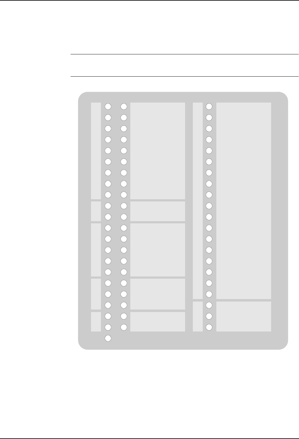
8 Trouble Shooting
Product Manual, Control Cabinet IRC5P 3HNA009834-001 en Rev.06 197
8.5 LED Indicator Panel
8.5 LED Indicator Panel
8.5.1 Panel Overview
General The following provides description of the LED indicator panel.
Panel Overview Figure 86 LED Indicator panel
Encoder 1 - A / B
Start - 1 / 2
General Mode Stop
Delayed Stop
Robot 1
Process - 2.1 / 2.2
Paint Enable
Emy Stop Panel
Emy Stop Pendant
Emy Stop External
Emy Stop Chain
Mode Stop
Enabling Device
Enable Main
Enable Axis
Enable PIB
Enable SIB
Enable MIB
Enable Manipulator 1
Enable Manipulator 2
2 Ch. Monitoring
Power status
Temp. Cabinet
Enable Chain Closed
Overpressure
Pressurized
Min. Flow
Purge Timer
Process Status
System Status
Cooling Fan
HV Chain
SPI - Int. / Ext
Display Valid
Chain Closed
RUN CHAIN
DRIVE
PROCESS
COMM.
SYSTEM
CH2CH1
USER
USER
PIB CAN1 - MS / NS
PIB CAN2 - MS / NS
Encoder 2 - A / B

8 Trouble Shooting
8.5 LED Indicator Panel
198 3HNA009834-001 en Rev.06 Product Manual, Control Cabinet IRC5P
8.5.2 LED Description
General The following provides description of the LED indicators.
RUN CHAIN LEDs showing the status of the emergency stop chain and run chain.
Description Source of fault / Remedy
Emy Stop Panel (Chain 1-2)
Green - OK.
Off - Emergency stop button on the
control cabinet is depressed.
The emergency stop chain is broken at the main panel
emy stop switch or in the chain in front of the switch.
– Check cause for emergency stop. If OK, pull out button.
– Check emy stop chain 1 and/or 2 from +24VDC supply
to main panel switch.
Emy Stop Pendant (Chain 1-2)
Green - OK.
Blinking Green - Hot plug activated.
Blinking Green/Red - Hot plug time
out and Emy stop chain closed.
Blinking Red - Hot plug time out
and Emy stop chain is broken.
Off - Emergency stop button on the
pendant is depressed.
The emergency stop chain is broken at the pendant emy
stop switch or in the chain leading to the pendant switch.
– Check cause for emergency stop. If OK, pull out button.
– Use the Motor On-button to reset Run Chain. If not OK,
proceed below.
– Check emy stop chain 1 and/or 2 from main panel
switch to pendant switch.
– Check pendant cable and connector. (If the pendant is
not connected, a dummy connector must be installed in
its place).
– Check I.S. barriers (TIB board) and wiring.
– Check SIB board for malfunction. Replace as required.
Emy Stop External (Chain 1-2)
Green - OK.
Off - External emergency stop
button(s) is depressed.
The emergency stop chain is broken at the external emy
stop switch or in the chain leading to the external switch.
– Check cause for emergency stop. If OK, pull out button.
– Use the Motor On-button to reset Run Chain. If not OK,
proceed below.
– Check emergency stop chain 1 and/or 2 from pendant
switch to the external switch.
Emy Stop Chain (Chain 1-2)
Green - Chain closed.
Off - when panel, pendant,
emergency stop category 0 and
category 1 is open.
Blinking Red - Emy stop reset fail.
The emergency stop chain is broken after the external
emy stop switch.
– Check chain from external emy stop switch to 0V conn.
for emy stop chain.
The emergency stop reset function (pressing motor ‘on’,
etc.) is stuck or has been held depressed for more than 4
seconds.
– Check operation of emy stop switches.
– Check that emy stop reset has not been blocked (does
not have a continuous signal).

8 Trouble Shooting
Product Manual, Control Cabinet IRC5P 3HNA009834-001 en Rev.06 199
8.5 LED Indicator Panel
Mode Stop (Chain 1-2)
Green - OK.
Off - Auto mode stop is activated.
The run chain is broken at the auto mode stop switch (in
Automatic mode) or test mode stop switch (in Manual
Reduced Speed or High Speed mode) or in the chain in
front of the switches.
– For auto mode stop, check that the mode selector is in
Automatic mode and that the cabin door(s) is closed.
(The auto mode stop switch is typically used for cabin
entrance door).
– Use the Motor On-button to reset Run Chain. If not OK,
proceed below.
– For test mode stop, check that the mode selector is in
manual mode and that the pendant enabling device
(Enabling Device LED) and possible additional enabling
device is pressed. (The test mode stop switch is
typically used for an additional enabling device).
– Check operation of the auto mode stop switch, enabling
device and test mode stop switch.
– Check operation of the mode selector.
– Check run chain 1 and/or 2 from +24VDC supply via
mode selector to the mode stop switches.
Enabling Device (Chain 1-2)
Green - Enabling device is
depressed.
Off - Enabling device is released.
The run chain is broken at the pendant enabling device
switch or in the chain in front of the switch.
– Use the Motor On-button to reset Run Chain. If not OK,
proceed below.
– Check that the enabling device is depressed.
– Check that mode selector is in manual mode.
– Check pendant cable and connector.
– Check I.S. barriers (TIB board) and wiring.
– Check SIB board for malfunction. Replace as required.
– Check run chain 1 and/or 2 from +24VDC supply via
mode selector to pendant enabling device.
General Mode Stop (Chain 1-2)
Green - OK.
Off - General mode stop is
activated.
The run chain is broken at the general mode stop switch
or in the chain in front of the switch.
– Check that the mode selector is in Automatic mode.
– Use the Motor On-button to reset Run Chain. If not OK,
proceed below.
– Check operation of the general mode stop switch.
(General mode stop act as an emergency stop and is
normally used in more complex installation where the
robot emy stop system is integrated with the factory
emy stop system).
Delayed Stop (Chain 1-2)
Green - OK.
Off - Delayed stop is activate.
The motor chain is broken by delayed stop (emergency
stop category 1).
– Use the Motor On-button to reset Run Chain. If not OK,
proceed below.
– Check that cabin door(s) is closed. (Delayed stop may
be used for entrance doors located at a distance from
the robot).
– Check switches and wiring.
Chain Closed (Chain 1-2)
Green - OK.
Ch1 Blinking Red - Servo
disconnect system 1
Ch2 Blinking Red - Servo
disconnect system 2
Off - Run chain is broken.
The run chain is broken.
– Check that LEDs for Mode Stop, Enabling Device,
General Mode Stop and Delayed Stop are lit.
– Check that purging is OK.
– Check that emergency stop chain is OK (Emergency
Stop Chain LED is lit).
– Check complete run chain.
Description Source of fault / Remedy

8 Trouble Shooting
8.5 LED Indicator Panel
200 3HNA009834-001 en Rev.06 Product Manual, Control Cabinet IRC5P
DRIVE LEDs showing status of the motor drive system for the manipulator and paint
pumps.
PROCESS LEDs showing the status of functions related to the spray booth and paint process.
Description Source of fault / Remedy
Robot 1
Green - Power relay for robot motor
drive system is activated.
Ch1 Red - Relay KM1 error.
Ch2 Red - Relay KM2 error.
Off - Relay not activated.
If LED is extinguished when it should have been lit:
– Check hat Motor On switch has been pressed.
– Check that Mode Selector is in Automatic mode or that
Enabling Device on pendant is pressed when Mode
Selector is in Manual mode.
– Check that Emy chain is closed.
– Check wires between power relay and MIB.
– Replace power relay.
– Replace MIB
Process - 2.1 / 2.2
Green - Chain closed - Relay for
process equipment 2.1 (e.g. pump)
or motor drive system 2.2 (e.g.
CBS motion) is activated.
Blinking green: Hardware chain
closed - Waiting for RID.
Blinking Red: Aux. chain open
(Process 2.1) / System 2 interlock
open (Process 2.2).
2.1 Red - Relay KM101 error.
2.2 Red - Relay KM102 error.
Off - Chain open.
If LED is extinguished or blinking red:
– Check that enable chain is closed.
– Check that paint enable is activated.
– Check that cabin safety switches are closed.
– Check cables between power relay and MIB.
– Replace power relay.
–Replace MIB.
Description Source of fault / Remedy
Paint Enable (Chain 1-2)
Green - Chain closed
Blinking Green: Process interlock
open - cabin interlock closed.
Blinking Red - Divergency in
process interlock chain.
Off - Cabin interlock chain is
broken.
The cabin interlock chain is broken. This chain includes a
safety switch on the cabin door, and a cabin interlock
switch for the cabin ventilation to disable the paint control
system when the cabin door is open and/or ventilation
fans not running.
– Check that equipment connected in the cabin interlock
chain is closed.
HV Chain (Chain 1-2)
Green - Chain closed.
Off - Chain open.
Blinking Red: HV Interlock broken.
The High Voltage interlock chain is broken.
– Check external HV interlock chain.
– Check cabin interlock chain.
– Check position of HV on/off switch on panel.
Encoder 1 - A / B (Phase 1-2)
Green - Flashes to indicate phase
1 and 2 from Encoder 1, normally
conveyor encoder.
By encoder frequency below 10Hz,
the LEDs will blink: off-off, on-off,
off-on, on-on. A stopped encoder
shows one of these combinations.
By frequencies above 10Hz, both
LEDs will be constantly lit.
Flashes by each encoder pulse. By frequencies higher
than a few Hz, blinking can no longer be observed (light
will appear weaker). No light in one LED indicates fault in
one encoder phase.
– Check that the conveyor is running.
– Check that the encoder rotates as it should.
– Check power supply for encoder.
– Check encoder, wiring and connectors.
– Check encoder circuit on PIB unit.
Encoder 2 - A / B (Phase 1-2)
Green - As Encoder 1. Encoder 2
may be used as backup for
encoder 1 etc.
As encoder 1.

8 Trouble Shooting
Product Manual, Control Cabinet IRC5P 3HNA009834-001 en Rev.06 201
8.5 LED Indicator Panel
COMM. LEDs showing the status of the CAN and SPI communication.
SYSTEM LEDs showing status of the different control systems, power supply, purge system,
temperature etc.
Start 1 / 2
Green - Lit when digital input is
active. Normally Start 1 input is
used as Sync Switch for conveyor
tracking and Start 2 is not used.
Faulty limit switch, photocell etc.
External wiring or connectors, short circuit or broken wire.
Faulty power supply for input circuit (internal or external).
Defective input circuit on board. If Exi input on TIB is used,
check I.S. barrier.
Description Source of fault / Remedy
Description Source of fault / Remedy
PIB CAN1 - MS / NS
Green - OK.
Any other status, see ‘Unit
Description, IRC5P’, Distributed
I/O.
CAN1 bus is used for communication between the robot
controller (PIB) and external field bus units (CAN1.1) and
manipulator (CAN1.2).
– Check CAN bus from PIB to internal I/O nodes.
– Check CAN bus from PIB via MIB to robot.
– Check CAN bus from PIB to external I/O nodes.
PIB CAN2 - MS / NS
Green - OK.
Any other status, see ‘Unit
Description, IRC5P’, Distributed
I/O.
CAN2 is normally not used.
– If used, check CAN bus from PIB to external I/O nodes
SPI - Int. / Ext
Green: OK
Red: During SPI initialization.
SPI bus communication between
PIB and SIB, MIB (SPI - Int) and
between PIB and external I/O units
(SPI - Ext).
If LED is Off, blinking green, red or blinking red, check:
– That nodes are initialized.
– Cables and connections.
– PIB board and units connected to SPI bus.
– For more information, see description of LEDs Ext SPI1
/ Ext SPI2 under ‘Paint Interface Board PIB’ in ‘Unit
Description, IRC5P’.
Description Source of fault / Remedy
Enable Main
Green, blinking each 8 ‘th second -
Main Computer OK.
Off - No communication
Blinking Red - Failure
– Check cable for communication from Axis Computer to
Main Computer.
– Check communication cable from PIB to Main
Computer.
Note. To remove message, acknowledge must be issued
(e.g. pressing Motor On button).
Enable Axis
Green, blinking each 8 ‘th second -
OK. Enable signal from axis
computer active.
Blinking Red - Failure, signal not
active.
– Try to reset by pressing Motor On. If persistent, check:
– Check Power LED on Axis Computer.
– Check cable for feedback from Axis Computer to MIB.
– Check cable for control from Axis Computer to Drive
Unit.
– Check cable for communication from Axis Computer to
Main Computer.
– Replace Axis Computer board.
Note. To remove message, acknowledge must be issued
(e.g. pressing motor on button).

8 Trouble Shooting
8.5 LED Indicator Panel
202 3HNA009834-001 en Rev.06 Product Manual, Control Cabinet IRC5P
Enable PIB
Green - Enable signal from PIB OK
Blinking Green/Red - Software
deactive and
Enable Chain - HW OK.
Blinking Red during start up -
Waiting for loading of FPGA.
Off - Enable signal lost
Blinking Red - Failure
– Check communication cable from PIB to Main
Computer.
– Check communication cable to SIB and MIB.
Enable SIB
Green - Enable signal from PIB
OK. Communication between SIB
and PIB is OK.
Off - Communication lost.
Blinking Red - Failure
– Check communication cable from SIB to PIB.
– Check Power LED on SIB.
Enable MIB
Green - Communication between
MIB and SIB is OK (MIB OK).
Off - Communication lost.
Blinking Red - Failure
– Check communication cable from MIB to SIB.
– Check Power LED on MIB.
Enable Manipulator 1
Green - OK. MCOB is operative.
Blinking Red - Failure, MCOB not
ready.
Indicator lights red during purging
sequence.
Enable signal from MCOB or robot temp. sensor chain.
– Check Temp. Motors LED.
– If used, check working area limit switches for
manipulator axes, wiring and connectors.
– If used, check collision protection, wiring and
connectors.
Enable Manipulator 2
Same as Enable Manipulator 1 but
for 2nd manipulator such as CBS.
2 Ch. Monitoring
Green - OK.
Blinking Red - Failure, divergency
in switches and/or relays in safety
chain.
– Check Run Chain LEDs for divergency.
– Check safety chain switches and relays for malfunction.
– Check wiring and connections for Emy Stop buttons.
– Safety element not tested after divergency failure.
Power Status
Green - OK.
Blinking Green - Low voltage on
measuring system battery.
Blinking Red - One or more supply
voltages faulty, e.g. emy stop chain
supply.
If LED is blinking green,
– Replace the battery.
If LED is blinking red,
– Check 24V supply to PDB.
– Check PDB power status LEDs
– Check Purging status.
– Check Fuses for rectifier (DC Link).
– Emy stop chain supply.
Temp Cabinet
Green - OK.
Blinking Red - Temperature in
control cabinet or transformer too
high.
– Check cause of increased temperature in cabinet. Take
necessary measures to reduce temperature. (By
excessive ambient temperature cooler may be
installed).
– Check PTC on mains transformer and wiring.
Enable Chain Closed
Green - OK. Enable chain is active.
Blinking Red - Chain is not active.
The ‘Enable Chain Closed’ LED indicates that all elements
in the enable chain are active.
– Check that all SYSTEM LEDs above the ‘Enable Chain.
Closed’ LED are OK. If not, correct error as required.
Description Source of fault / Remedy

8 Trouble Shooting
Product Manual, Control Cabinet IRC5P 3HNA009834-001 en Rev.06 203
8.5 LED Indicator Panel
Overpressure
Green - OK. Purging pressure
below maximum pressure limit.
Blinking Red - Pressure is above
maximum limit.
Note: If 2 purge systems are used,
LED applies for both systems.
Indicates the state of the maximum pressure sensors.
– Check that purge air exhaust on robot is not blocked.
– Check the air supply pressure.
– Check purge sensor.
– Check cables and wiring.
– Check that purge air supply to robot is not blocked.
Pressurized
Green - OK. Purging pressure is
above minimum limit.
Blinking Red - Pressure is below
minimum limit.
Note: If 2 purge systems are used,
LED applies for both systems.
Indicates the state of the minimum pressure sensors.
– Check for leaks in the manipulator.
– Check cables and wiring.
– Check purge sensor.
Note: Indicator will be red in a short period while pressure
is being established.
Min. Flow
Green - OK. Flow is OK.
Blinking Green - No flow.
Red - Mismatch between purge
valve and high flow. - Ref:
‘Manipulator Interface Board, MIB’,
Purge Sequence, in ‘Unit
Description, IRC5P’,
Note: If 2 purge systems are used,
LED applies for both systems.
Off - No high flow.
Indicates the state of the flow sensors.
– Check the air supply.
– Check purge sensor.
– Check cables and wiring.
– Check LEDs Purging P1 and P2 (should be lit).
Note: Indicator will be red in a short period while pressure
is being established.
Purge Timer
Blinking Green - Purge sequence
in progress.
Off - Purge sequence not started or
sequence completed.
Indicates status of purge sequence
– Check purge LEDs: Overpressure, Pressurized and
Min. Flow (should be lit).
Process Status
Green - 2 channel supervision of
process chain OK
Blinking Red: Chain broken.
Off - Supervision not OK.
If LED is extinguished or blinking red, check
– Check that enable chain is closed.
– Check that paint enable is activated.
– Check that cabin safety switches are closed.
– Check for divergency in LEDs Paint Enable and
HV Chain.
– Check cables between power relay and MIB.
– Replace power relay.
–Replace MIB.
System Status
Green - System OK.
Blinking Red - System fault.
If LED is blinking red, after installed new software,
– Configuration failure, consult error log.
If LED is blinking red, after normal operation,
– Failure status, consult error log. Requires restart: Cycle
power by switching cabinet mains switch off-on.
– Check voltages.
– Check power related wiring and connectors.
Cooling Fan
Green - OK.
Blinking Red - Cooling fans not
running or running with low speed.
Control cabinet cooling fans are not running and a
warning is displayed on the pendant.
– Check cause and reset from pendant.
– Check cooling fans and wiring.
Description Source of fault / Remedy

8 Trouble Shooting
8.5 LED Indicator Panel
204 3HNA009834-001 en Rev.06 Product Manual, Control Cabinet IRC5P
MISC. LEDs showing status of the LED board and LEDs which can be defined by the user.
Description Source of fault / Remedy
USER
4 + 3 user definable LEDs.
These LEDs can be specified by the user in the software.
Display Valid
Green - OK. System indicator
board, ALED is active.
Off - ALED board not active.
Note that LED is blinking red/green
during initialization until
communication with PIB is started.
– Check communication cable between PIB and ALED.
– Try to reset board by momentary disconnecting power
connector to ALED.
– Check ALED board. Replace board as required.
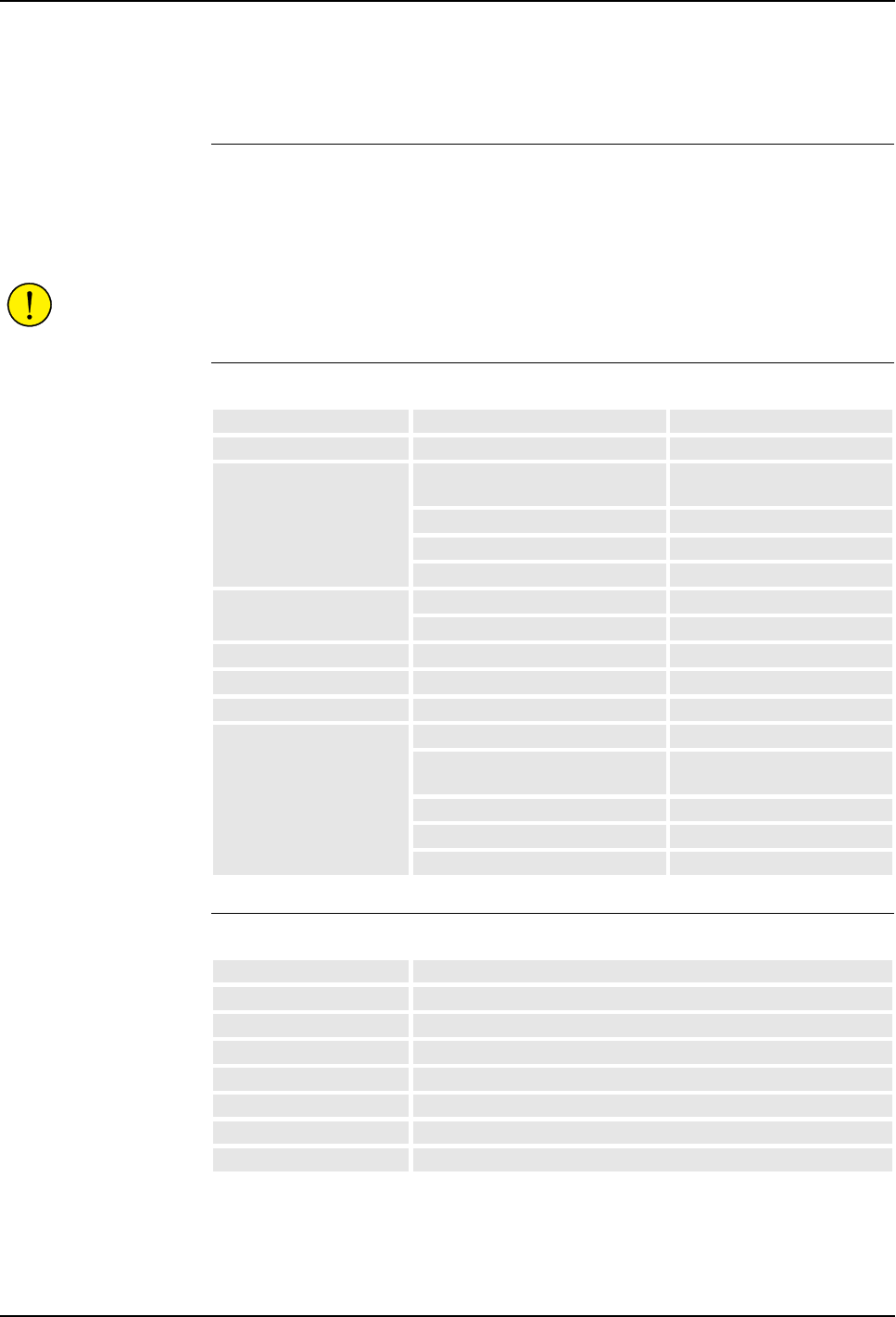
9 Decommissioning
Product Manual, Control Cabinet IRC5P 3HNA009834-001 en Rev.06 205
9 Decommissioning
General The components of the robot are manufactured from many different materials. Some
of them are listed below to facilitate scrapping, i.e. so that the components can be
disposed of in a way that does not have a detrimental effect on anyone’s health or
the environment.
CAUTION! Decommissioning must always be performed in accordance with
standards and regulations of the country where the robot is installed.
Manipulators
Control Cabinet
Material Examples of components Part of
Copper Cables, motors All robot types
Cast iron/nodular iron Foot unit, base unit,
vertical arm (axis 2 arm) lower part
IRB 5400 / IRB 540 / IRB 580
Foot unit IRB 5500
Foot unit, base, arm assembly IRB 52
Foot unit, base, inner arm IRB 5300
Steel Gears, screws, base-frame, etc. All robot types
Foot unit, axis 7 arm/axis 8 arm IRB 5500 w 2 axis swing arm
Samarium-Cobalt Brakes, motors All robot types
Plastic/rubber (PVC) Cables, connectors, drive belts etc. All robot types
Oil, grease Gearboxes All robot types
Aluminium Covers, sync. brackets All robot types
Vertical/horizontal arm
(axis 2 arm/axis 3 arm)
All robot types except IRB 52
Base unit IRB 5500
Outer arm and tower IRB 5300
Castings in wrist, arms All robot types
Material Examples of components
Copper Transformers, cables
Tin Cables
Alu-Zinc sheets Control cabinets, various sheet material parts
Iron Transformers
Polyester Circuit boards
Plastic/rubber (PVC) Cables, connectors, pendant, covers (drive units, I/O units) etc.
Lithium Batteries

9 Decommissioning
206 3HNA009834-001 en Rev.06 Product Manual, Control Cabinet IRC5P
Scrapping Following warning must be observed before disassembling.
WARNING! Before removing any parts from the manipulator, study the removal
instructions for the component in question.
Oil and Grease Where possible, arrange for the oil and grease to be recycled. Dispose of via an
authorized person/contractor in accordance with local regulations. Do not dispose of
oil and grease near lakes, ponds, ditches, down drains, or onto soil. Incineration
must be carried out under controlled conditions in accordance with local
regulations.
Also note that:
– Spills may form a film on water surfaces causing damage to organisms. Oxygen
transfer could also be impaired.
– Spillage may penetrate the soil causing ground water contamination.
Balancing system If the robot includes balancing springs, special care is needed when removing the
balancing system.
The balancing system contains 2 preloaded spiral springs. Before scrapping
(melting down, or other form of destruction) the springs must be unloaded in a safe
way.


10 Reference Information
10.1 Cable Information
208 3HNA009834-001 en Rev.06 Product Manual, Control Cabinet IRC5P
10.1 Cable Information
General This section includes information on cables which should be used for the
installation.
Signal Classes Power Supplies external motors and brakes.
Control signals Digital operating and data signals (digital I/O, safety stop, etc.).
Measuring signals Analog measuring and control signals (resolver and analog
I/O).
Data communication signals Gateway (field bus) connection, computer link.
Different rules apply to the different classes when selecting and laying cable.
Signals from different classes must not be mixed.
Selecting Cables All cables laid in the controller must be capable of withstanding 70°C. In addition,
the following rules apply to the cables of certain signal classes:
Power Signals Shielded cable with an area of at least 0.75 mm² or AWG 18. Note
that any local standards and regulations concerning insulation and area must always
be complied with.
Control Signals Shielded cable.
Measuring Signals Shielded cable with twisted pair conductors.
Data Communication Signals Shielded cable with twisted pair conductors. A
specific cable should be used for Gateway (field bus) connections and Ethernet.
CAN bus with DeviceNet for Distributed I/O units Thin cable according to
DeviceNet specification release 1.2, must be used. The cable is shielded and has
four conductors, two for electronic supply and two for signal transmission. Note that
a separate cable for supply of I/O loads is required.
Allen Bradley Remote I/O Cables according to Allen Bradley specification, e.g.
so called ‘Blue hose’ should be used for connection between DSQC 350 and Allen
Bradley PLC bus.
Interbus-S Cable according to Phönix specification, e.g. so called ‘Green type’
should be used between the I/O unit, DSQC 351 and external Interbus-S units.
Profibus DP Cables according to Profibus DP specification should be used for
connections between the I/O unit DSQC 352 and the external Profibus DP bus.
Ethernet Shielded twisted pair conductors (10 Base T STP).
CCLink Cables according to Mitsubishi specification should be used for
connections between the I/O unit DSQC 378 and the external CCLink bus.
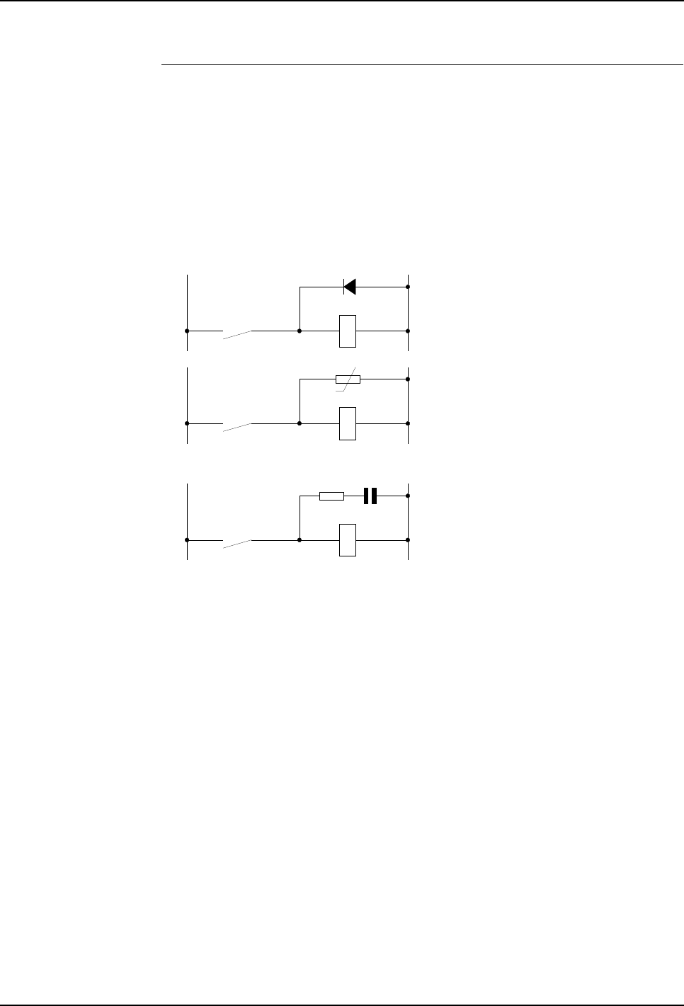
10 Reference Information
Product Manual, Control Cabinet IRC5P 3HNA009834-001 en Rev.06 209
10.1 Cable Information
Interference Elimination Internal relay coils and other units that can generate interference inside the
controller are neutralized. External relay coils, solenoids and other units must be
clamped in a similar way. The illustration in Figure 87 shows how this can be done.
Note that the turn-off time for DC relays increases after neutralization, especially if
a diode is connected across the coil. Varistors give shorter turn-off times.
Neutralizing the coils lengthens the life of the switches that control them.
Figure 87 Examples on how peripheral equipment can be neutralized
+24 VDC 0 Volt
+24 V, DC or AC voltage 0 Volt
RC
The diode is to be dimensioned for the
same current as the relay coil, and a
voltage of twice the supply voltage.
The varistor is to be dimensioned for
the same energy as the relay coil, and
a voltage of twice the supply voltage.
R 100 ohm, 1W
C 0.1 - 1 µF (typically 0.47 µF
> 500 V max. voltage
125 V nominal voltage

10 Reference Information
10.2 Connection Types
210 3HNA009834-001 en Rev.06 Product Manual, Control Cabinet IRC5P
10.2 Connection Types
General Inter-connections between the different components of the robot system, and
external connections may be performed using connectors, connectors with screw
terminals, terminal boards with screw terminals or spring terminals, depending on
how the robot is specified etc. The following sections provide general information
on the different types of connections which are- or may be used in the system.
Note: Bend unused conductors backwards and attach them to the cable using a
clasp etc. In order to prevent interference, ensure that such conductors are not
connected at the other end of the cable (antenna effect). In environments with much
interference, disconnected conductors should be grounded (0 V) in both ends.
Connection to Screw
Terminals The robot may include terminal boards or connectors with screw terminals for
connection of wires with area between 0.25 - 1.5mm². A maximum of two wires
can be connected to each terminal provided that a protection sleeve is installed on
the two wire ends. The cable screen must be connected at the lead-through in the
cabinet, - Ref: ’Clamping Cables’ on page 213.
Connections to Spring
Terminals The robot may include terminal boards with spring connection of wires with area
between 0.25 - 1.5mm². Only one wire can be connected to each of these terminals.
The cable is released from the connection by inserting a screwdriver in a slot beside
the connection point. The cable screen must be connected at the lead-through in the
cabinet, - Ref: ’Clamping Cables’ on page 213.
Connection to
Connectors Industrial connectors with varying number of pins for contact crimping are used in
the robot. Some options installed in the cabinet may also use these types of
connectors.
When contact crimping industrial connectors, the following applies:
Using special tongs, press a pin or socket on to each non-insulated conductor.
The pin can then be snapped into the actual contact.
Push the pin into the connector until it locks.
Also, see instructions from contact supplier.
A special extractor tool must be used to remove pins from industrial connectors.
When two conductors need to be connected to the same pin, both of them are
pressed into the same pin. A maximum of two conductors may be pressed into any
one pin.

10 Reference Information
Product Manual, Control Cabinet IRC5P 3HNA009834-001 en Rev.06 211
10.3 Bonding Information
10.3 Bonding Information
General Grounding or PE ground means the connection to protective earth. IS ground is
ground connection for the ex-systems. Bonding means additional ‘grounding’ to
protect sensitive signals from RF noise etc.
When the PE ground and IS ground connections of the robot components have been
performed in accordance with the description in this manual, the electronics
components in the shielded environment of the cabinet and manipulator are well
protected against electric noise.
To ensure proper operation of the robot system when electronic devices such as
external PLC, communication nodes, external cabinets etc. are placed outside these
protected environments, it is extremely important that proper bonding is provided
for the external units and corresponding communication cables.
In the following you will find information and hints on how proper bonding can be
obtained. For more information on protecting of signal cables etc., books describing
the subject are available on the market.
Bonding Connections When the robot is installed in accordance with the description in this manual, all
components of the robot system; control cabinet, manipulator, purge unit and
possible external cabinets etc. will be connected by a firm bonding wire as part of
the robots design. Additional external equipment installed must be connected by a
bonding wire of minimum 16mm2 (AWG 4). The wire must be firmly connected to
the bare metal of the component with a solid screwed connection. A solid
connection like this will ensure that no voltage potential can be built up between the
different units.
If the robot, control cabinet, purge unit, spray booth door switch or any other device
in the robot system is mounted on a metal surface, the user must make sure that
these surfaces are properly grounded.
CAUTION! No components in the robot system must be mounted on metal surfaces
which are not properly grounded.
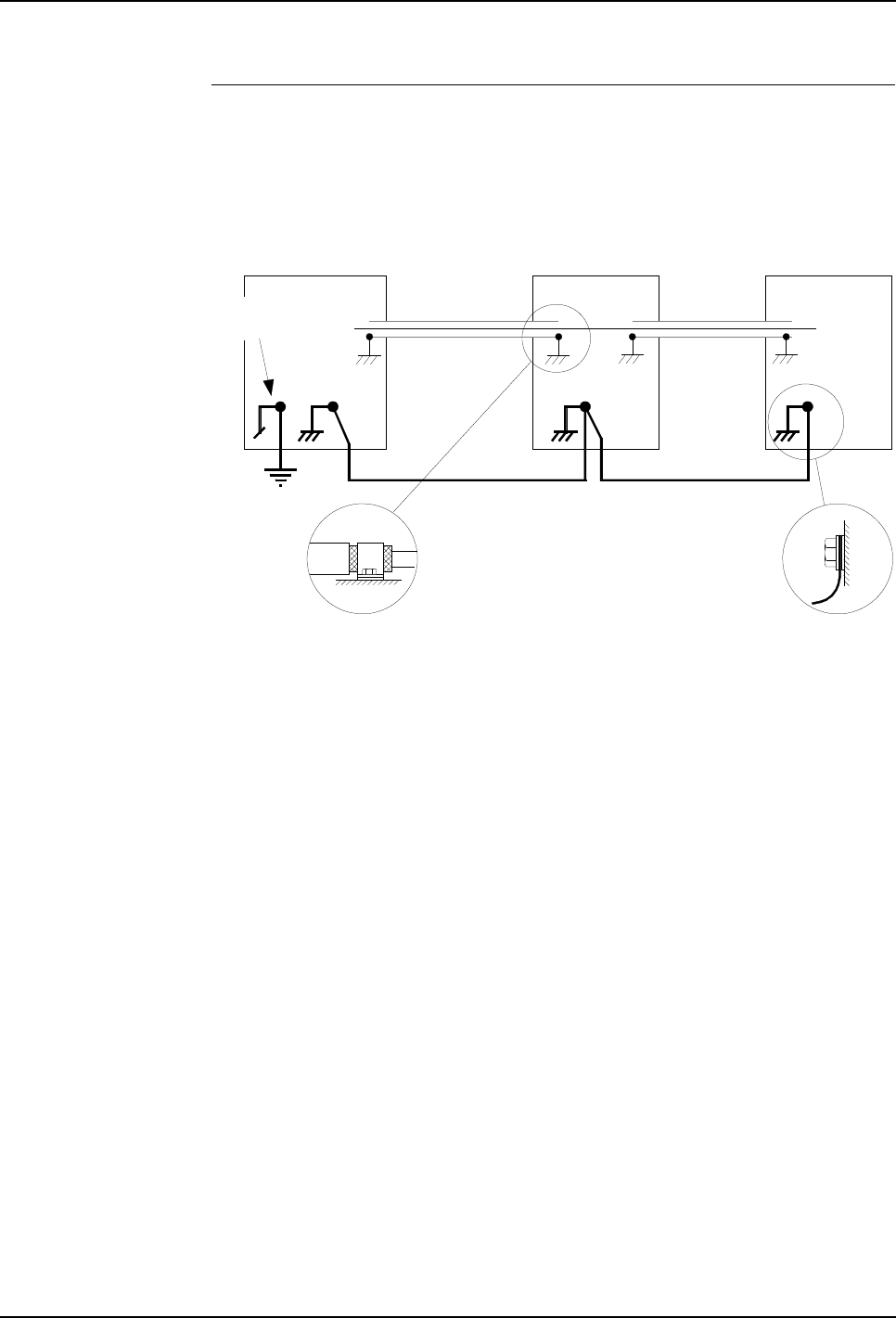
10 Reference Information
10.3 Bonding Information
212 3HNA009834-001 en Rev.06 Product Manual, Control Cabinet IRC5P
Signal Cable Screen
Connections All signal cables used in the system must be screened cables and all screens on all
signal cables are best connected to a good ground connection at both ends. An
example of a grounding system like this is shown in Figure 88.
Figure 88 Bonding connections in the robot system
Note: The bonding wire may be omitted. The use of this wire depends on the size of
the components (the amount of noise which can be induced in the component
casing), the distance to the component, the signals sensitivity to noise and present
noise in the installation etc.
External cabinet,
junction box etc.
Bonding wire
Factory mains
ground connection
Control cabinet
Screened cable
All bonding of signal cable screen
should be performed using P-Clip.
All bonding wire connection must be made
with screwed connection to bare metal.
P.E Ground
External cabinet,
junction box etc.
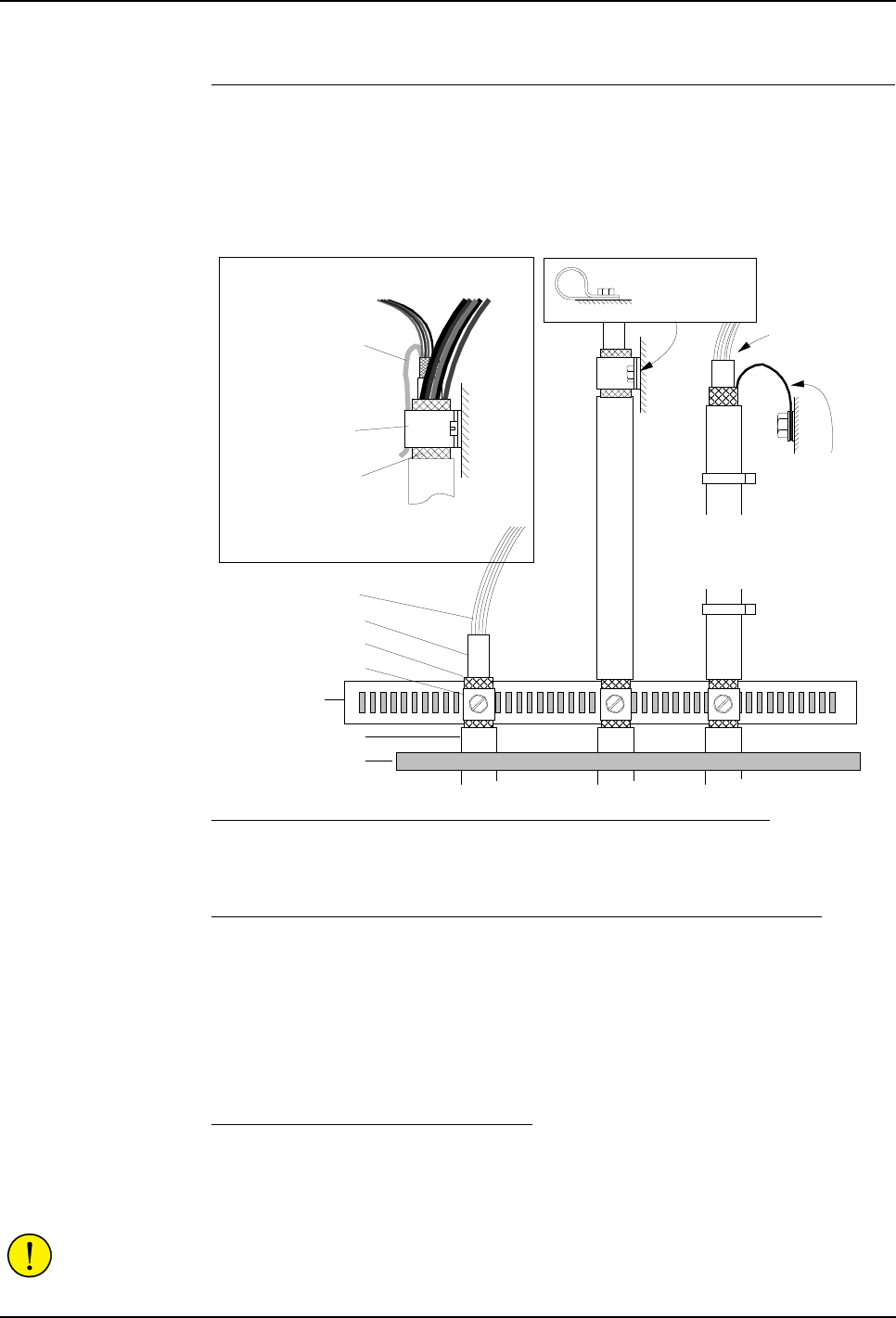
10 Reference Information
Product Manual, Control Cabinet IRC5P 3HNA009834-001 en Rev.06 213
10.3 Bonding Information
Clamping Cables All cables entered into the control cabinet must be clamped to the screen rail at the
bottom of the cabinet as shown in Figure 89 and if necessary clamped at the
connector where it is connected. Different methods are used for different types of
connections as follows:
Figure 89 Screen clamping
Method A - Cables connected to connectors near the strain relief rail
Cable screen must be clamped to the strain relief rail and wires / connector routed to
the connection point as shown in Figure 89 left.
Method B - Cables connected to connectors away from the strain relief rail
A section of the cable must be dismantled and clamped to the strain relief rail. The
cable is then routed to the connection point where the screen is clamped to the
cabinet frame using p-clip as shown in Figure 89 center. For the motor/signal cable
connected to X11 and X12, it must be observed that both the outer screen for the
motor cable and the inner screen for the signal cable must be secured under the
clamp. Ref. Figure 89 inset.
Method C - Cables for sensitive signals
Cable for extra sensitive signals such as analog signals must be grounded at the
component where it is connected in addition to the ground connection on the strain
relief rail as shown in Figure 89 right.
CAUTION! Do not use excessive force when tightening clamps. Tightening clamps
too hard may damage cable and signal wires.
Signal cable for
extra sensitive
signals
Screen
Screen clamp
Signal cable etc.
IMPORTANT:
Max length: 30mm
Inner Insulation
Outer Insulation
Strain relief rail
Dust seal
Method A
Method B
Method C
Secure cable at
connection point
using p-clip.
IMPORTANT:
Both motor cable screen and signal cable
screen must be secured under clamp
Signal cable
to X12 Motor power
cable to X11
Signal cable screen
Motor cable screen
Clamp
IMPORTANT:
For extended cabinet, cables
connected at the top must be
secured with 2 strain relief ties

10 Reference Information
10.3 Bonding Information
214 3HNA009834-001 en Rev.06 Product Manual, Control Cabinet IRC5P
Alternative Bonding
Methods The following shows 3 examples on how the signal cable screens can be bonded:
Figure 90 Bonding examples
Example 1
Where a good bonding is available on all units, the best shielding is obtained by
bonding all screens at both ends on all units.
Example 2
If a solid bonding connection can not be provided e.g. for an external unit such as a
communication node, I/O unit, PLC or a sensor etc., the screen for the cable must
not be bonded at the unit without a good bonding connection. This situation is
shown in Figure 90, example 2. If the cable is routed and terminated in a junction
box etc. and the junction box has a good bonding connection, the screens for both
cables must be bonded at this point.
Example 3
If the cable is terminated in a junction box or other unit where a good bonding is not
available, the screens of the 2 cables must be connected as shown in Figure 90,
example 3, but not connected to the chassis of the unit.
Junction box etc. External unit Example 1
Ground all screens
when a good ground
connection is available
Control cabinet
Example 2
Do not ground screen
at end where good
ground is not available
Example 3
Interconnect screens
but do not connect to
ground in external units
when good ground is not
available
Interconnect screens at
this point if single cable
cannot be used
Example on noise
supression capacitor

10 Reference Information
Product Manual, Control Cabinet IRC5P 3HNA009834-001 en Rev.06 215
10.3 Bonding Information
Hints • You may check that the bonding is good by using an oscilloscope with an EMI
probe (Electro Magnetic Interference). By setting the oscilloscope to a relatively
high frequency and measuring on the screens and chassis of the different units in
the system, possible noise can be seen on the oscilloscope screen.
• If noise is present in the situations shown in Figure 90 example 2 and 3, a
ceramic capacitor of e.g. 0.22µF can be installed between the screen and chassis
as shown in example 3.
• Cables of different types such as signal cables and power cables must not be
routed together as the power cables may introduce noise in the signal cable.
• If the bonding has been performed according to the general guidelines given here
but noise is still present, there is a good chance that the bonding wire used are of
too small square in relation to the length of the wire or that the connections
between the bonding wire and/or screens are not good enough.
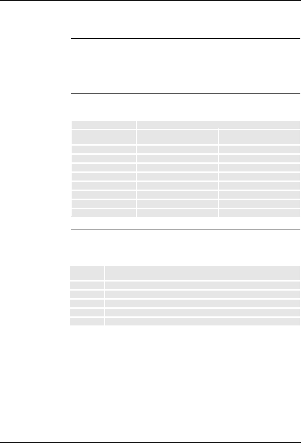
10 Reference Information
10.4 Tightening Torques
216 3HNA009834-001 en Rev.06 Product Manual, Control Cabinet IRC5P
10.4 Tightening Torques
General All screws on the robot except screws for covers and adjusting screws should be
tightened with torque according to the tables below unless otherwise specified.
Galvanized screws are of 8.8 quality and untreated screws (black oxide) are of 12.9
quality. Torques apply to lightly lubricated screws.
Torque Tables for
Screws with Hexagon
Socket Heads
The table below shows tightening torques for screws used
Torque Table for Slotted
or Cross Recessed
Head
The table below shows tightening torques to be used for electrical connections,
terminal board screws etc.
Table 1
Screw quality
Nominal Diameter 8.8
Nm 12.9
Nm
M4 2.9 4.9
M5 5.9 10.0
M6 9.9 16.5
M8 24.0 40.0
M10 47.0 79.0
M12 82.0 140.0
M14 130.0 220.0
M16 200.0 340.0
Table 2
Nominal
Diameter Tightening torque - Nm
class 4.8 “Dry”
M 2.5 0.25
M 3 0.5
M 4 1.2
M 5 2.5
M 6 5.0

Product Manual, Control Cabinet IRC5P 3HNA009834-001 en Rev.06 217
Manual Status
Manual Status
Product Manual
Control Cabinet, IRC5P
3HNA009834-001 en Rev.06
Documents included in manual:
Chp.: Subject: File Identification: Page:
Preface . . . . . . . . . . . . . . . . . . . . . . . . . . . . . . . . . . . . . . . . . . . . . . . . . . A009834 9
1 Introduction . . . . . . . . . . . . . . . . . . . . . . . . . . . . . . . . . . . . . . . . . . . . . . . T02606 Rev.02 11
2 Safety. . . . . . . . . . . . . . . . . . . . . . . . . . . . . . . . . . . . . . . . . . . . . . . . . . . . T02607 Rev.01 13
3 System Description . . . . . . . . . . . . . . . . . . . . . . . . . . . . . . . . . . . . . . . . . T02644 Rev.06 15
4 Technical Specifications . . . . . . . . . . . . . . . . . . . . . . . . . . . . . . . . . . . . . T02724 Rev.07 31
5 Installation and commissioning . . . . . . . . . . . . . . . . . . . . . . . . . . . . . . . . T02608 Rev.07 39
6 Preventive Maintenance . . . . . . . . . . . . . . . . . . . . . . . . . . . . . . . . . . . . . T02609 Rev.05 123
7 Repair . . . . . . . . . . . . . . . . . . . . . . . . . . . . . . . . . . . . . . . . . . . . . . . . . . . T02610 Rev.04 129
8 Trouble Shooting . . . . . . . . . . . . . . . . . . . . . . . . . . . . . . . . . . . . . . . . . . . T02604 Rev.05 169
9 Decommissioning . . . . . . . . . . . . . . . . . . . . . . . . . . . . . . . . . . . . . . . . . . T02611 Rev.05 205
10 Reference Information . . . . . . . . . . . . . . . . . . . . . . . . . . . . . . . . . . . . . . . T02612 Rev.01 207


Product Manual, Control Cabinet IRC5P 3HNA009834-001 en Rev.06 219
List of Imported Graphics
List of Imported Graphics
Product Manual
Control Cabinet, IRC5P
3HNA009834-001 en Rev.06
Graphic files imported in manual:
Pg.: Illustration: Pg.: Illustration: Pg.: Illustration:
1 FrontPict.jpg @ 300 dpi
16 T0264401.wmf
17 t0264402.wmf
18 t0264407.wmf
21 t0264405.wmf
22 T0264406.wmf
23 T0264410.wmf
23 T0264411.wmf
24 T0264413.wmf
24 T0264412.wmf
25 T0264414.wmf
25 T0264415.wmf
26 T0264416.wmf
27 t0264420.wmf
27 t0264421.wmf
27 T0264422.wmf
27 T0264423.wmf
27 T0264424.wmf
28 T0264425.wmf
28 Icon_Auto.wmf
28 Icon_Reduced.wmf
28 Icon_High.wmf
28 Icon_Warning.gif @ 75 dpi
29 T0264404.wmf
34 T0272401.wmf
35 T0272403.wmf
37 T0272402.wmf
42 T0260804.wmf
44 T0260802.wmf
45 T0260803.wmf
47 T0260805.wmf
50 T0260806.wmf
52 T0260807.wmf
54 T0260817.wmf
55 T0260808.wmf
57 T0260819.wmf
58 T0260818.wmf
59 T0260809.wmf
61 T0260870.wmf
62 T0260871.wmf
62 T0260872.wmf
63 T0260873.wmf
63 T0260874.wmf
67 T0260810.wmf
69 T0260811.wmf
72 T0260813.wmf
73 Icon_Auto.wmf
73 Icon_Reduced.wmf
73 Icon_High.wmf
73 Icon_Reduced_w.wmf
73 Icon_High_w.wmf
73 Icon_Auto_w.wmf
75 Icon_Reduced_w.wmf
75 Icon_High_w.wmf
75 Icon_Auto_w.wmf
75 Icon_Reduced_w.wmf
75 Icon_High_w.wmf
76 T0260814.wmf
77 T0260842.wmf
79 T0260820.wmf
84 T0260821.wmf
85 T0260822.wmf
87 T0260826.wmf
90 T0260827.wmf
91 T0260828.wmf
92 T0260829.wmf
93 T0260830.wmf
94 T0260831.wmf
94 T0260832.wmf
95 T0260833.wmf
96 T0260834.wmf
98 T0260835.wmf
99 T0260837.wmf
100 T0260836.wmf
101 T0260838.wmf
102 T0260839.wmf
103 T0260846.wmf
103 T0260844.wmf
104 T0260840.wmf
105 T0260845.wmf
107 T0260847.JPG @ 300 dpi
107 T0260848.JPG @ 300 dpi
107 T0260849.JPG @ 300 dpi
109 T0260853.wmf
110 T0260854.wmf
111 T0260850.wmf
112 T0260851.wmf
115 T0260860.wmf
117 T0260862.wmf
118 T0260863.wmf
119 T0260864.wmf
120 T0260866.wmf
124 T0260901.wmf
126 T0260902.wmf
128 T0260905.jpg @ 300 dpi
131 T0261002.jpg @ 300 dpi
131 T0261001.jpg @ 450 dpi
131 T0261003.jpg @ 300 dpi
132 T0261004.wmf
133 T0261001.jpg @ 450 dpi
133 T0261005.wmf
135 T0261001.jpg @ 450 dpi
135 T0261006.wmf
137 T0261007.wmf
139 T0261001.jpg @ 450 dpi
139 T0261009.wmf
141 T0261001.jpg @ 450 dpi
141 T0261011.wmf
143 T0261001.jpg @ 450 dpi
143 T0261012.wmf
145 T0261013.wmf
147 T0261015.wmf
149 T0261018.wmf
151 T0261001.jpg @ 450 dpi
151 T0261016.wmf
153 T0261001.jpg @ 450 dpi
153 T0261017.wmf
155 T0261030.wmf
155 T0261001.jpg @ 300 dpi
157 T0261020.wmf
157 T0261001.jpg @ 300 dpi
159 T0261001.jpg @ 450 dpi
159 T0261021.wmf
161 T0261022.wmf
163 T0261001.jpg @ 450 dpi
163 T0261023.wmf
165 T0261001.jpg @ 450 dpi
165 T0261024.wmf
167 T0261025.jpg @ 300 dpi
167 T0261001.jpg @ 450 dpi
197 T0260401.wmf
209 T0261201.wmf
212 T0261202.wmf
213 T0261203.wmf
214 T0261204.wmf