IXP300/IXP400 Installers Guide IXP300 IXP400 V1.00
User Manual: IXP300 IXP400 Installers Guide v1.00
Open the PDF directly: View PDF ![]() .
.
Page Count: 308 [warning: Documents this large are best viewed by clicking the View PDF Link!]
- Manufacturers Details
- Distributor Details
- Introduction
- General Hardware Installation Guidelines
- Summary of Cable Requirements
- Input Voltage Requirements
- ImproNet Hardware Components
- Installation Information
- ImproX Unit Categories
- ImproX HI Host Interface
- ImproX RH Registration Interface
- ImproX RS Registration Interface
- ImproX ProxMate
- ImproX RRA Registration Reader Antenna
- ImproX IC LCD Keypad Controller
- ImproX AC Advanced Controller
- ImproX TT Twin Antenna Terminal
- ImproX ER Extended Range Terminal and Fibreglass Antenna
- Tag Read Ranges
- Approvals
- Specifications
- Physical – ImproX (ER) Extended Range Terminal
- Physical – 350 mm x 350 mm Fibreglass Antenna
- Environmental – ImproX (ER) Extended Range Terminal
- Environmental – 350 mm x 350 mm Fibreglass Antenna
- Electrical – ImproX (ER) Extended Range Terminal
- Electrical – 350 mm x 350 mm Fibreglass Antenna
- Operator or Installer Interfaces
- Installation Information
- Mounting the Terminal and the Antenna
- Electrical Connections
- Installation Test Mode
- Fixed Address Label
- Operation and Functionality
- ImproX I16 16 Channel Input Terminal
- ImproX O16 16 Channel Output Terminal
- ImproX MA Micro Antenna Reader
- ImproX MHA Metal Antenna Reader
- ImproX MMA Mullion Antenna Reader
- ImproX KHA Metal Keypad Antenna Reader
- Hardware Maintenance
- Minimum PC Specifications
- ImproNet Applications
- Peripheral Hardware
- ImproNet Network Specifications
- Architecture
- ImproNet Modules in a Network Environment
- General Network Requirements
- Running ImproNet Applications across a LAN
- Running ImproNet Applications across a WAN
- Properties Files
- Configuring ImproNet Modules for a Stand Alone (Single PC) S
- Configuring ImproNet Modules for a LAN
- Configuring ImproNet Modules for a WAN
- Using Routers Configuration
- System Concepts
- Software Installation Procedure
- Pre-Configuration Procedure
- Configuration Overview
- System Configuration Parameters
- Engine Functions
- Engine Menu Functions
- Engine Properties
- Advanced Properties
- Open Advanced Properties
- Controller Timeout
- Controller Slow Poll Drop Time
- Challenge Timeout
- AutoID Time
- Host Interface Fast Polling
- Terminal Bus Fast Polling
- Controller Bus Additional Timeout
- Terminal Bus Additional Timeout
- Uploader Cycle Delay
- Uploader Inter Table Delay
- Uploader Daily Start Time
- Uploader Daily End Time
- Poller Inter Poll Delay
- Poller Daily Start Time
- Poller Daily End Time
- Uploader Database Connection Reset
- System Configuration Procedure
- Sites
- Controller
- Terminals
- Access Time Patterns
- Areas
- Access Groups
- Tag Holders – Assign Access to Tags
- Device Time Patterns
- Holidays
- Time Triggered Actions
- Actions
- Inputs
- Outputs
- Common Zones
- Messages
- Common Zones
- Emergency Unlock
- Supervisor Unlock
- Random Search
- Operator Security
- CSV Import
- DBUpgrade
- Firmware Upgrade
- Replacing Controllers and Terminals

IXP300/IXP400 INSTALLATION GUIDE
Issue Date: 11 July 2006Document Number: INS-310-0-0-UL-00

Introduction
COPYRIGHTS
This manual is propriety information of Impro Technologies (Pty) Ltd. Unauthorized reproduction
of any portion of this manual is prohibited. The content of this manual is for information
purposes only and is subject to change without notice. Impro Technologies assumes no
responsibility for incorrect information this manual may contain.
TRADEMARKS
Impro, ImproX, and ImproNet are registered trademarks of Impro Technologies (Pty) Ltd in
South Africa and/or other countries. Other brands and products are trademarks or registered
trademarks of their respective holders and should be noted as such.
Manufacturers Details
Impro Technologies
47 Gillitts Road
Pinetown 3610
South Africa
Distributor Details
Impro USA
1177 Main Street, Suite A
Dunedin
Florida
United States
Document Number: INS-310-0-0-UL-00
Document Version 1.00
Issue Date: 11 July 2006
2 Tuesday, 11 July 2006

IXP300/IXP400 Installation Guide
At a Glance
PART I – Hardware Configuration
Provides information to set-up and configure ImproX Hardware prior to configuring the ImproNet
software. It includes information on cabling, power, and earthing requirements.
PART II – Getting Started
Provides an overview of the ImproNet System, and the basic steps required for installation and
pre-configuration.
PART III – General Configuration
General Configuration provides the nuts-and-bolts procedures for ImproNet Software
configuration. All everyday tasks are described in this Part.
PART IV – Advanced Configuration
Details not covered in Parts I, II, or III, are described here. Most information in this Part is not
required for everyday configuration.
PART V – Utilities
The ImproNet utility modules enable you to perform administrative and maintenance tasks to the
core ImproNet components.
Tuesday, 11 July 2006 3

Introduction
Contents
INTRODUCTION ......................................................................................................14
Document Conventions........................................................................................... 14
Terminology............................................................................................................. 14
Supported Software and Firmware Versions .......................................................... 15
Compliance with UL................................................................................................ 15
ImproX Units Evaluated by UL................................................................................ 16
PART I – Hardware Configuration 17
GENERAL HARDWARE INSTALLATION GUIDELINES ..................................................18
Essential Installation Requirements........................................................................ 18
Unit Serial Numbers................................................................................................ 18
Power Supply.......................................................................................................... 18
Communication ....................................................................................................... 20
Network Topology.................................................................................................... 21
Placement of ImproX Units ..................................................................................... 22
Grounding the Shield in an IXP400 System ........................................................... 23
Grounding Controllers and Terminals in an IXP400 System .................................. 23
Terminating the Communication Bus ...................................................................... 25
Door Hardware Units .............................................................................................. 27
SUMMARY OF CABLE REQUIREMENTS ....................................................................29
General Requirements............................................................................................ 29
Low Voltage Power Supply to ImproX Controllers and Terminals .......................... 32
Digital Input Specifications...................................................................................... 32
INPUT VOLTAGE REQUIREMENTS ............................................................................33
Comms Interfaces................................................................................................... 33
Enrollment Readers ................................................................................................ 33
Controllers............................................................................................................... 34
Terminals................................................................................................................. 34
4 Tuesday, 11 July 2006

IXP300/IXP400 Installation Guide
IMPRONET HARDWARE COMPONENTS....................................................................35
Interface Devices .................................................................................................... 35
Card Readers.......................................................................................................... 35
Controllers............................................................................................................... 35
Terminals................................................................................................................. 36
Bus Types ............................................................................................................... 36
System Hardware Combinations ............................................................................ 37
ImproX Units that can be used in an IXP300 or IXP400 System............................ 38
System Size Limits.................................................................................................. 40
INSTALLATION INFORMATION ..................................................................................42
Doors and Zones .................................................................................................... 42
Addressing Scheme................................................................................................ 42
Positioning Units ..................................................................................................... 43
IMPROX UNIT CATEGORIES....................................................................................47
IMPROX HI HOST INTERFACE.................................................................................48
Applications............................................................................................................. 48
Specifications .......................................................................................................... 49
International Standards........................................................................................... 50
Installation Information............................................................................................ 51
Enclosure ................................................................................................................ 53
Electrical Connections ............................................................................................ 53
Operational Information .......................................................................................... 54
IMPROX RH REGISTRATION INTERFACE..................................................................55
Tag Read/Write Ranges.......................................................................................... 55
Approvals ................................................................................................................ 56
Specifications .......................................................................................................... 56
Installation Information............................................................................................ 58
Mounting the Cabinet.............................................................................................. 58
DIP-switch Settings................................................................................................. 59
Electrical Connections ............................................................................................ 60
Power-on Self-test .................................................................................................. 60
Fixed Address Label ............................................................................................... 61
Operation and Functionality.................................................................................... 61
Tuesday, 11 July 2006 5

Introduction
IMPROX RS REGISTRATION INTERFACE..................................................................62
Key Features........................................................................................................... 62
Typical Read Range................................................................................................ 62
Approvals ................................................................................................................ 63
Specifications .......................................................................................................... 63
Installation Information............................................................................................ 65
Electrical Connections ............................................................................................ 67
Fixed Address Label ............................................................................................... 68
IMPROX PROXMATE ..............................................................................................69
Applications............................................................................................................. 69
Features.................................................................................................................. 69
Accessories............................................................................................................. 70
Specifications .......................................................................................................... 70
Installation Information............................................................................................ 71
IMPROX RRA REGISTRATION READER ANTENNA ...................................................74
Tag Read/Write Ranges.......................................................................................... 74
Approvals ................................................................................................................ 74
Specifications .......................................................................................................... 74
Installation Information............................................................................................ 75
Electrical Connections ............................................................................................ 77
Initial Start-up .......................................................................................................... 77
Serial Number Label ............................................................................................... 77
Operation and Functionality.................................................................................... 78
IMPROX IC LCD KEYPAD CONTROLLER.................................................................79
Approvals ................................................................................................................ 79
Specifications .......................................................................................................... 79
Electrical.................................................................................................................. 80
Installation Information............................................................................................ 82
Electrical Connections ............................................................................................ 85
Power-on Self-test .................................................................................................. 85
Fixed Address Label ............................................................................................... 86
Operation and Functionality.................................................................................... 86
IMPROX AC ADVANCED CONTROLLER ...................................................................87
6 Tuesday, 11 July 2006

IXP300/IXP400 Installation Guide
Approvals ................................................................................................................ 87
Specifications .......................................................................................................... 87
Installation Information............................................................................................ 89
Mounting the Controller........................................................................................... 91
Electrical Connections ............................................................................................ 92
Power-on Self-test .................................................................................................. 93
Fixed Address Label ............................................................................................... 93
Operation and Functionality.................................................................................... 93
IMPROX TT TWIN ANTENNA TERMINAL...................................................................94
Tag Read/Write Ranges.......................................................................................... 94
Approvals ................................................................................................................ 95
Specifications .......................................................................................................... 95
Interface Details ...................................................................................................... 97
Installation Information............................................................................................ 98
Mounting the ImproX TT ....................................................................................... 100
Electrical Connections .......................................................................................... 102
ImproX TT Address Information ............................................................................ 103
Fixed Address Label ............................................................................................. 103
Operation and Functionality.................................................................................. 103
IMPROX ER EXTENDED RANGE TERMINAL AND FIBREGLASS ANTENNA ................104
Tag Read Ranges ................................................................................................. 104
Approvals .............................................................................................................. 105
Specifications ........................................................................................................ 105
Installation Information.......................................................................................... 108
Mounting the Terminal and the Antenna ............................................................... 110
Electrical Connections .......................................................................................... 115
Installation Test Mode ........................................................................................... 116
Fixed Address Label ............................................................................................. 116
Operation and Functionality.................................................................................. 116
IMPROX I16 16 CHANNEL INPUT TERMINAL..........................................................118
Approvals .............................................................................................................. 118
Specifications ........................................................................................................ 118
Interface Details .................................................................................................... 120
Installation Information.......................................................................................... 122
Tuesday, 11 July 2006 7

Introduction
Mounting the ImproX I16....................................................................................... 122
Electrical Connections .......................................................................................... 124
ImproX I16 Address Information ........................................................................... 124
Fixed Address Label ............................................................................................. 125
Operation and Functionality.................................................................................. 125
IMPROX O16 16 CHANNEL OUTPUT TERMINAL ....................................................126
Approvals .............................................................................................................. 126
Specifications ........................................................................................................ 126
Interface Details .................................................................................................... 128
Installation Information.......................................................................................... 129
Mounting the ImproX O16..................................................................................... 130
Electrical Connections .......................................................................................... 131
ImproX O16 Address Information.......................................................................... 131
Fixed Address Label ............................................................................................. 132
Operation and Functionality.................................................................................. 132
IMPROX MA MICRO ANTENNA READER................................................................133
Tag Read/Write Ranges........................................................................................ 133
Approvals .............................................................................................................. 133
Specifications ........................................................................................................ 134
Installation Information.......................................................................................... 135
Mounting the ImproX MA ...................................................................................... 135
Electrical Connections .......................................................................................... 138
Serial Number Label ............................................................................................. 138
Operation and Functionality.................................................................................. 139
IMPROX MHA METAL ANTENNA READER .............................................................140
Tag Read/Write Ranges........................................................................................ 140
Approvals .............................................................................................................. 140
Specifications ........................................................................................................ 141
Installation Information.......................................................................................... 142
Mounting the ImproX MHA.................................................................................... 142
Electrical Connections .......................................................................................... 145
Initial Start-up ........................................................................................................ 145
Serial Number Label ............................................................................................. 145
Operation and Functionality.................................................................................. 146
8 Tuesday, 11 July 2006

IXP300/IXP400 Installation Guide
IMPROX MMA MULLION ANTENNA READER .........................................................147
Tag Read/Write Ranges........................................................................................ 147
Approvals .............................................................................................................. 147
Specifications ........................................................................................................ 148
Installation Information.......................................................................................... 149
Mounting the ImproX MMA ................................................................................... 149
Electrical Connections .......................................................................................... 152
Initial Start-up ........................................................................................................ 152
Serial Number Label ............................................................................................. 153
Operation and Functionality.................................................................................. 153
IMPROX KHA METAL KEYPAD ANTENNA READER ................................................154
Tag Read/Write Ranges........................................................................................ 154
Approvals .............................................................................................................. 154
Specifications ........................................................................................................ 155
Installation Information.......................................................................................... 156
Mounting the ImproX KHA .................................................................................... 157
Mounting the Front Cover onto the Backing Plate................................................ 158
Electrical Connections .......................................................................................... 158
Serial Number Label ............................................................................................. 159
Operation and Functionality.................................................................................. 160
HARDWARE MAINTENANCE ..................................................................................161
Maintenance Overview ......................................................................................... 161
Basic Maintenance................................................................................................ 161
Maintenance Tools ................................................................................................ 161
Hardware Testing .................................................................................................. 163
Specific Maintenance............................................................................................ 163
PART II – Getting Started with ImproNet
Software 169
MINIMUM PC SPECIFICATIONS..............................................................................171
Database Server................................................................................................... 171
ImproNet Module PCs........................................................................................... 173
Tuesday, 11 July 2006 9

Introduction
Known Issues........................................................................................................ 174
IMPRONET APPLICATIONS ....................................................................................175
ImproNet Modules................................................................................................. 175
ImproNet Utilities................................................................................................... 176
PERIPHERAL HARDWARE .....................................................................................178
ProX-Mate........................................................................................................... 178
Host Interface—Serial Communications Converter............................................ 179
USB Enrollment Readers...................................................................................... 179
ImproX RH ............................................................................................................ 179
ImproX RS........................................................................................................... 180
ImproX RRA.......................................................................................................... 180
ImproX RRM....................................................................................................... 180
IMPRONET NETWORK SPECIFICATIONS.................................................................181
Architecture........................................................................................................... 181
ImproNet Modules in a Network Environment ...................................................... 182
General Network Requirements............................................................................ 184
Running ImproNet Applications across a LAN...................................................... 185
Running ImproNet Applications across a WAN..................................................... 186
Properties Files..................................................................................................... 187
Configuring ImproNet Modules for a Stand Alone (Single PC) System................ 187
Configuring ImproNet Modules for a LAN............................................................. 188
Configuring ImproNet Modules for a WAN............................................................ 189
Using Routers Configuration................................................................................. 190
SYSTEM CONCEPTS.............................................................................................192
System Architecture Concepts.............................................................................. 192
Sites ...................................................................................................................... 192
System Building Blocks......................................................................................... 193
SOFTWARE INSTALLATION PROCEDURE................................................................195
New ImproNet Installation..................................................................................... 195
Installing the Database Server.............................................................................. 197
ImproNet Installation Procedure ........................................................................... 202
Installing the Access or Engine Modules Only...................................................... 204
Upgrading an Existing Installation......................................................................... 206
10 Tuesday, 11 July 2006

IXP300/IXP400 Installation Guide
PRE-CONFIGURATION PROCEDURE ......................................................................207
Identifying the Hardware....................................................................................... 207
PART III – General Configuration 209
CONFIGURATION OVERVIEW.................................................................................210
Using ImproNet Access......................................................................................... 210
Common Interface Controls.................................................................................. 211
A Note on Screenshots ......................................................................................... 212
SYSTEM CONFIGURATION PARAMETERS ...............................................................213
A Note on Fixed Addresses................................................................................... 214
ENGINE FUNCTIONS.............................................................................................215
Engine Menu Functions ........................................................................................ 215
Engine Properties ................................................................................................. 217
Advanced Properties............................................................................................. 220
System Configuration Procedure.......................................................................... 223
SITES ..................................................................................................................224
Shared Data.......................................................................................................... 225
About Time Patterns ............................................................................................. 225
Configure Site ....................................................................................................... 226
Set Up the Host PC............................................................................................... 227
About Hardware Configuration.............................................................................. 227
CONTROLLER ......................................................................................................228
Assign Terminals................................................................................................... 228
TERMINALS..........................................................................................................231
Terminal Mode Configuration................................................................................ 232
Inputs .................................................................................................................... 234
Outputs.................................................................................................................. 238
Actions .................................................................................................................. 239
Active System Events ........................................................................................... 240
ACCESS TIME PATTERNS .....................................................................................243
Configure Access Time Patterns........................................................................... 243
Tuesday, 11 July 2006 11

Introduction
AREAS ................................................................................................................245
ACCESS GROUPS ................................................................................................247
Configure Tag Holder Access Groups................................................................... 248
Configure Access Descriptions ............................................................................. 249
TAG HOLDERS – ASSIGN ACCESS TO TAGS ..........................................................251
Configure Tag Holder............................................................................................ 251
Batch Enrollment of Tags...................................................................................... 254
Advanced Search.................................................................................................. 255
DEVICE TIME PATTERNS.......................................................................................257
HOLIDAYS............................................................................................................260
TIME TRIGGERED ACTIONS...................................................................................261
Configure Time Triggered Actions......................................................................... 261
ACTIONS .............................................................................................................263
Edit and Delete Actions......................................................................................... 263
INPUTS ................................................................................................................265
OUTPUTS ............................................................................................................266
COMMON ZONES..................................................................................................267
MESSAGES..........................................................................................................268
PART IV – Advanced Configuration 269
COMMON ZONES..................................................................................................270
Configure Common Zones.................................................................................... 270
EMERGENCY UNLOCK..........................................................................................273
Set Up Emergency Unlock Mode.......................................................................... 273
Activating Emergency Unlock via an Input ........................................................... 276
SUPERVISOR UNLOCK..........................................................................................279
Configure Supervisor Unlock................................................................................ 279
RANDOM SEARCH................................................................................................281
The Random Search Event................................................................................... 281
12 Tuesday, 11 July 2006

IXP300/IXP400 Installation Guide
Set Up Random Search........................................................................................ 281
Example ................................................................................................................ 283
OPERATOR SECURITY ..........................................................................................286
Security Access..................................................................................................... 287
Users..................................................................................................................... 289
Tag Holder Access Groups ................................................................................... 292
User Profiles.......................................................................................................... 292
PART V – Utilities 295
CSV IMPORT .......................................................................................................296
CSV Overview....................................................................................................... 296
Importing a CSV File............................................................................................. 297
Creating a CSV File .............................................................................................. 298
Ensuring Correct CSV File Format ....................................................................... 299
Structure of Master, Department, and Employee Tables ...................................... 300
DBUPGRADE.......................................................................................................302
Database Upgrade Procedures ............................................................................ 302
FIRMWARE UPGRADE...........................................................................................303
REPLACING CONTROLLERS AND TERMINALS ........................................................306
Replace Controller ................................................................................................ 306
Replace Terminal .................................................................................................. 307
Tuesday, 11 July 2006 13

Introduction
Introduction
This manual is intended to assist the installer during the installation and configuration stages of
the ImproNet Software suite. It is not designed as an operational manual for the end-user. For
operational information, please refer to the ImproNet Software User Manual.
This manual is structured to assist the installer with configuring the basic components of the
system first, followed by advanced features and functions.
Document Conventions
The following conventions are used in this document:
Note—indicates additional information about a topic
Tip—indicates suggestions and alternative methods to perform tasks
Important—indicates important information
Warning—indicates potential danger to you or the product
Terminology
Impro-Specific Terminology
The following terminology is used in this document:
• ImproNet—the commonly used name of the IXP300 / IXP400 Series Software Suite.
However, the term ImproNet also describes an access solution as a whole; it encompasses
all hardware, software, and third-party applications.
• IXP300—the ImproNet System based around the ImproX IC Controller
• IXP400—the ImproNet System based around the ImproX AC Controller
• ImproX Hardware—the hardware units comprising an ImproNet System. The major
ImproX components are Controllers, Terminals, and Card Readers.
• Tag—the passive, proximity component used as a unique identifier in an ImproNet access
control system
14 Tuesday, 11 July 2006

IXP300/IXP400 Installation Guide
Country-Specific Terminology
Different countries use different words to name or describe the same thing. Table 1 lists the
International terms and their American equivalents used in this document.
International American
Lift Elevator
Grounding Earthing
Ground Earth
Tag Card
Registration Enrollment
Registration Reader Enrollment Reader
Screen Shield
Screening Shielding
Table 1 – International and American Terms
In some cases, terms are used inter-changeably.
Supported Software and Firmware Versions
This release of the IXP300/IXP400 Installation Guide applies to the following Impro Software
and Firmware revisions only:
ImproNet Software Suite V 7.02
ImproX AC Controller V 7.04
ImproX IC Controller V 7.04
ImproX RH Registration Interface V 1.02
ImproX ER Terminal V 7.03
ImproX TT Terminal V 7.02
Compliance with UL
Unless otherwise stated, all hardware discussed in this manual has been evaluated and
approved by UL.
Not Evaluated by UL
Please note that the following have NOT been evaluated by UL:
• Use of Third Party Tags
• Fire Detection hardware
• Intrusion Detection hardware
• Alarm System hardware
• ImproNet Software
• Lift control
• RS232
Tuesday, 11 July 2006 15

Introduction
Throughout this guide, items not approved by UL are marked with a character.
ImproX Units Evaluated by UL
The following ImproX units have been successfully evaluated by UL and conform to the UL294
Standard:
Comms Interfaces
Unit Description Part Number
ImproX RH Registration Interface XRH900-1-0
Enrollment Readers
Unit Description Part Number
ImproX RRA Antenna for RH and RS XPR901-1-0
Controllers
Unit Description Part Number
ImproX IC Controller in the ImproNet system (IXP300). This
standard controller can support up to 48 Terminals. XIC900-1-0
ImproX AC Controller in the ImproNet system (IXP400). This
advanced controller can support up to 64 Terminals XAC904-1-0
Terminals
Unit Description Part Number
ImproX I16 Input Terminal providing 16 digital inputs. XIT900-0-0
ImproX O16 Output Terminal providing 16 relay outputs. XOT900-0-0
ImproX TT Twin Antenna Terminal. XOT910-1-0
ImproX ER Extended range Terminal with external antenna
Readers for ImproX TT
Unit Description Part Number
ImproX MMA Mullion Antenna Reader XTT901-1-0
ImproX MA Micro Antenna Reader XTT902-1-0
ImproX MHA Metal Antenna Reader XTT903-1-0
ImproX KHA Metal Keypad Antenna Reader XTT904-1-0
Table 2 - ImproX Units Evaluated by UL
16 Tuesday, 11 July 2006

IXP300/IXP400 Installation Guide
PART I – Hardware Configuration
Tuesday, 11 July 2006 17
General Hardware Installation Guidelines
General Hardware Installation Guidelines
Essential Installation Requirements
All units must be installed and wired in accordance with the National Electric
Code (ANSI/NFPA 70), local codes, and the authorities having jurisdiction.
Unit Serial Numbers
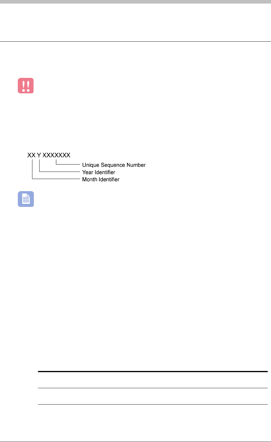
All ImproX hardware units have a unique serial number. The format of the serial number is as
follows:
•
The Year Identifier uses letters to denote year. Each year, the letter advances by one.
For example, O = 2004, P = 2005, and Q = 2006.
Power Supply
Requirements
• Power to all units must be supplied by a power-limited, UL Listed, access control or burglar
alarm power supply capable of providing the following:
− Required voltage and current
− Minimum four-hour standby time
• One Power Supply must be installed for each set of Readers and Terminals at a Location.
This ensures a reduced current load.
• Each high-current Magnetic Lock must be powered by a separate UL Listed power supply.
• The maximum distance between the Power Supply Unit and the units it supplies with power,
depends on the following:
− Output voltage of the Power Supply Unit
− Cross-sectional area of cable. Refer to Table 3 on page 31 for details.
Power Supply Unit
Output Voltage Maximum Distance Cable Specification
12 V DC 10 m (32.81 ft) Conductors with a minimum cross-sectional
area of 0.5 mm² (0.0008 in²).
24 V DC 20 m (65.62 ft) Conductors with a minimum cross-sectional
area of 0.5 mm² (0.0008 in²).
18 Tuesday, 11 July 2006
IXP300/IXP400 Installation Guide
The input voltage supplied by the Power Supply to a unit, must not exceed
the value specified in this Manual. Otherwise, the unit may be damaged.
Recommendations
• All mains supplies to the Power Supply should be protected from high voltage surges. You
can protect the mains supplies by means of Metal Oxide Varistors (MOV), Line
Transformers, or Un-interruptible Power Supply (UPS) systems.
• Power Supplies with battery backup are preferable as they ensure that frequent occurrences
of mains brownouts have no effect on the Reader or Controller performance. Battery
backups should supply a minimum of 4 hours standby time.
• Batteries have a life expectancy of 3 to 4 years. Therefore, ensure they are changed at
regular intervals.
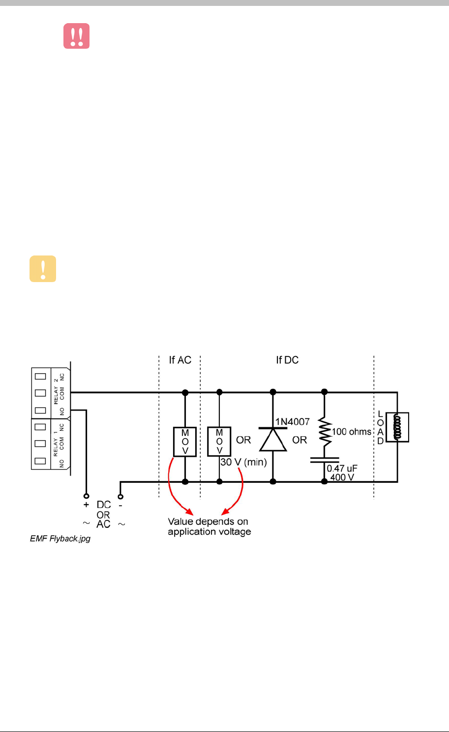
Arc Suppression
Arc suppression components must be fitted on all doors and access positions where
there are Strike Locks or Magnetic Locks.
Snubber devices are recommended for EMF flyback and arc suppression when driving an
inductive load with a Relay.
Figure 1 illustrates technical details.
Figure 1 - Arc Suppression
Surge Protection
In areas where lightning is common, we recommended using surge protection on low voltage
power lines and RS485 Communications lines. The Impro Line Surge Protector is
recommended for RS485 Communications Protection. The Impro Low Voltage Line
Protector is recommended for low voltage lines.
Tuesday, 11 July 2006 19

General Hardware Installation Guidelines
Communication
The ImproX range uses RS232 and RS485 protocols for most communication purposes.
• RS232 is generally used for short distances up to 25 m (82.02 ft). RS232 connects to a
single hardware device via a serial communications port to a PC running the ImproNet
Software.
• RS485 supports longer communications runs. It connects multiple hardware devices to a
common bus (Multi-Dropping). The IXP300 and IXP400 systems use RS485 for their
Terminal and Controller busses.
• USB is used between the ImproX RH and the PC running ImproNet Engine.
Recommended Cable
Choice of cable is a critical part of the installation process. Defective or unspecified cable can
result in communication problems. This can result in hardware timeouts and an overall speed
reduction of system procedures. Correct cable is particularly important for RS485 buses.
Ensure the following when selecting cable:
• Use twisted pair Mylar shielded cable only, for RS485 Comms bus
• For RS485 Ports, the individual cross-sectional area of the cable must not be less than 0.2
mm² (0.0003 in²). The maximum permissible cable length is 1000 m (3281 ft).
• For RS232 Ports, the individual core cross-sectional area of the cable must not be less than
0.2 mm² (0.0003 in²). The maximum permissible cable length is 25 m (82.02 ft).
• Cables must be:
− Neatly laid out
− Labelled correctly on both ends with cable markers
− Earthed correctly—the shield of the cable should be connected to the Earth terminal on
the unit. The unit should in turn be connected to a good Earth point. The earth must be
a low resistance connection to Earth and not an arbitrary Earth connection.
Connect the shield at one end of the cable only.
• Cable joins must be:
− Connected by proper connecting strips
− Kept to a minimum
• Shielded cables should be connected as follows:
− Strip to the required length exposing two internal wires
− Untwist the excess length of metallic foil and plastic covering and remove the plastic
− Twist the metallic foil to form a wire tail
− The shield lead must be connected to the Earth terminal. Earthing is at one end of the
cable only.
20 Tuesday, 11 July 2006
IXP300/IXP400 Installation Guide
• Cable layout of an installation must be documented
• Daisy-chain formations are preferable to Star formations
• Sites where transmission lines are long, or multiple star formations are used, may
experience timeouts on certain ImproX Controllers or Terminals. These are caused by
reflections on the RS485 lines. To solve the problem, it may be necessary to terminate the
lines. Termination resistors are added at the end of a cable run only and not at every
Terminal. Refer to the Terminating the Communication Bus section on page 25 for
details
Termination resistors are built into most ImproX Terminals.
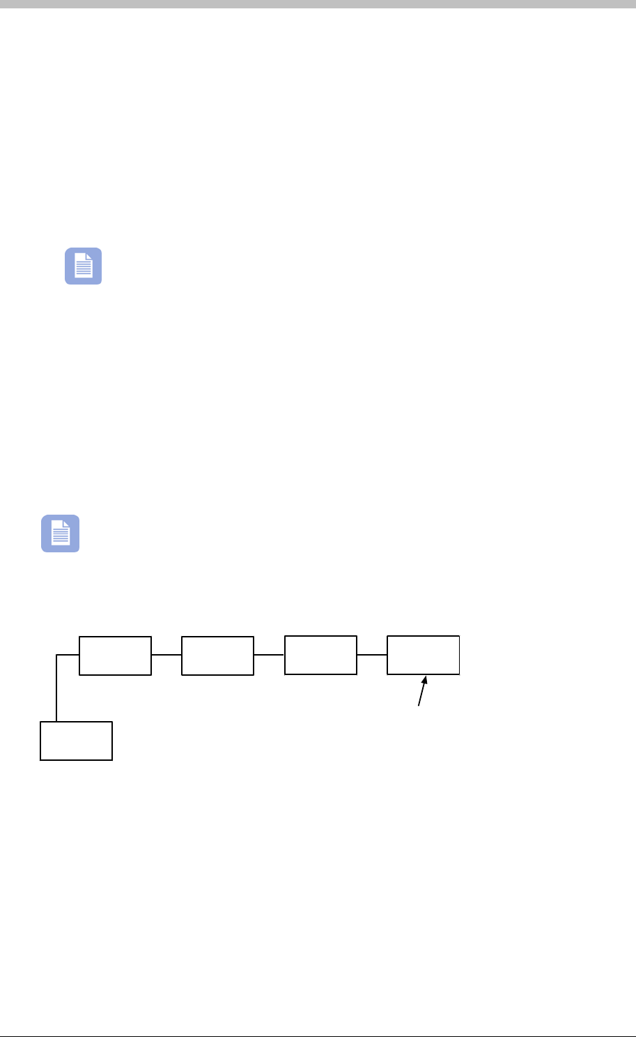
Network Topology
Cables should be run in a daisy chain configuration to provide effective RS485
communication for ImproX hardware. Figure 2 illustrates a daisy chain configuration.
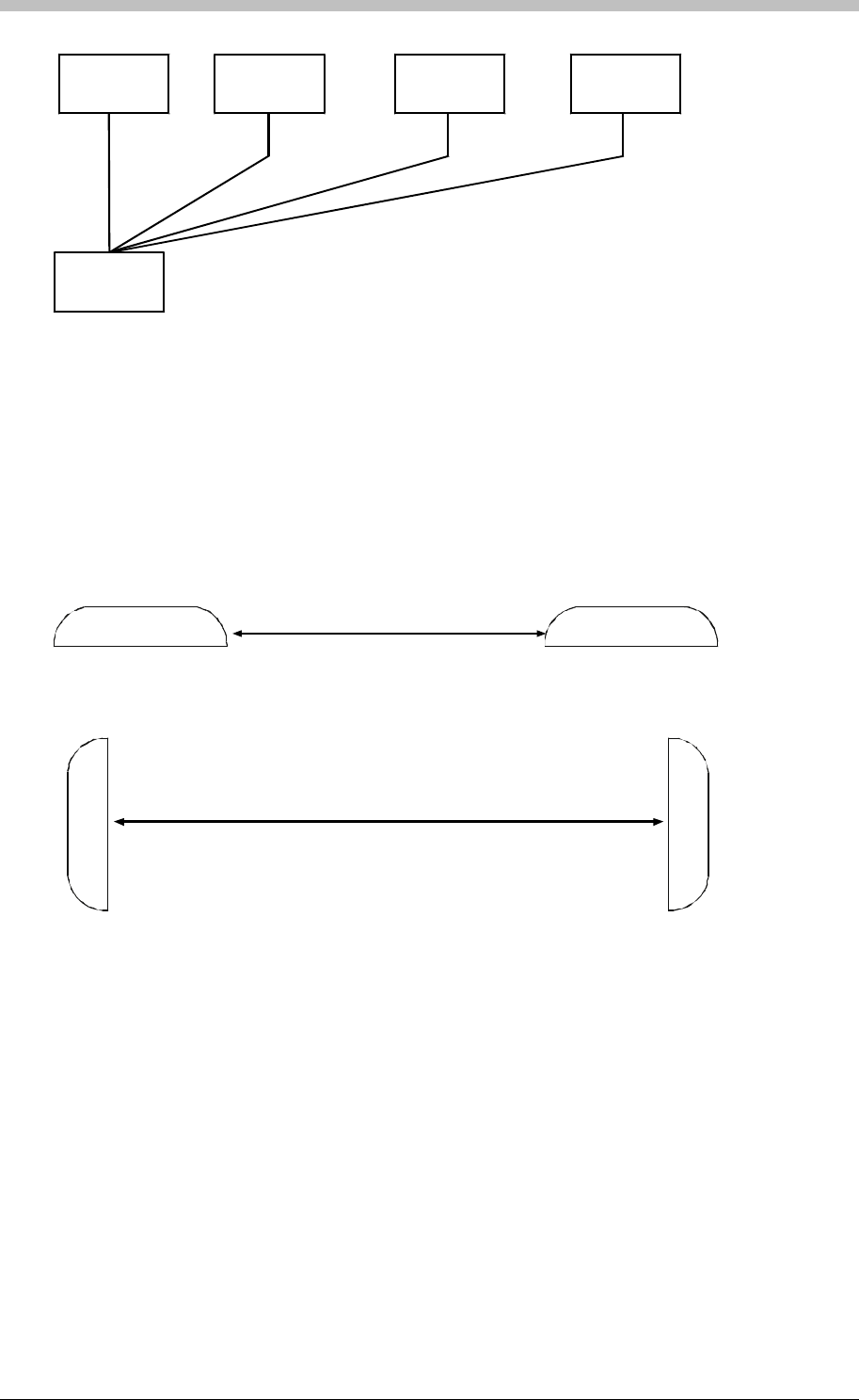
Star configurations are not recommended, as they are susceptible to signal reflections and
can result in signal degradation. End-of-line termination is also a problem with Star
configurations, due to the number of endpoints. If a termination resistor is required at each
endpoint, it will overload the RS485 driver.
More than four resistors on four of the star bus connections will overload the driver due
to low parallel resistance.
Controller
Last unit on the bus.
The termination
resistor must be con-
nected at this unit
only.
Terminal Bus
daisy-chain.wmf
ImproX
Terminal ImproX
Terminal
ImproX
Terminal
ImproX
Terminal
Figure 2 - Daisy-Chain Bus Connection - Good Wiring Practice
Tuesday, 11 July 2006 21
General Hardware Installation Guidelines
ImproX
Terminal ImproX
Terminal
ImproX
Terminal
ImproX
Terminal
star.wmf
Controller
Figure 3 - Star Bus Connection (BAD Wiring Practice)
Placement of ImproX Units
Minimum Distance between ImproX Units
It is important to maintain a minimum distance between adjacent ImproX Terminals or Remote
Readers to avoid mutual interference. Ensure a minimum distance of 500 mm (19.69 in)
between units.
Minimum distance 500 mm
Minimum distance 500 mm
khr distances.wmf
Figure 4 - Minimum Distance between Terminals or Remote Readers
Shielding of Units
In some situations, it is not possible to space the Readers the minimum distance apart. For
example, if two Readers are mounted back-to-back on either side of a drywall, place aluminium
plate between the two Readers. The dimensions of the plate must be at least 400 mm X 400
mm (15.75 in x 15.75 in), and have a thickness of at least 1 mm (0.04 in).
Line Termination—Principles of a Terminating Resistor
Long RS485 cable runs can cause problems with impedance matching and result in degraded
signals. The impedance between two units can mismatch when an increase in number of units
changes the resistance and capacitance of the connection. Such an impedance-mismatched
network creates reflections on signals and data sent on the cable. Reflected signals introduce
noise and errors on the connecting line.
22 Tuesday, 11 July 2006

IXP300/IXP400 Installation Guide
Each connected unit adds a small amount of capacitance to the network. The longer the cable
run, the more inductance and resistance is added. If this occurs, units on the cable-run can
timeout due to the reflections from the end of the cable conflicting with the messages sent from
the Terminals.
To overcome this problem, match the impedance by placing a terminating resistor between the
A and B line, at the last unit on the run. The terminating resistor inhibits the reflection and
enhances the signal or data integrity.
Ensure you adhere to the following criteria when placing terminating resistors:
• Place one terminating resistor on a single cable run only. If more are placed, they could
lower the resistance too much. As a result, the bus may hang-up.
• Place a terminating resistor on the cable run only if the cable has been checked for faults
but timeouts are still occurring.
You should use terminating resistors only if the system is experiencing communication
problems, or if the combined RS485 comms run is greater than 328 ft.
Grounding the Shield in an IXP400 System
A shield’s purpose is to drain off electrical noise. A correctly grounded shield leads electrical
noise along a path to the ground. Using a mains ground is possible, but it must be established
before hardware installation to determine if it is a suitable option.
To prevent ground loops, a shield must never be grounded at both ends of a RS485 cable run.
We recommend that you join - but not ground - the shield for the Controller bus and Terminal
bus at each termination point, and ground the shield at one end of the bus only. A suitable
grounding position is at the beginning or the end of the bus.
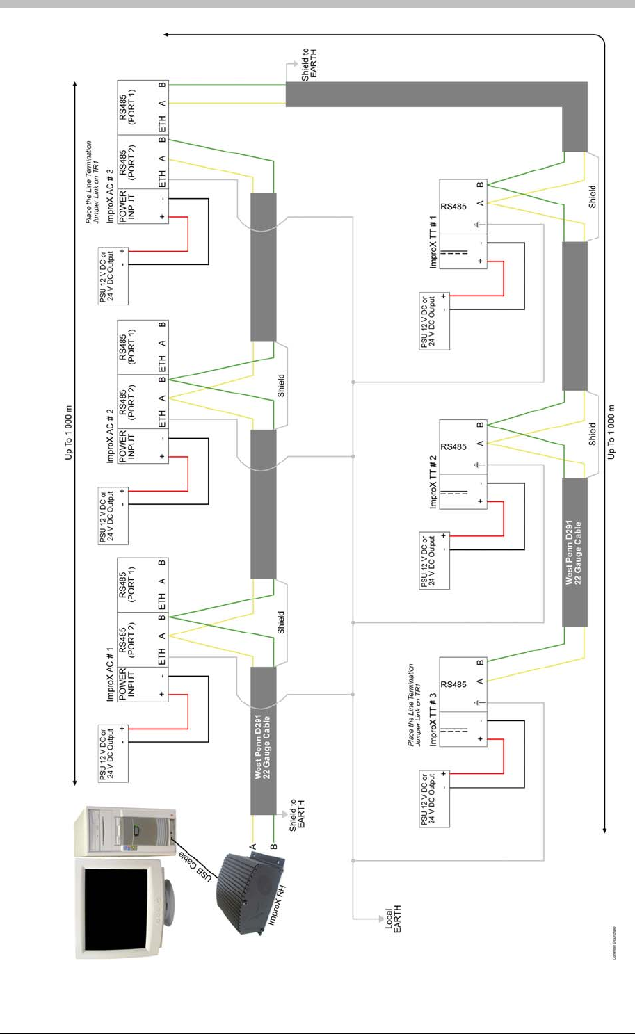
Grounding Controllers and Terminals in an IXP400 System
Common Ground
Figure 5 on page 24 illustrates the recommended grounding procedure when a common ground
point is available.
Connecting to a mains ground is acceptable provided it is a common (local) ground. Often, in a
single building or structure, each mains ground point is connected to a common ground.
However, you must confirm the grounding scenario before proceeding with a common ground.
The common ground method is preferred because it conforms to EMC standards. It also
provides good electrostatic discharge protection and emission reduction.
Tuesday, 11 July 2006 23
General Hardware Installation Guidelines
Figure 5 - Common Ground Schematic
24 Tuesday, 11 July 2006

IXP300/IXP400 Installation Guide
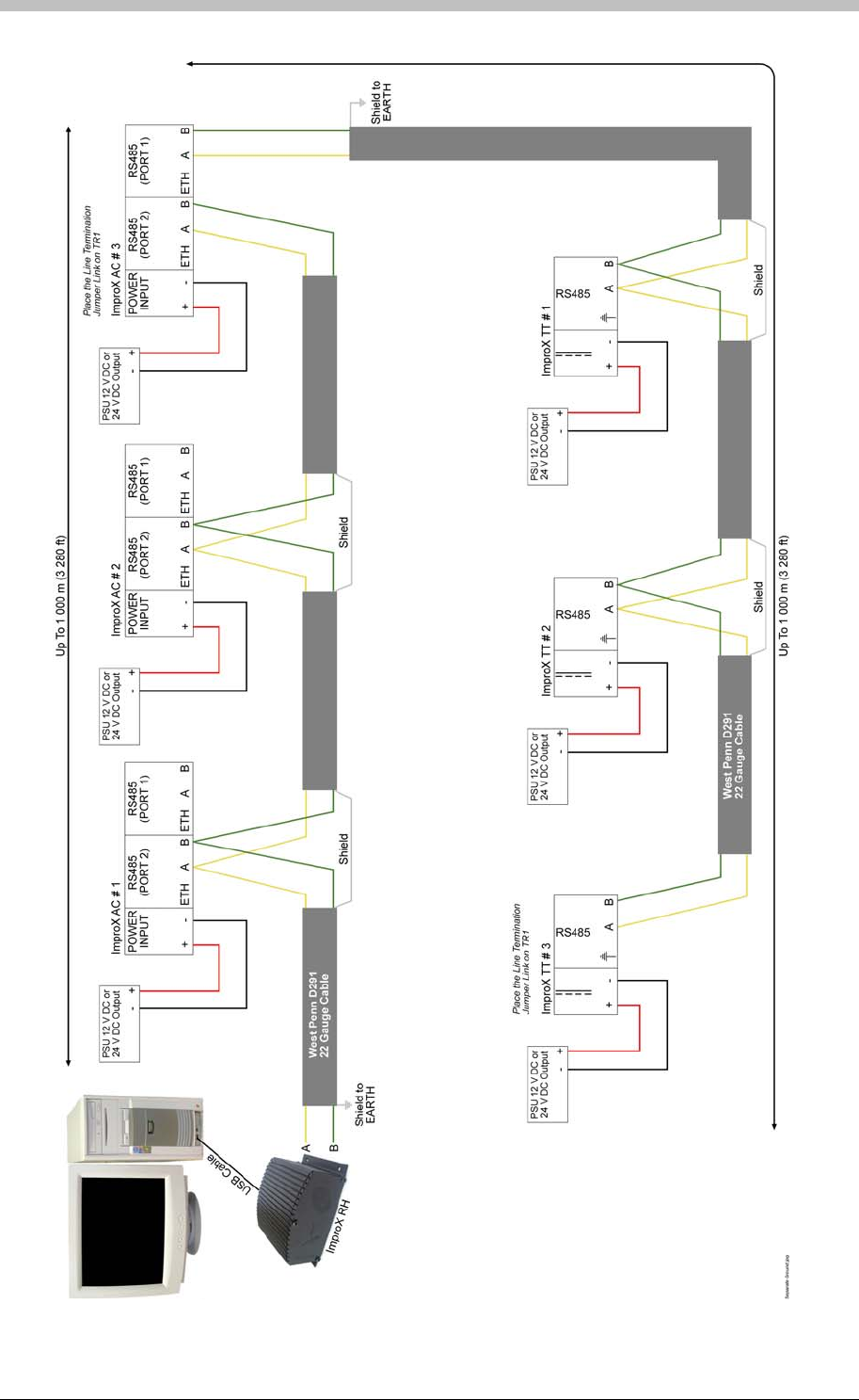
Separate Ground Points
Figure 6 on page 26 illustrates the recommended grounding procedure when a common ground
reference is not available.
This is often the case when the communications bus spans a number of buildings or structures
that do not share a common (local) ground. Communication problems can occur if the
hardware is grounded to separate (isolated) ground points and a potential difference exists
between these points. Therefore, we recommend you do not ground Controllers and Terminals
via separate ground points.
In the Separate Ground Point configuration, Controllers and Terminals are floating; therefore,
they are susceptible to electrostatic discharge. This method requires true floating power
supplies.
Terminating the Communication Bus
The comms bus requires termination to prevent reflections on the line. ImproX Controllers and
Terminals have onboard resistors that are used for line termination. Ensure the following when
terminating the Communication Bus:
Host Bus (Port 2)
Terminate the Controller comms bus (port 2) at the last Controller on the bus if the combined
RS485 comms run is more than 100 m.
Both the ImproX IC (IXP300) and ImproX AC (IXP400) Controllers have onboard termination
resistors that are disabled by default. To terminate the comms bus at a particular Controller,
short the TR1 jumper.
Terminal Bus (Port 1)
Terminate the Terminal comms bus (port 1) at the last Terminal on the bus if the combined
RS485 comms run is more than 100 m.
To terminate the comms bus at a particular ImproX TT terminal, short the onboard jumper.
To terminate the beginning of the Terminal comms bus at the Controller, short the TR2 jumper
on the Controller.
The ImproX TT, ImproX I16, ImproX O16, and ImproX ER Terminals have a single, onboard,
termination resistor. To enable line termination on a particular Terminal, connect the onboard
line termination link.
All onboard termination resistors on Controllers and Terminals are 150 ohms.
Tuesday, 11 July 2006 25
General Hardware Installation Guidelines
General Hardware Installation Guidelines
26 Tuesday, 11 July 2006
Figure 6 - Separate Ground Schematic
26 Tuesday, 11 July 2006
IXP300/IXP400 Installation Guide
Door Hardware Units
To ensure that Terminal relays function correctly, use only UL Listed strike locks and
magnetic locks.
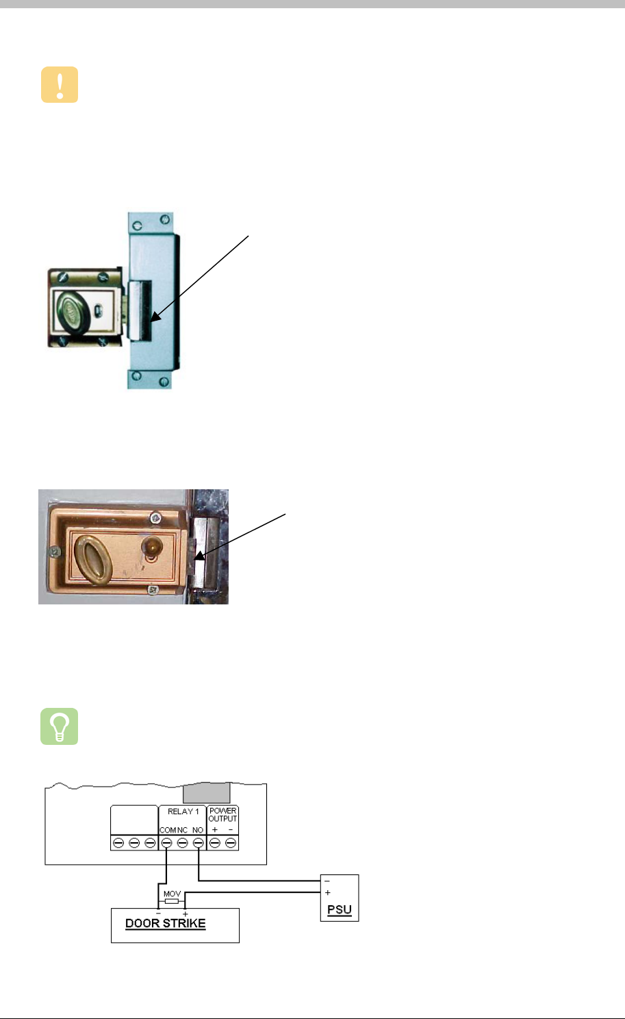
Door Strike
The Door Strike is the usual mechanical type lock but with an electromechanical action enabling
it to be actuated by the presence or absence of a current flowing through an internal solenoid.
Figure 7 - Door Strike
Figure 7 and Figure 8 show a type of a door lock called a door strike. Door strikes use a small
electro-mechanical solenoid to release a lip—a metal latch that keeps the door locked.
Door Strike
A
Door Strike
showing the lip
released
Figure 8 - Door Strike Showing Lip Released
Figure 8 shows the lip in a released position, so the door can be opened.
Strike locks have the advantage of being opened with a key if necessary.
Figure 9 - Typical Wiring to a Door Strike
Tuesday, 11 July 2006 27
General Hardware Installation Guidelines
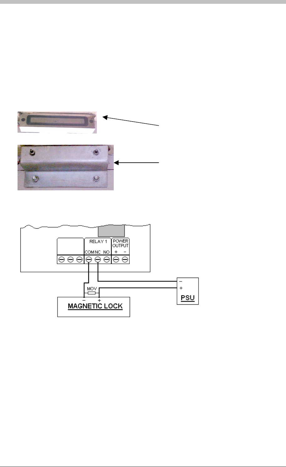
Magnetic Locks
Magnetic Locks use an electro-magnet to stay closed. When a metal bar on the back of a door
makes contact with the magnetic lock, a current in the lock is activated. The current induces a
magnetic field in the electro-magnet, which holds the door closed.
If the power to the lock fails, or is switched off, the door is released and can be easily opened.
This feature is an advantage in an emergency.
Electromagnet
attached to the
doorframe.
Metal bar bolted to
the door.
Figure 10 - Magnetic Lock Mounted in the top of a Door Frame
Figure 11 - Typical Wiring to a Magnetic Lock
28 Tuesday, 11 July 2006

IXP300/IXP400 Installation Guide
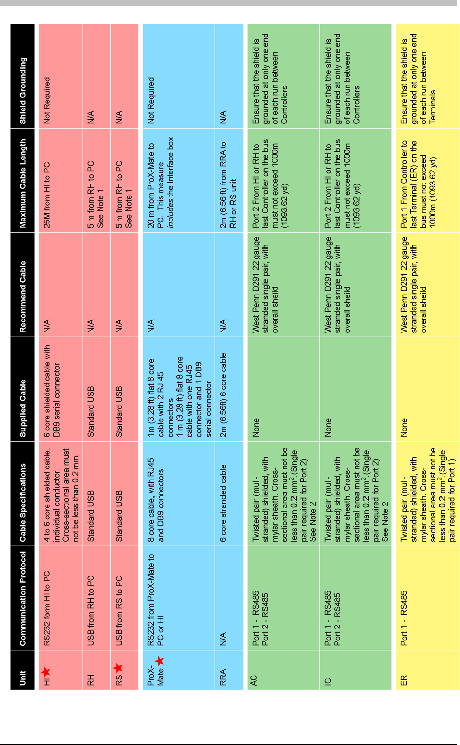
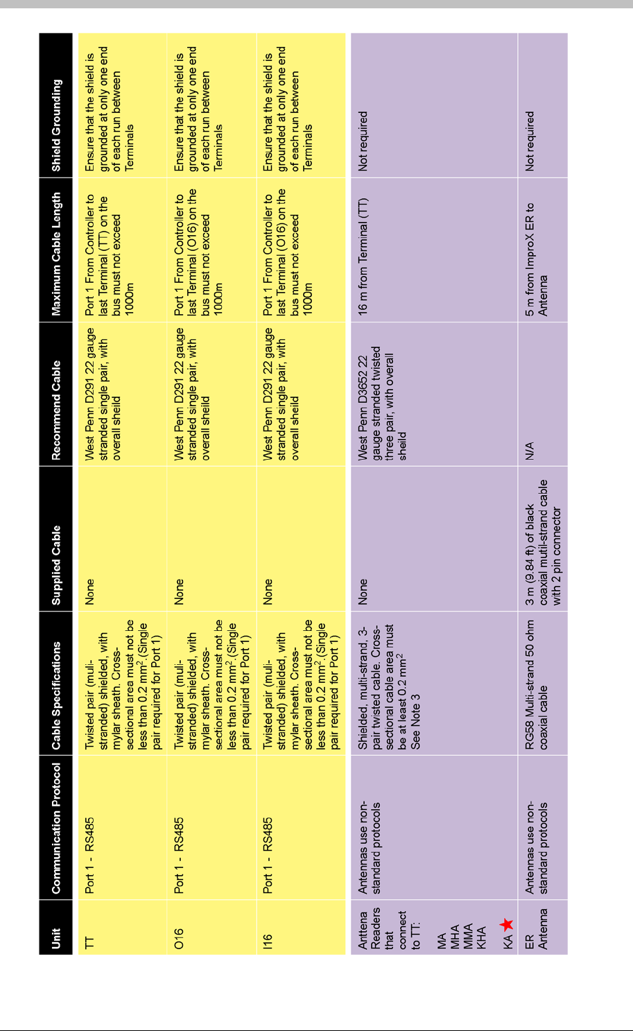
Summary of Cable Requirements
General Requirements
Table 3 on page 31 provides a summary of cable requirements and related information for
ImproX units. The following notes refer to the content of Table 3.
Notes
Note 1
Do not attempt to extend the USB cable supplied with the ImproX RH. Rather, obtain a new 5 m
cable.
Note 2
We recommend that you run a 2-pair or 3-pair cable with at least a one-pair spare. Although
only a single-pair cable is required for Host Bus (Port 2) communication, it is advisable to run 2
or 3 pair cable and have at least one pair spare.
Note 3
We recommend cable specifications similar to the following:
• Conductor Resistance: < 2 ohms
• Capacitance, Core to Earth: > 160 pF/m
• Capacitance Core to Core: < 100 pF/m
A Standard USB cable is 1.8 m long and has one Type A and one Type B Connector.
Metric Conversion
1 m = 3.28 ft
2 m = 6.56ft
0.2 mm2 = 0.0003 in2
Tuesday, 11 July 2006 29
Summary of Cable Requirements Summary of Cable Requirements
30 Tuesday, 11 July 2006
30 Tuesday, 11 July 2006
IXP300/IXP400 Installation Guide
IXP300/IXP400 Installation Guide
Tuesday, 11 July 2006 31
Table 3 – Cable Requirements Matrix
Tuesday, 11 July 2006 31

Summary of Cable Requirements
Low Voltage Power Supply to ImproX Controllers and Terminals
PSU
Output
Voltage
Maximum
Distance from
PSU to Device Cable Specification Recommended Cable
12 V DC 10 m (32.81 ft) Conductors with a minimum cross-
sectional area of 0.5 mm2West Penn B4232, 18 Gauge, 4
Conductor, stranded, unshielded
24 V DC 20 m (65.62 ft) Conductors with a minimum cross-
sectional area of 0.5 mm2West Penn B4232, 18 Gauge, 4
Conductor, stranded, unshielded
Table 4 – Low Voltage Power Supply cable Requirements
Digital Input Specifications
Terminal Recommended Cable Input Specification
ImproX TT Single Pair Ensure total resistance of cable is
less than 5 KOhm
ImproX I16 Single Pair Ensure total resistance of cable is
less than 5.6 KOhm
Table 5 – Digital Input Specifications
32 Tuesday, 11 July 2006
IXP300/IXP400 Installation Guide
Input Voltage Requirements
This section details the input voltage requirements for ImproX Hardware. Note that all units
must be powered by a power-limited, UL Listed access control or burglar alarm power supply
capable of the following:
• Providing the required voltage and current
• A minimum 4-hour standby time
Comms Interfaces
ImproX RH
Input Voltage Current Consumption
(All Indicators On)
12 V DC 65 mA
24 V DC 35 mA
ImproX RS
Input Voltage Current Consumption
(All Indicators On)
5 V DC
Supplied by USB
Port
200 mA
ImproX HI
Input Voltage Current Consumption
(All Indicators On)
12 V DC 85 mA
24 V DC 25 mA
Enrollment Readers
ProX-Mate and Utility ProX-Mate
Input Voltage Current Consumption
(All Indicators On)
5 V DC 200 mA
The ProX-Mate and the Utility ProX-Mate operate at 5 V DC. However, they require a 6
V DC power supply. This is because the power supply connects to the 5 V DC, PC-
interface junction-box that connects to the ProX-Mate or ProX-Pal. Refer to the ImproX
Registration Reader section for further details.
Tuesday, 11 July 2006 33

Input Voltage Requirements
Controllers
ImproX AC
Input Voltage Current Consumption
(All Indicators On)
12 V DC 60 mA
24 V DC 35 mA
ImproX IC
Input Voltage Current Consumption
(All Indicators On)
12 V DC 245 mA
24 V DC 125 mA
Terminals
ImproX TT
Input Voltage Current Consumption
(One Antenna Reader connected,
all indicators and one relay on)
Current Consumption
(Two Antenna Readers connected,
all indicators and two relays on)
12 V DC 95 mA 140 mA
24 V DC 45 mA 70 mA
ImproX ER
Input Voltage Current Consumption
(One Antenna Reader connected,
all indicators and one relay on)
Current Consumption
(Two Antenna Readers connected,
all indicators and relay on)
12 V DC 520 mA 1100 mA
ImproX O16
Input Voltage Current Consumption
(All relays off)
Current Consumption
(All relays on)
12 V DC 35 mA 400 mA
24 V DC 20 mA 160 mA
ImproX I16
Input Voltage Current Consumption
(All indicators off)
Current Consumption
(All indicators on)
12 V DC 45 mA 80 mA
24 V DC 20 mA 30 mA
34 Tuesday, 11 July 2006

IXP300/IXP400 Installation Guide
ImproNet Hardware Components
Interface Devices
ImproNet supports the following types of interface device; all connect to the Comms Server:
• ImproX HI
• ImproX RH
• ImproX RS
The ImproX HI acts as an RS485 to RS232 converter. The ImproX RH acts as an
RS485 to USB converter. Either device can connect to the Comms Server.
The ImproX RS has protocol conversion functionality. However, this functionality is not
used in an ImproNet system. Therefore, the ImproX RS is used to interface third-party
Tag Enrollment hardware.
Card Readers
Card readers attach to ImproX TT, ImproX PT, and ImproX DT Terminals, and provide
them with proximity Tag-reading functionality.
Controllers
ImproNet supports the following two Controller types:
• IC Controller (IXP300)
• AC Controller (IXP400)
The main functional difference between the Controllers is memory size. The AC Controller has
more memory that the IC Controller. Therefore, the AC Controller supports more Tag Holders
and buffers more transactions. It also supports more Tag Holder Access Groups than the IC
Controller. For details on differences between the Controllers, refer to Table 7 on page 40.
If a combination of IC and AC Controllers are used in a system, the limitations of the IC
Controller apply. The only exception is the number of transactions each Controller can
buffer.
Controller Operation and Functionality
Controllers perform many functions in an ImproNet System. However, the main functions are as
follows:
• Terminal Polling—Controllers poll Terminals for Transactions. A Transaction is generated
when a Tag or Card is read by a Terminal.
Tuesday, 11 July 2006 35

ImproNet Hardware Components
• Making System Related Decisions—when a Controller receives a Transaction, it decides
whether to allow or deny access based on pre-defined information stored in its memory.
When a transaction is processed, the Controller instructs the Terminal to execute Actions
associated with the allowed or denied access Event. The decision to grant a Tag Holder
access is made by the Controller only; the Terminal only passes Transaction data to the
Controller. If Controller communication with Terminals is disrupted, Terminals are disabled
until communication is re-established.
• Offline Transaction Buffering—if the Host PC or Engine software is offline, the Controller
buffers Transactions received from its Terminals. When the Controller is back online, it is
polled by the Engine and the stored transactions are downloaded to the Engine PC.
Terminals
There are two groups of Terminals in an IXP400 system; each has a different purpose. The
Terminal groups are as follows:
• Tag Reading Terminals—provide a Tag reading function
• Non Tag-Reading Terminals—perform functions other than reading Tags. For example,
Building Management and or Elevator Control.
Tag Reading Terminals
These are access Readers for Locations (Doors) and Elevators and includes Reader Terminals,
Remotes, and the following models: ImproX DT, ImproX PT, ImproX TT, ImproX KT,
ImproX KHR, and ImproX DL.
Non Tag-Reading Terminals
Used for Building Management and Elevator Control, and include the ImproX I16 and
ImproX O16. In smaller installations, you can use an ImproX DR for Building Management
and Elevator Control
During the Software configuration process, you must assign Terminals to a Door, an
Elevator, or a Building Management function in accordance with installation wiring.
Bus Types
In an IXP400 System, there are two data bus types:
• Host Bus
• Terminal Bus
Host Bus (Controller Port 2)
The connection from the ImproX HI or ImproX RH to the Controller (ImproX IC or ImproX
AC) is known as the Host Bus.
36 Tuesday, 11 July 2006

IXP300/IXP400 Installation Guide
It is necessary to connect the PC communications port via an RS232 to RS485
converter (ImproX HI in Figure 12) to the ImproX AC Terminal Port 2 RS485 terminal
block. Alternatively, use the ImproX RH instead of the ImproX HI—the ImproX RH functions as
a USB to RS485 converter.
RS232 has not been evaluated by UL.
Terminal Bus (Controller Port 1)
The connection from the ImproX IC or AC Controller to the other ImproX Terminals is known
as the Terminal Bus and uses the RS485 bus protocol.
System Hardware Combinations
IXP300
The following hardware comprises an IXP300 system:
• 16 ImproX IC Controllers
• Each IC Controller supports up to 16 Locations, with a maximum of three Terminals (Fixed
Address) per location. The most commonly used Terminals for door access are the ImproX
DT, ImproX PT and ImproX TT.
− ImproX DT – 1 Fixed Address
− ImproX PT – 2 Fixed Addresses, if a Remote is connected
− ImproX TT – 2 Fixed Addresses
• Optional Terminals that may be used for Building Management functions, are the ImproX
O16, ImproX I16, and ImproX DR Terminals (ImproX DR for smaller installations).
• A maximum of five O16 Terminals may be coupled for Elevator Control (if Elevator Control
is implemented), with one ImproX Reader per Elevator.
IXP400
The following hardware comprises an IXP400 system:
• 64 ImproX AC Controllers
• Each AC Controller supports up to 64 Terminals (Fixed Addresses). The most commonly
used Terminals for door access are the ImproX DT, ImproX PT and ImproX TT.
− ImproX DT – 1 Fixed Address
− ImproX PT – 2 Fixed Addresses, if a Remote is connected
− ImproX TT – 2 Fixed Addresses
• Optional Terminals that may be used for Building Management functions are the ImproX
O16, ImproX I16, and ImproX DR Terminals (DR for smaller installations).
• A maximum of five O16 Terminals may be coupled for Elevator Control (if Elevator Control
is implemented), with one ImproX Reader per Elevator.
If a single Terminal (Fixed Address) only, is allocated to a Location, it is possible for the
Controller to support 64 Locations.
Items marked with a have not been evaluated by UL.
Tuesday, 11 July 2006 37

ImproNet Hardware Components
ImproX Units that can be used in an IXP300 or IXP400 System
The following Impro units are compatible with IXP300 AND IXP400 systems:
Comms Interfaces
Unit Description Part Number UL Tested
ImproX HI Host Interface. XHI900-0-0 No
ImproX RH Registration Interface XRH900-1-0 Yes
ImproX RS Registration Interface XRS902-1-0 No
Enrollment Readers
Unit Description Part Number UL Tested
ImproX ProxMate Tag Reader with RS232 connection. XPM901-1-0 No
ImproX RRA Antenna for RH and RS XPR901-1-0 Yes
ImproX RRM Card Enrollment Reader for RH and RS units XRM901-4-0 No
Controllers
Unit Description Part Number UL Tested
ImproX IC Controller in the ImproNet system (IXP300). This
standard controller can support up to 48 Terminals. Yes
ImproX AC Controller in the ImproNet system (IXP400). This
advanced controller can support up to 64 Terminals XAC904-1-0 Yes
Terminals
Unit Description Part Number UL Tested
ImproX DL LCD Keypad Terminal. XDL900-1-0 No
ImproX DT Door Terminal. XDT900-0-0 No
ImproX DR Door relay unit (4 digital inputs and 4 relay outputs). XDR900-0-0 No
ImproX MT Micro Terminal. XMT900-1-0 No
ImproX KT Keypad Terminal. XKT900-1-0 No
ImproX MH Harsh Environment Terminal. XMH900-1-0 No
ImproX KH Harsh Environment Keypad Terminal. XKH900-1-0 No
ImproX I16 Input Terminal providing 16 digital inputs. XIT900-0-0 Yes
ImproX O16 Output Terminal providing 16 relay outputs. XOT900-0-0 Yes
ImproX PT Portal Terminal. XOT910-1-0 No
ImproX TT Twin Antenna Terminal. XOT910-1-0 Yes
ImproX TA Time and Attendance Terminal XOT902-1-0 No
ImproX ER Extended Range Terminal with external antenna Yes
38 Tuesday, 11 July 2006

IXP300/IXP400 Installation Guide
Readers for ImproX TT
Unit Description Part Number UL Tested
ImproX MMA Mullion Antenna Reader XTT901-1-0 Yes
ImproX MA Micro Antenna Reader XTT902-1-0 Yes
ImproX MHA Metal Antenna Reader XTT903-1-0 Yes
ImproX KMA Mullion Keypad Antenna Reader XTT905-1-0 No
ImproX KA Keypad Antenna Reader XTT907-1-0 No
ImproX KHA Metal Keypad Antenna Reader XTT904-1-0 Yes
ImproX RA Rod Antenna Reader XTT906-1-0 No
ImproX DP Door Entry Panel Antenna Reader XTT908-1-0 No
Readers for ImproX DT and ImproX PT
Unit Description Part Number UL Tested
ImproX MR Micro Remote Reader. No
ImproX MHR Micro Harsh Environment Remote XMR901-1-0 No
ImproX KR Keypad Remote Reader. XKR900-1-0 No
ImproX KHR Micro Harsh Environment Keypad Remote. XKR901-1-0 No
Receivers
Unit Description Part Number UL Tested
ImproX IR Infra red Receiver. ITR900-0-0 No
ImproX RF UHF 433 MHz 4 Channel receiver. UHR903-0-1 No
Table 6 - ImproX Units Compatible with the IXP300 or IXP400 System
Other IXP300 AND IXP400-compatible units are currently under development.
Tuesday, 11 July 2006 39

ImproNet Hardware Components
System Size Limits
This list provides details of a maximum system using either ImproX IC Controllers or ImproX AC
Controllers.
Item IC Controller (IXP300) AC Controller (IXP400)
Total Number of Tags 8000 160000 See Note 1
Total Number of Transactions Buffered per Controller 9000 See Note 2 Up to 500000 See Note 3
Sites per System 256 256
Hosts per Site 1 1
Controllers per System 16 64
Terminals (Fixed Addresses) per Controller 48 See Note 4 64 See Note 4
Terminals (Fixed Addresses) per Location 3 See Note 4 3 See Note 4
Locations per Zone 16 64
Zones per Controller 16 64
Locations per Controller 16 64 See Note 5
Tag Holder Access Groups 256 1024
Operating Voltage 12 or 24 V DC 12 or 24 V DC
Controller Communications Baud Rate 38400 38400
Terminal Communications Baud Rate 38400 38400
Digital Inputs (not used for access control) 4 None
Onboard Relays 2 None
Elevator Control 6 See Note 6 6 See Note 6
Table 7 - System Configuration Parameters
If a Site use a combination of IC and AC Controllers, it is limited by the IC Controller’s
parameters. Only the number of transaction types that each Controller can buffer is
independent.
Note 1
160000 Tags require all memory modules in the Controller
to be populated.
Note 2
Up to 9000 in Controller Transaction Buffer at one time
Note 3
This amount is relative to the number of Tags in the
ImproNet Database, and the number of memory modules
in the Controller
Note 4
Terminals with two Fixed Addresses, such as the ImproX
TT, are treated as two separate Terminals.
Note 5
In APB mode, two Terminals per Location are required.
Therefore, if all locations are in APB mode, the limit is 32
Locations per AC Controller—assuming all Terminals
have a single Fixed Address.
Note 6
We recommend a maximum of 6 Elevators. This enables
one Access Group per Tag for normal Access control
requirements. A maximum of 80 floors per Elevator is
supported.
40 Tuesday, 11 July 2006
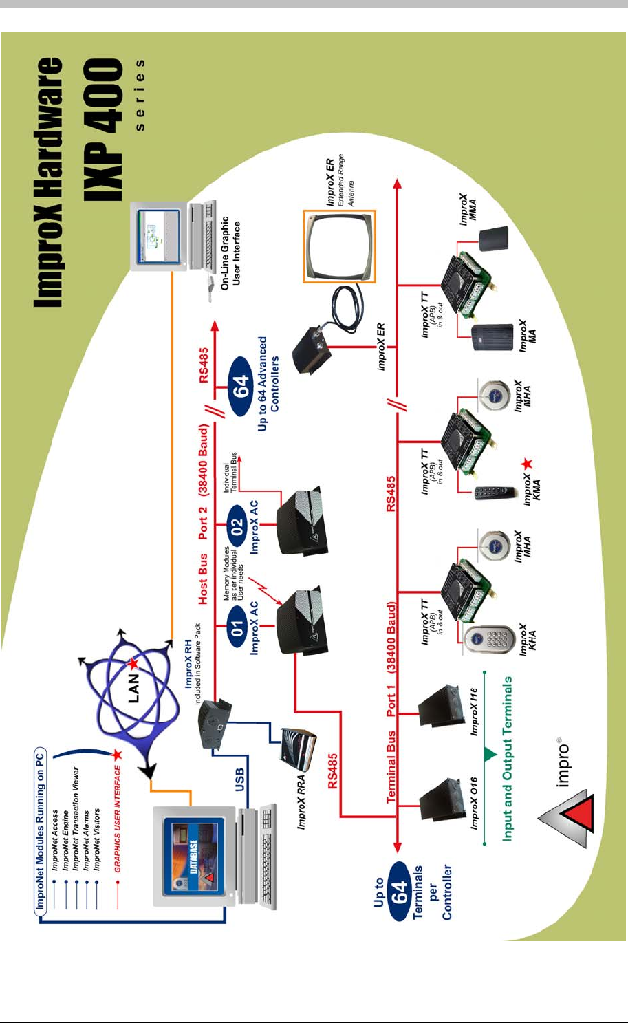
IXP300/IXP400 Installation Guide
Figure 12 - ImproX Hardware for IXP400
Tuesday, 11 July 2006 41

Installation Information
Installation Information
Doors and Zones
Each Location supports up to three ImproX Terminals (Fixed Addresses).
The ImproX AC Controller supports a maximum of 64 Terminals (Fixed
Addresses). However, if each Location uses three Terminals, the ImproX AC
Controller can only support 21 Locations.
Anti-Passback (APB) mode requires two Readers. Each Location can have its own
Zone, or a number of Locations can be grouped together to form an APB Zone. APB
Zones are set-up during configuration of an IXP300 or IXP400 system.
Addressing Scheme
Each ImproX Controller and Terminal has two types of addresses: A Logical Address and a
Fixed Address. The following process is performed when the AutoID function in the ImproNet
Engine Software is run:
1. The Engine polls all Controllers
2. The Controllers poll their Terminals to request unique Fixed Addresses
3. The ImproNet Software assigns a unique Logical Address to each detected Controller and
Terminal
Each ImproX TT and ImproX PT has two fixed addresses. Therefore, ImproNet
operates each unit as two separate Terminals
Logical Addresses
A Logical Address is a unique, hexadecimal address assigned by ImproNet Engine to each
Controller and Terminal in a system. Logical Addresses are used to identify hardware units and
are stored in the units non-volatile memory.
The process of assigning logical addresses to all units is only required on the initial
system start-up.
Hardware cannot be configured until it is physically connected to the PC via the serial
port, or to the USB port if an ImproX RH is used. Data cannot be entered until the
hardware units have been identified and assigned addresses.
Fixed Addresses
A Fixed Address is a unique address allocated to each ImproX unit during manufacture. All
ImproX Terminals are programmed with an eight-digit unique address.
42 Tuesday, 11 July 2006

IXP300/IXP400 Installation Guide
Recording Installation Information
This following procedure is required by ImproNet Software Operators when they
configure the system.
When you install ImproX Terminals, you must record the following information on the Unit
Location Chart:
• The unit’s Fixed Address
• The unit’s direction—Entry or Exit
• The unit type
• An accurate description of the unit’s location
Record the Fixed Address before attaching a unit to its mounting surface.
The Unit Location Chart is a document included with all IC and AC Controllers.
A sticky label displaying the unit’s Fixed Address is included with every unit—stick this
label onto the Unit Location Chart
Positioning Units
The Unit Location Chart must correspond with the cable layout diagram specified for the Site.
This will enable you to trace units and find faults.
Arc Suppression Circuitry must be fitted on all doors where there are Strike Locks or
Magnetic Locks. Guidelines are provided in the Hardware Installation Manuals. 24 V
Metal Oxide Varistors can be used.
All units must be attached to the wall as stated in their Installation Manuals. All covers
must be attached and in-place at all times.
Tuesday, 11 July 2006 43
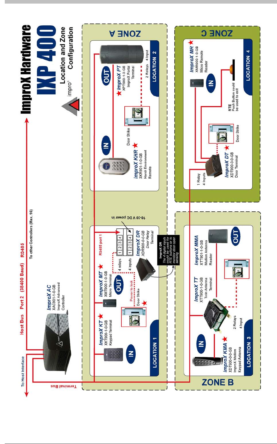
Installation Information
Figure 13 - Location and Zone Configuration Diagram
44 Tuesday, 11 July 2006
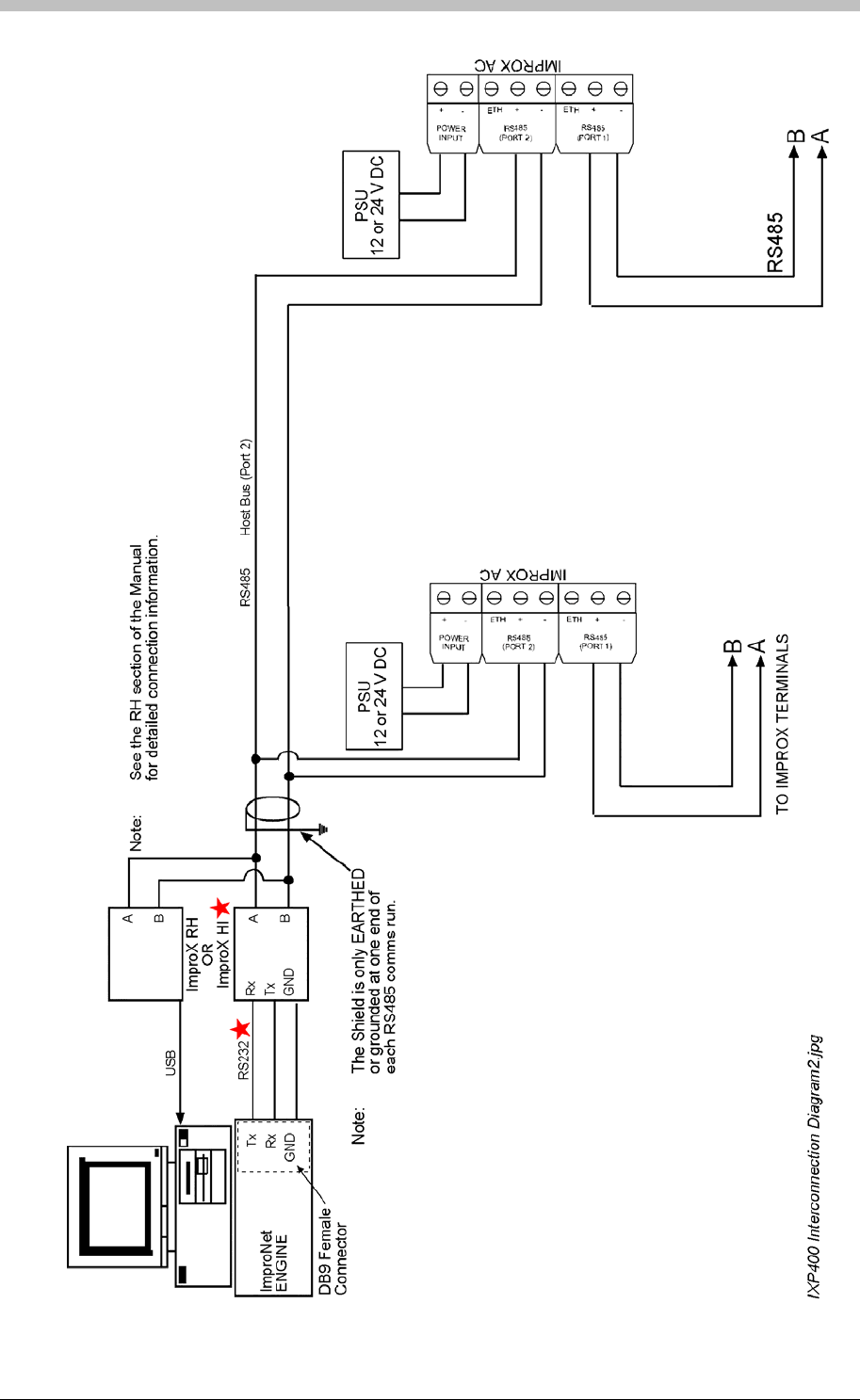
IXP300/IXP400 Installation Guide
IXP300/IXP400 Installation Guide
Tuesday, 11 July 2006 45
Figure 14 - IXP400 Inter-Connection Diagram 1
Tuesday, 11 July 2006 45
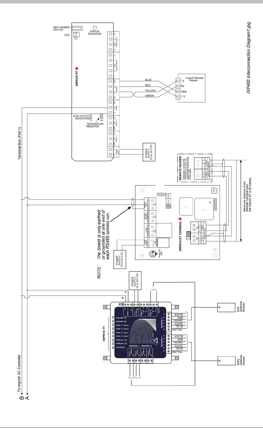
Installation Information
Figure 15 - IXP400 Inter-Connection Diagram 2
46 Tuesday, 11 July 2006

IXP300/IXP400 Installation Guide
ImproX Unit Categories
ImproX hardware comprises the following categories:
Comms Interfaces
• ImproX HI
• ImproX RH
• ImproX RS
The ImproX RS has protocol conversion functionality. However, this functionality is not
used in an ImproNet system. Therefore, the ImproX RS is used to interface third-party
Tag Enrollment hardware.
Enrollment Readers
• ImproX ProX-Mate
• ImproX RRA
Controllers
• ImproX IC
• ImproX AC
Terminals
• ImproX TT
• ImproX ER
• ImproX O16
• ImproX I16
System Card Readers
• ImproX MA
• ImproX KA
• ImproX KMA
• ImproX MHA
• ImproX MMA
• ImproX ER Antenna
The manual includes information on selected ImproX units only. For a complete list of
ImproX hardware, refer to the Impro Specification Catalogue.
Tuesday, 11 July 2006 47

ImproX HI Host Interface
ImproX HI Host Interface
The ImproX HI has not been evaluated by UL.
The ImproX HI forms part of the ImproX range of access
control equipment and is primarily intended for use in
Impro Technologies IXP300 and IXP400 Series access
control systems.
When used in an IXP system, the unit is intended to
provide an interface between the Host PC and ImproX
IC or AC Controller/s when these are further than 25 m apart, and to provide for
communications between ImproX IC or AC Controllers in the system.
RS232 communications with the PC are in 3-wire format without flow control, while
communications with Controllers are in RS485 format.
The unit can also be used to communicate with a peripheral such as a printer. Data can be
transferred between this peripheral and either the RS232 bus or the RS485 bus.
RS232 communications with the peripheral are in 5-wire format including flow control.
Applications
The following are possible uses of the unit:
• Conversion between RS232 to RS485 data formats
• Control of a 5-wire RS232 peripheral device, such as a printer
Features
The unit provides the following features:
• An RS232 bus port for communication with a PC
• An RS232 bus port with flow control for communications with compatible peripherals
• An RS485 host bus port for communication with ImproX Controllers
• Inter-Controller Communications
• LEDs indicate transmit and receive line activity for diagnostics
• Operation from power inputs in the range 12 V or 24 V DC
Accessories
The ImproX HI Terminal is supplied with the following accessories:
• Wall mounting plugs and screws
48 Tuesday, 11 July 2006

IXP300/IXP400 Installation Guide
• RS232 interface cable with connectors
• Self-adhesive label for address configuration
Specifications
Physical
Dimensions L = 108 mm (4.25")
W = 115 mm (4.52")
H = 50 mm (1.96")
Weight 275g. (9.68oz)
Housing Material Aluminium
Colour Black
Environmental
Temperature
Operating -15oC to +70oC (- 13oF to +176oF)
Storage -40o C to +80o C (-40o F to +176o F)
Humidity Range 0 to 95% relative humidity at +40 o C (+104o F) non-condensing
EMC EN 55024
Electrostatic Discharge EN6 1000-4-2
Electrical Fast Transients EN6 1000-4-4
Surge Immunity EN6 1000-4-5
Radiated Susceptibility EN6 1000-4-3
Conducted Susceptibility EN6 1000-4-6
Dust And Splash Resistance Indoor Unit
Drop Endurance 2m drop (in packaging)
Electrical
Power Requirements
Voltage 12 V or 24 V DC
Current 120 mA
Permissible Input Supply Ripple
Voltage (Maxi-Mum) 1 V PP at 50 Hz
Power Input Protection Reverse polarity, Over-voltage, Over-current
Anti-Tamper Protection Internal switch
Memory
Ram 128 Kbytes
Flash Rom 128 Kbytes
Firmware Upgrade Facility Via the PC Bus Port (Port 1)
Rs485 Host Bus Port (Port 2)
Electrical Interface RS485, ASCII with 16-bit CRC checking
Baud Rates 1200, 2400, 4800, 9600, 19200, 28800,
38400, 57600 and 76800 selectable via the communications
Tuesday, 11 July 2006 49

ImproX HI Host Interface
protocol
Data Format 8 data bits, no parity, 1 stop bit
Communications Protocol ImproX Secure Communications Protocol
RS232 PC Bus Port (Port 1)
Electrical Interface RS232, Full Duplex, No flow control, ASCII with 16-bit CRC
checking
Baud Rates 1200, 4800, 9600, 19200, 28800, 38400, 57600 and 76800
selectable via the communications protocol
Data Format 8 data bits, no parity, 1 stop bit
Communications Protocol ImproX Secure Communications Protocol
RS232 Peripheral Bus Port (Port 3) This port, as well as being connected to the terminal block
labelled port 3, is also connected to the D-type connector on the
unit front panel for external use
Electrical interface RS232, Full Duplex, CTS and RTS available, ASCII with 16-bit
CRC checking
Baud rates 1200, 4800, 9600, 19200, 28800, 38400, 57600 and 76800
selectable via the communications protocol
Data format 8 data bits, no parity, 1 stop bit
Communications protocol ImproX Secure Communications Protocol
Operator Interfaces
Status Indicators
red LED Power On Indicator. (Externally visible).
green LED Incoming RS485 data. (Internally visible).
red LED Outgoing RS485 data. (Internally visible).
green LED Incoming RS232 data. (Internally visible).
red LED Outgoing RS232 data. (Internally visible).
Factory Default Settings
RS485 port Default baud rate 38400
RS232 port Default baud rate 38400
International Standards
The ImproX HI unit complies with the requirements of the following international standards
where applicable:
EIA RS-485 Standard for Electrical Characteristics of Generators and Receivers for use in
Balanced Digital Multi-point Systems
EN 55024 Limits and Methods of Measurement of Radio Disturbance Characteristics of
Information Technology Equipment
EN6 1000-4-1 Electromagnetic Compatibility (EMC)
Part 4: Testing and Measurement Techniques
Section 1: Overview of Immunity Tests. Basic EMC Publication
50 Tuesday, 11 July 2006

IXP300/IXP400 Installation Guide
EN6 1000-4-2 Electromagnetic Compatibility (EMC)
Part 4: Testing and Measurement Techniques
Section 2: Electrostatic Discharge Immunity Test. Basic EMC Publication
EN6 1000-4-4 Electromagnetic Compatibility (EMC)
Part 4: Testing and Measurement Techniques
Section 4: Electrical Fast Transients / Bursts. Basic EMC Publication
EN6 1000-4-3 Electromagnetic Compatibility (EMC)
Part 4: Testing and Measurement Techniques
Section 3: Radiated, Radio-Frequency, Electro-magnetic Field Immunity Test
EN6 1000-4-6 Conducted Susceptibility
EN6 1000-4-5 Surge Immunity
EN6 1000-4-11 Voltage Dips and Interruptions
Approvals
• CE Approved
Tamper-Proofing
• Internal Switch
Installation Information
Requirements
• A suitable electric drill and suitable drill bits
• A suitable Flat-head screwdriver
• A suitable Phillips-head screwdriver
• Double-sided adhesive tape, if required
• Side-cutters
Positioning
The HI unit can be mounted on virtually any surface. It is recommended that the surface be flat
and at least 120 mm (4.72”) x 120 mm (4.72”) in size.
Tuesday, 11 July 2006 51
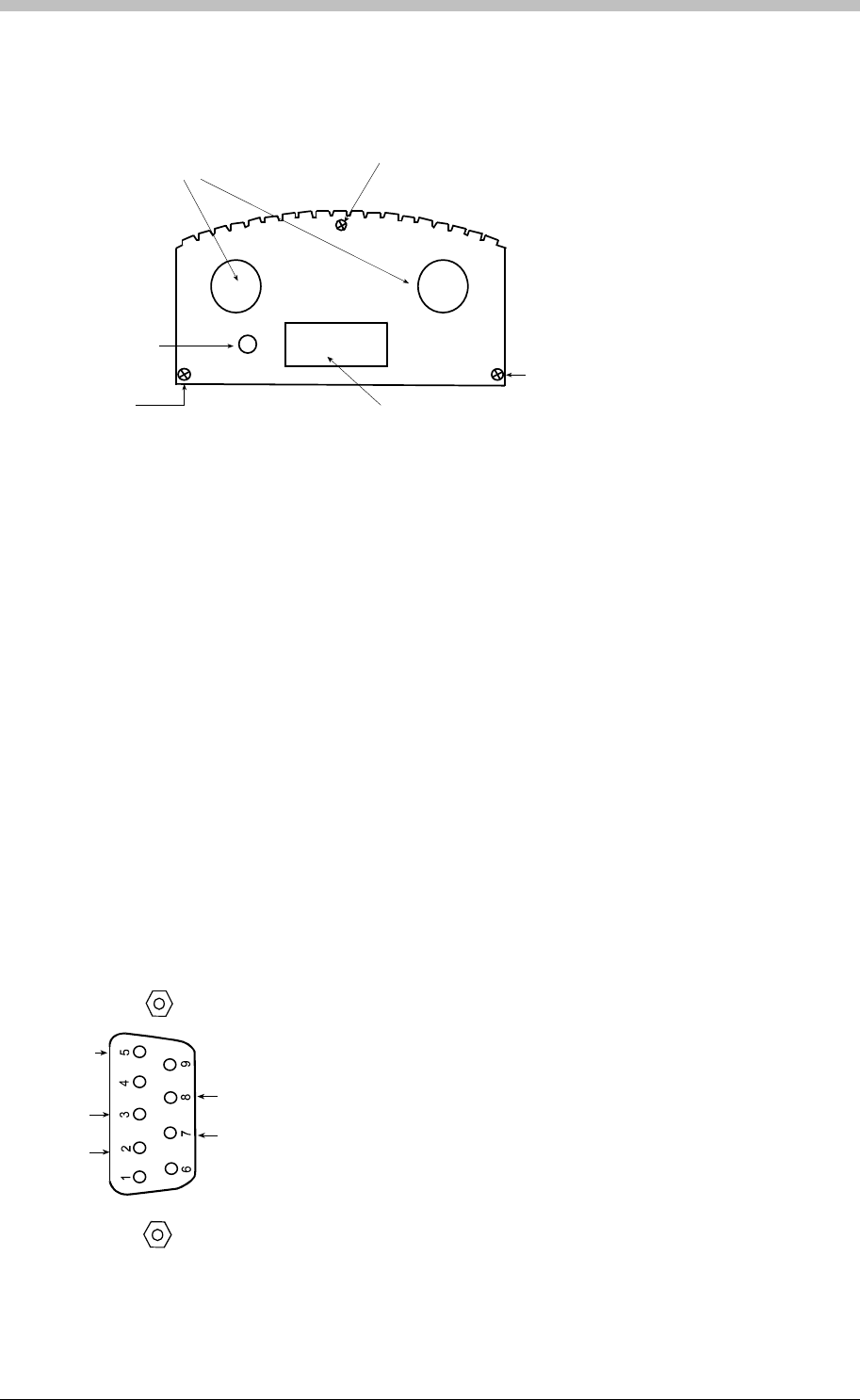
ImproX HI Host Interface
Cabling
The locations of the cable glands and the single 9-way D-type connector are shown in Figure
16.
Cable
Gland
Cover
Securing
Screw
D-Type
Connector
connector end plate.wmf
Power
On
Indicator
End Plate
Securing
Screw
End Plate
Securing
Screw
Figure 16 – ImproX HI Connector End Plate
Power
Power must be connected to the unit only at the terminal block labelled POWER INPUT. This
input is polarity sensitive and must be connected as indicated by the + and – symbols. Correct
connection of the power will illuminate the Power On indicator.
Maximum Data Communications Distance
• RS485—The distance between the HI and other ImproX units can be increased to a
maximum of 1 kilometre using a good quality shielded, twisted-pair cable. The cable
individual conductor cross-sectional area should not be less than 0.2 mm2. The shield of
the cable should be connected to the Port 2 terminal block labelled ETH. This point in turn
should then be connected to a good Earth point.
9-way d-type connector.wm
f
GND
TX
RX
CTS
RTS
• RS232—The maximum distance between the ImproX HI and a PC or peripheral is 25 m
using a good quality shielded, 4 or 6-core cable. The individual conductor cross-sectional
area should not be less than 0.2 mm2. The shield of the cable should be connected to the
Port 2 terminal block labelled ETH.
Figure 17 – 9-way D-type connector
52 Tuesday, 11 July 2006

IXP300/IXP400 Installation Guide
Connector Pin-outs
The 9-way D-type connector pin-outs are shown in Figure 17. This view is from the solder side
of the PCB.
Enclosure
General
The ImproX HI is housed in an aluminium extrusion consisting of four parts, namely a base, two
end plates and the cover. The mounting holes are located in the flanges of the base so it is not
necessary to remove the cover for mounting purposes.
Cable Exit Points
The cables are inserted through the grommets situated on either side of the D-type connector.
Mounting on a Concrete or Brick Wall
1. Use the ImproX HI as a template and mark off the required holes
2. Drill the four mounting holes using a 5 mm diameter masonry drill bit, to the depth of the
length of the wall plug
3. Insert wall plugs into the mounting holes
4. Secure the ImproX HI to the surface using the four mounting screws and wall plugs
provided
Mounting on a Hard Wood Surface
1. Use the ImproX HI as a template and mark off the required holes
2. Drill the four mounting holes using a 2,5 mm diameter drill bit to the depth of three-quarters
of the length of the mounting screws
3. Secure the ImproX HI to the surface using the four mounting screws provided
Mounting on Metal
The unit may be mounted on metal using four suitable securing devices, such as self-tapping
screws, nuts and bolts, or rivets.
1. Use the ImproX HI as a template and mark off the required holes
2. Drill the four mounting holes using a suitable diameter drill bit
3. Secure the ImproX to the surface using the chosen method
Mounting on Glass or Tiles
1. Using a double-sided adhesive tape cut strips and adhere them to the flanges on the bottom
of the case
2. Secure the ImproX HI by positioning the unit on the surface and applying pressure
Electrical Connections
Remove the cover by removing the screws that secure the cover to each end plate. Refer to
Figure 16. Insert the cables through the relevant grommet and connect to the ImproX HI
terminal blocks as shown in or Figure 18.
Tuesday, 11 July 2006 53

ImproX HI Host Interface
2
3
5
7
8
9-Way D-type
connector
Peripheral
Device
ImproX
HI
Unit
ImproX
Controller
intercon separate psu[2].wmf
PC
-+
PSU
8-30V DC
2
3
5
7
8
9 -Way D-type
connector
N
OTE : Take care when connecting
power. The + output of the
PSU must connect
to terminal marked + on the
ImproX HI, and similarly - to -.
Figure 18 – Terminal cable connections (separate PSU).
Operational Information
Address Allocation
Each ImproX HI unit is allocated a unique fixed Address at the factory. As only one ImproX HI is
required per system, the logical address of every unit is set to 127 (hex 7F) at the factory.
Remote Firmware Downloading
The Unit provides a remote firmware upgrade facility via the PC Bus Port (PORT1). The
firmware upgrade occurs transparently via the communications protocol and the user is not
required to enter any special modes of operation.
54 Tuesday, 11 July 2006
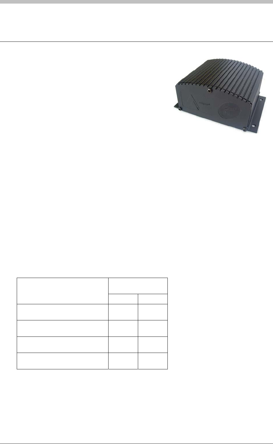
IXP300/IXP400 Installation Guide
ImproX RH Registration Interface
The ImproX (RH) Registration Interface forms part of the
IXP300 and IXP400 Access Control System, supporting
a USB interface.
The Registration Interface performs the following
functions:
• Acts as an authentication device for ImproNet
Engine.
• Registration of 125 kHz Tags into our IXP300 and IXP400 Software.
• Converts USB to RS485.
•
The Registration Interface includes a single tone Buzzer. You can adjust the Buzzer volume to
any one of these four levels (off, low, medium and high). The Registration Interface also
includes a single bi-coloured Red or Green Status LED. You can set the functions of the Buzzer
and Status LED to suit the needs of your application.
Although the ImproX RH is housed in a Black, Aluminium extruded Cabinet it is still intended for
installation in an indoor (dry) environment.
Tag Read/Write Ranges
Typical ranges for the ImproX (RRA) Registration Reader Antenna, placed on a non-metallic
surface are shown in Table 8.
Typical Range
(Minimum)
Tag Type
(mm) (in)
ISO Credit Card (Slim), 64-bit,
Manchester encoded protocol, ASK 20-30 0.80-1.20
Credit Card (Semi Slim), 64-bit,
Manchester encoded protocol, ASK 20-30 0.80-1.20
ImproX Credit Card, 64-bit,
Manchester encoded protocol, ASK 20-30 0.80-1.20
Key Ring Tag, 64-bit, Manchester
encoded protocol, ASK 20-30 0.80-1.20
Table 8: Typical Read/Write Ranges
Tuesday, 11 July 2006 55

ImproX RH Registration Interface
Typical ranges for the ImproX (RRM) Registration Reader MiFare (not UL evaluated), placed on
a non-metallic surface are shown in Table 9.
Typical Range
(Minimum)
Tag Type
(mm) (in)
MiFare Credit Card Tag (not UL
evaluated) 25-50 1-2
Table 9: Typical Read/Write Ranges
Approvals
• CE
• UL294
• FCC Approval Pending
Specifications
Physical
Dimensions
Length 84 mm (3.31 in).
Width 116 mm (4.57 in).
Height 54 mm (2.13 in).
Approximate Weight 242 g (0.53 lb) (Excluding the USB Cable).
Cabinet Material Aluminium.
Colour Black.
Environmental
Temperature
Operating 0oC to +49oC (-13oF to +140oF)
Storage -40oC to +80oC (-40oF to +176oF)
Humidity Range 85% ± 5oC relative humidity at +30oC ± 2oC (86oF ± 3 oF)
Approvals (Test
Information)
UL Rating UL 294.
EMC EN 55022: Limits and Methods of Measurement of Radio Disturbance
Characteristics of Information Technology Equipment.
EN 55024: Immunity Characteristics, Limits and Methods of
Measurement.
Electrostatic Discharge IEC 61000-4-2: Electromagnetic Compatibility (EMC). Part 4: Testing
and Measurement Techniques. Section 2: Electrostatic Discharge
Immunity Test. Basic EMC Publication.
Radiated Susceptibility IEC 61000-4-3: Electromagnetic Compatibility (EMC). Part 4: Testing
and Measurement Techniques. Section 3: Radiated, Radio-
Frequency, Electromagnetic Field Immunity Test.
Electrical Fast Transients IEC 61000-4-4: Electromagnetic Compatibility (EMC). Part 4: Testing
and Measurement Techni
q
ues. Section 4: Electrical Fast Transients /
56 Tuesday, 11 July 2006

IXP300/IXP400 Installation Guide
Bursts. Basic EMC Publication.
Surge Immunity IEC 61000-4-5: Surge Immunity.
Conducted Susceptibility IEC 61000-4-6: Conducted Susceptibility.
Power Frequency Magnetic
Field IEC 61000-4-8: Electromagnetic Compatibility (EMC). Part 4: Testing
and Measurement Techniques. Section 8: Frequency Magnetic Field
Immunity Test.
Dust and Splash
Resistance The ImproX RH is designed to work in an indoor (dry) environment
similar to IP20. The ImproX RH is, therefore, NOT sealed against
water.
Drop Endurance 2 m (6.56 ft) drop (in packaging).
Electrical
Power Requirements
Input Voltage 12 V DC and 24 V DC, polarity sensitive.
Power Requirements Current (mA) Power (W)
Input Voltage 12 V DC
All Indicators ON
65 0.78
Input Voltage 24 V DC
All Indicators ON
35 0.84
Permissible Input Supply 0.2 V PP at 50 Hz.
Ripple Voltage (Max)
Third-party Port (Not UL
Evaluated) 5 V DC ± 0.1 V is supplied to power the single Reader connected to this
Port. A maximum of 100 mA can be supplied from this Port.
Factory Default Settings
Default Baud Rate Factory-set to 38 400.
Operator or Installer Interfaces
Buzzer Four volume, single tone (Software dependent).
Status Indicators
Registration Interface
Power Indicator
Power LED Blue (steady) (externally visible).
Diagnostic Indicators
USB Tx LED Red (flashing) (internally visible).
USB Rx LED Green (flashing) (internally visible).
RS485 Tx LED Red (flashing) (internally visible).
RS485 Rx LED Green (flashing) (internally visible).
ImproX RRA or RRM (not
UL evaluated)
Status Indicator
Status LED Bi-colour, Red or Green LED.
Tuesday, 11 July 2006 57

ImproX RH Registration Interface
Installation Information
Accessories
Find the following when unpacking the Registration Interface:
• An ImproX (RH) Registration Interface is housed in a Black, Aluminium extruded Cabinet.
The Cabinet consists of a Top Cover, a Base and two End Plates (each End Plate is
attached with three Thread Cutter Screws (M3 x 8 mm)).
• Four Brass Wood Screws (3.5 mm x 25 mm).
• Four Wall Plugs (7 mm).
• A 1.8 m (5.90 ft) standard USB Cable with a Type A to Type B Connector.
• An extra Fixed Address Label.
General
Remember the following when installing the Registration Interface:
• Communications Distance
− The USB communications distance between the Host PC and the Registration Interface
MUST NOT exceed 5 m (16.40 ft).
− DO NOT cut and join the supplied USB Cable. If extension of the USB Cable is
required, source a new longer length USB Cable.
• Distance between the ImproX RH and the Registration Readers – The maximum cable
distance between the ImproX Registration Interface and the ImproX RRM (not UL
evaluated) or ImproX RRA, MUST NOT exceed 2 m (6.56 ft).
• Distance between Registration Readers from Different ImproX RHs – To avoid mutual
interference install the ImproX RRAs or ImproX RRMs (not UL evaluated) no closer than
500 mm (20 in) apart.
Mounting the Cabinet
Select the mounting position of the ImproX RH, considering accessibility, routing of wires and
visibility of the externally visible Power LED.
Mounting on a Concrete or Brick Wall
1. Use the Base as a template and mark off the required holes.
2. Drill the four mounting holes using a 7 mm diameter masonry drill bit, to a depth equal to the
length of the supplied wall plugs.
3. Insert the wall plugs into the mounting holes.
4. Secure the Base to the surface using the four mounting screws provided.
Mounting on a Hard Wood Surface
1. Use the Base as a template and mark off the required holes.
2. Drill the four mounting holes using a 2.5 mm diameter drill bit to the depth equal to three-
quarters of the length of the mounting screws.
3. Secure the Base to the surface using the four mounting screws provided.
58 Tuesday, 11 July 2006
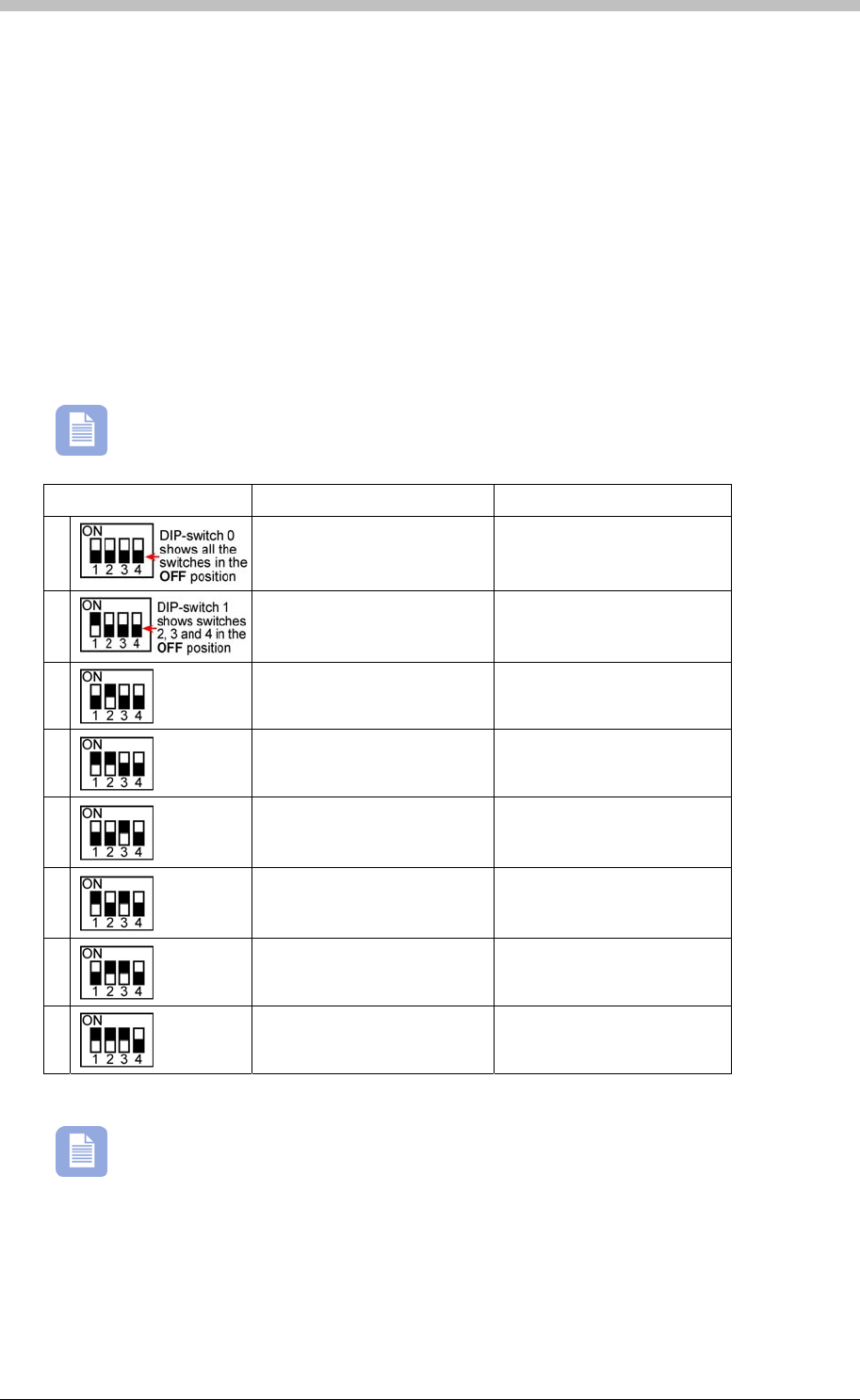
IXP300/IXP400 Installation Guide
Mounting on Metal
Use four suitable securing devices such as screws, nuts and bolts, or rivets to mount the
ImproX TT on a metal surface.
1. Use the Base as a template and mark off the required holes.
2. Drill the four mounting holes using a suitable diameter drill bit.
3. Secure the Base to the surface using the chosen method.
DIP-switch Settings
The format selection for each type of device that can be connected to the Third-party Port is
made by setting the internal DIP-switches as indicated in Table 10.
Terminals ‘A’ and ‘B’ in Table 10 are on the Third-party Port Terminal Block.
DIP-switch Position Format Connections
0
No peripheral Reader N/A
1
MiFare Remote (ImproX
ed) Rx to terminal ‘A’
RRM) (not UL evaluat Tx to terminal ‘B’
2
RF Receiver (not UL
evaluated) Data Line to terminal ‘B’
3
Magstripe ABA Track 2
UL evaluated) (not
Clock Line to terminal ‘B’
Data Line to terminal ‘A’
4
Barcode Code-39 with
Checksum (not UL
evaluated)
Data Line to terminal ‘B’
5
Barcode Code-39 without
Checksum (not UL
evaluated)
Data Line to terminal ‘B’
6
Wiegand 26/37/40 and 44
(not UL evaluated) 0 Data Line to terminal ‘B’
1 Data Line to terminal ‘A’
Wi
7
egand Open Format (not
UL evaluated) 0 Data Line to terminal ‘B’
1 Data Line to terminal ‘A’
Table 10 Settings
Once the DIP-switch setting is modified reset the ImproX RH to acknowledge the new
settings.
: DIP-switch
Tuesday, 11 July 2006 59
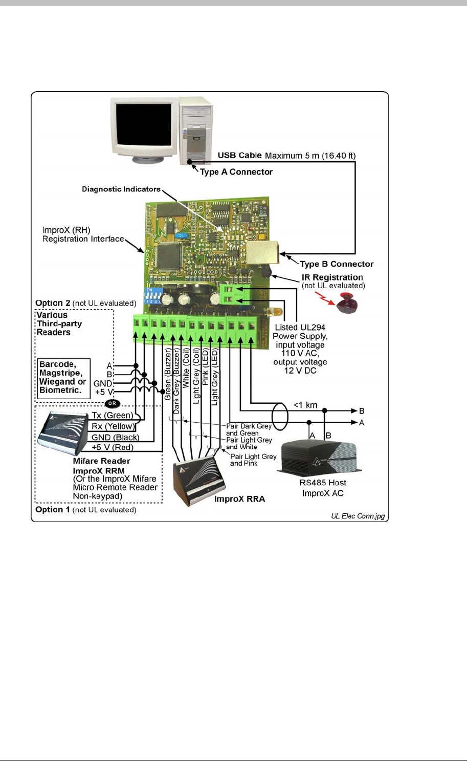
ImproX RH Registration Interface
Electrical Connections
Connecting the ImproX RH
Figure 19 shows a detailed connection diagram for the ImproX RH.
Figure 19: Typical ImproX RH Electrical Connections
Power-on Self-test
The Power-on Self-test tests the RAM and Flash Checksums.
If any parameter in the Self-test fails, the Registration Reader (i.e. ImproX RRA or ImproX RRM
(not UL evaluated)) emits a continuous beep for 2 seconds.
When the Registration Interface passes the Self-test, the Registration Reader (i.e. ImproX RRA
or ImproX RRM (not UL evaluated)) emits two short beeps, each 200 ms in duration, separated
by a 200 ms inter-beep pause.
60 Tuesday, 11 July 2006

IXP300/IXP400 Installation Guide
Testing the Connection
When the Registration Interface is connected, check that the Power LED is illuminated Blue
(steady). This will confirm that the connection is correct and working.
Fixed Address Label
Keep the Fixed Address Label in a safe place, as you may need the Label at a later date if you
wish to upgrade your Software.
Operation and Functionality
The ImproX RH operates as comms interface and connects to the comms server (Engine) PC.
Refer to page 179 for more information.
Tuesday, 11 July 2006 61
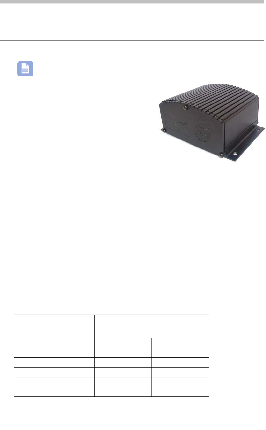
ImproX RS Registration Interface
ImproX RS Registration Interface
The ImproX RS has not been evaluated by UL
The ImproX (RS) Registration Interface supports
a USB interface. The Registration Interface
performs the following functions:
• Registration of 125 kHz and MiFare 13.56 MHz
Tags into the ImproNet Software.
Key Features
• The Antenna Port allows connection to the ImproX (RRA) Registration Antenna Reader
(preferred option) or alternatively the standard range of ImproX Antenna Readers.
• Read capability using the following 125 kHz Impro Tags: Slim Tags, Omega Tags, WriTag
128 and WriTag 2048. Reads third-party Tags.
• The Third-party Port can be used to connect to one of the following: Barcode, Magstripe,
Wiegand, Biometric Readers, the ImproX (RRM) MiFare Registration Remote Reader
(preferred option) or the ImproX MiFare Micro Remote Reader Non-keypad.
• Reads MiFare 13.56 MHz Tags.
• The Registration Interface has a simple user interface, consisting of four Diagnostic
Indicators and one Power Indicator LED.
• A four volume, single tone, Software dependent Buzzer, located on the ImproX RRA or
ImproX RRM.
• A bi-colour red and green Status LED located on the ImproX RRA or ImproX RRM.
• Infrared registration—the Infrared Receiver is located in the extrusion of the ImproX RS,
next to the USB plug.
Typical Read Range
Tag Type Typical Range (Minimum)
(ImproX RRA placed on non-metallic
surface)
(mm) (in)
ISO Credit Card (Slim) 25-50 1-2
ISO Credit Card (Omega) 25-50 1-2
ISO Credit Card WriTag 128 25-50 1-2
ISO Credit Card WriTag 2048 25-50 1-2
Third-party Tags (Credit Card) 25-50 1-2
62 Tuesday, 11 July 2006

IXP300/IXP400 Installation Guide
Tag Type Typical Range (Minimum)
(ImproX RRM placed on a non-metallic
surface)
(mm) (in)
MiFare Credit Card Tag 25-50 1-2
Approvals
• CE Approved
• FCC Approval Pending
Specifications
Physical
Dimensions
Length 84 mm (3.31 in)
Width 116 mm (4.57 in)
Height 54 mm (2.13 in)
Approximate Weight 229 g (8.09 oz) (Excluding the USB cable)
Cabinet Material Aluminium
Colour Black
Environmental
Temperature
Operating -25oC to +60oC (-13oF to +140oF)
Storage -40oC to +80oC (-40oF to +176oF)
Humidity Range 0 to 95% relative humidity at +40oC (+104oF) non-condensing
Approvals (Test
Information)
EMC EN 55022: Limits and Methods of Measurement of Radio Disturbance
Characteristics of Information Technology Equipment
EN 55024: Immunity Characteristics, Limits and Methods of Measurement
Electrostatic Discharge IEC 61000-4-2: Electromagnetic Compatibility (EMC)
Part 4: Testing and Measurement Techniques
Section 2: Electrostatic Discharge Immunity Test. Basic EMC Publication
Radiated Susceptibility IEC 61000-4-3: Electromagnetic Compatibility (EMC)
Part 4: Testing and Measurement Techniques
Section 3: Radiated, Radio-Frequency, Electromagnetic Field Immunity
Test
Electrical Fast Transients IEC 61000-4-4: Electromagnetic Compatibility (EMC)
Part 4: Testing and Measurement Techniques
Section 4: Electrical Fast Transients / Bursts. Basic EMC Publication
Surge Immunity IEC 61000-4-5: Surge Immunity
Conducted Susceptibility IEC 61000-4-6: Conducted Susceptibility
Tuesday, 11 July 2006 63

ImproX RS Registration Interface
Power Frequency
Magnetic Field IEC 61000-4-8: Electromagnetic Compatibility (EMC)
Part 4: Testing and Measurement Techniques
Section 8: Frequency Magnetic Field Immunity Test
Dust and Splash
Resistance The ImproX RS is designed to work in an indoor (dry) environment similar to
IP20. The ImproX RS is NOT sealed against water.
Drop Endurance 2 m (6.56 ft) drop (in packaging)
Electrical
Power Requirements
Input Voltage 5 V DC Supplied from the USB Port.
Power Requirements Current (mA) Power (W)
Maximum Current Drawn from the
USB Port by the ImproX RS 200 1.0
Permissible Input Supply Ripple
Voltage (Max) 0.2 V PP at 50 Hz.
Third-party Port 5 V DC ± 0.1 V is supplied to power the single
Reader connected to this Port. A maximum of
100 mA can be supplied from this Port.
Factory Default Settings
Default Baud Rate Factory-set to 38 400.
Beep Codes
Fails Power-on Self-test Continuous beep for 2 seconds
Passes Power-on Self-test Two short beeps of 200 ms duration, separated
by a 200 ms inter-beep pause
Operator or Installer Interfaces
Installer Interfaces
Registration Interface
Power Indicator
Power LED Blue (steady) (externally visible)
Diagnostic Indicators
USB Tx LED Red (flashing) (internally visible)
USB Rx LED Green (flashing) (internally visible)
RS485 Tx LED Red (flashing) (internally visible)
RS485 Rx LED Green (flashing) (internally visible)
ImproX RRA or RRM
Status Indicator
Status LED Bi-colour, red and green LED
Buzzer
Volume and Tone Four volume, single tone
64 Tuesday, 11 July 2006

IXP300/IXP400 Installation Guide
Installation Information
Accessories
You will find the following when unpacking your Registration Interface:
• An ImproX (RS) Registration Interface housed in a Black, Aluminium extruded Cabinet. The
ImproX RS consists of a Top Cover, a Base and two End Plates (each End Plate is attached
with three Thread Cutter Screws (M3 x 8 mm)).
• Four Brass Wood Screws (3.5 mm x 25 mm)
• Four wall plugs (7 mm)
• A 1.8 m (5.90 ft) standard USB cable with a Type A to Type B Connector
• An extra Fixed Address Label
General
Remember the following when installing your Registration Interface:
• Communications Distance—The USB communications distance between the Host PC and
the Registration Interface MUST NOT exceed 5 m (16.40 ft). DO NOT cut and join the
supplied USB cable. If extension of the USB cable is required, source a new longer length
USB cable.
• Distance between the Registration Interface and the ImproX RRM or ImproX RRA—
The maximum cable distance between the ImproX Registration Interface and the ImproX
RRM or ImproX RRA, MUST NOT exceed 2 m (6.56 ft).
Mounting the Cabinet
1. Select the mounting position of the ImproX RS, considering accessibility, routing of wires
and visibility of the externally visible LED.
2. Secure the Cabinet to the mounting surface, using four suitable screws and wall plugs
(supplied), nuts and bolts, or rivets.
DIP-switch Settings
The format selection for each type of device that can be connected to the Third-party Port is
made by setting the internal DIP-switches as indicated in Table 11.
Terminals ‘A’ and ‘B’ in Table 11 are on the Third-party Port Terminal Block.
Tuesday, 11 July 2006 65
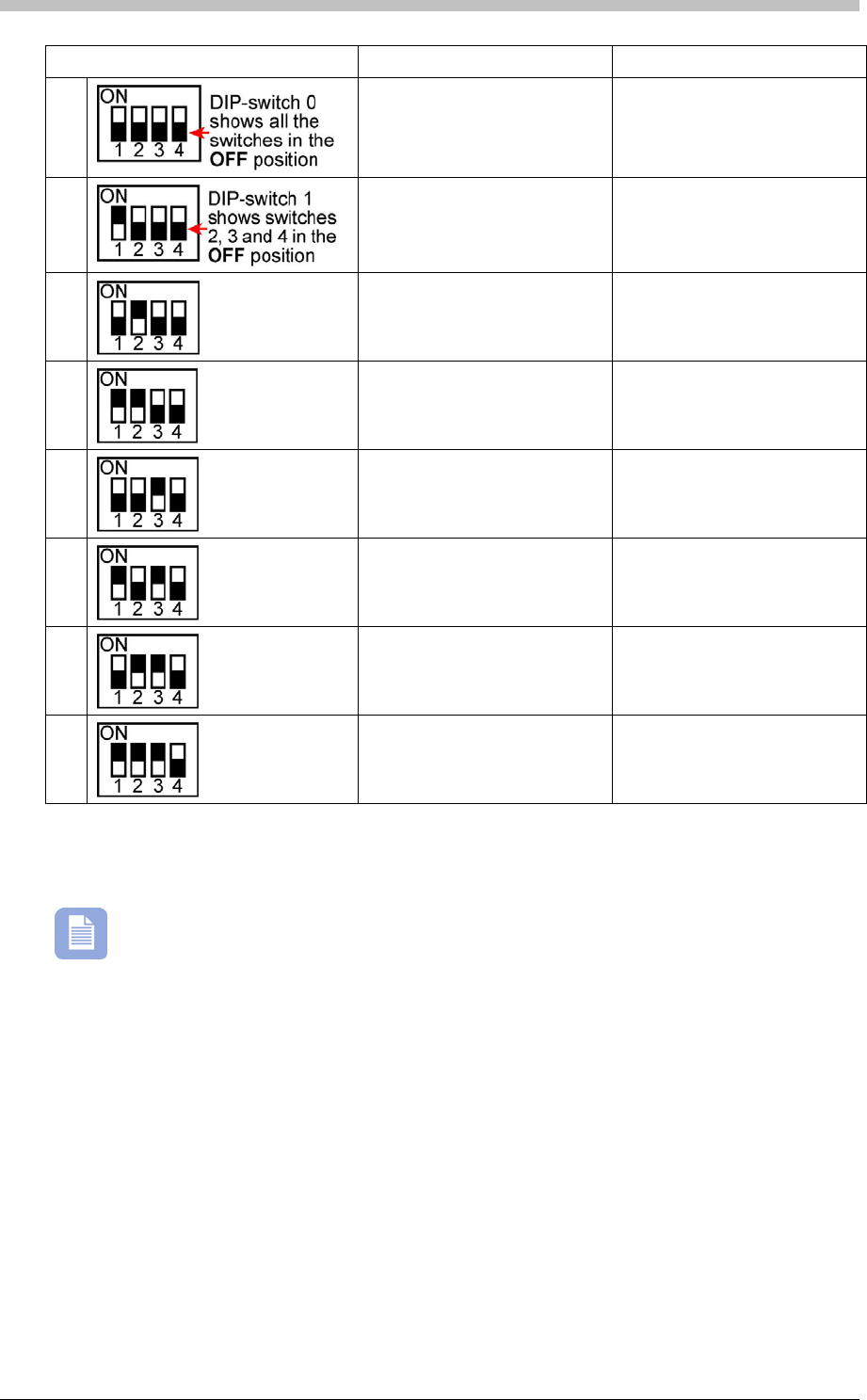
ImproX RS Registration Interface
DIP-switch Position Format Connections
0
No peripheral Reader N/A
1
MiFare Remote (ImproX RRM) Rx to terminal ‘A’
Tx to terminal ‘B’
2
RF Receiver Data Line to terminal ‘B’
3
Magstripe ABA Track 2 Data Line to terminal ‘A’
Clock Line to terminal ‘B’
4
Barcode Code-39 with
Checksum Data Line to terminal ‘B’
5
Barcode Code-39 without
Checksum Data Line to terminal ‘B’
6
Wiegand 26/37/40 and 44 0 Data Line to terminal ‘B’
1 Data Line to terminal ‘A’
Wiegand Open Format 0 Data Line to terminal ‘B’
7
1 Data Line to terminal ‘A’
Table 11: DIP-switch Settings
Once the DIP-switch setting is modified reset the ImproX RS to acknowledge the new
settings.
66 Tuesday, 11 July 2006
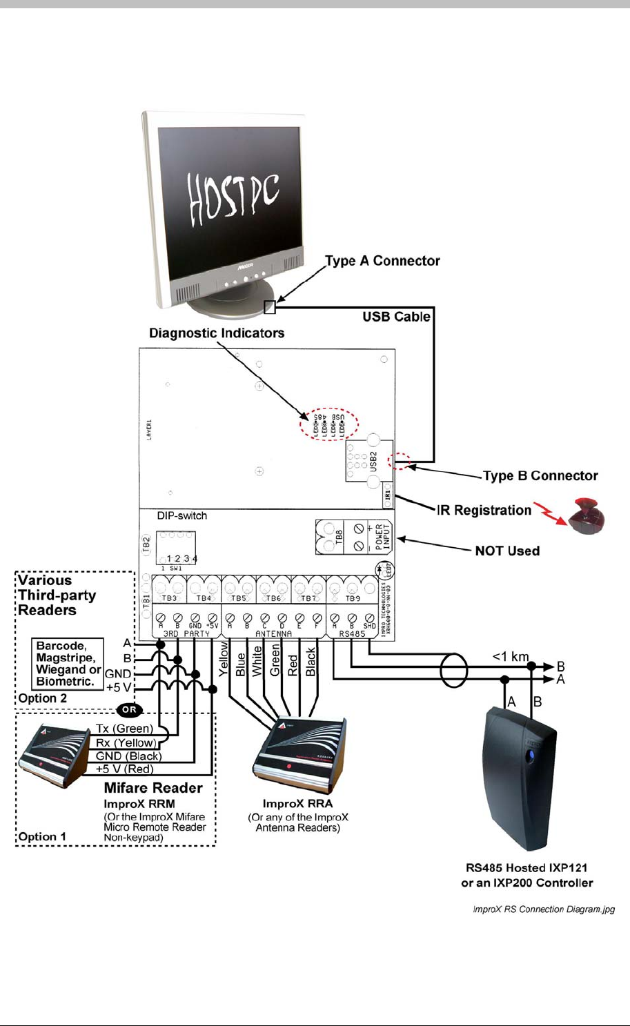
IXP300/IXP400 Installation Guide
Electrical Connections
Connecting the Registration Interface
Figure 20 – Typical ImproX RS Electrical Connections
Tuesday, 11 July 2006 67

ImproX RS Registration Interface
Power-on Self-test
The Power-on Self-test tests the RAM and Flash Checksums. If any parameter in the Self-test
fails, the Registration Reader (i.e. ImproX RRA or ImproX RRM) emits a continuous beep for 2
seconds.
When the Registration Interface passes the Self-test, the Registration Reader (i.e. ImproX RRA
or ImproX RRM) emits two short beeps, each 200 ms in duration, separated by a 200 ms inter-
beep pause.
Testing the Connection
When you connect the Registration Interface to the PC for the first time, the PC will prompt you
to install the necessary Drivers, once installed, the Status LED will illuminate Blue (steady).
This confirms the Registration Interfaces connection is correct and working. Further
connections on the same PC will not call for reloading the Drivers.
Fixed Address Label
Keep the Fixed Address Label in a safe place, as you may need the Label at a later date if you
wish to upgrade your Software.
68 Tuesday, 11 July 2006

IXP300/IXP400 Installation Guide
ImproX ProxMate
The ImproX ProxMate has not been evaluated
by UL.
This manual provides installation information for the
ImproX ProxPal, ProxMate and Utility ProxMate
Registration Readers.
The different products are to be used together with:
• ProxMate—ImproNet Access Software Suite and
most ImproNet utilities.
• Utility ProxMate—ImproNet utilities, excluding the
Access Suite and the CCTV integration.
The Registration Readers are intended for indoor use, and can be located on a desk. An
externally mounted, External PC Interface Junction Box is supplied with each of the Registration
Readers.
Applications
The following are possible uses of the Registration Readers:
• Tag registration.
• Optical code registration, for Infrared Vehicle Tags.
Features
The Registration Readers provide the following features:
• Read/Write tag capability for various tag types: Slim Tags, Omega Tags, WriTag 128 and
WriTag 2048 and ISO Animal Tags
• The registering of Infrared tags
• Three LEDs (one Red, one Green, and one Yellow), these are used as software status
indicators
• A buzzer
• RS232 communications interface
• Operation from a 6 V DC power supply
• The ability to upgrade internal firmware whilst installed on-site, without removal of the
Registration Reader
Tuesday, 11 July 2006 69

ImproX ProxMate
Accessories
The Registration Readers are supplied with the following accessories:
• An External PC Interface Junction Box.
• A 1 m (3.28 ft) interconnection cable supplied with RJ45 connectors at both ends.
Specifications
Physical
Dimensions L=116 mm (4.56 in)
W=60 mm (2.36 in)
H=70 mm (2.75 in)
Approximate Weight 200 g (7.05 oz)
Housing Material Aluminium
Colour Anodized, Natural
Environmental Specifications
Temperature
Operating -20oC to +70oC (-68oF to +176oF).
Storage -40oC to +80oC (-40oF to +176oF).
Humidity Range 0 to 95% relative humidity at +40oC (+104oF) non-condensing.
Dust And Splash
Resistance The ProxPal, ProxMate and Utility ProxMate Registration Readers and
External PC Interface Junction Box are manufactured in accordance with a
dust and splash environment similar to that required for a rating of IP40.
Drop Endurance 2 m (6.56 ft) drop (in packaging)
Electrical Specifications
Power Requirements Current (mA) Power (W)
Supply Voltage = 5 V ± 0.2 V DC
Indicators all off. 35 0.175
Supply Voltage = 5 V ± 0.2 V DC
Indicators all on. 60 0.3
Permissible Input Supply Ripple Voltage
(maximum) 1 V PP at 50 Hz
Power Input Protection Reverse polarity protection is provided on the Registration
Readers. 1 Amp slow blow fuse, 6 mm x 30 mm in-line on
the External PC Interface Junction Box
Firmware Upgrade Facility Via the RS232 Communications Port
Rs232 Communications Port
Electrical Interface RS232
Communications Protocol ImproX Secure Communications Protocol
Data Format 8 data bits, no parity, 1 stop bit
70 Tuesday, 11 July 2006
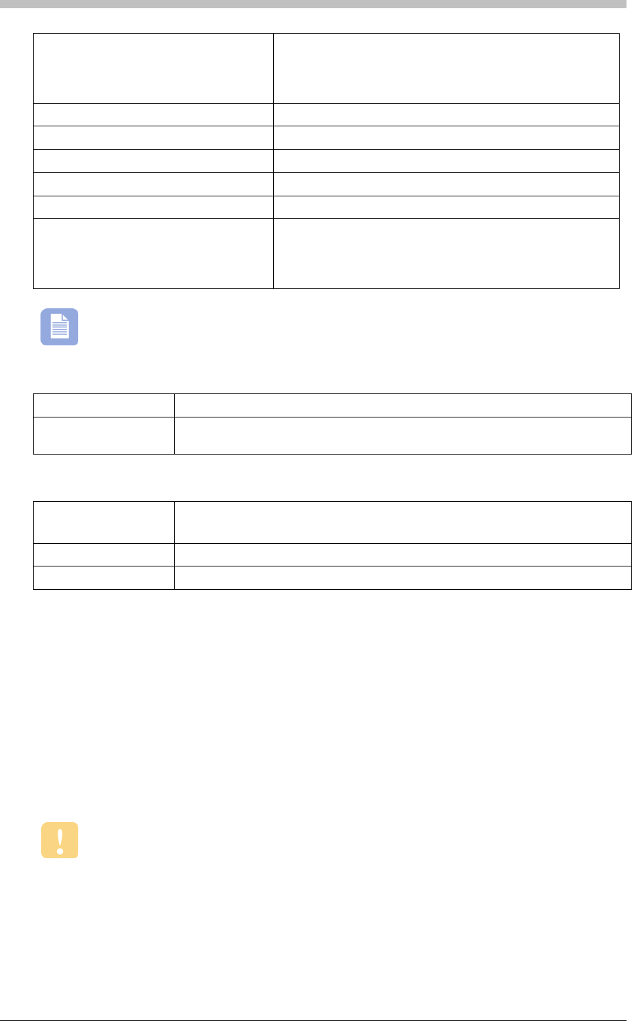
IXP300/IXP400 Installation Guide
Baud Rates 1 200, 2 400, 4 800, 9 600, 19 200, 28 800, 38 400, 57 600
select-able via the RS232 Communications Protocol
If used with Impro software suites, the Baud rate is set at a
fixed rate of 38 400
Registration Reader Status Slave
Test Modes Power-On Self-test - RAM, ROM, Tag Read, EEPROM
Electrical Interface RS485
Communications Protocol ImproX Secure Communications Protocol
Data Format 8 data bits, no parity, 1 stop bit
Baud Rates 1 200, 2 400, 4 800, 9 600, 19 200, 28 800, 38 400 and 57
600 selectable via the RS232 Communications Protocol
For communication with the ImproX Controllers, the Baud
rate is set at a fixed rate of 38 400
The RS232 and RS485 ports will always have the same baud rates. They cannot be
set separately
Operator Interfaces
Buzzer Single tone, adjustable to on or off via the RS232 Communications Protocol
Status Indicators Externally visible red, green and yellow LEDs. The function of each LED is
application specific and controlled via the RS232 Communications Protocol.
Factory Default Settings
Baud Rate
38 400
Note: RS232 and RS485 (ProxPal only) Communications Ports
Buzzer Volume Off
LEDs yellow LED on
Approvals
• CE approved
Installation Information
General
In a normal installation, the Registration Reader would be located near the Host PC. This is
achieved by connecting directly to the Host PC Serial Communications Port using the External
PC Interface Junction Box.
The External PC Interface Junction Box is designed for use between a PC and ProxPal,
ProxMate or Utility ProxMate Registration Reader only. No other devices must be
connected.
Maximum Cabling Distance
The distance between the ImproX ProxPal, ProxMate or Utility ProxMate Registration Reader
and the Host PC can be increased to a maximum of 20 m (65.62 ft) using a good quality
Tuesday, 11 July 2006 71
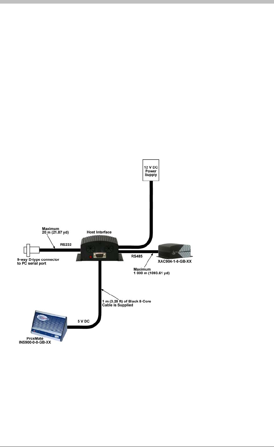
ImproX ProxMate
shielded, 2-pair twisted pair cable. The cable individual conductor cross-sectional area should
not be less than 0.2 mm2 (0.0003 in2).
When using flat cable, a maximum reliable distance of 1.5 m (4.92 ft) is possible.
External PC Interface Junction Box Installation
The Junction Box is installed by attaching it to a convenient surface using the supplied double-
sided adhesive tape. The electrical connections to the Registration Readers are shown in
Figure 21.
Connect the PC Interface Junction Box to the following items as shown:
• A suitable 6 V DC power supply
• A serial port on the system Host PC
• The Registration Reader
Figure 21 – IXP400 Connection via the Host Interface
Operational Information
The Registration Readers can be controlled by using their Logical Address 0x7E. This Logical
Address is a fixed value programmed at the factory, and cannot be changed.
72 Tuesday, 11 July 2006
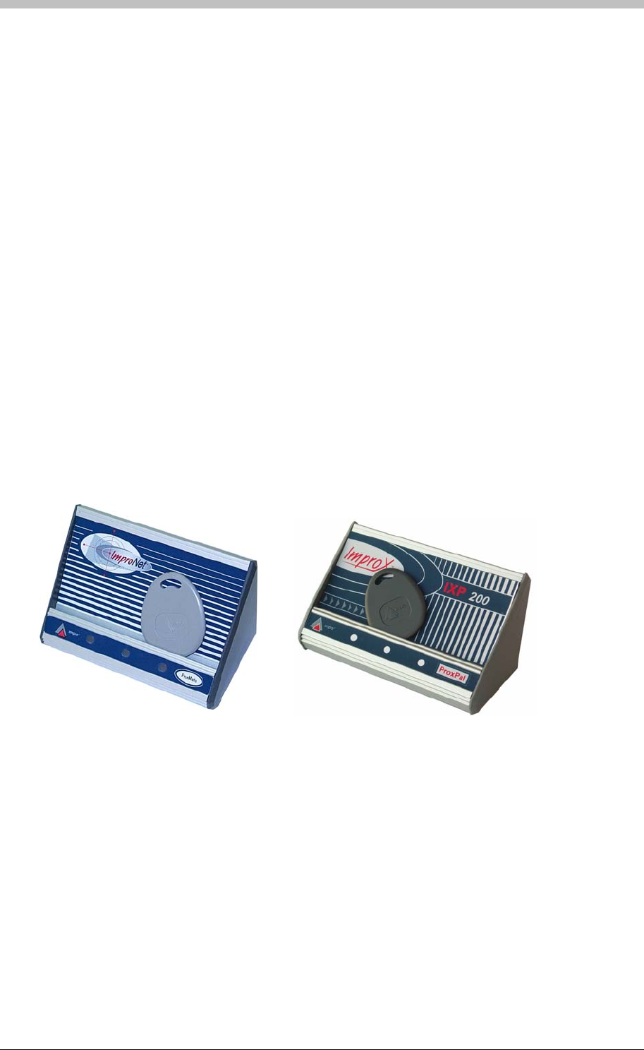
IXP300/IXP400 Installation Guide
Remote Firmware Downloading
The Registration Readers provide a remote firmware upgrade facility via the RS232
Communications Port. The firmware upgrade occurs transparently via the protocol and the user
is not required to enter any special modes of operation.
Led Indicator
The functions of the externally visible red, green, and yellow LEDs are determined by the
associated system software.
Power-On Self-Test
The Power-On Self-test tests the RAM, ROM checksums, EEPROM checksums, and tag
read/write circuitry.
When the Registration Readers pass the Self-test, two short beeps of 200 ms duration are
emitted, separated by a 200 ms inter-beep pause and the yellow LED activates.
Placement of the Tag for Registration
The passive tag to be registered can be placed in the recessed area provided during the
registration process. The Infrared tag to be registered must be powered up and pointed towards
the front of the Registration Reader. No other Infrared tag should be ON in the vicinity and no
passive tag should be in the recessed area at the time.
Figure 22 – Placement of the Tag for Registration
Operation Registration Readers LEDs
The Registration Readers have three LEDs on the lower edge of the front panel (see Figure 4).
These LEDs are red, green, and yellow. The yellow LED is the power on LED.
When the Read Tag button in the IXP400 Software is clicked, the green LED comes on briefly
and the buzzer sounds briefly if the tag code is read correctly. If the tag code cannot be read,
the red LED comes on briefly and the buzzer emits a longer beep.
Tuesday, 11 July 2006 73
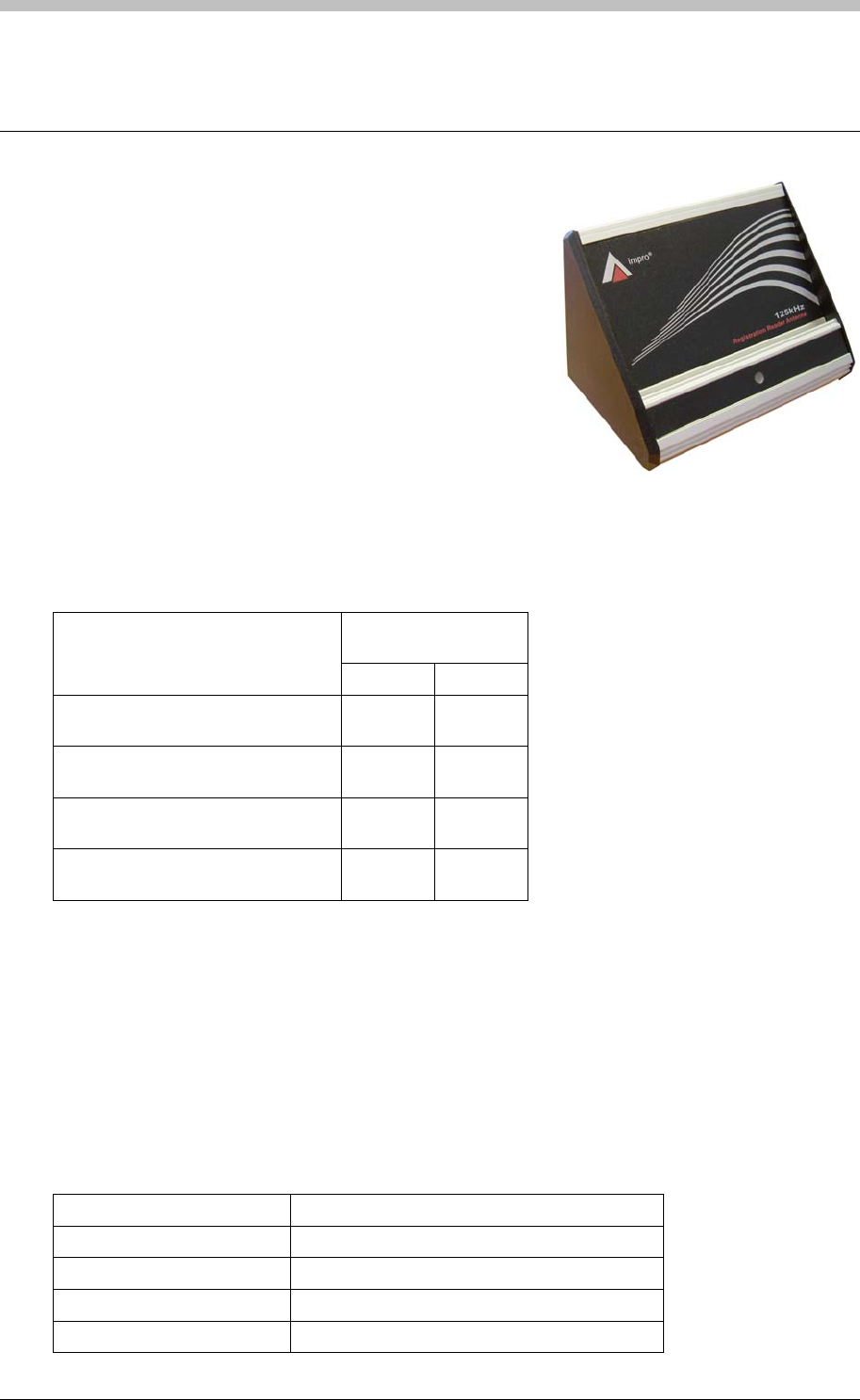
ImproX RRA Registration Reader Antenna
ImproX RRA Registration Reader Antenna
The ImproX (RRA) Registration Reader Antenna is a
compact Tag Reader, designed for use with the ImproX
RH Registration Interface in the IXP300 and IXP400
Access Control Systems.
The ImproX RRA includes a single tone Buzzer, and a bi-
coloured Red or Green Status LED. You can set the
functions of the Buzzer and Status LED to suit the needs
of your application.
The ImproX RRA is intended for indoor use only. The
electronic components are housed in a Natural, Anodised, Aluminium extruded Cabinet.
Tag Read/Write Ranges
Typical Range
(Minimum)
Tag Type
(mm) (in)
ISO Credit Card (Slim), 64-bit,
Manchester encoded protocol, ASK 20-30 0.80-1.20
Credit Card (Semi Slim), 64-bit,
Manchester encoded protocol, ASK 20-30 0.80-1.20
ImproX Credit Card, 64-bit,
Manchester encoded protocol, ASK 20-30 0.80-1.20
Key Ring Tag, 64-bit, Manchester
encoded protocol, ASK 20-30 0.80-1.20
Approvals
• CE
• UL294
• FCC Approval Pending.
Specifications
Physical
Dimensions
Length 97 mm (3.81 in).
Width 61.40 mm (2.41 in).
Height 68.30 mm (2.68 in).
Approximate Weight 199 g (0.43 lb).
74 Tuesday, 11 July 2006

IXP300/IXP400 Installation Guide
Cabinet Material Aluminium.
Colour Natural, Anodised.
Environmental
Temperature
Operating 0oC to +49oC (-13oF to +140oF)
Storage -40oC to +80oC (-40oF to +176oF)
Humidity Range 85% ± 5oC relative humidity at +30oC ± 2oC (86oF ± 3 oF)
Approvals (Test
Information)
UL Rating UL 294.
EMC EN 55022: Limits and Methods of Measurement of Radio
Disturbance Characteristics of Information Technology Equipment.
EN 55024: Immunity Characteristics, Limits and Methods of
Measurement.
Electrostatic Discharge IEC 61000-4-2: Electromagnetic Compatibility (EMC). Part 4:
Testing and Measurement Techniques. Section 2: Electrostatic
Discharge Immunity Test. Basic EMC Publication.
Radiated Susceptibility IEC 61000-4-3: Electromagnetic Compatibility (EMC). Part 4:
Testing and Measurement Techniques. Section 3: Radiated,
Radio-Frequency, Electromagnetic Field Immunity Test.
Electrical Fast Transients IEC 61000-4-4: Electromagnetic Compatibility (EMC). Part 4:
Testing and Measurement Techniques. Section 4: Electrical Fast
Transients / Bursts. Basic EMC Publication.
Surge Immunity IEC 61000-4-5: Surge Immunity.
Conducted Susceptibility IEC 61000-4-6: Conducted Susceptibility.
Power Frequency Magnetic
Field IEC 61000-4-8: Electromagnetic Compatibility (EMC). Part 4:
Testing and Measurement Techniques. Section 8: Frequency
Magnetic Field Immunity Test.
Dust and Splash
Resistance Approved for indoor use in an environment similar to IP42.
Drop Endurance 2 m (6.56 ft) drop (in packaging).
Operator or Installer Interfaces
Buzzer
Volume and Tone Four volume, single tone (Software may
support single tone only).
Status Indicators
Status LED Bi-coloured Red or Green.
Installation Information
Accessories
Find the following when unpacking the ImproX RRA:
• An ImproX (RRA) Registration Reader Antenna housed in a Natural, Anodised, Aluminium
extruded Cabinet. The ImproX RRA consists of a Front Cover, a Base Frame and two Side
Tuesday, 11 July 2006 75

ImproX RRA Registration Reader Antenna
Plates. The ImproX RRA assembly includes 2 m (6.56 ft) of West Penn D3652, shielded,
22-gauge, multi-strand, 3-pair twisted cable.
• An extra Serial Number Label.
General
Wire and install the ImproX RRA in accordance with the National Electric Code
(ANSI/NFPA 70), local codes, and the authorities having jurisdiction.
• Distance between the Registration Interface and the ImproX RRA – The maximum
cable distance between the ImproX Registration Interface and the ImproX RRA, MUST NOT
exceed 2 m (6.56 ft).
Mounting the Cabinet
There is no installation required for the ImproX RRA. Place the ImproX RRA in a convenient
location near the Registration Interface and Host PC.
DO NOT place the ImproX RRA within 500 mm (19.68 in) of the PC Monitor or any other
125 kHz device. Doing so, may reduce the reading range of the ImproX RRA.
The ImproX RRA MUST be located in the same room as the ImproX (RH) Registration
Interface to which it is connected.
76 Tuesday, 11 July 2006
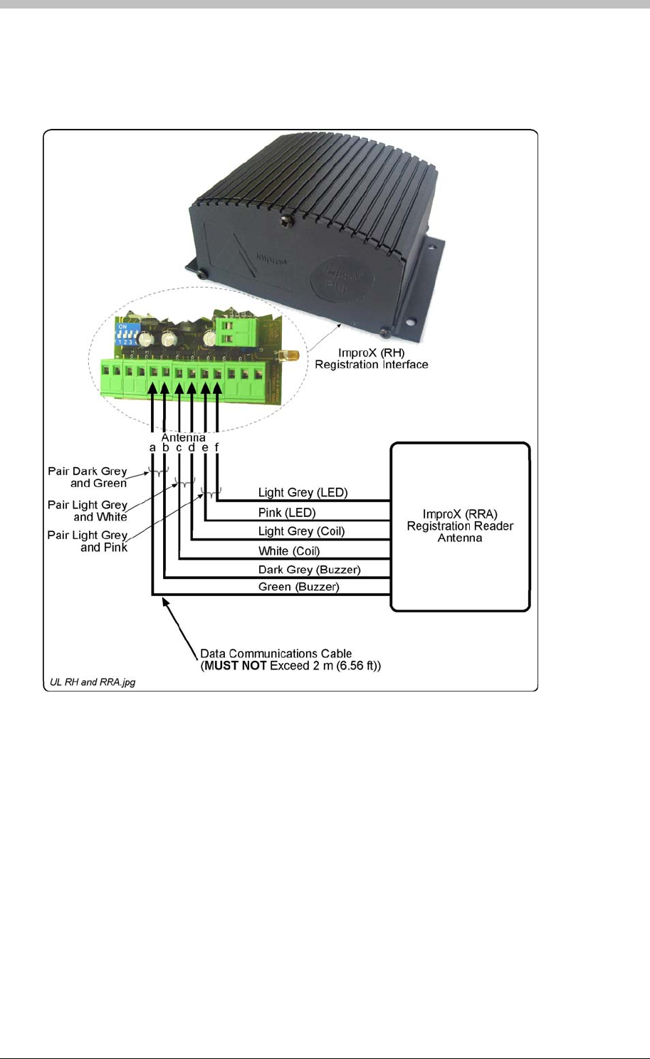
IXP300/IXP400 Installation Guide
Electrical Connections
Connecting the ImproX RRA
Figure 23 shows a detailed connection diagram for the ImproX RRA.
Figure 23: Typical ImproX RRA Electrical Connections
Initial Start-up
On powering up, the ImproX RRA will produce a beep sound and the Status LED will illuminate
solid Red.
The ImproX RRA will only read a Tag during the tag enrollment process initiated in the ImproNet
Software.
Serial Number Label
The loose Serial Number Label (packaged with the ImproX RRA) identifies the type of product
and its Serial Number.
Tuesday, 11 July 2006 77

ImproX RRA Registration Reader Antenna
Operation and Functionality
The primary function of the ImproX RRA is to enroll user Cards and Tags into the ImproNet
software. During the enrollment process, the ImproX RRA reads the unique Tag code that is
written to the ImproNet database. When saved in the database, the Tag code and associated
access rights are sent to the IXP300/400 Controllers via the communications infrastructure. The
ImproX RRA connects directly to the ImproX RH comms interface.
Refer to the Read the Tag section on page 253 for details.
78 Tuesday, 11 July 2006
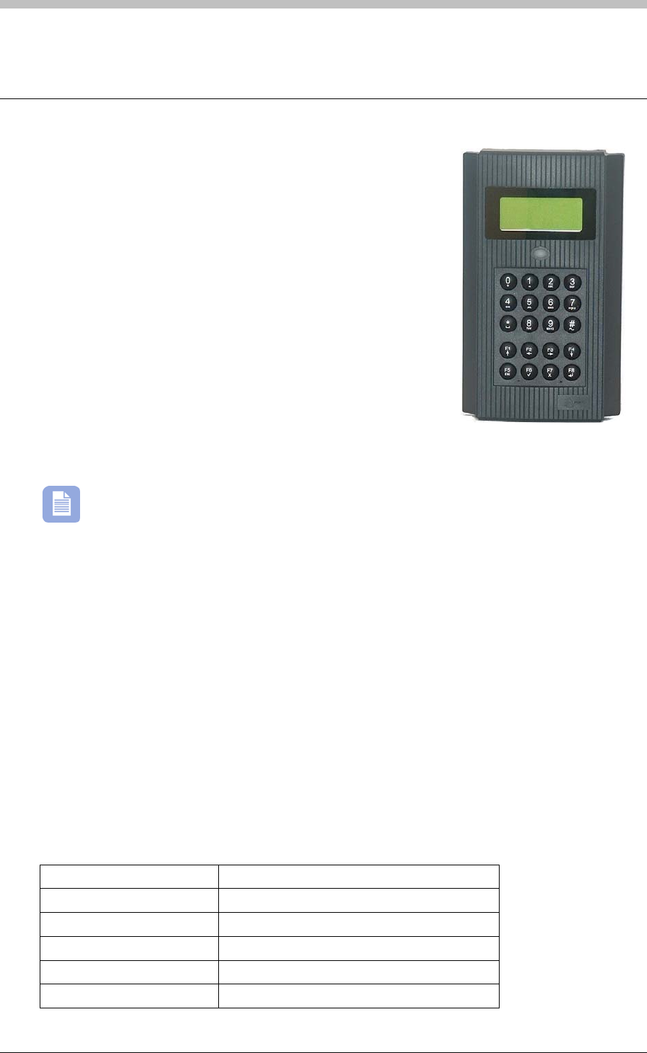
IXP300/IXP400 Installation Guide
ImproX IC LCD Keypad Controller
The ImproX IC LCD Keypad Controller is a fully featured
Controller for use in the IXP300 System. The ImproX IC
Controllers applications include:
• Access control
• Alarm control (not UL evaluated).
• Time and attendance monitoring (not UL evaluated).
• Parking garage control (not UL evaluated).
The Controller has a 20-key Keypad and a 16-character by 4-
line alphanumeric Liquid Crystal Display (LCD). Both the
Keypad and the LCD include back-lighting. The back-lighting for
the Keypad and the LCD work in conjunction and are switched
on or off via the Communications Protocol. The Controller offers
4 “Bus Activity LED Indicators” for the installer and 1 “Power-on Indicator”. The “Bus Activity
LED Indicators” indicate incoming and outgoing RS232 (not UL evaluated) and RS485 Data.
Functionality of the Keypad and Liquid Crystal Display are not employed in the IXP300
System (as such, the Keypad and Liquid Crystal Display are not UL evaluated).
The Controller is capable of communicating with other ImproX units via an RS485 Terminal Bus
Port and with a PC via an RS232 or RS485 Host Bus Port.
The ImproX IC is housed in a Dark Grey ABS Plastic Cabinet. As the Cabinet is not
weatherproof, the Controller is intended for installation in an indoor (dry) environment.
Approvals
• CE
• UL294
• FCC Approval Pending.
Specifications
Physical
Dimensions
Length 204 mm (8.03 in).
Width 121 mm (4.76 in).
Height 45 mm (1.77 in).
Approximate Weight 510 g (1.12 lb).
Cabinet Material ABS Plastic.
Tuesday, 11 July 2006 79

ImproX IC LCD Keypad Controller
Colour Dark Grey.
Environmental
Temperature
Operating 0oC to +49oC (32oF to +120oF).
Storage -40oC to +80oC (-40oF to +176oF).
Humidity Range 85% ± 5oC relative humidity at +30oC ± 2oC (86oF ± 3 oF)
Approvals (Test
Information)
UL Rating UL 294.
EMC EN 55022: Limits and Methods of Measurement of Radio
Disturbance Characteristics of Information Technology Equipment.
EN 55024: Immunity Characteristics, Limits and Methods of
Measurement.
Electrostatic Discharge IEC 61000-4-2: Electromagnetic Compatibility (EMC). Part 4:
Testing and Measurement Techniques. Section 2: Electrostatic
Discharge Immunity Test. Basic EMC Publication.
Radiated Susceptibility IEC 61000-4-3: Electromagnetic Compatibility (EMC). Part 4:
Testing and Measurement Techniques. Section 3: Radiated,
Radio-Frequency, Electromagnetic Field Immunity Test.
Electrical Fast Transients IEC 61000-4-4: Electromagnetic Compatibility (EMC). Part 4:
Testing and Measurement Techniques. Section 4: Electrical Fast
Transients / Bursts. Basic EMC Publication.
Surge Immunity IEC 61000-4-5: Surge Immunity.
Conducted Susceptibility IEC 61000-4-6: Conducted Susceptibility.
Power Frequency Magnetic
Field IEC 61000-4-8: Electromagnetic Compatibility (EMC). Part 4:
Testing and Measurement Techniques. Section 8: Frequency
Magnetic Field Immunity Test.
Dust and Splash
Resistance Designed to work in an indoor (dry) environment similar to IP40.
The Controller is, therefore, NOT sealed against water.
Drop Endurance 2 m (6.56 ft) drop (in packaging).
Electrical
Power Requirements
Input Voltage 12 V DC and 24 V DC, polarity sensitive.
Power Requirements Current (mA) Power (W)
Input Voltage 12 V DC
Relays all ON 245 2.94
Input Voltage 24 V DC
Relays all ON 125 3.0
Permissible Input Supply
Ripple Voltage (Max) 1 V PP at 50 Hz.
Power Input Protection Reverse polarity, over-voltage and over-current protection are
provided on the Controller.
Ethernet Port Not Applicable.
Terminal Bus Port (Port 1)
Electrical Interface RS485, ASCII with 16-bit CRC checking.
80 Tuesday, 11 July 2006

IXP300/IXP400 Installation Guide
Baud Rates 1 200, 2 400, 4 800, 9 600, 19 200, 28 800, 38 400, 57 600 and 76
800 selectable via the Protocol.
Data Format 8 data bits, no parity, 1 stop bit.
Communications Protocol ImproX Secure Communications Protocol.
Line Termination Provision is made for line termination.
Default Mode Transmit Mode.
Host Bus Port (Port 2)
Electrical Interface RS232 (full duplex, no flow control) or RS485, ASCII with 16-bit CRC
checking, selectable via the Protocol.
Baud Rates 1 200, 2 400, 4 800, 9 600, 19 200, 28 800, 38 400 and 57 600
selectable via the Communications Protocol.
Data Format 8 data bits, no parity, 1 stop bit.
Communications Protocol ImproX Secure Communications Protocol.
Line Termination Provision is made for line termination.
Default Mode Receive Mode.
Unit Status Slave.
Serial Peripheral Port (Port
3)
Electrical Interface RS232 (full duplex, RTS and CTS flow control available).
Baud Rates 1 200, 2 400, 4 800, 9 600, 19 200, 28 800, 38 400, 57 600 and 76
800 selectable via the Communications Protocol.
Data Format 8 data bits, no parity, 1 stop bit.
Interface Protocol Determined by the peripheral device used.
Relays
Relay Output 2 x Relays, each with NO, COM and NC contacts.
Contact Rating 4 A at 24 V AC,
4 A at 24 V DC.
Digital Input (Not UL
Evaluated)
Input Type 4 x Dry Contact Inputs.
Detection Resistance Range +15 V and -15 V continuous.
Note: The IXP300 system does not support Inputs.
Anti-tamper Protection An internal infra-red beam detects when the Front Cover is removed
from the Controller. This event detection is reported by the Controller
via the Protocol.
Memory
RAM (Non-volatile) 512 KBytes.
Flash ROM 128 KBytes.
Battery Backup (for RAM)
Battery Type 1 x 3.6 V Lithium, size ½ AA
Battery Life 5 Years (with power OFF).
Tuesday, 11 July 2006 81

ImproX IC LCD Keypad Controller
Factory Default Settings
Test Modes
Power-on Self-test RAM, Flash-ROM, Tag Read/Write, RTC and stuck keys.
Baud Rate
Terminal Bus Port 38 400.
Host Bus Port 38 400.
Back-lighting
LCD and Keypad On.
Contrast (LCD) Level 3.
Host Port Mode RS232.
Buzzer
Tone 25.
Volume Level 4 (maximum).
Operator or Installer Interfaces
Liquid Crystal Display
(LCD)
Characters 16 Characters by 4 lines.
Character Sets English, Katakana.
Contrast Adjustable in 8 discrete steps via the Communications Protocol.
Back-lighting Turned on and off via the Communications Protocol.
Keypad
Buttons 20 Alphanumeric and function keys.
Back-lighting Turned on and off via the Communications Protocol.
Note: The LCD and keypad backlighting operate in conjunction.
Buzzer
Volume and Tone 5-Step adjustable volume, 36 different tones. Selectable via the
Communications Protocol.
LED Indicators
Power-on Indicator Red LED (internally visible).
Incoming RS485 Data Flashing Green LED (internally visible).
Outgoing RS485 Data Flashing Red LED (internally visible).
Incoming RS232 Data Flashing Green LED (internally visible).
Outgoing RS232 Data Flashing Red LED (internally visible).
Status Indicator Bi-colour Red or Green LED (externally visible), function
programmable via the Communications Protocol.
Installation Information
Accessories
Find the following when unpacking the ImproX IC Controller:
82 Tuesday, 11 July 2006

IXP300/IXP400 Installation Guide
• An ImproX IC LCD Keypad Controller housed in a Dark Grey ABS Plastic Cabinet. The
Cabinet will consist of a Front and Back Cover secured with a Thread Cutter Screw (M3 x 8
mm).
• A 3.6 V, >950 mAH, ½ AA Cylindrical Lithium Battery.
• Four Wood Screws (3.5 mm x 25 mm).
• Four Wall Plugs (7 mm).
• An extra Fixed Address Label.
General
Remember the following when installing your ImproX IC Controller:
• Communications Distance – The RS485 communications distance between the ImproX IC
Controller and the LAST ImproX Unit in a cable run, MUST NOT exceed 1 km (3 281 ft).
Achieve this by using West Penn D291 22 gauge, stranded, single pair cable with the
overall shield EARTHED at one end.
The individual conductor cross sectional area of the each cable conductor must not be less
than 0.2 mm² (0.0003 in²).
• Distance between ImproX IC Controllers – To avoid mutual interference Install the
Controllers no closer than 500 mm (20 in) apart.
• Termination Resistors for RS485 Bus Communications – Long transmission lines or
multiple “star” connections, may cause communication problems. Placing the Terminating
Resistor Jumper Link in the LAST UNIT AT THE END OF THE CABLE RUN should solve
the problem (depending on the bus). The termination resistor has a value of 150 ohms.
• EARTH Connection – Connect the ImproX IC Controller to a good EARTH point. Using
either of the RS485 Ports, connect the EARTH Lead to the “ETH” Terminal. Mains EARTH
can be used, but electrical noise may exist. The EARTH Lead to the ImproX IC Controller
should have a minimum cross-sectional area of 1 mm2 (0.001 in2) and can be either solid or
stranded.
Installing the Battery – First Time Use
Insert the Battery into the Battery Holder BEFORE powering up the ImproX IC
Controller.
The Battery Holder is located in the middle right-hand side of the ImproX IC Controllers Printed
Circuit Board (PCB), directly below the “Bus Activity LED Indicators”.
Insert the 3.6 V Lithium Battery into the Battery Holder, with the "+" Terminal facing AWAY from
the Terminal Blocks.
Replacement
DO NOT disconnect Power from the ImproX IC Controller during this operation.
Disconnecting the Power could result in the RAM loosing data.
Tuesday, 11 July 2006 83

ImproX IC LCD Keypad Controller
1. With the Controller powered up, remove the Controllers Front Cover. DO NOT disconnect
the Ribbon Cable Connectors.
2. Remove the Battery from the Battery Holder.
3. Insert the new 3.6 V Lithium Battery into the Battery Holder, with the "+" Terminal facing
AWAY from the Terminal Blocks.
4. Attach the Controllers Front Cover.
Mounting the Controller
Select the mounting position of the ImproX IC Controller, considering accessibility, routing of
wires and visibility of the externally visible LED.
Secure the Controller to the mounting surface, using four suitable screws and wall plugs
(supplied), nuts and bolts, or rivets.
84 Tuesday, 11 July 2006
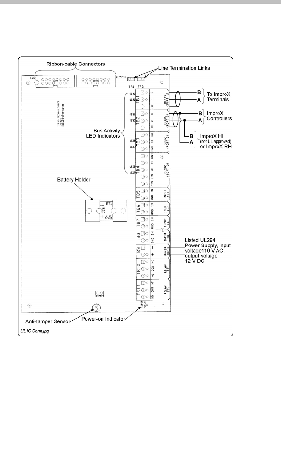
IXP300/IXP400 Installation Guide
Electrical Connections
Connecting the ImproX IC Controller
Figure 24 shows typical connecting details for the ImproX IC Controller.
Figure 24: Typical ImproX IC Electrical Connections
Power-on Self-test
The Power-on Self-test test the RAM, Flash-ROM checksums, RTC, read/write circuitry and
stuck keys.
The results of the Self-test are made available as diagnostic information via the protocol to the
associated Controller or PC.
If any parameter in the Self-test fails, the Controller emits a continuous beep for 2 seconds.
Tuesday, 11 July 2006 85

ImproX IC LCD Keypad Controller
When the Controller passes the Self-test, the Controller emits two short beeps of 200 ms
duration, separated by a 200 ms inter-beep pause.
Fixed Address Label
Once the ImproX IC Controller is installed, attach the additional loose Fixed Address Label
(packaged with the Controller) in position on the Unit Location Chart. When the system
installation is complete and all the units are represented on the Unit Location Chart by their
Fixed Address Labels, file the document for future reference.
Operation and Functionality
Refer to the Controllers section on page 35 for details.
86 Tuesday, 11 July 2006
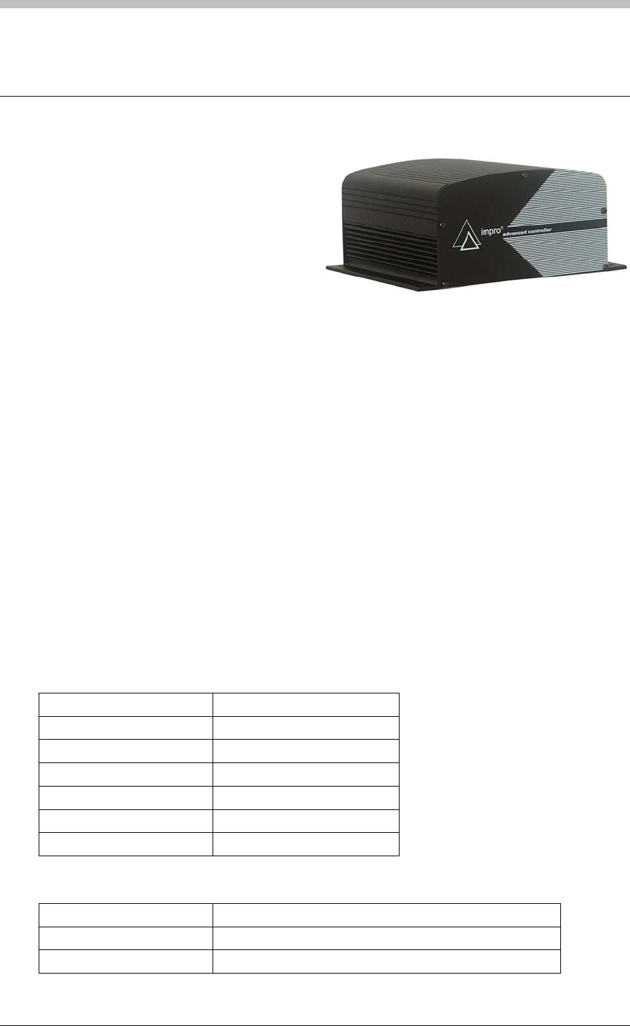
IXP300/IXP400 Installation Guide
ImproX AC Advanced Controller
The ImproX (AC) Advanced Controller is a
fully featured Controller that forms part of
the IXP400 range of access control
equipment. This Controller is capable of
increased Tag and transaction storage as it
is fitted with two Memory Modules (storage
of up to 30 000 Tags and 37 000
transactions).
The Controller offers two “Bus Activity LED Indicators” for the installer and one “Power-on
Indicator”. The “Bus Activity LED Indicators” indicate incoming and outgoing RS485 Data.
The Controller is capable of communicating with other ImproX units via an RS485 Terminal Bus
Port, with a PC and or other Controllers via an RS485 Host Bus Port.
The Controller is enclosed in an Aluminium Cabinet, and is intended for indoor use only. The
ImproX AC is, therefore, NOT waterproof.
Approvals
• CE
• UL294
• FCC Approval Pending.
Specifications
Physical
Dimensions
Length 168 mm (6.61 in).
Width 197 mm (7.75 in).
Height 89 mm (3.50 in).
Approximate Weight 1.2 kg (No Battery) (2.64 lb).
Housing Material Aluminium.
Colour Black.
Environmental
Temperature
Operating 0oC to +49oC (-13oF to +140oF).
Storage -40oC to +80oC (-40oF to +176oF).
Tuesday, 11 July 2006 87

ImproX AC Advanced Controller
Humidity Range 85% ± 5oC relative humidity at +30oC ± 2oC (86oF ± 3 oF)
Approvals (Test
Information)
UL Rating UL 294.
EMC EN 55022: Limits and Methods of Measurement of Radio
Disturbance Characteristics of Information Technology
Equipment.
EN 55024: Immunity Characteristics, Limits and Methods of
Measurement.
Electrostatic Discharge IEC 61000-4-2: Electromagnetic Compatibility (EMC). Part
4: Testing and Measurement Techniques. Section 2:
Electrostatic Discharge Immunity Test. Basic EMC
Publication.
Radiated Susceptibility IEC 61000-4-3: Electromagnetic Compatibility (EMC). Part
4: Testing and Measurement Techniques. Section 3:
Radiated, Radio-Frequency, Electromagnetic Field Immunity
Test.
Electrical Fast Transients IEC 61000-4-4: Electromagnetic Compatibility (EMC). Part
4: Testing and Measurement Techniques. Section 4:
Electrical Fast Transients / Bursts. Basic EMC Publication.
Surge Immunity IEC 61000-4-5: Surge Immunity.
Conducted Susceptibility IEC 61000-4-6: Conducted Susceptibility.
Voltage Dips and Short
Interruptions IEC 61000-4-11: Voltage Dips and Interruptions.
Dust and Splash Resistance Designed to work in an indoor (dry) environment similar to
IP30. The Controller is, therefore, NOT sealed against
water.
Drop Endurance 2 m (6.56 ft) drop (in packaging).
Electrical
Power Requirements
Input Voltage 12 V DC and 24 V DC.
Power Requirements Current (mA) Power (W)
Input Voltage 12 V DC All
Indicators ON 60 0.72
Input Voltage 24 V DC All
Indicators ON 35 0.84
Permissible Input Supply
Ripple Voltage (Max) 1 V PP at 50 Hz.
Power Input Protection Reverse polarity on DC power inputs, over-voltage and
over-current protection are provided on the Controller.
Terminal Bus Port (Port 1)
Electrical Interface RS485, ASCII with 16-bit CRC checking.
Baud Rates 1 200, 2 400, 4 800, 9 600, 19 200, 28 800, 38 400, 57 600
and 76 800 selectable via the Protocol.
Data Format 8 data bits, no parity, 1 stop bit.
Communications Protocol ImproX Secure Communications Protocol.
Line Termination Provision is made for line termination.
Default Mode Receive Mode.
88 Tuesday, 11 July 2006

IXP300/IXP400 Installation Guide
Host Bus Port (Port 2)
Electrical Interface RS485, ASCII with 16-bit CRC checking.
Baud Rates 1 200, 2 400, 4 800, 9 600, 19 200, 28 800, 38 400 and 57
600 selectable via the Communications Protocol.
Data Format 8 data bits, no parity, 1 stop bit.
Communications Protocol ImproX Secure Communications Protocol.
Line Termination Provision is made for line termination.
Default Mode Receive Mode.
Unit Status Slave.
Anti-tamper Protection Internal switch.
Memory
RAM (Non-volatile) 2 MBytes standard, 8 MBytes maximum.
Flash ROM 128 KBytes.
Battery Backup (for RAM)
Battery Type 1 x 3 V, CR2032, Lithium cell Battery.
Battery Life 5 Years (with power OFF).
Type 16-bit Micro-controller operating at 16 MHz.
Ram Memory 2 K Byte.
Flash Memory 64 K Byte.
Factory Default Settings
Test Modes
Power-on Self-test RAM, Flash-ROM, RTC.
Baud Rate
Terminal Bus Port 38 400.
Host Bus Port 38 400.
Operator or Installer Interfaces
LED Indicators
Power-on Indicator Red LED (internally visible).
Incoming RS485 Data Flashing Green LED (internally visible).
Outgoing RS485 Data Flashing Red LED (internally visible).
Installation Information
Accessories
Find the following when unpacking the ImproX AC:
• An ImproX AC Controller, fitted with two Memory Modules. The ImproX AC is supplied
housed in a Black, powder coated, Aluminium extruded Cabinet. The Cabinet will consist of
a Top Cover and a Base sealed at each end with a Mild Steel End Plate, secured with 5
Thread Cutter Screws (M3 x 8 mm).
Tuesday, 11 July 2006 89

ImproX AC Advanced Controller
• A 3 V, CR2032, Lithium cell Battery.
• Four Wood Screws (3.5 mm x 25 mm).
• Four Wall Plugs (7 mm).
• An extra Fixed Address Label.
General
Remember the following when installing your ImproX AC Controller:
Wire and install the Controller in accordance with the National Electric Code
(ANSI/NFPA 70), local codes, and the authorities having jurisdiction.
DO NOT connect Power Supply cables to Port 1 and Port 2 terminals, as this will cause
serious damage to the Controller.
• Communications Distance – The RS485 communications distance between the ImproX
AC Controller and the LAST ImproX Unit in a cable run, MUST NOT exceed 1 km (3 281 ft).
Achieve this by using West Penn D291 22 gauge, stranded, single pair cable with the
overall shield EARTHED at one end.
The individual conductor cross sectional area of the each cable conductor must not be less
than 0.2 mm² (0.0003 in²).
• Termination Resistors for RS485 Bus Communications – Long transmission lines or
multiple “star” connections, may cause communication problems. Placing the Terminating
Resistor Jumper Link in the LAST UNIT AT THE END OF THE CABLE RUN should solve
the problem (depending on the bus). The termination resistor has a value of 150 ohms.
• EARTH Connection – Connect the ImproX AC Controller to a good EARTH point. Using
either of the RS485 Ports, connect the EARTH Lead to the “ETH” Terminal. Mains EARTH
can be used, but electrical noise may exist. The EARTH Lead to the ImproX AC Controller
should have a minimum cross-sectional area of 1 mm2 (0.001 in2) and can be either solid or
stranded.
Installing the Battery – First Time Use
Insert the Battery into the Battery Holder BEFORE powering up the ImproX AC
Controller.
The Battery Holder is located in the top left-hand side of the ImproX AC Controllers Printed
Circuit Board (PCB).
1. Remove the Controllers Top Cover.
2. Slide the supplied 3 V, CR2032, Lithium cell Battery under the metal clip of the Battery
Holder, with the "+" Terminal facing UP.
3. Pull the plastic clip horizontally AWAY from the Battery Holder and press the Battery firmly
into the Battery Holder.
4. Attach the Controllers Top Cover.
90 Tuesday, 11 July 2006

IXP300/IXP400 Installation Guide
Installing the Battery – Replacement
DO NOT disconnect Power from the ImproX AC Controller during this operation.
Disconnecting the Power could result in the RAM loosing data.
1. With the Controller powered up, remove the Top Cover. DO NOT disconnect the Ribbon
Cable Connector.
2. Remove the Battery from the Battery Holder, by pulling the plastic retaining clip horizontally
AWAY from the Battery Holder. The Battery Holder is spring-loaded, and will raise the
Battery out of the Holder.
3. Slide the new 3 V, CR2032, Lithium cell Battery under the metal clip of the Battery Holder,
with the "+" Terminal facing UP.
4. Pull the plastic clip horizontally AWAY from the Battery Holder and press the Battery firmly
into the Battery Holder.
5. Attach the Controllers Top Cover.
Installing Extra Memory Modules (Optional Extra)
Add additional Memory Modules for applications where additional memory is required:
It is important that the Memory Modules are inserted correctly. Pin 1 as indicated on the
Memory Module must correspond with Pin 1 on the ImproX AC Controller.
1. Remove the power from the ImproX AC Controller.
2. Remove the Controllers Top Cover and the LCD Display Cover (if installed).
3. Carefully insert the Memory Modules into the positions JP3 to JP8 as indicated on the
ImproX AC Controller.
4. Re-attach the Controllers Top Cover and if necessary the LCD Display Cover and re-apply
power to the Controller.
5. On power-up a diagnostic test will run on the inserted Memory Modules added to the
system. The diagnostic test will display on the LCD Display Cover (if installed).
Mounting the Controller
Select the mounting position of the ImproX AC Controller, considering accessibility and routing
of wires.
Mounting on a Concrete or Brick Wall
1. Use the Base as a template and mark off the required holes.
2. Drill the four mounting holes using a 7 mm diameter masonry drill bit, to a depth equal to the
length of the supplied wall plugs.
3. Insert the wall plugs into the mounting holes.
4. Secure the Base to the surface using the four mounting screws provided.
Tuesday, 11 July 2006 91
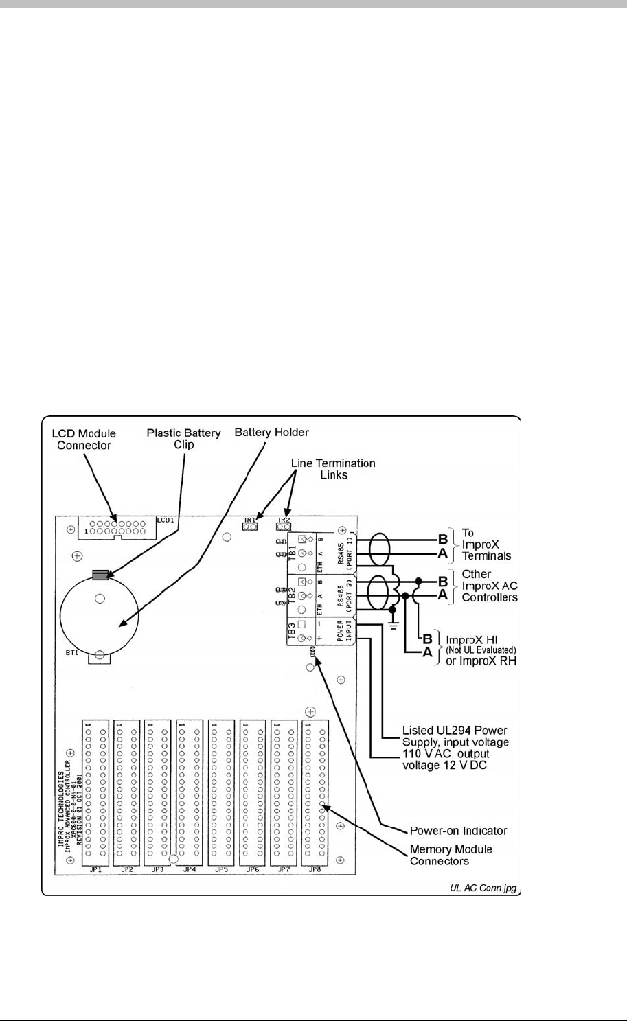
ImproX AC Advanced Controller
Mounting on a Hard Wood Surface
1. Use the Base as a template and mark off the required holes.
2. Drill the four mounting holes using a 2.5 mm diameter drill bit to the depth equal to three-
quarters of the length of the mounting screws.
3. Secure the Base to the surface using the four mounting screws provided.
Mounting on Metal
Use four suitable securing devices such as screws, nuts and bolts, or rivets to mount the
ImproX AC on a metal surface.
1. Use the Base as a template and mark off the required holes.
2. Drill the four mounting holes using a suitable diameter drill bit.
3. Secure the Base to the surface using the chosen method.
Electrical Connections
Connecting the ImproX AC Controller
Figure 25 shows various connection options for the ImproX AC Controller.
Figure 25 – Typical ImproX AC Electrical Connections
92 Tuesday, 11 July 2006

IXP300/IXP400 Installation Guide
Power-on Self-test
The Power-on Self-test tests the RAM, Flash-ROM checksums and RTC.
The results of the Self-test are made available as diagnostic information via the protocol to the
associated Controller or PC.
Fixed Address Label
Once the ImproX AC Controller is installed, attach the additional loose Fixed Address Label
(packaged with the Controller) in position on the Unit Location Chart. When the system
installation is complete and all the units are represented on the Unit Location Chart by their
Fixed Address Labels, file the document for future reference.
Operation and Functionality
Refer to the Controllers section on page 35 for details.
Tuesday, 11 July 2006 93
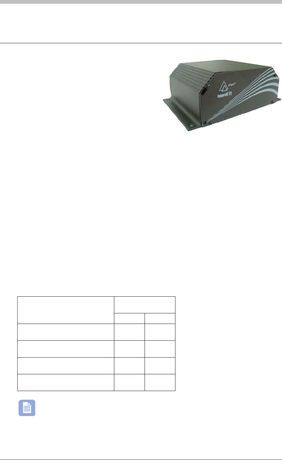
ImproX TT Twin Antenna Terminal
ImproX TT Twin Antenna Terminal
The ImproX (TT) Twin Antenna Terminal is
designed to interface with the IXP300 and IXP400
Access Control Systems via the RS485 Bus
Connection.
The low-cost ImproX TT is designed to provide
access control to one door in Full Anti-passback
Mode (APB) (using two Antenna Readers on the
door), or two doors in Relaxed Anti-passback Mode (APB) (using one Antenna Reader per
door). We offer a wide range of Antenna Readers suitable for most installations:
• ImproX (MMA) Mullion Antenna Reader.
• ImproX (MA) Micro Antenna Reader.
• ImproX (MHA) Metal Antenna Reader.
• ImproX (KHA) Metal Keypad Antenna Reader.
The ImproX TT offers 9 preset LED “Diagnostic Indicators”, these indicate: Power On, Upgrade
Mode, RS485 Communications Failure, Incoming and Outgoing RS485 Data, Contact Closure
on the Digital Inputs and Activation of the Relays.
The Terminal is housed in a robust Black; Aluminium extruded Cabinet suitable for indoor
installation. A label mounted on the inside of the Top Cover shows the functions of the various
terminal block connections and the LEDs.
Tag Read/Write Ranges
Typical Range
(Minimum)
Tag Type
(mm) (in)
ISO Credit Card (Slim), 64-bit,
Manchester encoded protocol, ASK 60 2.36
Credit Card (Semi Slim), 64-bit,
Manchester encoded protocol, ASK 60 2.36
ImproX Credit Card, 64-bit,
Manchester encoded protocol, ASK 50 1.96
Key Ring Tag, 64-bit, Manchester
encoded protocol, ASK 40 1.58
The distances indicated are for the Terminal mounted on a non-metallic surface.
Mounting the Terminal on a metallic surface will reduce the Tag reading range slightly.
94 Tuesday, 11 July 2006

IXP300/IXP400 Installation Guide
Approvals
• CE
• UL294
• FCC Approval Pending.
Specifications
Physical
Dimensions
Length 104 mm (4.09 in).
Width 150 mm (5.90 in).
Height 53.70 mm (2.11 in).
Approximate Weight 502 g (1.10 lb).
Cabinet Material Aluminium.
Colour Black.
Environmental
Temperature
Operating 0oC to +49oC (32oF to +120oF).
Storage -40oC to +80oC (-40oF to +176oF).
Humidity Range 85% ± 5oC relative humidity at +30oC ± 2oC (86oF ± 3 oF)
Approvals (Test
Information)
UL Rating UL 294.
EMC EN 55022: Limits and Methods of Measurement of Radio Disturbance
Characteristics of Information Technology Equipment.
EN 55024: Immunity Characteristics, Limits and Methods of
Measurement.
Electrostatic Discharge IEC 61000-4-2: Electromagnetic Compatibility (EMC). Part 4: Testing
and Measurement Techniques. Section 2: Electrostatic Discharge
Immunity Test. Basic EMC Publication.
Radiated Susceptibility IEC 61000-4-3: Electromagnetic Compatibility (EMC). Part 4: Testing
and Measurement Techniques. Section 3: Radiated, Radio-
Frequency, Electromagnetic Field Immunity Test.
Electrical Fast Transients IEC 61000-4-4: Electromagnetic Compatibility (EMC). Part 4: Testing
and Measurement Techniques. Section 4: Electrical Fast Transients /
Bursts. Basic EMC Publication.
Surge Immunity IEC 61000-4-5: Surge Immunity.
Conducted Susceptibility IEC 61000-4-6: Conducted Susceptibility.
Power Frequency Magnetic
Field IEC 61000-4-8: Electromagnetic Compatibility (EMC). Part 4: Testing
and Measurement Techniques. Section 8: Frequency Magnetic Field
Immunity Test.
Dust and Splash
Resistance Approved for indoor use in an environment similar to IP40.
Drop Endurance 2 m (6.56 ft) drop (in packaging).
Tuesday, 11 July 2006 95

ImproX TT Twin Antenna Terminal
Electrical
Power Requirements
Input Voltage 12 V DC and 24 V DC, polarity sensitive.
Power Requirements Current (mA) Power (W)
Input Voltage 12 V DC
One Antenna Reader Connected, all Indicators
and One Relay ON
95 1.14
Input Voltage 12 V DC
Two Antenna Readers Connected, all
Indicators and Two Relays ON
140 1.68
Input Voltage 24 V DC
One Antenna Reader Connected, all Indicators
and One Relay ON
45 1.08
Input Voltage 24 V DC
Two Antenna Readers Connected, all
Indicators and Two Relays ON
70 1.68
Permissible Input Supply
Ripple Voltage (Max)
1 V PP at 50 Hz.
Power Input Protection Reverse polarity, over-voltage and over-current
protection are provided on the Terminal.
Terminal Bus Port
Electrical Interface RS485, ASCII with 16-bit CRC checking.
Baud Rates 1 200, 2 400, 4 800, 9 600, 19 200, 28 800, 38 400
(default), 57 600 and 76 800 selectable via the
Communications Protocol.
Data Format 8 data bits, no parity, 1 stop bit.
Communications Protocol ImproX Secure Communications Protocol.
Unit Status Slave.
Relays
Relay Output 2 x Relays, each with NO, COM and NC contacts.
Contact Rating 3 A at 24 V DC.
3 A at 24 V AC.
Digital Inputs
Input Type 4 x Dry-contact inputs.
Detection Resistance Range < 5 kOhm.
Protection + 50 V to – 50 V continuous,
+ 80 V to – 80 V surge.
Processor
Type 16-bit CPU operating at 16 MHz.
Ram Memory 2 K Byte.
Flash Memory 64 K Byte.
Anti-tamper Switch 2 Switches detect opening of the enclosure.
96 Tuesday, 11 July 2006

IXP300/IXP400 Installation Guide
Factory Default Settings
Default Baud Rate Factory-set to 38 400.
Default Mode Receive (Slave Mode).
Buzzer Volume Level 3 (maximum).
Beep Codes
Fails Power-on Self-test Continuous beep for 2 seconds.
Passes Power-on Self-test Two short beeps of 200 ms duration, separated by a 200 ms inter-
beep pause.
Operator or Installer Interfaces
Status Indicators
Power On Continuous Red.
Upgrade Mode Flashing Red (Steady).
RS485 Communications
Failure
Flashing Red (Intermittent).
Relay 2 Continuous Red on activation of the Relay.
Relay 1 Continuous Red on activation of the Relay.
Reader 2, Inp 2 Continuous Green on detected contact closure.
Reader 2, Inp 1 Continuous Green on detected contact closure.
Reader 1, Inp 2 Continuous Green on detected contact closure.
Reader 1, Inp 1 Continuous Green on detected contact closure.
RS485 RX Flashing Green as per incoming data.
RS485 TX Flashing Red as per outgoing data.
Interface Details
RS485 Terminal Bus Port
The RS485 Terminal Bus Port lets you connect the ImproX TT Terminal to other ImproX
Terminals and the Controller in the IXP300 or IXP400 Access Control System.
The interface is made by connecting the “A” and “B” lines on the ImproX TT to the “A” and “B”
lines on the other ImproX units. Incoming and outgoing information on this Port is shown on the
RS485 TX and RX LED “Diagnostic Indicators” on the ImproX TT.
Relays
The ImproX TT has two independent single-pole, double-throw (SPDT) Relay Outputs. These,
user configurable, Relay Outputs let you interface to door strikes and magnetic locks.
Dry Contact Digital Inputs
The ImproX TT has four user configurable Dry Contact Digital Inputs. These Digital Inputs let
you interface with a variety of devices such as reed switches and push-buttons; you can
perform specific tasks such as:
• Door Open Sensing.
• Request to Exit.
• Scanner Inhibit.
Tuesday, 11 July 2006 97
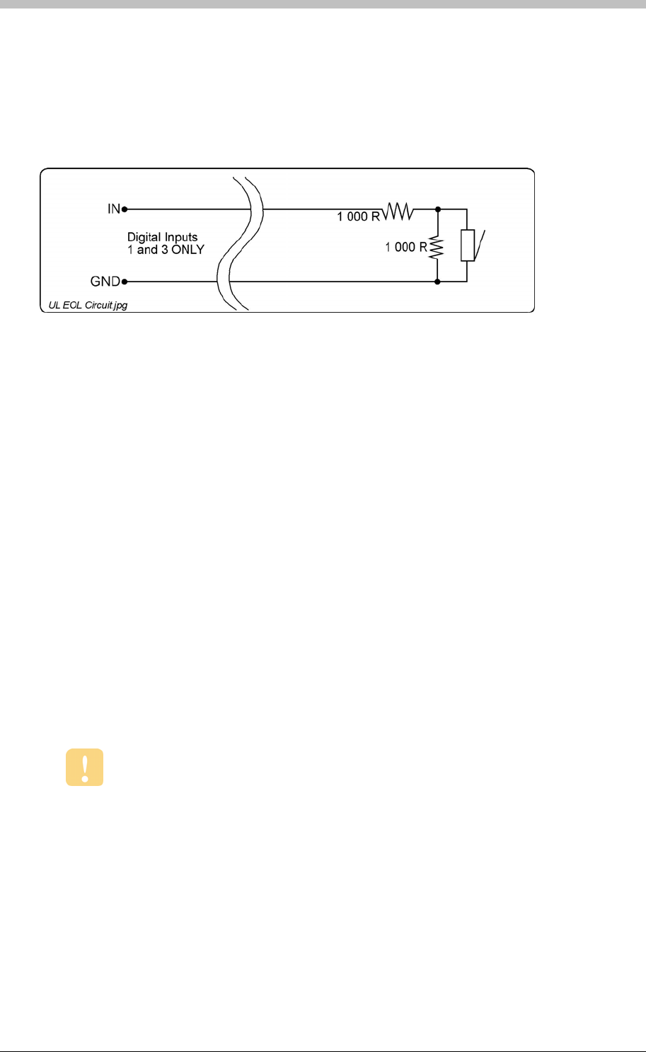
ImproX TT Twin Antenna Terminal
• Alarm Interface (not UL evaluated).
• Action Request.
End of Line (EOL) Sensing
Digital Inputs are Software configurable in Normal Sensing Mode and in End of Line (EOL)
Sensing Mode.
Figure 26 – End of Line (EOL) Sensing Circuit
End of Line (EOL) Sensing enables the Terminal to raise an alarm when somebody tampers
with the circuit (that is, cutting or shorting the wires) between the Digital Input (IN 1 and IN 3)
and GROUND (GND). In other words, the Terminal distinguishes between tampering on the
circuit, and the door being in an actual ‘Normally Open’ state.
By placing Resistors into the circuit between the Digital Input (IN 1 and IN 3) and GROUND
(GND), the Terminal’s Digital Input monitors a constant resistance through the circuit. When the
circuit is tampered with, the Resistors are bypassed; the Terminal detects the resistance change
raising an alarm.
Installation Information
Accessories
Find the following when unpacking the ImproX TT Terminal:
• An ImproX (TT) Twin Antenna Terminal housed in a Black, Aluminium extruded Cabinet.
The Cabinet consists of a Top Cover, a Base and two End Plates. Each End Plate is
attached with four Thread Cutter Screws (2.2 x 5 mm).
DO NOT use the Metal-oxide Varistors (25 Vrms, 500 A, 77 V max clamping) with
mains power applications.
• Two Metal-oxide Varistors, 25 Vrms, 500 A, 77 V max clamping.
• Four Brass Wood Screws (3.5 mm x 25 mm).
• Four Wall Plugs (7 mm).
• An extra Fixed Address Label.
98 Tuesday, 11 July 2006
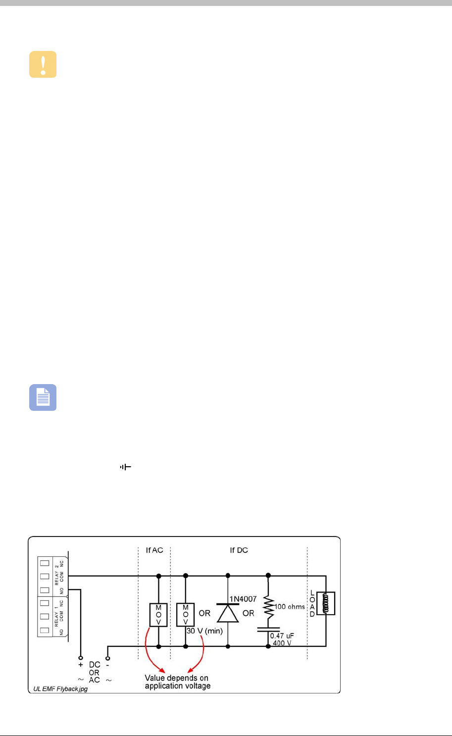
IXP300/IXP400 Installation Guide
General
Wire and install the Terminal in accordance with the National Electric Code (ANSI/NFPA
70), local codes, and the authorities having jurisdiction.
• Communications Distance – The RS485 communications distance between the first
ImproX TT and the LAST ImproX unit in a cable run, MUST NOT exceed 1 km (3 270 ft).
Achieve this by using West Penn D291 22 gauge, stranded, single pair cable with the
overall shield EARTHED at one end.
• Jumper Links for Termination Resistor – Long transmission lines or multiple “star”
connections, may cause communication problems. Placing a Jumper Link across the
jumper [TR1] in the LAST UNIT AT THE END OF THE CABLE RUN should solve the
problem. The termination resistor has a value of 150 ohms.
• Antenna Reader Distance – The ideal cable distance between the ImproX TT and its
Antenna Reader ranges between 2 m to 16 m (7 ft to 53 ft). Achieve this by using good
quality screened, twisted pair cable.
• Distance between Antenna Readers from the SAME Terminal – To avoid mutual
interference, install the Antenna Readers alongside each other at least 150 mm (6 in) apart.
• Distance between Antenna Readers from DIFFERENT Terminals – To avoid mutual
interference, install the Antenna Readers alongside each other at least 500 mm (20 in)
apart.
ImproX TT Terminals can be mounted alongside each other.
EARTH Connection
Connect the ImproX TT Terminal to a good EARTH point. Using the RS485 Port, connect the
EARTH Lead to the ‘ ’ Terminal. Mains EARTH can be used, but electrical noise may exist.
Arc Suppression
Snubber devices are recommended for EMF Flyback and Arc Suppression when driving an
inductive load with the Relay, see Figure 27.
Tuesday, 11 July 2006 99
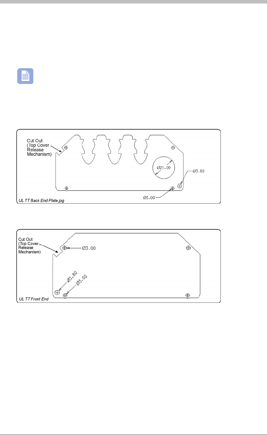
ImproX TT Twin Antenna Terminal
Figure 27 – EMF Flyback and Arc Suppression
Mounting the ImproX TT
Select the mounting position of the ImproX TT Terminal, considering accessibility, routing of
wires and visibility of the LEDs.
The ImproX TT can be mounted onto virtually any surface including metal.
Cable Exit Holes
The Terminals design offers a choice of three rubber cable glands and one bushing plug located
in the Terminals Back End Plate (see Figure 28).
Figure 28 – Back End Plate
Figure 29 – Front End Plate
Top Cover Release Mechanism
1. Remove the top two Thread Cutter Screws (2.2 x 5 mm) from each of the End Plates.
2. Insert a flat head screwdriver (maximum 7 mm) into the cut out in either of the two End
Plates. Swivel the screwdriver until the Top Cover makes a click sound.
3. Insert the screwdriver in the gap (on the side of the ImproX TT) between the Top Cover and
the Base. Swivel the screwdriver again, to release the Top Cover from the Base.
4. Remove the remaining Thread Cutter Screws (2.2 x 5 mm) from each of the End Plates.
100 Tuesday, 11 July 2006

IXP300/IXP400 Installation Guide
Mounting on a Concrete or Brick Wall
1. Use the Base as a template and mark off the required holes.
2. Drill the four mounting holes using a 7 mm diameter masonry drill bit, to a depth equal to the
length of the supplied wall plugs.
3. Insert the wall plugs into the mounting holes.
4. Secure the Base to the surface using the four mounting screws provided.
Mounting on a Hard WoodSurface
1. Use the Base as a template and mark off the required holes.
2. Drill the four mounting holes using a 2.5 mm diameter drill bit to the depth equal to three-
quarters of the length of the mounting screws.
3. Secure the Base to the surface using the four mounting screws provided.
Mounting on Metal
Use four suitable securing devices such as screws, nuts and bolts, or rivets to mount the
ImproX TT on a metal surface.
1. Use the Base as a template and mark off the required holes.
2. Drill the four mounting holes using a suitable diameter drill bit.
3. Secure the Base to the surface using the chosen method.
Tuesday, 11 July 2006 101
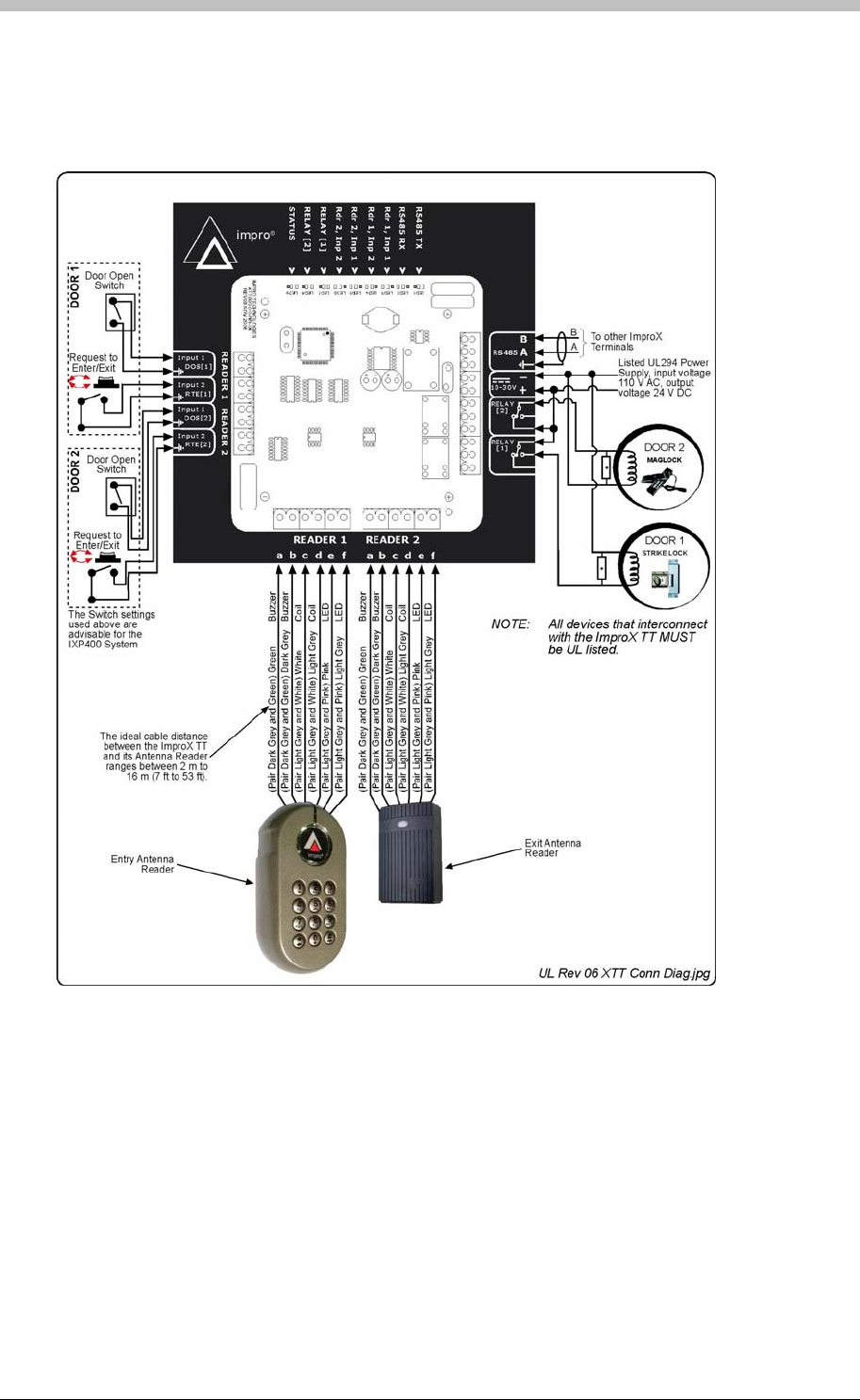
ImproX TT Twin Antenna Terminal
Electrical Connections
Connecting the ImproX TT
Figure 30 shows a detailed connection diagram for the ImproX TT.
Figure 30: Typical ImproX TT Electrical Connections
Power-on Self-test
The Power-on Self-test tests the RAM and Flash Checksums and the Read/Write Circuitry. The
results of the Self-test are available as diagnostic information from the Controller or PC.
If any parameter in the Self-test fails, the Antenna Reader** emits a continuous beep for 2
seconds.
When the Terminal passes the Self-test, the Antenna Reader** emits two short beeps, each 200
ms in duration, separated by a 200 ms inter-beep pause.
102 Tuesday, 11 July 2006

IXP300/IXP400 Installation Guide
The **ImproX MMA Antenna Reader DOES NOT include a Buzzer.
ImproX TT Address Information
Each ImproX TT Terminal is, in fact, two Terminals in one. The first “Terminal” Fixed Address is
associated with Reader [1], and the second with Reader [2].
Each ImproX TT is allocated two unique Fixed Addresses at the factory. These addresses are
stored in the Terminals memory. When the Terminal is installed in an IXP300 or IXP400
System, the System allocates two separate Logical Addresses to the Terminal for
communication purposes.
Address Allocation
IXP Software Suites allocate Logical Addresses to the Terminal, either on initial software start-
up, or on request, depending on the system configuration.
Fixed Address Label
Once the ImproX TT is installed, sketch a rough site plan. Attach the loose (additional Fixed
Address Label packaged with the Terminal) Fixed Address Label in the position of the Terminal
on the sketched site plan. When the system installation is complete and all the units are
represented on the site plan by their Fixed Address Labels, file the site plan for future reference.
Operation and Functionality
The ImproX TT acts as an interface for card readers (ImproX Antenna readers). Because it is a
Terminal, it must be connected to a system Controller via comms bus port 1, to function
correctly.
Before a Tag can be read, it must first be presented within the specified read range of the
Antenna reader. When within range, the ImproX TT decodes the Tag code. Because Terminals
do not initiate communication with Controllers, the ImproX TT buffers the Tag code until it is
polled by the Controller. Then, it passes the buffered Tag code, as a transaction, to the
Controller. The Controller determines whether to allow or deny access based on information in
its database.
Next, the Controller instructs the ImproX TT to execute Actions associated with the Allowed or
Denied Event. A relay Action is commonly used to drive the access control door hardware (door
strike or magnetic lock), to enable physical access through a door. One of the ImproX TT’s two
onboard relays is normally connected to the door hardware. The ImproX TT has 4 digital inputs
which can be configured for various functions; examples include door status monitoring and
interfacing a request-to-exit (RTE) push-button.
Tuesday, 11 July 2006 103
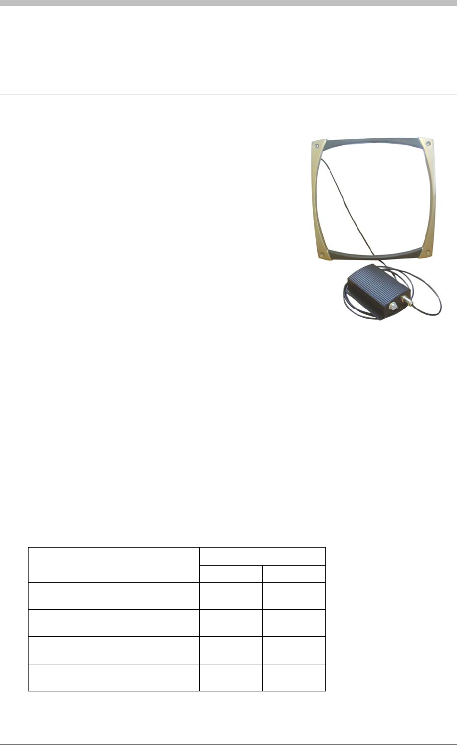
ImproX ER Extended Range Terminal and Fibreglass Antenna
ImproX ER Extended Range Terminal and
Fibreglass Antenna
The ImproX (ER) Extended Range Terminal and 350 mm x
350 mm Fibreglass Antenna are ideally suited for use as a
“hands-free” access control system or for OEM custom
requirements (not UL evaluated) where extended read
range is necessary (product and asset management) (not
UL evaluated). The Terminal is designed to be used as an
access point interfacing with the IXP300 and IXP400
Access Control Systems.
The Terminal includes four LED Indicators providing a
useful user interface for the installer. These LED Indicators
include a bi-colour Status LED, an Auto-tuning Status LED
and two LEDs indicating data transfer on the RS485
Terminal Bus. The ImproX ER includes a single tone
Buzzer. You can adjust the Buzzer volume to any one of these four levels (off, low, medium and
high).
The Terminal is enclosed in an Aluminium Cabinet, however, as the Cabinet is NOT waterproof
the Terminal is intended for indoor use only. The Antenna is housed in a fibreglass housing and
is fully potted. The Antenna is therefore rated for both indoor and outdoor (not UL evaluated)
installation.
Due to its extended read range, this Terminal is capable of being used in situations where the
use of a normal short-range Passive Proximity Reader would not be effective. A simple, auto-
tuning procedure allows the Terminal to be placed in various locations where different amounts
of metal are found.
Tag Read Ranges
Typical Range (Minimum)
Tag Type (mm) (in)
ISO Credit Card (Slim), 64-bit,
Manchester encoded protocol, ASK 500 19.68
Credit Card (Semi Slim), 64-bit,
Manchester encoded protocol, ASK 500 19.68
ImproX Credit Card, 64-bit, Manchester
encoded protocol, ASK 400 15.74
Key Ring Tag, 64-bit, Manchester
encoded protocol, ASK 250 9.84
Table 12 – Typical Read Ranges
104 Tuesday, 11 July 2006

IXP300/IXP400 Installation Guide
Tag ranges stated are for one Antenna only.
Approvals
• CE
• UL294
• FCC Approval Pending
Specifications
Physical – ImproX (ER) Extended Range Terminal
Dimensions
Length 150 mm (5.90 in).
Width 116 mm (4.56 in).
Height 51 mm (2.00 in).
Approximate Weight 430 g (0.94 lb).
Housing Material Aluminium.
Colour Black.
Physical – 350 mm x 350 mm Fibreglass Antenna
Dimensions
Length 350 mm (13.78 in).
Width 350 mm (13.78 in).
Height 16 mm (0.63 in).
Approximate Weight 600 g (1.32 lb).
Housing Material Fibreglass.
Colour Black and Satin Nickel.
Environmental – ImproX (ER) Extended Range Terminal
Temperature
Operating 0oC to +49oC (-13oF to +140oF)
Storage -40oC to +80oC (-40oF to +176oF)
Humidity Range 85% ± 5oC relative humidity at +30oC ± 2oC (86oF ± 3 oF)
Approvals (Test
Information)
UL Rating UL 294.
EMC EN 55022: Limits and Methods of Measurement of Radio
Disturbance Characteristics of Information Technology Equipment.
EN 55024: Immunity Characteristics, Limits and Methods of
Measurement.
Electrostatic Discharge IEC 61000-4-2: Electromagnetic Compatibility (EMC). Part 4:
Testing and Measurement Techniques. Section 2: Electrostatic
Discharge Immunity Test. Basic EMC Publication.
Radiated Susceptibility IEC 61000-4-3: Electromagnetic Compatibility (EMC). Part 4:
Tti dM
tT hi S ti 3 Rditd
Tuesday, 11 July 2006 105

ImproX ER Extended Range Terminal and Fibreglass Antenna
Testing and Measurement Techniques. Section 3: Radiated,
Radio-Frequency, Electromagnetic Field Immunity Test.
Electrical Fast Transients IEC 61000-4-4: Electromagnetic Compatibility (EMC). Part 4:
Testing and Measurement Techniques. Section 4: Electrical Fast
Transients / Bursts. Basic EMC Publication.
Surge Immunity IEC 61000-4-5: Surge Immunity.
Conducted Susceptibility IEC 61000-4-6: Conducted Susceptibility.
Power Frequency Magnetic
Field IEC 61000-4-8: Electromagnetic Compatibility (EMC). Part 4:
Testing and Measurement Techniques. Section 8: Frequency
Magnetic Field Immunity Test.
Dust and Splash
Resistance (Not evaluated
by UL)
Designed to work in an indoor (dry) environment similar to IP30.
The ImproX ER is, therefore, NOT sealed against water.
Drop Endurance 1 m (3.28 ft) drop (in packaging).
Environmental – 350 mm x 350 mm Fibreglass Antenna
Temperature
Operating 0oC to +49oC (-13oF to +140oF)
Storage -40oC to +80oC (-40oF to +176oF)
Humidity Range 85% ± 5oC relative humidity at +30oC ± 2oC (86oF ± 3 oF)
Approvals (Test
Information)
UL Rating UL 294.
EMC EN 55022: Limits and Methods of Measurement of Radio
Disturbance Characteristics of Information Technology Equipment.
EN 55024: Immunity Characteristics, Limits and Methods of
Measurement.
Electrostatic Discharge IEC 61000-4-2: Electromagnetic Compatibility (EMC). Part 4:
Testing and Measurement Techniques. Section 2: Electrostatic
Discharge Immunity Test. Basic EMC Publication.
Radiated Susceptibility IEC 61000-4-3: Electromagnetic Compatibility (EMC). Part 4:
Testing and Measurement Techniques. Section 3: Radiated,
Radio-Frequency, Electromagnetic Field Immunity Test.
Electrical Fast Transients IEC 61000-4-4: Electromagnetic Compatibility (EMC). Part 4:
Testing and Measurement Techniques. Section 4: Electrical Fast
Transients / Bursts. Basic EMC Publication.
Surge Immunity IEC 61000-4-5: Surge Immunity.
Conducted Susceptibility IEC 61000-4-6: Conducted Susceptibility.
Power Frequency Magnetic
Field IEC 61000-4-8: Electromagnetic Compatibility (EMC). Part 4:
Testing and Measurement Techniques. Section 8: Frequency
Magnetic Field Immunity Test.
Dust and Splash
Resistance (Not evaluated
by UL)
Designed to work in an indoor or outdoor environment similar to
IP66. The Antenna is, therefore, sealed against water.
106 Tuesday, 11 July 2006

IXP300/IXP400 Installation Guide
Electrical – ImproX (ER) Extended Range Terminal
Power Requirements
Input Voltage 12 V DC.
Power Requirements Current (mA) Power (W)
Input Voltage 12 V DC
One Antenna Connected, all
Indicators and one Relay
ON
520 6.24
Input Voltage 12 V DC
Two Antennas Connected,
all Indicators and one Relay
ON
1 100 13.20
Permissible Input Supply
Ripple Voltage (Max)
0.5 V PP at 50 Hz.
Power Input Protection Reverse polarity, over-voltage and over-current protection are
provided on the Terminal.
Terminal Bus Port
Electrical Interface RS485, ASCII with 16-bit CRC checking.
Baud Rates 1 200, 2 400, 4 800, 9 600, 19 200, 28 800, 38 400 (default), 57
600 and 76 800 selectable via the Communications Protocol.
Data Format 8 data bits, no parity, 1 stop bit.
Communications Protocol ImproX Secure Communications Protocol.
Relays
Relay Output 1 Relay, SPDT, with NO, COM and NC contacts.
Contact Rating 4 A at 24 V AC.
4 A at 24 V DC.
Digital Inputs
Input Type 2 Dry-contact inputs.
Protection +50 V to -50 V continuous,
+80 V to -80 V surge.
Processor
Type 16-bit Micro-controller operating at 16 MHz.
Ram Memory 2 K Byte.
Flash Memory 64 K Byte.
Electrical – 350 mm x 350 mm Fibreglass Antenna
Frequency 134.2 kHz.
Operator or Installer Interfaces
LED Indicators
Status LED Red or Green LED (externally visible).
Incoming RS485 Data Green LED (flashing) (internally visible).
Outgoing RS485 Data Red LED (flashing) (internally visible).
Auto-tuning Status Green LED (internally visible).
Tuesday, 11 July 2006 107

ImproX ER Extended Range Terminal and Fibreglass Antenna
Installation Information
Accessories
Find the following when unpacking the Terminal:
• An ImproX (ER) Extended Range Terminal housed in a Black, Aluminium extruded Cabinet.
The ImproX ER consists of a Top Cover, a Base and two End Plates. Each End Plate is
attached with three Thread Cutter Screws (M3 x 8 mm).
• Four Brass Wood Screws (3.5 mm x 25 mm).
• Four Wall Plugs (7 mm).
• An extra Fixed Address Label.
Find the following when unpacking the Fibreglass Antenna:
• An ImproX ER 350 mm x 350 mm Fibreglass Antenna. The Antenna includes 3 m (9.84 ft)
of Black RG58, Multi-strand 50 ohm Coaxial Cable.
• Four Mirror Screws (25 mm).
• Four Wall Plugs (7 mm).
General
Wire and install the Terminal in accordance with the National Electric Code (ANS/NFPA
70), local codes, and the authorities having jurisdiction.
Remember the following when installing the Terminal and the Antenna:
• Important Installation Considerations
− DO NOT mount the Antenna directly on to a metal surface.
− Always connect the Negative Power Input terminal to a good EARTH (Ground)
point in order to get maximum read range.
− DO NOT run power and RS485 communications in the same run of cable.
− DO NOT run the Antennas cables alongside any other communications or power cable,
including the power and RS485 cables to the Terminal.
− DO NOT position the Antenna within 3 m (9.84 ft) of data-carrying communications
cables or high-voltage power lines.
− Always secure the Antenna cable neatly.
− DO NOT position the Antenna where it can be bumped or disturbed, to prevent micro-
phonics.
− DO NOT position the Antenna of one ImproX ER within 10 m (32.82 ft) of the Antenna
of a second ImproX ER.
− Each ImproX ER is supplied with 2 Protection Caps, these Protection Caps must only
be removed if an Antenna is connected. If no Antenna is connected the Proection Cap
must remain in position, to protect the ImproX ER from dust and electrostatic discharge.
• Communications Distance – The RS485 communications distance between the first
ImproX ER and the associated Controller, MUST NOT exceed 1 km (3 270 ft). Achieve this
by using West Penn D291 22 gauge, stranded, single pair cable with the overall shield
EARTHED at one end.
108 Tuesday, 11 July 2006

IXP300/IXP400 Installation Guide
The individual conductor cross sectional area of the each cable conductor must not be less
than 0.2 mm² (0.0003 in²).
• Jumper Link for Termination Resistor – Long transmission lines or multiple “star”
connections, may cause communication problems. Placing a Jumper Link across the Line
Termination Link [TR1] in the LAST UNIT AT THE END OF THE CABLE RUN should solve
the problem. The termination resistor has a value of 150 ohms.
• Distance between the Antenna and the Terminal – You may extend the Antennas
supplied cable beyond the 3 m (9.84 ft) supplied length to a maximum of 5 m (16.40 ft).
However, please keep in mind that this will decrease the Tag reading range.
• Distance between Antennas Connected to the SAME Terminal – Where more than one
Antenna is connected to the SAME ImproX ER, install the Antennas no closer than 800 mm
(2.63 ft) apart.
• Distance between Antennas Connected to DIFFERENT Terminals – Where more than
one ImproX ER is installed, install the adjacent Antennas no closer than 10 m (32.82 ft)
apart.
• Distance between Terminals – You may install other ImproX Terminals, with lower
sensitivity Antennas, within 5 m (16.41 ft) of the ImproX ER.
• EARTH Connection – Connect the Terminal to a good EARTH point. Using the RS485
Port, connect the EARTH Lead to the ‘SHD’ terminal. Use a cable with a conductor cross
sectional area of at least 1.0 mm² (0.002 in²) and Keep the EARTH line as short as possible.
Use a good quality copper EARTH spike if possible. Mains EARTH can be used, but
electrical noise may exist.
This ETH point must only be connected at one end of the cable.
• Arc Suppression – Snubber devices are recommended for EMF Flyback and Arc
Suppression when driving an inductive load with the Relay, see Figure 31.
Tuesday, 11 July 2006 109
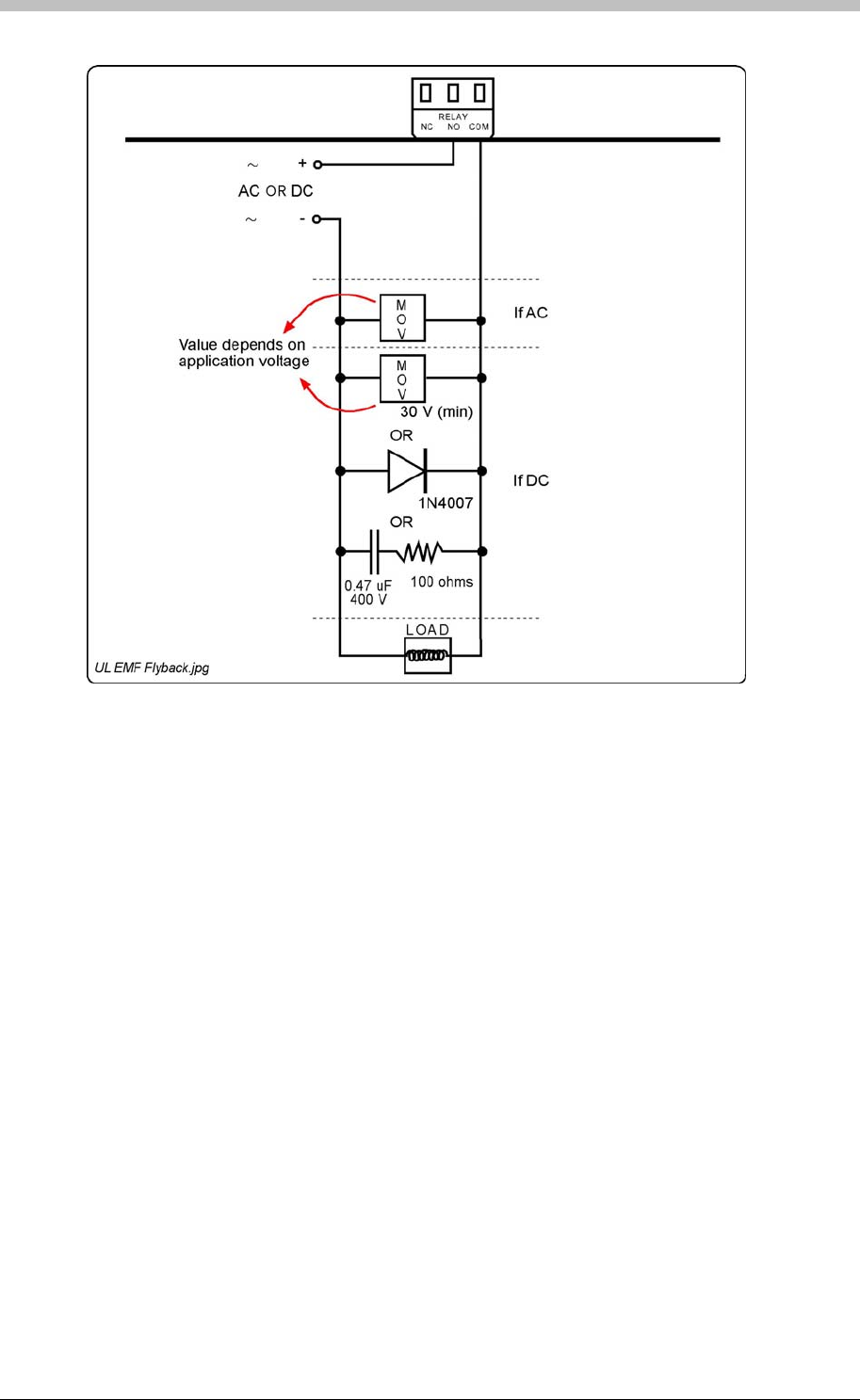
ImproX ER Extended Range Terminal and Fibreglass Antenna
Figure 31:
EMF Flyback and Arc Suppression
Mounting the Terminal and the Antenna
Please keep the following information in mind, when selecting the mounting position of the
ImproX ER and the Antenna.
Secure the Terminal and the Antenna to the mounting surface, using four suitable screws and
wall plugs, nuts and bolts or rivets.
Antenna Detection Patterns
The various Antenna configurations that can be used with the Terminal (single Antenna, dual
Antennas in-phase, or dual Antennas anti-phase) have Tag detection patterns that determine
the range of detection for Tags presented in various orientations to the Antennas.
Single Antenna Installation
In an installation where only a single Antenna is used, the Antenna must be connected to the
Channel 1 Output. The orientation of the Tag is critical, so position the Antenna so that it most
suits the orientation of the Tag (Figure 32).
A typical installation would be access through a single door.
110 Tuesday, 11 July 2006
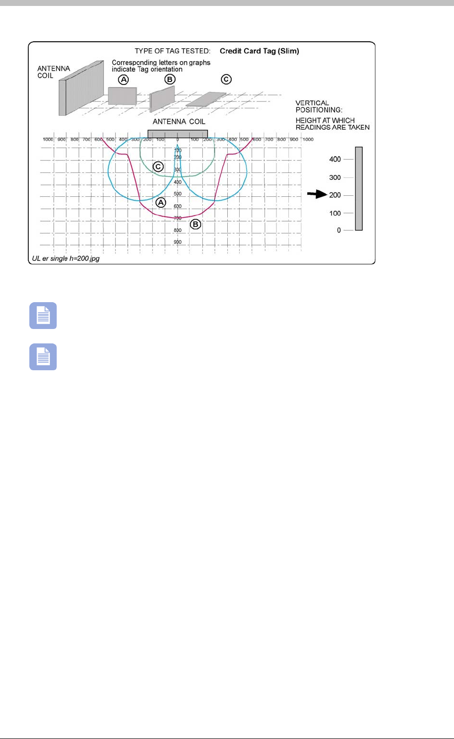
IXP300/IXP400 Installation Guide
Figure 32: Single Antenna Field Diagram
All drawing dimensions are in millimeters.
Figure 32 shows the field for ONE side of the Antenna only. Be aware that the field is
duplicated on the rear side of the Antenna. This means that you may present a Tag on
either side of the Antenna.
Dual Antenna Installation
In an installation where dual Antennas are used, the Antennas are connected to the Channel 1
and Channel 2 outputs respectively. Phasing of the two Antennas is critical for the best
performance of the System. Set the phasing of the Antennas in such a way that most suits the
orientation of the Tag (Figure 33 and Figure 34).
A typical installation would be access through a corridor.
Tuesday, 11 July 2006 111
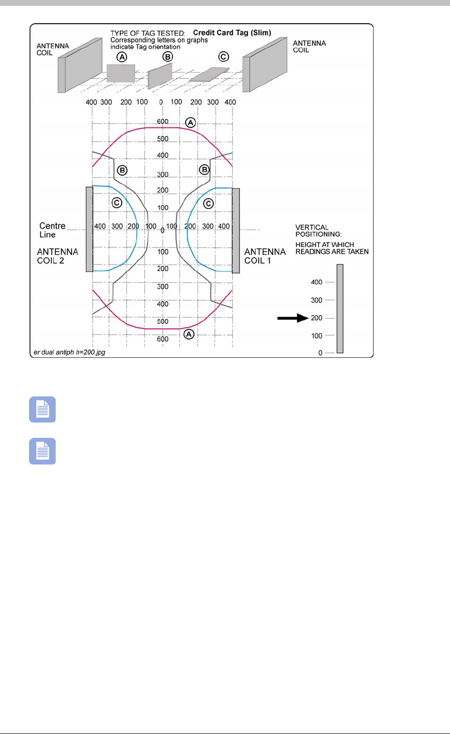
ImproX ER Extended Range Terminal and Fibreglass Antenna
Figure 33: Dual Anti-phase Antenna Field Diagram
All drawing dimensions are in millimeters.
With the Antennas facing each other, connect the Antenna Phasing Link (LK3) to
position 1. This configuration is best for Tag orientation A. (Figure 35 shows the
position of the Antenna Phasing Link).
112 Tuesday, 11 July 2006
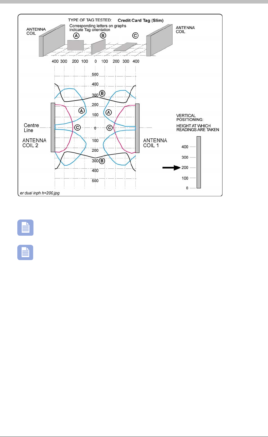
IXP300/IXP400 Installation Guide
Figure 34: Dual In-phase Antenna Field Diagram
All drawing dimensions are in millimeters.
For this configuration with the Antennas facing each other, connect the Antenna
Phasing Link (LK3) to position 2. This configuration is best for Tag orientation B.
(Figure 35 shows the position of the Antenna Phasing Link).
Auto-tuning
The ImproX ER is capable of automatically tuning and re-tuning itself if the environment
surrounding the Antenna changes. This occurs when a metallic object is placed in the vicinity of
the Antenna.
If the metallic object, placed within the Antenna Field, is large or too near the Antenna, you
could reach the auto-tuning limit.
Auto-tuning Indicator
We provide a visual indicator on the ImproX ER as an aid in auto-tuning and installing the
Terminal. The visual indicator is a low intensity LED indicator located in the ImproX ER Cabinet.
There are three tuning states that the Terminal can be in: ‘Tuned’, ‘Busy Tuning’ and ‘Not Able to
Tune’. Each of these states has a visual indication and is described in Table 13.
Tuesday, 11 July 2006 113

ImproX ER Extended Range Terminal and Fibreglass Antenna
Status LED State
Tuned ON
Busy Tuning Flashing
Not Able to Tune OFF
Table 13: Auto-tuning Indicators
If the Terminal indicates ‘Not Able to Tune’, check whether the Antenna is obstructed by,
or mounted on, a metallic surface. If so, re-position the Antenna or remove the metallic
interference.
Disabling the Auto-tuning Facility
Although the auto-tuning facility is required under normal conditions, disabling the facility is
sometimes necessary. This condition is typical, where a Tag is mounted on a metallic object
(including vehicles or conveyors) that is constantly moving through the Antenna Field. This
prevents the ImproX ER from constantly trying to compensate for the moving metallic object.
1. Install and set up the Terminal and Antenna.
2. Position the metallic object into position and allow the ImproX ER auto-tuning to
compensate for the metallic object.
3. Place the jumper over the Tuning Disable Link (LK1). Refer to Figure 35 for the location of
this Link. The ImproX ER will now refrain from auto-tuning.
Once the metallic object is removed from the Antenna Field the Visual Tuning Indicator
may switch OFF. This is natural as when the metallic object is re-introduced into the
Antenna Field the Antenna will once again be tuned, the Visual Tuning Indicator will switch ON
and the Tag will be read optimally.
If the power is removed and then re-introduced to the Terminal and the Tuning Disable
Link is in place the Terminal will return to the tuning value stored when the Link was last
placed. To resume the auto-tuning facility, remove the Tuning Disable Link.
Failure to Tune
If the Terminal indicates the state ‘Not Able to Tune’ then check the following:
• Is either of the Antennas obstructed by, or mounted on a metallic object? If so re-position
the Antennas or remove the metallic object.
• Is either of the Antenna connectors not properly connected to the ImproX ER?
• Is either of the Antennas damaged?
114 Tuesday, 11 July 2006
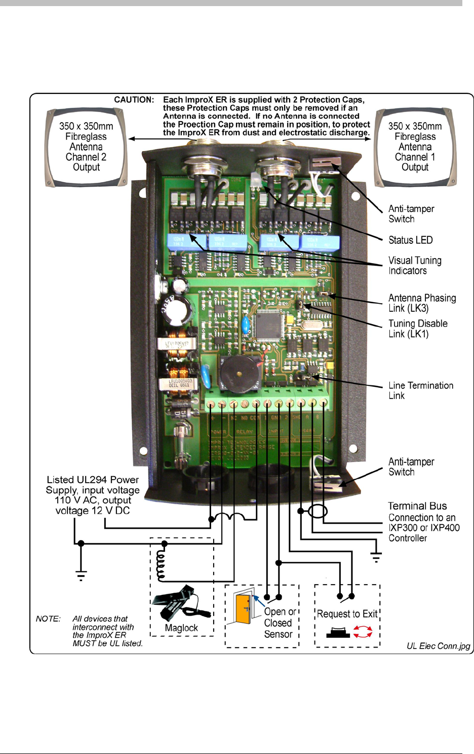

ImproX ER Extended Range Terminal and Fibreglass Antenna
Installation Test Mode
As an aid during installation, the ImproX ER contains a test facility to indicate the Tag reading
status.
To access the Test Mode do the following:
1. Remove the RS485 communications from the ImproX ER. Wait approximately 10 seconds
until the ImproX ER’s Status LED indicates a Red intermittent flash.
2. Present Tags to the Antenna. When a Tag is read the Status LED will go solid Green and
the Buzzer will emit an audible tone.
To return to normal operation power the ImproX ER down, reconnect the RS485 Bus and power
up.
This Test Mode only applies to Firmware version 5.14 and upwards.
Power-on Self-test
The Power-on Self-test tests the RAM, ROM checksums, and Tag read circuitry. The results of
the Self-test are made available as diagnostic information, via the protocol, to the associated
Controller or PC.
If any parameter in the Self-test fails, the Terminal emits a continuous beep for 2 seconds.
When the Terminal passes the Self-test, the Terminal emits two short beeps of 200 ms duration,
separated by a 200 ms inter-beep pause.
Fixed Address Label
Once the ImproX ER is installed, sketch a rough site plan. Attach the loose (additional Fixed
Address Label packaged with the Terminal) Fixed Address Label in the position of the Terminal
on the sketched site plan. When the system installation is complete and all the units are
represented on the site plan by their Fixed Address Labels, file the site plan for future reference.
Operation and Functionality
The ImproX ER is a Terminal and must be connected to a Controller via comms bus port 1, to
function correctly. To read Tags, the XER902 Antenna reader must be connected to the ImproX
ER.
Before a Tag can be read, it must first be presented within the specified read range of the
Antenna reader. When within range, the ImproX ER decodes the Tag code. Because Terminals
do not initiate communication with Controllers, the ImproX ER buffers the Tag code until it is
polled by the Controller. Then, it passes the buffered Tag code, as a transaction, to the
Controller. The Controller determines whether to allow or deny access based on information in
its database.
116 Tuesday, 11 July 2006

IXP300/IXP400 Installation Guide
Next, the Controller instructs the ImproX ER to execute Actions associated with the Allowed or
Denied Event. A relay Action is commonly used to drive the access control door hardware (door
strike or magnetic lock), to enable physical access through a door.
For details on configuring the ImproX ER via the ImproNet Access software, refer to the
Terminals section on page 231.
Tuesday, 11 July 2006 117
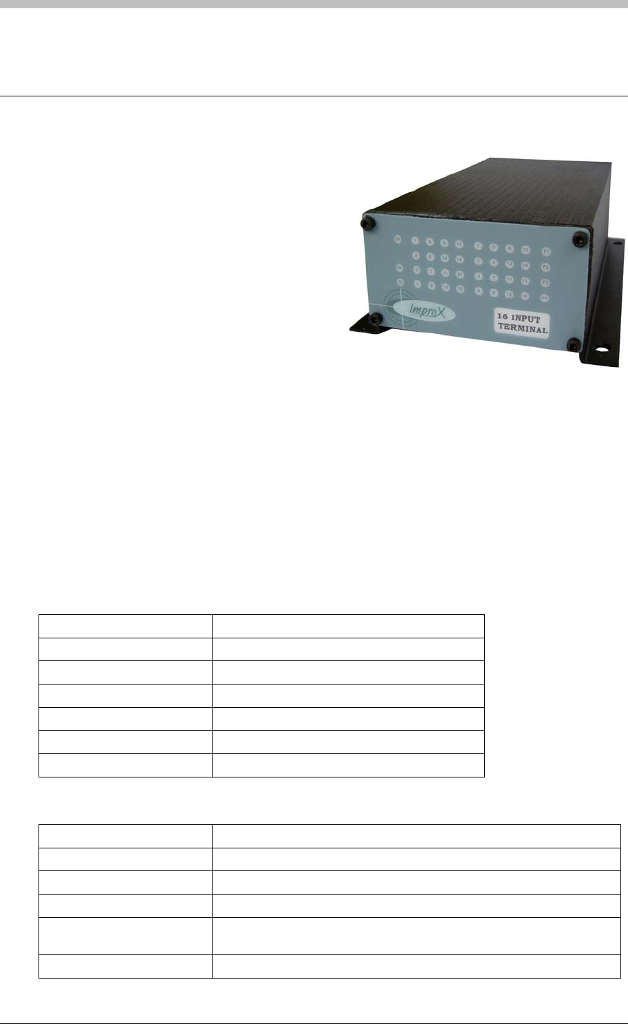
ImproX I16 16 Channel Input Terminal
ImproX I16 16 Channel Input Terminal
The ImproX I16 16 Channel Input Terminal is a
general-purpose module, designed to interface
with the IXP400 Access Control System via the
RS485 Bus Connection.
The ImproX I16 is an Input Terminal, providing
sixteen Digital Inputs with optional End of Line
Sensors for door open or closed sensing.
The Terminal is housed in a durable Aluminium,
Black anodized Cabinet, sealed with ABS
Plastic End Plates. The Terminal offers twenty
LED Status Indicators; these Status Indicators are visible through the Front End Plate.
Approvals
• CE
• UL294
• FCC Approval Pending
Specifications
Physical
Dimensions
Length 194 mm (7.63 in).
Width 119.60 mm (4.70 in).
Height 57.60 mm (2.26 in).
Approximate Weight 465 g (1.03 lb).
Cabinet Material Aluminium.
Colour Black anodized.
Environmental
Temperature
Operating 0oC to +49oC (-13oF to +140oF)
Storage -40oC to +80oC (-40oF to +176oF)
Humidity Range 85 % ±5 % Relative Humidity at 30oC ±2oC (86oF ±3oF)
Approvals (Test
Information)
UL Rating UL 294.
118 Tuesday, 11 July 2006

IXP300/IXP400 Installation Guide
EMC EN 55022: Limits and Methods of Measurement of Radio Disturbance
Characteristics of Information Technology Equipment.
EN 55024: Immunity Characteristics, Limits and Methods of
Measurement.
Electrostatic Discharge EN 61000-4-2: Electromagnetic Compatibility (EMC). Part 4: Testing
and Measurement Techniques. Section 2: Electrostatic Discharge
Immunity Test. Basic EMC Publication.
Radiated Susceptibility EN 61000-4-3: Electromagnetic Compatibility (EMC). Part 4: Testing
and Measurement Techniques. Section 3: Radiated, Radio-
Frequency, Electromagnetic Field Immunity Test.
Electrical Fast Transients EN 61000-4-4: Electromagnetic Compatibility (EMC). Part 4: Testing
and Measurement Techniques. Section 4: Electrical Fast Transients /
Bursts. Basic EMC Publication.
Surge Immunity EN 61000-4-5: Surge Immunity.
Conducted Susceptibility EN 61000-4-6: Conducted Susceptibility.
Dust and Splash
Resistance Mounted vertically, with the Cable Entry Glands at the lower side, the
Terminal is designed to work in an indoor environment similar to IP43.
Drop Endurance 2 m (6.56 ft) drop (in packaging).
Electrical
Power Requirements
Input Voltage 12 V DC and 24 V DC, polarity sensitive.
Power Requirements Current (mA) Power (W)
Input Voltage 12 V DC
Indicators all OFF
45 0.55
Input Voltage 12 V DC
Indicators all ON
80 0.96
Input Voltage 24 V DC
Indicators all OFF
20 0.47
Input Voltage 24 V DC
Indicators all ON
30 0.75
Permissible Input Supply
Ripple Voltage (Max)
1 V PP at 50 Hz.
Power Input Protection Reverse polarity and over-voltage protection are provided on the
Terminal.
Terminal Bus Port
Electrical Interface RS485, ASCII with 16-bit CRC checking.
Baud Rates 1 200, 2 400, 4 800, 9 600, 19 200, 28 800, 38 400 (default), 57 600
and 76 800 selectable via the Communications Protocol.
Data Format 8 data bits, no parity, 1 stop bit.
Communications Protocol ImproX Secure Communications Protocol.
Unit Status Slave.
Digital Inputs
Type 16 Dry-contact Digital Inputs.
Protection Range +80 V to -80 V single pulse,
+35 V to -30 V continuous.
Memory
Tuesday, 11 July 2006 119

ImproX I16 16 Channel Input Terminal
Flash ROM 128 KBytes.
RAM 2 KBytes.
Anti-tamper Switch Detects the opening of the Terminals Cabinet.
Factory Default Settings
Default Baud Rate Factory-set to 38 400.
Default Mode Receive (Slave Mode).
Operator or Installer Interfaces
Status Indicators
Input Status 16 Green LEDs (Software controllable,
indicates when Input is high or low), (externally
visible).
Power Polarity Indicator Red LED (internally visible).
Incoming RS485 Data Flashing Green LED (externally visible).
Outgoing RS485 Data Flashing Red LED (externally visible).
Unit Status Red LED (Software controllable) (externally
visible).
Interface Details
RS485 Terminal Bus Port
The RS485 Terminal Bus Port lets you connect the ImproX I16 to other ImproX Terminals and
the Controller in your ImproNet System. The interface is made by connecting the ‘A’ and ‘B’
lines on the ImproX I16 to the ‘A’ and ‘B’ lines on the other ImproX units. Incoming and outgoing
information on this Port is shown on the RS485 ‘TX’ and ‘RX’ LED Status Indicators on the
ImproX I16.
Dry Contact Digital Inputs
The ImproX I16 has sixteen Dry Contact Digital Inputs. These Digital Inputs let you interface
with a variety of devices such as reed switches, push-buttons and alarm panels (not UL
evaluated).
The Digital Inputs should be connected to a dry Normally Open or Normally Closed contact.
Digital Inputs are Software configurable in Normal Sensing Mode and in End of Line (EOL)
Sensing Mode.
120 Tuesday, 11 July 2006
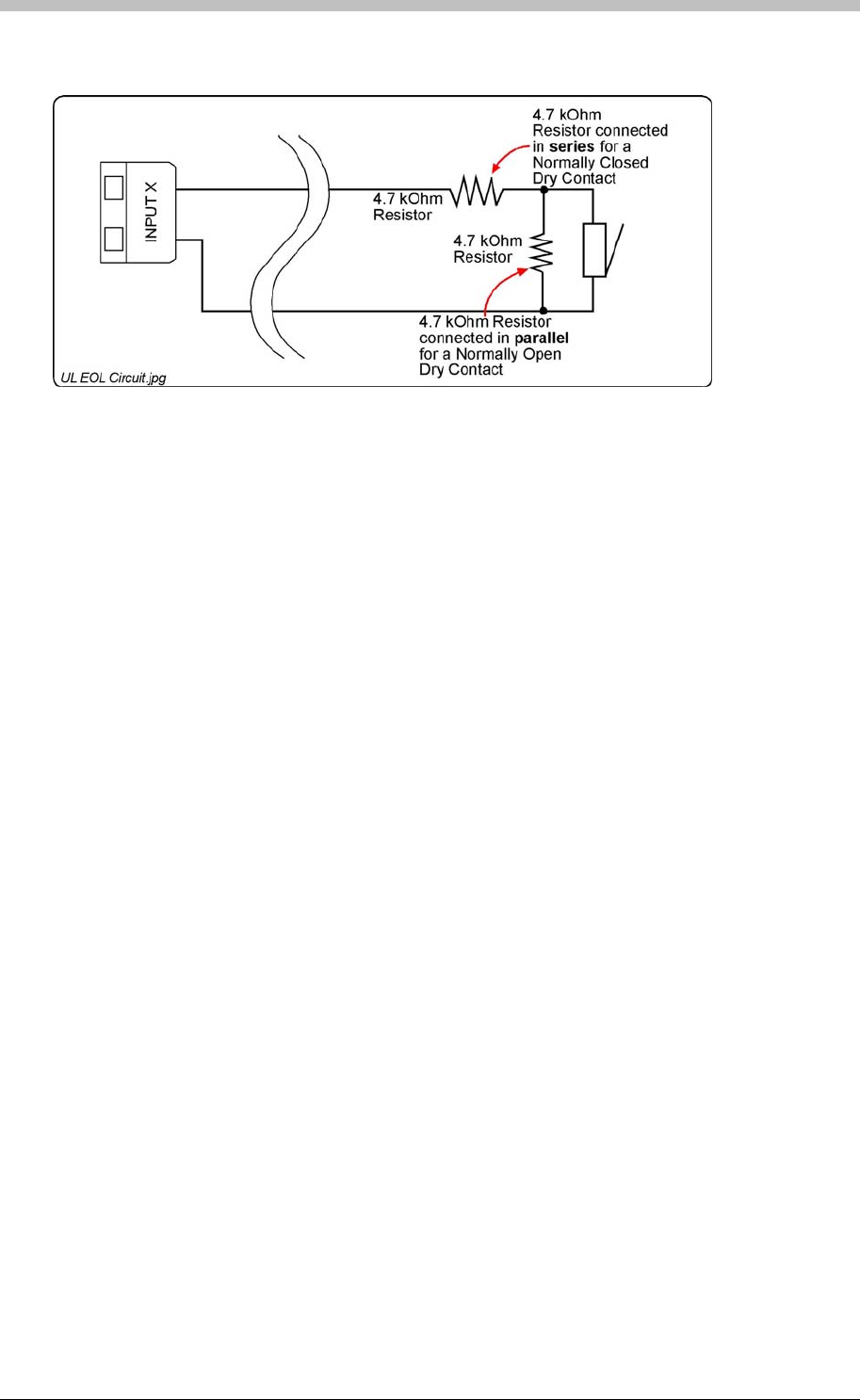
IXP300/IXP400 Installation Guide
End of Line (EOL) Sensing
Figure 36 – End of Line (EOL) Sensing Circuit
These Inputs can be individually configured to have End of Line (EOL) Sensing in the Software
via the Communications Protocol. With End of Line Sensing active, the Input detects when the
input line has gone open or closed circuit. Connect a 4.7 kOhm Resistor either in series with, or
in parallel to, the Dry Contact, mounted as close as possible to the Dry Contact for effective End
of Line Sensing.
Status Indicators
The Rx and Tx LEDs are continuously on when the Terminal is communicating correctly. If they
flash intermittently, there are communication problems. The Relay LEDs indicate when the
processor has sent a command for a particular relay to activate.
The recommended connection of the Resistor for Normally Closed (NC) and Normally Open
(NO) contacts is shown in Figure 36. For Normally Closed Dry Contacts, connect the 4.7 kOhm
Resistor in series with the contact; while for Normally Open contacts connect the Resistor in
parallel with the contact, see Figure 36.
Use in the IXP300 and IXP400 System
In the IXP300/400 System, the sixteen Digital Inputs are user configurable (can perform specific
tasks such as):
• Door Open Sensing.
• Request to Exit.
• Scanner Inhibit.
• Alarm Interface (not UL evaluated).
• Action Request.
The Terminals LEDs indicate Bus activity, as an aid in fault finding. Green LEDs indicate
incoming Bus activity and Red LEDs indicate outgoing Bus activity; the LEDs flash when data is
being received or transmitted on the associated Bus. See Figure 37 for the positions of the
various LEDs.
Tuesday, 11 July 2006 121
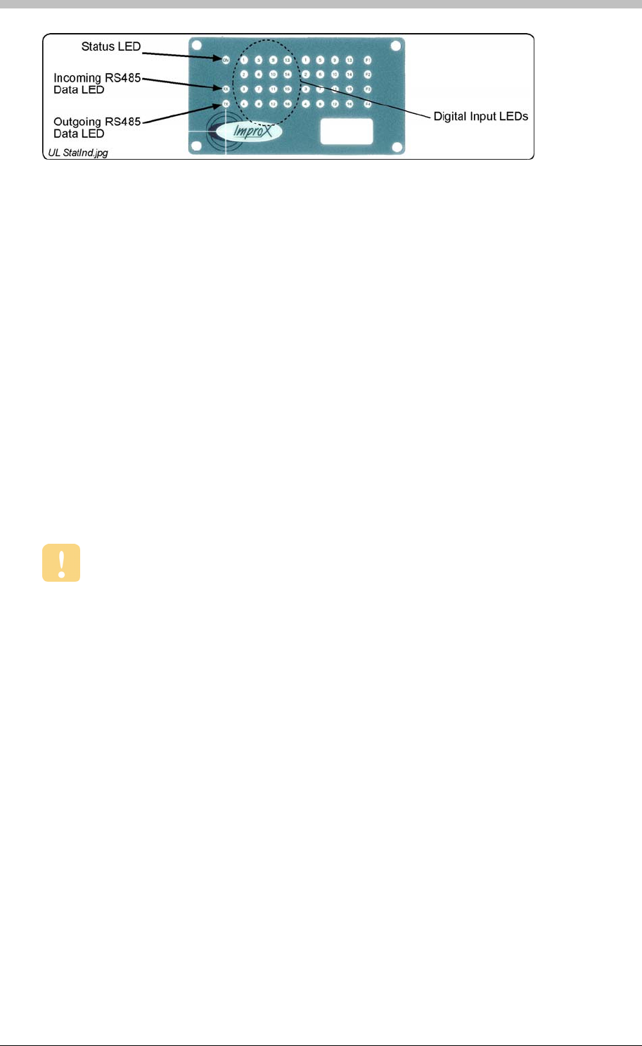
ImproX I16 16 Channel Input Terminal
Installation Information
• Four Brass Wood Screws (3.5 mm x 25 mm).
Wire and install the Terminal in accordance with the National Electric Code (ANSI/NFPA
70), local codes, and the authorities having jurisdiction.
• Jumper Links for Termination Resistors – Long transmission lines or multiple ‘star’
connections, may cause communication problems. Placing a Jumper Link across the
jumper [LNK1] in the LAST UNIT AT THE END OF THE CABLE RUN should solve the
problem. The termination resistor has a value of 150 ohms.
Figure 37 – Position of the Status Indicators on the Front End Plate
Accessories
Find the following when unpacking the ImproX I16 Terminal:
• An ImproX I16 16 Channel Input Terminal housed in a Black powder-coated Aluminium
extruded Cabinet. The Cabinet is sealed at each end with a Nylon End Plate, secured with
4 Allen Head Screws (M3 x 12 mm).
• Two Plastic Bushing Plugs (20.6 mm).
• A 2.5 mm Allen Key.
• Four Wall Plugs (7 mm).
• An extra Fixed Address Label.
General
• Communications Distance – The RS485 communications distance between the first
ImproX Controller and the LAST ImproX unit in a cable run, MUST NOT exceed 1 km (1 094
yd). Achieve this by using West Penn D291 22 gauge, stranded, single pair cable with the
overall shield EARTHED at one end.
• EARTH Connection – Connect the Terminal to a good EARTH point. Using the RS485
Port, connect the EARTH Lead to the ‘ETH’ Terminal. Mains EARTH can be used, but
electrical noise may exist.
Mounting the ImproX I16
Select the mounting position of the Terminal, considering accessibility, routing of wires and
visibility of the externally visible LEDs.
122 Tuesday, 11 July 2006

IXP300/IXP400 Installation Guide
Mounting on a Concrete or Brick Wall
2. Drill the four mounting holes using a 7 mm diameter masonry drill bit, to a depth equal to the
length of the supplied wall plugs.
1. Use the Base as a template and mark off the required holes.
3. Insert the wall plugs into the mounting holes.
4. Secure the Base to the surface using the four mounting screws provided.
Mounting on a Hard Wood Surface
1. Use the Base as a template and mark off the required holes.
2. Drill the four mounting holes using a 2.5 mm diameter drill bit to the depth equal to three-
quarters of the length of the mounting screws.
3. Secure the Base to the surface using the four mounting screws provided.
Mounting on Metal
Use four suitable securing devices such as screws, nuts and bolts, or rivets to mount the
ImproX I16 on a metal surface.
1. Use the Base as a template and mark off the required holes.
2. Drill the four mounting holes using a suitable diameter drill bit.
3. Secure the Base to the surface using the chosen method.
Tuesday, 11 July 2006 123
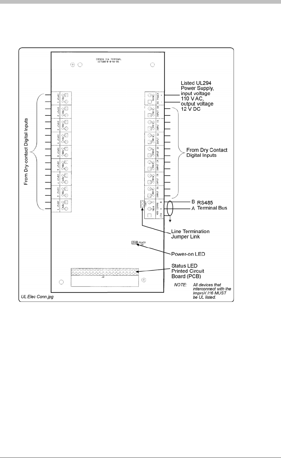
ImproX I16 16 Channel Input Terminal
Electrical Connections
Connecting the ImproX I16
Figure 38
Figure 38 – Typical ImproX I16 Electrical Connections
ImproX I16 Address Information
Each ImproX I16 is allocated a unique Fixed Address at the factory. This address is stored in
the Terminals memory. When the Terminal is installed in the ImproNet System, the System
allocates a separate Logical Address for communication purposes.
shows a detailed connection diagram for the ImproX I16.
The ImproNet Software Suite allocates a Logical Address to the Terminal, either on initial
software start-up, or on request, depending on the system configuration.
124 Tuesday, 11 July 2006

IXP300/IXP400 Installation Guide
Fixed Address Label
Once the ImproX I16 is installed, sketch a rough site plan. Attach the loose (additional Fixed
Address Label packaged with the Terminal) Fixed Address Label in the position of the Terminal
on the sketched site plan. When the system installation is complete and all the units are
represented on the site plan by their Fixed Address Labels, file the site plan for future reference.
Terminals
Operation and Functionality
The ImproX I16 is a Terminal and must be connected to a Controller via comms bus port 1, to
function correctly.
The I16 has 16 digital inputs that can be configured to report a contact open, or contact closed
signal. When the I16 detects one of these conditions, it reports the Event (transaction) to the
Controller during the next poll cycle. The Controller then determines the Action to be executed.
Examples of this process include a push-button connected to one of the inputs; when the
contact signal is received from the push-button, a relay connected to a door strike on another
Terminal is activated. Access is then granted.
For details on configuring the ImproX I16 via the ImproNet Access software, refer to the
section on page 231.
Tuesday, 11 July 2006 125
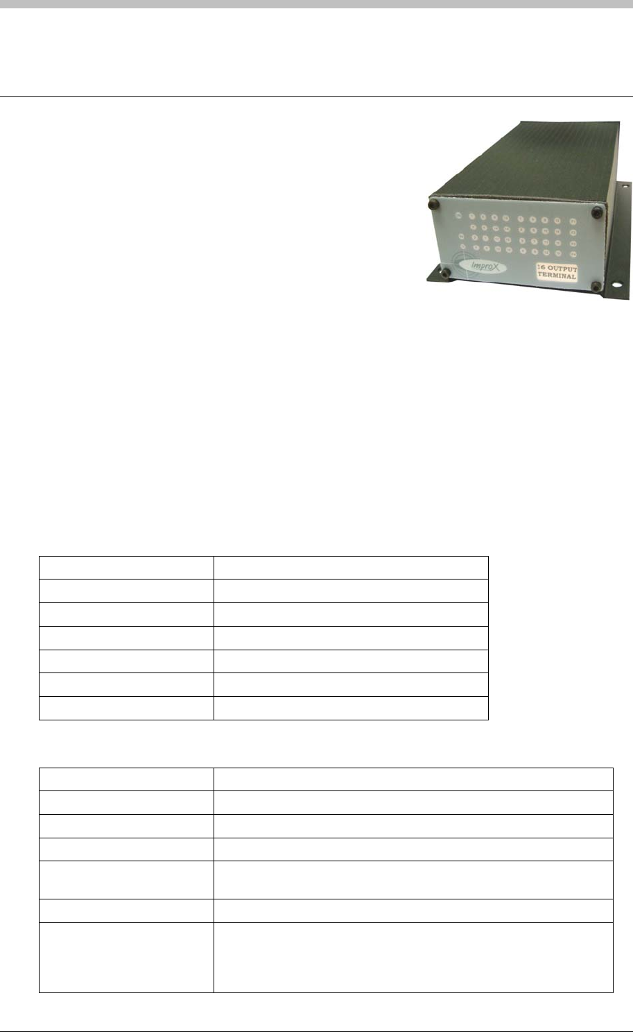
ImproX O16 16 Channel Output Terminal
ImproX O16 16 Channel Output Terminal
The ImproX O16 16 Channel Output Terminal is a general
purpose module, designed to interface with the IXP400
Access Control System via the RS485 Bus Connection.
The ImproX O16 is an Output Terminal, providing sixteen
Relays for controlling door strikes and other equipment.
The ImproX O16 is housed in a durable Aluminium, Black
anodized Cabinet, sealed with ABS Plastic End Plates. The Terminal offers twenty LED Status
Indicators; these Status Indicators are visible through the Front End Plate.
Approvals
• CE
• UL294
• FCC Approval Pending.
Specifications
Physical
Dimensions
Length 194 mm (7.63 in).
Width 119.60 mm (4.70 in).
Height 57.60 mm (2.26 in).
Approximate Weight 555 g (1.22 lb).
Cabinet Material Aluminium.
Colour Black anodized.
Environmental
Temperature
Operating 0oC to +49oC (-13oF to +140oF)
Storage -40oC to +80oC (-40oF to +176oF)
Humidity Range 85% ± 5oC relative humidity at +30oC ± 2oC (86oF ± 3 oF)
Approvals (Test
Information)
UL Rating UL 294.
EMC EN 55022: Limits and Methods of Measurement of Radio
Disturbance Characteristics of Information Technology Equipment.
EN 55024: Immunity Characteristics, Limits and Methods of
Measurement.
126 Tuesday, 11 July 2006

IXP300/IXP400 Installation Guide
Electrostatic Discharge EN 61000-4-2: Electromagnetic Compatibility (EMC). Part 4:
Testing and Measurement Techniques. Section 2: Electrostatic
Discharge Immunity Test. Basic EMC Publication.
Radiated Susceptibility EN 61000-4-3: Electromagnetic Compatibility (EMC). Part 4:
Testing and Measurement Techniques. Section 3: Radiated, Radio-
Frequency, Electromagnetic Field Immunity Test.
Electrical Fast Transients EN 61000-4-4: Electromagnetic Compatibility (EMC). Part 4:
Testing and Measurement Techniques. Section 4: Electrical Fast
Transients / Bursts. Basic EMC Publication.
Surge Immunity EN 61000-4-5: Surge Immunity.
Conducted Susceptibility EN 61000-4-6: Conducted Susceptibility.
Dust and Splash Resistance
Mounted vertically, with the Cable Entry Glands at the lower side, the
Terminal is designed to work in an indoor environment similar to
IP43.
Drop Endurance 2 m (6.56 ft) drop (in packaging).
Electrical
Power Requirements
Input Voltage 12 V DC and 24 V DC, polarity sensitive.
Power Requirements Current (mA) Power (W)
Input Voltage 12 V DC
Relays and Indicators all
OFF
35 0.42
Input Voltage 12 V DC
Relays and Indicators all ON
400 4.8
Input Voltage 24 V DC
Relays and Indicators all
OFF
0.45 20
Input Voltage 24 V DC
Relays and Indicators all ON
160 3.9
Permissible Input Supply
Ripple Voltage (Max)
1 V PP at 50 Hz.
Power Input Protection Reverse polarity and over-voltage protection are provided on the
Terminal.
Terminal Bus Port
Electrical Interface RS485, ASCII with 16-bit CRC checking.
Baud Rates 1 200, 2 400, 4 800, 9 600, 19 200, 28 800, 38 400 (default), 57 600
and 76 800 selectable via the Communications Protocol.
Data Format 8 data bits, no parity, 1 stop bit.
Communications Protocol ImproX Secure Communications Protocol.
Unit Status Slave.
Relays
Relay Output 16 Relays, each with NO, COM and NC contacts.
Contact Rating 1 A at 30 V DC.
1 A at 24 V AC.
Memory
Flash ROM 128 KBytes.
Tuesday, 11 July 2006 127

ImproX O16 16 Channel Output Terminal
RAM 2 KBytes.
Anti-tamper Switch Detects the opening of the Terminals Cabinet.
Factory Default Settings
Default Baud Rate Factory-set to 38 400.
Default Mode Receive (Slave Mode).
Relays Off.
Status Indicators
Operator or Installer Interfaces
Relay Status 16 Red LEDs (On when Relay operates),
(externally visible).
Power Polarity Indicator Red LED (internally visible).
Incoming RS485 Data Flashing Green LED (externally visible).
Outgoing RS485 Data Flashing Red LED (externally visible).
Unit Status Red LED (Software controllable) (externally
visible).
Interface Details
RS485 Terminal Bus Port
The RS485 Terminal Bus Port lets you connect the ImproX O16 to other ImproX Terminals and
the Controller in your ImproNet System. The interface is made by connecting the ‘A’ and ‘B’
lines on the ImproX O16 to the ‘A’ and ‘B’ lines on the other ImproX units. Incoming and
outgoing information on this Port is shown on the RS485 ‘TX’ and ‘RX’ LED Status Indicators on
the ImproX O16.
Relays
The ImproX O16 has sixteen independent single-pole, double-throw (SPDT) Relay Outputs.
These Relay Outputs let you interface to door strikes, magnetic locks and other third party
devices (for example alarm panels or lighting) (not UL evaluated).
Relay functions are user configurable in the IXP300 and IXP400 System.
Status Indicators
The Terminals LEDs indicate Bus activity, as an aid in fault finding. Green LEDs indicate
incoming Bus activity and Red LEDs indicate outgoing Bus activity; the LEDs flash when data is
being received or transmitted on the associated Bus. See Figure 39 for the positions of the
various LEDs.
128 Tuesday, 11 July 2006
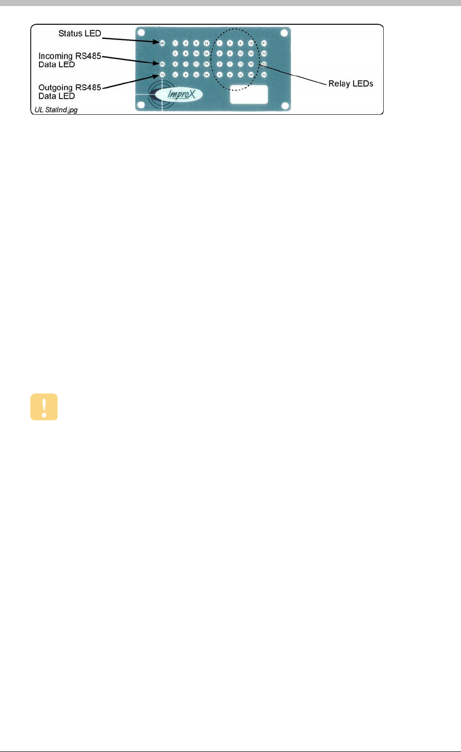
IXP300/IXP400 Installation Guide
Figure 39 – Position of the Status Indicators on the Front End Plate
• Two Plastic Bushing Plugs (20.6 mm).
• An extra Fixed Address Label.
Wire and install the Terminal in accordance with the National Electric Code (ANSI/NFPA
70), local codes, and the authorities having jurisdiction.
Installation Information
Accessories
Find the following when unpacking the ImproX O16 Terminal:
• An ImproX O16 16 Channel Output Terminal housed in a Black powder-coated Aluminium
extruded Cabinet. The Cabinet is sealed at each end with a Nylon End Plate, secured with
4 Allen Head Screws (M3 x 12 mm).
• A 2.5 mm Allen Key.
• Four Brass Wood Screws (3.5 mm x 25 mm).
• Four Wall Plugs (7 mm).
General
• Communications Distance – The RS485 communications distance between the first
ImproX Controller and the LAST ImproX unit in a cable run, MUST NOT exceed 1 km (1 094
yd). Achieve this by using West Penn D291 22 gauge, stranded, single pair cable with the
overall shield EARTHED at one end.
• Jumper Links for Termination Resistor – Long transmission lines or multiple ‘star’
connections, may cause communication problems. Placing a Jumper Link across the
jumper [LNK1] in the LAST UNIT AT THE END OF THE CABLE RUN should solve the
problem. The termination resistor has a value of 150 ohms.
• EARTH Connection – Connect the Terminal to a good EARTH point. Using the RS485
Port, connect the EARTH Lead to the ‘ETH’ Terminal. Mains EARTH can be used, but
electrical noise may exist.
• Arc Suppression – Snubber devices are recommended for EMF Flyback and Arc
Suppression when driving an inductive load with the Relay, see Figure 40.
Tuesday, 11 July 2006 129
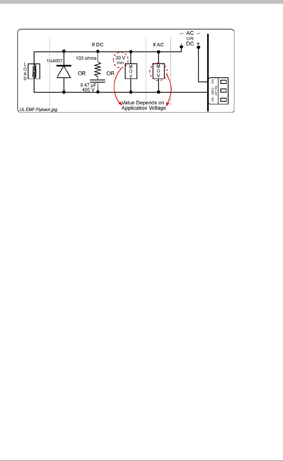
ImproX O16 16 Channel Output Terminal
Figure 40 – EMF Flyback and Arc Suppression
Mounting the ImproX O16
Select the mounting position of the Terminal, considering accessibility, routing of wires and
visibility of the externally visible LEDs.
Mounting on a Concrete or Brick Wall
1. Use the Base as a template and mark off the required holes.
2. Drill the four mounting holes using a 7 mm diameter masonry drill bit, to a depth equal to the
length of the supplied wall plugs.
3. Secure the Base to the surface using the four mounting screws provided.
Use four suitable securing devices such as screws, nuts and bolts, or rivets to mount the
ImproX O16 on a metal surface.
3. Insert the wall plugs into the mounting holes.
4. Secure the Base to the surface using the four mounting screws provided.
Mounting on a Hard Wood Surface
1. Use the Base as a template and mark off the required holes.
2. Drill the four mounting holes using a 2.5 mm diameter drill bit to the depth equal to three-
quarters of the length of the mounting screws.
Mounting on Metal
1. Use the Base as a template and mark off the required holes.
2. Drill the four mounting holes using a suitable diameter drill bit.
3. Secure the Base to the surface using the chosen method.
130 Tuesday, 11 July 2006
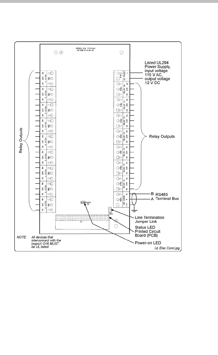
IXP300/IXP400 Installation Guide
Electrical Connections
Connecting the ImproX O16
Figure 51
Figure 41 – Typical ImproX O16 Electrical Connections
shows a detailed connection diagram for the ImproX O16.
ImproX O16 Address Information
Each ImproX O16 is allocated a unique Fixed Address at the factory. This address is stored in
the Terminals memory. When the Terminal is installed in the ImproNet System, the System
allocates a separate Logical Address for communication purposes.
The ImproNet Software Suite allocates a Logical Address to the Terminal, either on initial
software start-up, or on request, depending on the system configuration.
Tuesday, 11 July 2006 131

ImproX O16 16 Channel Output Terminal
Fixed Address Label
Once the ImproX O16 is installed, sketch a rough site plan. Attach the loose (additional Fixed
Address Label packaged with the Terminal) Fixed Address Label in the position of the Terminal
on the sketched site plan. When the system installation is complete and all the units are
represented on the site plan by their Fixed Address Labels, file the site plan for future reference.
Operation and Functionality
The ImproX O16 is a Terminal and must be connected to a Controller via comms bus port 1, to
function correctly.
The O16 has 16 relays. Each relay can be individually configured to activate for a specific
system Event or Device Time Pattern via ImproNet Access software. Relays fall into the
category of system Actions. For details on configuring relays, refer to the Actions section on
page 263.
132 Tuesday, 11 July 2006
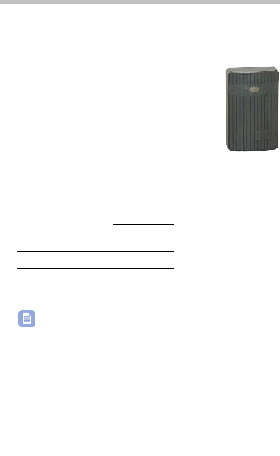
IXP300/IXP400 Installation Guide
ImproX MA Micro Antenna Reader
The ImproX (MA) Micro Antenna Reader is a compact Tag Reader for use
with an ImproX (TT) Twin Antenna Terminal in the ImproX IXP300 and
IXP400 Access Control Systems.
The Antenna Reader includes a single tone Buzzer. You can adjust the
Buzzer volume to any one of these four levels (off, low, medium and
high). The Antenna Reader includes a single bi-coloured Red or Green
Status LED. You can set the functions of the Buzzer and Status LED to
suit the needs of your application.
The Antenna Reader is intended for indoor or outdoor (not UL evaluated)
use. The electronic components are fully potted in a Dark Grey, ABS Plastic housing. The
potting compound prevents vandals tampering with the electronic components.
Tag Read/Write Ranges
Typical Range
(Minimum)
Tag Type
(mm) (in)
ISO Credit Card (Slim), 64-bit,
Manchester encoded protocol, ASK 60 2.36
Credit Card (Semi Slim), 64-bit,
Manchester encoded protocol, ASK 60 2.36
ImproX Credit Card, 64-bit,
Manchester encoded protocol, ASK 50 1.96
Key Ring Tag, 64-bit, Manchester
encoded protocol, ASK 40 1.58
The distances indicated are for the Antenna Reader mounted on a non-metallic surface.
Mounting the Antenna Reader on a metallic surface will reduce the Tag reading range
slightly.
Approvals
• CE
• UL294
• FCC Approval Pending.
Tuesday, 11 July 2006 133

ImproX MA Micro Antenna Reader
Specifications
Physical
Dimensions
Length 88 mm (3.46 in).
Width 54 mm (2.12 in).
Height 25 mm (0.98 in).
Approximate Weight 100 g (0.22 lb).
Housing Material ABS Plastic.
Colour Dark Grey.
Environmental
Temperature
Operating 0oC to +49oC (-13oF to +140oF)
Storage -40oC to +80oC (-40oF to +176oF)
Humidity Range 85% ± 5oC relative humidity at +30oC ± 2oC (86oF ± 3 oF)
Approvals (Test
Information)
UL Rating UL 294.
EMC EN 55022: Limits and Methods of Measurement of Radio Disturbance
Characteristics of Information Technology Equipment.
EN 55024: Immunity Characteristics, Limits and Methods of
Measurement.
Electrostatic Discharge IEC 61000-4-2: Electromagnetic Compatibility (EMC). Part 4: Testing
and Measurement Techniques. Section 2: Electrostatic Discharge
Immunity Test. Basic EMC Publication.
Radiated Susceptibility IEC 61000-4-3: Electromagnetic Compatibility (EMC). Part 4: Testing
and Measurement Techniques. Section 3: Radiated, Radio-
Frequency, Electromagnetic Field Immunity Test.
Electrical Fast Transients IEC 61000-4-4: Electromagnetic Compatibility (EMC). Part 4: Testing
and Measurement Techniques. Section 4: Electrical Fast Transients /
Bursts. Basic EMC Publication.
Surge Immunity IEC 61000-4-5: Surge Immunity.
Conducted Susceptibility IEC 61000-4-6: Conducted Susceptibility.
Power Frequency Magnetic
Field IEC 61000-4-8: Electromagnetic Compatibility (EMC). Part 4: Testing
and Measurement Techniques. Section 8: Frequency Magnetic Field
Immunity Test.
Dust and Splash
Resistance The Antenna Reader is sealed (potted) and is therefore suitable for
indoor or outdoor installation in an environment similar to IP53.
Drop Endurance 2 m (6.56 ft) drop (in packaging).
Operator or Installer Interfaces
Buzzer
Volume and Tone Single tone, 4-step adjustable volume.
Status Indicators
Status LED Bi-coloured Red or Green.
134 Tuesday, 11 July 2006

IXP300/IXP400 Installation Guide
Installation Information
Wire and install the Antenna Reader in accordance with the National Electric Code
(ANSI/NFPA 70), local codes, and the authorities having jurisdiction.
•
Mounting the ImproX MA
• Through the top of the Front Cover, see Figure 42.
• Through the centre of the Backing Plate, see Figure 43.
Accessories
Find the following when unpacking the Antenna Reader:
• An ImproX MA Antenna Reader housed in a Dark Grey, ABS Plastic housing. The ImproX
MA consists of a Front Cover and a Backing Plate (the Backing Plate is attached with a Self-
tapping Screw (M2 x 6 mm)). The Front Cover (including the potted electronic components)
assembly includes 2 m (6.56 ft) of West Penn D3652, shielded, 22-gauge, multi-strand, 3-
pair twisted cable.
• Four Brass Wood Screws (3.5 mm x 25 mm).
• Four Wall Plugs (7 mm).
• An extra Serial Number Label.
General
Maximum Data Communications Distance – The ideal cable distance between the
ImproX TT and its Antenna Reader ranges between 2 m to 16 m (7 ft to 53 ft). Achieve this
by using West Penn D3652, shielded, 22-gauge, multi-strand, 3-pair twisted cable. The
cross-sectional area of the cable must be at least 0.2 mm2 (0.0003 in2). The cable
specifications should be similar to the following:
− Conductor Resistance: < 2 ohms.
− Capacitance, Core to Earth: < 160 pF/m.
− Capacitance, Core to Core: < 100 pF/m.
• Distance between Antenna Readers from the SAME Terminal – To avoid mutual
interference, install the Antenna Readers no closer than 150 mm (6 in) apart.
• Distance between Antenna Readers from DIFFERENT Terminals – To avoid mutual
interference, install the Antenna Readers no closer than 500 mm (20 in) apart.
Select the mounting position of the ImproX MA Antenna Reader, considering accessibility,
routing of wires and visibility of the externally visible Status LED.
Secure the ImproX MA to the mounting surface, using four suitable screws and wall plugs, nuts
and bolts, rivets. or double-sided adhesive tape (not UL evaluated).
Cable Exit Holes
The Antenna Readers design offers a choice of three cable exit holes. These are:
Tuesday, 11 July 2006 135
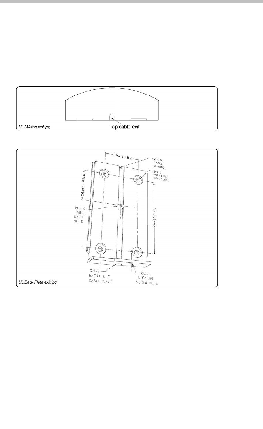
ImproX MA Micro Antenna Reader
• Through the bottom of the Backing Plate, see Figure 43.
To access these exit holes, remove the Front Cover as follows:
1. Using a screwdriver, remove the Self-tapping Screw (M2 x 6 mm) from the bottom of the
Antenna Reader.
2. Lift the bottom edge of the Backing Plate away from the Front Cover.
If you are going to use the cable exit hole in the bottom of the Backing Plate, remove the central
plastic plug from the hole using a screwdriver.
3. Pull the Backing Plate away until it clears the top of the Front Cover.
Figure 42 - Top Cable Exit Hole (Front Cover)
Figure 43 – Backing Plate
If you are going to use the cable exit hole at the centre of the Backing Plate, drill a
corresponding hole in the mounting surface. Use the Backing Plate as a template to mark the
position for this hole.
If you are going to use the cable exit hole at the top of the Front Cover, remove the thin plastic
wall using a sharp tool.
136 Tuesday, 11 July 2006

IXP300/IXP400 Installation Guide
Mounting on a Concrete or Brick Wall
1. Use the Backing Plate as a template and mark off the required holes.
2. Drill the four mounting holes using a 7 mm diameter masonry drill bit, to a depth equal to the
length of the supplied wall plugs.
1. Use the Backing Plate as a template and mark off the required holes.
3. If required, drill the centre hole through the wood (for the cable), using a 5 mm diameter
(minimum) drill bit.
1. Use the Backing Plate as a template and mark off the required holes.
Mounting the Front Cover onto the Backing Plate using the Centre Cable Exit
5. Insert the Self-tapping Screw (M2 x 6 mm) through the Backing Plate into the Front Cover,
and tighten it.
2. Clip the Front Cover over the top of the Backing Plate.
3. If required, drill the centre hole through the wall (for the cable), using a 5 mm diameter
(minimum) masonry drill bit.
4. Insert the wall plugs into the mounting holes.
5. Secure the Backing Plate to the surface using the four mounting screws provided.
Mounting on a Hard Wood Surface
2. Drill the four mounting holes using a 2.5 mm diameter drill bit to the depth equal to three-
quarters of the length of the mounting screws.
4. Secure the Backing Plate to the surface using the four mounting screws provided.
Mounting on Metal
Use four suitable securing devices such as screws, nuts and bolts, or rivets to mount the
ImproX MA on a metal surface.
2. Drill the four mounting holes using a suitable diameter drill bit.
3. If required, drill the centre hole through the metal (for the cable), using a 5 mm diameter
(minimum) drill bit.
4. Secure the Backing Plate to the surface using the chosen method.
1. Feed the cable through the centre hole in the Backing Plate, through to the other side of the
mounting surface.
2. Pull the cable until the Front Cover meets the Backing Plate.
3. Clip the Front Cover over the top of the Backing Plate.
4. Push the Front Cover towards the Backing Plate until it is in position.
Mounting the Front Cover onto the Backing Plate using the Top or Bottom Cable
Exit
1. Feed the cable via the cable channel to the top or bottom of the Antenna Reader. Ensure
that the cable is underneath the securing screw.
3. Push the Front Cover towards the Backing Plate until it is in position.
4. Insert the Self-tapping Screw (M2 x 6 mm) through the Backing Plate into the Front Cover,
and tighten it.
Tuesday, 11 July 2006 137
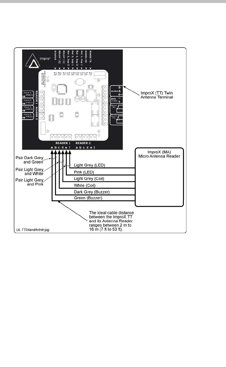
ImproX MA Micro Antenna Reader
Electrical Connections
Connecting the ImproX MA
Figure 44
Figure 44: Typical ImproX MA Electrical Connections
The ImproX MA will not read Tags until configured in the Software.
shows a detailed connection diagram for the ImproX MA.
Initial Start-up
On powering up, the Antenna Reader will produce a beep sound and the Status LED will
illuminate solid Red.
Serial Number Label
Once the ImproX MA is installed, sketch a rough site plan. The loose Serial Number Label
(packaged with the Antenna Reader) should be used (paired) in conjunction with the ImproX TTs
Fixed Address Label.
138 Tuesday, 11 July 2006

IXP300/IXP400 Installation Guide
The Antenna Reader does not have its own Fixed Address. When connected to an ImproX TT it
is assigned one of the available Fixed Addresses.
Micro Antenna Reader
When a Tag is presented within reading range to an Antenna reader, the Antenna reader in
combination with the ImproX TT energizes the Tag and decodes the Tag code. During operation
and configuration, the ImproX TT and Antenna readers are not seen as separate system
components but rather as a single Terminal component. In ImproNet Access Antenna readers
are configured as Terminals. Refer to the Terminals section on page 231 for details.
The Serial Number Label identifies the type of Antenna Reader, and the Fixed Address Label
(shipped with the ImproX TT) identifies the Fixed Address. Both these labels should be
attached to the site plan to assist in identifying the hardware once an Auto-ID is performed.
Operation and Functionality
The ImproX MA is supported by the ImproX TT. An Antenna Reader’s
primary function is to read proximity cards and Tags. Some ImproX Antenna readers have
keypads that enable input of PIN codes and reason codes. To function correctly, Antenna
readers must be connected to an ImproX TT Terminal. Functionally, Antenna readers are an
extension of the ImproX TT terminal; all processing and scanner circuitry is onboard the ImproX
TT.
Tuesday, 11 July 2006 139
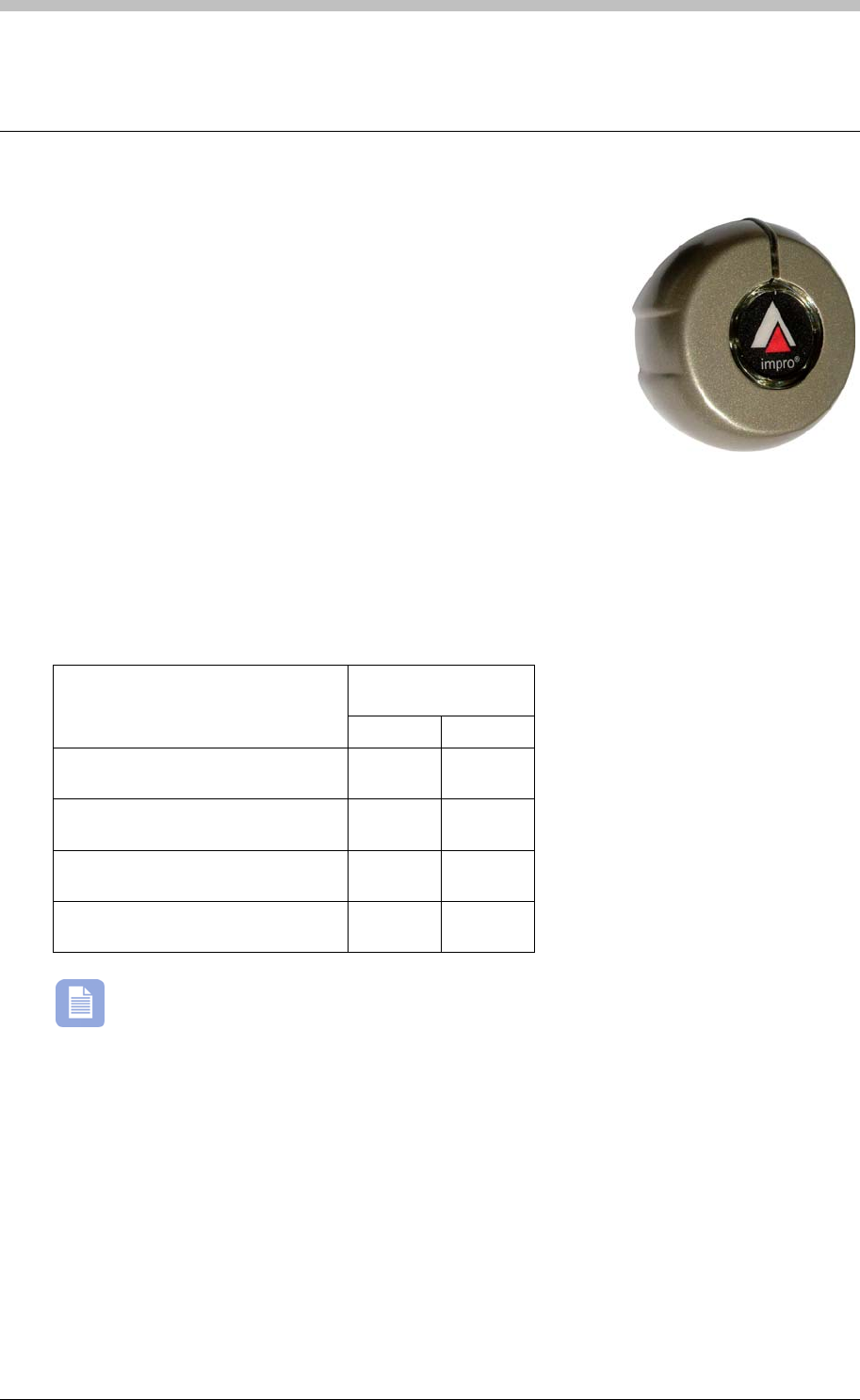
ImproX MHA Metal Antenna Reader
ImproX MHA Metal Antenna Reader
The ImproX (MHA) Metal Antenna Reader is a compact Tag
Reader for use with an ImproX (TT) Twin Antenna Terminal in the
ImproX IXP300 and IXP400 Access Control Systems.
The Antenna Reader includes a single tone Buzzer. You can
adjust the Buzzer volume to any one of these four levels (off, low,
medium and high). The Antenna Reader includes a single bi-
coloured Red or Green Status LED. You can set the functions of
the Buzzer and Status LED to suit the needs of your application.
The Antenna Reader is intended for indoor or outdoor (not UL evaluated) use, in harsh
environments (not UL evaluated), such as industrial areas. The electronic components are fully
potted and housed in a die-cast housing. This enhances its resistance to vandalism or
tampering.
Tag Read/Write Ranges
Typical Range
(Minimum)
Tag Type
(mm) (in)
ISO Credit Card (Slim), 64-bit,
Manchester encoded protocol, ASK 60 2.36
Credit Card (Semi Slim), 64-bit,
Manchester encoded protocol, ASK 60 2.36
ImproX Credit Card, 64-bit,
Manchester encoded protocol, ASK 50 1.96
Key Ring Tag, 64-bit, Manchester
encoded protocol, ASK 40 1.58
The distances indicated are for the Antenna Reader mounted on a non-metallic surface.
Mounting the Antenna Reader on a metallic surface will reduce the Tag reading range
slightly.
Approvals
• CE
• UL294
• FCC Approval Pending.
140 Tuesday, 11 July 2006

IXP300/IXP400 Installation Guide
Specifications
Physical
Dimensions
Length 75 mm (2.95 in).
Width 72 mm (2.83 in).
Height 27 mm (1.06 in).
Approximate Weight 220 g (0.48 lb).
Housing Material Die-cast Zinc Alloy.
Colour Satin Nickel.
Environmental
Temperature
Operating 0oC to +49oC (-13oF to +140oF)
Storage -40oC to +80oC (-40oF to +176oF)
Humidity Range 85% ± 5oC relative humidity at +30oC ± 2oC (86oF ± 3 oF)
Approvals (Test
Information)
UL Rating UL 294.
EMC EN 55022: Limits and Methods of Measurement of Radio
Disturbance Characteristics of Information Technology Equipment.
EN 55024: Immunity Characteristics, Limits and Methods of
Measurement.
Electrostatic Discharge IEC 61000-4-2: Electromagnetic Compatibility (EMC). Part 4:
Testing and Measurement Techniques. Section 2: Electrostatic
Discharge Immunity Test. Basic EMC Publication.
Radiated Susceptibility IEC 61000-4-3: Electromagnetic Compatibility (EMC). Part 4:
Testing and Measurement Techniques. Section 3: Radiated, Radio-
Frequency, Electromagnetic Field Immunity Test.
Electrical Fast Transients IEC 61000-4-4: Electromagnetic Compatibility (EMC). Part 4:
Testing and Measurement Techniques. Section 4: Electrical Fast
Transients / Bursts. Basic EMC Publication.
Surge Immunity IEC 61000-4-5: Surge Immunity.
Conducted Susceptibility IEC 61000-4-6: Conducted Susceptibility.
Power Frequency Magnetic
Field IEC 61000-4-8: Electromagnetic Compatibility (EMC). Part 4:
Testing and Measurement Techniques. Section 8: Frequency
Magnetic Field Immunity Test.
Dust and Splash
Resistance The Antenna Reader is sealed (potted) and is therefore suitable for
indoor or outdoor installation in an environment similar to IP53.
Drop Endurance 2 m (6.56 ft) drop (in packaging).
Operator or Installer Interfaces
Buzzer
Volume and Tone Single tone, 4-step adjustable volume.
Status Indicators
Status LED Bi-coloured Red or Green.
Tuesday, 11 July 2006 141

ImproX MHA Metal Antenna Reader
Installation Information
Accessories
Find the following when unpacking the Antenna Reader:
•
• An ImproX MHA Antenna Reader housed in a Zinc alloy die-cast housing. The ImproX
MHA consists of a Front Cover and a Backing Plate (the Backing Plate is attached with a
Hexagonal Screw (M3 x 8 mm)). The Front Cover (including the potted electronic
components) assembly includes 2 m (6.56 ft) of West Penn D3652, shielded, 22-gauge,
multi-strand, 3-pair twisted cable.
• An Allen Key (2 mm).
• Four Brass Wood Screws (3.5 mm x 25 mm).
• Four Wall Plugs (7 mm).
• An extra Serial Number Label.
General
Wire and install the Antenna Reader in accordance with the National Electric Code
(ANSI/NFPA 70), local codes, and the authorities having jurisdiction.
Maximum Data Communications Distance – The ideal cable distance between the
ImproX TT and its Antenna Reader ranges between 2 m to 16 m (7 ft to 53 ft). Achieve this
by using West Penn D3652, shielded, 22-gauge, multi-strand, 3-pair twisted cable. The
cross-sectional area of the cable must be at least 0.2 mm2 (0.0003 in2). The cable
specifications should be similar to the following:
− Conductor Resistance: < 2 ohms.
− Capacitance, Core to Earth: < 160 pF/m.
− Capacitance, Core to Core: < 100 pF/m.
• Distance between Antenna Readers from the SAME Terminal – To avoid mutual
interference, install the Antenna Readers no closer than 150 mm (6 in) apart.
• Distance between Antenna Readers from DIFFERENT Terminals - To avoid mutual
interference, install the Antenna Readers no closer than 500 mm (20 in) apart.
Mounting the ImproX MHA
Select the mounting position of the ImproX MHA, considering accessibility, routing of wires and
visibility of the externally visible LED.
Secure the ImproX MHA to the mounting surface, using three suitable screws and wall plugs
(supplied), nuts and bolts or rivets.
Access the Cable Exit Hole
To access the Cable Exit Hole, remove the Front Cover as follows:
142 Tuesday, 11 July 2006
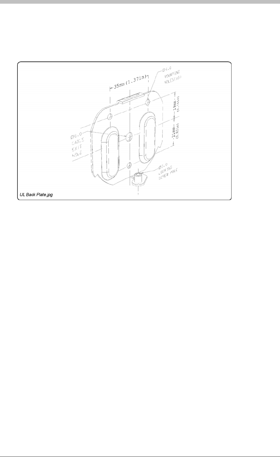
IXP300/IXP400 Installation Guide
1. Using the 2 mm Allen Key supplied, remove the Hexagonal Screw (M3 x 8 mm) from the
bottom of the Antenna Reader.
2. Pull the bottom edge of the Backing Plate away from the Front Cover.
3. Pull down the Front Cover until it clears the top of the Backing Plate.
Figure 45 – Backing Plate
Mounting on a Concrete or Brick Wall
1. Use the Backing Plate as a template and mark off the required holes.
2. Drill the four mounting holes using a 7 mm diameter masonry drill bit, to a depth equal to the
length of the supplied wall plugs.
3. If required, drill the centre hole through the wall (for the cable), using a 5 mm diameter
(minimum) masonry drill bit.
4. Insert the wall plugs into the mounting holes.
5. Secure the Backing Plate to the surface using the four mounting screws provided.
Mounting on a Hard Wood Surface
1. Use the Backing Plate as a template and mark off the required holes.
2. Drill the four mounting holes using a 2.5 mm diameter drill bit to the depth equal to three-
quarters of the length of the mounting screws.
3. If required, drill the centre hole through the wood (for the cable), using a 5 mm diameter
(minimum) drill bit.
4. Secure the Backing Plate to the surface using the four mounting screws provided.
Tuesday, 11 July 2006 143

ImproX MHA Metal Antenna Reader
Mounting on Metal
Use four suitable securing devices such as screws, nuts and bolts, or rivets to mount the
ImproX MHA on a metal surface.
2. Drill the four mounting holes using a suitable diameter drill bit.
2. Pull the cable until the Front Cover meets the Backing Plate.
5. Insert the Hexagonal Screw (M3 x 8 mm) through the cover into the Backing Plate. Tighten
the Hexagonal Screw (M3 x 8 mm) using the 2 mm Allen Key supplied.
1. Use the Backing Plate as a template and mark off the required holes.
3. If required, drill the centre hole through the metal (for the cable), using a 5 mm diameter
(minimum) drill bit.
4. Secure the Backing Plate to the surface using the chosen method.
Mounting the Front Cover onto the Backing Plate Using the Centre Cable Exit
1. Feed the cable through the centre hole in the Backing Plate, through to the other side of the
mounting surface.
3. Clip the Front Cover over the top of the Backing Plate.
4. Push the Front Cover towards the Backing Plate until it is in position.
144 Tuesday, 11 July 2006
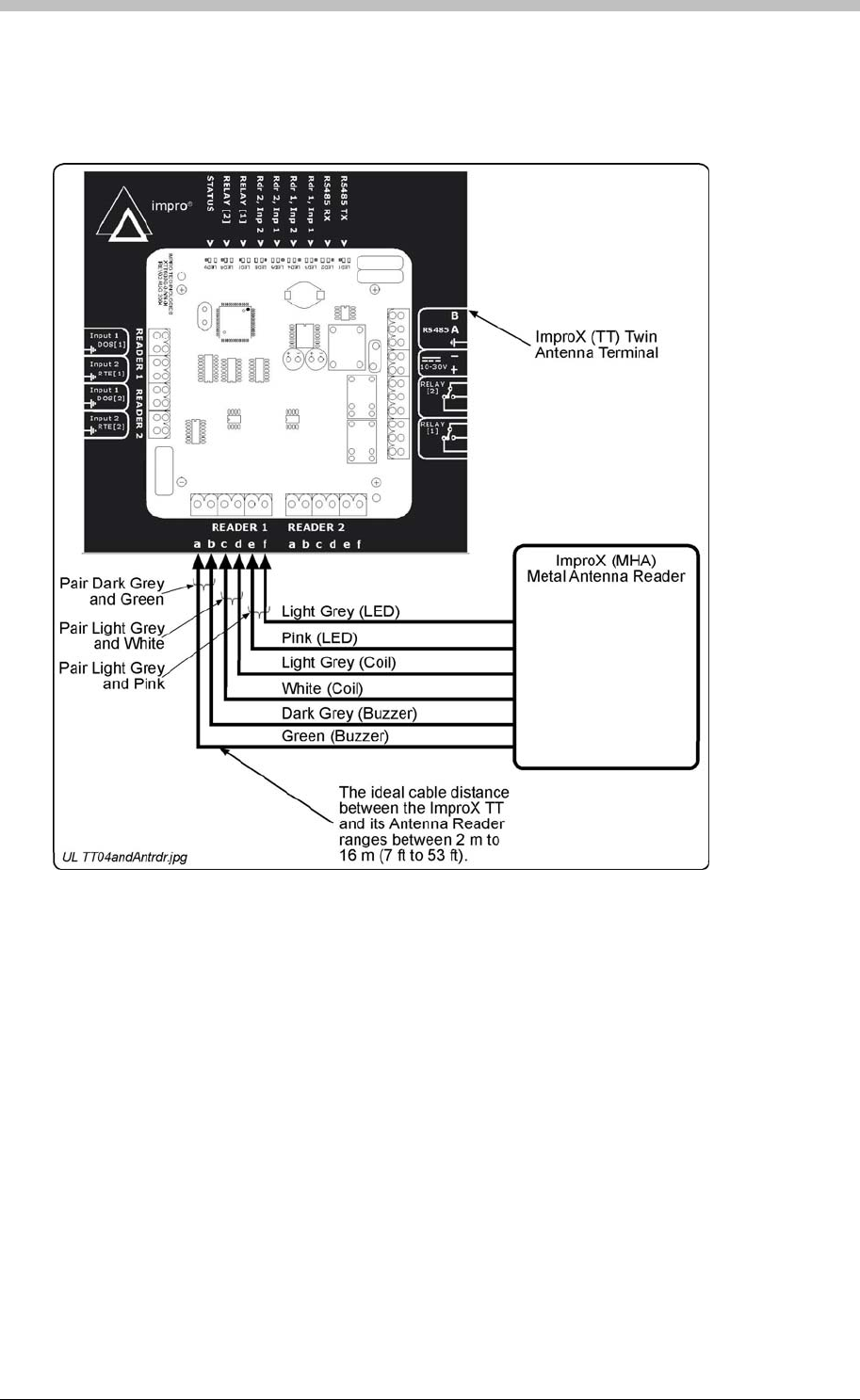
IXP300/IXP400 Installation Guide
Electrical Connections
Connecting the ImproX MHA
Figure 46
Once the ImproX MHA is installed, sketch a rough site plan. The loose Serial Number Label
(packaged with the Antenna Reader) should be used (paired) in conjunction with the ImproX TTs
Fixed Address Label.
shows a detailed connection diagram for the ImproX MHA.
Figure 46: Typical ImproX MHA Electrical Connections
Initial Start-up
On powering up, the Antenna Reader will produce a beep sound and the Status LED will
illuminate solid Red.
The ImproX MHA will not read Tags until configured in the Software.
Serial Number Label
The Antenna Reader does not have its own Fixed Address. When connected to an ImproX TT it
is assigned one of the available Fixed Addresses.
Tuesday, 11 July 2006 145

ImproX MHA Metal Antenna Reader
The Serial Number Label identifies the type of Antenna Reader, and the Fixed Address Label
(shipped with the ImproX TT) identifies the Fixed Address. Both these labels should be
attached to the site plan to assist in identifying the hardware once an Auto-ID is performed.
Operation and Functionality
The ImproX MHA is supported by the ImproX TT. An Antenna
Reader’s primary function is to read proximity cards and Tags. Some ImproX Antenna readers
have keypads that enable input of PIN codes and reason codes. To function correctly, Antenna
readers must be connected to an ImproX TT Terminal. Functionally, Antenna readers are an
extension of the ImproX TT terminal; all processing and scanner circuitry is onboard the ImproX
TT.
Metal Antenna Reader
rminals
When a Tag is presented within reading range to an Antenna reader, the Antenna reader in
combination with the ImproX TT energizes the Tag and decodes the Tag code. During operation
and configuration, the ImproX TT and Antenna readers are not seen as separate system
components but rather as a single Terminal component. In ImproNet Access Antenna readers
are configured as Terminals. Refer to the Te section on page 231 for details.
146 Tuesday, 11 July 2006
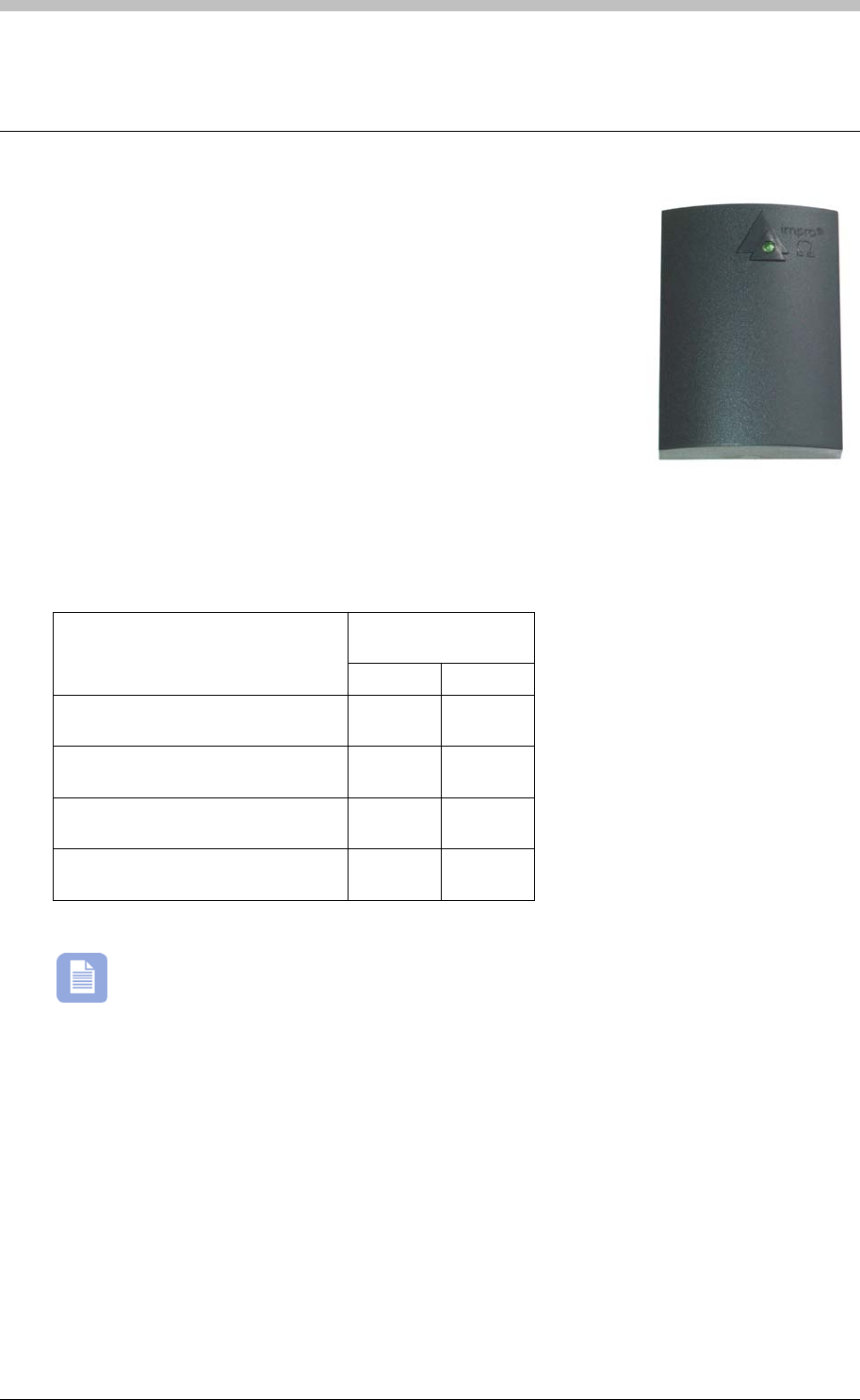
IXP300/IXP400 Installation Guide
ImproX MMA Mullion Antenna Reader
The ImproX (MMA) Mullion Antenna Reader is a compact Tag
Reader for use with an ImproX (TT) Twin Antenna Terminal in the
ImproX IXP300 and IXP400 Access Control Systems.
The Antenna Reader includes a single bi-coloured Red or Green
Status LED. You can set the function of the Status LED to suit the
needs of your application.
The Antenna Reader is intended for indoor or outdoor (not UL
evaluated) use. The electronic components are fully potted in a
Dark Grey, ABS Plastic housing. The potting compound prevents
vandals tampering with the electronic components.
Tag Read/Write Ranges
Typical Range
(Minimum)
Tag Type
(mm) (in)
ISO Credit Card (Slim), 64-bit,
Manchester encoded protocol, ASK 60 2.36
Credit Card (Semi Slim), 64-bit,
Manchester encoded protocol, ASK 60 2.36
ImproX Credit Card, 64-bit,
Manchester encoded protocol, ASK 50 1.96
Key Ring Tag, 64-bit, Manchester
encoded protocol, ASK 40 1.58
The distances indicated are for the Antenna Reader mounted on a non-metallic surface.
Mounting the Antenna Reader on a metallic surface will reduce the Tag reading range
slightly.
• UL294
Approvals
• CE
• FCC Approval Pending.
Tuesday, 11 July 2006 147

ImproX MMA Mullion Antenna Reader
Specifications
Physical
Dimensions
Length 59 mm (2.32 in).
Width 43 mm (1.69 in).
Height 16 mm (0.62 in).
Approximate Weight 67 g (0.14 lb).
Housing Material ABS Plastic.
Colour Dark Grey.
Environmental
Temperature
Operating 0oC to +49oC (-13oF to +140oF)
Storage -40oC to +80oC (-40oF to +176oF)
Humidity Range 85% ± 5oC relative humidity at +30oC ± 2oC (86oF ± 3 oF)
Approvals (Test
Information)
UL Rating UL 294.
EMC EN 55022: Limits and Methods of Measurement of Radio Disturbance
Characteristics of Information Technology Equipment.
EN 55024: Immunity Characteristics, Limits and Methods of
Measurement.
Electrostatic Discharge IEC 61000-4-2: Electromagnetic Compatibility (EMC). Part 4: Testing
and Measurement Techniques. Section 2: Electrostatic Discharge
Immunity Test. Basic EMC Publication.
Radiated Susceptibility IEC 61000-4-3: Electromagnetic Compatibility (EMC). Part 4: Testing
and Measurement Techniques. Section 3: Radiated, Radio-
Frequency, Electromagnetic Field Immunity Test.
Electrical Fast Transients IEC 61000-4-4: Electromagnetic Compatibility (EMC). Part 4: Testing
and Measurement Techniques. Section 4: Electrical Fast Transients /
Bursts. Basic EMC Publication.
Surge Immunity IEC 61000-4-5: Surge Immunity.
Conducted Susceptibility IEC 61000-4-6: Conducted Susceptibility.
Power Frequency Magnetic
Field IEC 61000-4-8: Electromagnetic Compatibility (EMC). Part 4: Testing
and Measurement Techniques. Section 8: Frequency Magnetic Field
Immunity Test.
Dust and Splash
Resistance (not UL
evaluated)
Approved for indoor use. The Antenna Reader is sealed (potted) and is
therefore suitable for outdoor installation in an environment similar to
IP66.
Drop Endurance 2 m (6.56 ft) drop (in packaging).
Operator or Installer Interfaces
Buzzer
Volume and Tone Not Applicable.
Status Indicators
Status LED Bi-coloured Red or Green.
148 Tuesday, 11 July 2006

IXP300/IXP400 Installation Guide
Installation Information
Accessories
Find the following when unpacking the Antenna Reader:
• Four countersunk, Brass Wood Screws (3.5 mm x 25 mm).
• A dark grey, ABS Plastic Backing Plate
•
• Cable Specifications – The cable specifications should be similar to the following:
− Capacitance, Core to Earth: < 160 pF/m.
• Distance between Antenna Readers from the SAME Terminal – To avoid mutual
interference, install the Antenna Readers no closer than 150 mm (6 in) apart.
• Distance between Antenna Readers from DIFFERENT Terminals – To avoid mutual
interference, install the Antenna Readers no closer than 500 mm (20 in) apart.
• An ImproX MMA Antenna Reader housed in a Dark Grey, ABS Plastic housing. The ImproX
MMA consists of a Front Cover and a Backing Plate. The Front Cover (including the potted
electronic components) assembly includes 2 m (6.56 ft) of West Penn D3652, shielded, 22-
gauge, multi-strand, 3-pair twisted cable.
• Four Wall Plugs (7 mm).
• An extra Serial Number Label.
You will find the following when unpacking the ImproX MMA accessory pack (XTT901-0-0-UL-
99)
General
Wire and install the Antenna Reader in accordance with the National Electric Code
(ANSI/NFPA 70), local codes, and the authorities having jurisdiction.
Maximum Data Communications Distance – The ideal cable distance between the
ImproX TT and its Antenna Reader ranges between 2 m to 16 m (7 ft to 53 ft). Achieve this
by using West Penn D3652, shielded, 22-gauge, multi-strand, 3-pair twisted cable. The
cross-sectional area of the cable must be at least 0.2 mm2 (0.0003 in2).
− Conductor Resistance: < 2 ohms.
− Capacitance, Core to Core: < 100 pF/m.
Mounting the ImproX MMA
Select the mounting position of the ImproX MMA, considering accessibility, routing of wires and
visibility of the externally visible LED.
Secure the ImproX MMA to the mounting surface, using two suitable screws and wall plugs,
nuts and bolts, rivets or double-sided adhesive tape (not UL evaluated).
Tuesday, 11 July 2006 149

ImproX MMA Mullion Antenna Reader
Cable Exit Holes
The ImproX MMAs design offers a choice of three cable exit holes. These are:
• Through the top of the Front Cover, see Figure 48.
Figure 48 - Cable Exit Holes (Front Cover)
• Through the centre of the Backing Plate, see Figure 47
• Through the bottom of the Front Cover, see Figure 48
Figure 47 – Backing Plate
If you are going to use the cable exit hole at the centre of the Backing Plate, drill a
corresponding hole in the mounting surface. Use the Backing Plate as a template to mark the
position for this hole.
If you are going to use the cable exit hole at the top or bottom of the Front Cover, remove the
thin plastic wall using a sharp tool.
150 Tuesday, 11 July 2006

IXP300/IXP400 Installation Guide
Mounting on a Concrete or Brick Wall
1. Use the Backing Plate as a template and mark off the required holes.
2. Drill the two mounting holes using a 7 mm diameter masonry drill bit, to a depth equal to the
length of the supplied wall plugs.
3. If required, drill the centre hole through the wall (for the cable), using a 5 mm diameter
(minimum) masonry drill bit.
4. Insert the wall plugs into the mounting holes.
5. Secure the Backing Plate to the surface using two of the mounting screws provided.
Mounting on a Hard Wood Surface
1. Use the Backing Plate as a template and mark off the required holes.
2. Drill the two mounting holes using a 2.5 mm diameter drill bit to the depth equal to three-
quarters of the length of the mounting screws.
3. If required, drill the centre hole through the wood (for the cable), using a 5 mm diameter
(minimum) drill bit.
4. Secure the Backing Plate to the surface using two of the mounting screws provided.
Mounting on Metal
Use four suitable securing devices such as screws, nuts and bolts, or rivets to mount the
ImproX MMA on a metal surface.
1. Use the Backing Plate as a template and mark off the required holes.
2. Drill the two mounting holes using a suitable diameter drill bit.
3. If required, drill the centre hole through the metal (for the cable), using a 5 mm diameter
(minimum) drill bit.
4. Secure the Backing Plate to the surface using the chosen method.
The Backing Plate and Front Cover clip together firmly, separation is likely to damage
the clips.
If it is necessary to separate the Front Cover from the Backing Plate, insert a 5 mm flat head
screwdriver between the Front Cover and the Backing Plate (either at the top or bottom end).
Apply sufficient force to unclip the Front Cover.
If the Backing Plate is damaged during this process a replacement Backing Plate can be
ordered from your local Impro Distributor, using the following part number: XTT901-0-0-UL-99.
Mounting the Front Cover onto the Backing Plate Using the Centre Cable Exit
1. Feed the cable supplied through the centre hole in the Backing Plate, through to the other
side of the mounting surface.
2. Pull the cable until the Front Cover meets the Backing Plate.
3. Push the Front Cover towards the Backing Plate until it clips securely.
Tuesday, 11 July 2006 151
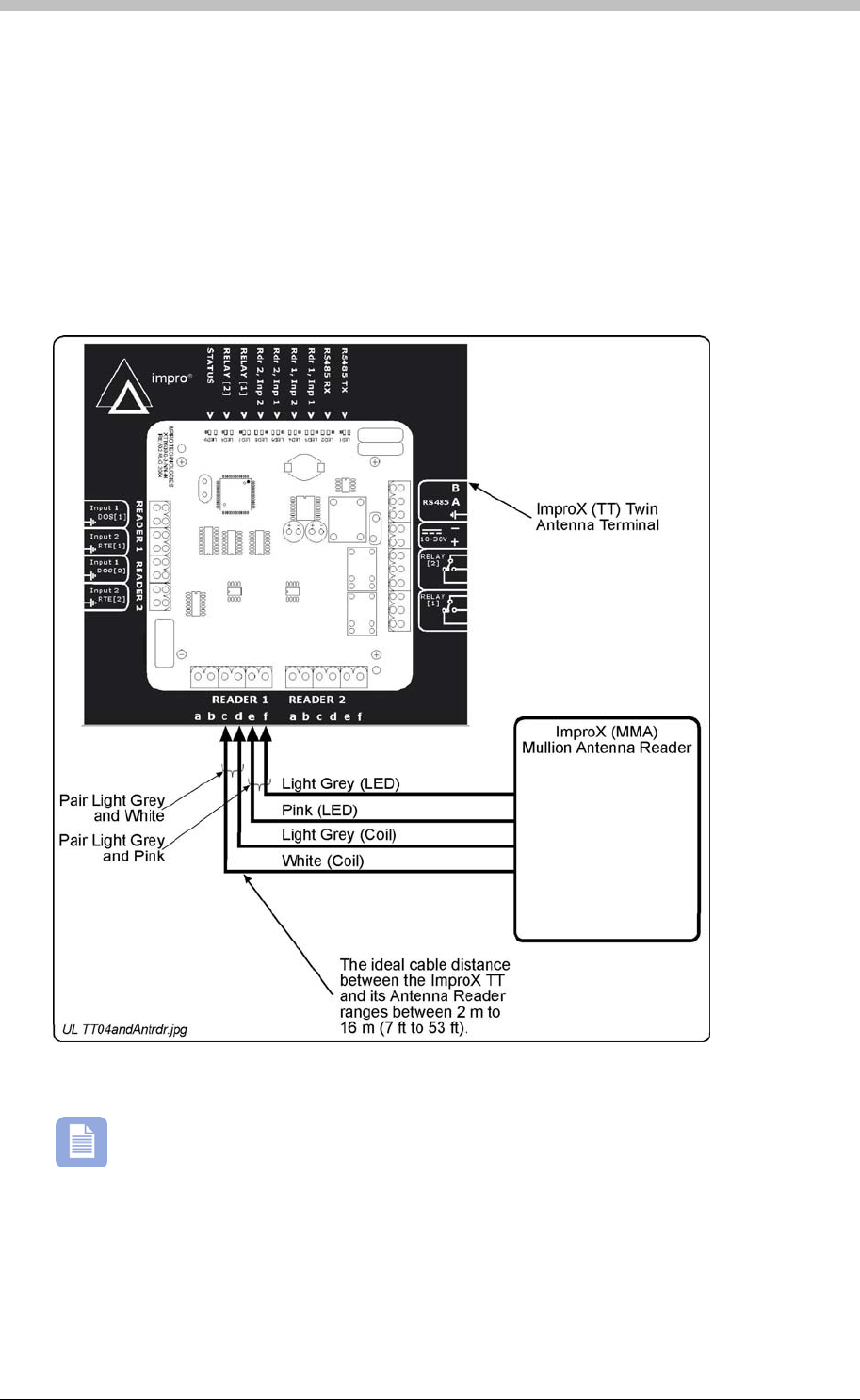
ImproX MMA Mullion Antenna Reader
Mounting the Front Cover onto the Backing Plate Using the Top or Bottom Cable
Exit
1. Feed the cable via the cable channel to the top or bottom of the Antenna Reader.
Figure 49
Figure 49 – Typical ImproX MMA Electrical Connections
2. Push the Front Cover towards the Backing Plate until it clips securely.
Electrical Connections
Connecting the ImproX MMA
shows a detailed connection diagram for the ImproX MMA.
The ImproX MMA does NOT make use of the Buzzer facility. The ImproX MMA,
therefore, does not have the Green and Dark Grey wires and can therefore NOT make
use of connections “A” and “B” on the ImproX TT.
Initial Start-up
On powering up, the Antenna Readers Status LED will illuminate solid Red. The ImproX MMA
will not read Tags until configured in the Software.
152 Tuesday, 11 July 2006

IXP300/IXP400 Installation Guide
Serial Number Label
Once the ImproX MMA is installed, sketch a rough site plan. The loose Serial Number Label
(packaged with the Antenna Reader) should be used (paired) in conjunction with the ImproX TTs
Fixed Address Label.
Operation and Functionality
Mullion Antenna Reader
rminals
The Antenna Reader does not have its own Fixed Address. When connected to an ImproX TT it
is assigned one of the available Fixed Addresses.
The Serial Number Label identifies the type of Antenna Reader, and the Fixed Address Label
(shipped with the ImproX TT) identifies the Fixed Address. Both these labels should be
attached to the site plan to assist in identifying the hardware once an Auto-ID is performed.
The ImproX MMA is supported by the ImproX TT. An Antenna
Reader’s primary function is to read proximity cards and Tags. Some ImproX Antenna readers
have keypads that enable input of PIN codes and reason codes. To function correctly, Antenna
readers must be connected to an ImproX TT Terminal. Functionally, Antenna readers are an
extension of the ImproX TT terminal; all processing and scanner circuitry is onboard the ImproX
TT.
When a Tag is presented within reading range to an Antenna reader, the Antenna reader in
combination with the ImproX TT energizes the Tag and decodes the Tag code. During operation
and configuration, the ImproX TT and Antenna readers are not seen as separate system
components but rather as a single Terminal component. In ImproNet Access Antenna readers
are configured as Terminals. Refer to the Te section on page 231 for details.
Tuesday, 11 July 2006 153
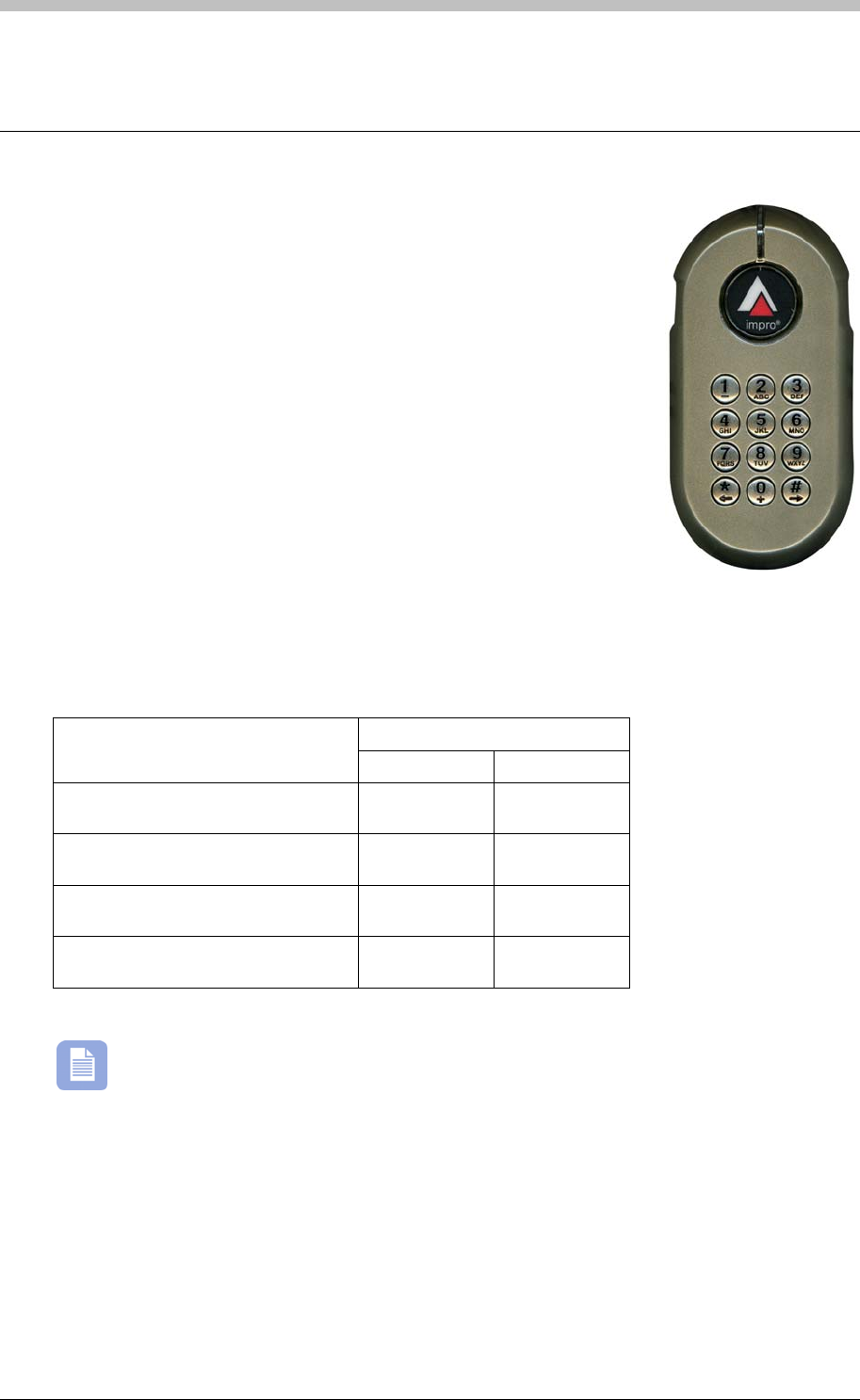
ImproX KHA Metal Keypad Antenna Reader
ImproX KHA Metal Keypad Antenna Reader
The ImproX (KHA) Metal Keypad Antenna Reader is a compact Tag
Reader for use with an ImproX (TT) Twin Antenna Terminal in the
ImproX IXP300 and IXP400 Access Control Systems.
The Antenna Reader includes a single tone Buzzer, a single bi-
coloured Red or Green Status LED and a 12-button alphanumeric
Keypad. The Antenna Readers Buzzer volume is adjustable to any
one of these four levels (off, low, medium and high). You may use the
Keypad for Personal Access Code (PAC), PIN-Code or Reason Code
entry. Set the functions of the Buzzer and Status LED to suit the
needs of your application.
The Antenna Reader is intended for indoor or outdoor use (not UL
evaluated), in harsh environments (not UL evaluated), such as
industrial areas. The electronic components are fully potted and
housed in a die-cast housing. This enhances its resistance to vandalism or tampering.
Tag Read/Write Ranges
Typical Range (Minimum)
Tag Type (mm) (in)
ISO Credit Card (Slim), 64-bit,
Manchester encoded protocol, ASK 60 2.36
Credit Card (Semi Slim), 64-bit,
Manchester encoded protocol, ASK 60 2.36
ImproX Credit Card, 64-bit,
Manchester encoded protocol, ASK 50 1.96
Key Ring Tag, 64-bit, Manchester
encoded protocol, ASK 40 1.58
Table 14 – Typical Read/Write Ranges
Approvals
• FCC Approval Pending
The distances indicated are for the Antenna Reader mounted on a non-metallic surface.
Mounting the Antenna Reader on a metallic surface will reduce the Tag reading range
slightly.
• CE
• UL294
154 Tuesday, 11 July 2006

IXP300/IXP400 Installation Guide
Specifications
Physical
Dimensions
Length 142 mm (5.59 in).
Width 76 mm (2.99 in).
Height 27 mm (1.06 in).
Approximate Weight 510 g (1.12 lb).
Housing Material Die-cast Zinc Alloy.
Colour Satin Nickel.
Environmental
Temperature
Operating 0oC to +49oC (-13oF to +140oF)
Storage -40oC to +80oC (-40oF to +176oF)
Humidity Range 85% ± 5oC relative humidity at +30oC ± 2oC (86oF ± 3 oF)
Approvals (Test
Information)
UL Rating UL 294.
EMC EN 55022: Limits and Methods of Measurement of Radio
Disturbance Characteristics of Information Technology Equipment.
EN 55024: Immunity Characteristics, Limits and Methods of
Measurement.
Electrostatic Discharge IEC 61000-4-2: Electromagnetic Compatibility (EMC). Part 4:
Testing and Measurement Techniques. Section 2: Electrostatic
Discharge Immunity Test. Basic EMC Publication.
Radiated Susceptibility IEC 61000-4-3: Electromagnetic Compatibility (EMC). Part 4:
Testing and Measurement Techniques. Section 3: Radiated, Radio-
Frequency, Electromagnetic Field Immunity Test.
Electrical Fast Transients IEC 61000-4-4: Electromagnetic Compatibility (EMC). Part 4:
Testing and Measurement Techniques. Section 4: Electrical Fast
Transients / Bursts. Basic EMC Publication.
Surge Immunity IEC 61000-4-5: Surge Immunity.
Conducted Susceptibility IEC 61000-4-6: Conducted Susceptibility.
Power Frequency Magnetic
Field IEC 61000-4-8: Electromagnetic Compatibility (EMC). Part 4:
Testing and Measurement Techniques. Section 8: Frequency
Magnetic Field Immunity Test.
Dust and Splash
Resistance (not UL
evaluated)
Approved for indoor use. The Antenna Reader is sealed (potted) and
is therefore suitable for outdoor installation in an environment similar
to IP53.
Drop Endurance 2 m (6.56 ft) drop (in packaging).
Tuesday, 11 July 2006 155

ImproX KHA Metal Keypad Antenna Reader
Operator or Installer Interfaces
Buzzer
Volume and Tone Single tone, 4-step adjustable volume.
Status Indicators
Status LED Bi-coloured Red or Green.
Keypad
Keys 12 alphanumeric keys.
Find the following when unpacking the Antenna Reader:
•
− Capacitance, Core to Earth: < 160 pF/m
• Distance between Antenna Readers from DIFFERENT Terminals – To avoid mutual
interference, install the Antenna Readers no closer than 500 mm (20 in) apart.
Installation Information
Accessories
• An ImproX KHA Antenna Reader housed in a Zinc alloy die-cast housing. The ImproX KHA
consists of a Front Cover and a Backing Plate (the Backing Plate is attached with a
Hexagonal Screw (M3 x 8 mm)). The Front Cover (including the potted electronic
components) assembly includes 2 m (6.56 ft) of West Penn D3652, shielded, 22-gauge,
multi-strand, 3-pair twisted cable.
• An Allen Key (2 mm).
• Four Brass Wood Screws (3.5 mm x 25 mm).
• Four Wall Plugs (7 mm).
• An extra Serial Number Label.
General
Wire and install the Antenna Reader in accordance with the National Electric Code
(ANSI/NFPA 70), local codes, and the authorities having jurisdiction.
Maximum Data Communications Distance – The ideal cable distance between the
ImproX TT and its Antenna Reader ranges between 2 m to 16 m (7 ft to 53 ft). Achieve this
by using West Penn D3652, shielded, 22-gauge, multi-strand, 3-pair twisted cable. The
cross-sectional area of the cable must be at least 0.2 mm2 (0.0003 in2).
• Cable Specifications – the cable specifications should be similar to the following:
− Conductor Resistance: < 2 ohms
− Capacitance, Core to Core: < 100 pF/m
• Distance between Antenna Readers from the SAME Terminal – To avoid mutual
interference, install the Antenna Readers no closer than 150 mm (6 in) apart.
156 Tuesday, 11 July 2006
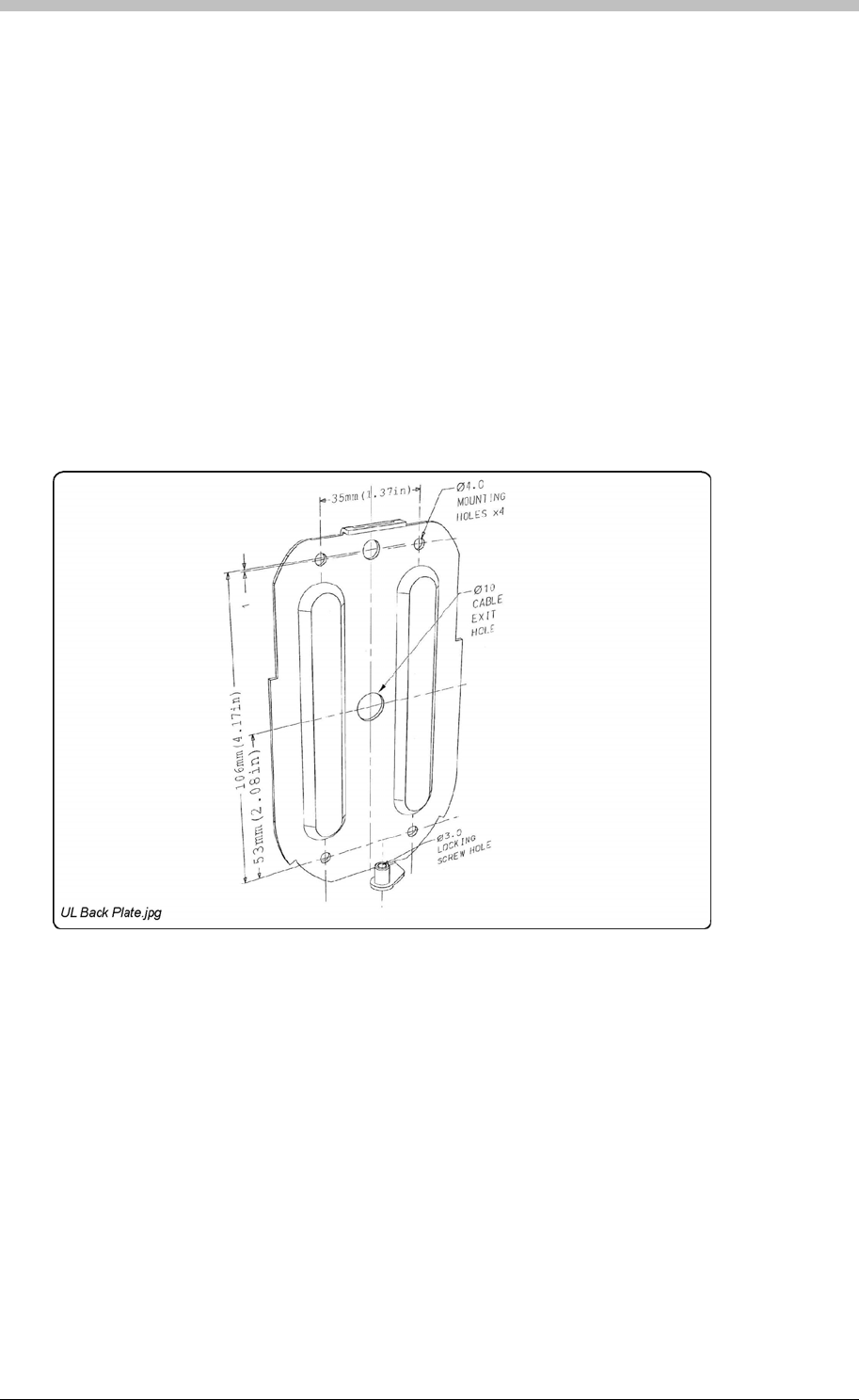
IXP300/IXP400 Installation Guide
Mounting the ImproX KHA
Select the mounting position of the ImproX KHA, considering accessibility, routing of wires and
visibility of the externally visible LED.
Secure the ImproX KHA to the mounting surface, using four suitable screws and wall plugs
(supplied), nuts and bolts or rivets.
To access the Cable Exit Hole, remove the Front Cover as follows:
2. Pull the bottom edge of the Backing Plate away from the Front Cover.
Mounting on a Concrete or Brick Wall
4. Insert the wall plugs into the mounting holes.
5. Secure the Backing Plate to the surface using the four mounting screws provided.
Access the Cable Exit Hole
1. Using the 2 mm Allen Key supplied, remove the Hexagonal Screw (M3 x 8 mm) from the
bottom of the Antenna Reader.
3. Pull down the Front Cover until it clears the top of the Backing Plate.
Figure 50: Backing Plate
1. Use the Backing Plate as a template and mark off the required holes.
2. Drill the four mounting holes using a 7 mm diameter masonry drill bit, to a depth equal to the
length of the supplied wall plugs.
3. Drill the centre hole through the wall (for the cable), using a 5 mm diameter (minimum)
masonry drill bit.
Tuesday, 11 July 2006 157

ImproX KHA Metal Keypad Antenna Reader
Mounting on a Hard Wood Surface
1. Use the Backing Plate as a template and mark off the required holes.
2. Drill the four mounting holes using a 2.5 mm diameter drill bit to the depth equal to three-
quarters of the length of the mounting screws.
3. Drill the centre hole through the wall (for the cable), using a 5 mm diameter (minimum)
masonry drill bit.
4. Secure the Backing Plate to the surface using the four mounting screws provided.
1. Use the Backing Plate as a template and mark off the required holes.
2. Drill the four mounting holes using a suitable diameter drill bit.
3. Drill the centre hole through the wall (for the cable), using a 5 mm diameter (minimum)
masonry drill bit.
4. Secure the Backing Plate to the surface using the chosen method.
Mounting the Front Cover onto the Backing Plate
1. Feed the cable through the centre hole in the Backing Plate, through to the other side of the
mounting surface.
2. Pull the cable until the Front Cover meets the Backing Plate.
3. Clip the Front Cover over the top of the Backing Plate.
4. Push the Front Cover towards the Backing Plate until it is in position.
5. Insert the Hexagonal Screw (M3 x 8 mm) through the cover into the Backing Plate. Tighten
the Hexagonal Screw (M3 x 8 mm) using the 2 mm Allen Key supplied.
Connecting the ImproX KHA
Figure 51
Mounting on Metal
Use four suitable securing devices such as screws, nuts and bolts, or rivets to mount the
ImproX KHA on a metal surface.
Electrical Connections
shows a detailed connection diagram for the ImproX KHA.
158 Tuesday, 11 July 2006
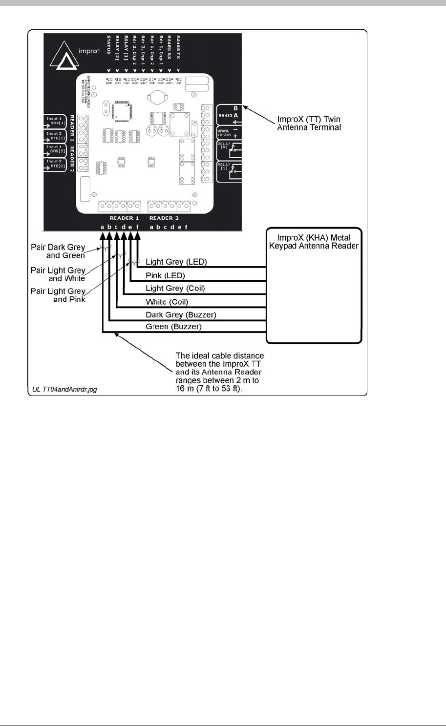
IXP300/IXP400 Installation Guide
Figure 51 – Typical ImproX KHA Electrical Connections
Initial Start-up
On powering up, the Antenna Reader will produce a beep sound and the Status LED will
illuminate solid Red. The ImproX KHA will not read Tags until configured in the Software.
Serial Number Label
Once the ImproX KHA is installed, sketch a rough site plan. The loose Serial Number Label
(packaged with the Antenna Reader) should be used (paired) in conjunction with the ImproX
TT’s Fixed Address Label.
The Antenna Reader does not have its own Fixed Address. When connected to an ImproX TT it
is assigned one of the available Fixed Addresses.
The Serial Number Label identifies the type of Antenna Reader, and the Fixed Address Label
(shipped with the ImproX TT) identifies the Fixed Address. Both these labels should be
attached to the site plan to assist in identifying the hardware once an Auto-ID is performed.
Tuesday, 11 July 2006 159

ImproX KHA Metal Keypad Antenna Reader
Operation and Functionality
The Im is supported by the ImproX TT. An Antenna
Reader’s primary function is to read proximity cards and Tags. Some ImproX Antenna readers
have keypads that enable input of PIN codes and reason codes. To function correctly, Antenna
readers must be connected to an ImproX TT Terminal. Functionally, Antenna readers are an
extension of the ImproX TT terminal; all processing and scanner circuitry is onboard the ImproX
TT.
proX KHA Metal Keypad Antenna Reader
When a Tag is presented within reading range to an Antenna reader, the Antenna reader in
combination with the ImproX TT energizes the Tag and decodes the Tag code. During operation
and configuration, the ImproX TT and Antenna readers are not seen as separate system
components but rather as a single Terminal component. In ImproNet Access Antenna readers
are configured as Terminals. Refer to the Terminals section on page 231 for details.
160 Tuesday, 11 July 2006

IXP300/IXP400 Installation Guide
Hardware Maintenance
Maintenance Overview
Basic Maintenance
Maintenance Tools
are Upgrade
Periodic hardware maintenance ensures the following:
• Units continue to run efficiently
• Problems requiring attention are noted
Impro does not support on-site repairs. Should an ImproX unit fail, return it to your local
Impro Distributor. They will repair or replace the unit.
For the Impro USA contact details, refer to the front inside cover of this document.
Cleaning Unit Housing
Wipe unit with a damp cloth. Do not use detergents or solvents.
Cleaning Inside Unit
Use a high-pressure air hose to clean inside ImproX unit.
Do not use water, detergents, or other chemicals inside an ImproX unit.
Software – ImproNet Firmware Upgrade utility
The following functions in the ImproNet Firmware Upgrade utility can be used for maintenance
and fault-detection in ImproX hardware:
• Ping test – indicates the installed ImproX hardware that is communicating on the comms
busses. The Ping test detects the comms interface, Controllers, and Terminals. Refer to
the Firmw section on 303 for operational details.
• Comms Test – run to determine the quality of communications on the Controller comms
bus (Port 2), and Terminal comms bus (Port 1). To prevent potential communications
errors, tested units should return a pass of 100 percent. A pass rate less than 100 percent
indicates potential problems with the hardware or communications media.
Tuesday, 11 July 2006 161
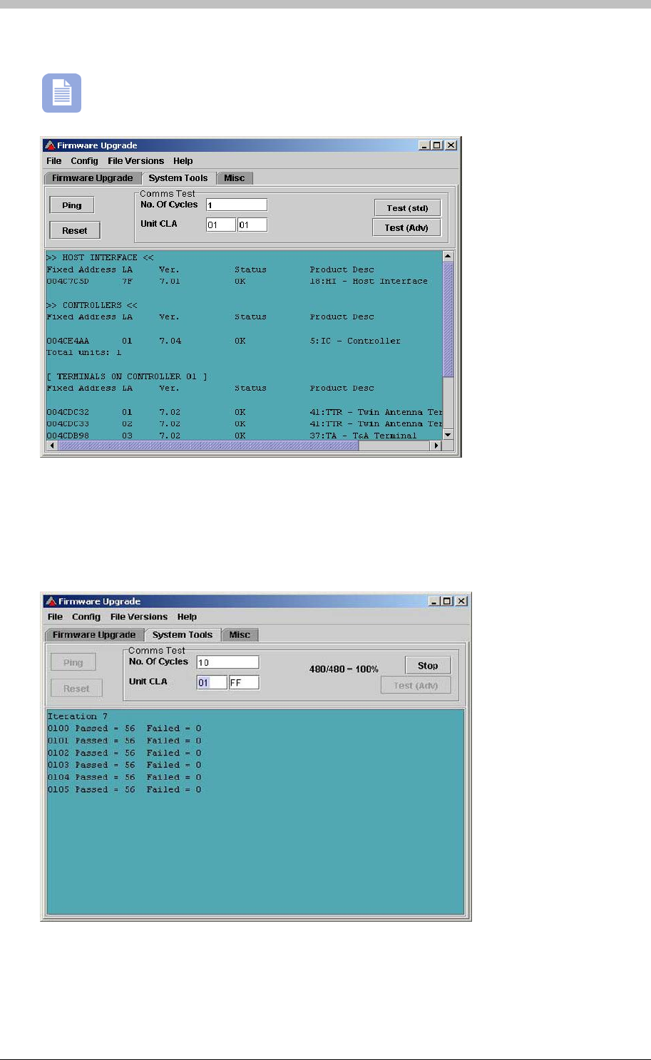
Hardware Maintenance
Performing a Comms Test
You must perform a Ping Test before you run a comms test.
• The No. of Cycles field specifies the number of times that the Comms test cycles through
sending and receiving data packets from units.
• The Test (std) button displays the Comms Test window in a simple format.
• The Test (Adv) button displays the Comms Test window in a detailed grid format
162 Tuesday, 11 July 2006

IXP300/IXP400 Installation Guide
Hardware Diagnostics
• Onboard LEDs – Some ImproX hardware devices have onboard LEDs that indicate the
communication, inputs, and relays statuses. Therefore, LEDs are a useful in field-diagnostic
tools when Host PC is unavailable. Various diagnostic options are discussed later in this
chapter.
Hardware Testing
• Onboard diagnostic LEDs – units display communication status via onboard LEDs. This is
useful if you are working on the unit or do not have access to the Host PC.
• Comms Test – use the Firmware Upgrade utility to run a Comms test. This ensures that
communication between the unit and Host PC is present.
Communications
• Ping test – used to test whether a connection between units or the Host PC is present.
Details are provided for each unit in the Specific Maintenance section on page 163.
Card Reading
Test the read range of a Reader by presenting a Card form a distance and moving it closer to
the Reader. When the card is read, the Reader beeps or flashes its LED depending on its
features and settings. Refer to the ImproX TT section on page 166 for more details.
Buzzer
Units with buzzers make a beep sound on presentation of a Tag. However, the buzzer must be
enabled via the ImproNet Access software application to work.
LEDs
LEDs provide a visual indicator for unit communication status and Tag reading status.
Specific Maintenance
ImproX RH
• Ping Test – use the Firmware Upgrade utility to run a Ping test. Ensure that the unit
responds.
• Diagnostic LEDs:
− USB LED illuminates when ImproNet Engine is polling
− RS485 LED illuminates when communication is established between the Controller and
the ImproX RH
• POST Test – on power-up, the Controller automatically runs a Power On Self Test (POST).
During this test, the diagnostics LEDs indicate unit status.
Tuesday, 11 July 2006 163
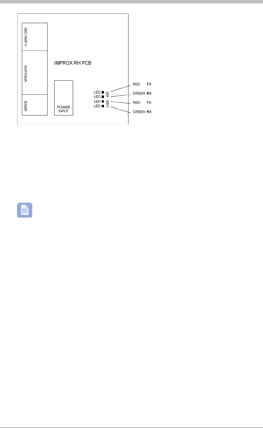
Hardware Maintenance
The LED changes from red to green, and the buzzer beeps when a Tag is read.
Figure 52 - ImproX RH Diagnostic LEDs
ImproX RRA
• Tag Reading Test – place a Tag on the unit. In ImproNet Access, create a new Tag
Holder. Select Read Tag. The Tag’s number should display in Tag Code textbox. Refer to
the Add or Edit a Tag Holder section on page 251 for details.
• POST Test – on power-up, the Reader automatically runs a Power On Self Test (POST).
During this test, the LED illuminates RED and the buzzer beeps.
ImproX IC
• Ping Test – use the Firmware Upgrade utility to run a Ping test. Ensure that the Controller
responds.
• Comms Test – use the Firmware Upgrade utility to run a Comms test. This ensures that
communication between the Controller and Host PC is present.
• Onboard LEDs provide real-time indication of communication status for Port 1 (Terminal)
and Port 2 (Controller) comms busses. When you have configured the attached Terminals
in ImproNet Access, LEDs 2, 3, 4, and 5 are permanently on.
− LEDs 2 and 3 indicate that the Controller is sending and receiving information from its
Terminals. Intermittently flashing LEDs indicate potential communication problems;
probable causes are bad wiring bad wiring, induced noise on the comms bus, or faulty
Terminals on the comms bus.
− LEDs 4 and 5 indicate the Controller comms bus state. If both LEDs are on, there is
good communication between the ImproX HI (not UL evaluated) and the ImproX RH.
The LEDs are off if the HI or RH is offline.
• Power LED – remove power form unit. Reconnect power to unit – the power LED
illuminates when sufficient voltage is available.
164 Tuesday, 11 July 2006
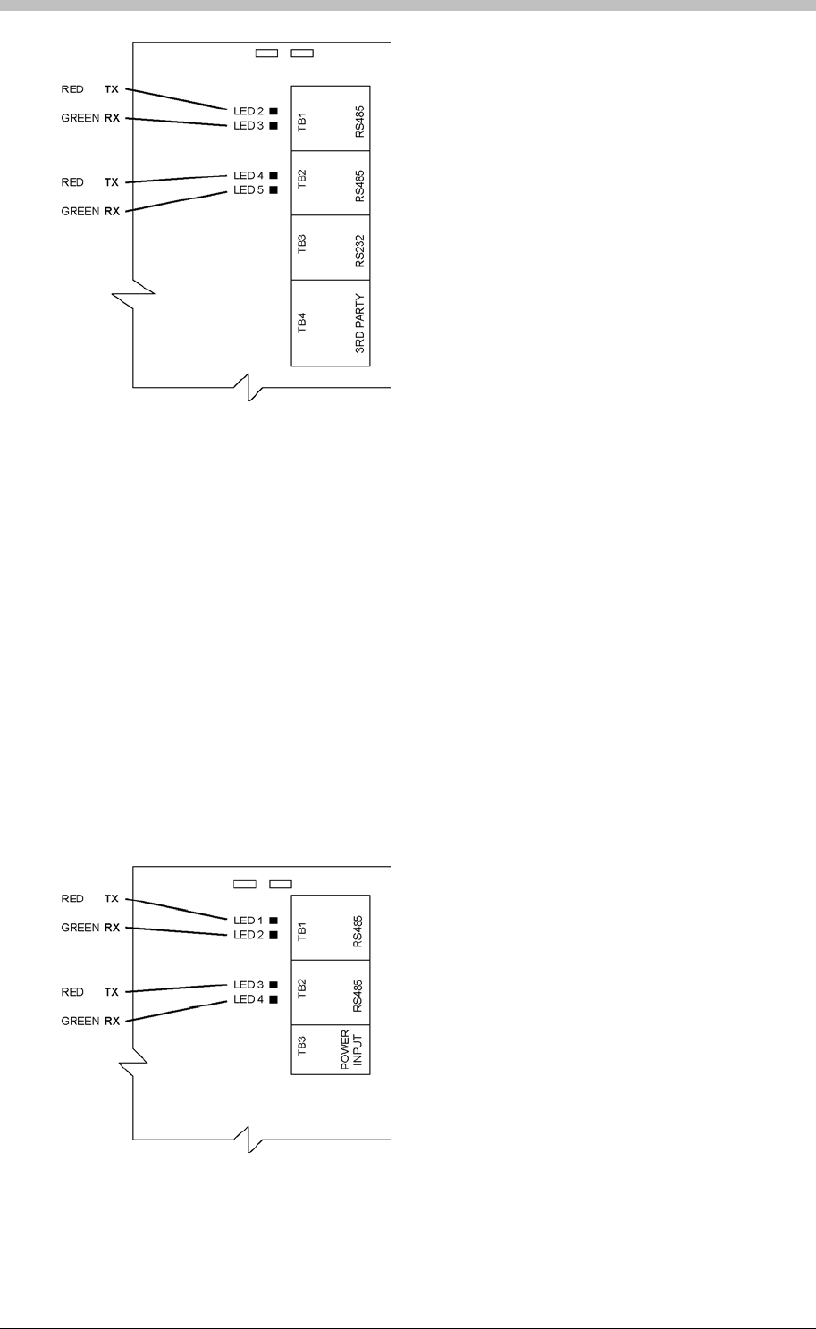
IXP300/IXP400 Installation Guide
Figure 53 - ImproX IC Diagnostic LEDs
ImproX AC
• Ping Test – use the Firmware Upgrade utility to run a Ping test. Ensure that the Controller
responds.
• Comms Test – use the Firmware Upgrade utility to run a Comms test. This ensures that
communication between the Controller and Host PC is present.
• Onboard LEDs provide real-time indication of communication status for Port 1 (Terminal)
and Port 2 (Controller) comms busses. When you have configured the attached Terminals
in ImproNet Access, LEDs 1, 2, 3, and 4 are permanently on.
− LEDs 1 and 2 indicate that the Controller is sending and receiving information from its
Terminals. Intermittently flashing LEDs indicate potential communication problems;
probable causes are bad wiring bad wiring, induced noise on the comms bus, or faulty
Terminals on the comms bus.
− LEDs 3 and 4 indicate the Controller comms bus state. If both LEDs are on, there is
good communication between the ImproX HI (not UL evaluated) Interface and the
ImproX RH. The LEDs are off if the ImproX HI or ImproX RH is offline.
Figure 54 - ImproX IC Diagnostic LEDs
Tuesday, 11 July 2006 165
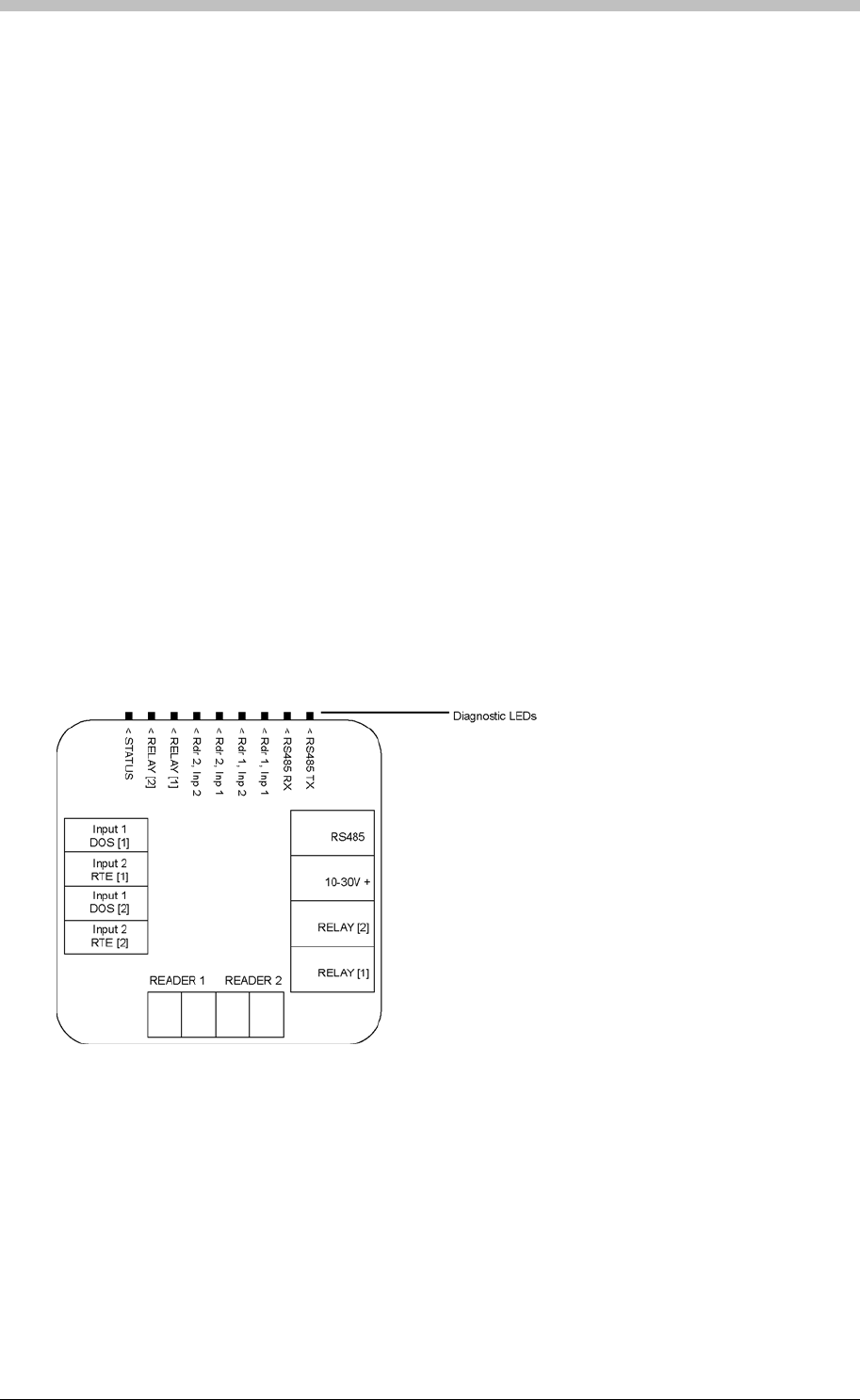
Hardware Maintenance
ImproX TT
• Ping Test – use the Firmware Upgrade utility to run a Ping test. Ensure that the Terminal
responds.
− If a parameter fails, the antenna Reader emits a continuous beep for 2 seconds
• Comms Test – use the Firmware Upgrade utility to run a Comms test. This ensures that
communication between the Terminal and Controller is present.
• POST Test – on power-up, the Terminal automatically runs a Power On Self Test (POST).
POST tests the RAM and Flash Checksums, and the Read/Write Circuitry. The results of
the POST are available as diagnostic information from the Controller or PC.
− When POST is complete, the Terminal emits two short beeps
• Onboard Diagnostic LEDs:
− RS485 Rx and Tx.
− Reader 1 and 2, Input 1 and 2.
− Relay 1 and 2.
− Status LED.
• Test Mode – Tests Readers attached to ImproX TT. This mode indicates when a Tag is in
range and being read by the Reader.
To access Test Mode, remove the RS485 communications cable from the ImproX TT. Wait
for approximately 10 seconds until the red LED on the Antenna attached to the ImproX TT
flashes intermittently. Present a Tag to the Reader. When the Tag is read the LED
changes to solid red and the buzzer emits a continuous, long beep while the Tag is in range.
Use this procedure to verify that a Reader is reading a Tag, or to determine the Tag reading
range.
Figure 55 - ImproX TT Diagnostic LEDs
ImproX O16
• Ping Test – use the Firmware Upgrade utility to run a Ping test. Ensure that the Terminal
responds.
• Comms Test – use the Firmware Upgrade utility to run a Comms test. This ensures that
communication between the Terminal and Controller is present.
• Status LEDs – Terminal bus comms is correct if the green LED and the Red LED on the
Terminal are flashing. The Rx and Tx LEDs are continuously on when the Terminal is
communicating correctly. If they flash intermittently, there are communication problems.
166 Tuesday, 11 July 2006
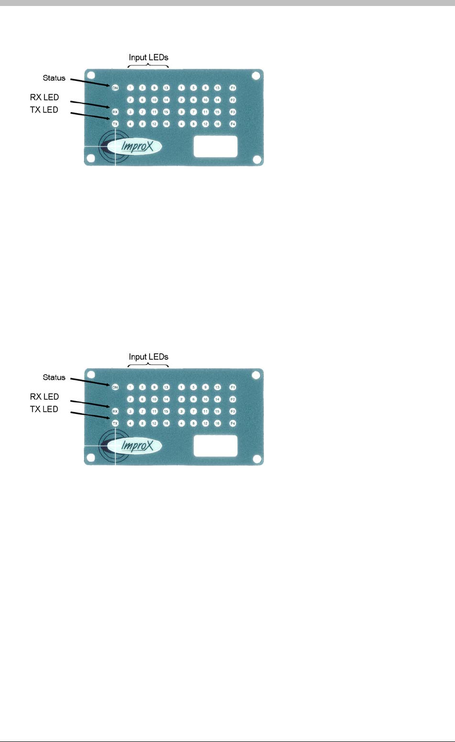
IXP300/IXP400 Installation Guide
The Relay LEDs indicate when the processor has sent a command for a particular relay to
activate.
activate.
Figure 56 – Position of the Status Indicators on the Front End Plate
ImproX I16
• Ping Test – use the Firmware Upgrade utility to run a Ping test. Ensure that the Terminal
responds.
• Comms Test – use the Firmware Upgrade utility to run a Comms test. This ensures that
communication between the Terminal and Controller is present.
• Status LEDs – Terminal bus comms is correct if the green LED and the Red LED on the
Terminal are flashing. The Rx and Tx LEDs are continuously on when the Terminal is
communicating correctly. If they flash intermittently, there are communication problems.
The Relay LEDs indicate when the processor has sent a command for a particular relay to
Figure 57 – Position of the Status Indicators on the Front End Plate
ImproX ER
• Ping Test – use the Firmware Upgrade utility to run a Ping test. Ensure that the Terminal
responds.
• Comms Test – use the Firmware Upgrade utility to run a Comms test. This ensures that
communication between the Terminal and Controller is present.
• Test Mode – Testing Readers attached to ImproX ER. This mode indicates when a Tag is in
range and being read by the Reader.
To access Test Mode, remove the RS485 communications cable from the ImproX ER. Wait
for approximately 10 seconds until the ImproX ER’s red status LED flashes intermittently.
Present a Tag to the Reader. When a Tag is read the Status LED changes to solid Green
and the Buzzer emits a long, continuous beep while the Tag is in range. Use this procedure
to verify that a Reader is reading a Tag, or to determine the Tag reading range.
Tuesday, 11 July 2006 167

Hardware Maintenance
ImproX MMA
• Tag Reading Test – present a Tag to the Reader by moving in from a distance. The status
LED illuminates when the Tag is read. Ensure that the read distance is adequate.
• LED Test – using ImproNet Access, set the Reader’s LED state to red strobe green, and
then to green strobe red. Ensure that the LED flashes red and green for both settings. For
details, refer to the Status LED section on page 239.
ImproX Card Readers
Card Readers’ are dependant on their host Terminal. Therefore, refer to the ImproX TT
maintenance section on page 166 for details.
168 Tuesday, 11 July 2006

IXP300/IXP400 Installation Guide
PART II – Getting Started with ImproNet Software
ImproNet Software has not been evaluated by UL
Tuesday, 11 July 2006 169

Hardware Maintenance
170 Tuesday, 11 July 2006
IXP300/IXP400 Installation Guide
Minimum PC Specifications
You need to consider a number of factors to determine the correct PC specifications for different
scenarios.
The Database Server usually has the highest specification requirements. Consider the following
factors when specifying the Database Server:
• Number of doors (Terminals)
• Number of Tag Holders supported by the system
• Number of client (Module) connections to the database
Database Server
Scenario 1
• 1 to 5000 Tag Holders
• Less than 5 client modules connecting to Database Server
• Less than 100 doors
Hardware Requirement
CPU Pentium II 450MHz or faster
Memory 256 MB RAM
Hard Disk 1GB available space
Display 800x600, 16-bit colour
Graphics Card 800x600, 16-bit colour
Optical Drive CD-ROM drive
Input Devices Mouse and keyboard
Power supply 250W Uninterruptible power supply unit or as
specified in mainboard manual
Software Requirement
Operating System Windows 2000, XP, or NT
Database System FireBird 1.5 by the Open Source Community.
(Supplied on the installation CD)
Tuesday, 11 July 2006 171
Minimum PC Specifications
Scenario 2
• 5 000 to 10 000 Tag Holders
• Greater than 5 client modules connecting to Database Server
• Greater than 100 doors
Hardware Requirement
CPU Pentium III 1GHz or faster
Memory 512 MB RAM
Hard Disk 2GB available space
Display 800x600, 16-bit colour
Graphics Card 800x600, 16-bit colour
Optical Drive CD-ROM drive
Input Devices Mouse and keyboard
Power supply 300W Uninterruptible power supply unit or as
specified in mainboard manual
Software Requirement
Operating System Windows 2000, XP, or NT
Database System FireBird 1.5 by the Open Source Community.
(Supplied on the installation CD)
Scenario 3
• Greater than 10 000 Tag Holders
• Greater than 10 client modules connecting to Database Server
• Greater than 150 doors
Hardware Requirement
CPU Pentium 4 1.6GHz or faster
Memory 1GB RAM
Hard Disk 4GB available space
Display 800x600, 16-bit colour
Graphics Card 800x600, 16-bit colour
Optical Drive CD-ROM drive
Input Devices Mouse and keyboard
Power supply 300W Uninterruptible power supply unit or as
specified in mainboard manual
Software Requirement
Operating System Windows 2000, XP, or NT
Database System FireBird 1.5 by the Open Source Community.
(Supplied on the installation CD)
172 Tuesday, 11 July 2006

IXP300/IXP400 Installation Guide
ImproNet Module PCs
Engine
• Part number: INS902-0-0-GB-xx
Hardware Requirement
CPU Pentium II 400MHz or faster
Memory 128MB RAM
Hard Disk 500MB available space
Display 800x600, 16-bit colour
Graphics Card 800x600, 16-bit colour
Ports Free RS232 Serial port
Optical Drive CD-ROM drive
Input Devices Mouse and keyboard
Power supply 250W Uninterruptible power supply unit or as
specified in mainboard manual
Software Requirement
Operating System Windows 2000, XP, or NT
Database System FireBird 1.5 by the Open Source Community.
(Supplied on the installation CD)
Access, Quicktag, Visitor, Transaction Viewer, Alarms
• Part number: INS904-1-0-GB-xx
Hardware Requirement
CPU Pentium II 450MHz or faster
Memory 256MB RAM
Hard Disk 1GB available space
Display 1024x768, 16-bit colour
Graphics Card 1024x768, 16-bit colour
Ports Free RS232 Serial port
Optical Drive CD-ROM drive
Input Devices Mouse and keyboard
Power supply 250W Uninterruptible power supply unit or as
specified in mainboard manual
Printer (optional) Standard Inkjet or Laserjet
Software Requirement
Operating System Windows 2000, XP, or NT
Database System FireBird 1.5 by the Open Source Community.
(Supplied on the installation CD)
Tuesday, 11 July 2006 173

Minimum PC Specifications
Graphics Modules—Designer and Runtime
• Part number: IXP331-0-0-GB-xx (Designer)
• Part number: IXP332-0-0-GB-xx (Runtime)
Hardware Requirement
CPU Pentium III 1GHz or faster
Memory 512MB RAM
Hard Disk 1GB available space
Display 1024x768, 16-bit colour
Graphics Card 1024x768, 16-bit colour
Ports Free RS232 Serial port
Optical Drive CD-ROM drive
Input Devices Mouse and keyboard
Power supply 250W Uninterruptible power supply unit or as
specified in mainboard manual
Printer (optional) Standard Inkjet or Laserjet
Software Requirement
Operating System Windows 2000, XP, or NT
Database System FireBird 1.5 by the Open Source Community.
(Supplied on the installation CD)
Known Issues
• There have been isolated cases of ImproNet not installing correctly on some Dell PCs.
174 Tuesday, 11 July 2006

IXP300/IXP400 Installation Guide
ImproNet Applications
The ImproNet Software Suite consists of a collection of Modules and Utilities. The Modules
form the core of the ImproNet Suite and provide control for everyday and important functions.
The Utilities provide support for advanced configuration and system maintenance. This section
provides a brief description of the ImproNet Modules and Utilities.
UL has evaluated the IXP300/400 system as a stand-alone type access control system.
In other words, it operates as intended and does not rely on a constant, dedicated PC
connection.
ImproNet Modules
It is possible to run the entire ImproNet Software Suite on a single PC. However, the Suite is
designed to operate on multiple PCs in a Client-Sever configuration. Therefore, to ensure
correct functioning, it is essential to have dedicated PCs as specified in this manual.
The configurable aspect of the ImproNet modules enables efficient operation in LAN and WAN
infrastructures; Each ImproNet module performs a specific function.
ImproNet Access
ImproNet Access is the configuration module for ImproNet. It performs a number of important
functions including:
• Site and Host configuration
• Hardware configuration—enables installer to define and configure ImproX hardware such as
Terminals and Controllers
• Tag Holder Access Group configuration. The key element of access control—A Tag Holder
Access Group is a combination of when (Access Time Patterns) and where (Areas) Tag
Holders have access
ImproNet Engine
ImproNet Engine is the communications module. It is required to do the following:
• Monitor the database for edits made by ImproNet client applications such as ImproNet
Access, or Quicktag. Edits or changes are communicated to the ImproX Controllers.
• Polls the ImproX Controllers for transactions, then logs the transactions to the ImproNet
database.
• Runs the ImproNet Reports web server. Note that the Engine must be running for web
reports to run.
• Open socket connection ports for modules such as ImproNet Graphics, which make a direct
connection to the Engine.
Tuesday, 11 July 2006 175

ImproNet Applications
ImproNet Quicktag
The Quicktag module is used for enrolling and editing of Employee and Visitor tags.
ImproNet Visitor
The Visitor module is used for enrolling Visitor tags. You can assign tags to the Visitor Tag
Holder Access Groups in this module only. Employee Tag Holder Access Groups are not
accessible from the Visitor module.
ImproNet Graphics Designer
Used to create a graphic plan representation of a Site. It enables arranging of icons that
represent ImproX hardware units, on a floor plan.
ImproNet Graphics Runtime
Provides real-time graphical monitoring of the site.
ImproNet Alarms
Provides real time monitoring of alarm transactions.
ImproNet Transaction Viewer
Provides real-time monitoring of transactions
ImproNet Utilities
Archive
The Archive utility enables you to create copies of the ImproNet Database on specified dates.
You can use these Database copies to generate transaction reports for a particular historical
period. Running Archive also decrease the size of the ImproNet Database.
DBUpgrade
The DBUpgrade enables automatic updating of the ImproNet Database. The utility checks for
available update scripts and processes them automatically.
IBConsole
IBConsole is a third-party database configuration and administration tool. You can use it to
perform advanced configuration and administration tasks on the ImproNet Database.
Import
This utility is used to import comma separated value (CSV) files into the ImproNet Database.
You can use it to import data such as employee records from other applications, to the ImproNet
Database. Refer to the CSV Import on page 296 for details.
Find Duplicates
Importing CSV files into the ImproNet Database can result in duplicate records. The Find
Duplicates utility enables you to search the Database for, and delete duplicate records.
176 Tuesday, 11 July 2006

IXP300/IXP400 Installation Guide
IXP200 Conversion
The IXP200 Conversion utility facilitates conversion of IXP200 data to the ImproNet format.
Note that this utility converts user data only. Site information must be re-configured in
ImproNet.
Pump
Pump transfers user-defined data from the existing ImproNet Database to a new empty
database when ImproNet is upgraded to a new version.
Translate
This utility facilitates changing the field names in the ImproNet Database to words of another
language. The Translate utility requires you to manually enter replacement text.
Unlock
The Unlock utility enables you to activate applications that are otherwise disabled. You do this
by entering a code called a Product Unlock Key into the utility.
Tuesday, 11 July 2006 177
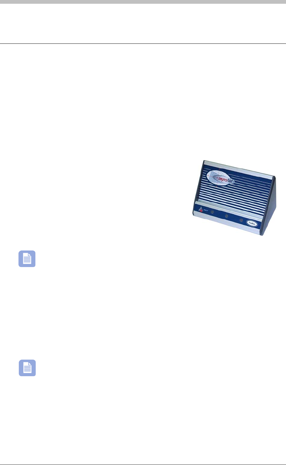
Peripheral Hardware
Peripheral Hardware
ImproNet use various peripheral hardware devices to perform a software protection function.
Some ImproNet modules search for these devices on start-up. If the required device is not
present, the module does not run. Some devices also perform tag Enrollment and
communication functions.
ProX-Mate
The ProX-Mate performs a tag Enrollment and software protection function. It connects
directly to the PC’s RS232 serial port or to the Host Interface that connects to the PC. There
are two versions of ProX-Mates.
INS900
INS900 is bundled with the INS904 software package.
The following software modules run with the XPM:
• ImproNet Access
• ImproNet Quicktag
• ImproNet Visitor
• Graphics Designer
• Graphics Runtime
An additional unlock code is required if the ProX-Mate is required to run the iNet DVR
integration. Contact your local Impro Distributor for more information.
Utility ProX-Mate – XPM910
XPM910 Utility ProX-Mate is generally used when ImproNet modules are required to run on
multiple PC’s. The Utility ProX-mate enables you to run the following modules:
• QuickTag
• Visitor
• Graphics Runtime
• Graphics Designer
The Utility ProX-Mate requires an additional unlock code to run ImproNet Access.
178 Tuesday, 11 July 2006
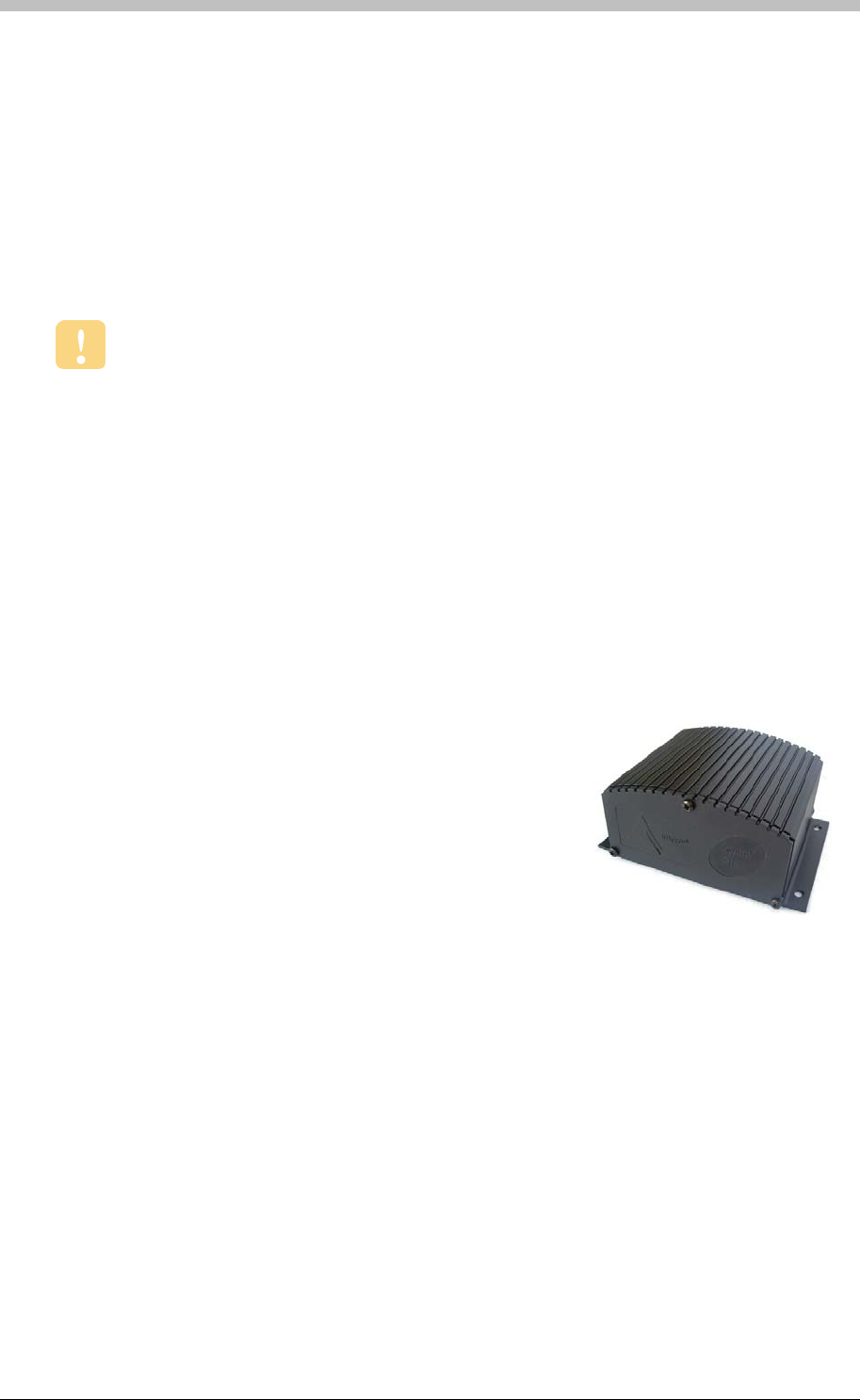
IXP300/IXP400 Installation Guide
Host Interface—Serial Communications Converter
The Host Interface does the following:
• Acts as an RS232 to RS485 converter
• Performs a software protection function
• Facilitates Inter Controller communications
• Software protection—ImproNet Engine requires an ImproX
RH Host Interface to start-up.
USB Enrollment Readers
USB Enrollment Readers are compatible with ImproNet software V6.4.4 or later only.
USB Enrollment Readers perform similar functions to standard Enrollment readers, but have a
different communications architecture and support additional features.
New Features
• USB connectivity
• Support for third-party readers and tag Enrollment
• HID tag support
• MiFare tag support
ImproX RH
The ImproX RH is a USB version of the Host Interface. It is
used for the following:
• RS485 to USB converter.
Facilitates Inter Controller Communications—the ImproX RH must be connected to an external
battery backed-up power supply to ensure that Inter Controller communications is maintained
during a power failure or PC reboot.
The ImproX RH does not support the ProX-Mate. However, the following alternatives are
available:
• ImproX RRA—supports the Enrollment of 125KHz Impro and HID tags.
• ImproX RRM—supports the Enrollment of MiFare tags.
The ImproX RH also supports the standard ImproX Antenna readers and MiFare remotes.
Tuesday, 11 July 2006 179
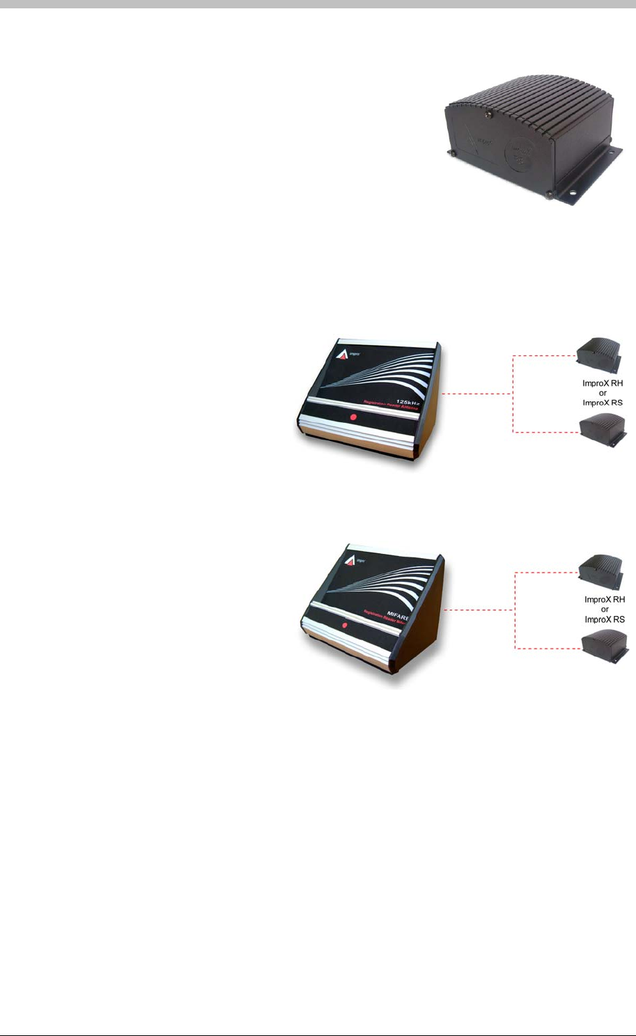
Peripheral Hardware
ImproX RS
The ImproX RS enables third-party readers such as Barcode
and Magstripe readers, to interface with the ImproNet system
as Enrollment readers.
It also perform a software protection function for the same
modules supported by the Utility ProX-Mate:
• QuickTag
• Graphics Runtime
• Visitors
• Graphics Designer
ImproX RRA
The ImproX RRA is an external
Enrollment reader that connects to an
ImproX RH or ImproX RS unit.
The ImproX RRA is used to read
125KHz Tags.
ImproX RRM
The ImproX RRM is an external
Enrollment reader that connects to an
ImproX RH or ImproX RS unit.
The ImproX RRM is used to read
MiFare 13.56 MHz Tags.
180 Tuesday, 11 July 2006

IXP300/IXP400 Installation Guide
ImproNet Network Specifications
The ImproNet suite is designed to run over a network in Client-Server mode. However, it can
also run successfully on a single PC.
Architecture
Client-Server
Client-Server architecture consists of users’ PCs (Clients) connected via a network to a central
host (Server). In most situations, Client PCs are workstations that access files or databases, or
applications running on one or more Servers.
In ImproNet, the following are Server components:
• ImproNet Engine
• ImproNet Database
The rest of the applications are Client components
Software Connection Relationships
Figure 58 illustrates the relationship between the ImproNet Database and ImproNet Client
applications. Socket connections enable communication between PCs. Database
connections enable communication between PCs and the ImproNet Database. Jaybird is an
interface component installed with the Firebird database; it facilitates database interaction.
Routers
Network Hardware
An ImproNet compatible network requires the following hardware:
• CAT5 or CAT6 UTP cabling
• 100Mbps or faster, TCP/IP enabled Network Interface Cards (NICs)
If routers or switches are used, they must conform to the following:
• TCP/IP protocol
• 100Mbps or faster
Tuesday, 11 July 2006 181
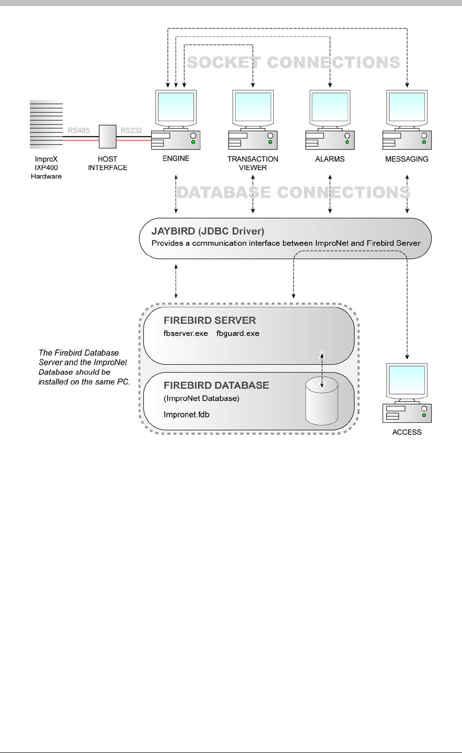
ImproNet Network Specifications
• ImproNet Database
Figure 58 – Software Connection Relationships Diagram
ImproNet Modules in a Network Environment
The ImproNet suite is designed to run over a network in Client-Server architecture. However, all
modules can run on a stand alone PC if required. The following components are important
when running ImproNet over a LAN or WAN:
• Firebird Database Server
• ImproNet Engine
ImproNet Database
ImproNet uses a Firebird database by default. It is installed with ImproNet during the Software
installation process. The default location for the Database is as follows:
• C:\ImproNet\Database\Impronet.fdb
182 Tuesday, 11 July 2006

IXP300/IXP400 Installation Guide
Impronet.fdb is the name of the database file.
Firebird is an open-source product—it has no licensing fee. For more information refer
to the following websites: http://www.opensource.org and http://www.firebirdsql.org/
Firebird Server
Firebird Server is a Database Server program that facilitates connections between the
ImproNet Database and ImproNet Applications such as Engine, and Access.
Firebird Server must be installed in the same PC as the ImproNet Database.
ImproNet Engine
ImproNet Engine functions primarily as a Comms Server. It performs the following functions:
• Retrieves transactions from ImproX Controllers
• Monitors the ImproNet Database for changes
• Communicates Database changes to the ImproX Controllers
Some of Client Applications, such as Graphics Runtime, Transaction Viewer, and Alarms,
process and report information in real-time. Therefore, they use a TCP/IP socket connections to
connect to the Engine, because it is more efficient than a direct database connection.
Socket connections are also used to send messages to ImproNet Engine. For example, when a
Graphics Runtime initiates a Door Unlock command, it is sent to the Engine via a socket
connection. The Engine then, sends the command to the Access Control hardware. T
displays the Socket ports used by ImproNet.
able 15
Transaction
Ports Port Number
26663
Alarm 26661
Messaging 26665
Host Validation 26669
Door Status 26667
Firebird Server 3050
Table 15 - ImproNet Socket Ports
You can configure Socket Ports in ImproNet Access
Tuesday, 11 July 2006 183

ImproNet Network Specifications
The following ImproNet client modules connect to the Engine, or the ImproNet Database, or to
both.
• Access
• Quicktag
• Visitor
• Alarms
• Transaction Viewer
• Graphics Designer
• Graphics Runtime
General Network Requirements
The following requirements are essential for ImproNet to operate over a network:
• Network hardware must support the TCP/IP protocol
• The network must support 100 Mb/s bandwidth or greater
184 Tuesday, 11 July 2006
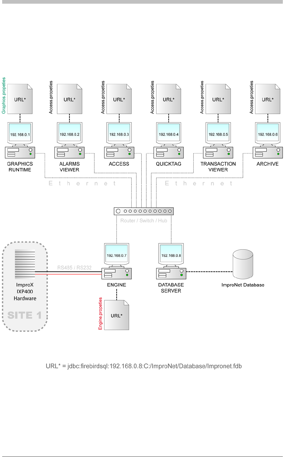
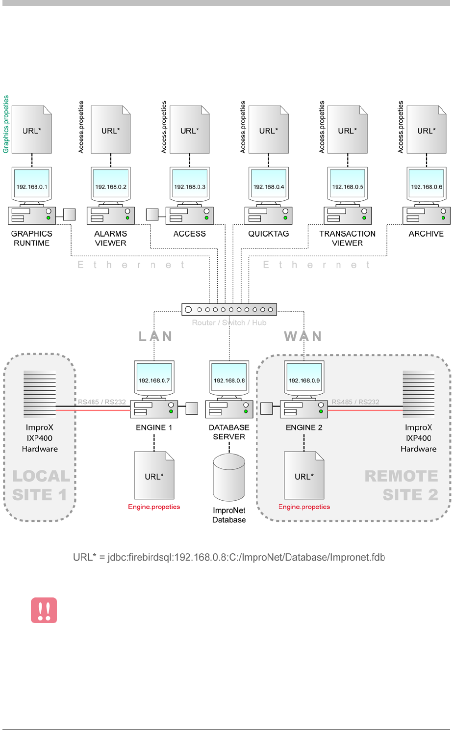
ImproNet Network Specifications
Running ImproNet Applications across a WAN
Figure 60
Minimum WAN Requirements
illustrates the network configuration for running ImproNet across a Wide Area
Network (WAN).
Figure 60 - ImproNet Configuration across a WAN
Communication across a WAN is generally slower than across a LAN. Therefore,
a WAN’s performance must be carefully assessed before ImproNet is
implemented across it.
A WAN must support a minimum speed of 1Mb/s per Engine.
186 Tuesday, 11 July 2006

IXP300/IXP400 Installation Guide
Properties Files
ImproNet Client applications store their connection settings in an editable text files called
Properties Files. These files contain URLs that specify the location of the Database Server. If
the URL is incorrect, the application will not function.
Properties Files are stored in the ImproNet root folder. The following applications have their
own Properties files:
The files have the same name as their application. For example, the Properties file for
ImproNet Access is called Access.properties, and is stored in C:\Impronet. Other ImproNet
applications including Quicktag, Visitor, Alarms, and Transaction Viewer use the
Access.properties file.
The following code is the default format for the Database URL:
• Access
• Archive
• Engine
• Graphics
• Pump
There is one Access.properties file per PC.
Configuring ImproNet Modules for a Stand Alone (Single PC)
System
This section provides the requirements for installing all ImproNet modules, including the
Database Server, on a single PC.
Connecting to the Database
The ImproNet suite is installed by default to C:\Impronet. The URL in each Client Properties
File points to the following default Database location:
• C:\Impronet\Databases\Impronet.fdb
If you move the Database to another location on the PC, you must to change the URL in each
Properties file to point to the new Database location.
For security reasons, we recommend that you do not share the Database folder.
• access.database.Interbase.URL=jdbc:firebirdsql://localhost/C:/ImproN
et/Database/Impronet.fdb
Tuesday, 11 July 2006 187
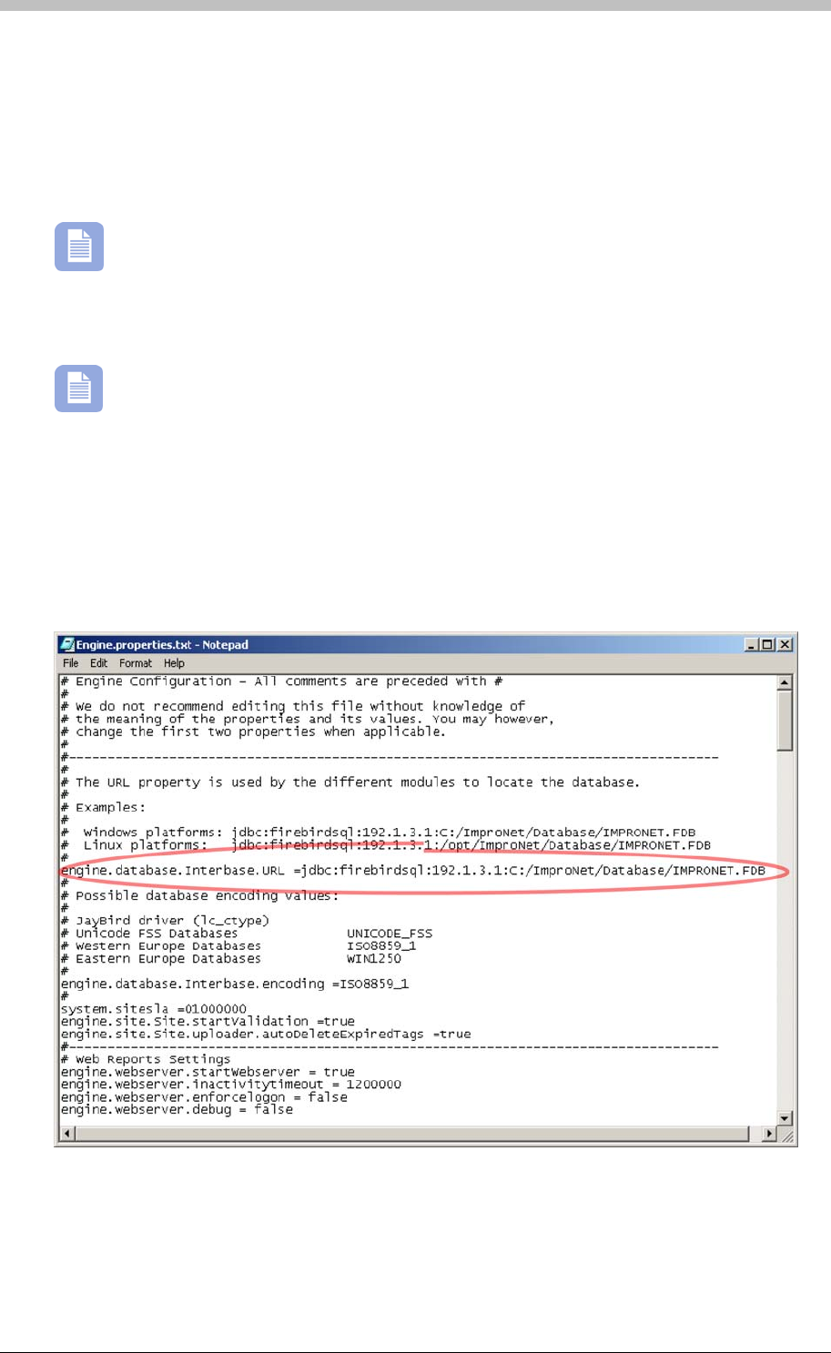
ImproNet Network Specifications
If you move the ImproNet Database, you must update this code to reflect the new location. For
example, if you move the IMPRONET.FDB file to a folder called Site1 on drive D, you must
change the URL to the following:
• access.database.Interbase.URL=jdbc:firebirdsql://localhost/D:/Site1/
Impronet.fdb
If other ImproNet Applications are installed on the Database Server, the URLs in each
Client Properties File must use a local path, not a network path.
Configuring ImproNet Modules for a LAN
LAN Networking has not been evaluated by UL.
If ImproNet modules are distributed across a LAN, Properties files must be edited to point to the
Database Server PC, and the location of the Database on the PC.
Figure 61 shows an example the Engine.Properties file when ImproNet is installed over a
network.
Figure 61 - Edited Engine Properties File
Connecting to the Database
188 Tuesday, 11 July 2006

IXP300/IXP400 Installation Guide
In Figure 61, the Database resides on a PC with an IP address of 192.1.3.1. In a stand-alone
configuration, the default computer address is always Localhost. In a networked environment,
replace Localhost with the IP Address or Machine Name of the Database Server.
Advanced Engine Settings
Configuring ImproNet Modules for a WAN
WAN Networking has not been evaluated by UL.
Running ImproNet across a WAN is similar to running ImproNet across a LAN. However,
WANS generally have slower performance. ImproNet has options to minimize the resources
required by a slower-than-usual architecture.
The following text box displays an extract from the Engine.properties file. Lines beginning with
a # are comments describing the settings. Edit the highlighted settings as required to
compensate for the Engine running across a WAN:
# uploader.cycleDelay is the delay in-between uploader cycles
# Increase this to reduce network traffic on a wan eg. 60000 (1 minute)
# Note that changes to the controllers will be delayed by this amount when editing
# Default is 10000 (10 seconds)
engine.comms.uploader.cycleDelay = 10000
#
# uploader.interTable delay is the delay in processing each table in the Uploader
# Increase this if you wish to reduce network traffic on a wan during an Upload
cycle eg. 1000
# Default is 10
engine.comms.uploader.interTableDelay = 10
#
# Daily start and end times for uploader - it will upload only within these times
# Set start time greater than end time if you wish upload only at night eg. 2100 to
0600
# Default is 0000 to 2400
engine.comms.uploader.dailyStartTime = 0000
engine.comms.uploader.dailyEndTime = 2400
#
# interPollDelay is the delay between successive polls
# Use this to poll less often to reduce network traffic over etherpads on a wan eg. 2000
# Default is 200
engine.comms.poller.interPollDelay = 200
#
# Daily start and end times for the poller - it will poll only within these times
# Set start time greater than end time if you wish poll only at night eg. 2100 to 0600
# Default is 0000 to 2400
engine.comms.poller.dailyStartTime = 0000
engine.comms.poller.dailyEndTime = 2400
Tuesday, 11 July 2006 189

ImproNet Network Specifications
#
# The uploader database connection is reset periodically every so often
# This releases memory resouces - default is reset once a day - should not need to
change this
# Default is 86400000 (once a day)
engine.uploader.databaseConnectionResetTime = 86400000
You can also edit these settings via the ImproNet Engine software. Refer to the
section on page 220 for details. Advanced Properties
Figure 60
Connecting to the Database
In this example, change the System Site SLA from system.sitesla = 01000000 to
Using Routers Configuration
• Number of hardware devices configured in ImproNet Access
• Number of ImproNet client application that access data via a router
WAN routers must enable pass-through communication on the port that the Database Server is
using for connection. This is essential if the router has a built-in firewall.
Firebird uses port 3050 by default. Therefore, ensure that WAN routers have TCP/IP enabled
for network traffic sent to port 3050.
Every ImproNet installation will have different bandwidth requirements. For example, an Engine
that uploads 200 Tags to a single Controller can do so through a 64k ISDN line. However, an
on page 186 illustrates a possible ImproNet Configuration where a second site is
connected via a WAN. In this type of scenario, it is important to determine how much bandwidth
is available to the Engine Server. If resources are limited, we recommend editing the advanced
Engine settings to further reduce the bandwidth that Engine requires to operate efficiently.
Refer to Figure 60 on page 186—to connect the Engine 2 PC on Site 2 to the Database
Server, edit the Engine.properties file on Engine 2 to point to the Database Server.
Because a second Engine (Site) has been added, you must update the Engine.properties file
on Engine 2 to reflect Site 2. You must do this before you execute an Auto ID procedure.
system.sitesla = 02000000
The following factors affect bandwidth when a router is used:
• Number of Tag Holders
• Existing WAN load usage
Router Configuration
Firebird Port
Bandwidth Requirements
190 Tuesday, 11 July 2006

IXP300/IXP400 Installation Guide
Engine that has to upload 5000 tags to five Controllers needs at least a 768k dedicated ISDN
line.
Bandwidth-intense activities such as uploading Tag data to Controllers can be
performed after-hours to reduce network load during normal hours.
It is impossible to specify the exact requirement for a WAN. However, we recommend a
minimum WAN connection bandwidth of 512k/s. For optimal performance across a WAN, we
advise you to consider a connection with at least 1Mb/s of bandwidth.
Tuesday, 11 July 2006 191

System Concepts
System Concepts
System Architecture Concepts
An ImproNet Access Control System comprises the following elements:
• Locations
The ImproNet System Architecture is illustrated in Figure 12 on page 41.
Sites
Each System consists of one or more Sites. Sites are independent of each other. Each Site
can have only one Host. The Host is the Engine module for a particular Site.
An IXP300 Site supports up to 16 IC Controllers. Each Controller supports up to 48 Terminals
(fixed addresses).
Sites using IC and AC Controllers are also possible. However, a Site using both
Controller types is limited to the parameters of the IC Controller. For example,
such a Site will accept a maximum of 16 Controllers and 8000 Tags instead of the AC
Controller limit of 160000 Tags.
• Door Exit
• Sites
• Controllers
• Zones
Controllers
An IXP400 Site supports up to 64 AC Controllers. Each Controller supports up to 64
Terminals (fixed addresses).
Location
A location is a physical access control point. It comprises a group of Terminals servicing an
access control point such as a Door. A Location supports up to three terminals for the following
functions.
• Door Entry
• Door Relay Control
Zones
A Zone is a group of Locations (access control points). Entry and exit to and from a Zone is
achievable via its Locations only. Generally, a Zone is a physically bounded area containing
one or more locations.
192 Tuesday, 11 July 2006
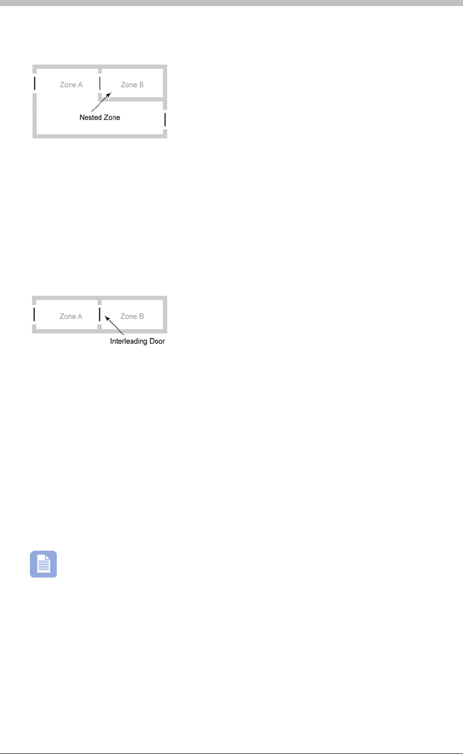
IXP300/IXP400 Installation Guide
A Zone can also contain other Zones within it. This enables an Operator to configure settings
such as Anti-Passback settings. These Zones are referred to as Nested Zones.
Figure 62 - Nested Zone
270
System Building Blocks
The ImproNet Software Suite is designed to run on Microsoft Windows NT, 2000, and XP. Refer
to the section on page 169 for more information. These limitations are important for the
efficiency and reliability of the system.
In this manual, the term Host PC refers to computers that perform control and
supervisory functions, regardless of the number of PCs used.
• Database Server—dedicated to the Site Database
Zone Grouping is when one Zone is linked to another Zone to form a Common Zone. This
enables Tag Holders to enter via a Location in one Zone and exit via a Location in another
Zone. For more information on Common Zones, refer to the Common Zones section on page
.
Adjacent Zoning is a form of Zone grouping. It is when two neighbouring Zones use a single
Location to go from the one Zone to the other Zone.
Figure 63 - Adjacent Zoning
ImproNet Software Suite
Supervisory Elements—Host PC
Each Site requires a Host PC for Control and Supervision of the Site. Alternatively, multiple PCs
can be used for the same function.
On a typical Site, the following functions are performed by the Host PC:
• Site Engine—dedicated to processing communications between the Database Server and
the Controllers. It also performs a polling function from the Server to the Controllers.
• Client Workstation—dedicated to supervisory aspects. These include entering and
deleting data, viewing Graphics Runtime and Alarms, preparing Transaction reports, and
running Utilities. Note that some monitoring installations may need a dedicated PC to run
Graphics Runtime.
Tuesday, 11 July 2006 193
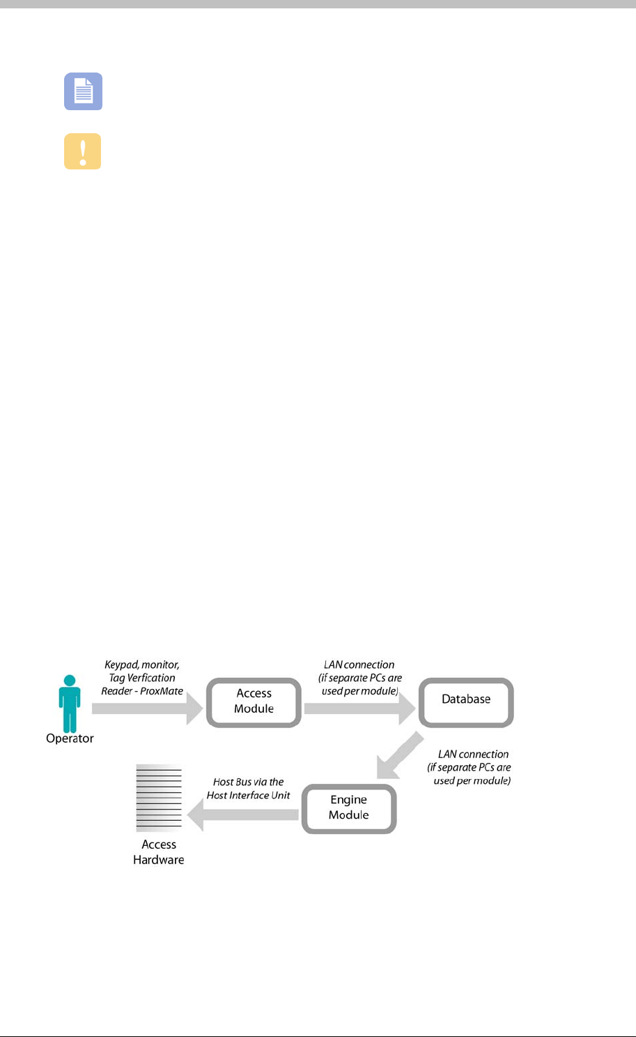
System Concepts
• CCTV—required when Cameras are installed as part of the monitoring system
There are two systems buses in an Access Control system:
• The Host Bus—An RS232 or RS485 bus that links the Host PC via the Host Interface Unit
(ImproX HI or ImproX RH), to the Controllers. Each Site in a System requires its own Host
Bus
• The Terminal Bus—An RS485 bus that connects each Controller to its Terminals. There is
one Terminal Bus per Controller.
Serial Peripheral Ports
Some hardware units have an RS232 Serial Peripheral Port. They can be connected to a single
peripheral device.
Host Interface Unit
The Host Interface unit converts RS232 to RS485. It serves as an interface between the Host
PC and the Controllers.
RH Interface Unit
The RH is the USB equivalent of the Host Interface unit. It converts RS485 to USB. It serves as
an interface between a USB enabled Host PC and the Controllers.
Figure 64 - Access System Communications Paths
Additional, dedicated CCTV PCs may be required depending on the number of
cameras.
The CCTV DVR Server must be a dedicated PC.
System Buses
194 Tuesday, 11 July 2006

IXP300/IXP400 Installation Guide
Software Installation Procedure
ImproNet does not support Windows 95 / 98.
Windows NT, 2000, and XP Professional are recommended operating systems.
Windows 2003 Server requires a different installation. Refer to the Windows 2003
section on page 197 for more information. Server
You must be logged on to Windows with Administrator privileges to install ImproNet.
New ImproNet Installation
The ImproNet Software Suite is supplied on an installation CD-ROM. Before you install it,
ensure you have read the following:
PC Hardware Requirements
Refer to the section on page 169.
Installing both the Access and Engine modules, requires 98MB of available disk space.
Installing the Access module only, requires 50MB of available disc space. The Installation
Wizard verifies that enough space is available. The Database Server requirements are
dependent on the database size.
TCP/IP is required for single and multiple Host PC scenarios to provide IP addresses. A single
Host PC without a Network Interface Card (NIC) installs a Virtual Network adapter such as the
Microsoft Loopback Adapter or the Microsoft Virtual Private Networking (VPN) Adaptor. These
are virtual software adapters only; no additional hardware is required. Install the TCP/IP
protocol using the Windows Control Panel.
Do not install any software until the TCP/IP protocol is installed, and the machine
is assigned an IP address.
ImproNet Engine and Access modules are validated to run on a Linux operating
system. However, no other ImproNet modules are validated yet.
Disk Space Requirements
TCP/IP Network
Tuesday, 11 July 2006 195
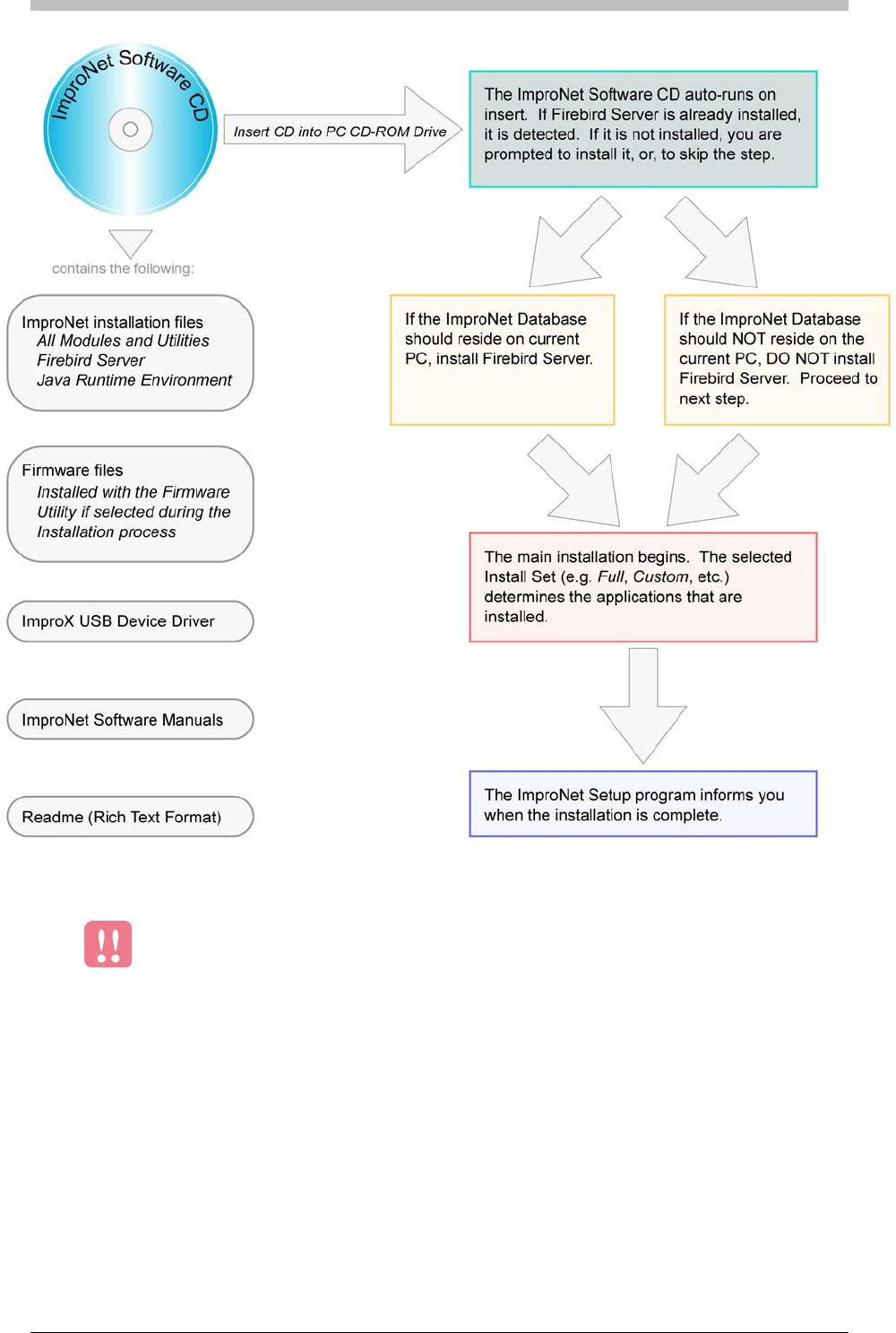
Software Installation Procedure
Figure 65 - ImproNet Software Installation Flowchart
Firebird Server must be installed on the same PC that stores the ImproNet
Database.
196 Tuesday, 11 July 2006

IXP300/IXP400 Installation Guide
Windows 2003 Server
To install the Engine module and IBConsole utility on a Windows 2003 Server PC, do the
following:
5. Check the Run this program in compatibility mode for option
Installation Sequence
alling the Database
Server
2. Applications—Modules and Utilities
1. Open Windows Explorer
2. Navigate to the ImproNet install files on the ImproNet CD
3. Right-click on Setup.exe and select Properties
4. Select the Compatibility tab
6. Select Windows 2000 from the drop-down list
7. Click OK
8. Run Setup.exe using default settings
The ImproNet Installation CD uses an automated, interactive Installation Wizard to guide you
through the installation process. The Wizard prompts you at various stages to select installation
options. This makes it possible to customize the ImproNet Software Suite.
Install the Software in the following sequence:
1. Database Sever—this is ESSENTIAL. Refer to the next section, Inst
3. Database—Installed with the Engine module
4. USB Driver—Only if USB Enrollment readers or Converters are used.
If you have an earlier version of InterBase, InterServer, or InterClient installed on the
PC, you must uninstall them before running the Software Installation Wizard. New
versions of these software programs are installed. If the Installation program detects an earlier
version, you are prompted to remove the earlier version and start again.
We recommend that you read the Release Notes on the Installation CD. The following
items are specifically mentioned: Removal of Interbase V6; Default Username and
Password; Database update, Coding and error settings; Windows XP Restore feature;
Controller and Firmware versions; New software features.
Installing the Database Server
A Database Server is required to host the ImproNet Database. If the ImproNet
Suite is installed on to a single PC, the Database Server is installed automatically.
However, if more than one PC is used to host the ImproNet Software, you must install the
Database Server manually.
Tuesday, 11 July 2006 197
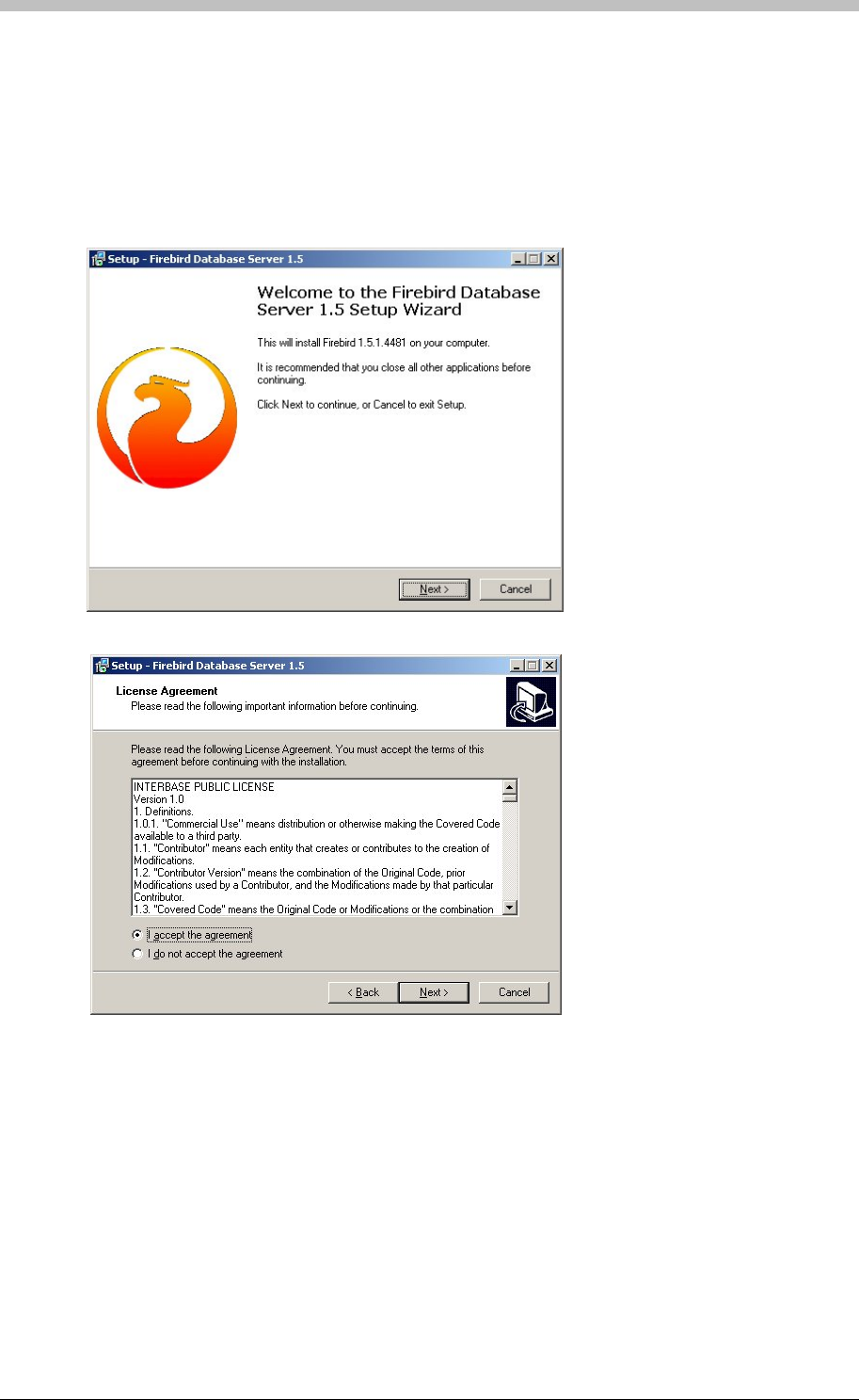
Software Installation Procedure
Any PC on the network can host the Database Server. ImproNet use Firebird 1.5 as its
Database Server. To install Firebird 1.5 manually, proceed as follows:
1. Select a PC to host the Database Server
2. Insert the ImproNet Installation CD in the PC’s CD-ROM drive
3. Browse to the \database\firebird directory on the ImproNet Installation CD
4. Double-click Firebird.exe
5. Follow the onshield instructions
6. Accept the Licence Agreement
198 Tuesday, 11 July 2006
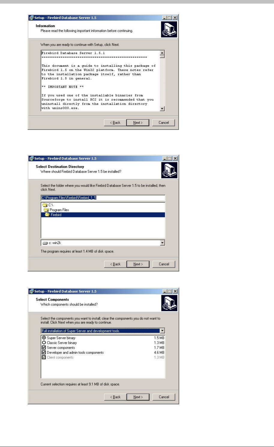
IXP300/IXP400 Installation Guide
7. Select the Destination Directory—we recommend that you use the default location of
C:\Program Files\Firebird\Firebird_1_5
8. Select the Full installation of Super Server and development tools option
Tuesday, 11 July 2006 199
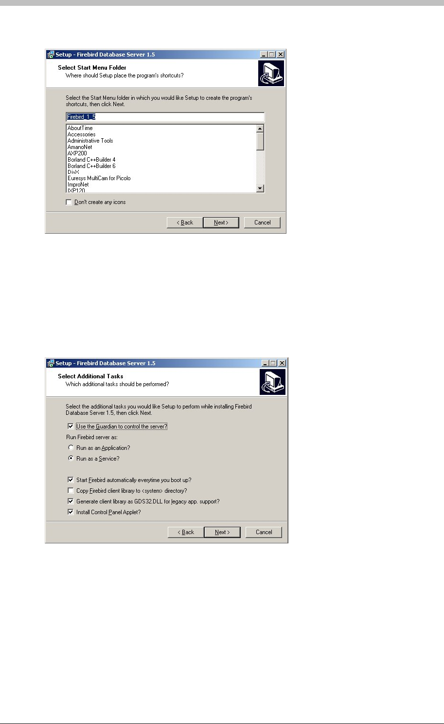
Software Installation Procedure
9. Click Next
10. On the Select Additional Tasks screen:
− Select the Use the Guardian to control the server? option
− Select Run as A Service? option
− Select the Start Firebird automatically everytime you boot up? option
− Select the Copy Firebird client library to <system> directory? option
− Select the Generate client library AS GDS32.DLL for legacy app. support? option
− Select the Install Control Panel Applet? option
200 Tuesday, 11 July 2006
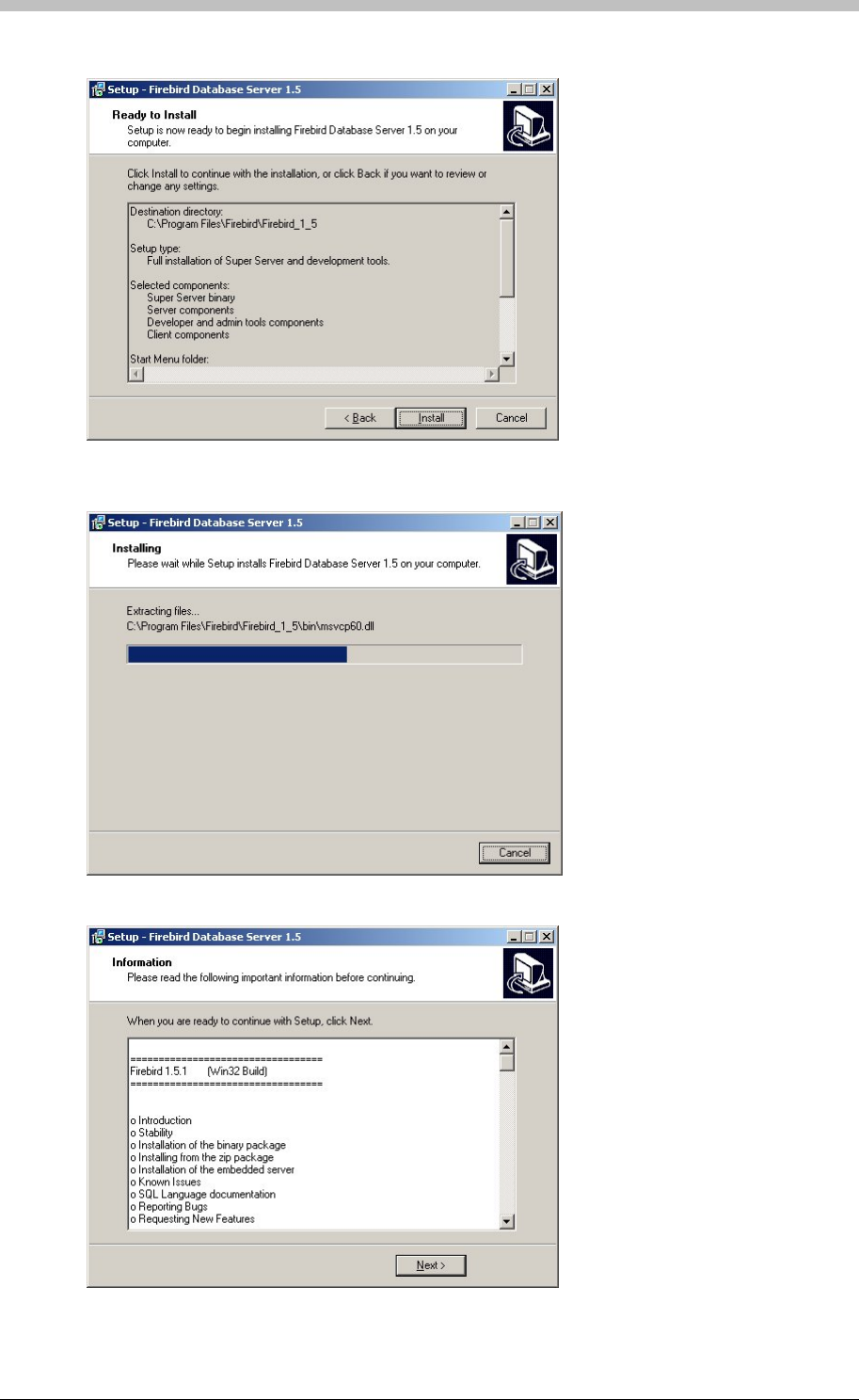
IXP300/IXP400 Installation Guide
11. Click Install
12. Wait for file to be extracted
13. Click Next
Tuesday, 11 July 2006 201
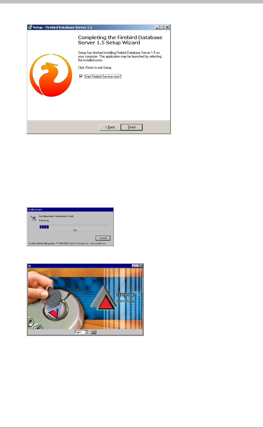
Software Installation Procedure
14. Click Finish
To install the ImproNet Software Suite on a single Host PC proceed as follows:
18. Click OK. If no Database Server is present, one is installed. Follow the onscreen
instructions for this.
ImproNet Installation Procedure
15. Insert the ImproNet Installation CD into the CD-ROM drive. If the CD does not start up
automatically, browse to the CD in Windows Explorer and double-click Setup.exe
16. The Install Anywhere screen is displayed and files are extracted
17. Select English as the language option
202 Tuesday, 11 July 2006
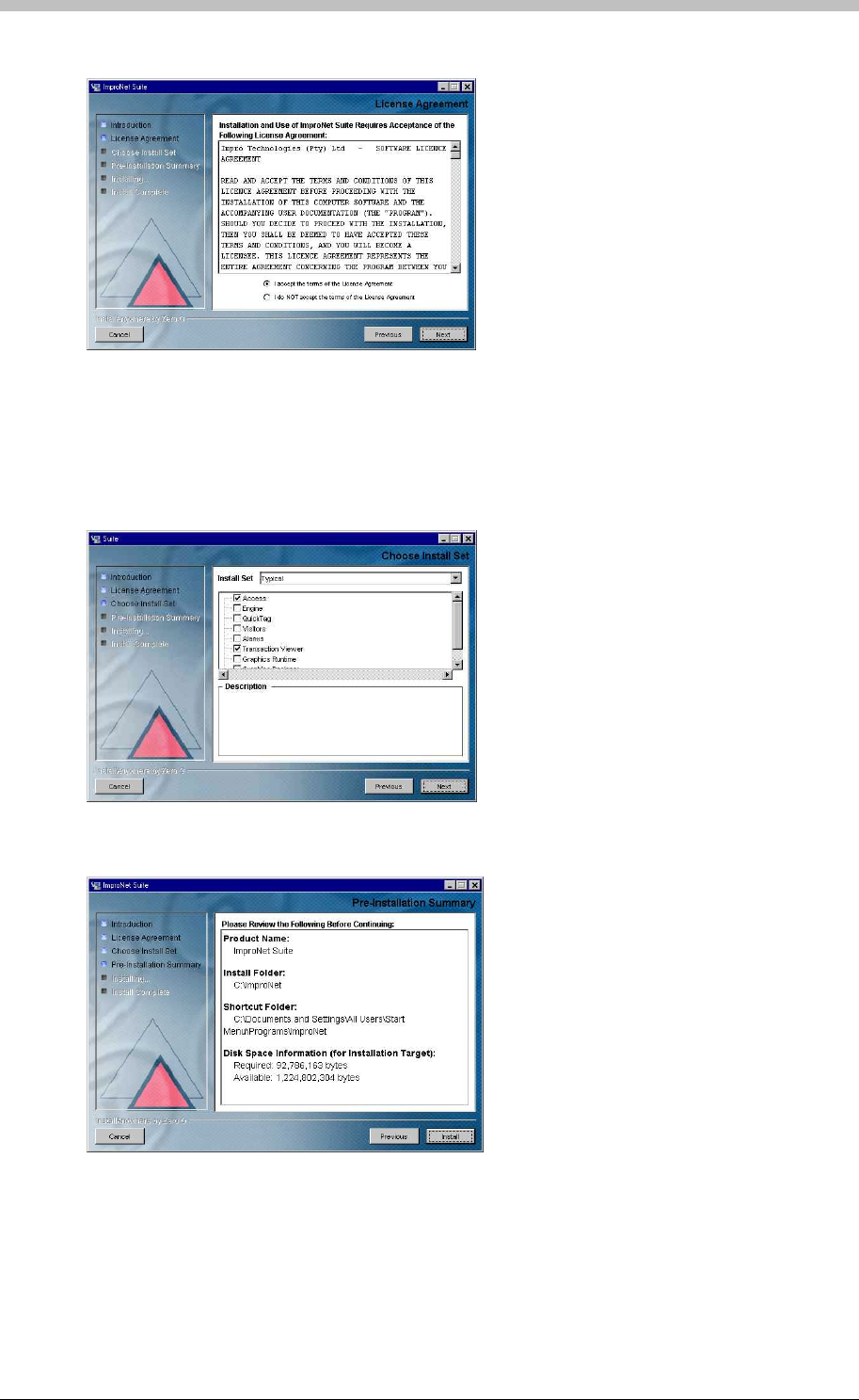
IXP300/IXP400 Installation Guide
19. Click Next. The License Agreement screen is displayed.
23. Select an option from the Install Set menu. An Install Set is a collection of pre-selected
applications suitable for specific scenarios. Customize an Install Set option by selecting or
de-selecting applications from the list.
20. Ensure that the I accept the terms of the licence agreement is selected
21. Click Next. The Choose Install Folder screen is displayed.
22. Click Next
24. Click Next
25. Click Install
Tuesday, 11 July 2006 203

Software Installation Procedure
Installing the Access or Engine Modules Only
This Section describes the installation procedure for the Access and Engine modules, and the
Database Server only.
Installing ImproNet Access Only
11. Clear all other checkboxes
1. Insert the ImproNet Installation CD into the CD-ROM drive. If the CD does not start up
automatically, browse to the CD in Windows Explorer and double-click Setup.exe
7. Click Next. The Choose Install Folder screen is displayed.
9. Select the Custom option form the Install Set menu
During the Engine module installation, a blank Database is created in
C:\ImproNet\Database.
To Install the Access module only, proceed as follows:
1. Insert the ImproNet Installation CD into the CD-ROM drive. If the CD does not start up
automatically, browse to the CD in Windows Explorer and double-click Setup
2. The Install Anywhere screen is displayed and files are extracted.
3. Select English as the language option
4. Click OK. If a Database Server is present, it is detected. If no Database Server is present,
one is installed. Follow the onscreen instructions for this.
5. Click Next. The License Agreement screen is displayed.
6. Ensure that the I accept the terms of the licence agreement is selected
7. Click Next. The Choose Install Folder screen is displayed.
8. Click Next
9. Select the Custom option form the Install Set menu
10. Select the Access checkbox from the list
12. Click Next
Installing ImproNet Engine Only
To Install the Engine module only, proceed as follows:
2. The Install Anywhere screen is displayed and files are extracted.
3. Select English as the language option
4. Click OK. If a Database Server is present, it is detected. If no Database Server is present,
one is installed. Follow the onscreen instructions for this.
5. Click Next. The License Agreement screen is displayed.
6. Ensure that the I accept the terms of the licence agreement is selected
8. Click Next
10. Select the Engine checkbox from the list
11. Clear all other checkboxes
12. Click Next
13. Click Install
The Installation Wizard prompts you to install Firebird database if there is no Database
Server on the PC. If the Database Server is installed on another PC, cancel the
Database install set-up.
204 Tuesday, 11 July 2006

IXP300/IXP400 Installation Guide
Next, proceed as follows:
1. Connect the ImproX hardware via the Host Interface to the RS232 Serial port on the Engine
PC.
The ImproNet Installation CD includes a USB driver for the USB Registration Reader Interface.
You can find the USB driver in the following locations:
2. If the Database is not installed to C:\ImproNet\Database on the Engine PC, set the
Database Connection URL to the location of the Database. For further information on
Engine Properties configuration, refer to the Properties Files section on page 187.
Database Encoding
The default database uses UNICODE-FSS encoding. ISO 8859_1 (Western Europe) and
WIN1250 (Eastern Europe) are provided for archiving support and for installations that need
ImproNet Pump.
Install USB Driver for USB Registration Reader Interface
ImproNet uses a USB Registration Reader Interface to read Tags. Some Interface versions also
provide an RS485 communication link to the Controllers.
• ImproX_USB_Device_Driver directory on the CD
• The ImproNet folder on the Host PC
To install the driver, proceed as follows:
If there are old USB Drivers on the PC, delete them before installing the provided
driver.
1. Plug the USB Registration Reader Interface into a USB port on the PC. The Found New
Hardware wizard is displayed.
2. Follow the onscreen instructions. In some cases, two drivers are installed; one for the USB
Registration Reader and one for the COM port to USB Bridge. Therefore, the wizard will
pop-up twice.
In Windows XP, proceed as follows:
1. The second time the wizard pops up, select Install from a list or specified location
2. Click Next
3. Select Search for best driver in these locations and select include this location. The
Location specified should be the ImproX_USB_Device_Driver folder.
4. Click Next. Ignore any warning dialog screen if they are displayed.
5. Click Finish
On some PCs, the New Hardware Found wizard is displayed every time a USB
Registration Reader Interface with a new USB Serial Number (Fixed Address) is
plugged in. If this happens, choose the option to automatically install the unit; The New
Hardware Found wizard will not be displayed again.
Tuesday, 11 July 2006 205

Software Installation Procedure
Upgrading an Existing Installation
1. Backup the existing ImproNet Database
4. Install New ImproNet Modules
abase Upgrade Procedures
2. Copy the properties files if ImproNet is running on a LAN or WAN
3. Uninstall existing ImproNet Modules
5. Ensure that the Database Server is Firebird 1.5 or higher. If not, uninstall the existing
version and replace it with the newer version
6. Upgrade the ImproNet database if necessary. Refer to the Dat
section on page 302 for details.
7. Upgrade the Controller and Terminal firmware if necessary
This procedure installs the Engine module on the Server and sets each executable file
to run in Windows 2000 compatibility mode.
206 Tuesday, 11 July 2006

IXP300/IXP400 Installation Guide
Pre-Configuration Procedure
When all ImproNet Software components are installed, you need to perform a pre-configuration
procedure. This procedure is necessary to determine if the hardware communication
infrastructure is functioning correctly.
It is critical that there are no communication problems prior to software configuration.
Otherwise, the system will not function.
Auto-ID
The ImproNet hardware operates on a two-tier communications architecture that comprises:
• Host Comms—Connects to ImproX Controllers and the Host Interface, or ImproX RH
• Terminal Comms—Connects to ImproX Terminals
Identifying the Hardware
When the ImproX hardware is physically connected and powered, perform the following steps to
determine if the hardware is communicating correctly:
Ensure that the Engine has a working connection to the ImproNet database. Configure
this connection in the Engine.properties file. For more information, refer to page 187
for a single PC, page 188 for a LAN, or page 189for a WAN.
You can perform an Auto-ID process at any time. During an Auto-ID, the engine polls attached
controllers and terminals, identifies their type, and their logical address. Hardware detected
for the first time receives a logical address. To open ImproNet Engine and run Auto-ID, proceed
as follows:
1. In Windows, click Start > Programs > ImproNet > Engine
2. Click the button. The Auto-ID process is started.
When a logical address has been allocated, it is never changed. This ensures
continuity in the ImproNet Database.
Ping the Hardware
Ensure the Engine is stopped before executing the Auto-ID.
After the AutoID is performed, use the ImproNet Firmware Upgrade utility to ping the
hardware. To open the Firmware Upgrade utility, proceed as follows:
• In Windows, click Start > Program Files > ImproNet > Utils > Firmware Upgrade
Tuesday, 11 July 2006 207
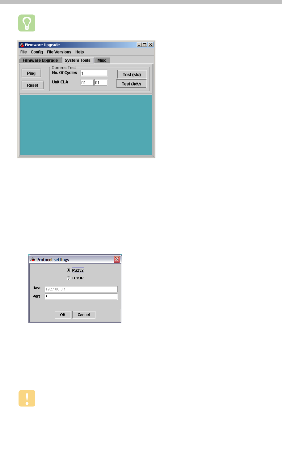
Pre-Configuration Procedure
For more information on the Firmware Upgrade utility, refer to page 303.
Figure 66 - Firmware Upgrade Utility
Perform Ping Test
The Ping test requests ImproX Controllers and Terminals to transmit their Fixed Address,
Product ID, and Logical Address. To execute a Ping test, proceed as follows:
3. Open the Firmware Upgrade utility,
4. On the menu, select Config > Protocol
5. If an ImproX HI or ImproX RH comms interface device is used, select the RS232 option and
enter the relevant com Port number
6. Click the Ping button
7. Ensure that all Terminals and Controllers have been identified. We recommend that a list of
each terminal and its physical location be updated during the hardware installation process.
This ensures an efficient software configuration process.
8. Open the ImproNet Firmware Upgrade utility and run a Comms test. Ensure a pass rate
of 100% is achieved.
It essential that the communication infrastructure is working correctly before you
proceed with configuring ImproNet.
208 Tuesday, 11 July 2006

IXP300/IXP400 Installation Guide
PART III – General Configuration
Tuesday, 11 July 2006 209
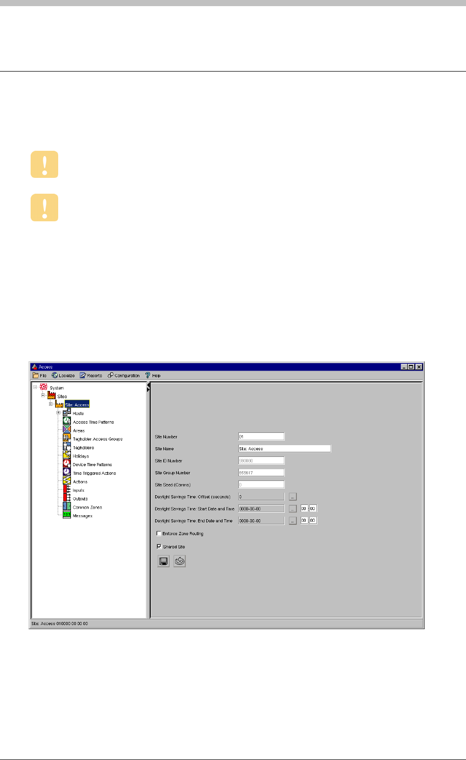
Configuration Overview
Configuration Overview
ImproNet Access is the software application used to configure an ImproNet Access Control
System.
Run the Auto-ID process in ImproNet Engine to find what hardware is installed and to
assign addresses to the hardware.
Ensure that the Unit Location Chart for IC Controllers and AC Controllers is
correctly filled in when the Controllers are physically installed.
Using ImproNet Access
The following panels comprise the ImproNet Access interface:
• Menu
• Navigator
• Main
Menu Bar
The Menu contains drop-down lists that enable you to navigate to different screens in ImproNet
Access
210 Tuesday, 11 July 2006
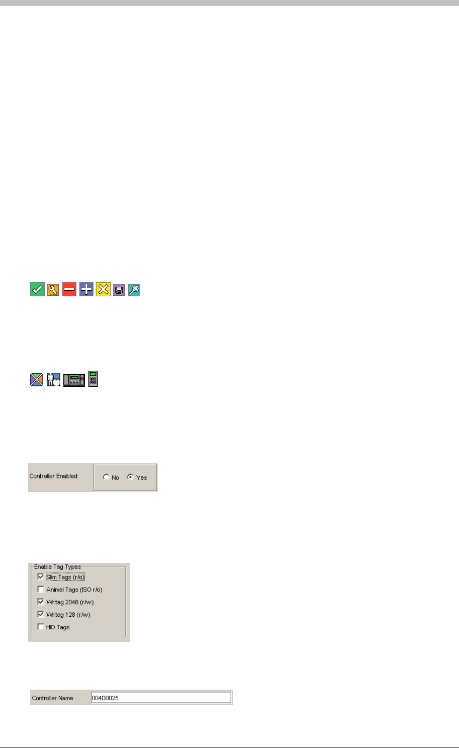
IXP300/IXP400 Installation Guide
Navigator Pane
The Navigator provides an expanding hierarchical tree menu. It enables you to view and
navigate to different items. The Navigation Tree consists of nodes that display components by
connection.
Main Pane
Items selected in the Navigation Tree display their details in the Main pane.
Common Interface Controls
The following types of controls enable you to interact with the ImproNet Access interface:
Buttons
Open another screen or window when clicked on. They are usually different colours. Examples
include the following:
Icons
Similar function to buttons except they are located in the Navigation tree. Examples include the
following:
Radio buttons
Used to select multiple options. Any number of checkboxes in a group can be selected. Click
to enable or disable.
Used to select an option. Only one radio button in a group can be selected. Click to enable or
disable.
Checkboxes
Textboxes
Enable you to enter text such as an item name. Click the checkbox and type some text.
Tuesday, 11 July 2006 211
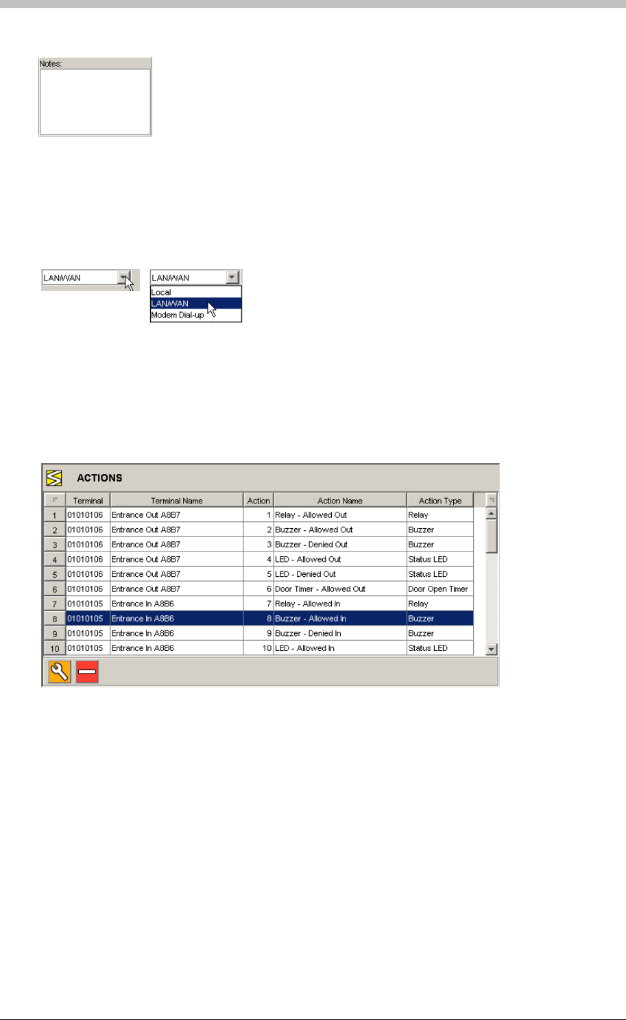
Configuration Overview
Text areas
Same function as a textbox, except a text area displays multiple lines of text.
Drop-down lists
Used to select an option from a list. Click the button with the arrow to display the list. Then,
click a list item to select it.
Records
Records are rows of information displayed in a grid format. A record is a collection of fields that
that correspond to column names. In the following example, record number 8 is selected. It
has the following fields: Terminal, Terminal Name, Action, Action Name, and Action Type.
Click a record to select it.
A Note on Screenshots
This manual displays screenshots of various screens in ImproNet Access. Some of the details
displayed in a screenshot may not be available in your copy of ImproNet Access. This is
because some details are dependant on the hardware installed on a Site.
212 Tuesday, 11 July 2006

IXP300/IXP400 Installation Guide
System Configuration Parameters
Table 16 displays important configuration parameters for the ImproNet system. Some
parameters have additional requirements—these are indicated by reference notes displayed
after the table.
Item IC Controller (IXP300) AC Controller (IXP400)
Total Number of Tags 8000 Up to 160000
See Note 1
Maximum Sites per System 255 255
Maximum Controllers per Site 16 64
Maximum Terminals (Fixed Addresses) per Controller 48 See Note 2 64 See Note 2
Maximum Terminals (Fixed Addresses) per Location 3 See Note 2 3 See Note 2
Max Locations per Controller 16 Up to 64 See Note 3
Maximum Locations per Zone 16 64
Access Time Patterns per site 128 128
Tag Holder Access Groups per site 256 1024
Holidays per site per site 32 32
Device Time Patterns per site 128 128
Time Triggered Actions per site 512 512
Actions per site 10000 10000
Common Zone 16 See Note 4 32 See Note 5
Hosted Visitors per site 1500 1500
Elevator Control 6 See Note 6 6 See Note 6
Table 16 - System Configuration Parameters
Note 1
If a Site use IC and AC Controllers, it is limited by the IC Controller’s parameters. Only
the number of transaction types that each Controller can buffer is independent.
160000 Tags require all memory modules in the
Controller to be populated.
Note 2
Terminals with two Fixed Addresses, such as the
ImproX TT, are treated as two separate Terminals.
Note 3
In APB mode, two Terminals per Location are
required. Therefore, if all locations are in APB
mode, the limit is 32 Locations per Controller—
assuming all Terminals have a single Fixed
Address.
Note 4
A Zone can be part of one Common Zone only.
The Maximum number of Common Zones
supported per IXP300 Site is 16.
Note 5
A Zone can be part of one Common Zone only.
The Maximum number of Common Zones
supported per IXP400 Site is 32.
Note 6
We recommend a maximum of 6 Elevators
(Elevators). This enables one Access Group per
Tag for normal Access control requirements. A
maximum of 80 floors per Elevator (Elevator) is
supported.
Tuesday, 11 July 2006 213

System Configuration Parameters
A Note on Fixed Addresses
Most Terminals have one fixed address. Other Terminals, such as the ImproX TT have two fixed
addresses. Fixed addresses limit how many physical units a device such as a Controller can
connect to.
To avoid confusion, we recommend that you count each fixed Address as a separate
Terminal. For example, count 48 fixed addresses as 48 Terminals.
214 Tuesday, 11 July 2006
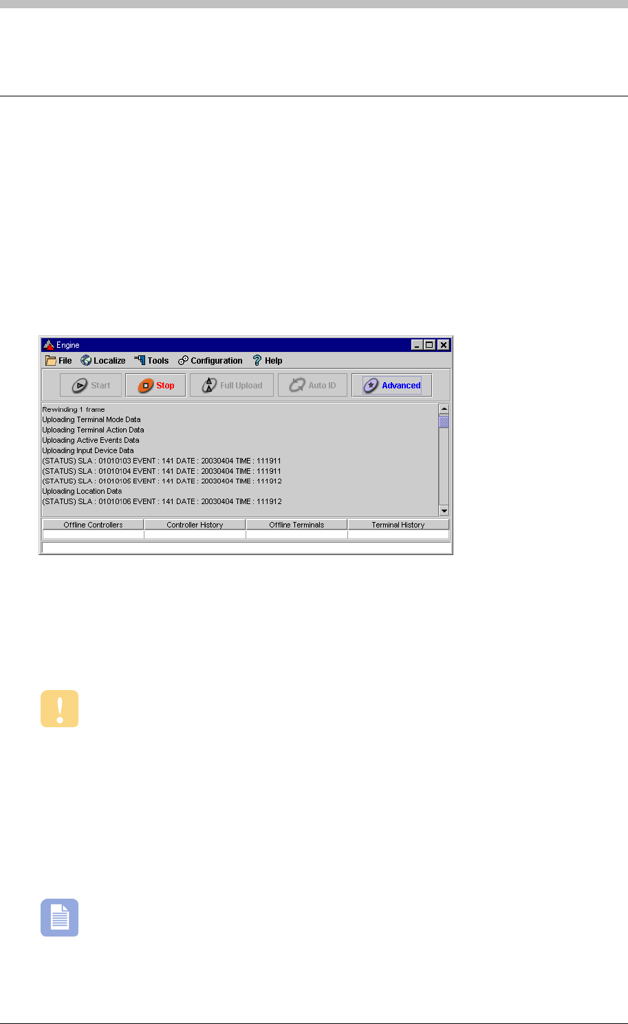
IXP300/IXP400 Installation Guide
Engine Functions
Engine Menu Functions
ImproNet Engine has the following user-controlled functions:
• Engine Start
• Engine Stop
• Upload
• Auto-ID
• Advanced
Figure 67 – Engine started
Engine Start
Starts the Engine. Transactions are downloaded from the Controllers and logged to the
Database. In addition, changes are uploaded to the Controllers.
Run this only after you have performed an Auto-ID and a Full Upload.
Engine Stop
Stops all Engine processes and procedures.
Full Upload
Uploads all data in the ImproNet Database to the Controllers. The Engine polls each Controller
three times to verify its presence before starting the upload. The engine stops when the upload
is complete.
You must perform a Full Upload when the Terminals and Controllers are initially
configured, and each time that major hardware changes are made to a Site.
Tuesday, 11 July 2006 215
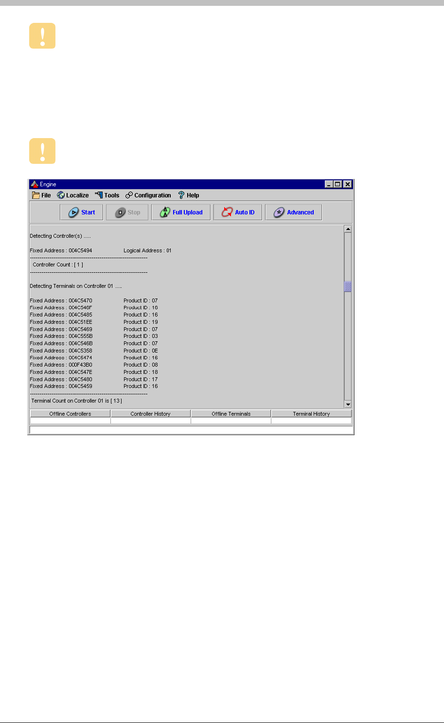
Engine Functions
During a Full Upload, the selected Site is offline.
Auto-ID
Auto-ID is a process that polls Controllers to identify their type and the logical address.
Similarly, other units such as Terminals are also polled and identified. Newly connected units
are assigned logical addresses.
• Estart—places the Site in Emergency Mode
Stop the Engine before executing Auto-ID.
Figure 68 – Auto ID Complete
Advanced
The Advanced function provides a Command Prompt that enables you to manually enter and
execute specific commands. The Command prompt is illustrated in Figure 69, and is
recommended for advanced users only. Some common commands include the following:
• Start AutoID—starts the Auto ID process
• Start Download 01—downloads data from Controller 1 to the ImproNet Database
• Start Upload 01 03 05—uploads data from the ImproNet Database to Controller 1,
Controller 3, and Controller 5
• AlarmServer—starts the Alarms Server Software so that the Alarm Status of the System is
displayed
• Estop—reverts the Site from Emergency Mode to Normal Mode
• APB Reset—resets the APB status of all Tags
216 Tuesday, 11 July 2006
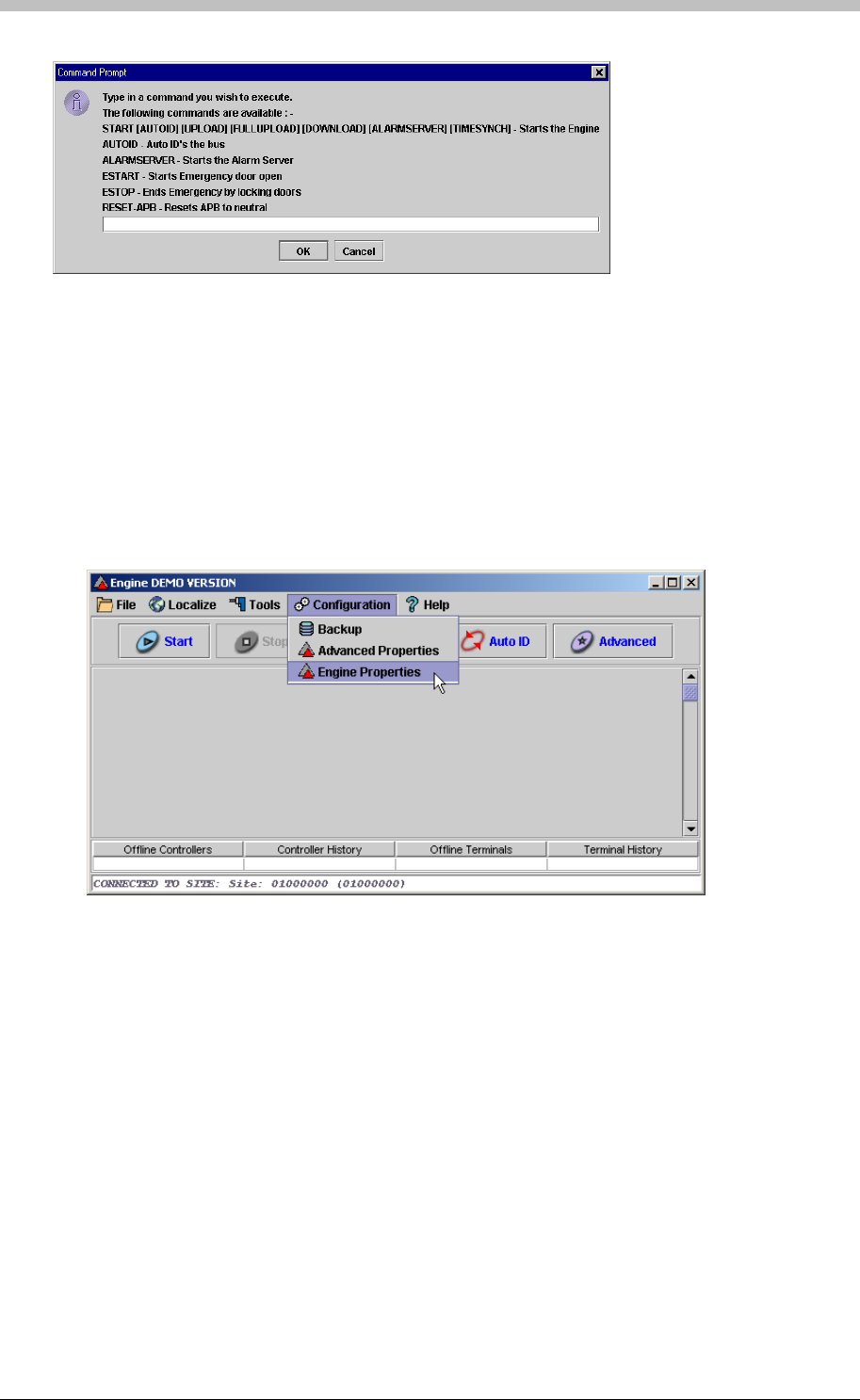
IXP300/IXP400 Installation Guide
To open ImproNet Engine, Engine Properties, proceed as follows:
1. In Windows, click Start > Programs > ImproNet > Engine
Figure 69 – Advanced Screen Command Prompt
Engine Properties
Open Advanced Properties
2. In ImproNet Engine, select Engine Properties from the Configuration drop-down menu
The Engine Properties window is displayed.
Tuesday, 11 July 2006 217
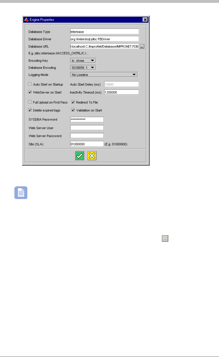
Engine Functions
• URL— specifies the location of the ImproNet Database. Click the
The Engine Properties window enables you to view and change the following settings:
Settings described in this section are stored in the Engine.Properties file
Database
• Type—the name of the ImproNet Database type. The default is Interbase—the name of
the company that produced Firebird
• Driver—specifies the driver file for the ImproNet Database
button to browse.
Note that you cannot select Mapped network drives from the browse dialog.
Encoding Key
Refers to the type of database driver used. Jaybird is the default the database driver. In the
Engine.properties file, the encoding key is lc_ctype.
218 Tuesday, 11 July 2006

IXP300/IXP400 Installation Guide
Database Encoding
Specifies the applicable database-encoding format as displayed in Table 17.
Encoding format charSet
8859_1
Encoding format lc_ctype
ISO8859_1
WIN1250 Cp1250
UNICODE_FSS UTF_8
Logging Mode
Auto Start on Startup
Autostart Delay
WebServer on start
Sets the time-out delay for the Web Server.
Sets the Engine to perform a full upload on startup.
Specifies Error that messages are written to a Log file.
Deletes expired Tags from the database.
Validate the ImproNet Database on startup.
Changes the SYSDBA password.
Table 17 – Database Encoding Format
Used for diagnostic purposes when there are communication problems between the Engine and
Controllers.
Enables the Engine to start when it is opened. By default, you have to manually start the
Engine.
Specifies the amount of time to delay starting the Engine after it is opened. For example, a
setting of 50000 ms delays the Engine starting by five seconds after it is opened.
Sets the Web Server to start when the Engine is started.
Inactivity Timeout
Full Upload on First Pass
Redirect to File
Delete Expired Tags
Validation on start
SYSDBA Password
Tuesday, 11 July 2006 219
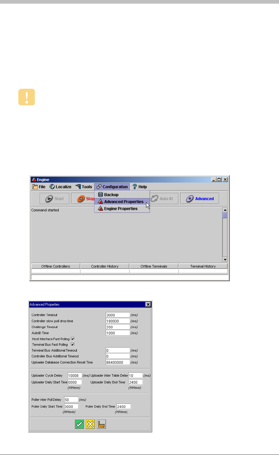
Engine Functions
Site SLA
Advanced Properties
We recommend that you do not change the Engine settings for a standard
configuration. You should only edit Engine settings to improve the efficiency of
ImproNet across a WAN.
The Site’s Logical Address.
The Advanced Properties window in ImproNet Engine enables you to fine-tune the timing
between ImproNet Engine, the ImproNet Database, and System Hardware.
Open Advanced Properties
To open ImproNet Engine Advanced Properties, proceed as follows:
1. In Windows, click Start > Programs > ImproNet > Engine
2. In ImproNet Engine, select Advanced Properties from the Configuration drop-down menu
The Advanced Properties window is displayed
220 Tuesday, 11 July 2006

IXP300/IXP400 Installation Guide
The Advanced Properties enables you to view and change the following settings:
Controller Slow Poll Drop Time
AutoID Time
Host Interface Fast Polling
Terminal Bus Fast Polling
Controller Bus Additional Timeout
All times are measured in ms (milliseconds), unless stated otherwise. 1000 ms = 1
second.
Controller Timeout
The length of time that the Engine will wait for a reply from a Controller. The default time is
3000.
• Increase to 5000 if Ethernet converters or radio modems are used
• Increase the value if Controller Dropped error messages are displayed
The amount of time that a Controller is dropped from the poll sequence, if it times out. The
default is 180 000 (3 minutes). After the drop time has passed, polling continues normally.
Challenge Timeout
Amount of time allowed for detecting a Host Interface. If a Host Interface is not detected within
the Challenge Timeout time, the Not Authorised to Run error message is displayed. The
Default is 350. If a valid Host Interface is connected and all connections are correct, you can
extend the time to 800
Amount of time a Controller allows to AutoID its Terminals. The default is 1000. Increase
AutoID Time to 2000 if there are AutoID problems over Ethernet, radio modem, or WAN.
Enables fast polling of the Controllers by the Host Interface, and facilitates inter-Controller
communication. If Ethernet converters or radio modems are used, you can disable fast polling.
The default is true.
Enables fast polling. Default value =true.
Increases the timeout duration for the Controllers and Host Interface fast polling. The default is
0. We recommend that you use the default value
Terminal Bus Additional Timeout
Increases the timeout duration for Fast Polling Terminals. Default value is 0. We recommend
that you use the default value.
Tuesday, 11 July 2006 221

Engine Functions
Uploader Cycle Delay
Sets the delay between upload cycles to the Controllers. Default is 10 000. If operating on a
Wide Area Network (WAN), increase the Uploader Cycle Delay to 60 000 (1 minute) to reduce
network traffic.
Time taken between processing Database tables in the uploader. Default value is 10. Increase
to 1000 to reduce bandwidth usage on a Wide Area Network (WAN).
Uploader Inter Table Delay
Uploader Daily Start Time
Sets the start time for the upload cycle. The default is 0000. Change this value to specify
starting an upload during specific periods. For example, running an upload after-hours does not
reduce network usage during office hours.
Uploader Daily End Time
Sets the end time for the upload cycle. The default is 2400 (midnight). If uploading is limited to
after-hours, set the Uploader Daily End Time to 0600 – this ensures that upload cycles are
stopped before the work day begins.
Poller Inter Poll Delay
Sets the time between successive polls. The default is 200. Increase to 2000 to reduce
network traffic over Ethernet converters on a WAN.
Poller Daily Start Time
Specifies when the Engine starts polling Controllers. The default 0000.
Poller Daily End Time
Specifies when the Engine stops polling Controllers. The default 2400.
Uploader Database Connection Reset
Limits amount of PC memory used by the software. This value is reset periodically. We
recommend that you do not change it. The default is 86400000 (once a day).
222 Tuesday, 11 July 2006

IXP300/IXP400 Installation Guide
System Configuration Procedure
It is important to perform the configuration procedure in the following order:
1. Sites
− Host PC
− Hardware auto-detection
2. Controller
− Identify
− Name
− Configure
− Assign Terminals to Zones and Locations
− Configure Zones and Locations
3. Terminals
− Identify
− Readers
− Actions
10. Common Zones
− Name
− Configure
− Inputs
− Outputs
− Parameters
4. Events and Actions
5. Access Time Patterns
6. Areas
7. Access Groups
− Time Patterns
− Areas
8. Tag holders
− Tags
− Assign Tags
9. Time Triggered Actions
− Inputs
− Outputs
11. Messages
Tuesday, 11 July 2006 223
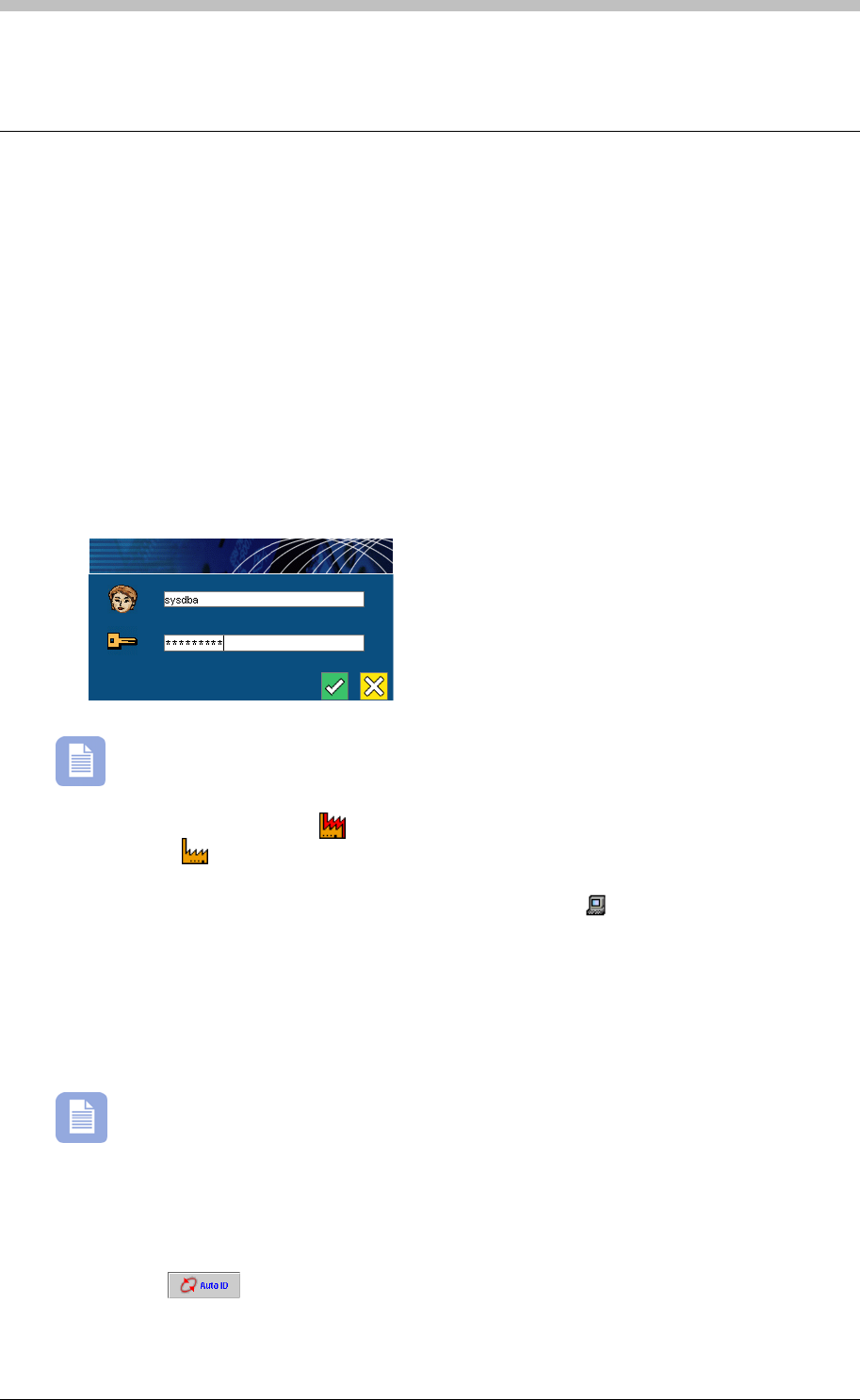
Sites
Sites
To set up a Site, you need to configure the following components:
• Host PC
• Zones and Locations
To ImproNet Access, proceed as follows:
2. Enter your Username and Password
The default username is SYSDBA. The default password is masterkey.
In the Navigator pane, click the
• Controllers
• Terminals
Open ImproNet Access
1. In Windows, click Start > Programs > ImproNet > Access
icon to create a new Site. A new Site node is added to the
tree. Click the icon. The new Site’s details are displayed in the Main pane.
The Host node expands to display the Host PC icon. Click the icon. In the Main pane, enter
the Host PC details.
odules in a
Network Environment
Run Auto-ID to Detect Access Hardware
Before you can use ImproNet Access to configure hardware, you must run the Auto-ID function
in the ImproNet Engine to detect the hardware.
If ImproNet Engine and ImproNet Access are on different Host PCs, you must change
the Engine.Properties file. For more information, refer to the ImproNet M
on page 182.
To open ImproNet Engine and run Auto-ID, proceed as follows:
1. In Windows, click Start > Programs > ImproNet > Engine
2. Click the button. The Auto-ID process is started.
224 Tuesday, 11 July 2006

IXP300/IXP400 Installation Guide
When hardware units are detected, they are added to the ImproNet Database and become
available in the ImproNet Access tree. Controllers are assigned default names that contain their
logical addresses. Each Controller has a node displaying its unassigned Terminals.
Use your Unit Location Chart to re-name Controllers and Terminals.
Deleting Nodes
• Device Time Patterns
Device Time Pattern
Access Time Pattern
You can delete Terminals, Controllers, Zones, and Locations only, from the Navigator tree.
Other node types cannot be deleted. Note, to delete a unit, you must first delete its child
components. For example, to delete a Controller, you must first delete its Terminals, Zones, and
Locations.
Shared Data
ImproNet Access includes user-configurable data that is shared by other Modules; Deleting this
data can result in other Modules functioning incorrectly. The following data is shared:
• Access Time Patterns
• Tag Holder Access Groups
• Areas
Do not delete Tag Holder Access Groups or Areas unless you are sure that they
are not required by other Site components.
About Time Patterns
There are two types of time patterns:
• Device Time Patterns— determine when a device is physically operational
• Access Time Patterns—determine when Zones and Locations are accessible
A Device Time Pattern (DTP) determines when an electrical function or mechanical state on a
hardware device is active. Device Time Patterns must be active for the same duration as all
Access Time Pattern, and Tag Holder Time Patterns that use a relevant device.
An Access Time Pattern (ATP) determines when a Tag Holder has access to an Area. When an
Access Time Pattern and an Area are linked, they form an Access Description.
Tuesday, 11 July 2006 225
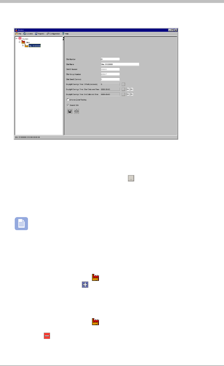
Sites
Configure Site
• Site Number—enter a number for the Site
Select a Site in the Navigator pane. Complete the following fields in the Main pane:
• Site Name—enter a name for the Site
• Daylight Savings Time—if applicable, click the button and enter a daylight savings
offset
• Enforce Zone Routing—requires Tag Holders to access Zones in a specified sequence.
Refer to page 230 for details.
rks if the PC’s Operating System has the
Daylight Savings Offset feature enabled.
eave other fields with their default values.
o add a new Site, proceed as follows:
The Daylight Savings Time setting only wo
L
Add Site
T
1. In the Navigator pane, click the button
2. In the Main pane, click the button. The new Site is added to the Navigator tree.
To delete a Site, proceed as follows:
Delete Site
1. In the Navigator pane, click the button
2. In the Main pane, select the row containing the Site to delete.
3. Click the button
4. Enter the ImproNet Access password to confirm the action
226 Tuesday, 11 July 2006

IXP300/IXP400 Installation Guide
Set Up the Host PC
ImproNet Engine enters Host PC’s IP address and Computer Name (network name)
when it runs the Auto ID process.
Specify the Host PC for a Site as follows:
1. In ImproNet Access, select a Site
2. Click the button
About Hardware Configuration
Types of Address
Recording Installation Information
• Fixed Address—supplied on a label included with the unit
A Unit Location Chart is provided with every Controller.
Each hardware unit is allocated a unique Fixed Address when it is built. ImproNet Engine
allocates a Logical Address to the unit for communication purposes.
You must ensure the following information is recorded on the Unit Location Chart when a new
hardware unit is received:
• A unique description of the unit's physical Location
Address Allocation
ImproNet Engine assigns Logical Addresses to hardware units when it starts-up, or on request,
depending on the system configuration.
Tuesday, 11 July 2006 227
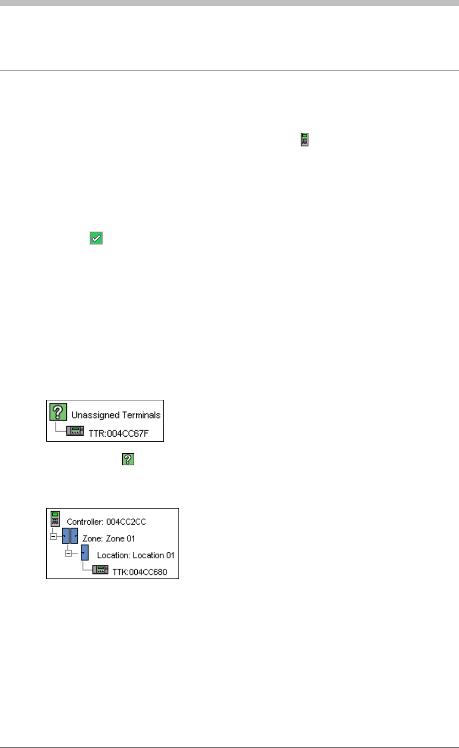
Controller
Controller
To configure a Controller, proceed as follows:
1. In the Navigator pane, select a Controller by clicking the icon
2. Change the default Controller Name to the name specified on the Unit Location Chart
3. Click the Edit Controller Parameters button. The Controller Parameters Screens is
displayed.
4. In the Enable Tag Types section, select the types of Tags to be used. If HiD Tags are
used, enable them here.
5. In the Terminal Port Baud Rate section, leave the default setting of 38400
6. Click the button to accept
Assign Terminals
The first step in configuring a Controller is to assign its Terminals to Zones and Locations.
2. Double-click the
Terminals must be manually assigned to a Controller before they can be configured for Zones
and Locations. Unassigned Terminals are terminals that the Auto-ID process has identified, but
not assigned to a Location. To assign Terminals to a Controller, proceed as follows:
1. In the Navigator Pane, select a Controller, an Unassigned Terminals node is displayed
icon to expand the Unassigned Terminals node
3. Drag-and-drop unassigned Terminals onto a Controller. A new Zone containing a Location
is created. Terminals are displayed in the Location.
Move Terminal
If you placed a Terminal in the wrong Location, drag-and-drop it to another Location.
Create New Zones and Locations
• To add another Terminal to an existing Location, drag-and-drop an unassigned Terminal to
that Location.
• To create a new Location within an existing Zone, drag-and-drop an unassigned Terminal to
the existing Zone
228 Tuesday, 11 July 2006

IXP300/IXP400 Installation Guide
There is a limit of three Terminals (Fixed Addresses) per Location.
Configure the Controller
The IXP400 AC Controller supports a maximum of 64 Zones.
Configure Zones
To configure Zones, proceed as follows:
1. In the Navigator pane, click a
A Terminal can be assigned to one Controller only.
Name each Terminal and Location according to the Unit Location Chart.
Configure Zones and Locations
Locations in the same physically bounded vicinity are grouped into Zones. The total number of
Zones per Controller is dependant on the number of Locations per Zone.
The IXP300 IC Controller supports a maximum of 16 Zones. However, there is a limit of
16 Locations per Controller. Therefore, if there is more than one Location per Zone, the
total number of Zones is less than 16.
icon to select a Zone. The Zones settings are displayed in
the Main pane
2. Enter a name for the Zone in the Zone Name textbox
3. Set the Anti-Passback (APB) mode
− None—APB off
− Strict—APB Zone rules are enforced for in and out directions. A Tag Holder cannot
enter or exit a Zone consecutively.
isor
Unlock
6. Part of Common Zone—select an option if the Zone is part of a Common Zone. Refer to
the Common Zones on page 270 for details
− Relaxed—Once a Tag Holder has entered a Zone, they must exit the Zone using their
Tag before they can re-enter. However, Tag Holders can use their Tags for multiple,
consecutive exits in this mode.
4. Supervisor Group for this Zone—specifies the Supervisor group that must have entered a
Zone before a non-supervisor Tag Holder is permitted access to that Zone. The default
value for this option is none (no value). For more information, refer to the Superv
section on page 279.
5. Fully Nested within Zone—select an option from this drop-down list if the Zone is
physically contained within another Zone. This option is useful for Zone Routing.
7. Relaxed Exit Conditions for this Zone—enables a Tag Holder to exit a Zone even if the
Access Time Pattern for the Zone has expired. The default value is Yes.
Tuesday, 11 July 2006 229

Controller
8. Anti-Passback Lockout Time—enter a time in minutes to enforce APB. Only available if
Relaxed or Strict APB mode is selected. Refer to point 3 for APB details.
9. Limit Tags Inside the Zone to— enter the maximum number of Tags permitted in the Zone
at the same time. Only available if Strict APB mode is selected.
A Location is a physical point of access. Examples include doors, turnstiles, vehicle gates, and
Time and Attendance points. A Location can have a maximum of three Terminals, but can also
host a non-scanner Terminal such as the I16 16 Channel Input Terminal. To configure
Locations, proceed as follows:
5. Click Enforce Interleading Zone Routing if required
3. In the Navigator pane, select a nested Zone
Configure Locations
1. In the Navigator pane, select a Location. The Location settings are displayed in the Main
pane.
2. Enter a descriptive Location Name
3. If the Location is a Time and Attendance point, select the Time and Attendance option from
the Location Type drop-down list
4. If the Location accesses an Interleading Zone, select it from the Interleading Zone drop-
down list
6. To specify Multiple Tag Access, select the 2 Tags option. This option is a security feature
that requires two Tag Holders to access a Zone.
Zone Routing
Zone Routing ensures that a Tag Holder accesses Zones in a specified sequence. To set up
Zone Routing, proceed as follows:
1. In the Navigator pane, select a Site
2. In the Main pane, select the Enforce Zone Routing option
4. In the Main pane, select a Zone from the Fully Nested Within Zone drop-down list to
specify the selected outer Zone.
Nested Zone must be configured on the same Controller.
230 Tuesday, 11 July 2006
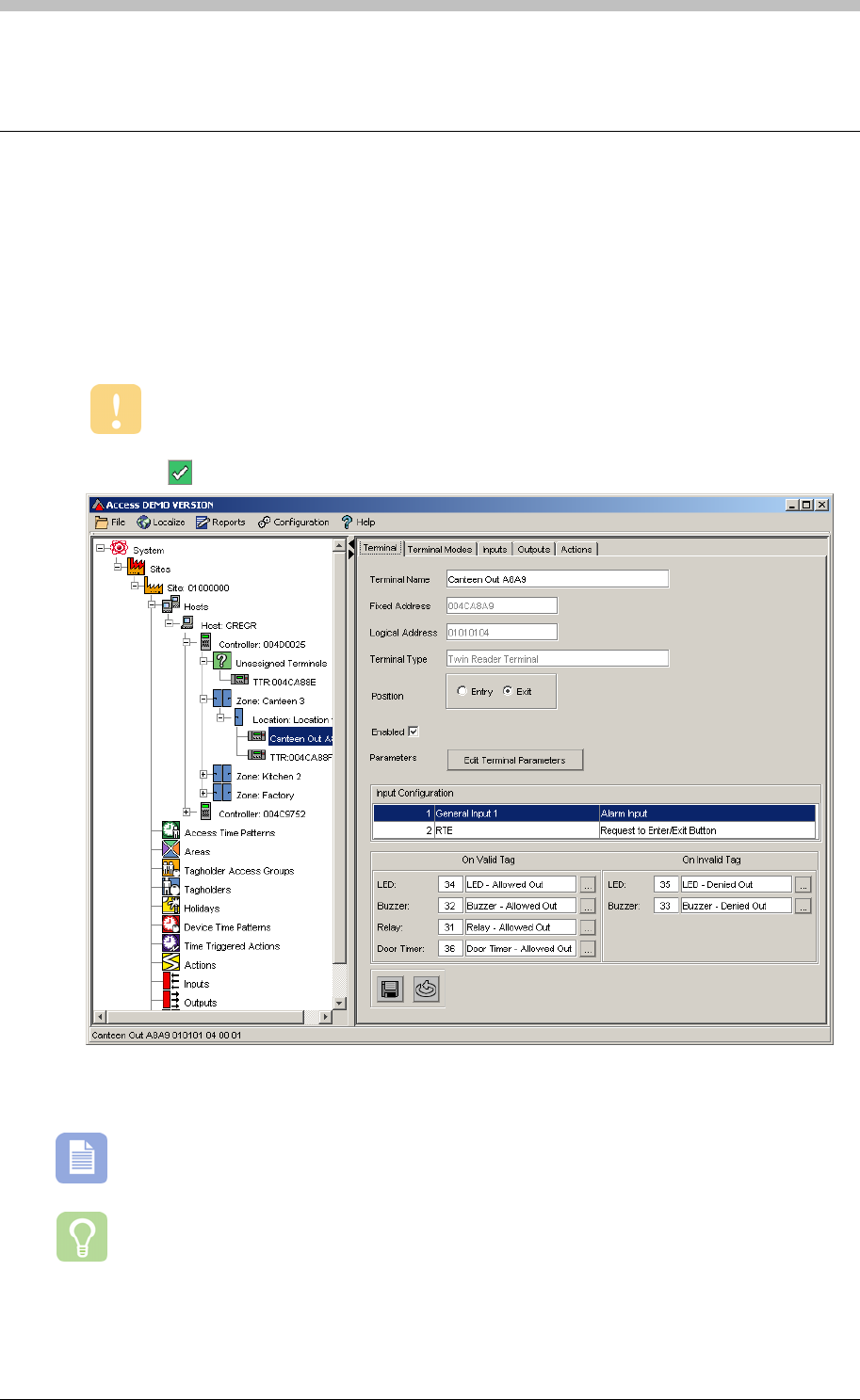
IXP300/IXP400 Installation Guide
Terminals
The Terminals screen enables you to configure a Terminal and set-up it Actions, Inputs, and
Outputs. To configure a Terminal, proceed as follows:
1. In the Navigator pane, click a Terminal to select it. The Terminal tab is displayed
2. Enter a descriptive Terminal Name
3. Select whether the Reader is an Entry or Exit reader.
This step is important because it determines the default Actions assigned to the
Reader.
4. Click the button to save the settings
Edit Terminal Parameters
We recommend the default settings for standard configurations.
Terminal Parameters are different for each Terminal type. This section provides
information on the most common parameters only.
Tuesday, 11 July 2006 231

Terminals
1. Click the Edit Terminal Parameters button. The Terminal Parameters screen is displayed.
2. Select a Buzzer Volume
3. Enter the value for Same Tag Timeout in milliseconds—this is the minimum time that must
elapse before the same Tag can be re-read at the Terminal.
4. Select a Tag Validation option:
− Controller Validation—the Tag is authenticated by the Controller. This is the default
setting.
− Host Validation—the Tag is authenticated by the Host PC. With this option, the
Reader does not respond if the Host PC is offline.
5. Enter Random Search values if required. Refer to page 281 for details
6. Click the button to save the settings
The Host Validation option should only be enabled if third-party software is being used
and requires validation.
Special Codes
You can use Special Codes to manually activate specific Actions, such as opening a door or
sounding a siren.
Special Codes are only available on Terminals with a Keypad. However, they are not
available if the Terminal is configured for Personal Access Code (PAC) mode.
We recommend restricting Special Codes to specific Tag Holders.
Select Activate Special Key Codes in Keypad Transaction Reporting to enable this feature.
The Special Code format has a maximum of five digits in the following configurations:
• Three digits and a hash. For example, 123#
• Four digits and a hash. For example, 1234#
• Five digits up to the number 65535.
Duress Codes
Duress Codes generate an Alarm action when entered on a Keypad Terminal. You can allocate
them to Tag Holders who have a pin code. The Duress Code format is one digit higher or lower
than the Tag Holder’s pin code. For example, if the pin code is 12345, the Duress Code is
12344 or 12346.
Terminal Mode Configuration
Device Time Patterns must be set-up before Terminal Modes can be configured.
Terminal Mode specifies the state of a Terminal during a selected Time Pattern. The following
Terminal Modes and access conditions are available:
• Tag Mode—the Terminal requires a valid Tag to be accessible. This is the default mode.
• Locked Mode—the Terminal is Locked and access is denied, even to valid Tags.
232 Tuesday, 11 July 2006
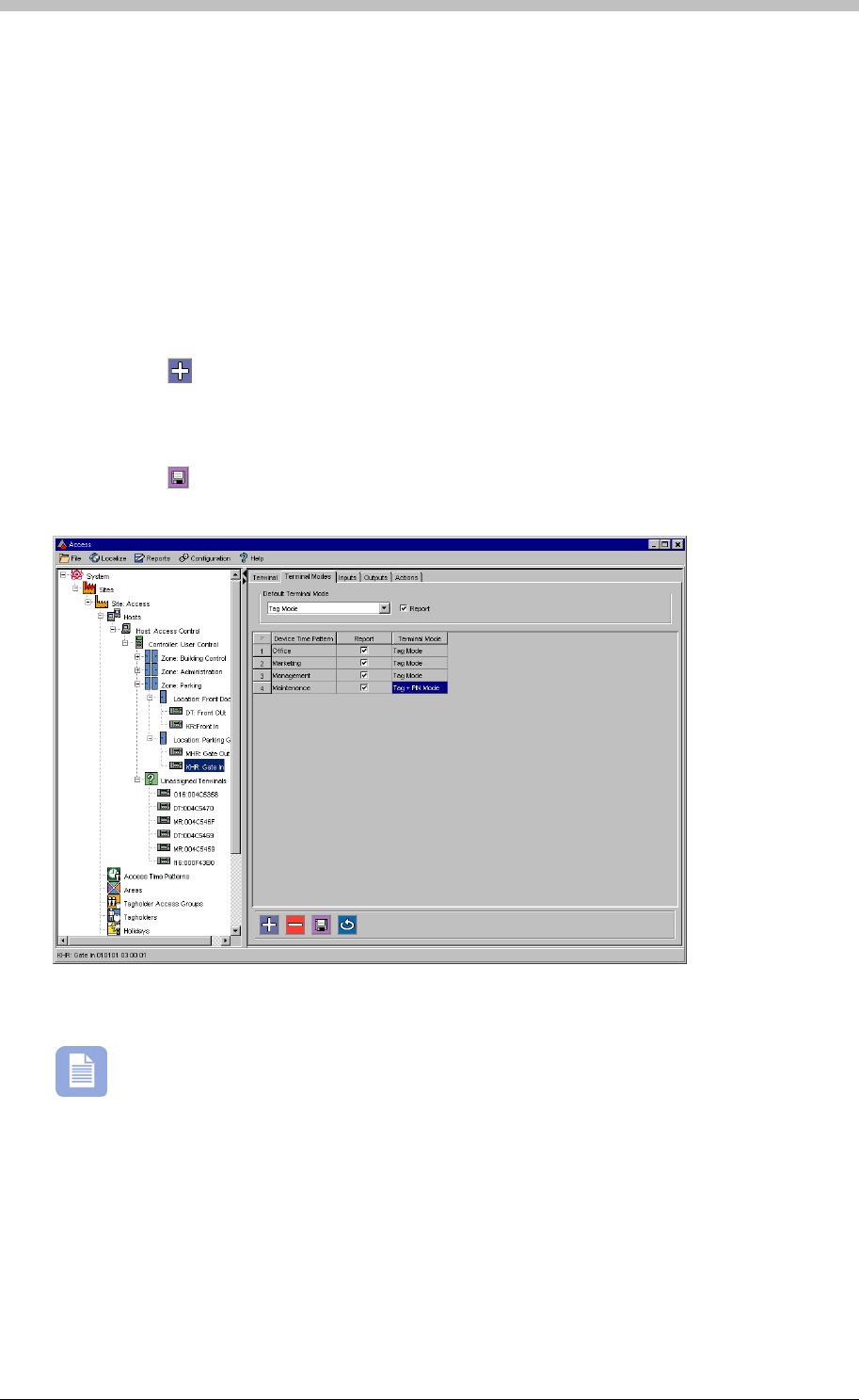
IXP300/IXP400 Installation Guide
• Unlocked Mode—the Terminal is Unlocked
• Tag + PIN— the Terminal requires a Valid Tag and a PIN Code for to be accessible
• Tag + Reason Code— the Terminal requires a Valid Tag and a Reason Code to be
accessible
• Tag + PIN + Reason Code— the Terminal requires a Valid Tag and a PIN Code and a
Reason Code to be accessible
To configure Terminal Modes, proceed as follows:
2. Select the Default Terminal Mode form the drop-down list
3. Click the
• PAC— the Terminal requires a valid Personal Access Code (PAC) or Tag to be accessible
1. In the Main pane, select the Terminal Mode tab
button to create a new Terminal Mode
4. Click the Device Time Pattern field and select an existing Device Time Pattern
5. Select a corresponding Terminal Mode from the Terminal Mode field
6. Select the Report checkbox to enable reporting of all access actions
7. Click the button to save
Figure 70 - Terminal Mode Configuration Screen
ImproNet supports up to 128 Device Time Patterns. Each Terminal can have up to eight
Device Time Patterns.
Tuesday, 11 July 2006 233
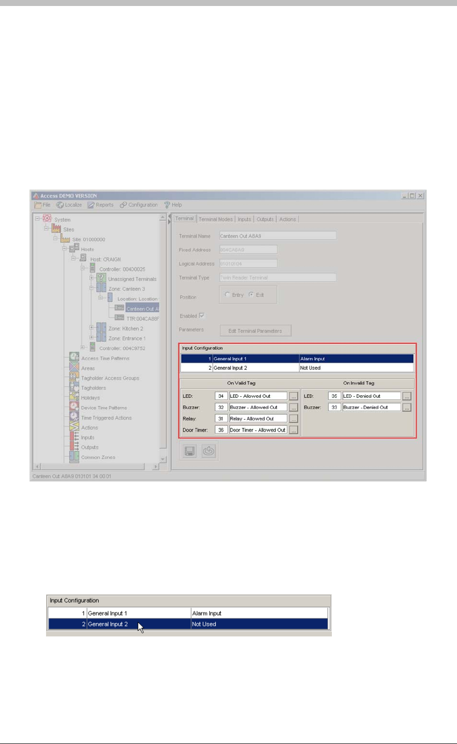
Terminals
Inputs
The Inputs tab enables you configure the inputs on the I16, DR, DL, KT, DT, PT, and TT
Terminals. However, Inputs can also be edited and assigned, directly from the Terminals tab.
shows the area of the Terminal tab where you can edit Inputs and assign Actions. Figure 71
Configure Inputs for the following:
• Request to Enter / Exit buttons
• Door Open / Door Forced sensing
• Inhibit Scanner function
• Alarm monitoring
Figure 71 - Terminal Input Configuration
Example of Input Configuration
The following example demonstrates how to create an RTE configuration from the Terminal tab:
1. In the Input Configuration field, double-click a General Input that is Not Used. The Input
Device window is displayed
2. Enter RTE for the Input Name
3. Select Request to Enter/Exit Button from Input Function drop-down list
234 Tuesday, 11 July 2006
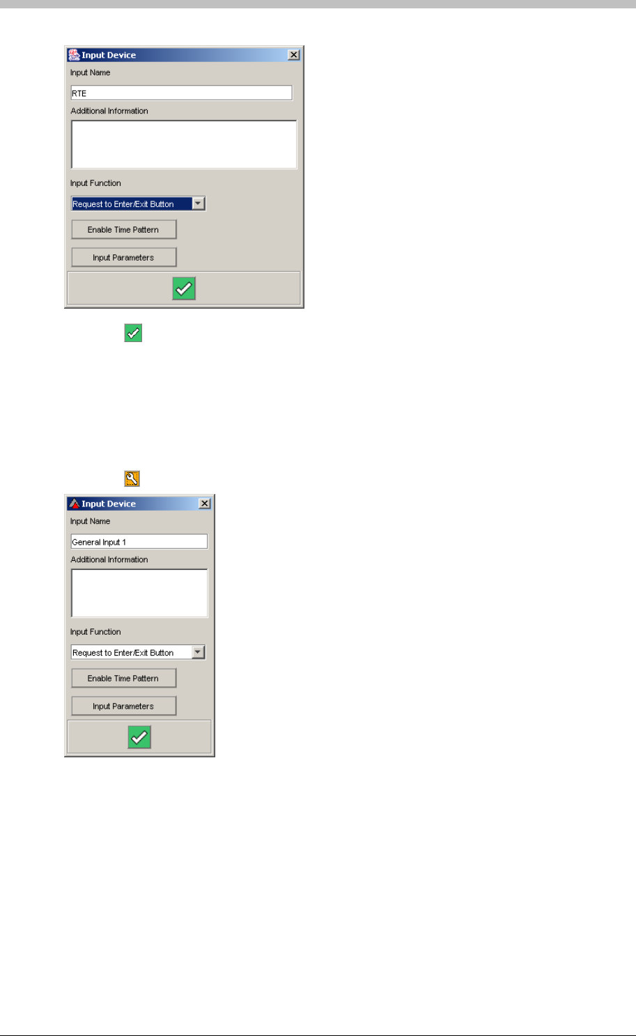
IXP300/IXP400 Installation Guide
4. Click the button to save. You are returned to the Terminal tab
3. Click the
Input Configuration
To configure Terminal Inputs, proceed as follows:
1. In the Main pane, select the Input tab
2. Select an Input row
button. The Input Device window is displayed.
6. Not Used—select if the input is unused
7. Request to Enter/Exit Button—select if the input is connected to a Request To Enter or
Exit (RTE) button
4. Enter an Input Name, or use the default name
5. Select an Input Function from the drop-down list. The following options are available:
8. Door Open Sensor—select if the input is connected to a Door Open Sensor (DOS)
9. Alarm Input—select this option if the Input is connected to a third-party alarm system
Tuesday, 11 July 2006 235
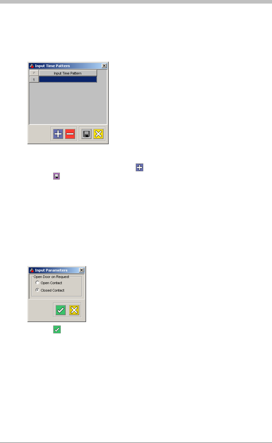
Terminals
Enable Time Patterns
Time Patterns determine when a Terminal Input is active. To configure Time Patterns, proceed
as follows:
1. On the Input Device window, click the Enable Time Pattern button.
2. Click the empty, highlighted field.
3. Select a Time Pattern from the pop-up window and click OK. The selected Time Pattern is
enabled for the relevant Input. Click the button to add additional Time Patterns.
4. Click the button to save
Input Parameters
The Input Parameter setting provides options for the selected Input Function. Proceed as
follows to configure Input Parameters:
1. On the Input Device window, click the Input Parameters button
2. For the Request to Enter/Exit Button Input Function, the following options are available:
− Contact Open—Door opens when Input receives an open-contact signal
− Contact Closed—Door opens when Input receives a closed-contact signal
3. Click the button to accept.
− Door Open is Closed Contact— Input reports that Door is open when an closed-
contact signal is received
− Door Open Sensing with End of Line Detection—enables End of Line sensing option
4. For the Door Open Sensor Input Function, the following options are available:
− Door Open is Open Contact—Input reports that Door is open when an open-contact
signal is received
236 Tuesday, 11 July 2006
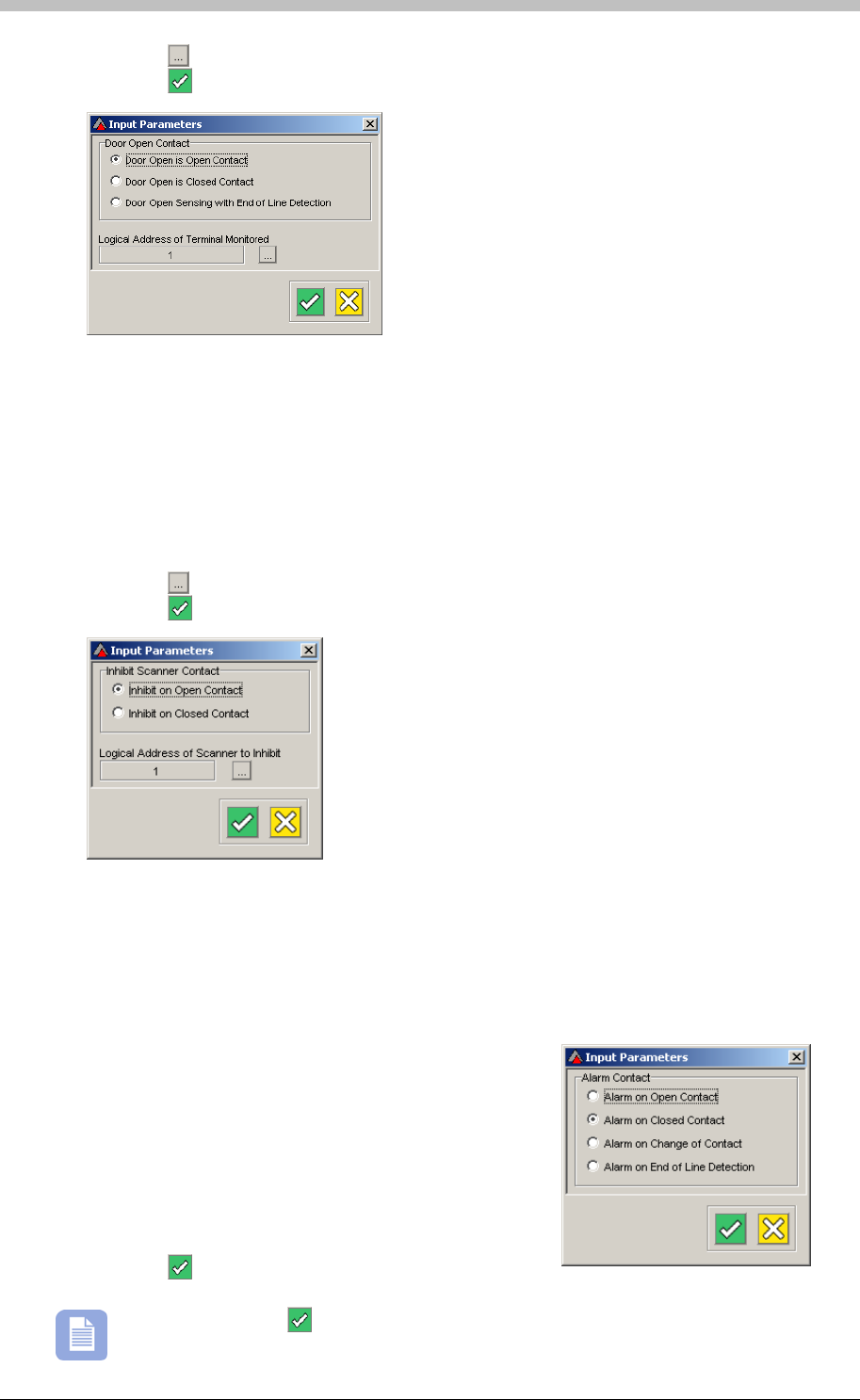
IXP300/IXP400 Installation Guide
5. Click the button to select the Logical Address of Terminal Monitored.
6. Click the button to accept.
• Inhibit on Closed Contact— The Reader does not read Tags if the Input detects a Door
closed-contact signal
The Inhibit Scanner Input function disables a Tag Reader from reading Tags. The following
Inhibit Scanner options are available:
• Inhibit on Open Contact—The Reader does not read Tags if the Input detects a Door
open-contact signal
1. Click the button to select the Logical Address of Scanner to Inhibit
2. Click the button to accept.
For the Alarm Input Function, the following options are available:
− Alarm on Open Contact—an Alarm event is generated if the Input receives an open-
contact signal
− Alarm on Closed Contact—an Alarm event is generated if the Input receives a closed-
contact signal
− Alarm on Change of Contact—an Alarm event is
generated if the Input receives a change-in-
contact-state signal
− Alarm on End of Line Detection—an Alarm
event is generated if the Input receives an End-of-
Line-Detection contact signal. This option is
recommended for the ImproX I16 Terminal.
3. Click the button to accept.
Be sure to click the button when you exit the Input Device window.
Tuesday, 11 July 2006 237
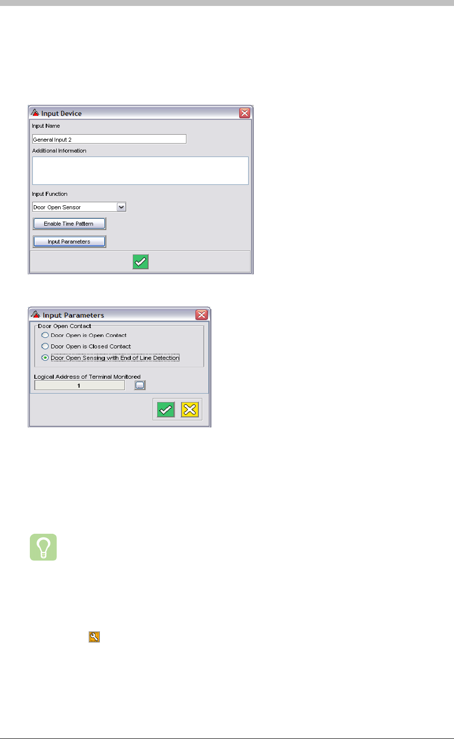
Terminals
End of Line Sensing for ImproX TT
End of line sensing on the ImproX TT is only possible if Door Open Sensing is configured. Only
Inputs 1 and 3 on the ImproX TT have end of line sensing functionality. The Input must be
configured as a Door Open Sensor, and Door Opens Sensing with End of Line Detection must
be selected from the input parameters list.
Figure 72 – Input Device Window
Figure 73 – Input Parameters Window
Outputs
The Outputs tab enables you to configure a Terminal’s LED and Relay states for different
Terminal modes.
We recommend setting different LED states for different Terminal Modes, as this will
help Tag Holders identify Terminal Mode changes.
To configure Terminal Outputs, proceed as follows:
1. In the Main pane, select the Output tab
2. Select an Output row
3. Click the button. The Output Device window is displayed.
238 Tuesday, 11 July 2006
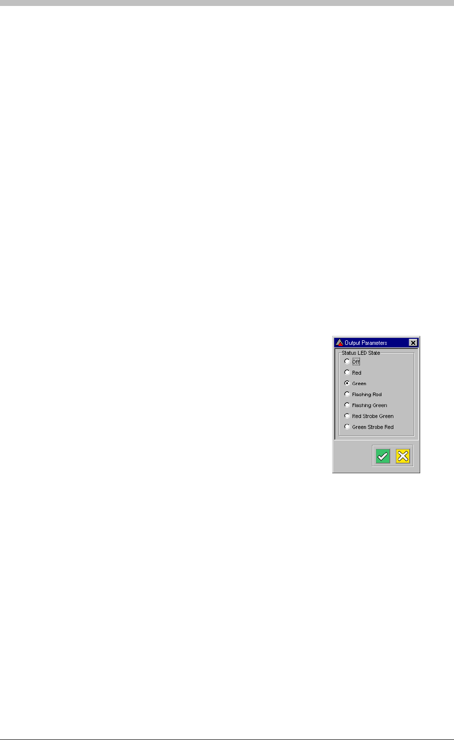
IXP300/IXP400 Installation Guide
The content in the Output Device window is one of the following depending on the function of
the output device.
• General Relay
• Status LED
General Relay
If the output device is a General Relay, select a Relay Contact State for each of the following:
• Relay during Locked Mode
• Relay during Unlocked Mode
• Relay during Tag Mode
• Relay during Emergency Mode
The following Relay Contact States are available:
• Do NOT drive relay in this mode
• Drive relay in this mode
Status LED
If the output device is a Status LED, select a Status LED State for each of the following:
• Status LED during Locked Mode
• Status LED during Unlocked Mode
• Status LED during Tag Mode
• Status LED during Emergency Mode
The following Status LED States are available:
• Off
• Red
• Green
• Flashing Red
• Flashing Green
• Red Strobe Green
• Green Strobe Red
Actions
About Actions
ImproNet enables you to define Actions for Terminals and in some cases, Controllers. Actions
are instructions stored in a Controller’s memory, and are triggered by Events or by the Time
Triggered Actions function. The following are examples of common Actions:
• Driving a Relay
• Sounding a Buzzer
• Changing LED state
• Displaying LCD message
Tuesday, 11 July 2006 239
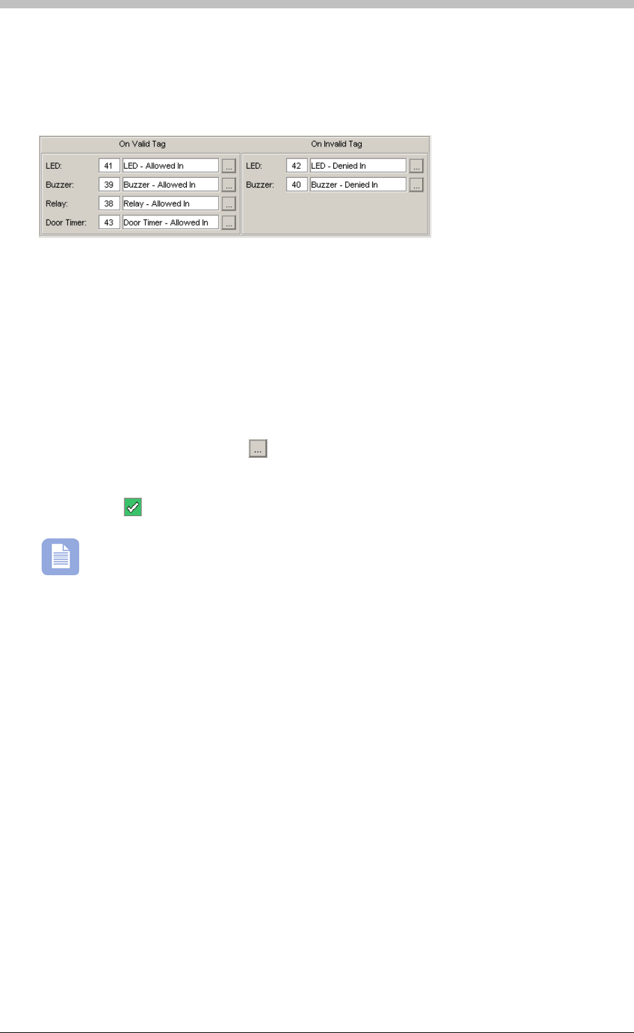
Terminals
When a Terminal is assigned to a Location, default actions for the Terminal are created. Figure
displays the default actions created for the On Valid Tag event, and for the On Invalid Tag.
These Actions are executed when a Tag is presented at the Terminal.
74
Figure 74 - Default Terminal Actions
The On Valid Tag event encompasses all valid Tag Events. Therefore, the On Valid Tag
section on the Terminal tab enables you to assign actions to all valid Tag Events in a bulk
procedure. Similarly, the On Invalid Tag event encompasses all invalid Tag Events. Therefore,
the On Invalid Tag section on the Terminal tab enables you to assign actions to all invalid Tag
Events in a bulk procedure.
To customize the settings of the default actions, proceed as follows:
1. On the Terminal tab, click the button next to the Action that you want to edit. The Action
Parameters window is displayed.
2. Change the settings as necessary
3. Click the button to accept
The Actions tab lists all Actions currently assigned to the selected Terminal and
enables you to assign additional actions to the On Valid Tag and On Invalid Tag
events.
About Events
System Events are activated by a Controller when a particular procedure or process is
performed. For example, when a Reader detects a Tag, the Tag is validated by the Controller,
and the Event Allowed_Normal_In or Allowed_Normal_Out is activated. In this example, the
actual Event depends on whether the Reader is an Entry or Exit Reader. When an Event is
generated, the Controller executes the Actions linked to the Event.
Active System Events
The Active System Events Editor enables you to link Actions to Allowed Events and Denied
Events. You can have up to five of the following Action types per Event:
• Relay—created by default when you specify a Terminal as an Entry or Exit Reader
• Buzzer—created by default when you specify a Terminal as an Entry or Exit Reader
• LED—created by default when you specify a Terminal as an Entry or Exit Reader
• Door Open Timer—created by default when you specify a Terminal as an Entry or Exit
Reader
• LCD—optional Action described in T able 18
240 Tuesday, 11 July 2006

IXP300/IXP400 Installation Guide
• Emergency Mode—optional Action described in T able 18
able 18
able 18
• Reset Digital Input—optional Action described in T
• Multiple Actions—optional Action described in T
An Action is not created for a Terminal if the hardware does not support the Action.
Action Description
Door Open Timer The Door Open Timer Action is created by default for XDT,
XPT, and XTT Terminals. However, it is not enabled until a
Terminal Input is configured as a Door Open Sensor (DOS).
A Door Open Timer Action prevents a Door Forced Alarm
Event from being activated if a door is opened under the
following conditions:
− A valid Tag Event precedes the door opening
− A valid RTE Event precedes the door opening
LCD An LCD Action displays a user-configurable text message
on a Terminal or Controller with an LCD.
Emergency Mode Emergency Mode Actions are only executed on Controllers
and Terminals that have been configured for Emergency
Mode. Refer to section Eme on page 273
for details. rgency Unlock
Multiple Actions A Multiple Action groups up to five other Actions together so
that they execute as a single Action. Multiple Actions are
useful for Elevator control.
Reset Digital
Inputs Resets Digital Inputs
Table 18 - Optional Actions
Configure Active System Events
On the Actions tab, click the Active System Events button. The Active System Events
Editor window is displayed. The Active System Events Editor enables you to assign up to five
Actions to the On Valid Tag and On Invalid Tag events. Available Actions are listed in
sequence. If the middle block of an Action is empty, it is unused.
Tuesday, 11 July 2006 241
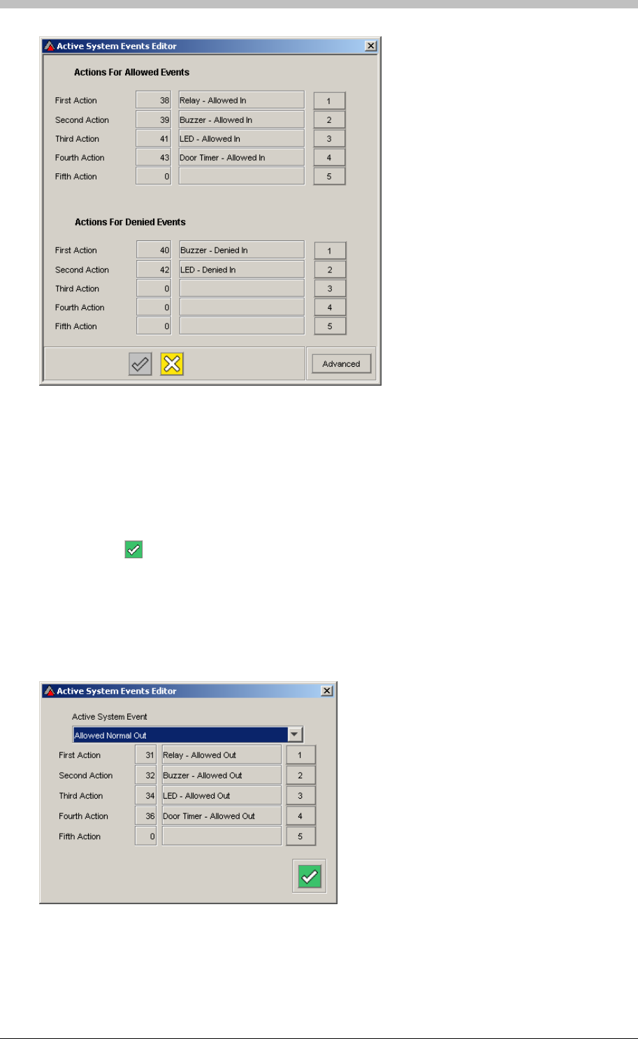
Terminals
Figure 75 - Active Systems Event Editor
To assign new actions to an event, proceed as follows:
1. Click the number button to the right of an unused Action
2. The Action Selector window is displayed
3. Click an Action to select it
4. Click the button
Advanced Active Systems Events
The Active Systems Events window enables you to assign up to five Actions to any system
Event. To access this facility, click the Advanced button on the Active Systems Event Editor
window, and select an Event from the Active System Events drop-down list
Figure 76 - Advanced Active Systems Events Window
242 Tuesday, 11 July 2006
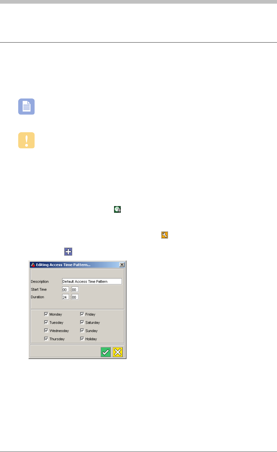
IXP300/IXP400 Installation Guide
Access Time Patterns
Access Time Patterns specify times when access is permitted. Tag Holders Access Groups are
assigned one or more Access Time Patterns. When an Access Time Pattern and an Area are
linked, they form an Access Description.
An Access Time Pattern is similar to a Device Time Pattern, but it has no start and end
dates. Access Time Patterns regulate Tag Holder access times. Device Time Patterns
regulate Terminal operation times.
Terminal modes override Access Time patterns. For example, if a Tag Holder has
access from 6am to 6pm, but the Terminal is locked from 5:30pm, the Tag Holder will be
denied in after 5:30pm.
Configure Access Time Patterns
To configure an Access Time Pattern, proceed as follows:
1. In the Navigator pane, click the icon. In the Main pane, the Default Access Time Pattern
is displayed.
2. Do one of the following:
− Select an Access Time Pattern, and click the button. The Edit Access Time
Pattern screen is displayed
− Click the button to create a new Access Time Pattern
3. Enter a Description for the Access Time Pattern
4. Enter a Start Time—this is the time of day when the Access Time Pattern becomes active
5. Enter a Duration in hours and minutes—this is how long after the start time, the Access
Time Pattern is active
6. Select the days of the week when the Access Time Pattern is enabled
7. Create as many Access Time Patterns as necessary
Tuesday, 11 July 2006 243

Access Time Patterns
If a lockout period between regular access periods is required, you need to create two
Access Time Patterns. For example, to disable access during a lunch hour, you need to
create an Access Time Pattern that ends when lunch starts, and another Access Time Pattern
that starts when lunch ends.
244 Tuesday, 11 July 2006
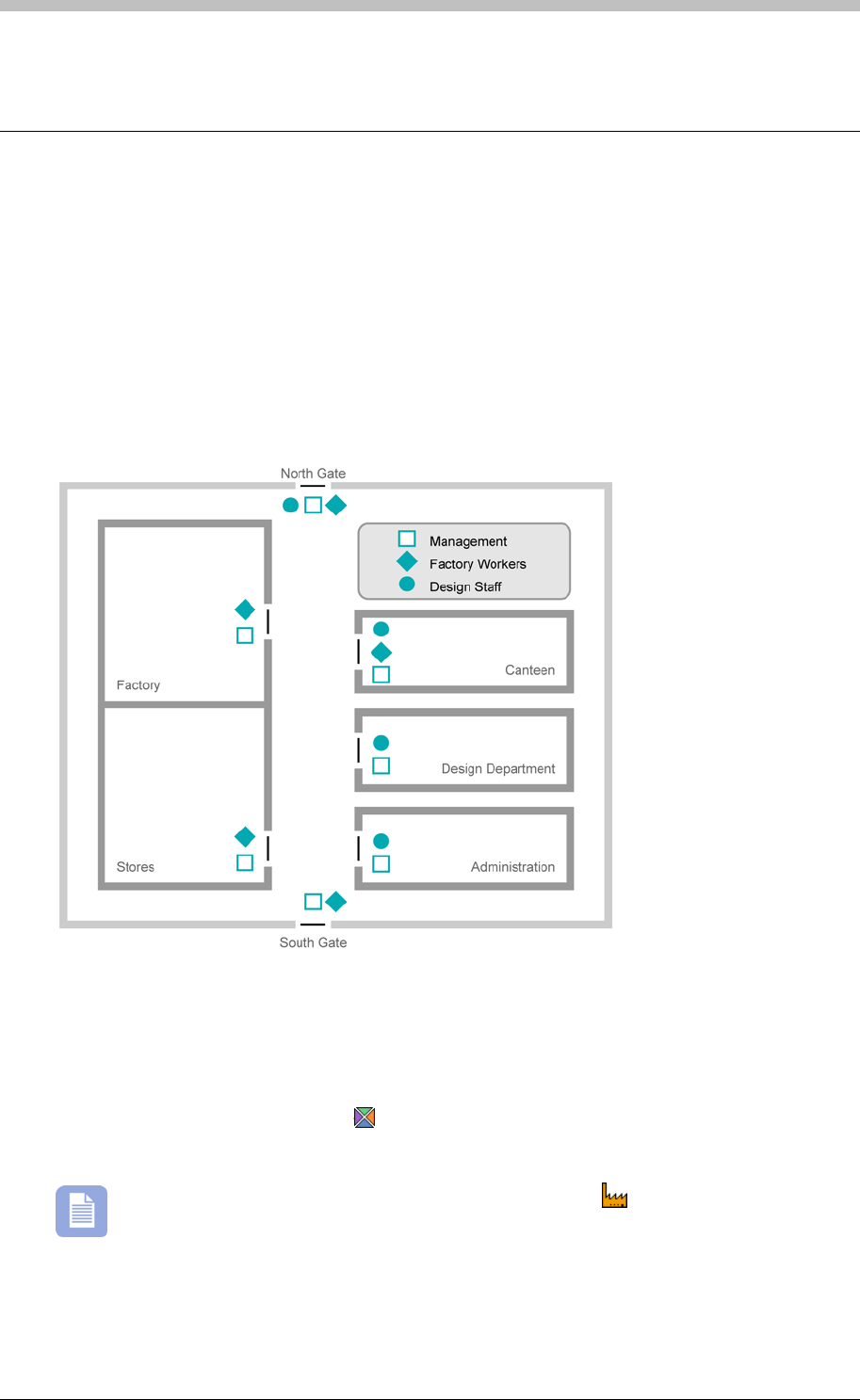
IXP300/IXP400 Installation Guide
Areas
An Area consists of a number of Locations that are grouped together to form a logical unit. An
Area is not a physically bounded building or place; it is a collection of Locations that a group of
Tag Holders has access to.
The purpose of an Area is to group Locations with the same access requirements together. This
enables you to assign the same access rights to multiple locations at the same time. Figure 77,
illustrates the concept of Areas. In the schematic, Locations are assigned to the Management,
Factory Workers, or Design Staff Areas. Note that a single Location can be assigned to more
than one Area.
Figure 77 - Area Schematic
Select Area
To select an existing Area, proceed as follows:
1. In the Navigator pane, click the button
2. Select an Area from the Area Name drop-down list
An Area that has no Locations assigned to it displays the icon only. A configured
area displays a tree of locations. If a Location is visible, then it is assigned to the
selected Area.
Tuesday, 11 July 2006 245
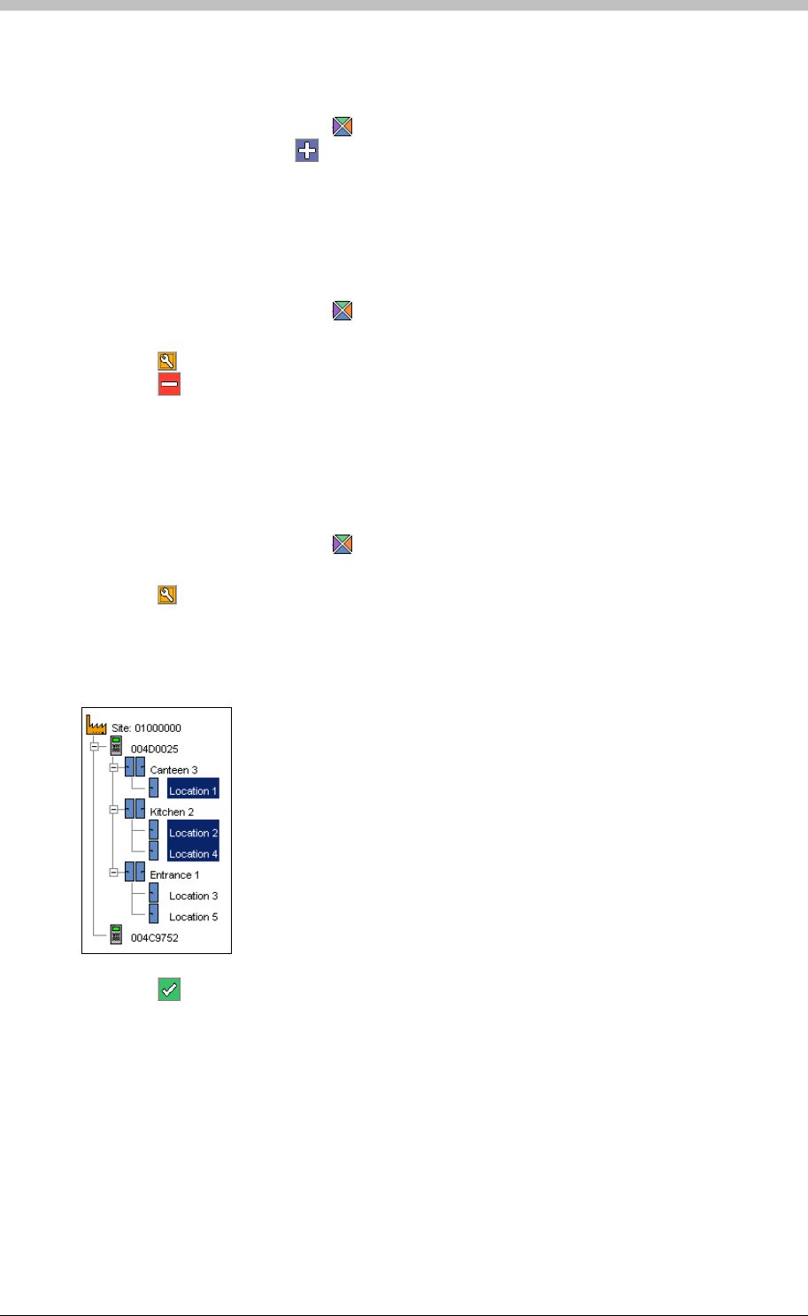
Areas
Create Area
To create an Area, proceed as follows:
1. In the Navigator pane, click the button
2. In the Main pane, click the button
3. Enter an Area Name and Area Description
Delete Area
To delete an Area, proceed as follows:
1. In the Navigator pane, click the button
2. Select an Area from the Area Name drop-down list
3. Click the button. The Area Edit window is displayed.
4. Click the button. A confirmation dialog is displayed
5. Click Yes
Assign Locations to Areas
To assign Locations to an Area, proceed as follows:
1. In the Navigator pane, click the button
2. Select an Area from the Area Name drop-down list
3. Click the button. The Area Edit window is displayed.
4. In the Edit window, select a Location by clicking it—Select multiple Locations by holding
down the Ctrl key while you click. Selected Locations are highlighted.
5. Click the button to save. The selected Locations are assigned to the Area
246 Tuesday, 11 July 2006
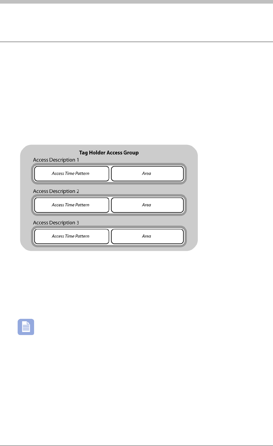
IXP300/IXP400 Installation Guide
Access Groups
Each Tag Holder in a Site is assigned to at least one Tag Holder Access Group. The purpose of
Access Groups is to allocate Tag Holder access permissions in bulk. This saves you the trouble
of configuring Tag Holders one-at-a-time. A Tag can be assigned to up to three Tag Holder
Access Groups per Site. Each Tag Holder Access Group consists of three Access
Descriptions.
Access Descriptions
An Access Description defines the Time and the Area where access is permitted.
Figure 78 - Tag Holder Access Group Breakdown
There are two types of Tag Holder Access Groups:
• General—used for permanent staff
• Visitor—used for visitors
The IXP300 System supports up to 255 Tag Holder Access Groups. The IXP400
System supports up to 1024 Tag Holder Access Groups.
Tuesday, 11 July 2006 247
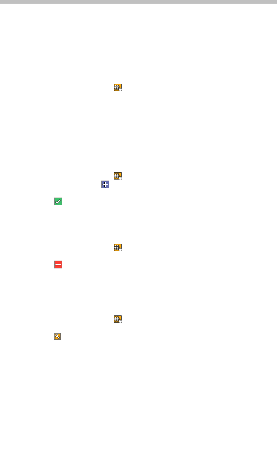
Access Groups
Configure Tag Holder Access Groups
The Tag Holder Access Group screen displays available Access Groups in the left-hand panel,
and their Access Descriptions in the right-hand panel.
Select a Tag Holder Access Group
To select an existing Tag Holder Access Group, proceed as follows:
1. In the Navigator pane, click the button
2. Select a Tag Holder Access Group from the General tab in the left-hand panel.
Alternatively, click the Visitors tab and select a Visitors Access Group.
Create a Tag Holder Access Group
1. In the Navigator pane, click the
The selected Access Group’s Access Descriptions are displayed in the right-hand panel of the
Tag Holder Access Group screen
To create a Tag Holder Access Group, proceed as follows:
button
2. In the Main pane, click the button
3. Enter a name in the Tagholder access group Name textbox
4. Click the button to save
Delete a Tag Holder Access Group
To delete a Tag Holder Access Group, proceed as follows:
1. In the Navigator pane, click the button
2. Select a Tag Holder Access Group
3. Click the button. A confirmation dialog is displayed
4. Click Yes. The Tag Holder Access Group is removed
Edit a Tag Holder Access Group
To edit a Tag Holder Access Group, proceed as follows:
1. In the Navigator pane, click the button
2. Select a Tag Holder Access Group
3. Click the button. The Access Descriptions screen is displayed.
248 Tuesday, 11 July 2006
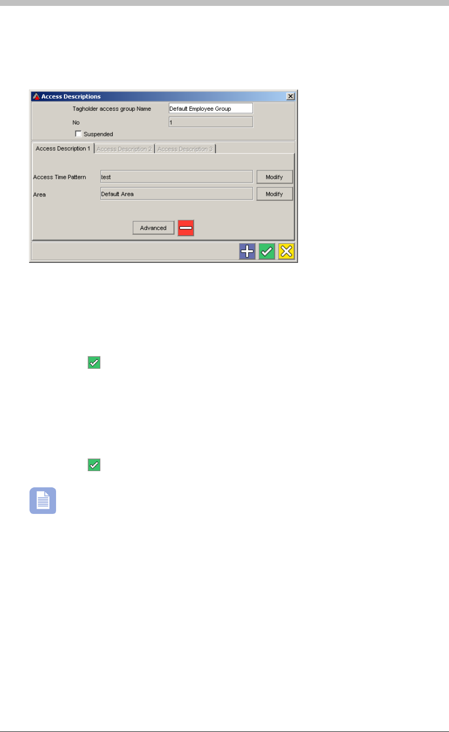
IXP300/IXP400 Installation Guide
Configure Access Descriptions
The Access Descriptions screen has three tabs—one for each Access Description per Access
Group. The Access Description 1 tab is displayed by default.
Assign Access Time Patterns
1. Click the top Modify button to assign an Access Time Pattern to the Access Description.
The Access Time Patterns screen is displayed.
2. Click a Time Pattern Name to select it
3. Click the button to accept
Assign Areas
1. Click the bottom Modify button to assign an Area to the Access Description. The Select
Area screen is displayed.
2. Click a Time Pattern Name to select it
3. Click the button to accept
Three Access Descriptions are available per Access Group. However, you only need to
configure one of them to save an Access Group.
Advanced Settings
Click the Advanced Settings button on the Access Descriptions. Additional settings are
displayed on the following tabs:
• Reporting—click the checkbox to log all transactions for the selected Access Description
• Start & Expiry Date—click the edit buttons and enter dates to control when the Access
Description is active
• Supervisor Unlock—select the Supervisor who is required to be inside the Area before
other Tag Holders are permitted entry
• Actions—click the Select buttons to assign actions for when Tag Holders are entering
(Coming In), or exiting (Going Out) the Area specified in the Access Description
Tuesday, 11 July 2006 249

Access Groups
The Supervisor Unlock facility is only applicable to Areas comprising a single zone set
to Strict Anti-passback.
Visitor Access Group
Visitor Access Groups are displayed on the Visitors tab on the Tag Holder Access Groups
screen. They operate the same as other Access Groups. Note that Visitor Tags can be
assigned to Visitor Access Groups only.
250 Tuesday, 11 July 2006
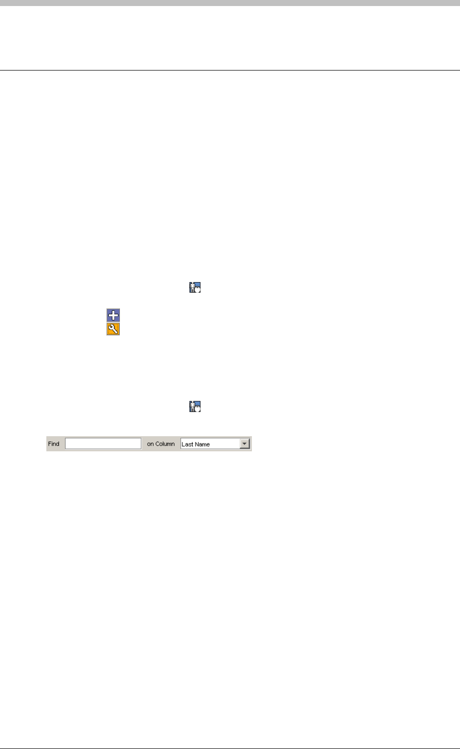
IXP300/IXP400 Installation Guide
Tag Holders – Assign Access to Tags
A Tag Holder is any person who uses a Tag to access a Site. Visitors are Tag Holders with
restricted access rights. Before you can assign access to a Tag, you must first assign the Tag to
a Tag Holder. The Tag Holder screen enables you to do the following:
• Add Tag Holders to a Site
• Edit existing Tag Holder information
• Search for Tag Holders
• Read Tags
Add or Edit a Tag Holder
To add or edit a Tag Holder, proceed as follows:
1. In the Navigator pane, click the button
2. In the Main pane, do one of the following:
− Click the button to add a Tag Holder
− Click the button to edit a Tag Holder
Quick Search for Tag Holder
To search for a Tag Holder, proceed as follows:
1. In the Navigator pane, click the button
2. Enter some text into the Find textbox
Configure Tag Holder
5. Enter a PIN code of up to 5 digits if the Tag Holder is required to use keypad-type Readers
3. Select the search criteria from the on Column drop-down-list. The results are displayed in
the Main pane.
The Edit Tagholder Screen enables you create or edit a Tag Holder’s information and assign
Tags. Only the First Name and Last Name fields are required. However, we recommend
entering as much information as possible.
To create or edit a Tag Holder, proceed as follows:
1. Enter the Tag Holder’s First Name and Last Name
2. Complete other personal information as necessary
3. Select the Current checkbox to enable the Tag Holder. If this Current checkbox is
unchecked, the Tag Holder is inactive in the system.
4. Use the Notes text area to enter other information about the Tag Holder
Tuesday, 11 July 2006 251
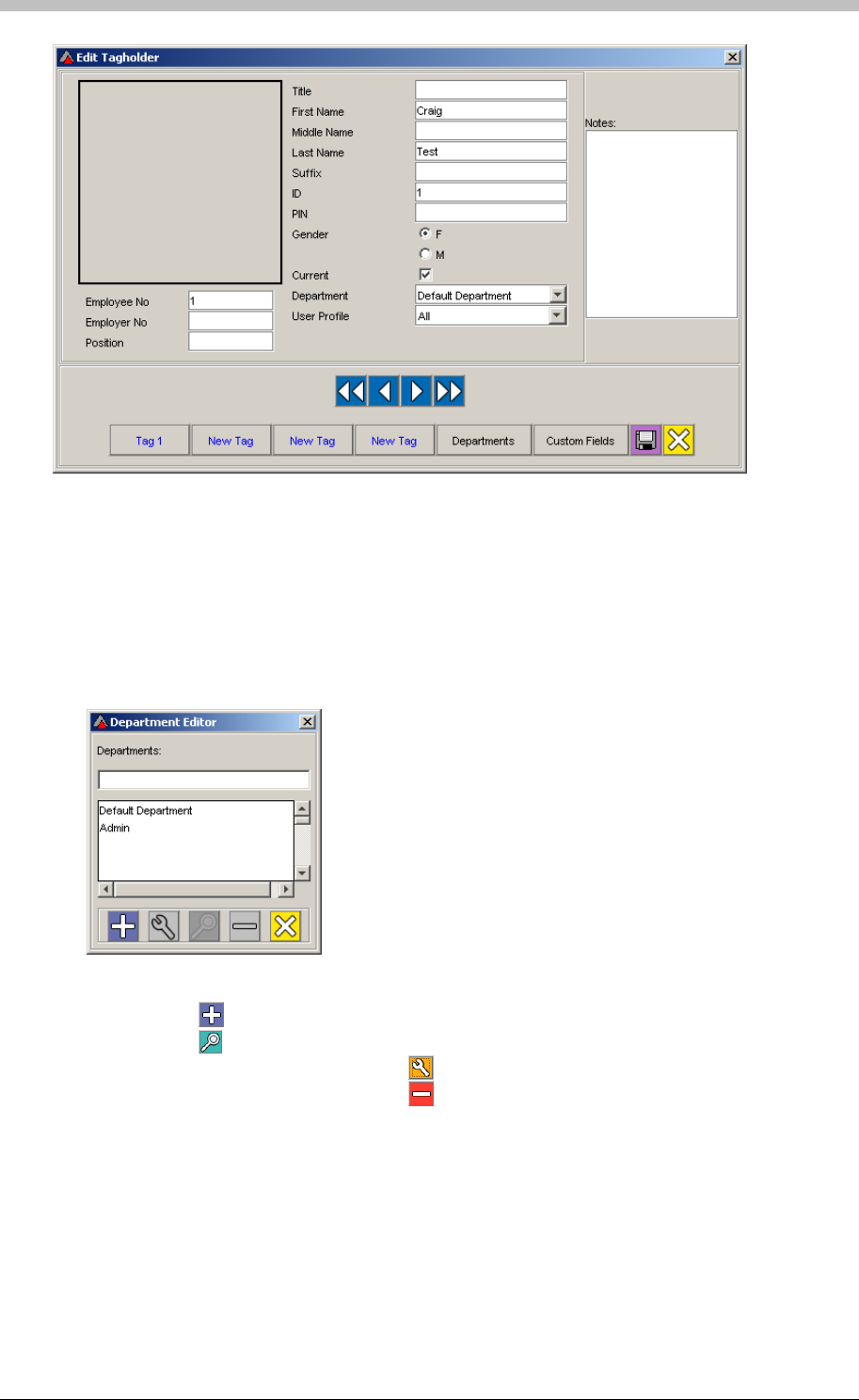
Tag Holders – Assign Access to Tags
Figure 79 - Edit Tagholder Screen
Departments
Select the Tag Holder’s Department from the Department drop-down list. To add new values or
to edit the Department list, proceed as follows:
1. Click the Departments button. The Department Editor screen is displayed.
2. Do one of the following:
− Click the button to add a new Department
− Click the button to display Tag Holders belonging to the selected Department
− Select a Department and click the button to edit it
− Select a Department and click the button to delete it
User Profile
User Profiles are configured when Operator Security is required. Refer to the Operator
section on page 286 for details Security
252 Tuesday, 11 July 2006

IXP300/IXP400 Installation Guide
Configure Tag Details
A Tag Holder can have four Tags assigned to them. To assign Tags to a Tag Holder, proceed as
follows:
1. On the Edit Tagholder screen, click any of the New Tag buttons. The Tag Details screen
is displayed.
2. On the Tag Details screen, select one of the following Tag Options:
− Normal – normal employee
− Suspend – Tag is suspended form all access on the Site
− Blacklist – Tag Holder is blacklisted and denied access to the Site
− Special Event 1 – Tag raises an Event when presented to the Reader – in this case
Special Event 1. The Event can be linked to a specific Action
− Special Event 2 – Tag raises an Event when presented to the Reader – in this case
Special Event 2. The Event can be linked to a specific Action
3. Configure the following:
− APB Override – Tags are not subject to APB rules
− Report Always – All Transactions for the Tag are written to the Database
4. Assign the Tag Holder to a Site by selecting a value form the Site Assigned drop-down list
5. Assign the Tag Holder to one or more Tag Holder Access Groups by selecting values form
the Group1, Group 2, and Group 3 drop-down lists.
At least one Tag Holder Access Group must be assigned for the Tag to have any
access rights.
6. Repeat procedure for additional Tags if necessary
Read the Tag
1. Present a Tag to an Enrollment Reader and click the Read Tag button. The Tag type is
usually detected automatically.
2. If the Tag Type is not displayed when the card is read, or if you are entering a Tag code
manually, select the Tag Type from the drop-down list.
When ImproNet detects a Tag, a Tag number is displayed in the Tag Code textbox.
To create a Personal Access Code (PAC) only, select the Personal Access Code
option from the Tag Type drop-down list and enter the PAC in the Tag Code text box.
Multiple Tags do not work in an Anti-Passback Zone; if you enter a Zone with one Tag,
and exit the Zone using a different Tag, APB is not enforced.
Tuesday, 11 July 2006 253
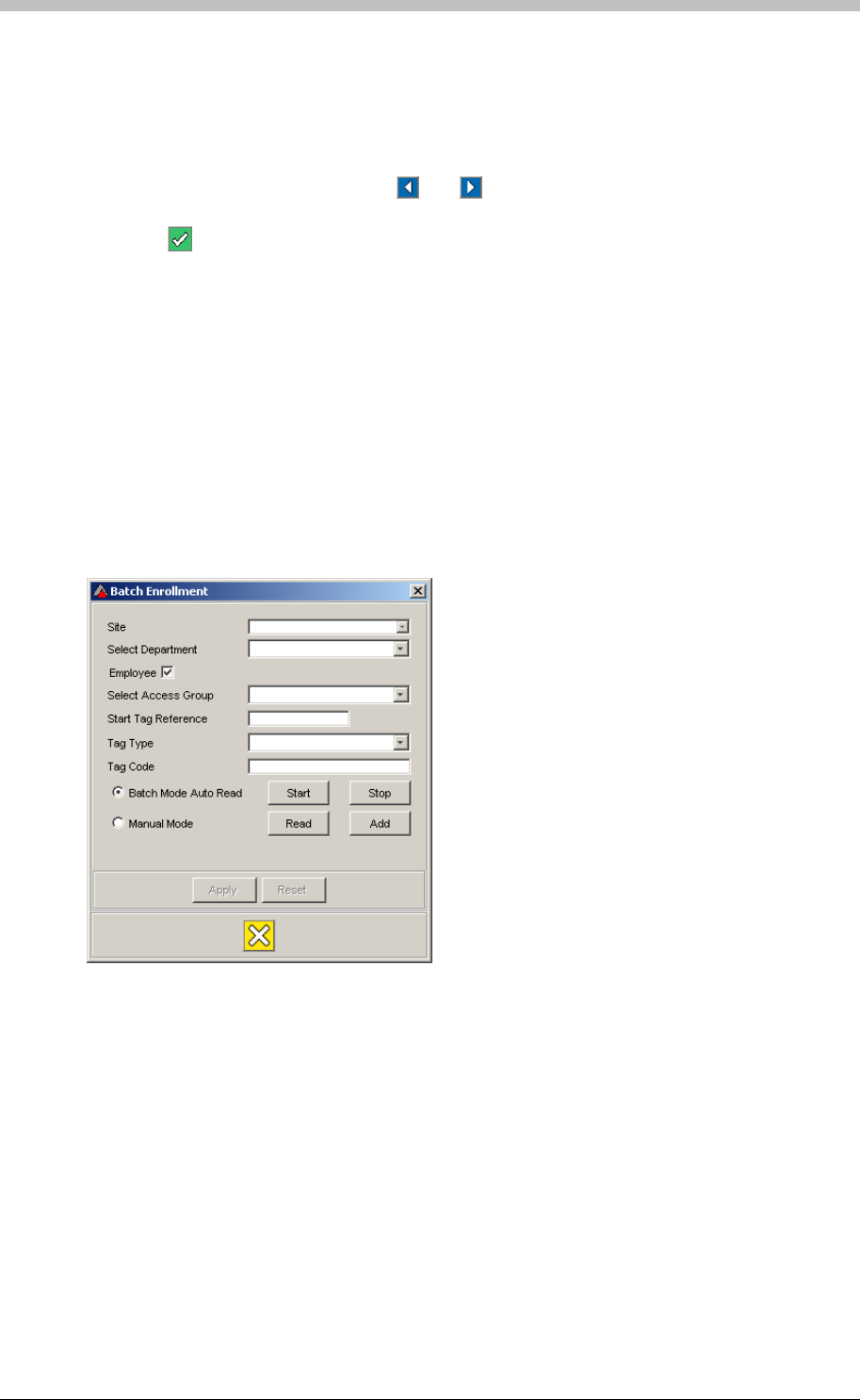
Tag Holders – Assign Access to Tags
Specify Start and End Dates
If the Tag Holder is temporary, click the Pick Start Date and Pick End Date buttons to select a
Start Date and Expiry Date. The Select Date window is displayed. To select dates, proceed as
follows:
1. Select a month and a year using the and arrow buttons
2. Select a day by clicking it. Alternatively, click Zero Date to set no date.
3. Click the button to accept
3. Select a Department if necessary
6. Enter a Start Tag Reference number if required. The Start Tag Reference number is any
number or identification that you can use to temporarily identify the Tags.
Batch Enrollment of Tags
The Batch Enrollment feature enables you to rapidly assign multiple Tags to a Site, without
entering Tag Holder details.
Start Batch Enrollment
Proceed as follows to open Batch Enrollment and start adding Tags:
1. On the ImproNet Access Menu, select Configuration > Batch Enrollment. The Batch
Enrollment screen is displayed.
2. Select a Site to assign the Tags to
4. Select the Employee checkbox if the Tags are for employees. Deselect the Employee
checkbox if the Tags are for Visitors.
5. Select an Access Group
7. Select one of the following to start the Batch Enrollment process:
− Batch Mode Auto Read
− Manual Mode
254 Tuesday, 11 July 2006
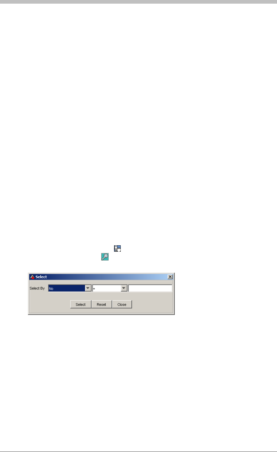
IXP300/IXP400 Installation Guide
Batch Mode Auto Read
This mode enables you to scan a batch of Tags in quick succession:
1. Ensure the Batch Mode Auto Read option is selected
Manual Mode
4. Repeat steps 1 to 3 for additional Tags
Advanced Search
1. In the Navigator pane, click the
2. Click the Start button
3. Present Tags to the Enrollment Reader one at a time
4. Click the Stop button
5. Click the Add button. Newly scanned Tags are added to the ImproNet Database
6. Click Apply
This mode enables you to scan a batch of Tags one at a time. It is useful if an Enrollment
Reader is not within reach of the Host PC.
1. Ensure the Manual Mode option is selected
2. Present a Tag to the Enrollment Reader
3. Click the Read button. The Tag is read when its number is displayed in the Tag Code
textbox.
5. Click the Add button when all Tags are scanned
6. Click Apply
To search for a Tag Holder, proceed as follows:
button
2. In the Main pane, click the button. The Select search window is displayed.
− Click Close to exit the search window
3. In the first drop-down list, select a field to search
4. In the second drop-down list, select an operator—see the next section for details
5. Enter keywords in the textbox on the right
6. Click the Select button to start the search. The results are displayed in the Main pane.
− Click Reset to display the original Tag Holder list in the Main pane
Tuesday, 11 July 2006 255

Tag Holders – Assign Access to Tags
Search Operators
• = means the same as—use = to search for exact matches to your keyword
• != means not equal to—use != to search for Tag Holders that do not match your keyword.
For example, use != to search for Tag Holders that are not in a particular Department
• LIKE means same first character—use LIKE to search for Tag Holders if you are unsure
of a spelling. For example, if you know that a Tag Holders Last Name is Johnson, but you
are unsure how to spell it, enter the character J into the keyword textbox. All Tag Holder
records that have Last Names beginning with a J are returned.
Available Search Fields
Description
No
The first drop-down list in the Select search window contains the following fields:
Field Name Search Criteria
Tag Holder’s unique ID assigned by ImproNet Number
Title Tag Holder’s Title. For example, Mr, Mrs, or Prof. Text
First Name Tag Holder’s first name Text
Second Name Tag Holder’s second or middle name Text
Last Name Tag Holder’s last name Text
Suffix Tag Holder’s name suffix. For example, John Doe Jr Text
ID Number of Tag Holder’s ID Document or Passport Number
Gender Male or Female M or F
Pin Pin code for use with Keypad Terminals Number
Type Text
Current Employee Checkbox The Tag Holder is currently employed
Position Tag Holder’s status in the company Text
Department Tag Holder’s department Text
Employee Number Tag Holder’s number assigned by their company Number
Table 19 – Available Search Fields
256 Tuesday, 11 July 2006
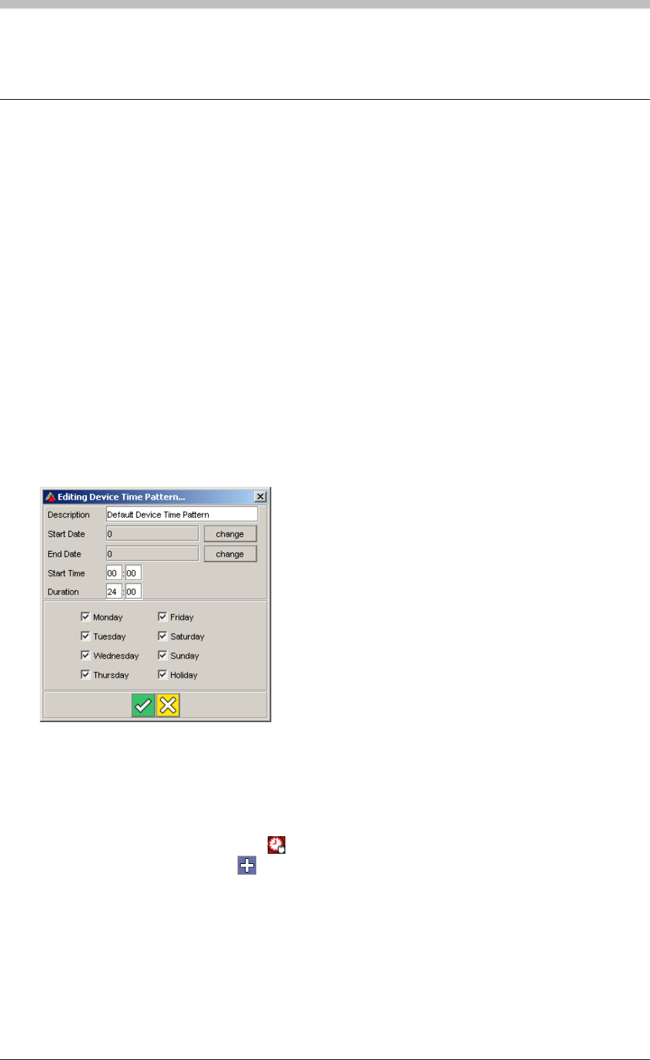
IXP300/IXP400 Installation Guide
Device Time Patterns
A Device Time Pattern (DTP) determines when a device is physically operational. You create
Device Time Patterns on the Device Time Pattern screen, and assign them when you set up
Terminals. You can also link Device Time Patterns to other functions including the following:
• Time Triggered Actions
• Inputs
• Random Search
1. In the Navigator pane, click the
A Device Time Pattern has the following settings:
• DTP Name—unique name
• Start Date—date when DTP starts operating
• End Date— date when DTP stops operating
• Start Time—time of day when DTP starts operating, configurable on a per day basis
• Duration—the length of time when the DTP is active
• Day of the Week—the days of the week when the DTP is active
Figure 80 - Device Time Pattern Edit Screen
Create a Device Time Pattern
To create a new Device Time Pattern, proceed as follows:
button
2. In the Main pane, click the button. The Adding Device Pattern Time screen is
displayed.
3. Configure the new Device Time Pattern as specified in the Configure Device Time
Patterns section
Open a Device Time Pattern
o configure a Device Time Pattern, proceed as follows:
T
Tuesday, 11 July 2006 257
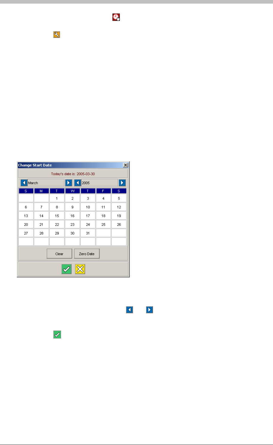
Device Time Patterns
1. In the Navigator pane, click the button
2. In the Main pane, select a Time Pattern Name
3. Click the button. The Edit Device Pattern Time screen is displayed.
4. Configure the new Device Time Pattern as specified in the next section: Configure Dev
ice
Time Patterns
1. Click the change button for the Start Date. The Change Start Date screen is displayed.
Configure Device Time Patterns
To configure the Device Time Patterns, proceed as follows:
1. Create a new Device Time Pattern, or open an existing one
2. Enter a Description that describes the Device Time Pattern
Configure Dates
If the Device Time Pattern is not required permanently, you can specify a start date and an end
date. The default value for Start Date and End Date is Zero Date—this means that the Device
Time Pattern begins immediately and does not expire. Specify a Start Date as follows:
Figure 81 - Change Date Screen
2. Select a month and a year using the and arrow buttons
3. Select a day by clicking it
4. Alternatively, click the Zero Date button to enable the default value
5. Click the button to accept
258 Tuesday, 11 July 2006

IXP300/IXP400 Installation Guide
Now, Specify an End Date as follows:
1. Click the change button for the End Date. The Change Start Date screen is displayed.
2. Select a month and a year with the blue and white arrow buttons
3. Select a day by clicking it
4. Alternatively, click the Zero Date button to enable the default value
5. Click the button to accept
Configure Times
Configure operating times as follows:
1. Enter a Start Time—this is the time of day when the Device Time Pattern becomes active
2. Enter a Duration in hours and minutes—this is how long after the start time, the Access
Time Pattern is active
Configure Days
Configure days as follows:
1. Select the days of the week when the Device Time Pattern is enabled
2. Click the button to accept the Device Time Pattern
Multiple Device Time Patterns
You can create up to 128 Device Time Patterns per Site. Additionally, multiple Terminals can
share a single Device Time Pattern.
Tuesday, 11 July 2006 259
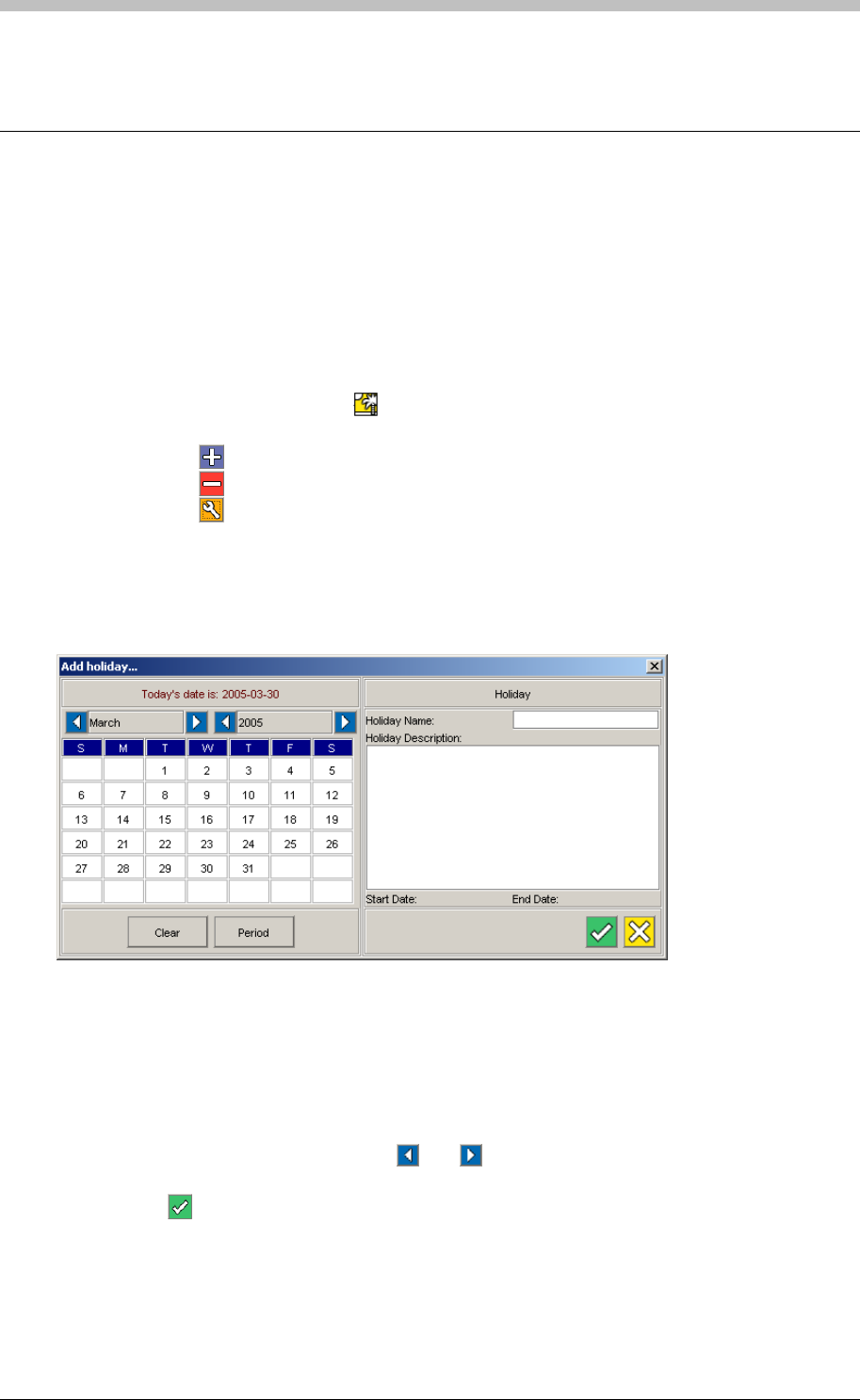
Holidays
Holidays
Holidays are days or periods when access to a Site is restricted to Administrators. If the
Holiday checkbox in an Access Time Pattern is selected, then Tag Holders assigned to that
Access Time Pattern have access to a Site on or during Holidays.
To add, edit, or delete a Holiday, proceed as follows:
1. In the Navigator pane, click the
Add, Edit, or Delete a Holiday
button
2. In the Main pane, do one of the following:
− Click the button to add a Holiday
− Click the button to delete a Holiday
− Click the button to edit a Holiday
1. Enter a Holiday Name
2. Enter a Holiday Description
3. Select a month and a year using the
The Add Holiday screen is displayed.
Configure Holidays
Figure 82 - Add Holiday Screen
To Add Holidays screen enables you to select the day or days to specify as a Holiday. To do
this, proceed as follows:
and arrow buttons
4. Select a day by clicking it. Click the Period button to select a period of more than one day
5. Click the button to accept
260 Tuesday, 11 July 2006
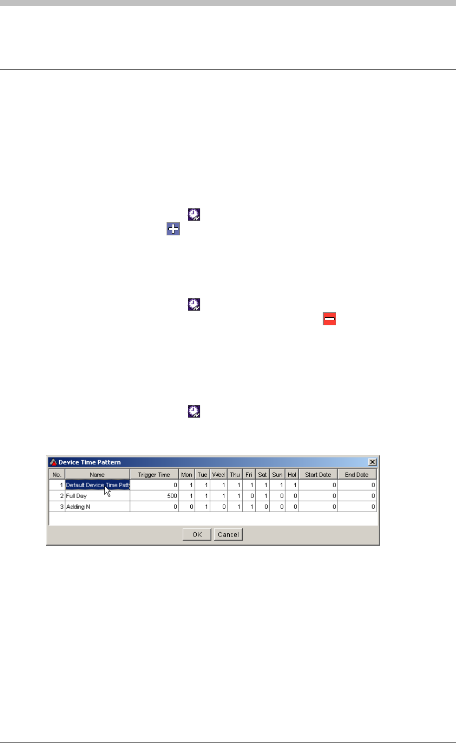
IXP300/IXP400 Installation Guide
Time Triggered Actions
Time Triggered Actions are actions triggered by a Controller at the Start Time of a specified
Device Time Pattern. They continue for the duration of the Device Time Pattern. To specify a
Time Triggered Action you must assign a Device Time Pattern and an Action.
Add a Time Triggered Action
To add a Time Triggered Action, proceed as follows:
1. In the Navigator pane, click the button
2. In the Main pane, click the button
Delete a Time Triggered Action
To delete a Time Triggered Action, proceed as follows:
1. In the Navigator pane, click the button
2. In the Main pane, select a Time Triggered Action and click the button
Configure Time Triggered Actions
To Configure a Time Triggered Action, proceed as follows:
1. In the Navigator pane, click the button
2. In the Main pane, double-click the Device Time Pattern field of a Time Triggered Action.
The Device Time Pattern screen is displayed.
3. Select a Device Time Pattern by clicking it, then click OK
4. Double-click the Action field of the same Time Triggered Action. The Select Action screen
is displayed.
Tuesday, 11 July 2006 261
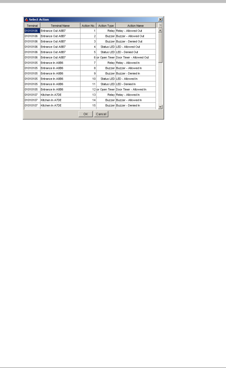
Time Triggered Actions
5. Select an Action by clicking it, then click OK
6. Double-click the Time Triggered Action Name field and enter a name
262 Tuesday, 11 July 2006
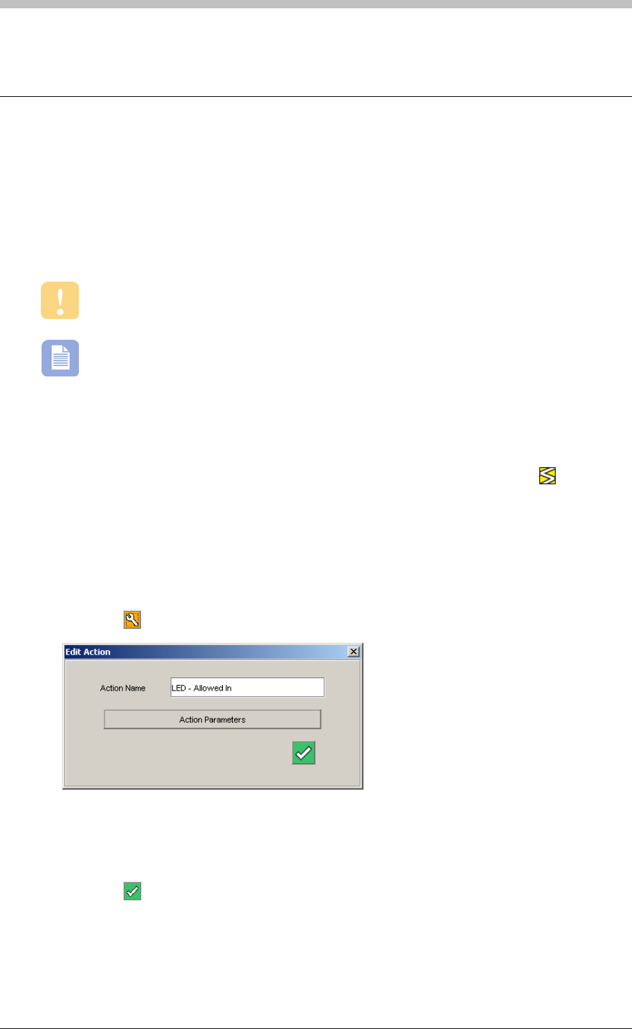
IXP300/IXP400 Installation Guide
Actions
When a Terminal is assigned to a Location, default Actions are created and linked to default
Events. For example, the Normal Allowed In Event is automatically linked to the
Action Relay Allowed In.
ImproNet Access enables you to create additional Actions and link them to Events.
Most Actions are created and configured on the Action tab of the Terminals screen.
Refer to the Actions section on page 239 for details.
It is possible for Events on one Terminal to activate Actions on other Terminals.
Edit and Delete Actions
Actions are create when Terminals are assigned to Locations. Therefore, the Actions screen
only enables you to edit or delete Actions. To open the Actions screen, click the button in
the Navigator pane,
Edit an Action
2. Click the
To edit an Action, proceed as follows:
1. In the Main pane, select an Action row
button. The Edit Action window is displayed.
6. Click the
3. Edit the Action Name if necessary
4. Click the Action Parameters button. An Action Parameters window corresponding to the
Action type is displayed.
5. Edit the parameters as required.
button to accept
Tuesday, 11 July 2006 263

Actions
Delete Action
To delete an Action, proceed as follows:
1. In the Main pane, select an Action row
2. Click the button. A delete confirmation dialogue box is displayed.
3. Click Yes
There is no undo for this procedure. Deleting an Action can result in a Terminal
or Location functioning incorrectly.
264 Tuesday, 11 July 2006

IXP300/IXP400 Installation Guide
Inputs
When a Terminal is assigned to a Location, default Inputs Functions are created. For example,
If a Terminal has a Request to Exit (RTE) facility, a General Input for the Terminal is created.
The Inputs screen enables you to configure existing Inputs created during Terminal assignment.
We recommend using the Inputs tab on the Terminal screen to configure Inputs. Refer
to the Inputs section on page 234 for details.
Tuesday, 11 July 2006 265

Outputs
Outputs
When a Terminal is assigned to a Location, default Output Functions are created. For example,
an Output function that controls the Terminal’s LED status is created.
The Outputs screen enables you to configure existing Outputs created during Terminal
assignment.
We recommend using the Outputs tab on the Terminal screen to configure Outputs.
Refer to the Outputs section on page 238 for details.
266 Tuesday, 11 July 2006

IXP300/IXP400 Installation Guide
Common Zones
Terminals on different Controllers can be assigned to Common Zones. However, you must first
create a Common Zone in the Common Zones screen before it is available in the Terminal
screen.
For more information, refer to the Common Zones section on page 270.
Tuesday, 11 July 2006 267
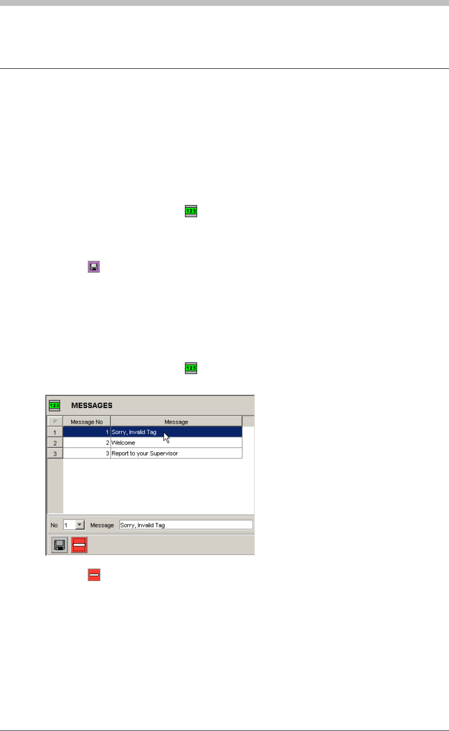
Messages
Messages
Devices fitted with an LCD, such as a Time and Attendance Reader, can display a messages.
Messages can be activated by Events and Time Triggered Events. The Message screen in
ImproNet Access enables you to create up to 63 messages to assign to suitable hardware.
Create a Message
To create a new Message, proceed as follows:
1. In the Navigator pane, click the button. The Messages screen is displayed
4. Click the
2. In the Main pane, select a Message number from the No drop-down list. The default value
is 1
3. Enter the Message content in the Message textbox
button to save
Delete a Message
5. Repeat steps 1 – 4 to create additional messages. However, remember to select an
unused Message Number each time, otherwise the original Message will be overwritten.
To Delete a Message, proceed as follows:
1. In the Navigator pane, click the button. The Messages screen is displayed
3. Click the
2. In the Main pane, click a Message to select it
button. The selected Message is deleted.
268 Tuesday, 11 July 2006

IXP300/IXP400 Installation Guide
PART IV – Advanced Configuration
Tuesday, 11 July 2006 269
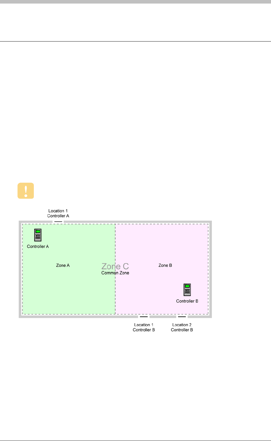
Common Zones
Common Zones
Common Zones enable you to group Zones on different Controllers together and maintain full
APB control. This enables Tag Holders to enter an Area via one Zone, and exit the Area via
another Zone.
Figure 83
Zones must be set up in relaxed or strict APB mode if they are part of a common Zone
illustrates a basic Common Zone set-up. In this scenario, there are two Controllers
with one Zone each. Zone A and Zone B are grouped into a Common Zone, Zone C. This
enables a Tag Holder to enter and Exit at any Location.
Why Common Zones?
Remember that a Zone can belong to one Controller only. In some cases, it is not possible to
connect all Doors entering a building to the same Controller—this could be a distance
constraint, or a result of bad initial planning. Common Zones enable you to treat two or more
Zones as a single zone. Therefore, APB is enforced across multiple Zones.
Figure 83 - Common Zone Diagram
Configure Common Zones
Perform the following steps to set up a Common Zone:
1. Create a new Common Zone
2. Assign existing Zones to a Common Zone
270 Tuesday, 11 July 2006
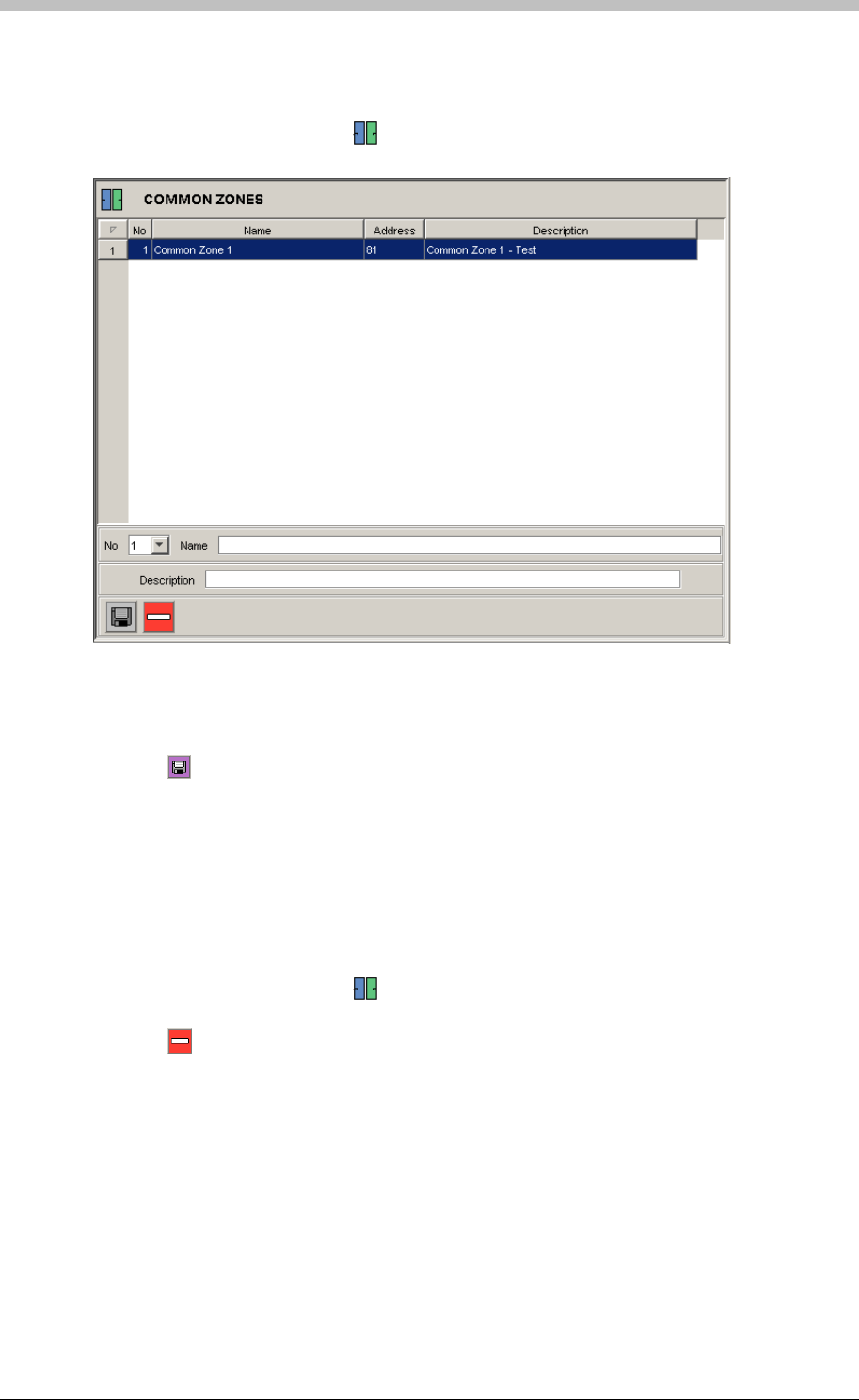
IXP300/IXP400 Installation Guide
Create Common Zone
To create a Common Zone, proceed as follows:
1. In the Navigator pane, click the button. The Common Zone screen is displayed
2. In the Main pane, select a Common Zone number from the No drop-down list. The default
value is 1
3. Enter the Common Zone Name and Description
4. Click the button to save
5. Repeat steps 1 – 4 to create additional Common Zones. However, remember to select an
unused Common Zone number each time, otherwise the original Common Zone will be
overwritten.
Delete Common Zone
To Delete a Common Zone, proceed as follows:
1. In the Navigator pane, click the button. The Common Zone screen is displayed
2. In the Main pane, click a Common Zone to select it
3. Click the button. The selected Common Zone is deleted.
Assign Zones to Common Zone
Perform the following procedure for each Zone you are assigning to a Common Zone:
1. In the Navigator pane, click a Terminal to select it. The Terminal tab is displayed
2. Select a Common Zone from the Part of Common Zone drop-down list
Tuesday, 11 July 2006 271
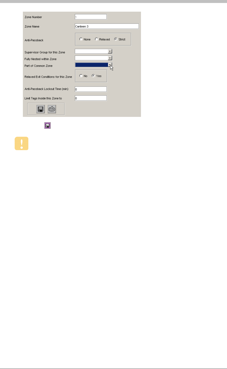
Common Zones
3. Click the button to save the settings
Ensure that APB is set to Strict.
272 Tuesday, 11 July 2006
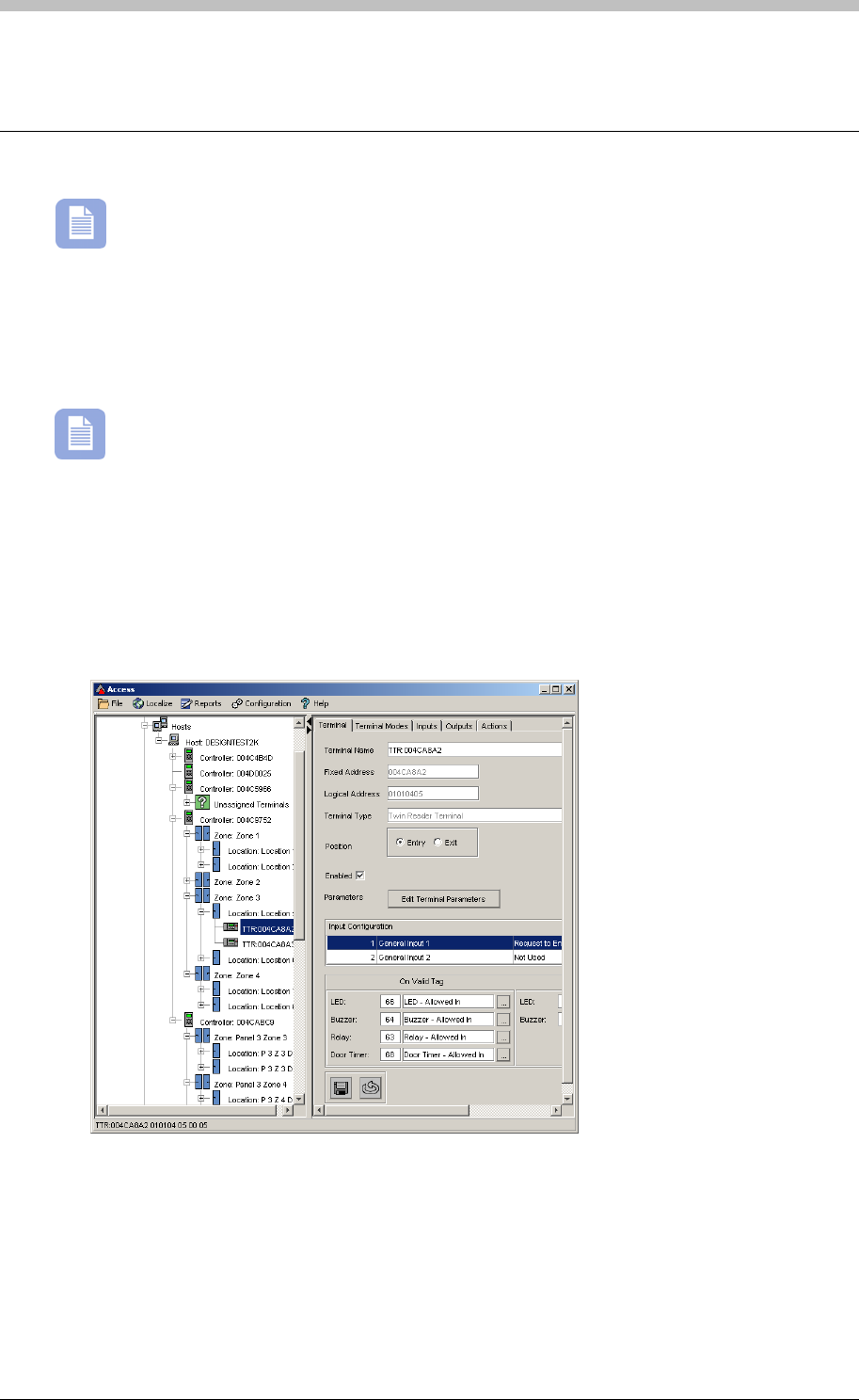
IXP300/IXP400 Installation Guide
Emergency Unlock
Items not approved by UL are marked with a character.
Emergency Unlock is used during an emergency to unlock selected doors in a Site. It can be
activated directly via the ImproNet Software or by a Controller Event. For example, in the event
of a fire, a third-party fire detector Terminal. The input
triggers an Event that activates Emergency Unlock Mode at selected Terminals.
can trigger an input on a selected
You need to configure each Terminal separately for Emergency Unlock Mode.
Set Up Emergency Unlock Mode
To set up Emergency Unlock, proceed as follows:
1. In Access, select a Terminal for a location where you want to enable Emergency Unlock.
The Terminal tab is displayed.
2. Select the Outputs tab
Tuesday, 11 July 2006 273
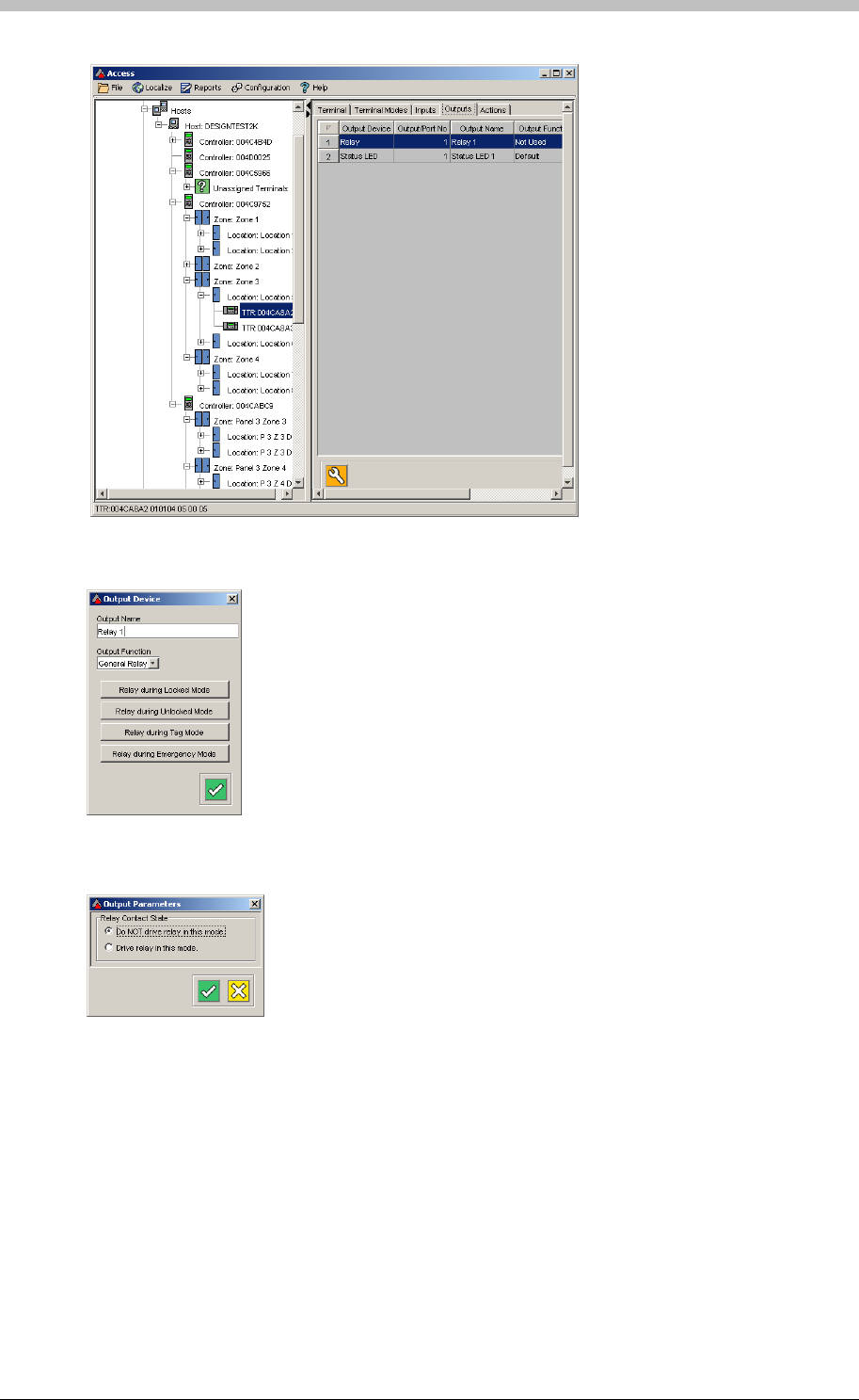
Emergency Unlock
3. Select the Relay row. The Output Device screen is displayed.
5. Select the Relay Contact State required during Emergency Mode
4. Click the Relay during Emergency Mode button. The Output Parameters screen is
displayed. It contains settings for Relay Contact State.
274 Tuesday, 11 July 2006
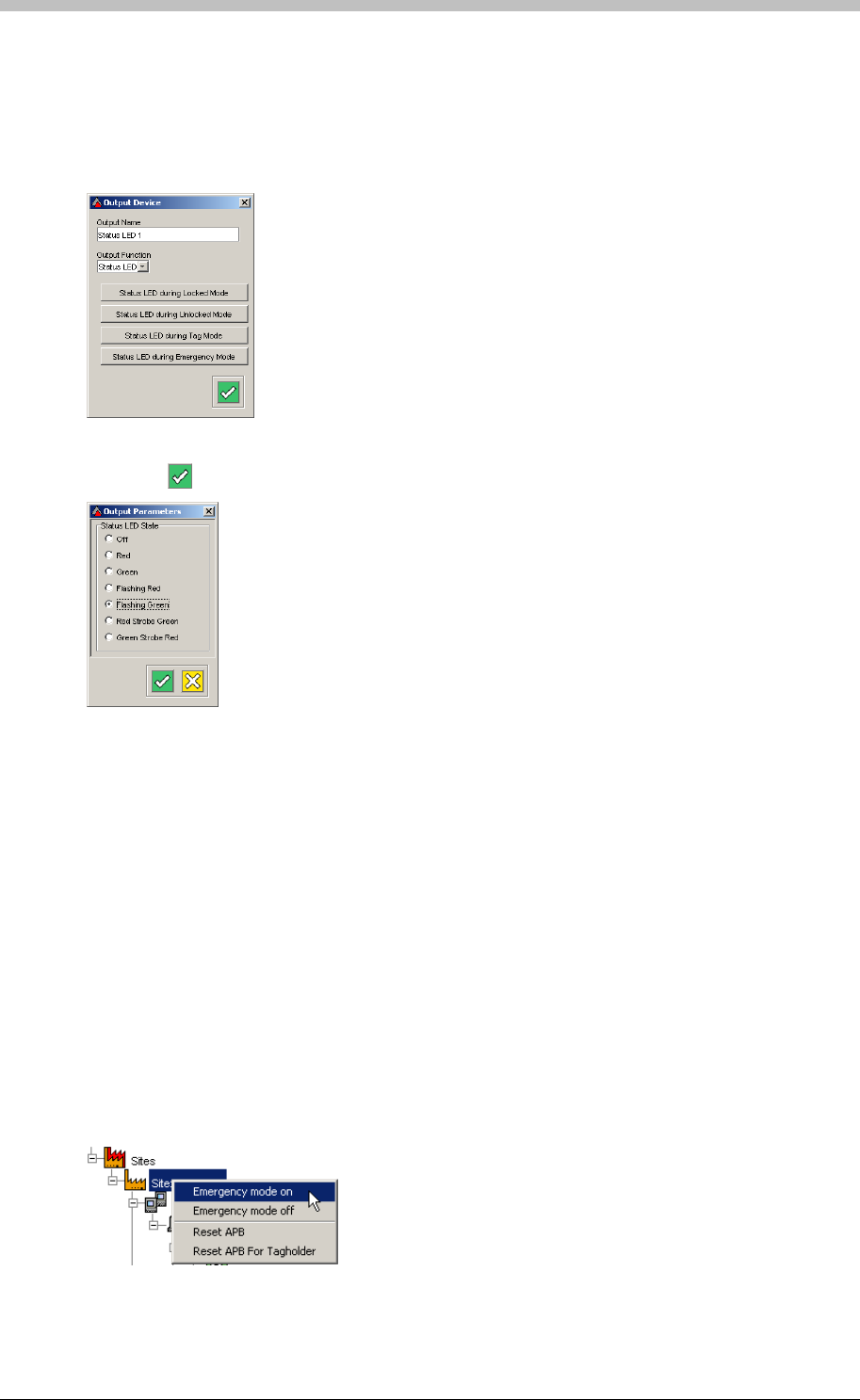
IXP300/IXP400 Installation Guide
Now, configure the Terminal LED state as follows:
1. Select the Status LED option from the Output Function drop-down list
2. Click the Status LED during Emergency Mode button. The Output Parameters screen is
displayed. It contains settings for Status LED State.
3. Select an option—we recommend Flashing Green
4. Click the button to Save
Activating Emergency Unlock Mode Manually
You can activate Emergency Unlock Mode at the following levels:
• Site
• Controller
• Terminal
Site Emergency Unlock
ImproNet Access enables you to manually activate Emergency Unlock Mode on a per Site
basis. At this level, Emergency Unlock Mode triggers all Terminals that were set up for it. To do
this, proceed as follows:
1. In the Navigator pane, click a Site to select it
2. Right-click the Site. A popup menu is displayed.
Tuesday, 11 July 2006 275
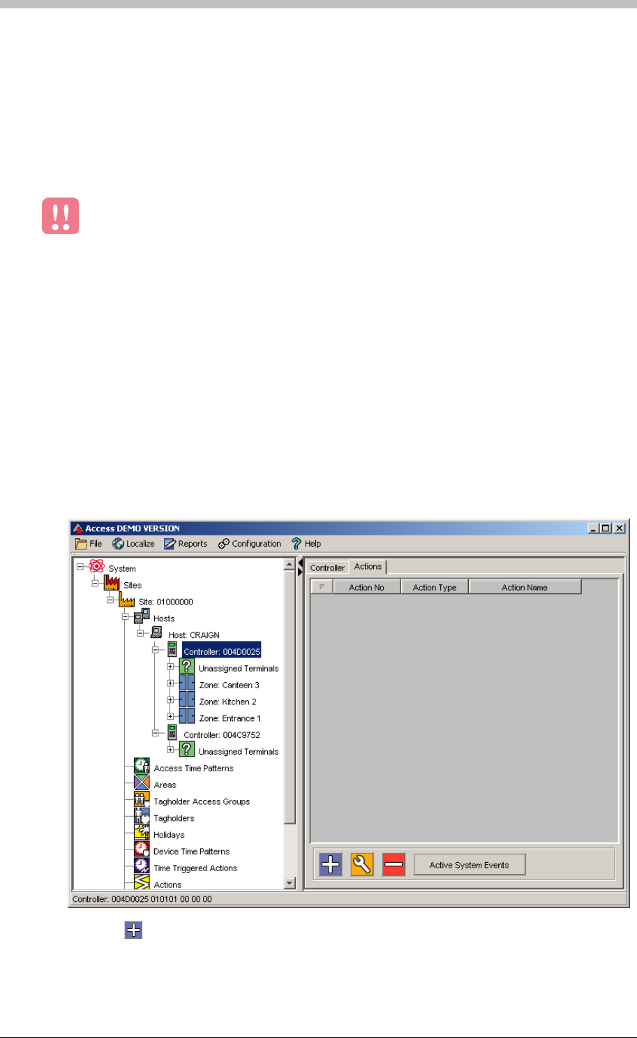
Emergency Unlock
3. Select the Emergency mode on option. Emergency Unlock Mode is activated on all
Terminals that were set-up for it.
Controller and Terminal Emergency Unlock
Activating Emergency Unlock via an Input
1. In the Navigator pane, select a Controller
You can also activate Emergency Unlock mode for Terminals connected to a specific Controller
or Terminal. The procedure is the same as the Site Emergency Unlock procedure, except you
must select a Controller or Terminal in the Navigator pane.
Emergency Unlock is only activated on a Terminal if it has been configured for
Emergency Unlock.
Emergency Unlock can also be triggered via selected Terminals. In this configuration, the
Emergency Unlock Action is triggered when an Input receives a specific signal. For example,
you can set-up a Controller to activate the Emergency Unlock Action when the Terminals Input
receives a signal from a panic button.
Configure Controller Action
First, configure the Emergency Unlock Action on a Controller as follows:
2. Click the Action tab
3. Click the button to create a new action
4. Select Emergency Mode from the Select Action Type drop-down list
276 Tuesday, 11 July 2006
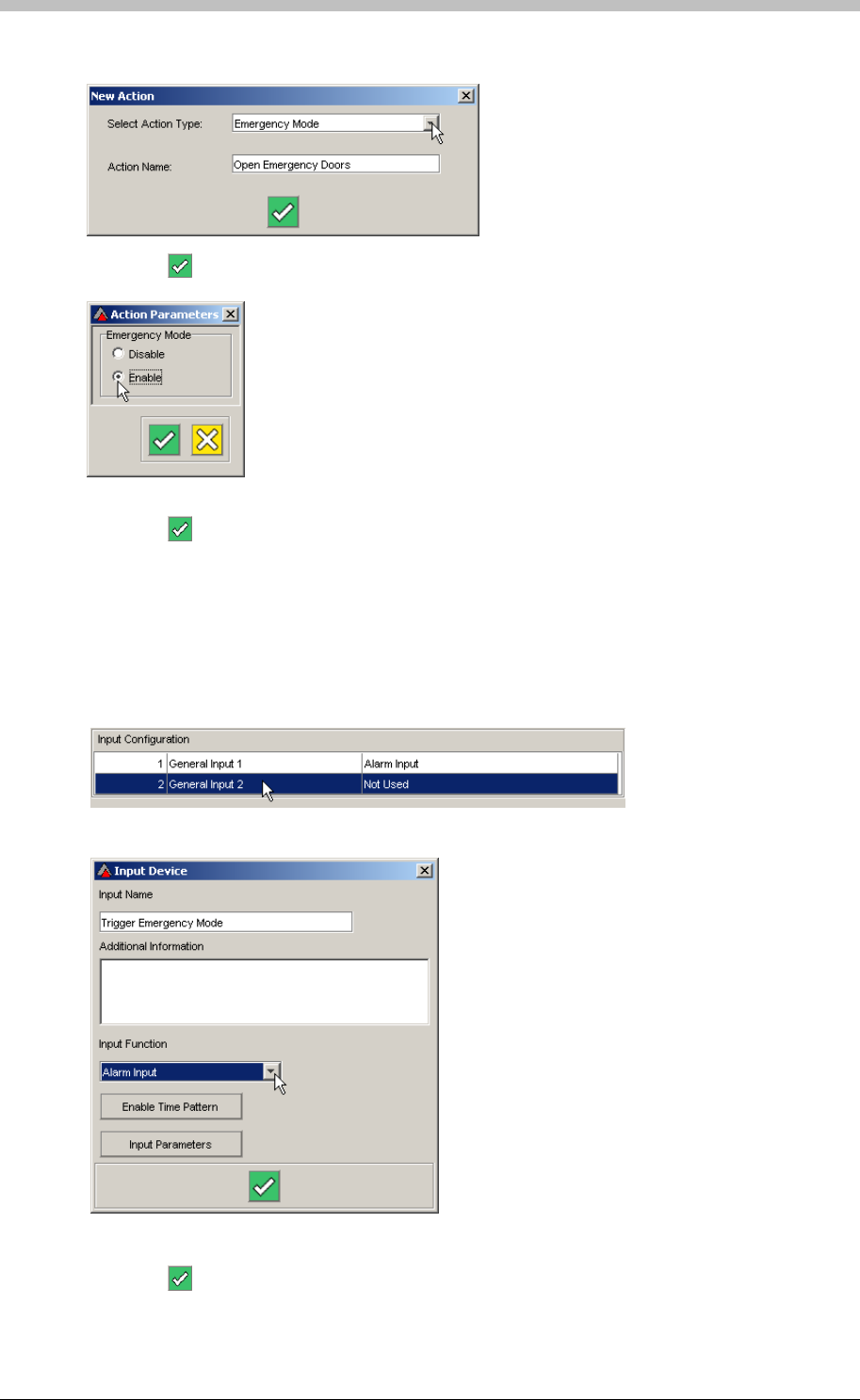
IXP300/IXP400 Installation Guide
5. Name the Action Open Emergency Doors
6. Click the button to save. The Action Parameters window is displayed.
7. Select the Enabled option
8. Click the button to save
Configure Terminal Input
Second, configure an Input on a Terminal as follows:
1. In the Navigator pane, select a Terminal
2. In the Input Configuration field, double-click a General Input that is Not Used.
The Input Device window is displayed.
3. Enter Trigger Emergency Mode for the Input Name
4. Select Alarm Input from the Input Function drop-down list
5. Click the button to save
Tuesday, 11 July 2006 277
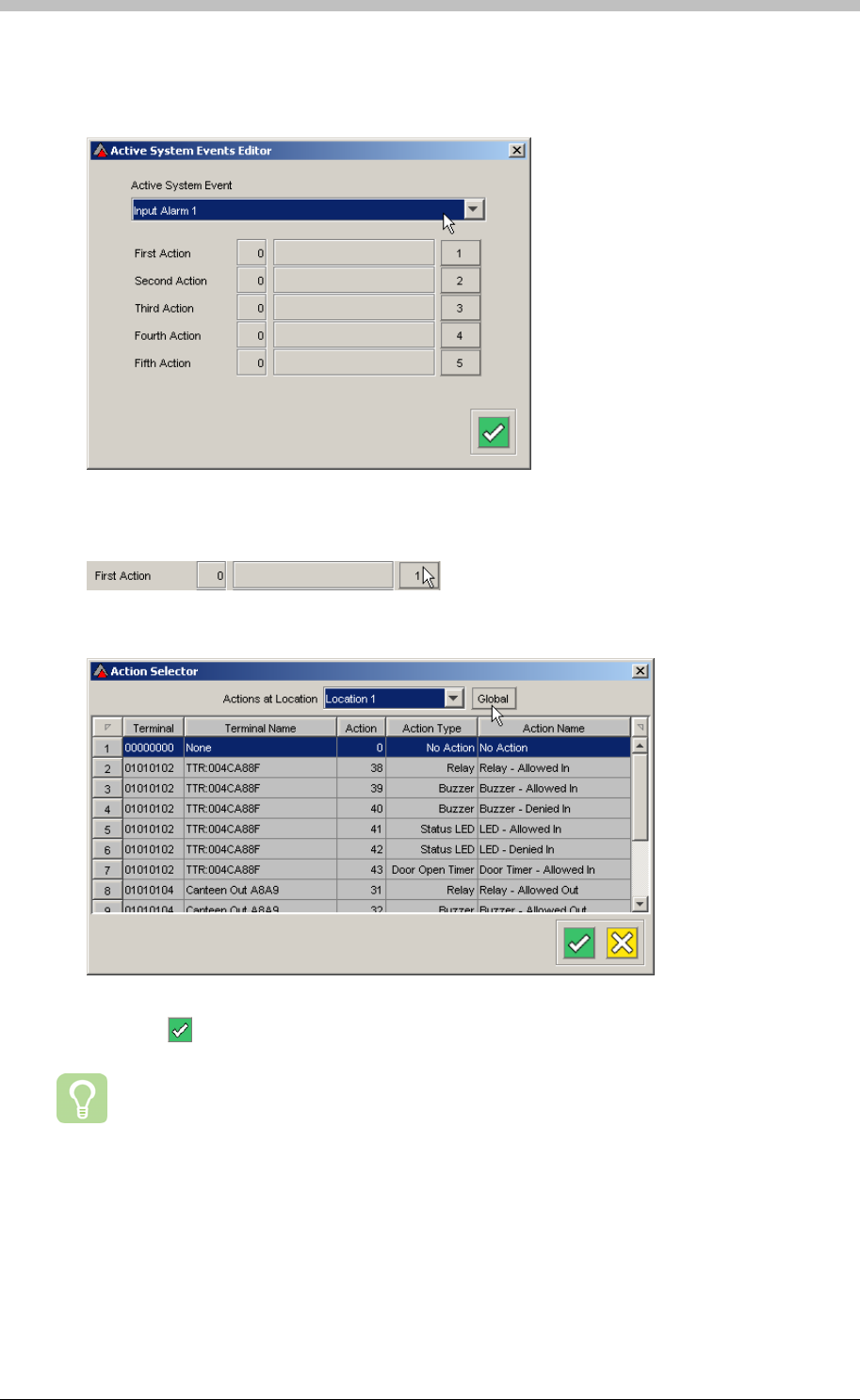
Emergency Unlock
6. Click the Action tab
7. Click the Active System Events button
13. Click the
8. Click the Advanced button. The Advanced Active System Events Editor is displayed.
9. Select Input Alarm from the Active System Event drop-down list
10. Click the 1 button
The Action Selector window is displayed
11. Click the Global button to list all Actions on all Controllers
12. Select the Open Emergency Doors Action that you created on the Controller Action tab
button to save
We recommend configuring a second Input to revert a Site to normal operation after
Emergency Unlock has been triggered. An additional Emergency Mode disable Action
is also required.
278 Tuesday, 11 July 2006
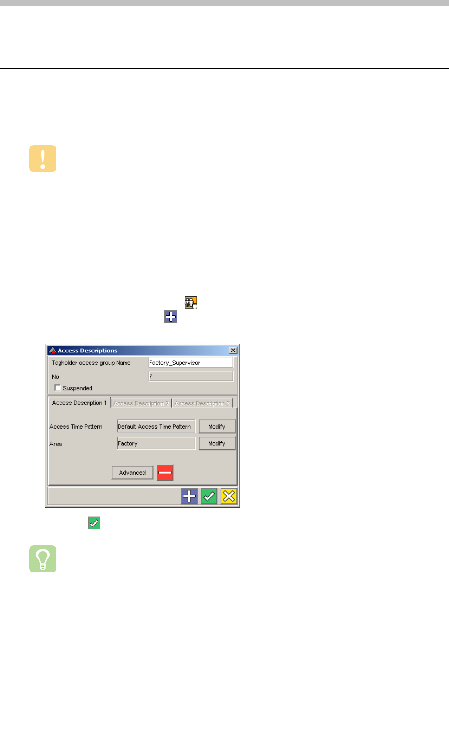
IXP300/IXP400 Installation Guide
Supervisor Unlock
Supervisor Unlock is a security feature that allows Tag Holders to enter a Zone only after a
Supervisor has entered the Zone.
The following steps enable you to configure a Zone for Supervisor Unlock:
Supervisor Unlock does not work if an Area has more than one Zone.
Configure Supervisor Unlock
Create Supervisor Tag Holder Access Group
To create a Supervisor Tag Holder Access Group, proceed as follows:
1. In the Navigator pane, click the button
2. In the Main pane, click the button
3. Enter a name in the Tagholder access group Name textbox
4. Click the button to save
We recommend using the word Supervisor as part of the name for the Supervisor Tag
Holder Access Group.
Tuesday, 11 July 2006 279
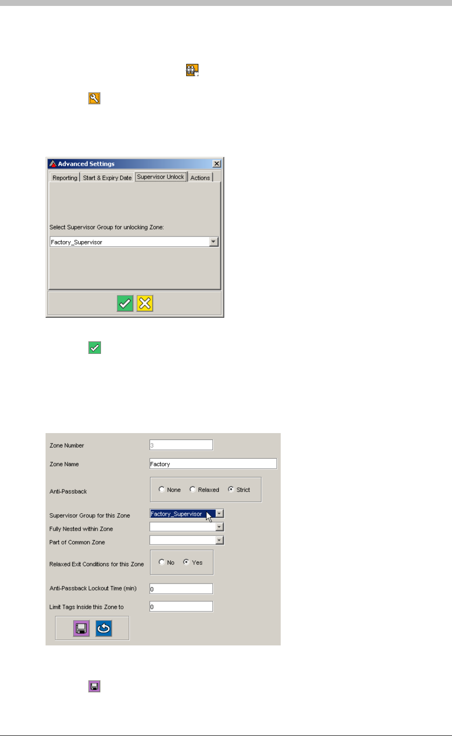
Supervisor Unlock
Specify Supervisor
To create an Access Group and specify a Supervisor for the group, proceed as follows:
1. In the Navigator pane, click the icon
2. Select the Tag Holder Access Group that requires a Supervisor
3. Click the button. The Access Description screen is displayed.
4. Select the Access Description that contains the Area that requires a Supervisor
5. Click the Advanced button. The Advanced Settings window is displayed.
6. Click the Supervisor Unlock tab
7. Select the name of the Supervisor group from the drop-down list
8. Click the button to save
Configure Zone for Supervisor Unlock
Open an existing Zone and configure Supervisor Unlock as follows:
1. In the Navigator pane, select a Zone
2. Select the name of the Supervisor Access Group from the Supervisor Group for this Zone
drop-down list
3. Click the button to save
280 Tuesday, 11 July 2006
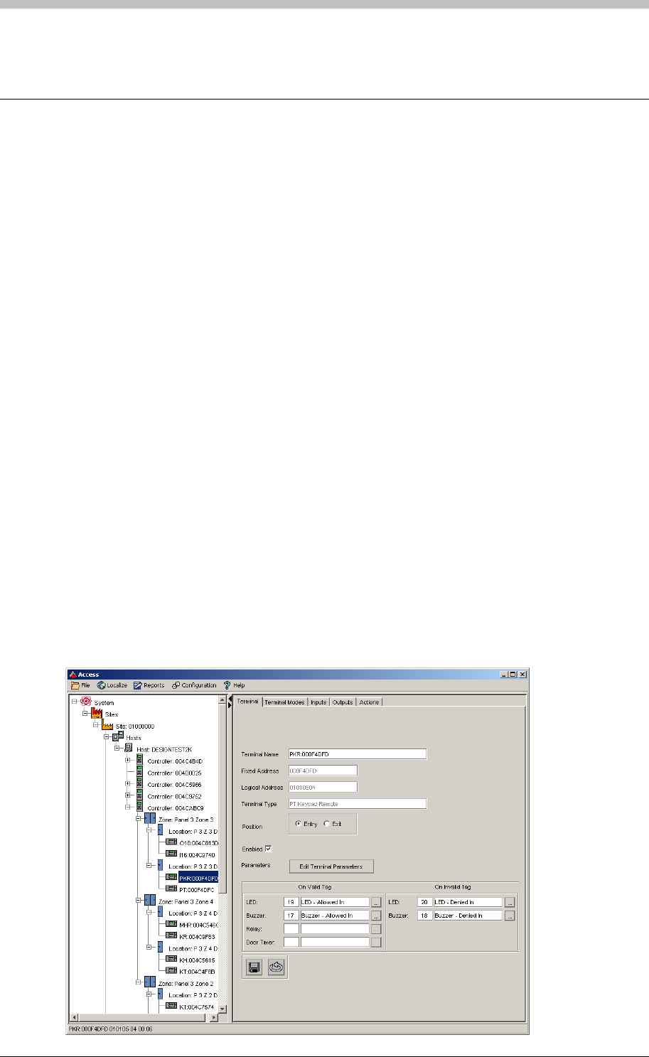
IXP300/IXP400 Installation Guide
Random Search
Some establishments require their staff to be physically searched for security purposes.
ImproNet provides a facility to randomly select Tag Holders for this purpose. Random Search
can be enabled on a per Reader basis.
The Random Search Event
ImproNet enables you to assign the Random Search Event to any number of Terminals. Tag
Holders using these Terminals are randomly selected and locked out. The Tag Holder is denied
access to the location until a Security person has attended to them.
Parameters
You can specify the following key parameters for the Random Search Event:
• Same Tag Timeout—the time that the effected Tag Holder is denied access
• Random Search Frequency—the frequency that Random Search Event operates. You
can set it to operate from every Tag Holder to one in every 255 Tag Holders on a Random
basis.
Set Up Random Search
Configure Random Search for each Reader as follows:
1. Navigate to the Location where you want to enable Random Search
2. Click the Edit Terminal Parameter button. The Terminal Parameters screen is displayed.
Tuesday, 11 July 2006 281
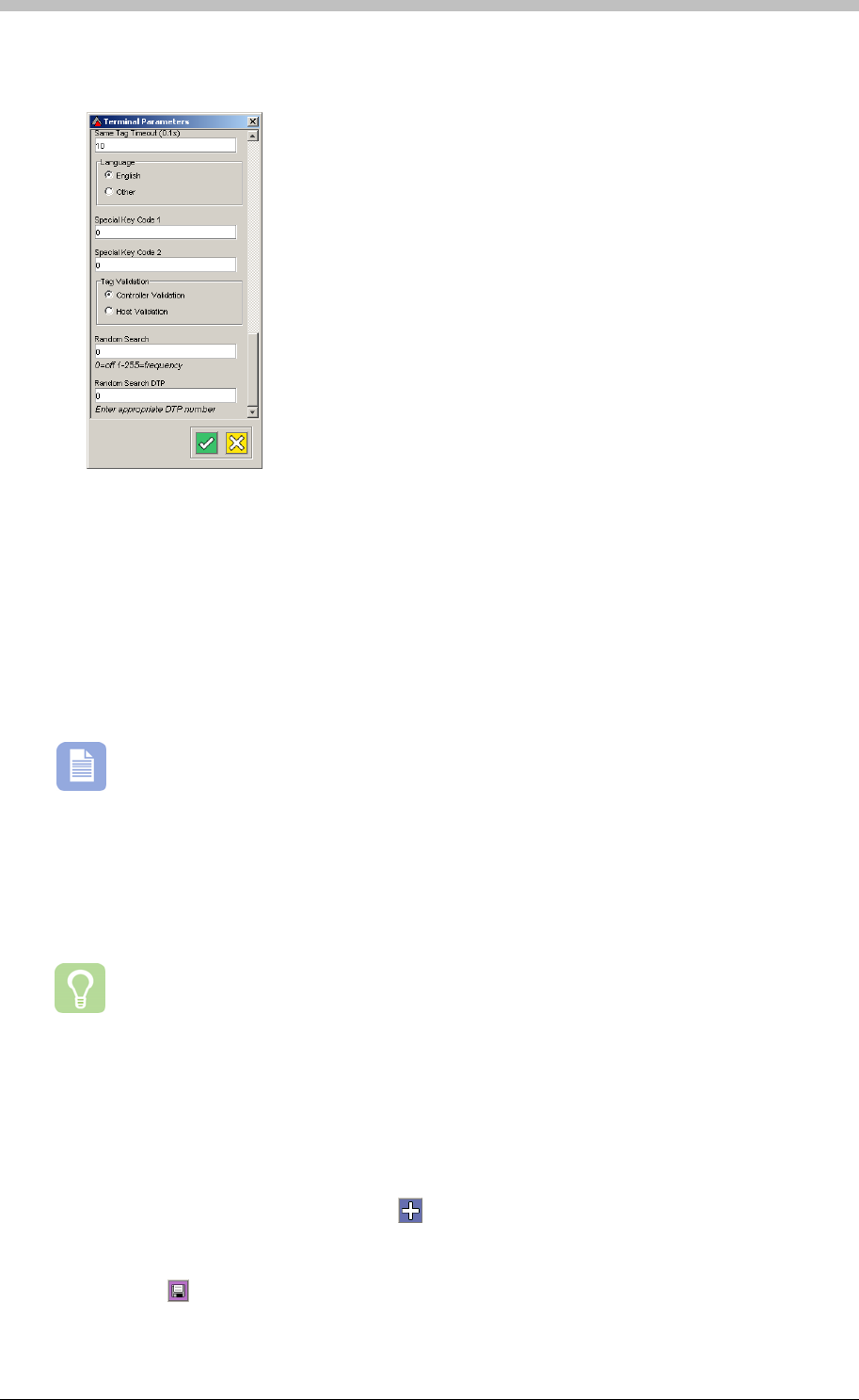
Random Search
3. Scroll to the bottom of the Terminal Parameters screen until you reach the Random
Search textbox
4. Enter a number from 1 to 255 to enable random Search. 0 is the default value—Random
Search is disabled.
About the Frequency 1 to 255
Entering 1 means that one out of every Tag Holder is selected—in other words, all Tag Holders
are selected. Similarly, entering 2 means that one out of two Tag Holders is selected, a fifty
percent selection rate. You can enter any number up to 255. The higher the number, the less
the function is activated.
Random Search is a random function. Setting the frequency to a particular number
only guarantees the probability of the function occurring at that rate.
Enable Search at Specific Times Only
The Random Search event can be set up to function only during a Reader’s specific Device
Time Patterns (DTP). To set up this feature, enter a number into the Random Search DTP
textbox.
A Device Time Pattern is a period of time when a hardware device is set to operate
The Random Search DTP value must correspond with the number of the Device Time Pattern
for the designated Reader. 0 is the default value and enables Random Search for 24 hours
each day of the week.
To set a Device Time Pattern for Random Search, proceed as follows:
1. On the Terminal Mode tab, click the button. A new Terminal Mode is created.
2. Double-click the Device Time Pattern field and select a Device Time Pattern
3. Double-click the Terminal Mode field and select Tag Mode
4. Click the button to save
282 Tuesday, 11 July 2006
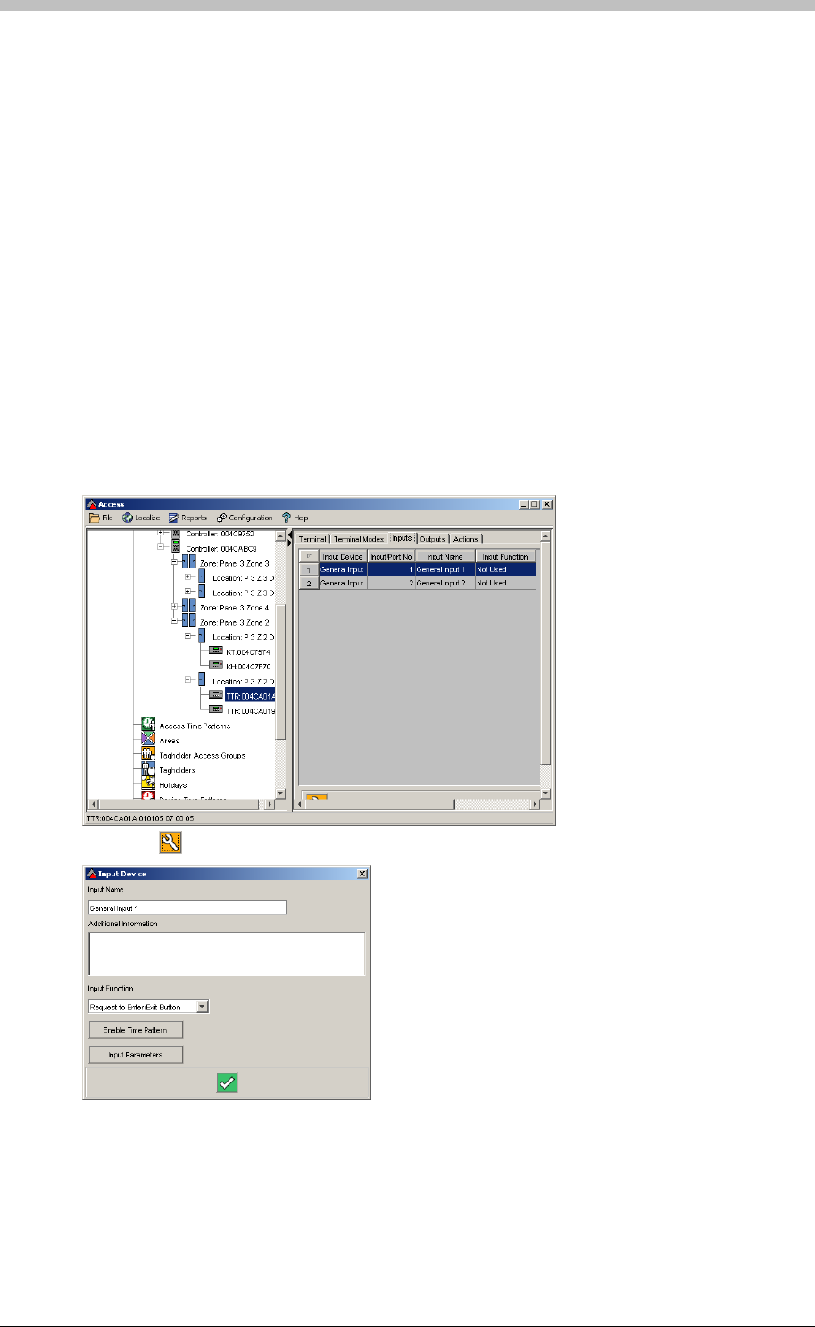
IXP300/IXP400 Installation Guide
When a Denied Random Search Event is generated, the Tag Holder is denied access.
Additional options are available to prevent the Tag Holder entering the Site in the case that the
further measures are required. An example is to enable the Inhibit Scanner option—this
prevents the Tag Holder re-gaining access by re-presenting their tag after it is denied for
Random Search purposes.
The following example, an additional Terminal relay and Input are used to inhibit a Reader when
a Denied Random Search Event is raised. In this example, the relay is connected to the Input.
When activated, the Relay creates a contact closed signal at the Input. When the contact
closed signal is registered, the Inhibit Scanner function is enabled.
Example
Configure Input
Select the Input tab. Configure the inputs as follows:
1. Select an unused Input
2. Click the button. The Input Device screen is displayed.
3. On the Input Function drop-down menu, select Inhibit Scanner
Tuesday, 11 July 2006 283
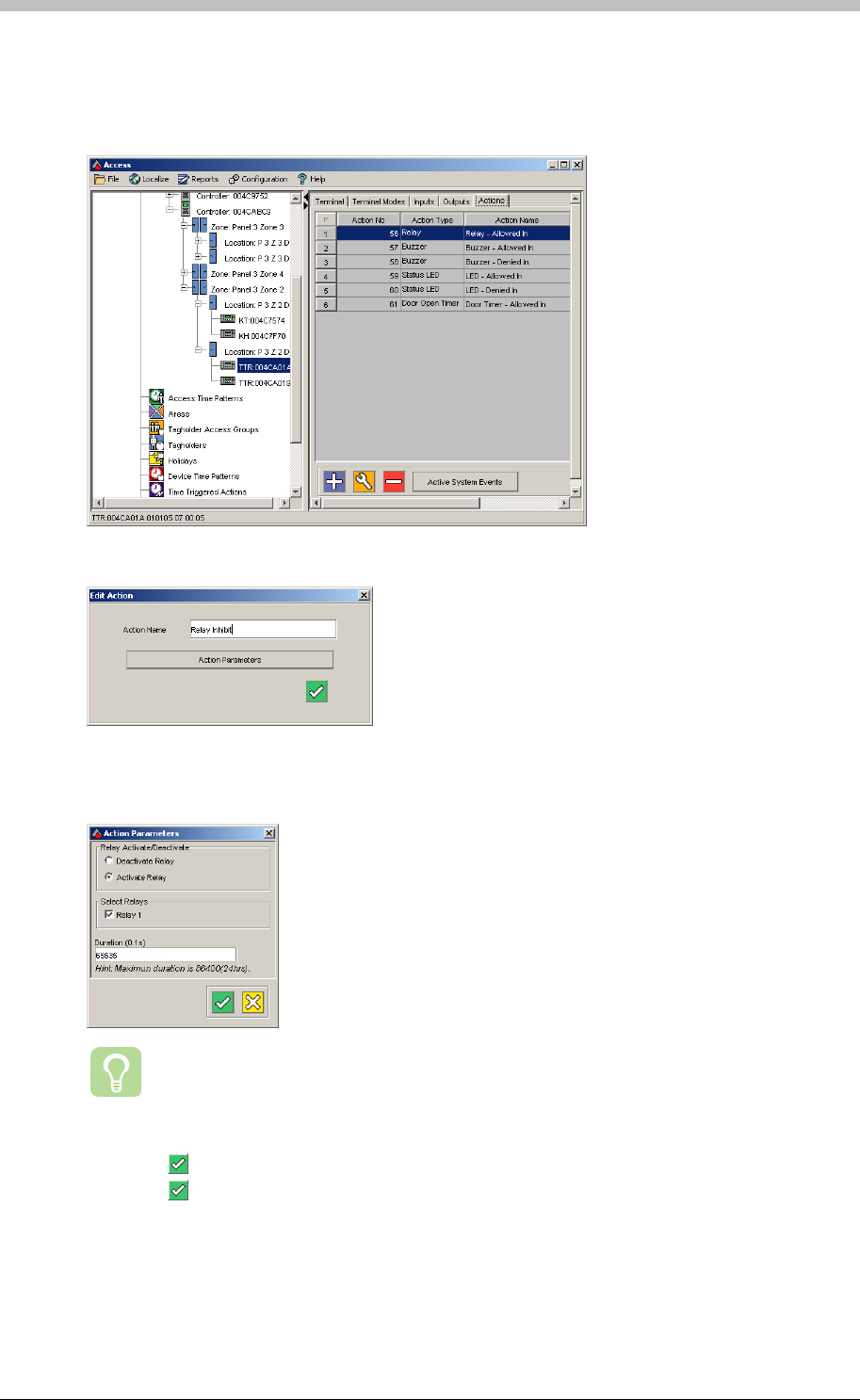
Random Search
Create Action
Create a Relay Action that connects to the Input that enables the Inhibit Scanner function:
2. Create a new relay action and name it Relay Inhibit
4. Set the Duration to 65535. This value enables indefinite duration.
1. Select the Action tab. Proceed as follows:
3. Click the Action Parameters button. The Action Parameters screen is displayed
We recommend that you create a second relay Action to deactivate the first one.
The second Action will deactivate the Relay and disable the Inhibit Scanner
function.
5. Click the button on the Action Parameters screen
6. Click the button on the Edit Action screen
284 Tuesday, 11 July 2006
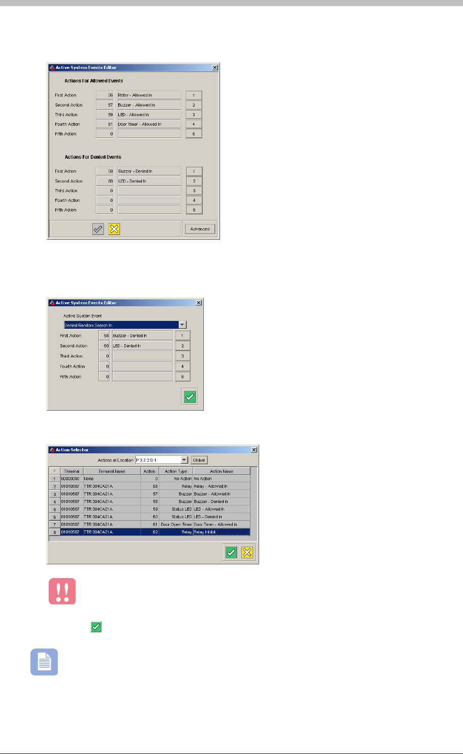
IXP300/IXP400 Installation Guide
7. On the Action tab, click the Active System Events button. The Active System Events
Editor is displayed.
Do not change the values for the First Action and Second Action.
8. Click on the Advanced button
9. Select the Denied by Random Search In option from the Active System Event drop-down
menu
10. Select the new Relay Inhibit Action you created for the Third Action
11. Click the button to save
The Relay must be physically connected to the Input for this configuration to work.
Tuesday, 11 July 2006 285
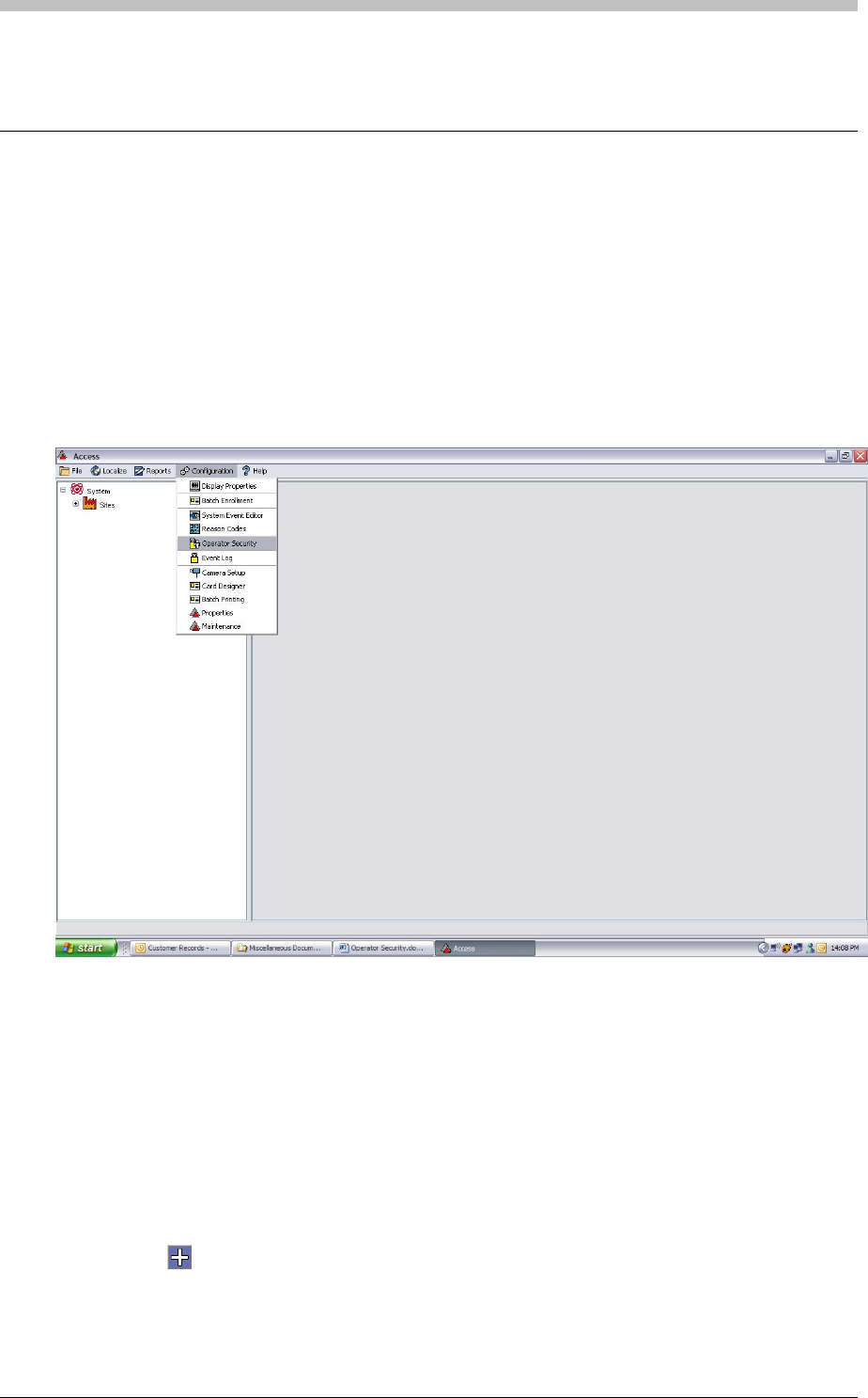
Operator Security
Operator Security
The ImproNet Software Suite offers full User and Operator Security. Previously, the third-party
database utility, IBConsole, was required to administer usernames and passwords. Now,
ImproNet facilitates administration of usernames and passwords. Any User or Operator can be
configured to have access to any part of the ImproNet software. It is possible to restrict
operator access to specific Tag Holders and ImproNet applications.
To open the Operator Security screen, proceed as follows:
• On the Access menu, select Configuration > Operator Security
The Operator Security screen displays the System Administrator group by default. This group
has full access to all ImproNet Software applications and all Tag Holders. The System
Administrator group cannot be edited or deleted. SYSDBA is the only user that is a member of
the System Administrator operator group.
System Administrator Group
Create Group
To create a new Operator Group, proceed as follows:
1. Click the button
2. Enter an Operator Group Name
3. Click OK
286 Tuesday, 11 July 2006
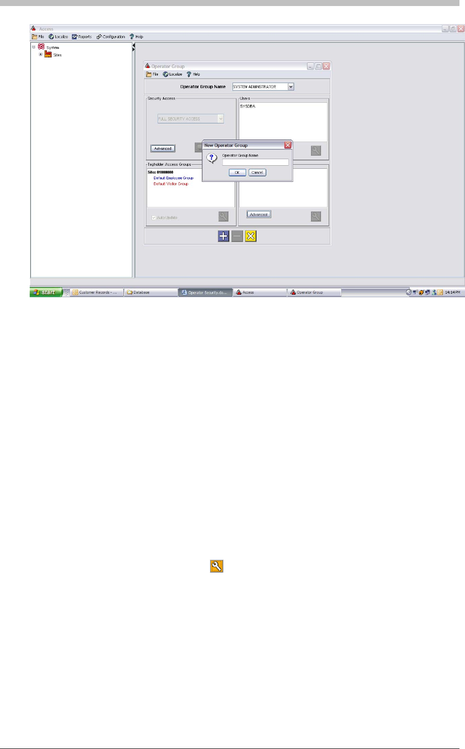
IXP300/IXP400 Installation Guide
The Operator Security screen consists of the following sections:
• Security Access
To change to a different profile, click the
• Users
• Tag Holder Access Groups
• User Profiles.
Configure each section for each Operator Group that you create.
Security Access
The Security Access screen defines the Software interfaces that different Users have access to.
The Full Security access profile is enabled by default. To change this, choose from a list of
preset access profiles, or click the Advanced button to configure a new access profile in the
Security Control Panel.
Change Profile
button, and select another profile from the drop-
down list.
Templates
You can select default, pre-configured templates from the Security template name drop-down-
list. These templates are not editable but are useful for standard Users. Alternatively, create a
new template as follows:
Tuesday, 11 July 2006 287
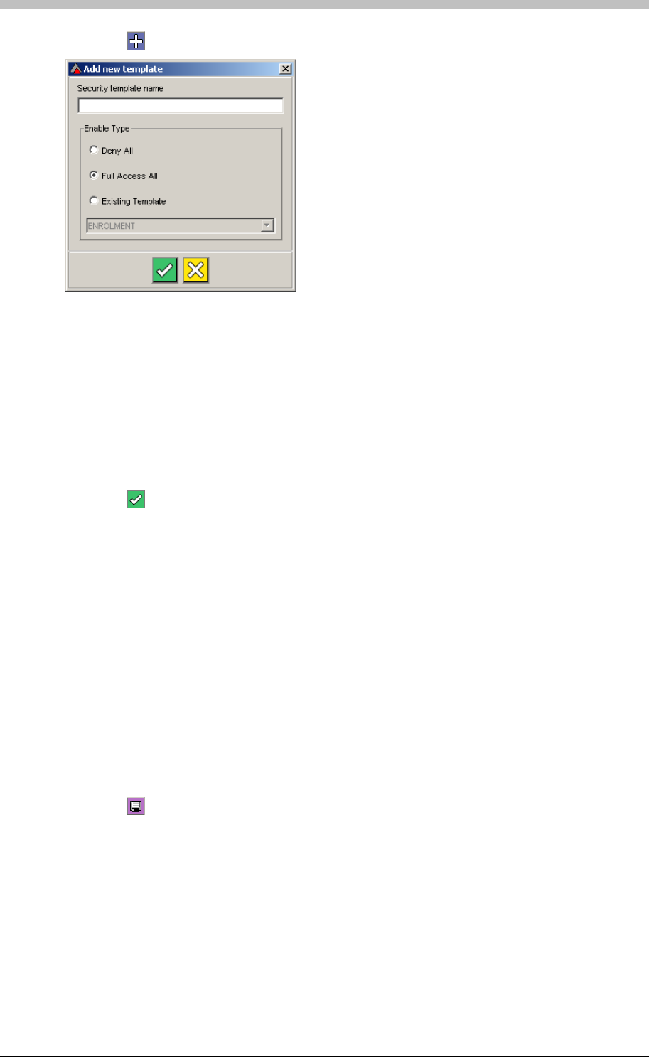
Operator Security
1. Click the button. The Add New Template window is displayed.
− Deny All—all parts of ImproNet Access are restricted. Use this option if you are only
enabling a few items.
2. Enter a Security template name
3. Select on of the following options as a starting point:
− Full Access All—all parts of ImproNet Access are accessible. Use this option if you
are only restricting a few items.
− Existing Template—the new template settings are the same as an existing template.
Use this option if you are designing a template that is similar to an existing template and
has only a few differences.
4. Click the button to save
Using Security Control Panel
The Security Control Panel enables you to restrict access to almost every screen, section, or
object in ImproNet Access. Figure 84 shows the Security Control Panel. ImproNet
applications are listed in the left-hand pane. When an application is selected, its features are
displayed on tabs in the main Security Control Panel pane.
2. In the main pain, select a tab, and do one of the following:
3. Click the
To customize a template proceed as follows:
1. Select each application one at a time
− Click the Full Access option to enable access to all items on the tab
− Click the Denied Access option to deny access to all items on the tab
− Click an item to toggle its accessibility—the Customised Access option is selected
button to save
288 Tuesday, 11 July 2006
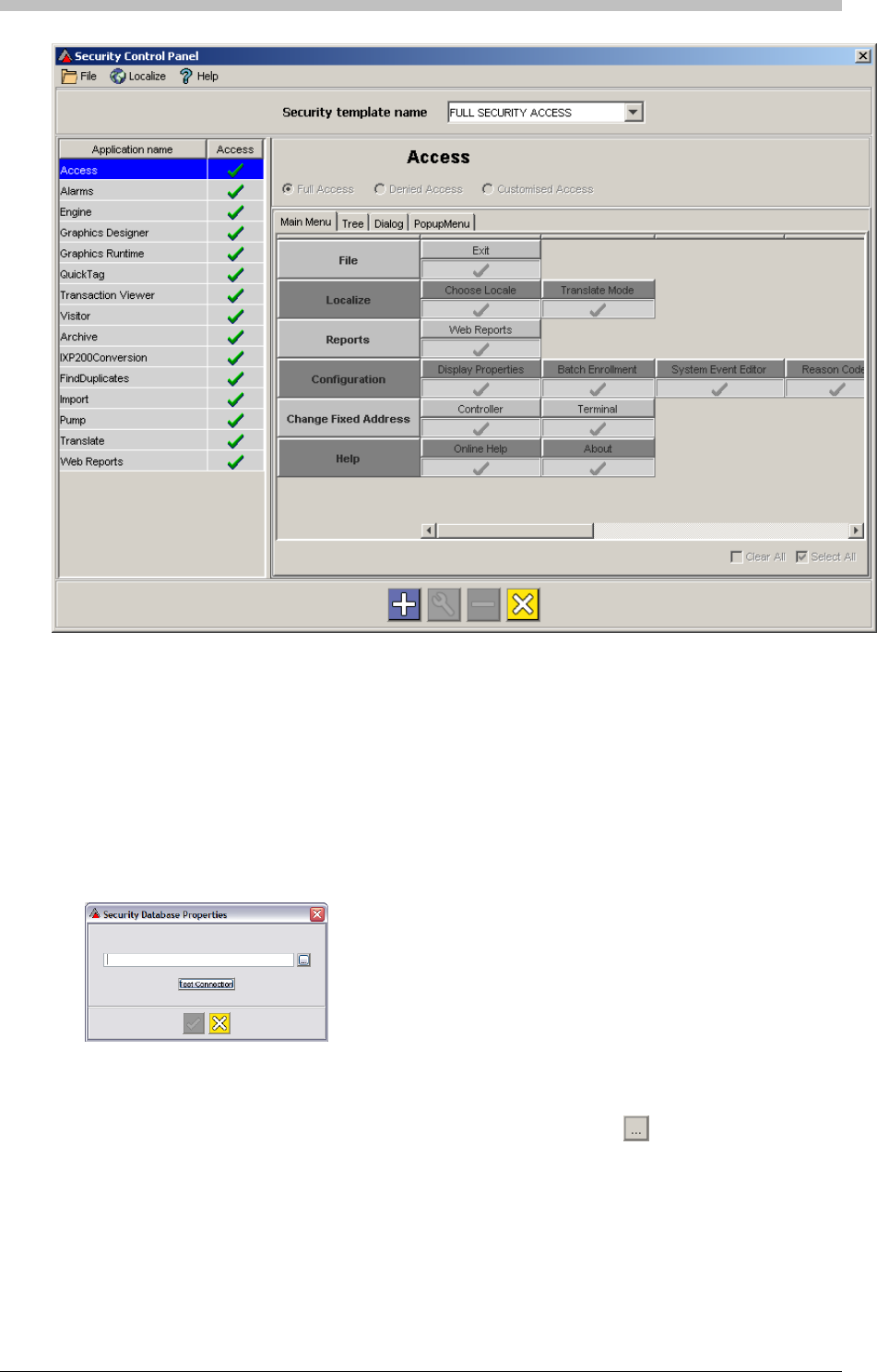
IXP300/IXP400 Installation Guide
Users must be added to the database before they can be assigned to an Operator Group. To
add users to the database, proceed as follows:
2. If there is no Database file path displayed in the textbox, click the
Figure 84 - Security Control Panel
Users
1. In the Users panel, click the Advanced button. The first time the Advanced button is
clicked, the following dialog box is displayed:
Use this window to specify or confirm the location of the Security Database that you are
connecting to. A default path is if a Database exists.
button
3. Browse to the location of the Security Database
Tuesday, 11 July 2006 289
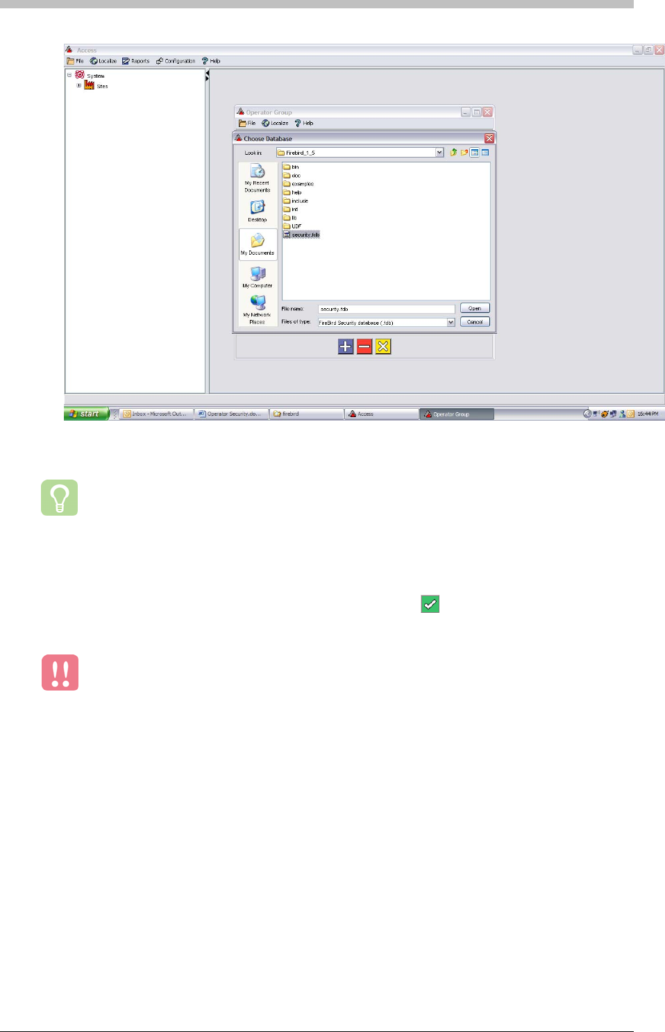
Operator Security
5. Click Open
If Access connects to the Security Database successfully, the
4. Select the security.fdb file
The Security Database is installed to c:\program files\firebird\firebird_1_5 by default.
However, if the default directory does not exist, consult the person who installed the
Firebird Database Server.
6. Click Test Connection
button turns green and
enables you to save the setting.
The location of the Security Database is saved in the access.properties file.
Therefore, if the location of the Security Database changes, you must edit the last
line of the access.properties file to reflect the change.
290 Tuesday, 11 July 2006
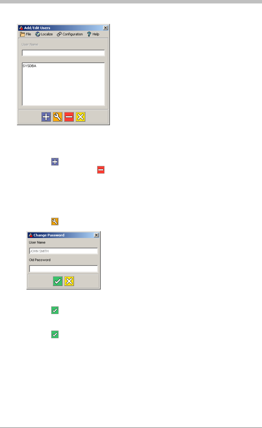
IXP300/IXP400 Installation Guide
Add and Delete Users
Figure 85 - Add/Edit User Window
1. Click the
In the Add/Edit Users window, do one of the following:
button to add a User
2. Select a User and click the button to delete them
In the Add/Edit Users window, proceed as follows to change a User’s password:
Change Password
1. Select a User
2. Click the button
3. Enter the Old Password
4. Click the button
5. Enter a New Password
6. Re-enter Password to Confirm
7. Click the button
Tuesday, 11 July 2006 291
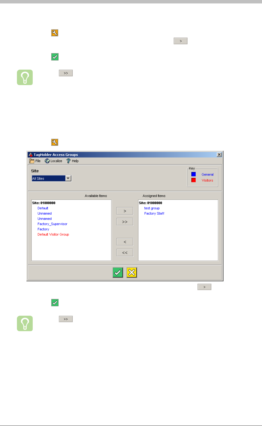
Operator Security
Assign Users
1. Click the button. The Select Group’s Users window is displayed
2. Select users in the Available Users section and click the button to move them to the
Assigned Users section
3. Click the button
Use the button to move all users at once
Tag Holder Access Groups
The Tag Holder Access Groups section specifies the Access Groups that the selected
Operator has access to. To edit the available Tag Holder Access Groups, proceed as follows:
1. Click the button. The TagHolder Access Groups window is displayed
2. Select Access Groups in the Available Items section and click the button to move
them to the Assigned Items section
3. Click the button
Use the button to move all Access Groups at once
User Profiles
A Tag Holder assigned to a User Profile is visible and editable only to Security Users who are
configured for the particular User Profile. For example, John Smith is an Operator Security
When Tag Holders are added to the database, they can be assigned to a User Profile.
However, you must create User Profiles in the Operator Group screen before you can assign a
Tag Holders to them.
292 Tuesday, 11 July 2006
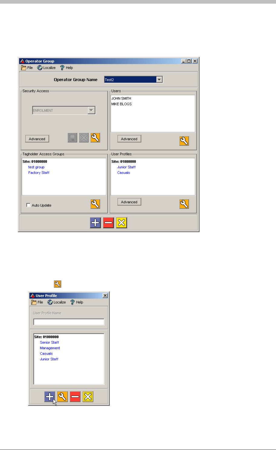
IXP300/IXP400 Installation Guide
User. He belongs to an Operator Group called Test2—refer to Figure 86. John is assigned the
Junior Staff and Casuals User Profiles. This means that when he uses Access, he can only
see and edit Tag Holders who are assigned to one of these groups. John will not see Tag
Holders who belong to other User Profiles.
Figure 86 - User Profile Example
Create User Profile
To create a User Profile, proceed as follows:
1. Click the button. The User Profile window is displayed
Tuesday, 11 July 2006 293
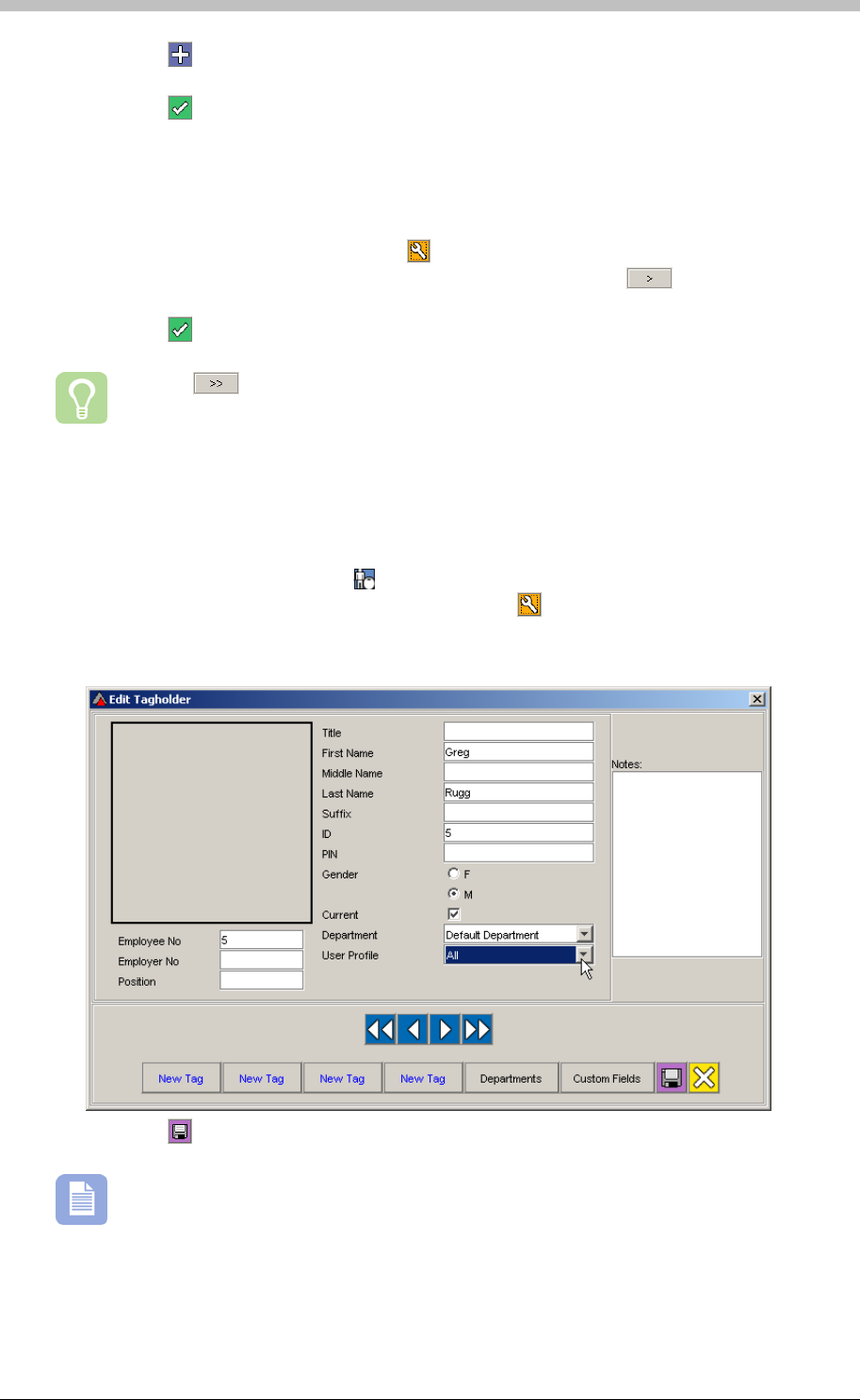
Operator Security
2. Click the button
3. Enter a User Profile Name
4. Click the button to save
Ensure the correct Operator Group Name is selected then proceed as follows:
Assign User Profiles to Users
1. In the User Profiles section, click the button. The User Profiles window is displayed
2. Select User profiles in the Available Items section and click the button to move them
to the Assigned Items sectio
n
3. Click the button
Use the button to move all User Profiles at once
Assign Tag Holders
User Profiles can be assigned to Tag Holders on the Edit Tagholder screen. To do this,
proceed as follows:
1. In the Navigator pane, click the button
2. In the Main pane, select a Tag Holder and click the button. The Edit Tagholder screen
is displayed.
3. Select a User Profile from the User Profile drop-down list
4. Click the button to save
If the All value is selected, the Tag Holder is visible to Operator Security Users who are
assigned any User Profile
294 Tuesday, 11 July 2006

IXP300/IXP400 Installation Guide
PART V – Utilities
Tuesday, 11 July 2006 295

CSV Import
CSV Import
The format of a CSV file must match the format of the Database that is receiving
the data.
If you have no experience with databases or CSV files, we recommend that you
consult someone with the necessary skills.
Why Import a CSV File?
• Export data as a CSV file from another Database—Almost all Databases have a CSV
export facility. Consult the documentation of the database containing the data to export.
Export the relevant data to a CSV file using the database’s CSV export facility.
• Manually create it—You can create a CSV file with a text editor. Refer to page 298 for
details
CSV Overview
The CSV Import Utility enables you to import a Comma Separated Value (CSV) file into the
ImproNet Database.
Use the CSV Import Utility to import data from other database systems to the ImproNet
Database.
CSV files are commonly used to transfer data between different databases. For example, you
may already have a database containing thousands of records – CSV Import enables you
transfer this existing data to the ImproNet Database without re-entering it one record at a time.
Specific examples of CSV Import use include the following:
• Transferring a company’s existing employee details to the ImproNet Database
• Transferring a list of department names to the ImproNet Database
• Transferring details from another access control system to the ImproNet Database
How to Create a CSV File
There are two methods to create a CSV file:
296 Tuesday, 11 July 2006
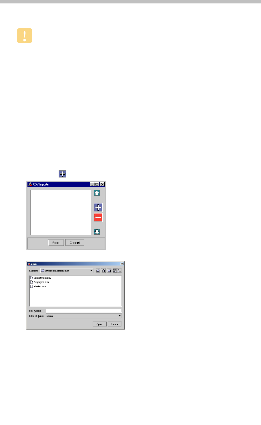
IXP300/IXP400 Installation Guide
Importing a CSV File
Close all ImproNet software before opening the CSV Import Utility.
• Not null fields must contain data, even if it is space characters
Open CSV File
Guidelines for CSV Import Utility
• Parent Tables must be added before Child Tables; Tables containing the Primary Keys
must be added before tables containing Foreign Keys
• Char and VarChar fields can have spaces
• Int fields must be separated by commas
To open the CSV Import Utility, proceed as follows:
1. In Windows, click Start > Programs > ImproNet > Utils > Import
2. Enter your Username and Password
1. Click on the button
2. Browse and select the relevant CSV file
3. Click Open
4. Repeat steps 1 to 3 for each CSV file to be imported
Tuesday, 11 July 2006 297
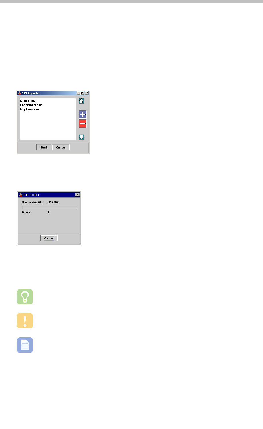
CSV Import
Ensure Correct Sequence
If you are importing any of the following files, ensure that they are in the same sequence as
displayed:
1. Master.csv
To change the order of the files, select a file and use the arrow buttons.
You can create a CSV file manually with a plain text editor such as Notepad. Microsoft
Excel is useful for creating spreadsheets to export as CSV files.
1. Ensure you know the correct field names of the table you are importing into
2. Department.csv
3. Employee.csv
Import CSV File
1. Click Start to begin the import process
2. A confirmation message is displayed after a successful import
Creating a CSV File
Do not use rich text editors such as WordPad or Microsoft Word as these programs
contain hidden characters.
CSV files can add data to one table at a time only. Therefore, you need to have a CSV
file for each table you are updating.
To create a CSV file manually, proceed as follows:
2. Open your text editor
3. Enter the field names separated by commas
298 Tuesday, 11 July 2006
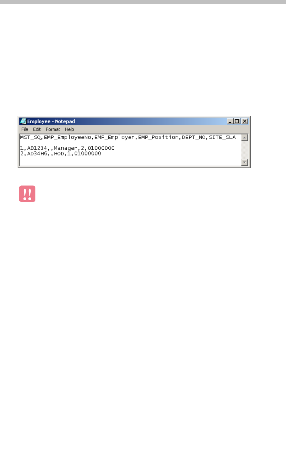
IXP300/IXP400 Installation Guide
4. Press Enter
5. Enter the data value of each record separating the values with commas. Press Enter after
each record.
6. Save the file with a suitable name and a csv file extension
Figure 87
Each field in a database table has a specified Type. The Type determines the data that is
permitted in that field. For example, a Varchar type is a text field that accepts text and number
characters. An Int type is a number field only—it cannot accept text characters. Table 20
describes some common Field Types in the ImproNet Database.
Example
shows an example of a CSV file containing two records. The first row contains the
field names separated by commas. The second line is blank. The third and forth lines contain
record data; each value separated by a comma. In this example, the value for EMP_Employer
is null in both records.
Figure 87 - Example of CSV file
Correct field types are vital for a successful import. Be sure to read the next
section.
Ensuring Correct CSV File Format
If you create or modify a CSV file, ensure that its data conforms to the specified field
requirements.
Null and Not Null Values
A Null field in a database table means that a value is not required for that field. Do not confuse
Null with zero. Zero is a value (0); Null has no value. For example, the Gender field in the
ImproNet Database has a Null option. This means that you do not have to enter a value in this
field—you can leave it empty.
A Not Null field in a database table means that a field must contain a value. The value can be
any value that conforms to the field Type. In this case, a zero (0) is accepted as a number
value, provided the field permits a number Type.
Field Types
Tuesday, 11 July 2006 299

CSV Import
Field Type Description
Varchar(40) A text field permitting up to 40 alphanumeric characters
Varchar(16) A text field permitting up to 16 alphanumeric characters
Char(1) A text only field permitting 1 text character
Char(8) A text only field permitting up to 8 text
Int A number field permitting up to 65536 characters (16 bit)
SmallInt A number field permitting up to 256 characters (8 bit)
Table 20 - Database Field Types
The following tables are the most likely tables to receive data via the Import utility:
• Master
• Department
• Employee
Master Table Requirements
Table 21 displays the field requirements for the Master Table.
Field Name Null Value
Int Not
You can use Import to add data to any of the tables in the ImproNet database. However, you
must ensure that the data conforms to the receiving table’s structure.
Import Data to Other Tables
To ensure correct CSV file format for other ImproNet Database tables, you need to view the
tables’ structures. We recommend using the IBConsole utility to do this.
Structure of Master, Department, and Employee Tables
Type
MST_SQ(PK) Null
MST_Title Varchar(40) Not Null
MST_FirstName Varchar(40) Not Null
MST_MiddleName Varchar(40) Not Null
MST_LastName Varchar(40) Not Null
MST_Suffix Varchar(40) Not Null
MST_ID Varchar (16) Not Null
MST_Gender Char (1) Null
MST_Pin Int Null
MST_Type SmallInt Not Null
MST_Current SmallInt Not Null
SILE_SLA(FK) Char(8) Not Null
Table 21 – Master Table Requirements
300 Tuesday, 11 July 2006

IXP300/IXP400 Installation Guide
Department Table Requirements
Table 22
Type
displays the field requirements for the Department Table.
Field Name Null Value
DEPT_No (PFK) SmallInt Not Null
Site_SLA(FK) Varchar(8) Not Null
DEPT_NAME Varchar(40) Not Null
Table 22 – Department Table Requirements
Employee Table Requirements
Table 23 displays the field requirements for the Employee Table.
Null Value
Not Null
Field Name Type
MST_SQ(PK)(FK) Int
EMP_EmployeeNo Varchar(16) Not Null
EMP_Employer Varchar(16) Not Null
EMP_Position Varchar(40) Not Null
DEPT_No (FK) SmallInt Not Null
Site_SLA(FK) Char(8) Not Null
Table 23 – Employee Table Requirements
Notes
• PK means Primary Key—This is sequential number unique to every record.
• FK means Foreign Key—This is a number that corresponds with the Primary Key. It is
used to link recodes in one table with records in another table. For example, MST_SQ is
the Primary Key in the Master Table. It is also used in the Employee Table as a Foreign
Key to identify a particular Tag Holder.
Tuesday, 11 July 2006 301
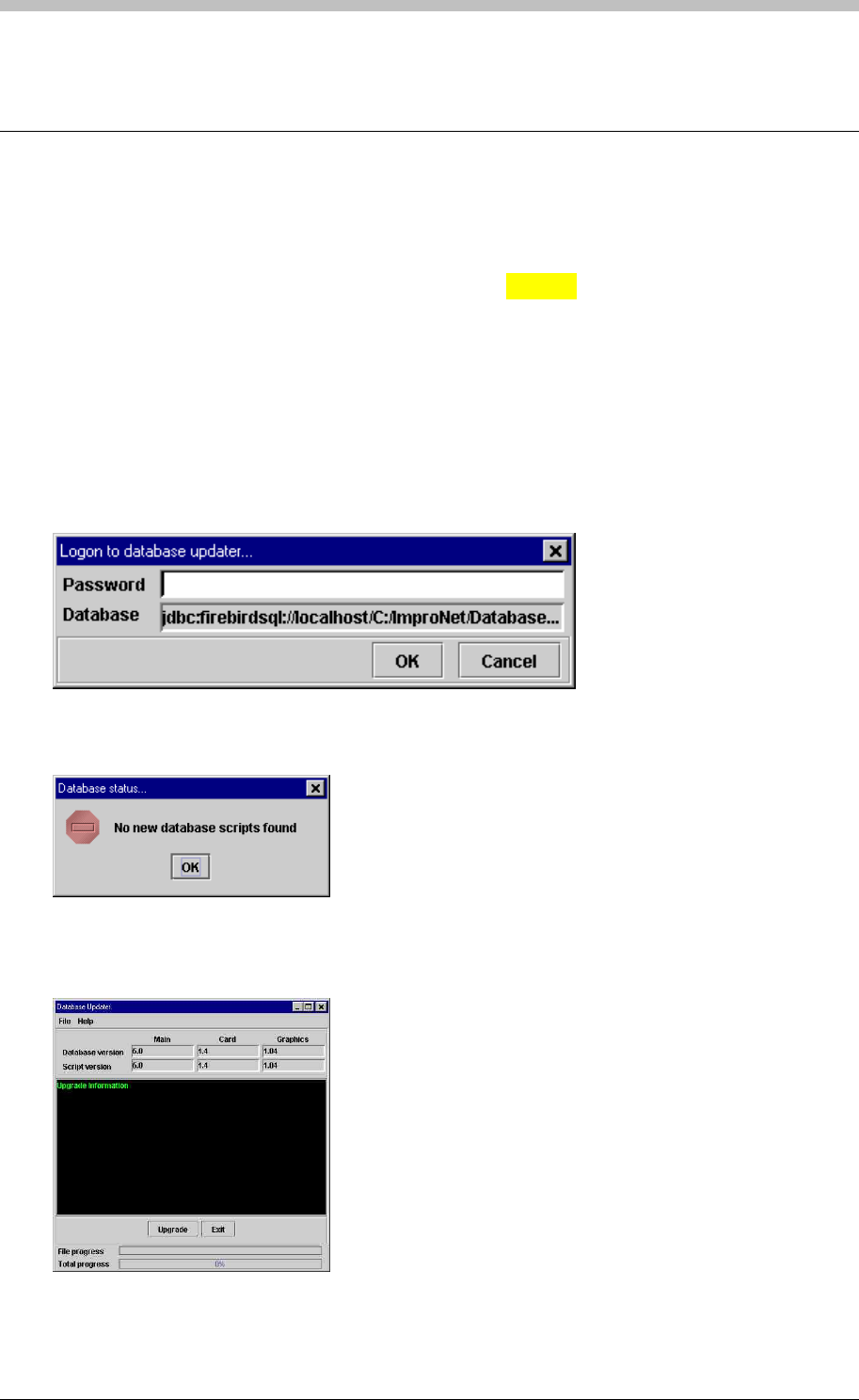
DBUpgrade
DBUpgrade
Database Upgrade Procedures
The Database Upgrade utility enables automatic updating of the ImproNet database. The
Utility checks the database for available Scripts in the directory. Update Scripts are processed
automatically and a status message is displayed. A status message is also displayed if no
scripts are found.
To open the Database Upgrade utility, proceed as follows:
If no new database scripts are found, the following message is displayed:
• In Windows, click Start > Programs > ImproNet > Utils > DBUpgrade
The Logon to database updater screen is displayed. Enter the password.
Figure 88 - Database Update Logon
Figure 89 - Database Status screen – no scripts found
If new database scripts are found, the following screen is displayed:
Figure 90 - Database Status screen – scripts found
302 Tuesday, 11 July 2006
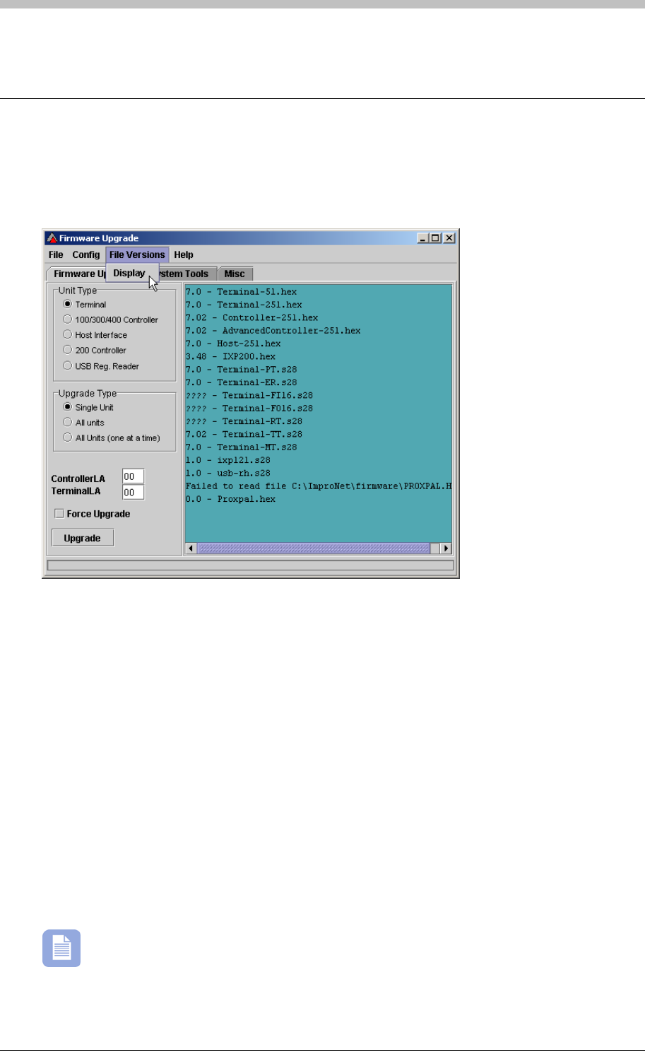
IXP300/IXP400 Installation Guide
Firmware Upgrade
Identify Firmware Versions
Select Display on the File Versions menu to view Firmware File Versions of installed
hardware units.
Upgrade Unit
To upgrade a unit, proceed as follows:
1. On the firmware Upgrade Tab, select the Unit Type
2. Select one of the following Upgrade Type options:
− Single Unit—upgrades one unit only
− All Units—
− All Units (one at a time)—upgrades all units of the specified type, one at a time
3. Enter the Controller LA—the logical address of the Controller. If 300/400 Controller is
selected as Unit Type, the Controller LA specifies the Controller that will be upgraded. If
another Unit Type is selected, the Controller LA specifies the Controller that the selected
unit is connected to.
4. Enter the Terminal LA—the Logical Address of the Terminal. This field is only available
when upgrading Terminals
The Force upgrade button is used to force an upgrade on a unit that has a newer
firmware version than is available with your current ImproNet Software Suite. We
recommend that you do not use this feature.
5. Click the Upgrade button
Tuesday, 11 July 2006 303
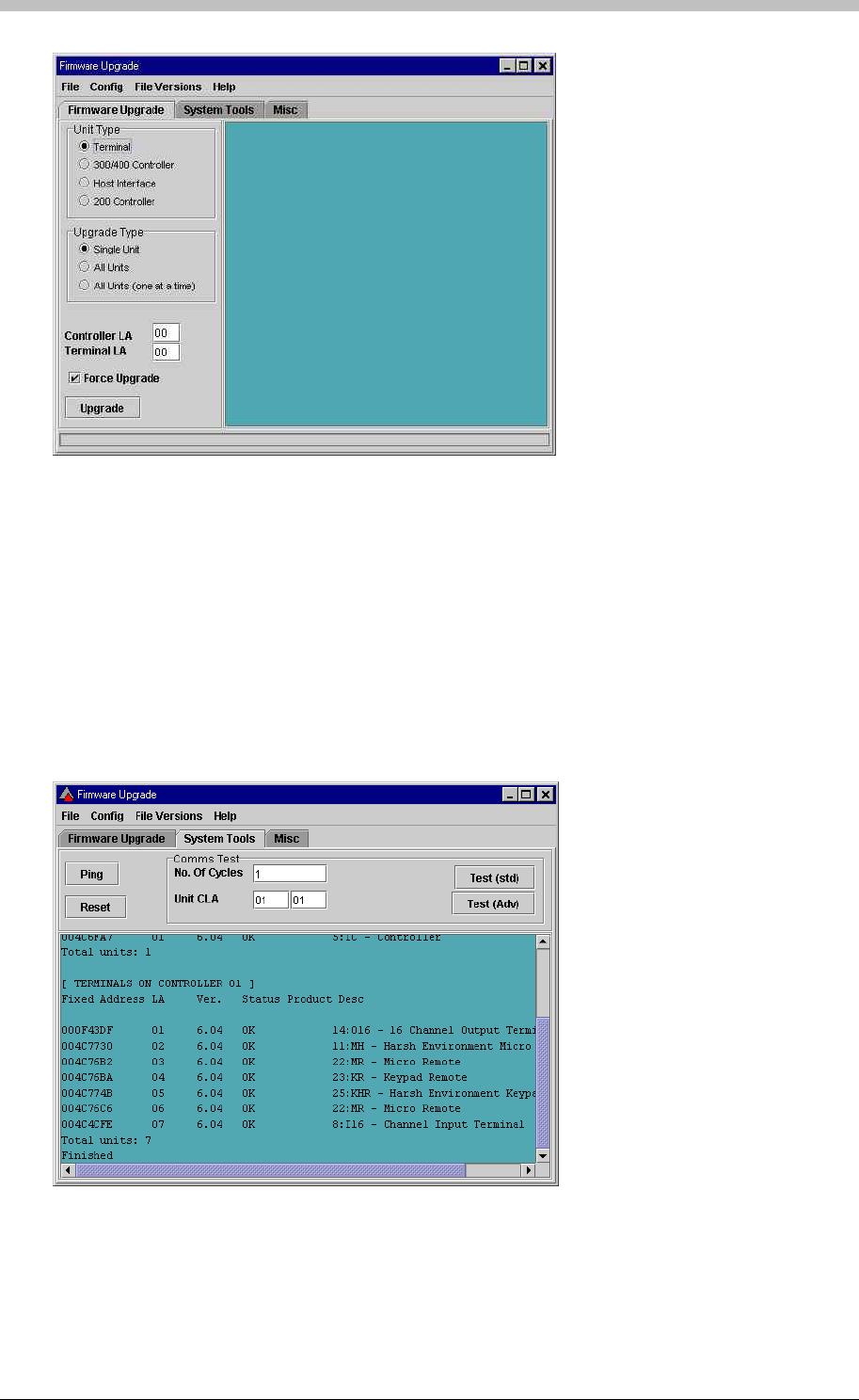
Firmware Upgrade
Figure 91 – Firmware Upgrade Utility Display
Ping Function
Use the ping function on the System Tools tab to ensure that all hardware is connected and
working as specified.
1. Enter the logical address of the Controller to ping in the first Unit CLA textbox
2. Enter the logical address of the Terminal to ping in the second Unit CLA textbox. A value of
FF in this textbox will ping all Terminals.
3. Click the Ping button. The results of the ping test are displayed
Figure 92 – Results of Ping Check
304 Tuesday, 11 July 2006
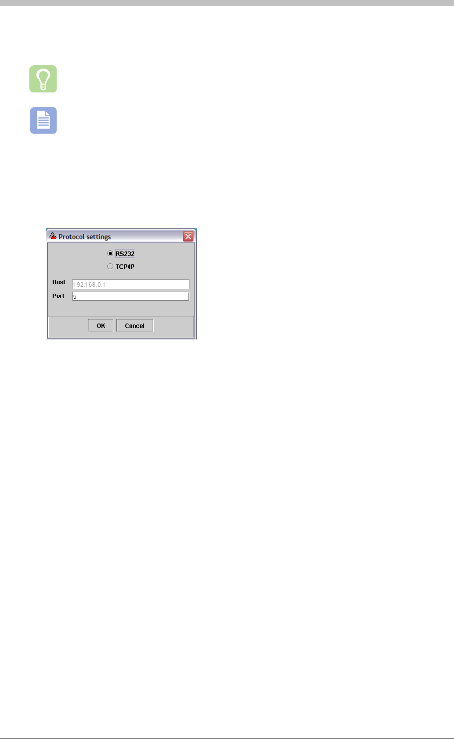
IXP300/IXP400 Installation Guide
Select Com Port
Select Protocol on the Config menu to specify an RS232 or TCP/IP communication protocol.
Select the RS232 option if you are using a USB connection.
Further information on the Firmware Upgrade utility is available in the ImproNet
Software Manual.
Configuring Comm Port for Ping Untility
1. Open the Firmware Upgrade utility,
2. On the menu, select Config > Protocol
3. If an ImproX HI or ImproX RH comms interface device is used, select the RS232 option and
enter the relevant com Port number
Tuesday, 11 July 2006 305
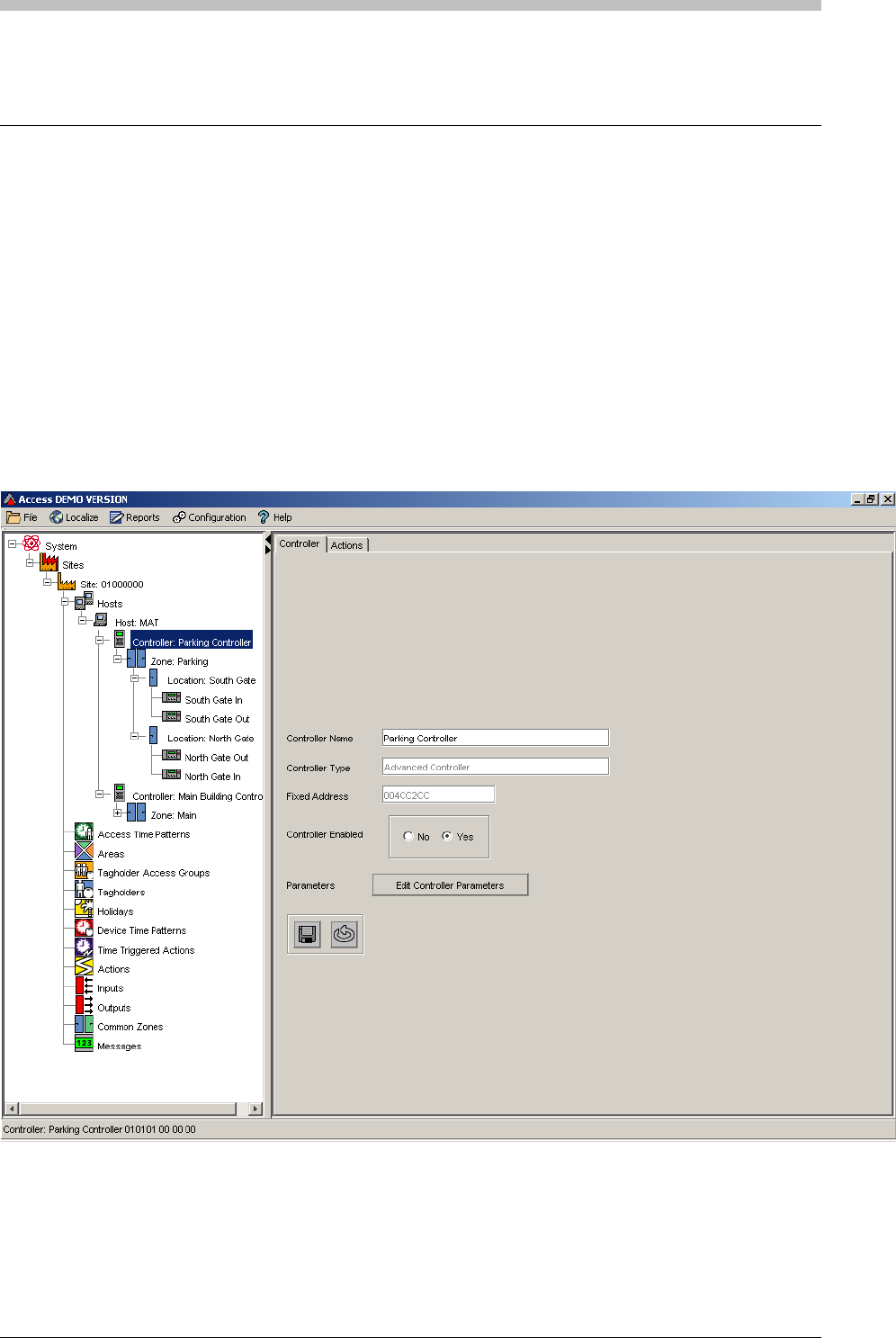
Replacing Controllers and Terminals
Replacing Controllers and Terminals
To remove Controllers or Terminals from their bus, perform the following procedure:
1. Physically disconnect and remove the old hardware
2. Physically connect and mount the new hardware
3. Configure the new hardware configuration in ImproNet Access
Replace Controller
1. Remove the old Controller from the Controller bus
2. Connect the new Controller to the Controller bus
3. Open ImproNet Access
4. In the Navigation pane, click the old Controller to select it
5. Right-click the Controller and select the Replace Unit option. A dialog box is displayed
306 Tuesday, 11 July 2006
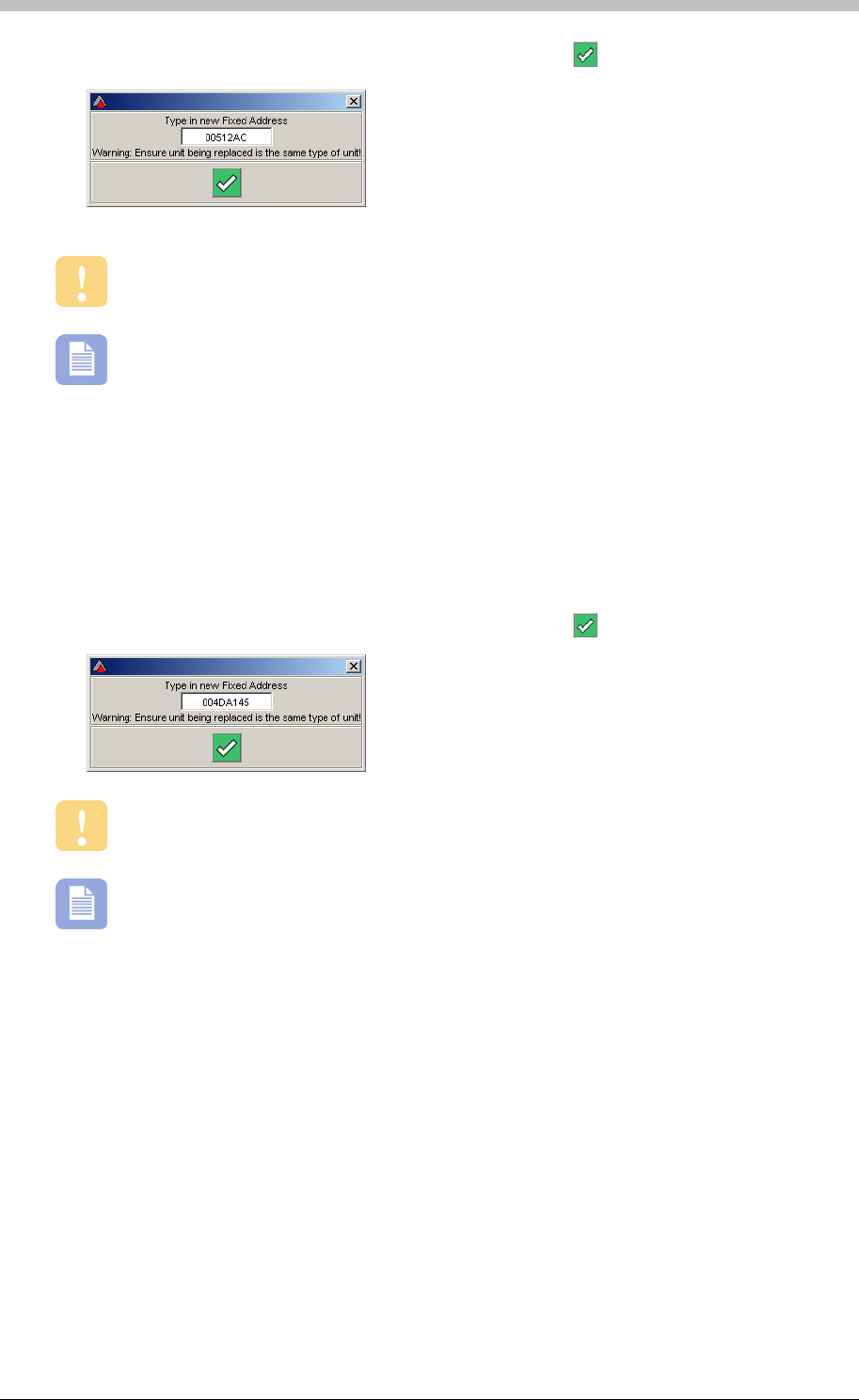
IXP300/IXP400 Installation Guide
6. Enter fixed address of the new Controller and click on the button
When you replace an old unit with a new one, ensure both units are the same type.
You can keep ImproNet Engine running when you replace a unit.
Replace Terminal
1. Remove the old Terminal from the Terminal bus
2. Connect the new Terminal to the Terminal bus
3. Open ImproNet Access
4. In the Navigation pane, click the old Terminal to select it
5. Right-click the Terminal and select the Replace Unit option. A dialog box is displayed
6. Enter fixed address of the new Controller and click on the button
When you replace an old unit with a new one, ensure both units are the same type.
You can keep ImproNet Engine running when you replace a unit.
Tuesday, 11 July 2006 307
