Installation_ing_Troublesho Side By MSD2356AEA Installation Ing Troubleshooting Starters Overload Relays
User Manual: Side by Side MSD2356AEA
Open the PDF directly: View PDF ![]() .
.
Page Count: 34

OVERLOAD RELAYS, STARTERS
TESTING, INSTALLATION &
TROUBLE SHOOTING.
SAFE & SURE
L&T SWITCHGEAR
30
SAFE & SURE
L&T SWITCHGEAR
ESP
SERVICE
MANUAL
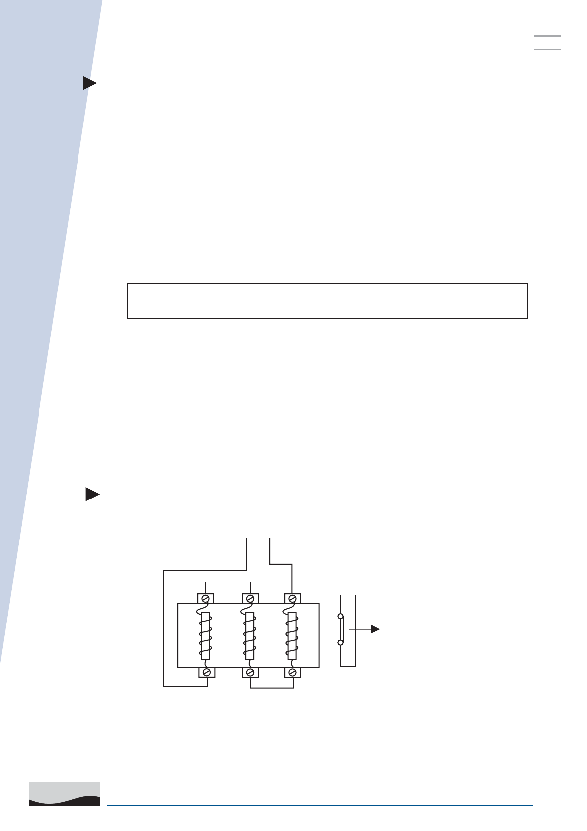
OVERLOAD TEST
1m
1m
DUT
1m
1m
FROM CURRENT SOURCE
'NC' CONTACT
OF RELAY
Connections of Thermal Overload Relay for O/L Testing
TESTING OF THERMAL OVERLOAD RELAY
1. Fill up the following data of relay under test.
a) Relay Type _____________________ b) Relay Range ____________________
c) Max. Back up fuse rating __________
2. Check continuity of auxiliary contacts and main poles.
a) Normally open __________________ b) Normally closed _________________
c) R Pole ________________________ d) Y Pole _________________________
NOTE : If the answer is O.K. to all above points then only take the relay for
overload testing.
3. Select the proper size of cable for connection. In case of smaller size of cable or
improper termination, relay may trip early.
4. Connect all three poles of relay in series as shown in the following diagram.
Use proper size of cables. Length of cable should be one metre.
5. Connect normally closed (NC) contact of relay in series with test panel's auxiliary
contact. (This will give relay trip to test panel.)
31
SAFE & SURE
L&T SWITCHGEAR
ESP
SERVICE
MANUAL
8. Switch on the supply and adjust the test current. Immediately switch off the current. Keep
variac at adjusted position. Reset the time counter. Cool the relay for about 10 minutes.
9. Switch on the test current and check trip time of the relay.
Caution
After each test, cool the relay for minimum 10 minutes. Otherwise, relay will trip
early and you will not get correct results.
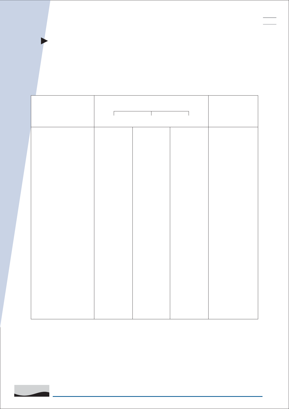
6. Set the relay and calculate the test current as follows:
Relay Setting X Multiples of Set Current Test Current
(% of overload) = Amps
Eg.: 10 Amps. X 2(200%) = 20 Amps
1. X 2(200%) =
2. X 3(300%) =
Sr. No. Relay
Setting
Test Current (Amp) Trip Time in Seconds
i-t characteristics.
Actual
Remark
OK /
Not OK
1.
2.
Min. Max.
As per Curve
7. Find out the minimum and maximum trip time with respect to multiples of set
current you have selected and note down the values in the following table.
Cable size with respect to test current.
Test Current Amp
For Copper Cables
sq. mm
0 to 15
1
15 to 30
1.5
30 to 46
4
46 to 66
6
66 to 110
10
100 to 150
25
150 to 220
35
32
SAFE & SURE
L&T SWITCHGEAR
ESP
SERVICE
MANUAL
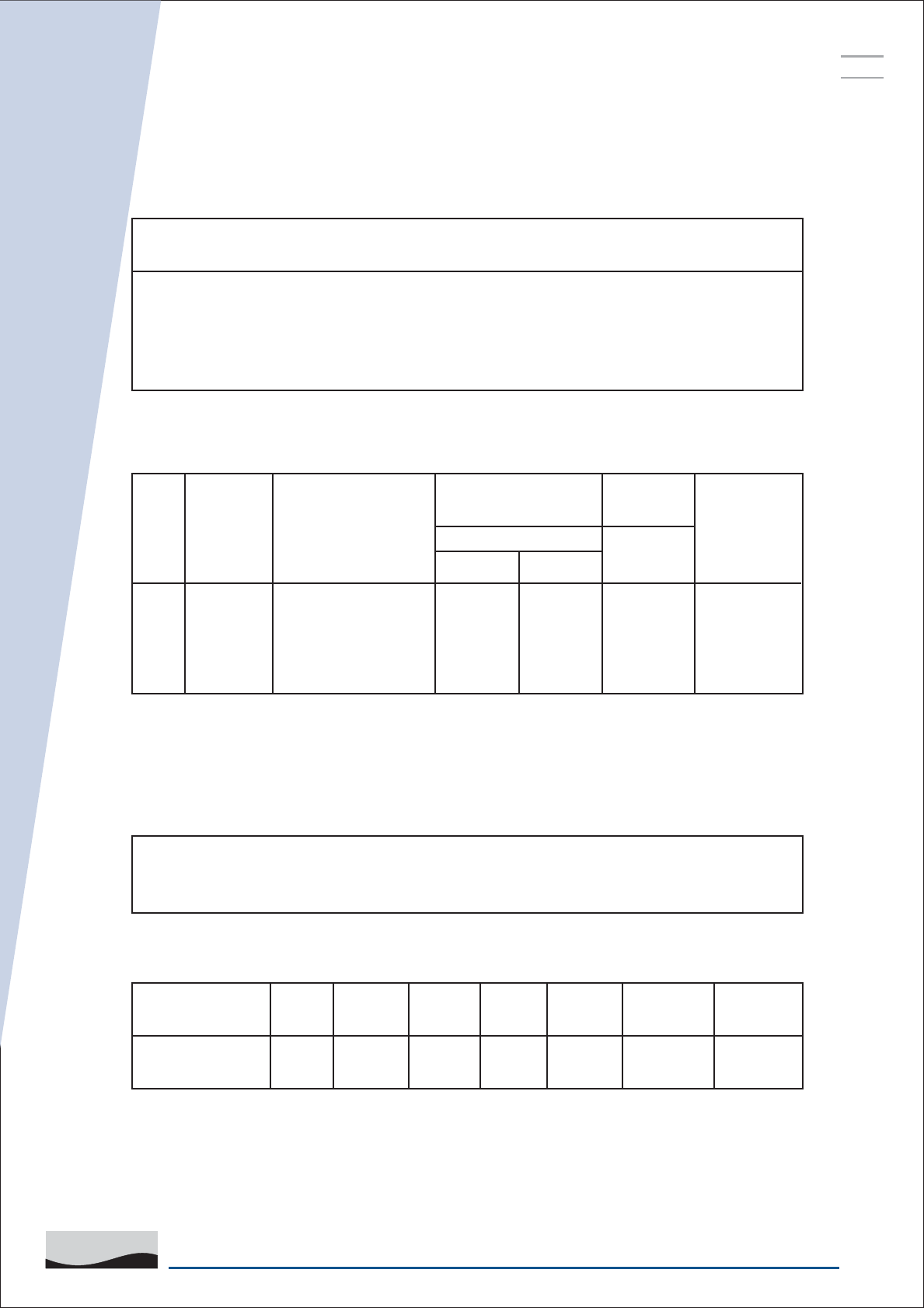
SINGLE PHASING TEST
1m
1m
1m
DUT
FROM CURRENT SOURCE
'NC' CONTACT
OF RELAY
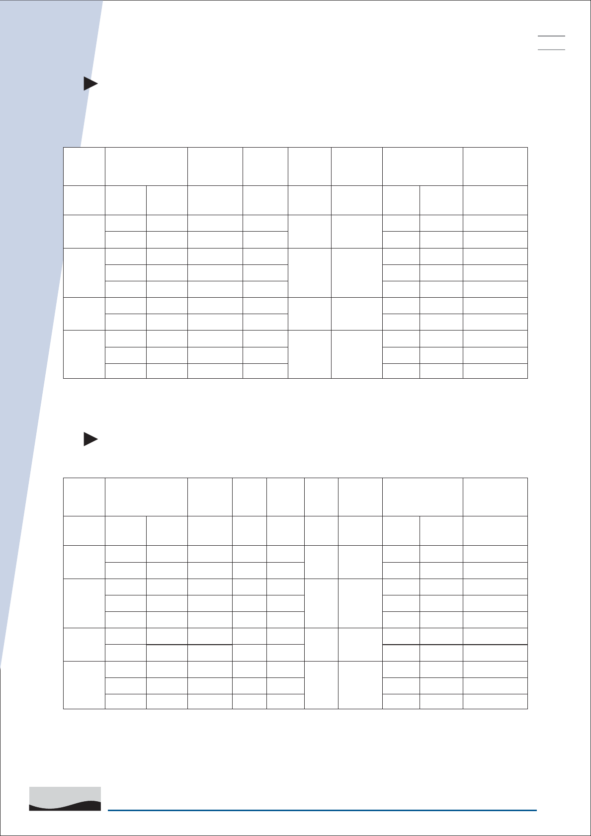
CONNECTIONS OF THERMAL OVERLOAD RELAY
FOR SINGLE PHASE TESTING
Sr. No. Relay Setting Test Current (Amp) Trip Time in
Sec. from
i-t characteristics.
Actual Remark
OK /
Not OK
1.
2.
Min. Max.
33
SAFE & SURE
L&T SWITCHGEAR
ESP
SERVICE
MANUAL
NOTE :
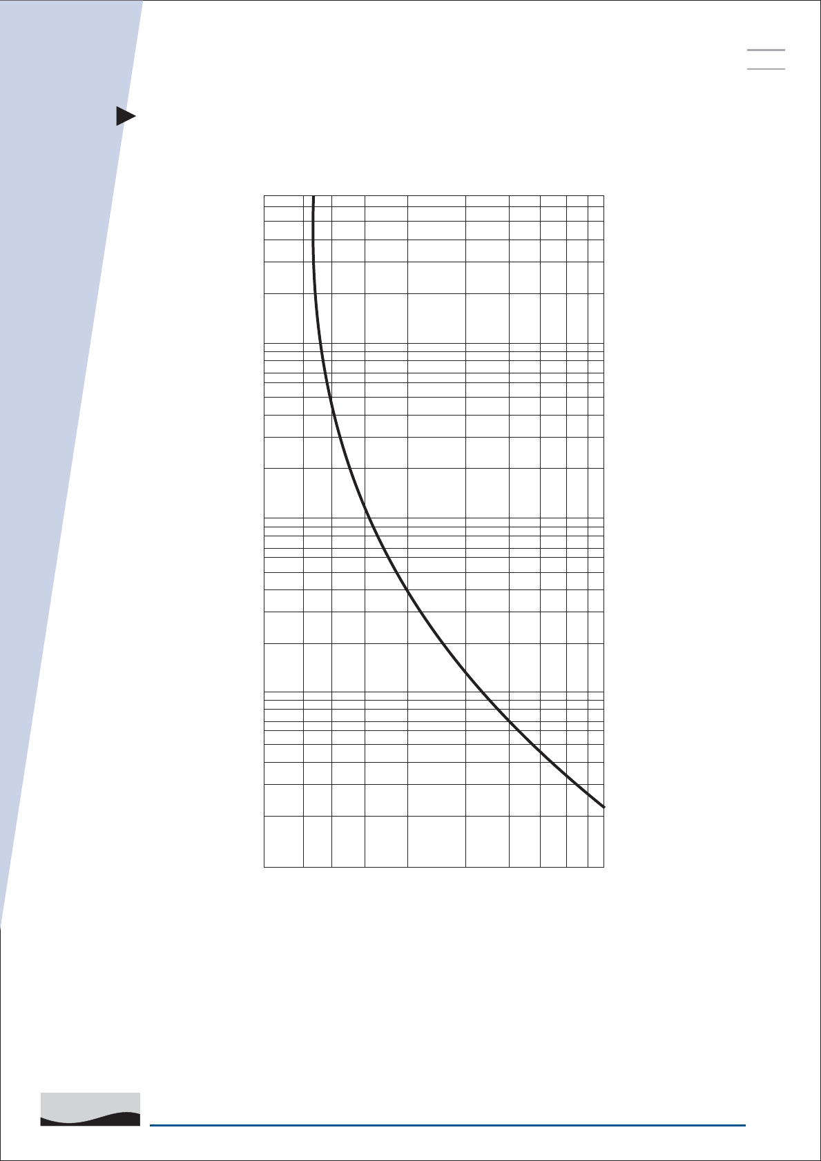
1. THE TRIPPING TIME FOR ANY CURRENT SHALL LIE BETWEEN THE VALUES
CORRESPONDING TO 90% AND 110% OF THAT CURRENT.
2. CURVE REPRESENTS COLD STATE CHARACTERISTICS.
4000
2000
1000
600
400
200
100
60
50
40
30
20
10
6
4
2
TRIPPING TIME IN SECONDS
0.8 1 1.2 1.5 2 3 4 5 6 7 8
MULTIPLES OF SET CURRENT
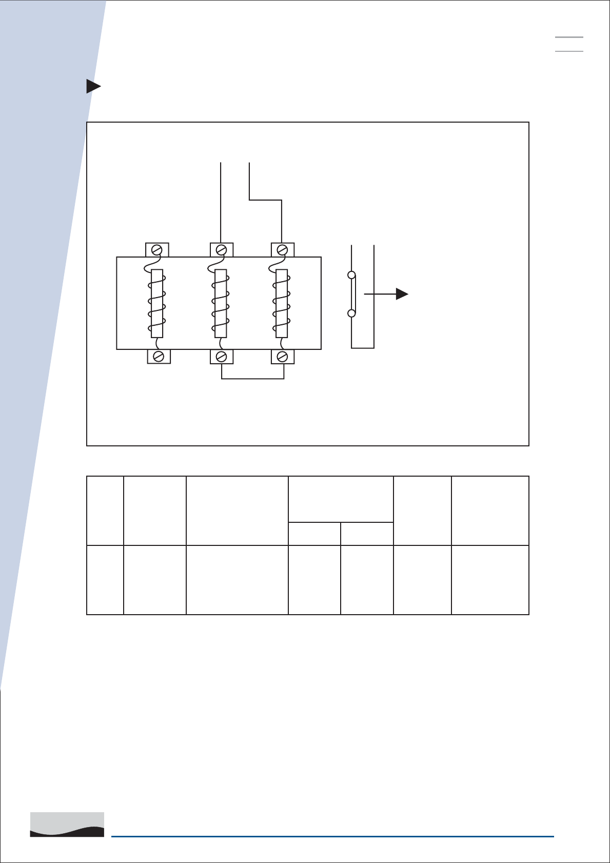
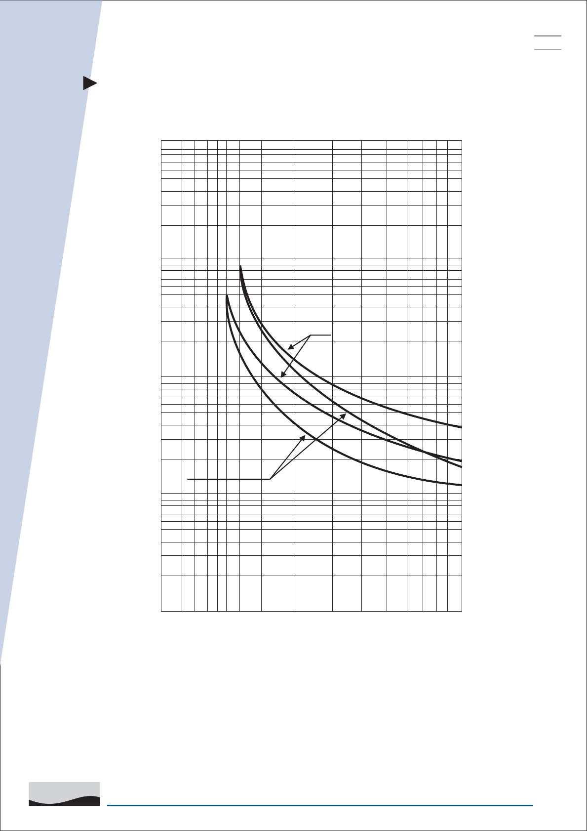
TRIPPING CURVE FOR MK1 / ML1 RELAYS
FOR RANGES UPTO 6-10 AMPS.
34
SAFE & SURE
L&T SWITCHGEAR
ESP
SERVICE
MANUAL
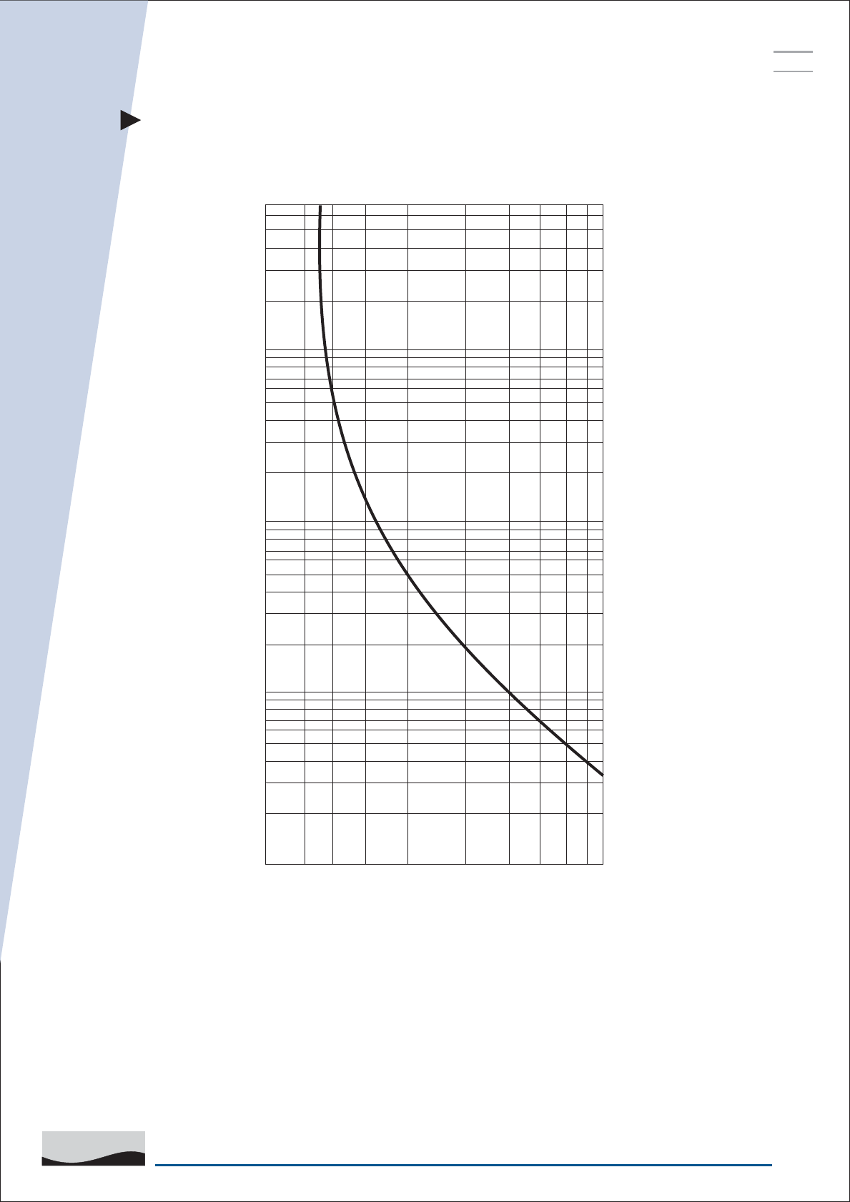
NOTE :
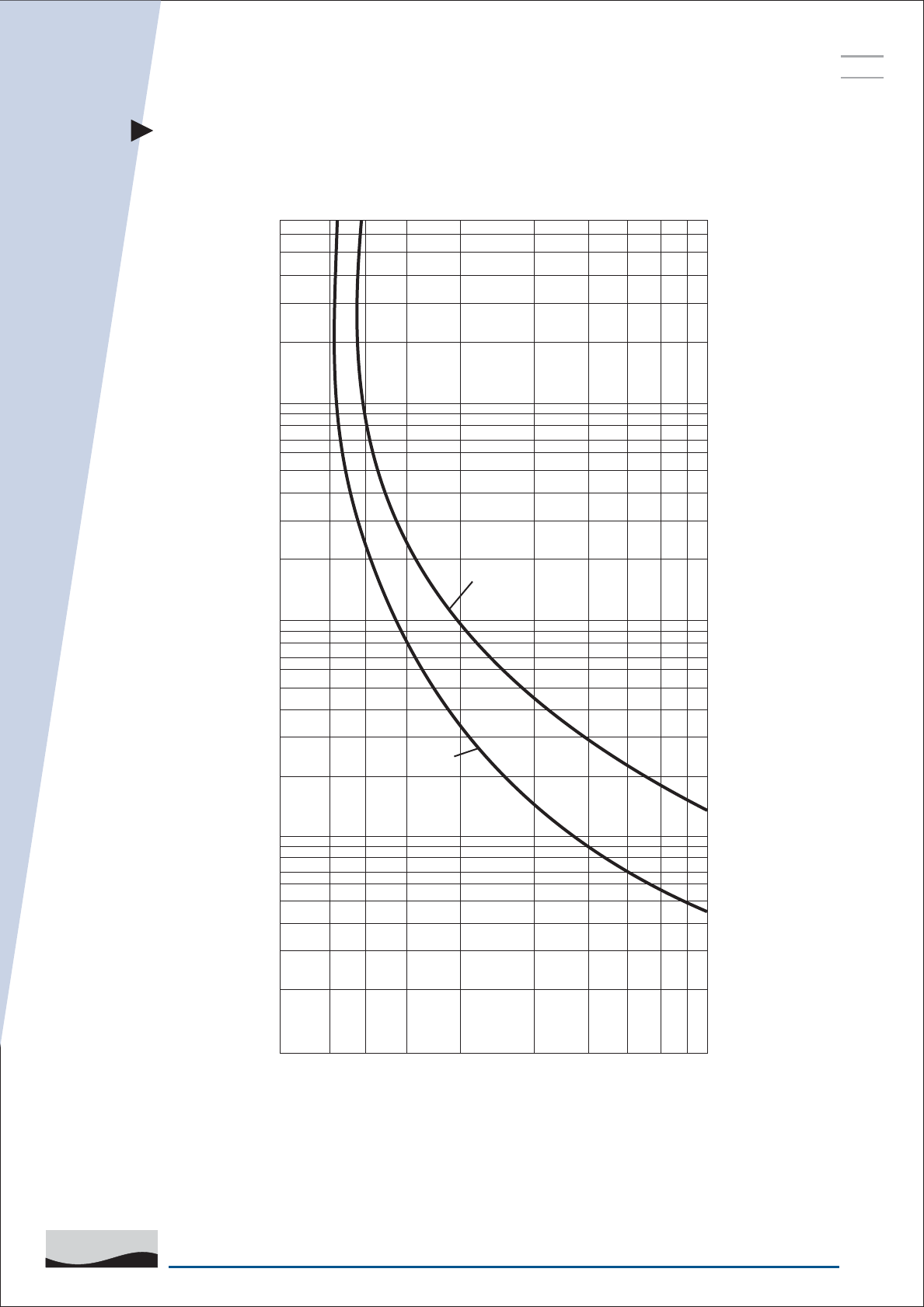
1. THE TRIPPING TIME FOR ANY CURRENT SHALL LIE BETWEEN THE VALUES
CORRESPONDING TO 90% AND 110% OF THAT CURRENT.
2. CURVE REPRESENTS COLD STATE CHARACTERISTICS.
7200
6000
4000
2000
1000
600
400
200
100
60
50
40
30
20
10
6
4
2
TRIPPING TIME IN SECONDS
0.8 1 1.2 1.5 2 3 4 5 6 7 8
MULTIPLES OF SET CURRENT
TRIPPING CURVE FOR MK1 / ML1 RELAYS
FOR RANGES UPTO 9-14 & 10-16 AMPS.
35
SAFE & SURE
L&T SWITCHGEAR
ESP
SERVICE
MANUAL
7200
6000
4000
2000
1000
600
400
200
100
60
50
40
30
20
10
6
4
2
TRIPPING TIME IN SECONDS
0.8 1 1.2 1.5 2 3 4 5 6 7 8
MULTIPLES OF SET CURRENT
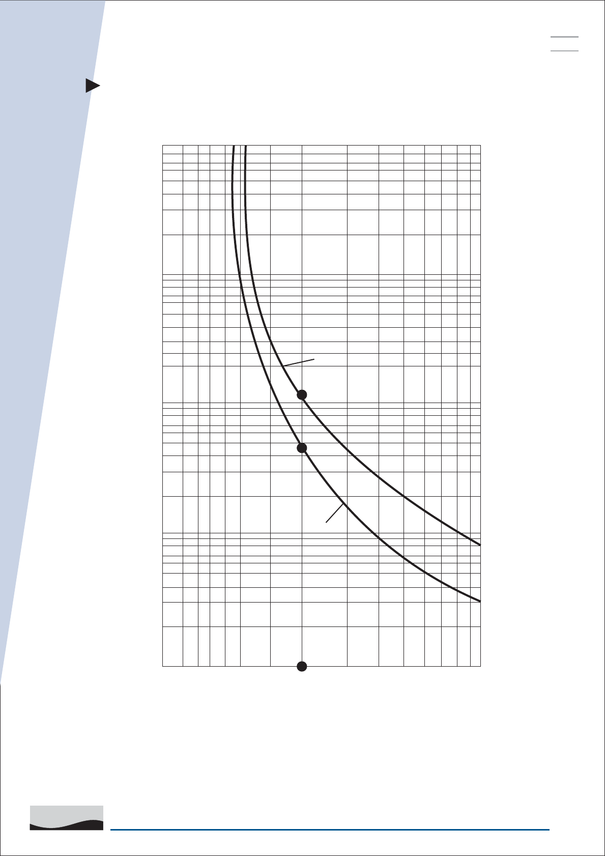
NOTE : CURVE REPRESENTS COLD STATE CHARACTERISTICS.
MAXI. TRIP
TIME CURVE
MINI. TRIP
TIME CURVE
TRIPPING CURVE FOR ML2 / ML3 RELAYS
36
SAFE & SURE
L&T SWITCHGEAR
ESP
SERVICE
MANUAL
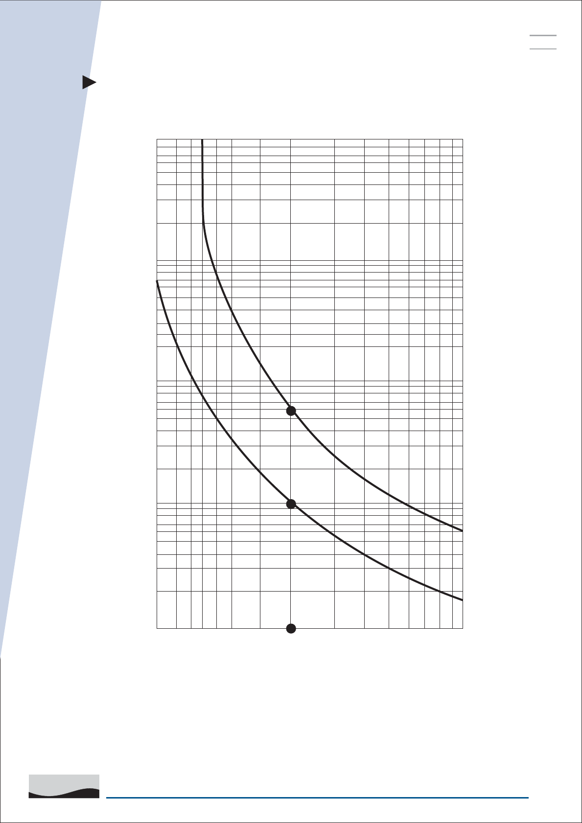
TRIPPING CURVE FOR MN RELAYS
ON 3 POLE LOADING (BALANCED) CONDITION
10000
4000
2000
1000
400
200
100
40
20
10
2
TRIPPING TIME IN SECONDS
MULTIPLES OF SET CURRENT
0.8 1 1.5 2 3 4 5 6 7 8 9 10
115 SEC.
MAX. TRIP
TIME CURVE
48 SEC.
MINI. TRIP
TIME CURVE
NOTE : CURVE REPRESENTS COLD STATE CHARACTERISTICS.
37
SAFE & SURE
L&T SWITCHGEAR
ESP
SERVICE
MANUAL
TRIPPING CURVE FOR MN RELAYS
ON 2 POLE LOADING (SINGLE PHASING) CONDITION
10000
4000
2000
1000
400
200
100
40
20
10
6
4
2
TRIPPING TIME IN SECONDS
MULTIPLES OF SET CURRENT
0.8 1 1.5 2 3 4 5 6 7 8 9 10
60 SEC.
11 SEC.
NOTE : CURVE REPRESENTS COLD STATE CHARACTERISTICS.
38
SAFE & SURE
L&T SWITCHGEAR
ESP
SERVICE
MANUAL
MULTIPLES OF SET CURRENT
TRIPPING TIME IN SECONDS
0.6 1.2 1.5 2 3 4 6 8 10
4
10
3
10
2
10
1
10
MAX. SETTING
MIN. SETTING
TRIPPING CURVE FOR MN12 L RELAYS
ON 3 POLE BALANCED LOADING CONDITION
39
SAFE & SURE
L&T SWITCHGEAR
ESP
SERVICE
MANUAL
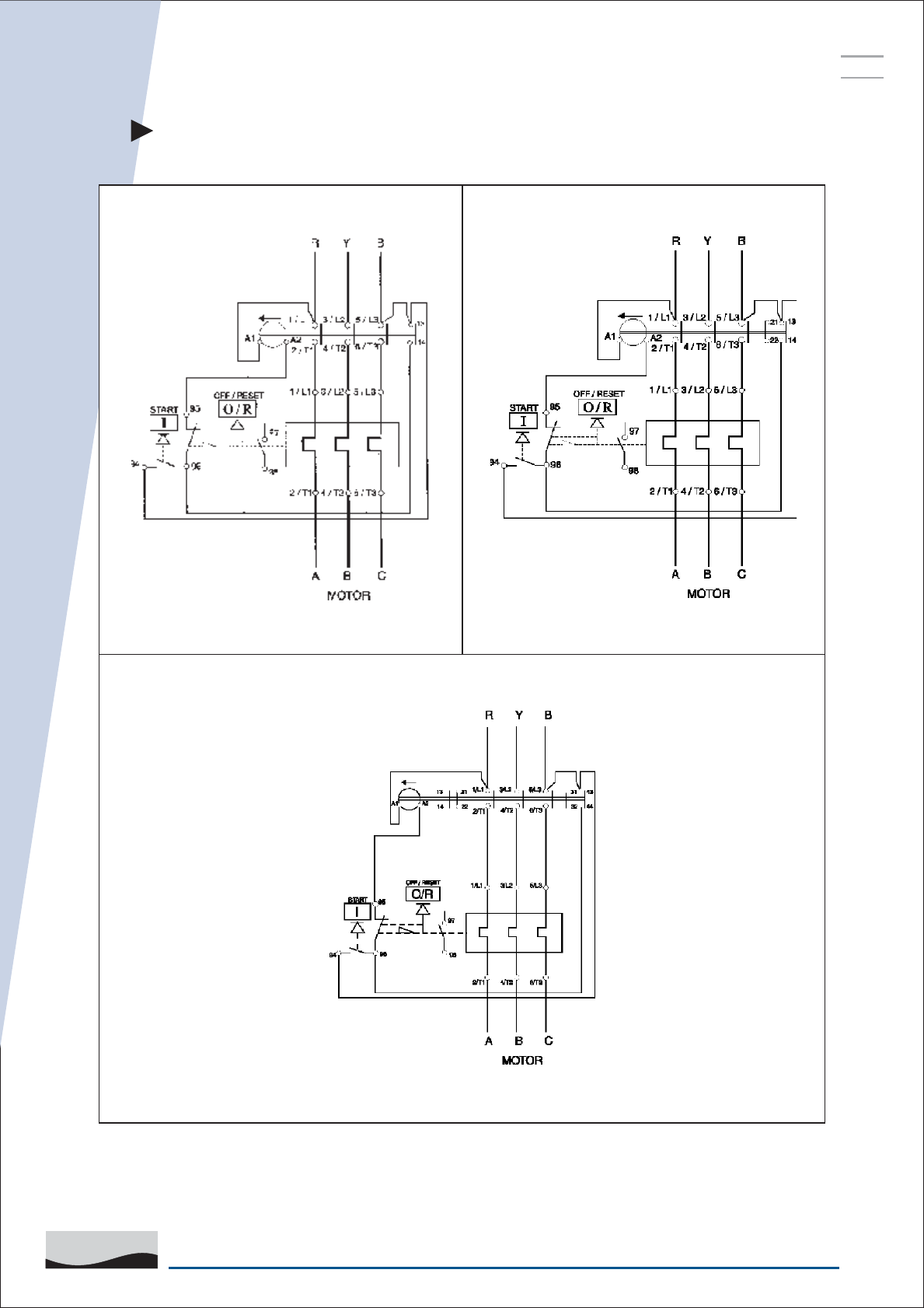
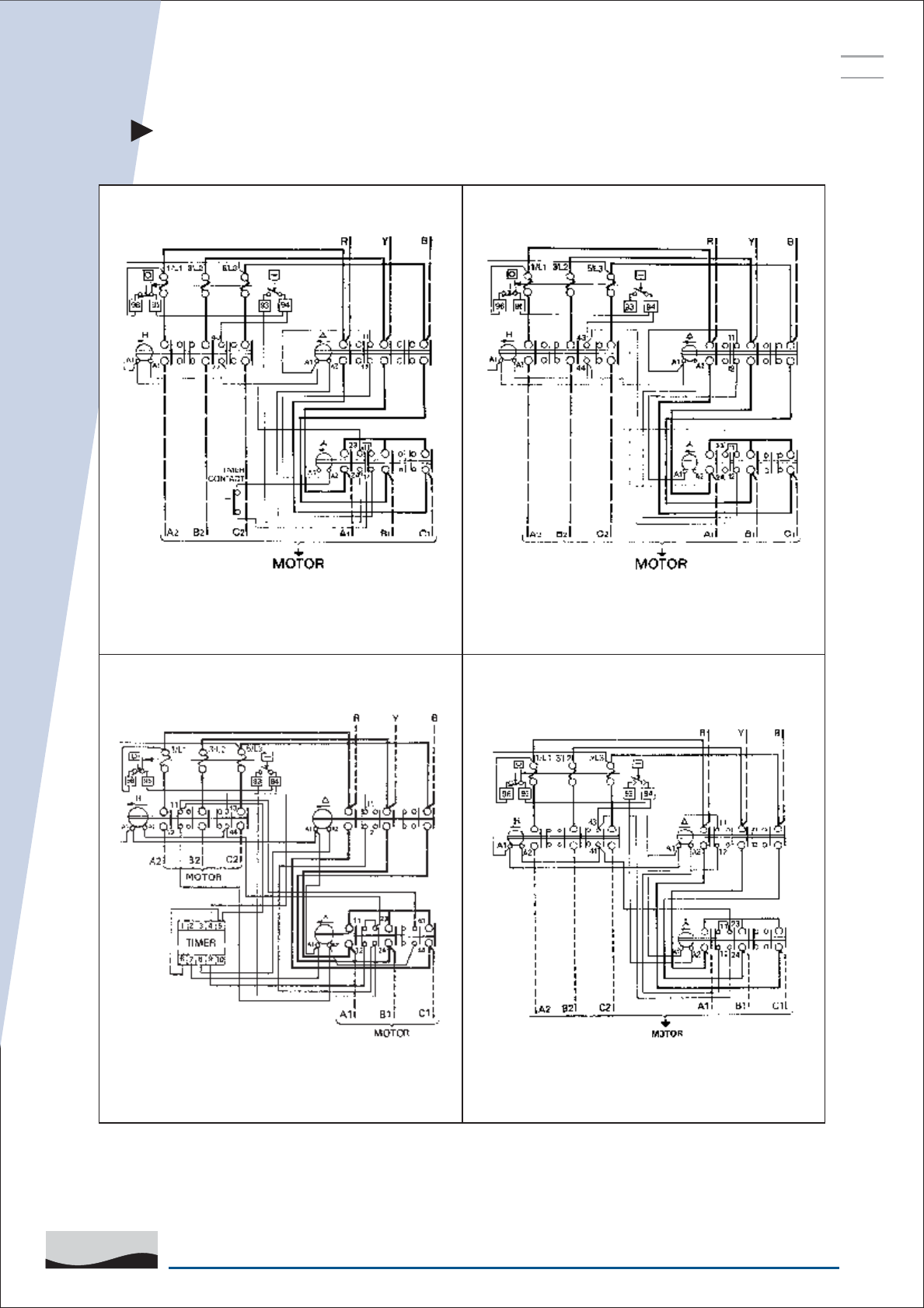
WIRING DETAILS
MN45, MN65 DOL
MN25, MN32 DOL
MN16 DOL
40
SAFE & SURE
L&T SWITCHGEAR
ESP
SERVICE
MANUAL
WIRING DETAILS
MN25, MN32 SASDMN25, MN32 FASD
MN16 SASDMN16 FASD
41
SAFE & SURE
L&T SWITCHGEAR
ESP
SERVICE
MANUAL
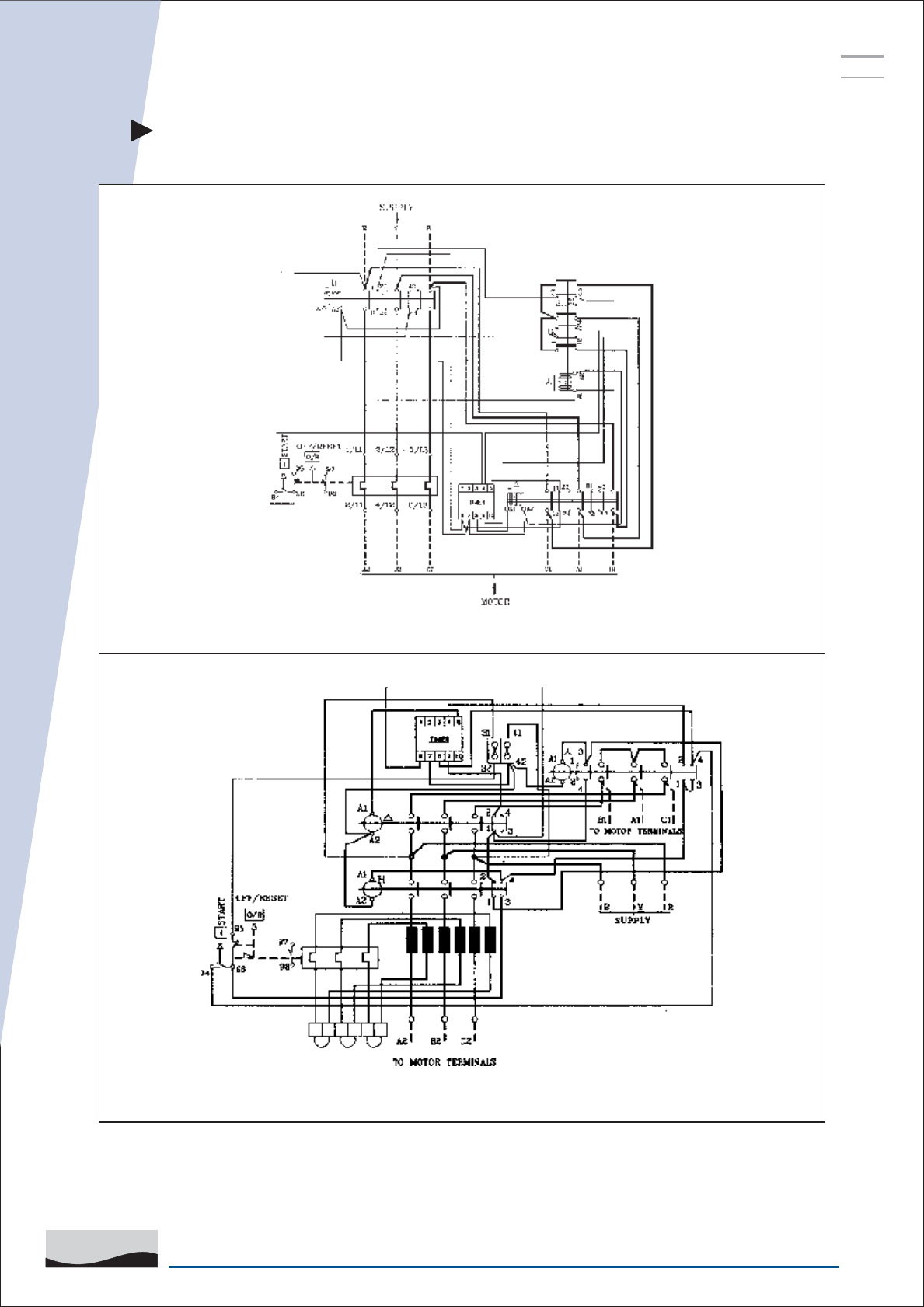
WIRING DETAILS
MN80, MN110, MN140 FASD
MN45, MN65 FASD

42
SAFE & SURE
L&T SWITCHGEAR
ESP
SERVICE
MANUAL
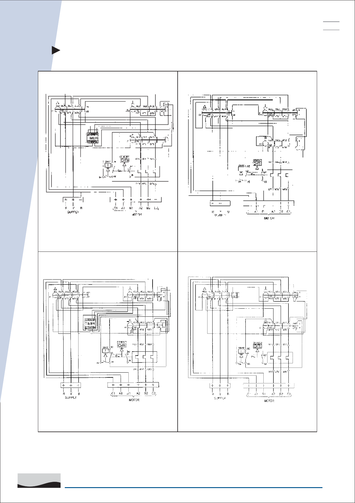
WIRING DETAILS
ML1.5 DOLML1 DOL
ML1.5 FASD ML1.5 SASD
43
SAFE & SURE
L&T SWITCHGEAR
ESP
SERVICE
MANUAL
WIRING DETAILS
ML3 SASDML3 FASD
ML2 SASDML2 FASD
44
SAFE & SURE
L&T SWITCHGEAR
ESP
SERVICE
MANUAL
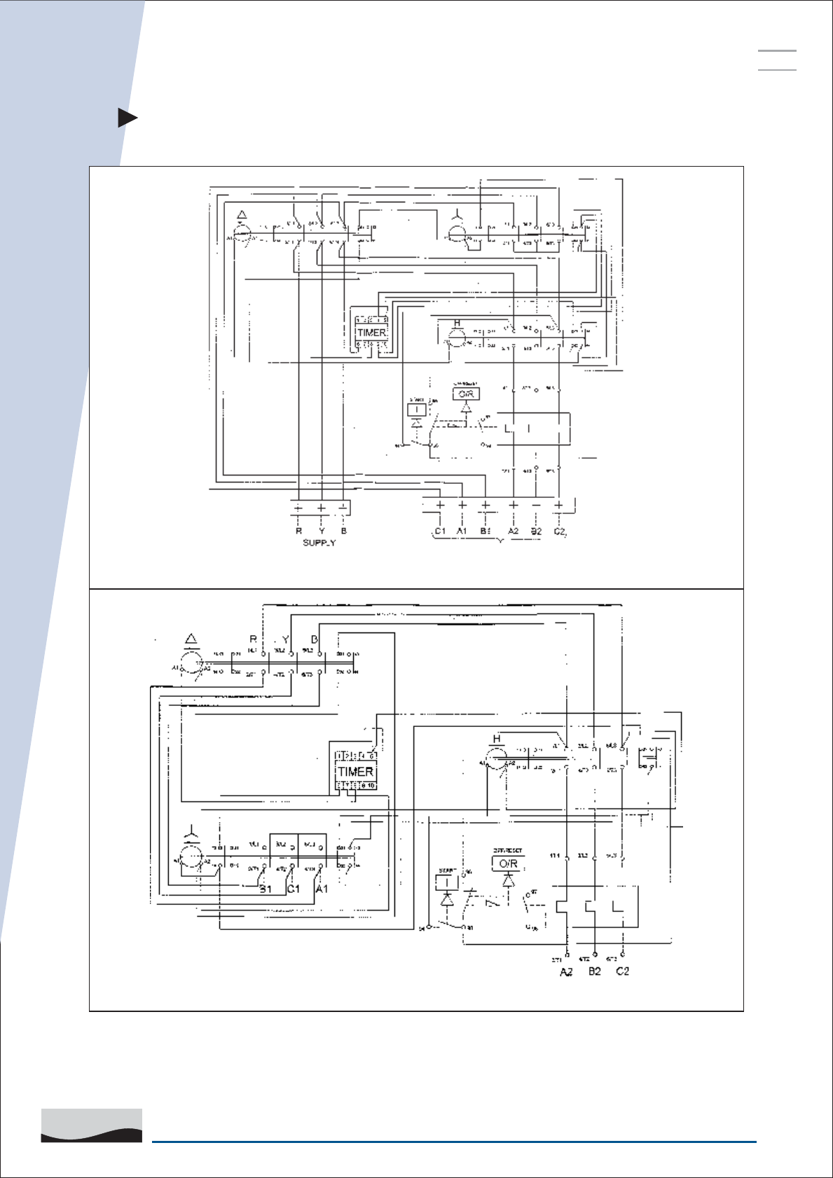
WIRING DETAILS
ML4, ML6 FASD
ML10, ML12 FASD
45
SAFE & SURE
L&T SWITCHGEAR
ESP
SERVICE
MANUAL
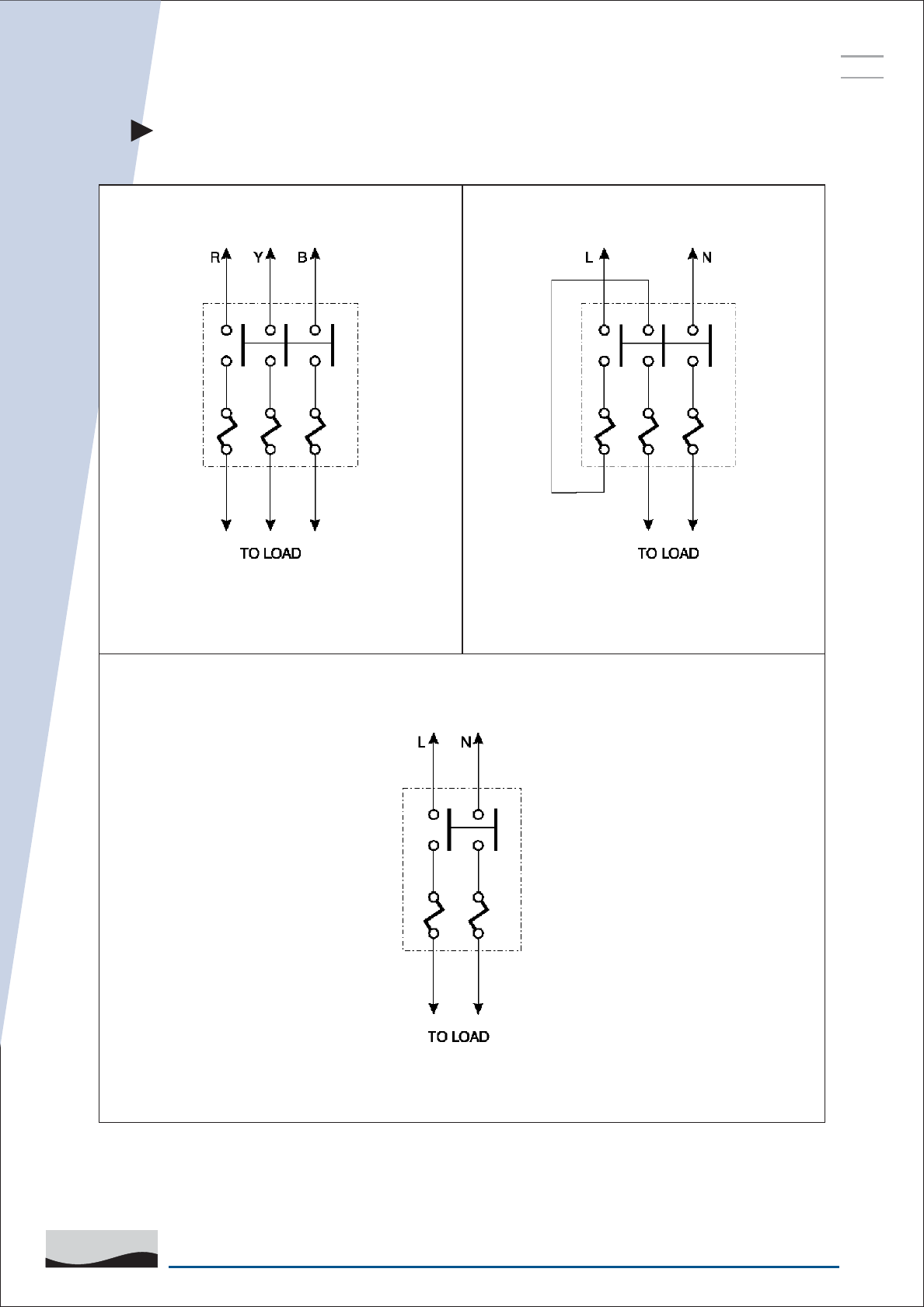
WIRING DETAILS
MF1 DOL (3 PHASE) STARTERS
FOR SINGLE PHASE LOADS
MF1 DOL (3 PHASE) STARTERS
MF1 DOL (SINGLE PHASE) STARTERS
46
SAFE & SURE
L&T SWITCHGEAR
ESP
SERVICE
MANUAL
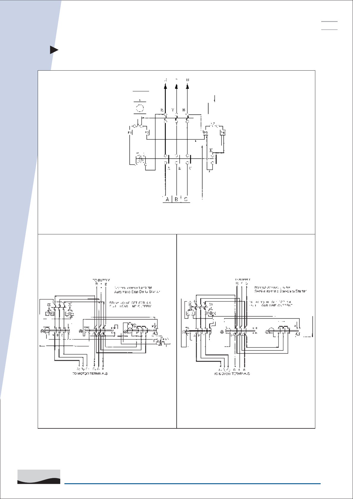
WIRING DETAILS
MK1 FASD
MK1 DOL
MK1 SASD
47
SAFE & SURE
L&T SWITCHGEAR
ESP
SERVICE
MANUAL
STAR DELTA STARTERS (ML SERIES)
Details of Contactors and timers used in
ML series star delta starters
Starters Contactors Timers
STAR DELTA HOLD ON
ML 1.5 SASD ML 1 ML 1.5 ML 1.5 —
ML 1.5 FASD ML 1 ML 1.5 ML 1.5 GT-200
ML 2 SASD ML 2 ML 2 ML 2 —
ML 2 FASD ML 2 ML 2 ML 2 GT-200
ML 3 SASD ML 2 ML 3 ML 3 —
ML 3 FASD ML 2 ML 3 ML 3 ET-100
ML 4 FASD ML 3 ML 4 ML 4 ET-100
ML 6 FASD ML 4 ML 6 ML 6 ET-100
ML 10 FASD ML 10 ML 10 ML 10 ET-100
ML 12 FASD ML 12 ML 12 ML 12 ET-200

48
SAFE & SURE
L&T SWITCHGEAR
ESP
SERVICE
MANUAL
CHART FOR DOL MOTOR STARTERS
WITH ML RELAYS
Motor Rating
240V-1 Phase
Sr.
No
Motor Rating
215V-3 Phase
Relay
Range
Contactor Back up
fuse
SDF
1 0.125 0.09 0.45 0.4-0.65 MLO 2 HF FN32
2 0.15 0.11 0.45 0.4-0.65 MLO 2 HF FN32
3 0.2 0.15 0.57 0.4-0.65 MLO 2 HF FN32
4 0.25 0.19 0.7 0.6-1.0 MLO 4 HF FN32
5 0.33 0.25 0.88 0.6-1.0 MLO 4 HF FN32
6 0.125 0.11 0.5 0.37 1.2 1.0-1.6 MLO 6 HF FN32
7 0.75 0.55 1.6 1.5-2.5 MLO 6 HF FN32
8 0.25 0.18 2.0 1.0 0.75 1.8 1.5-2.5 MLO 6 HF FN32
9 1.25 0.92 2.1 1.5-2.5 MLO 8 HF FN32
10 0.5 0.4 3.6 1.5 1.1 2.6 2.5-4.0 MLO 10 HF FN32
11 1.75 1.3 3.0 2.5-4.0 MLO 10 HF FN32
12 2.0 1.5 3.5 2.5-4.0 MLO 10 HF FN32
13 0.75 0.55 2.5 1.8 4.8 4-6.5 MLO 16 HF FN32
14 3.0 2.2 5.0 4-6.5 MLO 16 HF FN32
15 4.0 3.0 6.2 4-6.5 MLO 16 HF FN32
kWhp TypeRating
(A)
InkWhpIn

49
SAFE & SURE
L&T SWITCHGEAR
ESP
SERVICE
MANUAL
CHART FOR DOL MOTOR STARTERS
WITH ML RELAYS
Motor Rating
240V-1 Phase
Sr.
No
Motor Rating
215V-3 Phase
Relay
Range
Contactor Back up
fuse
SDF
kWhp TypeRating
(A)
InkWhpIn
16 1.0 0.75 7.5 5.0 3.7 7.5 6-10 MLO 20 HF FN32
17 1.25 0.9 8.0 6.0 4.5 9.0 6-10 MLO 25 HF FN32
18 2.0 1.5 9.5 7.5 5.5 11.0 10-16 MLO 25 HF FN32
19 3.0 2.25 14.0 10.0 7.5 14.0 10-16 ML1 32 HF FN32
20 12.5 9.3 18.0 13-21 ML1.5 50 HF FN63
21 15.0 11.0 21.0 20-32 ML1.5 63 HF FN63
22 17.5 13.0 24.0 20-32 ML2 63 HF FN63
23 20.0 15.0 28.0 20-32 ML2 63 HN/00 FN100
24 25.0 18.6 35.0 28-42 ML3 80 HN/00 FN100
25 30.0 22.5 40.0 28-42 ML3 80 HN/00 Fn100
NOTES:
(1) The full load currents given apply in the case of single phase motors, to capacitor-start type motors and in the
case of 3 phase motors, to squirrel cage type induction motors at full load having average power factor and
efficiency. The motors should have speeds not less than the following:
Upto 10 hp - 750 R.P.M., 10 to 30 HP - 600 R.P.M., 30 - 125 HP - 500 R.P.M., 125 - 300 HP - 375 R.P.M.
(2) Contactors/Switches indicated are the minimum ratings suitable for the application. Higher sizes/Ratings can
be used.
(3) Normal motor starting times are assumed in all cases.

50
SAFE & SURE
L&T SWITCHGEAR
ESP
SERVICE
MANUAL
CHART FOR STAR-DELTA MOTOR STARTERS
WITH ML RELAYS
NOTES:
(1) Contactors/Switches indicated are the minimum ratings suitable for the application. Higher sizes/Ratings can
be used.
(2) For applications above 35 hp suitable scheme to be employed to ensure change over delay of 40-75ms
between star and delta contactors.
(3) Normal motor starting times are assumed in all cases.
1 1 0.75 1.8 1.04 1-1.6 MLO MLO MLO 4 HF FN32
2 1.5 1.1 2.6 1.5 1-1.6 MLO MLO MLO 6 HF FN32
3 2 1.5 3.5 2.02 1.5-2.5 MLO MLO MLO 6 HF FN32
4 3 2.25 5 2.88 2.5-4.0 MLO MLO MLO 8 HF FN32
5 4 3 6.2 3.58 2.5-4 MLO MLO MLO 10 HF FN32
6 5 3.75 7.5 4.32 4-6.5 MLO MLO MLO 16 HF FN32
7 6 4.5 9 5.2 4-6.5 MLO MLO MLO 16 HF FN32
8 7.5 5.5 11 6.34 6-10 MLO MLO MLO 20 HF FN32
9 10 7.5 14 8.08 6-10 MLO MLO MLO 20 HF FN32
10 12.5 9.3 18 10.04 10-16 MLO MLO MLO 32 HF FN32
11 15 11 21 12.1 10-16 MLO Ml1 Ml1 32 HF FN32
12 20 15 28 16.2 13-21 ML1 ML1.5 ML1.5 40 HF FN63
13 25 18.5 35 20.2 13-21 ML1 ML1.5 ML1.5 50 HF FN63
14 30 22.5 40 23 20-32 ML2 ML2 ML2 63 HF FN63
15 35 26 47 27 20-32 ML2 ML2 Ml2 63 HN/00 FN100
16 40 30 55 31.8 28-42 ML2 ML3 ML3 63 HN/00 FN100
17 45 33.5 60 34.6 28-42 ML2 ML3 ML3 80 HN/00 FN100
18 50 37.5 66 38.2 28-42 ML2 ML3 ML3 80 HN/00 FN100
Motor Rating
Sr.
No
Current
at 415 V (A)
Relay
Range
Contactor Nominal Back
up fuse link
SDF
kWhp Type/
Size
Rating
A
(A) STARPHASELINE LINE DELTA

51
SAFE & SURE
L&T SWITCHGEAR
ESP
SERVICE
MANUAL
CHART FOR MF1 THREE PHASE / SINGLE PHASE
Motor rating in hp Relay
scale
Maximum safe rating of
back-up fuses*
240V
Single phase
415V
3 phase
Amps
(A)
Cartridge
fuses
Rewritable
fuses SWG
0.125 0.4-0.65 4A 35
0.25 0.6-1.0 6A 32
0.125 0.5 1.0-1.6 6A 32
0.75 1.5-2.5 16A 25
0.25 1.0 1.5-2.5 16A 25
1.25 1.5-2.5 16A 25
0.5 1.5 2.5-4.0 25A 23
1.75 2.5-4.0 25A 23
2.0 2.5-4.0 25A 23
2.5 4.0-6.5 25A 23
3.0 4.0-6.5 25A 23
4.0 4.0-6.5 25A 23
0.75 4.5-7 25A 23
1.00/1.25 6.5-11 32A 21
5.0 6.0-10 32A 21
6.0 6.0-10 32A 21
2.00 10.5-17.5A 32A 21
7.5 9.0-15 32A 21
11-18 32A 21
3.00 12-20A 32A 21
* Cartridge type fuses are recommended

52
SAFE & SURE
L&T SWITCHGEAR
ESP
SERVICE
MANUAL
CHART FOR Mk1 DOL STARTER
0.005 0.05 0.15-0.25 1A
0.1 0.1 0.25-0.4 2A
0.125 0.125 0.25-0.4 2A
0.15 0.15 0.4-0.65 4A 35
0.2 0.2 0.4-0.65 4A 35
0.25 0.4-0.65 4A 35
0.25 0.6-1.0 6A 32 6A 32
0.125 0.5 0.5 1.0-1.6 6A 32 6A 32
0.75 1.0-1.6 6A 32 6A 32
0.25 0.75 1.0 1.5-2.5 15A 25 6A 32
1.0 1.25 1.5-2.5 15A 25 6A 32
SS96210 0.5 1.25 1.5 2.5-4.0 25A 23 10A 28
1.5 1.75 2.5-4.0 25A 23 10A 28
1.75 2.0 2.5-4.0 25A 23 10A 28
2.0 2.5-4.0 25A 23 10A 28
0.75 2.5 2.5 4.0-6.5 25A 23 10A 28
3.0 3.0 4.0-6.5 25A 23 10A 28
4.0 4.0-6.5 25A 23 10A 28
1.0 4.0 6-10 35A 21 15A 25
1.25 5.0 5.0 6-10 35A 21 15A 25
1.5 6.0 6.0 6-10 35A 21 15A 25
1.75 9-14 35A 21 15A 25
2.0 7.5 7.5 11-18 35A 21 15A 25
SS96211 2.0 7.5 7.5 11-18 35A 21 15A 25
SS96228 2.0 7.5 7.5 13-22 40A 21 15A 25
Relay
Amps.
Range
Motor rating H.P. Back-up Fuse Rating
Maximum Minimum
Diazed SWG Diazed SWG
Cat No. 220
1-Phase
400V
3-phase
440V
4-phase
Note :
Amp. Rating of back-up fuse refers to the recommended diazed type HRC catridge fuse. Where rewirable
semi-enclosed, tinned copper wire fuses are used, SWG number in table is approximate guide to size of wire
required.

53
SAFE & SURE
L&T SWITCHGEAR
ESP
SERVICE
MANUAL
CHART FOR MK1 STAR-DELTA STARTER
Note: Amp. Rating of back-up fuse refers to the recommended diazed type HRC catridge fuse. Where
rewirable semi-enclosed, tinned copper wire fuses and used, SWG number in table is approximate guide to
size of wire required.
Cat. No SS 96254 & SS 96257 - FASD Starters
Cat. No SS 96255 & SS 96258 - SASD Starters
1 1.7 1 1-1.6A 6 32 4 35
1.5 2.4 1.4 1-1.6A 15 25 6 32
2 3.1 1.8 1.5-2.5A 15 25 6 32
SS96254 3 4.4 2.5 2.5-4A 25 23 6 32
& 4 5.7 3.3 2.5-4A 25 23 10 28
SS96255 5 7.1 4.1 4-6.5A 25 23 10 28
6 8.4 4.9 4-6.5A 25 23 10 28
7.5 10.4 6 6-10A 35 21 15 25
10 13.6 7.9 6-10A 35 21 15 25
12.5 17 9.7 9-14A 35 21 20 24
15 19.9 11.5 9-14A 35 21 25 23
SS96257
& 15 19.9 11.5 11-18A 35 21 25 23
SS96258
Relay
Amps.
Range
Motor
Rating
400/440v
3-phase
hp
Back-up Fuse Rating
Maximum Minimum
Diazed SWG Diazed SWG
Cat No.
Full load
line
current
in Amps.
ln
In
V3
54
SAFE & SURE
L&T SWITCHGEAR
ESP
SERVICE
MANUAL
SELECTION CHART FOR MU/MBDOL STARTERS
7.5 5.5 11 9-15 HF 32 FN 32
MN2 MU1
10 7.5 14 14-23 HF 50 FN 63
12.5 9.3 18 14-23 HF 50 FN 63
15 11 21 14-23 HF 63 FN 63
MN2 MU2
15 11 21 20-33 HF 63 FN 63
7.5 5.5 11 9-14 HF 32 FN 32
MU2 MU1
10 7.5 14 13-21 HF 50 FN 63
12.5 9.3 18 13-21 HF 50 FN 63
15 11 21 13.21 HF 63 FN 63
MU2 MU2
15 11 21 20-32 HF 63 FN 63
Maximum
Motor rating at
145V.3 ph 50 HZ
Type
Approx.
Full load
Current in
Relay
Range
(A)
Relay Contactor Back-up
HRC Fuse
Switch
Disconector
Fuse Unit
HP KW Type Rating
(A)
MB1
DOL
MB2
DOL
MU1
DOL
MU2
DOL
MB1
SASD
MB2
SASD
MU1
SASD
MU2
SASD
15 11 21 12.1 9-15 HF 32 FN 32
MN2 MU1
15 11 21 12.1 14-23 HF 40 FN 63
20 15 28 16.2 14-23 HF 40 FN 63
25 18.5 35 20.2 14-23 HF 50 FN 63
MN2 MU1
30 22.5 40 23 20-33 HF 63 FN 63
15 11 21 12.1 9-14 HF 32 FN 32
MU2 MU1
15 11 21 12.1 13-21 HF 40 FN 63
20 15 28 16.2 9-14 HF 40 FN 63
25 18.5 35 20.2 13-21 HF 50 FN 63
MU2 MU2
30 22.5 40 23 20-32 HF 63 FN 63
Maximum
Motor rating at
145V.3 ph 50 HZ
Type
Approx.
Full load
Current in
Relay
Range
(A)
Relay Contactor Back-up
HRC Fuse
Switch
Disconector
Fuse Unit
HP KW Type Rating
(A)
Phase
Current
SELECTION CHART FOR MU/MB STAR DELTA STARTERS

55
SAFE & SURE
L&T SWITCHGEAR
ESP
SERVICE
MANUAL
SELECTION CHART FOR MUG-10 DOL
SUBMERSIBLE PUMP STARTERS
HP KW Type Rating
(A)
Type Type
Maximum
submersible
pump rating
at 415 V,
3ph., 50hz
Type Relay
Range
(A)
Relay Contactor Back-up HRC Fuse Switch
Disco-
nnector
Fuse Unit
3 2.2 4-6.5 MU 1 MU 1 HF 16 FN 32
5 3.7 6-10 MU 1 MU 1 HF 16 FN 32
MUG-10 DOL
7.5 5.5 9-14 MU 2 MU 1 HF 32 FN 32
10 7.5 13-21 MU 2 MU 1 HF 40 FN 63
5 3.7 6-10 MN 2 MU 1 HF 16 FN 32
MUG-10N DOL
7.5 5.5 9-15 MN 2 MU 1 HF 32 FN 32
10 7.5 20-32 MU 2 MU 2 HF 63 FN 63
MUG-10H DOL*
10 7.5 28-42 MU 2 MU 2 HN/00 63 FN 100
Note : MU 1/2 contactors are available in 415 V coil operating voltage also.
Note : MUG-10 DOL are available with dry run facility as a optional feature.
* - Controllers for low voltage application

56
SAFE & SURE
L&T SWITCHGEAR
ESP
SERVICE
MANUAL
SELECTION CHART FOR MUG-20 STAR - DELTA
SUBMERSIBLE PUMP STARTERS
15 11 9-14 MU 2 MU 1 HF 32 FN 32
MUG-20
Star-Delta 20 15 13-21 MU 2 MU 1 HF 40 FN 63
20 15 20-32 MU 2 MU 2 HF 63 FN 63
MUG-20H*
Star-Delta 20 15 28-42 MU 2 MU 2 HN/00 63 FN 100
Maximum
submersible
pump rating
at 415 V,
3ph., 50hz
Type Relay
Range
(A)
Relay Contactor Back-up HRC Fuse
HP KW Type Rating
(A)
Type Type
Switch
Disco-
nnector
Fuse Unit
Note : MU 1/2 contactors are available in 415 V coil operating voltage also.
Note : MUG-10 DOL are available with dry run facility as a optional feature.
* - Controllers for low voltage application

57
SAFE & SURE
L&T SWITCHGEAR
ESP
SERVICE
MANUAL
Cable connections to the terminals
When aluminium wires are used, the following method should be adopted:
2
If the wire is small up to 1 mm
– Single strand
1. Clean the wire surface by rubbing with a small hard wire brush.
2. Tin the wire immediately (within 2 or 3 minutes).
3. Put wire under terminal clamp and tighten screws. Do not tighten to such an
extent that the wire becomes flat.
Every two or three months, it may be necessary to ensure that the screws are tight
and the wire has not become loose. This may happen because aluminium is soft and
is likely to “flow”. Always apply inhibiting grease around the terminal and wire to
prevent moisture from reaching the area of contact. Apply inhibiting grease, only on
the terminals and wire and not on the contacts.
2
If the wire is large – larger than 10 mm
– Multi-strand
Wires should be connected with the help of cable lugs or thimbles. The cable lugs
may be of "soldering" or "crimping" type.
For "soldering" type cable lugs:
• Check that cable lug socket is clean and dry inside.
• Clean every strand of aluminium wire with a small hard wire brush by opening out
the cable strands.
• Immediately dip all the strands in tin solder.
• Insert the stranded cable in the proper size cable lug and pour solder through the
cable lug. Ensure that solder fills the entire space inside the cable lug socket.
• Wipe off excess solder on cable insulation.
• Connect the cable lug to the terminal and tighten terminal screws using spring
washers on the cable lug.
• There should not be excess load on the cable lug, or else the solder will become
loose. Care must, therefore, be taken to cut the cable core and strip the insulation
to the correct length. The cable lug should sit flat on the terminal and the cable
should not have sharp bends.
Every two or three months it is necessary to check whether the connection is firm
and to tighten the screws, if necessary. Also check and ensure that the cable is
not loose in the cable lug.
INFORMATION FOR INSTALLATION AND
PREVENTIVE MAINTENANCE

58
SAFE & SURE
L&T SWITCHGEAR
ESP
SERVICE
MANUAL
For "crimping" type cable-lugs :
• Check that cable lug socket is clean and dry inside.
• Clean every strand of aluminium wire with a small hard wire brush after opening
strands.
• Close the strand again immediately, insert to the proper length inside the cable lug
socket and crimp, using the correct crimping tool.
• Connect the cable lugs to the terminal and tighten terminal screws using spring
washers on the cable lug.
Contact maintenance
Contact tips are made of silver compositions like silver nickel and silver cadmium
oxide. In normal use, these tips may show slight brown or black tarnish. If the
atmosphere around the starter contains high moisture and sulphur, the contact
tips will show excessive tarnishing. To clean the contact tips, use this maintenance
procedure:
1. Rub the contact tips lightly with fine emery paper.
DO NOT FILE THE CONTACT.
2. Remove small particles by rubbing with wet cotton wool or with a
wet, clean cloth.
3. Remove the water on the contact tip surface with a dry, clean cloth. If possible,
apply acetone or carbon terachloride. Do not use petrol.
The maintenance procedure is necessary only if contact tips are covered' with thick,
black tarnish film. If the contact tip is uneven, but not heavily tarnished, do not disturb
the contact.
Contact replacement
Contact replacement becomes necessary if less than one- third of the original
contact tip remains on the contact. This can be ascertained by comparing the contact
with a new one of the same starter. When replacing contacts, change contact springs
and leaf springs, if any.
Note :
Proper soldering of aluminium cables requires special grade of solders and fluxes
meant for that purpose. Normal solders and fluxes will produce a joint deceptively
acceptable but It will in practice lead to over-heating and eventually to burnouts.

59
SAFE & SURE
L&T SWITCHGEAR
ESP
SERVICE
MANUAL
Trouble shooting chart for starters
Given below are some of the common complaints in starters. The probable cause
and suggested remedy are also given. But before attending to any complaint,
ensure that the wiring is as per the wiring diagram given in this booklet. Most of the
complaints can be traced to the wiring carried out at the site.
Complaint
1. Motor does not start even
though 'Start' button is pressed.
However on lifting the moving
magnet manually, motor starts.
2. Relay/coil has been
charged. However motor
does not start when green
button is pressed.
3. Motor starts when green
button is pressed. It
however stops immediately
when it is released.
Reasons / Solutions
1) a) Coil does not get energised
(see control wiring diagram)
b) Check nylon strip on relay,
Check nylon button below
start button.
2. Check if red wire on the relay
and black wire on the coil are
properly connected.
3. a) Blue wire is not connected
properly or completely absent,
b) Hold-on contact moving strip is
missing or improperly placed.
SECTION VIII
4. Humming and/or chattering
noise.
5. Use of starters on 230V 10
supply. Incoming / outgoing
lines wired. However motor
does not start.
6. Remote start/stop button not
working properly; motor starts
on remote start; however does
not stop on remote stop.
4. a) Low supply voltage
b) Magnet faces unclean.
Moving system functioning is
obstructed by dirt.
5. Coil obtains supply from across R
& B supply. However if in/out
wires are connected on R & Y
phases coil will not energise. You
may connect all three phases in
series.
6. Red wire not wired as per wiring
diagram.
FOR DOL STARTERS :

60
SAFE & SURE
L&T SWITCHGEAR
ESP
SERVICE
MANUAL
7. Thermostat/float
switch/pressure switch are
wired to the starter. Motor
cannot be stopped properly.
Motor stops on pressing stop
button. However it restarts on
releasing the same.
8. Motor does not restart
immediately after tripping on
O/L even though resetting has
been resorted to.
7) No mistake in wiring here
However it is necessary that the
stop button is of the stay-put type
or locked in.Off position
Alternatively, you could shut the
main switch.
8) It takes a little time for the
thermal bimetals to coil and
reset. Hence wait for 2-4 minutes
before restarting.
1. Motor works in Star. However it
does not work properly In Delta
and refuses to take load.
2. a) Motor starts with difficulty in
Star or trips when additional
load is present,
b) Motor works in Star.
However stops when Delta
connection comes on.
3. a) Even though all six wires
have been connected, motor
stops when in Delta,
b) Motor stops when in Delta,
starter trips and fuse blows.
4. Relay has been changed in
semi-automatic starter, however
when the main switch is on, the
motor starts immediately
without the necessity of
pressing the start button. Motor
stops in Star itself.
1. Check if only three wires are
being terminated in terminal box
of motor. Six wires should be
connected to starter. If shorting
links are present they should be
removed.
2. Reduce time delay from Star to
Delta in case it is kept very long.
a) Or if a semi-automatic starter
is being used, switch over
from Star to Delta earlier than
done previously.
b) Possibly due to low system
voltage.
3. a) Delta connection from motor is
improper.
b) Low system voltage. Star/Delta
connection in starter wrongly
connected.
4. This is a usual complaint. You
may have changed the original
relay yourself. All factory made
relays have loop-wires 2-3 wired,
in semi-automatic starters.
2-4 terminals on relays must be
connected. Check relay before
connecting it on starter.
FOR STAR-DELTA STARTERS :

61
SAFE & SURE
L&T SWITCHGEAR
ESP
SERVICE
MANUAL
This controller is provided with several protection features and indicating instruments
for the convenience of operation and safety. The motor can be set to start
(automatically) within 30-60 secs. after supply is restored. For this, the rocker switch
on SPPR has to be set to "AUTO", otherwise set to "BY-PASS" mode. This feature is
by-passed as supplied from the factory.
The motor controller is armed with the following protection features:
1. Overload protection
2. Phase failure*
3. Phase unbalance *
4. Phase reversal *
5. Dry run protection (Not Standard)*
* - Protection features enabled only in AUTO mode and not in BY-PASS mode.
Visual indication is provided :
1. Supply Voltage (Line)
2. Current drawn by motor (Phase)
3. Lamp-indicating supply ON
4. Lamp - indicating motor ON
For normal operation (manual mode) motor can be switched ON-OFF with GREEN &
RED push buttons. Toggle switch should be in ON position.
However, please note that the standard RED push button will not function in "AUTO"
mode & toggle switch has to be used for switching OFF.
INSTALLATION & COMMISSIONING OF THE MOTOR
CONTROLLER MU-G10 AND MU-G20
By taking these few precautions and care the starter will be able to perform
satisfactorily year after year.
installation & Commissioning of the motor controller MU-G10 and MlU-G20
• Ensure that the enclosure is mounted in the vertical position.
• Set the rocker switch on the SPPR to "BY-PASS" mode, the switch can be set to
"Auto" mode only after ensuring the proper operation of the motor for a few
minutes.
• Use right size of the cables with cable lugs. Use cable glands for fixing cables to
the enclosure to avoid excess stress on terminals.
• Connect the supply (Line) cables on the terminal block provided, Marked "Supply
terminals" in star-delta controller and in DOL controller on the MU contactor.
• Connect the motor terminals on the terminal block provided, marked "Motor
terminals".
A) Installation instruction:
62
SAFE & SURE
L&T SWITCHGEAR
ESP
SERVICE
MANUAL
• Ensure that the termination joints are properly tightened.
• Set the relay pointer corresponding to the actual current drawn by the motor, as
indicated by the ammeter. In star-delta controller, the relay setting (phase current)
should be reduced to 1 /1.732 times of the ammeter reading (line current)
• Keep the toggle switch in OFF position & SPPR in "By-Pass" mode:
• Switch ON the power supply. The RED lamp will be switched ON indicating the
presence of the power supply, the actual voltage can be read in the voltmeter
(select the phase using the selectorswitch provided.)
• Now put the Toggle switch in ON position.
• Press the START button. The Green LED lamp should glow and the motor should
start.
• Ammeter will show the line current drawn by the motor.
• For starting the motor automatically after the supply is restored set the switch on
the SPPR in "AUTO" mode. The motor will start after a delay of 30-60 secs. In this
mode the motor can be switched OFF by the toggle switch - Not by the red button.
B) Commissioning
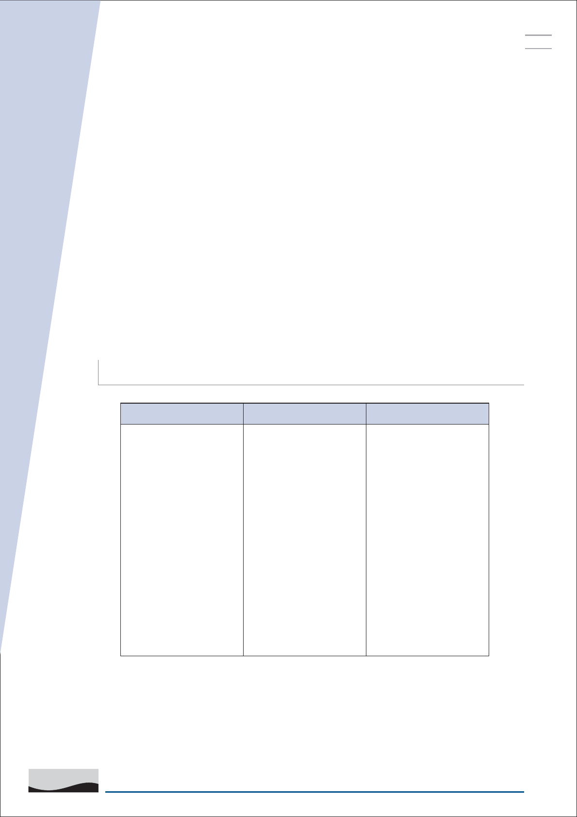
Star Delta Motor Controller Troubleshooting
Motor runs in reverse
direction
Motor runs in correct
direction but stops
immediately
Motor not starting
Phase sequence not
correct
Motor overloaded
Relay tripping
SPPR trips sensing
wrong sequence
(lamp dosn't glow)
Low supply voltage
Single phasing SPPR
trips Phase is
unbalanced SPPR trips
Interchange the supply
sequence
Check the current &
increase the relay
setting appropriately
Interchange Y&B on
the SPPR
Wait till proper supply
is restored Wait till
proper supply is
restored Wait till proper
supply is restored
PROBLEM CAUSE SOLUTION
1.
2.
3.
