Installation Guide EN 8 23
User Manual: Installation guide EN 8-23
Open the PDF directly: View PDF ![]() .
.
Page Count: 10

0
HUAWEI TECHNOLOGIES CO., LTD.
SUN2000 (8KTL-28KTL)
Quick Installation Guide
Issue: 13
Part Number: 31505445
Date: 2015-08-03
Copyright © Huawei Technologies Co., Ltd. 2015. All rights
reserved.
1
1 System Installation
1. Before you install the devices, closely read the SUN2000 (8KTL-28KTL) User Manual to get
familiar with product information and precautions. To locate the user manual, log in to
http://support.huawei.com/carrier/ and browse or search for SUN2000 on the Product
Support page.
2. Use insulated tools.
Inverter Model
Weight
SUN2000-8KTL/10KTL/12KTL
40 kg
SUN2000-15KTL/17KTL/20KTL/23KTL/28KTL
48 kg
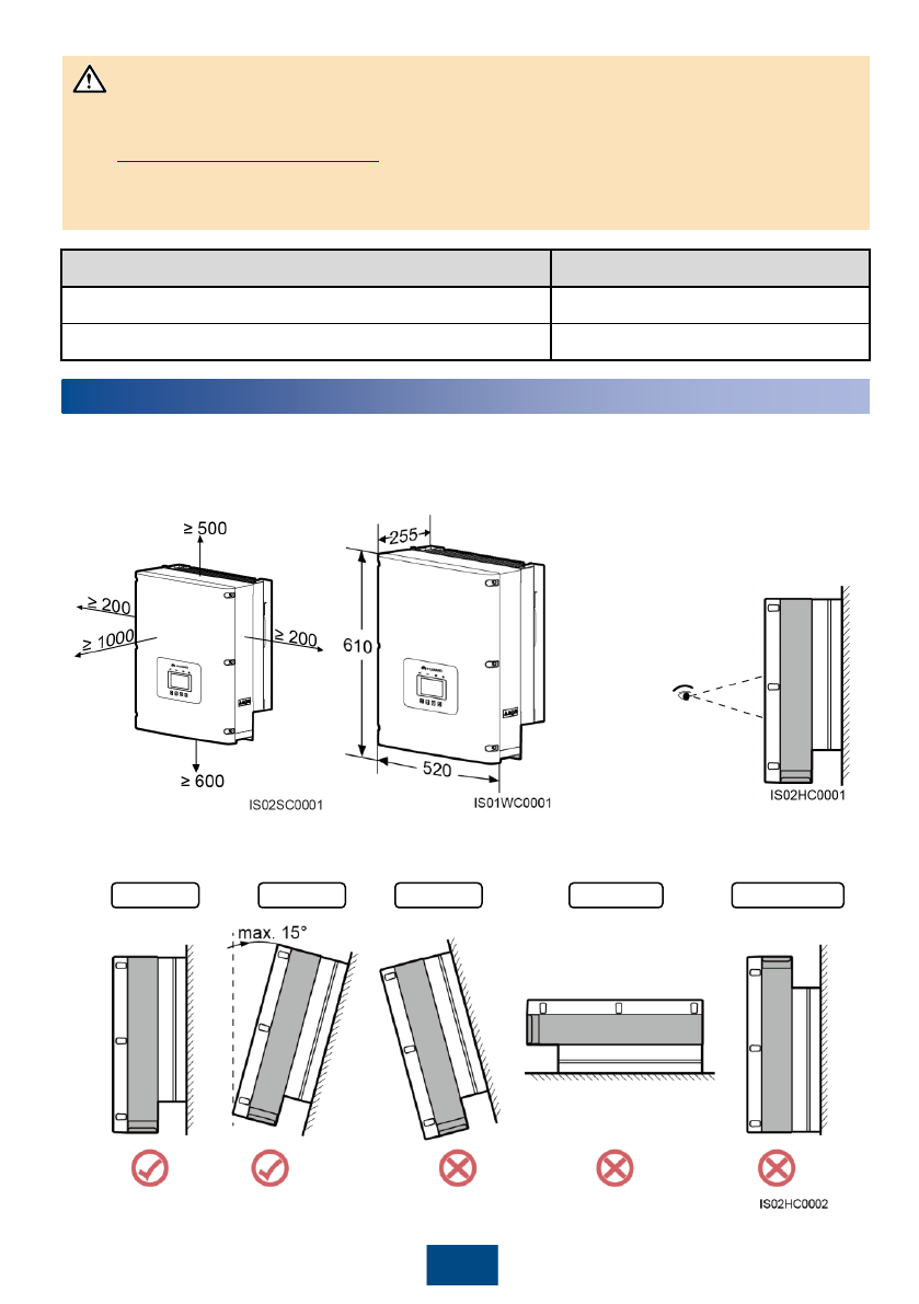
Determine the installation position.
Unit: mm
Install the
SUN2000 in a
position where
the liquid
crystal display
(LCD) is easy
to view and
operate.
Vertical Backward Forward Horizontal Upside down
NOTICE

2
Installing an Inverter (support-mounting is used as an example)
1. The antitheft lock is prepared by customers.
2. For details about wall-mounting the device, see the
SUN2000 (8KTL-28KTL) User Manual.
1. Determine the hole positions on the support
based on rear panel dimensions. 2. Drill holes.
3. Secure the rear panel. 4. Mount the inverter on the rear panel.
5. Tighten hexagon bolts. 6. (Optional) Install an anti-theft lock.
M10 (3 PCS)
30 N·m
Unit: mm
NOTE
3
1. Do not use solid conductor hard cables.
2. 3-core outdoor cables (L1, L2, L3) are configured for the SUN2000-28KTL and 4-core outdoor
cables (L1, L2, L3, and N) are for other models.
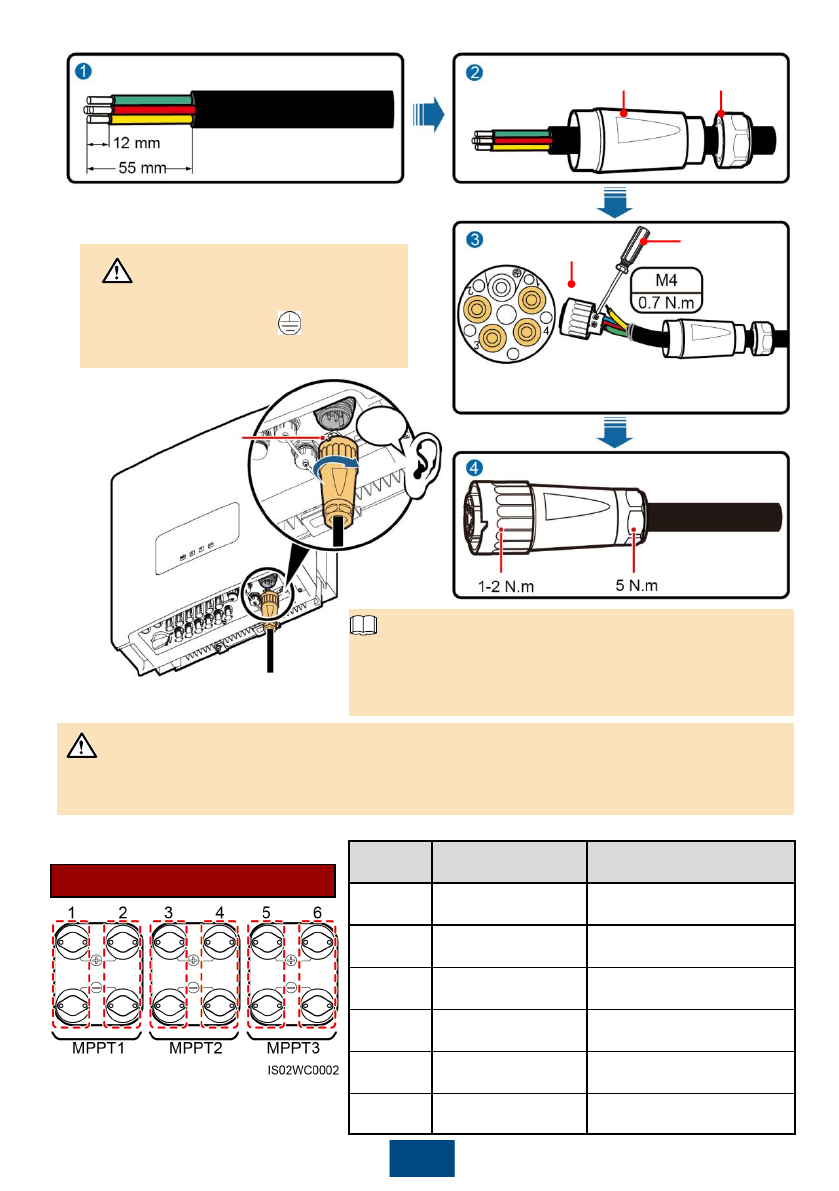
2. Install AC output power cables.
Inverter Model
Cross-sectional Area of the Cable
(Recommended)
SUN2000-8KTL/10KTL/12KTL
4.0 mm2 (12 AWG)
SUN2000-15KTL/17KTL/20KTL/23KTL/28KTL
6.0 mm2 (10 AWG) / 10.0 mm2 (8 AWG)
The table lists only the recommended cable specifications. For more information about cable
specifications, see the SUN2000 (8KTL-28KTL) User Manual.
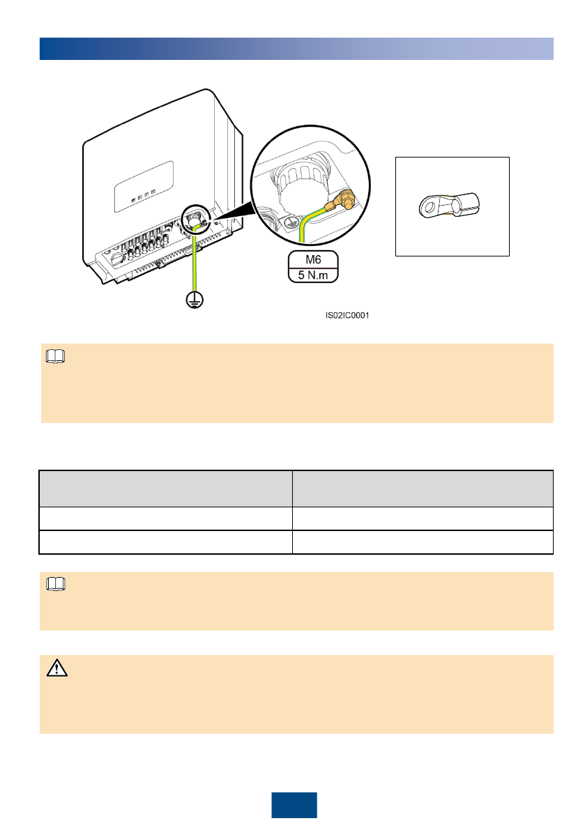
2 Electrical Connection
OT-6mm2-M6
PE terminal
1. Install a ground cable.
1. It is recommended that the ground cable be connected to a nearby ground position.
2. To enhance the corrosion resistance performance of the PE terminals, apply silica gel on them
after connecting the ground cable.
NOTICE
NOTE
NOTE
4
Large handle
screwdriver
(recommended)
The N cable is inserted into hole 4. Do
not insert L1/L2/L3 into .
Socket Cable sealing
cover
Auxiliary
connector
Click
To quickly connect the AC output connector to the AC
output terminal of the inverter, keep the notch of the
connector facing exactly to the operator.
Notch
Ensure that the AC output connector is securely connected. Otherwise, the connector may be
damaged after the inverter has been running for a long time.
3. Install DC input power cables.
Optional DC input terminals:
Number of
Inputs
8KTL-12KTL
15KTL-28KTL
1
Connects to any one
route
Connects to any one route
2
Connects to routes 1
and 3
Connects to routes 1 and 3
3
Connects to routes 1,
2, and 3
Connects to routes 1, 3, and 5
4
Connects to routes 1,
2, 3, and 4
Connects to routes 1, 2, 3, and
5
5
N/A
Connects to routes 1, 2, 3, 4,
and 5
6
N/A
Connects to routes 1, 2, 3, 4, 5,
and 6
NOTICE
NOTICE
NOTE
5
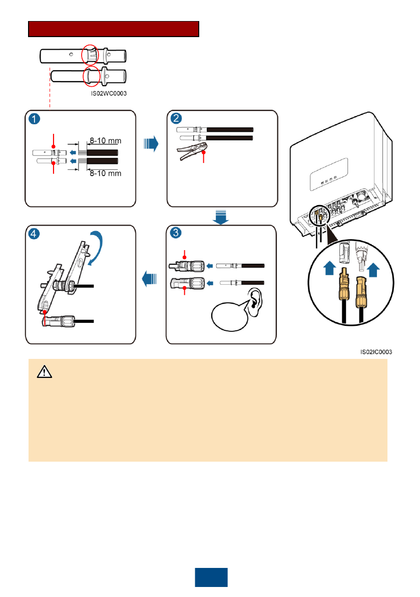
Positive connector
Negative
connector
Positive metal terminals
Negative metal terminals
Common PV cables with a cross-
sectional area of 4 mm² in the
industry are recommended.
Ensure that cables cannot
be removed after crimped.
Positive and negative metal terminals:
Negative metal terminal (male)
Positive metal terminal (female)
The skid automatically
starts after the ejector
lever is fastened.
1. Pull back the DC input power cables to check whether the cables would be disconnected.
2. If DC input power cables are reversely connected and the DC switch is ON, do not turn off
the DC switch immediately. Otherwise, the equipment may be damaged. You can
disconnect the DC input power cable on the PV string side or wait until the PV string
voltage reduces to a value within the safety range. Then, turn off the DC switch, remove
the positive and negative connectors, and rectify the connection.
Recommended: H4TC0001
(Amphenol)
Recommended: H4TW0001
(Amphenol)
Click
NOTICE
6
3 Installation Verification
5 Setting Monitoring Parameters
1. If no data collector is used, set the following parameters before connecting the SUN2000 to the
power grid. For the other parameter settings, see the SUN2000 (8KTL-28KTL) User Manual. If
a data collector is used, see the SmartLogger1000 User Manual for the parameter settings.
2. The preset password for Common User, Advanced User, and Special User is 000001. Use
the preset password to log in to the SUN2000 for the first time and then change the password
to a new one to ensure the account security.
4 System Power-on
1. Switch on the AC circuit breaker between the SUN2000 and the power grid.
2. Ensure that the DC Switch at the bottom of the SUN2000 is ON.
3. (Optional) Measure the temperatures at the joints between the DC terminals and the connectors.
1. Check that all screws, especially the screws used for electrical connections,
are secured.
Passed □ Failed □
2. Check that all circuit breakers are switched to OFF.
Passed □ Failed □
3. Check that the ground cable is securely connected and no short circuit
occurs.
Passed □ Failed □
4. Check that AC output power cables are connected correctly and securely
(the N wire is connected to hole 4, and L1/L2/L3 can be connected to any
hole of 1/2/3; for details, see 2.2 Install AC output power cables), with no
short circuit.
Passed □ Failed □
5. Check that DC input power cables are connected correctly and securely,
with no short circuit.
Passed □ Failed □
6. Ensure that idle DC input terminals are sealed.
Passed □ Failed □
7. Check that the idle USB and RS485 ports are plugged with waterproof
plugs.
Passed □ Failed □
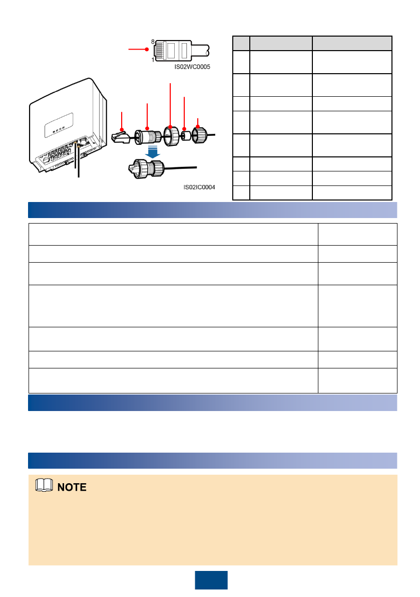
No.
Color
Pin Definition
1
White and
orange
RS485A, and RS485
differential signal+
2
Orange
RS485B, and RS485
differential signal-
3
White and green
PGND
4
Blue
RS485A, and RS485
differential signal+
5
White and blue
RS485B, and RS485
differential signal-
6
Green
PGND
7
White and brown
PGND
8
Brown
PGND
4. Install an RS485 communications cable.
RJ45
connector
with
shielding
functions
Plastic
base
Matching nut
Sealing
washer
Cable
sealing nut
The side without buckles
7
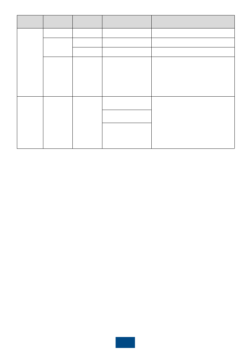
Main
Menu Second-
Level Menu Third-Level
Menu Fourth-Level Menu Setting
Wizard Language - - Set based on site requirements.
Date&Time Date - Set based on site requirements.
Time - Set based on site requirements.
Grid Code - - -China medium-voltage power grid,
choose CHINA-MV480.
-China low-voltage power grid,
choose NB/T 32004.
For other cases, see the Appendix.
Main Menu Settings Isolation(Ad
vanced User) Input Grounded, With
TF
-When the PV- is grounded, an
isolation transformer should be
connected. Set Isolation to Input
Grounded, With TF.
-When the PV- is not grounded, set
Isolation to Input Ungrounded,
Without TF or Input Ungrounded,
With TF.
Input Ungrounded,
Without TF
Input Ungrounded,
With TF
8
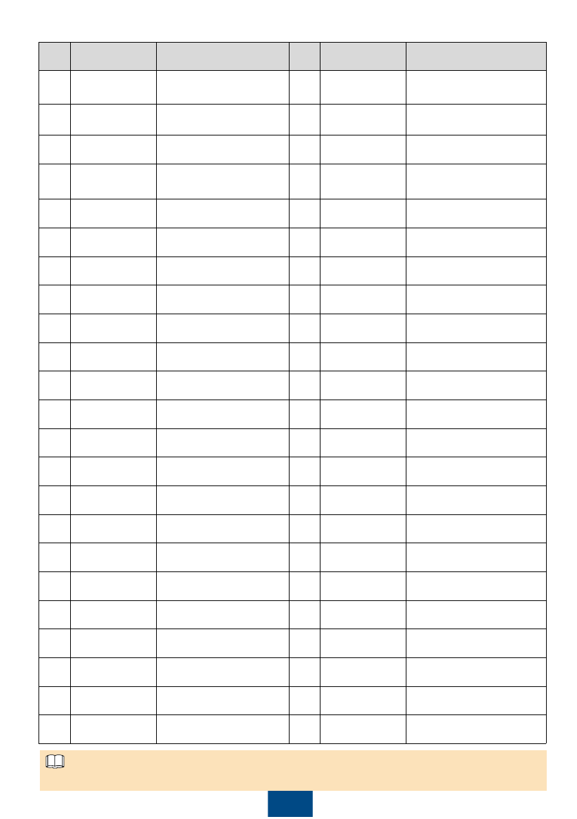
No. Power Grid
Standard Code Country and Condition No. Power Grid
Standard Code Country and Condition
1 CHINA-MV480 China medium-voltage
power grid 24 IEC61727-
MV480 IEC medium-voltage power
grid
2 NB/T 32004 China low-voltage power
grid 25 VDE 0126-1-1-
BU Bulgaria low-voltage power
grid
3 UTE C 15-712-
1(A) France low-voltage power
grid 26 VDE-AR-N-4105 Germany low-voltage power
grid
4 UTE C 15-712-
1(B) Islands of France 230 V
50 Hz 27 BDEW-MV480 Germany medium-voltage
power grid
5 UTE C 15-712-
1(C) Islands of France 230 V
60 Hz 28 BDEW-MV Germany medium-voltage
power grid (400 V AC)
6 UTE C 15-712-
1-MV480 France medium-voltage
power grid 29 TAI-PEA Thailand low-voltage power
grid (PEA)
7 G59-England-
MV480 UK 480 V Medium-voltage
power grid (I > 16 A) 30 TAI-MEA Thailand low-voltage power
grid (MEA)
8 G59-England England 230 V
power grid (I > 16 A) 31 TAI-PEA-MV480 Thailand medium-voltage
power grid (PEA)
9 G59-Scotland Scotland 240 V
power grid (I > 16 A) 32 TAI-MEA-MV480 Thailand medium-voltage
power grid (MEA)
10 G83-England England 230 V
power grid (I < 16 A) 33 EN 50438-DK Denmark medium-voltage
power grid
11 G83-Scotland Scotland 240 V
power grid (I < 16 A) 34 Japan(50Hz) Japan power grid (50 Hz)
12 CEI0-21 Italian low-voltage power
grid 35 Japan(60Hz) Japan power grid (60 Hz)
13 CEI0-16 Italian medium-voltage
power grid 36 EN50438-TR-
MV480 Turkey medium-voltage
power grid
14 IEC61727 IEC low-voltage power grid 37 EN50438-TR Turkey low-voltage power
grid
15 VDE 0126-1-1-
GR(A) Mainland of Greece low-
voltage power grid 38 C10/11 Belgium low-voltage power
grid
16 VDE 0126-1-1-
GR(B) Islands of Greece low-
voltage power grid 39 C11/C10-MV480 Belgium medium-voltage
power grid
17 EN50438-CZ Czech Republic low-
voltage power grid 40 Philippines Philippines low-voltage
power grid
18 RD1699 Spanish low-voltage power
grid (Pn < 100 kW) 41 Philippines-
MV480 Philippines medium-voltage
power grid
19 RD661 Spanish low-voltage power
grid (Pn > 100 kW) 42 EN50438-NL Netherlands low-voltage
power grid
20 AS4777 Australia low-voltage
power grid 43 Custom(50Hz) Reserved
21 AS4777-MV480 Australia medium-voltage
power grid 44 Custom(60Hz) Reserved
22 NRS-097-2-1 South Africa low-voltage
power grid 45 Custom-MV480
(50Hz) Reserved
23 NRS-097-2-1-
MV480 South Africa medium-
voltage power grid 46 Custom-MV480
(60Hz) Reserved
Appendix: Power Grid Standard Code Mapping Table
Grid codes are subject to change. The listed codes are for your reference only.
NOTE

9
HUAWEI TECHNOLOGIES CO., LTD.
Huawei Industrial Base Bantian Longgang
Shenzhen 518129
People's Republic of China
www.huawei.com
