IS CS1718RK
2017-08-30
: Is-Cs1718Rk is-cs1718rk images 708 p4dbimg
Open the PDF directly: View PDF ![]() .
.
Page Count: 3
1of3
Assembly Instruction Sheet #IS-CS1718RK
For Style CS1718RK
6 CORPORATE PARKWAY
GOOSE CREEK SC 29445
www quoizel com
,.
..
Thank you for purchasing a Quoizel product.
Need assistance with parts or assembly? Call Quoizel customer service at 1-631-273-2700
or visit us on-line at www.quoizel.com
2015 QuoizelInc. January2015
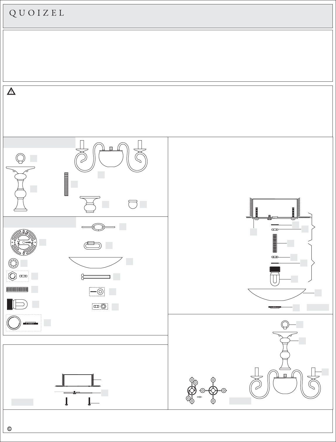
Package Contents
Hardware Contents
Ceiling
Canopy
x1
Fixture Chain
x1
HH Quick Link
x2
II
JJ Mounting Screw
x2
KK Small Lock Washer
x2
Small Hex Nut
x2
STEP 1 Install Crossbar-
A. A)Attach the Crossbar (A to the Outlet Box with the head of the
Green Ground Screw facing you. Secure it with Outlet Box Screws
(not included) Tighten until snug..
Figure 1
Outlet Box
Outlet Box Screw
(not included)
Green Ground
Screw
FOR HANGING
AA
Crossbar
x1
AA
BB
CC
DD
EE
Lock Washer
x2
Big Hex Nut
x2
Nipple
x1
Canopy
Chain Loop
x1
FF
Canopy Lock
Ring
x1
GG
LL
Pleasegoto forproductcleaningtips.Gotothe selection.www.quoizel.com Care + Maintenance
ToolsRequired:Flatheadscrewdriver, Phillips screwdriver,pliers,wirecutters,wirestrippers,electricaltape,safetyglasses.
EstimatedAssemblyTime:30-45 minutes
Preparation:
Note:Thisfixturecanbemountedashangingorsemi-flush.Refertorespectiveinstallationstepsforinstallations.
Identifyandinspectallpartsbeforebeginninginstallation.Checkpackagecontentlistanddiagramsbelowtobesureallpartsare
present.Ifanypartsaremissingordamaged,donotattempttoassemble,install,oroperatethefixture.Contactcustomerserviceforreplacement
parts.
Warnings and Cautions
Turn off electricity at circuit breaker or main fuse box before installation. Consult a licensed electrician if in doubt.
These instructions are provided for your safety. It is very important you read them completely before installing the fixture. We strongly
recommend that a licensed, professional electrician perform the installation.
Disconnect fixture from power source before replacing bulbs. Make sure bulbs are given sufficient time to cool before removal. Do not subject
glass parts to any shock while in operation or shattering may result.
LightSource:(4)B10CandelabraBase60WbulbMaximum.
C
Socket
Assembly
x1
A
Fixture
Loop
x1
B
Center
Column
x1
DNipple
x1
FFinial
x1
ECap
x1
STEP 2 Install Canopy Chain Loop and Nipple-
*Pliers is required for this step.
A. Thread one Hex Nut (CC) to one end of the Nipple (DD) until it is at
least 0.25” from the end. Pass one Lock Washer (BB) over the end of
the Nipple (DD) and thread the Canopy Chain Loop (EE) onto the
Nipple (DD). By using pliers, thread the Hex Nut (CC) against the
Canopy Chain Loop (EE) and hand tighten until snug.
B. Thread another Hex Nut (CC) to the middle of the Nipple (DD). Place
another Lock Washer (BB) over the Nipple (DD) and then thread the
Step B
Step A
CC
BB
EE
II
FF
AA
BB CC
DD
Figure 2
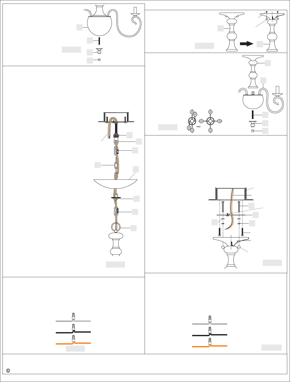
STEP 3 Install Column to Fixture
Body
-
A. Unfold support arms on fixture
assembly to proper locations.
B. Thread Center Column (B) onto Socket
Assembly (C), tighten until sung.
C. Thread Fixture Loop (A) onto the
nipple on the top of Center Column (B),
hand tighten until sung.
Nipple (DD) into the Crossbar
(AA) until the Nipple (DD) is
about 0.375” above the
Crossbar (AA).
C. Remove the Canopy Lock Ring
(FF) from the Canopy Chain
Loop (EE). Place the Ceiling
Canopy (II) over the Canopy
Chain Loop (EE) against the
ceiling to determine the correct
position of the Nipple (DD).
Thread the Canopy Lock Ring
onto the Canopy Chain Loop
(EE). Adjust the Nipple (DD) to
allow the Ceiling Canopy (II) to
rest against the ceiling when
held in place by the Canopy
Lock Ring (FF).
D. Remove the Canopy Lock Ring
(FF) and the Ceiling Canopy
(II). Tighten the Hex Nut (CC)
against the Crossbar (AA) to
secure in place.
Figure 3
A
B
C
2of3
Thank you for purchasing a Quoizel product.
Need assistance with parts or assembly? Call Quoizel customer service at 1-631-273-2700
or visit us on-line at www.quoizel.com
2015 QuoizelInc. January2015
B
Figure 7
STEP 7 Remove the Mounting
Ball
-
A. Remove the Mounting Ball from
Center Column (B) by unscrew
the Lock Screw.
FOR SEMI-FLUSH
B
STEP 9 Install Crossbar and Mounting Screws-
A. Attach the Crossbar (AA) to the Canopy and line up a set of
mounting holes on the Crossbar (AA) to holes on the Canopy.
Thread Mounting Screws (JJ) into the holes. Pass Small Lock
Washers (KK) and thread Small Hex Nuts (LL) onto Mounting
Screws (JJ).
B. Pass the supply wires through the Crossbar (AA). Attach the
Crossbar (AA) to the Outlet Box with the head of the Green Ground
Screw facing you. Secure it with Outlet Box Screws (not included).
Tighten until snug.
C. Fit the Canopy to Mounting
Screws (JJ) and secure with
Mounting Balls. Note: The
Canopy should be snug against
the ceiling and the Mounting
Balls. If not, adjust the length of
Mounting Screws (JJ) by
unscrewing the assembled
Small Hex Nut (LL) and Small
Lock Washer (KK) and then
screwing the Mounting Screws
(JJ) in or out of the Crossbar
(AA) until the correct length is
achieved. Once the Ceiling
Canopy with Small Hole (II) is
secure, remove the Mounting
Ball and Canopy and proceed
to Step 10.
Outlet Box Screw
(not included)
Green
Ground
Screw
Outlet Box
Supply Wires
with Ground Wire
A
JJ
KK LL
Figure 9
Canopy
STEP 4 - Install Cap and Finial
A. Thread the Nipple (D) into the
Socket Assembly (C).
B. Place the Cap (E) over the
Nipple (D), secure by threading
the Finial (F) onto the Nipple
(D), hand tighten until sung.
Figure 4
D
E
F
C
STEP 5 - Install Fixture Chain and Ceiling Canopy
A. Adjust the Fixture Chain (GG) to your desired length by removing
the links if needed.
Pliers is required for this step.
B. With the Fixture Chain (GG) not attached to the Fixture Loop (A) and
the Canopy Chain Loop (EE), pull the supply wires through the
Fixture Chain (GG) alternating links. After the wires are through the
Fixture Chain (GG), pull the Supply Wires and the Ground Wire
*
Figure 5
DD
GG
II
Supply Wires
and Ground
Wire
EE
FF
HH
HH
A
STEP 6 - Wire Connections
A. Use standard wire connectors (not included) to make all wire
connections. (Connectors are not included with fixture.) Twist
connectors until wires are tightly joined together. Wrap each
connection with approved electrical tape and carefully stuff all the
connected wires into the Outlet Box.
White wire
from supply Ribbed side wire
from fixture
Black wire from
supply (or Red)
Smooth side wire
from fixture
Ground wire
from supply
Ground wire
from fixture
Figure 6
STEP 8 Install Column to Fixture Body-
A. Unfold support arms on fixture assembly
to proper locations.
B. Thread Center Column (B) onto Socket
Assembly (C), tighten until sung.
C. Thread the Nipple (D) into the Socket
Assembly (C).
D. Place the Cap (E) over the Nipple (D),
secure by threading the Finial (F) onto
the Nipple (D), hand tighten until sung.
Figure 8
B
C
Mounting
Ball
Lock
Screw
Mounting
Ball
STEP 10 - Wire Connections
A. 6
Use standard wire connectors (not included) to make
all wire connections. (Connectors are not included with fixture.)
Twist connectors until wires are tightly joined together. Wrap each
connection with approved electrical tape and carefully stuff all the
connected wires into the Outlet Box.
Cut the wires leaving approximately ” of wire extending from the
fixture canopy.
White wire
from supply Ribbed side wire
from fixture
Black wire from
supply (or Red)
Smooth side wire
from fixture
Ground wire
from supply
Ground wire
from fixture Figure 10
D
E
F
through the Canopy Lock Ring (FF)
and the Ceiling Canopy (II) in order.
C. Attach one end of the Fixture Chain
(GG) to the Fixture Loop (A) with one
Quick Link (HH). Lift the fixture and
Fixture Chain (GG) up And Attach the
other end of the Fixture Chain (GG)
onto the Canopy Chain Loop (EE) with
another Quick Link (HH). The fixture
will now hang safely. Close the chain
loop at the Ceiling Canopy Loop (EE).
D. Feed the Supply Wires and Ground
Wire through the Canopy Chain Loop
(EE) and Nipple (DD) into the Outlet
Box. Cut the wires leaving
approximately 8” of wire extending
from the Outlet Box.
E. Refer to Step 6 for wire connections.
F. Raise the Ceiling Canopy (II) and
Canopy Lock Ring (FF) up the Fixture
Chain (GG) and over the Canopy
Chain Loop (EE). Tighten the Canopy
Lock Ring (FF) onto the Canopy Chain
Loop (EE) until tight.
G
Suggested chain length for Ceiling
height :
8’ ceiling : use 9 links of chain and 2
quick links
9’ ceiling : use 19 links of chain and 2
quick links
10’ ceiling : use 29 links of chain and 2
quick links
. Process to Step 12 to complete the
installations.
Mounting
Ball
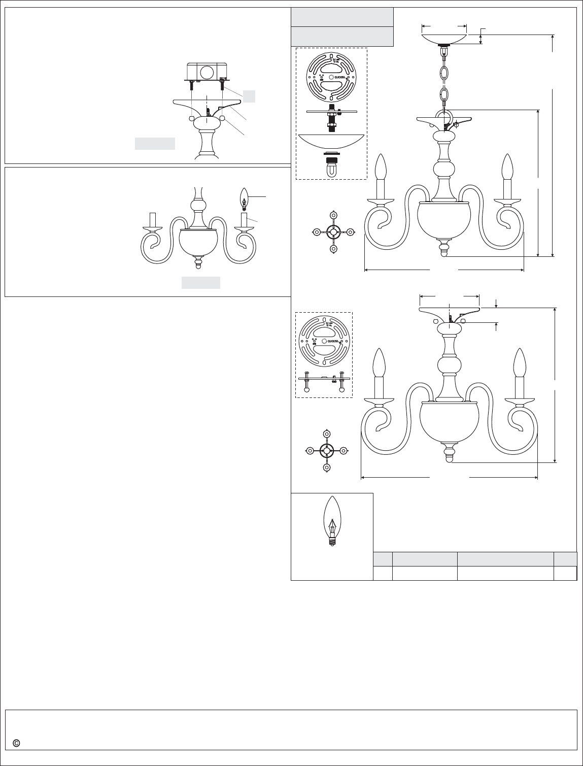
STEP 11 - Install Fixture to Ceiling
A. Carefully tuck all wires into the outlet box and position the Canopy
over the outlet box. Align the holes in the Canopy with Mounting
Screws (JJ), then attach the Canopy using Mounting Balls. Hand
Figure 11
JJ
Canopy
STEP 12 - Install Bulb
A. This fixture uses candelabra
bulb with standard screw base.
Maximum 60 watts.
B. Insert bulb and screw snugly
into place.
Your fixture is now assembled
and ready to use. Enjoy!
Bulb
Figure 12
Socket
CS1718RK
PART NUMBER
NOTE: ALL DIMENSIONS ARE ROUNDED
UP TO THE NEAREST 1/2"
REPLACEMENT PART REQ.
NO.
(4) 60W Candelabra
Bulbs
(Not Supplied)
Base
1
NOTE: TWO LIGHTS SHOWN FOR
ILLUSTRATION PURPOSES ONLY.
FINISH: RUSTIC BLACK
5” Dia.
3of3
Thank you for purchasing a Quoizel product.
Need assistance with parts or assembly? Call Quoizel customer service at 1-631-273-2700
or visit us on-line at www.quoizel.com
2015 QuoizelInc. January2015
1”
69.6”OVERALL HEIGHT
INCLUDES 48” CHAIN
AND 2 QUICK LINKS
(
)
16.5”
18” Dia.
15.8”
1.5”
6” Dia.
18” Dia.
tighten until snug.
B. Continue Step 12 to complete the
rest installations.
