JE665_RS232_Interface_Users_Maunual_1983 JE665 RS232 Interface Users Maunual 1983
JE665_RS232_Interface_Users_Maunual_1983 JE665_RS232_Interface_Users_Maunual_1983
User Manual: JE665_RS232_Interface_Users_Maunual_1983
Open the PDF directly: View PDF ![]() .
.
Page Count: 20
Jameco'
JE665
RS-232C
INTERFACE
USER'S MANUAL
Operation and Programming
.,,.
JAMECO ELECTRONICS, 1355 SHOREWAY ROAD, BELMONT,CA 94002
(415)
592·8097
. . .
This manual is intended as a supplement
to
the JE664 EPROM Programmer Operation Manual. It
describes the operation and programming
of
the JE665 RS·232C Interface Option. Complete details
are given for connection
of
the JE665
to
any
computer
with a spare RS-232C port
(9600
baud, 8
data
bits, 2
stop
bits, odd parity). A sample program is provided in
Microsoft*
MBASIC for implementation
on CP/M t systems.
JAMECO ELECTRONICS makes no warranties, expressed or implied, concerning the accuracy
of
this manual. Every effort is made
to
insure that the contents are correct but errors may occur.
Second Edition
© 1983 by
Jameco
Electronics
1355 Shoreway Road
Belmont, CA 94002
(415)
592-8097
Written by David
H.
Nelson -Jameco Electronics
*
Microsoft
and MBASIC are registered trademarks
of
Microsoft Corp.
t CPIM is a registered trademark
of
Digital Research, Inc.
Table
of
Contents
INTRODUCTION ii
1 THE RS·232C INTERFACE 1
2 THEORYOFOPERATION 2
3 JE665 PROGRAM 4
4 JE665 PROGRAM MODIFICATION 10
5 USING THE JE665 PROGRAM 13
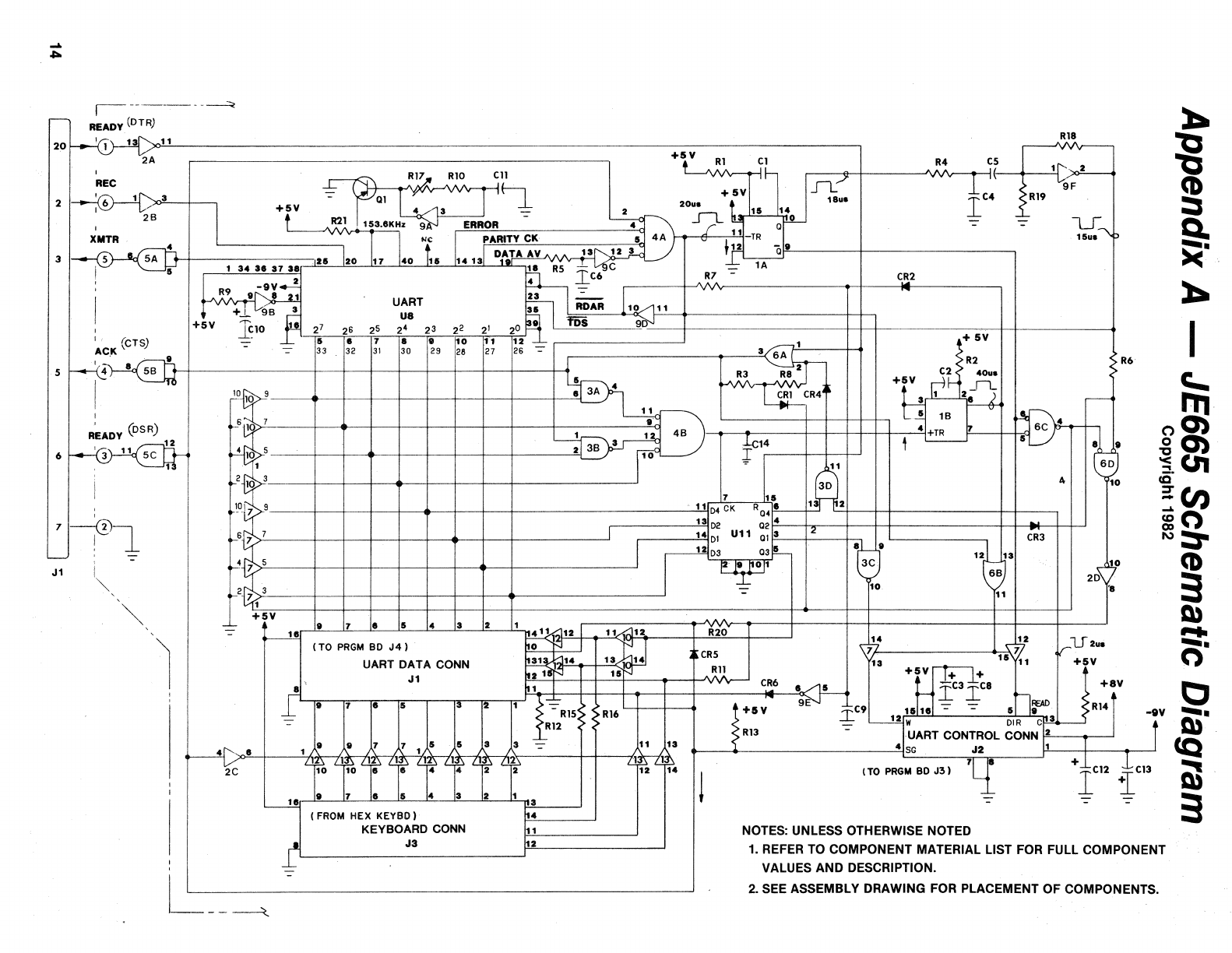
APPENDIX A - JE665 SCHEMATIC DIAGRAM
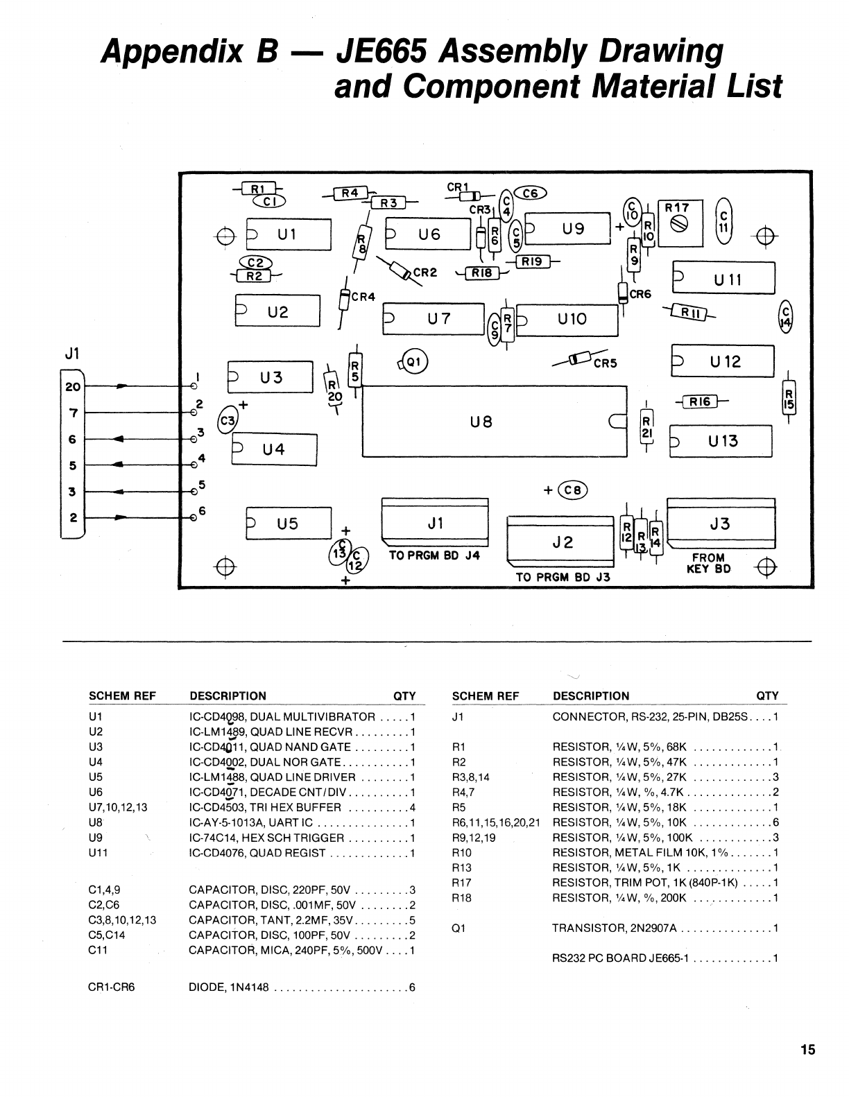
APPENDIX B - JE665 ASSEMBLY DRAWING
AND
COMPONENT MATERIAL
LIST'
ii
Introduction
The JE665 option is a
circuit
board that implements the RS-232C standard interface
to
allow
connection
of
the JE664 EPROM Programmer
to
a computer system. The JE665 requires a spare
RS-232C port capable
of
9600 baud, 8 data bits, 2
stop
bits and odd parity.
A sample program is provided in Microsoft MBASIC for implementation on CP/M computers. Modifica-
tions may be necessary due to the different hardware configurations available. These changes are
explained in detail.
When connection is complete, the computer will have access
to
the
RAM
inside the JE664. This allows
for convenient data storage and manipulation
with
the computer.
The
RS·232C Interface
The
RS-232C
interface is
an
EIA (Electronic Industries Association) "Recommended Standard" inter-
face. It transmits and receives data
in
serial form, one bit at a time.
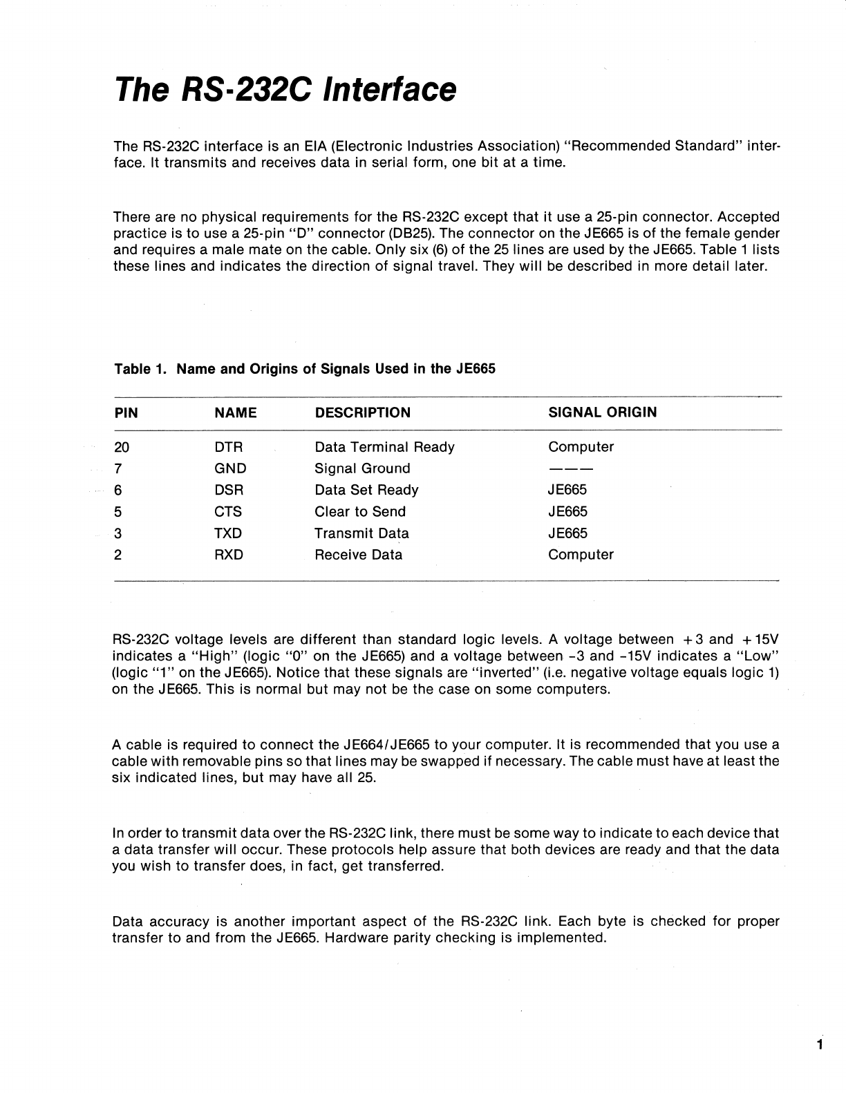
There are no physical requirements for the RS-232C except that
it
use a 25-pin connector. Accepted
practice is to use a 25-pin
"0"
connector (0825). The connector
on
the JE665 is of the female gender
and requires a male mate on the cable. Only six
(6)
of
the
25
lines are used by the JE665. Table 1 lists
these lines and indicates the direction
of
signal travel. They will be described in more detail later.
Table
1_
Name and Origins of Signals Used
in
the JE665
PIN NAME DESCRIPTION SIGNAL ORIGIN
20
DTR
Data Terminal Ready Computer
7 GND Signal Ground
---
6
DSR
Data Set Ready JE665
5
CTS
Clear to Send JE665
3
TXD
Transmit Data JE665
2
RXD
Receive Data Computer
RS-232C voltage levels are different than standard logic levels. A voltage between + 3 and + 15V
indicates a
"High"
(logic
"a"
on the
JE665)
and a voltage between
-3
and -15V indicates a
"Low"
(logic
"1"
on
the JE665). Notice that these signals are "inverted"
(Le.
negative voltage equals logic
1)
on the JE665. This is normal but may not
be
the case on some computers.
A cable is required
to
connect the JE664/JE665 to your computer. It is recommended that you use a
cable with removable pins so that lines may be swapped if necessary. The cable must have at least the
six indicated lines, but may have all
25.
In
order
to
transmit data over the RS-232C link, there must
be
some way
to
indicate to each device that
a data transfer will occur. These protocols help assure that both devices are ready and that the data
you wish
to
transfer does, in fact, get transferred.
Data accuracy is another important aspect
of
the RS-232C link. Each byte is checked for proper
transfer to and from the JE665. Hardware parity checking is implemented.
1
2
Theory
of
Operation
To access the JE665 from your computer, certain events must occur in the correct order. As long as
the proper signals are present the JE665 will communicate properly: But
if
they are not you may have
unexpected difficulties.
The first signal
to
occur comes from the JE665. This is the
DSR
(Oata Set Reaoy,t;lfIl:
6)
line. It will be
held high (RS-232C + 3
to
+
15V)
by the JE665 when the cable is connected and the
IPRGM
PULSES/RS
2321
switch is in the
IRS
2321
pOSition.
lfindicates
that the programmer is ready.
After the computer determines that the programmer is ready
it
will set the
DTR
(Data Terminal Ready,
pin
20)
line low
(-3
to -15V) and then back high
(+
3
t'o
+
15V).
This will reset the JE665 and tell it to
expect a control word next. It will also set the
CTS
(Clear
to
&end,
pin
5)
line low
(-3
to
...:15V)
signalling
that the J
E665
expects a control word.
7
1
Control Code
•
6 5
o 1
4 3
o
I
x
Control
Bit
0 -
control
word follows t
1 - data
follows
--------'
Address Clear Disable 0 - clear address
2
x
1 -
don't
clear
_________
....J
1
x
Write Enable 0 - load from programmer
-------------~
1 - save
to
programmer
o
x
Shift 0 - lower 32K
-------------------------------'
1 - upper 32K
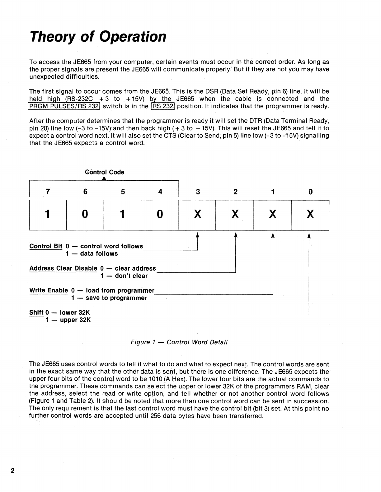
Figure 1 - Control Word Detail
The JE665 uses control words to tell
itwhat
to
do and what to expect next. The control words are sent
in
the exact same way that the
other
data is sent, but there is one difference. The JE665 expects the
upper four bits
of
the
coo.troJ
word to be
1010
{A
Hex). The lower four bits are the actual commands to
the programmer. These commands can select the upper or lower 32K
of
the programmers
RAM,
clear
the address, select the read or write option, and tell whether or not another control word follows
. (Figure 1 and Table
2).
It
should
be noted that more than one control word can
be
sent in succession.
The only requirement is that the last control word must have the control bit (bit
3)
set. At this point no
further control words are accepted until
256
data bytes have been transferred.
After the correct control word(s) are sent, the last one having the control
bit
(bit
3)
set, the actual data
will follow. A block
of
256 bytes will be transferred. If the transfer is to the programmer then each byte
will
be sent and immediately read back. This will verify that the transfer Wl:fS correct. If the transfer is
from the programmer then a dummy byte will be sent and the byte returned
will
be the desired data.
After the
256
byte
block
has been transferred, the CTS line will
again
be set low
(-3
to
-15V)
acknowledging that the
block
was accepted and indicating that the JE665 expects another control
word.
The proper control word(s) are sent followed by another
256
byte data block. This cycle is repeated
until all
of
the data is transferred or until the end of the lower 32K bits is reached. If the lower 32K is fill-
ed then two new control words are sent that select the upper 32K. The cycle
of
256
byte blocks and
control words is then repeated until all of the data has been transferred. (Note: The UPPER 32K LED on
the JE664 front panel
will
NOT change when the
RS232
is active even though the 32K segment may
change. When returning to manual control of the programmer be sure that you are in the upper or
lower 32K as necessary).
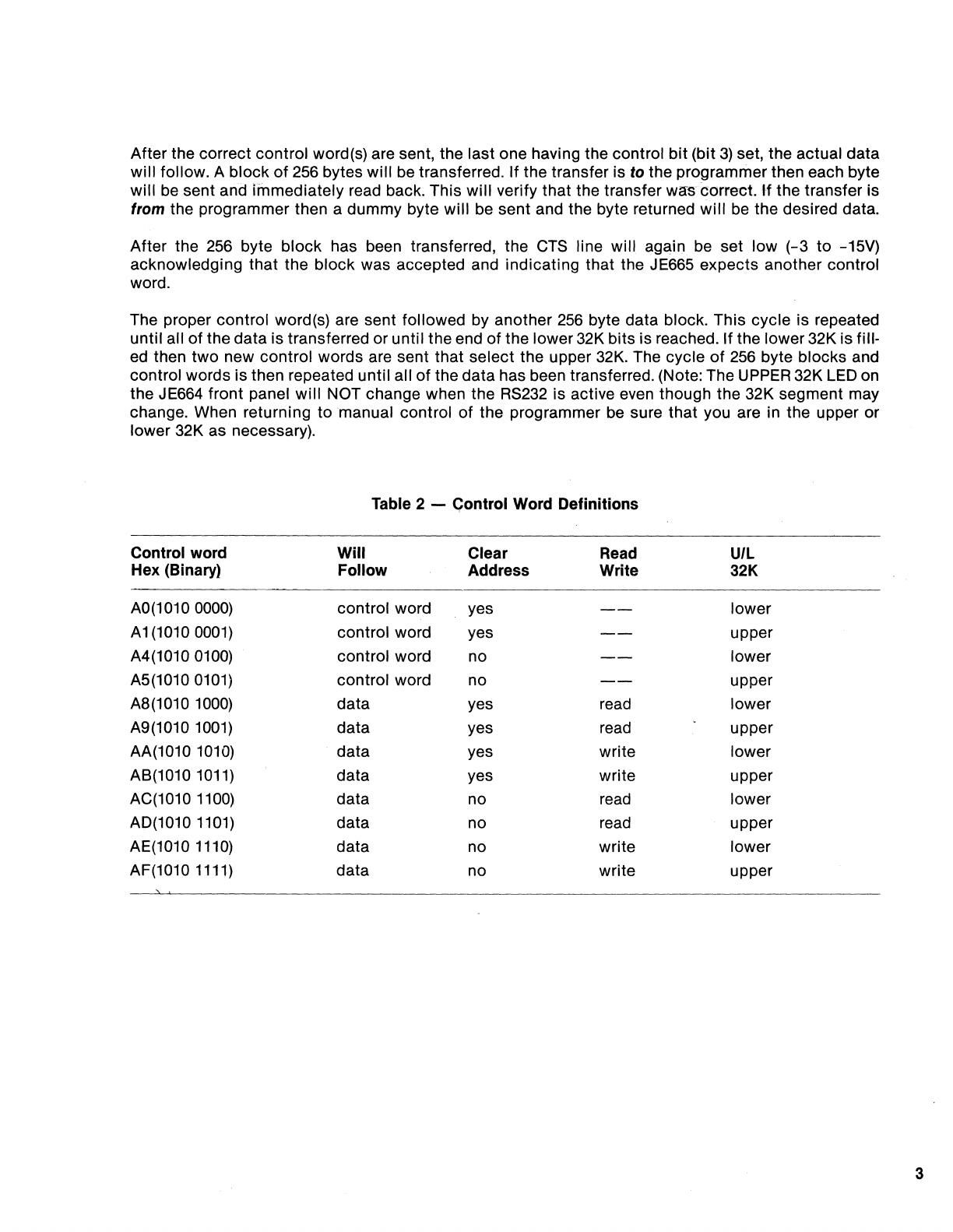
Table 2 - Control Word Definitions
Control word
Will
Clear Read
U/L
Hex (Binary) Follow Address Write 32K
AO(1010
0000)
control word yes lower
Ai
(10100001) control word yes upper
A4(1010
0100)
control word no lower
A5(1010
0101)
control word no upper
A8(1010
1000)
data yes read lower
A9(1010
1001)
data yes read upper
AA(1010
1010)
data yes write lower
AB(1010
1011)
data yes write upper
AC(1010
1100)
data no read lower
AD(1010
1101)
data no read upper
AE(1010
1110)
data no write lower
AF(1010
1111)
data no write upper
3
4
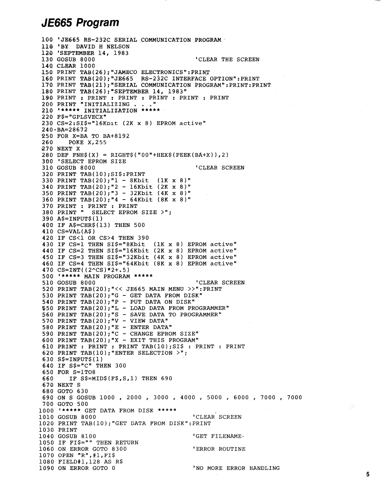
JE665
Program
The sample program
ofthis
chapter is provided
to
help you make the connection from the JE665
to
your computer. It has all the features necessary for data transfer, data storage and data entry. You
. may choose
to
use
it
or
you may write your own.
The program was written in
Microsoft
MBASIC version 4.51. If you have MBASIC you can enter the pro-
gram
into
your computer and save it as "JE665." The next chapter explains how
to
customize
it
to
your
specific computer.
If you choose
to
write your own program, carefully
follow
the sample program and THEORY OF
OPERATION. You may use another BASIC
or
a different language. You
will
also need
to
read JE665
PROGRAM MOD/FICA TlON.
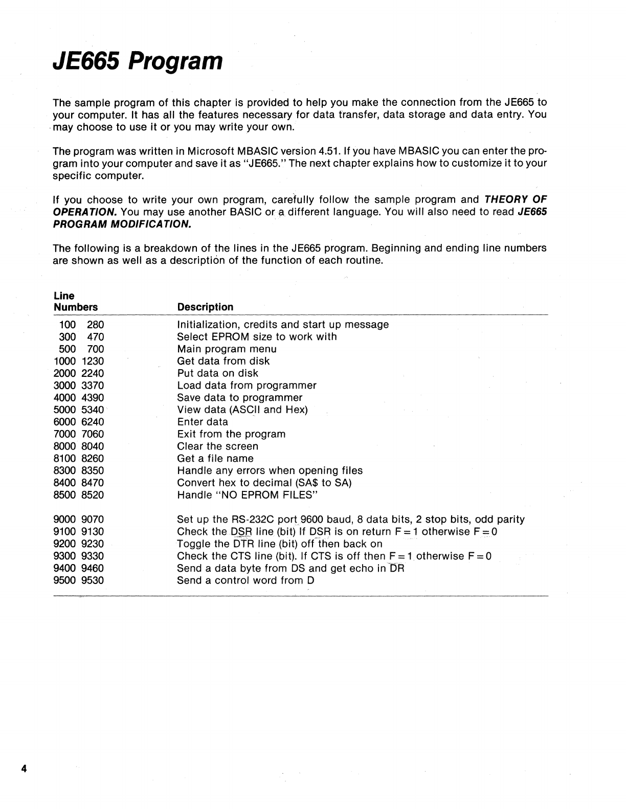
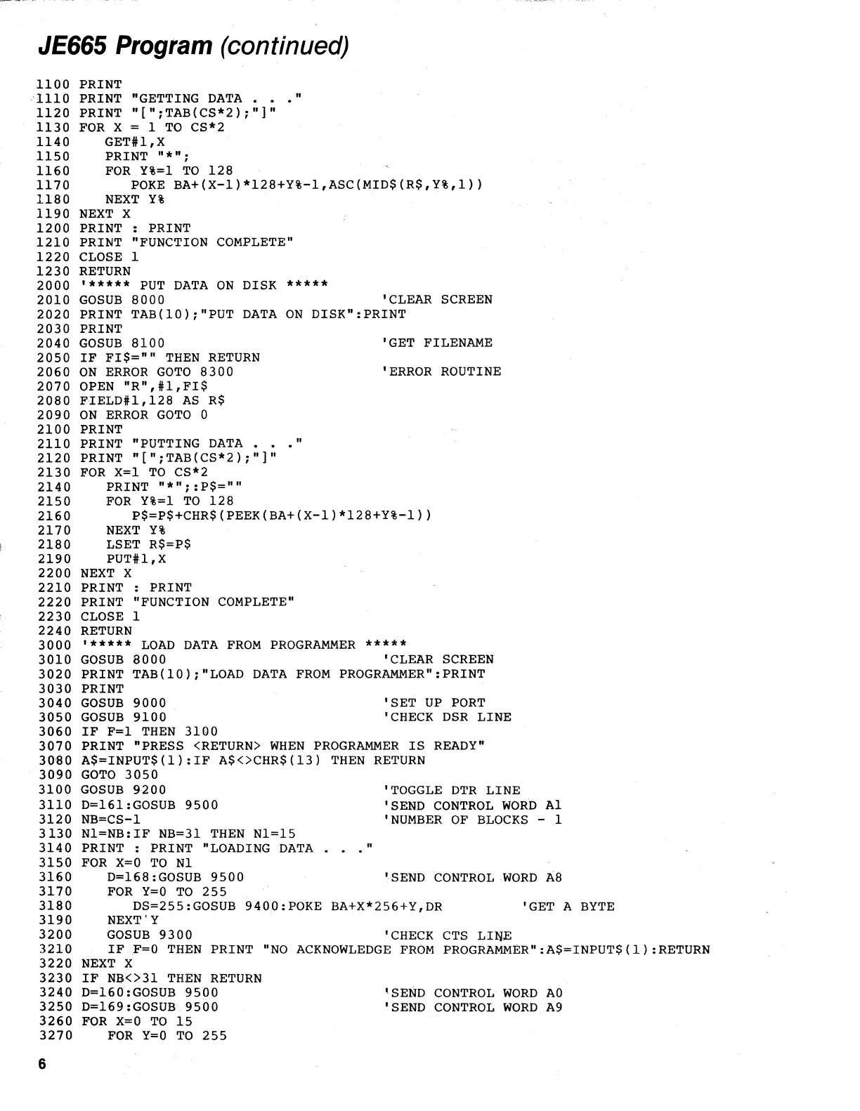
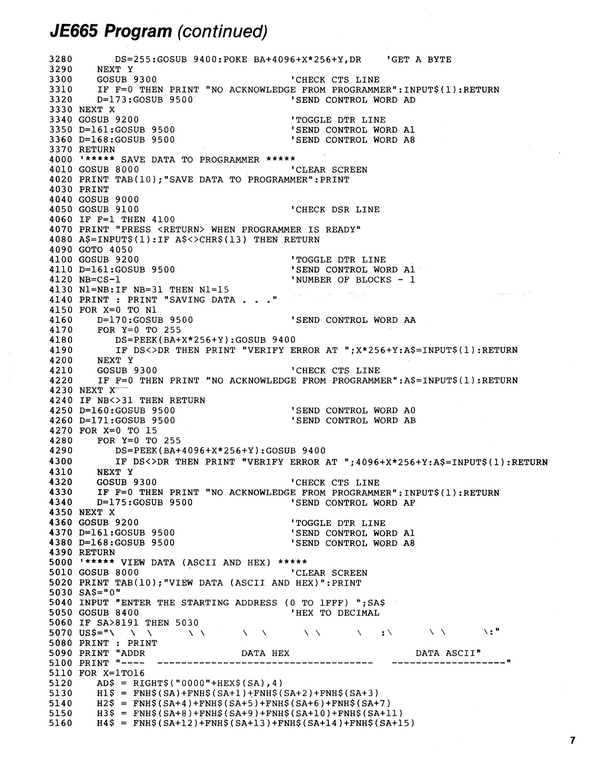
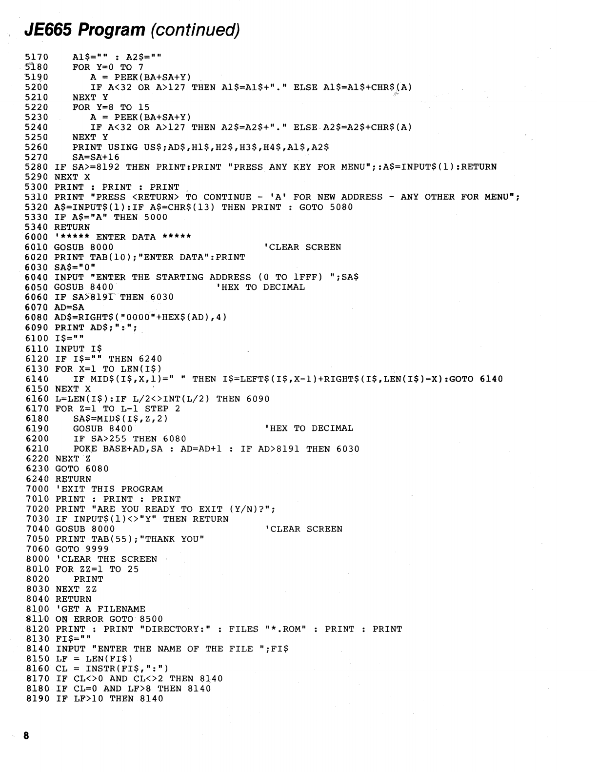
The following is a breakdown
of
the lines in the JE665 program. Beginning and ending line numbers
are shown as well as a description
of
the function
of
each routine.
Line
Numbers
100 280
300
470
500
700
1000 1230
2000 2240
3000 3370
4000 4390
5000
5340
6000
6240
7000 7060
8000 8040
8100
8260
8300 8350
8400 8470
8500
8520
9000
9070
9100 9130
9200
9230
9300 9330
9400
9460
9500
9530
Description
Initialization, credits and start up message
Select EPROM size
to
work
with
Main program menu
Get data from
disk
Put data on
disk
Load data from programmer
Save data
to
programmer
View data (ASCII and Hex)
Enter data
Exit from the program
Clear the screen
Get a file name
Handle any errors when opening files
Convert hex
to
decimal (SA$
to
SA)
Handle
"NO
EPROM FILES"
Set up the RS-232C
port
9600 baud, 8 data bits, 2 stop bits, odd parity
Check the
P§B
line (bit) If
DSR
is on return F = 1 otherwise F = 0
Toggle the
DTR
line (bit)
ofnhen
back on .
Check the CTS line (bit). If CTS is
off
then F =
1.
otherwise F = 0
Send a data byte from
DS
and get echo i
nl5R
Send a control word from D
JE665
Program
100
'JE665
RS-232C
SERIAL
COMMUN.ICATION
PROGRAM
llQ'BY
DAV.ID
Ii
NELSON
12~
'SEPTEMBER
14,
1983
130
GOSUB
8000
1·40 CLEAR
1000
'CLEAR
THE
SCREEN
150
PRINT
TAB(26).;"J.AMECO l!;LECTRONICS":PRINT
16,0
PRINT
TAB(20)
j"JE6.f)5
RS-232C
INT.ERFACE'OPTION" :
PRINT
170
PRINT
TAB(21)
j
"SERIAL
COMMUNICATION
PROGR~":PRINT:PRINT
180
PRINT
TAB.(
26)
j "SEPTEMBER
14,
1983"
1,90
PRINT
:
PRINT:
PRINT
=
PRINT
:
PRINT
:
PRINT
200
PRINT
"INITIALIZING.
"
210
'*****
INITIALIZATION
*****
220
F$="GPLSVECX"
230
CS=2:SI$="16KDlt
(2K
x
8)
EPROM
active"
240·BA=28672
250
FOR
X=BA
TO
BA+8192
260
POKE
X,255
1270
NEXT
X
280
DEF FNH$(X} =
RIGHT$("00"+HEX$(PEEK(BA+X)),2)
300
'SELECT
EPROM
SIZE
310
GOSUB
8000
320
PRINT
TAB(10)jSI$:PRINT
330
PRINT
TAB(20)j"1
-
8Kbit
340
PRINT
TAB(20);"2.
-
16Kbit
350
PRINT
TAB(20)j"3
-
32Kbit
360
PRINT
TAB(20)j"4
-
64Kbit
370
PRINT
:
PRINT
:
PRINT
(lK
x
(2K
x
(4K
x
(8l(
x
380
PRINT"
SELECT
EPROM
SIZE
>"j
390A$=INPUT$(1)
400
IF
A$=CHR$(13)
THEN
500
410
CS=VAL(A$)
420
IF
CS<l
OR
CS>4
THEN
390
430
IF
CS=l
THEN
SI$="8Kbit
440
IF
CS=2
THEN
SI$="16Kbit
450
IF
CS=3
THEN
SI$="32Kbit
460
IF
CS=4
THEN
SI$="64Kbit
470
CS=INT«2
A
CS)*2+.5)
500
'*****
MAIN
PROGRAM
*****
(IK
x
(2K
x
(4K
x
(8K
x
8)"
8)
"
8)"
8)"
'CLEAR SCREEN
8)
EPROM
active"
8)
EPROM
active"
8 )
8 )
EPROM
active"
EPROM
active"
510
GOSUB
8000
'CLEAR SCREEN
520
PRINT
TAB(20)j"«
JE665
MAIN
MENU
»":PRINT
530
PRINT
TAB(20);"G
-
GET
DATA
FROM
DISK"
540
PRINT
TAB(20)j"p
-PUT
DATA
ON
DISK"
650
PRINT
TAB(20);"L
-
LOAD
DATA
FROM
PROGRAMMER"
560
PRINT
TAB(20);"S
-
SAVE
DATA
TO
PROGRAMMER"
570
PRINT
TAB(20);"V
-VIEW
DATA"
580
PRINT
TAB(20)j"E
-ENTER
DATA"
590
PRINT
TAB(20);"C
-
CHANGE
EPROM
SIZE"
600
PRINT
TAB(20)j"X
-
EXIT
THIS
PROGRAM"
610
PRINT:
PRINT:
PRINT
TAB(lO)jSI$
:
PRINT
620
PRINT
TAB(10)i"ENTER
SELECTION
>"j
630
S$=IN,PUT$
(1)
640
IF
S$="C"
THEN
300
650
FOR
S=lT08
660
IF
S$=MID$(F$,S,l)
THEN
690
670
NEXT
S
680
GOTO
630
PRINT
690
ON
S
GOSUB
1000
,
2000
,
3000
,
4000
,
5000
,
6000
,
7000
,
7000
700
GOTO
500
1000
'*****
GET
DATA
FROM
DISK
*****
1010
GOSUB
8000
'CLEAR SCREEN
1020
PRINT
TAB(10);"GET
DATA
FROM
DISK":PRINT
1030
PRINT
1040
GOSUB
8100
1050
IF
FI$=""
THEN
RETURN
1060
ON
ERROR
GOTO
8300
1070
OPEN
nR",ll,FI$
1080
FIELDIl,128
AS
R$
1090
ON
ERROR
GO
TO
0
'GET
FILENAME·
'ERROR ROUTINE
'NO
MORE
ERROR
HANDLING
5
JE665
Program
(continued)
1100
'1110
1120
1130
1140
1150
1160
1170
1180
1190
1200
1210
1220
1230
2000
2010
2020
2030
2040
2050
2060
2070
2080
2090
2100
2110
2120
2130
2140
2150
2160
2170
2180
2190
2200
2210
2220
2230
2240
3000
3010
3020
3030
3040
3050
3060
3070
30'80
3090
3100
3110
3120
3130
3140
3150
3160
3170
3180
3190
3200
3210
3220
3230
3240
3250
3260
3270
6
PRINT
PRINT "GETTING
DATA
•••
"
PRINT
"[";TAB(CS*2);"]"
FOR
x = 1
TO
CS*2
GET#l,X
PRINT
"*";
FOR
y%=1
TO
128
POKE
BA+(X-l)*128+Y%-1,ASC(MID$(R$,Y%,1»
NEXT
Y%
NEXT
X
PRINT : PRINT
PRINT "FUNCTION COMPLETE"
CLOSE 1
RETURN
'*****
PUT
DATA
ON
DISK
*****
GOSUB
8000
'CLEAR SCREEN
PRINT
TAB(10);"PUT
DATA
ON
DISK":PRINT
PRINT
GOSUB
8100
IF
FI$=""
THEN
RETURN
ON
ERROR
GO
TO
8300
OPEN
"R",#l,FI$
FIELD#1,128
AS
R$
ON
ERROR
GO
TO
0
PRINT
PRINT "PUTTING
DATA
PRINT
"[";TAB(CS*2);"]"
FOR
X=l
TO
CS*2
PRINT
"*";:P$=''''
FOR
Y%=1
TO
128
'GET FILENAME
'ERROR ROUTINE
"
P$=P$+CHR$(PEEK(BA+(X-l)*128+Y%-1»
NEXT
Y%
LSET R$=P$
PUT#l,X
NEXT
X
PRINT : PRINT
PRINT "FUNCTION COMPLETE"
CLOSE 1
RETURN
'*****
LOAD
DATA
FROM
PROGRAMMER
*****
GOSUB
8000
'CLEAR SCREEN
PRINT
TAB(10);"LOAD
DATA
FROM
PROGRAMMER":PRINT
PRINT
GOSUB
9000
GOSUB
9100
IF
F=l
THEN
3100
'SET
UP
PORT
'CHECK
DSR
LINE
PRINT "PRESS
<RETURN>
WHEN
PROGRAMMER
IS
READY"
A$=INPUT$(l):IF
A$<>CHR$(13)
THEN
RETURN
GOTO
3050
GOSUB
9200
D=161:GOSUB
~500
NB=CS-l
'TOGGLE
DTR
LINE
'SEND
CONTROL
WORD
Al
'NUMBER
OF
BLOCKS
- 1
Nl=NB:IF
NB=31
THEN
Nl=15
PRINT : PRINT "LOADING
DATA
FOR
X=O
TO
Nl
D=168:GOSUB
9500
FOR
Y=O
TO
255
"
'SEND
CONTROL
WORD
A8
DS=255:GOSUB
9400:POKE
BA+X*256+Y,DR
NEXT'Y 'GET A
BYTE
GOSUB9JOO
IF
,F=O
THEN
PRINT
"NO
NEXT
X
IF
NB<>31
THEN
RETURN
D=160:GOSUB9500
D=169:GOSUB
9500
FOR
X=O
TO
15
FOR
Y=O
TO
255
'CHECK CTS
LINE
ACKNOWLEDGE
FROM
PROGRAMMER":A$=INPUT$(l):RETURN
\SEND
CONTROL
WORD
AO
'SEND
CONTROL
WORDA9
JE665
Program
(continued)
3280
3290
3300
3310
3320
3330
3340
3350
3360
3370
4000
4010
4020
4030
4040
4050
4060
4070
4080
4090
4100
4110
4120
4130
4140
4150
4160
4170
4180
4190
4200
4210
4220
4230
4240
4250
4260
4270
4280
4290
4300
4310
4320
4330
4340
4350
4360
4370
4380
4390
5000
5010
5020
5030
5040
5050
5060
5070
5080
5090
5100
5110
5120
5130
5140
5150
5160
DS=255
:GOSUB
9400-:
POKE
BA+4096+X*256+Y,
DR
NEXT
Y 'CHECK CTS LINE
'GET A
BYTE
GOSUB
9300
IF
F=O
THEN
D=173:GOSUB PRINT
"NO
ACKNOWLEDGE
FROM
PROGRAMMER":INPUT$(l):RETURN
9 5 0
0'
'SEND
CONTROL
WORD
AD
NEXT
X
GOSUB
9200
D=161:GOSUB
9500
D=168:GOSUB
9500
RETURN
'TOGGLE
DTR
LINE
'SEND
CONTROL
WORD
Al
'SEND
CONTROL
WORD
A8
'*****
SAVE
DATA
TO
PROGRAMMER
*****
GOSUB
8000
'CLEAR
SCREEN
PRINT
TAB(10);"SAVE
DATA
TOPROGRAMMER":PRINT
PRINT
GOSUB
9000
GOSUB
9100
'CHECK
DSR
LINE
IF
F=l
THEN
4100
PRINT "PRESS
<RETURN>
WHEN
PROGRAMMER
IS
READY"
A$=INPUT$(l):IF
A$<>CHR$(13)
THEN
RETURN
GOTO
4050
GOSUB
9200
D=161:GOSUB
9500
NB=CS-l
Nl=NB:IF
NB=31
THEN
Nl=15
PRINT : PRINT "SAVING
DATA
FOR
X=O
TO
Nl
D=170:GOSUB
9500
"
'TOGGLE
DTR
LINE
'SEND
CONTROL
WORD
Al
'NUMBER
OF
BLOCKS
- 1
'SEND
CONTROL
WORD
AA
FOR
Y=O
TO
255
DS=PEEK(BA+X*256+Y):GOSUB
9400
IF
DS<>DR
THEN
PRINT "VERIFY
ERROR
AT
";X*256+Y:A$=INPUT$(1):RETURN
NEXT
Y
GOSUB
9300
'CHECK CTS LINE
IF
F=O
THEN
PRINT
"NO
ACKNOWLEDGE
FROM
PROGRAMMER":A$=INPUT$(l):RETURN
NEXT
X""'
...
e
IF
NB<>31
THEN
RETURN
D=160:GOSUB
9500
D=171:GOSUB
9500
FOR
X=O
TO
15
'SEND
CONTROL
WORD
AO
'SEND
CONTROL
WORD
AB
FOR
Y=O
TO
255
DS=PEEK(BA+4096+X*256+Y):GOSUB
9400
IF
DS<>DR
THEN
PRINT "VERIFY
ERROR
AT
";4096+X*256+Y:A$=INPUT$(1):RETURN
NEXT
Y 'CHECK CTS LINE
GOSUB
9300
IF
F=O
THEN
D=175:GOSUB PRINT
"NO
ACKNOWLEDGE
FROM
PROGRAMMER":INPUT$(l):RETURN
9500
'SEND
CONTROL
WORD
AF
NEXT
X
GOSUB
9200
D=161:GOSUB
9500
D=168:GOSUB
9500
RETURN
'TOGGLE
DTR
LINE
'SEND
CONTROL
WORD
Al
'SEND
CONTROL
WORD
A8
'*****
VIEW
DATA
(~SCII
AND
HEX)
*****
GOSUB
8000
'CLEAR
SCREEN
PRINT
TAB(lO);"VIEW
DATA
(ASCII
AND
HEX)
":PRINT
SA$="o-"
INPUT "ENTER
THE
STARTING
ADDRESS
(0
TO
IFFF)
";8A$
GOSUB
8400
'HEX
TO
DECIMAL
IF
SA>8191
THEN
5030
US$="\·
\ \
PRINT : PRINT \ \ \ \ \ \ \
DATA
HEX
: \ \ \
\:
II
DATA
ASCII"
PRINT
"ADDR
PRINT
"----
FOR
X=lT016
-------------------"
AD$
RIGHT$("0000"+HEX$(SA),4)
Hl$
=
FNH$(SA)+FNH$(SA+l)*FNH$(SA+2)+FNH$(SA+3)
H2$
FNH$(SA+4)+FNH$(SA+5)+FNH$(SA+6)+FNH$(SA+7)
H3$
FNH$
(SA+8)
+FNH$
(SA+9)
+FNH$
(SA+lO)
+FNH$ (.sA+11)
H4$
FNH$(SA+12)+FNH$(SA+13)+FNH$(SA+l4)+FNH$(SA+l5)
7
JE665
Program
(continued)
5170
S'i80
'51~0
5200
5210
5220
5230
5240
5250
5260
5270
5280
5290
5300
5310
5320
5330
5340
6000
6010
6020
6030
6040
6050
6060
6070
6080
6090
6100
6110
6120
6130
6140
6150
6160
6170
6180
6190
6200
6210
6220
6230
6240
7000
7010
7020
7030
7040
7050
7060
8000
8010
8020
8030
8040
81.00
81J;O
8120
8130
8140
8150
8160
8170
8180
8190
8
Al$=h"
:
A2$=""
FOR
Y=O
TO
7
A =
PEEK
(BA+SA+Y) .
IF
A<32
OR
A>127
THEN
A1$=Al$+"."
ELSE
A1$=A1$+CHR$1~)
NEXT
Y
".
FOR
Y=8
TO
15
A =
PEEK
(BA+SA+Y)
IF
A<32
OR
A>127
THEN
A2$=A2$+"."
ELSE·A2$=A2$+CHR$(A)
NEXT
Y
PRINT USING
US$;AD$,Hl$,H2$,H3$,H4$,Al$,A2$
SA=SA+16
IF
SA>=8192
THEN
PRINT:PRINT
"PRESS
ANY
KEY
FOR
MENUh;:A$=INPUT$(l):RETURN
NEXT
X
PRINT : PRINT : PRINT .
PRINT hPRESS
<RETURN>
TO
CONTINUE
-
'A'
FOR
NEW
ADDRESS
-
ANY
OTHER
FOR
MENU";
A$=INPUT$(l):IF
A$=CHR$(13)
THEN
PRINT:
GOTO
5080
IF
A$=RAw
THEN
5000
RETURN
,***.*
ENTER
DATA
.****
GOSUB
8000
'CLEAR
SCREEN
PRINT
TAB(10);"ENTER
DATA":PRINT
SA$="O"
INPUT "ENTER
THE
STARTING
ADDRESS
(0
TO
1FFF)
";SA$
GOSUB
8400
'HEX
TO
DECIMAL
IF
SA>819T
THEN
6030
AD=SA
.
AD$=RIGHT$ (,"OOOO"+HEX$ (AD) ,
4)
PRINT AD$;
0:";
.
1$=""
INPUT
1$
IF
1$="0
THEN
6240
FOR
X=l
TO
LEN(I$)
IF
MID$(I$,X,l)="
R
THEN
I$=LEFT$(I$,X-l1+RIGHT$(I$,LEN(I$)-X):GOTO
6140
NEXT
X
L=LEN(I$):IF
L/2<>INT(L/2)
THEN
6090
FOR
Z=l
TO
L-1
STEP 2
SA$=MID$(I$,Z,2)
GOSUB
8400
'HEX
TO
DECIMAL
IF
SA>255
THEN
6080
POK.E
BASE+AD,SA : AD=AD+l
IF
AD>8191
THEN
6030
NEXT·Z
GOTO
6080
RETURN
'EXIT
THIS
PROGRAM
PRINT : PRINT : PRINT
PRINT
RARE
YOU
READY
TO
EXIT
(YIN)?";
IF
INPUT$(l)<>"Y"
THEN
RETURN
GOSUB
8000
'CLEAR
SCREEN
PRINT
TAB(55);"THANK
YOU"
GOTO
9999
'CLEAR
THE
SCREEN
FOR
ZZ=l
TO
25
PRINT
NEXT
ZZ
RETURN
'GET A FILENAME
OR
ERROR
GO
TO
8500
PRINT:
PRINT "DIRECTORY:"
FILES
"*.ROM" PRINT PRINT
FI$="R
INPUT
RENTER
THE
NAME
OF
THE
FILE
";FI$
LF =
LEN(FI$)
CL
=
INSTR(FI$,R:")
IF
CL<>O
AND
CL<>2
THEN
8140
IF
CL=O
AND
LF>8
THEN
8140
IF
LF>10
THEN
8140
JE665
Program
(continued)
8200
PD
=
INSTR(FI$,".")
8210
IF
PD>O
THEN
8140
8220
IF
LF<1
THEN
FI$=""
RETURN
8230
FI$
=
FI$+".ROM"
8240
PRINT
8250
ON
ERROR
GOTO
0
8260
RETURN
8300
'ERROR
HANDLING
8310
IF
ERR=53
THEN
PRINT,
"****
FILE
NOT
FOUND
****":CLOSE
1:RESUME
8320
IF
ERR=61
THEN
PRINT
"****
DISK FULL
****":CLOSE
I:RESUME
2030
8330
IF
ERR=67
THEN
PRINT
"****
DIRECTORY
FULL
****":CLOSE
1:RESUME
8340
PRINT
"ERROR
NUMBER
";ERR;"
AT
LINE
";ERL
:STOP
8350
RETURN
8400
'HEX
TO
DECIMAL
(SA$
TO
SA)
8410
SA=O
8420
FOR
X=1
TO
LEN(SA$)
8430
FOR
Y=O
TO
15
8440
IF
MID$(SA$,X,l)=HEX$(Y)
THEN
SA=SA*16+Y
8450
NEXT
Y
8460
NEXT
X
8470
RETURN
8500
'HANDLE
"NO
FILES"
8510
IF
ERR=53
THEN
PRINT
"NO
EPROM
FILES"
8520
RESUME
NEXT
'SET
UP
THE
RS
232
PORT
P=5*16+8
'SET
P
TO
PORT
ADDRESS
'GET'READY
FOR
BAUD
MVISOR
'S~ND
BAUD
DIVISOR
1030
2030
9000
9010
9020
9030
9040
9050
9060
9070
9100
9110
9120
9130
9200
9210
9220
OUT
P+T,128+8+4+2+1
OUT
P,12:~T
P+1,0
OUT
P+3,8+4+2+1
OUT
P+5,0
'SET
8
BITS,2
STOP
BITS,
ODD
PARITY
'RESET
FLAGS
,9230
9300
9310
9320
9330
9400
9410
9420
9430
9440
9450
9460
9500
9510
9520
9530
9999
Oll'!'
P+1,0
RETURN
'CHECK
DSR
LINE
(PROGRAMMER
READY)
F=O
IF
(INP(p+6)AND32)=32
THEN
F=l
RETURN
'DISABLE
ALL
INTERRUPTS
'DSR
BIT
IS
ON
'TOGGLE
DTR
LINE (SIGNAL
OUT
P+4,INP(P+4)AND254
OUT
P+4,INP(P+4)ORl
"COMPUTER
READY")
RETURN
'TURN
DTR
BIT
OFF
'TURN
DTR
BIT
BACK
ON
'CHECK CTS LINE
(PROGRAMMER
ACKNOWLEDGE)
F=O
IF
(INP(P+6)AND16)<>16
THEN
F=1
RETURN
'SEND
DATA
BYTE
'CTS
BIT
IS
OFF
'DS
-
DATA
SEND
DR
-
DATA
RECEIVE
IF
(INP(P!f.5)AND32)<>32
THEN
9420
'WAIT
FOR
TX
REG
EMPTY
OUT
P,DS
'SEND
THE
BYTE
IF
(INP(P+5)AND
1)<>
1
THEN
9440
'WAIT
FOR
DATA
READY
DR
=
INP(P)
'GET
THE
ECHO
RETURN
'SEND
CONTROL
WORD
'D
-.,
CONTROL
WORD
-
OUT
P:D'tl. b
'7,
RETURN
-
END
'SEND
I,T
OUT
9
10
JE665 Program Modification
In
order for the JE665 Program
to
work properly on your computer
it
will need
to
be modified. This is
necessary due
to
the different hardware configurations available.
The first step is
to
locate an unused RS·232C port and determine which
chip
your computer uses as
an
interface for that port. You should
be
able
to
find
this
information in the computer's documentation. If
not, you may ask your computer dealer or
contact
the customer support department of your computer
manufacturer.
The chip will likely be one
of
the more popular ones such as:
8250
8251
Z80 -
Z80 -
2651
ACE
USART
SIO
DART
PCI
Asynchronous Communications Element
Universal Synchronousl Asynchronous Receiver/Transmitter
Serial Input/Output controller
Dual Asynchronous ReceiverlTransmitter
Programmable Communications Interface
In
any case you
will
need some information on how
to
program it. The JE665 Program uses the 8250
ACE as
an
example. .
Now you need
to
know where (what port address) your interface
chip
is located. This
will
be important
for programming. The base address should be in the range from 0
to
254.
If you have a
16
bit computer
this number may be higher. There
will
be
two
or more addresses for the chip. The 8250 uses six
addresseS. At least one
of
these will be a transmit and/or receive register and at least one other will be
a status and/or control register.
In
the chip specifications you should locate the registers and particular
bits
that indicate and control
each
of
the following:
DTR
-Data Terminal Ready (computer ready)
DSR
-Data Set Ready (programmer ready)
. CTS -Clear to Send (programmer acknowledge)
These lines are individually monitored and controlled by the JE665 program.
The program lines that you will need
to
modify will
be
in the range from 9000 to
9999.
No other changes
should
be
needed. .
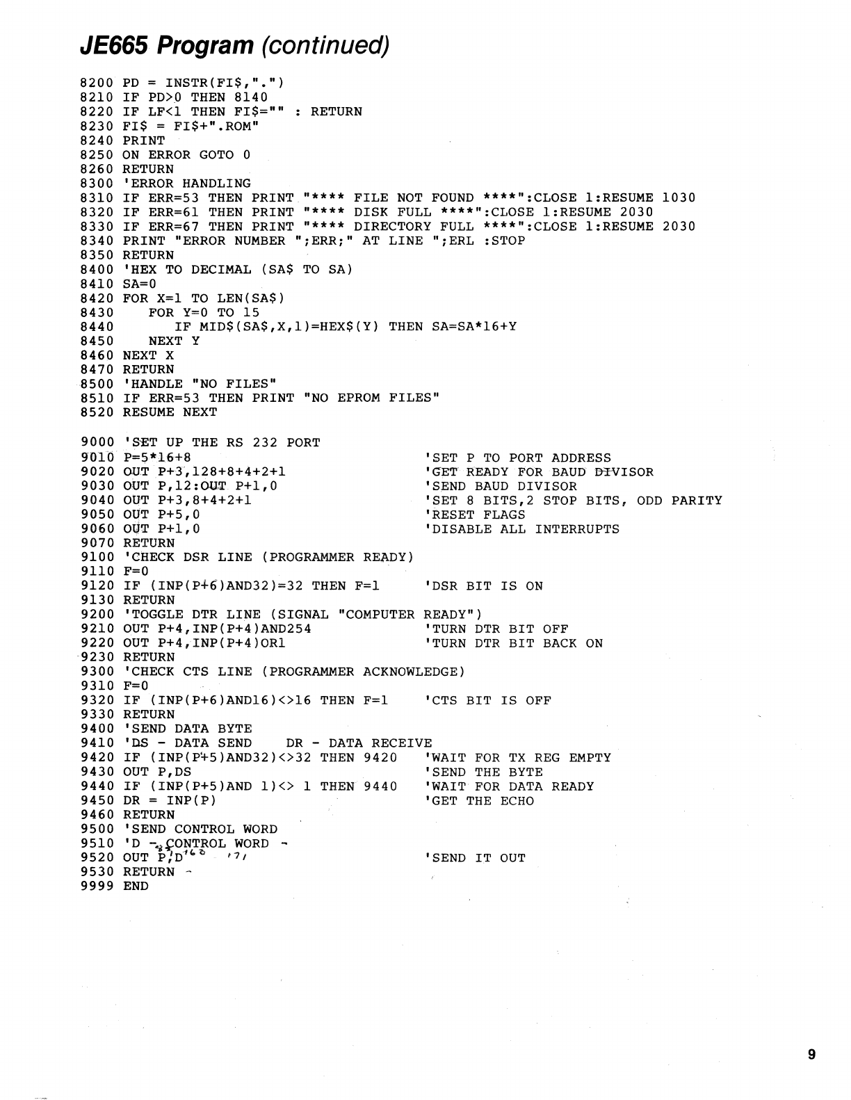
• Lines 9000 through 9070 set up the RS-232C port for the correct characteristics. They set the
baud rate to
9600,
the number
of
data bits to
8,
the number
of
stop bits to
2,
and set odd parity.
They also reset all of the flags and turn
off
any interrupt modes the port may have. Line 9010 tells
the program that the base address
of
the port chip is 58H
(88
decimal). You should change all
of
these lines
to
set up your chip. If you have
an
8250 then the only change necessary should
be
set-
ting P to the correct base address in line
9010.
Remember that these modifications need not
agree line for line
with
the sample program but only that each complete routine does its par-
ticular
task in any way possible.
Some computers may require
that
you set up the port from hardware rather than software. In this
case
it
may
be
necessary
to
move some jumpers or change a
DIP
switch or two. Instructions for
this will
be
found in your hardware manuals.
• The
DSR
(Data Set Ready) line is checked in lines 9100 to
9130.
If the
DSR
bit
is in the proper state
(1)
then F is set to
1,
otherwise
it
is set
to
O.
Line 9120 does all the work here. It checks the
DSR
bit
(bit
5)
of
the status register on the 8250 chip. To check any
bit
(0-7)
of
a register you can use the
general statement
I F
(I
N P(REGADDR) AN D
(2
A
BIT))
=
(2
A
BIT)
TH
EN
...
This will be true
if
BIT is a
1.
If you want
to
check that a bit is
0,
replace
the"
="
\/\lith a "<
>"
• Lines 9200
to
9230 toggle the
DTR
(Data Terminal Ready) line
to
0 and then back to
1.
They do this
by turning the
DTR
bit
of
the control register
off
and then back on. To turn any particular
bit
off
use the statement
OUT REGADDR,INP(REGADDR) AND (256-2 A
BIT)
and to turn any
bit
on use
OUT REGADDR,INP(REGADDR)
OR
(2A
BIT)
Change lines 9210 and 9220 to reflect your register locations and bit numbers.
• The
CTS
(Clear
to
Send)
bit
is checked in line 9320
of
the CHECK CTS LINE routine. If
it
is correct
(off) then F is set
to
1,
otherwise
it
is set to
O.
This routine starts
at
line 9300 and ends at line
9330.
Change line 9320 to reflect your
chip
address and
bit
location.
11
12
• The routine that actually sends the data over the RS·232C link is from 9400 to
9460.
DS
is the data
to be sent.
line
9420 waits for the transmitter
(TX)
buffer to be empty and then line 9430 sends
DS
to
the transmitter buffer which takes care
of
the rest
of
the transmission. Line 9340 similarly
waits for the receiver
(RX)
buffer to be full and then line
9350
reads the echoed data into
DR.
Once
again, these lines should be changed to reflect the proper addresses and bits for your chip.
• The final routine that needs to be modified is very similar to the previous routine. D is the control
word
to
be sent. It is output to the transmitter register in line
9350.
Congratulations! You have finished the modifications
to
the JE665 Program. You can now save
it
as
"JE665."
You
can then proceed to USING THE JE665 PROGRAM.
Using the JE665 Program
Now you are ready
to
begin using the JE665 and the JE665 Program. Your first step is
to
be
sure that
the JE664 Programmer is set up correctly. You should connect your RS-232C cable between the
programmer and the port on your computer.
There are two
distinct
members in an RS-232C link: the
DTE
(Data Terminal Equipment) and the
DCE
(Data Communication Equipment). They are distinguished by the locations
of
the signals on the con-
nector. Some computers
act
as
DTE
and some
act
as
DCE.
Others are hardware selectable. The JE665
is
DTE.
You must be sure
that
all
of
the signals from the computer go to the proper lines on the JE665. Check
the hardware manual for your port and
be
sure that the
DTR
signal goes to pin
20
of
the JE665,
CTS
goes
to
pin
5,
etc. You can change signals by pushing the pins out and swapping them on one end
of
the RS-232C cable. Some common signal swaps are the transmit and receive lines (pins 2 and
3)
and
the
DTR
and
DSR
lines (pins
20
and
6).
After the cable is connected with the proper lines, be sure that the programmer is plugged in and
turned on. Set the mode
switch
to
/KEYBDI
and the
IPRGM
PULSES/RS
2321
switch to
IRS-2321.
Also
be
sure the IWRITE ENABLEI
switch
is off. Now invoke the program by typing
MBASIC JE665
A log-on message will indicate that the program is initializing. Next a menu will appear asking for the
size
of
EPROM
you will be working with. This may easily
be
changed later. Press the number
of
your
choice. Now the main menu will appear. It will allow you to load data from the programmer or from
disk and
to
save data
to
the programmer or to disk. It will also allow you to view the data presently in
computer
RAM
and
to
enter new data. These options give you the flexibility to store, retrieve and
modify
EPROM
data.
For the Enter Data option, when the address appears enter the data in groups
of
two hex
digits
~Et(>arated
by spaces. Enter a blank line to return
to
the main menu. This same technique will return
you from a disk command.
The rest
of
the program is self explanatory. Simply press the letter
of
your selection and answer any
questions
that
may be asked. If an error message appears
just
press any key to return
to
the main
menu. When you are through with the program, select option X and answer Y when asked
if
you are
ready to exit.
You
have added a new dimension to using the JE664
EPROM
Programmer. We hope you enjoy this
new flexibility.
13
....
..
r----------~
-READY (OTR)
20
1 -
!'1i\13~~1~1
______________________________________________________________________________________
-.
~
+t
V
RI
CI
RIa
'Y
R4
C5
1 2
v
REC
r'((N'\
RI~
R~O
S~I
-A.JV\r
~I
J
-=-
WJ4IQ-I_J\'Y.j)'V~..JWv\r--H~
+
SV
4 3
-=-
2
.-
20
n
t_
11
140
2
1~~3~+-~
2B
I
1C4
SF
?R19
~
rr
1aue
XMTR
3
1----'5'
.~
I~
!
!,
(CTS'
AC,K
\ '/
5~
I
I
• 5B
~EADY
(oSR)
8
~
12
6 3
11
5C
, 1
J1
153.8KHz
S ERROR 4
f"
~
aF-
R21
'v
-=-
Ne
PARITY
CK
I
D4A
11
TR
,I.
t DATA
AVJ\AA
1~
,12
"Qj!!8
________
-+-
________________
-,
134383738
III
20
17
40
111
1413
18
R5V~~L;9C
R7
-=-
1A
~
-LC6
C,1i2
J\~9A
8~;~
UART
:3
-=-
,--------1f-J'Wv\-----------------_+-------4If-------------,
vv
+1
Vg;3
~
ROAR
10
~'~'~~------------------++.
+SV
~lofl---'2;:.;--~2';-:--2:O::;---T2U:-~8--2;:":,.-..;2,,..,~,...-;:;~'"""--'2~102~
lDS
sD--J
1
10
10
9_
33
32
31
30
29
26
27
26
-=-
1,----------------T-----=3~6AA
C==k..--:"'-
----'2J
~
I
~CR4'~
+
SV
>R2
a 1
I~
___
~~_+--~--+_--~_4--_+--~----~~:~~_3_AJ4
"~
~6~
7
1......--~8'
L-JI
4B
\l-_-'---+-+-++++--~
3B
alc
14
4
10
5 I
~
10
J ,----+--+-f---J
+~~~
n:
I 1B I
4 +TR
17
,~
1
11
210~3-------+--_+---+---
__
--~_+--+--4_------------~
3D
7
18
~17
91
_____
~_J---t--~--~~--_+--~--------------------~'~'~'root4~cK~IR~a~4~·~_+'~
2
~4
I
4
l.J:
15ue'P
.---
~.
60)
'1'0
.--
____
--"'-"1
3
D2
a2
"'4'--_+~---+---+-~------------+-~W-_+_+-l
~6
7">-7------l---+---+--4_--+-~~_+---+------------'
r
______
--"~4
01
U11
all!'!a'---l-' 2
__
+-.
4
7~5----_4--_+--~--+---~_+--~---+-------------~
~2
7~3------+--_+---+---+---l-_+--+--~-----------------
1
+SV
-:-'=-
8 7 • 5 4 3 I
-
CR3
12
r
6B
20
12
03
a3~
a
T8
~'
3~0
11
~
(TO
PRGM
BO
J4)
1 4
11
::::\12
11
~12lho
o
~
1'1
P
'7
12
I,V
2u.
h313J~14
13
tJ14
,"CR5
13 11
11
+SV
UART
DATA
CONN
10
..
R6
J1
a
hI
1if:]
1
If'!
Rll
+lt
SV
r:F.:l:
•
~~_r_~~~~_r--~~~~f1'~~lLt--1_r--t_~r---'v~--C~~~6~.~~
j[c3I
ca
>
+8V
8 7 • I 13 2 1
.-:~
~>
I
+5V
S
'1'C9
,1,.
-=-
-=-
,h~
~R141r
tV
,
R15;>
>R16
:>
~
JI
W
OIR
CCiz~
-r
• Rl2 • >
'"
~
-
,>
R13
-UART CONTROL CONN
1",2
__
>---,
L
___
~
1 8 8 7 7 1 I I 3
~3
______
-I-+-'-----f,
11
13
4
SG
J2
1
r-\:;Cx>·!!.-+----!.fiLJ'~~o--f.LJil~L:~:~::
L:~:
3
"f,-ll~.
I
ITO
.....
O,,,
'L[
l"
to"
~~~~~~--~~~~--~~~~--~
(FROM HEX KEYBO) 4
KEYBOARD CONN 1
tL--
________
~J3~
________
J1~2------------~
NOTES: UNLESS OTHERWISE NOTED
1. REFER TO COMPONENT MATERIAL LIST FOR FULL COMPONENT
VALUES AND DESCRIPTION.
2.
SEE ASSEMBLY DRAWING FOR PLACEMENT OF COMPONENTS.
Jl
Appendix
B -
JE665
Assembly
Drawing
and
Component
Material List
~
--04lm:r
~~<ID
-$
'----p
U----',
I
ih
P
U6
r~
®PL...---U~9
I+~~[!J
®
.~
,Cffi-
9f!1~·
~
-!IDD-
~.
PUll
I
P
~2
I CR4 h
I~CR.
-QnJ-
fC1
-
.t
~
___
u_7
__
~I~~p
___
U_l0
__
~.
~
~I--_~_-+-€)I
P U 3 I
~
~~~
_@_1
__
~_C--.R5
§ U
12
I
f.J
~I
I
-{OO-
~
2 +
7
r-----t-e_@
:
r--~--+--£I:
§--U-4--1
~
_____
U_8
________
C~~
~p--U-13~1
3
1--
__
--+--£1
5
+@
2
1--_---t-e~6
t J 1 . I
e=::::::F
J====:j2
I
~~r----t
J
3-----11
SCHEM
REF
U1
U2
U3
U4
U5
U6
U7,10,12,13
U8
U9
"\
U11
C1,4,9
C2,C6
C3,8, 10, 12,13
C5,C14
C11
CR1-CR6
TO
PRGM
BD
J4
l :
~~
FROM
-$
KEY
BD
TO
PRGM
BD
J3
DESCRIPTION QTY
IC-CD4Q.98,
DUAL
MULTIVIBRATOR
.....
1
IC-LM1'$l9,
QUAD
LINE
RECVR
.........
1
IC-CD4D11,
QUAD
NAND
GATE
.........
1
IC-CD4Q92,
DUAL
NOR
GATE
...........
1
IC-LM11,88,
QUAD
LINE
DRIVER
........
1
IC-CD4Q71, DECADE
CNT
I DIV
..........
1
IC-CD4503, TRI
HEX
BUFFER
..........
4
IC-AY-5-1013A,
UARTIC
...............
1
IC-74C14,
HEX
SCH
TRIGGER
..........
1
IC-CD4076,
QUAD
REG
1ST
.............
1
CAPACITOR,
DISC, 220PF, 50V
.........
3
CAPACITOR,
DISC, .001 MF, 50V
........
2
CAPACITOR,
TANT,
2.2MF, 35V
.........
5
CAPACITOR, DISC, 100PF, 50V
.........
2
CAPACITOR,
MICA,
240PF,
5%,
500V
....
1
DIODE, 1N4148
......................
6
SCHEM
REF
J1
R1
R2
R3,8,14
R4,7
R5
R6,
11,
15,
16,20,21
R9,12,19
R10
R13
R17
R18
Q1
DESCRIPTION QTY
CONNECTOR,
RS-232, 25-PIN, DB25S
....
1
RESISTOR, % W,
5%,
68K
.............
1.
RESISTOR,
%W,
5%,
47K
.............
1
RESISTOR, % W,
5%,
27K
.............
3
RESISTOR,
%W,
%,4.7K
..............
2
RESISTOR,
%W,5%,
18K
.............
1
RESISTOR,
%W,
5%,
10K
.............
6
RESISTOR,
%W,
5%,
100K
............
3
RESISTOR,
METAL
FILM
10K, 1 %
.......
1
RESISTOR,
%W,5%,
1K
..............
1
RESISTOR,
TRIM
POT, 1 K(840P-1K)
.....
1
RESISTOR,
%W,
%,
200K
...
.:
.........
1
TRANSISTOR,
2N2907A
...............
1
RS232 PC BOARDJE665-1
.............
1
15
NOTICE -Changes are
periodically
made to the information herein.
These,
changes
wiilbe
..
incorporated in
new
editions
of
this manual.
FOR SERVICE, SEND EQUIPMENT TO: ,
JAMECO
ELECTRONICS REPAIR CENTER, 1355 SHOREWAY ROAD, BELMONT,
CALIFORNIA
94002
PLEASE PACK SECURELY; WE SUGGEST YOU INSURE THE SHIPMENT.
