KTR Rotex Manual
User Manual: KTR Rotex Manual
Open the PDF directly: View PDF ![]() .
.
Page Count: 34
17
ROTEX®
You will find continuously updated data in our online catalogue at www.ktr.com.
ROTEX®
Torsionally flexible coupling with T-PUR®
18 You will find continuously updated data in our online catalogue at www.ktr.com.
Table of contents
ROTEX®
Torsionally flexible coupling 17
Description of coupling 19
Coupling selection 20
Displacements 22
Selection of standard IEC motors 23
Properties of standard spiders 24
Technical data of standard spiders 25
Technical data and properties of special spiders 26
Installation of spider 26
Hub designs 27
Cylindrical bores and spline bores 28
Inch bores and taper bores 29
Shaft coupling - casted materials 30
Shaft coupling - material steel 31
Shaft coupling for taper clamping bushes 32
Clamping ring hubs 33
Clamping hubs 34
Flange programme types AFN and BFN 35
Drop-out center design coupling type A-H 36
Drop-out center design coupling type S-H 37
Double cardanic type ZS-DKM-H 38
Double cardanic type DKM 39
Intermediate shaft programme type ZR 40
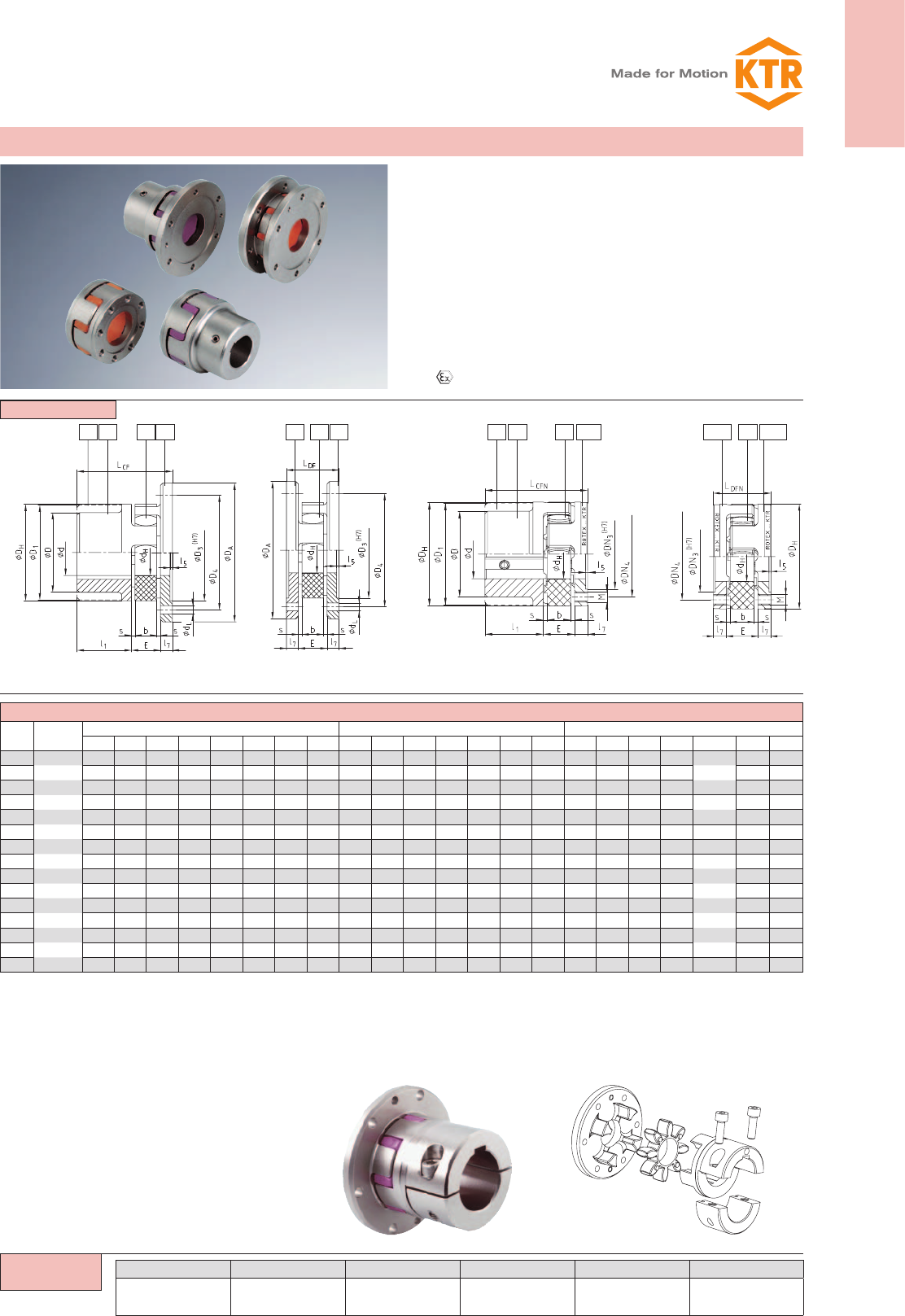
Flange programme types CF, CFN, DF and DFN 41
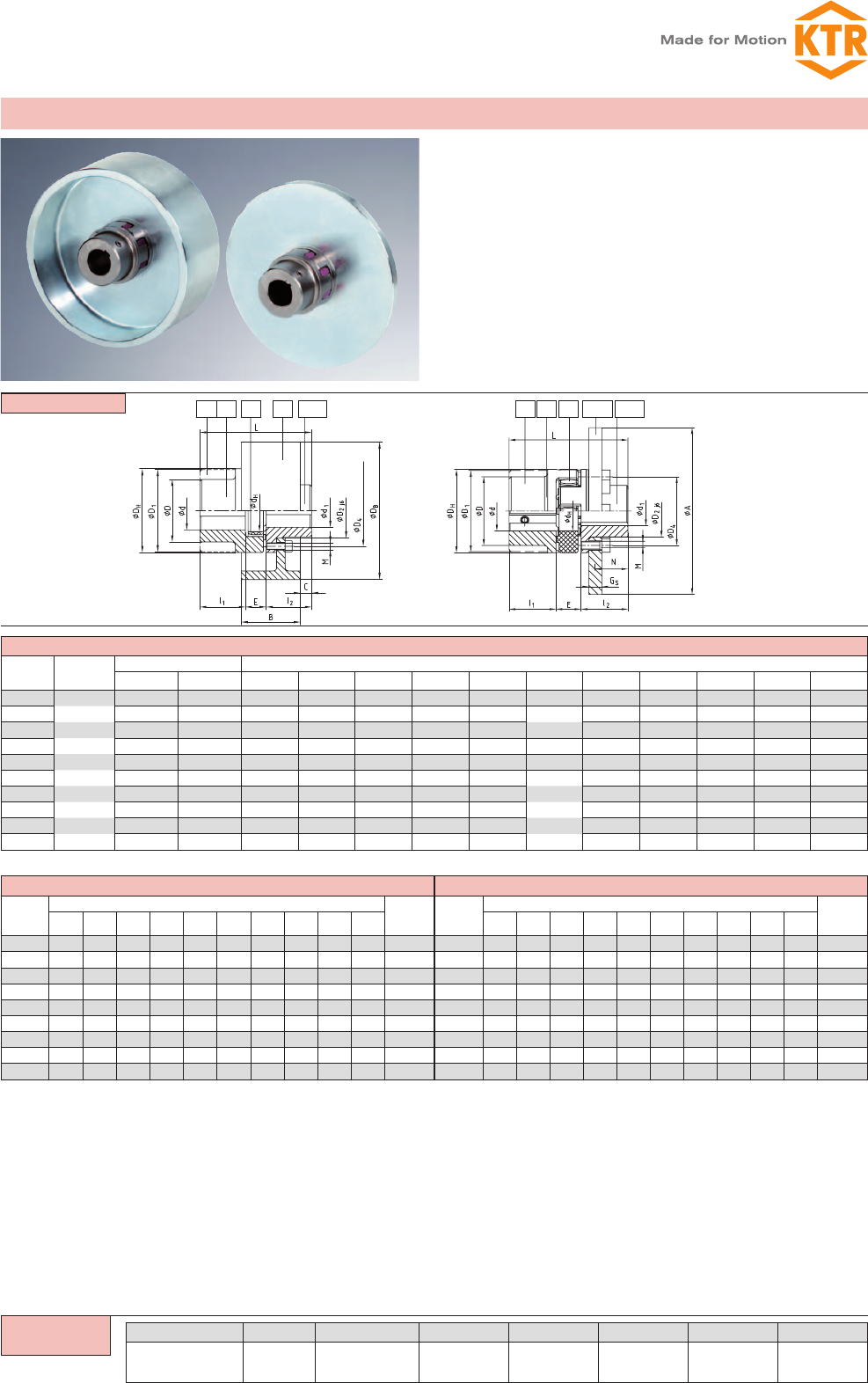
Type BTAN with brake drum/type SBAN with brake disk 42
Type AFN-SB special with brake disk 43
Type SD (shiftable at standstill) 44
Type FNN and FNN with fan 45
Further types with clamping sets 46
Further types with torque limiter 47
Weights and mass moments of inertia 48
ROTEX®
19
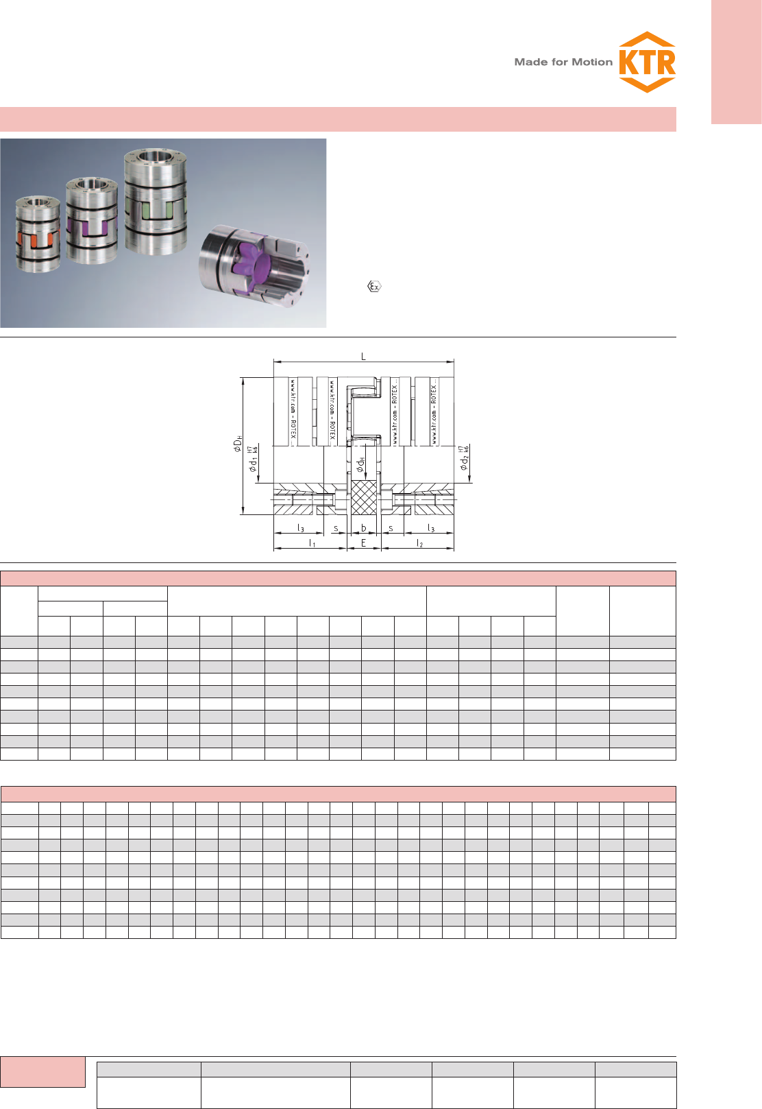
ROTEX®
Torsionally flexible coupling
You will find continuously updated data in our online catalogue at www.ktr.com.
ψ =
Spider
Standard from
size 14 - 180
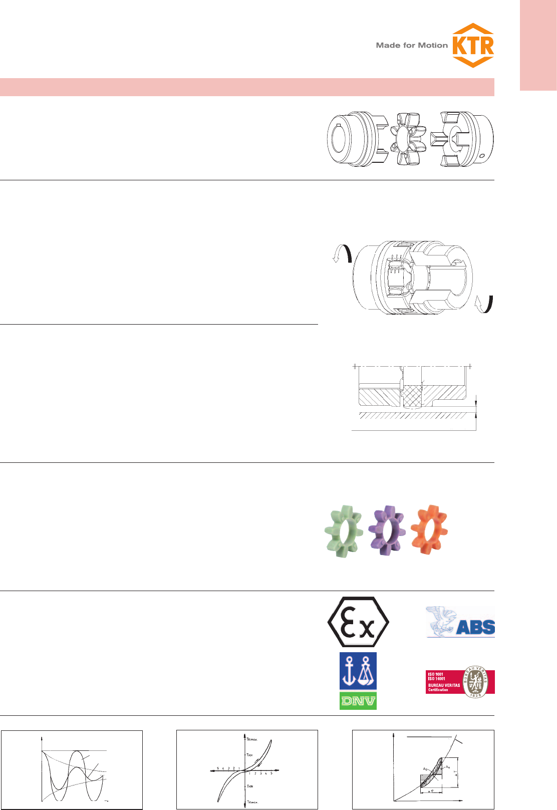
Spiders – our innovation T-PUR®
KTR has developed a new standard material for its spiders. The improved polyurethane
material T-PUR® is resistant to significantly higher temperatures and has a considerably
longer service life than the previous polyurethane material. From the visual point of view
we have characterized the material T-PUR® by the colours orange (92 Shore-A), purple
(98 Shore-A) and pale green (64 Shore-D). The previous spiders made of polyurethane
in yellow, red and natural white with green ends will still be available.
Up to size ROTEX® 180 inclusive single-parted spiders are used as a standard. Optionally
the DZ tooth elements continiue to be available for ROTEX® couplings sizes 100-180.
pressure
requested mounting space min. DH x 0,05
Deformation with load
torsion
Load on spider
Explosion-proof use
ROTEX® couplings are suitable for power transmission in drives in hazardous areas. The
couplings are certified and confirmed according to EC standard 94/9/EC (ATEX 95) as
units of category 2G/2D and thus suitable for the use in hazardous areas of zone 1, 2, 21
and 22. Please read through our information included in the respective Type Examination
Certificate and the operating and mounting instructions at www.ktr.com.
In addition to the ATEX marking an inspection certificate by DNV, Bureau Veritas or ABS
can be ordered for ROTEX® couplings.
Performance
In contrast to other flexible couplings, the intermediate members of which are subject to
bending stress and are therefore prone to earlier wear, the flexible teeth of ROTEX® cou-
plings are subject to pressure only. This gives the additional advantage of the individual
teeth being able to accept considerably higher loads. The elastomer parts show deforma-
tion with load and excessive speeds. Sufficient space for expansion should be ensured
(see drawing – deformation with load).
The maximum torsion angle with ROTEX® couplings of any size amounts to 5°. They can
be fitted both horizontally and vertically.
General description
ROTEX® couplings are torsionally flexible and designed for positive torque transmission.
They are fail-safe. Operational vibrations and shocks are efficiently dampened and re-
duced. The two congruent coupling halves with concave claws on the inside are periphally
offset in relation to one another by half a pitch. In addition, they are designed in such a
way as to enable an involute spider to be located between them.
The teeth of the spider are crowned to avoid edge pressure if the shafts are misaligned.
ROTEX® couplings are capable of compensating for axial, radial and angular
displacements of the shafts to be connected.
ROTEX®couplings are characterized by small dimensions, low weight and low mass
moments of inertia yet transmit high torques. Running quality and service life of the coupling
are improved by accurate all-over machining.
Their application is ideal for transmitting torque while damping torsional
vibrations and absorbing shocks produced by the uneven operation of certain
prime movers.
Description of coupling
torsion
period
Comparison of loads Twisting angle Damping
torque T
w/o damping
with damping
twisting angle φ
twisting angle φ
Damping operation [AD]
torque T
dyn. charact.
curve CTdyn
operating point
stat. charact.
curve
CTstat.
torque T
Flex. deformation [Ae]
operation
20
ROTEX®
Torsionally flexible coupling
You will find continuously updated data in our online catalogue at www.ktr.com.
Description Symbol Definition or explanation
Rated torque of
coupling TKN Torque that can continuously be transmitted
over the entire permissible speed range
Maximum torque of
coupling TK max
Torque that can be transmitted as dynamic load ≥ 105
times or 5 x 10⁴ as vibratory load, respectively, during
the entire operating life of the coupling
Vibratory torque of
coupling TKW
Torque amplitude of the permissible periodical torque
fluctuation with a frequency of 10 Hz and a basic load
of TKN or dynamic load up to TKN, respectively
Damping power of
coupling PKW Permissible damping power with an Pambient tem-
perature of + 30 °C.
Rated torque of machine TNStationary rated torque on the coupling
Rated torque of driving
side TAN Rated torque of machine, calculated from rated power
and rated speed
Rated torque of load
side TLN Maximum figure of the load torque calculated from
power and speed
Peak torque of machine TSPeak torque on the coupling
Peak torque on the
driving side TAS Peak torque with torque shock on the driving side, e.
g. breakdown torque of the electric motor
Description Symbol Definition or explanation
Peak torque of load side TLS Peak torque with torque shock on load side, e. g.
braking
Vibratory torque of
machine TWAmplitude of the vibratory torque effective on the
coupling
Damping power of the
machine PWDamping power which is effective on the coupling due
to the load produced by the vibratory torque
Moment of inertia of
driving side JATotal of moments of inertia existing on the driving or
load side referring to the coupling speed
Moment of inertia of
load side JL
Rotational inertia coef-
ficient of driving side MAFactor taking into account the mass distribution with
shocks and vibrations produced on the driving or
load side
MA = JL / (JA + JL) ML = JA / (JA + JL)
Rotational inertia coef-
ficient of load side ML
Screw tightening torque TATightening torque of screw
The shaft-hub-connection has to be verified by the customer. Per-
missible surface pressure according to DIN 6892 (method C).
Cast iron GJL 225 N/mm²
Nodular iron GJS 225 N/mm²
Steel 250 N/mm²
The ROTEX® coupling is selected in accordance with DIN 740 part 2. The coupling has to be dimensioned in a way that the permissible coupling
load is not exceeded in any operating condition. For this purpose the actual loads have to be compared to the permissible parameters of the
coupling. The torques TKN/TKmax mentioned refer to the spider. The shaft-hub-connection has to be investigated by the customer.
1. Drives without periodical torsional vibrations
e. g. centrifugal pumps, fans, screw compressors, etc.The coupling
is selected taking into account the rated torques TKN and maximum
torque TK max.
1.1 Load produced by rated torque
Taking into consideration the ambi-
ent temperature, the permissible rated
torque TKN of the coupling has to cor-
respond at least to the rated torque
TN.of the machine.
1.2 Load produced by torque shocks
The permissible maximum torque of the
coupling has to correspond at least to
the total of peak torque TS and the
rated torque TN of the machine, taking
into account the shock frequency Z and
the ambient temperature. This applies
in case if the rated torque TN of the
machine is at the same time subject to
shocks. Knowing the mass distribution, shock direction and shock mode,
the peak torque TS can be calculated. For drives with
A. C.-motors with high masses on the load side we
would recommend to calculate the peak driving torque with the
help of our simulation programme.
TN [Nm] = 9550 P [kW] / n [rpm]
TKN ≥ TN St
TK max ≥ TS Sz St + TN St
Drive-sided shock
TS = TAS MA SA
Load-sided shock
TS = TLS ML SL
MA = JL / (JA+JL) MA = JL / (JA+JL)
Coupling selection
2. Drives with periodical torsional vibrations
For drives subject to high torsional vibrations, e.g. diesel engines,
piston compressors, piston pumps, generators, etc., it is necessary to
perform a torsional vibration calculation to ensure a safe operation. If
requested, we perform the torsional vibration calculation and the
coupling selection in our company. For necessary details please
see KTR standard 20004.
2.1 Load produced by rated torque
Taking into account the ambi-
ent temperature, the permissible
rated torque TKN of the coupling has to correspond at
least to the rated torque TN of the machine.
2.2 Passing through the resonance
range
Taking into account the temperature,
the peak torque TS arising when the resonance range is run through
must not exceed the maximum torque TKmax of the coupling.
2.3 Load produced by vibratory torque shocks
Taking into account the ambient
temperature, the permissible vibra-
tory torque TKW of the coupling
must not be exceeded by the high-
est periodical vibratory torque TW with operating speed. For
higher operating frequencies f > 10, the heat produced by
damping in the elastomer part is considered as damping power
PW. For higher operating frequencies f > 10, the heat produced by
damping in the elastomer part is considered as damping power
PW.
TKN ≥ TN St
TK max. ≥ TS St
TKW ≥ TW St
PKW ≥ PW
Permissible load on feather key of the coupling hub
ROTEX®
21
ROTEX®
Torsionally flexible coupling
You will find continuously updated data in our online catalogue at www.ktr.com.
Service SZ factor for starting frequency
starting
frequency/h 100 200 400 800
SZ1,0 1,2 1,4 1,6
Service factor SA/SL for shocks
SA/SL
gentle shocks 1,5
average shocks 1,8
heavy shocks 2,5
Service factor temperature St
-50 °C -30 °C
+30 °C +40 °C +50 °C +60 °C +70 °C +80 °C +90 °C +100 °C +110 °C +120 °C
T-PUR®1,0 1,0 1,1 1,2 1,3 1,45 1,6 1,8 2,1 2,5 3,0
PUR – 1,0 1,2 1,3 1,4 1,55 1,8 2,2 – – –
For the selection with PEEK spider a temperature factor is not necessary.
For temperature factors for PA spiders see page 26.
Coupling selection
Example of calculation of standard IEC motors shown on page 23:
Given: Details of driving side
A. C. motor type: 315 L SA =1,8
Motor output: P = 160 kW
Speed: n = 1485 rpm
Moment of inertia of driving side: JA = 2,9 kgm2
Start-up frequency: z = 6 1/h SZ =1,0
Ambient temperature: = + 70 °C St =1,45 using T-PUR®
Given: Details of load side
Screw compressor
Rated torque of load side: TLN = 930 Nm
Moment of inertia of load side: JL = 6,8 kgm2
Calculation TAN [Nm] = 9550 PAN [kW] / nAN [rpm]
zl Rated driving torque TAN [Nm] = 9550 160 [kW] / 1485 [rpm] = 1029 Nm
Coupling selection: TKN ≥ TLN St
zl Load produced by rated torque TKN ≥ 930 Nm 1,45 = 1348,5 Nm
Selected:
ROTEX® Size 90 - spider 92 Shore A with:
TKN = 2400 Nm
TK max. = 4800 Nm
zLoad produced by torque shocks
TK max. ≥ TS Sz St
MA= JL / (JA + JL) = (6,8 kgm² + 0,0673 kgm²) / (2,9 kgm² + 0,0673 kgm² + 6,8 kgm² + 0,0673 kgm²)
Drive-sided shock
TS = TAS MA SA
zDriving torque TAS = 2,0 TAN = 2,0 1029 Nm = 2058 Nm
TS = 2058 Nm 0,7 1,8 = 2593,1 Nm
TK max. ≥ 2593,1 Nm 1 1,45 = 3670 Nm
TK max. with 4800 Nm ≥ 3760 Nm
22
ROTEX®
Torsionally flexible coupling
You will find continuously updated data in our online catalogue at www.ktr.com.
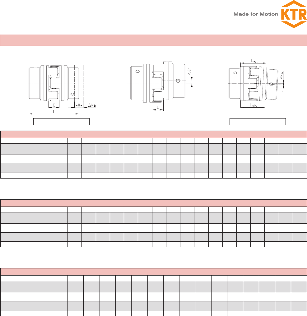
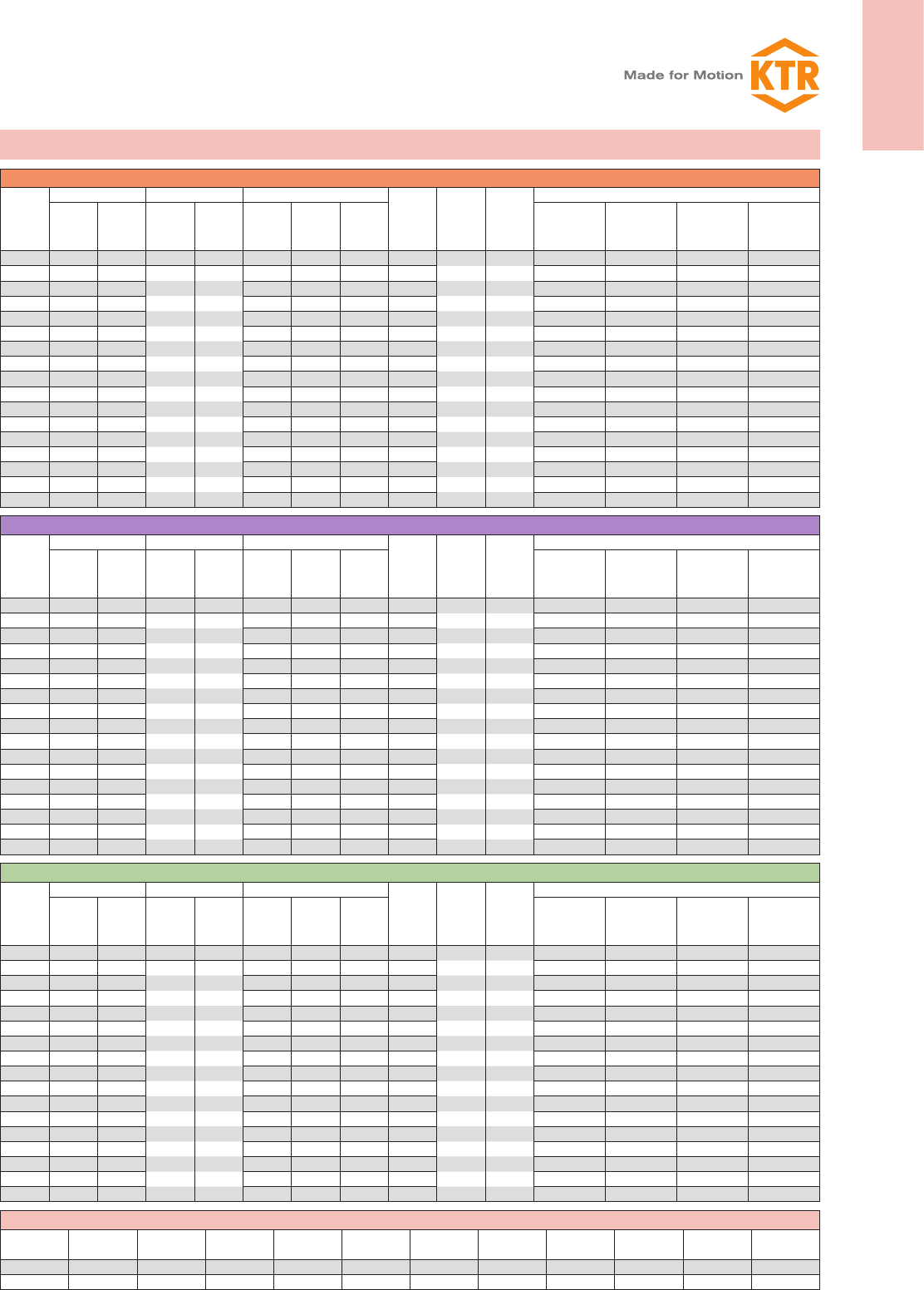
Displacements for spider 92, 95/98 Shore-A
ROTEX® size 14 19 24 28 38 42 48 55 65 75 90 100 110 125 140 160 180
Max. axial displacement ΔKa [mm] -0,5 -0,5 -0,5 -0,7 -0,7 -1,0 -1,0 -1,0 -1,0 -1,5 -1,5 -1,5 -2,0 -2,0 -2,0 -2,5 -3,0
+1,0 +1,2 +1,4 +1,5 +1,8 +2,0 +2,1 +2,2 +2,6 +3,0 3,4 +3,8 +4,2 +4,6 +5,0 +5,7 +6,4
Max. radial displacement with
n=1500 rpm ΔKr [mm] 0,17 0,20 0,22 0,25 0,28 0,32 0,36 0,38 0,42 0,48 0,50 0,52 0,55 0,60 0,62 0,64 0,68
Max. angular displacement with
n= 1500 RPM ΔKw [degree] 1,2 1,2 0,9 0,9 1,0 1,0 1,1 1,1 1,2 1,2 1,2 1,2 1,3 1,3 1,2 1,2 1,2
∆Kw [mm] 0,67 0,82 0,85 1,05 1,35 1,70 2,00 2,30 2,70 3,30 4,30 4,80 5,60 6,50 6,60 7,60 9,00
Displacements for spider 64 Shore-D
ROTEX® size 14 19 24 28 38 42 48 55 65 75 90 100 110 125 140 160 180
Max. axial displacement ΔKa [mm] -0,5 -0,5 -0,5 -0,7 -0,7 -1,0 -1,0 -1,0 -1,0 -1,5 -1,5 -1,5 -2,0 -2,0 -2,0 -2,5 -3,0
+1,0 +1,2 +1,4 +1,5 +1,8 +2,0 +2,1 +2,2 +2,6 +3,0 +3,4 +3,8 +4,2 +4,6 +5,0 +5,7 +6,4
Max. radial displacement with
n=1500 rpm ΔKr [mm] 0,11 0,13 0,15 0,18 0,21 0,23 0,25 0,27 0,30 0,34 0,36 0,37 0,40 0,43 0,45 0,46 0,49
Max. angular displacement with
n= 1500 RPM ΔKw [degree] 1,1 1,1 0,8 0,8 0,9 0,9 1,0 1,0 1,1 1,1 1,1 1,1 1,2 1,2 1,1 1,1 1,1
∆Kw [mm] 0,57 0,76 0,76 0,90 1,25 1,40 1,80 2,00 2,50 3,00 3,80 4,30 5,30 6,00 6,10 7,10 8,00
Displacements for spider PA, PEEK
ROTEX® size 14 19 24 28 38 42 48 55 65 75 90 100 110 125 140
Max. axial displacement ΔKa [mm] -0,5 -0,5 -0,5 -0,7 -0,7 -1,0 -1,0 -1,0 -1,0 -1,5 -1,5 -1,5 -2,0 -2,0 -2,0
+1,0 +1,2 +1,4 +1,5 +1,8 +2,0 +2,1 +2,2 +2,6 +3,0 +3,4 +3,8 +4,2 +4,6 +5,0
Max. radial displacement with
n=1500 RPM ΔKr [mm] 0,08 0,10 0,11 0,12 0,14 0,16 0,18 0,19 0,21 0,24 0,25 0,26 0,27 0,30 0,31
Max. angular displacement with
n= 1500 rpm ΔKw [degree] 0,60 0,45 0,45 0,50 0,50 0,55 0,55 0,55 0,60 0,60 0,60 0,60 0,65 0,65 0,60
∆Kw [mm] 0,33 0,41 0,42 0,52 0,67 0,85 1,00 1,15 1,35 1,65 2,15 2,40 2,80 3,25 3,30
Lmax. = L + ∆Ka ∆Kw [mm] = Lmax – Lmin
The above-mentioned figures of displacement of flexible ROTEX® couplings are standard values taking into account the load of the coupling
up to the rated torque TKN and an operating speed n = 1500 rpm along with an ambient temperature of + 30° C.
The displacement figures may only be used individually - if they arise simultaneously, they must be used proportionately. Care should be
taken to maintain the distance dimension E accurately in order to allow for axial clearance of the coupling while in operation. Detailed mount-
ing instructions are shown on our homepage (www.ktr.com).
Angular displacement ΔKw [degrees]
Radial displacement ΔKrAxial displacement ΔKa
Displacements
ROTEX®
23
ROTEX®
Torsionally flexible coupling
You will find continuously updated data in our online catalogue at www.ktr.com.
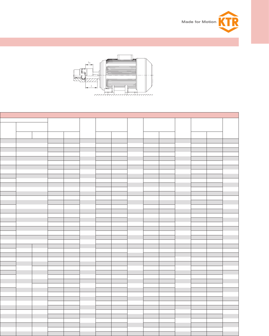
ROTEX® couplings for standard IEC motors, protection class IP 54/IP 55 (spider 92 Shore A)
A. C. motor 50 Hz Motor output
n = 3000 rpm
2-pole
ROTEX®
coupling
size
Motor output
n = 1500 rpm
4-pole
ROTEX®
coupling
size
Motor output
n = 1000 rpm
6-pole ROTEX®
coupling
size
Motor output
n = 750 rpm
8-pole
ROTEX®
coupling
size
Size
Shaft end dxl [mm]
2-pole 4, 6, 8 pole Output P
[kW]
Torque
T[Nm]
Output P
[kW]
Torque
T[Nm]
Output P
[kW]
Torque
T[Nm]
Output P
[kW]
Torque
T[Nm]
56 9 x 20 0,09 0,32 9 1) 0,06 0,43 9 1) 0,037 0,43 9 1)
0,12 0,41 0,09 0,64 0,045 0,52
63 11 x 23 0,18 0,62
14
0,12 0,88
14
0,06 0,7
14
0,25 0,86 0,18 1,3 0,09 1,1
71 14 x 30 0,37 1,3 0,25 1,8 0,18 2 0,09 1,4 14
0,55 1,9 0,37 2,5 0,25 2,8 0,12 1,8
80 19 x 40 0,75 2,5
19
0,55 3,7
19
0,37 3,9
19
0,18 2,5
19
1,1 3,7 0,75 5,1 0,55 5,8 0,25 3,5
90S 24 x 50 1,5 5 1,1 7,5 0,75 8 0,37 5,3
90L 2,2 7,4 1,5 10
24
1,1 12
24
0,55 7,9
24
100L 28 x 60 3 9,8 24
2,2 15 1,5 15 0,75 11
3 20 1,1 16
112M 4 13 4 27 2,2 22 1,5 21
132S
38 x 80
5,5 18
28
5,5 36
28
3 30
28
2,2 30
28
7,5 25
132M 7,5 49 4 40 3 40
5,5 55
160M 42 x 110
11 36
38
11 72
38 7,5 75 38
4 54
38
15 49 5,5 74
160L 18,5 60 15 98 11 109 7,5 100
180M 48 x 110 22 71
42
18,5 121
42 42 42
180L 22 144 15 148 11 145
200L 55 x 110 30 97 30 196 18,5 181 15 198
37 120 22 215
225S 55 x 110 60 x 140 37 240 48 18,5 244 48
225M 45 145 45 292 55 30 293 55 22 290 55
250M 60 x 140 65 x 140 55 177 48 55 356 37 361 65 2) 30 392 65
280S
65 x 140
75 x 140 75 241 55 75 484 65 2) 45 438 37 483 65 2)
280M 90 289 90 581
75
55 535
75
45 587 75
315S
80 x 170
110 353
65
110 707 75 727 55 712
315M 132 423 132 849 90 873 75 971
90
315L
160 513 160 1030
90
110 1070
90
90 1170
200 641
75
200 1290 132 1280 110 1420
85 x 170
160 1550 132 1710
315 250 802 250 1600 200 1930 160 2070
100
315 1010
90
315 2020
100
250 2410 100 200 2580
355 75 x 140 95 x 170
355 1140 355 2280
400 1280 400 2570 315 3040 110 250 3220 110
500 1600 500 3210 110 400 3850 125 315 4060 125
400 80 x 170 110 x 210
560 1790 560 3580 125 450 4330 355 4570
140
630 2020
100
630 4030 500 4810
140
400 5150
710 2270 710 4540
140
560 5390 450 5790
450 90 x 170 120 x 210
800 2560 800 5120 630 6060 500 6420
160
900 2880 110 900 5760 710 6830 160 560 7190
1000 3200 1000 6400 160 800 7690 630 8090
Standard
or large hub
Large hub lengthened
The arrangement of couplings is valid for an ambient temperature of up to + 30 °C.For the selection there is a minimum safety fac-
tor of 2 of the max. coupling torque (TKmax.). A detailed arrangement is possible according to catalogue, page 20 and 21. Drives
with periodical torque curves must be selected according to DIN 740 part 2. If requested, KTR will perform the selection.
Torque T = rated torque according to Siemens catalogue M 11 · 1994/95..
1) For dimensions see ROTEX® GS line
2) Motor hub from steel see page 31
Selection of standard IEC motors
24
ROTEX®
Torsionally flexible coupling
You will find continuously updated data in our online catalogue at www.ktr.com.
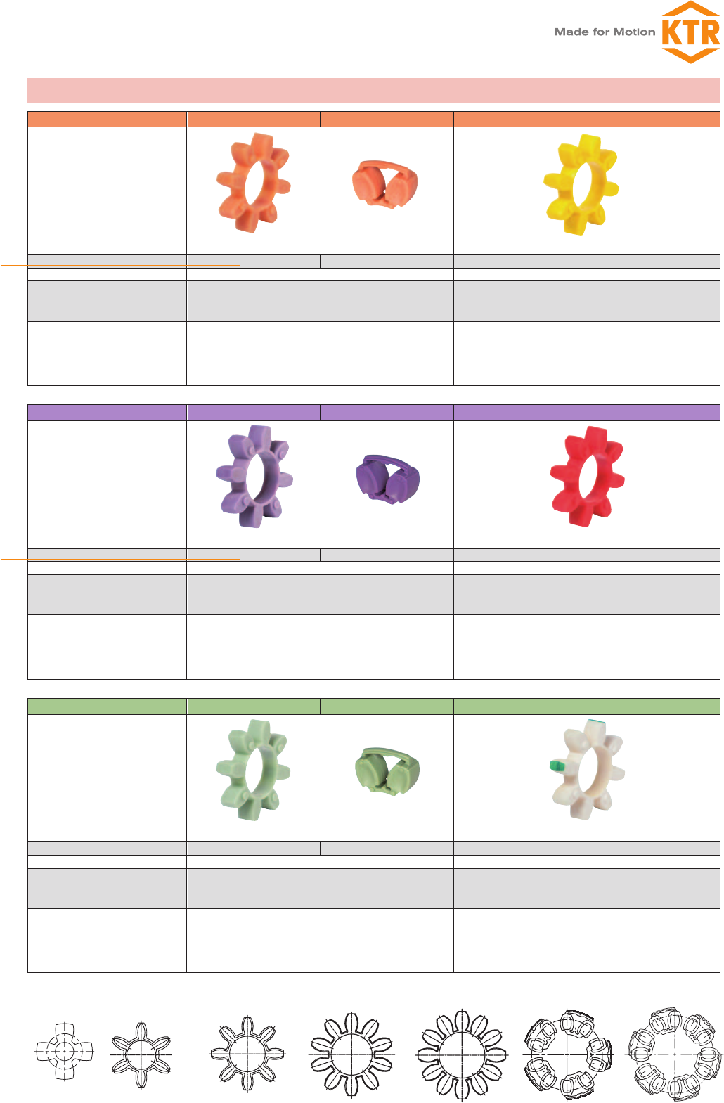
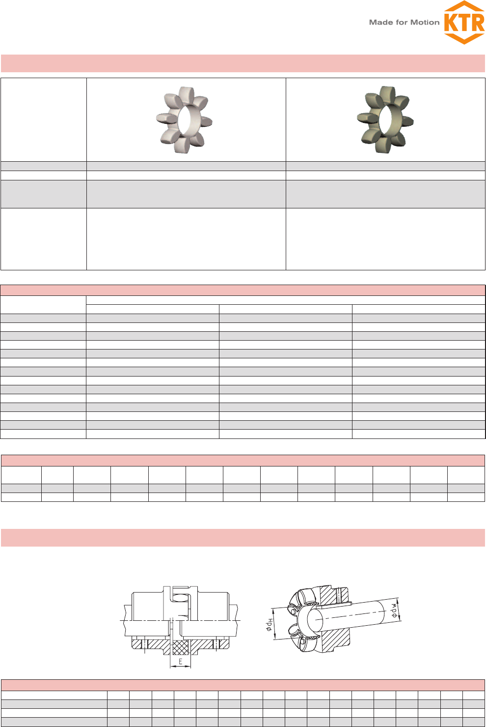
Spider type (hardness Shore) 92 Shore-A (T-PUR®) DZ 92 Shore-A (T-PUR®) 92 Shore-A
Innovation T-PUR®
Size 14 to 180 100 to 180 14 to 90
Material T-PUR®Polyurethane (PUR)
Perm. temperature range
Continuous temperature
Max. temperature short time
-50 °C to +120 °C
-50 °C to +150 °C
-40 °C to +90 °C
-50 °C to +120 °C
Properties
– significantly longer service life
– very good temperature resistance
– improved damping of vibrations
– good damping, average elasticity
– suitable for all hub materials
– good damping, average elasticity
– suitable for all hub materials
NEW
Spider type (hardness Shore) 98 Shore-A (T-PUR®) 1) DZ 95 Shore-A (T-PUR®) 98 Shore-A 1)
Innovation T-PUR®
Size 14 to 180 100 to 180 14 to 90
Material T-PUR®Polyurethane (PUR)
Perm. temperature range
Continuous temperature
Max. temperature short time
-50 °C to +120 °C
-50 °C to +150 °C
-30 °C to +90 °C
-40 °C to +120 °C
Properties
– significantly longer service life
– very good temperature resistance
– improved damping of vibrations
– transmission of high torques with average damping
– recommended hub material: steel, GJL and GJS
– transmission of high torques with average damping
– recommended hub material: steel, GJL and GJS
NEW
Spider type (hardness Shore) 64 Shore-D (T-PUR®) DZ 64 Shore-D (T-PUR®) 64 Shore-D
Innovation T-PUR®
Size 14 to 180 100 to 180 14 to 90
Material T-PUR®Polyurethane (PUR)
Perm. temperature range
Continuous temperature
Max. temperature short time
-50 °C to +120 °C
-50 °C to +150 °C
-30 °C to +110 °C
-30 °C to +130 °C
Properties
– significantly longer service life
– very good temperature resistance
– improved damping of vibrations
– transmission of high torques with average damping
– recommended hub material: steel, GJL and GJS
– transmission of very high torques with low damping
– suitable for displacing critical speeds
– resistant to hydrolysis
– recommended hub material: steel and GJS
NEW
ROTEX® 19ROTEX® 14 ROTEX® 24 - 65 ROTEX® 75 - 160 ROTEX® 180 ROTEX® DZ 100 - 160 ROTEX® DZ 180
Properties of our standard spiders
1) from size 75: 95Sh-A
ROTEX®
25
ROTEX®
Torsionally flexible coupling
You will find continuously updated data in our online catalogue at www.ktr.com.
Spider 92 Shore-A made of T-PUR® and PUR
ROTEX®
size
Max. speed Twist angle φ with Torque [Nm] Damping
power
PKW
[W] 1)
Relative
damping ψ
Resonance
factor VR
Torsion spring stiffness C dyn. [Nm/rad]
V=35 m/s
cast iron
V=40 m/s
steel TKN TK max Rated
(TKN)
Max
(TK max)
Vibratory
(TKW)1,0 TKN 0,75 TKN 0,5 TKN 0,25 TKN
14 22200 25400 6,4° 10° 7,5 15 2,0 –
0,80 7,90
0,38x1030,31x1030,24x1030,14x103
19 16700 19000
3,2° 5°
10 20 2,6 4,8 1,28x1031,05x1030,80x1030,47x103
24 12100 13800 35 70 9,1 6,6 4,86x1033,98x1033,01x1031,79x103
28 10100 11500 95 190 25 8,4 10,90x1038,94x1036,76x1034,01x103
38 8300 9500 190 380 49 10,2 21,05x10317,26x10313,05x1037,74x103
42 7000 8000 265 530 69 12,0 23,74x10319,47x10314,72x1038,73x103
48 6350 7250 310 620 81 13,8 36,70x10330,09x10322,75x10313,49x103
55 5550 6350 410 820 107 15,6 50,72x10341,59x10331,45x10318,64x103
65 4950 5650 625 1250 163 18,0 97,13x10379,65x10360,22x10335,70x103
75 4150 4750 1280 2560 333 21,6 113,32x10392,92x10370,26x10341,65x103
90 3300 3800 2400 4800 624 30,0 190,09x103155,87x103117,86x10369,86x103
100 2950 3350 3300 6600 858 36,0 253,08x103207,53x103156,91x10393,01x103
110 2600 2950 4800 9600 1248 42,0 311,61x103255,52x103193,20x103114,52x103
125 2300 2600 6650 13300 1729 48,0 474,86x103389,39x103294,41x103174,51x103
140 2050 2350 8550 17100 2223 54,6 660,49x103541,60x103409,50x103242,73x103
160 1800 2050 12800 25600 3328 75,0 890,36x103730,10x103552,03x103327,21x103
180 1550 1800 18650 37300 4849 78,0 2568,56x1032106,22x1031592,51x103943,95x103
95/98 Shore-A spider made of T-PUR® and PUR 2)
ROTEX®
size
Max. speed Twist angle φ with Torque [Nm] Damping
power
PKW
[W] 1)
Relative
damping ψ
Resonance
factor VR
Torsion spring stiffness C dyn. [Nm/rad]
V=35 m/s
iron
V=40 m/s
steel TKN TK max Rated
(TKN)
Max
(TKmax)
Vibratory
(TKW)1,0 TKN 0,75 TKN 0,5 TKN 0,25 TKN
14 22200 25400 6,4° 10° 12,5 25 3,3 –
0,80 7,90
0,56x1030,46x1030,35x1030,21x103
19 16700 19000
3,2° 5°
17 34 4,4 4,8 2,92x1032,39x1031,81x1031,07x103
24 12100 13800 60 120 16 6,6 9,93x1038,14x1036,16x1033,65x103
28 10100 11500 160 320 42 8,4 26,77x10321,95x10316,60x1039,84x103
38 8300 9500 325 650 85 10,2 48,57x10339,83x10330,11x10317,85x103
42 7000 8000 450 900 117 12,0 54,50x10344,69x10333,79x10320,03x103
48 6350 7250 525 1050 137 13,8 65,29x10353,54x10340,48x10324,00x103
55 5550 6350 685 1370 178 15,6 94,97x10377,88x10358,88x10334,90x103
65 4950 5650 940 1880 244 18,0 129,51x103106,20x10380,30x10347,60x103
75 4150 4750 1920 3840 499 21,6 197,50x103161,95x103122,45x10372,58x103
90 3300 3800 3600 7200 936 30,0 312,20x103256,00x103193,56x103114,73x103
100 2950 3350 4950 9900 1287 36,0 383,26x103314,27x103237,62x103140,85x103
110 2600 2950 7200 14400 1872 42,0 690,06x103565,85x103427,84x103253,60x103
125 2300 2600 10000 20000 2600 48,0 1343,64x1031101,79x103833,06x103493,79x103
140 2050 2350 12800 25600 3328 54,6 1424,58x1031168,16x103883,24x103523,54x103
160 1800 2050 19200 38400 4992 75,0 2482,23x1032035,43x1031538,98x103912,22x103
180 1550 1800 28000 56000 7280 78,0 3561,45x1032920,40x1032208,10x1031308,84x103
Spider 64 Shore-D made of T-PUR® and PUR
ROTEX®
size
Max. speed Twist angle φ with Torque [Nm] Damping
power
PKW
[W] 1)
Relative
damping ψ
Resonance
factor VR
Torsion spring stiffness C dyn. [Nm/rad]
V=35 m/s
iron
V=40 m/s
steel TKN TK max Rated
(TKN)
Max
(TKmax)
Vibratory
(TKW)1,0 TKN 0,75 TKN 0,5 TKN 0,25 TKN
14 22200 25400 4,5° 7,0° 16 32 4,2 9,0
0,75 8,50
0,76x1030,62x1030,47x1030,28x103
19 16700 19000
2,5° 3,6°
21 42 5,5 7,2 5,35x1034,39x1033,32x1031,97x103
24 12100 13800 75 150 19,5 9,9 15,11x10312,39x1039,37x1035,55x103
28 10100 11500 200 400 52 12,6 27,52x10322,57x10317,06x10310,12x103
38 8300 9500 405 810 105 15,3 70,15x10357,52x10343,49x10325,78x103
42 7000 8000 560 1120 146 18,0 79,86x10365,49x10349,52x10329,35x103
48 6350 7250 655 1310 170 20,7 95,51x10378,32x10359,22x10335,10x103
55 5550 6350 825 1650 215 23,4 107,92x10388,50x10366,91x10339,66x103
65 4950 5650 1175 2350 306 27,0 151,09x103123,90x10393,68x10355,53x103
75 4150 4750 2400 4800 624 32,4 248,22x103203,54x103153,90x10391,22x103
90 3300 3800 4500 9000 1170 45,0 674,52x103553,11x103418,20x103247,89x103
100 2950 3350 6185 12370 1608 54,0 861,17x103706,16x103533,93x103316,48x103
110 2600 2950 9000 18000 2340 63,0 1138,59x103933,64x103705,92x103418,43x103
125 2300 2600 12500 25000 3250 72,0 1435,38x1031177,01x103889,93x103527,50x103
140 2050 2350 16000 32000 4160 81,9 1780,73x1031460,20x1031104,05x103654,42x103
160 1800 2050 24000 48000 6240 112,5 3075,80x1032522,16x1031907,00x1031130,36x103
180 1550 1800 35000 70000 9100 117,0 6011,30x1034929,27x1033727,01x1032209,15x103
Temperature factor St
-50 °C -30 °C
+30 °C +40 °C +50 °C +60 °C +70 °C +80 °C +90 °C +100 °C +110 °C +120 °C
T-PUR®1,0 1,0 1,1 1,2 1,3 1,45 1,6 1,8 2,1 2,5 3,0
PUR – 1,0 1,2 1,3 1,4 1,55 1,8 2,2 – – –
Technical data of our standard spiders
Unless explicitly specified in your order, we will supply spiders with Shore hardness 92 Sh-A T-PUR®.
For circumferential speeds exceeding V = 30 m/s dynamic balancing is necessary. For circumferential speeds exceeding V = 35 m/s only steel or nodular iron.
1) with +30 °C
2) from size 65 on: 95 Sh-A
26
ROTEX®
Torsionally flexible coupling
You will find continuously updated data in our online catalogue at www.ktr.com.
Spider type PA PEEK
Material Polyamide Polyetheretherketone
Perm. temperature range
Continuous temperature
Max. temperature short time
-20 °C to +130 °C 1)
-30 °C to +150 °C 1)
up to +180 °C (ATEX to +160 °C)
up to +250 °C
Properties
– low twisting angles and high torsion spring stiffness
– transmission of very high torques with very low damping
– good resistance to chemicals 1)
– recommended hub material: steel
– high restoring forces with displacements
– low twisting angle and high torsion spring stiffness
– transmission of very high torques with very low damping
– highly temperature-resistant, resistant to hydrolysis
– good resistance to chemicals
– recommended hub material: steel
– high restoring forces with displacements
Service factor temperature St
-50 °C -30 °C
+30 °C +40 °C +50 °C +60 °C +70 °C +80 °C +90 °C +100 °C +110 °C +120 °C +180 °C
PA – 1,0 1,15 1,25 1,4 1,6 1,9 2,3 3,0 – – –
PEEK – 1,0 1,0 1,0 1,0 1,0 1,0 1,0 1,0 1,0 1,0 1,0
Torques
PA, PEEK
TKN [Nm] TK max [Nm] TKW [Nm]
14 22 44 5,5
19 30 60 8,0
24 105 210 27,5
28 280 560 73
38 565 1130 147
42 785 1570 204
48 915 1830 238
55 1200 2400 312
65 1645 3290 427
75 2560 5130 667
90 6300 12600 1640
100 8650 17300 2250
110 10500 21000 2730
125 13000 26000 3380
Mounting dimension
ROTEX® size 14 19 24 28 38 42 48 55 65 75 90 100 110 125 140 160 180
Distance dimension E 13 16 18 20 24 26 28 30 35 40 45 50 55 60 65 75 85
Dimension dH10 18 27 30 38 46 51 60 68 80 100 113 127 147 165 190 220
Dimension dW 2) 7 12 20 22 28 36 40 48 55 65 80 95 100 120 135 160 185
Technical data and properties of the special spiders
1) Different properties depending on compound
Shaft ØdWwith feather key (acc. to DIN 6885 sh.1) protruding into the spider ØdH
Installation of spider
2) If the shaft diameter is smaller than or corresponds to the dimension dH, one shaft end or both shaft ends may protude with the feather key in the spider.
ROTEX®
27
ROTEX®
Torsionally flexible coupling
You will find continuously updated data in our online catalogue at www.ktr.com.
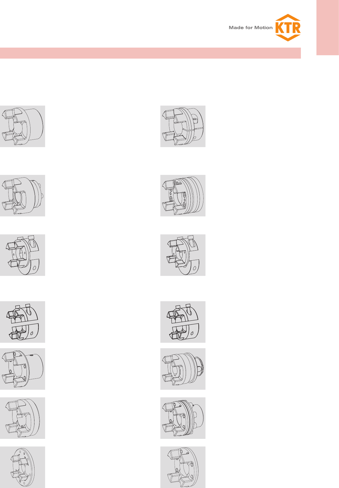
Design 1.0 hub with keyway and fixing screw Design 2.0 clamping hub, single slotted, without
keyway
Positive locking power transmission, permissible torque
depending on the permissible surface pressure. Not suitable
for backlash-free power transmission with heavily reversing
operation.
Frictionally engaged, backlash-free shaft-hub-connection-.
Transmittable torques depending on bore diameter (see
page 34). (For ATEX category 3 only).
Design 1.1 hub without keyway, with fixing screw Design 2.1 clamping hub, single slotted, with keyway
Non-positive torque transmission for crimp and glued con-
nections.
Positive locking power transmission with additional friction-
ally engaged condition. The frictionally engaged condition
prevents or reduces reverse backlash, respectively. Surface
pressure of the feather key connection is prevented.
Design 1.3 hub spline bore (see page 28) Design 2.3 clamping hub with spline bore (see page
28/34)
Design 4.2 with CLAMPEX® clamping set KTR 250 Design 6.0 clamping ring hub (see ROTEX® GS series)
Frictionally engaged, backlash-free shaft-hub-connection for
the transmission of average torques.
Integrated frictionally engaged shaft-hub-connection for the
transmission of higher torques. Screwing on elastomer side.
For details about torque and dimensions see page 33.Suit-
able for high speeds.
Design 4.1 for CLAMPEX® clamping set KTR 200
Design 4.3 for CLAMPEX® clamping set KTR 400
Design 6.5 clamping ring hub (see ROTEX® GS series)
Frictionally engaged, backlash-free shaft-hub-connection for
the transmission of high torques.
Design like 6.0, except for clamping screws externally. As an
example for radial disassembly of intermediate pipe (special
design).
Design 7.5 clamping hub type DH without feather key-
way for double-cardanic connection
Design 7.8 clamping hub type H without feather keyway
Frictionally engaged, backlash-free shaft-hub-connection for
radial assembly of coupling. Transmittable torques depen-
ding on bore diameter (for ATEX category 3 only)
Frictionally engaged, backlash-free shaft-hub-connection for
radial assembly of coupling. Transmittable torques depend
on the bore diameter (for ATEX category 3 only).
Design 7.6 clamping hub type DH with feather keyway
for double-cardanic connection
Design 7.9 clamping hub type H with feather keyway
Positive locking power transmission with additional frictionally
engaged condition for radial assembly of coupling. The
frictionally engaged condition prevents or reduces reverse
backlash, respectively. Surface pressure of the feather key
connection is reduced.
Positive locking power transmission with additional friction
fit for radial assembly of coupling. The frictionally engaged
condition prevents or reduces reverse backlash, respectively.
Surface pressure of the feather key connection is prevented.
Design 7.0 split hub without feather keyway Design 7.1 split hub with feather keyway
Split hub made of cast iron. Frictionally engaged, backlash-
free shaft-hub-connection-. Transmittable torques depending
on bore diameter (For ATEX category 3 only)
Split hub made of cast iron. Positive locking power transmis-
sion with additional frictionally engaged condition. The
frictionally engaged condition prevents or reduces reverse
backlash, respectively. The surface pressure of the feather
key connection is reduced.
FNN hub SD hub shifting hub
Coupling hub to be connected to an attachment such as
brake drum, brake disk and fan.
Coupling hub for separating or switching on the driving/
driven machine with standstill of the machine. Can be com-
bined with slip ring and shiftable linkage.
TB1 hub/TB2 hub Design 3Na + 4N
Driving flange with C-flange
Coupling hub for taper clamping bushes. TB1 screwed on
cam side. TB2 screwed externally.
For type AFN and BFN.
With type AFN the spider can be replaced while being
assembled without having to disassemble the driving and
driven side.
Driving flange design 3b Driving flange design 3Na
Driving flange to connect to customer’s component. For
dimensions see page 41
Driving flange to connect to customer’s component. For
dimensions see page 41.
Hub designs
Due to the numerous applications of ROTEX® for many different applications and mounting situa-
tions, this coupling system is available with various hub designs. These designs mainly differ in that they
offer either positive or frictionally engaged connections, but mounting situations like, for example, gear shafts
with integrated transmission cams or similar applications are covered, too.
28
ROTEX®
Torsionally flexible coupling
You will find continuously updated data in our online catalogue at www.ktr.com.
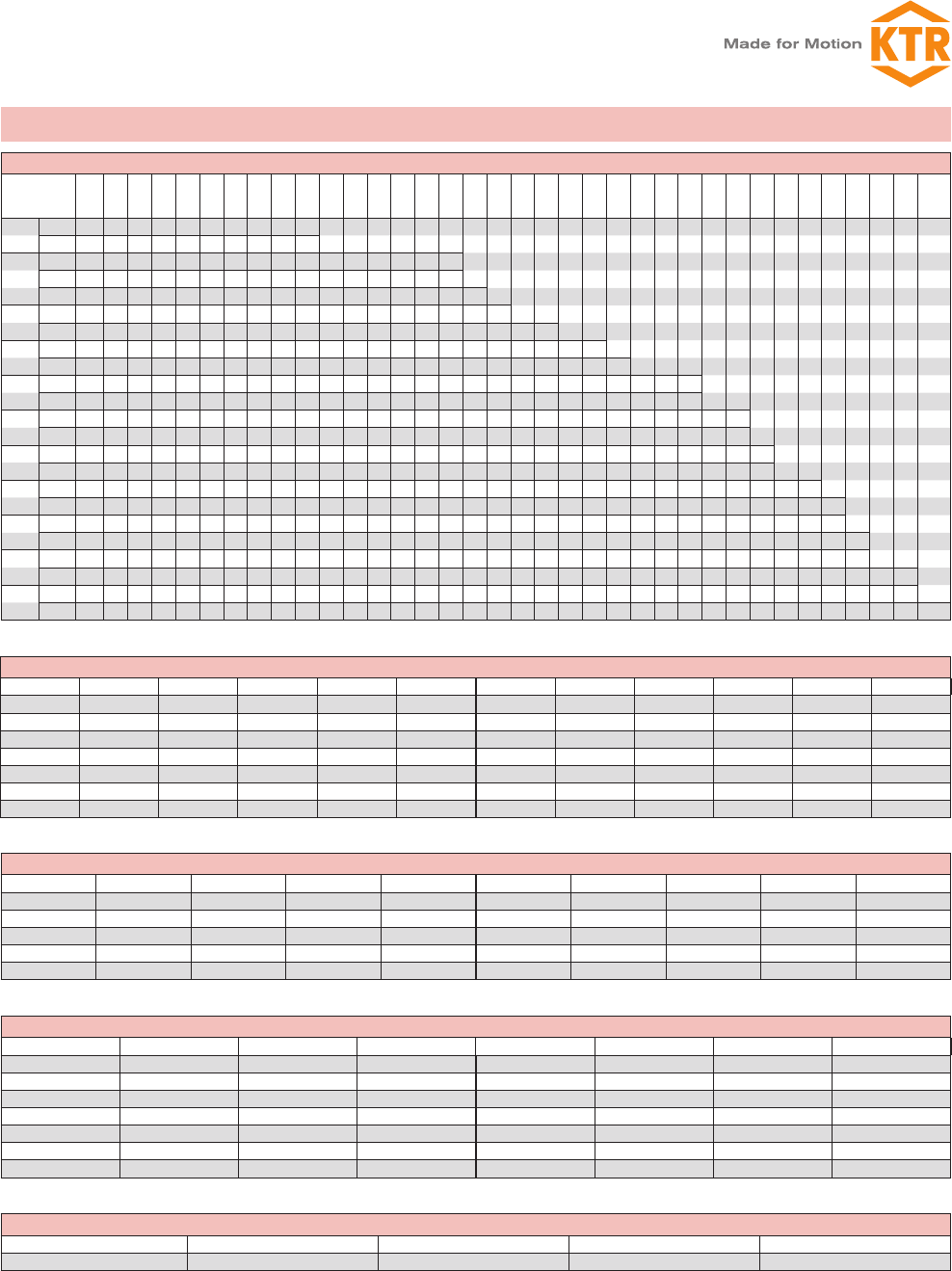
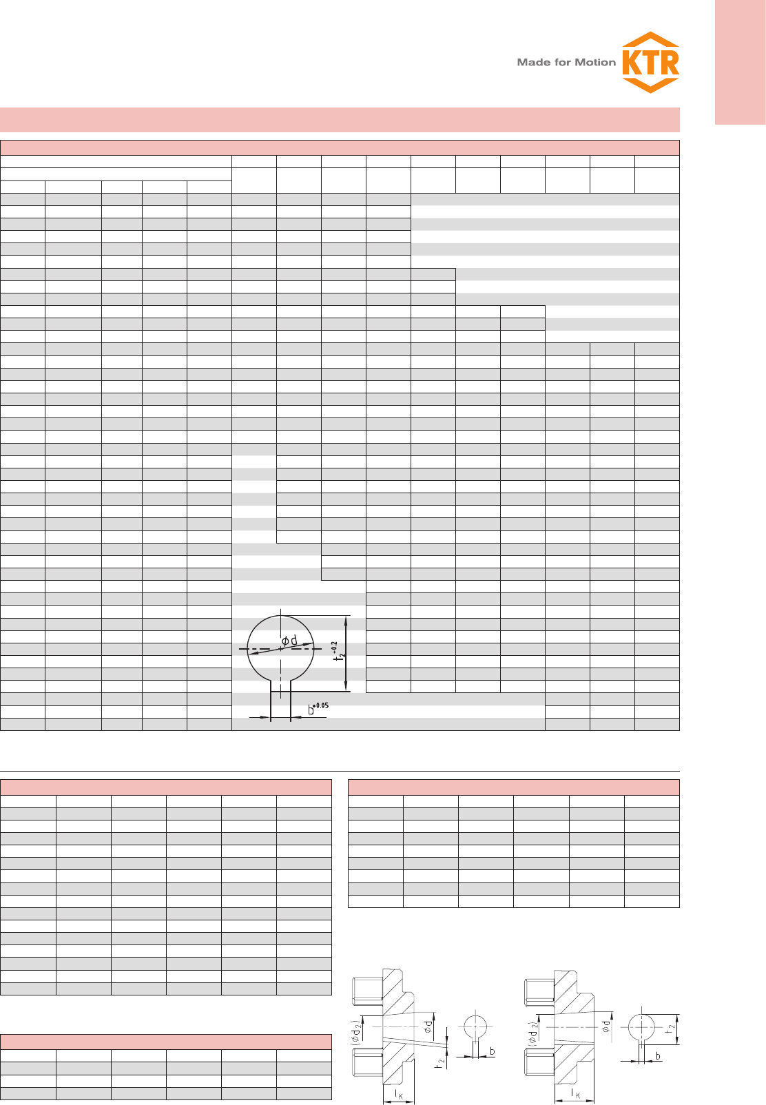
Basic programme SAE involute spline
Spline code Size Pitch circle Pitch No. of teeth Angle Spline code Size Pitch circle Pitch No. of teeth Angle
PH-S ⁵/₈” 14,28 16/32 9 30° PS-S 1 1/₂” 35,98 12/24 17 30°
PI-S 3/₄” 17,46 16/32 11 30° PD-S 1 1/₂” 36,51 16/32 23 30°
PB-S ⁷/₈” 20,63 16/32 13 30° PE-S 1 3/₄” 42,86 16/32 27 30°
PB-BS 1” 23,81 16/32 15 30° PK 1 3/₄” 41,275 8/16 13 30°
PJ 1 1/₈” 26,98 16/32 17 30° PT-C 1) 2” 47,625 8/16 15 30°
PC-S 1 1/₄” 29,63 12/24 14 30° PQ-C 1) 2 1/₄” 53,975 8/16 17 30°
PA-S 1 3/₈” 33,33 16/32 21 30°
Basic programme spline bores to DIN 5482
Size Pitch circle Pitch No. of teeth Profile correction Size Pitch circle Pitch No. of teeth Profile correction
A 17 x 14 14,40 1,6 9 +0,600 2) A 35 x 31 31,50 1,75 18 +0,676
A 20 x 17 19,20 1,6 12 -0,2 A 40 x 36 38,00 1,9 20 +0,049
A 25 x 22 22,40 1,6 14 +0,550 A 45 x 41 44,00 2 22 +0,181
A 28 x 25 26,25 1,75 15 +0,302 A 50 x 45 48,00 2 24 +0,181
A 30 x 27 28,00 1,75 16 +0,327
Basic programme spline bores to DIN 5480
Spline code Pitch circle Pitch No. of teeth Spline code Pitch circle Pitch No. of teeth
20 x 1 x 18 x 7H 18,0 1 18 40 x 2 x 18 x 8H 36,0 2 18
20 x 1,25 x 14 x 7H 17,5 1,25 14 45 x 2 x 21 x 7H 41,0 2 21
25 x 1,25 x 18 x 7H 22,5 1,25 18 48 x 2 x 22 x 9H 44,0 2 22
28 x 1,25 x 21 x 7H 26,25 1,25 21 50 x 2 x 24 x 8H 48,0 2 24
30 x 2 x 14 x 7H 26,0 2 14 60 x 2 x 28 x 8H 56,0 2 28
32 x 2 x 14 x 8H 28,0 2 14 75 x 3 x 24 x 7H 72,0 3 24
35 x 2 x 16 x 8H 32,0 2 16 80 x 3 x 25 x 8H 75,0 3 25
Basic programme spline bores to DIN 9611
Size Width of keyway No. of teeth Tip circle Root circle
1 3/₈” 8,69 6 34,93 29,65
Stock programme cylindrical finish bore [mm] H7 keyway to DIN 6885 sheet 1 [JS9] with thread for setscrew
ROTEX®
Size/material
un-
bo-
red Ø6 Ø8 Ø9 Ø10Ø11Ø12Ø14Ø15Ø16Ø17Ø18Ø19Ø20Ø22Ø24Ø25Ø28Ø30Ø32Ø35Ø38Ø40Ø42Ø45Ø48Ø50Ø55Ø60Ø65Ø70Ø75 Ø80 Ø85 Ø90 Ø100
14 Sint z z z z z z
Al-H z zzzzzzzzz
19
Sint z z z z z z z
AL-D z z zzzzzzzzzz z
St z z zzzzzzzzzzzzz
24 Al-D z zzzzzzzzzzzzzz
St z z zzzzzzzzzzzzzz
28 Al-D z z z zzzzzzzzzzz
St z zzz zzzzzzzzzzzz
38 GJL z z zzzzzzzzzzzzzzz
St z z zzzzzzzzz z
42 GJL z zzzzzzzzzzzzzzz
St z zzzzzzzzzzzz
48 GJL z zzzzzzzzzzzzzz
St z zzzzzzzzzzz
55 GJL z z zzzzzzzzzzzzz
St z zzzz zzzzzz
65 GJL z zzzzzzzzzzzz
St z z zzzzzzzz
75 GJL z z z zzzzzzzzz
St z zzzz zzzz
90 GJL z z zzzzzzzzz
St z z z z z z z z
Cylindrical bores and spline bores
Spline clamping hubs are often adapted to the shafts of hydraulic pumps/hydraulic motors. Please ask us about the corresponding hub length of the spline code!
1) For clamping hubs only, for plug-in hubs use code PT or PQ.
2) Profile correction different from DIN
ROTEX®
29
ROTEX®
Torsionally flexible coupling
You will find continuously updated data in our online catalogue at www.ktr.com.
Stock programme inch bores
ROTEX® size 19 24 28 38 42 48 55 65 75 90
Material
Code Ød Ød Inch b+0,05 t2+0,2 St St St GJL GJL GJL GJL GJL GJL GJL
Tb 9,5+0,03 3/₈ 3,17 11,1
DNB 11,11M7 ⁷/₁₆ 2,4 12,5
T 12,69H7 1/₂ 4,75 14,6
Ta 12,7+0,03 1/₂ 3,17 14,3 z z
DNC 13,45H7 17/₃₂ 3,17 14,9
Do 14,29+0,03 ⁹/₁₆ 3,17 15,6
E 15,87+0,03 ⁵/₈ 3,17 17,5
Es 15,88+0,03 ⁵/₈ 4,00 17,7 zzz
Ed 15,87+0,03 ⁵/₈ 4,75 18,1 z z
DNH 17,465H7 11/₁₆ 4,75 19,6
Ad 19,02+0,03 3/₄ 3,17 20,7
A 19,05+0,03 3/₄ 4,78 21,3 zzzz
Gs 22,22+0,03 ⁷/₈ 4,78 24,4 z
G 22,22+0,03 ⁷/₈ 4,75 24,7 zzzzz
F 22,22+0,03 ⁷/₈ 6,38 25,2 zzzzz
Gd 22,225M7 ⁷/₈ 4,76 24,7 z
Gf 23,80+0,03 1⁵/₁₆ 6,35 26,8
Bs 25,38+0,03 1 6,37 28,3 zzzz
H 25,40+0,03 1 4,78 27,8
Hs 25,40+0,03 1 6,35 28,7 z
R 26,95+0,03 1 1/₁₆ 4,78 29,3
Sa 28,575M7 1 1/₈ 6,35 31,7 z z
Sb 28,58+0,03 1 1/₈ 6,35 31,5 z z
Sd 28,58+0,03 1 1/₈ 7,93 32,1
Js 31,75+0,03 1 1/₄ 6,35 34,6
K 31,75K7 1 1/₄ 7,93 35,5 zzzzzz
Ma 34,925M7 1 3/₈ 7,93 38,7 z
RH1 34,93M7 1 3/₈ 9,55 37,8
Cb 36,50+0,03 1 ⁷/₁₆ 9,55 40,9
Ca 38,07+0,03 1 1/₂ 7,93 42,0
C 38,07+0,03 1 1/₂ 9,55 42,5 zzzzzzz
Nb 41,275M7 1 ⁵/₈ 9,55 45,8 z z
Ls 44,42+0,03 1 3/₄ 9,55 48,8
L 44,45K7 1 3/₄ 11,11 49,4 z z
Lu 47,625M7 1 ⁷/₈ 12,7 53,5 z
Da 49,20+0,03 1 15/₁₆ 12,7 55,0
Ds 50,77+0,03 2 12,7 56,4
D 50,80+0,03 2 12,7 55,1
Pa 53,975M7 2 1/₈ 12,7 60,0 z
U 57,10+0,03 2 1/₄ 12,7 62,9
Ub 60,325M7 2 3/₈ 15,875 67,6
Wd 85,725M7 3 3/₈ 22,225 95,8
Wf 92,075M7 3 ⁵/₈ 22,225 101,9
Basic programme taper 1:8
Code d+0,05 (d2) bJS9 t2+0,1 lK
N/ 1 9,7 7,575 2,4+0,05 10,85 17,0
N/ 1c 11,6 9,5375 3JS9 12,90 16,5
N/ 1e 13,0 10,375 2,4+0,05 13,80 21,0
N/ 1d 14,0 11,813 3JS9 15,50 17,5
N/ 1b 14,3 11,8625 3,2+0,05 5,65 19,5
N/ 2 17,287 14,287 3,2+0,05 18,24 24,0
N/ 2a 17,287 14,287 4JS9 18,94 24,0
N/ 2b 17,287 14,287 3JS9 18,34 24,0
N/ 3 22,002 18,502 4JS9 23,40 28,0
N/ 4 25,463 20,963 4,78+0,05 27,83 36,0
N/ 4b 25,463 20,963 5JS9 28,23 36,0
N/ 4a 27,0 22,9375 4,78+0,05 28,80 32,5
N/ 4g 28,45 23,6375 6JS9 29,32 38,5
N/ 5 33,176 27,676 6,38+0,05 35,39 44,0
N/ 5a 33,176 27,676 7JS9 35,39 44,0
Basic programme taper 1:5
Code d+0,05 (d2) bJS9 t2+0,1 lK
A-10 9,85 7,55 2JS9 1,0 11,5
B-17 16,85 13,15 3JS9 1,8 18,5
C-20 19,85 15,55 4JS9 2,2 21,5
Cs-22 21,95 17,65 3JS9 1,8 21,5
D-25 24,85 19,55 5JS9 2,9 26,5
E-30 29,85 23,55 6JS9 2,6 31,5
F-35 34,85 27,55 6JS9 2,6 36,5
G-40 39,85 32,85 6JS9 2,6 35,0
Basic programme taper 1:10
Code d+0,05 (d2) bJS9 t2+0,1 lK
CX 19,95 16,75 5JS9 22,08 32
DX 24,95 20,45 6JS9 26,68 45
EX 29,75 24,75 8JS9 31,88 50
Inch bores and taper bores
For code N/6 and N/6a keywith parallel to the taper.
Taper 1:5 Taper 1:8
Taper 1:10
ROTEX®
Torsionally flexible coupling
30 You will find continuously updated data in our online catalogue at www.ktr.com.
Components
ROTEX® Aluminium diecast (AI-D)
Size Compo-
nent
Spider (part 2) 1)
Rated torque [Nm]
Dimensions [mm]
Finish bore d (min-
max)
General Thread for setscrew
92 Sh-A 98 Sh-A 64 Sh-D L l1; l2E b s DHDZdHD; D1N G t TA [Nm]
14 2) 1a 7,5 12,5 — 6-16 35 11 13 10 1,5 30 — 10 30 — M4 5 1,5
19 110 17 — 6-19 66 25 16 12 2 41 — 18 32 20 M5 10 2
1a 19-24 41
24 135 60 — 9-24 78 30 18 14 2 56 — 27 40 24 M5 10 2
1a 22-28 56
28 195 160 — 10-28 90 35 20 15 2,5 66 — 30 48 28 M8 15 10
1a 28-38 66
ROTEX® Nodular iron (GJS)
100 1 3300 4950 6185 50-115 270 110 50 38 6 225 246 113 180 89 M12 30 40
110 1 4800 7200 9000 60-125 295 120 55 42 6,5 255 276 127 200 96 M16 35 80
125 1 6650 10000 12500 60-145 340 140 60 46 7 290 315 147 230 112 M16 40 80
140 1 8550 12800 16000 60-160 375 155 65 50 7,5 320 345 165 255 124 M20 45 140
160 1 12800 19200 24000 80-185 425 175 75 57 9 370 400 190 290 140 M20 50 140
180 1 18650 28000 35000 85-200 475 195 85 64 10,5 420 450 220 325 156 M20 50 140
ROTEX® Cast iron (GJL)
38
1
190 325 405
12-40 114 45 24 18 3 80 — 38
66 37
M8 15 10
1a 38-48 78
1b 12-48 164 70 62
42
1
265 450 560
14-45 126 50 26 20 3 95 — 46
75 40 M8 20 10
1a 42-55 94
1b 14-55 176 75 65
48
1
310 525 655
15-52 140 56 28 21 3,5 105 — 51
85 45 M8 20 10
1a 48-62 104
1b 15-62 188 80 69
55 1410 685 825 20-60 160 65 30 22 4 120 — 60 98 52 M10 20 17
1a 55-74 118
65 1 625 940 1175 22-70 185 75 35 26 4,5 135 — 68 115 61 M10 20 17
75 1 1280 1920 2400 30-80 210 85 40 30 5 160 — 80 135 69 M10 25 17
90 1 2400 3600 4500 40-97 245 100 45 34 5,5 200 218 100 160 81 M12 30 40
1 1a2 11a2 1b
ROTEX® 38 GJL 92 Sh-A 1a Ø 45 1 Ø 25
Coupling size Material Spider hardness Component Finish bore Component Finish bore
Elements DZ
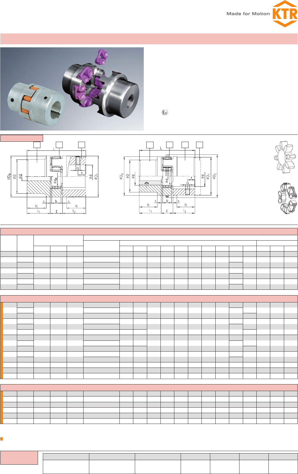
Hardness 92Sh-A and
95Sh-A size 100 - 180
Spider
Hardness 92Sh-A,
95/98Sh-A, 64Sh-D
Standard from size
14 - 180
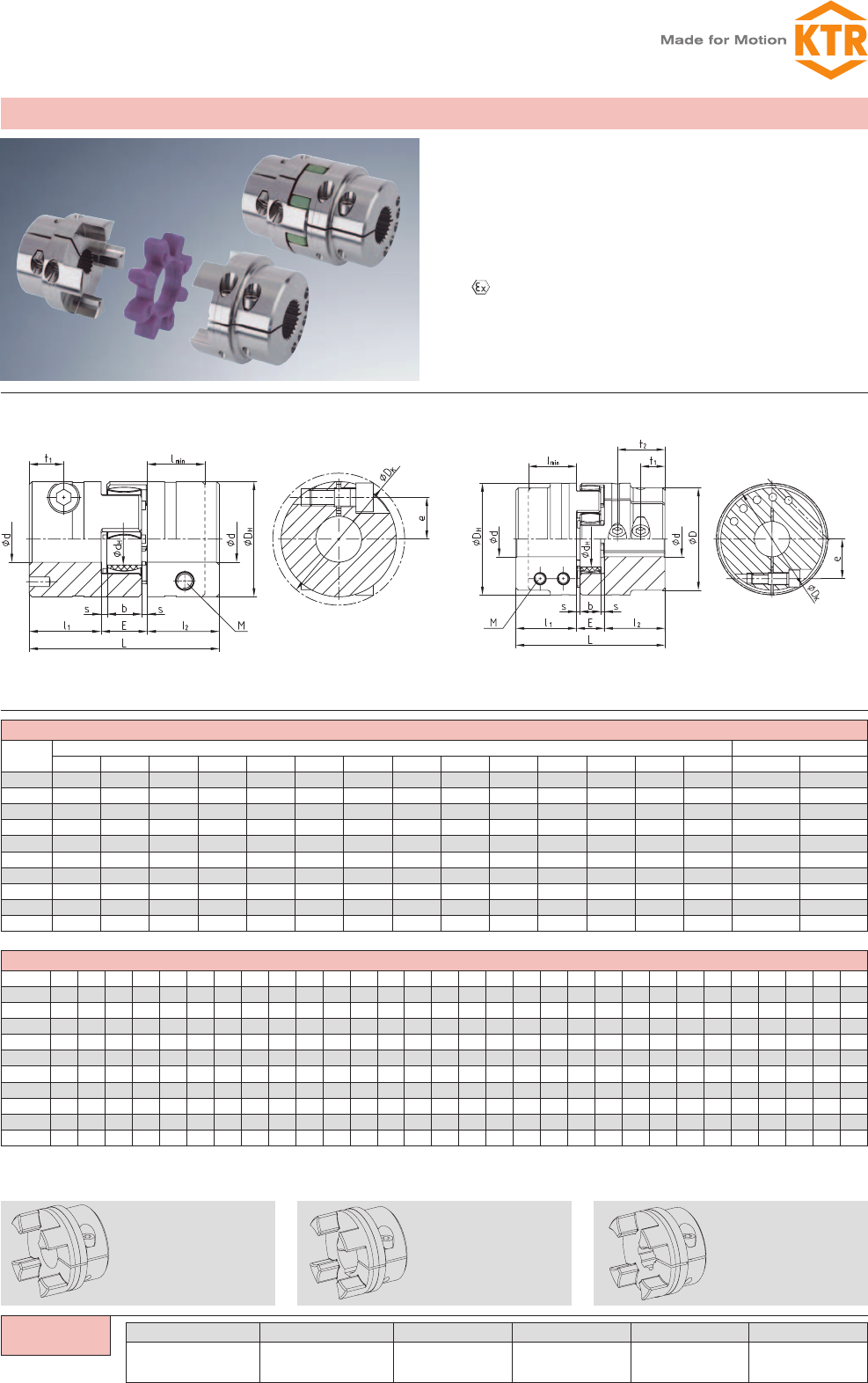
Shaft coupling design No. 001 - casted materials -
zTorsionally flexible, maintenance-free
zDamping vibrations
zAxial plug-in, fail-safe
zAllover machining (except for aluminium AL-D) –
good dynamic properties
zCompact design/low flywheel effect
zFinish bore acc. to ISO tolerance H7, feather keyway
acc. to DIN 6885 sheet 1 - JS9
zStock programme/basic programme see pages 28 and 29
z Approved according to EC standard 94/9/EC
(except for aluminium AL-D)
zMounting instructions at www.ktr.com
AL-D (thread opposite to the keyway) GJL / GJS (thread on the keyway)
Ordering
example:
= If no material is mentioned in the order, it is stipulated in the calculation/order.
1) Maximum torque of the coupling TKmax. = rated torque of the coupling TK Nenn. x 2. see page 20/21 for selection.
2) Material Al-H.
31
ROTEX®
Torsionally flexible coupling
You will find continuously updated data in our online catalogue at www.ktr.com.
ROTEX®
Compenents
ROTEX® 38 St 92 Sh-A 1 – Ø 45 1 – Ø 25
Coupling size Material Spider hardness Component Finish bore Component Finish bore
11 1 2 1a 1b
2
ROTEX® Steel (St)
Size Compo-
nent
Spider (part 2) 1)
Rated torque [Nm]
Dimensions [mm]
Finish bore General Thread for setscrew
92 Sh-A 98 Sh-A 64 Sh-D d (min-max) L l1; l2E b s DHdHD N G t TA [Nm]
14 1a 7,5 12,5 16 0-16 35 11 13 10 1,5 30 10 30 — M4 5 1,5
1b 50 18,5
19 1a 10 17 21 0-25 66 25 16 12 2 40 18 40 — M5 10 2
1b 90 37
24 1a 35 60 75 0-35 78 30 18 14 2 55 27 55 — M5 10 2
1b 118 50
28 1a 95 160 200 0-40 90 35 20 15 2,5 65 30 65 — M8 15 10
1b 140 60
38 1190 325 405 0-48 114 45 24 18 3 80 38 70 27 M8 15 10
1b 164 70 80 —
42 1265 450 560 0-55 126 50 26 20 3 95 46 85 28 M8 20 10
1b 176 75 95 —
48 1310 525 655 0-62 140 56 28 21 3,5 105 51 95 32 M8 20 10
1b 188 80 105 —
55 1410 685 825 0-74 160 65 30 22 4 120 60 110 37 M10 20 17
1b 210 90 120 —
65 1625 940 1175 0-80 185 75 35 26 4,5 135 68 115 47 M10 20 17
1b 235 100 135 —
75 11280 1920 2400 0-95 210 85 40 30 5 160 80 135 53 M10 25 17
1b 260 110 160 —
90 12400 3600 4500 0-110 245 100 45 34 5,5 200 100 160 62 M12 30 40
1b 295 125 200 —
ROTEX® Sintered steel
Size Compo-
nent
Spider (part 2) 1)
Rated torque [Nm]
Dimensions [mm]
Finish bore
d
General Thread for setscrew
92 Sh-A 98 Sh-A L l1; l2E b DHdHD N G t TA [Nm]
14 1a 7,5 12,5 unbored 8, 10, 11, 12, 14, 15, 16 35 11 13 10 1,5 30 10 30 - M4 5 1,5
19 1a 10 17 14, 16, 19, 20, 22, 24 66 25 16 12 2 40 18 40 - M5 10 2
s
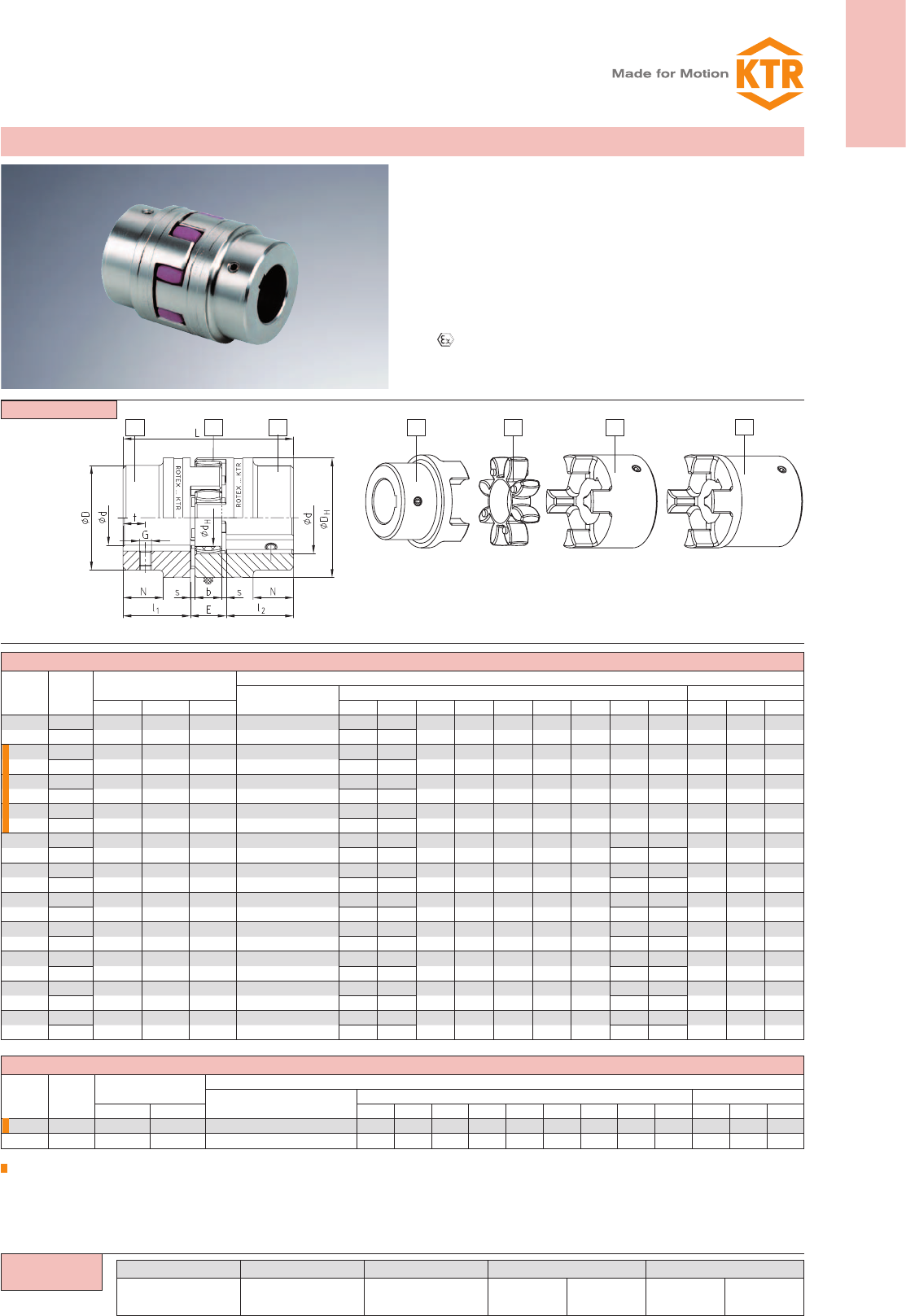
Shaft coupling design No. 001 - material steel -
zHubs from steel, specifically suitable for drive elements subject
to high loads, e. g. steel mills, elevator drives, spline hubs, etc.)
zTorsionally flexible, maintenance-free, vibration-damping
zAxial plug-in, fail-safe
zMachined allover - good dynamic properties
zCompact design/low flywheel effect
zFinish bore acc. to ISO fit H7, feather keyway acc. to DIN
6885 sheet 1 - JS9.
zStock programme/basic programme see pages 28 and 29
z Approved according to EC Standard 94/9/EC
zMounting instructions at www.ktr.com
Ordering
example:
ROTEX® 19 – 48 from stainless steel available from stock
Steel (thread on the keyway)
Standard hub Spider Large hub Large hub lengthened
– ROTEX® 19, 28 and 42 – hub material X10CrNiS 18-9 material number 1.4305 (V2A) DIN 17440
– ROTEX® 24, 38 and 48 – hub material X6CrNiMoTi17-12-2 material number 1.4571 (V4A) DIN 17440
= If no material is mentioned in the order, the material is stipulated with the calculation/order.
1) Maximum torque of the coupling TKmax. = rated torque of the coupling TK Nenn. x 2. Selection see page 20/21
ROTEX®
Torsionally flexible coupling
32 You will find continuously updated data in our online catalogue at www.ktr.com.
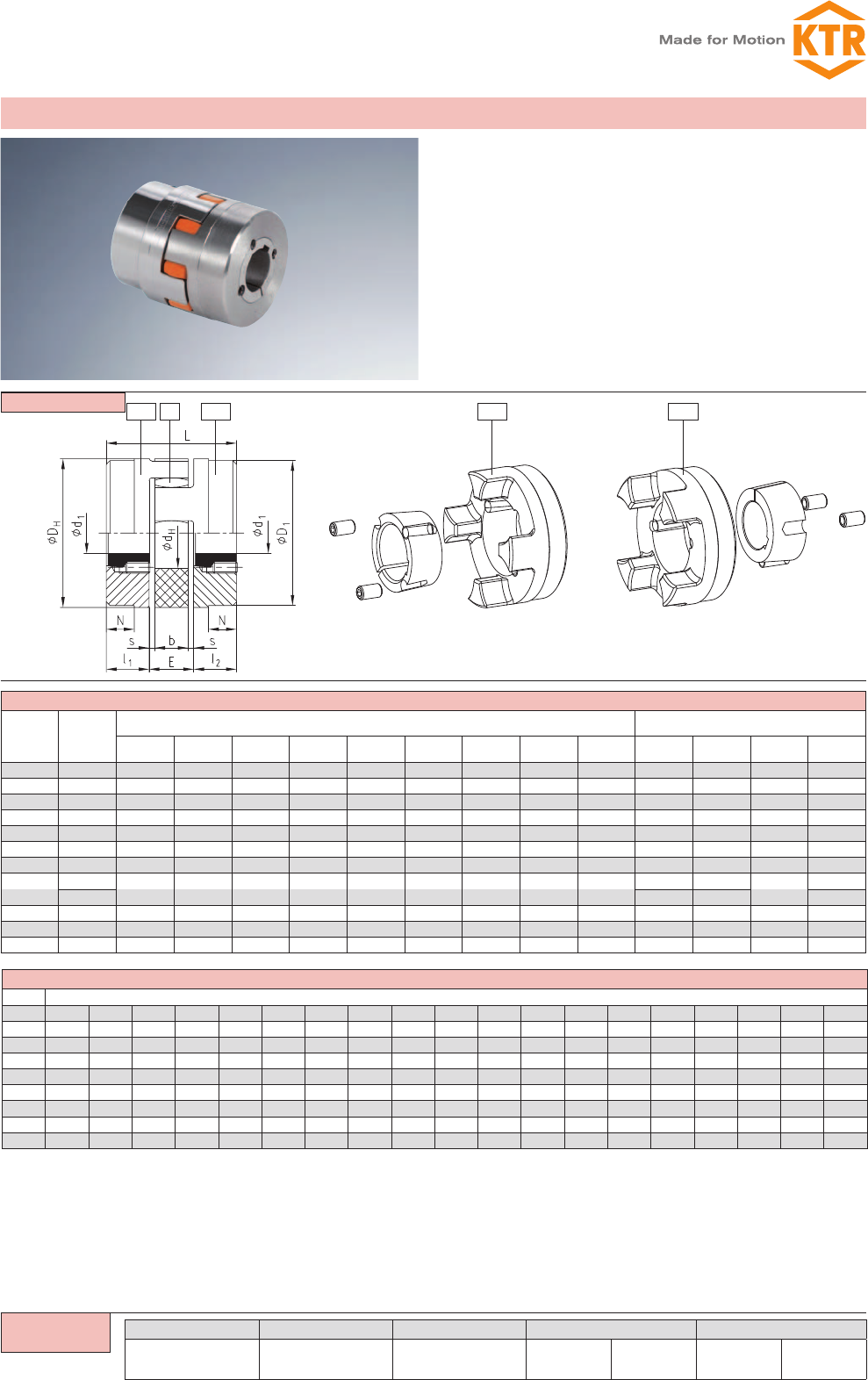
TB1 TB1 TB2TB22
ROTEX® shaft coupling for taper clamping bush
Size Taper clam-
ping bush
Dimensions [mm] Fastening screw
for taper bush
l1;l2E s b L N DHD1dHSize [Inch]1) Length
[mm] Number TA [Nm]
24 1008 22 18 2,0 14 62 – 55 55 27 1/₄ 13 2 5,7
28 1108 23 20 2,5 15 66 – 65 65 30 1/₄” 13 2 5,7
38 1108 23 24 3,0 18 70 15 80 78 38 1/₄” 13 2 5,7
42 1610 26 26 3,0 20 78 16 95 94 46 3/₈” 16 2 20
48 1615 39 28 3,5 21 106 28 105 104 51 3/₈” 16 2 20
55 2012 33 30 4,0 22 96 20 120 118 60 7/16” 22 2 31
65 2012 33 35 4,5 26 101 19 135 115 68 7/16” 22 2 31
75 2517 52 40 5,0 30 144 36 160 158 80
1/2” 25 249
3020 5/8” 32 92
90 3020 52 45 5,5 34 149 33 200 160 100 5/8” 32 2 92
100 3535 90 50 6 38 230 69 225 180 113 1/2” 49 3 113
125 4545 114 60 7,0 46 288 86 290 230 147 3/4” 49 3 192
Taper clamping bush
Size Bore dimensions d1 [mm] available; H7 fit – keyways to DIN 6885 sheet 1
1008 Ø10 Ø11 Ø12 Ø14 Ø16 Ø18 Ø19 Ø20 Ø22 Ø24 Ø25
1108 Ø10 Ø11 Ø12 Ø14 Ø16 Ø18 Ø19 Ø20 Ø22 Ø24 Ø25 Ø282)
1610 Ø14 Ø16 Ø18 Ø19 Ø20 Ø22 Ø24 Ø25 Ø28 Ø30 Ø32 Ø35 Ø38 Ø40 Ø42*
1615 Ø14 Ø16 Ø18 Ø19 Ø20 Ø22 Ø24 Ø25 Ø28 Ø30 Ø32 Ø35 Ø38 Ø40 Ø42*
2012 Ø14 Ø16 Ø18 Ø19 Ø20 Ø22 Ø24 Ø25 Ø28 Ø30 Ø32 Ø35 Ø38 Ø40 Ø42 Ø45 Ø48 Ø50
2517 Ø16 Ø18 Ø19 Ø20 Ø22 Ø24 Ø25 Ø28 Ø30 Ø32 Ø35 Ø38 Ø40 Ø42 Ø45 Ø48 Ø50 Ø55 Ø60
3020 Ø25 Ø28 Ø30 Ø35 Ø38 Ø40 Ø42 Ø45 Ø48 Ø50 Ø55 Ø60 Ø65 Ø70 Ø75
3535 Ø35 Ø38 Ø40 Ø42 Ø45 Ø48 Ø50 Ø55 Ø60 Ø65 Ø70 Ø75 Ø80 Ø85 Ø90
4545 Ø55 Ø60 Ø65 Ø70 Ø75 Ø80 Ø85 Ø90 Ø95 Ø100 Ø105 Ø110
Components
ROTEX® 38 92 Sh-A 1108 TB1 – Ø 24 TB2 – Ø 22
Coupling size Spider hardness Taper clamping bush Hub design Finish bore Hub design Finish bore
zShaft coupling for taper clamping bush
zSliding fit facilitates the axial alignment of the coupling
zShort mounting length
zEasy assembly/disassembly of the coupling hubs
zExtra securing by positive locking, the clamping screws are
each mounted by half in the coupling hub and in the taper
clamping bush
Shaft coupling for taper clamping bush
Only available for design TB 2
1) 1. BSW thread
Coupling type TB 1/1; TB 2/2; TB 1/2 possible
Please order our separate dimension sheet (M 373054).
2) Bores with feather keyway (flat design) acc. to DIN 6885 sheet 3
Ordering
example:
33
ROTEX®
Torsionally flexible coupling
You will find continuously updated data in our online catalogue at www.ktr.com.
ROTEX®
Clamping ring hubs steel
Size
Torques [Nm] 1)
Dimensions [mm] Clamping screws Weight per
hub with max.
bore
[kg]
Mass moment
of inertia per hub
with max. bore
[kgm2]
92 Sh A 98 Sh A
TKN TKmax TKN TKmax DH2) dHL l1; l2l3E b s M Number
zTA[Nm] M1
19 10,0 20 17 34 40 18 66 25 18 16 12 2,0 M4 6 4,1 M4 0,179 0,44 x 10⁻⁴
24 35,0 70 60 120 55 27 78 30 22 18 14 2,0 M5 4 8,5 M5 0,399 1,91 x 10⁻⁴
28 95,0 190 160 320 65 30 90 35 27 20 15 2,5 M5 8 8,5 M5 0,592 4,18 x 10⁻⁴
38 190,0 380 325 650 80 38 114 45 35 24 18 3,0 M6 8 14 M6 1,225 12,9 x 10⁻⁴
42 265 530 450 900 95 46 126 50 35 26 20 3,0 M8 4 35 M8 2,30 31,7 x 10⁻⁴
48 310 620 525 1050 105 51 140 56 41 28 21 3,5 M10 4 69 M10 3,08 52,0 x 10⁻⁴
55 375 750 685 1370 120 60 160 65 45 30 22 4,0 M10 4 69 M10 4,67 103,0 x 10⁻⁴
65 — — 940 3) 1880 3) 135 68 185 75 55 35 26 4,5 M12 4 120 M12 6,70 191,0 x 10⁻⁴
75 — — 1920 3) 3840 3) 160 80 210 85 63 40 30 5,0 M12 5 120 M12 9,90 396,8 x 10⁻⁴
90 — — 3600 3) 4500 3) 200 104 245 100 75 45 34 5,5 M16 5 295 M16 17,70 1136 x 10-4
Bore d1/d2 and the corresponding transmittable friction torques TR of clamping ring hub in [Nm] 1)
Size Ø10 Ø11 Ø14 Ø15 Ø16 Ø19 Ø20 Ø24 Ø25 Ø28 Ø30 Ø32 Ø35 Ø38 Ø40 Ø42 Ø45 Ø48 Ø50 Ø55 Ø60 Ø65 Ø70 Ø80 Ø90 Ø95 Ø100 Ø105
19 27 32 69 84 57 94 110
24 70 87 56 97 114 116 133 192
28 108 131 207 148 253 285 315 382 330 433 503
38 208 353 395 439 531 463 603 593 689 793 776
42 358 398 483 416 547 536 625 571 704 851 865
48 616 704 899 896 1030 962 1160 1379 1222 1543
55 863 856 991 918 1119 1110 1247 1277 1672 1605 2008
65 1446 1355 1637 1635 1827 1887 2429 2368 2930
75 1710 2053 2059 2294 2384 3040 2983 3664 4293
90 3845 4249 4794 5858 5900 7036 8047 9247 9575 10845
ROTEX® GS 24 98 Sh-A 6.0 Steel Ø24 6.0 Steel Ø20
Coupling size Spider hardness Hub design Finish bore Hub design Finish bore
Ordering
example:
zTorsionally flexible shaft coupling with integrated clamping
system
zHigh running smoothness, application up to a peripheral
speed of 40 m/s
zFor high friction torques (consider the selection in case
of explosion protection applications)
zEasy to assemble due to internal clamping screws
zFinish bore up to Ø 50 mm according to ISO fit H7,
from Ø 55 mm according to ISO fit G77
z Approved according to EC Standard 94/9/EC
Pull-off thread
M1 between
clamping
screws
1) Please note coupling selection on pages 140/141
2) ØDH + 2 mm with high speeds for expansion of spider
3) 95 Sh-A
The transmittable torques of the clamping connection consider the max. clearance with shaft fit k6/bore H7, from Ø55 G7/m6. With a higher clearance the torque is reduced. For the stiffness
calculation of the shaft/hollow shaft please refer to KTR standard 45510 at our homepage www.ktr.com)
Clamping ring hubs
ROTEX®
Torsionally flexible coupling
34 You will find continuously updated data in our online catalogue at www.ktr.com.
ROTEX® 19 - 28 ROTEX® 38 - 90
ROTEX® as clamping hubs
Size Dimensions [mm] Screw DIN EN ISO 4762
max. d L l1;l2l min. E b s DHD dHDKt1t2e M TA [Nm]
19 201) 66 25 20 16 12 2,0 40 - 18 46,0 12 — 14,5 M6 14
24 28 78 30 25 18 14 2,0 55 - 27 57,5 12 — 20,0 M6 14
28 38 90 35 30 20 15 2,5 65 - 30 73,0 142) — 25,0 M8 35
38 42 114 45 35 24 18 3,0 80 70 38 77,5 19 — 26,5 M8 35
42 50 126 50 42 26 20 3,0 95 85 46 93,5 182) — 32,0 M10 69
48 55 140 56 46 28 21 3,5 105 95 51 105,0 212) — 36,0 M12 120
55 68 160 65 50 30 22 4,0 120 110 60 119,5 26 512) 42,53) M12 120
65 70 185 75 55 35 26 4,5 135 115 68 132,5 33 612) 50,03) M12 120
75 80 210 85 65 40 30 5,0 160 135 80 158,0 36 682) 57,03) M16 295
90 90 245 100 80 45 34 5,5 200 160 100 197,0 40 802) 72,03) M20 580
Bore area and the corresponding transmittable friction torques [Nm] of ROTEX® clamping hubs design 2.0
Size Ø8 Ø10 Ø11 Ø14 Ø15 Ø16 Ø18 Ø19 Ø20 Ø22 Ø24 Ø25 Ø28 Ø30 Ø32 Ø35 Ø38 Ø40 Ø42 Ø45 Ø48 Ø50 Ø55 Ø60 Ø65 Ø70 Ø75 Ø80 Ø85 Ø90
19 44 46 47 51 52 53 55 57 58
24 59 60 64 65 66 68 70 71 73 76 77 80
28 139 141 144 148 150 152 157 161 163 170 174 178 185 191
38 163 165 170 172 174 178 183 185 192 196 200 207 213 217 222
42 291 297 304 308 318 325 332 342 353 360 367 377 387 394
48 466 476 486 491 506 516 526 542 557 567 577 592 607 618 643
55 1185 1215 1245 1266 1286 1316 1347 1367 1417 1468 1519
65 1316 1347 1367 1387 1417 1448 1468 1519 1569 1620 1671
75 2869 2926 2983 3022 3117 3213 3309 3404 3500 3595
90 5220 5310 5400 5460 5610 5760 5910 6060 6210 6360 6510 6660
ROTEX® 24 98 Sh-A 2.1 Ø 24 2.0 Ø20
Coupling size Spider hardness Hub design Finish bore Hub design Finish bore
Clamping hubs
zStandard hub material steel
zSuitable in combination with spline bores according to
DIN 5480, DIN 5482, SAE J498 (see page 28) and
in addition DIN 9611, DIN 5463 (ISO 14), DIN 5481
and DIN 5472
zBalanced on the basis of 3D-CAD data
zParticularly suitable for applications with reversing operation
z Protection assessed and confirmed in accordance with EU
standard 94/9/EC (only for hub designs 2.1 and 2.3,
hub design 2.0 only according to category 3)
zMounting instructions at www.ktr.com
Design 2.0
clamping hub,
single slot,
without keyway
Design 2.1
clamping hub,
single slot,
with keyway
Design 2.3
clamping hub with
spline bore
(Please find a selection of
our spline bore programme
on page 28)
1) With design 2.1 dmax. Ø17 mm
2) With reduced hubs the dimension t1 varies or the number of screws changes from 2-off to 1-off
3) t1 and t2 have a different installation dimension e
Ordering
example:
35
ROTEX®
Torsionally flexible coupling
You will find continuously updated data in our online catalogue at www.ktr.com.
ROTEX®
Components
4N 2
3Na 3Na 4N 1a 1 3Na 4N2
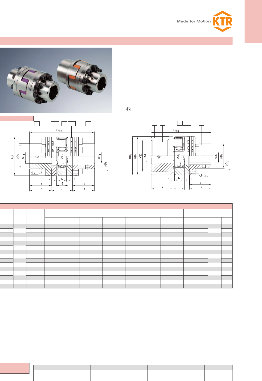
ROTEX® AFN (No. 002) and BFN (No. 004)
Size
Pilot
bored
Ød;ØD;
ØD1
Component
4N
max. finish
bore Ød1
Dimensions [mm] Cyl. screws 3)
DIN EN ISO 4762 - 12.9
DHDFD4dHl1; l2E E1s b l3; l4LAFN LBFN Mxl z Pitch 2) 1) TA
[Nm]
24 24 55 36 45 27 30 18 33 2,0 14 30,5 94 86 M5x16 8
8x45°
10
28 28 65 42 54 30 35 20 39 2,5 15 35,5 110 100 M6x20 8 17
38 38 80 52 66 38 45 24 43 3,0 18 45,5 134 124 M8x22 8 41
42 42 95 62 80 46 50 26 48 3,0 20 51,0 150 138 M8x25 12 16x22,5° 41
48 48 105 70 90 51 56 28 50 3,5 21 57,0 164 152 M8x25 12 41
55 55 120 80 102 60 65 30 60 4,0 22 66,0 192 176 M10x30 8 8x45° 83
65 65 135 94 116 68 75 35 65 4,5 26 76,0 217 201 M10x30 12 16x22,5° 83
75 75 160 108 136 80 85 40 75 5,0 30 86,5 248 229 M12x40 15
20x18°
120
90 100 200 142 172 100 100 45 82 5,5 34 101,5 285 265 M16x40 15 295
100 110 225 158 195 113 110 50 97 6,0 38 111,5 320 295 M16x50 15 295
110 125 255 178 218 127 120 55 103 6,5 42 122,0 347 321 M20x50 15 580
125 145 290 206 252 147 140 60 116 7,0 46 142,0 400 370 M20x60 15 580
140 165 320 235 282 165 155 65 128 7,5 50 157,5 443 409 M20x60 15 580
160 190 370 270 325 190 175 75 146 9,0 57 177,5 501 463 M24x70 15 1000
180 220 420 315 375 220 195 85 159 10,5 64 198,0 555 515 M24x80 18 24x15° 1000
ROTEX® 24 AFN 92 Sh-A 4N Ø 38 4N Ø35
Coupling size Type Spider hardness Component Finish bore Component Finish bore
z = number
z= number
Flange programme design AFN and BFN
zDouble flange design AFN and flange design BFN applicable
to heavy machinery
zRadial assembly of driving or driven machine after disassembly
of driving flanges
zFor design AFN - spider to be replaced while coupling
installed, without removal of driving or driven machine
zPower flow can be disconnected while coupling is installed
zFlange materials: component 4N (C-flange) made of steel,
component 3Na (driving flange) made of GJS
zFinish bore acc. to ISO fit H7, feather keyway acc. to DIN
6885 sheet 1 - JS9.
z Approved according to EC standard 94/9/EC
see shaft coupling on pages 30 and 31
stock programme/basic programme see
pages 28 and 29
1) Screw tightening torque TA [Nm].
2) Thread in driving flange between cams.
3) Coupling is delivered not assembled.
Type AFN Type BFN
Ordering
example:
ROTEX®
Torsionally flexible coupling
36 You will find continuously updated data in our online catalogue at www.ktr.com.
ROTEX® Type A-H
Size Max. finish bore
Ød [mm]
Dimension [mm] Cyl. screw DIN EN ISO 4762
L l1; l2E b s DHD DK1 DK2 x1/x2E1Mxl Tightening torque TA [Nm]
19 20 66 25 16 12 2,0 40 — 46 — 17,5 31 M6x16 14
24 28 78 30 18 14 2,0 55 — 57,5 — 22,5 33 M6x20 14
28 38 90 35 20 15 2,5 65 — 73 — 25,5 39 M8x25 35
38 45 114 45 24 18 3,0 80 — 83,5 — 35,5 43 M8x30 35
42 50 126 50 26 20 3,0 95 85 — 93,5 39 48 M10x30 69
55 — 97 — M10x35
48 55 140 56 28 21 3,5 105 95 — 105 45 50 M12x35 120
60 — 108,5 — M12x40
55 65 160 65 30 22 4,0 120 110 — 119,5 50 60 M12x40 120
70 — 122 — M12x45
65 70 185 75 35 26 4,5 135 115 — 123,5 60 65 M12x40 120
80 — 132,5 — M12x45
75 80 210 85 40 30 5,0 160 135 — 147,5 67,5 75 M16x50 295
90 — 158 —
90 90 245 100 45 34 5,5 200 160 — 176 81,5 82 M20x60 580
110 — 197 —
1001) 110 270 110 50 38 6,0 225 180 — 185,5 84 102 M16x50 295
1101) 120 295 120 55 42 6,5 255 200 — 208 90 115 M20x60 580
1251) 140 340 140 60 46 7,0 290 230 — 242,5 105 130 M24x70 1000
Components
27.8/7.9 7.8/7.9
ROTEX® 38 A-H 98 Sh-A 7.8 Ø 38 7.8 Ø30
Coupling size Type Spider hardness Hub design Finish bore Hub design Finish bore
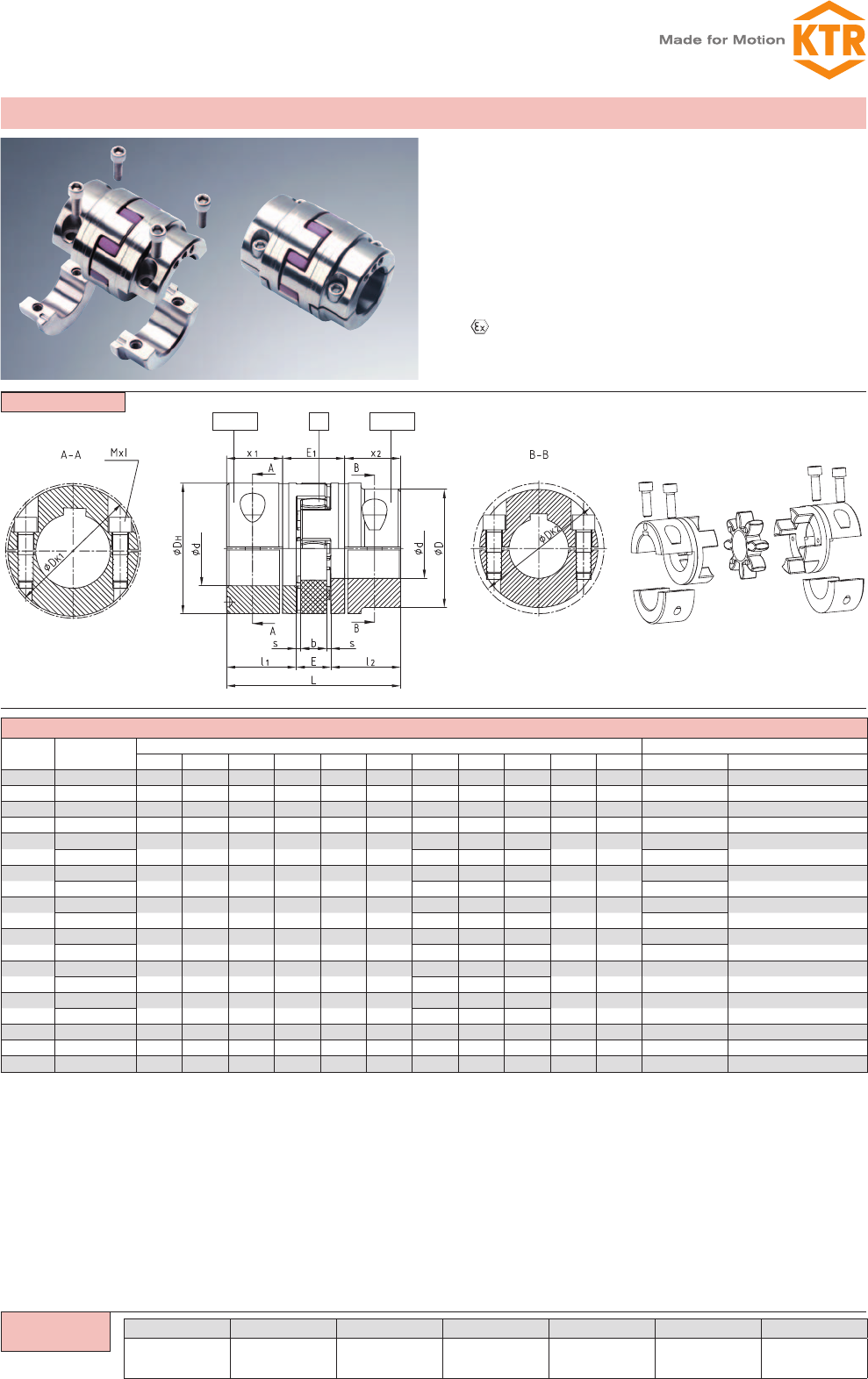
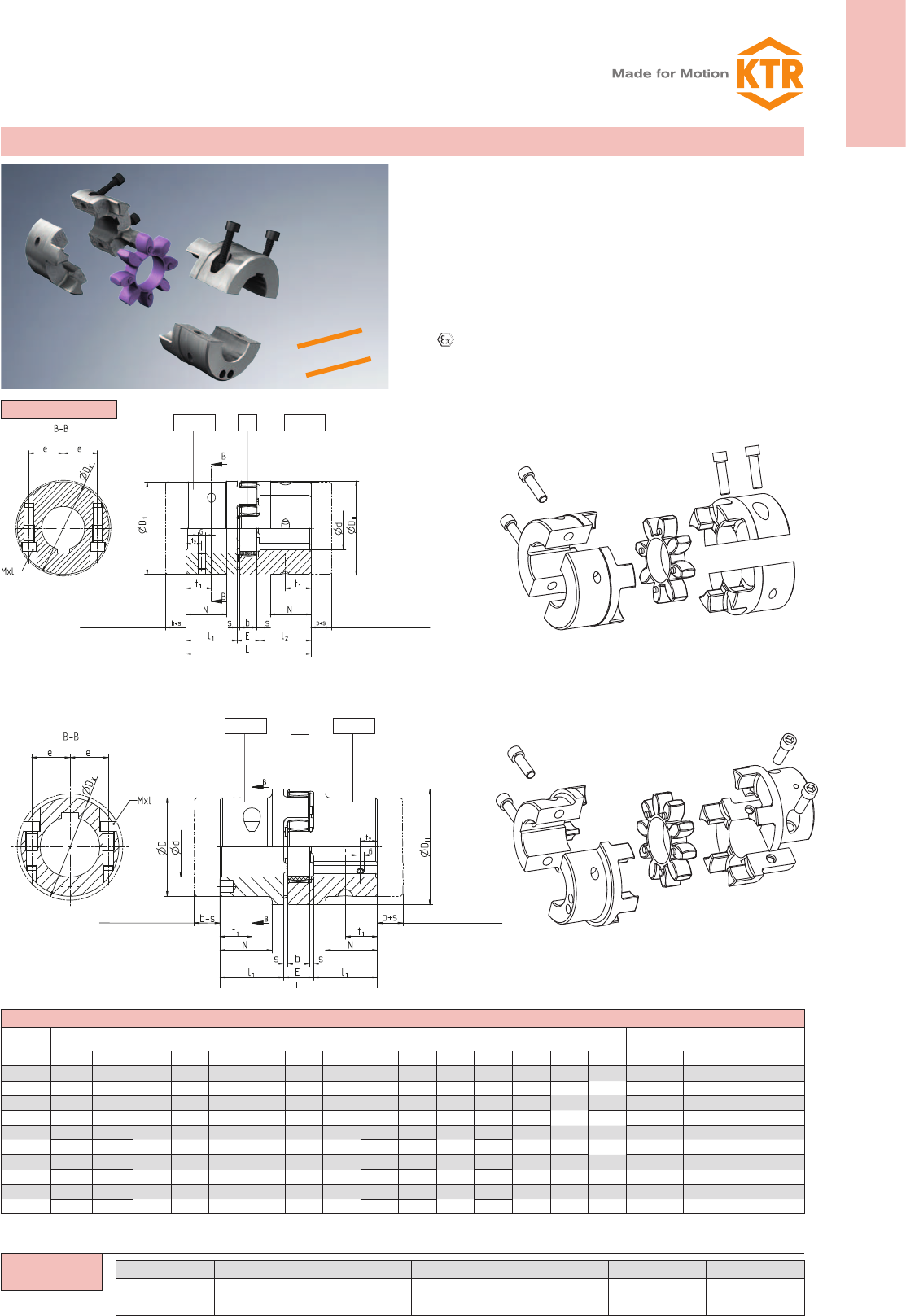
Drop-out center design coupling type A-H
Type A-H
zAssembly/disassembly by means of 4 screws only
zReplacement of spider with no need to shift the driving and
driven side (motor and pump)
zPositive-locking and frictionally engaged hub combinations
to be assembled radially (dimension E1 of type
AFN = dimension E1 of type A-H)
zFinish bore according to ISO tolerance H7,feather key accor-
ding to DIN 6885 sheet 1 - JS9
zPlease order our separate dimension sheet (M425460)
z Approved according to EC standard 94/9/EC (type 7.8
shell clamping hub without feather key according to
category 3)
Please note:
With maximum bore the feather keys are offset to each other by approx. 5°!
Hub materials: up to size 90 steel
from size 100 GJS
7.8= Shell clamping hub without feather key
7.9= Shell clamping hub with feather key
1) From size 100: 4 clamping screws for each clamping hub.
Ordering
example:
37
ROTEX®
Torsionally flexible coupling
You will find continuously updated data in our online catalogue at www.ktr.com.
ROTEX®
ROTEX® Type S-H
Size
Finish bore Ød
[mm] Dimensions [mm] Cyl. screws DIN EN ISO 4762
minimum maximum L l1; l2E b s DHD1DKN e t1t2GMxl Tightening torque TA [Nm]
38 24 45 114 45 24 18 3 80 78 83,5 37 30 22,5 15 M8x30 34
42 24 55 126 50 26 20 3 95 94 97 40 30 25
20
M8 M10x30 67
48 24 60 140 56 28 21 3,5 105 104 108,5 45 35 28 M12x35 115
55 24 70 160 65 30 22 4 120 118 122 52 40 32,5 M12x40 115
65 24 70 185 75 35 26 4,5 135 115 123,5 61 45 37,5 M12x40 115
70 80 135 132,5 50 M10
75 40 80 210 85 40 30 5 160 135 147 69 51 42,5 25 M16x50 290
80 90 160 158 57
90 40 90 245 100 45 34 5,5 200 160 176 81 60 50 30 M12 M20x60 560
90 110 200 197 72
Components 2
2
7.0/7.1
7.0/7.1
7.0/7.1
7.0/7.1
ROTEX® 38 S-H 98 Sh-A 7.1 Ø 38 7.1 Ø30
Coupling size Type Spider hardness Hub type Finish bore Hub type Finish bore
NEW
Drop-out center design coupling type S-H with SPLIT hubs
Type S-H
Size 38-55
Type S-H
Size 65-90
zEasy assembly/disassembly by means of 4-off screws
zCentering of both hub halves via the surface of fracture
zFor mounting it is not necessary to displace the power packs
Please note displacement of the hub
zMaterial cast iron
zTorsionally flexible and maintenance-free
zSpecifically suitable for tight mounting spaces
zFinish bore according to ISO tolerance H7, feather key ac-
cording to DIN6885 sheet1- JS9
zApproved according to EC standard 94/9/EC (type 7.0
SPLIT hubs without feather key according to category 3)
7.0= SPLIT hub without feather key
7.1= SPLIT hub with feather key
Ordering
example:
Displacement
Displacement
Displacement
Displacement
ROTEX®
Torsionally flexible coupling
38 You will find continuously updated data in our online catalogue at www.ktr.com.
Components
2 6x 27.5/7.6 7.5/7.6
ROTEX® ZS-DKM-H
Size
Dis-
mount-
able
length L
[mm]
Max. finish
bore
Ød1/d2
[mm]
Spider
(part 2) 1)
TKN [Nm]
Dimensions [mm]
Cyl. screw
DIN EN ISO 4762
– 12.9
Max. displacements
Weight2)
[kg]
Axial
[mm]
with n = 1500 rpm with n = 3000 rpm
DHdHl1; l2x1; x2l11 E LZS-DKM-H M TA [Nm] Radial [mm] Angular [°] Radial [mm] Angular [°]
24 100 28 35 55 27 30 22,5 49 18 145 M6 14 1,4 1,17
1,0
0,87
0,75
1,40
140 89 185 1,87 1,40 1,60
28 100 38 95 65 30 35 25,5 41 20 151 M8 35 1,5 1,06 0,80 1,90
140 81 191 1,76 1,32 2,20
38 100 45 190 80 38 45 35,5 33 24 171 M8 35 1,8 0,99 0,74 3,90
140 73 211 1,69 1,27 4,10
42 100 55 265 95 46 50 39,0 26 26 178 M10 69 2,0 0,91 0,68 5,10
140 66 218 1,60 1,20 5,70
48 100 60 310 105 51 56 45,0 22 28 190 M12 120 2,1 0,87 0,65 7,10
140 62 230 1,57 1,18 7,90
55
100
70 410 120 60 65 50,0
10
30
200
M12 120 2,2
0,70 0,52 9,50
140 50 240 1,40 1,05 11,20
180 90 280 2,09 1,57 12,30
200 110 300 2,44 1,83 12,80
65 140 80 625 135 68 75 60,0 40 35 260 M12 120 2,6 1,31 0,98 16,10
180 80 300 2,00 1,50 16,80
75
140
90 1280 160 80 85 67,5
25
40
275
M16 295 3,0
1,13 0,85 23,60
180 65 315 1,83 1,37 26,00
200 85 335 2,19 1,64 27,00
250 135 385 3,05 2,29 29,50
90 180 110 2400 200 100 100 81,5 53 45 343 M20 580 3,4 1,71 1,28 48,90
250 123 413 2,93 2,19 52,60
ROTEX® 38 ZS-DKM-H 140 98 Sh-A-GS 7.5 Ø 38 7.5 Ø30
Coupling size Type Shaft distance
dimension L
Spider hard-
ness Hub design Finish bore Hub design Finish bore
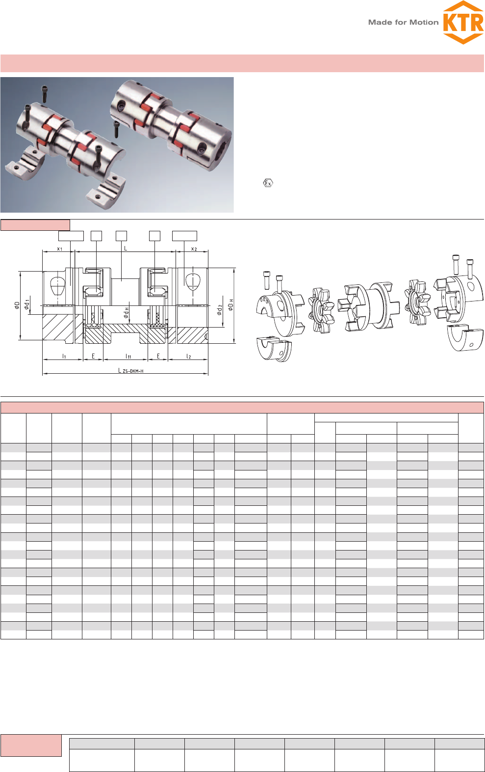
Double cardanic type ZS-DKM-H
zStandard spacers up to 250 mm shaft distance dimension –
from stock
zAssembly/disassembly by means of 4 screws only
zCompensates for high shaft displacements due to double-
cardanic design
zRemains torsionally symmetric in case of shaft displacements
zReduced vibration and noise
zLow restoring forces Increase of the overall service life of all
adjacent components (bearing, seals, etc.)
z Approved according to EC standard 94/9/EC (type 7.6
marked at stock, type 7.5 shell clamping hub without feather
key according to category 3)
Type ZS-DKM-H
1) Maximum torque of coupling TKmax. = rated torque of coupling TKN x 2
Size 24 to 90 spider type 95/98 Sh-A-GS
ZS-DKM-H: transmittable torque according to 92 Sh-A-GS
2) Referring to max. bore
Finish bore according to ISO fit H7, feather keyway according to DIN 6885 sheet 1 - JS9.
7.5= Shell clamping hub without feather key for a double-cardanic connection
7.6= Shell clamping hub with feather key for a double-cardanic connection
ATTENTION: The standard line is only applicable for horizontal assembly. Vertical assembly on request.
Ordering
example:
39
ROTEX®
Torsionally flexible coupling
You will find continuously updated data in our online catalogue at www.ktr.com.
ROTEX®
1a 1a2 61 2 1
ROTEX® DKM (No. 018)
Size Ød, ØD,
ØD1
Spider (part 2)
Rated torque [Nm] 1Dimensions [mm] Max. displacements
with n = 1500 rpm
92 Sh-A 98 Sh-A DHdHl1; l2l11 l12 E s b LDKM
Radial
[mm] Angular [°] Axial [mm]
19 10 17 40 18 25 10 42 16 2,0 12 92 0,45 1,0 +1,2/-1,0
24 35 60 55 27 30 16 52 18 2,0 14 112 0,59 1,0 +1,4/-1,0
28 95 160 65 30 35 18 58 20 2,5 15 128 0,66 1,0 +1,5/-1,4
38 190 325 80 38 45 20 68 24 3,0 18 158 0,77 1,0 +1,8/-1,4
42 265 450 95 46 50 22 74 26 3,0 20 174 0,84 1,0 +2,0/-2,0
48 310 525 105 51 56 24 80 28 3,5 21 192 0,91 1,0 +2,1/-2,0
55 410 685 120 60 65 28 88 30 4,0 22 218 1,01 1,0 +2,2/-2,0
65 625 940 135 68 75 32 102 35 4,5 26 252 1,17 1,0 +2,6/-2,0
75 1280 1920 160 80 85 36 116 40 5,0 30 286 1,33 1,0 +3,0/-3,0
90 2400 3600 200 100 100 40 130 45 5,5 34 330 1,48 1,0 +3,4/-3,0
Components
ROTEX® 38 DKM GJL 98 Sh-A 1 Ø 38 1 Ø30
Coupling size Type Material Spider hard-
ness Component Finish bore Component Finish bore
1) Selection on page 20/21
Finish bore according to ISO fit H7, feather keyway according to DIN 6885 sheet 1 - JS9.
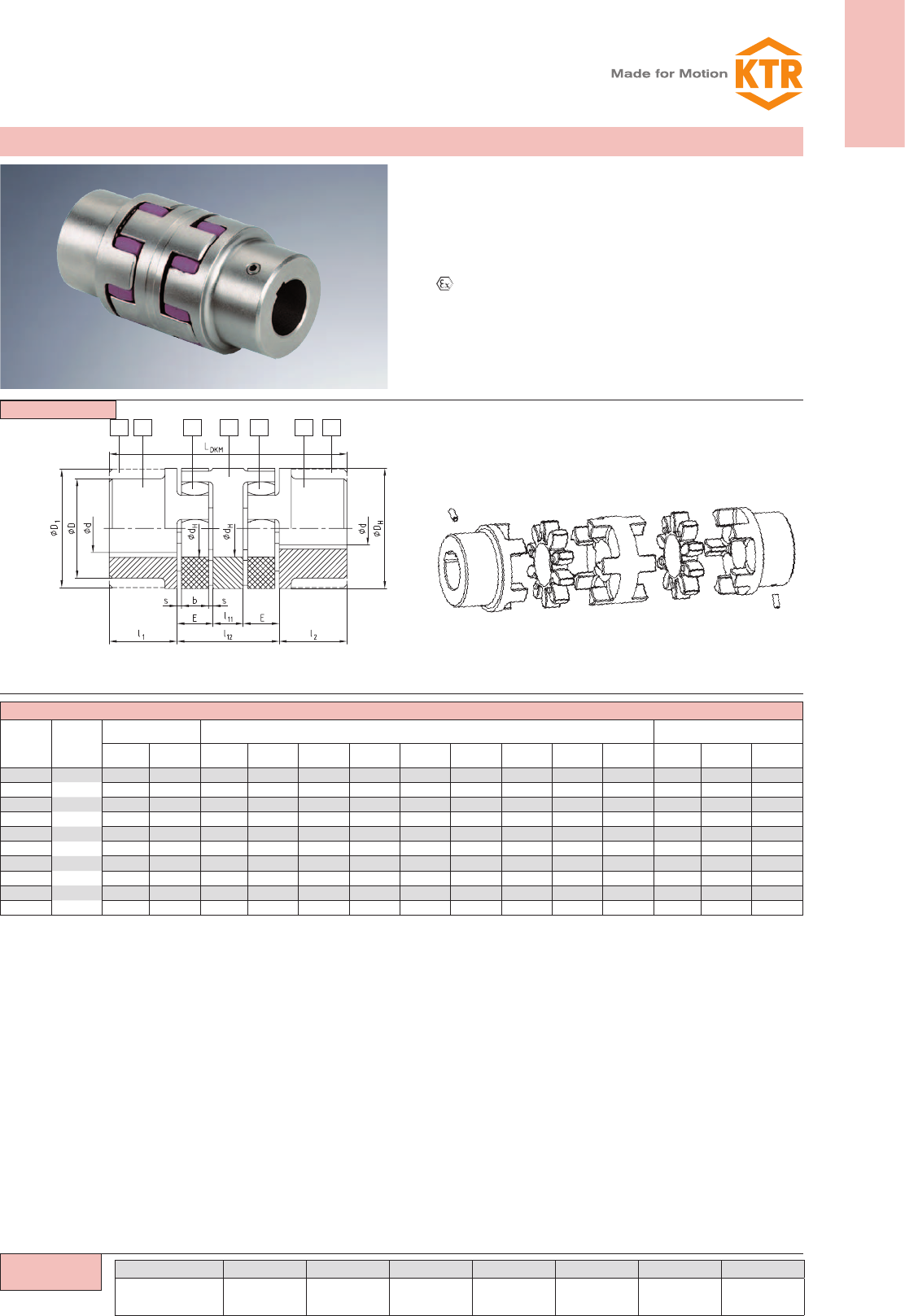
Double-cardanic type DKM
see shaft coupling page 30
and 31;
stock programme/basic pro-
gramme page 28 and 29
Type DKM
zFor big shaft displacements, 3-parted, double-cardanic
zReduced vibration and noise
zThe double-cardanic design allows for big shaft displacements
with low restoring forces
zIncrease of the overall service life of all adjacent components
(bearings, seals etc.)
z CApproved according to EC standard 94/9/EC
zMounting instructions at www.ktr.com
zDouble-cardanic couplings without bearing require a protec-
tion for coupling
Ordering
example:
ROTEX®
Torsionally flexible coupling
40 You will find continuously updated data in our online catalogue at www.ktr.com.
Components
1a 2 2 1a2.0 9 2.0 2.0 9 2.07.5/7.6 2 2 7.5/7.6
ROTEX® type ZR (No. 037)
Size
Finish bore
Ød Dimensions [mm] Intermediate pipe
Torsional stiffness/m
Clamping screw
Component 2.0
Clamping screw
Component
7.5/7.6
LZR;
LZH
min.
LR1
min.
LR2
Locking screw
G1
Cone bore
dp [mm]
Axial
displacement
[mm]
Angular
displacement
[degrees]
Compo-
nent
1a
Compo-
nent
7.5/7.6 DHl1; l2x1; x2E s b RA
C2)
[Nm²/rad] M1TA [Nm] M2TA [Nm]
19 25 20 40 25 17,5 16 2,0 12 Ø20x3 954,9 M6 14 M6 10 110 97 M6 4,0 1,2 0,9
24 35 28 55 30 22,5 18 2,0 14 Ø30x4 4522 M6 14 M6 14 128 111 M8 5,5 1,4 0,9
28 40 38 65 35 25,5 20 2,5 15 Ø35x4 7611 M8 35 M8 35 145 129 M10 7,0 1,5 0,9
38 48 45 80 45 35,5 24 3,0 18 Ø40x4 11870 M8 25 M8 35 180 157 M12 8,5 1,8 1,0
42 55 55 95 50 39,0 26 3,0 20 Ø45x4 17487 M10 49 M10 69 198 174 M12 8,5 2,0 1,0
48 62 60 105 56 45,0 28 3,5 21 Ø50x4 24648 M12 86 M12 120 217 190 M16 12 2,1 1,1
55 74 70 120 65 50,0 30 4,0 22 Ø55x4 33544 M12 120 M12 120 242 220 M16 12 2,2 1,1
65 80 80 135 75 60,0 35 4,5 26 Ø65x5 68329 M12 120 M12 120 281 250 M16 12 2,6 1,2
75 95 90 160 85 67,5 40 4,0 30 Ø75x5 108000 M16 295 M16 295 318 285 M16 12 3,0 1,2
LR1 + 2 l1
LR2 + 2 x1/x2
ROTEX® 38 ZR 1200 98 Sh-A-GS 7.5 Ø 38 7.5 Ø30
Coupling size Type Shaft distance
dim. LR1/LR2
Spider hard-
ness
Hub
design Finish bore Hub design Finish bore
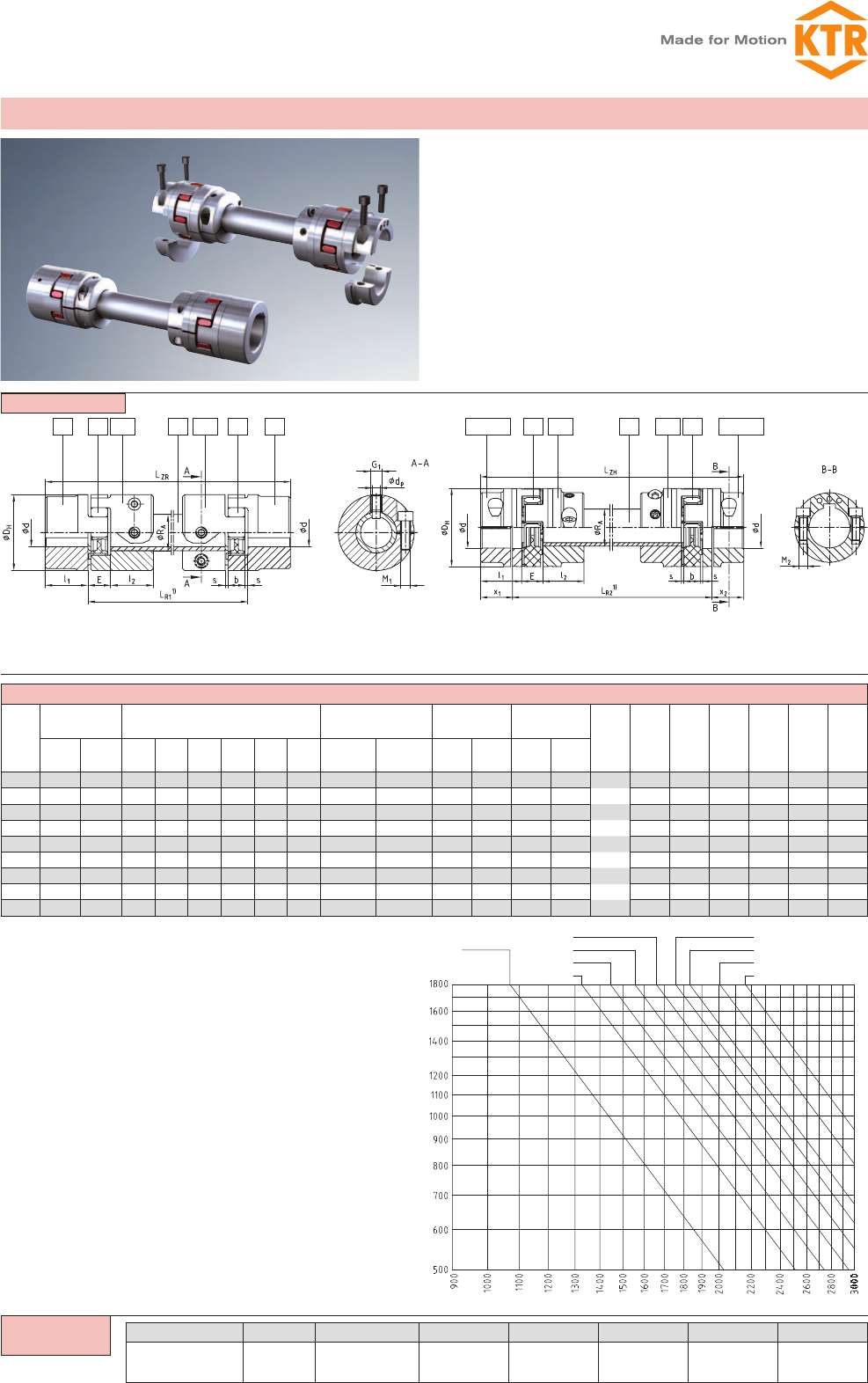
Intermediate shaft programme design ZR
1) Please indicate the shaft distance dimensions LR1 and LR2 in all inquiries and orders
along with the maximum speed to review the critical whirling speed.
2) Torsion spring stiffness when the intermediate pipe is 1m
Finish bore acc. to ISO fit H7, feather key acc. to DIN 6885 sheet 1 - JS9
Friction torques of clamping hubs have to be taken into account. Please order dimension
sheet No. 583613.
Not permissible for crane and hoisting gear drives
Type ZR
(with GS spider)
Type ZR
(with GS spider and clamping hubs type DH for a double-cardanic
connection 7.5 or 7.6)
zTo connect shaft ends with extended shaft separations
zCompensating for big shaft displacements due to the
double-cardanic design
zRadial assembly possible without displacement of the driving
or driven machine
zParticularly easy maintenance with the use of clamping hubs
type DH (design 7.5 and 7.6)
zFlexible bearing in backlash-free ROTEX® GS spiders
size 48 ZR
size 55 ZR
size 65 ZR
size 75 ZR
size 42 ZR
size 38 ZR
size 28 ZR
size 24 ZR
size 19 ZR
Length of pipe [mm]
Speed [rpm]
Diagramme for
coupling selection:
Ordering
example:
41
ROTEX®
Torsionally flexible coupling
You will find continuously updated data in our online catalogue at www.ktr.com.
ROTEX®
1a 121 1a 3Na 3Na 3Na3b 3b 3b2 2 2
Components
ROTEX® CF, CFN (No. 005) and DF, DFN (No. 006)
Size d, ØD,
ØD1
General dimension Dimensions CF and DF Dimensions CFN and DFN
DHdHl1E s b l5l7DAD3D4z dLLCF LDF DN3 DN4 M z Pitch LCFN LDFN
24 55 27 30 18 2,0 14 1,5 8 80 55 65 5 4,5 56 34 36 45 M5 8
8x45°
56 34
28 65 30 35 20 2,5 15 1,5 10 100 65 80 6 6,6 65 40 44 54 M6 8 65 40
38 80 38 45 24 3,0 18 1,5 10 115 80 95 6 6,6 79 44 54 66 M8 8 79 44
42 95 46 50 26 3,0 20 2,0 12 140 95 115 6 9,0 88 50 65 80 M8 12 16x22,5° 88 50
48 105 51 56 28 3,5 21 2,0 12 150 105 125 8 9,0 96 52 75 90 M8 12 96 52
55 120 60 65 30 4,0 22 2,0 16 175 120 145 8 11,0 111 62 84 102 M10 8 8x45° 111 62
65 135 68 75 35 4,5 26 2,0 16 190 135 160 10 11,0 126 67 96 116 M10 12 16x22,5° 126 67
75 160 80 85 40 5,0 30 2,5 19 215 160 185 10 13,5 144 78 112 136 M12 15
20x18°
144 78
90 200 100 100 45 5,5 34 3,0 20 260 200 225 12 13,5 165 85 145 172 M16 15 165 85
100 225 113 110 50 6,0 38 4,0 25 285 225 250 12 13,5 185 100 165 195 M16 15 185 100
110 255 127 120 55 6,5 42 4,0 26 330 255 290 12 18,0 201 107 180 218 M20 15 201 107
125 290 147 140 60 7,0 46 5,0 30 370 290 325 16 18,0 230 120 215 252 M20 15 230 120
140 320 165 155 65 7,5 50 5,0 34 410 320 360 16 22,0 254 133 245 282 M20 15 254 133
160 370 190 175 75 9,0 57 5,0 38 460 370 410 16 22,0 288 151 280 325 M24 15 288 151
180 420 220 195 85 10,5 64 5,5 40 520 420 465 16 26,0 320 165 330 375 M24 18 24x15° 320 165
ROTEX® 38 CF 92 Sh-A 1 GJL Ø20
Coupling size Type Spider hardness Hub side
Component Material Finish bore
Flange programme designs CF, CFN, DF and DFN
see shaft coupling on pages 30 and 31
stock programme/basic programme
see pages 28 and 29
Other flange dimensions see page 35
z = number
z = number
z = number
z = number
Type DFNType DF Type CFNType CF
zFlange designs applicable to heavy machinery
zCF and CFN - connection flange to shaft
DF and DFN - double flange design for the connection of
driving and driven machine, radial assembly possible without
removal of other components quick replacement of spider
zCFN and DFN - particularly small outside diameters
zDF and DFN – particularly short mounting length
zDFN - for customer-specific mounting flanges
zFlange material part 3b: GJS
zFinish bore according to ISO fit H7, feather keyway according
to DIN 6885 sheet 1 - JS9
z Approved according to EC standard 94/9/EC
Further types: ROTEX® CF-H
Flange drop-out center design coupling
Please order our separate dimension sheet (M412069)
Ordering
example:
ROTEX®
Torsionally flexible coupling
42 You will find continuously updated data in our online catalogue at www.ktr.com.
1a 1 27N 1Nd 15N 1Nd2 11a
ROTEX® type BTAN (No. 011) and SBAN (No. 013)
Size
Pilot bore
Ød; ØD
ØD1
Finish bore max.d1Dimensions [mm]
GJS Steel DHD2D4dHz Pitch 1) M TA [Nm] l1; l2E L
38 — 34 80 50 66 38 8 8 x 45° M8 41 45 24 114
42 — 42 95 60 80 46 12 16 x 22,5° M8 41 50 26 126
48 — 48 105 68 90 51 12 M8 41 56 28 140
55 — 55 120 78 102 60 8 8 x 45° M10 83 65 30 160
65 — 65 135 92 116 68 12 16 x 22,5° M10 83 75 35 185
75 — 75 160 106 136 80 15
20 x 18°
M12 120 85 40 210
90 — 100 200 140 172 100 15 M16 295 100 45 245
100 100 — 225 156 195 113 15 M16 295 110 50 270
110 110 — 255 176 218 127 15 M20 580 120 55 295
125 130 — 290 204 252 147 15 M20 580 140 60 340
Type BTAN Type SBAN
Brake
drum
ROTEX® BTAN dimension „C“ Speed
RPM [V]
(30 m/s)
Brake disk
ROTEX® SBAN dimension “N” Speed
RPM [V]
(30 m/s)
38 42 48 55 65 75 90 100 110 125 38 42 48 55 65 75 90 100 110 125
160x60 14 3550 200x12,5 31,25 2800
200x75 9 12 17 24 2800 250x12,5 31,25 34,25 39,25 2240
250x95 1 4 9 16 25 33 2240 315x16 32,5 37,5 44,5 53,5 61,5 1800
315x118 -5 0 7 16 24 36 1800 400x16 37,5 44,5 53,5 61,5 73,5 81,5 88,5 1400
400x150 -18 -13 -6 3 11 23 31 38 1400 500x16 44,5 53,5 61,5 73,5 81,5 88,5 104,5 1120
500x190 -12 -4 8 16 23 39 1120 630x20 51,5 59,5 71,5 79,5 86,5 102,5 900
630x236 -22 -10 -2 5 21 900 710x20 51,5 59,5 71,5 79,5 86,5 102,5 800
710x265 -13 -6 10 800 800x25 69 77 84 100 710
800x300 -4 710 900x25 84 100 630
Components
ROTEX® 38 BTAN Ø200x75 98 Sh-A 1Nd Ø 38 1 Ø30
Coupling size Type ØBrake drum x
width
Spider hard-
ness Component Finish bore Component Finish bore
Type BTAN with brake drum/type SBAN with brake disk
1) Thread in the hub between the cams
Other sizes on request according to dimension sheet No.:
BTAN:M 380821
SBAN straight: M380822; cranked: M 370065
FNN hub: M 380823
Finish bore according to ISO fit H7, feather keyway according to DIN 6885 sheet 1 - JS9
see shaft coupling on pages
30 and
31; stock programme/basic
programme see pages 28
and 29
z = number
z = number
Brake disk
type SBAN
Brake drum
type BTAN
zShaft coupling BTAN with brake drum to be mounted to external
drum brakes with double shoes according to DIN 5431/15435
zShaft coupling SBAN with disk for braking calipers
zCan be combined with different sizes of brake drums/disks
(see table dimension „N/C“)
zThe brake drum or brake disk has to be placed onto the shaft
end with the biggest mass moment of inertia
zThe maximum brake torque must not exceed the maximum
torque of the coupling
zDesigns BTAN and SBAN - modification for customer from the
stock programme
zMounting instructions at www.ktr.com
Ordering
example:
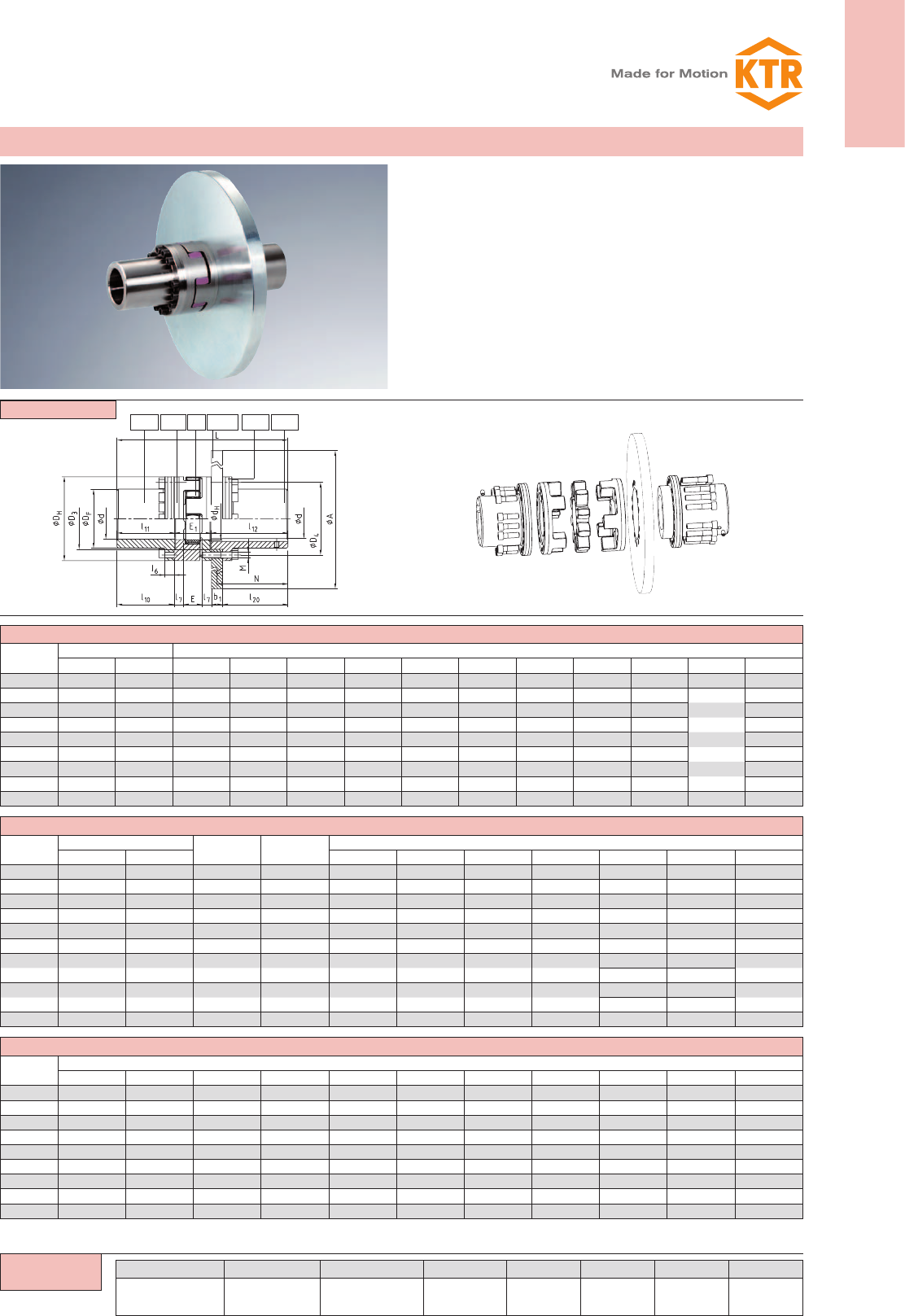
43
ROTEX®
Torsionally flexible coupling
You will find continuously updated data in our online catalogue at www.ktr.com.
ROTEX®
4Nv 3Na 3Na15Nx 4Nx2
ROTEX® type AFN-SB special
Size Finish bore d Dimensions [mm]
min. max. DHDFD3 H7/h7 D4dHE E1M z Pitch TA [Nm]
65 22 65 135 94 96 116 68 35 65 M10 12 16x22,5° 83
75 30 75 160 108 112 136 80 40 75 M12 15
20x18°
120
90 40 100 200 142 145 172 100 45 82 M16 15 295
100 46 110 225 158 165 195 113 50 97 M16 15 295
110 60 125 255 178 180 218 127 55 103 M20 15 580
125 60 145 290 206 215 252 147 60 116 M20 15 580
140 60 165 320 235 245 282 165 65 128 M20 15 580
160 80 190 370 270 280 325 190 75 146 M24 15 1000
180 85 220 420 315 330 375 220 85 159 M24 18 24x15° 1000
ROTEX® type AFN-SB special
Size Torque1) with 95Sh-A Max. speed
[RPM]
Max.braking
torque [Nm]2)
Dimensions [mm]
TKN TKmax l7l10 l11 l12 l20 N L
65 940 1880 3450 1880 16 112,5 113,5 166,0 135 150 344,5
75 1920 3840 3250 3840 19 131,5 133,0 166,5 135 150 374,5
90 3600 7200 3000 7200 20 164,0 165,5 206,5 175 190 454,0
100 4950 9900 2800 9900 25 153,5 155,0 206,5 175 190 458,5
110 7200 14400 2600 14400 26 201,5 203,5 212,0 180 195 518,5
125 10000 20000 2250 20000 30 198,5 200,5 212,0 180 195 528,5
140 12800 25600 1800 25600 34 244,5 247,0 252,5 220 235 627,5
210 3) 230 3)
160 19200 38400 1500 38400 38 226,5 229,0 252,5 220 235 627,5
210 3) 230 3)
180 28000 56000 1350 56000 40 195,0 198,0 252,5 220 235 609,5
ROTEX® assignment of coupling/brake disk
Size Brake disk ØA x b1
355x30 400x30 450x30 500x30 560x30 630x30 710x30 800x30 900x30 900x40 1000x40
65 x x x
75 x x x
90 x x x x
100 x x x
110 x x x x
125 x x x
140 x x x x x
160 x x x x x
180 x x x x x
Components
ROTEX® 90 AFN-SB special Ø450x30 98 Sh-A 4Nv Ø90 4Nx Ø90
Coupling size Type Øbrake disk, x
-width
Spider hard-
ness Component Finish
bore Component Finish
bore
Ordering
example:
1) Selection see page 20/21
2) The max. braking torque must not exceed the maximum torque of the coupling.
3) Dimensions for a brake disk width b1 of 40 mm.
Type AFN-SB special with brake disk
z = number
Motor side
zShaft coupling AFN-SB special with brake disk for brake cali-
pers
zBrake disk and spider can be replaced while being
assembled
zThe brake disk has to be placed onto the shaft end with the
biggest mass moment of inertia
zThe maximum braking torque must not exceed the
maximum torque of the coupling
zFinish bore according to ISO fit H7,
feather keyway according to DIN 6885 sheet 1 - JS9
zMounting instructions at www.ktr.com
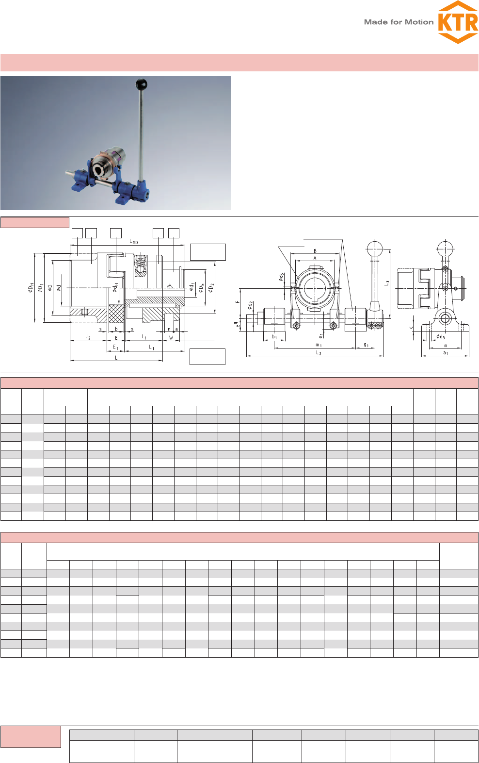
ROTEX®
Torsionally flexible coupling
44 You will find continuously updated data in our online catalogue at www.ktr.com.
1a 1 1e 11
2
ROTEX® type SD (No. 015)
Size Ød, ØD,
ØD1
Finish bore d1Dimensions [mm] Shifting
force
set in
[N]
Slip
ring
size
Shiftable
linkage
size
min. max. DHD2±0,1 Db dHl1;l2E s b E1L L1W a n±0,1 LSD
24 8 18 55 41 30 27 30 18 2,0 14 16,5 78 51,5 16,0 6 6,0 98 110 — —
28 10 22 65 58 36 30 35 20 2,5 15 18,0 90 60,0 17,5 8 8,0 113 130 — —
38 12 28 80 70,5 45 38 45 24 3,0 18 22,0 114 73,0 21,0 8 12,5 140 150 1.1 1
42 14 32 95 70,5 50 46 50 26 3,0 20 24,0 126 82,0 23,0 8 12,5 156 180 1.1 1
48 15 40 105 89,5 60 51 56 28 3,5 21 25,5 140 90,5 24,5 6 17,5 172 200 2.2 2
55 18 48 120 112,5 70 60 65 30 4,0 22 27,0 160 103,0 26,0 6 18,0 195 250 3.3 3
65 20 55 135 112,5 80 68 75 35 4,5 26 32,0 185 120,0 30,5 7 18,0 227 280 3.3 3
75 25 65 160 130,5 95 80 85 40 5,0 30 37,0 210 135,0 35,0 6 20,5 257 350 4.4 3
90 28 75 200 164,5 110 100 100 45 5,5 34 41,0 245 152,0 39,5 8 25,5 293 350 5.5 4
100 30 80 225 164,5 115 113 110 50 6,0 38 46,0 270 169,0 44,0 14 25,5 325 380 5.5 4
110 35 85 255 164,5 125 127 120 55 6,5 42 51,5 295 184,0 48,5 18,5 25,5 355 450 5.5 4
125 40 100 290 210,5 145 147 140 60 7,0 46 55,5 340 208,5 53,0 18,5 30,5 404 500 6.6 5
Slip ring and shiftable linkage
Size
Shiftable
linkage
size
Dimensions [mm] Max. speed
for slip ring
[RPM]
a1b1c d2d3d5e1) e1F g1L2L3m m1 min. m1 max. A B
38 1 110 50 18 20 11 12 30 25 70 55 320 400 75 180 190 90 114 3280
42 1
48 2
140
60 25
25
13,5
17 40
27 97,5 60 430 450
100
240 270 111 151 2550
55 3
30 32,5 120 70 490 600 280 310 140 180 2120
65 3
75 3 170 210 1710
90 4
160 35 21 50 37,5 147,5 70 565 750 120 321 365 200 244 1360
100 4
110 4
125 5 40 25 46 190 80 630 1085 365 410 250 300 855
Components
ROTEX® 38 SD with 1,1 and 1 98 Sh-A 1 Ø38 11 Ø28
Coupling size Type with slip ring 1.1 and
shifting linkage 1
Spider hard-
ness Component Finish
bore Component Finish
bore
Ordering
example:
1) In case of a through base plate the dimension „e“ of the shiftable linkage size 5 has to be increased by at least 10 mm.
Finish bore according to ISO fit H7, feather keyway according to DIN 6885 sheet 1 - JS9
see shaft coupling on pages 30 and 31;
stock programme/basic programme see
pages 28 and 29
shiftable linkage
slip ring
disengaged
shifting path
engaged
zShiftable shaft coupling for all applications in general
engineering
zEasy to engage and disengage driving or driven machines with
standstill of machine
zExisting shifting hub to be combined with slip ring and
shiftable linkage
zWith pilot bored shifting hubs the requested shifting force
must be set after final machining
zOther sizes on request according to M 370266
zComplete shifting device consisting of:
separated slip ring from red bronze, shift fork, shifting shaft,
shifting lever, eye type bearing
Design SD (shiftable at standstill)
Type SD with slip ring and shiftable linkageType SD
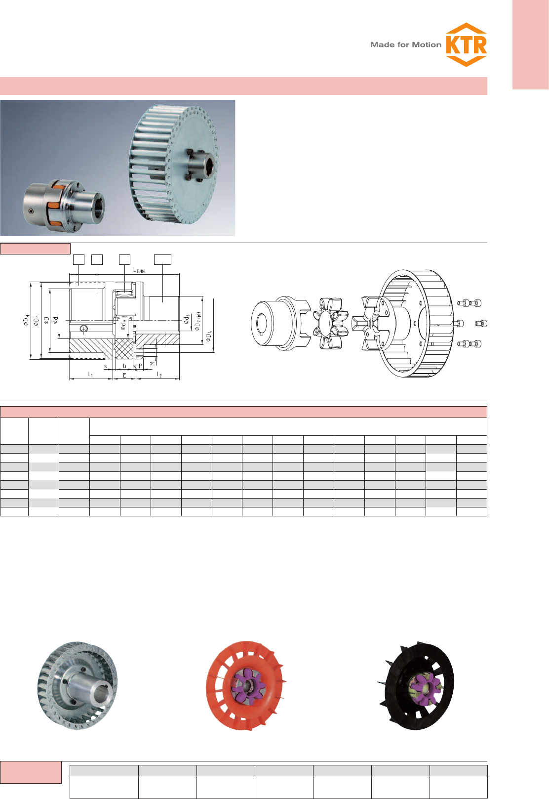
45
ROTEX®
Torsionally flexible coupling
You will find continuously updated data in our online catalogue at www.ktr.com.
ROTEX®
1a 1 1Nd2
ROTEX® type FNN (No. 021)
Size Ød, ØD,
ØD1
Max.
finish bore
Ød1
Dimensions [mm]
DHD2D4dHE s b l1;l2P M z Pitch LFNN
28 24 65 40 54 30 20 2,5 15 35 6,5 M6 8 8x45° 90
38 34 80 50 66 38 24 3,0 18 45 7,5 M8 8 114
42 42 95 60 80 46 26 3,0 20 50 9,5 M8 12 16x22,5° 126
48 48 105 68 90 51 28 3,5 21 56 10,5 M8 12 140
55 55 120 78 102 60 30 4,0 22 65 12,5 M10 8 8x45° 160
65 65 135 92 116 68 35 4,5 26 75 13,5 M10 12 16x22,5° 185
75 75 160 106 136 80 40 5,0 30 85 15,5 M12 15 20x18° 210
90 100 200 140 172 100 45 5,5 34 100 18,5 M16 15 245
Components
ROTEX® 38 FNN 92 Sh-A 1 Ø 38 1Nd Ø30
Coupling size Type Spider hardness Component Finish bore Component Finish bore
Design FNN and FNN with fan
see shaft coupling on
pages 30 and 31; stock pro-
gramme/basic programme
see pages 28 and 29
Type 3: Fan pressed or glued on
Special surface forming (knurling according
to DIN 82) allows the fan to be pressed or
glued onto the hub collar.
Type 2: Fan injection-moulded
Low prices due to production volumes
with higher quantities.
Type 1: Fan screwed on
The ROTEX® coupling can be supplied with
the fan screwed on. Specific connection
dimensions of customers such as pitch circle
of threads, size of threads and number or
centering of fans should be mentioned in your
inquiry.
Other sizes on request
Type FNN with fan (type 1)Type FNN
z = number
zDamping vibrations and reducing noise
zPerfect compensation for misalignment due to crowned teeth
zCoupling as plug-in design
zEasy inspection of wear by sight control
zCoupling to be equipped with any fan
zFinish bore according to ISO fit H7,
feather keyway according to DIN 6885 sheet 1 - JS9
Ordering
example:
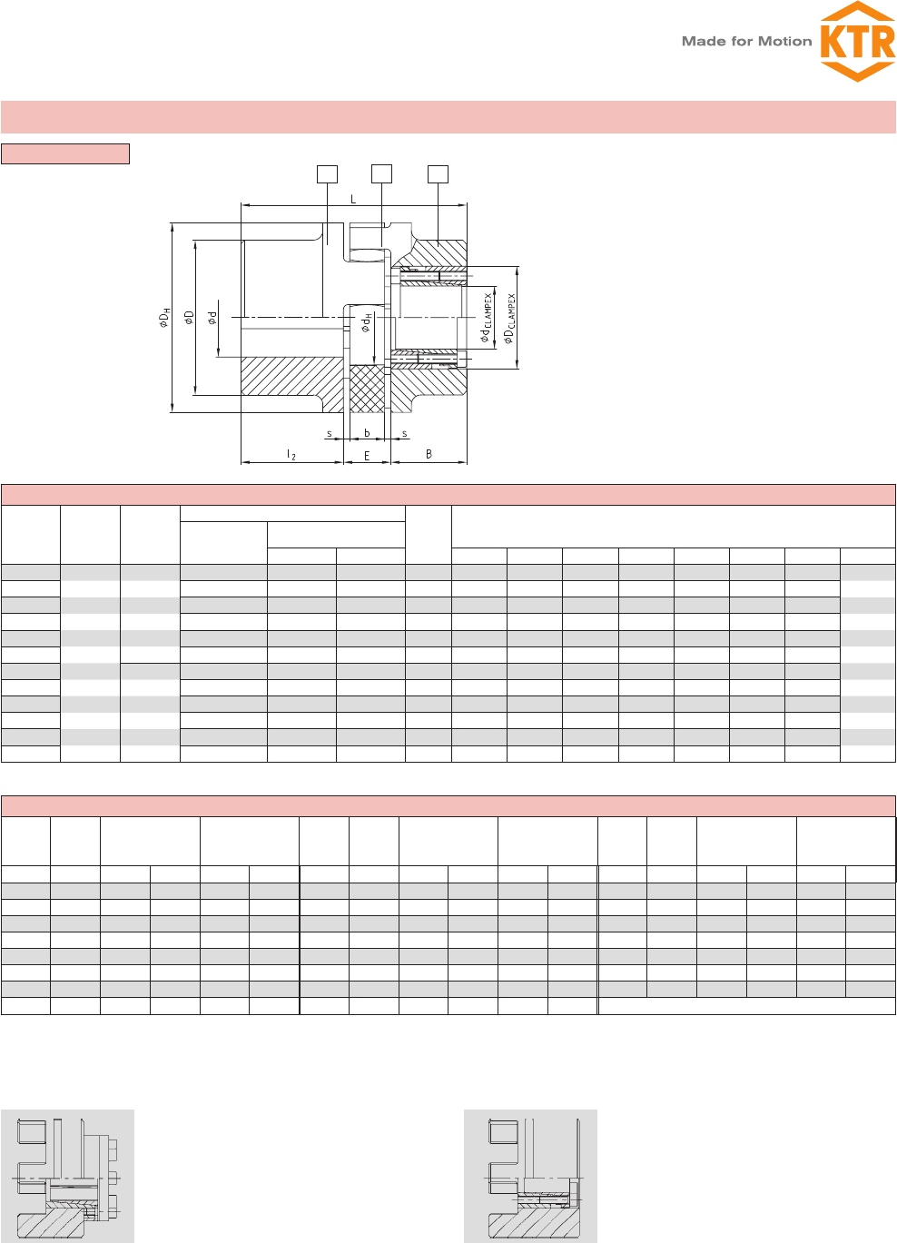
46
ROTEX®
Torsionally flexible coupling
You will find continuously updated data in our online catalogue at www.ktr.com.
1 1
2
ROTEX® type No. 001 with clamping set CLAMPEX® KTR 200
Size Ød, ØD,
ØD1Hub material
CLAMPEX® KTR 200
B
Dimensions [mm]
Max. size of KTR
clamping set
dxD
Transmittable torque and
axial force
T [Nm] FAX [kN] l2E s b DHD dHL
42 30x55 769 51 48 50 26 3,0 20 95 — 46
48 35x60 1197 68 48 56 28 3,5 21 105 — 51
55 45x75 2132 95 59 65 30 4,0 22 120 — 60
65 45x75 2132 95 59 75 35 4,5 26 135 115 68
75 50x80 3159 126 59 85 40 5,0 30 160 135 80
90 65x95 4107 126 59 100 45 5,5 34 200 160 100
100 65x95 4107 126 59 110 50 6,0 38 225 180 113
110 70x110 7023 201 70 120 55 6,5 42 255 200 127
125 80x120 8026 201 70 140 60 7,0 46 290 230 147
140 95x135 11373 239 70 155 65 7,5 50 320 255 165
160 110x155 16068 292 80 175 75 9,0 57 370 290 190
180 120x165 21910 365 80 195 85 10,5 64 420 325 220
ROTEX® type No. 001 with clamping set CLAMPEX® KTR 200
KTR 200
size Length
Transmittable
torque and
axial force
Clamping screws
DIN EN ISO 4762
– 12.9
KTR 200
Size Length
Transmittable
torque and
axial force
Clamping screw
DIN EN ISO 4762
– 12.9
KTR 200
Size Length
Transmittable
torque and
axial force
Clamping screws
DIN EN ISO 4762
– 12.9
dxD B T [Nm] Fax [kN] zxM TA [Nm] dxD B T [Nm] Fax [kN] zxM TA [Nm] dxD B T [Nm] Fax [kN] zxM TA [Nm]
20x47 48 513 51 6xM6 17 38x65 48 1299 68 8xM6 17 65x95 59 4107 126 8xM8 41
22x47 48 564 51 6xM6 17 40x65 48 1368 68 8xM6 17 70x110 70 7023 201 8xM10 83
24x50 48 616 51 6xM6 17 42x75 59 1990 95 6xM8 41 75x115 70 7524 201 8xM10 83
25x50 48 641 51 6xM6 17 45x75 59 2132 95 6xM8 41 80x120 70 8026 201 8xM10 83
28x50 48 718 51 6xM6 17 48x80 59 3033 126 8xM8 41 85x125 70 10659 251 10xM10 83
30x55 48 769 51 6xM6 17 50x80 59 3159 126 8xM8 41 90x130 70 11286 251 10xM10 83
32x60 48 1094 68 8xM6 17 55x85 59 3475 126 8xM8 41 95x135 66 11373 239 10xM10 83
35x60 48 1197 68 8xM6 17 60x90 59 3791 126 8xM8 41 for further details please see CLAMPEX® catalogue
Components
Further types with clamping sets
Assembly 1
Assembly 2
length = I2+ E + B (clamping set)
see shaft coupling on pages 30 and
31basic programme see pages 28 and
29
Design 4.3 with CLAMPEX® clamping set KTR 400Design 4.2 with CLAMPEX® clamping set KTR 250
Steel
part 1
GJS
part 1
Frictionally engaged, backlash-free shaft-
hub-connection for transmission of average
torques.
Frictionally engaged, backlash-free shaft-
hub-connection for transmission of bigger
torques. Maximum size of clamping set de-
pends on the hub collar diameter. Clamping
set screw fitting possible both internally and
externally. For details of calculation please
see CLAMPEX® catalogue.
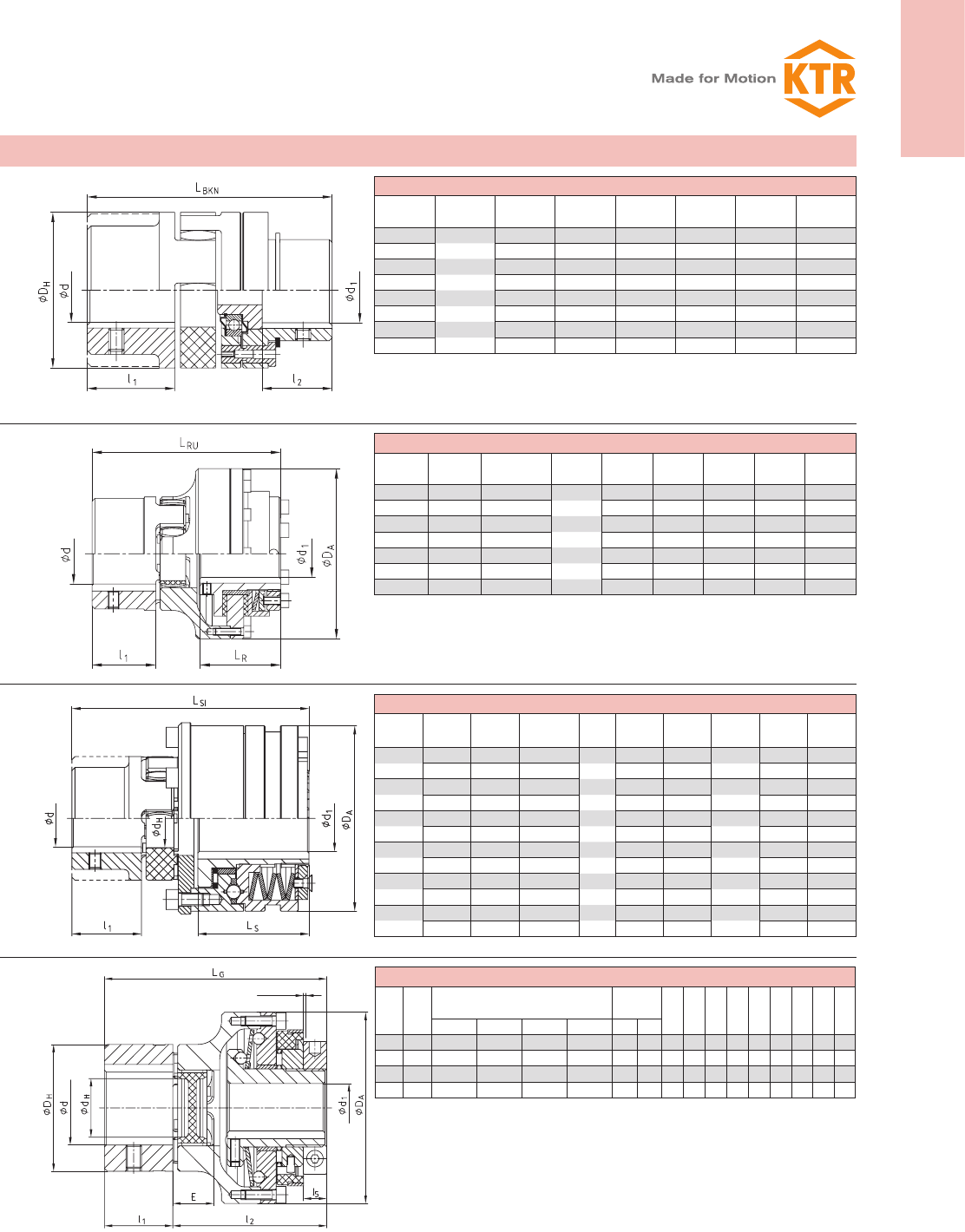
ROTEX®
47
ROTEX®
Torsionally flexible coupling
You will find continuously updated data in our online catalogue at www.ktr.com.
ROTEX® BKN - shear pin coupling, type BKN No. 009
Size Max. finish
bore d
Max. finish
bore d1l1l2 LBKN DHMin. fracture
torque [Nm]
28 28 35 25 101 65 100
38 38 45 35 125 80 190
42 42 50 40 139 95 250
48 48 56 46 153 105 300
55 55 65 55 177 120 400
65 65 75 65 202 135 500
75 75 85 70 230 160 600
90 100 100 85 266 200 700
ROTEX® - RUFLEX® - coupling with torque limiter, type No. 070
ROTEX®
size
RUFLEX®
size
Ratchet
torques [Nm] d d1 max. DAl1LRLRU
14 00 0,5 — 5 10 44 11 31 59
19 0 2 — 20 20 1) 63 25 33 78
24 01 5 — 70 22 80 30 45 98
28 1 20 — 200 25 98 35 52 113
38 2 25 — 400 35 120 45 57 133
48 3 50 — 800 45 162 56 68 166
75 4 90 — 1600 55 185 85 78 205
ROTEX® - KTR-SI - coupling with torque limiter, type No. 070
ROTEX®
size
KTR-SI
type
KTR-SI
size
Ratchet
torques
[Nm]
d max. d1DAl1LSLSI
28 DK 2 12-200 35 100 35 56 124
SR/SGR 0 5-40 20 55 34,5 102
38 DK 3 25-450 45 120 45 73 155
SR/SGR 1 12-100 25 82 48 129,5
48 DK 4 50-1000 55 146 56 93,5 194
SR/SGR 2 25-200 35 100 56 155
55 DK 5 85-2000 65 176 65 107 222,5
SR/SGR 3 50-450 45 120 73 186
75 DK — — — — 85 — —
SR/SGR 4 100-2000 55 146 93,5 241,5
90 DK — — — — 100 — —
SR/SGR 5 170-3400 65 176 107 275,5
SYNTEX® - backlash-free, torsionally rigid overload coupling with ROTEX® GS
ROTEX®
size
SYNTEX®
size
SYNTEX® torque range
disk spring [Nm]
Max.
bore DADHdHE L LGl1l2l5
DK1DK2SK1SK2d d1
24 20 6-20 15-30 10-20 20-65 35 20 80 55 27 18 45 100 30 70 10
28 25 20-60 45-90 25-65 40-100 40 25 98 65 30 20 50 113 35 78 11
38 35 25-80 75-150 30-100 70-180 48 35 120 80 38 24 60 136 45 91 13
48 50 60-180 175-300 80-280 160-400 55 50 162 105 51 28 70 167 56 111 14
Further designs with torque limiter
stroke = 2 mm
1) Finish bore exceeding ø 19, keyway according to 6885 sheet 3
Modification for customer from the stock programme.
Please mention the fracture torques with your order!
For further details please see dimension sheet No. 5020/000/009-7603
see shaft coupling
on pages 30 and 31,
basic programme
see pages 28 and 29
see shaft coupling
on pages 30 and 31,
basic programme
see pages 28 and 29
see shaft coupling on pages 30 and 31,
basic programme see pages 28 and 29
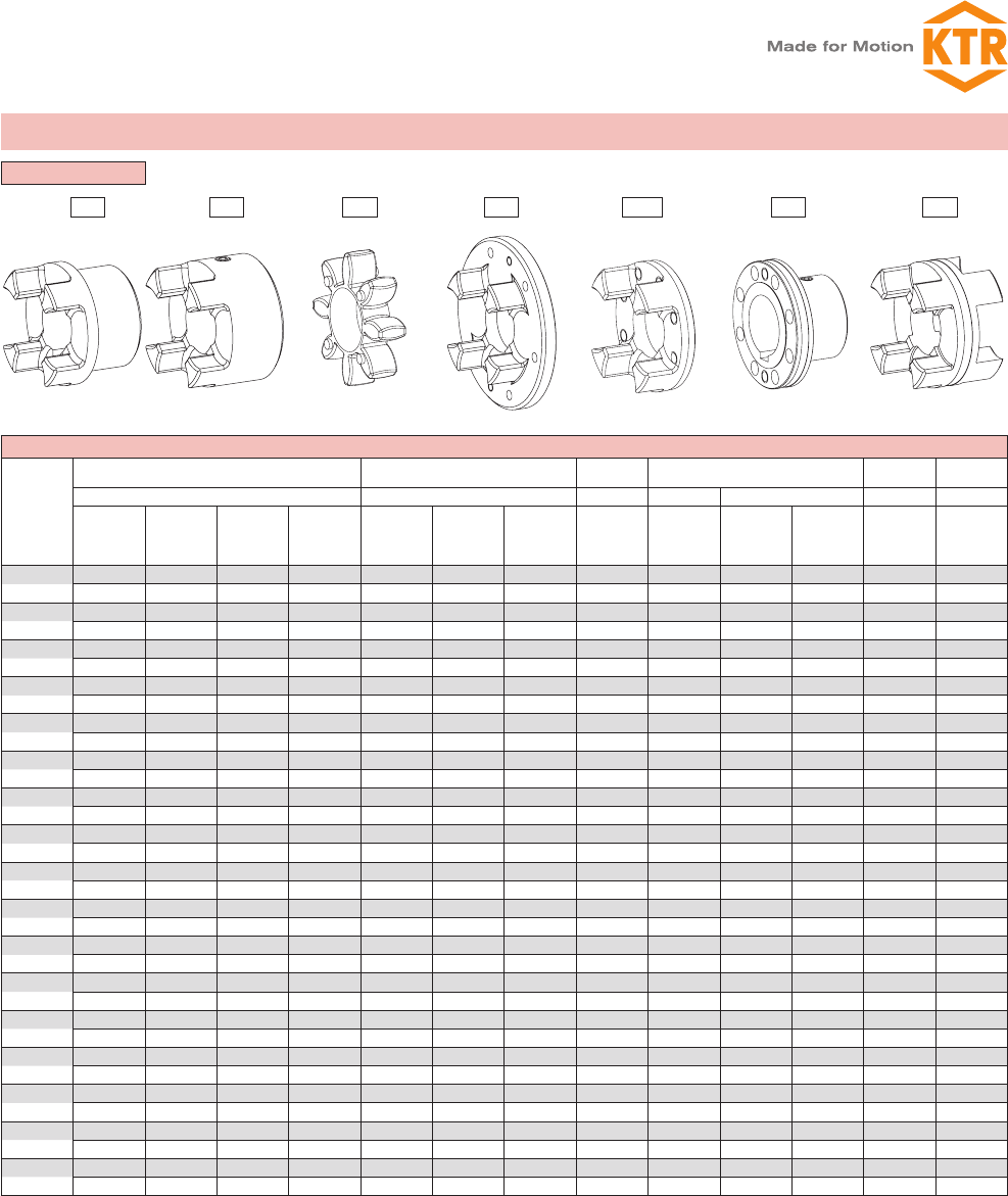
48
ROTEX®
Torsionally flexible coupling
You will find continuously updated data in our online catalogue at www.ktr.com.
1 1a 2 3b 3Na 64N
Components
ROTEX® components
Size
Standard hub Large hub Spider Driving flange C-flange DKM
spacer
Part 1 Part 1a Part 2 Part 3b Part 3Na Part 4N Part 6
Alu
[kg]
[kgm²]
GJL
[kg]
[kgm²]
GJS
[kg]
[kgm²]
St
[kg]
[kgm²]
Alu
[kg]
[kgm²]
GJL
[kg]
[kgm²]
St
[kg]
[kgm²]
Polyurethane
(Vulkollan)
[kg]
[kgm²]
GJS
[kg]
[kgm²]
St
[kg]
[kgm²]
GJS
[kg]
[kgm²]
St
[kg]
[kgm²]
Alu
[kg]
[kgm²]
14 — — — — 0,020 — — 0,0044 — — — — —
— — — — 0,000003 — — 0,0000005 — — — — —
19 0,064 — — — 0,074 — 0,25 0,0056 — — — — —
0,00001 — — — 0,00002 — 0,00006 0,000001 — — — — —
24 0,123 — — — 0,174 — 0,55 0,014 0,028 0,145 — 0,30 0,14
0,00004 — — — 0,00008 — 0,00023 0,000006 0,00023 0,00007 — 0,00009 0,00006
28 0,200 — — — 0,264 — 0,89 0,024 0,54 0,232 — 0,49 0,22
0,00010 — — — 0,00019 — 0,00053 0,000010 0,0007 0,00017 — 0,0002 0,00013
38 0,44 1,16 — 1,6 0,470 1,32 1,74 0,042 0,73 — 0,313 0,87 0,35
0,00033 0,00086 — 0,00151 0,00046 0,00135 0,00155 0,00003 0,001 — 0,00038 0,0005 0,00035
42 0,69 1,75 — 2,44 0,772 2,05 2,74 0,065 1,26 — 0,608 1,4 0,47
0,00067 0,00178 — 0,00281 0,00111 0,00291 0,00343 0,00007 0,0032 — 0,00089 0,0011 0,00068
48 0,80 2,44 — 3,34 1,01 2,78 3,72 0,086 1,45 — 0,755 1,92 0,62
0,011 0,00308 — 0,00473 0,00174 0,00484 0,00570 0,00013 0,0043 — 0,001358 0,0018 0,0011
55 — 3,68 — 5,05 — 4,08 5,57 0,11 2,58 — 1,243 2,93 0,90
— 0,00615 — 0,00948 — 0,00926 0,01193 0,00023 0,0105 — 0,002920 0,0037 0,0021
65 — 5,67 — 6,79 — 6,04 8,22 0,17 3,10 — 1,635 4,36 1,31
— 0,01240 — 0,01516 — 0,01789 0,02079 0,00042 0,0149 — 0,004891 0,0069 0,0039
75 — 8,72 — 10,5 — 9,53 14,3 0,32 4,46 — 2,511 6,80 1,97
— 0,02644 — 0,03269 — 0,03946 0,05069 0,00116 0,0281 — 0,01050 0,0151 0,0082
90 — 14,8 — 18,7 — 18,2 24,0 0,57 6,94 — 4,151 12,84 3,45
— 0,06730 — 0,08742 — 0,15086 0,13151 0,00323 0,0651 — 0,02723 0,0448 0,0224
100 — — 19,7 — — — — 0,81 10,2 — 6,350 16,16 —
— — 0,11694 — — — — 0,00588 0,1165 — 0,05273 0,0798 —
110 — — 27,4 — — — — 1,19 — — 8,578 21,35 —
— — 0,20465 — — — — 0,01097 — — 0,09121 0,2824 —
125 — — 42,3 — — — — 1,63 — — 12,598 34,33 —
— — 0,40727 — — — — 0,01972 — — 0,17469 0,3229 —
140 — — 58,1 — — — — 2,11 — — 17,271 48,69 —
— — 0,67739 — — — — 0,03129 — — 0,29247 0,4917 —
160 — — 84,2 — — — — 3,21 — — 26,305 71,08 —
— — 1,31729 — — — — 0,06323 — — 0,59436 0,9693 —
180 — — 118,5 — — — — 5,25 — — 33,076 109,43 —
— — 2,30835 — — — — 0,13789 — — 0,97394 1,9650 —
Weight and mass moment of inertia each refer to the average finish bore without keyway.
Weights and mass moments of inertia
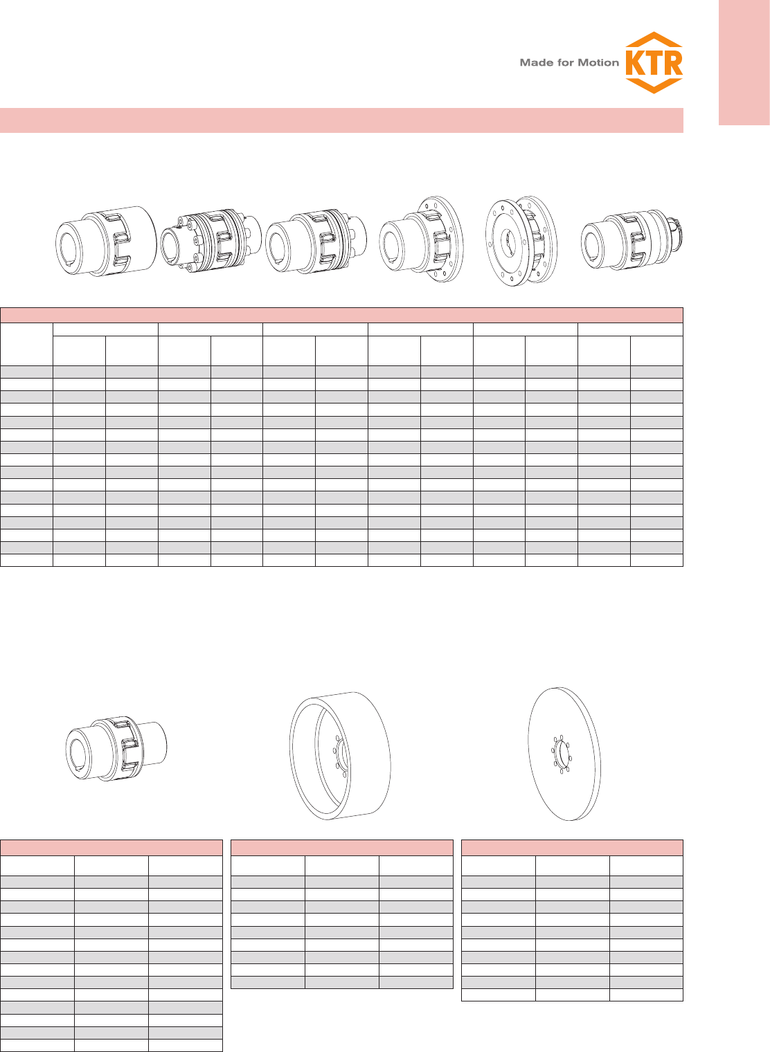
ROTEX®
49
ROTEX®
Torsionally flexible coupling
You will find continuously updated data in our online catalogue at www.ktr.com.
ROTEX® complete couplings
Size
Standard AFN BFN CF DF SD
Weight
[kg]
Mass moment
of inertia J
[kgm²]
Weight
[kg]
Mass moment
of inertia J
[kgm²]
Weight
[kg]
Mass moment
of inertia J
[kgm²]
Weight
[kg]
Mass moment
of inertia J
[kgm²]
Weight
[kg]
Mass moment
of inertia J
[kgm²]
Weight
[kg]
Mass moment
of inertia J
[kgm²]
19 0,51 0,000121 — — — — 0,44 0,00016 0,38 0,00020 0,42 0,00008
24 1,1 0,000466 0,98 0,00036 1,1 0,00041 0,84 0,00047 0,57 0,00047 1,1 0,00046
28 1,8 0,00107 1,6 0,00083 1,7 0,00095 1,5 0,00124 1,1 0,00141 1,9 0,00106
38 2,5 0,00171 2,8 0,00209 2,6 0,00193 1,9 0,00217 1,5 0,00259 3,0 0,00435
42 3,9 0,00476 4,5 0,00472 4,1 0,00419 3,1 0,00513 2,6 0,00662 4,4 0,00804
48 5,3 0,00805 5,9 0,00736 5,5 0,00684 3,9 0,00755 3,0 0,00881 6,2 0,00223
55 7,9 0,01564 8,9 0,01480 8,3 0,01369 6,4 0,01692 5,3 0,02131 9,8 0,0166
65 11,9 0,03071 12,9 0,0266 12,3 0,0259 8,9 0,02780 6,4 0,003037 14,9 0,0326
75 18,6 0,06706 20,6 0,0601 19,3 0,0572 13,5 0,0557 9,2 0,05741 23,2 0,0706
90 33,6 0,22139 37,8 0,1718 34,2 0,1551 22,3 0,1356 14,5 0,1333 40,5 0,1891
100 40,2 0,23976 49,6 0,3068 45,2 0,2737 30,9 0,2401 21,2 0,2394 46,7 0,2467
110 56,0 0,42027 67,5 0,5385 61,7 0,4793 42,9 0,4324 29,8 0,4446 61,5 0,4186
125 86,2 0,83426 102,6 1,0485 94,4 0,9413 64,4 0,8187 42,2 0,8031 96,8 0,8497
140 118,3 1,38607 141,2 1,743 129,7 1,564 90,4 1,4221 62,5 1,4580 127,8 1,368
160 171,6 2,69781 210,3 3,517 190,9 3,107 127,6 2,589 83,6 2,4805 190,3 2,723
180 242,25 4,75449 306,6 6,582 274,4 5,668 175,1 4,448 107,9 4,141 262,2 4,810
BTAN/SBAN without drum/disk
Size Weight
[kg]
Mass moment of
inertia J [kgm²]
28 0,90 0,0004
38 2,10 0,0014
42 3,24 0,0031
48 4,41 0,0053
55 6,60 0,0105
65 10,1 0,0209
75 15,4 0,0442
90 27,6 0,1224
100 36,9 0,2074
110 50,9 0,3665
125 79,1 0,7349
140 109,0 1,2292
160 161,9 2,4569
180 232,9 4,4967
Brake drum for BTAN 1)
Brake drum
ØDB x B
Weight
[kg]
Mass moment of
inertia J [kgm²]
160 x 60 2,12 0,01
200 x 75 3,45 0,03
250 x 95 6,87 0,08
315 x 118 14,95 0,28
400 x 150 31,20 0,89
500 x 190 60,00 2,70
630 x 236 112,00 8,01
710 x 265 161,00 14,9
800 x 300 202,00 27,2
Brake disk for SBAN 1)
Brake disk
ØA x GS
Weight
[kg]
Mass moment of
inertia J [kgm²]
200 x 12,5 2,928 0,015367
250 x 12,5 4,662 0,037584
315 x 16 8,618 0,111829
400 x 16 15,230 0,315206
500 x 16 23,964 0,769963
630 x 20 47,716 2,426359
710 x 20 60,934 3,915100
800 x 25 94,913 7,878998
900 x 25 118,954 12,609089
1000 x 25 148,240 19,234941
Weights and mass moments of inertia
Weight and mass moment of inertia each refer to the average finish bore without keyway.
1) Selection of ROTEX® brake drum/brake disk please see page 42.

50 You will find continuously updated data in our online catalogue at www.ktr.com.
