Kohler Engine Accessories (E 1953 L) As Of Apr08 Accessories(E 200804
User Manual: Kohler Engine Accessories (E-1953-L) as of Apr08 WFMFiles.com
Open the PDF directly: View PDF ![]() .
.
Page Count: 56
EnginE AccEssoriEs
Capitalizing on performance and reliability.
2008 Edition

2
Table of Contents
SECTION PAGE
Central Distributors – North America ....................3
Central Distributors – International .......................3
Engine Model Lines .............................................4-5
Lubrication ...........................................................6-8
Starting .................................................................9
Meters & Special Tools .........................................10
Special Items ........................................................11
Ignition and Electrical ...........................................12-14
Guards, Screens, and Blower Housings...............15-17
Front Drive Shafts.................................................18
Fuel.......................................................................19-21
Controls
(Includes coolant and lubrication alert items) .......22-24
Electrical Accessories ...........................................25
Air Intake ..............................................................26-32
Exhaust.................................................................33-46
Labels ...................................................................47-53
Hang Tags and Cards ...........................................54
Contents
3
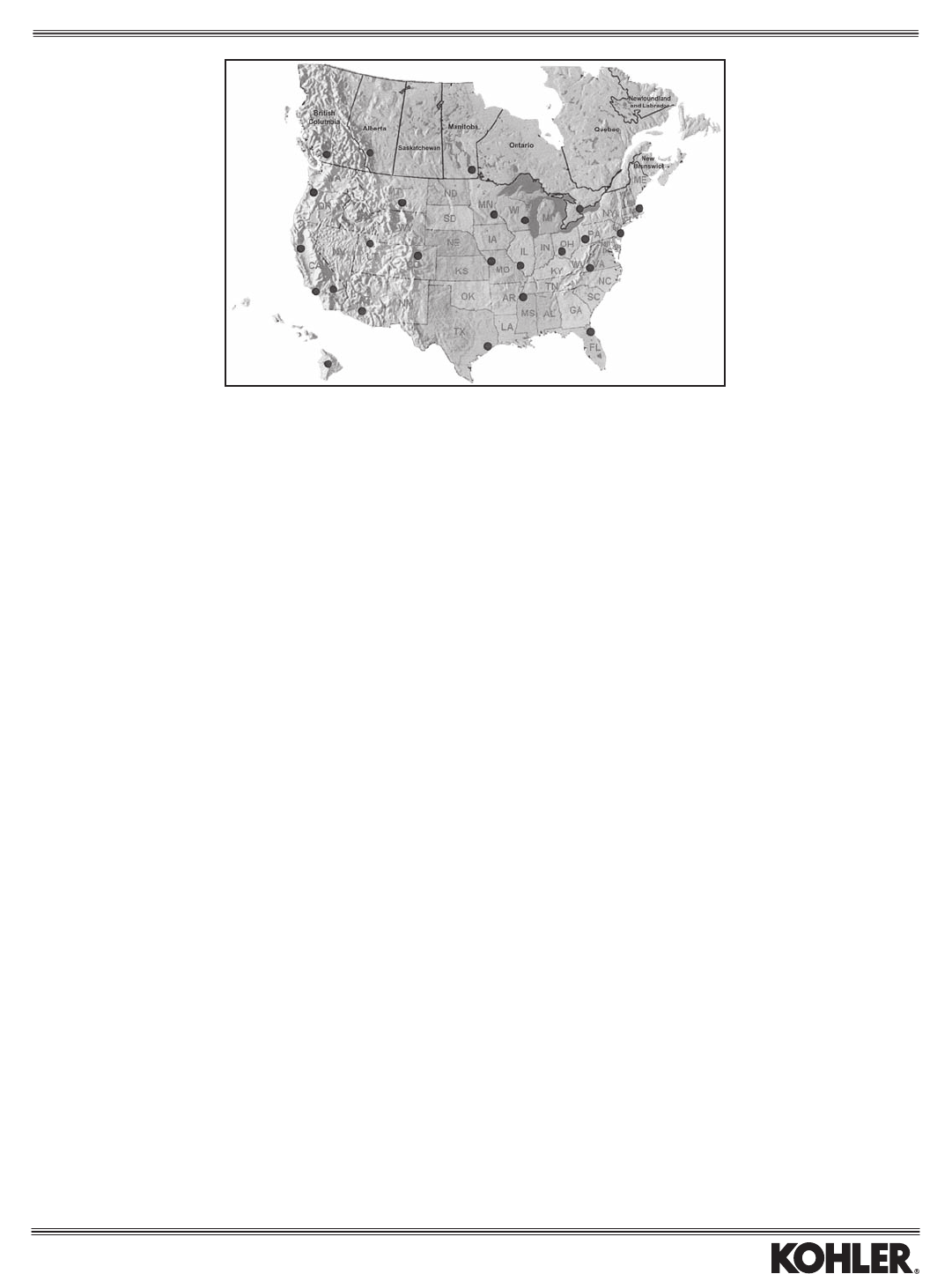
Kohler central distributors are listed on this page. They...and all Kohler dealers...can quickly provide the eld-installed accessories in this
catalog to keep your KOHLER® engines running smoothly and efciently.
UNITED STATES
STATE/PROVINCE KOHLER CENTRAL DISTRIBUTOR CITY PHONE
Arizona ................................. Loftin Equipment Co., Inc ............................................Phoenix ...............................................602-272-9466
California .............................. H. G. Makelim Co. .......................................................Anaheim ..............................................650-873-4757
H. G. Makelim Co. .......................................................S. San Francisco .................................650-873-4757
Colorado ............................... H. G. Makelim Co.–Denver ..........................................Aurora..................................................303-307-8874
Florida ................................... Gardner of Florida, Inc. ...............................................Jacksonville .........................................888-889-3010
Hawaii ................................... Small Engine Clinic ......................................................Aiea .....................................................808-488-0711
Kansas .................................. Medart–Kansas City ....................................................Edwardsville ........................................636-282-2300
Massachusetts ...................... W.J. Connell Co. ..........................................................Franklin................................................508-543-3600
Minnesota ............................. Central Power Distributors, Inc. ...................................Anoka ..................................................763-576-0901
Mississippi ............................ Medart–Tennessee/Mississippi ....................................Olive Branch, MS ................................636-282-2300
Missouri ................................ Medart–St. Louis .........................................................St. Louis ..............................................636-282-2300
Montana ................................ Original Equipment, Inc. .............................................Billings .................................................406-245-3081
New Jersey ........................... Gardner, Inc.–New Jersey ...........................................Cranbury..............................................609-860-8060
Ohio ...................................... Gardner, Inc.–Ohio ......................................................Columbus ............................................614-456-4000
Oregon .................................. Power Equipment Systems .........................................Salem ..................................................800-782-2700
Pennsylvania ........................ Pitt Auto Electric Co. ...................................................Cranberry Township ............................724-778-8200
Tennessee ............................ Medart–Tennessee/Mississippi ....................................Olive Branch, MS ................................636-282-2300
Texas .................................... Waukesha-Pearce Industries, Inc. ...............................Houston ...............................................713-723-1050
Utah ...................................... Diesel Electric Service & Supply Co., Inc. ..................Salt Lake City ......................................801-972-1836
Virginia .................................. Chesapeake Engine Distributors .................................Ashland ...............................................804-550-2231
Wisconsin ............................. Central Power Distributors, Inc. ..................................Menomonee Falls ................................262-250-1977
CANADA
Alberta .................................. Lotus Equipment Sales, Ltd. ........................................Calgary ................................................403-253-0822
British Columbia ................... Magneto Sales .............................................................Surrey ..................................................604-888-7240
Manitoba ............................... Yetman’s Ltd. ...............................................................Winnipeg ............................................204-586-8046
Ontario .................................. CPT–Canada Power Technology .................................Mississauga.........................................905-890-6900
INTERNATIONAL ~ Visit the Dealer Locator: www.KohlerEngines.com
Distributors
4
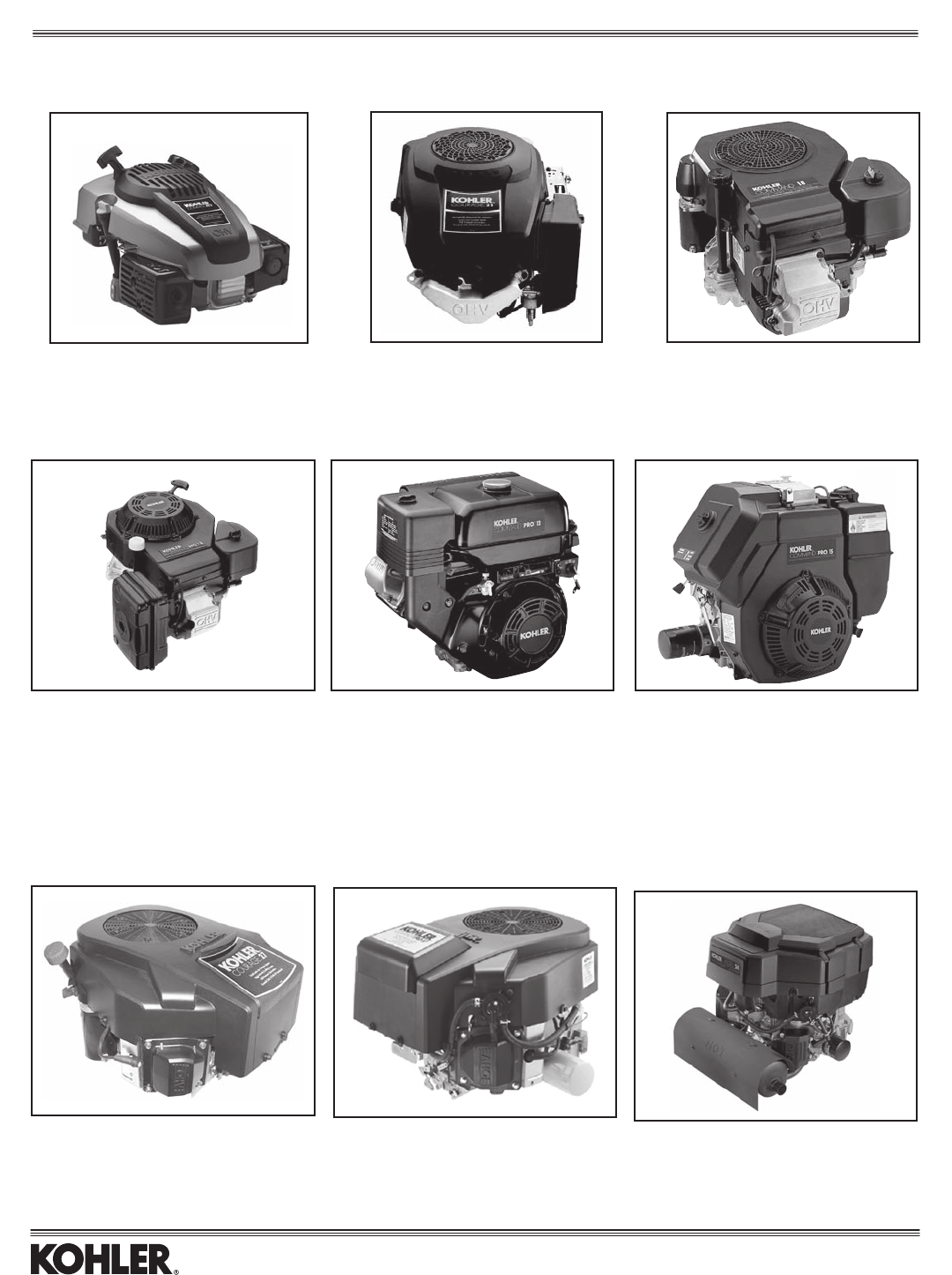
TWIN CYLINDER
Command PRO® CS 4-12.75 HP
Air-cooled, horizontal, OHV
Models: CS4, 6, 8.5, 10, 12
Courage® 15-22 HP
Air-cooled, vertical, OHV
Models: SV470, 480, 530, 540, 590, 600, 610, 620
Command® 13-18 HP
Air-cooled, vertical, OHV
Models: CV13, 15, 460, 490, 492
Command PRO® 11-15 HP
Air-cooled, horizontal, OHV
Models: CH15, 410, 430, 450
Command PRO® 13-18 HP
Air-cooled, vertical, OHV
Models: CV13, 15, 493
KOHLER Aegis® 20-24 HP
Liquid-cooled, vertical, OHV
Models: LV625, 680
KOHLER Courage® 20-27 HP
Air-cooled, vertical, OHV
Models: SV710, 715, 720, 730, 735, 740
Courage® 4.5 HP
Air-cooled, vertical, OHV
Models: XT-7
KOHLER Courage PRO® 20-27 HP
Air-cooled, vertical, OHV
Models: SV810, 820, 830, 840
SINGLE CYLINDER
The Growing Family of KOHLER Engines
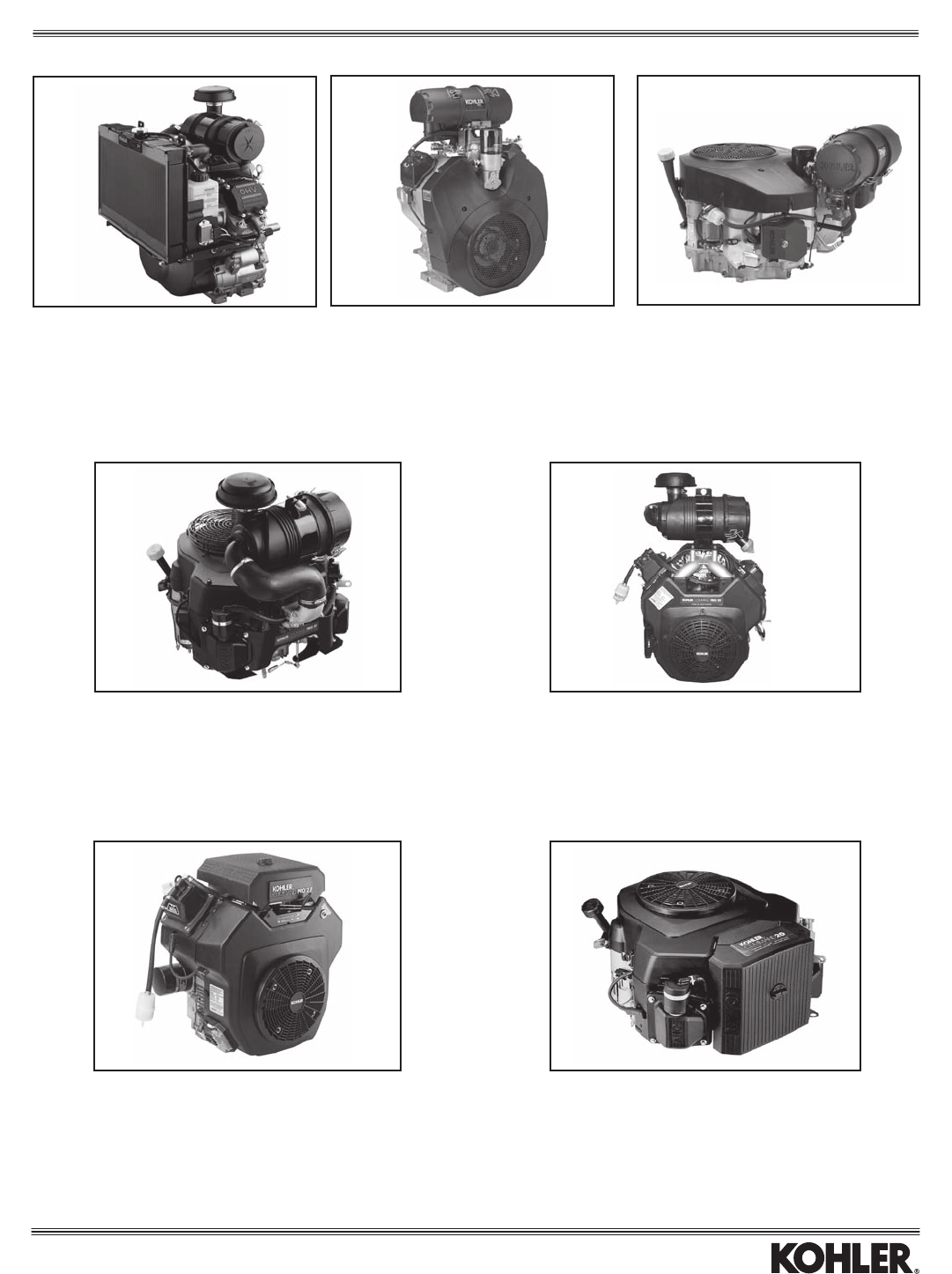
5
KOHLER Aegis® 24-31 HP
Liquid-cooled, horizontal, OHV
Models: LH640, 690, 755, 775 EFI
Command PRO® 34-40 HP
Air-cooled, horizontal, OHV
Models: CH940, 960, 980, 1000
Command PRO® 17-30 HP
Air-cooled, vertical, OHV
Models: CV17, 18, 22, 25, 26, 730, 740,
745 EFI, 750
Command® 18-27 HP
Air-cooled, horizontal, OHV
Models: CH18, 20, 22, 620, 640, 680, 730, 740
Command PRO® 34-40 HP
Air-cooled, vertical, OHV
Models: CV940, 960, 980, 1000
Command PRO® 18-30 HP
Air-cooled, horizontal, OHV
Models: CH18, 20, 22, 25, 26, 730, 740,
745 EFI, 750
Command® 18-27 HP
Air-cooled, vertical, OHV
Models: CV18, 20, 22, 730, 740
The Growing Family of KOHLER Engines
6
* For valve cover with pulse-type fuel pump, not mechanical fuel pump. Includes o-ring.
** For valve cover with mechanical fuel pump. Includes o-ring.
***Usedwitharedtubeforimprovedseal.StandardsinceSerialNo.3016800011.Earlierstandarddipstick2403806-Ssupersededto24755121-SKitwhich
includesthe2403810-SdipstickandthreedipsticktubestotallCHtwincongurations.
****Canbeusedinplaceofthe1”diametermetaloilll/dipsticktubeforimprovedseal.Canbeusedwithstandardcanister-stylemufers.Donotuseonapplications
with crossover manifolds.
OIL COOLER KIT
To add cooler to engine. Reduces oil sump temperature up to 40°F.
Kit No. Adapter Material Models
24 755 120-S* Stanyl CH/CV17-26/730-750
*Increasesenginewidthonoilltersideby1.25"(CHtwins)or0.625"(CVtwins).
YELLOW ACCESSORIES
Part No. Item Models
2475546-S* Oilllcapkit CH18-26/730-750,LH640-775 1
2422702-S** Oilllcapassy CH18-26/730-750,LH640-775 2
12 038 10-S Dipstick, bent tube CH11-15 3
12 038 14-S Dipstick, straight tube CH11-15 3
12 038 02-S Dipstick, straight tube CV11-16/460-493 4
24 038 04-S Dipstick, straight tube CV17-26/730-750 4
66 038 01-S Dipstick, bent tube LV625-680 4
24 038 10-S*** Dipstick, bent/straight tube CH18-26/730-750, LH640-775 5
2004002-S**** Dipstick,benttube(Standard) SV470-610 -
2412322-S**** Dipstick,tubekit(plastic) CH18-26/730-750,LH640-775 6
OIL DRAIN ADAPTER
Forusewith2575514-SOilDrainValveKit(3/8"-18).Includesseal.
Part No. Thread, Engine End Thread, Cap End Models
6375511-S* M10-1.25,Male 1/8"-27,Female CS4-6
6375510-S M12-1.5,Male2 3/8"-18,Female CS8.5-12
*Customermustfurnisha1/8"-27straightpipe(toextendawayfromengine),anda
3/8"-18x1/8"-27reducercouplingforattachingpipetoValveKit.
OIL DRAIN VALVE KIT
Part No. Drain Hole Models
2575514-S 3/8"-18NPTF AllModels*
Includes 25 173 14-S yellow plastic cap.
*ForCH6,alsoorder1515802-Sbushingwhichadapts3/8"NPTvalveto1/2"
NPT engine drain.
OIL DRAIN HOSE
Forusewith2575514-SOilDrainValveKit(3/8"-18).
Part No. Length Thread Models
2432659-S* 7" 3/8"-18,Male(bothends) All
2432666-S** 12.25" 3/8"-18,Female(oneend) All
2532605-S** 28" 3/8"-18,Female(oneend) All
*Also order 25 249 01-S Female Coupling for attaching hose to Valve Kit.
**Also order 24 294 22-S Barbed Fitting and 25 237 02-S Clamp for attaching
hose to oil drain hole.
12
3
4
5
6
Lubrication
OIL COOLER HOSE
Part No. Length I.D.
2432617-S* 140mm(5-1/2”) 9.52mm(3/8”)
7
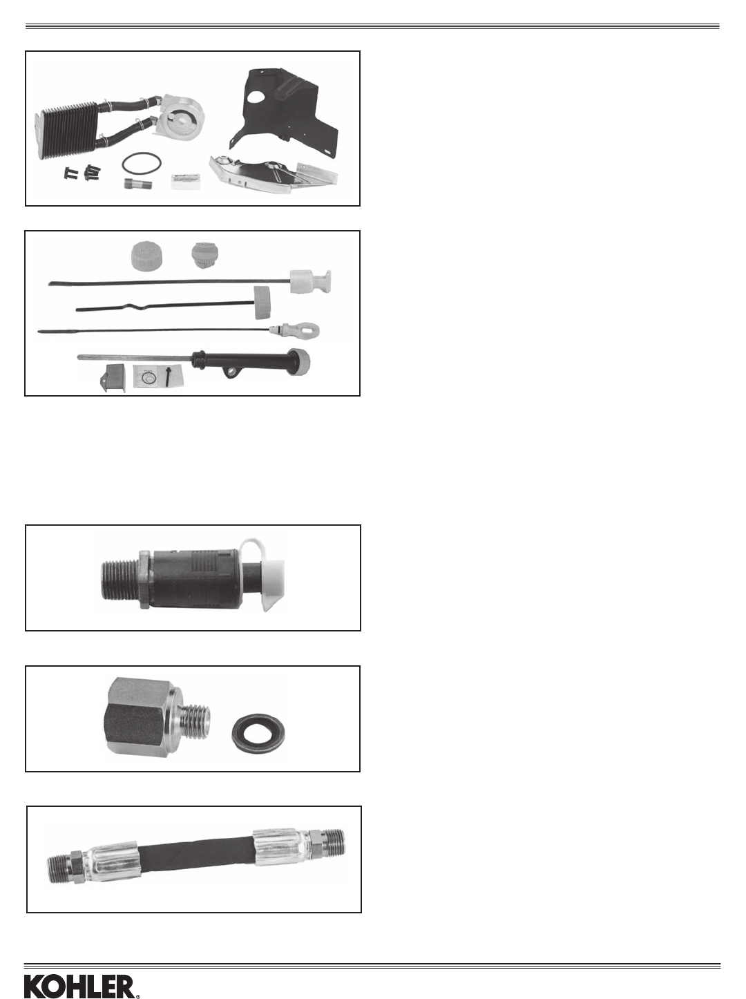
OIL FILTERS
Part No. Height Models Item
2505034-S 3.47" SV810-840PRO 1
5205002-S 3.47" CH11-15PRO,SV470-610 2
CV13-15/493 PRO, SV710-740,
CH/CV18-26/730-745 PRO,
LV625-675, LH640-775
1205001-S 2.72" CV11-16/460-492,SV470-610, 3
CH/CV17-25/730-740,
SV710-740, TH520-575
2805001-S* 2.32" TH520-575 4
*Shorterforapplicationswithinterferenceissues.Approx.15%lessltercapacity.
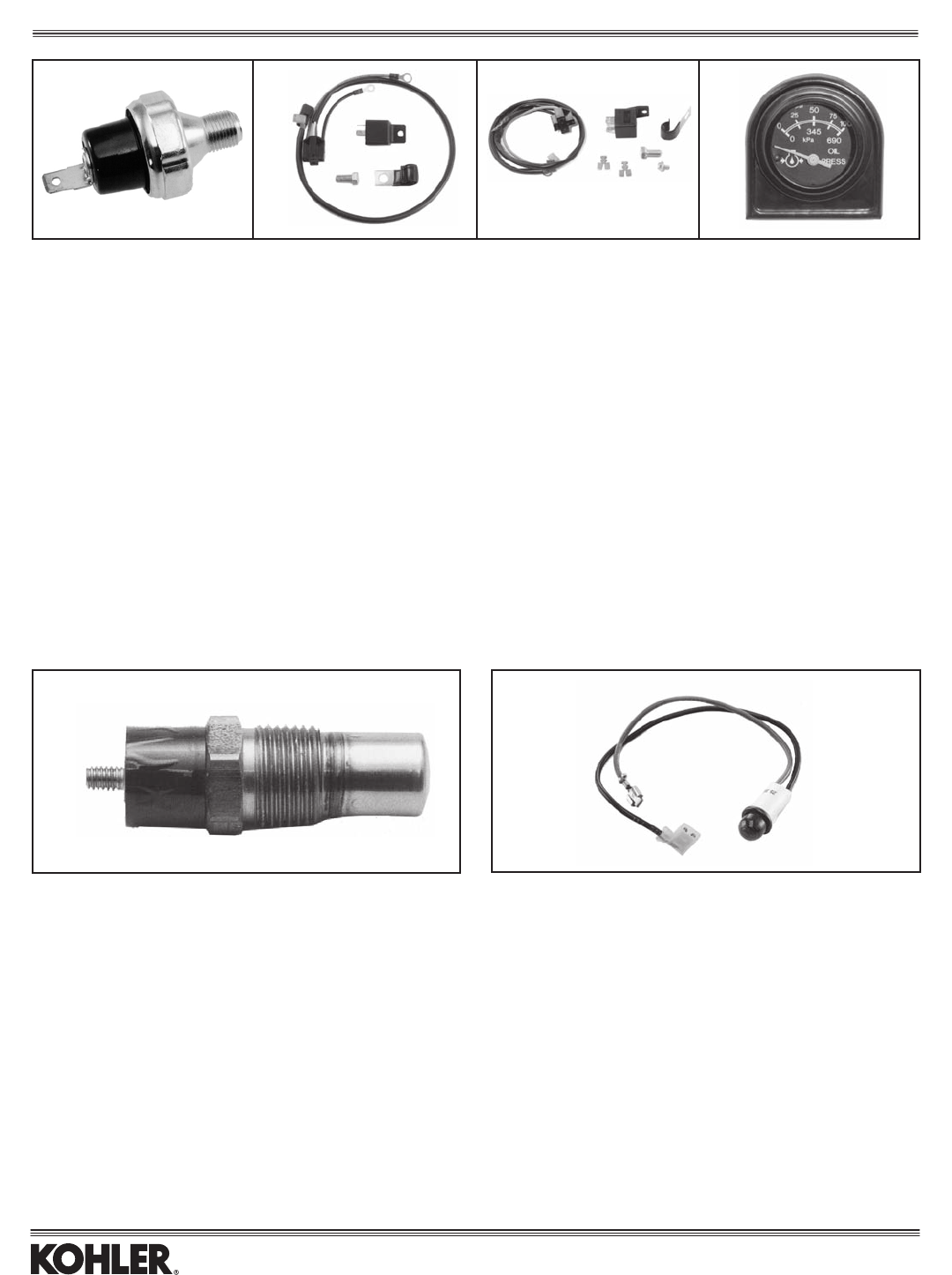
REMOTE OIL FILTER
Kit No. Oil Line Length Models
2470202-S* 23" CH/CV11-16/460-493,
SV470-610, CH/CV17-26,
CH/CV730-750, LV625-675,
SV710-740
*Includes 12 050 01-S Filter.
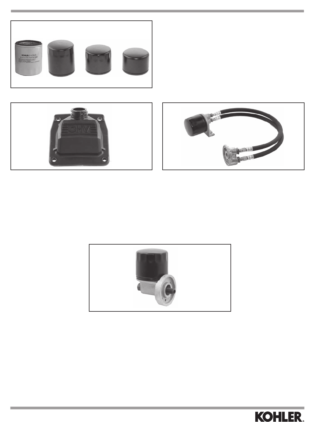
VALVE COVER WITH OIL FILL
Idealforaddinganextraoillllocation.
Part No. Description Models
24755140-S* Valvecoverwithoilll** CH18-26/730-745
6675510-S* Valvecoverwithoilll*** LH640-775
* Usable on either valve cover side, except for basic engines which include
amechanicalfuelpump(withoilll)inltersidevalvecover.
** Also order 24 755 46-S yellow cap/o-ring assembly, or 25 755 13-S black
cap/o-ring assembly.
***Includes yellow cap, o-ring, etc.
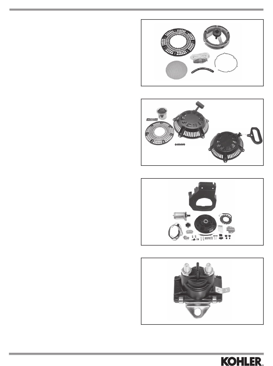
OIL FILTER BASE (ENGINE-MOUNTED)
Part No. Position Extends Models
2470201-S* Rotatable,6positions 3-4" CH/CV17-22,LV625-680
*Notusableonspecswithoilcooler.Includes1205001-Slter.
234
Lubrication
1
8
OIL PRESSURE SWITCH (OIL SENTRY™)
Available on electric start engines only.
Part No. Circuit PSI To Activate Models Item
12 704 01-S* Normally Closed 2-5 CH/CV11-16/460-493 1
52 704 01-S* Normally Closed 2-5 CH/CV17-26/730-745, LV625-680 1
25 099 03-S Normally Closed 2-5 CH/CV17-26/730-745, SV810-840 1
2509927-S NormallyClosed 2-6 LH640-775(Standardonbasics) 1
*Kit includes switch, other components and instructions.
OIL PRESSURE BYPASS KITS
Allows for momentary bypass of oil pressure switch when electric starter is engaged.
Part No. Circuit Models Item
82 755 25-S Normally Closed CH11-15*, CH/CV17-26/730-745, CH/CV940-1000, LV625-680, LH640-775 2
25 743 05-S Normally Open** CH/CV14 LP** 3
* Usable on CH11-15, except with solenoid shift starter. Became standard on CH11-15 PRO electric start basics beginning with serial no. 3208409911.
**Usableonanyenginewherethefuelsystemvalveiscontrolledbya"normallyopen"oilpressureswitch,typicallyfoundongaseousfuelengines.
OIL TEMPERATURE SENSOR
Fits into oil drain hole to signal when temperature exceeds recommended range.
Part No. Open Closed Models
2441801-S(standard) 310°F 350°F CH/CV17-26*/730-745,
LV625-680, LH640-775
24 418 02-S 255°F 310°F CH/CV17-26*/730-745,
LV625-680, LH640-775
*On CV specs, use on starter side only. Filter side has oil cooler.
OIL PRESSURE GAUGE KIT
Includessenderthatmountstooillterbase,gaugeholder/hardwareformountingontopofengine-mountedcontrolpanel.(See"CONTROLS"section.)
Part No. Pressure Range Models Item
6675513-S 0-100psi(0-690kPa) LH640-775 4
OIL WARNING LIGHTS
Lead
Part No. Notes Length Models
2570405-S* Non-mobileequipment 6" TH520-575
1270402-S** ‘S’or‘ST’ 6" CH/CV11-16/460-493
2535206-S Need1517603-Sharness 3" CH5-6
2535210-S*** — 6.5",9" CH18-26/730-745
2535212-S*** — 6.5",9" LH640-775
* Includes light plus other parts not necessarily needed.
** Includes light, pressure switch, wiring, etc.
***Usableinpanelkits.(See“CONTROLPANEL”page).
ALSO SEE PAGE 22 FOR COOLANT AND LUBRICATION ALERT ITEMS.
1234
Lubrication
9
ROPE START PULLEY KITS
Kit No. Models
12 755 46-S CH11-15
STARTER SOLENOIDS
Part No. Description Models
25 435 02-S* Internally grounded CH/CV11-16/460-493
*Water resistant
RECOIL START KITS
Kit No. Models Notes
1275547-S CH/CV11-16/460-493(Shown) Formetalblowerhousings
only.
25 312 01-S Optional mitt grip handle for
recoil starter.
12 165 02-S Recoil starter assembly with
mitt grip handle.
ELECTRIC START KITS
Kit No. Models
1274902-S CH11-15(Shown)
12 749 03-S CV11-16/460-493
(Excludeswireharnesswhichcustomermust
supplyduetovariations.)
Starting
10
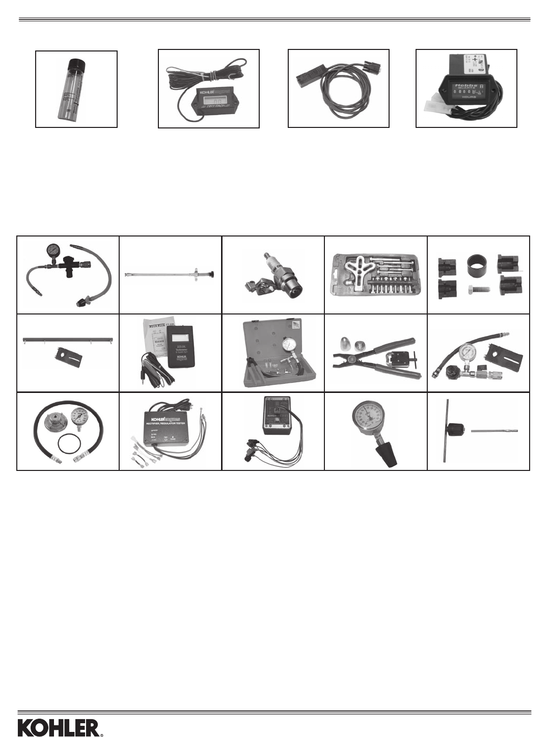
Item
25 455 11-S Alcohol Content Tester - Tests for E10/E20/E85 All 1
2544905-S* UsageMeter/Tachometer(solidstate) Allsingles&twins 2
2576123-S EFIDiagnosticKit(includesCD-ROMtodiagnoseengine) AllEFI 3
52 362 01-S Hourmeter All with electric start 4
*Indicateswhentoserviceaircleaner,oillterandchangeoil.Alsoservesasanhourmeterandtachometer.
Service intervals are dependent upon environmental factors and not this meter alone.
Part No. Description Models Item
25 455 10-S* Radiator and Cap Tester Liquid Cooled Models 4
25 761 38-S Hydraulic Valve Lifter Tool All with hydraulic lifters 5
2445502-S IgnitionOutputTester(capacitivedischarge,resat18kV) Alltwincylinder 6
2545501-S IgnitionOutputTester(allexceptcapacitivedischarge,resat12kV) Allsinglecylinder 6
KLR-82408** Flywheel Puller Set All 7
2576118-S StarterSnap-RingSet(inertiadrivestarters) AllexceptMagnumtwinsandCS 8
2876101-S OHCTimingToolSet(timingbelt) AllOHC 9
DTI-110** Inductive Tachometer All except battery ignition 10
2476101-S EFIServiceToolKit(forindividualcomponentsseePartsBulletin228) AllEFI 11
KLR-82411** Electric Starter Service Kit All 12
25 761 05-S Cylinder Leakdown Tester All 13
25 761 06-S Oil Pressure Test Kit All w/pressure lubrication 14
2576120-S Rectier/RegulatorTester(operateson110-120voltcurrent) All 15
2576141-S Rectier/RegulatorTester(operateson220-240voltcurrent) All 15
25 761 40-S Spark Advance Module Tester All w/spark advance module 16
25 761 22-S Vacuum/Pressure Tester All 17
2545509-S T-HandleforValveGuideReimer(below) All 18
2545512-S 0.25mmOversizedReimerforValveGuides CommandandAegis(11HP) 18
*Designedtoworkwithitem#13(2576105-S)orrequiresaregulatedairsupply.
**Available from Kohler-recommended tool supplier, see Parts Bulletin 228.
ALSO SEE PAGE 22 FOR COOLANT AND LUBRICATION ALERT ITEMS.
234
45678
910 11 12 13
14 15 16 17
Meters, Testers, and Special Tools
18
ALCOHOL CONTENT TESTER & METERS
SPECIAL TOOLS
1
11
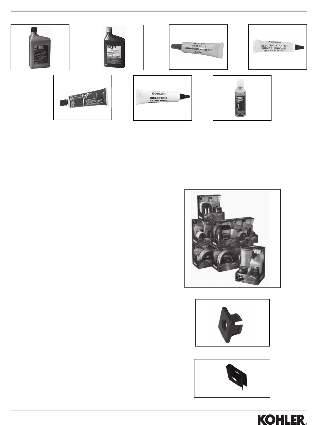
OIL, SEALANT, LUBRICANT
Part No. Description Fl. Size For Item
25 357 06-S SAE 10W-30 KOHLER® Oil 32 oz. All OHV/OHC Engines 1
25 357 03-S SAE 30 KOHLER® Oil 32 oz. XT-7 Engines 2
25 357 14-S Lubricant, Camshaft/Lifter 0.25 oz. — 3
52 357 01-S Lubricant, Inertia Drive Starter 0.25 oz — 4
52 357 02-S Lubricant, Solenoid Shift Starter 0.25 oz. — 4
25 357 12-S Lubricant, Spline Drive 2.8 oz. All 5
25 357 11-S Grease, Dielectric 0.25 oz. All except EFI 6
2559707-S Sealant(LoctiteInstantGasket) 4oz. AllRTVApplications 7
MAINTENANCE KITS
Everything needed for periodic preventative maintenance, in a handy display pack.
Part No. Models
20 789 01-S SV470-620
12 789 01-S CV11-15, 460, 490, 492
12 789 02-S CV11-15, 460-493 PRO
24 789 01-S CV17-23, 724-740; CH18-25, 730-740
24 789 02-S CV18-30, 675-740; CH18-25, 730-750 PRO
24 789 03-S CV17-27, 730-740 WAWB
25 789 01-S CV18-25, 625-750; CH18-25, 730-750 HDAC
32 789 01-S SV710-740
134
567
Special Items
PLASTIC NUT
Part No. Hardware Size
24 100 37-S 6mm
BAFFLE MOUNTING CLIP
Part No. Hardware Size
25 154 02-S 6mm
2
12
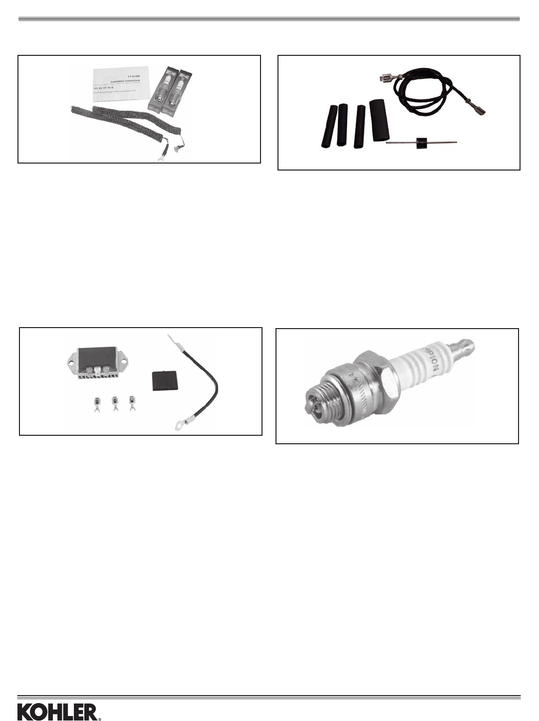
RFI/EMI CONVERSION KIT
Kit No. Models
25 707 01-S All CH, CV, LH, LV, SV Twins
CHARGING SYSTEMS
Part No. Description Models
15 Amp
237878-S Stator Kit CH/CV11-16/460-493, SV470-620,
CH/CV17-26/730-745, LH640-775,
LV625-685, SV710-740
4140309-S Rectier-Regular All
25 Amp
28 085 02-S Stator Kit CH/CV11-16/460-493, SV470-620
5475503-S Stator/Rectier-RegularKit* CH/CV17-26/730-745,TH520-575,
LH640-775, LV625-675,
SV710-740
24755144-S Rectier-RegularKit**(Shown)
* Converts 15 amp system to 25 amp.
**Convertsold25amprectier-regular(2540301-Sor2540304-S)tonew25
amprectier-regular(2540305-S)onallmodels.Includesrectier-regular,
terminals(3),lead,connectorblock.
SPARK PLUGS
Part No. Models
6613201-S LH640-775,LV625-680,CS4-12.75(Champion)
12 132 02-S CH6, CH/CV11-15/460-492, CH/CV17-30/730-750, CH20-25 LP,
TH520-575, TH520-575 LP, XT-7
25 132 12-S CH/CV11-15/493 PRO, CH/CV18-30/730-750 PRO
25 132 08-S CH/CV11-15 LP
28 132 01-S CH/CV17-25/730-740 R.F.I. with shielded metal boots
28 132 02-S TH520-575 R.F.I.
25 132 14-S SV470-620 R.F.I., SV710-840 R.F.I., LV625-680 R.F.I.,
LH640-755 R.F.I., CH/CV17-25/730-740 R.F.I. w/o metal boots
62 132 04-S CH940-1000 R.F.I.,
Ignition and Electrical
DIODE KIT
Part No. Specications Models
25 755 31-S 5 AMP 800PIV All
13
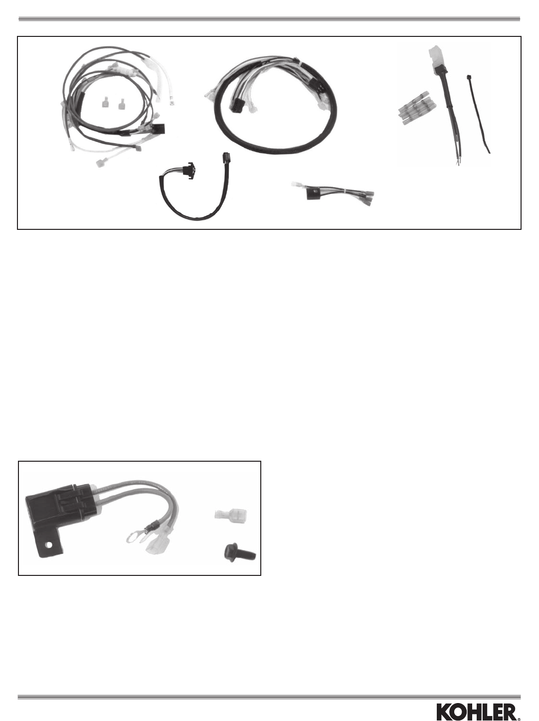
WIRING HARNESSES
No. Lead
Part No. Leads Length Connector Models Item
5475502-S * 34"longest Numerous CH/CV17-25/730-740 1
6617618-S 8** 36"longest 2515506(Female),4815501(Male) LH640-755 2
5215508-S 2 18"all 5215504(Female) Various 3
5215509-S 3 18"all 237088(Female) Various(shown) 3
2515507-S 5 18"all 2515506(Female) Various 3
2515509-S 5 18"all 2515506(Female),4815501(Male) Various 3
2517602-S 6*** 75"longest 2515506(Female),4815501(Male) C11-16/460-493,C17-25/730-740 3
LH640-755, LV625-680
2517610-S 6*** 75"longest 2515506(Female),4815501(Male) CH/CV940-1000 3
6317601-S 6**** 5"longest 4815501(Male) CS8.5-12 4
24755155-S ***** 4"longest AllEFI 5
6217610-S 4 30"longest Molex#33482-0401(Male) CH/CV940-1000 NotPictured
6217611-S 4 3-7/8" Molex#33482-0401(Male),6PinPackard CH/CV940-1000 NotPictured
*Includesuniversalharness,duplexleadharness,OilSentry™lead,20ampB+lead,25ampB+leadwithConnector2515503-S,(2)Terminals1545210-S,and
instructions.
**Canbeusedasageneral36"extensiontobasicwireharness.
*** Includes equipment ground lead for between keyswitch and engine block.
****Usedtocreateremote-mountkeyswitch(useKeyswitch2509904-S).AlsoorderHarness2517602-Sabove.
*****Pigtail harness used to replace diagnostic plug. Includes protective cap, 24 139 06-S.
12
3
5
4
SEALED FUSE HARNESS/HOLDER
Part No. Models
54 755 13-S All
Converts standard harness/fuse holder to a sealed version to prevent moisture,
dirt, etc., from penetrating. Ideal for pressure washers or applications in corrosive
environment. Includes 30 amp fuse.
5
Ignition and Electrical
14
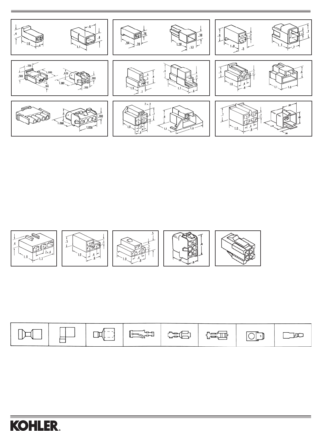
MATED (M) CONNECTORS
Uses Female Uses Male
Connector Connector Terminal Connector Connector Terminal
Description Item Part No. (See Below) Item Part No. (See Below)
1 Wire M1 277563-S Item 5, 6 M2 15 155 01-S Item 4
1 Wire M3 25 155 04-S Item 5, 6 M4 25 155 03-S —
2 Wire M5 41 155 03-S Item 5, 6 M6 52 155 04-S Item 4
2 Wire M7 47 155 14-S — M8 47 155 13-S —
2 Wire M9 48 155 02-S Item 5, 6 M10 48 155 03-S Item 4
3 Wire M11 236473-S Item 5, 6 M12 237088-S Item 4
4 Wire M13 12 155 03-S — M14 12 155 02-S —
5 Wire M15 48 155 01-S Item 5, 6 M16* 25 155 06-S Item 4
4 Wire M17 41 155 02-S Item 5, 6 M18 12 155 10-S Item 4
*MountingscrewslotsonM16are1.328"centertocenter.
UNMATED (U) CONNECTORS
Connector Connector Uses Terminal
Description Part No. Item (See Below)
3 Wire 25 155 41-S U1 Item 5, 6
3 Wire 237429-S U2 Item 5, 6
3 Wire 52 155 06-S U3 Item 5, 6
6 Wire 12 155 09-S U4 —
Cap, Protective 24 139 06-S U5 —
TERMINALS
Size Part No. Type Code Item
3/16"Flat 2545211-S F.I.F. S 1
3/16"Flat 2545212-S F.I.F. F 2
1/4"Flat 2545207-S F.I.F. S 1
1/4"Flat 1545201-S F.I.M. S 3
1/4"Flat 5245201-S L.M. S,U 4
1/4"Flat 2545201-S L.F. S,U 5
1/4"Flat 2545206-S L.F. S,U 6
1/4"Flat 1245202-S M 45°,U 7
1/8"Round 2545217-S F.I.M. S 8
Type Code
F.I.F. = Fully Insulated Female S = Straight push on tab
F.I.M. = Fully Insulated Male F = Flag push on tab
L.F. = Locking Female U = Uninsulated
L.M. = Locking Male
M = Male
M1 M2 M3 M4 M5 M6
M7 M8 M9 M10 M11 M12
M13 M14 M15 M16 M17 M18
U1 U2 U3 U4 U5
1 23 4 5 678
Ignition and Electrical
15
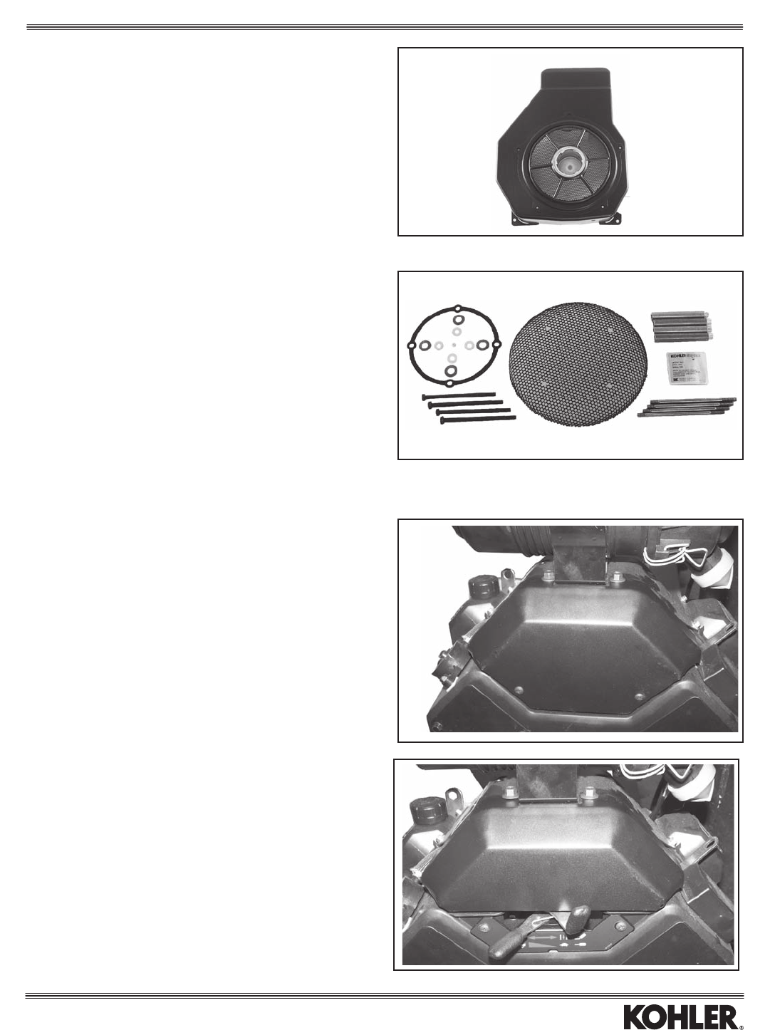
METAL CHOPPER GRASS SCREEN KITS
Kit No. Models
12 755 78-S CV11-16/460-493
Replaces plastic screen on recoil start engines. Includes outer-edge guard and
blower housing.
MANIFOLD COVER KITS
Kit No. Model
24 096 110-S CH750
24096111-S CH750(w/frontmountedcontrols)
Covers hide exposed portion of intake manifold.
Kit No. Models
24 755 79-S CH/CV17-26/730-745
Replacesplasticscreen,orcanreplace“crowned”metalscreenonenginesbelow
Serial No. 2528418567. A new blower housing is required if replacing a plastic screen.*
Note: Wheninstallingmetalscreenonan“open”application,guardkit
24 755 94-S is required.
*Due to blower housing variations, consult Kohler factory. Based on the spec
number of your engine, the corresponding blower housing can be determined.
Guards, Screens, and Blower Housings
16
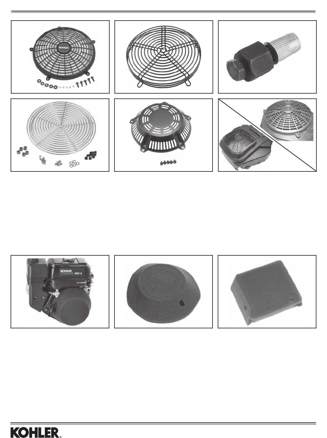
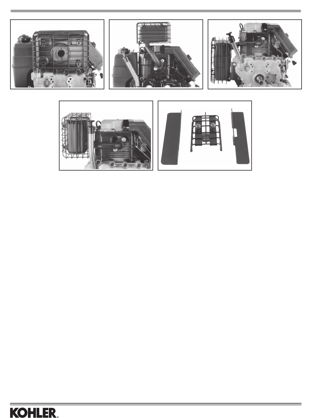
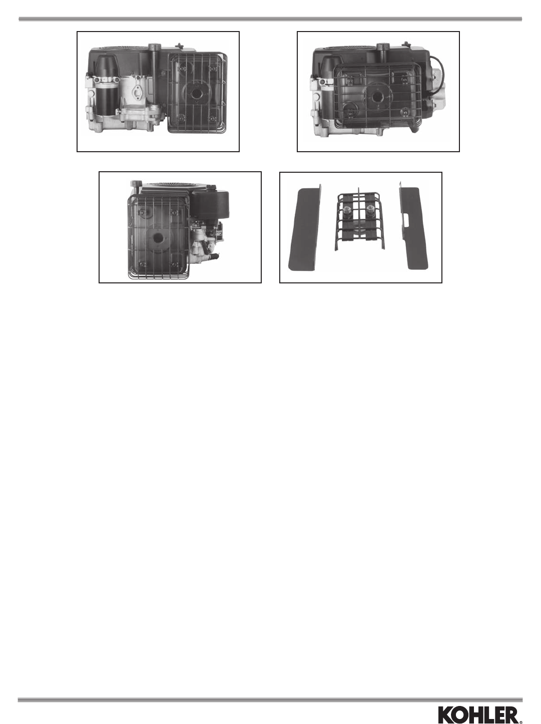
FIXED GUARDS (NOT USABLE WITH RECOIL STARTER)
Model Plastic, Stylized Wire, Deep Tool Wire, Flat Metal, Recoil
CS8.5-12.75 — — — 63 755 17-S —
CH/CV11-16/460-493 1275565-S(Shown) — — 1275544-S(Shown) 1275548-S
SV470-620 20 755 11-S, 20 755 14**
CH/CV17-26/730-750 24 755 81-S* 24 755 94-S* 24 455 01-S — —
SV710-740 32 027 08-S
*Guardkits2475581-Sand2475594-Sincludethreadedinserts(2433201-S).Inserttool(2445501-S)isnotincludedbutneededtoattachguardtoexistingblower
housing. Tool is reusable. If engine has a metal grass screen, then only guard kit 24 755 94-S should be used. In addition, guard 24 755 94-S is required in open applications
(mowers,etc.)toprotectthemetalscreenfrompotentialdamage.
**Use 20 755 11-S if engine Serial No. is below 36145XXXXX, use 20 755 14-S if above.
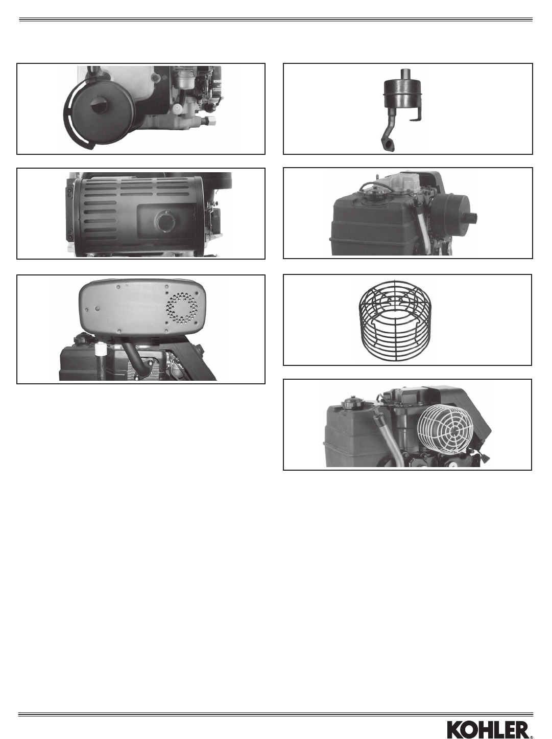
RECOIL STARTER FILTERS
Help prevent dust, dirt and debris from entering around recoil starter.
Part No. Notes Models Item
63 755 18-S Includes handle hole, Velcro, maintenance label and instructions. CS4-6 1
12 050 02-S* Includes handle hole. Conforms to shape of recoil housing when using fasteners*. CV11-16/460-493 2
15 050 01-S** Includes handle hole. CH6 3
*Forrst-timeusage,alsoorder(10)1229001-SVelstudsforholdingthelterinplace.Velstudsarereusable;theyinterlockwithslotsinstarterhousing.
**Alsoorder6329001-SVelcrostrip(4.75"long).Cutintopiecesforattachmentofltertostarterhousing.
(Tool shown with insert.)
Plastic, Stylized Wire, Deep Tool
Wire, Flat Metal, Recoil
123
Courage Twin
Guards, Screens, and Blower Housings
17
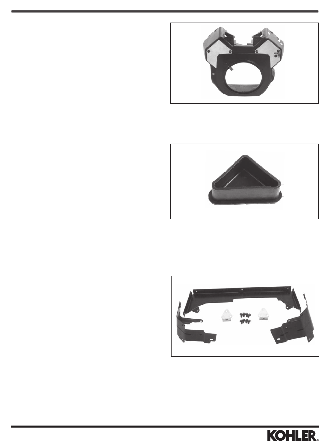
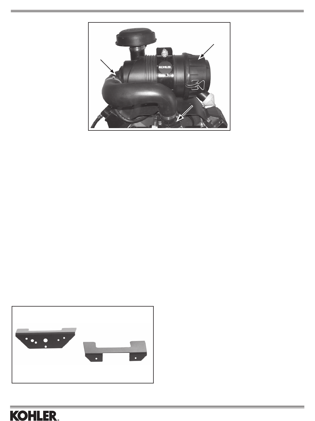
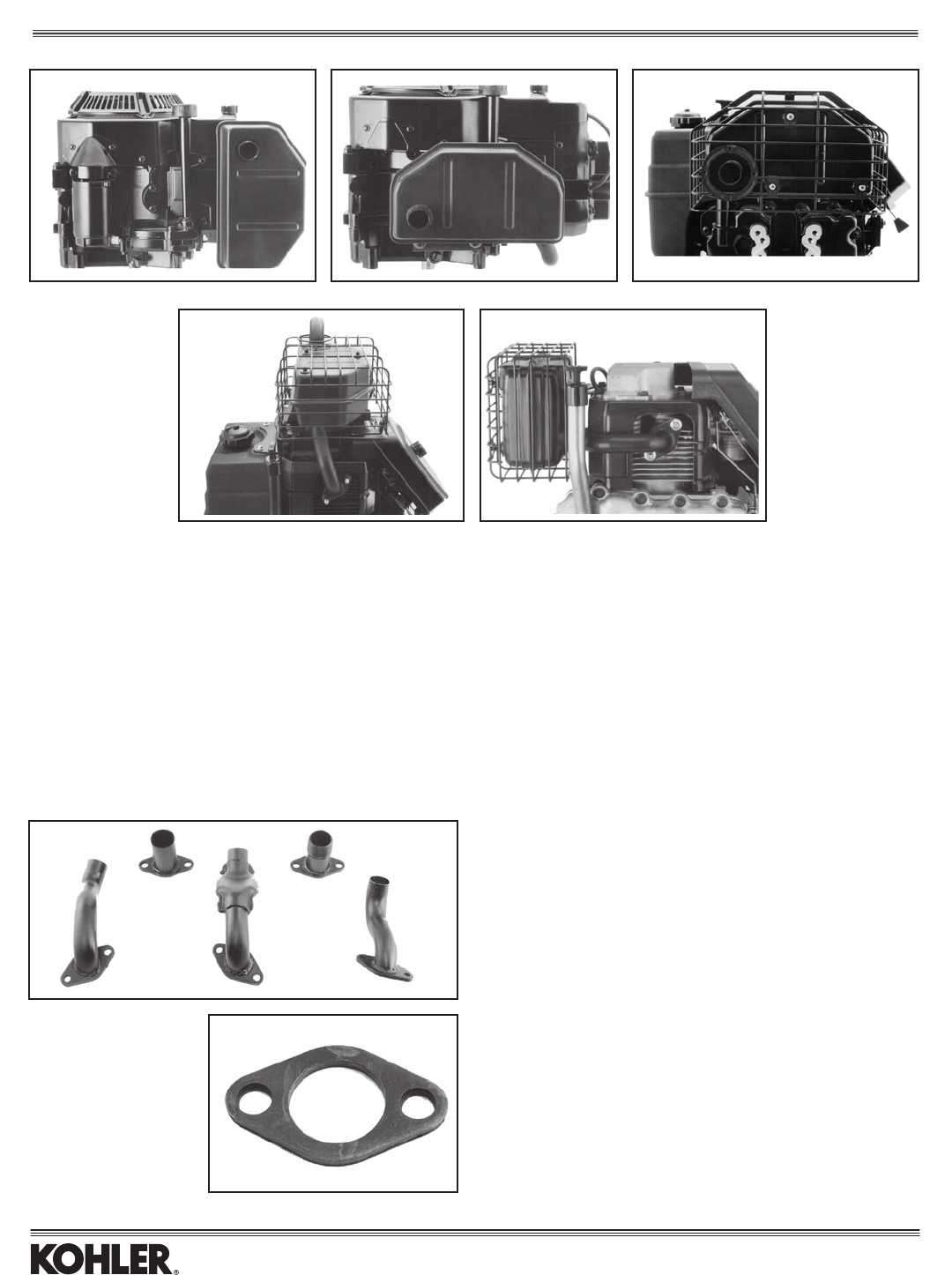
BLOWER HOUSING PLUGS
Part No. Description Model
2409617-S* TriangularPlug(1)(Shown) CH/CV17-26/730-750
2409685-S** TriangularPlugWithLip(1) CV17-26/730-750
* Seals the triangular hole in the blower housing underneath the air cleaner. Two
required for CH twins, one for CV twins.
**Similar to 24 096 17-S, but has an extended rubber lip. Seals the triangular hole
(undertheaircleaner)throughwhichthebreatherhoseisrouted.Onerequired.
BLOWER HOUSING CLEAN OUT
PANELS
Kit No. Description Model
2575520-S MatteBlackPanel(2) CH/CV17-26/730-750
2575521-S ZincDichromatePanel(2) CH/CV17-26/730-750
(Shown)
Allows for cleaning debris from behind blower housing and also servicing of ignition
modules. Kit includes instructions/template for cutting holes in blower housing, plus
panels(onewithpop-outplugandlabelforkeyswitch),mountingclipsandscrews.
(Blowerhousingnotincluded.)
DUCTED AIR KIT
Kit No. Description Model
24 755 14-S Ducted Air Kit CH18-26/730-750
Guards, Screens, and Blower Housings
18
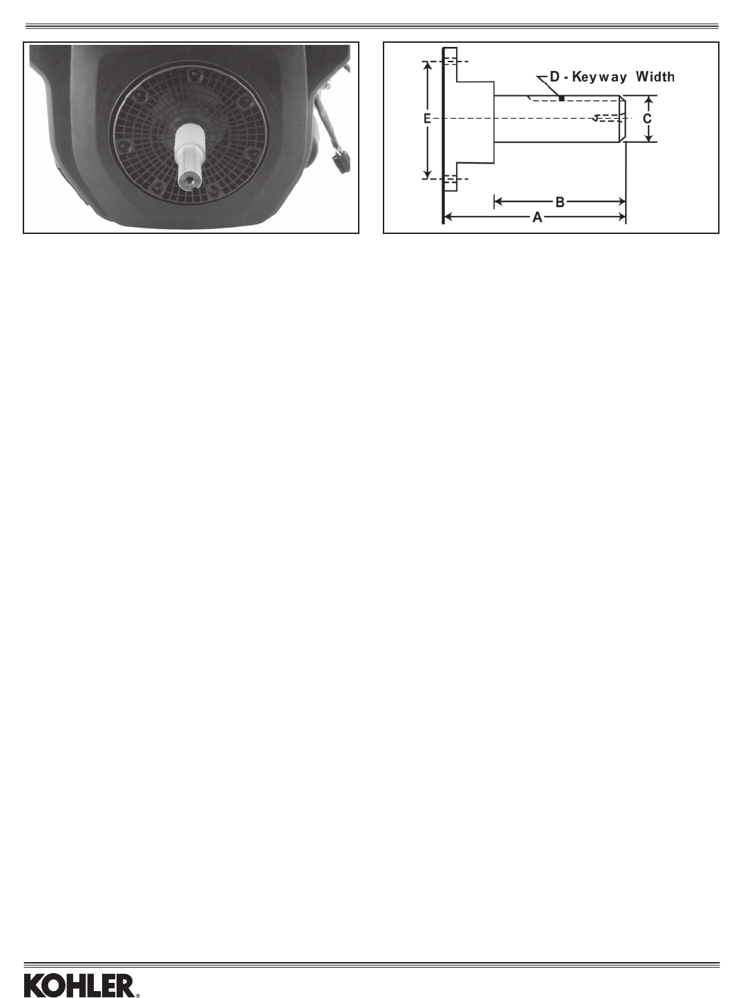
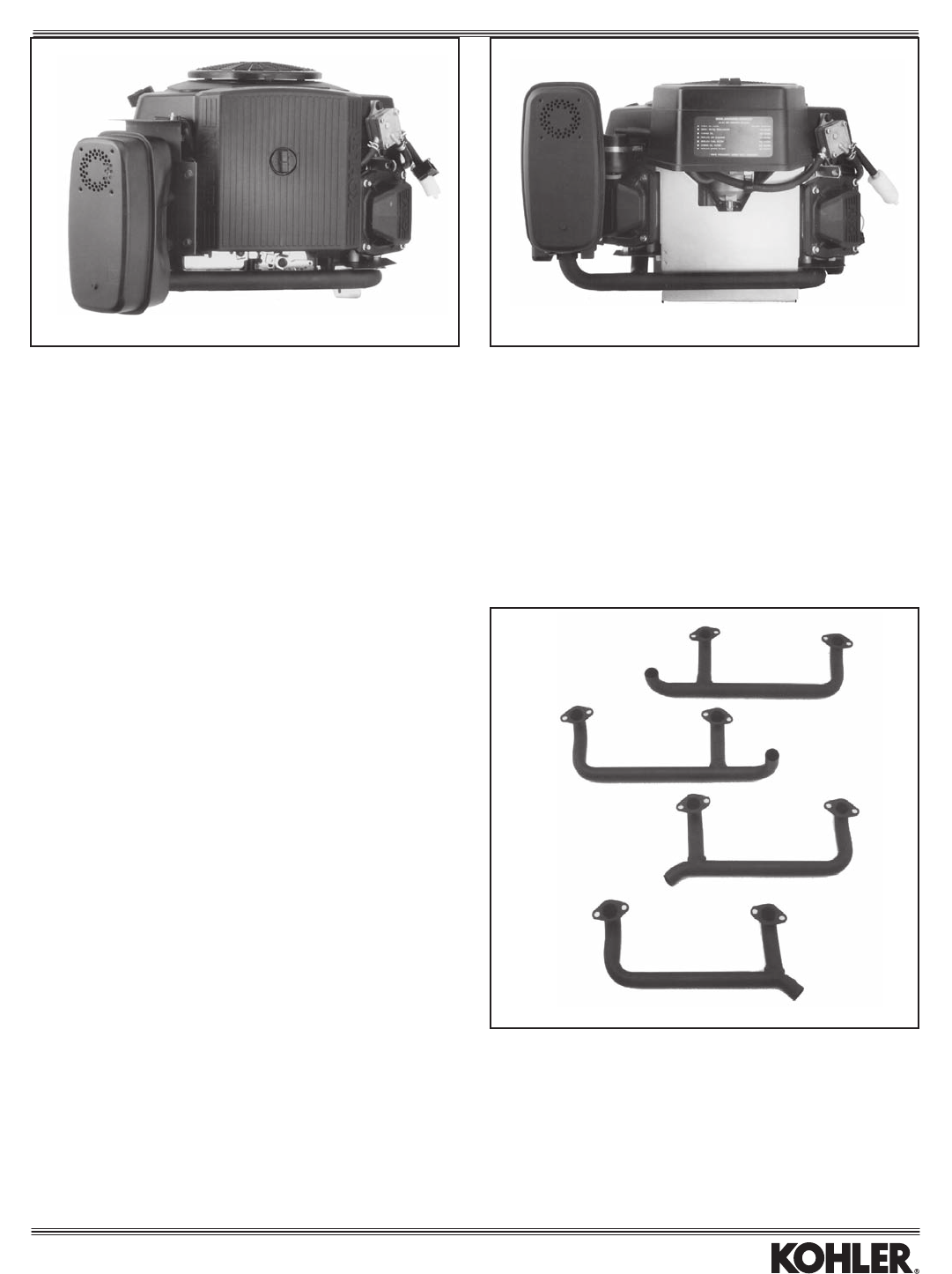
FRONT DRIVES (DIMENSIONS IN INCHES)
Hardware
Part No. A B C D E Required D & T Model*
52 144 19-S 4.66 2.53 1.0 .25 3.0 See Below 3/8-16 CH11-15, LH640-775
235954-S 3.48 1.44 1.0 .25 3.0 See Below 3/8-16 CH11-15, LH640-775
237350-S 4.66 2.41 1.125 — 3.0 See Below — CH11-15, LH640-775
47 144 09-S 3.88 1.75 1.0 .25 3.0 See Below 7/16-20 CH11-15, LH640-775
52 144 07-S 3.80 1.80 1.0 .25WD 3.0 See Below — CH11-15, LH640-775
24 755 05-S 7.00 1.44 1.0 .25 3.0 See Below 3/8-16 CH18-26/730-750, LH640-775
24 755 06-S 7.00 1.76 1.0 .25 3.0 See Below 7/16-20 CH18-26/730-750, LH640-775
24 755 07-S 7.00 1.80 1.0 .25 3.0 See Below — CH18-26/730-750, LH640-775
24 755 08-S 7.00 2.53 1.0 .25 3.0 See Below 3/8-16 CH18-26/730-750, LH640-775
24 144 13-S 6.40 2.53 1.0 .25 3.0 See Below 3/8-16 CH18-26/730-750, LH640-775
24 144 16-S 5.35 2.53 1.0 .25 3.0 See Below — CH18-26/730-750, LH640-775
24 144 17-S 4.00 1.93 0.7** .188WD 3.0 See Below — CH18-26/730-750, LH640-775
24 144 22-S 6.20 2.60 1.125 .25 3.0 See Below — CH18-26/730-750, LH640-775
24 144 23-S 4.84 2.82 1.0 .25 3.0 See Below 3/8-16 CH18-26/730-750, LH640-775
24 144 25-S 5.51 2.17 1.0 .25 3.0 See Below — CH18-26/730-750, LH640-775
24 144 26-S 3.94 1.06 0.625 .187 3.0 See Below — CH18-26/730-750, LH640-775
24 144 32-S 8.23 3.79 1.0 .25 3.0 See Below M12 x 1.75 CH18-26/730-750, LH640-775
24 144 47-S 4.50 1.50 1.125 .25 3.0 See Below 7/16-20 CH18-26/730-750, LH640-775
24 144 51-S 5.98 2.36 1.0 .25 3.0 See Below 7/16-20 CH18-26/730-750, LH640-775
24 144 53-S 4.00 1.36 1.0 .25 3.0 See Below 3/8-16 CH18-26/730-750, LH640-775
28 144 05-S 5.28 3.07 1.125 .25 3.0 See Below — CH18-26/730-750, LH640-775
66 144 04-S 3.87 2.37 1.125 .25 3.0 See Below — CH18-26/730-750, LH640-775
62 144 07-S 4.54 2.30 1.125 .25 3.0 See Below 7/16-20 CH940-1000
62 144 09-S 5.33 2.00 1.125 .25 3.0 See Below 7/16-20 CH940-1000
24 144 55-S 4.50 1.50 1.0 .25 3.0 See Below 3/8-16 CH18-26/730-750
* Consult factory on: CH11-15 sinceywheelholesmayvaryandspecmaynotacceptfrontdrive:LH640-775 to verify front loading.
**Threadedend(3/4"-16UNF-2A).
WD = Woodruff Key
Required Hardware:
CH11-15: (2)X-22-2-SWasher,(2)M-1053030-SScrew.
CH18-26/730-750: (4)M-839025-SScrew(Includedin-755kits).
LH640-775: (4)M-839025-SScrew.
CH940-1000:(4)M-839035-SScrew.
SOME FRONT DRIVES REqUIRE:
LH640-775: Alsoorder6609618-SFlywheelCoverw/holeforfrontdriveorinstructionsheetTT-5081foratemplatetocuttheholeinyourexistingywheelcover.
All other models: Also order Grass Screen w/hole for front drive per table below. If changing from plastic screen to metal screen, also order blower housing. Contact
customer service at factory for correct blower housing.
.
Grass Screen Hardware Required
Part No. Type Hole Dia. (In.) To Attach New Screen Model
12 162 03-S Plastic 2.56 None CH11-15
2416216-S Plastic 1.42 (4)M-639016-SScrew,(4)1211201-SSpacer CH18-22
24 162 18-S Plastic, Hi-Eff. 1.77 None CH18-26/730-750
24 162 22-S Metal*, Flat 1.57 None* CH18-26/730-750
24 162 23-S Metal*, Flat 2.95 None* CH18-26/730-750
24 162 24-S Metal*, Flat 2.46 None* CH18-26/730-750
62 162 09-S Metal 1.81 None CH940-1000
*Flatdesign.Ifreplacingolder“crowned”version,alsoorder5475510-SHardwareKit.
Front Drive Shafts
19
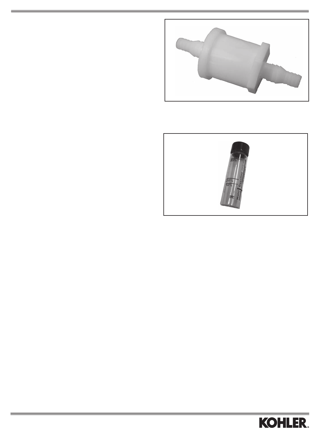
FUEL FILTERS
Inlet Hose Shell
Part No. I.D. Micron Length Model
1405004-S 3/16,1/4" 60 .67” Standard:XT-7
2505021-S1 1/4" 75 2.13" Standard:CH/CV11-15/493PRO*
2405013-S 9/32" 9-12 2.35" Standard:CH/CV17-25/730-740,750
LV625-680, LH640-755,
SV470-620, SV710-840
2405003-S 5/16" 8-10 5.51" Standard:AllEFI(metal,highpressure,
betweenfuelpumpandengine)
2405012-S 3/8" 80 5.51" Standard:AllEFI(plastic,lowpressure,
betweenfueltankandfuelpump)
2505007-S 3/16,1/4" 75 1.0" Standard:CH/CV11-16/460-492
non-PRO(electricstart)
2505022-S 1/4" 51 2.13" Standard:CH/CV11-15/493PRO
(recoilstart)
* Standard on PRO specs with gravity-feed carb. For PRO specs with fuel pump,
lter2505022-Sisstandard.
HIGH-ALTITUDE KITS
Used on Models/ A/C
Kit No. Altitude* Carb Series Style
14 755 03-S 5-10,000 14 053 01 XT-7 Standard
14 755 04-S 5-10,000 14 053 02 XT-7 Standard
12 755 92-S 5-10,000' 12 053 77/78/ CH/CV11-15 Standard
80/82/93/94/
95/139/140,
42 053 03
12 755 108-S 5-10,000’ 12 053 117/118/ CV490-493 Standard
12 755 109-S 10,000’+ 136/145/148/149
20 755 06-S 5-10,000’ 20 053 01/02/04/05 SV530-620 Standard
20 755 07-S 10,000’+ 07/14/15/16/17/ SV530-620 Standard
19/20/21/22
20 755 08-S 5-10,000’ 20 053 03/06/18/23 SV470,480 Standard
20 755 09-S 10,000’+ SV470,480 Standard
24755131-S 5-10,000' 2405375 CH20(624cc) Flat
5-10,000' 2405386 CH22/23(674cc) Flat
24755125-S 5-10,000' 2405331/ CH18/22(624cc) Flat
32/33/43
5-10,000' 2405358/59 CH22/23(674cc) Flat
24 755 126-S 5-10,000' 24 053 47 CH25 Flat
24 755 130-S 5-10,000' 24 053 34 CH25 Flat
24 755 138-S 5-10,000’ 24 053 93 CH730-740 Flat
24 755 137-S 10,000’+ 24 053 93 CH730-740 Flat
*5-10,000’ = 1500-3000 m.
Models/ A/C
Kit No. Altitude¤ Series Style
63 755 20-S 4-8,000' CS4 Standard
63 755 22-S 8,000'+ CS4 Standard
4-8,000' CS4 Heavy-Duty
63 755 25-S 8,000' CS4 Heavy-Duty
63 755 21-S 4-8,000' CS6 Standard
63 755 23-S 4-8,000' CS6 Heavy-Duty
63 755 24-S 8,000'+ CS6 Standard
4-8,000' CS6 Rectangular
63 755 26-S 8,000'+ CS6 Heavy-Duty
63 755 38-S 8,000'+ CS6 MZ
Rectangular
6375527-S 4-8,000’ CS8.5(250cc) Standard
8,000'+ CS8.5(250cc) Heavy-Duty
6375529-S 8,000'+ CS8.5(250cc) Standard
6375528-S 4-8,000' CS8.5(250cc) Heavy-Duty
63 755 30-S 4-8,000' CS10/9316 Standard
8,000'+ CS10/9315 Standard
4-8,000' CS12/9415,9416 Heavy-Duty
63 755 33-S 4-8,000' CS10/9315,9416 Heavy-Duty
63 755 35-S 8,000'+ CS10/9316 Standard
63 755 36-S 8,000'+ CS10/9315 Heavy-Duty
8,000'+ CS10/9316 Heavy-Duty
8,000”+ CS12/9415 Rectangular
63 755 31-S 4-8,000' CS10/9315 Standard
4-8,000’ CS12/9415 Rectangular
63 755 32-S 4-8,000' CS12/9415 Standard
4-8,000' CS12/9416 Standard
63 755 34-S 8,000'+ CS12/9415 Standard
8,000'+ CS12/9416 Standard
63 755 37-S 8,000'+ CS12/9415 Heavy-Duty
8,000'+ CS12/9416 Heavy-Duty
¤4-8,000’ = 1200-2400 m.
LOW PERMEATION FUEL LINE
Part No. I.D. Length Model
2511134-S 1/4" 24” AllexceptEFI
2511139-S 1/4" 25’(bulkroll) AllexceptEFI
2511137-S 5/16" 5’ EFIOnly
Fuel
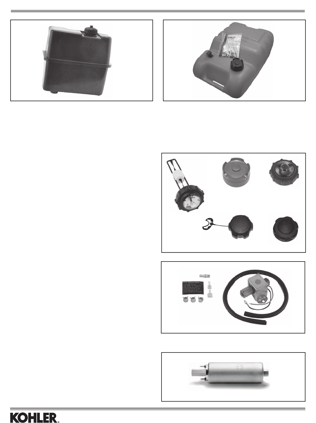
ALCOHOL CONTENT TESTER
Part No. - Tests for E10/E20/E85
25 455 11-S
20
FUEL TANK CAPS
Gauge
Item Part No. in Cap Fits
1 25 173 04-S Yes Voided 52 755 45 remote metal tank
1 25 173 21-S Yes Voided 52 755 79 remote plastic tank
2 25 173 22-S No 25 755 35 remote plastic tank
3 25 173 20-S No CH11-15
4 14 227 06-S No XT-7
5 14 227 04-S No XT-7
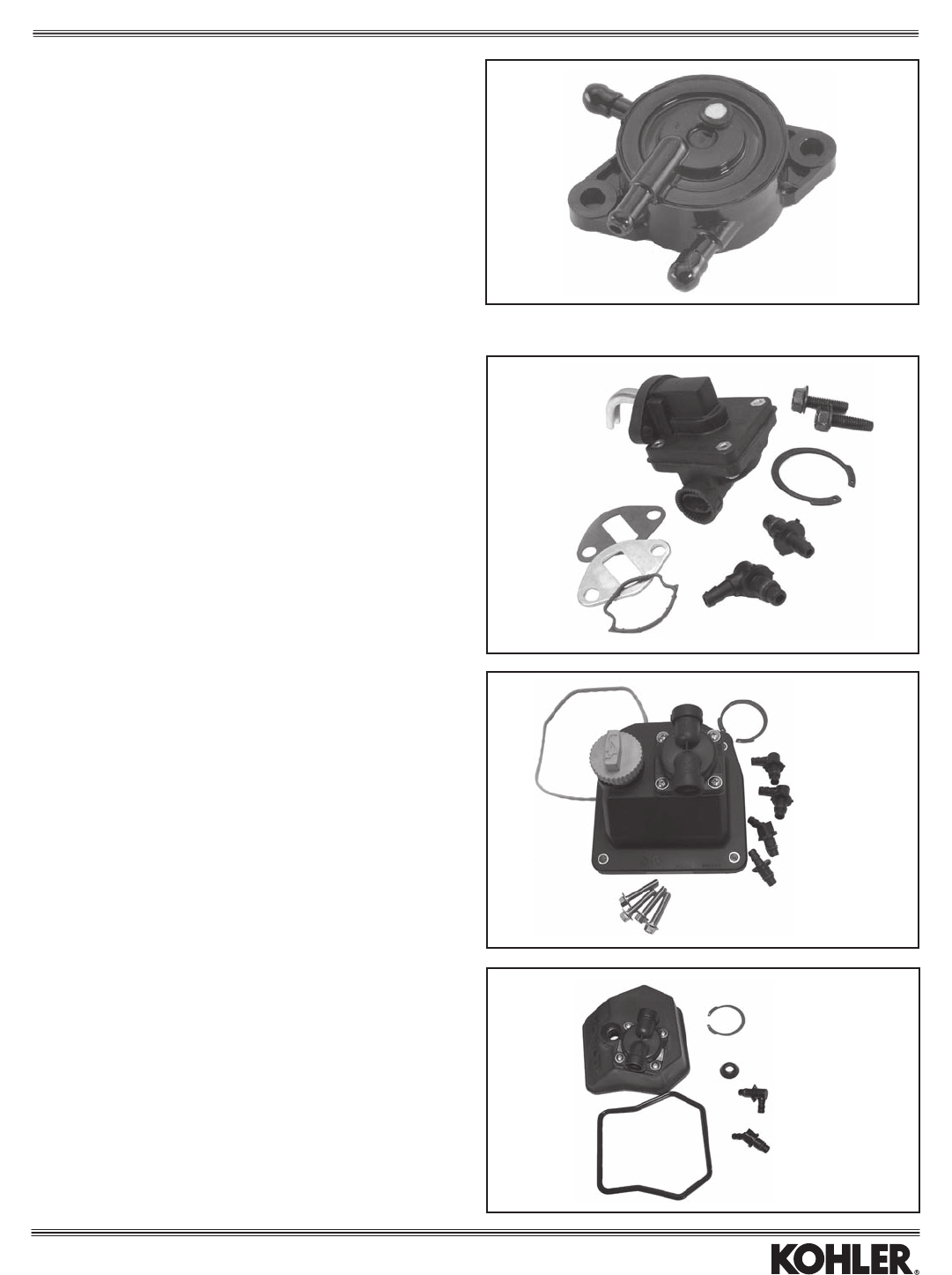
FUEL TANK KITS
Tank Tank Tank Includes
Kit No. Mounting Material Capacity (Gal.) Cap Model Item
12 760 01-S Engine Plastic 1.25 25 173 08-S CH11-15 1
25 755 35-S* Remote Plastic 6.0 25 173 22-S All 2
*Overallsizeis19.6"x14.2"x9.3".
1
23
1 2
5
4
ELECTRIC FUEL PUMP
P.S.I. at Self-Prime Total
Kit No. Model 0 Delivery Lift Column
2555901-S AllexceptCH6,CS,&EFI 0.5-2.0 12" 6'
EFI ELECTRIC FUEL PUMP - HIGH
PRESSURE
Part No Model P.S.I G.P.H. AMPS Max
24 393 52-S All EFI 50 15.0 5.0
Fuel
ELECTRIC FUEL RELAY
Part No. Models
20 404 01-S All
21
PULSE FUEL PUMP
Part No. Model Item
24 393 16-S CH/CV17-25/730-740, LV625-675 1
1
1
25 294 09-S**
12 294 13-S**
25 294 11-S**
25 294 13-S**
25 294 09-S**
3
25 294 11-S**
25 294 13-S**
2
MECHANICAL FUEL PUMPS
Part No. (Non-Metallic) Model Item
12 559 02-S CH/CV11-16/460-493 1
24 559 10-S* CH18-25/730-740 2
62 559 01-S*** CH940-1000 3
*Integralvalvecover. For#2cylinderside(oillterside)only.Forengines
below Serial No. 2520800017, also order Valve Train Kit 24 755 66-S to convert to
compatible rocker arms.
** Fittings include o-ring 25 153 03-S.
***Integralvalvecover.For#2cylinderside(oillterside)only.
Fuel
22
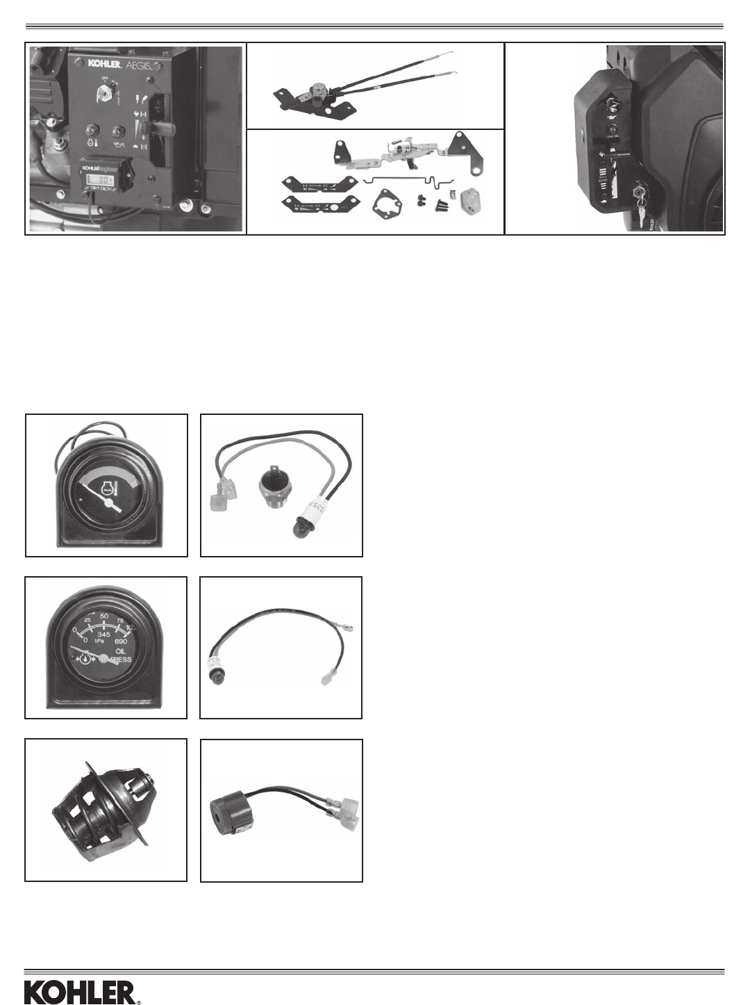
ENGINE-MOUNTED CONTROL PANELS
Kit No. Mounting Location Major Components Models Item
6675509-S* FilterSide(only) Panel,keyswitch,choke,throttle,lowoillight,harness LH640-755 1
24 225 02-S** Front Side Bracket, levers, cable assembly CH18-26/730-745 2
24755106-S** FrontSide Panel,choke,throttle(includesitem2) CH18-26/730-745 3
24 711 01-S*** Filter Side Panel, keyswitch, choke, throttle, low oil light, harness CH18-26/730-740 4
62 376 02-S Front Side Panel, keyswitch, indicator light, choke/throttle brackets CH940-1000 -
*Shownwithoptionaladditionalitems:CoolantTempGaugeandCoolantTempLight(onlyonemaybeused),andTinyTach/Hourmeter.
** For installation of lever-type throttle/choke which became standard since Serial No. 3009400011. Also order Air Cleaner Cover 24 096 26-S if adding controls to
non-panel engine spec.
***Willnotworkwithradiator-styleoilcooleroronsamesideasside-mountedmufer.
COOLANT ITEMS
Kit No. Description Models Item
66 755 06-S* Gauge, Coolant Temperature LV625-680 1
66 755 11-S** Gauge, Coolant Temperature LH640-775 1
66 755 12-S*** Light, Coolant Temperature LH640-775 2
*Includesgauge,temp.sensor,wiring(upto6'fromengine).
** Includes gauge & holder for mounting atop control panel shown above,
temp. sensor, harness.
*** Includes light/wiring, temp. switch.
Note: Coolant gauges show green band for safe temp., red band for hot.
LUBRICATION ITEMS
Kit No. Description Models Item
6675513-S* Gauge,OilPressure(0-100psi) LH640-775 1
25 352 10-S** Light, Oil Warning CH18-26/730-745 2
25 352 12-S** Light, Oil Warning LH640-775 2
12 704 02-S*** Light, Oil Warning CH/CV11-16/460-493 2
* Includes gauge & holder for mounting atop control panel shown above,
switch, wiring.
**Includeslight,6.5"&9"leads,tsincontrolpanelsshownabove.
***Includeslight,6"lead,switch,wiring.
HORN ALERT KIT
Includes alarm, coolant temp. switch, harness. Already std. on LV.
Kit No. Description Models
66 755 05-S Horn Alert Kit* LV625-680, LH640-775
6655601-S Horn(only)* Allw/electricstart
*Provides audible alarm in conjunction with or in place of light or gauge.
1
1
2
1 3 4
2
CAUTION (ALL WARNING DEVICES ON THIS PAGE): 1.Ifoverheatingoccurs,removeload,runengineathighspeedtocreateairowforcoolingengine.
2. If low oil level/pressure occurs, stop engine immediately.
2
THERMOSTAT
No gasket or o-ring included.
Kit No. Description Models
66 453 02-S 190°F Thermostat LV625-680, LH640-775
66 453 03-S 205°F Thermostat LV625-680, LH640-775
Controls
23
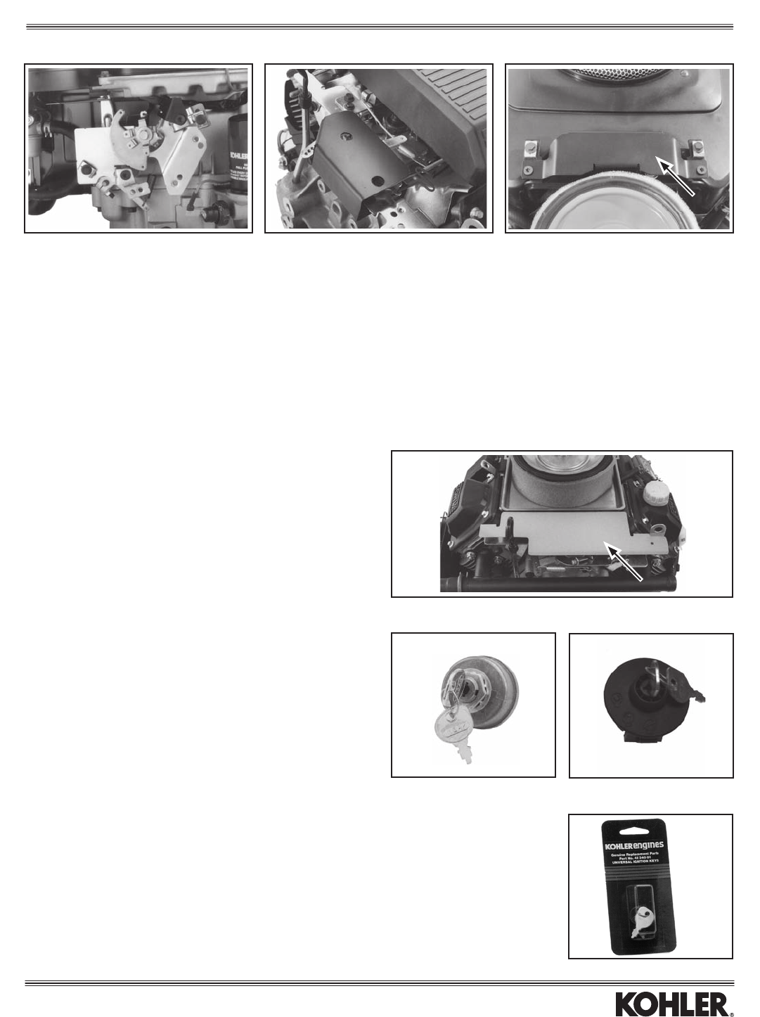
TAMPER-RESISTANT CONTROL KITS
Preventstamperingwithhigh-speedadjustment(asproposedbyEuropeanregulations).
When Models Are
Kit No. For Model Equipped With Note Item
None CH/CV11-16/460-493 Standard Controls A —
12 755 71-S CV11-16/460-493 Dual Controls B 1
24 755 93-S CH/CV18-26/730-745, LH640-775 Standard Controls C 2
24 755 97-S CV18-26/730-745 Top Controls C 3
A—EngineswithSerialNo.2527814194andhigheraretamper-resistantuponleavingthefactory.Toretrotolderengines,order(2)M-664020-STORXscrewsto
replace the hex head screws on the control bracket.
B—Includescoverand(2)TORXscrewsforattachmenttocontrolbracket.
C—Includescoverand(2)TORXscrewsforattachmenttocontrolbracket.Instructionsareincludedtoaddholestothebracketiftherearenone.
3
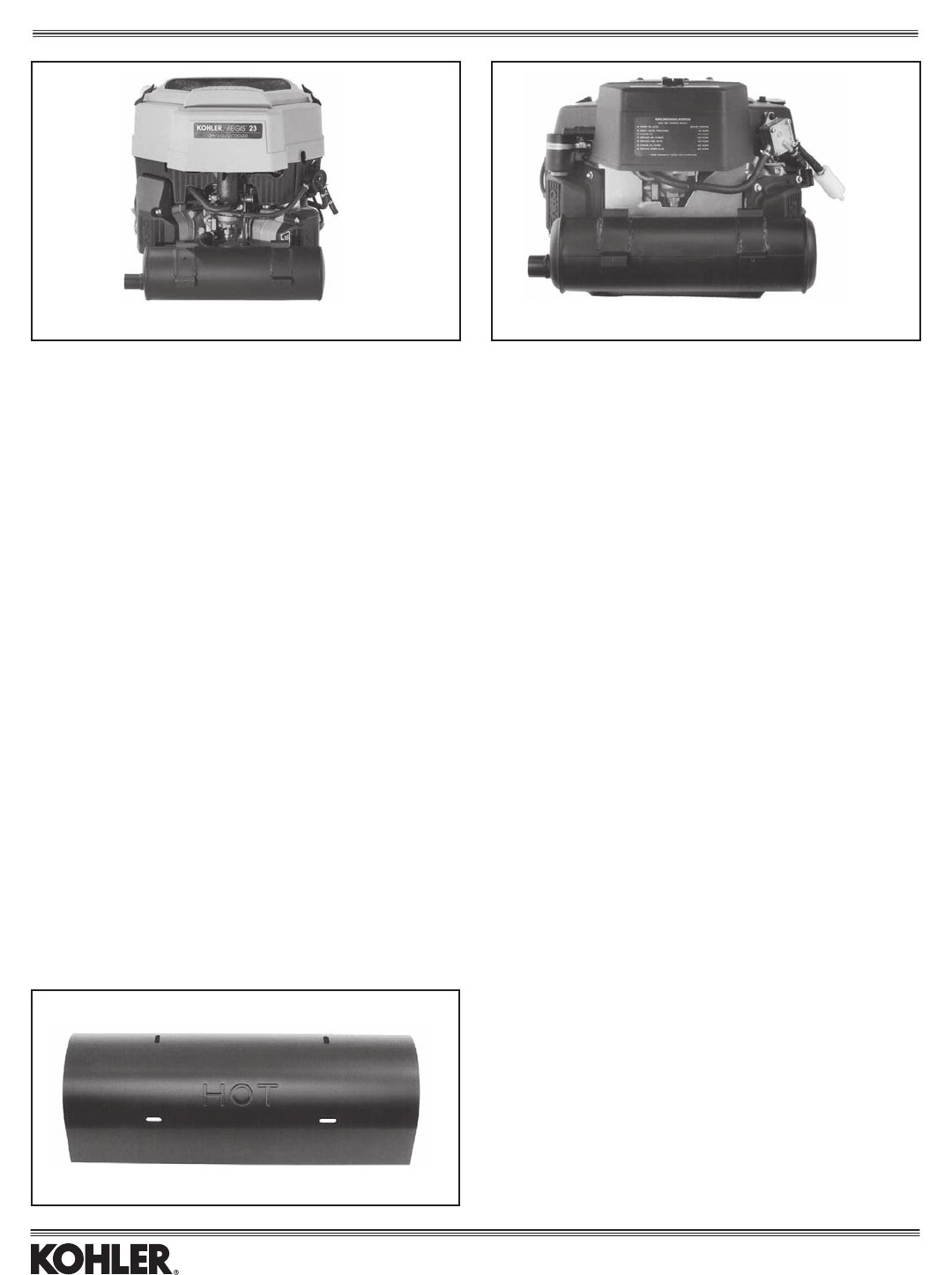
DEBRIS COVER
Part No. Description Model
24 063 32-S Debris Cover CH18-26/730-745, LH640-775
Sheet metal cover protects against debris buildup over controls. Uses existing
screws.Compatiblewithvariousdipsticksandmufers,including“QS”ducting.
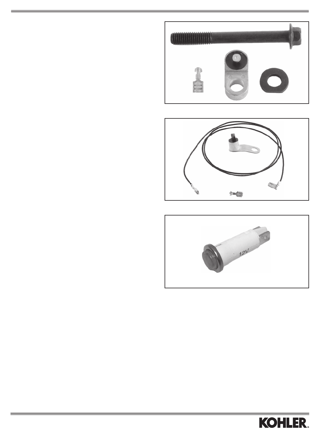
KEY SWITCH & KEYS
Part No. Description Model Item
2509904-S Switch(5pin)&KeyMagneto 1
2509929-S Switch(5pin)&KeyCH940-1000 1
5209902-S Switch(3pin)&KeyEFI 1
2509930-S Switch(5pin)&Key
CH640-750, CV17-26, CV624-750 2
4834001-S1 Keys(2)OnlyAll 3
12
1
3
2
Controls
24
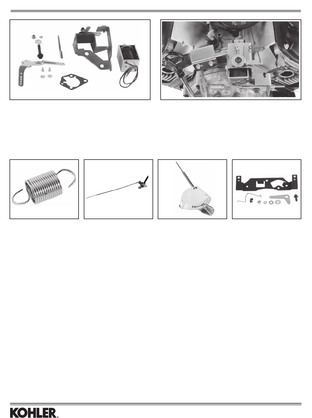
SOLENOID-OPERATED CONTROLS (12 DC VOLTS)
Kit No. Description For Engines With Models Item
24 755 100-S Idle Kit* Constant Speed CH18-25/730-740, LH640-755*** 1
24 755 101-S Throttle/Choke Kit** Constant Speed CH18-25/730-740, LH640-755*** 2
*Whenvoltageisappliedtosolenoid,enginespeedis“lowidle.”Whenvoltageisremoved,enginespeedis“highidle.”
**Allowsstart-uptoconstanthighspeedfromremoteequipment(liftplatform,etc.).
***MountingbracketwillinterferewithmanifoldsonCH18-25/730-740sidemufers.Also2416404-Scrossovermanifold.
THROTTLE CONTROL
Part No. Description/Mount Type Cable Length Models Item
63 089 23-S Throttle Return Spring* — CS4-12 1
225011-2-S Remote 41-51" All 2
225011-6-S Remote 60-72" All 2
225011-7-S Remote 12-40" All 2
230326-1-S Remote 15" All 2
235160-S Remote 5.625" All 3
*For recreational vehicle applications. Returns engine speed to idle when foot pedal is released.
1234
CHOKE CONTROL
Part No. Description/Mount Type Models Item
2475595-S ChokeControlKit(Addschokecontrollevertotopcontrols.) CV17-25/730-740Com.Mowers 4
12
Controls
25
Kit No. Cutout Range Reset Model
24 703 01-S 440-490°F 415°F CH/CV17-26/
730-745
SV710-740
HIGH TEMPERATURE CUTOUT
SWITCHES
Kit No. Cutout Range Reset Model
12 703 01-S 346-360°F 310°F CH/CV11-16/460-493
SV470-610
MALFUNCTION INDICATOR LAMP (MIL)
Part No. Models With
2535219-S ElectronicFuelInjection(EFI)
Electrical Accessories
26
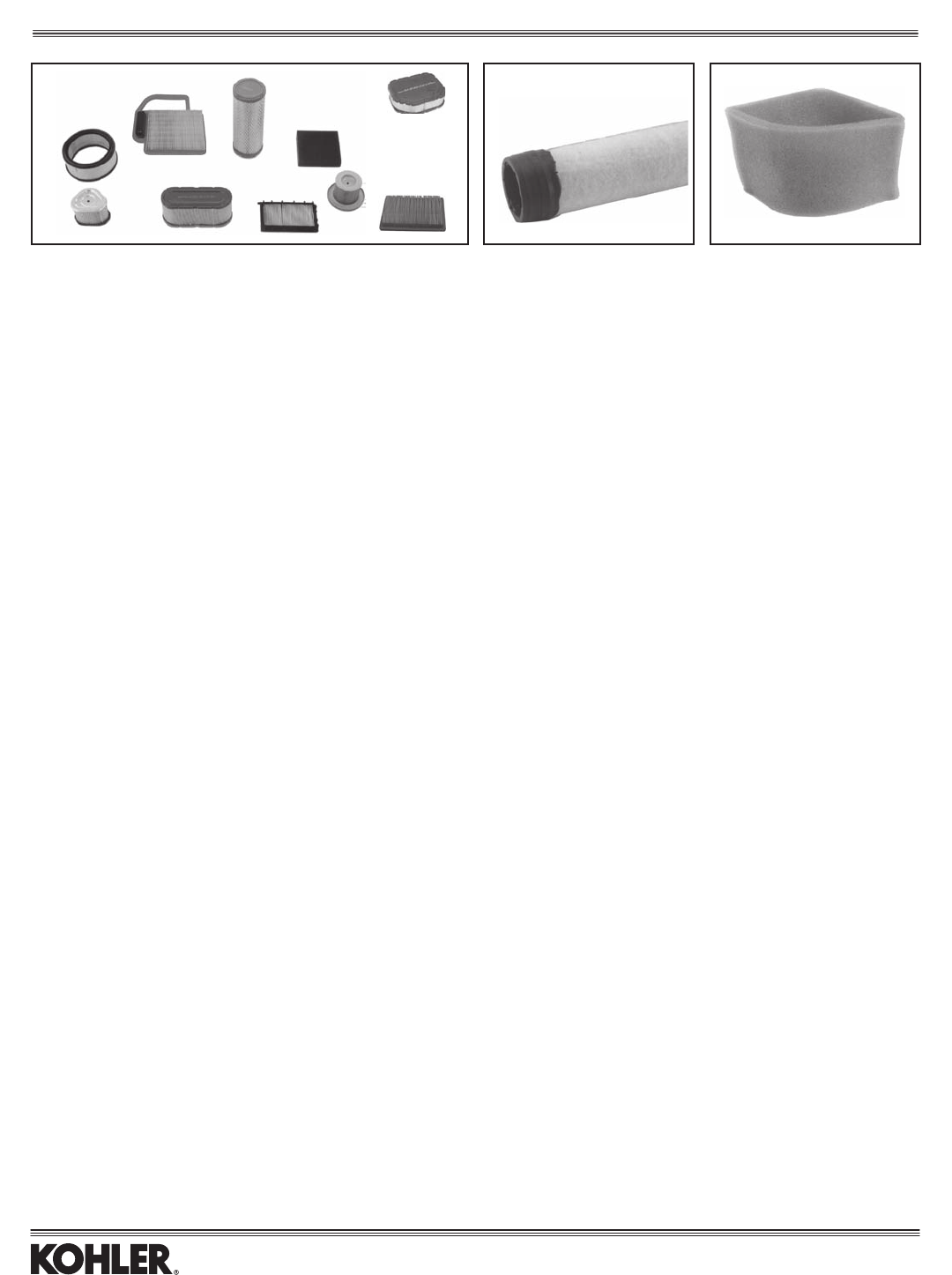
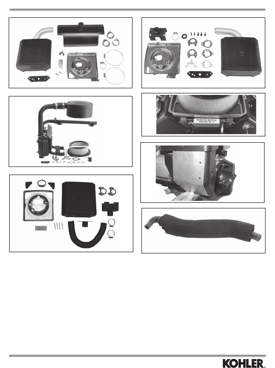
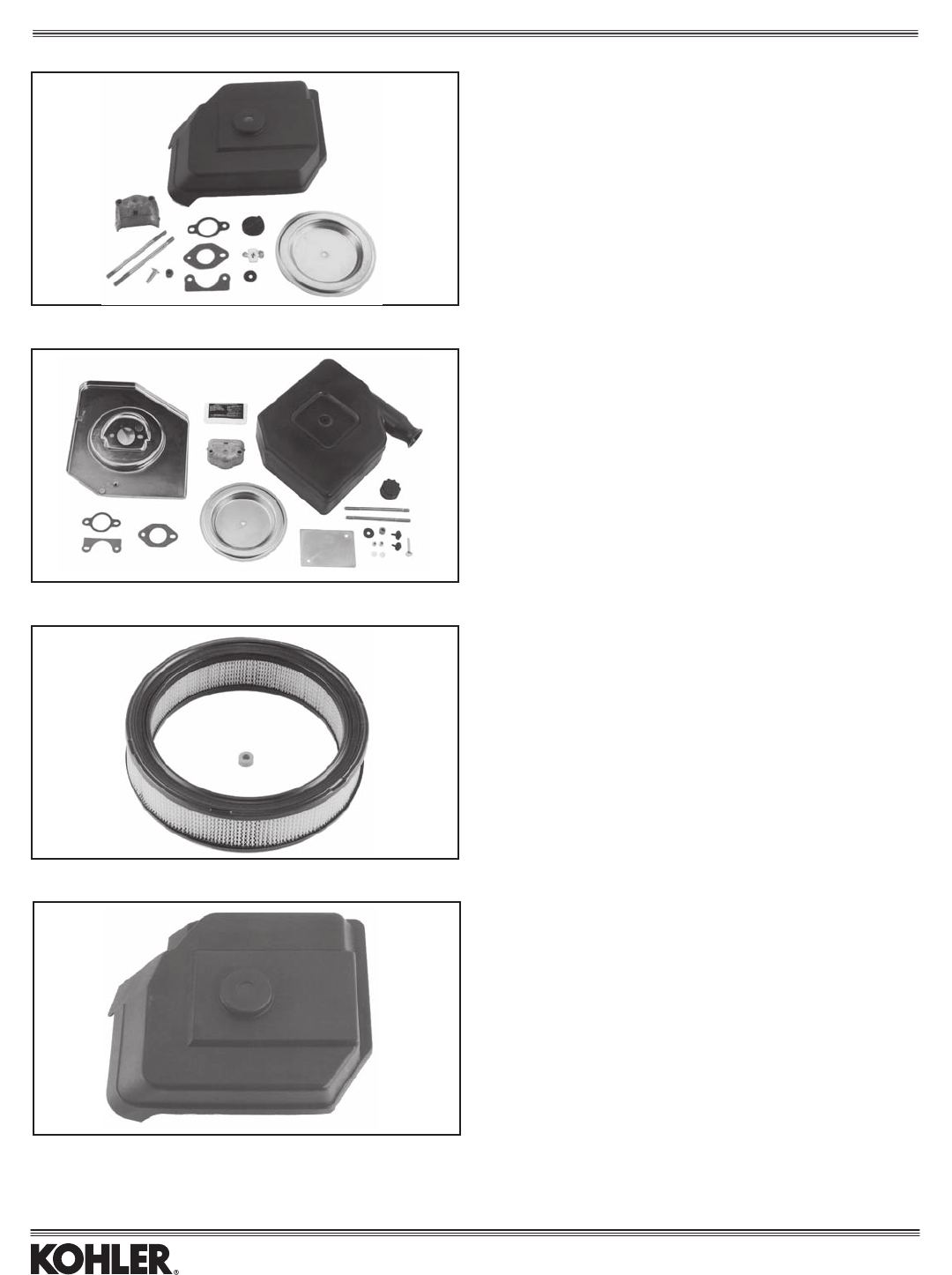
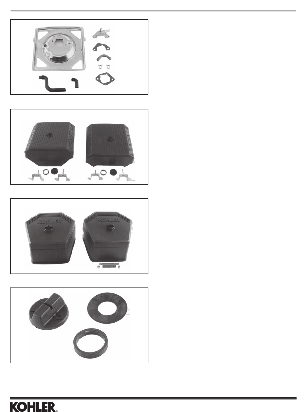
ELEMENTS & PRECLEANERS
Note: Elements and precleaners may appear differently for various models.
Element U.L. Element Inner Element Precleaner
Style (Photo A) Equivalent (Photo B) (Photo C) Model
1 4508302-S 5208304-S — 4508301-S CV17-26/730-745(Commercialmowing)
1 47 083 01-S 47 083 04-S — 52 083 01-S CH11-15
4 6308303-S — — 6308304-S CS4-6(Standard,dualelement)
4 6308311-S — — 6308312-S CS8.5/250cc(Standard,dualelement)
4 6308301-S — — 6308302-S CS8.5/300cc,10-12(Standard,dualelement)
6 6308306-S — — — CS4-6(Foam,singleelement)
6 6308305-S — — — CS8.5/300cc,10-12(Foam,singleelement)
7 6308307-S — — 6308308-S CS4-6(Heavy-dutycyclonic)
7 6308310-S — — 6308309-S CS8.5/250-300cc,10-12(Heavy-dutycyclonic)
8 6308313-S — — 6308314-S CS8.5/250cc(Lowprole,dualelement)
4 6308315-S — — 6308316-S CS10(931600),CS12(941600)
3 20 083 02-S — — 20 083 03-S SV470-620
2 1208305-S* 1208309-S* — 1208308-S CV11-16/460-493(Standard,2.8”High)
2 1208310-S* 1208313-S* — 1208312-S CV11-16/460-493(Tall,3.4”High)
1 4708303-S 2408308-S — 2408302-S CH/CV17-23(Flat)
1 2408303-S 2408309-S — 2408305-S CH/CV25-26/730-745(Flat)
5 24 083 07-S — — — CH/CV17-22 Metal H.D. A/C
5 25 083 01-S — 25 083 04-S — CH/CV17-26/730-745/LH640-775 Plastic H.D. A/C
9 3208303-S — — 3208305-S SV710-740(Standard,1.73”High)
9 3208306-S — — 3208308-S SV810-840(Large,3”High)
4 66 083 01-S — — 66 083 03-S LV625-680
10 14 083 01-S 14 083 02-S XT-7
Notes: *Includes element and rubber seal.
BC
1
A
3
2
4
5
6
7
8
ALSO SEE PAGE 16 FOR RECOIL STARTER FILTERS.
9
Air Intake
10
27
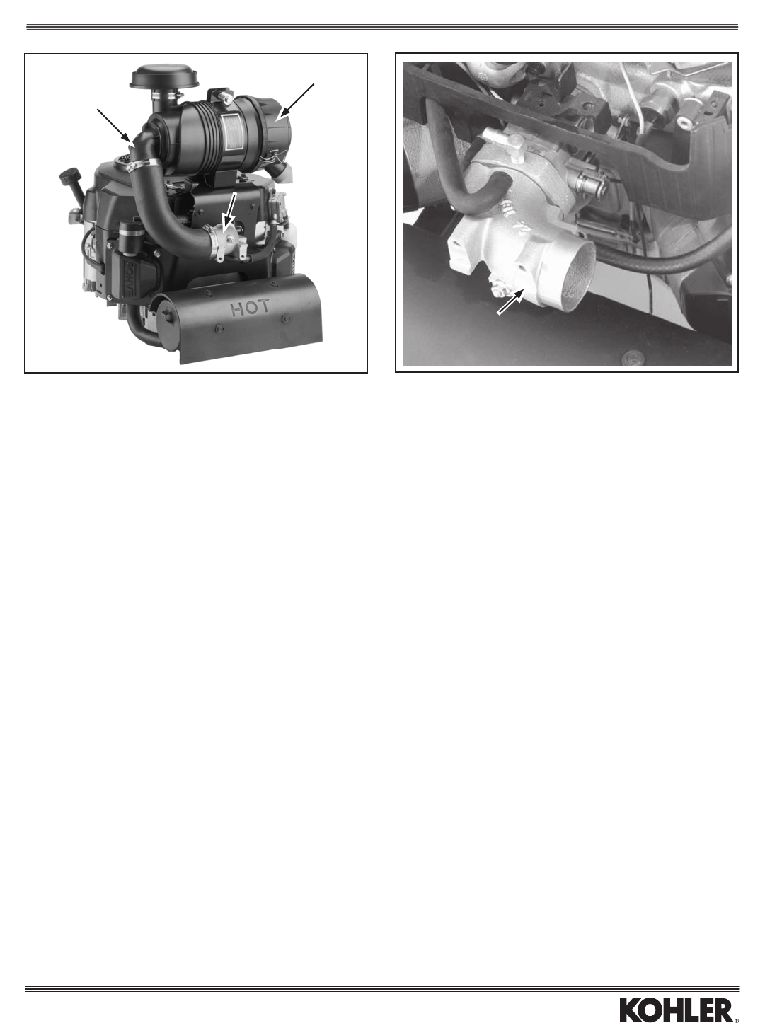
ANTI-ICING COMPONENTS
Iftheincludedinstructionsarefollowed,thesekits/partsmaybeusedwithoutjeopardizingCARB/EPAcerticationontheengine.
Kit No. Model As Low As Notes Heat From Item
2475564-S CH18-22 20°F ForPTOmufers Mufer 1(shown)
2475565-S CH25-26/730-745 20°F ForPTOmufers Mufer 1
2475568-S* CH18-22 20°F Forsidemufers Manifold 2(shown)
2475569-S* CH25-26/730-745 20°F Forsidemufers Manifold 2
2475582-S CH18-26/730-745 –20°F Includesstartersidemufer*** Mufer 3
2475583-S* CH18-22 –20°F Includesltersidemufer*** Mufer 3(shown)
54 755 06-S** CH/CV17-26/730-745 — Not for comm’l. mowers — 4
63 755 39-S CS8.5-12 20°F — — 5
12 168 02-S CH18-26/730-745 — Foam insulation only — —
24 168 01-S LH640-775 — Breather hose insulation — —
24755165-S CH750w/FlatAirCleaners — Forsidemufers Manifold 6
12 326 24-S**** CH11-15 — Insulated breather hose — 7
*Notforuseonltersideofengineifequippedwithoilcooler.
**Increasescarbtemperatureapprox.13°F.Coverstriangularholes(2)inblowerhousing.Removeabove45°F.
***Tubestravelthroughmuferstobringwarmairtoaircleaner.
****Replaces existing breather hose to prevent icing, or order insulation only and install over existing hose.
12
3
4
7
5
Air Intake
6
28
FUEL RECOVERY/SPITBACK
CONTROL SYSTEM
Kit No. Description Model
12 755 84-S Fuel Recovery/Spitback Control Kit CH11-15
Prevents fuel spitback and oil mist from affecting air cleaner element, or allowing
residue to drip off air cleaner base. Engines built after Serial No. 2721720234
include this system.
PLENUM DOME COVER KIT
Hose Clamp
Kit No. Snorkel O.D. Surface Model
1274310-S 1.75" 0.625" CH11-15
Note: May attach to customer-supplied remote-mount air cleaner or
precleaner and hose. Requires Kohler review for CARB/EPA approval
or if TT sheet guidelines for connections cannot be met.
SEAL RETROFIT KIT
Kit No. Description Model
1274309-S SealRetrotKit CH11-15
For engines before Serial No. 2519500004. Seal replaces loose washer and
grommet in cover plate. Kit includes seal and element.
Part No. Description Model
12 096 41-S Air Cleaner Cover CH11-15
(w/multilingualmaintenanceinstructions)
Standard air cleaner cover, including multilingual maintenance instructions
embossed underneath. Now available individually for engines built earlier.
Air Intake
29
AIR CLEANER RETROFIT KITS
Includes For
Kit No. Description Filter Spec. Item
1274303-S Convertsstandardltertoalargerlter Large* A 1
12 743 04-S Cover has opening to line up with opening in blower housing Large* B 2
A—ProSeries“T/ST”afterSerialNo.2404917244,ProSeries“S”afterSerialNo.2424505854.
B—Basic“S”,lawntractors.
*Largecapacitylteris20%greaterthanstandardlter.
1 2
FILTER MINDER
Vacuum-typegaugedetectsairinletrestrictions,signalingwhentoserviceairlter(whenyellowindicatorreachesredline).
Kit No. Mounting Air Drawn From Model Item
25 755 18-S Remote Air cleaner base plate CH/CV11-16/460-493,CH/CV17-26/730-745 1
or heavy-duty air cleaner elbow
25 755 24-S Direct* Heavy-duty air cleaner elbow CH18-26/730-750, CV493 2
62 330 02-S Direct Heavy-duty air cleaner CH/CV940-1000 _
*Includesbrassttings,instructions.
1 2
Air Intake
30
DEBRIS SHIELDS
BothshieldsareincludedinHeavy-DutyAirCleanerKitsabove(carb/elbow)
topreventdebrisfrominterferingwiththrottle/chokecontrols.(Onlyone
shieldneededdependinguponenginespec.)
Part No. Used With Model Item
24 314 25-S Knob-type controls, no CH18-26/730-745 1
controls,remoteaircleaner (shownabove)
24 314 29-S Lever-type controls* CH18-26/730-745 2
*Lever-type controls have been standard on CH18-25 panel specs since
Serial No. 3009400011.
HEAVY-DUTY AIR CLEANER KITS (Convert from Flat Air Cleaner)
Complete,engine-mountedsystem(items1and2usedtogether)isCARB/EPAcertied.Anyremote-mountingconguration(item1plusremote-mountedaircleaner),must
be Kohler approved for CARB/EPA. Filtering area is 1,398 sq. in. Not usable on engines with plastic intake manifold.
Kit No. Description Includes Use With Model Item
2474320-S Elbow/AdapterKit* A AA CH18-22(624cc)/730-740 1
2474325-S Elbow/AdapterKit A AA CH22/23(674cc) 1
24 743 21-S Elbow/Adapter Kit A AA CH25 1
24 743 34-S Elbow/Adapter Kit A AA CH26/745 EFI 1
2474322-S AirCleanerKit(90°canisterelbow)** B BB All 2
2474323-S AirCleanerKit(Straightcanisterelbow)*** C BB All 2
2575524-S FilterMinderKit(Elbowmounted)**** D AA All 3
2575518-S FilterMinderKit(Remotemounted)***** E AA All —
* For CH730/740, carburetor replacement is necessary. Order assembly 24 853 93-S.
**Typicallyusedforengine-mountedconguration(asshown).Ifremote-mounted,customersupplieshose(mustbeKohlerapprovedforCARB/EPA).
***Usedwithcustomer-suppliedhoseforremote-mountlocation.(MustbeKohlerapprovedforCARB/EPA).
****Attachestoaircanisterelbow(peritem3).(Seeearlierpagefordescription.)
*****Attachestoanyremotelocation(frontofengine,application,etc.).(Seeearlierpagefordescription.)
Kits include instructions plus:
A-Elbow/adapter,mountingbracket,2"I.D.hose,hardware,debrisshieldsforeitherknob-typeorlever-typecontrols(seebelow).
B-Aircleanercanister,rainhood(2532402-S),mainandinnerlters,plug(2513920-S)tocloseFilterMinderopeningifnotused.
C-Aircleanercanister,rainhood(2532402-S),mainandinnerlters,cap(2517319-S)tocloseFilterMinderopeningifnotused.
D-FilterMinder,brassttings.
E-FilterMinder,brassttings,10'hose,mountingbracket.
Use with:
AA - Air Cleaner Kit 24 743 22-S . . . or customer-supplied air cleaner, which must be Kohler approved for CARB/EPA.
BB - Elbow/Adapter Kit 24 743 20-S, 25-S, 21-S or 34-S.
1
2
1
2
3
Air Intake
31
HEAVY-DUTY AIR CLEANER KITS
(Convert from Flat or Commercial Mower Air Cleaner)
Complete,engine-mountedsystemsareCARB/EPAcertied.RemotesystemsusingeitherKOHLERorcustomer-suppliedaircleanerandhose,mustbeKohlerapprovedfor
CARB/EPA. Filtering area is 1,398 sq. in. Not usable on Command engines with plastic intake manifold.
Kit No. Description Includes Use With Model Item
2474336-S Elbow/AdapterKit A AA CommandCV18-22(624cc) 1
2474337-S Elbow/AdapterKit A AA CommandCV22/23(674cc) 1
24 743 38-S Elbow/Adapter Kit A AA Command CV25/730-740 1
24 743 39-S Complete Kit B – Command CV26/745 EFI 1,2
2474322-S AirCleanerKit(90ºcanisterelbow)* C BB CommandorAegis***** 2
2474323-S AirCleanerKit(straightcanisterelbow)** D BB CommandorAegis***** 2
6674301-S Elbow/AdapterKit(remoteonly) E CC AegisLV625-675 4
2575524-S FilterMinderKit(Elbow-mounted***) F AA All 3
2575518-S FilterMinderKit(Remote-mounted****) G AA All –
*Typicallyusedforengine-mountedconguration(asshown).NotcompatiblewithverticalpositionedmufersasshowninEXHAUSTsection.
**Usedwithcustomer-suppliedhoseforremote-mountlocation.(MustbeKohler-approvedforCARB/EPA).
***Attachestooutletincanister.(SeeappearanceanddescriptionofFilterMinderonearlierpage.)
****Attachestoanyremotelocation.(SeeappearanceanddescriptionofFilterMinderonearlierpage.)
***** Usable on Aegis but only inremote-mountconguration,notengine-mounted.
Kits include instructions plus:
A - Carburetor, elbow/adapter,mountingbrackets,2"I.D.hose,hardware.
B-Elbow/adapter,mountingbrackets,2"I.D.hose,hardware,plusC.
C-Aircleanercanister(†),rainhood(2532402-S),mainandinnerlters,plug(2513920-S)tocloseFilterMinderopeningifnotused.
D-Aircleanercanister(‡),rainhood(2532402-S),mainandinnerlters,cap(2517319-S)tocloseFilterMinderopeningifnotused.
E-Elbow/adapter,aircleanergaskets,misc.hardware.Customersupplies2"I.D.remotehosetoaircleaner.(MustbeKohler-approvedforCARB/EPA.)
F-FilterMinder,brassttings.
G-FilterMinder,brassttings,10'hose,mountingbracket.
(†)90°aircleanercanisteriscomprisedof:2508101-Smainbody,2509606-Sendcapw/ejectorvalve&clips.
(‡)Straightaircleanercanisteriscomprisedof:no–Spartnumberformainbody,2509606-Sendcapw/ejectorvalve&clips.
Use with:
AA - Air Cleaner Kit 24 743 22-S . . . or customer-supplied air cleaner and hose, which must be Kohler-approved for CARB/EPA.
BB-Elbow/AdapterKit2474336-S,37-Sand38-S;or6674301-S(remote-mountonly).
CC - Air Cleaner Kit 24 743 22-S or 23-S may only beusedinremote-mountedconguration,notengine-mounted.Customersupplies2"I.D.hose.(Mustbe
Kohler-approvedforCARB/EPA.)
1
2
3
Air Intake
4
32
KNOB REPLACEMENT KIT
Kit No. Description Model
54 755 01-S Knob Kit CH/CV17-26/730-750
AIR CLEANER BASE/BREATHER KIT
Kit No. Description Model
24 755 86-S Base/breather kit CV17-25/730-740
Note: Breather system for models with accelerator pump carburetor.
AIR CLEANER COVER KITS
STANDARD
Kit No. For Engine With Model Item
24 743 05-S No control panel CH/CV17-25/730-740* 1
24 743 06-S Control panel CH18-26/730-740 2
Note: Covers include embossed KOHLER name on outside, maintenance
instructionsoninside(English,Spanish,German,French).
*CV17-25/730-740withstandardaircleaneralsorequires2475586-Skit(above).
AIR CLEANER COVER KITS
COMMERCIAL MOWER
Kit No. Model Item
24 743 11-S* CV17-25/730-740 1
24 743 17-S** CV17-25/730-740 2
24 743 32-S** CV26/745 2
Note: Covers include embossed KOHLER name on outside, maintenance
instructionsoninside(English,Spanish,German,French).
* Cover is made of high-temp material for extreme conditions.
** Same as -11-S kit, but includes stud, seal and nuts for high-moisture conditions
preventing water seepage under cover.
12
12
Air Intake
33
CS4-6 MUFFLER
Kitincludesmuferandgasket.Usehardwarefromexistingmufer.
Outlet Outlet Mufer Outlet Tube
Kit No. Location O.D. Length Length Model
6378601-S ThrottleSide* 1.0" 9.46" 1.0" CS4-6
*Outletisonoppositesideofstandardmuferlocation.Alsoallowsfor
unobstructed PTO face.
COURAGE SINGLE (SV710-840)
MUFFLER KIT
Kitincludesmufer,gasket,slip-tmanifolds,andscrews.Customersupplies
mounting bracket to frame.
Kit No. Mufer Only Outlet Location/Direction
32 786 01-S* 32 068 01-S Bottom/Toward Oil Filter
32 086 03-S** Bottom/Toward Oil Filter
* Not compliant for California.
**Californiacompliantmufer.
COURAGE SINGLE (SV470-620)
MUFFLER KIT
Kitincludesmufer,gasket,supportbracket,hardwareandinstructions.
Kit No. Description Engine Side Outlet D.B.C.
2078602-S*** MuferKit Starter 2.047
2008602-S**** MuferKit Starter 2.047
20 755 10-S Guard Kit*
12 755 107-S Guard Kit**
* Cage open at bottom to avoid interference with deck.
** Cage closed at bottom.
*** Not compliant for California.
****Californiacompliantmufer.
COURAGE SINGLE EXHAUST
FLANGE
For adapting manifold length to customer-supplied exhaust.
Part No. Description Model
20 295 01-S Steel, 0.188 thick SV470-620
Shown with
optional guard kit.
Exhaust
XT-7 (COURAGE) MUFFLER KIT
Kitincludesmuferandheatdeector.
Kit No. Mufer Only Outlet Location/Direction
14 068 01-S N/A Out/Away from Engine
34
3
12
5
4
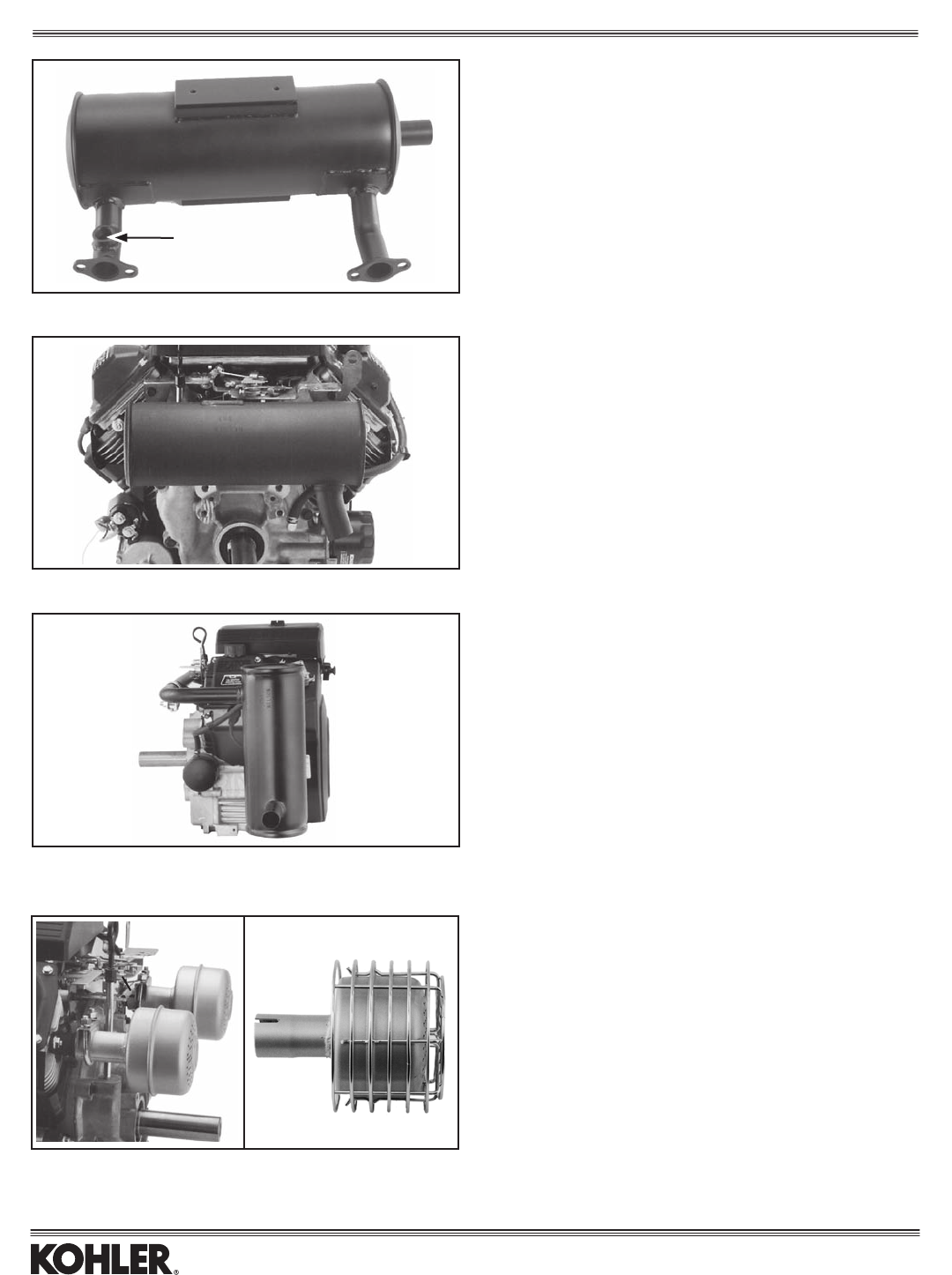
PILLOW MUFFLERS & GUARDS (CH11-15)
Muferkitsincludeoillltube/dipstickaspictured...toavoidinterferencewithmuferorguard...includingsealantandadrivertoaidininstallation.
Mufershavestandoffsforattachingoptionalwireguard.Guardkitsdonotincludemufer.
Muff. Engine Outlet
Part No. Only Description Side D.B.C. A B C D E F G H Item
1278609-S* 1206826-S MuferKit PTO 2.047" 13.0" — 7.0" — 5.0" — 4.25" — 1
1278613-S** 1206838-S MuferKit PTO 2.047" 13.0" — 7.0" — 5.0" — 4.25" — 1
12755107-S — GuardKit PTO — — 13.5" — 6.25" — 5.5" — 5.0" 1
1278608-S* 1206825-S MuferKit Top 2.047" 17.0" — 13.25" — 4.5" — — — 2
1278612-S** 1206839-S MuferKit Top 2.047" 17.0" — 13.25" — 4.5" — — — 2
12755107-S — GuardKit Top — — 17.75" — 13.125" — 5.0" — — 2
1278610-S* 1206827-S MuferKit*** Starter,NoTank 2.047" 8.0" — 1.0" — 11.0" — — — 3
1278614-S** 1206841-S MuferKit*** Starter,NoTank 2.047" 8.0" — 1.0" — 11.0" — — — 3
1275572-S — GuardKit Starter,NoTank — — 8.5" — 1.5" — 11.75" — — 3
1278611-S* 1206823-S MuferKit Starter,NoTank 2.047" 13.0" — 7.0" — 10.0" — — — 4
1278615-S** 1206840-S MuferKit Starter,NoTank 2.047" 13.0" — 7.0" — 10.0" — — — 4
— **1206830-S** Mufer**** Starter,NoTank 2.047" 13.0" — 7.0" — 10.0" — — — 4
12755107-S — GuardKit Starter,NoTank — — 13.75" — 6.25" — 10.5" — — 4
12 755 91-S***** Guard Kit All — — — — — — — — — 5
*Muferhasnointegralportliner.ItisusableonlyonCH11-14modelsbelowSerialNo.2628900001.
**Muferhasintegralportlinerextendingfrommountingange,tointerfacewithcored-outcylinderhead.OnlyformodelswithSerialNo.2628900001orhigher,
which include cored-out cylinder head.
***Muferkitnotusableonspecswithfuelpump.
****ForCH14LPenginesonly;includesoxygensensorportinmanifold-to-muferpipe.
*****Guard kit 12 755 91-S must be used with guard kit 12 755 70-S or 12 755 72-S to comply with EEC standards for avoidance with hot surfaces. Kit includes
wireguardandtwoshields,plusinstructions,althoughallpartsarenotnecessaryforeverymufercongurationshown.Wireguardcoversexhaustmanifold;
shields prevent contact with manifold periphery.
A —Centerlineofcranktotopofmufer. E — Centerlineofcranktoleftedgeofmufer.
B — Centerline of crank to top of guard. F — Centerline of crank to left edge of guard.
C —Centerlineofcranktobottomofmufer. G— FromPTOfacetofarthestedgeofmufer.
D — Centerline of crank to bottom of guard. H — From PTO face to farthest edge of guard.
IncludesExhaustDeector(notshown). IncludesExhaustDeector(notshown). Vertical Orientation
Horizontal Orientation EEC Guards*****
Exhaust
35
PILLOW MUFFLERS & GUARDS (CV11-16/460-493)
Guardkitsdonotincludemufer.Note: Mufers1206854-Sand55-SareexclusivetoCV460-493,1206839-Sisalsouseable.Noothermufersareusableonthese
models.
Engine Stand Offs Hardware Outlet
Part No. Description Side For Guard (See note) D.B.C. A B C D E F Item
1206821-S* Mufer(Standard) Starter No 1 2.047" 12.0" — 0.75" — 4.5" — 1
1206844-S** Mufer(Standard) Starter No 1 2.047" 12.0" — 10.75" — 4.5" — 1
1206854-S** Mufer Starter No 1 2.047" 12.47" — 10.75" — 4.5" — 1
1206823-S* Mufer Starter Yes 1 2.047" 12.0" — 10.75" — 4.5" — 1
1206840-S** Mufer Starter Yes 1 2.047" 12.0" — 10.75" — 4.5" — 1
1206830-S** Mufer**** Starter Yes 1 2.047" 12.0" — 10.75" — 4.5" — 1
1206855-S** Mufer Starter Yes 1 2.047" 12.47" — 10.75" — 4.5" — 1
12755107-S GuardKit Starter — — — — 12.5" — 11.25" — 5.25" 1
(12.97"/460-493)
1206820-S* Mufer*** Starter No 2 2.047" 8.0" — 9.25" — 3.75" — 2
1206842-S** Mufer*** Starter No 2 2.047" 8.0" — 9.25" — 3.75" — 2
1206827-S* Mufer*** Starter Yes 2 2.047" 8.0" — 9.25" — 3.75" — 2
1206841-S** Mufer*** Starter Yes 2 2.047" 8.0" — 9.25" — 3.75" — 2
1275572-S GuardKit Starter — — — — 8.5" — 9.75" — 4.25" 2
1206825-S* Mufer Valve Yes 3 2.047" 2.5" — 10.5" — — — 3
1206839-S** Mufer Valve Yes 3 2.047" 2.5" — 10.5" — — — 3
12755107-S GuardKit Valve — — — — 3.0" — 11.0" — — 3
12 755 91-S*****Guard Kit Items 1 & 2 — — — — — — — — — 4
*Muferhasnointegralportliner.ItisusableonlyonCV11-14modelsbelowSerialNo.2628900001.
**Muferhasintegralportlinerextendingfrommountingange,tointerfacewithcored-outcylinderhead.OnlyformodelswithSerialNo.2628900001orhigher,
which include cored-out cylinder head.
***Mufernotusableonspecswithfuelpump.
****ForCV14LPenginesonly;includesoxygensensorportinmanifold-to-muferpipe.
***** Guard kit 12 755 91-S must be used with guard kit 12 755 107-S or 12 755 72-S to comply with EEC standards for avoidance with hot surfaces. Kit includes
wireguardandtwoshields,plusinstructions,althoughallpartsarenotnecessaryforeverymufercongurationshown.Wireguardcoversexhaustmanifold;
shields prevent contact with manifold periphery.
Note: formufers1206825-Sand1206839-S,onlyguard12755107-SisnecessaryforEEC.Mufers1206820-S,1206821-S,1206842-Sand1206844-S
do not have weld nuts for guard attachment, so they cannot be made EEC-compliant.
A — Centerlineofcranktorightedgeofmufer. B — Centerlineofcranktorightedgeofguard. C — Mountingsurfacetotopofmufer.
D — Mountingsurfacetotopofguard. E— Centerlineofoilllcaptoouteredgeofmufer. F — Centerlineofoilllcaptoouteredgeofguard.
Mounting Hardware (ifnotpresentlyonengine)
1 -Order(1)1212671-Sbracket,(2)M-645025-Sscrew,(1)M-545016-Sscrew,(2)M-841080nut,(1)X-25-78-Swasher.(2)1211220-Sspacer(sheetmetal
valvecoveronly).
2 - Order 12 755 30-S mounting kit.
3 -Order(1)1212656-Sbracket,(2)M-645025-Sscrew,(2)M-645015-Sscrew,(1)1204103-Sgasket,(2)M-841060-Snut,(2)1211220-Sspacer(sheet
metalvalvecoveronly).
2
1
4
3
VerticalOrientation(Standard) Horizontal Orientation
Valve Cover Orientation EEC Guards*****
Exhaust
36
CV Models
Outlet
Part No. Description O.D. A Side Item
1206801-S Mufer 1.25" 4.94" Starter 1
12 786 18-S Mounting Kit* — — Starter 1
1206803-S Mufer 1.25" 6.5" Starter 2
1206835-S Mufer** 1.25" 6.5" Starter 2
12 755 30-S Mounting Kit* — — Starter 2
A — Extends away from blower housing.
* Includes bracketry, gasket, hardware.
**Identicaltothe-03mufer,butincludesintegralportlinerextendingfromthe
mountingange.OnlyhamcanmuferusableonCV11-15modelswith
cored-out cylinder head, Serial No. 26289000001 and higher.
3
12
5
4
HAM CAN MUFFLERS (CH/CV11-15)
CH Models
Outlet
Part No. Description D.B.C. Space Side Item
1206811-S Muferonly** 2.047" B PTO 3
12 786 04-S Mounting Kit *** — — PTO 3
12 755 26-S Guard Kit — B PTO 3
1206811-S Muferonly** 2.047" C Top 4
12 786 03-S Mounting/Guard Kit**** — C Top 4
1206811-S Muferonly 2.047" D Starter 5
12 786 02-S Mounting Kit*** — — Starter 5
12 755 26-S Guard Kit — D Starter 5
**Shownwithdeector,notincluded.
*** Includes manifold, bracketry, gaskets, hardware.
****Includesmanifold,bracketry,exhaustdeector,gasket,guard,hardware.
B—Fromcenterlineofcranktotopofmuferis12.5";totopofguardis13";to
bottomofguardis6".FromPTOfacetoguardatfarthestpointis5.5";to
muferis5".
C—Fromcenterlineofcranktotopofguardis18.5";totopofdeectoris20.55".
D—Fromcenterlineofcranktoleftedgeofguardis11.25";toleftedgeofmufer
is10.75".
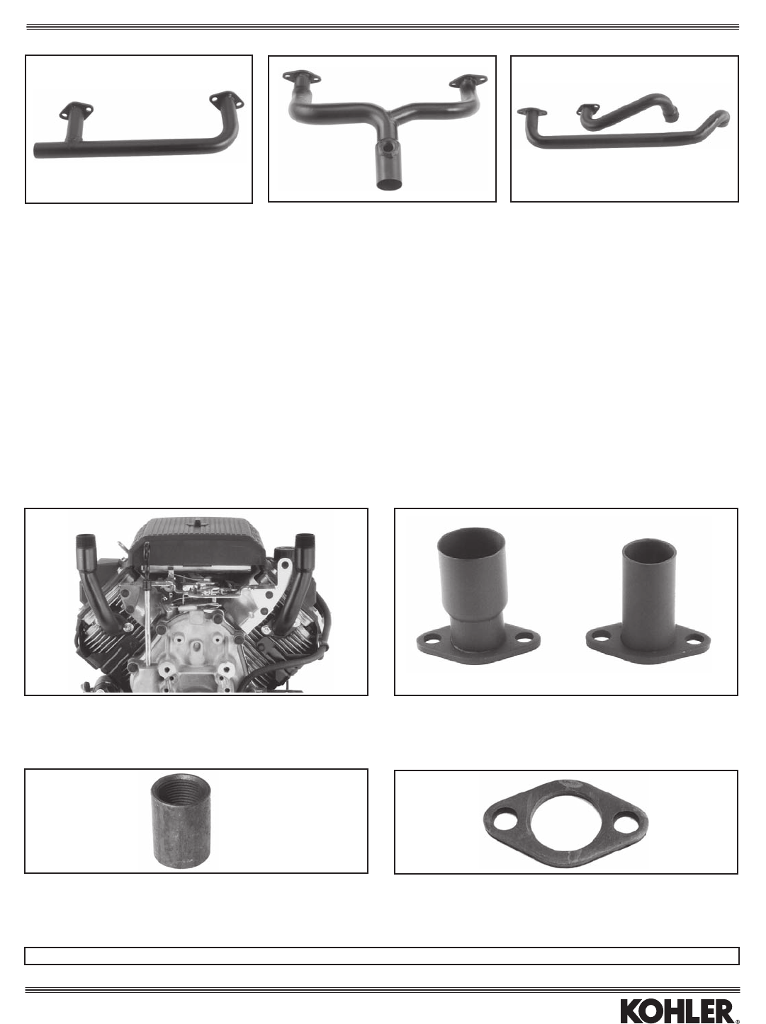
MANIFOLDS
Outlet For
Part No. O.D. Model Mufer Item
1216403-S 1.312" CH11-15 Various 1
12 164 04-S* — CH11-15 Pepperpot 2
12 164 05-S** — CH11-15 Pepperpot 3
1238201-S 1.125" CH11-15 HamCan,Top 3
1238202-S 1.125" CH11-15 HamCan,Starter 4
1238203-S 1.125" CH11-15 HamCan,PTO 5
*1.0"N.P.T.externalthread.
**Sameas1238201-S,except1.0"N.P.T.externalthread.
EXHAUST FLANGE (CH/CV11-15)
For adapting manifold length to customer-supplied exhaust.
Part No. Description Model
1229501-S Steel,0.188"thick CH/CV11-15
5
3
12
4
Exhaust
37
MISCELLANEOUS MUFFLERS
CV Models CH Models
Outlet
Part No. Description Engine Side O.D. Item
12 068 57-S*& Mufer(Aluminized) ValveCover 1.25" 1
1275520-S** MuferKit ValveCover 1.25" 2
1206849-S*** Mufer ValveCover 1.125" 3
*Includesintegralheatshieldandexhaustdeector.Alsoorder(2)M-841080-S
nut,(1)1204103-Sgasket,(1)2508616-Sscrew,(1)X-25-95-Sspacer,
(1)X-20-1-Slockwasher,(1)2510020-Snut.Muferextends5.625"from
valvecover.(1)M-645025-Sscrew,(1)1211220-Sspacer(ifenginehas
stampedsteelvalvecover).
**Includesintegralguard.Muferextends7"fromblowerhousing.
***Alsoorder(1)1204103-Sgasket,(2)M-841060-Snuts,(1)1212685-S
bracket,(2)1211220-Sspacers,(4)M-645016screws,and(2)M-645025
screws.
& Aluminized steel canister.
Kit No. Muff. Only Description (Ideal For) Engine Side Item
12 786 16-S* 12 068 58-S& Round(Compressors) Top 1
(Aluminized)
1278620-S 1206851-S Round(Press.Washers) AbovePTO 2
12 314 32-S — Guard for 1 & 2 — 3
12 786 05-S** 275679-S Pepperpot-Thread On Above PTO 4
25 314 01-S — Guard only — 4
*Includesangledoillltubeanddipsticktoclearmufer,plusmountingbracket
andhardware.Muferoutletis5.5"abovevalvecover.OutletO.D.is1.25".
**Includesmufer,manifold,gasket,hardware.Muferhas1.0"N.P.T.internal
thread.NotusableifenginerequiresCARB/EPAcertication.
& Aluminized steel canister.
1
2
3
4
1
2
3
Exhaust
38
COMMERCIAL MOWER CANISTER MUFFLERS —
HEAT SHIELDS REqUIRED. SEE BELOW.
Outlet Mufer Mufer
Part No. Outlet Location/Direction O.D. Dia. Length A B Model
2406809-S StarterSide/Straight 1.375" 4.0" 12.0" 1.0" 4.75" CV17-25/730,740,750,LV625-680
2406808-S FilterSide/Straight 1.375" 4.0" 12.0" 1.0" 4.75" CV17-25/730,740,750,LV625-680
2406820-S FilterSide/Down 1.375" 4.0" 12.0" 1.0" 4.75" CV17-25/730,740,750,LV625-680
2406821-S FilterSide/Extended 1.375" 4.0" 12.0" 1.0" 4.75" CV17-25/730,740,750,LV625-680
24 068 58-S& FilterSide/Straight 1.375" 4.0" 12.0" 1.0" 4.75" CV17-25/730,740,750,LV625-680
*Same as 24 068 08-S, but outlet is higher on end cap to clear obstructions.
&Aluminized steel canister.
Note: Formounting,order(2)2404149-Sgasket,(2)2407208-Sstud,(2)M-641060-Snut,(4)M-841080-Snut.
qUIET CANISTER MUFFLERS —
HEAT SHIELDS REqUIRED. SEE BELOW.
Thesemufersarelargerthanthoseabove,andalsoupto4dBAquieter(@3600RPM,WOT).
Outlet Mufer Mufer
Part No. Outlet Location/Direction O.D. Dia. Length A B Model
2406825-S Center/Straight 1.375" 4.62" 16.0" 1.0" 5.5" CV17-25/730,740,750,LV625-680
2406827-S StarterSide/Straight 1.375" 4.62" 16.0" 1.0" 5.5" CV17-25/730,740,750,LV625-680
2406829-S FilterSide/Straight 1.375" 4.62" 16.0" 1.0" 5.5" CV17-25/730,740,750,LV625-680
2406828-S FilterSide/Down 1.375" 4.62" 16.0" 1.0" 5.5" CV17-25/730,740,750,LV625-680
2406826-S FilterSide/Extended 1.375" 4.62" 16.0" 1.0" 5.5" CV17-25/730,740,750,LV625-680
2406858-S FilterSide/Straight 1.375" 4.62" 16.0" 1.0" 5.5" CV17-25/730,740,750,LV625-680
2406843-S Center/Straight 1.375" 4.62" 16.0" 1.0" 5.5" CV26/745EFI
2406845-S StarterSide/Straight 1.375" 4.62" 16.0" 1.0" 5.5" CV26/745EFI
2406847-S FilterSide/Straight 1.375" 4.62" 16.0" 1.0" 5.5" CV26/745EFI
2406846-S FilterSide/Down 1.375" 4.62" 16.0" 1.0" 5.5" CV26/745EFI
2406844-S FilterSide/Extended 1.375" 4.62" 16.0" 1.0" 5.5" CV26/745EFI
A — Mountingsurfacetobottomofmufer.
B — Mountingsurfacetotopofmufer.
Note: Formounting,order(2)2404149-Sgasket,(2)2407208-Sstud,
(2)M-641060-Snut,(4)M-841080-Snut.
HEAT SHIELDS FOR CANISTER
MUFFLERS
Kohlerrequiresaheatshieldbetweenmuferandaircleaner.
Part No. Designed for Mufers
24 281 06-S* 24 068 08-S, 09-S, 20-S, 21-S
24 281 13-S* 24 068 26-S, 27-S, 28-S, 29-S
24 281 14-S* 24 068 25-S
24 281 15-S* 24 068 44-S, 45-S, 46-S, 47-S
24 281 16-S* 24 068 43-S
24 314 51-S*& 24 068 58-S
*Order(4)2508640-Sscrewsformountingheatshield.
&Aluminizedsteeltomatchmufer.
Shown:2406827-SQuietversion.
(Muferswilltwithtop-mountcontrolsonly.)
Shown:2406827-SQuietversion.
(Muferswilltwithtop-mountcontrolsonly.)
Exhaust
39
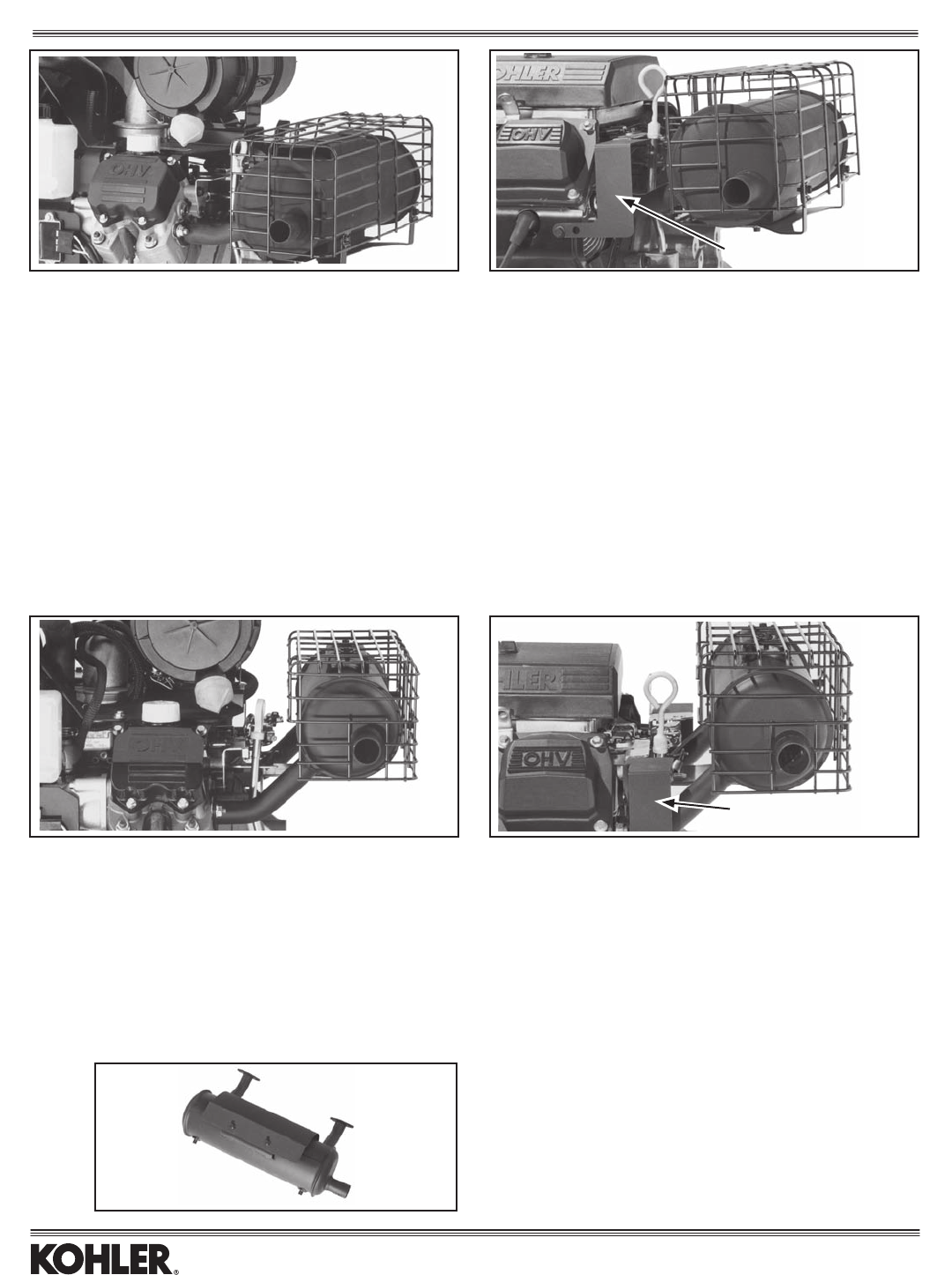
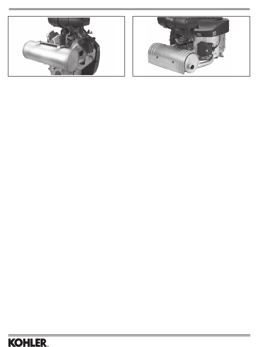
VERTICAL MUFFLER KITS* (CV17-740,750)
Kit No. Muff. Only Location Outlet D.B.C. A B Item
2478613-S 2406819-S StarterSide 3.06" 3.0" 3.5" 1(Shown)
2478614-S 2406819-S FilterSide 3.06" 3.0" 3.5" 1
2478615-S 2406822-S StarterSide 3.06" — — 2(Shown)
2478616-S 2406822-S FilterSide 3.06" — — 2
*Includesmufer,manifold,brackets,heatdeector,clamp,gaskets,andhardware.
A — Extendsforwardofaircleaner. B — Extendsright(orleft)ofvalvecover.
FLAT AIR CLEANER COMMERCIAL MOWER AIR CLEANER
CROSSOVER MANIFOLDS
USED IN KITS ABOVE
Outlet Outlet
Part No. Location O.D. Item
2416412-S StarterSide,Down 1.125" 3
2416413-S FilterSide,Down 1.125" 4
2416416-S StarterSide,Up 1.125" 1
2416417-S FilterSide,Up 1.125" 2
1 2
1
2
3
4
Exhaust
40
PTO-CANISTER MUFFLER & GUARD KITS (IDEAL FOR GEN SETS)
Mufersaresamesizeasstandardcanisters(topofpage),buthavearaisedbodytoclearthealternatorassemblyonageneratorset.Notethatthereisnocenter
outletmuferbecauseitwouldallowhotexhausttoblowdirectlyatthegensetcontrolbox.
AEGIS COMMAND
Kit No. Muff. Only Outlet Location/Direction Outlet O.D. A B A B Model
2478621-S* 2406836-S FilterSide/Straight 1.25" 6.3" 13.1" 6.5" 13.25" CH18-25/730,740,750,LH640-755
2478622-S* 2406837-S StarterSide/Straight 1.25" 6.3" 13.1" 6.5" 13.25" CH18-25/730,740,750,LH640-755
2478627-S 2406851-S FilterSide/Straight 1.25" 6.3" 13.1" 6.5" 13.25" CH26/745,LH775
24755104-S** — MuferGuardKit — — — — — CH18-25/730-750,LH640-775
24755114-S** — SideShieldKit(2Shields) — — — — — CH18-25/730-750only(notLH)
*Includesonlyscrewsforattachingheatshield.Seeshieldsbelow.(RequiredforCH25,26/730-750,LH690-775.)
**Whenguardkit24755104-Sandshieldkit24755114-Sareusedtogether,theymeetEEC(European)standardsforavoidancewithhotsurfaces.
A-Centerlineofcranktobottomofmufer.B-Centerlineofcranktotopofmufer.
STANDARD PTO-CANISTER MUFFLER & GUARD KITS
(notusablewith1”dia.metaloillltube)
AEGIS COMMAND
Kit No. Muff. Only Outlet Location/Direction Outlet O.D. A B A B Model
2478604-S 2406805-S Center/Straight 1.25" — — 4.5" 10.5" CH18-22
2478605-S 2406807-S FilterSide/Straight 1.25" — — 4.5" 10.5" CH18-22
2478606-S 2406806-S StarterSide/Straight 1.25" — — 4.5" 10.5" CH18-22
2478623-S* — StarterSide/45°Down 1.25" 4.3" 10.3" 4.5" 10.5" CH18-22,CH25/730-740,LH640-755
2478610-S** 2406812-S Center/Straight 1.25" 4.3" 10.3" 4.5" 10.5" CH25/,730,740,750,LH640-755
2478611-S** 2406818-S FilterSide/Straight 1.25" 4.3" 10.3" 4.5" 10.5" CH25/,730,740,750,LH640-755
24 786 12-S** 24 068 59-S& StarterSide/Straight(Shown) 1.25" 4.3" 10.3" 4.5" 10.5" CH25/,730,740,750,LH640-755
24 786 26-S 24 068 57-S& FilterSide/Straight 1.25" 4.3" 10.3" 4.5" 10.5" CH25/,730,740,750,LH640-755
2475580-S*** — MuferGuardKit — — — — — CH18-26/730-750,LH640-775
24755114-S*** — SideShieldKit(2Shields) — — — — — CH18-26/730-750only(notLH)
— 24 068 35-S**%FilterSide/Straight 1.25" 4.3" 10.3" 4.5" 10.5" CH26/745,LH775
— 24 068 41-S**%Center/Straight 1.25" 4.3" 10.3" 4.5" 10.5" CH26/745,LH775
— 24 068 42-S*% StarterSide/Straight 1.25" 4.3" 10.3" 4.5" 10.5" CH26/745,LH775
*CH25,26/730-750,LH640-775 require heat shield. See shields below. **Includes heat shield and screws. See shields below.
***Whenguardkit2475580-Sandshieldkit24755114-Sareusedtogether,theymeetEEC(European)standardsforavoidancewithhotsurfaces.
%2575536-Smountingkitrequiredforrsttimeinstallation.&Aluminized steel canister.
HEAT SHIELDS FOR CANISTER
MUFFLERS
Part No. Designed for Mufers
24 314 04-S* 24 068 12-S, 17-S, 18-S, 36-S, 37-S
24 314 21-S** 24 068 35-S, 41-S, 42-S, 51-S
24 314 50-S*& 24 068 57-S
*(4)M-650012screwsformountingheatshieldareincludedinmuferkits,except
for2478623-Swhichrequiresscrewstobeordered.**Order(4)M-650012-S
screws for mounting heat shield. &Aluminizedsteeltomatchmufer.
Side Shield
Side Shield
Exhaust
41
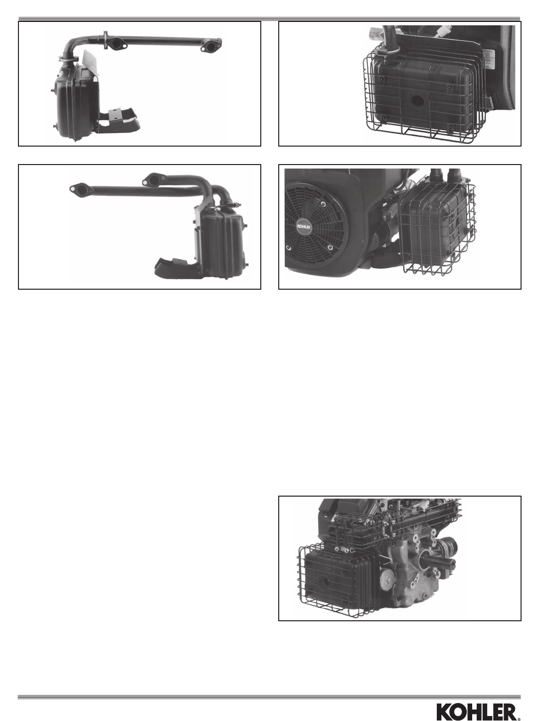
SIDE-MOUNT MUFFLER & GUARD KITS (STANDARD)
(notusablewith1”dia.metalorplasticoillltube)
Extends Engine
Kit No. Muff. Only Location Outlet D.B.C. Model Width By Item
2478608-S 2406813-S StarterSide 2.047" CH18-22 4.0" 1
2478609-S 2406814-S FilterSide*** 2.047" CH18-22* 4.0" 1(Shown)
2475522-S — GuardKit** — CH18-22* 4.375" 2
2478619-S 2406830-S StarterSide 2.047" CH25/730,740,750,LH640-755***** 4.25" 3(Shown)
2478620-S 2406831-S FilterSide**** 2.047" CH25/730,740,750,LH640-755***** 5.60" 3
24755149-S — GuardKit,StarterSide — CH25/730-750,LH640-755 4.25" 4(Shown)
24755151-S — GuardKit,FilterSide — CH25/730-750,LH640-755 5.60" 4
2478624-S 2406854-S StarterSide 2.047" CH26,745***** 4.25" 3
2478625-S 2406855-S FilterSide**** 2.047" CH26,745,LH775***** 4.25" 3
* Not usable on models with oil cooler.
**Shownon2478609-SMuferKit(mufernotincluded).
***Mayalsoneedtoorder1205014-Soilltertoavoidinterferencewithmufer.
****Includes1205014-Soilltertoavoidinterferencewithmufer.
******Kitsincludemuferanddualmanifolds.
SIDE-MOUNT GUARD KITS,
EEC (EUROPEAN) COMPLIANT
Thesekitsincludeguardsforthemufer,manifoldandexhaustelbow.Theguards
must be used together to meet EEC standards for avoiding contact with hot
surfaces.
Extends Engine
Kit No. Location Width By Model
5475524-S StarterSide 4.375" CH18-22(Shown)
5475525-S FilterSide 4.375" CH18-22
24755150-S* FilterSide 4.375" CH25/730,740,750
LH640-755
24755148-S* StarterSide 4.375" CH25/730,740,750
LH640-755
*Manifold guard is metal mesh, compared to wire form in other kits.
1 2 (Shown on Command)
34 (Shown on Command)
(Shown on Command)
Exhaust
42
CANISTER MUFFLER
(Vertical Orientation)
Availableonltersideonly(withoutoilcooler)andasremote.Specialshieldingis
necessary(furnishedbycustomer)toprotectthefuelpump...whetherspechas
pulse or mechanical pump. If a mechanical pump is used on starter side, no shielding
is necessary.
Mounting Outlet
Part No. Location O.D. Models
2406815-S* RemoteMount 1.375" CH18-22
2406816-S** FilterSide(shown) 1.375" CH18-22
*Alsoorder(1)2416404manifold,(2)2404149gasket,and(4)M-841080nut.
**Sameasabove,plus:(1)1223702clamp,(1)M-839020screw(bracketto
crankcase),and(1)M-651030screw(brackettovalvecover).
PTO CANISTER MUFFLERS &
GUARD (Closed Loop LP Systems)
Mufersincludethreadedadapterinlter-sideinletpipe,toacceptoxygensensor
for closed loop LP fuel systems.
Outlet
Kit No. Muff. Only Location/Direction Outlet O.D. Models
— 2406833-S* StarterSide/Straight 1.25" CH18-25,730
— 2406834-S* FilterSide/Straight 1.25" CH18-25,730
24 755 80-S — Wire Guard Kit — CH18-25,730
*Mufersincludebracketsforattachingheatshield(requiredforCH25).
Order2431404-Sheatshieldand(4)M-650012-Sscrews.
PTO CANISTER MUFFLER
(Special Outlet Pointing Down)
Will not accept heat shield or wire guard kit. CARB/EPA compliant on CH18-22 only.
Outlet Outlet
Part No. Direction O.D. Models
2406811-S Down 1.375" CH18-22*
* Application Engineering approval needed for CH25/730-740 and LH640-755 due
tosmallermufervolumeandpotentialforhigherheat.
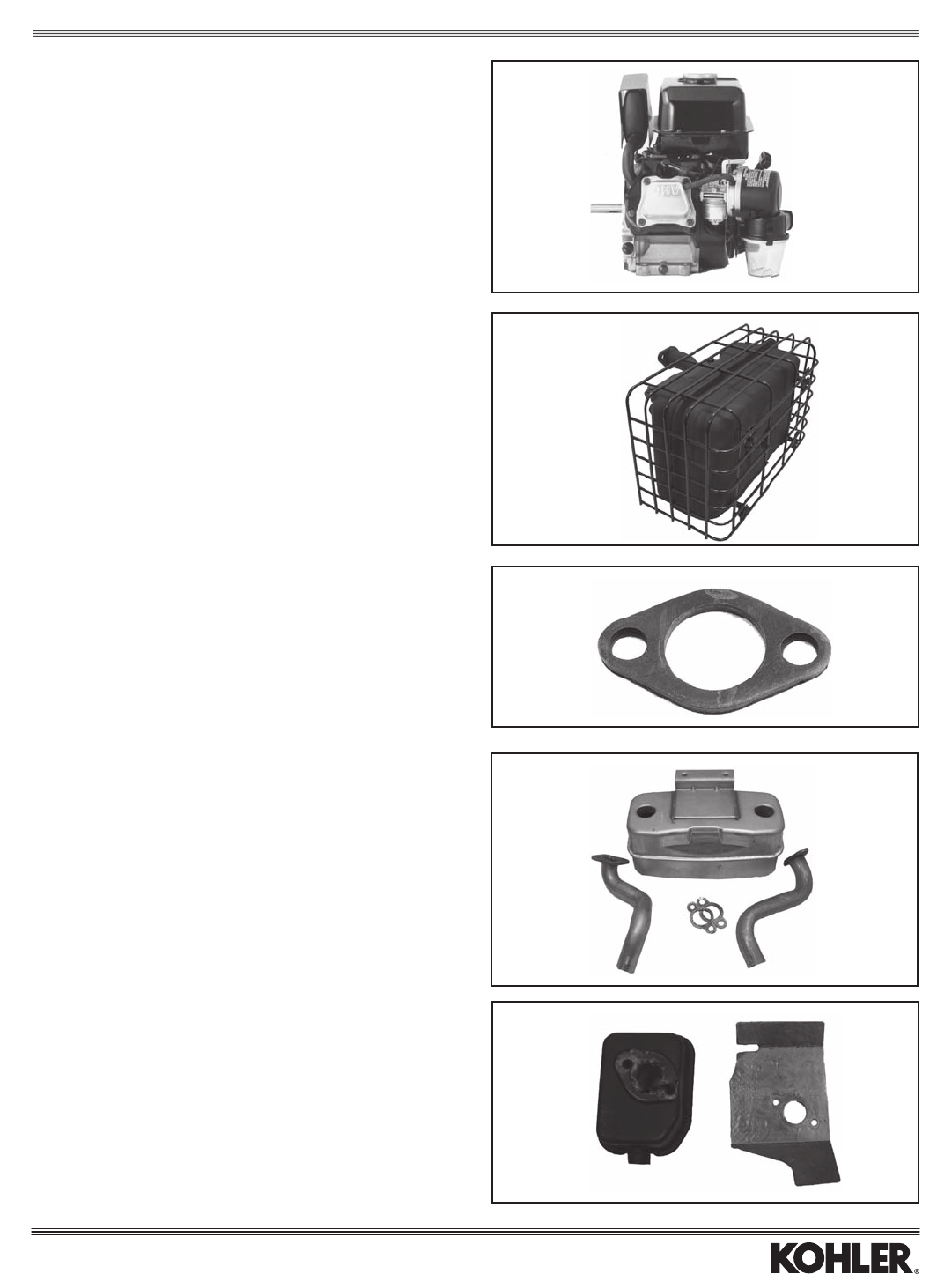
PEPPERPOT MUFFLER & GUARD
Muferkitincludestwomufers,manifoldsandgaskets,plushardware.Mufer
is not usable on engines that must meet CARB/EPA emission regulations, unless
approvedbyKohlerforspecicapplications.
Mufer
Part No. Only Description Models
2478607-S 5206804-S MuferKit CH18-25/730-750,
LH640
2531401-S — Guard(order2) CH18-25/730-750,
LH640
Threaded adapter to
accept oxygen sensor.
Exhaust
43
CROSSOVER MANIFOLDS
Outlet Extends
Part No. Location Outlet From PTO Face Model Item
Single Manifolds
2416404-S FilterSide 1.11"(O.D.) 0.75"OutsideFace CH18-22 1
2416402-S FilterSide(Fitsductpackage) 1.11"(O.D.) 2.125"OutsideFace CH18-22 1
2416403-S StarterSide(Fitsductpackage) 1.11"(O.D.) 2.125"OutsideFace CH18-22 1
2416410-S StarterSide(Forsidemufer) 1.11"(O.D.) 0.25"InsideFace CH18-22 1
2416411-S FilterSide(Forsidemufer) 1.11"(O.D.) 0.25"InsideFace CH18-22 1
2416427-S**** FilterSide 1.24"(O.D.) 0.25"InsideFace CH25/730-750,LH640-755 1
2416428-S**** StarterSide 1.24"(O.D.) 0.25"InsideFace CH25/730-750,LH640-755 1
2416425-S Center* 1.468"(O.D.) 6.5"OutsideFace CH26/745,LH775 2
Dual Manifolds
2416419-S StarterSide(Forsidemufer,cyl.#1)** 1.26"(I.D.) 0.25"InsideFace CH25/730-750,LH640-755 3
2416420-S StarterSide(Forsidemufer,cyl.#2)** 1.26"(I.D.) 0.25"InsideFace CH25/730-750,LH640-755 3
2416421-S FilterSide(Forsidemufer,cyl.#2)*** 1.26"(I.D.) 0.25"InsideFace CH25/730-750,LH640-755 3
2416422-S FilterSide(Forsidemufer,cyl#1)*** 1.26"(I.D.) 0.25"InsideFace CH25/730-750,LH640-755 3
*Includesportforoxygensensor(2441805-S,notincluded).TobeCARB/EPAcertied,musthaveKohlerApplicationEngineeringapprovalwhennon-Kohlerexhaust
components are used.
**Includedinthe2478619-Sside-mountmuferkit.
***Includedinthe2478620-Sside-mountmuferkit.
****Willnottwithstraightdipsticktube.Offsetdipsticktubeorkit2412316-Srequired.
STRAIGHT COUPLE
Use with 90° manifold kit above or other threaded parts.
Part No. Description Thread
2424901-S StraightCouple 1"N.P.S.
90° MANIFOLD KIT
Kit No. Fits Mufer Thread Model
†2473001-S 275679-S 1"N.P.T. CH18-25/730-750,LH640-755
Kitincludes(2)elbows,(2)gaskets,(4)nuts.NointerferencewithPTOface.
EXHAUST FLANGE
For adaptation of customer-supplied exhaust.
Part No. Description Model
2429501-S Steel,0.188"thick CH/CV17-25/730-750,LH640-775
STUB MANIFOLDS
Kit No. Outlet O.D. Model Item
†2416405-S 1.415" CH18-25/730-750,LH650-775 1
†2416407-S 1.125" CH18-25/730-750,LH650-775 2
2
1
12 3
†IndicatesitemnotusableonengineswhicharerequiredtomeetCARBorEPAemissionregulations,unlessapprovedbyKohlerforspecicapplications.
Exhaust
44
HORIzONTAL MUFFLER KITS*
Kit No. Muff. Only Discharge Outlet O.D. A B Item Heat Shield (required)
6278601-S 6206806-S Center 1.5" 11.75" 4.0" 1 6231405-S
6278602-S 6206805-S StarterSide 1.5" 11.75" 4.0" 1 6231405-S
6278603-S 6206802-S OppositeStarter 1.5" 11.75" 4.0" 1 6231405-S
*Includesmufer,gaskets,heatshield,andhardware.
A — Centerlineofcranktotopofmufer. B — Centerlineofcranktobottomofmufer.
VERTICAL MUFFLER KITS*
Kit No. Muff. Only Discharge Outlet O.D. A B Item Heat Shield (required)
6278604-S 6206809-S Center 1.5" 2.68" 4.04" 2 6231406-S
6278605-S 6206808-S StarterSide 1.5" 2.68" 4.04" 2 6231404-S
6278606-S 6206807-S OppositeStarter 1.5" 2.68" 4.04" 2 6231404-S
*Includesmufer,brackets,gaskets,heatshield,andhardware.
A — Mountingsurfacetobottomofmufer. B — Mountingsurfacetotopofmufer.
12
Exhaust
CROSS OVER MANIFOLDS & MUFFLER
Original Equipment Manufacturer responsible for the original installation and thermal protection.
Kit No. Model Description Location Outlet O.D. Inlet I.D.
6216410-S CH940-1000 Manifold Non-StarterSide 1.5" NotPictured
6216411-S CH940-1000 Manifold StarterSide 1.5" NotPictured
6206810-S CH940-1000 Mufer — 1.5" NotPictured
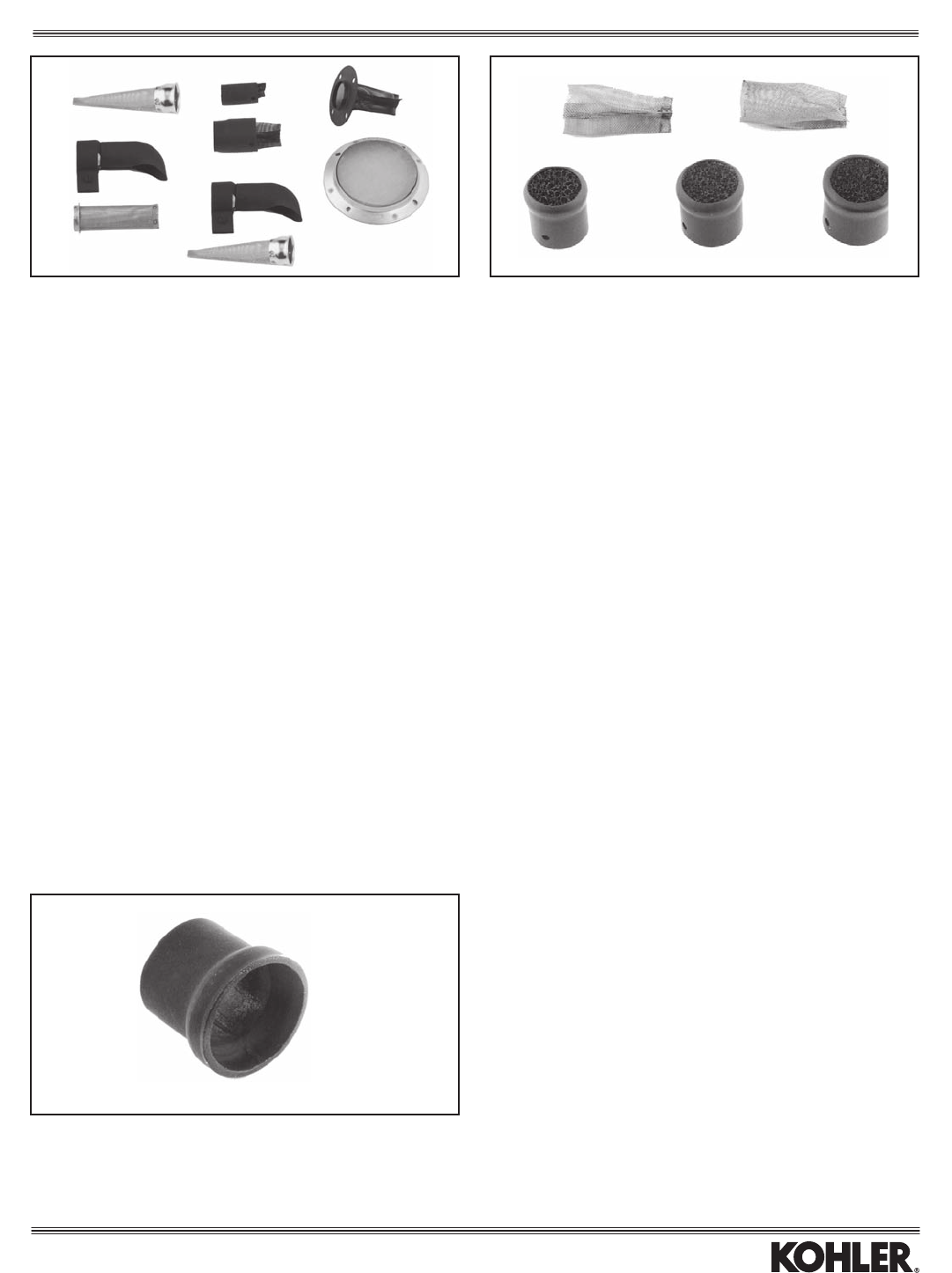
45
SPARK ARRESTORS
HP Rating Inlet Fits Mufer Mounting
Part No. Model/HP For U.S.F.S. Size Outlet D.B.C. Notes Item
63 189 02-S CS4-6 6 — — — Already factory-installed on engine 1
63 189 01-S CS8.5-12 12 — — — Already factory-installed on engine 1
1518901-S CH6 6 0.76"I.D. 0.75"O.D. — Includessetscrew 2
1575516-S* CH6 6 0.76"I.D. 0.75"O.D. — Kitincludes1518901-Sarrestor —
(above)and1502902-Sadapter
(seebelow)
1218902-S** CH/CV11-16/460-493,CH18-25/730-740, 27 1.125"O.D. 1.126"I.D. 2.047" Forpillowsidemufer 3
LH640-755, SV470-620
2418901-S CH18-26/730-750,LH640-775, 31 1.26"I.D. 1.25"O.D. — Forcanistermufer,inc.deector 4
2518901-S CH/CV11-16/460-493,CH18-26/730-750, 27 1.26"I.D. 1.25"O.D. — Includessetscrew 5
LH640-775
2518902-S CH/CV17-26/730-750,LH640-775, 27 1.39"I.D. 1.375"O.D. — Includessetscrew 5
LV625-680
2553301-S** CH11-15 23 — — 3.68" For275679-Spepperpotmufer 6
62 189 02-S CH940-1000 40 — Includes set screw —
6253301-S CH940-1000 40 — Forcanistermufer,inc.deector 7
*Usermustweldadaptertomuferoutlet.Otherendwillthenaccept1518901-Sarrestor.Alsomustcutslotinguard.
**Alsoorder(4)M-545010-Sscrew(drill5/32"holesinmufer).
EXHAUST SILENCERS
HP Rating Inlet Fits Mufer
Part No. Model/HP For U.S.F.S. Size Outlet Notes Item
5242801-S Variesbyoutletsize **** — 1.375"O.D. Use5208620-Sscrew 7
1275535-S Variesbyoutletsize **** — 1.25"O.D. Includesscrew 8
2575508-S Variesbyoutletsize **** — 1.25"O.D. Includesscrew 9
2575509-S Variesbyoutletsize **** — 1.375"O.D. Includesscrew 10
2575510-S Variesbyoutletsize **** — 1.5"O.D. Includesscrew 11
****Not U.S.F.S. approved.
5
9
10
1
4
2 37
11
8
6
Inside Fit
Outside Fit
MUFFLER ADAPTER
(Mufer to Arrestor)
Part No. Mufer End I.D.* Arrestor End O.D.
1502902-S 0.76" 0.75"
*Weld to exhaust pipe.
Mufer End
Arrestor End
Exhaust
7
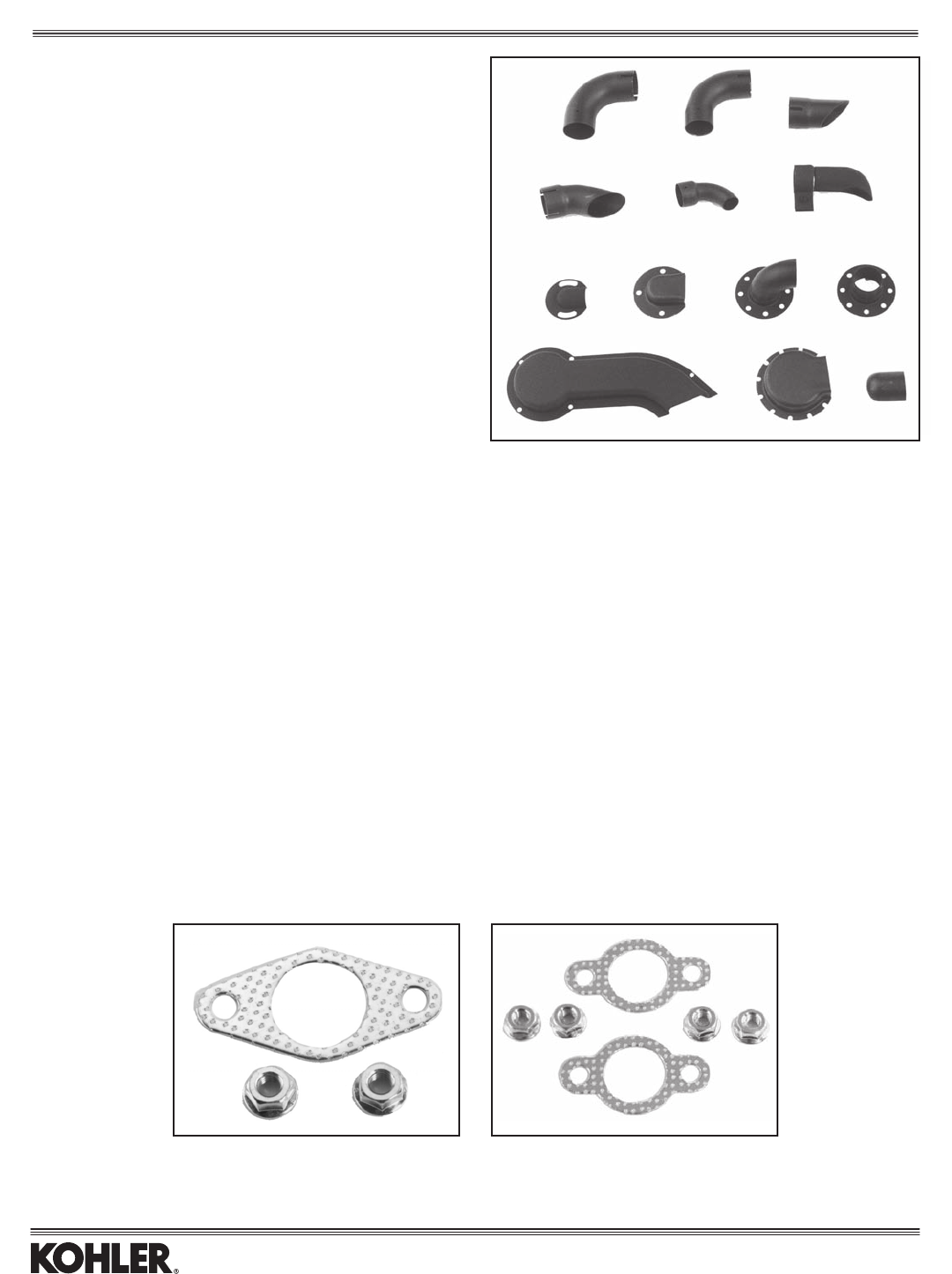
46
HARDWARE KITS
Forattachingmuferstoexhaustoutlets.
Kit No. Model Includes Item
12 786 17-S CH/CV11-16/460-493 2 nuts, 1 gasket 1
2578601-S CH18-26/730-750,LH630-775,TH520-575w/standardangenuts(shown) 4nuts,2gaskets 2
EXHAUST DEFLECTORS
Part Inlet Fits Mufer Also
No. Model I.D. Outlet Order Item
4505421-S CH/CV17-26/730-750, 1.376" 1.375"O.D. D 1
LH640-775, LV625-680
2505405-S CH/CV940-1000, 1.55" 1.50"O.D. D 1
1205402-S CV11-16/460-493, 1.26" 1.25"O.D. B 2
CH18-26/730-750,
LH640-775
2426506-S CH/CV17-26/730-750, 1.39" 1.375"O.D. B 3
LH640-775, LV625-680
2426507-S CS8.5(300cc),CS10-12, 1.39" 1.375"O.D. B 4
CH/CV17-26/730-750,
LH640-775, LV625-680
6326501-S CS4-6 1.02" 1.0" E 5
6326502-S CS8.5(250cc) 1.96" 1.94"O.D. E 5
2426501-S CH/CV11-16/460-493, 1.25" 1.25"O.D. — 6
CH18-26/730-750,
LH640-775
1526502-S CH6 — 1.57"D.B.C. A 7
12755106-S*CH/CV11-16/460-493, — 2.047"D.B.C. — 8
CH18-25/730-740**,
LH640-755, SV470-620
1275528-S* CH/CV11-16/460-493, — 2.047"D.B.C. — 9
CH18-25/730-740,
LH640-755, SV470-620
2575519-S*CH/CV11-16/460-493, — 2.047"D.B.C. — 10
CH18-25/730-740,
LH640-755, SV470-620
2475549-S* CH/CV17-750 — 3.06"D.B.C. — 11
2475550-S* CH/CV17-750 — 3.06"D.B.C. — 12
1212308-S Allw/1.25"outletO.D. — 1.25"O.D. C 13
62 265 03-S CH940-1000. — 1.50” O.D..
*Kitincludesdeector,screws.
**Minormodicationsareneededtomuferguard2475522-Sifdeectorisused
with it.
A — (2)M-556010-SScrew B — (1)4723704-SClamp
C — (1)2508640-SScrew D — (1)237548-SClamp
E — (1)2508646-SScrew
2
1
1
23
456
78 9
10
11
12 13
Exhaust
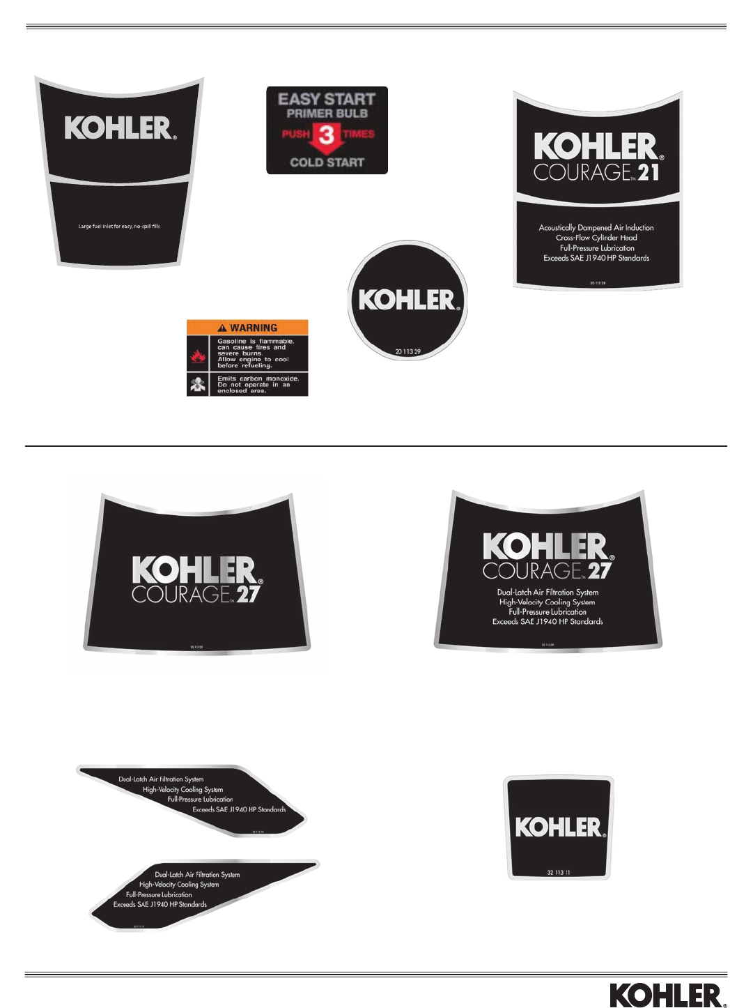
47
Silver letters/numbers
20 113 09-S - 15 HP
20 113 10-S - 16 HP
20 113 11-S - 17 HP
20 113 12-S - 18 HP
20 113 13-S - 19 HP
20 113 14-S - 20 HP
20 113 28-S - 21 HP
20 113 38-S - 22 HP
Silver letters/numbers
2011329-S(xedguard)
Courage® Twin
Silver letters/numbers
32 113 02-S - 20 HP
32 113 03-S - 23 HP
32 113 04-S - 25 HP
32 113 24-S - 26 HP
32 113 05-S - 27 HP
Silver letters/numbers
32 113 06-S - 20 HP
32 113 12-S - 22 HP
32 113 07-S - 23 HP
32 113 08-S - 25 HP
32 113 25-S - 26 HP
32 113 09-S - 27 HP
Silver letters/numbers
32 113 10-S wing set
Silver letters/numbers
3211311-S-(xedguard)
Gold letters/numbers
3211353-S-(xedguard)
Labels
XT-7COURAGETM
14 113 02
Cast-iron cylinder liner for extended life
Heavy-duty forged crankshaft for extra strength
Ball bearing for smooth, sure starts
Meets or exceeds SAE J1940 HP ratings
173 cc
Silver Graphics
14 113 02-S for XT-7
Primer Decal
14 113 04-S
Warning Decal
14 113 03-S
Courage® Single
(Note:Alllabelsshownsmallerthanactualsize.)
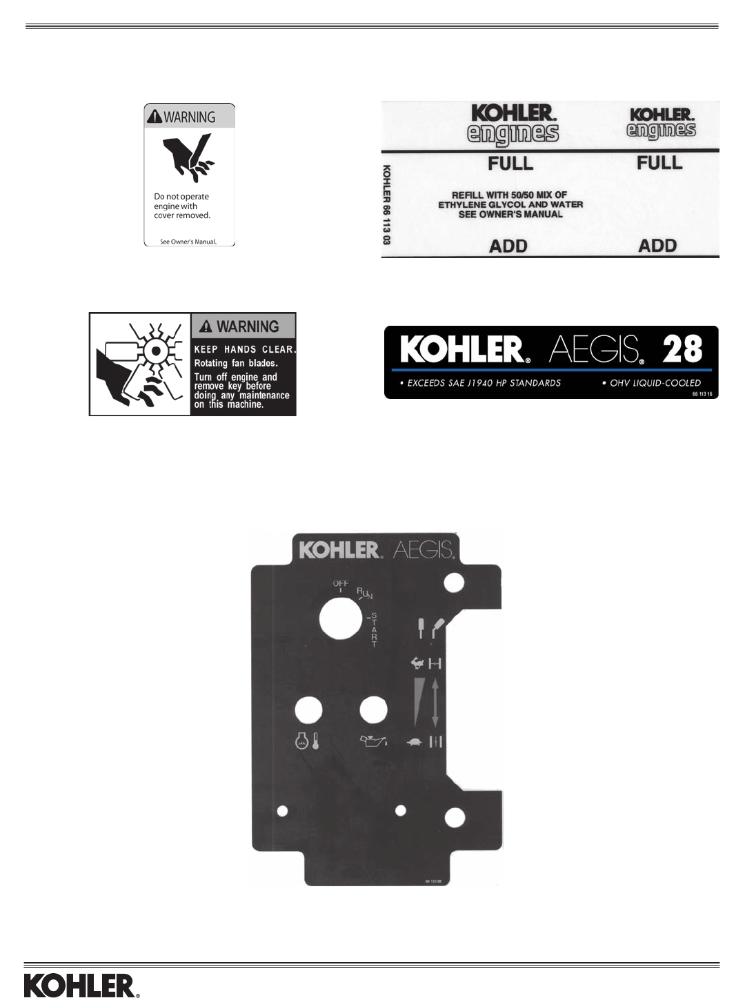
48
66 113 01-S Black on clear, coolant bottle level
66 113 03-S
66 113 04-S
Matte gold letters/numbers, blue stripe
66 113 12-S – 20 HP
66 113 14-S – 24 HP
66 113 07-S – 25 HP
66 113 15-S – 26 HP
66 113 16-S – 28 HP
6611317-S–31HP(EFI)
66 113 08-S
Labels
Aegis®
(Note:Alllabelsshownsmallerthanactualsize.)
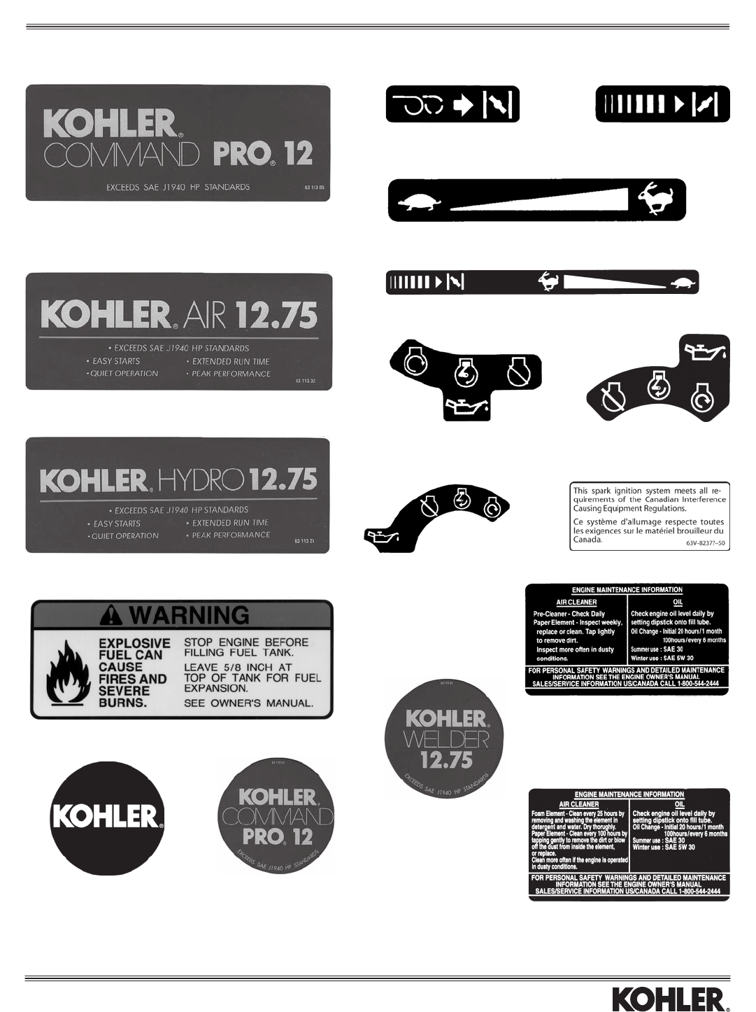
49
Gold letters/numbers
63 113 08-S – 4 HP 63 113 14-S – 10 HP
63 113 12-S – 6 HP 63 113 05-S – 12 HP
63 113 13-S – 8.5 HP 63 113 33-S – 12.75 HP
Gold letters/numbers
63 113 32-S
Gold letters/numbers
63 113 25-S
6311306-S(AllHP)
6311311-S–Recoil(4,6HP)
6311304-S–Recoil(8.5,10,12HP)
Gold letters/numbers
6311318-S–6HP(2.5"dia.)
6311319-S–8.5HP(3.25"dia.)
6311320-S–10HP(3.25"dia.)
6311321-S–12HP(3.25"dia.)
6311310-S–Choke(4,6HP) 63 113 02-S –
Choke(8.5/300cc,10,12HP)
6311301-S–Speed(4-6,8.5/300cc10,12HP)
6311323-S–Speed/Choke(8.5/250ccHP)
6311316-S–Ignition(4,6HP) 63 113 26-S – Ignition
(8.5/250ccHP)
63 113 15-S – Ignition
(8.5/300cc,10,12HP)
63 113 07-S
Gold letters/numbers
6611331-S(3.25"dia.)
6311303-S(AllHP)
63 113 24-S
(4-6,8.5-12HP,H.D.AirCleaner)
Labels
Command PRO CS® Single
(Note:Alllabelsshownsmallerthanactualsize.)
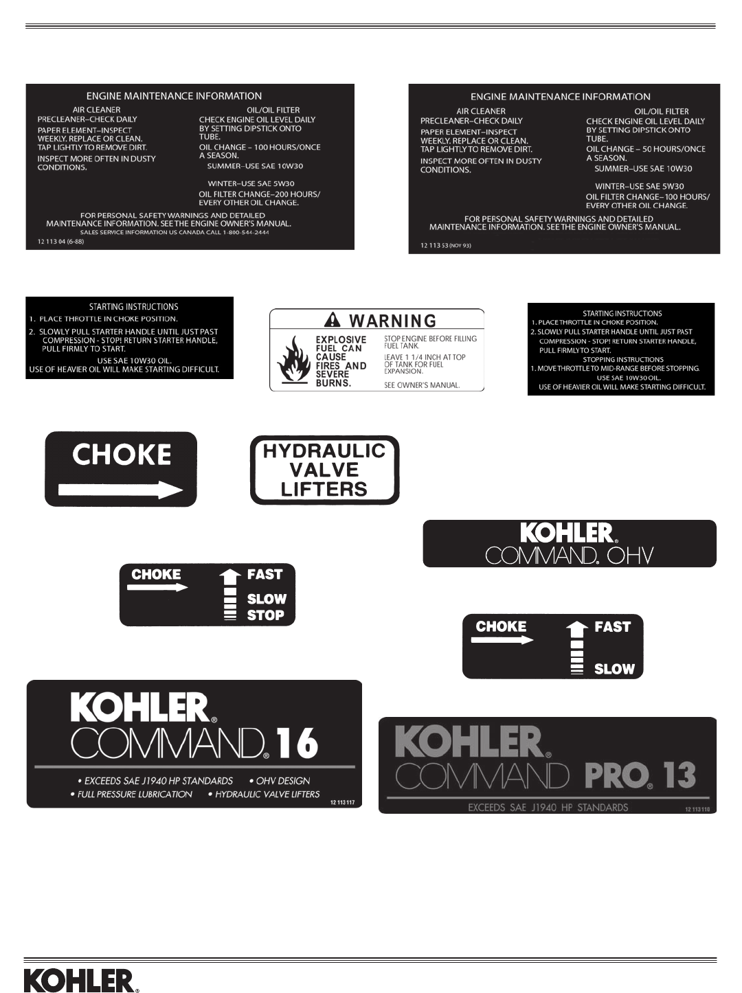
50
1211304-S(100hr.oilinterval,summer10W-30)
1211307-S(Starting)
12 113 17-S – white on clear
12 113 22-S – white on clear
Non-PRO, silver on black, red stripe
12 113 41-S – 12.5 HP 12 113 118-S – 17 HP
12 113 42-S – 14 HP 12 113 113-S – 17.5 HP
12 113 46-S – 15 HP 12 113 119-S – 18 HP
12 113 117-S – 16 HP
1211353-S(50hr.oilinterval)
12 113 21-S 1211371-S(Starting/Stopping)
12 113 16-S – white on clear
12 113 50
12 113 50-S
12 113 25-S
PRO, matte gold letters/numbers, red stripe
12 113 108-S – 11 HP 12 113 111-S – 14 HP
12 113 109-S – 12.5 HP 12 113 112-S – 15 HP
12 113 110-S – 13 HP 12 113 120-S – 15.5 HP
24 113 94-S – 18 HP
Labels
Command® Single
(Note:Alllabelsshownsmallerthanactualsize.)
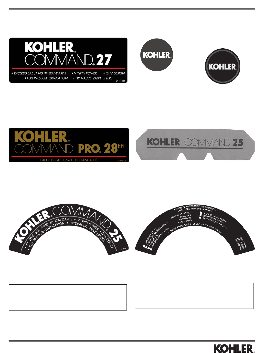
51
Non-PRO®, silver on black, red stripe
24 113 134-S – 16 HP 24 113 71-S – 22 HP
24 113 32-S – 17 HP 24 113 130-S – 23 HP
24 113 11-S – 18 HP 24 113 131-S – 25 HP
2411333-S–19HP 24113137-S–26HP(non-EFI)
24 113 102-S – 21 HP 24 113 132-S – 27 HP
24 113 129-S – 20 HP 24 113 133-S – 28 HP
PRO, matte gold letters/numbers, red stripe
24 113 93-S – 17 HP 24 113 97-S – 25 HP
2411394-S–18HP 24113100-S–26HP(EFI)
24 113 95-S – 20 HP 24 113 124-S – 27 HP
2411396-S–22HP 24113125-S–28HP(EFI)
24 113 90-S – 23 HP 24 113 143-S – 30 HP
24 113 19-S – 18 HP
24 113 20-S – 20 HP
24 113 83-S – 23 HP
24 113 51-S – 25 HP
PROPANE
24113108-S(redonwhite)
PRO, matte gold on black
2511324-S–1.625"dia.
2511325-S–2.5"dia. Non-PRO, silver on black, red circle
2411318-S–1.75"dia.
Blackonsilver,high-temperaturematerial-rearofatA/C
24 113 88 – 16 HP
24 113 99-S – 17 HP 24 113 24-S – 22 HP
24 113 07-S – 18 HP 24 113 89-S – 23 HP
24 113 08-S – 20 HP 24 113 34-S – 25 HP
24 113 150-S – 21 HP 24 113 138-S – Plain Silver, no HP
24 113 31-S
NATURAL GAS
24113109-S(blueonwhite)
(Note:Alllabelsshownsmallerthanactualsize.)
Labels
Command® Twin
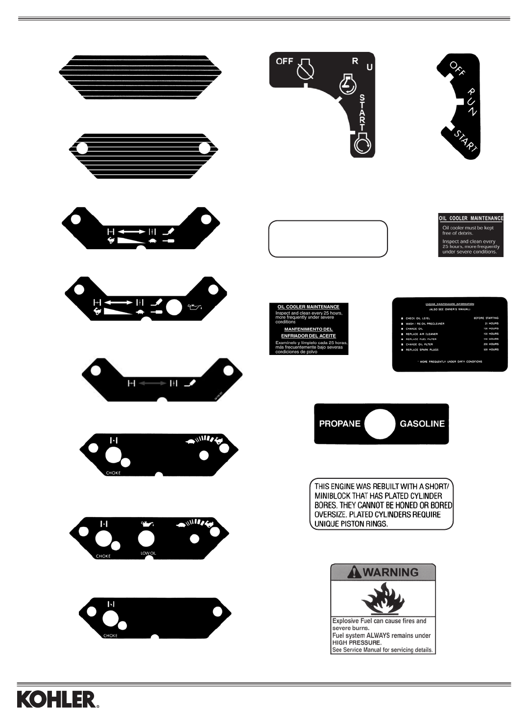
52
24 113 05-S – Red Stripes
24 113 58-S – Gold Stripes
24 113 103-S – Gold Stripes
24 113 92-S – New choke/throttle w/o Oil Sentry™
24 113 91-S – New choke/throttle w/Oil Sentry™
24 113 127-S – New choke w/o Oil Sentry™
24 113 06-S – Old choke/throttle
w/o Oil Sentry™
24 113 04-S – Old choke/throttle
w/Oil Sentry™
24 113 15-S – Old choke
24 113 126-S
For CH Twins with plastic
intake manifold.
24 113 03-S
For CH Twins with aluminum
intake manifold.
REMOVE BAFFLE
ABOVE 45°F
24 113 45-S 24 113 25-S
24 113 145-S
24 113 14-S
24 113 77-S
24 113 56-S
24 113 78-S
Labels
Command® Twin
(Note:Alllabelsshownsmallerthanactualsize.)
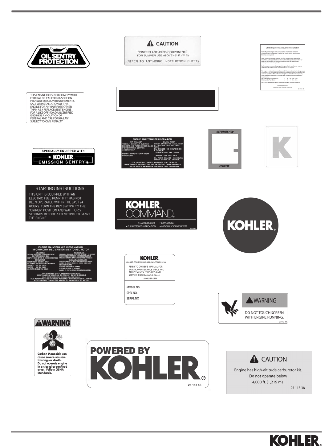
53
2511305-S(whiteonclear)
25 113 28-S
25 113 16-S
25 113 18-S
25 113 32-S
25 113 44-S
25 113 23-S
25 113 17-S
STOPPING INSTRUCTIONS
ENGINE IS EQUIPPED WITH A FUEL SHUT-OFF SOLENOID
MOVE THROTTLE TO MID-RANGE BEFORE STOPPING
25 113 27-S - H.D. air cleaner
25 113 42-S
41 037 10-S Write-on w/clear
protective overlay
25 113 29-S
25 113 36-S
25 113 39-S
(clearoverlay
fornameplate)
PRO®, matte gold on black
2511324-S–1.625"dia.
2511325-S–2.5"dia.
25 113 33-S
25 113 38-S
2511346-S(blackonclear)
2511347-S(whiteonclear)
Labels
All Models
(Note:Alllabelsshownsmallerthanactualsize.)
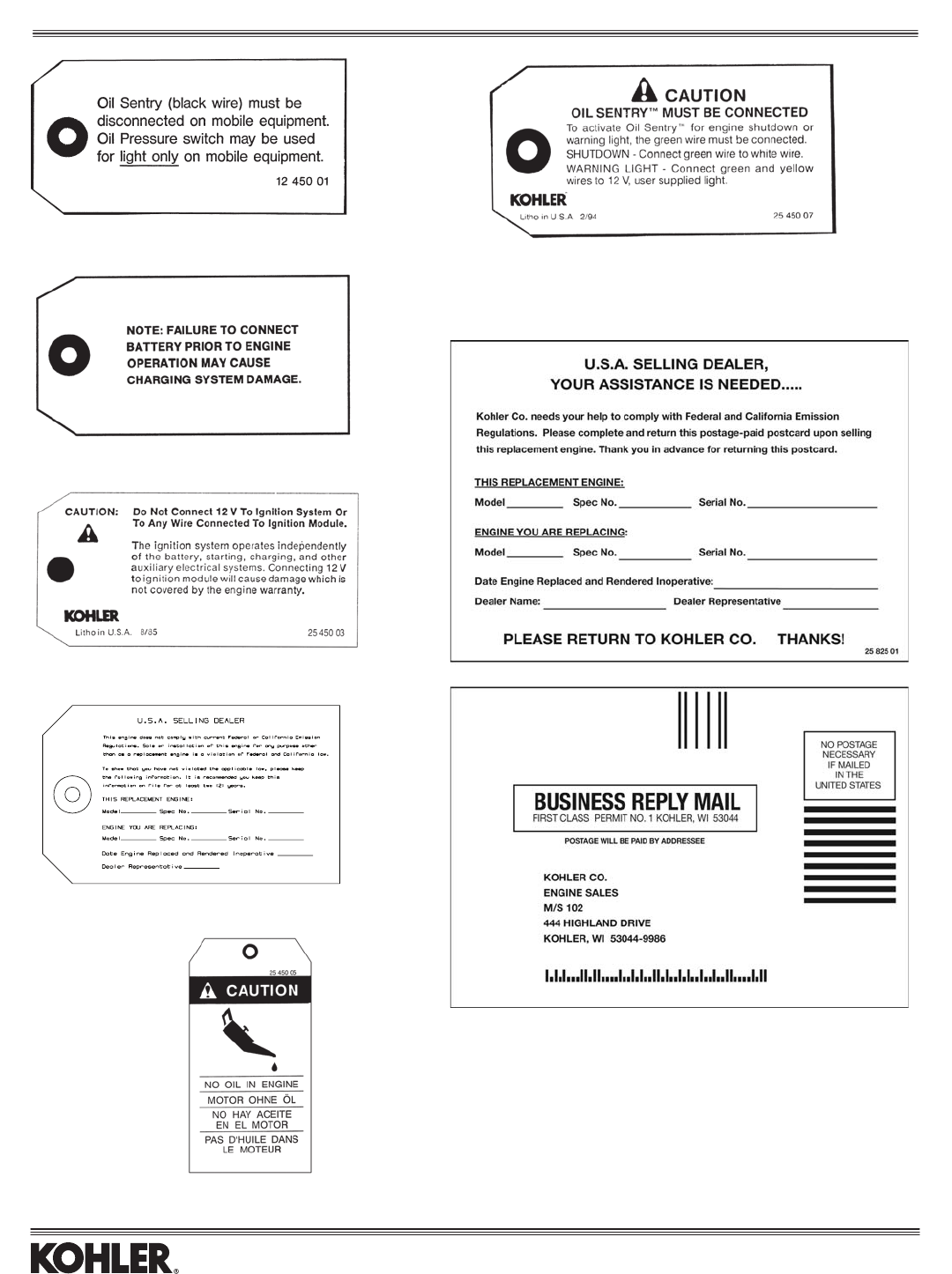
54
12 450 01-S
15 450 01-S
25 450 03-S
25 450 09-S
25 450 05-S
25 450 07-S
Front Side
25 825 01-S
Back Side
Hang Tags and Cards
(Note:Allhangtagsshownsmallerthanactualsize.)

55

ENGINE DIVISION, KOHLER CO., KOHLER, WISCONSIN 53044
FOR SALES AND SERVICE INFORMATION
IN U.S. AND CANADA, CALL 1-800-544-2444
LITHO IN U.S.A.
FORM NO.: E-1953-L
ISSUED: 7/06
REVISED: 4/08
KohlerEngines.com
