L010413 23MD Series Spec Sheet
User Manual: L010413 - 23MD Series Spec Sheet
Open the PDF directly: View PDF ![]() .
.
Page Count: 2
FEATURES
CUSTOM ORDER LAYOUT
910 East Orangefair Ln. Anaheim, CA 92801 Tel. (714) 992-6990 Fax. (714) 992-0471 www.anaheimautomation.com
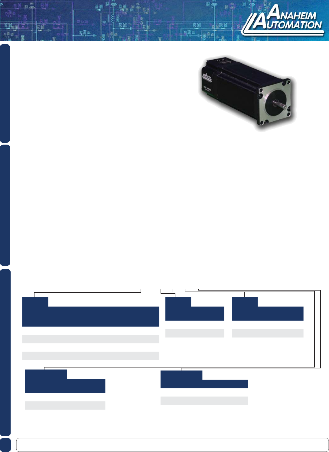
DESCRIPTION
The 23MD Series is a compact construction that implements a microstepping driver and a
stepper motor in one streamline package. With the two parts combined into one casing, the
need to include motor wires has been eliminated. The high-torque step motor can gener-
ate up to 230 oz-in of torque. The microstepping driver will operate off 12VDC minimum to
24VDC maximum with a maximum power intake of 40W. The inputs are capable of running
from either open collector or TTL level logic outputs, or sourcing 24VDC outputs from PLCs.
The microstepping driver features resolutions from 200 - 1600 steps/revolution, provid-
ing smooth rotary operation. The 23MD series comes in either a single shaft version or a
double shaft version with optional encoder and motor stack lengths of 1/2, 1, 2, or 3 allowing
for varying amounts of start-up torque and inertia. The 23MD series features include built in
over temperature and short circuit shut down, automatic 70% reduction in current after clock
pulses stop being received, and status LED’s to indicate power on (green LED) and clocks
being received (yellow LED).
L010413
23MD Series - Integrated Stepper Motor/Drivers
23MD Series - Integrated Stepper Motor/Drivers
• Stepper Motor/Microstep Driver Combination
• Eliminates Motor Wires
• Microstep Divisors of 8, 4, 2, or Full Step
• Compact Package
• 12-24V Power Requirement
• TTL Logic or 24V Level Inputs Available
• Ideal for Precise Positioning
• 0.225° Resolution at Eighth Step
• Effi cient and Durable
• RoHS Compliant
Note: Other Speed Options, Custom leadwires, cables, connectors, and windings are available upon request
Table 1
Model # Frame
Size
Bipolar
Torque
(oz-in)
Rotor
Inertia
(oz-in-sec2)
Weight
(lbs)
“L”
Length
(in)
23MD006 23 76 0.0017 1.20 2.98
23MD106 23 175 0.0042 1.75 4.03
23MD206 23 262 0.0068 2.41 4.94
23MD306 23 425 0.0103 3.51 5.94
23MD106S-10-24-00
Table 2
Shaft
Option Description
S Single
D Double
Table 3
Encoder
Option Description
-00 No Encoder
-04 400 Line Encoder
-10 1000 Line Encoder
Table 4
Sourcing/Sinking
Options Description
-00 Sinking Inputs
-24 Sourcing Inputs
Table 5
Special Options Description
-00 Standard Products
-## Other Options
Example:
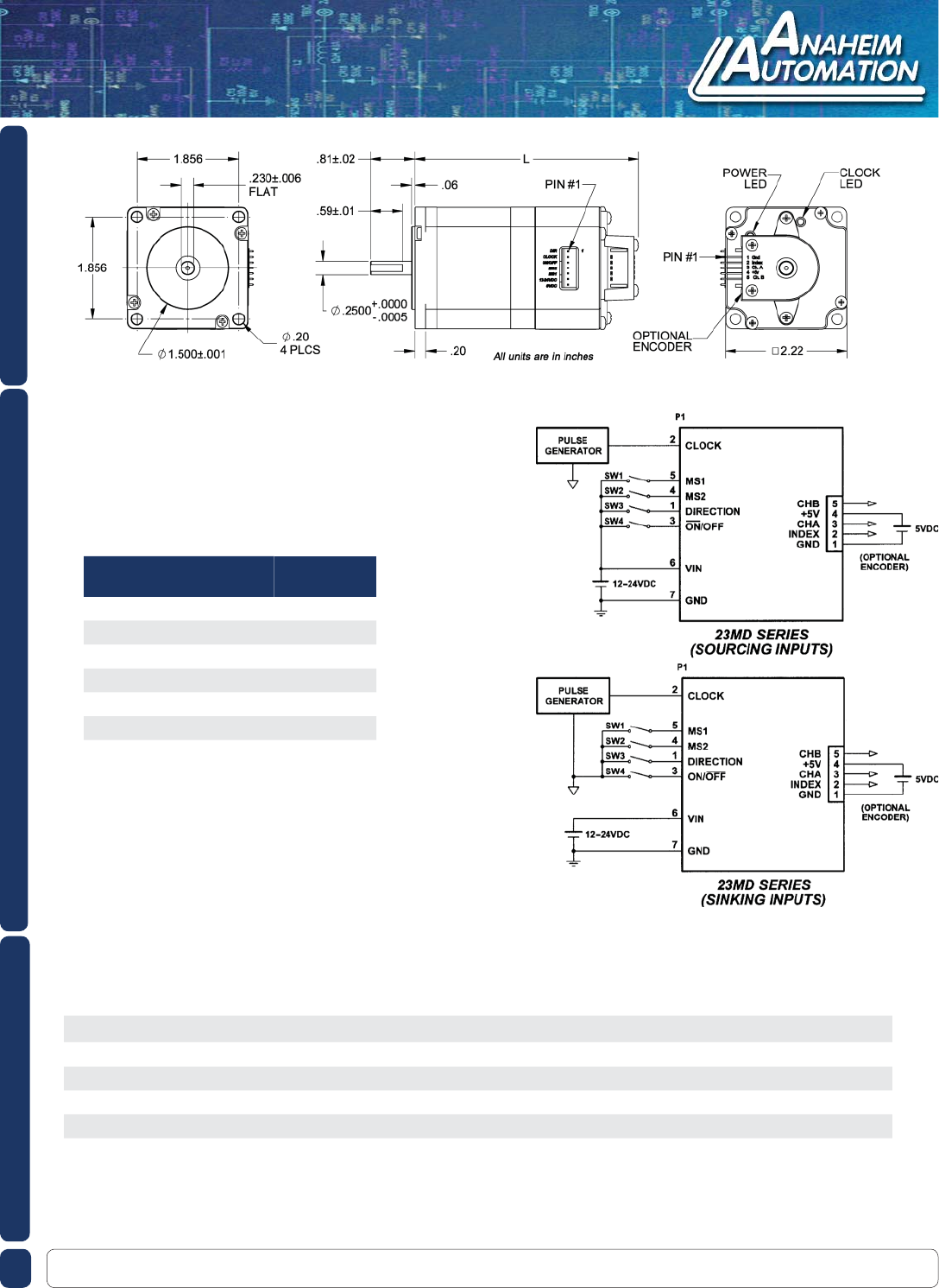
DIMENSIONS
910 East Orangefair Ln. Anaheim, CA 92801 Tel. (714) 992-6990 Fax. (714) 992-0471 www.anaheimautomation.com
WIRING INFORMATION
Terminal
Block Pin Description CBL-AA4031
Wire Color
1 Direction Brown
2 Clock Red
3 On/Off Orange
4 MS2 Yellow
5 MS1 Green
6 12VDC-24VDC Blue
7 0VDC (Gnd) Violet
SPECIFICATIONS
Step Angle: 1.8° Insulation Resistance: 100M ohm Min., 500VDC
Step Angle Accuracy: ±5% Dielectric Strength: 500VAC for one minute
Resistance Accuracy: ±10% Shaft Radial Play: 0.02 Max. (1lb load)
Inductance Accuracy: ±20% Shaft Axial Play: 0.08 Max. (1lb load)
Temperature Rise: 80°C Max. (rated current, 2 phase on) Max. Radial Force: 16.9lbs (0.79 in from the fl ange
Ambient Temperature: -20°C to +50°C Max. Axial Force: 3.37lbs
