L010990 PLCS CPU_manual CPU Manual
User Manual: L010990 - PLCS-CPU_manual
Open the PDF directly: View PDF ![]() .
.
Page Count: 8
CM3-SP32MDT/V/E/F/SD
CM3-SP16MDR/V/E/F
Items
Specification
Reference
Ambient Temp
-10℃ ~ ℃
Storage Temp
25℃ ~80℃
Ambient Humidity
5 ~95%RH, (Non-condensing)
Storage Humidity
5 ~95%RH, (Non-condensing)
Vibration
Occasional vibration
IEC 61131-2
Frequency
Acceleration
Pulse
width
Times
10 f
57Hz
0.075mm
X,Y,Z
Each
direction,
10 times
57 f
150Hz
9.8m/s²{1G}
Continuous vibration
Frequency
Acceleration
Pulse
width
10 f
57Hz
0.035mm
57 f
150Hz
4.9m/s²{0.5G}
Shocks
Peak acceleratioin : 147 m/S²
Duration : 11㎳
Pulse wave type : Half-sine (3times each X,Y,Z 3
direction)
IEC 61131-2
Impulse Noise
Square wave
impulse noise
2,000 V
KDT Standard
Electrostatic
discharge
Voltage :4kV (Contact discharge)
IEC 61131-2
IEC 1000-4-2
Radiated
electromagneti
c field noise
27 ~500 MHz,10 V/m
IEC 61131-2
IEC 1000-4-3
Fast
transient/
Burst noise
P
o
w
e
r
Digital I/O
(24V or more)
Digital I/O(24V or less)
Analog I/O Comm.
Interface
IEC 61131-2
IEC 1000-4-4
2
k
V
2 kV
0.25 kV
Voltage
2KV/1min
0.5KV/1min
Operation
ambience
Free from corrosive gases and excessive dust
Altitude
2,000m or less
Pollution
degree
2 or less
Cooling method
Air-cooling
Items
Specifications
Power
DC24V
Program Control Method
Stored Program, Process-Driven Interrupt, Time
Driven Interrupt
I/O Control Method
Indirect method, Directed by program instruction
Program language
IL(Instruction List), LD(Ladder Diagram)
Data Processing Method
32 Bit
Instructions
Sequence
55 Instruction
Application
389 Instruction
Processing speed (Sequence)
200ns / Step
Program capacity
10K Step
Max. I/O, Max. expansion
384 pts / 1 main Block + Max. 11 Block
Operation mode
Run, Stop, Remote Run, Remote Stop
Back-up method
Data which set up as retain
Total program
128
Program types
Scan
(127-Program block)
Cyclic
task
16
Special
126
Initial
task
2 (_INIT,_H_INIT)
Subroutine
126
Self-diagnosis
Detects errors of scan time, memory, I/O and power
supply, battery error
Re-start
Cold, Hot re-start
Device memory capacity
X
1024 pts (X0000 – X063F)
Y
1024 pts (Y0000 – Y063F)
M
8192 pts (M0000 – M511F)
L
4096 pts (L0000 – L255F)
K
4096 pts (K0000 – K255F)
F
2048 pts (F0000 – F127F)
T
512 pts (T0000 – T0511)
C
512 pts (C0000 – C0511)
S
100 states x 100 set (00.00 - 99.99)
D
10000 words (D0000 - D9999)
Z
1024 words (Call Stack : Z0000 - Z0063, Z1000 -
Z1063)
R
16 pts (Index)
High Speed Counter
20Kpps, 2 Phase 2Ch.
Positioning
Max. 100Kpps, 2 Axis, Linear interpolation
PID
32 Channels, Auto-Tuning
RTC
Embedded (Battery CR2032 Backup)
Comm. Channel
Standard : USB Loader, Serial 1(RS232C)
Optional : Serial 1Ch(RS485), Ethernet 1Ch
Etc.
General Specifications
PLC-S CPU Performance Specification( Specifications)
▶ Device
- Input : X - Output : Y
- Sub Relay : M - Keep Relay : K
- Timer : T - Counter : C
- Data Device : D - Sub Data Device : @D
- Link Relay : L - Step control Relay : S
- Special Relay : F - Index registor : R
▶ Device Address
- Bit Data: [Device]+[Card No.]+[Bit No.]
Device : X, Y, M, K, L, F, Card No. : 10Dec(Decimal). 3 Characters
Bit No. : 16Hex. 1 Character
Ex) X0100 -> 10Dec. (word) + 16Hex(Last Bit)
: [10th Address and 0th bit]
- Word Data: [Device]+[Card No.]
Device : D, Z, T, C, Card No. : 10Dec. 4Characters
Ex) D0100 -> 10Dec. (Word) : [100th word Address]
- Timer, Counter Output: [Device]+[Bit No.]
Device : T. C, Bit No. : 10Dec. 4Characters
Ex) T0100 -> 10Dec. (Word) : [T 100th Bit Address]
- Step Controller I/O: [Device]+[Card No.]+[.]+[ Step No.]
Device : S
Card No. : 10Dec. 2Characters, Step No. : 10Dec. 2Characters
Ex) Sxx.xx -> xx is 10Dec. (0~99)
- assign Bit Device to Word: [Device]+[Card No.]+[0]
Device : X, Y, M, K, L, F, Card No. : 10Dec. 3Characters
Ex) X010 -> 10Dec. (Word), [X 10th Address]
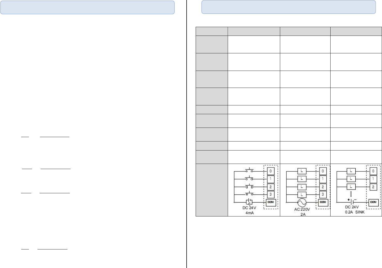
Items
DC Input
Relay Output
TR Output
Rated I/O
Voltage
DC 24V
AC 220V / DC 24V
DC 12V / 24V
Rated I/O
Current
4mA
1point 2A / COM 5A
1point 0.2A, COM 2A
On V/A
DC19V / 3mA
-
-
Off V/A
DC6V / 1mA
-
-
Response time
3ms or less
10ms or less
1ms or less
Operation
indicator
Input ON, LED ON
Input ON, LED ON
Input ON, LED ON
Insulation
method
Photo coupler insulation
Relay Insulation
Photo coupler insulation
Input method
SINK/SRC
-
-
Output
method
-
Relay
Sink
Circuit
Diagram
Device & Address
I/O Specification
▶ Slot number is assigned in order from left.
Max. expansion modules are 11 except CPU.
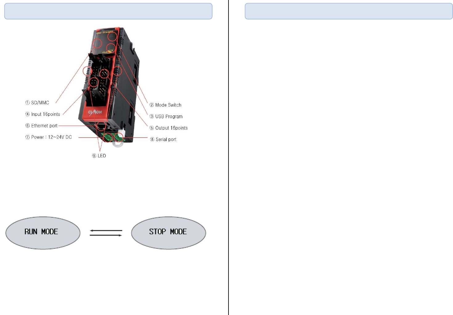
▶ Mode change
▶ Operation mode is changed by mode switch.
▶ The mode can be changed through CICON but when power reset,
RUN/STOP mode is decided through switch position.
▶ Built-in Functions
PID Control
It operates 32LOOP PID without PID module.
RTC
It reads time from RTC and save it in F device address.
I/O reservation.
It scans module at designated slot.
It refers to reservation function which writes a program without I/O change in
case of expansion, damage or replacement.
Online Edit
Program can be edited while Run mode.
▶ Features
SD/MMC Built-in.
Scan program or firmware can be upgraded by SD memory card.
(Stop mode Power off Insert SD card Run Stop Run Stop :
firmware will be upgrade automatically.)
20Kpps High Speed Counter (2Channel) Built-in.
2PH. 2/4Multi. Input mode possible, Voltage input type (Open collector)
100Kpps 2axis Pulse Output built-in. (Positioning)
Pulse+Direction Output, Position/Speed/Speed-Position, Position-Speed Control.
Max. 3 communications can work simultaneously. (Ethernet, RS232, RS485)
CIMON HMI, MODBUS RTU/TCP, PLC Link, Protocol program(user protocol),
Loader protocol support, Remote access & up/down load support.
Abundant memory (10K Step)
Data reserved in case of Power cut
Built-in Flash memory enabling permanent backup of program without any
separate battery.
Names of Part and Mode Change
Features of CPU
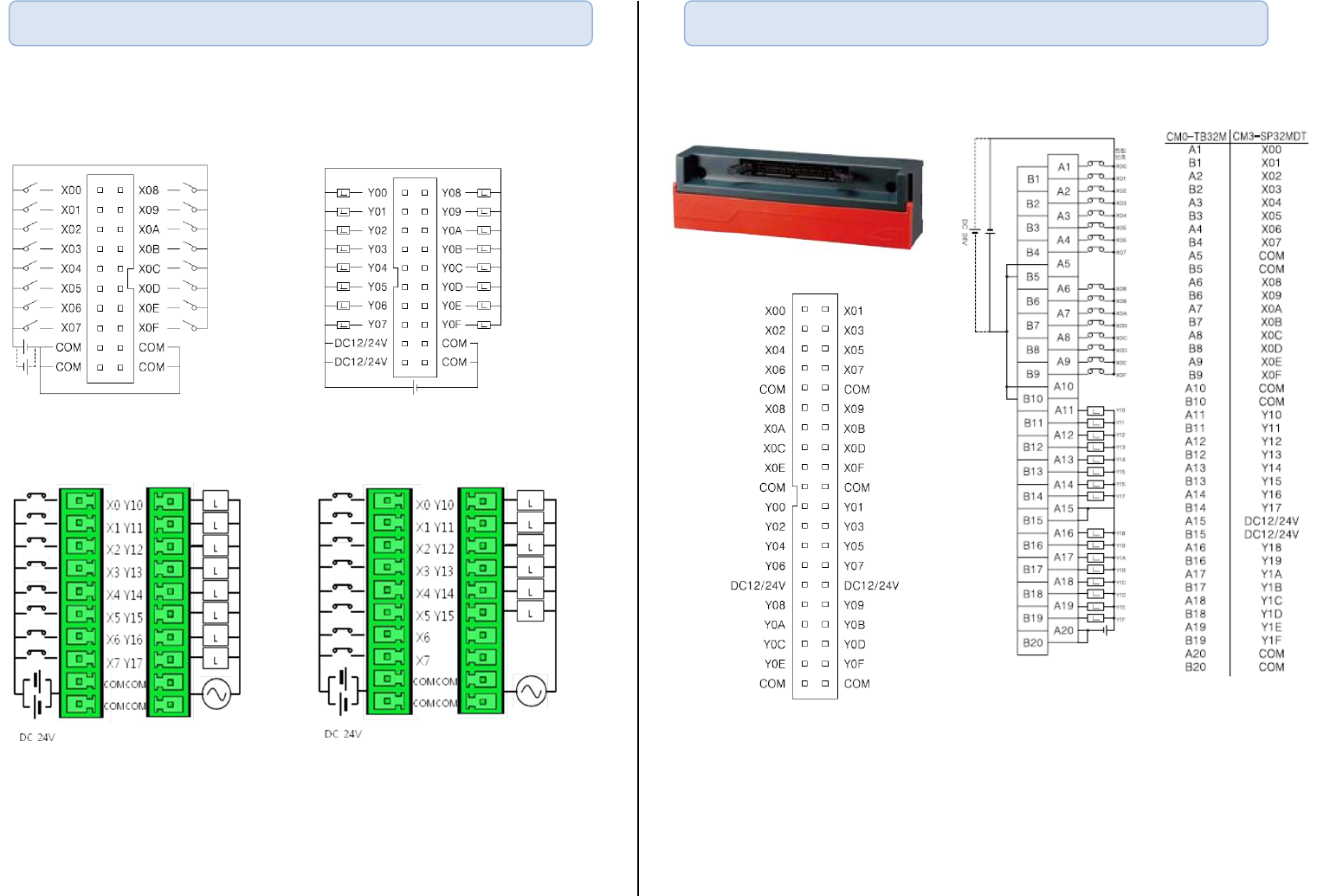
▶ MDT Input ▶ MDT Output
▶ SP16MDR, SP16MDRV I/O ▶ SP16MDRE, SP16MDRF I/O
▶ In case of SP16MDRE and SP16MDRF, relay output is 6 points.
▶ Terminal (CM0-TB32M)
▶ Terminal(CM0-TM32M) has its own Terminal Cable.
Terminal Cable : CM0-SCB15M
CPU I/O Pin Map
Terminal I/O Pin Map
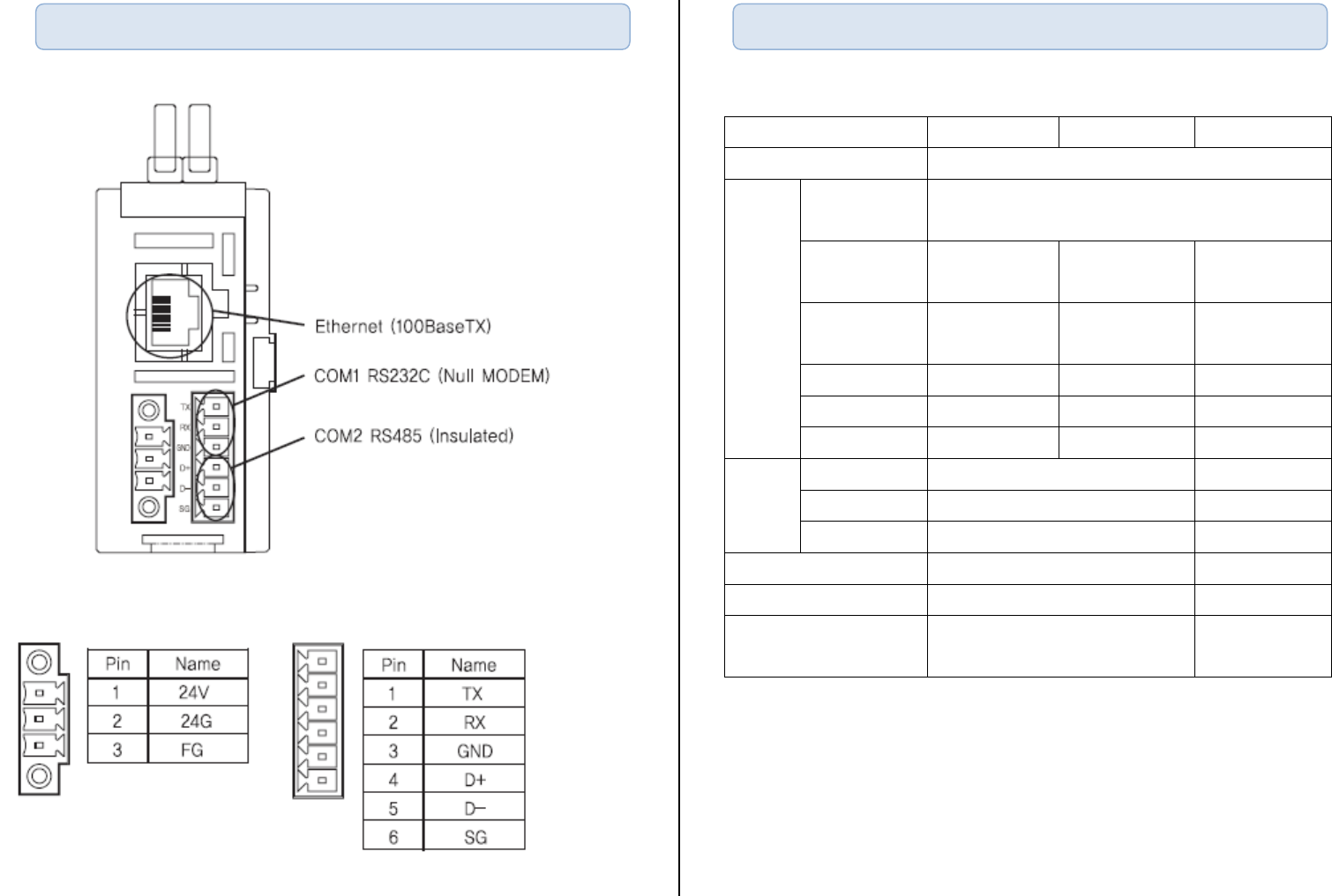
▶ Power and RS232/485 Terminal map
.
Items
RS232C
RS422/485
Ethernet
Power
Supplied by CPU
Comm.
Mode
Dedicated
protocol
HMI protocol (1:n)
Loader
protocol
O
O
O
User defined
protocol
O
O
MODBUS
O
O
O
PLC Link
O
DHCP
O
Types
Data Bit
8Bit
Stop Bit
1 or 2Bit
Parity
Even / Odd / None
Synchronization
Asynchronous
Transmission speed
300~38400
10/100Mbps
Modem
Long distance comm. is
possible by external modem
Communication Interface
Built-in Comm. Specification
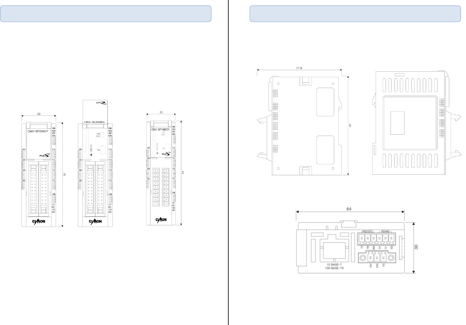
Dimension
Dimension

▶ Use PLC only in the environment specified in PLC manual or general
standard of data sheet.
▶ Do not let any metallic foreign materials inside the products
which may cause electric shock, fire or abnormal operation.
▶ Do not touch or install the module when PLC power is on.
▶ Do not disassemble or remodel the module.
▶ When F3,4(Special relay address for battery error) is on, change the battery
Safety Instructions
MEMO
