LR And EF Tire Spreaders
User Manual: LR and LR-EF Tire Spreaders
Open the PDF directly: View PDF ![]() .
.
Page Count: 12
REV.121709
P/N: 81-0195
Branick Industries, Inc. • 4245 Main Avenue • P.O. Box 1937 • Fargo, North Dakota 58103
Installation, Operation
and Repair Parts
Information
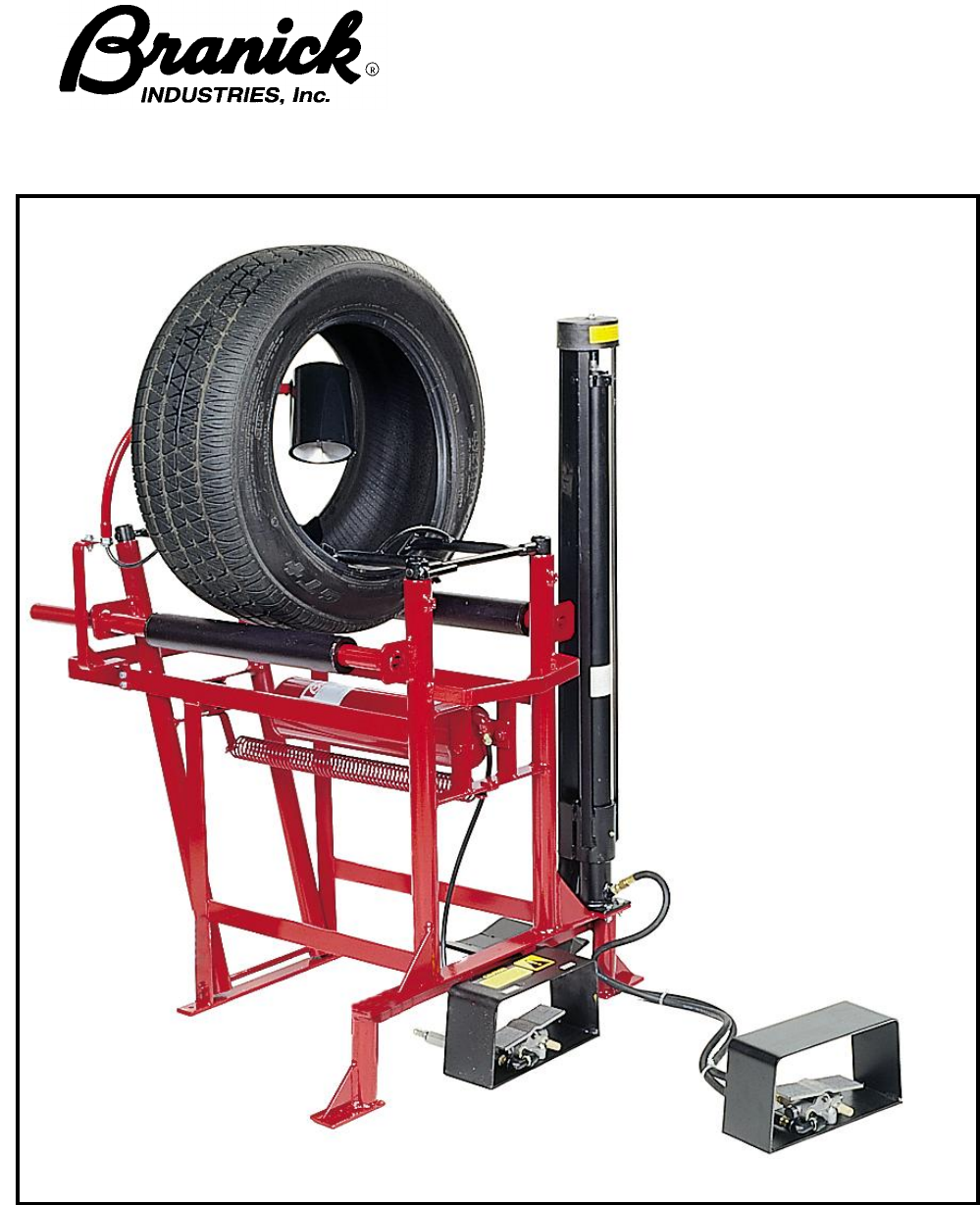
MODEL L/R/EF
Sectional
Tire Spreader
1
TABLE OF CONTENTS _________________________________________________________________
SAFETY INSTRUCTIONS 1
DEFINITIONS 1
INSTALLATION INSTRUCTIONS 2
OPERATING INSTRUCTIONS 2, 3
MAINTENANCE 3
REPAIR PARTS 4, 5, 6
REPAIR PARTS LIST 7,8
WARRANTY 11
SAFETY INSTRUCTIONS _______________________________________________________________
§ NEVER allow unauthorized personnel to operate this product.
§ NEVER use this product for anything other than its intended use.
§ THOROUGHLY train new employees in the proper use and care of this product.
§ PROHIBIT unauthorized personnel from being in shop area while this product is in use.
DEFINITIONS __________________________________________________________________________
§ CAUTION: Indicates a potentially hazardous situation, which if not avoided, may result in damage to
property or minor personal injury.
§ HAZARD: A source of potential injury to a person.
§ MAINTENANCE: Those actions that preserve the correct and proper conditions under which the
machine shall be used. This may include adjustment, replacement of wear items, lubrication and
cleaning, but not modifications or repair of damage.
§ MAY: This word is understood to be permissive.
§ MUST: This word is understood to be mandatory.
§ OPERATION: The correct and proper use of the machine as described in this manual.
§ SAFETY ALERT SYMBOL: A symbol that indicates a potential personal safety hazard. It is composed
of an equilateral triangle surrounding an exclamation point.
§ SHALL: This word is understood to be mandatory.
§ SHOULD: This word is understood to be advisory.
§ WARNING: Indicates a potentially hazardous situation, which if not avoided, may result in death or
serious personal injury.
2
INSTALLATION___________________________________________________________________
1) Unpack and remove unit from shipping carton and pallet.
2) Position the Model L/R/EF on a solid level floor leaving a minimum of 12 inches of
clearance from rear and 24 inches of clearance from sides. The L/R/EF should be bolted
down using the four holes in bottom of frame.
3) Install a 1/4 NPT quick coupler nipple (not provided) into the air filter (Item 39) located on
mounted foot pedal.
4) Connect the shop air line to the quick coupler installed from previous step.
5) Connect the light to any convenient 115V power source.
OPERATION______________________________________________________________________
1) Pull the bead hooks up and away from the center of the machine.
.
2) With the tire lift on the floor, roll the tire onto the lift cradle. Steady the tire on the lift as the
foot valve is actuated and raise the tire all the way up. The lift will stop when it reaches
the full up position.
CAUTION
♦ Before using this product, read and fully understand the operating
instructions and all decals on the product. This is necessary to
prevent injury to the operator and damage to the product.
♦ This product is intended to be used to spread tire casings for
inspection and/or repair only.
♦ Keep fingers and hands clear of all hooks and mechanisms during
operation.
♦ Do not use this product if it is visibly worn, distorted or damaged.
♦ Always wear appropriate eye protection.
WARNING
♦ Keep feet clear of the tire lift when raising and lowering tire.
♦ All personnel must be clear of the spread arms during operation.

3
3) Rotate the lift cradle in front of the tread roller and roll the tire onto the machine. Release
the foot valve lever and it will return to natural position.
4) Place the bead hooks between the tire beads. The vertical height of the bead hooks are
fully adjustable and friction stops maintain the height.
5) Spread the tire as required with the foot valve. The light can be positioned to view any
portion of the tire.
6) To rotate the tire while on the spreader, release the air pressure from the spread cylinder
and allow the spread hooks to close. Rotate the tire to desired position and again spread
to the desired width. Repeat this operation until the tire is inspected.
7) To remove the tire from the machine, release the air pressure from the spread cylinder. As
the bead hooks disengage, swing them up and out of the tire. Move the light fixture out of
the tire.
8) With the lift cradle in the up position and next to the tread roller, roll the tire onto the lift
cradle. Rotate the cradle away from the machine and release the lift foot valve lever.
9) When the lift returns to the floor, roll the tire off the cradle.
MAINTENANCE___________________________________________________________________
MONTHLY – Put a few ounces of 10 or 20 weight oil in all cylinders.
Lubricate all moving parts (bolts, hinges, rollers, etc.) with a lubricating oil.
Pull the cotter pin which attaches the piston out of its socket, rotate the rod a half
turn and replace the cotter pin.
BI-YEARLY – Grease the zerk fitting found on lift carriage
CAUTION
Before servicing machine disconnect air and electric.
4
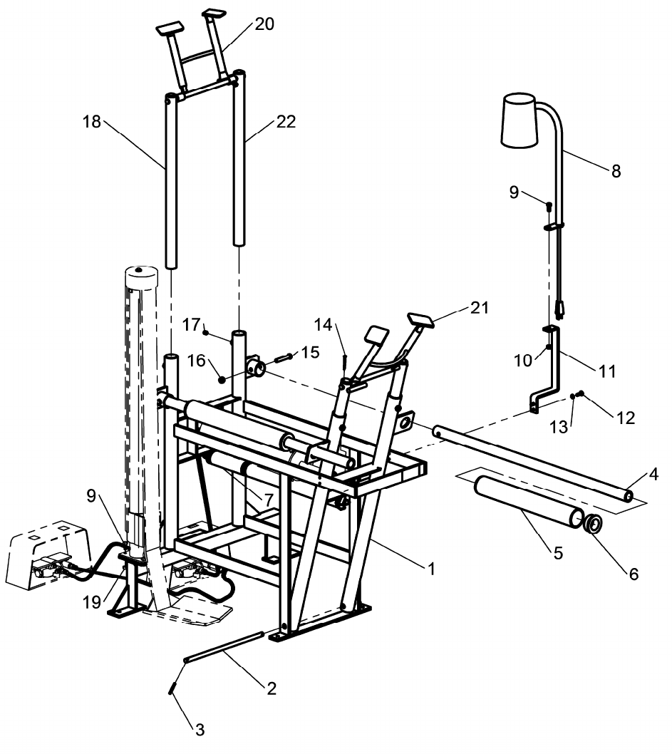
REPAIR PARTS ___________________________________________________________________________
UNIT ASSEMBLY
5
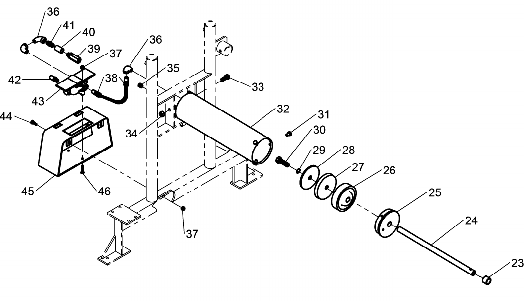
SPREAD CYLINDER PNEUMATICS
6
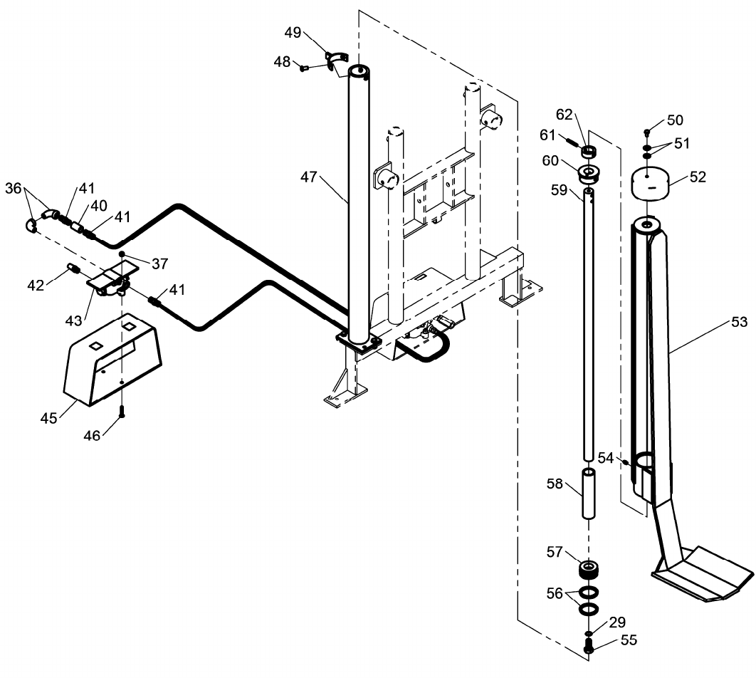
LIFT CYLINDER PNEUMATICS

7
REPAIR PARTS LIST
_________________________________________________________________
ITEM
QTY PART NO. DESCRIPTION
1 1 900-087 FRAME
2 1 104-030 PIVOT SHAFT
3 2 061-189 SPRING PIN
4 2 104-032 SPRING FRAME SHAFT
5 2 281-043 ROLLER
6 4 107-087 BEARING
7 1 110-004 TENSION SPRING
8 1 376-016 LIGHT FIXTURE ASSEMBLY
1 40-0070 CFL BULB
9 5 028-012 5/16-18" X 3/4" HHC SCREW
10 1 055-145 5/16-18" NYLOCK NUT
11 1 111-524 BRACKET
12 2 028-010 1/4-20" X 3/4" HHC SCREW
13 2 108-008 1/4" INTERNAL TOOTH WASHER
14 1 061-013 COTTER PIN
15 2 028-033 3/8-16 x 2/1/4 HHC SCREW
16 2 055-154 3/8-16 NYLOCK NUT
17 4 028-207 NYLON TIP SET SCREW
18 2 950-475 HOOK POST ASSEMBLY
19 4 055-023 5/16-18 TORQUE LOCK NUT
20 1 950-424 FRONT HOOK ASSEMBLY
21 1 950-425 REAR HOOK ASSEMBLY
22 2 950-427 HOOK ARM
23 1 268-565 SPACER TUBE
24 1 149-090 PISTON ROD
25 1 098-037 CYLINDER HEAD
26 1 051-297 PISTON
27 1 041-295 PISTON CUP
28 1 101-296 CUP RETAINER
29 2 167-240 14MM GASKET
30 1 028-013 9/16-12 X 1/3/4 HHC SCREW
31 3 028-280 5/16-18 X 1/2 HHC SCREW
32 1 025-022 CYLINDER
33 2 028-054 7/16-14 X 1 HHC SCREW
34 2 055-021 7/16-14 BI-WAY LOCK NUT
35 1 096-004 1/4 NPT PLUG
36 5 096-038 1/4 NPT STREET ELBOW
37 6 055-160 NYLON HEX LOCK NUT
38 3 096-163 1/4 NPT X 3/8 CONNECTOR FITTING
39 1 932-001 IN-LINE FILTER
40 2 096-107 PIPE COUPLING FITTING

8
ITEM
QTY PART NO. DESCRIPTION
41 4 096-162 1/4 NPT NIPPLE FITTING
42 2 885-035 1/4 NPT MUFFLER
43 2 190-277 3 WAY TREADLE VALVE
44 2 028-010 1/4-20 X 3/4 HHC SCREW
45 2 835-022 FOOT PEDAL GUARD
46 4 028-390 1/4 X 1/1/4 FHM SCREW
47 1 950-329 CYLINDER ASSEMBLY
48 3 50-0126 5/16-18 X 5/8 BTN HD SCREW
49 1 822-004 LIFT CYLINDER COLLAR
50 1 028-132 1/4-20 X 1/2 HHC SCREW
51 2 108-013 WASHER
52 1 098-091 VINYL CAP PROCTECTOR
53 1 826-006 CRADLE ASSEMBLY
54 1 096-008 ZERK FITTING
55 1 028-239 9/16-12 X 1/1/4 HHC SCREW
56 2 044-006 2" PISTON RING
57 1 051-014 2" LIFT PISTON
58 1 446-074 CYLINDER SLEEVE
59 1 149-216 PISTON ROD
60 1 098-026 CYLINDER CAP
61 1 061-050 SPRING PIN
62 1 489-030 PISTON ROD COLLAR

9
Notes:

10
Notes:

11
COMMERCIAL WARRANTY
This product is warranted by BRANICK INDUSTRIES, INC. to the original user-owner against defective materials or workmanship for a period of
one year from the date of delivery. During the warranty period, product found to be defective will be repaired or replaced at, BRANICK
INDUSTRIES, INC.'s option, without charge. The product must be returned, with prior approval, transportation charges prepaid and with proof of
original delivery date, to BRANICK INDUSTRIES, INC., 4245 Main Ave., Fargo, North Dakota 58107. The repaired or replacement product will be
returned with transportation charges prepaid by Branick.
This warranty does not cover defects in the product caused by ordinary wear and tear, abuse, misuse, overloading, accident (including shipping
damage), improper maintenance, alteration, or any other cause not the result of defective materials or workmanship.
REPAIR OF REPLACEMENT IS THE EXCLUSIVE REMEDY FOR DEFECTIVE PRODUCT UNDER THIS WARRANTY. THIS WARRANTY IS
EXPRESSLY IN LIEU OF ALL OTHER WARRANTIES, INCLUDING ANY IMPLIED WARRANTY OF MERCHANTABILITY OR ANY IMPLIED
WARRANTY OF FITNESS FOR A PARTICULAR PURPOSE OF THIS PRODUCT. BRANICK INDUSTRIES, INC. SHALL NOT BE LIABLE
FOR ANY CONSEQUENTIAL OR INCIDENTAL DAMAGES.
BRANICK INDUSTRIES, INC. reserves the right to make changes in the design or construction of our products without obligation to incorporate
such changes in products already sold and without notice.
Service parts, warranty, and regular repair service for products are available from Branick authorized distributors or from:
BRANICK INDUSTRIES, INC.
4245 Main Ave.
Box 1937
Fargo, North Dakota 58107
701/281-8888
© Copyright 2011 by Branick Industries, Inc. Printed in U.S.A.
