NAVAIR 00 80T 104 LSO NATOPS Manual
User Manual:
Open the PDF directly: View PDF ![]() .
.
Page Count: 120 [warning: Documents this large are best viewed by clicking the View PDF Link!]
- NAVAIR 00-80T-104
- Letter of Promulgation
- Interim Change Summary
- Summary of ApplicableTechnical Directives
- Record of Changes
- Table of Contents
- List of Illustrations
- List of Acronyms and Abbreviations
- Preface
- Part I — The Landing Signal Officer
- Chapter 1 — Introduction
- Chapter 2 — Indoctrination
- Part II — The LSO Workstation
- Chapter 3 — Shore-Based Workstation
- Chapter 4 — Shipboard Workstation
- 4.1 MINIMUM EQUIPMENT LIST FOR SHIPBOARD OPERATIONS
- 4.2 FRESNEL LENS OPTICAL LANDING SYSTEM
- 4.3 MANUALLY OPERATED VISUAL LANDING AID SYSTEM
- 4.4 LSO HEADS-UP DISPLAY
- 4.5 LSO BASE CONSOLE
- Part III — Normal Procedures
- Chapter 5 — Shore-Based Procedures
- Chapter 6 — Shipboard Procedures
- 6.1 BRIEFING AND DEBRIEFING
- 6.2 CARRIER QUALIFICATIONS
- 6.3 CURRENCY CRITERIA FOR CARRIER QUALIFIED PILOTS
- 6.4 NORMAL RECOVERY OPERATIONS
- 6.4.1 Personnel Requirements
- 6.4.2 LSO Responsibilities
- 6.4.3 Recovery Procedures for Final Approach
- 6.4.4 Foul Deck Waveoff
- 6.4.5 Optical Landing System Limits
- 6.4.6 Wind Over Deck (WOD) Requirements
- 6.4.7 Safety Precautions
- 6.4.8 MOVLAS Training
- 6.4.9 MOVLAS During Carrier Qualifications
- 6.4.10 MOVLAS Operating Procedures
- Part IV — Emergency Procedures
- Part V — Extreme Weather Condition Operations
- Part VI — Communications
- Part VII — NATOPS Evaluation, Pilot Performance Records and Aircraft Mishap Statements
- Chapter 10 — NATOPS Evaluation
- Chapter 11 — Pilot Performance Records
- Chapter 12 — Aircraft Mishap Statements
- INDEX
- LIST OF EFFECTIVE PAGES

NATOPS
LANDING SIGNAL OFFICER
MANUAL
THE LANDING
SIGNAL OFFICER
THE LSO
NORMAL
PROCEDURES
EMERGENCY
PROCEDURES
EXTREME WEATHER
CONDITION OPERATIONS
COMMUNICATIONS
NATOPS EVAL, PILOT
PERFORMANCE RECS,
INDEX
15 DECEMBER 2001
1 (Reverse Blank)
NAVAIR 00-80T-104
THIS PUBLICATION SUPERSEDES NAVAIR 00-80T-104
DATED 1 NOVEMBER 1997 AND CHANGED 15 AUGUST 1998.
DISTRIBUTION STATEMENT C — Distribution authorized to U.S. Government
Agencies and their contractors to protect publications required for official use or for
administrative or operational purposes only determined on 1 May 1992. Other
requests for this document shall be referred to Commanding Officer, Naval Air
Technical Data and Engineering Service Command, Naval Air Station, North Island,
P.O. Box 357031, Building 90, Distribution, San Diego, CA 92135–7031.
DESTRUCTION NOTICE — For unclassified, limited documents, destroy by any
method that will prevent disclosure of contents or reconstruction of the document.
ISSUED BY AUTHORITY OF THE CHIEF OF NAVAL OPERATIONS AND
UNDER THE DIRECTION OF THE COMMANDER,
NAVAL AIR SYSTEMS COMMAND.
WORKSTATION
A/C MISHAP STATEMENTS
2
NAVAIR 00-80T-104
ORIGINAL
3/(4 blank)
15 December 2001
LETTER OF PROMULGATION
1. The Naval Air Training and Operating Procedures Standardization (NATOPS) Program is a posi-
tive approach toward improving combat readiness and achieving a substantial reduction in the
aircraft mishap rate. Standardization, based on professional knowledge and experience, provides
the basis for development of an efficient and sound operational procedure. The standardization
program is not planned to stifle individual initiative, but rather to aid the commanding officer in
increasing the unit’s combat potential without reducing command prestige or responsibility.
2. This manual standardizes ground and flight procedures but does not include tactical doctrine.
Compliance with the stipulated manual requirements and procedures is mandatory except as
authorized herein. In order to remain effective, NATOPS must be dynamic and stimulate rather
than suppress individual thinking. Since aviation is a continuing, progressive profession, it is
both desirable and necessary that new ideas and new techniques be expeditiously evaluated and
incorporated if proven to be sound. To this end, commanding officers of aviation units are autho-
rized to modify procedures contained herein, in accordance with the waiver provisions estab-
lished by OPNAVINST 3710.7, for the purpose of assessing new ideas prior to initiating recom-
mendations for permanent changes. This manual is prepared and kept current by the users in order
to achieve maximum readiness and safety in the most efficient and economical manner. Should
conflict exist between the training and operating procedures found in this manual and those found
in other publications, this manual will govern.
3. Checklists and other pertinent extracts from this publication necessary to normal operations and
training should be made and carried for use in naval aircraft.
M.J. McCABE
Rear Admiral, U.S. Navy
Director, Air Warfare

NAVAIR 01-F14AAP-1
ORIGINAL
5/(6 blank)
NAVAIR 00-80T-104
ORIGINAL
5/(6 blank)
INTERIM CHANGE SUMMARY
The following Interim Changes have been cancelled or previously incorporated into this manual.
INTERIM
CHANGE
NUMBER(S) REMARKS/PURPOSE
1 thru 10 Previously incorporated.
The following Interim Changes have been incorporated into this Change/Revision.
INTERIM
CHANGE
NUMBER(S) REMARKS/PURPOSE
Interim Changes Outstanding — To be maintained by the custodian of this manual.
INTERIM
CHANGE
NUMBER ORIGINATOR/DATE
(or DATE/TIME GROUP) PAGES
AFFECTED REMARKS/PURPOSE

NAVAIR 01-F14AAP-1
ORIGINAL
5/(6 blank)

NAVAIR 00-80T-104
ORIGINAL
7/(8 blank)
SUMMARY OF APPLICABLE TECHNICAL DIRECTIVES
Information relating to the following recent technical directives has been incorporated into this manual.
CHANGE
NUMBER DESCRIPTION DATE INC.
IN MANUAL VISUAL IDENTIFICATION
Information relating to the following applicable technical directives will be incorporated in a future change.
CHANGE
NUMBER DESCRIPTION DATE INC.
IN MANUAL VISUAL IDENTIFICATION

NAVAIR 01-F14AAP-1
ORIGINAL
5/(6 blank)

NAVAIR 00-80T-104
ORIGINAL
9/(10 blank)
RECORD OF CHANGES
Change No. and
Date of Change Date of
Entry Page Count Verified by
(Signature)

NAVAIR 01-F14AAP-1
ORIGINAL
5/(6 blank)

NAVAIR 00-80T-104
ORIGINAL
11
NATOPS Landing Signal Officer Manual
CONTENTS
Page
No.
PART I — THE LANDING SIGNAL OFFICER
CHAPTER 1 — INTRODUCTION
1.1 GENERAL 1-1. . . . . . . . . . . . . . . . . . . . . . . . . . . . . . . . . . . . . . . . . . . . . . . . . . . . . . . . . . . . .
1.2 ROLE OF LANDING SIGNAL OFFICER 1-1. . . . . . . . . . . . . . . . . . . . . . . . . . . . . . . . . . . .
1.3 COMMAND RELATIONSHIPS AND RESPONSIBILITIES
OF THE LANDING SIGNAL OFFICER 1-1. . . . . . . . . . . . . . . . . . . . . . . . . . . . . . . . . . . . . .
1.3.1 Type Commander 1-1. . . . . . . . . . . . . . . . . . . . . . . . . . . . . . . . . . . . . . . . . . . . . . . . . . . . . . . .
1.3.2 LSO Training Model Manager 1-2. . . . . . . . . . . . . . . . . . . . . . . . . . . . . . . . . . . . . . . . . . . . . .
1.3.3 Ship/Air Wing Commanding Officer 1-2. . . . . . . . . . . . . . . . . . . . . . . . . . . . . . . . . . . . . . . . .
1.3.4 Air Wing Commander 1-2. . . . . . . . . . . . . . . . . . . . . . . . . . . . . . . . . . . . . . . . . . . . . . . . . . . . .
1.3.5 Squadron Commanding Officer 1-2. . . . . . . . . . . . . . . . . . . . . . . . . . . . . . . . . . . . . . . . . . . . .
1.4 LSO DESIGNATIONS 1-3. . . . . . . . . . . . . . . . . . . . . . . . . . . . . . . . . . . . . . . . . . . . . . . . . . . .
1.4.1 LSO Designation Category 1-3. . . . . . . . . . . . . . . . . . . . . . . . . . . . . . . . . . . . . . . . . . . . . . . . .
1.4.2 LSO Trainee Nomination Procedures 1-3. . . . . . . . . . . . . . . . . . . . . . . . . . . . . . . . . . . . . . . . .
1.4.3 Upgrading Procedures 1-3. . . . . . . . . . . . . . . . . . . . . . . . . . . . . . . . . . . . . . . . . . . . . . . . . . . . .
1.5 LSO SENIORITY 1-3. . . . . . . . . . . . . . . . . . . . . . . . . . . . . . . . . . . . . . . . . . . . . . . . . . . . . . . .
1.6 ASSIGNMENT 1-4. . . . . . . . . . . . . . . . . . . . . . . . . . . . . . . . . . . . . . . . . . . . . . . . . . . . . . . . . .
1.7 FLIGHT DECK HAZARDOUS DUTY INCENTIVE PAY (FDHIDP) 1-4. . . . . . . . . . . . . .
CHAPTER 2 — INDOCTRINATION
2.1 SELECTION OF LSO TRAINEES 2-1. . . . . . . . . . . . . . . . . . . . . . . . . . . . . . . . . . . . . . . . . .
2.2 LSO TRAINING PROGRAM 2-1. . . . . . . . . . . . . . . . . . . . . . . . . . . . . . . . . . . . . . . . . . . . . .
2.2.1 Formal Ground Training 2-1. . . . . . . . . . . . . . . . . . . . . . . . . . . . . . . . . . . . . . . . . . . . . . . . . . .
2.2.2 Field Training 2-1. . . . . . . . . . . . . . . . . . . . . . . . . . . . . . . . . . . . . . . . . . . . . . . . . . . . . . . . . . .
2.2.3 Shipboard Training 2-1. . . . . . . . . . . . . . . . . . . . . . . . . . . . . . . . . . . . . . . . . . . . . . . . . . . . . . .
2.2.4 Aircraft Crosstype Training 2-1. . . . . . . . . . . . . . . . . . . . . . . . . . . . . . . . . . . . . . . . . . . . . . . . .
2.3 REQUIREMENTS FOR LSO DESIGNATION 2-2. . . . . . . . . . . . . . . . . . . . . . . . . . . . . . . . .
2.4 MINIMUM CURRENCY REQUIREMENTS 2-2. . . . . . . . . . . . . . . . . . . . . . . . . . . . . . . . . .

NAVAIR 00-80T-104
ORIGINAL 12
Page
No.
2.5 FACTORS AFFECTING LSO READINESS 2-2. . . . . . . . . . . . . . . . . . . . . . . . . . . . . . . . . .
2.6 TRAINING LSO CARRIER QUALIFICATION (CQ) REQUIREMENTS 2-2. . . . . . . . . . .
2.7 LSO TRAINER (DEVICE 2H111) 2-2. . . . . . . . . . . . . . . . . . . . . . . . . . . . . . . . . . . . . . . . . . .
PART II — THE LSO WORKSTATION
CHAPTER 3 — SHORE-BASED WORKSTATION
3.1 GENERAL 3-1. . . . . . . . . . . . . . . . . . . . . . . . . . . . . . . . . . . . . . . . . . . . . . . . . . . . . . . . . . . . .
3.2 MINIMUM EQUIPMENT FOR FIELD CARRIER
LANDING PRACTICE (FCLP) OPERATIONS 3-1. . . . . . . . . . . . . . . . . . . . . . . . . . . . . . . .
3.2.1 Day FCLP 3-1. . . . . . . . . . . . . . . . . . . . . . . . . . . . . . . . . . . . . . . . . . . . . . . . . . . . . . . . . . . . . .
3.2.2 Night FCLP 3-1. . . . . . . . . . . . . . . . . . . . . . . . . . . . . . . . . . . . . . . . . . . . . . . . . . . . . . . . . . . . .
3.3 VISUAL LANDING AIDS 3-1. . . . . . . . . . . . . . . . . . . . . . . . . . . . . . . . . . . . . . . . . . . . . . . . .
3.3.1 General 3-1. . . . . . . . . . . . . . . . . . . . . . . . . . . . . . . . . . . . . . . . . . . . . . . . . . . . . . . . . . . . . . . .
3.3.2 Mk 8 Fresnel Lens 3-2. . . . . . . . . . . . . . . . . . . . . . . . . . . . . . . . . . . . . . . . . . . . . . . . . . . . . . . .
3.3.3 MOVLAS 3-2. . . . . . . . . . . . . . . . . . . . . . . . . . . . . . . . . . . . . . . . . . . . . . . . . . . . . . . . . . . . . .
3.3.4 Operation and Checks of Shore-Based Visual Landing Aids 3-2. . . . . . . . . . . . . . . . . . . . . .
3.4 LSO GREENHOUSE AND RADIOS 3-2. . . . . . . . . . . . . . . . . . . . . . . . . . . . . . . . . . . . . . . .
3.5 LSO VEHICLE 3-2. . . . . . . . . . . . . . . . . . . . . . . . . . . . . . . . . . . . . . . . . . . . . . . . . . . . . . . . . .
CHAPTER 4 — SHIPBOARD WORKSTATION
4.1 MINIMUM EQUIPMENT LIST FOR SHIPBOARD OPERATIONS 4-1. . . . . . . . . . . . . . .
4.1.1 Day Carrier 4-1. . . . . . . . . . . . . . . . . . . . . . . . . . . . . . . . . . . . . . . . . . . . . . . . . . . . . . . . . . . . .
4.1.2 Night Carrier 4-2. . . . . . . . . . . . . . . . . . . . . . . . . . . . . . . . . . . . . . . . . . . . . . . . . . . . . . . . . . . .
4.1.3 Miscellaneous LSO Equipment Malfunction 4-2. . . . . . . . . . . . . . . . . . . . . . . . . . . . . . . . . . .
4.2 FRESNEL LENS OPTICAL LANDING SYSTEM 4-2. . . . . . . . . . . . . . . . . . . . . . . . . . . . . .
4.2.1 Optical Characteristics 4-2. . . . . . . . . . . . . . . . . . . . . . . . . . . . . . . . . . . . . . . . . . . . . . . . . . . .
4.2.2 General Operating Intensities 4-3. . . . . . . . . . . . . . . . . . . . . . . . . . . . . . . . . . . . . . . . . . . . . . .
4.2.3 System Condition Indicators 4-4. . . . . . . . . . . . . . . . . . . . . . . . . . . . . . . . . . . . . . . . . . . . . . . .
4.2.4 Datum, Waveoff, and Cut Lights 4-4. . . . . . . . . . . . . . . . . . . . . . . . . . . . . . . . . . . . . . . . . . . . .
4.2.5 Stabilization Modes 4-5. . . . . . . . . . . . . . . . . . . . . . . . . . . . . . . . . . . . . . . . . . . . . . . . . . . . . . .
4.2.6 Effects of Deck Motion 4-7. . . . . . . . . . . . . . . . . . . . . . . . . . . . . . . . . . . . . . . . . . . . . . . . . . . .
4.2.7 Effective Glideslope Due to Wind and Deck Motion 4-7. . . . . . . . . . . . . . . . . . . . . . . . . . . . .
4.2.8 Roll Angle and Hook-to-Eye 4-8. . . . . . . . . . . . . . . . . . . . . . . . . . . . . . . . . . . . . . . . . . . . . . . .
4.3 MANUALLY OPERATED VISUAL LANDING AID SYSTEM 4-10. . . . . . . . . . . . . . . . . .
4.3.1 MOVLAS Construction 4-12. . . . . . . . . . . . . . . . . . . . . . . . . . . . . . . . . . . . . . . . . . . . . . . . . .

NAVAIR 00-80T-104
ORIGINAL
13
Page
No.
4.4 LSO HEADS-UP DISPLAY 4-12. . . . . . . . . . . . . . . . . . . . . . . . . . . . . . . . . . . . . . . . . . . . . . .
4.5 LSO BASE CONSOLE 4-12. . . . . . . . . . . . . . . . . . . . . . . . . . . . . . . . . . . . . . . . . . . . . . . . . . .
PART III — NORMAL PROCEDURES
CHAPTER 5 — SHORE-BASED PROCEDURES
5.1 BRIEFING AND DEBRIEFING 5-1. . . . . . . . . . . . . . . . . . . . . . . . . . . . . . . . . . . . . . . . . . . .
5.1.1 Precarrier Briefing 5-1. . . . . . . . . . . . . . . . . . . . . . . . . . . . . . . . . . . . . . . . . . . . . . . . . . . . . . . .
5.1.2 Simulator Procedures Briefing 5-2. . . . . . . . . . . . . . . . . . . . . . . . . . . . . . . . . . . . . . . . . . . . . .
5.1.3 Conduct of Field Carrier Landing Practice Briefings 5-3. . . . . . . . . . . . . . . . . . . . . . . . . . . . .
5.1.4 Postsimulator/Postflight Debriefing 5-3. . . . . . . . . . . . . . . . . . . . . . . . . . . . . . . . . . . . . . . . . .
5.2 SIMULATOR TRAINING 5-4. . . . . . . . . . . . . . . . . . . . . . . . . . . . . . . . . . . . . . . . . . . . . . . . .
5.2.1 CV Approach/Departure Procedures 5-4. . . . . . . . . . . . . . . . . . . . . . . . . . . . . . . . . . . . . . . . . .
5.2.2 Emergency Procedures 5-4. . . . . . . . . . . . . . . . . . . . . . . . . . . . . . . . . . . . . . . . . . . . . . . . . . . .
5.3 FCLP 5-4. . . . . . . . . . . . . . . . . . . . . . . . . . . . . . . . . . . . . . . . . . . . . . . . . . . . . . . . . . . . . . . . . .
5.3.1 Personnel Requirements 5-4. . . . . . . . . . . . . . . . . . . . . . . . . . . . . . . . . . . . . . . . . . . . . . . . . . .
5.3.2 Traffic Pattern Control Responsibilities 5-4. . . . . . . . . . . . . . . . . . . . . . . . . . . . . . . . . . . . . . .
5.3.3 Preflight Briefing 5-4. . . . . . . . . . . . . . . . . . . . . . . . . . . . . . . . . . . . . . . . . . . . . . . . . . . . . . . . .
5.3.4 Conduct of FCLP 5-5. . . . . . . . . . . . . . . . . . . . . . . . . . . . . . . . . . . . . . . . . . . . . . . . . . . . . . . .
5.4 PILOT PERFORMANCE EVALUATION 5-5. . . . . . . . . . . . . . . . . . . . . . . . . . . . . . . . . . . . .
5.4.1 Minimum Number of FCLP Periods 5-5. . . . . . . . . . . . . . . . . . . . . . . . . . . . . . . . . . . . . . . . . .
5.4.2 FCLP Performance Records 5-5. . . . . . . . . . . . . . . . . . . . . . . . . . . . . . . . . . . . . . . . . . . . . . . .
5.4.3 LSO Certification of Pilot Performance 5-5. . . . . . . . . . . . . . . . . . . . . . . . . . . . . . . . . . . . . . .
CHAPTER 6 — SHIPBOARD PROCEDURES
6.1 BRIEFING AND DEBRIEFING 6-1. . . . . . . . . . . . . . . . . . . . . . . . . . . . . . . . . . . . . . . . . . . .
6.1.1 Carrier Qualification/Currency Landing Procedures Briefing 6-1. . . . . . . . . . . . . . . . . . . . . .
6.1.2 Postflight Debriefing 6-1. . . . . . . . . . . . . . . . . . . . . . . . . . . . . . . . . . . . . . . . . . . . . . . . . . . . . .
6.1.3 Pilot Landing Trend Debriefs 6-1. . . . . . . . . . . . . . . . . . . . . . . . . . . . . . . . . . . . . . . . . . . . . . .
6.1.4 Recurrent CV Procedures Training 6-1. . . . . . . . . . . . . . . . . . . . . . . . . . . . . . . . . . . . . . . . . . .
6.1.5 Special Operations Procedures Briefing 6-1. . . . . . . . . . . . . . . . . . . . . . . . . . . . . . . . . . . . . . .
6.2 CARRIER QUALIFICATIONS 6-1. . . . . . . . . . . . . . . . . . . . . . . . . . . . . . . . . . . . . . . . . . . . .
6.2.1 Definitions 6-1. . . . . . . . . . . . . . . . . . . . . . . . . . . . . . . . . . . . . . . . . . . . . . . . . . . . . . . . . . . . . .
6.2.2 Limitations for Initial Carrier Qualifications 6-5. . . . . . . . . . . . . . . . . . . . . . . . . . . . . . . . . . .
6.2.3 LSO Certification of Pilot Performance 6-6. . . . . . . . . . . . . . . . . . . . . . . . . . . . . . . . . . . . . . .

NAVAIR 00-80T-104
ORIGINAL 14
Page
No.
6.3 CURRENCY CRITERIA FOR CARRIER QUALIFIED PILOTS 6-6. . . . . . . . . . . . . . . . . .
6.3.1 Limitations for Currency/Refresher Landings 6-6. . . . . . . . . . . . . . . . . . . . . . . . . . . . . . . . . .
6.4 NORMAL RECOVERY OPERATIONS 6-7. . . . . . . . . . . . . . . . . . . . . . . . . . . . . . . . . . . . . .
6.4.1 Personnel Requirements 6-7. . . . . . . . . . . . . . . . . . . . . . . . . . . . . . . . . . . . . . . . . . . . . . . . . . .
6.4.2 LSO Responsibilities 6-8. . . . . . . . . . . . . . . . . . . . . . . . . . . . . . . . . . . . . . . . . . . . . . . . . . . . . .
6.4.3 Recovery Procedures for Final Approach 6-10. . . . . . . . . . . . . . . . . . . . . . . . . . . . . . . . . . . . .
6.4.4 Foul Deck Waveoff 6-11. . . . . . . . . . . . . . . . . . . . . . . . . . . . . . . . . . . . . . . . . . . . . . . . . . . . . .
6.4.5 Optical Landing System Limits 6-11. . . . . . . . . . . . . . . . . . . . . . . . . . . . . . . . . . . . . . . . . . . .
6.4.6 Wind Over Deck (WOD) Requirements 6-11. . . . . . . . . . . . . . . . . . . . . . . . . . . . . . . . . . . . . .
6.4.7 Safety Precautions 6-11. . . . . . . . . . . . . . . . . . . . . . . . . . . . . . . . . . . . . . . . . . . . . . . . . . . . . . .
6.4.8 MOVLAS Training 6-12. . . . . . . . . . . . . . . . . . . . . . . . . . . . . . . . . . . . . . . . . . . . . . . . . . . . . .
6.4.9 MOVLAS During Carrier Qualifications 6-12. . . . . . . . . . . . . . . . . . . . . . . . . . . . . . . . . . . . .
6.4.10 MOVLAS Operating Procedures 6-12. . . . . . . . . . . . . . . . . . . . . . . . . . . . . . . . . . . . . . . . . . .
PART IV — EMERGENCY PROCEDURES
CHAPTER 7 — EMERGENCY PROCEDURES
7.1 INTRODUCTION 7-1. . . . . . . . . . . . . . . . . . . . . . . . . . . . . . . . . . . . . . . . . . . . . . . . . . . . . . . .
7.2 SHORE-BASED EMERGENCIES 7-1. . . . . . . . . . . . . . . . . . . . . . . . . . . . . . . . . . . . . . . . . .
7.2.1 FCLP Pattern Emergencies 7-1. . . . . . . . . . . . . . . . . . . . . . . . . . . . . . . . . . . . . . . . . . . . . . . . .
7.3 SHIPBOARD EMERGENCIES 7-1. . . . . . . . . . . . . . . . . . . . . . . . . . . . . . . . . . . . . . . . . . . . .
7.3.1 Aircraft Emergencies 7-1. . . . . . . . . . . . . . . . . . . . . . . . . . . . . . . . . . . . . . . . . . . . . . . . . . . . . .
7.3.2 Landing Aid Malfunctions 7-2. . . . . . . . . . . . . . . . . . . . . . . . . . . . . . . . . . . . . . . . . . . . . . . . .
7.3.3 Communication Emergencies (General) 7-3. . . . . . . . . . . . . . . . . . . . . . . . . . . . . . . . . . . . . . .
7.3.4 Communication Emergencies (Day) 7-3. . . . . . . . . . . . . . . . . . . . . . . . . . . . . . . . . . . . . . . . . .
7.3.5 Communication Emergencies (Night) 7-3. . . . . . . . . . . . . . . . . . . . . . . . . . . . . . . . . . . . . . . . .
7.3.6 Miscellaneous LSO Equipment Malfunction 7-4. . . . . . . . . . . . . . . . . . . . . . . . . . . . . . . . . . .
7.3.7 Excessive Deck Motion 7-4. . . . . . . . . . . . . . . . . . . . . . . . . . . . . . . . . . . . . . . . . . . . . . . . . . . .
7.3.8 Ship Static Mistrim 7-5. . . . . . . . . . . . . . . . . . . . . . . . . . . . . . . . . . . . . . . . . . . . . . . . . . . . . . .
7.3.9 Barricade Engagements 7-5. . . . . . . . . . . . . . . . . . . . . . . . . . . . . . . . . . . . . . . . . . . . . . . . . . . .
PART V — EXTREME WEATHER CONDITION OPERATIONS
CHAPTER 8 — EXTREME WEATHER CONDITION OPERATIONS
8.1 ABSENCE OF HORIZON REFERENCE 8-1. . . . . . . . . . . . . . . . . . . . . . . . . . . . . . . . . . . . .
8.2 RESTRICTED VISIBILITY/CEILING OPERATIONS 8-1. . . . . . . . . . . . . . . . . . . . . . . . . .

NAVAIR 00-80T-104
ORIGINAL
15
Page
No.
8.3 EXCESSIVE DECK MOTION 8-1. . . . . . . . . . . . . . . . . . . . . . . . . . . . . . . . . . . . . . . . . . . . .
8.4 EXCESSIVE WIND-OVER-DECK OPERATIONS 8-1. . . . . . . . . . . . . . . . . . . . . . . . . . . . .
PART VI — COMMUNICATIONS
CHAPTER 9 — COMMUNICATIONS
9.1 GENERAL 9-1. . . . . . . . . . . . . . . . . . . . . . . . . . . . . . . . . . . . . . . . . . . . . . . . . . . . . . . . . . . . .
9.2 RADIO COMMUNICATIONS 9-1. . . . . . . . . . . . . . . . . . . . . . . . . . . . . . . . . . . . . . . . . . . . . .
9.3 STANDARD LSO PHRASEOLOGY 9-1. . . . . . . . . . . . . . . . . . . . . . . . . . . . . . . . . . . . . . . . .
9.4 RADIO COMMUNICATIONS DURING EMERGENCY SITUATIONS 9-1. . . . . . . . . . . .
PART VII — NATOPS EVALUATION, PILOT PERFORMANCE RECORDS AND AIRCRAFT
MISHAP STATEMENTS
CHAPTER 10 — NATOPS EVALUATION
10.1 INTRODUCTION 10-1. . . . . . . . . . . . . . . . . . . . . . . . . . . . . . . . . . . . . . . . . . . . . . . . . . . . . . .
10.1.1 Concepts 10-1. . . . . . . . . . . . . . . . . . . . . . . . . . . . . . . . . . . . . . . . . . . . . . . . . . . . . . . . . . . . . .
10.1.2 Implementation 10-1. . . . . . . . . . . . . . . . . . . . . . . . . . . . . . . . . . . . . . . . . . . . . . . . . . . . . . . . .
10.2 FIELD LSO QUALIFICATION 10-1. . . . . . . . . . . . . . . . . . . . . . . . . . . . . . . . . . . . . . . . . . . .
10.2.1 Formal Ground Training 10-1. . . . . . . . . . . . . . . . . . . . . . . . . . . . . . . . . . . . . . . . . . . . . . . . . .
10.2.2 Field Experience 10-1. . . . . . . . . . . . . . . . . . . . . . . . . . . . . . . . . . . . . . . . . . . . . . . . . . . . . . . .
10.2.3 Field Evaluation 10-1. . . . . . . . . . . . . . . . . . . . . . . . . . . . . . . . . . . . . . . . . . . . . . . . . . . . . . . .
10.2.4 Certification 10-1. . . . . . . . . . . . . . . . . . . . . . . . . . . . . . . . . . . . . . . . . . . . . . . . . . . . . . . . . . . .
10.3 SQUADRON LSO QUALIFICATION 10-1. . . . . . . . . . . . . . . . . . . . . . . . . . . . . . . . . . . . . . .
10.3.1 Formal Ground Training 10-1. . . . . . . . . . . . . . . . . . . . . . . . . . . . . . . . . . . . . . . . . . . . . . . . . .
10.3.2 Shipboard Experience 10-2. . . . . . . . . . . . . . . . . . . . . . . . . . . . . . . . . . . . . . . . . . . . . . . . . . . .
10.3.3 Written and Practical Evaluation 10-2. . . . . . . . . . . . . . . . . . . . . . . . . . . . . . . . . . . . . . . . . . . .
10.3.4 Certification 10-2. . . . . . . . . . . . . . . . . . . . . . . . . . . . . . . . . . . . . . . . . . . . . . . . . . . . . . . . . . . .
10.4 WING LSO QUALIFICATION 10-2. . . . . . . . . . . . . . . . . . . . . . . . . . . . . . . . . . . . . . . . . . . .
10.4.1 Formal Ground Training 10-2. . . . . . . . . . . . . . . . . . . . . . . . . . . . . . . . . . . . . . . . . . . . . . . . . .
10.4.2 Shipboard LSO Experience 10-2. . . . . . . . . . . . . . . . . . . . . . . . . . . . . . . . . . . . . . . . . . . . . . . .
10.4.3 Written and Practical Evaluation 10-2. . . . . . . . . . . . . . . . . . . . . . . . . . . . . . . . . . . . . . . . . . . .
10.4.4 Certification 10-2. . . . . . . . . . . . . . . . . . . . . . . . . . . . . . . . . . . . . . . . . . . . . . . . . . . . . . . . . . . .
10.5 TRAINING LSO QUALIFICATION 10-3. . . . . . . . . . . . . . . . . . . . . . . . . . . . . . . . . . . . . . . .

NAVAIR 00-80T-104
ORIGINAL 16
Page
No.
10.5.1 Prerequisites 10-3. . . . . . . . . . . . . . . . . . . . . . . . . . . . . . . . . . . . . . . . . . . . . . . . . . . . . . . . . . .
10.5.2 Formal Ground Training 10-3. . . . . . . . . . . . . . . . . . . . . . . . . . . . . . . . . . . . . . . . . . . . . . . . . .
10.5.3 Classroom Training Experience 10-3. . . . . . . . . . . . . . . . . . . . . . . . . . . . . . . . . . . . . . . . . . . .
10.5.4 Field Experience 10-3. . . . . . . . . . . . . . . . . . . . . . . . . . . . . . . . . . . . . . . . . . . . . . . . . . . . . . . .
10.5.5 Shipboard Experience 10-3. . . . . . . . . . . . . . . . . . . . . . . . . . . . . . . . . . . . . . . . . . . . . . . . . . . .
10.5.6 Certification 10-3. . . . . . . . . . . . . . . . . . . . . . . . . . . . . . . . . . . . . . . . . . . . . . . . . . . . . . . . . . . .
10.6 STAFF LSO QUALIFICATION 10-3. . . . . . . . . . . . . . . . . . . . . . . . . . . . . . . . . . . . . . . . . . . .
10.6.1 Formal Ground Training 10-3. . . . . . . . . . . . . . . . . . . . . . . . . . . . . . . . . . . . . . . . . . . . . . . . . .
10.6.2 Shipboard Currency 10-3. . . . . . . . . . . . . . . . . . . . . . . . . . . . . . . . . . . . . . . . . . . . . . . . . . . . . .
10.6.3 Certification 10-3. . . . . . . . . . . . . . . . . . . . . . . . . . . . . . . . . . . . . . . . . . . . . . . . . . . . . . . . . . . .
10.7 CARRIER AIR WING PREDEPLOYMENT LSO EVALUATION 10-3. . . . . . . . . . . . . . . .
10.7.1 General 10-3. . . . . . . . . . . . . . . . . . . . . . . . . . . . . . . . . . . . . . . . . . . . . . . . . . . . . . . . . . . . . . .
10.7.2 Formal Ground Training Program Evaluation 10-3. . . . . . . . . . . . . . . . . . . . . . . . . . . . . . . . .
10.7.3 Shipboard LSO Team Performance Evaluation 10-4. . . . . . . . . . . . . . . . . . . . . . . . . . . . . . . .
10.8 LSO TRAINING STATUS MATRIX 10-4. . . . . . . . . . . . . . . . . . . . . . . . . . . . . . . . . . . . . . . .
10.9 REMOVAL OF LSO DESIGNATION 10-4. . . . . . . . . . . . . . . . . . . . . . . . . . . . . . . . . . . . . . .
CHAPTER 11 — PILOT PERFORMANCE RECORDS
11.1 INTRODUCTION 11-1. . . . . . . . . . . . . . . . . . . . . . . . . . . . . . . . . . . . . . . . . . . . . . . . . . . . . . .
11.2 LOG BOOKS 11-1. . . . . . . . . . . . . . . . . . . . . . . . . . . . . . . . . . . . . . . . . . . . . . . . . . . . . . . . . .
11.3 PILOT PERFORMANCE RECORDS 11-1. . . . . . . . . . . . . . . . . . . . . . . . . . . . . . . . . . . . . . .
11.3.1 Automated Performance Assessment and Readiness Training System 11-1. . . . . . . . . . . . . .
11.4 STANDARD LOG SYMBOLS 11-1. . . . . . . . . . . . . . . . . . . . . . . . . . . . . . . . . . . . . . . . . . . .
11.4.1 General Symbols 11-4. . . . . . . . . . . . . . . . . . . . . . . . . . . . . . . . . . . . . . . . . . . . . . . . . . . . . . . .
11.4.2 Descriptive Symbols 11-5. . . . . . . . . . . . . . . . . . . . . . . . . . . . . . . . . . . . . . . . . . . . . . . . . . . . .
11.4.3 Symbol Suffixes 11-7. . . . . . . . . . . . . . . . . . . . . . . . . . . . . . . . . . . . . . . . . . . . . . . . . . . . . . . .
CHAPTER 12 — AIRCRAFT MISHAP STATEMENTS
12.1 GENERAL 12-1. . . . . . . . . . . . . . . . . . . . . . . . . . . . . . . . . . . . . . . . . . . . . . . . . . . . . . . . . . . .
12.1.1 LSO Mishap Statement 12-1. . . . . . . . . . . . . . . . . . . . . . . . . . . . . . . . . . . . . . . . . . . . . . . . . . .
INDEX Index-1. . . . . . . . . . . . . . . . . . . . . . . . . . . . . . . . . . . . . . . . . . . . . . . . . . . . . . . . . . . . . . . . . . . . .

NAVAIR 00-80T-104
ORIGINAL
17/(18 blank)
LIST OF ILLUSTRATIONS
Page
No.
CHAPTER 1 — INTRODUCTION
Figure 1-1. Recommended Minimum LSO Requirements 1-5. . . . . . . . . . . . . . . . . . . . . . . . . . . . . . . . . .
CHAPTER 4 — SHIPBOARD WORKSTATION
Figure 4-1. Vertical Field Angle 4-3. . . . . . . . . . . . . . . . . . . . . . . . . . . . . . . . . . . . . . . . . . . . . . . . . . . . . . .
Figure 4-2. Vertical Field Angle Table 4-3. . . . . . . . . . . . . . . . . . . . . . . . . . . . . . . . . . . . . . . . . . . . . . . . . .
Figure 4-3. Azimuthal Range and Angle 4-4. . . . . . . . . . . . . . . . . . . . . . . . . . . . . . . . . . . . . . . . . . . . . . . .
Figure 4-4. Source Light Bulb Failure 4-4. . . . . . . . . . . . . . . . . . . . . . . . . . . . . . . . . . . . . . . . . . . . . . . . . .
Figure 4-5. Deck-Edge Assembly (FLOLS) 4-5. . . . . . . . . . . . . . . . . . . . . . . . . . . . . . . . . . . . . . . . . . . . .
Figure 4-6. Geometry of Line Mode Stabilization 4-6. . . . . . . . . . . . . . . . . . . . . . . . . . . . . . . . . . . . . . . . .
Figure 4-7. Glideslope Glidepath Relation with RHW 4-7. . . . . . . . . . . . . . . . . . . . . . . . . . . . . . . . . . . . .
Figure 4-8. Determination of Basic Angle 4-8. . . . . . . . . . . . . . . . . . . . . . . . . . . . . . . . . . . . . . . . . . . . . . .
Figure 4-9. Effects of Pitch Angle (Basic Angle) Changes on Light Plane 4-9. . . . . . . . . . . . . . . . . . . . . .
Figure 4-10. Effects of Hook-to-Eye Changes on Light Plane 4-9. . . . . . . . . . . . . . . . . . . . . . . . . . . . . . . .
Figure 4-11. Optical Glideslope and Hook-to-Eye Distances 4-10. . . . . . . . . . . . . . . . . . . . . . . . . . . . . . . .
Figure 4-12. Manually Operated Visual Landing Aid System (MOVLAS)
Mk 1 Mod 2 Shipboard, General Arrangement 4-11. . . . . . . . . . . . . . . . . . . . . . . . . . . . . . . . .
Figure 4-13. Mk 1 Mod 0 LSO Heads-Up Display (HUD) Console 4-13. . . . . . . . . . . . . . . . . . . . . . . . . . .
Figure 4-14. LSO Base Console 4-14. . . . . . . . . . . . . . . . . . . . . . . . . . . . . . . . . . . . . . . . . . . . . . . . . . . . . . .
Figure 4-15. Stabilization Remote Panel (A230A) 4-15. . . . . . . . . . . . . . . . . . . . . . . . . . . . . . . . . . . . . . . .
Figure 4-16. Lighting Remote Control Panel (A730A) 4-16. . . . . . . . . . . . . . . . . . . . . . . . . . . . . . . . . . . . .
CHAPTER 6 — SHIPBOARD PROCEDURES
Figure 6-1. Operating Criteria for Qualified Pilots 6-2. . . . . . . . . . . . . . . . . . . . . . . . . . . . . . . . . . . . . . . .
CHAPTER 9 — COMMUNICATIONS
Figure 9-1. Standard Radio Phraseology 9-2. . . . . . . . . . . . . . . . . . . . . . . . . . . . . . . . . . . . . . . . . . . . . . . .
CHAPTER 10 — NATOPS EVALUATION
Figure 10-1. LSO Training Status Matrix 10-5. . . . . . . . . . . . . . . . . . . . . . . . . . . . . . . . . . . . . . . . . . . . . . .
CHAPTER 11 — PILOT PERFORMANCE RECORDS
Figure 11-1. Carrier Landing Trend Analysis Form 11-2. . . . . . . . . . . . . . . . . . . . . . . . . . . . . . . . . . . . . . .
Figure 11-2. APARTS Trend Analysis Form 11-3. . . . . . . . . . . . . . . . . . . . . . . . . . . . . . . . . . . . . . . . . . . . .

NAVAIR 01-F14AAP-1
ORIGINAL
5/(6 blank)

NAVAIR 00-80T-104
ORIGINAL
19
LIST OF ACRONYMS AND ABBREVIATIONS
A
ACLS. Automatic carrier landing system.
AFGT. Advanced formal ground training.
APARTS. Automated performance assessment and
readiness training system.
APC. Approach power compensator.
ARBs. Aircraft recovery bulletins.
C
CAFSUs. Carrier and field service units.
CARQUAL. Carrier qualification.
CATCC. Carrier air traffic control center.
CCA. Carrier controlled approach.
CDP. Cross deck pendant.
COD. Carrier on-board delivery.
CV. Aircraft carrier.
E
EMCON. Emission control.
F
FCLP. Field carrier landing practice.
FDHDP. Flight deck hazardous duty pay.
FGT. Formal ground training.
FLOLS. Fresnel lens optical landing system.
FRS/TRACOM. Fleet replacement squadron/
training command.
G
GCA. Ground control approach.
H
H/E. Hook-to-eye.
HUD. Heads-up display.
I
IFF. Identification friend or foe.
IFGT. Initial formal ground training.
IFLOLS. Improved Fresnel Lens Optical Landing
System.
IFR. Instrument flight rules.
ILARTS. Integrated launch and recovery television
system.
ILS. Instrument landing system.
L
LSO. Landing signal officer.
M
MOVLAS. Manually operated visual landing aid
system.
N
NATOPS. Naval air training and operating proce-
dures standardization.
NFOs. Naval flight officers.
NORDO. No-radio.
O
ODCR. Officer data control report.
OLS. Optical landing system.
OTC. Officer in tactical command.

NAVAIR 00-80T-104
ORIGINAL 20
P
PALS. Precision Automatic Landing System.
PLAT. Pilot landing aid television.
R
RHW. Recovery headwind.
S
SAR. Search and rescue.
SATS. Short airfield tactical support.
SME. Subject matter expert.
SRC. Scheduled removal component.
T
TRAWING. Training wing.
U
UHF. Ultrahigh frequency.
V
V/STOL. Vertical/short takeoff and landing.
VFR. Visual flight rules.
VHF. Very high frequency.

NAVAIR 00-80T-104
ORIGINAL
21
PREFACE
SCOPE
The NATOPS Flight Manual is issued by the
authority of the Chief of Naval Operations and under the
direction of Commander, Naval Air Systems Command
in conjunction with the Naval Air Training and
Operating Procedures Standardization (NATOPS) Pro-
gram. This manual contains information on all aircraft
systems, performance data, and operating procedures
required for safe and effective operations. However, it
is not a substitute for sound judgment. Compound
emergencies, available facilities, adverse weather or
terrain, or considerations affecting the lives and
property of others may require modification of the
procedures contained herein. Read this manual from
cover to cover. It is your responsibility to have a
complete knowledge of its contents.
HOW TO GET COPIES
One-Time Orders
If this publication is needed on a one-time basis
(without future updates), order it from stock by sending
an electronic DD 1348 requisition in accordance with
NAVSUP Publication 2002D.
Automatic Distribution (with Updates)
This publication and changes to it are automatically
sent to activities that are established on the Automatic
Distribution Requirements List (ADRL) maintained by
Naval Air Technical Data and Engineering Service
Command, in San Diego, CA. If there is continuing
need for this publication, each activity’s Central
Technical Publication Librarian must send a revised
ADRL report on floppy disk to Naval Air Technical
Data and Engineering Service Command. If an activity
does not have a library, send a letter to the
Commanding Officer, Naval Air Technical Data and
Engineering Service Command, Naval Aviation Depot,
North Island, Bldg. 90, Code 3.3A, P.O. Box 357031,
San Diego, CA 92135-7031, requesting assignments of
a distribution account number (if necessary) and
automatic mailing of future issues of the publications
needed.
Note
The ADRL floppy disk can be used only to
place an activity on the mailing list for
automatic distribution of future issues of the
publication. It cannot be used to make
one-time orders of publications from current
stock. To get publications from current
stock, see One-Time Orders above.
Once established on automatic distribution for this
or any other NAVAIR technical publication, an activity
must submit an ADRL report on floppy disk at least
once every 12 months to update or confirm their
automatic distribution requirements.
Note
Activities not submitting an ADRL report
on floppy disk for more than 12 months may
be dropped from distribution of all NAVAIR
technical publications.
UPDATING THE MANUAL
To ensure that the manual contains the latest
procedures and information, NATOPS review confer-
ences are held in accordance with OPNAVINST 3710.7
series.
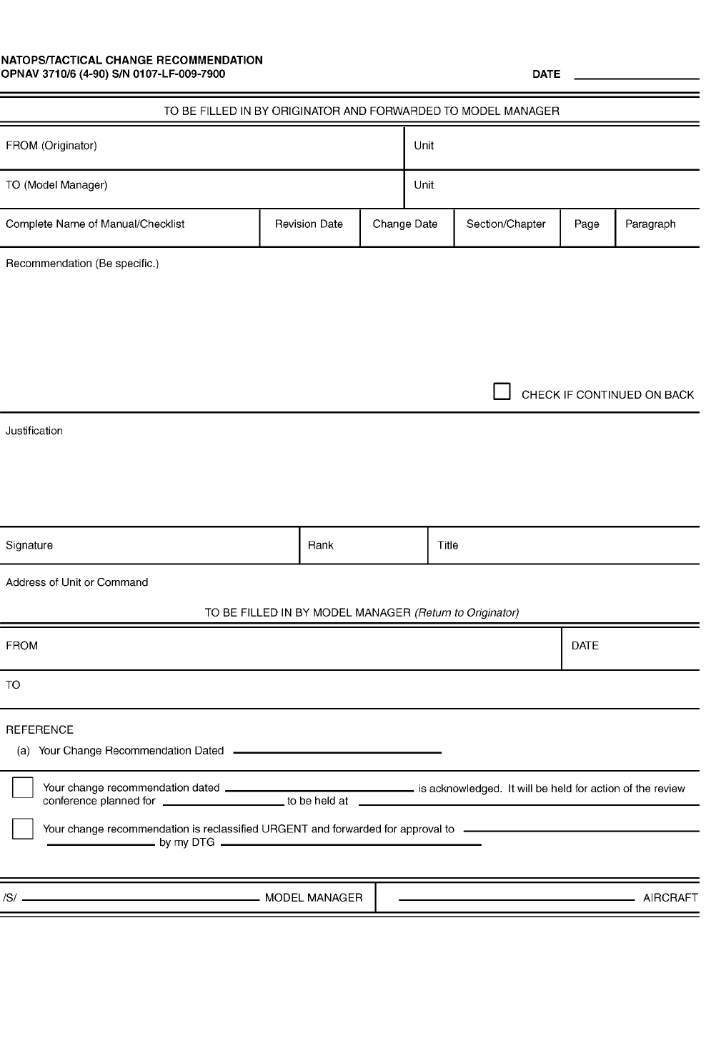
CHANGE RECOMMENDATIONS
Recommended changes to this manual or other
NATOPS publications may be submitted by anyone in
accordance with OPNAVINST 3710.7 series.
Routine change recommendations are submitted
directly to the Model Manager on OPNAV Form 3710/6
(4-90) shown herein. The address of the Model
Manager of this program is:
Officer in Charge
U.S. Navy LSO School
1680 Tomcat Blvd. Suite 100
Virginia Beach, VA 23460-2189
lsoschool@nasoceana.navy.mil
Change recommendations of an URGENT nature
(safety of flight, etc.), should be submitted directly to
the NATOPS Advisory Group Member in the chain of
command by priority message.
NAVAIR 00-80T-104
ORIGINAL 22
YOUR RESPONSIBILITY
NATOPS Flight Manuals are kept current through
an active manual change program. Any corrections,
additions, or constructive suggestions for improvement
of its content should be submitted by routine or urgent
change recommendation, as appropriate at once.
NATOPS FLIGHT MANUAL INTERIM CHANGES
Flight Manual Interim Changes are changes or
corrections to the NATOPS Flight Manuals promul-
gated by CNO or NAVAIRSYSCOM. Interim Changes
are issued either as printed pages, or as a naval message.
The Interim Change Summary page is provided as a
record of all interim changes. Upon receipt of a change
or revision, the custodian of the manual should check
the updated Interim Change Summary to ascertain that
all outstanding interim changes have been either
incorporated or canceled; those not incorporated shall
be recorded as outstanding in the section provided.
CHANGE SYMBOLS
Revised text is indicated by a black vertical line in
either margin of the page, like the one printed next to
this paragraph. The change symbol shows where there
has been a change. The change might be material added
or information restated. A change symbol in the margin
by the chapter number and title indicates a new or
completely revised chapter.
WARNINGS, CAUTIONS, AND NOTES
The following definitions apply to WARNINGs,
CAUTIONs, and Notes found throughout the manual.
An operating procedure, practice, or condi-
tion, etc., that may result in injury or death,
if not carefully observed or followed.
CAUTION
An operating procedure, practice, or condi-
tion, etc., that may result in damage to
equipment, if not carefully observed or
followed.
Note
An operating procedure, practice, or condi-
tion, etc., that is essential to emphasize.
WORDING
The concept of word usage and intended meaning
adhered to in preparing this Manual is as follows:
1. Shall has been used only when application of a
procedure is mandatory.
2. Should has been used only when application of a
procedure is recommended.
3. May and need not have been used only when
application of a procedure is optional.
4. Will has been used only to indicate futurity, never
to indicate any degree of requirement for
application of a procedure.
NAVAIR 00-80T-104
ORIGINAL
23/(24 blank)

NAVAIR 01-F14AAP-1
ORIGINAL
5/(6 blank)


NAVAIR 01-F14AAP-1
ORIGINAL
5/(6 blank)

NAVAIR 00-80T-104
ORIGINAL
1-1
CHAPTER 1
Introduction
1.1 GENERAL
This manual provides all conventional landing
non-V/STOL LSOs with standardized operating proce-
dures, technical guidance, and a single source of LSO
policy and information to all command levels.
Note
Officers involved in V/STOL aircraft con-
trol shall be governed by separate directives.
The LSO shall be thoroughly familiar with the
contents of the following directives in addition to this
manual:
1. CV NATOPS Manual — carrier operations
manual which includes landing patterns and
procedures in Chapter 5.
2. Appropriate aircraft model NATOPS flight
manual sections pertaining to carrier recovery.
3. ARBs
a. ARB 10-10 series — general recovery infor-
mation that is required reading for all person-
nel concerned with aircraft recovery
operations.
b. ARB 0-11 series — current status of all ARBs.
c. ARB 12-12 series — deck configuration for
barricade engagements.
d. ARB 20 through 39 series as appropriate —
covers various types of arresting gear, engag-
ing speeds/weights, etc.
e. ARB 62-12 series — Fresnel lens settings for
all aircraft and CVs, required reading for all
pilots.
f. ARB 63-12 series — Improved Fresnel lens
settings for all aircraft and CVs, required
reading for all pilots.
4. Respective type commander instructions.
1.2 ROLE OF LANDING SIGNAL OFFICER
The landing signal officer’s primary responsibility
is the safe and expeditious recovery of non-V/STOL
fixed-wing aircraft aboard ship. The employment of
high-performance aircraft and the necessity for all
weather operations have placed ever increasing de-
mands on the LSO’s skill and judgment. Through
training and experience, he is capable of correlating
factors of wind, weather, aircraft capabilities, ship
configuration, pilot experience, etc., in order to provide
optimum control and assistance in aircraft landings. The
LSO is also directly responsible for training pilots in
carrier landing techniques. In this regard, he must
constantly monitor pilot performance, schedule and
conduct necessary ground training, counsel and debrief
individual pilots, and certify their carrier readiness and
qualification. The pilot and LSO form a professional
and disciplined team, both ashore and afloat. The LSO
strives to develop the pilot’s confidence, judgment,
maximum effort, technical proficiency, and personal
interest. The pilot must rely on the LSO’s experience
and ability to prepare him for optimum effectiveness as
a carrier pilot.
1.3 COMMAND RELATIONSHIPS AND
RESPONSIBILITIES OF THE LANDING
SIGNAL OFFICER
1.3.1 Type Commander. The type commander
LSO shall act as a coordinator in all matters concerning
the readiness, training, and qualifications of LSOs
under his cognizance; shall work with the LSO training
model manager in all matters concerning LSO readiness
and training; and shall be responsible for the nomination
of qualified LSOs to the Chief of Naval Personnel or
Commandant of the Marine Corps for future assign-
ment. The senior LSO in each subordinate command is
responsible for informing the type commander or Chief

NAVAIR 00-80T-104
ORIGINAL 1-2
of Naval Air Training of the status of LSO training and
qualifications. This report shall be submitted in accor-
dance with Part VII, Chapter 10 of this manual.
1.3.2 LSO Training Model Manager. The officerin charge of the LSO School shall act as the LSO
training and NATOPS model manager. As such, he will
be responsible for the following major training areas:
1. Developing, implementing, monitoring, and up-dating educational media materials for all LSO
training.
2. Conducting IFGT, FRS/TRACOM FGT, and
AFGT.
3. Monitoring training levels of all U.S. Navy and
Marine Corps LSO personnel.
4. Acting as the SME representative to all researchand development projects relating to LSO training
and equipment.
5. Monitoring status of shipboard LSO equipment
stations and providing inputs to appropriate fleet
type commander LSOs.
6. Acting as a liaison between pertinent commands
concerning LSO matters.
1.3.3 Ship/Air Wing Commanding Officer.
When embarked, the LSO is responsible to the Captain
and Air Wing Commander for the safe and expeditious
recovery of aircraft. The LSO shall inform the Captain
and Air Wing Commander through the Air Officer of
any conditions that might interfere with recovery such
as malfunctions of equipment, improper deck configu-
ration, adverse weather and wind, or sea conditions. It
is the LSO’s responsibility to make appropriate recom-
mendations to the Captain and Air Wing Commander
based on his evaluation of the operating environment.
1.3.3.1 Air Officer. When embarked, the LSO
performs his platform duties under the supervision of
the Air Officer. It is incumbent on the LSO to establish
a close working relationship with the Air Officer, to
include periodic discussions regarding mutual expecta-
tions and delegation of responsibilities in the recovery
of aircraft.
1.3.4 Air Wing Commander. The air wing staff
LSO is responsible to the Air Wing Commander for the
following:
1. The operational readiness of all assigned squad-
rons and detachments pertaining to FCLP and
carrier landing operations.
2. Coordination and supervision of the training and
employment of all LSOs within the air wing. He
will ensure that a high level of proficiency is
maintained by the administration of an LSO
training program. It is incumbent upon the air
wing staff LSO to establish training goals and
pursue their accomplishment through field and
shipboard training.
3. Provision of trend analysis forms and written
commentary where applicable to the Command-
ing Officer of a detachment’s parent squadron
following each operating period. It is intended that
all pilot carrier performance be observed, evaluat-
ed, and critiqued by the host air wing regardless of
the unit’s tenure aboard ship or the frequency of its
operations.
4. Ensuring that a separate COD log is maintained in
Air Operations, and that all landings to the carrier
by COD aircraft are recorded and debriefed. If
operational tempo does not facilitate a face-to-
face debrief with the pilot, the pass shall be
recorded in the COD logbook for retrieval and
subsequent debrief by the squadron LSO.
1.3.5 Squadron Commanding Officer. The
squadron LSO advises and makes recommendations to
the squadron commander pertaining to:
1. The state of pilot training
2. Any unsafe tendencies of individual pilots
3. The state of assistant LSO assignment and
training
4. The latest technical developments of appropriate
type aircraft, ship configurations, and equipment
which concern the recovery of aircraft.
For CV detachments, the parent squadron LSO shall
ensure that the level of readiness of the detachment to
be assigned meets the requirements outlined in this

NAVAIR 00-80T-104
ORIGINAL
1-3
manual. Recipient LSOs should, as far as practicable,
observe all detachment performance of FCLP prior to
embarkation.
It is incumbent on the Commanding Officer to fully
support the LSO training program.
Commanding officers should ensure that LSOs
receive flight time commensurate with other squadron
pilots.
1.4 LSO DESIGNATIONS
1.4.1 LSO Designation Category
1. Field LSO reflects the individual’s ability to
satisfactorily control one or more specific type
aircraft during FCLP. Further, he is considered
qualified to maintain and interpret LSO logs and
records of FCLP periods conducted for the
purpose of making recommendations to the com-
manding officer regarding extension or revoca-
tion of pilot currency for CV landings.
2. Squadron LSO reflects the individual’s ability to
satisfactorily control one or more type aircraft at
the field and aboard ship in day and night
conditions and satisfactorily operate the
MOVLAS (day). Further, he is considered quali-
fied to maintain and interpret LSO logs and
records and make recommendations to the com-
manding officer concerning individual pilot qual-
ifications. It is the responsibility of the air wing
staff LSO to recommend the squadron LSO
designation.
3. Wing LSO reflects an individual’s ability to
control a majority of the air wing aircraft at the
field and aboard ship in day/night, all weather and
deck conditions without assistance, as well as an
ability to function as an LSO watch team supervi-
sor and satisfactorily recover aircraft aboard ships
utilizing MOVLAS. Designation as a wing LSO
shall be required prior to assignment to an air wing
staff LSO billet. It is the responsibility of the air
wing staff LSO to recommend the designation as
wing LSO.
4. Training LSO reflects the individual’s ability to
administer, instruct, and supervise initial in-type
carrier qualification for a specific type aircraft.
The recommendation for designation as a training
LSO shall be the responsibility of the senior
training LSO.
5. Staff LSO reflects the attainment of the highest
level of qualification and experience gained as a
result of performance in subordinate categories.
The responsibility for recommending designation
as a staff LSO rests with the Air Wing Commander
and represents his judgment of the individual’s
preparedness to assume the responsibility of an air
wing staff LSO.
1.4.2 LSO Trainee Nomination Procedures.
The decision to recommend initial LSO nomination
rests with the individual’s Commanding Officer,
based upon the recommendation of the senior cogni-
zant LSO. A letter recommending nomination as an
LSO trainee shall be submitted by the Commanding
Officer to the type commander via the Air Wing
Commander, Training Wing Commander, or Marine
Air Wing Commander.
1.4.3 Upgrading Procedures. When a letter re-
questing LSO nomination, qualification, or qualifica-
tion upgrade is forwarded to the first endorser, the LSO
is authorized to control aircraft in that capacity while
approval from the type commander is pending. Copies
of the type commander’s approval letter shall be
forwarded to Bureau of Naval Personnel (PERS 433) or
Commandant of the Marine Corps (Code MMOA2) for
inclusion into the officer’s service record.
1.5 LSO SENIORITY
LSO seniority will be determined by level of LSO
designation, with LSO School OIC, TYCOM LSOs,
and CNATRA LSO being the highest level of designa-
tion, followed by staff LSO, wing LSO, and squadron
LSO in that order. In FRS and training command
squadrons only, the training LSO designation shall be
used to determine LSO seniority, regardless of squadron
or wing designation. In situations involving two or more
individuals with the same level of designation, seniority
of designation date will determine LSO seniority unless
modified by the CNAF, Air Wing Commander, or
Commanding Officer.
All LSOs within the air wing are operationally
subordinate to the air wing staff LSO.

NAVAIR 00-80T-104
ORIGINAL 1-4
1.6 ASSIGNMENT
The type commander LSO shall act as coordinator
in all matters concerning the readiness, training, qualifi-
cation, and assignment of LSOs under their cognizance.
The type commander LSO billet shall be filled by a
current staff qualified LSO. Marine air wing staff LSO
billets should be filled by experienced and current wing
designated LSOs.
The Officer in Charge LSO School billet shall be
filled by a staff qualified LSO immediately following
his air wing staff LSO tour.
The numbers contained in Figure 1-1 are the
recommended minimum LSO requirements. However,
it should be recognized that practical maximums also
exist because of variable operating tempos and corre-
sponding training opportunities. Nomination of LSO
trainees in excess of those indicated could result in
reducing the overall experience level of LSOs in the
future. Staff LSOs shall coordinate and limit the total
number of LSOs per air wing in order to provide
adequate training opportunities at the operational level.
1.7 FLIGHT DECK HAZARDOUS DUTY
INCENTIVE PAY (FDHDIP)
Per CNAL 220935ZAPR99, LSOs are authorized to
exceed the quotas listed in OPNAVINST 7220.4 to
compensate individuals who are “under instruction.”
All LSOs are considered to be “under instruction” until
they become CVW staff qualified LSOs. LSOs that
meet the requirements as set forth in OPNAVINST
7220.4 are entitled to FDHDIP, at no penalty to the
command’s other quotas.

NAVAIR 00-80T-104
ORIGINAL
1-5/(1-6 blank)
STAFF QUAL IN TRAINING TOTAL
TYCOM 1 —1
LSO SCHOOL 4—4
CVW 3 —3
TRAWING 1 —1
MAW 1—1
NATC 2 —2
OPERATIONAL SQUADRONS QUAL IN TRAINING TOTAL
VF/VS/VAW/VFA 2 2 4
VAQ 2 1 3
VMAQ/VMFA/VMFA (AW) 1 1 2
VMFA (CV DEPLOYED) 2 2 4
VR/VRC 1 1 2
VX (AS APPROPRIATE) 1—1
VT (INT. STK.) 5—5*
VT (ADV. STK.) 4—4*+
VT (E-2/C-2) 3—3*
DETACHMENTS (CV DEPLOYED) QUAL IN TRAINING TOTAL
VMAQ 1 1 1
REPLACEMENT SQUADRONS QUAL IN TRAINING TOTAL
VFA 6 —6
VMFAT 6—5
VF 6 —5
VAW 6—6
VS 6 —5
VAQ 5—5
*NOT LESS THAN 1 LSO/8 STUDENTS
+ VT-7 REQUIREMENT IS 5
Note
The above numbers represent minimum recommended LSO requirements. Operational squadrons will
normally exceed these minimums to maintain a quality LSO training program.
Figure 1-1. Recommended Minimum LSO Requirements

NAVAIR 01-F14AAP-1
ORIGINAL
5/(6 blank)

NAVAIR 00-80T-104
ORIGINAL
2-1
CHAPTER 2
Indoctrination
2.1 SELECTION OF LSO TRAINEES
Prospective LSOs are first tour pilots nominated by
squadron commanding officers. When selecting candi-
dates for LSO training, consideration should be given to
motivation, aviation ability, and potential as an instruc-
tor. Candidates should also be identified early enough
in their first operational tour to be given the opportunity
to progress to wing qualification status before the end
of that tour. Nominees should be sent to the U.S. Navy
LSO School as soon as nominees have enough initial
familiarization with the LSO trade to make the school
a worthwhile experience.
Squadron commanding officers shall submit a letter
of nomination for LSO training via the chain of
command to their cognizant type commander for
approval. Letters of nomination should include the
following information:
1. Name, rank, SSN, designator, and date of rank
2. Date reporting/reported to squadron and rotation
date as shown on latest ODCR
3. Total flight hours/hours in type
4. Total carrier landings day/night by type aircraft.
2.2 LSO TRAINING PROGRAM
The LSO training and qualification program con-
sists of the following:
1. Ground training for LSO trainees and squadron
LSOs
2. Initial field training prior to squadron LSO
designation
3. IFGT prior to wing LSO designation
4. Shipboard training prior to squadron and wing
LSO designation
5. Initial formal ground training and FRS/TRACOM
formal ground training prior to training LSO
designation
6. Advanced field and shipboard training prior to
training LSO designation
7. AFGT prior to staff LSO designation.
2.2.1 Formal Ground Training. Initial, FRS/
TRACOM, and advanced formal ground training shall
be conducted by the U.S. Navy LSO School. Initial
formal ground training should be completed prior to
designation as a squadron LSO and shall be completed
prior to designation as a wing LSO. FRS/TRACOM
formal ground training should be completed prior to
reporting to an FRS or training command squadron.
Advanced formal ground training shall be completed
prior to reporting to the carrier air wing commander’s
staff.
2.2.2 Field Training. Field training prior to desig-
nation as a squadron LSO shall be conducted under the
supervision of a squadron, wing, or staff LSO. A
training LSO shall supervise the advanced field training
required for training LSO qualification.
2.2.3 Shipboard Training. Shipboard training
pursuant to squadron, wing, or training LSO qualifica-
tion shall be conducted under the supervision of a
training or staff LSO. A designated staff LSO shall
supervise the progress of a prospective staff LSO until
the candidate has attained sufficient proficiency in
controlling all assigned air wing aircraft for staff
designation. In all cases, it is the responsibility of the
senior designated LSO to evaluate the capabilities and
progress of the LSO under training and report the same
in accordance with Part VII, Chapter 10 of this manual.
2.2.4 Aircraft Crosstype Training. Designated
squadron LSOs should receive flight indoctrination in
at least one additional type of aircraft assigned to his
respective air wing. LSO cross-training is designed to
improve LSO understanding of aircraft handling and
performance characteristics primarily in the approach

NAVAIR 00-80T-104
ORIGINAL 2-2
and landing phases. LSO exposure to the flight charac-
teristics of aircraft other than his own has a positive
effect on overall LSO expertise.
2.3 REQUIREMENTS FOR LSO
DESIGNATION
The requirements for LSO qualification and desig-
nation are discussed in Part VII, Chapter 10 (NATOPS
Evaluation) of this manual.
2.4 MINIMUM CURRENCY REQUIREMENTS
The following criteria apply to qualified LSOs and
are established to ensure minimum LSO proficiency for
safe recovery operations:
PERIOD SINCE
ACTING AS
CONTROLLING
LSO FOR CV
RECOVERY
OPERATIONS
REQUIRED ACTION
PRIOR TO ACTING AS
CONTROLLING OR
BACKUP LSO FOR
CV RECOVERY
OPERATIONS
Up to 12 months Discretion of senior LSO
Over 12 months 1. Control 80 field carrier
landing practice
(FCLP) landings or
observe 30 CV
landings; and
2. Control 20 CV landings
under supervision of
senior LSO. Senior
LSO must be current to
supervise currency
training.
2.5 FACTORS AFFECTING LSO
READINESS
1. The duties of the LSO require the same levels of
mental alertness that are required of a naval
aviator in actual control of aircraft. The LSO shall
be a physically qualified (or waivered) designated
naval aviator with a current Aeromedical Clear-
ance Notice (up-chit, NAVMED 6410/2).
Additionally, LSOs shall remain in full
compliance with OPNAVINST 3710.7 series,
Section 822, concerning personnel readiness and
qualifications. There will be occasions when the
LSO is physically fit for LSO duties but not for
actual flight (e.g., sprained wrist). This requires an
Aeromedical Clearance Notice for LSO Duties
Only.
2. LSOs shall maintain flight proficiency in the
carrier landing environment. Staff LSOs are the
senior air wing subject matter experts in the
fixed-wing recovery environment and therefore
must fly with the air wing to be credible evaluators
as well as to have first-hand knowledge of the
conditions air wing pilots face during recovery
operations. Consequently, staff LSO billets
should be fully afforded adequate flight hours for
proficiency.
2.6 TRAINING LSO CARRIER
QUALIFICATION (CQ) REQUIREMENTS
In order to maintain proficiency in the carrier
landing environment, Training LSO’s shall receive
carrier arrestments whenever possible. CV (N) and
FRS/TRACOM commanding officers should ensure, as
a minimum, Training LSO’s receive six arrested
landings every 6 months or 12 arrested landings per
year.
2.7 LSO TRAINER (DEVICE 2H111)
The Landing Signal Officer Trainer, Device 2H111,
is operational at NAS Oceana. It simulates a fully
functional LSO platform on a CVN-68 (Nimitz) or
CVN 76 (Reagan) class CV, and employs models of
virtually all current fleet aircraft. A wide variety of
environmental conditions, operating parameters (in-
cluding MOVLAS), and normal or emergency scenar-
ios may be simulated to provide realistic individual
LSO or LSO team procedural and proficiency training.
The use of the trainer is highly recommended for LSO
turnaround training on both a squadron and air wing
level, to enhance the overall preparedness of LSO teams
prior to embarked operations.


NAVAIR 01-F14AAP-1
ORIGINAL
5/(6 blank)

NAVAIR 00-80T-104
ORIGINAL
3-1
CHAPTER 3
Shore-Based Workstation
3.1 GENERAL
Certain specific equipment and personnel shall be
provided for both shore and shipboard operations so that
an LSO can safely and efficiently perform his mission.
Responsibility for the provision, maintenance, and
proper functioning of the equipment rests with the air
station’s or ship’s air department, as applicable. It is the
LSO’s responsibility to ascertain, before commencing
operations, that all required equipment is available and
operative.
3.2 MINIMUM EQUIPMENT FOR FIELD
CARRIER LANDING PRACTICE (FCLP)
OPERATIONS
3.2.1 Day FCLP. The minimum equipment and
personnel required for day FCLP are:
1. Visual landing aid and necessary accessories,
including waveoff pickle switch and press-on and
release-off cut switch
2. MOVLAS (available for at least one full FCLP
period per pilot)
3. Communications: a UHF transceiver with exten-
sion speaker and microphone and guard transceiv-
er capability
4. Simulated carrier deck markings, adequately
maintained
5. Crew: a qualified LSO shall be on station for all
FCLP operations.
3.2.2 Night FCLP. In addition to the items listed in
the preceding paragraph, the following equipment and
personnel are required for night FCLP:
1. Permanent, flush-deck lighting. Unless this sys-
tem is installed, a minimum of 24 portable
powered lights with suitable holders will be
provided.
2. Aldis lamp for emergency use located at the LSO
station
3. Abeam position marker light located at the LSO
station, visible abeam to the pilot
4. Emergency arresting gear marker light
5. Crew: With more than two aircraft in an LSO
controlled FCLP pattern, an individual to assist
the controlling LSO is required.
3.3 VISUAL LANDING AIDS
3.3.1 General. There are presently four optical
landing aids used aboard naval air stations.
1. Mk 8 Fresnel lens
a. Mod 0: Equipped with roll angle drive assem-
bly; no cut lights unless change No. 43 is
incorporated
b. Mod 1: Not equipped with roll angle drive
assembly
2. MOVLAS (Mk 2 Mod 2)
3. Mk 14 Mod 0 improved Fresnel lens.
Note
Visual landing aids which are installed as a
part of an air station’s normal approach
lighting and marking scheme may be config-
ured to activate the runway waveoff light
system (wheels up waveoff lights) whenever
the lens waveoff lights are activated by the
tower, wheels watch, or the LSO’s pickle
switch. Use of this configuration may not be
suitable for conduct of FCLPs. Refer to
NAVAIR 00-80T-114 (ATC Facilities
Manual).
Ship Installations Equipment Handbook, CD-1025,
Naval Air Engineering Center, Lakehurst, NJ, lists
numbers, types, and certification dates of visual landing
aids located at each air station.

NAVAIR 00-80T-104
ORIGINAL 3-2
3.3.2 Mk 8 Fresnel Lens. The Mk 8 Fresnel lens
is nearly identical to the shipboard variant. The datum
arms may be pinned inward against the power control
unit when not in use. On/off and intensity controls are
provided for independent control of source, datum, and
combined cut and waveoff lights. Proper temperature
and unit ready indications are identical to those
described in the FLOLS section. A jackscrew and
hand-crank on the front of the trailer base is used to
adjust desired glideslope. A mirrored pole is provided
with the unit to check glideslope settings (the Mk 8 is the
only unit that comes standard equipped with a pole).
The Mk 8 Mod 0 is equipped with a roll angle assembly
so that the unit may be used for continuous short-field
arrestments with SATS systems. Aircraft Recovery
Bulletin No. 80 series lists operating instructions and
roll angle settings.
3.3.3 MOVLAS. The Mk 2 Mod 2 land-based
MOVLAS is compatible with the Mk 8 FLOLS, or may
be used independently. Refer to the shipboard
MOVLAS discussion in Chapter 4 for further informa-
tion concerning the MOVLAS system.
3.3.4 Operation and Checks of Shore-BasedVisual Landing Aids. The following discussion
provides pertinent information regarding the operation
and preoperational checks for shore-based visuallanding aids.
3.3.4.1 Pole Check. All land-based optical sys-
tems are checked for basic angle at a point 150 feet in
front of the unit using a telescoping mirror. The exactheight of the mirror assembly shall be calculated usingsite survey data as described in the applicable system
operational manual.
3.3.4.2 Intensities. When setting intensities of the
lens, excessive intensity of the lights causes light
spillage, interference with pilot’s vision, reflection oflight into the background, and an afterglow. Thereflection of light into the background hampers properidentification of the meatball by the pilot on approachand may cause mistaken identification of light reflec-tion for a nonexistent meatball. The afterglow may
impede the pilot’s vision in the final stages of approach,prevent him from recognizing a waveoff, and cause theloss of the glidepath. Light brightness settings mustalways be maintained near the minimum requiredintensity to compensate for ambient light and weather
conditions. The brightness settings are determined by
the position of the lens with respect to the sun and by the
decision of the LSO.
3.3.4.3 Touchdown Points. The height of thedatum lights above the runway surface is different foreach of the shore-based optical systems. This heightdifference results in slightly different approach geome-
try and aircraft touchdown point when using the varioussystems. Touchdown points also vary with each aircraft
because of their differences in hook-to-eye (or maintires to eye). The Mk 8 Mod 0 with its roll angle drive
assembly is the exception and maintains a constant hook
touchdown point. Most field optical landing systemsuse only basic angles; no roll angle adjustments aremade, and each aircraft will have a different touchdownpoint based on its H/E value.
Relative wind over the deck needs to be considered
during FCLP to select a reasonable compromise on
glideslope angle used, considering pilot senses, aircraftpower response, LSO sight picture, and aircraft aerody-
namics. When selecting a basic angle for FCLP with
relatively light winds at the field, a 2-3/4° or 3°
glideslope may have the pilot and the LSO seeing a low,
flat glideslope. Additionally, the ball will be consider-
ably more difficult to control as the aircraft approaches
touchdown. This may become apparent in an excessive
number of bolters or early touchdowns.
3.4 LSO GREENHOUSE AND RADIOS
Located at many master jet bases and their outlying
fields are environmentally protected LSO stations.
The greenhouse should house the controls for the
FCLP equipment listed in section 3.2 (i.e., standard
LSO pickle switch, MOVLAS controller, radio, etc.).
Radio equipment configuration may vary, but must
include as a minimum a UHF transceiver with guard
transceiver capability.
3.5 LSO VEHICLE
A variety of vehicles are available for LSO use at
facilities not having a permanent LSO workstation
(greenhouse). Although several radio configurations
are available, a minimum of one UHF transceiver (with
guard capability) and VHF or FM transceiver (for LSO
to tower communication) is required for FCLP
operations.
NAVAIR 00-80T-104
ORIGINAL
4-1
CHAPTER 4
Shipboard Workstation
4.1 MINIMUM EQUIPMENT LIST FOR
SHIPBOARD OPERATIONS
4.1.1 Day Carrier. The minimum equipment re-
quired for day carrier operations includes the following:
1. Visual landing aid and necessary accessories,
including three portable switch assemblies (wave-
off pickles) with a press-on and release-off cut
switch.
2. MOVLAS.
3. The following operable communication equip-
ment is required on the LSO platform:
a. Minimum of 2 Air-to-Ship radio communica-
tion devices, one for Back up LSO and
Controlling LSO, with connections for 2
headsets/handsets each. At a minimum, the
communication devices shall provide access
to CATCC Final A and Final B UHF radio
circuit transceivers and 2 dedicated/backup
Air-to-Ship UHF transceivers. The dedi-
cated/backup transceivers shall be capable of
selecting required frequency channels from
the Backup/Controlling LSO operating area.
b. The communication devices shall provide the
capability for the Back up and Controlling
LSO to override/preempt any Air-to-Ship
radio transmission on the frequency of the
landing aircraft. In addition, the Back up LSO
communication device shall provide the
added capability to override/preempt the Con-
trolling LSO.
c. Access to the Ship’s Service Telephone
System (SSTS) for administrative calls.
d. Internal Communications (IC) access to Pri-
mary Flight Control, CATCC, Arresting Gear
operators and PLAT/Lens operators.
e. Direct communication access to the Air
Officer.
f. A sound-powered hot line to the air officer.
4. For ACLS capable ships, during Case III opera-
tions, operable LSO HUD SPN-42/46 indicators.
5. Accurately calibrated relative wind indicator.
6. Colored deck status light system with intensity
control for day and night use, clearly visible to
PriFly and the LSO. Colored flags or paddles for
use in the event of a deck status light failure.
7. 7 X 50 binoculars.
8. Distress equipment:
a. Battery powered marker
b. Life preserver ring
c. Search and rescue sonobuoy.
9. Padded safety net, with an access to the catwalk
and interior of the ship, continually maintained.
CAUTION
The padded safety net is for emergency use
only.
10. A windscreen, constructed of suitable material,
with adequate window area.
11. An operable hook-to-ramp indicator and an oper-
able hook touchdown point indicator.
12. A weatherproof, external radio speaker with
adjustable volume control.
13. An operable PLAT/ILARTS monitor with center-
line reference.

NAVAIR 00-80T-104
ORIGINAL 4-2
4.1.2 Night Carrier. All equipment required for
day carrier operations is required at night, with the
following additions:
1. Aldis lamp or high intensity spotlight which is
located at the LSO platform for emergency use
2. Colored wands for use in the event of a deck status
light failure.
4.1.3 Miscellaneous LSO Equipment Mal-
function. The LSO shall notify the Air Officer of the
malfunction or loss of any required equipment. The
decision to continue recovery operations with any
required LSO equipment inoperative shall rest with the
commanding officer.
4.2 FRESNEL LENS OPTICAL LANDING
SYSTEM
The Mk 6 Mod 3 FLOLS is an electro-optical pilot
landing aid featuring two identical channels of
stabilization complete with gyro/sensor units, electronic
computers, monitoring circuits, built-in maintenance facil-
ities, and automatic trim stabilization units. The FLOLS
automatically corrects lens settings for static mistrim of the
ship to maintain a constant preselected hook touchdown
point. The FLOLS currently has line and inertial (heave)
modes of stabilization available.
The FLOLS includes a deck edge assembly (the
lens), the FLOLS control room, the PriFly area, and
LSO platform.
There is a vast amount of printed information
available on the FLOLS. A thorough understanding of
the following list of publications is a must for an LSO:
1. Technical Manual, Fresnel Lens Optical Landing
System Mk 6 Mod 3, Installation, Service, Opera-
tion, and Maintenance Instruction (NAVAIR
51-4OABA-l0)
2. Aircraft Recovery Bulletin No. 62-12 (Mk 6
Mod 3 FLOLS)
3. Aircraft Recovery Bulletin No. 10-10.
4.2.1 Optical Characteristics
4.2.1.1 Effects of Temperature. The optical
characteristics of the Fresnel lens vary appreciably with
changes in internal cell temperature. If the lens
temperature is allowed to vary beyond operational
limits (97 ±7 °F), three effects will be observed:
1. As temperature varies, the size of the bar of light
will appear to change as the image moves from the
lens center to the transition line between cell
assemblies. If the temperature is higher than
operational temperatures, the bar of light at the
center will appear smaller and bloom to a larger
bar of light at the transition line between cells. At
lower temperatures, the opposite will occur.
2. At extreme temperatures it is possible to get blank
areas or double bars of light at or near the
transition point between cells.
3. The light bar will be wider (i.e., less well-defined)
at temperatures higher than design temperatures,
and smaller at lower temperatures. Extremes in
temperatures (below 90 °F or above 135 °F) will
cause out of tolerance indications in PriFly and the
FLOLS control room. Overtemperature may be
caused by a failed thermal switch(es) causing the
cell heaters to stay on, outside air temperature, or
aircraft spotted with exhausts pointed near the
lens. Since the actual Fresnel lens inside the cell
assembly is made of plastic (Lucite), a metal
frame (eggcrate) is bolted to the plastic Fresnel
lens to support it and keep the lens from warping.
The plastic Fresnel lens can be damaged resulting
in transition problems if the eggcrate bolts are
over-tightened or the clamps that hold the Fresnel
lens in the cell are overtightened. Bad transition
can usually be detected on deck, but you must be
at least 80 feet away from the lens when viewing
the display. V-2 lens technicians can move the lens
in pitch so all transitions can be viewed. All cells
are interchangeable, so the best cells should be put
in the center and adjacent positions. V-2 lens
technicians can determine the best cells with
visual examination of the cell output and by
performing the MRC for the Flip Test. If it is
necessary to use the lens prior to complete
warmup, pilots should be informed that there may
not be a smooth transition of the ball between cells
and that the ball may disappear as it traverses the
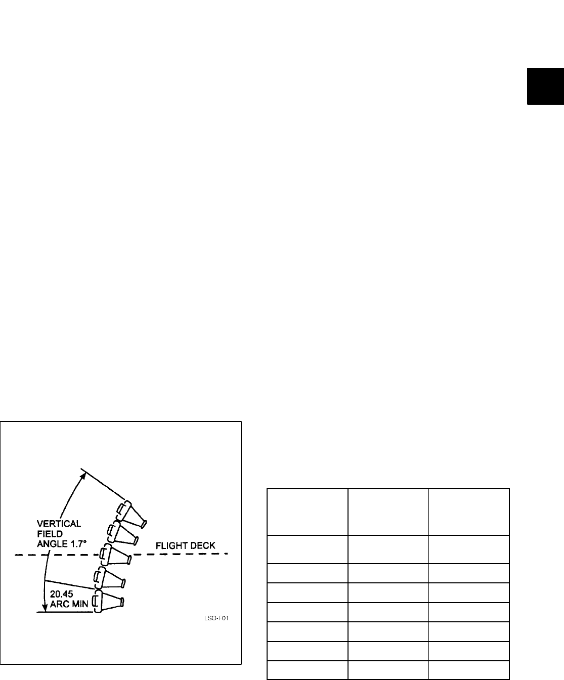
NAVAIR 00-80T-104
ORIGINAL
4-3
junction between adjacent cells. No difficulty
should be experienced when the ball is in the
center of the cell.
4.2.1.2 Focal Point and Field of View. The
inherent characteristic of the FLOLS display is a linear
projected glideslope (i.e., the total beam height becomes
wider as distance from the lens is increased, and that width
increase is linear). The further a pilot is from the lens, the
more difficult it is for the pilot to perceive changes in
glideslope. The total glideslope vertical field composed of
all five cells (Figure 4-1) is approximately 1.7° (each cell
accounts for 20.45 minutes of arc or .34°).
Figure 4-2 helps illustrate vertical field angle and
also shows why pilot glideslope corrections must
become smaller as the aircraft approaches the touch-
down point.
Couple the conditions of Figure 4-2 with too bright
a lens setting (which significantly reduces ball defini-
tion the closer the aircraft approaches the lens) or minor
the closer the aircraft approaches the lens) or minor
visual acuity problems (pilot, weather, salt on lens, etc.),
and the result is unperceived glideslope deviations.
The lenticular lens is the vertical fluted lens
attached in front of the Fresnel lens. It provides
meatball color and azimuth ($20_) (Figure 4-3) and
Figure 4-1. Vertical Field Angle
helps to disburse sun reflection from the lens face.
The slots should be outside. It can be easily Murphyed
(i.e., slots on the inside). Since it is exposed to the
elements, it needs to be kept clean and dry. Salt, water,
dirt, or exhaust smoke may cause spherical aberration
(i.e., poor definition). These lenses are plastic and
will be damaged and need immediate replacement if
they are cleaned improperly.
4.2.1.3 Circuitry. Source lights are wired in
series-parallel in the four yellow cells. Each cell
contains three lamps. If one lamp fails, the corre-
sponding lamp in the other three cells will go out (see
Figure 4-4). This provides constant, even illumina-
tion from cell to cell. When one lamp burns out, a
failure light illuminates in the lens control room.
When one lamp in a string fails, extinguishing the
entire string, the source lamp intensity must be
increased to compensate for the loss of one lamp in
each yellow cell. This increased voltage on the
remaining lamps will age them faster. The source
light series/parallel circuitry provides for all lamps
(yellow cells) to age at the same rate, thus (theoreti-
cally) producing even illumination among the yellow
cells.
4.2.2 General Operating Intensities. Set the
source, low cell, and datum lights to minimum intensity
prior to energizing the lens, then adjust the intensity
after the lens is on. This will prevent the LSO or primary
from blowing out all the source lights. Maximum
recommended intensity settings during daylight are
near 9.0, and are usually required at low sun angles.
Night settings normally range from 2.0 to 3.0.
DISTANCE FROM
TOUCHDOWN
(230 FT HTDP)
VERTICAL BEAM
HEIGHT OF
ALL 5 CELLS
VERTICAL BEAM
HEIGHT OF
CENTER (OR ANY
OTHER) CELL
0
(Touchdown ramp) 11.8 ft 2.4 ft
230 ft 18.6 ft 3.7 ft
1/4 nm 56.3 ft 11.3 ft
1/2 nm 100.8 ft 20.2 ft
3/4 nm 145.3 ft 30.5 ft
1 nm 189.8 ft 38 ft
2 nm 367.9 ft 73.6 ft
Figure 4-2. Vertical Field Angle Table
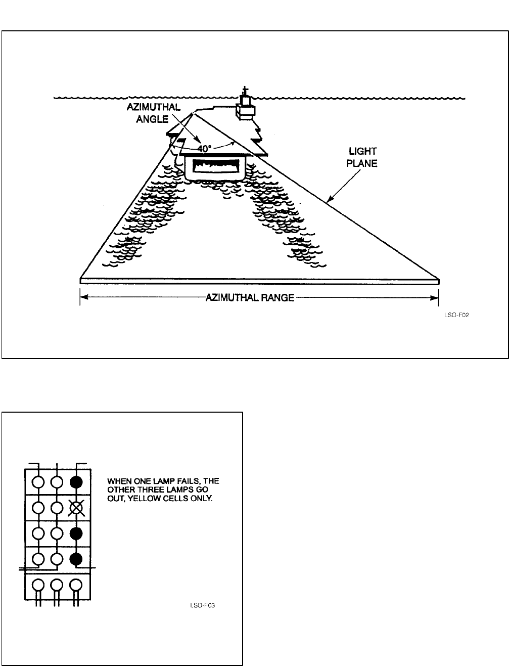
NAVAIR 00-80T-104
ORIGINAL
4-4
Figure 4-3. Azimuthal Range and Angle
Figure 4-4. Source Light Bulb Failure
Intensity in the low (red) cell is adjusted indepen-
dently. It may also be flashed at a 45 times-per-minute
rate. The flasher/steady switch is located in the
FLOLS control room on lighting remote control
panel A720A.
4.2.3 System Condition Indicators. System
condition indicators are located on remote control
panels A710A and A720A (in PriFly and the FLOLS
control room). The LSO platform lighting remote
control panel A730A contains a GO/NO-GO
indicator.
4.2.4 Datum, Waveoff, and Cut Lights. (See
Figure 4-5.) Three fixed datum lights (green) and four
conditional datum lights (green) are mounted horizon-
tally on each side of the lens source lights. The fixed
datums are continuously illuminated, while the condi-
tional datums go out when the waveoff lights are
actuated.
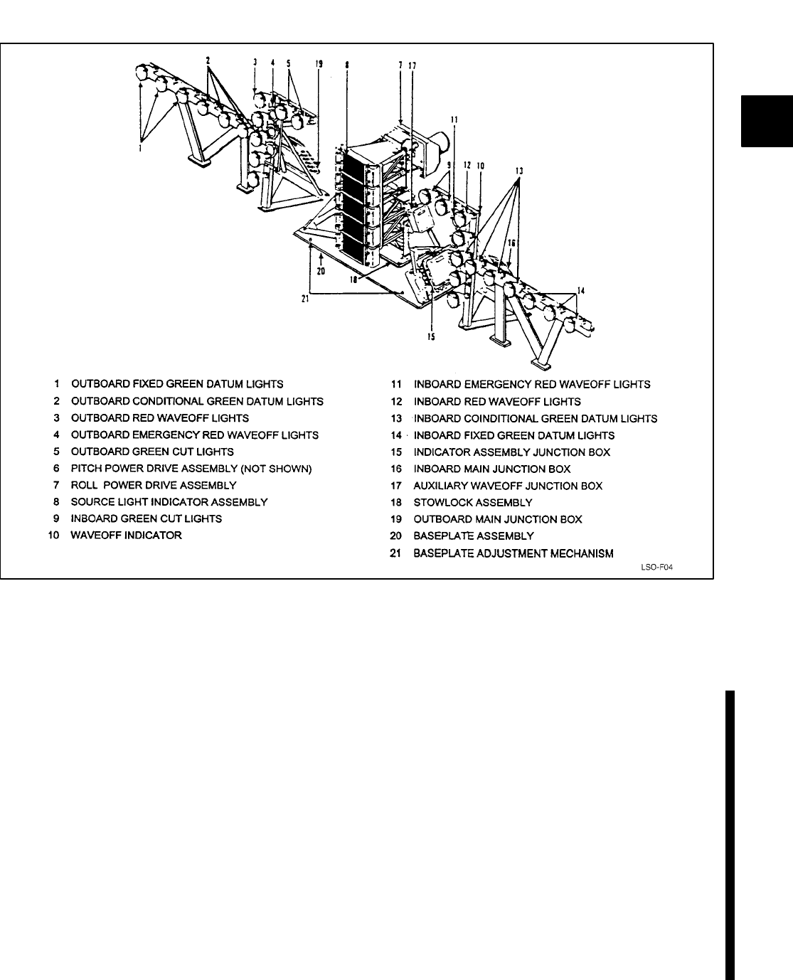
NAVAIR 00-80T-104
ORIGINAL
4-5
Figure 4-5. Deck-Edge Assembly (FLOLS)
Four waveoff lights (red) and three or four
emergency waveoff lights (red) are mounted vertically
on each side of the lens source lights. When a waveoff
is initiated, the waveoff lights first flash at full intensity,
then dim to the preset brightness. The emergency
waveoff lights are on a separate circuit and act as a
backup system to the normal waveoff lights.
Four horizontal cut lights (green) are located above
the source lights (2 on each side). The cut lights are
illuminated by means of a pushbutton on top of the LSO
pickle switch (and by pushbuttons on all remote panels).
The cut lights remain illuminated as long as the
pushbutton is depressed; once released, the cut lights
extinguish.
4.2.5 Stabilization Modes. The FLOLS stabi-
lization computer receives signals from the ship’s stable
element to project a stabilized glideslope with respect to
the horizon under moving deck conditions. The follow-
ing modes of FLOLS stabilization are employed.
4.2.5.1 Line Stabilization. Used as a backup to
inertial mode, this mode stabilizes the FLOLS display
for pitch and roll motions of the ship maintaining a
predetermined line in space at the intersection of the
FLOLS light plane and the true vertical plane through
the centerline of the angled deck (Figure 4-6). This
provides a completely stabilized glideslope referenced
to the carrier deck, (glideslope moves with deck heave
motion) as long as the pilot is on centerline of angled
deck. Line mode is not stabilized for ship’s heave
(vertical displacement). Pilot perceived ball movement
is because of ship’s heave. Mode I’s should be flown
using line stabilization mode, inertial is acceptable.
4.2.5.2 Inertial Mode of Stabilization. The Pri-
mary mode of operation for the FLOLS. This Mode is
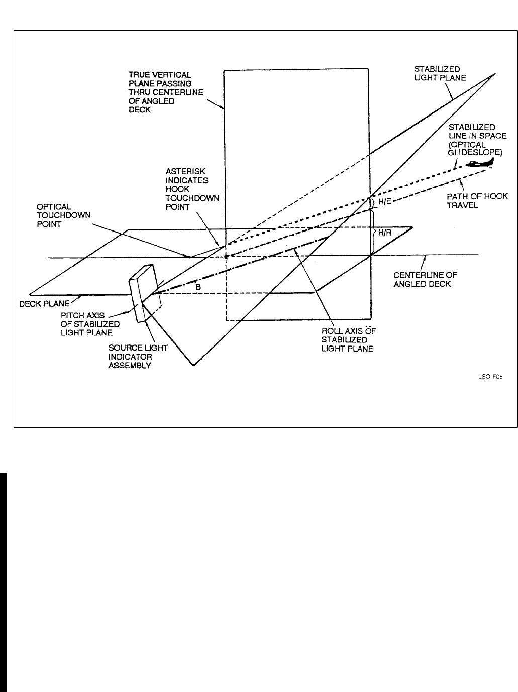
NAVAIR 00-80T-104
ORIGINAL 4-6
Figure 4-6. Geometry of Line Mode Stabilization
line stabilization with additional correction for ship’s
heave motion. It essentially stabilizes the glideslope
regardless of carrier motion. The deck edge roll drive
makes all corrections for heave stabilization. The pilot
must be on the centerline of the angle to see a properly
stabilized display. During heavy sea states (5/6) in
inertial mode, the hook to ramp clearance and touch-
down point indicators will occasionally display a
negative or aft touchdown point respectively. The
dynamic touchdown point varies more in inertial mode
than it does in line mode. This is the sacrifice for a more
stable light beam/glideslope for the pilots. A pilot on a
perfect pass may hit any of the four wires, the ramp or
bolter, depending on ramp motion and heave. At the
moment of touchdown, the hook touchdown point will
be displayed by the dynamic hook touchdown point
indicator for a centered ball pass.
4.2.5.3 Stabilization Limits. Lens stabilization
limits for the Mk 6 Mod 3 FLOLS are ±6_ pitch, ±10_
roll. It should be noted that in any discussion of deck
motion and its associated effect on FLOLS, rate of pitch
is just as important as amount of pitch. A moderate or
even a small amount of pitch, normally within the
stabilization capability of the FLOLS, can result in an
unstabilized glideslope if the rate is rapid enough. The
electric motor jackscrews in the FLOLS simply cannot
position the roll and pitch of the lens box stack quickly
enough when the deck excursions are rapid.
An additional stabilization feature limits the glide-
slope to a deck angle of not less than 1_. Thus, with a 4_
basic angle, stabilization is limited to 3_ stern ramp up
(2.5_ on a 3.5_ basic angle). In a typical pitching deck
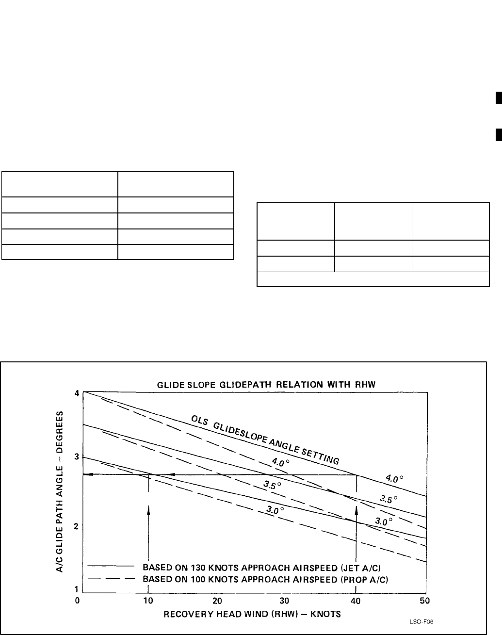
NAVAIR 00-80T-104
ORIGINAL
4-7
situation, this limitation (vice stabilization limits)
usually results in apparent lens lag.
4.2.6 Effects of Deck Motion. During flight
operations, deck motion seldom exceeds ±1.5 _ pitch,
±2.2 _ in roll, and 5.5 feet in heave. Using basic
geometry, each 1-foot aircraft vertical deviation from
optimum glideslope moves the hook touchdown point
forward or aft in the landing area by the following
distances:
BASIC
GLIDESLOPE ANGLE DISTANCE IN FEET
3_19.1
3.5_16.4
3.75_15.3
4_14.3
Thus, 5.5 feet in heave will move the hook
touchdown point ±90 feet on a 3.5_ glideslope. Note
also that 3_ of pitch (1.5_ up, 1.5_ down), although not
exceeding lens stabilization limits, equates to 24.1 feet
of vertical ramp movement (based on CVN-71’s
461-foot pitch axis to ramp distance).
4.2.7 Effective Glideslope Due to Wind and
Deck Motion. The glideslope angle, referred to as
the basic angle aboard ship, is the fixed pitch angle
around which the lens assembly stabilizes. A basic
angle setting of 3.5_ is most commonly used, with 4_
used for higher wind-over-deck conditions (38+ knots)
or on the small decks when hook-to-ramp clearance is
near the 10-foot minimum. In moderate wind-over-deck
conditions (32 to 37 knots), a 3.75 _ basic angle may be
desirable. In Figure 4-7, note that decreased closure rate
of aircraft to ship caused by wind-over-deck reduces the
actual glideslope flown (effective glideslope).
WIND OVER
DECK
(KNOTS) BASIC ANGLE
(DEGREES) EFFECTIVE
GLIDESLOPE*
35 4 3.2
30 3.5 2.8
*Based on a 130-knot approach speed
Aircraft landing stress limits are predicated on
moderate deck conditions. Extreme deck motion may
significantly increase these landing stresses; the ramp
Figure 4-7. Glideslope Glidepath Relation with RHW
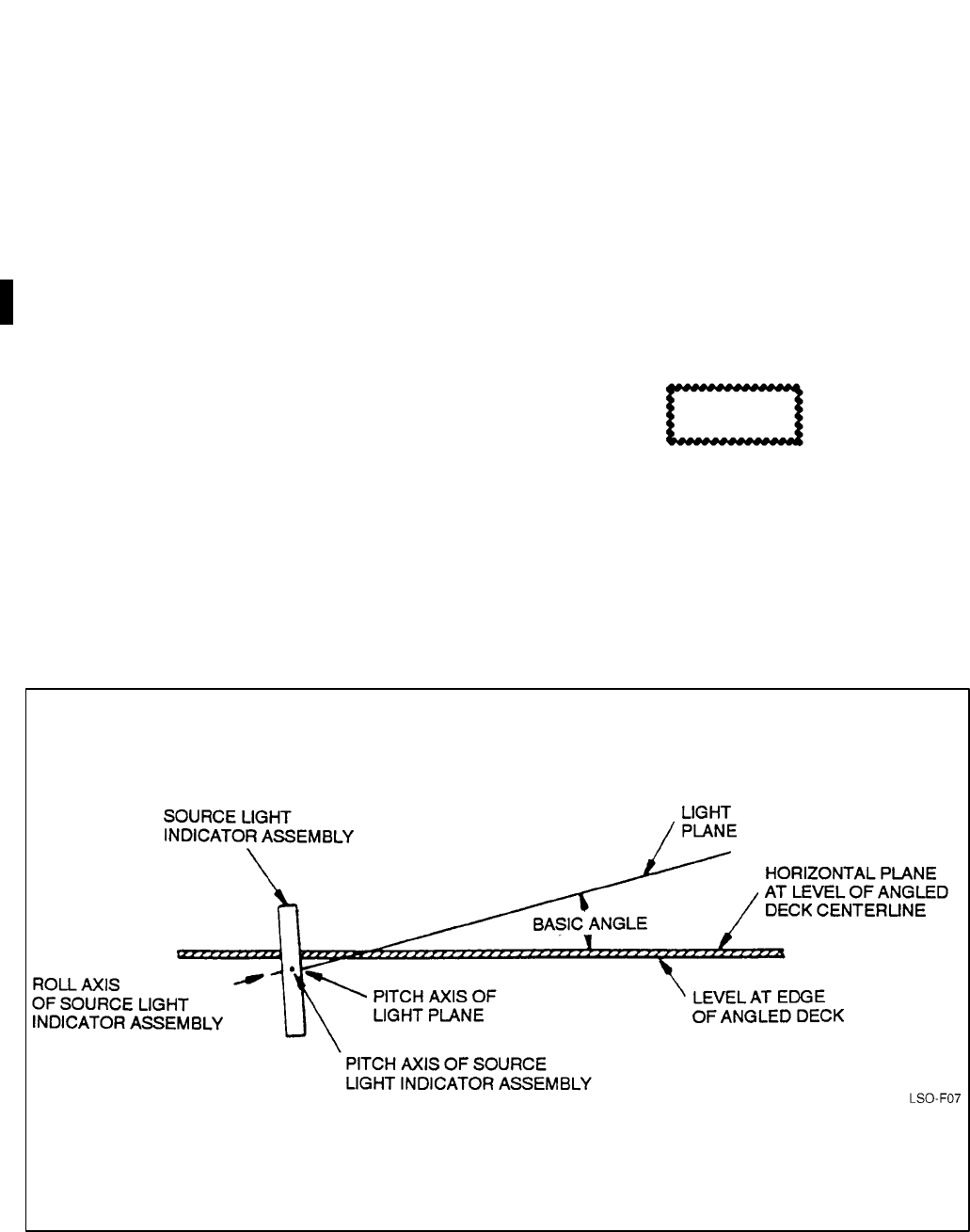
NAVAIR 00-80T-104
ORIGINAL
4-8
coming up at touchdown increases relative sink rate.
Additionally, 1_ of ramp down is the same as adding 1_
to the glideslope as far as aircraft landing stresses are
concerned. These deck motion factors are among the
most critical to consider when landing aircraft on
carriers.
During pitching deck conditions the aircraft hook
may not engage the crossdeck pendant at the optimum
angle. This may result in an apparent increase in the
frequency of hook-skip bolters.
4.2.8 RoIl Angle and Hook-to-Eye. The lens
assembly may be tilted about two horizontal planes, at
right angles to each other, the lens roll axis is parallel to
the angle deck centerline, and the lens pitch axis is
perpendicular to the angle deck centerline. The tilt in
pitch, referred to as the basic angle, is seldom changed
during a recovery (3.5_, 3.75_, or 4.0_) (Figures 4-8
and 4-9). Moving the lens about the roll axis rolls the
light plane, causing the glideslope at the centerline of
the landing area to be raised or lowered. This compen-
sates for the various H/E distances to provide a constant
hook path for all aircraft (Figure 4-10). H/E distance,
which varies between aircraft, is the vertical distance
between the hook path and the pilot’s eye path relative
to the carrier (Figure 4-11). Aircraft Recovery Bulletin
No. 62-12 provides H/E values for all aircraft and
configurations. These H/E values, along with basic
angle, desired hook touchdown point, and ship’s static
pitch/roll mistrim, are used by the FLOLS system to
calculate and set the proper lens roll angle. Roll angles
vary from 0 to 15 units. At 7.5 units of roll, the lens is
vertical (zero tilt); at 15 units, the top of the lens is
canted 7.5_ outboard providing proper ramp clearance
for the largest H/E aircraft. The selected basic angle will
not change when the lens roll angle is increased or
decreased.
CAUTION
Because of roll angle, extreme off-center
approaches for aircraft with large H/E values
may provide hazardous ramp clearance.
H/E values for most aircraft are such that the lens is
upright or tilted outboard for normal configurations and
normal hook touchdown points (a positive roll angle,
greater than 7.5 units). No roll angle or basic angle
settings are used for MOVLAS as the LSO manually
Figure 4-8. Determination of Basic Angle
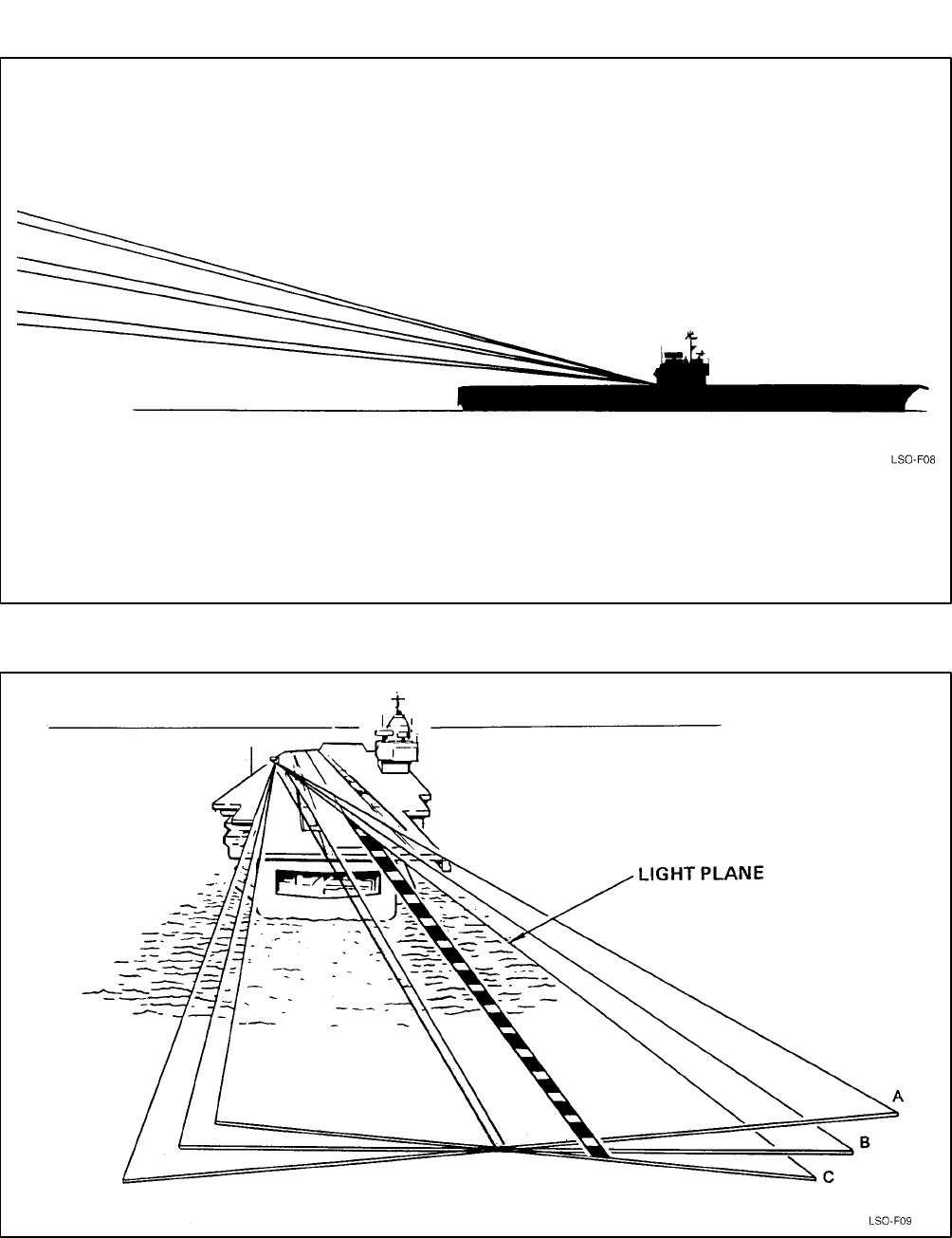
NAVAIR 00-80T-104
ORIGINAL
4-9
Figure 4-9. Effects of Pitch Angle (Basic Angle) Changes on Light Plane
Figure 4-10. Effects of Hook-to-Eye Changes on Light Plane
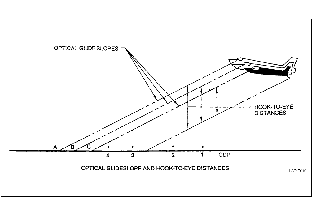
NAVAIR 00-80T-104
ORIGINAL
4-10
Figure 4-11. Optical Glideslope and Hook-to-Eye Distances
controls the ball to establish the proper glideslope. Most
field optical landing systems use only basic angles; no
roll angle adjustments are made, and each aircraft will
have a different touchdown point based on its H/E
value.
All published lens settings are intended to provide
optimum hook glidepath, with a hook touchdown point
halfway between the number two and three crossdeck
pendants. Roll angle places the visual glideslope some
distance above the hook glideslope which corresponds
to each aircraft’s H/E distance. H/E (in feet) is
determined for each aircraft while properly configured,
flying on-speed attitude, and with a centered ball. For
many aircraft, a change in configuration will change
H/E distance. H/E values for various configurations are
specified in the Recovery Bulletins. If no preconfigured
H/E pushbutton is available for the aircraft, configura-
tion and adjustment for a nonstandard H/E must be
made for FLOLS to provide the desired glide-path and
hook touchdown point. Failure to maintain optimum
aircraft attitude to touchdown may result in engagement
of other than the targeted wire even with the aircraft on
the visual glideslope (i.e., pilot sees a centered ball) at
touchdown.
Deck centerline camber (i.e., the centerline is higher
than the deck edge) is for water drainage. On most decks
it is approximately 4 inches. All lens settings in the
Recovery Bulletins compensate for deck camber.
4.3 MANUALLY OPERATED VISUAL
LANDING AID SYSTEM
The Mk 1 Mod 2 MOVLAS is a backup shipboard
visual landing aid system that is used when the primary
optical system (FLOLS) is inoperable, when stabiliza-
tion limits are exceeded, or for pilot/LSO training. The
system presents glideslope information in the same
visual form presented by the FLOLS system. There are
three installation stations aboard ship (Figure 4-12):
STATION 1: Installation is immediately in front
of the FLOLS and utilizes the FLOLS waveoff,
datum, and cut light displays.
STATION 2: Installation is completely indepen-
dent of the FLOLS. Because of cable resistance,
it must be located on the port side not less than 75
feet nor more than 100 feet aft of the FLOLS
assembly.
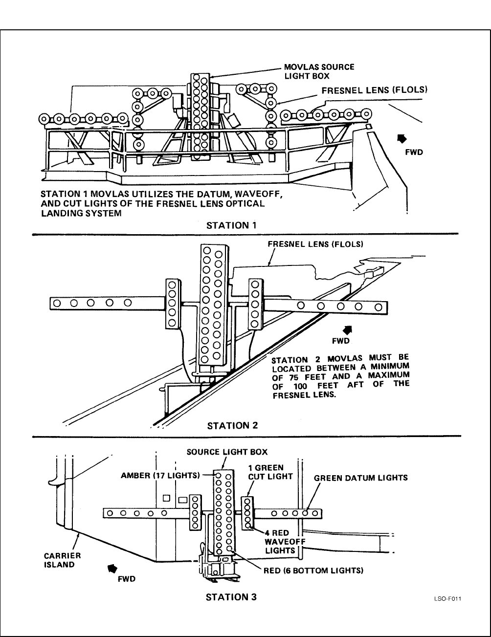
NAVAIR 00-80T-104
ORIGINAL
4-11
Figure 4-12. Manually Operated Visual Landing Aid System (MOVLAS) Mk 1 Mod 2 Shipboard, General
Arrangement

NAVAIR 00-80T-104
ORIGINAL 4-12
STATION 3: Installation is mounted on a base as-
sembly located on the flight deck on the starboard
side. The approximate position is aft of the island
and outboard of the safe parking line. The exact
location can be determined by the air officer, LSO,
or other cognizant personnel (i.e., CAFSUs).
Utilization of this position may require on-deck
aircraft movement.
4.3.1 MOVLAS Construction. The light box
contains 23 vertically mounted lights that provide the
meatball display. A set of perforated doors may be
latched open or closed in front of the unit. When closed,
the light intensity is decreased to approximately 3.5
percent of that with the shutters open. This doubles the
range of light intensity control available from the power
controller box and ensures adequate intensity range for
day and night use. The bottom six lamps are red to
provide coloring similar to the FLOLS low cell (they do
not flash). Two toggle switches mounted on the LSO
controller disable the lower and uppermost three lamps.
With either switch in the disabled position, the control-
ling LSO can indicate to the pilot a glideslope position
beyond the limits of the normal FLOLS system (i.e.,
ball off the top/bottom of the lens).
Note
Air wing policy should determine the posi-
tion of the upper lamp enable switch. The
lower lamp enable switch shall remain in the
Enabled On position at all times.
For MOVLAS stations 2 and 3, a datum box unit is
mounted on each side of the light box and contains five
separate datum lamps, four waveoff lamps, and one cut
lamp. The single perforated door is used to increase the
range of intensity control for the waveoff and cut lights.
Perforated doors are used for all lamps which are not
continuously lighted to ensure sufficient line voltage
across the filaments to light the lamp instantly.
The LSO controller is located at the LSO worksta-
tion. A handle on the controller enables the LSO to
select the position of the meatball. The pickle switch is
attached to the end of the controller handle. As the
handle on the LSO controller is moved up or down, it
lights three or four consecutive lamps in the light box,
thus providing an LSO controlled meatball. Detents are
located at the horizontal or centered ball position and
near the bottom just prior to the red ball going off the
bottom.
Independent controls are provided for intensity
adjustment of the datum and source lights, with a
combined control for the cut and waveoff lights. When
activated, waveoff lights flash at a rate of 90 times a
minute.
Because the controller detents proved inadequate in
use, MOVLAS Service Change No. 13 added a repeater
light box to the system. The repeater monitors every
other light on the light box and allows the LSO to
visually monitor the glideslope he is presenting to the
pilot while facing the approaching aircraft (Service
Change No. 13 also added the disable switch to the
uppermost three lamps). A separate MOVLAS repeater
is also integrated into the left side of the LSO HUD
console. A small panel opens behind which there is a
mirror that reflects the MOVLAS repeater image to the
LSO.
Additional information about MOVLAS may be
found in NAVAIR 51-40ACA-3 (Mk 2 Mod 2 land-
based MOVLAS) or NAVAIR 5l-40ACA-2 (Mk 1
Mod 2 shipboard MOVLAS).
4.4 LSO HEADS-UP DISPLAY
The Mk 1 Mod 0 LSO HUD console system (Figure
4-13) provides the LSO with real time aircraft, deck
motion, deck status, and trend information in a consoli-
dated display. It provides the LSO a dynamic visual
display of all critical aircraft landing factors including
range, rate of descent, true or closing airspeed, and
lineup and glideslope data, as well as indicators of
wind-over-deck relative to the landing area, clear/foul
deck status, aircraft type, and approach mode. Ramp
motion/ship’s trim information is also available. A
MOVLAS repeater, 21MC intercom, and two UHF
radio barrel switch controls are also located on the
console.
4.5 LSO BASE CONSOLE
The LSO Base Console (Figure 4-14), located to the
right of the LSO HUD, consolidates several essential
LSO equipment items. These include: the stabilization
remote panel (A230A), FLOLS lighting remote control
panel (A730A), radio set control panel (WSC-3), deck
status light control panel, 19MC intercom panel or
monitor, phone panel assembly, and a connector panel
assembly with receptacles for sound powered phones,
Aldis lamp, LSO handsets, and portable switch assem-
blies (pickle switches).
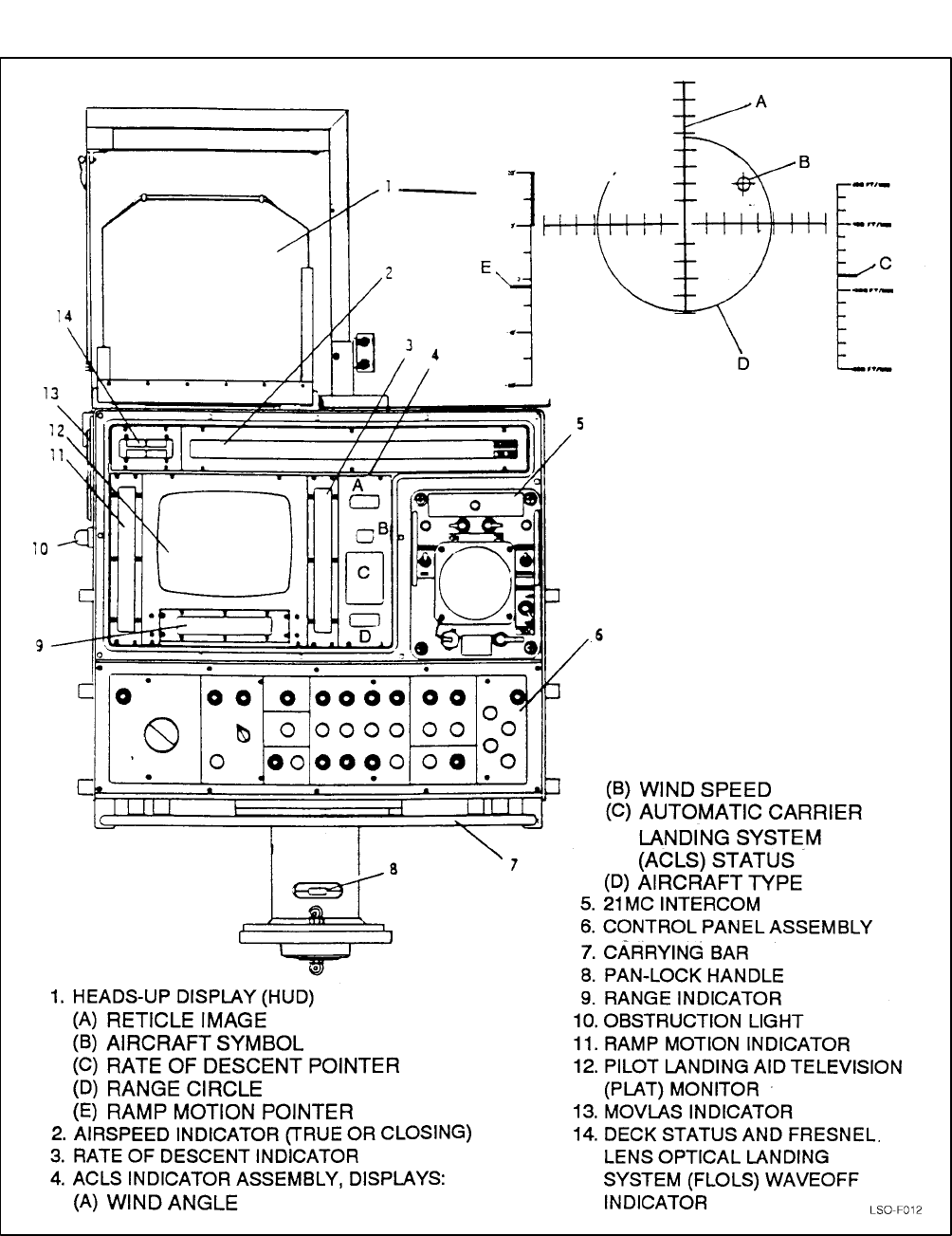
NAVAIR 00-80T-104
ORIGINAL
4-13
Figure 4-13. Mk 1 Mod 0 LSO Heads-Up Display (HUD) Console
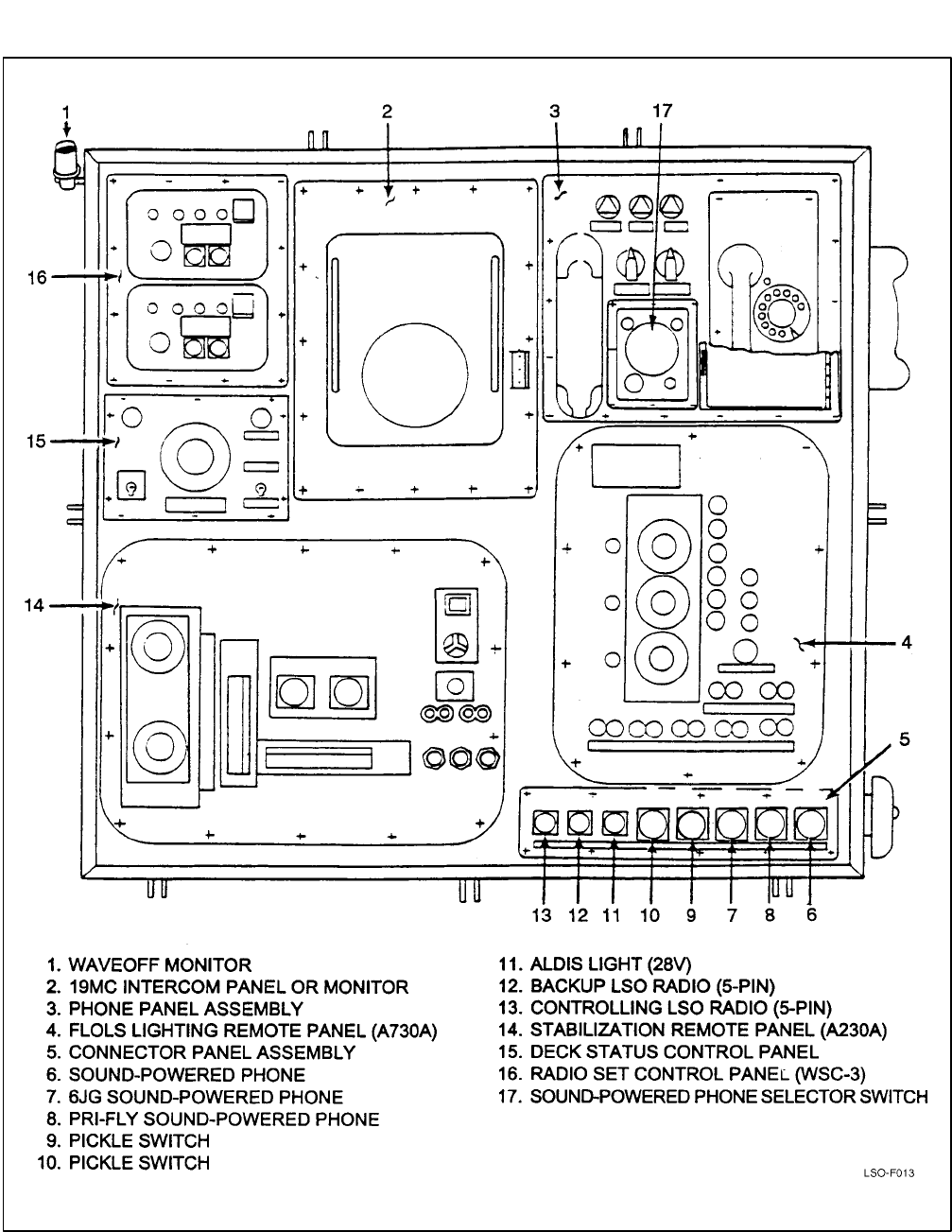
NAVAIR 00-80T-104
ORIGINAL 4-14
Figure 4-14. LSO Base Console
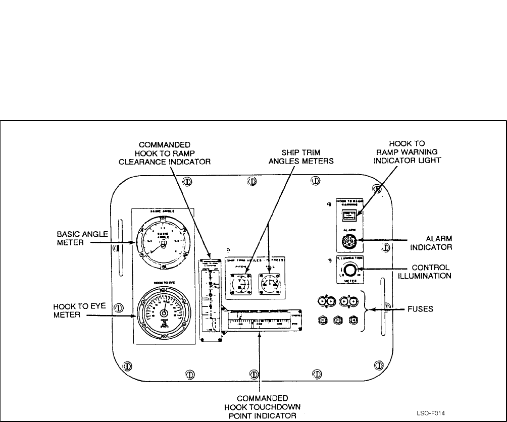
NAVAIR 00-80T-104
ORIGINAL
4-15
The stabilization remote panel (A230A) (Figure
4-15) contains six indicators, including: a basic angle
meter, commanded hook-to-ramp clearance indicator,
commanded hook touchdown point indicator, ship trim
angle meters (pitch/roll), and H/E meter (ship
dependent).
The FLOLS lighting remote control panel (A730A)
(Figure 4-16) provides LSO controls and indicators for
datum, cut, and waveoff light intensity, low cell
intensity, source light intensity, system go/no-go
indicators, and pushbutton cut and waveoff light
switches.
Figure 4-15. Stabilization Remote Panel (A230A)
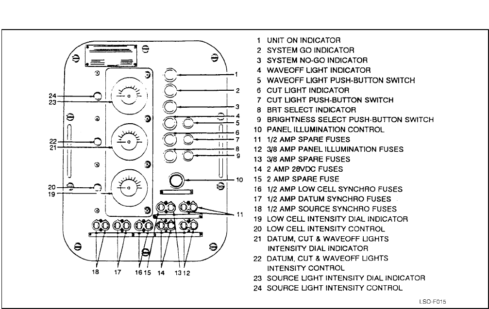
NAVAIR 00-80T-104
ORIGINAL 4-16
Figure 4-16. Lighting Remote Control Panel (A730A)


NAVAIR 01-F14AAP-1
ORIGINAL
5/(6 blank)

NAVAIR 00-80T-104
ORIGINAL
5-1
CHAPTER 5
Shore-Based Procedures
5.1 BRIEFING AND DEBRIEFING
5.1.1 Precarrier Briefing. The LSO shall ascer-
tain that pilots/NFOs are thoroughly prepared in all
respects for carrier landing operations.
The following subjects shall be covered by the LSO
in briefings for pilots/NFOs prior to and, as deemed
necessary, during carrier landing operations:
1. Carrier configurations
a. Recovery systems
(1) Fresnel lens, MOVLAS, LSO talkdown
approaches, and ACLS procedures (if
applicable)
(a) Systems design
(b) Capabilities
(c) Limitations
(d) Special procedures.
(2) Arresting gear and barricade
(a) Design
(b) Capabilities
(c) Limitations.
b. Deck configuration
c. PLAT/ILARTS
d. Deck, hull, and mast lighting system and
control
2. Communications and communications discipline
a. Channelization
b. Voice reports.
3. Carrier operating procedures
a. Launch and departure procedures
(1) Deck procedures: Taxi/power
considerations
(2) Catapult procedures
(3) Case I/II/III departure procedures
(4) Voice reports
(5) EMCON
(6) Launch emergencies: Ship, aircraft (con-
sult aircraft NATOPS flight manual).
b. Check-in and marshal procedures
c. Approach procedures
(1) Case I/II/III
(2) CV-1/2/3 approaches
(3) Mode I/IA/II/III ACLS, ASR, self-
contained approaches
(4) EMCON/ZIP LIP
(5) Downwind recovery
(6) Voice reports
(7) NORDO aircraft approaches.
d. VFR pattern
(1) Entry
(2) Break (interval)
(3) Downwind
(4) Abeam position
(5) Approach turn

NAVAIR 00-80T-104
ORIGINAL
5-2
(6) Spin
(7) Delta.
e. Glideslope techniques
(1) Start position
(2) Airspeed/angle-of-attack control
(3) Lineup
(4) Glideslope error corrections
(5) Touchdown
(6) Effects of wind
(7) Effects of deck motion
(8) LSO calls (standard phraseology and
responses)
(9) MOVLAS/pitching deck recovery.
f. Bolter
g. Waveoff
(1) Mandatory
(2) Own waveoff
(3) Technique.
h. Night operations
(1) Lack of depth perception
(2) Radar altimeter
(3) Instrument scan/scan transition
(4) Aircraft lighting.
i. Bingo procedures
(1) Fuel state
(2) Profile.
j. Barricade procedures
(1) LSO-to-pilot 10-line barricade brief.
k. Emergency procedures
(1) LSO equipment malfunction
(2) Ship equipment malfunction
(3) Aircraft emergencies
(a) Low fuel state
(b) Hook malfunction
(c) Brake failure
(d) Single engine/compressor stalls
(e) Landing gear malfunctions
(f) Launch bar/tow link malfunctions
(g) Ditching
(h) Fire
(i) Loss of canopy
(j) Flight control malfunctions
(k) Other emergencies from Section V of
aircraft NATOPS flight manual.
(4) Ejection.
4. Operations and air department briefings. The
following areas should be briefed by cognizant
operations and air department personnel prior to
CV operations. Student naval aviators shall be
briefed by the parent squadron LSO.
a. Deck handling procedures
b. Air operations procedures
c. Communications
d. Catapult launch procedures
e. CATCC procedures
f. SAR procedures.
5.1.2 Simulator Procedures Briefing. The
LSO shall conduct a formal briefing with all pilots prior
to simulator syllabus flights covering the procedures
and training objectives to be accomplished.

NAVAIR 00-80T-104
ORIGINAL
5-3
5.1.3 Conduct of Field Carrier Landing
Practice Briefings. The following subjects shall be
covered by the LSO in lectures prior to and, as
necessary, during FCLP training:
1. Fresnel lens, MOVLAS, LSO talkdown ap-
proaches, and ACLS procedures (if applicable)
a. Systems design, capabilities, and limitations
b. Special procedures.
2. Communications and communications discipline
3. General FCLP procedures
a. Course rules
b. Pattern, turns, and dimensions
c. Altitude control
d. Speed control and angle of attack
e. Attitude control
f. Lineup
g. Landing
h. Night procedures
i. APC control (if applicable)
j. Emergency procedures
k. LSO calls (standard phraseology and
responses).
4. Specific FCLP procedures
a. Takeoff/entry
b. Climbout
c. Break (interval)
d. Upwind turn
e. Downwind leg
f. Landing checklist
g. Abeam position: “(Modex), abeam, gear,
(fuel state), (pilot’s name)”
Note
If unable to call “Abeam, gear” (e.g., gear in
transition or aircraft on the ball), make the
gear call prior to the ball call on the first pass.
h. Approach turn
i. Voice report (at normal meatball acquisition
position)
(1) Modex number
(2) Type aircraft
(3) Ball or Clara
(4) Fuel state (nearest 100 pounds)
(5) Auto (if applicable).
j. Glideslope and entry
k. Glideslope technique
l. Landing
m. Waveoff
(1) Mandatory (including test/close-in
waveoff)
(2) Own waveoff
(3) Techniques involved.
n. Aircraft lighting (determined by local conditions)
o. Charlie procedures
p. Bingo procedures
q. Loss of LSO radio or two-way communications
r. NORDO aircraft procedures.
5.1.4 Postsimulator/Postflight Debriefing.
The LSO shall debrief each pilot as soon as practicable
following each simulator or FCLP flight regarding
procedures and landing performance during the period.
The LSO should use this debriefing to discuss any

NAVAIR 00-80T-104
ORIGINAL 5-4
significant trends in landing performance and recom-
mended corrective action.
5.2 SIMULATOR TRAINING
Carrier landing simulators shall be used to the
maximum extent practicable in preparation for ship-
board operations. The LSO shall develop a simulator
syllabus to supplement FCLP training and reinforce
precarrier briefing material. Each pilot should complete
the simulator syllabus prior to carrier operations.
5.2.1 CV Approach/Departure Procedures.
The simulator training syllabus should include, at a
minimum, one complete case III departure, marshal,
ACLS approach, and recovery. Loss of radio proce-
dures should be reviewed and executed. Environmental
conditions should be varied and the pilot should be
required to execute both precision and nonprecision
approaches to minimums.
5.2.2 Emergency Procedures. The carrier land-
ing simulator syllabus should include emergency proce-
dures training in the following areas:
1. NORDO (in all phases of flight)
2. Loss of navigation aids
3. Common aircraft emergencies (peculiar to aircraft
type)
4. Aircraft emergencies/abnormal configurations af-
fecting landing performance
5. Shipboard casualties (i.e., failure of navigation
aids, drop lights, lens, etc.)
6. Pitching deck recovery
7. Computation of Bingo fuel requirements and
execution of Bingo profile.
5.3 FCLP
Field carrier landing practice is defined as that phase
of required flight training that precedes carrier landing
operations. It should simulate, as nearly as practicable,
the conditions encountered during carrier landing
operations.
5.3.1 Personnel Requirements. A qualified
LSO shall be on station for all day FCLP operations. For
night operations, the qualified LSO shall have an
assistant (not necessarily an LSO or pilot) present
whenever more than two aircraft are in the FCLP
pattern.
5.3.2 Traffic Pattern Control Responsibilities.
Although tower personnel may be responsible for
control of aircraft entering and departing the FCLP
pattern and non-FCLP aircraft during concurrent opera-
tions, the LSO shall monitor all aircraft in the pattern to
ensure proper interval and adherence to briefed FCLP
pattern procedures.
5.3.3 Preflight Briefing. Pilots shall be briefed
prior to each FCLP period in accordance with the
NATOPS flight manual. The following items are to be
included:
1. Takeoff and recovery time
2. Weather briefing
3. Alternate Bingo field
4. Formation procedures
5. Traffic rules and terrain of bounce field
6. Pattern
7. Gross weight limitations
8. Radio discipline
9. Lost communication procedures
10. Field lighting
11. Alternate approach procedures
12. Emergencies
13. Type of field arresting gear and location
14. Waveoff/lineup response
15. No acknowledgment of “ball” call
16. Final recovery instructions
17. Debrief arrangements.

NAVAIR 00-80T-104
ORIGINAL
5-5/(5-6 blank)
5.3.4 Conduct of FCLP. The following equip-
ment checks shall be made by LSOs prior to FCLP
operations:
1. Functional check of visual landing aids (cut and
waveoff lights, pole check, intensity, etc.)
2. All lighting facilities for proper operations
3. Radios
4. Aldis lamp or spotlight (night only).
Each pilot shall have demonstrated proficiency in the
following:
1. Waveoff — at least one waveoff (technique or
test) per FCLP period.
2. Lineup response — at least one test of lineup
response per FCLP period.
3. Simulated shipboard radar controlled approaches
should be practiced during at least one night FCLP
period. Where applicable, FCLP in conjunction
with shore-based SPN-42 is highly desirable to
familiarize pilots with procedures from an ACLS
to visual approach.
4. NORDO approaches — including proper re-
sponse to cut lights and waveoff lights.
5. MOVLAS approaches.
6. Aircraft simulated emergency approaches.
7. Pilot response to no verbal or visual acknowledg-
ment of the ball call should be frequently tested
during FCLP.
Note
Conduct of FCLP during deployed opera-
tions with less than the minimum prescribed
equipment may be conducted at the discre-
tion of the senior cognizant LSO.
5.4 PILOT PERFORMANCE EVALUATION
5.4.1 Minimum Number of FCLP Periods.
Chapter 6 establishes the requirement for FCLP refresh-
er prior to carrier operations when a pilot has not made
a CV landing in over 30 days. The number of FCLP
periods (and total number of FCLP landings) required
to prepare a pilot for CV landings will vary with
individual pilot skills, experience, and currency in
aircraft type. The senior command LSO should submit
to the commanding officer, via the operations officer, a
list of anticipated FCLP requirements for each pilot
prior to commencing precarrier deployment training.
This list should also include simulator requirements.
These requirements should be adjusted as necessary
according to individual performance. The senior com-
mand LSO is ultimately responsible for certifying to the
commanding officer that an individual is prepared for
CV flight operations.
5.4.2 FCLP Performance Records. Fleet squad-
rons shall maintain records of all squadron pilot FCLP
landings from the beginning of shore-based operations
until the end of the next extended deployment.
5.4.3 LSO Certification of Pilot Performance.
FCLP training shall be completed to the satisfaction of
the senior air wing LSO (senior command LSO, if not
assigned to an air wing) prior to carrier qualification.
During this training period, the pilot should demon-
strate his ability to operate with appropriate configura-
tions and simulated emergency conditions. When this
has been completed, an oral or written recommendation
shall be submitted by the senior LSO to the pilot’s
commanding officer certifying pilot day/night FCLP
qualification. In the case when 60 days have elapsed
since a pilot’s last CV landing, the senior command
LSO shall submit a memorandum to the appropriate
staff/type LSO certifying day/night readiness of pilot(s)
to include the number of FCLP periods (day/night) and
number of carrier related simulators. Reciprocal accep-
tance between commands of FCLP qualification and
LSO certification is authorized. The senior LSO shall
recommend revocation of a certification at any time a
pilot’s standard of performance is less than satisfactory.

NAVAIR 01-F14AAP-1
ORIGINAL
5/(6 blank)

NAVAIR 00-80T-104
ORIGINAL
6-1
CHAPTER 6
Shipboard Procedures
6.1 BRIEFING AND DEBRIEFING
6.1.1 Carrier Qualification/Currency Landing
Procedures Briefing. The carrier configurations,
communications and communications discipline, and
carrier operating procedures outlined in the precarrier
briefing discussed in Chapter 5 shall be completed
within 10 days of carrier qualification/currency carrier
landings.
6.1.2 Postflight Debriefing. The controlling
LSO shall debrief pilots as soon as practicable after all
carrier landings. During carrier qualification and cur-
rency carrier landing evolutions, the LSO should
debrief each pilot, if practicable, concerning his day
landing performance prior to night carrier landings.
6.1.3 Pilot Landing Trend Debriefs. The LSO
shall periodically debrief each pilot concerning his
carrier landing trends. Debriefs should be annotated on
the pilot’s Carrier Landing Trend Analysis sheet
(OPNAV Form 3760/7 1) or APARTS-generated trend
analysis forms. For squadrons or detachments cross-
decking, the departing air wing staff LSO shall ensure
the relieving air wing staff LSO receives trend analyses
and written debriefs on all pilots in that squadron or
detachment.
6.1.4 Recurrent CV Procedures Training. The
LSO should conduct CV procedure training periodically
during extended carrier deployments. The training
should include, at a minimum, the following portions of
the precarrier briefing discussed in Chapter 5.
1. Carrier configurations
2. Communications and communications discipline
3. Carrier operating procedures.
6.1.5 Special Operations Procedures
Briefing. The LSO is responsible for briefing proce-
dures pertinent to special carrier recovery operations
(day/night EMCON, E-2 controlled approach, etc.).
6.2 CARRIER QUALIFICATIONS
6.2.1 Definitions
1. Initial carrier qualifications — Pilot’s first day/
night carrier qualification.
2. Requalification — Pilot’s day/night currency
exceeds 12 months in type/model/series. Initial
carrier qualification requirements apply, unless
otherwise specified in paragraph 6.2.
3. Transition carrier qualification — First day/night
carrier qualification in type/model/series aircraft
for aviators that have previously completed initial
day/night carrier qualification in another type/
model/series aircraft (e.g., F-14 to F/A-18). Initial
carrier qualification requirements apply, unless
otherwise specified in paragraph 6.2. Transition
requirements between various series within a
type/model/series (e.g., F-14A to F-14B) shall be
determined by the cognizant typewing/FRS with
Force LSO concurrence.
4. Currency — Pilot meets the currency require-
ments of Figure 6-1.
6.2.1.1 Minimum Landings for Initial,
Transition, and Requalification
6.2.1.1.1 Day Qualification
1. Twelve landings, ten of which shall be arrested.
6.2.1.1.2 Night Qualification
1. Eight landings, six of which shall be arrested.
Note
A pilot attempting initial night qualification
shall fulfill all requirements for initial quali-
fication even though he may have previously
completed day qualification only.

NAVAIR 00-80T-104
ORIGINAL 6-2
DAY
DAYS SINCE LAST
DAY CURRENT REQUIREMENTS
PRIOR TO A DAY LANDING WEATHER DECK DIVERT
FIELD CURRENCY
REQUIREMENT
1-14 days FCLP not required Ships mins ALL conditions N/R 1 arrested landing
15-29 days FCLP refresher at the discretion of
the C.O. TACAN mins Relatively
steady(1), or Divert
available 1 arrested landing
30-59 days FCLP refresher(2) TACAN mins Relatively
steady(1), or Divert
available 1 arrested landing
60 days to 6 months FCLP refresher(2) TACAN mins Relatively
steady(1),
and
Divert
available 4 landings
2 shall be arrested(8)
Dual F/A-18A-D
and F/A-18 E/F
qualification
currency(11)
FCLP refresher(2) TACAN mins Relatively
steady(1),
and
Divert
available
4 landings in the least
current series, 2 shall be
arrested. 1 additional
arrested landing in the
other series if not already
current
6-12 months FCLP refresher(2) 700/3 Relatively
steady(1),
and
Divert
available 4 landings
2 shall be arrested(8)
Dual F/A-18A-D
and F/A-18 E/F
qualification
currency(11)
FCLP refresher(2) 700/3 Relatively
steady(1),
and
Divert
available
4 landings in the least
current series, 2 shall be
arrested. 1 additional
arrested landing in the
other series if not already
current
Greater than 12
months Refer to initial qualification Refer to initial
qualification
NIGHT (3)
DAYS SINCE LAST
NIGHT CURRENT
REQUIREMENTS
PRIOR TO A NIGHT LANDING
OR NIGHT CAT SHOT(6, 7, 9) WEATHER DECK DIVERT
FIELD CURRENCY
REQUIREMENT
1-7 days None Ships mins ALL conditions N/R 1 arrested landing
(T/G or arrested)(10)
8-14 days 1. One day landing that day to
include a day cat shot TACAN mins ALL conditions N/R 1 arrested landing
(T/G or arrested)(10)
OR
2. Two day landings, one of
which shall be arrested, one
day cat shot and not less than
one hour of flight time within a
36 hour period prior to the
night landing
Dual F/A-18A-D
and F/A-18 E/F
qualification
currency(11)
3. None, if the aircrew has had
one night arrested landing in
the other series in the previous
7 days.
N/A
Figure 6-1. Operating Criteria for Qualified Pilots (Sheet 1 of 3)

NAVAIR 00-80T-104
ORIGINAL
6-3
NIGHT(3) (Cont.)
DAYS SINCE LAST
NIGHT CURRENT
REQUIREMENTS
PRIOR TO A NIGHT LANDING
OR NIGHT CAT SHOT(6, 7, 9) WEATHER DECK DIVERT
FIELD CURRENCY
REQUIREMENT
15-21 days 1. Two day landings, one of which
shall be arrested, within a 36
hour period prior to the night
landing. This shall include one
cat shot(4) in the day light hours
preceding the night landing, and
not less than 1 hour of flight time
(day or night).
TACAN mins Relatively
steady(1), or Divert
available 1 arrested landing
Dual F/A-18A-D
and F/A-18 E/F
qualification
currency(11)
2. Two day landings, in that series,
one of which shall be arrested,
within 36 hour period prior to the
night landing. This shall include
one cat shot(4) in the day light
hours preceding the night land-
ing, and not less than 1 hour of
flight time (day or night).
TACAN mins Relatively
steady(1), or Divert
available 1 arrested landing
22-29 days 1. Two day landings, one of which
shall be arrested, within a 36
hour period prior to the night
landing. this shall include one
day cat shot(4) in the day light
hours preceding the night land-
ing, and not less than 1 hour of
flight time (day or night).
TACAN mins Relatively
steady (1), or Divert
available 1 arrested landing
Dual F/A-18A-D
and F/A-18 E/F
qualification
currency(11)
2. Once current in one series refer
to the 8-14 days, requirement 1
or 2 for the other series.
N/A
30-59 days 1. Four day landings, two of which
shall be arrested, within a 48 hour
period prior to the night arrested
landing. This shall include a cat
shot(4) and arrested landing during
the daylight hours immediately
preceding the night landing, and
not less than 1 hour of flight time
(20 minutes of which should be at
night).
700/3 Relatively
steady(1),
and
Divert
available 1 arrested landing
Dual F/A-18A-D
and F/A-18 E/F
qualification
currency(11)
2. Once current in one series refer
to the 8-14 days requirements 1
or 2 for the other series.
N/A
60 days to 6 months Four day landings, two of which shall
be arrested, within a 48 hour period
prior to the night arrested landing. This
shall include a cat shot(4) and arrested
landing during the daylight hours im-
mediately preceding the night landing,
and not less than 1 hour of flight time
(20 min. of which should be at night).
700/3 Relatively
steady(1),
and
Divert
available 2 arrested landings
6 to 12 months Four day landings, two of which shall
be arrested, within a 48 hour period
prior to the night arrested landing. This
shall include a cat shot(4) and arrested
landing during the daylight hours im-
mediately preceding the night landing,
and not less than 1 hour of flight time
(20 min. of which should be at night).
1000/3(5) Relatively
steady(1),
and
Divert
available 4 landings
2 shall be
arrested(10)
Figure 6-1. Operating Criteria for Qualified Pilots (Sheet 2)

NAVAIR 00-80T-104
ORIGINAL 6-4
NIGHT(3) (Cont.)
DAYS SINCE LAST
NIGHT
CURRENT
REQUIREMENTS
PRIOR TO A NIGHT LANDING
OR NIGHT CAT SHOT(9)WEATHER DECK DIVERT
FIELD CURRENCY
REQUIREMENT
Greater than 12
months Refer to initial qualification.
Subj: NOTES FOR PILOT CURRENCY REQUIREMENTS ICO LSO NATOPS FIGURE 6-1
Note 1 — Relatively steady deck is defined as less than 6 feet of ramp movement at the centerline (i.e., ±3 feet change in hook-to-ramp).
Note 2 — See Pilot Performance Evaluation in paragraph 5.4.
Note 3 — For currency purposes, a landing within 1/2 hour of sunset shall not be counted as a night carrier landing unless it is quite dark
due to cloud coverage.
Note 4 — For multi-piloted aircraft with two aviators qualified in model at the controls, catapult launches may be counted by both pilots for
refresher catapult shot criteria.
Note 5 — May be waived to 700/3 by OTC.
Note 6 — Day requirements are good for 36 hours after first night arrested landing.
Note 7 — A fleet experienced aviator whose intention is not to CQ may take a night cat shot if he has completed one day landing and one
cat shot during the 48 hours preceding the night cat shot, or 4 day landings within 72 hours.
Note 8 — Currency requirements must be completed prior to any landings with passengers.
Note 9 — The requirement for 1 hour of flight time does not apply to the night cat shot.
Note 10 — Night T/G landings are not recommended for currency unless operational necessity dictates.
Note 11 — See Dual F/A-18A-D and F/A-18E/F qualification requirements on page 6-6, paragraph 6.3.1, Step 10.
Figure 6-1. Operating Criteria for Qualified Pilots (Sheet 3)
Note
D Night touch-and-go’s are for CAT I
initial carrier qualification and not
intended for pilots who have night
carrier qualified before, nor are they to
be utilized for refresher/currency
where not specifically authorized in
Figure 6-1. Any touch-and-go is re-
quired to be a satisfactory pass in which
an arrestment would normally occur.
For aviators that have previously been
night carrier qualified in any type/
model/series aircraft, qualification re-
quirements shall be reduced from eight
landings to six arrested landings.
DInitial and transition qualification shall
be conducted by a designated training
LSO for that type/model/series air-
craft. This requirement may be waived
by the type commander to utilize a
designated staff LSO. Requalification
of a fleet-experienced aviator may be
conducted by a designated staff LSO.
DWing-qualified LSOs assigned to the
Naval Strike Test Squadron, Patuxent
River, are authorized to conduct day-only
transition carrier qualification and/or re-
qualification of test pilots in lieu of a
training qualified LSO.
6.2.1.2 Waiver Criteria. The minimum require-
ments listed above may be waived by the type com-
mander or his designated representative to not less than
four day and four night arrested landings for fleet-
experienced aviators.* This waiver will be judiciously
granted, contingent upon pilot experience, demon-
strated performance, and only upon recommendation of
the squadron LSO.
______________________
*The term fleet-experienced aviators applies to individuals who have been carrier qualified and operationally current in the
same model aircraft within the last 4 years.

NAVAIR 00-80T-104
ORIGINAL
6-5
6.2.1.3 Training Command Instructors and
Students. As prescribed by Chief of Naval Air
Training.
6.2.2 Limitations for Initial Carrier
Qualifications
1. A qualifying pilot shall not exceed in any period
of continuous flight duty (crew day), as defined by
OPNAVINST 3710.7 series:
a. Ten arrested landings
b. Four night arrested landings
c. Six and one-half hours in the cockpit
Note
For E-2 and C-2 aircraft, the 6.5-hour rule
shall apply to left-seat time (pilot at the
controls) only.
d. Three flights.
Note
A flight begins with the first field takeoff or
carrier catapult launch and ends when (1) the
pilot makes his last arrested landing on the
carrier in that aircraft, or (2) makes a full stop
landing at a field facility. A CQ period that
ends with a divert or bingo shall be counted
as one flight.
2. No longer than 5 days should elapse between the
last FCLP period and the first carrier landing.
When qualification will occur on board a carrier
with IFLOS installed, a minimum of three
IFLOLS FCLP periods shall be flown prior to any
carrier landing.
3. Provided other operational limitations have not
been exceeded and upon the recommendation of
the controlling LSO, the carrier commanding
officer may waive daily landing limitations for
pilots who have been previously night qualified in
any T/M/S to the following:
a. Total arrested landings: 12
b. Total night arrested landings: maximum of 6.
4. A minimum of eight day landings, six of which
shall be arrested, shall be completed prior to a pilot
participating in night carrier qualification. Fol-
lowing completion of the required minimum day
landings, the LSO may recommend to the carrier
commanding officer that the pilot participate in
night qualification landings. Participation in night
qualification landings in no way represents pilot
day qualification. The minimum arrested landings
for initial qualification remain 10 day and 6 night.
If the controlling LSO considers that a pilot’s
performance warrants additional landings, such
recommendation shall be made to the carrier
commanding officer.
5. A minimum of two carrier landings, at least one of
which shall be arrested, the other a successful
touch and go (no bolters), and one catapult launch
shall be completed during the daylight hours
preceding night qualification landings. After
completing the first night qualification landing,
fleet experienced aviators* will be considered to
have satisfied this requirement for a period not to
exceed 36 hours for subsequent night carrier
qualification. The 36-hour rule does not apply to
CAT I pilots.
6. Carrier qualification should be completed within
a 30-day period.
7. During the first night of initial night qualification,
qualifying pilots shall have a minimum of 20
minutes of flight time prior to their first night
landing of that night. This requirement is optional
on subsequent nights.
8. Carrier qualification for fixed-wing aircraft shall
be conducted within divert range of a suitable
shore facility airfield with not less than circling
minimums. If any part of the descent is IFR,
sufficient fuel must be included for a standard
instrument penetration and approach. It is the
responsibility of each participating unit to guaran-
tee that valid Bingo information for their particu-
lar aircraft is available and in use aboard the
carrier.
9. All night carrier aircraft operations shall be
CATCC controlled.
10. Multiplace carrier aircraft shall carry only a
minimum flightcrew aboard during carrier quali-
fication landings. Qualification landings shall not

NAVAIR 00-80T-104
ORIGINAL 6-6
be conducted with qualifying pilots aboard other
than the pilot and/or copilot, unless dictated by
operational necessity, except for necessary trans-
portation to/from the ship.
11. For qualification purposes, a landing within
one-half hour of sunrise or sunset shall not be
counted as a night carrier landing unless it is quite
dark (e.g., because of cloud coverage). The senior
cognizant LSO shall make this determination.
12. Carrier qualifications shall normally be con-
ducted with a minimum ceiling of 1,000 feet and
3 statute miles visibility. When authorized by the
OTC, carrier qualification landings may be con-
ducted with a ceiling of not less than 700 feet and
not less than 3 statute miles visibility.
13. Carrier qualification should not be conducted with
recovery headwinds less than 20 knots or greater
than 40 knots.
14. Deck movement shall not exceed ±3 feet of ramp
motion. The decision to continue qualification
landings when deck motion exceeds ±3 feet rests
with the carrier commanding officer and senior
LSO recommendations.
15. The number of aircraft in the pattern should be
limited to six.
16. During night CARQUAL, CCA shall utilize a
single frequency to control all aircraft in the
CARQUAL pattern.
17. The LSO shall make timely divert recommenda-
tions to the air officer based on unsatisfactory pilot
performance or unsatisfactory CARQUAL condi-
tions around the ship.
18. Aircraft or equipment parked forward of the LSO
platform shall not obstruct the LSO’s ability to
observe any part of the landing area.
19. The carrier commanding officer shall have the
authority to approve waivers or deviations from
the procedures contained herein.
6.2.3 LSO Certification of Pilot Performance.
The cognizant LSO shall report orally and in writing
when individual pilots have completed day/night carrier
qualification. The originals of such reports shall be
delivered to the appropriate squadron commanding
officer or wing commander who will certify the pilot as
day/night carrier qualified. Copies shall be provided for
pilot training jackets and LSO files. Reciprocal accep-
tance between commands of carrier qualification and
LSO certification is authorized. The senior cognizant
LSO may recommend revocation of a qualification
anytime a pilot’s standard of performance is less than
satisfactory.
6.3 CURRENCY CRITERIA FOR CARRIER
QUALIFIED PILOTS
6.3.1 Limitations for Currency/Refresher
Landings. In addition to the criteria established in
Figure 6-1, the following is applicable:
1. Minimum currency requirements established
by Figure 6-1 do not imply adequate pilot
proficiency. Completion of additional landings
required for pilot qualifications, pilot profi-
ciency, and operational readiness of embarked
units is the responsibility of the carrier com-
manding officer and air wing commander.
2. Operating criteria of Figure 6-1 for multipiloted
aircraft shall apply to the pilot at the controls.
However, a divert field is not required if the
qualifying pilot has been night current within 59
days, both pilots are NATOPS qualified in model,
and one pilot is night current. Prior to a pilot’s first
exposure to IFLOLS, a minimum of one IFLOLS
FCLP period shall be flown before any attempted
carrier landing. This requirement is waiverable
only by the carrier commanding officer and CAG.
3. When FCLP refresher is required, unless unusual
operating circumstances dictate, no longer than 10
days should elapse between the last FCLP period
and the first carrier landing.
4. In maintaining night currency, Mode I ACLS
approaches shall be closely monitored to ensure
that consecutive Mode I approaches do not
adversely affect pilot proficiency. Mode I ACLS
approaches shall not be used to regain night
currency once such currency has lapsed.
5. Flightcrew composition for any currency landing
shall be at the discretion of the squadron com-
manding officer.
6. Multiplace carrier aircraft should carry only a
minimum flightcrew aboard during carrier

NAVAIR 00-80T-104
ORIGINAL
6-7
qualification landings. Qualification landings
should not be conducted with qualifying pilots
aboard other than the pilot and/or copilot, unless
dictated by operational necessity, except for
necessary transportation to/from the ship.
7. For currency purposes, a landing within one-half
hour of sunrise or sunset shall not be counted as a
night carrier landing unless it is quite dark (e.g.,
because of cloud coverage). The senior cognizant
LSO shall make this determination.
8. Night landings while at anchor shall not be used
to meet the currency requirements in Figure 6-1
without the specific approval of the carrier
commanding officer.
9. For day or night currency landings, MOVLAS
may be utilized to recover aircraft if deck move-
ment or stabilization limits preclude normal use of
the FLOLS within the limits of Figure 6-1. Use of
the MOVLAS in such circumstances shall be
predicated on LSO currency/proficiency in
MOVLAS control, as determined by the senior
cognizant LSO.
10. OPERATIONAL CURRENCY BETWEEN
F-18A-D AND F-18E/F. In order to be simulta-
neously current in both the F-18A-D and the
F–18E/F, the following conditions must be met.
A particular “background” is defined as one
complete fleet tour.
a. F-18A-D background
(1) Have greater than 30 F-18E/F hours PIC
(2) Full initial F-18E/F Carrier Qualification
completed
(3) Have completed full initial F-18A-D
Carrier Qualification or be in compliance
with F-18A-D Carrier Qualification cur-
rency requirements
(4) Current NATOPS Qualifications in both
F-18A-D and F-18E/F
(5) One flight in both aircraft in the previous
14 days.
b. F-14A-D background
(1) Have greater than 250 F-18E/F hours PIC
(2) Full initial F-18E/F Carrier Qualification
completed
(3) F-18A-D CAT 4 with full initial Carrier
Qualification completed
(4) 30 hours PIC in the F-18A-D, waiverable
to 10 hours with AIRPAC/AIRLANT
approval
(5) Current NATOPS Qualifications in both
F-18A-D and F-18E/F
(6) One flight in both aircraft in the previous
14 days.
Once all of the above requirements are met an
aircrew can operate both the F-18A-D and the F-18E/F
in the carrier environment. Flight in either aircraft will
satisfy the 1 night trap in previous 7-day requirement.
11. The carrier commanding officer shall have the
authority to approve waivers or deviations from
the procedures contained herein.
6.4 NORMAL RECOVERY OPERATIONS
The primary responsibility for determining accept-
able pilot performance during the final approach to the
carrier rests with the LSO.
6.4.1 Personnel Requirements. The following
personnel are required on the LSO platform for day
Case I/II operations:
1. A wing- or training-qualified LSO
2. An assistant LSO (whenever available)
3. A qualified enlisted phone talker
4. A qualified enlisted hook spotter.
The following personnel are required for night/Case
III recovery operations:
1. A wing-qualified LSO
2. An assistant LSO
3. A bookwriter (whenever available)
4. A qualified enlisted phone talker
5. A qualified enlisted hook spotter.
NAVAIR 00-80T-104
ORIGINAL
6-8
The following personnel are optional for all recov-
ery operations:
1. The deck caller
When the CV (N) CO, CAG and CAG LSO desire
to use the deck caller position, it is to be manned
by a qualified LSO team member that has under-
gone proper training by the air wing staff LSO.
Specific responsibilities of the deck caller are:
a. Stand in a position visually in front of the
controlling LSOs with an unobstructed view
of the angle deck and signal if men or
equipment are in the landing area.
b. Signal an obstruction in the landing area (LA)
by raising his hand over his head
c. When all obstructions are clear of the LA, he
lowers his hand and moves behind the control-
ling and backup LSOs.
The presence or absence of the deck status
caller is not an indication of clear/foul deck.
Clear/Foul deck status is signaled to the
LSOs by the AGO and handled per para-
graph 6.4.4.
Used in this way, it is a direct indication to the
controlling and backup LSOs that the waveoff window
is either one hundred feet (obstructions in the LA) or ten
feet (no obstructions in the LA). If the landing area is
obstructed in any manner at the 100-foot waveoff point,
the controlling or backup LSO shall wave the aircraft
off. The deck caller shall not be used as an indicator
of clear or foul deck. The arresting gear officer is the
sole person designated to indicate clear/foul deck status
(LA clear, arresting gear in battery and set for the correct
aircraft), and signals this to all parties via the deck status
lights. When the deck is foul due to obstructions in the
landing area, the deck caller is only indicating that the
100-foot clearance waveoff window shall be used. If
the deck is not obstructed, the deck caller has no
function and moves out of sight. With no deck
obstruction, waveoffs are predicated on the conditional
factors of the approaching aircraft, but in no case will
the clearance be less than 10 feet if the deck is foul.
6.4.2 LSO Responsibilities. These responsibili-
ties include:
1. While embarked aboard the carrier, duty LSOs
shall keep the air officer informed of their
whereabouts during flight quarters.
2. Upon reporting aboard a carrier for carrier opera-
tions, the LSO should meet with the air officer and
CATCC officer to discuss the conduct of air
operations in the LSO’s area of responsibility.
3. The senior embarked LSO is responsible for the
proper indoctrination and training of the LSO
phone talkers and hook spotters. Specific job
responsibilities for phone talkers and hook
spotters shall be defined by the senior LSO.
Additionally, the senior LSO on the platform shall
ensure the proper training and procedures of the
required enlisted watchstanders.
a. Enlisted PHONE TALKER — Has the pri-
mary responsibility for informing LSO’s of
the status of the arresting gear, weight setting,
wire run-out and wire number and shall be tied
into the arresting gear sound powered (6JG)
phone circuit. It is their responsibility to call
“foul deck” when gear is not in battery and any
aircraft is in the groove. The tone and volume
of these calls shall increase as the aircraft
nears the waveoff window. These calls shall
only cease when the deck becomes clear or the
aircraft is waved off.
b. Enlisted HOOK SPOTTER — Responsible to
check aircraft at the 180 (Case I/II) or prior to
1 NM (Case III) position for proper configura-
tion and call: “aircraft type, gear down, hook
up/down and good/flashing approach light.”
They shall be tied to PriFly, CCA, FLOLS and
ILARTS control rooms via sound powered
(11JG) phone circuit. The Hook Spotter shall
call “Lens set, aircraft type” for each
approach. They shall also notify the LSOs of
any FLOLS or ILARTS degrade or failure.
4. The senior LSO on the platform is responsible for
the conduct of all platform operations and ensur-
ing all team members are thoroughly briefed
regarding platform procedures.
5. The senior cognizant LSO on the platform shall at all
times ensure that the assigned controlling and

NAVAIR 00-80T-104
ORIGINAL
6-9
backup LSOs are of sufficient experience and
qualification level given the present operational
situation. Factors that should be considered in
determining controlling and backup LSO assign-
ments include, but are not limited to, the following:
a. Day/night recovery operations
b. Weather and environmental conditions (ceil-
ing, visibility, winds)
c. Deck motion
d. MOVLAS proficiency (if MOVLAS in use)
e. LSO platform equipment malfunctions (e.g.,
PLAT, HUD, radio)
f. Pilot proficiency/currency
g. Aircraft fuel state, aircraft with multiple
approaches
h. Aircraft malfunctions
i. LSO currency in controlling type aircraft
recovering
j. Shipboard equipment malfunction (e.g., miss-
ing CDP)
k. Deck conditions (e.g., obscured lineup refer-
ence, static mistrim)
l. Type of recovery operations (e.g., CARQUAL,
CARQUAL refresher, normal embarked opera-
tions, EMCON operations).
The senior cognizant LSO on the platform is ulti-
mately responsible for balancing the need to conduct
LSO training with the operational realities of the current
situation. When conducting LSO training, close super-
vision by a wing- or staff-qualified LSO is required. The
supervising LSO, if not specifically functioning as the
controlling or backup LSO, may consider utilizing a
third UHF handset and/or pickle while conducting
training of junior LSOs.
6. The LSO shall make the following equipment
checks prior to recovery operations:
a. Functional check of visual landing aids
b. All lighting facilities for proper operation
(centerline, landing area lights and deck status
lights)
c. Radio check prior to each recovery (EMCON
permitting)
d. Relative wind indicator
e. Sound-powered phones
f. Windscreen operation
g. Escape net condition and evacuation route
h. Platform safety equipment
i. Aldis lamp or spotlight (night only)
j. LSO HUD
k. PLAT/ILARTS on and adjusted.
7. The air officer/LSO shall keep each other in-
formed concerning conditions that affect the
recovery of aircraft, including malfunctioning or
inoperative equipment, aircraft emergencies,
wind and weather conditions, and ship’s trim and
list.
8. During recovery operations, LSO responsibilities
include the following:
a. Controlling all fixed-wing aircraft approaches
after the 180° position
b. Ensuring that approaching aircraft are prop-
erly configured
c. Monitoring the operation of the FLOLS and
crosschecking the approach radar/ILS glide-
path angle setting
d. Assisting in controlling aircraft that have
radio failure by flashing the cut or waveoff
lights in accordance with standard NATOPS
visual signals
e. Whenever possible, maintaining visual con-
tact with all aircraft in the Case I/II/III pattern
f. Monitoring wind-over-deck and deck motion
g. Assisting pilots through informative, advi-
sory, and imperative communications to

NAVAIR 00-80T-104
ORIGINAL 6-10
maintain approach parameters within
acceptable limits
h. Monitoring arresting gear settings, lens set-
tings, and deck status
i. Evaluating aircraft approach performance and
recording deviations for postflight pilot
debriefs
j. Determining acceptable aircraft performance
during the final approach, and waving off
aircraft that exceed or will exceed acceptable
approach parameter limits.
9. The LSO should be familiar with the landing
characteristics of each aircraft under his control as
described in the individual aircraft’s NATOPS
flight manual. Additionally, he should have a
working knowledge of the effects of aircraft
malfunctions upon approach configuration and
speed, pilot workload, and flight characteristics.
10. It is the LSO’s responsibility to wave off aircraft
in sufficient time for the pilot to effect a safe
maneuver utilizing standard procedures. Wave-
offs necessitated by poor pilot technique that
could result in an in-flight engagement shall only
be initiated by the LSO.
6.4.3 Recovery Procedures for Final
Approach. The pilot shall be familiar with proce-
dures pertaining to the carrier landing pattern and
approaches delineated in Chapter 5 of the CV NATOPS
Manual.
6.4.3.1 Specific LSO and Pilot Recovery
Procedures
1. Transition to LSO control occurs at the 180°
position in the Case I/II pattern, at 3/4 nm for a
Case III precision approach (1-1/4 nm for a jet/
1 nm for a turboprop nonprecision approach), or
upon transmission of “Paddles contact.”
2. The LSO radio transmission “Paddles contact”
may occur any time during an approach when the
LSO visually determines that an aircraft requires
additional control to arrive within acceptable start
parameters. Once “Paddles contact” has been
transmitted, the LSO assumes control and
CATCC should refrain from further transmissions
until the completion of the approach, or at such
time the LSO elects to return the aircraft to
CATCC control.
3. In the Case I/II pattern, the LSO shall monitor
each aircraft’s approach turn from the 180°
position. He shall immediately wave off any
aircraft that will fly too short a groove length. For
Case III approaches, the LSO should monitor each
aircraft’s CCA and be prepared to initiate
“Paddles contact” control.
4. At the normal “Ball” call position (i.e., rolling
wings level in the groove for Case I/II, or at
approach minimums for Case III), when the pilot
has usable FLOLS or MOVLAS, lineup, and
angle of attack reference, the following shall be
transmitted (if not EMCON or ZIP LIP): Modex
number, type aircraft, “Ball,” fuel state to the
nearest hundreds pounds, “Auto”/“Coupled” (if
applicable). If the pilot does not have glideslope
reference (e.g., no ball, sun glare, or poor
visibility), then the call “Clara” shall replace the
ball call. If the pilot does not have usable lineup
information (e.g., wet landing area, sun glare, or
poor visibility), then the call “Clara lineup” shall
be transmitted.
5. If the pilot is experiencing any aircraft difficulty
that may significantly affect his ability to fly a safe
approach and landing, he shall make every effort
to notify the ship (through CATCC, Marshal,
Tower, etc.) prior to final approach. In any case, he
shall inform the LSO of the difficulty at the “Ball”
call. Such difficulties are not limited to aircraft
configuration problems alone; loss of primary
attitude reference, angle of attack malfunction,
controllability problems, pilot vertigo, or other
difficulties that may necessitate additional LSO
assistance should be conveyed.
6. The pilot shall report loss of meatball (i.e.,
“Clara”); if no timely amplifying verbal informa-
tion is received from the LSO, he shall initiate his
own waveoff.
7. If APC is disengaged or a Mode I approach is
downgraded, “Manual” or “Downgrading”
should be reported.
8. During ZIP LIP or EMCON conditions, or for a
NORDO aircraft, the LSO shall acknowledge
control of the aircraft on final approach with a
NAVAIR 00-80T-104
ORIGINAL
6-11
steady (3-second) flash of the cut lights. In doing
so, the LSO is also acknowledging that the pilot
has meatball acquisition, lineup reference, and
angle of attack. Subsequent flashes of the cut
lights by the LSO command a pilot response of
adding power, the degree of which is indicated by
the duration of the cut light signal.
6.4.4 Foul Deck Waveoff. The waveoff point is
defined as a moving window through which the aircraft
passes and is the latest point where normal pilot
technique will result in a safe waveoff. Many factors
must be considered in determining this point, including
aircraft/engine performance, approach dynamics, and
environmental conditions (i.e., sink rate, angle of bank,
deck movement, visibility).
Foul deck waveoff responsibility rests equally with
the controlling and backup LSOs. Additionally, when in
the opinion of the air officer, the deck will remain foul
throughout an aircraft’s approach (i.e., arresting gear
malfunctions, personnel or equipment in the landing
area, etc.), he should advise the LSO via the 5MC, “No
chance, foul/closed deck.” The LSO shall immediately
initiate the waveoff using the FLOLS/ MOVLAS wave-
off lights and a UHF radio transmission (EMCON
permitting).
With an aircraft crossing the ship’s wake during
Case I/II operations, or with an aircraft approaching
3/4 nm during Case III operations, the controlling and
backup LSOs shall each raise their pickle switch arm
above their heads as a visual signal and reminder
anytime the deck status is foul (except for MOVLAS,
when the backup LSO is the only LSO to raise his arm).
The LSOs shall lower their arms only upon receipt of a
clear deck signal, or upon waving off the approaching
aircraft for a foul deck.
During normal recovery operations, the LSO shall
initiate a foul deck waveoff such that normal waveoff
response will allow the aircraft to pass no closer than 10
feet to the landing area. If aircraft, personnel, or
equipment are in the landing area, the waveoff shall
prevent the aircraft from passing within 100 feet of the
highest obstacle in the landing area.
If at any time doubt exists as to the condition
causing a Foul Deck, in the interest of safety,
100 feet window SHALL be the default.
6.4.5 Optical Landing System Limits. The
LSO must be cognizant of the stabilization limitations
of the FLOLS. Stabilization limits vary with individual
FLOLs, pitch severity, pitch rate, and associated roll
and heave. The LSO shall consider utilizing MOVLAS
when FLOLS stabilization has, in the LSO’s estimation,
been exceeded. The recommendation to utilize
MOVLAS must take into account air wing MOVLAS
currency and response, LSO MOVLAS proficiency,
and all environmental conditions.
6.4.6 Wind Over Deck (WOD) Requirements.
Optimum and minimum RHW information is contained
in Aircraft Recovery Bulletin Nos. 10-10, 26-, and
29-series. RHW should be maintained as close as
possible to the optimum velocity and the centerline of
the landing area.
CAUTION
The LSO shall immediately inform the air
officer of any adverse wind conditions
unsafe to aircraft recovery, and the air officer
shall inform the LSO of downwind recovery
situations. EMCON conditions permitting,
pilots shall be advised of adverse wind
conditions or downwind recoveries.
6.4.7 Safety Precautions. The LSO platform
shall be manned when directed by the air officer, and at
all times when he broadcasts, “Man all recovery
stations.” If access to the LSO platform is obstructed
(e.g., by turning aircraft spotted for launch), the LSO
team shall be readily available to man their recovery
station as soon as the area becomes clear. Once the LSO
platform is manned with the required personnel of
paragraph 6.4.1, the LSO shall report “manned and
ready” to the air officer. The LSO platform shall be
manned and ready prior to activation of the OLS for
NAVAIR 00-80T-104
ORIGINAL
6-12
fixed-wing recoveries. Operation of the OLS for use as
a reference for V/STOL aircraft will not normally
require the presence of a fixed-wing LSO.
If, during launch or recovery operations, any part of
the aircraft strikes the ramp, aircraft, or equipment on
deck or ship’s structure other than normal flight deck
protrusions (crossdeck pendants, flight deck light
covers, ILARTS centerline cameras, PLAT heads, or
waist catapult ramp), no further effort shall be made to
effect a normal carrier arrestment. A divert or barricade
is required in this case.
6.4.8 MOVLAS Training. LSOs shall acquaint
themselves and receive adequate training with the
MOVLAS ashore prior to using it aboard ship. To
maintain proficiency with the MOVLAS, air wing staff
LSOs should train air wing pilots and LSOs frequently.
6.4.9 MOVLAS During Carrier Qualifications.
Use of MOVLAS for carrier qualifications, during
initial, transition, and refresher CQ is not prohibited.
6.4.10 MOVLAS Operating Procedures. Posi-
tioning the MOVLAS ball to indicate proper glidepath
tasks the LSO’s ability to monitor all required safety
parameters concurrently (i.e., landing area, deck status
light, wind, aircraft glideslope, lineup, airspeed, PLAT,
MOVLAS repeater, pitching deck, etc.). LSO scan
breakdown can occur even under ideal conditions.
Added difficulty occurs when attempting to lead
pilot-induced excessive sink rates or when accentuating
ball movement. To optimize the safe recovery of aircraft
utilizing the MOVLAS the following procedures shall
be used:
1. EMCON conditions permitting, pilots shall be
advised when unplanned MOVLAS recoveries,
whether practice or actual, are in progress and
station location of the MOVLAS.
During night/Case III recovery operations,
failure to notify pilots of MOVLAS recovery
may result in dangerous situations if pilots
respond to glideslope indications intended
for other aircraft.
Note
MOVLAS recoveries under EMCON condi-
tions may result in mandatory LSO radio
transmissions because of safety-of-flight
considerations.
2. When the MOVLAS is installed at station 1, turn
off the FLOLS source light to preclude double
images.
3. Monitor subsequent aircraft on final (especially
during Case III operations) to preclude multiple
aircraft from flying the same ball.
4. After aircraft touchdown or when not under
positive control, the control handle should be
lowered to the full-down position, displaying a
low red ball, until the next aircraft is under LSO
control.
The upper and lower MOVLAS power lamp on/off
switches enable/disable power to the upper and lower
three MOVLAS lamps, respectively. Placement of the
MOVLAS control handle to the full-up or full-down
position will display an amber ball or red ball,
respectively, if that power lamp switch is in the
ENABLED ON position. Conversely, placement of the
MOVLAS control handle to the full-up or full-down
position will not display a ball if that respective power
lamp switch is in the OFF position.
The lack of visual glideslope information for
aircraft not under positive LSO control (as
with the MOVLAS controller handle in the
full-up or full-down position and the respec-
tive lamp switch disabled) may result in an
unsafe deviation below glidepath if the pilot
attempts to correct for a perceived “Clara”
high condition.
5. Upon initiating a technique waveoff with the
pickle switch, the LSO shall immediately transmit
a “waveoff” over UHF and lower the MOVLAS
control handle to the full-down position.

NAVAIR 00-80T-104
ORIGINAL
6-13/(6-14 blank)
6. Caution shall be exercised when using station 3
(starboard side) because of scan breakdown
(especially with left-seat-piloted aircraft).
7. During night/no-horizon pitching deck opera-
tions, the only source of information concerning
deck movement or ship’s trim is the HUD ramp
motion indicator. The LSO’s ability to accurately
determine and present glideslope information via
MOVLAS is significantly reduced. Under this
circumstance, timely placement of plane guard
ship/helicopter or flares/light sonobuoys to give
an artificial horizon reference for the LSO is
recommended.

NAVAIR 01-F14AAP-1
ORIGINAL
5/(6 blank)


NAVAIR 01-F14AAP-1
ORIGINAL
5/(6 blank)

NAVAIR 00-80T-104
ORIGINAL
7-1
CHAPTER 7
Emergency Procedures
7.1 INTRODUCTION
This chapter outlines the procedures to be followed
in the event of an emergency situation or an equipment
malfunction during FCLP or carrier landing operations.
It supplements the doctrine set forth in other NATOPS
manuals. Aboard ship, the LSO shall immediately
advise the air officer whenever a malfunction is
suspected or known so that corrective action can be
initiated. Shore-based equipment malfunctions shall be
reported to the commander fleet air detachment or
station operations officer, as appropriate.
The LSO (field) and air officer (at sea) should delta
aircraft in the landing pattern when an emergency
aircraft is within 3 miles of landing so that the
emergency aircraft has a clear landing area.
Note
Procedures described herein are intended for
use to safely recover aircraft already air-
borne. Every effort should be made to
correct existing malfunctions. Continued
operations under such conditions or with
malfunctioning equipment is not
recommended.
7.2 SHORE-BASED EMERGENCIES
7.2.1 FCLP Pattern Emergencies
1. Loss of LSO radio
a. If FCLP aircraft can continue in the landing
pattern under tower control, FCLP landings
may continue at the discretion of the control-
ling LSO.
b. The bingo signal, when necessary, shall be
given by alternating waveoff and cut lights.
2. Loss of aircraft radio
a. Aircraft experiencing loss of radio in the
FCLP pattern shall discontinue FCLP and
land. The LSO shall signal clearance to land
with cut lights.
b. For outlying field operations, bingo signal
shall be given if the controlling LSO wishes
the NORDO aircraft to proceed to the primary
field as briefed.
c. LSOs shall notify tower of the NORDO
aircraft.
3. No approach lights — Aircraft without approach
lights shall be waved off, visually checked for
proper landing configuration, and directed to
make a full stop landing at night.
4. Aircraft at night with loss of exterior lights —
Aircraft without exterior lights shall be directed to
make a full stop landing. Other pattern aircraft
shall be advised of the position of the darkened
aircraft.
7.3 SHIPBOARD EMERGENCIES
Whenever normal operating procedures are modi-
fied because of emergencies or malfunctions such as
those discussed in the following paragraphs, the pilot
shall be informed of existing circumstances and proce-
dures being employed.
7.3.1 Aircraft Emergencies
1. No approach lights — During night operations,
aircraft without approach lights shall be waved off
for a visual check of landing gear, launch bar/tow
link (if applicable), and hook status. The follow-
ing exceptions apply:
a. For F-14 aircraft, simultaneous illumination
of at least one wingtip and at least one glove
position light may be substituted for an
approach light.

NAVAIR 00-80T-104
ORIGINAL
7-2
For F-14 aircraft, with nose wheel door
closed (e.g., gear up) the lower fuselage
forward anti-collision light can be mistaken
for a flashing approach light.
b. For all multicrew aircraft, except the EA-6B
aircraft, where cockpit configuration permits
at least two aircrewmembers to visually
confirm landing gear indications, verbal con-
firmation of “gear down and locked” may be
substituted for an approach light.
c. Verbal confirmation of “gear down and
locked” may be substituted for an approach
light for aircraft in extremis. Prior liaison with
the ship’s commanding officer shall be ac-
complished to identify what constitutes an
extremis situation.
2. Abnormal aircraft configurations — The LSO
shall verify with the pilot the exact configuration,
gross weight, and final approach speed of any
aircraft approaching in an abnormal configura-
tion. He shall verify the lens setting and the
wind-over-deck requirement for the aircraft con-
figuration/approach speed combination. He
should also rebrief the pilot concerning any
procedures peculiar to the aircraft in its abnormal
configuration (i.e., afterburner on touchdown, use
of DLC, etc.).
When consulting the ARBs to determine the re-
quired head wind, the LSO and Air Officer should not
as a general rule add 6 knots as recommended as a note
in the beginning of each ARB without considering
adverse effects of higher wind conditions. Some aircraft
in certain abnormal landing configurations have better
flight characteristics under lower wind conditions.
Higher WOD could be detrimental.
3. Aircraft lighting malfunctions (night) — At night,
abnormal aircraft lighting configurations because
of lighting or other aircraft malfunctions pose
many potential problems for the LSO. These
problems may include the following: misidenti-
fication or late identification of aircraft type;
misidentification of a navigation or other aircraft
light as an approach light; inability to confirm
aircraft configuration; degradation of depth or
range perception, associated with loss of normal
visual cues; and effects of autokinesis from a
singular aircraft light source. The LSO should be
aware of these potential problems and how they
may complicate his ability to provide proper
control of aircraft. The LSO shall positively
confirm aircraft type and configuration if any
doubt exists.
For aircraft without any external lights at night, the
LSO’s ability to provide timely control is severely limited.
The decision to recover an aircraft under these circum-
stances rests solely with the commanding officer.
7.3.2 Landing Aid Malfunctions
1. Complete landing aids failure/damage
a. CARQUALS — Discontinue landings.
b. Deployed/refresher — The use of a divert
field, if available, should be considered. If
none are available and aircraft fuel state does
not permit delay:
(1) Establish positive radio contact with each
aircraft that is commencing approach
(2) Primary control is by radio talkdown
(PRC-90 if necessary)
(3) Radio transmission shall be the primary
means of waveoff
2. Partial OLS failure/damage
a. CARQUALS — Discontinue landings.
b. Deployed/refresher — Rig MOVLAS and
continue recovery, with radio as backup.
3. When consecutive aircraft approaches result in
above or below glidepath conditions:
a. CARQUALS — Discontinue landing until a
thorough check of OLS settings and monitor-
ing equipment is made.
b. Deployed/refresher — Rig MOVLAS and
continue recovery, with radio as backup. A
complete check of the OLS settings and

NAVAIR 00-80T-104
ORIGINAL
7-3
monitoring equipment shall be made immedi-
ately upon completion of the recovery.
4. Malfunctioning landing aid stabilization under
steady deck conditions
a. CARQUALS — Discontinue landings.
b. Deployed/refresher — Rig MOVLAS and
continue recovery, with radio as backup.
5. Waveoff lights inoperative
a. CARQUALS — Discontinue landings.
b. Deployed/refresher — Continue landings
with radio transmission as primary means of
waveoff.
7.3.3 Communication Emergencies (General).
Visual communications to be used in the event of radio
failure or during EMCON shall be in accordance with
the CV NATOPS Manual.
Note
The LSO shall acknowledge control of the
approaching aircraft by illuminating the cut
lights for 3 seconds at the normal meatball
acquisition point. Subsequent illumination
of the cut lights indicates to jet/turboprop
aircraft that a power addition is required.
Immediate power response is mandatory.
7.3.4 Communication Emergencies (Day)
1. Loss of LSO radios
a. CARQUALS — Discontinue landings. Ad-
vise air officer to initiate delta or bingo
instructions, as appropriate.
b. Deployed/refresher — PriFly shall notify
aircraft in pattern that LSO radio is out and
transmit “Waveoff” if LSO uses waveoff
lights.
2. Loss of all ship’s radios
a. CARQUALS — Discontinue landings. Use
visual signals with OLS or from LSO platform
to delta or bingo, as appropriate.
b. Deployed/refresher — Continue landings at
the discretion of the OTC.
3. Loss of aircraft radios
a. CARQUALS with receiver
(1) Pilot shall be given landing instructions
and aircraft shall remain aboard when
arrested.
(2) PriFly shall transmit bingo fuel states
each time the aircraft approaches abeam.
The pilot shall acknowledge with a
wingrock.
(3) If unable to get aboard, pilot shall initiate
own bingo when fuel state dictates.
Another aircraft should be designated as
an escort.
b. CARQUALS with no receiver — Aircraft
should be diverted.
c. Deployed/refresher — With or without re-
ceiver, make normal approach and landing.
7.3.5 Communication Emergencies (Night)
1. Loss of LSO radios
a. CARQUALS — Discontinue landings. Give
delta or bingo instructions, as appropriate.
b. Deployed/refresher — The LSO shall inform
CCA via sound-powered phone of the radio
failure. The LSO shall accept control of each
aircraft from CCA via sound-powered phone
as the aircraft reaches approximate meatball
acquisition position. At this time, CCA shall
transmit to the pilot of each aircraft that the
LSO has assumed control of the approach and
the LSO shall use standard visual signals as
necessary.
2. Loss of all ship’s radios
a. CARQUALS — Discontinue landings. The
senior officer of each unit airborne should
organize a flight of his unit members and
proceed to divert field.
b. Deployed/refresher — Continue landings or
bingo at the discretion of the OTC. Use standard

NAVAIR 00-80T-104
ORIGINAL 7-4
visual signals on the OLS, or from the LSO
platform, or from PriFly, as appropriate.
3. Loss of aircraft radios
a. CARQUALS
(1) Without receiver, pilot should be diverted.
(2) With receiver, pilot shall be given landing
instructions and aircraft shall remain
aboard when arrested. CATCC shall
transmit bingo fuel state each time the
aircraft commences approach. If unable to
get aboard, pilot shall bingo when fuel
state dictates. Another aircraft should be
designated as an escort.
b. Deployed/refresher — NORDO aircraft with
flight leader
(1) The lead pilot calls “Ball” and receives
normal reply from the LSO.
(2) After receiving acknowledgment, the lead
pilot makes the appropriate light signal,
breaks off to the left, then parallels final
bearing, allowing the NORDO aircraft to
continue the approach visually. The
NORDO aircraft shall receive cut lights
from the LSO following breakaway.
(3) The lead pilot shall position his aircraft to
be rejoined by the NORDO aircraft in the
event of a bolter or waveoff.
c. Deployed/refresher — NORDO aircraft with-
out a flight leader
(1) The pilot makes the approach with lights
as indicated in the CV NATOPS Manual.
(2) The pilot squawks the appropriate code on
IFF.
(3) The LSO shall acknowledge positive
control of the NORDO aircraft by the cut
light signal. An aircraft with transmitter
only receives the same acknowledgment
as the NORDO aircraft. Without ac-
knowledgment, the pilot shall execute his
own waveoff.
d. Deployed/refresher — NORDO aircraft with-
out external lights and without a flight leader
(1) The pilot shall squawk the appropriate
code in IFF and commence a normal
approach, but shall not land without visual
acknowledgment by the LSO.
(2) If visual acknowledgment is not received,
the pilot shall execute a normal waveoff
into the bolter pattern and expect pattern
priority and acknowledgment on the next
approach.
(3) After determining the aircraft will not
have any external lights, the senior LSO
shall recommend recovery/divert to the
air officer.
Under these conditions, the LSO’s ability to
determine aircraft configuration and provide
assistance to the approaching aircraft is
severely limited. The decision to recover
aircraft under these circumstances rests
solely with the commanding officer.
(4) The cut lights, when used as an
acknowledgment signal, shall be given as
near the normal meatball reporting
position as possible.
7.3.6 Miscellaneous LSO Equipment
Malfunction. The LSO shall notify the air officer of
the malfunction or loss of any required equipment listed
in Part II, Chapter 4. The decision to continue recovery
operations with any required LSO equipment inopera-
tive shall rest with the commanding officer.
7.3.7 Excessive Deck Motion. The decision to
continue flight operations during periods of excessive
deck motion must be made after considering many
factors. These factors include but are not limited to the
following: amount and rate of pitch, associated heave
and roll, day or night, visibility and horizon, air wing
and LSO proficiency, tanker and divert availability.
Although there are no hard and fast numbers to define
excessive motion, as a general rule, deck motion in
excess of 20 feet of pitch in anything less than 5 seconds
NAVAIR 00-80T-104
ORIGINAL
7-5/(7-6 blank)
of periodicity should be viewed as an emergency
situation. MOVLAS is the primary method of recover-
ing aircraft during excessive deck motion, depending on
other factors previously mentioned. LSO workload will
be very high in these conditions. The LSO will most
likely be required to make nearly continuous voice
transmissions during pitching deck operations regard-
less of whether MOVLAS or FLOLS is utilized. The
LSO will most likely be required to utilize a steeper than
normal glideslope as well as to ensure adequate
hook-to-ramp clearance during extreme pitch cycles.
Recovery of fixed-wing aircraft during
pitching deck operations has a higher risk of
hard landings, ramp strikes, off-center en-
gagements, and in-extremis low fuel states
airborne because of inability to get aboard
and lower overall boarding rate.
7.3.8 Ship Static Mistrim. Recovery operations
shall not be conducted under static mistrim conditions
which would result in hook-to-ramp clearances of less
than 10 feet for a normal pendant recovery or 8 feet for
a barricade recovery. For a pendant recovery, a change
in commanded hook touchdown point or, wind permit-
ting, a higher FLOLS basic angle setting should be
considered to correct the low hook to ramp. MOVLAS
may also be utilized.
Under conditions of significant static roll
mistrim, without a defined horizon (night or
Case III), pilots may be prone to level their
wings with the listing deck and establish an
insidious lineup drift during the latter stages
of an approach. A lineup drift upon rollout
may also be aggravated.
Note
A barricade recovery using FLOLS glide-
slope information under mistrim conditions
which preclude targeting of the optimum hook
touchdown point reduces the probability of
successful engagement. Under these
conditions, MOVLAS should be used.
7.3.9 Barricade Engagements. The LSO shall
verify with the pilot the exact configuration, gross
weight, and final approach speed of the aircraft to
engage the barricade. Based upon environmental condi-
tions, he shall recommend to the air officer whether the
FLOLS or MOVLAS should be used for the approach.
If the FLOLS is to be utilized, the LSO shall verify
setting of a 4_ basic angle, the proper hook touchdown
point, and ensure hook-to-ramp clearance is at or above
the minimum of 8 feet. Additionally, he shall verify
wind-over-deck requirements for the planned gross
weight/approach speed combination.
The controlling LSO should brief the pilot concern-
ing the following procedures:
1. Deck motion
2. Wind over deck
3. Importance of lineup/drift control
4. Importance of airspeed control/maximum engag-
ing speed
5. Importance of glideslope control to touchdown
6. Loss of OLS in close (because of barricade
stanchions)
7. LSO voice calls
8. Cut
9. Inability to execute late waveoff
10. Four-degree glideslope or MOVLAS (as
appropriate).

NAVAIR 01-F14AAP-1
ORIGINAL
5/(6 blank)


NAVAIR 01-F14AAP-1
ORIGINAL
5/(6 blank)

NAVAIR 00-80T-104
ORIGINAL
8-1/(8-2 blank)
CHAPTER 8
Extreme Weather Condition Operations
8.1 ABSENCE OF HORIZON REFERENCE
When environmental conditions at night are such
that no visible horizon exists, consideration should be
given to utilizing a plane guard destroyer or helicopter
aft of the ship to provide a reference point for the LSO.
A series of Mk 58 marine markers placed astern of the
ship can also provide a useful reference.
Note
Reflection of light from low ceilings may
induce pilot vertigo because of the percep-
tion of constantly changing horizons.
8.2 RESTRICTED VISIBILITY/CEILING
OPERATIONS
Recovery operations with ceilings as low as 200 feet
and visibility as low as one-half mile severely limit the
time available for the LSO to acquire the approaching
aircraft, evaluate aircraft type and configuration, and
provide assistance to the pilot. Under extreme low
ceiling/visibility conditions, the LSO should use all
available means to track and determine aircraft position
to facilitate LSO visual acquisition at greater ranges.
This may include use of LSO HUD SPN-42/46
information, close attention to CATCC CCA calls for
approaching aircraft, and aircraft illumination of land-
ing/taxi lights. The LSO will frequently visually acquire
the approaching aircraft prior to the pilot having
positive reference to the landing environment (meatball
and lineup). Late acquisition of aircraft necessitates that
the LSO be prepared to provide immediate, concise,
meaningful voice calls to assist the pilot in getting to
stabilized approach parameters for recovery.
8.3 EXCESSIVE DECK MOTION
Recovery operations under conditions of excessive
deck motion are discussed in Chapter 7 of this manual.
8.4 EXCESSIVE WIND-OVER-DECK
OPERATIONS
Turbulence and ramp burble increase significantly
with RHW values in excess of optimum, resulting in an
increased frequency of high landing gear loading.
Winds starboard of the angle also adversely affect
recovery conditions. The burble, aft of the ramp,
becomes stronger and moves closer to the ship as the
magnitude of recovery crosswind is increased. The
airflow disturbance requires corrective pilot technique
if the recovery crosswind exceeds 7 knots for all
carriers. Even with corrective pilot technique, sinking
speeds 3 to 6 feet per second in excess of those
experienced during normal (no recovery crosswind)
operations can be expected. For these reasons, recovery
headwind should be maintained as closely as possible to
the optimum velocity and the centerline of the landing
area. Shipboard aircraft recovery operations with re-
covery crosswinds in excess of those specified should
be avoided. Refer to Aircraft Recovery Bulletin
No. 10-10.

NAVAIR 01-F14AAP-1
ORIGINAL
5/(6 blank)


NAVAIR 01-F14AAP-1
ORIGINAL
5/(6 blank)

NAVAIR 00-80T-104
ORIGINAL
9-1
CHAPTER 9
Communications
9.1 GENERAL
The LSO shall possess a thorough knowledge of
visual and radio communication procedures as well as
complete familiarity with the operation of all available
communication equipment, including ACLS data link
if applicable. In addition, he should ensure that all pilots
under his cognizance are periodically examined on their
knowledge of visual communication procedures.
9.2 RADIO COMMUNICATIONS
Under normal recovery conditions, the LSO should
restrict his radio transmissions to the minimum
necessary to provide positive corrective signals to the
pilot during the actual approach. It must be realized,
however, that at some times (i.e., initial stages of FCLP,
excessive deck motion, restricted ceiling/visibility, etc.)
the number of LSO radio transmissions will be greater
than normal. Radio communications may be used for
airborne brief/debrief at the discretion of the controlling
LSO whenever the situation requires it. This includes
the pattern and final approach.
The LSO should not permit perceived pressure to
maintain total radio silence during EMCON training or
ZIP LIP conditions to override his absolute responsibil-
ity for the safe recovery of aircraft.
9.3 STANDARD LSO PHRASEOLOGY
The LSO must on occasion use radio transmissions
to effect safe aircraft recovery. Calls that are too
frequent or verbose actually degrade pilot training and
performance. Safety of flight requires that pilots receive
short meaningful transmissions that can be instantly
understood. Figure 9-1 contains a listing of standard
LSO informative, advisory, and imperative phrases.
LSOs shall train pilots on these standard LSO voice
calls, their meanings, and the correct response to them.
LSOs shall adopt a voice call strategy that is primarily
limited, under normal conditions, to the calls listed
herein. Such a strategy will reduce pilot confusion or
misinterpretation of any nonstandard calls.
9.4 RADIO COMMUNICATIONS DURING
EMERGENCY SITUATIONS
During emergency situations such as loss of visual
landing aids, reduced cockpit visibility, excessive deck
motion, etc., the LSO will often be required to give
pilots a complete radio talkdown, providing lineup,
glideslope, and corrective information. The LSO should
brief the pilots as time permits on format for the
talkdown as well as expected pilot responses to calls.

NAVAIR 00-80T-104
ORIGINAL 9-2
INFORMATIVE CALLS
Used to inform pilots of existing situations.
TRANSMISSION MEANING RESPONSE (Aircraft in
Manual Mode) RESPONSE (Aircraft in
APC Mode)
“You’re (a little) high.”Aircraft is (slightly) above
optimum glide-slope. Adjust sink rate with power/
nose attitude to establish
center ball.
Adjust sink rate with nose
attitude to establish center
ball. (Avoid using in close.)
You’re (a little) low.”Aircraft is (slightly) below
optimum glide-slope. Adjust glide slope
immediately. Adjust glide slope
immediately.
“You’re going high
(low).”Unless corrected, aircraft
will go above (below) opti-
mum glide-slope.
Adjust sink rate with power/
nose attitude to maintain
center ball.
Adjust sink rate with nose
attitude to maintain center
ball.
“You’re on centerline.”Self-explanatory. N/A N/A
“You’re on glideslope/
glidepath.”Self-explanatory. N/A N/A
“You’re on speed.”Self-explanatory. N/A N/A
“You’re lined up left/
right.”Aircraft has undershot/over-
shot centerline. Reestablish centered line-
up. Reestablish centered
lineup.
“You’re drifting left/
right.”Aircraft is drifting left/right of
center-line. Correct lineup to centerline. Correct lineup to centerline.
“You’re (a little fast/
slow).” (To be followed
by “Go manual” if
auto.)
Self-explanatory. Adjust nose attitude/power
to establish optimum AOA. APC is not maintaining air-
craft at optimum AOA. Dis-
engage APC and adjust
power/attitude to maintain
optimum AOA.
“Roger Ball”
(“Auto”/“Coupled” as
appropriate).
LSO acknowledges pilot
has meatball acquisition,
lineup reference, and angle
of attack.
N/A N/A
“Paddles contact.”LSO assuming control from
CCA. N/A N/A
“The deck is moving/
down/up (a little).”OLS information may be in-
valid (to be followed by ad-
visory/imperative calls).
Adjust power and attitude
under LSO guidance. Adjust attitude under LSO
guidance.
“The deck is steady.”OLS information is valid Fly normal approach. Fly normal approach.
“Winds are (slightly)
starboard/port/axial.”Self-explanatory. Monitor lineup to maintain
centerline. Monitor lineup to maintain
centerline.
“You’re underpowered/
overpowered.”Self-explanatory. Adjust attitude and power
as required. Not used.
“Ship’s in a starboard/
port turn.”Self-explanatory. Adjust lineup as necessary. Adjust lineup as necessary.
“MOVLAS
recovery.”MOVLAS is in use. Fly published pattern alti-
tude until “Roger ball”
received.
Fly published pattern alti-
tude until “Roger ball”
received.
Figure 9-1. Standard Radio Phraseology (Sheet 1 of 4)

NAVAIR 00-80T-104
ORIGINAL
9-3
ADVISORY CALLS
Used to direct pilot’s attention to potential difficulties and prevent possible control errors.
TRANSMISSION MEANING RESPONSE (Aircraft in
Manual Mode) RESPONSE (Aircraft in
APC Mode)
“Keep your turn in.”If angle of bank is not ad-
justed, the aircraft will over-
shoot the centerline.
Adjust angle of bank, Adjust angle of bank.
“Check your lineup.”
(Start only.) Aircraft lineup is not
optimum. Correct lineup drift or posi-
tion to maintain aircraft on
centerline.
Correct lineup drift or posi-
tion to maintain aircraft on
centerline.
“Back to the right/left.”Aircraft is drifting such that
if drift is not corrected, it will
overshoot the centerline.
Correct lineup drift to re-
main on centerline. Correct lineup drift to re-
main on centerline.
“Don’t settle.”
“Don’t go low.”Aircraft will settle below op-
timum glideslope if not
corrected.
Check sink rate and meat-
ball to avoid settling below
glideslope.
Check sink rate and meat-
ball to avoid settling below
glideslope.
“Don’t climb.”
“Don’t go high.”Aircraft is on or above opti-
mum glideslope with insuffi-
cient rate of descent to
maintain constant
glideslope.
Adjust power/attitude to
stop the ball from rising. Adjust power/attitude to
stop the ball from rising.
“Don’t go any lower
(higher).”Aircraft is maintaining posi-
tion well below (above) opti-
mum glideslope with insuffi-
cient or no correction.
Adjust power/attitude to
make positive correction to-
ward optimum glideslope.
Adjust attitude to make pos-
itive correction toward opti-
mum glideslope.
“Hold what you’ve
got.”OLS information is invalid.
Present rate-of-descent is
correct to maintain proper
glideslope.
Adjust power/attitude. Hold
present rate-of-descent and
optimum airspeed.
Adjust attitude. Hold
present (optimum) rate-of-
descent.
“Fly the ball.”OLS information is valid. Scan the lens and adjust
power/attitude to maintain
optimum glideslope.
Scan the lens and adjust at-
titude to maintain optimum
glideslope.
“Easy with it.”Magnitude of power correc-
tion immediately preceding
this transmission is
excessive.
Reduce magnitude of
power correction to inter-
cept and reestablish opti-
mum glideslope and air-
speed.
Reduce magnitude of nose
attitude correction to inter-
cept and reestablish opti-
mum glideslope and
airspeed.
“Easy with your nose.”Magnitude of nose attitude
correction immediately pre-
ceding this transmission is
excessive.
Reduce magnitude of nose
attitude correction to estab-
lish optimum aircraft
attitude.
Not used.
“Easy with your
wings.”Magnitude of lineup correc-
tion immediately preceding
this transmission is
excessive.
Reduce magnitude of
lineup correction to inter-
cept and reestablish
centerline.
Reduce magnitude of
lineup correction to
intercept and reestablish
centerline.
Figure9-1. Standard Radio Phraseology (Sheet 2)

NAVAIR 00-80T-104
ORIGINAL 9-4
IMPERATIVE CALLS
Used to direct the pilot to execute a specific control action. MANDATORY IMMEDIATE RESPONSE
TRANSMISSION MEANING RESPONSE (Aircraft in
Manual Mode) RESPONSE (Aircraft in
APC Mode)
“A little power.”Aircraft is decelerating or
settling. Correct with power. Not used.
“Power back on.”Pilot has made an exces-
sive power reduction. Add power to maintain opti-
mum glideslope/AOA. Disengage APC. Add pow-
er to maintain optimum
glideslope/AOA.
“Power.”Aircraft is low/slow. Add power. Disengage APC. Refer to
Note.
“Burner.”Aircraft is extremely under-
powered or in extremis. Select afterburner power. Select afterburner power.
“Go manual.”Disengage APC. Not used. Disengage APC. Refer to
Note.
“Attitude.” (“A little atti-
tude.”)Manual: Aircraft nose is
low.
Auto: Aircraft is low/setting
or nose is low.
Increase nose attitude
(slightly) to establish land-
ing attitude.
Increase nose attitude
(slightly) to reduce sink rate
or to establish landing
attitude.
“(A little) right/left rud-
der.”Aircraft does not have
enough right or left rudder
and will land yawed right or
left if not corrected.
Adjust rudder to return air-
craft to balanced flight. Note applicable.
“(A little) right for line-
up.” “(A little) come
left.”
Aircraft will land left/right if
not corrected. Correct lineup to centerline,
then level wings. Correct lineup to center-
line, then level wings.
“Bolter.”Self-explanatory. Add 100 percent power and
execute bolter in accor-
dance with model NATOPS
manual.
Add 100 percent power and
execute bolter in accor-
dance with model NATOPS
manual.
“Waveoff” or “Waveoff,
foul deck.”Self-explanatory. Execute waveoff in accor-
dance with model NATOPS
manual.
Execute waveoff in accor-
dance with model NATOPS
manual.
“Waveoff up the star-
board side.”Discontinue turning at-
tempt to overfly the landing
area.
Execute waveoff in accor-
dance with model
NATOPS manual starboard
of the landing area (island).
Execute waveoff in accor-
dance with model
NATOPS manual starboard
of the landing area (island).
“Cut.”Aircraft is in a position to
land. For barricade recovery, re-
tard throttle(s) to idle and
secure engine(s) once
safely on deck.
For barricade recovery, re-
tard throttle(s) to idle and
secure engine(s) once
safely on deck.
“Speedbrakes.”Speedbrakes are extended. Retract speedbrakes. Retract speedbrakes.
“Extend speed-
brakes.”Self-explanatory. Comply. Comply.
Figure 9-1. Standard Radio Phraseology (Sheet 3)

NAVAIR 00-80T-104
ORIGINAL
9-5/(9-6 blank)
IMPERATIVE CALLS (Cont.)
TRANSMISSION MEANING RESPONSE (Aircraft in
Manual Mode) RESPONSE (Aircraft in
APC Mode)
“Drop your hook.”Self-explanatory. Comply. Comply.
“Drop your gear.”Self-explanatory. Comply. Comply.
“Drop your flaps.”Self-explanatory. Comply. Comply.
“Level your wings.”Aircraft is in angle of bank. Comply. Comply.
“Downgrade.”Disengage ACLS. Disengage ACLS. Disengage ACLS.
“DLC.”Self-explanatory. Activate DLC (down). Activate DLC (down).
“Climb.”Aircraft has boltered/waved
off but has not established
proper attitude/power for
positive rate of climb.
Adjust nose attitude to opti-
mum, level wings, and main-
tain MRT (burner if required)
to establish positive rate of
climb.
Note
Aircraft is considered to be in manual mode
immediately after this call. Manual calls/
responses are subsequently applicable.
Figure 9-1. Standard Radio Phraseology (Sheet 4)

NAVAIR 01-F14AAP-1
ORIGINAL
5/(6 blank)


NAVAIR 01-F14AAP-1
ORIGINAL
5/(6 blank)

NAVAIR 00-80T-104
ORIGINAL
10-1
CHAPTER 10
NATOPS Evaluation
10.1 INTRODUCTION
10.1.1 Concepts. The standard operating proce-
dures prescribed in this manual optimize the safety and
efficiency of LSO operations. The NATOPS evaluation
is intended to evaluate compliance with NATOPS
procedures by observing and grading individuals and
units. This evaluation is tailored for compatibility with
various operational commitments and missions of both
Navy and Marine Corps units. The primary objective of
the NATOPS evaluation program is to assist the type
commander LSO in improving LSO readiness and
safety through constructive comment. Maximum bene-
fit from the NATOPS evaluation program will only be
achieved through the active, vigorous support of all
LSOs.
10.1.2 Implementation. The type commander
LSO shall supervise the implementation of the NA-
TOPS qualification and evaluation program. Individual
evaluations are a prerequisite to certification for each
level of LSO qualification. Unit evaluations shall be
conducted by the type commander LSO during the
normal carrier workup cycle prior to extended deploy-
ment. Instruction in, and adherence to, NATOPS
procedures is the responsibility of the senior cognizant
LSO, and should be on a routine basis within each unit
to obtain maximum benefits from the program.
10.2 FIELD LSO QUALIFICATION
10.2.1 Formal Ground Training. Prior to certifi-
cation for field qualification, the LSO trainee should
complete initial formal ground training at the U.S. Navy
LSO School. The trainee shall receive instruction in the
following subject areas from a designated LSO:
1. Operation of the Mk 8 Mod 1 Fresnel lens
2. Operation of Mk 8 Mod 0 Fresnel lens or Mk 9/10
mirror systems (if installed at the command’s
primary FCLP facilities)
3. Operation of MOVLAS and MOVLAS technique
(if installed at the command’s primary FCLP
facilities)
4. Glideslope geometry/hook touchdown point cal-
culations for field equipment, and FLOLS pole
check procedures.
5. Operation of UHF communications equipment at
command’s primary FCLP facilities
6. Shore-based arresting gear
7. Aircraft shore-based emergency landing charac-
teristics/procedures (for each type/model aircraft
operated by command)
8. Course rules/FCLP procedures for command’s
primary FCLP facilities.
10.2.2 Field Experience. The LSO under training
shall receive sufficient field training under the supervi-
sion of a designated LSO to ensure the LSO under
training can safely control day/night FCLP operations.
He should also receive training in control of aircraft
using MOVLAS (if available).
10.2.3 Field Evaluation. A designated LSO shall
evaluate the LSO under training’s ability to safely
control day/night FCLP operations (using both the
normal lens/mirror, LSO talkdowns, and MOVLAS if
available) prior to certification.
10.2.4 Certification. Based upon a favorable eval-
uation from the senior squadron LSO and concurrence
from the air wing LSO/Marine air wing LSO, the air
wing commander/Marine air wing commander may
grant field LSO qualifications. A copy of the approval
letter shall be forwarded to the type commander. The
letter shall include a statement that the LSO has
completed initial formal ground training or has received
instruction in the required subject areas specified in
paragraph 10.2.1.
10.3 SQUADRON LSO QUALIFICATION
10.3.1 Formal Ground Training. The LSO
should complete initial formal ground training at the

NAVAIR 00-80T-104
ORIGINAL
10-2
U.S. Navy LSO School prior to qualification as a
squadron LSO. The LSO shall receive instruction in the
following subject areas from a designated LSO prior to
certification as a squadron LSO:
1. Required formal ground training for field
qualification
2. CV and LSO NATOPS Manuals
3. Aircraft launch procedures and recovery bulletins
4. LSO shipboard workstation and equipment
5. AN/SPN-41 and AN/SPN-42/46
6. PLAT/ILARTS
7. Catapults and arresting gear
8. Barricade
9. MOVLAS technique
10. Glideslope geometry/hook touchdown point
calculations
11. Received training in LSO trainer (device 2H111)
(as available)
12. Pilot debriefing techniques
13. APARTS computer program
14. LSO recordkeeping and trend analysis.
10.3.2 Shipboard Experience.
The LSO under
training shall receive sufficient training under the
supervision of a wing-designated LSO to ensure the
LSO under training can safely control shipboard
recovery of one or more type aircraft under the
following conditions:
1. Day and night operations
2. Relatively steady deck
3. Fresnel lens and MOVLAS (daylight operations).
10.3.3 Written and Practical Evaluation. The
LSO shall complete a written evaluation covering all
areas of formal ground training listed in this chapter and
administered by the senior air wing staff LSO prior to
certification. Additionally, the senior staff LSO shall
evaluate the LSO’s ability to safely control day/night
FCLP and day/night shipboard recovery of aircraft
using both the Fresnel lens and MOVLAS (daylight).
Night shipboard recovery operations are not required
for squadron qualification in C-2 type aircraft.
10.3.4 Certification. Once the above training re-
quirements have been successfully completed, and
based upon a favorable evaluation from the senior staff
LSO, the air wing commander shall submit a letter
recommending squadron qualification to the type
commander. The letter shall include a statement indicat-
ing that the LSO has completed initial formal ground
training or has received instruction in the required
subject areas specified in paragraph 10.3.1. The type
commander shall forward a copy of the approval letter
to the Bureau of Naval Personnel (PERS 433) or
Commandant of the Marine Corps (Code MMOA2) for
entry into the individual’s permanent record.
10.4 WING LSO QUALIFICATION
10.4.1 Formal Ground Training. The LSO shall
complete the initial formal ground training syllabus of
the U.S. Navy LSO School prior to wing LSO
qualification.
10.4.2 Shipboard LSO Experience. The LSO
under training shall receive sufficient training under the
supervision of the senior air wing staff LSO to ensure
that individual’s ability to control a majority of the air
wing aircraft aboard ship in day/night and all weather
and deck conditions, without assistance, using the
Fresnel lens, MOVLAS, and LSO talkdowns.
10.4.3 Written and Practical Evaluation. The
LSO shall complete a written evaluation covering the
subject areas discussed in the initial formal ground
training syllabus and administered by the senior air
wing staff LSO prior to certification. The senior staff
LSO shall evaluate the LSO’s ability to safely control
FCLP and shipboard recovery of air wing aircraft and
function as a watch team leader instructing proper
control techniques and platform strategy.
10.4.4 Certification. Once the above training re-
quirements have been successfully completed, and
based upon a favorable evaluation from the senior staff
LSO, the air wing commander shall submit a letter
recommending wing qualification to the type

NAVAIR 00-80T-104
ORIGINAL
10-3
commander. The letter shall include a statement indicat-
ing that the LSO has completed initial formal ground
training. The type commander shall forward a copy of
the approval letter to the Bureau of Naval Personnel
(PERS 433) or Commandant of the Marine Corps (Code
MMOA2) for entry into the individual’s permanent
record.
10.5 TRAINING LSO QUALIFICATION
10.5.1 Prerequisites. The LSO shall have, as a
minimum, a Wing LSO Designation prior to commenc-
ing training for a FRS Training LSO qualification.
Note
A Squadron LSO designation will suffice for
commencing training for a CNATRA Train-
ing LSO qualification.
10.5.2 Formal Ground Training. The LSO shall
complete the initial formal ground training and FRS/
TRACOM formal ground training courses of the U.S.
Navy LSO School prior to training LSO qualification.
10.5.3 Classroom Training Experience. Prior
to certification of training LSO qualification, the LSO
shall demonstrate the ability to present the precarrier
briefing syllabus to pilots undergoing initial in-type
carrier qualification.
10.5.4 Field Experience. Prior to certification of
training LSO qualification, the LSO shall demonstrate
the ability to safely control day/night FCLP operations
and conduct effective postflight debriefs with pilots
preparing for initial in-type carrier qualification.
10.5.5 Shipboard Experience. Prior to certifica-
tion of training LSO qualification, the LSO shall
demonstrate, under the supervision of a training LSO,
the ability to safely control day/night initial in-type
carrier qualification landings and conduct effective
postflight debriefs.
Note
Control of night carrier landings is not
required for training LSO qualification for
aircraft types whose mission does not re-
quire night carrier operations.
10.5.6 Certification. Upon satisfactory evaluation
and recommendation by the senior training LSO, the
squadron commanding officer shall recommend train-
ing qualification via letter to the type commander
(training command squadron commanding officers
shall forward letters to the type commander, via the
training wing commander). The type commander shall
forward a copy of the approval letter to the Bureau of
Naval Personnel (PERS 433) or Commandant of the
Marine Corps (Code MMOA2) for entry into the
individual’s permanent record.
10.6 STAFF LSO QUALIFICATION
10.6.1 Formal Ground Training. The LSO shall
complete the advanced formal ground training syllabus
of the U.S. Navy LSO School prior to staff LSO
qualification.
10.6.2 Shipboard Currency. Prior to certifica-
tion of staff LSO qualification, the LSO shall demon-
strate, under the supervision of a staff LSO, proficiency
in safely controlling all air wing aircraft aboard ship in
day/night and all weather and deck conditions, without
assistance, using the Fresnel lens, MOVLAS, and LSO
talkdowns.
10.6.3 Certification. Upon satisfactory evaluation
and recommendation by the senior staff LSO, the air
wing commander shall recommend staff qualification
via letter to the type commander. The type commander
shall forward a copy of the approval letter to the Bureau
of Naval Personnel (PERS 433) for entry to the
individual’s permanent record.
10.7 CARRIER AIR WING PREDEPLOYMENT
LSO EVALUATION
10.7.1 General. In supervising the implementation
of the NATOPS qualification and evaluation program,
the cognizant type commander LSO shall evaluate the
LSO training program and team performance of each
carrier air wing prior to extended deployment. Training
air wings, reserve air wings, and fleet readiness
squadrons shall be evaluated at least every 18 months.
10.7.2 Formal Ground Training Program
Evaluation. The type commander LSO shall admin-
ister a written examination to all trainee, squadron,
wing, training, and staff LSOs covering appropriate
material from the initial and advanced formal ground

NAVAIR 00-80T-104
ORIGINAL 10-4
training syllabi and aircraft recovery bulletins appropri-
ate to the specific ship and aircraft of the embarked air
wing. Designated LSOs shall demonstrate a working
knowledge of the examination material commensurate
with their level of designation. Failure to do so may
result in revocation of LSO designation at the discretion
of the type commander LSO.
10.7.3 Shipboard LSO Team Performance
Evaluation. The type commander LSO shall evalu-
ate the ability of the air wing’s LSOs to safely and
expeditiously control shipboard recovery of aircraft in
day/night and all weather and deck conditions using the
Fresnel lens, MOVLAS, and LSO talkdowns.
10.8 LSO TRAINING STATUS MATRIX
The LSO training status matrix shall be completed
by the senior air wing LSO, TRAWING LSO, FRS
LSO, or Marine air wing LSO on a quarterly basis. The
matrix is due to the type commander LSO with a copy
to Bureau of Naval Personnel (PERS 433) (or Marine
liaison officer, U.S. Navy LSO School for Marine
LSOs); CNATRA (Code N333); and OIC, LSO School,
on the 15th of January, April, July, and October. The
remarks/recommendations column is used to identify
LSOs that are particularly qualified to advance in the
LSO pipeline. Comments should include estimation of
further qualification, identification of problem areas,
and recommendation for future assignment. The senior
LSO should debrief individual LSOs on their progress
toward further qualification at least on a quarterly basis.
Refer to Figure 10-1.
10.9 REMOVAL OF LSO DESIGNATION
When it is necessary to remove an LSO’s designa-
tion, the senior cognizant LSO shall make a recommen-
dation to the LSO’s commanding officer. If the LSO’s
commanding officer concurs in the recommendation, a
letter shall be forwarded via the chain of command to
the Bureau of Naval Personnel (PERS 1651) or
Commandant Marine Corps (Code MMOA2) request-
ing such action. Commanding officers shall cite the
reasons for removing the LSO’s designation.
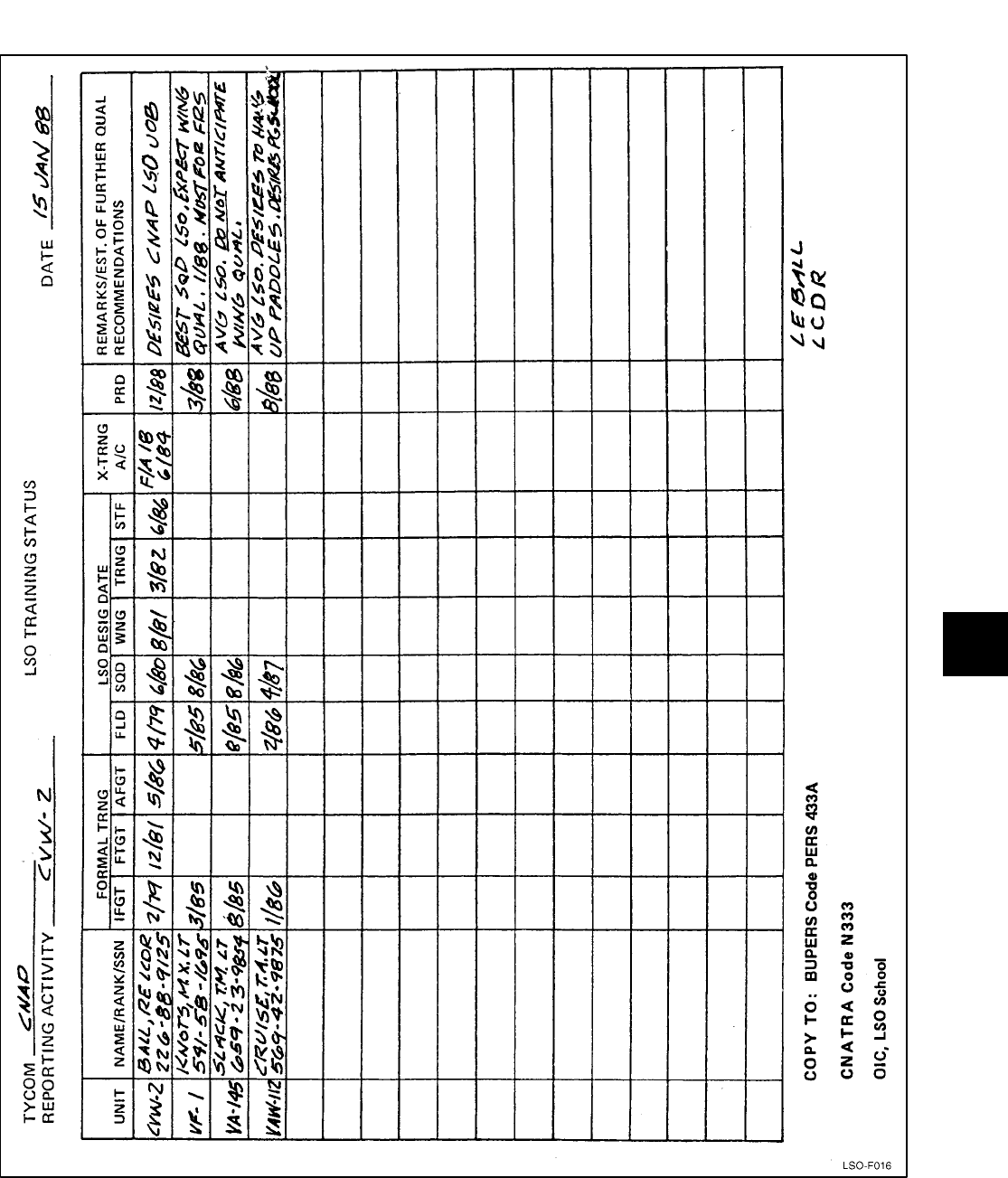
NAVAIR 00-80T-104
ORIGINAL
10-5
Figure 10-1. LSO Training Status Matrix (Sheet 1 of 2)
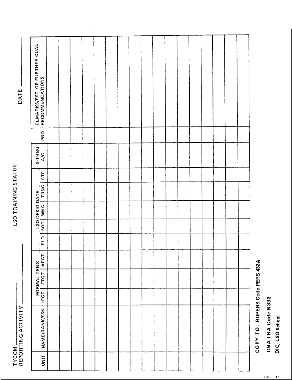
NAVAIR 00-80T-104
ORIGINAL 10-6
Figure 10-1. LSO Training Status Matrix (Sheet 2)

NAVAIR 00-80T-104
ORIGINAL
11-1
CHAPTER 11
Pilot Performance Records
11.1 INTRODUCTION
The effectiveness and combat readiness of the
aircraft carrier depends on the overall efficiency of
carrier landing operations. To effectively carry out
assigned missions, each aviator must be able to perform
a carrier approach and landing within the standards set
for this evolution. The cognizant commanding officer
and air wing commander shall be immediately informed
about those pilots who display unsafe practices or
unsatisfactory progress. The LSO shall recommend to
the commanding officer or air wing commander either
additional field/carrier work or immediate grounding
and evaluation of those individual pilots concerned.
11.2 LOG BOOKS
The controlling LSO shall maintain a field and
carrier logbook. Comments should be sufficiently
detailed to enable the LSO to give a comprehensive
debrief to the pilots concerned. The Landing Signal
Officer’s Log, OPNAV 3760/76 (5-87) (S/N
0107-LF-037-6390), may be used for documentation.
The Senior Air Wing Staff LSO shall ensure that all
COD shipboard approaches are logged in a separate
COD log maintained in the Air Operations office on
board the ship.
11.3 PILOT PERFORMANCE RECORDS
The LSO shall keep a smooth carrier landing trend
analysis for all pilots making carrier landings in aircraft
for which his command is reporting custodian, using
OPNAV Form 3760/7 1 (Figure 11-1) or by using the
APARTS (Figure 11-2). The pilot performance record
should be updated daily, reviewed and debriefed
routinely, and the pilot and his commanding officer
notified of any unsatisfactory trends. LSO logbooks and
pilot performance records are privileged and personal
documents. Extracts from them are authorized for
official use provided they are interpreted and compiled
by the LSO concerned.
11.3.1 Automated Performance Assessment
and Readiness Training System. APARTS is a
computer software program designed to assist the LSO
in recording and analyzing pilot and LSO carrier
landing performance information. The system provides
various summaries for individual pilots, squadrons, or
an entire air wing. The results may be displayed on the
computer screen or printed out for a hard copy record
(Figure 11-2). Copies of fleet and FRS APARTS
programs, including operating manuals, may be ob-
tained from the U.S. Navy LSO School.
11.4 STANDARD LOG SYMBOLS
The following symbols are in common use for
recording comments concerning approaches/landings
during FCLP and carrier operations. The symbols used
in APARTS are also listed. If there is no corresponding
APARTS symbol, the space is left blank.
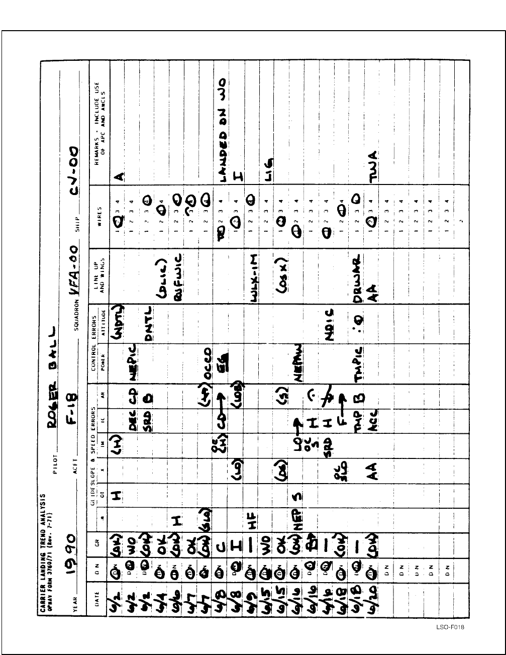
NAVAIR 00-80T-104
ORIGINAL 11-2
Figure 11-1. Carrier Landing Trend Analysis Form

NAVAIR 00-80T-104
ORIGINAL
11-3
SQUADRON: ALL TREND ANALYSIS
RECOVERY PERIOD: 9006021200 - 9006201200
PILOTS SELECTED: BALL, ROGER
AIRCRAFT: ALL
DAY/NITE/ALL: ALL
MOVLAS: ALL RECOVERIES
GLIDE SLOPE AND SPEED ERRORS CONTROL
ERRORS
LINEUP
WIRE
DATE GRADE AW X IM IC AR POWER ATT
LINEUP
& WING OTHER
WIRE
#
06/02D (OK) H (H) (NDTL) 2
06/02N WO DEC CD NEPIC WO
06/02N (OK) SRD B DNTL 4
06/04D OK (DLIC) 3
06/06D (OK) H RUFWIC 4
06/07D OK (B) 4
06/07D (OK) (SLO) (/) OCCOIC 4
06/08D C OC(H) CD CD _EGIC_
EGAR . T1
06/08N M1 (LO) (LO)
(B) 2
06/09D —H
FLULX
LULIM 4
06/15D WO LIG WO
06/15D OK (S) (OSX) 2
06/16D (OK) S LO LO NEPAW 1
06/16N B OCS H ^ ^AR B
06/16N —SRD H \ NDIC 1
06/18D (OK) OCSLO F F 3
06/18N —B TMPIC DRWAR
LRWDIW 4
06/20D (OK) ACC AA 2
TOTAL # OF APPROACHES – 18
Figure 11-2. APARTS Trend Analysis Form
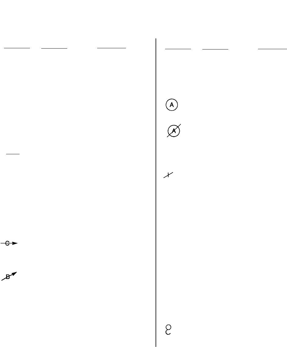
NAVAIR 00-80T-104
ORIGINAL 11-4
11.4.1 General Symbols
APARTS
SYMBOL
APARTS
SYMBOL MEANING
WO WO Waveoff
WOP WOP Waveoff Pattern
OWO OWO Own Waveoff
TWO TWO Test Waveoff
TLU TLU Test Lineup
OK _OK_ Perfect pass
OK OK Reasonable deviations
with good corrections
(OK) (OK) Fair.
Reasonable deviations
—––No-grade. Below average
but safe pass
C Cut. Unsafe, gross devi-
ations inside waveoff
window
B Bolter
NC NC No count (used in grade
column)
( ) ( ) Parentheses around any
symbol signifies “a little”
(e.g., (F) means “a little
fast”)
APARTS
SYMBOL
APARTS
SYMBOL MEANING
_______ _Comment_ Underline.
For emphasis
PATT PATT Pattern
(A) APC/Auto
APC/Auto downgraded to
manual
| M1 Mode I ACLS (record in
grade column)
Mode I ACLS, uncoupled
after the ball call
••A dot between two
symbols indicates “on”
(e.g., S•LUIC)
—–A dash between two sym-
bols indicates “to” (e.g.,
HIM-IC)
SQUARE Comment [ ] A square around any
symbol indicates that a
signal was not answered
CIRCLE Comment ( ) A circle around any
symbol indicates that a
signal was answered too
slowly
OC When used as a prefix to
any symbol, “ ” indicates
“over controlled”

NAVAIR 00-80T-104
ORIGINAL
11-5
11.4.2 Descriptive Symbols
APARTS
SYMBOL
APARTS
SYMBOL MEANING
AA AA Angling approach
ACC ACC Accelerate
AFU AFU All “fouled” up
B B Flat glideslope
C Climbing
CB CB Coming back to lineup
CD CD Coming down
CH CH Chased
CO CO Come-on
CU CU Cocked up
DD DD Deck down
DEC DEC Decelerate
DL DL Drifted left
DN DN Dropped nose
DR DR Drifted right
DU DU Deck up
EG EG Eased gun
F F Fast
FD FD Fouled deck
GLI GLI Gliding approach
H H High
APARTS
SYMBOL
APARTS
SYMBOL MEANING
HO HO Hold off
LIG LIG Long in the groove
LL LL Landed left
LLU LLU Late lineup
LO LO Low
LR LR Landed right
LTR LTR Left to right
LU LU Lineup
LUL LUL Lined up left
LUR LUR Lined up right
LWD DLW Left wing down
N N Nose
NC NC Nice correction
ND ND Nose down
NEA NEA Not enough attitude
NEP NEP Not enough power
NERD NERD Not enough rate of descent
NERR NERR Not enough right rudder
NESA NESA Not enough straight away
NH NH No hook
NSU NSU Not set up
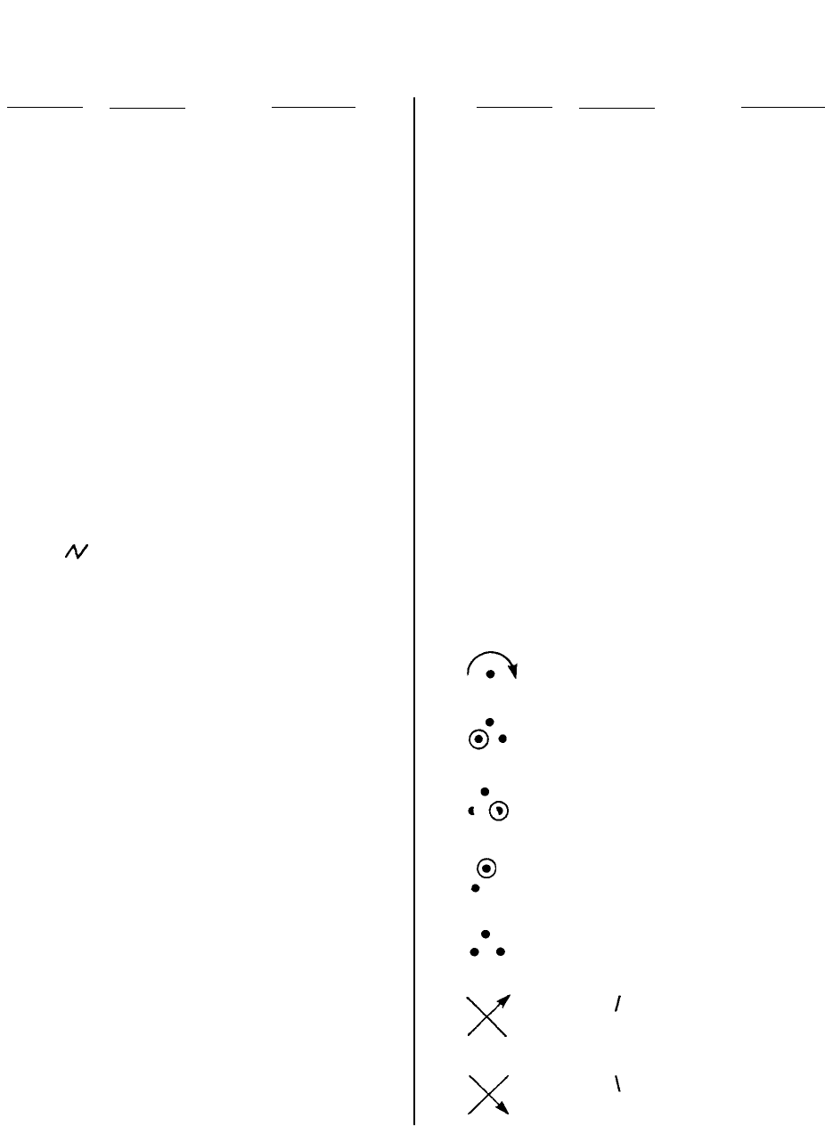
NAVAIR 00-80T-104
ORIGINAL 11-6
APARTS
SYMBOL
APARTS
SYMBOL MEANING
OR OR Overrotate
OS OS Overshoot
OSCB OSCB Overshot coming back
P P Power
PD PD Pitching deck
PNU PNU Pulled nose up
ROT ROT Rotate
RUD RUD Rudder
RUF or RUF Rough
RWD DRW Right wing down
RR RR Right rudder
RTL RTL Right to left
S S Settle
SD SD Spotted deck
SHT SHT Ship’s turn
SKD SKD Skid
SLO SLO Slow
SRD SRD Stopped rate of descent
ST ST Steep turn
TCA TCA Too close abeam
APARTS
SYMBOL
APARTS
SYMBOL MEANING
TMA TMA Too much attitude
TMP TMP Too much power
TMRD TMRD Too much rate of descent
TMRR TMRR Too much right rudder
TTL TTL Turned too late
TTS TTS Turned too soon
TWA TWA Too wide abeam
W W Wings
WU WU Wrapped up
XCTL XCTL Cross control
^ Over the top
LLWD Landed left wing down
LRWD Landed right wing down
LNF Landed nose
3PTS Landed 3 points
Fly through the glideslope
(going up)
Fly through the glideslope
(going down)

NAVAIR 00-80T-104
ORIGINAL
11-7/(11-8 blank)
11.4.3 Symbol Suffixes
SYMBOL APARTS
SYMBOL MEANING
CCA CCA Carrier controlled approach
OT OT Out of turn (as aircraft rolls
wings level)
BC BC Ball call
X X At the start (first one-third
of glideslope)
SYMBOL APARTS
SYMBOL MEANING
IM IM In the middle (middle one-
third of the glideslope)
IC IC In close (last one-third of
glideslope)
AR AR At the ramp
TL TL To land
IW IW In the wires
AW AW All the way

NAVAIR 01-F14AAP-1
ORIGINAL
5/(6 blank)

NAVAIR 00-80T-104
ORIGINAL
12-1/(12-2 blank)
CHAPTER 12
Aircraft Mishap Statements
12.1 GENERAL
It is incumbent upon the LSO to prepare detailed and
complete statements regarding aircraft mishaps. It is
recognized that the LSO is usually in the best position
to evaluate incidents culminating in carrier landing
mishaps. The following is an outline of items that are
pertinent to most CV landing mishaps. These items
should be used, when applicable, in the preparation of
LSO statements to aircraft mishap investigation boards.
Controlling LSOs shall be afforded access to the
PLAT/ILARTS tape (with sound) prior to preparing
their statements.
12.1.1 LSO Mishap Statement
1. Narrative
a. State, as you saw them, the events as they
occurred.
b. Include an explanation of your actions.
2. Environmental Factors
a. Weather — Include both observed and LSO-
called.
b. Deck conditions — Include list, dutch roll,
deck movement in feet, periodicity, and
heave.
c. Wind — Both direction and velocity, gusts,
wind shifts, shears, sink holes, turbulence in
the groove, and crosswind component.
d. LSO equipment — State what was working or
inoperative, and if all problems were passed to
the air officer. State if any of the inoperative
gear could have had an effect on the recovery.
e. LSO horizon — State what was being used as
a horizon reference (destroyer position, flares,
helo, nothing, etc.).
f. OLS — Intensity setting, lens settings, and
status of deck and drop lights.
3. Air Operations
a. Had the LSO advised to cancel flight opera-
tions prior to the mishap?
b. Were air operations canceled after the
mishap?
4. LSO Data
a. Type qualification, date received, aircraft
qualified to wave at the field or ship, and day,
night, and MOVLAS experience.
b. Date of last formal training.
c. Time in LSO duty status for that day, physical
condition, and fatigue factor.
d. Warfare specialty, type aircraft qualified in as
a pilot.
e. Any other aircraft qualified in as a pilot,
cross-trained in, or received familiarization/
orientation flights in.
5. Pilot Performance
a. Updated trend analysis from squadron LSO.
b. Narrative of the pilot’s specific trends.
c. Comparison of pilot’s performance to that of
his experience-level peers.
Note
An Embarked Landing Hazard Report shall
be submitted utilizing the format contained
in OPNAVINST 3750.6 anytime any part of
the landing aircraft impacts on or below the
round down, personnel, or equipment in the
landing area, or for any other occurrences
considered appropriate.

NAVAIR 01-F14AAP-1
ORIGINAL
5/(6 blank)

NAVAIR 00-80T-104
ORIGINAL
1
INDEX
A
Absence of horizon reference 8-1. . . . . . . . . . . . . . . .
Air Officer 1-2. . . . . . . . . . . . . . . . . . . . . . . . . . . . . .
Aircraft
crosstype training 2-1. . . . . . . . . . . . . . . . . . . . . . .
emergencies 7-1. . . . . . . . . . . . . . . . . . . . . . . . . . .
mishap statements 12-1. . . . . . . . . . . . . . . . . . . . .
Assignment 1-4. . . . . . . . . . . . . . . . . . . . . . . . . . . . .
Automated performance assessment and
readiness training system 11-1. . . . . . . . . . . . . . . . .
B
Barricade engagements 7-5. . . . . . . . . . . . . . . . . . . .
Briefing and debriefing 5-1, 6-1. . . . . . . . . . . . . . . .
carrier qualification/currency landing
procedures briefing 6-1. . . . . . . . . . . . . . . . . . . .
conduct of field carrier landing practice
briefings 5-3. . . . . . . . . . . . . . . . . . . . . . . . . . . . .
pilot landing trend debriefs 6-1. . . . . . . . . . . . . . .
postflight debriefing 6-1. . . . . . . . . . . . . . . . . . . .
postsimulator/postflight debriefing 5-3. . . . . . . . .
precarrier briefing 5-1. . . . . . . . . . . . . . . . . . . . . .
recurrent CV procedures training 6-1. . . . . . . . . .
simulator procedures briefing 5-2. . . . . . . . . . . . .
special operations procedures briefing 6-1. . . . . .
C
Carrier air wing predeployment LSO
evaluation 10-3. . . . . . . . . . . . . . . . . . . . . . . . . . . . .
formal ground training program
evaluation 10-3. . . . . . . . . . . . . . . . . . . . . . . . . .
general 10-3. . . . . . . . . . . . . . . . . . . . . . . . . . . . . .
shipboard LSO team performance
evaluation 10-4. . . . . . . . . . . . . . . . . . . . . . . . . .
Carrier qualification/currency landing
procedures briefing 6-1. . . . . . . . . . . . . . . . . . . . . .
Carrier qualifications 6-1. . . . . . . . . . . . . . . . . . . . . .
day qualification 6-1. . . . . . . . . . . . . . . . . . . . . . .
definitions 6-1. . . . . . . . . . . . . . . . . . . . . . . . . . . .
limitations for initial carrier qualifications 6-5. . .
LSO certification of pilot performance 6-6. . . . . .
minimum landings for initial, transition,
and requalification 6-1. . . . . . . . . . . . . . . . . . . . .
night qualification 6-1. . . . . . . . . . . . . . . . . . . . . .
training command instructors and students 6-5. . .
waiver criteria 6-4. . . . . . . . . . . . . . . . . . . . . . . . .
Circuitry 4-3. . . . . . . . . . . . . . . . . . . . . . . . . . . . . . . .
Classroom training experience 10-3. . . . . . . . . . . . . .
Command relationships and responsibilities of the
Landing Signal Officer 1-1. . . . . . . . . . . . . . . . . . .
air officer 1-2. . . . . . . . . . . . . . . . . . . . . . . . . . . . .
air wing commander 1-2. . . . . . . . . . . . . . . . . . . .
LSO training model manager 1-2. . . . . . . . . . . . .
ship/air wing commanding officer 1-2. . . . . . . . . .
squadron commanding officer 1-2. . . . . . . . . . . . .
type commander 1-1. . . . . . . . . . . . . . . . . . . . . . .
Communication emergencies 7-3. . . . . . . . . . . . . . . .
Conduct of FCLP 5-5. . . . . . . . . . . . . . . . . . . . . . . . .
Conduct of Field Carrier Landing Practice
briefings 5-3. . . . . . . . . . . . . . . . . . . . . . . . . . . . . . .
Currency criteria for carrier qualified pilots 6-6. . . .
limitations for currency/refresher landings 6-6. . .
CV approach/departure procedures 5-4. . . . . . . . . . .
D
Datum, waveoff, and cut lights 4-4. . . . . . . . . . . . . .
Day
carrier 4-1. . . . . . . . . . . . . . . . . . . . . . . . . . . . . . . .
FCLP 3-1. . . . . . . . . . . . . . . . . . . . . . . . . . . . . . . .
qualification 6-1. . . . . . . . . . . . . . . . . . . . . . . . . . .
Descriptive symbols 11-5. . . . . . . . . . . . . . . . . . . . . .
E
Effective glideslope due to wind and deck
motion 4-7. . . . . . . . . . . . . . . . . . . . . . . . . . . . . . . .
Effects of
deck motion 4-7. . . . . . . . . . . . . . . . . . . . . . . . . . .
effects of temperature 4-2. . . . . . . . . . . . . . . . . . .
Emergency procedures 5-4. . . . . . . . . . . . . . . . . . . . .
Excessive deck motion 8-1. . . . . . . . . . . . . . . . . . . . .
Excessive deck motion 7-4. . . . . . . . . . . . . . . . . . . . .
F
Factors affecting LSO readiness 2-2. . . . . . . . . . . . .
Index-1

NAVAIR 00-80T-104
ORIGINAL 2
FCLP 5-4. . . . . . . . . . . . . . . . . . . . . . . . . . . . . . . . . .
conduct of FCLP 5-5. . . . . . . . . . . . . . . . . . . . . . .
pattern emergencies 7-1. . . . . . . . . . . . . . . . . . . . .
performance records 5-5. . . . . . . . . . . . . . . . . . . .
personnel requirements 5-4. . . . . . . . . . . . . . . . .
preflight briefing 5-4. . . . . . . . . . . . . . . . . . . . . . .
traffic pattern control responsibilities 5-4. . . . . . .
Field evaluation 10-1. . . . . . . . . . . . . . . . . . . . . . . . .
Field experience 10-1, 10-3. . . . . . . . . . . . . . . . . . . .
Field LSO qualification 10-1. . . . . . . . . . . . . . . . . . .
certification 10-1. . . . . . . . . . . . . . . . . . . . . . . . . .
field evaluation 10-1. . . . . . . . . . . . . . . . . . . . . . .
field experience 10-1. . . . . . . . . . . . . . . . . . . . . . .
formal ground training 10-1. . . . . . . . . . . . . . . . . .
Field training 2-1. . . . . . . . . . . . . . . . . . . . . . . . . . . .
Flight Deck Hazardous Duty Incentive
Pay (FDHIDP) 1-4. . . . . . . . . . . . . . . . . . . . . . . . . .
Focal point and field of view 4-3. . . . . . . . . . . . . . . .
Formal ground training 2-1, 10-1. . . . . . . . . . . . . . .
Foul deck waveoff 6-11. . . . . . . . . . . . . . . . . . . . . . .
Fresnel lens optical landing system 4-2. . . . . . . . . . .
circuitry 4-3. . . . . . . . . . . . . . . . . . . . . . . . . . . . . .
datum, waveoff, and cut lights 4-4. . . . . . . . . . . .
effective glideslope due to wind and deck
motion 4-7. . . . . . . . . . . . . . . . . . . . . . . . . . . . . .
effects of deck motion 4-7. . . . . . . . . . . . . . . . . .
effects of temperature 4-2. . . . . . . . . . . . . . . . . . .
focal point and field of view 4-3. . . . . . . . . . . . . .
general operating intensities 4-3. . . . . . . . . . . . . .
inertial mode of stabilization 4-5. . . . . . . . . . . . . .
line stabilization 4-4. . . . . . . . . . . . . . . . . . . . . . . .
optical characteristics 4-2. . . . . . . . . . . . . . . . . . . .
roll angle and hook-to-eye 4-8. . . . . . . . . . . . . . . .
stabilization limits 4-6. . . . . . . . . . . . . . . . . . . . . .
stabilization modes 4-5. . . . . . . . . . . . . . . . . . . . .
system condition indicators 4-4. . . . . . . . . . . . . . .
G
General operating intensities 4-3. . . . . . . . . . . . . . . .
General symbols 11-4. . . . . . . . . . . . . . . . . . . . . . . . .
I
Inertial mode of stabilization 4-5. . . . . . . . . . . . . . . .
Intensities 3-2. . . . . . . . . . . . . . . . . . . . . . . . . . . . . . .
L
Landing aid malfunctions 7-2. . . . . . . . . . . . . . . . . .
Landing Signal Officer
command relationships and
responsibilities of the 1-1. . . . . . . . . . . . . . . . . .
role of 1-1. . . . . . . . . . . . . . . . . . . . . . . . . . . . . . .
Limitations
for currency/refresher landings 6-6. . . . . . . . . . . .
for initial carrier qualifications 6-5. . . . . . . . . . . .
Line stabilization 4-5. . . . . . . . . . . . . . . . . . . . . . . . .
Log books 11-1. . . . . . . . . . . . . . . . . . . . . . . . . . . . .
LSO
base console 4-12. . . . . . . . . . . . . . . . . . . . . . . . . .
certification of pilot performance 5-5, 6-6. . . . . .
designation category 1-3. . . . . . . . . . . . . . . . . . . .
designations 1-3. . . . . . . . . . . . . . . . . . . . . . . . . . .
greenhouse and radios 3-2. . . . . . . . . . . . . . . . . . .
heads-up display 4-12. . . . . . . . . . . . . . . . . . . . . .
LSO training model manager 1-2. . . . . . . . . . . . .
mishap statement 12-1. . . . . . . . . . . . . . . . . . . . . .
recommended minimum LSO requirements 1-5. .
responsibilities 6-8. . . . . . . . . . . . . . . . . . . . . . . . .
seniority 1-3. . . . . . . . . . . . . . . . . . . . . . . . . . . . . .
trainee nomination procedures 1-3. . . . . . . . . . . . .
training status matrix 10-4. . . . . . . . . . . . . . . . . . .
vehicle 3-2. . . . . . . . . . . . . . . . . . . . . . . . . . . . . . .
LSO Designations 1-3. . . . . . . . . . . . . . . . . . . . . . . .
LSO designation category 1-3. . . . . . . . . . . . . . . .
LSO trainee nomination procedures 1-3. . . . . . . .
upgrading procedures 1-3. . . . . . . . . . . . . . . . . . . .
LSO trainer (device 2H111) 2-2. . . . . . . . . . . . . . . . .
LSO Training Program 2-1. . . . . . . . . . . . . . . . . . . . .
aircraft crosstype training 2-1. . . . . . . . . . . . . . . .
field training 2-1. . . . . . . . . . . . . . . . . . . . . . . . . .
formal ground training 2-1. . . . . . . . . . . . . . . . . . .
shipboard training 2-1. . . . . . . . . . . . . . . . . . . . .
M
Manually operated visual landing aid system 4-10. .
MOVLAS construction 4-12. . . . . . . . . . . . . . . . .
Minimum currency requirements 2-2. . . . . . . . . . . . .
Minimum equipment for field carrier
landing practice (FCLP) operations 3-1. . . . . . . . . .
day FCLP 3-1. . . . . . . . . . . . . . . . . . . . . . . . . . . . .
night FCLP 3-1. . . . . . . . . . . . . . . . . . . . . . . . . . .
Index-2

NAVAIR 00-80T-104
ORIGINAL
3
Minimum equipment list for
shipboard operations 4-1. . . . . . . . . . . . . . . . . . . . .
day carrier 4-1. . . . . . . . . . . . . . . . . . . . . . . . . . . .
miscellaneous LSO equipment malfunction 4-2. .
night carrier 4-2. . . . . . . . . . . . . . . . . . . . . . . . . . .
Minimum landings for initial transition and
requalification 6-1. . . . . . . . . . . . . . . . . . . . . . . . . .
Minimum number of FCLP periods 5-5. . . . . . . . . .
Miscellaneous LSO equipment
malfunction 4-2, 7-4. . . . . . . . . . . . . . . . . . . . . . . .
Mk 8 fresnel lens 3-2. . . . . . . . . . . . . . . . . . . . . . . . .
MOVLAS 3-2. . . . . . . . . . . . . . . . . . . . . . . . . . . . . . .
construction 4-12. . . . . . . . . . . . . . . . . . . . . . . . . .
during carrier qualifications 6-12. . . . . . . . . . . . . .
operating procedures 6-12. . . . . . . . . . . . . . . . . . .
training 6-12. . . . . . . . . . . . . . . . . . . . . . . . . . . . . .
N
NATOPS Evaluation 10-1. . . . . . . . . . . . . . . . . . . . .
concepts 10-1. . . . . . . . . . . . . . . . . . . . . . . . . . . . .
implementation 10-1. . . . . . . . . . . . . . . . . . . . . . .
Night carrier 4-2. . . . . . . . . . . . . . . . . . . . . . . . . . . . .
Night FCLP 3-1. . . . . . . . . . . . . . . . . . . . . . . . . . . . .
Night qualification 6-1. . . . . . . . . . . . . . . . . . . . . . . .
Normal recovery operations 6-7. . . . . . . . . . . . . . . . .
foul deck waveoff 6-11. . . . . . . . . . . . . . . . . . . . .
LSO responsibilities 6-8. . . . . . . . . . . . . . . . . . . .
MOVLAS during carrier qualifications 6-12. . . . .
MOVLAS operating procedures 6-12. . . . . . . . . .
MOVLAS training 6-12. . . . . . . . . . . . . . . . . . . . .
optical landing system limits 6-11. . . . . . . . . . . . .
personnel requirements 6-7. . . . . . . . . . . . . . . . . .
recovery procedures for final approach 6-10. . . . .
safety precautions 6-11. . . . . . . . . . . . . . . . . . . . .
specific LSO and pilot recovery
procedures 6-10. . . . . . . . . . . . . . . . . . . . . . . . . .
wind over deck (WOD) requirements 6-11. . . . . .
O
Operation and checks of shore-based
visual landing aids 3-2. . . . . . . . . . . . . . . . . . . . . . .
Optical
characteristics 4-2. . . . . . . . . . . . . . . . . . . . . . . . .
landing system limits 6-11. . . . . . . . . . . . . . . . . . .
P
Personnel requirements 5-4, 6-7. . . . . . . . . . . . . . . .
Pilot
landing trend debriefs 6-1. . . . . . . . . . . . . . . . . . .
performance evaluation 5-5. . . . . . . . . . . . . . . . . .
performance records 11-1. . . . . . . . . . . . . . . . . . .
Pilot Performance evaluation 5-5. . . . . . . . . . . . . . . .
FCLP performance records 5-5. . . . . . . . . . . . . . .
LSO certification of pilot performance 5-5. . . . . .
minimum number of FCLP periods 5-5. . . . . . . .
Pilot performance records 11-1. . . . . . . . . . . . . . . . .
automated performance assessment and
readiness training system 11-1. . . . . . . . . . . . . . .
Pole check 3-2. . . . . . . . . . . . . . . . . . . . . . . . . . . . . .
Postflight debriefing 6-1. . . . . . . . . . . . . . . . . . . . . .
Postsimulator/postflight debriefing 5-3. . . . . . . . . . .
Precarrier briefing 5-1. . . . . . . . . . . . . . . . . . . . . . . .
Preflight briefing 5-4. . . . . . . . . . . . . . . . . . . . . . . . .
R
Radio communications 9-1. . . . . . . . . . . . . . . . . . . .
during emergency situations 9-1. . . . . . . . . . . . . .
Recovery procedures for final approach 6-10. . . . . .
Recurrent CV procedures training 6-1. . . . . . . . . . . .
Removal of LSO designation 10-4. . . . . . . . . . . . . . .
Requirements for LSO designation 2-2. . . . . . . . . . .
Restricted visibility/ceiling operations 8-1. . . . . . . .
Roll angle and hook-to-eye 4-8. . . . . . . . . . . . . . . . .
Role of landing signal officer 1-1. . . . . . . . . . . . . . .
S
Safety Precautions 6-11. . . . . . . . . . . . . . . . . . . . . . .
Selection of LSO trainees 2-1. . . . . . . . . . . . . . . . . .
Ship static mistrim 7-5. . . . . . . . . . . . . . . . . . . . . . . .
Ship/Air Wing Commanding Officer 1-2. . . . . . . . . .
Shipboard
currency 10-3. . . . . . . . . . . . . . . . . . . . . . . . . . . . .
emergencies 7-1. . . . . . . . . . . . . . . . . . . . . . . . . . .
experience 10-2. . . . . . . . . . . . . . . . . . . . . . . . . . .
LSO experience 10-2. . . . . . . . . . . . . . . . . . . . . . .
training 2-1. . . . . . . . . . . . . . . . . . . . . . . . . . . . . .
Shipboard emergencies 7-1. . . . . . . . . . . . . . . . . . . .
aircraft emergencies 7-1. . . . . . . . . . . . . . . . . . . . .
barricade engagements 7-5. . . . . . . . . . . . . . . . . . .
communication emergencies (day) 7-3. . . . . . . . .
communication emergencies (general) 7-3. . . . . .
Index-3

NAVAIR 00-80T-104
ORIGINAL 4
communication emergencies (night) 7-3. . . . . . . .
excessive deck motion 7-4. . . . . . . . . . . . . . . . . . .
landing aid malfunctions 7-2. . . . . . . . . . . . . . . . .
miscellaneous LSO equipment malfunction 7-4. .
ship static mistrim 7-5. . . . . . . . . . . . . . . . . . . . . .
Shore-based emergencies 7-1. . . . . . . . . . . . . . . . . . .
FCLP pattern emergencies 7-1. . . . . . . . . . . . . . . .
Simulator procedures briefing 5-2. . . . . . . . . . . . . . .
Simulator training 5-4. . . . . . . . . . . . . . . . . . . . . . . .
CV approach/departure procedures 5-4. . . . . . . . .
emergency procedures 5-4. . . . . . . . . . . . . . . . . . .
Special operations procedures briefing 6-1. . . . . . . .
Specific LSO and pilot recovery procedures 6-10. . .
Squadron commanding officer 1-2. . . . . . . . . . . . . . .
Squadron LSO qualification 10-1. . . . . . . . . . . . . . .
certification 10-2. . . . . . . . . . . . . . . . . . . . . . . . . .
formal ground training 10-1. . . . . . . . . . . . . . . . . .
shipboard experience 10-2. . . . . . . . . . . . . . . . . . .
written and practical evaluation 10-2. . . . . . . . . . .
Stabilization
limits 4-6. . . . . . . . . . . . . . . . . . . . . . . . . . . . . . . .
modes 4-5. . . . . . . . . . . . . . . . . . . . . . . . . . . . . . . .
Staff LSO qualification 10-3. . . . . . . . . . . . . . . . . . .
certification 10-3. . . . . . . . . . . . . . . . . . . . . . . . . .
formal ground training 10-3. . . . . . . . . . . . . . . . . .
shipboard currency 10-3. . . . . . . . . . . . . . . . . . . . .
Standard log symbols 11-1. . . . . . . . . . . . . . . . . . . . .
descriptive symbols 11-5. . . . . . . . . . . . . . . . . . . .
general symbols 11-4. . . . . . . . . . . . . . . . . . . . . . .
symbol suffixes 11-7. . . . . . . . . . . . . . . . . . . . . . .
Standard LSO phraseology 9-1. . . . . . . . . . . . . . . . .
Symbol suffixes 11-7. . . . . . . . . . . . . . . . . . . . . . . . .
System condition indicators 4-4. . . . . . . . . . . . . . . . .
T
Touchdown points 3-2. . . . . . . . . . . . . . . . . . . . . . . .
Traffic pattern control responsibilities 5-4. . . . . . . . .
Training command instructors and students 6-5. . . .
Training LSO carrier qualification (CQ)
requirements 2-2. . . . . . . . . . . . . . . . . . . . . . . . . . . .
Training LSO qualification 10-3. . . . . . . . . . . . . . . .
certification 10-3. . . . . . . . . . . . . . . . . . . . . . . . . .
classroom training experience 10-3. . . . . . . . . . . .
field experience 10-3. . . . . . . . . . . . . . . . . . . . . . .
formal ground training 10-3. . . . . . . . . . . . . . . . . .
prerequisites 10-3. . . . . . . . . . . . . . . . . . . . . . . . . .
shipboard experience 10-3. . . . . . . . . . . . . . . . . . .
Type commander 1-1. . . . . . . . . . . . . . . . . . . . . . . . .
U
Upgrading procedures 1-3. . . . . . . . . . . . . . . . . . . . .
V
Visual landing aids 3-1. . . . . . . . . . . . . . . . . . . . . . . .
general 3-1. . . . . . . . . . . . . . . . . . . . . . . . . . . . . . .
Mk 8 fresnel lens 3-2. . . . . . . . . . . . . . . . . . . . . . .
MOVLAS 3-2. . . . . . . . . . . . . . . . . . . . . . . . . . . .
Operation and checks of shore-based visual
landing aids 3-2. . . . . . . . . . . . . . . . . . . . . . . . . .
W
Waiver criteria 6-4. . . . . . . . . . . . . . . . . . . . . . . . . . .
Wind Over Deck (WOD) requirements 6-11. . . . . . .
Wing LSO qualification 10-2. . . . . . . . . . . . . . . . . . .
certification 10-2. . . . . . . . . . . . . . . . . . . . . . . . . .
formal ground training 10-2. . . . . . . . . . . . . . . . . .
shipboard LSO experience 10-2. . . . . . . . . . . . . . .
written and practical evaluation 10-2. . . . . . . . . . .
Written and practical evaluation 10-2. . . . . . . . . . . .
Index-4

NAVAIR 00-80T-104
ORIGINAL
1/(2 blank)
LIST OF EFFECTIVE PAGES
Effective Pages Page Numbers
Original 1 (Reverse Blank)
Original 3 (Reverse Blank)
Original 5 (Reverse Blank)
Original 7 (Reverse Blank)
Original 9 (Reverse Blank)
Original 11 thru 16
Original 17 (Reverse Blank)
Original 19 thru 23 (Reverse Blank)
Original 25 (Reverse Blank)
Original 1-1 thru 1-5 (Reverse Blank)
Original 2-1 thru 2-2
Original 27 (Reverse Blank)
Original 3-1 thru 3-2
Original 4-1 thru 4-16
Original 29 (Reverse Blank)
Effective Pages Page Numbers
Original 5-1 thru 5-5 (Reverse Blank)
Original 6-1 thru 6-13 (Reverse Blank)
Original 31 (Reverse Blank)
Original 7-1 thru 7-5 (Reverse Blank)
Original 33 (Reverse Blank)
Original 8-1 (Reverse Blank)
Original 35 (Reverse Blank)
Original 9-1 thru 9-5 (Reverse Blank)
Original 37 (Reverse Blank)
Original 10-1 thru 10-6
Original 11-1 thru 11-7 (Reverse Blank)
Original 12-1 (Reverse Blank)
Original Index-1 thru Index-4
Original LEP-1 (Reverse Blank)
LEP-1(LEP-2 blank)

NAVAIR 01-F14AAP-1
ORIGINAL
5/(6 blank)
