E650 Series 3 (ZMD310AT/CT) Landis Technical Data
User Manual: Home
Open the PDF directly: View PDF ![]() .
.
Page Count: 6
Electricity Meters IEC/MID
Industrial+Commercial
ZMD310AT/CT
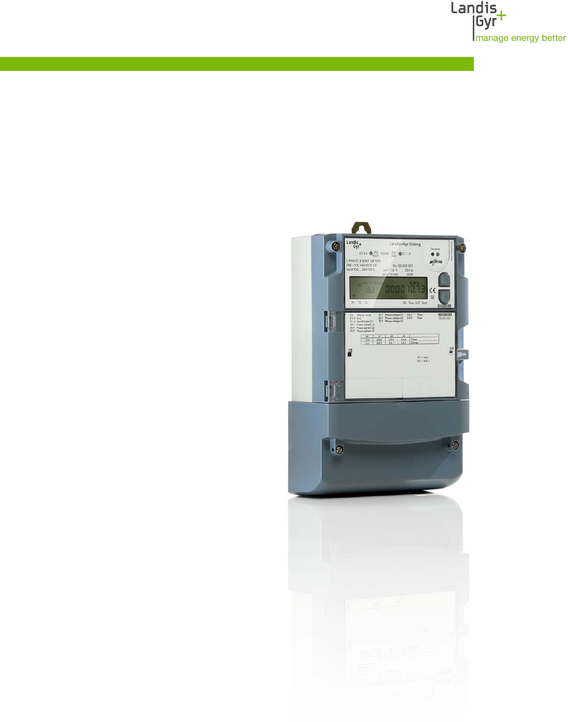
E650 Series 3 (ZMD310AT/CT)
Technical Data
Building on its tradition of industrial meters, Landis+Gyr is now bringing out the E650
series 3, the latest generation of ZxD300 meters. These meters feature a new
hardware platform, combining modern technology with proven functions.
Date: 06.04.2010
Filename: D000030104 E650 ZMD300xT series 3 Technical Data
D000030104 d

2/6
The E650 directly connected I&C meters record
active and reactive energy consumption in all three-
phase four-wire and three-phase three-wire
networks.
Range
E650 meters are the answer to a wide range of
specific needs: from the reliable commercial meter
to the complex measuring device with comprehen-
sive additional functionality for sophisticated data
acquisition and flexible tariff control of large indus-
trial customers.
Communication
AT/CT-type meters are equipped with modular
communication units which provide the right choice
for the best data channel at all times. «Plug+Play»
modules also offer you full freedom of choice for
deployment of new communication technologies.
Installation support
The monitoring of voltage, current, demand and
power factor supports the installation.
E650 Series 3 – ZMD310AT/CT Technical specifications
General
Voltage
Nominal voltage Un
3 x 220/380 V to 240/415 V
3 x 110/190 V to 133/230 V
Voltage range 80% to 115% Un
Frequency
Nominal frequency fn 50 or 60 Hz
tolerance ± 2%
IEC-specific Data
Current
Base current Ib selectable: 5, 10, 20 or 40 A
Maximum current Imax
metrological selectable: 40, 60, 80, 100 or 120 A
thermal 120 A
Short circuit ≤ 10 ms 5000 A
Measurement Accuracy
ZMD310xT
active energy, to IEC 62053-21 class 1
reactive energy, to IEC 62053-23 accuracy 1%
Measurement Behaviour
Starting current
according to IEC 0.4% Ib
typical 0.3% Ib
The startup of the meter is controlled by the starting
power and not by the starting current.
Starting power in M-circuit single phase
nominal voltage x starting current
MID-specific Data
Current (for class B)
Minimum current Imin 0.25, 0.5, 0.75, 1.0 A
Transitional current Itr 0.5, 1.0, 1.5, 2.0 A
Maximum current Imax 120 A
Measurement Accuracy to EN 50470-3
ZMD310AT/CT class B
Measurement Behaviour
Starting current Ist 0.02, 0.04, 0.06, 0.08 A
General
Operating Behaviour
Voltage failure (Power Down)
bridging time 0.5 s
data storage after another 0.2 s
switch off after approx. 2.5 s
Voltage restoration (Power Up)
function standby 3 phases after 2 s
function standby 1 phase after 5 s
detection of energy direction and phase voltage
after 2 to 3 s
Power Consumption
Power consumption per phase in voltage circuit
phase voltage 110 V 240 V
active power (typical) 0.5 W 0.7 W
apparent power (typical) 1.0 VA 1.7 VA
Power consumption per phase in current circuit
phase current 10 A
apparent power (typical) 0.03 VA
© Landis+Gyr AG D000030104 d – E650 Series 3 (ZMD310AT/CT) – Technical Data

3/6
Environmental Influences
Temperature range to IEC 62052-11
operation –25 °C to +70 °C
storage –40 °C to +85 °C
Temperature coefficient
range –25 °C to +70 °C
average value (typical) ± 0.012% per K
at cosϕ=1 (from 0.05 Ib to Imax) ± 0.02% per K
at cosϕ=0.5 (from 0.1 Ib to Imax) ± 0.03% per K
Impermeability to IEC 60529 IP51
Electromagnetic Compatibility
Electrostatic discharges to IEC 61000-4-2
contact discharge 15 kV
Electromagnetic RF fields to IEC 61000-4-3
80 MHz to 2 GHz 10 and 30 V/m
Radio interference suppression
according to IEC/CISPR 22 class B
Fast transient burst test to IEC 61000-4-4
current and voltage circuits under load
according to IEC 62053-21/23 4 kV
auxiliary circuits > 40 V 2 kV
Fast transient surge test to IEC 61000-4-5
current and voltage circuits 4 kV
auxiliary circuits > 40 V 1 kV
Insulation Strength
Insulation strength 4 kV at 50 Hz during 1 min.
Impulse voltage 1.2/50 μs to IEC 62052-11
current and voltage circuits 8 kV
auxiliary circuits > 40 V 6 kV
Protection class ll to IEC 62052-11
Calendar Clock
Calendar Type Gregorian or Persian (Jalaali)
Accuracy < 5 ppm
Backup time (power reserve)
with supercap > 20 days
charging time for max. backup time 300 h
with battery (optional) 10 years
battery type CR-P2
Display
Characteristics
type LCD liquid crystal display
digit size in value field 8 mm
number of digits in value field up to 8
digit size in index field 6 mm
number of digits in index field up to 8
Inputs and Outputs
Control inputs
control voltage US 100 to 240 VAC
input current < 2 mA ohmic at 230 VAC
Output contacts
type solid state relay
voltage 12 to 240 VAC/DC
max. current 100 mA
max. switching frequency (pulse length 20 ms) 25 Hz
Optical test outputs active and reactive energy
type red LED
number 2
meter constant selectable
Communication Interface
Optical interface to IEC 62056-21
type serial, bidirectional, half-duplex
max. transmission rate 9600 bps
protocols IEC 62056-21 and dlms
Communication units
Exchangeable communciation units for various
applications
Additional Power Supply (optional)
On Extension Board 045x
nominal voltage range 100 to 240 VAC/DC
tolerance 80 to 115% Un
frequency 50 or 60 Hz
max. power consumption 6.8 W
On Extension Board 046x
nominal voltage range 12 to 24 VDC
tolerance 80 to 115% Un
max. power consumption 3.5 W
D000030104 d – E650 Series 3 (ZMD310AT/CT) – Technical Data © Landis+Gyr AG

4/6
© Landis+Gyr AG D000030104 d – E650 Series 3 (ZMD310AT/CT) – Technical Data
Weight and Dimensions
Weight approx. 1.5 kg
External dimensions
width 177 mm
height (with short terminal cover) 244 mm
height (with standard terminal cover) 281.5 mm
height (with extended hook) 305.5 mm
depth 75 mm
Suspension triangle
height (with extended hook) 230 mm
height (suspension eyelet open) 206 mm
height (suspension eyelet covered) 190 mm
width 150 mm
Terminal cover
short no free space
standard 40 mm free space
long 60 mm free space
GSM 60 mm free space
ZxB-type 80 mm 80 mm free space
ZxB-type 110 mm 110 mm free space
ADP1 adapter
RCR/FTY adapter
Connections
Phase Connections
type screw type terminals
diameter for Imax ≤ 80 A 8.5 mm
diameter for Imax > 80 A 9.5 mm
minimal conductor cross section 4 mm2
max. cross section cable 35 mm2 (up to 120 A)
max. cross section strand 25 mm2 (up to 80 A)
screw head Pozidrive Combi No. 2
screw dimension M6 x 14
max. screw head diameter ≤ 6.6 mm
tightening torque < 3 Nm
Other Connections
type screwless spring-type terminal
max. current of voltage outputs 1 A
max. voltage of inputs 250 V
Material
Housing
Polycarbonate, partly glass-fibre reinforced
5/6
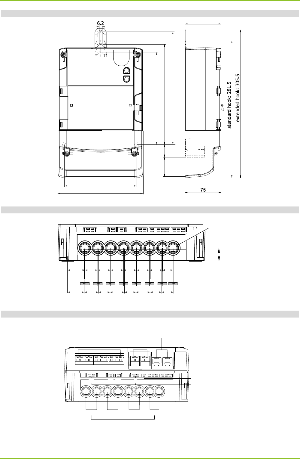
Meter Dimensions (standard terminal cover)
190
standard hook: 206
2640
150
177
75
extended hook: 230
Terminal Dimensions
15.3
14.5 14.5 14.5 14.5 14.5 14.5 1219.75
19 16 16 16
13 13 13 13.5
Spacings of
terminal openings
Spacings of
terminal stampings
for smaller conductors
Ø 8.5 or Ø 9.5
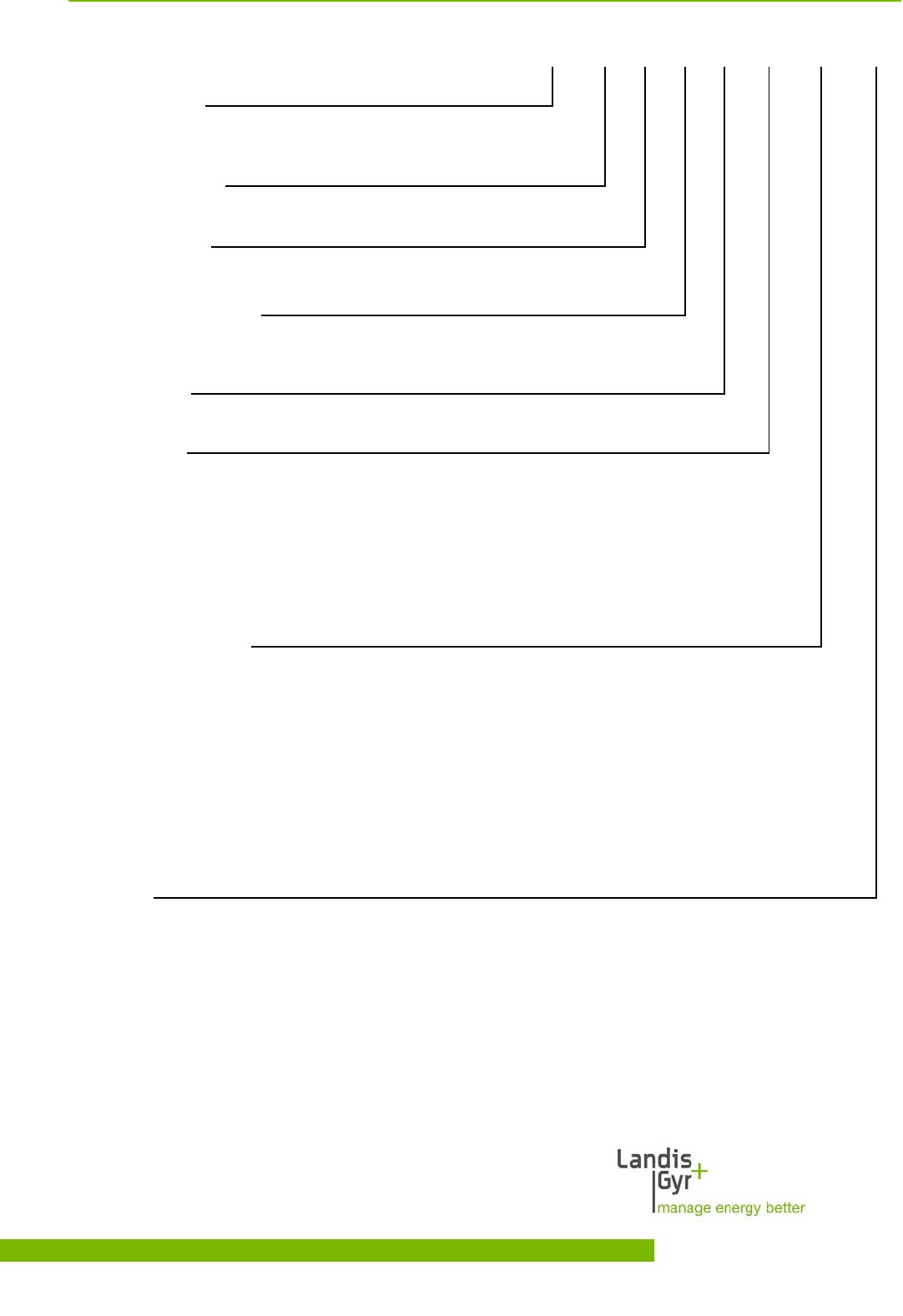
Terminal Layout
Voltage outputs
Control inputs and
output contacts
Inputs and/or
output contacts of
extension board
Pulse
inputs Communication
interfaces
Communication unit
L1 L2 L3 N
Phase connections
U1 U2 U3 N
D000030104 d – E650 Series 3 (ZMD310AT/CT) – Technical Data © Landis+Gyr AG
6/6
ZMD 3 10 C T 44 4207 S3a
Network Type
ZMD 3-phase 4 wire network (M-circuit)
Connection Type
3 Direct connection
Accuracy Class
10 Active energy class 1 (IEC), B (MID)
Measured Quantities
C
A
Active and reactive energy
Active energy
Construction
T With exchangeable communication units
Tariffication
21
24
41
44
Energy rates, external rate control via control inputs
Energy rates, internal rate control via time switch
(additionally possible via control inputs)
Energy and demand rates, external rate control via control inputs
Energy and demand rates, internal rate control via time switch
(additionally possible via control inputs)
All versions with 3 control inputs and 2 output contacts
Additional functions
060x
240x
420x
045x
046x
6 outputs
2 control inputs, 4 outputs
4 control inputs, 2 outputs
4 outputs, auxiliary power supply 100 to 240 VAC
4 outputs, auxiliary power supply 12 to 24 VDC
xxx0
xxx2
xxx7
xxx9
no additional functions
DC-magnet-detection
load profile
DC-magnet-detection and load profile
Series 3
© Landis+Gyr AG D000030104 d – E650 Series 3 (ZMD310AT/CT) – Technical Data
Copyright © 2009, Landis+Gyr. All rights reserved. Subject to change without notice.
Landis+Gyr AG
Feldstrasse 1
CH-6301 Zug
Switzerland
Phone: +41 41 935 6000
www.landisgyr.com
