21 Series Lennox CB29M CB30M IOM
User Manual: 21 Series
Open the PDF directly: View PDF ![]() .
.
Page Count: 20
09/05 504,719M
*2P0905* *P504719M*
Page 1
E2005 Lennox Industries Inc.
Dallas, Texas, USA
IMPORTANT
For downflow application, kit number 83M57
(LB−109844A) is required. Kit is not provided with
coil blower; order separately.
IMPORTANT
The Clean Air Act of 1990 bans the intentional vent-
ing of refrigerant (CFC’s and HCFC’s) as of July 1,
1992. Approved methods of recovery, recycling or
reclaiming must be followed. Fines and/or incar-
ceration may be levied for noncompliance.
WARNING
Product contains fiberglass wool.
Disturbing the insulation in this product during
installation, maintenance, or repair will expose you
to fiberglass wool. Breathing this may cause lung
cancer. (Fiberglass wool is known to the State of
California to cause cancer.)
Fiberglass wool may also cause respiratory, skin,
and eye irritation.
To reduce exposure to this substance or for further
information, consult material safety data sheets
available from address shown below, or contact
your supervisor.
Lennox Industries Inc.
P.O. Box 799900
Dallas, TX 75379−9900
INSTALLATION
INSTRUCTIONS
CB29M & CB30M
Elite® Series Units
MULTI−POSITION BLOWER COILS
504,719M
09/05
Supersedes 04/05
RETAIN THESE INSTRUCTIONS
FOR FUTURE REFERENCE
Table of Contents
CB29M & CB30M Series Units 1. . . . . . . . . . . . . . . . . .
General 1. . . . . . . . . . . . . . . . . . . . . . . . . . . . . . . . . . . . . .
Shipping & Packing List 1. . . . . . . . . . . . . . . . . . . . . . . .
CB29M Unit Dimensions 2. . . . . . . . . . . . . . . . . . . . . . .
CB30M Unit Dimensions 4. . . . . . . . . . . . . . . . . . . . . . .
Requirements 5. . . . . . . . . . . . . . . . . . . . . . . . . . . . . . . . .
Installation 5. . . . . . . . . . . . . . . . . . . . . . . . . . . . . . . . . . . .
Field Piping Connections 8. . . . . . . . . . . . . . . . . . . . . . .
Condensate Drain 9. . . . . . . . . . . . . . . . . . . . . . . . . . . . .
Filters 9. . . . . . . . . . . . . . . . . . . . . . . . . . . . . . . . . . . . . . . .
Sealing the Unit 9. . . . . . . . . . . . . . . . . . . . . . . . . . . . . .
Blower Speed Adjustments 10. . . . . . . . . . . . . . . . . . . . .
Electrical 16. . . . . . . . . . . . . . . . . . . . . . . . . . . . . . . . . . . . .
System Wiring Diagrams 17. . . . . . . . . . . . . . . . . . . . . . .
CB29M & CB30M Series Units
The Lennox CB29M and CB30M Elite® series blower coil
units are designed for installation with a matched remote
outdoor unit and optional field−installed electric heat. The
blower coil units are for indoor installation only.
The CB29M and CB30M units, designed for multi−position-
al installations, are completely assembled at the factory
and shipped ready for upflow or horizontal right−hand dis-
charge installation.
General
These instructions are intended as a general guide and do
not supersede local codes in any way. Consult authorities
having jurisdiction before installing the unit
Check equipment for shipping damage; if found, immedi-
ately contact the last carrier.
Shipping and Packing List
Each CB29M and CB30M unit package contains:
1 − Assembled blower coil unit
Litho U.S.A.
Page 2
504719M 09/05
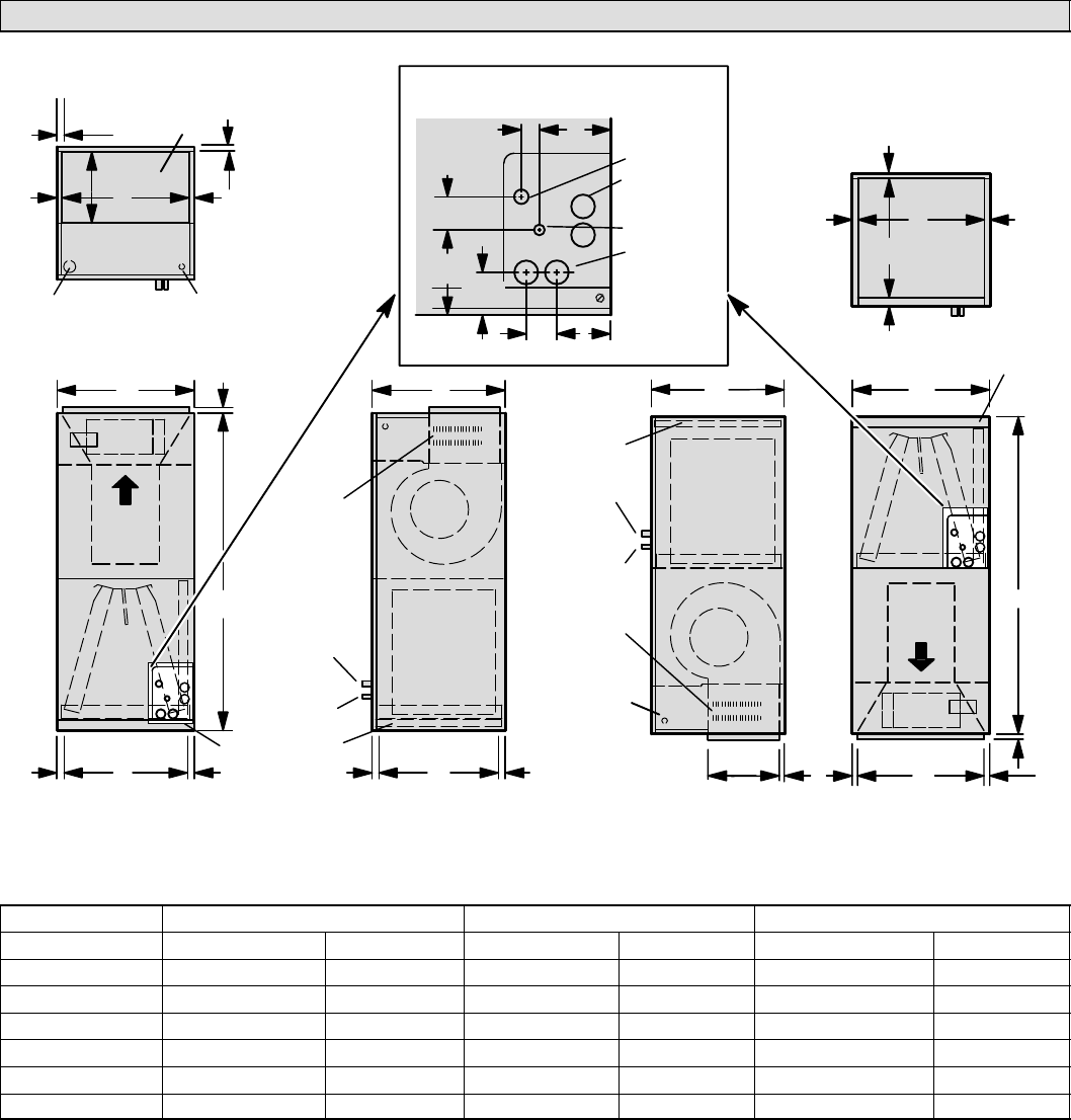
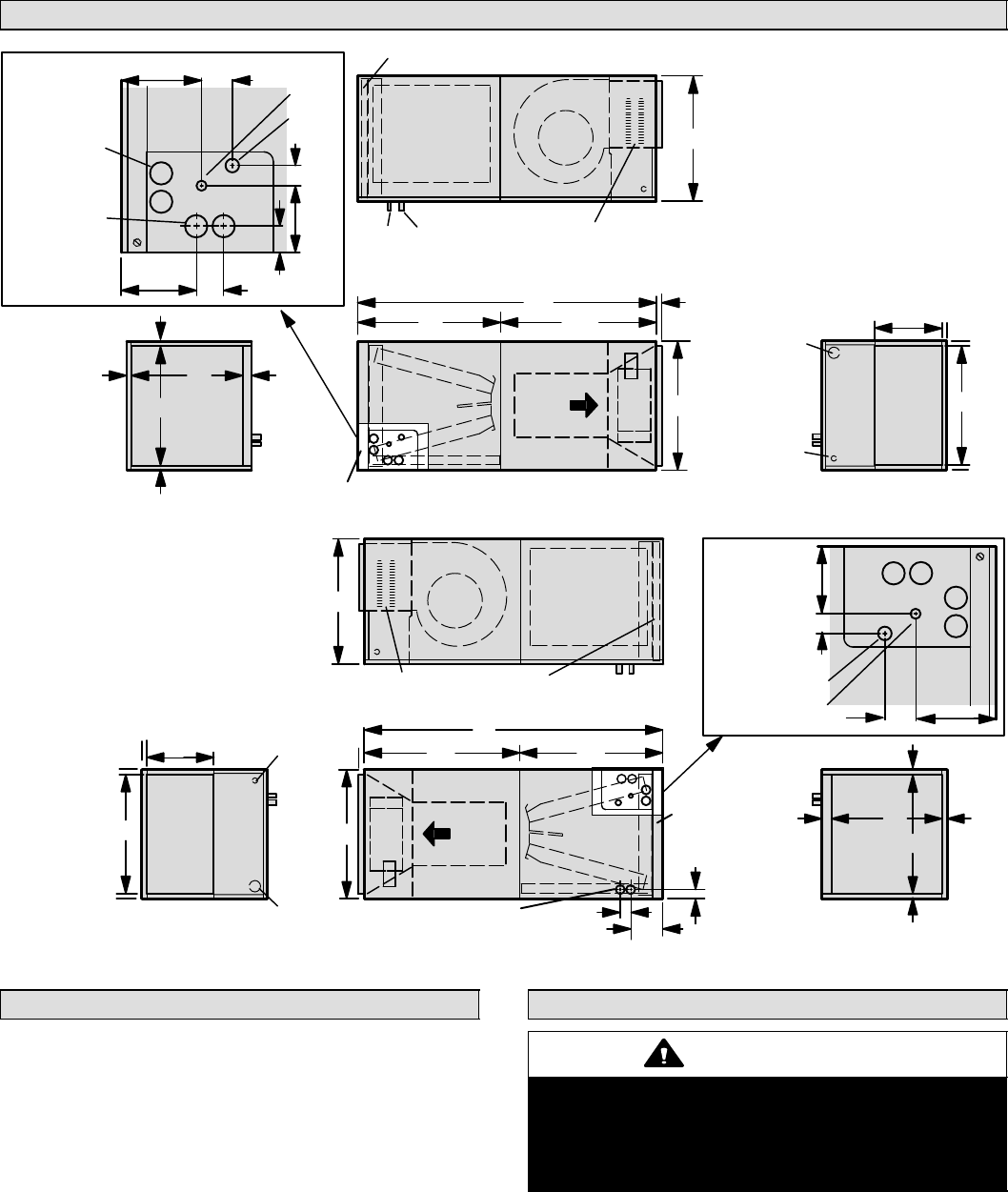
CB29M Upflow and Downflow Unit Dimensions − inches (mm)
OPTIONAL
ELECTRIC
HEAT
(FIELD−
INSTALLED)
AIR
FLOW
LIQUID
LINE
SUCTION
LINE
SUPPLY
AIR OPENING
RETURN AIRFILTER
LOW VOLTAGE
INLETS (TOP &
RIGHT SIDE)
RETURN AIR
Top View
Front View Side View
BLOWER
PIPING PLATE DETAIL
(For upflow and downflow positions)
A
BC
11-1/16
(281)
D
FE
LIQUID LINE
SUCTION LINE
CONDENSATE
DRAINS (2)
(HORIZONTAL)
COIL
3/4
(19)
3/4
(19)
5/8
(16)
5/8
(16)
1
(25)
5/8
(16)
1-3/4 (44)
2
(51)
1-1/8 (29) 4-3/8 (111)
2-3/4
(70)
5-3/8
(137)
3-1/2 (89)
OPTIONAL
ELECTRIC
HEAT
(FIELD−
INSTALLED)
AIR FLOW
LIQUID
LINE
SUCTION
LINE
RETURN
AIR
OPENING
SUPPLY
AIR
FILTER
SUPPLY AIR
Top View
Front ViewSide View
BLOWER
A
BC
11-1/16 (281)
F
D
E
COIL
5/8
(16)
5/8
(16)
5/8
(16)
5/8 (16)
5/8
(16)
LOW VOLTAGE
(RIGHT SIDE)
LINE VOLTAGE
(LEFT SIDE)
Downflow Position
(Kit number 83M57 (LB−909844A) required to convert
unit to downflow applications.)
1 (25)
Upflow Position
CONDENSATE
DRAINS (2)
(UPFLOW AND
DOWNFLOW)
FILTER
ACCESS
FILTER
ACCESS
LINE VOLTAGE
INLETS (TOP &
LEFT SIDE)
5/8
(16)
5/8 (16)
Model No. CB29M-21/26 & CB29M-31 CB29M-41 & CB29M-46 CB29M-51 & CB29M-65
Dimension inch mm inch mm inch mm
A45-1/4 1149 49-1/4 1251 52-1/2 1334
B16-1/4 413 21-1/4 540 21-1/4 540
C20-5/8 524 20-5/8 524 22-5/8 575
D14-3/4 375 19-3/4 502 19-3/4 502
E19 483 19 483 21 533
F15 351 20 508 20 508
Page 3
CB29M/CB30M SERIES
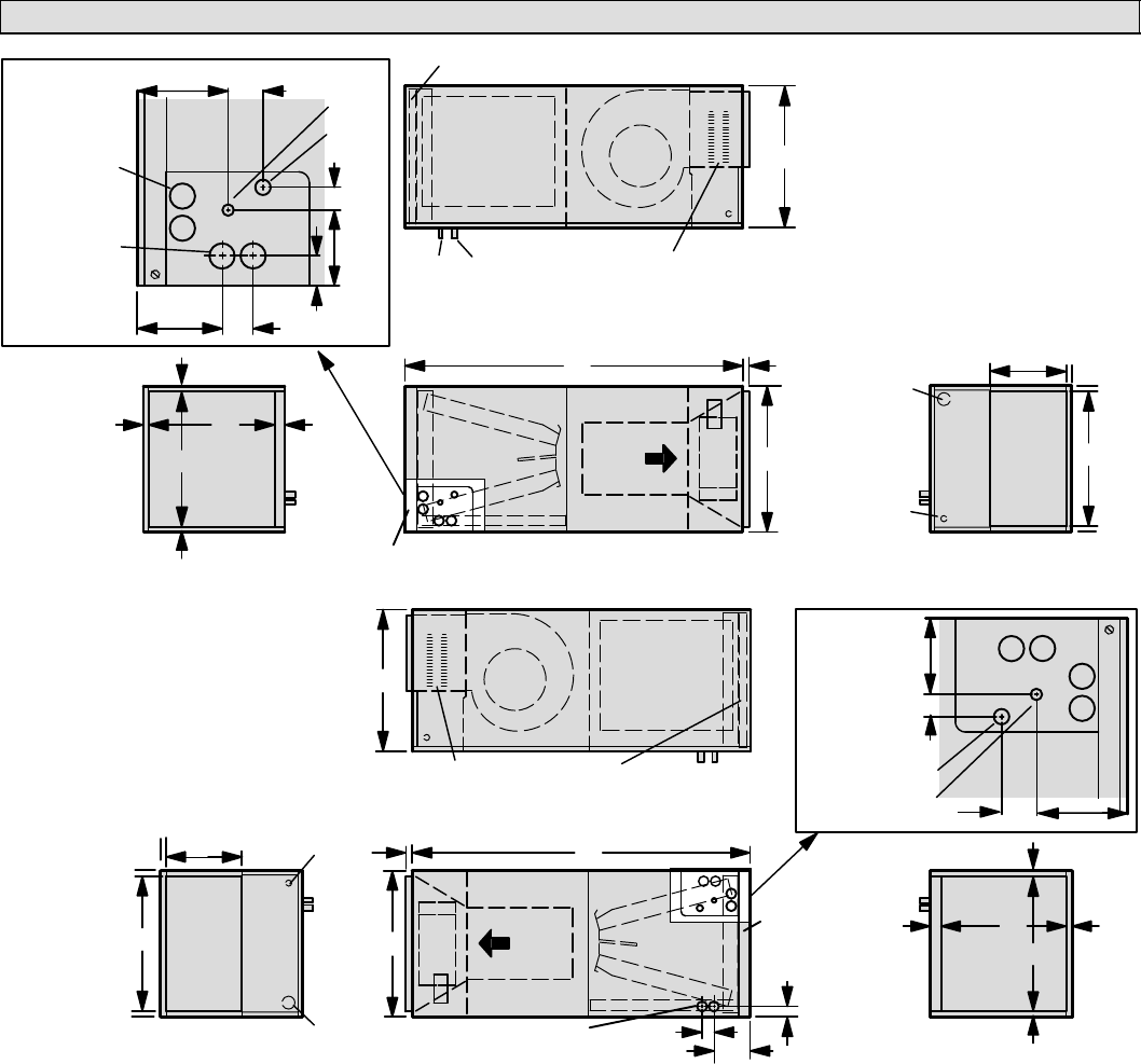
CB29M Horizontal Left− and Right−Hand Unit Dimensions − inches (mm)
LIQUID
LINE
SUCTION
LINE
SUPPLY
AIR
OPENING
FILTER
LOW VOLTAGE
INLETS (BOTTOM
& RIGHT SIDE)
Top View
Front View
BLOWER
B
C
D
LIQUID
LINE
SUCTION
LINE
CONDENSATE
DRAINS (2)
(UPFLOW AND
DOWNFLOW)
CONDENSATE
DRAINS (2)
(HORIZONTAL)
COIL
3/4
(19)
3/4
(19)
1-1/2
(38)
1-3/4
(44)
5-3/4
(46)
2
(51)
1-1/8
(29)
RETURN
AIR
OPENING
F
E
5/8
(16)
5/8
(16)
5/8
(16)
End View
AIR
FLOW
OPTIONAL ELECTRIC
HEAT (FIELD−INSTALLED)
11-1/16
(281)
LINE VOLTAGE
INLETS (TOP &
RIGHT SIDE)
5-3/8
(137)
4-3/8
(111)
LIQUID
LINE
SUCTION
LINE
SUPPLY
AIR
OPENING
FILTER
LOW VOLTAGE
INLETS (TOP &
LEFT SIDE)
End View
BLOWER
B
C
D
COIL
3/4
(19)
3/4
(19)
3/4
(19)
RETURN
AIR OPENING
F
E
5/8
(16)
5/8
(16)
5/8
(16)
End View
AIR
FLOW
OPTIONAL ELECTRIC
HEAT (FIELD INSTALLED)
LINE VOLTAGE INLETS
(BOTTOM & LEFT SIDE)
Horizontal Position (Right-Hand Air Discharge)
FILTER ACCESS
FILTER
ACCESS
5-3/4
(146)
1-1/2
(38)
1-3/4
(44)
CONDENSATE DRAINS (2)
(HORIZONTAL)
A
5/8
(16)
A
5/8
(16)
1
(25)
1
(25)
11-1/16
(281)
PIPING
PLATE
DETAIL
LIQUID
LINE
SUCTION
LINE
2
(51)
1-1/8
(29)
5-3/8
(137)
4-3/8
(111)
PIPING
PLATE
DETAIL
Horizontal Position (Left-Hand Air Discharge)
Top View
Front View
3/4
(19)
End View
For dimensions A"
through F", see
chart on Page 2.
Page 4
504719M 09/05
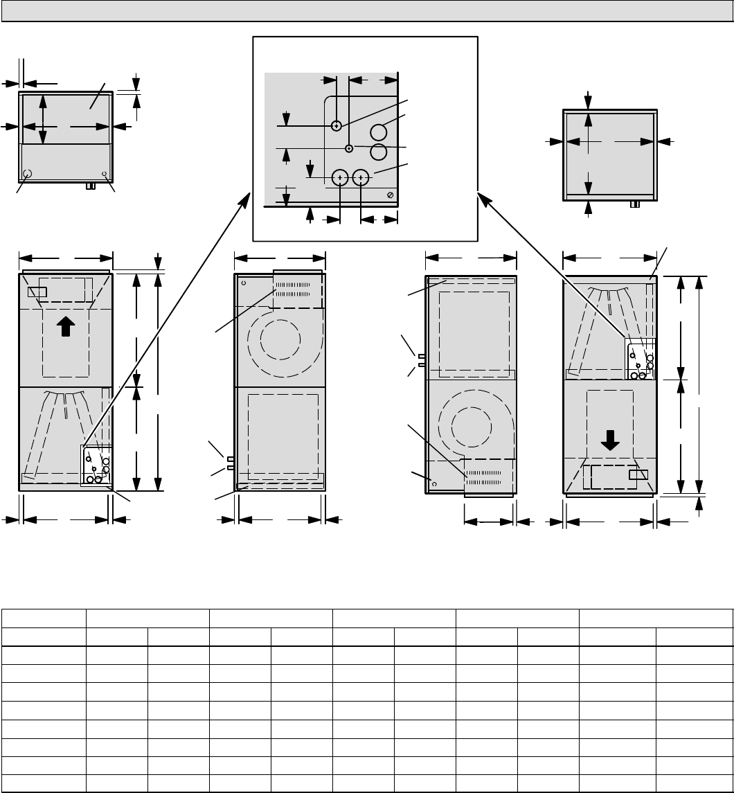
CB30M Upflow and Downflow Unit Dimensions − inches (mm)
OPTIONAL
ELECTRIC
HEAT
(FIELD−
INSTALLED)
AIR
FLOW
LIQUID
LINE
SUCTION
LINE
SUPPLY
AIR OPENING
RETURN AIRFILTER
LOW VOLTAGE
INLETS (TOP &
RIGHT SIDE)
RETURN AIR
Top View
Front View Side View
BLOWER
PIPING PLATE DETAIL
(For upflow and downflow positions)
A
BC
11-1/16
(281)
D
FE
LIQUID LINE
SUCTION LINE
CONDENSATE
DRAINS (2)
(HORIZONTAL)
COIL
3/4
(19)
3/4
(19)
5/8
(16)
5/8
(16)
1
(25)
5/8
(16)
1-3/4 (44)
2
(51)
1-1/8 (29) 4-3/8 (111)
2-3/4
(70)
5-3/8
(137)
3-1/2 (89)
OPTIONAL
ELECTRIC
HEAT
(FIELD−
INSTALLED)
AIR FLOW
LIQUID
LINE
SUCTION
LINE
RETURN
AIR
OPENING
SUPPLY
AIR
FILTER
SUPPLY AIR
Top View
Front ViewSide View
BLOWER
A
BC
11-1/16 (281)
F
D
E
COIL
5/8
(16)
5/8
(16)
5/8
(16)
5/8 (16)
5/8
(16)
LOW VOLTAGE
(RIGHT SIDE)
LINE VOLTAGE
(LEFT SIDE)
Downflow Position
(Kit number 83M57 (LB−909844A) required to convert
unit to downflow applications.)
1 (25)
Upflow Position
CONDENSATE
DRAINS (2)
(UPFLOW AND
DOWNFLOW)
FILTER
ACCESS
FILTER
ACCESS
H
G
H
G
LINE VOLTAGE
INLETS (TOP &
LEFT SIDE)
5/8
(16)
5/8 (16)
Model No. CB30M-21/26 CB30M-31 CB30M-41 CB30M-46 CB30M-51 & CB30M-65
Dimension inch mm inch mm inch mm inch mm inch mm
A45-1/4 1149 49-1/4 1251 51 1295 52-1/2 1334 58-1/2 1486
B16-1/4 413 21-1/4 540 21-1/4 540 21-1/4 540 21-1/4 540
C20-5/8 524 20-5/8 524 22-5/8 575 22-5/8 575 24-5/8 625
D14-3/4 375 19-3/4 502 19-3/4 502 19-3/4 502 19-3/4 502
E19 483 19 483 21 533 21 533 23 584
F15 351 20 508 20 508 20 508 20 508
G24-5/8 625 24-5/8 625 26-3/8 670 27-7/8 708 27-7/8 708
H20-5/8 524 24-5/8 625 24-5/8 625 24-5/8 625 30-5/8 778
Page 5
CB29M/CB30M SERIES
CB30M Horizontal Left− and Right−Hand Unit Dimensions − inches (mm)
LIQUID
LINE
SUCTION
LINE
SUPPLY
AIR
OPENING
FILTER
LOW VOLTAGE
INLETS (BOTTOM
& RIGHT SIDE)
Top View
Front View
BLOWER
H
B
C
D
LIQUID
LINE
SUCTION
LINE
CONDENSATE
DRAINS (2)
(UPFLOW AND
DOWNFLOW)
CONDENSATE
DRAINS (2)
(HORIZONTAL)
COIL
3/4
(19)
3/4
(19)
1-1/2
(38)
1-3/4
(44)
5-3/4
(46)
2
(51)
1-1/8
(29)
RETURN
AIR
OPENING
F
E
5/8
(16)
5/8
(16)
5/8
(16)
End View
AIR
FLOW
OPTIONAL ELECTRIC
HEAT (FIELD−INSTALLED)
11-1/16
(281)
LINE VOLTAGE
INLETS (TOP &
RIGHT SIDE)
5-3/8
(137)
4-3/8
(111)
LIQUID
LINE
SUCTION
LINE
SUPPLY
AIR
OPENING
FILTER
LOW VOLTAGE
INLETS (TOP &
LEFT SIDE)
End View
BLOWER
B
C
D
COIL
3/4
(19)
3/4
(19)
3/4
(19)
RETURN
AIR OPENING
F
E
5/8
(16)
5/8
(16)
5/8
(16)
End View
AIR
FLOW
OPTIONAL ELECTRIC
HEAT (FIELD INSTALLED)
LINE VOLTAGE INLETS
(BOTTOM & LEFT SIDE)
Horizontal Position (Right-Hand Air Discharge)
FILTER ACCESS
FILTER
ACCESS
5-3/4
(146)
1-1/2
(38)
1-3/4
(44)
CONDENSATE DRAINS (2)
(HORIZONTAL)
A5/8
(16)
G
H
A
5/8 (16)
G
1
(25)
1
(25)
11-1/16
(281)
PIPING
PLATE
DETAIL
LIQUID
LINE
SUCTION
LINE
2
(51)
1-1/8
(29)
5-3/8
(137)
4-3/8
(111)
PIPING
PLATE
DETAIL
Horizontal Position (Left-Hand Air Discharge)
Top View
Front View
3/4
(19)
End View
For dimensions A"
through H", see
chart on Page 4.
Requirements
Installation of Lennox blower coil units with or without op-
tional electric heat must conform with standards in the Na-
tional Fire Protection Association (NFPA) Standard for
Installation of Air Conditioning and Ventilation Systems
NFPA No. 90A," and Standard for Installation of Resi-
dence Type Warm Air Heating and Air Conditioning Sys-
tems NFPA No. 90B," manufacturer’s installation instruc-
tions and local municipal building codes.
This unit is certified for installation clearances to combus-
tible material as listed on the unit rating plate. Accessibility
and service clearances must take precedence over com-
bustible material clearances.
Installation
WARNING
Improper installation, adjustment, alteration, ser-
vice or maintenance can cause property damage,
personal injury or loss of life. Installation and ser-
vice must be performed by a qualified installer or
service agency.
The CB29M and CB30M units are factory−configured for
upflow or horizontal right−hand discharge installation. For
downflow or horizontal left−hand discharge, some field
modification is required.
Page 6
504719M 09/05
IMPORTANT
Kit number 83M57 (LB−109844A) must be installed
for downflow application.
Disassembling CB30M Blower Coil Unit
These units are shipped from the factory fully assembled.
The CB30M blower coil unit’s sections may be separated
to facilitate movement at some installation sites. If re-
quired, disassemble the unit as follows:
1. Remove access panels from both blower and coil as-
semblies. This will lighten the cabinet for lifting.
2. Remove one screw from the left and right posts inside
the unit. Remove one screw from each side on the
back of the unit. Unit sections will now separate.
3. To reassemble, align cabinet sections and reinstall
screws. Replace access panels.
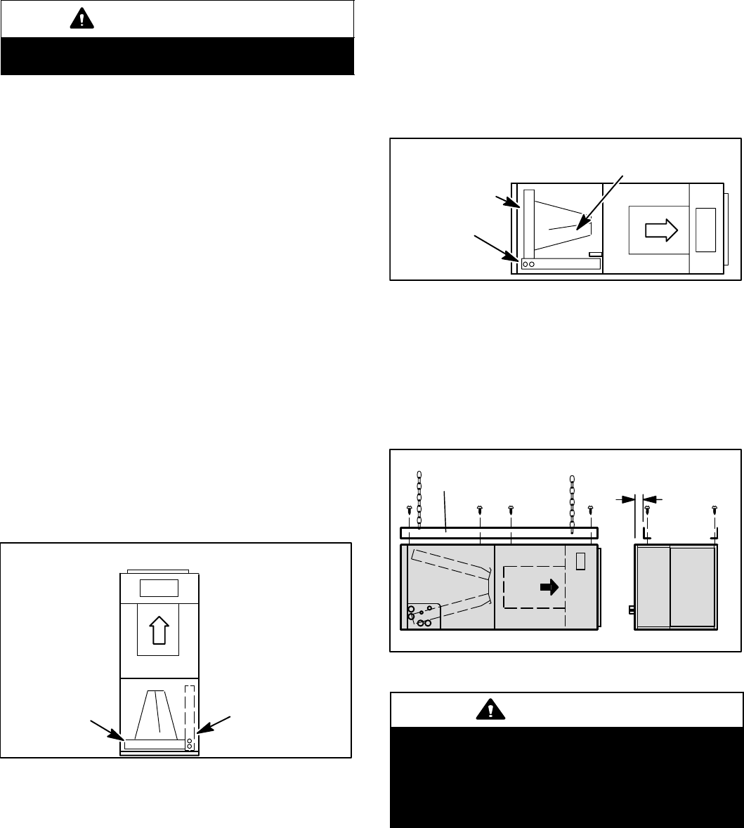
Upflow Application
1. Remove access panels. Remove corrugated padding
from the space between the blower and coil assem-
blies.
2. To ensure proper operation, remove the horizontal
drain pan from units in upflow configurations (see fig-
ure 1).
3. Place unit in desired location. Make sure that unit is
level. Connect return and supply air plenums as re-
quired using sheet metal screws.
4. Install units that have no return air plenum on a mount-
ing stand at least 14" from the floor for proper air re-
turn. Lennox offers an optional upflow unit stand.
(45K31 for CB29M−21, −26, and −31; 45K32 for
CB29M−41 through −65.)
Figure 1
Upflow Configuration
Horizontal Drain Pan
(Remove for Opti-
mum Performance)
Upflow/
Downflow
Drain Pan
Horizontal Right−Hand Discharge Application
1. Remove access panels. Remove corrugated padding
from the space between the blower and coil assembly.
2. No further adjustment is necessary. Set unit so that it is
sloped 1/4 inch toward the drain pan end of the unit.
NOTE − For horizontal applications, an auxiliary drain
pan is recommended. Refer to local codes.
NOTE − For horizontal applications in high humidity
areas, seal around the exiting drain pipe, liquid line,
and suction line to prevent infiltration of humid air.
Figure 2
Right−Hand Discharge Configuration
No Adjustment
is Necessary
Horizontal Drip ShieldUpflow/
Downflow
Drain Pan
Horizontal
Drain Pan
3. If the unit is to be suspended, it must be supported
along the entire length of the cabinet (see figure 3). If
using a chain or strap, attach a piece of angle iron or
sheet metal to the unit (either above or below the unit),
so that the full length of the cabinet is supported. Use
securing screws which are no longer than 1/2 inch to
avoid damaging the coil or filter. Use sheet metal
screws to connect the return and supply air plenums.
Figure 3
Suspending Horizontal Unit
FRONT VIEW END VIEW
Angle Iron or
Sheet Metal
Electrical Inlet Clearance
4 in. (102 mm)
1/2 IN.
SCREWS
MAX.
CAUTION
When removing the coil, there is possible danger of
equipment damage and personal injury. Be careful
when removing the coil assembly from a unit
installed in right− or left−hand applications. The coil
may tip into the drain pan once it is clear of the cabi-
net. Support the coil when removing it.
Page 7
CB29M/CB30M SERIES
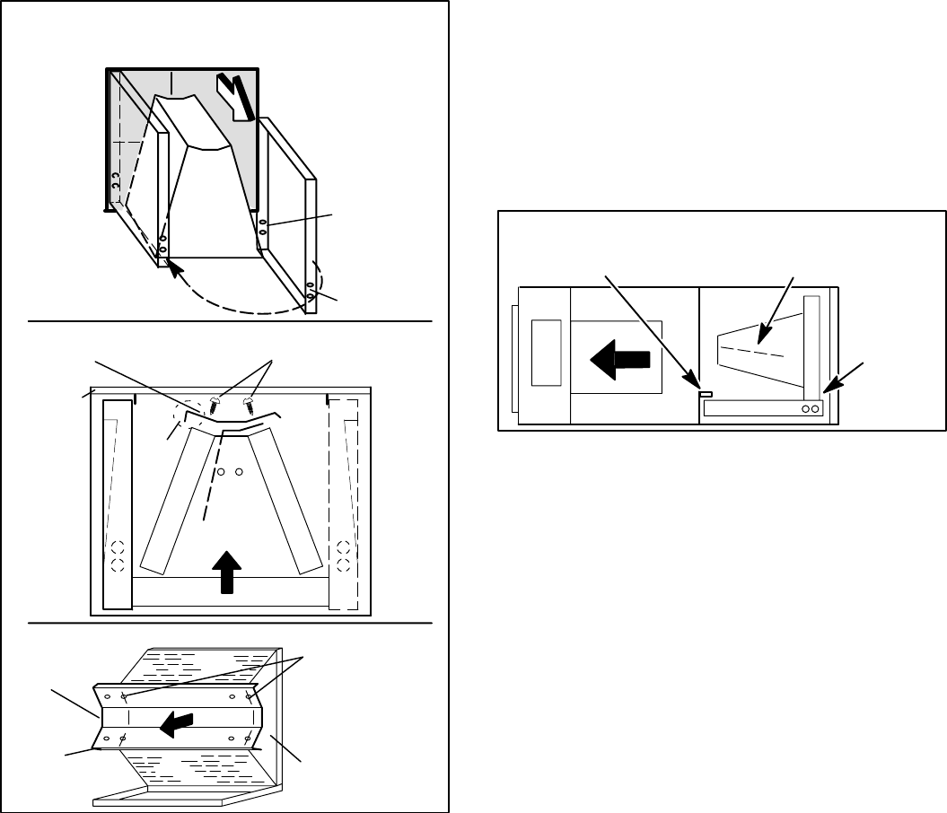
Horizontal Left−Hand Discharge Application
NOTE − For horizontal applications, an auxiliary drain pan
is recommended. Refer to local codes.
Remove the access panels and the corrugated padding
from the space between the blower and coil assembly be-
fore operation. Make the following modifications:
1. (See Detail A in figure 4.) Pull coil assembly from unit.
Pull off the horizontal drain pan.
2. Remove drain plugs from back drain holes on horizon-
tal drain pan and re−install them on front holes.
3. Rotate drain pan 180° front to back and install it on the
opposite side of coil.
ORIGINAL
PLUG
LOCATION
NEW PLUG
LOCATION
PLUGGED
END
OPEN END FOR
CONDENSATION
DRAIN
COIL
ASSEMBLY
Left-Hand Discharge Modifications
Figure 4
90_
BEND
CABINET
SUPPORT
Coil shown in upflow position for easy conversion
TOP CAP
SCREWS
TOP CAP ROTATED TO
CORRECT POSITION
BACK COIL
END SEAL
TOP
CAP
90_
BEND
ALIGN HOLES
WITH HOLES
IN COIL END
PLATE.
DRAIN PAN
Detail A
(DRAIN
PAN)
Detail B
(TOP CAP)
Detail C
4. (See Detail B and C in figure 4.) Remove screws from
top cap. Remove horizontal drip shield screw located
in the center of the back coil end seal.
5. Rotate horizontal drip shield 180° front to back.
6. Remove plastic plug from left hole on coil front end
seal and re−install plug in back hole. Re−install horizon-
tal drip shield screw in front coil end seal. Drip shield
should drain downward into horizontal drain pan inside
coil.
7. Rotate top cap 180° front to back and align with un-
used screw holes. Holes must align with front and back
coil end plates. Note that top cap has a 45° bend on
one side and 90° bend on the other. The 90° bend
must be on the same side as the horizontal drain
pan. See figure 4.
NOTE − Use extreme care when re−installing screws
into coil end plate engaging holes. Misaligned screws
may damage coil.
8. (See figure 5.) From the upflow position, flip cabinet
90° to the left and set into place. Replace coil assem-
bly. Secure coil in place by bending down tab on cabi-
net support rail.
Figure 5
Left−Hand Discharge Configuration
Horizontal
Drip Shield
Horizontal
Drain Pan
Securing Tab on
Cabinet Support Rail
NOTE − For horizontal applications in high humidity
areas, seal around the exiting drain pipe, liquid line
and suction line to prevent infiltration of humid air.
9. Knock out drain seal plate from access door. Secure
plate to cabinet front flange with screw provided.
10. Flip access door and replace it on the unit.
11. Set unit so that it is sloped 1/4 inch toward the drain
pan end of the unit. Connect return and supply air ple-
nums as required using sheet metal screws.
12. If the unit is to be suspended, it must be supported
along the entire length of the cabinet (see figure 3). If
using a chain or strap, attach a piece of angle iron or
sheet metal to the unit (either above or below the unit),
so that the full length of the cabinet is supported. Use
securing screws which are no longer than 1/2 inch to
avoid damaging the coil or filter. Use sheet metal
screws to connect the return and supply air plenums.
Page 8
504719M 09/05
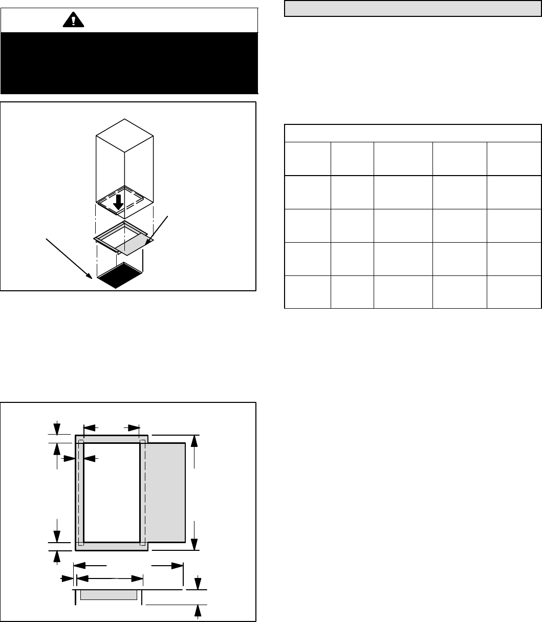
Downflow Application
NOTE − If downflow application is required, separately or-
der kit number 83M57 and install per kit’s instructions.
Also, use metal or class I supply and return air plenums.
WARNING
If electric heat section with circuit breakers (ECB29)
are applied to downflow CB29M or CB30M unit, cir-
cuit breakers must be rotated 180_ to the UP posi-
tion. See ECB29 installation instructions for more
details.
Figure 6
Combustible
Floor Additive
Base
Properly−Sized
Floor Opening
BLOWER
COIL UNIT
Combustible Flooring Additive Base
On combustible flooring, use an additive base (figure 6).
Cut an appropriately sized opening for combustible base
(see dimensions in figure 7). Set the additive base into
opening. Connect supply air plenum to the additive base.
Set the unit on the additive base so flanges of the unit drop
into the base opening and seal against the insulation strips.
The unit is now locked in place. Install return air plenum
and secure with sheet metal screws.
TOP VIEW
OPENING
SIDE VIEW
1-5/8 (41)
11-3/8
(289)
2 (51)
22-1/8 (562)
5/8 (16) 13-3/8 (340)
SUPPLY
AIR
OPENING
Figure 7
18−1/4 (464)
CB29M−21/26 & 31
CB30M−21/26
23−1/4 (591)
CB29M−41 to −65
CB30M−31 to 65
Downflow Combustible Base Dimensions
15 (381)
CB29M−21/26 & 31
CB30M−21/26
20 (508)
CB29M−41 to −65
CB30M−31 to 65
1-5/8 (41)
1-5/8 (41)
inches
(mm)
If the homeowner reports water dripping from supply air dif-
fusers, check the shields and tape. Make sure the tape is
completely attached to the edges of the drip shield, and
that the drip shield is wedged firmly in place.
Field Piping Connections
All CB29M/CB30M coils are equipped with a factory−
installed, internally mounted expansion valve. Use Lennox
L15 (sweat) series line sets as shown in Table 1 or use
field−fabricated refrigerant lines. L10 (flare) line sets may
be used by cutting off flare nut. Refer to the piping section
of the Lennox Unit Information Service Manual for proper
size, type and application of field−fabricated lines.
Table 1
Refrigerant Line Sets
CB29M
CB29M
Unit
Liquid
Line No.
Vapor/
Suction Line
L10
Line Sets
L15
Line Sets
−21/26 3/8 in
(8 mm)
5/8 in
(16 mm)
L10−26
20 ft. − 50 ft.
(6 m − 15 m)
L15−26
20 ft. − 50 ft.
(6 m − 15 m)
−31 −41 3/8 in
(10 mm)
3/4 in.
(19 mm
L10−41
20 ft. − 50 ft.
(6 m − 15 m)
L15−41
20 ft. − 50 ft.
(6 m − 15 m)
−46 −51 3/8 in
(10 mm)
7/8 in.
(22 mm)
L10−65
30 ft. − 50 ft.
(9 m − 15 m)
L15−65
30 ft. − 50 ft.
(9 m − 15 m)
−65 3/8 in
(10 mm)
1−1/8 in.
(29 mm)
FIELD
FABRI-
CATED
FIELD
FABRI-
CATED
NOTE − CB29M/CB30M series evaporators use nitro-
gen or dry air as a holding charge. If there is no pressure
when the rubber plugs are removed, check the coil or line
set for leaks before installing. After installation, pull a
vacuum on the line set and coil before releasing the unit
charge into the system.
1. Use a wet rag to protect TXV bulb (or remove it) when
brazing suction line.
2. Be aware of filter access panel when connecting lines.
Filter must be accessible.
3. Place heat shield (damp rag) against piping plate and
around the suction line connection. Heat shield must
be in place to guard against damage to the paint.
4. With heat shield in place, sweat in suction line elbow,
provided, and line set. After procedure is completed,
remove heat shield.
5. Place heat shield against piping plate and around the
liquid line connection. Sweat in the liquid line elbow
(provided) and the line set.
6. Refer to instructions provided with outdoor unit for leak
testing, evacuating and charging procedures.
Page 9
CB29M/CB30M SERIES
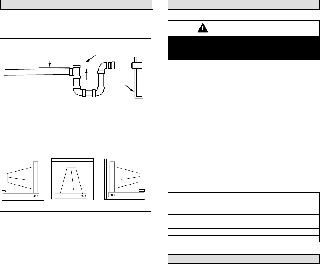
Condensate Drain
Connect main condensate drain and route downward to an
open drain or sump. Do not connect drain to a closed waste
system. Refer to figure 8 for typical condensate trap con-
figuration.
Figure 8
Minimum 1 inch (25 mm) pitch
per 10 feet (3048mm) of line
Pipe diameter difference
Trap must be deep enough to
offset maximum static difference
(generally, 2" [51mm] minimum).
Typical Condensate Drain Connection
Coil
drain
pan
It is recommended that the auxiliary drain be connected to
a drain line for all units. If auxiliary drain is not connected, it
must be plugged with provided cap. For downflow units,
the auxiliary drain MUST be connected and routed to a
drain. See figure 9 for auxiliary and main drain locations.
Figure 9
Left−Hand
Discharge
Main drain on rightAuxiliary drain on left
Upflow or
Downflow
Right−Hand
Discharge
The following practices are recommended to ensure con-
densate removal (see figures 8 and 9):
1. Drain piping should not be smaller than the drain con-
nections at drain pan.
2. A trap must be installed in the main drain line.
3. The trap must be deep enough to offset the difference
in static pressure between drain pan and atmosphere.
Generally, two inches is satisfactory for medium static
applications.
4. Horizontal runs must be sloped 1 inch per 10 feet of
drain line to offset friction.
5. An open vent in drain line will sometimes be required due
to line length, friction and static pressure.
6. Drain construction and routing should facilitate future
cleaning and must not interfere with filter access.
7. Auxiliary drain should run to an area where homeown-
er will notice any drainage. Refer to local codes.
Filters
IMPORTANT
Filter access panel must be in place during unit op-
eration. Excessive warm air entering the unit may re-
sult in water blow−off problems.
Each unit includes a factory−installed filter. Note that filter
access door fits over access panel. Air leakage will occur if
access panel is placed over filter door.
Filters should be inspected monthly and must be cleaned
or replaced when dirty to assure proper furnace operation.
Reusable filters supplied with some units can be washed
with water and mild detergent. Some units are equipped
with standard throw−away type filters which should be re-
placed when dirty.
To remove filter, loosen the thumbscrews holding the filter
panel in place. Slide filter out of the guides on either side of
cabinet, insert new filter and replace panel. See Table 2 for
replacement filter sizes.
Table 2
Filter Dimensions
Unit Model No.
Filter Size
Inches (mm)
CB29M/CB30M−21/26, CB29M−31 15 x 20 (381 x 508)
CB29M−41, −46, CB30M−31 20 x 20 (508 x 508)
CB29M−51, −65, CB30M−41, −46 20 x 22 (508 x 559)
CB30M−51, −65 20 x 24 (508 x 610)
Sealing the Unit
It is very important to seal the unit so that warm air is not
allowed into the cabinet. Warm air introduces moisture,
which results in water blow−off problems. This is especially
important when the unit is installed in an unconditioned
area.
Make sure the liquid line and suction line entry points are
sealed with either the provided Armaflex material or with
Permagum. Permagum may also be used to seal around
the main and auxiliary drains and around open areas of
electrical inlets.
Page 10
504719M 09/05
Blower Speed Adjustments
Minimum Blower Speeds (With Electric Heaters)
For the minimum allowable speed for the CB29M/CB30M
series units with electric heat, refer to the ECB29 installa-
tion instructions.
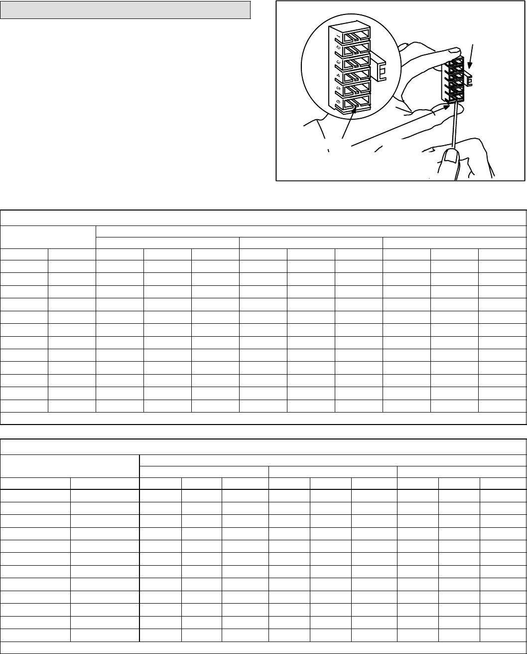
Air Volume Adjustment
Blower speed selection is accomplished by changing the
taps at the harness connector at the blower motor. See fig-
ure 10. Refer to unit wiring diagram in figure 11. Refer to
Tables 3 through 20 for blower performance data.
Blower Speed Tap Selection
Figure 10
harness
connector
Press the tab to release wire connector.
select connector location for new speed.
Insert wire until it clicks.
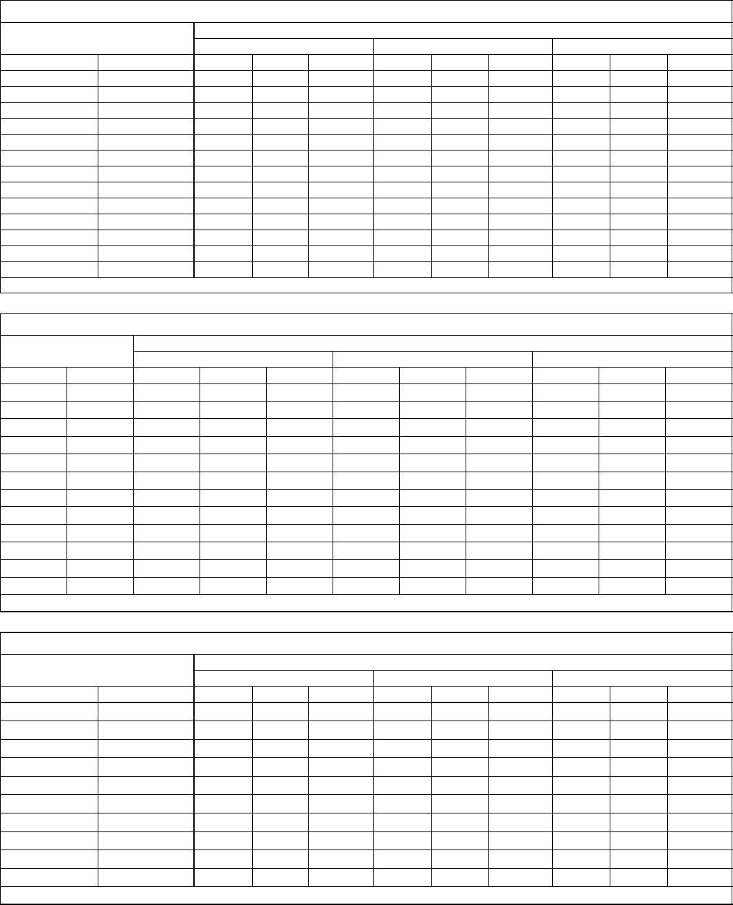
Table 3
CB29M-21/26 Blower Performance (208/230V)
External Static Air Volume and Motor Watts at Specific Blower Taps
External
Static
Pressure Low Medium High
in. w.g. Pa cfm L/s Watts cfm L/s Watts cfm L/s Watts
.00 0 700 330 245 895 420 310 1030 485 375
.05 10 690 325 240 875 415 305 1010 475 370
.10 25 680 320 235 865 410 300 990 470 365
.15 35 665 315 230 850 400 290 970 460 355
.20 50 655 310 225 830 390 285 955 450 350
.25 60 640 300 220 810 385 280 925 440 345
.30 75 625 295 220 795 375 270 900 425 335
.40 100 595 280 210 750 355 255 850 400 320
.50 125 555 260 195 700 330 240 800 380 305
.60 150 510 240 185 640 300 225 725 340 290
.70 175 395 185 165 - - - - - - - - - - - - 620 295 265
.75 185 - - - - - - - - - - - - - - - - - - - - - - - - 570 270 255
NOTE − All air data is measured external to unit with air filter in place. Electric heaters have no appreciable air resistance.
Table 4
CB29M-31 Blower Performance (208/230V)
Air Volume and Motor Watts at Specific Blower Taps
External Static Pressure Low Medium High
in. w.g. Pa cfm L/s Watts cfm L/s Watts cfm L/s Watts
.00 0 1015 480 385 1135 535 410 1230 580 450
.05 10 995 470 375 1120 530 400 1205 570 445
.10 25 980 465 365 1095 515 390 1190 560 440
.15 35 960 455 355 1075 505 380 1165 550 430
.20 50 945 445 345 1050 495 375 1140 540 425
.25 60 925 435 335 1025 485 365 1105 520 415
.30 75 900 425 325 1005 475 355 1080 510 405
.40 100 860 405 305 950 450 335 1025 485 390
.50 125 800 380 285 890 420 315 960 450 370
.60 150 740 350 265 810 385 290 875 415 350
.70 175 670 315 240 735 345 270 790 375 330
.75 185 610 290 225 675 320 255 725 340 315
NOTE − All air data is measured external to unit with air filter in place. Electric heaters have no appreciable air resistance.
Page 11
CB29M/CB30M SERIES
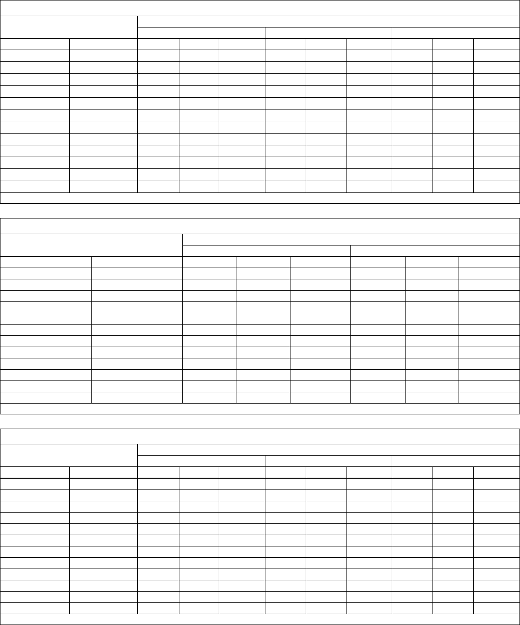
Table 5
CB29M-41 Blower Performance (208/230V)
Air Volume and Motor Watts at Specific Blower Taps
External Static Pressure Low Medium High
in. w.g. Pa cfm L/s Watts cfm L/s Watts cfm L/s Watts
.00 0 935 440 420 1145 540 510 1505 710 655
.05 10 930 440 415 1140 535 500 1485 700 640
.10 25 925 435 410 1130 535 490 1475 695 630
.15 35 915 435 395 1125 530 480 1455 685 615
.20 50 910 430 390 1115 525 475 1435 680 600
.25 60 905 425 380 1110 525 465 1420 670 585
.30 75 900 425 370 1100 520 455 1395 660 570
.40 100 885 415 355 1080 510 430 1350 640 540
.50 125 865 410 335 1060 500 415 1300 615 510
.60 150 845 400 315 1030 485 390 1235 585 480
.70 175 820 390 300 - - - - - - - - - - - - 1160 550 455
.75 185 - - - - - - - - - - - - - - - - - - - - - - - - 1015 480 425
NOTE − All air data is measured external to unit with air filter in place. Electric heaters have no appreciable air resistance.
Table 6
CB29M-41 Blower Performance (460V − 1 ph)
Air Volume and Motor Watts at Specific Blower Taps
External Static Pressure Low Medium High
in. w.g. Pa cfm L/s Watts cfm L/s Watts cfm L/s Watts
.00 0 955 450 425 1130 535 530 1460 690 665
.05 10 950 450 415 1120 530 520 1445 680 650
.10 25 945 445 410 1115 525 510 1435 675 640
.15 35 940 445 400 1110 525 500 1415 670 630
.20 50 935 440 390 1105 520 490 1400 660 615
.25 60 930 440 385 1100 520 485 1380 650 600
.30 75 920 435 375 1090 515 475 1360 645 585
.40 100 910 430 360 1075 510 455 1325 625 555
.50 125 895 420 345 1060 500 435 1280 605 520
.60 150 880 415 330 1035 490 410 1225 580 480
.70 175 855 405 315 - - - - - - - - - - - - 1145 540 430
NOTE − All air data is measured external to unit with air filter in place. Electric heaters have no appreciable air resistance.
Table 7
CB29M-46 Blower Performance (208/230V)
Air Volume and Motor Watts at Specific Blower Taps
External Static Pressure Low Medium High
in. w.g. Pa cfm L/s Watts cfm L/s Watts cfm L/s Watts
.00 0 1295 610 520 1520 720 595 1775 840 730
.05 10 1275 605 510 1505 710 585 1750 825 720
.10 25 1255 590 495 1480 700 570 1720 810 710
.15 35 1230 580 480 1455 685 555 1690 795 700
.20 50 1215 575 470 1430 675 540 1650 780 685
.25 60 1195 565 455 1405 665 525 1620 765 675
.30 75 1170 555 440 1380 650 515 1595 750 660
.40 100 1125 530 415 1320 625 485 1515 715 635
.50 125 1065 500 385 1260 595 460 1420 670 605
.60 150 1005 475 360 1175 555 425 1325 625 575
.70 175 910 430 330 1075 505 395 1210 570 545
.80 200 - - - - - - - - - - - - - - - - - - - - - - - - 900 425 480
NOTE − All air data is measured external to unit with air filter in place. Electric heaters have no appreciable air resistance.
Page 12
504719M 09/05
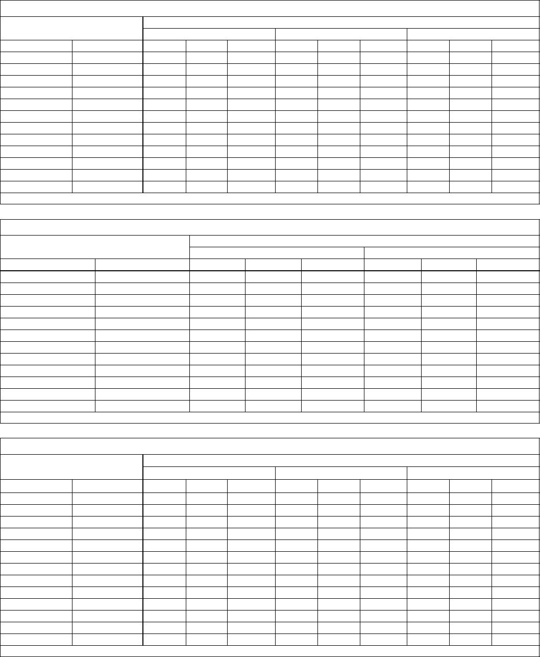
Table 8
CB29M−51 Blower Performance (208/230V)
Air Volume and Motor Watts at Specific Blower Taps
External Static Pressure Low Medium High
in. w.g. Pa cfm L/s Watts cfm L/s Watts cfm L/s Watts
.00 0 1590 750 665 1790 845 805 2055 970 1005
.05 10 1570 740 660 1770 835 790 2035 960 995
.10 25 1555 735 655 1750 825 785 2005 945 980
.15 35 1530 720 645 1730 815 775 1980 935 970
.20 50 1510 710 640 1710 805 765 1945 920 955
.25 60 1485 700 635 1685 795 755 1915 905 940
.30 75 1460 690 625 1660 785 745 1885 890 930
.40 100 1415 670 615 1610 760 725 1820 860 900
.50 125 1370 645 600 1550 730 705 1750 825 875
.60 150 1310 620 580 1490 705 685 1670 790 845
.70 175 1240 585 560 1405 665 660 1575 745 820
.75 185 1210 570 550 1360 640 645 1520 720 800
NOTE − All air data is measured external to unit with air filter in place. Electric heaters have no appreciable air resistance.
Table 9
CB29M−51 Blower Performance (460V − 1 ph)
Air Volume and Motor Watts at Specific Blower Taps
External Static Pressure Low Medium High
in. w.g. Pa cfm L/s Watts cfm L/s Watts cfm L/s Watts
.00 0 1695 800 680 1900 895 805 2140 1010 965
.05 10 1675 790 670 1880 885 795 2110 995 950
.10 25 1655 780 665 1855 875 780 2080 980 935
.15 35 1640 775 655 1830 865 770 2050 970 920
.20 50 1620 765 650 1805 850 755 2025 955 910
.25 60 1595 750 640 1775 840 740 1995 940 895
.30 75 1570 740 630 1750 825 730 1965 925 885
.40 100 1525 720 610 1700 805 710 1905 900 860
.50 125 1475 695 595 1640 775 685 1845 870 835
.60 150 1420 670 575 1585 750 665 1770 835 805
.70 175 1355 640 555 1515 715 640 1700 800 780
.80 200 1290 610 535 1450 685 620 1625 765 755
.85 210 1255 590 525 1405 665 610 1595 750 745
NOTE − All air data is measured external to unit with air filter in place. Electric heaters have no appreciable air resistance.
Table 10
CB29M-65 Blower Performance (208/230v)
External Static Air Volume and Motor Watts at Specific Blower Taps
External
Static
Pressure Low Medium−Low Medium Medium−High High
in.w.g. Pa cfm L/s Watts cfm L/s Watts cfm L/s Watts cfm L/s Watts cfm L/s Watts
.00 0 1570 740 575 1800 850 700 2005 945 825 2135 1005 930 2245 1060 1080
.05 10 1550 730 570 1780 840 690 1980 935 815 2110 995 925 2220 1050 1070
.10 25 1530 725 560 1760 830 680 1950 920 805 2080 985 915 2190 1035 1060
.15 35 1520 715 560 1735 820 670 1930 910 795 2055 970 905 2165 1020 1050
.20 50 1495 705 550 1710 805 660 1910 900 790 2025 955 895 2135 1010 1040
.25 60 1475 695 545 1690 795 655 1880 890 780 1995 940 885 2105 995 1030
.30 75 1460 690 540 1670 785 650 1855 875 770 1965 930 875 2075 980 1020
.40 100 1415 670 530 1615 760 630 1795 850 750 1910 900 855 2005 945 995
.50 125 1370 645 520 1560 735 615 1735 820 730 1850 875 835 1935 910 975
.60 150 1310 620 505 1495 705 595 1670 790 710 1780 840 810 1855 875 950
.70 175 1250 590 490 1425 675 575 1600 755 690 1705 805 785 1780 840 925
.80 200 1175 555 470 1360 640 560 1520 715 665 1620 765 755 1685 795 900
.90 225 1025 485 440 1280 605 545 1420 670 645 1520 715 725 1595 750 875
.95 235 - - - - - - - - - - - 1240 585 535 1365 645 630 1460 690 705 1545 730 860
NOTE − All air data is measured external to unit with air filter in place. Electric heaters have no appreciable air resistance.
Page 13
CB29M/CB30M SERIES
Table 11
CB29M−65 Blower Performance (460V − 1 ph)
Air Volume and Motor Watts at Specific Blower Taps
External Static Pressure Low Medium High
in. w.g. Pa cfm L/s Watts cfm L/s Watts cfm L/s Watts
.00 0 1785 845 750 2050 970 925 2230 1055 1145
.05 10 1775 835 745 2025 955 915 2200 1040 1135
.10 25 1745 825 735 2005 945 905 2170 1025 1120
.15 35 1725 815 725 1980 935 900 2135 1010 1105
.20 50 1700 800 715 1955 920 885 2105 995 1095
.25 60 1680 795 705 1925 910 875 2075 980 1085
.30 75 1655 780 695 1900 895 865 2045 965 1075
.40 100 1600 755 675 1840 870 845 1980 935 1050
.50 125 1545 730 655 1785 845 825 1910 900 1025
.60 150 1490 705 640 1715 810 800 1835 865 1000
.70 175 1425 670 620 1645 775 775 1765 830 975
.80 200 1360 640 600 1565 735 745 1690 795 955
.90 225 1290 610 585 1465 690 710 1600 755 925
NOTE − All air data is measured external to unit with air filter in place. Electric heaters have no appreciable air resistance.
Table 12
CB30M-21/26 Blower Performance (208/230V)
External Static Air Volume and Motor Watts at Specific Blower Taps
External
Static
Pressure Low Medium High
in. w.g. Pa cfm L/s Watts cfm L/s Watts cfm L/s Watts
.00 0 700 330 245 895 425 300 1030 485 365
.05 10 695 330 245 890 420 295 1015 480 360
.10 25 690 325 240 875 415 290 1000 470 355
.15 35 680 320 235 860 405 285 980 465 345
.20 50 665 315 230 845 400 280 960 455 340
.25 60 650 310 220 825 390 275 935 440 335
.30 75 635 300 215 800 380 265 910 430 325
.40 100 590 280 205 745 355 250 850 400 310
.50 125 535 255 190 685 320 235 780 370 295
.60 150 470 220 175 605 285 220 705 330 280
.70 175 395 185 165 520 245 200 615 290 265
.75 185 350 165 155 475 225 195 565 265 255
NOTE − All air data is measured external to unit with air filter in place. Electric heaters have no appreciable air resistance.
Table 13
CB30M-31 Blower Performance (208/230V)
Air Volume and Motor Watts at Specific Blower Taps
External Static Pressure Low Medium High
in. w.g. Pa cfm L/s Watts cfm L/s Watts cfm L/s Watts
.00 0 1045 490 315 1175 555 335 1290 610 385
.05 10 1075 505 310 1190 560 330 1295 610 380
.10 25 1085 515 300 1190 560 325 1290 610 375
.15 35 1085 510 295 1175 555 320 1265 600 370
.20 50 1065 505 285 1145 540 310 1230 580 360
.25 60 1030 485 270 1105 520 295 1180 555 350
.30 75 980 460 255 1045 495 280 1115 525 335
.40 100 830 390 220 890 420 250 945 445 305
.50 125 615 290 190 675 320 215 720 340 275
.60 150 335 155 160 405 190 185 440 205 240
NOTE − All air data is measured external to unit with air filter in place. Electric heaters have no appreciable air resistance.
Page 14
504719M 09/05
Table 14
CB30M-41 Blower Performance (208/230V)
Air Volume and Motor Watts at Specific Blower Taps
External Static Pressure Low Medium High
in. w.g. Pa cfm L/s Watts cfm L/s Watts cfm L/s Watts
.00 0 915 430 335 1120 530 390 1525 720 505
.05 10 965 455 330 1150 540 385 1520 720 495
.10 25 1005 475 315 1170 550 380 1510 715 480
.15 35 1035 490 235 1180 560 285 1495 705 470
.20 50 1055 495 230 1190 560 280 1475 695 455
.25 60 1060 500 220 1185 560 275 1450 685 440
.30 75 1050 495 215 1175 555 375 1415 670 430
.40 100 1005 475 290 1135 535 325 1335 630 400
.50 125 915 430 255 1060 500 300 1230 580 375
.60 150 775 365 230 960 455 280 1100 520 345
.70 175 590 280 205 830 390 255 950 450 320
.75 185 485 230 195 750 355 245 870 410 305
NOTE − All air data is measured external to unit with air filter in place. Electric heaters have no appreciable air resistance.
Table 15
CB30M-41 Blower Performance (460V − 1 ph)
Air Volume and Motor Watts at Specific Blower Taps
External Static Pressure Low High
in. w.g. Pa cfm L/s Watts cfm L/s Watts
.00 0 1120 530 390 1525 720 505
.05 10 1150 540 385 1520 720 495
.10 25 1170 550 380 1510 715 480
.15 35 1180 560 285 1495 705 470
.20 50 1190 560 280 1475 695 455
.25 60 1185 560 275 1450 685 440
.30 75 1175 555 375 1415 670 430
.40 100 1135 535 325 1335 630 400
.50 125 1060 500 300 1230 580 375
.60 150 960 455 280 1100 520 345
.70 175 830 390 255 950 450 320
.75 185 750 355 245 870 410 305
NOTE − All air data is measured external to unit with air filter in place. Electric heaters have no appreciable air resistance.
Table 16
CB30M-46 Blower Performance (208/230V)
Air Volume and Motor Watts at Specific Blower Taps
External Static Pressure Low Medium High
in. w.g. Pa cfm L/s Watts cfm L/s Watts cfm L/s Watts
.00 0 1325 625 370 1600 755 455 1825 860 565
.05 10 1335 630 370 1585 750 455 1790 845 555
.10 25 1335 630 370 1565 740 450 1750 825 540
.15 35 1330 630 365 1540 725 440 1710 805 530
.20 50 1320 620 360 1505 710 435 1660 785 520
.25 60 1300 615 355 1470 695 425 1610 760 505
.30 75 1270 600 350 1425 675 415 1555 735 495
.40 100 1195 565 330 1320 625 390 1430 675 465
.50 125 1090 515 310 1195 565 365 1290 610 440
.60 150 955 450 285 1050 495 335 1135 535 415
.70 175 795 375 260 875 415 310 965 455 385
.75 185 700 330 250 780 370 295 875 415 370
NOTE − All air data is measured external to unit with air filter in place. Electric heaters have no appreciable air resistance.
Page 15
CB29M/CB30M SERIES
Table 17
CB30M-51 Blower Performance (208/230V)
Air Volume and Motor Watts at Specific Blower Taps
External Static Pressure Low Medium High
in. w.g. Pa cfm L/s Watts cfm L/s Watts cfm L/s Watts
.00 0 1475 695 430 1785 845 520 1910 900 590
.05 10 1480 700 430 1770 835 515 1895 895 585
.10 25 1475 695 425 1750 825 510 1870 880 580
.15 35 1465 690 420 1720 810 500 1840 865 570
.20 50 1445 680 410 1685 795 490 1800 850 565
.25 60 1415 670 405 1645 775 480 1755 830 550
.30 75 1380 650 395 1600 755 465 1700 805 540
.40 100 1290 610 370 1485 700 440 1580 745 515
.50 125 1170 550 345 1350 635 410 1425 675 485
.60 150 1020 480 320 1190 560 380 1250 590 450
.70 175 840 395 295 1000 470 350 1045 495 415
.75 185 740 350 280 900 425 335 930 440 400
NOTE − All air data is measured external to unit with air filter in place. Electric heaters have no appreciable air resistance.
Table 18
CB30M-51 Blower Performance (460V − 1 ph)
Air Volume and Motor Watts at Specific Blower Taps
External Static Pressure Low High
in. w.g. Pa cfm L/s Watts cfm L/s Watts
.00 0 1775 835 530 1870 885 610
.05 10 1775 835 530 1875 885 610
.10 25 1765 835 515 1870 880 590
.15 35 1750 825 510 1850 875 585
.20 50 1720 815 500 1825 860 575
.25 60 1685 795 490 1790 845 560
.30 75 1645 775 480 1745 825 545
.40 100 1530 720 450 1625 765 505
.50 125 1380 650 420 1465 690 470
.60 150 1195 565 385 1270 600 425
.70 175 975 460 350 1030 485 385
.80 200 720 340 320 755 355 340
NOTE − All air data is measured external to unit with air filter in place. Electric heaters have no appreciable air resistance.
Table 19
CB30M-65 Blower Performance (208/230V)
External Static Pressure
Air Volume and Motor Watts at Specific Blower Taps
E
x
t
erna
l
St
a
ti
c
P
ressure Low Medium High
in. w.g. Pa cfm L/s Watts cfm L/s Watts cfm L/s Watts
.00 0 1775 835 585 2025 955 670 2115 995 780
.05 10 1775 835 590 2010 950 665 2100 990 770
.10 25 1770 835 580 1995 940 655 2085 985 765
.15 35 1760 830 570 1975 930 645 2060 970 750
.20 50 1745 825 560 1950 920 635 2030 960 740
.25 60 1725 815 550 1915 905 625 2000 945 730
.30 75 1695 800 535 1880 885 610 1960 925 715
.40 100 1630 770 505 1795 845 580 1870 880 685
.50 125 1540 725 475 1690 795 545 1755 830 655
.60 150 1425 675 440 1560 735 515 1620 765 625
.70 175 1295 610 410 1415 670 480 1465 690 590
.80 200 1140 535 375 1250 590 445 1290 610 560
.85 210 1050 495 360 1160 550 425 1195 565 545
NOTE − All air data is measured external to unit with air filter in place. Electric heaters have no appreciable air resistance.
Page 16
504719M 09/05
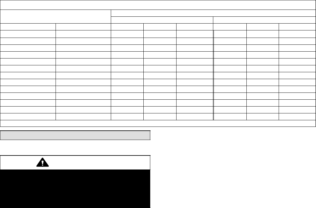
Table 20
CB30M-65 Blower Performance (460V − 1 ph)
Air Volume and Motor Watts at Specific Blower Taps
External Static Pressure Low High
in. w.g. Pa cfm L/s Watts cfm L/s Watts
.00 0 1965 930 710 2140 1010 795
.05 10 1950 920 700 2110 995 780
.10 25 1930 910 685 2080 980 765
.15 35 1910 900 675 2045 965 755
.20 50 1880 890 660 2005 945 740
.25 60 1850 875 645 1965 925 725
.30 75 1815 855 630 1920 905 710
.40 100 1735 820 600 1820 860 680
.50 125 1635 770 570 1710 805 650
.60 150 1520 720 540 1585 750 615
.70 175 1390 655 505 1450 685 585
.80 200 1245 590 475 1305 615 550
.85 210 1165 550 460 1225 580 535
NOTE − All air data is measured external to unit with air filter in place. Electric heaters have no appreciable air resistance.
Electrical
WARNING
USE COPPER CONDUCTORS ONLY.
Run 24V Class II wiring only through specified low
voltage opening. Run line voltage wiring only
through specified high voltage opening. Do not
combine voltage in one opening.
Wiring must conform to the current National Electric Code
ANSI/NFPA No. 70, or Canadian Electric Code Part I, CSA
Standard C22.1, and local building codes. Refer to follow-
ing wiring diagrams. See unit nameplate for minimum cir-
cuit ampacity and maximum overcurrent protection size.
Select the proper supply circuit conductors in accor-
dance with Tables 310−16 and 310−17 in the National
Electric Code, ANSI/NFPA No. 70 or Tables 1 through 4
in the Canadian Electric Code, Part I, CSA Standard
C22.1.
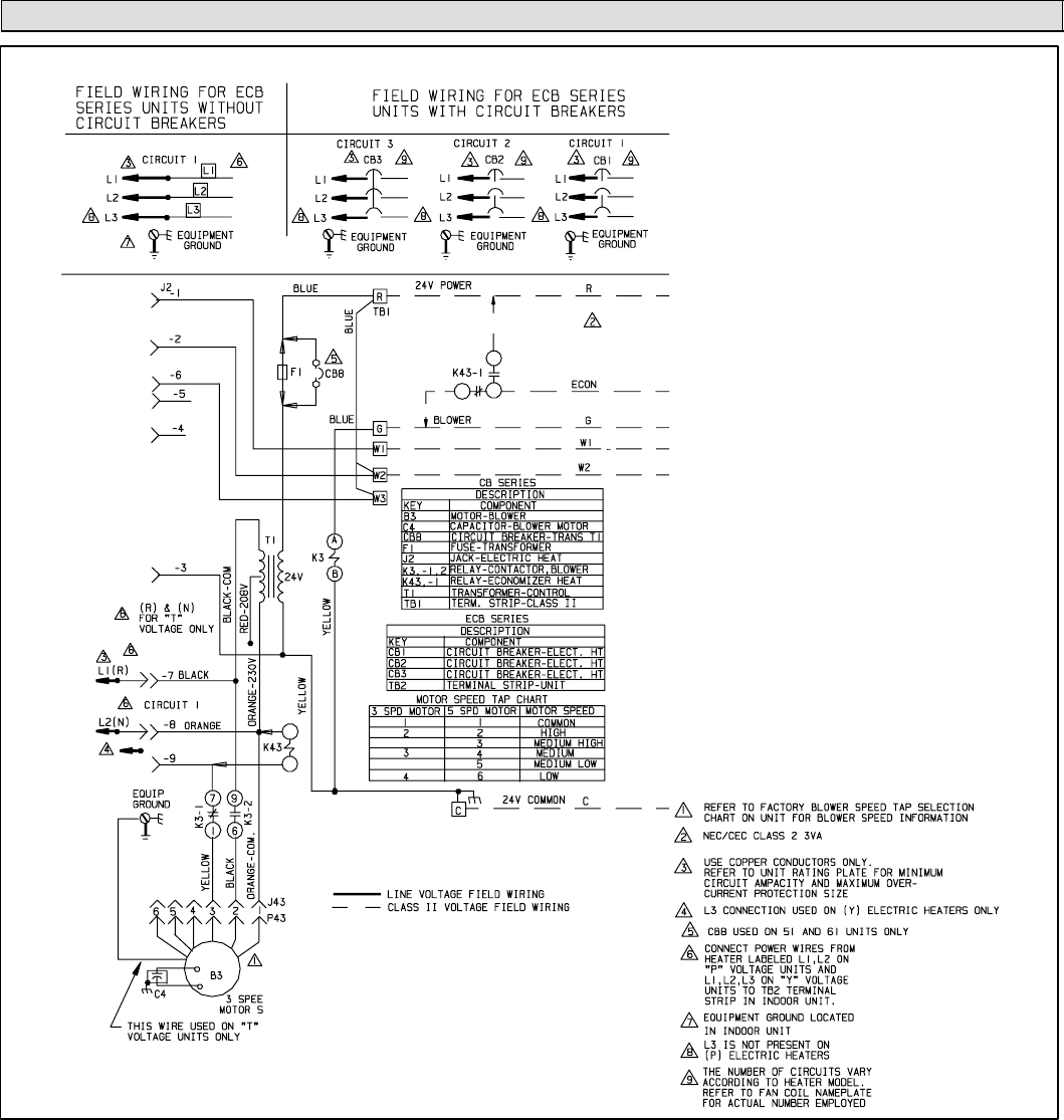
This unit is provided with knockouts for conduit. Reducer
washers are provided, in bag assembly to allow use of
smaller conduit. Use provided caps to seal holes not
used. Refer to figure 11 for unit schematic wiring dia-
gram. Refer to figures 13 and 14 for typical field wiring.
Separate openings have been provided for 24V low volt-
age and line voltage. Refer to the dimension illustration for
specific location.
Page 17
CB29M/CB30M SERIES
System Wiring Diagrams
CB29 & CB30 Typical Wiring Diagram − Single Phase
Figure 11
Page 18
504719M 09/05
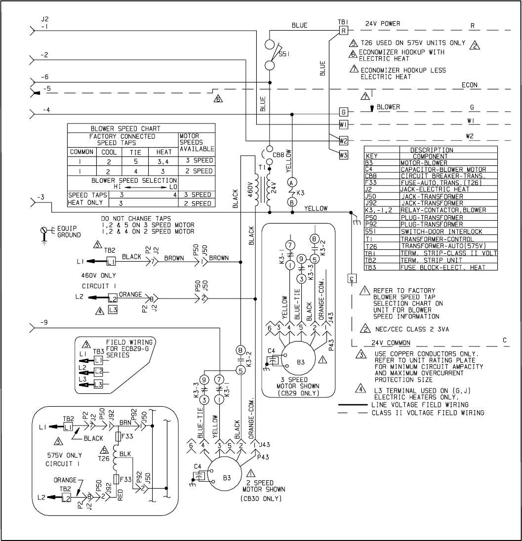
CB29 & CB30 Typical Wiring Diagram − Three Phase
Figure 12
Page 19
CB29M/CB30M SERIES
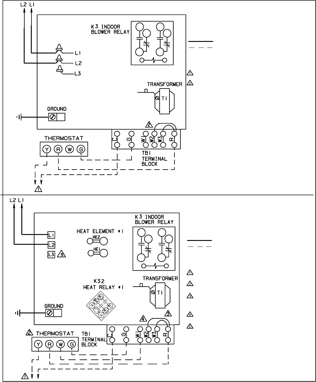
CIRCUIT 1
CIRCUIT 1
Figure 13
CIRCUIT BREAKERS
OR TERMINAL BLOCK
FIELD−SUPPLIED
WIRE NUTS
1
4
7
3
6
9
Typical Field Wiring − Cooling Application With Electric Heat
Typical Field Wiring − Cooling Only Application
FUSE
1
4
7
3
6
9
FUSE
(Black)
(Orange)
NOTE − USE COPPER CONDUCTORS ONLY.
REFER TO UNIT RATING PLATE FOR MINIMUM
CIRCUIT AMPACITY AND MAXIMUM OVERCUR-
RENT PROTECTION SIZE.
LINE VOLTAGE FIELD INSTALLED
CLASS 2 VOLTAGE FIELD INSTALLED
NEC/CEC
NOTE − ALL REMAINING WIRES ARE FACTORY
INSTALLED
TO EXTERNAL LOAD 24VAC AT .50 AMP MAXIMUM.
FACTORY INSTALLED JUMPERS
NOTE − USE COPPER CONDUCTORS ONLY.
REFER TO UNIT RATING PLATE FOR MINIMUM
CIRCUIT AMPACITY AND MAXIMUM OVERCUR-
RENT PROTECTION SIZE.
LINE VOLTAGE FIELD INSTALLED
CLASS 2 VOLTAGE FIELD INSTALLED
NEC/CEC
NOTE − ALL REMAINING WIRES ARE FACTORY
INSTALLED
TO EXTERNAL LOAD 24VAC AT .50 AMP MAXI-
MUM.
THERMOSTAT HEAT ANTICIPATION SETTING 0.4
AMP ELECTRIC HEAT
WHEN TWO−STAGE THERMOSTAT IS USED,
CONNECT SECOND STAGE HEAT BULB TO TER-
MINAL W2" AND REMOVE JUMPER BETWEEN
TERMINALS R" AND W2."
FACTORY INSTALLED JUMPERS
L3 CONNECTION USED ON (Y−VOLTAGE)
3−PHASE ELECTRIC HEATERS ONLY.
Page 20
504719M 09/05
C
W1 O Y1 R LT
E C W1 G O Y1 R L T
SERVICE LIGHT
THERMISTOR
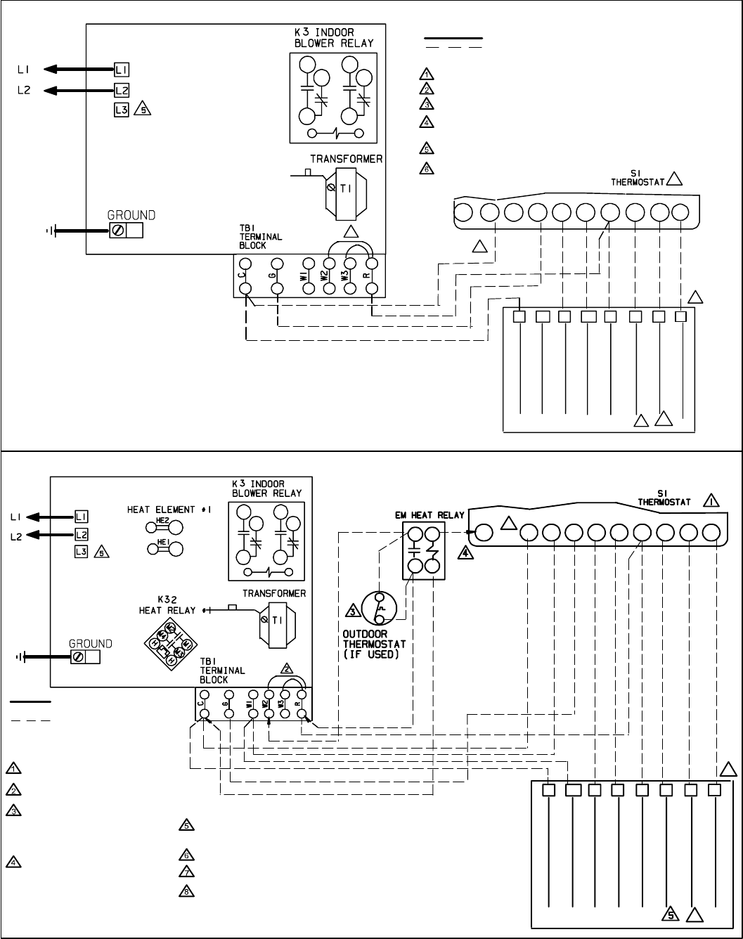
Figure 14
Typical Field Wiring − Heat Pump Only Application
Y2
Y2
2ND STAGE COMPRESSOR
1
2
3
4
5
6
COMMON
ELECTRIC HEAT
REVERSING VALVE
COMPRESSOR
POWER
1
4
7
3
6
9
LINE VOLTAGE FIELD INSTALLED
CLASS 2 VOLTAGE FIELD INSTALLED NEC/CEC
NOTE − ALL REMAINING WIRES ARE FACTORY INSTALLED
TO EXTERNAL LOAD 24VAC AT .50 AMP MAXIMUM
FACTORY INSTALLED JUMPERS
Y2 USED ONLY WHEN TWO SPEED COMPRESSOR IS USED (HP21).
USING SERVICE LIGHT OPTION (S54) WITH SOME ELECTRONIC
THERMOSTATS MAY REQUIRE MOVING S54 COMMON WIRE TO Y1
IN HEAT PUMP UNIT.
COMMON USED ONLY ON SOME THERMOSTATS.
AMBIENT COMPENSATING THERMISTOR CONNECTION USED ONLY
ON SOME THERMOSTATS.
FUSE
CIRCUIT 1
CIRCUIT BREAKERS
OR TERMINAL BLOCK
K22
S23
CW1 OY1 RL T
EC
W1 GOY1RL T
COMMON
ELECTRIC HEAT
REVERSING VALVE
COMPRESSOR
POWER
SERVICE LIGHT
THERMISTOR
Y2
2ND STAGE COMPRESSOR
Y2
6
7
8
1
4
7
3
6
9
NOTE − ALL REMAINING WIRES
ARE FACTORY INSTALLED
THERMOSTAT HEAT ANTICIPATION
SETTING 0.4 AMP ELECTRIC HEAT
FACTORY INSTALLED JUMPERS
WHEN OUTDOOR THERMOSTAT IS
USED, CONNECT LEADS TO
TERMINALS R" AND W2" AND
REMOVE JUMPER BETWEEN
TERMINALS R’ AND W2."
EMERGENCY HEAT RELAY (USED
ONLY IF OUTDOOR T’STAT IS
USED) FIELD PROVIDED AND
INSTALLED NEW INDOOR UNIT.
24VAC 5VA MAX NEC/CEC CLASS 2
USING SERVICE LIGHT OPTION (S54) WITH SOME ELECTRONIC
THERMOSTATS MAY REQUIRE MOVING S54 COMMON WIRE TO Y1 IN
HEAT PUMP UNIT.
COMMON USED ONLY ON SOME THERMOSTATS.
Y2 USED ONLY WHEN TWO-SPEED COMPRESSOR IS USED (HP21)
AMBIENT COMPENSATING THERMISTOR CONNECTION USED ONLY ON
SOME THERMOSTATS.
LINE VOLTAGE FIELD
INSTALLED
CLASS 2 VOLTAGE FIELD
INSTALLED NEC/CEC
Typical Field Wiring − Heat Pump Application With Electric Heat
FUSE
CIR-
CUIT 1 CIRCUIT
BREAKERS OR
TERMINAL
BLOCK
HEAT PUMP CLASS 2
VOLTAGE TERMINALS
HEAT PUMP CLASS 2
VOLTAGE TERMINALS
