Front Matter Lister 20TS TR Engine User Manual
User Manual: Lister 20TS-TR Engine User Manual
Open the PDF directly: View PDF ![]() .
.
Page Count: 194 [warning: Documents this large are best viewed by clicking the View PDF Link!]

TS, TR
Master Parts Manual
Manual des pièces • Manual de Piezas Prototipo
Ersatzteilhandbuch • Cataloga Parti Principale

Lister-Petter TS/TR Master Parts Manual
Issue 9: May 2000
ii
Publication 027-08030 Edition 9
© 2000 Lister-Petter Limited, all rights reserved
Published in June 2000 by Lister-Petter Technical Publications
Printed in the United Kingdom
Lister-Petter Limited, Dursley GL11 4HS, England
Lister-Petter TS/TR Master Parts Manual Issue 9: May 2000
1
Introduction - Français
Ce Manuel des pièces constitue un dossier présentant les
pièces utilisées sur les moteurs TS et TR Lister-Petter ainsi
que les changements et modifications qui ont été effectués.
Les paliers et les coussinets de bielle sont disponibles
minorés et les pistons et les segments sont disponibles
majorés. Les segments de piston ne sont fournis que sous
forme de jeu complet et les pistons sont fournis dotés de
segments, d’axe et de circlips.
En raison d’une politique de développement et d’amélioration
permanents, il est tout à fait possible qu’une pièce achetée
puisse ne pas entièrement ressembler à celle illustrée. Ce
ne sont pas tous les articles qui sont illustrés et, si un article
est listé sans numéro, il n’est disponible que comme partie
d’un ensemble. Bien qu’un numéro puisse être indiqué,
l’article peut ne pas être disponible tout seul, mais sous forme
d’ensemble. Les articles qui sont mis en retrait sous une
entrée sont inclus dans un ensemble et font partie de ce
dernier.
Afin d’aider l’utilisateur à identifier les pièces, la plupart des
listes comportent une illustration, les pièces individuelles
étant affectées de la même référence que celle figurant sur
la liste. Il faut veiller à se référer à la bonne illustration.
Les pièces de rechange devraient être commandées
enindiquant le numéro de la pièce, et non le numéro de
l’illustration, et le numéro d’ordre du moteur.
Chaque moteur comporte un numéro d’ordre unique qui est
gravé sur une plaque attachée au capot. Il est nécessaire
de vérifier ce numéro d’ordre avant d’utiliser ce manuel pour
veiller à ce que la pièce demandée soit correcte pour le
moteur particulier. Lorsque le numéro de construction est
précédé d’un 9, cela indique que le moteur est d’une
configuration non standard, ou contient des pièces ou
accessoires non standards.
Plaque de numéro d’ordre
Code de numéro d'ordre
43 ........... Code de l'année de fabrication
00014 ..... Numéro consécutif du moteur
TS2......... Modèle
A ............. Sens antihoraire
001 ......... Modèle du moteur
ATTENTION
On ne peut pas se fier aux matériaux, dimensions ou
fini des pièces qui ne sont pas homologuées pour
utilisation sur les moteurs TS ou TR.
Introduction - English
The purpose of this Master Parts Manual is to give a record
of the parts used on Lister-Petter TS and TR engines together
with alterations and modifications that have been effected.
Main bearings and big end bearings are available undersize
and pistons and rings are available oversize. Piston rings
are only supplied as a complete set and pistons are supplied
complete with rings, gudgeon pin and circlips.
Due to continued development and improvement it is quite
possible that a part purchased may not completely resemble
that illustrated. Not all items are illustrated and if an item is
listed without a part number it is only available as part of an
assembly. Although a part number may be shown, the item
may not be available on its own but as an assembly. Items
that are shown indented under an entry are included in, and
form part of an assembly.
To help the user identify parts, most lists have an illustration
with the individual parts given the same item number
reference as appears in the list. Care should be taken to
ensure the correct illustration is being referred to.
Replacement parts should be ordered by quoting the Part
Number, not the illustration item number, and the engine
serial number.
Each engine has a unique serial number which is stamped
on a plate attached to the air cowling. It is necessary for this
serial number to be identified before using this manual to
ensure the part being requested is correct for the particular
engine. Where the Build Number is preceded by a 9 this
indicates that the engine is either of a non-standard
configuration, or contains non-standard parts or accessories.
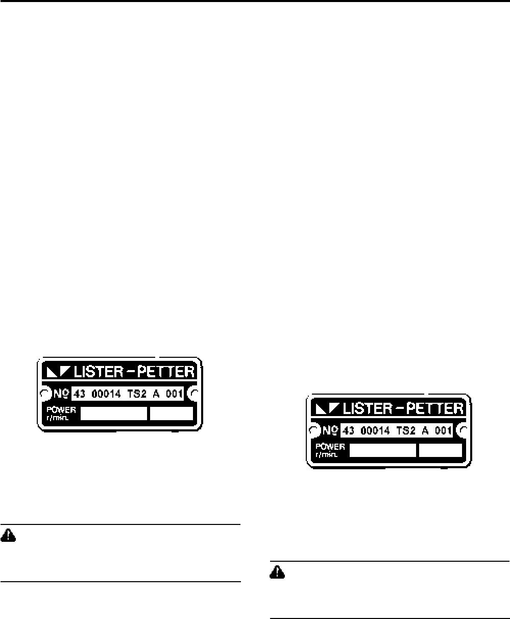
Engine Serial Number
Serial Number Code
43 ........... Year of manufacture code
00014 ..... Consecutive number of engine
TS2......... Model
A ............. Anti-clockwise rotation
001 ......... Build
CAUTION
Parts that have not been approved for use on TS or TR
engines cannot be relied upon for correct material,
dimensions or finish.
Lister-Petter TS/TR Master Parts Manual
Issue 9: May 2000
2
Introduccion - Español
El objeto de este Manual de Piezas Prototipo es dar una
descripción de las piezas usadas en los motores de Lister-
Petter TS y TR, junto a las modificaciones y alteraciones
que se hayan efectuado.
Los cojinetes principales y los cojinetes de biela están
disponibles en tamaños reducidos y los pistones y los aros
de pistón en tamaños ampliados. Los aros de se suministran
exclusivamente como juegos completos y los pistones se
proporcionan completos con muñequillas y fiadores de
perno.
Debido al continuo desarrollo y perfeccionamiento es muy
posible que se adquiera alguna pieza que no asemejara
totalmente a la ilustrada.
No todos los artículos tienen ilustración y si alguno figurara
en lista y no tuviera número de pieza, es por que sólo está
disponible como parte de una unidad completa. Aunque
figurara el número de pieza, pudiera ser también que no
estuviera disponible solo, sino como parte de una unidad
completa. Los artículos que figuran sangrados debajo de
una entrada están incluidos y forman parte de una unidad
completa.
Con objeto de ayudar al usuario a identificar las piezas, la
mayoría de las listas tienen una ilustración en la que las
piezas individuales tienen el mismo número de referencia
de artículo que el que aparece en la lista.
Para ordenar piezas de repuesto deberá citarse el Número
de Pieza, no el número del artículo en la ilustración, y el
Número de Serie del Motor.
Cada motor tiene un número de serie único, que lleva
grabado en una placa fijada a la cubierta del aire. Resulta
necesario comprobar el número de serie antes de hacer
uso de este manual para asegurarse de que la pieza
requerida es la adecuada para el motor del que se trate en
particular. En los casos en los que el Número de
Construcción vaya precedido de un 9, esto indica bien que
el motor no es se configuración prototipo o bien que contiene
piezas o accesorios que no lo son.
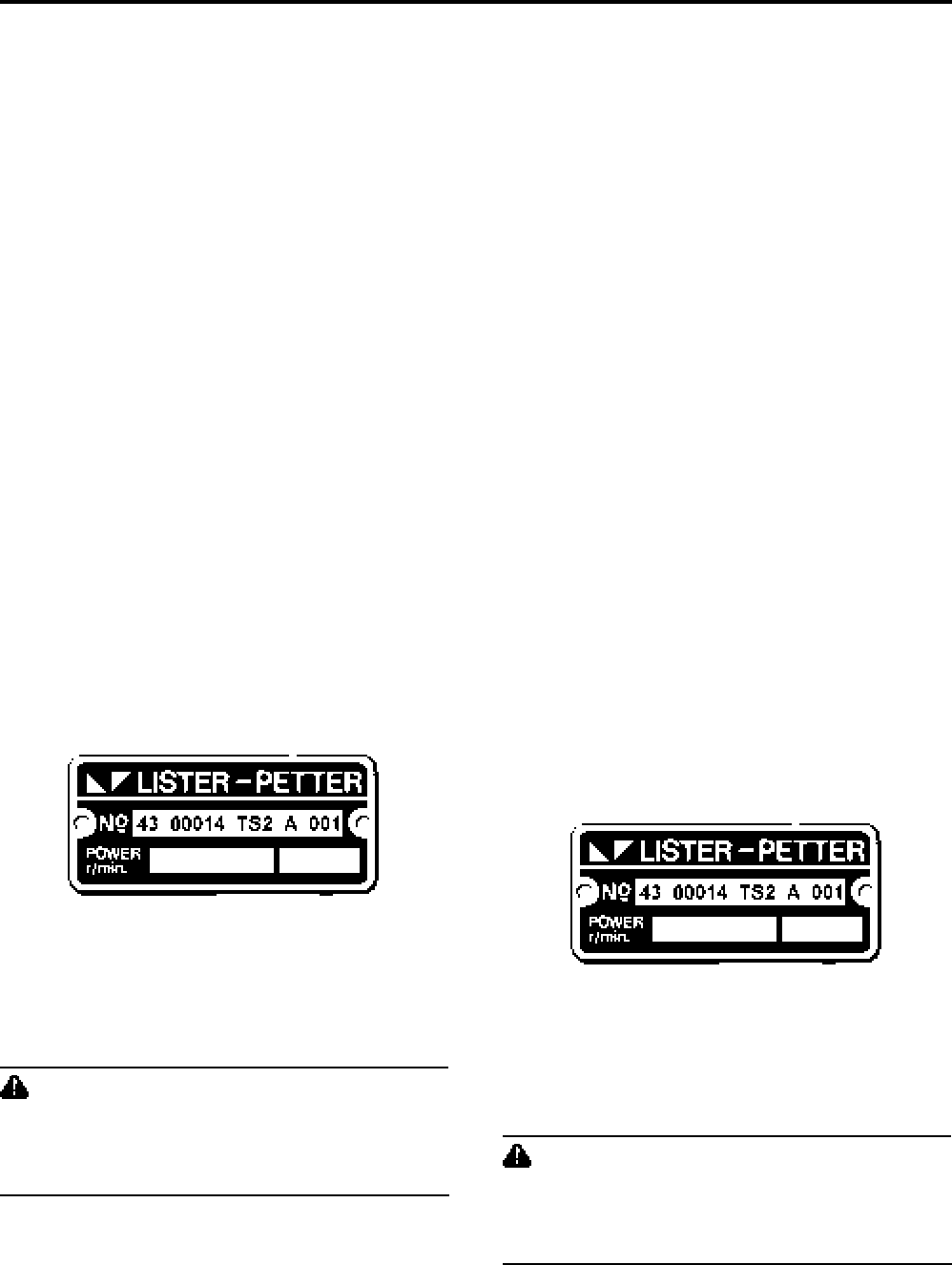
Placa de Número Serial
Código de Número de Serial
43 ........... Ano
00014 ..... Número consecutivo de motor
TS2......... Modelo
A ............. Rotación antihorario
001 ......... Construcción de Motor
PRECAUCION
No se puede tener confianza en que las piezas que
no hayan sido aprobadas para usarse en TS o TR sean
del material correcto o tengan las dimensiones o
acabado apropiados.
Einleitung - Deutsch
In diesem Teilehauptbuch sollen die bei Lister-Petter Motoren
TS und TR zur Anwendung kommenden Teile sowie die daran
vorgenommenen Änderungen und Modifikationen aufgeführt
werden.
Hauptlager und Pleuelfußlager können mit Untermaß
geliefert werden, Kolben und Kolbenringe mit Übermaß.
Kolbenringe werden nur satzweise geliefert, Kolben komplett
mit Ringen, Kolbenbolzen und Sicherungsringen.
Angesichts fortgesetzter Weiterentwicklungen und
Verbesserungen kann es vorkommen, daß ein gekauftes
Teilnicht immer ganz dem abgebildeten gleicht.
Nicht alle Teile sind abgebildet, und wenn ein Teil ohne
Teilnummer aufgeführt wird, wird es nur als Teil einer
Baugruppe geliefert. Auch wenn eine Teilnummer angegeben
ist, kann das betreffende Teil ggf. nicht allein, sondern nur
als Baugruppe gekauft werden. Eingerückte Teile unter einer
Eintragung gehören zu und bilden einen Teil einer
Baugruppe.
Um dem Benutzer die Identifizierung von Teilen zu
erleichtern, kommen die meisten Listen mit Abbildung, und
die Einzelteile haben die gleiche Kennummer wie in der Liste.
Es ist daher darauf zu achten, daß immer auf das richtige
Bild verwiesen wird.
Bei der Bestellung von Ersatzteilen ist nicht die Kennummer
der Abbildung, sondern die Teilnummer und die
Seriennummer des Motors anzugeben.
Jeder Motor hat seine eigene Seriennummer, die auf einem
Schild an der Luftkanalverkleidung eingestanzt ist. Diese
Seriennummer ist vor Benutzung dieses Buches zu ermitteln,
um sicherzustellen, daß das richtige Teil für den betreffenden
Motor bestellt wird. Wenn der Bauartnummer eine 9
vorausgeht, ist der Motor entweder eine Sonderkonfiguration,
oder er enthält nicht serienmäßige Teile und Zubehör.
Motorseriennummer
Seriennummerncode
43 ........... Baujahr
00014 ..... Seriennummer
TS2......... Typ
A ............. Linksdrehung
001 ......... Bauart
VORSICHT
Wenn Sie Teile bestellen, die nicht für Motoren TS oder
TR zugelassen sind, können Sie sich nicht auf die
richtigen Werkstoffe, Abmessungen und Ausführung
verlassen.

Lister-Petter TS/TR Master Parts Manual Issue 9: May 2000
3
Introduzione - Italiano
Lo scopo di questo Manuale dei Pezzi Principali è quello di
dare una documentazione dei pezzi usati sui motori Lister-
Petter TS e TR, assieme alle variazioni e modifiche che sono
state effettuate.
I cuscinetti principali e i cuscinetti di biella sono disponibili
minorati, mentre i pistoni e gli anelli sono disponibili
maggiorati. Gli anelli dei pistoni sono forniti solo come gruppo
completo e i pistoni sono completi di anelli, spinotto e anelli
elastici di arresto.
A causa della linea di continuo sviluppo e perfezionamento,
è possibile che un pezzo acquistato non sia esattamente
come quello illustrato.
Non tutti gli articoli sono illustrati e se un articolo è elencato
senza un numero categorico, è disponibile solo come parte
di un complessivo. Anche quando un numero categorico è
indicato, l’articolo non è necessariamente disponibile da solo,
ma come complessivo. Gli articoli che sono indicati rientrati
sotto un titolo sono inclusi in un complessivo e ne fanno
parte.
Per aiutare l’utente ad identificare i pezzi, la maggior parte
degli elenchi ha un’illustrazione con i pezzi individuali ai quali
viene dato lo stesso numero di riferimento del pezzo che
appare sull’elenco. Si dovrà fare attenzione di consultare
l’illustrazione corretta.
I pezzi di sostituzione dovranno essere ordinati citando il
numero categorico, non il numero d’articolo dell’illustrazione,
e il numero di serie del motore.
Ciascun motore ha un numero di serie individuale che è
stampato su una piastra attaccata alla cappottatura dell’aria.
E’ necessario identificare questo numero di serie prima di
usare questo manuale per accertarsi che il pezzo richiesto
sia corretto per il particolare motore. Quando il numero di
costruzione è preceduto da un 9, ciò indica che il motore o
presenta una configurazione non standard, o contiene pezzi
o accessori non standard.
Numero di serie del motore
Seriennummerncode
43 ........... Codice anno di fabbricazione
00014 ..... Numero consecutivo di motore
TS2......... Modello
A ............. Rotazione in senso antiorario
001 ......... Costruzione del motore
ATTENZIONE
I pezzi il cui uso non è stato approvato per i motori TS
o TR non sono affidabili quanto a materiale, dimensioni
o finitura.

Lister-Petter TS/TR Master Parts Manual
Issue 9: May 2000
4

Lister-Petter TS/TR Master Parts Manual Issue 9: May 2000
5
Index - English
H
Holding Down Bolts ............................................ 190
Hydraulic Pump Adaptors ............................ 161-168
I
Injector ................................................................. 76
Inlet Manifold .................................................. 86, 88
Introduction............................................................. 2
J
Joint Sets..................................................... 186-189
K
Key Switch .......................................................... 178
Key Switch and Hour Recorder Panel................. 181
Key Switch Panel ................................................ 180
L
Lagging....................................................... 184, 185
Leak-off Pipe .................................................. 76, 78
Lift Pump ........................................................ 68, 70
M
Main Bearings...........................................18, 32, 33
Manifold Lagging ........................................ 184, 185
O
Oil Distribution Block ...........................................116
Oil Distribution Block - Flexible Pipes ..................114
Oil Distribution Block - Steel Pipes ......................115
Oil Filter .......................................................... 26, 28
Oil Pressure Gauge ............................................ 126
Oil Pump............................................................... 26
Oil Strainer ........................................................... 26
Outlet Pipe Lagging ............................................ 184
P
Piston ................................................................... 30
Power Take-Off................................................... 152
R
Remote Stop ...................................................... 106
Running Hour Recorder - Electrical .................... 131
Running Hour Recorder - Vibration ..................... 130
S
SAE Adapter....................................................... 156
Service Tools ...................................................... 190
Shaft Extension ............................................ 110-113
Side Shield - Flywheel End ................................... 66
Silencer Lagging ......................................... 184, 185
Silencers......................................................... 90, 91
Speed Controls - Variable ................................... 102
Speeder Spring......................................... 38, 40, 41
Start Panels - Electric .................................. 170-177
Starter Motor .................................................. 93, 94
Starting Handle ............................................... 95, 96
Steel Fuel Pipes ................................................... 78
Sump ......................................................... 20, 22-25
T
Temperature Gauge ........................................... 129
Temperature Switch.............................................118
Tool Kit................................................................ 190
Two Speed Control ..................................... 103, 104
Two Speed Solenoid ........................................... 105
V
Valves ............................................................. 56, 57
A
Accessory Kits ................................................. 11-15
Accessory Kits (American) Lister-Petter Inc. ............
Air Cleaner .................................................. 132-151
Air Cowling ...................................................... 60-67
Air Duct............................................................ 60-67
Air Shields ....................................................... 60-67
Alternator ......................................................98, 100
Ammeter............................................................. 131
B
Battery Leads ..................................................... 182
C
Cable Looms - Protective Switches .................... 182
Camshaft ......................................................... 34-36
Camshaft Bush ..................................................... 18
Charge Indicator .........................................178, 179
Charge Windings - Nicsa ...................................... 54
Charge Windings - Synchro .................................. 52
Clutch ................................................................. 152
Clutch Drive Member .......................................... 158
Connecting Rod .................................................... 30
Coupling ..............................................157, 159, 160
Crankcase ....................................................... 18-20
Crankshaft ............................................................ 30
Cylinder Barrel ................................................ 30, 31
Cylinder Head ........................................... 56, 58, 59
D
Decompressor Lever Insulation .......................... 185
Dipstick...........................................................18, 21
Dumper Accessories (Loose) ............................. 107
E
End Cover ..................................................... 43 - 45
Engine Controls .................................................... 38
Engine Builds.................................................. 16, 17
Exhaust Manifold ............................................ 86, 88
Exhaust Manifold Adapters ................................... 89
Exhaust Pipe - Flexible ......................................... 92
Exhaust Silencers ........................................... 90, 91
Extension Shaft ............................................ 110-113
F
Flat Belt Pulley.................................................... 156
Flywheel and Fanshroud ................................. 46-51
Flywheel Charge Windings - Nicsa ....................... 54
Flywheel Charge Windings - Synchro ................... 52
Fuel Control Solenoid .................................. 122-125
Fuel Filter ................................................. 63, 72, 74
Fuel Injector.......................................................... 76
Fuel Lift Pump ................................................ 68, 70
Fuel Pump ...................................................... 72, 74
Fuel Pump Linkage............................................... 38
Fuel Tank ......................................................... 80-84
G
Gauge Panel ...................................................... 126
Gear End Cover............................................... 42-45
Governor Lever Assembly .............................. 34, 36
Governor Linkage ................................................. 38
Governor Weights .......................................... 40, 41

Lister-Petter TS/TR Master Parts Manual
Issue 9: May 2000
6
Index - Français
A
Accessoires pour dumper (non monté)............... 107
Accouplement......................................157, 159, 160
Adaptateurs pour pompe hydraulique .......... 161-168
Adapteur SAE ..................................................... 156
Adapteurs de collecteur d’échappement............... 89
Alternateur .................................................... 98, 100
Ampèremètre...................................................... 131
Arbre à cames ................................................. 34-36
Arrêt à distance .................................................. 106
Articulation de régulateur ...................................... 38
B
Bielle..................................................................... 30
Bloc de distribution d’huile moteur -
tuyaux en acier ...............................................115
Bloc de distribution d’huile moteur -
tuyaux flexibles ...............................................114
Bloc de distribution d’huile moteur .......................116
Bloc moteur ..................................................... 18-20
Boulons de fixation ............................................. 190
C
Câbles de batterie .............................................. 182
Cadre d’entrée d’air ......................................... 60-67
Cadres de sortie d’air ...................................... 60-67
Carter de distribution ....................................... 42-45
Carter d’huile ............................................. 20, 22-25
Charge de batterie incorporé dans le volant moteur -
Nicsa ............................................................... 54
Charge de batterie incorporé dans le volant moteur -
Synchro ........................................................... 52
Collecteur d’admission ................................... 86, 88
Collecteur d’échappement .............................. 86, 88
Commandes moteur ............................................. 38
Contacteur à clé ................................................. 178
Contrôle de vitesse - variable ............................. 102
Contrôle deux vitesses ............................... 103, 104
Coussinet d’arbre à cames ................................... 18
Couvercle d’extrémité .................................... 43 - 45
Crépine à huile ..................................................... 26
Culasse .................................................... 56, 58, 59
Cylindre .......................................................... 30, 31
D
Démarreur ...................................................... 93, 94
E
Embrayage ......................................................... 152
Ensemble levier de régulateur ........................ 34, 36
Enveloppe calorifugée ................................ 184, 185
Enveloppe calorifugée pour collecteur
d’échappement ...................................... 184, 185
Enveloppe calorifugée sur pipe de sortie ............ 184
Enveloppe d’echappement calorifugée pour
silencieux d’échappement ..................... 184, 185
Extension d’arbre.......................................... 110-113
F
Faisceau de câbles avec sécurités ..................... 182
Filtre à combustible .................................. 63, 72, 74
Filtre à huile .................................................... 26, 28
Filtres à air................................................... 132-151
H
Horamètre - Electrique ....................................... 131
Horamètre à vibrations ....................................... 130
I
Injecteur ............................................................... 76
Introduction............................................................. 1
J
Jauge de niveau d’huile .................................. 18, 21
K
Kits d’accessoires ............................................ 11-15
Kits d’accessoires (Etats-Unis) Lister-Petter Inc. ......
L
Levier de décompresseur calorifugé ................... 185
M
Manivelles ...................................................... 95, 96
Manomètre de pression d’huile........................... 120
Masselottes centrifuges de régulateur ............ 40, 41
Modèles des moteurs ..................................... 16, 17
O
Outils pour l’entretien moteur.............................. 190
P
Paliers ...................................................... 18, 32, 33
Pièce de liaison de pompe d’injection ................... 38
Pipe d’échappement - flexible............................... 92
Piston ................................................................... 30
Plaques de protection d’air chaud.................... 60-67
Plateau d’entraînement pour embrayage ............ 158
Pochette de joints ........................................ 186-189
Pompe à huile ...................................................... 26
Pompe d’élévation de combustible ................. 68, 70
Pompe d’injection ........................................... 72, 74
Poulie pour courroie plate ................................... 156
Prise de force ..................................................... 152
R
Réservoir à combustible .................................. 80-84
Ressort de régulateur ............................... 38, 40, 41
S
Sécurité de température ......................................118
Silencieux d’échappement .............................. 90, 91
Solénoïde d’arrêt ......................................... 122-125
Solénoïde deux vitesses ..................................... 105
Soupapes ....................................................... 56, 57
T
Tableau avec contacteur à clé ............................ 180
Tableau avec contacteur à clé et horamètre ....... 181
Tableau de démarrage électrique ................ 170-177
Tableau d’indicateurs .......................................... 126
Témoin de charge batterie .......................... 178, 179
Thermomètre...................................................... 129
Tôle latérale - côté volant ..................................... 66
Trousse d’outillage.............................................. 190
Tuyau de retour au réservoir........................... 76, 78
Tuyaux d’alimentation de combustible en acier .... 78
V
Vilebrequin............................................................ 30
Volant et ventilateur monté sur volant .............. 46-51

Lister-Petter TS/TR Master Parts Manual Issue 9: May 2000
7
Sachverzeichnis - Deutsch
A
Abdeckung .................................................... 43 - 45
Abgassammelrohr .......................................... 86, 88
Abgassammelrohr - Isolierung ............................ 184
Abgassammelrohr Adapter ................................... 89
Abgasschlauch - flexibel ....................................... 92
Abtrieb ................................................................ 152
Amperemeter...................................................... 131
Andrehkurbel .................................................. 95, 96
Auspuffschalldämpfer ..................................... 90, 91
B
Batteriekabel ...................................................... 182
Befestigungsschrauben ...................................... 190
Betriebsstundenzähler - elektrisch ...................... 131
D
Dekompressorhebelisolierung ............................ 185
Dichtungssätze ............................................ 186-189
Drehzahlfeder ........................................... 38, 40, 41
Drehzahlregler - variabel .................................... 102
Drehzahlregulierung / 2 Drehzahlen ........... 103, 104
Drehzahlverstellmagnet / 2 Drehzahlen .............. 105
E
Einlaßkrümmer ............................................... 86, 88
Einleitung ................................................................ 2
Einspritzdüse ........................................................ 76
Einspritzpumpe ............................................... 72, 74
Einspritzpumpengestänge .................................... 38
F
Flachriemenscheibe ........................................... 156
Förderpumpe .................................................. 68, 70
H
Hauptlager ................................................ 18, 32, 33
Hydraulikpumpenadapter............................. 161-168
I
Instrumententafel ................................................ 126
Isolierung .................................................... 184, 185
K
Kabelbaum - Schutzschalter ............................... 182
Kipperzubehör (lose) .......................................... 107
Kolben .................................................................. 30
Kraftstoffbehälter ............................................. 80-84
Kraftstoffeinspritzdüse .......................................... 76
Kraftstoffförderpumpe ..................................... 68, 70
Kraftstoffilter ............................................. 63, 72, 74
Kraftstoffsteuerung - Hubmagnet................. 122-125
Krümmerisolierung ..................................... 184, 185
Kupplung ..................................... 152, 157, 159, 160
Kupplungsmitnehmer.......................................... 158
Kurbelgehäuse ................................................ 18-20
Kurbelwelle ........................................................... 30
L
Ladeanzeige ............................................... 178, 179
Ladewicklungen - Nicsa ........................................ 54
Ladewicklungen - Synchro.................................... 52
Lichtmaschine .............................................. 98, 100
Luftfilter ....................................................... 132-151
Luftführung ...................................................... 60-67
Luftführungen .................................................. 60-67
Luftschilde ....................................................... 60-67
M
Motorbedienungselemente ................................... 38
Motorbauarten ................................................ 16, 17
N
Nockenwelle .................................................... 34-36
Nockenwellenlager ............................................... 18
O
Öldruckanzeige................................................... 120
Ölfilter ............................................................. 26, 28
Ölpeilstab ....................................................... 18, 21
Ölpumpe............................................................... 26
Ölsieb ................................................................... 26
Ölverteilblock - flexible Leitungen ........................114
Ölverteilblock - Stahlleitungen .............................115
Ölverteilerblock ....................................................116
Ölwanne .................................................... 20, 22-25
P
Pleuelstange ......................................................... 30
R
Reglergestänge .................................................... 38
Reglergewichte ............................................... 40, 41
Reglerhebel-Baugruppe.................................. 34, 36
Rücklaufleitung ............................................... 76, 78
S
SAE-Adapter ...................................................... 156
Schlüsselschalter ............................................... 178
Schlüsselschalter- und Betriebsstundenzählertafel 181
Schlüsselschalterpanel ....................................... 180
Schwungrad und Kühlluftgehäuse ................... 46-51
Schwungradladewicklungen - Nicsa ..................... 54
Schwungradladewicklungen - Synchro ................. 52
Seitenabdeckung - Schwungradseitig................... 66
Stahlkraftstoffleitungen ......................................... 78
Start Panel - elektrisch ................................ 170-177
Startermotor ................................................... 93, 94
Stirnradgetriebedeckel ..................................... 42-45
Stopkabel (lose) ................................................. 106
T
Temperaturanzeige ............................................. 129
Temperaturschalter..............................................118
V
Ventile............................................................. 56, 57
Verlängerungswelle ...................................... 110-113
Vibrations-Betriebsstundenzähler ....................... 130
W
Wartungswerkzeug ............................................. 190
Wellenverlängerung...................................... 110-113
Werkzeugsatz..................................................... 190
Z
Zubehörsätze................................................... 11-15
Zubehörsätze (USA) Lister-Petter Inc. ......................
Zylinder........................................................... 30, 31
Zylinderkopf .............................................. 56, 58, 59

Lister-Petter TS/TR Master Parts Manual
Issue 9: May 2000
8
Indice - Español
A
Accesorios de Amortiguador (sueltos) ................ 107
Acoplador ............................................157, 159, 160
Adaptador SAE ................................................... 156
Adaptadores de Bomba Hidráulica .............. 161-168
Adaptadores de Colector de Escape .................... 89
Aislamiento ................................................. 184, 185
Aislamiento de Palanca de Descompresor ......... 185
Alternador ..................................................... 98, 100
Amperímetro ...................................................... 131
Arranque de Llave y Panel de Registro de Horas 181
B
Barrera Lateral - Extremo de Volante ................... 66
Barreras de Aire .............................................. 60-67
Bloque de Distribución de Aceite .........................116
Bloque de Distribución de Aceite -
Tuberías de Acero ..........................................115
Bloque de Distribución de Aceite -
Tuberías Flexibles ..........................................114
Bobina de Cables - Interruptores de Seguridad .. 182
Bobinas de Carga - Nicsa ..................................... 54
Bobinas de Carga - Sincro.................................... 52
Bomba de Aceite .................................................. 26
Bomba de Combustible .................................. 72, 74
Bomba de Elevación....................................... 68, 70
Bomba de Elevación de Combustible ............. 68, 70
C
Cables de Batería ............................................... 182
Cárter .............................................................. 18-20
Casquillo de Eje de Levas .................................... 18
Cigüeñal ............................................................... 30
Cojinetes Principales ................................ 18, 32, 33
Colador de Aceite ................................................. 26
Colector de Admisión ..................................... 86, 88
Colector de Escape ........................................ 86, 88
Conductos de Aire ........................................... 60-67
Conexión de Acelerador ....................................... 38
Conexión de Bomba de Combustible ................... 38
Conjunto de Palanca de Acelerador ............... 34, 36
Construcciones de Motor................................ 16, 17
Control de Velocidad - Variable........................... 102
Controles de Motor ............................................... 38
Cubierta de Extremo de Engranajes ................ 42-45
Culata de Cilindros ................................... 56, 58, 59
E
Eje de Extensión........................................... 110-113
Eje de Levas.................................................... 34-36
Embrague........................................................... 152
Extensión de Eje........................................... 110-113
F
Filtro de Aceite................................................ 26, 28
Filtro de Combustible................................ 63, 72, 74
Filtros de Aire .............................................. 132-151
H
Herramientas de Servicio ................................... 190
I
Indicador de Carga ..................................... 178, 179
Interruptor de Temperatura ..................................118
Introduccion ............................................................ 2
Inyector de Combustible ....................................... 76
J
Juego de Herramientas ...................................... 190
Juegos de Uniones ...................................... 186-189
K
Kits de Accesorios ........................................... 11-15
Kits de Accesorios (EE.UU.) Lister-Petter Inc. ..........
L
Llave de Arranque .............................................. 178
M
Manivela de Arranque..................................... 95, 96
Miembro de Accionamiento de Embrague .......... 158
Motor de Arranque.......................................... 93, 94
Muelle de Velocímetro .............................. 38, 40, 41
P
Panel de Arranque - Eléctrico ...................... 170-177
Panel de Arranque de Llave ............................... 180
Panel de Indicadores .......................................... 126
Parrilla de Aire ................................................. 60-67
Pernos de Fijación .............................................. 190
Pesos de Acelerador ...................................... 40, 41
Pistón ................................................................... 30
Polea de Correa Plana ....................................... 156
Presiómetro de Aceite ........................................ 120
R
Registro de Horas en Marcha - Eléctrico ............ 131
Registro de Horas en Marcha - Vibración ........... 130
Revestimiento de Colector.......................... 184, 185
Revestimiento de Silencioso....................... 184, 185
Revestimiento de Tuberías de Salida ................. 184
S
Silencioso de Escape ..................................... 90, 91
Solenoide de Control de Combustible.......... 122-125
Solenoide de Doble Velocidad ............................ 105
Solenoide de Doble Velocidad .................... 103, 104
Stop Remoto ...................................................... 106
Sumidero ................................................... 20, 22-25
T
Tambor de Cilindro ......................................... 30, 31
Tanque de Combustible ................................... 80-84
Tapa de Extremo ............................................. 43-45
Termómetro ........................................................ 129
Toma de Fuerza ................................................. 152
Tuberías de Combustible de Acero ...................... 78
Tubo Contra Derrame..................................... 76, 78
Tubos de Escape - Flexibles ................................ 92
V
Válvulas .......................................................... 56, 57
Varilla de Acoplamiento ........................................ 30
Varilla Indicadora ............................................ 18, 21
Volante y Cubrimiento de Ventilador ................ 46-51

Lister-Petter TS/TR Master Parts Manual Issue 9: May 2000
9
Indice - Italiano
A
Accessori autoribaltabile (Sciolti) ........................ 107
Accoppiamento....................................157, 159, 160
Adattatore SAE ................................................... 156
Adattatori collettore scarico .................................. 89
Adattatori della pompa idraulica................... 161-168
Albero a camme .............................................. 34-36
Albero a gomiti...................................................... 30
Alternatore .................................................... 98, 100
Amperometro...................................................... 131
Asta di livello................................................... 18, 21
Attrezzi di manutenzione..................................... 190
Avvolgimento carica batteria sul volano - Nicsa .... 54
Avvolgimento carica batteria sul volano - Synchro 52
B
Basamento ...................................................... 18-20
Biella..................................................................... 30
Blocco di distribuzione olio...................................116
Blocco distribuzione olio - tubi d’acciaio ...............115
Blocco distribuzione olio - tubi flessibili ................114
Boccola albero a camme ...................................... 18
Bulloni di fissaggio .............................................. 190
C
Cablaggio- Interruttori protettivi........................... 182
Canna cilindro................................................. 30, 31
Cavi Batteria ....................................................... 182
Collettore d’entrata ......................................... 86, 88
Collettore scarico ............................................ 86, 88
Comandi motore ................................................... 38
Complessivo leva regolatore .......................... 34, 36
Condotti di ventilazione .................................... 60-67
Controllo con solenoide due velocità .......... 103, 105
Controllo velocità - variabile ................................ 102
Coperchio distribuzione ................................... 43-45
Coperchio distribuzione ingranaggi .................. 42-45
Copertura pneumatica ..................................... 60-67
Coppa ........................................................ 20, 22-25
Cuscinetti principali ................................... 18, 32, 33
E
Elemento trasmissione frizione ........................... 158
Estensione albero ......................................... 110-113
F
Filtri dell’aria ................................................ 132-151
Filtro carburante ....................................... 63, 72, 74
Filtro dell’olio................................................... 26, 28
Frizione............................................................... 152
I
Indicatore carica ......................................... 178, 179
Indicatore della temperatura ............................... 129
Iniettore carburante .............................................. 76
Interruttore a chiavetta ........................................ 178
Interruttore temperatura.......................................118
Introduzione ............................................................ 3
Isolamento leva decompressore ......................... 185
K
Kit accessori .................................................... 11-15
Kit accessori (Stati Uniti) Lister-Petter Inc. ...............
Kit attrezzi ........................................................... 190
L
Leveraggio pompa d’alimentazione ...................... 38
Leveraggio regolatore ........................................... 38
M
Manometro olio................................................... 120
Manopola d’avviamento .................................. 95, 96
Molla dispositivo di regolazione velocità ... 38, 40, 41
Motorino avviamento ...................................... 93, 95
P
Pesi del regolatore.......................................... 40, 41
Pistone ................................................................. 30
Pompa aspirante d’alimentazione ................... 68, 70
Pompa carburante .......................................... 72, 74
Pompa d’alimentazione carburante ................ 68, 70
Pompa dell’olio ..................................................... 26
Presa di forza ..................................................... 152
Prolunga albero ............................................ 110-113
Protezione laterale - Estremità volano .................. 66
Protezioni aria.................................................. 60-67
Puleggia cinghia piatta........................................ 156
Q
Quadro avviamento - elettrico...................... 170-177
Quadro indicatori ................................................ 126
Quadro interruttore a chiavetta ........................... 180
Quadro interruttore a chiavetta e contaore ......... 181
R
Registratore ore funzionamento - Elettrico.......... 131
Registratore ore funzionamento - Vibrazione ...... 130
Rivestimento............................................... 184, 185
Rivestimento collettore ............................... 184, 185
Rivestimento silenziatore ............................ 184, 185
Rivestimento tubo d’uscita .................................. 184
S
Serbatoio carburante ....................................... 80-84
Serie guarnizioni .......................................... 186-189
Silenziatore scarico ........................................ 90, 91
Silenziatori ...................................................... 90, 91
Solenoide a due velocità..................................... 105
Solenoide elettrostop controllo carburante... 122-125
Stili di motore .................................................. 16, 17
T
Telearresto.......................................................... 106
Testa cilindro ............................................ 56, 58, 59
Tubi d’acciaio carburante...................................... 78
Tubo di perdita................................................ 76, 78
Tubo scarico - flessibile ........................................ 92
V
Valvole ............................................................ 56, 57
Volano e protezione ventilatore ........................ 46-51

Lister-Petter TS/TR Master Parts Manual
Issue 9: May 2000
10

Lister-Petter TS/TR Master Parts Manual Issue 9: May 2000
11
Adaptors
Code Description of Accessory Kit Kit Part Number Page
CA SAE4, SAE5 Fanshroud Ventilated Adaptor Ring - 51mm ...........................................570-31590 .......... 156
CB SAE4 Fanshroud Ventilated Adaptor Ring - 51mm ......................................................570-31600 .......... 156
DA Air outlet duct adaptor - TS/TR1 ..................................................................................570-32820 ............ 60
Air outlet duct adaptor - TS/TR2 ..................................................................................570-31670 ............ 64
Air outlet duct adaptor - TS/TR3 ..................................................................................570-32090 ............ 64
DF Flywheel end side shield - for use with codes JC or PF - TS/TR1 ...............................570-33770 ............ 66
Air Cleaners
Code Description of Accessory Kit Kit Part Number Page
AA Medium duty dry type - paper element TS/TR1 ...........................................................570-33740 .......... 132
Medium duty dry type - paper element TS/TR2,3 (TR3 up to 1800r/min).....................570-31381 .......... 132
AO Medium duty dry type - paper element TR3 above 1801r/min only ..............................570-36100 .......... 132
AB Medium duty dry type - foam element TS/TR2,3 .........................................................570-31391 .......... 133
AJ Medium duty dry type -
to suit TS/TR1 13,5 litre fuel tank, includes Codes AA and AS ..
570-33750 .......... 138
AK Medium duty oil bath type - TS/TR1, use with Code AS ..............................................570-32770 .......... 151
AR Medium duty oil bath type - TS/TR2 ............................................................................570-36901 .......... 151
Medium duty oil bath type - TS/TR3 (TR3 up to 2000r/min ..........................................570-36902 .......... 151
AC Heavy duty dry type - TS/TR1, not for use with Code FB.............................................570-41580 .......... 136
AD Heavy duty dry type - TS/TR2,3
TS/TR2........................................................................................................................570-35651 .......... 142
TS/TR3........................................................................................................................570-35652 .......... 142
AG Remote mounted heavy duty dry type - TS/TR2,3 .......................................................570-41670 .......... 148
AE Heavy duty dry type - gear end mounted, TS/TR2,3
TS/TR2........................................................................................................................570-41611 .......... 146
TS/TR3........................................................................................................................570-41612 .......... 146
AN Heavy duty oil bath air cleaner - TS/TR1 .....................................................................570-33880 .......... 150
AP Inlet manifold adaptor - spigot diameter 21/4“ (57,1mm) for standard manifold, TS/TR2,3 .570-41730 ............ 86
AX Inlet manifold with gear end flange - TS/TR2...............................................................570-32560 ............ 86
Inlet manifold with gear end flange - TS/TR3...............................................................570-32570 ............86
AT Inlet manifold with gear end spigot - TS/TR2 ...............................................................570-41991 ............ 86
Inlet manifold with gear end spigot - TS/TR3 ...............................................................570-41992 ............86
AS Inlet manifold with vertical flange - TS/TR1 .................................................................570-32760 ............ 86
Controls - Industrial
Code Description of Accessory Kit Kit Part Number Page
KA Variable speed control - 1,8m cable and lever
TS/TR1........................................................................................................................570-32870 .......... 102
TS/TR2,3.....................................................................................................................570-31901 .......... 102
KB Variable speed control - engine mounted .................................................................... 570-31911 .......... 101
KC Variable speed control - less cable and lever, TS/TR1.................................................570-32900 .......... 102
Variable speed control - less cable and lever, TS/TR2,3..............................................570-31921 .......... 102
KD Remote stop - 1,8m cable operated, TS/TR1 ..............................................................570-33180 .......... 106
Remote stop - 1,8m cable operated, TS/TR2,3 ...........................................................570-31930 .......... 106
KE Adaptor for electronic governor - TS/TR2,3 .................................................................570-33080 .......... 108
KG Manual two speed control - not for use with solenoid Code JE - TS/TR1 ....................570-33200 .......... 103
Manual two speed control - not for use with solenoid Code JE - TS/TR2,3 .................570-33460 .......... 104
X D Dumper accessories (loose)........................................................................................570-41310 .......... 107
Controls - Marine
Code Description of Accessory Kit Kit Part Number Page
MKH Engine fittings for control cable....................................................................................570-60520 ............... -
MKA 2m control cable ..........................................................................................................570-60070 ............... -
MKB 3m control cable ..........................................................................................................570-60040 ............... -
MKC 4m control cable ..........................................................................................................750-60050 ............... -
MKD 5m control cable ..........................................................................................................750-60060 ............... -
MKF Single lever, side mounted control head ......................................................................750-60020 ............... -
MKE 3m cable operated remote stop ...................................................................................750-60030 ............... -
Accessory Kits
Some accessory kits are not compatible with others or
suitable for all engine builds. In some instances more
than one accessory kit code is included in the listings on
a page. In these cases care must be taken to check the
details given in ‘Description of Accessory Kit’ to help
identify the kit items needed, as more items than are
actually required in a specific accessory kit may be listed.
Please Note: All Marine Accessories shown in this listing
are not included in this manual. For further information
refer to Lister-Petter.

Lister-Petter TS/TR Master Parts Manual
Issue 9: May 2000
12
Accessory Kits
Drives - Flywheel End
Code Description of Accessory Kit Kit Part Number Page
BA Long crankshaft extension - 40mm diameter...............................................................570-31460 ........... 110
BB Short crankshaft extension - 40mm diameter, TS/TR1 only ........................................602-51620 ...........110
BC Crankshaft extension - unmachined ............................................................................570-31470 ...........110
BE Heavy duty overcentre clutch PTO ..............................................................................570-31480 .......... 154
BF Flat belt pulley .............................................................................................................570-37460 .......... 156
BN Flat belt pulley - TS3....................................................................................................570-37460 .......... 156
CL 71/2” (190mm) drive member for alternator or overcentre clutch ..................................570-31650 .......... 154
BN Bolt on 7" (178mm) diameter pulley - TS/TR1 .............................................................570-32950 .......... 156
CH 8" (203mm) Automotive clutch drive member - use with adaptor Code CA or CB .......570-31630 .......... 158
CI 9" (229mm) Automotive clutch drive member - use with adaptor Code CA or CB .......570-31640 .......... 158
BO Flexible half coupling - less taper lock bush ................................................................570-31520 .......... 157
BL Flexible half coupling - solid boss ................................................................................601-53920 .......... 157
BQ Flexible half coupling for 35mm shaft, supplied with taper lock bush...........................570-31540 .......... 157
BR Flexible half coupling for 38mm shaft, supplied with taper lock bush...........................570-31550 .......... 157
BS Flexible half coupling for 42mm shaft, supplied with taper lock bush...........................570-31560 .......... 157
BX As Code BO but with harder element ..........................................................................570-31521 .......... 157
CY Extra flexible coupling for TR2 1500r/min generating sets for 35mm shaft - TS/TR2 ..570-34670 .......... 160
XA Shaft extension - TS/TR2,3 .........................................................................................570-32880 ...........112
Gear End Drive
Code Description of Accessory Kit Kit Part Number Page
BW Crankshaft extension - 40mm diameter.......................................................................570-31580 ........... 111
Exhaust Equipment - Industrial
Code Description of Accessory Kit Kit Part Number Page
NA Medium duty silencer - includes Code NJ on TS/TR2,3
TS/TR1........................................................................................................................570-31170 ............ 90
TS/TR2,3 .....................................................................................................................570-31960 ............ 90
NL Medium duty silencer - TS/TR1 Build 16 only ..............................................................570-13980 ............90
NB Heavy duty silencer - TS/TR2,3, use with Code AE or AX ...........................................570-32400 ............ 91
NC Heavy duty silencer - supplied loose............................................................................570-15780 ............ 90
NE 1m Flexible exhaust pipe .............................................................................................570-32410 ............ 92
NG Vertical manifold adaptor - TS/TR1 .............................................................................570-32980 ............ 89
Vertical manifold adaptor - TS/TR2,3...........................................................................570-31980 ............ 89
NJ Horizontal manifold adaptor - TS/TR2,3 ......................................................................570-31990 ............ 89
NF Manifold flange - TS/TR1 tapped 11/2” BSP .................................................................570-32970 ............ 89
Manifold flange - TS/TR2,3 tapped 11/2” BSP ..............................................................570-31970 ............ 89
NH Exhaust outlet bend - use with Code NA if required ....................................................570-32520 ............ 90
NM Heat Shield ..................................................................................................................570-41720 ............ 90
Exhaust Equipment - Marine
Code Description of Accessory Kit Kit Part Number Page
MNC Dry type exhaust silencer ............................................................................................750-60280 ............... -
MND Skin fittings for dry exhaust .........................................................................................750-60190 ............... -
Fuel Equipment
Code Description of Accessory Kit Kit Part Number Page
FA 8,25 litre fuel tank - TS/TR1.........................................................................................570-32791 ............ 80
FB 13,5 litre fuel tank - TS/TR1.........................................................................................570-35691 ............ 84
13,5 litre fuel tank - TS/TR2.........................................................................................570-35692 ............ 84
13,5 litre fuel tank - TS/TR3.........................................................................................570-35693 ............ 84
FD 25,0 litre fuel tank - supplied loose ..............................................................................570-32641 ............ 84
FE Fuel lift pump - TR/TS1 ...............................................................................................570-32810 ............ 70
Fuel lift pump - TR/TS2 ...............................................................................................570-34690 ............ 70
Fuel lift pump - TR/TS3 ...............................................................................................570-34700 ............ 70
FF Fuel filter/agglomerator - in lieu of standard filter - TS/TR2,3 ......................................570-34650 ............ 74
FH Steel fuel lines - TS/TR2..............................................................................................570-33020 ............ 78
Steel fuel lines - TS/TR3..............................................................................................570-33030 ............ 78
MFA 45.5 litre cylindrical fuel tank........................................................................................750-60260 ............... -
MFB 113.5 litre oblong fuel tank ...........................................................................................750-60290 ............... -
MFC Flexible fuel connections - 0.46 metre .........................................................................570-60060 ............... -
MFD Steel supply and leak off pipes - 2.4 metres ................................................................750-60270 ............... -
MFF Duplex fuel filter...........................................................................................................570-60070 ............... -

Lister-Petter TS/TR Master Parts Manual Issue 9: May 2000
13
Accessory Kits
Gauges
Code Description of Accessory Kit Kit Part Number Page
PE Oil pressure gauge ...................................................................................................... 570-32011 .......... 128
PF Air temperature gauge .................................................................................................570-32020 .......... 129
PG Running hour recorder - 12V/24V ................................................................................570-30520 .......... 131
PK Running hour recorder - vibration type - TS/TR2,3 ......................................................570-32030 .......... 130
PA 2 gauge panel - less gauges........................................................................................570-32421 .......... 126
MPA Oil pressure and engine temperature gauges with remote panel (1.83m) ...................570-60100 ............... -
MPB Oil pressure gauge and fittings (no panel) - TS2 .........................................................570-60440 ............... -
Gearbox & Gearbox Couplings - Marine
MVB Hurth HBW100 Gearbox, adaptors and drive member (ratio 1.79:1) - TS2 ................. 570-60110 ............... -
MVB Hurth HBW150 Gearbox, adaptors and drive member (ratio 1.88:1) - TS3 .................570-60350 ............... -
MVC Hurth HBW125 Gearbox, adaptors and drive member (ratio 2.14:1) ...........................570-60470 ............... -
MVG Newage PRM 150 D2 Gearbox, adaptors and drive member (ratio 2.09:1).................570-60720 ............... -
MVK Newage PRM 260 D2 Gearbox, adaptors and drive member (ratio 1.96:1) - TS2 .......570-60130 ............... -
Newage PRM 260 D2 Gearbox, adaptors and drive member (ratio 1.96:1) - TS3 .......570-60370 ............... -
MVE Hurth HBW100 Gearbox, adaptors and drive member (ratio 2.72:1) - TS2 .................570-60120 ............... -
Hurth HBW100 Gearbox, adaptors and drive member (ratio 2.74:1) - TS3 .................570-60360 ............... -
MVF Hurth HBW125 Gearbox, adaptors and drive member (ratio 2.63:1) ...........................570-60450 ............... -
MVH Newage PRM 150 D3 Gearbox, adaptors and drive member (ratio 2.82:1).................570-60730 ............... -
MVL Newage PRM 260 D3 Gearbox, adaptors and drive member (ratio 2.94:1) - TS2 .......570-60140 ............... -
Newage PRM 260 D3 Gearbox, adaptors and drive member (ratio 2.94:1) - TS3 .......570-60380 ............... -
MYA Solid coupling (pilot bored) to suit Hurth HBW or Newage PRM Delta ........................570-60260 ............... -
MYP Solid coupling (pilot bored) to suit Newage PRM 260 ..................................................570-60270 ...............-
MYQ Flexible coupling (pilot bored) to suit Hurth HBW or Newage PRM Delta ....................570-60280 ............... -
MYK Flexible coupling (pilot bored) to suit Newage PRM 260..............................................570-60290 ............... -
Guards - (exhaust & manifold lagging, to meet EEC machinery Directive 89/392/EEC)
Code Description of Accessory Kit
GQ Lagging for manifold only (not build 16) - TS/TR1 .......................................................570-37060 .......... 184
Lagging for manifold only (not build 16) - TS/TR2 .......................................................570-37100 .......... 184
Lagging for manifold only (not build 16) - TS/TR3 .......................................................570-37140 .......... 184
GR Lagging for manifold and silencer code NA - TS/TR1..................................................570-37070 .......... 184
Lagging for manifold and silencer code NA - TS/TR2..................................................570-37110 .......... 184
Lagging for manifold and silencer code NA - TS/TR3..................................................570-37150 .......... 184
GW Lagging for manifold, silencer code NA, and outlet pipe code NH - TS/TR1................570-37080 .......... 184
Lagging for manifold, silencer code NA, and outlet pipe code NH - TS/TR2................570-37120 .......... 184
Lagging for manifold, silencer code NA, and outlet pipe code NH - TS/TR3................570-37160 .......... 184
GX Lagging for manifold and silencer code NL (build 16 only) - TS/TR1 ...........................570-37090 .......... 185
GU Lagging for manifold and manifold flange code NF - TS/TR2 ......................................570-37130 .......... 185
Lagging for manifold and manifold flange code NF - TS/TR3 ......................................570-37220 .......... 185
GH Decompressor lever insulation ....................................................................................570-72350 .......... 185
Gear End Hydraulics - (for use with Builds 06,07,66 only)
Code Description of Accessory Kit Kit Part Number Page
HF Dowty 1P3000 hydraulic pump (or equivalent) - 15bhp limit
TS/TR1........................................................................................................................570-41530 .......... 162
TS/TR2,3.....................................................................................................................570-41540 .......... 162
HI SAE A hydraulic pump - 15bhp limit ............................................................................570-41550 .......... 164
Flywheel End Hydraulics
Code Description of Accessory Kit Kit Part Number Page
HH Dowty 1P3000 hydraulic pump (or equivalent).............................................................570-31830 .......... 166
HK Dowty 2P3000 hydraulic pump (or equivalent).............................................................570-31850 .......... 166
Hydraulic Pump Adaptor Kit
Code Description of Accessory Kit Kit Part Number Page
HN Hydraulic Pump Adaptor Kit.........................................................................................570-35750 .......... 161

Lister-Petter TS/TR Master Parts Manual
Issue 9: May 2000
14
Accessory Kits
Lubrication Equipment - Industrial
Code Description of Accessory Kit Kit Part Number Page
LA Extended running equipment - TS/TR1 .......................................................................570-31160 ............ 22
Extended running equipment - TS/TR2 .......................................................................570-31940 ............ 22
Extended running equipment - TS/TR3 .......................................................................570-32150 ............ 22
LB Remote mounted oil filter.............................................................................................570-31950 ............ 28
JG Oil distribution block - TR2 ..........................................................................................570-37360 ...........116
LG Oil distribution block - flexible feed pipe.......................................................................570-17100 ...........114
LF Oil distribution block - steel feed pipe - TS/TR2,3........................................................570-33090 ...........115
LJ Sump with provision for heater and thermostat TS/TR2 ..............................................570-33540 ............ 25
Sump with provision for heater and thermostat TS/TR3 ..............................................570-33550 ............ 25
LP 5 litre sump (in lieu of std sump) - TS/TR1 ..................................................................570-35550 ............ 24
LQ Extended dipstick (in lieu of std dipstick) - use with code LP - TS/TR1 .......................570-35560 ............ 21
Lubrication Equipment - Marine
Code Description of Accessory Kit Kit Part Number Page
MLC High level dipstick........................................................................................................570-60550 ............... -
MLD Oil filter blanking plate .................................................................................................570-60190 ............... -
MLE Sump oil drain pump - TS2 ..........................................................................................570-60180 ............... -
Sump oil drain pump - TS3 ..........................................................................................570-60390 ............... -
Mountings - Industrial
Code Description of Accessory Kit Kit Part Number Page
QA Holding down bolts ......................................................................................................570-14070 .......... 190
QD Cylinder head cover - gear end with mounting facility ..................................................570-35890 ............ 58
QF Sump with side mounting pads in lieu of standard sump - TS/TR2..............................570-35490 ............ 20
Sump with side mounting pads in lieu of standard sump - TS/TR3..............................570-35500 ............ 20
Mountings - Marine
Code Description of Accessory Kit Kit Part Number Page
MQB Gear end bearers ........................................................................................................570-60540 ............... -
MQE Flywheel end bearers ..................................................................................................570-60530 ............... -
MQG Tico absorbent Mounting Pads ....................................................................................570-60210 ............... -
Protection Devices and Solenoids
Code Description of Accessory Kit Kit Part Number Page
High Engine Temperature Switches
JA Cylinder head temperature switch - up to 1850r/min, NC contacts ..............................570-34200 ...........118
JB Cylinder head temperature switch - above 1851r/min, NC contacts ............................570-32390 ...........118
JM Cylinder head temperature switch - up to 1850r/min, NO contacts ..............................570-36820 ........... 118
JK Cylinder head temperature switch - NC contacts .........................................................570-42170 ...........118
JC Airstream sensor - TS/TR1..........................................................................................570-33220 ...........118
Airstream sensor - TS/TR2,3.......................................................................................570-30540 ........... 118
JD Low lubricating oil pressure switch - includes Code LG ...............................................570-30512 .......... 120
JE Fuel control solenoid - TS/TR1 ....................................................................................570-32841 .......... 124
Fuel control solenoid - TS/TR2,3 .................................................................................570-31882 .......... 122
JG Oil distribution block and pressure switch ....................................................................570-37360 ...........116
WC Wiring Loom - for protection switches Code JD with JA or JB - TS/TR2,3 ..................570-30982 .......... 182

Lister-Petter TS/TR Master Parts Manual Issue 9: May 2000
15
Accessory Kits
Starting Equipment - Industrial
Code Description of Accessory Kit Kit Part Number Page
EA Starting handle - gear end - short grip - TS/TR1,2 .......................................................601-53350 ............95
EB Starting handle - gear end - long grip ..........................................................................570-31690 ............ 95
ED Starting handle - gear end hydraulics (assembled)......................................................570-31710 ............ 95
EF Starting handle - gear end hydraulics (kit form) ...........................................................570-31730 ............ 95
ER Starting handle - gear end - limited kickback ...............................................................570-35724 ............ 96
EX Starting handle - gear end hydraulics -limited kickback (kit form not available) ...........570-35725 ............ 96
EK 12V pre-engaged starter motor - includes Code EM....................................................570-30421 ............ 93
WA Electric start panel - wired to starter motor/regulator with provision for two
additional gauges - see Codes PE, PF, PG)
Electric start panel - TS/TR1 .......................................................................................570-33782 .......... 176
Electric start panel - TS/TR2,3 ....................................................................................570-30553 .......... 176
WM Electric start panel complete - supplied loose
Synchro .......................................................................................................................602-51752 .......... 170
Nicsa ...........................................................................................................................570-35441 .......... 174
WL Charging indication lamp - Builds 02,07,09,11,15,61,63,66 .........................................570-35450 .......... 178
WK Keyswitch and Charge Indicator ..................................................................................572-56250 .......... 178
EL 24V pre-engaged starter motor - includes Code EM....................................................570-30431 ............ 93
EJ Coupled decompressors - TS/TR2 ..............................................................................570-31740 ............ 56
Coupled decompressors - TS/TR3 ..............................................................................570-32100 ............ 56
EM Spacer for starter motor with SAE1 flange ..................................................................570-31750 ............ 93
EN Spacer for air, hydraulic and Delco starters .................................................................570-31760 ............ 95
EP Alternator - TS2,3 ........................................................................................................570-35760 .......... 100
EU Cold start oil cups - fitted as standard on TR2,3
Cold start oil cups - TR/TS1 ........................................................................................570-32830 ............ 60
Cold start oil cups - TS/TR2 ........................................................................................570-31770 ............ 64
Cold start oil cups - TS/TR3 ........................................................................................ 570-32110 ............ 64
EY Non hand start gear end cover .................................................................................... 570-72411 ............ 42
WG Keyswitch and panel - not for use with Code JE, or builds without charge windings
TS/TR1........................................................................................................................570-34626 .......... 180
TS/TR2,3.....................................................................................................................570-34627 .......... 180
WI Keyswitch and electric running hour recorder in panel - not for use with Code JE or
builds without charge windings
TS/TR1........................................................................................................................570-36860 .......... 181
TS/TR2,3.....................................................................................................................570-36850 .......... 181
WO Battery leads ...............................................................................................................570-13880 .......... 182
Starting Equipment - Marine
Code Description of Accessory Kit Kit Part Number Page
MEG Starting handle (for use with code MER) .....................................................................570-60340 ............... -
MER Raised hand start (use with code MEG) - TS2 ............................................................570-60250 ............... -
Raised hand start (use with code MEG) - TS3 ............................................................570-60400 ............... -
MEH 12V Starter motor and push button - insulated return ..................................................570-60230 ............... -
MEK 12V Starter motor and 55 Amp alternator - insulated return ........................................570-60220 ............... -
MWA Start Panel with warning lights and keyswitch..............................................................570-60080 ............... -
MEX Cold start primer - automatic - TS2 .............................................................................570-60480 ............... -
Cold start primer - automatic - TS3 .............................................................................570-60500 ............... -
Sundries - Industrial
Code Description of Accessory Kit Kit Part Number Page
SD Transfer kit ..................................................................................................................570-41302 ............... -
SJ Tool kit .........................................................................................................................570-32490 .......... 190
XC Tool kit .........................................................................................................................570-41750 .......... 190
Sundries - Marine
Code Description of Accessory Kit Kit Part Number Page
MSG Jabsco 1" bilge pump, belt driven with clutch, supplied loose with belt and pulley .......570-60300 ............... -
MSH Anti roll equipment (22 degrees) - TS2 ........................................................................570-60490 ............... -
Anti roll equipment (22 degrees) - TS3 ........................................................................570-60510 ............... -

Lister-Petter TS/TR Master Parts Manual
Issue 9: May 2000
16
Build Detail
01 Variable speed up to 2500 r/min* with no overload
02 Variable speed up to 2500 r/min* with no overload
03 Variable speed up to 3000 r/min with no overload, high speed flywheel
04 Variable speed up to 3000 r/min with no overload
05 Variable speed up to 2500 r/min with overload, provision for hydraulic pump
06 Variable speed up to 2500 r/min* with overload, provision for hydraulic pump
07 Variable speed up to 2500 r/min* with overload, provision for hydraulic pump
08 Genset Build - 1500 r/min with overload
09 Fixed speed 1500 r/min with overload, heavy flywheel
10 Genset Build - 1800 r/min with overload
11 Genset Build - 1800 r/min with overload
12 Genset Build - 3000 r/min with overload
13 Genset Build - 3000 r/min with overload
14 Variable speed - up to 2500 r/min with overload, dumper build
15 Variable speed - up to 2500 r/min with overload, dumper build
16 Variable speed - up to 2000 r/min with overload, sheetmetal fanshroud
18 Genset Build - up to 2200 r/min with no overload
40 Variable Speed - up to 2600 r/min with no overload, marine build
41 Variable Speed - up to 2000 r/min with no overload, marine build
42 Variable Speed - up to 2600 r/min with no overload, marine build
60 Variable speed - up to 2500 r/min with no overload, low noise Q Build
61 Variable speed - up to 2500 r/min* with no overload, low noise Q Build
62 Fixed speed - 1500 r/min with overload, low noise Q Build
63 Fixed speed - 1500 r/min with overload, low noise Q Build
64 Fixed speed - 1800 r/min with overload, low noise Q Build
65 Fixed speed - 1800 r/min with overload, low noise Q Build
66 Fixed speed - 1500 r/min with overload, low noise Q Build, provision for hydraulic pump
78 Fixed speed - 1500 r/min with overload
101 Fixed speed - 1500 r/min with overload
102 Variable speed - 2500 r/min with no overload
103 Variable speed - 2500 r/min with no overload
104 Variable speed - 2500 r/min with overload
Some Builds may not be available in all engines or cylinder configurations.
Where the build number is preceded by a 9 this indicates that the engine is either of a non-standard configuration, or
contains non-standard parts or accessories.
When new parts are required for such a build it is suggested that reference be made to Lister-Petter to determine the
exact engine specification and which parts are non-standard.
TS Engine Builds

Lister-Petter TS/TR Master Parts Manual Issue 9: May 2000
17
Some Builds may not be available in all engines or cylinder configurations.
Where the build number is preceded by a 9 this indicates that the engine is either of a non-standard configuration, or
contains non-standard parts or accessories.
When new parts are required for such a build it is suggested that reference be made to Lister-Petter to determine the
exact engine specification and which parts are non-standard.
TR Engine Builds
Build Detail
01 Variable speed up to 2500 r/min* with no overload
02 Variable speed up to 2500 r/min* with no overload
03 Variable speed up to 3000 r/min with no overload, high speed flywheel
04 Variable speed up to 3000 r/min with no overload
05 Variable speed up to 2500 r/min with overload, provision for hydraulic pump
06 Variable speed up to 2500 r/min* with overload, provision for hydraulic pump
07 Variable speed up to 2500 r/min* with overload, provision for hydraulic pump
08 TR1 - Genset Build - 1500 r/min with overload, heavy flywheel
TR2,3 - Genset Build - up to 1800 r/min with overload, heavy flywheel
09 Fixed speed up to 1500 r/min with overload
10 Genset Build - 1800 r/min with overload
11 Genset Build - 1800 r/min with overload
12 Fixed speed - 3000 r/min with overload, high speed flywheel
13 Fixed speed - 3000 r/min with overload, high speed flywheel
14 TR1 - Variable speed - up to 2500 r/min with overload
TR2 - Variable speed - up to 2000 r/min with no overload
15 TR1 - Variable speed - up to 2500 r/min with overload
TR2 - Variable speed - up to 2000 r/min with no overload
16 Variable speed - up to 2500 r/min with overload, sheetmetal fanshroud
18 Genset Build - up to 2200 r/min with no overload
50 Fixed Speed - up to 2500 r/min with no overload
78 Fixed speed - 1500 r/min with overload
101 Fixed speed - 1500 or 1800 r/min with overload

Lister-Petter TS/TR Master Parts ManualIssue 9: June 2000
18
Crankcase
Illustration T5 TS/TR
No. Description Part Number 1 2 3 Remarks
- Crankcase Assembly - TS/TR1 ...............................570-33140 1 - - See Note
1 Crankcase Assembly - TS2 .....................................570-30560 - 1 - See Note
- Crankcase Assembly - TS3 .....................................570-30570 - - 1 See Note
- Crankcase Assembly - TR2 .....................................570-30780 - 1 - See Note
- Crankcase Assembly - TR3 .....................................570-30790 - - 1 See Note
- Crankcase Assembly - TS/TR2 ...............................570-30781 - 1 - Build 80 with side door
- Crankcase Assembly - TS/TR3 ...............................570-30791 - - 1 Build 80 with side door
- Door .....................................................................202-45480 - 2 3 Build 80
- Setscrew - M6 x 16mm.........................................272-00034 - 8 12 Build 80
- Spring Washer......................................................272-00070 - 8 12 Build 80
2 Main Bearings ......................................................570-30010 1 1 1
- Main Bearings - 0,25mm undersize ............... 570-30010/025 1 1 1
- Main Bearings - 0,50mm undersize ............... 570-30010/050 1 1 1
- Main Bearings - 0,75mm undersize ............... 570-30010/075 1 1 1
- Main Bearings - 1,00mm undersize ............... 570-30010/100 1 1 1
3 Flywheel End Camshaft Bush...............................201-30250 1 1 1
4 Flywheel End Plug ................................................201-39810 1 1 1
5 Centre Camshaft Bush .........................................202-12030 - 1 2
6 Camshaft Bore Expansion Plug...............................201-47290 1 1 1 Replaces 027-06116
7 Gear End Plug .........................................................027-01604 1 1 1
8 Dipstick Assembly ...................................................027-06874 1 1 1 Replaces 570-10200
9 ‘O’ Ring ...................................................................201-13120 1 1 1
10 Lubricating Oil Pipe .................................................202-30571 1 1 1
Fuel Pump Inspection Door
- TS/TR1 ....................................................................201-39690 1 - -
11 TS/TR2, 3 - Gear End .............................................202-30600 - 1 1 Replaces 201-30590
12 TS/TR2, 3 - Flywheel End and Centre .....................202-30600 - 1 2
- Joint - TS/TR1 .........................................................201-39701 1 - - Replaces 201-39700
13 Joint - TS/TR2, 3 .....................................................201-30612 - 2 3
14 Washer ....................................................................272-00364 4 7 11
- Setscrew - M6 x 16mm - TS/TR1 ............................272-00034 4 - -
15 Setscrew - M6 x 14mm - TS/TR2, 3 ........................272-00033 - 7 11
16 Stopping Lever Spring .............................................201-38010 1 1 1
17 Washer ....................................................................027-00618 - 1 1
18 Setscrew - M6 x 16mm............................................272-00034 - 1 1
19 Stiffener ...................................................................201-42650 1 - -
20 Fuel Lift Pump Blanking Plate..................................602-36710 1 1 1
21 Blanking Plate Joint .................................................602-36721 1 1 1
22 Spring Washer.........................................................272-00071 4 4 4
23 Setscrew - M8 x 14mm............................................272-00037 4 4 4
24 Governor Lever Pivot ............................................... 201-31141 2 2 2
Note:
These part numbers replace all previous crankcase assembly part numbers for standard builds.
Continued ....
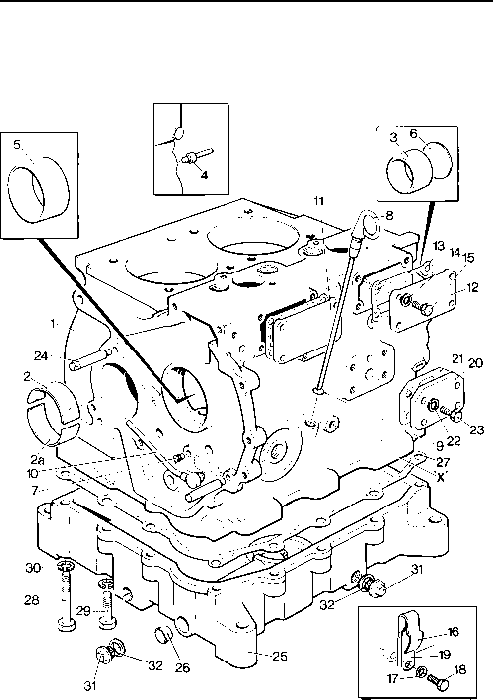
Lister-Petter TS/TR Master Parts Manual Issue 9: June 2000
19
Illustration T5

Lister-Petter TS/TR Master Parts ManualIssue 9: June 2000
20
Crankcase continued ....
Illustration T5 TS/TR
No. Description Part Number 1 2 3 Remarks
- Sump - TS/TR1 .......................................................570-33710 1 - - Not Builds 40,42
25 Sump - TS/TR2 .......................................................570-33590 - 1 - Not Builds 40,42
- Sump - TS/TR3 .......................................................570-33600 - - 1 Not Builds 40,42
- Sump - TS/TR1 .......................................................570-33860 1 - - Build 40
- Sump - TS/TR2 .......................................................570-33592 - 1 - Build 40
- Sump - TS/TR3 .......................................................570-33602 - - 1 Build 40
- Sump - TS/TR2 .......................................................202-42510 - 1 - Builds 42
- Sump - TS/TR3 .......................................................203-42510 - - 1 Builds 42
Accessory Kit Code QF - TS/TR2............................570-35490 - 1 - With side mounting pads
Sump ....................................................................570-41900 - 1 -
Accessory Kit Code QF - TS/TR3............................570-35500 - - 1 With side mounting pads
Sump ....................................................................570-41890 - - 1
26 Expansion Plug .......................................................351-41510 1 1 1 Not Build 42
- Joint - TS/TR1 .........................................................201-37751 1 - -
27 Joint - TS/TR2 .........................................................202-30541 - 1 -
- Joint - TS/TR3 .........................................................203-30542 - - 1
28 Bolt - M8 x 75mm ....................................................272-00047 4 4 4
29 Bolt - M8 x 35mm ....................................................272-00042 8 10 14
30 Spring Washer.........................................................272-00071 12 14 18
31 Drain Plug................................................................201-47470 1 2 2 Replaces 007-00407
32 Copper Washer .......................................................013-21778 1 2 2
- Drain Plug - 1/2" BSP................................................027-00140 1 1 1 Build 40
- Drain Plug - 1/2" BSP................................................027-00140 - 5 8 Build 42
- Flanged Drain Plug - 1"BSP ....................................003-00140 1 1 1 Build 40,42.Replaces 027-00142
- Copper Washer .......................................................616-01524 1 1 1 Build 40,42
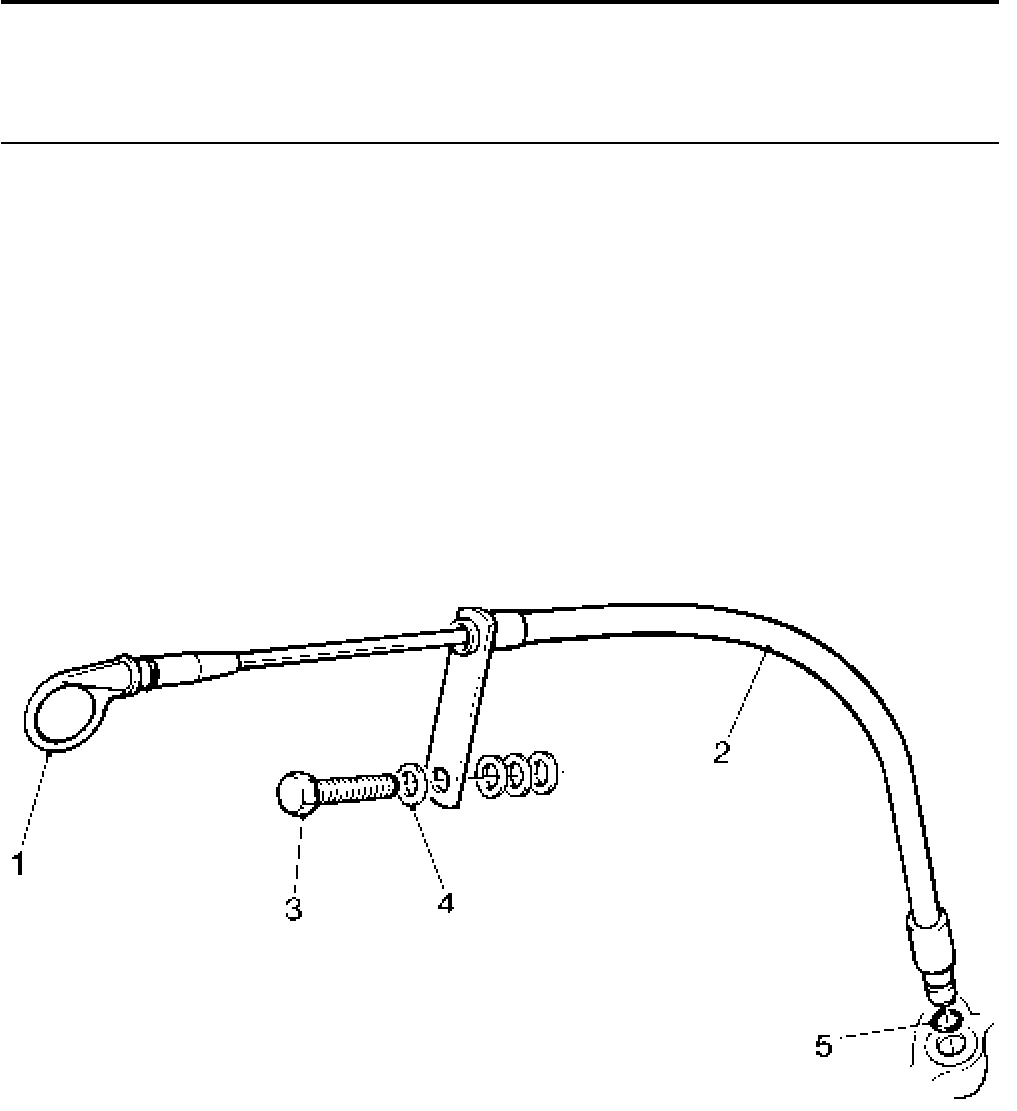
Lister-Petter TS/TR Master Parts Manual Issue 9: June 2000
21
Extended Dipstick (in lieu of standard dipstick) - TS/TR1
Illustration T421 TS/TR
No. Description Part Number 1 2 3 Remarks
Accessory Kit Code LQ ...........................................570-35560 1 - -
1 Dipstick Assembly ...................................................027-07948 1 - -
2 Dipstick Assembly ...................................................201-47171 1 - -
3 Bolt - M8 x 80mm ....................................................272-00128 1 - -
4 Washer....................................................................027-00082 4 - -
5 'O' Ring....................................................................201-13120 1 - -
Note:
For other reference to Dipstick see 'Crankcase' section.
Illustration T421

Lister-Petter TS/TR Master Parts ManualIssue 9: June 2000
22
Dry Sump
Illustration T198 TS/TR
No. Description Part Number 1 2 3 Remarks
Accessory Kit Code LA - TS/TR1 ............................ 570-31160 1 - -
Accessory Kit Code LA - TS/TR2 ............................570-31940 - 1 -
Accessory Kit Code LA - TS/TR3 ............................570-32150 - - 1
1 Lubricating Oil Pump Cylinder ................................. 602-20611 1 1 1
2 ’O’ Ring ...................................................................366-07720 1 1 1
- Sump - TS/TR1 .......................................................201-37743 1 - -
3 Sump - TS/TR2 .......................................................366-07076 - 1 -
- Sump - TS/TR3 .......................................................366-07077 - - 1
- Joint - TS/TR1 .........................................................201-37751 1 - -
4 Joint - TS/TR2 .........................................................202-30541 - 1 -
- Joint - TS/TR3 .........................................................203-30542 - - 1
5 Union Connection ....................................................351-40700 1 1 1
6 Copper Washer .......................................................291-30640 1 1 1
7 Union Connection ....................................................010-02085 1 1 1
8 Copper Washer .......................................................013-21778 1 1 1
9 Vent Pipe Adaptor....................................................027-04569 1 1 1
10 Drain Plug................................................................007-00407 1 2 2
11 Copper Washer .......................................................013-21778 1 2 2
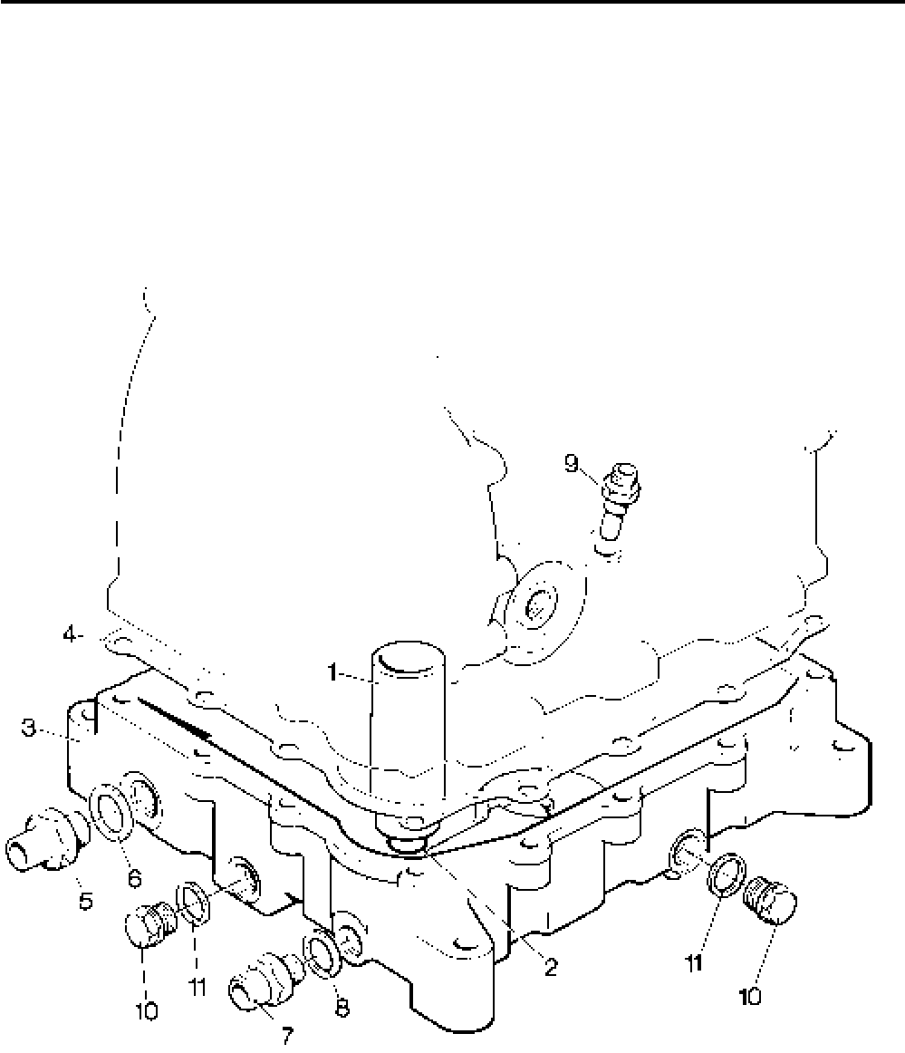
Lister-Petter TS/TR Master Parts Manual Issue 9: June 2000
23
Illustration T198
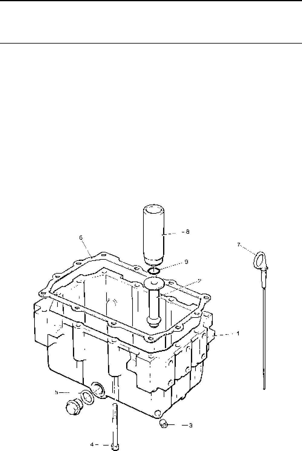
Lister-Petter TS/TR Master Parts ManualIssue 9: June 2000
24
5 Litre Deep Sump (in lieu of standard sump) - TS/TR1
Illustration T424 TS/TR
Description Part Number 1 2 3 Remarks
Accessory Kit Code LP ............................................570-35550 1 - -
- 5 Litre Sump Assembly............................................201-47140 1 - -
1 5 Litre Sump ......................................................... 201-47110 1 - -
2 Oil Pump Pedestal................................................201-47130 1 - -
3 Expansion Plug.....................................................201-39810 1 - -
4 Caphead Bolt...........................................................272-00770 12 - -
5 Copper Washer 1/2" BSP .........................................013-21778 1 - -
6 Joint.........................................................................201-37751 1 - -
7 Dipstick Assembly ...................................................027-07946 1 - -
8 Lubricating Oil Pump Cylinder ................................. 602-20611 1 - -
9 'O' Ring Seal............................................................366-07720 1 - -
- Strainer Mesh ..........................................................202-33740 1 - - See Note
- Cap Assembly .........................................................602-36820 1 - - See Note
- Setscrew - M8 x 14mm............................................272-00037 1 - - See Note
- Spring Washer.........................................................272-00071 1 - - See Note
- Drain Plug................................................................007-00407 1 - - See Note
Note:
If sump is being fitted to replace standard sump, these items must be
removed from the original sump as they do not form part of Accessory Kit LP.
Illustration T424
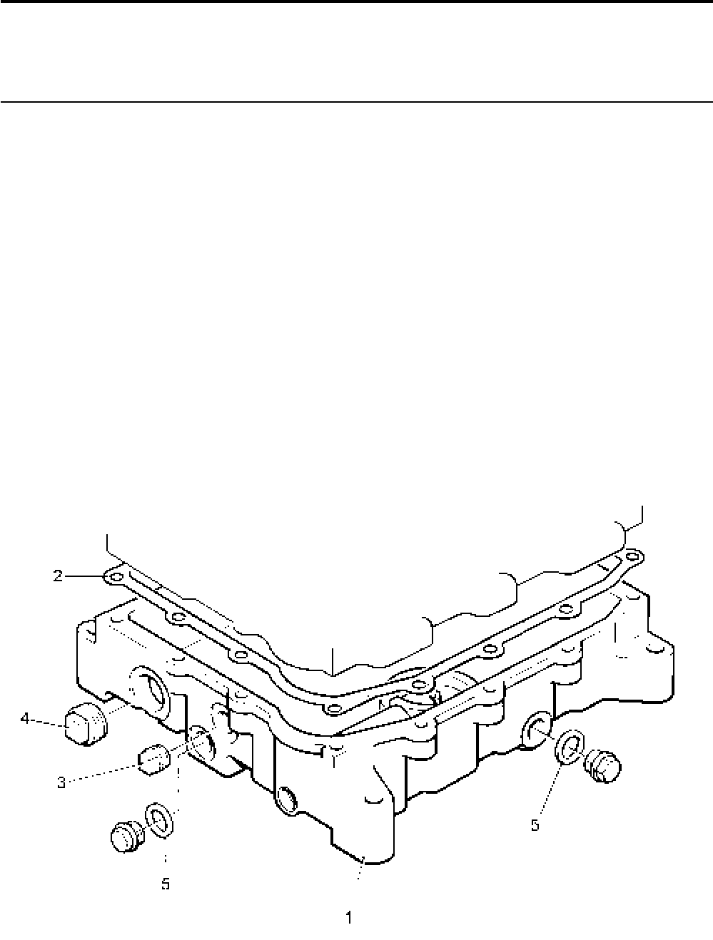
Lister-Petter TS/TR Master Parts Manual Issue 9: June 2000
25
Sump with provision for Heater and Thermostat - TS/TR2, 3
Illustration T428 TS/TR
Description Part Number 1 2 3 Remarks
Accessory Kit Code LJ - TS/TR2 .............................570-33540 - 1 - See Note
Accessory Kit Code LJ - TS/TR3 .............................570-33550 - - 1 See Note
1 Sump Assembly - TS/TR2 .......................................570-33592 - 1 -
- Sump Assembly - TS/TR3 .......................................570-33602 - - 1
2 Sump Joint - TS/TR2...............................................202-30541 - 1 -
- Sump Joint - TS/TR3 ...............................................203-30542 - - 1
3 Taper Plug 1/2" BSP .................................................027-00140 - 1 -
4 Taper Plug 1" BSP ...................................................027-00142 - 1 -
5 Copper Washer 1/2" BSP .........................................013-21778 - 2 -
Note:
The accessory kit must be factory or approved Lister-Peter Distributor fitted only.
Illustration T428

Lister-Petter TS/TR Master Parts ManualIssue 9: June 2000
26
Oil Strainer, Pump and Filter
Illustration T11 TS/TR
No. Description Part Number 1 2 3 Remarks
1 Strainer Mesh ..........................................................202-33740 1 1 1
2 Cap Assembly .........................................................602-36820 1 1 1
3 Setscrew - M8 x 14mm............................................272-00037 1 1 1
4 Spring Washer.........................................................272-00071 1 1 1
- Oil Pump Assembly - TS/TR1..................................570-32670 1 - -
5 Oil Pump Assembly - TS/TR2,3...............................570-30680 - 1 1
- Oil Pump Assembly - TS/TR2,3...............................570-30681 - 1 1 Build 42
6 Cylinder ................................................................602-20610 1 1 1
- Seal - TS2,3 ......................................................... 352-11911 - 1 1 Build 42
7 Lower Ball Valve ...................................................210-00393 1 1 1
8 Retaining Plate .....................................................602-22150 1 1 1
9 Spring - TS/TR1 ...................................................602-37550 1 - -
- Spring - TS/TR2,3 ................................................202-31055 - 1 1
10 Plunger Washer....................................................602-36340 1 1 1
11 Plunger .................................................................602-20581 1 1 1
12 Plunger Valve Seat Insert .....................................602-36351 1 1 1
13 Plunger Cap .........................................................602-20571 1 1 1
14 Upper Ball Valve ...................................................202-32120 1 1 1
15 Push Rod..............................................................203-45160 1 1 1 Replaces 203-31370
16 Oil Filter ...................................................................201-55370 1 1 1
17 Connector ................................................................ 201-36111 1 1 1
- Lubricating Oil Pipe - TS/TR1 .................................. 201-41181 1 - -
18 Lubricating Oil Pipe - TS/TR2 ..................................202-31671 - 1 -
- Lubricating Oil PNew Pageipe - TS/TR3..................203-31671 - - 1
19 Swivel Union Plug ....................................................202-34000 2 3 4
20 Copper Washer .......................................................616-01608 4 6 8
21 Clip .......................................................................... 201-31411 2 2 2
22 Adaptor....................................................................201-41710 1 - -
23 Copper Washer .......................................................616-01608 1 - -
24 Swivel Union Plug ....................................................601-30946 1 - -
25 Copper Washer .......................................................291-26090 2 - -
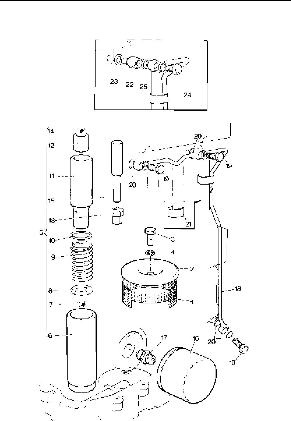
Lister-Petter TS/TR Master Parts Manual Issue 9: June 2000
27
Illustration T11

Lister-Petter TS/TR Master Parts ManualIssue 9: June 2000
28
Remote Mounted Oil Filter
Illustration T217 TS/TR
No. Description Part Number 1 2 3 Remarks
Accessory Kit Code LB ............................................570-31950 1 1 1
1 Oil Filter Adaptor......................................................367-34470 1 1 1
2 Union .......................................................................352-28760 4 4 4
3 Copper Washer 1/4" BSP .........................................013-22350 4 4 4
4 Union Adaptor .........................................................366-06930 1 1 1
5 'O' Ring Seal............................................................351-10341 2 2 2
6 Remote Oil Filter Adaptor ........................................367-34480 1 1 1
7 'O' Ring Seal............................................................201-41970 1 1 1
8 Oil Filter ...................................................................201-55370 1 1 1
9 Pipe Union...............................................................201-55360 1 1 1
10 Nut...........................................................................272-00004 1 1 1
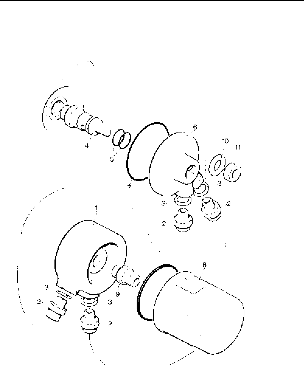
Lister-Petter TS/TR Master Parts Manual Issue 9: June 2000
29
Illustration T217

Lister-Petter TS/TR Master Parts ManualIssue 9: June 2000
30
Crankshaft, Connecting Rod, Piston and Cylinder Barrel
Illustration T173 TS/TR
No. Description Part Number 1 2 3 Remarks
Cylinder barrels are only available as a kit complete with piston.
- Crankshaft Assembly - TS1 .....................................570-30403 1 - - See Note 1
- Crankshaft Assembly - TS2 .....................................570-30033 - 1 - See Note 1
- Crankshaft Assembly - TS3 .....................................570-30143 - - 1 See Note 1
- Crankshaft Assembly - TR1 ....................................570-31042 1 - -
1 Crankshaft Assembly - TR2 ....................................570-30223 - 1 -
- Crankshaft Assembly - TR3 ....................................570-30233 - - 1
2 Expansion Plug - TS.............................................201-46820 1 2 3 Replaces rivet 027-06890
- Expansion Plug - TR.............................................351-40190 1 2 3 See Note 2
3 Balance Weight .......................................................201-30362 2 4 4 See Note 3. Not used on Build 07
- Balance Weight .......................................................201-30363 2 4 4 Build 07
4 Cap Screw...............................................................272-00353 4 8 8
5 Pinion ......................................................................201-37660 1 1 1
6 Key ..........................................................................027-00352 1 1 1
- Thrust Washer Assembly ........................................570-31360 2 2 2
7 Top Half ................................................................................ 2 2 2
7a Bottom Half .......................................................................... 2 2 2
- Connecting Rod Assembly ......................................570-30261 1 2 3
8 Connecting Rod.................................................................... 1 2 3
9 Bolt .......................................................................201-80300 2 4 6
10 Nut - 3/8” UNF........................................................270-00778 2 4 6
11 Small End Bush ....................................................201-44950 1 2 3
- Big End Bearing Assembly ......................................570-31370 1 2 3
12 Top Half ................................................................................ 1 2 3
12a Bottom Half .......................................................................... 1 2 3
- Piston Assembly - TS (5 Ring).................................570-12840 1 2 3 Not Builds 41, 60-66
- Piston Assembly - TS (3 Ring).................................570-33470 1 2 3 Builds 41, 60-66
13 Piston Assembly - TR (3 Ring) ................................570-33360 1 2 3
- Piston Ring Set - TS (5 Ring) ...............................570-12910 1 2 3 Not Builds 41, 60-66
- Piston Ring Set - TS (3 Ring) ...............................570-33480 1 2 3 Builds 41, 60-66
- Piston Ring Set - TR (3 Ring) ...............................570-33370 1 2 3
14 Gudgeon Pin ........................................................................ 1 2 3
15 Circlip ...................................................................201-80420 2 4 6
16 Cylinder Barrel/Piston Kit - TS .................................570-35540 1 2 3 See Note 4
- Cylinder Barrel/Piston Kit - TS .................................570-37430 1 2 3 Builds 41 & 60-66. See Note 4
- Cylinder Barrel/Piston Kit - TS .................................570-37430 - 2 3 Build 104. See Note 4
- Cylinder Barrel/Piston Kit - TR .................................570-35530 1 2 3 See Note 5
17 Joint.........................................................................201-32430 1 1 1
Notes:
1. Up to the following engine numbers flywheels were secured with a Retaining Setscrew 201-30340.
Nut 202-33790 and Washer 202-33800 will be required with crankshafts after these engine numbers.
3500630TS1 3506716TS2 3505963TS3
3600255TR1 3600073TR2 3600112TR3
2. The plug was first fitted on the following TS engines:
4300920TS1 4302489TS2 4301742TS3
3. Early crankshaft balance weights were fitted with a single capscrew.
If an early crankshaft is being replaced it will be necessary to fit the
later two hole fixing balance weights.
2 Bolt Balance Weights introduced on Engine numbers:
3405892TS2 3406086TS3
To replace Crankshafts/Balance Weights on earlier engines supply items 1, 3 and 4 above.
4. TS Cylinder Barrel/Piston Kit comprises 201-37700 and 570-12840.
For builds 41 & 60-66 kit comprises 201-37700 and 570-33470.
For build 104 kit comprises 201-32430 and 570-30701.
5. TR Cylinder Barrel/Piston Kit comprises 201-32804 and 570-33360.
(201-32804 replaces 201-32802).
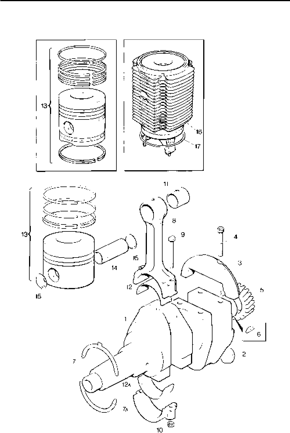
Lister-Petter TS/TR Master Parts Manual Issue 9: June 2000
31
Illustration T173
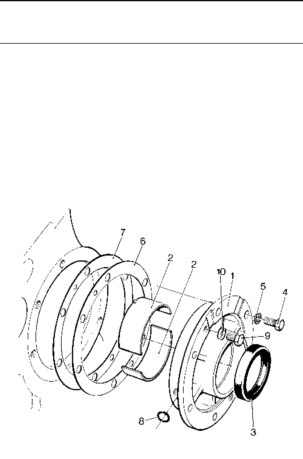
Lister-Petter TS/TR Master Parts ManualIssue 9: June 2000
32
Main Bearing Housing
Illustration T1 TS/TR
No. Description Part Number 1 2 3 Remarks
1 Main Bearing Housing Assembly .............................570-30602 1 1 1 Replaces 570-30601
- Main Bearing Housing Assembly .............................570-30603 1 1 1 For charge winding builds
2 Main Bearing - Standard....................................... 570-30011 1 1 1
- Main Bearing - 0,25mm undersize ................. 570-30011/025 1 1 1
- Main Bearing - 0,50mm undersize ................. 570-30011/050 1 1 1
- Main Bearing - 0,75mm undersize ................. 570-30011/075 1 1 1
- Main Bearing - 1,00mm undersize ................. 570-30011/100 1 1 1
3 Lip Seal ...................................................................201-41940 1 1 1
4 Setscrew - M8 x 20mm............................................272-00039 6 6 6
5 Spring Washer.........................................................272-00071 6 6 6
6 Shim - 0,127mm (0,005") ........................................201-30943 Use as required
7 Shim - 0,254mm (0,010") ........................................201-30944 Use as required
8 'O' Ring Seal............................................................201-45920 1 1 1 Replaces 601-37420
9 Setscrew - M8 x 20mm............................................272-00727 2 2 2 Not used on TR1 Build 100
- Setscrew - M8 x 10mm............................................272-00239 2 - - Only used on TR1 Build 100
10 Copper Washer .......................................................616-01608 2 2 2
Note:
For further reference to Main Bearings see 'Crankcase' section.
Illustration T1
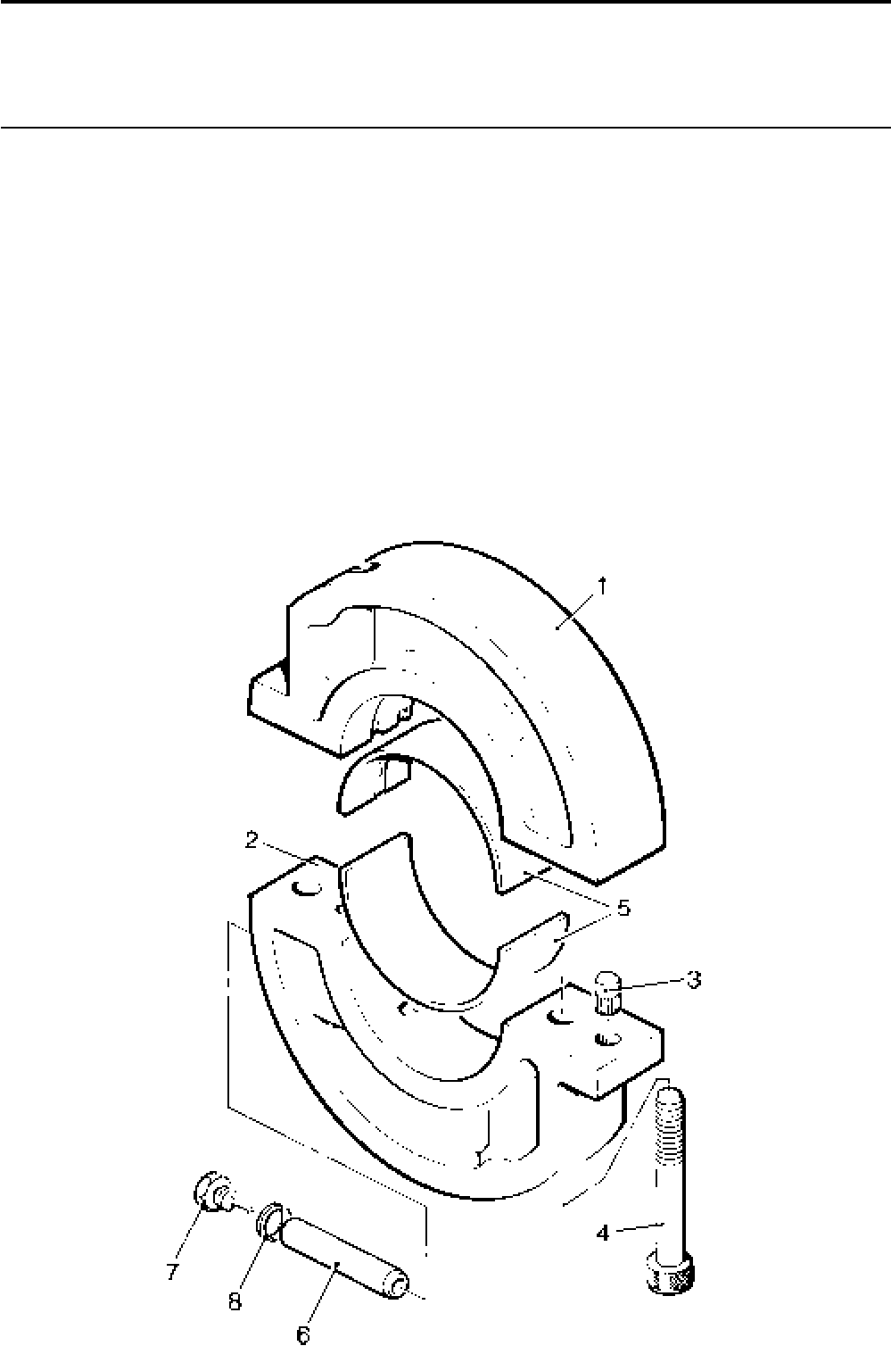
Lister-Petter TS/TR Master Parts Manual Issue 9: June 2000
33
Centre Bearing Housing
Illustration T327 TS/TR
No. Description Part Number 1 2 3 Remarks
- Centre Bearing Housing Assembly ..........................202-80591 - 1 2
1 Top Half Bearing Housing ..................................................... - 1 2
2 Bottom half Bearing Housing ................................................ - 1 2
3 Spring Dowel Bush ...............................................751-18290 - 2 4 Replaces Dowel 010-02110
4 Cap Screw - M8 x 50mm ......................................272-00261 - 2 4
5 Centre Bearing - Standard.......................................570-12990 - 1 2
- Centre Bearing - 0,010in undersize .................. 570-12990/010 - 1 2
- Centre Bearing - 0,020in undersize .................. 570-12990/020 - 1 2
- Centre Bearing - 0,030in undersize .................. 570-12990/030 - 1 2
- Centre Bearing - 0,040in undersize .................. 570-12990/040 - 1 2
6 Locating Dowel ........................................................202-31090 - 1 2 Fitted into position ‘X’ as shown
in the Crankcase Illustration T5
7 Plug Assembly......................................................... 202-31100 - 1 2
8 Copper Washer .......................................................600-00106 - 1 2
Illustration T327

Lister-Petter TS/TR Master Parts ManualIssue 9: June 2000
34
Camshaft and Governor - Early Engines
Notes:
There have been alterations to the governor assembly
and the two types are not totally interchangeable.
A one-piece ‘Nylatron’ sleeve has been introduced to
replace the original sleeve assembly.
The Nylatron sleeve is interchangeable with the older
assembly if the:
Governor lever shoes are removed,
Governor weight shoes are removed,
Governor sleeve setting ‘A’ is set at 9,5mm (refer
to the Workshop Manual).
Re-designed pivot blocks and return springs are now
fitted with the springs not being interchangeable, if the
pivot blocks are changed the return springs must also
be changed.
All of the above changes were introduced on the
following engines:
35 01614 TS1 36 00001 TR1
35 07495 TS2 36 00011 TR2
35 06047 TS3 36 00141 TR3
From the above engines refer to 'Camshaft and
Governor - Later Engines'
Illustration T157 TS/TR
No. Description Part Number 1 2 3 Remarks
- Camshaft Assembly - TS/TR1 .................................570-31210 1 - -
- Camshaft Assembly - TS/TR2 ................................. 570-30611 - 1 -
- Camshaft Assembly - TS/TR3 .................................570-30641 - - 1
1 Camshaft - TS/TR2 .............................................................. - 1 -
2 Gearwheel ............................................................202-38000 1 1 1 Replaces 201-37650
3 Dowel Pin ............................................................. 601-31100 1 1 1
4 Key .......................................................................027-00441 1 1 1
5 Ball Bearing ..........................................................201-30670 1 1 1
6 Governor Weight Assembly .................................................. See 'Governor Weights and
Speeder Springs' section
7 Shoe .....................................................................351-34850 2 2 2
8 Pin ........................................................................201-10721 2 2 2
9 Retainer................................................................202-37990 4 4 4
10 Setscrew - M6 x 16mm .........................................272-00034 4 4 4
11 Spring Washer......................................................272-00070 4 4 4
12 Catch Pin .................................................................201-43040 1 1 1
13 Spring Pin ................................................................027-05516 1 1 1
14 Thrust Washer.........................................................201-30390 2 2 2
15 Thrust Pad...............................................................201-30410 1 1 1
16 Spring Ring..............................................................201-30400 1 1 1
17 Governor Sleeve......................................................201-42900 1 1 1 Replaces 201-30370
18 Governor Lever Assembly ....................................... 201-31160 1 1 1
19 Pivot Block............................................................... 201-31141 2 2 2 Replaces 201-31140
20 Pin ...........................................................................601-20910 2 2 2
21 Shim ........................................................................601-22330 Use as required
22 Shoe ........................................................................601-33220 2 2 2
23 Return Spring ..........................................................201-31312 1 1 1 Variable speed engines only
24 Shim - 0,13mm ........................................................201-30680 Use as required
- Shim - 0,25mm ........................................................201-30681 Use as required
- Shim - 0,38mm ........................................................201-30682 Use as required
25 Thrust Washer.........................................................201-30420 1 1 1
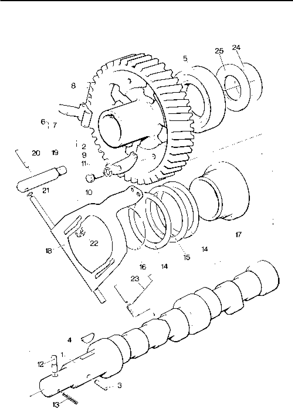
Lister-Petter TS/TR Master Parts Manual Issue 9: June 2000
35
Illustration T157

Lister-Petter TS/TR Master Parts ManualIssue 9: June 2000
36
Camshaft and Governor - Later Engines
Illustration T157C TS/TR
No. Description Part Number 1 2 3 Remarks
- Camshaft Assembly - TS/TR1 .................................570-31032 1 - -
- Camshaft Assembly - TS1.......................................570-31200 1 - - Build 101
- Camshaft Assembly - TS/TR2 .................................570-30275 - 1 -
- Camshaft Assembly - TS2.......................................570-30821 - 1 - Build 104
- Camshaft Assembly - TR2 ......................................570-30631 - 1 - Build 101
- Camshaft Assembly - TS/TR3 .................................570-30285 - - 1
- Camshaft Assembly - TS3.......................................570-30851 - - 1 Build 104
1 Camshaft .............................................................................. - 1 -
2 Gearwheel ............................................................202-38000 1 1 1
3 Dowel Pin ............................................................. 601-31100 1 1 1
4 Key .......................................................................027-00441 1 1 1
5 Ball Bearing ..........................................................201-30670 1 1 1
6 Governor Weight Assembly .................................................. See 'Governor Weights and
Speeder Springs' section
7 Pin ...........................................................................201-10721 2 2 2
8 Retainer...................................................................202-37990 4 4 4
9 Setscrew - M6 x 16mm............................................272-00034 4 4 4
10 Spring Washer.........................................................272-00070 4 4 4
11 Catch Pin.................................................................201-43040 1 1 1
12 Grub Screw .............................................................272-00603 1 1 1
13 Governor Sleeve......................................................201-42900 1 1 1
14 Governor Lever Assembly ....................................... 201-31160 1 1 1
15 Pivot Block............................................................... 201-31141 2 2 2
16 Pin ...........................................................................601-20910 2 2 2
17 Shim ........................................................................601-22330 Use as required - see Note.
18 Return Spring ..........................................................201-31312 1 1 1 Variable speed engines only
Note:
The shims are fitted to achieve an endfloat of 0.12-0.25mm
Note:
On engine numbers below those shown refer to 'Camshaft and
Governor - Early Engines'
3501614TS1 3600001TR1
3507495TS2 3600011TR2
3506047TS3 3600141TR3
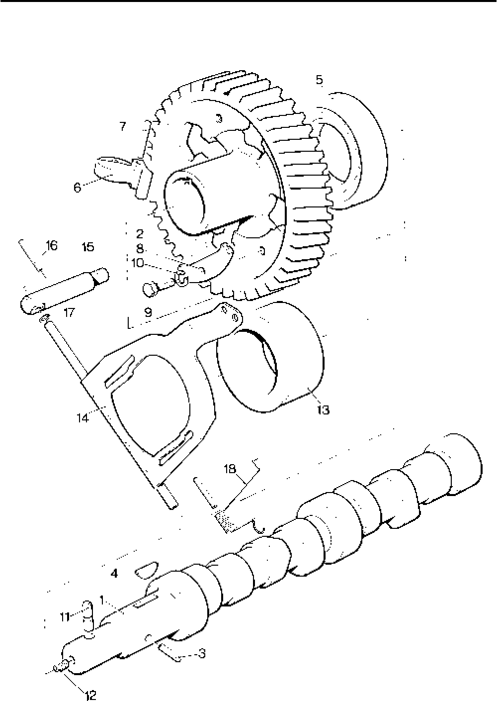
Lister-Petter TS/TR Master Parts Manual Issue 9: June 2000
37
Illustration T157C

Lister-Petter TS/TR Master Parts ManualIssue 9: June 2000
38
Fuel Pump Linkage and Engine Controls
Illustration T126 TS/TR
No. Description Part Number 1 2 3 Remarks
1 Governor Link Assembly .........................................202-39430 1 1 1 Replaces 202-36950
2 Fuel Pump Link Assembly .......................................202-42070 - 1 2 Replaces 202-32300, 203-32370,
203-32410
- Governor Link .......................................................202-39180 - 1 2
3 Connector.............................................................202-39190 - 1 2
4 Shackle ................................................................202-39170 - 1 2
5 Retaining Link.......................................................601-38490 - 1 2
6 Retaining Spring ...................................................202-39200 - 1 2
7 Governor Lever Spring ............................................201-31340 1 1 1
8 Nut...........................................................................272-00001 4 4 4
9 Swivel Spacer..........................................................601-21000 2 2 2
- Speed Control Lever Assembly - TS/TR1 ................201-39742 1 - - Replaces 201-39741 when
Bracket 202-34193 is supplied
10 Speed Control Lever Assembly - TS/TR2,3 .............202-34233 - 1 1 Replaces 202-34232 when
Bracket 202-34193 is supplied
11 Bracket - TS/TR2,3 .................................................202-34193 1 1 1 Replaces 202-34192
12 ’O’ Ring ...................................................................201-13120 1 1 1
13 Pin ...........................................................................201-31240 1 1 1
- Setscrew - M6 x 14mm - TS/TR1 ............................272-00034 1 - - Replaces 272-00033
14 Setscrew - M6 x 12mm - TS/TR2,3 .........................272-00120 - 1 1
15 Spring Washer.........................................................272-00070 1 1 1
16 Adjusting Screw - M6 x 35mm .................................272-00349 1 1 1
17 Adjusting Screw - M6 x 45mm .................................272-00387 1 1 1
18 Nut...........................................................................272-00351 2 2 2
19 Adjusting Screw....................................................................... 1 1 1 See 'Governor Weights and
Speeder Springs' section
20 Speeder Spring ....................................................................... See 'Governor Weights and
Speeder Springs' section
21 Spindle Assembly ....................................................201-42530 1 1 1
22 Location Plate ..........................................................201-31381 1 1 1
23 Tamperproof Setscrew ............................................201-46630 1 1 1
23a Setscrew - M6 x 12mm............................................272-00032 1 1 1
24 Spring Washer.........................................................272-00070 1 1 1
25 Washer ....................................................................027-00618 1 1 1
26 ’O’ Ring ...................................................................201-13120 1 1 1
27 Stop Control Spring .................................................601-35490 1 1 1
- Lever Assembly .......................................................570-33430 1 1 1
28 Lever ....................................................................201-31270 1 1 1
29 Cam......................................................................201-31280 1 1 1
30 Automatic Excess Fuel Spring ..............................201-31350 1 1 1
31 Pin ........................................................................601-40370 1 1 1 Replaces 382-03233
32 Spring ......................................................................202-37600 1 1 1
33 Dowel ......................................................................601-35370 1 1 1
34 Stop Control Knob ...................................................201-37291 1 1 1
35 Screw - M4 x 10mm ................................................272-00061 2 2 2
36 Spring Washer.........................................................272-00084 2 2 2
37 Washer .............................................................064-06612/004 2 2 2
- Capscrew - M4 x 80mm ..........................................272-00381 1 1 - Builds 101, 102
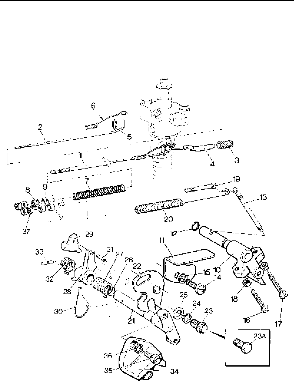
Lister-Petter TS/TR Master Parts Manual Issue 9: June 2000
39
Illustration T126

Lister-Petter TS/TR Master Parts ManualIssue 9: June 2000
40
Governor Weights and Speeder Springs - TS
TS1
Build Governor
Weights
Weights Speeder
Spring Spring
Colour Code Adjusting
Screw Inner
Spring
Qty. Code Early
01 - 07 351-35910 2 Q (18)* 201-31364 White 272-00620 -
08 - 11 351-35860 4 L (13)* 201-31364 White 272-00381 201-41980
12, 13 351-35930 2 S (20)* 201-31361 Yellow 272-00173 -
14, 15 351-35910 2 Q (18)* 201-31364 White 272-00620 -
16 351-35860 2 L 201-31364 White 272-00620 -
17 351-35910 2 Q (18)* 201-31364 White 272-00620 -
18 351-35860 2 L 201-31364 White 272-00620 -
40 - 61 351-35910 2 Q 201-31364 White 272-00620 -
62 - 65 351-35860 4 L 201-31364 White 272-00381 201-41980
66 351-35910 2 Q 201-31364 White 272-00620 -
78, 101 351-35860 4 L 201-31364 White 272-00381 201-41980
102, 104 351-35910 2 Q 201-31364 White 272-00620 -
* See Note below
TS2, 3
Build Governor
Weights
Weights Speeder
Spring Spring
Colour Code Adjusting
Screw Inner
Spring
Qty. Code Early
01 - 07 351-35910 2 Q (18)* 201-31364 White 272-00620 -
08 - 11 351-35860 4 L (13)* 201-31364 White 272-00381 201-41980
12, 13 351-35930 2 S (13)* 201-31361 Yellow 272-00344 -
14 - 40 351-35910 2 Q 201-31364 White 272-00620 -
41 351-35860 2 L 201-31364 White 272-00620 -
42 351-35910 2 Q 201-31364 White 272-00620 -
43 351-35860 4 L 201-31364 White 272-00381 201-41980
50 - 61 351-35910 2 Q 201-31364 White 272-00620 -
62 - 65 351-35860 4 L 201-31364 White 272-00381 201-41980
66 351-35910 2 Q 201-31364 White 272-00620 -
78, 101 351-35860 4 L 201-31364 White 272-00381 201-41980
104 351-35910 2 Q 201-31364 White 272-00620 -
* Note:
The codes in brackets are for early engines, refer to 'Camshaft and Governor - Early Engines'.

Lister-Petter TS/TR Master Parts Manual Issue 9: June 2000
41
Governor Weights and Speeder Springs - TR
TR1
Build Governor
Weights
Weights Speeder
Spring Spring
Colour Code Adjusting
Screw Inner
Spring
Qty. Code Early
01 - 07 351-35910 2 Q (18)* 201-31364 White 272-00620 -
08 - 11 351-35860 4 L (13)* 201-31364 White 272-00381 201-41980
14 - 16 351-35910 2 Q (18)* 201-31364 White 272-00620 -
78 351-35860 4 L 201-31364 White 272-00381 201-41980
100 351-35910 2 Q 201-31364 White 272-00620 -
* See Note below
TR2, 3
Build Governor
Weights
Weights Speeder
Spring Spring
Colour Code Adjusting
Screw Inner
Spring
Qty. Code Early
01 - 07 351-35910 2 Q (18)* 201-31364 White 272-00620 -
08 - 11 351-35860 4 L (13)* 201-31364 White 272-00381 201-41980
12, 13 351-35930 2 S (13)* 201-31361 Yellow 272-00344 -
14 - 40 351-35910 2 Q 201-31364 White 272-00620 -
41 351-35860 2 L 201-31364 White 272-00620 -
42 351-35910 2 Q 201-31364 White 272-00620 -
43 351-35860 4 L 201-31364 White 272-00381 201-41980
50 - 61 351-35910 2 Q 201-31364 White 272-00620 -
62 - 65 351-35860 4 L 201-31364 White 272-00381 201-41980
66 351-35910 2 Q 201-31364 White 272-00620 -
78, 101 351-35860 4 L 201-31364 White 272-00381 201-41980
104 351-35910 2 Q 201-31364 White 272-00620 -
* Note:
The codes in brackets are for early engines, refer to 'Camshaft and Governor - Early Engines'.
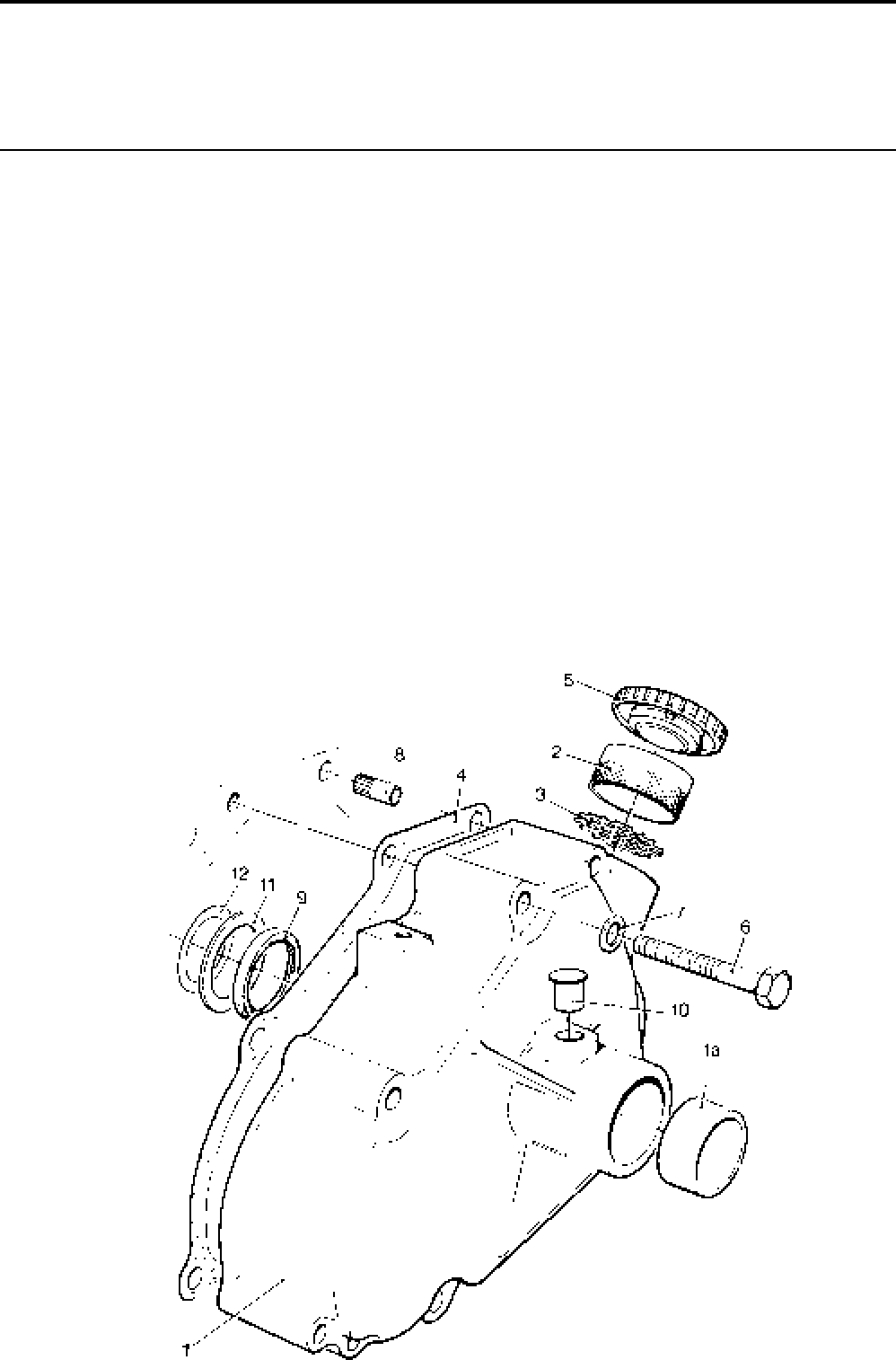
Lister-Petter TS/TR Master Parts ManualIssue 9: June 2000
42
Gear End Cover
Not used on Builds 05, 06, 07, 40
Illustration T2 TS/TR
No. Description Part Number 1 2 3 Remarks
1 End Cover Assembly ...............................................201-47980 1 1 1 Replaces 201-33851
Accessory Kit Code EY ........................................... 570-72411 1 1 1 Replaces 570-72410. Non-hand-
start End Cover Assembly. Se e Note
1a Bush .....................................................................601-39740 1 1 1
2 Oil Filler ................................................................027-06317 1 1 1
3 Strainer Plate........................................................291-23751 1 1 1
- Protective Cap ......................................................027-07917 1 1 1 Included in Code EY
4 Joint......................................................................... 201-33011 1 1 1
5 Oil Filler Cap............................................................366-08126 1 1 1 Replaces 027-03824 / 366-00091
- Oil Filler Cap Joint ................................................303-00253 1 1 1
6 Bolt - M8 x 70mm ....................................................272-00179 7 7 7
7 Washer ....................................................................027-00082 7 7 7
8 Dowel ......................................................................351-13660 2 2 2
9 Camshaft Oil Seal ...................................................601-39550 1 1 1
10 Cap..........................................................................351-36580 1 1 1
11 Camshaft Thrust Washer ........................................201-30420 1 1 1
12 Shim - 0.13mm ........................................................201-30680 Use as required
- Shim - 0.25mm ........................................................201-30681 Use as required
- Shim - 0.38mm ........................................................201-30682 Use as required
- Shim - 0.50mm ........................................................201-30683 Use as required
- Shim - 0.63mm ........................................................201-30684 Use as required
Note:
When fitting Non hand start End Cover Assembly, Catch Pin (201-43040)
and Spring Pin (027-05516) must be removed from Camshaft.
Illustration T2
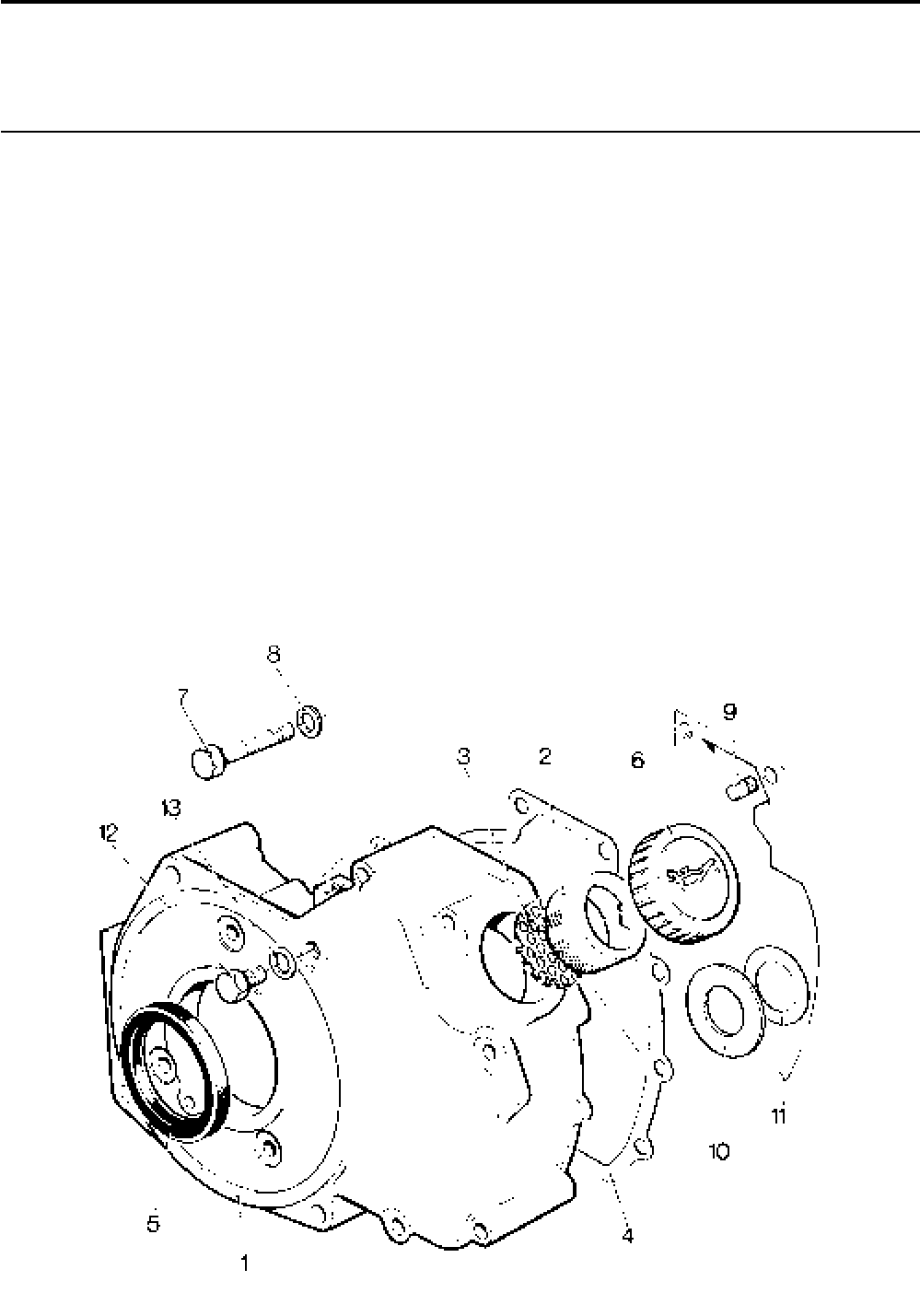
Lister-Petter TS/TR Master Parts Manual Issue 9: June 2000
43
Gear End Cover - Builds 05 and 104
Illustration T131 TS/TR
No. Description Part Number 1 2 3 Remarks
1 End Cover Assembly ...............................................570-30061 - 1 1
2 Oil Filler ............................................................... 027-06317 - 1 1
3 Strainer Plate........................................................291-23751 - 1 1
4 Joint.........................................................................201-33012 - 1 1
5 Oil Seal....................................................................201-32740 - 1 1
6 Oil Filler Cap............................................................027-03824 - 1 1 Build 05
- Oil Filler Cap............................................................366-08126 - 1 1 Build 104
- Oil Filler Cap Joint ................................................303-00253 - 1 1
7 Bolt - M8 x 70mm ....................................................272-00179 - 7 7
8 Washer....................................................................027-00082 - 7 7
9 Dowel ......................................................................351-13660 - 2 2
10 Camshaft Thrust Washer ........................................201-30420 - 1 1
11 Shim - 0.13mm ........................................................201-30680 - Use as required
- Shim - 0.25mm ........................................................201-30681 - Use as required
- Shim - 0.38mm ........................................................201-30682 - Use as required
- Shim - 0.50mm ........................................................201-30683 - Use as required
- Shim - 0.63mm ........................................................201-30684 - Use as required
12 Setscrew .................................................................270-00350 - 1 1
13 Washer .................................................................... 201-11890 - 2 2
Illustration T131
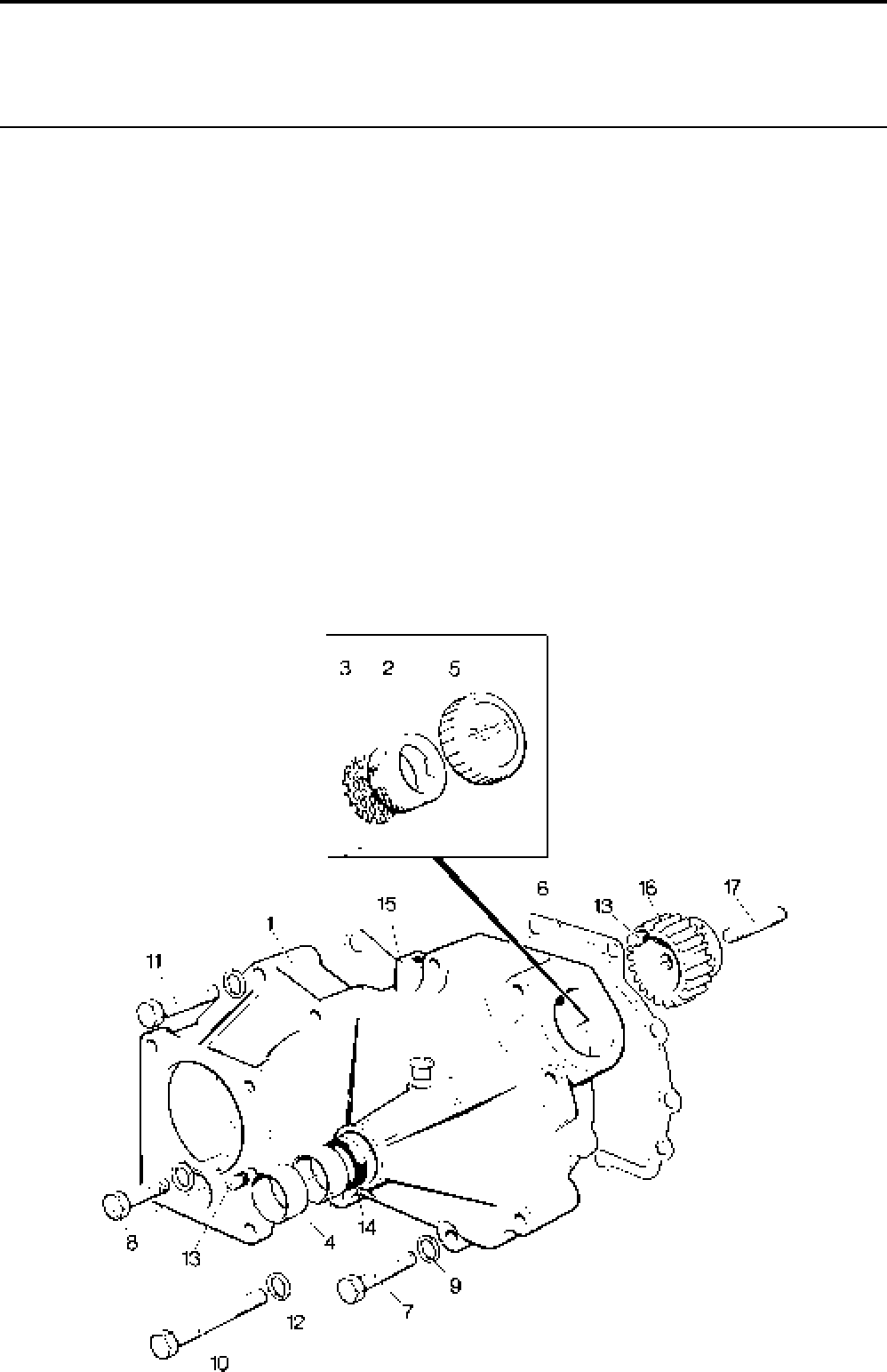
Lister-Petter TS/TR Master Parts ManualIssue 9: June 2000
44
Gear End Cover - Builds 06, 07
Illustration T25 TS/TR
No. Description Part Number 1 2 3 Remarks
1 End Cover Assembly - TS/TR2,3.............................201-47983 1 1 1 Replaces 570-30101, 570-31070
2 Oil Filler ................................................................027-06317 1 1 1
3 Strainer.................................................................291-23751 1 1 1
4 Bush .....................................................................601-39740 2 2 2
5 Oil Filler Cap............................................................366-08126 1 1 1
- Oil Filler Cap Joint ................................................303-00253 1 1 1
6 Joint.........................................................................201-33012 1 1 1
7 Bolt - M8 x 70mm ....................................................272-00179 6 6 6
8 Bolt - M8 x 50mm ....................................................272-00044 1 1 1
9 Washer ....................................................................027-00082 7 7 7
10 Bolt - 7/16"UNC x 33/4" ..............................................:270-00756 1 1 1
11 Bolt - 7/16"UNC x 3" .................................................:270-00777 1 1 1
12 Washer .................................................................... 201-11890 2 2 2
13 Dowel ......................................................................351-13660 2 2 2
14 Oil Seal ....................................................................601-39550 1 1 1
15 Plug .........................................................................351-36580 1 1 1
16 Pump Gear Assembly .............................................570-30293 1 1 1 See Note
17 Stud .........................................................................201-31930 1 1 1
Note:
Comprises Pump Gear (201-31913) and Drive Pinion (201-31903). It is recommended that these
items be fitted as a matched pair. See also Accessory Kits HF and HI.
Illustration T25
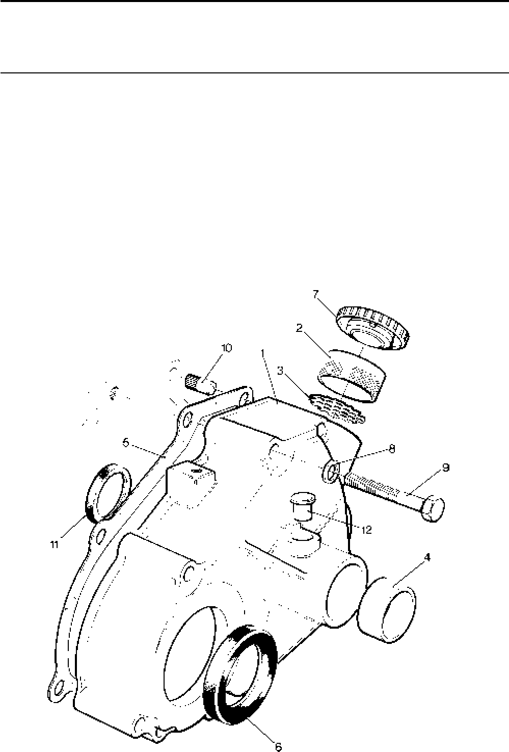
Lister-Petter TS/TR Master Parts Manual Issue 9: June 2000
45
Gear End Cover - Build 40
Illustration T391 TS/TR
No. Description Part Number 1 2 3 Remarks
1 End Cover Assembly ...............................................201-47981 1 1 1 Replaces 201-33850
2 Oil Filler ................................................................027-06317 1 1 1
3 Strainer Plate........................................................291-23751 1 1 1
4 Bush .....................................................................601-39740 1 1 1
5 Joint......................................................................... 201-33011111
6 Oil Seal....................................................................201-30690 1 1 1
7 Oil Filler Cap............................................................027-03824 1 1 1
- Oil Filler Cap Joint ................................................303-00253 1 1 1
8 Washer....................................................................027-00082 7 7 7
9 Bolt - M8 x 70mm ....................................................272-00179 7 7 7
10 Dowel ......................................................................351-13660 2 2 2
11 Camshaft Oil Seal ...................................................601-39550 1 1 1
13 Nylon Cap ................................................................351-36580 1 1 1
Illustration T391

Lister-Petter TS/TR Master Parts ManualIssue 9: June 2000
46
Flywheel and Fanshroud - TS/TR1
Not Builds 16, 17, 101, 102
Illustration T158 TS/TR
No. Description Part Number 1 2 3 Remarks
1 Fanshroud ...............................................................202-33664 1 - - Replaces 201-41051 & 201-41050
2 Self-lock Setscrew - M10 x 25mm ...........................272-00621 6 - -
3 Blanking Plug ..........................................................201-46130 1 - - No longer used
4 Bolt - M10 x 55mm ..................................................272-00050 2 - -
5 Disc Spring Washer.................................................202-24060 2 - -
6 Blanking Plug ..........................................................351-36580 1 - -
7 Flywheel Assembly - TS ..........................................570-42021 1 - - Builds 01, 03, 06, 10, 14, 60, 64,
101
- Flywheel Assembly - TS ..........................................570-42022 1 - - Build 04
- Flywheel Assembly - TS ..........................................570-42023 1 - - Build 12
- Flywheel Assembly - TS/TR ....................................570-42025 1 - - Builds 08, 62, 78. With Integral fan
- Flywheel Assembly - TS ..........................................570-42027 1 - - Build 40
- Flywheel Assembly - TR ..........................................570-42031 1 - - Build 01, 03, 06, 10, 14
8 Flywheel ............................................................................... 1 - -
9 Gear Ring ..........................................................202-30520 1 - -
10 Fan - TS1 ............................................................. 201-39911 1 - - Not fitted where fan is integral
- Fan - TR1 .............................................................202-33540 1 - - Not fitted where fan is integral
11 Capscrew - M8 x 30mm .......................................272-00176 8 - - Not fitted where fan is integral
12 Spring Washer......................................................272-00089 8 - - Not fitted where fan is integral
13 Flywheel Nut ............................................................202-33790 1 - -
14 Lock Washer ...........................................................202-33800 1 - -
15 Key ..........................................................................201-80550 1 - -
16 Starter Motor Blanking Plate ....................................201-38230 1 - -
17 Spring Washer.........................................................272-00072 3 - -
18 Setscrew - M10 x 16mm..........................................272-00124 3 - -
19 Setscrew - M6 x 16mm............................................272-00034 2 - -
20 Spring Washer.........................................................272-00070 2 - -
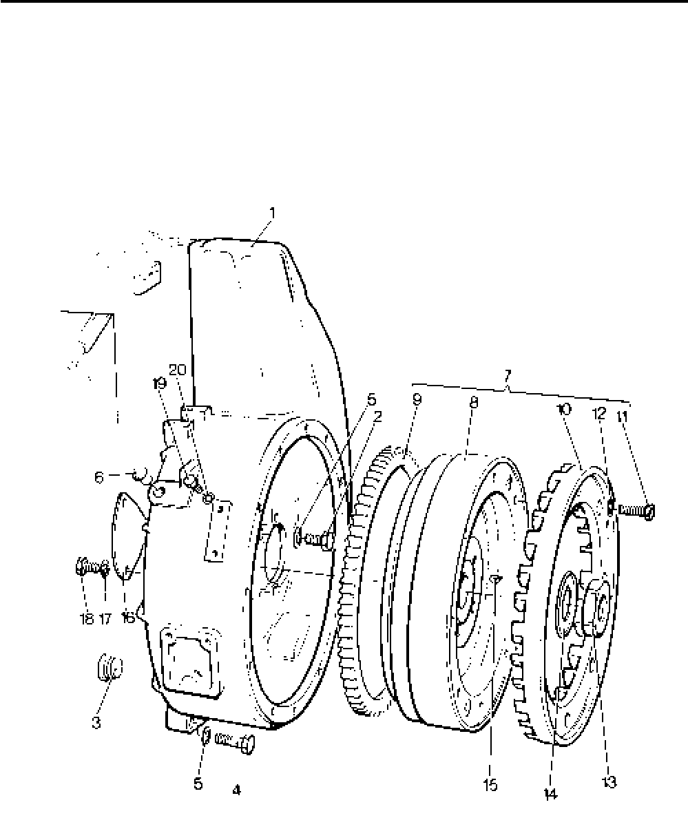
Lister-Petter TS/TR Master Parts Manual Issue 9: June 2000
47
Illustration T158

Lister-Petter TS/TR Master Parts ManualIssue 9: June 2000
48
Flywheel and Fanshroud
TS1 Builds 16, 17, 101, 102
TR1 Builds 16, 17
Illustration T172 TS/TR
No. Description Part Number 1 2 3 Remarks
- Flywheel Assembly - TS1 ........................................570-33160 1 - -
- Flywheel Assembly - TR1 ........................................570-33340 1 - -
1 Flywheel ............................................................................... 1 - -
2 Fan .......................................................................201-41510 1 - -
3 Cheese Head Screw - M6 x 35mm.......................272-00265 6 - -
4 Spring Washer......................................................272-00086 6 - -
5 Key ..........................................................................201-80550 1 - -
6 Flywheel Nut............................................................202-33790 1 - -
7 Lock Washer ...........................................................202-33800 1 - -
8 Sheet Metal Fan Shroud..........................................201-41390 1 - -
9 Air Seal....................................................................201-41460 1 - -
10 Spring Disc Washer.................................................202-24060 6 - -
11 Setscrew - M10 x 20mm..........................................272-00241 6 - -
12 Retainer...................................................................201-41540 1 - -
- Lockwasher .............................................................272-00086 2 - - Builds 101, 102
13 Setscrew - M6 x 20mm............................................ 272-00117 2 - -
14 Setscrew - M6 x 12mm............................................272-00032 1 - -
15 Spring Washer....................................................... `272-00070 1 - -
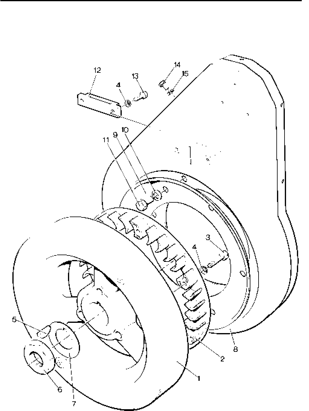
Lister-Petter TS/TR Master Parts Manual Issue 9: June 2000
49
Illustration T172

Lister-Petter TS/TR Master Parts ManualIssue 9: June 2000
50
Flywheel and Fanshroud - TS/TR2,3
Illustration T7 TS/TR
No. Description Part Number 1 2 3 Remarks
1 Fanshroud - TS2,3 and TR2 ....................................202-33664 - 1 1
- Fanshroud - TR3 .....................................................570-41562 - - 1 Replaces 202-33665
2 Baffle - TR3 ............................................................. 203-43011 - - 1 See Note
3 Setscrew - M6 x 16mm - TR3..................................272-00034 - - 3 See Note
4 Nut - TR3.................................................................272-00002 - - 3 See Note
5 Spring Washer - TR3...............................................272-00070 - - 3 See Note
6 Setscrew .................................................................272-00621 - 6 6
7 Bolt - M10 x 55mm ..................................................272-00050 - 2 2
8 Disc Spring Washer.................................................202-24060 - 2 2
9 Blanking Plug ..........................................................351-36580 - 1 1
10 Flywheel Assembly - TS2 ........................................570-42041 - 1 - Builds 01, 03, 05, 06, 10, 60
- Flywheel Assembly - TS2 ........................................570-42042 - 1 - Builds 04
- Flywheel Assembly - TS2 ........................................570-42043 - 1 - Build 12
- Flywheel Assembly - TS/TR2 ..................................570-42045 - 1 - Builds 08, 14, 62, 78.
With Integral Fan
- Flywheel Assembly - TS2 ........................................570-42047 - 1 - Builds 40, 41, 42
- Flywheel Assembly - TR2 ........................................570-42051 - 1 - Builds 01, 06, 50
- Flywheel Assembly - TR2 ........................................570-42052 - 1 - Build 04
- Flywheel Assembly - TR2 ........................................570-42053 - 1 - Builds 12
- Flywheel Assembly - TR2 ........................................570-42017 - 1 - Build 101
- Flywheel Assembly - TS/TR3 ..................................570-42061 - - 1 Builds 01, 03, 05, 06, 08, 10, 50, 60,
62, 78
- Flywheel Assembly - TS3 ........................................570-42062 - - 1 Build 04
- Flywheel Assembly - TS/TR3 ..................................570-42063 - - 1 Build 12
- Flywheel Assembly - TS3 ........................................570-42065 - - 1 Builds 40, 41, 42
11 Flywheel ............................................................................... - 1 -
12 Gear Ring ..........................................................202-30520 - 1 1
13 Fan - TS/TR2 .......................................................202-33540 - 1 - Not fitted where fan is integral
- Fan - TS/TR3 .......................................................203-33540 - - 1
14 Capscrew - M8 x 30mm - TS/TR2,3 .....................272-00176 - 8 8 Not fitted where fan is integral
15 Spring Washer......................................................272-00089 - 8 8 Not fitted where fan is integral
16 Flywheel Nut ............................................................202-33790 - 1 1
17 Lock Washer ...........................................................202-33800 - 1 1
18 Key ..........................................................................201-80550 - 1 1
19 Starter Motor Blanking Plate ....................................201-38230 - 1 1
20 Spring Washer.........................................................272-00072 - 3 3
21 Setscrew - M10 x 16mm..........................................272-00124 - 3 3
22 Blanking Plug ..........................................................201-46130 - 1 1 No longer fitted
Note:
Only fitted on TR3 and from 3600014TR3.
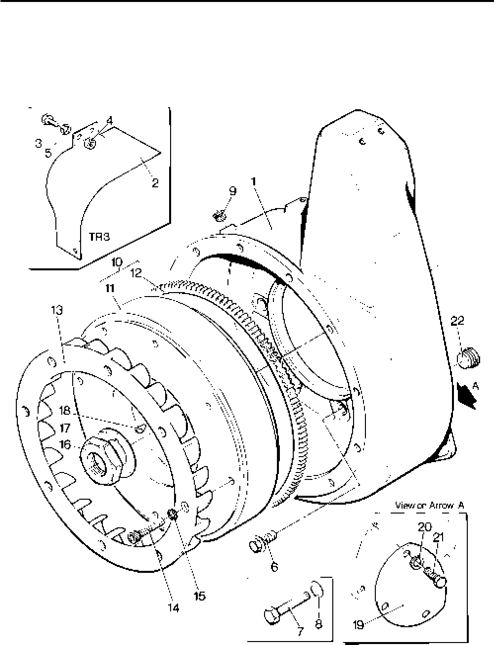
Lister-Petter TS/TR Master Parts Manual Issue 9: June 2000
51
Illustration T7

Lister-Petter TS/TR Master Parts ManualIssue 9: June 2000
52
Flywheel Charge Windings - Synchro
From the following engine numbers refer to "Flywheel Charge Wingings - Nicsa".
The Synchro and Nicsa systems are not interchangeable.
4100433TS1 4101651TS2 4101568TS3
4100240TR1 4100281TR2 4100301TR3
Illustration T155F TS/TR
No. Description Part Number 1 2 3 Remarks
- Flywheel Assembly - TS1 ........................................570-31081 1 - - No longer available
- Flywheel Assembly - TS1 ........................................ 570-31101 1 - - Build 04. No longer available
- Flywheel Assembly - TS/TR2,3 ...............................202-41950 - 1 1 No longer available
- Flywheel Assembly - TS/TR2,3 ...............................202-41951 - 1 1 Build 04. No longer available.
1 Flywheel Assembly - TR1 ........................................570-33800 1 - - No longer available
- Flywheel Assembly - TR1 ........................................ 570-31150 1 - - Build 07. No longer available
- Flywheel Assembly - TR1 ........................................570-33820 1 - - Build 04. No longer available
2 Flywheel .................................................................................. 1 1 1
3 Gear Ring .............................................................202-30520 1 1 1
4 Rotor .................................................................................... 1 1 1
- Fan - TS1 ............................................................. 201-39911 1 - -
5 Fan - TR1 .............................................................202-33540 1 - - Replaces 201-42710
- Fan - TS2 ................................................................202-33540 - 1 - Replaces 202-33541
- Fan - TS3,TR2,3......................................................203-33540 - 1 1 Replaces 203-33541
6 Lock Washer ........................................................272-00089 8 8 8
7 Capscrew - M8 x 30mm .......................................272-00176 8 8 8 Required if replacing 202-33541
or 203-33541 fans
8 Key ..........................................................................201-80550 1 1 1
9 Nut...........................................................................202-33790 1 1 1
10 Locking Washer ......................................................202-33800 1 1 1
11 Stator Assembly ..................................................... 201-45570 1 1 1 Replaces 602-36640.
No longer available. See Note:
12 Capscrew ................................................................270-00765 6 6 6
13 Spring Washer........................................................ 027-00717 6 6 6
14 Cable Strap .............................................................602-37600 1 1 1
15 Taptite Screw - M4 x 8mm .......................................272-00282 2 2 2
- Main Bearing Housing Assembly .............................570-30603 1 1 1 Replaces 570-30601
16 Main Bearing Housing ..........................................201-42890 1 1 1
- Main Bearing Assembly ........................................ 570-30011 1 1 1
17 Setscrew - M8 x 25mm............................................272-00040 6 6 6
18 Spring Washer.........................................................272-00071 6 6 6
19 Regulator Cover ......................................................202-37710 1 1 1 For 602-36900
20 Stud .........................................................................202-37970 2 2 2
- Regulator and Rectifier Kit .......................................570-41701 1 1 1 Replaces 602-36900 & 570-41700
21 Regulator ...................................................................360567 1 1 1
22 Mounting Plate Assembly .....................................201-45590 1 1 1
23 Screw - M6 x 16mm .............................................272-00034 2 2 2
24 Copper Washer - 1/4" diameter ............................291-26090 2 2 2
25 Setscrew ................................................................... 712008 2 2 2
26 Spring Washer...........................................................786003 2 2 2
27 Terminal Adaptor ................................................... 382-07807 1 1 1 Replaced by 064-15649/007
- Ring Termination .............................................064-15649/007 1 1 1 Replaces 382-07807
28 Push-on Connector .........................................064-33068/002 4 4 4
29 Insulation Cover .............................................. 064-33991/001 4 4 4
30 Inline Connector .................................................... 366-06915 2 2 2
Note:
Synchro Stator 201-45570 is no longer available but can
be replaced by Nicsa Stator and Regulator Kit 570-42120.
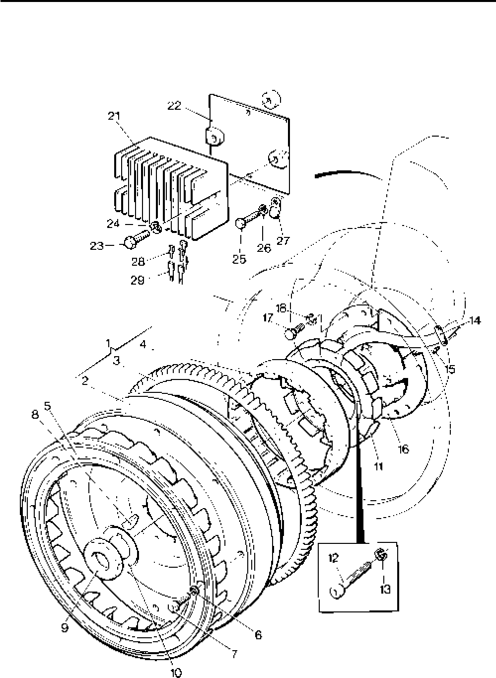
Lister-Petter TS/TR Master Parts Manual Issue 9: June 2000
53
Illustration T155F

Lister-Petter TS/TR Master Parts ManualIssue 9: June 2000
54
Flywheel Charge Windings - Nicsa
Before the following engine numbers refer to "Flywheel
Charge Wingings - Synchro". The Nicsa and Synchro
systems are not interchangeable.
4100433TS1 4101651TS2 4101568TS3
4100240TR1 4100281TR2 4100301TR3
Illustration 155G TS/TR
No. Description Part Number 1 2 3 Remarks
- Flywheel Assembly - TS1 ........................................570-42022 1 - - Build 02, 07, 11, 15, 61, 65, 66
- Flywheel Assembly - TS1 ........................................570-42024 1 - - Build 04, 13
- Flywheel Assembly - TR1 ........................................570-42032 1 - - Build 02, 07, 11, 15
- Flywheel Assembly - TR1 ........................................570-42034 1 - - Build 04
- Flywheel Assembly - TS/TR1 ..................................570-42026 1 - - Builds 09,63. With Integral Fan
1 Flywheel Assembly - TS2 ........................................570-42042 - 1 - Builds 02, 07, 11, 61, 66
- Flywheel Assembly - TS2 ........................................570-42044 - 1 - Build 04, 13
- Flywheel Assembly - TR2 ........................................570-42052 - 1 - Build 02, 07
- Flywheel Assembly - TR2 ........................................570-42054 - 1 - Build 04, 13
- Flywheel Assembly - TS/TR2 ..................................570-42046 - 1 - Builds 09,15, 63. With Integral Fan
- Flywheel Assembly - TS/TR3 ..................................570-42062 - - 1 Builds 02, 07, 09, 11, 61, 63, 66
- Flywheel Assembly - TS/TR3 ..................................570-42064 - 1 - Build 04, 13
2 Flywheel ............................................................................... - 1 -
3 Gear Ring .............................................................202-30520 1 1 1
4 Rotor ....................................................................366-08143 1 1 1
5 Caphead Screw - M6 x 20mm ..............................272-00388 6 6 6
- Fan - TS1 ............................................................. 201-39911 1 - -
- Fan - TR1 .............................................................202-33540 1 - - Replaces 201-42710
6 Fan - TS/TR2 .......................................................202-33540 - 1 - Replaces 202-33541
- Fan - TS/TR3 .......................................................203-33540 - - 1 Replaces 203-33541
7 Lock Washer ........................................................272-00089 8 8 8
8 Capscrew - M8 x 30mm .......................................272-00176 8 8 8 Required if replacing
202-33541 or 203-33541
9 Key ..........................................................................201-80550 1 1 1
10 Nut...........................................................................202-33790 1 1 1
11 Lock Washer ...........................................................202-33800 1 1 1
12 Stator Assembly ......................................................366-08142 1 1 1
13 Capscrew ................................................................270-01081 6 6 6 Replaces 270-00765
14 Spring Washer.........................................................027-00717 6 6 6
15 Cable Strap .............................................................602-37601 1 1 1
16 Taptite Screw - M4 x 8mm .......................................272-00282 2 2 2
17 Main Bearing Housing Assembly .............................570-30603 1 1 1 Replaces 570-30601
- Main Bearing Housing ..........................................201-42890 1 1 1
- Main Bearing Assembly ........................................ 570-30011 1 1 1
18 Setscrew - M8 x 25mm............................................272-00040 6 6 6
19 Spring Washer.........................................................272-00071 6 6 6
20 Regulator .................................................................366-08144 1 1 1
21 Self-lock Screw........................................................272-00752 2 2 2
22 Connector................................................................366-08145 1 1 1
23 Push-on Connector .................................................366-07265 1 1 1
24 Push-on Connector .................................................366-08151 1 1 1
25 Push-on Connector .................................................366-08152 1 1 1
- Connection Diagram ................................................742-00647
Notes:
1. 201-46177 with integral fan replaces 201-46172
2. 202-46175 with integral fan replaces 202-46171
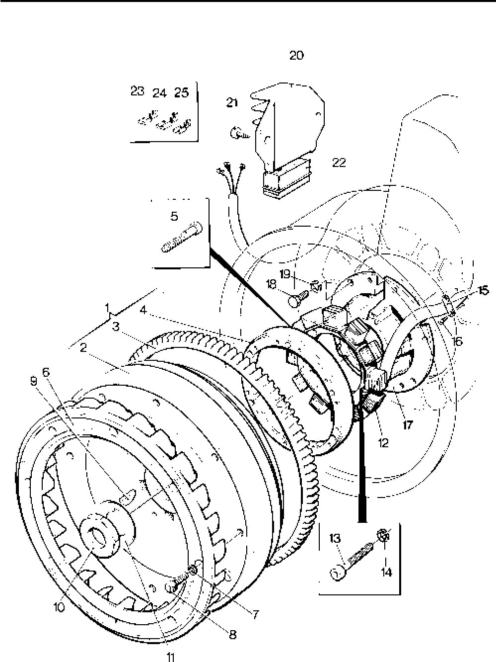
Lister-Petter TS/TR Master Parts Manual Issue 9: June 2000
55
Illustration T155G

Lister-Petter TS/TR Master Parts ManualIssue 9: June 2000
56
Cylinder Head
Illustration T13 TS/TR
No. Description Part Number 1 2 3 Remarks
- Cylinder Head Assembly TS1 ..................................570-32940 1 - - With valves & springs. See Note
- Cylinder Head Assembly TS2,3 ...............................570-30730 - 2 3 With valves & springs. See Note
- Cylinder Head Assembly TR....................................570-33630 1 2 3 With valves & springs. See Note
1 Cylinder Head - TS ..................................................570-36500 1 2 3
2 Inlet Valve Insert ...................................................201-80051 1 2 3
3 Exhaust Valve Insert .............................................201-80041 1 2 3
- Cylinder Head - TR ..................................................570-36520 1 2 3
- Inlet Valve Insert ...................................................201-33050 1 2 3
- Exhaust Valve Insert .............................................201-33060 1 2 3
4 Top Plate ................................................................................. 1 2 3
5 Inlet Valve Guide .....................................................201-30181 1 2 3
6 Exhaust Valve Guide ...............................................201-30171 1 2 3
7 Inlet Valve Guide Oil Seal ........................................201-81200 1 2 3
8 Breather Tube .........................................................201-30191 1 2 3
9 Copper Washer .......................................................616-01608 2 4 6
10 Setscrew - M8 x 10mm............................................272-00239 1 2 3
11 Spring Carrier - bottom ............................................201-55660 1 2 3 No longer fitted
12 Cylinder Head Gasket - TS ......................................201-80210 1 2 3
13 Shim - 0,076mm - TS ..............................................201-80220 Use as required
- Shim - 0,254mm - TS ..............................................201-80221 Use as required
12 Cylinder Head Gasket - TR ..................................... 201-33110 1 2 3
13 Shim - 0,076mm - TR ..............................................201-33100 Use as required
- Shim - 0,254mm - TR ..............................................201-33101 Use as required
14 Lubricating Oil Pipe .................................................202-31790 1 2 3
15 Cylinder Head Nut ...................................................270-00005 2 4 6
16 Inlet Valve - TS ........................................................201-30040 1 2 3
- Inlet Valve - TR ........................................................201-33070 1 2 3
17 Exhaust Valve - TS ..................................................201-30051 1 2 3
- Exhaust Valve - TR ..................................................201-33080 1 2 3
18 Inlet Valve Stem Shield ............................................201-37630 1 2 3
19 Exhaust Valve Stem Shield......................................201-39520 - 2 3
20 Valve Spring ............................................................201-30080 2 4 6
21 Cotter ......................................................................201-50921 2 4 6 Replaces 201-50920. Pairs supplied
22 Spring Carrier - top ..................................................201-80230 2 4 6
23 Valve Rocker Lever .................................................201-30650 2 4 6
24 Bush .....................................................................351-50170 2 4 6
25 Adjusting Screw ....................................................... 201-30110 2 4 6
26 Nut...........................................................................272-00003 2 4 6
27 Stub Shaft ...............................................................201-30640 2 4 6
28 ’O’ Ring ...................................................................201-31460 2 4 6
29 Decompressor Lever ...............................................201-30461 1 2 3
30 Oil Seal ....................................................................201-81200 1 2 3
31 Spring ......................................................................201-30480 1 2 3
32 Circlip ......................................................................353-81780 1 2 3
33 Screw ......................................................................201-30470 1 2 3
34 Nut...........................................................................272-00002 1 2 3
35 Tappet .....................................................................351-10210 2 4 6
36 Push Rod ................................................................201-30100 2 4 6
37 Sealing Tube ...........................................................201-30150 2 4 6
38 Bottom Rubber Cup .................................................201-30261 2 4 6
39 Top Rubber Cup ......................................................201-42360 2 4 6
40 Cylinder Head Stud .................................................201-30990 4 8 12
Accessory Kit Code EJ - TS/TR2 ............................570-31740 1 1 1 Comprises no's 41, 42
Accessory Kit Code EJ - TS/TR3 ............................570-32100 1 1 1 Comprises no's 41, 42
41 Coupled Decompressor Link - TS/TR2,3 .................202-17330 - 1 2
42 Cheese Head Screw - M4 x 20mm ..........................272-00344 - 2 3
43 Self-lock Nut ............................................................272-00371 - 2 3
44 Breather Plate Sealing Ring ....................................601-35440 1 2 3
Note:
All Cylinder Head Assemblies comprise of no's 1-10, 14 & 16-22
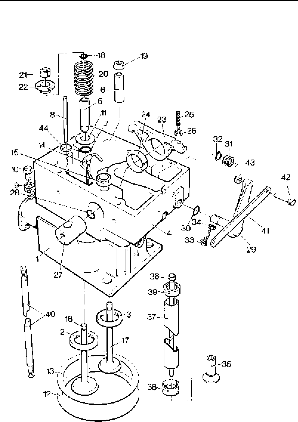
Lister-Petter TS/TR Master Parts Manual Issue 9: June 2000
57
Illustration T13

Lister-Petter TS/TR Master Parts ManualIssue 9: June 2000
58
Cylinder Head Cover
Illustration T18 TS/TR
No. Description Part Number 1 2 3 Remarks
1 Cylinder Head Cover ...............................................570-30742 1 2 3
- Cylinder Head Cover ...............................................201-30798 - 2 3 TS2,3 Builds 08,09,11. Only one
is fitted on TR2 Build 101
- Gear End Cylinder Head Cover - TS/TR1................570-30753 1 - - With mounting facility for gauge
or 13.5 litre fuel tank. Not used
on Build 102
- Gear End Cylinder Head Cover - TS/TR1................570-30752 1 - - With mounting facility for gauge
or 13,5 litre fuel tank. Used on
Build 102
- Gear End Cylinder Head Cover - TS/TR2,3 .............570-30752 - 1 1 With mounting facility for gauge
or 13.5 litre fuel tank.
2 Joint.........................................................................201-30805 1 2 3
3 Bolt - M6 x 25mm ....................................................272-00256 4 8 12
4 Washer ....................................................................272-00364 4 8 12
5 Breather Plate Sealing Ring ....................................601-35440 1 2 3
6 Lifting Eye................................................................202-36540 1 1 1
7 Pillar Nut..................................................................202-36550 2 2 2
- Nut...........................................................................270-00005 1 5 9 All TS Builds 40,41,42
8 Setscrew - 7/16“UNF x 1” ........................................270-00335 2 2 2
9 Spring Washer.........................................................027-00984 2 2 2
Note:
Accessory Code QD available (570-35890) consisting of -
Gear End Cylinder Head Cover (570-30752 replaces 570-30753)
Joint (201-30805)
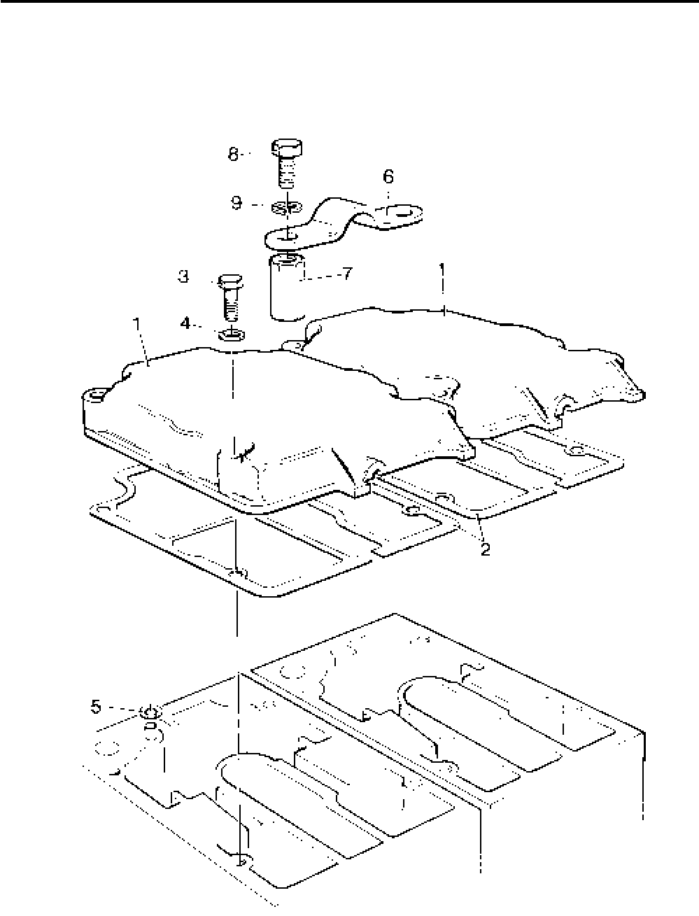
Lister-Petter TS/TR Master Parts Manual Issue 9: June 2000
59
Illustration T18

Lister-Petter TS/TR Master Parts ManualIssue 9: June 2000
60
Air Duct, Cowling, Shields - TS/TR1
Illustration T156 TS/TR
No. Description Part Number 1 2 3 Remarks
Accessory Kit Code DA ...........................................570-32820 1 - - Comprises of 3 items below
- Air Outlet Duct Adaptor............................................201-38100 1 - -
- Setscrew - M6 x 12mm............................................272-00032 3 - - Use with 201-38100 (above)
- Spring Washer.........................................................272-00070 3 - -
1 Air Cowling Assembly ..............................................201-37833 1 - - Replaces 201-37830 &
201-37832. Not Builds 16-18
- Air Cowling Assembly ..............................................201-37832 1 - - Builds 16-18, 101.
Replaces 201-37830
2 Setscrew - M6 x 12mm............................................272-00032 3 - -
3 Spring Washer.........................................................272-00070 3 - -
4 Setscrew - M8 x 20mm............................................272-00039 2 - - Not Builds 16-18
5 Spring Washer.........................................................272-00071 2 - - Not Builds 16-18
6 Blind Grommet ........................................................201-50950 1 - -
7 Gear End Side Shield ..............................................201-37880 1 - -
- Gear End Side Shield - TS1 ....................................201-39851 1 - - Build 40
- Gear End Side Shield - TS1 ....................................201-42750 1 - - Builds 60,61,62,63
8 Setscrew - M6 x 16mm............................................272-00034 1 - -
- Setscrew - M6 x 12mm............................................272-00032 2 - -
9 Spring Washer.........................................................272-00070 3 - -
10 Washer ....................................................................027-00618 3 - -
11 Setscrew - M8 x 16mm............................................272-00038 2 - -
12 Spring Washer.........................................................272-00071 2 - -
13 Washer ....................................................................027-00082 1 - -
14 Flywheel End Side Shield - TS1 ..............................202-34270 1 - - Not Builds 16, 17, 40
- Flywheel End Side Shield - TS1 ..............................201-42760 1 - - Builds 60,61,62,63 and replaces
201-39850
- Flywheel End Side Shield - TR1 ..............................202-42400 1 - - Not Builds 16, 17
15 Setscrew - M6 x 12mm............................................272-00032 3 - -
16 Spring Washer.........................................................270-00070 3 - -
17 Washer ....................................................................027-00618 3 - -
18 Setscrew - M8 x 20mm............................................272-00039 1 - -
19 Spring Washer.........................................................272-00071 1 - -
- Fir Tree Button ........................................................201-48130 1 - -
Accessory Kit Code EU - TS/TR1 ............................570-32830 1 - - Cold Start Oil Cups Kit
comprising no's 20, 21, 22
20 Cold Start Reservoir and Plunger Assembly ............201-26480 1 - - See Note
21 Adaptor ....................................................................201-30890 1 - - See Note. Screws into inlet
manifold port
22 Grommet .................................................................201-12951 1 - - Fitted in place of 201-50950 See
Note
23 Plain Washer ...........................................................272-00751 1 - -
24 Clamping Plate ........................................................202-39120 1 - - Not Builds 16-18
Note:
No longer fitted as standard. Available as spares, either separately or all 3 items under kit EU.
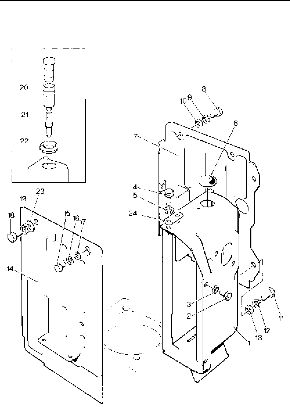
Lister-Petter TS/TR Master Parts Manual Issue 9: June 2000
61
Illustration T156
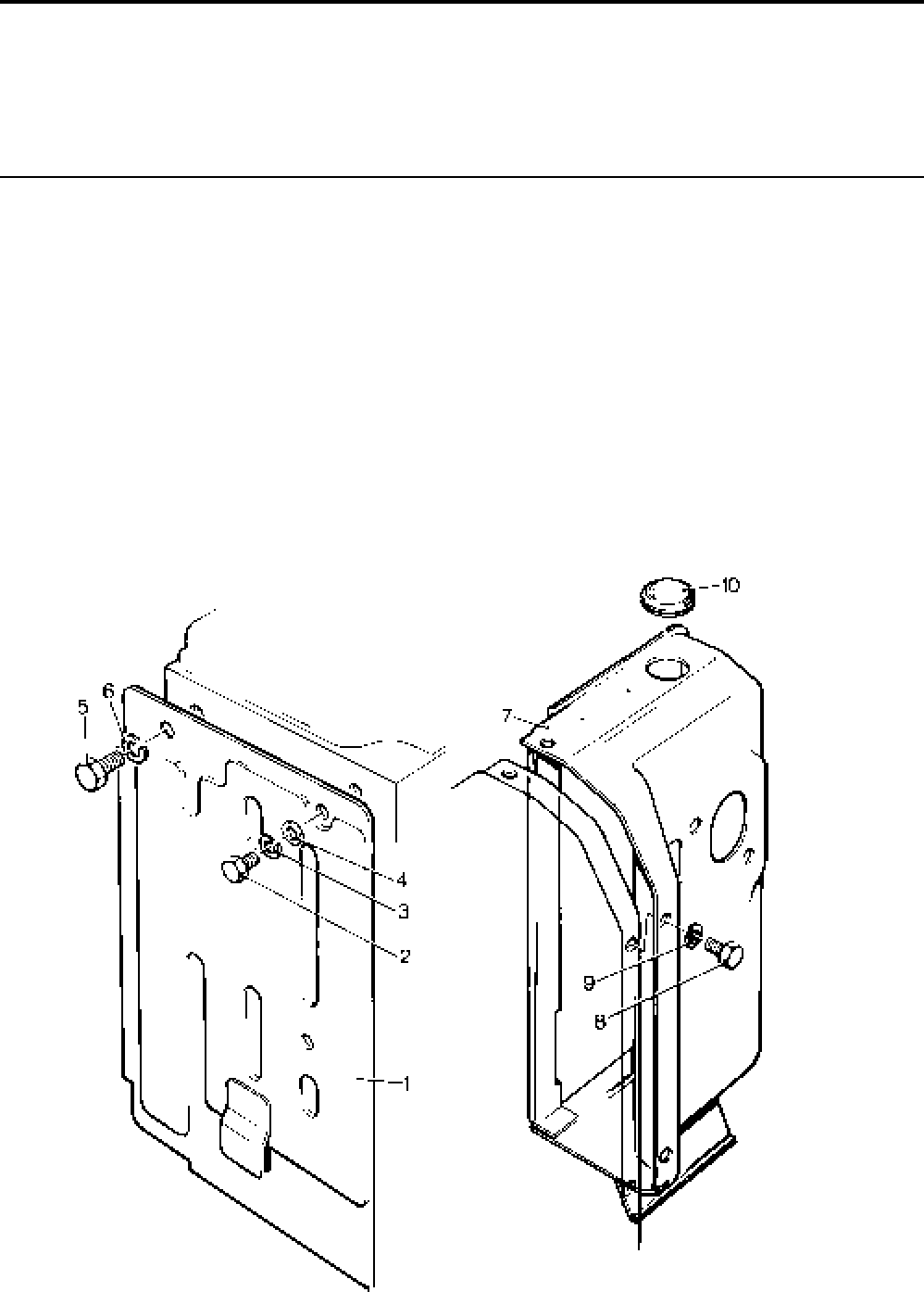
Lister-Petter TS/TR Master Parts ManualIssue 9: June 2000
62
Air Duct, Cowling, Shields
TS1 Builds 16, 17, 101, 102
TR1 Builds 16, 17
Illustration T166 TS/TR
No. Description Part Number 1 2 3 Remarks
1 Side Shield Assembly - TS ......................................201-41520 1 - -
- Side Shield Assembly - TR ......................................201-44690 1 - -
2 Setscrew - M6 x 12mm............................................272-00032 1 - -
3 Spring Washer.........................................................272-00070 1 - -
4 Washer ....................................................................027-00618 1 - -
5 Setscrew - M8 x 12mm............................................272-00166 1 - - Not used on Builds 101, 102
- Setscrew - M8 x 20mm............................................272-00039 1 - - Builds 101, 102
6 Spring Washer.........................................................272-00071 1 - -
7 Air Cowling Assembly ..............................................201-37832 1 - - Replaces 201-37830
8 Setscrew - M6 x 12mm............................................272-00032 3 - -
9 Spring Washer.........................................................272-00070 3 - -
10 Grommet .................................................................201-50950 1 - -
- Plain Washer ..........................................................027-00082 1 - - Builds 101, 102
Illustration T166
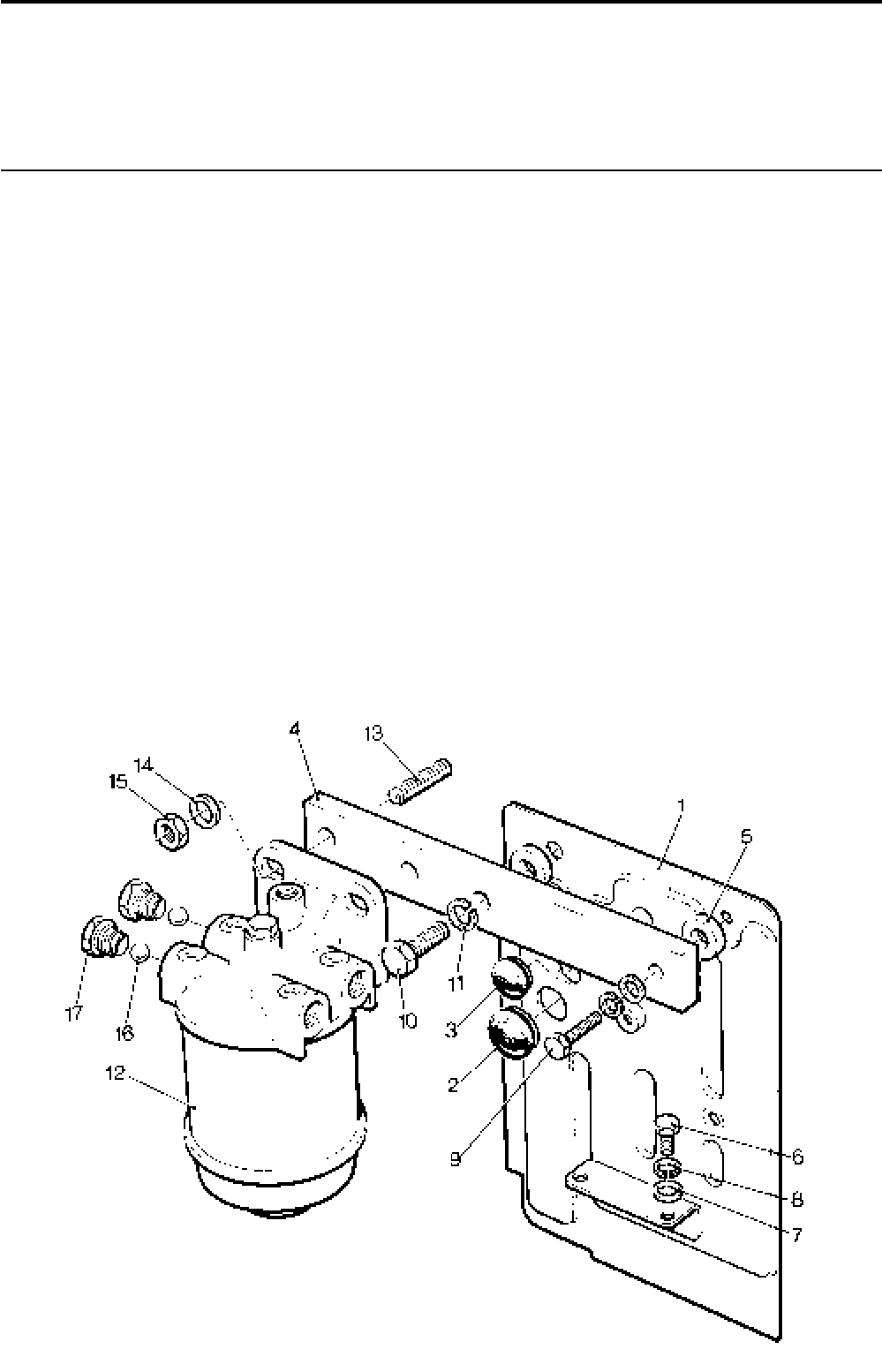
Lister-Petter TS/TR Master Parts Manual Issue 9: June 2000
63
Fuel Filter - TS Build 102
Side Shield and Fuel Filter - TS1 - Build 40
Illustration T389 TS/TR
No. Description Part Number 1 2 3 Remarks
1 Flywheel End Side Shield ........................................201-42760 1 - - Replaces 201-39850
2 Grommet .................................................................201-41830 1 - -
3 Grommet .................................................................201-41840 1 - -
4 Fuel Filter Mounting Bracket....................................201-44770 1 - -
- Fuel Filter Mounting Bracket ....................................202-34261 1 - - Build 102
5 Washer....................................................................202-80680 2 - -
6 Setscrew - M6 x 12mm............................................272-00032 2 - -
7 Washer....................................................................027-00618 2 - -
8 Spring Washer.........................................................272-00070 3 - -
9 Bolt - M6 x 30mm ....................................................272-00035 1 - -
10 Bolt - M8 x 30mm ....................................................272-00041 1 - -
11 Spring Washer.........................................................272-00071 1 - -
12 Fuel Filter ............................................................... 201-44580 1 - - Replaced by Agglomerator
- Element Kit ...........................................................351-29760 1 - -
- Agglomerator ...........................................................750-14120 1 - - Replaces Fuel Filter 201-44580
- Element Kit ...........................................................751-18100 1 - -
13 Setscrew - M8 x 25mm............................................272-00039 2 - -
14 Washer ....................................................................272-00359 2 - -
- Plain Washer ...........................................................027-00082 2 - - Build 102
15 Self-locknut .............................................................272-00373 2 - -
16 Ball ..........................................................................202-32120 2 - - Replaces Washer 201-41640
17 Union .......................................................................202-42370 2 - - Replaces Plug 354-28530
- Union .......................................................................202-42371 1 - - Build 102
- Olive ........................................................................351-21640 1 - - Build 102
Illustration T389

Lister-Petter TS/TR Master Parts ManualIssue 9: June 2000
64
Air Duct, Cowling and Shields - TS/TR2,3
Illustration T9 and T371 TS/TR
No. Description Part Number 1 2 3 Remarks
Accessory Kit Code DA - TS/TR2 ............................570-31670 - 1 - See Illustration T371
- Air Outlet Duct Adaptor .........................................202-31593 - 1 -
- Setscrew - M6 x 12mm.........................................272-00032 - 4 -
- Spring Washer......................................................272-00070 - 4 -
Accessory Kit Code DA - TS/TR3 ............................570-32090 - - 1
- Air Outlet Duct Adaptor .........................................203-31591 - - 1
- Setscrew - M6 x 12mm.........................................272-00032 - - 4
- Spring Washer......................................................272-00070 - - 4
1 Air Cowling Assembly - TS2 ....................................202-30742 - 1 - Not Builds 41, 60, 61, 62, 63.104
- Air Cowling Assembly - TS3 ....................................203-30742 - - 1 Not Builds 41, 60, 61, 62, 63,104
- Air Cowling Assembly - TR2 ....................................202-42421 - 1 -
- Air Cowling - TR2 .................................................202-30742 - 1 -
- Damping Pad - TR2 ..............................................202-42430 - 1 -
- Air Cowling Assembly - TR3 ....................................203-42421 - - 1
- Air Cowling - TR3 .................................................203-30742 - - 1
- Damping Pad - TR3 ..............................................203-42430 - - 1
2 Setscrew - M8 x 20mm............................................272-00039 - 2 2
3 Spring Washer.........................................................272-00071 - 2 2
4 Setscrew - M6 x 12mm............................................272-00032 - 2 2
5 Spring Washer.........................................................272-00070 - 2 2
6 Blind Grommet ........................................................201-50950 - 2 3
7 Clamping Plate ........................................................202-39120 - 1 1
8 Air Baffle..................................................................201-33830 - 1 2
9 Tie ...........................................................................201-33821 - 1 2 Replaces 201-33820
10 Spring Clip ...............................................................353-71370 - 1 2
11 Split Pin ...................................................................027-00957 - 1 2
12 Gear End Side Shield -TS2,3 ..................................201-37880 - 1 1
- Gear End Side Shield -TR2,3 ..................................201-42750 - 1 1
13 Setscrew - M6 x 12mm............................................272-00032 - 2 2
- Setscrew - M6 x 16mm............................................272-00034 - 1 1
14 Spring Washer.........................................................272-00070 - 3 3
15 Washer ....................................................................027-00618 - 3 3
16 Setscrew - M8 x 16mm............................................272-00038 - 2 2
17 Spring Washer.........................................................272-00071 - 2 2
18 Washer ....................................................................027-00082 - 1 1
19 Flywheel End Side Shield - TS2,3 ...........................202-34270 - 1 1
- Flywheel End Side Shield - TR2,3 ...........................202-42400 - 1 1
20 Setscrew - M6 x 12mm............................................272-00032 - 4 4
21 Spring Washer.........................................................270-00070 - 4 4
22 Washer ....................................................................027-00618 - 4 4
23 Setscrew - M8 x 25mm............................................272-00040 - 1 1
24 Spring Washer.........................................................272-00071 - 1 1
25 Washer ....................................................................027-00082 - 1 1
Accessory Kit Code EU - TS/TR2 ............................570-31770 - 1 - Cold Start Oil Cups Kit
comprising no's 26, 27, 28
Accessory Kit Code EU - TS/TR3 ............................ 570-32110 - - 1 Cold Start Oil Cups Kit
comprising no's 26, 27, 28
26 Cold Start Reservoir and Plunger Assembly ............201-26480 - 1 1 See Note
27 Adaptor ....................................................................201-30890 - 2 3 See Note. Screws into inlet
manifold port
28 Grommet .................................................................201-12951 - 2 3 Fitted in place of 201-50950
See Note
Note:
No longer fitted as standard. Available as spares, either separately or all 3 items under kit EU.
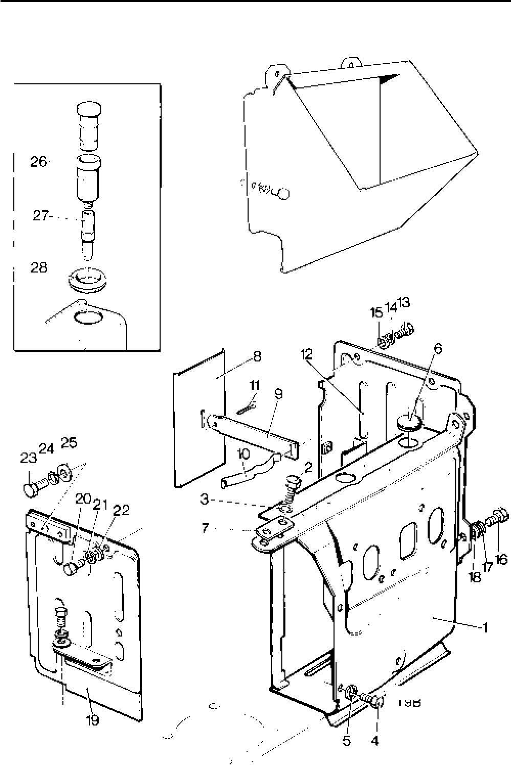
Lister-Petter TS/TR Master Parts Manual Issue 9: June 2000
65
Illustration T9
Illustration T371

Lister-Petter TS/TR Master Parts ManualIssue 9: June 2000
66
Air Duct, Cowling and Shields
TS/TR2,3 Builds 41, 60, 61, 62, 63, 104
Illustration T134 TS/TR
No. Description Part Number 1 2 3 Remarks
1 Air Cowling - TS/TR2...............................................202-42421 - 1 -
- Air Cowling ...........................................................202-30742 - 1 -
- Damping Pad........................................................202-42430 - 1 -
- Air Cowling - TS/TR3 ...............................................203-42421 - - 1
- Air Cowling ...........................................................203-30742 - - 1
- Damping Pad........................................................203-42430 - - 1
2 Setscrew - M8 x 20mm............................................272-00039 - 2 2
3 Spring Washer.........................................................272-00071 - 2 2
4 Setscrew - M6 x 12mm............................................272-00032 - 2 2
5 Spring Washer.........................................................272-00070 - 2 2
6 Grommet .................................................................201-50950 - 2 3
7 Clamping Plate ........................................................202-39120 - 1 1
8 Air Baffle..................................................................201-33830 - 1 2
9 Tie ...........................................................................201-33820 - 1 2
10 Spring Clip ...............................................................353-71370 - 1 2
11 Split Pin ...................................................................027-00957 - 1 2
12 Gear End Side Shield ..............................................201-42750 - 1 1 Replaces 202-42380
13 Setscrew - M6 x 12mm............................................272-00032 - 2 2 Three were fitted
- Setscrew - M6 x 16mm............................................272-00034 - 1 1 Replaces 1 of 272-00032
14 Spring Washer.........................................................272-00070 - 3 3
15 Washer ....................................................................027-00618 - 3 3
16 Setscrew - M8 x 16mm............................................272-00038 - 2 2
17 Spring Washer.........................................................272-00071 - 2 2
18 Washer ....................................................................027-00082 - 2 2
19 Flywheel End Side Shield ........................................202-42400 - 1 1
20 Setscrew - M4 x 40mm............................................272-00082 - 1 1
21 Spring Washer.........................................................272-00070 - 4 4
22 Washer ....................................................................027-00618 - 4 4
23 Setscrew - M8 x 25mm............................................272-00040 - 1 1
24 Spring Washer.........................................................272-00071 - 1 1
- Setscrew - M6 x 14mm............................................272-00033 - 2 2 Build 104
Flywheel End Side Shield - TS/TR1
Illustration T416 TS/TR
No. Description Part Number 1 2 3 Remarks
Accessory Kit Code DF ...........................................570-33770 1 - -
1 Side Shield Assembly ..............................................201-39851 1 - -
2 Grommet .................................................................201-41840 1 - -
3 Grommet .................................................................201-41830 1 - -
Note:
For use with codes JC or PF.
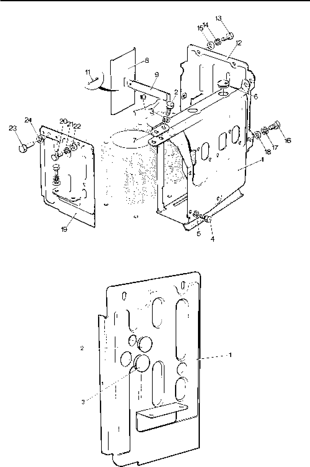
Lister-Petter TS/TR Master Parts Manual Issue 9: June 2000
67
Illustration T134
Illustration T416

Lister-Petter TS/TR Master Parts ManualIssue 9: June 2000
68
Fuel Lift Pump - AC Delco & Pienne
Illustration T388
The AC Delco type was last fitted on:
3802252TS1 3800753TR1
3800286TS2 3800002TR2
3800261TS3 3800093TR3 TS/TR
No. Description Part Number 1 2 3 Remarks
- Fuel Lift Pump - AC Delco .......................................602-40480 1 1 1 Replaced by Pienne then Corona
1 Fuel Lift Pump - TS/TR1 - Pienne ...........................201-45343 1 - - Replaced by Corona pump
- Fuel Lift Pump - TS/TR2,3 - Pienne.........................201-45345 - 1 1 Replaced by Corona pump
2 Push Rod ................................................................201-30550 1 1 1
3 Union - 1/2" UNF........................................................202-42371 1 1 1
4 Olive ........................................................................351-21640 1 1 1
5 Union .......................................................................202-42370 2 2 2
6 Olive ........................................................................601-38360 2 2 2
7 Setscrew - M8 x 16mm............................................272-00038 4 4 4
8 Spring Washer.........................................................272-00071 4 4 4
- Pipe Clip ..................................................................201-42640 1 - -
- Clip Felt ...................................................................201-17170 1 - -
- Fuel Pipe - TS/TR1..................................................201-39961 1 - -
9 Fuel Pipe - TS1 .......................................................201-44741 1 - - Build 40
- Fuel Pipe - TS/TR2..................................................202-44871 - 1 -
- Fuel Pipe - TS/TR3..................................................203-44871 - - 1
10 Joint.........................................................................602-36721 1 1 1
11 Union .......................................................................354-26260 1 1 1
12 Washer ....................................................................354-26310 2 2 2
- Pienne Pump Repair Kit ..........................................027-07897
Note:
To convert from an AC Delco pump or Pienne pump to a current Corona Pump use:
TS/TR1 - Accessory Kit Code FE (570-32810)
TS/TR2 - Accessory Kit Code FE (570-34690)
TS/TR3 - Accessory Kit Code FE (570-34700)
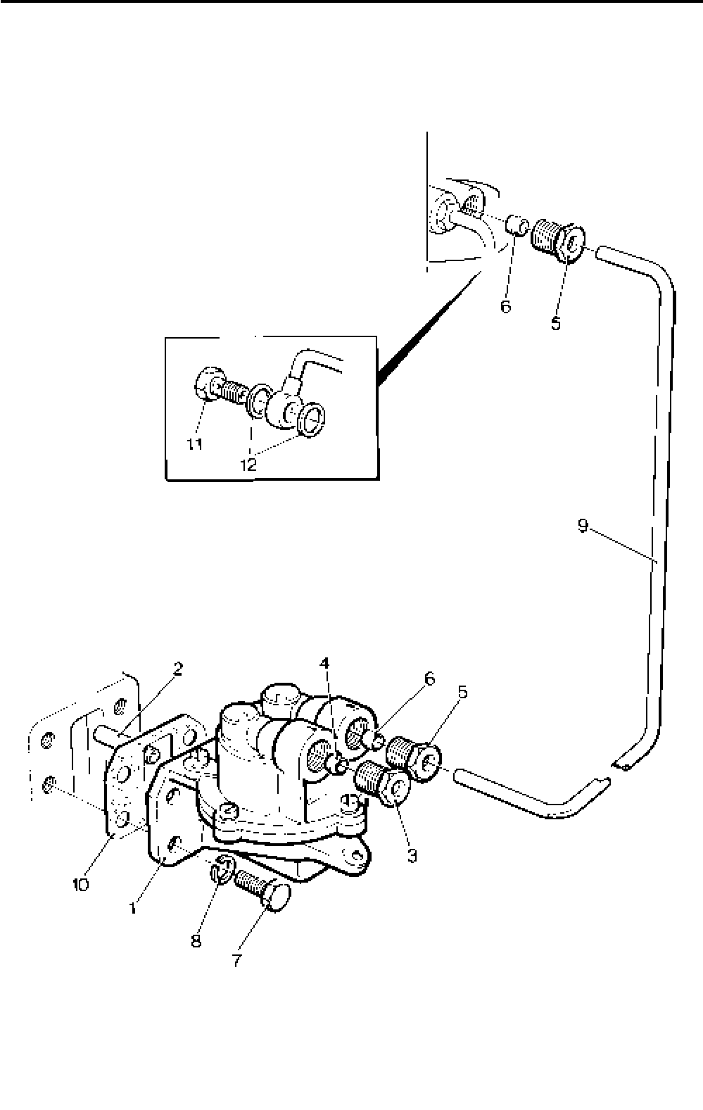
Lister-Petter TS/TR Master Parts Manual Issue 9: June 2000
69
Illustration T388

Lister-Petter TS/TR Master Parts ManualIssue 9: June 2000
70
Fuel Lift Pump - Corona
Illustration T415 TS/TR
No. Description Part Number 1 2 3 Remarks
Accessory Kit Code FE - TS/TR1 ............................570-32810 1 - -
Accessory Kit Code FE - TS/TR2 ............................570-34690 - 1 -
Accessory Kit Code FE - TS/TR3 ............................570-34700 - - 1
1 Fuel Pipe - TS/TR1..................................................201-44871 1 - -
2 Fuel Pipe - TS/TR2..................................................202-44871 - 1 -
- Fuel Pipe - TS/TR3..................................................203-44871 - - 1
3 Union .......................................................................202-42370 2 2 2
4 Olive ........................................................................601-38360 2 2 2
5 Push Rod ................................................................201-30550 1 1 1
6 Joint.........................................................................602-36721 1 1 1
7 Fuel Lift Pump .........................................................201-46296 1 - -
- Repair Kit.................................................................027-10043 1 - - Not part of kit FE
8 Fuel Lift Pump .........................................................201-46298 - 1 1
- Repair Kit.................................................................027-10041 - 1 1 Not part of kit FE
9 Screw - M8 x 16mm ................................................272-00038 4 4 4
10 Union .......................................................................202-42371 1 1 1
11 Olive ........................................................................351-21640 1 1 1
12 Felt ..........................................................................201-17170 1 - -
13 Clip ..........................................................................351-19920 1 - -
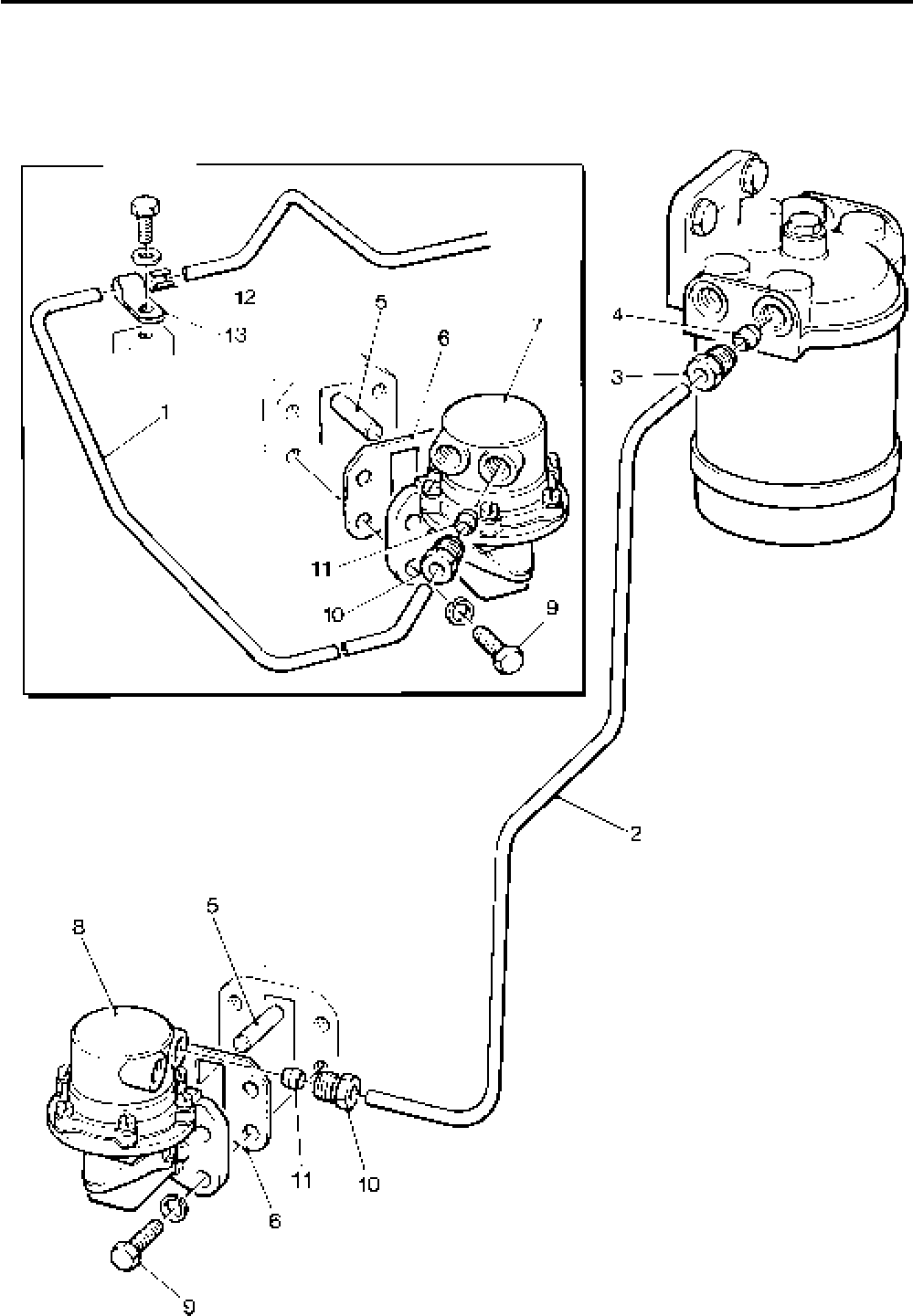
Lister-Petter TS/TR Master Parts Manual Issue 9: June 2000
71
Illustration T415

Lister-Petter TS/TR Master Parts ManualIssue 9: June 2000
72
Fuel Filter and Pump - TS/TR1 (Early Type)
Illustration T159 TS/TR
No. Description Part Number 1 2 3 Remarks
1 Filter Bracket ...........................................................601-31732 1 - -
2 Bolt - M6 x 25mm ....................................................272-00256 2 - -
3 Spacer .....................................................................366-04966 2 - -
4 Spring Washer.........................................................272-00070 2 - -
5 Bleed Screw ............................................................601-21620 2 - -
6 Washer ....................................................................601-32470 2 - -
7 Fuel Filter Adaptor ...................................................601-34690 1 - -
- Bowl and Element Assembly ...................................570-31260 1 - -
8 Bowl ..................................................................................... 1 - -
9 Locating Washer .................................................................. 1 - -
10 Spring ................................................................................... 1 - -
11 Bolt Assembly....................................................................... 1 - -
12 Element Kit ...........................................................203-32470 1 - -
13 Sealing Ring ...................................................................... 1 - -
14 Sealing Ring ...................................................................... 1 - -
15 Sealing Ring ...................................................................... 2 - -
16 Fuel Pump Tappet Assembly ...................................570-30770 1 - -
17 Tappet .................................................................................. 1 - -
18 Roller ....................................................................601-21390 1 - -
19 Bush .....................................................................601-21400 1 - -
20 Pin ........................................................................601-21410 1 - -
21 Fuel Pump Tappet Guide .........................................201-30120 1 - -
22 Locating Pin.............................................................201-39680 1 - -
23 Cap..........................................................................201-30140 1 - -
24 Fuel Pump ...............................................................201-31303 1 - - See Note 1
- Element ................................................................660-14260 1 - - See Note 1
- Delivery Valve .......................................................660-14270 1 - - See Note 1
- Vent Screw ................................................................ 3/485A 1 - - See Note 1
25 Shim - 0,127mm ......................................................201-45961 Use as required. See Note 2
- Shim - 0,762mm ......................................................201-45962 Use as required. See Note 2
- Shim - 1,016mm ......................................................201-45963 Use as required. See Note 2
- Shim - 1,270mm ......................................................201-45964 Use as required. See Note 2
26 Bolt - M6 x 45mm ....................................................272-00165 2 - -
27 Spring Washer.........................................................272-00070 2 - -
28 ’O’ Ring ...................................................................601-20691 1 - -
29 Fuel Pipe Assembly .................................................570-35700 1 - - Replaces 201-38940
30 Copper Washer .......................................................616-01608 2 - -
31 Swivel Union Plug ....................................................202-34000 1 - -
32 Connection ..............................................................602-38250 1 - -
33 Washer ....................................................................354-26310 1 - -
34 Inlet Connection Adaptor .........................................201-39660 1 - -
35 Washer ....................................................................354-26310 1 - -
36 Flexible Pipe Assembly ...........................................366-07044 1 - -
Notes:
1. The current pump being fitted is Lucas Dizel. Before replacing any other pump
refer to Lister Petter Diesel Centre or distributor.
2. The new type pump timing shims were first fitted on the following engines and
both types must not be mixed on the same pump.
4000213TS1 4000113TR1
4300318TS1 4300299TR1
The sikle type fuel timing shim were:
0,127mm 602-21870 0,508mm 602-21872
0,254mm 602-21871 0,762mm 602-21873
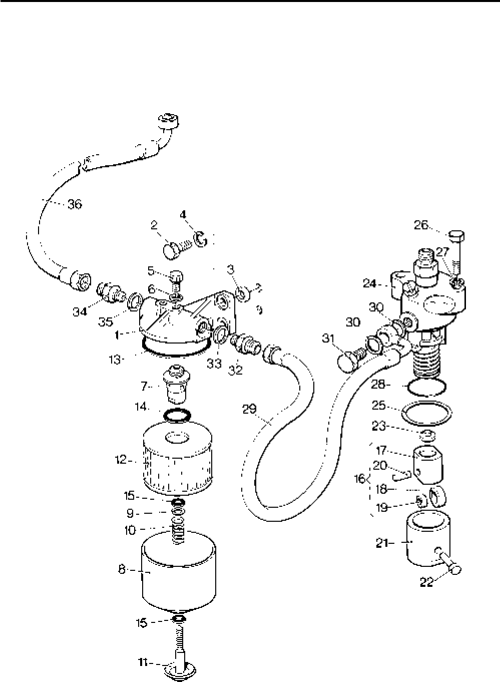
Lister-Petter TS/TR Master Parts Manual Issue 9: June 2000
73
Illustration T159

Lister-Petter TS/TR Master Parts ManualIssue 9: June 2000
74
Fuel Filter and Pump
Illustration T15 TS/TR
No. Description Part Number 1 2 3 Remarks
1 Fuel Filter ................................................................201-44580 1 1 1 Replaced by later Agglomerator
2 Element Kit ...........................................................351-29760 1 1 1
- Agglomerator - Later Type .......................................750-14120 1 1 1 Replaces Fuel Filter 201-44580
Element Kit ...........................................................751-18100 1 1 1
3 Setscrew - M8 x 20mm............................................272-00039 2 2 2
4 Washer ....................................................................027-00082 2 2 2 Replaces 272-00751
5 Union .......................................................................202-42370 2 2 2 Replaces Blanking Plug 354-28530
6 Ball ..........................................................................202-32120 2 2 2 Replaces Washer 201-41640
7 Union .......................................................................202-42370 1 1 1 Replaces 354-28380, see Notes:
8 Olive ........................................................................601-38360 1 1 1
9 Non-return Valve...................................................... 572-10611 1 1 1 Replaces 352-28740
10 Copper Washer .......................................................354-26310 2 2 2
11 Union .......................................................................202-42371 1 1 1
12 Olive ........................................................................351-21640 1 1 1
13 Fuel Pipe - TS/TR1 ..................................................201-46300 1 - -
- Fuel Pipe - TS/TR2..................................................202-46300 - 1 - Replaces 202-37511 & 202-32161
- Fuel Pipe - TS/TR3..................................................203-46300 - - 1 Replaces 203-32161 & 203-32161
14 Copper Washer .......................................................616-01608 2 4 6
15 Swivel Union Plug ....................................................202-34000 1 2 3
16 Fuel Pump Tappet Guide .........................................201-30120 1 2 3
17 Locating Screw ........................................................201-30630 - 2 3
- Locating Pin.............................................................201-39680 1 - -
18 Copper Washer .......................................................616-01608 - 2 3
- Tappet Assembly .....................................................570-30770 1 2 3
19 Tappet .................................................................................. 1 2 3
20 Pin ........................................................................601-21410 1 2 3
21 Roller ....................................................................601-21390 1 2 3
22 Bush .....................................................................601-21400 1 2 3
23 Cap..........................................................................201-30140 1 2 3
24 Fuel Pump ...............................................................201-31305 1 2 3 Replaces 201-31303. See Note 1
- Element ................................................................660-14260 1 2 3 See Note 1
- Delivery Valve .......................................................660-14270 1 2 3 See Note 1
- Vent Screw ................................................................ 3/485A 1 2 3 See Note 1
25 Shim - 0,127mm ......................................................201-45961 Use as required, See Note 2
- Shim - 0,762mm ......................................................201-45962 Use as required, See Note 2
- Shim - 1,016mm ......................................................201-45963 Use as required, See Note 2
- Shim - 1,270mm ......................................................201-45964 Use as required, See Note 2
26 Bolt - M6 x 45mm ....................................................272-00165 2 4 6
27 Spring Washer.........................................................272-00070 2 4 6
28 ’O’ Ring ...................................................................601-20691 1 2 3
Accessory Kit Code FF - TS/TR2,3 .........................570-34650 - 1 1 Fuel Agglomerator Kit.
Contains all items listed below
29 Fuel Agglomerator - Early Type ...............................366-07180 - 1 1 Replaces fuel filter. See above kit
and Note
- Element Kit ...........................................................351-29760 - 1 1
30 Copper Washer .......................................................354-26310 - 2 2
31 Union .......................................................................202-42370 - 2 2 Replaces Blanking Plug 354-28530
32 Ball ..........................................................................202-32120 - 2 2 Replaces Washer 201-41640
Notes:
1. The current pump being fitted is Lucas Dizel. Before replacing any other pump
refer to Lister Petter or a distributor.
2. The round type fuel timing shims were first fitted on the following engines and
the round and sickle types must not be mixed on the same pump.
4000297TS2 4000135TR2
4000223TS3 4000039TR3
The sickle type fuel timing shim were:
0,127mm 602-21870 0,508mm 602-21872
0,254mm 602-21871 0,762mm 602-21873
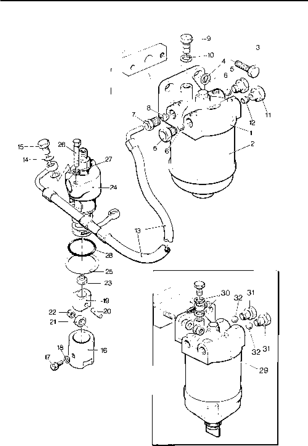
Lister-Petter TS/TR Master Parts Manual Issue 9: June 2000
75
Illustration T15

Lister-Petter TS/TR Master Parts ManualIssue 9: June 2000
76
Fuel Injector
Illustration T17 TS/TR
No. Description Part Number 1 2 3 Remarks
1 Pump to Injector Pipe ..............................................201-31474 1 2 3
2 Clamp ......................................................................351-55890 1 2 3
3 Capscrew ................................................................272-00257 1 2 3
- Fuel Injector - TS .....................................................201-47072 1 2 3 See Note 1
- Nozzle ..................................................................201-47092 1 2 3 See Note 2
4 Fuel Injector - TR.....................................................201-47042 1 2 3 See Note 1
5 Nozzle ..................................................................201-47062 1 2 3 See Note 2
6 Washer ....................................................................351-40230 1 2 3
7 Copper Washer .......................................................352-29370 1 2 3
8 Injector Union ..........................................................202-38500 1 2 3
- Leak-off Pipe Assembly ...........................................201-46591 1 - - TS1 Build 102
9 Tee Piece ................................................................751-13100 1 2 3 Replaces 202-38460
10 Hose ........................................................................027-07396 - 3 3 Replaces 202-41260
11 Hose........................................................................202-48120 1 2 3 Replaces 202-41260
12 Hose ........................................................................202-42480 1 1 1 Not TS1 Build 16-18, 102 and TR1
Build 16. See Note 3.
- Hose ........................................................................027-07400 1 - - TS1 Builds 16-18, 102, TR1 Build
16
13 Rubber Boot ............................................................202-41270 1 1 1
14 Connection ..............................................................202-38490 1 1 1 See Note 3
15 Non-return Valve Assembly ..................................... 572-10611 1 1 1
16 Washer ....................................................................354-26310 2 2 2
Notes:
1. This Injector replaces all previous Injectors.
It is recommended that fuel injectors are fitted as a complete set.
If in doubt, refer to any Lister-Petter Diesel Distrubutor
2. TS - For injector 201-90463 use nozzle 201-81395
TR - For injector 202-36730 use nozzle 202-36720
NOZZLES ARE NOT INTERCHANGEABLE
3. Hose 202-42480 (number 12) replaces Hose 201-42620 on TS/TR1 (shown on illustration as letter A) and
Connection 202-38490 (number 14) replaces Connection 201-42600 on TS/TR1 (shown on illustration as letter B).
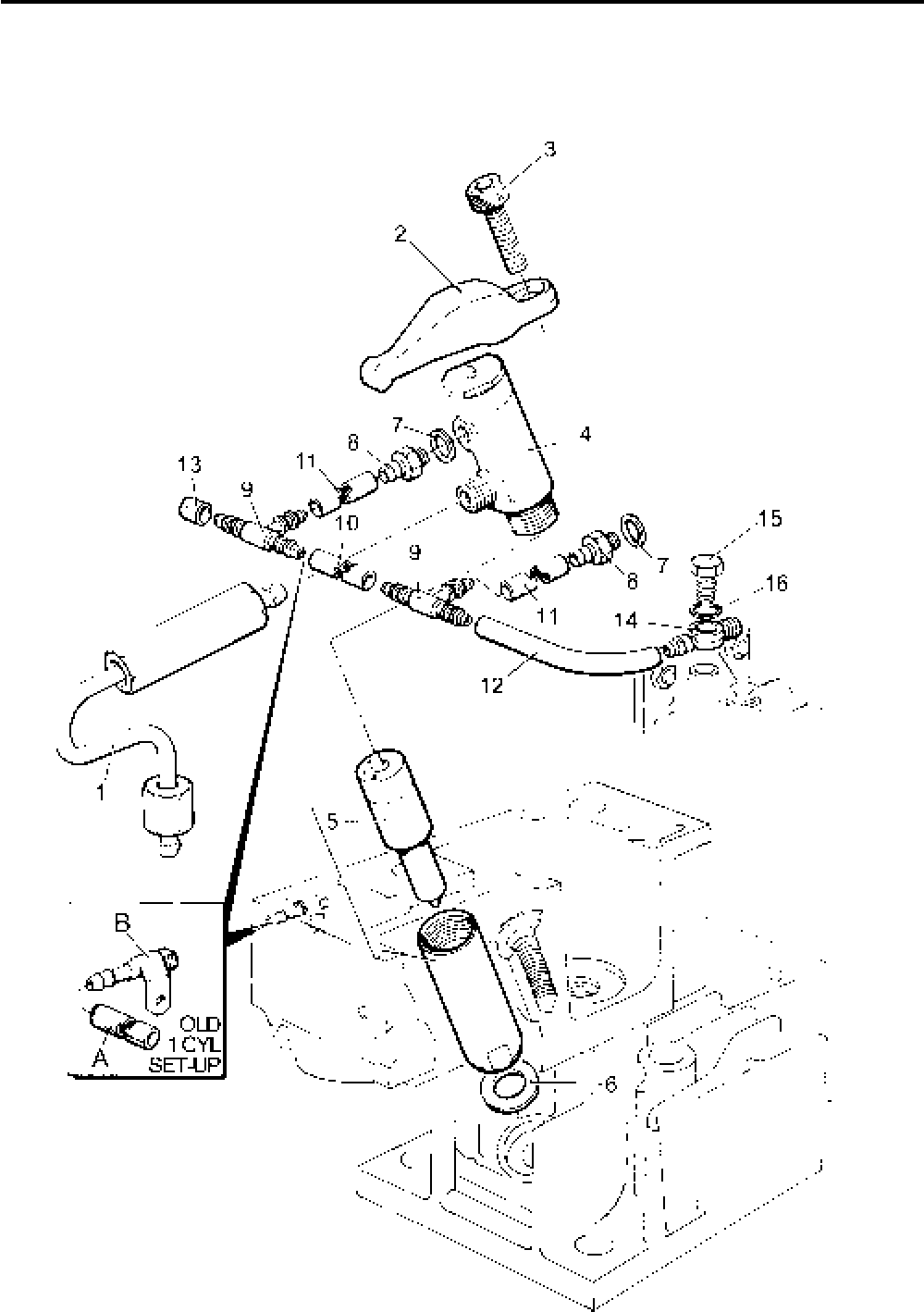
Lister-Petter TS/TR Master Parts Manual Issue 9: June 2000
77
Illustration T17

Lister-Petter TS/TR Master Parts ManualIssue 9: June 2000
78
Steel Fuel Pipes
Illustration T390 TS/TR
No. Description Part Number 1 2 3 Remarks
Accessory Kit Code FH - TS/TR2 ............................570-33020 - 1 -
Accessory Kit Code FH - TS/TR3 ............................570-33030 - - 1
- Leak-off Pipe - TS1 .................................................201-44750 1 - -
1 Leak-off Pipe - TS/TR2............................................202-38740 - 1 - See Note 1
- Leak-off Pipe - TS/TR3............................................203-38740 - - 1 See Note 2
2 Swivel Union Plug....................................................601-36100 1 2 3
3 Copper Washer .......................................................352-29370 2 4 6
4 Grommet .................................................................202-41320 1 2 3
5 Non-return Valve...................................................... 572-10611 1 1 1
6 Copper Washer .......................................................354-26310 2 2 2
- Filter to Pump Pipe - TS1 ........................................201-44721 1 - -
7 Filter to Pump Pipe - TS/TR2 ..................................202-38702 - 1 - See Note 3
- Filter to Pump Pipe - TS/TR3 ..................................203-38702 - - 1 See Note 3
8 Copper Washer .......................................................616-01608 2 4 6
9 Swivel Union Plug....................................................202-34000 1 2 3
10 Union - TS/TR2,3 ....................................................202-42370 - 1 1
11 Olive ........................................................................601-38360 - 1 1
- Swivel Union Plug - TS/TR1 ....................................201-45710 1 - - Not used on Build 40
- Copper Washer - TS/TR1........................................201-41640 2 - - Not used on Build 40
Notes:
1. Replaces 202-31981 (2 off) and 202-34290 from engine no. 3501131TS2
2. Replaces 202-31981 (3 off) and 203-34290 from engine no. 3500854TS3
3. 202-38702 and 203-38702 replaces 202-38700, 202-38701, 203-38700 and 203-38701,
and Union 202-42370 and Olive 201-45710 are also supplied
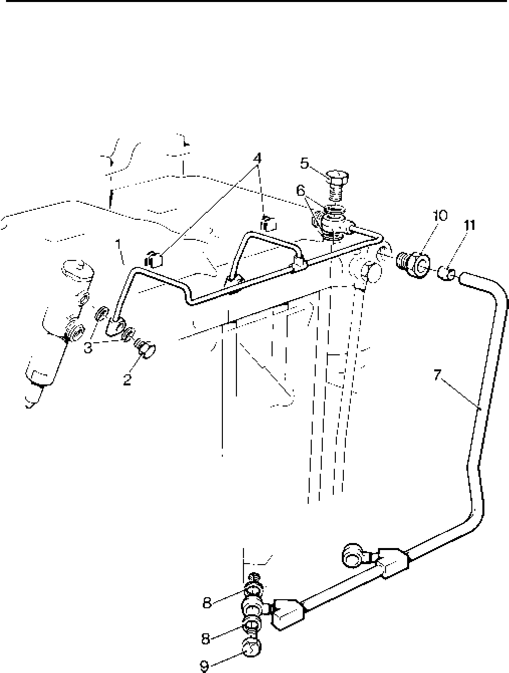
Lister-Petter TS/TR Master Parts Manual Issue 9: June 2000
79
Illustration T390

Lister-Petter TS/TR Master Parts ManualIssue 9: June 2000
80
Fuel Tank - 8,25 litre
Illustration T260 TS/TR
No. Description Part Number 1 2 3 Remarks
Accessory Kit Code FA ............................................570-32791 1 - -
1 Fuel Tank.................................................................601-37862 1 - -
2 Stay .........................................................................201-38070 1 - -
3 Setscrew - M6 x 14mm............................................272-00034 1 - - Replaces 272-00033
4 Washer ....................................................................272-00364 1 - -
5 Spring Washer.........................................................272-00070 1 - -
6 Nut...........................................................................272-00002 1 - -
7 Spacer .....................................................................027-07804 1 - -
8 Bolt - M6 x 30mm ....................................................272-00035 1 - -
9 Spring Washer.........................................................272-00070 1 - -
10 Washer ....................................................................202-80680 3 - -
11 Setscrew - M8 x 25mm............................................272-00040 3 - -
12 Spring Washer.........................................................272-00071 3 - -
13 Filler Cap .................................................................366-08136 1 - - Replaces 366-00091
- Joint.........................................................................027-06151 1 - - Only used with 366-00091
14 Grommet .................................................................601-33740 1 - -
15 Leak-off Pipe ...........................................................201-41760 1 - -
16 Hose ........................................................................202-41280 1 - -
17 Setscrew - M6 x 12mm............................................272-00032 1 - -
18 Spring Washer.........................................................272-00070 1 - -
19 Plug .............................................................................. 318982 1 - -
20 Washer ....................................................................601-43141 1 - -
21 Fuel Filter Element .......................................................330573 1 - -
22 Seal .........................................................................031-61533 1 - - Replaces 013-22350
23 Fuel Pipe Union .......................................................601-42610 1 - -
24 Fuel Pipe .................................................................366-07607 1 - -
25 Copper Washer .......................................................616-01608 2 - -
- Cylinder Head Cover ...............................................570-30752 1 - - Replaces 570-30753
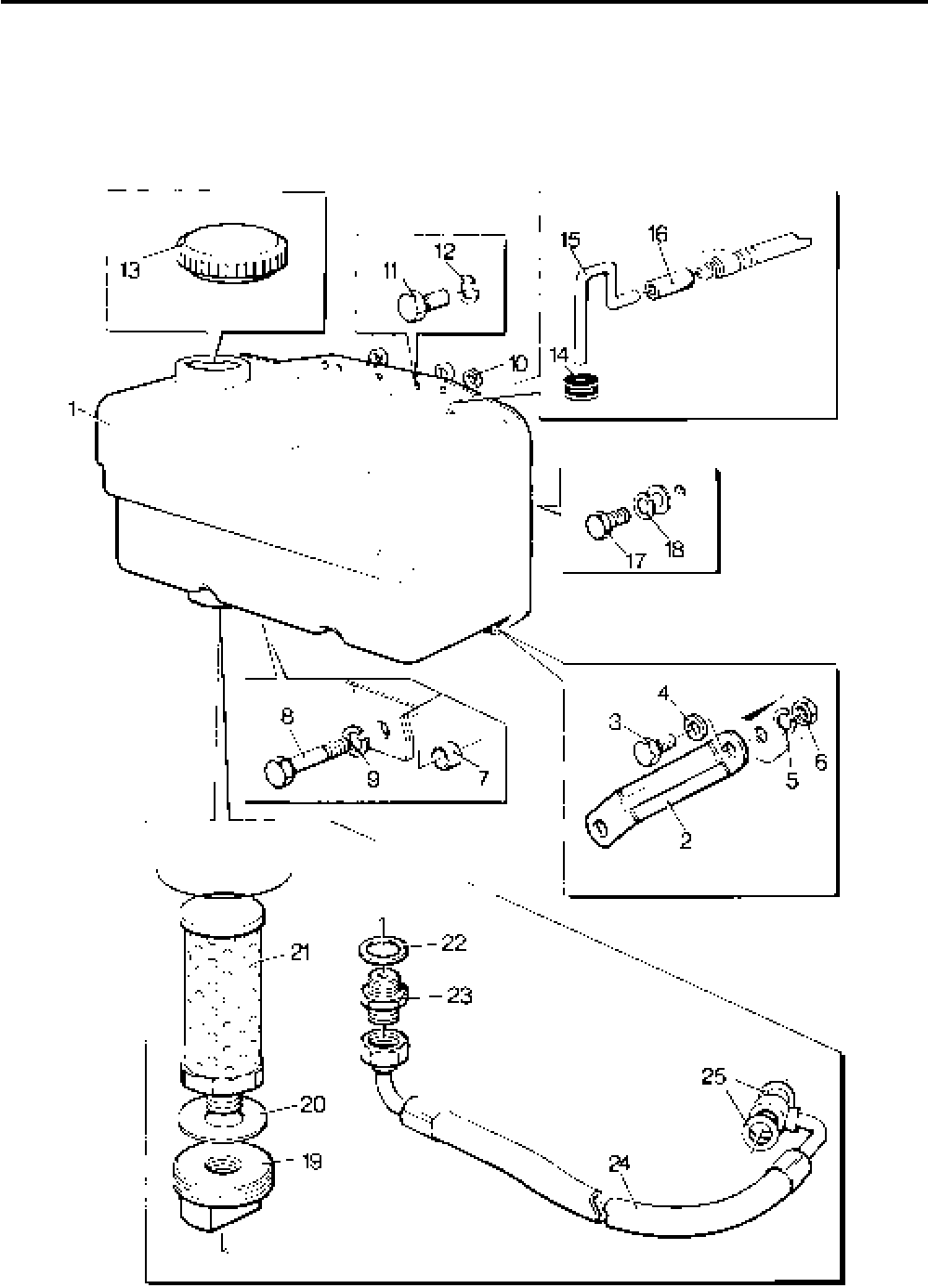
Lister-Petter TS/TR Master Parts Manual Issue 9: June 2000
81
Illustration T260

Lister-Petter TS/TR Master Parts ManualIssue 9: June 2000
82
Fuel Tank - 13,5 litre - Early Engines
Illustration T325 TS/TR
No. Description Part Number 1 2 3 Remarks
1 Fuel Tank.................................................................201-30822 1 1 1 Replaces 201-30821
2 Setscrew - M8 x 25mm............................................272-00040 4 4 4
3 Spring Washer.........................................................272-00071 4 4 4
4 Setscrew - M8 x 20mm............................................272-00039 1 1 1
5 Nut...........................................................................272-00003 1 1 1
6 Spacer .....................................................................201-42450 1 1 1
7 Stay .........................................................................201-31422 1 1 1
8 Filler Cap .................................................................366-08136 1 1 1 Replaces 366-00091
- Joint.........................................................................027-06151 1 1 1 Only used with 366-00091
9 Fuel Filter Bracket ...................................................601-31732 1 1 1
10 Bleed Screw ............................................................601-21620 2 2 2
11 Washer ....................................................................601-32470 2 2 2
- Union Adaptor - TS/TR1 ..........................................602-38250 1 - -
12 Union Adaptor- TS/TR2,3 ........................................202-37950 - 1 1
13 Copper Washer .......................................................354-26310 1 1 1
14 Fuel Filter Adaptor ...................................................601-34690 1 1 1
- Bowl and Element Assembly ...................................570-31260 1 1 1
15 Filter Bowl............................................................................. 1 1 1
16 Locating Washer .................................................................. 1 1 1
17 Spring ................................................................................... 1 1 1
18 Bolt ....................................................................................... 1 1 1
19 Element Kit ...........................................................203-32470 1 1 1
20 Sealing Ring ...................................................................... 1 1 1
21 Sealing Ring ...................................................................... 1 1 1
22 Sealing Ring ...................................................................... 2 2 2
23 Mounting Plate ........................................................201-44930 1 1 1
24 Setscrew - M8 x 20mm............................................272-00039 1 1 1
25 Washer ....................................................................027-00082 1 1 1
26 Spring Washer.........................................................272-00071 1 1 1
27 Nut...........................................................................272-00003 1 1 1
28 Setscrew - M6 x 20mm............................................ 272-00117 2 2 2
29 Washer ....................................................................272-00364 2 2 2
30 Spring Washer.........................................................272-00070 2 2 2
31 Nut...........................................................................272-00002 2 2 2
32 Grommet .................................................................601-33740 1 1 1
33 Fuel Leak-off Pipe ................................................... 366-07117 1 1 1
34 Hose ........................................................................202-41280 1 1 1
35 Rubber Boot ............................................................202-41270 1 1 1
- Setscrew - M6 x 12mm............................................272-00032 1 - -
- Setscrew - M8 x 20mm............................................272-00039 1 - -
- Bolt - M8 x 30mm ....................................................272-00041 1 - -
- Spacer .....................................................................201-41750 1 - -
36 Bolt - M8 x 35mm ....................................................272-00042 - 1 1
37 Spacer .....................................................................201-42570 - 1 1
38 Spring Washer.........................................................272-00071 1 1 1
- Fuel Pipe - TS/TR1..................................................570-35700 1 - - Replaces 201-38940
39 Fuel Pipe - TS/TR2 ..................................................202-34070 - 1 -
- Fuel Pipe - TS/TR3..................................................203-34070 - - 1
40 Copper Washer .......................................................616-01608 2 4 6
41 Fuel Pipe .................................................................366-07845 1 1 1
42 Union Nut ................................................................601-38370 1 1 1
43 Olive ........................................................................601-38360 1 1 1
44 Fuel Filter Union ......................................................602-38800 1 1 1
45 Copper Washer .......................................................354-26310 1 1 1
- Cylinder Head Cover - TS/TR1 ................................570-30753 1 - - See Note
- Cylinder Head Cover - Gear End TS/TR2,3 .............570-30752 - 1 1 See Note
- Joint.........................................................................201-30805 1 1 1 See Note
- Flywheel End Side Shield ........................................201-39850 - 1 1 See Note
- Setscrew - M8 x 12mm............................................272-00166 - 1 1 See Note
- Spring Washer.........................................................272-00071 - 1 1 See Note
Note:
These items must be fitted to engine to enable fuel tank mounting.
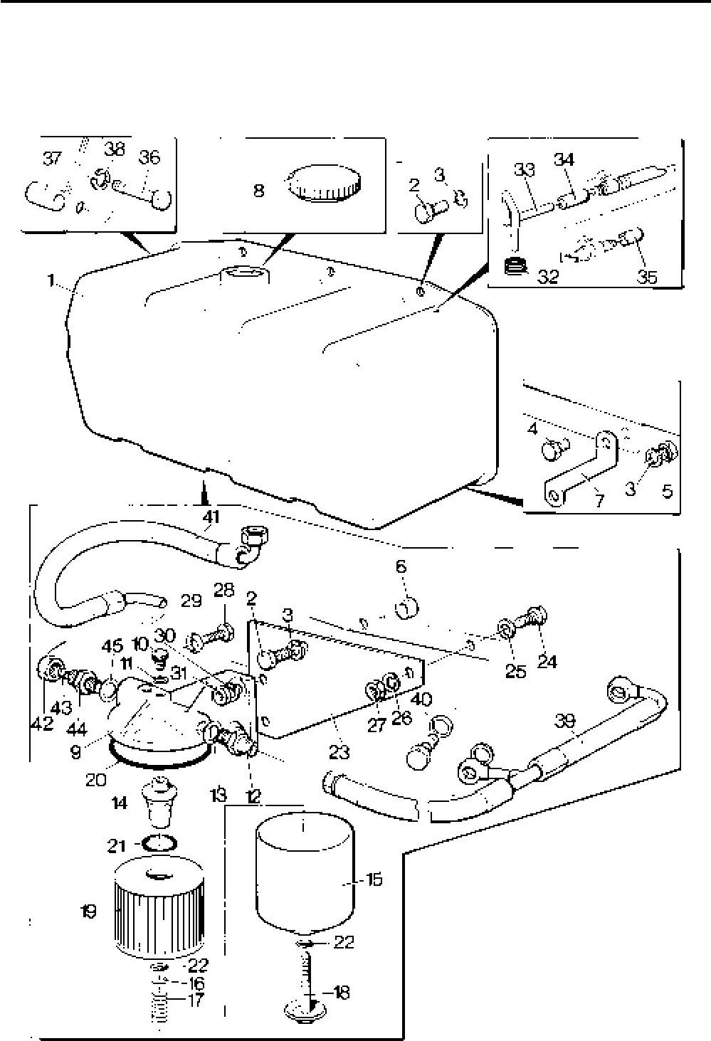
Lister-Petter TS/TR Master Parts Manual Issue 9: June 2000
83
Illustration T325

Lister-Petter TS/TR Master Parts ManualIssue 9: June 2000
84
Fuel Tank - 13,5 litre - TS1,2,3 - Later Engines
Illustration T426 TS
No. Description Part Number 1 2 3 Remarks
Accessory Kit Code FB - TS/TR1 ............................570-35691 1 - -
Accessory Kit Code FB - TS/TR2 ............................570-35692 - 1 -
Accessory Kit Code FB - TS/TR3 ............................570-35693 - - 1
1 Fuel Tank Assembly ................................................201-30822 1 1 1
2 Setscrew - M8 x 25mm............................................272-00040 4 4 4
3 Spring Washer - M8 ................................................272-00071 7 7 7
4 Screw - M8 x 20mm ................................................272-00039 2 2 2
5 Nut - M8 ..................................................................272-00003 4 4 4
6 Spacer .....................................................................201-42450 1 1 1
7 Stay .........................................................................201-31422 1 1 1
8 Filler Cap .................................................................366-08136 1 1 1
9 Bracket ....................................................................201-46830 1 1 1
10 Bolt - M8 x 30mm ....................................................272-00041 3 3 3
11 Washer - 5/16" ...........................................................027-00082 2 2 2
12 Plug - M10 ...............................................................272-00370 1 1 1
13 Copper Washer .......................................................354-26310 1 1 1
14 Fuel Pipe Assembly - Tank to Filter .........................201-46880 1 1 1
- Fuel Pipe Assembly - Filter to Engine - TS1 ............201-46800 1 - -
15 Fuel Pipe Assembly - Filter to Engine - TS2 ............202-46800 - 1 -
- Fuel Pipe Assembly - Filter to Engine - TS3 ............203-46800 - - 1
16 Copper Washer - 5/16" ..............................................616-01608 2 4 6
17 Grommet .................................................................601-33740 1 1 1
18 Leak Off Pipe........................................................... 366-07117 1 1 1
19 Hose ........................................................................ 202-41280 1 1 1
20 Rubber Boot ............................................................202-41270 1 1 1
21 Spacer .....................................................................201-42570 1 1 1
22 Bolt - M8 x 35mm ....................................................272-00042 1 1 1
- Cylinder Head Cover Assembly ...............................570-30752 1 1 1 See Note 1
- Joint - Cylinder Head Cover .....................................201-30805 1 1 1 See Note 1
- Side Shield Assembly ..............................................201-42760 1 1 1 See Note 1
- Screw - M8 x 12mm ................................................272-00166 1 1 1 See Note 1
- Washer - 5/16" ...........................................................027-00082 1 1 1 See Note 1
30 Fuel Filter ................................................................201-44580 1 1 1 Replaced by Agglomerator
- Element Kit ...........................................................351-29760 1 1 1
- Agglomerator ...........................................................750-14120 1 1 1 Replaces Fuel Filter 201-44580.
See Note 2
- Element Kit ...........................................................751-18100 1 1 1 See Note 2
31 Ball ..........................................................................202-32120 2 2 2 Replaces Washer 201-41640
32 Union .......................................................................202-42370 2 2 2 Replaces Blanking Plug 354-28530
33 Tube Nut..................................................................202-42370 2 2 2 See Note 2
34 Olive ........................................................................601-38360 2 2 2 See Note 2
35 Washer - 5/16"...........................................................027-00082 2 2 2 See Note 2
36 Spring Washer - M8 ................................................272-00071 2 2 2 See Note 2
Notes:
1. These items must be fitted to engine to enable fuel tank mounting.
2. Items marked are NOT part of this Accessory Kit. They are part of the Basic Engine Build,
and are labelled only for information.
25 Litre Fuel Tank - Loose
Not Illustrated TS/TR
Description Part Number 1 2 3 Remarks
Accessory Kit Code FD ..................................................570-32641 1 1 1
Fuel Tank Assembly .......................................................202-34580 1 1 1
Filler Cap ........................................................................366-08136 1 1 1
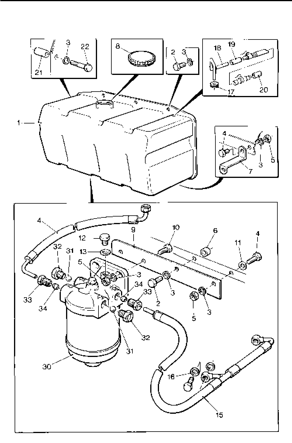
Lister-Petter TS/TR Master Parts Manual Issue 9: June 2000
85
Illustration T426

Lister-Petter TS/TR Master Parts ManualIssue 9: June 2000
86
Inlet and Exhaust Manifolds
Not TS1 Builds 16, 101, 102, 103
Not TR1 Builds 16
Illustration T185 TS/TR
No. Description Part Number 1 2 3 Remarks
- Inlet Manifold - TS/TR1............................................201-37852 1 - - Replaces 201-37851
1 Inlet Manifold - TS/TR2............................................202-31003 - 1 -
- Inlet Manifold - TS/TR3............................................203-31003 - - 1
- Inlet Manifold - TS/TR1............................................201-37861 1 - - Used with oil bath air cleaner
203-11422. Available as kit AS
(570-32760) with no's 8 & 3
- Inlet Manifold - TS/TR2............................................202-45880 - 1 - Used with oil bath air cleaner
203-11422 and TR2 Build 101
- Inlet Manifold - TS/TR3............................................203-45880 - - 1 TR3 up to 2000 r/min. Used with
oil bath air cleaner 203-11422.
- Inlet Manifold - TS/TR2............................................202-31004 - 1 - Used with cyclonic air cleaner
366-08108. Available as kit AT
(570-41991) with Joint (no. 3)
- Inlet Manifold - TS/TR3............................................202-31005 - - 1 Used with cyclonic air cleaner
366-08108. Available as kit AT
(570-41992) with Joint (no. 3)
- Inlet Manifold with Gear End Flange - TS/TR2,3 .....202-31001 - 1 1 Available as kit AX with Joint (no. 3).
TS/TR2 = 570-32560
TS/TR3 = 570-32570
- Remote Air Cleaner Adaptor - TS/TR2,3 .................366-08094 - 1 1 Spigot diameter 21/4“ (57,1mm)
Available as kit AP (570-41730)
- Exhaust Manifold - TS/TR1 .....................................201-37842 1 - -
2 Exhaust Manifold - TS/TR2 .....................................202-31021 - 1 -
- Exhaust Manifold - TS/TR3 .....................................203-31021 - - 1
3 Joint.........................................................................201-33420 2 4 6 One fitted each side of the air
cowling
- Manifold Top Stud M8 x 45mm - TS/TR1 ................272-00301 2 - - One fitted on TR1 Build 100
4 Manifold Top Stud M8 x 40mm - TS/TR2,3..............272-00307 - 4 6 Two fitted on TR2 Build 101
- Clamping Washer - TS/TR1 ....................................201-34760 2 - -
5 Clamping Washer - TS/TR2,3 .................................202-80680 - 4 6 Two fitted on TR2 Build 101
6 Spring Washer.........................................................272-00071 2 4 6 Two fitted on TR2 Build 101
7 Nut...........................................................................272-00380 1 2 3
- Bottom Manifold Stud - M6 x 85mm ........................272-00357 1 - -
8 Bottom Manifold Stud - M6 x 30mm ........................272-00304 2 4 6 One fitted on TR1 Build 100
9 Spring Washer.........................................................272-00070 2 4 6
10 Nut...........................................................................272-00379 2 4 6
11 Setscrew - M8 x 10mm............................................272-00239 - 1 1
12 Washer ....................................................................616-01608 - 1 1
13 Inlet Manifold Adaptor - TS/TR2,3 ...........................202-38721 - 1 1 For Cooper air cleaner
14 Joint.........................................................................202-33231 - 1 1 Replaces 202-33230
15 Stud .........................................................................272-00108 - 2 2
16 Nut...........................................................................272-00003 - 2 2
17 Spring Washer.........................................................272-00071 - 2 2
- Stud .........................................................................272-00789 1 - - TR1 Build 100 only
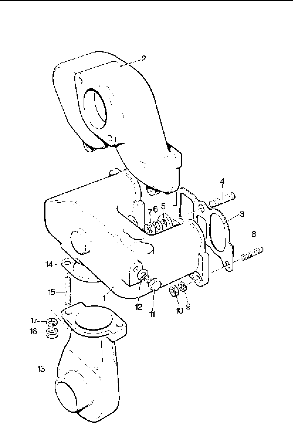
Lister-Petter TS/TR Master Parts Manual Issue 9: June 2000
87
Illustration T185
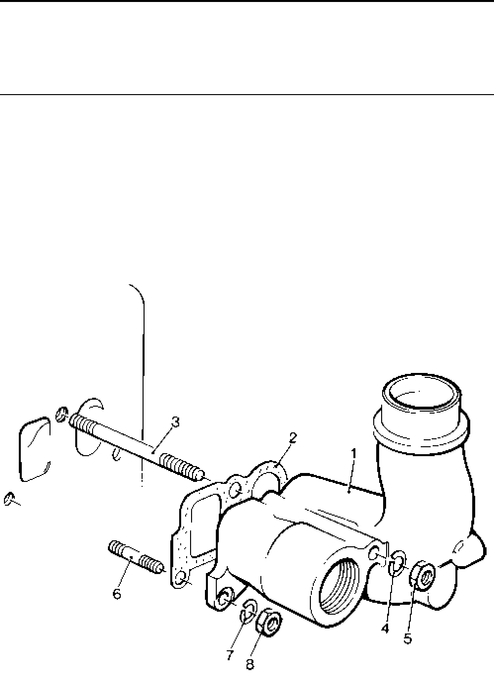
Lister-Petter TS/TR Master Parts ManualIssue 9: June 2000
88
Inlet and Exhaust Manifolds
TS1 Builds 16, 101, 102, 103
TR1 Build 16
Illustration T165 TS/TR
No. Description Part Number 1 2 3 Remarks
1 Inlet and Exhaust Manifold ......................................201-41552 1 - - Replaces 201-41551
2 Joint.........................................................................201-33420 1 - -
3 Stud - M8 x 100mm .................................................272-00366 1 - -
4 Spring Washer.........................................................272-00071 1 - -
5 Nut...........................................................................272-00380 1 - - Replaces 272-00011
6 Stud - M6 x 35mm ...................................................272-00304 2 - - Replaces 272-00334
7 Spring Washer.........................................................272-00070 2 - -
8 Nut...........................................................................272-00379 2 - - Replaces 201-35070
Illustration T165

Lister-Petter TS/TR Master Parts Manual Issue 9: June 2000
89
Vertical Outlet Exhaust Manifold Adaptor
Not Illustrated TS/TR
Description Part Number 1 2 3 Remarks
Accessory Kit Code NG - TS/TR1 ..................................570-32980 1 - -
Accessory Kit Code NG - TS/TR2,3 ...............................570-31980 - 1 1
Adaptor - TS/TR1 ...........................................................202-31031 1 - -
Adaptor - TS/TR2,3 ........................................................366-06969 - 1 1
Joint................................................................................366-01287 2 2 2 Replaces 757-15750
Bolt - M10 x 35mm - TS/TR1 ..........................................272-00168 2 - -
Nut - TS/TR1 ..................................................................272-00012 2 - -
Setscrew - M10 x 30mm - TS/TR2,3 ..............................272-00080 - 2 2
Spring Washer................................................................272-00072 2 2 2
Horizontal Outlet Exhaust Manifold Adaptor
Not Illustrated TS/TR
Description Part Number 1 2 3 Remarks
Accessory Kit Code NJ - TS/TR2,3 ................................570-31990 - 1 1
Exhaust Bend .................................................................202-31031 - 1 1
Joint................................................................................366-01287 - 2 2 Replaces 757-15750
Setscrew - M10 x 30mm .................................................272-00080 - 2 2
Spring Washer................................................................272-00072 - 2 2
11/2" Outlet Flange Exhaust Manifold Adaptor
Not Illustrated TS/TR
Description Part Number 1 2 3 Remarks
Accessory Kit Code NF - TS/TR1 ...................................570-32970 1 - -
Accessory Kit Code NF - TS/TR2,3 ................................570-31970 - 1 1
Exhaust Flange - 11/2” .....................................................010-21801 1 1 1
Bolt - M10 x 45mm - TS/TR1 ..........................................272-00213 2 - -
Brass Nut........................................................................272-00012 2 - -
Setscrew - M10 x 30mm - TS/TR2,3 ..............................272-00080 - 2 2
Spring Washer................................................................272-00072 2 2 2
Joint................................................................................366-01287 1 1 1 Replaces 757-15750

Lister-Petter TS/TR Master Parts ManualIssue 9: June 2000
90
Silencer Outlet Bend
Not Illustrated TS/TR
Description Part Number 1 2 3 Remarks
Accessory Kit Code NH ..................................................570-32520 1 1 1
Silencer Outlet Bend ....................................................202-36900 1 1 1
Clamp ..........................................................................737-13060 1 1 1
Heat Shield
Not Illustrated TS/TR
Description Part Number 1 2 3 Remarks
Accessory Kit Code NM ..................................................570-41720 1 1 1
Heat Shield ..................................................................366-08148 1 1 1
Clip ..............................................................................027-10021 2 2 2
Medium Duty Silencer
Not Illustrated TS/TR
Description Part Number 1 2 3 Remarks
Accessory Kit Code NA - TS/TR1 ................................... 570-31170 1 - -
Accessory Kit Code NA - TS/TR2,3 ................................570-31960 - 1 1 Includes code NJ in kit
Silencer - TS/TR1 ........................................................201-37072 1 - -
Silencer - TS/TR2,3 .....................................................203-32561 - 1 1 Replaces 203-32560
Adaptor - TS/TR3 ........................................................202-31031 - 1 1
Setscrew - M10 x 30mm ..............................................272-00080 2 4 4
Spring Washer .............................................................272-00072 2 4 4
Joint .............................................................................366-01287 1 2 2 Replaces 757-15750
Accessory Kit Code NL - TS/TR1 ...................................570-13980 1 - - Build 16 only
Silencer Assembly .......................................................202-55190 1 - - Build 16
Heavy Duty Silencer (not engine mounted)
Not Illustrated TS/TR
Description Part Number 1 2 3 Remarks
Accessory Kit Code NC ..................................................570-15780 1 1 1 Not Build 16
Silencer Assembly ..........................................................027-06332 1 1 1 Not Build 16
Silencer Body ..............................................................027-06320 1 1 1
Flange .........................................................................366-01265 2 2 2
Joint .............................................................................366-01266 1 1 1
Screw - 1/2" UNF x 11/4" ................................................270-00077 4 4 4
Nut - 1/2" UNF...............................................................270-00006 4 4 4
Spring Washer - 1/2" diameter ......................................027-00394 4 4 4
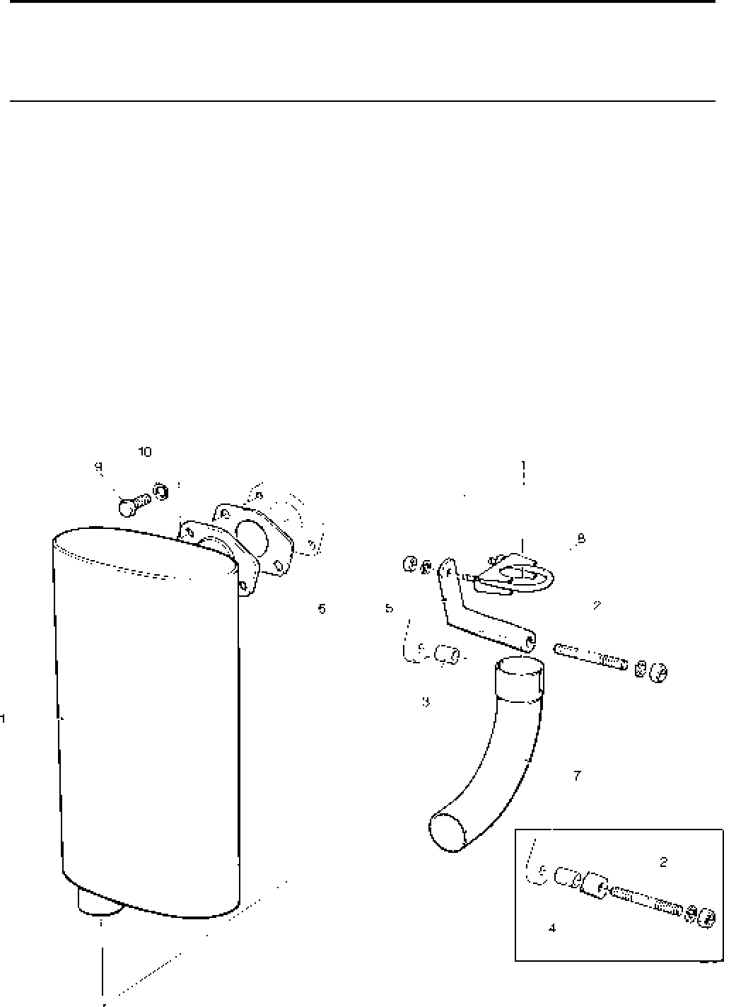
Lister-Petter TS/TR Master Parts Manual Issue 9: June 2000
91
Heavy Duty Silencer - TS2,3
Illustration T411 TS
No. Description Part Number 1 2 3 Remarks
Accessory Kit Code NB ...........................................570-32400 - 1 1 Use with code AE or AX
1 Silencer ................................................................202-36742 - 1 1
2 Stud - M10 x 70mm ..............................................272-00057 - 1 1
3 Spacer ..................................................................201-42830 - 2 2
4 Spacer ..................................................................201-42520 - 1 1
5 Silencer Support Bracket ......................................202-36891 - 1 1
6 Joint......................................................................366-01287 - 1 1
7 Silencer Outlet Bend.............................................202-36900 - 1 1
8 Clamp ...................................................................737-13060 - 1 1
9 Setscrew - M10 x 30mm.......................................272-00080 - 2 2
10 Spring Washer......................................................272-00072 - 2 2
Illustration T411
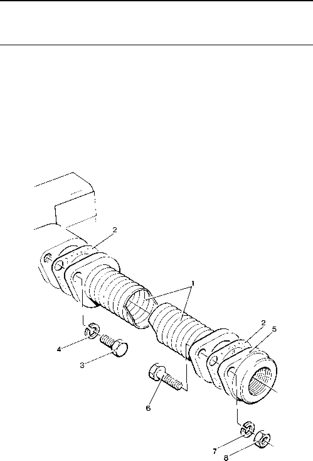
Lister-Petter TS/TR Master Parts ManualIssue 9: June 2000
92
Flexible Exhaust Pipe (1 metre)
Illustration T118 TS/TR
No. Description Part Number 1 2 3 Remarks
Accessory Kit Code NE ...........................................570-32410 1 1 1
1 Flexible Exhaust Pipe ..............................................366-08129 1 1 1
2 Joint.........................................................................366-01287 2 2 2
3 Setscrew - M10 x 30mm..........................................272-00080 2 2 2
4 Spring Washer.........................................................272-00072 2 2 2
5 Mating Flange..........................................................010-21801 2 2 2
6 Bolt - 3/8”UNF x 13/4”................................................ 270-00221 4 4 4
7 Spring Washer.........................................................027-00393 4 4 4
8 Nut...........................................................................270-00004 4 4 4
Illustration T118
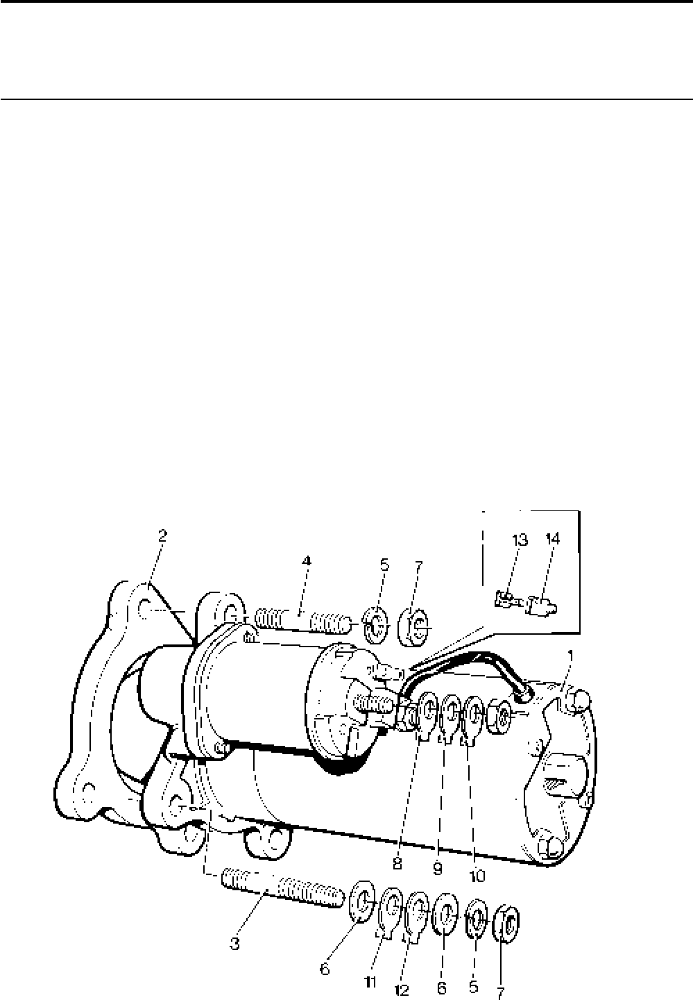
Lister-Petter TS/TR Master Parts Manual Issue 9: June 2000
93
Starter Motor
Illustration T324 TS/TR
No. Description Part Number 1 2 3 Remarks
Accessory Kit Code EK ...........................................570-30421 1 1 1 12V pre-engaged. Includes code EM
Accessory Kit Code EL ............................................570-30431 1 1 1 24V pre-engaged. Includes code EM
1 Starter Motor - 12V Lucas .......................................202-34963 1 1 1
- Starter Motor - 12V Bosch .......................................202-42470 1 1 1 Replaced by 12V Lucas type
- Starter Motor - 24V Bosch .......................................202-44940 1 1 1 Replaces 202-44941
Accessory Kit Code EM ...........................................570-31750 1 1 1 Spacer kit for Starter Motor with
SAE1 flange. Comprises no's 2-7.
2 Spacer .....................................................................202-33180 1 1 1
3 Earth Terminal Stud .................................................272-00605 1 1 1
4 Stud .........................................................................858-00108 2 2 2
5 Spring Washer.........................................................272-00072 3 3 3
6 Washer....................................................................027-00545 2 2 2
7 Nut...........................................................................272-00004 3 3 3
8 Terminal Lug .....................................................064-15649/010 2 2 2
9 Terminal Lug .....................................................064-15651/010 1 1 1
10 Terminal Lug.....................................................064-15648/013 1 1 1
11 Terminal Lug ..................................................... 064-15649/011111
12 Terminal Lug.....................................................064-15648/014 1 1 1
13 Push-on Connector ..........................................064-33068/002 1 1 1
14 Cover ................................................................ 064-33991/002 1 1 1
Illustration T324
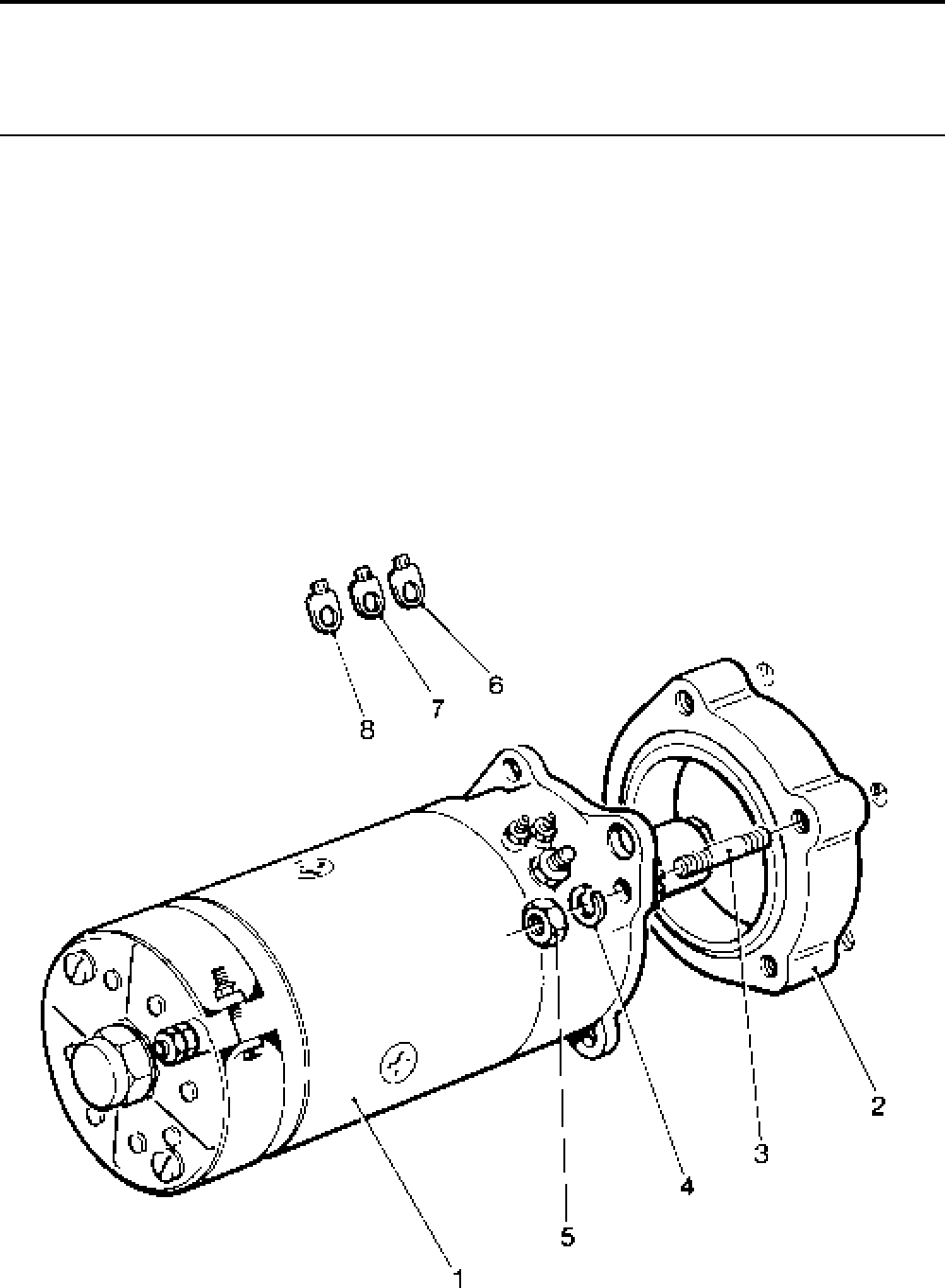
Lister-Petter TS/TR Master Parts ManualIssue 9: June 2000
94
24V Co-axial Starter
Illustration T346 TS/TR
No. Description Part Number 1 2 3 Remarks
Accessory Kit Code EN ...........................................570-31760 1 1 1 Spacer kit. Comprises no's 2-5.
1 Starter Motor ...........................................................366-07703 1 1 1
2 Spacer .....................................................................202-33160 1 1 1
3 Stud - M10 x 65mm .................................................272-00171 3 3 3
4 Spring Washer.........................................................272-00072 3 3 3
5 Nut...........................................................................272-00004 3 3 3
6 Terminal Lug.....................................................064-15648/010 1 1 1
7 Terminal Lug.....................................................064-15649/007 1 1 1
8 Terminal Lug.....................................................064-15651/010 1 1 1
Illustration T346

Lister-Petter TS/TR Master Parts Manual Issue 9: June 2000
95
Starting Handle
Not Illustrated TS/TR
Description Part Number 1 2 3 Remarks
Accessory Kit Code EA...................................................601-53350 1 1 - Gear end - short grip (standard)
Standard Handle - TS/TR1,2 .......................................601-52010 1 1 - 'Flush' type
Accessory Kit Code EB...................................................570-31690 1 1 1 Gear end - long grip
Long Grip Handle ........................................................570-31000 1 1 1 'Flush' type
Accessory Kit Code ED ..................................................570-31710 1 1 1 Gear end hydraulics - assembled
Long Grip Handle ........................................................ 570-30112 1 1 1
Accessory Kit Code EF ...................................................570-31730 1 1 1 Gear end hydraulics - kit form
Long Grip Handle ........................................................570-30451 1 1 1
Starting Dog.................................................................201-31951 1 1 1
Accessory Kit Code MEG ...............................................570-60340 - 1 1 Marine Starting Handle
Starting Handle Assembly ...........................................854-00526 - 1 1 For use with code MER

Lister-Petter TS/TR Master Parts ManualIssue 9: June 2000
96
Limited Kickback Starting Handle - Gear End
Illustration T420 TS/TR
No. Description Part Number 1 2 3 Remarks
Accessory Kit Code ER ...........................................570-35724 1 1 1 Replaces 570-35721
1 Starting Dog Assembly ............................................201-47660 1 1 1
2 Bissel Pin.................................................................601-43750 1 1 1
3 End Cover Joint ....................................................... 201-33011 1 1 1
4 End Cover Assembly ...............................................201-47990 1 1 1 Replaces 201-33853
5 Bearing Housing Assembly...................................... 201-47711 1 1 1 Replaces 201-47710. See Note
6 Bolt ..........................................................................272-00657 4 4 4 Replaces 272-00243
7 Washer ....................................................................272-00688 4 4 4
8 Starting Handle Assembly .......................................201-47692 1 1 1 Replaces 201-47690
Note:
Bearing Housing Assemblies 201-47711 and 201-47710 are not interchangeable.
Limited Kickback Starting Handle - Gear End Hydraulics
Illustration T419 TS/TR
No. Description Part Number 1 2 3 Remarks
Accessory Kit Code EX ...........................................570-35725 1 1 1 Replaces 570-35722
1 Starting Dog Assembly ............................................201-47660 1 1 1
2 Bissel Pin.................................................................601-43750 1 1 1
3 End Cover Joint ....................................................... 201-33011 1 1 1
4 End Cover Assembly ...............................................201-47993 1 1 1 Replaces 570-31071
5 Bearing Housing Assembly...................................... 201-47711 1 1 1 Replaces 201-47710. See Note
6 Bolt ..........................................................................272-00657 4 4 4 Replaces 272-00243
7 Washer ....................................................................272-00688 4 4 4
8 Starting Handle Assembly .......................................201-47701 1 1 1 Replaces 201-47700
Note:
Bearing Housing Assemblies 201-47711 and 201-47710 are not interchangeable.
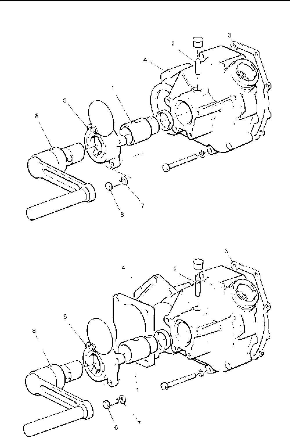
Lister-Petter TS/TR Master Parts Manual Issue 9: June 2000
97
Illustration T420
Illustration T419

Lister-Petter TS/TR Master Parts ManualIssue 9: June 2000
98
Alternator - TS/TR2, 3 - Build 05
Illustration T138 TS/TR
No. Description Part Number 1 2 3 Remarks
1 Alternator - Lucas ....................................................382-08919 - 1 1
2 Mounting Bracket ....................................................366-07048 - 1 1
3 Setscrew - M8 x 25mm............................................272-00040 - 4 4
4 Copper Washer .......................................................616-01608 - 4 4
5 Spacer .....................................................................366-07054 - 1 1
6 Bolt - M8 x 130mm ..................................................272-00352 - 1 1
7 Washer ....................................................................027-00184 - 1 1
8 Spring Washer.........................................................272-00071 - 1 1
9 Nut...........................................................................272-00003 - 1 1
10 Alternator Pulley ......................................................366-07686 - 1 1
11 Belt ..........................................................................601-37010 - 1 1
12 Stud - 7/16“ UNF/UNC x 5 1/2” ............................... 270-00398 - 1 1
13 Spacer .....................................................................366-07179 - 1 1
14 Adjusting Link ..........................................................366-07045 - 1 1
15 Spring Washer.........................................................027-00985 - 1 1
16 Nut...........................................................................270-00005 - 1 1
17 Spacer .....................................................................366-07051 - 1 1
18 Bolt M8 x 60mm ......................................................272-00045 - 1 1
19 Washer ....................................................................027-00184 - 1 1
20 Washer ....................................................................027-00545 - 1 1
21 Pulley - Crankshaft Drive .........................................201-32961 - 1 1
22 Setscrew .................................................................272-00040 - 4 4
23 Springwasher ..........................................................272-00071 - 4 4
24 Dowel ......................................................................291-22470 - 2 2
25 Extension Shaft .......................................................201-32910 - 1 1
26 Stud .............................................................................. 363245 - 1 1
27 Shim ........................................................................201-32970 - 1 1
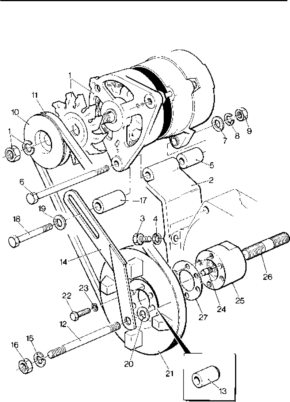
Lister-Petter TS/TR Master Parts Manual Issue 9: June 2000
99
Illustration T138

Lister-Petter TS/TR Master Parts ManualIssue 9: June 2000
100
Alternator - TS2,3
Not Illustrated TS/TR
Description Part Number 1 2 3 Remarks
Accessory Kit Code EP...................................................570-35760 - 1 1
Bracket ...........................................................................201-43973 - 1 1
Setscrew.........................................................................272-00039 - 6 6
Spring Washer................................................................272-00071 - 9 9
Bracket Assembly ...........................................................366-09062 - 1 1
Nut ................................................................................272-00003 - 2 2
Alternator ........................................................................366-08009 - 1 1
Pulley..............................................................................201-43782 - 1 1
Bolt ................................................................................272-00352 - 1 1
Spacer ............................................................................366-08241 - 1 1
Adjusting Bracket ...........................................................201-43984 - 1 1
Setscrew.........................................................................272-00040 - 4 4
Plain Washer ..................................................................272-00082 - 3 3
Belt ................................................................................751-17560 - 1 1
Connector Plug ...............................................................757-19520 - 1 1
Washer ................................................................................785632 - 1 1
Washer ................................................................................785642 - 2 2
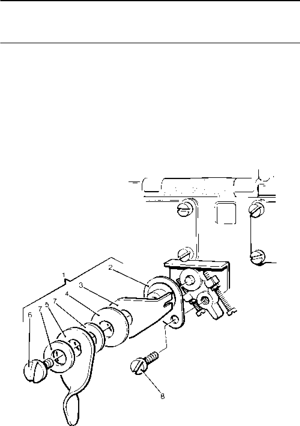
Lister-Petter TS/TR Master Parts Manual Issue 9: June 2000
101
Variable Speed Control - Lever Operated Engine Mounted
Illustration T115 TS/TR
No. Description Part Number 1 2 3 Remarks
Accessory Kit Code KB ........................................... 570-31911111
1 Control Lever assembly ...........................................202-34222 1 1 1
2 Connecting Plate ..................................................202-34210 1 1 1
3 Anchor Plate .........................................................202-34181 1 1 1
4 Spring Disc Washer .............................................. 601-33110 1 1 1
5 Hand Lever ...........................................................601-33061 1 1 1
6 Adjusting Screw....................................................601-33120 1 1 1
7 Copper Washer ....................................................366-07279 2 2 2
8 Cheese Head Screw - M6 x 12mm..........................272-00120 1 1 1
9 Washer....................................................................027-00618 1 1 1
Illustration T115
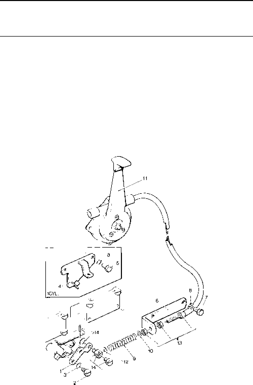
Lister-Petter TS/TR Master Parts ManualIssue 9: June 2000
102
Variable Speed Control - Cable Operated
Illustration T423 TS/TR
No. Description Part Number 1 2 3 Remarks
Accessory Kit Code KA - TS/TR1 ............................570-32870 1 - -
Accessory Kit Code KA - TS/TR2,3 .........................570-31901 - 1 1
Accessory Kit Code KC - TS/TR1 ............................570-32900 1 - - Less cable and lever
Accessory Kit Code KC - TS/TR2,3 .........................570-31921 - 1 1 Less cable and lever
1 Lever .......................................................................366-07068 1 1 1
2 Cheese Head Screw - M6 x 12mm..........................272-00120 1 1 1
3 Copper Washer .......................................................291-26090 1 1 1
4 Mounting Bracket - TS/TR1 .....................................201-41070 1 - -
5 Setscrew - M6 x 20mm............................................ 272-00117 2 - -
6 Mounting Bracket - TS/TR2,3 ..................................366-07912 - 1 1
7 Setscrew - M6 x 14mm............................................272-00034 - 2 2
8 Spring Washer.........................................................272-00070 2 2 2
9 Spring ......................................................................601-33771 1 1 1
10 Washer ....................................................................027-00618 1 1 1
11 Control Lever and Cable Assembly .........................366-07069 1 1 1
12 Washer ....................................................................366-06926 1 1 1
13 Cable End Adjuster..................................................366-07070 1 1 1
14 Swivel Connector.....................................................366-07071 1 1 1
Illustrator T423
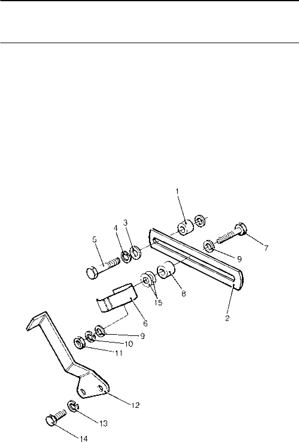
Lister-Petter TS/TR Master Parts Manual Issue 9: June 2000
103
Illustration T401
Two Speed Control - TS/TR1
Illustration T401 TS/TR
No. Description Part Number 1 2 3 Remarks
Accessory Kit Code KG ...........................................570-33200 1 - -
1 Spacer .....................................................................601-41700 2 - -
2 Adjusting Link ..........................................................201-41800 1 - -
3 Washer....................................................................272-00364 2 - -
4 Spring Washer.........................................................272-00070 2 - -
5 Bolt - M6 x 30mm ....................................................272-00035 2 - -
6 Spring ......................................................................201-53140 1 - -
7 Bolt - M6 x 25mm ....................................................272-00256 1 - -
8 Spacer .....................................................................601-41700 1 - -
9 Washer....................................................................272-00364 2 - -
10 Spring Washer.........................................................272-00070 1 - -
11 Nut...........................................................................272-00002 1 - -
12 Speed Control Lever ................................................366-08282 1 - - Replaces 201-41791
13 Spring Washer.........................................................272-00070 1 - -
14 Setscrew - M6 x 12mm............................................272-00032 1 - -
15 Washer ............................................................. 064-06612/006 2 - -
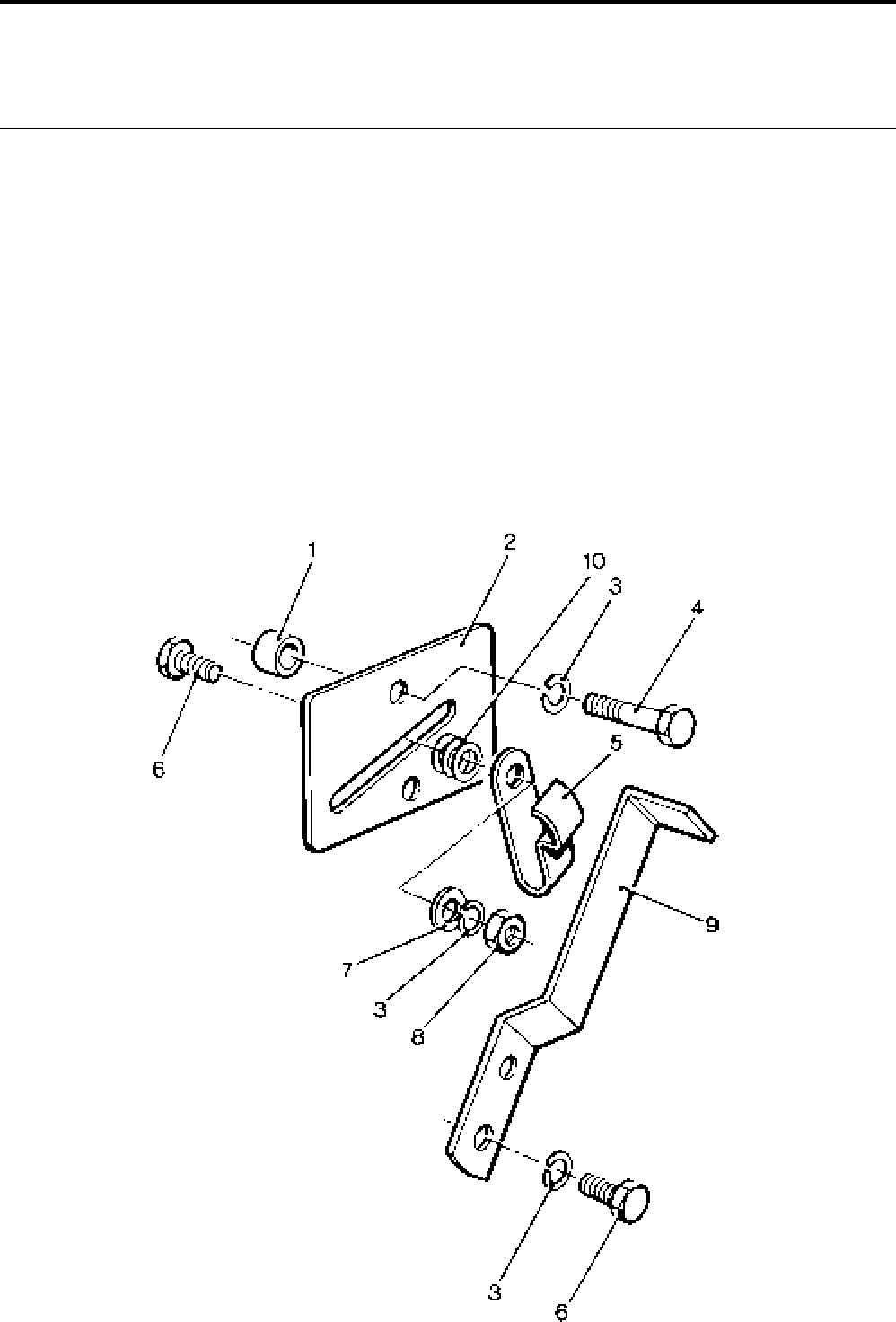
Lister-Petter TS/TR Master Parts ManualIssue 9: June 2000
104
Two Speed Control - TS/TR2,3
Illustration T402 TS/TR
No. Description Part Number 1 2 3 Remarks
Accessory Kit Code KG ...........................................570-33460 - 1 1
1 Spacer .....................................................................601-41700 - 2 2
2 Spring Carrier Plate .................................................201-42990 - 1 1
3 Spring Washer.........................................................272-00070 - 4 4
4 Bolt - M6 x 25mm ....................................................272-00256 - 2 2
5 Spring ......................................................................201-53140 - 1 1
6 Setscrew - M6 x 12mm............................................272-00032 - 2 2
7 Washer ....................................................................027-00618 - 1 1
8 Nut...........................................................................272-00002 - 1 1
9 Speed Control Lever................................................366-08252 - 1 1 Replaces 366-07167
10 Washer .............................................................064-06612/006 - 3 3
Illustration T402
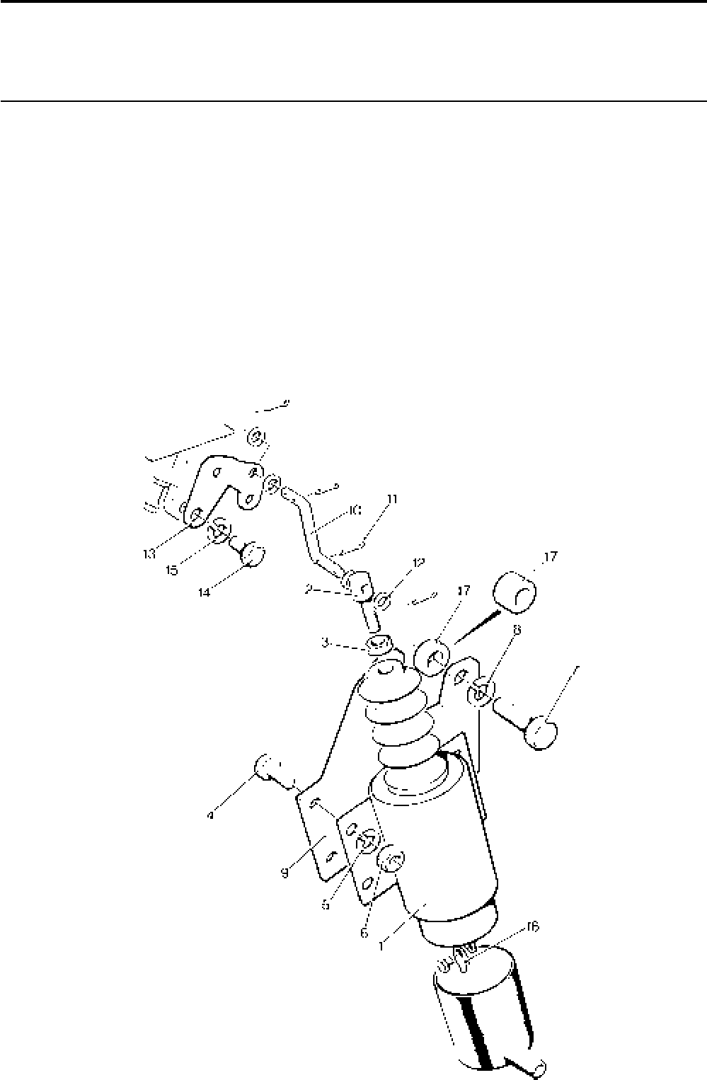
Lister-Petter TS/TR Master Parts Manual Issue 9: June 2000
105
Two Speed Solenoid
Illustration T233 TS/TR
No. Description Part Number 1 2 3 Remarks
1 Solenoid ..................................................................366-07216 - 1 1
2 Connector................................................................201-42630 - 1 1
3 Nut - 1/4“ UNF ........................................................ 270-00002 - 1 1
4 Setscrew - M6 x 16mm............................................272-00034 - 4 4
5 Spring Washer.........................................................272-00070 - 4 4
6 Nut - M6 ..................................................................272-00002 - 4 4
7 Setscrew - M8 x 30mm............................................272-00041 - 3 3
8 Spring Washer.........................................................272-00071 - 3 3
9 Mounting Bracket ....................................................366-07214 - 1 1
10 Link..........................................................................366-07215 - 1 1
11 Split Pin ...................................................................027-01986 - 4 4
12 Washer ............................................................. 064-06612/004 - 4 4
13 Speed Control Lever ................................................366-06946 - 1 1
14 Cheese Head Screw - M6 x 12mm ..........................272-00120 - 1 1
15 Spring Washer..................................................064-02582/003 - 1 1
16 Terminal............................................................ 064-15649/012 - 2 2
Illustration T233
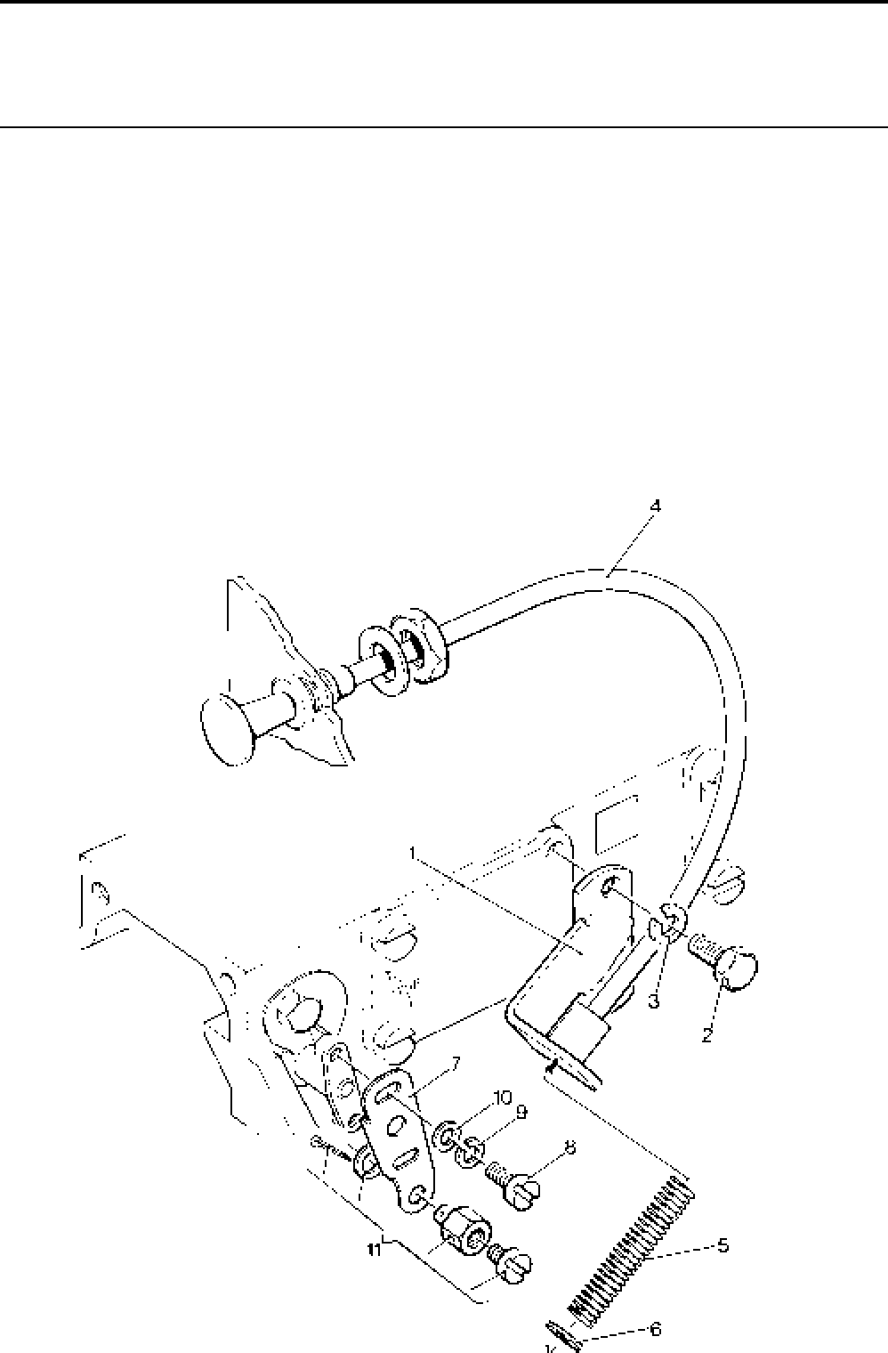
Lister-Petter TS/TR Master Parts ManualIssue 9: June 2000
106
1,8 Metre Cable Operated Remote Stop
Illustration T111 TS/TR
No. Description Part Number 1 2 3 Remarks
Accessory Kit Code KD - TS/TR1 ............................570-33180 1 - -
Accessory Kit Code KD - TS/TR2,3 .........................570-31930 - 1 1
- Cable Mounting Bracket - TS/TR1 ...........................201-41070 1 - -
- Setscrew - M6 x 20mm............................................ 272-00117 2 - -
1 Cable Mounting Bracket - TS/TR2,3........................202-35990 - 1 1
2 Setscrew - M6 x 16mm............................................272-00034 - 2 2
3 Spring Washer.........................................................272-00070 2 2 2
4 Cable .......................................................................202-36050 1 1 1
5 Return Spring ..........................................................382-07369 1 1 1
6 Locating Washer .....................................................366-06926 1 1 1
- Stopping Lever - TS/TR1 ......................................... 201-41140 1 - -
7 Stopping Lever - TS/TR2,3 ......................................202-36030 - 1 1
8 Cheese Head Screw - M5 x 12mm..........................272-00062 2 2 2
9 Spring Washer.........................................................272-00069 2 2 2
10 Washer ....................................................................027-01698 2 2 2
- Swivel Connector - TS/TR1 ..................................... 201-41130 1 - -
11 Swivel Connector - TS/TR2,3 ..................................366-07071 - 1 1
Illustration T111
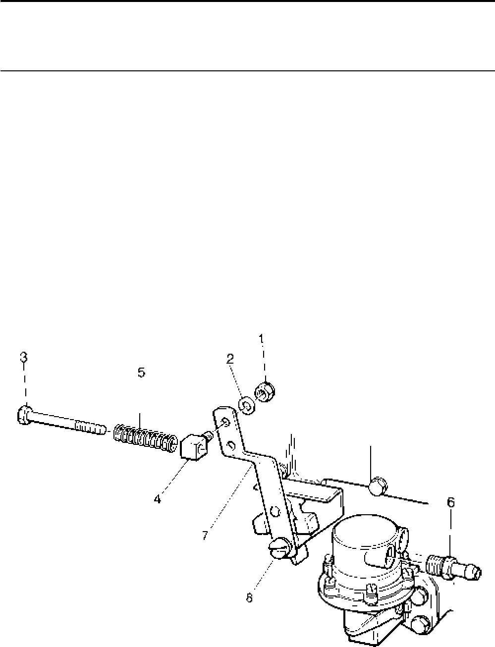
Lister-Petter TS/TR Master Parts Manual Issue 9: June 2000
107
Dumper Accessories (Loose)
Illustration T425 TS/TR
No. Description Part Number 1 2 3 Remarks
Accessory Kit Code XD ...........................................570-41310 1 1 1
1 Locknut.........................................................................707004 1 1 1
2 Washer.........................................................................785352 1 1 1
3 Bolt - M6 x 60mm .........................................................705231 1 1 1
4 Eye Bolt ........................................................................362612 1 1 1
5 Speeder Spring ............................................................ 314554 1 1 1
6 Pipe Connection ...........................................................365253 1 1 1
- Dumper Hook-up Bracket Kit ...................................570-34940 1 1 1 Not part of kit
7 Speed Control Lever.............................................366-07888 1 1 1 Not part of kit
8 Screw - M6 x 12mm .............................................272-00120 1 1 1 Not part of kit
- Spring Washer......................................................272-00070 1 1 1 Not part of kit
Illustration T425

Lister-Petter TS/TR Master Parts ManualIssue 9: June 2000
108
Electronic Governor Adaptor
Illustration T151 TS/TR
No. Description Part Number 1 2 3 Remarks
Accessory Kit Code KE ...........................................570-33080 - 1 1
1 Control Lever ...........................................................570-33100 - 1 1
2 Stopping Control Lever ............................................201-31780 - 1 1
3 Nut...........................................................................272-00002 - 1 1
4 Spring Washer.........................................................272-00070 - 1 1
5 Spring ......................................................................601-32670 - 1 1
6 ’O’ Ring ...................................................................201-13120 - 1 1
7 End Cover Joint .......................................................201-33010 - 1 1
8 Door Joint ................................................................201-30610 - 1 1
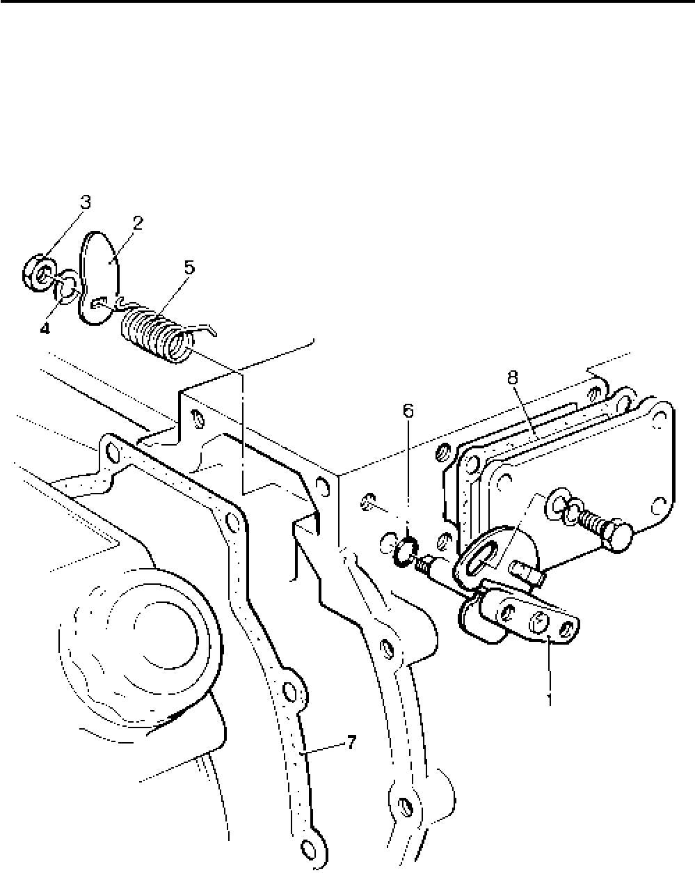
Lister-Petter TS/TR Master Parts Manual Issue 9: June 2000
109
Illustration T151
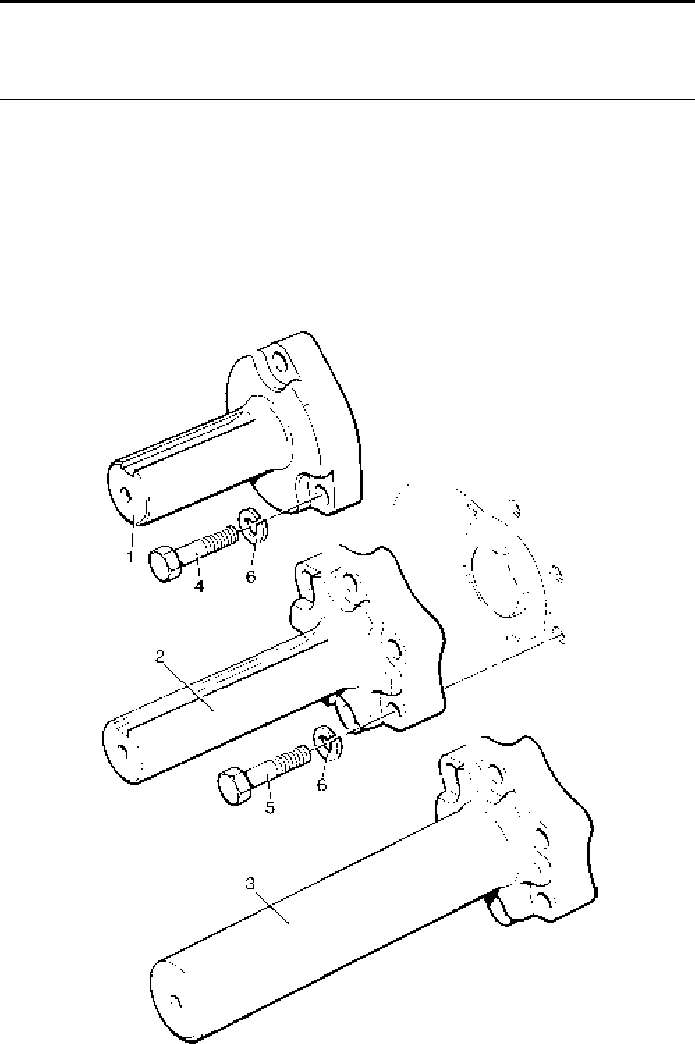
Lister-Petter TS/TR Master Parts ManualIssue 9: June 2000
110
Shaft Extension - Flywheel End
Illustration T171 TS/TR
No. Description Part Number 1 2 3 Remarks
Accessory Kit Code BA ...........................................570-31460 1 1 1 40mm diameter. Comprises 2, 5 & 6
Accessory Kit Code BB ...........................................602-51620 1 - - 40mm diameter. Comprises 1, 4 & 6
Accessory Kit Code BC ...........................................570-31470 1 1 1 Unmachined. Comprises 3, 5 & 6
1 Short Shaft Extension - TS/TR1 ..............................602-38680 1 - - 3 bolt fixing
2 Long Shaft Extension ..............................................202-35271 1 1 1
3 Long Shaft Extension ..............................................202-35272 1 1 1 Unmachined
4 Bolt - M12 x 50mm ..................................................272-00254 3 6 6
5 Bolt - M12 x 55mm ..................................................272-00177 - 6 6
6 Spring Washer.........................................................272-00073 3 6 6
Illustration T171
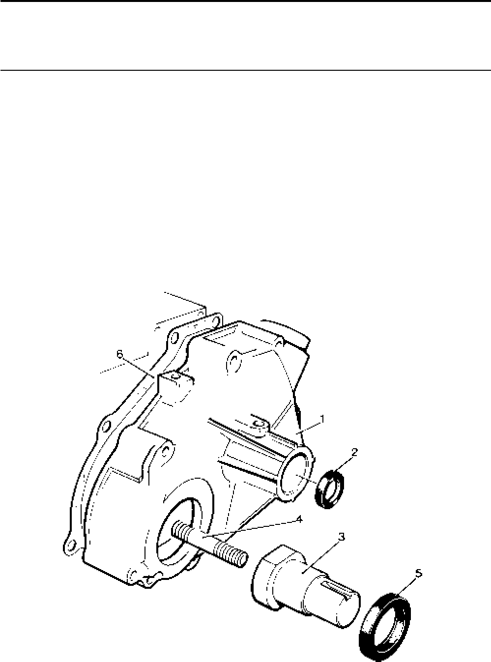
Lister-Petter TS/TR Master Parts Manual Issue 9: June 2000
111
Shaft Extension - Gear End
Illustration T52 TS/TR
No. Description Part Number 1 2 3 Remarks
Accessory Kit Code BW ..........................................570-31580 1 1 1 40mm diameter
1 End Cover ...............................................................201-47981 1 1 1 Replaces 201-33850
2 Oil Seal....................................................................601-39550 1 1 1
3 Crankshaft Extension ..............................................202-35441 1 1 1
4 Stud .........................................................................202-35430 1 1 1
5 Oil Seal....................................................................201-30690 1 1 1
6 End Cover Joint .......................................................201-33013 1 1 1
Illustration T52
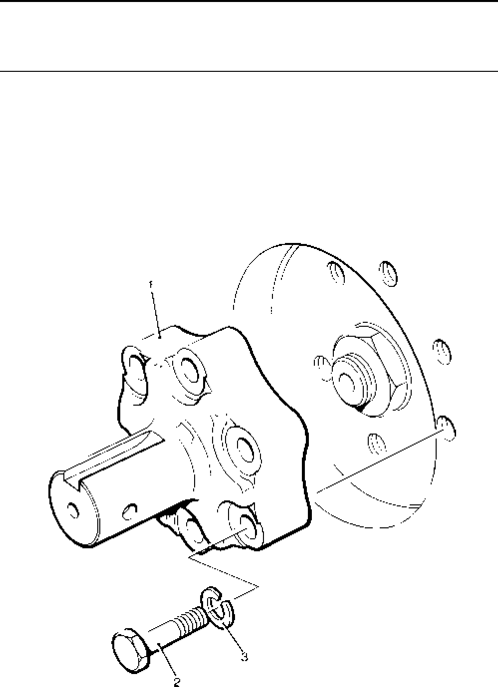
Lister-Petter TS/TR Master Parts ManualIssue 9: June 2000
112
Shaft Extension Kit - TS/TR2,3
Illustration T145 TS/TR
No. Description Part Number 1 2 3 Remarks
Accessory Kit Code XA ...........................................570-32880 1 1 1
1 Extension Shaft .......................................................202-41310 1 1 1
2 Bolt - M12 x 1.75-6g x 55mm ..................................272-00177 6 6 6
3 Spring Washer - M12 ..............................................272-00073 6 6 6
Illustration T145
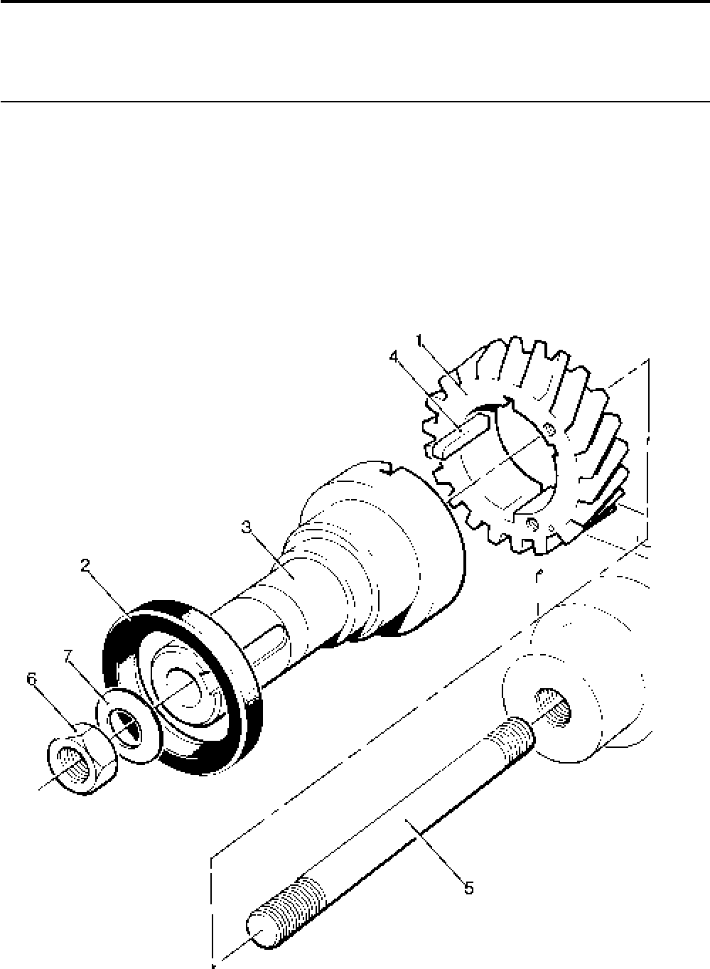
Lister-Petter TS/TR Master Parts Manual Issue 9: June 2000
113
Shaft Extension - Gear End - Build 40
Illustration T146 TS/TR
No. Description Part Number 1 2 3 Remarks
1 Crankshaft Pinion ....................................................202-39890 1 1 1
2 Oil Seal....................................................................201-30690 1 1 1
3 Crankshaft Extension ..............................................202-39870 1 1 1
4 Driving Key ..............................................................202-41250 2 2 2
5 Stud .........................................................................202-39880 1 1 1
6 Nut...........................................................................202-41690 1 1 1
7 Disc Spring Washer................................................. 639-11070 1 1 1
Illustration T146
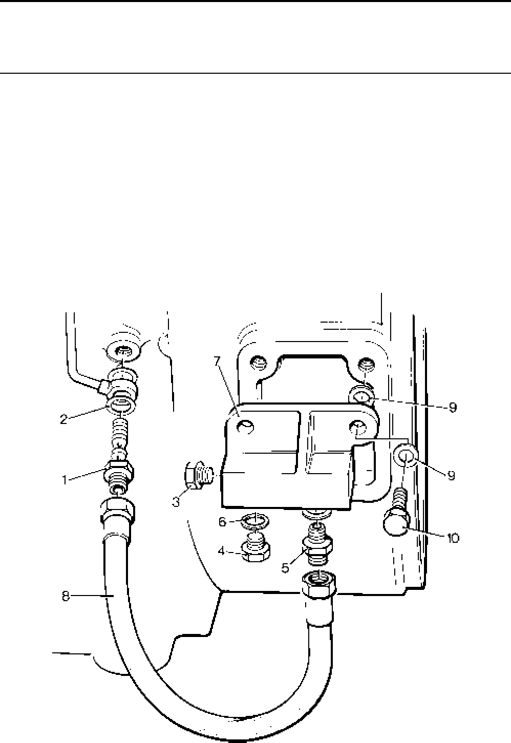
Lister-Petter TS/TR Master Parts ManualIssue 9: June 2000
114
Oil Distribution Block - Flexible Pipes
Illustration T150 TS/TR
No. Description Part Number 1 2 3 Remarks
Accessory Kit Code LG ...........................................570-17100 1 1 1
1 Swivel Union Plug....................................................366-07039 1 1 1
2 Copper Washer .......................................................616-01608 2 2 2
- Distribution Block Assembly ....................................366-07157 1 1 1
3 Plug ......................................................................366-07041 1 1 1
4 Plug ......................................................................008-03019 1 1 1
5 Union .................................................................... 291-21141 1 1 1
6 Copper Washer ....................................................600-00106 2 2 2
7 Distribution Block..................................................366-07129 1 1 1 Replaces 366-07151
8 Flexible Pipe .........................................................366-07518 1 1 1
9 Washer ....................................................................027-00184 4 4 4
10 Setscrew - M10 x 25mm..........................................272-00067 2 2 2
Illustration T150
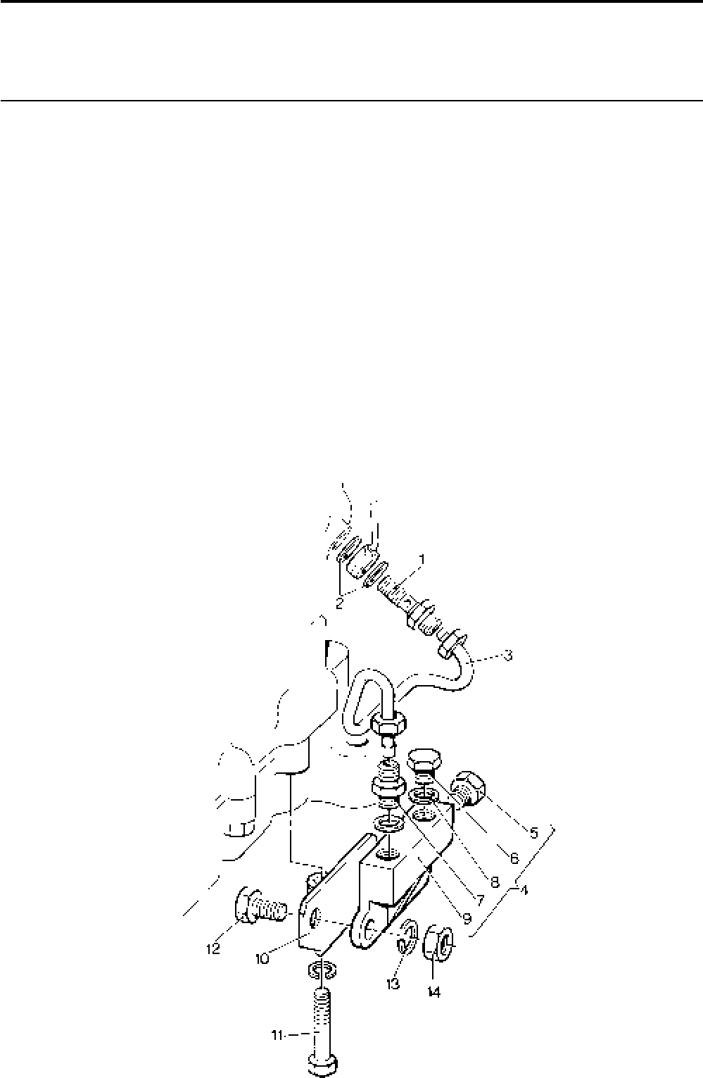
Lister-Petter TS/TR Master Parts Manual Issue 9: June 2000
115
Oil Distribution Block - Steel Pipes - TS/TR2,3
Illustration T178 TS/TR
No. Description Part Number 1 2 3 Remarks
Accessory Kit Code LF ............................................570-33090 - 1 1
1 Swivel Union Plug....................................................366-07039 - 1 1
2 Copper Washer .......................................................616-01608 - 2 2
3 Pipe Assembly......................................................... 366-07112 - 1 1
4 Oil Distribution Block Assembly ............................... 366-07114 - 1 1
5 Plug ......................................................................366-07041 - 1 1
6 Plug ......................................................................008-03019 - 1 1
7 Union .................................................................... 291-21141 - 1 1
8 Copper Washer ....................................................600-00106 - 2 2
9 Oil Distribution Block ............................................366-07129 - 1 1 Replaces 366-07151
10 Bracket Assembly.................................................... 366-07110 - 1 1
11 Bolt - M8 x 40mm ....................................................272-00043 - 1 1
12 Setscrew - M10 x 25mm ..........................................272-00067 - 2 2
13 Washer ....................................................................272-00072 - 2 2
14 Nut...........................................................................272-00018 - 2 2
Illustration T178

Lister-Petter TS/TR Master Parts ManualIssue 9: June 2000
116
Oil Distribution Block - TR2
Illustration T431 TS/TR
No. Description Part Number 1 2 3 Remarks
Accessory Kit Code JG............................................570-37360 - 1 -
1 Spring Washer.........................................................272-00072 - 2 -
2 Bolt - M10 x 40mm .................................................. 272-00116 - 2 -
3 Union .......................................................................366-07038 - 1 -
4 Swivel Union Plug....................................................366-07039 - 1 -
5 Plug .........................................................................366-07041 - 1 -
6 Flexible Pipe Assembly ...........................................366-07518 - 1 -
7 Spacer .....................................................................382-07208 - 2 -
8 Copper Washer .......................................................616-01608 - 2 -
9 Oil Distribution Block ...............................................757-12100 - 1 -
10 Oil Pressure Switch .................................................757-15420 - 1 -

Lister-Petter TS/TR Master Parts Manual Issue 9: June 2000
117
Illustration T431

Lister-Petter TS/TR Master Parts ManualIssue 9: June 2000
118
Temperature Switch
Illustration T80 TS/TR
No. Description Part Number 1 2 3 Remarks
Accessory Kit Code JA ............................................570-34200 1 1 1 Up to 1850 r/min, NC contacts
Accessory Kit Code JB ............................................570-32390 1 1 1 Above 1851 r/min, NC contacts
Accessory Kit Code JM ...........................................570-36820 1 1 1 Up to 1850 r/min, NO contacts
Accessory Kit Code JK ............................................570-42170 1 1 1 NC contacts
1 Head Switch - up to 1850r/min ................................382-08564 1 1 1 Set at 150°C break on rise
- Head Switch - above 1851r/min...............................202-36650 1 1 1 Set at 130°C break on rise
- Head Switch ............................................................382-09120 1 1 1 Set at 150°C make on rise
- Head Switch ............................................................366-07221 - 1 1 Set at 130°C make on rise
2 Push-on Connector ..........................................064-33068/001 2 2 2
3 Cover................................................................064-33991/001 2 2 2
Accessory Kit Code JC - TS/TR1 ............................570-33220 1 1 1 Kit comprising no's 4, 5, 10, 11
Accessory Kit Code JC - TS/TR2,3 .........................570-30540 1 1 1 Kit comprising no's 4-11
4 Air Temperature Switch ...........................................202-45310 1 1 1
5 Moulded Seal ..........................................................202-37580 1 1 1
6 Mounting Bracket ....................................................202-36670 1 1 1
7 Clamp ......................................................................382-08102 1 1 1
8 Setscrew - M6 x 12mm............................................272-00032 2 2 2
9 Spring Washer.........................................................272-00070 2 2 2
10 Push-on Connector .......................................... 064-33068/001 2 2 2
11 Cover................................................................ 064-33991/001 2 2 2
Note:
For wiring cable loom refer to "Cable Loom - Protective Switches" (Code WC).
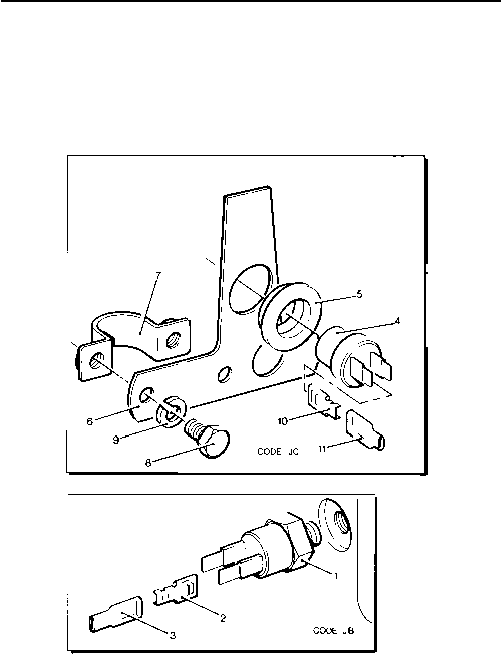
Lister-Petter TS/TR Master Parts Manual Issue 9: June 2000
119
Illustration T80

Lister-Petter TS/TR Master Parts ManualIssue 9: June 2000
120
Oil Pressure Switch
Illustration T294 TS/TR
No. Description Part Number 1 2 3 Remarks
Accessory Kit Code JD ............................................570-30512 1 1 1 Includes code LG
1 Swivel Union Plug....................................................366-07039 1 1 1
2 Copper Washer .......................................................616-01608 2 2 2
3 Flexible Pipe Assembly ...........................................366-07518 1 1 1
4 Oil Distribution Block Assembly ...............................366-07129 1 1 1 Replaces 366-07151
5 Washer ......................................................................... 785515 4 4 4
6 Setscrew - M10 x 25mm..........................................272-00067 2 2 2
7 Copper Washer .......................................................600-00106 2 2 2
8 Oil Pressure Switch .................................................757-15721 1 1 1 Replaces 757-15720 & 366-07040
9 Cover.......................................................................757-17390 1 1 1
10 Union ....................................................................... 291-21141 1 1 1
11 Setscrew .................................................................008-03019 1 1 1
12 Push Button .............................................................366-06378 1 1 1
13 Push-on Connector .................................................757-14150 2 2 2
14 Push-on Connector .......................................... 064-33380/001 2 2 2
15 Cover................................................................064-33991/001 2 2 2
16 Cable Link Assembly ...............................................366-06433 2 2 2
17 Cable Assembly ......................................................366-06934 1 1 1
18 Cable Assembly ......................................................366-06988 1 1 1
19 Relay .......................................................................382-07974 1 1 1
20 Cheese Head Screw.........................................064-06772/002 1 1 1
21 Spring Washer..................................................064-02582/002 1 1 1
22 Nut.................................................................... 064-06611/003 1 1 1
23 Cover.......................................................................757-14160 2 2 2
Note:
For wiring cable loom refer to "Cable Loom - Protective Switches" (Code WC).
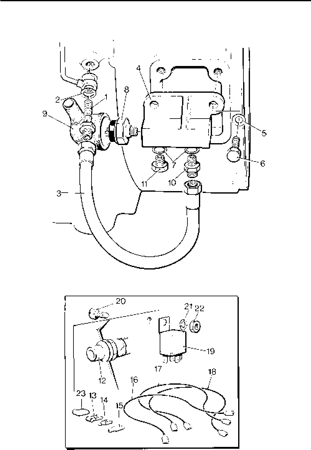
Lister-Petter TS/TR Master Parts Manual Issue 9: June 2000
121
Illustration T294

Lister-Petter TS/TR Master Parts ManualIssue 9: June 2000
122
Fuel Control Solenoid - TS/TR2, 3
Illustration T356 TS/TR
No. Description Part Number 1 2 3 Remarks
Accessory Kit Code JE ............................................570-31882 - 1 1
1 Solenoid - 12V .........................................................366-07197 - 1 1
- Solenoid - 24V .........................................................366-07198 - 1 1
2 Locking Nut .............................................................270-00002 - 1 1
3 Solenoid Link Assembly ..........................................366-07913 - 1 1
4 Bracket .................................................................... 366-07911 - 1 1
5 Setscrew .................................................................272-00033 - 2 2
6 Setscrew - M6 x 16mm............................................272-00034 - 2 2
7 Spring Washer.........................................................272-00070 - 4 4
8 Nut...........................................................................272-00002 - 2 2
9 Stopping Lever ........................................................366-07190 - 1 1
10 Cheese Head Screw - M4 x 12mm ..........................272-00062 - 2 2
11 Safety Spring Washer..............................................272-00084 - 2 2
12 Cable Assembly ......................................................366-06906 - 1 1
13 Connector.........................................................064-33068/002 - 1 1
14 Cover................................................................064-33991/002 - 1 1
15 Cable Assembly ......................................................366-07204 - 1 1
16 Cable Loom .............................................................366-07207 - 1 1
17 Nylon Washer ..........................................................366-08093 - 1 1
18 Circuit Breaker - 12V 6A ..........................................366-08092 - 1 1 See Note
- Label .......................................................................027-07893 - 1 1
- Label .......................................................................027-07894 - 1 1
Note:
Circuit breaker replaces 10A fuse 382-08043 and holder 382-08042
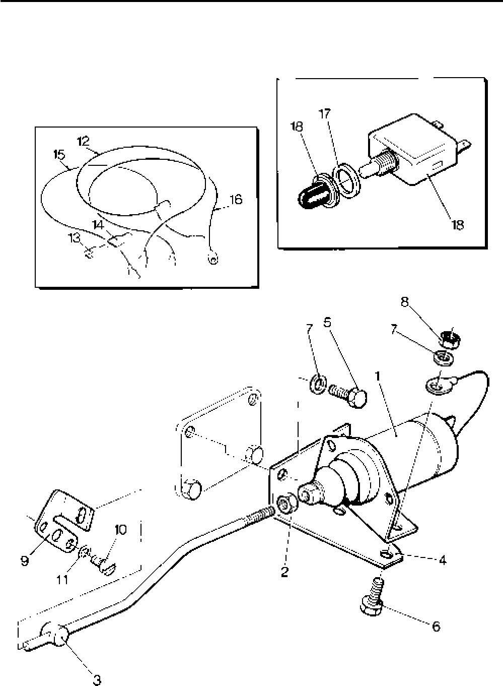
Lister-Petter TS/TR Master Parts Manual Issue 9: June 2000
123
Illustration T356

Lister-Petter TS/TR Master Parts ManualIssue 9: June 2000
124
Fuel Control Solenoid - TS/TR1 (Later Type)
Illustration T427 TS/TR
No. Description Part Number 1 2 3 Remarks
Accessory Kit Code JE ............................................570-32841 1 - -
1 Solenoid - 12V .........................................................366-07197 1 - -
- Solenoid - 24V .........................................................366-07198 1 - -
2 Nut...........................................................................270-00002 1 - -
3 Solenoid Link Assembly ..........................................366-07913 1 - -
4 Solenoid Support Bracket ........................................366-08255 1 - -
5 Solenoid Mounting Bracket......................................366-08256 1 - -
6 Capscrew - M6 x 12mm ........................................ 272--00167 1 - -
7 Lockwasher - 6mm ..................................................272-00086 1 - -
8 Setscrew - M10 x 20mm..........................................272-00241 1 - -
9 Spring Washer.........................................................272-00072 1 - -
- Washer ....................................................................027-00545 1 - -
10 Stopping Lever ........................................................366-07190 1 - -
11 Cheese Head Screw - M4 x 12mm..........................272-00062 2 - -
12 Safety Spring Washer..............................................272-00084 2 - -
13 Setscrew - M6 x 16mm............................................272-00034 2 - -
14 Spring Washer.........................................................272-00070 2 - -
15 Nut...........................................................................270-00002 2 - -
16 Cable Assembly ......................................................366-06906 1 - -
17 Connector.........................................................064-33068/002 1 - -
18 Cover................................................................064-33991/002 1 - -
19 Cable Assembly ......................................................366-07204 1 - -
20 Cable Loom .............................................................366-07207 1 - -
21 Nylon Washer ..........................................................366-08093 1 - -
22 Circuit Breaker - 12V 6A ..........................................366-08092 1 - -
- Label .......................................................................027-07893 1 - -
- Label .......................................................................027-07894 1 - -
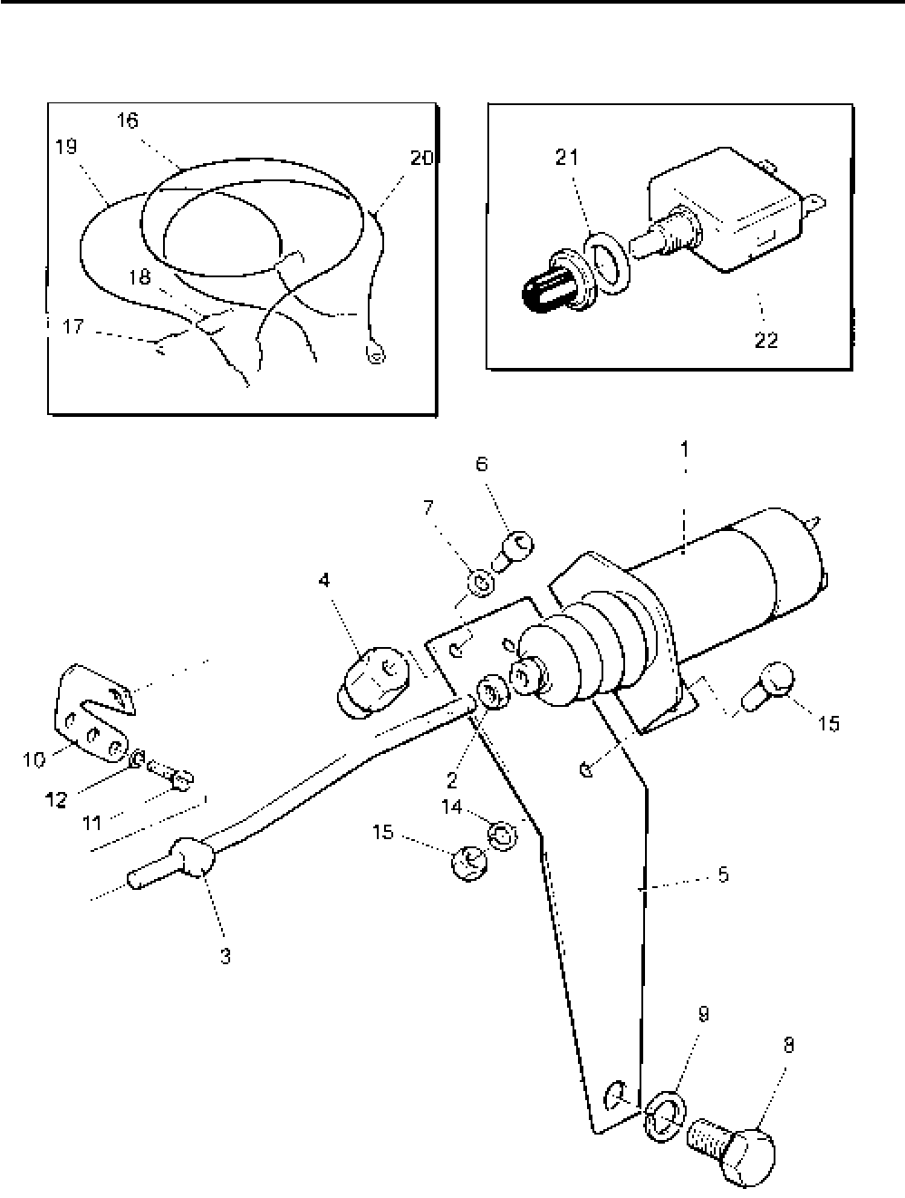
Lister-Petter TS/TR Master Parts Manual Issue 9: June 2000
125
Illustration T427
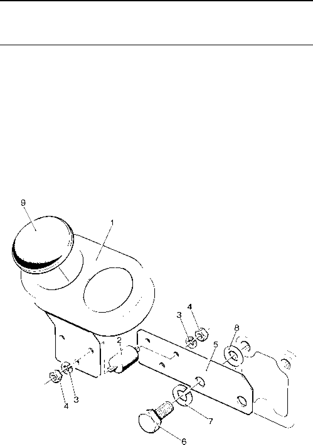
Lister-Petter TS/TR Master Parts ManualIssue 9: June 2000
126
Gauge Panel
Illustration T99 TS/TR
No. Description Part Number 1 2 3 Remarks
Accessory Kit Code PA............................................570-32421 1 1 1
1 Gauge Panel - less gauges .....................................382-07070 1 1 1
2 Flexible Mounting ....................................................064-07640 3 3 3
3 Spring Washer..................................................064-02582/002 6 6 6
4 Nut.................................................................... 064-06610/003 6 6 6
5 Mounting Bracket ....................................................366-07042 1 1 1
6 Setscrew - M10 x 25mm..........................................272-00067 2 2 2
7 Spring Washer.........................................................272-00072 2 2 2
- Spacer - TS/TR1 .....................................................396-18000 2 - -
8 Washer ....................................................................027-00184 2 2 2
9 Grommet .................................................................382-07342 1 1 1
Illustration T99
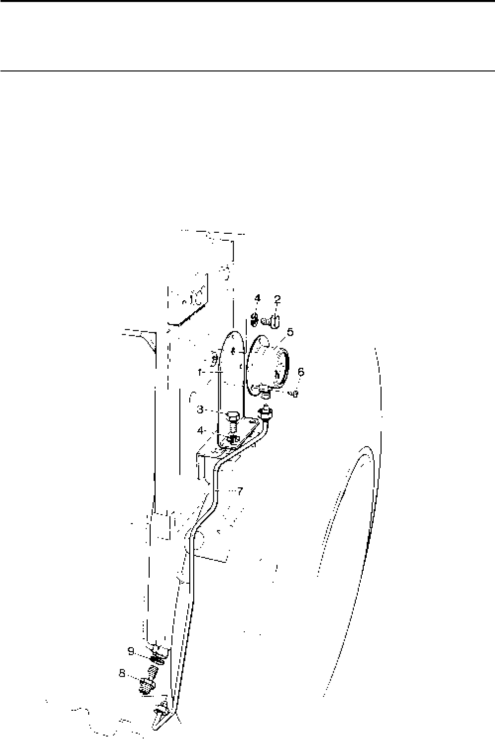
Lister-Petter TS/TR Master Parts Manual Issue 9: June 2000
127
Oil Pressure Gauge - TS/TR1
Illustration T229 TS/TR
No. Description Part Number 1 2 3 Remarks
1 Mounting Bracket .................................................... 201-41160 1 - -
2 Setscrew - M6 x 12mm............................................272-00032 1 - -
3 Setscrew - M6 x 16mm............................................272-00034 2 - -
4 Spring Washer.........................................................272-00070 3 - -
5 Oil Pressure Gauge .................................................351-15160 1 - -
6 Self-tapping Screw ..................................................291-37460 3 - -
7 Oil Pipe Assembly ................................................... 201-41190 1 - -
8 Swivel Union Plug....................................................366-07039 1 - -
9 Copper Washer .......................................................616-01608 1 - -
Illustration T229
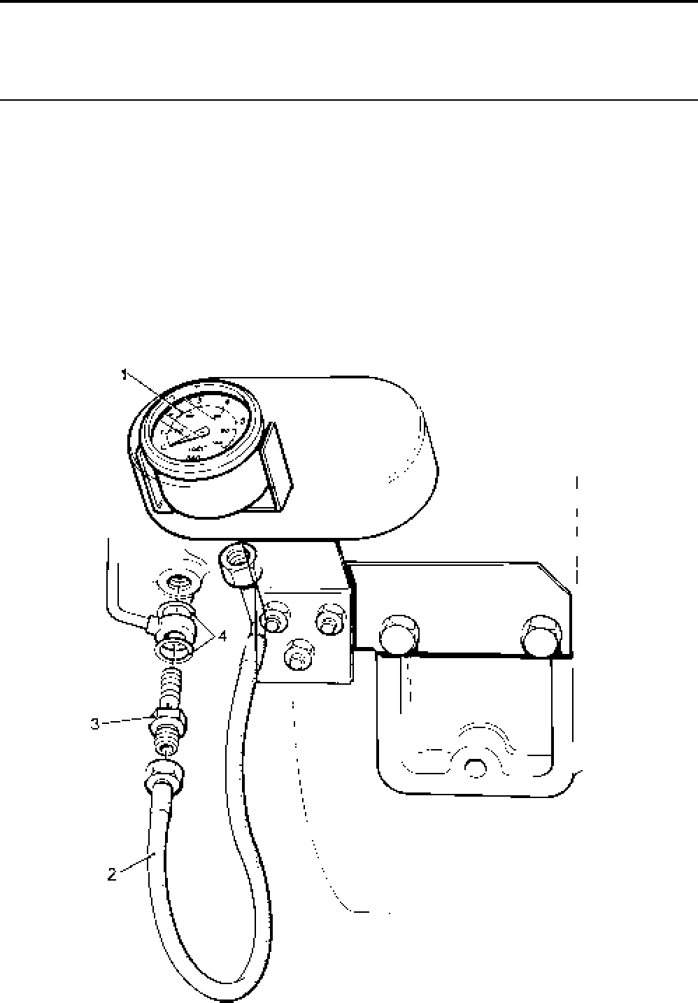
Lister-Petter TS/TR Master Parts ManualIssue 9: June 2000
128
Oil Pressure Gauge
Illustration T104 TS/TR
No. Description Part Number 1 2 3 Remarks
Accessory Kit Code PE ........................................... 570-32011 1 1 1
1 Oil Pressure Gauge .................................................370-12970 1 1 1
2 Flexible Pipe ............................................................366-07044 1 1 1
3 Swivel Union Plug....................................................366-07039 1 1 1
4 Copper Washer .......................................................616-01608 2 2 2
- Adaptor ....................................................................291-37920 1 1 1
Illustration T104
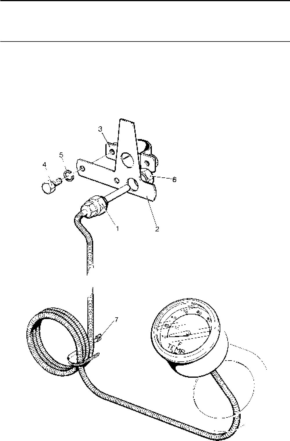
Lister-Petter TS/TR Master Parts Manual Issue 9: June 2000
129
Temperature Gauge
Illustration T109 TS/TR
No. Description Part Number 1 2 3 Remarks
Accessory Kit Code PF............................................570-32020 1 1 1
1 Temperature Gauge ................................................370-12991 1 1 1
2 Probe Mounting Bracket ..........................................202-36670 1 1 1
3 Clamp......................................................................382-08102 1 1 1
4 Setscrew - M6 x 12mm............................................272-00032 2 2 2
5 Spring Washer.........................................................272-00070 2 2 2
6 Locknut....................................................................027-00017 1 1 1
7 Cable Tie ..........................................................064-32790/001 4 4 4
Illustration T109
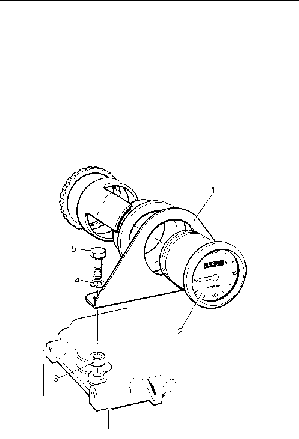
Lister-Petter TS/TR Master Parts ManualIssue 9: June 2000
130
Vibration Running Hour Recorder
Illustration T110 TS/TR
No. Description Part Number 1 2 3 Remarks
Accessory Kit Code PK ...........................................570-32030 1 1 1
1 Bracket ....................................................................202-36530 1 1 1
2 Vibration Hour Recorder ..........................................636-21651 1 1 1
3 Spacer .....................................................................351-22010 2 2 2
4 Spring Washer.........................................................272-00070 2 2 2
5 Bolt - M6 x 35mm ....................................................272-00191 2 2 2
Illustration T110

Lister-Petter TS/TR Master Parts Manual Issue 9: June 2000
131
Ammeter
Not Illustrated
Cannot be used with Nicsa charging system TS/TR
Description Part Number 1 2 3 Remarks
Ammeter.........................................................................291-37050 1 1 1
Terminal ...................................................................064-15649/007 2 2 2
Cable ..............................................................................366-07324 1 1 1
Electrical Running Hour Recorder
Not Illustrated TS/TR
Description Part Number 1 2 3 Remarks
Accessory Kit Code PG ..................................................570-30520 1 1 1
Electrical Running Hour Recorder ..................................757-14501 1 1 1 Replaces 367-14074
Cable ..............................................................................691-01355 1 1 1
Cable ..............................................................................366-06966 1 1 1
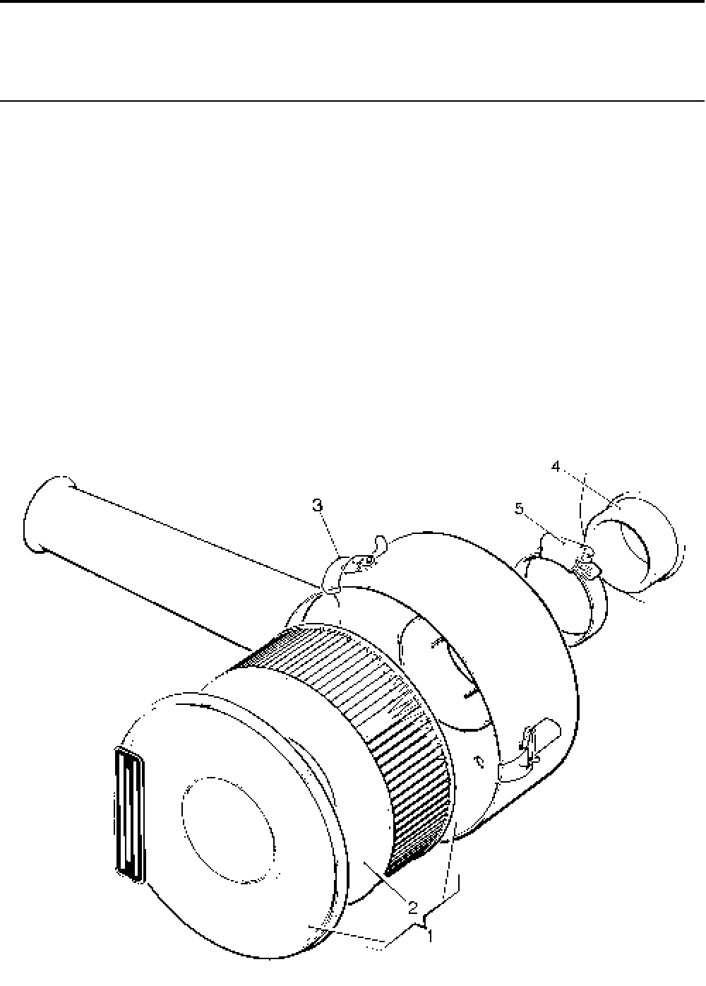
Lister-Petter TS/TR Master Parts ManualIssue 9: June 2000
132
Air Cleaner - Paper Element
Illustration T295 TS/TR
No. Description Part Number 1 2 3 Remarks
Accessory Kit Code AA - TS/TR1 ............................570-33740 1 - -
Accessory Kit Code AA - TS/TR2,3 .........................570-31381 - 1 1 TR3 up to 1800 r/min
Accessory Kit Code AO - TS/TR3............................570-36100 - - 1 TR3 above 1801 r/min
1 Air Cleaner - TS/TR1 ...............................................366-07028 1 - -
1 Air Cleaner - TS/TR2,3 ............................................366-07186 - 1 1 TR3 up to 1800r/min
- Air Cleaner - TR3 ....................................................366-07721 - - 1 TR3 above 1801r/min
2 Element ................................................................366-07188 1 1 1 TR3 up to 1800r/min
- Element ................................................................366-07723 - - 1 TR3 above 1801r/min
3 Clip ............................................................................ 365250 1 1 1
4 Sleeve .....................................................................366-08094 1 1 1 Not part of kit
5 Hose Clip .................................................................027-04234 1 1 1 Not part of kiT
Illustration T295
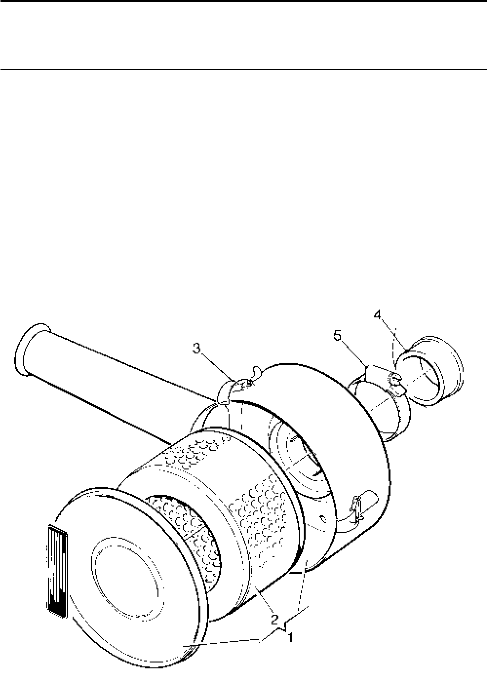
Lister-Petter TS/TR Master Parts Manual Issue 9: June 2000
133
Air Cleaner - Foam Element - TS/TR2,3
Illustration T184 TS/TR
No. Description Part Number 1 2 3 Remarks
Accessory Kit Code AB ...........................................570-31391 - 1 1
1 Air Cleaner - TS/TR2,3 ............................................366-07187 - 1 1
2 Element ................................................................366-07189 - 1 1
3 Clip ............................................................................ 365250 - 1 1
4 Sleeve .....................................................................366-08094 - 1 1 Not part of kit
5 Hose Clip .................................................................027-04234 - 1 1 Not part of kit
Illustration T184

Lister-Petter TS/TR Master Parts ManualIssue 9: June 2000
134
Heavy Duty Air Cleaner - TS/TR1
Replaced from 4200531TS1 by Cyclonic type
Illustration T337 TS/TR
No. Description Part Number 1 2 3 Remarks
1 Inlet Manifold ...........................................................201-37861 1
2 Joint.........................................................................201-33420 2 - - One each side of the air cowling
3 Stud - M6 x 30mm ...................................................272-00304 2 - -
- Spring Washer.........................................................272-00070 2 - -
- Nut...........................................................................272-00379 2 - -
4 Mounting Bracket ....................................................201-42800 1 - -
5 Steady Bracket ........................................................201-44680 1 - -
6 Bolt - M6 x 35mm ....................................................272-00191 2 - - For fuel filter fixing
7 Spacer .....................................................................202-33960 2 - -
8 Spring Washer.........................................................272-00070 2 - -
9 Setscrew - M6 x 16mm............................................272-00034 3 - -
10 Spring Washer.........................................................272-00070 3 - -
11 Setscrew - M8 x 25mm............................................272-00040 1 - -
12 Spring Washer.........................................................272-00071 1 - -
13 Mounting Band Assembly ........................................382-04373 2 - -
14 Setscrew - M8 x 20mm............................................272-00039 4 - -
15 Spring Washer.........................................................272-00071 4 - -
16 Nut...........................................................................272-00003 4 - -
17 Air Cleaner ..............................................................602-41740 1 - -
18 Element ................................................................602-41760 1 - -
19 Cover.......................................................................201-39000 1 - -
20 Tube ........................................................................201-42770 1 - -
21 Air Inlet Hose ...........................................................201-38990 2 - -
22 Hose Clip .................................................................027-04234 4 - -
23 Inlet Cap ..................................................................382-04372 1 - -
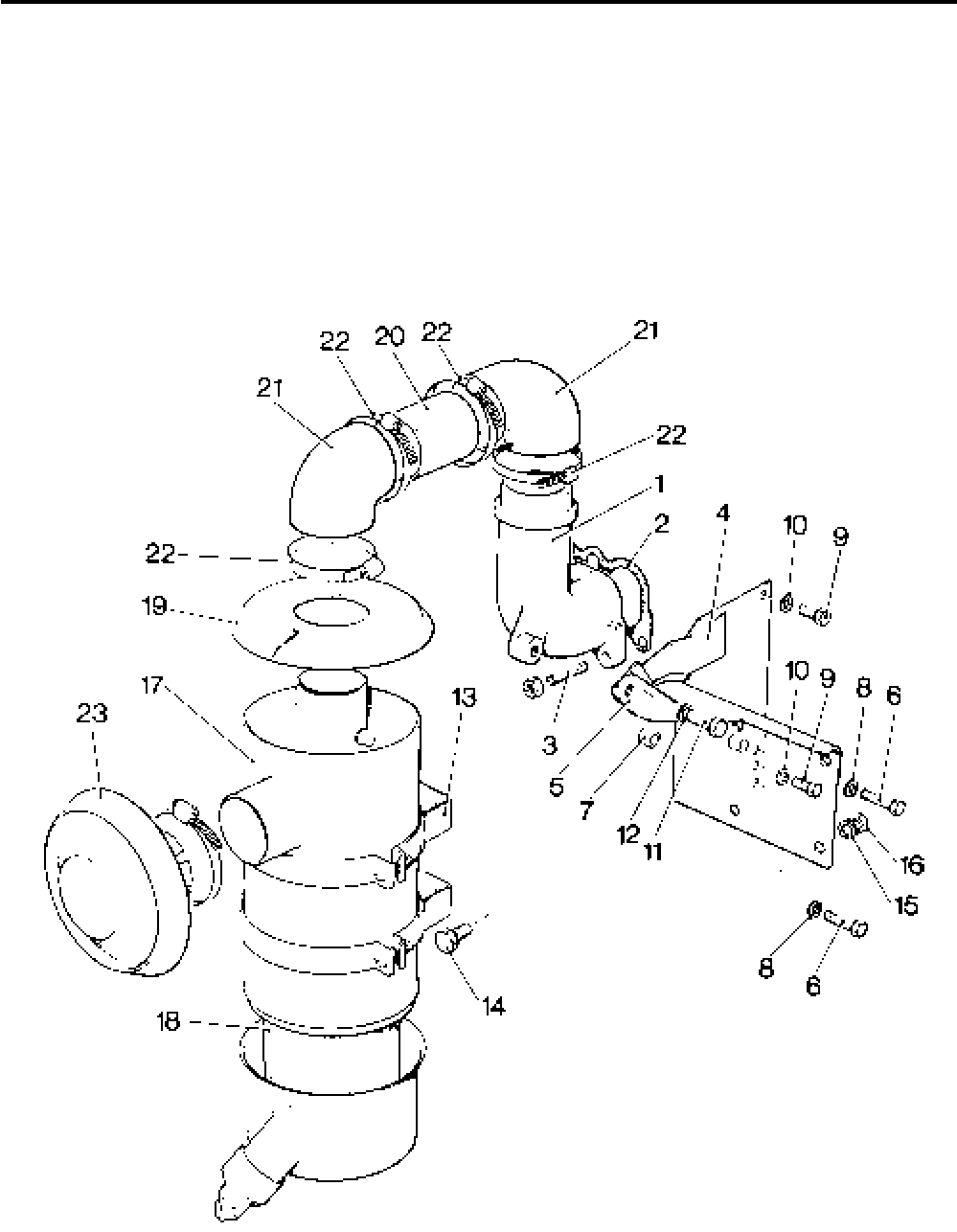
Lister-Petter TS/TR Master Parts Manual Issue 9: June 2000
135
Illustration T337

Lister-Petter TS/TR Master Parts ManualIssue 9: June 2000
136
Cyclonic Air Cleaner - TS/TR1
Front Mounted from 4200531TS1
Illustration T406 TS/TR
No. Description Part Number 1 2 3 Remarks
Accessory Kit Code AC ...........................................570-41580 1 - - Not for use with code FB
1 Inlet Manifold ...........................................................201-37861 1 - -
2 Joint.........................................................................201-33420 1 - -
3 Stud - M6 x 30mm ...................................................272-00304 1 - -
- Spring Washer.........................................................272-00070 1 - -
- Nut...........................................................................272-00379 1 - -
4 Mounting Bracket ....................................................366-08085 1 - -
5 Bolt - M6 x 30mm ....................................................272-00035 2 - - For fuel filter fixing
6 Spacer .....................................................................601-41700 2 - -
7 Spring Washer.........................................................272-00070 2 - -
8 Setscrew - M6 x 16mm............................................272-00034 3 - -
9 Spring Washer.........................................................272-00070 3 - -
10 Setscrew - M8 x 25mm............................................272-00040 1 - -
11 Spring Washer.........................................................272-00071 1 - -
12 Setscrew - M8 x 20mm............................................272-00039 2 - -
13 Spring Washer.........................................................272-00071 2 - -
14 Nut...........................................................................272-00003 2 - -
15 Air Cleaner Assembly ..............................................366-08107 1 - -
16 Main Element .......................................................366-08105 1 - -
17 Safety Element .....................................................366-08106 1 - -
18 Hose Clip .................................................................027-04234 4 - -
19 Tube ........................................................................201-42770 1 - -
20 Air Inlet Hose ...........................................................201-38990 2 - -
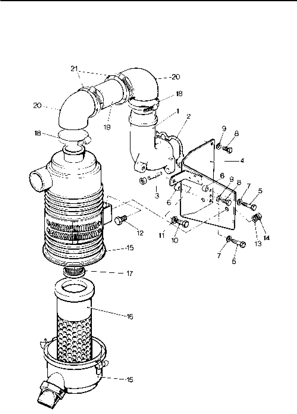
Lister-Petter TS/TR Master Parts Manual Issue 9: June 2000
137
Illustration T406

Lister-Petter TS/TR Master Parts ManualIssue 9: June 2000
138
Medium Duty Dry Type Air Cleaner - TS/TR1
Illustration T417 TS/TR
No. Description Part Number 1 2 3 Remarks
Accessory Kit Code AJ ............................................570-33750 1 - -
1 Air Cleaner - 8" ........................................................366-07028 1 - -
- Element ................................................................366-07188 1 - -
2 Vertical Air Inlet Manifold .........................................201-37861 1 - -
3 Stud - M6 x 30mm ...................................................272-00304 1 - -
4 Manifold Joint ..........................................................201-33420 1 - -
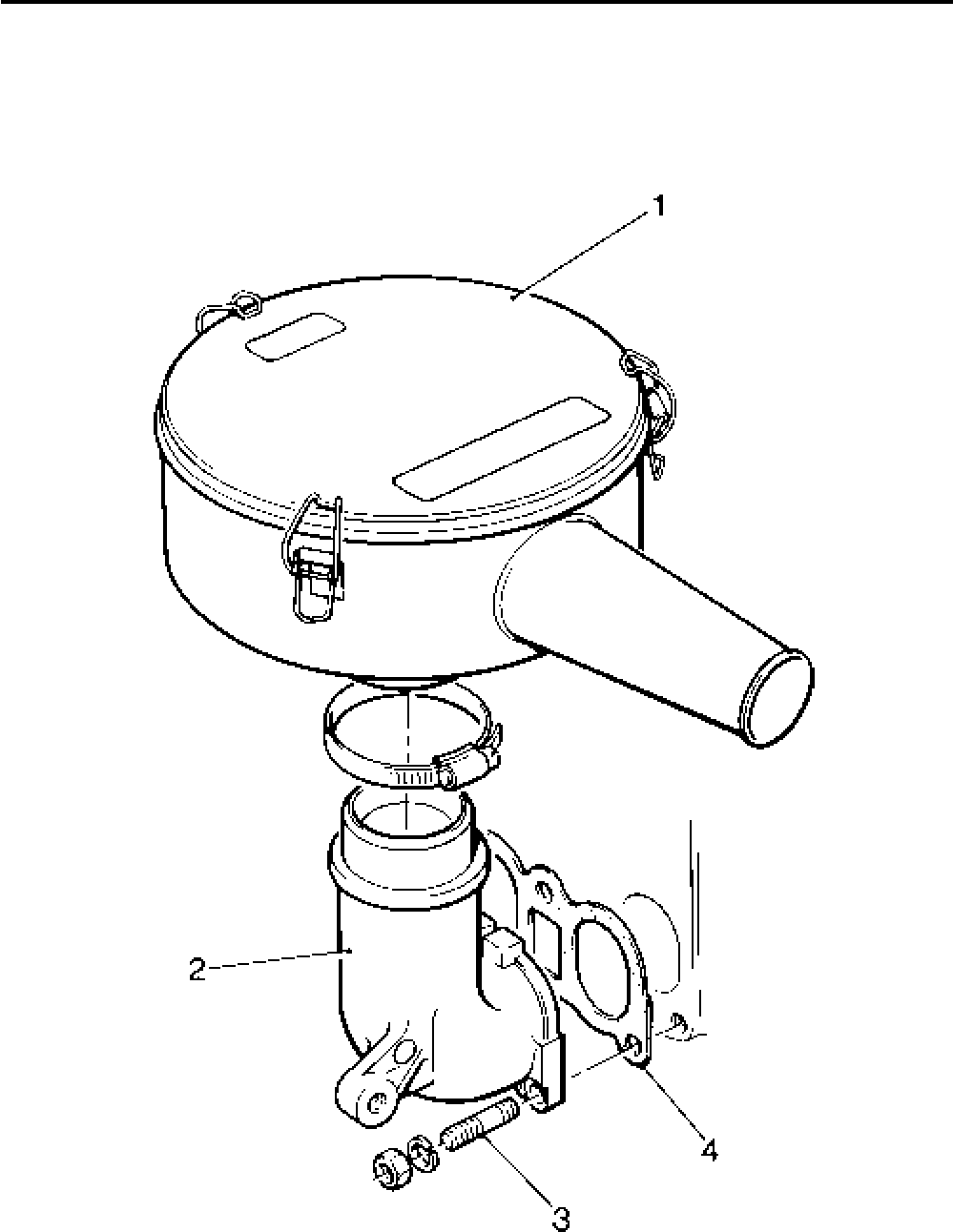
Lister-Petter TS/TR Master Parts Manual Issue 9: June 2000
139
Illustration T417

Lister-Petter TS/TR Master Parts ManualIssue 9: June 2000
140
61/2" Side Mounted Cyclonic Air Cleaner - TS/TR2,3
TR3 Engines up to 2500 r/min only
Illustration T235 TS/TR
No. Description Part Number 1 2 3 Remarks
- Air Cleaner Kit - 2 Cyl ..............................................570-34230 - 1 -
- Air Cleaner Kit - TS3................................................570-34250 - - 1
- Air Cleaner Kit - TR3 ...............................................570-41330 - - 1
1 Air Cleaner Assembly ..............................................366-07280 - 1 1
2 Element ................................................................366-07282 - 1 1
3 Mounting Band .....................................................382-04377 - 2 2
4 Manifold Adaptor .....................................................366-07202 - 1 1
5 Joint.........................................................................202-33231 - 1 1
- Mounting Plate - 2 Cyl .............................................366-07437 - 1 -
6 Mounting Plate - 3 Cyl .............................................366-07283 - - 1
7 Setscrew - M8 x 20mm............................................272-00039 - 2 2
8 Spring Washer.........................................................272-00071 - 2 2
9 Setscrew - M10 x 20mm..........................................272-00241 - 4 4
10 Spring Washer.........................................................272-00072 - 4 4
11 Nut - M10 ................................................................272-00004 - 4 4
- Hose - 2 Cyl.............................................................203-35580 - 1 -
12 Hose - 3 Cyl.............................................................366-05870 - - 1
13 Hose Clip .................................................................027-04234 - 2 2
14 Fanshroud - TS2-3/TR2 ..........................................366-07227 - 1 1 See Note
- Fanshroud - TR3 .....................................................366-08048 - - 1 See Note
15 Lock Washer ...........................................................201-30950 - 6 6
- Spring Washer - TR3...............................................272-00070 - - 3
Note:
Must be fitted to allow air cleaner mounting.
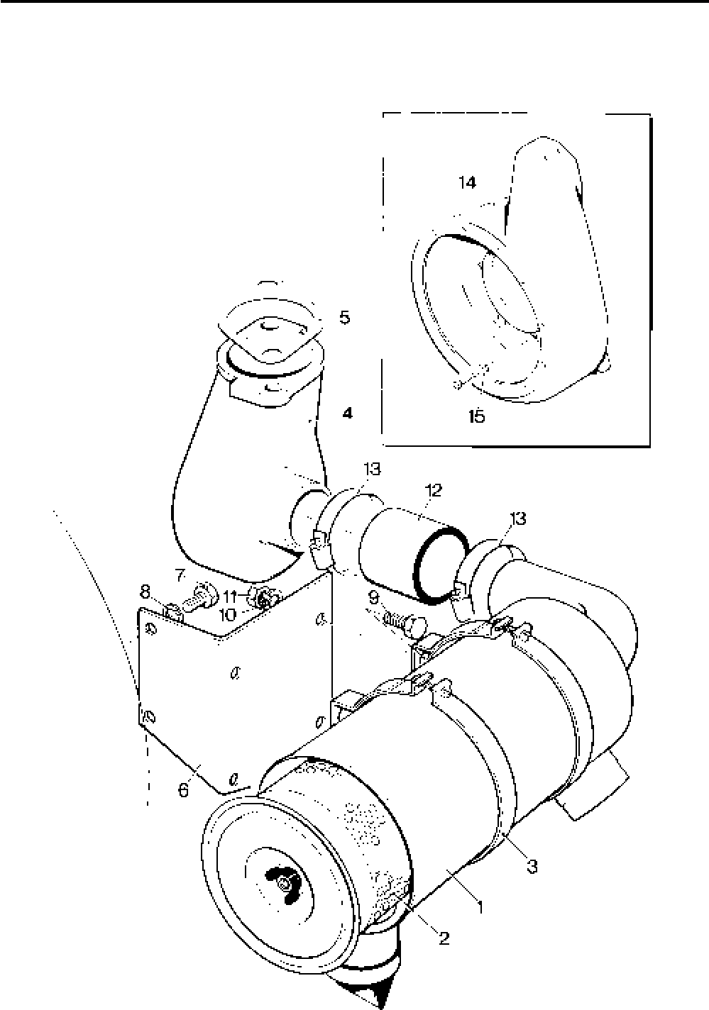
Lister-Petter TS/TR Master Parts Manual Issue 9: June 2000
141
Illustration T235

Lister-Petter TS/TR Master Parts ManualIssue 9: June 2000
142
7" Side Mounted Cyclonic Air Cleaner - TS/TR2,3
Illustration T394 TS/TR
No. Description Part Number 1 2 3 Remarks
Accessory Kit Code AD - TS/TR2 ............................570-35651 - 1 -
Accessory Kit Code AD - TS/TR3 ............................570-35652 - - 1
1 Air Cleaner Assembly ..............................................366-08108 - 1 1
2 Main Element .......................................................366-08109 - 1 1
3 Safety Element .....................................................366-08110 - 1 1
4 Hose Clip.................................................................027-04234 - 1 1
5 Sleeve .....................................................................366-08094 - 1 1
6 Mounting Bracket - TS/TR2 .....................................201-47330 - 1 - Replaces 366-08075, See Note
- Mounting Bracket - TS/TR3 .....................................201-47330 - - 1 Replaces 366-08103, See Note
7 Setscrew - M8 x 20mm............................................272-00039 - 4 4
8 Spring Washer.........................................................272-00071 - 4 4
9 Nut...........................................................................272-00003 - 2 2
10 Air Inlet Hose ...........................................................366-08098 - 1 1
11 Hose Clip.................................................................027-04696 - 1 1
12 Fanshroud ...............................................................366-07227 - 1 1 See Note
Note:
Latest kits only suitable for engines fitted with 13.5 litre tanks - mounted vertically
instead of horizontally. (Heatshield and special Fanshroud no longer needed).
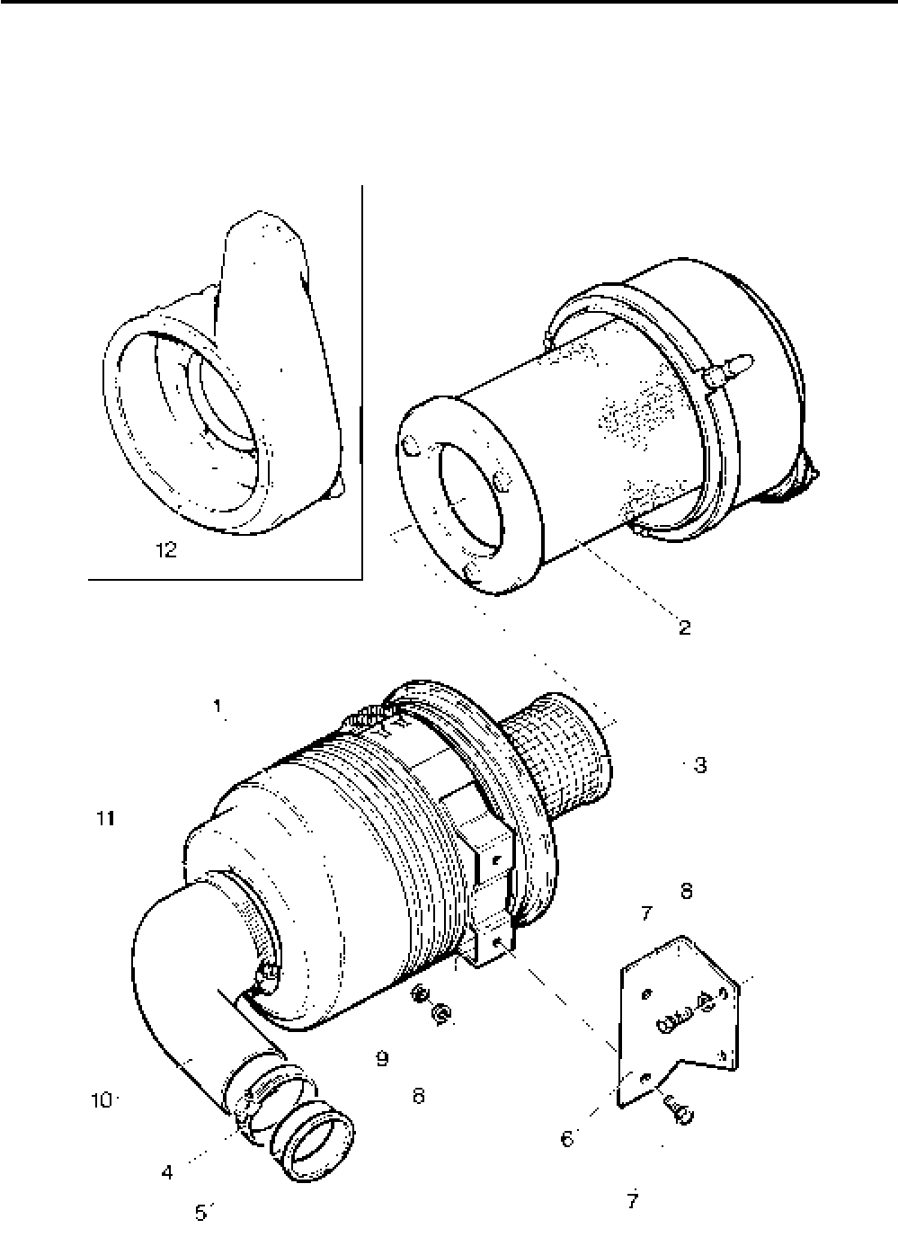
Lister-Petter TS/TR Master Parts Manual Issue 9: June 2000
143
Illustration T394

Lister-Petter TS/TR Master Parts ManualIssue 9: June 2000
144
61/2" Front Mounted Heavy Duty Cyclonic Air Cleaner - TS/TR2,3
Illustration T197 TS/TR
No. Description Part Number 1 2 3 Remarks
1 Air Cleaner ..............................................................366-07008 - 1 1 See Note
2 Element ................................................................202-33380 - 1 1
3 Joint.........................................................................202-33230 - 1 1
4 Stud - M8 x 35mm ...................................................272-00266 - 2 2
5 Spring Washer.........................................................272-00071 - 2 2
6 Nut...........................................................................272-00003 - 2 2
7 Pre-cleaner ..............................................................382-07900 - 1 1
8 Setscrew - M8 x 16mm............................................272-00038 - 1 1
9 Spring Washer.........................................................272-00071 - 1 1
Note:
Air cleaner no longer available.
To convert to current 7" cyclonic air cleaner (Code AE) use Conversion Kit SK2150/90
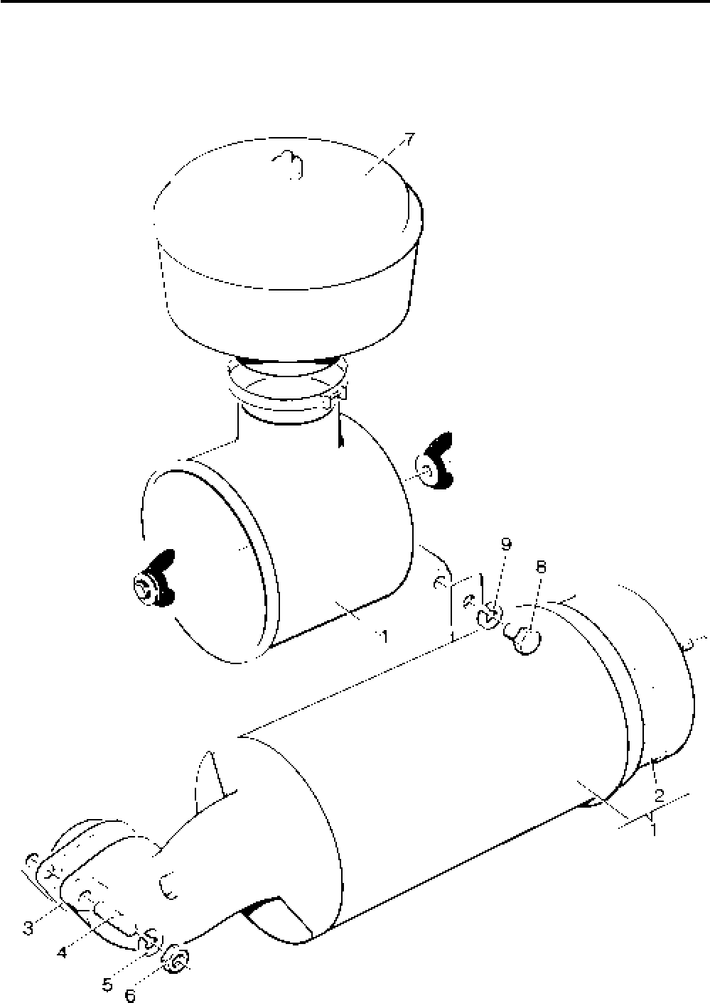
Lister-Petter TS/TR Master Parts Manual Issue 9: June 2000
145
Illustration T197

Lister-Petter TS/TR Master Parts ManualIssue 9: June 2000
146
7" Front Mounted Cyclonic Air Cleaner - TS/TR2,3
Illustration T397
First fitted on the following engines:
4103375TS2 4200321TR2
4103291TS3 4100643TR3 TS/TR
No. Description Part Number 1 2 3 Remarks
Accessory Kit Code AE - TS/TR2 ............................ 570-41611 - 1 -
Accessory Kit Code AE - TS/TR3 ............................570-41612 - - 1
1 Air Cleaner Assembly ..............................................366-08108 - 1 1
2 Main Element .......................................................366-08109 - 1 1
3 Safety Element .....................................................366-08110 - 1 1
4 Hose Clip.................................................................027-04696 - 1 1
5 Mounting Plate ........................................................366-08101 - 1 1
6 Spacer .....................................................................027-07804 - 3 3
7 Bolt - M6 x 30mm ....................................................272-00035 - 2 2
8 Washer ....................................................................027-00618 - 8 8
9 Air Inlet Manifold - TS/TR2 ......................................202-31004 - 1 -
- Air Inlet Manifold - TS/TR3 ......................................203-31005 - - 1
10 Air Inlet Hose ...........................................................366-08099 - 1 1
11 Hose Clip.................................................................027-04234 - 1 1
12 Setscrew - M8 x 20mm............................................272-00039 - 2 2
13 Spring Washer.........................................................272-00071 - 2 2
14 Nut...........................................................................272-00003 - 2 2
15 Bracket ....................................................................201-38071 - 1 1
16 Spring Washer.........................................................272-00070 - 1 1
17 Nut...........................................................................272-00002 - 1 1
18 Bolt - M6 x 35mm ....................................................272-00191 - 1 1
19 Washer ....................................................................027-00082 - 1 1
20 Bolt - M8 x 80mm ....................................................272-00128 - 1 1
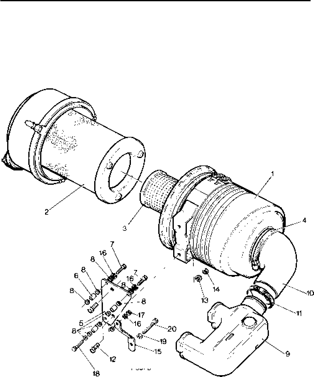
Lister-Petter TS/TR Master Parts Manual Issue 9: June 2000
147
Illustration T397

Lister-Petter TS/TR Master Parts ManualIssue 9: June 2000
148
7" Front Remote Mounted Cyclonic Air Cleaner - TS/TR2,3
Illustration T398 TS/TR
No. Description Part Number 1 2 3 Remarks
Accessory Kit Code AG - TS/TR2,3.........................570-41670 - 1 1
1 Air Cleaner Assembly ..............................................366-08108 - 1 1 See Note:
2 Main Element .......................................................366-08109 - 1 1
3 Safety Element .....................................................366-08110 - 1 1
4 Sleeve .....................................................................366-08094 - 1 1
5 Air Inlet Hose ...........................................................366-08098 - 1 1
6 Hose Clip.................................................................027-04234 - 3 3
7 Spigot ......................................................................366-07657 - 1 1
8 Air Hose ..................................................................366-06986 - 1 1
9 Hose Clip.................................................................027-04696 - 1 1
- Setscrew - M8 x 20mm............................................272-00039 - 2 2
- Nut...........................................................................272-00003 - 2 2
- Spring Washer.........................................................272-00071 - 2 2
Note:
Replaces 366-07280 (TR3 up to 2500r/min)
and 382-04369 (TR3 above 2500r/min)
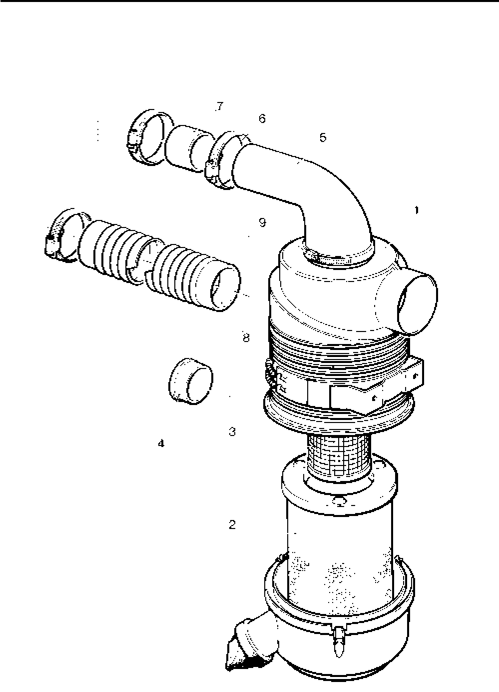
Lister-Petter TS/TR Master Parts Manual Issue 9: June 2000
149
Illustration T398
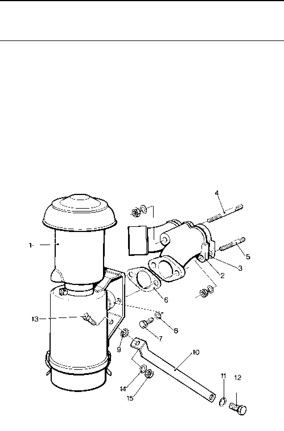
Lister-Petter TS/TR Master Parts ManualIssue 9: June 2000
150
Heavy Duty Oil Bath Air Cleaner - TS/TR1
Illustration T400 TS/TR
No. Description Part Number 1 2 3 Remarks
Accessory Kit Code AN ...........................................570-33880 1 - -
1 Oil Bath Air Cleaner .................................................201-42700 1 - -
2 Inlet/Exhaust Manifold .............................................201-42670 1 - -
3 Joint.........................................................................201-33420 1 - -
4 Stud - M8 x 90mm ...................................................272-00602 1 - -
5 Stud - M6 x 30mm ...................................................272-00304 1 - -
6 Joint.........................................................................201-42680 2 - - One each side of air cowling
7 Setscrew - M8 x 20mm............................................272-00039 2 - -
8 Spring Washer.........................................................272-00071 2 - -
9 Washer ....................................................................204-53470 1 - -
10 Air Cleaner Stay ......................................................201-42690 1 - -
11 Spring Washer.........................................................027-00984 1 - -
12 Setscrew - 7/16“UNC x 7/8” ....................................... 270-00350 1 - -
13 Setscrew - M6 x 16mm............................................272-00034 1 - -
14 Spring Washer.........................................................272-00070 1 - -
15 Nut...........................................................................272-00002 1 - -
Illustration T400
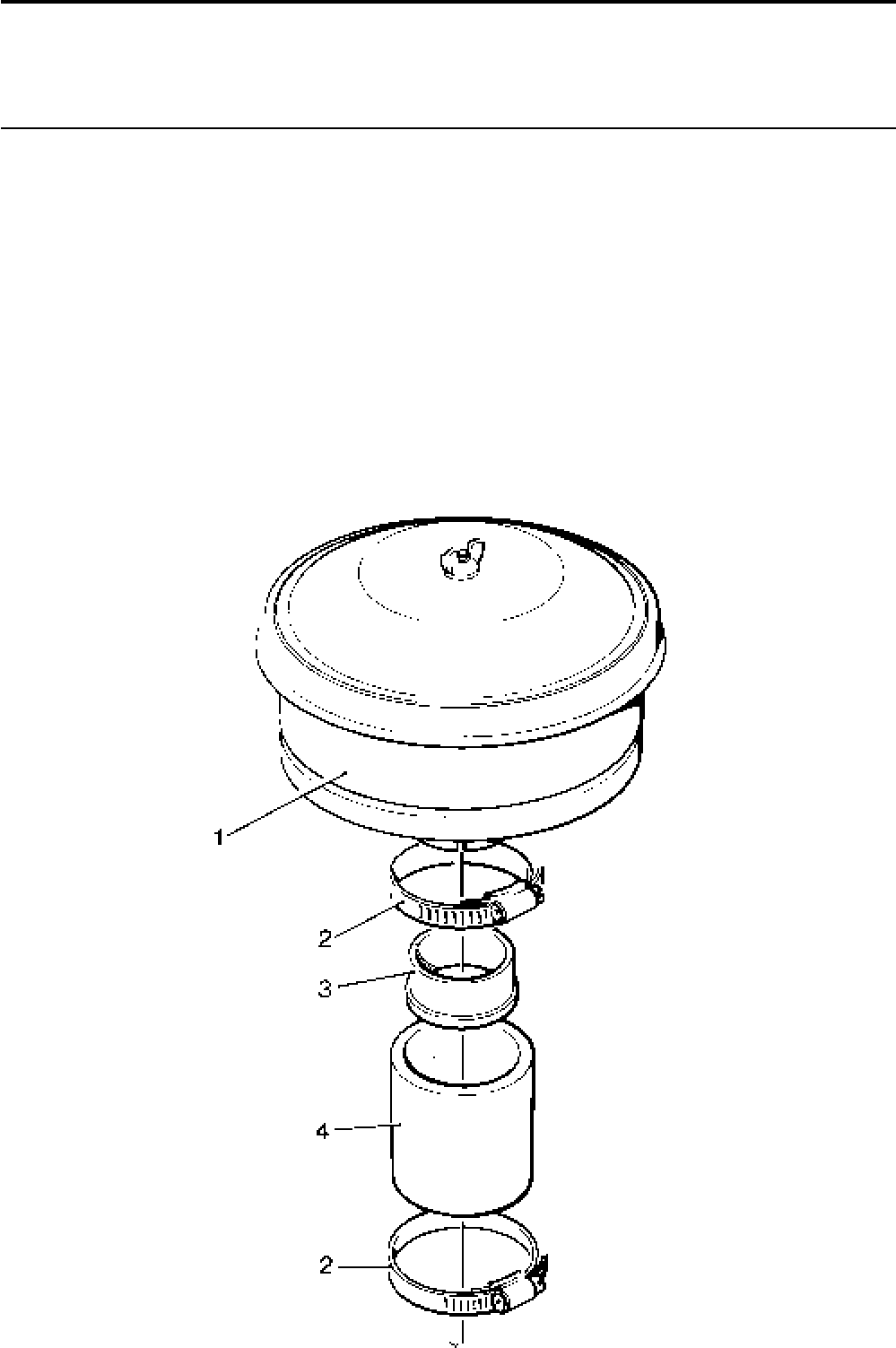
Lister-Petter TS/TR Master Parts Manual Issue 9: June 2000
151
Medium Duty Oil Bath Air Cleaner
Illustration T162 TS/TR
No. Description Part Number 1 2 3 Remarks
Accessory Kit Code AK - TS/TR1 ............................570-32770 1 - - Use with code AS
Accessory Kit Code AR - TS/TR2 ............................570-36901 - 1 -
Accessory Kit Code AR - TS/TR3 ............................570-36902 - - 1 TR3 up to 2000 r/min
1 Oil Bath Air Cleaner ................................................. 203-11422 1 1 1
2 Hose Clip.................................................................027-04234 2 2 2
3 Bush ........................................................................201-55530 1 1 1
4 Sleeve .....................................................................201-54980 1 1 1
Note:
On the TS/TR2 Accessory Kit Code AR also includes:
Air Inlet Manifold (202-45880) and Manifold Joint (201-33420)
On the TS/TR3 Accessory Kit Code AR also includes:
Air Inlet Manifold (203-45880) and Manifold Joint (201-33420)
Illustration T162

Lister-Petter TS/TR Master Parts ManualIssue 9: June 2000
152
Power Take-Off
8" Newage SAE5
Illustration T120 TS/TR
No. Description Part Number 1 2 3 Remarks
1 Clutch Drive Member...............................................202-35210 - 1 1
2 Bolt - M12 x 80 ........................................................272-00368 - 3 3
3 Spring Washer.........................................................272-00073 - 3 3
4 Bolt - M8 x 30 ..........................................................272-00041 - 4 4
5 Spring Washer.........................................................272-00071 - 4 4
6 Dowel ......................................................................351-13660 - 1 1
7 SAE4 - SAE5 Adaptor .............................................202-35200 - 1 1
8 Adaptor Guard .........................................................202-34972 - 1 1
9 Clamping Bracket ....................................................601-38441 - 2 2
10 Bolt - M6 x 50mm ....................................................272-00180 - 2 2
11 Washer ....................................................................027-00618 - 2 2
12 Self-locking Nut .......................................................272-00024 - 2 2
13 Bolt - 3/8”UNC x 23/4” ............................................... 270-00780 - 12 12
14 Spring Washer.........................................................027-00393 - 12 12
15 Washer ....................................................................027-00184 - 12 12
16 Setscrew - 3/8”UNC x 11/8" ........................................270-00485 - 8 8
17 Spring Washer.........................................................027-00393 - 8 8
18 Power Take-off Assembly ........................................366-06978 - 1 1
19 Clutch Drive Plate ....................................................366-06984 - 1 1
20 Friction Plate ...........................................................661-10720 - 1 1
21 Pressure Plate .........................................................366-06983 - 1 1
22 Setscrew - 5/16“UNF x 3/4" ........................................ 270-00060 - 6 6
23 Spring Washer.........................................................027-00413 - 6 6
24 Bearing Release ......................................................366-06980 - 1 1
25 Bearing Retainer......................................................366-07000 - 1 1
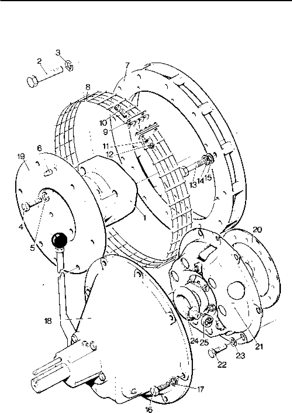
Lister-Petter TS/TR Master Parts Manual Issue 9: June 2000
153
Illustration T120

Lister-Petter TS/TR Master Parts ManualIssue 9: June 2000
154
Overcentre Clutch
Illustration T422 TS/TR
No. Description Part Number 1 2 3 Remarks
Accessory Kit Code BE ...........................................570-31480 1 1 1
17
1/2" Overcentre Clutch ............................................202-35630 1 1 1
2 Bolt - 3/8"UNC x 3 1/4" ....................................................755060 12 12 12 Replaces 270-00373
3 Spring Washer.........................................................027-00393 12 12 12
4 Setscrew - 5/16"UNC x 1" ..........................................270-00263 8 8 8
5 Spring Washer.........................................................272-00071 8 8 8
6 Bearing ....................................................................366-06997 1 1 1
7 Guard ......................................................................202-34972 1 1 1
8 Clamping Bracket ....................................................601-38441 2 2 2
9 Bolt - M6 x 50mm ....................................................272-00180 2 2 2
10 Washer ....................................................................027-00618 2 2 2
11 Self Locking Nut ......................................................272-00372 2 2 2
12 SAE4 Adaptor ..........................................................202-31852 1 1 1
13 Drive Member ..........................................................202-34980 1 1 1 See Note
14 Bolt - M12 x 80mm ..................................................272-00368 3 3 3
15 Spring Washer.........................................................272-00073 3 3 3
16 Clutch Friction Disc .................................................660-13940 1 1 1
17 Case Bearing...........................................................660-14010 1 1 1
Note:
Drive member Accessory Kit available under code CL (570-31650)
consisting of no's 4, 5, 6, 13, 14, 15
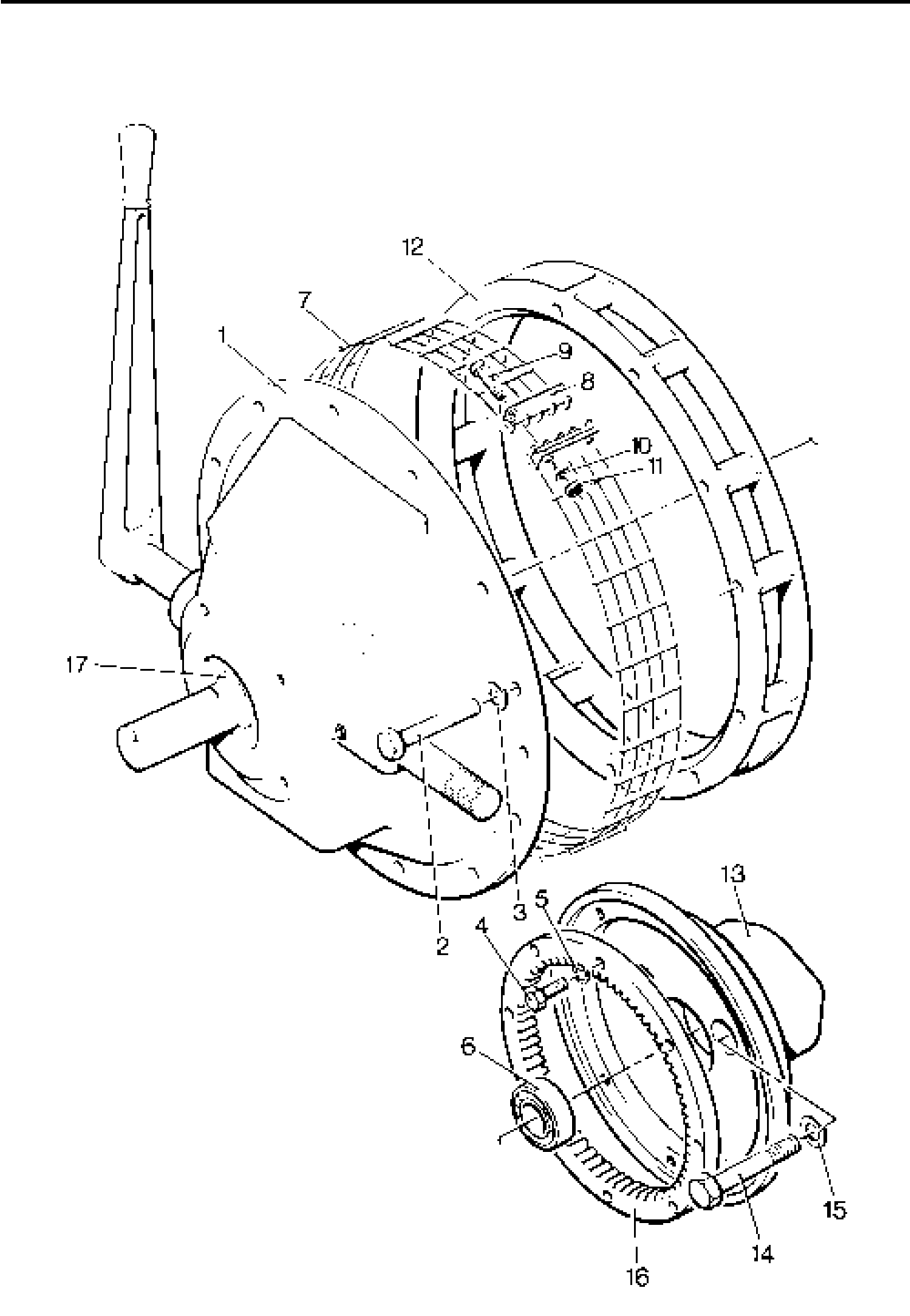
Lister-Petter TS/TR Master Parts Manual Issue 9: June 2000
155
Illustration T422
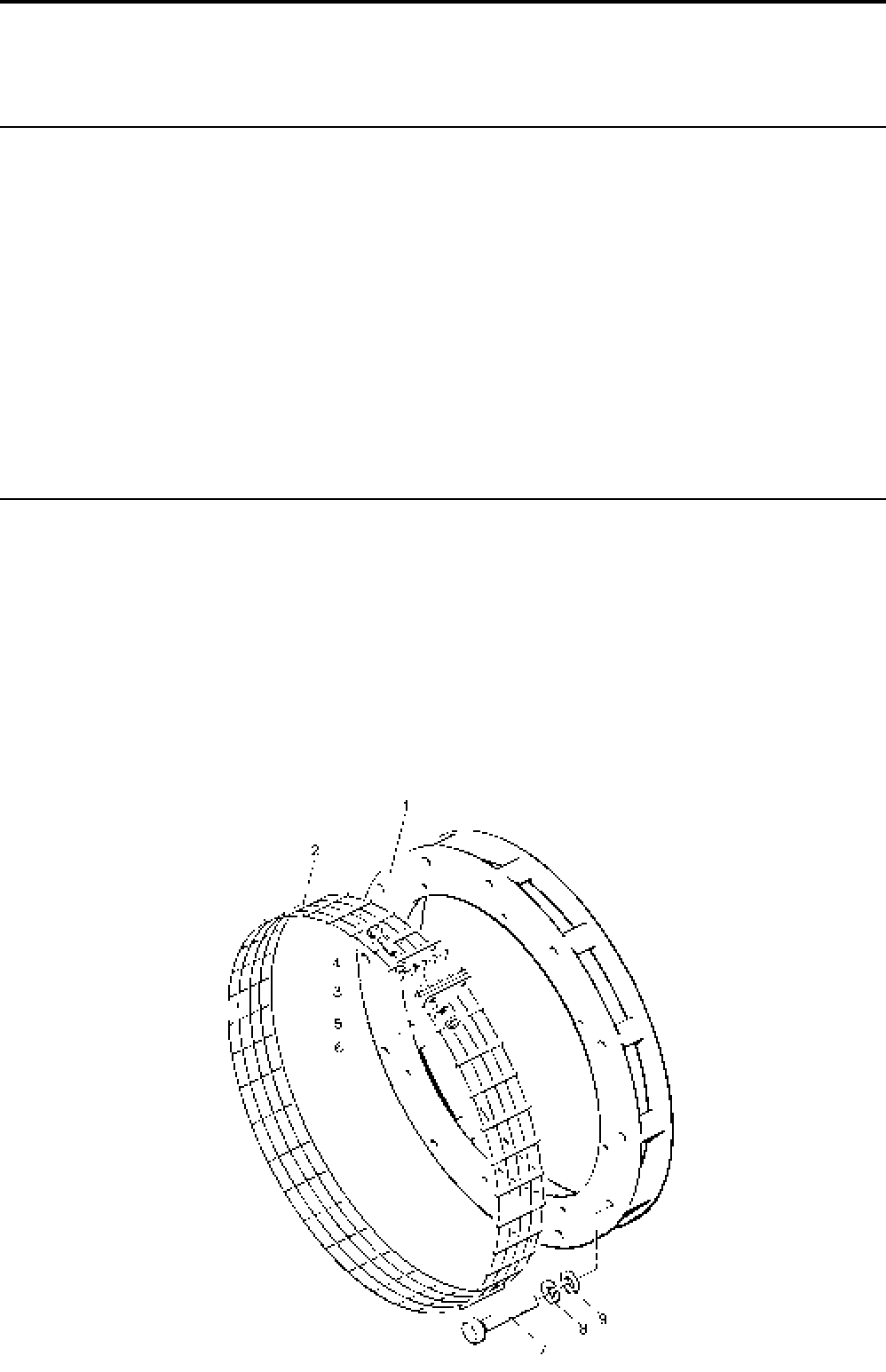
Lister-Petter TS/TR Master Parts ManualIssue 9: June 2000
156
Flat Belt Pulley - TS/TR1 and TS3
Not Illustrated TS/TR
Description Part Number 1 2 3 Remarks
Accessory Kit Code BN - TS/TR1 ...................................570-32950 1 - -
Pulley..............................................................................201-41730 1 - -
Bolt - M12 x 50mm .........................................................272-00254 3 - -
Spring Washer................................................................272-00073 3 - -
Accessory Kit Code BF - TS3 .........................................570-37460 - - 1
Pulley..............................................................................201-47510 - - 1
Flat Belt - 100mm x 6m ..................................................201-47520 - - 1
Key ................................................................................201-47530 - - 1
SAE Adaptor and Guard
Illustration T55 TS/TR
No. Description Part Number 1 2 3 Remarks
Accessory Kit Code CA ...........................................570-31590 1 1 1 For Adaptor SAE4/5
Accessory Kit Code CB ...........................................570-31600 1 1 1 For Adaptor SAE4
1 Adaptor SAE4/5.......................................................202-35200 1 1 1 51mm wide
- Adaptor SAE4..........................................................202-31852 1 1 1 51mm wide
2 Guard ......................................................................202-34972 1 1 1 Replaces 202-34970
3 Clamping Bracket ....................................................601-38441 2 2 2 Required with 202-34970
4 Bolt - M6 x 50mm ....................................................272-00180 2 2 2
5 Washer ....................................................................027-00618 2 2 2
6 Self-locking Nut .......................................................272-00372 2 2 2
7 Bolt - 3/8”UNC x 23/4” ................................................270-00780 12 12 12
8 Spring Washer.........................................................270-00393 12 12 12
9 Washer ....................................................................027-00184 12 12 12
Illustration T55
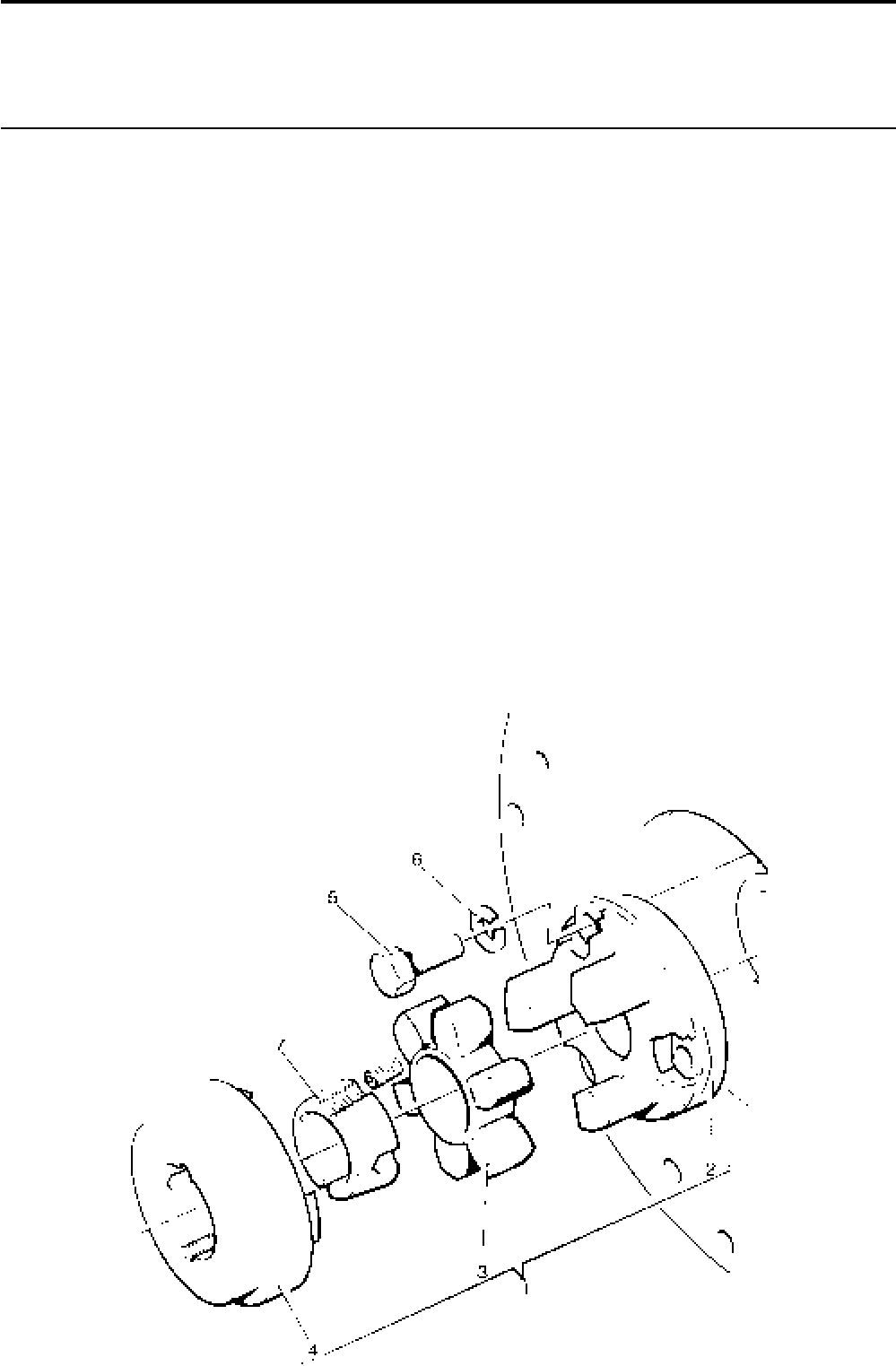
Lister-Petter TS/TR Master Parts Manual Issue 9: June 2000
157
Fenner Coupling
Illustration T200 TS/TR
No. Description Part Number 1 2 3 Remarks
Accessory Kit Code BO ...........................................570-31520 1 1 1 Comprising no's 1(a) & 2-6
Accessory Kit Code BQ ...........................................570-31540 1 1 1 For 35mm shaft
Comprising no's 1(a), 2-6 & 7(b)
Accessory Kit Code BL ............................................601-53920 1 1 1 For 35mm shaft
Comprising no's 1(c), 2-6
Accessory Kit Code BR ...........................................570-31550 1 1 1 For 38mm shaft
Comprising no's 1(a), 2-6 & 7(c)
Accessory Kit Code BS ...........................................570-31560 1 1 1 For 42mm shaft
Comprising no's 1(a), 2-6 & 7(d)
Accessory Kit Code BX ...........................................570-31521 1 1 1 Comprising no's 1(b) & 2-6
1 (a) Coupling Assembly ............................................202-35300 1 1 1 With taper lock
- (b) Coupling Assembly ............................................202-46160 1 1 1 ’B’ flange 110mm
- (c) Coupling Assembly.............................................601-53940 1 1 1 Solid Boss
2 Flywheel Coupling Flange................................202-35310 1 1 1
3 Element ...........................................................202-35320 1 1 1 Standard element. Included in
Coupling Assemblies (a) & (c)
- Element ...........................................................601-42090 1 1 1 Harder element. Included in
Coupling Assembly (b)
4 Flange .............................................................202-35330 1 1 1 Included in Coupling Assemblies
(a) & (b)
- ‘B’ Flange - Pilot bored ....................................601-42100 1 1 1 Included in Coupling Assembly (c)
5 Setscrew - M12 x 35mm..........................................272-00240 3 3 3
6 Spring Washer.........................................................272-00073 3 3 3
7 (a) Taper Lock Bush - 32mm ...................................202-35340 1 1 1
- (b) Taper Lock Bush - 35mm ...................................202-35341 1 1 1
- (c) Taper Lock Bush - 38mm ...................................202-35344 1 1 1
- (d) Taper Lock Bush - 42mm ...................................202-35343 1 1 1
Illustration T200
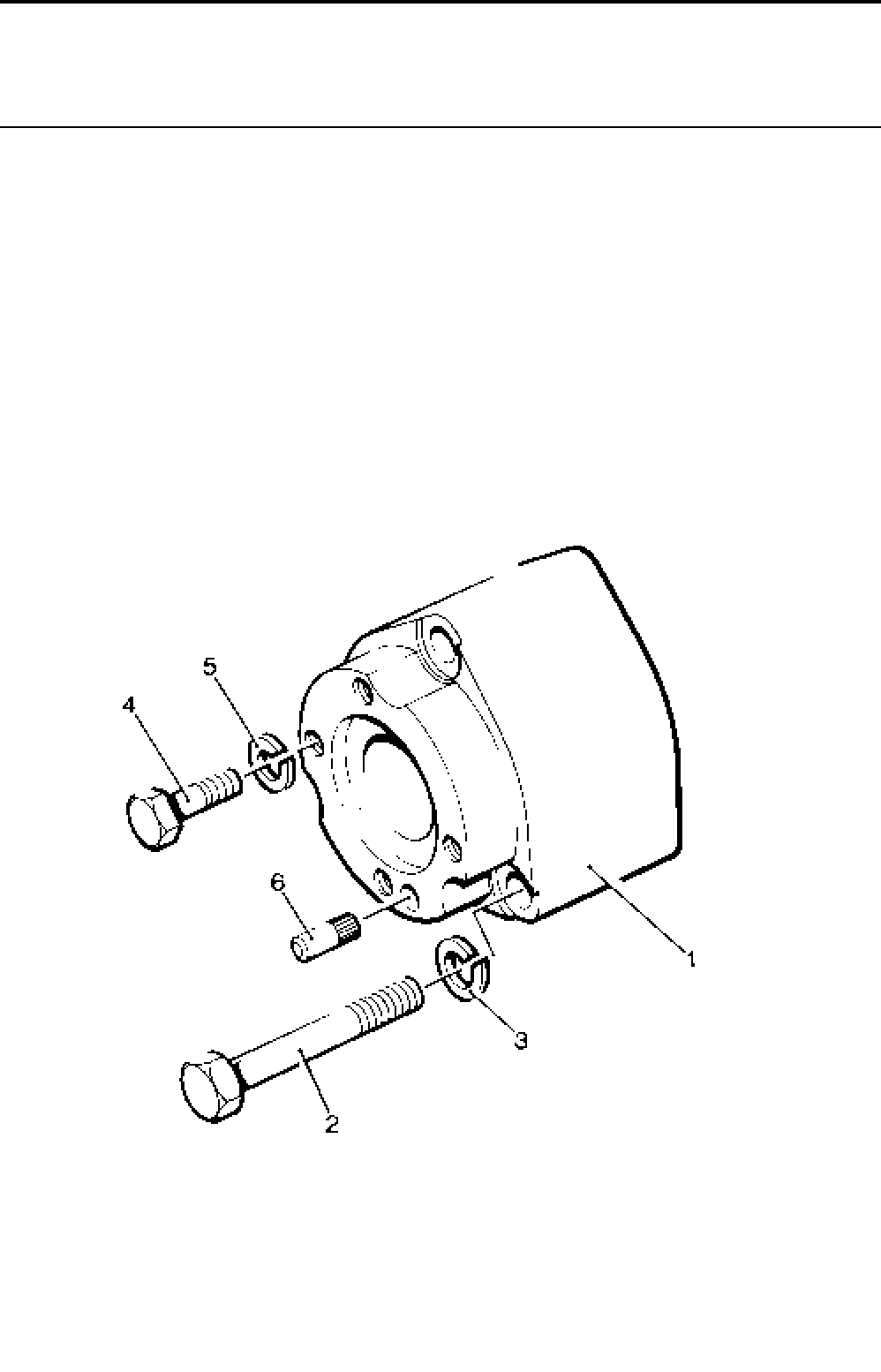
Lister-Petter TS/TR Master Parts ManualIssue 9: June 2000
158
Automotive Clutch Drive Member
Illustration T59 TS/TR
No. Description Part Number 1 2 3 Remarks
Accessory Kit Code CH ...........................................570-31630 1 1 1 For 8" Drive Member
Use with adaptor code CA or CB
Accessory Kit Code CI.............................................570-31640 1 1 1 For 9" Drive Member
Use with adaptor code CA or CB
1 Drive Member - 8" .................................................. 202-35210 - 1 1
- Drive Member - 9" .................................................. 202-35211 1 1 1
2 Bolt - M12 x 80mm ..................................................272-00368 3 3 3
3 Spring Washer.........................................................272-00073 3 3 3
4 Bolt - M8 x 30mm ....................................................272-00041 4 4 4
5 Spring Washer.........................................................272-00071 4 4 4
6 Dowel ......................................................................351-13660 1 1 1
Illustration T59
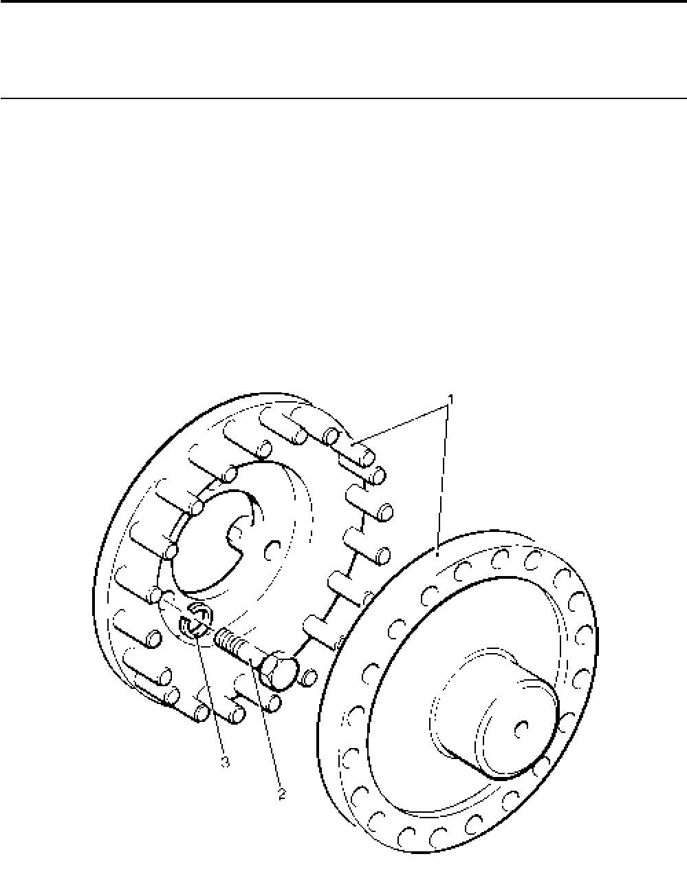
Lister-Petter TS/TR Master Parts Manual Issue 9: June 2000
159
Illustration T339
Flexible Coupling - TR2
Illustration T339 TS/TR
No. Description Part Number 1 2 3 Remarks
1 Centamex Coupling - Pilot Bored ............................202-44880 - 1 -
2 Bolt - M12 x 50mm ..................................................272-00254 - 3 -
3 Spring Washer.........................................................272-00073 - 3 -
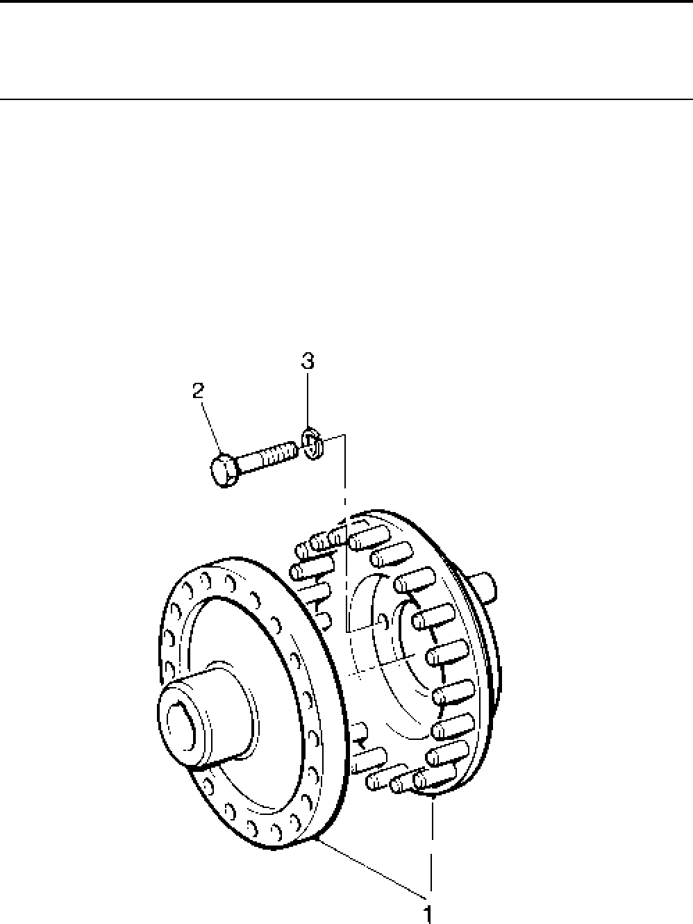
Lister-Petter TS/TR Master Parts ManualIssue 9: June 2000
160
Extra Flexible Coupling - TR2
Illustration T418 TS/TR
No. Description Part Number 1 2 3 Remarks
Accessory Kit Code CY ...........................................570-34670 - 1 -
1 Centamex Coupling - Pilot Bored ............................202-44890 - 1 -
2 Bolt - M12 x 50mm ..................................................272-00254 - 3 -
3 Spring Washer.........................................................272-00073 - 3 -
Note:
Suitable for TR2 1500 r/min generating sets for 35mm shaft.
Illustration T418

Lister-Petter TS/TR Master Parts Manual Issue 9: June 2000
161
Hydraulic Pump Adaptor - TS2,3
Not Illustrated TS/TR
Description Part Number 1 2 3 Remarks
Accessory Kit Code HN ..................................................570-35750 - 1 1
Adaptor ...........................................................................202-44306 - 1 1
Bolt .....................................................................................755686 - 3 3
Copper Washer .............................................................. 201-11890 - 4 4
Stud ................................................................................270-01077 - 1 1
Nut ................................................................................270-00005 - 1 1
Bolt ................................................................................272-00191 - 4 4
Spring Washer................................................................272-00070 - 4 4
Coupling Assembly .........................................................757-13252 - 1 1
Bolt ................................................................................ 272-00116 - 3 3

Lister-Petter TS/TR Master Parts ManualIssue 9: June 2000
162
Hydraulic Pump Adaptor - Gear End
4 bolt pump flange
Illustration T77 TS/TR
No. Description Part Number 1 2 3 Remarks
Accessory Kit Code HF - TS/TR1 ............................570-41530 1 - -
Accessory Kit Code HF - TS/TR2,3 .........................570-41540 - 1 1
- Pump Gear Assembly .............................................570-30293 1 1 1 See Note
1 Pump Gear .............................................................................. 1 1 1
2 Adaptor Plate - TS/TR1 ...........................................366-08065 1 - - Replaces 201-38130
- Adaptor Plate - TS/TR2,3 ........................................366-08063 - 1 1 Replaces 366-04139
3 ’O’ Ring ...................................................................366-08066 1 1 1 Replaces 201-41381 (TS/TR1)
and 366-07427 (TS/TR2,3)
4 Pump to Adaptor Plate Joint ....................................366-07428 1 1 1
5 Stud - 1/4“UNF x 13/8” Pump to Adaptor ....................270-00606 4 4 4
6 Spring Washer.........................................................027-00451 4 4 4
7 Nut...........................................................................270-00002 4 4 4
8 Bolt - M8 x 35mm ....................................................272-00042 3 3 3 Replaces 272-00040 (TS/TR1)
and 272-00041 (TS/TR2,3)
9 Stud - M8 x 35mm ...................................................272-00266 1 1 1
10 Spring Washer.........................................................272-00071 4 4 4
11 Nut...........................................................................272-00003 4 4 4
Note:
Comprises Pump Gear (201-31913) and Drive Pinion (201-31903). It is recommended that
these items be fitted as a matched pair.
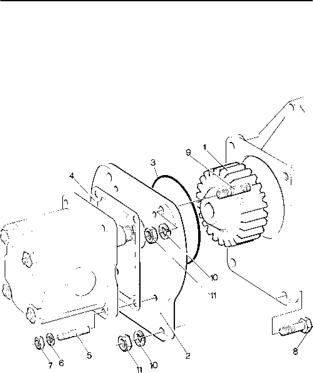
Lister-Petter TS/TR Master Parts Manual Issue 9: June 2000
163
Illustration T77

Lister-Petter TS/TR Master Parts ManualIssue 9: June 2000
164
Hydraulic Pump Adaptor - Gear End
2 bolt pump flange
Illustration T319 TS/TR
No. Description Part Number 1 2 3 Remarks
Accessory Kit Code HI.............................................570-41550 1 1 1 SAE A hydraulic pump 15 bhp limit
- Pump Gear Assembly .............................................570-30293 1 1 1 See Note:
1 Pump Gear .............................................................................. 1 1 1
2 Adaptor Plate...........................................................366-08064 1 1 1 Replaces 366-07217
3 ’O’ Ring ...................................................................366-08066 1 1 1 Replaces 201-41381
4 Pump to Adaptor Plate Joint ....................................201-32941 1 1 1
5 Bolt - M8 x 35mm ....................................................272-00042 3 3 3 Replaces 272-00041
6 Stud - M8 x 35mm ...................................................272-00266 1 1 1
7 Spring Washer.........................................................272-00071 4 4 4
8 Nut...........................................................................272-00003 4 4 4
9 Stud .........................................................................366-07747 2 2 2
10 Spring Washer.........................................................027-00393 2 2 2
11 Nut...........................................................................270-00004 2 2 2
Note:
Comprises Pump Gear (201-31913) and Drive Pinion (201-31903). It is recommended that
these items be fitted as a matched pair.
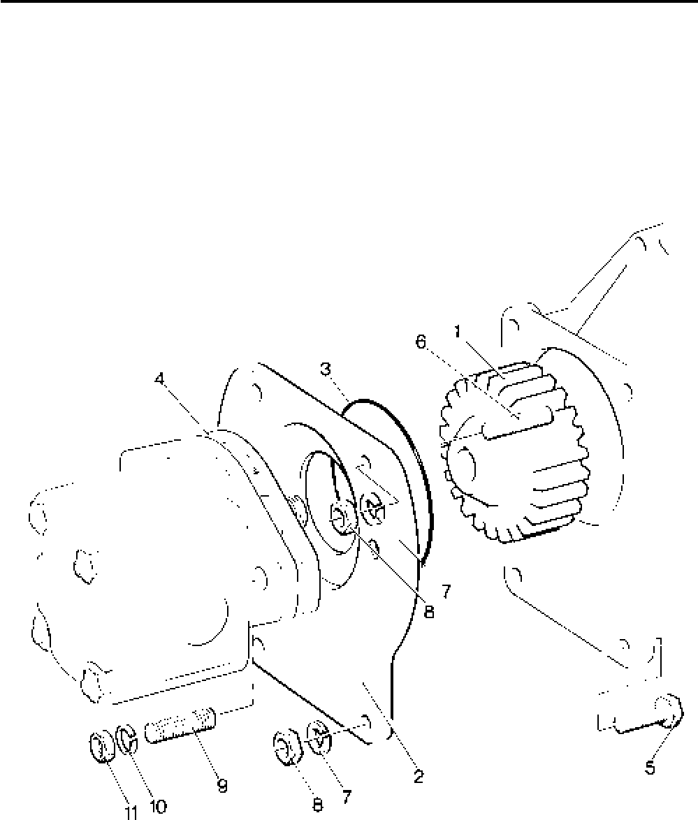
Lister-Petter TS/TR Master Parts Manual Issue 9: June 2000
165
Illustration T319

Lister-Petter TS/TR Master Parts ManualIssue 9: June 2000
166
Hydraulic Pump Adaptor - Flywheel End
4 bolt pump flange
Illustration T122 TS/TR
No. Description Part Number 1 2 3 Remarks
Accessory Kit Code HH ...........................................570-31830 1 1 1 For 1P3000 pump (or equivalent)
Accessory Kit Code HK ...........................................570-31850 1 1 1 For 2P3000 pump (or equivalent)
1 Adaptor - 1P3000 ....................................................202-35282 1 1 1
- Adaptor - 2P3000 ....................................................202-35284 1 1 1
2 Bolt ..........................................................................270-00759 12 12 12
3 Spring Washer.........................................................027-00393 12 12 12
4 Washer ....................................................................027-00184 12 12 12
5 Drive Member..........................................................202-35361 1 1 1 Replaces 202-35360 See Note:
6 Bolt - M12 x 50mm ..................................................272-00254 3 3 3
7 Spring Washer.........................................................272-00073 3 3 3
8 Coupling - 1P3000...................................................757-13252 1 1 1 Replaces 601-40110 See Note:
- Coupling - 2P3000 ...................................................757-13250 1 1 1 Replaces 601-40120 See Note:
- Coupling - Pilot Bored ..............................................757-13251 1 1 1 Replaces 202-35390 See Note:
9 Bolt - M10 x 45mm ..................................................272-00213 3 3 3
10 Bolt - 1P3000 M6 x 35mm .......................................272-00191 4 4 4
11 Spring Washer.........................................................272-00070 4 4 4
- Bolt - 2P3000 M6 x 40mm .......................................272-00043 4 4 4
- Spring Washer.........................................................272-00071 4 4 4
12 Rim Guard ...............................................................202-34972 1 1 1
13 Clamping Bracket ....................................................601-38441 2 2 2
14 Setscrew .................................................................272-00180 2 2 2
15 Washer ....................................................................027-00618 2 2 2
16 Self-locknut .............................................................272-00372 2 2 2
17 Face Guard .............................................................366-08033 1 1 1
Note:
The later couplings can only be used with Drive Member 201-35361
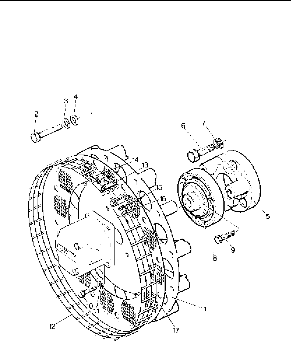
Lister-Petter TS/TR Master Parts Manual Issue 9: June 2000
167
Illustration T122

Lister-Petter TS/TR Master Parts ManualIssue 9: June 2000
168
Hydraulic Pump Adaptor - Flywheel End
2 bolt pump flange
Illustration T373 TS/TR
No. Description Part Number 1 2 3 Remarks
Former Accessory Kit Code HJ ...............................570-34130 1 1 1 Replaces 570-31840
Former Accessory Kit Code HL ...............................570-34140 1 1 1 Replaces 570-31860
1 Adaptor - 1P3000 ....................................................202-35281 1 1 1 Code HJ
- Adaptor - 2P3000 ....................................................202-35283 1 1 1 Code HL
2 Bolt 3/8"UNC x 21/4" ..................................................270-00759 12 12 12
3 Spring Washer.........................................................027-00393 12 12 12
4 Washer ....................................................................027-00184 12 12 12
5 Drive Member..........................................................202-35361 1 1 1 Replaces 202-35360
6 Bolt - M12 x 50mm ..................................................272-00254 3 3 3
7 Spring Washer.........................................................272-00073 3 3 3
8 Coupling - 1P3000...................................................202-43220 1 1 1 Code HL
- Coupling - 2P3000 ...................................................202-43210 1 1 1 Code HJ
9 Setscrew - 1P3000 M10 x 30mm ............................272-00080 2 2 2
10 Spring Washer.........................................................272-00072 2 2 2
- Setscrew - 2P3000 M12 x 35mm ............................272-00240 2 2 2
- Spring Washer.........................................................272-00073 2 2 2
11 Rim Guard ...............................................................202-34972 1 1 1
12 Clamping Bracket ....................................................601-38441 2 2 2
13 Setscrew .................................................................272-00180 2 2 2
14 Washer ....................................................................027-00618 2 2 2
15 Self-locknut .............................................................272-00372 2 2 2
16 Adapter Plate Guard ................................................366-08033 1 1 1
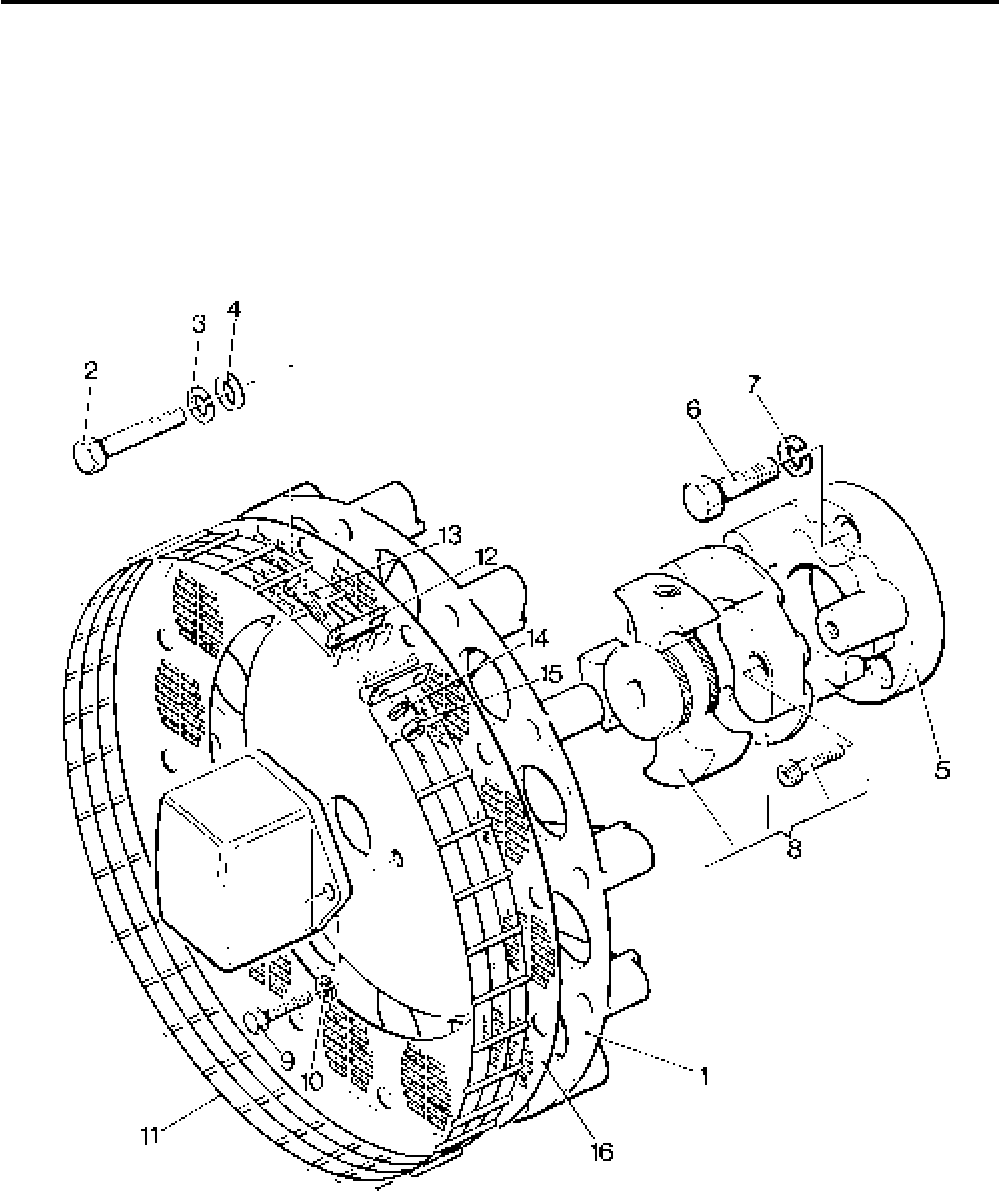
Lister-Petter TS/TR Master Parts Manual Issue 9: June 2000
169
Illustration T373

Lister-Petter TS/TR Master Parts ManualIssue 9: June 2000
170
Electric Start Panel - 12V
For use with the Synchro charging system
Illustration T193A TS/TR
No. Description Part Number 1 2 3 Remarks
Accessory Kit Code WM..........................................602-51752 1 1 1
- Start Control Panel Assembly ..................................570-33701 1 1 1
1 Panel ....................................................................607-10036 1 1 1 Replaces 607-10016
- Impulse Transmitter Assembly .............................607-10035 1 1 1 Replaces 366-07229
2 Impulse Transmitter ...........................................602-36870 1 1 1
3 Push-on Connector.....................................064-33068/001 1 1 1
4 Push-on Connector.....................................064-33068/002 1 1 1
- Push-on Connector.....................................064-33380/002 1 1 1
5 Insulation Cover..........................................064-33991/001 3 3 3
6 Screw ............................................................064-06772/002 1 1 1
7 Spring Washer...............................................064-02582/002 1 1 1
8 Nut................................................................. 064-06611/003 1 1 1
9 Screw ............................................................064-06617/012 1 1 1
10 Spring Washer............................................... 064-02582/002 1 1 1
11 Washer ..........................................................064-06618/004 2 2 2
12 Nut.................................................................064-06614/003 1 1 1
13 Cable Link Assembly ............................................366-06433 1 1 1
14 Lamp Holder .........................................................366-07228 1 1 1
15 Lamp ....................................................................605-00012 1 1 1
16 Lens ..............................................................064-20787/001 1 1 1
17 Key Switch ............................................................757-16570 1 1 1 Replaces 366-06379
17a Key Switch Cover .................................................757-16580 1 1 1
18 Helvin Button ................................................. 064-13033/008 1 1 1
19 Blanking Plug .......................................................382-08080 1 1 1
20 Label ....................................................................027-07870 1 1 1 Replaces 027-06269
21 Label ....................................................................027-07871 1 1 1 Replaces 027-06270
22 Back Plate ...............................................................607-10017 1 1 1
23 Terminal............................................................064-15648/010 1 1 1
24 Blade Terminal.........................................................366-07230 1 1 1
25 Cover.......................................................................366-07231 1 1 1
26 Push-on Connector .......................................... 064-33068/002 1 1 1
- Terminal............................................................064-33068/003 1 1 1
27 Cover................................................................064-33991/002 2 2 2
28 Key ..........................................................................366-08168 1 1 1
- Wiring Diagram .......................................................742-00589
- Wiring Diagram .......................................................742-00591
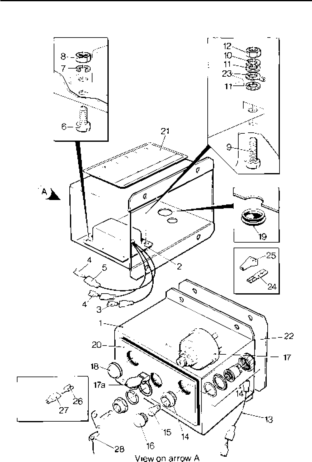
Lister-Petter TS/TR Master Parts Manual Issue 9: June 2000
171
Illustration T193A

Lister-Petter TS/TR Master Parts ManualIssue 9: June 2000
172
Electric Start Panel - 12V
For use with the Synchro charging system and with provision
for two gauges in the panel
Illustration T188A TS/TR
No. Description Part Number 1 2 3 Remarks
1 Panel .......................................................................366-06937 1 1 1
2 Impulse Transmitter Assembly ................................366-07229 1 1 1
3 Impulse Transmitter ..............................................602-36870 1 1 1
4 Push-on Connector........................................ 064-33068/001 1 1 1
5 Push-on Connector........................................ 064-33068/002 2 2 2
6 Cover.............................................................064-33991/001 3 3 3
7 Screw ...............................................................064-06772/002 1 1 1
8 Spring Washer..................................................064-02582/002 1 1 1
9 Nut.................................................................... 064-06611/003 1 1 1
10 Screw ............................................................... 064-06617/012 1 1 1
11 Spring Washer.................................................. 064-02582/002 1 1 1
12 Washer .............................................................064-06618/004 2 2 2
13 Nut.................................................................... 064-06611/003 1 1 1
14 Cable .......................................................................366-06433 1 1 1
15 Lamp Holder ............................................................366-07228 1 1 1
16 Lamp .......................................................................605-00012 1 1 1
17 Lens ................................................................. 064-20787/001 1 1 1
18 Key Switch...............................................................366-06379 1 1 1
19 Helvin Button ....................................................064-13033/008 1 1 1
20 Blanking Plug ..........................................................382-08080 1 1 1
21 Label .......................................................................027-06356 1 1 1
22 Grommet .................................................................382-07342 2 2 2
23 Cable Loom .............................................................366-07968 1 1 1
24 Cable Clip ................................................................382-08256 2 2 2
25 Setscrew - M6 x 12mm............................................272-00032 2 2 2
26 Spring Washer.........................................................272-00070 2 2 2
27 Nut...........................................................................272-00002 1 1 1
- Mounting Bracket - TS/TR1 .....................................201-42660 1 1 1
28 Mounting Bracket - TS/TR2,3 ..................................202-36442 1 1 1
29 Flexible Mounting ....................................................064-07640 3 3 3
30 Washer .............................................................064-06612/005 6 6 6
31 Spring Washer..................................................064-02582/002 6 6 6
32 Nut.................................................................... 064-06610/003 6 6 6
33 Bolt - M10 x 40mm .................................................. 272-00116 2 2 2
34 Spring Washer.........................................................272-00072 2 2 2
35 Spacer .....................................................................382-07208 2 2 2
36 Key ..........................................................................366-08168 1 1 1
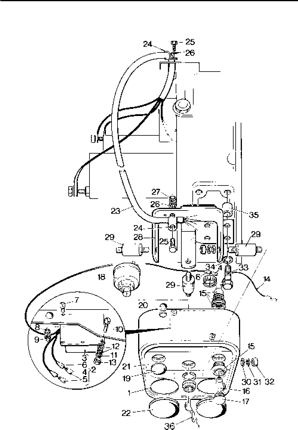
Lister-Petter TS/TR Master Parts Manual Issue 9: June 2000
173
Illustration T188A

Lister-Petter TS/TR Master Parts ManualIssue 9: June 2000
174
Electric Start Panel - 12V
For use with the Nicsa charging system
Illustration T193B TS/TR
No. Description Part Number 1 2 3 Remarks
Accessory Kit Code WM..........................................570-35441 1 1 1
- Control Panel Assembly ..........................................570-35401 1 1 1
1 Panel ....................................................................607-10016 1 1 1
2 Cable Link Assembly ............................................366-06433 1 1 1
3 Lampholder ..........................................................366-07228 1 1 1
4 Lamp .............................................................064-09681/001 1 1 1
5 Lens .............................................................. 064-20787/001 1 1 1
6 Key Switch............................................................366-06379 1 1 1
7 Helvin Button .................................................064-13033/008 1 1 1
8 Blanking Plug .......................................................382-08080 1 1 1
9 Label ....................................................................027-10052 1 1 1
10 Key ..........................................................................366-08168 1 1 1
11 Back Plate ...............................................................607-10017 1 1 1
12 Push-on Connector .......................................... 064-33068/001 1 1 1
13 Push-on Connector .......................................... 064-33380/001 1 1 1
14 Insulation Cover ...............................................064-33991/001 2 2 2
15 Push-on Connector .......................................... 064-33068/002 1 1 1
16 Cover................................................................064-33991/002 1 1 1
17 Terminal............................................................064-33068/004 1 1 1
18 Cover................................................................064-33991/004 1 1 1
Wiring Diagram .......................................................742-00648
Wiring Diagram .......................................................742-00796
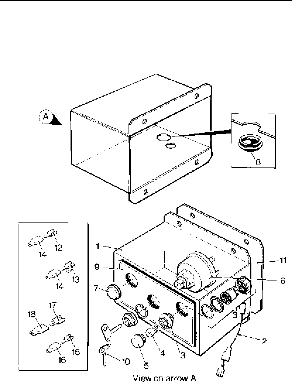
Lister-Petter TS/TR Master Parts Manual Issue 9: June 2000
175
Illustration T193B

Lister-Petter TS/TR Master Parts ManualIssue 9: June 2000
176
Electric Start Panel - 12V
For use with the Nicsa charging system and with provision
for two gauges in the panel
Illustration T188b TS/TR
No. Description Part Number 1 2 3 Remarks
Accessory Kit Code WA - TS/TR1 ...........................570-33782 1 - -
Accessory Kit Code WA - TS/TR2,3 ........................570-30553 - 1 1
1 Panel .......................................................................366-06937 1 1 1
2 Cable .......................................................................366-06433 1 1 1
3 Lampholder .............................................................366-07228 1 1 1
4 Lamp ................................................................064-09681/001 1 1 1
5 Lens .................................................................064-20787/001 1 1 1
6 Key Switch...............................................................366-06379 1 1 1
7 Helvin Button .................................................... 064-13033/008 1 1 1
8 Blanking Plug ..........................................................382-08080 1 1 1
9 Label .......................................................................027-06356 1 1 1
10 Grommet .................................................................382-07342 2 2 2
11 Cable Loom .............................................................366-08146 1 1 1
12 Cable Clip ................................................................382-08256 2 2 2
13 Setscrew - M6 x 12mm............................................272-00032 2 2 2
14 Spring Washer.........................................................272-00070 2 2 2
15 Nut...........................................................................272-00002 1 1 1
16 Mounting Bracket - TS/TR2,3 ..................................202-36442 - 1 1
- Mounting Bracket - TS/TR1 .....................................201-42660 1 - -
17 Flexible Mounting ....................................................064-07640 3 3 3
18 Washer .............................................................064-06612/005 6 6 6
19 Spring Washer..................................................064-02582/002 6 6 6
20 Nut.................................................................... 064-06610/003 6 6 6
21 Bolt - M10 x 40mm .................................................. 272-00116 2 2 2
22 Spring Washer.........................................................272-00072 2 4 4
23 Spacer .....................................................................382-07208 2 2 2
24 Key ..........................................................................366-08168 1 1 1
- Bolt - M10 x 45mm ..................................................272-00213 2 - -
- Nut...........................................................................272-00004 - 2 2
Wiring Diagram .......................................................742-00649
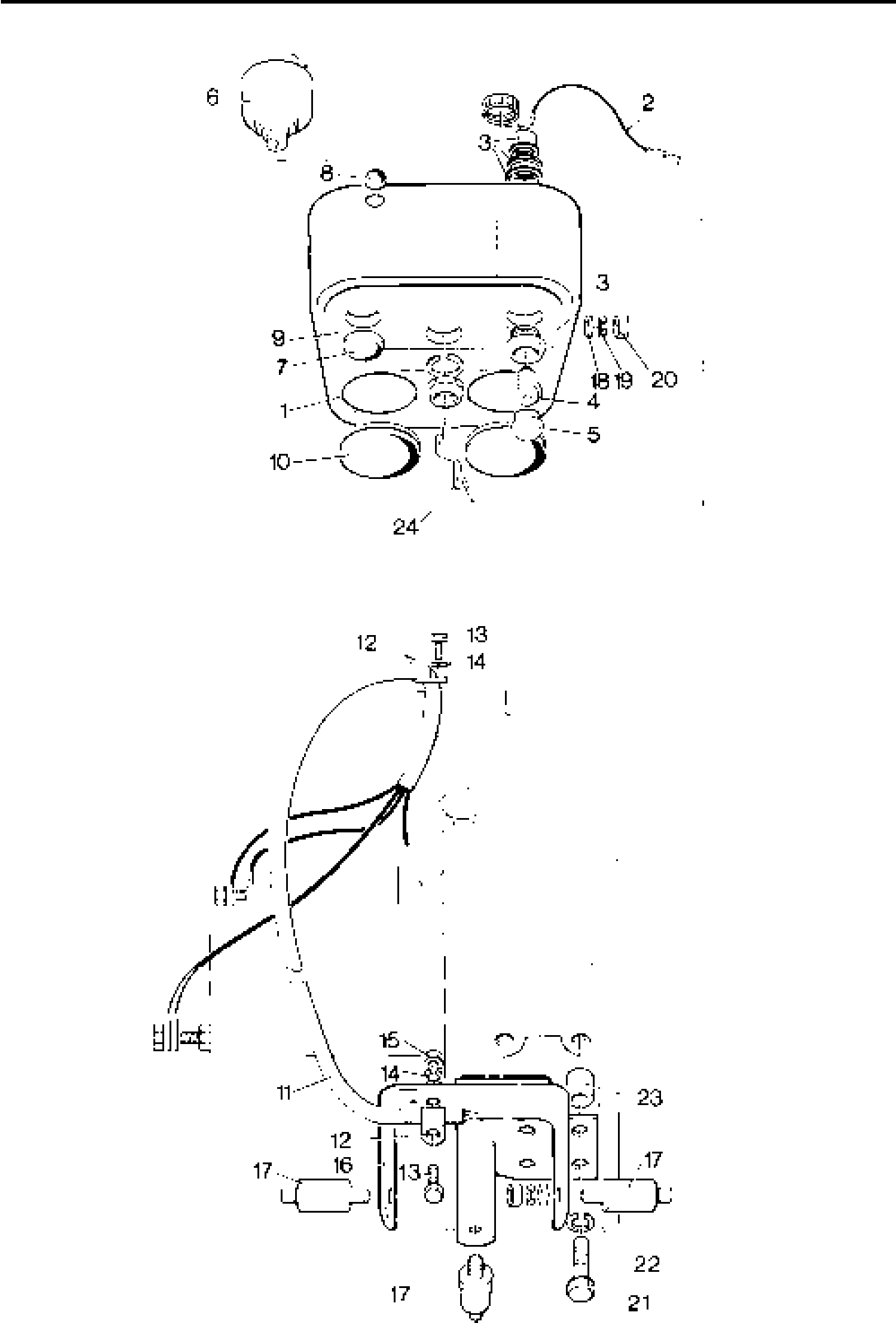
Lister-Petter TS/TR Master Parts Manual Issue 9: June 2000
177
Illustration T188b

Lister-Petter TS/TR Master Parts ManualIssue 9: June 2000
178
Key Switch and Charge Indicator
Illustration T190 TS/TR
No. Description Part Number 1 2 3 Remarks
Accessory Kit Code WK ..........................................572-56250 1 1 1
1 Key Switch...............................................................366-06379 1 1 1
2 Connector.........................................................064-33068/002 1 1 1
3 Cover................................................................064-33991/002 1 1 1
4 Connector.........................................................064-33068/004 1 1 1
5 Cover................................................................064-33991/004 1 1 1
Charge Indicator Lamp
Illustration T190 TS/TR
No. Description Part Number 1 2 3 Remarks
Accessory Kit Code WL...........................................570-35450 1 1 1
6 Lampholder .............................................................366-07228 1 1 1
7 Lens .................................................................064-20787/001 1 1 1
8 Lamp ................................................................064-09681/001 1 1 1
9 Key ..........................................................................366-08168 1 1 1
- Wiring Diagram .......................................................742-00648 1 1 1
- Wiring Diagram .......................................................742-00796 1 1 1
Note:
Suitable for builds 02, 07, 09, 11, 15, 61, 63, 66
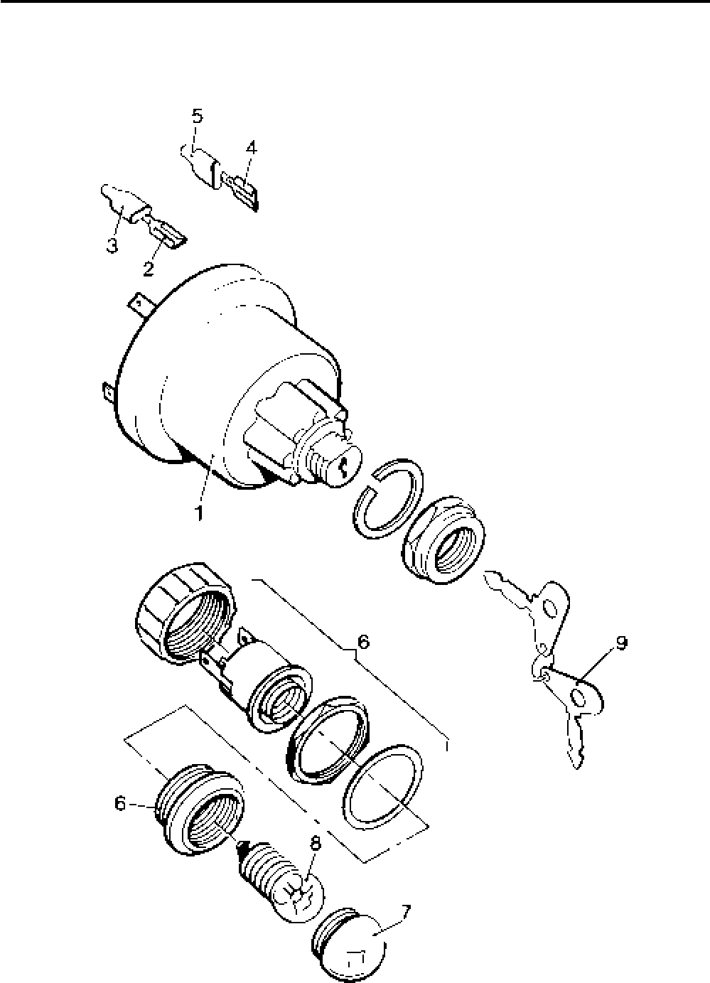
Lister-Petter TS/TR Master Parts Manual Issue 9: June 2000
179
Illustration T190
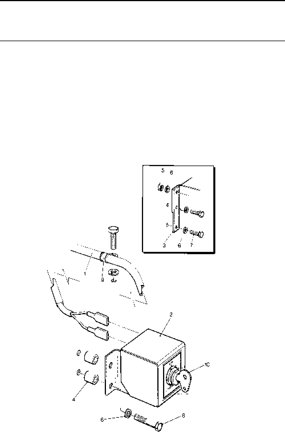
Lister-Petter TS/TR Master Parts ManualIssue 9: June 2000
180
Key Switch Panel
Illustration T347 TS/TR
No. Description Part Number 1 2 3 Remarks
Accessory Kit Code WG - TS/TR1 ..........................570-34626 1 - - Replaces 570-34625
Accessory Kit Code WG - TS/TR2,3 .......................570-34627 - 1 1 Replaces 570-34624
1 Cable Loom .............................................................366-08147 1 1 1
2 Panel .......................................................................366-08260 1 1 1 Replaces 366-07596
3 Bracket - TS/TR1 ....................................................366-07597 1 - -
4 Spacer - TS/TR2,3 ..................................................757-10970 - 2 2 Replaces 362729
- Alternative Spacer - TS/TR2,3 .................................027-07995 - 1 1 Replaces 366-08000
5 Nut - TS/TR1 ...........................................................272-00002 1 - -
6 Spring Washer.........................................................272-00070 3 2 2
7 Setscrew - M6 x 20mm TS/TR1 .............................. 272-00117 2 - -
8 Bolt - M6 x 40mm TS/TR2,3 ....................................272-00036 - 2 2
9 Clip ..........................................................................382-08256 1 1 1
10 Key ..........................................................................366-08168 1 1 1
Wiring Diagram .......................................................742-00647 1 1 1
Illustration T347
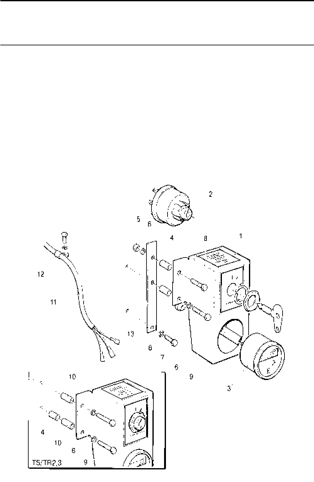
Lister-Petter TS/TR Master Parts Manual Issue 9: June 2000
181
Key Switch and Hour Recorder Panel
Illustration T410 TS/TR
No. Description Part Number 1 2 3 Remarks
Accessory Kit Code WI - TS/TR1 ............................570-36860 1 - -
Accessory Kit Code WI - TS/TR2,3 .........................570-36850 - 1 1
1 Gauge Panel ...........................................................570-36840 1 1 1
2 Keyswitch .............................................................366-06379 1 1 1
3 Hour Recorder ......................................................757-14501 1 1 1
4 Spacer .....................................................................027-07995 2 1 1
5 Nut - TS/TR1 ...........................................................272-00002 1 - -
6 Spring Washer.........................................................272-00070 3 2 2
7 Setscrew M6 x 20mm - TS/TR1 .............................. 272-00117 1 - -
8 Bolt M6 x 30mm - TS/TR1 .......................................272-00035 1 - -
9 Bolt - M6 x 40mm ....................................................272-00036 1 2 2
10 Spacer - TS/TR2,3 ..................................................757-10970 - 2 2
11 Loom Assembly .......................................................366-08147 1 1 1
12 Cable Clip .............................................................382-08256 1 1 1
13 Bracket - TS/TR1 ....................................................366-07597 1 - -
Illustration T410

Lister-Petter TS/TR Master Parts ManualIssue 9: June 2000
182
Cable Loom - Protective Switches - TS/TR2,3
Illustration T380 TS/TR
No. Description Part Number 1 2 3 Remarks
Accessory Kit Code WC ..........................................570-30982 - 1 1 Comprises of Cable Loom
366-08049 and numbers 2-6
1 Cable Loom .............................................................366-08049 - 1 1 Head temperature and oil
pressure switch, replaces
366-07206
- Cable Loom .............................................................366-08050 - 1 1 Air temperature and oil pressure
switch, replaces 366-07205
2 Clip ..........................................................................382-08254 - 3 3
3 Clip ..........................................................................382-08257 - 1 1
4 Washer ....................................................................027-00618 - 6 6
5 Setscrew .................................................................272-00034 - 3 3
6 Spring Washer.........................................................272-00070 - 3 3
- Cable Tie .................................................................064-32790 - 3 3
Battery Leads
Not Illustrated TS/TR
Description Part Number 1 2 3 Remarks
Accessory Kit Code WO .................................................570-13880 1 1 1
Positive Lead ...........................................................064-07172/001 1 1 1
Negative Lead .........................................................064-07172/002 1 1 1
Rubber Shroud ...............................................................064-08391 2 2 2
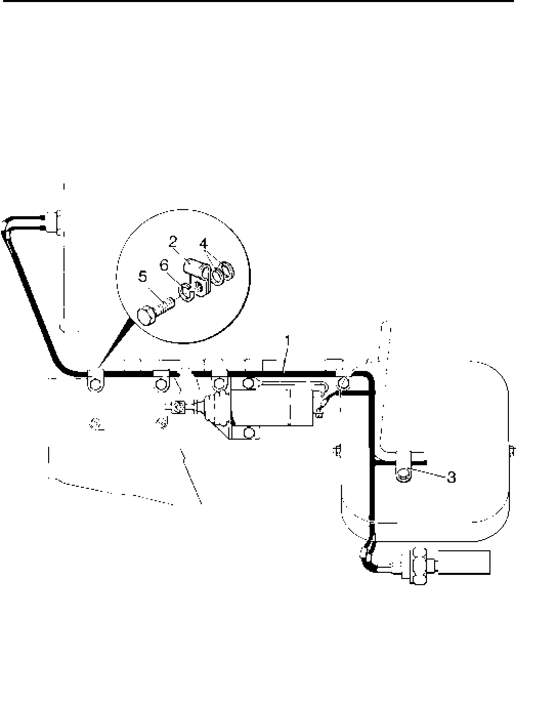
Lister-Petter TS/TR Master Parts Manual Issue 9: June 2000
183
Illustration T380

Lister-Petter TS/TR Master Parts ManualIssue 9: June 2000
184
Lagging for Manifold Only (Not Build 16)
TS/TR
No. Description Part Number 1 2 3 Remarks
Accessory Kit Code GQ - TS/TR1 ...........................570-37060 1 - -
Accessory Kit Code GQ - TS/TR2 ...........................570-37100 - 1 -
Accessory Kit Code GQ - TS/TR3 ...........................570-37140 - - 1
- Manifold Lagging - TS/TR1......................................366-08263 1 - -
- Manifold Lagging - TS/TR2......................................366-08267 - 1 -
- Manifold Lagging - TS/TR3......................................366-08270 - - 1
Lagging for Manifold and Silencer Code NA
TS/TR
No. Description Part Number 1 2 3 Remarks
Accessory Kit Code GR - TS/TR1 ...........................570-37070 1 - -
Accessory Kit Code GR - TS/TR2 ........................... 570-37110 - 1 -
Accessory Kit Code GR - TS/TR3 ...........................570-37150 - - 1
- Manifold Lagging TS/TR1 ........................................366-08263 1 - -
- Manifold Lagging TS/TR2 ........................................366-08267 - 1 -
- Manifold Lagging TS/TR3 ........................................366-08270 - - 1
- Silencer Lagging TS/TR1 ........................................366-08264 1 - -
- Silencer Lagging TS/TR2,3 .....................................366-08268 - 1 1
Lagging for Manifold, Silencer Code NA, and Outlet Pipe Code NH
TS/TR
No. Description Part Number 1 2 3 Remarks
Accessory Kit Code GW - TS/TR1 ..........................570-37080 1 - -
Accessory Kit Code GW - TS/TR2 ..........................570-37120 - 1 -
Accessory Kit Code GW - TS/TR3 ..........................570-37160 - - 1
- Manifold Lagging - TS/TR1......................................366-08263 1 - -
- Manifold Lagging - TS/TR2......................................366-08267 - 1 -
- Manifold Lagging - TS/TR3......................................366-08270 - - 1
- Silencer Lagging - TS/TR1 ......................................366-08264 1 - -
- Silencer Lagging - TS/TR2,3 ...................................366-08268 - 1 -
- Outlet Pipe Lagging - TS/TR1,2,3............................366-08265 1 - -

Lister-Petter TS/TR Master Parts Manual Issue 9: June 2000
185
Lagging for Manifold and Silencer Code NL (Build 16 Only) - TS/TR1
TS/TR
No. Description Part Number 1 2 3 Remarks
Accessory Kit Code GX ...........................................570-37090 1 - -
- Manifold Lagging .....................................................366-08266 1 - -
- Silencer Lagging ......................................................366-08275 1 - -
Lagging for Manifold and Manifold Flange Code NF - TS/TR2,3
TS/TR
No. Description Part Number 1 2 3 Remarks
Accessory Kit Code GU - TS/TR2 ...........................570-37130 - 1 -
Accessory Kit Code GU - TS/TR3 ...........................570-37220 - - 1
- Manifold Lagging - TS/TR2......................................366-08269 - 1 -
- Manifold Lagging - TS/TR3......................................366-08276 - - 1
Decompressor Lever Insulation
TS/TR
No. Description Part Number 1 2 3 Remarks
Accessory Kit Code GH ...........................................570-72350 1 1 1
- Heat Insulating Tubing .............................................027-10090 1 1 1

Lister-Petter TS/TR Master Parts ManualIssue 9: June 2000
186
Decarbonising Joint Sets - TS
TS
No. Description Part Number 1 2 3 Remarks
Joint Set - TS1................................................................657-32671 1 - -
Joint Set - TS2................................................................657-29501 - 1 -
Joint Set - TS3................................................................657-29521 - - 1
Cylinder Head Gasket..................................................201-80210 1 2 3
Cylinder Head Shim .....................................................201-80220 3 6 9
Cylinder Head Shim .....................................................201-80221 1 2 3
Cylinder Barrel Joint ....................................................201-32430 1 2 3
Cylinder Head Cover Joint ...........................................201-30805 1 2 3
Cylinder Head Cover Washer ......................................272-00364 4 8 12
Stub Shaft O Ring........................................................201-31460 2 4 5
Inlet Valve Guide O Ring..............................................201-81200 2 4 6
Inlet Valve Shield .........................................................201-37630 1 2 3
Exhaust Valve Shield ...................................................201-39520 - 2 3
Breather Tube Sealing Ring.........................................601-35440 1 2 3
Push Rod Tube (Bottom) .............................................201-30261 2 4 6
Push Rod Tube (Top) ..................................................201-42360 2 4 6
Injector Washer ...........................................................351-40230 1 2 3
Manifold Joint ..............................................................201-33420 1 4 6
Exhaust Joint ...............................................................366-01287 1 1 1
Inlet Manifold Adaptor Joint (up to 35 4109 TS2) .........201-31320 - 1 -
Inlet Manifold Adaptor Joint (up to 35 3463 TS3) .........201-31320 - - 1
Inlet Manifold Adaptor Joint (from 35 4110 TS2) ..........202-33231 - 1 -
Inlet Manifold Adaptor Joint (from 35 3464 TS3) .........202-33231 - - 1
Union Washer ..............................................................352-29370 1 4 6
Union Washer ..............................................................291-26090 2 - -
Copper Washer ...........................................................616-01608 3 7 10

Lister-Petter TS/TR Master Parts Manual Issue 9: June 2000
187
Overhaul Joint Sets - TS
TS
No. Description Part Number 1 2 3 Remarks
Joint Set - TS1................................................................657-32681 1 - -
Joint Set - TS2................................................................ 657-29511 - 1 -
Joint Set - TS3................................................................657-29531 - - 1
Cylinder Head Gasket..................................................202-80210 1 2 3
Cylinder Head Shim .....................................................201-80220 3 6 9
Cylinder Head Shim .....................................................201-80221 1 2 3
Cylinder Barrel Joint ....................................................201-32430 1 2 3
Cylinder Head Cover Joint ...........................................201-30805 1 2 3
Cylinder Head Cover Washer ......................................272-00364 8 16 24
Stub Shaft O Ring........................................................201-31460 2 4 6
Valve Guide O Ring .....................................................201-81200 2 4 6
Inlet Valve Shield .........................................................201-37630 1 2 3
Exhaust Valve Shield ...................................................201-39520 - 2 3
Breather Tube Sealing Ring.........................................601-35440 1 2 3
Push Rod Tube (Bottom) .............................................201-30261 2 4 6
Push Rod Tube (Top) ..................................................201-42360 2 4 6
Injector Washer ...........................................................351-40230 1 2 3
Manifold Joint ..............................................................201-33420 1 2 6
Exhaust Joint ...............................................................366-01287 1 1 1
Inlet Manifold Adaptor Joint (up to 35 4109 TS2) .........201-31320 - 1 -
Inlet Manifold Adaptor Joint (up to 35 3463 TS3) .........201-31320 - - 1
Inlet Manifold Adaptor Joint (from 35 4110 TS2) ..........202-33231 - 1 -
Inlet Manifold Adaptor Joint (from 35 3464 TS3) .........202-33231 - - 1
Union Washer..............................................................352-29370 1 4 6
Union Washer..............................................................291-26090 6 - -
Copper Washer ...........................................................616-01608 6 19 25
Sump Joint ..................................................................201-37751 1 - -
Sump Joint ..................................................................202-30541 - 1 -
Sump Joint ..................................................................203-30542 - - 1
Drain Plug Washer ......................................................013-21778 1 2 2
Main Bearing Housing O Ring .....................................601-37420 1 1 1
Main Bearing Housing Shim ........................................201-30943 2 2 2
Main Bearing Housing Shim ........................................201-30944 2 2 2
Camshaft Shim ............................................................201-30680 1 1 1
Camshaft Shim ............................................................201-30681 1 1 1
Camshaft Shim ............................................................201-30682 1 1 1
Camshaft Shim ............................................................201-30683 1 1 1
Camshaft Shim ............................................................201-30684 1 1 1
Inspection Door Joint ...................................................201-39701 1 - -
Inspection Door Joint ...................................................201-30612 - 2 3
Blanking Plate Joint .....................................................602-36271 1 1 1
End Cover Joint ........................................................... 201-33011111
End Cover Joint (TS1 Build 7, TS2,3 Build 6,7) ...........201-33012 1 1 1
End Cover Washer ......................................................027-00082 7 7 7
End Cover Washer (TS1 Build 7, TS2,3 Build 6,7) ...... 201-11890 2 2 2
Control Spindle O RIng ................................................201-13120 2 2 2
Dipstick O Ring .................................................................266003 1 1 1
Fuel Pump O RIng .......................................................601-20691 1 2 3
Filler Cap Joint.............................................................303-00253 1 1 1
Air Duct Grommet........................................................201-50950 1 2 3
Oil Plug O Ring ............................................................366-04010 - 1 1
Oil Pump O Ring.......................................................... 352-11911 - 1 1
Dowel Washer .............................................................600-00106 - 1 1
Union Washer..............................................................201-41640 - 2 2
Union Washer..............................................................354-26310 2 2 2

Lister-Petter TS/TR Master Parts ManualIssue 9: June 2000
188
Decarbonising Joint Sets - TR
TR
Description Part Number 1 2 3 Remarks
Joint Set - TR1 ...............................................................657-33301 1 - -
Joint Set - TR2 ...............................................................657-33361 - 1 -
Joint Set - TR3 ...............................................................657-33381 - - 1
Cylinder Head Gasket.................................................. 201-33110 1 2 3
Cylinder Head Shim .....................................................201-33100 3 6 9
Cylinder Head Shim .....................................................201-33101 1 2 3
Cylinder Barrel Joint ....................................................201-32430 1 2 3
Cylinder Head Cover Joint ...........................................201-30805 1 2 3
Cylinder Head Cover Washer ......................................272-00364 4 - -
Stub Shaft O Ring........................................................201-31460 2 4 6
Inlet Valve Guide O Ring..............................................201-81200 2 4 6
Inlet Valve Shield .........................................................201-37630 1 2 3
Exhaust Valve Shield ...................................................201-39520 - 2 3
Breather Tube Sealing Ring.........................................601-35440 1 2 3
Push Rod Tube (Bottom) .............................................201-30261 2 4 6
Push Rod Tube (Top) ..................................................201-42360 2 4 6
Injector Washer ...........................................................351-40230 1 2 3
Manifold Joint ..............................................................201-33420 2 4 6
Exhaust Joint ...............................................................366-01287 1 1 1
Inlet Manifold Adaptor Joint .........................................202-33231 - 1 1
Union Washer ..............................................................352-29370 1 2 3
Union Washer ..............................................................291-26090 2 - -
Copper Washer ...........................................................616-01608 4 8 12

Lister-Petter TS/TR Master Parts Manual Issue 9: June 2000
189
Overhaul Joint Sets - TR
TR
Description Part Number 1 2 3 Remarks
Joint Set - TR1 ...............................................................657-33091 1 - -
Joint Set - TR2 ...............................................................657-33371 - 1 -
Joint Set - TR3 ...............................................................657-33391 - - 1
Cylinder Head Gasket.................................................. 201.33110 1 2 3
Cylinder Head Shim .....................................................201-33100 3 6 9
Cylinder Head Shim .....................................................201-33101 1 2 3
Cylinder Barrel Joint ....................................................201-32430 1 2 3
Cylinder Head Cover Joint ...........................................201-30805 1 2 3
Cylinder Head Cover Washer ......................................272-00364 8 - -
Stub Shaft O Ring........................................................201-31460 2 4 6
Valve Guide O Ring .....................................................201-81200 2 4 6
Inlet Valve Shield .........................................................201-37630 1 2 3
Exhaust Valve Shield ...................................................201-39520 - 2 3
Breather Tube Sealing Ring.........................................601-35440 1 2 3
Push Rod Tube (Bottom) .............................................201-30261 2 4 6
Push Rod Tube (Top) ..................................................201-42360 2 4 6
Injector Washer ...........................................................351-40230 1 2 3
Manifold Joint ..............................................................201-33420 2 4 6
Exhaust Joint ...............................................................366-01287 1 1 1
Inlet Manifold Adaptor Joint .........................................202-33231 - 1 1
Union Washer..............................................................352-29370 1 2 3
Union Washer..............................................................291-26090 6 - -
Copper Washer ...........................................................616-01608 9 19 23
Sump Joint ..................................................................201-37751 1 - -
Sump Joint ..................................................................202-30541 - 1 -
Sump Joint ..................................................................203-30542 - - 1
Drain Plug Washer ......................................................013-21778 1 2 2
Main Bearing Housing O Ring .....................................601-37420 1 1 1
Main Bearing Housing Shim ........................................201-30943 2 2 2
Main Bearing Housing Shim ........................................201-30944 2 2 2
Camshaft Shim ............................................................201-30680 1 1 1
Camshaft Shim ............................................................201-30681 1 1 1
Camshaft Shim ............................................................201-30682 1 1 1
Camshaft Shim ............................................................201-30683 1 1 1
Camshaft Shim ............................................................201-30684 1 1 1
Inspection Door Joint ...................................................201-39701 1 - -
Inspection Door Joint ...................................................201-30612 - 2 3
Blanking Plate Joint .....................................................602-36271 1 1 1
End Cover Joint ........................................................... 201-33011 - 1 1
End Cover Joint (Build 6,7 TR2) ..................................201-33012 1 1 1
End Cover Washer ......................................................027-00082 7 - -
End Cover Washer ...................................................... 201-11890 2 - -
Control Spindle O RIng ................................................201-13120 2 2 2
Dipstick O Ring .................................................................266003 1 1 1
Fuel Pump O RIng .......................................................601-20691 1 2 3
Filler Cap Joint.............................................................303-00253 1 1 1
Air Duct Grommet........................................................201-50950 1 2 3
Oil Plug O Ring ............................................................366-04010 - 1 1
Dowel Washer .............................................................600-00106 - 1 1
Union Washer..............................................................201-41640 - 5 5
Union Washer..............................................................354-26310 2 2 2

Lister-Petter TS/TR Master Parts ManualIssue 9: June 2000
190
Service Tools
Description of Tool Part Number Remarks
Valve Spring Compressor 393155
Gear Puller Kit 393175
Main bearing Tool 393235 Removal and replacement
Governor Rack Linkage Tool 393236
Slide Hammer 317-50027
Stub Shaft Adaptor 317-50028 Use with 317-50027
Valve Guide Base Tool 317-50033 Removal and replacement
Valve Guide Adaptor 317-50034 Use with 317-50033
Valve Guide Depth Stop 317-50039 Use with 317-50034
Valve Seat and Recess Cutting Tool 317-50042
65mm Socket 317-50052 Use on flywheel bolt/nut
3/4”F - 1"M Adaptor 317-50053 Use with 317-50052
Flywheel Locking Tool 317-50057
Crankshaft Extension Spanner 317-50060 Use to torque flywheel end
Flywheel End Crankshaft Oil Seal Installer 317-50065
Flywheel End Crankshaft Oil Seal Remover 317-50074
Valve Clearance Gauge 317-50094
Injector Removal Adaptor 317-50096 Use with 317-50027
Gear End Camshaft Oil Seal Tool 317-50098
Universal Puller Plate 317-50100 Use with 393171
Flywheel Mandrel 317-50102
Fuel Injector Test Rig 317-50517
Fuel Pump Timing Gauge 317-50518
Holding Down Bolts
TS/TR
Description Part Number 1 2 3 Remarks
Accessory Kit Code QA ..................................................570-14070 1 1 1
Bolt - 1/2" BSW x 181/2" ....................................................027-00584 4 4 4
Nut - 1/2" BSW.................................................................027-00004 4 4 4
Spring Washer - 1/2" diameter .........................................027-00394 4 4 4
Tool Kit
TS/TR
Description Part Number 1 2 3 Remarks
Accessory Kit Code SJ ...................................................570-32490 1 1 1
Tool Kit............................................................................366-07016 1 1 1

WARNING
Engine exhaust and some of its constituents are
known to the State of California to cause cancer,
birth defects, and other reproductive harm.
Lister-Petter Limited
Dursley
Gloucestershire
GL11 4HS
England
Tel: +44 (0)1453 544141
Fax: +44 (0)1453 546732
E-mail: sales@lister-petter.co.uk
http://www.lister-petter.co.uk
Lister-Petter Inc.
815 E. 56 Highway
Olathe
Kansas 66061
USA
Tel: +1 913 764-3512
Fax: +1 913 764-5493
E-mail: lpinfo@lister-petter.com
http://www.lister-petter.com
Lister-Petter France
1, Avenue de L'escouvrier
Zone d'Activites
95842 Sarcelles Cedex
France
Tel: +33 (0)1 39330420
Fax: +33 (0)1 34195760
E-mail: lister-petter-france.fr
