IPL, McCulloch, PM605, PM610, PM645, PM650, PM655, 1987 01, Chain Saw PM645 MCCI1987 AAaa Pssup610
User Manual: PM645
Open the PDF directly: View PDF ![]() .
.
Page Count: 10
I1lUSTRIITEDPMTS11ST
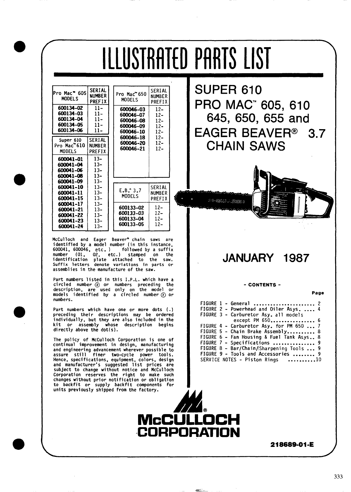
McCulloch and Eager Beavere chain saws are
identified by a model number (in this instance,
600041, 600046, etc. ) followed by a suffix
number (01, 02, etc. ) stamped on the
identification plate attached to the saw. JANUARY 1987
Suffix letters denote variations in parts or
assemblies in the manufacture of the saw.
Part numbers listed in this I.P.L. which have a
circled number @ or numbers preceding the - CONTENTS-
description, are used only on the model or
models identified by a circled number @ or Page
numbers. FIGURE 1 - General ...................... 2
Part numbers which have one or more dots (.) FIGURE 2 - Powerhead and Oiler Asys. .... 4
preceding their descriptions may be ordered FIGURE 3 - Carburetor Asy. all models
individually, but they are also included in the except PM 650 6
kit or assembly whose description begins ................
directly above the dot(s). FIGURE 4 - Carburetor Asy. for PM 650 ... 7
FIGURE 5 - Chain Brake Assembly .......... 8
The policy of McCul loch Corporation is one of FIGURE 6 - Fan Housing & Fuel Tank Asys.. 8
continual improvement in design, manufacturing FIGURE 7 - Specifications ............... 9
and engineering advancement wherever possible to FIGURE 8 - Bar/Chain/lSharpening Tools ... 9
assure still finer two-cycle power tools. FIGURE 9 - Tools and Accessories 9
Hence, specifications, equipment, colors, design ........
SERVICE NOTES - Piston Rings 10
and manufacturer’s suggested list prices are ..........
subject to change without notice and McCulloch
Corporation reserves the right to make such
changes without prior notification or obligation
to backfit or supply backfit components for
units previously shipped from the factory.
A@
McCULLOCH
CORPORATION 218689-01-E
333
Timberbear
McCulloch 6000
●a
-GENERAL ASSEMBLY
d
28—
1—.. b-ii ““ -p’
-f?’: 79
m II
Y(?L
18
1/. ; { En b
29
a
●
●
334
2

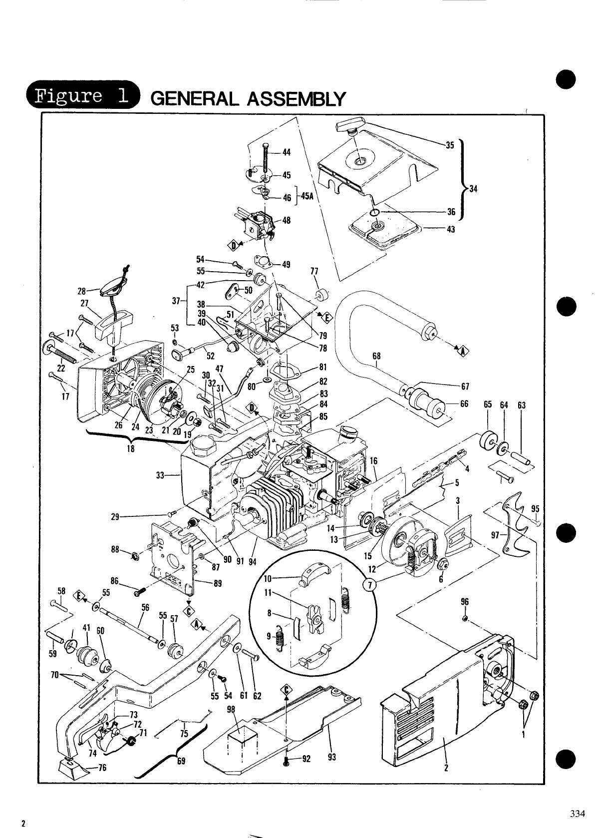
FIGURE 1GENERAL ASSEMBLY
ITEM PART
NO. UNITS PER
NUMBER DESCRIPTION ASY.
1216645 Nut-Hex Flange 2’
2 Fig. 2 Chain Brake Assembly 1
3 64325 Plate-Bar Guide 1
4 Fig. 7 Chain Assembly 1
Fig. 7 Bar Assembly 1
2 92457 Nut-Hex Flange MIO x 1.25 1’
(160-170 in. lb. torque)
7 214301 Clutch Assembly 1
8 64583 Retainer-Clutch Spring 2
9 83223 I Spring-Clutch 2
10 67233 Kit-Clutch Shoe 1
11 214300 I Rotor-Clutch
12 8
214979 1 Drum/Sprocket Assy. 1
214200 z Drum/Hub Assy. 1
13 86951 @ Sprocket-Rim .375P 1
14 86958 @ Washer-Shim 1
110971 Bearing-Needle 1
;: 92354 Jacket-Cylinder
17 120081 Screw-Pan Hd M4 x 16 :
(15-20 in. lb. torque)
lB 219159 Starter Assembly 1
19 111038 .Nut-l/4-20 1
(25-30 in. lb. torque)
20 95401 . Washer-Starter 1
21 216589 . Spacer-Starter 1
22 215848 . Step Bolt-Starter 1
23 219163 . Drum/Rope Kit-Starter 1
24 87670 .. Rope-Starter 1
25 217730 Bushing-Rope 1
26 87668 I“Spring-Starter Rewind 1
27 93137 Starter Handle 1
28 214699 Insert Handle 1
29 120002 Screw-Pan Hd M5 x 14 1
(30-35 in. lb. torque)
30 93232 Screw-Fan Housing M5 x 40 1
(45-50 in. lb. torque)
31 93233 Screw-Fan Housing M5 x 35 1
(45-50 in. lb. torque)
32 93234 Screw-Fan Housing M5 x 30 1
(45-50 in. lb. torque)
33 Fig. 3 Fan Housing/Fuel Tank Assy 1
34 217651 Cover Assy-Filter 1
35 91991 . Knob-Air Filter Cover 1
36 110565 . Ring-Retaining 1
37 95216 Air Box Assembly 1
38 95214 Box-Air 1
39 93261 : Gromnet-Choke 1
40 69597 . Boot-Control Rod 1
Isolator 1
;; :%: I Gronrnet-Strut
43 214226 Filter-Air 1
44 120004 Screw-Hx Hd M5 x 56 2
(35-40 in. lb. torque)
Bracket Assy-Filter/Cover 1
~A ?41% Choke & Rod Kit 1
46 94151 Choke-Carburetor 1
47 94171 I Rod-Choke 1
48 Fig. 3,4 Carburetor Assembly 1
49 91924 Gasket-Carburetor 1
50 91995-01 Grommet-Carburetor Needle 1
@ Used on all models except PM 650.
@ Used on all PM 650 Models.
@ Pm 650 Model 600046-10 uses only one (1)
Isolator, p/n 9484.7, in place of two (2)
Isolators, one (1) p/n 93913 and one (1)
p/n 94140.
ITEM PART UNITS PER
NO. NU4BER DESCRIPTION ASY.
51 93458 Clip-Oiler Button 1
52 92067-01 Button/Rod Assy-Oiler
53 105614 ‘O’ Ring ;
54 215266 Screw-Pan M5 Special 2
(25-30 in. lb. torque)
55 110990 Washer 4
56 93252-01 Strut-Handle 1
57 93253 Gronnnet-Strut 1
58 111015 Screw-Pan Hd 1/4-14 x 2.5 2
(70-80 in. lb. torque)
59 92071 Spacer 1
60 92066 Cup-Isolator 2
61 102115 Washer-Plain 1
62 111014 Screw-Pan Hd 1/4-14 x 1.75 1
(70-80 in. lb. torque)
63 92071 Spacer 1
64 111027 Washer-Plain 1
65 93913 Isolator 1
66 94140 Isolator 1
94847 @ Isolator 1
67 111027 Washer-Plain ‘ 1
68 91951 Fra~ 1
69 214723 Handle Assembly 1
70 110994 . Pin-Roll 2
71 93771 Spring-Trigger 1
72 93538-01 ; Trigger 1
73 111013 .. Screw-Set 1
74 91955 Release-Trigger 1
75 214504 : Rod-Throttle 1
76 93459 Boot-Handle 1
77 92161 Seal-Air Box
78 120037 Screw-Hx Hd M5 x 25 (Sems) ;
(35-40 in. lb. torque)
79 120039 Screw-Hx Hd M5 x 30 (Sems) 2
(35-40 in. lb. torque)
80 93460 Washer-Insulator 1
94018 Gasket-Air Box 1
Y2 94017-01 Insulator-Carburetor 1
83 91933 Gasket-Air Box 1
84 91934 Insulator-Air Box 1
85 92038 Gasket-Insulator 1
86 120037 Screw-Hx Hd M5 x 25 (Sems) 2
(45-50 in. lb. torque)
Washer-Insulator
;; :;:;;0 Nut-Hx 15/32-32 ;
(30-35 in. lb. torque)
89 218561 Shroud-Cylinder 1
90 93B90 Switch-Ignition 1
92466 Wire Assembly-Switch
;; 120002 Screw-Pan Hd M5 x 14 ;
(45-50 in. lb. torque)
93 214670 Shroud-Bottom 1
94 Fig. 6 Powerhead & Oiler Assy 1
95 120002 @ Screw-Pan Hd M5 x 14 2
96 120044 @ Nut-Hx M5 Lock 2
97 ;;;:;8 @ Spike 1
98 Safety Decal 1
@PM610 Models: 41-01, -02
128-05, -06
PM 650 Models: 46-02, -11, -19
NOTE :
PM 650 Models 46-01, -03, -04, -07, -08,
-19 use four (4) screws, two (2) nuts and
two (2) spikes.
333
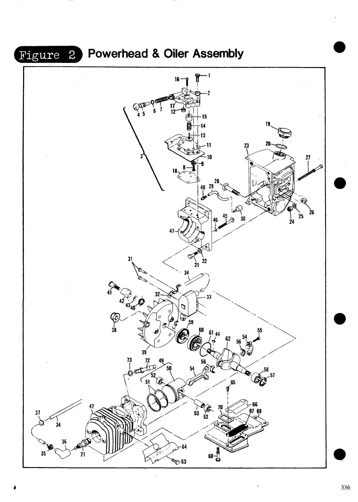
Powerhead &Oiler Assembly
\@-
–j14
‘\ ‘.\\,
55
‘/
565?
~~” /
,-
\/’
/
.- L-” “‘b” “63
●
●
●
336
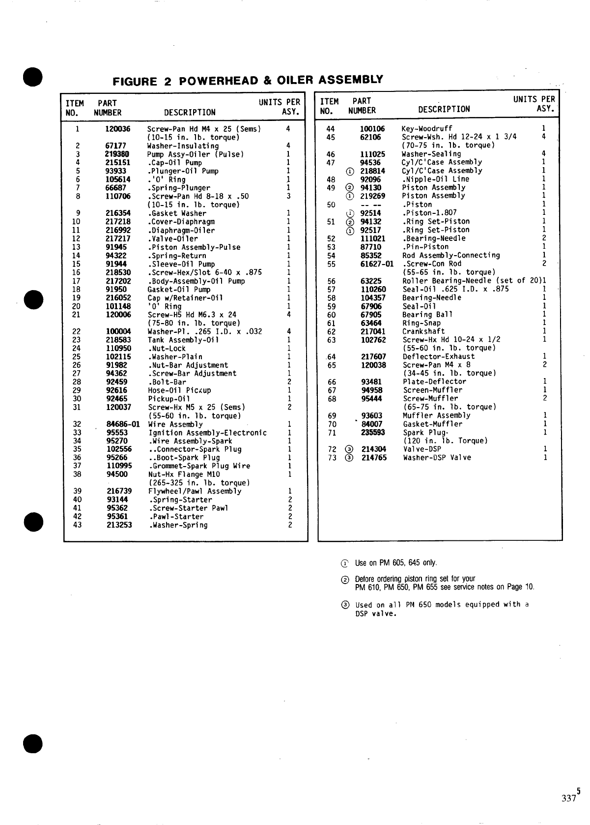
FIGURE 2POWERHEAD &OILER ASSEMBLY
[TEM PART UNITS PER
10. NUMBER DESCRIPTION ASY.
1120036 Screw-Pan Hd M4 x 25 (Sems) 4
(10-15 in. lb. torque)
267177 Washer-Insulating 4
3219380 Pump Assy-Oiler (Pulse) 1
4215151 .Cap-Oil Pump 1
93933 .Plunger-Oil Pump 1
: 105614 .‘O’ Ring 1
766687 .Spring-Plunger 1
8 110706 .Screw-Pan Hd 8-18 x .50 3
(10-I5 in. lb. torque)
9 216354 .Gasket Washer 1
10 217218 .Cover-Diaphragm 1
11 216992 .Diaphragm-Oiler 1
12 217217 .Valve-Oiler 1
13 91945 .Piston Assembly-Pulse 1
14 94322 .Spring-Return 1
15 91944 .Sleeve-Oil Pump 1
16 218530 .Screw-Hex/Slot 6-40 x .875 1
217202 .Body-Assembly-Oil Pump
ii 91950 Gasket-Oil Pump i
19 216052 Cap w/Retainer-Oil 1
20 101148 ‘O’ Ring
21 120D06 Screw-H5 Hd M6.3 x 24 i
(75-80 in. lb. torque)
22 1oOOo4 Washer-Pi. .265 I.D. X.032 4
23 218583 Tank Assembly-Oil 1
24 110950 .Nut-Lock 1
25 102115 .Washer-Plain 1
26 91982 .Nut-Bar Adjustment 1
27 94362 .Screw-Bar Adjustment 1
28 92459 .Bolt-Bar 2
29 92616 Hose-Oil Pic<up 1
30 92465 Pickup-Oil 1
31 120037 Screw-Hx M5 x 25 (Sems) 2
(55-60 in. lb. torque)
32 84686-01 Wire Assembly 1
33 95553 Ignition Assembly-Electronic 1
34 95270 .Wire Assembly-Spark 1
35 102556 ..Connector-Spark Plug 1
36 95266 ..Boot-Spark Plug 1
37 110995 .Grommet-Spark Plug Wire 1
38 94500 Nut-Hx Flange M1O 1
(265-325 in. lb. torque)
39 216739 Flywheel /Pawl Assembly
40 93144 .Spring-Starter ;
41 95362 .Screw-Starter Pawl 2
42 95361 .Pawl-Starter
43 213253 .Washer-Spri ng ;
;TEM PART UNITS PER
to. NUMBER DESCRIPTION ASY.
44 100106 Key-Woodruff 1
45 62106 Screw-Wsh. Hd 12-24 x 1 3/4 4
(70-75 in. lb. torque)
46 111025 Washer-Seal ing 4
47 94536 Cyl/C’Case Assembly 1
@ 218814 Cyl/C’Case Assembly 1
48 92096 .Nipple-Oil Line 1
49 @ 94130 Piston Assembly 1
@ 219269 Piston Assembly 1
50 -- -- .Pi ston 1
@92514 .Piston-l.807 1
51 @94132 .Ring Set-Piston 1
@ 92517 .Ring Set-Piston 1
52 111021 .Bearing-Needle 2
53 87710 .Pin-Piston 1
54 85352 Rod Assembly-Connecting
55 61627-01 .Screw-Con Rod ;
(55-65 in. lb. torque)
56 63225 Roller Bearing-Needle (set of 20)1
57 110260 Seal-Oil .625 I.D. x .875
58 104357 Bearing-Needle ;
59 67906 Seal-Oi1
60 67905 Bearing Ball ;
61 63464 Ririg-Snap
62 217041 Crankshaft :
63 102762 Screw-Hx Hd 10-24 x 1/2 1
(55-60 in. lb. torque)
.64 217607 Deflector-Exhaust 1
65 120038 Screw-Pan M4 x 8 2
(34-45 in. lb. torque)
66 93481 Plate-Deflector 1
67 94958 Screen-Muffler 1
68 95444 Screw-Muff 1er 2
(65-75 in. lb. torque)
69 93603 Muffler Assembly 1
70 -84007 Gasket-Muff 1er 1
71 235593 Spark Plug- 1
(120 in. lb. Torque)
72 @ 214304 Valve-DSP 1
73 @ 214765 Washer-DSP Valve 1
@ Useon PM605,6450nly.
@ Oeforeorderingpistonrirrgsetforyour
PM610, PM 650,PM655see servicenoteson Page IO.
@ Used on all PM 650 models equipped with a
DSP valve.
3375
●m
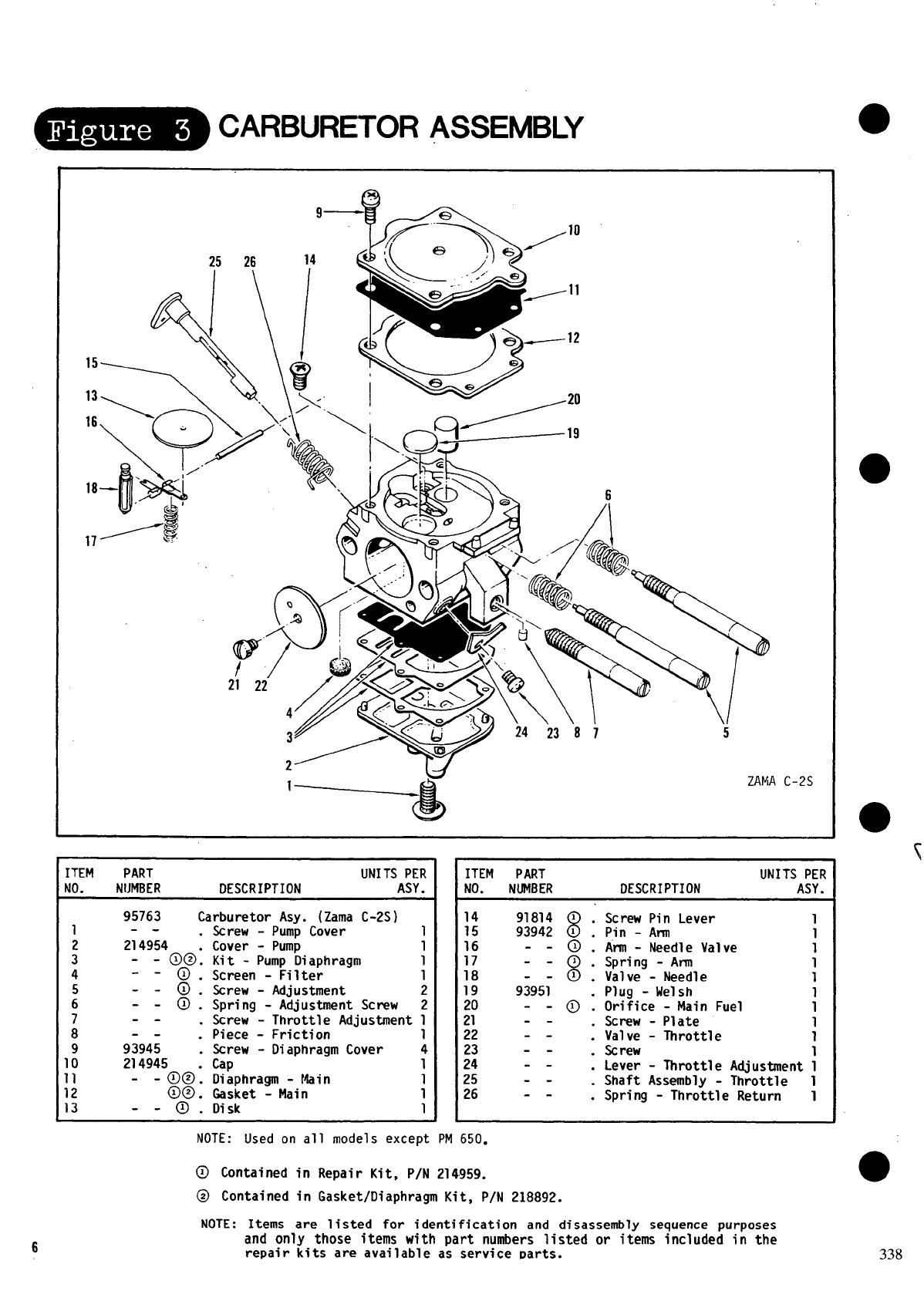
-CARBURETOR ASSEMBLY
<<-’~ >~ 24 23 ‘8 1 .
5
C-2S
ITEM PART UNITS PER
NO. NIJMBER DESCRIPTION ASY.
95763 Carburetor AsY. (Zama C-2S)
--
214954 :
- @@@.
--
-- 0:
-- Q.
--
--
93945 ;
214945
-@@:
$$$.
-- .
Screw - Pump Cover
Cover - Pump ;
Kit - Pump Diaphragm 1
Screen - Filter 1
Screw - Adjustment 2
Spring - Adjustment Screw 2
Screw - Throttle Adjustment 1
Piece - Friction 1
Screw - Diaphragm Cover 4
Cap 1
Diaphragm - Main
Gasket - Main :
Disk 1
ITEM PART UNITS PER
NO. NUMBER DESCRIPTION ASY.
8
91814 1 .
93942 1 .
-- -&
-- Q.
93951 .
-a.
--
-- .
--
.- .
--
-- .
Screw Pin Lever 1
Pln - Ann
Ann - Needle Valve ;
Spring - Ann 1
Valve - Needle 1
Plug - Welsh
Orifice - Main Fuel ;
Screw - Plate
Valve - Throttle 1
Screw 1
Lever - Throttle Adjustment 1
Shaft Assembly - Throttle 1
Spring - Throttle Return 1
6
NOTE: Used on all models except PM 650.
@ Contained in Repair Kit, P/N 214959.
@ Contained in Gasket/Diaphragm Kit, PIN 218892.
NOTE: Items are listed for identification and disassembly sequence purposes
and only those items with part numbers listed or items included in the
repair kits are available as service Darts. 338
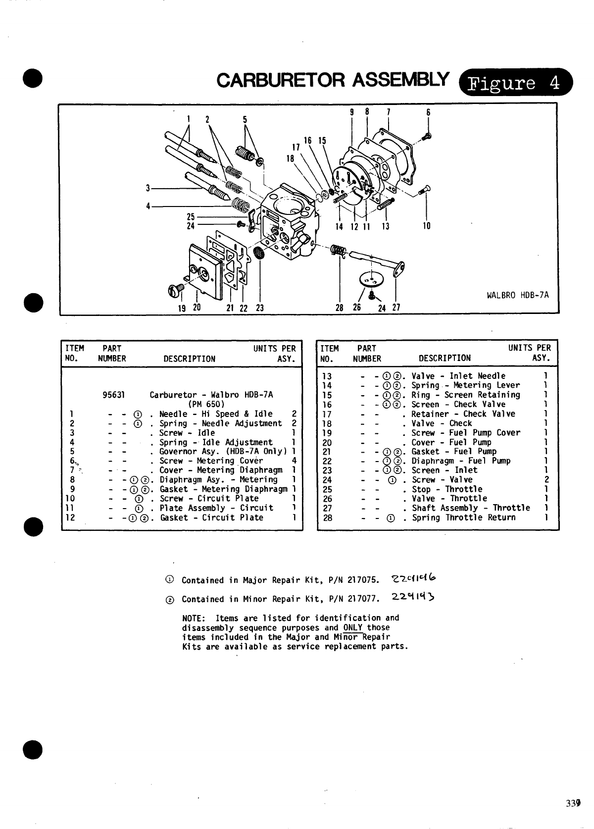
●CARBURETOR ASSEMBLY ~
I12 5
I19 20 21 22 23
[TEM PART UNITS PER
!0. NUMBER DESCRIPTION ASY.
95631 Carburetor - Walbro HDB-7A
(PM 650)
Needle - Hi Speed & Idle
Spring - Needle Adjustment
Screw - Idle
Spring -Idle Adjustment
Governor Asy. (HDB-7A Only)
Screw - Metering Cover
Cover - Metering Oiaphragm
Diaphragm Asy. - Metering
Gasket - Metering Diaphragm
Screw - Circuit Plate
Plate Assembly - Circuit
Gasket - Circuit Plate
2
2
1
1
1
4
1
1
1
1
1
1
1412it 13 10
*- .>.>
/k \WALBRO HDB-7A
28 26 24 21
ITEM PART UNITS PER
Uo. NUMBER DESCRIPTION ASY.
H
15
16
17
18
19
20
21
22
23
24
25
26
27
28
-- .
-- .
-- .
--
-@@:
-- 8
J@.
-- 1a.
-@.
-- .
--
--
-@.
Valve - Inlet Needle
Spring.- Metering Lever
Ring - Screen Retaining
Screen - Check Valve
Retainer - Check Valve
Valve - Check
Screw - Fuel Pump Cover
Cover - Fuel Pump
Gasket - Fuel Pump
Diaphragm - Fuel Pump
Screen - Inlet
Screw - Valve
stop - Throttle
Valve - Throttle
Shaft Assembly - Throttle
Spring Throttle Return
1
1
1
1
1
1
1
1
;
1
?
1
1
1
Contained in Major Repair Kit, P/N 217075. Z2C414 &
Contained in Minor Repair Kit, P/N 217077. z2%1~”>
NOTE: Items are listed for identification and
disassembly sequence purposes and ONLY those
items included in the Major and Mi~Repair
Kits are available as service replacement parts.
339
●a
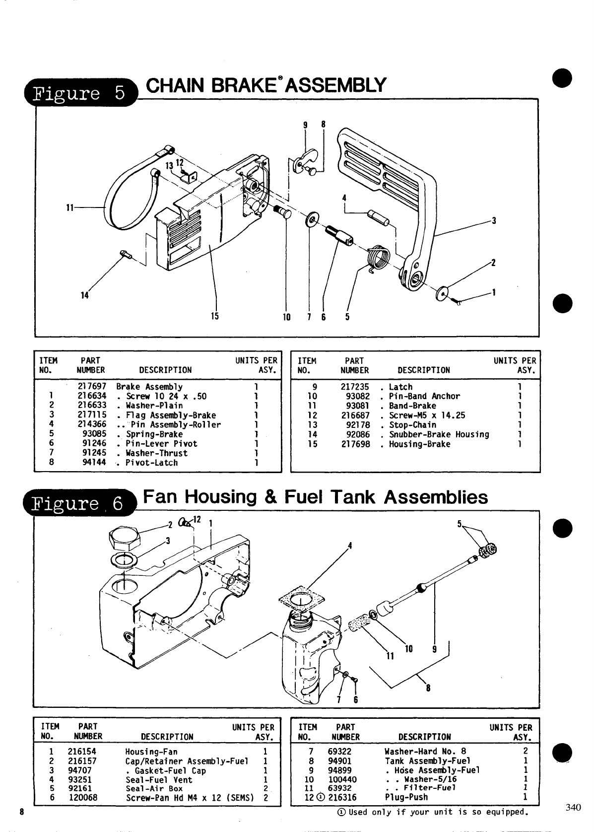
_CHAIN BRAKE”ASSEMBLY
15 io 765
ITEM PART UNITS PER
NO. NUMBER DESCRIPTION ASY.
217697 Brake Assembly
1216634 . Screw 10 24 x .50 i
2216633 . Washer-Plain
3217115 . Flag Assembly-Brake ;
4214366 .. Pin Assembly-Roller 1
593085 . Spring-Brake 1
691246 . Pin-Lever Pivot 1
791245 Washer-Thrust 1
8 94144 ~ Pivot-Latch 1
ITEM PART UNITS PEi
NO. NUMBER DESCRIPTION ASY,
217235 . Latch 1
1: 93082 . Pin-Band Anchor 1
11 93081 . Band-Brake 1
12 216687 . Screw-M5 x 14.25 1
13 92178 . Stop-Chain 1
14 92086 . Snubber-Brake Housing 1
15 217698 . Housing-Brake 1
Fan Housing &Fuel Tank Assemblies
.-
ITEM PART UNITS PER
NO. NUMBER DESCRIPTION ASY.
Housirig-Fan 1
; ;%:? Cap/Retainer Assembly-Fuel 1
94707 Gasket-Fuel Cap 1
: 93251 ;eal-Fuel Vent 1
5 92161 Seal-Air Box
6120068 Screw-Pan HdM4 x 12 (SEMS) j
8
ITEM PART UNITS PER
NO. NIFIBER DESCRIPTION ASY.
7 69322 Washer-Hard No. 8 2
8 94901 Tank Assembly-Fuel 1
9 94899 . Hose Assenbly-Fuel 1
10 100440 . . kJasher-5/16 1
11 63932 Fflter-Fuel 1
12@ 216316 ;l;g-Push 1
@llsed only if your unit is so equipped.
●
●
●
340
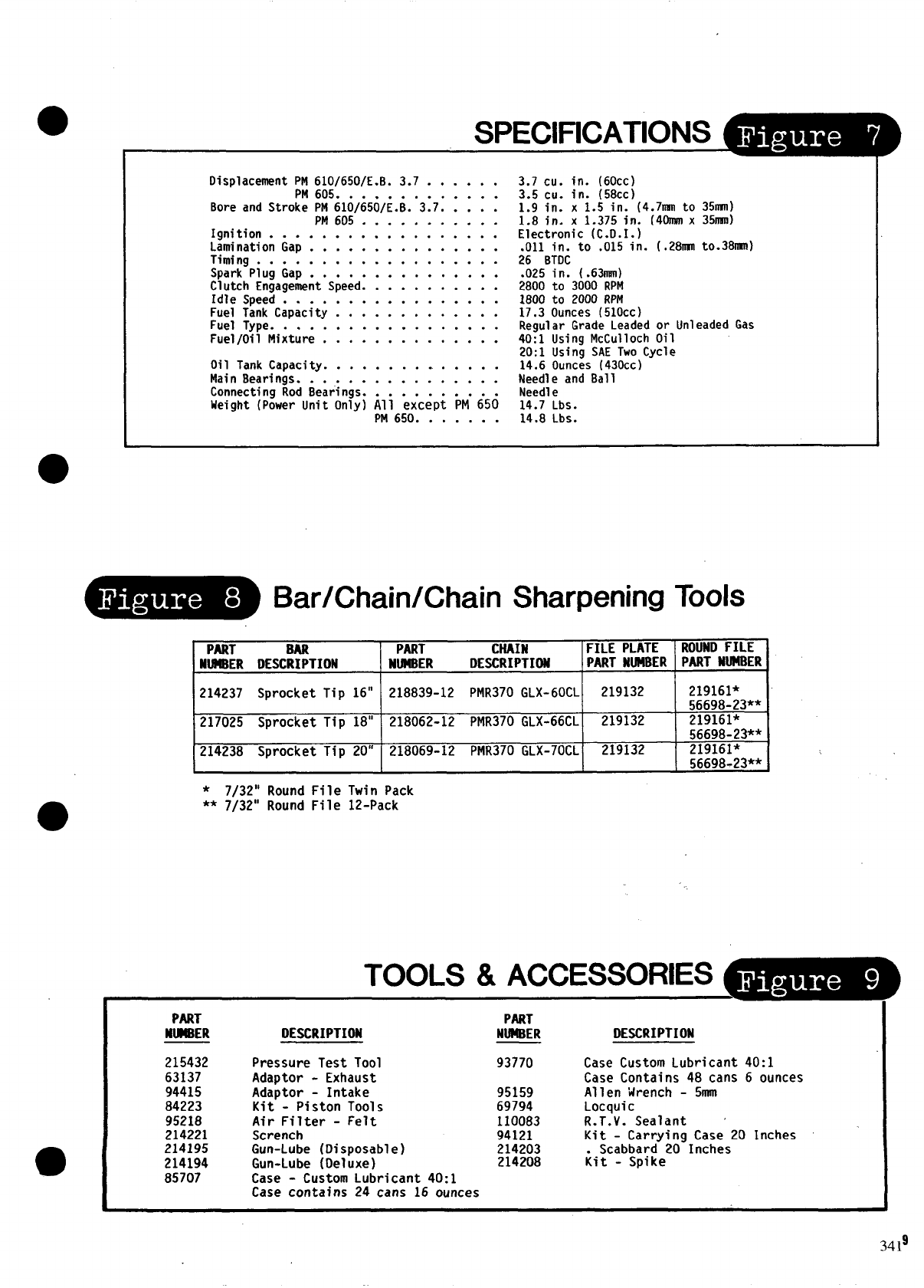
SPECIFICATIONS _
IDisplacement PM 610\650/E. B. 3.7 . . . . . .
PM 605; . ; . . . . . . . . . .
Bore and Stroke PM 610/6501E. B. 3.7. . . . .
PM 605” . ... . . . . . . . .
Ignition . . . . . . . . . . . . . . . . . .
Lamination Gap . . . . . . . . . . . . . . .
Timing . . . . . . . . . . . . . . . . . . .
Spark Plug Gap . . . . . . . . . . . . . . .
Clutch Engagement Speed. . . . . . . . . . .
Idle Speed . . . . . . . . . . . . . . . . .
Fuel Tank Capacity . . . . . . . . . . . . .
Fuel Type . . . . . . . . . . . . . . . . . .
Fuel/Oil Mixture . . . . . . . . . . . . . .
Oil Tank Capacity . . . . . . . . . . . . . .
Main Bearings . . . . . . . . . . . . . . . .
Connecting Rod Bearings. . . . . . . . . . .
Weight (Power Unit Only) All except PM 650
PM 650 . . . . . . .
3.7 cu. in. (60cc)
3.5 cu. in. (58cc)
1.9 in. x 1.5 in. (4.7nsnto 35~)
1.8 in. x 1.375 in. [40MMX 35nmI)
Electronic (C.O.I.)
.011 in. to .015 in. (.2811111to.38nwn)
26 BTDC
.025 in. (.63mm)
2800 to 3000 RPM
1800 to 2000 RPM
17.3 Ounces (510cc)
Regular Grade Leaded or Unleaded Gas
40:1 Using McCulloch Oil
20:1 Using SAE Two Cycle
14.6 Ounces (430cc)
Needle and Ball
Needle
14.7 Lbs.
14.8 Lbs.
Bar/Chain/Chain Sharpening Tools
PART BAR PART CNAIN FILE PLATE ROUND FILE
NUMBER DESCRIPTION NMBER DESCRIPTION PART NUMBER PART NUM8ER
,
214237 Sprocket Tip 16” 218839-12 PMR370 GLX-60CL 219132 219161*
56698-23**
217025 Sprocket Tip 18” 218062-12 PMR370 GLX-66CL 219132 219161*
56698-2P*
214238 Sprocket Tip 20” 218069-12 PMR370 GLX-70CL 219132 219161*
*7/32” Round File Twin Pack
** 7/32” Round File 12-Pack
TOOLS &ACCE~
PART PART
NM8ER
215432
63137
94415
84223
95218
214221
214195
214194
85707
DESCRIPTION
Pressure Test Tool
Adaptor - Exhaust
Adaptor - Intake
Kit - Piston Tools
Air Filter - Felt
Scrench
Gun-Lube (Disposable)
Gun-Lube (Deluxe)
Case - Custom Lubricant 40:1
Case contains 24 cans 16 ounces
NUM8ER DESCRIPTION
93770 Case Custom Lubricant 40:1
Case Contains 48 cans 6 ounces
95159 Allen Wrench - 5mm
69794 Locquic
110083 R.T.V. Sealant ‘
94121 Kit - Carrying Case 20 Inches
214203 Scabbard 20 Inches
214208 kit - Spike
3419
10
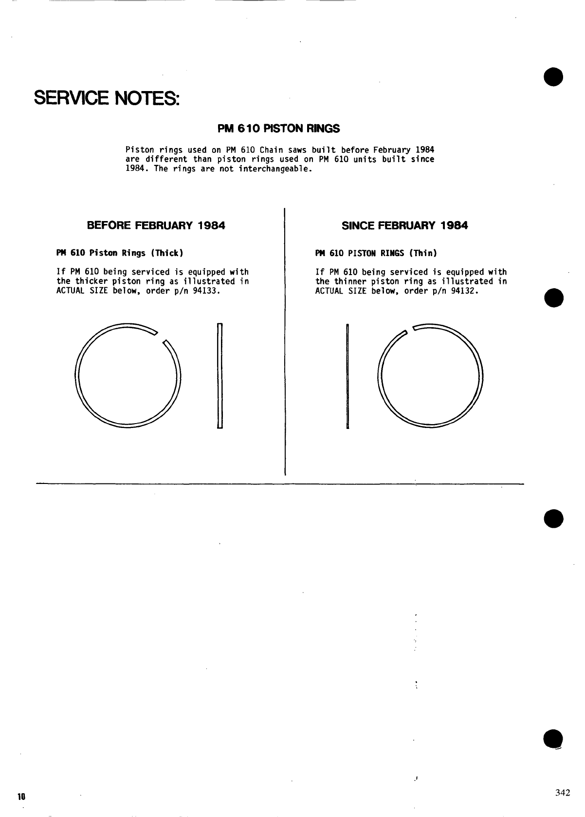
SERVICE NOTES
PM 610 PISTONRINGS
Piston rings used on PM 610 Chain saws built before February 1984
are different than piston rings used on PM 610 units built since
1984. The rings are not interchangeable.
BEFORE FEBRUARY 1984
W610 Piston Rings (lhick)
If PM 610 being serviced is equipped with
the thicker piston ring as illustrated in
ACTUAL SIZE below, order p/n 94133.
SINCEFEBRUARY1984
PU61O PISTON RINGS (Thin)
If PM 610 being serviced is equipped with
the thinner piston ring as illustrated
ACTUAL SIZE below, order p/n 94132. in
@
342
