PDPM175G6H MKEY 94LP2J R0 EN
User Manual: PDPM175G6H
Open the PDF directly: View PDF ![]() .
.
Page Count: 26
- Modular PDU Values
- Power Distribution Modules Values
- Display Interface
- Menu tree
- List Of Alarms
- Compliance
- Input Specifications
- Mains Input Voltage
- Mains Input Current
- Maximum Short-Circuit Withstand Rating
- Frequency
- Output Specifications
- Breakers
- Recommended Conductor Sizes
- 40° Ambient / 3CCC, 150 & 175 kW Modular PDU
- 30° Ambient / 3CCC, 150 & 175 kW Modular PDU
- CB1
- JLF361150C
- Environmental
- Transformer Specifications
- Dimensions
- Hardware Options
- Shunt Trip
- Configuration Options
- Worldwide Customer Support
Technical Specifications
APC Modular Power Distribution Unit
APC 144kVA Modular Power Distribution Unit,
Isolation Transformer, 480:208V, 72 Poles, 2 Subfeed
APC 144kVA Modular Power Distribution Unit,
Isolation Transformer, 600:208V, 72 Poles, 2 Subfeed
APC 175kVA Modular Power Distribution Unit,
Isolation Transformer, 480:415V, 72 Poles, 2 Subfeed

Table of Contents
990-4806 150/175 kVA Modular PDU Technical Specification i
Technical Data............................................................................................ 1
Modular PDU Values . . . . . . . . . . . . . . . . . . . . . . . . . . . . . . . . . . . . . . . . . . . . . . . . . . . . 1
Power Distribution Modules Values. . . . . . . . . . . . . . . . . . . . . . . . . . . . . . . . . . . . . . . . 1
Communication and Management ........................................................... 2
Display Interface . . . . . . . . . . . . . . . . . . . . . . . . . . . . . . . . . . . . . . . . . . . . . . . . . . . . . . . 2
Menu tree . . . . . . . . . . . . . . . . . . . . . . . . . . . . . . . . . . . . . . . . . . . . . . . . . . . . . . . . . . . . . 2
List Of Alarms . . . . . . . . . . . . . . . . . . . . . . . . . . . . . . . . . . . . . . . . . . . . . . . . . . . . . 3
Network Management Card . . . . . . . . . . . . . . . . . . . . . . . . . . . . . . . . . . . . . . . . . . . . . . 3
Input and Output Contacts . . . . . . . . . . . . . . . . . . . . . . . . . . . . . . . . . . . . . . . . . . . . . . 4
Compliance . . . . . . . . . . . . . . . . . . . . . . . . . . . . . . . . . . . . . . . . . . . . . . . . . . . . . . . 4
Facility Planning ........................................................................................ 5
Input Specifications. . . . . . . . . . . . . . . . . . . . . . . . . . . . . . . . . . . . . . . . . . . . . . . . . . . . . 5
Mains Input Voltage. . . . . . . . . . . . . . . . . . . . . . . . . . . . . . . . . . . . . . . . . . . . . . . . . . . . . 5
Mains Input Current. . . . . . . . . . . . . . . . . . . . . . . . . . . . . . . . . . . . . . . . . . . . . . . . . . . . . 5
Maximum Short-Circuit Withstand Rating . . . . . . . . . . . . . . . . . . . . . . . . . . . . . . . . . . 5
Frequency . . . . . . . . . . . . . . . . . . . . . . . . . . . . . . . . . . . . . . . . . . . . . . . . . . . . . . . . . . . . 5
Output Specifications . . . . . . . . . . . . . . . . . . . . . . . . . . . . . . . . . . . . . . . . . . . . . . . . . . . 6
Breakers . . . . . . . . . . . . . . . . . . . . . . . . . . . . . . . . . . . . . . . . . . . . . . . . . . . . . . . . . . . . . . 6
Recommended Conductor Sizes . . . . . . . . . . . . . . . . . . . . . . . . . . . . . . . . . . . . . . . . . . 6
40° Ambient / 3CCC, 150 & 175 kW Modular PDU. . . . . . . . . . . . . . . . . . . . . . . . . . . . . 7
30° Ambient / 3CCC, 150 & 175 kW Modular PDU. . . . . . . . . . . . . . . . . . . . . . . . . . . . . 7
CB1 . . . . . . . . . . . . . . . . . . . . . . . . . . . . . . . . . . . . . . . . . . . . . . . . . . . . . . . . . . . . . . . . . . 8
JLF361150C . . . . . . . . . . . . . . . . . . . . . . . . . . . . . . . . . . . . . . . . . . . . . . . . . . . . . . . . . . . 9
Environmental . . . . . . . . . . . . . . . . . . . . . . . . . . . . . . . . . . . . . . . . . . . . . . . . . . . . . . . . 10
Transformer Specifications . . . . . . . . . . . . . . . . . . . . . . . . . . . . . . . . . . . . . . . . . . . . . 10
Dimensions . . . . . . . . . . . . . . . . . . . . . . . . . . . . . . . . . . . . . . . . . . . . . . . . . . . . . . . . . . 11
Drawings................................................................................................... 12
Options ..................................................................................................... 16
Hardware Options . . . . . . . . . . . . . . . . . . . . . . . . . . . . . . . . . . . . . . . . . . . . . . . . . 16
Power Distribution Modules . . . . . . . . . . . . . . . . . . . . . . . . . . . . . . . . . . . . . . . . . . . . 16
APC Power Distribution Modules for 208V Modular PDUs . . . . . . . . . . . . . . . . . . . . 16
Power Distribution Modules continued . . . . . . . . . . . . . . . . . . . . . . . . . . . . . . . . . . . 17
APC Power Distribution Modules for 415V Modular PDUs . . . . . . . . . . . . . . . . . . . . 17
Seismic Kit . . . . . . . . . . . . . . . . . . . . . . . . . . . . . . . . . . . . . . . . . . . . . . . . . . . . . . . . . . 18
Bottom Feed Side Cars . . . . . . . . . . . . . . . . . . . . . . . . . . . . . . . . . . . . . . . . . . . . . . . . 18
Shunt Trip. . . . . . . . . . . . . . . . . . . . . . . . . . . . . . . . . . . . . . . . . . . . . . . . . . . . . . . . 18
Configuration Options. . . . . . . . . . . . . . . . . . . . . . . . . . . . . . . . . . . . . . . . . . . . . . 18

ii 150/175 kVA Modular PDU Technical Specification 990-4806
Warranty ................................................................................................... 19
Three Phase Power Products or Cooling Solutions One-Year Factory
Warranty . . . . . . . . . . . . . . . . . . . . . . . . . . . . . . . . . . . . . . . . . . . . . . . . . . . . . . . . . . . . . 19
Terms of Warranty. . . . . . . . . . . . . . . . . . . . . . . . . . . . . . . . . . . . . . . . . . . . . . . . . . . . . 19
Non-transferable Warranty . . . . . . . . . . . . . . . . . . . . . . . . . . . . . . . . . . . . . . . . . . . . . . 19
Assignment of Warranties . . . . . . . . . . . . . . . . . . . . . . . . . . . . . . . . . . . . . . . . . . . . . . 19
Drawings, descriptions . . . . . . . . . . . . . . . . . . . . . . . . . . . . . . . . . . . . . . . . . . . . . . . . . 19
Exclusions . . . . . . . . . . . . . . . . . . . . . . . . . . . . . . . . . . . . . . . . . . . . . . . . . . . . . . . . . . . 20
Warranty Claims . . . . . . . . . . . . . . . . . . . . . . . . . . . . . . . . . . . . . . . . . . . . . . . . . . . . . . 20
990-4806 150/175 kVA Modular PDU Technical Specification 1
Technical Data
Model Nomenclature
Modular PDU Values
Power Distribution Modules Values
PDPM150G6H
PD PM 150 G 6 H
Product Type Distribution
Type Power (kVA) Input Voltage Line Frequency Output Voltage
PD: Power
Distribution
PM: Modular
Power
Distribution
150: 144kVA
175: 175kVA
G: 480V
L: 600V
5=50Hz
6=60Hz
F=208V
H=415V
PDM3520L2120-1040
PDM 3 5 20 L2120 1040
Product Type Breaker
Poles
Number of
Wires
Breaker
Rating (A) Connector Type Cable Length (cm)
Power
Distribution
Mode
1
2
3
3
5
20A
30A
40A
50A
60A
L5-20
L21-20
L21-30
CS50
IEC 309 60A
L6-30R
IEC 309 20A
IEC 309
(for a complete list, see
Power Distribution
Module section of
Accessories)
Example Breaker Poles Number of
Wires
Breaker
Rating (A)
Connector
Type
Cable Length
(cm)
PDM3520L2120-1040 3 5 20A L2120 1040 cm
2 150/175 kVA Modular PDU Technical Specification 990-4806
Communication and Management
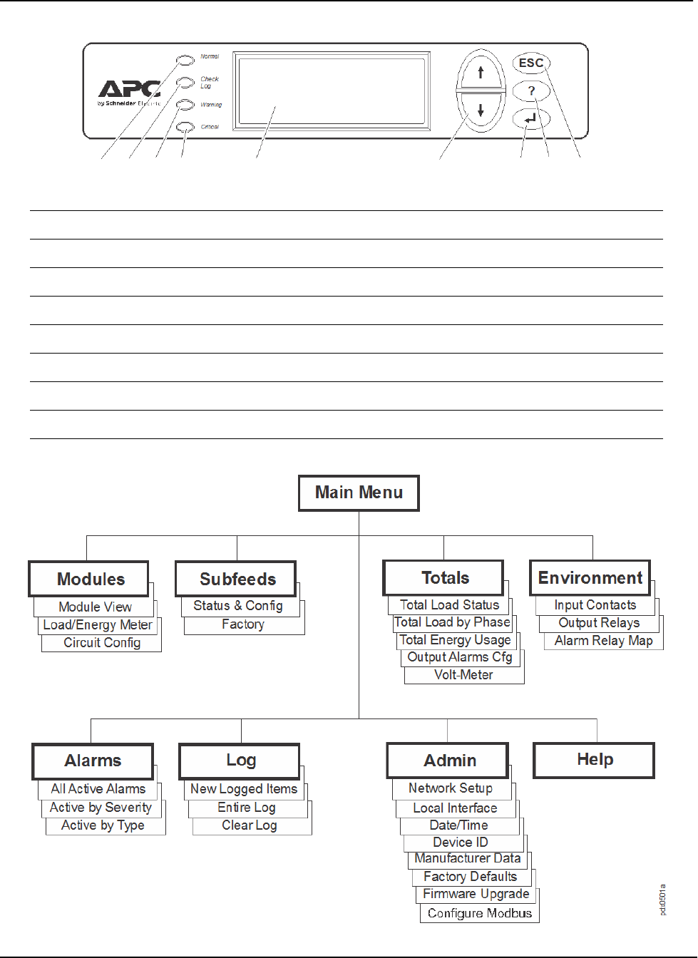
Display Interface
Menu tree
Normal LED Green = no alarms are present.
Check Log LED Green = a new event has been added to the log.
Warning LED Yellow = there are one or more active warning alarms in the system.
Critical LED Red = there are one or more active critical alarms in the system.
LCD Screen Displays alarms, status data, instructional help, and configuration items.
UP and DOWN keys Used to scroll through menu items.
ENTER Press to display new screens, open menu items, and finalize selections.
? - HELP Press to open content-sensitive help.
ESC Press to return to the previous screen.
990-4806 150/175 kVA Modular PDU Technical Specification 3
List Of Alarms
Network Management Card
The system is equipped with one embedded network management card for remote monitoring and
control of an individual Modular Power Distribution Unit (PDU) by connecting it directly to the
network.
• High Module Current
• High Subfeed Current
• High Total Output Current
• High Output Voltage
• Low Module Current
• Low Subfeed Current
• Low Total Output Current
• Low Output Voltage
• Maximum Module Current
• Maximum Subfeed Current
• Max Total Output Current
• Max Output Voltage
• Minimum Module Current
• Minimum Subfeed Current
• Min Total Output Current
• Min Output Voltage
• Modular Distribution Communication
• Module Breaker Open
• Output Frequency
• Subfeed Breaker Open
• Transformer Overheating
• Cooling Fan Failure
4 150/175 kVA Modular PDU Technical Specification 990-4806
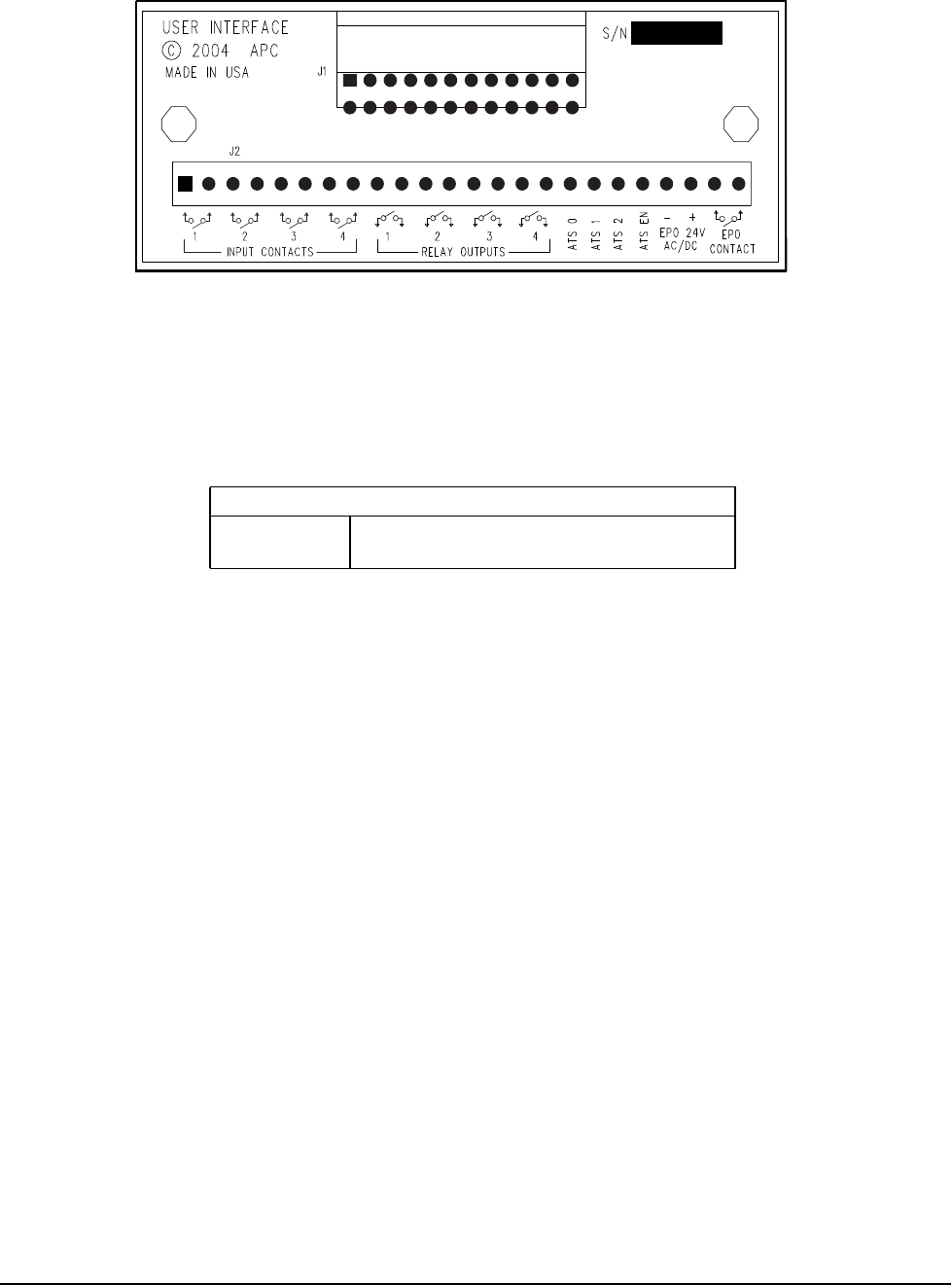
Input and Output Contacts
Note: Input Contacts are “Normally Open”
Available Output Contacts: SPST, 1A@30V
AST0, AST1, AST2, AST EN, EPO 24V AC/DC + ˗, and EPO CONTACT pair are reserved and not
available.
Wiring: 12 AWG to 30 AWG is recommended.
Compliance
• UL - UL 60950-1, 2nd Edition, 2007- 03 -27
• (Information Technology Equipment - Safety - Part 1: General Requirements)
• cUL - CSA C22.2 No. 60950-1-07, 2nd Edition, 2007 - 03
• (Information Technology Equipment - Safety - Part 1: General Requirements)
• The Conditional Short-Circuit Current Rating was not evaluated by Underwriters Laboratories.
User Interface Relay Outputs
Surge ratings Surge withstand voltage up to 2500VAC,
meets FCC Part 68 and Telecordia
pdx0420a

990-4806 150/175 kVA Modular PDU Technical Specification 5
Facility Planning
Input Specifications
Mains Input Voltage
Mains Input Current
Maximum Short-Circuit Withstand Rating
Frequency
PDPM150G6F PDPM150L6F PDPM175G6H
Grid system 3W + G+GEC
Input mains 3 Phase
Connection
Information:
Hardwire:
Max Input Conductor Size:
350MCM for Cu Cable
500MCM for Al Cable
Hardwire:
Max Input Conductor Size:
300MCM (Cu Cable Only)
Hardwire:
Max Input Conductor Size:
350MCM for Cu Cable
500MCM for Al Cable
Disconnect Molded Case Circuit Breaker (MCCB)
Nominal 480V 600V 480V
Nominal Current 178A 141A 214A
Maximum Continuous
Current with 100%
Rated Circuit Breaker
180A 150A 214A
Recommended current rating of input circuit breakers
Mains Input1 225 A 200 A 300 A
Inrush Currents
Inrush Current2 2000 A 1500 A 2100 A
1 Standard circuit breakers are rated to carry 80% of their current rating continuously.
2 The supply overcurrent protective device must be able to handle the listed transformer inrush currents.
PDPM150G6F PDPM150L6F PDPM175G6H
Max Short-Circuit
Withstand Rating* 65 kA 50 kA 30 kA
* The Maximum Short-Circuit Withstand Rating was not evaluated by Underwriters Laboratories.
Nominal 60Hz

6 150/175 kVA Modular PDU Technical Specification 990-4806
Output Specifications
Breakers
Recommended Conductor Sizes
Note: All wiring must comply with all applicable national and or local electrical codes.
Conductor sizing in this manual is based on Table 310-16 of the 2011 National Electrical Code (NEC) with
the following assertions:
• 90°C conductors (THHN) for 75°C termination
• 3 Current Carrying Conductors for Unit Input Circuit Breaker and 4 Current Carrying Conductors for
Subfeed Circuit Breaker
• An ambient temperature of 30°C
• Two conduits for each Subfeed
• One Equipment Grounding Conductor for each conduit
If the ambient room temperature is greater than 30°C, larger conductors are to be selected in accordance with
the correction factors of the NEC.
Equipment Grounding Conductors (EGC) are sized in accordance with NEC Article 250-122 and Table 250-
122.
Grounding Electrode Conductors (GEC) are sized in accordance with NEC Article 250-66 and Table 250-66.
PDPM150G6F PDPM150L6F PDPM175G6H
Grid System 208/120V, 3-pole modules 208/120V, 3-pole modules 415/240V, 3-pole modules
Number of Poles 72 72 72
Number of PDMs 24 24 24
Overload Protection yes yes yes
Full Load Rating 144KW @ 208V 144KW @ 208V 175KW @ 415V
Max Continuous
Current 400A 400A 243A
Nominal Voltage 208Y/120 V 208Y/120 V 415Y/240 V
Number of Subfeeds 2
PDPM150G6F PDPM150L6F PDPM175G6H
Location External to PDU, supplied
by others
External to PDU, supplied
by others
External to PDU, supplied
by others
OCP Rating 225A 200A 300A
Max Input Conductor
Size
See the Following Tables:
40° Ambient / 3CCC, 150 & 175 kW Modular PDU
30° Ambient / 3CCC, 150 & 175 kW Modular PDU
Terminal: Lug Size
Terminal Kit
(included with PDU):
dual lug
Terminal Kit
(included with PDU):
single lug
Terminal Kit
(included with PDU):
dual lug
Terminal: Cable Sizing
Dual Terminal:
from 2/0 AWG to 350
kcmil max for Copper,
from 2/0 AWG to 500
kcmil max for Aluminum.
Single terminal:
from 1/0 AWG to 300
kcmil max, Copper only.
Dual Terminal:
from 2/0 AWG to 350
kcmil max for Copper,
from 2/0 AWG to 500
kcmil max for Aluminum.

990-4806 150/175 kVA Modular PDU Technical Specification 7
The conductor sizes are recommendations for maximum configurations. Even if the load is less than the
maximum rating, it is wise to plan for future load increases. If the system is operated at a lower load than its
rating and it is desired to supply the system with a lower rated breaker and smaller conductors, conductor
ampacities are to be selected in accordance with the NEC. The transformer inrush must betaken into account
when sizing the circuit breaker.
40° Ambient / 3CCC, 150 & 175 kW Modular PDU
30° Ambient / 3CCC, 150 & 175 kW Modular PDU
PDPM150G6F
480:208
PDPM150L6F
600:208
PDPM175G6H
480:415
Mains Input Φ
Cu only: 250kcmil
75°C conductor minimum
Cu only: 3/0 AWG
90°C conductor minimum
Cu: 350kcmil
AL: 500kcmil
75°C conductor minimum
Equipment Grounding
Conductor (EGC)
Cu: 4 AWG Cu: 6 AWG Cu: 4 AWG
Al: 2 AWG
Grounding Electrode
Conductor (GEC)
Cu: 2 AWG Cu: 2 AWG Cu: 2 AWG
Al: 1/0 AWG
Output Supplied with Power Distribution Modules
4CCC Subfeed Output
Cu: (2) 300kcmil Φ and N,
3 AWG EGC,
GEC not required.
90°C conductor minimum
Cu: (2) 300kcmil Φ and N,
3 AWG EGC,
GEC not required.
90°C conductor minimum
Cu: (2) 2/0 AWG Φ and N,
4 AWG EGC,
GEC not required.
Al: (2) 4/0 AWG Φ and N,
2 AWG EGC,
GEC not required.
75°C conductor minimum
PDPM150G6F
480:208
PDPM150L6F
600:208
PDPM175G6H
480:415
Mains Input Φ
Cu: 4/0 AWG
A1: 300kcmil
75°C conductor minimum
Cu: 3/0 AWG
90°C conductor minimum
Cu: 300kcmil
Al: 400kcmil
75°C conductor minimum
Equipment Grounding
Conductor (EGC)
Cu: 4 AWG
A1: 2 AWG
Cu: 6 AWG Cu: 4 AWG
Al: 2 AWG
Grounding Electrode
Conductor (GEC)
Cu: 2 AWG
A1: 1/0 AWG
Cu: 2 AWG Cu: 2 AWG
Al: 1/0 AWG
Output Supplied with Power Distribution Modules
4CCC Subfeed Output
Cu: (2) 250kcmil Φ and N,
3 AWG EGC,
GEC not required.
Al: (2) 350 kcmil Φ and N,
1 AWG EGC,
GEC not required.
90°C conductor minimum
Cu: (2) 250kcmil Φ and N,
3 AWG EGC,
GEC not required.
Al: (2) 350 kcmil Φ and N,
1 AWG EGC,
GEC not required.
90°C conductor minimum
Cu: (2) 2/0 AWG Φ and N,
4 AWG EGC,
GEC not required.
Al: (2) 3/0 AWG Φ and N,
2 AWG EGC,
GEC not required.
75°C conductor minimum
Φ = phase, N = neutral
(2) = two conductors per phase and neutral (when neutral is required)
Subfeed is required to have two conductors per phase & N for full output due to limited wire bend space
Cu= Copper conductors, Al= Aluminum conductors
CCC = Current Carrying Conductor
8 150/175 kVA Modular PDU Technical Specification 990-4806
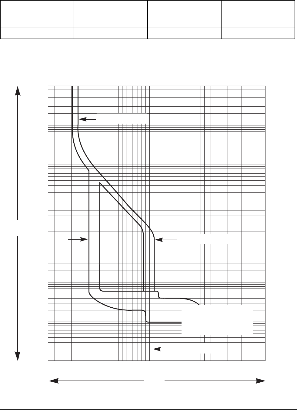
CB1
STR23SP
Merlin Gerin - Trip Units for Compact® NSJ400-NSJ600 Circuit Breakers
PDPM150G6F
480:208
PDPM150L6F
600:208
PDPM175G6H
480:415
Tripping Curve See ‘STR23SP’ See ‘JLF361150C’ See ‘STR23SP’
Type Merlin Gerin Square D Merlin Gerin
STR23SP
10 000
5 000
2 000
1 000
500
200
100
50
20
10
5
2
1
.5
.2
.1
.05
.02
.01
.005
.002
.001
t(s)
I / Ir
I = 11 x In
Ir = 0.4–1 x In
Im = 2–9 x Ir
Reflex Tripping:
t < 10 ms
06153218
.5 .7 12345710 20 30 50 70 100 200 300
990-4806 150/175 kVA Modular PDU Technical Specification 9
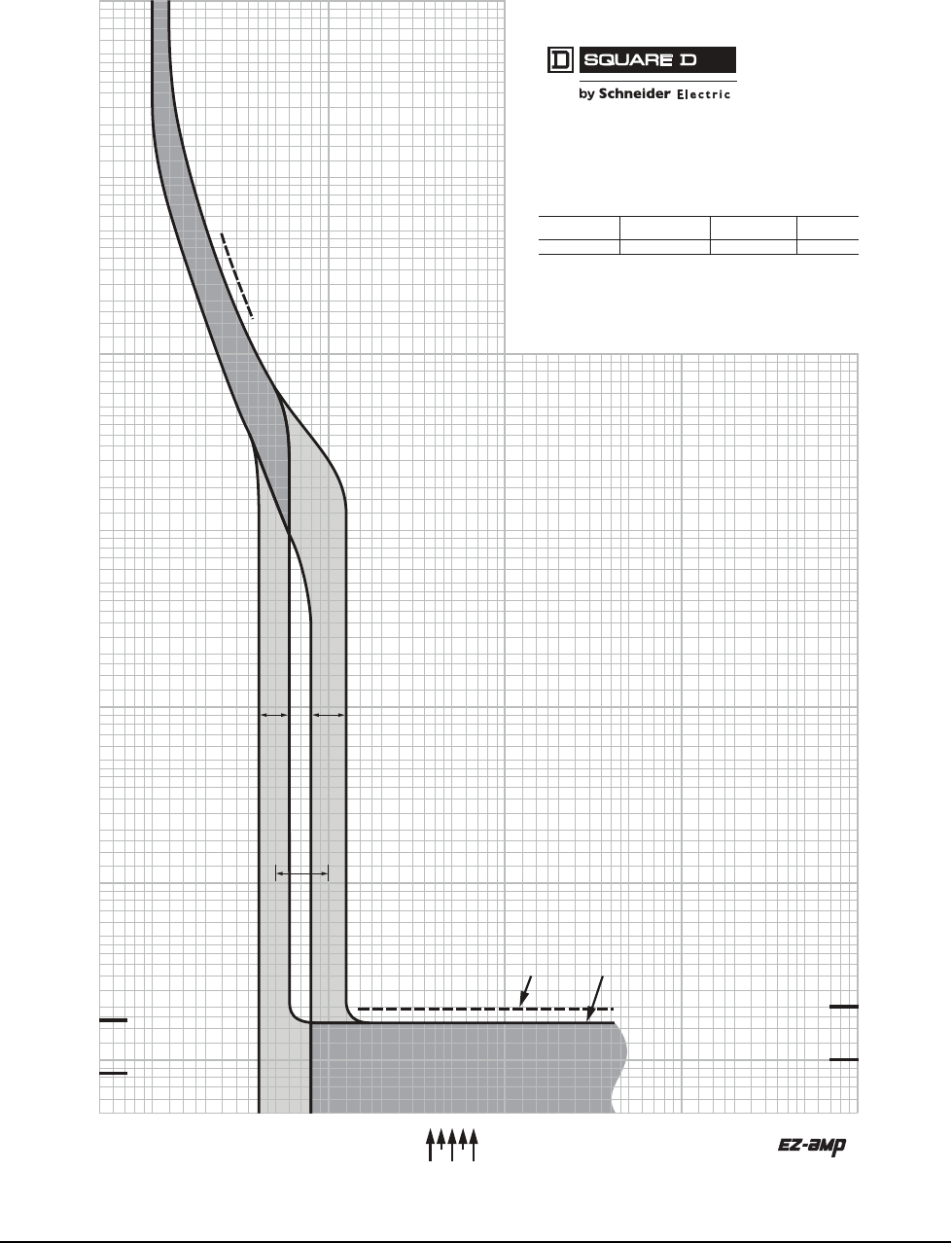
JLF361150C
2011 Schneider Electric
All Rights Reserved
J-Frame 150–250 A (JD, JG, JJ, and JL)
Thermal-Magnetic Trip
1.5
700
150
200
300
400
600
800
900
2000
3000
4000
5000
7000
8000
9000
10000
.5
.6
.7
.8
.9
1
2
3
4
5
6
7
8
9
10
15
20
30
40
50
60
70
80
90
100
6000
1500
1000
500
.005
.006
.007
.008
.009
.01
.015
.02
.03
.04
.05
.06
.07
.08
.09
.1
.15
.2
.3
.4
.5
.6
.7
.8
.9
1
1.5
2
3
4
5
6
7
8
9
10
20
30
40
50
60
70
80
90
100
15
200
300
400
500
600
700
800
900
1000
1500
2000
3000
4000
6000
7000
8000
9000
5000
10000
1
.5
.6
.7
.8
.9
1.5
2
3
4
5
6
7
8
9
10
15
20
30
40
50
60
70
80
90
100
MULTIPLES OF RATED CURRENT
TIME IN SECONDS
.005
.006
.007
.008
.009
.01
.015
.02
.03
.04
.05
.06
.07
.08
.09
.1
.15
.2
.3
.4
.5
.6
.7
.8
.9
1
1.5
2
3
4
5
6
7
8
9
10
15
20
30
40
50
60
70
80
90
100
150
200
300
400
500
600
700
800
900
1000
1500
2000
3000
4000
5000
6000
7000
8000
9000
10000
TIME IN SECONDS
1/2 CYCLE
(60 Hz)
1/2 CYCLE
(50 Hz)
150
200
300
400
500
600
700
800
900
1000
1500
2000
3000
4000
5000
6000
7000
8000
9000
10000
150
MULTIPLES OF RATED CURRENT
1 CYCLE
(60 Hz)
1 CYCLE
(50 Hz)
LIMITS HIGH
SETTING
LIMITS LOW
SETTING
MAGNETIC TRIP
ADJUSTMENT RANGE
MAXIMUM CLEARING TIME
(AT 50 Hz) (AT 60 Hz)
225
200
150
250
175
MAXIMUM SINGLE-POLE TRIP TIMES
AT 25 °C BASED ON NEMA AB-4 2003
JD, JG, JJ, JL MOLDED CASE CIRCUIT BREAKERS
CHARACTERISTIC TRIP CURVE NO. 50-5
CIRCUIT BREAKER INFORMATION
Circuit Breaker Continuous Maximum Number
Prex Ampere Rating AC Voltage of Poles
JD, JG, JJ, JL 150–250 600 2, 3
This curve is to be used for application and coordination purposes only. The
EZ-AMP overlay feature at the bottom of the page should be used during
coordination studies.
All time/current characteristic curve data is based on 40°C ambient cold start.
Terminations are made with conductors of appropriate length and ratings.
Curve No. 0050TC0405
June 2004
Drawing No. 48095-050-05
TM
10 150/175 kVA Modular PDU Technical Specification 990-4806
Environmental
Transformer Specifications
PDPM150G6F PDPM150L6F PDPM175G6H
Operating Temp -5 to +40°C
(23 to 104°F)
Storage Temp -25 to +65°C
(-13 to 149°F)
Operating Humidity 0 to 95%, non-condensing
Storage Humidity 0 to 95%, non-condensing
Max Operating Elevation 3,000 m
(9,842.5 ft)
Max Storage Elevation 15 000 m
(50,000 ft)
Operating Environment Protected from water and conductive contaminants.
Storage Environment Protected from water and conductive contaminants.
Full Load Heat Loss @ Nominal Mains 3.128 kW/hr
(10672.7 BTU/hr)
3.272 kW/hr
(11164.1 BTU/hr)
3.441 kW/hr
(11740.7 BTU/hr)
Airflow/Cooling Requirement Front to rear airflow
PDPM150G6F PDPM150L6F PDPM175G6H
Size 150kVA 150kVA 175kVA
Type Isolated
Transformer
Isolated
Transformer
Isolated
Transformer
Configuration Delta/Wye Delta/Wye Delta/Wye
Input Voltage 480V 600V 480V
Input Current 180A 150A 214A
Inrush Current Not to exceed 10X Nominal Input Current Per Phase
Output Voltage 208Y/120V 208Y/120V 415Y/240V
Output Current 400A 400A 243A
Thermal Sensing 180°C 180°C 180°C
Weight 900 lb
(409 kg)
900 lb
(409 kg)
1232 lb
(560 kg)
Impedance in %IZ 3 - 6% 3 - 6% 3 - 6%
Frequency 60 Hz 60 Hz 60 Hz
Frequency Range 57-63Hz 57-63Hz 57-63Hz
Noise <55db @ Im <55db @ Im <55db @ Im
Windings Copper - Each coil to be made from a continuous
conductor (wire or foil).
Insulation rating 180°C 180°C 180°C
Efficiency >98.2% >98.2% >98.5%

990-4806 150/175 kVA Modular PDU Technical Specification 11
Dimensions
PDPM150G6F PDPM150L6F PDPM175G6H
Unpackaged Dimensions
(H × W × D)
79.0 x 23.6 x 42.1 in.
(2007 x 600 x 1069 mm)
79.0 x 23.6 x 42.1 in.
(2007 x 600 x 1069 mm)
79.0 x 23.6 x 42.1 in.
(2007 x 600 x 1069 mm)
Shipping Dimensions
(H x W x D)
84.8 x 40 x 48.0 in.
(2153 x 1016 x 1219 mm)
84.8 x 40 x 48.0 in.
(2153 x 1016 x 1219 mm)
84.8 x 40 x 48.0 in.
(2153 x 1016 x 1219 mm)
Weight
(Unpopulated PDU)
1843.1 lb
(836 kg)
1942.3 lb
(881 kg)
2074.6 lb
(941 kg)
Shipping weight
(Unpopulated PDU)
1944.5 lb
(882 kg)
2043.7
(927 kg)
2176.0 lb
(987 kg)
Free space around PDU:
Minimum Recommended
Front Service Clearance*
42.0 in.
(1066.8 mm)
Minimum Recommended
Rear Service Clearance*
36 in.
(914.4 mm)
Side Clearance* Right: 24 in. (609.6 mm)
Left: None Required
Minimum Top Ventilation
Clearance*
8.25 in.
(210 mm)
* In establishing and verifying proper clearance, ensure full compliance with all applicable national, state, and
local electrical codes.
Color Black
Input Power Entry Cable
Route
(Top, Bottom, Both)
Top Top Top
Output Power Exit Cable
Route (Top, Bottom, Both) Top Top Top
Conduit Size Defined by input wiring
Size of Roof Hole or Bottom
Plate for Conduit Hole is punched by customer according to conduit size.

12 150/175 kVA Modular PDU Technical Specification 990-4806
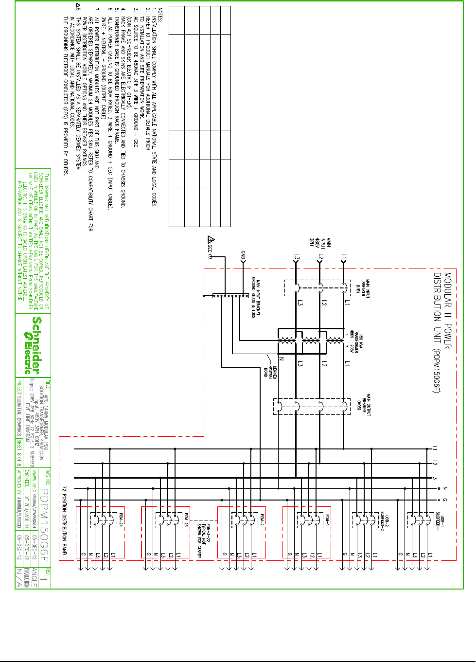
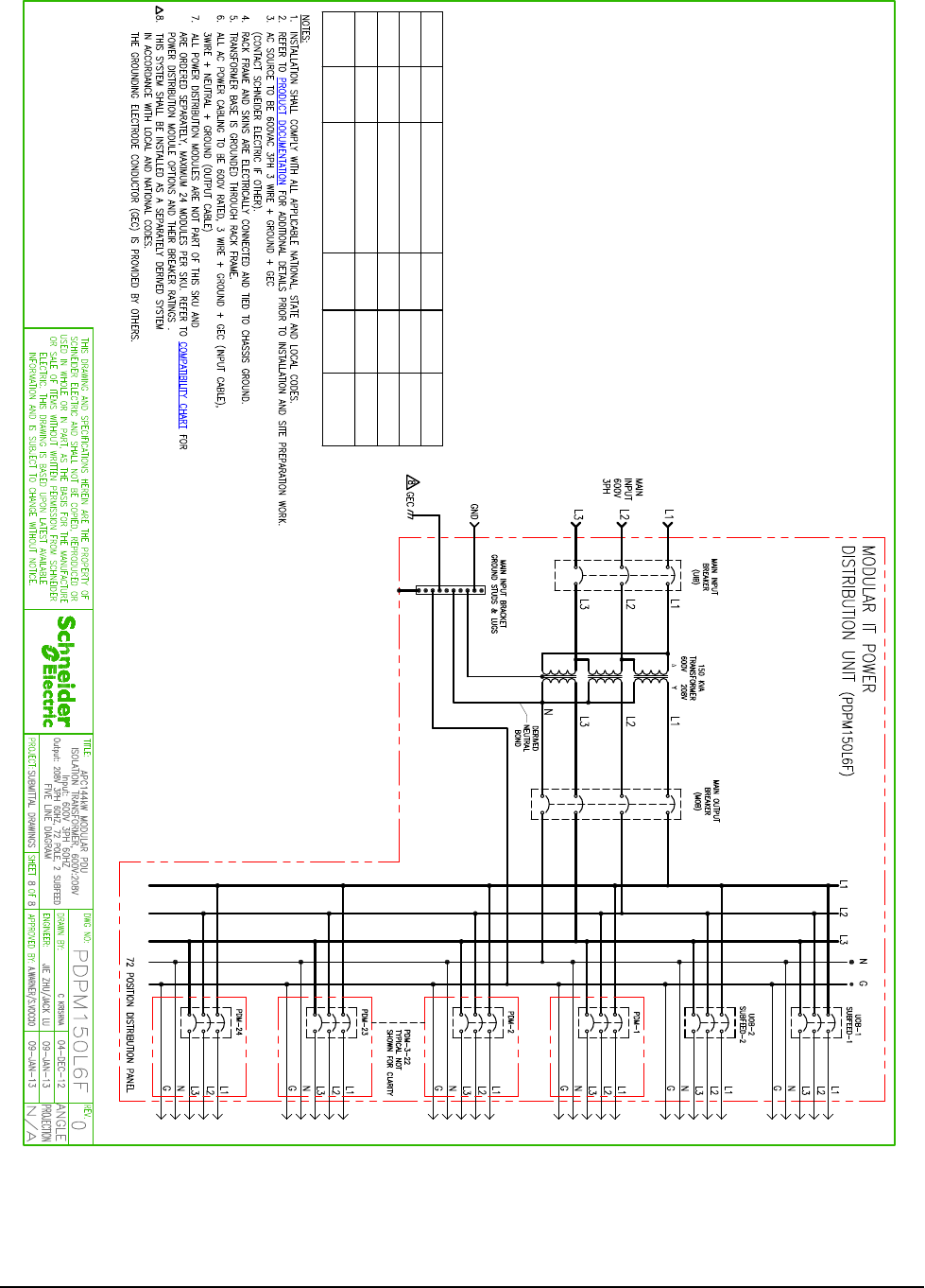
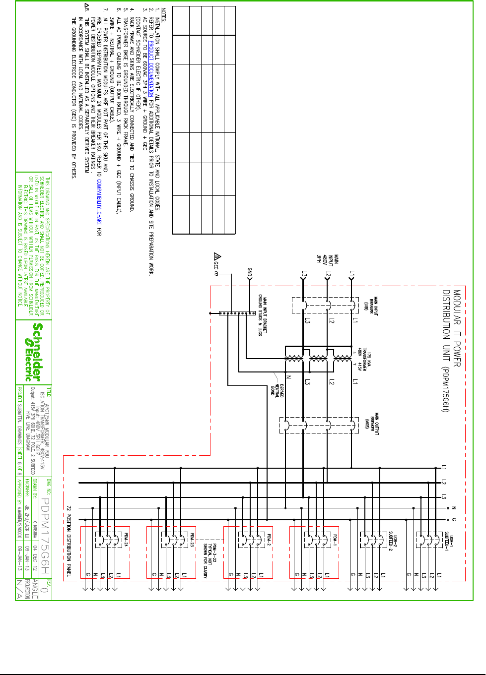
Drawings
Note: These drawings are for reference ONLY - subject to change without notice.
Note: A comprehensive set of drawings is available on the APC Web site: www.apc.com
990-4806 150/175 kVA Modular PDU Technical Specification 13
SUBFEED
BREAKER 400A, 600V 3 POLE BREAKER MERLIN GERIN NJHF36400E20
(100% Rated)
65kA
SYMMETRICAL
DEVISE RATED SHORT
CIRCUIT CURRENT
RATING
(100% Rated) TYPE MAKE MODEL
4 POLE BREAKER MERLIN GERIN NJHS46400E20
(100% Rated)
65kA
SYMMETRICAL
3 POLE BREAKER MERLIN GERIN NJHF36400E20
(100% Rated)
65kA
SYMMETRICAL
400A, 600VUIB
7 ETON EESV004X-ELUDOM 10kA
SYMMETRICAL
POWER DISTRIBUTION MODULE SCHNEIDER
ELECTRIC
400A, 600VMOB
14 150/175 kVA Modular PDU Technical Specification 990-4806
SUBFEED
BREAKER 400A, 600V 3 POLE BREAKER MERLIN GERIN NJHF36400E20
(100% Rated)
65kA
SYMMETRICAL
DEVISE RATED SHORT
CIRCUIT CURRENT
RATING
(100% Rated) TYPE MAKE MODEL
4 POLE BREAKER MERLIN GERIN NJHS46400E20
(100% Rated)
65kA
SYMMETRICAL
3 POLE BREAKER SQUARE D JLF36150CYE
(100% Rated)
50kA
SYMMETRICAL
150A, 600VUIB
7 ETON EESV004X-ELUDOM 10kA
SYMMETRICAL
POWER DISTRIBUTION MODULE SCHNEIDER
ELECTRIC
400A, 600VMOB
990-4806 150/175 kVA Modular PDU Technical Specification 15
SUBFEED
BREAKER 400A, 600V 3 POLE BREAKER MERLIN GERIN NJHF36400E20
(100% Rated)
65kA
SYMMETRICAL
400A, 600VUIB
7 ETON EESV042X-ELUDOM 10kA
SYMMETRICAL
POWER DISTRIBUTION MODULE SCHNEIDER
ELECTRIC
400A, 600V NIREG NILREMREKAERB ELOP 4BOM NJHS46400E20
(100% Rated)
65kA
SYMMETRICAL
3 POLE BREAKER MERLIN GERIN NJHF36400E20
(100% Rated)
65kA
SYMMETRICAL
DEVISE RA TE D SHORT
CIRCUIT CURRENT
RATING
(100% Rated) TYPE MAKE MODEL

16 150/175 kVA Modular PDU Technical Specification 990-4806
Options
Hardware Options
Power Distribution Modules
The following APC Power Distribution Modules (PDMs) are intended for, and can be installed in the following
208V Modular PDUs:
APC Power Distribution Modules for 208V Modular PDUs
208V Power Distribution Modules have black buss plates which match the black 208V PDU backplane. These
PDMs require one (1) Modular PDU slot position.
Notes:
APC Modular Power
Distribution Units
PDPM150G6F
PDPM150L6F
Module # cords Voltage Amperage
(Qty)
Circuit
Breakers
(Qty)
Connector
PDM1320L5-3P-x 3 120V 20A (3) 1P
(3) 3-wire
NEMA
L5-20R
PDM3520L2120-xxx 1 120V 20A (3) 1P
(1) 5-wire
NEMA
L21-20
PDM3530L2130-xxx 1 120V 30A (3) 1P
(1) 5 wire
NEMA
L21-30
PDM3450CS50-xxx 1 208V 50A (1) 3P (1) 4 wire
CS50
PDM3460IEC309-xxx 1 208V 60A (1) 3P
(1) 4 wire
(3P+PE) IEC
309 60A
PDM2330L6-xx-yyy 1 208V 30A (1) 2P
(1) 3 wire
NEMA
L6-30R
Input frequency: 50/60Hz
Certifications: UL Listed
Cable rating of Power Distribution Modules: TC-ER, DP-1. Approved for under floor usage per NFPA
645.5(E) and 645.5(E)(3) when used in a designated IT Site as defined in NFPA Article 645, Information
Technology Equipment.
The PDM3460IEC309-xxx PDMs use a 4-wire IEC 309 connector with a 9 o'clock ground position.
Unless otherwise noted, 1-cord Power Distribution Modules are available with these cord lengths:
200, 260, 320, 380, 440, 500, 560, 620, 680, 740, 800, 860, 920, 980, 1040, 1680
Unless otherwise noted, all 3-cord Power Distribution Modules are available with these cord lengths:
Option 1: PDM with 260, 380, and 500 cm cables
Option 2: PDM with 680, 860, and 1040 cm cables
Option 3: PDM with three 1680 cm cables
990-4806 150/175 kVA Modular PDU Technical Specification 17
Power Distribution Modules continued
The following APC Power Distribution Modules (PDMs) are intended for and can be installed in the following
415V Modular PDUs:
APC Power Distribution Modules for 415V Modular PDUs
415V Power Distribution Modules have gray buss plates which match the gray 415V PDU backplane. These
PDMs require one (1) Modular PDU slot position.
Notes:
APC Modular Power
Distribution Units
PDPM175G6H
Module # cords Voltage Amperage (Qty) Circuit
Breakers
(Qty)
Connector
PDM1320IEC-3P-x 3 240V 20A (3) 1P (3) 3-wire IEC
309 20A
PDM3520IEC309-xxx* 1 240V 20A (3) 1P (1) 5-wire
IEC 309
PDM3540IEC309-xxx 1 240V 40A (3) 1P (1) 5-wire
IEC 309
Input frequency: 50/60Hz
Certifications: UL Listed
Cable rating of Power Distribution Modules: TC-ER, DP-1. Approved for under floor usage per NFPA
645.5(E) and 645.5(E)(3) when used in a designated IT Site as defined in NFPA Article 645, Information
Technology Equipment.
The PDM3520IEC309-xxx and PDM3540IEC309-xxx PDMs use a 5-wire IEC 309 connector with a 6
o'clock ground position.
Unless otherwise noted, 1-cord Power Distribution Modules are available with these cord lengths:
200, 260, 320, 380, 440, 500, 560, 620, 680, 740, 800, 860, 920, 980, 1040, 1680
Unless otherwise noted, all 3-cord Power Distribution Modules are available with these cord lengths:
Option 1: PDM with 260, 380, and 500 cm cables
Option 2: PDM with 680, 860, and 1040 cm cables
Option 3: PDM with three 1680 cm cables
*PDM3520IEC309-xxx is also available with 80 and 140 cm cord lengths

18 150/175 kVA Modular PDU Technical Specification 990-4806
Seismic Kit
Bottom Feed Side Cars
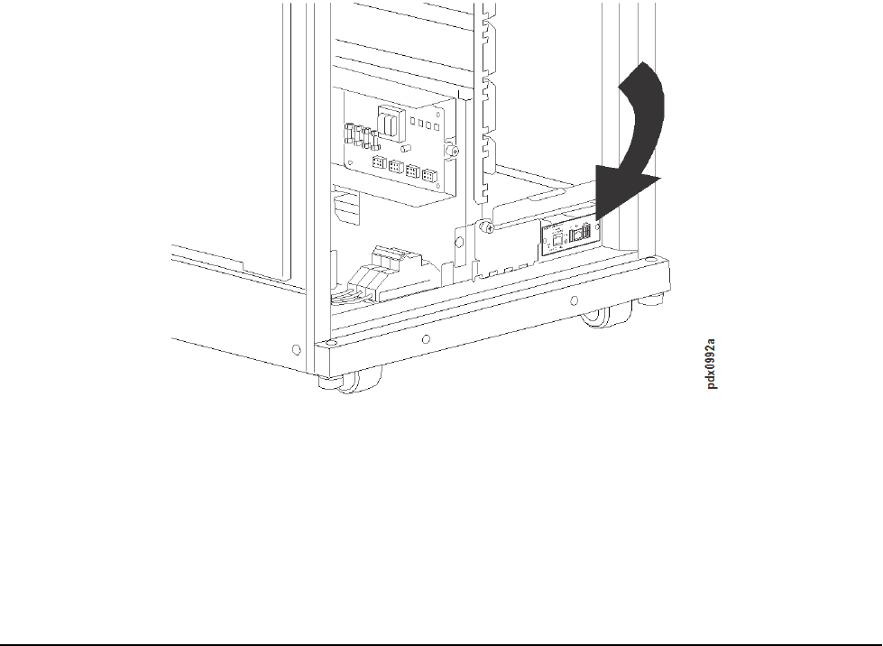
Shunt Trip
Square D shunt trip unit models for field installation:
S29384 for 24VAC
S29382 for 12VAC
S29390 for 24VDC
S29391 for 30VDC
Configuration Options
• StruxureWare Data Center Expert
• Network Manageable
• Seismic bracket kits available
• Optional Bottom Feed Side Car for bottom feed input/output
SYOPT600 Seismic Kit for 300mm Symmetra PX 100, Symmetra PX 250/500,
and Modular PDU Frames
SKU Description Compatible PDUs
PDPM100SC APC Symmetra PX 100kW Bottom Feed Side Car,
300mm
PDPM175G6H
PDPM150SC APC 150KVA Modular PDU Bottom Feed Side
Car, 300mm
PDPM150G6F
PDPM150L6F

990-4806 150/175 kVA Modular PDU Technical Specification 19
Warranty
SCHNEIDER ELECTRIC IT CORPORATION
LIMITED FACTORY WARRANTY
Three Phase Power Products or Cooling Solutions One-Year Factory Warranty1
The limited warranty provided by Schneider Electric IT Corporation (SE IT) in this Statement of Limited
Factory Warranty applies only to products you purchase for your commercial or industrial use in the ordinary
course of your business.
Terms of Warranty
SE IT warrants that the product shall be free from defects in materials and workmanship for a period of one
year from the date of product start-up when start-up is performed by SE IT authorized service personnel and
occurs within six months of The SE IT shipment date. This warranty covers repairing or replacing any
defective parts including on-site labor and travel. In the event that the product fails to meet the foregoing
warranty criteria, the warranty covers repairing or replacing defective parts at the sole discretion of SE IT for a
period of one year from the shipment date. For SE IT cooling solutions, this warranty does not cover circuit
breaker resetting, loss of refrigerant, consumables, or preventive maintenance items. Repair or replacement of
a defective product or part thereof does not extend the original warranty period. Any parts furnished under this
warranty may be new or factory-remanufactured.
Non-transferable Warranty
This warranty is extended to the first person, firm, association or corporation (herein referred to by “You” or
“Your”) for whom the SE IT product specified herein has been purchased. This warranty is not transferable or
assignable without the prior written permission of SE IT.
Assignment of Warranties
SE IT will assign you any warranties which are made by manufacturers and suppliers of components of the SE
IT product and which are assignable. Any such warranties are assigned “AS IS” and SE IT makes no
representation as to the effectiveness or extent of such warranties, assumes no responsibility for any matters
which may be warranted by such manufacturers or suppliers and extends no coverage under this Warranty to
such components.
Drawings, descriptions
SE IT warrants for the warranty period and on the terms of the warranty set forth herein that the SE IT product
will substantially conform to the descriptions contained in the SE IT Official Published Specifications or any
of the drawings certified and agreed to by contract with SE IT if applicable thereto (“Specifications”). It is
understood that the Specifications are not warranties of performance and not warranties of fitness for a
particular purpose.
1 To determine which factory warranty applies to the SE IT product you purchased, please consult the
factory warranties located on the SE IT web site: www.apc.com/products

20 150/175 kVA Modular PDU Technical Specification 990-4806
Exclusions
SE IT shall not be liable under the warranty if its testing and examination disclose that the alleged defect in the
product does not exist or was caused by end user or any third person misuse, negligence, improper installation
or testing. Further SE IT shall not be liable under the warranty for unauthorized attempts to repair or modify
wrong or inadequate electrical voltage or connection, inappropriate on-site operation conditions, corrosive
atmosphere, repair, installation, start-up by non-SE IT designated personnel, a change in location or operating
use, exposure to the elements, Acts of God, fire, theft, or installation contrary to SE IT recommendations or
specifications or in any event if the SEIT serial number has been altered, defaced, or removed, or any other
cause beyond the range of the intended use.
THERE ARE NO WARRANTIES, EXPRESS OR IMPLIED, BY OPERATION OF LAW OR OTHERWISE,
OF PRODUCTS SOLD, SERVICED OR FURNISHED UNDER THIS AGREEMENT OR IN
CONNECTION HEREWITH. SE IT DISCLAIMS ALL IMPLIED WARRANTIES OF
MERCHANTABILITY, SATISFACTION AND FITNESS FOR A PARTICULAR PURPOSE. SE IT
EXPRESS WARRANTIES WILL NOT BE ENLARGED, DIMINISHED, OR AFFECTED BY AND NO
OBLIGATION OR LIABILITY WILL ARISE OUT OF, SE IT RENDERING OF TECHNICAL OR OTHER
ADVICE OR SERVICE IN CONNECTION WITH THE PRODUCTS. THE FOREGOING WARRANTIES
AND REMEDIES ARE EXCLUSIVE AND IN LIEU OF ALL OTHER WARRANTIES AND REMEDIES.
THE WARRANTIES SET FORTH ABOVE CONSTITUTE SE IT SOLE LIABILITY AND PURCHASER’S
EXCLUSIVE REMEDY FOR ANY BREACH OF SUCH WARRANTIES. SE IT WARRANTIES RUN
ONLY TO PURCHASER AND ARE NOT EXTENDED TO ANY THIRD PARTIES.
IN NO EVENT SHALL SE IT, ITS OFFICERS, DIRECTORS, AFFILIATES OR EMPLOYEES BE LIABLE
FOR ANY FORM OF INDIRECT, SPECIAL, CONSEQUENTIAL OR PUNITIVE DAMAGES, ARISING
OUT OF THE USE, SERVICE OR INSTALLATION, OF THE PRODUCTS, WHETHER SUCH DAMAGES
ARISE IN CONTRACT OR TORT, IRRESPECTIVE OF FAULT, NEGLIGENCE OR STRICT LIABILITY
OR WHETHER SE IT HAS BEEN ADVISED IN ADVANCE OF THE POSSIBILITY OF SUCH
DAMAGES, SPECIFICALLY, SE IT IS NOT LIABLE FOR ANY COSTS, SUCH AS LOST PROFITS OR
REVENUE, LOSS OF EQUIPMENT, LOSS OF USE OF EQUIPMENT, LOSS OF SOFTWARE, LOSS OF
DATA, COSTS OF SUBSTITUANTS, CLAIMS BY THIRD PARTIES, OR OTHERWISE. NO SALESMAN,
EMPLOYEE OR AGENT OF SE IT IS AUTHORIZED TO ADD TO OR VARY THE TERMS OF THIS
WARRANTY. WARRANTY TERMS MAY BE MODIFIED, IF AT ALL, ONLY IN WRITING SIGNED BY
AN SE IT OFFICER AND LEGAL DEPARTMENT.
Warranty Claims
Customers with warranty claims issues may access the SE IT worldwide customer support network through the
SE IT web site: support.apc.com. Select your country from the country selection pull-down menu. Open the
Support tab at the top of the web page to obtain contact information for customer support in your region.
Worldwide Customer Support
Customer support is available at no charge via e-mail or telephone. Contact information is available at
www.apc.com/support/contact.
8/2013
990-4806
© 2013 Schneider Electric, APC and the APC logo are owned by Schneider Electric Industries S.A.S., or its affiliated
companies. All other trademarks are property of their respective owners.
