MR E A/AG QW003 INSTRUCTION MANUAL ES
User Manual:
Open the PDF directly: View PDF ![]() .
.
Page Count: 266 [warning: Documents this large are best viewed by clicking the View PDF Link!]
- Safety Instructions
- DISPOSAL OF WASTE
- COMPLIANCE WITH CE MARKING
- COMPLIANCE WITH UL/cUL STANDARD
- About the manuals
- Wiring
- CONTENTS
- 1. FUNCTIONS AND CONFIGURATION
- 2. INSTALLATION
- 3. SIGNALS AND WIRING
- 3.1 Standard connection example
- 3.2 Internal connection diagram of servo amplifier
- 3.3 I/O signals
- 3.4 Detailed description of the signals
- 3.5 Alarm occurrence timing chart
- 3.6 Interfaces
- 3.7 Input power supply circuit
- 3.8 Servo motor with electromagnetic brake
- 3.9 Grounding
- 3.10 Servo amplifier connectors (CNP1, CNP2) wiring method (When MR-ECPN1-B and MR-ECPN2-B of an option are used.)
- 3.11 Instructions for the 3M connector
- 4. OPERATION
- 5. PARAMETERS
- 6. DISPLAY AND OPERATION
- 7. GENERAL GAIN ADJUSTMENT
- 8. SPECIAL ADJUSTMENT FUNCTIONS
- 9. INSPECTION
- 10. TROUBLESHOOTING
- 11. OUTLINE DIMENSION DRAWINGS
- 12. CHARACTERISTICS
- 13. OPTIONS AND AUXILIARY EQUIPMENT
- 14. MR-E- AG-QW003 SERVO AMPLIFIER COMPATIBLE WITH ANALOG INPUT
- APPENDIX
- REVISIONS
- Warranty

SH (NA) 030075-B (1210) MEE Printed in Japan Specifications subject to change without notice.
This Instruction Manual uses recycled paper.
MR-E- A-QW003/MR-E- AG-QW003 Instruction Manual
General-Purpose AC Servo
EZMOTION MR-E Super
General-Purpose Interface
MODEL
MR-E- A-QW003
INSTRUCTION MANUAL
MR-E- AG-QW003
HEAD OFFICE : TOKYO BLDG MARUNOUCHI TOKYO 100-8310
HF-KN/HF-SN servo motor is available for the servo amplifier with
software version A9 or later.
For HF-KN/HF-SN servo motor, refer to HF-KN/HF-SN Servo Motor
Instruction Manual (SH030123).
MODEL
MODEL
CODE 1CW705
MR-E-A/AG-QW003
INSTRUCTIONMANUAL
B
B
Safety Instructions
(Always read these instructions before using the equipment.)
Do not attempt to install, operate, maintain or inspect the servo amplifier and servo motor until you have read
through this Instruction Manual, Installation guide, Servo motor Instruction Manual and appended documents
carefully and can use the equipment correctly. Do not use the servo amplifier and servo motor until you have a
full knowledge of the equipment, safety information and instructions.
In this Instruction Manual, the safety instruction levels are classified into "WARNING" and "CAUTION".
WARNING Indicates that incorrect handling may cause hazardous conditions,
resulting in death or severe injury.
CAUTION Indicates that incorrect handling may cause hazardous conditions,
resulting in medium or slight injury to personnel or may cause physical
damage.
Note that the CAUTION level may lead to a serious consequence according to conditions. Please follow the
instructions of both levels because they are important to personnel safety.
What must not be done and what must be done are indicated by the following diagrammatic symbols.
: Indicates what must not be done. For example, "No Fire" is indicated by .
: Indicates what must be done. For example, grounding is indicated by .
In this Instruction Manual, instructions at a lower level than the above, instructions for other functions, and so
on are classified into "POINT".
After reading this installation guide, always keep it accessible to the operator.
A - 1
1. To prevent electric shock, note the following
WARNING
Before wiring or inspection, turn off the power and wait for 15 minutes or more until the charge lamp turns
off. Otherwise, an electric shock may occur. In addition, always confirm from the front of the servo
amplifier, whether the charge lamp is off or not.
Connect the servo amplifier and servo motor to ground.
Any person who is involved in wiring and inspection should be fully competent to do the work.
Do not attempt to wire the servo amplifier and servo motor until they have been installed. Otherwise, you
may get an electric shock.
Operate the switches with dry hand to prevent an electric shock.
The cables should not be damaged, stressed, loaded, or pinched. Otherwise, you may get an electric
shock.
To prevent an electric shock, always connect the protective earth (PE) terminal (terminal marked ) of the
servo amplifier to the protective earth (PE) of the control box.
When using a residual current device (RCD), select the type B.
Insulate the connections of the power supply terminals to prevent an electric shock.
2. To prevent fire, note the following
CAUTION
Install the servo amplifier, servo motor and regenerative resistor on incombustible material. Installing them
directly or close to combustibles will lead to a fire.
Always connect a magnetic contactor between the main circuit power supply and L1, L2, and L3 of the
servo amplifier, and configure the wiring to be able to shut down the power supply on the side of the servo
amplifier’s power supply. If a magnetic contactor is not connected, continuous flow of a large current may
cause a fire when the servo amplifier malfunctions.
When a regenerative resistor is used, use an alarm signal to switch main power off. Otherwise, a
regenerative transistor fault or the like may overheat the regenerative resistor, causing a fire.
Provide adequate protection to prevent screws and other conductive matter, oil and other combustible
matter from entering the servo amplifier, and servo motor.
Always connect a molded-case circuit breaker to the power supply of the servo amplifier.
3. To prevent injury, note the follow
CAUTION
Only the voltage specified in the Instruction Manual should be applied to each terminal, Otherwise, a
burst, damage, etc. may occur.
Connect the terminals correctly to prevent a burst, damage, etc.
Ensure that polarity ( , ) is correct. Otherwise, a burst, damage, etc. may occur.
Take safety measures, e.g. provide covers, to prevent accidental contact of hands and parts (cables, etc.)
with the servo amplifier heat sink, regenerative resistor, servo motor, etc. since they may be hot while
power is on or for some time after power-off. Their temperatures may be high and you may get burnt or a
parts may damaged.
During operation, never touch the rotating parts of the servo motor. Doing so can cause injury.
A - 2
4. Additional instructions
The following instructions should also be fully noted. Incorrect handling may cause a fault, injury, electric
shock, etc.
(1) Transportation and installation
CAUTION
Transport the products correctly according to their mass.
Stacking in excess of the specified number of products is not allowed.
Do not carry the servo motor by the cables, shaft or encoder.
Install the servo amplifier in a load-bearing place in accordance with the Instruction Manual.
Do not get on or put heavy load on the equipment.
The servo amplifier and servo motor must be installed in the specified direction.
Leave specified clearances between the servo amplifier and control enclosure walls or other equipment.
Do not install or operate the servo amplifier and servo motor which has been damaged or has any parts
missing.
Do not block intake and exhaust areas of the servo amplifier. Doing so may cause malfunction to the
equipment.
Do not drop or strike servo amplifier or servo motor. Isolate from all impact loads.
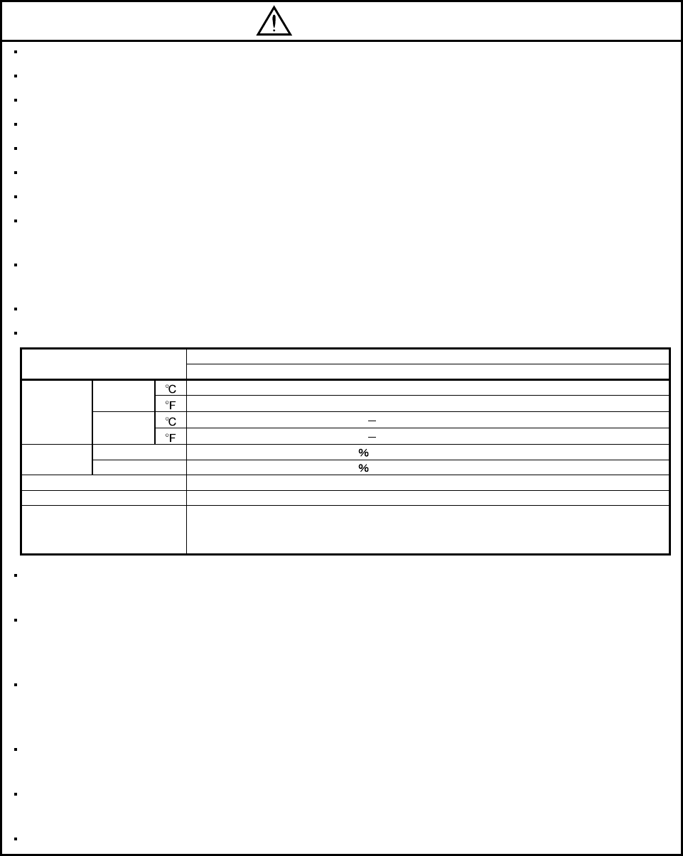
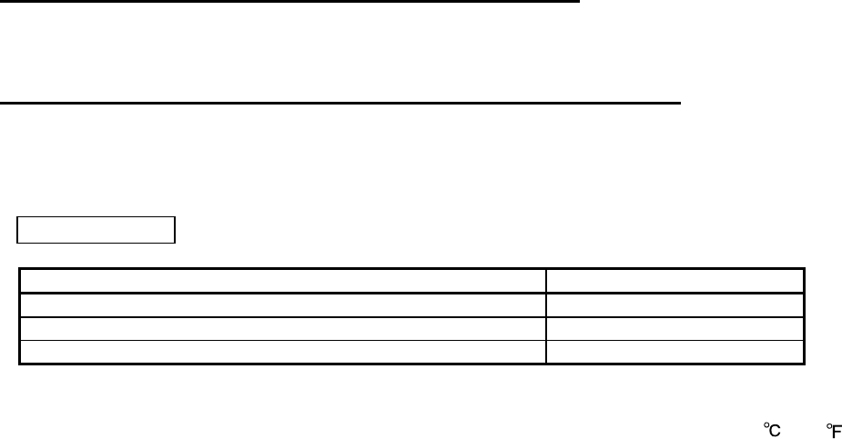
When you keep or use it, please fulfill the following environmental conditions.
Conditions
Environment Servo amplifier
[] 0 to 55 (non-freezing)
In
operation [] 32 to 131 (non-freezing)
[] 20 to 65 (non-freezing)
Ambient
temperature In storage [] 4 to 149 (non-freezing)
In operation 90 RH or less (non-condensing)
Ambient
humidity In storage 90 RH or less (non-condensing)
Ambience Indoors (no direct sunlight) Free from corrosive gas, flammable gas, oil mist, dust and dirt
Altitude Max. 1000m above sea level
(Note)
Vibration resistance 5.9m/s2 at 10Hz to 55Hz (directions of X,Y, and Z axes)
Securely attach the servo motor to the machine. If attach insecurely, the servo motor may come off during
operation.
Be sure to measure the motor vibration level with the servo motor mounted to the machine when checking
the vibration level. A great vibration may cause the early damage of a bearing, encoder, brake, and
reduction gear. The great vibration may also cause the poor connector connection or bolt looseness.
For the gain adjustment at the equipment startup, check the torque waveform and the speed waveform by
using a measurement device, and then check that no vibration occurs. If the vibration occurs due to high
gain, the vibration may cause the early damage of the servo motor.
Take safety measures, e.g. provide covers, to prevent accidental access to the rotating parts of the servo
motor during operation.
Never hit the servo motor or shaft, especially when coupling the servo motor to the machine. The encoder
may become faulty.
Do not subject the servo motor shaft to more than the permissible load. Otherwise, the shaft may break.
A - 3
(2) Wiring
CAUTION
Wire the equipment correctly and securely. Otherwise, the servo motor may operate unexpectedly.
Do not install a power capacitor, surge absorber or radio noise filter (FR-BIF option) between the servo
motor and servo amplifier.
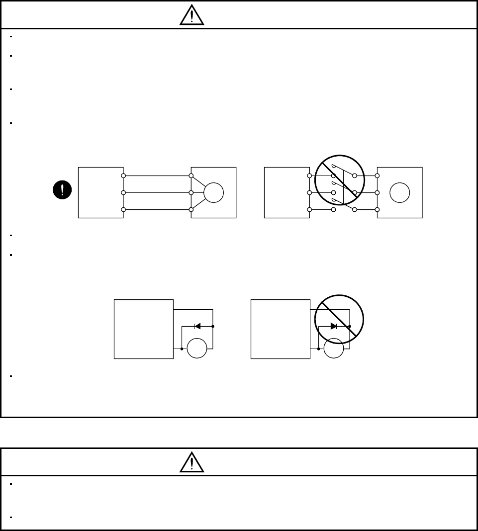
Connect the wires to the correct phase terminals (U, V, W) of the servo amplifier and servo motor.
Otherwise, the servo motor does not operate properly.
Connect the servo motor power terminal (U, V, W) to the servo motor power input terminal (U, V, W)
directly. Do not let a magnetic contactor, etc. intervene.
U
M
V
W
U
V
W
U
Servo motor
M
V
W
U
V
W
Servo amplifier
Servo motor
Servo amplifier
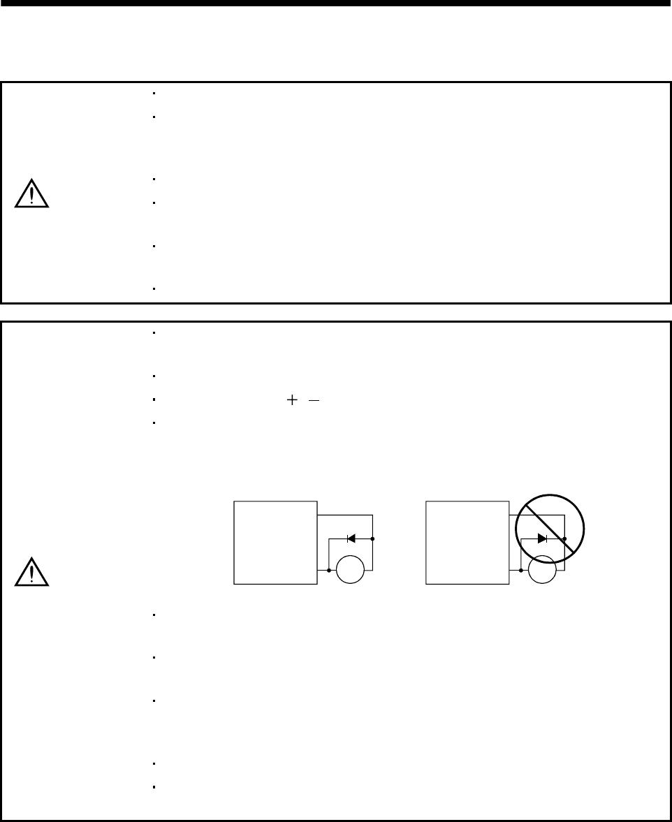
Do not connect AC power directly to the servo motor. Otherwise, a fault may occur.
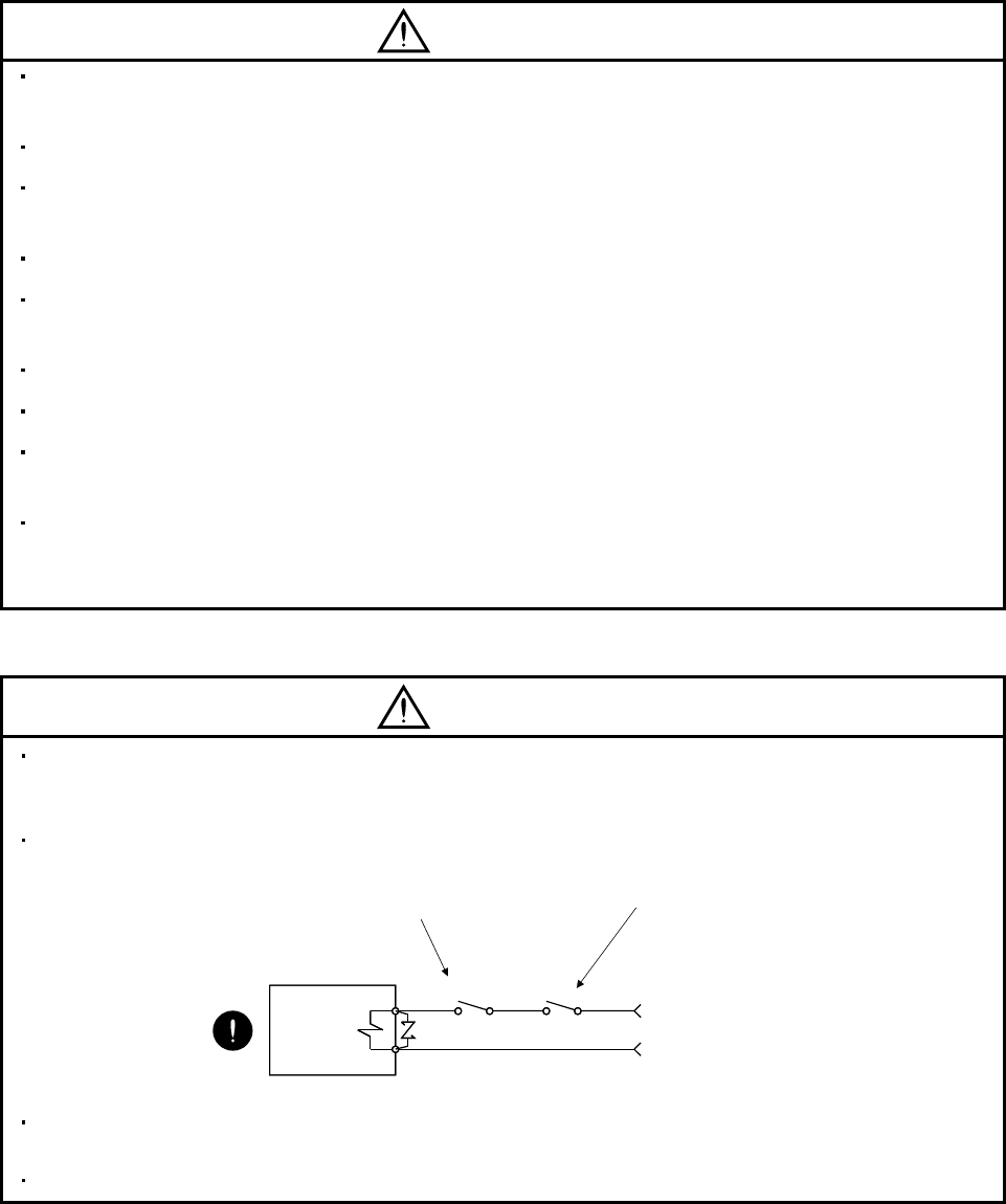
The surge absorbing diode installed on the DC output signal relay of the servo amplifier must be wired in
the specified direction. Otherwise, the emergency stop and other protective circuits may not operate.
RA
Control output
signal RA
Control output
signal
Servo amplifier Servo amplifier
SGSG
When the cable is not tightened enough to the terminal block (connector), the cable or terminal block
(connector) may generate heat because of the poor contact. Be sure to tighten the cable with specified
torque.
(3) Test run adjustment
CAUTION
Before operation, check the parameter settings. Improper settings may cause some machines to perform
unexpected operation.
The parameter settings must not be changed excessively. Operation will be insatiable.
A - 4
A - 5
(4) Usage
CAUTION
Provide an external emergency stop circuit to ensure that operation can be stopped and power switched
off immediately.
Any person who is involved in disassembly and repair should be fully competent to do the work.
Before resetting an alarm, make sure that the run signal of the servo amplifier is off to prevent an
accident. A sudden restart is made if an alarm is reset with the run signal on.
Do not modify the equipment.
Use a noise filter, etc. to minimize the influence of electromagnetic interference, which may be caused by
electronic equipment used near the servo amplifier.
Burning or breaking a servo amplifier may cause a toxic gas. Do not burn or break a servo amplifier.
Use the servo amplifier with the specified servo motor.
The electromagnetic brake on the servo motor is designed to hold the servo motor shaft and should not
be used for ordinary braking.
For such reasons as service life and mechanical structure (e.g. where a ball screw and the servo motor
are coupled via a timing belt), the electromagnetic brake may not hold the servo motor shaft. To ensure
safety, install a stopper on the machine side.
(5) Corrective actions
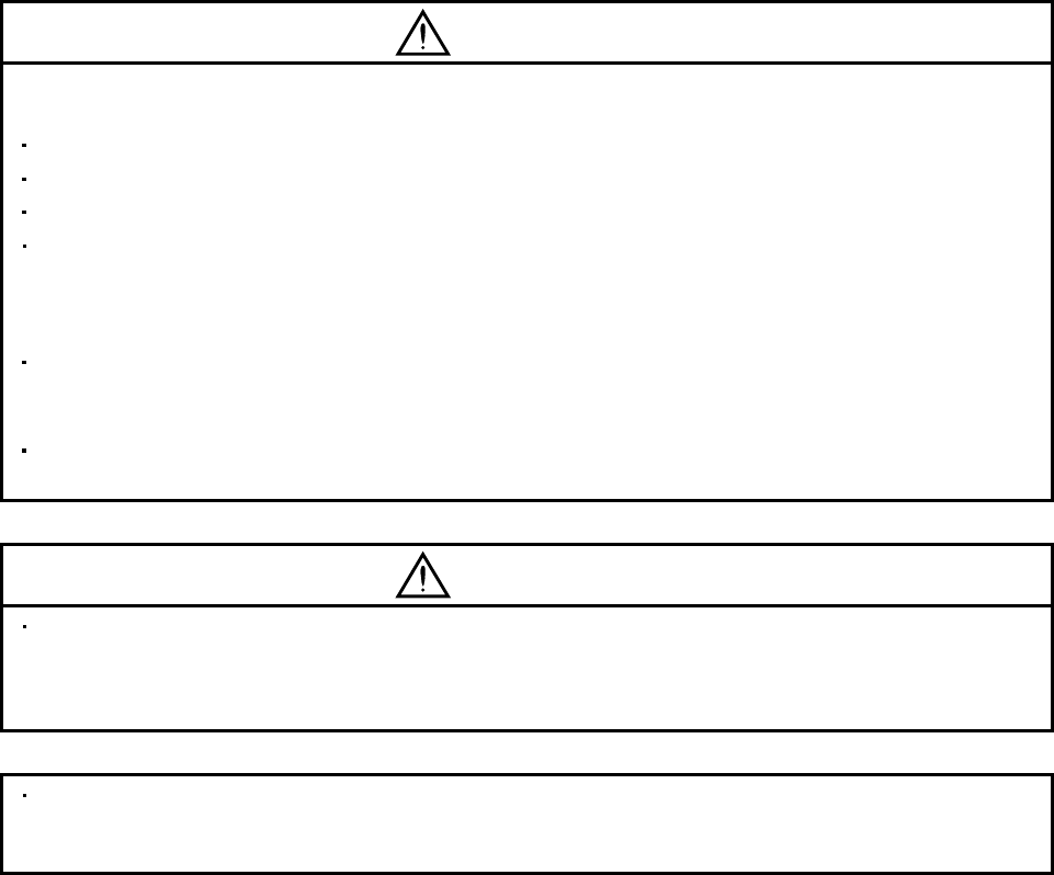
CAUTION
When it is assumed that a hazardous condition may take place at the occur due to a power failure or a
product fault, use a servo motor with electromagnetic brake or an external brake mechanism for the
purpose of prevention.
Configure an electromagnetic brake circuit so that it is activated also by an external EMG stop switch.
Contacts must be open when
an trouble (ALM) and when an
electromagnetic brake interlock
(MBR) turns off.
Electromagnetic brake
Contacts must be open with
the EMG stop switch.
RA
24VDC
Servo motor
When any alarm has occurred, eliminate its cause, ensure safety, and deactivate the alarm before
restarting operation.
Provide an adequate protection to prevent unexpected restart after an instantaneous power failure.
(6) Storage for servo motor
CAUTION
Note the following points when storing the servo motor for an extended period of time (guideline: three or
more months).
Always store the servo motor indoors in a clean and dry place.
If it is stored in a dusty or damp place, make adequate provision, e.g. cover the whole product.
If the insulation resistance of the winding decreases, reexamine the storage method.
Though the servo motor is rust-proofed before shipment using paint or rust prevention oil, rust may be
produced depending on the storage conditions or storage period.
If the servo motor is to be stored for longer than six months, apply rust prevention oil again especially to
the machined surfaces of the shaft, etc.
Before using the product after storage for an extended period of time, hand-turn the motor output shaft to
confirm that nothing is wrong with the servo motor. (When the servo motor is equipped with a brake,
make the above check after releasing the brake with the brake power supply.)
When the equipment has been stored for an extended period of time, please contact your local sales
office.
(7) Maintenance, inspection and parts replacement
CAUTION
With age, the electrolytic capacitor of the servo amplifier will deteriorate. To prevent a secondary accident
due to a fault, it is recommended to replace the electrolytic capacitor every 10 years when used in general
environment.
For replacement, please contact your local sales office.
(8) General instruction
To illustrate details, the equipment in the diagrams of this Instruction Manual may have been drawn
without covers and safety guards. When the equipment is operated, the covers and safety guards must be
installed as specified. Operation must be performed in accordance with this Instruction Manual.
A - 6

DISPOSAL OF WASTE
Please dispose a servo amplifier and other options according to your local laws and regulations.
EEP-ROM life
The number of write times to the EEP-ROM, which stores parameter settings, etc., is limited to 100,000. If
the total number of the following operations exceeds 100,000, the servo amplifier may fail when the EEP-
ROM reaches the end of its useful life.
Write to the EEP-ROM due to parameter setting changes
Write to the EEP-ROM due to device changes
Precautions for Choosing the Products
Mitsubishi will not be held liable for damage caused by factors found not to be the cause of Mitsubishi;
machine damage or lost profits caused by faults in the Mitsubishi products; damage, secondary damage,
accident compensation caused by special factors unpredictable by Mitsubishi; damages to products other
than Mitsubishi products; and to other duties.
A - 7
A - 8
COMPLIANCE WITH CE MARKING
Refer to Appendix 1 for the compliance with CE marking.
COMPLIANCE WITH UL/cUL STANDARD
Refer to Appendix 2 for the compliance with UL/cUL standard.
<<About the manuals>>
Relevant manuals
Manual name Manual No.
HF-KN/HF-SN Servo Motor Instruction Manual SH(NA)030123
MR-E Series Instructions and Cautions for Safe Use of AC Servos IB(NA)0300057
EMC Installation Guidelines IB(NA)67310
<<Wiring>>
Wires mentioned in this instruction manual are selected based on the ambient temperature of 40 (104 ).

1
CONTENTS
1. FUNCTIONS AND CONFIGURATION 1- 1 to 1-10
1.1 Introduction................................................................................................................................................1- 1
1.2 Function block diagram.............................................................................................................................1- 2
1.3 Servo amplifier standard specifications.................................................................................................... 1- 3
1.4 Function list ...............................................................................................................................................1- 4
1.5 Model code definition ................................................................................................................................ 1- 6
1.6 Combination with servo motor .................................................................................................................. 1- 6
1.7 Parts identification.....................................................................................................................................1- 7
1.8 Servo system with auxiliary equipment ....................................................................................................1- 9
2. INSTALLATION 2- 1 to 2- 4
2.1 Environmental conditions.......................................................................................................................... 2- 1
2.2 Installation direction and clearances ........................................................................................................2- 2
2.3 Keep out foreign materials........................................................................................................................ 2- 3
2.4 Cable stress ..............................................................................................................................................2- 3
3. SIGNALS AND WIRING 3- 1 to 3- 44
3.1 Standard connection example.................................................................................................................. 3- 2
3.1.1 Position control mode......................................................................................................................... 3- 2
3.1.2 Internal speed control mode ..............................................................................................................3- 8
3.2 Internal connection diagram of servo amplifier ........................................................................................3- 9
3.3 I/O signals.................................................................................................................................................3-10
3.3.1 Connectors and signal arrangements ..............................................................................................3-10
3.3.2 Signal explanations ...........................................................................................................................3-13
3.4 Detailed description of the signals...........................................................................................................3-19
3.4.1 Position control mode........................................................................................................................3-19
3.4.2 Internal speed control mode .............................................................................................................3-24
3.4.3 Position/internal speed control change mode ..................................................................................3-26
3.5 Alarm occurrence timing chart.................................................................................................................3-28
3.6 Interfaces..................................................................................................................................................3-29
3.6.1 Common line .....................................................................................................................................3-29
3.6.2 Detailed description of the interfaces ...............................................................................................3-30
3.7 Input power supply circuit ........................................................................................................................3-34
3.7.1 Connection example .........................................................................................................................3-34
3.7.2 Terminals...........................................................................................................................................3-35
3.7.3 Power-on sequence ..........................................................................................................................3-36
3.8 Servo motor with electromagnetic brake.................................................................................................3-37
3.8.1 Precautions........................................................................................................................................3-37
3.8.2 Setting................................................................................................................................................3-37
3.8.3 Timing charts.....................................................................................................................................3-38
3.9 Grounding.................................................................................................................................................3-40
3.10 Servo amplifier connectors (CNP1, CNP2) wiring method
(When MR-ECPN1-B and MR-ECPN2-B of an option are used.).......................................................3-41
3.11 Instructions for the 3M connector ..........................................................................................................3-44

2
4. OPERATION 4- 1 to 4- 6
4.1 When switching power on for the first time ..............................................................................................4- 1
4.2 Startup .......................................................................................................................................................4- 2
4.2.1 Selection of control mode ..................................................................................................................4- 2
4.2.2 Position control mode......................................................................................................................... 4- 2
4.2.3 Internal speed control mode ..............................................................................................................4- 4
5. PARAMETERS 5- 1 to 5- 30
5.1 Parameter list ............................................................................................................................................ 5- 1
5.1.1 Parameter write inhibit ....................................................................................................................... 5- 1
5.1.2 Lists..................................................................................................................................................... 5- 2
5.2 Detailed description..................................................................................................................................5-24
5.2.1 Electronic gear...................................................................................................................................5-24
5.2.2 Analog monitor ..................................................................................................................................5-26
5.2.3 Using forward/reverse rotation stroke end to change the stopping pattern ....................................5-29
5.2.4 Alarm history clear.............................................................................................................................5-29
5.2.5 Position smoothing............................................................................................................................5-30
6. DISPLAY AND OPERATION 6- 1 to 6-14
6.1 Display flowchart ....................................................................................................................................... 6- 1
6.2 Status display ............................................................................................................................................6- 2
6.2.1 Display examples ............................................................................................................................... 6- 2
6.2.2 Status display list................................................................................................................................ 6- 3
6.2.3 Changing the status display screen................................................................................................... 6- 4
6.3 Diagnostic mode .......................................................................................................................................6- 5
6.4 Alarm mode ............................................................................................................................................... 6- 6
6.5 Parameter mode .......................................................................................................................................6- 7
6.6 External I/O signal display ........................................................................................................................ 6- 8
6.7 Output signal (DO) forced output.............................................................................................................6-10
6.8 Test operation mode ................................................................................................................................6-11
6.8.1 Mode change.....................................................................................................................................6-11
6.8.2 Jog operation.....................................................................................................................................6-12
6.8.3 Positioning operation.........................................................................................................................6-13
6.8.4 Motor-less operation .........................................................................................................................6-14
7. GENERAL GAIN ADJUSTMENT 7- 1 to 7-10
7.1 Different adjustment methods................................................................................................................... 7- 1
7.1.1 Adjustment on a single servo amplifier..............................................................................................7- 1
7.1.2 Adjustment using MR Configurator (servo configuration software).................................................. 7- 2
7.2 Auto tuning ................................................................................................................................................ 7- 3
7.2.1 Auto tuning mode ...............................................................................................................................7- 3
7.2.2 Auto tuning mode basis .....................................................................................................................7- 4
7.2.3 Adjustment procedure by auto tuning................................................................................................7- 5
7.2.4 Response level setting in auto tuning mode ..................................................................................... 7- 6
7.3 Manual mode 1 (simple manual adjustment)...........................................................................................7- 7
7.3.1 Operation of manual mode 1 ............................................................................................................. 7- 7

3
7.3.2 Adjustment by manual mode 1 .......................................................................................................... 7- 7
7.4 Interpolation mode ...................................................................................................................................7-10
8. SPECIAL ADJUSTMENT FUNCTIONS 8- 1 to 8-10
8.1 Function block diagram.............................................................................................................................8- 1
8.2 Machine resonance suppression filter......................................................................................................8- 1
8.3 Adaptive vibration suppression control.....................................................................................................8- 3
8.4 Low-pass filter ........................................................................................................................................... 8- 4
8.5 Gain changing function ............................................................................................................................. 8- 5
8.5.1 Applications ........................................................................................................................................8- 5
8.5.2 Function block diagram...................................................................................................................... 8- 5
8.5.3 Parameters......................................................................................................................................... 8- 6
8.5.4 Gain changing procedure................................................................................................................... 8- 8
9. INSPECTION 9- 1 to 9- 2
10. TROUBLESHOOTING 10- 1 to 10-12
10.1 Trouble at start-up.................................................................................................................................10- 1
10.1.1 Position control mode.....................................................................................................................10- 1
10.1.2 Internal speed control mode ..........................................................................................................10- 4
10.2 When alarm or warning has occurred ..................................................................................................10- 5
10.2.1 Alarms and warning list..................................................................................................................10- 5
10.2.2 Remedies for alarms......................................................................................................................10- 6
10.2.3 Remedies for warnings .................................................................................................................10-11
11. OUTLINE DIMENSION DRAWINGS 11- 1 to 11- 8
11.1 Servo amplifiers ....................................................................................................................................11- 1
11.2 Connectors............................................................................................................................................11- 5
12. CHARACTERISTICS 12- 1 to 12- 4
12.1 Overload protection characteristics ......................................................................................................12- 1
12.2 Power supply equipment capacity and generated loss .......................................................................12- 1
12.3 Dynamic brake characteristics..............................................................................................................12- 3
12.4 Encoder cable flexing life......................................................................................................................12- 4
12.5 Inrush currents at power-on of main circuit and control circuit............................................................12- 4
13. OPTIONS AND AUXILIARY EQUIPMENT 13- 1 to 13-24
13.1 Options ..................................................................................................................................................13- 1
13.1.1 Regenerative options .....................................................................................................................13- 1
13.1.2 Cables and connectors ..................................................................................................................13- 6
13.1.3 Analog monitor, RS-232C branch cable (MR-E3CBL15-P) ......................................................... 13- 9
13.1.4 MR Configurator (servo configurations software) ........................................................................13-10
13.2 Auxiliary equipment..............................................................................................................................13-11
13.2.1 Selection example of wires ...........................................................................................................13-11
13.2.2 Circuit breakers, fuses, magnetic contactors ...............................................................................13-12

13.2.3 Power factor improving AC reactors.............................................................................................13-13
13.2.4 Relays............................................................................................................................................13-14
13.2.5 Surge absorbers............................................................................................................................13-14
13.2.6 Noise reduction techniques ..........................................................................................................13-15
13.2.7 Leakage current breaker...............................................................................................................13-22
13.2.8 EMC filter.......................................................................................................................................13-24
14. MR-E- AG-QW003 SERVO AMPLIFIER COMPATIBLE WITH ANALOG INPUT 14- 1 to 14- 64
14.1. Functions and configuration ................................................................................................................14- 1
14.1.1 Introduction.....................................................................................................................................14- 1
14.1.2 Function block diagram..................................................................................................................14- 2
14.1.3 Servo amplifier standard specifications.........................................................................................14- 3
14.1.4 Model code definition .....................................................................................................................14- 4
14.1.5 Parts identification..........................................................................................................................14- 4
14.1.6 Servo system with auxiliary equipment .........................................................................................14- 6
14.2. Signals and wiring................................................................................................................................14- 8
14.2.1 Standard connection example .......................................................................................................14- 8
14.2.2 Internal connection diagram of servo amplifier ............................................................................14-11
14.2.3 Connectors and signal arrangements ..........................................................................................14-12
14.2.4 Signal explanations .......................................................................................................................14-14
14.2.5 Detailed description of the signals................................................................................................14-20
14.3 Startup ..................................................................................................................................................14-27
14.3.1 Speed control mode......................................................................................................................14-27
14.3.2 Torque control mode.....................................................................................................................14-30
14.4 Parameters...........................................................................................................................................14-32
14.4.1 Item list ..........................................................................................................................................14-32
14.4.2 Details list ......................................................................................................................................14-35
14.5 Display and operation ..........................................................................................................................14-55
14.5.1 Display flowchart ...........................................................................................................................14-55
14.5.2 Status display ................................................................................................................................14-56
14.5.3 Diagnostic mode ...........................................................................................................................14-58
14.5.4 External I/O signal display ............................................................................................................14-60
14.6. Troubleshooting ..................................................................................................................................14-62
14.6.1 Trouble at start-up.........................................................................................................................14-62
14.6.2 Alarms and warning list.................................................................................................................14-64
APPENDIX App.- 1 to App.- 6
App. 1 COMPLIANCE WITH CE MARKING.............................................................................................App.- 1
App. 2 COMPLIANCE WITH UL/cUL STANDARD ..................................................................................App.- 4
4

1. FUNCTIONS AND CONFIGURATION
1 - 1
1. FUNCTIONS AND CONFIGURATION
1.1 Introduction
The Mitsubishi general-purpose AC servo MR-E Super has position control and internal speed control modes.
It can perform operation with the control modes changed, e.g. position/internal speed control. Hence, it is
applicable to wide range of fields such as precision positioning and smooth speed control of machine tools and
general industrial machines.
As this new series has the RS-232C or RS-422 serial communication function, a MR Configurator (servo
configuration software)-installed personal computer or the like can be used to perform parameter setting, test
operation, status display monitoring, gain adjustment, etc.
With real-time auto tuning, you can automatically adjust the servo gains according to the machine.
The MR-E Super servo motor is equipped with an incremental position encoder that has the resolution of
131072 pulses/rev to ensure high precision positioning.
(1) Position control mode
An up to 1Mpps high-speed pulse train is used to control the speed and direction of a motor and execute
precision positioning of 131072 pulses/rev resolution.
The position smoothing function provides a choice of two different modes appropriate for a machine, so a
smoother start/stop can be made in response to a sudden position command.
A torque limit is imposed on the servo amplifier by the clamp circuit to protect the power transistor in the
main circuit from overcurrent due to sudden acceleration/deceleration or overload. This torque limit value
can be changed to any value with the parameter.
(2) Internal speed control mode
The parameter-driven internal speed command (max. 7 speeds) is used to control the speed and direction
of a servo motor smoothly.
There are also the acceleration/deceleration time constant setting in response to speed command, the
servo lock function at a stop time.
1. FUNCTIONS AND CONFIGURATION
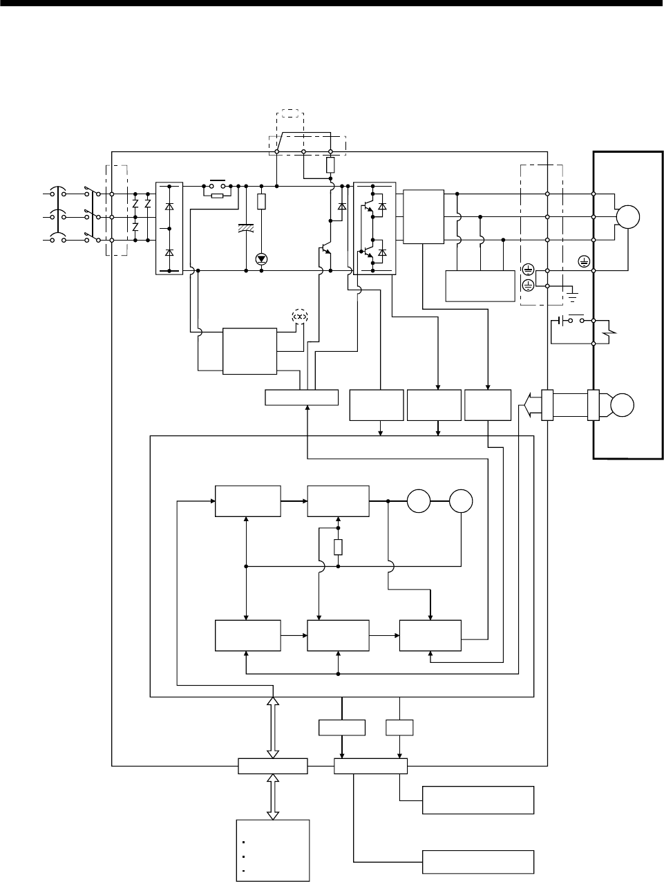
1.2 Function block diagram
The function block diagram of this servo is shown below.
Regenerative option
Servo amplifier
CHARGE
lamp
Servo motor
Regenerative
TR
(Note 1)
Base amplifier Voltage
detection
Overcurrent
protection
Encoder
Dynamic
brake circuit
Control
circuit
power
supply
Electro-
magnetic
brake
Current
detection
Model position
control
Model speed
control
Pulse
input
Model
position
Actual position
control
Actual speed
control
Current
control
Model
torque
Virtual
motor
Virtual
encoder
Model
speed
D I/O control
Servo on
Start
Failure, etc.
Controller
Analog monitor
(2 channels)
D
C
P
MCCB
CN1 CN3
RS-232C
I/F
CN2
U
V
W
U
V
W
M
RS-232C D/A
(Note 3)
(Note 3)
(Note 3)
(Note 3)
(Note 3)(Note 3)
(Note 2)
Power
supply
(Note 4)
Cooling fan
Current
detector
Diode
stack
B2
B1
Relay
RA
24VDC
MC L1
L2
L3
Note 1. The built-in regenerative resistor is not provided for the MR-E-10A-QW003/MR-E-20A-QW003.
2. The single-phase 230VAC can be used for MR-E-70A-QW003 or smaller servo amplifier.
Connect the power supply cables to L1 and L2 while leaving L3 open. Refer to section 1.3 for the power supply specification.
3. The control circuit connectors (CN1, CN2 and CN3) are safely isolated from main circuit terminals
(L1, L2, L3, U, V, W, P, C and D).
4. Servo amplifiers MR-E-200A-QW003 have a cooling fan.
1 - 2
1 - 3
1. FUNCTIONS AND CONFIGURATION
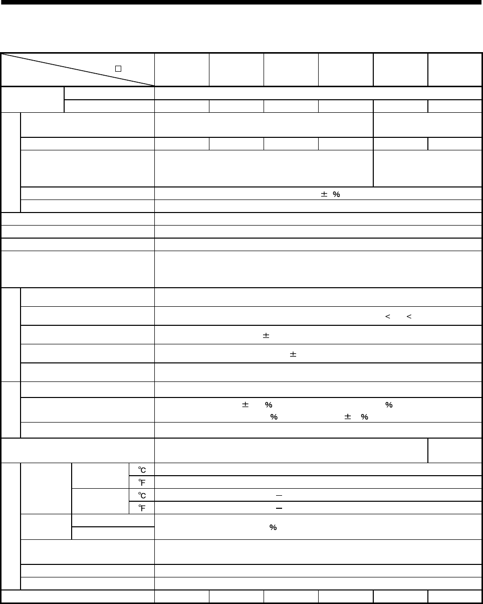
1.3 Servo amplifier standard specifications
Servo amplifier
MR-E- -QW003
Item
10A 20A 40A 70A 100A 200A
Rated voltage 3-phase 170VAC
Output Rated current [A] 0.7 1.1 2.3 5.8 6.0 11.0
Voltage/frequency 3-phase 200 to 230VAC, 50/60Hz or 1-phase 230VAC,
50/60Hz
3-phase 200 to 230VAC,
50/60Hz
Rated current [A] 0.9 1.5 2.6 3.8 5.0 10.5
Permissible voltage fluctuation
3-phase 200 to 230VAC:
170 to 253VAC
1-phase 230VAC: 207 to 253VAC
3-phase 170 to 253VAC
Permissible frequency fluctuation Within 5
Power supply
Power supply capacity Refer to section 12.2
Inrush current [A] Refer to section 12.5
Control system Sine-wave PWM control, current control system
Dynamic brake Built-in
Protective functions
Overcurrent shut-off, regenerative overvoltage shut-off, overload shut-off (electronic thermal
relay), encoder error protection, regenerative error protection, undervoltage, instantaneous
power failure protection, overspeed protection, excessive error protection
Max. input pulse frequency 1Mpps (for differential receiver), 200kpps (for open collector)
Command pulse multiplying factor Electronic gear A: 1 to 65535 B: 1 to 65535, 1/50 A/B 50
In-position range setting 0 to 10000 pulse (command pulse unit)
Error excessive 2.5 revolutions
Position control mode
Torque limit Set by parameter setting
Speed control range Internal speed command 1: 5000
Speed fluctuation ratio 0.01 or less (load fluctuation 0 to 100 )
0 (power fluctuation 10 )
Internal speed
control mode
Torque limit Set by parameter setting
Structure Self-cooled, open (IP00)
Force-cooling,
open (IP00)
[] 0 to 55 (non-freezing)
Operation [] 32 to 131 (non-freezing)
[] 20 to 65 (non-freezing)
Ambient
temperature Storage [] 4 to 149 (non-freezing)
Operation Ambient
humidity Storage 90 RH or less (non-condensing)
Ambient Indoors (no direct sunlight)
Free from corrosive gas, flammable gas, oil mist, dust and dirt
Altitude Max. 1000m above sea level
Environment
Vibration resistance 5.9m/s2 at 10Hz to 55Hz (directions of X,Y, and Z axes)
Mass [kg] 0.7 0.7 1.1 1.7 1.7 2.0

1 - 4
1. FUNCTIONS AND CONFIGURATION
1.4 Function list
The following table lists the functions of this servo. For details of the functions, refer to the reference field.
Function Description
(Note)
Control mode Reference
Position control mode This servo is used as position control servo. P
Section 3.1.1
Section 3.4.1
Section 4.2.2
Internal speed control mode This servo is used as internal speed control servo. S
Section 3.1.2
Section 3.4.2
Section 4.2.3
Position/internal speed control
change mode
Using external input signal, control can be switched between
position control and internal speed control. P/S Section 3.4.4
High-resolution encoder High-resolution encoder of 131072 pulses/rev is used as a
servo motor encoder. P, S
Gain changing function
You can switch between gains during rotation and gains during
stop or use an external input signal to change gains during
operation.
P, S Section 8.5
Adaptive vibration suppression
control
Servo amplifier detects mechanical resonance and sets filter
characteristics automatically to suppress mechanical vibration. P, S Section 8.3
Low-pass filter Suppresses high-frequency resonance which occurs as servo
system response is increased. P, S Section 8.4
Machine analyzer function
Analyzes the frequency characteristic of the mechanical system
by simply connecting a MR Configurator (servo configuration
software)-installed personal computer and servo amplifier.
P
Machine simulation Can simulate machine motions on a personal computer screen
on the basis of the machine analyzer results. P
Gain search function
MR Configurator (servo configuration software) installed in a
personal computer changes gains automatically and searches
for overshoot-free gains in a short time.
P
Slight vibration suppression
control
Suppresses vibration of 1 pulse produced at a servo motor
stop. P Parameter No.20
Electronic gear Input pulses can be multiplied by 1/50 to 50. P Parameters No.3, 4,
69 to 71
Auto tuning Automatically adjusts the gain to optimum value if load applied
to the servo motor shaft varies. P, S Chapter 7
Position smoothing Speed can be increased smoothly in response to input pulse. P Parameter No.7
S-pattern acceleration/
deceleration time constant Speed can be increased and decreased smoothly. S Parameter No.13
Regenerative option
Used when the built-in regenerative resistor of the servo
amplifier does not have sufficient regenerative capability for the
regenerative power generated.
P, S Section 13.1.1

1. FUNCTIONS AND CONFIGURATION
1 - 5
Function Description
(Note)
Control mode Reference
Alarm history clear Alarm history is cleared. P, S Parameter No.16
Restart after instantaneous
power failure
If the input power supply voltage had reduced to cause an
alarm but has returned to normal, the servo motor can be
restarted by merely switching on the start signal.
S Parameter No.20
Command pulse selection Command pulse train form can be selected from among four
different types. P Parameter No.21
Input signal selection Forward rotation start, reverse rotation start, servo-on and other
input signals can be assigned to any pins. P, S Parameters
No.43 to 48
Torque limit Servo motor torque can be limited to any value. P, S Section 3.4.1 (5)
Parameter No.28
Status display Servo status is shown on the 5-digit, 7-segment LED display P, S Section 6.2
External I/O signal display ON/OFF statuses of external I/O signals are shown on the
display. P, S Section 6.6
Output signal (DO)
forced output
Output signal can be forced on/off independently of the servo
status.
Use this function for output signal wiring check, etc.
P, S Section 6.7
Test operation mode Servo motor can be run from the operation section of the servo
amplifier without the start signal entered. P, S Section 6.8
Analog monitor output Servo status is output in terms of voltage in real time. P, S Parameter No.17
MR Configurator
(servo configuration software)
Using a personal computer, parameter setting, test operation,
status display, etc. can be performed. P, S Section 13.1.4
Alarm code output If an alarm has occurred, the corresponding alarm number is
output in 3-bit code. P, S Section 10.2.1
Note. P: Position control mode, S: Internal speed control mode
P/S: Position/internal speed control change mode
1 - 6
1. FUNCTIONS AND CONFIGURATION
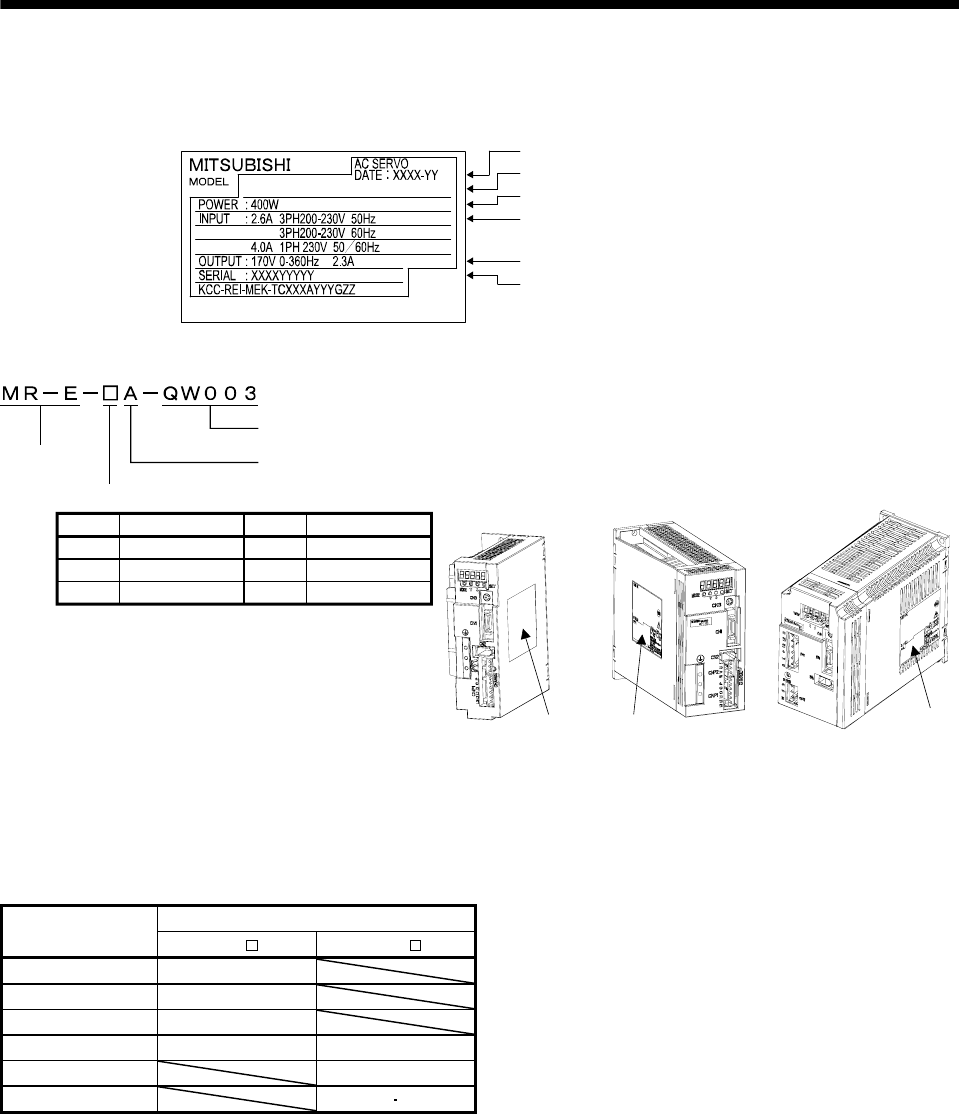
1.5 Model code definition
(1) Rating plate
MR-E-40A-QW003
Applicable power supply
Capacity
Model
Rated output current
Serial number
The year and month of manufactur
e
(2) Model
70 750
40 400
10 100
20 100
200 1000
200 2000
Rating plate Rating plate Rating plate
Rated output
Series Pulse train interface
MR-E Super servo amplifier (Source I/O interface)
MR-E-40A-QW003 or less MR-E-70A-QW003,
MR-E-100A-QW003 MR-E-200A-QW003
Symbol SymbolRated output [W] Rated output [W]
1.6 Combination with servo motor
The following table lists combinations of servo amplifiers and servo motors. The same combinations apply to
the servo motor models with electromagnetic brakes. HF-KN/HF-SN servo motor is available for the servo
amplifier with software version A9 or later.
Servo motors
Servo amplifier HF-KN (J) HF-SN J
MR-E-10A-QW003 13
MR-E-20A-QW003 23
MR-E-40A-QW003 43
MR-E-70A-QW003 73 52
MR-E-100A-QW003 102
MR-E-200A-QW003 152 202
1. FUNCTIONS AND CONFIGURATION
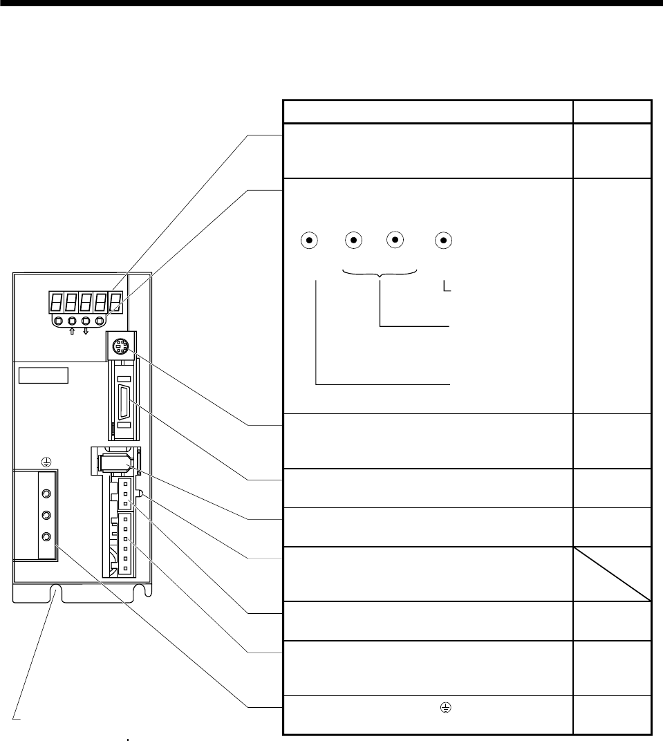
1.7 Parts identification
(1) MR-E-100A-QW003 or less
MODE
CN3
SET
CN1
CN2
CNP2
CNP1
L3L2L1 D C P W V U
CHARGE
MITSUBISHI
MR-
Used to set data.
Used to change the
display or data in each
mode.
Used to change the
mode.
MODE UP DOWN SET
Fixed part
(MR-E-10A-QW003 to MR-E-40A-QW003: 2 places
MR-E-70A-QW003 MR-E-100A-QW003: 3 places)
Reference
Name/application
Display
The 5-digit, seven-segment LED shows the servo status
and alarm number.
Operation section
Used to perform status display, diagnostic, alarm and
parameter setting operations.
Communication connector (CN3)
Used to connect a command device (RS-232C) and
output analog monitor data.
Chapter 6
Chapter 6
Section 3.3
Section 13.1.2
Section 3.3
I/O signal connector (CN1)
Used to connect digital I/O signals.
Encoder connector (CN2)
Use to connect the servo motor encoder.
Charge lamp
Lit to indicate that the main circuit is charged. While this
lamp is lit, do not reconnect the cables.
Servo motor power connector (CNP2)
Used to connect the servo motor.
Power supply/regenerative connector (CNP1)
Used to connect the input power supply and regenerative
option.
Protective earth (PE) terminal ( )
Ground terminal.
Section 3.3
Section1 3.1.2
Section 3.7
Section 11.1
Section 3.7
Section 11.1
Section 13.1.1
Section 3.9
Section 11.1
1 - 7
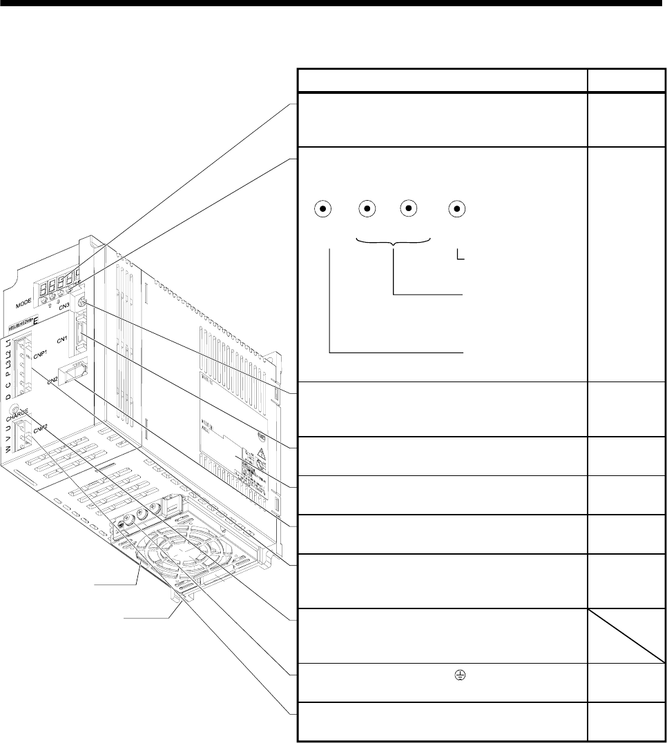
1. FUNCTIONS AND CONFIGURATION
(2) MR-E-200A-QW003
Used to set data.
Used to change the
display or data in each
mode.
Used to change the
mode.
MODE UP DOWN SET
Cooling fan
Fixed part
(3 places)
Display
The 5-digit, seven-segment LED shows the servo status
and alarm number. Chapter 6
ReferenceName/application
Chapter 6
Section 3.3
Section 13.1.2
Communication connector (CN3)
Used to connect a command device (RS-232C) and
output analog monitor data.
I/O signal connector (CN1)
Used to connect digital I/O signals.
Rating plate
Encoder connector (CN2)
Used to connect the servo motor encoder.
Power supply/regenerative connector (CNP1)
Used to connect the input power supply and regenerative
option.
Charge lamp
Lit to indicate that the main circuit is charged. While this
lamp is lit, do not reconnect the cables.
Protective earth (PE) terminal ( )
Ground terminal.
Servo motor power connector (CNP2)
Used to connect the servo motor. Section 3.7
Section 11.1
Section 3.9
Section 11.1
Section 3.7
Section 11.1
Section 13.1.1
Section 3.3
Section 13.1.2
Section 1.5
Section 3.3
Operation section
Used to perform status display, diagnostic, alarm and
parameter setting operations.
1 - 8
1 - 9
1. FUNCTIONS AND CONFIGURATION
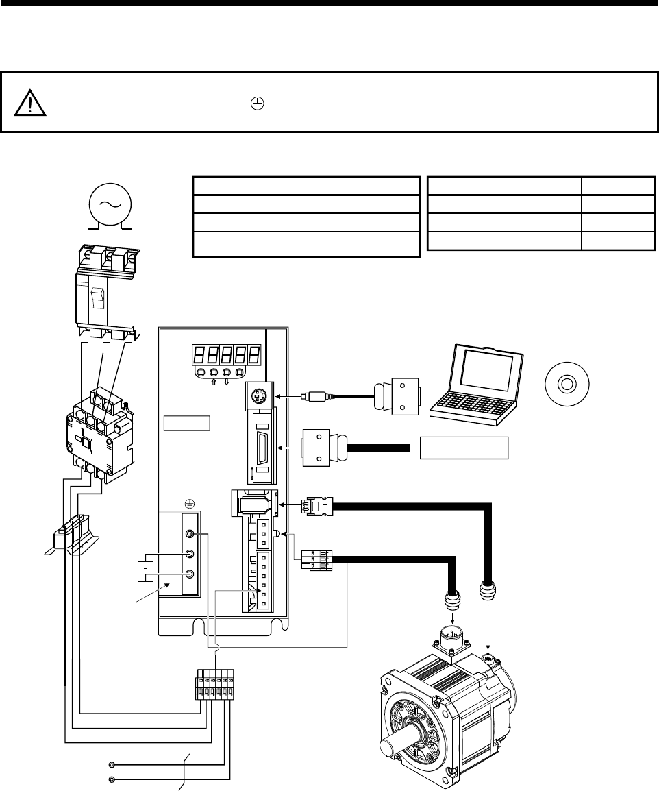
1.8 Servo system with auxiliary equipment
WARNING To prevent an electric shock, always connect the protective earth (PE) terminal
(terminal marked ) of the servo amplifier to the protective earth (PE) of the control
box.
(1) MR-E-100A-QW003 or less
Personal
computer MR Configurator
(Servo configuration software)
Regenerative option
Command device
CN3
SET
CN1
CN2
CNP2
CNP1
L3 L1 D C P W V U
MITSUBISHI
MR-E-
C
P
L3
L2
L1
To CN3
To CN1
Servo amplifier
L2
To CN2
To CNP2
(Note)
Power supply
Options and auxiliary equipment
Circuit breaker
Magnetic contactor
MR Configurator
(Servo configuration software)
Reference
Section 13.2.2
Section 13.2.2
Section 13.1.4
Options and auxiliary equipment
Regenerative option
Cables
Power factor improving reactor
Reference
Section 13.1.1
Section 13.2.1
Section 13.2.3
Circuit breaker
(MCCB) or fuse
Power
factor
improving
reactor
(FR-HAL)
Magnetic
contactor
(MC)
Protective earth
MODE
CHARGE
Servo motor
Note. A 1-phase 230VAC power supply may be used with the servo amplifier of MR-E-70A-QW003 or less. Connect the power supply to L1
and L2 terminals and leave L3 open. Refer to section 1.3 for the power supply specification.
1 - 10
1. FUNCTIONS AND CONFIGURATION
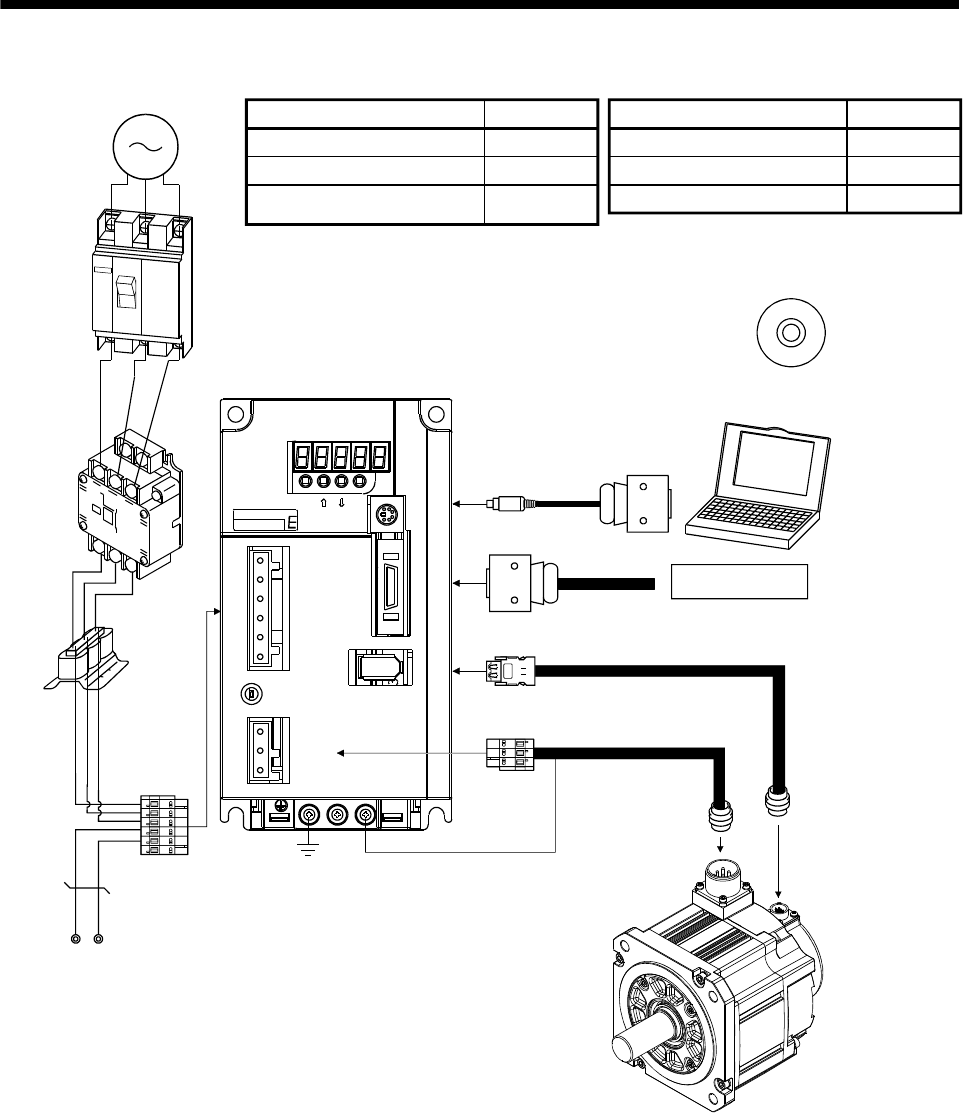
(2) MR-E-200A-QW003
UV
Command device
L3
L2
L1
DC L3PL1L2
CHARGE
CNP2
CNP1
CN1
CN2
W
CN3
MODE SET
MITSUBISHI EZMotion
PC
Power
facto
r
improving
reactor
(FR-HAL)
(Note)
Power supply
Circuit
breaker
(MCCB)
or fuse
Magnetic
contactor
(MC)
To CN2
To CN1
To CN3
Servo amplifier
Regenerative option
Personal
computer
Options and auxiliary equipment
Circuit breaker
Magnetic contactor
Reference
Section 13.2.2
Section 13.2.2
Section 13.1.4
Options and auxiliary equipment
Regenerative option
Cables
Power factor improving reactor
Reference
Section 13.1.1
Section 13.2.1
Section 13.2.3
MR Configurator
(Servo configuration software)
MR Configurator
(Servo configuration software)
To CNP2
Servo motor
Note. Refer to section 1.3 for the power supply specification.
2 - 1
2. INSTALLATION
2. INSTALLATION
WARNING To prevent electric shock, ground each equipment securely.
CAUTION
Stacking in excess of the limited number of products is not allowed.
Install the equipment on incombustible material. Installing them directly or close to
combustibles will lead to a fire.
Install the equipment in a load-bearing place in accordance with this Instruction
Manual.
Do not get on or put heavy load on the equipment to prevent injury.
Use the equipment within the specified environmental condition range. (For details
of the environmental condition, refer to section 2.1.)
Provide an adequate protection to prevent screws, metallic detritus and other
conductive matter or oil and other combustible matter from entering the servo
amplifier.
Do not block the intake/exhaust ports of the servo amplifier. Otherwise, a fault may
occur.
Do not subject the servo amplifier to drop impact or shock loads as they are
precision equipment.
Do not install or operate a faulty servo amplifier.
When the product has been stored for an extended period of time, please contact
your local sales office.
When treating the servo amplifier, be careful about the edged parts such as the
corners of the servo amplifier.
The servo amplifier must be installed in the metal cabinet (control box).
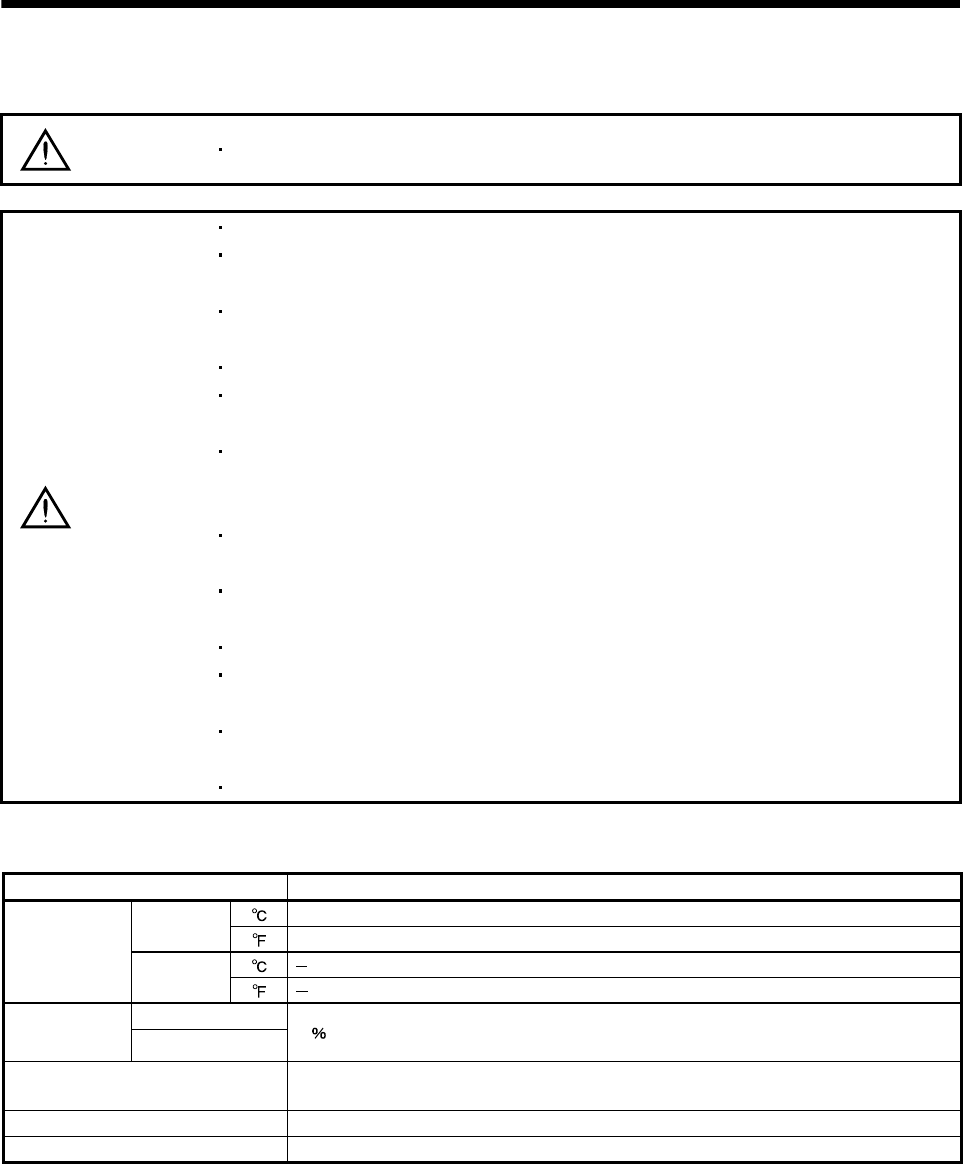
2.1 Environmental conditions
Environment Conditions
[] 0 to 55 (non-freezing)
In operation [] 32 to 131 (non-freezing)
[] 20 to 65 (non-freezing)
Ambient
temperature In storage [] 4 to 149 (non-freezing)
In operation
Ambient
humidity In storage 90 RH or less (non-condensing)
Ambience Indoors (no direct sunlight)
Free from corrosive gas, flammable gas, oil mist, dust and dirt
Altitude Max. 1000m above sea level
Vibration resistance 5.9m/s2 at 10Hz to 55Hz (directions of X,Y, and Z axes)
2. INSTALLATION
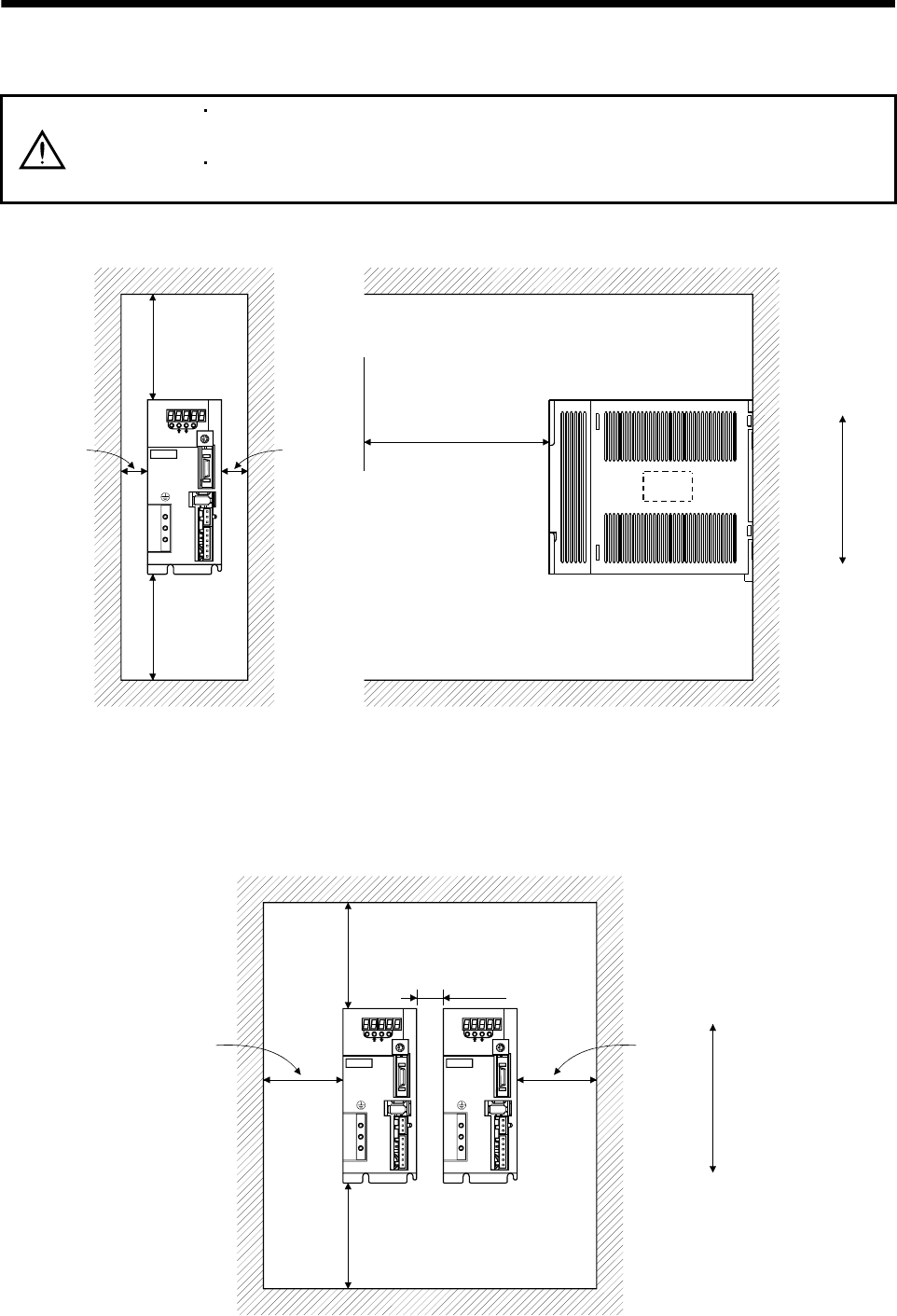
2.2 Installation direction and clearances
CAUTION
The equipment must be installed in the specified direction. Otherwise, a fault may
occur.
Leave specified clearances between the servo amplifier and control box inside
walls or other equipment.
(1) Installation of one servo amplifier
MODE
CN3
SET
CN1
CN2
CNP2
CNP1
L3L2 L1 D C P W V U
CHARGE
MITSUBISHI
MR-
Control box Control box
10mm
or more 10mm
or more
40mm
or more
Servo
amplifier
40mm
or more
Wiring clearance Top
Bottom
70mm
(2) Installation of two or more servo amplifiers
Leave a large clearance between the top of the servo amplifier and the internal surface of the control box,
and install a cooling fan to prevent the internal temperature of the control box from exceeding the
environmental conditions.
MODE
CN3
SET
CN1
CN2
CNP2
CNP1
L3L2L1 D C P W V U
CHARGE
MITSUBISHI
MR-
MODE
CN3
CN1
CN2
CNP2
CNP1
L3L2L1 D C P W V U
CHARGE
MITSUBISHI
MR-
SET
Control box
30mm
or more 30mm
or more
10mm
or more
40mm
or more
100mm
or more
Top
Bottom
2 - 2

2 - 3
2. INSTALLATION
(3) Others
When using heat generating equipment such as the regenerative option, install them with full consideration
of heat generation so that the servo amplifier is not affected.
Install the servo amplifier on a perpendicular wall in the correct vertical direction.
2.3 Keep out foreign materials
(1) When installing the unit in a control box, prevent drill chips and wire fragments from entering the servo
amplifier.
(2) Prevent oil, water, metallic dust, etc. from entering the servo amplifier through openings in the control box or
a cooling fan installed on the ceiling.
(3) When installing the control box in a place where there are much toxic gas, dirt and dust, conduct an air
purge (force clean air into the control box from outside to make the internal pressure higher than the
external pressure) to prevent such materials from entering the control box.
2.4 Cable stress
(1) The way of clamping the cable must be fully examined so that flexing stress and cable's own weight stress
are not applied to the cable connection.
(2) For use in any application where the servo motor moves, fix the cables (encoder, power supply, and brake)
with having some slack from the connector connection part of the servo motor to avoid putting stress on the
connector connection part. Use the optional encoder cable within the flexing life range. Use the power
supply and brake wiring cables within the flexing life of the cables.
(3) Avoid any probability that the cable insulator might be cut by sharp chips, rubbed by a machine corner or
stamped by workers or vehicles.
(4) For installation on a machine where the servo motor will move, the flexing radius should be made as large
as possible. Refer to section 12.4 for the flexing life.

2. INSTALLATION
2 - 4
MEMO
3. SIGNALS AND WIRING
3. SIGNALS AND WIRING
WARNING
Any person who is involved in wiring should be fully competent to do the work.
Before wiring, turn off the power and wait for 15 minutes or more until the charge
lamp turns off. Otherwise, an electric shock may occur. In addition, always confirm
from the front of the servo amplifier whether the charge lamp is off or not.
Ground the servo amplifier and the servo motor securely.
Do not attempt to wire the servo amplifier and servo motor until they have been
installed. Otherwise, you may get an electric shock.
The cables should not be damaged, stressed excessively, loaded heavily, or
pinched. Otherwise, you may get an electric shock.
Insulate the connections of the power supply terminals to prevent an electric shock.
CAUTION
Wire the equipment correctly and securely. Otherwise, the servo motor may
operate unexpectedly, resulting in injury.
Connect cables to correct terminals to prevent a burst, fault, etc.
Ensure that polarity ( , ) is correct. Otherwise, a burst, damage, etc. may occur.
The surge absorbing diode installed to the DC relay designed for control output
should be fitted in the specified direction. Otherwise, the signal is not output due to
a fault, disabling the emergency stop and other protective circuits.
RA
Control output
signal RA
Control output
signal
Servo amplifier Servo amplifier
SGSG
Use a noise filter, etc. to minimize the influence of electromagnetic interference,
which may be given to electronic equipment used near the servo amplifier.
Do not install a power capacitor, surge suppressor or radio noise filter (FR-BIF
option) with the power line of the servo motor.
When using the regenerative resistor, switch power off with the alarm signal.
Otherwise, a transistor fault or the like may overheat the regenerative resistor,
causing a fire.
Do not modify the equipment.
During power-on, do not open or close the motor power line. Otherwise, a
malfunction or faulty may occur.
3 - 1
3. SIGNALS AND WIRING
3.1 Standard connection example
POINT
Refer to section 3.7.1 for the connection of the power supply system and to HF-
KN/HF-SN Servo Motor Instruction Manual for connection with the servo motor.
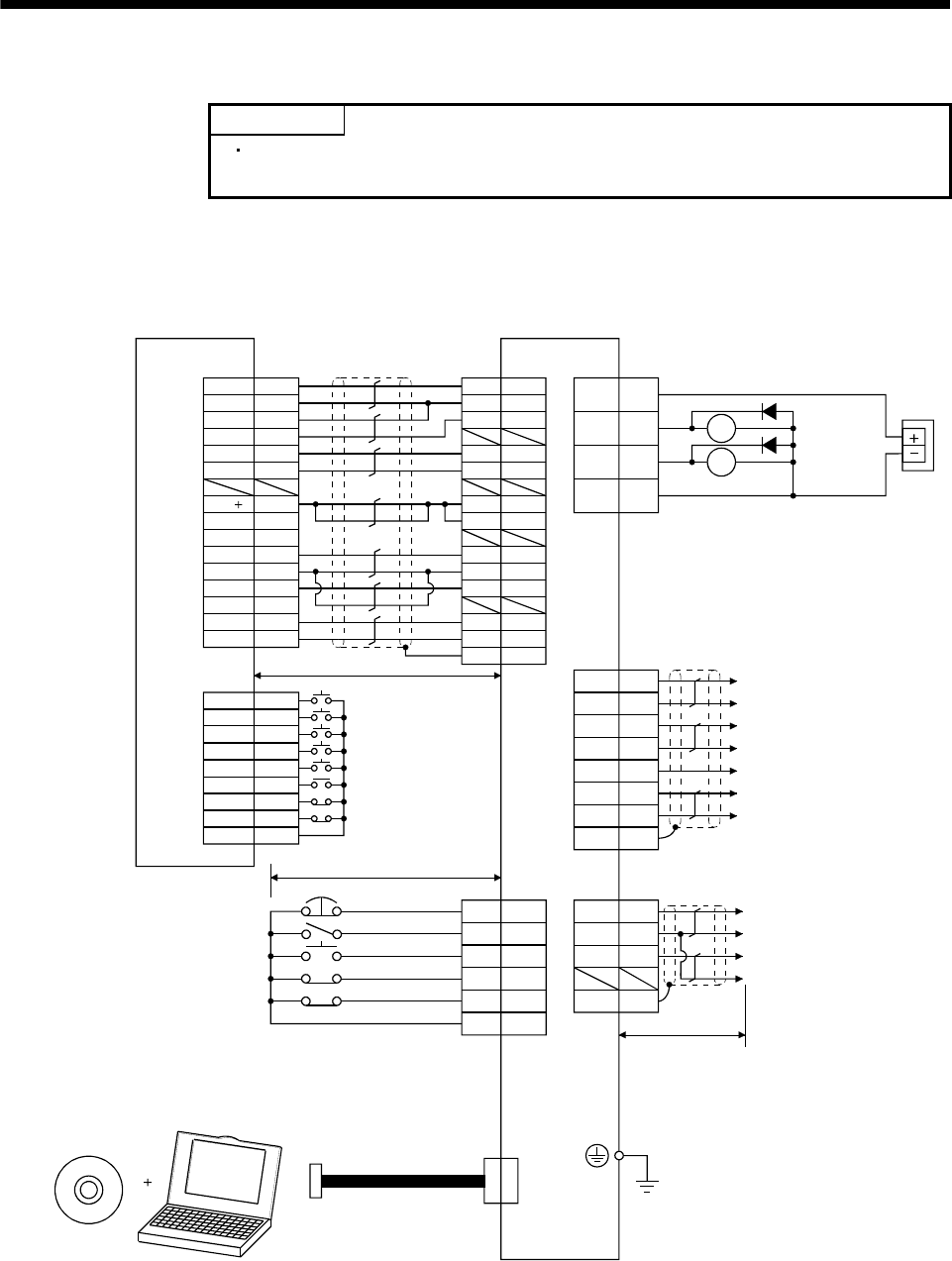
3.1.1 Position control mode
(1) FX-10GM
(Note 8) 2m max.
2m max.
10m max.
9,19
9
12
INP
RD
RA1
RA2
ALM
ZSP
17
16
18
SD
15
SG
VIN
OP
OPC
VIN
PP
SG
NP
VIN
CR
SD
10
11
13
1
21
2
1
23
13
25
1
5
12
1
2
14
13
7,17
8,18
6
9,19
16
3
4
11
5
15
1
2
4
5
6
8
3
7
START
STOP
FWD
RVS
DOG
LSR
COM1
ZRN
LSF
FX-10GM
CN3
20
19
8
4
3
6
7
1
EMG
SON
RES
LSP
LSN
VIN
1VIN
CN1
13 SG
SVRDY
COM2
COM2
SVEND
COM4
PGO
VC
FPO
FP
COM5
RP
RPO
CLR
COM3
24
Positioning module Servo amplifier
(Note 7) (Note 7)
CN1 CN1
(Note 2)
(Note 5)
Trouble
Zero speed
Plate (Note 7)
Plate
(Note 3, 4) Emergency stop
Servo-on
Reset
(Note 4) Forward rotation stroke end
Reverse rotation stroke end
(Note 6)
Communication cable
(Note 7) (Note 1)
CN1
(Note 7)
CN3
(Note 7)
Encoder A-phase pulse
(differential line driver)
Encoder B-phase pulse
(differential line driver)
Encoder Z-phase pulse
(differential line driver)
External
power
supply
24VDC
(Note 10)
18
LG Control common
LA
LAR
LB
LBR
14
LZR
LZ
(Note 9)
MR Configurator
(Servo configuration software) Personal
computer
MO1
LG
MO2
4
3
6
SDPlate
Analog monitor 1
Analog monitor 2
Control common
Control common
3 - 2

3. SIGNALS AND WIRING
Note 1. To prevent an electric shock, always connect the protective earth (PE) terminal (terminal marked ) of the servo amplifier to the
protective earth (PE) of the control box.
2. Connect the diode in the correct direction. If it is connected reversely, the servo amplifier will be faulty and will not output signals,
disabling the emergency stop and other protective circuits.
3. The emergency stop switch (normally closed contact) must be installed.
4. When starting operation, always connect the emergency stop (EMG) and forward rotation stroke end (LSN), reverse rotation stroke
end (LSP) with VIN. (Normally closed contacts)
5. Trouble (ALM) is connected with VIN in normal alarm-free condition (normally closed contact). When this signal is switched off (at
occurrence of an alarm), the output of the controller should be stopped by the sequence program.
6. When connecting the personal computer together with monitor outputs 1, 2, use the branch cable (MR-E3CBL15-P). (Refer to
section 13.1.3)
7. The pins with the same signal name are connected in the servo amplifier.
8. This length applies to the command pulse train input in the open collector system. It is 10m or less in the differential line driver
system.
9. Use MRZJW3-SETUP154E or 154C.
10. Externally supply 24VDC 10 , 200mA power for the interface. 200mA is a value applicable when all I/O signals are used.
Reducing the number of I/O points decreases the current capacity. Refer to the current necessary for the interface described in
section 3.6.2. Connect the external 24VDC power supply if the output signals are not used.
3 - 3
3. SIGNALS AND WIRING
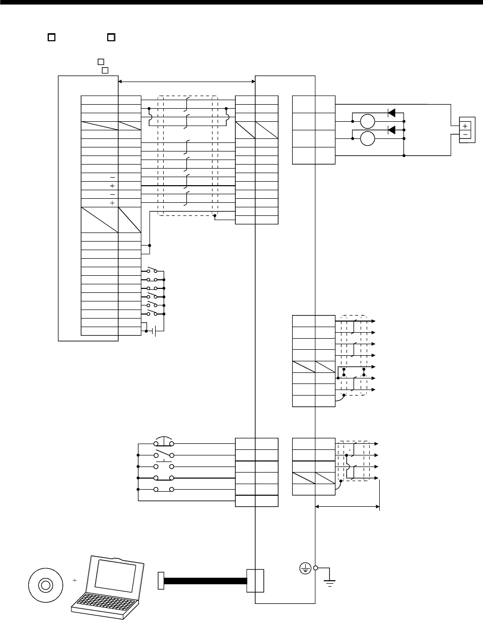
(2) AD75P (A1SD75P )
(Note 9)
MR Configurator
(Servo configuration software) Personal
computer
PULSE R
2m max.
(Note 8) 10m max.
26
8
24
5
21
4
22
7
23
3
25
6
1
20
12
14
35
16
13
15
11
2
36
19
SG
INP
LZ
VIN
PG
NP
NG
RD
CR
PP
LZR
SD
LG
DOG
COM
RLS
START
CHG
FLS
STOP
COM
READY
COM
INPS
CLEAR
PGO(24V)
PGO(5V)
PGO COM
CLEAR COM
PULSE F
PULSE COM
PULSE R
PULSE COM
17
16
18
15
CN3
21
14
8
4
3
6
7
1
EMG
SON
RES
LSP
LSN
VIN
CN1 CN3
CN1
CN1
9
12
RA1
RA2
ALM
ZSP
1VIN
CN1
13 SG
11
13
10
19
20
1
5
22
23
24
25
14
(Note 7)
24VDC
Positioning module
AD75P
(A1SD75P ) Servo amplifier
(Note 2)
(Note 5)
Trouble
Zero speed
Encoder A-phase pulse
(differential line driver)
Encoder B-phase pulse
(differential line driver)
Encoder Z-phase pulse
(open collector)
(Note 3, 4) Emergency stop
Servo-on
Reset
(Note 4) Forward rotation stroke end
Reverse rotation stroke end
(Note 6)
Communication cable
(Note 1)
(Note 7) (Note 7)
(Note 7)
(Note 7)
(Note 7)
Plate
Plate
External
power
supply
24VDC
(Note 11)
Control common
PULSE F
PULSE F
PULSE R
OP
LG
SD
LA
LAR
LB
LBR
(Note 10)
MO1
LG
MO2
4
3
6
SDPlate
Analog monitor 1
Analog monitor 2
Control common
Control common
3 - 4

3. SIGNALS AND WIRING
Note 1. To prevent an electric shock, always connect the protective earth (PE) terminal (terminal marked ) of the servo amplifier to the
protective earth (PE) of the control box.
2. Connect the diode in the correct direction. If it is connected reversely, the servo amplifier will be faulty and will not output signals,
disabling the emergency stop and other protective circuits.
3. The emergency stop switch (normally closed contact) must be installed.
4. When starting operation, always connect the emergency stop (EMG) and forward rotation stroke end (LSN), reverse rotation stroke
end (LSP) with VIN. (Normally closed contacts)
5. Trouble (ALM) is connected with VIN in normal alarm-free condition (normally closed contact). When this signal is switched off (at
occurrence of an alarm), the output of the controller should be stopped by the sequence program.
6. When connecting the personal computer together with monitor outputs 1, 2, use the branch cable (MR-E3CBL15-P). (Refer to
section 13.1.3)
7. The pins with the same signal name are connected in the servo amplifier.
8. This length applies to the command pulse train input in the differential line driver system.
It is 2m or less in the open collector system.
9. Use MRZJW3-SETUP154E or 154C.
10. To enhance noise immunity, connect LG and pulse output COM.
11. Externally supply 24VDC 10 , 200mA power for the interface. 200mA is a value applicable when all I/O signals are used.
Reducing the number of I/O points decreases the current capacity. Refer to the current necessary for the interface described in
section 3.6.2. Connect the external 24VDC power supply if the output signals are not used.
3 - 5
3. SIGNALS AND WIRING
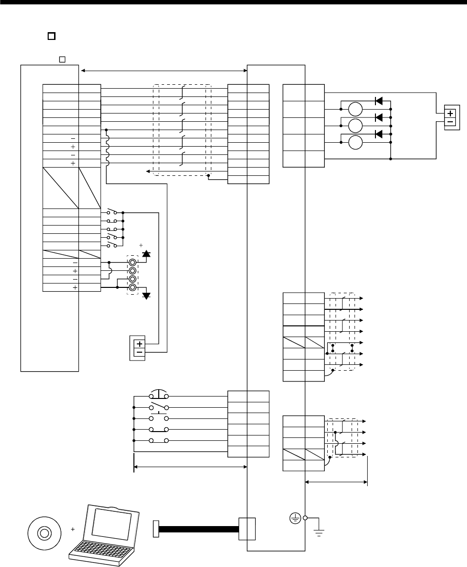
(3) QD75D (differential driver)
(Note 9)
MR Configurator
(Servo configuration software) Personal
computer
(Note 8) 10m max.
RDY COM
10m or less
PULSE R
PULSE F
PULSE F
PULSE R
SG
LZ
VIN
PG
NP
NG
RD
CR
PP
LZR
SD
LG
17
16
18
15
CN3
21
14
8
4
3
6
7
1
EMG
SON
RES
LSP
LSN
VIN
CN1
CN3
CN1
9
12
RA1
RA2
ALM
ZSP
1VIN
13 SG
11
13
19
20
1
5
22
23
24
25
14
12
9
13
16
17
18
11
14
15
10
A19
B20
1
4
2
5
3
A20
B19
READY
CLEAR
DOG
RLS
CHG
FLS
STOP
PGO
PGO COM
CLEAR COM
A
B
0V
5V
5G
(Note 7)
Positioning module
QD75D Servo amplifier
(Note 7)
CN1
(Note 7)
CN1
(Note 2)
Encoder A-phase pulse
(differential line driver)
Encoder B-phase pulse
(differential line driver)
Control common
Encoder Z-phase pulse
(open collector)
(Note 7)
Plate
(Note 3, 4) Emergency stop
Servo-on
Reset
(Note 4) Forward rotation stroke end
Reverse rotation stroke end
(Note 6)
Communication cable
(Note 1)
(Note 5)
Trouble
Zero speed
(Note 7)
(Note 7)
5V
External
power
supply
24VDC
Manual pulse
generator
MR-HDP01
(Note 11)
10 INP RA3
External
power
supply
24VDC
PULSER B
PULSER A
PULSER A
PULSER B
2m max.
LA
LAR
LB
LG
LBR
OP
SD
(Note 10) Plate
MO1
LG
MO2
4
3
6
SDPlate
Analog monitor 1
Analog monitor 2
Control common
Control common
3 - 6

3. SIGNALS AND WIRING
Note 1. To prevent an electric shock, always connect the protective earth (PE) terminal (terminal marked ) of the servo amplifier to the
protective earth (PE) of the control box.
2. Connect the diode in the correct direction. If it is connected reversely, the servo amplifier will be faulty and will not output signals,
disabling the emergency stop and other protective circuits.
3. The emergency stop switch (normally closed contact) must be installed.
4. When starting operation, always connect the emergency stop (EMG) and forward rotation stroke end (LSN), reverse rotation stroke
end (LSP) with VIN. (Normally closed contacts)
5. Trouble (ALM) is connected with VIN in normal alarm-free condition (normally closed contact). When this signal is switched off (at
occurrence of an alarm), the output of the controller should be stopped by the sequence program.
6. When connecting the personal computer together with monitor outputs 1, 2, use the branch cable (MR-E3CBL15-P). (Refer to
section 13.1.3)
7. The pins with the same signal name are connected in the servo amplifier.
8. This length applies to the command pulse train input in the differential line driver system.
It is 2m or less in the open collector system.
9. Use MRZJW3-SETUP154E or 154C.
10. This connection is not required for the QD75D. Depending on the used positioning module, however, it is recommended to
connect the LG and control common terminals of the servo amplifier to enhance noise immunity.
11. Externally supply 24VDC 10 , 200mA power for the interface. 200mA is a value applicable when all I/O signals are used.
Reducing the number of I/O points decreases the current capacity. Refer to the current necessary for the interface described in
section 3.6.2. Connect the external 24VDC power supply if the output signals are not used.
3 - 7
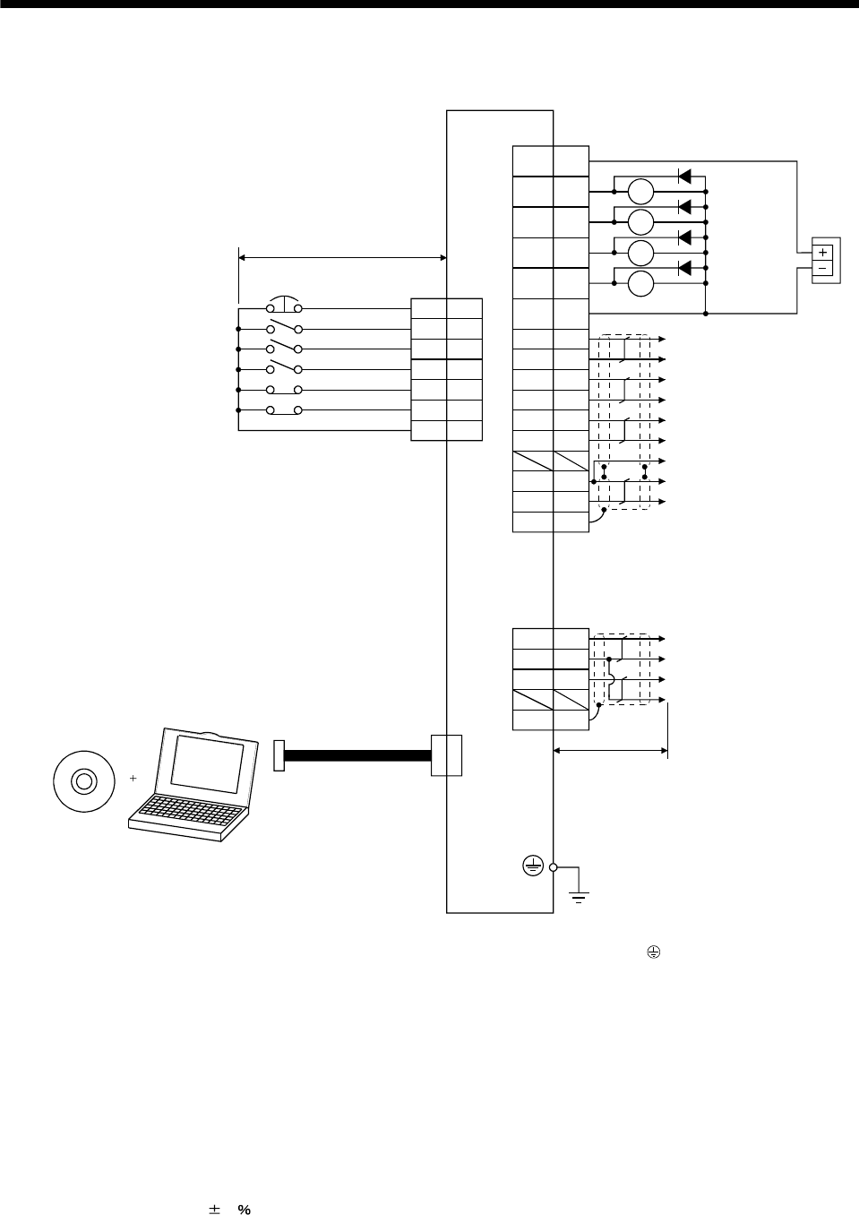
3. SIGNALS AND WIRING
3.1.2 Internal speed control mode
LZR
LA
LAR
LB
LBR
LG
RD
10m max.
1
9
12
RA1
RA2
8
4
3
5
6
7
EMG
SON
ST1
ST2
LSP
LSN
VIN 1
ALM
ZSP
CN3
VIN
CN1
CN3
20
19
21
17
16
18
LZ
SD
14
15
11
10 SA RA3
RA4
13 SG
Plate
Personal
computer
CN1
(Note 7)
(Note 5)
Trouble
Zero speed
(Note 2)
Control common
Encoder Z-phase pulse
(differential line driver)
Encoder A-phase pulse
(differential line driver)
Encoder B-phase pulse
(differential line driver)
(Note 6)
Communication cable
(Note 1)
Servo amplifier
(Note 7)
Speed reached
Ready
(Note 3, 4) Emergency stop
Servo-on
Forward rotation start
Reverse rotation start
(Note 4) Forward rotation stroke end
Reverse rotation stroke end
External
power
supply
24VDC
(Note 7)
(Note 7)
(Note 9)
Encoder Z-phase pulse
(open collector)
OP
2m max.
(Note 8)
MR Configurator
(Servo configuration software)
MO1
LG
MO2
4
3
6
SDPlate
Analog monitor 1
Analog monitor 2
Control common
Control common
Note 1. To prevent an electric shock, always connect the protective earth (PE) terminal (terminal marked ) of the servo amplifier to the
protective earth (PE) of the control box.
2. Connect the diode in the correct direction. If it is connected reversely, the servo amplifier will be faulty and will not output signals,
disabling the emergency stop and other protective circuits.
3. The emergency stop switch (normally closed contact) must be installed.
4. When starting operation, always connect the emergency stop (EMG) and forward rotation stroke end (LSN), reverse rotation stroke
end (LSP) with VIN (Normally closed contacts).
5. Trouble (ALM) is connected with VIN in normal alarm-free condition (normally closed contact).
6. When connecting the personal computer together with monitor outputs 1, 2, use the branch cable (MR-E3CBL15-P). (Refer to
section 13.1.3)
7. The pins with the same signal name are connected in the servo amplifier.
8. Use MRZJW3-SETUP154E or 154C.
9. Externally supply 24VDC 10 , 200mA power for the interface. 200mA is a value applicable when all I/O signals are used.
Reducing the number of I/O points decreases the current capacity. Refer to the current necessary for the interface described in
section 3.6.2. Connect the external 24VDC power supply if the output signals are not used.
3 - 8
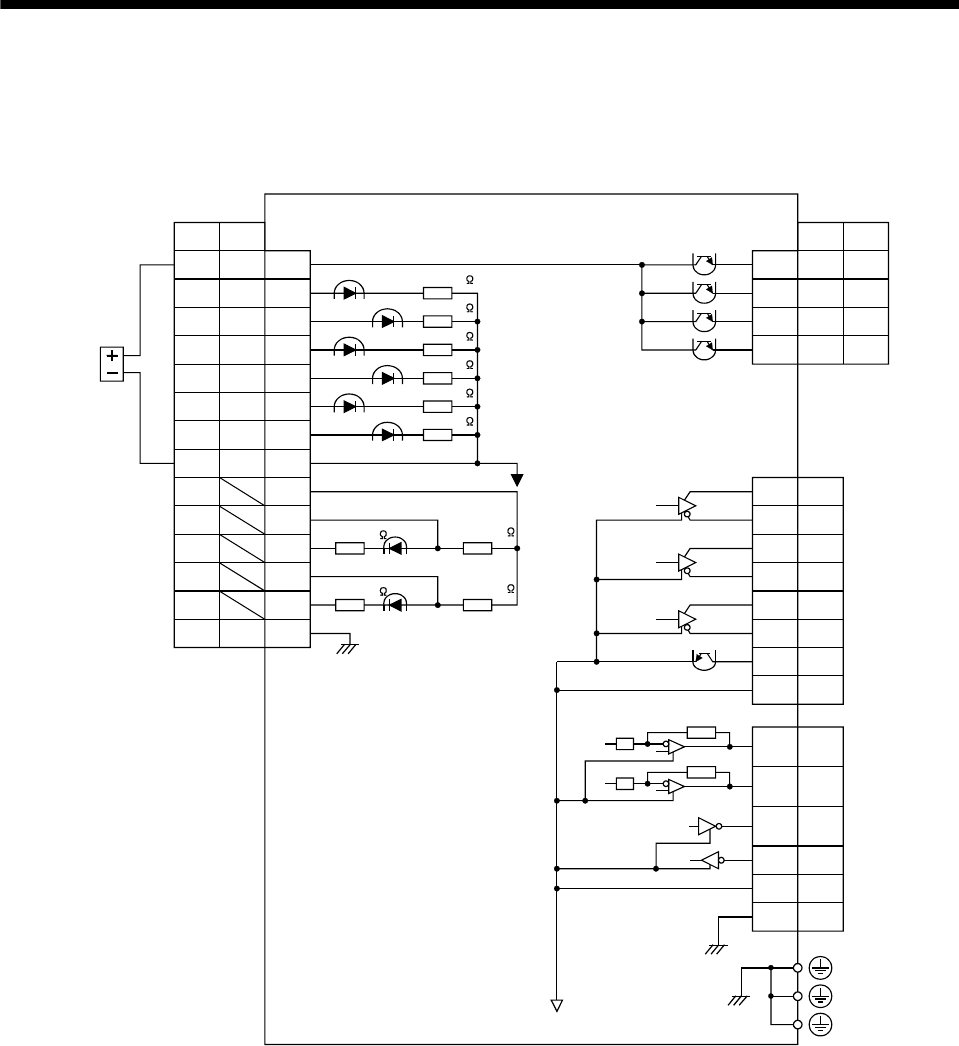
3. SIGNALS AND WIRING
3.2 Internal connection diagram of servo amplifier
The following is the internal connection diagram where the signal assignment has been made in the initial
status in each control mode.
External
power
supply
24VDC
S
RD RD11CR
OPC
PG
RES
EMG
LSP
LSN
SG
EMG
LSP
LSN
SG
ST1
SD
PP
NG
NP
SD
P
13
CN1
CN1
SON SON 4
3
8
6
7
ST2 5
2
22
23
24
25
Case
PS
INP SA10
ALM ALM9
ZSP ZSP12
15
16
18
17
20
21
19
LA
LAR
LBR
LB
LZR
OP
LZ
CN1
4MO1
6
2
MO2
TXD
CN3
1RXD
3LG
PE
LG14
VIN VIN 1
Case SD
(Note)
Servo amplifier
Approx. 100
Approx. 100
Approx. 1.2k
Approx. 1.2k
Approx. 4.7k
(Note)
Approx. 4.7k
Approx. 4.7k
Approx. 4.7k
Approx. 4.7k
Approx. 4.7k
Note. P: Position control mode, S: Internal speed control mode
3 - 9
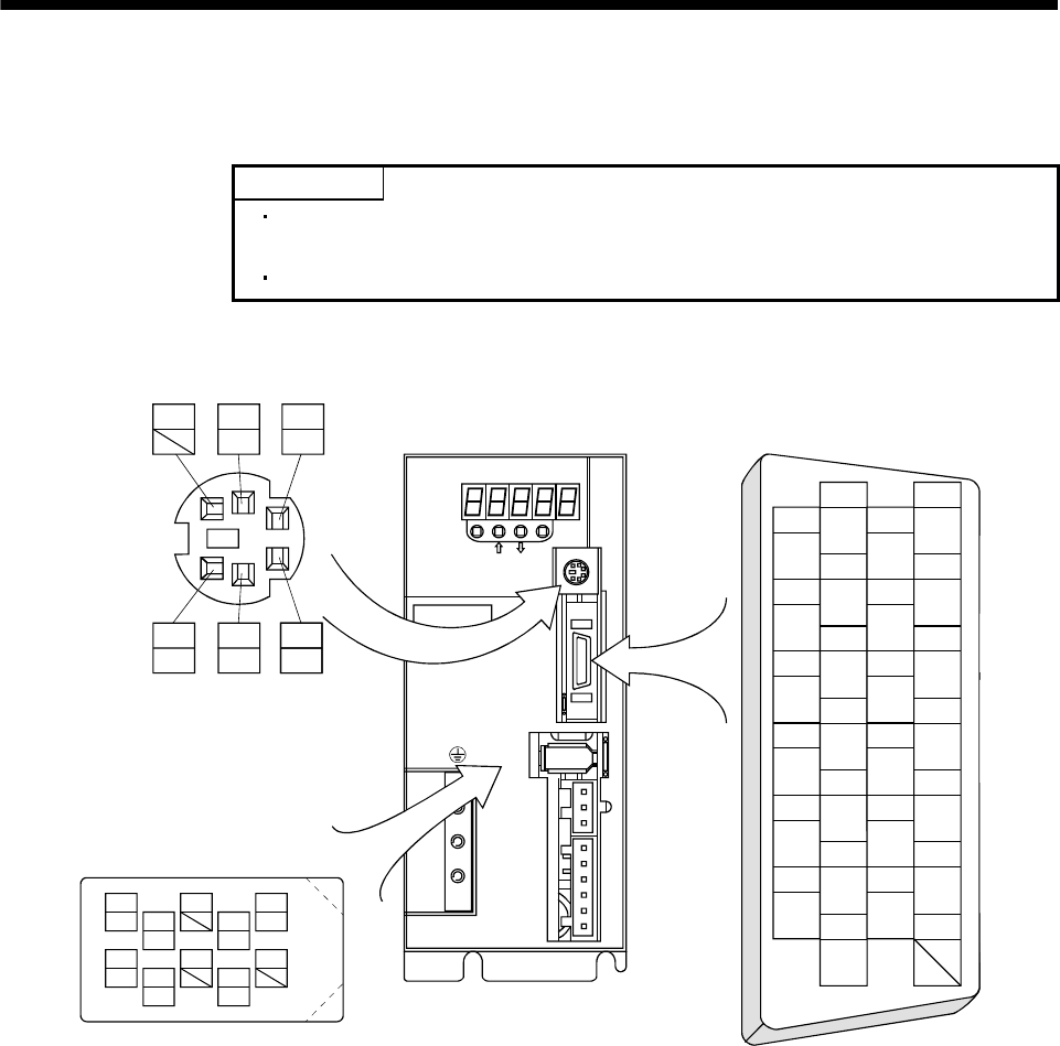
3. SIGNALS AND WIRING
3.3 I/O signals
3.3.1 Connectors and signal arrangements
POINT
The pin configurations of the connectors are as viewed from the cable
connector wiring section.
Refer to the next page for CN1 signal assignment.
(1) Signal arrangement
CN1
MODE
CN3
SET
CN1
CN2
CNP2
CNP1
L3L2L1 D C P W V U
CHARGE
MITSUBISHI
MR-E
6
MO2
2
OPC
1
VIN 15
LA
14
LG
16
LAR
17
LB
3
RES
4
SON
6
LSP
5
CR 19
LZ
18
LBR
20
LZR
21
OP
7
LSN
8
EMG
10
INP
9
ALM 23
PP
22
PG
24
NG
25
NP
11
RD
12
ZSP 2613
SG
MO1
42
TXD
2
TXD
5 3
LG
1
RXD
The connector frames are
connected with the PE (earth)
terminal inside the servo amplifier.
9
4
MRR
2
LG 8
6
1
P5 5
10
3
MR 7
LG
CN2
MDR
MD
CN3
3 - 10
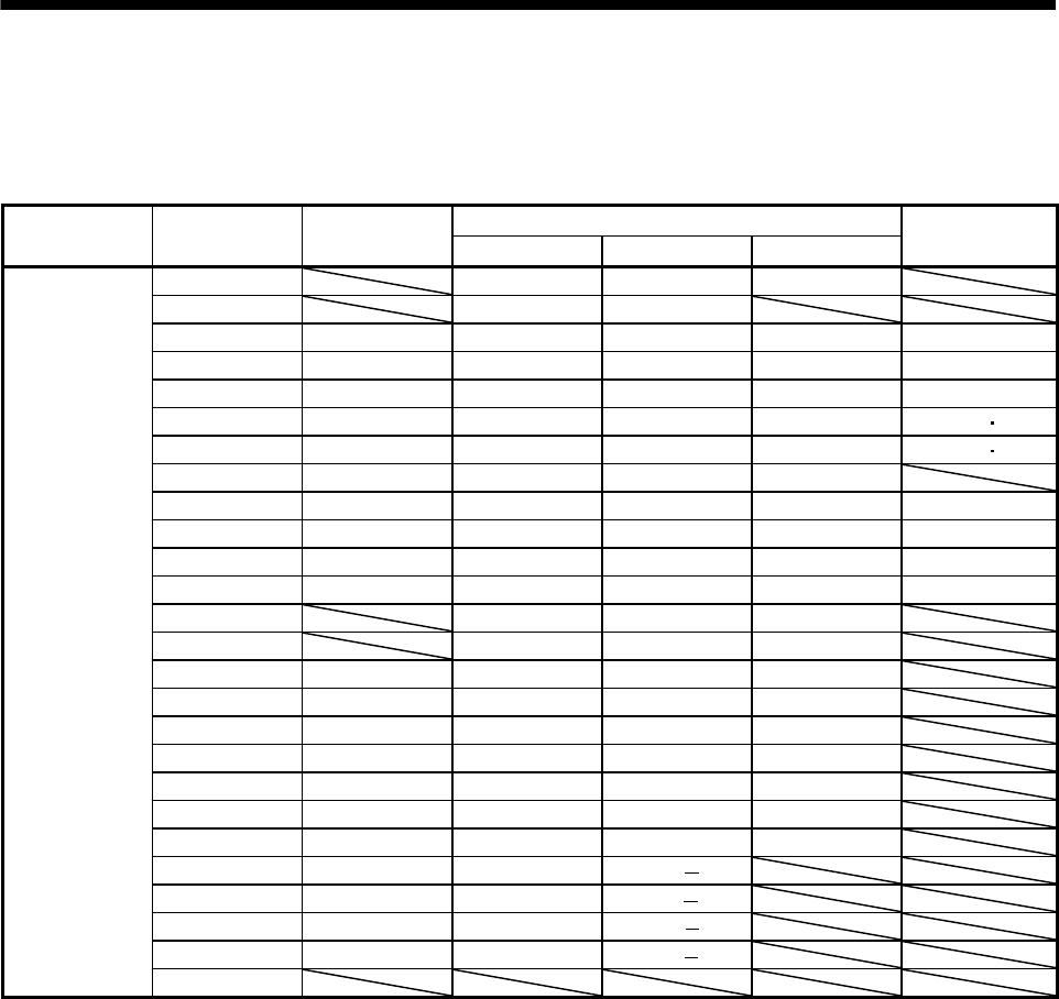
3. SIGNALS AND WIRING
(2) CN1 signal assignment
The signal assignment of connector changes with the control mode as indicated below;
For the pins which are given parameter No.s in the related parameter column, their signals can be changed
using those parameters.
(Note 2) I/O Signals in control modes
Connector Pin No. (Note 1) I/O P P/S S
Related parameter
1 VIN VIN VIN
2 OPC OPC
3 I RES RES/ST1 ST1 No.43 to 48
4 I SON SON
SON
No.43 to 48
5 I CR LOP
ST2
No.43 to 48
6 I LSP LSP LSP No.43 48
7 I LSN LSN LSN No.43 48
8 I EMG EMG EMG
9 O ALM ALM ALM No.49
10 O INP INP/SA SA No.49
11 O RD RD RD No.49
12 O ZSP ZSP ZSP No.1, 49
13 SG SG SG
14 LG LG LG
15 O LA LA LA
16 O LAR LAR LAR
17 O LB LB LB
18 O LBR LBR LBR
19 O LZ LZ LZ
20 O LZR LZR LZR
21 O OP OP OP
22 I PG PG/
23 I PP PP/
24 I NG NG/
25 I NP NP/
CN1
26
Note 1. I: Input signal, O: Output signal
2. P: Position control mode, S: Internal speed control mode, P/S: Position/internal speed control change mode
3 - 11

3. SIGNALS AND WIRING
3 - 12
(
3) Symbols and signal names
Symbol Signal name Symbol Signal name
SON Servo-on ZSP Zero speed detection
LSP Forward rotation stroke end INP In position
LSN Reverse rotation stroke end SA Speed reached
CR Clear ALM Trouble
SP1 Speed selection 1 WNG Warning
SP2 Speed selection 2 OP Encoder Z-phase pulse (open collector)
PC Proportion control MBR Electromagnetic brake interlock
ST1 Forward rotation start LZ
ST2 Reverse rotation start LZR
Encoder Z-phase pulse
(differential line driver)
TL1 Internal Torque limit selection LA
RES Reset LAR
Encoder A-phase pulse
(differential line driver)
EMG Emergency stop LB
LOP Control change LBR
Encoder B-phase pulse
(differential line driver)
PP VIN Digital I/F power supply input
NP OPC Open collector power input
PG SG Digital I/F common
NG
Forward/reverse rotation pulse train
LG Control common
RD Ready SD Shield
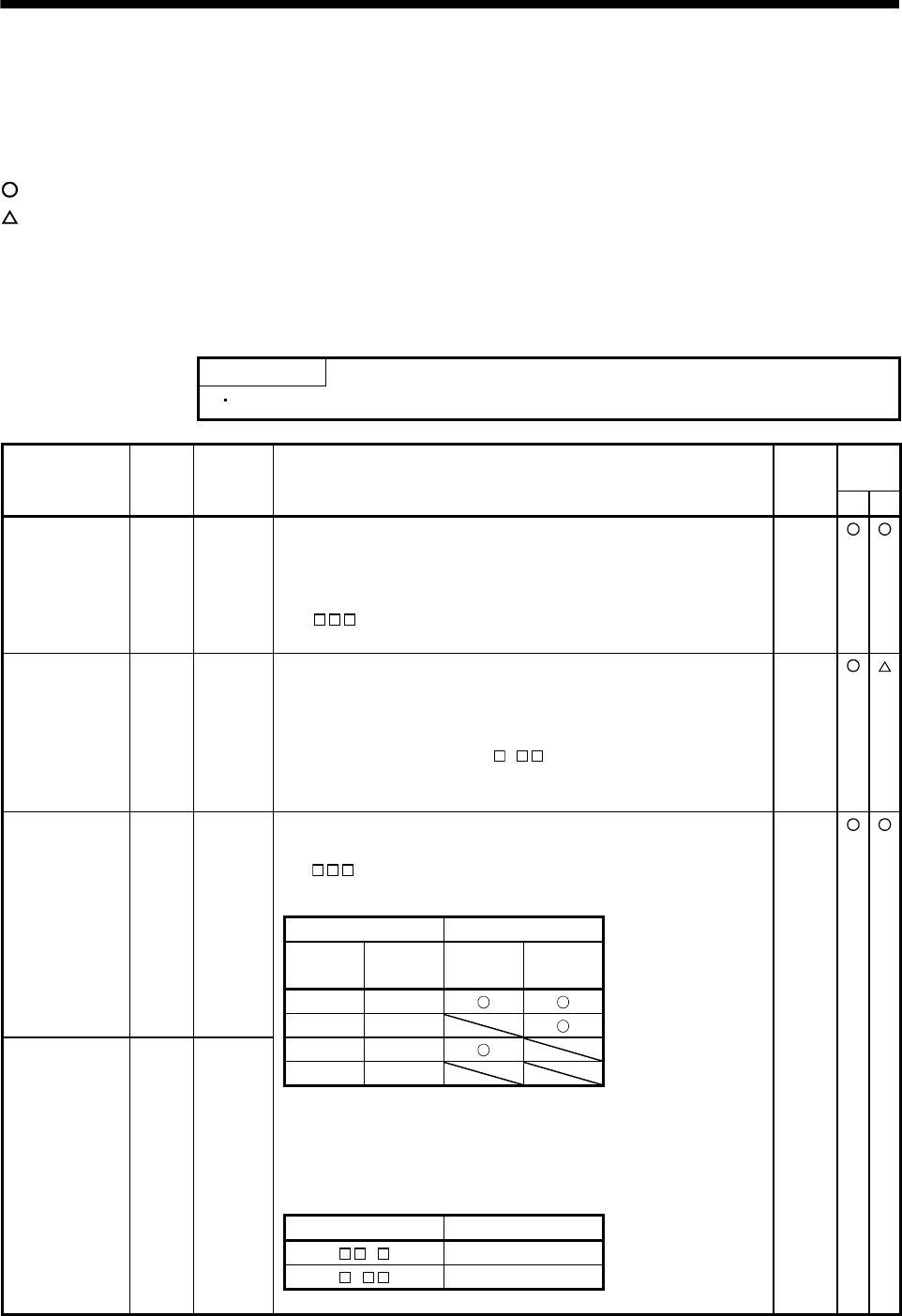
3. SIGNALS AND WIRING
3.3.2 Signal explanations
For the I/O interfaces (symbols in I/O column in the table), refer to section 3.6.2.
In the control mode field of the table
P : Position control mode, S: Internal speed control mode
: Denotes that the signal may be used in the initial setting status.
: Denotes that the signal may be used by setting the corresponding parameter among parameters No.43 to
49.
The pin No.s in the connector pin No. column are those in the initial status.
(1) Input signals
POINT
The acceptance delay time of each input signal is less than 10ms.
Control
mode
Signal Symbol
Connector
pin No. Functions/applications I/O
division P S
Servo-on SON CN1-4 Connect SON-VIN to switch on the base circuit and make the servo
amplifier ready to operate (servo-on).
Disconnect SON-VIN to shut off the base circuit and coast the servo motor
(servo off) .
Set " 1" in parameter No.41 to switch this signal on (keep terminals
connected) automatically in the servo amplifier.
DI-1
Reset RES CN1-3 Disconnect RES-VIN for more than 50ms to reset the alarm.
Some alarms cannot be deactivated by the reset (RES). (Refer to section
10.2.1.)
Shorting RES-VIN in an alarm-free status shuts off the base circuit. The
base circuit is not shut off when " 1" is set in parameter No.51.
This device is not designed to make a stop. Do not turn it ON during
operation.
DI-1
Forward rotation
stroke end
LSP CN1-6 To start operation, short LSP-VIN and/or LSN-VIN. Open them to bring the
motor to a sudden stop and make it servo-locked.
Set " 1" in parameter No.22 to make a slow stop.
(Refer to section 5.2.3.)
DI-1
(Note) Input signals Operation
LSP LSN
CCW
direction
CW
direction
1 1
0 1
LSN CN1-7 1 0 Reverse rotation
stroke end 0 0
Note. 0: LSP/LSN-VIN off (open)
1: LSP/LSN-VIN on (short)
Set parameter No.41 as indicated below to switch on the signals (keep
terminals connected) automatically in the servo amplifier.
Parameter No.41 Automatic ON
1 LSP
1 LSN
3 - 13
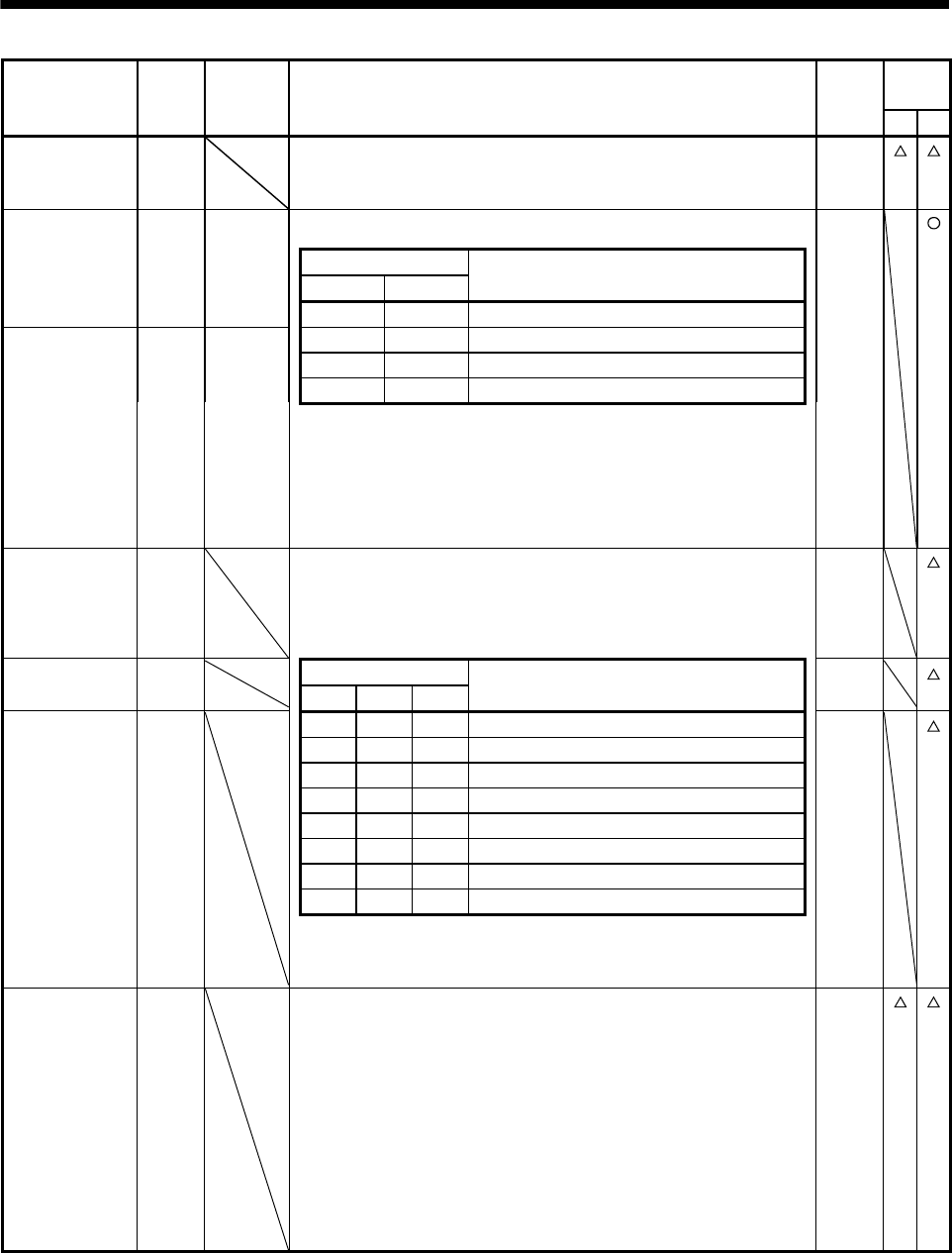
3. SIGNALS AND WIRING
Control
mode
Signal Symbol
Connector
pin No. Functions/applications I/O
division P S
Internal torque
limit selection
TL1 When using this signal, make it usable by making the setting of parameter
No.43 to 48.
(Refer to section 3.4.1 (5).)
DI-1
ST1 CN1-3 Used to start the servo motor in any of the following directions.
DI-1 Forward rotation
start (Note) Input signals
ST2 ST1
Servo motor starting direction
0 0 Stop (servo lock)
ST2 CN1-5 0 1 CCW Reverse rotation
start 1 0 CW
1 1 Stop (servo lock)
Note. 0: ST1/ST2-VIN off (open)
1: ST1/ST2-VIN on (short)
If both ST1 and ST2 are switched on or off during operation, the servo
motor will be decelerated to a stop according to the parameter No.12
setting and servo-locked.
Speed selection 1 SP1 <Internal speed control mode>
Used to select the command speed for operation.
When using SP1 to SP3, make it usable by making the setting of
parameter No.43 to 48.
DI-1
Speed selection 2 SP2 (Note) Input signals DI-1
SP3 SP2 SP1 Servo motor starting direction
SP3 0 0 0 Internal speed command 1 (parameter No.8) DI-1 Speed selection 3
0 0 1 Internal speed command 1 (parameter No.8)
0 1 0 Internal speed command 2 (parameter No.9)
0 1 1 Internal speed command 3 (parameter No.10)
1 0 0 Internal speed command 4 (parameter No.72)
1 0 1 Internal speed command 5 (parameter No.73)
1 1 0 Internal speed command 6 (parameter No.74)
1 1 1 Internal speed command 7 (parameter No.75)
Note. 0: SP1/SP2/SP3-VIN off (open)
1: SP1/SP2/SP3-VIN on (short)
Proportion control PC Connect PC-VIN to switch the speed amplifier from the proportional integral
type to the proportional type.
If the servo motor at a stop is rotated even one pulse due to any external
factor, it generates torque to compensate for a position shift. When the
servo motor shaft is to be locked mechanically after positioning completion
(stop), switching on the proportion control signal (PC) upon positioning
completion will suppress the unnecessary torque generated to compensate
for a position shift.
When the shaft is to be locked for a long time, set the internal torque limit 1
and 2 (parameter No.28 and 76) to make the torque less than the rated
torque at the same time of turning ON the proportion control signal.
DI-1
3 - 14
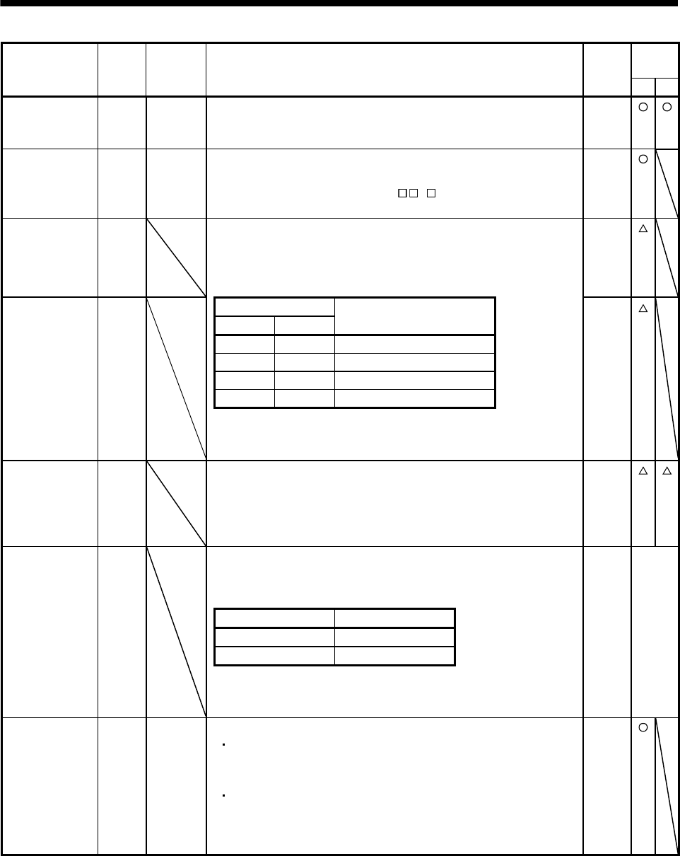
3. SIGNALS AND WIRING
Control
mode
Signal Symbol
Connector
pin No. Functions/applications I/O
division P S
Emergency stop EMG CN1-8 Disconnect EMG-VIN to bring the servo motor to emergency stop state, in
which the servo is switched off and the dynamic brake is operated.
Connect EMG-VIN in the emergency stop state to reset that state.
DI-1
Clear CR CN1-5 Connect CR-VIN to clear the position control counter droop pulses on its
leading edge. The pulse width should be 10ms or more.
When the parameter No.42 setting is " 1", the pulses are always
cleared while CR-VIN are connected.
DI-1
Electronic gear
selection 1
CM1 When using CM1 and CM2, make them usable by the setting of
parameters No.43 to 48.
The combination of CM1-VIN and CM2-VIN gives you a choice of four
different electronic gear numerators set in the parameters.
DI-1
CM2 (Note) Input signals DI-1 Electronic gear
selection 2 CM2 CM1
Electronic gear numerator
0 0 Parameter No.3
0 1 Parameter No.69
1 0 Parameter No.70
1 1 Parameter No.71
Note. 0: CM1/CM2-VIN off (open)
1: CM1/CM2-VIN on (short)
Gain changing CDP When using this signal, make it usable by the setting of parameter No.43 to
48.
Connect CDP-VIN to change the load inertia moment ratio into the
parameter No.61 setting and the gain values into the values multiplied by
the parameter No.62 to 64 settings.
DI-1
Control change LOP <Position/internal speed control change mode>
Used to select the control mode in the position/internal speed control
change mode.
DI-1
(Note) LOP Control mode
0 Position
1 Internal speed
Note. 0: LOP-VIN off (open)
1: LOP-VIN on (short)
Refer to
Functions
/appli-
cations
Forward rotation
pulse train
Reverse rotation
pulse train
PP
NP
PG
NG
CN1-23
CN1-25
CN1-22
CN1-24
Used to enter a command pulse train.
In the open collector system (max. input frequency 200kpps).
Forward rotation pulse train across PP-SG
Reverse rotation pulse train across NP-SG
In the differential receiver system (max. input frequency 500kpps).
Forward rotation pulse train across PG-PP
Reverse rotation pulse train across NG-NP
The command pulse train form can be changed using parameter No.21.
DI-2
3 - 15
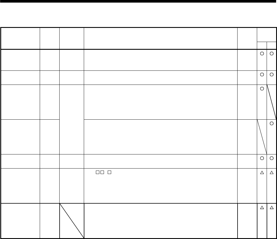
3. SIGNALS AND WIRING
(
2) Output signals
Control
mode
Signal Symbol
Connector
pin No. Functions/applications I/O
division P S
Trouble ALM CN1-9 ALM-VIN are disconnected when power is switched off or the protective
circuit is activated to shut off the base circuit. Without alarm, ALM-VIN are
connected within about 1s after power on.
DO-1
Ready RD CN1-11 RD-VIN are connected when the servo is switched on and the servo
amplifier is ready to operate.
DO-1
In position INP CN1-10 INP-VIN are connected when the number of droop pulses is in the preset
in-position range. The in-position range can be changed using parameter
No.5.
When the in-position range is increased, INP-VIN may be kept connected
during low-speed rotation.
DO-1
Speed reached SA SA turns off when servo on (SON) turns off or the servo motor speed has
not reached the preset speed with both forward rotation start (ST1) and
reverse rotation start (ST2) turned off. SA turns on when the servo motor
speed has nearly reached the preset speed. When the preset speed is
20r/min or less, SA always turns on.
DO-1
Zero speed
detection
ZSP CN1-12 ZSP-VIN are connected when the servo motor speed is zero speed
(50r/min) or less. Zero speed can be changed using parameter No.24.
DO-1
Electromagnetic
brake interlock
MBR (CN1-12) Set " 1" in parameter No.1 to use this parameter. Note that ZSP will
be unusable.
In the servo-off or alarm status, MBR-VIN are disconnected.
When an alarm occurs, they are disconnected independently of the base
circuit status.
DO-1
Warning WNG To use this signal, assign the connector pin for output using parameter
No.49. The old signal before assignment will be unusable.
When warning has occurred, WNG-VIN are connected.
When there is no warning, WNG-VIN are disconnected within about 1s
after power-on.
DO-1
3 - 16
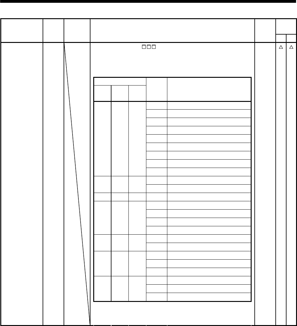
3. SIGNALS AND WIRING
Control
mode
Signal Symbol
Connector
pin No. Functions/applications I/O
division P S
A
larm code To use this signal, set " 1" in parameter No.49.
This signal is output when an alarm occurs. When there is no alarm,
respective ordinary signals (RD, INP, SA, ZSP) are output.
Alarm codes and alarm names are listed below.
DO-1
ACD 0
ACD 1
ACD 2 (Note) Alarm code
CN1
12 Pin
CN1
11 Pin
CN1
10 Pin
Alarm
display Name
88888 Watchdog
AL.12 Memory error 1
AL.13 Clock error
AL.15 Memory error 2
0 0 0 AL.17 Board error
AL.19 Memory error 3
AL.37 Parameter error
AL.8A Serial communication timeout
AL.8E Serial communication error
AL.30 Regenerative error
0 1 0
AL.33 Overvoltage
0 0 1 AL.10 Undervoltage
AL.45 Main circuit device
AL.46 Servo motor overheat
0 1 1
AL.50 Overload 1
AL.51 Overload 2
AL.24 Main circuit error
1 0 0
AL.32 Overcurrent
AL.31 Overspeed
1 1 0 AL.35 Command pulse frequency alarm
AL.52 Error excessive
AL.16 Encoder error 1
1 0 1 AL.1A Monitor combination error
AL.20 Encoder error 2
Note. 0: Pin-VIN off (open)
1: Pin-VIN on (short)
3 - 17
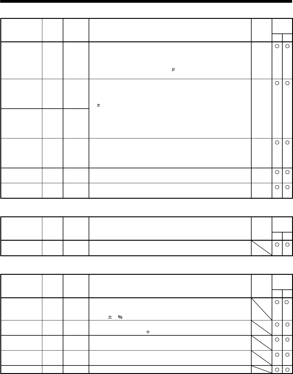
3. SIGNALS AND WIRING
Control
mode
Signal Symbol
Connector
pin No. Functions/applications I/O
division P S
Encoder Z-phase
pulse
(Open collector)
OP CN1-21 Outputs the zero-point signal of the encoder. One pulse is output per servo
motor revolution. OP and LG are connected when the zero-point position is
reached. (Negative logic)
The minimum pulse width is about 400 s. For home position return using
this pulse, set the creep speed to 100r/min. or less.
DO-2
Encoder A-phase
pulse
(Differential line
driver)
LA
LAR
CN1-15
CN1-16
DO-2
Encoder B-phase
pulse
(Differential line
driver)
LB
LBR
CN1-17
CN1-18
Outputs pulses per servo motor revolution set in parameter No.27 in the
differential line driver system. In CCW rotation of the servo motor, the
encoder B-phase pulse lags the encoder A-phase pulse by a phase angle
of /2.
The relationships between rotation direction and phase difference of the A-
and B-phase pulses can be changed using parameter No.54.
Encoder Z-phase
pulse
(Differential line
driver)
LZ
LZR
CN1-19
CN1-20
The same signal as OP is output in the differential line driver system. DO-2
Analog monitor 1 MO1 CN3-4 Used to output the data set in parameter No.17 to across MO1-LG in terms
of voltage. Resolution 10 bits
Analog
output
Analog monitor 2 MO2 CN3-6 Used to output the data set in parameter No.17 to across MO2-LG in terms
of voltage. Resolution 10 bits
Analog
output
(
3) Communication
Control
mode
Signal Symbol
Connector
pin No. Functions/applications I/O
division P S
RS-232C I/F RXD
TXD
CN3-1
CN3-2
RS-232C communication interface.
(4) Power supply
Control
mode
Signal Symbol
Connector
pin No. Functions/applications I/O
division P S
Digital I/F power
supply input
VIN CN1-1 Used to input 24VDC for input interface.
Connect the positive terminal of the 24VDC external power supply.
24VDC 10
Open collector
power input
OPC CN1-2 When inputting a pulse train in the open collector system, supply this
terminal with the positive ( ) power of 24VDC.
Digital I/F
common
SG CN1-13 Common terminal for output signals such as ALM and INP.
Separated from LG.
Control common LG CN1-14 Common terminal for OP, MO1, and MO2.
Pins are connected internally.
Shield SD Plate Connect the external conductor of the shield cable.
3 - 18
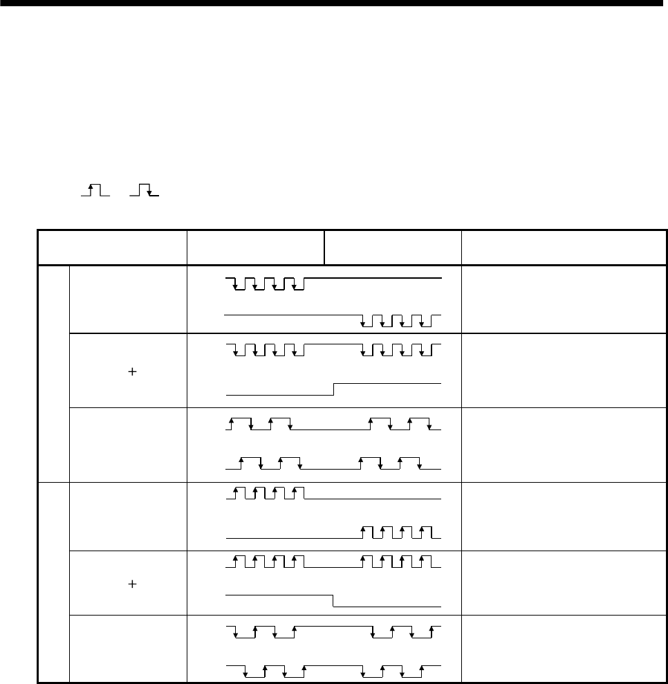
3. SIGNALS AND WIRING
3.4 Detailed description of the signals
3.4.1 Position control mode
(1) Pulse train input
(a) Input pulse waveform selection
Encoder pulses may be input in any of three different forms, for which positive or negative logic can be
chosen. Set the command pulse train form in parameter No.21.
Arrow or in the table indicates the timing of importing a pulse train.
A- and B-phase pulse trains are imported after they have been multiplied by 4.
Pulse train form Forward rotation command Reverse rotation command Parameter No.21
(Command pulse train)
Forward rotation pulse
train
Reverse rotation pulse
train
PP
NP
0010
Pulse train sign
PP
NP LH
0011
Negative logic
A-phase pulse train
B-phase pulse train
PP
NP
0012
Forward rotation pulse
train
Reverse rotation pulse
train
PP
NP
0000
Pulse train sign
PP
NP HL
0001
Positive logic
A-phase pulse train
B-phase pulse train
PP
NP
0002
3 - 19
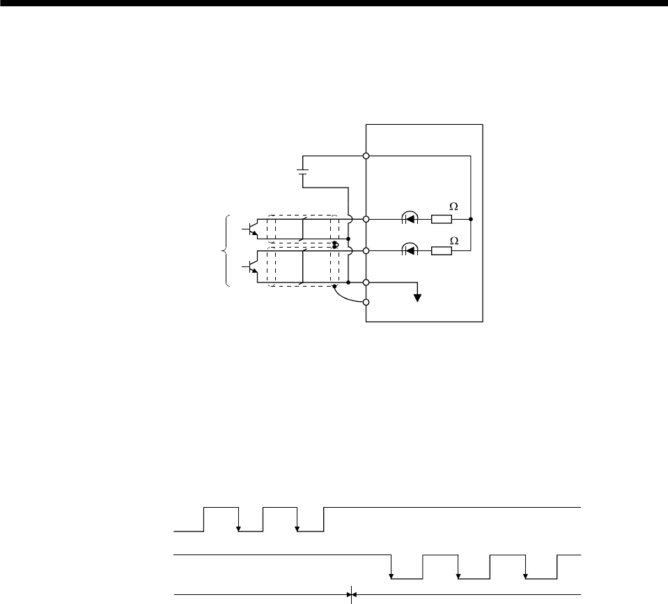
3. SIGNALS AND WIRING
(b) Connections and waveforms
1) Open collector system
Connect as shown below.
SG
SD
OPC
PP
NP
Servo amplifier
Approx.
1.2k
Approx.
1.2k
External power
supply 24VDC
(Note)
Note. Pulse train input interface is comprised of a photo coupler.
Therefore, it may be any malfunctions since the current is reduced when connect a resistance
to a pulse train signal line.
The explanation assumes that the input waveform has been set to the negative logic and forward and
reverse rotation pulse trains (parameter No.21 has been set to 0010). The waveforms in the table in
(1) (a) of this section are voltage waveforms of PP and NP based on SG. Their relationships with
transistor ON/OFF are as follows.
(ON)(OFF)
(ON) (OFF) (ON) (OFF) (ON)
(OFF)
Forward rotation
pulse train
(transistor)
Reverse rotation
pulse train
(transistor)
(ON)(OFF)
Forward rotation command Reverse rotation command
(OFF)
3 - 20
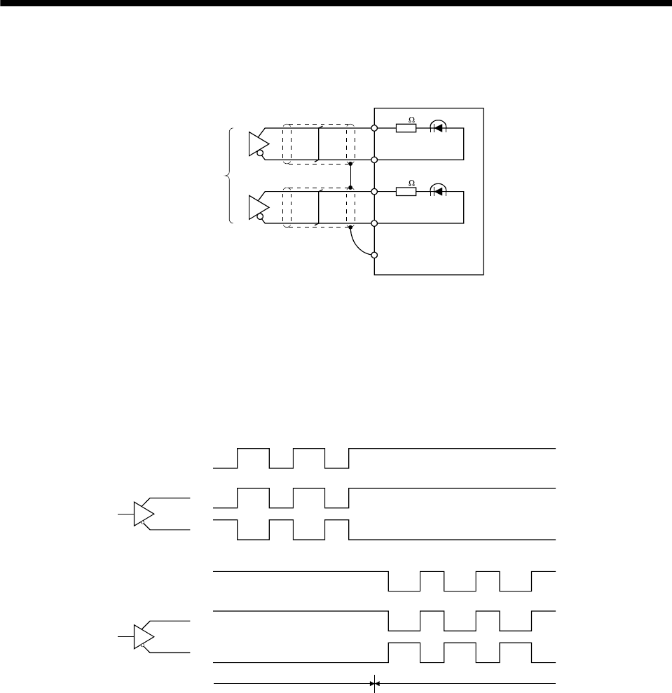
3. SIGNALS AND WIRING
2) Differential line driver system
Connect as shown below.
PP
NP
PG
NG
SD
Servo amplifier
(Note)
Approx.
100
Approx.
100
Note. Pulse train input interface is comprised of a photo coupler.
Therefore, it may be any malfunctions since the current is reduced when connect a resistance
to a pulse train signal line.
The explanation assumes that the input waveform has been set to the negative logic and forward and
reverse rotation pulse trains (parameter No.21 has been set to 0010).
For the differential line driver, the waveforms in the table in (1) (a) of this section are as follows.
The waveforms of PP, PG, NP and NG are based on that of the ground of the differential line driver.
PP
PG
NP
NG
Forward rotation
pulse train
Reverse rotation
pulse train
Forward rotation command Reverse rotation command
3 - 21
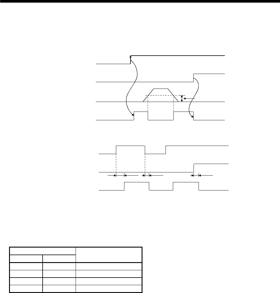
3. SIGNALS AND WIRING
(2) In-position (INP)
PF-VIN are connected when the number of droop pulses in the deviation counter falls within the preset in-
position range (parameter No.5). INP-VIN may remain connected when low-speed operation is performed
with a large value set as the in-position range.
Servo-on (SON)
Alarm
Droop pulses
In position (INP)
ON
OFF
Yes
No
In-position range
ON
OFF
(3) Ready (RD)
Servo-on (SON)
Alarm
Ready (RD)
ON
OFF
Yes
No
80ms or less 10ms or less 10ms or less
ON
OFF
(4) Electronic gear switching
The combination of CM1-VIN and CM2-VIN gives you a choice of four different electronic gear numerators
set in the parameters.
As soon as CM1/CM2 is turned ON or OFF, the numerator of the electronic gear changes. Therefore, if any
shock occurs at this change, use position smoothing (parameter No.7) to relieve shock.
(Note) External input signal
CM2 CM1
Electronic gear numerator
0 0 Parameter No.3
0 1 Parameter No.69
1 0 Parameter No.70
1 1 Parameter No.71
Note. 0: CM1/CM2-VIN off(open)
1: CM1/CM2-VIN on(short)
3 - 22
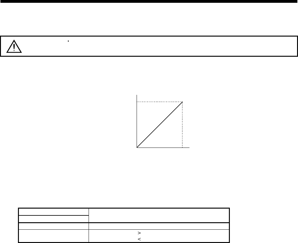
3. SIGNALS AND WIRING
(5) Torque limit
CAUTION Releasing the torque limit during servo lock may cause the servo motor to
suddenly rotate according to the position deviation from the instructed position.
(a) Torque limit and torque
By setting parameter No.28 (internal torque limit 1), torque is always limited to the maximum value
during operation. A relationship between the limit value and servo motor torque is shown below.
001
Max. torque
Torque
Torque limit value [%]
00
(b) Torque limit value selection
When internal torque limit selection (TL1) is made usable by parameter No.43 to 48, internal torque limit
2 (parameter No.76) can be selected. However, if the parameter No.28 value is less than the limit value
selected by parameter No.76, the parameter No.28 value is made valid.
(Note) External input signals
TL1 Torque limit value made valid
0 Internal torque limit value 1 (parameter No.28)
1 Parameter No.76 Parameter No.28: Parameter No.28
Parameter No.76 Parameter No.28: Parameter No.76
Note. 0: TL/TL1-VIN off (open)
1: TL/TL1-VIN on (short)
3 - 23
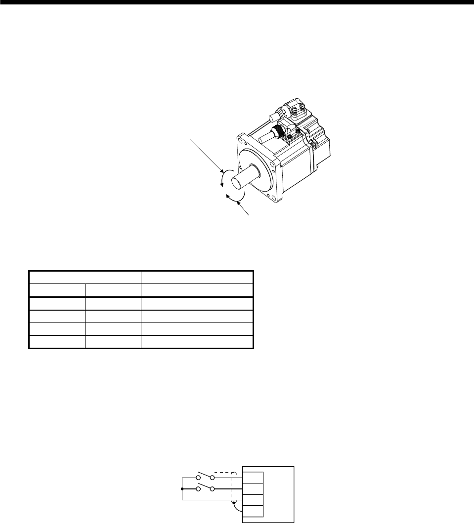
3. SIGNALS AND WIRING
3.4.2 Internal speed control mode
(1) Speed setting
(a) Speed command and speed
The servo motor is run at the speeds set in the parameters.
Forward rotation (CCW)
Reverse rotation (CW)
The following table indicates the rotation direction according to forward rotation start (ST1) and reverse
rotation start (ST2) combination.
(Note 1) External input signals (Note 2) Rotation direction
ST2 ST1
Internal speed commands
0 0 Stop (Servo lock)
0 1 CCW
1 0 CW
1 1 Stop (Servo lock)
Note 1. 0: ST1/ST2-VIN off (open)
1: ST1/ST2-VIN on (short)
2. Releasing the torque limit during servo lock may cause the servo motor to suddenly rotate according to the position
deviation from the instructed position.
The forward rotation start (ST1) and reverse rotation start (ST2) can be assigned to any pins of the
connector CN1 using parameters No.43 to 48.
Generally, make connection as shown below.
ST1
ST2
VIN
SD
Servo amplifier
3 - 24
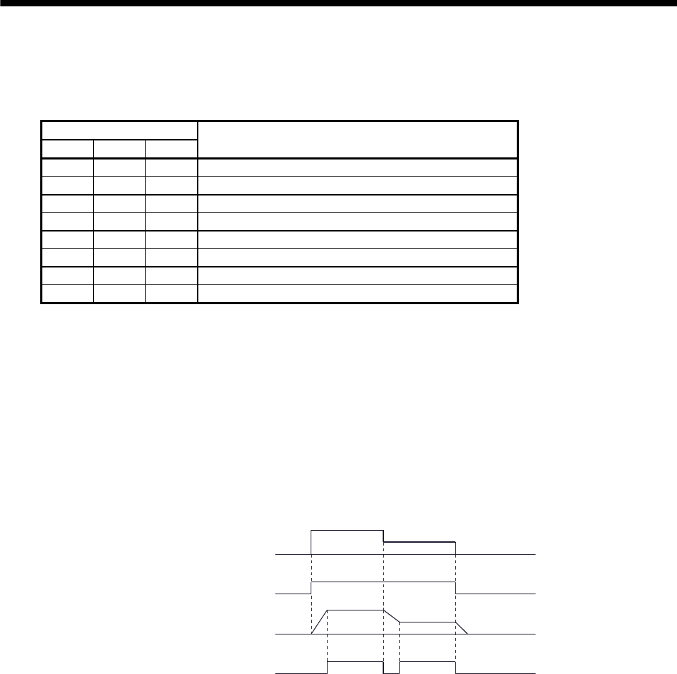
3. SIGNALS AND WIRING
(b) Speed selection 1 (SP1), speed selection 2 (SP2), speed selection 3 (SP3) and speed command value
By making speed selection 1 (SP1), speed selection 2 (SP2) and speed selection 3 (SP3) usable by
setting of parameter No.43 to 47, you can choose the speed command values of internal speed
commands 1 to 7.
(Note) External input signals
SP3 SP2 SP1 Speed command value
0 0 0 Internal speed command 1 (parameter No.8)
0 0 1 Internal speed command 1 (parameter No.8)
0 1 0 Internal speed command 2 (parameter No.9)
0 1 1 Internal speed command 3 (parameter No.10)
1 0 0 Internal speed command 4 (parameter No.72)
1 0 1 Internal speed command 5 (parameter No.73)
1 1 0 Internal speed command 6 (parameter No.74)
1 1 1 Internal speed command 7 (parameter No.75)
Note. 0: SP1/SP2/SP3-VIN off (open)
1: SP1/SP2/SP3-VIN on (short)
The speed may be changed during rotation. In this case, the values set in parameters No.11 and 12 are
used for acceleration/deceleration.
When the speed has been specified under any internal speed command, it does not vary due to the
ambient temperature.
(2) Speed reached (SA)
SA-VIN are connected when the servo motor speed nearly reaches the speed set to the internal speed
command.
ON
OFF
ON
OFF
Set speed selection Internal speed
command 1
Internal speed
command 2
Start (ST1,ST2)
Servo motor speed
Speed reached (SA)
(3) Torque limit
As in section 3.4.1 (5).
3 - 25
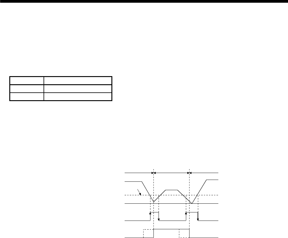
3 - 26
3. SIGNALS AND WIRING
3.4.3 Position/internal speed control change mode
Set "0001" in parameter No.0 to switch to the position/internal speed control change mode.
(1) Control change (LOP)
Use control change (LOP) to switch between the position control mode and the internal speed control mode
from an external contact. Relationships between LOP-VIN status and control modes are indicated below.
(Note) LOP Servo control mode
0 Position control mode
1 Speed control mode
Note. 0: LOP-VIN off (open)
1: LOP-VIN on (short)
The control mode may be changed in the zero-speed status. To ensure safety, change control after the servo
motor has stopped. When position control mode is changed to speed control mode, droop pulses are reset.
If the LOP has been switched on-off at the speed higher than the zero speed and the speed is then reduced to
the zero speed or less, the control mode cannot be changed. A change timing chart is shown below.
ON
OFF
ON
OFF
Position
control mode
Internal speed
control mode
Servo motor speed
Zero speed detection
(ZSP)
Control change (LOP)
Zero speed
level
(Note)
Note. When Zero speed detection (ZSP) is not on, control cannot be
changed if Control change (LOP) is switched on-off.
If Zero speed detection (ZSP) switches on after that, control cannot
be changed.
(Note)
Position
control mode
(2) Torque limit in position control mode
As in section 3.4.1 (5).
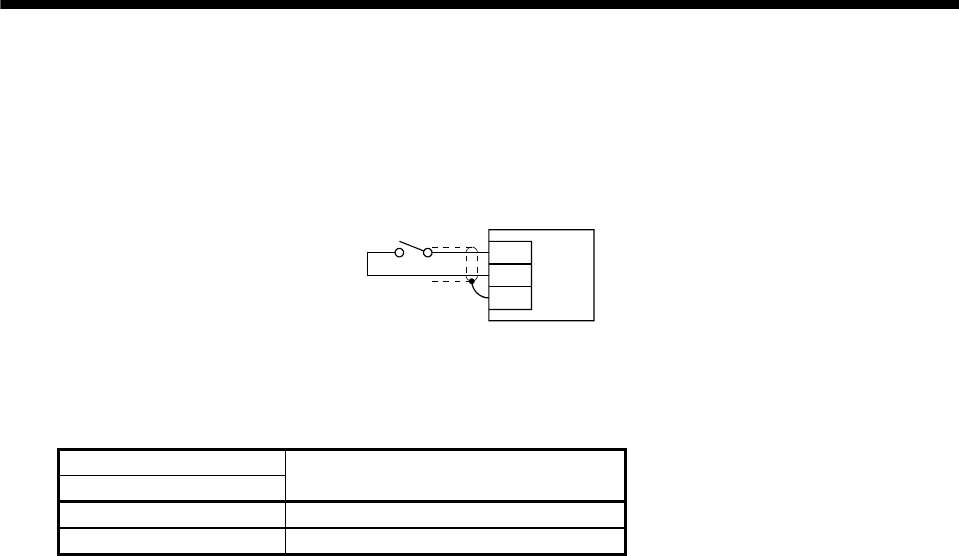
3. SIGNALS AND WIRING
(3) Internal speed setting in speed control mode
(a) Speed command and speed
The servo motor is run at the speed set in parameter No.8 (internal speed command 1) the forward
rotation start (ST1) and reverse rotation start (ST2) are as in section 3.4.2 (1) (a).
Generally, make connection as shown below.
SP2
VIN
SD
Servo amplifier
(b) Speed selection 2 (SP2) and speed command value
Use speed selection 2 (SP2) to select between the speed set by the internal speed command 1 and the
speed set by the Internal speed command 2 as indicated in the following table.
(Note) External input signals
SP1 Speed command value
0 Internal speed command 1 (parameter No.8)
1 Internal speed command 2 (parameter No.9)
Note. 0: SP1-VIN off (open)
1: SP1-VIN on (short)
The speed may also be changed during rotation. In this case, it is increased or decreased according to
the value set in parameter No.11 or 12.
When the internal speed command 1 is used to command the speed, the speed does not vary with the
ambient temperature.
(c) Speed reached (SA)
As in section 3.4.2 (2).
3 - 27
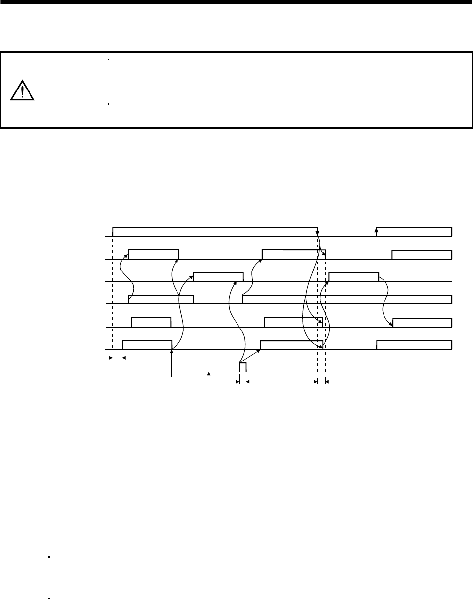
3. SIGNALS AND WIRING
3.5 Alarm occurrence timing chart
CAUTION
When an alarm has occurred, remove its cause, make sure that the operation
signal is not being input, ensure safety, and reset the alarm before restarting
operation.
As soon as an alarm occurs, turn off Servo-on (SON) and power off the power
supply.
When an alarm occurs in the servo amplifier, the base circuit is shut off and the servo motor is coated to a
stop. Switch off the power supply in the external sequence. To reset the alarm, switch the power supply from
off to on, press the "SET" button on the current alarm screen, or turn the reset (RES) from off to on. However,
the alarm cannot be reset unless its cause is removed.
ON
OFF
ON
OFF
ON
OFF
ON
OFF
ON
OFF
ON
OFF
2s
Brake operation
50ms or more 60ms or more
Alarm occurs.
Remove cause of trouble.
Brake operation
Power off Power on
Valid
Invalid
Power supply
Base circuit
Dynamic brake
Servo-on
(SON)
Reset
(RES)
Ready
(RD)
Trouble
(ALM)
(Note)
Note. Shut off the power as soon as an alarm occurs.
(1) Overcurrent, overload 1 or overload 2
If operation is repeated by switching power off, then on to reset the overcurrent (AL.32), overload 1
(AL.50) or overload 2 (AL.51) alarm after its occurrence, without removing its cause, the servo
amplifier and servo motor may become faulty due to temperature rise. Securely remove the cause of
the alarm and also allow about 30 minutes for cooling before resuming operation.
(2) Regenerative error
If operation is repeated by switching power off, then on to reset the regenerative (AL.30) alarm after
its occurrence, the external regenerative resistor will generate heat, resulting in an accident.
(3) Instantaneous power failure
Undervoltage (AL.10) occurs when the input power is in either of the following statuses.
A power failure of the control circuit power supply continues for 60ms or longer, then the power
restores.
During the servo-on status, the bus voltage dropped to 200VDC.
(4) In position control mode
When an alarm occurs, the home position is lost. When resuming operation after deactivating the
alarm, make a home position return.
3 - 28
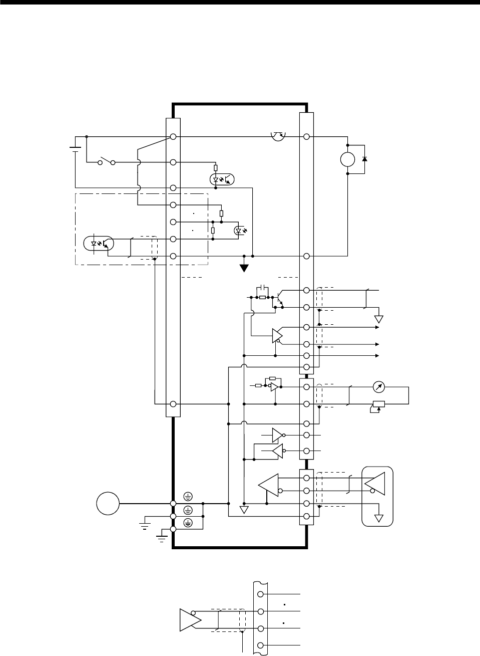
3. SIGNALS AND WIRING
3.6 Interfaces
3.6.1 Common line
The following diagram shows the power supply and its common line.
< Isolated >
CN1 CN1
SON, etc.
SG
OPC
PG NG
PP NP
SG
SD
OP
LG
LA etc.
MR
MRR
SD
M
DI-1
VIN
LG
SD
CN3
CN2
SD
MO1
MO2
LG
SG
TXD
RXD RS-232C
LAR
etc.
LG
ALM, etc. DO-1
RA
External
power
supply
24VDC
(Note)
Servo motor
Ground
Servo motor encoder
Analog monitor output
Differential line
driver output
35mA max.
Note. For the open collection pulse train input. Make the following connection for the different line driver pulse train input.
PP NP
PG NG
SG
OPC
3 - 29
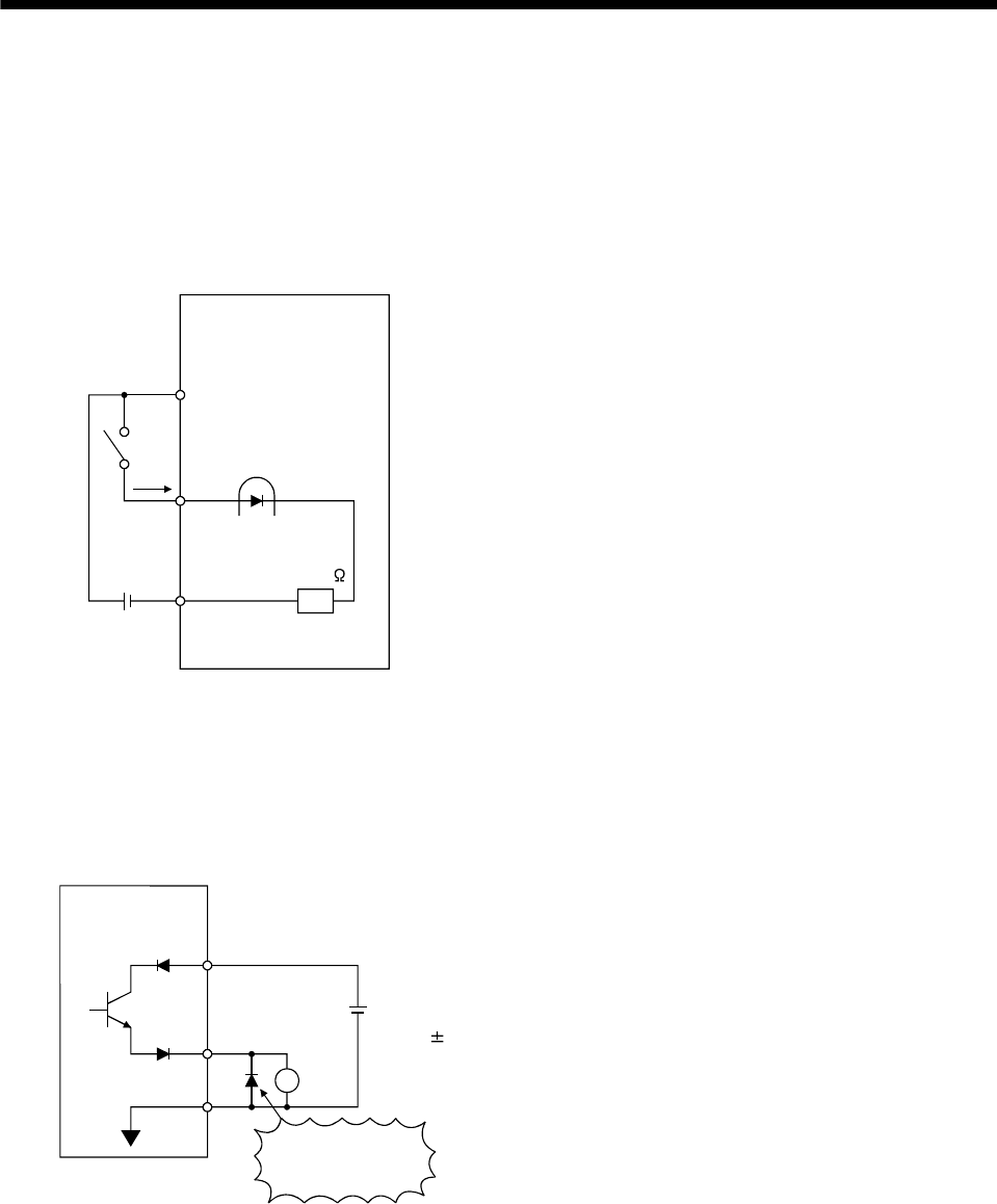
3. SIGNALS AND WIRING
3.6.2 Detailed description of the interfaces
This section gives the details of the I/O signal interfaces (refer to I/O Division in the table) indicated in section
3.3.2.
Refer to this section and connect the interfaces with the external equipment.
(1) Digital input interface DI-1
Give a signal with a relay or open collector transistor.
Servo amplifier
SG
SON, etc.
R: Approx. 4.7k
VIN
External power
supply 24VDC
200mA or more
(2) Digital output interface DO-1
A lamp, relay or photocoupler can be driven. Provide a diode (D) for an inductive load, or an inrush current
suppressing resistor (R) for a lamp load. (Rated current: 40mA or less, maximum current: 50mA or less,
inrush current: 100mA or less)
(a) Inductive load
(Note)
External
power supply
24VDC 10%
If polarity of diode is
reversed, servo
amplifier will fail.
Servo amplifier
VIN
ALM,
etc.
Load
SG
Note. If the voltage drop (maximum of 2.6V) interferes with the relay operation, apply high voltage (up to 26.4V) from external
source.
3 - 30
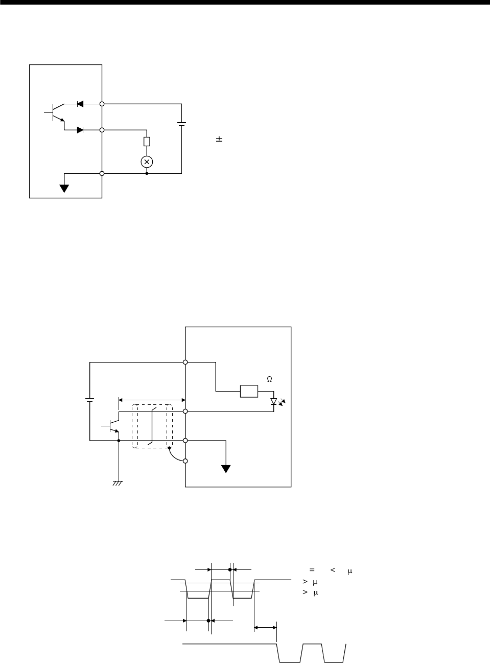
3. SIGNALS AND WIRING
(b) Lamp load
Servo amplifier
VIN
ALM,
etc.
R
SG
(Note)
External
power supply
24VDC 10%
Note. If the voltage drop (maximum of 2.6V) interferes with the relay operation, apply high voltage (up to 26.4V) from external
source.
(3) Pulse train input interface DI-2
Provide a pulse train signal in the open collector or differential line driver system.
(a) Open collector system
1) Interface
OPC
PP, NP
SG
SD
Servo amplifier
Max. input pulse
frequency 200kpps
Approx. 1.2k
External power
supply 24VDC
2m (78.74in)
or less
(Note)
Note. Pulse train input interface is comprised of a photo coupler.
Therefore, it may be any malfunctions since the current is reduced when connect a resistance to a pulse train signal line.
2) Conditions of the input pulse
0.9
0.1
tc tHL
tc tLH tF
tLH tHL 0.2 s
tc 2 s
tF 3 s
PP
NP
3 - 31

3. SIGNALS AND WIRING
(b) Differential line driver system
1) Interface
SD
PG(NG)
PP(NP)
Max. input pulse
frequency 500kpps
Servo amplifier
Am26LS31 or equivalent
10m or less
Approx. 100
VOH: 2.5V
VOL: 0.5V
(Note)
Note. Pulse train input interface is comprised of a photo coupler.
Therefore, it may be any malfunctions since the current is reduced when connect a resistance
to a pulse train signal line.
2) Conditions of the input pulse
0.9
PP PG
tc tHL
tc tLH tF
tLH tHL 0.1 s
tc 1 s
tF 3 s
NP NG
0.1
(4) Encoder pulse output
(a) Open collector system
Interface
Servo amplifier
OP
5 to 24VDC
Photocouple
r
SD
Max. output current : 35mA
LG
Servo amplifier
OP
SD
LG
3 - 32
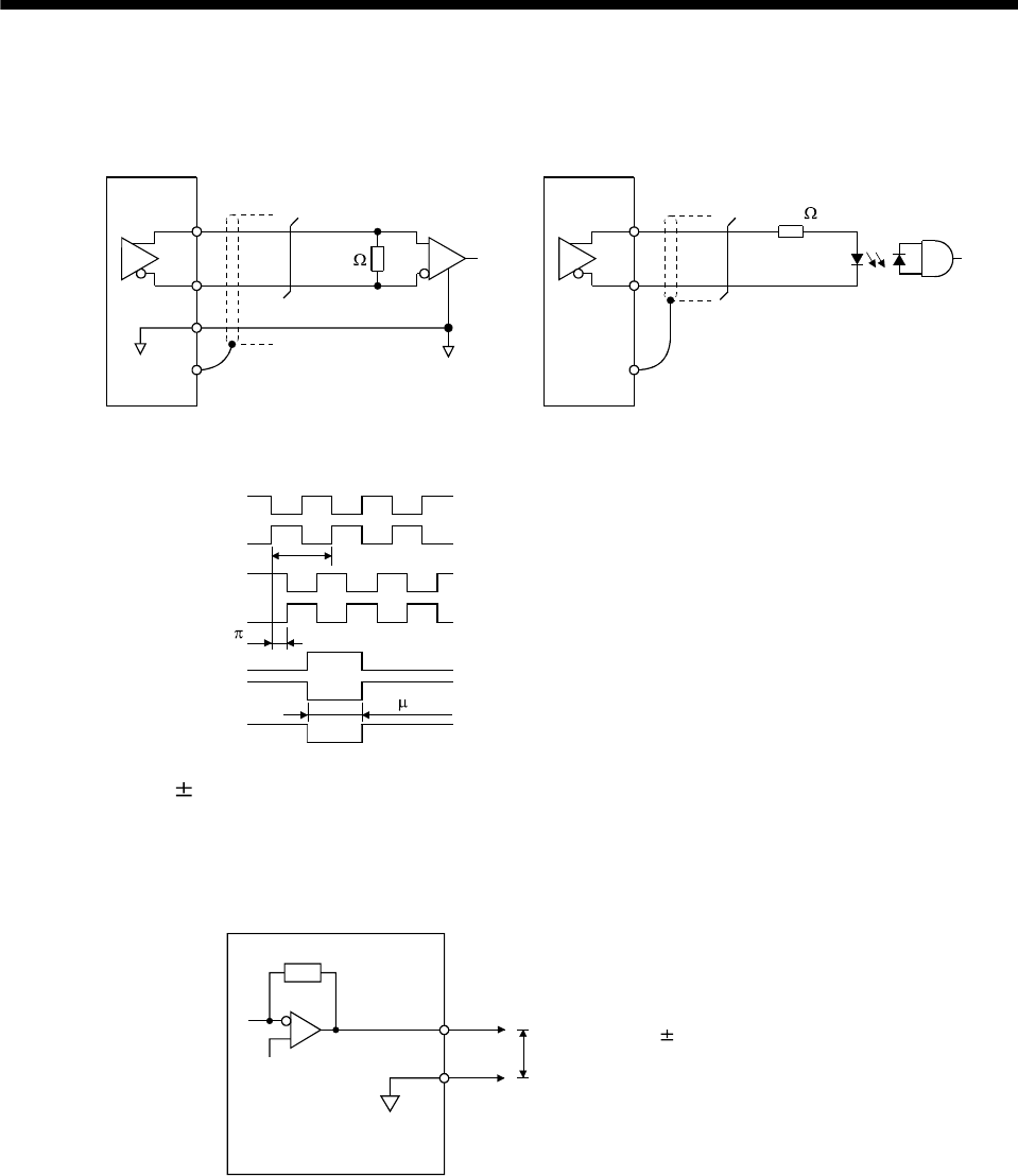
3. SIGNALS AND WIRING
(b) Differential line driver system
1) Interface
Max. output current: 35mA
LA
(LB, LZ)
LAR
(LBR, LZR)
LG
SD
LA
(LB, LZ)
LAR
(LBR, LZR)
SD
Servo amplifier Servo amplifier
Am26LS32 or equivalent High-speed photocoupler
150
100
2) Output pulse
Servo motor CCW rotation
LA
LAR
LB
LBR
LZ
LZR
T
/2
400 s or more
OP
Time cycle (T) is determined by the settings
of parameter No.27 and 54.
(5) Analog output
Output voltage 10V
Max. 1mA
Max. output current
Resolution: 10bit
LG
MO1
Servo amplifier
(MO2) Output voltage: 10V
Max. Output current: 1mA
Resolution: 10 bits or equivalent
3 - 33
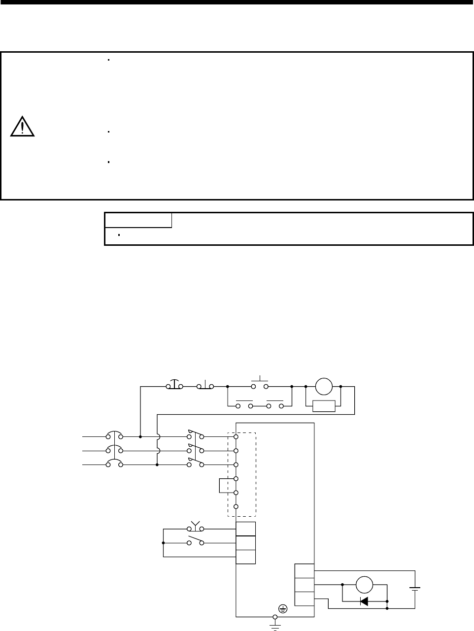
3. SIGNALS AND WIRING
3.7 Input power supply circuit
CAUTION
Always connect a magnetic contactor between the main circuit power supply and
L1, L2, and L3 of the servo amplifier, and configure the wiring to be able to shut
down the power supply on the side of the servo amplifier’s power supply. If a
magnetic contactor is not connected, continuous flow of a large current may cause
a fire when the servo amplifier malfunctions.
Use the trouble (ALM) to switch power off. Otherwise, a regenerative transistor
fault or the like may overheat the regenerative resistor, causing a fire.
For main circuit power supply of servo amplifier, check the model of servo amplifier
and input the correct voltage. If a voltage exceeding the upper limit shown in the
servo amplifier input voltage specification is input, the servo amplifier malfunctions.
POINT
The power supply connector (CNP1) is optional. Purchase it without fail.
3.7.1 Connection example
Wire the power supply and main circuit as shown below so that the servo-on (SON) turns off as soon as alarm
occurrence is detected and power is shut off.
A circuit breaker (MCCB) must be used with the input cables of the power supply.
(1) For 3-phase 200 to 230VAC power supply
3-phase
200 to 230 VAC
Emergency stop (Note 2)
Servo-on
Trouble
Servo amplifier
External
power
supply
24VDC
(Note 1)
RA
OFF ON
MC MC
SK
MCCB MC (Note 3)
L1
L2
L3
VIN
EMG
SON
VIN
ALM
SG
RA
CNP1
P
D
C
Emergency
stop
(Note 2)
Note 1. To use the built-in regenerative resistor, be sure to connect across P and D of the power supply connector (CNP1).
2. Configure the circuit to shut off the main circuit power supply by an external sequence simultaneously with the emergency
stop turning OFF.
3. Be sure to use a magnetic contactor with an operation delay time of 80ms or less. The operation delay time is the time
interval between current being applied to the coil until closure of contacts.
3 - 34
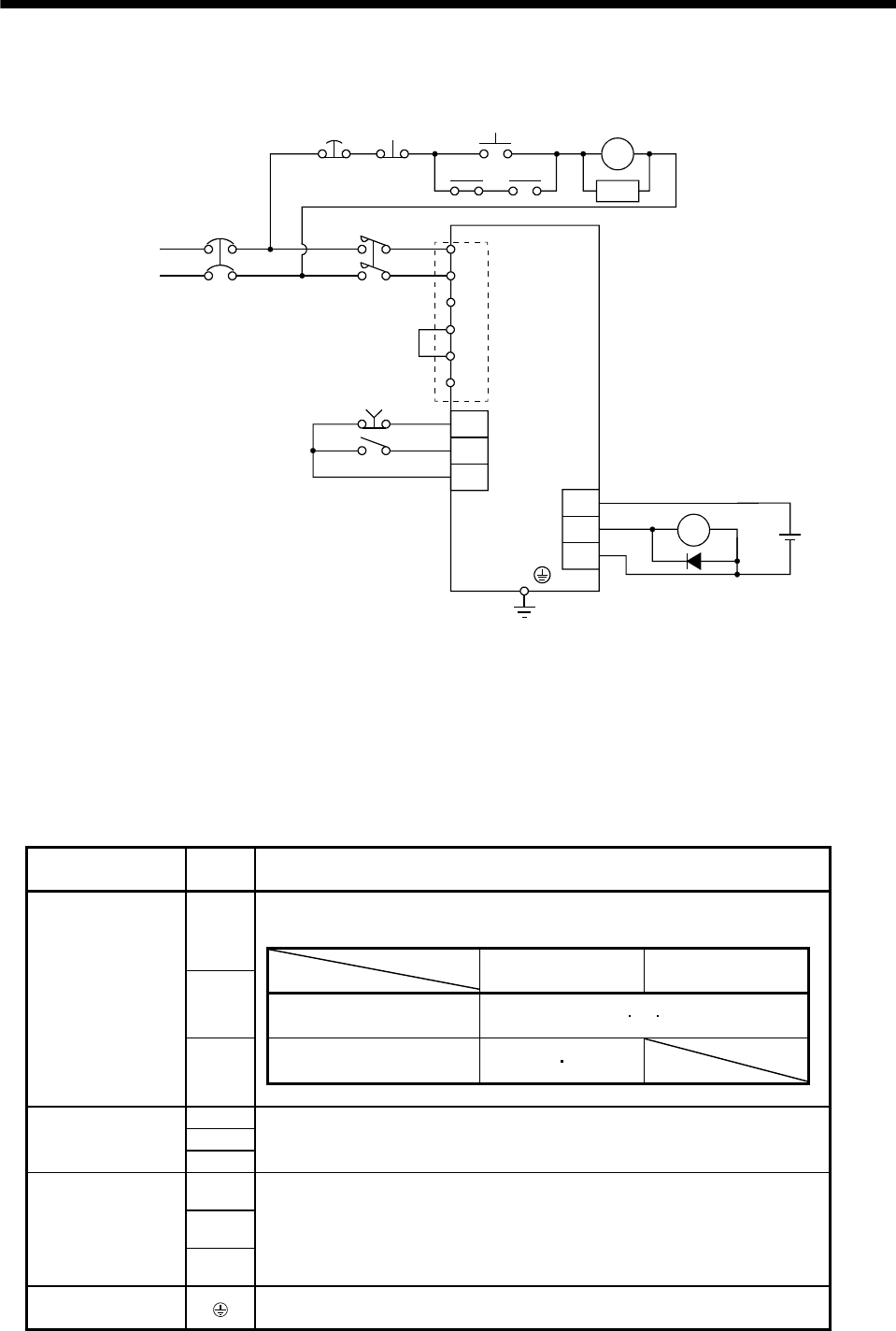
3. SIGNALS AND WIRING
(2) For 1-phase 230VAC power supply
1-phase 230VAC
Emergency stop (Note 2)
Servo-on
Servo amplifier
Trouble
Emergency
stop
(Note 2)
External
power
supply
24VDC
RA
OFF ON
MC MC
SK
MCCB MC (Note 3)
L1
L2
L3
EMG
SON
VIN
VIN
ALM
SG
RA
(Note 1)
CNP1
P
D
C
Note 1. To use the built-in regenerative resistor, be sure to connect across P and D of the power supply connector (CNP1).
2. Configure the circuit to shut off the main circuit power supply by an external sequence simultaneously with the emergency
stop turning OFF.
3. Be sure to use a magnetic contactor with an operation delay time of 80ms or less. The operation delay time is the time
interval between current being applied to the coil until closure of contacts.
3.7.2 Terminals
Refer to section 11.1 (4) for the signal arrangement.
Connected terminal
(Application) Symbol Description
Supply L1, L2 and L3 with the following power.
For 1-phase 230VAC, connect the power supply to L1, L2 and L3 open.
L1
Servo amplifier
Power supply
MR-E-10A-QW003 to
MR-E-70A-QW003
MR-E-100A-QW003/
MR-E-200A-QW003
L2
3-phase 200 to 230VAC,
50/60Hz L1L2L3
1-phase 230VAC,
50/60Hz L1L2
Power supply
L3
U
V
Servo motor
W
Connect to the servo motor power terminals (U, V, W). During power-on, do not open
or close the motor power line. Otherwise, a malfunction or faulty may occur.
P
C
Regenerative option
D
To use the built-in regenerative resistor of the servo amplifier, connect the wiring across
P-D of the power supply connector (CNP1).
When using the regenerative option, always remove the wiring from across P-D and
connect the regenerative option across P-C.
Refer to section 13.1.1 for details.
Protective earth (PE) Connect this terminal to the protective earth (PE) terminals of the servo motor and
control box for grounding.
3 - 35
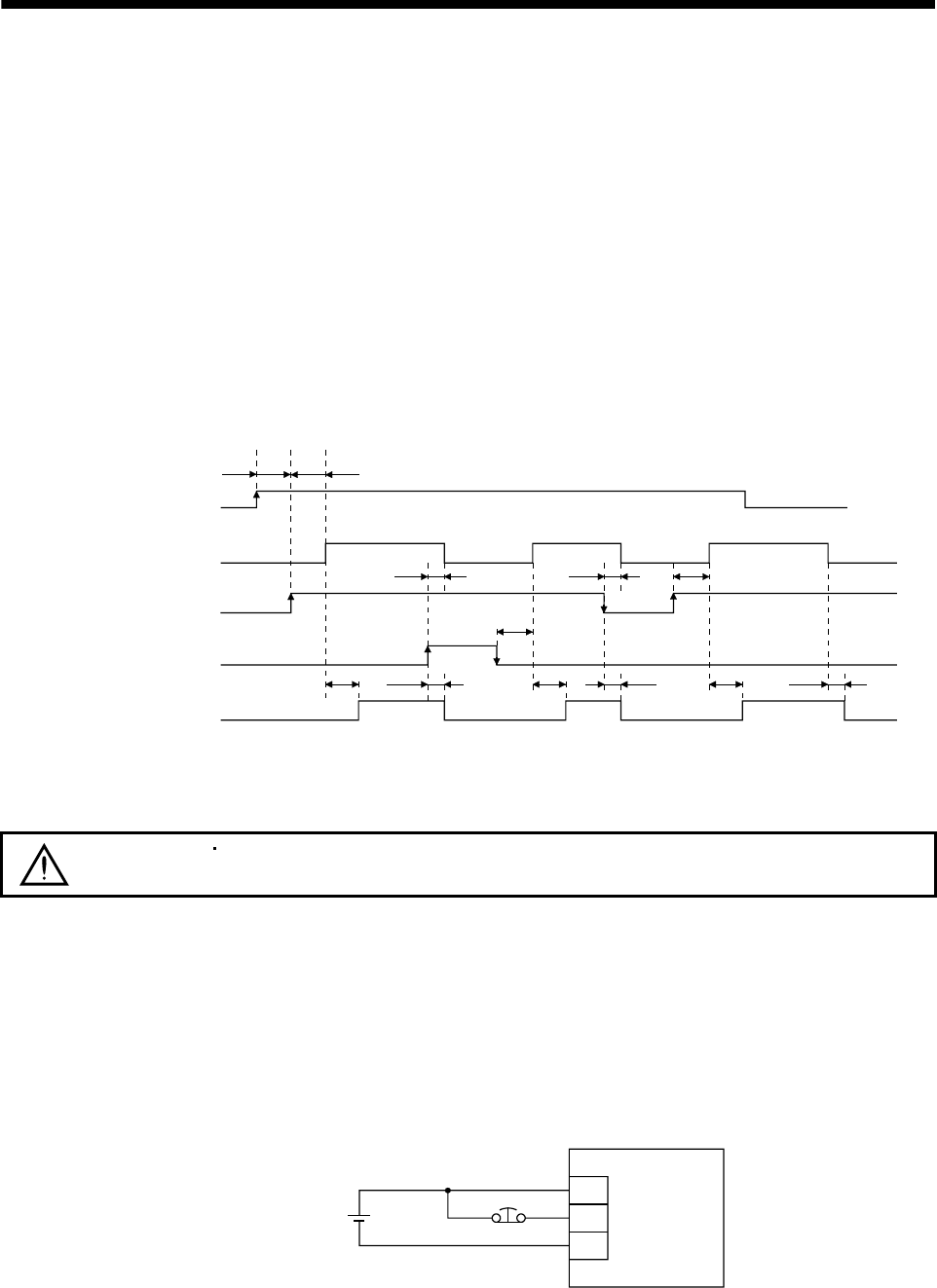
3. SIGNALS AND WIRING
3.7.3 Power-on sequence
(1) Power-on procedure
1) Always wire the power supply as shown in above section 3.7.1 using the magnetic contactor with the
power supply (three-phase 200V: L1, L2, L3, single-phase 230V: L1, L2). Configure up an external
sequence to switch off the magnetic contactor as soon as an alarm occurs.
2) The servo amplifier can accept the servo-on (SON) 2s or more after the power supply is switched on.
Therefore, when SON is switched on simultaneously with the power supply, the base circuit will switch
on in about 1 to 2s, and the ready (RD) will switch on in further about 20ms, making the servo amplifier
ready to operate. (Refer to paragraph (2) in this section.)
3) When the reset (RES) is switched on, the base circuit is shut off and the servo motor shaft coasts.
(2) Timing chart
20ms 20ms 20ms10ms 10ms
10ms
10ms
10ms
60ms
60ms
ON
OFF
ON
OFF
ON
OFF
ON
OFF
ON
OFF
power supply
Base circuit
Servo-on
(SON)
Reset
(RES)
Ready
(RD)
SON accepted
(1 to 2s)
2s or longer
Power-on timing chart
(3) Emergency stop
CAUTION Provide an external emergency stop circuit to ensure that operation can be
stopped and power switched off immediately.
Make up a circuit which shuts off power as soon as EMG-VIN are opened at an emergency stop. To ensure
safety, always install an external emergency stop switch across EMG-VIN. By disconnecting EMG-VIN, the
dynamic brake is operated to bring the servo motor to a sudden stop. At this time, the display shows the
servo emergency stop warning (AL.E6).
During ordinary operation, do not use the external emergency stop signal to alternate stop and run.
The servo amplifier life may be shortened.
Also, if the start signal is on or a pulse train is input during an emergency stop, the servo motor will rotate
as soon as the warning is reset. During an emergency stop, always shut off the run command.
VIN
EMG
SG
Emergency stop
External power
supply 24VDC
3 - 36
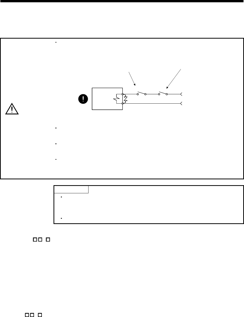
3 - 37
3. SIGNALS AND WIRING
3.8 Servo motor with electromagnetic brake
3.8.1 Precautions
CAUTION
Configure an electromagnetic brake circuit so that it is activated also by an external
EMG stop switch.
Contacts must be open when
an trouble (ALM) and when an
electromagnetic brake interlock
(MBR) turns off.
Electromagnetic brake
Contacts must be open with
the EMG stop switch.
RA
24VDC
Servo motor
The electromagnetic brake is provided for holding purpose and must not be used
for ordinary braking.
Before performing the operation, be sure to confirm that the electromagnetic brake
operates properly.
Do not use the 24VDC interface power supply for the electromagnetic brake.
Always use the power supply designed exclusively for the electromagnetic brake.
Otherwise, a fault may occur.
POINT
Refer to HF-KN/HF-SN Servo Motor Instruction Manual for specifications such
as the power supply capacity and operation delay time of the electromagnetic
brake.
Refer to HF-KN/HF-SN Servo Motor Instruction Manual for wiring diagrams.
Note the following when the servo motor equipped with electromagnetic brake is used.
1) Set " 1" in parameter No.1 to make the electromagnetic brake interlock (MBR) valid. Note that
this will make the zero speed signal (ZSP) unavailable.
2) Do not share the 24VDC interface power supply between the interface and electromagnetic brake.
Always use the power supply designed exclusively for the electromagnetic brake.
3) The brake will operate when the power (24VDC) switches off.
4) While the reset (RES) is on, the base circuit is shut off. When using the servo motor with a vertical
shaft, use the electromagnetic brake interlock (MBR).
5) Switch off the servo-on signal after the servo motor has stopped.
3.8.2 Setting
1) Set " 1" in parameter No.1 to make the electromagnetic brake interlock (MBR) valid.
2) Using parameter No.33 (electromagnetic brake sequence output), set a delay time (Tb) at servo-off from
electromagnetic brake operation to base circuit shut-off as in the timing chart shown in section 3.9.3.
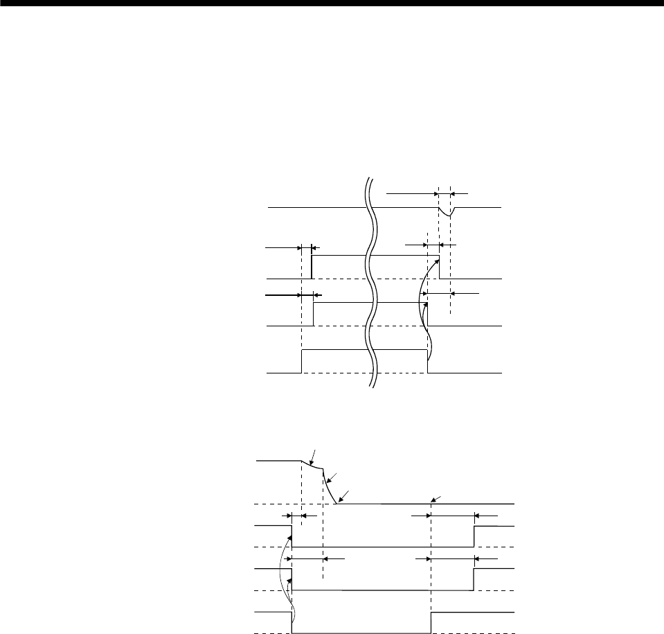
3. SIGNALS AND WIRING
3.8.3 Timing charts
(1) Servo-on signal command (from controller) ON/OFF
Tb [ms] after the servo-on (SON) signal is switched off, the servo lock is released and the servo motor
coasts. If the electromagnetic brake is made valid in the servo lock status, the brake life may be shorter.
Therefore, when using the electromagnetic brake in a vertical lift application or the like, set Delay time (Tb)
to about the same as the electromagnetic brake operation delay time to prevent a drop.
Servo motor speed
Electromagnetic
brake (MBR)
ON
OFF
Base circuit
Invalid(ON)
Valid(OFF)
ON
OFF
Servo-on(SON)
Electromagnetic brake
operation delay time
Tb
Coasting
0 r/min
(60ms)
(80ms)
(2) Emergency stop (EMG) ON/OFF
Servo motor speed
Electromagnetic
brake interlock (MBR)
ON
OFF
Base circuit
Invalid (ON)
Valid (OFF)
Emergency stop (EMG)
(10ms) (180ms)
(180ms)
Dynamic brake
Dynamic brake
Electromagnetic brake
Electromagnetic brake
Invalid (ON)
Valid (OFF)
Electromagnetic brake
operation delay time
Electromagnetic brake release
3 - 38
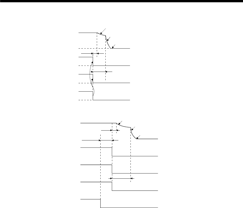
3. SIGNALS AND WIRING
(3) Alarm occurrence
Servo motor speed
ON
OFF
Base circuit
Electromagnetic
brake interlock (MBR)
Invalid(ON)
Valid(OFF)
Trouble (ALM) No(ON)
Yes(OFF)
Dynamic brake
Dynamic brake
Electromagnetic brake
Electromagnetic brake
operation delay time
Electromagnetic brake
(10ms)
(4) Power off
Servo motor speed
ON
OFF
Base circuit
Electromagnetic
brake interlock(MBR)
Invalid(ON)
Valid(OFF)
Trouble (ALM) No(ON)
Yes(OFF)
ON
OFF
Dynamic brake
Dynamic brake
Electromagnetic brake
Electromagnetic brake
Power
(Note)
15 to 100ms
(10ms)
Electromagnetic brake
operation delay time
Note. Changes with the operating status.
(Note 2)
3 - 39
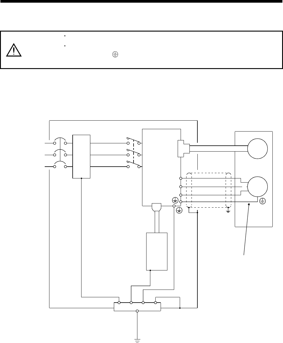
3. SIGNALS AND WIRING
3.9 Grounding
WARNING
Ground the servo amplifier and servo motor securely.
To prevent an electric shock, always connect the protective earth (PE) terminal
(terminal marked ) of the servo amplifier with the protective earth (PE) of the
control box.
The servo amplifier switches the power transistor on-off to supply power to the servo motor. Depending on the
wiring and ground cable routing, the servo amplifier may be affected by the switching noise (due to di/dt and
dv/dt) of the transistor. To prevent such a fault, refer to the following diagram and always ground.
To conform to the EMC Directive, refer to the EMC Installation Guidelines (IB(NA)67310).
Control box
Servo amplifier
L1
L2
L3
CN1
Line filter
MCCB MC
Protective earth(PE)
CN2
U
V
W
Outer
box
Servo motor
Ensure to connect it to PE
terminal of the servo amplifier.
Do not connect it directly to
the protective earth of
the control panel.
Encoder
M
U
V
W
(Note)
Power supply
Programmable
controllers
Note. For 1-phase 230VAC, connect the power supply to L1, L2 and leave L3 open. Refer to section 1.3 for the power supply
specification.
3 - 40
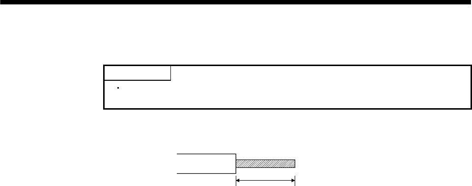
3. SIGNALS AND WIRING
3.10 Servo amplifier connectors (CNP1, CNP2) wiring method (When MR-ECPN1-B and MR-ECPN2-B of an
option are used.)
POINT
For the wire sizes used for wiring, refer to Table 13.1 1), 2) and 3) of section
13.2.1.
(1) Termination of the cables
Solid wire: After the insulator has been stripped, the cable can be used as it is.
8 to 9 mm
Twisted wire: Use the cable after stripping the insulator and twisting the core. At this time, take care to
avoid a short caused by the loose wires of the core and the adjacent pole. Do not solder the
core as it may cause a contact fault.
3 - 41
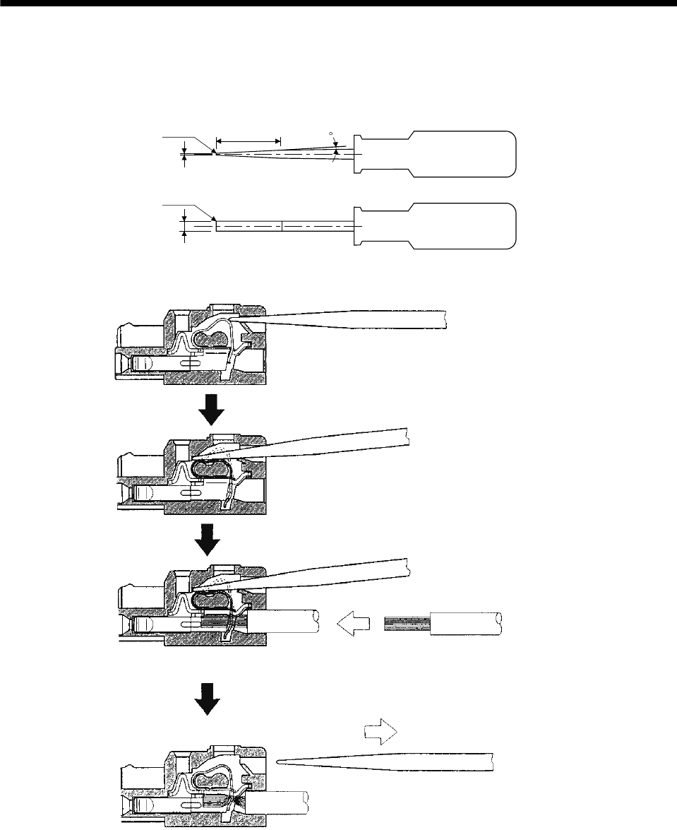
3. SIGNALS AND WIRING
(2) Inserting the cable into the connector
(a) Applicable flat-blade screwdriver dimensions
Always use the screwdriver shown here to do the work.
[Unit: mm]
3
0.6
(R0.3) (22)
(R0.3)
3 to 3.5
(b) When using the flat-blade screwdriver - part 1
1) Insert the screwdriver into the square hole.
Insert it along the top of the square hole to insert it smoothly.
2) If inserted properly, the screwdriver is held.
3) With the screwdriver held, insert the cable in the direction
of arrow. (Insert the cable as far as it will go.)
4) Releasing the screwdriver connects the cable.
3 - 42
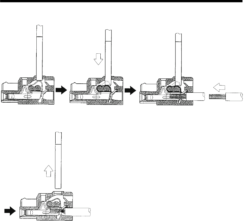
3. SIGNALS AND WIRING
(c) When using the flat-blade screwdriver - part 2
1) Insert the screwdriver into the
square window at top of the
connector.
2) Push the screwdriver in the
direction of arrow. 3) With the screwdriver pushed, insert the cable in the
direction of arrow. (Insert the cable as far as it will go.)
4) Releasing the screwdriver connects the cable.
3 - 43
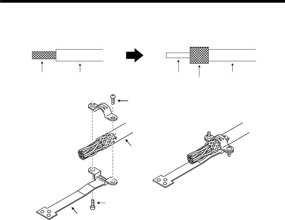
3. SIGNALS AND WIRING
3.11 Instructions for the 3M connector
When fabricating an encoder cable or the like, securely connect the shielded external conductor of the cable to
the ground plate as shown in this section and fix it to the connector shell.
External conductor Insulator External conductor
Pull back the external conductor to cover the insulato
r
InsulatorCore
Strip the insulator
Screw
Screw
Ground plate
Cable
3 - 44

4. OPERATION
4 - 1
4. OPERATION
4.1 When switching power on for the first time
Before starting operation, check the following.
(1) Wiring
(a) A correct power supply is connected to the power input terminals (L1, L2, L3) of the servo amplifier.
(b) The servo motor power supply terminals (U, V, W) of the servo amplifier match in phase with the power
input terminals (U, V, W) of the servo motor.
(c) The servo motor power supply terminals (U, V, W) of the servo amplifier are not shorted to the power
input terminals (L1, L2, L3) of the servo motor.
(d) The earth terminal of the servo motor is connected to the PE terminal of the servo amplifier.
(e) When using the regenerative option, the lead has been removed from across D-P of the servo amplifier
built-in regenerative resistor, and twisted cables are used for its wiring.
(f) When stroke end limit switches are used, the signals across LSP-VIN and LSN-VIN are on during
operation.
(g) 24VDC or higher voltages are not applied to the pins of connectors CN1.
(h) SD and SG of connectors CN1 are not shorted.
(i) The wiring cables are free from excessive force.
(2) Environment
Signal cables and power cables are not shorted by wire offcuts, metallic dust or the like.
(3) Machine
(a) The screws in the servo motor installation part and shaft-to-machine connection are tight.
(b) The servo motor and the machine connected with the servo motor can be operated.
4. OPERATION
4.2 Startup
WARNING Do not operate the switches with wet hands. You may get an electric shock.
CAUTION
Before starting operation, check the parameters. Some machines may perform
unexpected operation.
Take safety measures, e.g. provide covers, to prevent accidental contact of hands
and parts (cables, etc.) with the servo amplifier heat sink, regenerative resistor,
servo motor, etc. since they may be hot while power is on or for some time after
power-off. Their temperatures may be high and you may get burnt or a parts may
damaged.
During operation, never touch the rotating parts of the servo motor. Doing so can
cause injury.
Connect the servo motor with a machine after confirming that the servo motor operates properly alone.
4.2.1 Selection of control mode
Use parameter No.0 to choose the control mode used. After setting, this parameter is made valid by switching
power off, then on.
4.2.2 Position control mode
(1) Power on
1) Switch off the servo-on (SON).
2) When power is switched on, the display shows "C (Cumulative feedback pulses)", and in two second
later, shows data.
(2) Test operation 1
Confirm servo motor operation by operating JOG of test operation mode at lowest speed possible. (Refer to
section 6.8.2)
(3) Parameter setting
Set the parameters according to the structure and specifications of the machine. Refer to chapter 5 for the
parameter definitions and to section 6.5 for the setting method.
4
1 5
Description
Parameter No. Name Setting
Control mode, regenerative
option selection
0
Function selection 1
1
Auto tuning
2
3 1
1
Position control mode
MR-RB12 regenerative option is used.
Input filter 3.555ms (initial value)
Electromagnetic brake interlock (MBR) is not used.
3 0
02
Middle response (initial value) is selected.
Auto tuning mode 1 is selected.
Electronic gear numerator
Electronic gear denominatorElectronic gear denominator (CDV)
Electronic gear numerator (CMX)
Turn the power off after setting parameters No.0 and 1. Then switch power on again to make the set
parameter values valid.
4 - 2

4. OPERATION
4 - 3
(4) Servo-on
Switch the servo-on in the following procedure.
1) Switch on power supply.
2) Switch on the servo-on (SON).
When placed in the servo-on status, the servo amplifier is ready to operate and the servo motor is
locked.
(5) Command pulse input
Entry of a pulse train from the positioning device rotates the servo motor. At first, run it at lowest speed
possible and check the rotation direction, etc. If it does not run in the intended direction, check the input
signal.
On the status display, check the speed, command pulse frequency, load factor, etc. of the servo motor.
When machine operation check is over, check automatic operation with the program of the positioning
device.
This servo amplifier has a real-time auto tuning function under model adaptive control. Performing
operation automatically adjusts gains. The optimum tuning results are provided by setting the response
level appropriate for the machine in parameter No.2. (Refer to chapter 7)
(6) Home position return
Make home position return as required.
(7) Stop
In any of the following statuses, the servo amplifier interrupts and stops the operation of the servo motor.
Refer to section 3.8 for the servo motor equipped with electromagnetic brake. Note that the stop pattern of
forward rotation stroke end (LSP), reverse rotation stroke end (LSN) OFF is as described below.
(a) Servo-on (SON) OFF
The base circuit is shut off and the servo motor coasts.
(b) Alarm occurrence
When an alarm occurs, the base circuit is shut off and the dynamic brake is operated to bring the servo
motor to a sudden stop.
(c) Emergency stop (EMG) OFF
The base circuit is shut off and the dynamic brake is operated to bring the servo motor to a sudden stop.
Alarm AL.E6 (servo emergency stop warning) occurs.
(d) Forward rotation stroke end (LSP), reverse rotation stroke end (LSN) OFF
The droop pulse value is erased and the servo motor is stopped and servo-locked. It can be run in the
opposite direction.
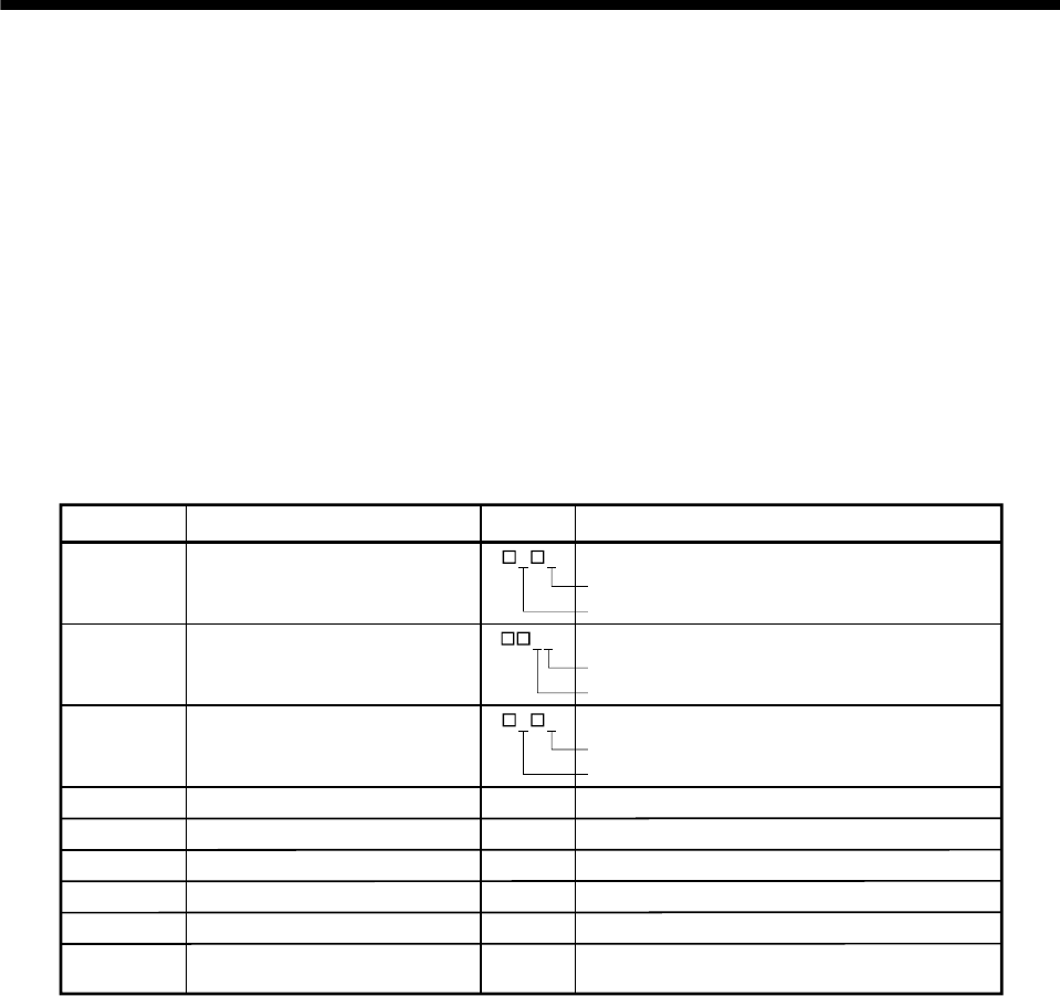
4. OPERATION
4.2.3 Internal speed control mode
(1) Power on
1) Switch off the servo-on (SON).
2) When circuit power is switched on, the display shows "r (servo motor speed)", and in two second
later, shows data.
(2) Test operation
Using jog operation in the test operation mode, make sure that the servo motor operates. (Refer to section
6.8.2.)
(3) Parameter setting
Set the parameters according to the structure and specifications of the machine. Refer to chapter 5 for the
parameter definitions and to section 6.5 for the setting method.
10
1 5
Description
Parameter No. Name Setting
Control mode, regenerative option
selection
0
Function selection 11
Auto tuning2
81000
91500
Internal speed control mode
Regenerative option is not used.
Input filter 3.555ms (initial value)
Electromagnetic brake interlock (MBR) is used.
0 2
12
Middle response (initial value) is selected.
Auto tuning mode 1 is selected.
Set 1000r/min.
Set 1500r/min.
Internal speed command 1
Internal speed command 1
2000 Set 2000r/min.
Internal speed command 1
11 1000 Set 1000ms.
Acceleration time constant
12 500 Set 500ms.
Deceleration time constant
13 0 Not used
S-pattern acceleration/deceleration
time constant
Turn the power off after setting parameters No.0 and 1. Then switch power on again to make the set
parameter values valid.
(4) Servo-on
Switch the servo-on in the following procedure.
1) Switch on circuit power supply.
2) Switch on the servo-on (SON) signal. (Short between SON and VIN.)
When placed in the servo-on status, the servo amplifier is ready to operate and the servo motor is
locked.
4 - 4

4. OPERATION
(5) Start
Using speed selection 1 (SP1) and speed selection 2 (SP2), choose the servo motor speed. Turn on
forward rotation start (ST1) to run the motor in the forward rotation (CCW) direction or reverse rotation start
(ST2) to run it in the reverse rotation (CW) direction. At first, set a low speed and check the rotation
direction, etc. If it does not run in the intended direction, check the input signal.
On the status display, check the speed, load factor, etc. of the servo motor.
When machine operation check is over, check automatic operation with the host controller or the like.
This servo amplifier has a real-time auto tuning function under model adaptive control. Performing
operation automatically adjusts gains. The optimum tuning results are provided by setting the response
level appropriate for the machine in parameter No.2. (Refer to chapter 7)
(6) Stop
In any of the following statuses, the servo amplifier interrupts and stops the operation of the servo motor.
Refer to section 3.8 for the servo motor equipped with electromagnetic brake. Note that simultaneous ON
or simultaneous OFF of forward rotation stroke end (LSP), reverse rotation stroke end (LSN) OFF and
forward rotation start (ST1) or reverse rotation start (ST2) signal has the same stop pattern as described
below.
(a) Servo-on (SON) OFF
The base circuit is shut off and the servo motor coasts.
(b) Alarm occurrence
When an alarm occurs, the base circuit is shut off and the dynamic brake is operated to bring the servo
motor to a sudden stop.
(c) Emergency stop (EMG) OFF
The base circuit is shut off and the dynamic brake is operated to bring the servo motor to a sudden stop.
Alarm AL.E6 (servo emergency stop warning) occurs.
(d) Forward rotation stroke end (LSP), reverse rotation stroke end (LSN) OFF
The servo motor is brought to a sudden stop and servo-locked. The motor may be run in the opposite
direction.
(e) Simultaneous ON or simultaneous OFF of forward rotation start (ST1) and reverse rotation start (ST2)
signals
The servo motor is decelerated to a stop.
POINT
A sudden stop indicates deceleration to a stop at the deceleration time constant
of zero.
4 - 5

4. OPERATION
4 - 6
MEMO
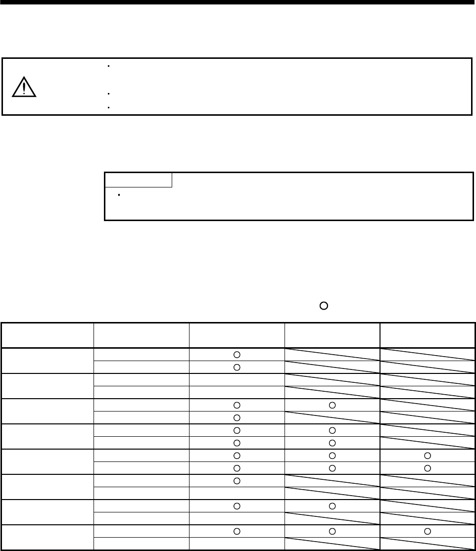
5. PARAMETERS
5. PARAMETERS
CAUTION
Never adjust or change the parameter values extremely as it will make operation
instable.
If fixed values are written in the digits of a parameter, do not change these values.
Do not change parameters for manufacturer setting.
5.1 Parameter list
5.1.1 Parameter write inhibit
POINT
After setting the parameter No.19 value, switch power off, then on to make that
setting valid.
This servo amplifier, its parameters are classified into the basic parameters (No.0 to 19), expansion
parameters 1 (No.20 to 49) and expansion parameters 2 (No.50 to 84) according to their safety aspects and
frequencies of use. In the factory setting condition, the customer can change the basic parameter values but
cannot change the expansion parameter values. When fine adjustment, e.g. gain adjustment, is required,
change the parameter No.19 setting to make the expansion parameters write-enabled.
The following table indicates the parameters which are enabled for reference and write by the setting of
parameter No.19. Operation can be performed for the parameters marked .
Parameter No.19 setting Operation Basic parameters
No.0 to 19
Expansion parameters 1
No.20 to 49
Expansion parameters 2
No.50 to 84
Reference 0000
(initial value) Write
Reference No.19 only
000A Write No.19 only
Reference
000B Write
Reference
000C Write
Reference
000E Write
Reference
100B Write No.19 only
Reference
100C Write No.19 only
Reference
100E Write No.19 only
5 - 1
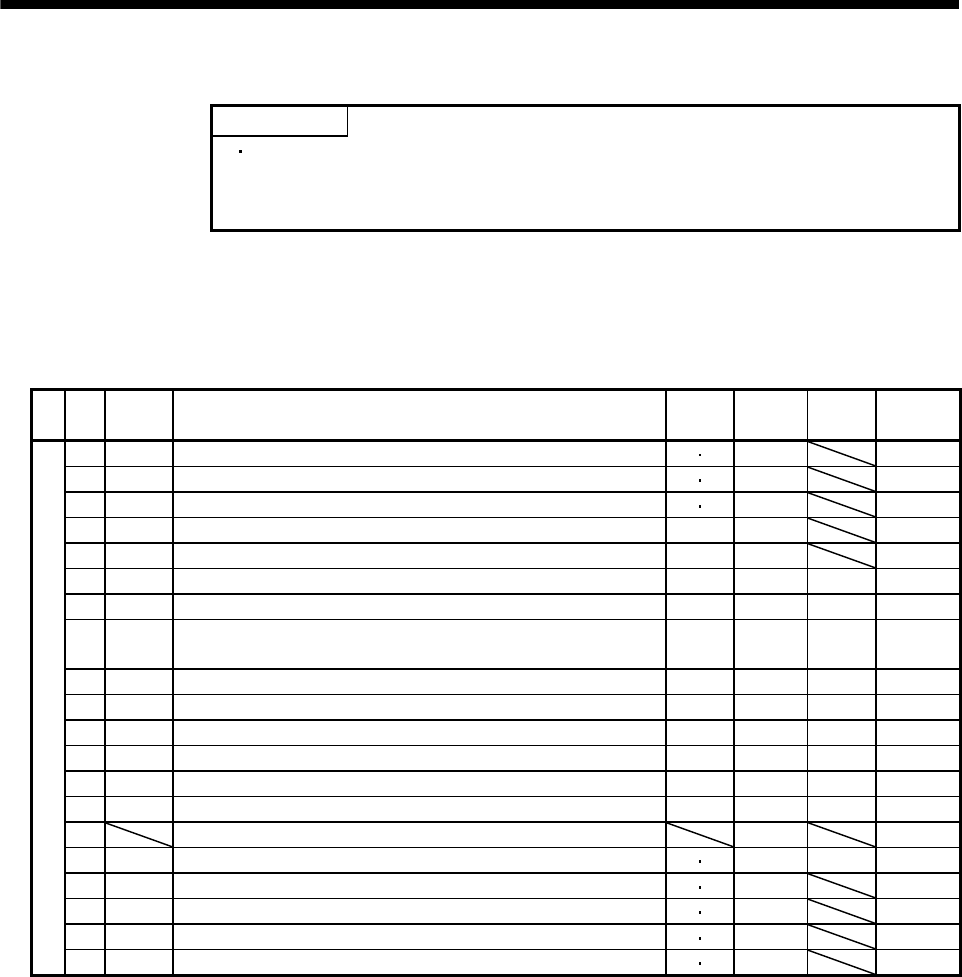
5. PARAMETERS
5.1.2 Lists
POINT
For any parameter whose symbol is preceded by *, set the parameter value
and switch power off once, then switch it on again to make that parameter
setting valid.
The symbols in the control mode column of the table indicate the following modes.
P: Position control mode
S: Internal speed control mode
(1) Item list
No. Symbol Name Control
mode
Initial
value Unit Customer
setting
0 *STY Control mode, regenerative option selection P S (Note 1)
1 *OP1 Function selection 1 P S 0002
2 ATU Auto tuning P S 0105
3 CMX Electronic gear numerator P 1
4 CDV Electronic gear denominator P 1
5 INP In-position range P 100 pulse
6 PG1 Position loop gain 1 P 35 rad/s
7 PST
Position command acceleration/deceleration time constant
(Position smoothing) P 3 ms
8 SC1 Internal speed command 1 S 100 r/min
9 SC2 Internal speed command 2 S 500 r/min
10 SC3 Internal speed command 3 S 1000 r/min
11 STA Acceleration time constant S 0 ms
12 STB Deceleration time constant S 0 ms
13 STC S-pattern acceleration/deceleration time constant S 0 ms
14 For manufacturer setting 0
15 *SNO Station number setting P S 0 station
16 *BPS Serial communication function selection, alarm history clear P S 0000
17 MOD Analog monitor output P S 0100
18 *DMD Status display selection P S 0000
Basic parameters
19 *BLK Parameter write inhibit P S 0000
5 - 2
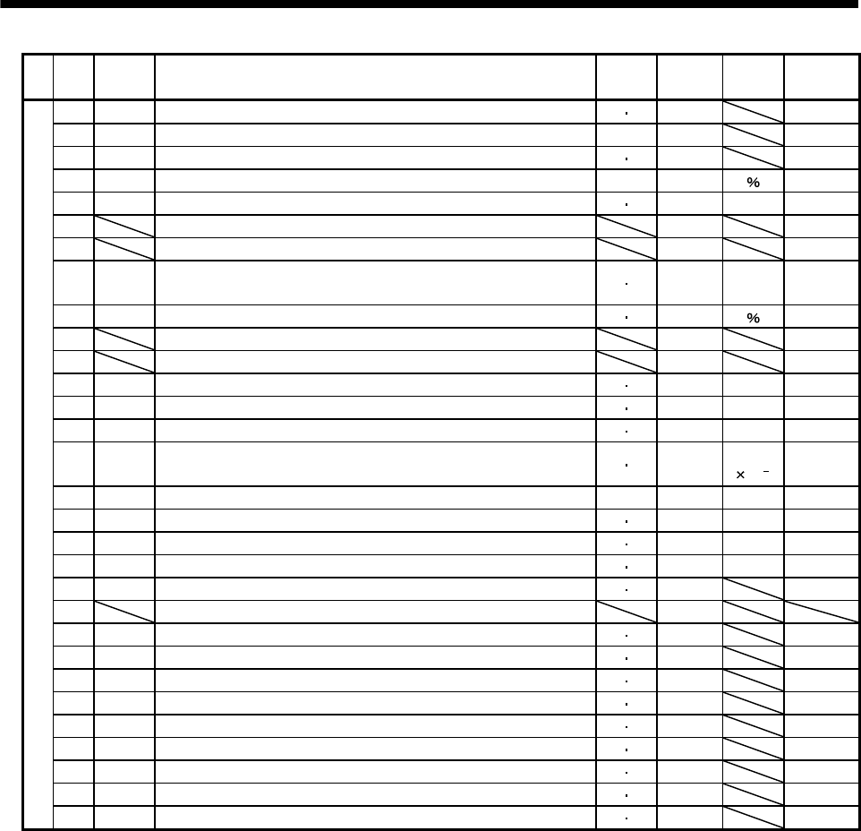
5. PARAMETERS
No. Symbol Name Control
mode
Initial
value Unit Customer
setting
20 *OP2 Function selection 2 P S 0000
21 *OP3 Function selection 3 (Command pulse selection) P 0000
22 *OP4 Function selection 4 P S 0000
23 FFC Feed forward gain P 0
24 ZSP Zero speed detection P S 50 r/min
25 For manufacturer setting 0
26 For manufacturer setting 100
27 *ENR Encoder output pulses P S 4000 pulse
/rev
28 TL1 Internal torque limit 1 P S 100
29 For manufacturer setting 0
30 For manufacturer setting 0
31 MO1 Analog monitor 1 offset P S 0 mV
32 MO2 Analog monitor 2 offset P S 0 mV
33 MBR Electromagnetic brake sequence output P S 100 ms
34 GD2 Ratio of load inertia moment to servo motor inertia moment P S 70
Multiplier
(10 1)
35 PG2 Position loop gain 2 P 35 rad/s
36 VG1 Speed loop gain 1 P S 177 rad/s
37 VG2 Speed loop gain 2 P S 817 rad/s
38 VIC Speed integral compensation P S 48 ms
39 VDC Speed differential compensation P S 980
40 For manufacturer setting 0
41 *DIA Input signal automatic ON selection P S 0000
42 *DI1 Input signal selection 1 P S 0002
43 *DI2 Input signal selection 2 (CN1-4) P S 0111
44 *DI3 Input signal selection 3 (CN1-3) P S 0882
45 *DI4 Input signal selection 4 (CN1-5) P S 0995
46 *DI5 Input signal selection 5 (CN1-6) P S 0000
47 *DI6 Input signal selection 6 (CN1-7) P S 0000
48 *LSPN LSP/LSN input terminals selection P S 0403
Expansion parameters 1
49 *DO1 Output signal selection 1 P S 0000
5 - 3
5. PARAMETERS
No. Symbol Name Control
mode
Initial
value Unit Customer
setting
50 For manufacturer setting 0000
51 *OP6 Function selection 6 P S 0000
52 For manufacturer setting 0000
53 *OP8 Function selection 8 P S 0000
54 *OP9 Function selection 9 P S 0000
55 *OPA Function selection A P 0000
56 SIC Serial communication time-out selection P S 0 s
57 For manufacturer setting 10
58 NH1 Machine resonance suppression filter 1 P S 0000
59 NH2 Machine resonance suppression filter 2 P S 0000
60 LPF Low-pass filter/adaptive vibration suppression control P S 0000
61 GD2B Ratio of load inertia moment to Servo motor inertia moment 2 P S 70
Multiplier
(10 1)
62 PG2B Position control gain 2 changing ratio P 100
63 VG2B Speed control gain 2 changing ratio P S 100
64 VICB Speed integral compensation changing ratio P S 100
65 *CDP Gain changing selection P S 0000
66 CDS Gain changing condition P S 10 (Note 2)
67 CDT Gain changing time constant P S 1 ms
68 For manufacturer setting 0
69 CMX2 Command pulse multiplying factor numerator 2 P 1
70 CMX3 Command pulse multiplying factor numerator 3 P 1
71 CMX4 Command pulse multiplying factor numerator 4 P 1
72 SC4 Internal speed command 4 S 200 r/min
73 SC5 Internal speed command 5 S 300 r/min
74 SC6 Internal speed command 6 S 500 r/min
75 SC7 Internal speed command 7 S 800 r/min
76 TL2 Internal torque limit 2 P S 100
77 100
78 10000
79 10
80 10
81 100
82 100
83 100
Expansion parameters 2
84
For manufacturer setting
0000
Note 1. Depends on the capacity of the servo amplifier.
2. Depends on the parameter No.65 setting.
5 - 4
5. PARAMETERS
(2) Details list
Class No. Symbol Name and function Initial
value Unit Setting
range
Control
mode
Control mode, regenerative option selection
Used to select the control mode and regenerative option.
Selection of regenerative option
0: Regenerative option is not used
For the servo amplifier of 200W or
lower, regenerative resistor is not used.
For the servo amplifier of 400W or
higher, built-in regenerative resistor is
used.
2: MR-RB032
3: MR-RB12
4: MR-RB32
5: MR-RB30
6: MR-RB50 (Cooling fan is required)
Select the control mode.
0: Position
1: Position and internal speed
2: Internal speed
Motor series selection
0: HF-KN (J)
1: HF-SN J
Motor capacity selection
0: 100W
1: 200W
2: 400W
3: 500W
4: 750W
5: 1kW
6: 1.5kW
7: 2kW
POINT
Wrong setting may cause the regenerative option to burn.
If the regenerative option selected is not for use with the servo
amplifier, parameter error (AL.37) occurs.
0 *STY
100W
: 0000
200W
: 1000
400W
: 2000
750W
: 4000
1kW
: 5010
2kW
: 6010
Refer to
name
and
function
column.
PS
Basic parameters
1 *OP1 Function selection 1
Used to select the input signal filter, the function of pin CN1-12.
Input signal filter
If external input signal causes chattering
due to noise, etc., input filter is used to
suppress it.
0: None
1: 1.777[ms]
2: 3.555[ms]
3: 5.333[ms]
CN1-12 function selection
0: Zero Speed detection signal
1: Electromagnetic brake interlock (MBR)
00
0002 Refer to
name
and
function
column.
PS
5 - 5
5. PARAMETERS
Class No. Symbol Name and function Initial
value Unit Setting
range
Control
mode
2 ATU Auto tuning
Used to selection the response level, etc. for execution of auto tuning.
Refer to chapter 7.
Auto tuning response level setting
If the machine hunts or generates
large gear sound, decrease the
set value.
To improve performance, e.g.
shorten the settling time, increase
the set value.
Set
value
Response
level
1Low
response
Middle
response
High
response
Gain adjustment mode selection
(For more information, refer to section 7.1.1.)
Machine resonance
frequency guideline
15Hz
220Hz
325Hz
430Hz
535Hz
645Hz
755Hz
870Hz
985Hz
A105Hz
B130Hz
C160Hz
D200Hz
E240Hz
F300Hz
Set
value Gain adjustment mode
0
Description
1
3 Simple manual adjustment.
4 Manual adjustment of all gains.
Interpolation mode Fixes position control gain 1
(parameter No.6).
Auto tuning mode 1
Fixes the load inertia moment
ratio set in parameter No.34.
Response level setting can be
changed.
Manual mode 1
Manual mode 2
2Auto tuning mode 2
Ordinary auto tuning.
0 0
0105 Refer to
name
and
function
column.
PS
3 CMX Electronic gear numerator
Used to set the electronic gear numerator value.
For the setting, refer to section 5.2.1.
Setting "0" automatically sets the resolution of the servo motor connected.
1 0
1
to
65535
P
Basic parameters
4 CDV Electronic gear denominator
Used to set the electronic gear denominator value.
For the setting, refer to section 5.2.1.
1 1
to
65535
P
5 - 6
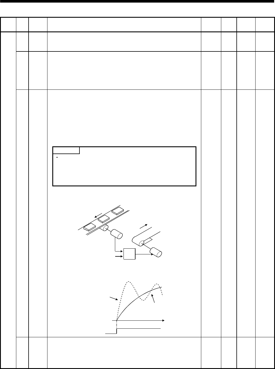
5. PARAMETERS
Class No. Symbol Name and function Initial
value Unit Setting
range
Control
mode
5 INP In-position range
Used to set the in-position signal (INP) output range in the command pulse
increments prior to electronic gear calculation.
100 pulse 0
to
10000
P
6 PG1 Position loop gain 1
Used to set the gain of position loop.
Increase the gain to improve track ability in response to the position
command.
When auto turning mode 1,2 is selected, the result of auto turning is
automatically used.
35 red/s 4
to
2000
P
Position command acceleration/deceleration time constant
(position smoothing)
Used to set the time constant of a low-pass filter in response to the position
command.
You can use parameter No.55 to choose the primary delay or linear
acceleration/deceleration control system. When you choose linear
acceleration/deceleration, the setting range is 0 to 10ms. Setting of longer
than 10ms is recognized as 10ms.
POINT
7 PST
When you have chosen linear acceleration/deceleration, do not
select control selection (parameter No.0) and restart after
instantaneous power failure (parameter No.20). Doing so will cause
the servo motor to make a sudden stop at the time of position control
switching or restart.
3 ms 0
to
20000
P
Example: When a command is given from a synchronizing detector,
synchronous operation can be started smoothly if started during line
operation.
Synchronizing
detector
Start
Servo amplifier
Servo motor
Without time
constant setting
Servo motor
speed
Start
With time
constant setting
ON
OFF
t
Basic parameters
8 SC1 Internal speed command 1
Used to set speed 1 of internal speed commands.
100 r/min
0 to
instan-
taneous
permis-
sible
speed
S
5 - 7
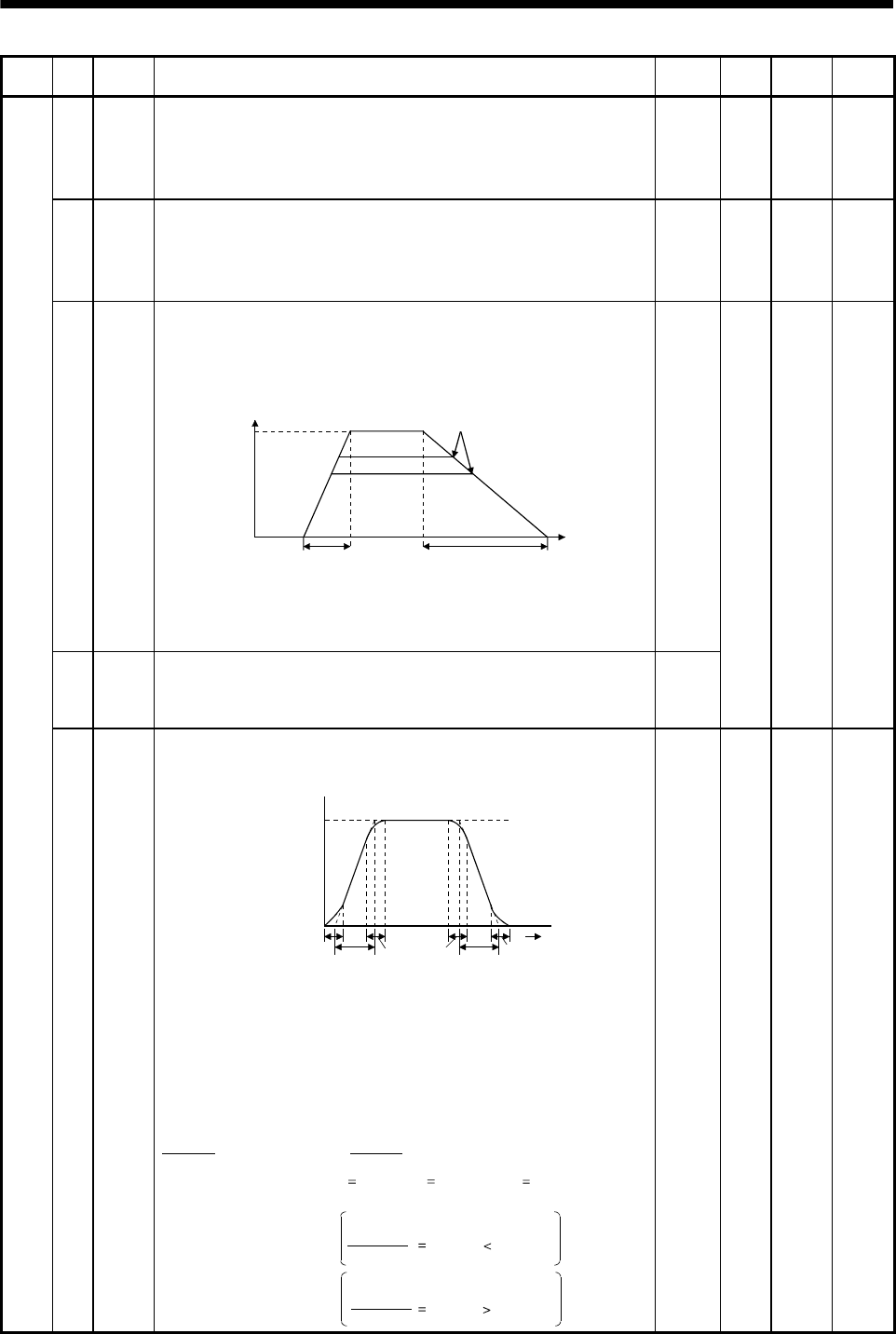
5. PARAMETERS
Class No. Symbol Name and function Initial
value Unit Setting
range
Control
mode
9 SC2 Internal speed command 2
Used to set speed 2 of internal speed commands.
500 r/min 0 to
instan-
taneous
permis-
sible
speed
S
10 SC3 Internal speed command 3
Used to set speed 3 of internal speed commands.
1000 r/min 0 to
instan-
taneous
permis-
sible
speed
S
11 STA
Acceleration time constant
Used to set the acceleration time required to reach the rated speed from
0r/min in response to the internal speed commands 1 to 7.
Tim
e
Parameter
No.12 setting
Parameter
No.11 setting
Zero
speed
Rated
speed
Speed
If the preset speed command is
lower than the rated speed,
acceleration/deceleration time
will be shorter.
For example for the servo motor of 3000r/min rated speed, set 3000 (3s) to
increase speed from 0r/min to 1000r/min in 1 second.
0
12 STB
Deceleration time constant
Used to set the deceleration time required to reach 0r/min from the rated
speed in response to the internal speed commands 1 to 7.
0
ms 0
to
20000
S
Basic parameters
13 STC S-pattern acceleration/deceleration time constant
Used to smooth start/stop of the servo motor.
Set the time of the arc part for S-pattern acceleration/deceleration.
STA: Acceleration time constant (parameter No.11)
STB: Deceleration time constant (parameter No.12)
STC: S-pattern acceleration/deceleration time constant
(parameter No.13)
Speed command
Servo motor
Speed
0r/min
STCSTA STC STC STB STC
Time
Long setting of STA (acceleration time constant) or STB (deceleration time
constant) may produce an error in the time of the arc part for the setting of
the S-pattern acceleration/deceleration time constant.
The upper limit value of the actual arc part time is limited by
At the setting of STA 20000, STB 5000 and STC 200,
the actual arc part times are as follows.
for acceleration or by for deceleration.
(Example)
During acceleration: 100[ms] 2000000
20000 100[ms] 200[ms].
Limited to 100[ms] since
During deceleration: 200[ms] 2000000
5000 400[ms] 200[ms].
200[ms] as set since
2000000
STA
2000000
STB
0 ms 0
to
1000
S
5 - 8
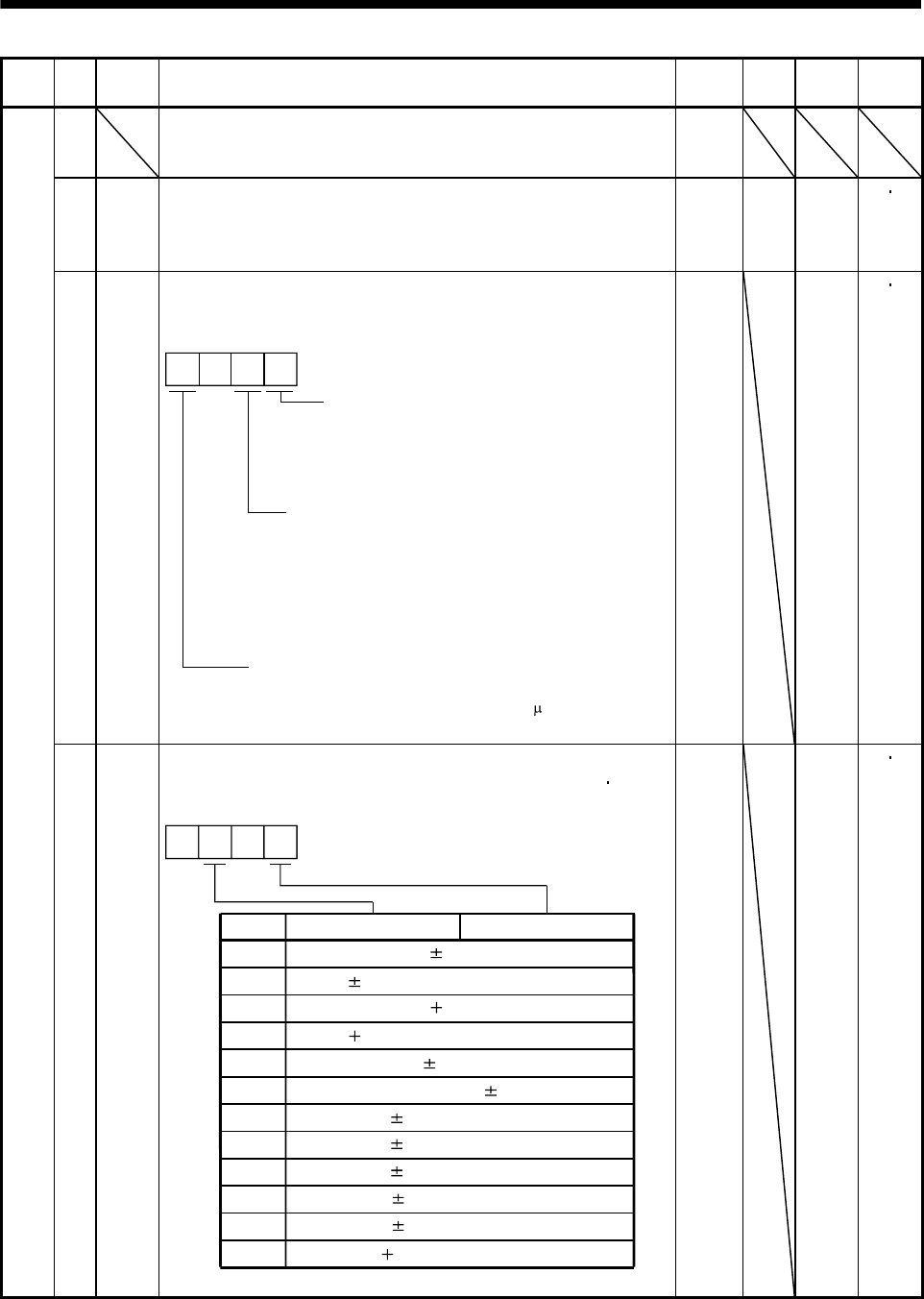
5. PARAMETERS
Class No. Symbol Name and function Initial
value Unit Setting
range
Control
mode
14 For manufacturer setting
Do not change this value by any means.
0
15 *SNO Station number setting
Used to specify the station number for serial communication.
Always set one station to one axis of servo amplifier. If one station number
is set to two or more stations, normal communication cannot be made.
0 station 0
to
31
PS
16 *BPS Serial communication function selection, alarm history clear
Used to select the serial communication baud rate, select various
communication conditions, and clear the alarm history.
Serial baud rate selection
0: 9600 [bps]
1: 19200[bps]
2: 38400[bps]
3: 57600[bps]
Alarm history clear
0: Invalid (not cleared)
1: Valid (cleared)
When alarm history clear is made valid,
the alarm history is cleared at next power-on.
After the alarm history is cleared, the setting
is automatically made invalid (reset to 0).
Serial communication response delay time
0: Invalid
1: Valid, reply sent after delay time of 800 s or more
0
0000 Refer to
name
and
function
column.
PS
Basic parameters
17 MOD Analog monitor output
Used to selection the signal provided to the analog monitor (MO1) analog
monitor (MO2) output. (Refer to section 5.2.2.)
Setting
0
Analog monitor 2 (MO2)
Servo motor speed ( 8V/max. speed)
1 Torque ( 8V/max. torque)
2 Servo motor speed ( 8V/max. speed)
3 Torque ( 8V/max. torque)
4 Current command ( 8V/max. current command)
5 Command pulse frequency ( 10V/500kpulse/s)
6 Droop pulses ( 10V/128 pulses)
7 Droop pulses ( 10V/2048 pulses)
8 Droop pulses ( 10V/8192 pulses)
9 Droop pulses ( 10V/32768 pulses)
A Droop pulses ( 10V/131072 pulses)
00
B Bus voltage ( 8V/400V)
Analog monitor 1 (MO1)
0100 Refer to
name
and
function
column.
PS
5 - 9
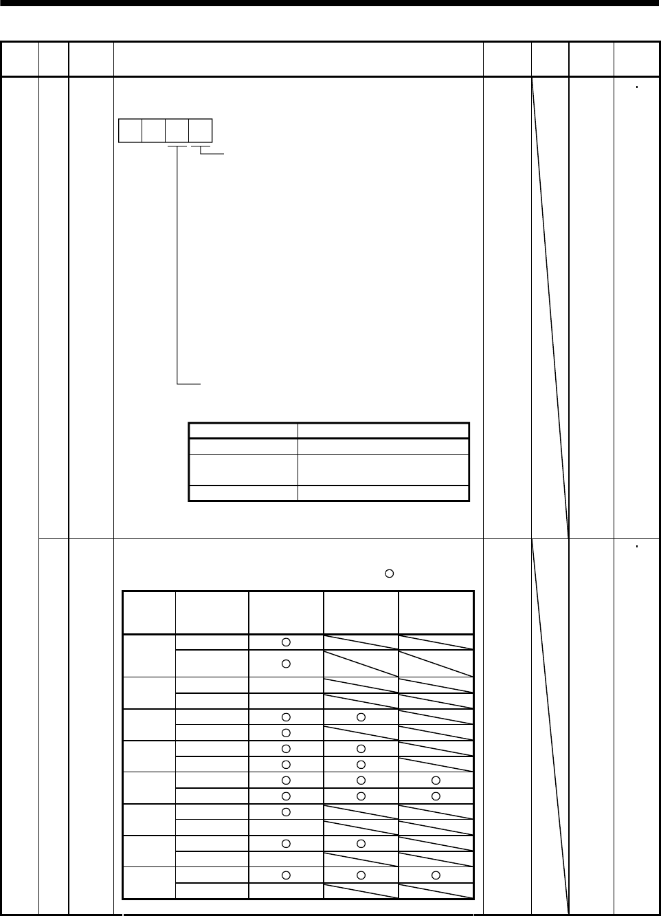
5. PARAMETERS
Class No. Symbol Name and function Initial
value Unit Setting
range
Control
mode
18 *DMD Status display selection
Used to select the status display shown at power-on.
Status display at power-on in
corresponding control mode
0: Depends on the control mode.
0 0
Selection of status display at
power-on
0: Cumulative feedback pulses
1: Servo motor speed
2: Droop pulses
3: Cumulative command pulses
4: Command pulse frequency
7: Regenerative load ratio
8: Effective load ratio
9: Peak load ratio
A: Instantaneous torque
B: Within one-revolution position low
C: Within one-revolution position high
D: Load inertia moment ratio
E: Bus voltage
Control mode
Position
Position/
internal speed
Internal speed
Status display at power-on
Cumulative feedback pulses
Cumulative feedback pulses/
servo motor speed
Servo motor speed
1: Depends on the first digit setting of this parameter.
0000 Refer to
name
and
function
column.
PS
Parameter write inhibit
Used to select the reference and write ranges of the parameters.
Operation can be performed for the parameters marked .
Set
value Operation
Basic
parameters
No.0 to 19
Expansion
parameters 1
No.20 to 49
Expansion
parameters 2
No.50 to 84
Reference 0000
(Initial
value) Write
Reference No.19 only
000A Write No.19 only
Reference
000B Write
Reference 000C Write
Reference 000E Write
Reference 100B Write No.19 only
Reference 100C Write No.19 only
Reference 100E Write No.19 only
Basic parameters
19 *BLK
0000 Refer to
name
and
function
column.
PS
5 - 10
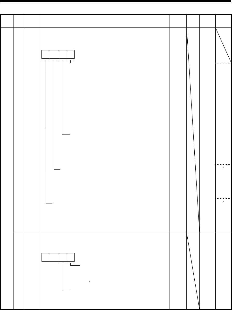
5. PARAMETERS
Class No. Symbol Name and function Initial
value Unit Setting
range
Control
mode
20 *OP2 0000 Refer to
name
and
function
column.
S
PS
Function selection 2
Used to select restart after instantaneous power failure,
servo lock at a stop in internal speed control mode, and slight vibration
suppression control.
0: Invalid (Undervoltage alarm
(AL.10) occurs.)
1: Valid
Restart after instantaneous
power failure
Stop-time servo lock selection
The shaft can be servo-locked to
remain still at a stop in the internal
speed control mode.
0: Valid
1: Invalid
Slight vibration suppression control
Made valid when auto tuning selection is
set to "0400" in parameter No.2.
Used to suppress vibration at a stop.
0: Invalid
1: Valid
If the power supply voltage has
returned to normal after an
undervoltage status caused by the
reduction of the input power supply
voltage in the speed control mode,
the servo motor can be restarted by
merely turning on the start signal
without resetting the alarm.
Encoder cable communication system selection
Incorrect setting will result in an encoder alarm 1
(AL.16) or encoder alarm 2 (AL.20).
0: Two-wire type
1: Four-wire type
PS
Expansion parameters 1
21 *OP3 Function selection 3 (Command pulse selection)
Used to select the input form of the pulse train input signal.
(Refer to section 3.4.1.)
Command pulse train input form
0: Forward/reverse rotation pulse train
1: Signed pulse train
2: A B-phase pulse train
Pulse train logic selection
0: Positive logic
1: Negative logic
0 0
0000 Refer to
name
and
function
column.
P
5 - 11
5. PARAMETERS
Class No. Symbol Name and function Initial
value Unit Setting
range
Control
mode
22 *OP4 Function selection 4
Used to select stop processing at forward rotation stroke end (LSP)
reverse rotation stroke end (LSN) off and choose TLC/VLC output.
00
How to make a stop when forward
rotation stroke end (LSP)
reverse rotation stroke end (LSN)
is OFF. (Refer to section 5.2.3.)
0: Sudden stop
1: Slow stop
0
0000 Refer to
name
and
function
column.
PS
23 FFC
Feed forward gain
Set the feed forward gain. When the setting is 100 , the droop pulses
during operation at constant speed are nearly zero. However, sudden
acceleration/deceleration will increase the overshoot. As a guideline, when
the feed forward gain setting is 100 , set 1s or more as the acceleration
time constant up to the rated speed.
0 0
to
100
P
24 ZSP Zero speed
Used to set the output range of the zero speed detection (ZSP).
50 r/min 0
to
10000
PS
25 0
26
For manufacturer setting
Do not change this value by any means. 100
Expansion parameters 1
27 *ENR Encoder output pulses
Used to set the encoder pulses (A-phase or B-phase) output by the servo
amplifier.
Set the value 4 times greater than the A-phase or B-phase pulses.
You can use parameter No.54 to choose the output pulse designation or
output division ratio setting.
The number of A B-phase pulses actually output is 1/4 times greater than
the preset number of pulses.
The maximum output frequency is 1.3Mpps (after multiplication by 4). Use
this parameter within this range.
For output pulse designation
Set "0 " (initial value) in parameter No.54.
Set the number of pulses per servo motor revolution.
Output pulse set value [pulses/rev]
At the setting of 5600, for example, the actually A B-phase pulses
output are as indicated below.
4
5600
A
B-phase output pulses 1400[pulse]
For output division ratio setting
Set "1 " in parameter No.54.
The number of pulses per servo motor revolution is divided by the set
value.
Output pulse [pulses/rev]
Resolution per servo motor revolution
Set value
At the setting of 8, for example, the actually A B-phase pulses output
are as indicated below.
A
B-phase output pulses 313[pulse]
8
10000
4
1
4000 pulse/
rev
1
to
65535
PS
5 - 12
5. PARAMETERS
Class No. Symbol Name and function Initial
value Unit Setting
range
Control
mode
Internal torque limit 1
Set this parameter to limit servo motor torque on the assumption that the
maximum torque is 100[ ].
When 0 is set, torque is not produced.
100 0
to
100
PS
(Note)
External
input
signals
TL1
Torque limit value made valid
0 Internal torque limit value 1 (parameter No.28)
1 Parameter No.76 Parameter No.28: Parameter No.28
Parameter No.76 Parameter No.28: Parameter No.76
28 TL1
Note. 0: TL1-VIN off (open)
1: TL1-VIN on (short)
When torque is output in analog monitor output, this set value is the
maximum output voltage ( 8V). (Refer to section 3.4.1 (5))
29
30
For manufacturer setting
Do not change this value by any means.
0
31 MO1 Analog monitor 1 offset
Used to set the offset voltage of the analog monitor 1 (MO1).
0 mV 999
to 999 PS
32 MO2 Analog monitor 2 offset
Used to set the offset voltage of the analog monitor 2 (MO2).
0 mV 999
to 999 PS
33 MBR Electromagnetic brake sequence output
Used to set the delay time (Tb) between electronic brake interlock (MBR)
and the base drive circuit is shut-off.
100 ms 0
to
1000
PS
34 GD2 Ratio of load inertia moment to servo motor inertia moment
Used to set the ratio of the load inertia moment to the servo motor shaft
inertia moment. When auto tuning mode 1 and interpolation mode is
selected, the result of auto tuning is automatically used.
(Refer to section 7.1.1)
In this case, it varies between 0 and 1000.
70 Multi-
plier
(10 1)
0
to
3000
PS
35 PG2 Position loop gain 2
Used to set the gain of the position loop.
Set this parameter to increase the position response to level load
disturbance. Higher setting increases the response level but is liable to
generate vibration and/or noise.
When auto tuning mode 1 2 and interpolation mode is selected, the result
of auto tuning is automatically used.
35 rad/s 1
to
1000
P
36 VG1 Speed loop gain 1
Normally this parameter setting need not be changed.
Higher setting increases the response level but is liable to generate
vibration and/or noise.
When auto tuning mode 1 2, manual mode and interpolation mode is
selected, the result of auto tuning is automatically used.
177 rad/s 20
to
8000
PS
37 VG2 Speed loop gain 2
Set this parameter when vibration occurs on machines of low rigidity or
large backlash. Higher setting increases the response level but is liable to
generate vibration and/or noise.
When auto tuning mode 1 2 and interpolation mode is selected, the result
of auto tuning is automatically used.
817 rad/s 20
to
20000
PS
38 VIC Speed integral compensation
Used to set the integral time constant of the speed loop.
Higher setting increases the response level but is liable to generate
vibration and/or noise.
When auto tuning mode 1 2 and interpolation mode is selected, the result
of auto tuning is automatically used.
48 ms 1
to
1000
PS
Expansion parameters 1
39 VDC Speed differential compensation
Used to set the differential compensation.
Made valid when the proportion control (PC) is switched on.
980 0
to
1000
PS
5 - 13
5. PARAMETERS
Class No. Symbol Name and function Initial
value Unit Setting
range
Control
mode
40 For manufacturer setting
Do not change this value by any means.
0
Refer to
name
and
function
column.
PS 41 *DIA Input signal automatic ON selection
Used to set automatic servo-on (SON) forward rotation stroke end
(LSP) reverse rotation stroke end (LSN).
5 - 14
Servo-on (SON) input selection
0: Switched on/off by external input.
1: Switched on automatically in servo
amplifier.
(No need of external wiring)
0: Switched on/off by external input.
1: Switched on automatically in servo
amplifier.
(No need of external wiring)
0: Switched on/off by external input.
1: Switched on automatically in servo
amplifier.
(No need of external wiring)
Reverse rotation stroke end (LSN)
input selection
Forward rotation stroke end (LSP)
input selection
0
0000
PS
42 *DI1 0002 Refer to
name
and
function
column.
P/S
Expansion parameters 1
Input signal selection 1
Used to assign the control mode changing signal input pins and to set the
clear (CR).
Control change (LOP) input pin assignment
Used to set the control mode change signal
input connector pins. Note that this parameter is
made valid when parameter No.0 is set to
select the position/internal speed change mode.
Set value
0
1
2
Connector pin No.
CN1-4
CN1-3
CN1-5
3CN1-6
Clear (CR) selection
0: Droop pulses are cleared on the leading edge.
1: While turning on, droop pulses are always
cleared.
4CN1-7
0 0
If forward rotation stroke end (LSP) or reverse
rotation stroke end (LSN) is assigned to any pin
with parameter No.48, this setting is invalid.
P
5. PARAMETERS
Class No. Symbol Name and function Initial
value Unit Setting
range
Control
mode
Expansion parameters 1
43 *DI2 Input signal selection 2 (CN1-4)
Allows any input signal to be assigned to CN1-pin 4.
Note that the setting digit and assigned signal differ according to the control
mode.
Position
control mode Input signals of
CN1-pin 4
selected.
Internal speed
control mode
01
Signals that may be assigned in each control mode are indicated below by
their symbols.
Setting of any other signal will be invalid.
Set value (Note) Control mode
PS
0
1
2
3
4
5
6
7
8
9
SON SON
RES RES
PC PC
SP1
SP2
ST1
ST2
CR CR
ASP3
B
C
DTL1
ECDP
CM1
CM2
TL1
CDP
F
Note. P: Position control mode
S: Internal speed control mode
This parameter is unavailable when parameter No.42 is set to assign the
control change (LOP) to CN1-pin 4.
This parameter is unavailable when parameter No.48 is set to assign the
Forward rotation stroke end (LSP) and Reverse rotation stroke end (LSN)
to be assigned to CN1-pin 4.
0111 Refer to
name
and
function
column.
PS
5 - 15
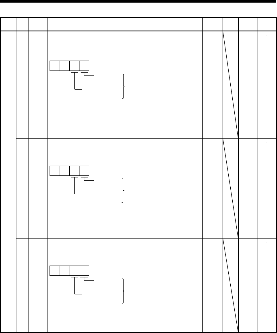
5. PARAMETERS
Class No. Symbol Name and function Initial
value Unit Setting
range
Control
mode
44 *DI3 Input signal selection 3 (CN1-3)
Allows any input signal to be assigned to CN1-pin 3.
The assignable signals and setting method are the same as in input signal
selection 2 (parameter No.43).
Position
control mode Input signals of
CN1-pin 3
selected.
Internal speed
control mode
00
This parameter is unavailable when parameter No.42 is set to assign the
control change (LOP) to CN1-pin 3.
This parameter is unavailable when parameter No.48 is set to assign the
Forward rotation stroke end (LSP) and Reverse rotation stroke end (LSN) to
be assigned to CN1-pin 3.
0882 Refer to
name
and
function
column.
PS
45 *DI4
Input signal selection 4 (CN1-5)
Allows any input signal to be assigned to CN1-pin 5.
The assignable signals and setting method are the same as in input signal
selection 2 (parameter No.43).
Position
control mode Input signals of
CN1-pin 5
selected.
Internal speed
control mode
09
This parameter is unavailable when parameter No.42 is set to assign the
control change (LOP) to CN1-pin 5.
This parameter is unavailable when parameter No.48 is set to assign the
Forward rotation stroke end (LSP) and Reverse rotation stroke end (LSN) to
be assigned to CN1-pin 5
0995 Refer to
name
and
function
column.
PS
Expansion parameters 1
46 *DI5
Input signal selection 5 (CN1-6)
Allows any input signal to be assigned to CN1-pin 6.
The assignable signals and setting method are the same as in input signal
selection 2 (parameter No.43).
Position
control mode Input signals of
CN1-pin 6
selected.
Internal speed
control mode
00
This parameter is unavailable when parameter No.42 is set to assign the
control change (LOP) to CN1-pin 6.
This parameter is unavailable when parameter No.48 is set to assign the
Reverse rotation stroke end (LSN) to be assigned to CN1-pin 6.
0000 Refer to
name
and
function
column.
PS
5 - 16
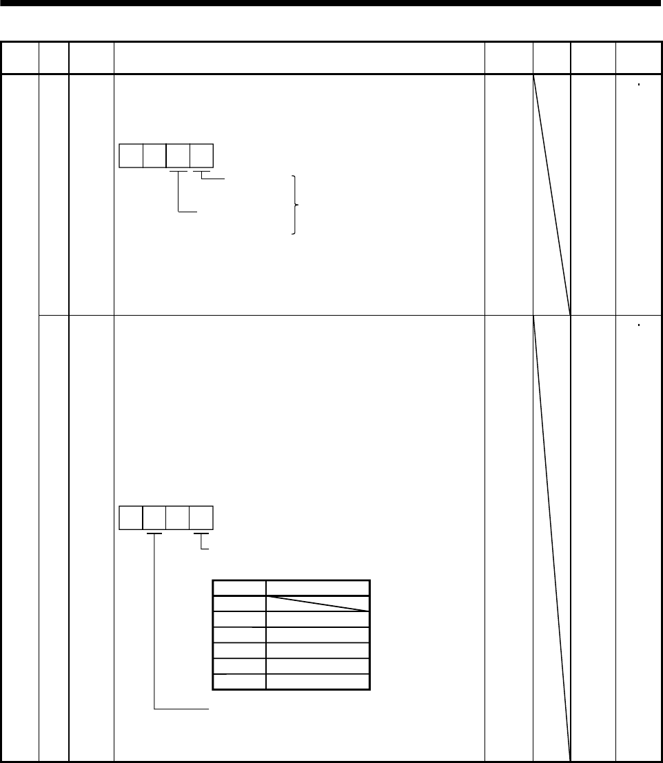
5. PARAMETERS
Class No. Symbol Name and function Initial
value Unit Setting
range
Control
mode
47 *DI6
Input signal selection 6 (CN1-7)
Allows any input signal to be assigned to CN1-pin 7.
The assignable signals and setting method are the same as in input signal
selection 2 (parameter No.43).
Position
control mode Input signals of
CN1-pin 7
selected.
Internal speed
control mode
00
This parameter is unavailable when parameter No.42 is set to assign the
control change signal (LOP) to CN1-pin 7.
This parameter is unavailable when parameter No.48 is set to assign the
Forward rotation stroke end (LSP) to be assigned to CN1-pin 7.
0000 Refer to
name
and
function
column.
PS
Expansion parameters 1
48 *LSPN
LSP/LSN input terminal selection
Select the pins where the forward rotation stroke end (LSP) and reverse
rotation stroke end (LSN) will be assigned. If the signals have already been
assigned using parameter No.42 to 47, this parameter setting has
preference.
However, if the forward rotation stroke end (LSP) is assigned at pin 6 of
CN1 (default setting), the setting of parameter No.46 takes priority.
Similarly, if the reverse rotation stroke end (LSN) is assigned at pin 7 of
CN1 (default setting), the setting of parameter No.47 takes priority. If the
forward rotation stroke end (LSP) and reverse rotation stroke end (LSN) are
assigned at the same pin, the forward rotation stroke end (LSP) takes
priority while the reverse rotation stroke end (LSN) is disabled.
CN1-7
CN1-4
CN1-3
CN1-5
CN1-6
3
4
1
2
0
00
5
Select the pin where the forward rotation stroke
end (LSP) will be assigned.
Set value Connector pin No.
Select the pin where the reverse rotation stroke
end (LSN) will be assigned. The settings are the
same as those of the first digit.
0403 Refer to
name
and
function
column.
PS
5 - 17
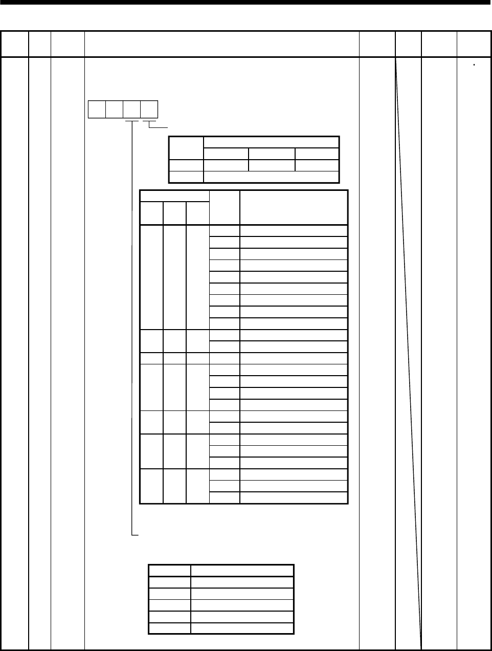
5. PARAMETERS
Class No. Symbol Name and function Initial
value Unit Setting
range
Control
mode
Expansion parameters 1
49 *DO1 Output signal selection 1
Used to select the connector pins to output the alarm code and warning
(WNG).
Setting of alarm code output
Connector pins
Set value CN1-10 CN1-11 CN1-12
0INP or SA RD ZSP
1
88888
AL.12
AL.13
AL.15
AL.17
AL.8A
AL.8E
AL.30
AL.45
AL.50
AL.51
AL.24
AL.32
AL.31
AL.35
AL.52
AL.16
AL.20
Name
Watchdog
Memory error 1
Clock error
Memory error 2
Board error 2
Serial communication time-out error
Serial communication error
Regenerative error
Main circuit device overheat
Overload 1
Overload 2
Main circuit
Overcurrent
Overspeed
Command pulse frequency error
Error excessive
Encoder error 1
Encoder error 2
Alarm
display
(Note) Alarm code
CN1
pin 10
0
000
1
CN1
pin 11
00
1
101
CN1
pin 12
1
1
0
1
0
1
0
AL.19 Memory error 3
AL.37 Parameter error
AL.33 Overvoltage
AL.46 Servo motor overheat
AL.10 Undervoltage
100
AL.1A Motor combination error
Set value Connector pin No.
Setting of warning (WNG) output
Select the connector pin to output warning. The old signal
before selection will be unavailable.
0 Not output.
1 CN1-11
2 CN1-9
3 CN1-10
4 CN1-12
0
Alarm code is output at alarm occurrence.
0
Note. 0: Pin-VIN off (open)
1: Pin-VIN on (short)
0000 Refer to
name
and
function
column.
PS
5 - 18
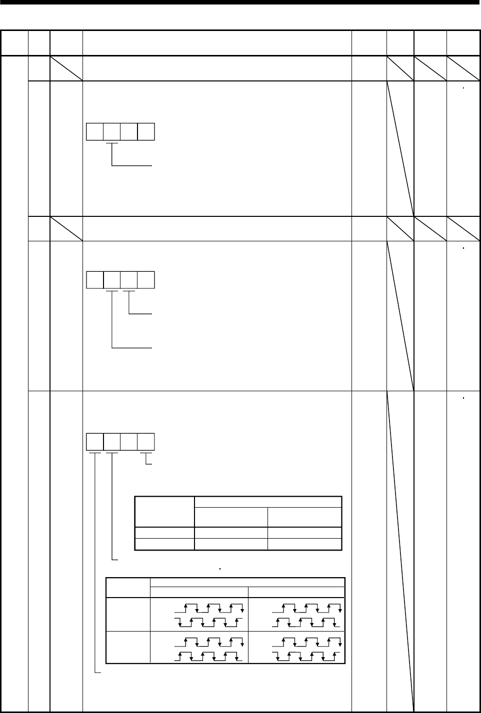
5. PARAMETERS
Class No. Symbol Name and function Initial
value Unit Setting
range
Control
mode
50 For manufacturer setting
Do not change this value by any means.
0000
51 *OP6 Function selection 6
Used to select the operation to be performed when the reset (RES)
switches on.
000
Operation to be performed when the
reset (RES) switches on
0: Base circuit shut off
1: Base circuit not shut off
0000
Refer to
name
and
function
column.
PS
52 For manufacturer setting
Do not change this value by any means.
0000
53 *OP8 Function selection 8
Used to select the protocol of serial communication.
0 0
Protocol checksum selection
0: Yes (checksum added)
1: No (checksum not added)
Protocol checksum selection
0: With station numbers
1: No station numbers
0000
Refer to
name
and
function
column.
PS
Expansion parameters 2
54 *OP9 Function selection 9
Use to select the command pulse rotation direction, encoder output pulse
direction and encoder pulse output setting.
0
0
1
CCW
CW
CW
CCW
Servo motor rotation direction changing
Changes the servo motor rotation
direction for the input pulse train.
Set value
Servo motor rotation direction
At forward rotation
pulse input
At reverse rotation
pulse input
Encoder pulse output phase changing
Changes the phases of A B-phase encoder pulses output .
Encoder output pulse setting selection (refer to parameter No.27)
0: Output pulse setting
1: Division ratio setting
Servo motor rotation direction
Set value CCW CW
0
1
A-phase
B-phase
A-phase
B-phase
A-phase
B-phase
A-phase
B-phase
0000
Refer to
name
and
function
column.
PS
5 - 19
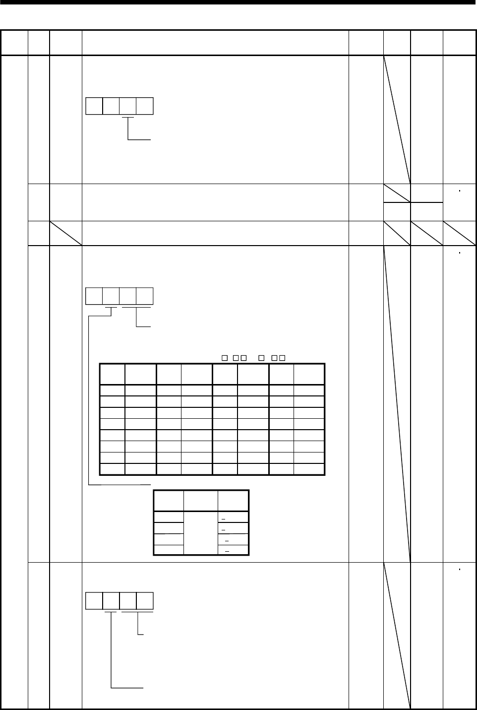
5. PARAMETERS
Class No. Symbol Name and function Initial
value Unit Setting
range
Control
mode
55 *OPA Function selection A
Used to select the position command acceleration/deceleration time
constant (parameter No.7) control system.
000
0: Primary delay
1: Linear acceleration/deceleration
Position command acceleration/deceleration
time constant control
0000 Refer to
name
and
function
column.
P
0
56 SIC Serial communication time-out selection
Used to set the communication protocol time-out period in [s].
When you set "0", time-out check is not made.
0
s 1 to 60
PS
57 For manufacturer setting
Do not change this value by any means.
10
58 NH1 Machine resonance suppression filter 1
Used to selection the machine resonance suppression filter.
(Refer to section 8.2.)
2
3
0
0
1
40dB
14dB
8dB
4dB
Notch frequency selection
Set "00" when you have set adaptive vibration
suppression control to be "valid" or "held"
(parameter No.60: 1 or 2 ).
00
01
02
03
04
05
06
07
Setting
value Frequency
Invalid
4500
2250
1500
1125
900
750
642.9
08
09
0A
0B
0C
0D
0E
0F
562.5
500
450
409.1
375
346.2
321.4
300
Frequency
10
11
12
13
14
15
16
17
281.3
264.7
250
236.8
225
214.3
204.5
195.7
Frequency
18
19
1A
1B
1C
1D
1E
1F
187.5
180
173.1
166.7
160.1
155.2
150
145.2
Frequency
Notch depth selection
Setting
value Depth Gain
Deep
Shallow
to
Setting
value
Setting
value
Setting
value
0000
Refer to
name
and
function
column.
PS
Expansion parameters 2
59 NH2 Machine resonance suppression filter 2
Used to set the machine resonance suppression filter.
0
Notch frequency
Same setting as in parameter No.58
However, you need not set "00" if you have
set adaptive vibration suppression control to
be "valid" or "held".
Notch depth
Same setting as in parameter No.58
0000
Refer to
name
and
function
column.
PS
5 - 20
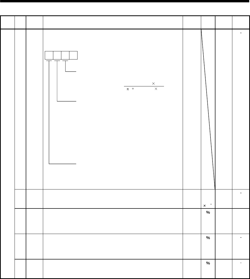
5. PARAMETERS
Class No. Symbol Name and function Initial
value Unit Setting
range
Control
mode
60 LPF Low-pass filter/adaptive vibration suppression control
Used to selection the low-pass filter and adaptive vibration suppression
control. (Refer to chapter 8.)
0
Low-pass filter selection
0: Valid (Automatic adjustment)
1: Invalid
When you choose "valid", 2 (1 GD2 setting 0.1)
VG2 setting 10
bandwidth filter is set automatically.
Adaptive vibration suppression control selection
Choosing "valid" or "held" in adaptive vibration
suppression control selection makes the machine
resonance suppression filter 1 (parameter No.58) invalid.
0: Invalid
1: Valid
Machine resonance frequency is always detected
and the filter is generated in response to resonance to
suppress machine vibration.
2: Held
The characteristics of the filter generated so far are held,
and detection of machine resonance is stopped.
Adaptive vibration suppression control sensitivity selection
Used to set the sensitivity of machine resonance detection.
0: Normal
1: Large sensitivity
[Hz]
0000 Refer to
name
and
function
column.
PS
61 GD2B Ratio of load inertia moment to servo motor inertia moment 2
Used to set the ratio of load inertia moment to servo motor inertia moment
when gain changing is valid.
70 Multi-
plier
(10 1)
0
to
3000
PS
62 PG2B Position control gain 2 changing ratio
Used to set the ratio of changing the position control gain 2 when gain
changing is valid.
Made valid when auto tuning is invalid.
100 10
to
200
P
63 VG2B Speed control gain 2 changing ratio
Used to set the ratio of changing the speed control gain 2 when gain
changing is valid.
Made valid when auto tuning is invalid.
100 10
to
200
PS
Expansion parameters 2
64 VICB Speed integral compensation changing ratio
Used to set the ratio of changing the speed integral compensation when
gain changing is valid. Made valid when auto tuning is invalid.
100 50
to
1000
PS
5 - 21
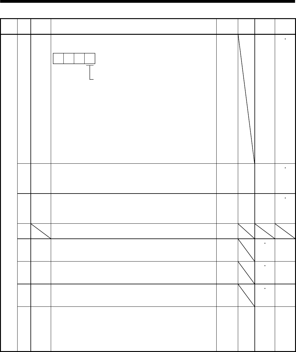
5. PARAMETERS
Class No. Symbol Name and function Initial
value Unit Setting
range
Control
mode
65 *CDP Gain changing selection
Used to select the gain changing condition. (Refer to section 8.5.)
000
Gain changing selection
Gains are changed in accordance with the settings
of parameters No.61 to 64 under any of the following
conditions:
0: Invalid
1: Gain changing (CDP) is ON
2: Command frequency is equal to higher than
parameter No.66 setting
3: Droop pulse value is equal to higher than
parameter No.66 setting
4: Servo motor speed is equal to higher than
parameter No.66 setting
0000 Refer to
name
and
function
column.
PS
66 CDS Gain changing condition
Used to set the value of gain changing condition (command frequency,
droop pulses, servo motor speed) selected in parameter No.65.The set
value unit changes with the changing condition item. (Refer to section 8.5.)
10 kpps
pulse
r/min
10
to
9999
PS
67 CDT Gain changing time constant
Used to set the time constant at which the gains will change in response to
the conditions set in parameters No.65 and 66.
(Refer to section 8.5.)
1 ms 0
to
100
PS
68 For manufacturer setting
Do not change this value by any means.
0
69 CMX2 Command pulse multiplying factor numerator 2
Used to set the multiplier for the command pulse.
Setting "0" automatically sets the connected motor resolution.
1 0 1
to
65535
P
70 CMX3 Command pulse multiplying factor numerator 3
Used to set the multiplier for the command pulse.
Setting "0" automatically sets the connected motor resolution.
1 0 1
to
65535
P
71 CMX4 Command pulse multiplying factor numerator 4
Used to set the multiplier for the command pulse.
Setting "0" automatically sets the connected motor resolution.
1 0 1
to
65535
P
Expansion parameters 2
72 SC4 Internal speed command 4
Used to set speed 4 of internal speed commands.
200 r/min 0 to
instan-
taneous
permis-
sible
speed
S
5 - 22
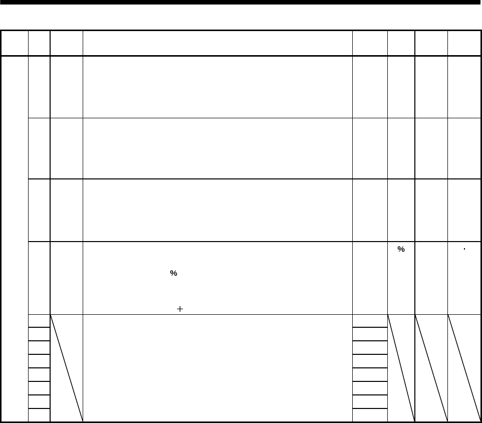
5. PARAMETERS
Class No. Symbol Name and function Initial
value Unit Setting
range
Control
mode
73 SC5 Internal speed command 5
Used to set speed 5 of internal speed commands.
300 r/min
0 to
instan-
taneous
permis-
sible
speed
S
74 SC6 Internal speed command 6
Used to set speed 6 of internal speed commands.
500 r/min
0 to
instant-
aneous
permis-
sible
speed
S
75 SC7 Internal speed command 7
Used to set speed 7 of internal speed commands.
800 r/min
0 to
instant-
aneous
permis-
sible
speed
S
76 TL2 Internal torque limit 2
Set this parameter to limit servo motor torque on the assumption that the
maximum torque is 100[ ].
When 0 is set, torque is not produced.
When torque is output in analog monitor output, this set value is the
maximum output voltage ( 8V).
100 0
to
100
PS
77 100
78 10000
79 10
80 10
81 100
82 100
83 100
Expansion parameters 2
84
For manufacturer setting
Do not change this value by any means.
0000
5 - 23
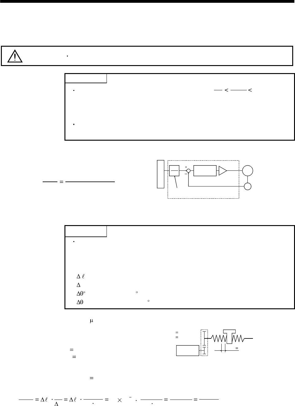
5. PARAMETERS
5.2 Detailed description
5.2.1 Electronic gear
CAUTION Wrong setting can lead to unexpected fast rotation, causing injury.
POINT
The guideline of the electronic gear setting range is 50
1
CDV
CMX 50.
If the set value is outside this range, noise may be generated during
acceleration/ deceleration or operation may not be performed at the preset
speed and/or acceleration/deceleration time constants.
Always set the electronic gear with servo off state to prevent unexpected
operation due to improper setting.
The machine can be moved at any multiplication factor to input pulses.
CDV
CMX
Parameter No.4
Parameter No.3
Electronic gear
Feedback pulse
CMX
CDV
Deviation
counter
Motor
Encoder
Input pulse train
The following setting examples are used to explain how to calculate the electronic gear.
POINT
The following specification symbols are required to calculate the electronic gear
Pb : Ball screw lead [mm]
1/n : Reduction ratio
Pt : Servo motor resolution [pulses/rev]
0: Travel per command pulse [mm/pulse]
S :
Travel per servo motor revolution [mm/rev]
: Angle per pulse [ /pulse]
: Angle per revolution [ /rev]
(1) For motion in increments of 10 m per pulse
Machine specifications
Ball screw lead Pb 10 [mm]
Reduction ratio: 1/n 1/2
Z1: Number of gear cogs on servo motor side
Z2: Number of gear cogs on load side
Servo motor resolution: Pt 131072 [pulses/rev]
Servo motor
131072 [pulse/rev]
n
Z1
Z2
Pb 10[mm]
1/n Z1/Z2
1/2
CDV
CMX
0
Pt
S0
Pt
1/n Pb 10 10 3
1/2 10
131072 262144
1000
32768
125
Hence, set 32768 to CMX and 125 to CDV.
5 - 24
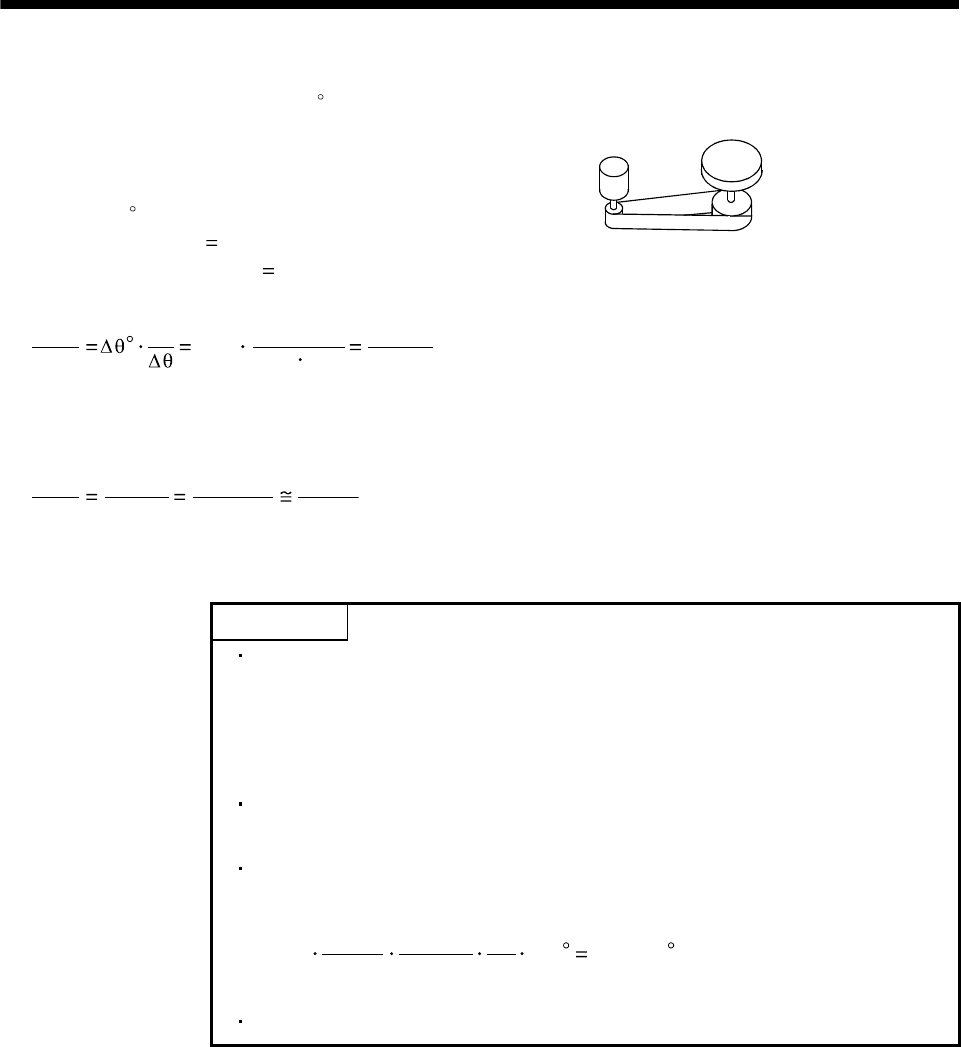
5. PARAMETERS
(2) Conveyor setting example
For rotation in increments of 0.01 per pulse
Machine specifications
Table : 360 /rev
Reduction ratio: 1/n 1/18
Servo motor resolution: Pt 131072 [pulses/rev]
Table
Timing belt : 4/64
Servo motor
131072 [pulse/rev]
CDV
CMX Pt 131072 65536
1125
0.01 4/64 360 ·······················································································(5.1)
Since CMX is not within the setting range in this status, it must be reduced to the lowest term.
When CMX has been reduced to a value within the setting range, round off the value to the nearest unit.
CDV
CMX 65536
1125
26214.4
450
26214
450
Hence, set 26214 to CMX and 450 to CDV.
POINT
When "0" is set to parameter No.3 (CMX), CMX is automatically set to the
servo motor resolution. Therefore, in the case of Expression (5.2), setting 0 to
CMX and 2250 to CDX concludes in the following expression:
CMX/CDV=131072/2250, and electric gear can be set without the necessity to
reduce the fraction to the lowest term.
For unlimited one-way rotation, e.g. an index table, indexing positions will be
missed due to cumulative error produced by rounding off.
For example, entering a command of 36000 pulses in the above example
causes the table to rotate only the following:
26214
450
36000 1
131072
4
64 360 359.995
Therefore, indexing cannot be done in the same position on the table.
5 - 25
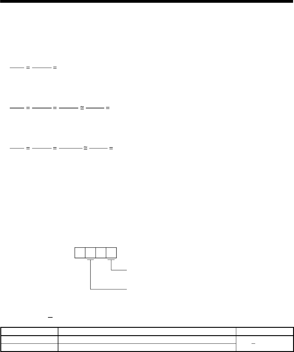
5. PARAMETERS
(3) Instructions for reduction
The calculated value before reduction must be as near as possible to the calculated value after reduction.
In the case of (2) in this section, an error will be smaller if reduction is made to provide no fraction for CDV.
The fraction of Expression (5.1) before reduction is calculated as follows.
CDV
CMX 65536
1125 58.25422 ···················································································································(5.2)
The result of reduction to provide no fraction for CMX is as follows.
CDV
CMX 65536
1125
32768
562.5
32768
563 58.20249···················································································· (5.3)
The result of reduction to provide no fraction for CDV is as follows.
CDV
CMX 65536
1125
26214.4
450
26214
450 58.25333·················································································· (5.4)
As a result, it is understood that the value nearer to the calculation result of Expression (5.2) is the result of
Expression (5.4). Accordingly, the set values of (2) in this section are CMX 26214, CDV 450.
5.2.2 Analog monitor
The servo status can be output to two channels in terms of voltage.
(1) Setting
Change the following digits of parameter No.17.
Analog monitor 1 (MO1) output selection
(Signal output to across MO1-LG)
Analog monitor 2 (MO2) output selection
(Signal output to across MO2-LG)
Parameter No.17
00
Parameters No.31 and 32 can be used to set the offset voltages to the analog output voltages. The setting
range is between 999 and 999mV.
Parameter No. Description Setting range [mV]
31 Used to set the offset voltage for the analog monitor 1 (MO1) output.
32 Used to set the offset voltage for the analog monitor 2 (MO2) output. 999 to 999
5 - 26
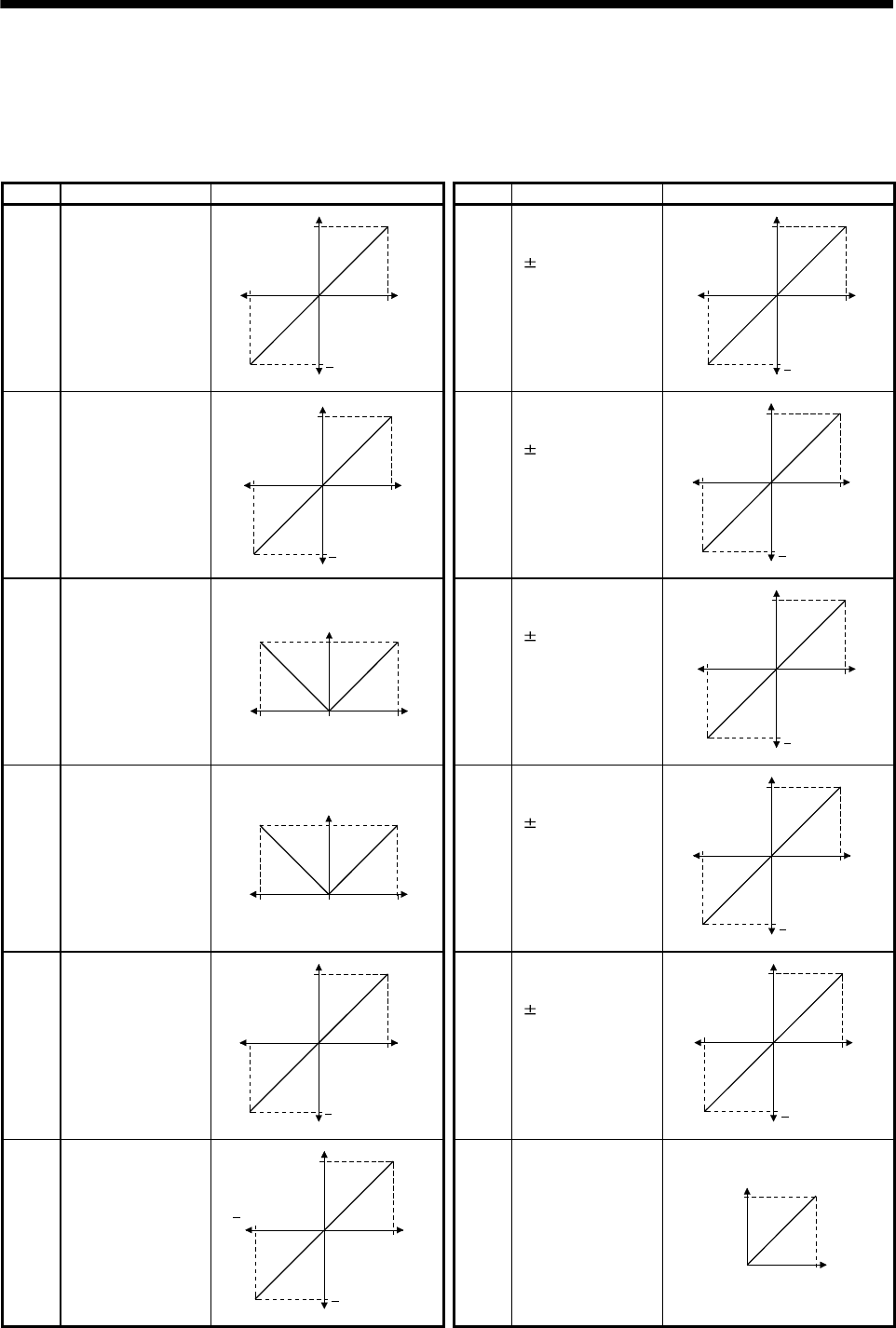
5. PARAMETERS
(2) Set content
The servo amplifier is factory-set to output the servo motor speed to Analog monitor 1 (MO1) and the
torque to Analog monitor 2 (MO2). The setting can be changed as listed below by changing the parameter
No.17 value.
Refer to (3) for the measurement point.
Setting Output item Description Setting Output item Description
0 Servo motor speed 8[V]
Max. speed
0Max. speed
8[V]
CCW direction
CW direction
6 Droop pulses
(Note 1)
(10V/128pulse)
10[V]
0128[pulse]
10[V]
CCW direction
CW direction
128[pulse]
1 Torque (Note 2)
8[V]
Max. torque
0Max. torque
8[V]
Drivin
g
in CW direction
Driving in CCW direction 7 Droop pulses
(Note 1)
(10V/2048pulse)
10[V]
02048[pulse]
10[V]
CCW direction
CW direction
2048[pulse]
2 Servo motor speed
8[V]
Max. speed 0Max. speed
CCW
direction
CW
direction
8 Droop pulses
(Note 1)
(10V/8192pulse)
10[V]
08192[pulse]
10[V]
CCW direction
CW direction
8192[pulse]
3 Torque (Note 2)
8[V]
Max. torque 0Max. torque
Driving in
CW direction
Driving in
CCW direction
9 Droop pulses
(Note 1)
(10V/32768pulse)
10[V]
032768[pulse]
10[V]
CCW direction
CW direction
32768[pulse]
4 Current command 8[V]
Max. command
current
0Max. command
current
8[V]
CCW direction
CW direction
A Droop pulses
(Note 1)
(10V/131072pulse)
10[V]
0131072[pulse]
10[V]
CCW direction
CW direction
131072[pulse]
5 Command pulse
frequency 10[V]
500kpps
0500kpps
10[V]
CCW direction
CW direction
B Bus voltage
8[V]
0400[V]
5 - 27
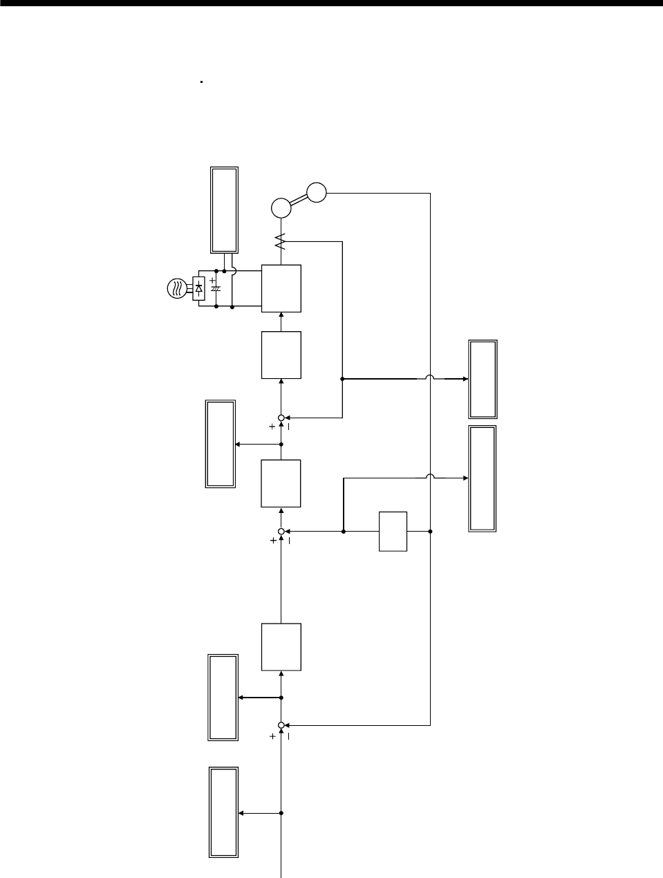
5. PARAMETERS
Note 1. Encoder pulse unit.
2. 8V is outputted at the maximum torque.
However, when parameter No.28 76 are set to limit torque, 8V is outputted at the torque highly limited.
(3) Analog monitor block diagram
PWM M
Current
control
Speed
control
Current
command
Position
control
Droop pulse
Differ-
ential
Command
pulse frequency Bus voltage
Speed
command
Command
pulse
Current feedback
Position feedback
Servo motor speed
Current
encoder
Servo moto
r
Encoder
Torque
5 - 28
5. PARAMETERS
5.2.3 Using forward/reverse rotation stroke end to change the stopping pattern
The stopping pattern is factory-set to make a sudden stop when the forward/reverse rotation stroke end is
OFF. A slow stop can be made by changing the parameter No.22 value.
Parameter No.22 setting Stopping method
0
(initial value)
Sudden stop
Position control mode
Internal speed control mode
: Motor stops with droop pulses cleared.
: Motor stops at deceleration time constant of zero.
1
Slow stop
Position control mode
Internal speed control mode
: The motor is decelerated to a stop in accordance with the
parameter No.7 value.
: The motor is decelerated to a stop in accordance with the
parameter No.12 value.
5.2.4 Alarm history clear
The servo amplifier stores one current alarm and five past alarms from when its power is switched on first. To
control alarms which will occur during operation, clear the alarm history using parameter No.16 before starting
operation.
Clearing the alarm history automatically returns to " 0".
After setting, this parameter is made valid by switch power from OFF to ON.
Alarm history clear
0: Invalid (not cleared)
1: Valid (cleared)
Parameter No.16
5 - 29
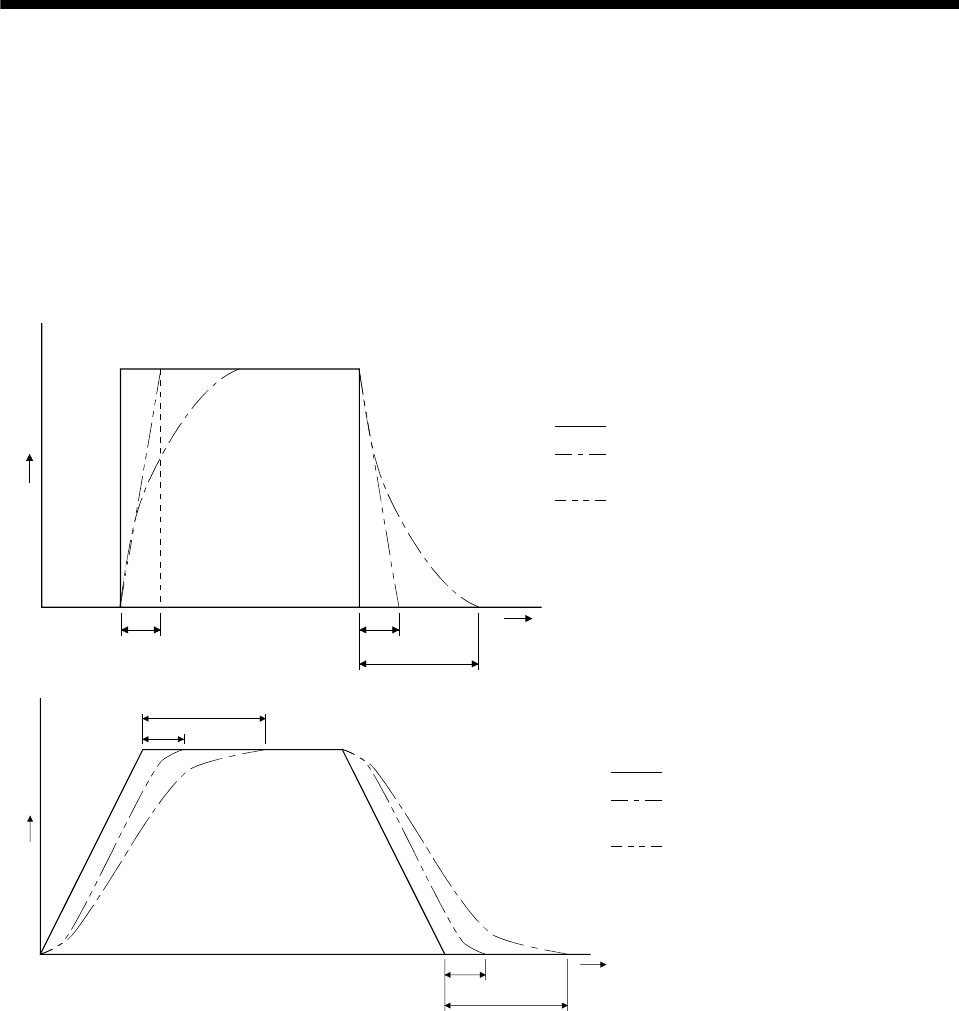
5. PARAMETERS
5.2.5 Position smoothing
By setting the position command acceleration/deceleration time constant (parameter No.7), you can run the
servo motor smoothly in response to a sudden position command.
The following diagrams show the operation patterns of the servo motor in response to a position command
when you have set the position command acceleration/deceleration time constant.
Choose the primary delay or linear acceleration/deceleration in parameter No.55 according to the machine
used.
(1) For step input
Command
(3t)
tt
Time
t
: Input position command
: Position command after
filtering for primary delay
: Position command after filtering
for linear acceleration/deceleration
: Position command acceleration/
deceleration time constant (parameter No.7)
(2) For trapezoidal input
Command
Tim
e
t
(3t)
t
(3t)
t
: Input position command
: Position command after
filtering for primary delay
: Position command after filtering
for linear acceleration/deceleration
: Position command acceleration/
deceleration time constant
(parameter No.7)
5 - 30
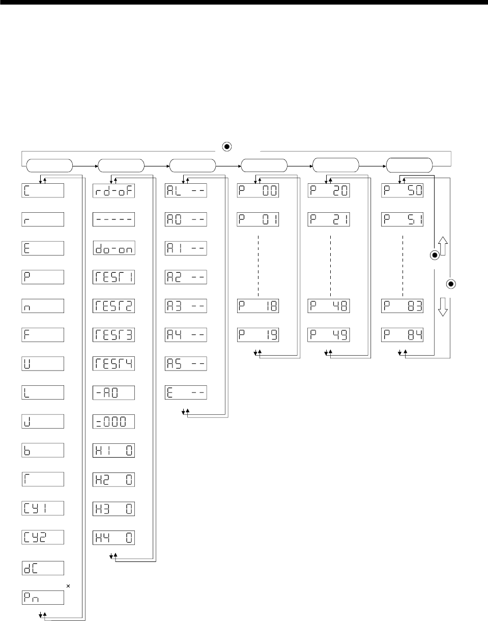
6. DISPLAY AND OPERATION
6. DISPLAY AND OPERATION
6.1 Display flowchart
Use the display (5-digit, 7-segment LED) on the front panel of the servo amplifier for status display, parameter
setting, etc. Set the parameters before operation, diagnose an alarm, confirm external sequences, and/or
confirm the operation status. Press the "MODE" "UP" or "DOWN" button once to move to the next screen.
To refer to or set the expansion parameters, make them valid with parameter No.19 (parameter write disable).
Cumulative feedback
pulses [pulse]
Servo motor speed
[r/min]
Droop pulses
[pulse]
Cumulative command
pulses [pulse]
Command pulse
frequency [kpps]
Regenerative load
ratio [%]
Effective load ratio
[%]
Peak load ratio
[%]
Within one-revolution
position low [pulse]
Load inertia moment
ratio [Multiplier ( 1)]
Sequence
External I/O
signal display
Output (DO) signal
forced output
Test operation mode
Jog feed
Test operation mode
Positioning operation
Test operation mode
Motor-less operation
Software version low
Software version high
Manufacturer setting
screen
Current alarm
Last alarm
Second alarm in past
Third alarm in past
Fourth alarm in past
Fifth alarm in past
Sixth alarm in past
Parameter error No.
Parameter No.0
Parameter No.1
Parameter No.18
Parameter No.19
Parameter No.20
Parameter No.21
Parameter No.48
Parameter No.49
(Note)
MODE
button
DOWN
UP
Status display Diagnosis Basic
parameters Expansion
parameters 1
Alarm Expansion
parameters 2
Parameter No.50
Parameter No.51
Parameter No.83
Parameter No.84
Instantaneous torque
[%]
Within one-revolution
position, high [100 pulses]
Bus voltage [V]
Test operation mode
Machine analyzer operation
Motor series ID
Motor type ID
Encoder ID
Note. The initial status display at power-on depends on the control mode.
Position control mode: Cumulative feedback pulses(C), Internal speed control mode: Servo motor speed(r)
Also, parameter No.18 can be used to change the initial indication of the status display at power-on.
6 - 1
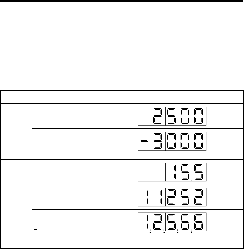
6. DISPLAY AND OPERATION
6.2 Status display
The servo status during operation is shown on the 5-digit, 7-segment LED display. Press the "UP" or "DOWN"
button to change display data as desired. When the required data is selected, the corresponding symbol
appears. Press the "SET" button to display its data. At only power-on, however, data appears after the symbol
of the status display selected in parameter No.18 has been shown for 2.
The servo amplifier display shows the lower five digits of 16 data items such as the servo motor speed.
6.2.1 Display examples
The following table lists display examples.
Displayed data
Item Status Servo amplifier display
Forward rotation at 3000r/min
Servo motor
speed
Reverse rotation at 3000r/min
Reverse rotation is indicated by " ".
Load inertia
moment 15.5 times
11252pulse
Multi-revolution
counter
12566pulse
Lit
Negative value is indicated by the lit decimal points in the upper four digits.
6 - 2
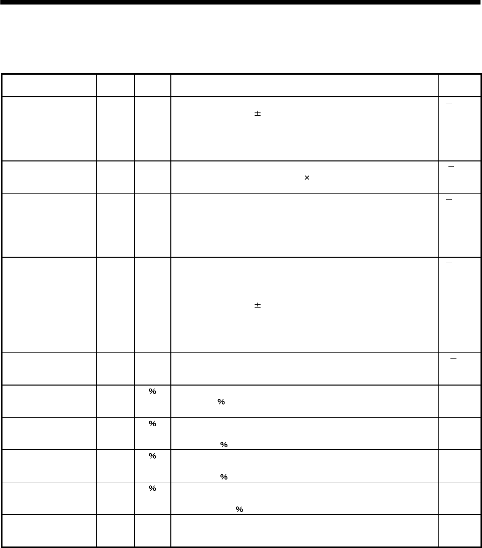
6. DISPLAY AND OPERATION
6.2.2 Status display list
The following table lists the servo statuses that may be shown.
Name Symbol Unit Description Display
range
Cumulative feedback
pulses
C pulse Feedback pulses from the servo motor encoder are counted and displayed.
The value in excess of 99999 is counted, bus since the servo amplifier
display is five digits, it shows the lower five digits of the actual value. Press
the "SET" button to reset the display value to zero.
Reverse rotation is indicated by the lit decimal points in the upper four
digits.
99999
to
99999
Servo motor speed r r/min The servo motor speed is displayed.
The value rounded off is displayed in 0.1r/min.
5400
to
5400
Droop pulses E pulse The number of droop pulses in the deviation counter is displayed. When
the servo motor is rotating in the reverse direction, the decimal points in the
upper four digits are lit.
Since the servo amplifier display is five digits, it shows the lower five digits
of the actual value.
The number of pulses displayed is not yet multiplied by the electronic gear.
99999
to
99999
Cumulative command
pulses
P pulse The position command input pulses are counted and displayed.
As the value displayed is not yet multiplied by the electronic gear
(CMX/CDV), it may not match the indication of the cumulative feedback
pulses.
The value in excess of 99999 is counted, but since the servo amplifier
display is five digits, it shows the lower five digits of the actual value. Press
the "SET" button to reset the display value to zero. When the servo motor is
rotating in the reverse direction, the decimal points in the upper four digits
are lit.
99999
to
99999
Command pulse
frequency
n kpps The frequency of the position command input pulses is displayed.
The value displayed is not multiplied by the electronic gear (CMX/CDV).
800
to
800
Regenerative load ratio L The ratio of regenerative power to permissible regenerative power is
displayed in .
0
to
100
Effective load ratio J The continuous effective load torque is displayed.
The effective value in the past 15 seconds is displayed relative to the rated
torque of 100 .
0
to
300
Peak load ratio b The maximum torque generated during acceleration/deceleration, etc.
The highest value in the past 15 seconds is displayed relative to the rated
torque of 100 .
0
to
400
Instantaneous torque T Torque that occurred instantaneously is displayed.
The value of the torque that occurred is displayed in real time relative to the
rate torque of 100 .
0
to
400
Within one-revolution
position low
Cy1 pulse Position within one revolution is displayed in encoder pulses.
The value returns to "0" when it exceeds the maximum number of pulses.
The value is incremented in the CCW direction of rotation.
0
to
99999
6 - 3

6. DISPLAY AND OPERATION
Name Symbol Unit Description Display
range
Within one-revolution
position high
Cy2 100
pulse
The within one-revolution position is displayed in 100 pulse increments of
the encoder.
The value returns to 0 when it exceeds the maximum number of pulses.
The value is incremented in the CCW direction of rotation.
0
to
1310
Load inertia moment
ratio
dC Multiplier
(1)
The estimated ratio of the load inertia moment to the servo motor shaft
inertia moment is displayed.
0.0
to
300.0
Bus voltage Pn V The voltage (across P-N) of the main circuit converter is displayed. 0
to
450
6.2.3 Changing the status display screen
The status display item of the servo amplifier display shown at power-on can be changed by changing the
parameter No.18 settings.
The item displayed in the initial status changes with the control mode as follows.
Control mode Status display at power-on
Position Cumulative feedback pulses
Position/
internal speed Cumulative feedback pulses/servo motor speed
Internal speed Servo motor speed
6 - 4
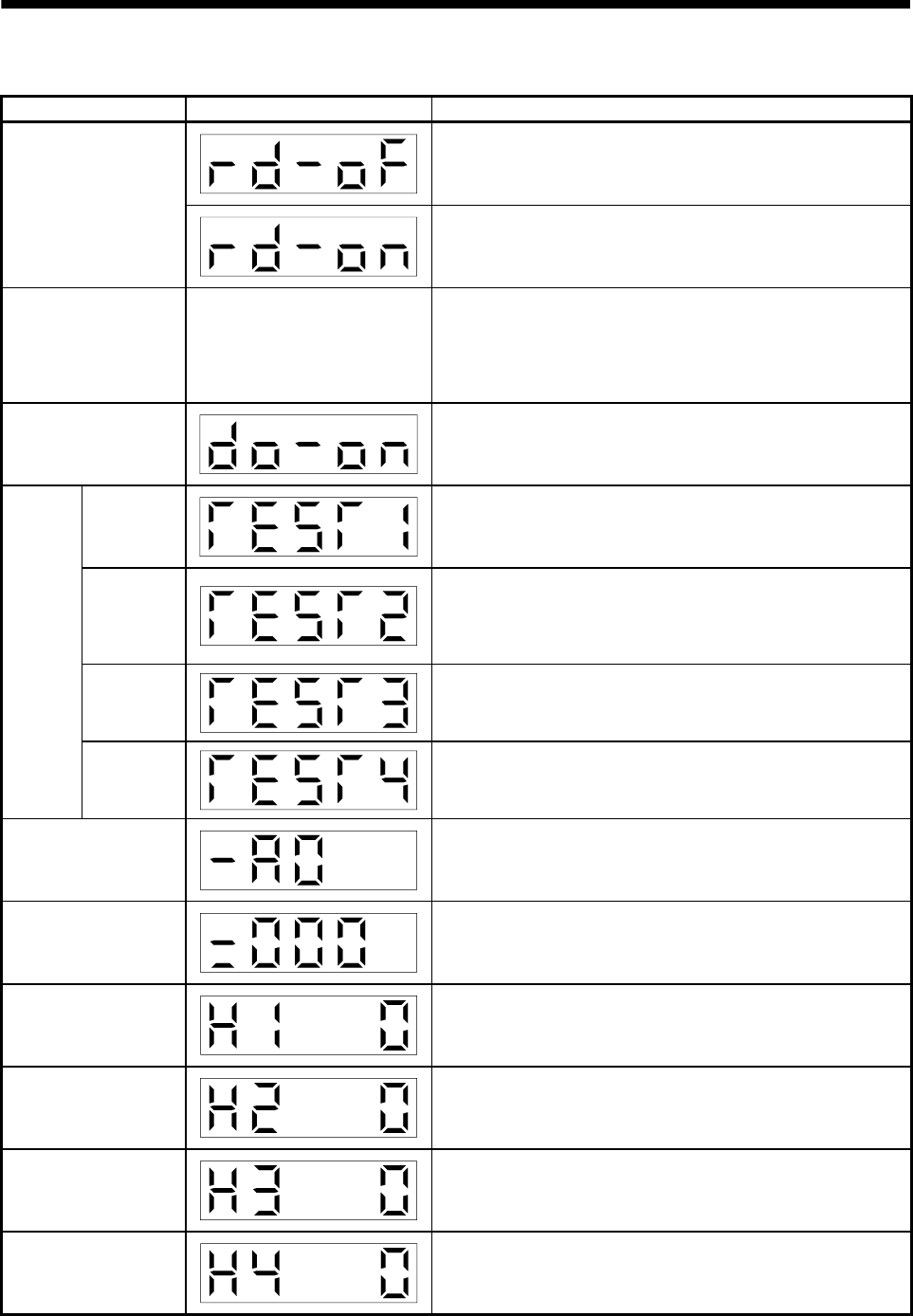
6. DISPLAY AND OPERATION
6.3 Diagnostic mode
Name Display Description
Not ready.
Indicates that the servo amplifier is being initialized or an alarm has
occurred.
Sequence
Ready.
Indicates that the servo was switched on after completion of
initialization and the servo amplifier is ready to operate.
External I/O signal display
Refer to section 6.6. Indicates the ON-OFF states of the external I/O signals.
The upper segments correspond to the input signals and the lower
segments to the output signals.
Lit: ON
Extinguished: OFF
The I/O signals can be changed using parameters No.43 to 49.
Output (DO) signal forced
output
The digital output signal can be forced on/off. For more information,
refer to section 6.7.
Jog feed
Jog operation can be performed when there is no command from the
external command device.
For details, refer to section 6.8.2.
Positioning
operation
The MR Configurator (servo configuration software) is required for
positioning operation. This operation cannot be performed from the
operation section of the servo amplifier.
Positioning operation can be performed once when there is no
command from the external command device.
Motor-less
operation
Without connection of the servo motor, the servo amplifier provides
output signals and displays the status as if the servo motor is running
actually in response to the external input signal.
For details, refer to section 6.8.4.
Test
operation
mode
Machine
analyzer
operation
Merely connecting the servo amplifier allows the resonance point of the
mechanical system to be measured.
The MR Configurator (servo configuration software) is required for
machine analyzer operation.
Software version low
Indicates the version of the software.
Software version high
Indicates the system number of the software.
Manufacturer setting
screen
Screen for manufacturer setting. When this screen is being displayed,
do not press any other buttons than "UP" and "DOWN" button.
Motor series ID
Press the "SET" button to show the motor series ID of the servo motor
currently connected.
Motor type ID
Press the "SET" button to show the motor type ID of the servo motor
currently connected.
Encoder ID
Press the "SET" button to show the encoder ID of the servo motor
currently connected.
6 - 5
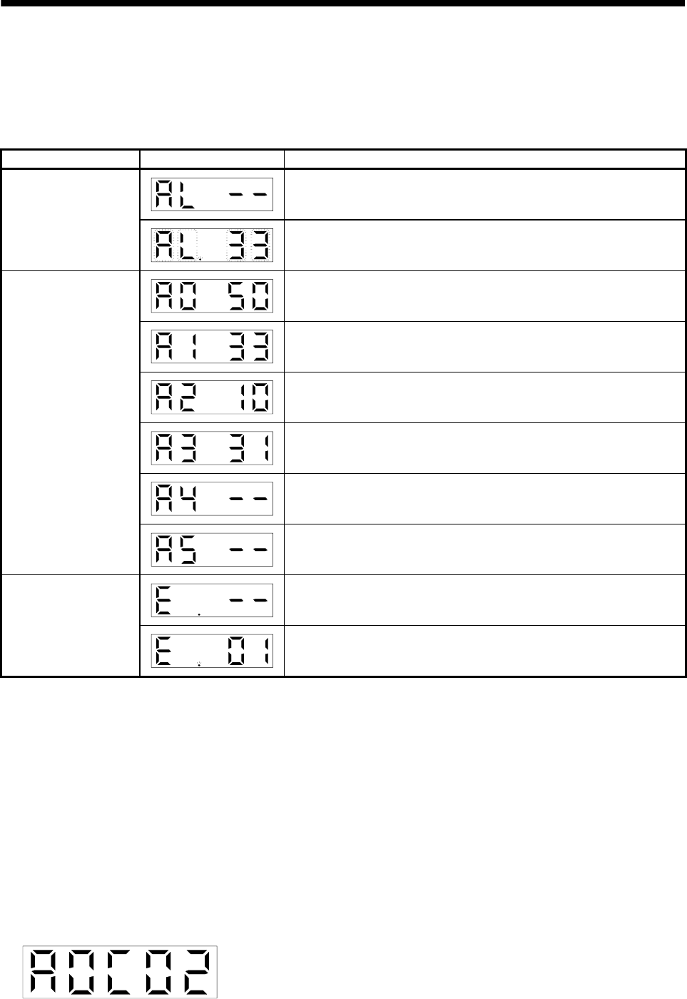
6. DISPLAY AND OPERATION
6.4 Alarm mode
The current alarm, past alarm history and parameter error are displayed. The lower 2 digits on the display
indicate the alarm number that has occurred or the parameter number in error. Display examples are shown
below.
Name Display Description
Indicates no occurrence of an alarm.
Current alarm
Indicates the occurrence of overvoltage (AL.33).
Flickers at occurrence of the alarm.
Indicates that the last alarm is overload 1 (AL.50).
Indicates that the second alarm in the past is overvoltage (AL.33).
Indicates that the third alarm in the past is undervoltage (AL.10).
Indicates that the fourth alarm in the past is overspeed (AL.31).
Indicates that there is no fifth alarm in the past.
Alarm history
Indicates that there is no sixth alarm in the past.
Indicates no occurrence of parameter error (AL.37).
Parameter error No.
Indicates that the data of parameter No.1 is faulty.
Functions at occurrence of an alarm
(1) Any mode screen displays the current alarm.
(2) Even during alarm occurrence, the other screen can be viewed by pressing the button in the operation
area. At this time, the decimal point in the fourth digit remains flickering.
(3) For any alarm, remove its cause and clear it in any of the following methods (for clearable alarms, refer to
section 10.2.1).
(a) Switch power OFF, then ON.
(b) Press the "SET" button on the current alarm screen.
(c) Turn on the reset (RES).
(4) Use parameter No.16 to clear the alarm history.
(5) Pressing "SET" button on the alarm history display screen for 2s or longer shows the following detailed
information display screen. Note that this is provided for maintenance by the manufacturer.
(
6) Press the "UP" or "DOWN" button to display the next alarm in the history.
6 - 6
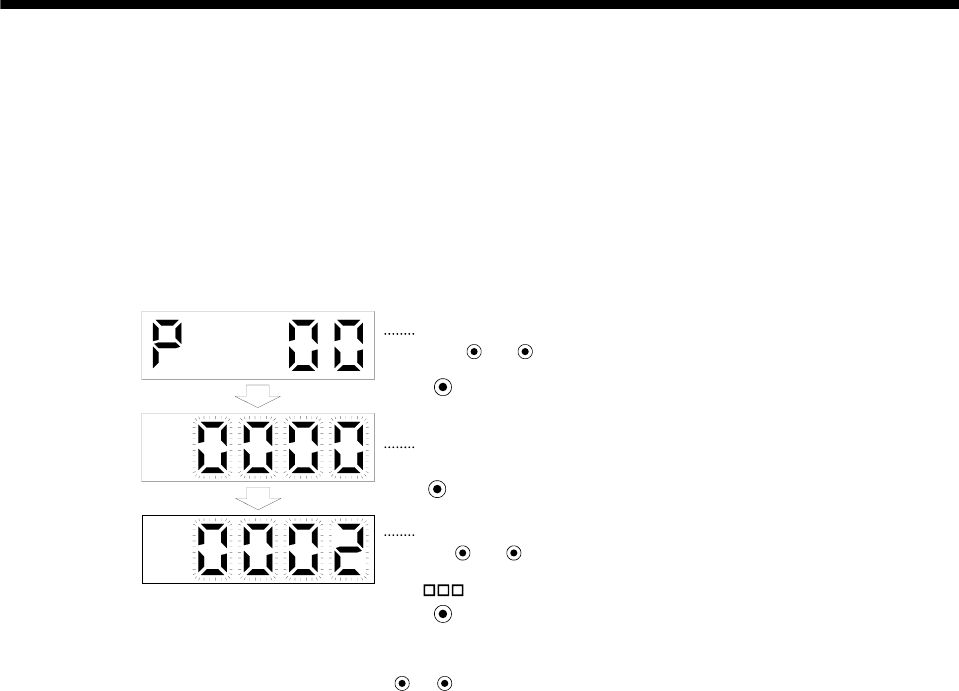
6. DISPLAY AND OPERATION
6.5 Parameter mode
The parameters whose abbreviations are marked* are made valid by changing the setting and then switching
power off once and switching it on again. Refer to section 5.1.2.
(1) Operation example
The following example shows the operation procedure performed after power-on to change the control
mode (parameter No.0) to the Internal speed control mode.
Using the "MODE" button, show the basic parameter screen.
The set value of the specified parameter number flickers.
UP DOWN
The parameter number is displayed.
Press or to change the number.
Press SET twice.
Press UP once.
During flickering, the set value can be changed.
Use or .
Press SET to enter.
( 2: Internal speed control mode)
UP DOWN
To shift to the next parameter, press the UP DOWN
/ button.
When changing the parameter No.0 setting, change its set value, then switch power off once and switch it
on again to make the new value valid.
(2) Expansion parameters
To use the expansion parameters, change the setting of parameter No.19 (parameter write disable).
Refer to section 5.1.1.
6 - 7
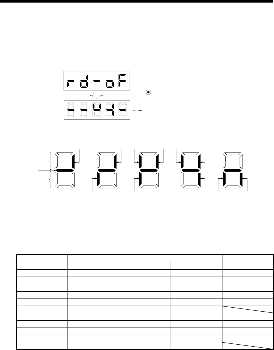
6. DISPLAY AND OPERATION
6.6 External I/O signal display
The ON/OFF states of the digital I/O signals connected to the servo amplifier can be confirmed.
(1) Operation
Call the display screen shown after power-on.
Using the "MODE" button, show the diagnostic screen.
Press UP once.
External I/O signal display screen
(2) Display definition
CN1
6
CN1
7
CN1
21
CN1
5
CN1
9
CN1
3CN1
4
CN1
12 CN1
11
CN1
10
Lit: ON
Extinguished: OFF
Input signals
Output signals
CN1
8
Always lit
The 7-segment LED shown above indicates ON/OFF.
Each segment at top indicates the input signal and each segment at bottom indicates the output signal. The
signals corresponding to the pins in the respective control modes are indicated below.
(Note 2) Signal abbreviation CN1
Pin No.
Input/Output
(Note 1) I/O P S
Related parameter No.
3 I RES ST1 43 to 47
4 I SON SON 43 to 47
5 I CR ST2 43 to 47
6 I LSP LSP 43 to 48
7 I LSN LSN 43 to 48
8 I EMG EMG
9 O ALM ALM 49
10 O INP SA 49
11 O RD RD 49
12 O ZSP ZSP 49
21 O OP OP
Note 1. I: Input signal, O: Output signal
2. P: Position control mode, S: Internal speed control mode
3. CN1B-4 and CN1A-18 output signals are the same.
6 - 8
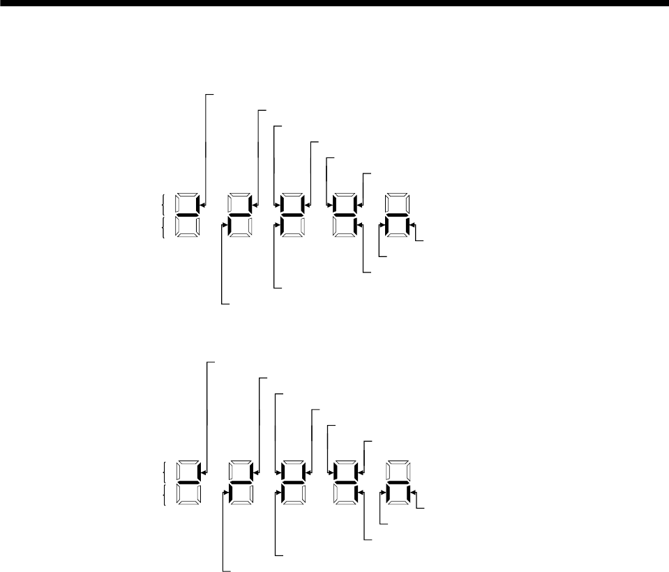
6. DISPLAY AND OPERATION
(3) Default signal indications
(a) Position control mode
Lit: ON
Extinguished: OFF
Input signals
Output signals
CR (CN 1-5) Clear
RES (CN 1-3) Reset
SON (CN 1-4) Servo-on
LSN (CN 1-7) Reverse rotation stroke end
LSP (CN 1-6) Forward rotation stroke end
RD (CN 1-11) Ready
INP (CN 1-10) In position
ZSP (CN 1-12) Zero speed detection
ALM (CN 1-9) Trouble
OP (CN 1-21) Encoder Z-phase pulse
EMG (CN 1-8) Emergency stop
(b) Internal speed control mode
Lit: ON
Extinguished: OFF
Input signals
Output signals
SON (CN 1-4) Servo-on
LSN (CN 1-7) Reverse rotation stroke end
LSP (CN 1-6) Forward rotation stroke end
RD (CN 1-11) Ready
ZSP (CN 1-12) Zero speed detection
ALM (CN 1-9) Trouble
OP (CN 1-21) Encoder Z-phase pulse
EMG (CN 1-8) Emergency stop
SA (CN 1-10) Limiting speed
ST1 (CN 1-3) Forward rotation start
ST2 (CN 1-5) Reverse rotation start
6 - 9
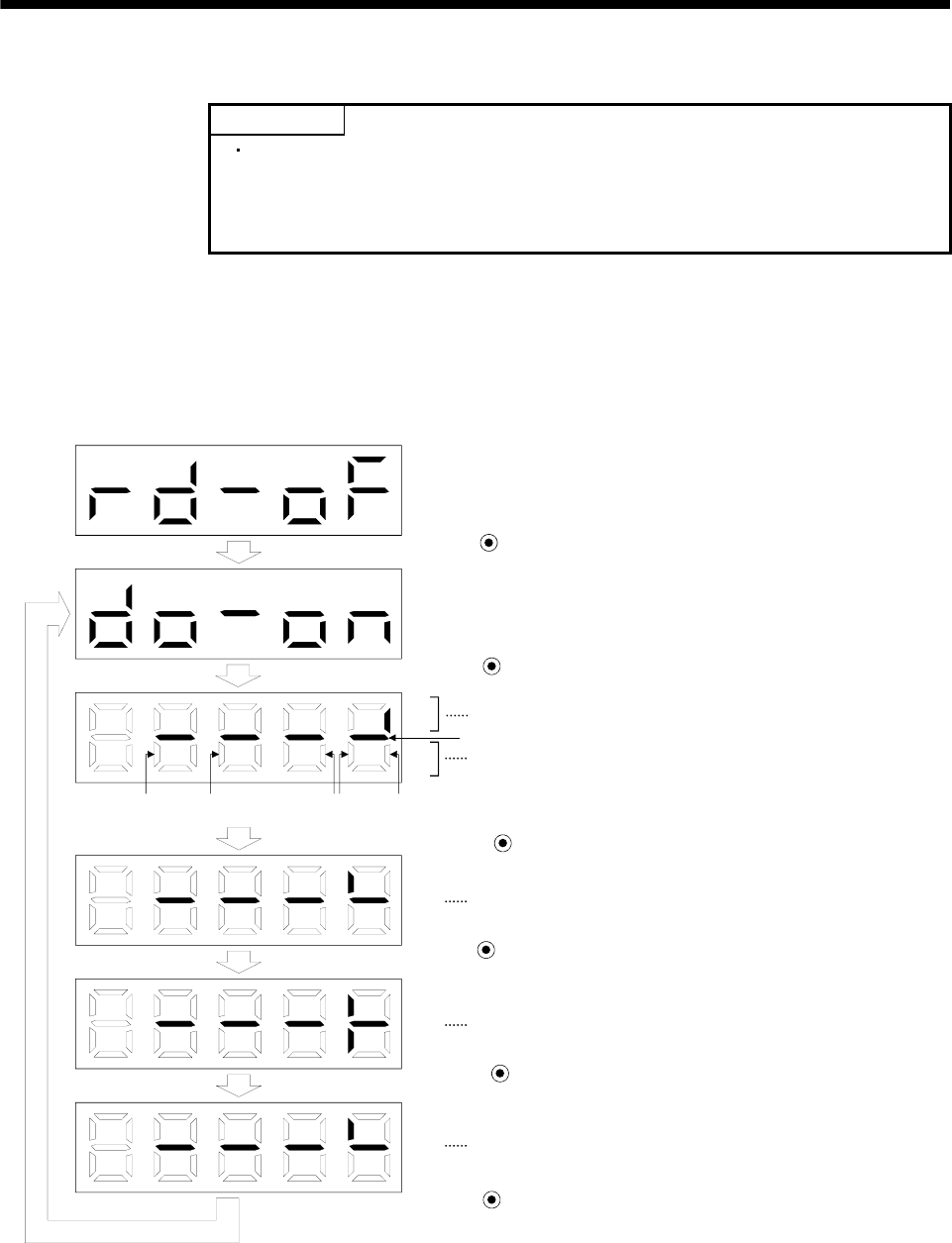
6. DISPLAY AND OPERATION
6.7 Output signal (DO) forced output
POINT
When the servo system is used in a vertical lift application, turning on the
electromagnetic brake interlock (MBR) after assigning it to pin CN1-12 will
release the electromagnetic brake, causing a drop. Take drop preventive
measures on the machine side.
The output signal can be forced on/off independently of the servo status. This function is used for output signal
wiring check, etc. This operation must be performed in the servo off state.
Operation
Call the display screen shown after power-on.
Using the "MODE" button, show the diagnostic screen.
Press UP twice.
Press SET for more than 2 seconds.
Switch on/off the signal below the lit segment.
Indicates the ON/OFF of the output signal. The correspondences
between segments and signals are as in the output signals of the
external I/O signal display.
(Lit: ON, extinguished: OFF)
Press MODE once.
The segment above CN1-pin 10 is lit.
Press UP once.
CN1-pin 10 is switched on.
(CN1-pin 10-VIN conduct.)
Press DOWN once.
CN1-pin 10 is switched off.
Press SET for more than seconds.
CN1
12 CN1
9CN1
12 CN1
10 CN1
11
Always lit
6 - 10
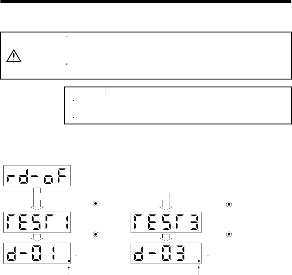
6 - 11
6. DISPLAY AND OPERATION
6.8 Test operation mode
CAUTION
The test operation mode is designed to confirm servo operation and not to confirm
machine operation. In this mode, do not use the servo motor with the machine.
Always use the servo motor alone.
If any operational fault has occurred, stop operation using the emergency stop
(EMG) signal.
POINT
The MR Configurator (servo configuration software) is required to perform
positioning operation.
Test operation cannot be performed if the servo-on (SON) is not turned OFF.
6.8.1 Mode change
After power-on, change the display to the diagnostic screen using the "MODE" button. Choose jog
operation/motor-less operation in the following procedure.
When this screen
appears, jog feed can
be performed.
(Refer to section 6.8.2)
Press UP three times.
Press SET for more than 2s.
Flickers in the test operation mode.
Press UP five times.
Press SET for more than 2s.
When this screen is displayed,
motor-less operation can be
performed.
(Refer to section 6.8.4)
<JOG operation stand-by
screen> <Motor-less operation stand-by screen>
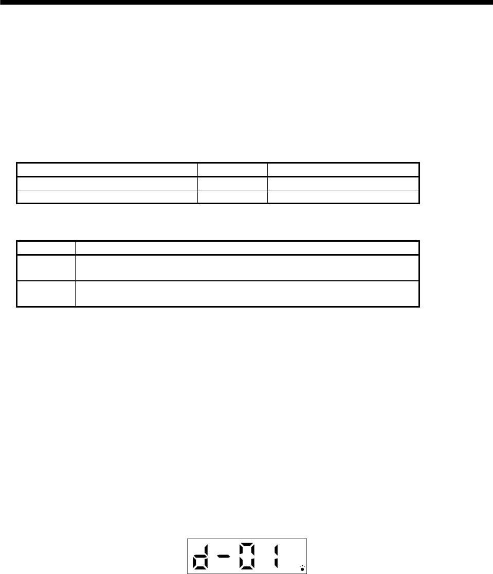
6. DISPLAY AND OPERATION
6.8.2 Jog operation
Jog operation can be performed when there is no command from the external command device.
(1) Operation
Connect EMG-VIN to start jog operation to use the internal power supply.
Hold down the "UP" or "DOWN" button to run the servo motor. Release it to stop. When using the MR
Configurator (servo configuration software), you can change the operation conditions. The initial conditions
and setting ranges for operation are listed below.
Item Initial setting Setting range
Speed [r/min] 200 0 to instantaneous permissible speed
Acceleration/deceleration time constant [ms] 1000 0 to 50000
How to use the buttons is explained below.
Button Description
"UP" Press to start CCW rotation.
Release to stop.
"DOWN" Press to start CW rotation.
Release to stop.
If the communication cable is disconnected during jog operation performed by using the MR Configurator
(servo configuration software), the servo motor will be decelerated to a stop.
(2) Status display
You can confirm the servo status during jog operation.
Pressing the "MODE" button in the jog operation-ready status calls the status display screen. With this
screen being shown, perform jog operation with the "UP" or "DOWN" button. Every time you press the
"MODE" button, the next status display screen appears, and on completion of a screen cycle, pressing that
button returns to the jog operation-ready status screen. For full information of the status display, refer to
section 6.2. In the test operation mode, you cannot use the "UP" and "DOWN" buttons to change the status
display screen from one to another.
(3) Termination of jog operation
To end the jog operation, switch power off once or press the "MODE" button to switch to the next screen
and then hold down the "SET" button for 2 or more seconds.
6 - 12
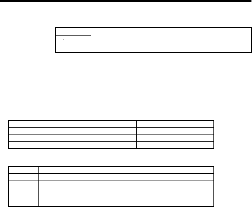
6. DISPLAY AND OPERATION
6.8.3 Positioning operation
POINT
The MR Configurator (servo configuration software) is required to perform
positioning operation.
Positioning operation can be performed once when there is no command from the external command device.
(1) Operation
Connect EMG-VIN to start positioning operation to use the internal power supply.
Click the "Forward" or "Reverse" button on the MR Configurator (servo configuration software) starts the
servo motor, which will then stop after moving the preset travel distance. You can change the operation
conditions on the MR Configurator (servo configuration software). The initial conditions and setting ranges
for operation are listed below.
Item Initial setting Setting range
Travel distance [pulse] 10000 0 to 9999999
Speed [r/min] 200 0 to instantaneous permissible speed
Acceleration/deceleration time constant [ms] 1000 0 to 50000
How to use the buttons is explained below.
Button Description
"Forward" Click to start positioning operation CCW.
"Reverse" Click to start positioning operation CW.
"Pause"
Click during operation to make a temporary stop. Pressing the "Pause" button again erases the
remaining distance.
To resume operation, click the button that was clicked to start the operation.
If the communication cable is disconnected during positioning operation, the servo motor will come to a
sudden stop.
(2) Status display
You can monitor the status display even during positioning operation.
6 - 13

6. DISPLAY AND OPERATION
6 - 14
6.8.4 Motor-less operation
Without connecting the servo motor, you can provide output signals or monitor the status display as if the servo
motor is running in response to external input signals. This operation can be used to check the sequence of a
host programmable controller or the like.
(1) Operation
After turning off the signal across SON-VIN, choose motor-less operation. After that, perform external
operation as in ordinary operation.
(2) Status display
You can confirm the servo status during motor-less operation.
Change the display to the status display screen by pressing the "MODE" button. (Refer to section 6.1.)
The status display screen can be changed by pressing the "UP" or the "DOWN" button. (Refer to section
6.2.)
(3) Termination of motor-less operation
To terminate the motor-less operation, switch power off.
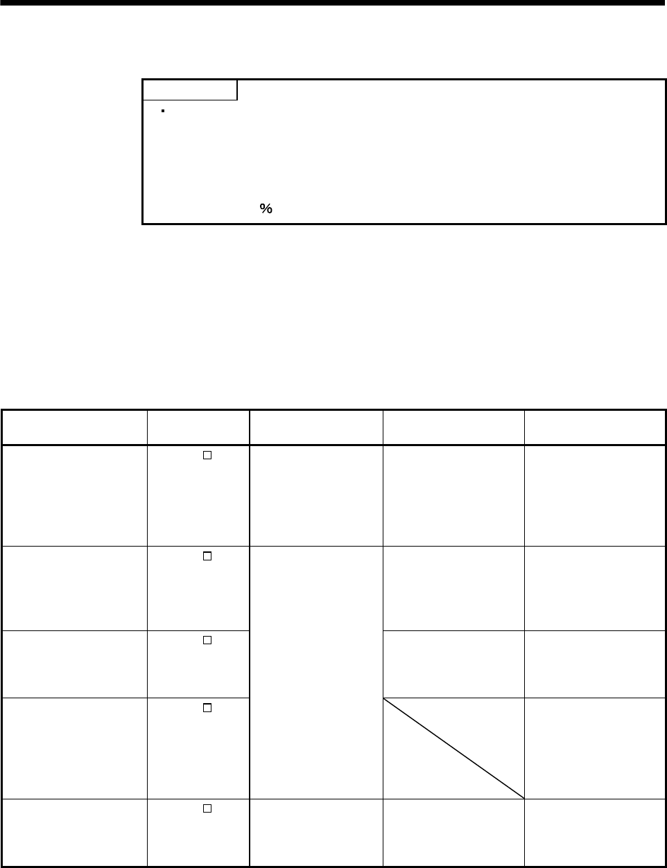
7. GENERAL GAIN ADJUSTMENT
7. GENERAL GAIN ADJUSTMENT
POINT
For the gain adjustment, check that the machine operates below the maximum
torque of the servo motor. If the machine operates beyond the maximum torque
of the servo motor, the machine may perform unexpected operation such as the
machine vibration. Make the gain adjustment with a safety margin considering
characteristic differences of each machine. Generated torque during operation
must be the 90 maximum torque or less of the servo motor.
7.1 Different adjustment methods
7.1.1 Adjustment on a single servo amplifier
The gain adjustment in this section can be made on a single servo amplifier. For gain adjustment, first execute
auto tuning mode 1. If you are not satisfied with the results, execute auto tuning mode 2, manual mode 1 and
manual mode 2 in this order.
(
1) Gain adjustment mode explanation
Gain adjustment mode Parameter No.2
setting
Estimation of load inertia
moment ratio
Automatically set
parameters Manually set parameters
Auto tuning mode 1
(initial value)
010 Always estimated PG1 (parameter No.6)
GD2 (parameter No.34)
PG2 (parameter No.35)
VG1 (parameter No.36)
VG2 (parameter No.37)
VIC (parameter No.38)
Response level setting of
parameter No.2
Auto tuning mode 2 020 PG1 (parameter No.6)
PG2 (parameter No.35)
VG1 (parameter No.36)
VG2 (parameter No.37)
VIC (parameter No.38)
GD2 (parameter No.34)
Response level setting of
parameter No.2
Manual mode 1 030 PG2 (parameter No.35)
VG1 (parameter No.36)
PG1 (parameter No.6)
GD2 (parameter No.34)
VG2 (parameter No.37)
VIC (parameter No.38)
Manual mode 2 040
Fixed to parameter No.34
value
PG1 (parameter No.6)
GD2 (parameter No.34)
PG2 (parameter No.35)
VG1 (parameter No.36)
VG2 (parameter No.37)
VIC (parameter No.38)
Interpolation mode 000 Always estimated GD2 (parameter No.34)
PG2 (parameter No.35)
VG2 (parameter No.37)
VIC (parameter No.38)
PG1 (parameter No.6)
VG1 (parameter No.36)
7 - 1
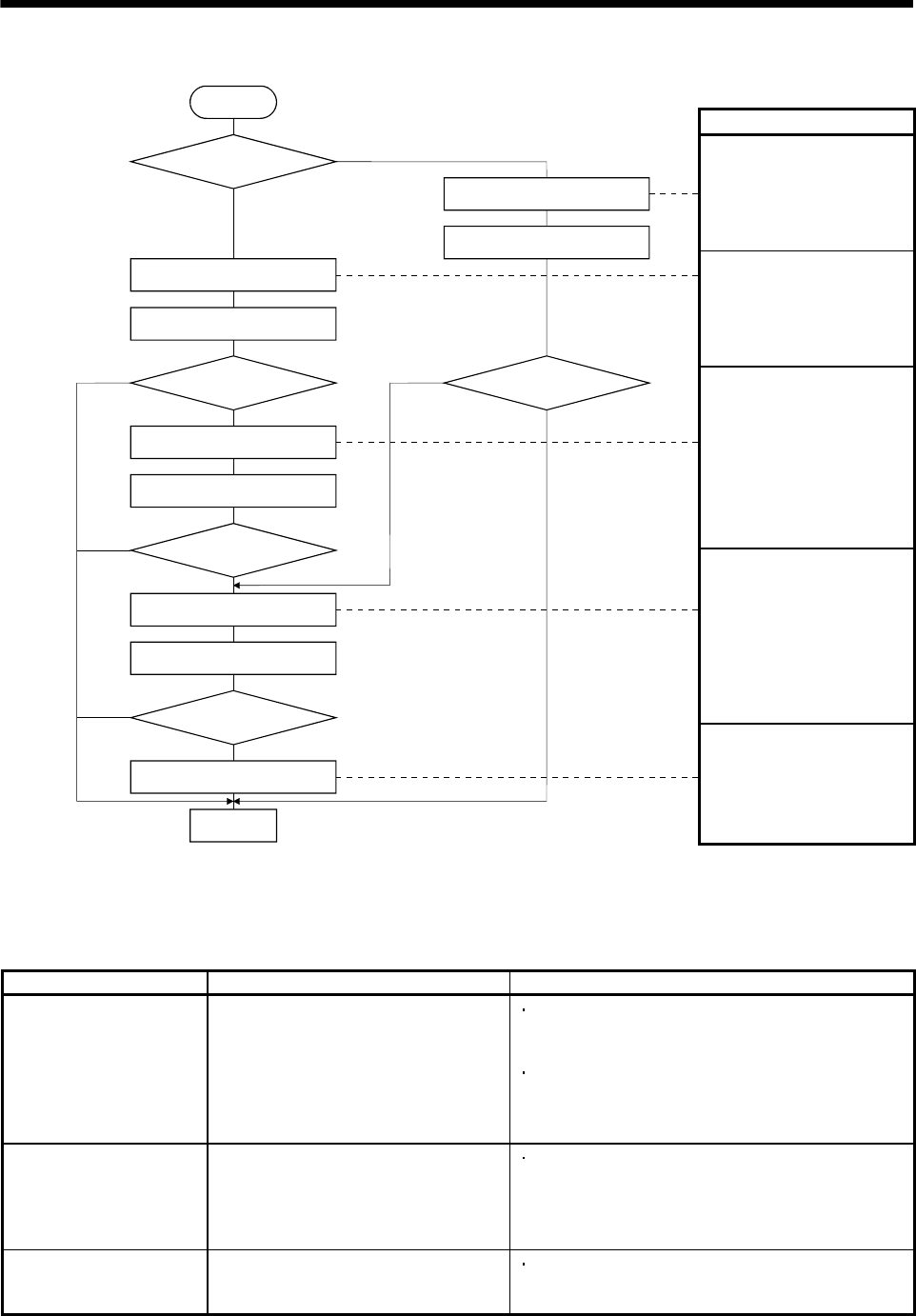
7. GENERAL GAIN ADJUSTMENT
(2) Adjustment sequence and mode usage
Usage
Used when you want to match
the position gain (PG1)
between 2 or more axes.
Normally not used for other
purposes.
Allows adjustment by merely
changing the response level
setting.
First use this mode to make
adjustment.
Used when the conditions of
auto tuning mode 1 are not
met and the load inertia
moment ratio could not be
estimated properly, for
example.
This mode permits adjustment
easily with three gains if you
were not satisfied with auto
tuning results.
START
Interpolation
made for 2 or more
axes?
7 - 2
END
Operation
Auto tuning mode 2
OK?
Manual mode 1
OK?
Manual mode 2
OK?
OK?
No
No
Yes
No
Yes
No
Yes
No
Yes
Auto tuning mode 1
Operation
Interpolation mode
Operation
Operation
Yes
You can adjust all gains
manually when you want to do
fast settling or the like.
7.1.2 Adjustment using MR Configurator (servo configuration software)
This section gives the functions and adjustment that may be performed by using the servo amplifier with the
MR Configurator (servo configuration software) which operates on a personal computer.
Function Description Adjustment
Machine analyzer With the machine and servo motor coupled,
the characteristic of the mechanical system
can be measured by giving a random
vibration command from the personal
computer to the servo and measuring the
machine response.
You can grasp the machine resonance frequency and
determine the notch frequency of the machine resonance
suppression filter.
You can automatically set the optimum gains in response
to the machine characteristic. This simple adjustment is
suitable for a machine which has large machine
resonance and does not require much settling time.
Gain search Executing gain search under to-and-fro
positioning command measures settling
characteristic while simultaneously
changing gains, and automatically searches
for gains which make settling time shortest.
You can automatically set gains which make positioning
settling time shortest.
Machine simulation Response at positioning settling of a
machine can be simulated from machine
analyzer results on personal computer.
You can optimize gain adjustment and command pattern
on personal computer.
7 - 3
7. GENERAL GAIN ADJUSTMENT
7.2 Auto tuning
7.2.1 Auto tuning mode
The servo amplifier has a real-time auto tuning function which estimates the machine characteristic (load
inertia moment ratio) in real time and automatically sets the optimum gains according to that value. This
function permits ease of gain adjustment of the servo amplifier.
(1) Auto tuning mode 1
The servo amplifier is factory-set to the auto tuning mode 1.
In this mode, the load inertia moment ratio of a machine is always estimated to set the optimum gains
automatically.
The following parameters are automatically adjusted in the auto tuning mode 1.
Parameter No. Abbreviation Name
6 PG1 Position control gain 1
34 GD2 Ratio of load inertia moment to servo motor inertia moment
35 PG2 Position control gain 2
36 VG1 Speed control gain 1
37 VG2 Speed control gain 2
38 VIC Speed integral compensation
POINT
The auto tuning mode 1 may not be performed properly if the following
conditions are not satisfied.
Time to reach 2000r/min is the acceleration/deceleration time constant of 5s or
less.
Speed is 150r/min or higher.
The load to motor inertia moment ratio is 100 times or less.
The acceleration/deceleration torque is 10 or more of the rated torque.
Under operating conditions which will impose sudden disturbance torque during
acceleration/deceleration or on a machine which is extremely loose, auto tuning
may not function properly, either. In such cases, use the auto tuning mode 2 or
manual mode 1,2 to make gain adjustment.
(2) Auto tuning mode 2
Use the auto tuning mode 2 when proper gain adjustment cannot be made by auto tuning mode 1. Since
the load inertia moment ratio is not estimated in this mode, set the value of a correct load inertia moment
ratio (parameter No.34).
The following parameters are automatically adjusted in the auto tuning mode 2.
Parameter No. Abbreviation Name
6 PG1 Position control gain 1
35 PG2 Position control gain 2
36 VG1 Speed control gain 1
37 VG2 Speed control gain 2
38 VIC Speed integral compensation
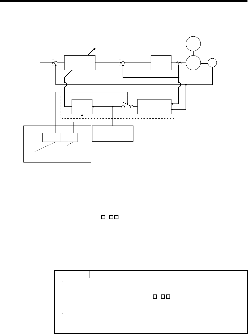
7. GENERAL GAIN ADJUSTMENT
7.2.2 Auto tuning mode basis
The block diagram of real-time auto tuning is shown below.
Servo
motor
Command
Automatic setting
Control gains
PG1,VG1
PG2,VG2,VIC
Current
control
Current feedback
Load inertia
moment
Encoder
Position/speed
feedback
Real-time auto
tuning section
Speed feedback
Load inertia
moment ratio
estimation section
Gain
table
Parameter No. 2
Gain adjustment
mode selection
First digit
Response level
setting
Parameter No. 34
Load inertia moment
ratio estimation value
Set 0 or 1 to turn on.
Switch
When a servo motor is accelerated/decelerated, the load inertia moment ratio estimation section always
estimates the load inertia moment ratio from the current and speed of the servo motor. The results of
estimation are written to parameter No.34 (the ratio of load inertia moment to servo motor). These results can
be confirmed on the status display screen of the MR Configurator (servo configuration software) section.
If the value of the load inertia moment ratio is already known or if estimation cannot be made properly, chose
the "auto tuning mode 2" (parameter No.2: 2) to stop the estimation of the load inertia moment ratio
(Switch in above diagram turned off), and set the load inertia moment ratio (parameter No.34) manually.
From the preset load inertia moment ratio (parameter No.34) value and response level (The first digit of
parameter No.2), the optimum control gains are automatically set on the basis of the internal gain tale.
The auto tuning results are saved in the EEP-ROM of the servo amplifier every 60 minutes since power-on. At
power-on, auto tuning is performed with the value of each control gain saved in the EEP-ROM being used as
an initial value.
POINT
If sudden disturbance torque is imposed during operation, the estimation of the
inertia moment ratio may malfunction temporarily. In such a case, choose the
"auto tuning mode 2" (parameter No.2: 2) and set the correct load inertia
moment ratio in parameter No.34.
When any of the auto tuning mode 1, auto tuning mode 2 and manual mode 1
settings is changed to the manual mode 2 setting, the current control gains and
load inertia moment ratio estimation value are saved in the EEP-ROM.
7 - 4
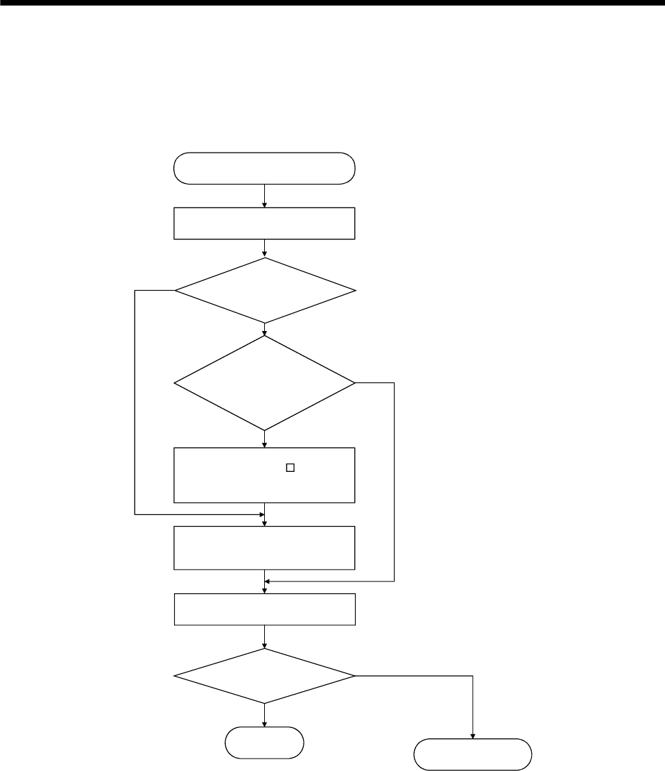
7. GENERAL GAIN ADJUSTMENT
7.2.3 Adjustment procedure by auto tuning
Since auto tuning is made valid before shipment from the factory, simply running the servo motor automatically
sets the optimum gains that match the machine. Merely changing the response level setting value as required
completes the adjustment. The adjustment procedure is as follows.
END
Yes
No
Yes
No
No
Yes
Auto tuning adjustment
Acceleration/deceleration repeated
Load inertia moment ratio
estimation value stable?
Auto tuning
conditions not satisfied.
(Estimation of load inertia
moment ratio is difficult)
Adjust response level setting
so that desired response is
achieved on vibration-free level.
Acceleration/deceleration repeated
Requested
performance satisfied?
To manual mode
Choose the auto tuning mode 2
(parameter No.2: 020 ) and set
the load inertia moment ratio
(parameter No.34) manually.
7 - 5
7. GENERAL GAIN ADJUSTMENT
7.2.4 Response level setting in auto tuning mode
Set the response (The first digit of parameter No.2) of the whole servo system. As the response level setting is
increased, the track ability and settling time for a command decreases, but a too high response level will
generate vibration. Hence, make setting until desired response is obtained within the vibration-free range.
If the response level setting cannot be increased up to the desired response because of machine resonance
beyond 100Hz, adaptive vibration suppression control (parameter No.60) or machine resonance suppression
filter (parameter No.58 59) may be used to suppress machine resonance. Suppressing machine resonance
may allow the response level setting to increase. Refer to section 8.2, 8.3 for adaptive vibration suppression
control and machine resonance suppression filter.
Parameter No.2
Response level setting
Gain adjustment mode selection
Machine characteristic
Response level setting Machine rigidity Machine resonance
frequency guideline Guideline of corresponding machine
1 Low 15Hz
2 20Hz
3 25Hz
4 30Hz
5 35Hz
6 45Hz
7 55Hz
8 Middle 70Hz
9 85Hz
A 105Hz
B 130Hz
C 160Hz
D 200Hz
E 240Hz
F High 300Hz
Large conveyor
Arm robot
General machine
tool conveyor
Precision
working
machine
Inserter
Mounter
Bonder
7 - 6
7. GENERAL GAIN ADJUSTMENT
7.3 Manual mode 1 (simple manual adjustment)
If you are not satisfied with the adjustment of auto tuning, you can make simple manual adjustment with three
parameters.
7.3.1 Manual Mode 1 basis
In this mode, setting the three gains of position control gain 1 (PG1), speed control gain 2 (VG2) and speed
integral compensation (VIC) automatically sets the other gains to the optimum values according to these gains.
PG1
VG2
VIC
PG2
VG1
GD2
Automatic setting
User setting
Therefore, you can adjust the model adaptive control system in the same image as the general PI control
system (position gain, speed gain, speed integral time constant). Here, the position gain corresponds to PG1,
the speed gain to VG2 and the speed integral time constant to VIC. When making gain adjustment in this
mode, set the load inertia moment ratio (parameter No.34) correctly.
7.3.2 Adjustment by manual mode 1
POINT
If machine resonance occurs, adaptive vibration suppression control (parameter
No.60) or machine resonance suppression filter (parameter No.58 59) may be
used to suppress machine resonance. (Refer to section 8.2, 8.3.)
(1) For speed control
(a) Parameters
The following parameters are used for gain adjustment.
Parameter No. Abbreviation Name
34 GD2 Ratio of load inertia moment to servo motor inertia moment
37 VG2 Speed control gain 2
38 VIC Speed integral compensation
(b) Adjustment procedure
Step Operation Description
1 Set an estimated value to the ratio of load inertia moment to servo motor
inertia moment (parameter No.34).
2 Increase the speed control gain 2 (parameter No.37) within the vibration-
and unusual noise-free range, and return slightly if vibration takes place.
Increase the speed control gain.
3 Decrease the speed integral compensation (parameter No.38) within the
vibration-free range, and return slightly if vibration takes place.
Decrease the time constant of the speed
integral compensation.
4
If the gains cannot be increased due to mechanical system resonance or
the like and the desired response cannot be achieved, response may be
increased by suppressing resonance with adaptive vibration suppression
control or machine resonance suppression filter and then executing steps 2
and 3.
Suppression of machine resonance.
Refer to section 8.2, 8.3.
7 - 7
7. GENERAL GAIN ADJUSTMENT
(c)Adjustment description
1) Speed control gain 2 (parameter No.37)
This parameter determines the response level of the speed control loop. Increasing this value
enhances response but a too high value will make the mechanical system liable to vibrate. The
actual response frequency of the speed loop is as indicated in the following expression.
Speed control gain 2 setting
(1 ratio of load inertia moment to servo motor inertia moment) 2
Speed loop response
frequency(Hz)
2) Speed integral compensation (VIC: parameter No.38)
To eliminate stationary deviation against a command, the speed control loop is under proportional
integral control. For the speed integral compensation, set the time constant of this integral control.
Increasing the setting lowers the response level. However, if the load inertia moment ratio is large or
the mechanical system has any vibratory element, the mechanical system is liable to vibrate unless
the setting is increased to some degree. The guideline is as indicated in the following expression.
Speed control gain 2 setting/(1 ratio of load inertia moment to
servo motor inertia moment setting 0.1)
2000 to 3000
Speed integral compensation
setting(ms)
(2) For position control
(a) Parameters
The following parameters are used for gain adjustment.
Parameter No. Abbreviation Name
6 PG1 Position control gain 1
34 GD2 Ratio of load inertia moment to servo motor inertia moment
37 VG2 Speed control gain 2
38 VIC Speed integral compensation
(b) Adjustment procedure
Step Operation Description
1 Set an estimated value to the ratio of load inertia moment to servo motor
inertia moment (parameter No.34).
2 Set a slightly smaller value to the position control gain 1 (parameter No.6).
3 Increase the speed control gain 2 (parameter No.37) within the vibration-
and unusual noise-free range, and return slightly if vibration takes place.
Increase the speed control gain.
4 Decrease the speed integral compensation (parameter No.38) within the
vibration-free range, and return slightly if vibration takes place.
Decrease the time constant of the speed
integral compensation.
5 Increase the position control gain 1 (parameter No.6). Increase the position control gain.
6
If the gains cannot be increased due to mechanical system resonance or
the like and the desired response cannot be achieved, response may be
increased by suppressing resonance with adaptive vibration suppression
control or machine resonance suppression filter and then executing steps 3
to 5.
Suppression of machine resonance.
Refer to section 8.2, 8.3.
7 While checking the settling characteristic and rotational status, fine-adjust
each gain.
Fine adjustment
7 - 8
7. GENERAL GAIN ADJUSTMENT
(c) Adjustment description
1) Position control gain 1 (parameter No.6)
This parameter determines the response level of the position control loop. Increasing position control
gain 1 improves track ability to a position command but a too high value will make overshooting liable
to occur at the time of settling.
(1 ratio of load inertia moment to servo motor inertia moment)
1
3
1
5
to
Speed control gain 2 setting
Position control
gain 1 guideline
2) Speed control gain 2 (VG2: parameter No.37)
This parameter determines the response level of the speed control loop. Increasing this value
enhances response but a too high value will make the mechanical system liable to vibrate. The actual
response frequency of the speed loop is as indicated in the following expression.
Speed control gain 2 setting
(1 ratio of load inertia moment to servo motor inertia moment) 2
Speed loop response
frequency(Hz)
3) Speed integral compensation (parameter No.38)
To eliminate stationary deviation against a command, the speed control loop is under proportional
integral control. For the speed integral compensation, set the time constant of this integral control.
Increasing the setting lowers the response level. However, if the load inertia moment ratio is large or
the mechanical system has any vibratory element, the mechanical system is liable to vibrate unless
the setting is increased to some degree. The guideline is as indicated in the following expression.
Speed control gain 2 setting/(1 ratio of load inertia moment to
servo motor inertia moment 2 setting 0.1)
2000 to 3000
Speed integral compensation
setting(ms)
7 - 9
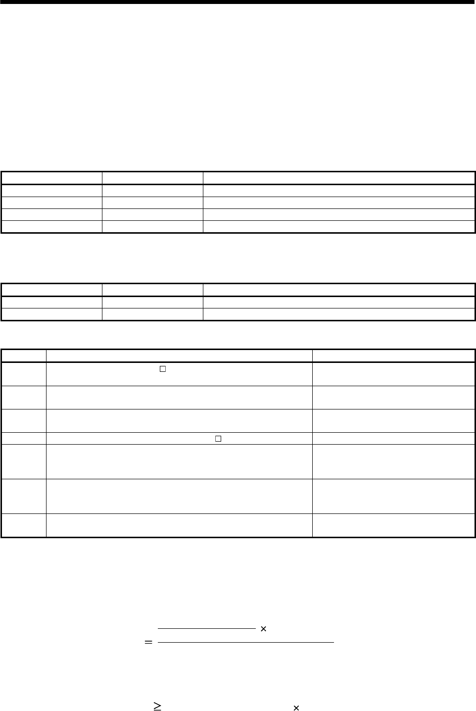
7. GENERAL GAIN ADJUSTMENT
7.4 Interpolation mode
The interpolation mode is used to match the position control gains of the axes when performing the
interpolation operation of servo motors of two or more axes for an X-Y table or the like. In this mode, the
position control gain 2 and speed control gain 2 which determine command track ability are set manually and
the other parameter for gain adjustment are set automatically.
(1) Parameter
(a) Automatically adjusted parameters
The following parameters are automatically adjusted by auto tuning.
Parameter No. Abbreviation Name
34 GD2 Ratio of load inertia moment to servo motor inertia moment
35 PG2 Position control gain 2
37 VG2 Speed control gain 2
38 VIC Speed integral compensation
(b) Manually adjusted parameters
The following parameters are adjustable manually.
Parameter No. Abbreviation Name
6 PG1 Position control gain 1
36 VG1 Speed control gain 1
(2) Adjustment procedure
Step Operation Description
1 Set 15Hz (parameter No.2: 010 ) as the machine resonance frequency of
response in the auto tuning mode 1. Select the auto tuning mode 1.
2 During operation, increase the response level setting (parameter No.2), and
return the setting if vibration occurs. Adjustment in auto tuning mode 1.
3 Check the values of position control gain 1 (parameter No.6) and speed
control gain 1 (parameter No.36). Check the upper setting limits.
4 Set the interpolation mode (parameter No.2: 000 ). Select the interpolation mode.
5
Using the position control gain 1 value checked in step 3 as the guideline of
the upper limit, set in PG1 the value identical to the position loop gain of the
axis to be interpolated.
Set position control gain 1.
6
Using the speed control gain 1 value checked in step 3 as the guideline of
the upper limit, look at the rotation status and set in speed control gain 1 the
value three or more times greater than the position control gain 1 setting.
Set speed control gain 1.
7 Looking at the interpolation characteristic and rotation status, fine-adjust the
gains and response level setting. Fine adjustment.
(3) Adjustment description
(a) Position control gain 1 (parameter No.6)
This parameter determines the response level of the position control loop. Increasing position control
gain 1 improves track ability to a position command but a too high value will make overshooting liable to
occur at the time of settling. The droop pulse value is determined by the following expression.
Position control gain 1 setting
60 131,072(pulse)
Droop pulse value (pulse)
Rotation speed (r/min)
(b) Speed control gain 1 (parameter No.36)
Set the response level of the speed loop of the model. Make setting using the following expression as a
guideline.
Speed control gain 1 setting Position control gain 1 setting 3
7 - 10
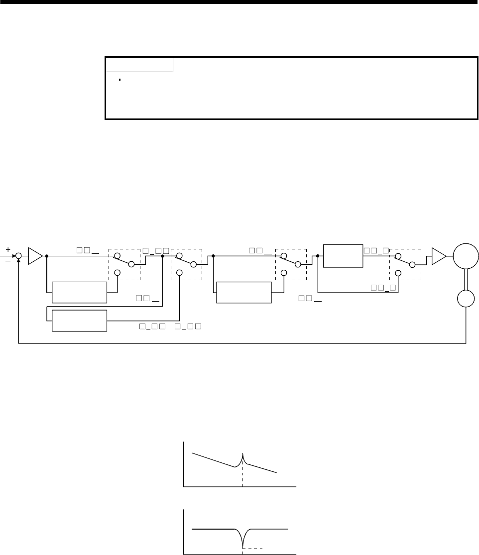
8 - 1
8. SPECIAL
A
DJUSTMENT FUNCTIONS
8. SPECIAL ADJUSTMENT FUNCTIONS
POINT
The functions given in this chapter need not be used generally. Use them if you
are not satisfied with the machine status after making adjustment in the
methods in chapter 7.
If a mechanical system has a natural resonance level point, increasing the servo system response may cause
the mechanical system to produce resonance (vibration or unusual noise) at that resonance frequency.
Using the machine resonance suppression filter and adaptive vibration suppression control functions can
suppress the resonance of the mechanical system.
8.1 Function block diagram
Speed
control
Machine resonance
suppression filter 2
Encoder
Current
command
Low-pass
filter
Parameter
No.58
Parameter
No.60 Parameter
No.59 Parameter
No.60
Machine resonance
suppression filter 1
Adaptive vibration
suppression control
00
or1 2
000 0
1
00
except 00
except
Servo
motor
8.2 Machine resonance suppression filter
(1) Function
The machine resonance suppression filter is a filter function (notch filter) which decreases the gain of the
specific frequency to suppress the resonance of the mechanical system. You can set the gain decreasing
frequency (notch frequency) and gain decreasing depth.
Mechanical
system
response
level
Machine resonance point
Frequency
Notch
depth
Notch frequency Frequency
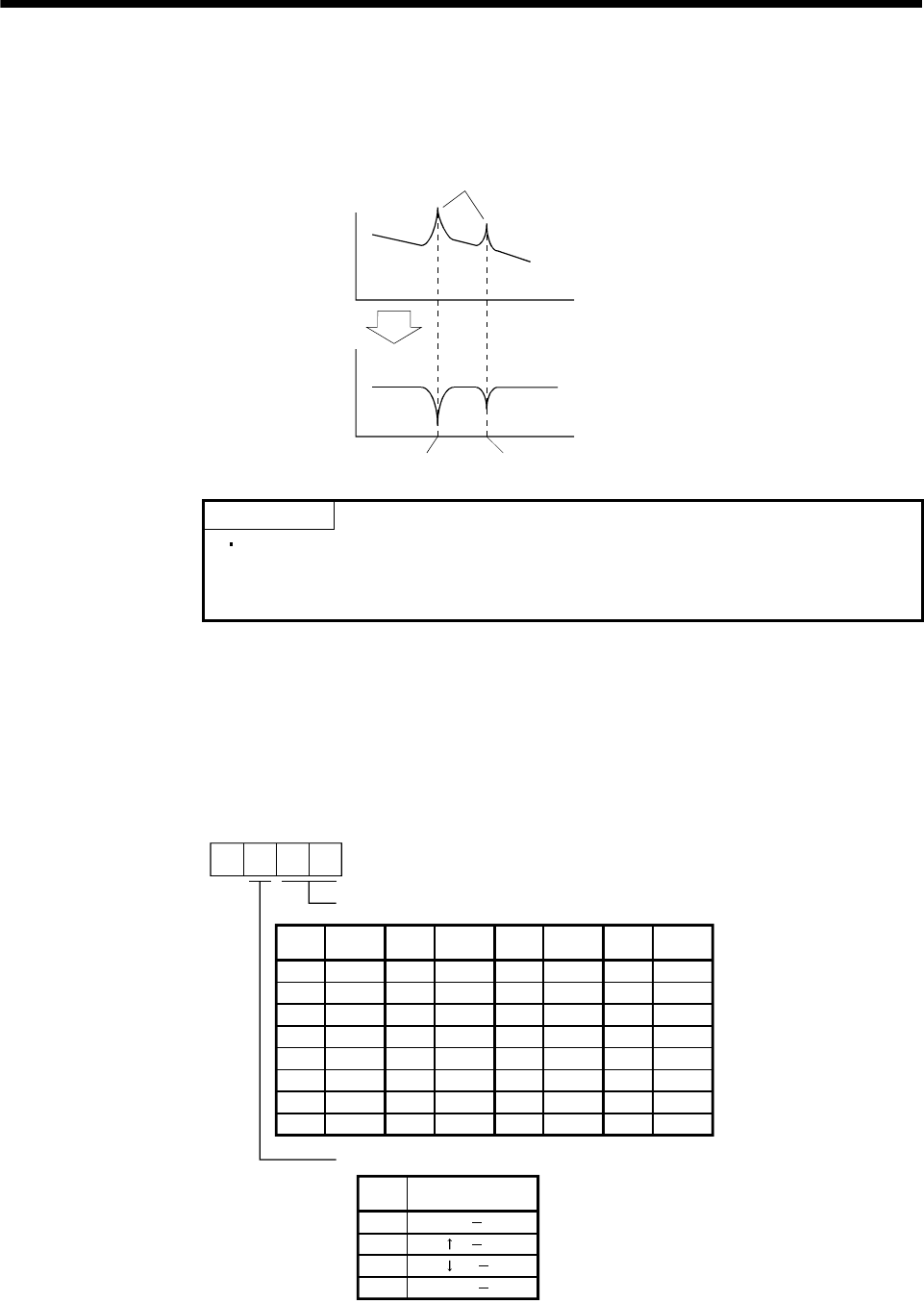
8. SPECIAL ADJUSTMENT FUNCTIONS
You can use the machine resonance suppression filter 1 (parameter No.58) and machine resonance
suppression filter 2 (parameter No.59) to suppress the vibration of two resonance frequencies. Note that if
adaptive vibration suppression control is made valid, the machine resonance suppression filter 1
(parameter No.58) is made invalid.
Mechanical
system
response
level
Machine resonance point
Frequency
Notch
depth
Parameter No. 58 Parameter No. 59
Frequency
POINT
The machine resonance suppression filter is a delay factor for the servo
system. Hence, vibration may increase if you set a wrong resonance frequency
or a too deep notch.
(2) Parameters
(a) Machine resonance suppression filter 1 (parameter No.58)
Set the notch frequency and notch depth of the machine resonance suppression filter 1 (parameter
No.58)
When you have made adaptive vibration suppression control selection (parameter No.60) "valid" or
"held", make the machine resonance suppression filter 1 invalid (parameter No.58: 0000).
Depth (Gain)
Setting
value Frequency Setting
value Frequency Setting
value
Setting
value
Parameter No.58
Notch frequency
Frequency Frequency
08
09
0A
0B
0C
0D
0E
0F
10
11
12
13
14
15
16
17
18
19
1A
1B
1C
1D
1E
1F
00
01
02
03
04
05
06
07
Invalid
4500
2250
1500
1125
900
750
642.9
500
450
409.1
300
321.4
346.2
375
562.5 281.3
264.7
250
236.8
225
214.3
204.5
195.7
187.5
180
173.1
166.7
160.1
155.2
145.2
150
Notch depth
Setting
value
00
00
00
00
Deep ( 40dB)
( 14dB)
( 8dB)
Shallow( 4dB)
8 - 2
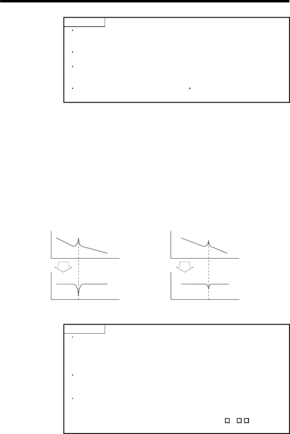
8. SPECIAL ADJUSTMENT FUNCTIONS
POINT
If the frequency of machine resonance is unknown, decrease the notch
frequency from higher to lower ones in order. The optimum notch frequency is
set at the point where vibration is minimal.
A deeper notch has a higher effect on machine resonance suppression but
increases a phase delay and may increase vibration.
The machine characteristic can be grasped beforehand by the machine
analyzer on the MR Configurator (servo configuration software). This allows the
required notch frequency and depth to be determined.
Resonance may occur if parameter No.58 59 is used to select a close notch
frequency and set a deep notch.
(b) Machine resonance suppression filter 2 (parameter No.59)
The setting method of machine resonance suppression filter 2 (parameter No.59) is the same as that of
machine resonance suppression filter 1 (parameter No.58). However, the machine resonance
suppression filter 2 can be set independently of whether adaptive vibration suppression control is valid
or invalid.
8.3 Adaptive vibration suppression control
(1) Function
Adaptive vibration suppression control is a function in which the servo amplifier detects machine resonance
and sets the filter characteristics automatically to suppress mechanical system vibration. Since the filter
characteristics (frequency, depth) are set automatically, you need not be conscious of the resonance
frequency of a mechanical system. Also, while adaptive vibration suppression control is valid, the servo
amplifier always detects machine resonance, and if the resonance frequency changes, it changes the filter
characteristics in response to that frequency.
Mechanical
system
response
level
Mechanical
system
response
level
Machine resonance point Machine resonance point
Frequency Frequenc
y
Notch
depth
Notch
depth
Notch frequency Notch frequency
Frequency Frequenc
y
When machine resonance is large and frequency is low When machine resonance is small and frequency is high
POINT
The machine resonance frequency which adaptive vibration suppression
control can respond to is about 150 to 500Hz. Adaptive vibration suppression
control has no effect on the resonance frequency outside this range. Use the
machine resonance suppression filter for the machine resonance of such
frequency.
Adaptive vibration suppression control may provide no effect on a mechanical
system which has complex resonance characteristics or which has too large
resonance.
Under operating conditions in which sudden disturbance torque is imposed
during operation, the detection of the resonance frequency may malfunction
temporarily, causing machine vibration. In such a case, set adaptive vibration
suppression control to be "held" (parameter No.60: 2) to fix the
characteristics of the adaptive vibration suppression control filter.
8 - 3
8. SPECIAL ADJUSTMENT FUNCTIONS
(2) Parameters
Set the adaptive vibration suppression control (parameter No.60).
Parameter No.60
Adaptive vibration suppression control selection
Choosing "valid" or "held" in adaptive vibration suppression
control selection makes the machine resonance suppression
filter 1 (parameter No.58) invalid.
0: Invalid
1: Valid
Machine resonance frequency is always detected to
generate the filter in response to resonance, suppressing
machine vibration.
2: Held
Adaptive vibration suppression control sensitivity selection
Set the sensitivity of detecting machine resonance.
0: Normal
1: Large sensitivity
Filter characteristics generated so far is held, and detection of
machine resonance is stopped.
POINT
Adaptive vibration suppression control is factory-set to be invalid (parameter
No.60: 0000).
Setting the adaptive vibration suppression control sensitivity can change the
sensitivity of detecting machine resonance. Setting of "large sensitivity" detects
smaller machine resonance and generates a filter to suppress machine
vibration. However, since a phase delay will also increase, the response of the
servo system may not increase.
8.4 Low-pass filter
(1) Function
When a ball screw or the like is used, resonance of high frequency may occur as the response level of the
servo system is increased. To prevent this, the low-pass filter is factory-set to be valid for a torque
command. The filter frequency of this low-pass filter is automatically adjusted to the value in the following
expression.
Filter frequency(Hz) (1 Ratio of load inertia moment to servo motor inertia moment setting 0.1)
2
Speed control gain 2 setting 10
(2) Parameter
Set the low-pass filter (parameter No.60.)
Parameter No.60
Low-pass filter selection
0: Valid (automatic adjustment) initial value
1: Invalid
POINT
In a mechanical system where rigidity is extremely high and resonance level is
difficult to occur, setting the low-pass filter to be "invalid" may increase the
servo system response level to shorten the settling time.
8 - 4
8. SPECIAL ADJUSTMENT FUNCTIONS
8.5 Gain changing function
This function can change the gains. You can change between gains during rotation and gains during stop or
can use an external input signal to change gains during operation.
8.5.1 Applications
This function is used when.
(1) You want to increase the gains during servo lock but decrease the gains to reduce noise during rotation.
(2) You want to increase the gains during settling to shorten the stop settling time.
(3) You want to change the gains using an external input signal to ensure stability of the servo system since
the load inertia moment ratio varies greatly during a stop (e.g. a large load is mounted on a carrier).
8.5.2 Function block diagram
The valid control gains PG2, VG2, VIC and GD2 of the actual loop are changed according to the conditions
selected by gain changing selection CDP (parameter No.65) and gain changing condition CDS (parameter
No.66).
Valid
GD2 value
Command pulse
frequency
Droop pulses
Model speed
External input
signal CDP
Comparator
Valid
PG2 value
Valid
VG2 value
Valid
VIC value
Changing
PG2 PG2B
100
VIC VICB
100
VG2 VG2B
100
GD2B
Parameter No.61
GD2
Parameter No.34
PG2
Parameter No.35
VG2
Parameter No.37
VIC
Parameter No.38
CDP
Parameter No.65
CDS
Parameter No.66
8 - 5
8. SPECIAL ADJUSTMENT FUNCTIONS
8.5.3 Parameters
When using the gain changing function, always set " 4" in parameter No.2 (auto tuning) to choose the
manual mode of the gain adjustment modes. The gain changing function cannot be used in the auto tuning
mode.
Parameter
No.
Abbrevi
ation Name Unit Description
6 PG1 Position control gain 1 rad/s
36 VG1 Speed control gain 1 rad/s
Position and speed gains of a model used to set the response
level to a command. Always valid.
34 GD2
Ratio of load inertia moment to
servo motor inertia moment
Multiplier
(10 1)
35 PG2 Position control gain 2 rad/s
37 VG2 Speed control gain 2 rad/s
38 VIC Speed integral compensation ms
Control parameters before changing.
61 GD2B
Ratio of load inertia moment to
servo motor inertia moment 2
Multiplier
(10 1)
Used to set the ratio of load inertia moment to servo motor inertia
moment after changing.
62 PG2B
Position control gain 2 changing
ratio Used to set the ratio ( ) of the after-changing position control
gain 2 to position control gain 2.
63 VG2B
Speed control gain 2 changing
ratio Used to set the ratio ( ) of the after-changing speed control gain
2 to speed control gain 2.
64 VICB
Speed integral compensation
changing ratio Used to set the ratio ( ) of the after-changing speed integral
compensation to speed integral compensation.
65 CDP Gain changing selection Used to select the changing condition.
66 CDS Gain changing condition
kpps
pulse
r/min
Used to set the changing condition values.
67 CDT Gain changing time constant ms You can set the filter time constant for a gain change at changing.
8 - 6
8. SPECIAL ADJUSTMENT FUNCTIONS
(1) Parameters No.6, 34 to 38
These parameters are the same as in ordinary manual adjustment. Gain changing allows the values of
ratio of load inertia moment to servo motor inertia moment, position control gain 2, speed control gain 2 and
speed integral compensation to be changed.
(2) Ratio of load inertia moment to servo motor inertia moment 2 (GD2B: parameter No.61)
Set the ratio of load inertia moment to servo motor inertia moment after changing. If the load inertia moment
ratio does not change, set it to the same value as ratio of load inertia moment to servo motor inertia
moment (parameter No.34).
(3) Position control gain 2 changing ratio (parameter No.62), speed control gain 2 changing ratio (parameter
No.63), speed integral compensation changing ratio (parameter No.64)
Set the values of after-changing position control gain 2, speed control gain 2 and speed integral
compensation in ratio ( ). 100 setting means no gain change.
For example, at the setting of position control gain 2 100, speed control gain 2 2000, speed integral
compensation 20 and position control gain 2 changing ratio 180 , speed control gain 2 changing ratio
150 and speed integral compensation changing ratio 80 , the after-changing values are as follows.
Position control gain 2 Position control gain 2 Position control gain 2 changing ratio /100 180rad/s
Speed control gain 2 Speed control gain 2 Speed control gain 2 changing ratio /100 3000rad/s
Speed integral compensation Speed integral compensation Speed integral compensation changing
ratio /100 16ms
(4) Gain changing selection (parameter No.65)
Used to set the gain changing condition. Choose the changing condition in the first digit. If you set "1" here,
you can use the gain changing (CDP) external input signal for gain changing. The gain changing (CDP) can
be assigned to the pins using parameters No.43 to 48.
Parameter No.65
Gain changing selection
Gains are changed in accordance with the settings of
parameters No.61 to 64 under any of the following conditions:
0: Invalid
1: Gain changing (CDP) input is ON
2: Command frequency is equal to higher than parameter No.66 setting
3: Droop pulse value is equal to higher than parameter No.66 setting
4: Servo motor speed is equal to higher than parameter No.66 setting
(5) Gain changing condition (parameter No.66)
When you selected "command frequency", "droop pulses" or "servo motor speed" in gain changing
selection (parameter No.65), set the gain changing level.
The setting unit is as follows.
Gain changing condition Unit
Command frequency kpps
Droop pulses pulse
Servo motor speed r/min
(6) Gain changing time constant (parameter No.67)
You can set the primary delay filter to each gain at gain changing. This parameter is used to suppress
shock given to the machine if the gain difference is large at gain changing, for example.
8 - 7
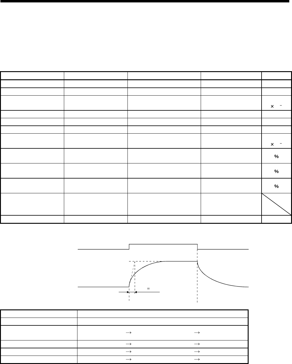
8. SPECIAL ADJUSTMENT FUNCTIONS
8.5.4 Gain changing procedure
This operation will be described by way of setting examples.
(1) When you choose changing by external input
(a) Setting
Parameter No. Abbreviation Name Setting Unit
6 PG1 Position control gain 1 100 rad/s
36 VG1 Speed control gain 1 1000 rad/s
34 GD2
Ratio of load inertia moment to
servo motor inertia moment 4 Multiplier
(10 1)
35 PG2 Position control gain 2 120 rad/s
37 VG2 Speed control gain 2 3000 rad/s
38 VIC Speed integral compensation 20 ms
61 GD2B
Ratio of load inertia moment to
servo motor inertia moment 2 100 Multiplier
(10 1)
62 PG2B
Position control gain 2 changing
ratio 70
63 VG2B
Speed control gain 2 changing
ratio 133
64 VICB
Speed integral compensation
changing ratio 250
65 CDP Gain changing selection
0001
(Changed by ON/OFF of
pin CN1-10)
67 CDT Gain changing time constant 100 ms
(b) Changing timing chart
OFF ON OFF
Gain changing
(CDP)
Change of
each gain
Before-changing gain
After-changing gain
CDT 100ms
Position control gain 1 100
Speed control gain 1 1000
Ratio of load inertia moment
to servo motor inertia moment 4.0 10.0 4.0
Position control gain 2 120 84 120
Speed control gain 2 3000 4000 3000
Speed integral compensation 20 50 20
8 - 8
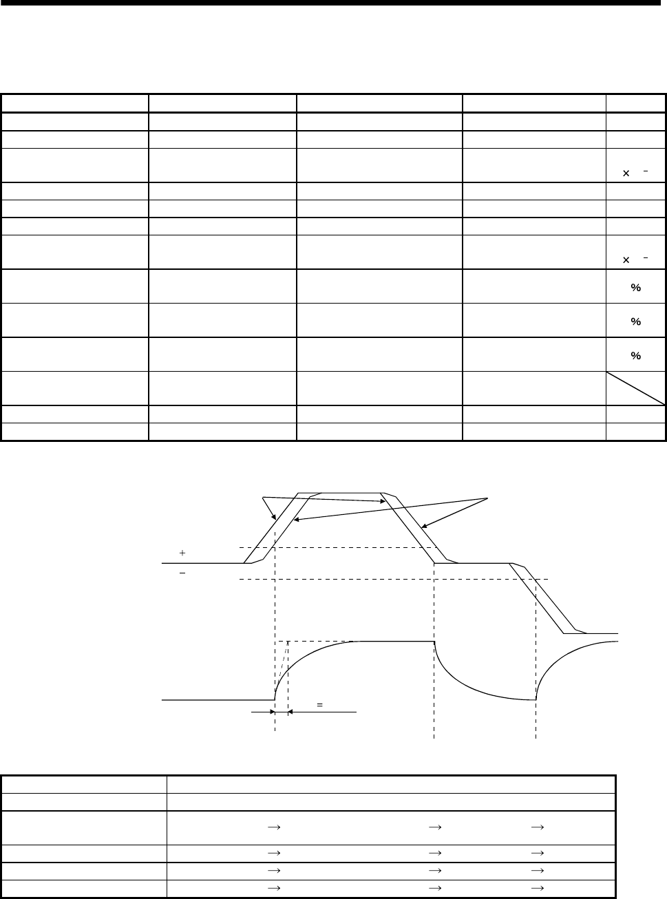
8. SPECIAL ADJUSTMENT FUNCTIONS
(2) When you choose changing by droop pulses
(a) Setting
Parameter No. Abbreviation Name Setting Unit
6 PG1 Position control gain 1 100 rad/s
36 VG1 Speed control gain 1 1000 rad/s
34 GD2
Ratio of load inertia moment to
servo motor inertia moment 40 Multiplier
(10 1)
35 PG2 Position control gain 2 120 rad/s
37 VG2 Speed control gain 2 3000 rad/s
38 VIC Speed integral compensation 20 ms
61 GD2B
Ratio of load inertia moment to
servo motor inertia moment 2 100 Multiplier
(10 1)
62 PG2B
Position control gain 2 changing
ratio 70
63 VG2B
Speed control gain 2 changing
ratio 133
64 VICB
Speed integral compensation
changing ratio 250
65 CDP Gain changing selection 0003
(Changed by droop pulses)
66 CDS Gain changing condition 50 pulse
67 CDT Gain changing time constant 100 ms
(b) Changing timing chart
CDT 100ms
0
Droop pulses [pulses]
Change of each gain
CDS
CDS
Before-changing gain
After-changing gain
Command pulse Droop pulses
Position control gain 1 100
Speed control gain 1 1000
Ratio of load inertia moment
to servo motor inertia moment 4.0 10.0 4.0 10.0
Position control gain 2 120 84 120 84
Speed control gain 2 3000 4000 3000 4000
Speed integral compensation 20 50 20 50
8 - 9

8. SPECIAL ADJUSTMENT FUNCTIONS
8 - 10
MEMO
9. INSPECTION
9. INSPECTION
WARNING
Before starting maintenance and/or inspection, turn off the power and wait for 15
minutes or more until the charge lamp turns off. Otherwise, an electric shock may
occur. In addition, always confirm from the front of the servo amplifier whether the
charge lamp is off or not.
Due to risk of electric shock, only qualified personnel should attempt inspection.
For repair and parts replacement, please contact your local sales office.
CAUTION
Do not perform insulation resistance test on the servo amplifier as damage may
result.
Do not disassemble and/or repair the equipment on customer side.
(1) Inspection
It is recommended to make the following checks periodically.
(a) Check for loose terminal block screws. Retighten any loose screws.
(b) Check the cables and the like for scratches and cracks. Perform periodic inspection according to
operating conditions.
(c) Check the servo motor bearings, brake section, etc. for unusual noise.
(d) Check the cables and the like for scratches and cracks. Perform periodic inspection according to
operating conditions.
(e) Check the servo motor shaft and coupling for misalignment.
(2) Life
The following parts must be changed periodically as listed below. If any part is found faulty, it must be
changed immediately even when it has not yet reached the end of its life, which depends on the operating
method and environmental conditions. For parts replacement, please contact your local sales office.
Part name Life guideline
Smoothing capacitor 10 years
Cooling fan 10,000 to 30,000 hours (2 to 3 years)
Relay Number of power-on and number of
emergency stop times: 100,000 times
Bearings 20,000 to 30,000 hours
Encoder 20,000 to 30,000 hours
Oil seal 5,000 hours
(a) Smoothing capacitor
Affected by ripple currents, etc. and deteriorates in characteristic. The life of the capacitor greatly
depends on ambient temperature and operating conditions. The capacitor will reach the end of its life in
10 years of continuous operation in normal air-conditioned environment.
(b) Relays
Their contacts will wear due to switching currents and contact faults occur. Relays reach the end of their
life when the cumulative number of power-on and emergency stop times is 100,000, which depends on
the power supply capacity.
9 - 1

9. INSPECTION
9 - 2
(c) Servo amplifier cooling fan
The cooling fan bearings reach the end of their life in 10,000 to 30,000 hours. Normally, therefore, the
cooling fan must be changed in a few years of continuous operation as a guideline.
It must also be changed if unusual noise or vibration is found during inspection.
(d) Bearings
When the servo motor is run at rated speed under rated load, change the bearings in 20,000 to 30,000
hours as a guideline. This differs on the operating conditions. The bearings must also be changed if
unusual noise or vibration is found during inspection.
(e) Oil seal, V ring
Must be changed in 5,000 hours of operation at rated speed as a guideline. This differs on the operating
conditions. These parts must also be changed if oil leakage, etc. is found during inspection.
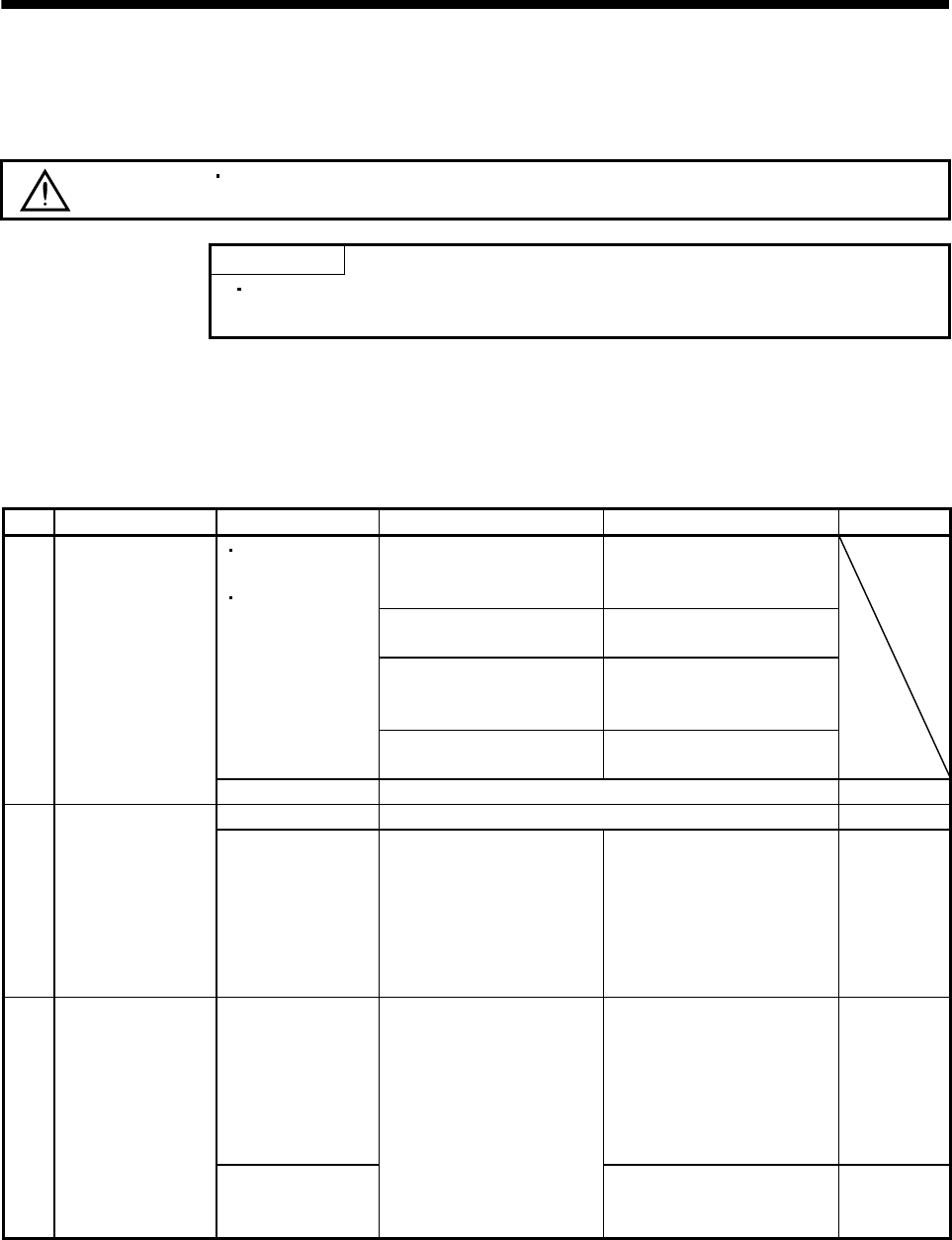
10. TROUBLESHOOTING
10. TROUBLESHOOTING
10.1 Trouble at start-up
CAUTION Excessive adjustment or change of parameter setting must not be made as it will
make operation instable.
POINT
Using the optional MR Configurator (servo configuration software), you can
refer to unrotated servo motor reasons, etc.
The following faults may occur at start-up. If any of such faults occurs, take the corresponding action.
10.1.1 Position control mode
(1) Troubleshooting
No. Start-up sequence Fault Investigation Possible cause Reference
Not improved if connectors
CN1, CN2 and CN3 are
disconnected.
1. Power supply voltage fault
2. Servo amplifier is faulty.
Improved when connectors
CN1 is disconnected.
Power supply of CNP1 cabling
is shorted.
Improved when connector
CN2 is disconnected.
1. Power supply of encoder
cabling is shorted.
2. Encoder is faulty.
Seven-segment
LED is not lit.
Seven-segment
LED flickers.
Improved when connector
CN3 is disconnected.
Power supply of CN3 cabling is
shorted.
1 Power on (Note)
Alarm occurs. Refer to section 10.2 and remove cause. Section 10.2
Alarm occurs. Refer to section 10.2 and remove cause. Section 10.2 2 Switch on servo-on
signal. Servo motor shaft is
not servo-locked
(is free).
1. Check the display to see if
the servo amplifier is ready
to operate.
2. Check the external I/O
signal indication to see if
the servo-on (SON) signal
is ON.
1. Servo-on signal is not input.
(Wiring mistake)
2. 24VDC power is not supplied
to COM.
Section 6.6
Servo motor does not
rotate.
1. Wiring mistake
(a) For open collector pulse
train input, 24VDC power
is not supplied to OPC.
(b) LSP/LSN-VIN are not
connected.
2. No pulses is input.
Section 6.2
3 Enter input
command.
(Test operation)
Servo motor run in
reverse direction.
Check cumulative command
pulses.
1. Mistake in wiring to controller.
2. Mistake in setting of
parameter No.54.
Chapter 5
10 - 1

10. TROUBLESHOOTING
10 - 2
No. Start-up sequence Fault Investigation Possible cause Reference
Rotation ripples
(speed fluctuations)
are large at low
speed.
Make gain adjustment in the
following procedure.
1. Increase the auto tuning
response level.
2. Repeat acceleration and
deceleration several times
to complete auto tuning.
Gain adjustment fault Chapter 7
4 Gain adjustment
Large load inertia
moment causes the
servo motor shaft to
oscillate side to side.
If the servo motor may be run
with safety, repeat
acceleration and deceleration
several times to complete auto
tuning.
Gain adjustment fault Chapter 7
5 Cyclic operation Position shift occurs. Confirm the cumulative
command pulses, cumulative
feedback pulses and actual
servo motor position.
Pulse counting error, etc.
due to noise.
(2) of this
section
Note. Switch power on again after making sure that the charge lamp has turned off completely.
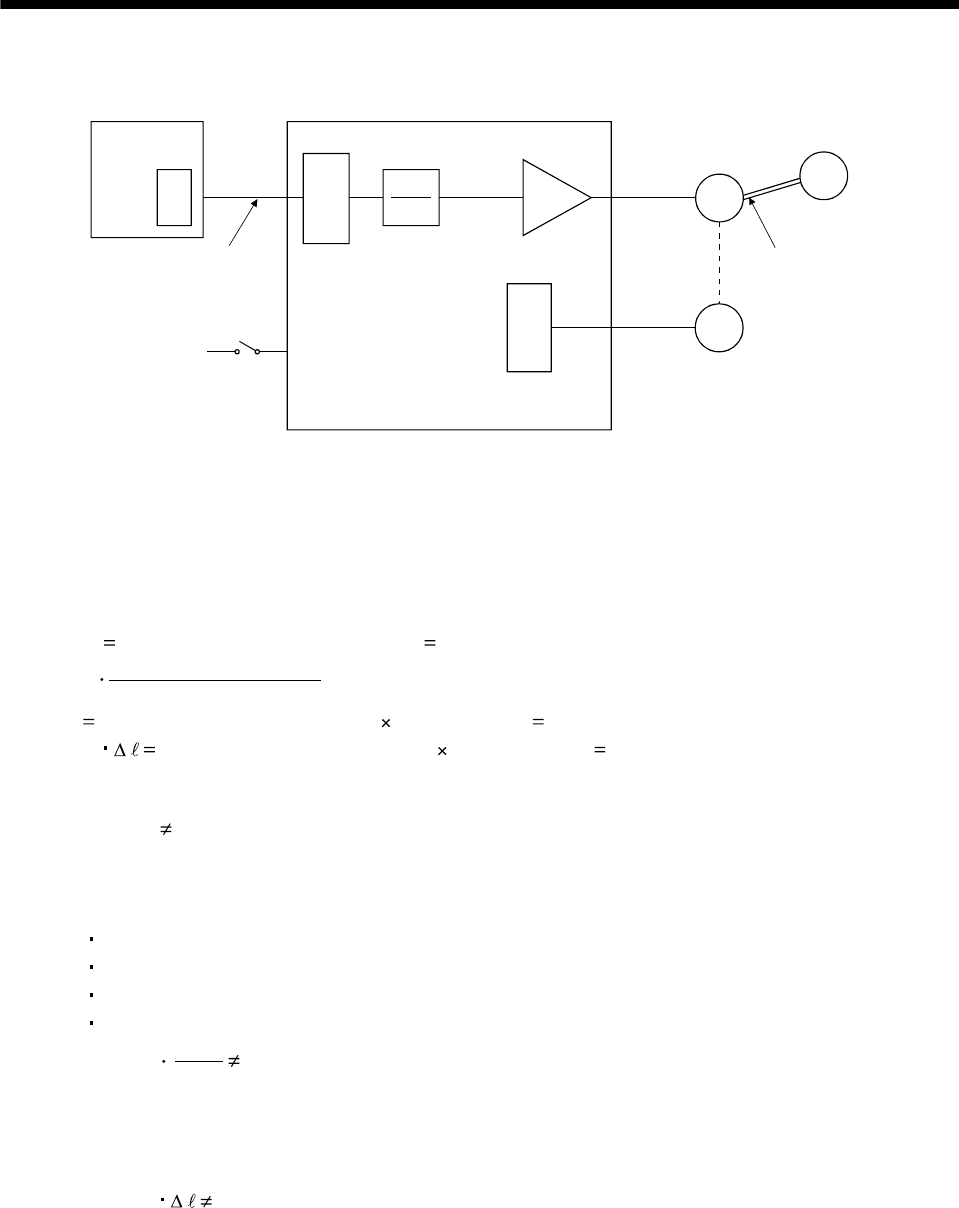
10. TROUBLESHOOTING
(2) How to find the cause of position shift
Positioning unit
(a) Output pulse
counter
QPCMX
CDV
(C) Servo-on (SON), forward
rotation stroke end
(LSP), reverse rotation
stroke end (LSN) input
(A) (b) Cumulative command
pulses
Electronic gear (parameters No.3, 4)
C
Servo motor
M
Encoder
L
Machine
(d) Machine stop
position M
(B)
(c) Cumulative
feedback pulses
Servo amplifier
When a position shift occurs, check (a) output pulse counter, (b) cumulative command pulse display, (c)
cumulative feedback pulse display, and (d) machine stop position in the above diagram.
(A), (B) and (C) indicate position shift causes. For example, (A) indicates that noise entered the wiring between
positioning unit and servo amplifier, causing pulses to be miss-counted.
In a normal status without position shift, there are the following relationships.
1) Q P (positioning unit's output counter servo amplifier's cumulative command pulses)
2) CMX(parameter No.3)
CDV(parameter No.4)
P
C (cumulative command pulses electronic gear cumulative feedback pulses)
3) C M (cumulative feedback pulses travel per pulse machine position)
Check for a position shift in the following sequence.
1) When Q P
Noise entered the pulse train signal wiring between positioning unit and servo amplifier, causing
pulses to be miss-counted. (Cause A)
Make the following check or take the following measures.
Check how the shielding is done.
Change the open collector system to the differential line driver system.
Run wiring away from the power circuit.
Install a data line filter.
2) CMX
CDV
P C
When
During operation, the servo-on signal (SON) or forward rotation stroke end (LSP), reverse rotation
stroke end (LSN) signal was switched off or the clear signal (CR) and the reset signal (RES) switched
on. (Cause C)
If a malfunction may occur due to much noise, increase the input filter setting (parameter No.1).
3) When C M
Mechanical slip occurred between the servo motor and machine. (Cause B)
10 - 3

10. TROUBLESHOOTING
10.1.2 Internal speed control mode
No. Start-up sequence Fault Investigation Possible cause Reference
Not improved if connectors
CN1, CN2 and CN3 are
disconnected.
1. Power supply voltage fault
2. Servo amplifier is faulty.
Improved when connectors
CN1 is disconnected.
Power supply of CN1 cabling is
shorted.
Improved when connector
CN2 is disconnected.
1. Power supply of encoder
cabling is shorted.
2. Encoder is faulty.
Seven-segment
LED is not lit.
Seven-segment
LED flickers.
Improved when connector
CN3 is disconnected.
Power supply of CN3 cabling is
shorted.
1 Power on (Note)
Alarm occurs. Refer to section 10.2 and remove cause. Section 10.2
Alarm occurs. Refer to section 10.2 and remove cause. Section 10.2 2 Switch on servo-on
signal. Servo motor shaft is
not servo-locked
(is free).
1. Check the display to see if
the servo amplifier is ready
to operate.
2. Check the external I/O
signal indication to see if the
servo-on (SON) signal is
ON.
1. Servo-on signal is not input.
(Wiring mistake)
2. 24VDC power is not supplied
to COM.
Section 6.6
Call the external I/O signal
display and check the ON/OFF
status of the input signal.
LSP, LSN, ST1 or ST2 is off. Section 6.6
Check the internal speed
commands 1 to 7
(parameters No.8 to 10 72 to
75).
Set value is 0.
3 Switch on forward
rotation start (ST1) or
reverse rotation start
(ST2).
Servo motor does not
rotate.
Check the internal torque limit
1 (parameter No.28).
Torque limit level is too low as
compared to the load torque.
Section 5.1.2
(1)
Rotation ripples
(speed fluctuations)
are large at low
speed.
Make gain adjustment in the
following procedure.
1. Increase the auto tuning
response level.
2. Repeat acceleration and
deceleration several times
to complete auto tuning.
Gain adjustment fault Chapter 7
4 Gain adjustment
Large load inertia
moment causes the
servo motor shaft to
oscillate side to side.
If the servo motor may be run
with safety, repeat
acceleration and deceleration
several times to complete auto
tuning.
Gain adjustment fault Chapter 7
Note. Switch power on again after making sure that the charge lamp has turned off completely.
10 - 4
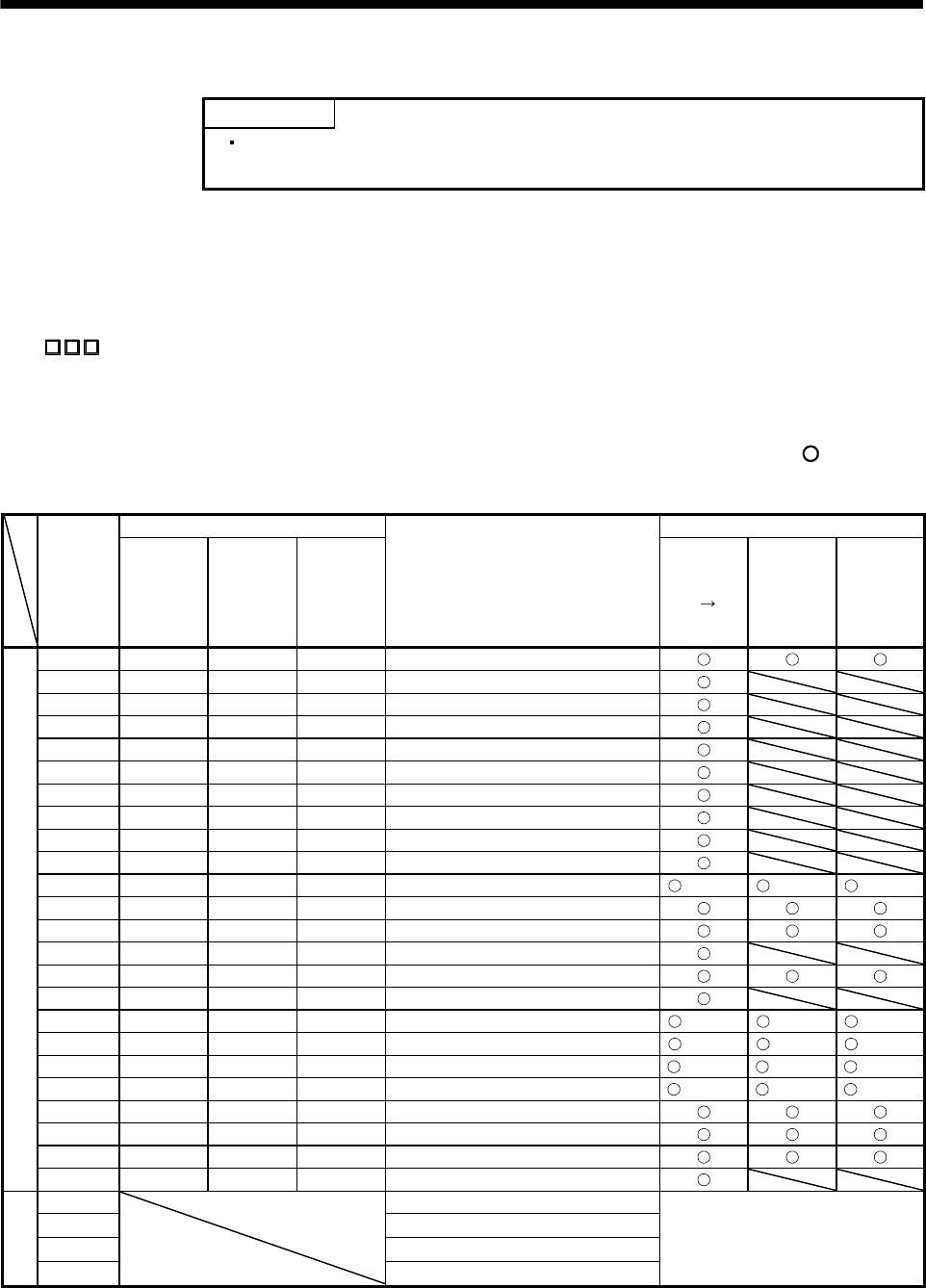
10. TROUBLESHOOTING
10.2 When alarm or warning has occurred
POINT
As soon as an alarm occurs, turn off Servo-on (SON) and power off the power
supply.
10.2.1 Alarms and warning list
When a fault occurs during operation, the corresponding alarm or warning is displayed. If any alarm or warning
has occurred, refer to section 10.2.2 or 10.2.3 and take the appropriate action. When an alarm occurs, the
current circuit between ALM and VIN opens.
Set " 1" in parameter No.49 to output the alarm code in ON/OFF status across the corresponding pin
and VIN. Warnings (AL.96 to AL.E9) have no alarm codes. Any alarm code is output at occurrence of the
corresponding alarm. In the normal status, the signals available before alarm code setting (CN1-12: ZSP, CN1-
11: RD, CN1-10: INP or SA) are output.
After its cause has been removed, the alarm can be deactivated in any of the methods marked in the alarm
deactivation column.
(Note 2) Alarm code Alarm deactivation
Display CN1-10
pin
CN1-11
pin
CN1-12
pin
Name Power
OFF ON
Press
"SET" on
current
alarm
screen.
Alarm
reset
(RES)
signal
AL.10 0 1 0 Undervoltage
AL.12 0 0 0 Memory error 1
AL.13 0 0 0 Clock error
AL.15 0 0 0 Memory error 2
AL.16 1 0 1 Encoder error 1
AL.17 0 0 0 Board error
AL.19 0 0 0 Memory error 3
AL.1A 1 0 1 Motor combination error
AL.20 1 1 0 Encoder error 2
AL.24 0 0 1 Main circuit error
AL.30 0 1 0 Regenerative error (Note 1) (Note 1) (Note 1)
AL.31 0 1 1 Overspeed
AL.32 0 0 1 Overcurrent
AL.33 0 1 0 Overvoltage
AL.35 0 1 1 Command pulse frequency error
AL.37 0 0 0 Parameter error
AL.45 1 1 0 Main circuit device overheat (Note 1) (Note 1) (Note 1)
AL.46 1 1 0 Servo motor overheat (Note 1) (Note 1) (Note 1)
AL.50 1 1 0 Overload 1 (Note 1) (Note 1) (Note 1)
AL.51 1 1 0 Overload 2 (Note 1) (Note 1) (Note 1)
AL.52 0 1 1 Error excessive
AL.8A 0 0 0 Serial communication time-out error
AL.8E 0 0 0 Serial communication error
Alarms
88888 0 0 0 Watchdog
AL.E0 Excessive regenerative warning
AL.E1 Overload warning
AL.E6 Servo emergency stop warning
Warnings
AL.E9
Undervoltage warning
Removing the cause of occurrence
deactivates the alarm automatically.
Note 1. Deactivate the alarm about 30 minutes of cooling time after removing the cause of occurrence.
2. 0: off
1: on
10 - 5
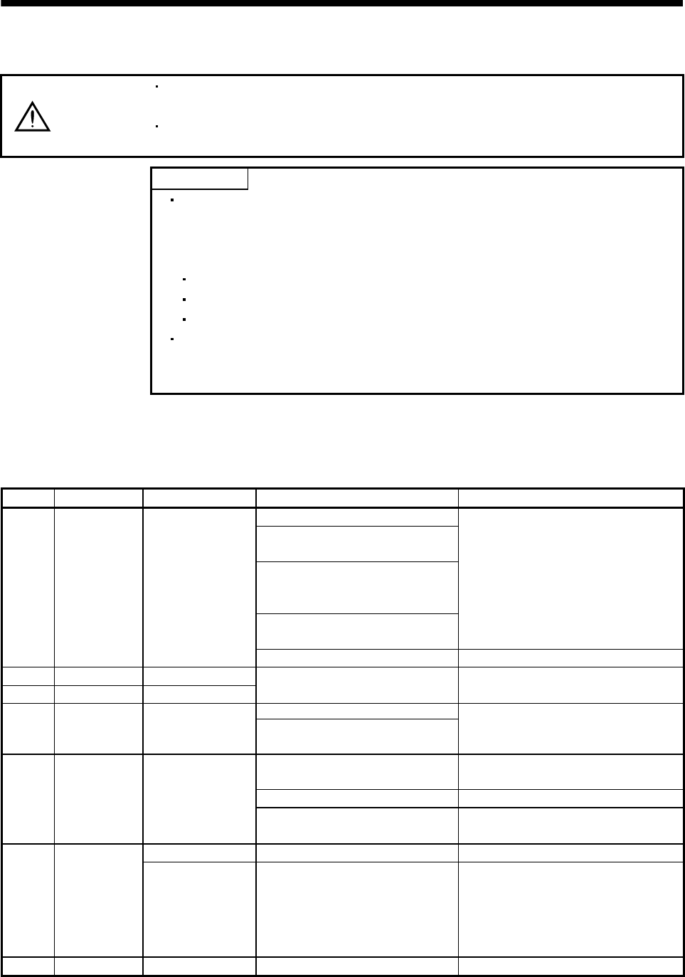
10. TROUBLESHOOTING
10.2.2 Remedies for alarms
CAUTION
When any alarm has occurred, eliminate its cause, ensure safety, then reset the
alarm, and restart operation. Otherwise, injury may occur.
As soon as an alarm occurs, turn off Servo-on (SON) and power off the power
supply.
POINT
When any of the following alarms has occurred, always remove its cause and
allow about 30 minutes for cooling before resuming operation. If operation is
resumed by switching power off, then on to reset the alarm, the servo amplifier
and servo motor may become faulty.
Regenerative error (AL.30)
Overload 1 (AL.50)
Overload 2 (AL.51)
The alarm can be deactivated by switching power off, then on press the "SET"
button on the current alarm screen or by turning on the reset signal (RES). For
details, refer to section 10.2.1.
When an alarm occurs, the trouble signal (ALM) switches off and the dynamic brake is operated to stop the
servo motor. At this time, the display indicates the alarm No.
The servo motor comes to a stop. Remove the cause of the alarm in accordance with this section. Use the
optional MR Configurator (servo configuration software) to refer to the cause of the alarm.
Display Name Definition Cause Action
1. Power supply voltage is low.
2. There was an instantaneous control
power failure of 60ms or longer.
3. Shortage of power supply capacity
caused the power supply voltage to
drop at start, etc.
4. The bus voltage dropped to
200VDC.
Check the power supply.
AL.10 Undervoltage Power supply
voltage dropped to
160VAC or less.
5. Faulty parts in the servo amplifier Change the servo amplifier.
AL.12 Memory error 1 RAM, memory fault
AL.13 Clock error Printed board fault
Faulty parts in the servo amplifier Change the servo amplifier.
1. Faulty parts in the servo amplifier
AL.15 Memory error 2 EEP-ROM fault
2. The number of write times to EEP-
ROM exceeded 100,000.
Change the servo amplifier.
1. Encoder connector (CN2)
disconnected.
Connect correctly.
2. Encoder fault Change the servo motor.
AL.16 Encoder error 1 Communication error
occurred between
encoder and servo
amplifier. 3. Encoder cable faulty
(Wire breakage or shorted)
Repair or change cable.
CPU/parts fault 1. Faulty parts in the servo amplifier Change the servo amplifier.
AL.17 Board error
The output terminals
U, V, W of the servo
amplifier and the
input terminals U, V,
W of the servo motor
are not connected.
2. The wiring of U, V, W is
disconnected or not connected.
Correctly connect the output terminals U, V,
W of the servo amplifier and the input
terminals U, V, W of the servo motor.
AL.19 Memory error 3 ROM memory fault Faulty parts in the servo amplifier Change the servo amplifier.
10 - 6
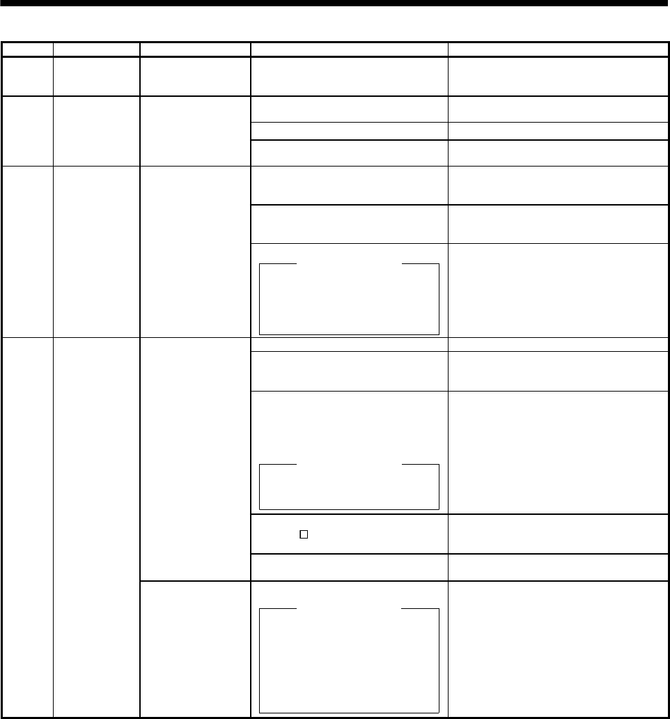
10. TROUBLESHOOTING
Display Name Definition Cause Action
AL.1A Motor
combination
error
Wrong combination
of servo amplifier
and servo motor.
Wrong combination of servo amplifier
and servo motor connected. Use correct combination.
1. Encoder connector (CN2)
disconnected. Connect correctly.
2. Encoder fault Change the servo motor.
AL.20 Encoder error 2 Communication error
occurred between
encoder and servo
amplifier. 3. Encoder cable faulty
(Wire breakage or shorted) Repair or change the cable.
1. Power input wires and servo motor
power wires are in contact at main
circuit terminal block (TE1).
Connect correctly.
2. Insulators of servo motor power
cables deteriorated, resulting in
ground fault.
Change the cable.
AL.24 Main circuit
error Ground fault
occurred at the
servo motor powers
(U,V and W phases)
of the servo
amplifier.
3. Main circuit of servo amplifier failed.
Checking method
Alarm (AL.24) occurs if the servo
is switched on after disconnecting
the U, V, W power cables from
the servo amplifier.
Change the servo amplifier.
1. Wrong setting of parameter No.0 Set correctly.
2. Built-in regenerative resistor or
regenerative option is not
connected.
Connect correctly.
3. High-duty operation or continuous
regenerative operation caused the
permissible regenerative power of
the regenerative option to be
exceeded.
Checking method
Call the status display and check
the regenerative load ratio.
1. Reduce the frequency of positioning.
2. Use the regenerative option of larger
capacity.
3. Reduce the load.
4. Power supply voltage is abnormal.
MR-E- A-QW003: 260VAC or
more
Check the power supply.
Permissible
regenerative power
of the built-in
regenerative resistor
or regenerative
option is exceeded.
5. Built-in regenerative resistor or
regenerative option faulty. Change servo amplifier or regenerative
option.
AL.30 Regenerative
error
Regenerative
transistor fault 6. Regenerative transistor faulty.
Checking method
1) The regenerative option has
overheated abnormally.
2) Alarm (AL.30) occurs even after
removal of the built-in
regenerative resistor or
regenerative option.
Change the servo amplifier.
10 - 7
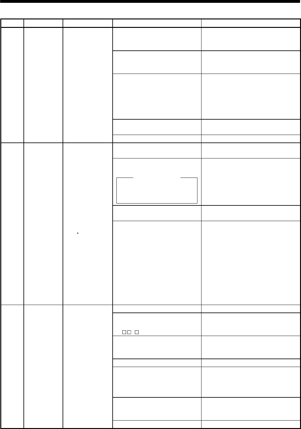
10. TROUBLESHOOTING
Display Name Definition Cause Action
1. Input command pulse frequency
exceeded the permissible
instantaneous speed frequency.
Set command pulses correctly.
2. Small acceleration/deceleration time
constant caused overshoot to be
large.
Increase acceleration/deceleration time
constant.
3. Servo system is instable to cause
overshoot.
1. Re-set servo gain to proper value.
2. If servo gain cannot be set to proper
value.
1) Reduce load inertia moment ratio; or
2) Reexamine acceleration/
deceleration time constant.
4. Electronic gear ratio is large
(parameters No.3, 4)
Set correctly.
AL.31 Overspeed Speed has
exceeded the
instantaneous
permissible speed.
5. Encoder faulty. Change the servo motor.
1. Short occurred in servo amplifier
output phases U, V and W.
Correct the wiring.
2. Transistor (IPM) of the servo
amplifier faulty.
Checking method
Alarm (AL.32) occurs if power is
switched on after U,V and W
are disconnected.
Change the servo amplifier.
3. Ground fault occurred in servo
amplifier output phases U, V and W.
Correct the wiring.
AL.32 Overcurrent Current that flew is
higher than the
permissible current
of the servo
amplifier. (When the
alarm (AL.32)
occurs, switch the
power OFF and then
ON to reset the
alarm. Then, turn on
the servo-on. When
the alarm (AL.32)
still occurs at the
time, the transistor
(IPM
IGBT) of the servo
amplifier may be at
fault. Do not switch
the power OFF/ON
repeatedly; check
the transistor
according to the
cause 2 checking
method.)
4. External noise caused the
overcurrent detection circuit to
misoperate.
Take noise suppression measures.
1. Regenerative option is not used. Use the regenerative option.
2. Though the regenerative option is
used, the parameter No.0 setting is
"0 (not used)".
Make correct setting.
3. Lead of built-in regenerative resistor
or regenerative option is open or
disconnected.
1. Change the lead.
2. Connect correctly.
4. Regenerative transistor faulty. Change the servo amplifier.
5. Wire breakage of built-in
regenerative resistor or regenerative
option
1. For wire breakage of built-in regenerative
resistor, change the servo amplifier.
2. For wire breakage of regenerative option,
change the regenerative option.
6. Capacity of built-in regenerative
resistor or regenerative option is
insufficient.
Add regenerative option or increase
capacity.
AL.33 Overvoltage Converter bus
voltage exceeded
400VDC.
7. Power supply voltage high. Check the power supply.
10 - 8
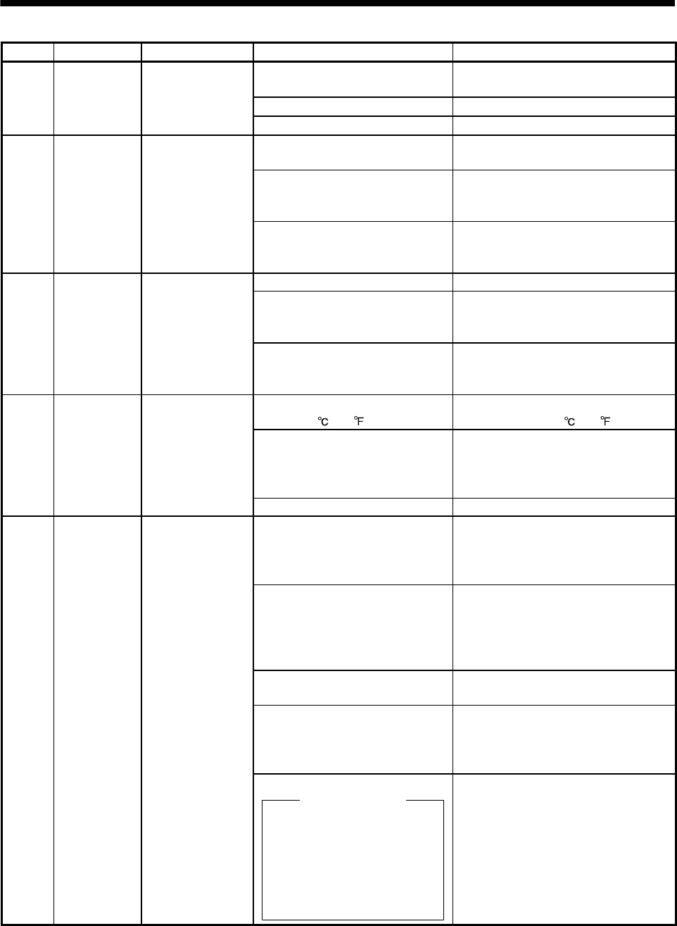
10. TROUBLESHOOTING
Display Name Definition Cause Action
1. Pulse frequency of the command
pulse is too high.
Change the command pulse frequency to a
proper value.
2. Noise entered command pulses. Take action against noise.
AL.35 Command
pulse frequency
error
Input pulse
frequency of the
command pulse is
too high. 3. Command device failure Change the command device.
1. Servo amplifier fault caused the
parameter setting to be rewritten.
Change the servo amplifier.
2. Regenerative option or servo motor
not used with servo amplifier was
selected in parameter No.0.
Set parameter No.0 correctly.
AL.37 Parameter error Parameter setting is
wrong.
3. The number of write times to EEP-
ROM exceeded 100,000 due to
parameter write, etc.
Change the servo amplifier.
1. Servo amplifier faulty. Change the servo amplifier.
2. The power supply was turned on
and off continuously by overloaded
status.
The drive method is reviewed.
AL.45 Main circuit
device overheat
Main circuit device
overheat
3. Air cooling fan of servo amplifier
stops.
1. Exchange the cooling fan or the servo
amplifier.
2. Reduce ambient temperature.
1. Ambient temperature of servo motor
is over 40 (104 ).
Review environment so that ambient
temperature is 0 to 40 (104 ).
2. Servo motor is overloaded. 1. Reduce load.
2. Review operation pattern.
3. Use servo motor that provides larger
output.
AL.46 Servo motor
overheat
Servo motor
temperature rise
actuated the thermal
sensor.
3. Thermal sensor in encoder is faulty. Change the servo motor.
1. Servo amplifier is used in excess
of its continuous output current.
1. Reduce load.
2. Review operation pattern.
3. Use servo motor that provides larger
output.
2. Servo system is instable and
hunting.
1. Repeat acceleration/
deceleration to execute auto tuning.
2. Change auto tuning response setting.
3. Set auto tuning to OFF and make gain
adjustment manually.
3. Machine struck something. 1. Review operation pattern.
2. Install limit switches.
4. Wrong connection of servo motor.
Servo amplifier's output terminals U,
V, W do not match servo motor's
input terminals U, V, W.
Connect correctly.
AL.50 Overload 1 Load exceeded
overload protection
characteristic of
servo amplifier.
5. Encoder faulty.
Checking method
When the servo motor shaft is
rotated with the servo off, the
cumulative feedback pulses do
not vary in proportion to the
rotary angle of the shaft but the
indication skips or returns
midway.
Change the servo motor.
10 - 9

10. TROUBLESHOOTING
Display Name Definition Cause Action
1. Machine struck something. 1. Review operation pattern.
2. Install limit switches.
2. Wrong connection of servo motor.
Servo amplifier's output terminals U,
V, W do not match servo motor's
input terminals U, V, W.
Connect correctly.
3. Servo system is instable and
hunting.
1. Repeat acceleration/deceleration to
execute auto tuning.
2. Change auto tuning response setting.
3. Set auto tuning to OFF and make gain
adjustment manually.
AL.51
Overload 2 Machine collision or
the like caused max.
output current to flow
successively for
several seconds.
Servo motor locked:
1s or more
During rotation:
2.5s or more
4. Encoder faulty.
Checking method
When the servo motor shaft is
rotated with the servo off, the
cumulative feedback pulses do
not vary in proportion to the
rotary angle of the shaft but the
indication skips or returns
midway.
Change the servo motor.
1. Acceleration/deceleration time
constant is too small.
Increase the acceleration/deceleration
time constant.
2. Torque limit value (parameter
No.28) is too small.
Increase the torque limit value.
3. Motor cannot be started due to
torque shortage caused by power
supply voltage drop.
1. Review the power supply capacity.
2. Use servo motor which provides larger
output.
4. Position control gain 1 (parameter
No.6) value is small.
Increase set value and adjust to ensure
proper operation.
5. Servo motor shaft was rotated by
external force.
1. When torque is limited, increase the limit
value.
2. Reduce load.
3. Use servo motor that provides larger
output.
6. Machine struck something. 1. Review operation pattern.
2. Install limit switches.
7. Encoder faulty Change the servo motor.
AL.52 Error excessive The difference
between the model
position and the
actual servo motor
position exceeds 2.5
rotations. (Refer to
the function block
diagram in section
1.2)
8. Wrong connection of servo motor.
Servo amplifier's output terminals U,
V, W do not match servo motor's
input terminals U, V, W.
Connect correctly.
1. Communication cable breakage. Repair or change communication cable.
2. Communication cycle longer than
parameter No.56 setting.
Set correct value in parameter.
AL.8A Serial
communication
time-out error
RS-232C or RS-422
communication
stopped for longer
than the time set in
parameter No.56.
3. Wrong protocol. Correct protocol.
1. Communication cable fault
(Open cable or short circuit)
Repair or change the cable. AL.8E Serial
communication
error
Serial
communication error
occurred between
servo amplifier and
communication
device (e.g. personal
computer).
2. Communication device (e.g.
personal computer) faulty
Change the communication device (e.g.
personal computer).
88888 Watchdog CPU, parts faulty Fault of parts in servo amplifier Change the servo amplifier.
10 - 10
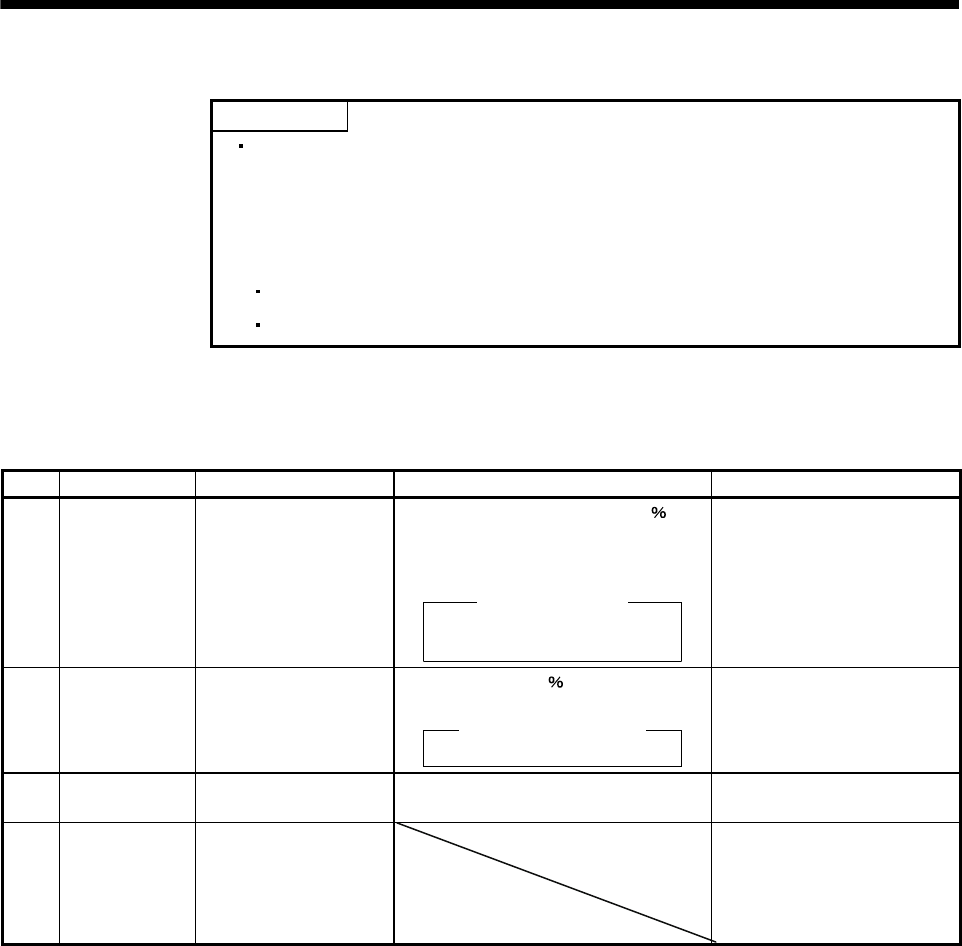
10. TROUBLESHOOTING
10.2.3 Remedies for warnings
POINT
When any of the following alarms has occurred, do not resume operation by
switching power of the servo amplifier OFF/ON repeatedly. The servo amplifier
and servo motor may become faulty. If the power of the servo amplifier is
switched OFF/ON during the alarms, allow more than 30 minutes for cooling
before resuming operation.
Excessive regenerative warning (AL.E0)
Overload warning 1 (AL.E1)
If AL.E6 occurs, the servo off status is established. If any other warning occurs, operation can be continued but
an alarm may take place or proper operation may not be performed. Use the optional MR Configurator (servo
configuration software) to refer to the cause of the warning.
Display Name Definition Cause Action
AL.E0 Excessive
regenerative
warning
There is a possibility that
regenerative power may
exceed permissible
regenerative power of
built-in regenerative
resistor or regenerative
option.
Regenerative power increased to 85 or
more of permissible regenerative power of
built-in regenerative resistor or regenerative
option. Checking method
Call the status display and check
regenerative load ratio.
1. Reduce frequency of
positioning.
2. Change regenerative option for
the one with larger capacity.
3. Reduce load.
AL.E1 Overload warning There is a possibility that
overload alarm 1 or 2 may
occur.
Load increased to 85 or more of overload
alarm 1 or 2 occurrence level.
Cause, checking method
Refer to AL.50, 51.
Refer to AL.50, AL.51.
AL.E6 Servo emergency
stop warning
EMG-VIN are open. External emergency stop was made valid.
(EMG-VIN opened.)
Ensure safety and deactivate
emergency stop.
AL.E9 Undervoltage
warning
This alarm occurs when
the servo motor speed
decreases to or below
50r/min with the bus
voltage dropping.
Check the power supply.
10 - 11

10. TROUBLESHOOTING
10 - 12
MEMO
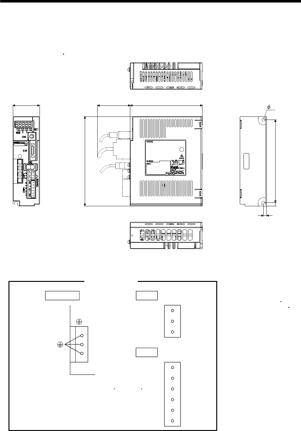
11. OUTLINE DIMENSION DRAWINGS
11. OUTLINE DIMENSION DRAWINGS
11.1 Servo amplifiers
(1) MR-E-10A-QW003 MR-E-20A-QW003
6
156
135
50
6
Approx.70
6
Mass: 0.7 [kg] (1.54 [lb])
[Unit: mm]
168
Terminal signal layout
CNP1
P
C
D
U
V
W
CNP2
Terminal screw: M4
Tightening torque: 1.2 [N m] (10.6 [lb in])
PE terminals
L1
L2
L3
Mounting Screw
Screw Size: M5
Tightening torque: 3.24 [N m]
(28.676 [lb in])
11 - 1
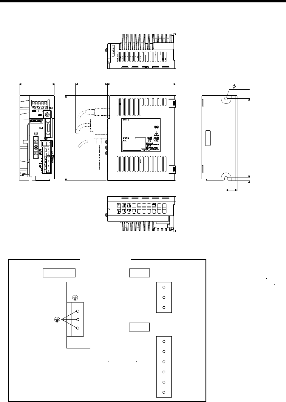
11. OUTLINE DIMENSION DRAWINGS
(2) MR-E-40A-QW003
156
22
135
168
6
Mass: 1.1 [kg] (2.43 [lb])
[Unit: mm]
70 Approx.70
6
Terminal signal layout
PE terminals
CNP1
P
C
D
U
V
W
CNP2
Terminal screw: M4
Tightening torque: 1.2 [N m] (10 .6 [lb in])
L1
L2
L3
Mounting Screw
Screw Size: M5
Tightening torque: 3.24 [N m]
(28.676 [lb in])
11 - 2
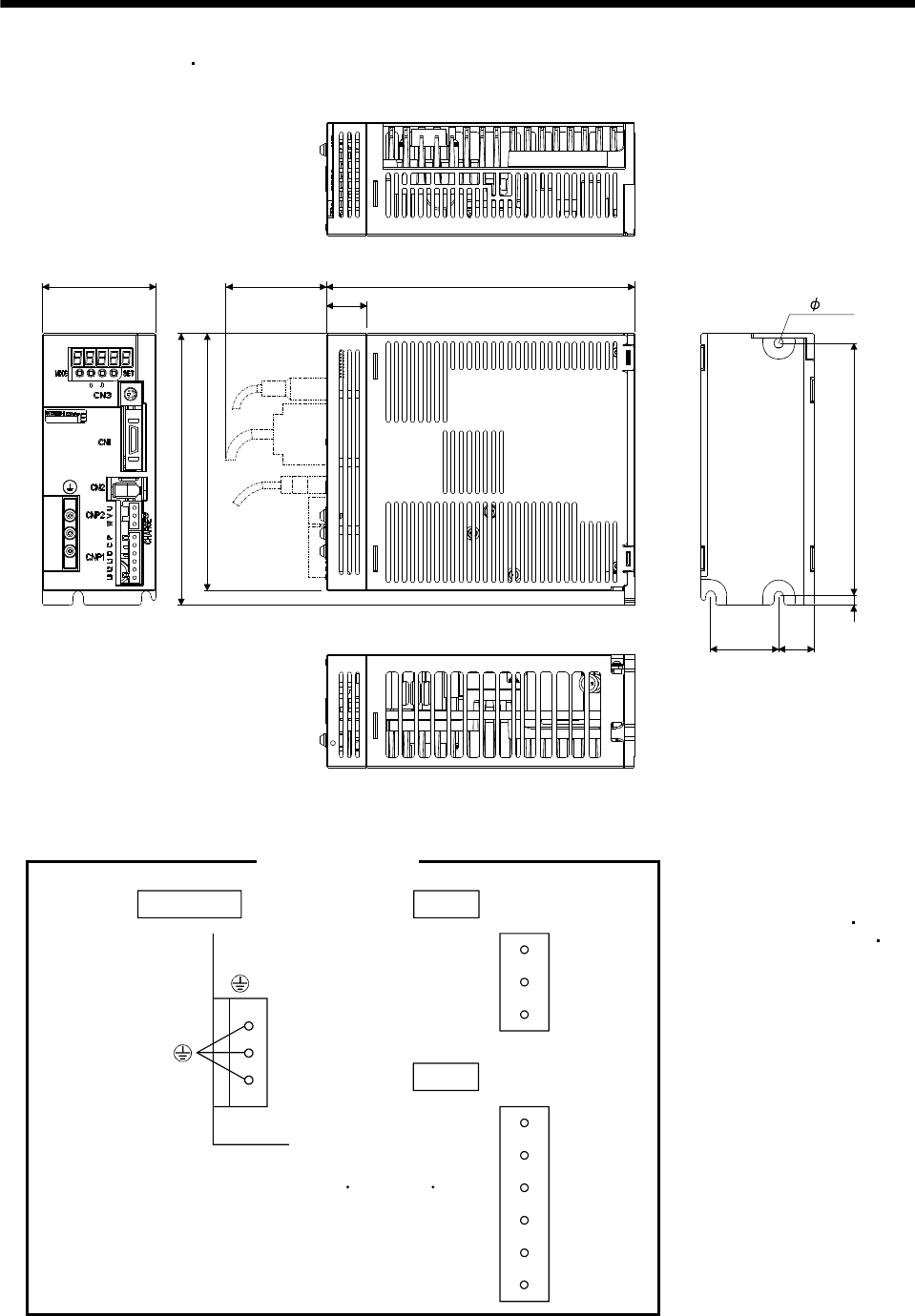
11. OUTLINE DIMENSION DRAWINGS
(3) MR-E-70A-QW003 MR-E-100A-QW003
70 190
25
159
42 22
156
Mass: 1.7 [kg] (3.75 [lb])
Approx. 70
6
[Unit: mm]
168
6
Terminal signal layout
PE terminals
CNP1
P
C
D
U
V
W
CNP2
Terminal screw: M4
Tightening torque: 1.2 [N m] (10.6 [lb in])
L1
L2
L3
Mounting Screw
Screw Size: M5
Tightening torque: 3.24 [N m]
(28.676 [lb in])
11 - 3
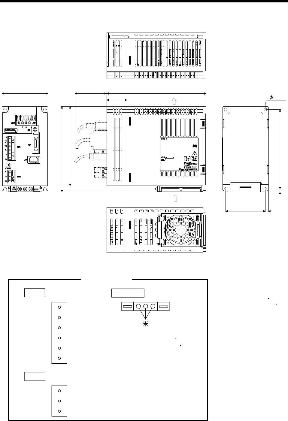
11. OUTLINE DIMENSION DRAWINGS
(4) MR-E-200A-QW003
90
78
168
156
Approx. 70 195
6
Mass: 2.0 [kg] (4.41 [lb])
[Unit: mm]
156
40
6
6
Exhaust
Cooling fan
air intake
Terminal signal layout
PE terminals
U
V
W
CNP2
CNP1
L1
L2
L3
P
C
D
Terminal screw: M4
Tightening torque: 1.2 [N m]
(10.6 [lb in])
Mounting Screw
Screw Size: M5
Tightening torque: 3.24 [N m]
(28.676 [lb in])
11 - 4
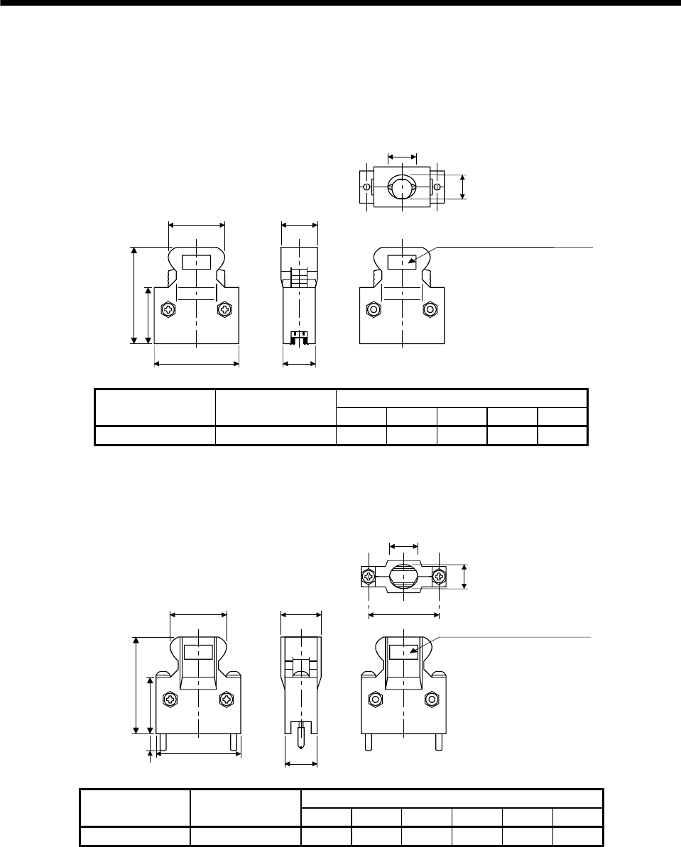
11. OUTLINE DIMENSION DRAWINGS
11.2 Connectors
(1) Miniature delta ribbon (MDR) system (3M)
(a) One-touch lock type
[Unit: mm]
E
B
A
23.8
39.0
12.7
C
Logo etc, are indicated here.
D
Each type of dimension
Connector Shell kit
A B C D E
10126-3000PE 10326-52F0-008 25.8 37.2 14.0 10.0 12.0
(b) Jack screw M2.6 type
This is not available as option.
[Unit: mm]
E
B
A
23.8
39.0
12.7
C
D
5.2
F
Logo etc, are indicated here.
Each type of dimension
Connector Shell kit
A B C D E F
10126-3000PE 10326-52A0-008 25.8 37.2 14.0 10.0 12.0 27.4
11 - 5
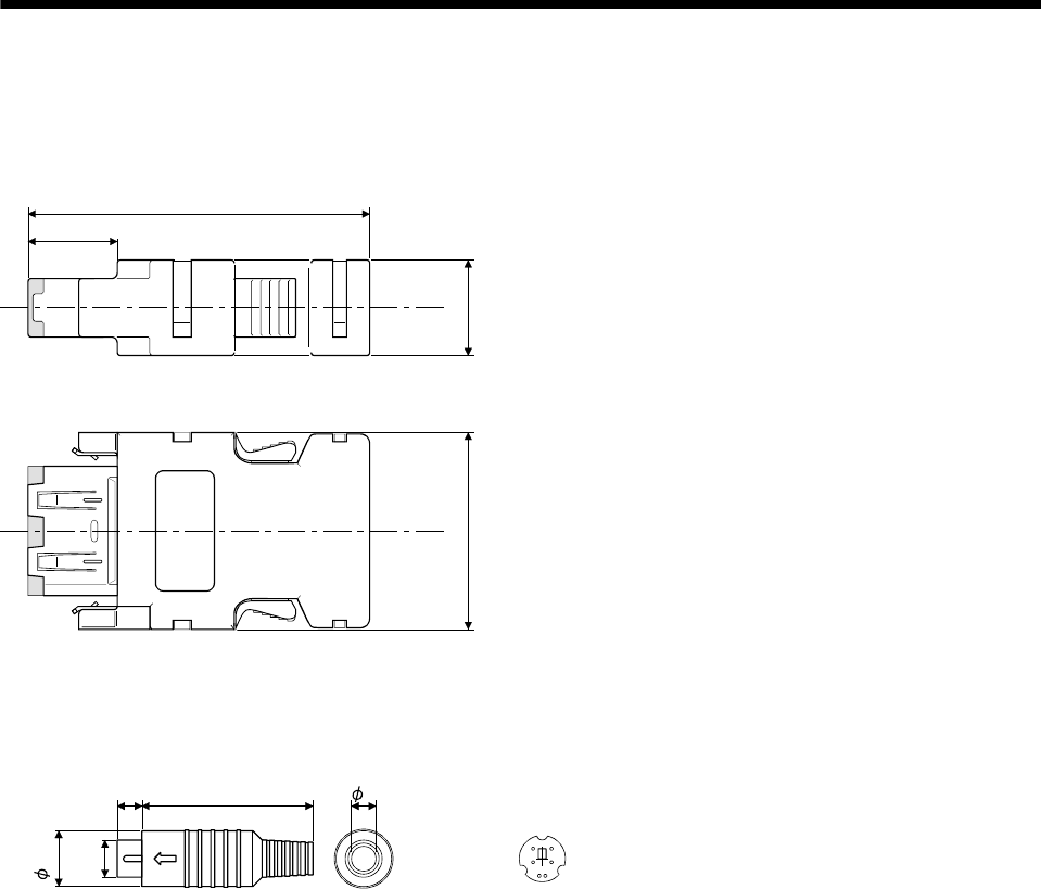
11. OUTLINE DIMENSION DRAWINGS
(2) CN2 Connector (Molex)
Connector set : 54599-1019
12.5
40
22.7 11
[Unit: mm]
(3) CN3 Connector (Marushin electric mfg)
Connector: MP371/6
[Unit: mm]
644.5
8.95
56
34
21
14.8
5
11 - 6
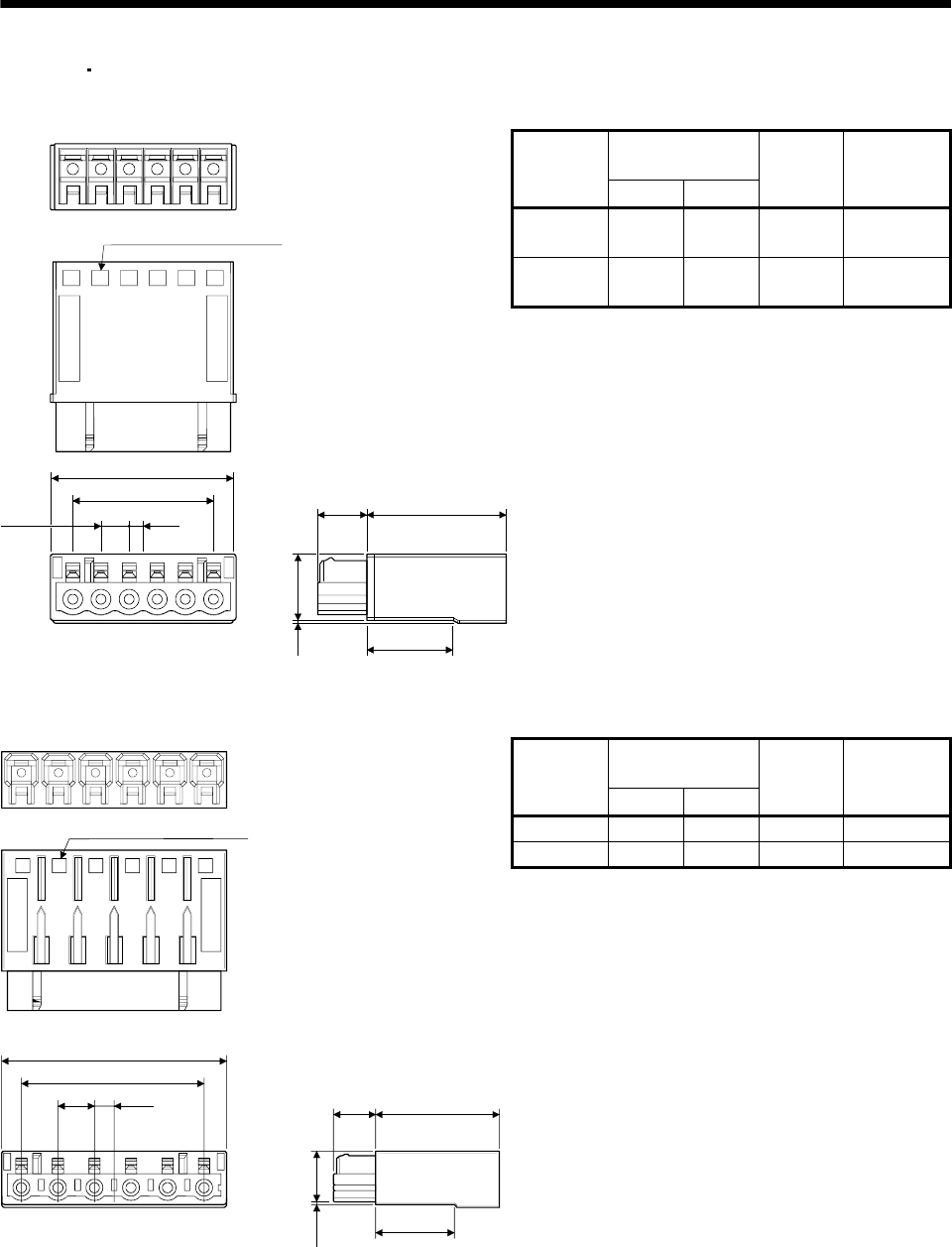
11. OUTLINE DIMENSION DRAWINGS
(4) CNP1 CNP2 Connector (Molex)
(a) Crimping type [Unit: mm]
Variable dimensions
[mm] ([in])
Connector
A B
Number of
poles Application
51240-0300 17.8 10 3 CNP2
(1kW or less)
51240-0600 32.8 25 6 CNP1
(1kW or less)
Crimping tool: 57349-5300 (Molex)
2.5
5
0.5
25
11.4
8.5
15.3
Pitch
Circuit number indication
11 - 7
(A)
(B)
654321
[Unit: mm]
Variable dimensions
[mm] ([in])
Connector
A B
Number of
poles Application
51241-0300 22.8 15 3 CNP2 (2kW)
51241-0600 45.3 37.5 6 CNP1 (2kW)
Crimping tool: 57349-5300 (Molex)
3.75
Circuit number indication
(B)
A
321 4 5 6
7.5
Pitch 8.5 25
15.3
0.5 11.4
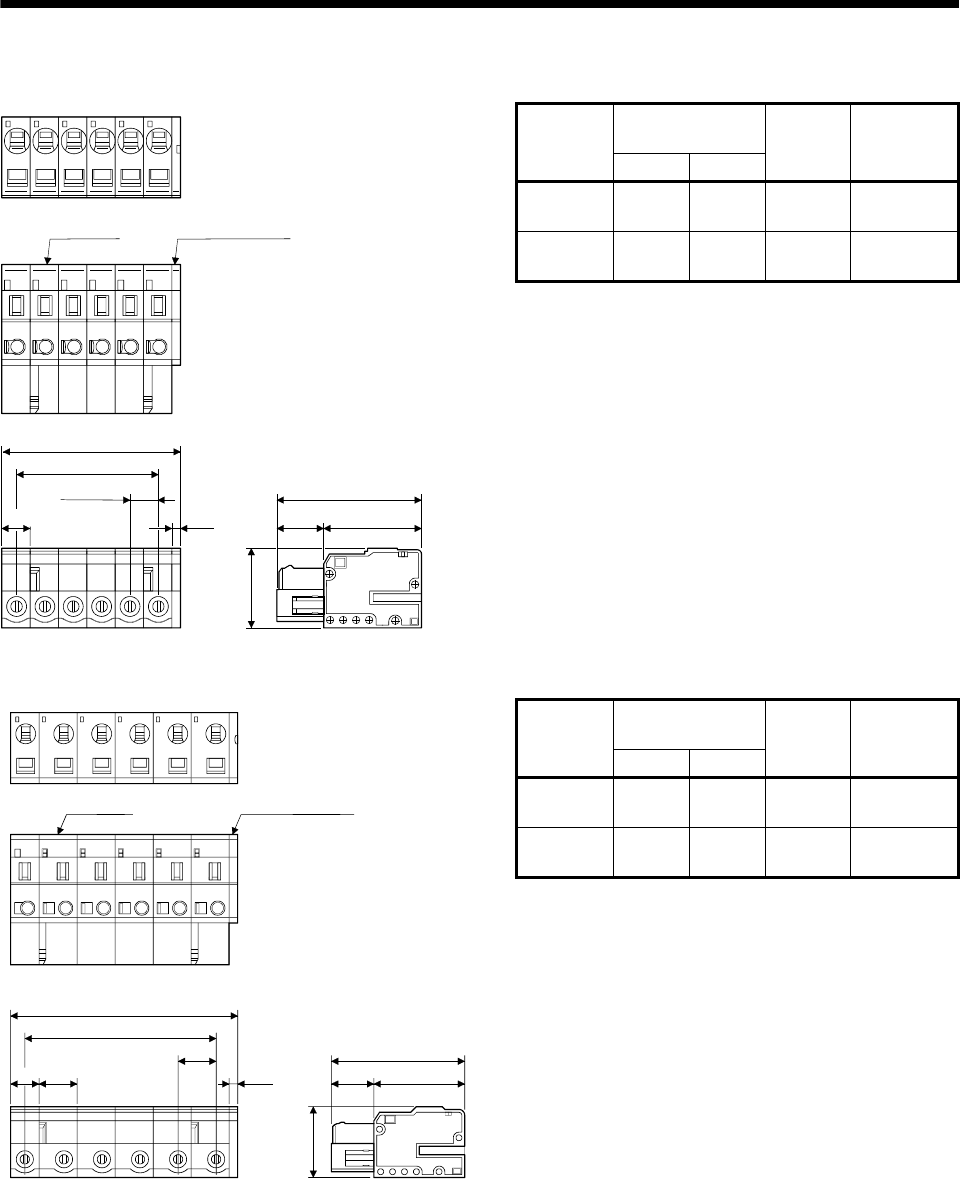
11. OUTLINE DIMENSION DRAWINGS
(b) Insertion type [Unit: mm]
Variable dimensions
[mm]
Connector
A B
Number of
poles Application
54927-0310 16.5 10 3 CNP2
(1kW or less)
54927-0610 31.5 25 6 CNP1
(1kW or less)
5
1.5
26.5
8.5 18
14.3
Housing Housing cover
Pitch
A
(B)
5
[Unit: mm]
Variable dimensions
[mm]
Connector
A B
Number of
poles Application
54928-0310 21.5 22.5 3 CNP2
(2kW)
54928-0610 44 37.5 6 CNP1
(2kW)
1.5
26.5
8.5 18
14.3
Housing Housing cover
(B)
A
7.5
7.5
Pitch
5
11 - 8
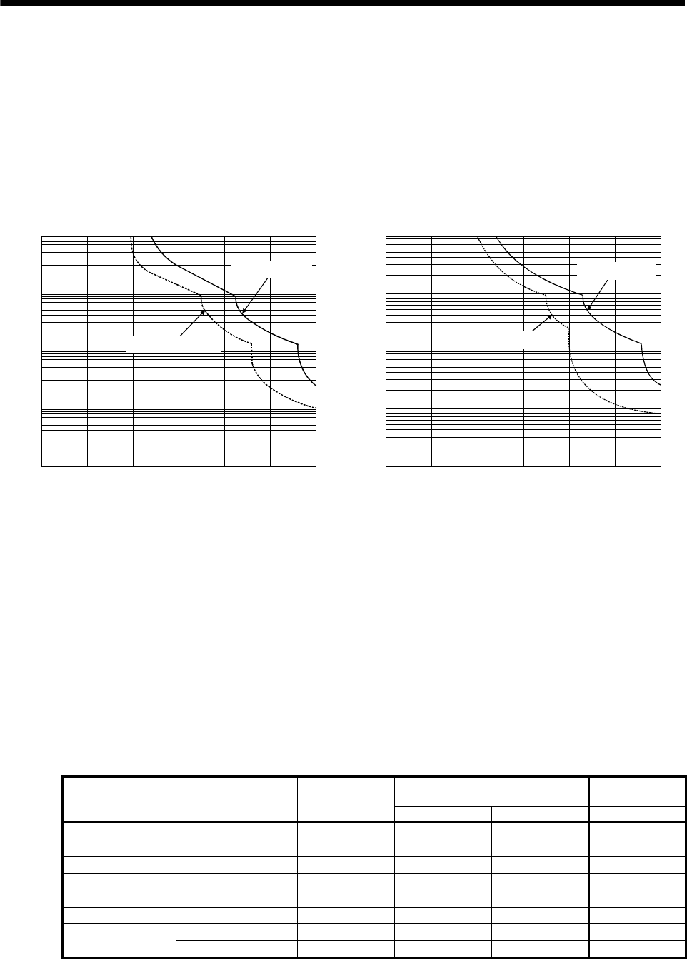
12. CHARACTERISTICS
12. CHARACTERISTICS
12.1 Overload protection characteristics
An electronic thermal relay is built in the servo amplifier to protect the servo motor, servo amplifier, and servo
motor power cable from overloads. Overload 1 (AL.50) occurs if overload operation performed is above the
electronic thermal relay protection curve shown in any of Figs 12.1, Overload 2 (AL.51) occurs if the maximum
current flew continuously for several seconds due to machine collision, etc. Use the equipment on the left-hand
side area of the continuous or broken line in the graph.
In a machine like the one for vertical lift application where unbalanced torque will be produced, it is
ecommended to use the machine so that the unbalanced torque is 70% or less of the rated torque.
r
1000
100
10
1
0.1
050 150 200 250 300
(Note) Load ratio [%]
Operation time[s]
100
During rotation
During servo lock
a. MR-E-10A-QW003 to MR-E-100A-QW003
1000
100
10
1
0.1
050 150 200 250 300
(Note) Load ratio [%]
Operation time[s]
100
During rotation
During servo lock
b. MR-E-200A-QW003
Note. If operation that generates torque more than 100% of the rating is performed with an abnormally high frequency in a servo motor stop
status (servo lock status) or in a 30r/min or less low-speed operation status, the servo amplifier may fail even when the electronic
thermal relay protection is not activated.
Fig 12.1 Electronic thermal relay protection characteristics
12.2 Power supply equipment capacity and generated loss
(1) Amount of heat generated by the servo amplifier
Table 12.1 indicates servo amplifiers' power supply capacities and losses generated under rated load. For
thermal design of an enclosure, use the values in Table 12.1 in consideration for the worst operating
conditions. The actual amount of generated heat will be intermediate between values at rated torque and
zero torque according to the duty used during operation. When the servo motor is run at less than the
maximum speed, the power supply capacity will be smaller than the value in the table, but the servo
amplifier's generated heat will not change.
Table 12.1 Power supply capacity and generated heat per servo amplifier at rated output
(Note 2)
Servo amplifier-generated heat [W]
Area required for
heat dissipation
Servo amplifier Servo motor (Note 1)
Power supply
capacity [kVA] At rated torque With servo off [m2]
MR-E-10A-QW003 HF-KN13(J) 0.3 25 15 0.5
MR-E-20A-QW003 HF-KN23(J) 0.5 25 15 0.5
MR-E-40A-QW003 HF-KN43(J) 0.9 35 15 0.7
HF-SN52J 1.0 40 15 0.8
MR-E-70A-QW003 HF-KN73J 1.3 50 15 1.0
MR-E-100A-QW003 HF-SN102J 1.7 50 15 1.0
HF-SN152J 2.5 90 20 1.8
MR-E-200A-QW003 HF-SN202J 3.5 90 20 1.8
Note 1. Note that the power supply capacity will vary according to the power supply impedance. This value assumes that the power factor
improving reactor is not used.
2. Heat generated during regeneration is not included in the servo amplifier-generated heat. To calculate heat generated by the
regenerative option, refer to section 13.1.1.
12 - 1
12. CHARACTERISTICS
(2) Heat dissipation area for enclosed servo amplifier
The enclosed control box (hereafter called the control box) which will contain the servo amplifier should be
designed to ensure that its temperature rise is within 10 at the ambient temperature of 40 (104 ).
(With a 5 (41 ) safety margin, the system should operate within a maximum 55 (131 ) limit.) The
necessary enclosure heat dissipation area can be calculated by Equation 12.1.
P
A
KT
....................................................................................................................................................(12.1)
where, A : Heat dissipation area [m2]
P : Loss generated in the control box [W]
T : Difference between internal and ambient temperatures [ ]
K : Heat dissipation coefficient [5 to 6]
When calculating the heat dissipation area with Equation 12.1, assume that P is the sum of all losses
generated in the enclosure. Refer to Table 12.1 for heat generated by the servo amplifier. "A" indicates the
effective area for heat dissipation, but if the enclosure is directly installed on an insulated wall, that extra
amount must be added to the enclosure's surface area.
The required heat dissipation area will vary wit the conditions in the enclosure. If convection in the
enclosure is poor and heat builds up, effective heat dissipation will not be possible. Therefore, arrangement
of the equipment in the enclosure and the use of a cooling fan should be considered.
Table 12.1 lists the enclosure dissipation area for each servo amplifier when the servo amplifier is operated
at the ambient temperature of 40 (104 ) under rated load.
(Outside) (Inside)
Air flow
Fig. 12.2 Temperature distribution in enclosure
When air flows along the outer wall of the enclosure, effective heat exchange will be possible, because the
temperature slope inside and outside the enclosure will be steeper.
12 - 2
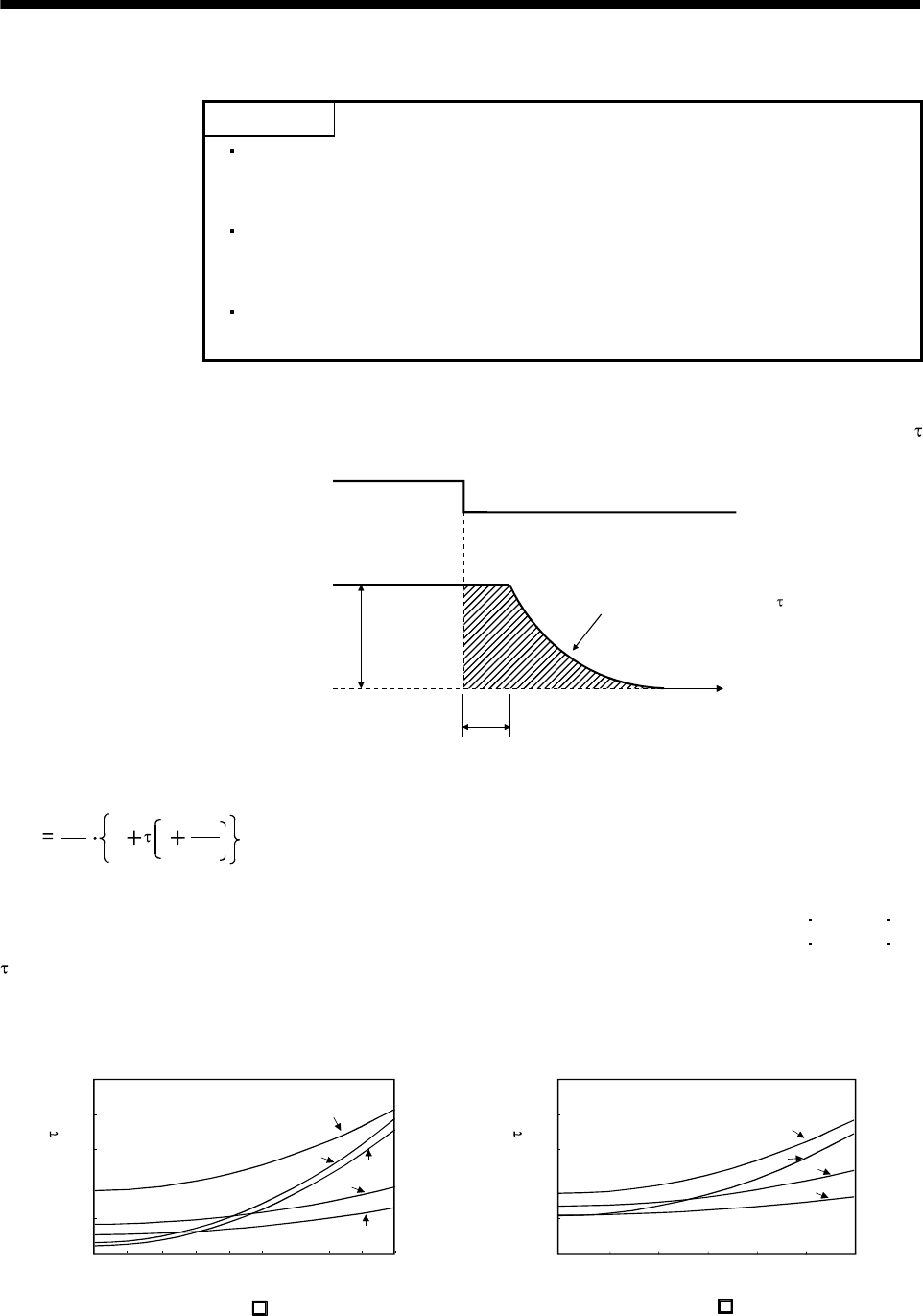
12 - 3
12. CHARACTERISTICS
12.3 Dynamic brake characteristics
POINT
Dynamic brake operates at occurrence of alarm, servo emergency stop
warning (AL.E6) and when power is turned off. Do not use dynamic brake to
stop in a normal operation as it is the function to stop in emergency.
Maximum usage time of dynamic brake for a machine operating under
recommended load inertia moment ratio is 1000 times while decelerating
from rated speed to a stop with frequency of once in 10 minutes.
Be sure to make emergency stop (EMG) valid after servo motor stops when
using emergency stop (EMG) frequently in other than emergency.
Fig. 12.3 shows the pattern in which the servo motor comes to a stop when the dynamic brake is operated.
Use Equation 12.2 to calculate an approximate coasting distance to a stop. The dynamic brake time constant
varies with the servo motor and machine operation speeds. (Refer to Fig. 12.4)
V0Dynamic brake time constant
Emergency stop(EMG) OFF
ON
Machine speed
teTime
Fig. 12.3 Dynamic brake operation diagram
Lmax 60
V0JL
JM
te1............................................................................................................................(12.2)
Lmax : Maximum coasting distance................................................................................................................[mm]
Vo : Machine rapid feed rate................................................................................................................[mm/min]
JM : Servo motor inertial moment .......................................................................................... [kg cm2][oz in2]
JL : Load inertia moment converted into equivalent value on servo motor shaft................ [kg cm2][oz in2]
: Dynamic brake time constant.................................................................................................................. [s]
te : Delay time of control section ................................................................................................................... [s]
(There is internal relay delay time of about 30ms.)
Speed [r/min]
Time constant [ms]
00
5
10
15
20
25
73
23 43
053
13
2000 2500 3000 3500 4000 45001000 1500500
00
Time constant [ms]
20
40
60
80
100
102
52 202
152
2000 2500 30001000 1500500
Speed [r/min]
a. HF-KN (J) b. HF-SN J
Fig. 12.4 Dynamic brake time constant
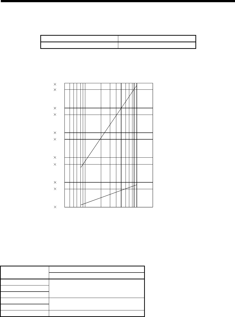
12. CHARACTERISTICS
Use the dynamic brake under the load inertia moment ratio indicated in the following table. If the load inertia
moment is higher than this value, the built-in dynamic brake may burn. If there is a possibility that the load
inertia moment may exceed the value, contact Mitsubishi.
Servo amplifier Load inertia moment ratio [times]
MR-E-10A-QW003 to MR-E-200A-QW003 30
12.4 Encoder cable flexing life
The flexing life of the cables is shown below. This graph calculated values. Since they are not guaranteed
values, provide a little allowance for these values.
1 107
5 107
1 108
5 106
1 106
5 105
1 105
5 104
1 104
5 103
1 103
a
b
Flexing life [times]
4 7 10 20 40 70 100 200
Flexing radius [mm]
a : Long flex life encoder cable
Long flex life motor power cable
Long flex life motor brake cable
b : Standard encoder cable
Standard motor power cable
Standard motor brake cable
12.5 Inrush currents at power-on of main circuit and control circuit
The following table indicates the inrush currents (reference value) that will flow when the maximum permissible
voltage (253VAC) is applied at the power supply capacity of 2500kVA and the wiring length of 1m.
Inrush currents (A0-p)
Servo amplifier Main circuit power supply (L1, L2, L3)
MR-E-10A-QW003
MR-E-20A-QW003
MR-E-40A-QW003
50A (Attenuated to approx. 10A in 10ms)
MR-E-70A-QW003
MR-E-100A-QW003 70A (Attenuated to approx. 20A in 10ms)
MR-E-200A-QW003 110A (Attenuated to approx. 20A in 10ms)
Since large inrush currents flow in the power supplies, always use circuit breakers and magnetic contactors.
(Refer to section 13.2.2.)
When circuit protectors are used, it is recommended to use the inertia delay type that will not be tripped by an
inrush current.
12 - 4
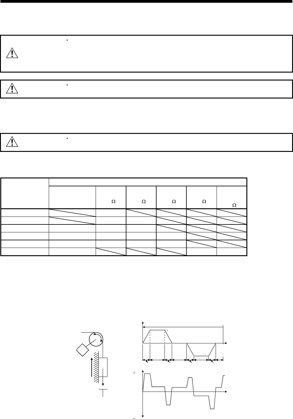
13. OPTIONS AND AUXILIARY EQUIPMENT
13. OPTIONS AND AUXILIARY EQUIPMENT
WARNING
Before connecting any option or peripheral equipment, turn off the power and wait
for 15 minutes or more until the charge lamp turns off. Otherwise, an electric shock
may occur. In addition, always confirm from the front of the servo amplifier whether
the charge lamp is off or not.
CAUTION Use the specified auxiliary equipment and options. Unspecified ones may lead to a
fault or fire.
13.1 Options
13.1.1 Regenerative options
CAUTION The specified combinations of regenerative options and servo amplifiers may only
be used. Otherwise, a fire may occur.
(1) Combination and regenerative power
The power values in the table are resistor-generated regenerative powers and not rated powers.
Permissible regenerative power [W]
Servo amplifier Built-in regenerative
resistor
MR-RB032
[40 ]
MR-RB12
[40 ]
MR-RB32
[40 ]
MR-RB30
[13 ]
(Note)
MR-RB50
[13 ]
MR-E-10A-QW003 30
MR-E-20A-QW003 30 100
MR-E-40A-QW003 10 30 100
MR-E-70A-QW003 20 30 100 300
MR-E-100A-QW003 20 30 100 300
MR-E-200A-QW003 100 300 500
Note. Always install a cooling fan.
(2) Selection of the regenerative option
Use the following method when regeneration occurs continuously in vertical motion applications or when it
is desired to make an in-depth selection of the regenerative option.
(a) Regenerative energy calculation
Use the following table to calculate the regenerative energy.
M
Friction
torque
Unbalance torque
TF
TU
Servo motor speed
Generated torque
Time
Up
No
tf(1 cycle)
Down
( )
( )
(Driving)
(Regenerative)
Tpsd2
t2 t3 t4t1
Tpsa2Tpsd1
Tpsa1
1)
2)
3)
4) 5)
6)
7)
8)
13 - 1
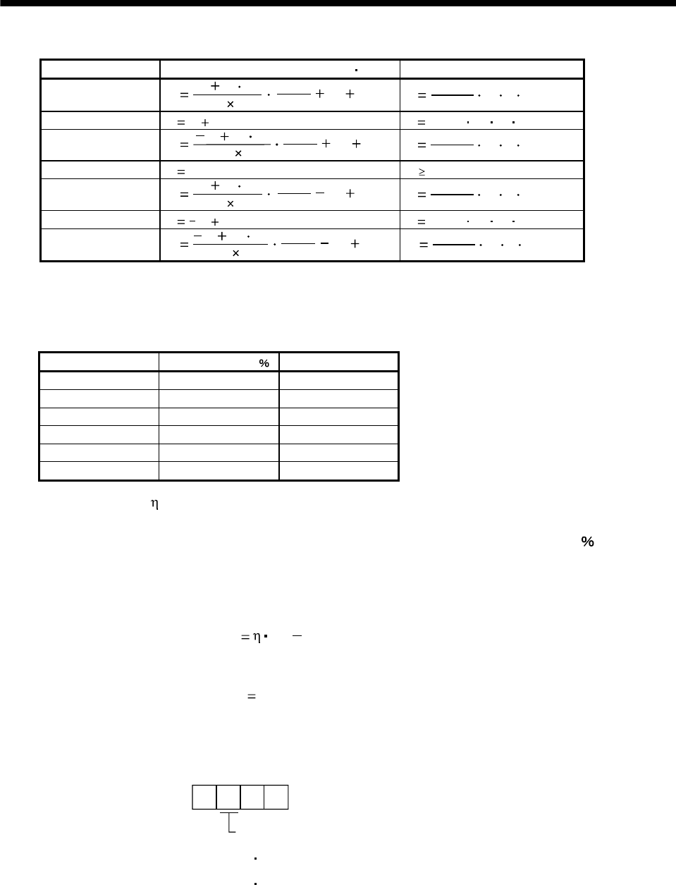
13. OPTIONS AND AUXILIARY EQUIPMENT
Formulas for calculating torque and energy in operation
Regenerative power Torque applied to servo motor [N m] Energy [J]
1)
13 - 2
T1(JL JM)
9.55 104
N01
Tpsa1 TUTF E12
0.1047 N0T1Tpsa1
2) T2 TU TFE2 0.1047 N0T2t1
3) T3(JL JM)
9.55 104
N01
Tpsd1 TUTF E32
0.1047 N0T3Tpsd1
4), 8) T4 TUE4 0 (No regeneration)
5) (JL JM)
T59.55 104
N01
Tpsa2 TUTF E52
0.1047 N0T5Tpsa2
6) T6 TU TFE6 0.1047 N0T6t3
7) (JL JM)
T79.55 104
N01
Tpsd2 TUTF E72
0.1047 N0T7Tpsd2
From the calculation results in 1) to 8), find the absolute value (Es) of the sum total of negative energies.
(b) Losses of servo motor and servo amplifier in regenerative mode
The following table lists the efficiencies and other data of the servo motor and servo amplifier in the
regenerative mode.
Servo amplifier Inverse efficiency [ ] Capacitor charging [J]
MR-E-10A-QW003 55 9
MR-E-20A-QW003 70 9
MR-E-40A-QW003 85 11
MR-E-70A-QW003 80 18
MR-E-100A-QW003 80 18
MR-E-200A-QW003 85 40
Inverse efficiency ( ) :Efficiency including some efficiencies of the servo motor and servo amplifier
when rated (regenerative) torque is generated at rated speed. Since the
efficiency varies with the speed and torque, allow for about 10 .
Capacitor charging (Ec) :Energy charged into the electrolytic capacitor in the servo amplifier.
Subtract the capacitor charging from the result of multiplying the sum total of regenerative energies by the
inverse efficiency to calculate the energy consumed by the regenerative option.
ER [J] Es Ec
Calculate the power consumption of the regenerative option on the basis of single-cycle operation period tf [s]
to select the necessary regenerative option.
PR [W] ER/tf
(3) Connection of the regenerative option
Set parameter No.2 according to the option to be used.
Parameter No.0
Selection of regenerative option
0: Regenerative option is not used
For the servo amplifier of 200W or lower,
lower, regenerative resistor is not used.
For the servo amplifier of 400W or higher,
built-in regenerative resistor is used.
2: MR-RB032
3: MR-RB12
4: MR-RB32
5: MR-RB30
6: MR-RB50
(
Coolin
g
fan is required
)
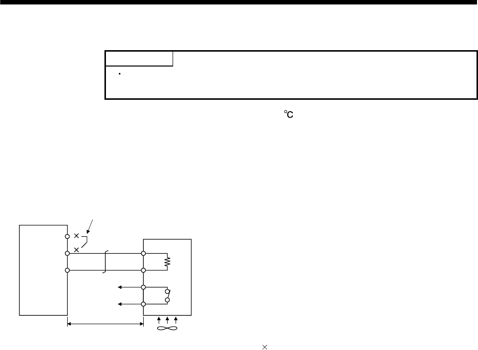
13. OPTIONS AND AUXILIARY EQUIPMENT
(4) Connection of the regenerative option
POINT
When using the MR-RB50, cooling by a cooling fan is required. Please obtain
a cooling fan at your discretion.
The regenerative option will cause a temperature rise of 100 relative to the ambient temperature. Fully
examine heat dissipation, installation position, used cables, etc. before installing the option. For wiring, use
flame-resistant cables and keep them clear of the regenerative option body. Always use twisted cables of
max. 5m length for connection with the servo amplifier.
Always remove the wiring from across P-D and fit the regenerative option across P-C.
The G3 and G4 terminals act as a thermal sensor. G3-G4 are disconnected when the regenerative option
overheats abnormally.
Servo amplifier
Regenerative option
Always remove the lead from across P-D.
D
P
C
G4
G3
(Note 2)
5m max.
Cooling fan
(Note 1)
C
P
Note 1. When using the MR-RB50, forcibly cool it with a cooling fan (92 92, minimum air flow: 1.0m3).
2. Make up a sequence which will switch off the magnetic contactor when abnormal heating occurs.
G3-G4 contact specifications
Maximum voltage: 120V AC/DC
Maximum current: 0.5A/4.8VDC
Maximum capacity: 2.4VA
13 - 3
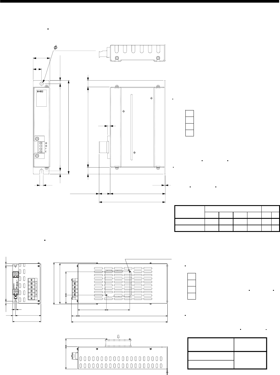
13. OPTIONS AND AUXILIARY EQUIPMENT
(5) Outline drawing
(a) MR-RB032 MR-RB12
[Unit: mm]
TE1
Terminal block
G4
G3
C
P
Applicable wire size: 0.2mm2 (AWG24)
to 2.5mm2 (AWG12)
Tightening torque:
3.24[N m](28.68 [lb in])
Mounting screw
Screw size: M5
Tightening torque:
0.5 to 0.6 [N m](4 to 5 [lb in])
TE1
LA
LB
Approx. 20 LD
1.6
LC
Approx. 12
14412
Approx. 6
156
168
6
6
5
6 mounting hole
Variable dimensions Mass Regenerative
option LA LB LC LD [kg] [lb]
MR-RB032 30 15 119 99 0.5 1.1
MR-RB12 40 15 169 149 1.1 2.4
(b) MR-RB32 MR-RB30
8.5 125 8.5
7
10 90
100 335
17 318
142
150
79
82.5
30
(30)
101.5
82.5
Cooling fan mounting
screw (2-M4 screw)
Air intake
Mounting screw
G4
G3
C
P
Terminal screw: M4
Tightening torque: 1.2 [N m] (10.6 [lb in])
[Unit: mm]
Terminal block
Tightening torque: 5.4 [N m](47.79 [lb in])
Regenerative option
MR-RB30
MR-RB32 2.9 (6.4)
Mass [kg] (lb)
Screw : M6
13 - 4
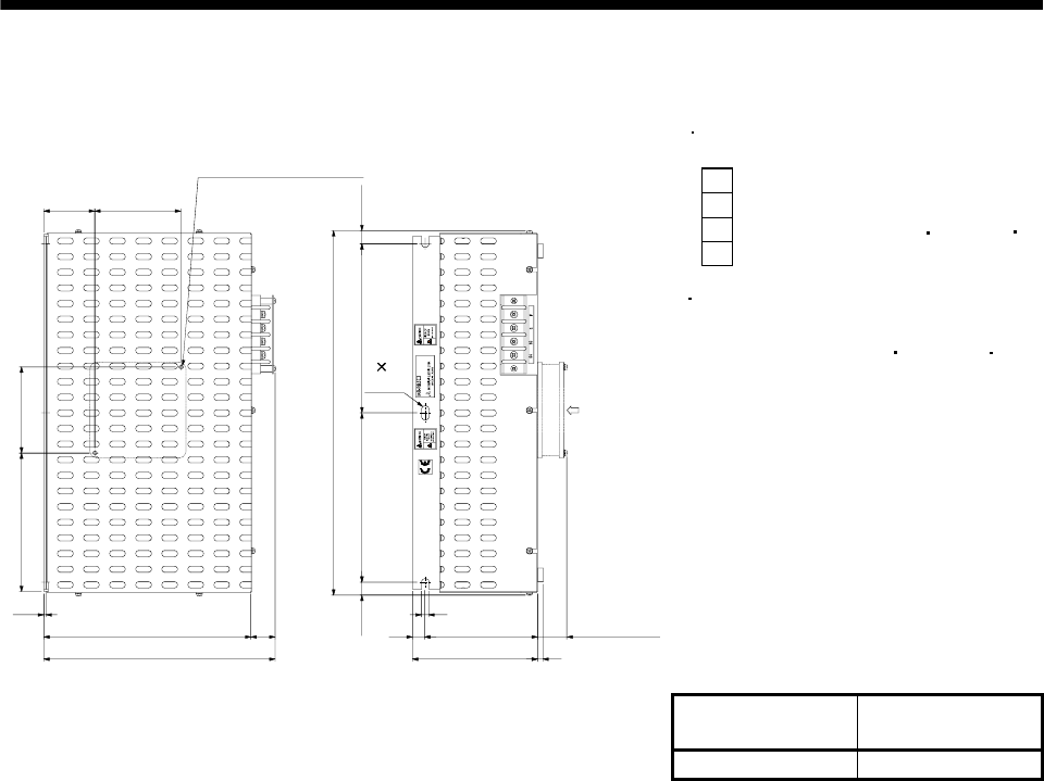
13. OPTIONS AND AUXILIARY EQUIPMENT
(c) MR-RB50
Tightening torque: 5.4 [N m](47.79 [lb in])
Terminal block
G4
G3
C
P
Terminal screw: M4
Tightening torque: 1.2 [N m](10.6 [lb in]
)
[Unit: mm (in)]
Mounting screw
Screw : M6
2.3
133 82.5
49 82.5
200 17
217 8120
108
12
12.5 162.5
350
162.5 12.5
7Approx. 30
7 14
slot Air
intake
Cooling fan mounting
screw (2-M3 screw)
On opposite side
Regenerative
option
Mass
[kg(lb)]
MR-RB50 5.6 (12.3)
13 - 5
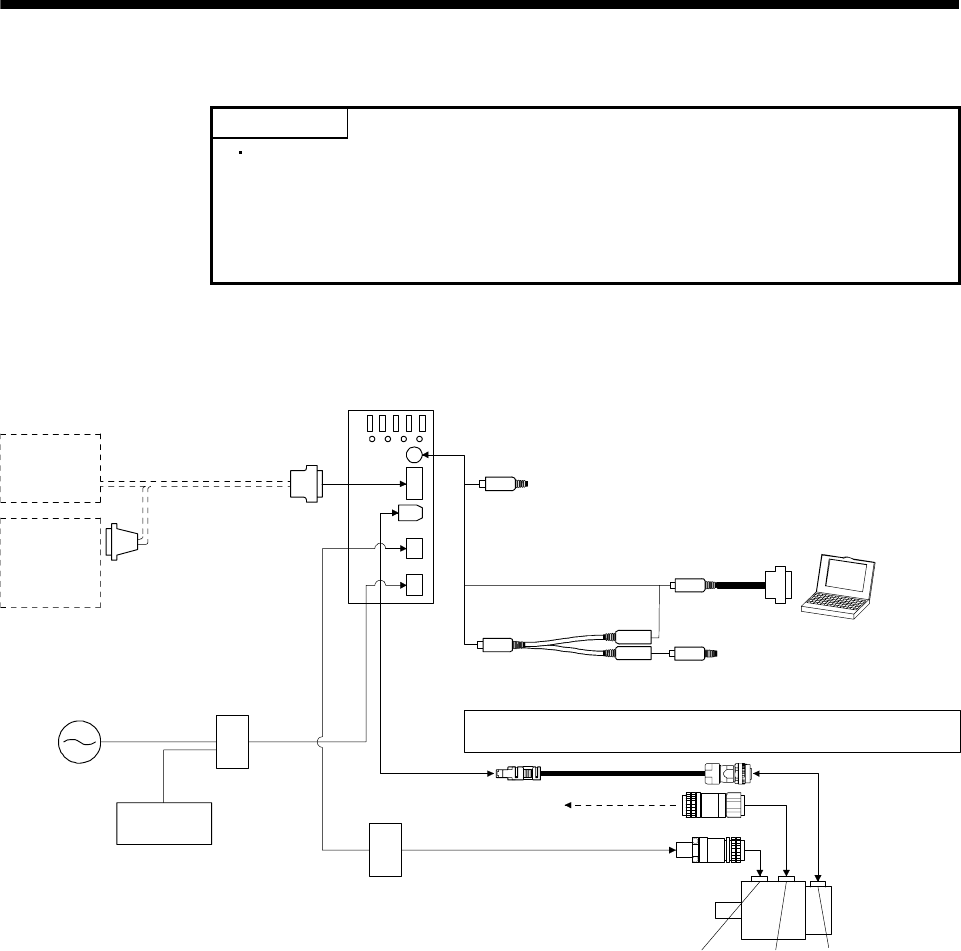
13. OPTIONS AND AUXILIARY EQUIPMENT
13.1.2 Cables and connectors
POINT
The IP rating indicated is the cable's or connector's protection against ingress
of dust and water when the cable or connector is connected to a servo amplifier
or servo motor. If the IP rating of the cable, connector, servo amplifier and
servo motor vary, the overall IP rating depends on the lowest IP rating of all
components.
(1) Cable make-up
The following cables are used for connection with the servo motor and other models. Those indicated by
broken lines in the figure are not options.
Servo amplifie
r
Operation
panel
Controller
1), 2)
Personal
computer
5)
Power supply
Regenerative
option
3) 4)
4) Analog monitor
Analog moniter
6), 7), 8), 9)
10), 11), 12), 13)
CNP1
CNP2
CN3
CN1
CN2
Refer to the HF-KN/HF-SN Servo Motor Instruction Manual for options for
servo motor power supply, electromagnetic brake, and encoder.
To 24 V DC power supply
for electromagnetic brake Servo motor
Encoder
connector
Brake
connector
Power supply
connector
13 - 6
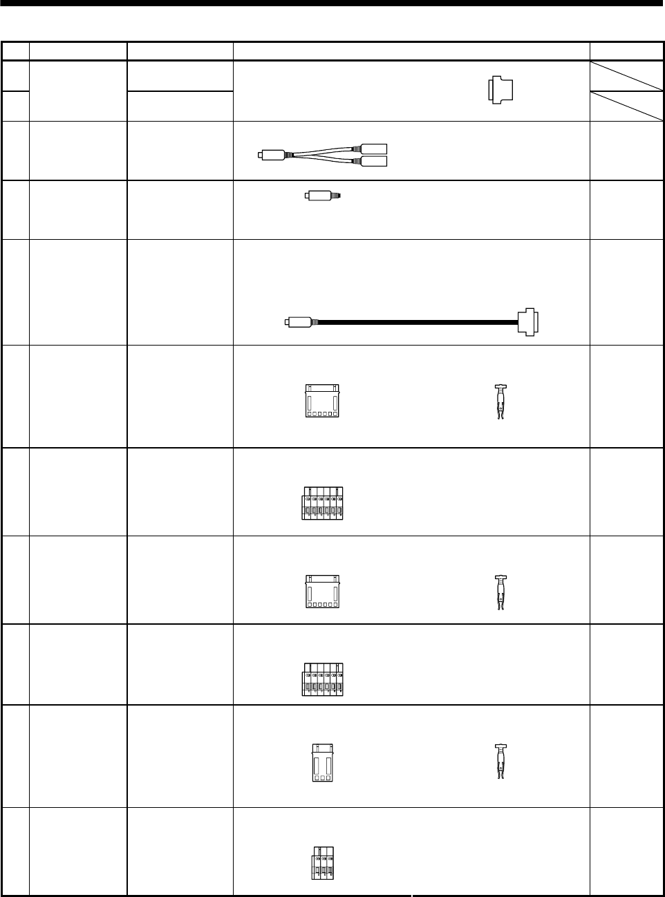
13. OPTIONS AND AUXILIARY EQUIPMENT
No. Product Model Description Application
1) MR-ECN1
(Unit: 20 pcs/box)
2)
Control signal
connector set
MR-J2CMP2
(Unit: 1 pcs/box)
Connector: 10126-3000PE
Shell kit: 10326-52F0-008
(3M or equivalent)
3) Analog monitor,
RS-232C branch
cable
MR-E3CBL15-P Connector: MP371/6
Connector: MJ372/6
(Marushin Musen Denki or
equivalent)
Analog
monitor, RS-
232C branch
cable
4) Analog monitor,
RS-232C
connector
MR-ECN3
(Unit: 20 pcs/box) Connector: MP371/6
(Marushin Musen Denki or
equivalent)
Analog
monitor, RS-
232C
connector
Connector: MP371/6
(Mini-DIN 6-pin male)
(Marushin Musen Denki or
equivalent)
Connector: DE-9SF-N
Case: DE-C1-J6-S6
(JAE)
5) Communication
cable
QC30R2
For
connection
with PC-AT
compatible
personal
computer
Connector: 51240-0600
(Molex or equivalent)
Terminal: 56125-0128
(Molex or equivalent)
6) Amplifier power
supply connector
set (Insulation
displacement
type) MR-E-10A-
QW003 to MR-E-
100A-QW003
MR-ECNP1-A
(Unit: 20 pcs/box)
Insulation
displacement
type
Connector: 54927-0610
(Molex or equivalent)
7) Amplifier power
supply connector
set (Insertion type)
MR-E-10A-
QW003 to MR-E-
100A-QW003
MR-ECNP1-B
(Unit: 20 pcs/box)
Insertion type
8) MR-ECNP1-A1
(Unit: 20 pcs/box)
Connector: 54241-0600
(Molex or equivalent)
Terminal: 56125-0128
(Molex or equivalent)
Amplifier power
supply connector
set (Insulation
displacement
type) MR-E-200A-
QW003
Insulation
displacement
type
9) MR-ECNP1-B1
(Unit: 20 pcs/box)
Connector: 54928-0610
(Molex or equivalent)
Insertion type
Amplifier power
supply connector
set (Insertion type)
MR-E-200A-
QW003
10) MR-ECNP2-A
(Unit: 20 pcs/box)
Connector: 51240-0300
(Molex or equivalent)
Terminal: 56125-0128
(Molex or equivalent)
Motor power
supply connector
(Insulation
displacement
type) MR-E-10A-
QW003 to MR-E-
100A-QW003
Insulation
displacement
type
11) MR-ECNP2-B
(Unit: 20 pcs/box)
Connector: 54927-0310
(Molex or equivalent)
Insertion type
Motor power
supply connector
(Insertion type)
MR-E-10A-
QW003 to MR-E-
100A-QW003
13 - 7
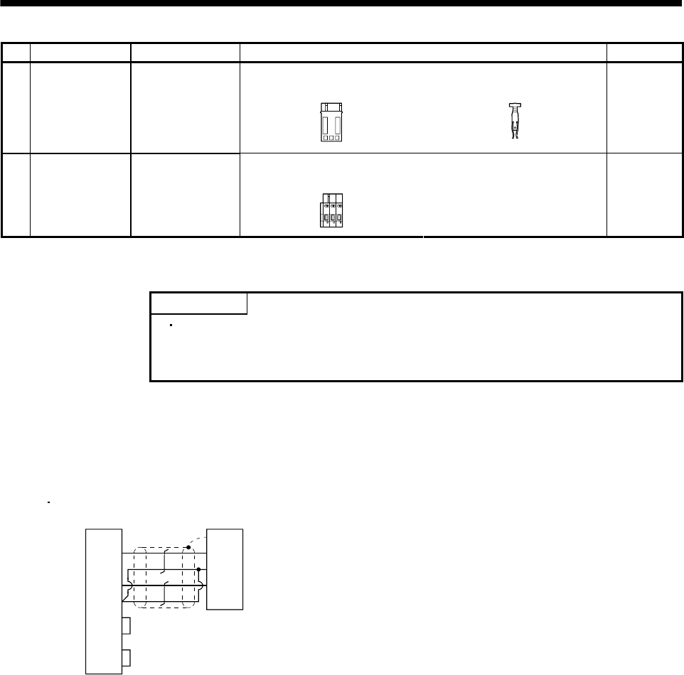
13. OPTIONS AND AUXILIARY EQUIPMENT
No. Product Model Description Application
12) MR-ECNP2-A1
(Unit: 20 pcs/box)
Connector: 54241-0300
(Molex or equivalent)
Terminal: 56125-0118
(Molex or equivalent)
Motor power
supply connector
(Insulation
displacement
type) MR-E-200A-
QW003
Insulation
displacement
type
13) MR-ECNP2-B1
(Unit: 20 pcs/box)
Connector: 54928-0310
(Molex or equivalent)
Insertion type
Motor power
supply connector
(Insertion type)
MR-E-200A-
QW003
(2) Communication cable
POINT
This cable may not be used with some personal computers. After fully
examining the signals of the RS-232C connector, refer to this section and
fabricate the cable.
(a) Model definition
Model: QC30R2 (Cable length 3[m])
(b) Connection diagram for fabrication
3
2
5
7
8
6
4
Plate
1
3
2
TXD
RXD
GND
RTS
CTS
DSR
DTR
SD
RXD
LG
TXD
D-SUB9 pins
MR-CPCATCBL3M
Personal computer side Servo amplifier side
Mini DIN 6 pins
When fabricating the cable, refer to the connection diagram in this section. Though this connection
diagram is not the connection diagram of the QC30R2, it is identical in functions.
The following must be observed in fabrication.
1) Always use a shielded, multi-core cable and connect the shield with SD securely.
2) The optional communication cable is 3m long. When the cable is fabricated, its maximum length is
15m in offices of good environment with minimal noise.
13 - 8
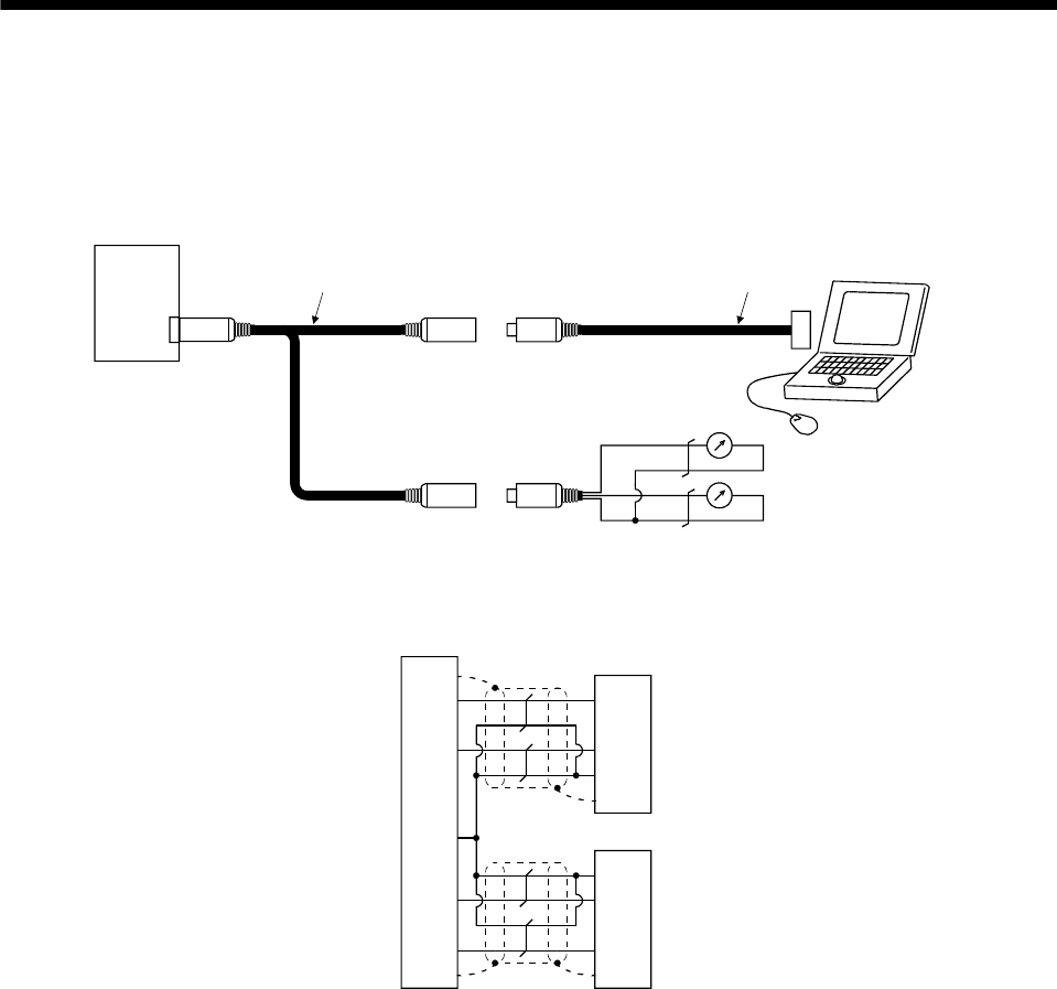
13. OPTIONS AND AUXILIARY EQUIPMENT
13.1.3 Analog monitor, RS-232C branch cable (MR-E3CBL15-P)
(1) Usage
The analog monitor, RS-232C branch cable (MR-E3CBL15-P) is designed for use when a personal
computer and analog monitor outputs are used at the same time.
CN3
MO2
MO1
LG
LG
Servo amplifier
Analog monitor, RS-232C branch cable
(MR-E3CBL15-P) Communication cable
(QC30R2)
Analog monitor output 2
Analog monitor output 1
(2) Connection diagram
RXD 1
TXD 2
MO1 4
6
RS-232C
MO2 6
4MO1
MO2
SD
SD
3LG
SD
3
2TXD
LG
1RXD
SD
LG 3
Servo amplifier
Analog monitor
Plate
Plate
Plate
Plate
13 - 9
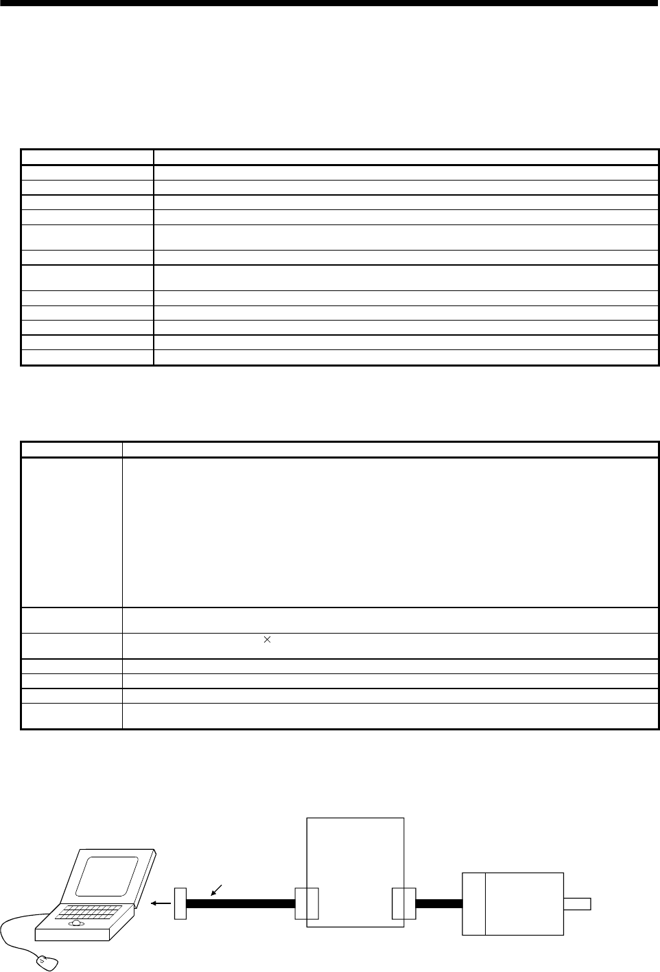
13. OPTIONS AND AUXILIARY EQUIPMENT
13.1.4 MR Configurator (servo configurations software)
The MR Configurator (servo configurations software MRZJW3-SETUP154E, 154C) uses the communication
function of the servo amplifier to perform parameter setting changes, graph display, test operation, etc. on a
personal computer.
(1) Specifications
Item Description
Model 154E: English, 154C: Chinese
Communication signal Conforms to RS-232C.
Baud rate [bps] 57600, 38400, 19200, 9600
System Station selection, Automatic demo
Monitor Display, high speed monitor, trend graph
Minimum resolution changes with the processing speed of the personal computer.
Alarm Display, history, amplifier data
Diagnostic Digital I/O, no motor rotation, total power-on time, amplifier version info, motor information, tuning data,
Automatic VC offset display, Axis name setting.
Parameters Parameter list, turning, change list, detailed information
Test operation Jog operation, positioning operation, Operation w/o motor, Forced output, Demo mode.
Advanced function Machine analyzer, gain search, machine simulation.
File operation Data read, save, print
Others Automatic demo, help display
(2) System configuration
(a) Components
To use this MR Configurator (servo configurations software), the following components are required in
addition to the servo amplifier and servo motor.
Model (Note 1) Description
(Note 2)
Personal computer
IBM PC-AT compatible where the English version and Chinese version of Windows® 95, Windows® 98,
Windows® Me, Windows NT® Workstation 4.0, Windows® 2000 Professional, Windows® XP Professional and
Windows® XP Home Edition operates
Processor: Pentium® 133MHz or more (Windows® 95, Windows® 98, Windows NT® Workstation 4.0, Windows®
2000 Professional)
Pentium® 150MHz or more (Windows® Me)
Pentium® 300MHz or more (Windows® XP Professional, Windows® XP Home Edition)
Memory: 16MB or more (Windows® 95), 24MB or more (Windows® 98)
32MB or more (Windows® Me, Windows NT® Workstation 4.0, Windows® 2000 Professional)
128MB or more (Windows® XP Professional, Windows® XP Home Edition)
Free hard disk space: 60MB or more
Serial port used
OS Windows® 95, Windows® 98, Windows® Me, Windows NT® Workstation 4.0, Windows® 2000 Professional,
Windows® XP Professional, Windows® XP Home Edition (English version, Chinese version)
Display One whose resolution is 800 600 or more and that can provide a high color (16 bit) display. Connectable with
the above personal computer.
Keyboard Connectable with the above personal computer.
Mouse Connectable with the above personal computer. Note that a serial mouse is not used.
Printer Connectable with the above personal computer.
Communication
cable QC30R2
When this cannot be used, refer to section 13.1.2 (3) and fabricate.
Note 1. Windows and Windows NT are the registered trademarks of Microsoft Corporation in the United States and other countries.
Pentium is the registered trademarks of Intel Corporation.
2. On some personal computers, this MR Configurator (servo configurations software) may not run properly.
(b) Configuration diagram
CN3 CN2
Personal computer
To RS-232C
connector
Communication cable
Servo amplifier
Servo motor
13 - 10
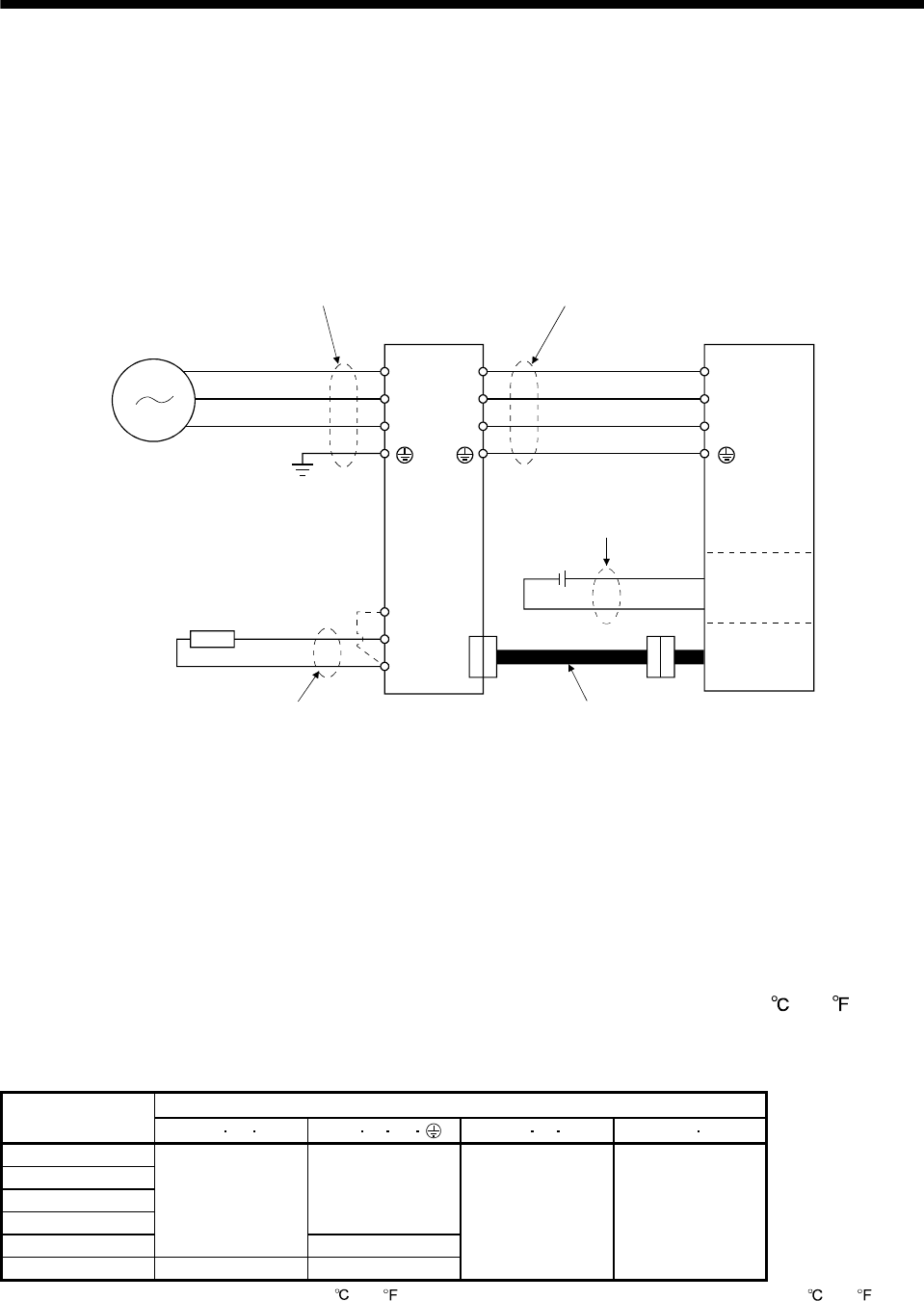
13. OPTIONS AND AUXILIARY EQUIPMENT
13.2 Auxiliary equipment
Always use the devices indicated in this section or equivalent. To comply with the EN Standard or UL/cUL
(CSA) Standard, use the products which conform to the corresponding standard.
13.2.1 Selection example of wires
(1) Wires for power supply wiring
The following diagram shows the wires used for wiring. Use the wires given in this section or equivalent.
C
P
U
V
W
B1
B2
U
V
W
L1
L2
L3
D
Power supply
1) Power supply lead
Regenerative option
3) Regenerative option lead
(Note)
Servo amplifier
2) Motor power supply lead
4) Electromagnetic
brake lead
Encoder cable (refer to section 13.1.2)
Motor
Electro-
magnetic
brake
Encoder
Servo motor
Note. When using the regenerative option, always remove the wiring across D-P.
The following table lists wire sizes. The wires used assume that they are 600V vinyl wires and the wiring
distance is 30m max. If the wiring distance is over 30m, choose the wire size in consideration of voltage
drop.
Refer to section 3.11 for connection with the connector (CNP1, CNP2).
The servo motor side connection method depends on the type and capacity of the servo motor. Refer to
HF-KN/HF-SN Servo Motor Instruction Manual.
To enable the built-in regenerative brake, connect the wiring across D-P. (Refer to section 3.7.2 for the
connection method.)
To comply with the UL/cUL (CSA) Standard, use UL-recognized copper wires rated at 60 (140 ) or more
for wiring.
Table 13.1 Selection example of wires
(Note) Wires [mm2]
Servo amplifier 1) L1L2L33) U V W 4) P CD 5) B1 B2
MR-E-10A-QW003
MR-E-20A-QW003
MR-E-40A-QW003
MR-E-70A-QW003
1.25 (AWG16)
MR-E-100A-QW003
2 (AWG14)
2 (AWG14)
MR-E-200A-QW003 (Note) 2.5 (AWG14) (Note) 2.5 (AWG14)
2 (AWG14) 1.25 (AWG16)
Note. Use the heat-resistant PVC cable (rated 105 (221 ) or more), if AWG14 cable is used in ambient temperature 40 (104 ) or
more.
13 - 11
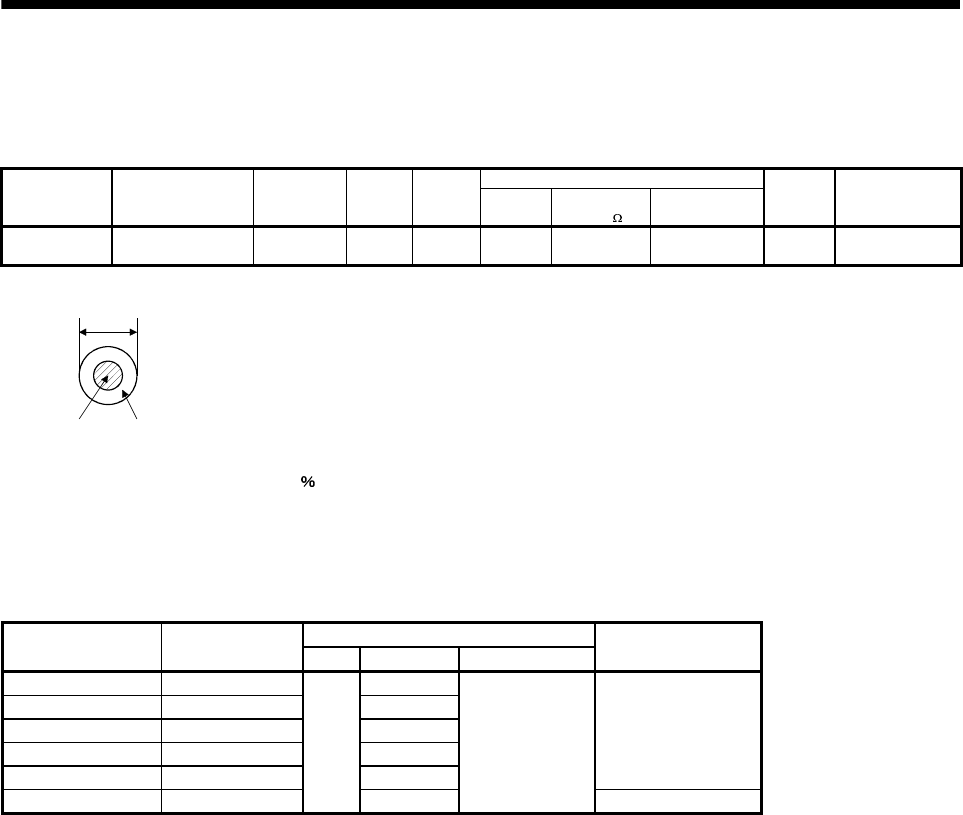
13. OPTIONS AND AUXILIARY EQUIPMENT
(2) Wires for cables
When fabricating a cable, use the wire models given in the following table or equivalent.
Table 13.2 Wires for option cables
Characteristics of one core
Type Model
Length
[mm]
Core size
[mm2]
Number
of cores Structure
[Wires/mm]
Conductor
resistance [ /mm]
Insulation coating
ODd [mm] (Note 1)
(Note 2)
Finishing
OD [mm]
Wire model
Communication
cable QC30R2 3 0.08
6
(3 pairs) 7/0.127 222 0.38 4.6
UL20276 AWG#28
3pair (BLACK)
Note 1. d is as shown below.
d
Conductor Insulators
2. Standard OD. Max. OD is about 10 greater.
13.2.2 Circuit breakers, fuses, magnetic contactors
Always use one circuit breaker and one magnetic contactor with one servo amplifier. When using a fuse
instead of the circuit breaker, use the one having the specifications given in this section.
Fuse
Servo amplifier Circuit breaker Class Current [A] Voltage AC [V]
Magnetic contactor
(Note)
MR-E-10A-QW003 30A frame 5A 10
MR-E-20A-QW003 30A frame 5A 10
MR-E-40A-QW003 30A frame 10A 15
MR-E-70A-QW003 30A frame 15A K5 15
MR-E-100A-QW003 30A frame 15A 15
S-N10
MR-E-200A-QW003 30A frame 20A 15
250
S-N18
Note. Be sure to use a magnetic contactor with an operation delay time of 80ms or less. The operation delay time is the time interval
between current being applied to the coil until closure of contacts.
13 - 12
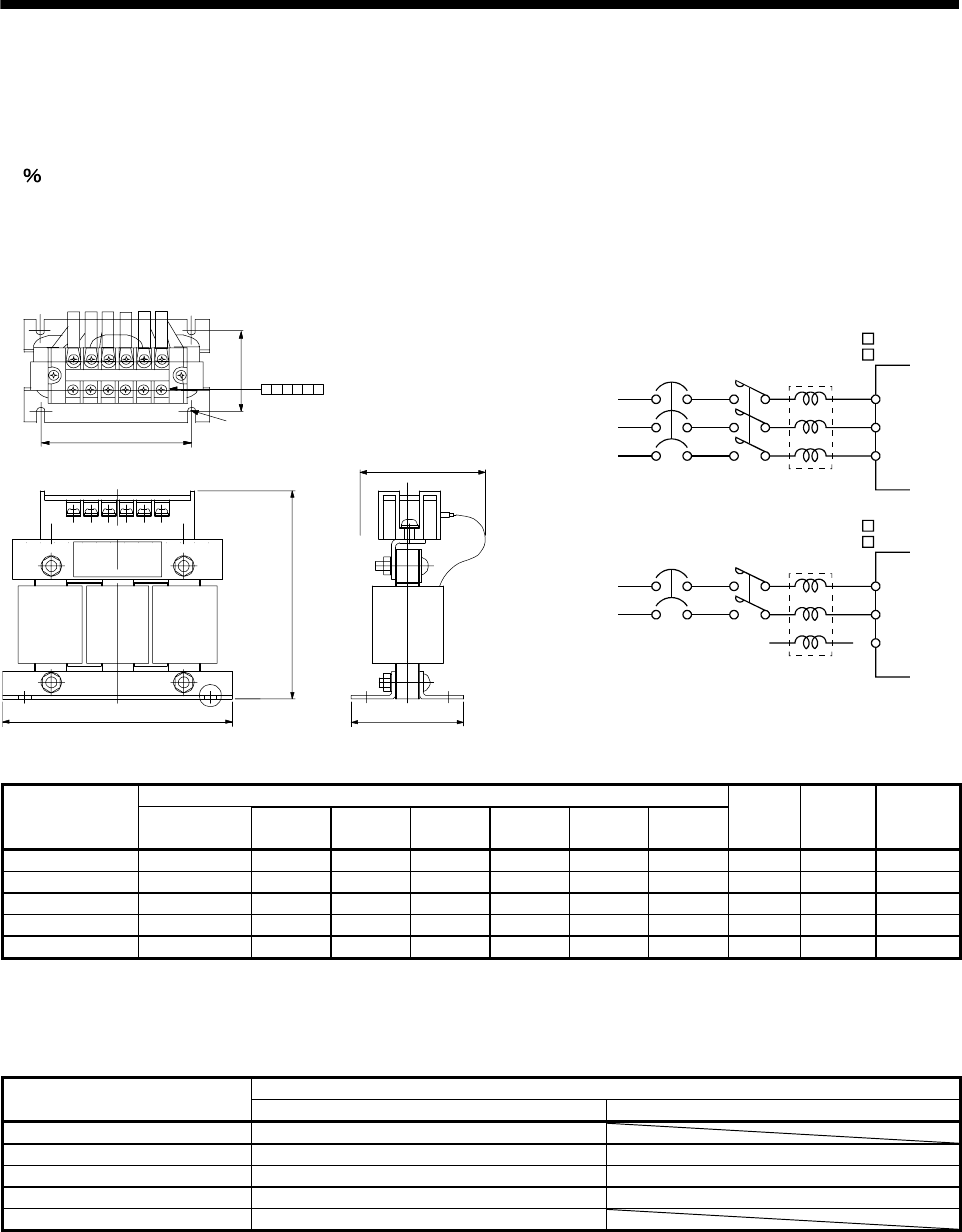
13 - 13
13. OPTIONS AND AUXILIARY EQUIPMENT
13.2.3 Power factor improving AC reactors
The power factor improving AC reactor FR-HAL increases the form factor of the servo amplifier's input current
to improve the power factor. It can reduce the power capacity. The input power factor is improved to be about
88 .
When using the power factor improving AC reactors FR-HAL for two or more servo amplifiers, be sure to
connect a power factor improving AC reactor FR-HAL to each servo amplifier. If using one power factor
improving AC reactor FR-HAL for multiple servo amplifiers, enough improvement effect of phase factor cannot
be obtained unless all servo amplifiers are operated.
Mounting hole for 4-d
(front right side,
varnish removal)(Note1)
Terminal layout
RX S Y TZ
MAX D
MAX W (Note 3)
W1
D20
H±5
D1±2
FR-HAL
L1
L2
L3
MC R
S
T
X
Y
Z
FR-HAL
L1
L2
L3
MC R
S
T
X
Y
Z
(Note4)
3-phase
200 to 230VAC
3-phase
200 to 230VAC
NFB
NFB
Servo amplifier
MR-E- A-QW003
MR-E- AG-QW003
Servo amplifier
MR-E- A-QW003
MR-E- AG-QW003
Dimensions [mm] Power factor
improving
AC reactor (FR-HAL) W W1 H
D
(Note 2) D1 D2 d
Terminal
screw size
Crimping
terminal
Mass
[kg]
FR-HAL-0.4K 104 84 99 72 51 40 M5 M4 2-4 0.6
FR-HAL-0.75K 104 84 99 74 56 44 M5 M4 2-4 0.8
FR-HAL-1.5K 104 84 99 77 61 50 M5 M4 2-4 1.1
FR-HAL-2.2K 115 (Note 2) 40 115 77 71 57 M6 M4 2-4 1.5
FR-HAL-3.7K 115 (Note 2) 40 115 83 81 67 M6 M4 5.5-4 2.2
Note. 1.Use this hole for grounding.
2.Maximum dimension (The dimension varies depending on the bending degree of the I/O line.)
3.W±2 for FR-HAL-0.4K to 1.5K.
4.Connect a 1-phase 200 to 230VAC power supply to L1, L2 and keep L3 open.
Applicable servo amplifier Power factor improving
AC reactor (FR-HAL) 3-phase power supply 1-phase power supply
FR-HAL-0.4K MR-E-10A-QW003・MR-E-20A-QW003
FR-HAL-0.75K MR-E-40A-QW003 MR-E-10A-QW003・MR-E-20A-QW003
FR-HAL-1.5 K MR-E-70A-QW003 MR-E-40A-QW003
FR-HAL-2.2K MR-E-100A-QW003 MR-E-70A-QW003
FR-HAL-3.7K MR-E-200A-QW003
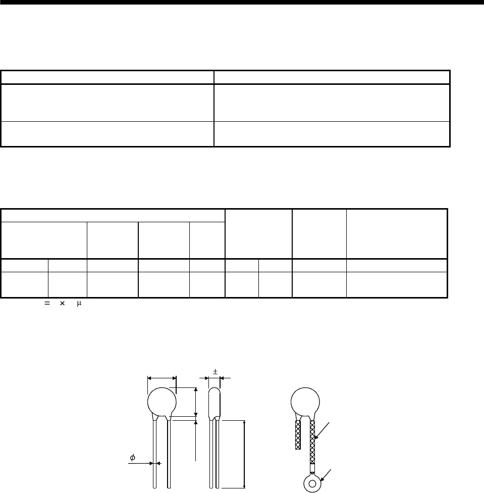
13. OPTIONS AND AUXILIARY EQUIPMENT
13.2.4 Relays
The following relays should be used with the interfaces.
Interface Selection example
Input signals (interface DI-1) signals To prevent defective contacts, use a relay for small signal
(twin contacts).
(Ex.) Omron: type G2A, MY
Relay used for digital output signals (interface DO-1) Small relay with 12VDC or 24VDC of rating 40mA or less
(Ex.) Omron: type MY
13.2.5 Surge absorbers
A surge absorber is required for the electromagnetic brake. Use the following surge absorber or equivalent.
Insulate the wiring as shown in the diagram.
Maximum rating
Permissible circuit
voltage
Surge
immunity
Energy
immunity
Rated
power
Maximum
limit voltage
Static
capacity
(reference
value)
Varistor voltage
rating (range) V1mA
AC[Vma] DC[V] [A] [J] [W] [A] [V] [pF] [V]
140 180
(Note)
500/time 5 0.4 25 360 300 220
(198 to 242)
Note. 1 time 8 20 s
(Example) ERZV10D221 (Panasonic)
TNR-10V221K (Nippon chemi-con)
Outline drawing [mm] (ERZ-C10DK221)
13.5
16.5
3.0or less
30.0or more
Crimping terminal
for M4 screw
Vinyl tube
4.7 1.0
0.8
13 - 14

13. OPTIONS AND AUXILIARY EQUIPMENT
13.2.6 Noise reduction techniques
Noises are classified into external noises which enter the servo amplifier to cause it to malfunction and those
radiated by the servo amplifier to cause peripheral devices to malfunction. Since the servo amplifier is an
electronic device which handles small signals, the following general noise reduction techniques are required.
Also, the servo amplifier can be a source of noise as its outputs are chopped by high carrier frequencies. If
peripheral devices malfunction due to noises produced by the servo amplifier, noise suppression measures
must be taken. The measures will vary slightly with the routes of noise transmission.
(1) Noise reduction techniques
(a) General reduction techniques
Avoid laying power lines (input and output cables) and signal cables side by side or do not bundle
them together. Separate power lines from signal cables.
Use shielded, twisted pair cables for connection with the encoder and for control signal transmission,
and connect the shield to the SD terminal.
Ground the servo amplifier, servo motor, etc. together at one point (refer to section 3.9).
(b) Reduction techniques for external noises that cause the servo amplifier to malfunction
If there are noise sources (such as a magnetic contactor, an electromagnetic brake, and many relays
which make a large amount of noise) near the servo amplifier and the servo amplifier may malfunction,
the following countermeasures are required.
Provide surge absorbers on the noise sources to suppress noises.
Attach data line filters to the signal cables.
Ground the shields of the encoder connecting cable and the control signal cables with cable clamp
fittings.
Although a surge absorber is built into the servo amplifier, to protect the servo amplifier and other
equipment against large exogenous noise and lightning surge, attaching a varistor to the power input
section of the equipment is recommended.
(c) Techniques for noises radiated by the servo amplifier that cause peripheral devices to malfunction
Noises produced by the servo amplifier are classified into those radiated from the cables connected to
the servo amplifier and its main circuits (input and output circuits), those induced electromagnetically or
statically by the signal cables of the peripheral devices located near the main circuit cables, and those
transmitted through the power supply cables.
13 - 15
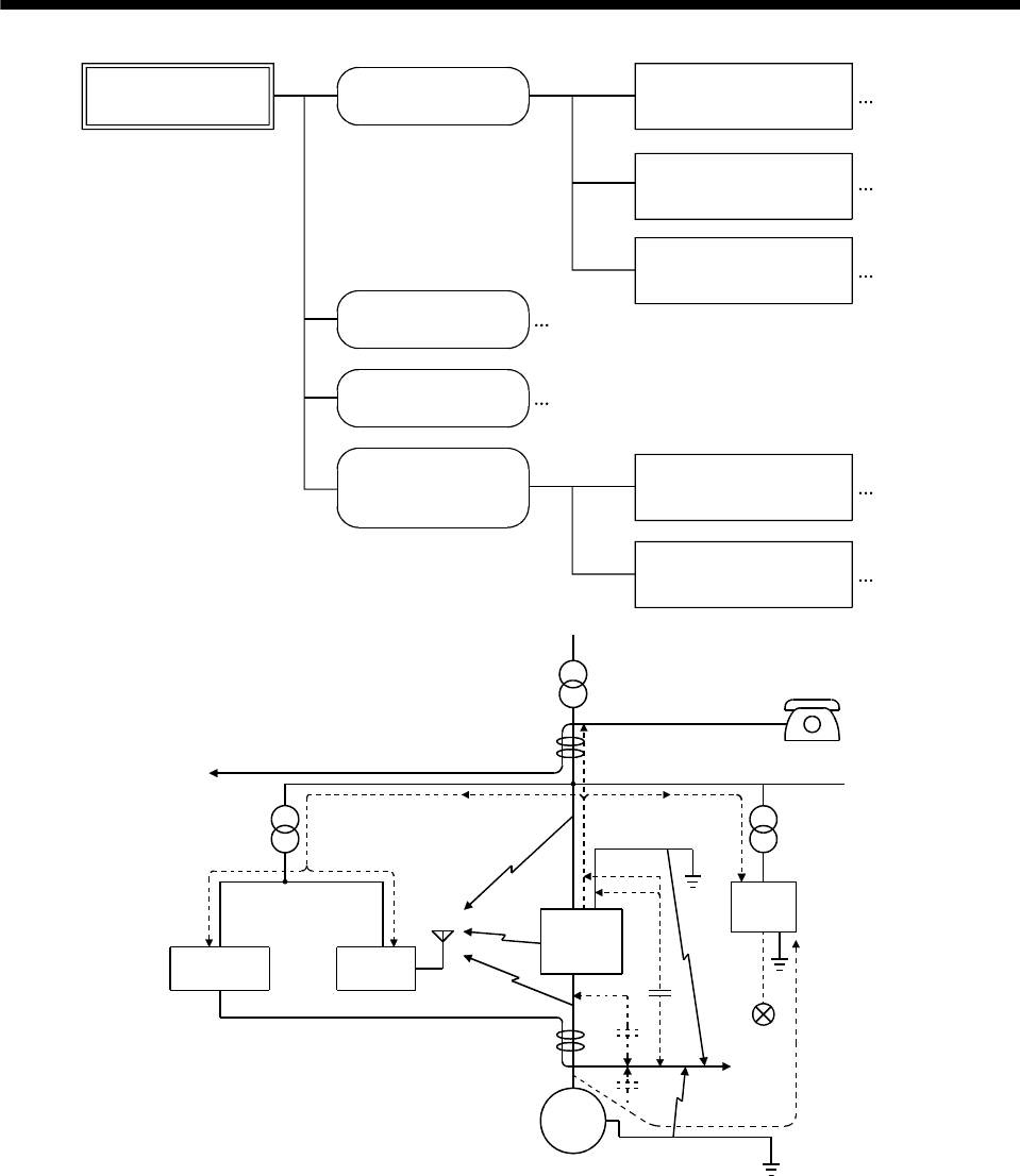
13. OPTIONS AND AUXILIARY EQUIPMENT
Noises produced
by servo amplifier Noises transmitted
in the air
Noise radiated directly
from servo amplifier
Magnetic induction
noise
Static induction
noise
Noises transmitted
through electric
channels
Noise radiated from the
power supply cable
Noise radiated from
servo motor cable
Noise transmitted through
power supply cable
Noise sneaking from
grounding cable due to
leakage current
Routes 4) and 5)
Route 1)
Route 2)
Route 3)
Route 7)
Route 8)
Route 6)
Instrument Receiver
Servo
amplifier
Servo motor M
2)
2)
8)
1)
7)
7) 7)
5)
3)
4)
6)
3)
Sensor
power
supply
Sensor
13 - 16
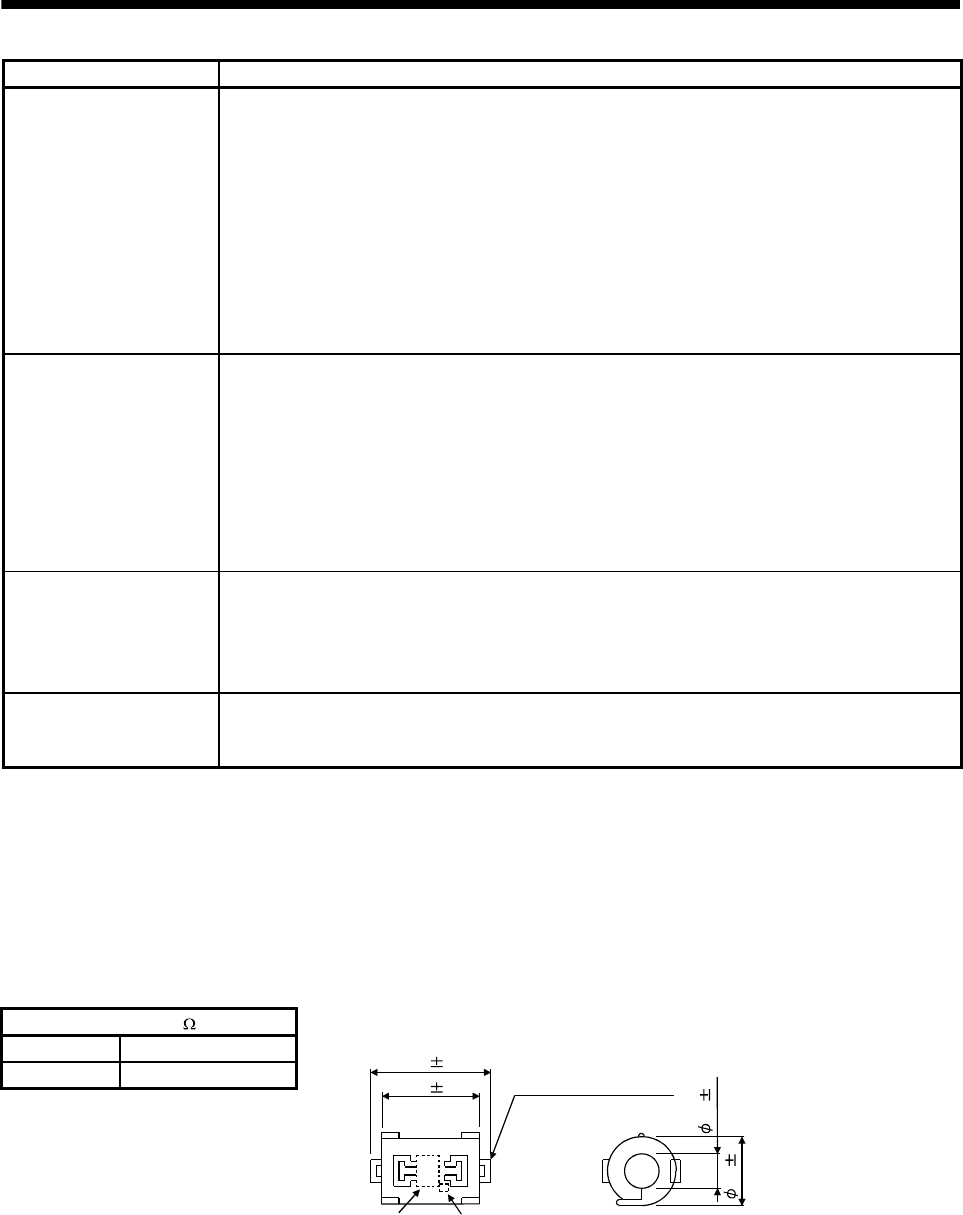
13. OPTIONS AND AUXILIARY EQUIPMENT
Noise transmission route Suppression techniques
1) 2) 3)
When measuring instruments, receivers, sensors, etc. which handle weak signals and may malfunction
due to noise and/or their signal cables are contained in a control box together with the servo amplifier or
run near the servo amplifier, such devices may malfunction due to noises transmitted through the air. The
following techniques are required.
(1) Provide maximum clearance between easily affected devices and the servo amplifier.
(2) Provide maximum clearance between easily affected signal cables and the I/O cables of the servo
amplifier.
(3) Avoid laying the power lines (Input cables of the servo amplifier) and signal cables side by side or
bundling them together.
(4) Insert a line noise filter to the I/O cables or a radio noise filter on the input line.
(5) Use shielded wires for signal and power cables or put cables in separate metal conduits.
4) 5) 6)
When the power lines and the signal cables are laid side by side or bundled together, magnetic induction
noise and static induction noise will be transmitted through the signal cables and malfunction may occur.
The following techniques are required.
(1) Provide maximum clearance between easily affected devices and the servo amplifier.
(2) Provide maximum clearance between easily affected signal cables and the I/O cables of the servo
amplifier.
(3) Avoid laying the power lines (Input cables of the servo amplifier) and signal cables side by side or
bundling them together.
(4) Use shielded wires for signal and power cables or put the cables in separate metal conduits.
7)
When the power supply of peripheral devices is connected to the power supply of the servo amplifier
system, noises produced by the servo amplifier may be transmitted back through the power supply cable
and the devices may malfunction. The following techniques are required.
(1) Insert the radio noise filter (FR-BIF) on the power cables (Input cables) of the servo amplifier.
(2) Insert the line noise filter (FR-BSF01) on the power cables of the servo amplifier.
8)
When the cables of peripheral devices are connected to the servo amplifier to make a closed loop circuit,
leakage current may flow to malfunction the peripheral devices. If so, malfunction may be prevented by
disconnecting the grounding cable of the peripheral device.
(2) Noise reduction products
(a) Data line filter
Noise can be prevented by installing a data line filter onto the encoder cable, etc.
For example, the ZCAT3035-1330 of TDK and the ESD-SR-250 of NEC Tokin make are available as
data line filters.
As a reference example, the impedance specifications of the ZCAT3035-1330 (TDK) are indicated
below.
This impedances are reference values and not guaranteed values.
Impedance [ ]
10 to 100MHz 100 to 500MHz
80 150
34 1
Outline drawing (ZCAT3035-1330)
[Unit: mm]
Loop for fixing the
cable band
Lot number Product name
TDK
39 1
13 1
30 1
13 - 17
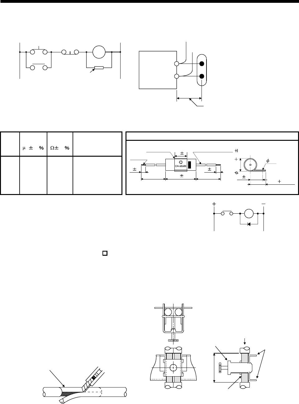
13 - 18
13. OPTIONS AND AUXILIARY EQUIPMENT
(b) Surge suppressor
The recommended surge suppressor for installation to an AC relay, AC valve or the like near the servo
amplifier is shown below. Use this product or equivalent.
Relay
This distance should be shor
t
(within 20cm).
Surge suppressor
MC
Surge suppressor
(Ex.) CR-50500
(OKAYA Electric Industries Co., Ltd.)
Outline drawing [Unit: mm] Rated
voltage
AC [V]
C
[F20 ]
R
[30 ] Test voltage AC [V]
250 0.5 50
(1/2W)
Between terminals:
625VAC 50/60Hz 60s
Between terminal and
case: 2,000VAC
50/60Hz 60s
6 1
300min 300min
Soldered
Band (clear) AWG18 Twisted wire
15 1
48 1.5
6 1
16 1 (18.5 5)max.
3.6
(18.5 2) 1
Note that a diode should be installed to a DC relay, DC valve or the
like.
Maximum voltage: Not less than 4 times the drive voltage of the
relay or the like
Maximum current: Not less than twice the drive current of the
relay or the like
Diode
RA
(c) Cable clamp fitting (AERSBAN -SET)
Generally, the earth of the shielded cable may only be connected to the connector's SD terminal.
However, the effect can be increased by directly connecting the cable to an earth plate as shown below.
Install the earth plate near the servo amplifier for the encoder cable. Peel part of the cable insulators to
expose the external conductor, and press that part against the earth plate with the cable clamp. If the
cable is thin, clamp several cables in a bunch.
The clamp comes as a set with the earth plate.
Strip the cable insulators of
the clamped area. cutter
cable
Cable clamp
(A,B)
Cable
Earth plate
External conductor
Clamp section diagram
40
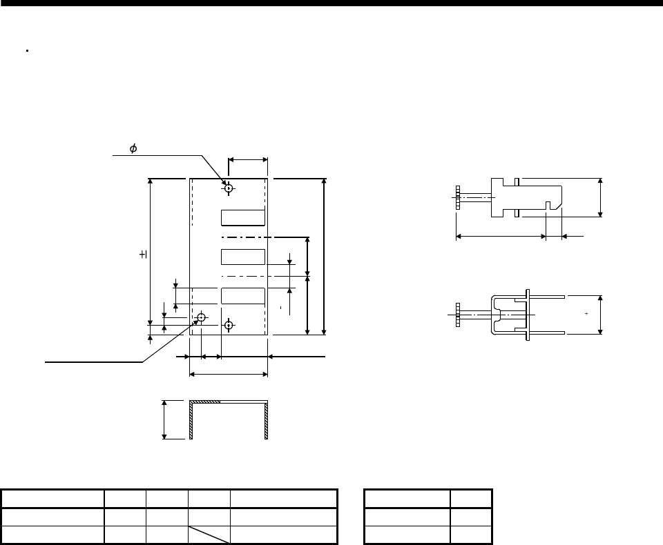
13. OPTIONS AND AUXILIARY EQUIPMENT
Outline drawing
B 0.3
2- 5 hole
installation hole
Earth plate Clamp section diagram
(Note)M4 screw
1136
C
A
622
17.5
35
35
L or less 10
30
7
24
0
0.2
Note. Screw hole for grounding. Connect it to the earth plate of the control box.
24
0.3
0
[Unit: mm]
Type A B C Accessory fittings Clamp fitting L
AERSBAN-DSET 100 86 30 clamp A: 2pcs. A 70
AERSBAN-ESET 70 56 clamp B: 1pc. B 45
13 - 19
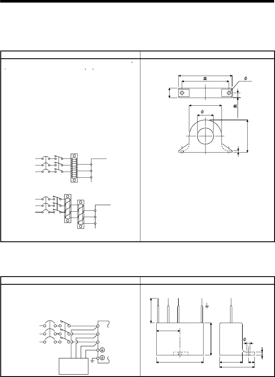
13 - 20
13. OPTIONS AND AUXILIARY EQUIPMENT
(d) Line noise filter (FR-BSF01)
This filter is effective in suppressing noises radiated from the power supply side and output side of the
servo amplifier and also in suppressing high-frequency leakage current (zero-phase current) especially
within 0.5MHz to 5MHz band.
Connection diagram Outline drawing [Unit: mm]
Use the line noise filters for wires of the main power supply (L1L2
L3) and of the motor power supply (U VW). Pass each of the
3-phase wires through the line noise filter an equal number of times
in the same direction. For the main power supply, the effect of the
filter rises as the number of passes increases, but generally four
passes would be appropriate. For the motor power supply, passes
must be four times or less. Do not pass the grounding (earth) wire
through the filter, or the effect of the filter will drop. Wind the wires by
passing through the filter to satisfy the required number of passes as
shown in Example 1. If the wires are too thick to wind, use two or
more filters to have the required number of passes as shown in
Example 2. Place the line noise filters as close to the servo amplifier
as possible for their best performance.
MCCB
Example 1
Power
supply
Servo amplifier
Line noise
filter
L1
L2
L3
(Number of passes: 4)
MCCB
L1
L2
L3
Two filters are used
(Total number of passes: 4)
MC
MC
Servo amplifier
Power
supply
Example 2
Line noise
filter
FR-BSF01
4.5
Approx. 110
95 0.5
Approx. 22.5
Approx. 65
Approx. 65
33
2- 5
11.25 0.5
(e) Radio noise filter (FR-BIF)...for the input side only
This filter is effective in suppressing noises radiated from the power supply side of the servo amplifier
especially in 10MHz and lower radio frequency bands. The FR-BIF is designed for the input side only.
Connection diagram Outline drawing [Unit: mm]
Make the connection cables as short as possible.
Grounding is always required.
When using the FR-BIF with a single-phase power supply, always
insulate the wires that are not used for wiring.
Servo amplifier
MCCB
L3
L2
L1
MC
Power
supply
Radio noise
filter FR-BIF
Leakage current: 4mA
29
58
42
4
Red BlueWhite Green
44
29 7
hole
About 300
5
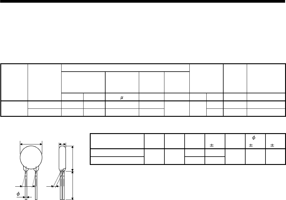
13. OPTIONS AND AUXILIARY EQUIPMENT
(f) Varistors for input power supply (Recommended)
Varistors are effective to prevent exogenous noise and lightning surge from entering the servo amplifier.
When using a varistor, connect it between each phase of the input power supply of the equipment. For
varistors, the TND20V-431K and TND20V-471K, manufactured by NIPPON CHEMI-CON, are
recommended. For detailed specification and usage of the varistors, refer to the manufacturer catalog.
Maximum rating
Permissible circuit
voltage
Surge current
immunity
Energy
immunity
Rated pulse
power
Maximum limit
voltage
Static
capacity
(reference
value)
Varistor voltage
rating (range)
V1mA
Power
supply
voltage
Varistor
AC [Vrms] DC [V] 8/20 s [A] 2ms [J] [W] [A] [V] [pF] [V]
100V class TND20V-431K 275 350 10000/1 time 195 710 1300 430(387 to 473)
200V class TND20V-471K 300 385 7000/2 time 215 1.0 100
775 1200 470(423 to 517)
[Unit: mm]
Model D
Max.
H
Max.
T
Max.
E
1.0
(Note) L
min.
d
0.05
W
1.0
TND20V-431K 6.4 3.3
TND20V-471K 21.5 24.5 6.6 3.5 20 0.8 10.0
Note. For special purpose items for lead length (L), contact the manufacturer.
d
W E
H
D
L
T
13 - 21
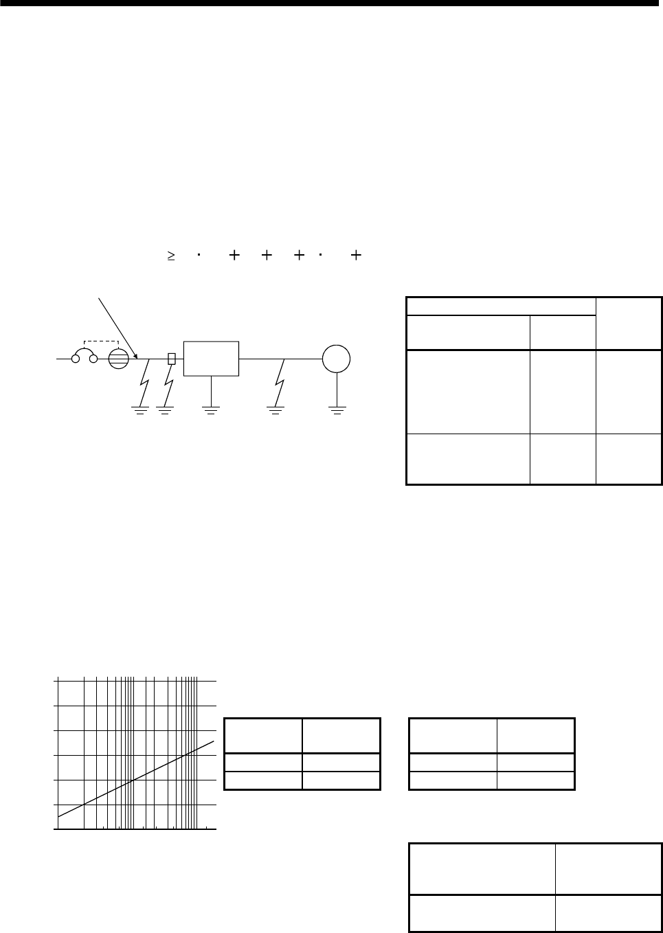
13. OPTIONS AND AUXILIARY EQUIPMENT
13.2.7 Leakage current breaker
(1) Selection method
High-frequency chopper currents controlled by pulse width modulation flow in the AC servo circuits.
Leakage currents containing harmonic contents are larger than those of the motor which is run with a
commercial power supply.
Select a leakage current breaker according to the following formula, and ground the servo amplifier, servo
motor, etc. securely.
Make the input and output cables as short as possible, and also make the grounding cable as long as
possible (about 30cm) to minimize leakage currents.
Rated sensitivity current 10 {Ig1 Ign Iga K(Ig2 Igm)} [mA]...........(13.1)
K: Constant considering the harmonic contents
Leakage current breaker
Type Mitsubishi
products
K
Models provided with
harmonic and surge
reduction techniques
NV-SP
NV-SW
NV-CP
NV-CW
NV-L
1
General models
BV-C1
NFB
NV-L
3
M
Servo
amplifier
Noise
filter
NV
Ig1 Ign Iga Ig2 Igm
Cable
Cable
Ig1: Leakage current on the electric channel from the leakage current breaker to the input terminals of the
servo amplifier (Found from Fig. 13.1.)
Ig2: Leakage current on the electric channel from the output terminals of the servo amplifier to the
servo motor (Found from Fig. 13.1.)
Ign: Leakage current when a filter is connected to the input side (4.4mA per one FR-BIF)
Iga: Leakage current of the servo amplifier (Found from Table 13.4.)
Igm: Leakage current of the servo motor (Found from Table 13.3.)
Table 13.3 Servo motor's
leakage current
example (Igm)
Table 13.4 Servo amplifier's
leakage current
example (Iga)
Servo motor
output [kW]
Leakage
current [mA]
Servo amplifier
capacity [kW]
Leakage
current [mA]
0.1 to 1.0 0.1 0.1 to 0.6 0.1
1.0 to 2.2 0.2 0.7 to 2.0 0.15
Table 13.5 Leakage circuit breaker selection example
Servo amplifier
Rated sensitivity
current of leakage
circuit breaker [mA]
120
100
80
60
40
20
023.5
5.581422388015
0
30 60 100
Fig. 13.1 Leakage current example
(Ig1, Ig2) for CV cable run
in metal conduit
Cable size[mm2]
[mA]
Leakage current
MR-E-10A-QW003 to
MR-E-200A-QW003 15
13 - 22
13. OPTIONS AND AUXILIARY EQUIPMENT
(2) Selection example
Indicated below is an example of selecting a leakage current breaker under the following conditions.
M
NV
Ig1 Iga Ig2 Igm
2mm2 5m 2mm2 5m
Servo amplifier
MR-E-40A-QW003 Servo motor
HF-KN43(J)
Use a leakage current breaker generally available.
Find the terms of Equation (13.1) from the diagram.
Ig1 20 1000
50.1 [mA]
Ig2 20 1000
50.1 [mA]
Ign 0 (not used)
Iga 0.1 [mA]
Igm 0.1 [mA]
Insert these values in Equation (13.1).
Ig 10 {0.1 00.1 1(0.1 0.1)}
4.0 [mA]
According to the result of calculation, use a leakage current breaker having the rated sensitivity current (Ig)
of 4.0 [mA] or more. A leakage current breaker having Ig of 15 [mA] is used with the NV-
SP/SW/CP/CW/HW series.
13 - 23
13. OPTIONS AND AUXILIARY EQUIPMENT
13.2.8 EMC filter
For compliance with the EMC Directive of the EN Standard, it is recommended to use the following filter.
Some EMC filters are large in leakage current.
(
1) Combination with the servo amplifier
Recommended filter
Servo amplifier Model Leakage current [mA] Mass [kg]([lb])
MR-E-10A-QW003 to
MR-E-100A-QW003 SF1252 38 0.75 (1.65)
MR-E-200A-QW003 SF1253 57 1.37 (1.65)
(2) Connection example
MCCB
L1
L2
L3
L1
L2
L3
LINE LOAD
EMC filter Servo amplifier
(Note 1) Power supply
(Note 2)
Note 1. For 1-phase 230VAC power supply, connect the power supply to L1,L2 and leave L3open.
2. Connect when the power supply has earth.
L1
L2
L3
MC
(3) Outline drawing
23.0
LABEL
LINELOAD
168.0
L1'
L2'
L3'
L1
L2
L3
149.5
LINE
(input side)
LOAD
(output side)
140.0
156.0
16.0
42.0
8.5
SF1252
LABEL
LINELOAD
168.0
L1'
L2'
L3'
L1
L2
L3
209.5
LINE
(input side)
LOAD
(output side)
140.0
156.0
49.0
8.5
SF1253 [Unit: mm]
6.0 6.0
13 - 24
14.
MR-E- AG-QW003 SERVO AMPLIFIER COMPATIBLE WITH ANALOG INPUT
14. MR-E- AG-QW003 SERVO AMPLIFIER COMPATIBLE WITH ANALOG INPUT
POINT
In this chapter, difference of the operation of MR-E- AG-QW003 from that of
MR-E- A-QW003 is described. For description not given in this chapter, refer
to chapters 1 through 13.
14.1 Functions and configuration
14.1.1 Introduction
The analog input MR-E- AG-QW003 Servo Amplifier is based on the MR-E- A-QW003 Servo Amplifier with
capability of speed control and torque control.
(1) Speed control mode
An external analog speed command (0 to 10VDC) or parameter-driven internal speed command (max. 7
speeds) is used to control the speed and direction of a servo motor smoothly.
There are also the acceleration/deceleration time constant setting in response to speed command, the
servo lock function at a stop time, and automatic offset adjustment function in response to external analog
speed command.
(2) Torque control mode
An external analog torque command (0 to 8VDC) or parameter-driven internal torque command is used
to control the torque output by the servo motor.
To prevent unexpected operation under no load, the speed limit function (external or internal setting) is also
available for application to tension control and the like.
14 - 1
14 - 2
14. MR-E- AG-QW003 SERVO AMPLIFIER COMPATIBLE WITH ANALOG INPUT
14.1.2 Function block diagram
The function block diagram of this servo is shown below.
B2
B1
Relay
RA
(Note 3)
(Note 3)
Base amplifier Voltage
detection
Over-
current
protection
Detector
Dynamic brake
circuit
Current
detector
Regenerative
TR
CHARGE
lamp
Control
circuit
power
supply
Electro-
magnetic
brake
Servo motor
D
C
P
Regenerative option
MCCB
(Note 2)
Power
supply
MC L1
L2
L3
CN1 CN3
RS-232C
Controller
I/F
Servo amplifier
Analog monitor
(2 channels)
Current
detection
Model
speed control
Actual speed
control
Current
control
Model
speed
Model
torque
Virtual
motor
Virtual
encoder
CN2
U
V
W
U
V
W
M
(Note 1)
(Note 4)
Cooling fan
RS-232C D/A
(Note 3)
(Note 3)(Note 3)
A/D
Analog
(2 channels)
(Note 3)
D I/O control
Servo On
Start
Failure, etc.
Diode
stack
24VDC
Note 1. The built-in regenerative resistor is not provided for the MR-E-10AG-QW003/MR-E-20AG-QW003.
2. Single-phase 230VAC power supply can be used for MR-E-70AG-QW003 or servo amplifiers with smaller capacities. Connect the
power cables to L1 and L2 while leaving L3 open. Refer to section 15.1.3 for the power supply specification.
3. The control circuit connectors (CN1, CN2 and CN3) are safely isolated from main circuit terminals (L1, L2, L3, U, V, W, P, C and D).
4. Servo amplifiers MR-E-200AG-QW003 have a cooling fan.
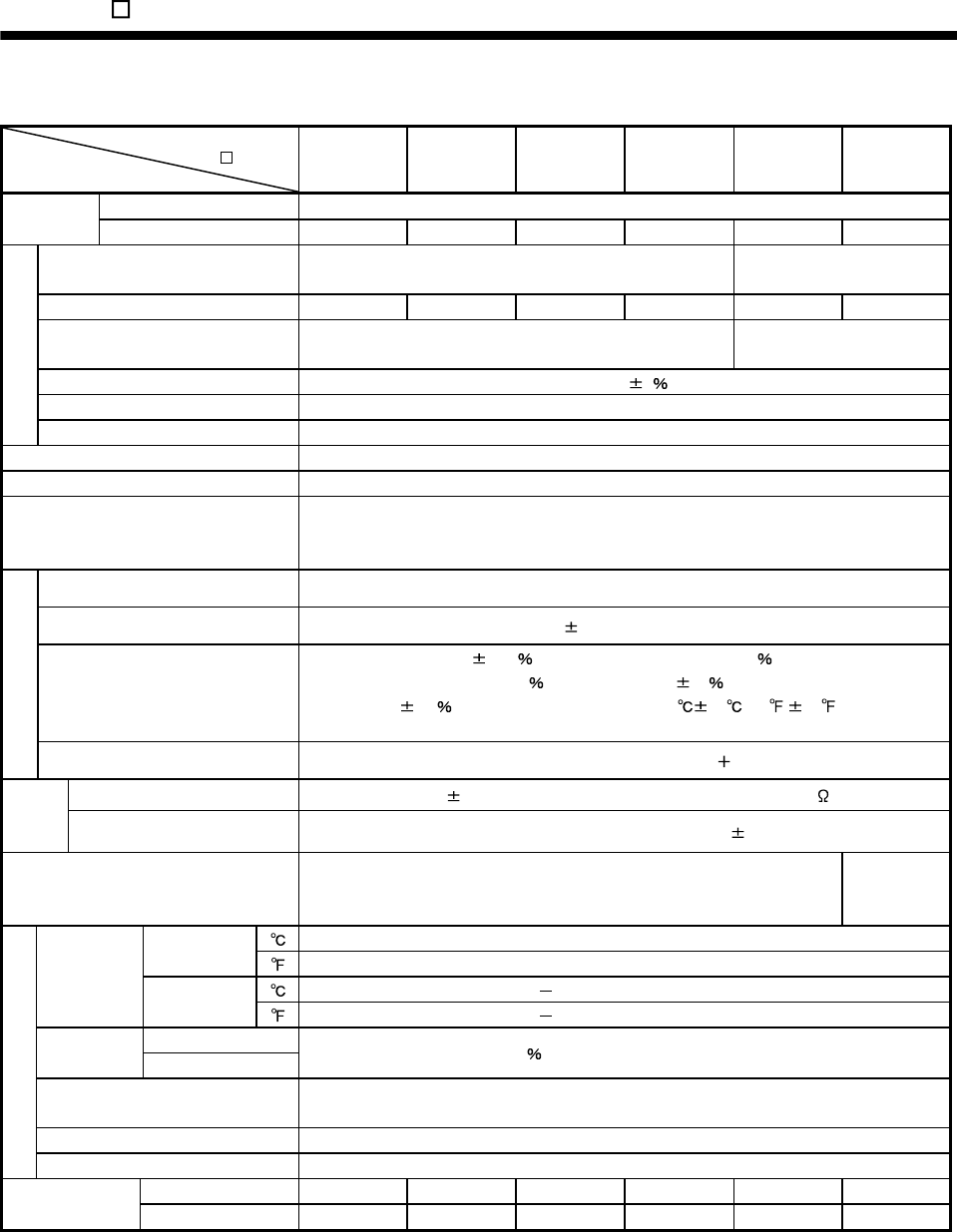
14 - 3
14. MR-E- AG-QW003 SERVO AMPLIFIER COMPATIBLE WITH ANALOG INPUT
14.1.3 Servo amplifier standard specifications
Servo amplifier
MR-E- -QW003
Item
10AG 20AG 40AG 70AG 100AG 200AG
Rated voltage 3-phase 170VAC
Output Rated current [A] 0.7 1.1 2.3 5.8 6.0 11.0
Voltage/frequency 3-phase 200 to 230VAC, 50/60Hz or 1-phase 230VAC,
50/60Hz
3-phase 200 to 230VAC,
50/60Hz
Rated current [A] 0.9 1.5 2.6 3.8 5.0 10.5
Permissible voltage fluctuation 3-phase 200 to 230VAC: 170 to 253VAC
1-phase 230VAC: 207 to 253VAC 3-phase 170 to 253VAC
Permissible frequency fluctuation Within 5
Power supply capacity Refer to section 12.2
Power supply
Inrush current [A] Refer to section 12.5
Control system Sine-wave PWM control, current control system
Dynamic brake Built-in
Protective functions
Overcurrent shut-off, regenerative overvoltage shut-off, overload shut-off (electronic thermal
relay), encoder error protection, regenerative error protection, undervoltage, instantaneous
power failure protection, overspeed protection, excessive error protection
Speed control range Analog speed command 1: 2000, internal speed command 1: 5000
Analog speed command input 0 to 10VDC/rated speed
Speed fluctuation ratio
0.01 or less (load fluctuation 0 to 100 )
0 (power fluctuation 10 )
0.2 or less (ambient temperature 25 10 (77 50 )),
when using analog speed command
Speed control mode
Torque limit Set by parameter setting or external analog input (0 to 10VDC/maximum torque)
Analog torque command input 0 to 8VDC/Maximum torque (input impedance 10 to 12k )
Torque
control
mode Speed limit Set by parameter setting or external analog input (0 to 10VDC/Rated speed)
Structure Self-cooled, open (IP00)
Force-
cooling, open
(IP00)
[] 0 to 55 (non-freezing)
Operation [] 32 to 131 (non-freezing)
[] 20 to 65 (non-freezing)
Ambient
temperature Storage [] 4 to 149 (non-freezing)
Operation Ambient
humidity Storage 90 RH or less (non-condensing)
Ambient Indoors (no direct sunlight)
Free from corrosive gas, flammable gas, oil mist, dust and dirt
Altitude Max. 1000m above sea level
Environment
Vibration resistance 5.9m/s2 at 10 to 55Hz (directions of X,Y and Z axes)
[kg] 0.7 0.7 1.1 1.7 1.7 2.0
Mass [lb] 1.54 1.54 2.43 3.75 3.75 4.41
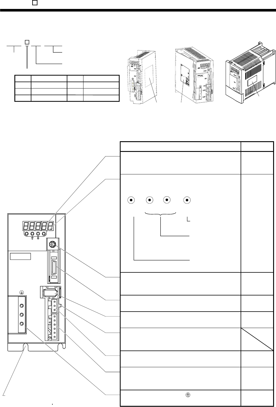
14. MR-E- AG-QW003 SERVO AMPLIFIER COMPATIBLE WITH ANALOG INPUT
14.1.4 Model code definition
AG QW003
MR-E super servo amplifier
(Source I/O interface)
Rated output
Series name
Analog input interface
MR-E-40AG-QW003
or less
Rating plate Rating plate
Rating plate
MR-E-70AG-QW003,
MR-E-100AG-QW003 MR-E-200AG-QW003
MR-E- -
Symbol Rated output [W]
10
20
40
100
200
400
Symbol Rated output [W]
70
100
200
750
1000
2000
14.1.5 Parts identification
(1) MR-E-100AG-QW003 or less
MODE
CN3
SET
CN1
CN2
CNP2
CNP1
L3L2L1 D C P W V U
CHARGE
MITSUBISHI
MR-
Used to set data.
Used to change the
display or data in each
mode.
Used to change the
mode.
MODE UP DOWN SET
Fixed part
(MR-E-10AG-QW003 to MR-E-40AG-QW003: 2 places
MR-E-70AG-QW003 MR-E-100AG-QW003: 3 places)
Reference
Name/application
Display
The 5-digit, seven-segment LED shows the servo status
and alarm number.
Operation section
Used to perform status display, diagnostic, alarm and
parameter setting operations.
Communication connector (CN3)
Used to connect a command device (RS-232C) and
output analog monitor data.
Section 14.5
Section 14.5
Section 3.3
Section 13.1.2
Section 14.2
I/O signal connector (CN1)
Used to connect digital I/O signals.
Encoder connector (CN2)
Connector for connection of the servo motor encoder.
Charge lamp
Lit to indicate that the main circuit is charged. While this
lamp is lit, do not reconnect the cables.
Servo motor power connector (CNP2)
Used to connect the servo motor.
Power supply/regenerative connector (CNP1)
Used to connect the input power supply and regenerative
option.
Protective earth (PE) terminal ( )
Ground terminal.
Section 3.3
Section 13.1.2
Section 3.7
Section 11.1
Section 3.7
Section 11.1
Section 13.1.1
Section 3.10
Section 11.1
14 - 4
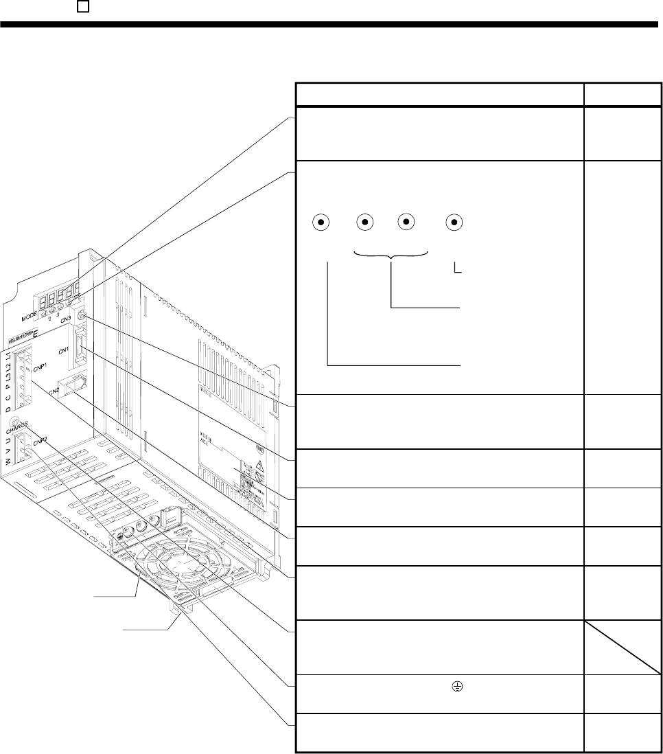
14. MR-E- AG-QW003 SERVO AMPLIFIER COMPATIBLE WITH ANALOG INPUT
(2) MR-E-200AG-QW003
Used to set data.
Used to change the
display or data in each
mode.
Used to change the
mode.
MODE UP DOWN SET
Cooling fan
Fixed part
(4 places)
Display
The 5-digit, seven-segment LED shows the servo status
and alarm number. Section 14.5
ReferenceName/application
Section 14.5
Section 3.3
Section 13.1.2
Communication connector (CN3)
Used to connect a command device (RS-232C) and
output analog monitor data.
I/O signal connector (CN1)
Used to connect digital I/O signals.
Rating plate
Encoder connector (CN2)
Connector for connection of the servo motor encoder.
Power supply/regenerative connector (CNP1)
Used to connect the input power supply and regenerative
option.
Charge lamp
Lit to indicate that the main circuit is charged. While this
lamp is lit, do not reconnect the cables.
Protective earth (PE) terminal ( )
Ground terminal.
Servo motor power connector (CNP2)
Used to connect the servo motor. Section 3.7
Section 11.1
Section 3.9
Section 11.1
Section 3.7
Section 11.1
Section 13.1.1
Section 3.3
Section 13.1.2
Section 1.5
Section 14.2
Operation section
Used to perform status display, diagnostic, alarm and
parameter setting operations.
14 - 5
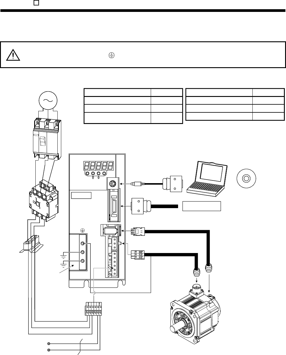
14 - 6
14. MR-E- AG-QW003 SERVO AMPLIFIER COMPATIBLE WITH ANALOG INPUT
14.1.6 Servo system with auxiliary equipment
WARNING To prevent an electric shock, always connect the protective earth (PE) terminal
(terminal marked ) of the servo amplifier to the protective earth (PE) of the control
box.
(1) MR-E-100AG-QW003 or less
Personal
computer MR Configurator
(Servo configuration software)
Regenerative option
Command device
CN3
SET
CN1
CN2
CNP2
CNP1
L3 L1 D C P W V U
MITSUBISHI
MR-E-
C
P
L3
L2
L1
To CN3
To CN1
Servo amplifier
L2
To CN2
To CNP2
(Note)
Power supply
Options and auxiliary equipment
Circuit breaker
Magnetic contactor
MR Configurator
(Servo configuration software)
Reference
Section 13.2.2
Section 13.2.2
Section 13.1.4
Options and auxiliary equipment
Regenerative option
Cables
Power factor improving reactor
Reference
Section 13.1.1
Section 13.2.1
Section 13.2.3
Circuit breaker
(MCCB) or fuse
Power
factor
improving
reactor
(FR-HAL)
Magnetic
contactor
(MC)
Protective earth
MODE
CHARGE
Servo motor
Note. A 1-phase 230VAC power supply may be used with the servo amplifier of MR-E-70AG-QW003 or less. Connect the power supply to
L1 and L2 terminals and leave L3 open. Refer to section 15.1.3 for the power supply specification.
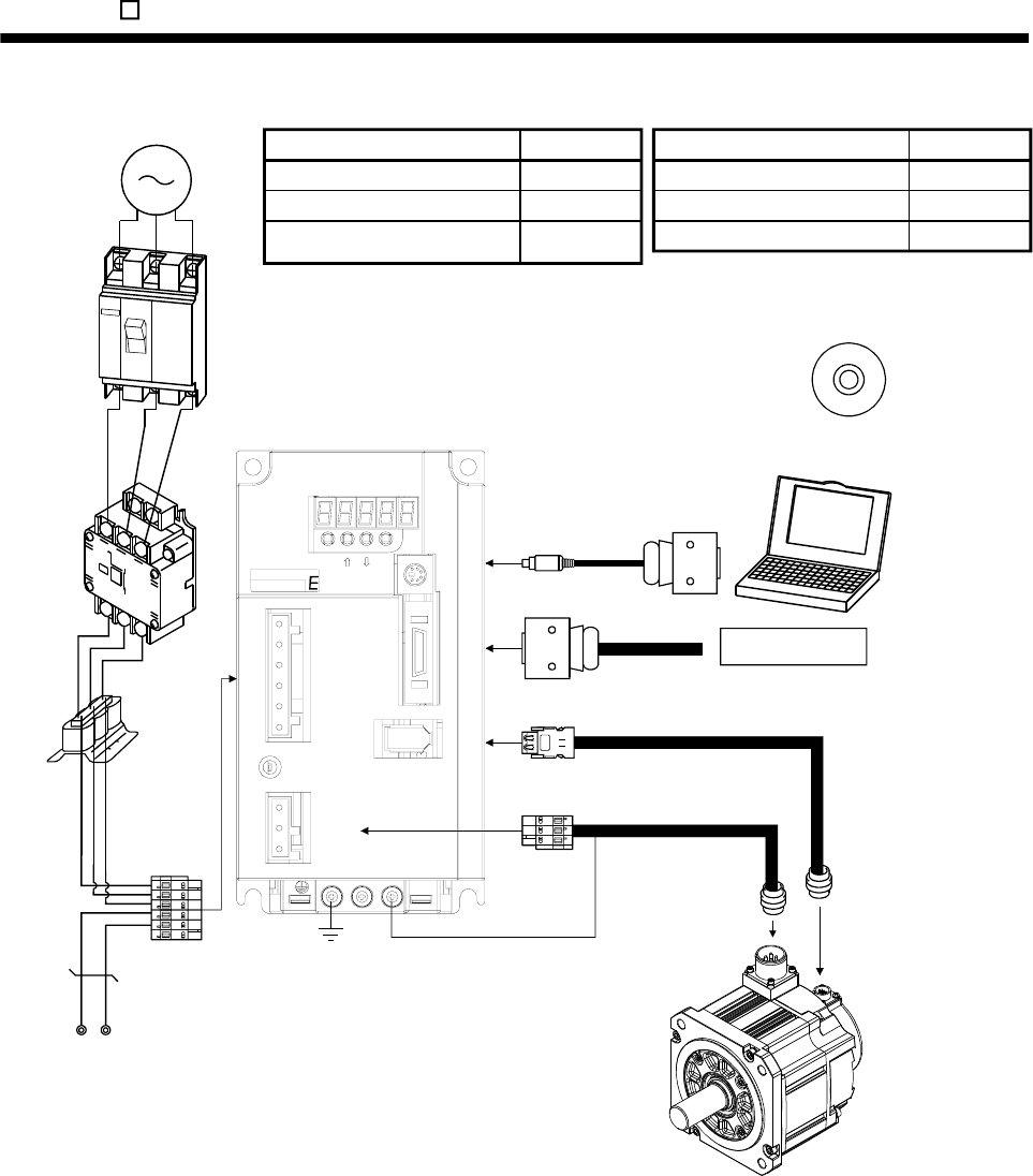
14 - 7
14. MR-E- AG-QW003 SERVO AMPLIFIER COMPATIBLE WITH ANALOG INPUT
(2) MR-E-200AG-QW003
Command device
L3
L2
L1
DC L3PL1L2
CHARGE
CNP2
CNP1
CN1
CN2
UVW
CN3
MODE SET
MITS U BIS HI
EZMotion
PC
Power
factor
improving
reactor
(FR-HAL)
3-phase 200V
to 230VAC
power supply
Circuit
breaker
(MCCB)
or fuse
Magnetic
contactor
(MC)
To CN2
To CN1
To CN3
Servo amplifier
Regenerative option
Personal
computer
To CNP2
Options and auxiliary equipment
Circuit breaker
Magnetic contactor
Reference
Section 13.2.2
Section 13.2.2
Section 13.1.4
Options and auxiliary equipment
Regenerative option
Cables
Power factor improving reactor
Reference
Section 13.1.1
Section 13.2.1
Section 13.2.3
MR Configurator
(Servo configuration software)
MR Configurator
(Servo configuration software)
Servo motor
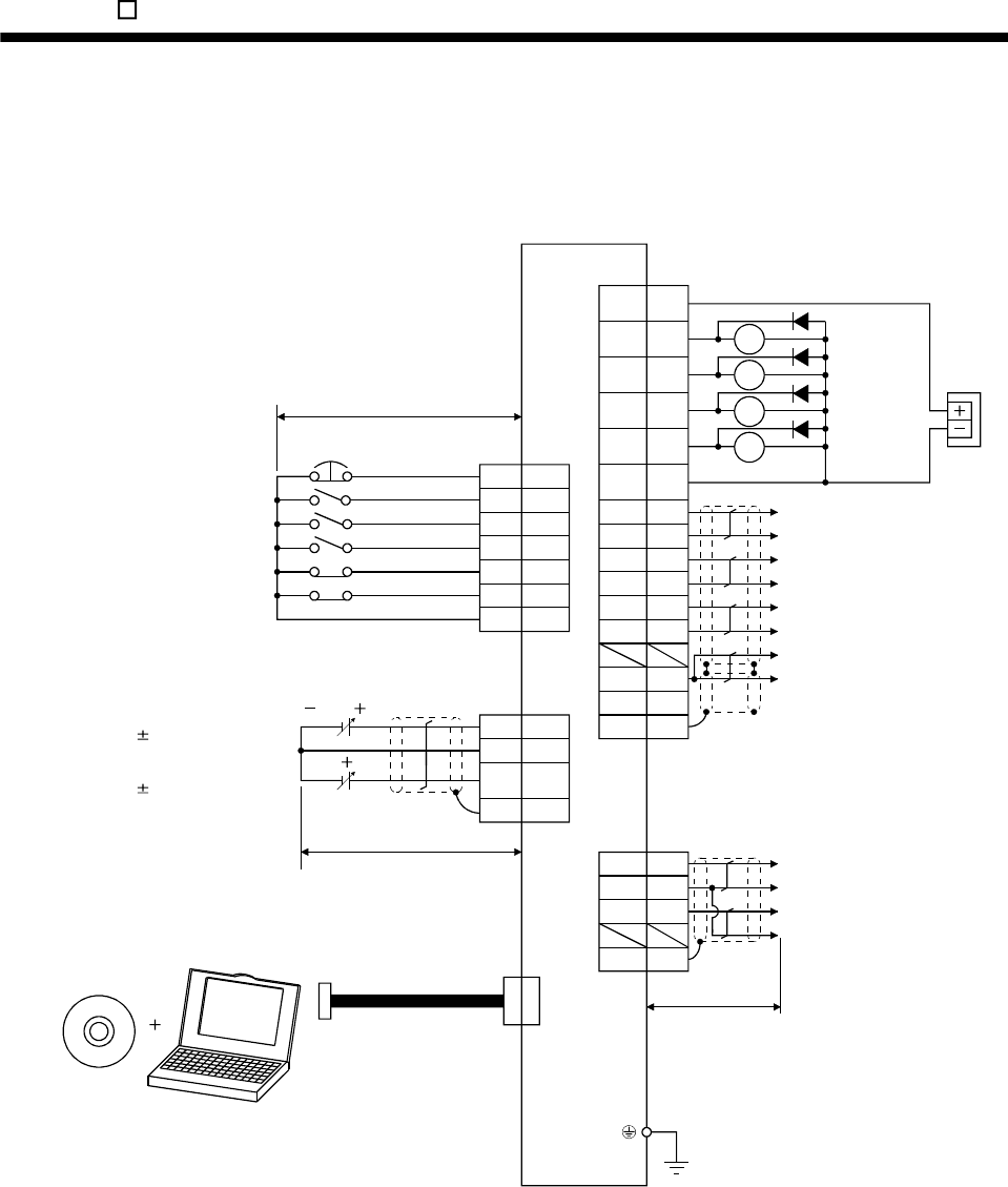
14. MR-E- AG-QW003 SERVO AMPLIFIER COMPATIBLE WITH ANALOG INPUT
14.2 Signals and wiring
14.2.1 Standard connection example
(1) Speed control mode
10 to 10V
0 to 10V
(Note 3, 4)
Personal
computer
(Note 8)
MR Configurator
(Servo configuration
software)
1
9
12
10m or less
RA1
RA2
8
4
3
5
6
7
EMG
SON
ST1
ST2
LSP
LSN
VIN 1
ALM
ZSP
Servo amplifier
(Note 1)
VIN
(Note 6)
Communication cable
(Note 2)
Forward rotation stroke end
Reverse rotation start
Forward rotation start
Servo-on
Emergency stop
(Note 4)
Reverse rotation stroke end
CN1
(Note 7)
Plate
20
19
18
LZ
15
11
10 SA RA3
RA4
13 SG
Plate
MO14
LG3
MO26
SD
RD
16
17
21
14
Ready
Speed reached
Zero speed
Trouble
(Note 5)
2m or less
VC 26
LG 14
TLA 2
SD
Analog speed command
10V/rated speed
Analog torque limit
10V/max. torque
CN1
(Note 7)
(Note 9)
External
power
supply
24VDC
Encoder Z-phase pulse
(differential line driver)
Encoder A-phase pulse
(differential line driver)
Encoder B-phase pulse
(differential line driver)
Control common
Encoder Z-phase pulse
(open collector)
CN3
(Note 7)
CN1
(Note 7)
CN3
(Note 7)
LZR
LA
LAR
LB
LBR
LG
OP
SD
Plate
2m max.
Analog monitor 1
Analog monitor 2
Control common
Control common
14 - 8

14. MR-E- AG-QW003 SERVO AMPLIFIER COMPATIBLE WITH ANALOG INPUT
Note 1. To prevent an electric shock, always connect the protective earth (PE) terminal (terminal marked ) of the servo amplifier to the
protective earth (PE) of the control box.
2. Connect the diode in the correct direction. If it is connected reversely, the servo amplifier will be faulty and will not output signals,
disabling the emergency stop and other protective circuits.
3. The emergency stop switch (normally closed contact) must be installed.
4. When starting operation, always connect the emergency stop (EMG) and forward rotation stroke end (LSP), reverse rotation stroke
end (LSN) with VIN. (Normally closed contacts)
5. Trouble (ALM) is connected with VIN in normal alarm-free condition. (Normally closed contacts)
6. When connecting the personal computer together with monitor outputs 1, 2, use the branch cable (MR-E3CBL15-P). (Refer to
section 13.1.3)
7. The pins with the same signal name are connected in the servo amplifier.
8. Use MRZJW3-SETUP 154E or 154C.
9. Externally supply 24VDC 10 , 200mA power for the interface. 200mA is a value applicable when all I/O signals are used.
Reducing the number of I/O points decreases the current capacity. Refer to the current necessary for the interface described in
section 3.6.2. Connect the external 24VDC power supply if the output signals are not used.
14 - 9
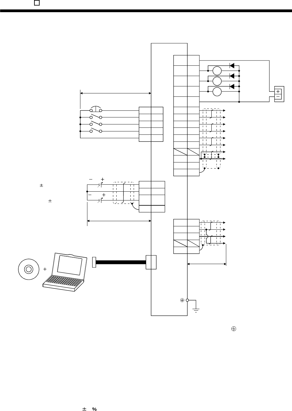
14. MR-E- AG-QW003 SERVO AMPLIFIER COMPATIBLE WITH ANALOG INPUT
(2) Torque control mode
10 to 10V
8 to 8V
(Note 3, 4)
Personal
computer
(Note 8)
MR Configurator
(Servo configuration
software)
10m or less
RA1
RA2
Servo amplifier
(Note 1)
(Note 6)
Communication cable
(Note 2)
Reverse rotation start
Forward rotation start
Servo-on
Emergency stop
RA3
Plate
Ready
Zero speed
Trouble
(Note 5)
2m or less
Analog torque command
8V/max. torque
Analog speed limit
0 to 10V/rated speed
CN1
(Note 7)
(Note 9)
External
power
supply
24VDC
Encoder Z-phase pulse
(differential line driver)
Encoder A-phase pulse
(differential line driver)
Encoder B-phase pulse
(differential line driver)
Control common
Encoder Z-phase pulse
(open collector)
CN3
(Note 7)
CN1
(Note 7)
CN3
(Note 7)
Plate
Plate
4
3
6
MO1
LG
MO2
SD
CN1
(Note 7)
8
4
5
3
EMG
SON
RS1
RS2
VIN 1
RD
1
9
12
RA1
RA2
ALM
ZSP
VIN
20
19
18
LZ
15
11 RA3
13 SG
16
17
21
14
TC 2
LG 14
VLA 26
SD
LZR
LA
LAR
LB
LBR
LG
OP
SD
2m max.
Analog monitor 1
Analog monitor 2
Control common
Control common
Note 1. To prevent an electric shock, always connect the protective earth (PE) terminal (terminal marked ) of the servo amplifier to
the protective earth (PE) of the control box.
2. Connect the diode in the correct direction. If it is connected reversely, the servo amplifier will be faulty and will not output
signals, disabling the emergency stop and other protective circuits.
3. The emergency stop switch (normally closed contact) must be installed.
4. When starting operation, always connect the emergency stop (EMG) with VIN. (Normally closed contacts)
5. Trouble (ALM) is connected with VIN in normal alarm-free condition. (Normally closed contacts)
6. When connecting the personal computer together with monitor outputs 1, 2, use the branch cable (MR-E3CBL15-P). (Refer to
section 13.1.3)
7. The pins with the same signal name are connected in the servo amplifier.
8. Use MRZJW3-SETUP 154E or 154C.
9. Externally supply 24VDC 10 , 200mA power for the interface. 200mA is a value applicable when all I/O signals are used.
Reducing the number of I/O points decreases the current capacity. Refer to the current necessary for the interface described
in section 3.6.2. Connect the external 24VDC power supply if the output signals are not used.
14 - 10
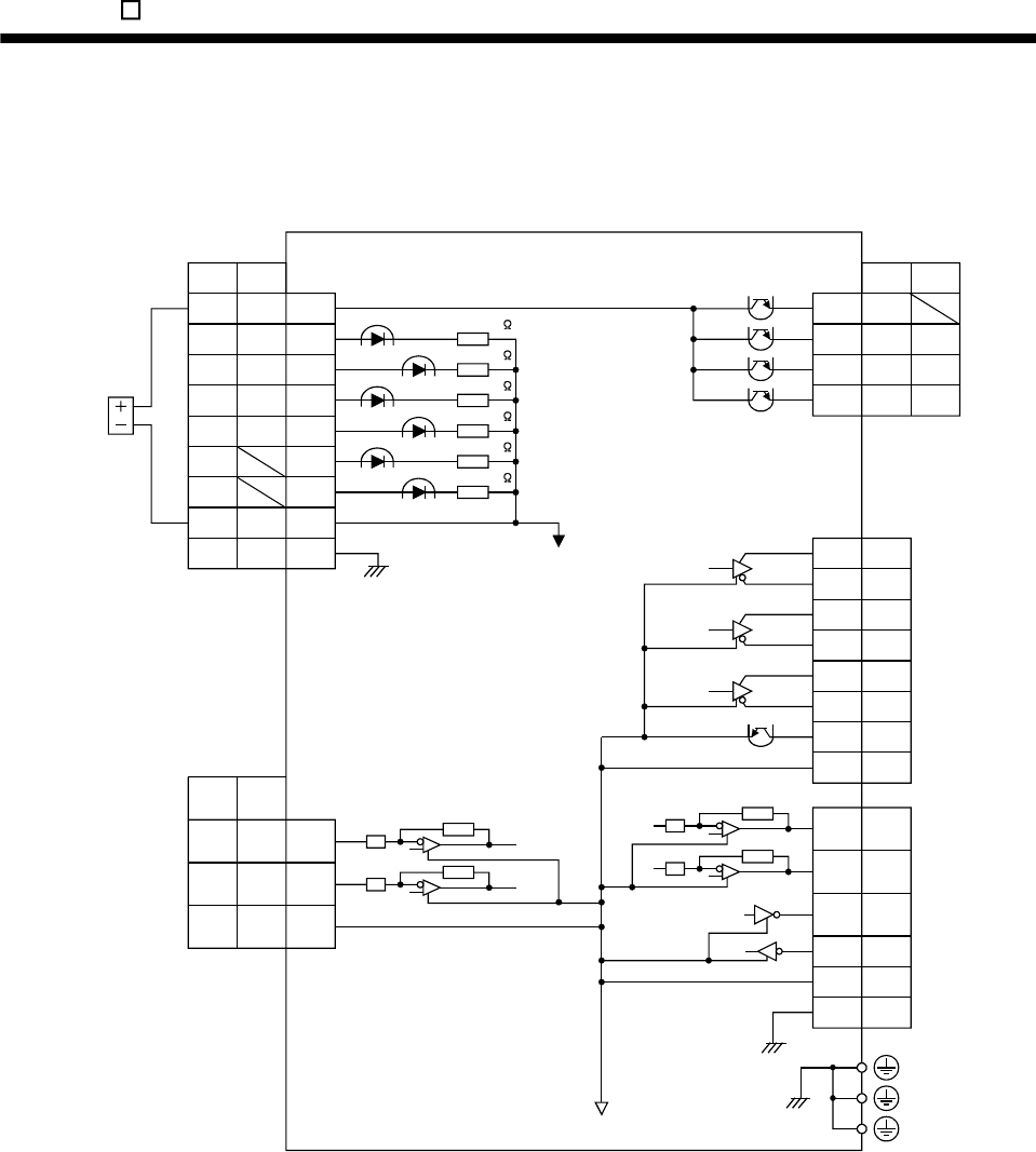
14. MR-E- AG-QW003 SERVO AMPLIFIER COMPATIBLE WITH ANALOG INPUT
14.2.2 Internal connection diagram of servo amplifier
The following is the internal connection diagram where the signal assignment has been made in the initial
status in each control mode.
Approx. 4.7k
External
power
supply
24VDC
CN1
CN1
Case
CN1
CN3
Case
(Note)
Servo amplifier
(Note)
(Note)
T
RD RD11ST2
ST1
EMG
LSP
LSN
SG
EMG
SG
RS2
SDSD
S
13
SON SON 4
3
8
6
7
RS1 5
ST
SA10
ALM ALM9
ZSP ZSP12
15
16
18
17
20
21
19
LA
LAR
LBR
LB
LZR
OP
LZ
4MO1
6
2
MO2
TXD
1RXD
3LG
LG14
VIN VIN 1
SD
ST
VC VLA
TLA TC
LG LG
26
2
14
Approx. 4.7k
Approx. 4.7k
Approx. 4.7k
Approx. 4.7k
Approx. 4.7k
PE
Note. S: Speed control mode, T: Torque control mode
14 - 11
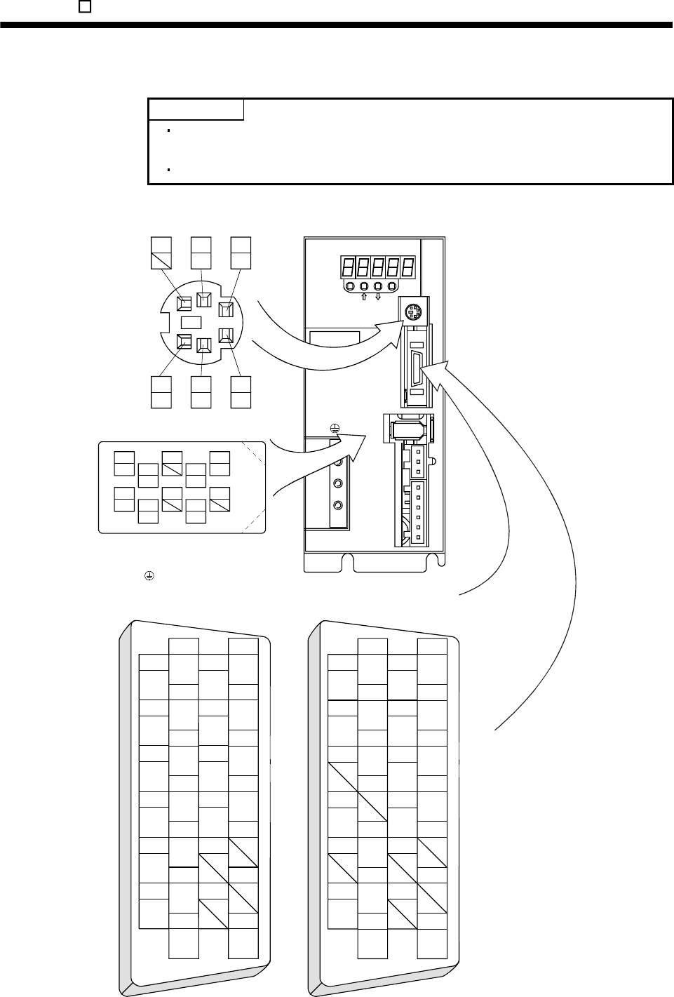
14. MR-E- AG-QW003 SERVO AMPLIFIER COMPATIBLE WITH ANALOG INPUT
14.2.3 Connectors and signal arrangements
POINT
The pin configurations of the connectors are as viewed from the cable
connector wiring section.
Refer to the next page for CN1 signal assignment.
(1) Signal arrangement
MODE
CN3
SET
CN1
CN2
CNP2
CNP1
L3L2L1 D C P W V U
MITSUBISHI
MR-E
The connector frames are
connected with the earth (PE)
terminal ( ) inside the servo amplifier.
53
LG
1
RXD
6
MO2
4
MO1
2
TXD
2
TLA
1
VIN 15
LA
14
LG
16
LAR
17
LB
3
ST1
4
SON
6
LSP
5
ST2 19
LZ
18
LBR
20
LZR
21
OP
7
LSN
8
EMG
10
SA
9
ALM 23
22
24
25
11
RD
12
ZSP 2613
SG
2
TC
1
VIN 15
LA
14
LG
16
LAR
17
LB
3
RS2
4
SON
6
5
RS1 19
LZ
18
LBR
20
LZR
21
OP
7
8
EMG
10
9
ALM 23
22
24
25
11
RD
12
ZSP 2613
SG
CN1(Speed control mode) CN1(Torque control mode)
Refer to section 3.3.2
VC VLA
CHARGE
CN2
9
4
MRR
2
LG 8
6
1
P5 5
10
3
MR 7
LG
MDR
MD
14 - 12
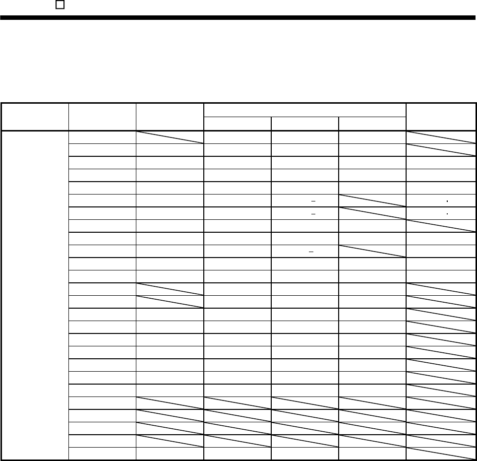
14. MR-E- AG-QW003 SERVO AMPLIFIER COMPATIBLE WITH ANALOG INPUT
(2) CN1 signal assignment
The signal assignment of connector changes with the control mode as indicated below.
For the pins which are given parameter No.s in the related parameter column, their signals can be changed
using those parameters.
(Note 2) I/O Signals in control modes
Connector Pin No. (Note 1) I/O S S/T T
Related
parameter
1 VIN VIN VIN
2 I TLA TLA/TC TC
3 I ST1 ST1/RS2 RS2 No.43 to 48
4 I SON SON SON No.43 to 48
5 I ST2 LOP RS1 No.43 to 48
6 I LSP LSP/ No.43 48
7 I LSN LSN/ No.43 48
8 I EMG EMG EMG
9 O ALM ALM ALM No.49
10 O SA SA/ No.49
11 O RD RD RD No.49
12 O ZSP ZSP ZSP No.1, 49
13 SG SG SG
14 LG LG LG
15 O LA LA LA
16 O LAR LAR LAR
17 O LB LB LB
18 O LBR LBR LBR
19 O LZ LZ LZ
20 O LZR LZR LZR
21 O OP OP OP
22
23
24
25
CN1
26 I VC VC/VLA VLA
Note 1. I: Input signal, O: Output signal
2. S: Speed control mode, T: Torque control mode, S/T: Speed/torque control switching mode
14 - 13
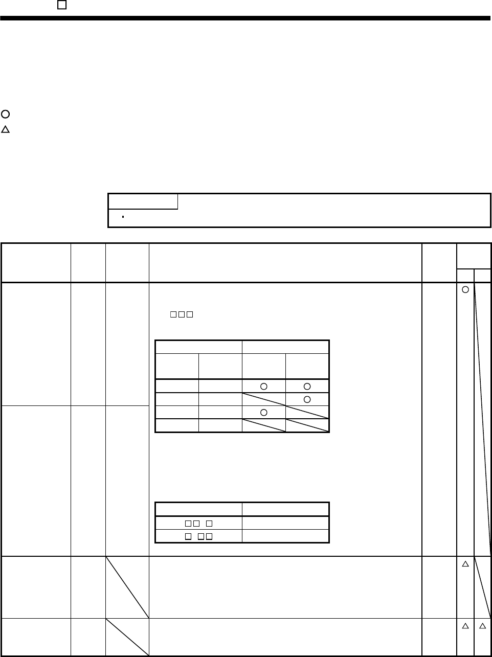
14. MR-E- AG-QW003 SERVO AMPLIFIER COMPATIBLE WITH ANALOG INPUT
14.2.4 Signal explanations
For the I/O interfaces (symbols in I/O column in the table), refer to section 3.6.2.
In the control mode field of the table
S: speed control mode, T: Torque control mode
: Denotes that the signal may be used in the initial setting status.
: Denotes that the signal may be used by setting the corresponding parameter among parameters 43 to 49.
The pin No.s in the connector pin No. column are those in the initial status.
(1) Input signals
POINT
The acceptance delay time of each input signal is less than 10ms.
Control
mode
Signal Symbol
Connector
pin No. Functions/Applications I/O
division S T
Forward rotation
stroke end
LSP CN1-6 To start operation, short LSP-VIN and/or LSN-VIN. Open them to bring the
motor to a sudden stop and make it servo-locked.
Set " 1" in parameter No.22 to make a slow stop.
(Refer to section 5.2.3.)
DI-1
(Note) Input signals Operation
LSP LSN
CCW
direction
CW
direction
1 1
0 1
LSN CN1-7 1 0 Reverse rotation
stroke end 0 0
Note. 0: LSP/LSN-VIN off (open)
1: SP/LSN-VIN on (short)
Set parameter No.41 as indicated below to switch on the signals (keep
terminals connected) automatically in the servo amplifier.
Parameter No.41 Automatic ON
1 LSP
1 LSN
Outside torque
limit selection
TL Turn TL off to make Internal torque limit 1 (parameter No.28) valid, or turn it
on to make Analog torque limit (TLA) valid.
When using this signal, make it usable by making the setting of parameter
No.43 to 48.
For details, refer to, section 15.2.5 (1)(C).
DI-1
Internal torque
limit selection
TL1 When using this signal, make it usable by making the setting of parameter
No.43 to 48.
(Refer to, section 3.4.1 (5).)
DI-1
14 - 14
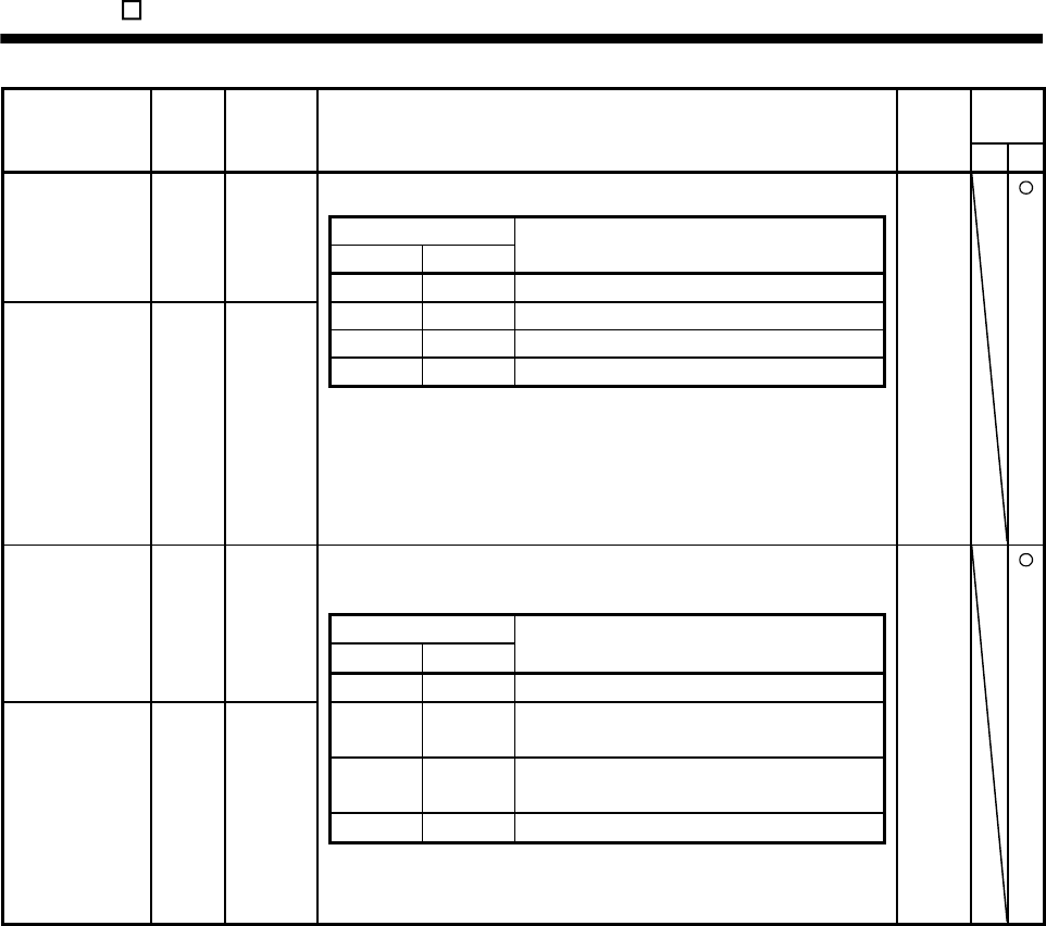
14. MR-E- AG-QW003 SERVO AMPLIFIER COMPATIBLE WITH ANALOG INPUT
Control
mode
Signal Symbol
Connector
pin No. Functions/applications I/O
division P S
ST1 CN1-3 Used to start the servo motor in any of the following directions.
DI-1 Forward rotation
start (Note) Input signals
ST2 ST1
Servo motor starting direction
0 0 Stop (servo lock)
ST2 CN1-5 0 1 CCW Reverse rotation
start 1 0 CW
1 1 Stop (servo lock)
Note. 0: ST1/ST2-VIN off (open)
1: ST1/ST2-VIN on (short)
If both ST1 and ST2 are switched on or off during operation, the servo
motor will be decelerated to a stop according to the parameter No.12
setting and servo-locked.
RS1 CN1-5 Used to select any of the following servo motor torque generation
directions.
DI-1
Forward rotation
selection
(Note) Input signals
ST2 ST1
Torque generation direction
0 0 Torque is not generated.
RS2 CN1-3 0 1
Forward rotation in driving mode/reverse
rotation in regenerative mode
Reverse rotation
selection
1 0
Reverse rotation in driving mode/forward
rotation in regenerative mode
1 1 Torque is not generated.
Note. 0: ST1/ST2-VIN off (open)
1: ST1/ST2-VIN on (short)
14 - 15
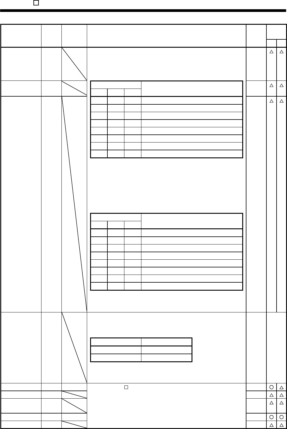
14. MR-E- AG-QW003 SERVO AMPLIFIER COMPATIBLE WITH ANALOG INPUT
Control
mode
Signal Symbol
Connector
pin No. Functions/applications I/O
division P S
Speed selection 1 SP1 <Speed control mode>
Used to select the command speed for operation.
When using SP1 to SP3, make it usable by making the setting of
parameter No.43 to 48.
DI-1
Speed selection 2 SP2 (Note) Input signals DI-1
SP3 SP2 SP1 Speed command
Speed selection 3 SP3 0 0 0 Analog speed command (VC) DI-1
0 0 1 Internal speed command 1 (parameter No.8)
0 1 0 Internal speed command 2 (parameter No.9)
0 1 1 Internal speed command 3 (parameter No.10)
1 0 0 Internal speed command 4 (parameter No.72)
1 0 1 Internal speed command 5 (parameter No.73)
1 1 0 Internal speed command 6 (parameter No.74)
1 1 1 Internal speed command 7 (parameter No.75)
Note. 0: SP1/SP2/SP3-VIN off (open)
1: SP1/SP2/SP3-VIN on (short)
<Speed control mode>
Used to select the command speed for operation.
When using SP1 to SP3, make it usable by making the setting of
parameter No.43 to 48.
(Note) Input signals
SP3 SP2 SP1
Speed limit
0 0 0 Analog speed limit (VLA)
0 0 1 Internal speed limit 1 (parameter No.8)
0 1 0 Internal speed limit 2 (parameter No.9)
0 1 1 Internal speed limit 3 (parameter No.10)
1 0 0 Internal speed limit 4 (parameter No.72)
1 0 1 Internal speed limit 5 (parameter No.73)
1 1 0 Internal speed limit 6 (parameter No.74)
1 1 1 Internal speed limit 7 (parameter No.75)
Note. 0: SP1/SP2/SP3-VIN off (open)
1: SP1/SP2/SP3-VIN on (short)
Control change LOP <Position/speed control change mode>
Used to select the control mode in the position/speed control change
mode.
DI-1
(Note) LOP Control mode
0 Position
1 Speed
Note. 0: LOP-VIN off (open)
1: LOP-VIN on (short)
Refer to
func-
tions/
applica-
tions.
Servo-on SON CN1-4 Same as MR-E- A-QW003. (Refer to section 3.3.2 (1).) DI-1
Reset RES DI-1
Proportion
control
PC DI-1
Emergency stop EMG CN1-8 DI-1
Gain changing CDP DI-1
14 - 16
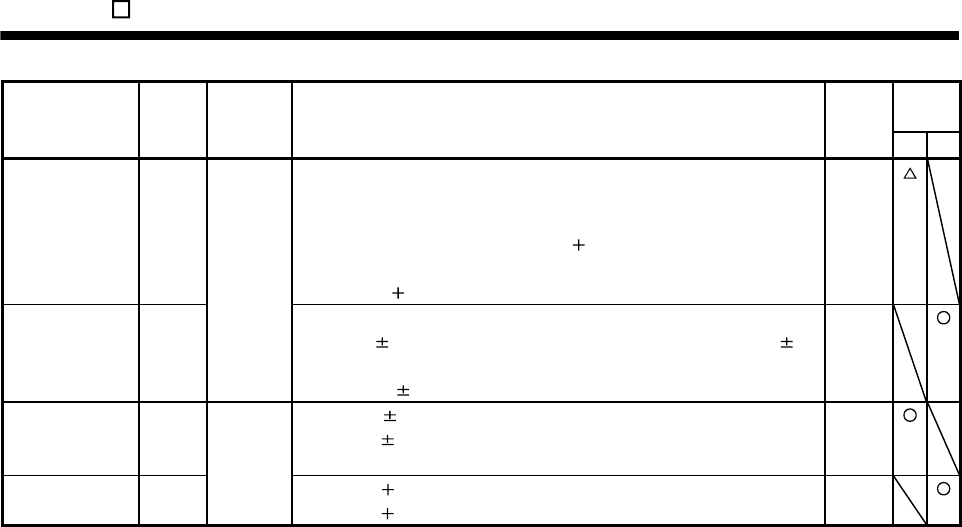
14. MR-E- AG-QW003 SERVO AMPLIFIER COMPATIBLE WITH ANALOG INPUT
Control
mode
Signal Symbol
Connecto
r pin No. Functions/applications I/O
division P S
Analog torque
limit
TLA CN1-2 To use this signal in the speed control mode, set any of parameters No.43
to 48 to make TL available.
When the analog torque limit (TLA) is valid, torque is limited in the full servo
motor output torque range. Apply 0 to 10VDC across TLA-LG. Connect
the positive terminal of the power supply to TLA. Maximum torque is
generated at 10V. (Refer to section 15.2.5 (1)(a).) Resolution:10bit
Analog
input
Analog torque
command
TC Used to control torque in the full servo motor output torque range.
Apply 0 to 8VDC across TC-LG. Maximum torque is generated at 8V.
(Refer to section 15.2.5 (2)(a).)
The torque at 8V input can be changed using parameter No.26.
Analog
input
Analog speed
command
VC CN1-26 Apply 0 to 10VDC across VC-LG. Speed set in parameter No.25 is
provided at 10V. (Refer to section 15.2.5 (1)(a).)
Resolution:14bit or equivalent
Analog
input
Analog speed
limit
VLA Apply 0 to 10VDC across VLA-LG. Speed set in parameter No.25 is
provided at 10V. (Refer to section 15.2.5 (2)(c).)
Analog
input
14 - 17
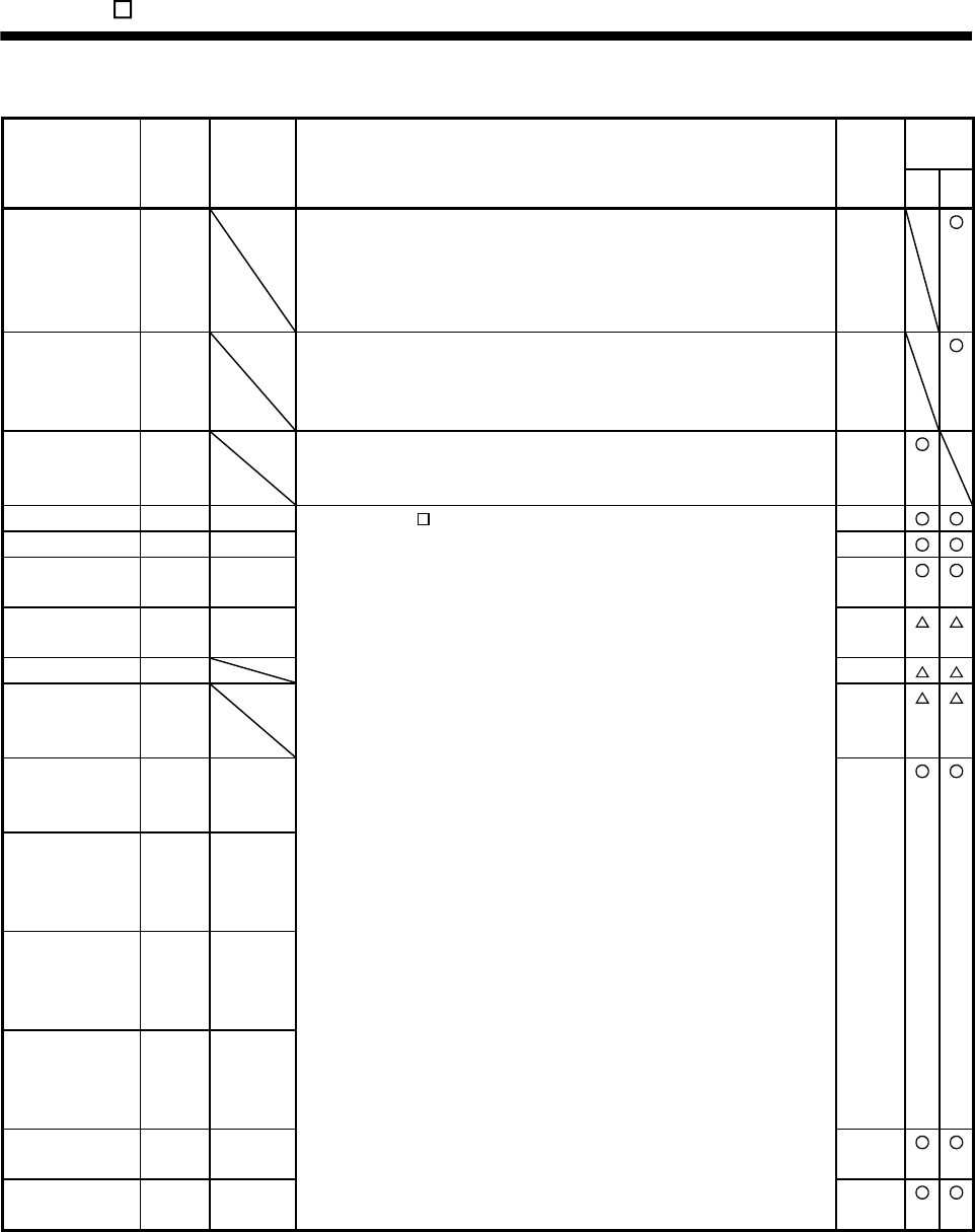
14. MR-E- AG-QW003 SERVO AMPLIFIER COMPATIBLE WITH ANALOG INPUT
(
2) Output signals
Control
mode
Signal Symbol
Connector
pin No. Functions/Applications I/O
division S T
Speed reached SA SA turns off when servo on (SON) turns off or the servo motor speed has
not reached the preset speed with both forward rotation start (ST1) and
reverse rotation start (ST2) turned off. SA turns on when the servo motor
speed has nearly reached the preset speed. When the preset speed is
30r/min or less, SA always turns on.
DO-1
Limiting speed VLC VLC turns on when speed reaches the value limited using any of the
internal speed limits 1 to 7 (parameter No.8 to 10, 72 to 75) or the analog
speed limit (VLA) in the torque control mode. VLC turns off when servo on
(SON) turns off.
DO-1
Limiting torque TLC TLC turns on when the torque generated reaches the value set to the
internal torque limit 1 (parameter No.28) or analog torque limit (TLA). TLC
turns off when servo on (SON) turns off.
DO-1
Trouble ALM CN1-9 Same as MR-E- A-QW003. (Refer to section 3.3.2 (2).) DO-1
Ready RD CN1-11 DO-1
Zero speed
detection
ZSP CN1-12 DO-1
Electromagnetic
brake interlock
MBR
[CN1-12]
DO-1
Warning WNG DO-1
Alarm code ACD0
ACD1
ACD2
DO-1
Encoder Z-phase
pulse
(Open collector)
OP CN1-21 DO-2
Encoder A-phase
pulse
(Differential line
driver)
LA
LAR
CN1-15
CN1-16
Encoder B-phase
pulse
(Differential line
driver)
LB
LBR
CN1-17
CN1-18
Encoder Z-phase
pulse
(Differential line
driver)
LZ
LZR
CN1-19
CN1-20
Analog monitor 1 MO1 CN3-4 Analog
output
Analog monitor 2 MO2 CN3-6 Analog
output
14 - 18
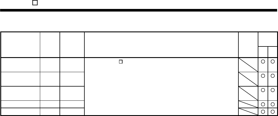
14. MR-E- AG-QW003 SERVO AMPLIFIER COMPATIBLE WITH ANALOG INPUT
(
3) Power
Control
mode
Signal Symbol
Connector
pin No. Functions/Applications I/O
division S T
Digital I/F power
supply input
VIN CN1-1 Same as MR-E- A-QW003. (Refer to section 3.3.2 (4).)
Open collector
power input
OPC CN1-2
Digital I/F
common
SG CN1-13
Control common LG CN1-14
Shield SD Plate
14 - 19
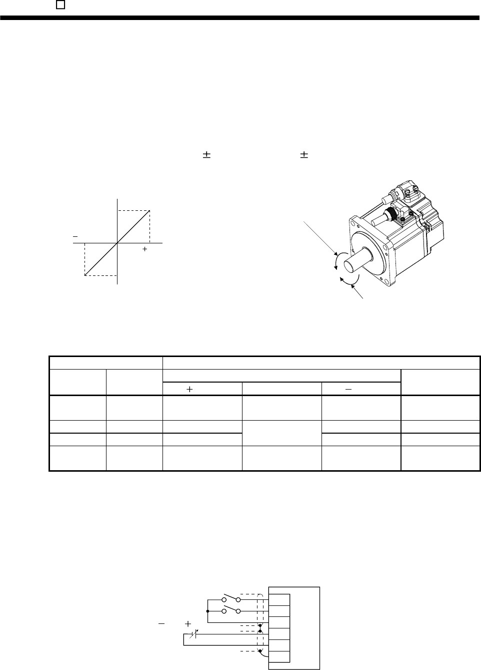
14. MR-E- AG-QW003 SERVO AMPLIFIER COMPATIBLE WITH ANALOG INPUT
14.2.5 Detailed description of the signals
(1) Speed control mode
(a) Speed setting
1) Speed command and speed
The servo motor is run at the speeds set in the parameters or at the speed set in the applied voltage
of the analog speed command (VC). A relationship between the analog speed command (VC)
applied voltage and the servo motor speed is shown below.
In the initial setting, rated speed is 10V. The speed at 10V can be changed using parameter
No.25.
Preset rotation speed
(Value for parameter No.25)
Preset rotation speed
(Value for parameter No.25) [r/min]
10
010
Speed [r/min]
CW direction VC applied voltage [V]
CCW direction
Forward rotation (CCW)
Reverse rotation (CW)
The following table indicates the rotation direction according to forward rotation start (ST1) and
reverse rotation start (ST2) combination.
(Note 1) External input signals (Note 2) Rotation direction
Analog speed command (VC)
ST2 ST1 Polarity 0V Polarity
Internal speed
commands
0 0 Stop
(Servo lock)
Stop
(Servo lock)
Stop
(Servo lock)
Stop
(Servo lock)
0 1 CCW CW CCW
1 0 CW
Stop
(No servo lock) CCW CW
1 1 Stop
(Servo lock)
Stop
(Servo lock)
Stop
(Servo lock)
Stop
(Servo lock)
Note 1. 0: off
1: on
2. Releasing the torque limit during servo lock may cause the servo motor to suddenly rotate according to the position
deviation from the instructed position.
The forward rotation start (ST1) and reverse rotation start (ST2) can be assigned to any pins of the
connector CN1 using parameters No.43 to 48.
Generally, make connection as shown below.
10 to 10V
Servo amplifier
ST1
ST2
VIN
VC
LG
SD
14 - 20
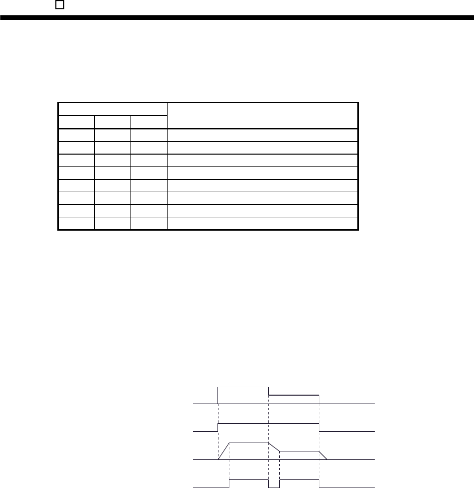
14. MR-E- AG-QW003 SERVO AMPLIFIER COMPATIBLE WITH ANALOG INPUT
2) Speed selection 1 (SP1), speed selection 2 (SP2), speed selection 3 (SP3) and speed command
value by making speed selection 1 (SP1), speed selection 2 (SP2) and speed selection 3 (SP3)
usable by setting of parameter No.43 to 47, you can choose the speed command values of internal
speed commands 1 to 7.
(Note) External input signals
SP3 SP2 SP1 Speed command value
0 0 0 Analog speed command (VC)
0 0 1 Internal speed command 1 (parameter No.8)
0 1 0 Internal speed command 2 (parameter No.9)
0 1 1 Internal speed command 3 (parameter No.10)
1 0 0 Internal speed command 4 (parameter No.72)
1 0 1 Internal speed command 5 (parameter No.73)
1 1 0 Internal speed command 6 (parameter No.74)
1 1 1 Internal speed command 7 (parameter No.75)
Note. 0: SP1/SP2/SP3-VIN off (open)
1: SP1/SP2/SP3-VIN on (short)
The speed may be changed during rotation. In this case, the values set in parameters No.11 and 12
are used for acceleration/deceleration.
When the speed has been specified under any internal speed command, it does not vary due to the
ambient temperature.
(b) Speed reached (SA)
SA-VIN are connected when the servo motor speed nearly reaches the speed set to the internal speed
command.
ON
OFF
ON
OFF
Set speed selection Internal speed
command 1
Internal speed
command 2
Start (ST1,ST2)
Servo motor speed
Speed reached (SA)
14 - 21
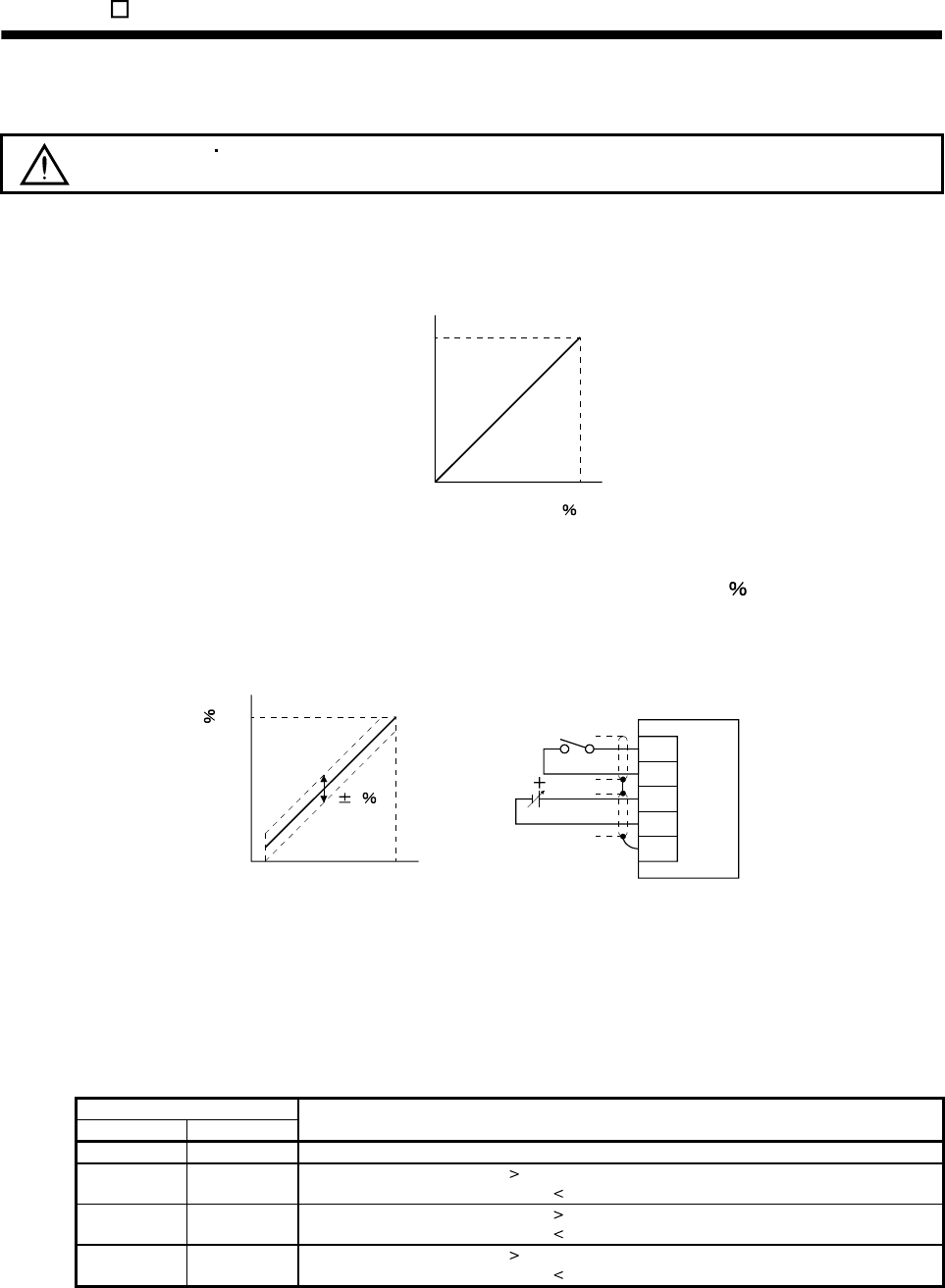
14. MR-E- AG-QW003 SERVO AMPLIFIER COMPATIBLE WITH ANALOG INPUT
(c) Torque limit
CAUTION Releasing the torque limit during servo lock may cause the servo motor to
suddenly rotate according to the position deviation from the instructed position.
1) Torque limit and torque
By setting parameter No.28 (internal torque limit 1), torque is always limited to the maximum value
during operation. A relationship between the limit value and servo motor torque is shown below.
100
0
Torque
Max. torque
Torque limit value[ ]
0
A relationship between the applied voltage of the analog torque limit (TLA) and the torque limit value
of the servo motor is shown below. Torque limit values will vary about 5 relative to the voltage
depending on products.
At the voltage of less than 0.05V, torque may vary as it may not be limited sufficiently. Therefore, use
this function at the voltage of 0.05V or more.
0 to 10V
5
10
0
100
TLA application voltage [V]
0
Torque limit value[ ]
0.05
TLA application voltage vs.
torque limit value
Servo amplifier
TL
VIN
TLA
LG
SD
2) Torque limit value selection
Use parameters No.43 through 48 to enable external torque limit (TL) and internal torque limit (TL1).
Torque limit values can be selected as shown in the following table. However, if the parameter No.28
value is less than the limit value selected by TL/TL1, the parameter No.28 value is made valid.
(Note) External input signals
TL1 TL Torque limit value made valid
0 0 Internal torque limit 1 (parameter No.28)
0 1 TLA Parameter No.28: Parameter No.28
TLA Parameter No.28: TLA
1 0 Parameter No.76 Parameter No.28: Parameter No.28
Parameter No.76 Parameter No.28: Parameter No.76
1 1 TLA Parameter No.76: Parameter No.76
TLA Parameter No.76: TLA
Note.0: off
1: on
14 - 22
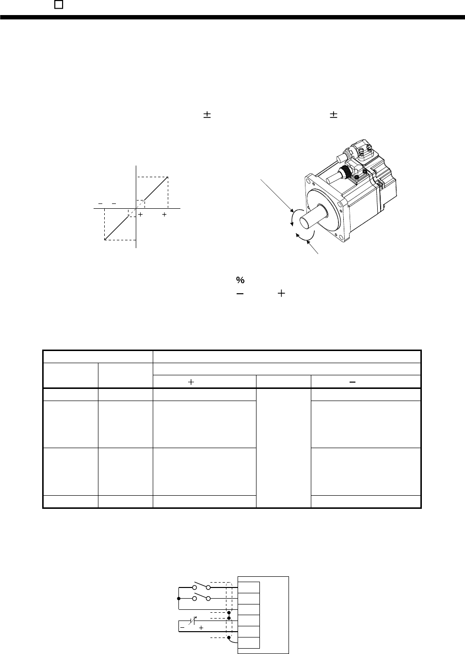
14. MR-E- AG-QW003 SERVO AMPLIFIER COMPATIBLE WITH ANALOG INPUT
(2) Torque control mode
(a) Torque command
1) Torque command and torque
A relationship between the applied voltage of the analog torque command (TC) and the torque by the
servo motor is shown below.
The maximum torque is generated at 8V. Note that the torque at 8V input can be changed with
parameter No.26.
Forward rotation (CCW)
Reverse rotation (CW)
8
0.05 8
0.05
Max. torque
Generated torque
CCW direction
CW direction Max. torque (Note)
TC applied voltage [V]
Generated torque limit values will vary about 5 relative to the voltage depending on products.
Also the torque may vary if the voltage is low ( 0.05 to 0.05V) and the actual speed is close to the
limit value. In such a case, increase the speed limit value.
The following table indicates the torque generation directions determined by the forward rotation
selection (RS1) and reverse rotation selection (RS2) when the analog torque command (TC) is used.
(Note) External input signals Rotation direction
Torque control command (TC)
RS2 RS1 Polarity 0V Polarity
0 0 Torque is not generated. Torque is not generated.
0 1
CCW (reverse rotation in
driving mode/forward
rotation in regenerative
mode)
CW (forward rotation in driving
mode/reverse rotation in
regenerative mode)
1 0
CW (forward rotation in
driving mode/reverse
rotation in regenerative
mode)
CCW (reverse rotation in
driving mode/forward rotation
in regenerative mode)
1 1 Torque is not generated.
Torque is not
generated.
Torque is not generated.
Note. 0: off
1: on
Generally, make connection as shown below.
RS1
RS2
TC
LG
SD
8 to 8V
Servo amplifie
r
VIN
14 - 23
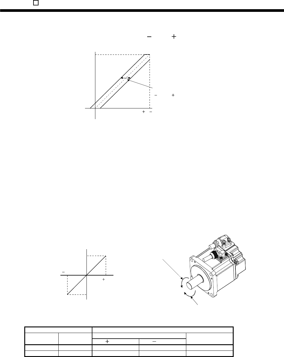
14. MR-E- AG-QW003 SERVO AMPLIFIER COMPATIBLE WITH ANALOG INPUT
2) Analog torque command offset
Using parameter No.30, the offset voltage of 999 to 999mV can be added to the TC applied
voltage as shown below.
08( 8)
Max. torque
Generated torque
TC applied voltage [V]
Parameter No.30 offset range
999 to 999mV
(b) Torque limit
By setting parameter No.28 (internal torque limit 1), torque is always limited to the maximum value
during operation. A relationship between limit value and servo motor torque is as in (1)(c) of this section.
Note that the analog torque limit (TLA) is unavailable.
(c) Speed limit
1) Speed limit value and speed
The speed is limited to the values set in parameters No.8 to 10, 72 to 75 (internal speed limits 1 to 7)
or the value set in the applied voltage of the analog speed limit (VLA).
A relationship between the analog speed limit (VLA) applied voltage and the servo motor speed is
shown below.
When the servo motor speed reaches the speed limit value, torque control may become unstable.
Make the set value more than 100r/min greater than the desired speed limit value.
Forward rotation (CCW)
Reverse rotation (CW)
10
010
Rated speed
Speed [r/min] CCW direction
CW direction VLA applied voltage [V]
Rated speed
The following table indicates the limit direction according to forward rotation selection (RS1) and
reverse rotation selection (RS2) combination.
(Note) External input signals Speed limit direction
Analog speed limit (VLA)
RS1 RS2 Polarity Polarity
Internal speed
commands
1 0 CCW CW CCW
0 1 CW CCW CW
Note.0: off
1: on
14 - 24
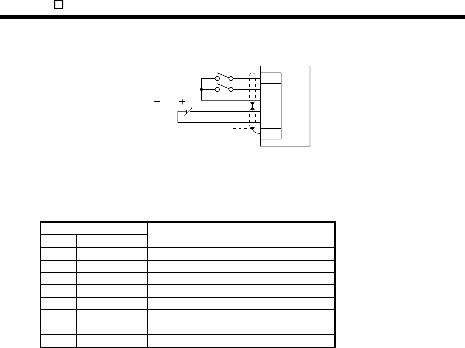
14. MR-E- AG-QW003 SERVO AMPLIFIER COMPATIBLE WITH ANALOG INPUT
Generally, make connection as shown below.
10 to 10V
Servo amplifier
RS1
RS2
VIN
VLA
LG
SD
2) Speed selection 1(SP1)/speed selection 2(SP2)/speed selection 3(SP3) and speed limit values
Choose any of the speed settings made by the internal speed limits 1 to 7 using speed selection
1(SP1), speed selection 2(SP2) and speed selection 3(SP3) or the speed setting made by the analog
speed limit (VLA), as indicated below.
(Note) External input signals
SP3 SP2 SP1 Speed limit value
0 0 0 Analog speed limit (VLA)
0 0 1 Internal speed limit 1 (parameter No.8)
0 1 0 Internal speed limit 2 (parameter No.9)
0 1 1 Internal speed limit 3 (parameter No.10)
1 0 0 Internal speed limit 4 (parameter No.72)
1 0 1 Internal speed limit 5 (parameter No.73)
1 1 0 Internal speed limit 6 (parameter No.74)
1 1 1 Internal speed limit 7 (parameter No.75)
Note.0: off
1: on
When the internal speed limits 1 to 7 are used to command the speed, the speed does not vary with
the ambient temperature.
3) Limiting speed (VLC)
VLC turns on when the servo motor speed reaches the speed limited using any of the internal speed
limits 1 to 7 or the analog speed limit (VLA).
14 - 25
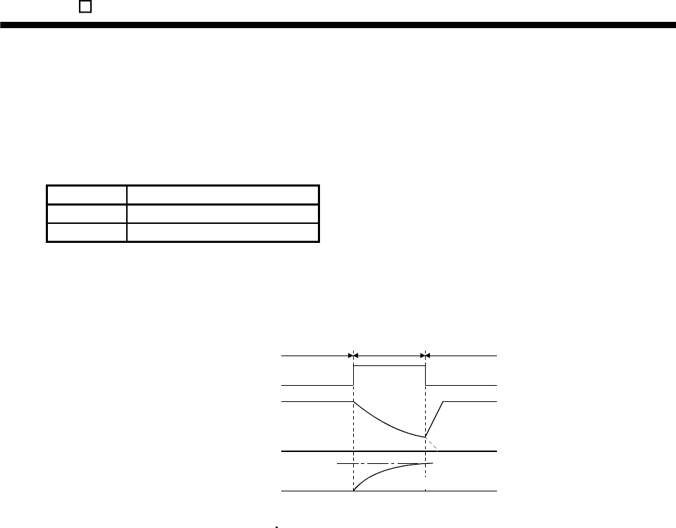
14. MR-E- AG-QW003 SERVO AMPLIFIER COMPATIBLE WITH ANALOG INPUT
(3) Speed/torque control change mode
Set "0003" in parameter No.0 to switch to the speed/torque control change mode.
(a) Control change (LOP)
Use control change (LOP) to switch between the speed control mode and the torque control mode from
an external contact. Relationships between LOP and control modes are indicated below.
(Note) LOP Servo control mode
0 Speed control mode
1 Torque control mode
Note.0: off
1: on
The control mode may be changed at any time. A change timing chart is shown below.
10V
0
ON
OFF
Torque
control mode
Servo motor speed
Control change (LOP)
(Note)
Speed
control mode
Speed
control mode
Analog torque
command (TC)
Load torque
Forward rotation in driving mode
Note. When the start (ST1 ST2) is switched off as soon as the mode is changed to speed control,
the servo motor comes to a stop according to the deceleration time constant.
(b) Speed setting in speed control mode
Same as (1)(a).
(c) Torque limit in speed control mode
Same as (1)(c).
(d) Speed limit in torque control mode
Same as (2)(c).
(e) Torque control in torque control mode
Same as (2)(a).
(f) Torque limit in torque control mode
Same as (2)(b).
14 - 26
14. MR-E- AG-QW003 SERVO AMPLIFIER COMPATIBLE WITH ANALOG INPUT
14.3 Startup
WARNING Do not operate the switches with wet hands. You may get an electric shock.
CAUTION
Before starting operation, check the parameters. Some machines may perform
unexpected operation.
Take safety measures, e.g. provide covers, to prevent accidental contact of hands
and parts (cables, etc.) with the servo amplifier heat sink, regenerative resistor,
servo motor, etc. since they may be hot while power is on or for some time after
power-off. Their temperatures may be high and you may get burnt or a parts may
damaged.
During operation, never touch the rotating parts of the servo motor. Doing so can
cause injury.
Perform pre-operation checks while referring to section 4.1. Connect the servo motor with a machine after
confirming that the servo motor operates properly alone.
Use parameter No.0 to choose the control mode used. After setting, this parameter is made valid by switching
power off, then on.
14.3.1 Speed control mode
(1) Power on
1) Switch off the servo-on (SON).
2) When power is switched on, the display shows "r (servo motor speed)", and in two second later, shows
data.
(2) Test operation
Confirm servo motor operation by operating JOG of test operation mode at lowest speed possible. (Refer to
section 6.8.2.)
14 - 27
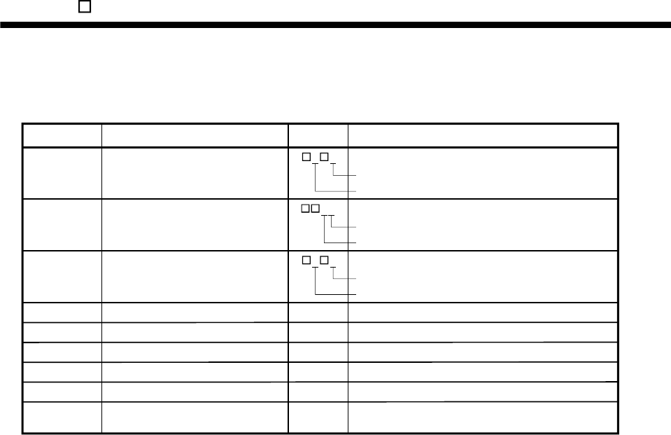
14. MR-E- AG-QW003 SERVO AMPLIFIER COMPATIBLE WITH ANALOG INPUT
(3) Parameter setting
Set the parameters according to the structure and specifications of the machine. Refer to chapter 5 for the
parameter definitions and to section 6.5 for the setting method.
10
1 5
Description
Parameter No. Name Setting
Control mode, regenerative option
selection
0
Function selection 11
Auto tuning2
81000
91500
Speed control mode
Regenerative option is not used.
Input filter 3.555ms (initial value)
Electromagnetic brake interlock (MBR) is used.
0 2
12
Middle response (initial value) is selected.
Auto tuning mode 1 is selected.
Set 1000r/min.
Set 1500r/min.
Internal speed command 1
Internal speed command 1
2000 Set 2000r/min.
Internal speed command 1
11 1000 Set 1000ms.
Acceleration time constant
12 500 Set 500ms.
Deceleration time constant
13 0 Not used
S-pattern acceleration/deceleration
time constant
Turn the power off to validate changes in parameters No.0 and 1. Then switch power on again to make the
set parameter values valid.
(4) Servo-on
Switch the servo-on in the following procedure.
1) Switch on power supply.
2) Switch on the servo-on (SON).
When placed in the servo-on status, the servo amplifier is ready to operate and the servo motor is
locked.
(5) Start
Using speed selection 1 (SP1) and speed selection 2 (SP2), choose the servo motor speed. Turn on
forward rotation start (ST1) to run the motor in the forward rotation (CCW) direction or reverse rotation start
(ST2) to run it in the reverse rotation (CW) direction. At first, set a speed as low as possible and check the
rotation direction, etc. If it does not run in the intended direction, check the input signal.
On the status display, check the speed, load factor, etc. of the servo motor.
When machine operation check is over, check automatic operation with the host controller or the like.
This servo amplifier has a real-time auto tuning function under model adaptive control. Performing
operation automatically adjusts gains. The optimum tuning results are provided by setting the response
level appropriate for the machine in parameter No.2. (Refer to chapter 7.)
(6) Stop
In any of the following statuses, the servo amplifier interrupts and stops the operation of the servo motor.
Refer to section 3.8 for the servo motor equipped with electromagnetic brake. Note that simultaneous ON
or simultaneous OFF of forward rotation stroke end (LSP), reverse rotation stroke end (LSN) OFF and
forward rotation start (ST1) or reverse rotation start (ST2) has the same stop pattern as described below.
(a) Servo-on (SON) OFF
The base circuit is shut off and the servo motor coasts.
(b) Alarm occurrence
When an alarm occurs, the base circuit is shut off and the dynamic brake is operated to bring the servo
motor to a sudden stop.
14 - 28

14. MR-E- AG-QW003 SERVO AMPLIFIER COMPATIBLE WITH ANALOG INPUT
(c) Emergency stop (EMG) OFF
The base circuit is shut off and the dynamic brake is operated to bring the servo motor to a sudden stop.
Alarm AL.E6 (servo emergency stop warning) occurs.
(d) Forward rotation stroke end (LSP), reverse rotation stroke end (LSN) OFF
The servo motor is brought to a sudden stop and servo-locked. The motor may be run in the opposite
direction.
(e) Simultaneous ON or simultaneous OFF of forward rotation start (ST1) and reverse rotation start (ST2)
The servo motor is decelerated to a stop.
POINT
A sudden stop indicates deceleration to a stop at the deceleration time constant
of zero.
14 - 29
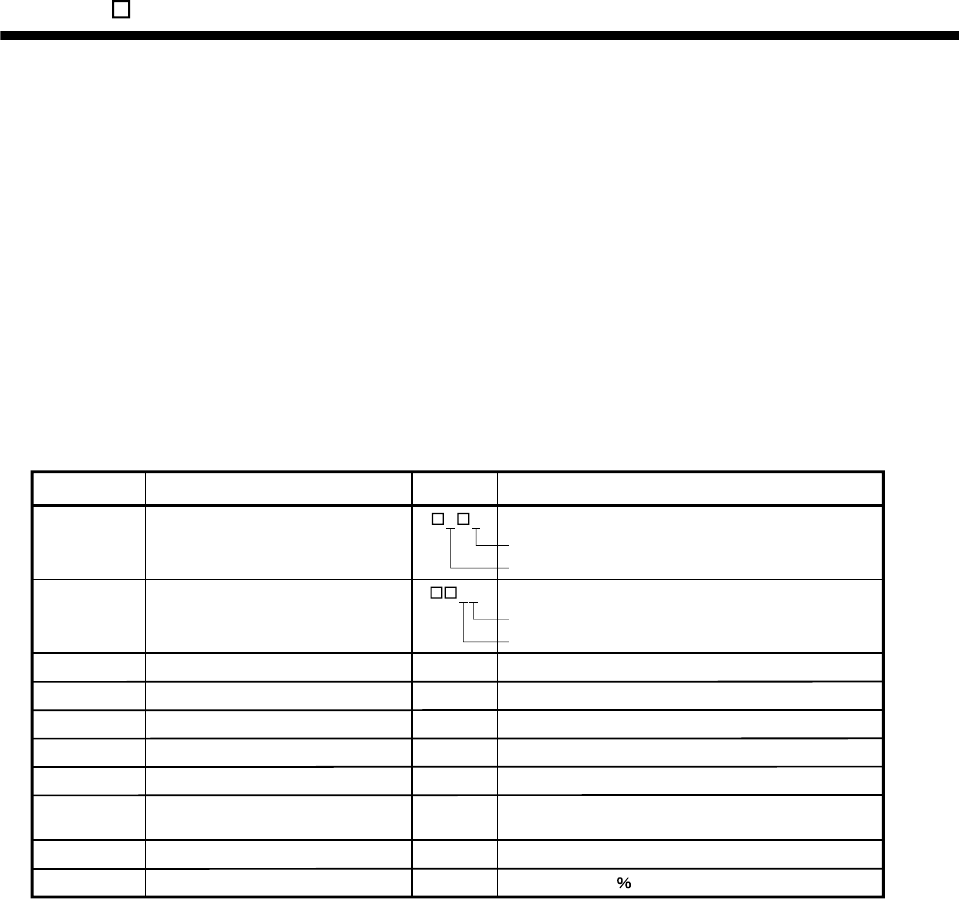
14. MR-E- AG-QW003 SERVO AMPLIFIER COMPATIBLE WITH ANALOG INPUT
14.3.2 Torque control mode
(1) Power on
1) Switch off the servo-on (SON).
2) When power is switched on, the display shows "U (torque command voltage)", and in two second later,
shows data.
(2) Test operation
Using jog operation in the test operation mode, make sure that the servo motor operates. (Refer to section
6.8.2.)
(3) Parameter setting
Set the parameters according to the structure and specifications of the machine. Refer to chapter 5 for the
parameter definitions and to section 6.5 for the setting method.
Controlled to 50 output
10
Description
Parameter No. Name Setting
Control mode, regenerative option
selection
0
Function selection 11
81000
91500
Torque control mode
Regenerative option is not used.
Input filter 3.555ms (initial value)
Electromagnetic brake interlock (MBR) is used.
0 4
02
Set 1000r/min.
Set 1500r/min.
Internal speed command 1
Internal speed command 1
2000 Set 2000r/min.
Internal speed command 1
11 1000 Set 1000ms.
Acceleration time constant
12 500 Set 500ms.
Deceleration time constant
13 0 Not used
S-pattern acceleration/deceleration
time constant
14 2000
28 50
Set 2000r/min.
Internal torque limit 1
Torque command time constant
Turn the power off after setting parameters No.0 and 1. Then switch power on again to make the set
parameter values valid.
(4) Servo-on
Switch the servo-on in the following procedure.
1) Switch on power supply.
2) Switch on the servo-on (SON).
When placed in the servo-on status, the servo amplifier is ready to operate and the servo motor is
locked.
(5) Start
Using speed selection 1 (SP1) and speed selection 2 (SP2), choose the servo motor speed. Turn on
forward rotation select (DI4) to run the motor in the forward rotation (CCW) direction or reverse rotation
select (DI3) to run it in the reverse rotation (CW) direction, generating torque. At first, set a low speed and
check the rotation direction, etc. If it does not run in the intended direction, check the input signal.
On the status display, check the speed, load factor, etc. of the servo motor.
When machine operation check is over, check automatic operation with the host controller or the like.
14 - 30
14. MR-E- AG-QW003 SERVO AMPLIFIER COMPATIBLE WITH ANALOG INPUT
(6) Stop
In any of the following statuses, the servo amplifier interrupts and stops the operation of the servo motor.
Refer to section 3.8 for the servo motor equipped with electromagnetic brake.
(a) Servo-on (SON) OFF
The base circuit is shut off and the servo motor coasts.
(b) Alarm occurrence
When an alarm occurs, the base circuit is shut off and the dynamic brake is operated to bring the servo
motor to a sudden stop.
(c) Emergency stop (EMG) OFF
The base circuit is shut off and the dynamic brake is operated to bring the servo motor to a sudden stop.
Alarm AL.E6 (servo emergency stop warning) occurs.
(d) Simultaneous ON or simultaneous OFF of forward rotation selection (RS1) and reverse rotation
selection (RS2)
The servo motor coasts.
POINT
A sudden stop indicates deceleration to a stop at the deceleration time constant
of zero.
14 - 31
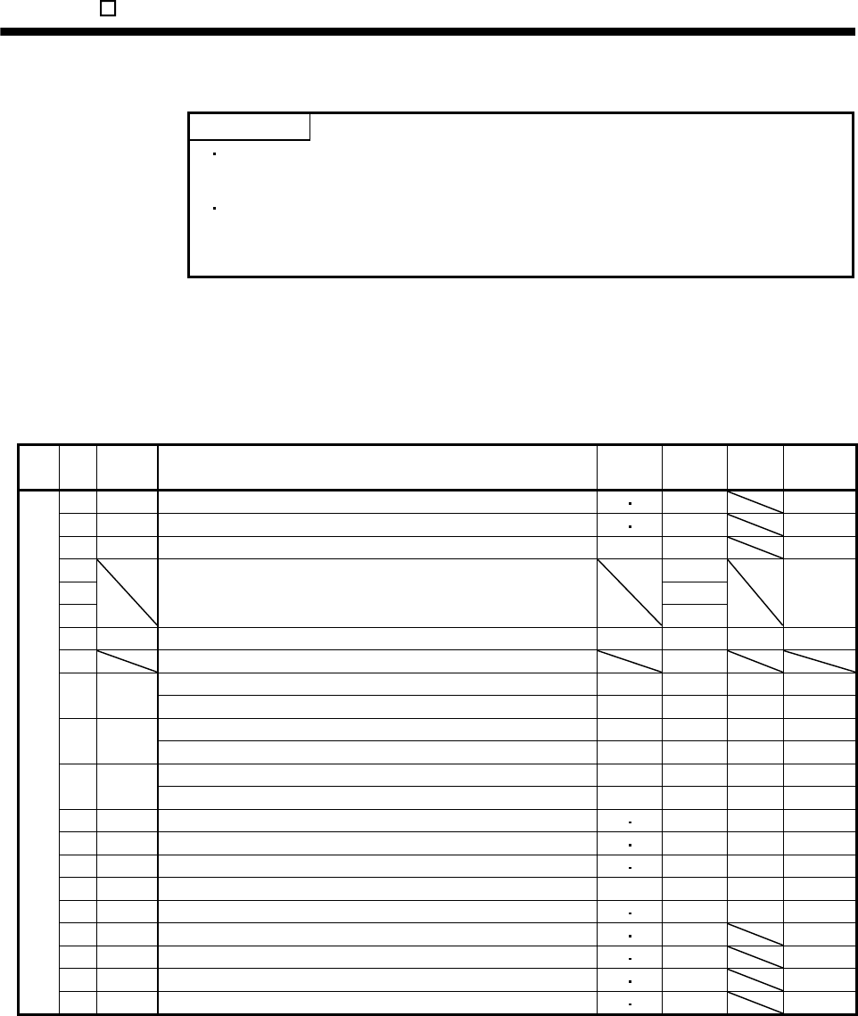
14. MR-E- AG-QW003 SERVO AMPLIFIER COMPATIBLE WITH ANALOG INPUT
14.4 Parameters
POINT
Before changing the settings of parameters No.20 through 84, cancel write
protection while referring to section 5.1.1.
For any parameter whose symbol is preceded by *, set the parameter value
and switch power off once, then switch it on again to make that parameter
setting valid.
The symbols in the control mode column of the table indicate the following modes:
S: Speed control mode
T: Torque control mode
14.4.1 Item list
Class No. Symbol Name Control
mode
Initial
value Unit Customer
setting
0 *STY Control mode, regenerative option selection S T (Note 1)
1 *OP1 Function selection 1 S T 0002
2 ATU Auto tuning S 0105
3 For manufacturer setting 1
4 1
5
100
6 PG1 Position loop gain 1 S 35 rad/s
7 For manufacture setting 3
Internal speed command 1 S 100 r/min
8 SC1
Internal speed limit 1 T 100 r/min
Internal speed command 2 S 500 r/min
9 SC2
Internal speed limit 2 T 500 r/min
Internal speed command 3 S 1000 r/min
10 SC3
Internal speed limit 3 T 1000 r/min
11 STA Acceleration time constant S T 0 ms
12 STB Deceleration time constant S T 0 ms
13 STC S-pattern acceleration/deceleration time constant S T 0 ms
14 TQC Torque command time constant T 0 ms
15 *SNO Station number setting S T 0 station
16 *BPS Serial communication function selection, alarm history clear S T 0000
17 MOD Analog monitor output S T 0100
18 *DMD Status display selection S T 0000
Basic parameters
19 *BLK Parameter block S T 0000
14 - 32
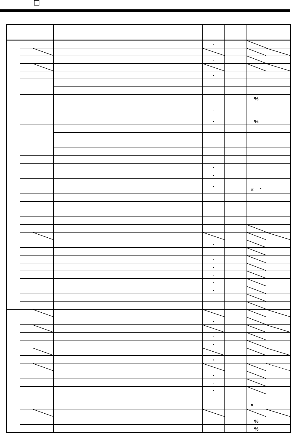
14. MR-E- AG-QW003 SERVO AMPLIFIER COMPATIBLE WITH ANALOG INPUT
Class No. Symbol Name Control
mode
Initial
value Unit Customer
setting
20 *OP2 Function selection 2 S T 0000
21 For manufacturer setting 0000
22 *OP4 Function selection 4 S T 0000
23 For manufacturer setting 0
24 ZSP Zero speed S T 50 r/min
Analog speed command maximum speed S (Note 3)0 (r/min)
25 VCM
Analog speed limit maximum speed T (Note 3)0 (r/min)
26 TLC Analog torque command maximum output T 100
27 *ENR Encoder output pulses S T 4000
pulse
/rev
28 TL1 Internal torque limit 1 S T 100
Analog speed command offset S (Note 2) mV
29 VCO
Analog speed limit offset T (Note 2) mV
Analog torque command offset T 0 mV
30 TLO
Analog torque limit offset S 0 mV
31 MO1 Analog monitor 1 offset S T 0 mV
32 MO2 Analog monitor 2 offset S T 0 mV
33 MBR Electromagnetic brake sequence output S T 100 ms
34 GD2 Ratio of load inertia moment to servo motor inertia moment S T 70
Multiplier
(10 1)
35 PG2 Position loop gain 2 S 35 rad/s
36 VG1 Speed loop gain 1 S 177 rad/s
37 VG2 Speed loop gain 2 S 817 rad/s
38 VIC Speed integral compensation S 48 ms
39 VDC Speed differential compensation S 980
40 For manufacturer setting 0
41 *DIA Input signal automatic ON selection S T 0000
42 *DI1 Input signal selection 1 S/T 0002
43 *DI2 Input signal selection 2 (CN1-4) S T 0111
44 *DI3 Input signal selection 3 (CN1-3) S T 0882
45 *DI4 Input signal selection 4 (CN1-5) S T 0995
46 *DI5 Input signal selection 5 (CN1-6) S T 0000
47 *DI6 Input signal selection 6 (CN1-7) S T 0000
48 *LSPN LSP/LSN input terminals selection S 0403
Expansion parameters 1
49 *DO1 Output signal selection 1 S T 0000
50 For manufacturer setting 0000
51 *OP6 Function selection 6 S T 0000
52 For manufacturer setting 0000
53 *OP8 Function selection 8 S T 0000
54 *OP9 Function selection 9 S T 0000
55 For manufacturer setting 0000
56 SIC Serial communication time-out selection S T 0 s
57 For manufacturer setting 10
58 NH1 Machine resonance suppression filter 1 S T 0000
59 NH2 Machine resonance suppression filter 2 S T 0000
60 LPF Low-pass filter/adaptive vibration suppression control S T 0000
61 GD2B Ratio of load inertia moment to Servo motor inertia moment 2 S 70 Multiplier
(10 1)
62 For manufacturer setting 100
63 VG2B Speed control gain 2 changing ratio S 100
Expansion parameters 2
64 VICB Speed integral compensation changing ratio S 100
14 - 33
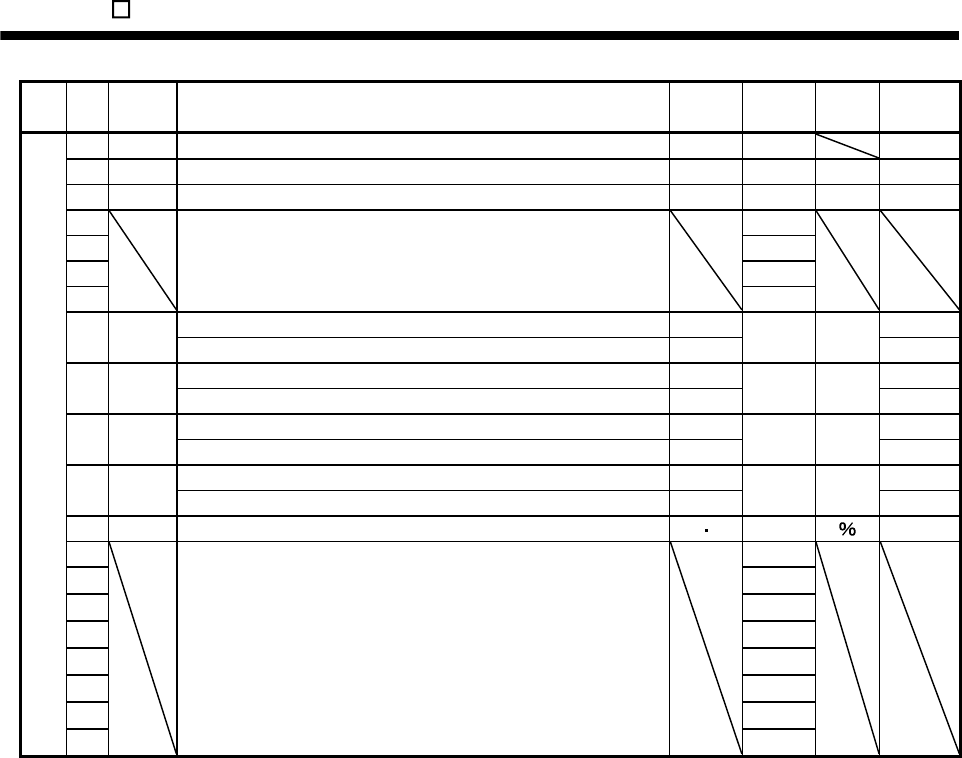
14. MR-E- AG-QW003 SERVO AMPLIFIER COMPATIBLE WITH ANALOG INPUT
Class No. Symbol Name Control
mode
Initial
value Unit Customer
setting
65 *CDP Gain changing selection S 0000
66 CDS Gain changing condition S 10 (Note 2)
67 CDT Gain changing time constant S 1 ms
68 For manufacturer setting 0
69 1
70 1
71
1
Internal speed command 4 S
72 SC4
Internal speed limit 4 T 200 r/min
Internal speed command 5 S
73 SC5
Internal speed limit 5 T 300 r/min
Internal speed command 6 S
74 SC6
Internal speed limit 6 T 500 r/min
Internal speed command 7 S
75 SC7
Internal speed limit 7 T 800 r/min
76 TL2 Internal torque limit 2 S T 100
77 100
78 10000
79 10
80 10
81 100
82 100
83 100
Expansion parameters 2
84
For manufacturer setting
0000
Note 1. Depends on the capacity of the servo amplifier.
2. Depends on the parameter No.65 setting.
3. The setting of "0" provides the rated servo motor speed.
14 - 34
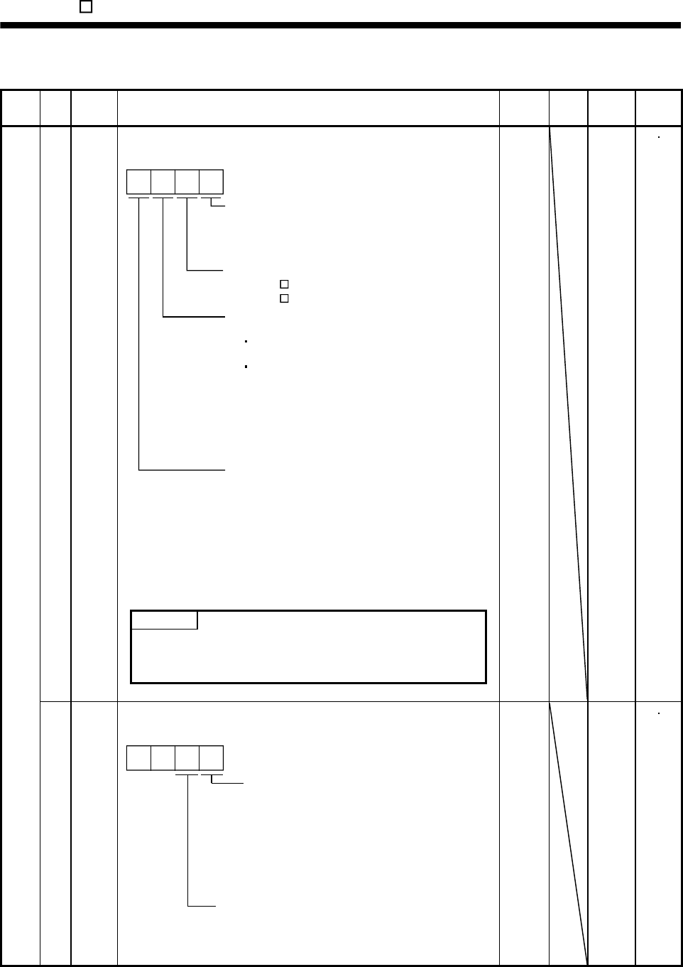
14. MR-E- AG-QW003 SERVO AMPLIFIER COMPATIBLE WITH ANALOG INPUT
14.4.2 Details list
Class No. Symbol Name and function Initial
value Unit Setting
range
Control
mode
Control mode, regenerative option selection
Used to select the control mode and regenerative option.
Motor series selection
0: HF-KN (J)
1: HF-SN J
Select the control mode.
0: Speed
1: Speed and torque
2: Torque
Selection of regenerative option
0: Regenerative option is not used
For the servo amplifier of 200W or lower,
regenerative resistor is not used.
For the servo amplifier of 400W or higher,
built-in regenerative resistor is used.
2: MR-RB032
3: MR-RB12
4: MR-RB32
5: MR-RB30
6: MR-RB50 (Cooling fan is required)
Motor capacity selection
0: 100W
1: 200W
2: 400W
3: 500W
4: 750W
5: 1kW
6: 1.5kW
7: 2kW
POINT
Wrong setting may cause the regenerative option to burn.
If the regenerative option selected is not for use with the servo
amplifier, parameter error (AL.37) occurs.
0 *STY
100W
: 0000
200W
: 1000
400W
: 2000
700W
: 4000
1kW
: 5010
2kW
: 6010
Refer to
name
and
function
column.
ST
Basic parameters
1 *OP1 Function selection 1
Used to select the input signal filter, the function of pin CN1-12.
Input signal filter
If external input signal causes chattering
due to noise, etc., input filter is used to
suppress it.
0: None
1: 1.777[ms]
2: 3.555[ms]
3: 5.333[ms]
CN1-12 function selection
0: Zero Speed detection signal
1: Electromagnetic brake interlock (MBR)
00
0002 Refer to
name
and
function
column.
ST
14 - 35
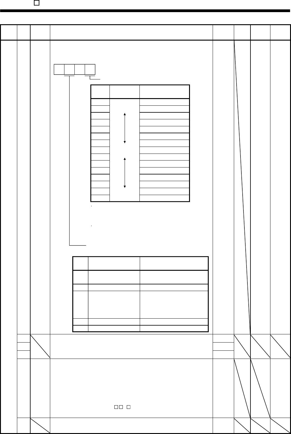
14. MR-E- AG-QW003 SERVO AMPLIFIER COMPATIBLE WITH ANALOG INPUT
Class No. Symbol Name and function Initial
value Unit Setting
range
Control
mode
2 ATU Auto tuning
Used to selection the response level, etc. for execution of auto tuning.
Refer to chapter 7.
Auto tuning response level setting
If the machine hunts or generates
large gear sound, decrease the
set value.
To improve performance, e.g.
shorten the settling time, increase
the set value.
Set
value
Response
level
1Low
response
Middle
response
High
response
Gain adjustment mode selection
(For more information, refer to section 7.1.1.)
Machine resonance
frequency guideline
15Hz
220Hz
325Hz
430Hz
535Hz
645Hz
755Hz
870Hz
985Hz
A105Hz
B130Hz
C160Hz
D200Hz
E240Hz
F300Hz
Set
value Gain adjustment mode
0
Description
1
3Simple manual adjustment.
4 Manual adjustment of all gains.
Interpolation mode Fixes position control gain 1
(parameter No.6).
Auto tuning mode 1
Fixes the load inertia moment
ratio set in parameter No.34.
Response level setting can be
changed.
Manual mode 1
Manual mode 2
2Auto tuning mode 2
Ordinary auto tuning.
0 0
0105 Refer to
name
and
function
column.
S
3 1
4 1
5
For manufacturer setting
Do not change this value by any means.
100
6 PG1 Position loop gain 1
Used to set the gain of position loop.
Increase the gain to improve track ability in response to the position
command.
When auto turning mode 1,2 is selected, the result of auto turning is
automatically used.
To use this parameter, set " 1" to parameter No.20 to validate servo
lock at stop.
35 S
Basic parameters
7 For manufacturer setting
Do not change this value by any means.
3
14 - 36
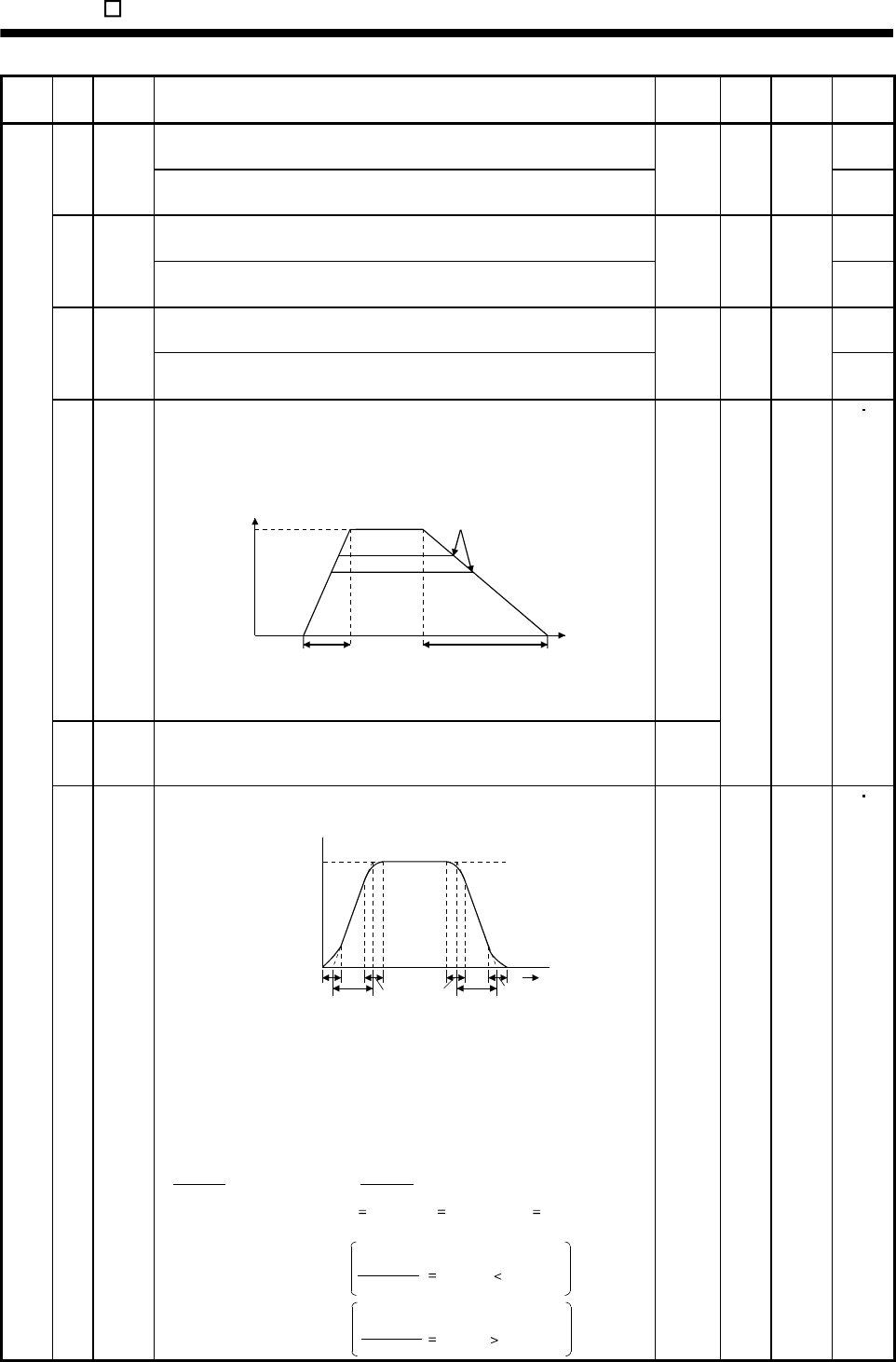
14. MR-E- AG-QW003 SERVO AMPLIFIER COMPATIBLE WITH ANALOG INPUT
Class No. Symbol Name and function Initial
value Unit Setting
range
Control
mode
Internal speed command 1
Used to set speed 1 of internal speed commands. S 8 SC1
Internal speed limit 1
Used to set speed 1 of internal speed limits.
100 r/min 0 to
instan-
taneous
permi-
ssible
speed
T
Internal speed command 2
Used to set speed 2 of internal speed commands. S 9 SC2
Internal speed limit 2
Used to set speed 2 of internal speed limits.
500 r/min 0 to
instan-
taneous
permi-
ssible
speed
T
Internal speed command 3
Used to set speed 3 of internal speed commands. S 10 SC3
Internal speed limit 3
Used to set speed 3 of internal speed limits.
1000 r/min 0 to
instan-
taneous
permi-
ssible
speed
T
11 STA
Acceleration time constant
Used to set the acceleration time required to reach the rated speed from
0r/min in response to the analog speed command and internal speed
commands 1 to 7.
Tim
e
Parameter
No.12 setting
Parameter
No.11 setting
Zero
speed
Rated
speed
Speed
If the preset speed command is
lower than the rated speed,
acceleration/deceleration time
will be shorter.
For example for the servo motor of 3000r/min rated speed, set 3000 (3s)
to increase speed from 0r/min to 1000r/min in 1 second.
0
12 STB
Deceleration time constant
Used to set the deceleration time required to reach 0r/min from the rated
speed in response to the analog speed command and internal speed
commands 1 to 7.
0
ms 0
to
20000
ST
Basic parameters
13 STC
S-pattern acceleration/deceleration time constant
Used to smooth start/stop of the servo motor.
Set the time of the arc part for S-pattern acceleration/deceleration.
STA: Acceleration time constant (parameter No.11)
STB: Deceleration time constant (parameter No.12)
STC: S-pattern acceleration/deceleration time constant
(parameter No.13)
Speed command
Servo motor
Speed
0r/min
STCSTA STC STC STB STC
Time
Long setting of STA (acceleration time constant) or STB (deceleration time
constant) may produce an error in the time of the arc part for the setting of
the S-pattern acceleration/deceleration time constant.
The upper limit value of the actual arc part time is limited by
At the setting of STA 20000, STB 5000 and STC 200,
the actual arc part times are as follows.
for acceleration or by for deceleration.
(Example)
During acceleration: 100[ms] 2000000
20000 100[ms] 200[ms].
Limited to 100[ms] since
During deceleration: 200[ms] 2000000
5000 400[ms] 200[ms].
200[ms] as set since
2000000
STA 2000000
STB
0 ms 0
to
1000
ST
14 - 37
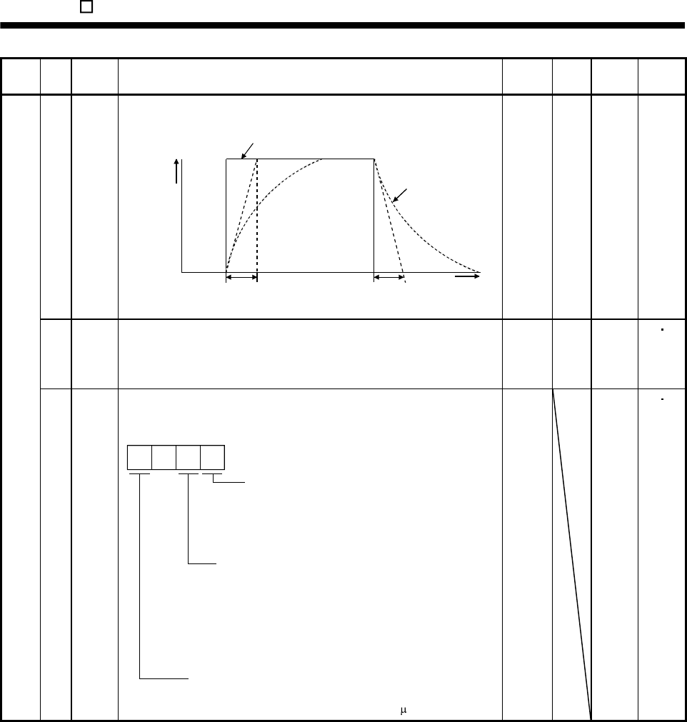
14. MR-E- AG-QW003 SERVO AMPLIFIER COMPATIBLE WITH ANALOG INPUT
Class No. Symbol Name and function Initial
value Unit Setting
range
Control
mode
14 TQC
Torque command time constant
Used to set the constant of a low-pass filter in response to the torque
command. Torque command
TQC TQC Time
After
filtered
TQC: Torque command time constant
Torque
0 ms 0
to
20000
T
15 *SNO Station number setting
Used to specify the station number for serial communication.
Always set one station to one axis of servo amplifier. If one station number
is set to two or more stations, normal communication cannot be made.
0 station 0
to
31
ST
Basic parameters
16 *BPS Serial communication function selection, alarm history clear
Used to select the serial communication baud rate, select various
communication conditions, and clear the alarm history.
Serial baud rate selection
0: 9600 [bps]
1: 19200[bps]
2: 38400[bps]
3: 57600[bps]
Alarm history clear
0: Invalid (not cleared)
1: Valid (cleared)
When alarm history clear is made valid,
the alarm history is cleared at next power-on.
After the alarm history is cleared, the setting
is automatically made invalid (reset to 0).
Serial communication response delay time
0: Invalid
1: Valid, reply sent after delay time of 800 s or more
0
0000 Refer to
name
and
function
column.
ST
14 - 38
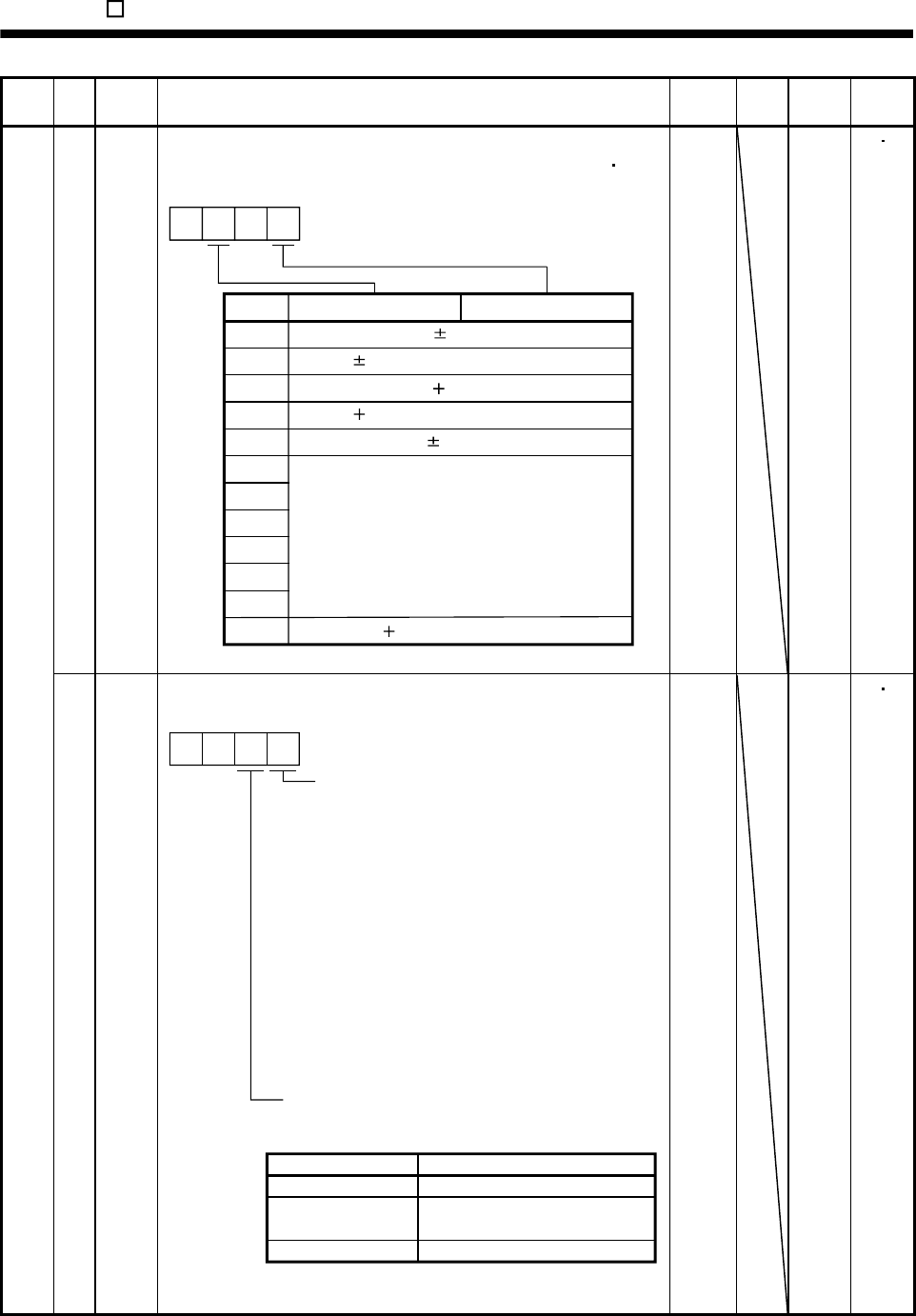
14. MR-E- AG-QW003 SERVO AMPLIFIER COMPATIBLE WITH ANALOG INPUT
Class No. Symbol Name and function Initial
value Unit Setting
range
Control
mode
17 MOD Analog monitor output
Used to selection the signal provided to the analog monitor (MO1)
analog monitor (MO2) output. (Refer to section 5.2.2)
Servo motor speed ( 8V/max. speed)
Setting
0
Analog monitor 2 (MO2)
1 Torque ( 8V/max. torque)
2 Servo motor speed ( 8V/max. speed)
3 Torque ( 8V/max. torque)
4 Current command ( 8 V/max. current command)
5
6
7
8
9
A
00
B
Analog monitor 1 (MO1)
Cannot be used.
Bus voltage ( 8V/400V)
0100 Refer to
name
and
function
column.
ST
Basic parameters
18 *DMD Status display selection
Used to select the status display shown at power-on.
Status display at power-on in
corresponding control mode
0: Depends on the control mode.
0 0
Selection of status display at
power-on
0: Cumulative feedback pulses
1: Servo motor speed
2: Cannot be used
3: Cannot be used
4: Cannot be used
7: Regenerative load ratio
8: Effective load ratio
9: Peak load ratio
A: Instantaneous torque
B: Within one-revolution position low
C: Within one-revolution position high
D: Load inertia moment ratio
E: Bus voltage
Control Mode
Speed
Speed/torque
Torque
Status display at power-on
Servo motor speed
Servo motor speed/
analog torque command voltage
Analog torque command voltage
1: Depends on the first digit setting of this parameter.
0000 Refer to
name
and
function
column.
ST
14 - 39
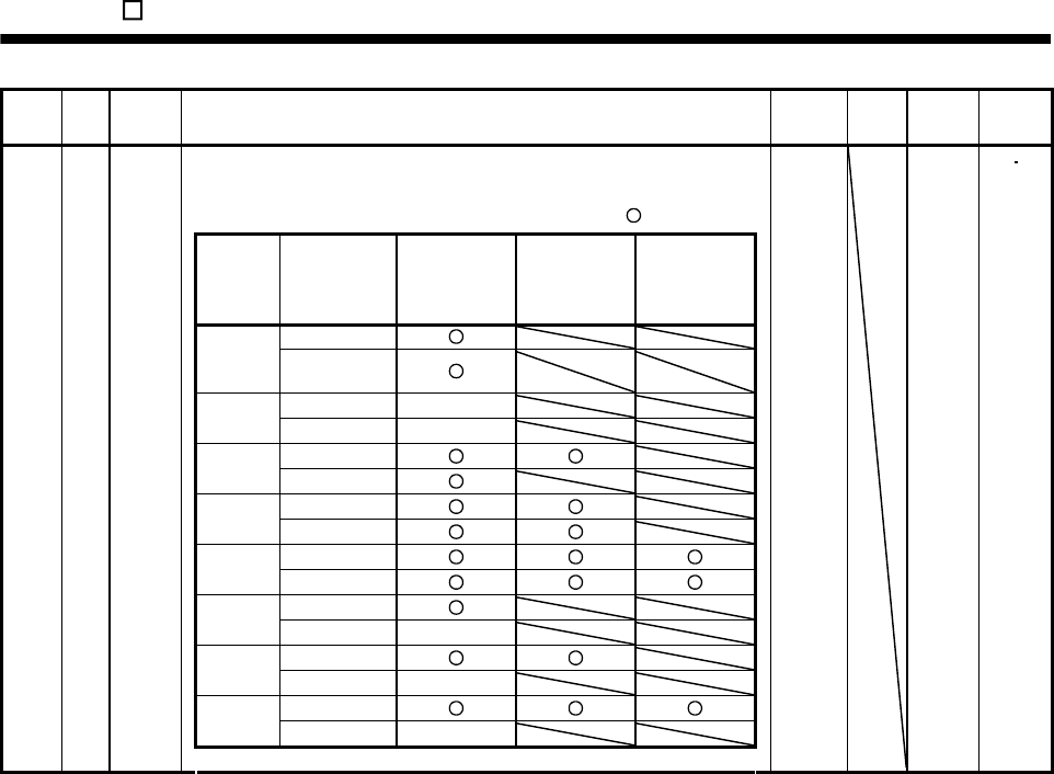
14. MR-E- AG-QW003 SERVO AMPLIFIER COMPATIBLE WITH ANALOG INPUT
Class No. Symbol Name and function Initial
value Unit Setting
range
Control
mode
Parameter block
Used to select the reference and write ranges of the parameters.
Operation can be performed for the parameters marked .
Set
value Operation
Basic
parameters
No.0
to No.19
Expansion
parameters 1
No.20
to No.49
Expansion
parameters 2
No.50
to No.84
Reference 0000
(Initial
value) Write
Reference No.19 only
000A Write No.19 only
Reference
000B Write
Reference 000C Write
Reference 000E Write
Reference 100B Write No.19 only
Reference 100C Write No.19 only
Reference 100E Write No.19 only
Basic parameters
19 *BLK
0000 Refer to
name
and
function
column.
ST
14 - 40
14. MR-E- AG-QW003 SERVO AMPLIFIER COMPATIBLE WITH ANALOG INPUT
Class No. Symbol Name and function Initial
value Unit Setting
range
Control
mode
0000 Refer to
name
and
function
column.
S
S
20 *OP2 Function selection 2
Used to select restart after instantaneous power failure,
servo lock at a stop in speed control mode, and slight vibration
suppression control.
Restart after instantaneous
power failure
Stop-time servo lock selection
The shaft can be servo-locked to
remain still at a stop in the internal
speed control mode.
0: Valid
1: Invalid
Slight vibration suppression control
Made valid when auto tuning selection is
set to "0400" in parameter No.2.
Used to suppress vibration at a stop.
0: Invalid
1: Valid
0: Invalid (Undervoltage alarm (AL.10) occurs.)
1: Valid
If the power supply voltage has
returned to normal after an
undervoltage status caused by the
reduction of the input power supply
voltage in the speed control mode,
the servo motor can be restarted by
merely turning on the start signal
without resetting the alarm.
Encoder cable communication system selection
Incorrect setting will result in an encoder alarm 1
(AL.16) or encoder alarm 2 (AL.20).
0: Two-wire type
1: Four-wire type
ST
Expansion parameters 1
21 For manufacturer setting
Do not change this value by any means.
0000
14 - 41
14. MR-E- AG-QW003 SERVO AMPLIFIER COMPATIBLE WITH ANALOG INPUT
Class No. Symbol Name and function Initial
value Unit Setting
range
Control
mode
S
22 *OP4 Function selection 4
Used to select stop processing at forward rotation stroke end (LSP)
reverse rotation stroke end (LSN) off, choose TLC/VLC output and choose
VC/VLA voltage averaging.
How to make a stop when forward
rotation stroke end (LSP)
reverse rotation stroke end (LSN)
is valid. (Refer to section 5.2.3.)
0: Sudden stop
1: Slow stop
Set value
0
1
2
Filtering time [ms]
0
0.444
0.888
31.777
VC/VLA voltage averaging
Used to set the filtering time when the
analog speed command (VC) voltage
or analog speed limit (VLA) is imported.
Set 0 to vary the speed to voltage fluctuation
in real time. Increase the set value to vary the
speed slower to voltage fluctuation.
43.555
0
Set value
0
1
2
Connector pin No.
Not output
CN1-11
CN1-9
3 CN1-10
TLC/VLC output selection
Select the connector pin at which
Torque Limit (TLC) or Speed Limit
(VLC) is output.
4 CN1-12
0000
Refer to
name
and
function
column.
ST
23
For manufacturer setting
Do not change this value by any means. 0
24 ZSP
Zero speed
Used to set the output range of the zero speed detection (ZSP). 50 r/min 0
to
10000
ST
25 VCM 0 0 S
Analog speed command maximum speed
Used to set the speed at the maximum input voltage (10V) of the analog
speed command (VC).
Set "0" to select the rated speed of the servo motor connected.
r/min
1
to
50000
0 0 T
Analog speed limit maximum speed
Used to set the speed at the maximum input voltage (10V) of the analog
speed limit (VLA).
Set "0" to select the rated speed of the servo motor connected.
r/min
1
to
50000
Expansion parameters 1
26 TLC
Analog torque command maximum output
Used to set the output torque at the analog torque command voltage (TC
8V) of 8V on the assumption that the maximum torque is 100[ ].
For example, set 50 to output (maximum torque 50/100) at the TC of
8V.
100 0
to
1000
T
14 - 42
14. MR-E- AG-QW003 SERVO AMPLIFIER COMPATIBLE WITH ANALOG INPUT
Class No. Symbol Name and function Initial
value Unit Setting
range
Control
mode
27 *ENR Encoder output pulses
Used to set the encoder pulses (A-phase or B-phase) output by the servo
amplifier.
Set the value 4 times greater than the A-phase or B-phase pulses.
You can use parameter No.54 to choose the output pulse designation or
output division ratio setting.
The number of A B-phase pulses actually output is 1/4 times greater
than the preset number of pulses.
The maximum output frequency is 1.3Mpps (after multiplication by 4). Use
this parameter within this range.
For output pulse designation
Set "0 " (initial value) in parameter No.54.
Set the number of pulses per servo motor revolution.
Output pulse set value [pulses/rev]
At the setting of 5600, for example, the actually A B-phase pulses
output are as indicated below.
4
5600
A B-phase output pulses 1400[pulse]
For output division ratio setting
Set "1 " in parameter No.54.
The number of pulses per servo motor revolution is divided by the set
value.
Output pulse [pulses/rev]
Resolution per servo motor revolution
Set value
At the setting of 8, for example, the actually A B-phase pulses output
are as indicated below.
A B-phase output pulses 313[pulse]
8
10000
4
1
4000 pulse/
rev 1
to
65535
ST
Internal torque limit 1
Set this parameter to limit servo motor torque on the assumption that the
maximum torque is 100[ ].
When 0 is set, torque is not produced.
(Note)
TL Torque limit
0 Internal torque limit 1 (Parameter No.28)
1 Analog torque limit internal torque limit 1
: Analog torque limit
Analog torque limit internal torque limit 1
: Internal torque limit 1
28 TL1
Note. 0 :off
1 :on
When torque is output in analog monitor output, this set value is the
maximum output voltage ( 8V). (Refer to section 15.2.5 (1)(c).)
100 0
to
100
ST
Analog speed command offset
Used to set the offset voltage of the analog speed command (VC).
For example, if CCW rotation is provided by switching on forward rotation
start (ST1) with 0V applied to VC, set a negative value.
When automatic VC offset is used, the automatically offset value is set to
this parameter. (Refer to section 15.5.3.)
The initial value is the value provided by the automatic VC offset function
before shipment at the VC-LG voltage of 0V.
S
Expansion parameters 1
29 VCO
Analog speed limit offset
Used to set the offset voltage of the analog speed limit (VLA).
For example, if CCW rotation is provided by switching on forward rotation
selection (RS1) with 0V applied to VLA, set a negative value.
When automatic VC offset is used, the automatically offset value is set to
this parameter. (Refer to section 15.5.3.)
The initial value is the value provided by the automatic VC offset function
before shipment at the VLA-LG voltage of 0V.
Depends
on servo
amplifier
mV 999
to
999
T
14 - 43
14. MR-E- AG-QW003 SERVO AMPLIFIER COMPATIBLE WITH ANALOG INPUT
Class No. Symbol Name and function Initial
value Unit Setting
range
Control
mode
Analog torque command offset
Used to set the offset voltage of the analog torque command (TC).
T 30 TLO
Analog torque limit offset
Used to set the offset voltage of the analog torque limit (TLA).
0 mV 999
to
999 S
31 MO1 Analog monitor 1 offset
Used to set the offset voltage of the analog monitor 1 (MO1).
0 mV 999 to
999
ST
32 MO2 Analog monitor 2 offset
Used to set the offset voltage of the analog monitor 2 (MO2).
0 mV 999 to
999
ST
33 MBR Electromagnetic brake sequence output
Used to set the delay time (Tb) between electronic brake interlock (MBR)
and the base drive circuit is shut-off.
100 ms 0
to
1000
ST
34 GD2 Ratio of load inertia moment to servo motor inertia moment
Used to set the ratio of the load inertia moment to the servo motor shaft
inertia moment. When auto tuning mode 1 and interpolation mode is
selected, the result of auto tuning is automatically used.
(Refer to section 7.1.1.)
In this case, it varies between 0 and 1000.
70 Multi-
plier
(10 1)
0
to
3000
ST
35 PG2 Position loop gain 2
Used to set the gain of the position loop.
Set this parameter to increase the position response to level load
disturbance. Higher setting increases the response level but is liable to
generate vibration and/or noise.
When auto tuning mode 1,2 and interpolation mode is selected, the result
of auto tuning is automatically used.
To use this parameter, set " 1" to parameter No.20 to validate servo
lock at stop.
35 rad/s 1
to
1000
S
36 VG1 Speed loop gain 1
Normally this parameter setting need not be changed.
Higher setting increases the response level but is liable to generate
vibration and/or noise.
When auto tuning mode 1 2, manual mode and interpolation mode is
selected, the result of auto tuning is automatically used.
177 rad/s 20
to
8000
S
37 VG2 Speed loop gain 2
Set this parameter when vibration occurs on machines of low rigidity or
large backlash. Higher setting increases the response level but is liable to
generate vibration and/or noise.
When auto tuning mode 1 2 and interpolation mode is selected, the
result of auto tuning is automatically used.
817 rad/s 20
to
20000
S
38 VIC Speed integral compensation
Used to set the integral time constant of the speed loop.
Higher setting increases the response level but is liable to generate
vibration and/or noise.
When auto tuning mode 1 2 and interpolation mode is selected, the
result of auto tuning is automatically used.
48 ms 1
to
1000
S
39 VDC Speed differential compensation
Used to set the differential compensation.
Made valid when the proportion control (PC) is switched on.
980 0
to
1000
S
Expansion parameters 1
40 For manufacturer setting
Do not change this value by any means.
0
14 - 44
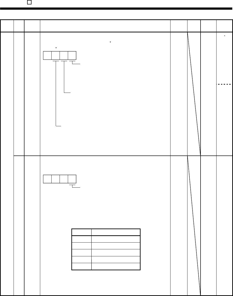
14. MR-E- AG-QW003 SERVO AMPLIFIER COMPATIBLE WITH ANALOG INPUT
Class No. Symbol Name and function Initial
value Unit Setting
range
Control
mode
ST 41 *DIA Input signal automatic ON selection
Used to set automatic servo-on (SON) forward rotation stroke end
(LSP) reverse rotation stroke end (LSN).
Servo-on (SON) input selection
0: Switched on/off by external input.
1: Switched on automatically in servo
amplifier.
(No need of external wiring)
0: Switched on/off by external input.
1: Switched on automatically in servo
amplifier.
(No need of external wiring)
0: Switched on/off by external input.
1: Switched on automatically in servo
amplifier.
(No need of external wiring)
Reverse rotation stroke end (LSN)
input selection
Forward rotation stroke end (LSP)
input selection
0
0000
Refer to
name
and
function
column.
S
S/T
Expansion parameters 1
42 *DI1 Input signal selection 1
Used to assign the control mode changing signal input pins and to set the
clear (CR).
Control change (LOP) input pin
assignment
Used to set the control mode
change signal input connector
pins. Note that this parameter is
made valid when parameter No.0
is set to select internal speed/torque
change mode.
Set value
0
1
2
Connector pin No.
CN1-4
CN1-3
CN1-5
3 CN1-6
4 CN1-7
000
If forward rotation stroke end (LSP) or reverse rotation stroke
end (LSN) is assigned to any pin with parameter No.48, this
parameter cannot be used.
0002
Refer to
name
and
function
column.
14 - 45
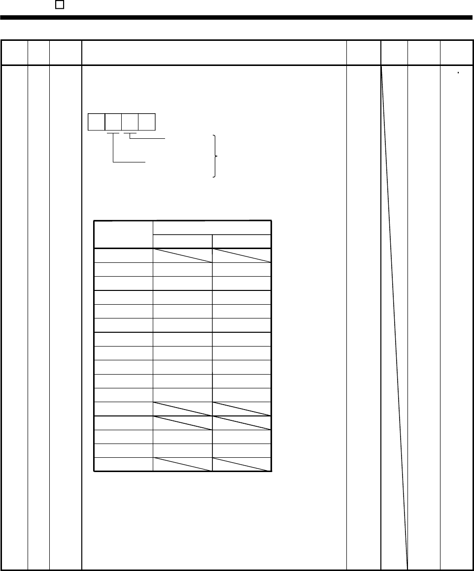
14. MR-E- AG-QW003 SERVO AMPLIFIER COMPATIBLE WITH ANALOG INPUT
Class No. Symbol Name and function Initial
value Unit Setting
range
Control
mode
Expansion parameters 1
43 *DI2 Input signal selection 2 (CN1-4)
Allows any input signal to be assigned to CN1-pin 4.
Note that the setting digit and assigned signal differ according to the
control mode.
Speed
control mode Input signals of
CN1-pin 4
selected.
Torque
control mode
01
Signals that may be assigned in each control mode are indicated below by
their symbols.
Setting of any other signal will be invalid.
Set value (Note) Control mode
ST
0
1
2
3
4
5
6
7
8
9
SON SON
RES RES
PC PC
SP1
SP2
RS2
RS1
CR CR
ASP3
B
C
DTL1
ECDP
TL1
CDP
F
TL TL
SP1
SP2
ST1
ST2
SP3
Note: P: Position control mode
S: Internal speed control mode
This parameter is unavailable when parameter No.42 is set to assign the
control change (LOP) to CN1-pin 4.
If rotation stroke end (LSP) or reverse rotation stroke end (LSN) is
assigned to pin 4 of CN1 with parameter No.48, this parameter cannot be
used.
0111 Refer to
name
and
function
column.
ST
14 - 46
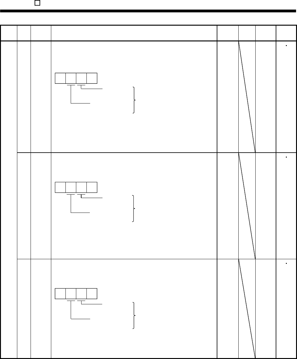
14. MR-E- AG-QW003 SERVO AMPLIFIER COMPATIBLE WITH ANALOG INPUT
Class No. Symbol Name and function Initial
value Unit Setting
range
Control
mode
44 *DI3 Input signal selection 3 (CN1-3)
Allows any input signal to be assigned to CN1-pin 3.
The assignable signals and setting method are the same as in input signal
selection 2 (parameter No.43).
Speed
control mode Input signals of
CN1-pin 3
selected.
Torque
control mode
02
This parameter is unavailable when parameter No.42 is set to assign the
control change (LOP) to CN1-pin 3.
If forward rotation stroke end (LSP) or reverse rotation stroke end (LSN) is
assigned to pin 3 of CN1 with parameter No.48, this parameter cannot be
used.
0882 Refer to
name
and
function
column.
ST
45 *DI4
Input signal selection 4 (CN1-5)
Allows any input signal to be assigned to CN1-pin 5.
The assignable signals and setting method are the same as in input signal
selection 2 (parameter No.43).
Speed
control mode Input signals of
CN1-pin 5
selected.
Torque
control mode
05
This parameter is unavailable when parameter No.42 is set to assign the
control change (LOP) to CN1-pin 5.
If forward stroke end (LSP) or reverse rotation stroke end (LSN) is
assigned to pin 5 of CN1 with parameter No.48, this parameter cannot be
used.
0995 Refer to
name
and
function
column.
ST
Expansion parameters 1
46 *DI5
Input signal selection 5 (CN1-6)
Allows any input signal to be assigned to CN1-pin 6.
The assignable signals and setting method are the same as in input signal
selection 2 (parameter No.43).
Speed
control mode Input signals of
CN1-pin 6
selected.
Torque
control mode
00
This parameter is unavailable when parameter No.42 is set to assign the
control change (LOP) to CN1-pin 6.
If reverse rotation stroke end (LSN) is assigned to pin 6 of CN1 with
parameter No.48, this parameter cannot be used.
0000 Refer to
name
and
function
column.
ST
14 - 47
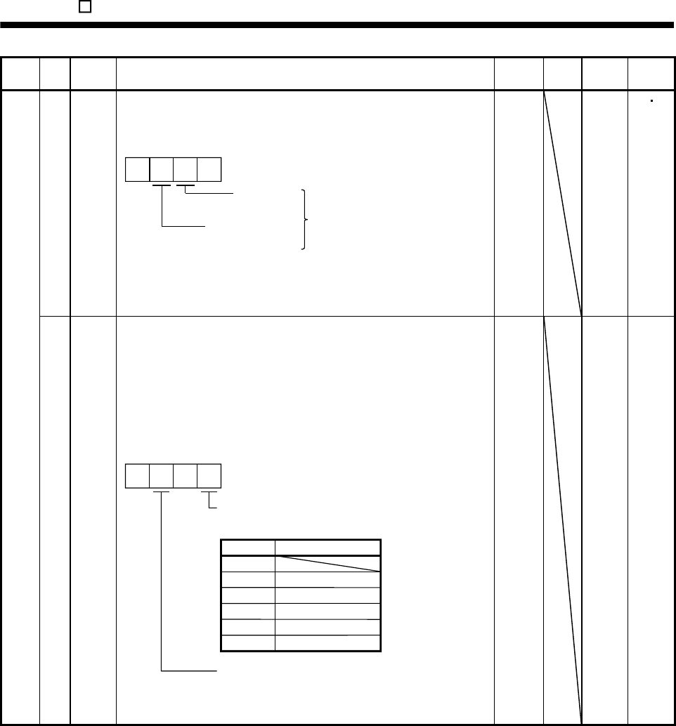
14. MR-E- AG-QW003 SERVO AMPLIFIER COMPATIBLE WITH ANALOG INPUT
Class No. Symbol Name and function Initial
value Unit Setting
range
Control
mode
47 *DI6
Input signal selection 6 (CN1-7)
Allows any input signal to be assigned to CN1-pin 7.
The assignable signals and setting method are the same as in input signal
selection 2 (parameter No.43).
Speed
control mode Input signals of
CN1-pin 7
selected.
Torque
control mode
00
This parameter is unavailable when parameter No.42 is set to assign the
control change signal (LOP) to CN1-pin 7.
If forward rotation stroke end (LSP) is assigned to pin 7 of CN1 with
parameter No.48, this parameter cannot be used.
0000 Refer to
name
and
function
column.
ST
Expansion parameters 1
48 *LSPN
LSP/LSN input terminal selection
Select the pins where the forward rotation stroke end (LSP) and reverse
rotation stroke end (LSN) will be assigned. If the signals have already
been assigned using parameter No.42 to 47, this parameter setting has
preference.
However, if forward rotation stroke end (LSP) is assigned to pin 6 of CN1
(default setting), the setting of parameter No.46 takes priority. Similarly, if
reverse rotation stroke end (LSN) is assigned to pin 7 of CN1 (default
setting), the setting of parameter No .47 takes priority.
CN1-7
CN1-4
CN1-3
CN1-5
CN1-6
3
4
1
2
0
00
5
Select the pin where the forward rotation stroke
end (LSP) will be assigned.
Set value Connector pin No.
Select the pin where the reverse rotation stroke
end (LSN) will be assigned. The settings are the
same as those of the first digit.
0403 Refer to
name
and
function
column.
S
14 - 48
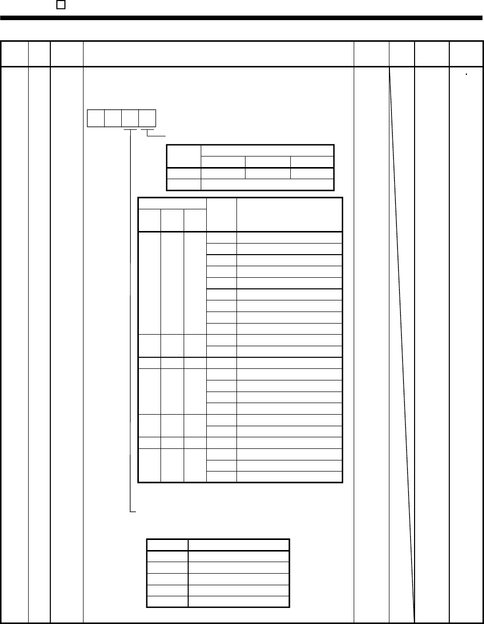
14. MR-E- AG-QW003 SERVO AMPLIFIER COMPATIBLE WITH ANALOG INPUT
Class No. Symbol Name and function Initial
value Unit Setting
range
Control
mode
Expansion parameters 1
49 *DO1 Output signal selection 1
Used to select the connector pins to output the alarm code and warning
(WNG).
Setting of alarm code output
Connector pins
Set value CN1-10 CN1-11 CN1-12
0SA RD ZP
1
88888
AL.12
AL.13
AL.15
AL.17
AL.8A
AL.8E
AL.30
AL.45
AL.50
AL.51
AL.24
AL.32
AL.31
AL.16
AL.20
Name
Watchdog
Memory error 1
Clock error
Memory error 2
Board error 2
Serial communication time-out error
Serial communication error
Regenerative error
Main circuit device overheat
Overload 1
Overload 2
Main circuit
Overcurrent
Overspeed
Encoder error 1
Encoder error 2
Alarm
display
(Note) Alarm code
CN1
pin 10
0
000
1
CN1
pin 11
00
1
10
1
CN1
pin 12
1
1
0
1
0
1
0
Set value Connector pin No.
Setting of warning (WNG) output
Select the connector pin to output warning. The old signal
before selection will be unavailable.
AL.19 Memory error 3
AL.37 Parameter error
AL.33 Overvoltage
AL.46 Servo motor overheat
AL.10 Undervoltage
100
AL.1A Motor combination error
0 Not output.
1 CN1-11
2 CN1-9
3 CN1-10
4 CN1-12
0
Alarm code is output at alarm occurrence.
0
Note. 0: Pin-VIN off (open)
1: Pin-VIN on (short)
0000 Refer to
name
and
function
column.
ST
14 - 49
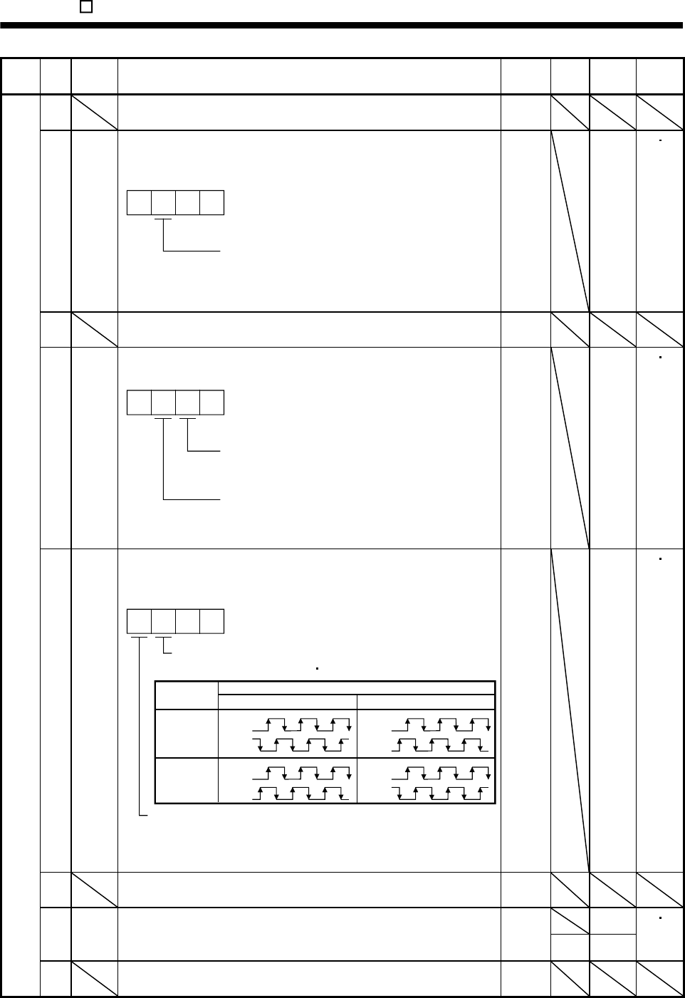
14. MR-E- AG-QW003 SERVO AMPLIFIER COMPATIBLE WITH ANALOG INPUT
Class No. Symbol Name and function Initial
value Unit Setting
range
Control
mode
50 For manufacturer setting
Do not change this value by any means.
0000
51 *OP6 Function selection 6
Used to select the operation to be performed when the reset (RES)
switches on.
000
Operation to be performed when the
reset (RES) switches on
0: Base circuit not switched off
1: Base circuit switched off
0000
Refer to
name
and
function
column.
ST
52 For manufacturer setting
Do not change this value by any means.
0000
53 *OP8 Function selection 8
Used to select the protocol of serial communication.
0 0
Protocol checksum selection
0: Yes (checksum added)
1: No (checksum not added)
Protocol checksum selection
0: With station numbers
1: No station numbers
0000
Refer to
name
and
function
column.
ST
54 *OP9 Function selection 9
Use to select the command pulse rotation direction, encoder output pulse
direction and encoder pulse output setting.
0
Encoder pulse output phase changing
Changes the phases of A B-phase encoder pulses output .
Encoder output pulse setting selection (refer to parameter No.27)
0: Output pulse designation
1: Division ratio setting
Servo motor rotation direction
Set value CCW CW
0
1
A-phase
B-phase
A-phase
B-phase
A-phase
B-phase
A-phase
B-phase
0
0000
Refer to
name
and
function
column.
ST
55 For manufacturer setting
Do not change this value by any means.
0000
0 56 SIC Serial communication time-out selection
Used to set the communication protocol time-out period in [s].
When you set "0", time-out check is not made.
0
s 1 to 60
ST
Expansion parameters 2
57 For manufacturer setting
Do not change this value by any means.
10
14 - 50
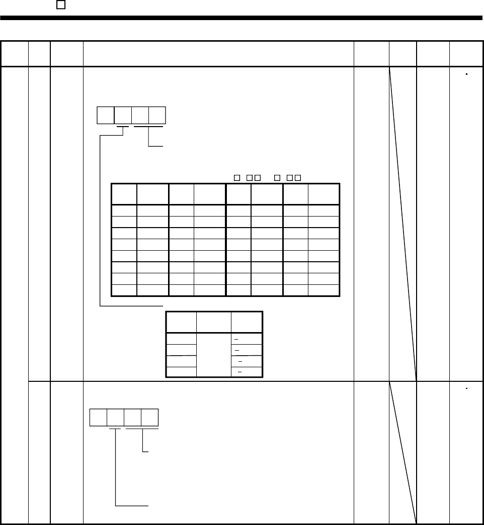
14. MR-E- AG-QW003 SERVO AMPLIFIER COMPATIBLE WITH ANALOG INPUT
Class No. Symbol Name and function Initial
value Unit Setting
range
Control
mode
58 NH1 Machine resonance suppression filter 1
Used to selection the machine resonance suppression filter.
(Refer to section 8.2.)
Set "00" when you have set adaptive vibration
suppression control to be "valid" or "held"
(parameter No.60: 1 or 2 ).
2
3
0
0
1
40dB
14dB
8dB
4dB
Notch frequency selection
00
01
02
03
04
05
06
07
Setting
value Frequency
Invalid
4500
2250
1500
1125
900
750
642.9
08
09
0A
0B
0C
0D
0E
0F
562.5
500
450
409.1
375
346.2
321.4
300
Frequency
10
11
12
13
14
15
16
17
281.3
264.7
250
236.8
225
214.3
204.5
195.7
Frequency
18
19
1A
1B
1C
1D
1E
1F
187.5
180
173.1
166.7
160.1
155.2
150
145.2
Frequency
Notch depth selection
Setting
value Depth Gain
Deep
Shallow
to
Setting
value
Setting
value
Setting
value
0000
Refer to
name
and
function
column.
ST
Expansion parameters 2
59 NH2 Machine resonance suppression filter 2
Used to set the machine resonance suppression filter.
0
Notch frequency
Same setting as in parameter No.58
However, you need not set "00" if you have
set adaptive vibration suppression control to
be "valid" or "held".
Notch depth
Same setting as in parameter No.58
0000
Refer to
name
and
function
column.
ST
14 - 51
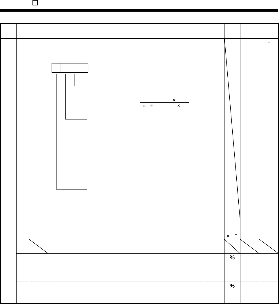
14. MR-E- AG-QW003 SERVO AMPLIFIER COMPATIBLE WITH ANALOG INPUT
Class No. Symbol Name and function Initial
value Unit Setting
range
Control
mode
60 LPF Low-pass filter/adaptive vibration suppression control
Used to selection the low-pass filter and adaptive vibration suppression
control. (Refer to chapter 8.)
0
Low-pass filter selection
0: Valid (Automatic adjustment)
1: Invalid
When you choose "valid", 2 (1 GD2 setting 0.1)
VG2 setting 10
bandwidth filter is set automatically.
Adaptive vibration suppression control selection
Choosing "valid" or "held" in adaptive vibration
suppression control selection makes the machine
resonance suppression filter 1 (parameter No.58) invalid.
0: Invalid
1: Valid
Machine resonance frequency is always detected
and the filter is generated in response to resonance to
suppress machine vibration.
2: Held
The characteristics of the filter generated so far are held,
and detection of machine resonance is stopped.
Adaptive vibration suppression control sensitivity selection
Used to set the sensitivity of machine resonance detection.
0: Normal
1: Large sensitivity
[Hz]
0000 Refer to
name
and
function
column.
ST
61 GD2B Ratio of load inertia moment to servo motor inertia moment 2
Used to set the ratio of load inertia moment to servo motor inertia moment
when gain changing is valid.
70 Multi-
plier
(10 1)
0
to
3000
S
62 For manufacturer setting
Do not change this value by any means.
100
63 VG2B Speed control gain 2 changing ratio
Used to set the ratio of changing the speed control gain 2 when gain
changing is valid.
Made valid when auto tuning is invalid.
100 10
to
200
S
Expansion parameters 2
64 VICB Speed integral compensation changing ratio
Used to set the ratio of changing the speed integral compensation when
gain changing is valid. Made valid when auto tuning is invalid.
100 50
to
1000
S
14 - 52
14. MR-E- AG-QW003 SERVO AMPLIFIER COMPATIBLE WITH ANALOG INPUT
Class No. Symbol Name and function Initial
value Unit Setting
range
Control
mode
65 *CDP Gain changing selection
Used to select the gain changing condition. (Refer to section 8.5.)
000
Gain changing selection
Gains are changed in accordance with the settings
of parameters No.61 to 64 under any of the following
conditions:
0: Invalid
1: Gain changing (CDP) is ON
2: For manufacturer setting
3: For manufacturer setting
4: Servo motor speed is equal to higher than
parameter No.66 setting
0000 Refer to
name
and
function
column.
S
66 CDS Gain changing condition
Used to set the value of gain changing condition (command frequency,
droop pulses, servo motor speed) selected in parameter No.65. The set
value unit changes with the changing condition item. (Refer to section 8.5.)
10 kpps
pulse
r/min
10
to
9999
S
67 CDT Gain changing time constant
Used to set the time constant at which the gains will change in response to
the conditions set in parameters No.65 and 66.
(Refer to section 8.5.)
1 ms 0
to
100
S
68 For manufacturer setting 0
69 Do not change this value by any means. 1
70 1
71
1
Internal speed command 4
Used to set speed 4 of internal speed commands.
S 72 SC4
Internal speed limit 4
Used to set speed 4 of internal speed limits.
200 r/min 0 to in-
stanta-
neous
permi-
ssible
speed
T
Internal speed command 5
Used to set speed 5 of internal speed commands.
S 73 SC5
Internal speed limit 5
Used to set speed 5 of internal speed limits.
300 r/min
0 to in-
stanta-
neous
permi-
ssible
speed
T
Internal speed command 6
Used to set speed 6 of internal speed commands.
S 74 SC6
Internal speed limit 6
Used to set speed 6 of internal speed limits.
500 r/min
0 to in-
stanta-
neous
permi-
ssible
speed
T
Internal speed command 7
Used to set speed 7 of internal speed commands.
S
Expansion parameters 2
75 SC7
Internal speed limit 7
Used to set speed 7 of internal speed limits.
800 r/min
0 to in-
stanta-
neous
permi-
ssible
speed
T
14 - 53
14. MR-E- AG-QW003 SERVO AMPLIFIER COMPATIBLE WITH ANALOG INPUT
Class No. Symbol Name and function Initial
value Unit Setting
range
Control
mode
76 TL2 Internal torque limit 2
Set this parameter to limit servo motor torque on the assumption that the
maximum torque is 100[ ].
When 0 is set, torque is not produced.
When torque is output in analog monitor output, this set value is the
maximum output voltage ( 8V).
100 0
to
100
ST
77 100
78 10000
79 10
80 10
81 100
82 100
83 100
Expansion parameters 2
84
For manufacturer setting
Do not change this value by any means.
0000
14 - 54
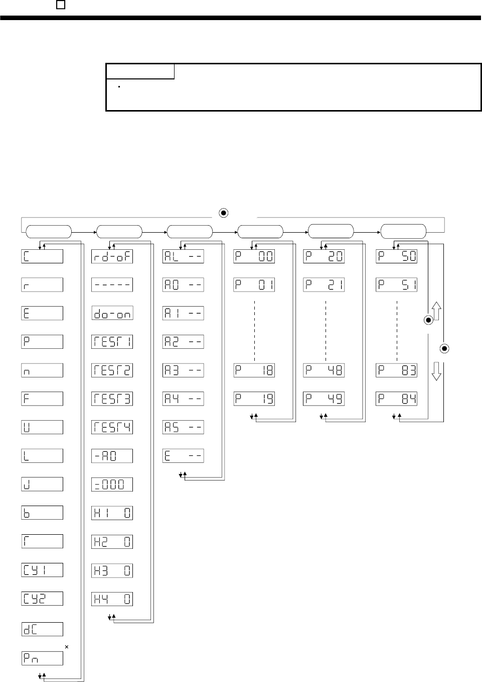
14. MR-E- AG-QW003 SERVO AMPLIFIER COMPATIBLE WITH ANALOG INPUT
14.5 Display and operation
POINT
For the alarm mode, parameter mode output signal (DO) forcible output and test
operation mode, refer to chapter 6.
14.5.1 Display flowchart
Use the display (5-digit, 7-segment LED) on the front panel of the servo amplifier for status display, parameter
setting, etc. Set the parameters before operation, diagnose an alarm, confirm external sequences, and/or
confirm the operation status. Press the "MODE" "UP" or "DOWN" button once to move to the next screen.
To refer to or set the expansion parameters, make them valid with parameter No.19 (parameter write disable).
Cumulative feedback
pulses [pulse]
Servo motor speed
[r/min]
Analog speed command voltage
Analog speed limit voltage [V]
Analog torque limit voltage
Analog torque command voltage
Regenerative load
ratio [%]
Effective load ratio
[%]
Peak load ratio
[%]
Within one-revolution
position low [pulse]
Load inertia moment
ratio [Multiplier ( 1)]
Sequence
External I/O
signal display
Output (DO) signal
forced output
Test operation mode
Jog feed
Test operation mode
Motor-less operation
Software version low
Software version high
Automatic VC offset
Current alarm
Last alarm
Second alarm in past
Third alarm in past
Fourth alarm in past
Fifth alarm in past
Sixth alarm in past
Parameter error No.
Parameter No.0
Parameter No.1
Parameter No.18
Parameter No.19
Parameter No.20
Parameter No.21
Parameter No.48
Parameter No.49
(Note)
MODE
button
DOWN
UP
Status display Diagnosis Basic
parameters Expansion
parameters 1
Alarm Expansion
parameters 2
Parameter No.50
Parameter No.51
Parameter No.83
Parameter No.84
Instantaneous torque
[%]
Within one-revolution
position, high [100 pulse]
Bus voltage [V]
Motor series ID
Motor type ID
Encoder ID
[V]
Test operation mode
Machine analyzer operation
Note. The initial status display at power-on depends on the control mode.
Speed control mode: Servo Motor speed(r),
Torque control mode: Torque command voltage (U)
Also, parameter No.18 can be used to change the initial indication of the status display at power-on.
14 - 55
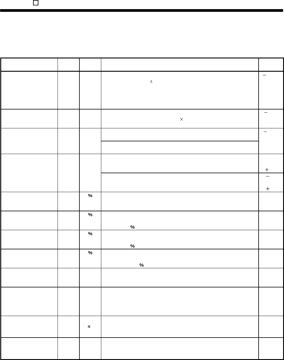
14. MR-E- AG-QW003 SERVO AMPLIFIER COMPATIBLE WITH ANALOG INPUT
14.5.2 Status display
(1) Status display list
The following table lists the servo statuses that may be shown.
Name Symbol Unit Description Display
range
Cumulative feedback
pulses
C pulse Feedback pulses from the servo motor encoder are counted and displayed.
The value in excess of 99999 is counted, bus since the servo amplifier
display is five digits, it shows the lower five digits of the actual value. Press
the "SET" button to reset the display value to zero.
Reverse rotation is indicated by the lit decimal points in the upper four
digits.
99999
to
99999
Servo motor speed r r/min The servo motor speed is displayed.
The value rounded off is displayed in 0.1r/min.
5400
to
5400
(1) Torque control mode
Analog speed limit (VLA) voltage is displayed.
Analog speed command
voltage
Analog speed limit
voltage
F V
(2) Speed control mode
Analog speed command (VC) voltage is displayed.
10.00
to
10.00
(1) Speed control mode
Analog torque limit (TLA) voltage is displayed.
0
to
10V
Analog torque command
voltage
Analog torque limit
voltage
U V
(2) Torque control mode
Analog torque command (TLA) voltage is displayed.
8.0
to
8.0
Regenerative load ratio L The ratio of regenerative power to permissible regenerative power is
displayed in .
0
to
100
Effective load ratio J The continuous effective load torque is displayed.
The effective value in the past is seconds is displayed relative to the rated
torque of 100 .
0
to
300
Peak load ratio b The maximum torque generated during acceleration/deceleration, etc.
The highest value in the past 15 seconds is displayed relative to the rated
torque of 100 .
0
to
400
Instantaneous torque T Torque that occurred instantaneously is displayed.
The value of the torque that occurred is displayed in real time relative to the
rate torque of 100 .
0
to
400
Within one-revolution
position low
Cy1 pulse Position within one revolution is displayed in encoder pulses.
The value returns to "0" when it exceeds the maximum number of pulses.
The value is incremented in the CCW direction of rotation.
0
to
99999
Within one-revolution
position high
Cy2 100
pulse
The within one-revolution position is displayed in 100 pulse increments of
the encoder.
The value returns to "0" when it exceeds the maximum number of pulses.
The value is incremented in the CCW direction of rotation.
0
to
1310
Load inertia moment ratio dC Multiplier
(1)
The estimated ratio of the load inertia moment to the servo motor shaft
inertia moment is displayed.
0.0
to
300.0
Bus voltage Pn V The voltage (across P-N) of the main circuit converter is displayed. 0
to
450
14 - 56

14. MR-E- AG-QW003 SERVO AMPLIFIER COMPATIBLE WITH ANALOG INPUT
14 - 57
(2) Changing the status display screen
The status display item of the servo amplifier display shown at power-on can be changed by changing the
parameter No.18 settings.
The item displayed in the initial status changes with the control mode as follows.
Control mode Status display at power-on
Speed Servo motor speed
Speed/torque Servo motor speed/analog torque command voltage
Torque Analog torque command voltage
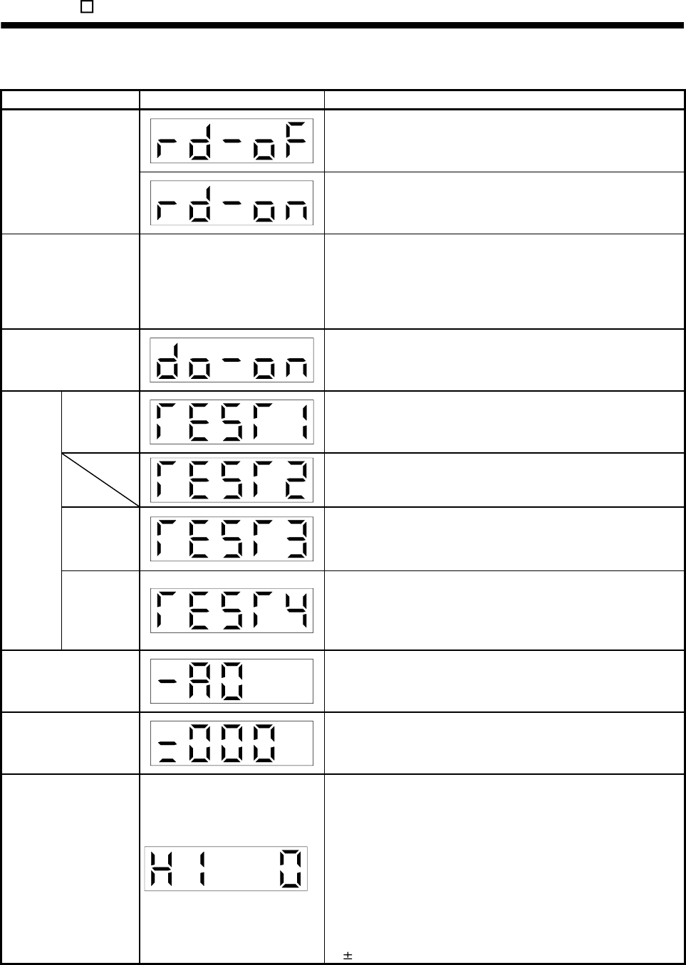
14. MR-E- AG-QW003 SERVO AMPLIFIER COMPATIBLE WITH ANALOG INPUT
14.5.3 Diagnostic mode
Name Display Description
Not ready.
Indicates that the servo amplifier is being initialized or an alarm has
occurred.
Sequence
Ready.
Indicates that the servo was switched on after completion of
initialization and the servo amplifier is ready to operate.
External I/O signal display
Refer to section 15.5.4. Indicates the ON-OFF states of the external I/O signals.
The upper segments correspond to the input signals and the lower
segments to the output signals.
Lit: ON
Extinguished: OFF
The I/O signals can be changed using parameters No.43 to 49.
Output (DO) signal forced
output
The digital output signal can be forced on/off. For more information,
refer to section 6.7.
Jog feed
Jog operation can be performed when there is no command from the
external command device.
For details, refer to section 6.8.2.
Screen for manufacturer setting. When this screen is being displayed,
do not press any other buttons than "UP" and "DOWN".
Motor-less
operation
Without connection of the servo motor, the servo amplifier provides
output signals and displays the status as if the servo motor is running
actually in response to the external input signal.
For details, refer to section 6.8.4.
Test
operation
mode
Machine
analyzer
operation
Merely connecting the servo amplifier allows the resonance point of the
mechanical system to be measured.
The MR Configurator (servo configuration software) is required for
machine analyzer operation.
Gain search cannot be used.
Software version low
Indicates the version of the software.
Software version high
Indicates the system number of the software.
Automatic VC offset
If offset voltages in the analog circuits inside and outside the servo
amplifier cause the servo motor to rotate slowly at the analog speed
command (VC) or analog speed limit (VLA) of 0V, this function
automatically makes zero-adjustment of offset voltages.
When using this function, make it valid in the following procedure.
Making it valid causes the parameter No.29 value to be the
automatically adjusted offset voltage.
1) Press "SET" once.
2) Set the number in the first digit to 1 with "UP"/"DOWN".
3) Press "SET".
You cannot use this function if the input voltage of VC or VLA is
0.4V or more.
14 - 58

14. MR-E- AG-QW003 SERVO AMPLIFIER COMPATIBLE WITH ANALOG INPUT
Name Display Description
Motor series ID
Press the "SET" button to show the motor series ID of the servo motor
currently connected.
Motor type ID
Press the "SET" button to show the motor type ID of the servo motor
currently connected.
Encoder ID
Press the "SET" button to show the encoder ID of the servo motor
currently connected.
14 - 59
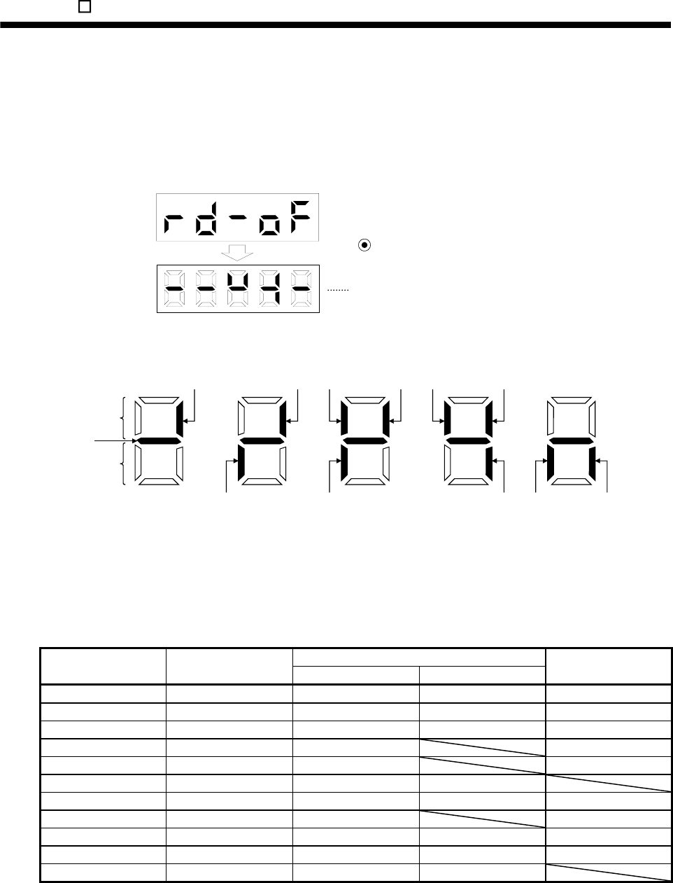
14. MR-E- AG-QW003 SERVO AMPLIFIER COMPATIBLE WITH ANALOG INPUT
14.5.4 External I/O signal display
The ON/OFF states of the digital I/O signals connected to the servo amplifier can be confirmed.
(1) Operation
Call the display screen shown after power-on.
Using the "MODE" button, show the diagnostic screen.
Press UP once.
External I/O signal display screen
(2) Display definition
CN1
6
CN1
7
CN1
21
CN1
5
CN1
9
CN1
3CN1
4
CN1
12 CN1
11
CN1
10
Lit: ON
Extinguished: OFF
Input signals
Output signals
CN1
8
Always lit
The 7-segment LED shown above indicates ON/OFF.
Each segment at top indicates the input signal and each segment at bottom indicates the output signal. The
signals corresponding to the pins in the respective control modes are indicated below.
(Note 2) Signal abbreviation CN1
Pin No.
Input/Output
(Note 1) I/O S T
Related parameter No.
3 I ST1 RS2 43 to 47
4 I SON SON 43 to 47
5 I ST2 RS1 43 to 47
6 I LSP 43 to 48
7 I LSN 43 to 48
8 I EMG EMG
9 O ALM ALM 49
10 O SA 49
11 O RD RD 49
12 O ZSP ZSP 49
21 O OP OP
Note 1. I: Input signal, O: Output signal
2. S: Speed control mode, T: Torque control mode.
3. CN1B-4 and CN1A-18 output signals are the same.
14 - 60
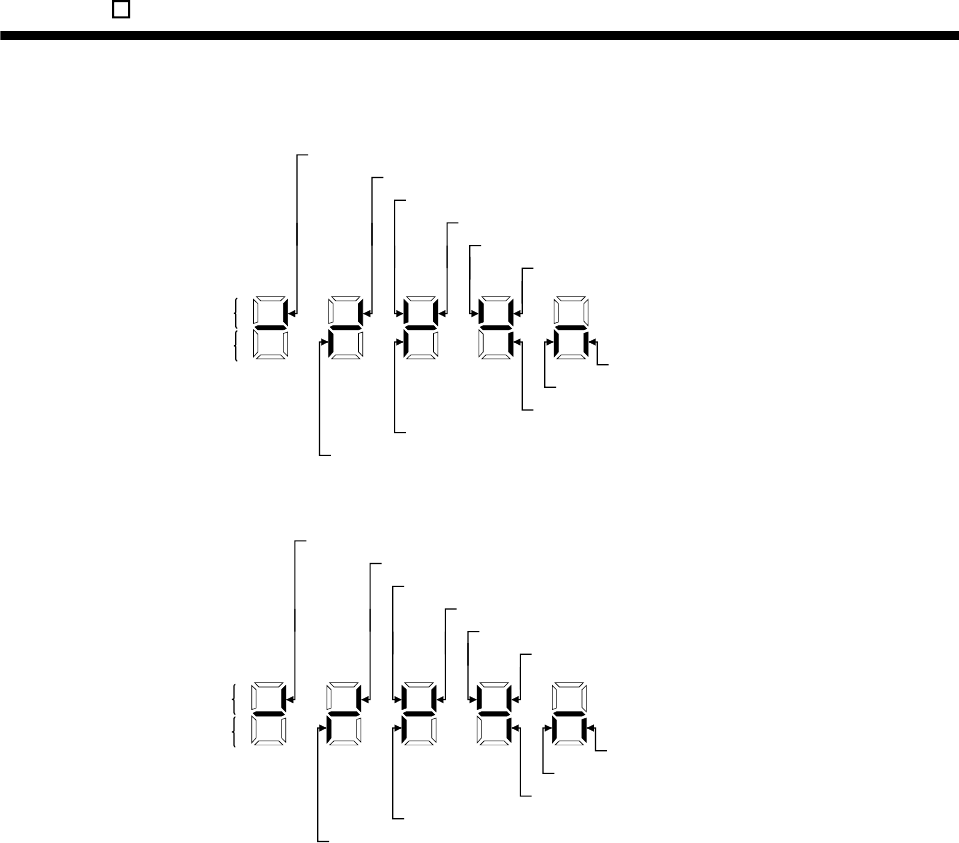
14. MR-E- AG-QW003 SERVO AMPLIFIER COMPATIBLE WITH ANALOG INPUT
(3) Default signal indications
(a) Speed control mode
Lit: ON
Extinguished: OFF
Input signals
Output signals
SON (CN 1-4) Servo-on
LSN (CN 1-7) Reverse rotation stroke end
LSP (CN 1-6) Forward rotation stroke end
RD (CN 1-11) Ready
ZSP (CN 1-12) Zero speed detection
ALM (CN 1-9) Trouble
OP (CN 1-21) Encoder Z-phase pulse
EMG (CN 1-8) Emergency stop
SA (CN 1-10) Limiting speed
ST1 (CN 1-3) Forward rotation start
ST2 (CN 1-5) Reverse rotation start
(b) Torque control mode
Lit: ON
Extinguished: OFF
Input signals
Output signals
RS1 (CN 1-5) Forward rotation selection
RS2 (CN 1-3) Reverse rotation selection
SON (CN 1-4) Servo-on
(CN 1-7)
(CN 1-6)
RD (CN 1-11) Ready
(CN 1-10)
ZSP (CN 1-12) Zero speed detection
ALM (CN 1-9) Trouble
OP (CN 1-21) Encoder Z-phase pulse
EMG (CN 1-8) Emergency stop
14 - 61
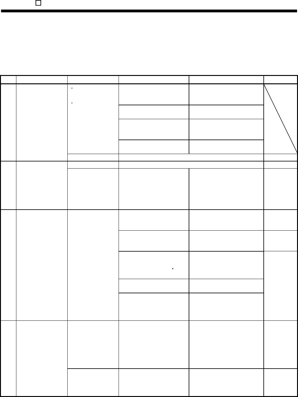
14. MR-E- AG-QW003 SERVO AMPLIFIER COMPATIBLE WITH ANALOG INPUT
14.6 Troubleshooting
14.6.1 Trouble at start-up
The following faults may occur at start-up. If any of such faults occurs, take the corresponding action.
(1) Speed control mode
No. Start-up sequence Fault Investigation Possible cause Reference
Not improved if connectors
CN1, CN2 and CN3 are
disconnected.
1. Power supply voltage fault
2. Servo amplifier is faulty.
Improved when connectors
CN1 is disconnected.
Power supply of CN1 cabling is
shorted.
Improved when connector
CN2 is disconnected.
1. Power supply of encoder
cabling is shorted.
2. Encoder is faulty.
7-segment LED is
not lit.
7-segment LED
flickers.
Improved when connector
CN3 is disconnected.
Power supply of CN3 cabling is
shorted.
1 Power on (Note)
Alarm occurs. Refer to section 10.2 and remove cause. Section 10.2
Alarm occurs. Refer to section 10.2 and remove cause. Section 10.2 2 Switch on servo-on
(SON). Servo motor shaft is
not servo-locked
(is free).
1. Check the display to see if
the servo amplifier is ready
to operate.
2. Check the external I/O
signal indication to see if the
servo-on (SON) is ON.
1. Servo-on (SON) is not input.
(Wiring mistake)
2. 24VDC power is not supplied
to COM.
Section 6.6
Call the status display and
check the input voltage of the
analog speed command (VC).
Analog speed command is 0V. Section 6.2
Call the external I/O signal
display and check the ON/OFF
status of the input signal.
LSP, LSN, ST1 or ST2 is off. Section 6.6
Check the internal speed
commands 1 to 7
(parameters No.8 to 10 72 to
75).
Set value is 0.
Check the internal torque limit
1 (parameter No.28).
Torque limit level is too low as
compared to the load torque.
3 Switch on forward
rotation start (ST1) or
reverse rotation start
(ST2).
Servo motor does not
rotate.
When the analog torque limit
(TLA) is usable, check the
input voltage on the status
display.
Torque limit level is too low as
compared to the load torque.
Section
5.1.2 (1)
Rotation ripples
(speed fluctuations)
are large at low
speed.
Make gain adjustment in the
following procedure.
1. Increase the auto tuning
response level.
2. Repeat acceleration and
deceleration several times
to complete auto tuning.
Gain adjustment fault Chapter 7
4 Gain adjustment
Large load inertia
moment causes the
servo motor shaft to
oscillate side to side.
If the servo motor may be run
with safety, repeat acceleration
and deceleration several times
to complete auto tuning.
Gain adjustment fault Chapter 7
N
ote. Switch power on again after making sure that the change lamp has turned off completely.
14 - 62
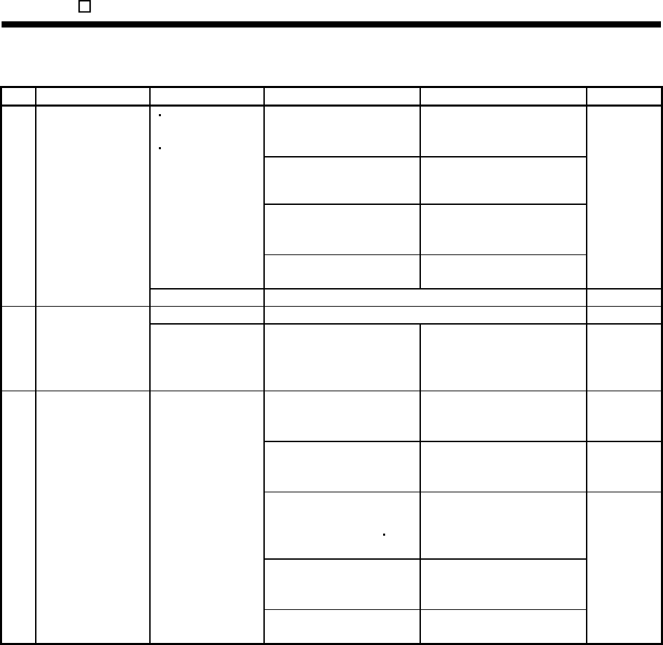
14. MR-E- AG-QW003 SERVO AMPLIFIER COMPATIBLE WITH ANALOG INPUT
(2) Torque control mode
No. Start-up sequence Fault Investigation Possible cause Reference
Not improved if connectors
CN1, CN2 and CN3 are
disconnected.
1. Power supply voltage fault
2. Servo amplifier is faulty.
Improved when connectors
CN1 is disconnected.
Power supply of CN1 cabling is
shorted.
Improved when connector
CN2 is disconnected.
1. Power supply of encoder
cabling is shorted.
2. Encoder is faulty.
7-segment LED is
not lit.
7-segment LED
flickers.
Improved when connector
CN3 is disconnected.
Power supply of CN3 cabling is
shorted.
1 Power on (Note)
Alarm occurs. Refer to section 10.2 and remove cause. Section 10.2
Alarm occurs. Refer to section 10.2 and remove cause. Section 10.2 2 Switch on servo-on
(SON). Servo motor shaft is
free.
Call the external I/O signal
display and check the ON/OFF
status of the input signal.
1. Servo-on (SON) is not input.
(Wiring mistake)
2. 24VDC power is not supplied
to COM.
Section 6.6
Call the status display and
check the analog torque
command (TC).
Analog torque command is 0V. Section 6.2
Call the external I/O signal
display and check the ON/OFF
status of the input signal.
RS1 or RS2 is off. Section 6.6
Check the internal speed limits
1 to 7
(parameters No.8 to 10 72 to
75).
Set value is 0.
Check the analog torque
command maximum output
(parameter No.26) value.
Torque command level is too low
as compared to the load torque.
3 Switch on forward
rotation start (RS1) or
reverse rotation start
(RS2).
Servo motor does not
rotate.
Check the internal torque limit
1 (parameter No.28).
Set value is 0.
Section
5.1.2 (1)
N
ote. Switch power on again after making sure that the change lamp has turned off completely.
14 - 63
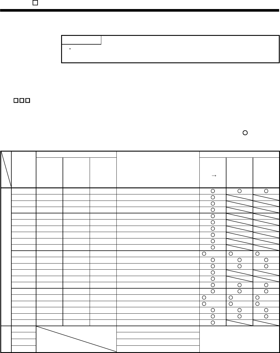
14. MR-E- AG-QW003 SERVO AMPLIFIER COMPATIBLE WITH ANALOG INPUT
14.6.2 Alarms and warning list
POINT
Configure up a circuit which will detect the trouble (ALM) signal and turn off
the servo-on (SON) signal at occurrence of an alarm.
When a fault occurs during operation, the corresponding alarm or warning is displayed. If any alarm or warning
has occurred, refer to section 10.2.2 or 10.2.3 and take the appropriate action. When an alarm occurs, the
current circuit between ALM and VIN opens.
Set " 1" in parameter No.49 to output the alarm code in ON/OFF status across the corresponding pin
and VIN. Warnings (AL.E0 to AL.E9) have no alarm codes. Any alarm code is output at occurrence of the
corresponding alarm. In the normal status, the signals available before alarm code setting (CN1-12: ZSP, CN1-
11: RD, CN1-10: SA) are output.
After its cause has been removed, the alarm can be deactivated in any of the methods marked in the alarm
deactivation column.
(Note 2) Alarm code Alarm deactivation
Display CN1-10
pin
CN1-11
pin
CN1-12
pin
Name Power
OFF ON
Press
"SET" on
current
alarm
screen.
Alarm reset
(RES)
signal
AL.10 0 1 0 Undervoltage
AL.12 0 0 0 Memory error 1
AL.13 0 0 0 Clock error
AL.15 0 0 0 Memory error 2
AL.16 1 0 1 Encoder error 1
AL.17 0 0 0 Board error
AL.19 0 0 0 Memory error 3
AL.1A 1 0 1 Motor combination error
AL.20 1 1 0 Encoder error 2
AL.24 0 0 1 Main circuit error
AL.30 0 1 0 Regenerative error (Note 1) (Note 1) (Note 1)
AL.31 0 1 1 Overspeed
AL.32 0 0 1 Overcurrent
AL.33 0 1 0 Overvoltage
AL.37 0 0 0 Parameter error
AL.45 1 1 0 Main circuit device overheat
AL.46 1 1 0 Servo motor overheat
AL.50 1 1 0 Overload 1 (Note 1) (Note 1) (Note 1)
AL.51 1 1 0 Overload 2 (Note 1) (Note 1) (Note 1)
AL.8A 0 0 0 Serial communication time-out error
AL.8E 0 0 0 Serial communication error
Alarms
88888 0 0 0 Watchdog
AL.E0 Excessive regenerative warning
AL.E1 Overload warning
AL.E6 Servo emergency stop warning
Warnings
AL.E9
Undervoltage warning
Removing the cause of occurrence
deactivates the alarm
automatically.
Note 1. Deactivate the alarm about 30 minutes of cooling time after removing the cause of occurrence.
2. 0: off
1: on
14 - 64
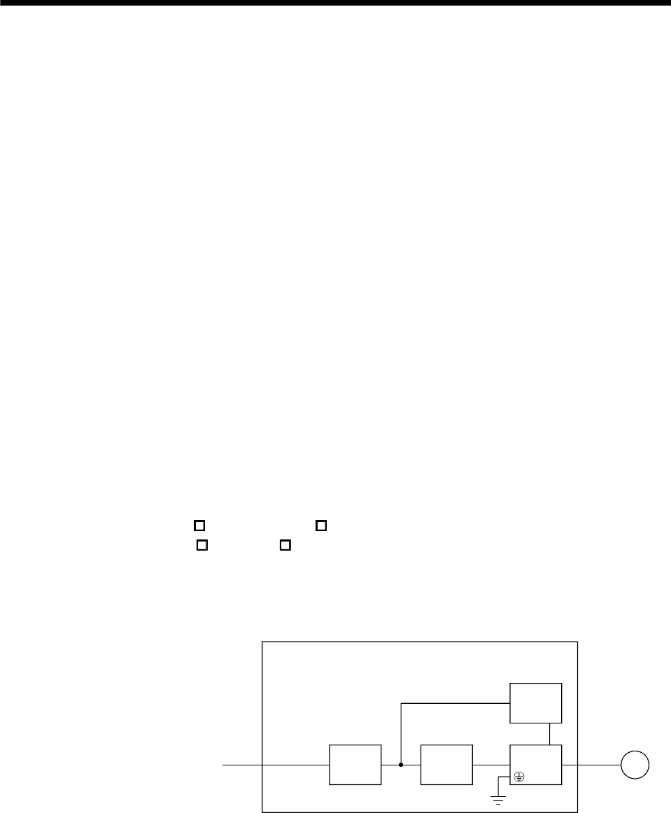
APPENDIX
App. 1 COMPLIANCE WITH CE MARKING
App. 1.1 What is CE marking?
The CE marking is mandatory and must be affixed to specific products placed on the European Union. When a
product conforms to the requirements, the CE marking must be affixed to the product. The CE marking also
applies to machines and equipment incorporating servos.
(1) EMC directive
The EMC directive applies to the servo units alone. This servo is designed to comply with the EMC
directive. The EMC directive also applies the servo-incorporated machines and equipment. This requires
the EMC filters to be used with the servo-incorporated machines and equipment to comply with the EMC
directive.
(2) Low voltage directive
The low voltage directive applies also to servo units alone. This servo is designed to comply with the low
voltage directive.
App. 1.2 For compliance
Be sure to perform an appearance inspection of every unit before installation. In addition, have a final
performance inspection on the entire machine/system, and keep the inspection record.
(1) Servo amplifiers and servo motors used
Use the servo amplifiers and servo motors which standard product.
Servo amplifier : MR-E- A-QW003, MR-E- AG-QW003
Servo motor series : HF-KN (J), HF-SN J
(2) Structure
The control circuit provide safe separation to the main circuit in the servo amplifier.
Servo motor
NFB MC
24VDC
power
supply
M
Control box
No-fise
breaker Magnetic
contactor
Reinforced insulating type
Servo
amplifier
App. - 1
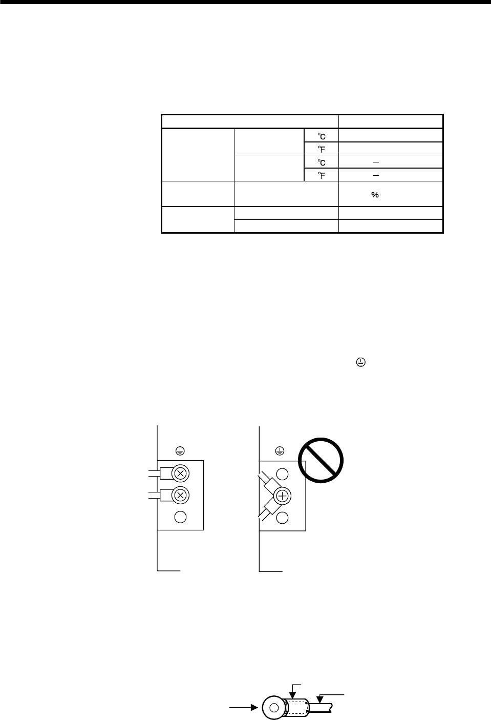
APPENDIX
(3) Environment
(a) Operate the servo amplifier at or above pollution degree 2 set forth in IEC/EN 60664-1. For this
purpose, install the servo amplifier in a control box which is protected against water, oil, carbon, dust,
dirt, etc. (IP54).
(b) Environment
Environment Conditions
[] 0 to 55
In operation [] 32 to 131
[] 20 to 65
(Note)
Ambient
Temperature In storage,
In transportation [] 4 to 149
Ambient Humidity In operation, In storage, In
transportation 90 RH or less
In operation, In storage 1000m or less
Maximum Altitude In transportation 10000m or less
Note. Ambient temperature is the internal temperature of the control box.
(4) Power supply
(a) This servo amplifier can be supplied from star-connected supply with earthed neutral point of
overvoltage category II set forth in IEC/EN 60664-1.
(b) For the interface power supply, use a 24VDC power supply with reinforced insulation on I/O terminals.
(5) Grounding
(a) To prevent an electric shock, the protective earth (PE) terminal (marked ) of the servo amplifier must
be connected to the protective earth (PE) of the control box.
(b) Do not connect two ground cables to the same protective earth (PE) terminal. Always connect cables
to the terminals one-to-one.
PE terminals PE terminals
(c) If an earth leakage circuit breaker is used, always earth the protective earth (PE) terminal of the servo
amplifier to prevent an electric shock.
(6) Wiring and installation
(a) The cables to be connected to the terminal block of the servo amplifier must have crimping terminals
provided with insulating tubes to prevent contact with adjacent terminals.
Crimping terminal
Insulating tube
Cable
App. - 2

App. - 3
APPENDIX
(b) Use the servo motor side power connector which complies with the IEC/EN Standard.
The IEC/EN Standard-compliant power connector sets are available from us as options.
(c) The servo amplifier must be installed in the metal cabinet (control box).
(7) Peripheral devices, options
(a) Use the circuit breaker and magnetic contactor models which are EN/IEC Standard-compliant products
given this Servo Amplifier Instruction Manual.
Use a type B (Note) breaker. When it is not used, provide insulation between the servo amplifier and
other device by double insulation or reinforced insulation, or install a transformer between the main
power supply and servo amplifier.
Note. Type A: AC and pulse detectable
Type B: Both AC and DC detectable
(b) The sizes of the wires given this Servo Amplifier Instruction Manual meet the following conditions. For
use in any other conditions, follow Table 5 and Annex C of IEC/EN 60204-1.
Ambient temperature: 40 (104 )
Sheath : PVC (polyvinyl chloride)
Installation on wall surface or open table tray
(c) Use the EMC filter for noise reduction.
(8) Performing EMC tests
When EMC tests are run on a machine/device into which the servo amplifier has been installed, it must
conform to the electromagnetic compatibility (immunity/emission) standards after it has satisfied the
operating environment/electrical equipment specifications.
For the other EMC directive guidelines on the servo amplifier, refer to the EMC Installation Guidelines
(IB(NA)67310).
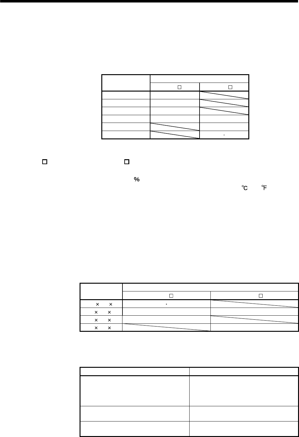
App. - 4
APPENDIX
App. 2 COMPLIANCE WITH UL/cUL STANDARD
This servo amplifier complies with UL 508C, and CSA C22.2 No.14 standard.
(1) Servo amplifiers and servo motors used
Use the servo amplifiers and servo motors which standard product.
Servo motors
Servo amplifier HF-KN (J) HF-SN J
MR-E-10A-QW003 13
MR-E-20A-QW003 23
MR-E-40A-QW003 43
MR-E-70A-QW003 73 52
MR-E-100A-QW003 102
MR-E-200A-QW003 152 202
(2) Installation
The MR-E- A-QW003 series and MR-E- AG-QW003 series have been approved as the products which
have been installed in the electrical enclosure.
The minimum enclosure size is based on 150 of each MR-E combination.
And also, design the enclosure so that the ambient temperature in the enclosure is 55 (131 ) or less,
refer to the spec manual.
The servo amplifier must be installed in the metal cabinet (control box).
(3) Short circuit rating (SCCR: Short Circuit Current Rating)
Suitable For Use In A Circuit Capable Of Delivering Not More Than 100 kA rms Symmetrical Amperes,
500 Volts Maximum.
(4) Flange
Mount the servo motor on a flange which has the following size or produces an equivalent or higher heat
dissipation effect.
Servo motor
Flange size HF-KN (J) HF-SN J
250 250 6 13 23
250 250 12 43 52 to 152
300 300 12 73
550 550 20 202
(5) Capacitor discharge time
The capacitor discharge time is as follows. To ensure safety, do not touch the charging section for 15
minutes after power-off.
Servo amplifier Discharge time [min]
MR-E-10A-QW003
MR-E-10AG-QW003
MR-E-20A-QW003
MR-E-20AG-QW003
1
MR-E-40A-QW003
MR-E-40AG-QW003 2
MR-E-70A-QW003 to MR-E-200A-QW003
MR-E-70AG-QW003 to MR-E-200AG-QW003 3
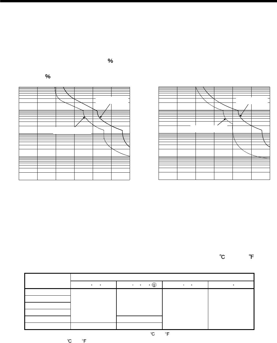
APPENDIX
(6) Overload protection characteristics
An electronic thermal relay is built in the servo amplifier to protect the servo motor and servo amplifier from
overloads. The operation characteristics of the electronic thermal relay are shown below. It is
recommended to use an unbalanced torque-generated machine, such as a vertical motion shaft, so that
unbalanced torque is not more than 70 of the rated torque.
Servo amplifier MR-E series have each solid-state servo motor overload protection. (The motor full load
current is 115 rated current.)
1000
100
10
1
0.1
050 150 200 250 300
(Note) Load ratio [%]
Operation time[s]
100
During rotation
During servo lock
a. MR-E-10A-QW003 to MR-E-100A-QW003
1000
100
10
1
0.1
050 150 200 250 300
(Note) Load ratio [%]
Operation time[s]
100
During rotation
During servo lock
b. MR-E-200A-QW003
Note. If operation that generates torque more than 100% of the rating is performed with an abnormally high
frequency in a servo motor stop status (servo lock status) or in a 30r/min or less low-speed operation
status, the servo amplifier may fail even when the electronic thermal relay protection is not activated.
(7) Selection example of wires
To comply with the UL/cUL Standard, use UL-approved copper wires rated at 60/75 (140/167 ) for
wiring.
(Note) Wires [mm2]
Servo amplifier 1) L1L2L33) U V W 4) P CD 5) B1 B2
MR-E-10A-QW003
MR-E-20A-QW003
MR-E-40A-QW003
MR-E-70A-QW003
1.25 (AWG16)
MR-E-100A-QW003
2 (AWG14)
2 (AWG14)
MR-E-200A-QW003 (Note) 2.5 (AWG14) (Note) 2.5 (AWG14)
2 (AWG14) 1.25 (AWG16)
Note. Use the heat-resistant PVC cable (rated temperature 105 (221 ) or more), if AWG14 cable is used in ambient
temperature 40 (104 ) or more.
App. - 5
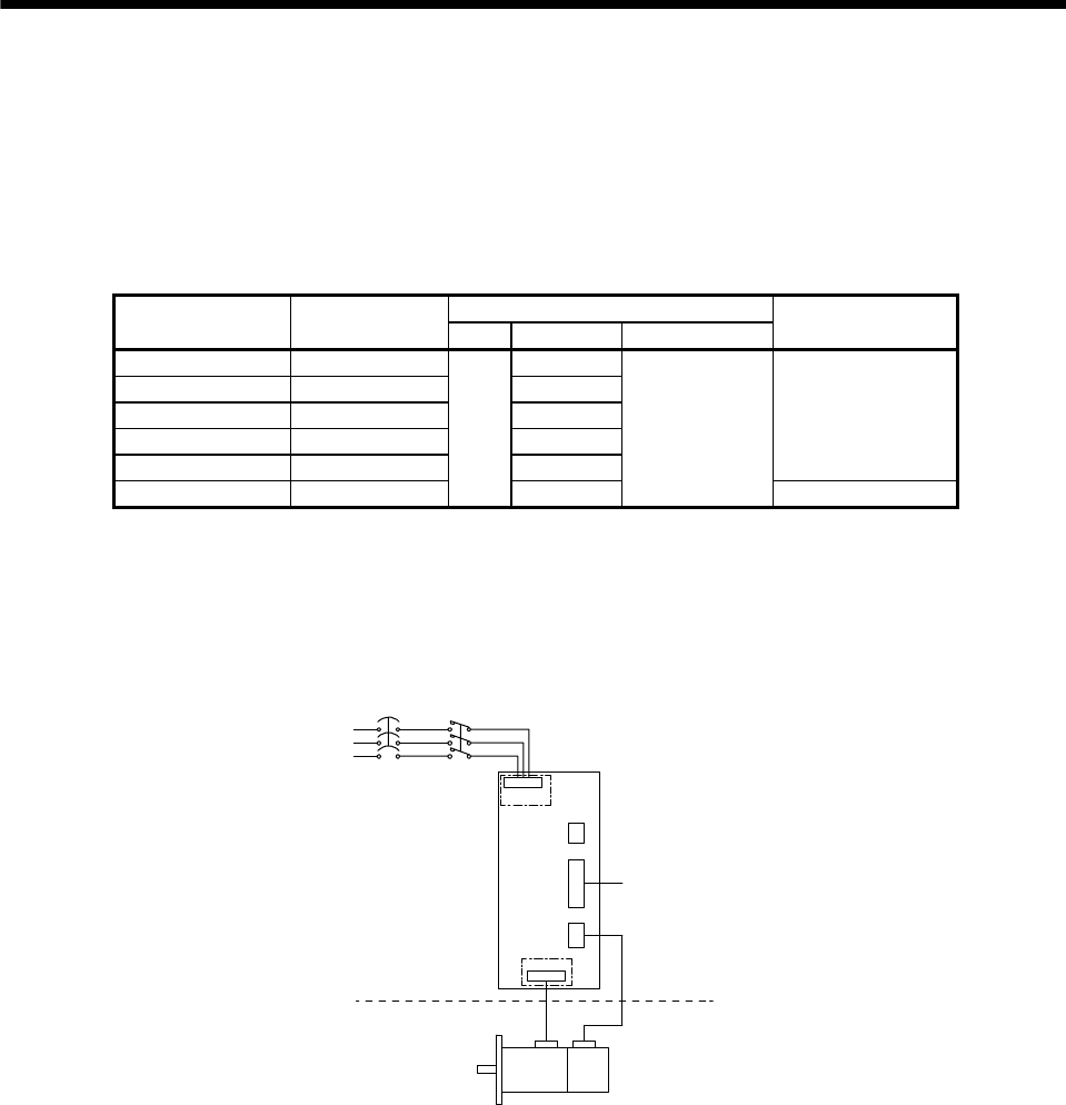
APPENDIX
(8) About wiring protection
For installation in United States, branch circuit protection must be provided, in accordance with the
National Electrical Code and any applicable local codes and per the table below.
For installation in Canada, branch circuit protection must be provided, in accordance with the Canada
Electrical Code and any applicable provincial codes and per the table below.
Use the molded-case circuit breaker or a Class T fuse indicated in the table below.
Fuse
Servo amplifier Circuit breaker Class Current [A] Voltage AC [V]
Magnetic contactor
(note)
MR-E-10A-QW003 30A frame 5A 10
MR-E-20A-QW003 30A frame 5A 10
MR-E-40A-QW003 30A frame 10A 15
MR-E-70A-QW003 30A frame 15A K5 15
MR-E-100A-QW003 30A frame 15A 15
S-N10
MR-E-200A-QW003 30A frame 20A 15
250
S-N18
(9) Options, peripheral devices
Use the UL/cUL Standard-compliant products.
(10) Connection example
L1, L2, L3
CNP1
CNP2
U, V, W
CN2
CN1
CN3
Fuse or
MCCB
Servo amplifier
Servo motor
Encoder
Cabinet side
Machine side
Encoder cable
Command device
Magne
t
contactor
App. - 6

REVISIONS
*The manual number is given on the bottom left of the back cover.
Print data *Manual number Revision
May 2008 SH(NA)030075-A First edition
Oct. 2012 SH(NA)030075-B The chapter of servo motor
is deleted.
Front cover
1. To prevent electric
shock, note the following
2. To prevent fire, note the
following
4. Additional instructions (1)
Transportation and
installation
4. Additional instructions (2)
Wiring
4. Additional instructions (5)
Corrective actions
COMPLIANCE WITH CE
MARKING
COMPLIANCE WITH
UL/cUL STANDARD
<<About the manuals>>
<<Wiring>>
Section 1.2
Section 1.3
Section 1.5 (1)
Section 1.6
Section 1.8 (1)
Section 1.8 (2)
Chapter 2
Section 2.1
Section 2.4 (2)
Chapter 3
Section 3.1
Section 3.1.1 (1)
Section 3.1.1 (2)
Section 3.1.1 (3)
Section 3.1.2
Section 3.3.2
Section 3.4.3
Section 3.6.2 (5)
Section 3.7
Section 3.7.1 (1)
Description of HF-KN/HF-SN motor is added.
The sentences are added.
The sentences are added.
The sentences are added, and the table is changed.
The diagram is changed.
The sentences are changed, and the diagram is
changed.
The title is changed, and descriptions of the
compliance with CE marking are moved to APPENDIX.
The title is changed, and descriptions of the
compliance with UL/cUL standard are moved to
APPENDIX.
HF-KN/HF-SN Servo Motor Instruction Manual is
added.
Added.
The diagram is changed.
The table is changed.
The rating plate is changed.
Description of HF-KN/HF-SN motor is added, and the
model name of servo motor in the table is changed.
The diagram is changed.
The diagram is changed.
WARNING is added, and the sentences are added to
CAUTION.
The table is changed.
The sentences are changed.
The sentences are added to WARNING.
The sentences of POINT are changed.
The diagram is changed.
The diagram is changed.
The diagram is changed.
The diagram is changed.
The table is changed.
The sentences are partially changed.
The diagram is changed.
The sentences are added to CAUTION.
Note 2 and 3 are added.

Print data *Manual number Revision
Oct. 2012 SH(NA)030075-B Section 3.7.1 (2)
Section 3.8
Section 3.8.1
Section 4.2.2 (3)
Chapter 5
Section 5.1.2 (2)
Section 5.2.1
Section 5.2.1 (1)
Section 5.2.1 (2)
Section 5.2.1 (3)
Section 5.2.2
Section 6.8.1
Section 6.8.4 (2)
Chapter 7
Section 7.3.2 (1) (b)
Section 8.5.4 (2) (b)
Chapter 9
Chapter 9 (2)
Section 10.1.1 (1)
Section 10.1.2
Section 11.1 (4)
Section 12.2 (1)
Section 12.3
Section 13.1.1 (2)
Section 13.1.1 (5) (a)
Section 13.1.1 (5) (b)
Section 13.1.1 (5) (c)
Section 13.1.2
Section 13.1.2 (1)
Section 13.1.2 (2)
Section 13.1.2 (4)
Section 13.1.2 (5)
Section 13.2.1 (2)
Section 13.2.2
Section 13.2.3
Section 13.2.6 (2) (a)
Note 2 and 3 are added.
The former section 3.8 is deleted, and section 3.9 is
raised to section 3.8.
The sentences are added and changed for CAUTION,
the diagram is changed, and the sentences of POINT
are changed.
The table is changed.
The sentences are added to CAUTION.
The servo motor series name of Parameter No. 0 is
changed.
The number in POINT is changed.
The calculation details are changed.
The calculation details are changed, and POINT is
added.
Newly added.
The sentences are partially changed.
The sentences are changed, and the explanation is
added to the diagram.
The sentences are changed.
POINT is added.
The table is changed.
The diagram is changed.
The sentences of WARNING are changed, and POINT
is changed to CAUTION.
The table is changed.
The table is changed.
The table is changed.
The diagram is changed.
The model name of servo motor in the table is
changed.
POINT is added, and the diagram is changed.
The sentences are partially changed.
The diagram is changed, and terminal screw is
changed to applicable wire size.
The diagram is changed.
The diagram is changed.
The sentences of POINT are changed.
The diagram is changed, and the table is changed.
The former section 13.1.2(2) is deleted, and section
13.1.2(3) is raised to section 13.1.2(2).
Deleted.
Deleted.
The table is changed.
The sentences are added.
The sentences are added, the diagram is changed, the
table is changed, and Note 1, 2, 3, and 4 are added.
The model name of data line filter is changed.

Print data *Manual number Revision
Oct. 2012 SH(NA)030075-B Section 13.2.6 (2) (b)
Section 13.2.6 (2) (d)
Section 13.2.7 (2)
Chapter 14
Section 14.1.2
Section 14.1.3
Section 14.1.6 (1)
Section 14.1.6 (2)
Section 14.2.1 (1)
Section 14.2.1 (2)
Section 14.4.2
Section 14.6.1 (1)
Section 14.6.1 (2)
Appendix 1
Appendix 2
Warranty
The diagram is changed, and the table is changed.
The diagram is changed.
The model name of servo motor in the diagram is
changed.
The former chapter 14 is deleted, and chapter 15 is
raised to chapter 14.
The diagram is changed.
The table is changed.
The diagram is changed.
The diagram is changed.
The diagram is changed.
The diagram is changed.
The servo motor series name of Parameter No.0 is
changed.
The table is changed.
The table is changed.
Appendix 1 is changed to COMPLIANCE WITH CE
MARKING.
Appendix 2 is changed to COMPLIANCE WITH
UL/cUL STANDARD.
Added.
This manual confers no industrial property rights or any rights of any other kind, nor does it confer any patent licenses.
Mitsubishi Electric Corporation cannot be held responsible for any problems involving industrial property rights which may
occur as a result of using the contents noted in this manual.
© 2012 MITSUBISHI ELECTRIC CORPORATION

Warranty
1. Warranty period and coverage
We will repair any failure or defect hereinafter referred to as "failure" in our FA equipment hereinafter referred to as the "Product"
arisen during warranty period at no charge due to causes for which we are responsible through the distributor from which you
purchased the Product or our service provider. However, we will charge the actual cost of dispatching our engineer for an on-site
repair work on request by customer in Japan or overseas countries. We are not responsible for any on-site readjustment and/or trial
run that may be required after a defective unit are repaired or replaced.
[Term]
The term of warranty for Product is twelve (12) months after your purchase or delivery of the Product to a place designated by you or
eighteen (18) months from the date of manufacture whichever comes first (“Warranty Period”). Warranty period for repaired Product
cannot exceed beyond the original warranty period before any repair work.
[Limitations]
(1) You are requested to conduct an initial failure diagnosis by yourself, as a general rule.
It can also be carried out by us or our service company upon your request and the actual cost will be charged. However, it will not
be charged if we are responsible for the cause of the failure.
(2) This limited warranty applies only when the condition, method, environment, etc. of use are in compliance with the terms and
conditions and instructions that are set forth in the instruction manual and user manual for the Product and the caution label
affixed to the Product.
(3) Even during the term of warranty, the repair cost will be charged on you in the following cases;
(i) a failure caused by your improper storing or handling, carelessness or negligence, etc., and a failure caused by your
hardware or software problem
(ii) a failure caused by any alteration, etc. to the Product made on your side without our approval
(iii) a failure which may be regarded as avoidable, if your equipment in which the Product is incorporated is equipped with a
safety device required by applicable laws and has any function or structure considered to be indispensable according to a
common sense in the industry
(iv) a failure which may be regarded as avoidable if consumable parts designated in the instruction manual, etc. are duly
maintained and replaced
(v) any replacement of consumable parts (battery, fan, smoothing capacitor, etc.)
(vi) a failure caused by external factors such as inevitable accidents, including without limitation fire and abnormal fluctuation of
voltage, and acts of God, including without limitation earthquake, lightning and natural disasters
(vii) a failure generated by an unforeseeable cause with a scientific technology that was not available at the time of the shipment
of the Product from our company
(viii) any other failures which we are not responsible for or which you acknowledge we are not responsible for
2. Term of warranty after the stop of production
(1) We may accept the repair at charge for another seven (7) years after the production of the product is discontinued. The
announcement of the stop of production for each model can be seen in our Sales and Service, etc.
(2) Please note that the Product (including its spare parts) cannot be ordered after its stop of production.
3. Service in overseas countries
Our regional FA Center in overseas countries will accept the repair work of the Product. However, the terms and conditions of the
repair work may differ depending on each FA Center. Please ask your local FA center for details.
4. Exclusion of responsibility for compensation against loss of opportunity, secondary loss, etc.
Whether under or after the term of warranty, we assume no responsibility for any damages arisen from causes for which we are not
responsible, any losses of opportunity and/or profit incurred by you due to a failure of the Product, any damages, secondary
damages or compensation for accidents arisen under a specific circumstance that are foreseen or unforeseen by our company,
any damages to products other than the Product, and also compensation for any replacement work, readjustment, start-up test run
of local machines and the Product and any other operations conducted by you.
5. Change of Product specifications
Specifications listed in our catalogs, manuals or technical documents may be changed without notice.
6. Application and use of the Product
(1) For the use of our General-Purpose AC Servo, its applications should be those that may not result in a serious damage even if any
failure or malfunction occurs in General-Purpose AC Servo, and a backup or fail-safe function should operate on an external
system to General-Purpose AC Servo when any failure or malfunction occurs.
(2) Our General-Purpose AC Servo is designed and manufactured as a general purpose product for use at general industries.
Therefore, applications substantially influential on the public interest for such as atomic power plants and other power plants of
electric power companies, and also which require a special quality assurance system, including applications for railway companies
and government or public offices are not recommended, and we assume no responsibility for any failure caused by these
applications when used
In addition, applications which may be substantially influential to human lives or properties for such as airlines, medical treatments,
railway service, incineration and fuel systems, man-operated material handling equipment, entertainment machines, safety
machines, etc. are not recommended, and we assume no responsibility for any failure caused by these applications when used.
We will review the acceptability of the abovementioned applications, if you agree not to require a specific quality for a specific
application. Please contact us for consultation.
SH(NA)030075-B

SH (NA) 030075-B (1210) MEE Printed in Japan Specifications subject to change without notice.
This Instruction Manual uses recycled paper.
MR-E- A-QW003/MR-E- AG-QW003 Instruction Manual
General-Purpose AC Servo
EZMOTION MR-E Super
General-Purpose Interface
MODEL
MR-E- A-QW003
INSTRUCTION MANUAL
MR-E- AG-QW003
HEAD OFFICE : TOKYO BLDG MARUNOUCHI TOKYO 100-8310
HF-KN/HF-SN servo motor is available for the servo amplifier with
software version A9 or later.
For HF-KN/HF-SN servo motor, refer to HF-KN/HF-SN Servo Motor
Instruction Manual (SH030123).
MODEL
MODEL
CODE 1CW705
MR-E-A/AG-QW003
INSTRUCTIONMANUAL
B
B
