F5210c MS5210UD Control Installation Manual
User Manual: MS5210UD Control Installation Manual AlarmHow.net Library
Open the PDF directly: View PDF ![]() .
.
Page Count: 124 [warning: Documents this large are best viewed by clicking the View PDF Link!]
MS-5210UD/MS-5210UDE
Fire Control Communicator
Programming, Installation, Maintenance
and Operating Instruction Manual
12 Clintonville Road
Northford, CT 06472
Phone (203) 484-7161
FAX: (203) 484-7118
P/N 50193:D ECN 97-173
D
Document #50193
5/2/97 Rev.
© 1997 Fire•Lite

WARNING: This equipment generates, uses, and can radiate radio frequency
energy and if not installed and used in accordance with the instruction manual, may
cause interference to radio communications. It has been tested and found to comply
with the limits for class A computing device pursuant to Subpart B of Part 15 of FCC
Rules, which is designed to provide reasonable protection against such interference
when operated in a commercial environment. Operation of this equipment in a
residential area is likely to cause interference, in which case the user will be required
to correct the interference at his own expense.
Installation Precautions - Adherence to the following will aid in problem-free installation with long-term reliability:
WARNING - Several different sources of power can be connected to the fire alarm
control panel. Disconnect all sources of power before servicing. Control unit and
associated equipment may be damaged by removing and/or inserting cards,
modules, or interconnecting cables while the unit is energized. Do not attempt to
install, service, or operate this unit until this manual is read and understood.
CAUTION - System Reacceptance Test after Software Changes: To ensure
proper system operation, this product must be tested in accordance with NFPA 72-
1993 Chapter 7 after any programming operation or change in site-specific software.
Reacceptance testing is required after any change, addition or deletion of system
components, or after any modification, repair or adjustment to system hardware or
wiring.
All components, circuits, system operations, or software functions known to be
affected by a change must be 100% tested. In addition, to ensure that other
operations are not inadvertently affected, at least 10% of initiating devices that are
not directly affected by the change, up to a maximum of 50 devices, must also be
tested and proper system operation verified.
This system meets NFPA requirements for operation at 0-49O C/32-120O F and
at a relative humidity of 85% RH (non-condensing) at 30O C/86O F. However, the
useful life of the system's standby batteries and the electronic components may
be adversely affected by extreme temperature ranges and humidity. Therefore,
it is recommended that this system and its peripherals be installed in an
environment with a nominal room temperature of 15-27O C/60-80O F.
Verify that wire sizes are adequate for all initiating and indicating device loops.
Most devices cannot tolerate more than a 10% I.R. drop from the specified device
voltage.
Like all solid state electronic devices, this system may operate erratically or can
be damaged when subjected to lightning induced transients. Although no system is
completely immune from lightning transients and interferences, proper grounding will
reduce susceptibility. Overhead or outside aerial wiring is not recommended, due to
an increased susceptibility to nearby lightning strikes. Consult with the Technical
Services Department if any problems are anticipated or encountered.
Disconnect AC power and batteries prior to removing or inserting circuit boards.
Failure to do so can damage circuits.
Remove all electronic assemblies prior to any drilling, filing, reaming, or punching
of the enclosure. When possible, make all cable entries from the sides or rear.
Before making modifications, verify that they will not interfere with battery,
transformer, and printed circuit board location.
Do not tighten screw terminals more than 9 in-lbs. Over tightening may damage
threads, resulting in reduced terminal contact pressure and difficulty with screw
terminal removal.
This system contains static-sensitive components. Always ground yourself with a
proper wrist strap before handling any circuits so that static charges are removed
from the body. Use static suppressive packaging to protect electronic assemblies
removed from the unit.
Follow the instructions in the installation, operating, and programming manuals.
These instructions must be followed to avoid damage to the control panel and
associated equipment. FACP operation and reliability depend upon proper
installation.
Fire Alarm System Limitations While installing a fire alarm system may make lower insurance rates
possible, it is not a substitute for fire insurance!
An automatic fire alarm system - typically made up of smoke detectors, heat
detectors, manual pull stations, audible warning devices, and a fire alarm control
with remote notification capability can provide early warning of a developing fire.
Such a system, however, does not assure protection against property damage or
loss of life resulting from a fire.
Any fire alarm system may fail for a variety of reasons:
Smoke detectors may not sense fire where smoke cannot reach the detectors such
as in chimneys, in walls, or roofs, or on the other side of closed doors. Smoke
detectors also may not sense a fire on another level or floor of a building. A second
floor detector, for example, may not sense a first floor or basement fire. Further-
more, all types of smoke detectors - both ionization and photoelectric types, have
sensing limitations. No type of smoke detector can sense every kind of fire caused
by carelessness and safety hazards like smoking in bed, violent explosions,
escaping gas, improper storage of flammable materials, overloaded electrical
circuits, children playing with matches, or arson.
IMPORTANT! Smoke detectors must be installed in the same room as the
control panel and in rooms used by the system for the connection of alarm
transmission wiring, communications, signaling, and/or power. If detectors are
not so located, a developing fire may damage the alarm system, crippling its
ability to report a fire.
Audible warning devices such as bells may not alert people if these devices are
located on the other side of closed or partly open doors or are located on another
floor of a building.
A fire alarm system will not operate without any electrical power. If AC power fails,
the system will operate from standby batteries only for a specified time.
Rate-of-Rise heat detectors may be subject to reduced sensitivity over time. For
this reason, the rate-of-rise feature of each detector should be tested at least once
per year by a qualified fire protection specialist.
Equipment used in the system may not be technically compatible with the control.
It is essential to use only equipment listed for service with your control panel.
Telephone lines needed to transmit alarm signals from a premise to a central
monitoring station may be out of service or temporarily disabled.
The most common cause of fire alarm malfunctions, however, is inadequate
maintenance. All devices and system wiring should be tested and maintained by
professional fire alarm installers following written procedures supplied with each
device. System inspection and testing should be scheduled monthly or as required
by National and/or local fire codes. Adequate written records of all inspections should
be kept.
FCC Warning
Canadian Requirements
This digital apparatus does not exceed the Class A limits for radiation noise
emissions from digital apparatus set out in the Radio Interference Regulations of the
Canadian Department of Communications.
Le present appareil numerique n'emet pas de bruits radioelectriques depassant les
limites applicables aux appareils numeriques de la classe A prescrites dans le
Reglement sur le brouillage radioelectrique edicte par le ministere des Communica-
tions du Canada.
Technical Publishing Document PRECAULG.PM6 12/31/96

3
CHAPTER 1: Product Description ......................................................................................................................... 8
1.1: Product Features..........................................................................................................................................8
FIGURE 1-1: Optional DP-5210UD....................................................................................................9
FIGURE 1-2: MS-5210UD Panel........................................................................................................10
1.2: Specifications ..............................................................................................................................................11
1.3: Controls and Indicators ...............................................................................................................................12
FIGURE 1-3: Display and Keypad ......................................................................................................12
1.4: Circuits ........................................................................................................................................................12
1.5: Digital Communicator.................................................................................................................................13
1.6: Components.................................................................................................................................................14
FIGURE 1-4: Transformer Assemblies ...............................................................................................14
1.7: Optional Modules........................................................................................................................................15
1.8: Optional Accessories...................................................................................................................................15
FIGURE 1-5: BB-17F Battery Box .....................................................................................................15
FIGURE 1-6: LED-10 Series Annunciator..........................................................................................16
FIGURE 1-7: AFM-16ATX.................................................................................................................16
FIGURE 1-8: AFM-16ATF .................................................................................................................17
FIGURE 1-9: AFM-16AF....................................................................................................................17
FIGURE 1-10: LDM-32F Module.......................................................................................................17
FIGURE 1-11: FCPS-24F(E)...............................................................................................................18
1.9: Telephone Requirements and Warnings ......................................................................................................18
1.9.1: Telephone Circuitry:..........................................................................................................................18
1.9.2: Digital Communicator: .....................................................................................................................19
1.9.3: Telephone Company Rights and Warnings: ......................................................................................19
1.9.4: For Canadian Applications................................................................................................................19
CHAPTER 2: Installation ................................................................................................................................ ......... 21
2.1: Mounting Options .......................................................................................................................................21
2.2: Backbox Mounting......................................................................................................................................21
FIGURE 2-1: Cabinet Dimensions and Knockout Locations..............................................................22
FIGURE 2-2: FACP Backbox and Battery Box ..................................................................................23
2.3: Operating Power..........................................................................................................................................24
FIGURE 2-3: Operating Power Connections.......................................................................................24
2.4: Input Circuits...............................................................................................................................................25
FIGURE 2-4: Style B Initiating Device Circuit Connections..............................................................26
2.5: Output Circuits ............................................................................................................................................26
FIGURE 2-5: Auxiliary Power Connections .......................................................................................26
FIGURE 2-6: Notification Appliance Circuit Connections.................................................................27
FIGURE 2-7: Programmable Relay Terminals....................................................................................27
2.6: Digital Communicator.................................................................................................................................28
FIGURE 2-8: Wiring Phone Jacks.......................................................................................................28
2.7: UL Power-limited Wiring Requirements ....................................................................................................29
FIGURE 2-9: Typical Wiring Diagram for UL Power-limited Requirements ....................................29
2.8: Installation of Optional Modules.................................................................................................................29
FIGURE 2-10: Installation of CAC-10F Module ................................................................................30
FIGURE 2-11: Wiring NACs and IDCs for Class A Operation ..........................................................30
FIGURE 2-12: Installation and Wiring of NAC-REM Module ..........................................................31
FIGURE 2-13: Remote Printer Connections .......................................................................................32
TABLE 2-1: Printer Settings................................................................................................................32
FIGURE 2-14: LED-10IM Installation................................................................................................33
FIGURE 2-15: Wiring LED-10IM to LED-10 Series .........................................................................33
FIGURE 2-16: ABS-8R Enclosure......................................................................................................34
FIGURE 2-17: Wiring LED-10IM to ACM-8RF................................................................................34
Table of Contents

Table of Contents
4
FIGURE 2-18: Wiring LED-10IM to LDM-32F .................................................................................35
FIGURE 2-19: Wiring LED-10IM to AFM-16ATX ...........................................................................36
CHAPTER 3: Programming Instructions ............................................................................................................... 37
3.1: Entering Program Mode ..............................................................................................................................37
3.2: Switch Functions .........................................................................................................................................38
FIGURE 3-1: Control Panel Keypad ...................................................................................................38
3.3: Program Options..........................................................................................................................................38
3.3.1: Level 1 - Main Panel Options............................................................................................................38
TABLE 3-1: Zone Functions ...............................................................................................................42
TABLE 3-2: Event Code Changes for ID Contact Format ..................................................................44
FIGURE 3-2: Verification Timing Diagram........................................................................................45
3.3.2: Level Two - Event Codes/Transmission Formats..............................................................................47
TABLE 3-3: Event Codes, Primary Central Station Number ..............................................................48
TABLE 3-4: Event Codes, Primary Central Station Number ..............................................................50
TABLE 3-5: Event Codes, Primary Central Station Number ..............................................................53
TABLE 3-6: Event Codes, Secondary Central Station Number..........................................................55
TABLE 3-7: Event Codes, Secondary Central Station Number..........................................................57
TABLE 3-8: Event Codes, Secondary Central Station Number..........................................................60
3.3.3: Level Three - Option Module Selections ..........................................................................................62
3.3.4: Level Four - Upload/Download Option.............................................................................................64
3.3.5: Default Programming........................................................................................................................66
CHAPTER 4: Operating Instructions ..................................................................................................................... 67
FIGURE 4-1: New and Old Keypad/Display.......................................................................................67
4.1: Switch Functions in Normal Mode..............................................................................................................67
4.2: LED Display and Status LEDs....................................................................................................................69
FIGURE 4-2: Phone Connectors and LEDs.........................................................................................70
4.3: Operation .....................................................................................................................................................71
4.3.1: Fire Alarm Response.........................................................................................................................71
4.3.2: Fire Alarm Restoral...........................................................................................................................72
4.3.3: System Supervisory Condition Response .........................................................................................72
4.3.4: System Supervisory Restoral Response ............................................................................................72
4.3.5: Trouble Condition Response.............................................................................................................73
4.3.6: Trouble Condition Restoral...............................................................................................................74
4.3.7: Process Monitored Alarm Response .................................................................................................74
4.3.8: Process Monitored Alarm Restoral ...................................................................................................74
4.3.9: OFF Normal Reporting .....................................................................................................................75
4.3.10: Zone Disable/Enable .......................................................................................................................75
4.3.11: NAC (bell) Disable/Enable..............................................................................................................75
4.3.12: Fire Drill..........................................................................................................................................76
4.4: Central Station Communications.................................................................................................................76
TABLE 4-1: Format Selection Addresses (16+42) Programming Level 1..........................................77
TABLE 4-2: Format Selection Address Explanation...........................................................................78
4.4.1: Transmittal Priorities.........................................................................................................................79
TABLE 4-3: Compatible UL Listed Receivers....................................................................................80
CHAPTER 5: Servicing ................................................................................................................................ ............81
5.1: Walk Test Mode...........................................................................................................................................81
5.2: History Mode...............................................................................................................................................82
TABLE 5-1: History Mode Messages..................................................................................................83
5.3: Troubleshoot Mode......................................................................................................................................84
5.3.1: Zones .................................................................................................................................................84
5.3.2: AC Line .............................................................................................................................................85
5.3.3: Battery ...............................................................................................................................................85

5
Table of Contents
5.3.4: Telephone Lines................................................................................................................................85
FIGURE 5-1: Handset/Speaker Connection ........................................................................................85
5.3.5: NACs 1, 2, 3 and 4 ............................................................................................................................86
5.3.6: Resettable Power...............................................................................................................................86
5.4: Lamp Test....................................................................................................................................................86
5.5: Print Mode...................................................................................................................................................86
5.6: Printer Output..............................................................................................................................................87
CHAPTER 6: Remote Site Upload/Download ........................................................................................................ 88
6.1: Downloading Program: General..................................................................................................................88
6.1.1: Security Features...............................................................................................................................89
6.2: Downloading Initiated at Control Panel......................................................................................................90
6.3: Downloading Initiated at a Service Terminal..............................................................................................91
6.4: Uploading Initiated at a Service Terminal...................................................................................................91
6.5: Simultaneous Data Transfers.......................................................................................................................92
Appendix A: Battery Calculations .......................................................................................................................93
TABLE A-1: Battery Calculation .......................................................................................................93
A.1: Main Power Supply ...................................................................................................................................94
TABLE A-2: Regulated Load in Standby @24 VDC . .............................................................................94
TABLE A-3: Regulated Load in Alarm @24 VDC . ................................................................................95
Appendix B: Main Panel Options Program Sheets ............................................................................................96
Appendix C: Event Codes/Transmission Format Programming Sheets ..........................................................101
Appendix D: Ademco Contact ID Format Event Code Descriptions ...............................................................111
Appendix E: Option Modules Programming Sheets ..........................................................................................116
Appendix F: Upload/Download Program Sheets ................................................................................................118
Appendix G: Wire Requirements ........................................................................................................................119
TABLE 6-1: Wire Requirements.........................................................................................................119
Appendix H: Operation and Function Modes ....................................................................................................120
TABLE 6-2: OPERATION MODES...................................................................................................120
TABLE 6-3: FUNCTION MODES .....................................................................................................120

This control panel has been designed to comply with standards set forth by the following regulatory agencies:
•Underwriters Laboratories Standard UL 864
•NFPA 72 National Fire Alarm Code
•CAN/ULC - S527-M87 Standard for Control Units for Fire Alarm Systems
NFPA Standards
This Fire Alarm Control Panel complies with the following NFPA Standards:
NFPA 72 National Fire Alarm Code for Central Station Signaling Systems Protected Premises Unit
(Automatic, Manual and Waterflow), Local Fire Alarm Systems and Remote Station Fire Alarm
Systems.
Underwriters Laboratories Documents:
UL 38 Manually Actuated Signaling Boxes
UL 217 Smoke Detectors, Single and Multiple Station
UL 228 Door Closers–Holders for Fire Protective Signaling Systems
UL 268 Smoke Detectors for Fire Protective Signaling Systems
UL 268A Smoke Detectors for Duct Applications
UL 346 Waterflow Indicators for Fire Protective Signaling Systems
UL 464 Audible Signaling Appliances
UL 521 Heat Detectors for Fire Protective Signaling Systems
UL 864 Standard for Control Units for Fire Protective Signaling Systems
UL 1481 Power Supplies for Fire Protective Signaling Systems
UL 1638 Visual Signaling Appliances
UL 1971 Signaling Devices for Hearing Impaired
CAN/ULC - S524-M91 Standard for Installation of Fire Alarm Systems
Other:
NEC Article 250 Grounding
NEC Article 300 Wiring Methods
NEC Article 760 Fire Protective Signaling Systems
Applicable Local and State Building Codes
Requirements of the Local Authority Having Jurisdiction (LAHJ)
Fire•Lite Documents
Fire•Lite Device Compatibility Document Document #15384
Annunciator Modules Document #15390
AFM-16ATF Annunciator Document #15970
AFM-16AF Annunciator Document #15210
FCPS-24F Field Charger/Power Supply Document #50079
LDM Series Lamp Driver Modules Document #50055
LED-10 Annunciator Document #50361
ACM-8RF Annunciator Control Relay Module Document #50362
PK-5210UD Manual Document #50363
Before proceeding, the installer should be familiar with the following documents.
Document #50193 Rev. D 5/2/97 P/N 50193:D
6
Document #50193 Rev. D 5/2/97 P/N 50193:D
7
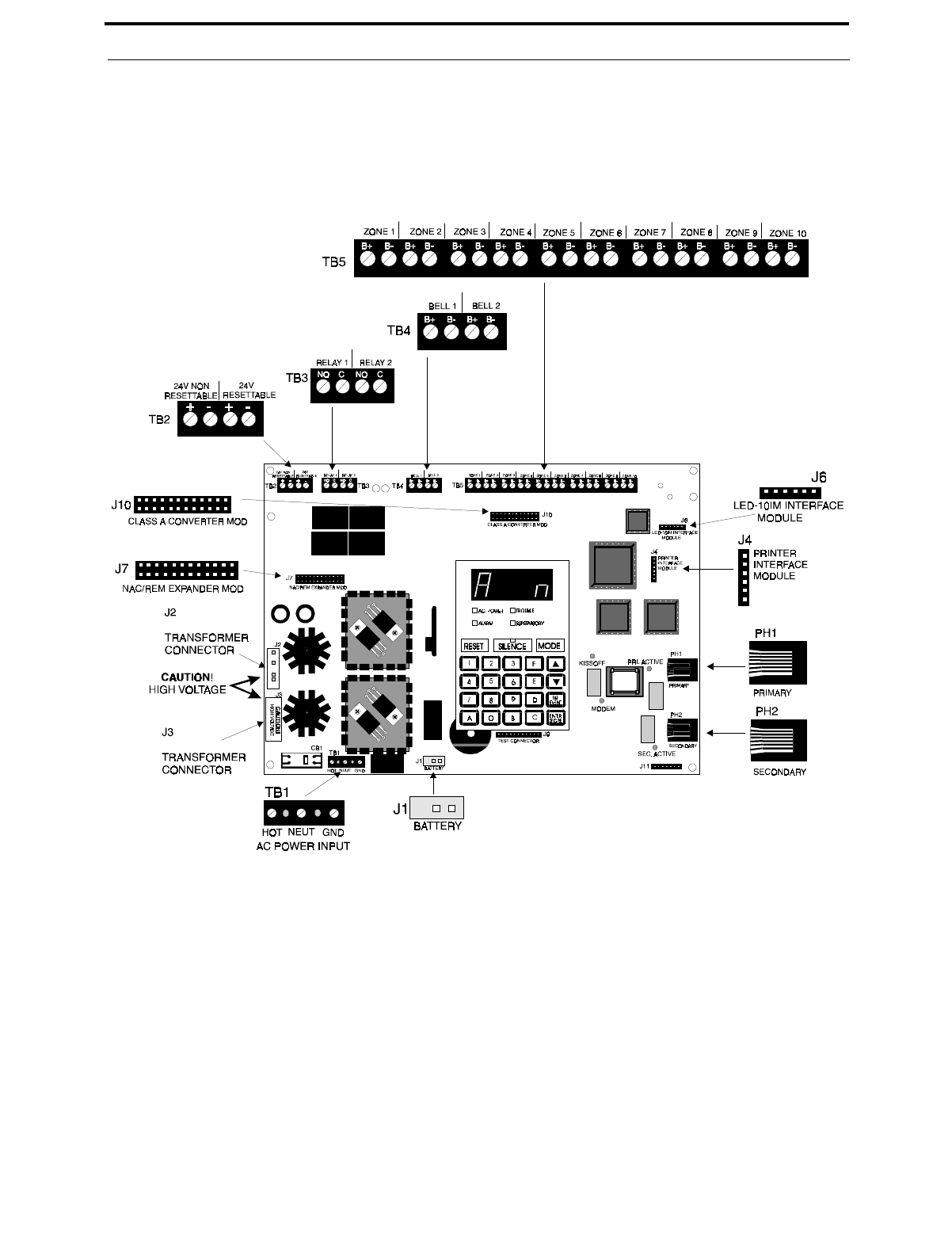
MS-5210UD Terminals and Connectors

Product Description
8
Document #50193 Rev.D 5/2/97 P/N 50193:D
CHAPTER 1 Product Description
The MS-5210UD is a combination control panel and digital communicator all on one circuit board. It is a 10-zone
panel, which uses conventional input devices. The panel accepts waterflow devices, two-wire smoke detectors,
four-wire smoke detectors, pull stations and other normally-open contact devices. Outputs include two Notification
Appliance Circuits (NACs) expandable to four, two programmable Form-A relays (option module with two Form-C
relays can be added), EIA-485 port to interface with remote annunciators and optional remote relay modules plus a
printer port.
The integral communicator transmits system status (alarms, troubles, AC loss, others) to UL-listed central stations via
the public switched telephone network. The control panel has a built-in programmer. It also supervises all wiring,
AC voltage, telephone line input voltage/current and battery level.
The control panel may be programmed or interrogated off site via the public switched telephone network. Any IBM
compatible personal computer with Windows™ 3.1 or greater, with a 1200 baud Hayes™ compatible modem and
Fire•Lite Upload/Download software P/N PK-5210UD, may serve as a Service Terminal. This allows downloading
of any portion or all of the program and upload of any portion or all of the program, history file, walktest data, current
status and system voltages. The MS-5210UDE offers the same features as the MS-5210UD but allows connection to
220/240 VAC input.
Note that unless otherwise specified, the term MS-5210UD shall be used in this manual to refer to both the
MS-5210UD and the MS-5210UDE Fire Control Communicators.
1.1 Product Features
•Selectable as Local Fire Panel of Fire Panel/Communicator
•Programmable Zone ID: 2-Wire Smoke; Pull Station; Normally-Open Contact; Supervisory; Supervisory
Auto-resettable; Waterflow (silenceable); Waterflow (nonsilenceable); Remote Switch for Reset, Silence,
Acknowledge and Drill; Standard and Auto-reset Critical and Noncritical Process Monitoring
•10 Style B (Class B) Initiating Device Circuits (IDCs)
•Two NFPA Style Y (Class B) Notification Appliance Circuits (NACs)
•CAC-10F Option Module to convert all 10 IDCs to Style D (Class A) and convert two Style Y (Class B) NACs
to Style Z (Class A)
•3.6 amps of system power expandable to 6.6 amps
•Remote Relay Option Module (ACM-8RF) providing one 5.0 amp relay per zone
•Built-in Programmer
•Built-in Voltmeter
•Telephone Line Active LED Indicators
•Communication Confirmation (Kissoff) LED
•Disable report by event
•Programmable Event Codes
•24 Volt Operation
•Real Time Clock and Calendar
•Trouble Reminder
•Alarm Verification
Document #50193 Rev. D 5/2/97 P/N 50193:D
9
Product Features
•Interfaces with Fire•Lite annunciators (requires LED-10IM Option Module)
LED Series Remote Annunciator provides one red alarm and one yellow trouble LED per zone
LDM-32F Graphic Annunciator
AFM Series LED Annunciators
•Small Size 16.900" (42.9 cm) X 14.500" (36.8 cm) X 4.625" (11.8 cm)
•History File with 256 Event Storage
•Silence Inhibit per Notification Appliance Circuit
•Auto-Silence per Notification Appliance Circuit
•Touchtone/Rotary Dialing per telephone line
•Programmable Make/Break Ratio
•Fuseless Design
•Printer Interface Module (PRT-24)
•NAC-REM Option Module adds two Form-C relays and two Style Z (Class A) NACs
•Print Real-time System Status
•Print History, Walktest Files, Program Contents and Troubleshoot mode voltages
•PK-5210UD Upload/Download Software Kit
•Number of dial attempts (5 minimum, 10 maximum)
•Programmable Zone Delay (waterflow only)
•Low AC Voltage Sense
•One-man silent or audible Walktest
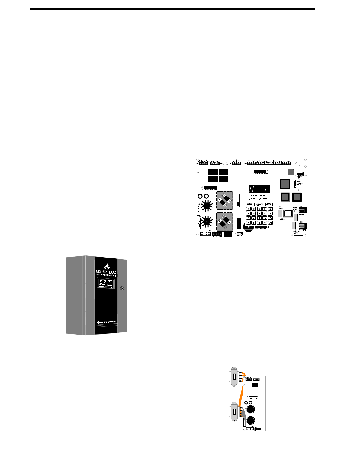
•Optional Dead Panel Coverplate (DP-5210UD)
FIGURE 1-1:Optional DP-5210UD
Product Features
10
Document #50193 Rev.D 5/2/97 P/N 50193:D
1Software for the Fire Control Communicator is located in a PROM inserted in the IC socket labeled U14. The
MS-5210UD and MS-5210UDE each contain unique software. For specific panel software information, refer to the
MS-5210UD/MS-5210UDE Field Software Change Procedure Document #50479.
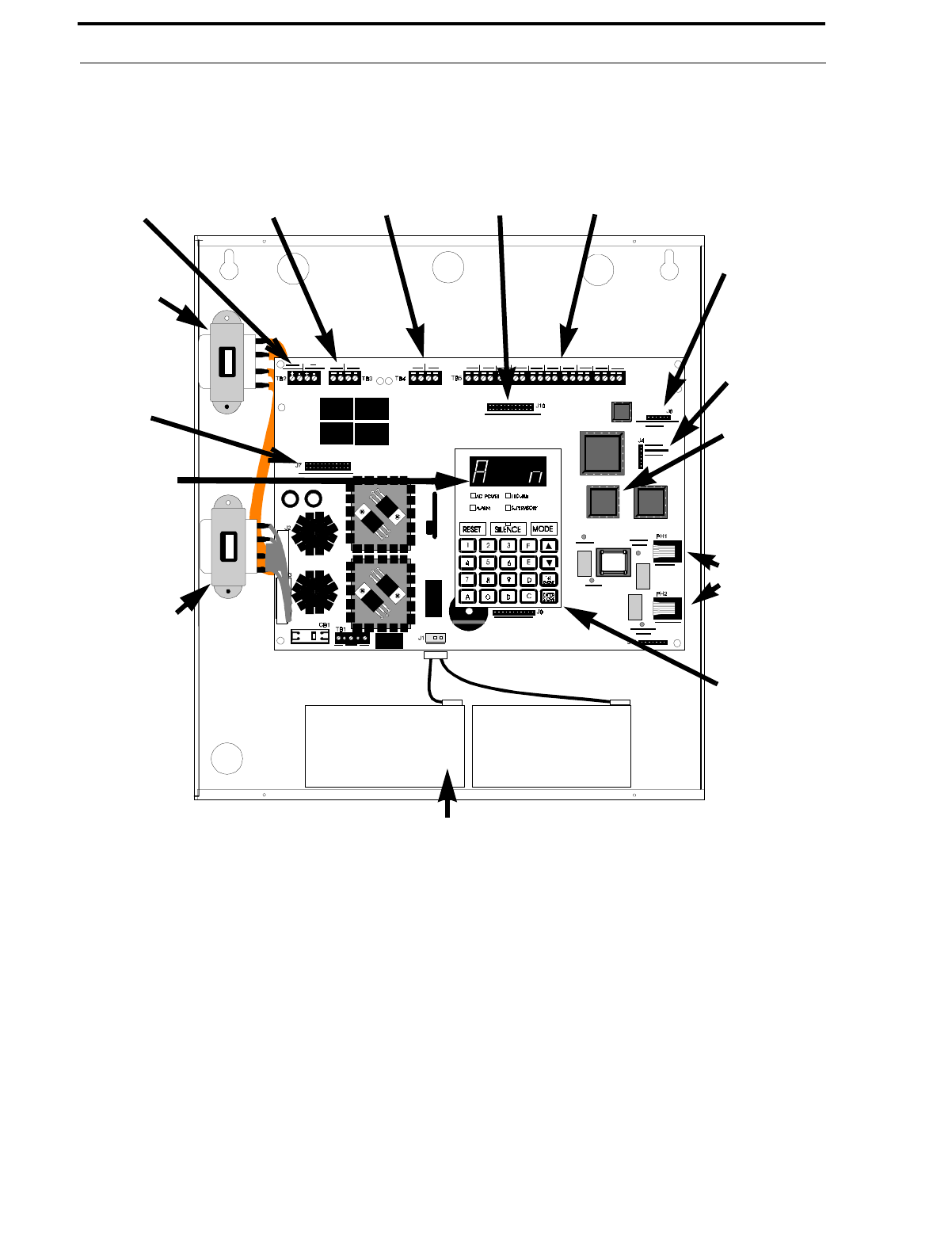
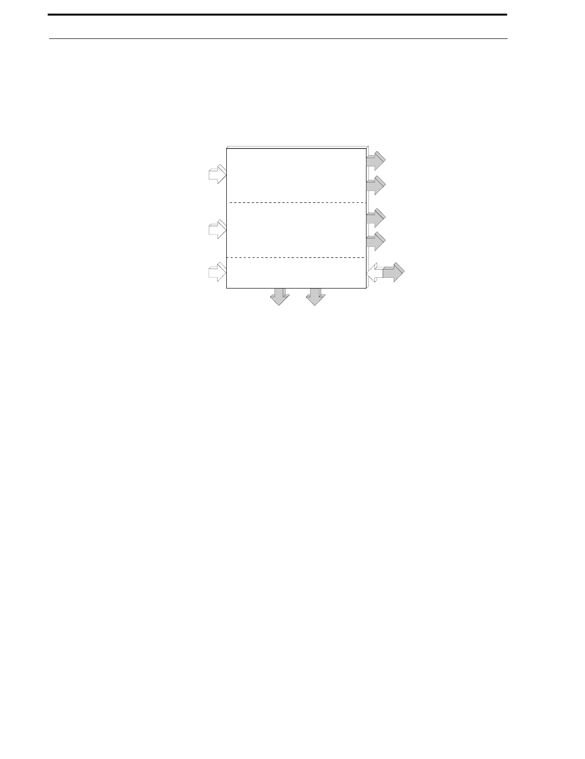
Transformer
Transformer
Four Character
7-Segment
LED Display
Keypad
NAC-REM
Expander
Module
24 VDC
Power
Programmable
Relays
Notification
Appliance
Circuits
Class A
Converter
Module
10 Input
Zones LED-10IM
Interface
Module
Connector
Printer
Interface
Module
Connector
PROM (U14)1
Primary &
Secondary
Phone Lines
Holds up to 12 AH Batteries,
Up to 60 Hrs. of Standby
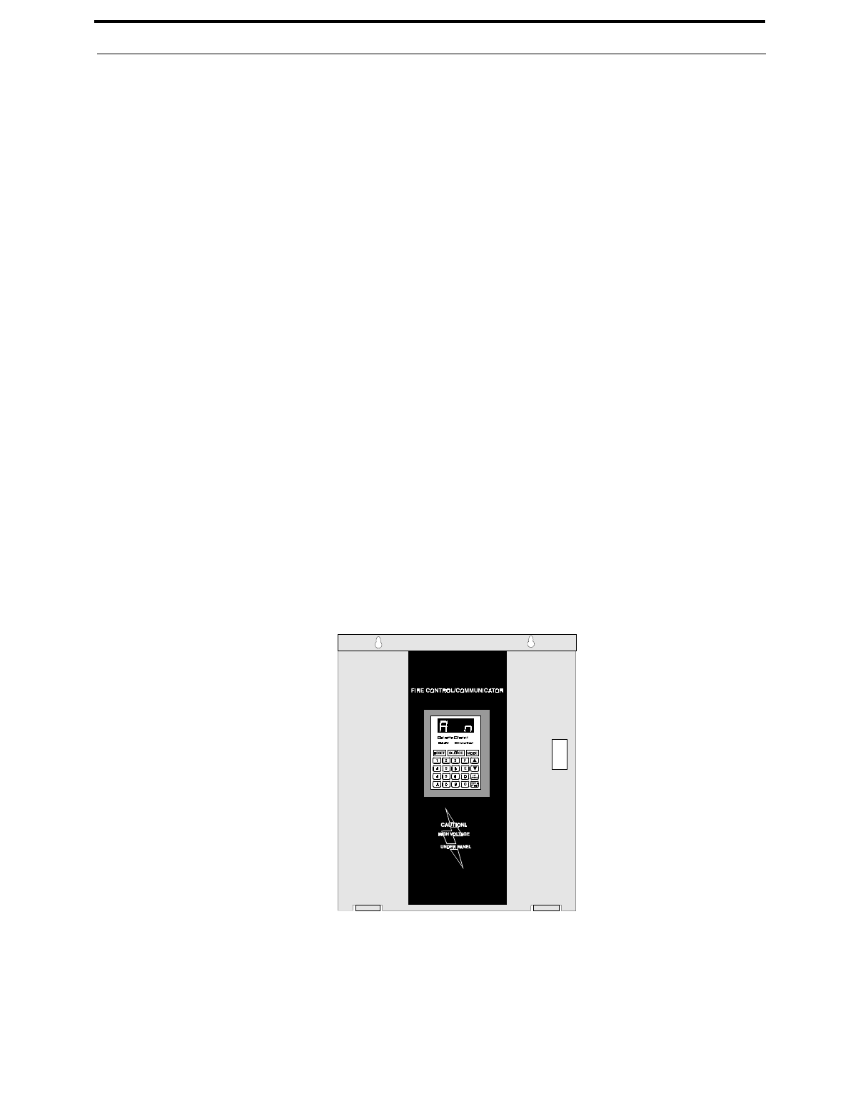
FIGURE 1-2:MS-5210UD Panel

Document #50193 Rev. D 5/2/97 P/N 50193:D
11
Specifications
1.2 Specifications
AC Power - TB1
MS-5210UD: 120 VAC, 60 Hz, 2.3 amps
MS-5210UDE: 220/240 VAC, 50 Hz, 1.2 amps
Wire size: minimum #14 AWG (2.0 mm2) with 600V insulation
Battery (lead acid only) - J1
Maximum Charging Circuit: Normal Flat Charge—27.6V @ 0.8 amp
Maximum Charger Capacity: 17 Amp Hour battery (MS-5210UD cabinet holds maximum 12 Amp Hour battery.
Larger batteries require Fire•Lite BB-17F or other UL listed battery cabinet)
Initiating Device Circuits TB5 and CAC-10F Option Module
Detector Zones 1 through 10
Power-limited Circuitry
Operation: All zones NFPA Style B - Convert to Style D using CAC-10F Class A Converter Module
Normal Operating Voltage: 24 VDC (ripple = 100 mV maximum)
Alarm Current: 15 mA
Short Circuit Current: 42 mA maximum
Maximum Loop Resistance: 100 ohms
End-of-Line Resistor: 4.7K, ½ watt (Part #27072 UL listed)
Detector Loop Current is sufficient to ensure operation of one alarmed detector per zone
Standby Current: 7.26 mA (includes ELR and 2 mA maximum detector current)
Smoke Detector Identifier A
Refer to Fire•Lite Device Compatibility Chart for listed compatible devices.
Notification Appliance Circuits - TB4 & NAC-REM Option Module (TB2 & TB3)
Nonregulated special purpose power, Styles Y & Z supported
Power-limited circuitry
Operating Voltage Nominal 24 volts
Current for all external devices: 3.0 amps expandable to 6.0 amps
Current Limit: TB4 via electronic protection, NAC-REM option module (TB2 & TB3) via PTC
Maximum signaling current/circuit: TB4 = 3.0 amps. NAC-REM = 1.5 amps.
End-of-Line resistor: 4.7K, ½ watt (Part #71252 UL listed) for Notification Appliance Circuits
Refer to Fire•Lite Device Compatibility Chart for listed compatible devices
Form-A Relays - TB3
TB3 contact rating: 2.0 amps @ 30 VDC (resistive), 5.0 amps @ 125 VAC (resistive)
NAC-REM Form-C contact rating: 2.0 amps @ 30 VDC, 0.6 amps @ 125 VAC (resistive)
Four-wire Smoke Detector Power - TB2 Terminals 3(+) &4(-)
Maximum ripple voltage: 10 mVRMS Operating Voltage nominal 24 volts
Up to 500 mA is available for powering 4-wire smoke detectors
Power-limited Circuitry. Recommended maximum Standby current is 50 mA1
Refer to Fire•Lite Device Compatibility Chart for compatible listed devices
1. For power supply and battery calculations, refer to Appendix A.
Controls and Indicators
12
Document #50193 Rev.D 5/2/97 P/N 50193:D
Nonresettable Regulated 24 VDC Power - TB2 Terminals 1(+) & 2(-)
Maximum ripple voltage: 10 mVRMS Operating Voltage nominal 24 volts
Total DC current available from this output is up to 500 mA
Power-limited Circuitry. Recommended maximum Standby current is 150 mA1
Refer to Fire•Lite Device Compatibility Chart for compatible listed devices
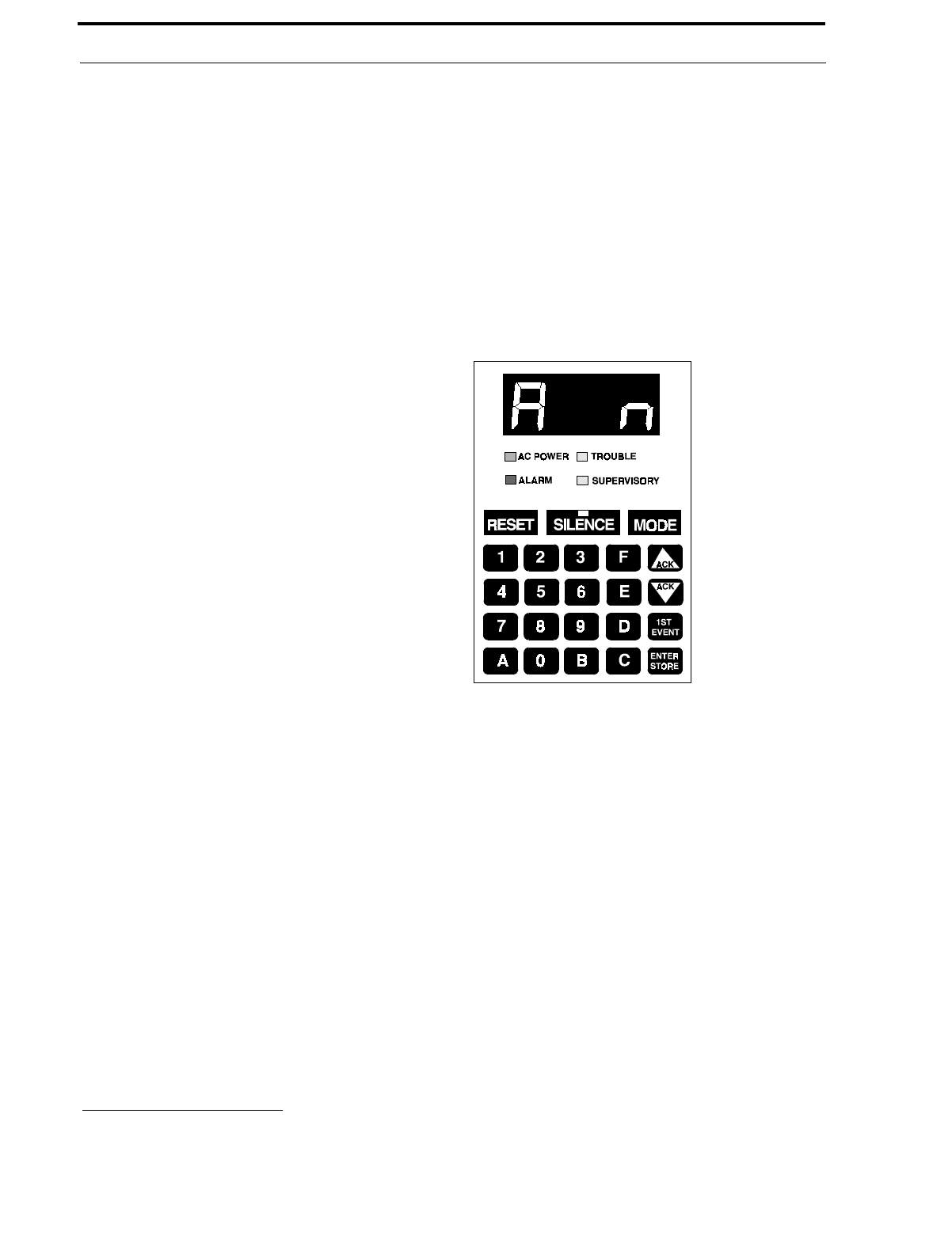
1.3 Controls and Indicators
Front Panel Switches
RESET
SILENCE
MODE
Up Arrow (ACK)
Down Arrow (ACK)
1st EVENT
ENTER/STORE
Digits 0 through 9
Letters A through F
Displays
Alarm - red LED
Trouble - yellow LED
Supervisory - yellow LED
AC Power - green LED
Four, Seven Segment Displays - red
Primary Phone Line Active - red LED
Secondary Phone Line Active - red LED
'Kissoff' Signal from Central Station - green LED
Silence - yellow LED
Modem - green LED
Local Sounder
A piezo sounder provides separate and distinct sounds for alarm, trouble, supervisory and critical process moni-
toring conditions
1.4 Circuits
Input Circuits
Ten input circuits provide Style B (Class B) configuration standard and may be converted to Style D (Class A) by
installing the CAC-10F module. Input circuits may be used as standard fire control panel zones, remote input
switches (Acknowledge, Silence, Drill, Reset) or as standard or auto-resettable critical and noncritical process
1. Total current for nonresettable power, four-wire smoke power, and four Notification Appliance Circuits must not exceed 6.0
amps. Total system current in excess of 3.6 amps requires the XRM-24 Transformer (XRM-24E for 220/240 VAC applica-
tions) and 12 Amp Hour or 17 Amp Hour batteries.
FIGURE 1-3:Display and Keypad

Document #50193 Rev. D 5/2/97 P/N 50193:D
13
Digital Communicator
monitoring. All ten Initiating Device Circuits accept Normally-Open contact devices and two-wire smoke
detectors.
Output Circuits
•24 Volt Resettable Power Output 500 mA
•24 Volt Nonresettable Power Output 500 mA
•Primary Telephone Line
•Secondary Telephone Line
•24 Volt Battery Charger (up to 17 AH batteries)
•Printer Port
•EIA-485 Port (interfaces to LED-10 Annunciator, AFM Series and LDM Graphic Series Annunciators and
ACM-8RF Remote Relay Module)
Notification Appliance Circuits
Two Notification Appliance Circuits Style Y (Class B) configurable for Style Z (Class A) using the CAC-10F
option module.
Relays
Two dry Form-A relay contacts programmable for system alarm, system trouble, system supervisory (standard and
autoresettable), standard and autoresettable process monitoring or communications failure are provided. Contacts
are rated 2.0 amps @ 30 VDC (resistive). Two additional Form-C relay contacts programmable for alarm, trouble,
standard and autoresettable supervisory, standard and autoresettable process monitoring or communications fail
are available using the NAC-REM (NAC/Relay) option module. Contacts are rated 2.0 amps @ 30 VDC and 0.6
amps at 125 VAC (resistive).
Printer Port
EIA-232 compatible, fully supervised and programmable for 2400, 4800 and 9600 Baud. Only one printer may be
connected to the port. Consult the factory for recommended printers.
EIA-485 Port
EIA-485 compatible port on the LED-10IM option module supports up to 32 LED-10 Remote Annunciators or 32
sets of ACM-8RF Relay Modules or 32 AFM Series Annunciators or 32 LDM Series Annunciators or any combi-
nation of the four devices totalling 32.
Telephone Lines
Fully supervised at all times, voltage is sensed to 4 volts and current is sensed to 5 mA.
Battery Charger
Battery Charger will charge up to 17 AH batteries. The MS-5210UD cabinet holds a maximum of 12 AH batter-
ies. The Fire•Lite BB-17F is required to hold 17 AH batteries. The charger is rated for 850 mA maximum current.
1.5 Digital Communicator
Two modular phone jacks allow easy connection to telephone lines. Modular jacks are labeled PH1 and PH2 for the
Primary and Secondary phone lines. Telephone line 'Active' red LEDs are provided as well as a green 'Kissoff' LED.
The integral digital communicator provides the following functions:
•Line Seizure - takes control of the phone lines disconnecting any premises phones
•Off/On Hook - perform on and off-hook status to the phone network
•Listen for dial tone - 440 hertz tone typical in most networks
•Dialing the Central Station(s) number - default is Touch-Tone©, programmable to rotary
Components
14
Document #50193 Rev.D 5/2/97 P/N 50193:D
•For tone burst or touchtone type formats: discern proper 'Ack' and 'Kissoff' tone(s) - the frequency and time
duration of the tone(s) varies with the transmission format. The control panel will adjust accordingly
•Communicate in the following formats:
✓12 Tone Burst Type: 20 pps
(3+1, 4+1, 4+2, 3+1 Exp., 4+1 Exp., 4+2 Exp.)
✓3 Touchtone Types:
4 + 1 Ademco Express
4 + 2 Ademco Express
Ademco Contact ID (Refer to Table 4-3 on page 80).
1.6 Components
Main Circuit Board
The main circuit board contains the system's CPU, power
supply, other primary components and wiring interface con-
nectors. Optional modules plug in and are mounted to the
main circuit board. The main circuit board is delivered pre-
mounted in the cabinet.
Cabinet
The cabinet is red with an attractive navy blue front overlay.
The backbox measures 16.900" (42.9 cm) X 14.500"
(36.8 cm) X 4.625"(11.8 cm) and provides space for two bat-
teries (up to 12 Amp Hours). Also available is an optional
dress panel, DP-5210UD, which mounts inside the cabinet.
Transformer Assembly
One 100VA transformer is provided stan-
dard with the panel. An optional 100VA
transformer, XRM-24 (XRM-24E for the
MS-5210UDE), is available to provide max-
imum accessory power.
Batteries
The cabinet provides space for 12 Amp
Hour batteries (larger batteries up to 17
Amp Hour batteries, use the listed Fire•Lite
BB-17F battery box). Batteries must be
ordered separately
Standard
Optional
XRM-24(E)
FIGURE 1-4:Transformer Assemblies

Document #50193 Rev. D 5/2/97 P/N 50193:D
15
Optional Modules
1.7 Optional Modules
LED-10IM
The LED-10IM Interface Module provides an EIA-485 port to support the LED-10 Series Remote Annunciator,
LDM Series Annunciator, AFM Series Annunciator and ACM-8RF Relay Modules. EIA-485 wiring is supervised
for open circuits by this module. The LED-10IM mounts to connector J6 in the upper right corner of the main
board. Refer to Figure 2-14, “LED-10IM Installation,” on page 33.
ACM-8RF Relay Module
The ACM-8RF option module provides eight Form-C relays rated a 5.0 amps each. The Relay Module connects to
the EIA-485 port off of the LED-10IM option module. Relays are assigned to each of the 10 Initiating Device Cir-
cuits. Refer to Figure 2-17, “Wiring LED-10IM to ACM-8RF,” on page 34, for additional information.
PRT-24 Printer Interface Module
The Printer Interface Module may be used to connect a printer to the control panel for the purpose of printing a
history report, walktest file, troubleshoot report, program entries or current system status. Printers require separate
external primary power. Connect the PRT-24 module (with cable) to the serial EIA-232 port on the printer. The
module mounts to the J4 connector on the main circuit board.
Note that an EDP listed printer must be used if printer will be permanently attached (Refer to Figure 2-13,
“Remote Printer Connections,” on page 32). The Baud rate is programmable (“Program Options” on page 38).
CAC-10F Module
The CAC-10F Module can be used to convert the 10 Style B (Class B) Initiating Device Circuits to 10 Style D
(Class A) IDCs and the two Style Y (Class B) Notification Appliance Circuits to two Style Z (Class A) NACs.
The CAC-10F module connects to J10 on the main circuit board. (Refer to Figure 2-10 on page 30).
NAC-REM Module
The NAC-REM (NAC/Relay) Module can be used to add two Style Z (Class A) NACs and two Form-C relays.
The module connects to J7 on the main circuit board. (Refer to Figure 2-12 on page 31).
1.8 Optional Accessories
Dress Panel
A red dead-front dress panel (DP-5210UD) is available as an option (required for Canadian installations). The
dress panel restricts access to the system wiring while allowing access to the membrane switch panel.
Battery Box
The Fire•Lite BB-17F battery box may be used to house
two batteries greater than 12 Amp Hour to a maximum of
17 Amp Hour. The battery box mounts directly below the
cabinet, centered to the main circuit board (Refer to Figure
2-2, “FACP Backbox and Battery Box,” on page 23). The
BB-17F is red and is provided with knockouts.
PK-5210UD Program Kit
The PK-5210UD Program Kit includes three 3½" diskettes plus Instruction Manual P/N 50363. When the soft-
ware is loaded into an IBM compatible computer, it creates an off-line Service Terminal that allows any
MS-5210UD panel to be uploaded or downloaded over standard telephone lines. Requires panel firmware P/N:
MS52102.0 or greater.
FIGURE 1-5:BB-17F Battery Box
Optional Accessories
16
Document #50193 Rev.D 5/2/97 P/N 50193:D
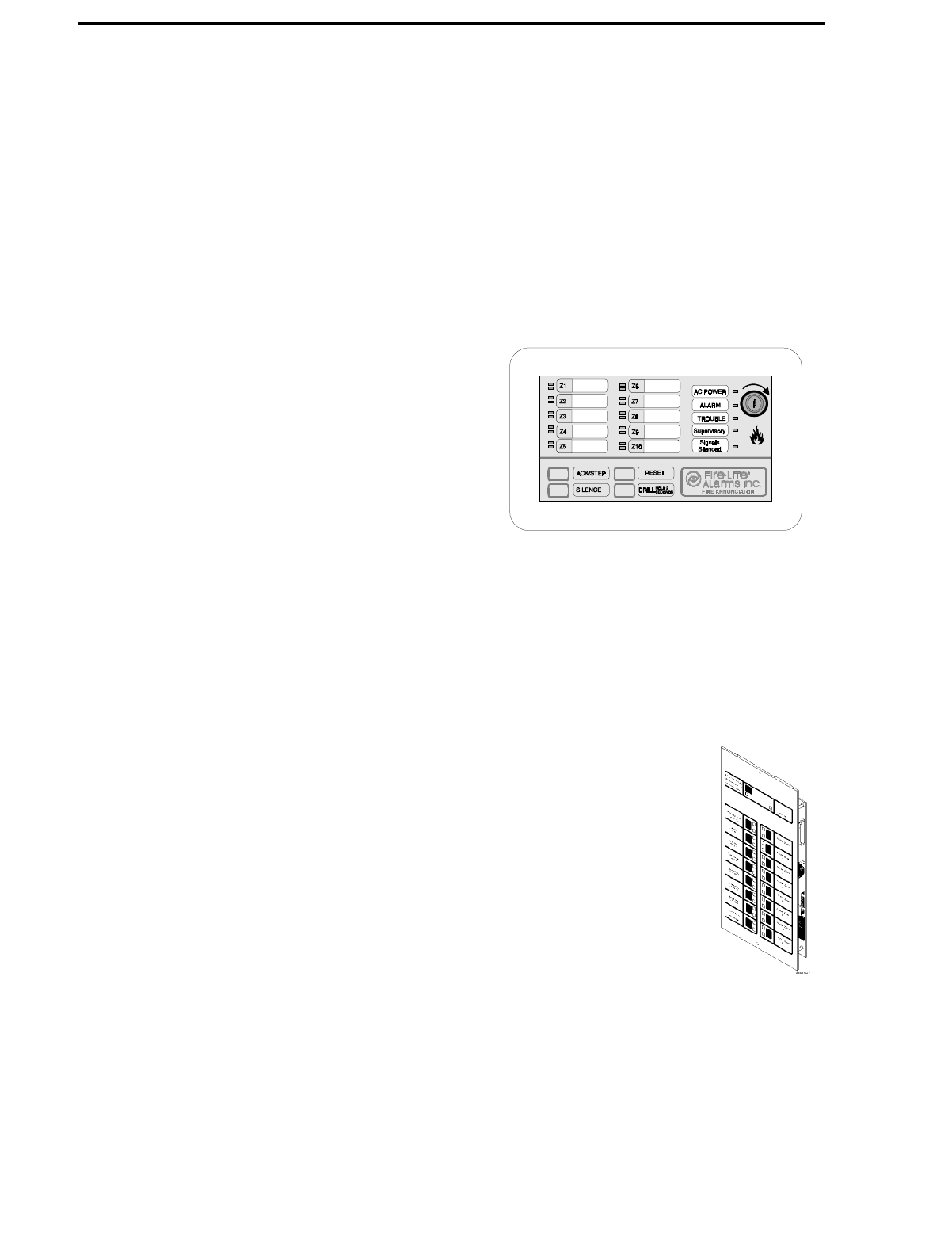
LED-10 Series Annunciator (LED Zone Type Annunciator)
The LED-10 Series is a 10 zone LED annunciator which mounts on a 3-gang electrical box and provides LED
indication of the following:
•Alarm Zones 1 through 10
•Trouble Zones 1 through 10
•AC Power (green)
•System Alarm (red)
•System Trouble (yellow)
•System Supervisory (yellow)
•Alarm Silence (yellow)
A local trouble sounder and switches for remote Acknowl-
edge, Silence, Drill and Reset are also provided. Wiring is
inherently supervised by the FACP. Slide-in paper labels
permit an easy change of zone information. DIP switches
allow the enabling and disabling of the local piezo sounder
(with approval of local AHJ), enabling and disabling of the
mechanical keyswitch which may be used to prevent unau-
thorized use of the function switches and selection of
annunciator receive/transmit mode (Refer to Figure 2-15 on
page 33).
Note that the LED-10 Series Remote Annunciator requires the use of the LED-10IM Interface Module.
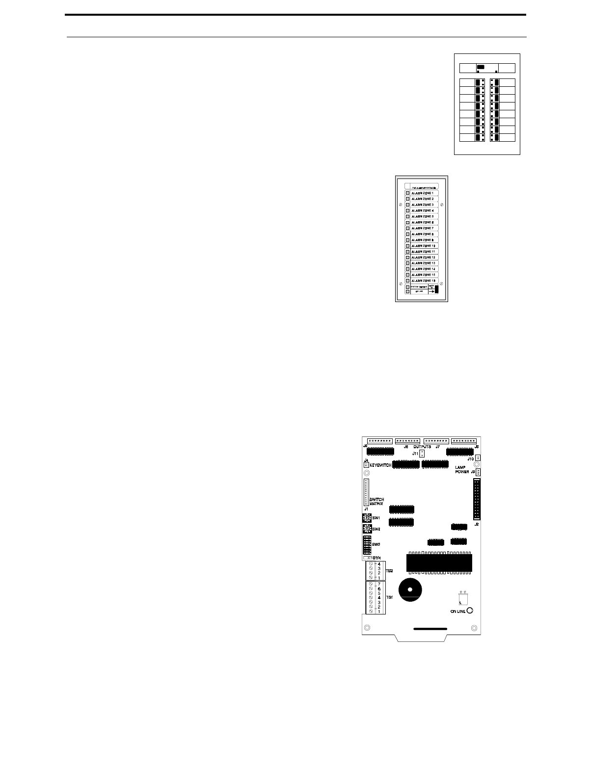
AFM Series Annunciators (LED Zone Type)
The AFM Series Annunciators remotely display system status. The AFM/AEM-16AT annunciators display zone
alarm and trouble status. In addition, they provide remote Acknowledge, Silence, Reset and Drill functions. The
AFM Series Annunciators require the use of the LED-10IM Interface Module. For more detailed information,
refer to the appropriate AFM Annunciator manual.
✓AFM-16ATX - The Annunciator Fixed Module-16ATX contains
16 red alarm and 16 yellow trouble LEDs, a system trouble LED,
an ON LINE/POWER LED and a local piezo sounder with
switches for Acknowledge, Silence, Reset and Drill. The
AFM-16ATX is fixed at address '1' and will accept up to 3
AEM-16ATF Expanders. The AFM-16ATX can be mounted in a
Fire•Lite ABS-1F or ABF-1F backbox. Refer to the
AFM-16ATX Manual for detailed information. Note that only
one AFM-16ATX is required to annunciate 10 zones of alarm and
trouble, provided '8 Point Shift' function is selected. Refer to
Annunciator Manual P/N 15390 for additional information.
✓AEM-16ATF - The Annunciator Expander Module-16ATF con-
nects to the AFM-16ATX and adds 16 sets of red alarm LEDs
and yellow trouble LEDs. Up to three AEM-16ATFs may be
added to an AFM-16ATX but only one is required. Note that one
AEM-16ATF is required with an AFM-16ATX to annunciate 10
zones of alarm and trouble as well as general system status pro-
vided '8 Point Shift' function is not selected. Refer to Annuncia-
tor Manual P/N 15390 for additional information.
FIGURE 1-6:LED-10 Series Annunciator
FIGURE 1-7:AFM-16ATX
Document #50193 Rev. D 5/2/97 P/N 50193:D
17
Optional Accessories
✓AFM-16ATF - The Annunciator Fixed Module-16ATF
contains 16 red alarm and 16 yellow trouble LEDs, a
system trouble LED, an ON LINE/POWER LED and a
local piezo sounder with switches for Acknowledge,
Silence, Reset and Drill. The AFM-16ATF is fixed at
address '1' and communication is via the EIA-485 data
line. The AFM-16ATF can be mounted in a Fire•Lite
ABS-1F or ABF-1F backbox. Refer to the AFM-16AT
Manual for detailed information.
✓AFM-16AF - The Annunciator Fixed Mod-
ule-16AF has 16 red alarm LEDs. Multiple
annunciators may be used by setting all annuncia-
tors to Receive Only, except the last AFM-16AF
in line. Each annunciator's address is internally
fixed at '1' and communication is via the EIA-485
data line. The Local Silence/Acknowledge
switch functions as local lamp test and silence for
annunciator piezo. LEDs include On-Line and
System Trouble indicators. The AFM-16AF
Annunciator can be mounted in a standard 4-gang
electrical box. Refer to the AFM-16AF Manual
for detailed information.
LDM Series Lamp Driver Modules (Graphic Annunciator)
The LDM Series Lamp Driver Modules, which consist of the LDM-32F master and LDM-E32F expander mod-
ules, are used to provide an interface to a custom graphic LED annunciator. The master module provides power
and control for a maximum of three expander modules (expander modules are not required when interfacing to the
MS-5210UD). The LDM-32F and LDM-E32F have output connectors which are used to drive lamps or LEDs and
input connectors which are used for remote switch functions. The LDM Series requires the use of the LED-10IM
Interface Module. Refer to the LDM Series Lamp Driver Modules Manual for a complete description. Refer to
Figure 2-18, “Wiring LED-10IM to LDM-32F,” on page 35 for wiring details.
✓LDM-32F - The Lamp Driver Module has 32
alarm lamp/LED driver outputs which sink cur-
rent to system common (-) on activation. A single
positive (+) voltage is required to supply total
operating power for all lamps or LEDs when all
drivers are activated. The LDM-32F provides a
separate driver for system trouble and inputs for a
local lamp test switch. A maximum of 16 exter-
nal control switches may be wired to the
LDM-32F. DIP switch SW3 is used to enable or
disable the onboard piezo sounder, enable remote
switch functions, select a flashing LED function
for new alarms and troubles and other functions.
Switch SW4 is used to configure the module to
annunciate 32 alarms or 16 alarms and 16 trou-
bles. A green ON-LINE LED flashes to indicate
ongoing communications with the host FACP.
One LDM-32F supports up to three LDM-E32F
modules. The LDM-32F is supplied with four
standoffs and screws for mounting to a CHS-4L
chassis or custom backbox.
FCPS-24F(E) Remote Power Supply (System Power Expansion)
The FCPS-24F (FCPS-24FE for 220/240 VAC applications) is a compact, remote power supply and battery
charger. This remote power supply consists of a filtered 24 VDC output that may be configured to drive up to four
Notification Appliance Circuits [four Style Y (Class B) or two Style Z (Class A) and two Style Y (Class B)].
FIGURE 1-8:AFM-16ATF
FIGURE 1-9:AFM-16AF
FIGURE 1-10:LDM-32F Module
Telephone Requirements and Warnings
18
Document #50193 Rev.D 5/2/97 P/N 50193:D
Alternately, the four Notification Appliance Circuits may be used as auxiliary regulated power configured for
resettable or nonresettable operation.
The FCPS-24F(E) may be used in a number of different applications. It may be used as a remotely mounted
power supply and battery charger powering up to four, coded or noncoded, Notification Appliance Circuits.
Alternately, any or all of these circuits may be used as 24 VDC output circuits capable of powering four-wire
smoke detectors or any device that requires filtered power. These circuits may be configured as resettable or non-
resettable outputs to expand FACP auxiliary system power.
One of the most common applications for the FCPS-24F(E) remote power supply utilizes the NAC expander
mode. In this application, one or two Notification Appliance Circuits (NACs) are connected from the main FACP
NAC output(s) to the remote power supply Control Input circuits. When these Control Input circuits activate (due
to reverse polarity of the NAC output), the power supply will activate its corresponding outputs. NAC Control
Input #1 controls power supply output circuits #1 and #2. NAC Control Input #2 controls output circuits #3 and
#4.
During the inactive state, the remote power supply supervises its NAC field wiring for short and open circuits. If
a fault is detected, the supply will enter a trouble condition and illuminate the corresponding NAC trouble LED
(Output Circuits 1-4), however, once the Notification Appliance Circuits are activated, the supervision is disabled
and the circuits are no longer supervised. Supervision of other power supply faults such as low battery, Earth
Fault, AC loss and battery charger failure will continue and may be monitored via the independent trouble relay
contact.
If a specific application requires that all four outputs activate at the same time, only one NAC control input from
the FACP is necessary. For this application, The Notification Appliance Circuit from the FACP is wired into NAC
Control Input #1 of the remote supply and then a pair of wires are connected from NAC Control Output #1 to
NAC Control Input #2. Refer to the FCPS-24F(E) Installation, Operation and Application Manual for a complete
description and examples of applications.
1.9 Telephone Requirements and Warnings
1.9.1 Telephone Circuitry:
Ringer Equivalence Number (REN) = 0.6B
Complies with FCC Part 68
Mates with RJ31X Male Connector
Supervision Threshold: less than 4.0 volts for 2 minutes
The REN is used to determine the quantity of devices which may be connected to the telephone line. Excessive RENs
on the telephone line may result in the devices not ringing in response to an incoming call. In most, but not all areas,
the sum of the RENs should not exceed five (5.0). To be certain of the number of devices that may be connected to
FIGURE 1-11:FCPS-24F(E) Style Y/Style Z Notification Appli-
ance Circuit or 24 VDC Output #1
Style Y Notification Appliance
Circuit or 24 VDC Output #2
Style Y/Style Z Notification Appli-
ance Circuit or 24 VDC Output #3
Style Y Notification Appliance
Circuit or 24 VDC Output #4
Battery Charger
FCPS Trouble
Contact Output
Specific Application
Power
AC Power
Notification Appliance Circuit
Control Input #1 (from FACP)
Notification Appliance Circuit
Control Input #2 (from FACP)

Document #50193 Rev. D 5/2/97 P/N 50193:D
19
Telephone Requirements and Warnings
the line, as determined by the total RENs, contact the telephone company to determine the maximum REN for the
calling area.
1.9.2 Digital Communicator:
Before connecting the control panel to the public switched telephone network, the installation of two RJ31X jacks is
necessary. The following information is provided if required by the local telephone company:
Manufacturer: Fire•Lite
12 Clintonville Road
Northford, CT 06472
Product Model Number: MS-5210UD
FCC Registration Number: 1W6USA-74525-AL-E
Ringer Equivalence: 0.6B
1.9.3 Telephone Company Rights and Warnings:
The telephone company, under certain circumstances, may temporarily discontinue services and/or make changes in
its facilities, services, equipment or procedures which may affect the operation of this control panel. The telephone
company, however, is required to give advance notice of such changes or interruptions.
If the control panel causes harm to the telephone network, the telephone company reserves the right to temporarily
discontinue service. Advance notification will be provided, except in cases when advance notice is not practical. In
such cases, notification will be provided as soon as possible. The opportunity will be given to correct any problems
and to file a complaint.
DO NOT CONNECT THIS PRODUCT TO COIN TELEPHONE, GROUND START OR PARTY LINE SERVICES.
When the control panel activates, premise phones will be disconnected.
Two separate phone lines are required. Do not connect both telephone interfaces to the same telephone line.
The control panel must be connected to the public switched telephone network upstream of any private telephone sys-
tem at the protected premises.
An FCC compliant telephone cord must be used with this equipment. This equipment is designed to be connected to
the telephone network or premises wiring using a compatible RJ31X male modular plug which is Part 68 compliant.
1.9.4 For Canadian Applications
The following is excerpted from CP-01 Issue 5:
"NOTICE: The Canadian Department of Communication label identifies certified equipment. This certification
means that the equipment meets certain telecommunications network protective, operational and safety requirements.
The Department does not guarantee the equipment will operate to the user's satisfaction.
Before installing the equipment, users should ensure that it is permissible to be connected to the facilities of the local
telecommunications company. The equipment must also be installed using an acceptable method of connection. In
some cases, the company's inside wiring associated with a single line individual service may be extended by means of
a certified connector assembly (telephone extension cord). The customer should be aware that compliance with the
above conditions may not prevent degradation of service in some situations.
Repairs to certified equipment should be made by an authorized Canadian maintenance facility designated by the sup-
plier. Any repairs or alterations made by the user to this equipment, or equipment malfunctions, may give the tele-
communications company cause to request the user to disconnect the equipment.

Telephone Requirements and Warnings
20
Document #50193 Rev.D 5/2/97 P/N 50193:D
Users should ensure, for their own protection, that the electrical ground connections of the power utility, telephone
lines and internal metallic water pipe system, if present, are connected together. This precaution may be particularly
important in rural areas.
Caution: Users should not attempt to make such connections themselves, but should contact the appropriate electric
inspection authority, or electrician, as appropriate."
"The Load Number (LN) assigned to each terminal device denotes the percentage of the total load to be connected to
a telephone loop which is used by the device, to prevent overloading. The termination on a loop may consist of any
combination of devices subject only to the requirement that the total of the Load Numbers of all the devices does not
exceed 100."
DOC Compliance - "This digital apparatus does not exceed the Class A limits for radio noise emissions from digital
apparatus set out in the Radio Interference Regulations of the Canadian Department of Communications."
IC Registration Number: 21325785A
Load Number: 2

Document #50193 Rev. D 5/2/97 P/N 50193:D
21
Installation
CHAPTER 2 Installation
2.1 Mounting Options
The cabinet may be either semi-flush or surface mounted. The door
is removable during the installation period by opening and lifting the
door off the pin hinges. The cabinet mounts using two key slots and
two additional 0.250" (6.35 mm) diameter holes located in the back-
box. The key slots are located at the top of the backbox and the two
securing holes at the bottom.
Carefully unpack the system and check for shipping damage. Mount
the cabinet in a clean, dry, vibration-free area where extreme temper-
atures are not encountered. The area should be readily accessible
with sufficient room to easily install and maintain the panel. Locate
the top of the cabinet approximately five feet above the floor with the
hinge mounting on the left. Determine the number of conductors
required for the devices to be installed. Sufficient knockouts are pro-
vided for wiring convenience. Select the appropriate knockout(s)
and pull the required conductors into the box. Note that there are no
knockouts on the left (hinged) side of the cabinet. All wiring should
be in accordance with the National and/or Local codes for fire alarm
systems.
2.2 Backbox Mounting
✓Open the door and lift the door off the pin hinges.
✓Remove the main PC board assembly by unscrewing the four screws in the corners of the board. Set the
board aside in a safe, clean place. Avoid static discharge which may damage the board.
✓Mark and predrill holes for the top two keyhole mounting bolts using the dimensions illustrated in
Figure 2-1.
✓Install two upper fasteners in the wall with the screw heads protruding.
✓Using the upper 'keyholes', mount the backbox over the two screws.
✓Mark and drill the lower two holes.
✓Mount backbox, install remaining fasteners and tighten.
✓When the location is dry and free of construction dust, reinstall the main PC board.
Backbox Mounting
22
Document #50193 Rev.D 5/2/97 P/N 50193:D
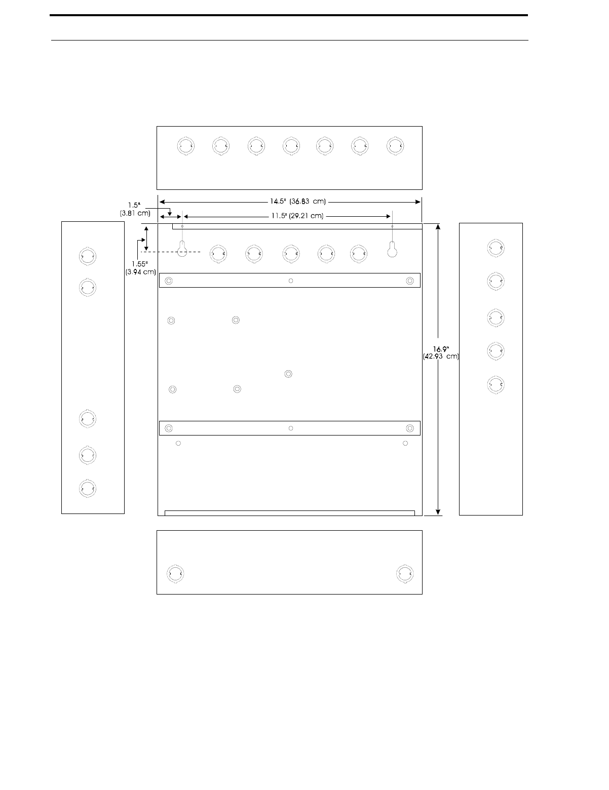
Draw wires through the respective knockout locations.
FIGURE 2-1:Cabinet Dimensions and Knockout Locations
Top
Left Side Right Side
Bottom
Document #50193 Rev. D 5/2/97 P/N 50193:D
23
Backbox Mounting
When batteries larger than 12 Amp Hour are being used, the BB-17F battery box (or equivalent) must be installed. To
install the BB-17F:
1. Mount the FACP cabinet to the wall.
2. Remove knockouts on the bottom of the FACP cabinet and top of the BB-17F.
3. Using conduit, hang the BB-17F from the FACP cabinet making sure there is at least ½" of clearance between
the two cabinets.
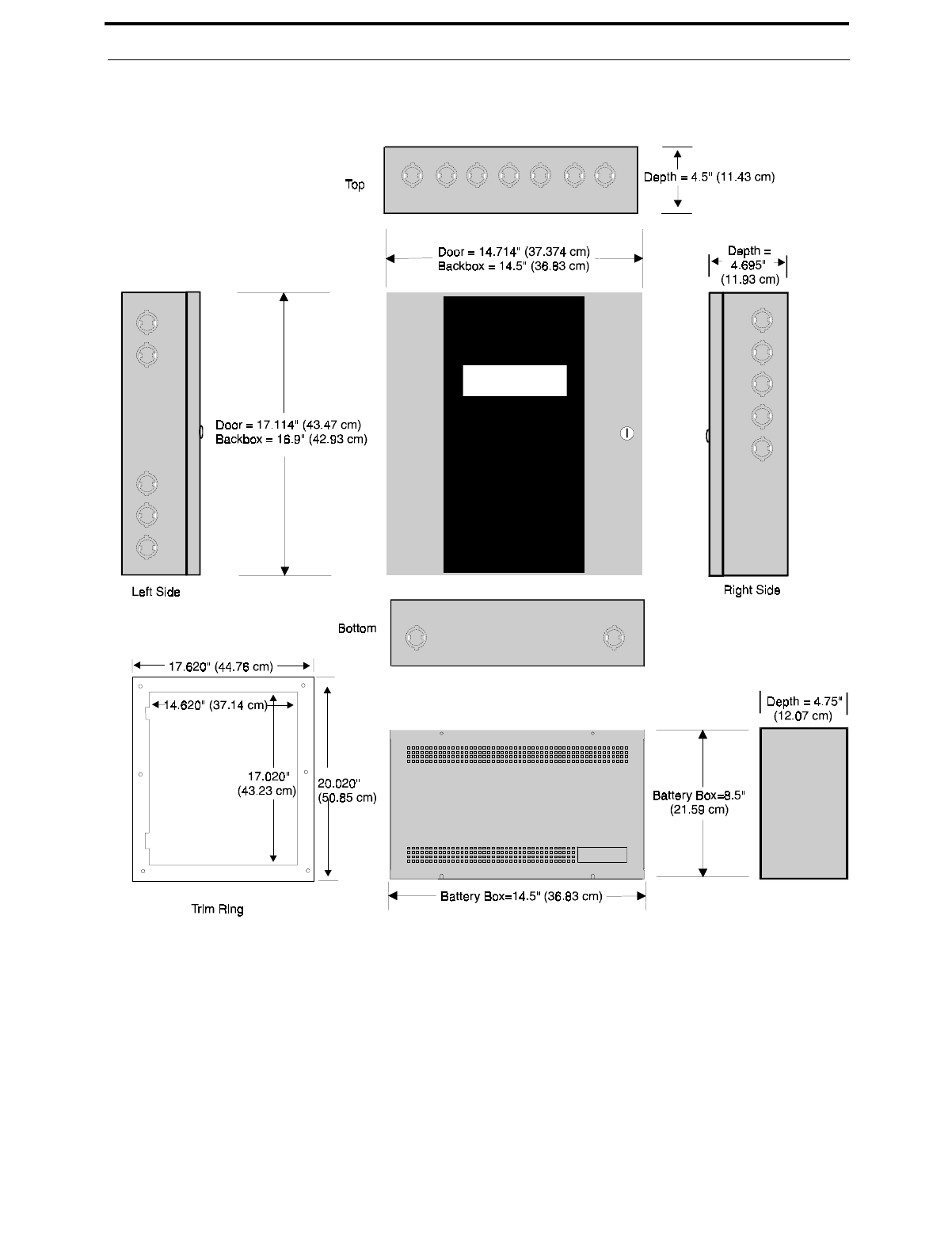
4. Anchor the BB-17F to the wall.
FIGURE 2-2:FACP Backbox and Battery Box
TR-4-R
Optional BB-17F
Operating Power
24
Document #50193 Rev.D 5/2/97 P/N 50193:D
2.3 Operating Power
WARNING: Several different sources of power can be connected to this panel. Disconnect all sources of power
before servicing. The panel and associated equipment may be damaged by removing and/or inserting cards, modules
or interconnecting cables while this unit is energized.
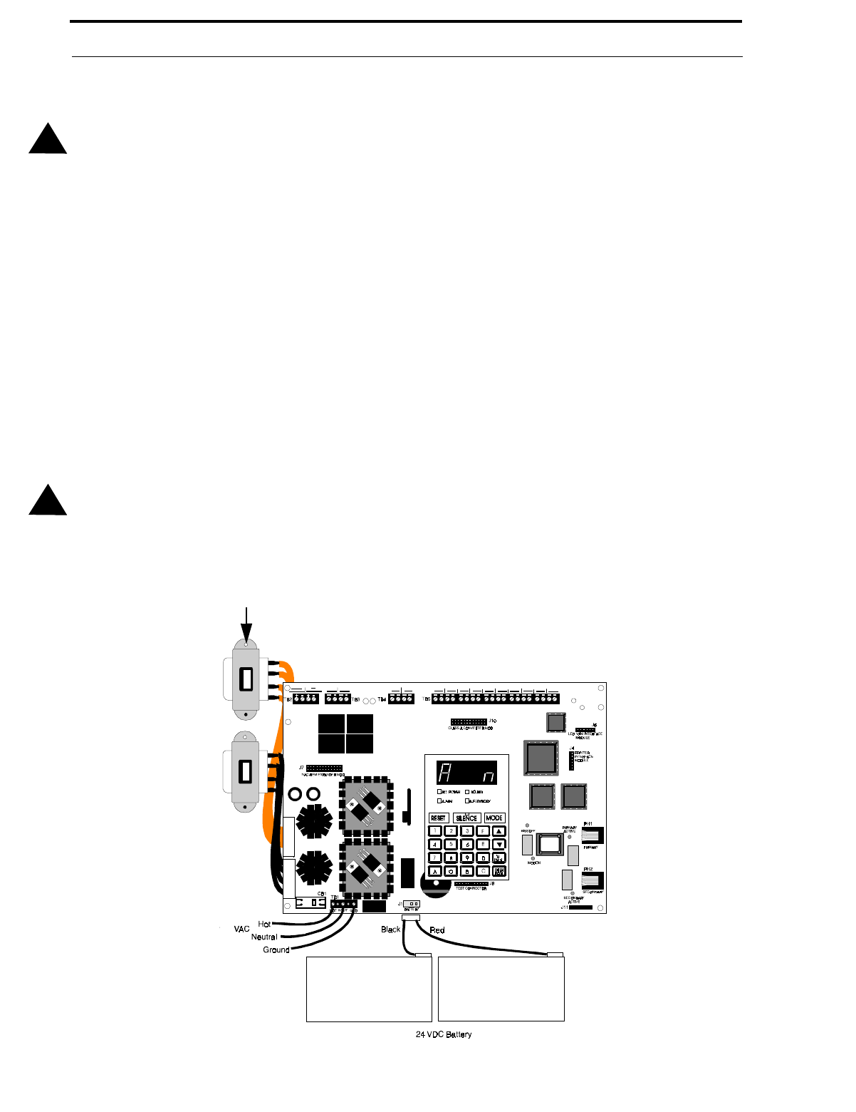
Primary Power Source (AC) and Earth Ground Connections
AC power connections are made inside the control panel cabinet. The primary power source for the MS-5210UD is
120 VAC, 60 Hz, 2.3 amps and for the MS-5210UDE is 220/240 VAC, 50 Hz, 1.2 amps. Run a pair of wires (with
ground conductor) from the protected premises main breaker box to TB1 of the main circuit board. As per the
National Electric Code, use 14 AWG (2.00 mm2, 1.6 mm O.D.) or heavier gauge wire with 600V insulation. No other
equipment may be connected to this circuit. In addition, this circuit must be provided with overcurrent protection and
may not contain any power disconnect devices. A separate Earth Ground connection must be made to ensure proper
panel operation and lightning and transient protection. Connect the Earth Ground wire [minimum 14 AWG (2.00
mm2)] to one of the transformer mounting studs. Do not use conduit for the Earth Ground connection since this does
not provide reliable protection.
Secondary Power Source (Batteries)
Observe polarity when connecting the battery. Connect the battery cable to J1 on the main circuit board using the
plug-in connector and cable provided. The battery charger is current-limited and capable of recharging sealed lead
acid type batteries. The charger shuts off when the system is in alarm. See “Battery Calculations” on page 93 for cal-
culation of the correct battery rating.
WARNING: Battery contains sulfuric acid which can cause severe burns to the skin and eyes and can destroy fabrics.
If contact is made with sulfuric acid, immediately flush the skin or eyes with water for 15 minutes and seek immediate
medical attention.
!
!
FIGURE 2-3:Operating Power Connections
Connect Earth Ground Wire to
Transformer mounting stud

Document #50193 Rev. D 5/2/97 P/N 50193:D
25
Input Circuits
2.4 Input Circuits
The control panel has 10 zone input circuits. The maximum loop resistance limit for each input circuit is 100 ohms.
All field wiring of each zone is supervised for opens and ground faults. Both conditions are visually and audibly
annunciated as well as communicated to a central station.
Each zone is a Style B (Class B) Initiating Device Circuit (IDC) designed to accept any Normally-Open contact
device and conventional 2-wire, 24 volt smoke detectors. Refer to Figure 2-4, “Style B Initiating Device Circuit Con-
nections,” on page 26, for information on wiring Style B circuits. Use the CAC-10F Option Module (Refer to Figure
2-11, “Wiring NACs and IDCs for Class A Operation,” on page 30) to convert all 10 circuits to Style D (Class A).
Each zone is power-limited to 7.26 mA in standby and 42 mA in alarm.
The zones may be programmed as shown below. The factory default is 2-wire smoke detector for all zones:
•2-wire Smoke Detector (factory default)
•Pull Station
•Normally-Open Contact Device(s)
•Supervisory
•Supervisory, auto-resettable
•Waterflow, silenceable
•Waterflow, nonsilenceable
•Reset
•Silence
•Drill
•Acknowledge
•Auto-resettable critical and noncritical process monitoring
•Critical and noncritical process monitoring
A maximum of five waterflow devices may be used on any circuit programmed as a waterflow zone per NFPA 72.
Four-wire smoke detectors may be connected to any zone. Resettable power is provided via TB2 Terminals 3 and 4.
Refer to the Fire•Lite Device Compatibility Document for a list of compatible smoke detectors.
It is allowable to mix an assortment of device types (i.e. smoke detectors, heat detectors, pull stations, etc.) on any
zone. This is not recommended, however, since specific and detailed reports will not be possible (particularly critical
when using Contact ID format). For example, the report of general fire alarm versus pull station fire alarm or smoke
detector fire alarm could not be distinguished.
Note that Process Monitoring refers to circuits which do not specifically tie into elements of the fire system as defined
by NFPA codes. With the exception of burglary functions, process monitoring circuits could be used to monitor any
nonfire functions such as water temperature, room temperature, door open/closed, gas leakage, chemical leakage, etc.
Process Monitoring may be accomplished for Local, Remote and Central Station type services in the following ways:
•Central and Remote Station - When a critical process is detected, the DACT will transmit the critical process
alarm to the Central or Remote Station.
•Local - When a critical process is detected, the relays (fail-safe) programmed to transfer will deenergize. The
ACM-8RF Remote Relay Module can only be used with noncritical process monitoring.
Output Circuits
26
Document #50193 Rev.D 5/2/97 P/N 50193:D
2.5 Output Circuits
DC Power Output Connections
All DC power outputs are power-limited.
Telephone Circuits
Provision to connect to two independent telephone lines is available via two telephone jacks labeled PH1 (Pri-
mary) and PH2 (Secondary). Telephone line control/command is possible via double line seizure as well as usage
of an RJ31X style interconnection. Refer to Figure 2-8, “Wiring Phone Jacks,” on page 28.
Notification Appliance Circuits
The MS-5210UD provides two Notification Appliance Circuits standard as Style Y (Class B). Each circuit is
capable of 3.0 amps of current. Total current drawn from these as well as other DC power outputs cannot exceed
3.6 amps with the standard transformer, 6.0 amps if an optional XRM-24 Transformer (XRM-24E for the
MS-5210UDE) is installed. Circuits are supervised and power-limited. Refer to the Fire•Lite Device Compatibil-
ity Document for a listing of compatible notification appliances.
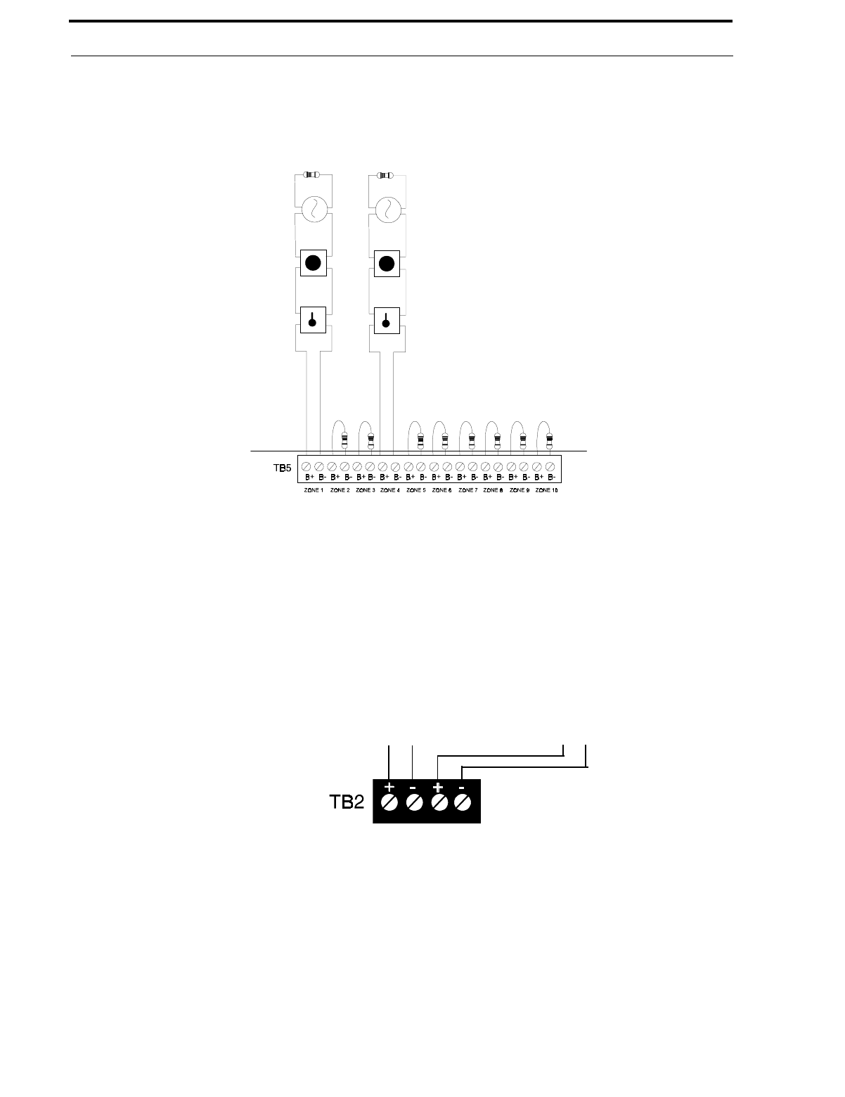
FIGURE 2-4:Style B Initiating Device Circuit Connections
Style B (Class B) Initiating Device Circuit (supervised and power-limited).
4.7K, ½watt, P/N: 71252 UL listed.
UL listed compatible 2-wire smoke detector
UL listed compatible 2-wire smoke detector
Manual Pull StationManual Pull Station
Heat Detector
Heat Detector
Dummy Load all unused circuits (P/N: 71245)
FIGURE 2-5:Auxiliary Power Connections
Nonresettable Power (500 mA)
24 VDC filtered, regulated, nonre-
settable power can be obtained
from TB2 Terminals 1(+) and 2(-).
4-Wire Smoke Detector Power (500 mA)
24 VDC filtered, regulated, resettable
power for 4-wire smoke detectors can be
obtained from TB2 Terminals 3(+) and 4(-)
Document #50193 Rev. D 5/2/97 P/N 50193:D
27
Output Circuits
All Notification Appliance Circuits may be programmed as follows:
•Silenceable
•Enabled/Disabled
•Auto Silence, 5 to 30 minutes
•Nonsilenceable
•Silence Inhibited
•March Time, Temporal or California rates.
Standard Relays
The control panel provides two Form-A relays rated for 2.0 amps @ 30 VDC (resistive). Two Form-C relays can
be added by installing the optional NAC-REM (NAC/Relay) module.
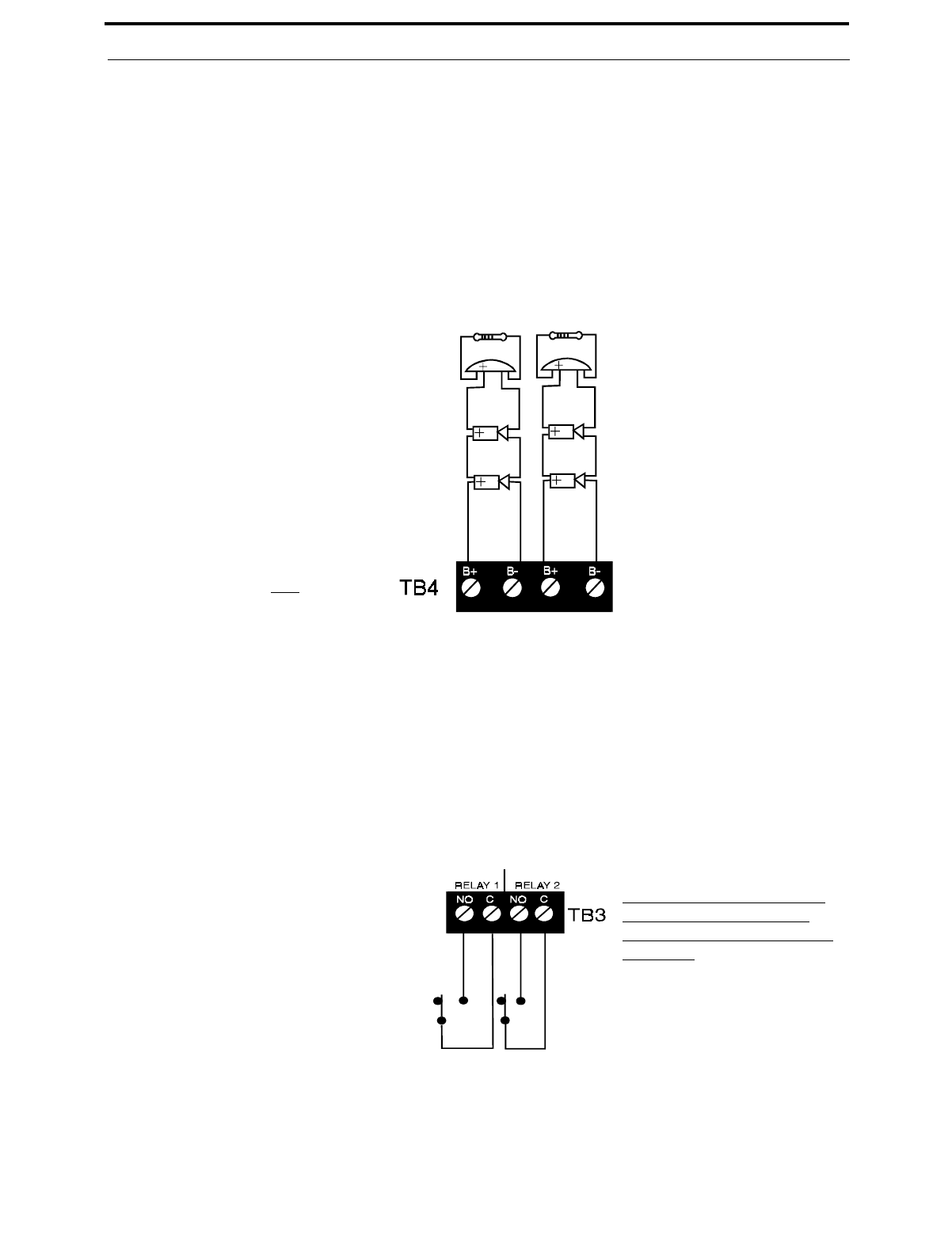
FIGURE 2-6:Notification Appliance Circuit Connections
Style Y (Class B) Notification Appliance Circuit (supervised and power-limited).
4.7K ohm, ½ watt. {/N: 71252 UL listed
Polarized BellPolarized Bell
Polarized Horn
Polarized Horn
Polarized Horn
Polarized Horn
Dummy Load all unused circuits (P/N: 71245)
Note: Notification Appliance Circuit polarity
shown in alarm state.
FIGURE 2-7:Programmable Relay Terminals
Relay connections may be power-limited or nonpower-limited, provided that a minimum of
0.25" is maintained between conductors of power-limited and nonpower-limited circuits.
Relays automatically change to
Normally Closed (energized)
when programmed for activation
on Trouble.
Digital Communicator
28
Document #50193 Rev.D 5/2/97 P/N 50193:D
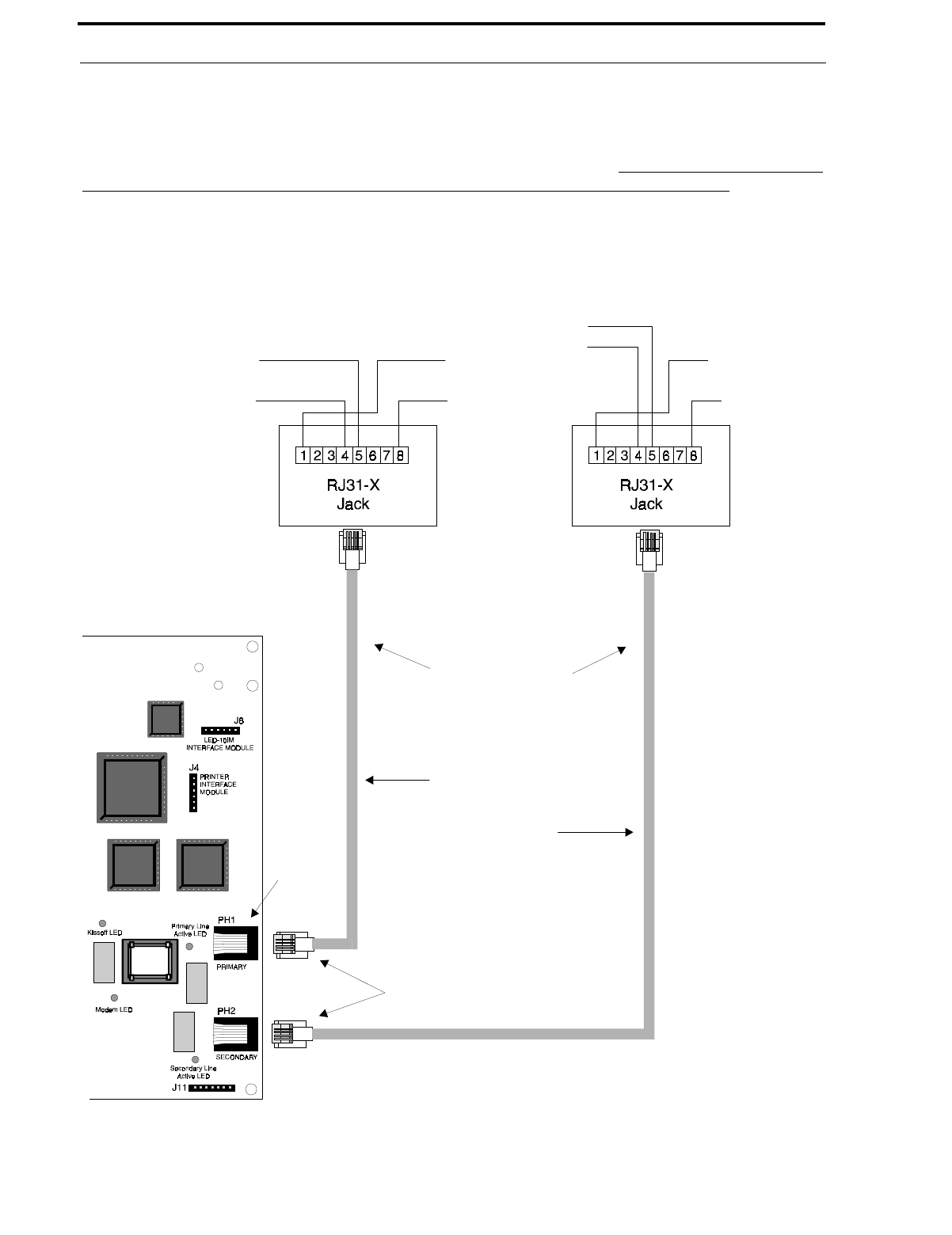
2.6 Digital Communicator
Two independent telephone lines can be connected to the control panel. Telephone line control/command is made
possible via double line seizure as well as usage of an RJ31X style interconnection. It is critical that the panel's dig-
ital communicator be located as the first device on the incoming telephone circuit to properly function.
The control panel's digital communicator is built into the main circuit board. Connection and wiring of two phone
lines is required as shown in Figure 2-8.
FIGURE 2-8:Wiring Phone Jacks
Primary Lines - Incoming
Telco Phone Lines
Secondary Lines - Incoming
Telco Phone Lines
Ring
Ring
Ring
Ring
Tip
Tip
Tip
Tip Green Wire
Green Wire
Red Wire
Red Wire To premise phones To premise phones
Note: Shorting bars
inside RJ31X Jack
removed during male
plug insertion
7 foot (2.13 m)
cables (MCBL-7)
not supplied -
order separately
Primary Phone Line PH1
Secondary Phone Line PH-2
Modular
Female
Connectors
Male Plug Connectors
Document #50193 Rev. D 5/2/97 P/N 50193:D
29
UL Power-limited Wiring Requirements
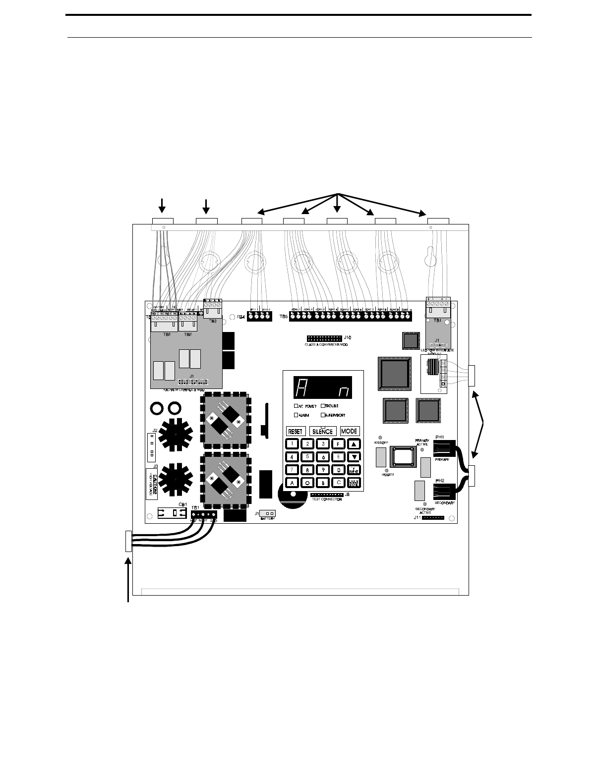
2.7 UL Power-limited Wiring Requirements
Power-limited and nonpower-limited circuit wiring must remain separated in the cabinet. All power-limited circuit
wiring must remain at least 0.25" (6.35 mm) away from any nonpower-limited circuit wiring. Furthermore, all
power-limited and nonpower-limited circuit wiring must enter and exit the cabinet through different knockouts and/or
conduits. A typical wiring diagram for the MS-5210UD is illustrated in Figure 2-9.
2.8 Installation of Optional Modules
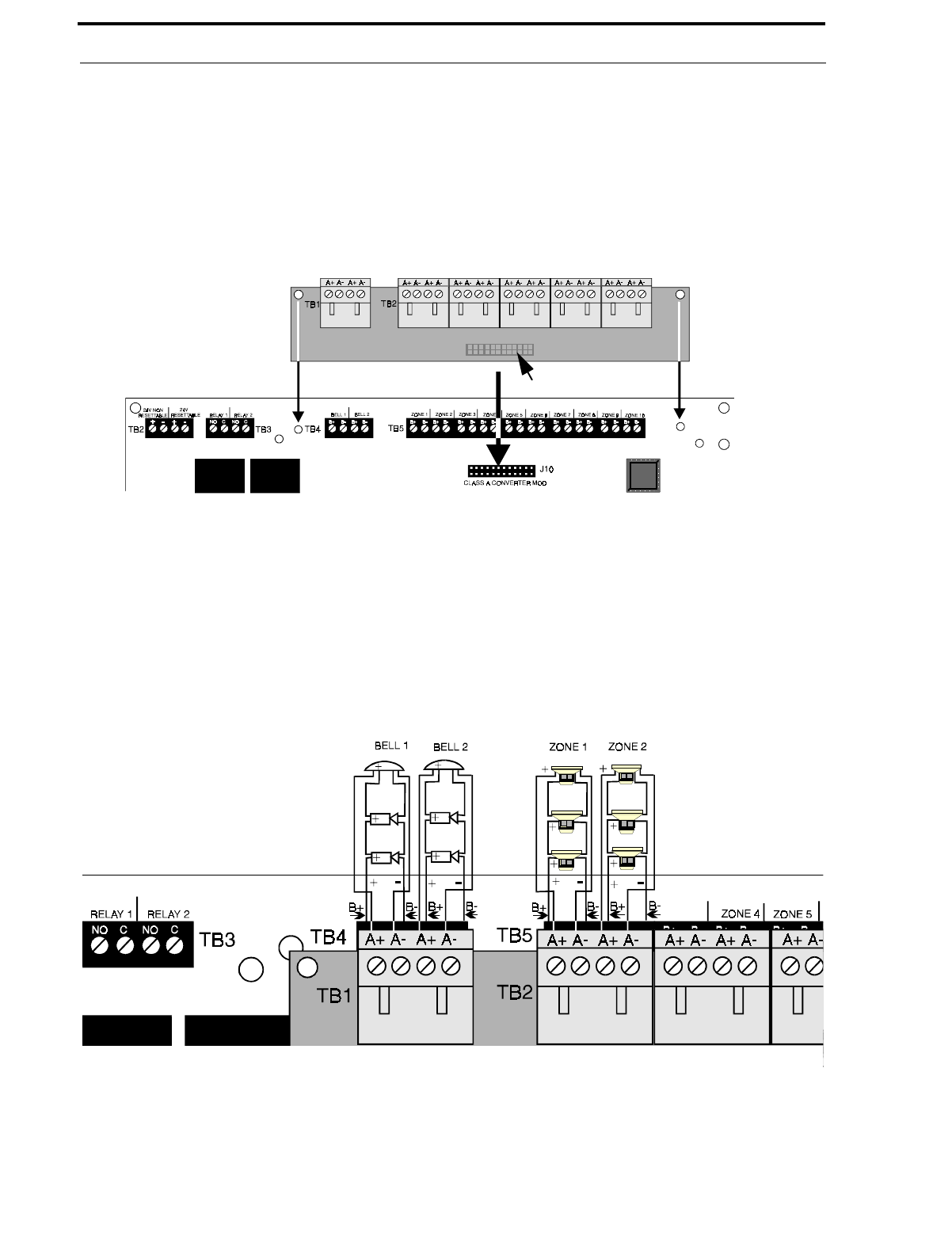
CAC-10F Class A Converter Module
The CAC-10F Module can be used to convert the 10 Style B (Class B) Initiating Device Circuits to 10 Style D
(Class A) IDCs and the two Style Y (Class B) Notification Appliance Circuits to two Style Z (Class A) NACs. J1
FIGURE 2-9:Typical Wiring Diagram for UL Power-limited Requirements
Power-limited Circuits
Nonpower-limited
Circuits
Power-limited Circuit
Note that power-lim-
ited wiring is con-
nected to terminal
block below the
installed circuit board
Power-limited
Circuit
AC Power
Installation of Optional Modules
30
Document #50193 Rev.D 5/2/97 P/N 50193:D
of the module plugs into connector J10 of the MS-5210UD, which is located at the top center of the FACP main
circuit board.
Install the two supplied metal standoffs in the holes on the main circuit board (refer to Figure 2-10). Carefully
align the two connectors and press the CAC-10F module securely into place. Make certain the pins are properly
aligned to prevent bending or breaking of any pins. Secure the CAC-10F module to the standoffs using the two
supplied screws. It is important that the supplied screw and washer be used to secure the module to the metal
standoff. This is necessary in order to help protect against electrical transients.
Wire the Style Z (Class A) Notification Appliance Circuits (NACs) using TB4 of the MS-5210UD and TB1 of the
CAC-10F module. Wire the Style D (Class A) Initiating Device Circuits (IDCs) using TB5 of the MS-5210UD and
TB2 of the CAC-10F module. Make certain to observe polarity when connecting the devices to the circuits. The B+
and A+ terminals must comprise the feed and return for the positive side of a device and the B- and A- terminals must
comprise the feed and return for the negative side of a device. To configure any of the zones for Class B when the
CAC-10F is installed, simply wire to the B+ and B- inputs on TB5 of the main circuit board and install the EOL resis-
tor across the end of the circuit. Do not wire to the corresponding A+ and A- terminals on TB2 of the CAC-10F mod-
ule. Refer to Figure 2-10 and Figure 2-11.
NAC-REM (NAC/Relay Expander Module)
The NAC-REM Module can be used to add two Style Y (Class B) or Style Z (Class A) NACs (1.5 amps maximum
each) and two Form-C relays to the MS-5210UD. Connector J1 of the NAC-REM module plugs into connector J7
which is located at the top left corner of the MS-5210UD main circuit board.
FIGURE 2-10:Installation of CAC-10F Module
metal standoff
metal standoff J1 - on back of module
FIGURE 2-11:Wiring NACs and IDCs for Class A Operation
All unused terminals
must be jumpered.
Jumper A+ to B+ and
A- to B-.
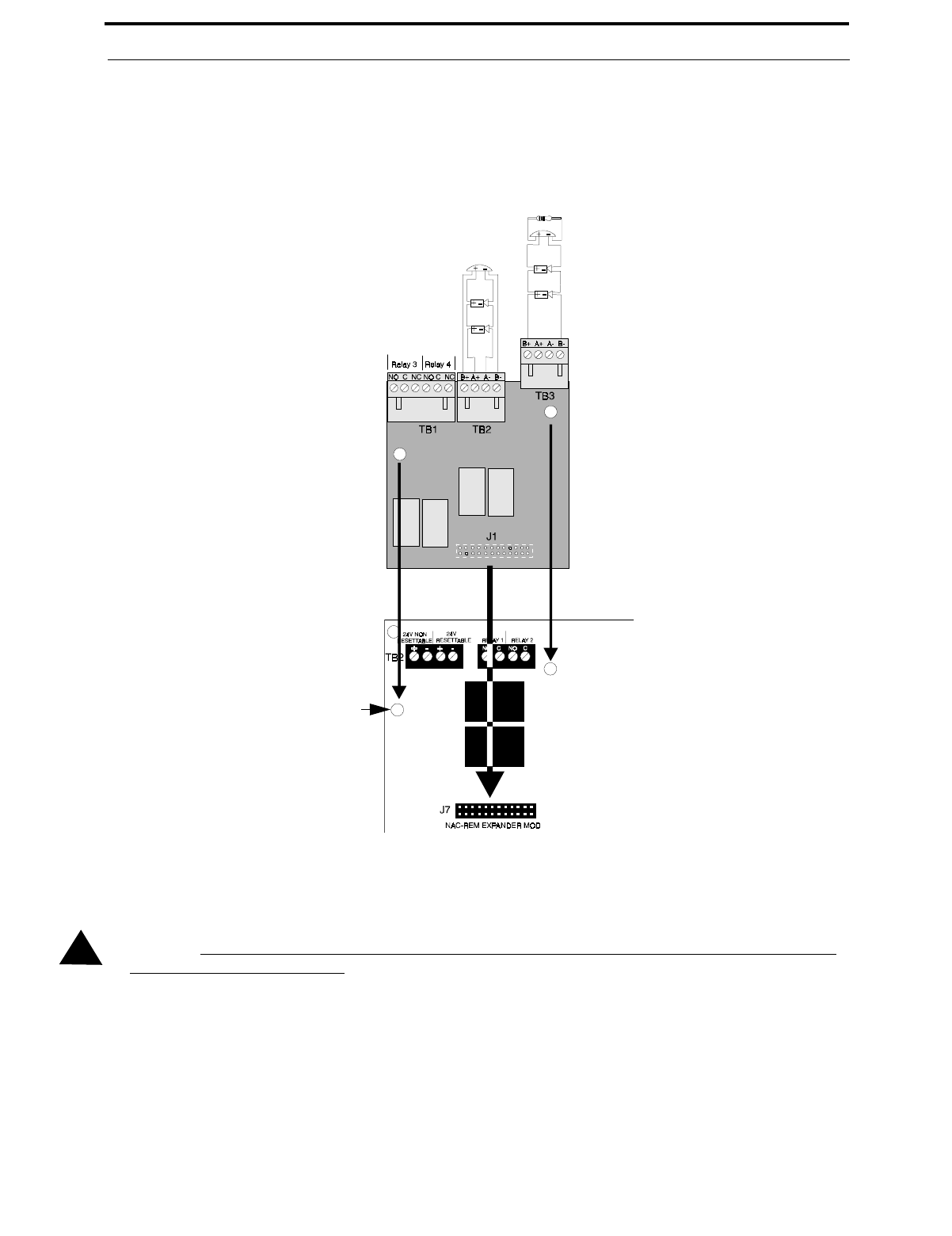
Document #50193 Rev. D 5/2/97 P/N 50193:D
31
Installation of Optional Modules
Install the two supplied metal standoffs into the FACP main circuit board. Ensure that the metal standoff is
installed in the position indicated in Figure 2-12. Carefully align the two connectors and press the NAC-REM
module securely into place. Make certain the pins are properly aligned to prevent bending or breaking of any pins.
It is important that the supplied screw and washer be used to secure the module to the metal standoff. This is nec-
essary in order to help protect against electrical transients.
PRT-24 Printer Interface Module
A remote printer may be permanently or temporarily connected to provide a hardcopy printout of normal current
system status and activity, program entries, history file, troubleshoot mode voltages and walktest data. The
PRT-24 provides an EIA-232 conversion to adapt to most 40 and 80 column printers.
CAUTION: DO NOT connect a printer to the Fire Alarm Control Communicator if a ground fault exists on the
panel. Circuit damage may result.
Installation - Remote printers require a separate external primary power source. Also required is the
PRT-24 which includes the Printer Interface Module and a 6-foot (1.83 m) interface cable prewired to
a DB25 connector. Connect the interface cable to the PRT-24 as illustrated in Figure 2-13. Insert the
two supplied standoffs into mounting holes near the J4 connector on the main circuit board. Connect
the Printer Interface board to J4 on the main circuit board, press onto standoffs and connect the
attached cable to the serial EIA-232 port on the printer. The printer may be placed a maximum of 50
feet (15.24 m) from the panel. Note that a ground fault may occur on the control panel when this con-
nection is made. For this reason, it is important that there be no preexisting ground fault on the panel.
For permanent printer connection, a ground fault is not allowed.
FIGURE 2-12:Installation and Wiring of NAC-REM Module NAC #4
NAC #3
Style Y (Class B) supervised and power-limited.
4.7K ohm, ½ watt Part #71252 UL listed.
Style Z (Class A) supervised and power-limited.
Metal Standoff
!
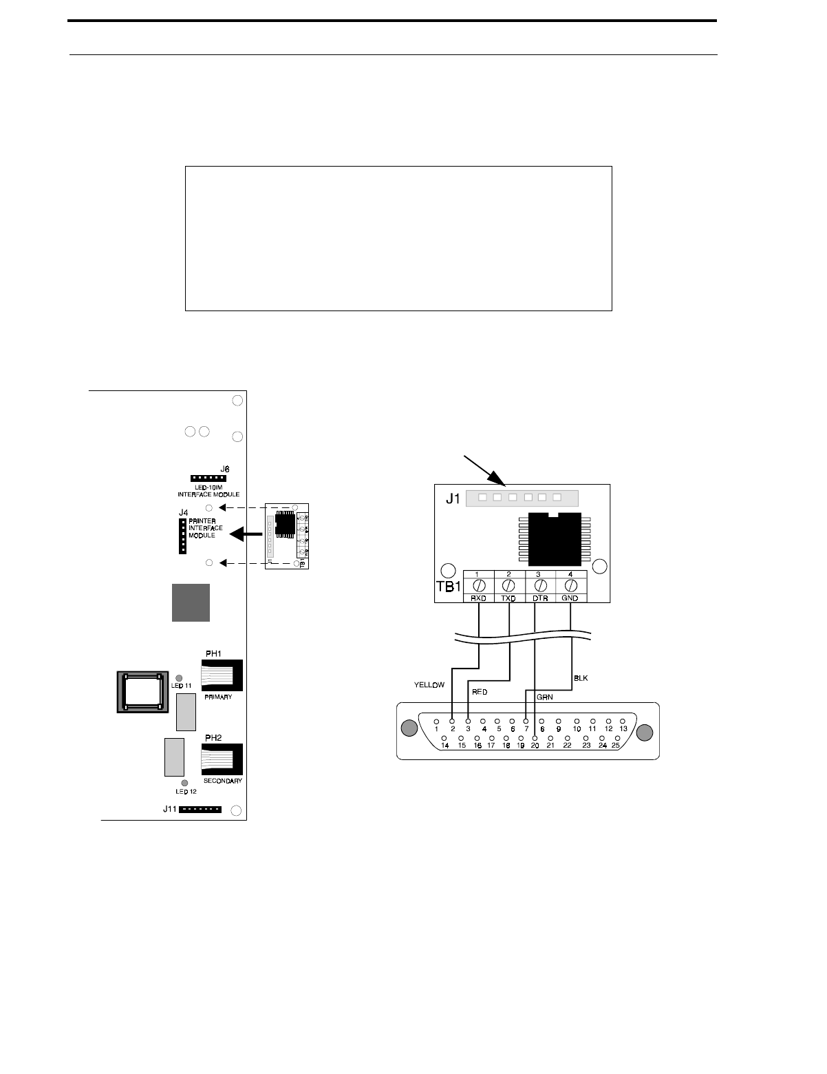
Installation of Optional Modules
32
Document #50193 Rev.D 5/2/97 P/N 50193:D
Printer Configuration - The PRT-24 is required. Also refer to the documentation supplied with your
printer. Set the printer's options as listed in Table 2-1 . Baud rate is programmable to 2400, 4800 or
9600.
LED-10IM - EIA-485 Interface Module
The LED-10IM Interface Module provides an EIA-485 port to support the LED-10 Series Remote Annunciator,
LDM Series Annunciator, AFM Series Annunciator and the ACM-8RF Relay Module. EIA-485 wiring is super-
vised for open circuits by this module. The LED-10IM mounts to connector J6 in the upper right corner of the
main board.
Install the two supplied standoffs into the FACP main circuit board. Ensure that the metal standoff is installed in
the position indicated in Figure 2-14. Carefully align the two connectors and press the LED-10IM module
securely into place. Make certain the pins are properly aligned to prevent bending or breaking of any pins. It is
TABLE 2-1: Printer Settings
Typical Printer
Under the MENU area:
COMMUNIC. SETUP:
DATA BITS: 7
PARITY: EVEN
STOP BIT: 1 STOP
BAUD RATE: MUST MATCH FACP SETTING
FIGURE 2-13:Remote Printer Connections
J1 located on back of PRT-24 board
PRT-24 connection to main board
DB-25P Front View
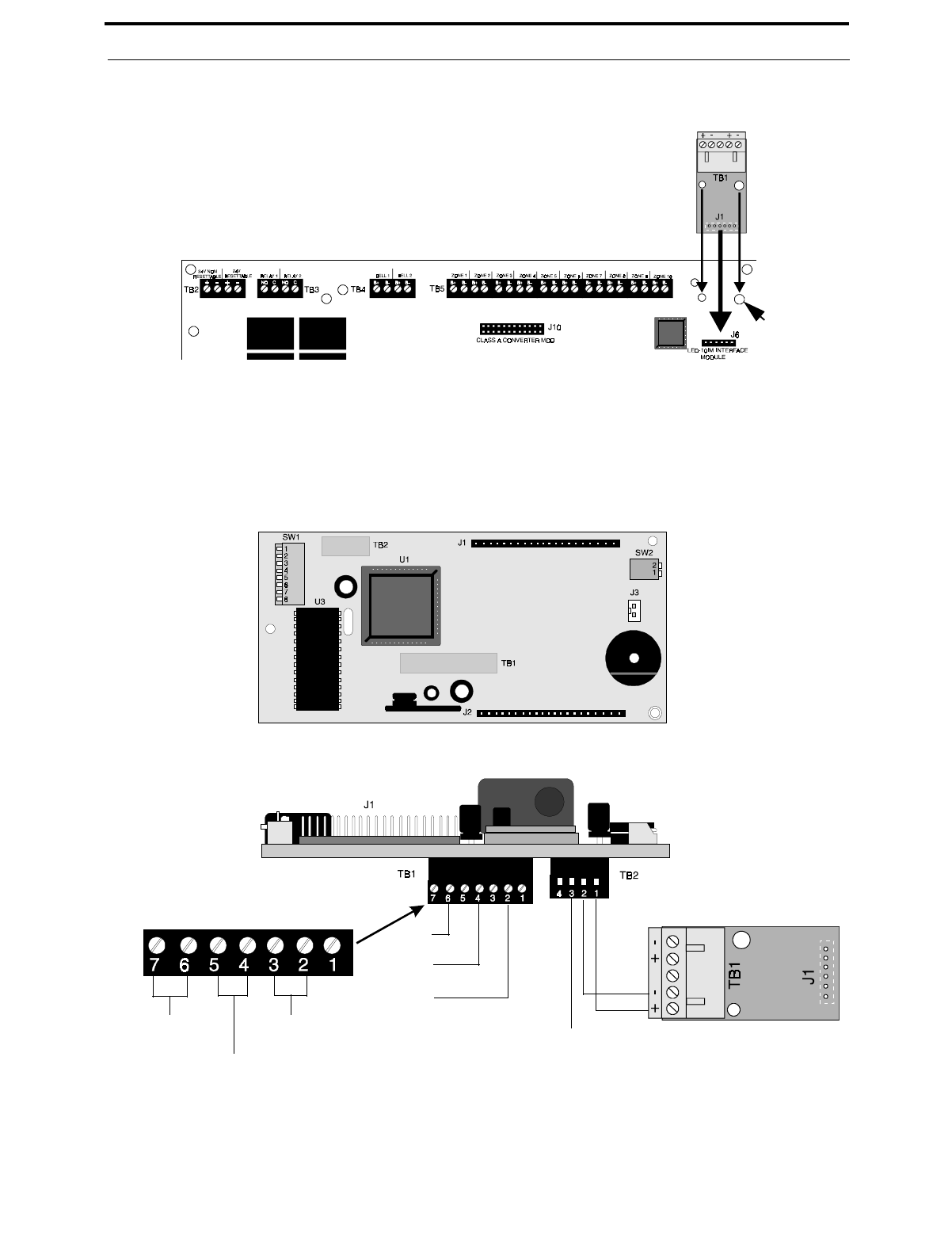
Document #50193 Rev. D 5/2/97 P/N 50193:D
33
Installation of Optional Modules
important that the supplied screw and washer be used to secure the module to the metal standoff. This is necessary
in order to help protect against electrical transients.
LED-10 Series Remote LED Annunciator
The LED-10 Series Annunciator connects to the MS-5210UD via the LED-10IM Interface Module. It is recom-
mended that overall foil/braided-shielded, twisted pair cable with a maximum length of 6,000 feet (1,800 m) @ 18
AWG (0.75 mm2) be used. Regulated power can be supplied by the MS-5210UD or a remote UL listed filtered,
regulated power supply such as the Fire•Lite FCPS-24.
FIGURE 2-14:LED-10IM Installation
metal standoff
FIGURE 2-15:Wiring LED-10IM to LED-10 Series
Shield
-+ EIA-485
Earth
Ground
- 24 VDC
+ 24 VDC
LED-10IM
Earth Ground +24 VDC
-24 VDC
LED-10 Series Annunciator
Top View
LED-10 Series Annunciator
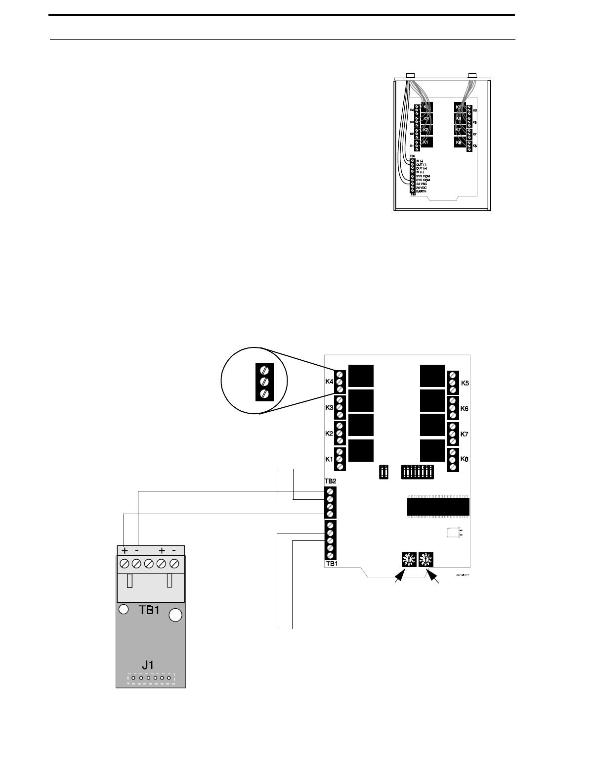
Installation of Optional Modules
34
Document #50193 Rev.D 5/2/97 P/N 50193:D
ACM-8RF Remote Relay Module
The ACM-8RF Module provides eight Form-C relays with contacts rated for
5.0 amps. Relays can be assigned to each of the ten Initiating Device Cir-
cuits (two ACM-8RF relay modules are required). The module is installed
on the EIA-485 line using the LED-10IM Interface Module. Communication
wiring is supervised by the FACP. Power for the module must be power-lim-
ited. Refer to the ACM-8RF Manual for UL power-limited wiring require-
ments and switch SW4 receive/transmit selection option.
Removable terminal blocks are provided for ease of installation and servic-
ing. DIP switch SW3 allows assignment of relays to FACP IDCs. The
ACM-8RF module can be mounted remotely in an ABS-8RF annunciator
surface-mount backbox.
ACM-8RF Address and SW3 DIP Switch Settings - Each of the ten
MS-5210UD IDCs can be assigned to an ACM-8RF relay. Two relay modules are required, with both set to the
same address. Use the decade rotary switches to set the address (i.e. for address '01', position the first [left] switch
so the arrow points to '0' and the second [right] switch so the arrow points to '1'). “Level Three - Option Module
Selections” on page 62, Annunciator Maximum Monitored Address (02-03).
✓To assign the first eight relays of the first ACM-8RF Relay Module to FACP IDCs 1 through 8, set
ACM-8RF SW3 DIP switches 2 and 5 ON and 1, 3, 4, 6, 7 and 8 OFF.
✓To assign the first two relays of the second ACM-8RF Relay Module to FACP IDCs 9 and 10, set
ACM-8RF SW3 DIP switches 3 and 5 ON and 1, 2, 4, 6, 7 and 8 OFF.
FIGURE 2-16:ABS-8R Enclosure
FIGURE 2-17:Wiring LED-10IM to ACM-8RF
ACM-8RF
IN (-)
OUT (+)
OUT (+)
IN (+)
SYS COM
SYS COM
24 VDC
24 VDC
EARTH
LED-10IM
Left
Decade
Switch
Right
Decade
Switch
Power-limited 24 VDC
To Next Device
NO
C
NC
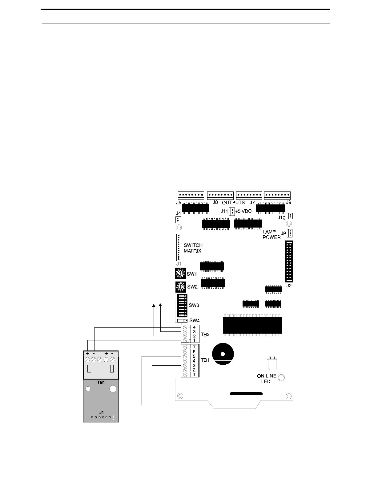
Document #50193 Rev. D 5/2/97 P/N 50193:D
35
Installation of Optional Modules
LDM-32F Lamp Driver Module
The Lamp Driver Module is used to provide an interface to a custom graphic annunciator. The LDM-32F has 32
alarm lamp/LED driver outputs which sink current to system common (-) on activation. A single positive (+) volt-
age is required to supply total operating power for all lamps or LEDs when all drivers are activated. The
LDM-32F provides a separate driver for system trouble and inputs for a local lamp test switch. A maximum of 16
external control switches may be wired to the LDM-32F. DIP switch SW3 is used to enable or disable the onboard
piezo sounder, enable remote switch functions, select a flashing LED function for new alarms and troubles and
other functions. A green ON LINE LED flashes to indicate ongoing communications with the host FACP. The
LDM-32F is supplied with four standoffs and screws for mounting to a CHS-4L chassis or custom backbox.
The LDM-32F is installed on the EIA-485 line using the LED-10IM Interface Module. Communications wiring is
supervised by the FACP. Power for the module must be power-limited.
LDM-32F Switch Settings - Use the decade rotary switches to set the address (i.e. for address '02', position switch
SW1 [top] so the arrow points to '2' and switch SW2 [bottom] so the arrow points to '0').
FIGURE 2-18:Wiring LED-10IM to LDM-32F
To Next Device
EIA-485
+
-
-
+
LED-10IM
Power-limited
24 VDC Source LDM-32F
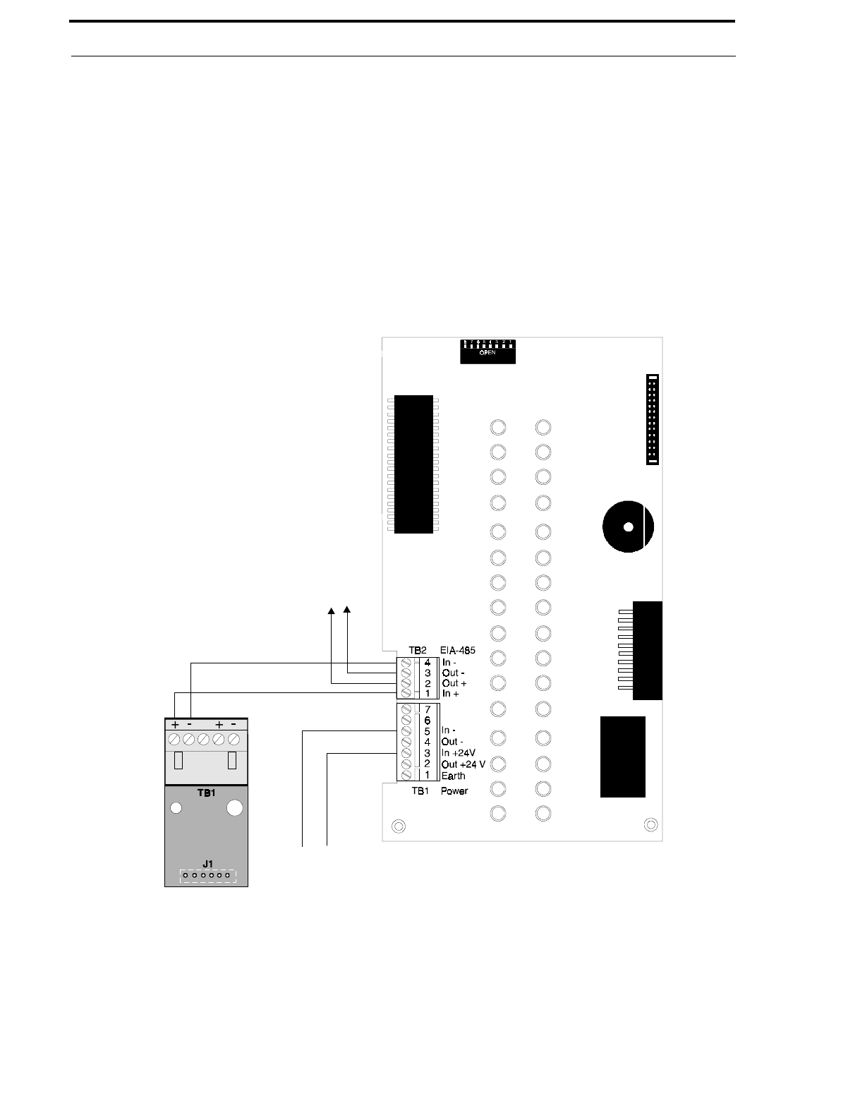
Installation of Optional Modules
36
Document #50193 Rev.D 5/2/97 P/N 50193:D
AFM-16ATX and AFM-16ATF Annunciators
The Annunciator Fixed Modules-16ATX and 16ATF each contain 16 red alarm and 16 yellow trouble LEDs, a
system trouble LED, an ON LINE/POWER LED and a local piezo sounder with switches for FACP Acknowl-
edge, Silence, Reset and Drill. The AFM-16ATX is fixed at address '1' and is installed on the EIA-485 line using
the LED-10IM Interface Module.
AFM-16AF Annunciator
The Annunciator Fixed Module-16AF has 16 red alarm LEDs. The annunciator address is fixed at '1' and commu-
nication is via the EIA-485 line using the LED-10IM Interface Module. The Local Silence/Acknowledge switch
functions as a local lamp test and silence for the annunciator piezo sounder. LEDs include ON LINE/POWER
and System Trouble.
FIGURE 2-19:Wiring LED-10IM to AFM-16ATX
To Next Device
EIA-485 +
-
+
-
LED-10IM
Power-limit ed
24 VDC Source

Document #50193 Rev. D 5/2/97 P/N 50193:D
37
Programming Instructions
CHAPTER 3 Programming Instructions
This section describes programming the panel from the onboard keyboard or the remote site upload/download soft-
ware which allows programming the control panel off premises. Programming of the control panel is possible at any
time except when an alarm condition is present or during a fire drill.
The control panel has been designed for many different types of applications. After examining your specific applica-
tion, review the programming options and choose the entries best suited for your system.
The control panel has a built-in intelligent programmer. All programming selections are stored in nonvolatile Electri-
cally-Erasable Programmable Read-Only Memory (EEPROM). This ensures that the control panel will remember all
entries made in programming mode even if both AC and battery power are removed. Invalid entries cause a 'beep'
from the onboard piezo sounder.
The user must program the primary and secondary phone numbers, account numbers and 24 hour test report times for
each central station account and the current time and date. The control panel comes with factory chosen options/fea-
tures already programmed. Other options/features may be programmed if desired. If all factory default settings are
acceptable, programming is complete.
Successful entry into Program Mode from the keypad shuts off the fire protection and places the panel into trouble. A
'system off normal' message is transmitted to the central station. Programming via the PK-5210UD upload/download
software is accomplished with the fire protection active/on.
3.1 Entering Program Mode
Program Mode is divided into four levels:
1. Main Panel Options
2. Event Codes/Transmission Formats
3. Option Module Selections
4. Upload/Download
Each level of Program Mode is entered by pressing the MODE key and then keying in the program mode entry code
(7764) and pressing the [ENTER/STORE] key.
☛ 7764 spells PROG on a Touch-Tone phone®
If an incorrect key is entered, reenter the proper 4-digit code before pressing the [ENTER/STORE] key. Note that as
information is entered into the control panel, the digits will scroll across the display from right to left:
---7
--77
-776
7764
You are allowed a pause of up to 10 seconds in between each number while entering the code. After pressing the
[ENTER/STORE] key, the control panel will be in Program Mode and will display P--1, with the 1 flashing. If the
[ENTER/STORE] key is pressed, Level 1 (Main Panel Options) will be selected for programming. If Level 2 (Event
Codes/Transmission Formats), Level 3 (Option Module Selections) or Level 4 (Upload/Download) is keyed in and
then the [ENTER/STORE] key pressed, the corresponding Level will be selected for programming. You are allowed
up to ten minutes of idle time at this point before starting your programming, otherwise, the control panel will return
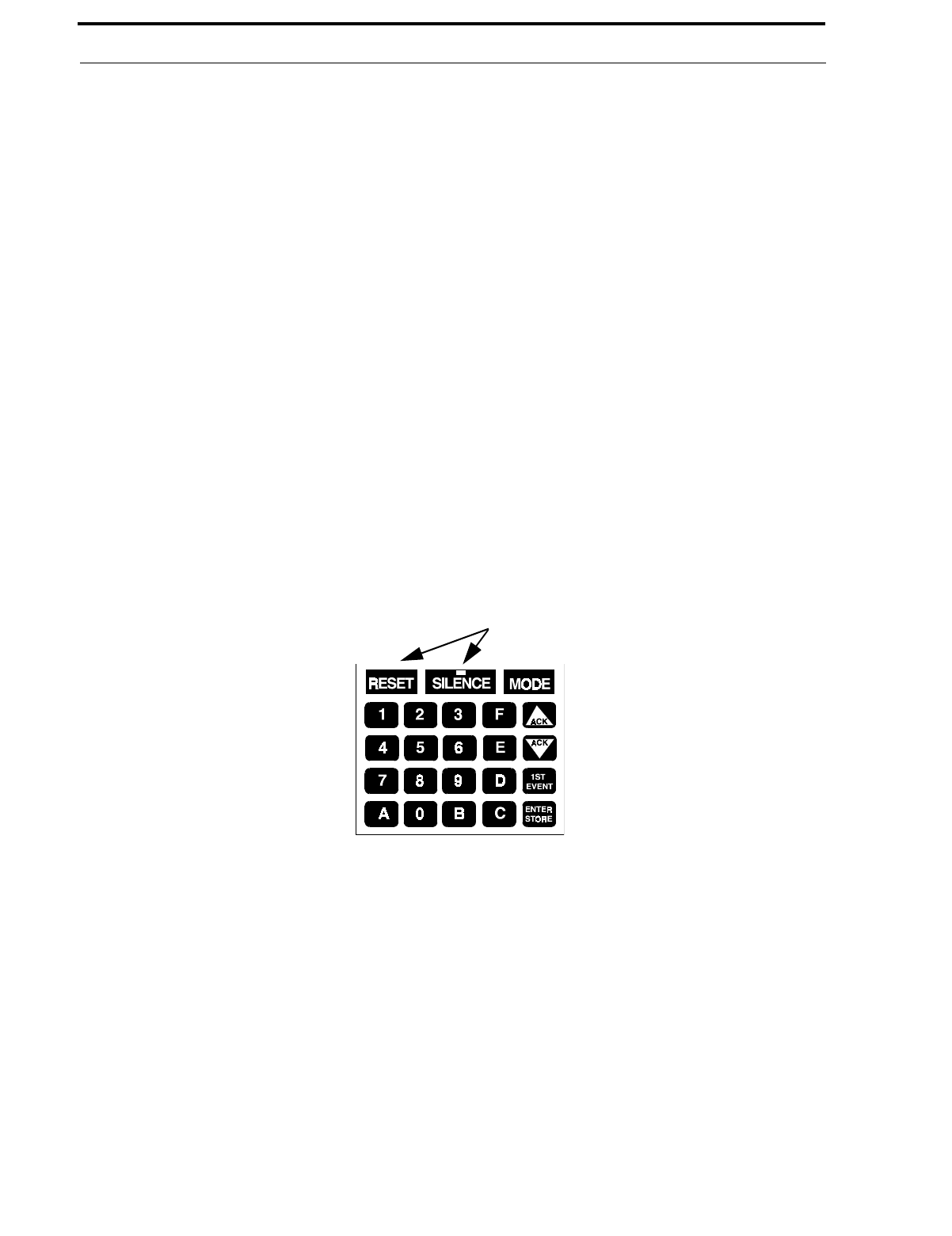
Switch Functions
38
Document #50193 Rev.D 5/2/97 P/N 50193:D
to Normal Mode. You also have a maximum of 10 minutes between any key stroke. All entries made prior to the 10
minute time-out are valid and are stored.
Once in any of the four levels of the Programming Mode, the control panel will:
•Blink the Trouble LED
•Activate the trouble relay
•Disable the Notification Appliance Circuit(s)
•Disable the alarm relay
•Display 00_F
•Ignore all other keys other than those mentioned in this section
•Continue to communicate any events not previously acknowledged at a central station prior to entering Pro-
gramming Mode
While in any of the four levels of Programming Mode, the first three locations on the left of the display represent the
memory address and the last location (farthest right) represents the contents of the memory address. The first address
displayed is shown below:
3.2 Switch Functions
The function of each switch in program mode is illustrated below:
3.3 Program Options
3.3.1 Level 1 - Main Panel Options
Note that the factory default setting for Location 56 is '0' for Control Panel only. This keeps the communicator off
until location 56 is changed to ‘1’ for panel/communicator. Once location 56 is set to ‘1’ and a valid phone number
is entered, entry into the program mode will cause transmission of the 'System Off Normal' report.
Primary Central Station Phone Number (00-15)
The first sixteen addresses, 00-15, are factory set to 'F' (from 00_F to 15_F). Programming is typically done as
follows:
✓If your phone number is 484-7161, press 4.
✓The display will read 00_4.
00_F
(address)(data)
FIGURE 3-1:Control Panel Keypad No function in Program Mode
Address entry keys are 0 to 9
Data entry keys are 0 to 9 and A to F
- Select operating mode
- Increment memory address
- Decrement memory address
Once = First memory address
Twice = Type any address
- Save data, go to next address

Document #50193 Rev. D 5/2/97 P/N 50193:D
39
Program Options
✓Press [ENTER/STORE] to save the entry to memory and increment to the next address 01_F.
✓Enter the remaining numbers in their respective addresses as shown below:
Valid entries for both the primary and secondary phone numbers are 0 to 9 and A to F with the numeric digits as
dialed numbers and the hexadecimal digits representing the following functions:
•A = * on a Touch-Tone phone keypad
•B = # on a Touch-Tone phone keypad
•C = look for secondary dial tone for up to two seconds (then dial anyway)
•D = three second pause
•E = five second pause
•F = end of phone number (Note: F must be entered in all unused phone number locations)
Primary Central Station Number Communication Format (16)
One location is needed to select the Communication Format to the primary phone number. Address 16 is used for
this purpose. The default ( factory setting) for this address is 'E', which is Contact ID Format. You may enter '0'
through 'D' in place of the default, then press [ENTER/STORE]. Choose from the list of formats below:
0: 4+1 Ademco Express Standard, DTMF, 1400/2300 ACK
1: 4+2 Ademco Express Standard, DTMF, 1400/2300 ACK
2: 3+1 Standard 1800 Hz Carrier, 2300 Hz ACK
3: 3+1 Expanded 1800 Hz Carrier, 2300 Hz ACK
4: 3+1 Standard 1900 Hz Carrier, 1400 Hz ACK
5: 3+1 Expanded 1900 Hz Carrier, 1400 Hz ACK
6: 4+1 Standard 1800 Hz Carrier, 2300 Hz ACK
7: 4+1 Expanded 1800 Hz Carrier, 2300 Hz ACK
8: 4+1 Standard 1900 Hz Carrier, 1400 Hz ACK
9: 4+1 Expanded 1900 Hz Carrier, 1400 Hz ACK
A: 4+2 Standard 1800 Hz Carrier, 2300 Hz ACK
B: 4+2 Expanded 1800 Hz Carrier, 2300 Hz ACK
C: 4+2 Standard 1900 Hz Carrier, 1400 Hz ACK
D: 4+2 Expanded 1900 Hz Carrier, 1400 Hz ACK
E: Contact ID, DTMF, 1400/2300 ACK
F: Future use
Note: Consult you Central Station for proper selection or consult our factory representatives. For any format cho-
sen, the control panel automatically programs all of the event codes. See Table 3-3 through Table 3-8 .
CAUTION: Default entries for event codes (as shown in Table 3-3 through Table 3-8 ) are programmed into mem-
ory each time address '16' is altered. Be certain to double check entries after programming the zone functions,
addresses 64 - 73. Program the format first, then program the zone(s) function. Do not alter while the communi-
cator is active.
Primary Central Station Number Account Code (17-20)
The four locations at addresses 17-20 default to all '0s'. Valid entries are 0-9 and A-F. The number of digits
entered must match the format selection. If programming '2, 3, 4 or 5' into address 16, enter three digits (one digit
each in locations 17, 18 and 19 - location 20 is ignored). If programming '0, 1, 6, 7, 8, 9, A, B, C, D or E' into
address 16, enter four digits (one digit each in locations 17, 18, 19 and 20).
00 01 02 03 04 05 06 07 08 09 10 11 12 13 14 15
Entry
Address
4 8 4 7 1 6 1 F F F F F F F F F
!

Program Options
40
Document #50193 Rev.D 5/2/97 P/N 50193:D
Primary Central Station Number 24 Hour Test Time (21-24)
Use military time when entering the 24 hour 'test' time. The 24 hour test report to phone number 1 takes up four
locations, from addresses 21-24. The default is 00:00 (12:00 midnight). The limits for each location are as fol-
lows (do not use values of A-F as entries):
21: enter 0, 1 or 2
22: enter 0-9
23: enter 0-5
24: enter 0-9
Primary Central Station Number 24/12/8/6 Hour Test Time Interval (25)
The test report sent to the Primary phone number may be sent every 6, 8, 12 or 24 hours. If the message is to be
sent every 24 hours, leave the factory default entry of ‘0’. If other test report times are needed, enter 1=12hr,
2=8hr or 3=6hr.
Secondary Central Station Phone Number (26-41)
Programming is similar to programming the primary phone number located at addresses 00 - 15. The defaults are
also all 'Fs'.
Secondary Central Station Number Communication Format (42)
Programming is the same as the primary number's Communication Format at address 16. Default entry is 'E',
Contact ID Format. Choose one entry from the list below:
0: 4+1 Ademco Express Standard, DTMF, 1400/2300 ACK
1: 4+2 Ademco Express Standard, DTMF, 1400/2300 ACK
2:3+1 Standard 1800 Hz Carrier, 2300 Hz ACK
3: 3+1 Expanded 1800 Hz Carrier, 2300 Hz ACK
4: 3+1 Standard 1900 Hz Carrier, 1400 Hz ACK
5: 3+1 Expanded 1900 Hz Carrier, 1400 Hz ACK
6: 4+1 Standard 1800 Hz Carrier, 2300 Hz ACK
7: 4+1 Expanded 1800 Hz Carrier, 2300 Hz ACK
8: 4+1 Standard 1900 Hz Carrier, 1400 Hz ACK
9: 4+1 Expanded 1900 Hz Carrier, 1400 Hz ACK
A: 4+2 Standard 1800 Hz Carrier, 2300 Hz ACK
B: 4+2 Expanded 1800 Hz Carrier, 2300 Hz ACK
C: 4+2 Standard 1900 Hz Carrier, 1400 Hz ACK
D: 4+2 Expanded 1900 Hz Carrier, 1400 Hz ACK
E: Contact ID, DTMF, 1400/2300 ACK
F: Future use
Note: Consult your Central Station for proper selection or consult our factory representatives. For any format
chosen, the control panel automatically programs all of the event codes. See Table 3-3 through Table 3-8 .
CAUTION: Default entries for event codes (as shown in Table 3-3 through Table 3-8 ) are programmed into
memory each time address '42' is altered. Be certain to double check entries after programming the zone func-
tions, addresses 64 - 73. Program the format first, then program the zone(s) function. Do not alter entry while the
communicator is active.
F F F F F F F F F F F F F F F F
26 27 28 29 30 31 32 33 34 35 36 37 38 39 40 41
Entry
Address
!

Document #50193 Rev. D 5/2/97 P/N 50193:D
41
Program Options
Secondary Central Station Number Account Code (43-46)
Four locations at addresses 43-46 default to all '0s'. Valid entries are 0-9 and A-F. The number of digits entered
must match the format selection. If programming '2, 3, 4 or 5' into address 42, enter three digits (one digit each in
locations 43, 44 and 45 - location 46 is ignored). If programming '0, 1, 6, 7, 8, 9, A, B, C, D or E' into address 42,
enter four digits (one digit each in locations 43, 44, 45 and 46).
Secondary Central Station Number 24-Hour Test Time (47-50)
Use military time when entering the 24 hour 'test' time. The 24 hour test report to phone number 2 takes up four
locations, from addresses 47-50. The default is 00:00 (12:00 midnight). The limits for each location are as fol-
lows (do not use values of A-F as entries):
47: enter 0, 1 or 2
48: enter 0-9
49: enter 0-5
50: enter 0-9
Secondary Central Station Number 24/12/8/6 Hour Test Time (51)
The test message sent to the Secondary phone number may be sent every 6, 8, 12 or 24 hours. If the message is to
be sent every 24 hours, leave the factory default entry of '0'. If other test report times are needed, enter 1=12hr,
2=8hr or 3=6hr.
Alarm Presignal (52)
Alarm Presignal is used to delay Notification Appliance Circuit(s) activation while allowing for visual verification
by a person. Once a zone triggers an alarm, the mainboard piezo sounder and the annunciator piezo sounder turn
on steady, the alarm LEDs on the FACP and annunciator flash, the FACP display indicates the activated zone, the
annunciator zone LED flashes and the Notification Appliance Circuits are held off for 15 seconds. During this
time, if the Silence or Acknowledge switch is pressed, the piezos are silenced and the notification appliances may
be held off for up to three minutes. (See Alarm Presignal Delay Timer Address 53-55). After the programmed
delay period, the notification appliances will activate if the source of the alarm is not cleared. Presignal does not
function for zones defined as Waterflow, Supervisory, Process Monitoring or zones defined as Remote Switches.
Factory default is '0' for no alarm presignal. Enter '1' to select alarm presignal. During alarm presignal, access to
other modes is prevented and the communicator will not transmit a signal to the central station signifying that the
alarm presignal sequence has been initiated.
CAUTION: ACM-8RF relays will activate during the Alarm Presignal sequence.
Alarm Presignal Delay Timer (53-55)
The Alarm Presignal Timer is factory set to 120 seconds (2 minutes), with addresses 53=1, 54=2 and 55=0. The
timer may be programmed from 0 to 179 seconds. Location 52 must be set to '1'.
Communicator/Fire Panel Selection (56)
Leaving address 56 at '0' causes the control panel to operate as a fire panel only. Selecting '1' will make it operate
as a fire panel/communicator.
Backup Reporting (57)
Leaving address 57 at '0' means that reports will be transmitted to the secondary Central Station phone number
only if attempts to communicate to the primary Central Station phone number are unsuccessful. Programming a '1'
causes all reports to be transmitted to both the primary and secondary Central Station phone numbers. Program-
ming a '2' causes reports to go to the first available receiver.
CAUTION: Do not alter this entry while the communicator is active.
Touchtone/Rotary Select for Primary Phone (58)
A '0' programmed in this address by the factory triggers Touchtone dialing over the primary phone line. Select '1'
for rotary dialing.
!
!

Program Options
42
Document #50193 Rev.D 5/2/97 P/N 50193:D
Make/Break Ratio for Primary Phone (59)
Use this address only if you have chosen '1' for address 58. The Make/Break ratio is factory set to '0' which is 67/
33 ratio, but may be changed to '1' which is 62/38 ratio.
Touchtone/Rotary Select for Secondary Phone (60)
A '0' programmed in this address by the factory triggers Touchtone dialing over the secondary phone line. Select
'1' for rotary dialing.
Make/Break Ratio for Secondary Phone (61)
Use this address only if you have chosen '1' for address 60. The Make/Break ratio is factory set to '0' which is 67/
33 ratio, but may be changed to '1' which is a 62/38 ratio.
Address (62)
Leave entry as default of '0'.
Address (63)
Leave entry as default of '0'.
Zones 1 through 10 Function Selection (64-73)
The ten zones on the control panel may be programmed as shown in Table 3-1 . Program entries alter zone func-
tion, transmittal priority and, as a result of altering the zone definition, the transmitted event code message is auto-
matically changed. Remote switch entries 9, A, B and C cause the zone function to be altered to match the FACP
keypad entries. Initial closure (or shorting) of a switch causes the switch function to occur. The switch must be
returned to its normal position.
Zone 1 Function Selection (64)
Factory default for zone 1 is '0' for 2-wire smoke detector. Enter '1' for Pull Station; '2' for Normally-Open contact
device; '3' for Supervisory; '4' for Supervisory, autoresettable; '5' for Waterflow, silenceable; '6' for Waterflow,
nonsilenceable; '7' for critical and noncritical process monitoring; '8' for autoresettable process monitoring; '9' for
remote reset switch; 'A' for remote silence switch; 'B' for remote acknowledge switch; or 'C' for remote manual
evacuate (drill) switch.
1. For remote switch applications, use Fire•Lite P/N: AKS-1F or equivalent UL listed switch.
TABLE 3-1: Zone Functions
Program Entry Function
0 Operate 2-wire smoke detectors
1 Pull Station
2 Normally-Open Contact Device (heat detector, 4-wire smoke, etc.)
3 Supervisory
4 Supervisory, autoresettable. Self restore function, is not latched by the control panel
5 Waterflow, silenceable. Silencing of Silenceable Notification Appliance Circuits allowed
6Waterflow, nonsilenceable. Silencing of Silenceable Notification Appliance Circuits not
allowed. Must clear waterflow alarm condition and press reset key
7 Critical and noncritical process monitoring
8 Autoresettable process monitoring
9 Remote reset switch1
ARemote silence switch1
BRemote acknowledge switch1
CRemote manual evacuate (drill) switch1

Document #50193 Rev. D 5/2/97 P/N 50193:D
43
Program Options
Zone 2 Function Selection (65)
Factory default for zone 2 is '0' for 2-wire smoke detector. Enter '1' for Pull Station; '2' for Normally-Open contact
device; '3' for Supervisory; '4' for Supervisory, autoresettable; '5' for Waterflow, silenceable; '6' for Waterflow, non-
silenceable; '7' for critical and noncritical process monitoring; '8' for autoresettable process monitoring; '9' for
remote reset switch; 'A' for remote silence switch; 'B' for remote acknowledge switch; or 'C' for remote manual
evacuate (drill) switch.
Zone 3 Function Selection (66)
Factory default for zone 3 is '0' for 2-wire smoke detector. Enter '1' for Pull Station; '2' for Normally-Open contact
device; '3' for Supervisory; '4' for Supervisory, autoresettable; '5' for Waterflow, silenceable; '6' for Waterflow, non-
silenceable; '7' for critical and noncritical process monitoring; '8' for autoresettable process monitoring; '9' for
remote reset switch; 'A' for remote silence switch; 'B' for remote acknowledge switch; or 'C' for remote manual
evacuate (drill) switch.
Zone 4 Function Selection (67)
Factory default for zone 4 is '0' for 2-wire smoke detector. Enter '1' for Pull Station; '2' for Normally-Open contact
device; '3' for Supervisory; '4' for Supervisory, autoresettable; '5' for Waterflow, silenceable; '6' for Waterflow, non-
silenceable; '7' for critical and noncritical process monitoring; '8' for autoresettable process monitoring; '9' for
remote reset switch; 'A' for remote silence switch; 'B' for remote acknowledge switch; or 'C' for remote manual
evacuate (drill) switch.
Zone 5 Function Selection (68)
Factory default for zone 5 is '0' for 2-wire smoke detector. Enter '1' for Pull Station; '2' for Normally-Open contact
device; '3' for Supervisory; '4' for Supervisory, autoresettable; '5' for Waterflow, silenceable; '6' for Waterflow, non-
silenceable; '7' for critical and noncritical process monitoring; '8' for autoresettable process monitoring; '9' for
remote reset switch; 'A' for remote silence switch; 'B' for remote acknowledge switch; or 'C' for remote manual
evacuate (drill) switch.
Zone 6 Function Selection (69)
Factory default for zone 6 is '0' for 2-wire smoke detector. Enter '1' for Pull Station; '2' for Normally-Open contact
device; '3' for Supervisory; '4' for Supervisory, autoresettable; '5' for Waterflow, silenceable; '6' for Waterflow, non-
silenceable; '7' for critical and noncritical process monitoring; '8' for autoresettable process monitoring; '9' for
remote reset switch; 'A' for remote silence switch; 'B' for remote acknowledge switch; or 'C' for remote manual
evacuate (drill) switch.
Zone 7 Function Selection (70)
Factory default for zone 7 is '0' for 2-wire smoke detector. Enter '1' for Pull Station; '2' for Normally-Open contact
device; '3' for Supervisory; '4' for Supervisory, autoresettable; '5' for Waterflow, silenceable; '6' for Waterflow, non-
silenceable; '7' for critical and noncritical process monitoring; '8' for autoresettable process monitoring; '9' for
remote reset switch; 'A' for remote silence switch; 'B' for remote acknowledge switch; or 'C' for remote manual
evacuate (drill) switch.
Zone 8 Function Selection (71)
Factory default for zone 8 is '0' for 2-wire smoke detector. Enter '1' for Pull Station; '2' for Normally-Open contact
device; '3' for Supervisory; '4' for Supervisory, autoresettable; '5' for Waterflow, silenceable; '6' for Waterflow, non-
silenceable; '7' for critical and noncritical process monitoring; '8' for autoresettable process monitoring; '9' for
remote reset switch; 'A' for remote silence switch; 'B' for remote acknowledge switch; or 'C' for remote manual
evacuate (drill) switch.
Zone 9 Function Selection (72)
Factory default for zone 9 is '0' for 2-wire smoke detector. Enter '1' for Pull Station; '2' for Normally-Open contact
device; '3' for Supervisory; '4' for Supervisory, autoresettable; '5' for Waterflow, silenceable; '6' for Waterflow, non-
silenceable; '7' for critical and noncritical process monitoring; '8' for autoresettable process monitoring; '9' for
remote reset switch; 'A' for remote silence switch; 'B' for remote acknowledge switch; or 'C' for remote manual
evacuate (drill) switch.

Program Options
44
Document #50193 Rev.D 5/2/97 P/N 50193:D
Zone 10 Function Selection (73)
Factory default for zone 10 is '0' for 2-wire smoke detector. Enter '1' for Pull Station; '2' for Normally-Open con-
tact device; '3' for Supervisory; '4' for Supervisory, autoresettable; '5' for Waterflow, silenceable; '6' for Waterflow,
nonsilenceable; '7' for critical and noncritical process monitoring; '8' for autoresettable process monitoring; '9' for
remote reset switch; 'A' for remote silence switch; 'B' for remote acknowledge switch; or 'C' for remote manual
evacuate (drill) switch.
Note: Programming any zone to function as supervisory or supervisory autoresettable will cause the defaulted
zone alarm event codes (see note in Table 3-2 ) to be automatically changed. The defaulted code of '1' is changed
to '8' for formats 3+1 and 4+1 Standard and Expanded, 4+2 Expanded and 4+1 Express (refer to Table 3-3 and
Table 3-6 ). The defaulted codes of 11 through 1A are changed to 81 through 8A accordingly for formats 4+2
Standard and 4+2 Express (refer to Table 3-4 and Table 3-7 ). Programming any zone to function as process
monitoring (Zone Function Selections 7 or 8) will cause the alarm event code to be automatically programmed as
'0' or '00' which disables the report. Be certain to reprogram the alarm event code for each process monitoring
zone. Restoral codes remain unchanged from factory defaults.
When using Contact ID Format, zone alarm and zone restoral event codes change automatically as shown in
Table 3-2 . Be certain to reprogram alarm event codes when selecting process monitoring functions. Zone fault
and disable event codes may also be user programmed (refer to “Ademco Contact ID Format Event Code
Descriptions” on page 111).
Programming a zone as a remote switch causes no transmission of an alarm or alarm restoral event code. The
zone wiring continues to be supervised for opens whereas a short simulates closure of a reset, silence, drill or
acknowledge switch. Zone fault and zone restoral codes continue to be transmitted.
Waterflow Retard Timer (74-75)
A delay may be added prior to declaring a Waterflow type of alarm. Delays up to 89 seconds are allowed. The
default for addresses 74 and 75 are '00' (no additional delay). Valid entries for 74 are 0 through 8 and for 75 are 0
through 9. Program an entry into these addresses only if entering a '5' or '6' in any of the addresses 64 through 73.
Be careful to include any built-in delays of the waterflow device.
Alarm Verification (76)
Alarm verification works only on zones programmed as 2-wire smoke detector zones. After detecting an alarm,
the panel removes power from all zones for six seconds, resetting all 2-wire smoke detectors. Power is reapplied
1. Be certain to program appropriate process monitoring functions (refer to “Ademco Contact ID Format
Event Code Descriptions” on page 111).
TABLE 3-2: Event Code Changes for ID Contact Format
Zone Function Selection Function Zone Alarm/Restoral Event Code
0 2-wire Smoke 111
1 Pull Station 115
2 N.O. Contact Device 110
3 Supervisory 200
4 Autoresettable Supervisory 200
5 Waterflow (silenceable) 113
6 Waterflow (nonsilenceable) 113
7 Process Monitoring 0001
8 Autoresettable Process Monitoring 0001
9 Reset Switch N/A
A Silence Switch N/A
B Acknowledge Switch N/A
C Drill Switch N/A
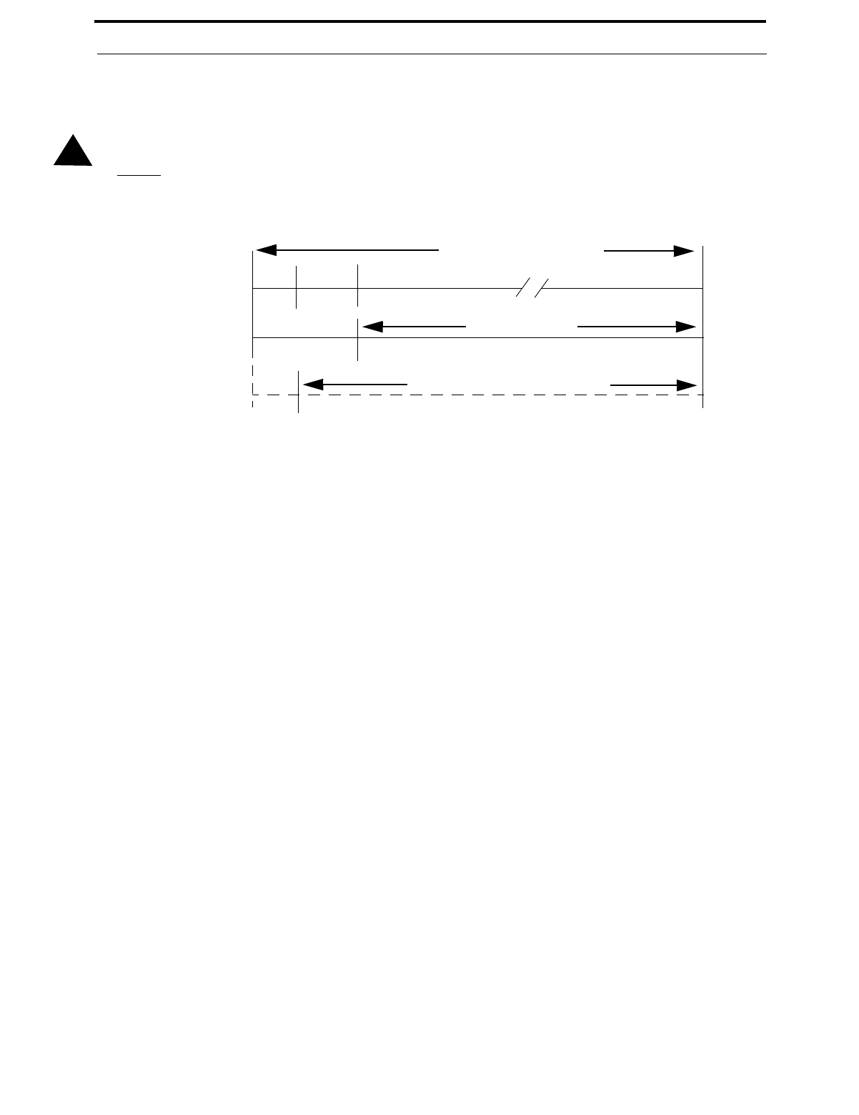
Document #50193 Rev. D 5/2/97 P/N 50193:D
45
Program Options
and a 12 second retard period allows detectors to stabilize. During the retard/reset period of 18 seconds, subse-
quent alarms by the same initiating zone are ignored. An alarm detected on any other 2-wire detector zone during
the retard period will cause immediate verified alarms. A subsequent alarm on the initiating zone occurring within
the confirmation time will cause a verified alarm.
CAUTION: Mixing devices on zones designated as 2-wire smoke zones is not recommended. The communicator
will not transmit a signal to the central station signifying that alarm verification is in progress.
Note that during the alarm verification period, access to other modes of operation is prevented.
Factory default selection is no verification which is '0'. Entering a '1' enables verification. Consult the Local
Authority Having Jurisdiction (LAHJ) prior to altering this address.
AC Loss Reporting Delay (77)
Enter a digit of 0 - 9 or A - F corresponding to the number of hours to be delayed in reporting the loss of AC
power. Factory default is 6 hour delay. The valid entries are '0' = 6 hours, '1' = 7 hours, '2' = 8 hours, '3' = 9 hours,
'4' = 10 hours, '5' = 11 hours, '6' = 12 hours, '7' = 15 hours, '8' = 16 hours, '9' = 17 hours, 'A' = 18 hours, 'B' = 19
hours, 'C' = 20 hours, 'D' = 21 hours, 'E' = 22 hours, 'F' = 23 hours.
Programmable Relay #1 (78)
Relay #1 on TB3 of the MS-5210UD main circuit board can be programmed to activate for any one of seven FACP
conditions. The factory default for address 78 is '0' for activation on alarm. Program a '1' for supervisory, '2' for
supervisory autoresettable, '3' for trouble, '4' for communication fail, '5' for process monitoring or '6' for process
monitoring autoresettable.
Programmable Relay #2 (79)
Relay #2 on TB3 of the MS-5210UD main circuit board can be programmed to activate for any one of seven FACP
conditions. The factory default for address 79 is '3' for activation on trouble. Program a '0' for alarm, '1' for super-
visory, '2' for supervisory autoresettable, '4' for communication fail, '5' for process monitoring or '6' for process
monitoring autoresettable.
Notification Appliance Circuit #1 Enable (80)
Notification Appliance Circuit #1 may be programmed as '0' for silenceable, '1' for nonsilenceable or '2' for dis-
abled. Factory default is '0' for silenceable. Note: Consult the Local Authority Having Jurisdiction (LAHJ) prior
to altering this address.
Silence Inhibit Notification Appliance Circuit #1 (81)
Setting address 81 to '1' prohibits silencing of Notification Appliance Circuit #1 for one minute after initiation of
an alarm. Factory default is '0' for no silence inhibit of Notification Appliance Circuit #1.
Autosilence Notification Appliance Circuit #1 (82)
Notification Appliance Circuit #1 may be autosilenced after a programmed time interval between 5 and 30 min-
utes. Enter '1' for 5 minute autosilence; '2' for 10 minute autosilence; '3' for 15 minute autosilence; '4' for 20
minute autosilence; '5' for 25 minute autosilence; or '6' for 30 minute autosilence. The factory default is '0' for no
autosilence.
!
FIGURE 3-2:Verification Timing Diagram
ALARM VERIFICATION PERIOD
RESET RETARD
6 Sec. 18 Sec.0 Sec.
Detector Alarm Verification
Detector Zone goes into Alarm
Different Detector Zone Alarms
Alarm Ignored Control Panel Processes Alarm if Same Detector Zone is Still in Alarm
120 Sec.
120906030
0
Control Panel Immediately Processes Alarm
CONFIRMATION TIME

Program Options
46
Document #50193 Rev.D 5/2/97 P/N 50193:D
Coding of Notification Appliance Circuit #1 (83)
Coding of Notification Appliance Circuit #1 is selectable for the following: '1' for March Time (120ppm); '2' for
California (10 seconds On, 5 seconds Off); or '3' for Temporal (½ second On, ½ second Off, ½ second On, ½ sec-
ond Off, ½ second On, 1½ seconds Off and then repeat). Factory default is '0' for steady (no coding).
Notification Appliance Circuit #2 Enable (84)
Notification Appliance Circuit #2 may be programmed as '0' for silenceable, '1' for nonsilenceable or '2' for dis-
abled. Factory default is '0' for silenceable. Note: Consult the Local Authority Having Jurisdiction (LAHJ) prior
to altering this address.
Silence Inhibit Notification Appliance Circuit #2 (85)
Setting address 85 to '1' prohibits silencing of Notification Appliance Circuit #2 for one minute after initiation of
an alarm. Factory default is '0' for no silence inhibit of Notification Appliance Circuit #2.
Autosilence Notification Appliance Circuit #2 (86)
Notification Appliance Circuit #2 may be autosilenced after a programmed time interval between 5 and 30 min-
utes. Enter '1' for 5 minute autosilence; '2' for 10 minute autosilence; '3' for 15 minute autosilence; '4' for 20
minute autosilence; '5' for 25 minute autosilence; or '6' for 30 minute autosilence. The factory default is '0' for no
autosilence.
Coding of Notification Appliance Circuit #2 (87)
Coding of Notification Appliance Circuit #2 is selectable for the following: '1' for March Time (120ppm); '2' for
California (10 seconds On, 5 seconds Off); or '3' for Temporal (½ second On, ½ second Off, ½ second On, ½ sec-
ond Off, ½ second On, 1½ seconds Off and then repeat). Factory default is '0' for steady (no coding).
Trouble Reminder (88)
Factory default '0' disables the trouble reminder feature. Selecting '1' will cause a reminding beep (after the
Silence or Acknowledge switch is pressed) every 15 seconds during an alarm and beep every two minutes during
a trouble condition. The beeps from the onboard piezo sounder will occur until the alarm or fault is cleared.
Programming the Real-Time Clock and Calendar (89-999)
Entering an address greater than 88 will cause a display of the current time. On initial power-up, the clock will
start running from the factory setting of 00:01 (military time). The far left digit will be flashing, indicating that
this is the first digit to be programmed.
Note that the software for the MS-5210UD operates the internal clock based upon 60 Hz. The software for the
MS-5210UDE operates the internal clock based upon 50 Hz.
•Programming Hours and Minutes - To program the first hour digit, press the corresponding number on the
keypad and then press [ENTER/STORE]. For example, to program 08:00 AM, press '0' on the keypad and
then [ENTER/STORE]. The digit 2nd from the left will start flashing. Enter the second hour digit and press
[ENTER/STORE]. In the previous example, the number '8' would be pressed on the keypad followed by the
[ENTER/STORE] key. This completes the Hours setting. The digit 2nd from the right should now be flash-
ing on the display. Select the first digit for the minutes by pressing the corresponding number on the keypad
and then the [ENTER/STORE] key. The digit on the far right of the display will now be flashing. Select the
second digit for the minutes by pressing the corresponding number on the keypad and then the [ENTER/
STORE] key. The Minutes setting is now complete. If during programming of the time an invalid digit is
selected (i.e. 3 or higher for the first digit) the FACP piezo sounder will beep and the digit will continue to
blink until a valid entry is made.
•Programming Year - After entering the last digit corresponding to minutes (far right digit), the display will
read 1996 with the digit '9', second from the right, flashing. Press [ENTER/STORE] if acceptable. To change
the year, enter a digit. Entering a zero '0' will change the display to the year 2000. Press the [ENTER/
STORE] key. Repeat for the digit to the far right.

Document #50193 Rev. D 5/2/97 P/N 50193:D
47
Program Options
•Programming Month/Day - After the year is entered, the display will show four digits representing the month
and day of the software release date. The month is represented by the two digits on the left and the day by the
two digits on the right. The digit on the far left will be flashing. The month and day are set the same way as
the hours and minutes. Once the last digit corresponding to the day is entered, the display will show the con-
tents of address '00'. The real time clock/calendar keeps track of leap years automatically.
End Programming/Exit to Alternate Program Level
Exit Programming Mode by pressing MODE, followed by the 4-digit code corresponding to an alternate mode of
operation, then press [ENTER/STORE]. To enter a different Programming Level, press MODE and then press
the [ENTER/STORE] key. The display will show P__1 with the '1' flashing. Press the digit (2, 3 or 4) of the Pro-
gramming Level to be accessed.
During Program Mode, if no key is pressed within 10 minutes, the panel will revert to Normal Mode.
3.3.2 Level Two - Event Codes/Transmission Formats
Each option of the Program Mode is entered by keying in the program mode entry code (7764) and pressing the
[ENTER/STORE] key.
☛ 7764 spells PROG on a Touch-Tone® phone
If an incorrect key is entered, reenter the proper 4-digit code before pressing the [ENTER/STORE] key.
Your are allowed a pause of up to 10 seconds in between each number while entering the code. After pressing the
[ENTER/STORE] key, the control panel will be in Program Mode and display P__1, with the '1' flashing. Press 2 on
the keypad and then the [ENTER/STORE] key to select the Event Code/Transmission Formats Level for program-
ming. You are allowed up to ten minutes of idle time at this point before starting your programming, otherwise, the
control panel will go back to Normal Mode. You also have a maximum of 10 minutes between any key stroke. All
entries made prior to the 10 minutes time-out are valid and are stored.
Upon entering the Event Codes/Transmission Formats Level in programming mode, the following will be displayed
on the FACP 7-Segment Display.
The first three locations on the left of the display represent the memory address 00 of the Format Chart previously
selected in address 16 of the Main Panel Options section of programming mode. The last location 1 (farthest right)
represents the contents of memory address 00 which is the format setting. The only value which can be altered in the
Format Charts is the setting which is the last digit to the right. To change the value, key in the new digit. Use the Up
and Down Arrow keys to increment to the next address or decrement to the previous address.
When desired changes have been completed, exit programming mode by pressing the MODE key, followed by the
4-digit code for an alternate mode and then the [ENTER/STORE] key. To enter a different Programming Level,
press MODE and then press the [ENTER/STORE] key. The display will show P__2 with the '2' flashing. Press the
digit (1, 3 or 4) of the Programming Level to be accessed. During Program Mode, if no key is pressed within 10 min-
utes, the panel will revert to Normal Mode.
The Format Charts which may be selected in the Main Panel Options (Level 1) section of the Programming Mode are
shown on the following pages of this section. Format charts for the Primary and Secondary Central Station Numbers
are included.
00_1
(address)(data)

Program Options
48
Document #50193 Rev.D 5/2/97 P/N 50193:D
3+1, 4+1 Express, 4+1 Standard and Expanded, 4+2 Expanded Formats
If '0, 2, 3, 4, 5, 6, 7, 8, 9, B or D' are entered for address 16 in Program Mode Level 1, the data shown in Table 3-
3 is automatically programmed for the Primary Central Station phone number event codes. Enter '0' for the set-
ting to disable the report.
TABLE 3-3: Event Codes, Primary Central Station Number
Address Description Setting
0 Primary # Zone 1 Alarm Code 11
1 Primary # Zone 2 Alarm Code 11
2 Primary # Zone 3 Alarm Code 11
3 Primary # Zone 4 Alarm Code 11
4 Primary # Zone 5 Alarm Code 11
5 Primary # Zone 6 Alarm Code 11
6 Primary # Zone 7 Alarm Code 11
7 Primary # Zone 8 Alarm Code 11
8 Primary # Zone 9 Alarm Code 11
9 Primary # Zone 10 Alarm Code 11
10 Primary # Zone 1 Disabled Code 4
11 Primary # Zone 2 Disabled Code 4
12 Primary # Zone 3 Disabled Code 4
13 Primary # Zone 4 Disabled Code 4
14 Primary # Zone 5 Disabled Code 4
15 Primary # Zone 6 Disabled Code 4
16 Primary # Zone 7 Disabled Code 4
17 Primary # Zone 8 Disabled Code 4
18 Primary # Zone 9 Disabled Code 4
19 Primary # Zone 10 Disabled Code 4
20 Primary # Drill Code 9
21 Primary # AC Fault Code 9
22 Primary # Zone 1 Fault Code F
23 Primary # Zone 2 Fault Code F
24 Primary # Zone 3 Fault Code F
25 Primary # Zone 4 Fault Code F
26 Primary # Zone 5 Fault Code F
27 Primary # Zone 6 Fault Code F
28 Primary # Zone 7 Fault Code F
29 Primary # Zone 8 Fault Code F
30 Primary # Zone 9 Fault Code F
31 Primary # Zone 10 Fault Code F
32 Primary # Earth Fault Code 6
33 Primary # Low Battery Fault Code 6
34 Primary # No Battery Fault Code 6
35 Primary # Telco Primary Line Fault Code 6
36 Primary # Telco Secondary Line Fault Code 6

Document #50193 Rev. D 5/2/97 P/N 50193:D
49
Program Options
37 Primary # NAC #1 Fault Code 6
38 Primary # NAC #2 Fault Code 6
39 Primary # NAC #3 Fault Code 6
40 Primary # NAC #4 Fault Code 6
41 Primary # NAC #1 Disable Code 4
42 Primary # NAC #2 Disable Code 4
43 Primary # NAC #3 Disable Code 4
44 Primary # NAC #4 Disable Code 4
45 Primary # Comm Trouble Primary # Code 6
46 Primary # Comm Trouble Secondary # Code 6
47 Primary # Printer Fault Code 6
48 Primary # Annunciator Fault Code 6
49 Primary # 485 Comm Trouble Code 6
50 Primary # System Off Normal Code 6
51 Primary # Zone 1 Alarm Restore Code E
52 Primary # Zone 2 Alarm Restore Code E
53 Primary # Zone 3 Alarm Restore Code E
54 Primary # Zone 4 Alarm Restore Code E
55 Primary # Zone 5 Alarm Restore Code E
56 Primary # Zone 6 Alarm Restore Code E
57 Primary # Zone 7 Alarm Restore Code E
58 Primary # Zone 8 Alarm Restore Code E
59 Primary # Zone 9 Alarm Restore Code E
60 Primary # Zone 10 Alarm Restore Code E
61 Primary # Zone 1 Disabled Restore Code 5
62 Primary # Zone 2 Disabled Restore Code 5
63 Primary # Zone 3 Disabled Restore Code 5
64 Primary # Zone 4 Disabled Restore Code 5
65 Primary # Zone 5 Disabled Restore Code 5
66 Primary # Zone 6 Disabled Restore Code 5
67 Primary # Zone 7 Disabled Restore Code 5
68 Primary # Zone 8 Disabled Restore Code 5
69 Primary # Zone 9 Disabled Restore Code 5
70 Primary # Zone 10 Disabled Restore Code 5
71 Primary # Drill Restore Code 9
72 Primary # AC Fault Restore Code 9
73 Primary # Zone 1 Fault Restore Code D
74 Primary # Zone 2 Fault Restore Code D
75 Primary # Zone 3 Fault Restore Code D
76 Primary # Zone 4 Fault Restore Code D
77 Primary # Zone 5 Fault Restore Code D
78 Primary # Zone 6 Fault Restore Code D
79 Primary # Zone 7 Fault Restore Code D
TABLE 3-3: Event Codes, Primary Central Station Number
Address Description Setting

Program Options
50
Document #50193 Rev.D 5/2/97 P/N 50193:D
4+2 Standard and 4+2 Express Formats
If '1, A or C' are entered for address 16 in Program Mode Level 1, the data shown in Table 3-4 is automatically
programmed for the Primary Central Station phone number event codes. Enter '00' for the setting to disable the
report.
1. Zones programmed as supervisory alarm transmit as Code 8 instead of Code 1.
80 Primary # Zone 8 Fault Restore Code D
81 Primary # Zone 9 Fault Restore Code D
82 Primary # Zone 10 Fault Restore Code D
83 Primary # Earth Fault Restore Code A
84 Primary #Low Battery Fault Restore Code A
85 Primary # No Battery Fault Restore Code A
86 Primary # Telco Primary Line Fault Restore Code A
87 Primary # Telco Secondary Line Fault Restore Code A
88 Primary # NAC #1 Fault Restore Code A
89 Primary # NAC #2 Fault Restore Code A
90 Primary # NAC #3 Fault Restore Code A
91 Primary # NAC #4 Fault Restore Code A
92 Primary # NAC #1 Disable Restore Code 5
93 Primary # NAC #2 Disable Restore Code 5
94 Primary # NAC #3 Disable Restore Code 5
95 Primary # NAC #4 Disable Restore Code 5
96 Primary # Comm Trouble Primary # Restore Code A
97 Primary # Comm Trouble Secondary # Restore Code A
98 Primary # Printer Fault Restore Code A
99 Primary # Annunciator Fault Restore Code A
100 Primary # 485 Comm Trouble Restore Code A
101 Primary # System Off Normal Restore Code A
102 Primary # System Test Report 9
103 Primary # System Abnormal Test Report F
104 Primary # Request for Up/Download 7
105 Primary # Successful Upload 7
106 Primary # Successful Download 7
107 Primary # Failed Up/Download 7
TABLE 3-4: Event Codes, Primary Central Station Number
Address Description Setting
0-1 Primary # Zone 1 Alarm Code 111
2-3 Primary # Zone 2 Alarm Code 121
4-5 Primary # Zone 3 Alarm Code 131
6-7 Primary # Zone 4 Alarm Code 141
8-9 Primary # Zone 5 Alarm Code 151
TABLE 3-3: Event Codes, Primary Central Station Number
Address Description Setting

Document #50193 Rev. D 5/2/97 P/N 50193:D
51
Program Options
10-11 Primary # Zone 6 Alarm Code 161
12-13 Primary # Zone 7 Alarm Code 171
14-15 Primary # Zone 8 Alarm Code 181
16-17 Primary # Zone 9 Alarm Code 191
18-19 Primary # Zone 10 Alarm Code 1A1
20-21 Primary # Zone 1 Disabled Code 41
22-23 Primary # Zone 2 Disabled Code 42
24-25 Primary # Zone 3 Disabled Code 43
26-27 Primary # Zone 4 Disabled Code 44
28-29 Primary # Zone 5 Disabled Code 45
30-31 Primary # Zone 6 Disabled Code 46
32-33 Primary # Zone 7 Disabled Code 47
34-35 Primary # Zone 8 Disabled Code 48
36-37 Primary # Zone 9 Disabled Code 49
38-39 Primary # Zone 10 Disabled Code 4A
40-41 Primary # Drill Code 97
42-43 Primary # AC Fault Code 92
44-45 Primary # Zone 1 Fault Code F1
46-47 Primary # Zone 2 Fault Code F2
48-49 Primary # Zone 3 Fault Code F3
50-51 Primary # Zone 4 Fault Code F4
52-53 Primary # Zone 5 Fault Code F5
54-55 Primary # Zone 6 Fault Code F6
56-57 Primary # Zone 7 Fault Code F7
58-59 Primary # Zone 8 Fault Code F8
60-61 Primary # Zone 9 Fault Code F9
62-63 Primary # Zone 10 Fault Code FA
64-65 Primary # Earth Fault Code 61
66-67 Primary # Low Battery Fault Code 62
68-69 Primary # No Battery Fault Code 63
70-71 Primary # Telco Primary Line Fault Code 64
72-73 Primary # Telco Secondary Line Fault Code 65
74-75 Primary # NAC #1 Fault Code 66
76-77 Primary # NAC #2 Fault Code 67
78-79 Primary # NAC #3 Fault Code 68
80-81 Primary # NAC #4 Fault Code 69
82-83 Primary # NAC #1 Disable Code 4B
84-85 Primary # NAC #2 Disable Code 4C
86-87 Primary # NAC #3 Disable Code 4D
88-89 Primary # NAC #4 Disable Code 4E
90-91 Primary # Comm Trouble Primary # Code 6A
92-93 Primary # Comm Trouble Secondary # Code 6B
94-95 Primary # Printer Fault Code 6C
TABLE 3-4: Event Codes, Primary Central Station Number
Address Description Setting

Program Options
52
Document #50193 Rev.D 5/2/97 P/N 50193:D
96-97 Primary # Annunciator Fault Code 6D
98-99 Primary # 485 Comm Trouble Code 6E
100-101 Primary # System Off Normal Code 6F
102-103 Primary # Zone 1 Alarm Restore Code E1
104-105 Primary # Zone 2 Alarm Restore Code E2
106-107 Primary # Zone 3 Alarm Restore Code E3
108-109 Primary # Zone 4 Alarm Restore Code E4
110-111 Primary # Zone 5 Alarm Restore Code E5
112-113 Primary # Zone 6 Alarm Restore Code E6
114-115 Primary # Zone 7 Alarm Restore Code E7
116-117 Primary # Zone 8 Alarm Restore Code E8
118-119 Primary # Zone 9 Alarm Restore Code E9
120-121 Primary # Zone 10 Alarm Restore Code EA
122-123 Primary # Zone 1 Disabled Restore Code 51
124-125 Primary # Zone 2 Disabled Restore Code 52
126-127 Primary # Zone 3 Disabled Restore Code 53
128-129 Primary # Zone 4 Disabled Restore Code 54
130-131 Primary # Zone 5 Disabled Restore Code 55
132-133 Primary # Zone 6 Disabled Restore Code 56
134-135 Primary # Zone 7 Disabled Restore Code 57
136-137 Primary # Zone 8 Disabled Restore Code 58
138-139 Primary # Zone 9 Disabled Restore Code 59
140-141 Primary # Zone 10 Disabled Restore Code 5A
142-143 Primary # Drill Restore Code 98
144-145 Primary # AC Fault Restore Code 93
146-147 Primary # Zone 1 Fault Restore Code D1
148-149 Primary # Zone 2 Fault Restore Code D2
150-151 Primary # Zone 3 Fault Restore Code D3
152-153 Primary # Zone 4 Fault Restore Code D4
154-155 Primary # Zone 5 Fault Restore Code D5
156-157 Primary # Zone 6 Fault Restore Code D6
158-159 Primary # Zone 7 Fault Restore Code D7
160-161 Primary # Zone 8 Fault Restore Code D8
162-163 Primary # Zone 9 Fault Restore Code D9
164-165 Primary # Zone 10 Fault Restore Code DA
166-167 Primary # Earth Fault Restore Code A1
168-169 Primary #Low Battery Fault Restore Code A2
170-171 Primary # No Battery Fault Restore Code A3
172-173 Primary # Telco Primary Line Fault Restore Code A4
174-175 Primary # Telco Secondary Line Fault Restore Code A5
176-177 Primary # NAC #1 Fault Restore Code A6
178-179 Primary # NAC #2 Fault Restore Code A7
180-181 Primary # NAC #3 Fault Restore Code A8
TABLE 3-4: Event Codes, Primary Central Station Number
Address Description Setting

Document #50193 Rev. D 5/2/97 P/N 50193:D
53
Program Options
Ademco Contact ID Format
If 'E' is entered for address 16 in Program Mode Level 1, the data shown in Table 3-5 is automatically pro-
grammed for the Primary Central Station phone number event codes. Enter '000' for the setting to disable the
report. The Setting entry is programmable, the Zone Number cannot be changed. Restoral code settings match the
settings shown with the addition of an 'R' code transmitted. Refer to page 111 for additional information.
1. Zones programmed as supervisory alarm transmit as 81, 82, 83, 84, 85, 86, 87, 88, 89, 8A
(instead of 11, 12, 13, 14, 15, 16, 17, 18, 19, 1A).
182-183 Primary # NAC #4 Fault Restore Code A9
184-185 Primary # NAC #1 Disable Restore Code 5B
186-187 Primary # NAC #2 Disable Restore Code 5C
188-189 Primary # NAC #3 Disable Restore Code 5D
190-191 Primary # NAC #4 Disable Restore Code 5E
192-193 Primary # Comm Trouble Primary # Restore Code AA
194-195 Primary # Comm Trouble Secondary # Restore Code AB
196-197 Primary # Printer Fault Restore Code AC
198-199 Primary # Annunciator Fault Restore Code AD
200-201 Primary # 485 Comm Trouble Restore Code AE
201-203 Primary # System Off Normal Restore Code AF
204-205 Primary # System Test Report 99
206-207 Primary # System Abnormal Test Report 91
208-209 Primary # Request for Up/Download 71
210-211 Primary # Successful Upload 72
212-213 Primary # Successful Download 73
214-215 Primary # Failed Up/Download 74
TABLE 3-5: Event Codes, Primary Central Station Number
Address Description Setting Zone No.
0-2 Primary # Zone 1 Alarm Code 1111001
3-5 Primary # Zone 2 Alarm Code 1111002
6-8 Primary # Zone 3 Alarm Code 1111003
9-11 Primary # Zone 4 Alarm Code 1111004
12-14 Primary # Zone 5 Alarm Code 1111005
15-17 Primary # Zone 6 Alarm Code 1111006
18-20 Primary # Zone 7 Alarm Code 1111007
21-23 Primary # Zone 8 Alarm Code 1111008
24-26 Primary # Zone 9 Alarm Code 1111009
27-29 Primary # Zone 10 Alarm Code 1111010
30-32 Primary # Zone 1 Disabled Code 570 001
33-35 Primary # Zone 2 Disabled Code 570 002
36-38 Primary # Zone 3 Disabled Code 570 003
39-41 Primary # Zone 4 Disabled Code 570 004
42-44 Primary # Zone 5 Disabled Code 570 005
TABLE 3-4: Event Codes, Primary Central Station Number
Address Description Setting

Program Options
54
Document #50193 Rev.D 5/2/97 P/N 50193:D
1. Refer to Table 3-1 for list of zone alarm event codes.
45-47 Primary # Zone 6 Disabled Code 570 006
48-50 Primary # Zone 7 Disabled Code 570 007
51-53 Primary # Zone 8 Disabled Code 570 008
54-56 Primary # Zone 9 Disabled Code 570 009
57-59 Primary # Zone 10 Disabled Code 570 010
60-62 Primary # Drill Code 604 000
63-65 Primary # AC Fault Code 301 000
66-68 Primary # Zone 1 Fault Code 380 001
69-71 Primary # Zone 2 Fault Code 380 002
72-74 Primary # Zone 3 Fault Code 380 003
75-77 Primary # Zone 4 Fault Code 380 004
78-80 Primary # Zone 5 Fault Code 380 005
81-83 Primary # Zone 6 Fault Code 380 006
84-86 Primary # Zone 7 Fault Code 380 007
87-89 Primary # Zone 8 Fault Code 380 008
90-92 Primary # Zone 9 Fault Code 380 009
93-95 Primary # Zone 10 Fault Code 380 010
96-98 Primary # Earth Fault Code 310 000
99-101 Primary # Low Battery Fault Code 302 000
102-104 Primary # No Battery Fault Code 311 000
105-107 Primary # Telco Primary Line Fault Code 351 000
108-110 Primary # Telco Secondary Line Fault Code 352 000
111-113 Primary # NAC #1 Fault Code 321 001
114-116 Primary # NAC #2 Fault Code 322 002
117-119 Primary # NAC #3 Fault Code 326 003
120-122 Primary # NAC #4 Fault Code 327 004
123-125 Primary # NAC #1 Disable Code 521 001
126-128 Primary # NAC #2 Disable Code 522 002
129-131 Primary # NAC #3 Disable Code 526 003
132-134 Primary # NAC #4 Disable Code 527 004
135-137 Primary # Comm Trouble Primary # Code 354 001
138-140 Primary # Comm Trouble Secondary # Code 354 002
141-143 Primary # Printer Fault Code 336 000
144-146 Primary # Annunciator Fault Code 330 001
147-149 Primary # 485 Comm Trouble Code 330 002
150-152 Primary # System Off Normal Code 308 000
153-155 Primary # System Test Message 602 000
156-158 Primary # System Abnormal Test Message 608 000
159-161 Primary # Upload/Download Request Code 411 000
162-164 Primary # Upload Successful Code 416 000
165-167 Primary # Download Successful Code 412 000
168-170 Primary # Upload/Download Failed Code 413 000
TABLE 3-5: Event Codes, Primary Central Station Number
Address Description Setting Zone No.

Document #50193 Rev. D 5/2/97 P/N 50193:D
55
Program Options
3+1, 4+1 Express, 4+1 Standard and Expanded, 4+2 Expanded Formats
If '0, 2, 3, 4, 5, 6, 7, 8, 9, B or D' are entered for address 42 in Program Mode Level 1, the data shown in Table 3-6
is automatically programmed for the Secondary Central Station phone number event codes. Enter '0' for the set-
ting to disable the report.
TABLE 3-6: Event Codes, Secondary Central Station Number
Address Description Setting
216 Secondary # Zone 1 Alarm Code 11
217 Secondary # Zone 2 Alarm Code 11
218 Secondary # Zone 3 Alarm Code 11
219 Secondary # Zone 4 Alarm Code 11
220 Secondary # Zone 5 Alarm Code 11
221 Secondary # Zone 6 Alarm Code 11
222 Secondary # Zone 7 Alarm Code 11
223 Secondary # Zone 8 Alarm Code 11
224 Secondary # Zone 9 Alarm Code 11
225 Secondary # Zone 10 Alarm Code 11
226 Secondary # Zone 1 Disabled Code 4
227 Secondary # Zone 2 Disabled Code 4
228 Secondary # Zone 3 Disabled Code 4
229 Secondary # Zone 4 Disabled Code 4
230 Secondary # Zone 5 Disabled Code 4
231 Secondary # Zone 6 Disabled Code 4
232 Secondary # Zone 7 Disabled Code 4
233 Secondary # Zone 8 Disabled Code 4
234 Secondary # Zone 9 Disabled Code 4
235 Secondary # Zone 10 Disabled Code 4
236 Secondary # Drill Code 9
237 Secondary # AC Fault Code 9
238 Secondary # Zone 1 Fault Code F
239 Secondary # Zone 2 Fault Code F
240 Secondary # Zone 3 Fault Code F
241 Secondary # Zone 4 Fault Code F
242 Secondary # Zone 5 Fault Code F
243 Secondary # Zone 6 Fault Code F
244 Secondary # Zone 7 Fault Code F
245 Secondary # Zone 8 Fault Code F
246 Secondary # Zone 9 Fault Code F
247 Secondary # Zone 10 Fault Code F
248 Secondary # Earth Fault Code 6
249 Secondary # Low Battery Fault Code 6
250 Secondary # No Battery Fault Code 6
251 Secondary # Telco Primary Line Fault Code 6
252 Secondary # Telco Secondary Line Fault Code 6
253 Secondary # NAC #1 Fault Code 6

Program Options
56
Document #50193 Rev.D 5/2/97 P/N 50193:D
254 Secondary # NAC #2 Fault Code 6
255 Secondary # NAC #3 Fault Code 6
256 Secondary # NAC #4 Fault Code 6
257 Secondary # NAC #1 Disable Code 4
258 Secondary # NAC #2 Disable Code 4
259 Secondary # NAC #3 Disable Code 4
260 Secondary # NAC #4 Disable Code 4
261 Secondary # Comm Trouble Primary # Code 6
262 Secondary # Comm Trouble Secondary # Code 6
263 Secondary # Printer Fault Code 6
264 Secondary # Annunciator Fault Code 6
265 Secondary # 485 Comm Trouble Code 6
266 Secondary # System Off Normal Code 6
267 Secondary # Zone 1 Alarm Restore Code E
268 Secondary # Zone 2 Alarm Restore Code E
269 Secondary # Zone 3 Alarm Restore Code E
270 Secondary # Zone 4 Alarm Restore Code E
271 Secondary # Zone 5 Alarm Restore Code E
272 Secondary # Zone 6 Alarm Restore Code E
273 Secondary # Zone 7 Alarm Restore Code E
274 Secondary # Zone 8 Alarm Restore Code E
275 Secondary # Zone 9 Alarm Restore Code E
276 Secondary # Zone 10 Alarm Restore Code E
277 Secondary # Zone 1 Disabled Restore Code 5
278 Secondary # Zone 2 Disabled Restore Code 5
279 Secondary # Zone 3 Disabled Restore Code 5
280 Secondary # Zone 4 Disabled Restore Code 5
281 Secondary # Zone 5 Disabled Restore Code 5
282 Secondary # Zone 6 Disabled Restore Code 5
283 Secondary # Zone 7 Disabled Restore Code 5
284 Secondary # Zone 8 Disabled Restore Code 5
285 Secondary # Zone 9 Disabled Restore Code 5
286 Secondary # Zone 10 Disabled Restore Code 5
287 Secondary # Drill Restore Code 9
288 Secondary # AC Fault Restore Code 9
289 Secondary # Zone 1 Fault Restore Code D
290 Secondary # Zone 2 Fault Restore Code D
291 Secondary # Zone 3 Fault Restore Code D
292 Secondary # Zone 4 Fault Restore Code D
293 Secondary # Zone 5 Fault Restore Code D
294 Secondary # Zone 6 Fault Restore Code D
295 Secondary # Zone 7 Fault Restore Code D
296 Secondary # Zone 8 Fault Restore Code D
TABLE 3-6: Event Codes, Secondary Central Station Number
Address Description Setting

Document #50193 Rev. D 5/2/97 P/N 50193:D
57
Program Options
4+2 Standard and 4+2 Express Formats
If '1, A or C' are entered for address 42 in Program Mode Level 1, the data shown in Table 3-7 is automatically
programmed for the Secondary Central Station phone number event codes. Enter '00' for the setting to disable the
report.
1. Zones programmed as supervisory alarm transmit as Code 8 instead of Code 1.
297 Secondary # Zone 9 Fault Restore Code D
298 Secondary # Zone 10 Fault Restore Code D
299 Secondary # Earth Fault Restore Code A
300 Secondary #Low Battery Fault Restore Code A
301 Secondary # No Battery Fault Restore Code A
302 Secondary # Telco Primary Line Fault Restore Code A
303 Secondary # Telco Secondary Line Fault Restore Code A
304 Secondary # NAC #1 Fault Restore Code A
305 Secondary # NAC #2 Fault Restore Code A
306 Secondary # NAC #3 Fault Restore Code A
307 Secondary # NAC #4 Fault Restore Code A
308 Secondary # NAC #1 Disable Restore Code 5
309 Secondary # NAC #2 Disable Restore Code 5
310 Secondary # NAC #3 Disable Restore Code 5
311 Secondary # NAC #4 Disable Restore Code 5
312 Secondary # Comm Trouble Primary # Restore Code A
313 Secondary # Comm Trouble Secondary # Restore Code A
314 Secondary # Printer Fault Restore Code A
315 Secondary # Annunciator Fault Restore Code A
316 Secondary # 485 Comm Trouble Restore Code A
317 Secondary # System Off Normal Restore Code A
318 Secondary # System Test Report 9
319 Secondary # System Abnormal Test Report F
320 Secondary # Request for Up/Download 7
321 Secondary # Successful Upload 7
322 Secondary # Successful Download 7
323 Secondary # Failed Up/Download 7
TABLE 3-7: Event Codes, Secondary Central Station Number
Address Description Setting
216-217 Secondary # Zone 1 Alarm Code 111
218-219 Secondary # Zone 2 Alarm Code 121
220-221 Secondary # Zone 3 Alarm Code 131
222-223 Secondary # Zone 4 Alarm Code 141
224-225 Secondary # Zone 5 Alarm Code 151
226-227 Secondary # Zone 6 Alarm Code 161
TABLE 3-6: Event Codes, Secondary Central Station Number
Address Description Setting

Program Options
58
Document #50193 Rev.D 5/2/97 P/N 50193:D
228-229 Secondary # Zone 7 Alarm Code 171
230-231 Secondary # Zone 8 Alarm Code 181
232-233 Secondary # Zone 9 Alarm Code 191
234-235 Secondary # Zone 10 Alarm Code 1A1
236-237 Secondary # Zone 1 Disabled Code 41
238-239 Secondary # Zone 2 Disabled Code 42
240-241 Secondary # Zone 3 Disabled Code 43
242-243 Secondary # Zone 4 Disabled Code 44
244-245 Secondary # Zone 5 Disabled Code 45
246-247 Secondary # Zone 6 Disabled Code 46
248-249 Secondary # Zone 7 Disabled Code 47
250-251 Secondary # Zone 8 Disabled Code 48
252-253 Secondary # Zone 9 Disabled Code 49
254-255 Secondary # Zone 10 Disabled Code 4A
256-257 Secondary # Drill Code 97
258-259 Secondary # AC Fault Code 92
260-261 Secondary # Zone 1 Fault Code F1
262-263 Secondary # Zone 2 Fault Code F2
264-265 Secondary # Zone 3 Fault Code F3
266-267 Secondary # Zone 4 Fault Code F4
268-269 Secondary # Zone 5 Fault Code F5
270-271 Secondary # Zone 6 Fault Code F6
272-273 Secondary # Zone 7 Fault Code F7
274-275 Secondary # Zone 8 Fault Code F8
276-277 Secondary # Zone 9 Fault Code F9
278-279 Secondary # Zone 10 Fault Code FA
280-281 Secondary # Earth Fault Code 61
282-283 Secondary # Low Battery Fault Code 62
284-285 Secondary # No Battery Fault Code 63
286-287 Secondary # Telco Primary Line Fault Code 64
288-289 Secondary # Telco Secondary Line Fault Code 65
290-291 Secondary # NAC #1 Fault Code 66
292-293 Secondary # NAC #2 Fault Code 67
294-295 Secondary # NAC #3 Fault Code 68
296-297 Secondary # NAC #4 Fault Code 69
298-299 Secondary # NAC #1 Disable Code 4B
300-301 Secondary # NAC #2 Disable Code 4C
302-303 Secondary # NAC #3 Disable Code 4D
304-305 Secondary # NAC #4 Disable Code 4E
306-307 Secondary # Comm Trouble Primary # Code 6A
308-309 Secondary # Comm Trouble Secondary # Code 6B
310-311 Secondary # Printer Fault Code 6C
TABLE 3-7: Event Codes, Secondary Central Station Number
Address Description Setting

Document #50193 Rev. D 5/2/97 P/N 50193:D
59
Program Options
312-313 Secondary # Annunciator Fault Code 6D
314-315 Secondary # 485 Comm Trouble Code 6E
316-317 Secondary # System Off Normal Code 6F
318-319 Secondary # Zone 1 Alarm Restore Code E1
320-321 Secondary # Zone 2 Alarm Restore Code E2
322-323 Secondary # Zone 3 Alarm Restore Code E3
324-325 Secondary # Zone 4 Alarm Restore Code E4
326-327 Secondary # Zone 5 Alarm Restore Code E5
328-329 Secondary # Zone 6 Alarm Restore Code E6
330-331 Secondary # Zone 7 Alarm Restore Code E7
332-333 Secondary # Zone 8 Alarm Restore Code E8
334-335 Secondary # Zone 9 Alarm Restore Code E9
336-337 Secondary # Zone 10 Alarm Restore Code EA
338-339 Secondary # Zone 1 Disabled Restore Code 51
340-341 Secondary # Zone 2 Disabled Restore Code 52
342-343 Secondary # Zone 3 Disabled Restore Code 53
344-345 Secondary # Zone 4 Disabled Restore Code 54
346-347 Secondary # Zone 5 Disabled Restore Code 55
348-349 Secondary # Zone 6 Disabled Restore Code 56
350-351 Secondary # Zone 7 Disabled Restore Code 57
352-353 Secondary # Zone 8 Disabled Restore Code 58
354-355 Secondary # Zone 9 Disabled Restore Code 59
356-357 Secondary # Zone 10 Disabled Restore Code 5A
358-359 Secondary # Drill Restore Code 98
360-361 Secondary # AC Fault Restore Code 93
362-363 Secondary # Zone 1 Fault Restore Code D1
364-365 Secondary # Zone 2 Fault Restore Code D2
366-367 Secondary # Zone 3 Fault Restore Code D3
368-369 Secondary # Zone 4 Fault Restore Code D4
370-371 Secondary # Zone 5 Fault Restore Code D5
372-373 Secondary # Zone 6 Fault Restore Code D6
374-375 Secondary # Zone 7 Fault Restore Code D7
376-377 Secondary # Zone 8 Fault Restore Code D8
378-379 Secondary # Zone 9 Fault Restore Code D9
380-381 Secondary # Zone 10 Fault Restore Code DA
382-383 Secondary # Earth Fault Restore Code A1
384-385 Secondary #Low Battery Fault Restore Code A2
386-387 Secondary # No Battery Fault Restore Code A3
388-389 Secondary # Telco Primary Line Fault Restore Code A4
390-391 Secondary # Telco Secondary Line Fault Restore Code A5
392-393 Secondary # NAC #1 Fault Restore Code A6
394-395 Secondary # NAC #2 Fault Restore Code A7
396-397 Secondary # NAC #3 Fault Restore Code A8
TABLE 3-7: Event Codes, Secondary Central Station Number
Address Description Setting

Program Options
60
Document #50193 Rev.D 5/2/97 P/N 50193:D
Ademco Contact ID Format
If 'E' is entered for address 42 in Program Mode Level 1, the data shown in Table 3-8 is automatically pro-
grammed for the Secondary Central Station phone number event codes. Enter '000' for the setting to disable the
report. The Setting entry is programmable, the Zone Number cannot be changed. Restoral code settings match
the settings shown with the addition of an 'R' code transmitted. Refer to page 101 for additional information.
1. Zones programmed as supervisory alarm transmit as 81, 82, 83, 84, 85, 86, 87, 88, 89, 8A.
398-399 Secondary # NAC #4 Fault Restore Code A9
400-401 Secondary # NAC #1 Disable Restore Code 5B
402-403 Secondary # NAC #2 Disable Restore Code 5C
404-405 Secondary # NAC #3 Disable Restore Code 5D
406-407 Secondary # NAC #4 Disable Restore Code 5E
408-409 Secondary # Comm Trouble Primary # Restore Code AA
410-411 Secondary # Comm Trouble Secondary # Restore Code AB
412-413 Secondary # Printer Fault Restore Code AC
414-415 Secondary # Annunciator Fault Restore Code AD
416-417 Secondary # 485 Comm Trouble Restore Code AE
418-419 Secondary # System Off Normal Restore Code AF
420-421 Secondary # System Test Report 99
422-423 Secondary # System Abnormal Test Report 91
424-425 Secondary # Request for Up/Download 71
426-427 Secondary # Successful Upload 72
428-429 Secondary # Successful Download 73
430-431 Secondary # Failed Up/Download 74
TABLE 3-8: Event Codes, Secondary Central Station Number
Address Description Setting Zone No.
216-218 Secondary # Zone 1 Alarm Code 1111001
219-221 Secondary # Zone 2 Alarm Code 1111002
222-224 Secondary # Zone 3 Alarm Code 1111003
225-227 Secondary # Zone 4 Alarm Code 1111004
228-230 Secondary # Zone 5 Alarm Code 1111005
231-233 Secondary # Zone 6 Alarm Code 1111006
234-236 Secondary # Zone 7 Alarm Code 1111007
237-239 Secondary # Zone 8 Alarm Code 1111008
240-242 Secondary # Zone 9 Alarm Code 1111009
243-245 Secondary # Zone 10 Alarm Code 1111010
246-248 Secondary # Zone 1 Disabled Code 570 001
249-251 Secondary # Zone 2 Disabled Code 570 002
252-254 Secondary # Zone 3 Disabled Code 570 003
255-257 Secondary # Zone 4 Disabled Code 570 004
258-260 Secondary # Zone 5 Disabled Code 570 005
TABLE 3-7: Event Codes, Secondary Central Station Number
Address Description Setting

Document #50193 Rev. D 5/2/97 P/N 50193:D
61
Program Options
1. Refer to Table 3-1 for a list of zone alarm event codes.
261-263 Secondary # Zone 6 Disabled Code 570 006
264-266 Secondary # Zone 7 Disabled Code 570 007
267-269 Secondary # Zone 8 Disabled Code 570 008
270-272 Secondary # Zone 9 Disabled Code 570 009
273-275 Secondary # Zone 10 Disabled Code 570 010
276-278 Secondary # Drill Code 604 000
279-281 Secondary # AC Fault Code 301 000
282-284 Secondary # Zone 1 Fault Code 380 001
285-287 Secondary # Zone 2 Fault Code 380 002
288-290 Secondary # Zone 3 Fault Code 380 003
291-293 Secondary # Zone 4 Fault Code 380 004
294-296 Secondary # Zone 5 Fault Code 380 005
297-299 Secondary # Zone 6 Fault Code 380 006
300-302 Secondary # Zone 7 Fault Code 380 007
303-305 Secondary # Zone 8 Fault Code 380 008
306-308 Secondary # Zone 9 Fault Code 380 009
309-311 Secondary # Zone 10 Fault Code 380 010
312-314 Secondary # Earth Fault Code 310 000
315-317 Secondary # Low Battery Fault Code 302 000
318-320 Secondary # No Battery Fault Code 311 000
321-323 Secondary # Telco Primary Line Fault Code 351 000
324-326 Secondary # Telco Secondary Line Fault Code 352 000
327-329 Secondary # NAC #1 Fault Code 321 001
330-332 Secondary # NAC #2 Fault Code 322 002
333-335 Secondary # NAC #3 Fault Code 326 003
336-338 Secondary # NAC #4 Fault Code 327 004
339-341 Secondary # NAC #1 Disable Code 521 001
342-344 Secondary # NAC #2 Disable Code 522 002
345-347 Secondary # NAC #3 Disable Code 526 003
348-350 Secondary # NAC #4 Disable Code 527 004
351-353 Secondary # Comm Trouble Primary # Code 354 001
354-356 Secondary # Comm Trouble Secondary # Code 354 002
357-359 Secondary # Printer Fault Code 336 000
360-362 Secondary # Annunciator Fault Code 330 001
363-365 Secondary # 485 Comm Trouble Code 330 002
366-368 Secondary # System Off Normal Code 308 000
369-371 Secondary # System Test Message 602 000
372-374 Secondary # System Abnormal Test Message 608 000
375-377 Secondary # Upload/Download Request Code 411 000
378-380 Secondary # Upload Successful Code 416 000
381-383 Secondary # Download Successful Code 412 000
384-386 Secondary # Upload/Download Failed Code 413 000
TABLE 3-8: Event Codes, Secondary Central Station Number
Address Description Setting Zone No.

Program Options
62
Document #50193 Rev.D 5/2/97 P/N 50193:D
3.3.3 Level Three - Option Module Selections
Each option of the Program Mode is entered by keying in the program mode entry code (7764) and pressing the
[ENTER/STORE] key.
☛ 7764 spells PROG on a Touch-Tone® phone
If an incorrect key is entered, reenter the proper 4-digit code before pressing the [ENTER/STORE] key.
You are allowed a pause of up to 10 seconds in between each number while entering the code. After pressing the
[ENTER/STORE] key, the control panel will be in Program Mode and display P__1, with the '1' flashing. Press 3 on
the keypad and then the [ENTER/STORE] key to choose the Option Module Selections. You are allowed up to ten
minutes of idle time at this point before starting your programming, otherwise, the control panel will return to Normal
Mode. You also have a maximum of 10 minutes between any keystroke. All entries made prior to the 10 minute
time-out are valid and are stored.
Upon entering the Option Modules Selections in programming mode, the following will be displayed on the FACP
7-Segment Display.
The first three locations on the left of the display represent the memory address 00 of the first Option Module
(CAC-10F Converter Card). The last location 0 (farthest right) represents the contents of memory address '00', which
indicates that the card is not installed. To install the card, press '1' on the keypad.
Use the Up and Down Arrow keys to increment to the next address or decrement to the previous address.
When desired changes have been completed, exit programming mode by pressing the MODE key, followed by the
4-digit code for an alternate mode and then the [ENTER/STORE] key. To enter a different Programming Level,
press MODE and then press the [ENTER/STORE] key. The display will show P__3 with the '3' flashing. Press the
digit (1, 2 or 4) of the Programming Level to be accessed. During Program Mode, if no key is pressed within 10 min-
utes, the panel will revert to Normal Mode.
Following are the various option modules and their addresses.
CAC-10F Class A Converter Card (00)
The factory default entry of '0' in address 00 informs the FACP that there is no CAC-10F Class A Converter Card
installed in the panel. When a CAC-10F is installed, '1' must be entered for this address.
LED-10IM EIA-485 Interface Module (01)
The factory default entry of '0' indicates to the panel that an LED-10IM is not installed. Enter a '1' in address 01 if
an LED-10IM EIA-485 Interface Module is installed.
Annunciator Maximum Monitored Address (02-03)
Annunciator addresses may be set from a value of '01' through '32'. Enter the value of the highest or maximum
address value selected on any annunciator or ACM-8RF connected to the EIA-485 port off of the LED-10IM
module.
Devices which may be connected to the EIA-485 port include LDM graphic annunciators, AFM LED type annun-
ciators, LED-10 Series annunciators and ACM-8RF relay modules. Included on the LDM, LED-10 Series and
ACM-8RF are switches which select an address from 01 to 32. For each device added or connected to the
EIA-485 port via the LED-10IM, select an address on each, with the exception of the ACM-8RF (refer to the
applications section of the ACM-8RF Manual). Addresses must be sequential with no gaps allowed. For exam-
ple, if 13 devices are connected to the EIA-845 port, the maximum monitored address value entered into locations
02-03 must be 02 = '1' and 02 = '3'. If 25 devices are connected to the EIA-485 port, the maximum monitored
address entered into locations 02-03 must be 02 = '2' and 03 = '5'.
00_0
(address)(data)

Document #50193 Rev. D 5/2/97 P/N 50193:D
63
Program Options
All devices connected to the EIA-485 are fully supervised by the FACP. Note that AFM series annunciators
occupy address '01'. The address of the AFM series cannot be altered. When using AFM series devices with
LDMs, LED-10 Series and ACM-8RFs, be certain that none of the other devices are set to address '01'. Factory
default entry is 02 = 0 and 03 = 1.
Printer Installed (04)
The factory default entry of '0' in address 04 informs the FACP that a printer is not connected to the panel. This
entry must be changed to '1' if a printer is connected. The PRT-24 printer interface module must be installed on J4
of the MS-5210UD main circuit board before a printer can be installed.
Printer Baud Rate (05)
Address 05 is used to set the Baud Rate when a printer is connected to the MS-5210UD. The factory default entry
is '0' for 2400 Baud. Enter '1' for 4800 Baud or '2' for 9600 Baud. An entry in address 05 is valid only if a printer
has been enabled in address 04.
NAC/Relay Option Module (06)
A Notification Appliance Circuit/Relay Option (NAC-REM) Module is available which adds two Style Z
(Class A) NAC circuits (NACs 3 and 4) and two programmable Form-C relays (Relays 3 and 4). The factory
default setting for address 06 is '0' for no module installed. This entry must be changed to '1' if the NAC/Relay
module is installed.
Programmable Relay 3 Definition (07)
This address programs Relay 3 if the NAC/Relay Option Module has been enabled in address 06. The factory
default entry for Relay 3 is '1' for supervisory. Enter '0' for alarm; '2' for supervisory autoresettable; '3' for trouble;
'4' for communication fail; '5' for process monitoring; '6' for autoresettable process monitoring.
Programmable Relay 4 Definition (08)
This address programs Relay 4 if the NAC/Relay Option Module has been enabled in address 06. The factory
default entry for Relay 4 is '4' for communication fail. Enter '0' for alarm; '1' for supervisory; '2' for supervisory
autoresettable; '3' for trouble; '5' for process monitoring; '6' for autoresettable process monitoring.
NAC #3 Type Selection (09)
This address programs NAC #3 if the NAC/Relay Option Module has been enabled in address 06. The factory
default entry for NAC #3 is '0' for enabled and silenceable. Enter '1' for enabled and nonsilenceable or '2' for dis-
abled.
NAC #3 Silence Inhibit (10)
This address is used for the silence inhibit feature on NAC #3 if the NAC/Relay Option Module has been enabled
in address 06. The factory default entry for NAC #3 is '0' for no silence inhibit. Enter '1' to enable the silence
inhibit feature for NAC #3. This will prevent the silencing of NAC #3 for one minute following activation of an
alarm.
NAC #3 Autosilence (11)
This address is used for the autosilence feature on NAC #3 if the NAC/Relay Option Module has been enabled in
address 06. The factory default entry for NAC #3 is '0' for no autosilence. If you wish NAC #3 to be automatically
silenced after one of the following lengths of time (requires prior approval of Local AHJ), enter '1' for 5 minutes;
'2' for 10 minutes; '3' for 15 minutes; '4' for 20 minutes; '5' for 25 minutes; or '6' for 30 minutes.
NAC #3 Signal Coding (12)
This address is used to select coding for NAC #3 if the NAC/Relay Option Module has been enabled in address 06.
The factory default entry for NAC #3 is '0' for steady output (no coding). Enter '1' for March Time coding
(120 ppm); '2' for California Time coding (10 secs. On, 5 secs. Off); or '3' for Temporal Time coding (½ sec. On, ½
sec. Off, ½ sec. On, ½ sec. Off, ½ sec. On, 1½ secs. Off, and then repeat sequence).

Program Options
64
Document #50193 Rev.D 5/2/97 P/N 50193:D
NAC #4 Type Selection (13)
This address programs NAC #4 if the NAC/Relay Option Module has been enabled in address 06. The factory
default entry for NAC #4 is '0' for enabled and silenceable. Enter '1' for enabled and nonsilenceable or '2' for dis-
abled.
NAC #4 Silence Inhibit (14)
This address is used for the silence inhibit feature on NAC #4 if the NAC/Relay Option Module has been enabled
in address 06. The factory default entry for NAC #4 is '0' for no silence inhibit. Enter '1' to enable the silence
inhibit feature for NAC #4. This will prevent the silencing of NAC #4 for one minute following activation of an
alarm.
NAC #4 Autosilence (15)
This address is used for the autosilence feature on NAC #4 if the NAC/Relay Option Module has been enabled in
address 06. The factory default entry for NAC #4 is '0' for no autosilence. If you wish NAC #4 to be automati-
cally silenced after one of the following lengths of time (requires prior approval of Local AHJ), enter '1' for 5 min-
utes; '2' for 10 minutes; '3' for 15 minutes; '4' for 20 minutes; '5' for 25 minutes; or '6' for 30 minutes.
NAC #4 Signal Coding (16)
This address is used to select coding for NAC #4 if the NAC/Relay Option Module has been enabled in address
06. The factory default entry for NAC #4 is '0' for steady output (no coding). Enter '1' for March Time coding
(120 ppm); '2' for California Time coding (10 secs. On, 5 secs. Off); or '3' for Temporal Time coding (½ sec. On,
½ sec. Off, ½ sec. On, ½ sec. Off, ½ sec. On, 1½ secs. Off, and then repeat sequence).
Canadian Supervisory Annunciation (17)
This address, when programmed to a '1', causes the annunciators (LDM, AFM, LED-10 Series) to indicate a
supervisory alarm by turning on the appropriate yellow zone LED only. The yellow zone LED blinks at a ½ sec-
ond ON/½ second OFF rate in alarm. It blinks at a 1 second ON/1 second OFF rate if the supervisory zone is in
fault. Should both an alarm and a fault occur on a supervisory zone at the same time, the alarm takes priority and
the blink rate is ½ second ON/½ second OFF.
The non-Canadian supervisory function will turn on the red zone alarm LED for any type of zone function. The
blink rate at the annunciators is 1 second ON/1 second OFF for fire alarm, ½ second ON/½ second OFF for super-
visory alarm and ¼ second ON/¼ second OFF for process monitored alarm. The default entry is '0' for non-Cana-
dian supervisory annunciation. Enter '1' for Canadian Supervisory Annunciation.
Note: UL and ULC require slide-in labels on all annunciators to be clearly marked as to the function of each zone.
CAUTION: When selecting this function, be aware that ACM-8RF relays programmed for alarm will not activate
for supervisory alarms.
3.3.4 Level Four - Upload/Download Option
Each option of the Program Mode is entered by keying in the program mode entry code (7764) and pressing the
[ENTER/STORE] key.
☛ 7764 spells PROG on a Touch-Tone® phone
If an incorrect key is entered, reenter the proper 4-digit code before pressing the [ENTER/STORE] key.
You are allowed a pause of up to 10 seconds in between each number while entering the code. After pressing the
[ENTER/STORE] key, the control panel will be in Program Mode and display P__1, with the '1' flashing. Press 4 on
the keypad and then the [ENTER/STORE] key to choose the Upload/Download Option. You are allowed up to ten
minutes of idle time at this point before starting your programming, otherwise, the control panel will return to Normal
Mode. You also have a maximum of 10 minutes between any key stroke. All entries made prior to the 10 minute
time-out are valid and are stored.
!

Document #50193 Rev. D 5/2/97 P/N 50193:D
65
Program Options
Upon entering the Upload/Download Option in programming mode, the following will be displayed on the FACP
LCD.
The first three locations on the left of the display represent the memory address 00. The last location 0 (farthest right)
represents the contents of memory address 00 which is the first digit of the Panel Identification Number. To change
the Panel ID Number, key in the first of the four digits for the ID. Increment to the next address and key in the second
number. Continue until all digits are programmed. Use the Up and Down Arrow keys to increment to the next
address or decrement to the previous address.
When desired changes have been completed, exit programming mode by pressing the MODE key, followed by the
4-digit code for an alternate mode and then the [ENTER/STORE] key. To enter a different Programming Level,
press MODE and then press the [ENTER/STORE] key. The display will show P__4 with the '4' flashing. Press the
digit (1, 2 or 3) of the Programming Level to be accessed. During Program Mode, if no key is pressed within 10 min-
utes, the panel will revert to Normal Mode.
The MS-5210UD can be programmed remotely from a PC using a modem and the telephone line. Information can
also be retrieved from the FACP with the same method. The Upload/Download Option allows an operator to set the
necessary parameters to allow the uploading and downloading of data between the FACP and PC.
Following are the various parameters and their addresses.
Panel Identification Number (00-03)
The Panel Identification Number is a 4-digit code (valid digits being 0-F) that is used to identify the installed
panel. This code is separate form the 8-digit secret code loaded in by the Service Terminal. It is important to pro-
gram this 4-digit code at the job site the first time that downloading is performed so that the called Service Termi-
nal can identify the control panel. Factory default is '0000'. (Future use).
Service Terminal Number 1 Phone Number (04-19)
Addresses 04 through 19 are reserved for the Service Terminal Number 1 phone number. Factory default is all Fs.
Valid entries are 0-9 plus A, B, C, D and E. Use 'F' to designate the end of the phone number.
Ring Count on Primary Phone Line (20-21)
Use this address to designate the number of rings allowed on the primary phone line prior to answering an incom-
ing call from a Service Terminal. Factory default is 25 meaning the panel will not answer an incoming call until
25 rings are detected. This entry may be programmed up to a maximum of 25 rings. A setting of 00 prevents the
panel from answering incoming calls.
FAX/Answer Machine, Primary Phone Line (22)
This entry is used when the primary phone line is being shared with a FAX, answering machine or other device.
Factory default is '0', no sharing of the primary phone line. An entry of '1' indicates that another device is sharing
the primary phone line. The panel will wait for three consecutive calls from the Service Terminal spaced 30 sec-
onds apart, before responding.
Service Terminal Number 2 Phone Number (23-38)
Addresses 23 through 38 are reserved for the Service Terminal Number 2 phone number. Factory default is all Fs.
Valid entries are 0-9 plus A, B, C, D and E. Use 'F' to designate the end of the phone number.
Ring Count on Secondary Phone Line (39-40)
Use this address to designate the number of rings allowed on the secondary phone line prior to answering an
incoming call from a Service Terminal. Factory default is 25, meaning the panel will not answer an incoming call
until 25 rings are detected. This entry affects the secondary phone line only. This entry may be programmed up to
a maximum of 25 rings. A setting of 00 prevents the panel from answering incoming calls.
00_0
(address)(data)

Program Options
66
Document #50193 Rev.D 5/2/97 P/N 50193:D
FAX/Answer Machine, Secondary Phone Line (41)
Factory default is '0' for no sharing of the secondary phone line with a FAX, answering machine or other device.
An entry of '1' allows the panel to wait for three consecutive calls spaced 30 seconds apart from the Service Termi-
nal before responding.
Upload/Download Reports Sent to Secondary Central Station Phone #, Backup or Always (42)
Leaving address 42 = 0 means that reports for request for 'upload/download', 'successful upload', 'successful
download' and 'failed upload/download' will be sent to the secondary Central Station phone number only if
attempts to the primary Central Station phone number are unsuccessful. Programming a '1' causes all reports to be
transmitted to both primary and secondary phone numbers. Factory default is '0' for secondary backup only.
Enter '1' to transmit to both Central Station phone numbers. Enter '2' to transmit to the first available receiver.
CAUTION: Do not alter entry while the communicator is active.
3.3.5 Default Programming
To return all program entries in all four levels to their factory original settings, perform the following steps only when
the system is idle in Normal standby condition:
Press the MODE key followed by the 4-digit code 3337 and press the [ENTER/STORE] key.
☛ 3337 spells DEFP (DEFault Programming) on a Touch-Tone® phone.
If an incorrect key is entered, reenter the proper 4-digit code before pressing the [ENTER/STORE] key.
Within five seconds, repeat this entry by again pressing the MODE key followed by the 4-digit code 3337 and
pressing the [ENTER/STORE] key. The display will read 3337 while the E2 nonvolatile memory (storage area
for all programming options) is being reprogrammed with the original default settings. When reprogramming is
complete, the display will be blank.
!
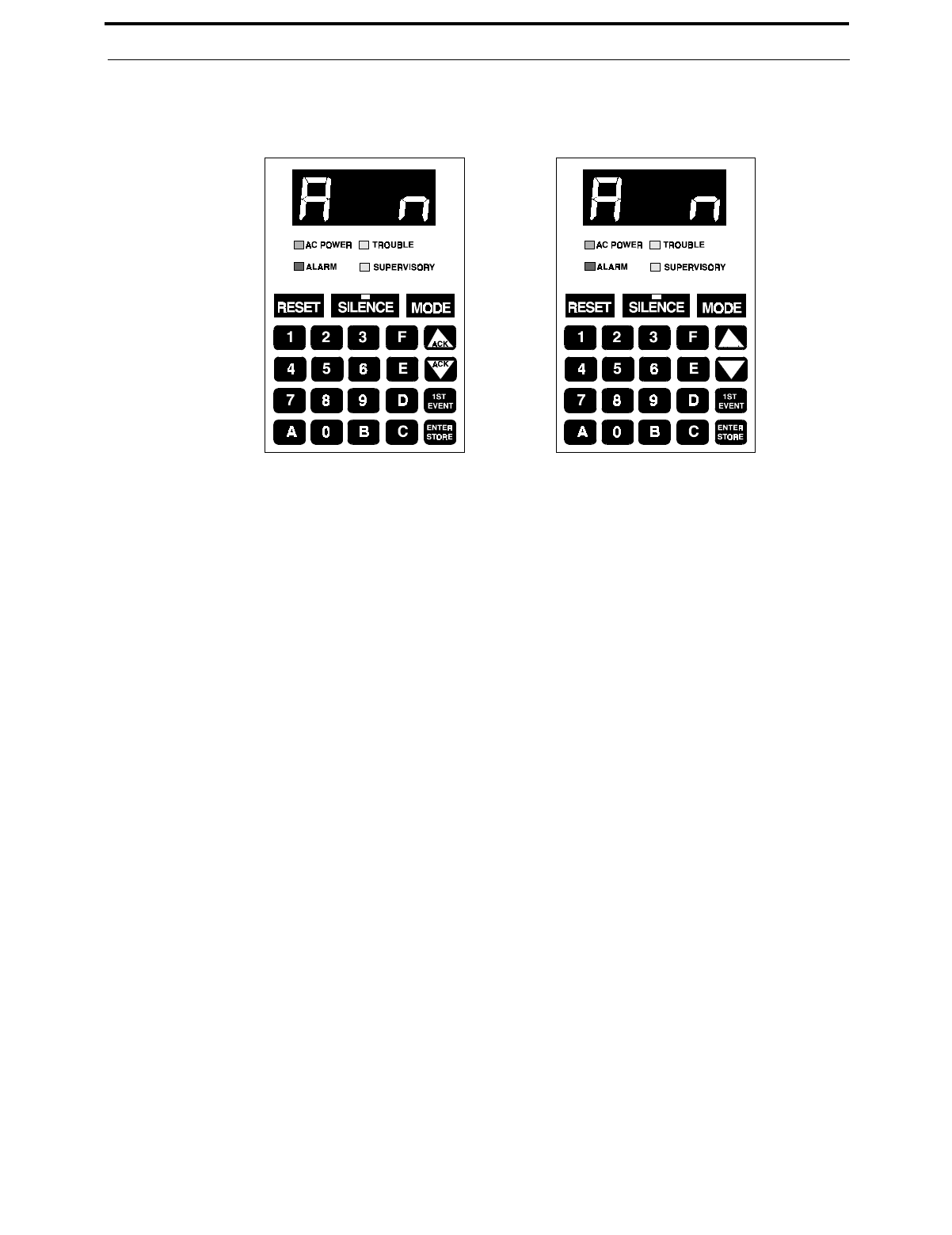
Document #50193 Rev. D 5/2/97 P/N 50193:D
67
Operating Instructions
CHAPTER 4 Operating Instructions
The MS-5210UD has several modes of operation including Normal, Program, Walk Test, Troubleshoot, History,
Lamp Test, Print and Upload/Download. There are also four function modes which include Drill, Zone Enable/Dis-
able, NAC Enable/Disable and Default Programming. Upon initial power-up, the system will be in Normal Mode.
This section discusses operation of the control panel in the Normal Mode.
4.1 Switch Functions in Normal Mode
RESET
The System Reset switches reset the system and any smoke detectors. Reset switches may be located on the FACP
keypad (illustrated in Figure 4-1), any of the ten zones programmed as a remote reset switch, remotely on any of
the LED-10 Series annunciators, the LDM graphic annunciators, or the AFM series annunciators. If any of the
System Reset Switches are pressed, the control panel will:
✓Clear the display and status LEDs
✓Turn off the Notification Appliance Circuits
✓Reset all zones by temporarily removing power
✓Silence the onboard piezo sounder
✓Store 'reset' message in the History file
✓Restore all system relays to normal
✓Temporarily remove power from the resettable power output TB2 Terminals 3 and 4
✓Output 'reset' message to printer
Any alarm, supervisory or trouble condition that exists after a system reset, will resound the system, reactivating
normal system activity. Upon release of a System Reset Switch, the FACP display will read rES_ for 6 seconds.
SILENCE
Silence switches may be located on the FACP keypad (illustrated in Figure 4-1), any of the ten zones programmed
as a remote silence switch, remotely located on any of the LED-10 Series annunciators, the LDM graphic annunci-
ators, or the AFM series annunciators. The Silence Switch performs the same functions as the System Acknowl-
edge switch. In addition, if any of the System Silence switches are pressed, the following will occur:
✓The silenceable Notification Appliance Circuits will be turned OFF
FIGURE 4-1:New and Old Keypad/Display
New - with ACK lettering Old - without ACK lettering

Switch Functions in Normal Mode
68
Document #50193 Rev.D 5/2/97 P/N 50193:D
✓The main circuit board silence LED will be turned ON
✓The SILn message will be displayed (where n = NAC #)
✓The system piezo sounders will be shut OFF
✓'NAC #N Silenced' message will be stored in the History file
✓'NAC #N Silenced' message will be sent to the printer
Upon the occurrence of a subsequent event (alarm or trouble), System Silence is overridden and the control panel
will respond to the new event. The System Silence switches will be ignored for nonsilenceable waterflow type
alarms.
ACKNOWLEDGE/STEP
Acknowledge/Step switches (Up/Down arrow keys) are located on newer model FACP keypads (refer to Figure 4-
1), remotely located on any of the LED-10 Series annunciators, the LDM graphic annunciators, or the AFM series
annunciators and an option exists that allows any of the ten zones to be programmed to function as a remote
Acknowledge switch.
The Acknowledge/Step switch silences the system piezo sounders and changes all flashing system LEDs to
steady. An acknowledge message is sent to the printer and history files. The Step function permits scrolling
through multiple stored events during normal, history and walktest modes.
When more than one event exists, the first press of the Acknowledge/Step switch silences the system piezo sound-
ers and changes all flashing system LEDs to steady. The second press of the switch stops the scrolling and holds
the event on the display for five seconds. Subsequent pressing of the switch 'steps' through each active event. The
Acknowledge/Step switch must be pressed within 15 seconds to prevent NACs from turning on if alarm presignal
is selected. For additional information on alarm presignal, refer to “Programming Instructions” on page 37.
Note: Software P/N: MS-52102.0 or greater supports the Acknowledge key function at the FACP keypad.
DRILL
Drill switches may be located on any of the ten zones programmed as a remote drill switch, remotely on any of the
LED-10 Series annunciators, the LDM graphic annunciators, or the AFM series annunciators. To perform a drill
from any of these switches, the Drill switch must be pressed and held for two seconds (time to prevent accidental
activation). The MS-5210UD turns on all NACs and turns off the system silence LEDs. The message shown on
the display is dril. The drill message is sent to the printer and history files. The system silence keys will silence
all silenceable NACs during a fire drill.
To perform a drill from the FACP, press the MODE key followed by the code 3745 then press [ENTER/STORE].
The display will read dril. The alarm relay is not activated. There is an option to transmit the fire drill report code
to the Central Station. During a fire drill, the SILENCE key will silence all silenceable NACs and the RESET
key restores the panel to normal. All zones remain active during a fire drill.
MODE
Pressing the Mode switch followed by a valid 4-digit numerical code and [ENTER/STORE] selects one of the six
modes of operation.
To enter Normal Mode from any other mode press MODE then 6676 [ENTER/STORE].
☛ 6676 spells NORM on a Touch-Tone® phone.
1st EVENT
The 1st Event switch along with the Up Arrow and Down Arrow keys, are used to display any presently active
alarm and/or fault conditions present in the system. Press the 1st Event switch at any time to display the first
event (alarm and/or trouble) that occurred.
DOWN ARROW (ACK)
Use the Down Arrow key to view other events (older) that have occurred and are active (not yet cleared). It also
acknowledges the event by silencing the local piezo sounder.

Document #50193 Rev. D 5/2/97 P/N 50193:D
69
LED Display and Status LEDs
UP ARROW (ACK)
Use the Up Arrow key to view other events (newer) that have occurred and are active (not yet cleared). It also
acknowledges the event by silencing the local piezo sounder.
[ENTER/STORE]
Refer to the individual mode descriptions in previous sections of this manual. In Normal Mode, this key is used
after pressing the MODE key followed by a 4-digit mode code followed by the [ENTER/STORE] key.
4.2 LED Display and Status LEDs
LED Display
Four 7-Segment red LED characters provide visual annunciation of status, events and messages. A list of mes-
sages that may appear on the display in Normal Mode is shown below:
d__1 Zone 1 Disabled F__9 Trouble Zone 9
d__2 Zone 2 Disabled F_10 Trouble Zone 10
d__3 Zone 3 Disabled F_85 Annunciator Bus Fault
d__4 Zone 4 Disabled F__A Annunciator Fault
d__5 Zone 5 Disabled F__E Earth Fault
d__6 Zone 6 Disabled F__P Printer Fault
d__7 Zone 7 Disabled Lo_b Low Battery
d__8 Zone 8 Disabled no_b No Battery
d__9 Zone 9 Disabled PH_1 Primary C.S. No. Comm. Fault
d_10 Zone 10 Disabled PH_2 Secondary C.S. No. Comm. Fault
d_b1 NAC/Bell #1 Disabled bEL1 Bell 1 Fault
d_b2 NAC/Bell #2 Disabled bEL2 Bell 2 Fault
d_b3 NAC/Bell #3 Disabled bEL3 Bell 3 Fault
d_b4 NAC/Bell #4 Disabled bEL4 Bell 4 Fault
drLL Fire Drill no_1 Primary Phone Line Fault
E__1 Zone 1 Enabled no_2 Secondary Phone Line Fault
E__2 Zone 2 Enabled PA_1 Process Monitoring Alarm Zone 1
E__3 Zone 3 Enabled PA_2 Process Monitoring Alarm Zone 2
E__4 Zone 4 Enabled PA_3 Process Monitoring Alarm Zone 3
E__5 Zone 5 Enabled PA_4 Process Monitoring Alarm Zone 4
E__6 Zone 6 Enabled PA_5 Process Monitoring Alarm Zone 5
E__7 Zone 7 Enabled PA_6 Process Monitoring Alarm Zone 6
E__8 Zone 8 Enabled PA_7 Process Monitoring Alarm Zone 7
E__9 Zone 9 Enabled PA_8 Process Monitoring Alarm Zone 8
E_10 Zone 10 Enabled PA_9 Process Monitoring Alarm Zone 9
A__1 Alarm Zone 1 PA10 Process Monitoring Alarm Zone 10
A__2 Alarm Zone 2 SIL1 NAC/Bell #1 Silenced
A__3 Alarm Zone 3 SIL2 NAC/Bell #2 Silenced
A__4 Alarm Zone 4 SIL3 NAC/Bell #3 Silenced
A__5 Alarm Zone 5 SIL4 NAC/Bell #4 Silenced
A__6 Alarm Zone 6 SU_1 Supervisory Alarm Zone 1
A__7 Alarm Zone 7 SU_2 Supervisory Alarm Zone 2
A__8 Alarm Zone 8 SU_3 Supervisory Alarm Zone 3
A__9 Alarm Zone 9 SU_4 Supervisory Alarm Zone 4
A_10 Alarm Zone 10 SU_5 Supervisory Alarm Zone 5
F__1 Trouble Zone 1 SU_6 Supervisory Alarm Zone 6
F__2 Trouble Zone 2 SU_7 Supervisory Alarm Zone 7
F__3 Trouble Zone 3 SU_8 Supervisory Alarm Zone 8
F__4 Trouble Zone 4 SU_9 Supervisory Alarm Zone 9
F__5 Trouble Zone 5 SU10 Supervisory Alarm Zone 10
F__6 Trouble Zone 6 _AC_ AC Power Loss
F__7 Trouble Zone 7 rES_ System Reset
F__8 Trouble Zone 8
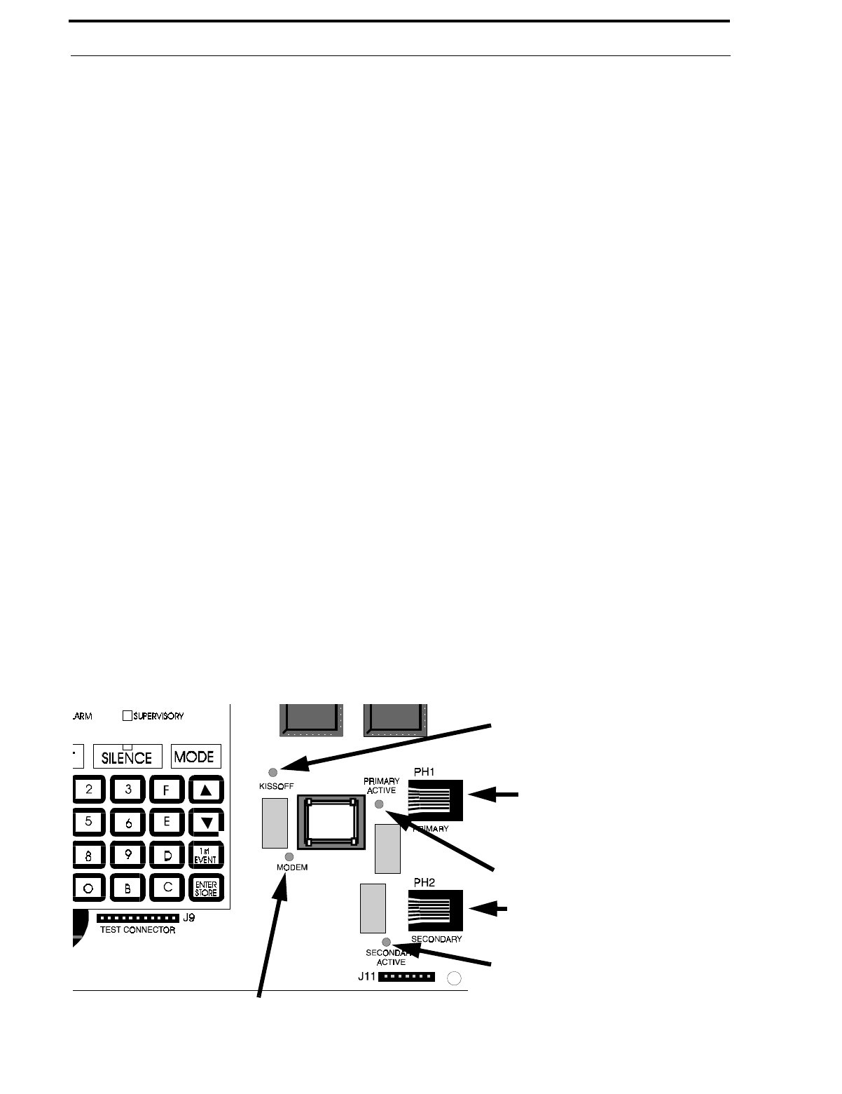
LED Display and Status LEDs
70
Document #50193 Rev.D 5/2/97 P/N 50193:D
System Fire Alarm LED
A red LED that flashes when a fire alarm condition is detected during the alarm presignal period. It turns on
steady when the system silence or acknowledge switches are pressed.
System Trouble LED
A yellow LED that blinks to indicate that a fault or abnormal condition exists and that the fire alarm system may
be inoperative. It turns on steady when a system silence or acknowledge switch is pressed.
AC Power On LED
A green LED that remains on while the AC power supply is within correct limits. If this indicator fails to light
under normal conditions, service the system immediately.
Supervisory LED
A yellow LED that blinks to indicate the need for action in connection with the supervision or maintenance of
sprinklers, extinguishing systems or other protective systems.
System Silence LED
A yellow LED that turns on to indicate that an Alarm or Trouble condition exists in the system, but Notification
Appliance Circuits (if programmed as silenceable) and local piezo sounder have been silenced.
Primary Line Active LED
A red LED that indicates the primary phone line is active.
Secondary Line Active LED
A red LED that indicates the secondary phone line is active.
Kiss-Off LED
A green LED that blinks when a Central Station has acknowledged receipt of each transmitted message or when a
portion of up or download data has been accepted from a Service Terminal.
Modem LED
A green LED that stays on steady during modem types of communications.
Kissoff LED
Primary Active LED
Primary Phone Line
Secondary Phone Line
Secondary Active LED
Modem LED
FIGURE 4-2:Phone Connectors and LEDs

Document #50193 Rev. D 5/2/97 P/N 50193:D
71
Operation
4.3 Operation
Normal Mode is the standard mode of operation. In this mode, the panel continuously monitors system status. When
no alarm or trouble conditions exist, the display will be blank and all LEDs will be off (except the AC Power LED).
The Notification Appliance Circuits will be off, all relays are in their normal state, the onboard piezo sounder will be
off and the printer (if connected) will not be printing. The Primary and Secondary Phone Line Active LEDs are off
since the communicator is not active.
All alarm and system trouble conditions are annunciated on the control panel's display. The control panel will main-
tain an 'active event list' which will consist of all alarms, supervisory alarms and system troubles currently active and
not cleared, requiring immediate service. When the system is cleared and restored to normal, the display will be
blank. All alarms and troubles are stored in a history file and may be recalled at any time.
Higher priority events take precedence over lower priority events. Display and reporting of System Status is done on
a priority basis. Priorities are, from highest to lowest:
1. Alarms
2. Supervisory Alarms
3. System Troubles
4. Process Monitoring Alarms
If the events to be displayed consist of alarms and disabled zones only (no troubles), the control panel will scroll them
on the display. As each new alarm occurs, it will be displayed immediately on the display for five seconds. After this
five second period, the display will scroll all alarms in the system. Pressing the 1st Event key or one of the 'ACK' keys
will stop the scrolling. The 1st Event key will also cause the display to show the First alarm that occurred after the
panel was last reset, cleared of all active events and placed into normal mode. Operation of the Up and Down arrow
keys will display all remaining events in sequence.
If events to be displayed include system troubles, only one event is displayed at a time and there is no scrolling. The
event displayed is the highest priority. Pressing the 1st Event key will cause the display of the first event that occurred
after the panel was last reset, cleared of all active events and placed into normal mode. Operation of the Up and Down
arrow keys will display all remaining events in order of their occurrences.
4.3.1 Fire Alarm Response
The control panel will, upon detection of an alarm condition, cause the following:
•Blink the FACP alarm LED (1 second On, 1 second Off)
•Display the alarm message (i.e. A__1 Alarm on Zone 1)
•Communicate the alarm to the Central Station
•Store the alarm in the History File
•Turn the Notification Appliance Circuits on
•Turn the piezo sounder on steady
•Turn on appropriate zone relay output (ACM-8RF)
•Turn on any system relays (main circuit board) programmed for alarm activation
•Output alarm message to printer
•Terminate upload or download communications
•Blink all remote annunciator general alarm LEDs (1 second On, 1 second Off)
•Blink all remote annunciator zone alarm LEDs (1 second On, 1 second Off)
Note that when any zone is programmed as a supervisory or process monitored zone, it will not be processed in the
same manner as a conventional alarm zone. Refer to “System Supervisory Condition Response” on page 72 and
“Process Monitored Alarm Response” on page 74

Operation
72
Document #50193 Rev.D 5/2/97 P/N 50193:D
4.3.2 Fire Alarm Restoral
The control panel returns to normal after all alarms have been cleared and a system reset switch has been pressed
(pull stations have been reset, smoke detectors have reset and no smoke is present, waterflow has stopped). The con-
trol panel will perform the following upon restoral of all active alarms:
•Turn off the FACP alarm LED
•Clear the 4-character display
•Send all 'Zone Restoral' messages to the Central Station
•Turn off the Notification Appliance Circuits
•Turn off the piezo sounder
•Turn off appropriate zone relay output (ACM-8RF)
•Turn off any system relays (main circuit board) programmed for alarm activation
•Output alarm restoral message to printer
•Terminate upload or download communications
•Turn off all remote annunciator general alarm LEDs
•Turn off all remote annunciator zone alarm LEDs
4.3.3 System Supervisory Condition Response
Program zones for Supervisory in applications where a waterflow sensing device has been employed and the wiring
to the waterflow valve and/or a tamper switch is to be monitored. If the tamper switch has been activated (Normally
Open contacts close), a supervisory alarm condition will occur.
When a supervisory condition occurs, the control panel will cause the following:
•Blink the FACP supervisory LED (½ second On, ½ second Off)
•Display the following message: SUXX (XX=Zone Number)
•Communicate the supervisory condition to the Central Station
•Store the 'supervisory' message in the History File
•Pulse system piezo sounders (½ second On, ½ second Off)
•Turn on appropriate zone relay output (ACM-8RF)
•Turn on any system relays (main circuit board) programmed for supervisory activation
•Output system supervisory message to printer
•Terminate upload or download communications
•Blink all remote annunciator general supervisory alarm LEDs (½ second On, ½ second Off)
•Blink all remote annunciator zone supervisory alarm LEDs (½ second On, ½ second Off)
4.3.4 System Supervisory Restoral Response
When the supervisory condition has been cleared (condition is restored and the reset switch has been pressed), the
control panel will perform the following:
•Turn off the supervisory LED
•Clear the display of the 'SUXX'
•Communicate a supervisory restoral message to the Central Station
•Shut off system piezo sounders
•Turn off appropriate zone relay output (ACM-8RF)
•Turn off any system relays (main circuit board) programmed for supervisory activation

Document #50193 Rev. D 5/2/97 P/N 50193:D
73
Operation
•Output system supervisory restoral message to printer
•Terminate upload or download communications
•Turn off all remote annunciator general supervisory alarm LEDs
•Turn off all remote annunciator zone supervisory alarm LEDs
Note that for any zone programmed for Supervisory autoresettable, the Reset key does not need to be pressed to clear
the zone (supervisory condition).
4.3.5 Trouble Condition Response
The control panel will perform the following upon detection of one or more trouble conditions:
•Blink the FACP trouble LED (1 second On, 1 second Off)
•Blink all annunciator general system trouble LEDs
•Blink all affected zone trouble LEDs on all system annunciators
•Activate any FACP trouble relay(s) if programmed for trouble activation
•Display the appropriate trouble message(s) in priority fashion from the highest priority to the lowest. Note that
the Up arrow key, Down arrow key or 1st Event key must be pressed to view the messages.
•Communicate the trouble conditions to the Central Station
•Store the trouble conditions in the History File
•Sound system piezo sounders at a rate of 1 second On, 1 second Off
•Output the system trouble messages to the printer
•Terminate upload or download communications
Note that when AC Brownout occurs, the AC LED is turned off and the Trouble LED blinks. Should the brownout con-
dition remain, it will be transmitted to the Central Station after a delay (see Program Address 77 in the Level 1 Main
Panel Options section).
Possible trouble messages that may appear on the display are as follows:
_AC_ AC Loss (shown only when requested)
d__1 Zone 1 Disabled F__10 Trouble Zone 10
d__2 Zone 2 Disabled d_b1 Bell 1 Disabled
d__3 Zone 3 Disabled d_b2 Bell 2 Disabled
d__4 Zone 4 Disabled d_b3 Bell 3 Disabled
d__5 Zone 5 Disabled d_b4 Bell 4 Disabled
d__6 Zone 6 Disabled F__A Annunciator Fault
d__7 Zone 7 Disabled F__P Printer Fault
d__8 Zone 8 Disabled F__E Earth Fault
d__9 Zone 9 Disabled Lo_b Low Battery
d_10 Zone 10 Disabled no_b No Battery
F__1 Trouble Zone 1 PH_1 Primary C.S. No. Comm. Fault
F__2 Trouble Zone 2 PH_2 Secondary C.S. No. Comm. Fault
F__3 Trouble Zone 3 bEL1 Bell 1 Fault
F__4 Trouble Zone 4 bEL2 Bell 2 Fault
F__5 Trouble Zone 5 bEL3 Bell 3 Fault
F__6 Trouble Zone 6 bEL4 Bell 4 Fault
F__7 Trouble Zone 7 no_1 Primary Phone Line Fault
F__8 Trouble Zone 8 no_2 Secondary Phone Line Fault
F__9 Trouble Zone 9

Operation
74
Document #50193 Rev.D 5/2/97 P/N 50193:D
4.3.6 Trouble Condition Restoral
The control panel performs the following upon restoral of all trouble conditions:
•The trouble LED is shut Off
•FACP trouble relay(s) deactivate if programmed for trouble activation
•If the trouble was loss of AC power, the control panel will turn on the AC LED upon restoral
•Clear the FACP display of trouble message(s)
•Communicate the restored trouble condition(s) to the Central Station
•Output the system trouble restoral message to the printer
•Terminate upload or download communications
•Turn off the system general trouble LED on all system annunciators if all trouble conditions are cleared
•Turn off all affected zone trouble LEDs on all system annunciators
4.3.7 Process Monitored Alarm Response
Upon detection of a critical or noncritical process monitored alarm condition on any zone, the control panel will:
•Display the alarm message PAXX (where XX = zone number)
•Communicate the alarm code programmed for the activated zone
•Store the alarm in the History File
•Pulse the piezo sounder at a ¼ second On, ¼ second Off
•Turn on appropriate zone relay output (ACM-8RF)
•Turn on any system relays (main circuit board) programmed for process alarm activation
•Output alarm message to printer
•Terminate upload or download communications
•Blink all remote annunciator zone alarm LEDs (¼ second On, ¼ second Off)
4.3.8 Process Monitored Alarm Restoral
The control panel returns to normal after all alarms have been cleared and a system reset switch has been pressed
(process monitored alarm devices reset). The control panel will perform the following upon restoral of all active pro-
cess monitored alarms:
•Clear the 4-character display
•Communicate the alarm restoral code programmed for the activated zone
•Store the alarm restoral message in the History File
•Turn off the piezo sounder
•Turn off appropriate zone relay output (ACM-8RF)
•Turn off any system relays (main circuit board) programmed for process alarm activation
•Output alarm restoral message to printer
•Terminate upload or download communications
•Turn off all remote annunciator zone alarm LEDs
Note that for any zone programmed for autoresettable process monitored alarm, the reset key does not need to be
pressed to clear the zone.

Document #50193 Rev. D 5/2/97 P/N 50193:D
75
Operation
4.3.9 OFF Normal Reporting
Removing the panel from Normal Mode and placing it into Troubleshoot, Walktest or Program Mode causes a trans-
mission of an 'off normal' fault message. Returning the panel to Normal Mode causes a transmission of a 'return to
normal' restoral message.
4.3.10Zone Disable/Enable
The zone disable feature may be used to disable any zone in the system. While in Normal Mode or Walktest Mode,
zones may be disabled if they are normal, in trouble or alarmed. If the panel is in alarm, the silence switch must be
pressed first before zone disable will function in Normal Mode.
To disable a zone, press the MODE key once, (the display will go blank). You then have 10 seconds to start entering
the code 3472. Next, press the [ENTER/STORE] key.
☛ 3472 spells DISA on a Touch-Tone® phone.
A flashing lower case d will appear on the far left of the display. Next, press the zone number to be disabled. The
number will appear on the far right display character. Press [ENTER/STORE]. The zone is disabled. All system
annunciators will show zone troubles and general trouble status. Note that the trouble relay is activated and the trou-
ble LED blinks.
The zone disable message will remain on the display until the zone is reenabled. To reenable a zone, press the MODE
key once (the display will go blank). You then have 10 seconds to start entering the code 3622. Next, press the
[ENTER/STORE] key.
☛ 3622 spells ENAB on a Touch-Tone® phone.
A flashing upper case E will appear on the left of the display. Next, press the zone number to be enabled. The number
will appear on the far right display character. Press [ENTER/STORE]. The zone is reenabled. Note that the trouble
relay is restored to normal and the FACP trouble LED is off and all system annunciator zone trouble LEDs are off.
4.3.11NAC (bell) Disable/Enable
The NAC/bell disable feature may be used to disable any of the four main panel NAC/bell circuits. While in Normal
Mode, NACs may be disabled if they are normal, in trouble or alarmed.
To disable an NAC/bell, press the MODE key once (the display will go blank). You then have 10 seconds to start
entering the code 3472. Next, press the [ENTER/STORE] key.
☛ 3472 spells DISA on a Touch-Tone® phone.
A flashing lower case d will appear on the far left of the display. Next, press the b key followed by the NAC number
to be disabled. The b and the NAC number will appear on the far right display characters. Pressing [ENTER/
STORE] will disable the NAC. All system annunciators will show general trouble status and the main panel display
will show the NAC disabled message, turn on the system trouble LED and activate relays programmed for system
trouble.
The NAC disable message will remain on the display until the circuit is reenabled. To reenable an NAC, press the
MODE key once (the display will go blank). You then have 10 seconds to start entering the code 3622. Next, press
the [ENTER/STORE] key.
☛ 3622 spells ENAB on a Touch-Tone® phone.
A flashing upper case E will appear on the left of the display. Next, press the b key followed by the NAC number to
be enabled. The b and the NAC number will appear on the far right display characters. Pressing [ENTER/STORE]
will reenable the NAC. Note that relays programmed as trouble are restored to normal and the FACP trouble LED is
off and all system annunciator general trouble LEDs are off.

Central Station Communications
76
Document #50193 Rev.D 5/2/97 P/N 50193:D
4.3.12Fire Drill
The DRILL (manual evacuate) feature turns on all Notification Appliance Circuits (if programmed as enabled) and
turns off the silence LED. To perform a fire drill, press the MODE key followed by the code 3745 then the [ENTER/
STORE] key. The display will read drLL. The alarm relay is not activated. There is an option to transmit the fire
drill report code to the Central Station.
☛ 3745 spells dril on a Touch-Tone® phone.
During a fire drill, the SILENCE key will silence the silenceable Notification Appliance Circuits and the RESET
key restores the panel to normal. All zones remain active during a fire drill.
4.4 Central Station Communications
The control panel transmits zone and system status reports to central stations via the public switched telephone net-
work. Two supervised telephone line connections are made to interface the control panel to the telephone lines. Two
7-foot (2.13 m) telephone cords P/N MCBL-7 may be used for this purpose.
The control panel supervises both telephone lines for proper voltage. A delay of two minutes will occur before a fault
in either phone line connection is reported as a trouble. When a fault is detected, an audible trouble signal will sound,
the yellow trouble LED will blink, the 4-character display will show either 'no_1' (primary phone line) or 'no_2' (sec-
ondary phone line), depending upon which telephone line has the fault, and the trouble condition will be reported to a
central station over the remaining good phone line.
The control panel comes with line seizure capability provided for both the primary and secondary telephone line
interfaces. Any time that the control panel needs to make a call to a central station, line seizure will disconnect any
local premises phones sharing the same telephone line.
All transmissions to central stations will be sent over the Primary Central Station phone line. In the event of noisy
phone lines, transmissions will be sent over the backup Secondary phone line.
Two phone numbers must be programmed, the Primary Central Station phone number and the Secondary Central Sta-
tion phone number. There are three options for transmission to the central station:
•All messages are always sent to the Primary Central Station phone number with the Secondary Central Station
phone number for emergency backup purposes only.
•All reports are sent to both central station phone numbers.
•Reports are sent to the first available central station phone number only.
If 10 total attempts to communicate are unsuccessful, system relays programmed for Communications Failure will be
activated. The FACP will also display 'PH1' for Communicator Failure to the Primary Central Station phone number
or 'PH2' for Communicator Failure to the Secondary Central Station phone number.
The MS-5210UD meets NFPA 72 National Fire Code reporting requirements for the type of signal, condition and
location of the reporting premises. The general priority reporting structure is:
1. Zone Alarms and Restores
2. Zone Trouble and Restores
3. System Troubles and Restores
4. 24-hour test
The control panel is capable of reporting detailed messages depending upon the format in use. Table 4-1 shows the
reporting structure for all formats.

Document #50193 Rev. D 5/2/97 P/N 50193:D
77
Central Station Communications
Refer to Table 4-2 for an explanation of each letter code in Table 4-1 .
Refer to Table 4-3 for a list of compatible receivers.
TABLE 4-1: Format Selection Addresses (16+42) Programming Level 1
Format #
0, 2, 4, 6, 8 Format #
3, 5, 7, 9 Format #
1, A, C Format #
B, D
Report 3+1/4+1/Standard
4+1 Express 3+1/4+1/Expanded 4+2/Standard
4+2 Express 4+2/Expanded
Alarm SSS(S) A SSS(S) A
AAA(A) Z SSSS AA2 SSSS AZ
Alarm Restore SSS(S) RA SSS(S) RA
RARARA(RA) Z SSSS RARA2 SSSS RAZ
Zone Trouble
(Zone Open) SSS(S) TZ SSS(S) TZ
TZTZTZ(TZ) Z SSSS TZTZ2 SSSS TZZ
Zone Trouble Restore SSS(S) RTZ SSS(S) RTZ
RTZRTZRTZ(RTZ) Z SSSS RTZRTZ2 SSSS RTZZ
System Trouble SSS(S) TS SSS(S) TS
TSTSTS(TS) Y SSSS TSTS2 SSSS TSY
System Trouble Restore SSS(S) RTS SSS(S) RTS
RTSRTSRTS(RTS) Y SSSS RTSRTS2 SSSS RTSY
Zone Disable SSS(S) DZ SSS(S) DZ
DZDZDZ(DZ) Z SSSS DZDZ2 SSSS DZZ
Zone Disable Restore SSS(S) RDZ SSS(S) RDZ
RDZRDZRDZ(RDZ) Z SSSS RDZRDZ2 SSSS RDZZ
Bell Disable SSS(S) DB SSS(S) DB SSSS DBDB2 SSSS DBDB2
Bell Disable Restore SSS(S) RB SSS(S) RB SSSS RBRB2 SSSS RBRB2
Low Battery SSS(S) L SSS(S) L SSSS LL2 SSSS LL2
Low Battery Restore SSS(S) RL SSS(S) RL SSSS RLRL2 SSSS RLRL2
No Battery SSS(S) N SSS(S) N SSSS NN2 SSSS NN2
No Battery Restore SSS(S) RN SSS(S) RN SSSS RNRN2 SSSS RNRN2
AC Loss SSS(S) P SSS(S) P SSSS PP2 SSSS PP2
AC Loss Restore SSS(S) RP SSS(S) RP SSSS RPRP2 SSSS RPRP2
Fire Drill SSS(S) Fd SSS(S) Fd SSSS FdFd2 SSSS FdFd2
Fire Drill Restore SSS(S) RFd SSS(S) RFd SSSS RFdRFd2 SSSS RFdRFd2
Supervisory Condition SSS(S) V SSS(S) V
VVV(V) Z SSSS VV2 SSSS VZ
Supervisory Condition
Restore SSS(S) RV SSS(S) RV
RVRVRV(RV) Z SSSS RVRV2 SSSS RVZ
Test Report SSS(S) X SSS(S) X SSSS XX2 SSSS XX2
Up or Download SSS(S) UD SSS(S) UD SSS UDUD2 SSS UDUD2

Central Station Communications
78
Document #50193 Rev.D 5/2/97 P/N 50193:D
Note that for Expanded Reporting, the control panel automatically adds the digit corresponding to the zone number,
and the second digit corresponding to any system trouble condition. Only the first digit is programmable.
TABLE 4-2: Format Selection Address Explanation
Where:
SSS or SSSS = Subscriber ID
A = Alarm (1st digit)
A2 = Alarm (2nd digit)
Z= Zone Number
RA = Alarm Restore (1st digit)
RA2 = Alarm Restore (2nd digit)
TZ = Zone Trouble (1st digit)
TZ2 = Zone Trouble (2nd digit)
RTZ = Zone Trouble Restore (1st digit)
RTZ2 = Zone Trouble Restore (2nd digit)
TS = System Trouble (1st digit)
TS2 = System Trouble (2nd digit)
RTS = System Trouble Restore (1st digit)
RTS2 = System Trouble Restore (2nd digit)
DZ = Zone Disable (1st digit)
DZ2 = Zone Disable (2nd digit)
RDZ = Zone Disable Restore (1st digit)
RDZ2 = Zone Disable Restore (2nd digit)
DB = Bell Disable (1st digit)
DB2 = Bell Disable (2nd digit)
RB = Bell Disable Restore (1st digit)
RB2 = Bell Disable Restore (2nd digit)
L = Low Battery (1st digit)
L2 = Low Battery (2nd digit)
RL = Low Battery Restore (1st digit)
RL2 = Low Battery Restore (2nd digit)
N = No Battery (1st digit)
N2 = No Battery (2nd digit)
RN = No Battery Restore (1st digit)
RN2 = No Battery Restore (2nd digit)
P = AC Loss (1st digit)
P2 = AC Loss (2nd digit)
RP = AC Loss Restore (1st digit)
RP2 = AC Loss Restore (2nd digit)
FD = Fire Drill (1st digit)
FD2 = Fire Drill (2nd digit)
RFD = Fire Drill Restore (1st digit)
RFD2 = Fire Drill Restore (2nd digit)
V = Supervisory Condition (1st digit)
V2 = Supervisory Condition (2nd digit)
RV = Supervisory Condition Restore (1st digit)
RV2 = Supervisory Condition Restore (2nd digit)
X = Test Report (1st digit)
X2 = Test Report (2nd digit)
Y = A Trouble corresponding to the following:
1 = Earth Fault
2 = Not Used
3 = Not Used
4 = Telco Primary Line Fault
5 = Telco Secondary Line Fault
6 = NAC #1 Fault
7 = NAC #2 Fault
8 = NAC #3 Fault
9 = NAC #4 Fault
A = Communication Failure to Primary Number
B = Communication Failure to Secondary Number
C = Printer Fault
D = Annunciator Fault
E = 485 Communication Failure
F = System Off Normal
UD = Upload/Download (1st digit)
UD2 = Upload/Download (2nd digit)

Document #50193 Rev. D 5/2/97 P/N 50193:D
79
Central Station Communications
4.4.1 Transmittal Priorities
The integral communicator transmits highest priority events first. Events in terms of priority are listed below in
descending order:
1. Alarms (Highest Priority Level)
Pull Stations
Waterflow
Smoke Detector
Other Alarm Types
2. Supervisory Zone
3. System Troubles
Zone/NAC Disabled
Fire Drill
AC Fail (after delay)
Zonal faults
Earth fault
Low battery/No battery
Telephone line fault
Notification Appliance Circuits fault
Communication Trouble
Printer Trouble
Annunciator Trouble
EIA-485 fault
System Off Normal
Process Monitoring Alarm
4. Restoral Reports
Zone Alarm
Supervisory
Zone(s) enabled
Fire Drill
AC
Zone fault
Earth
Battery
Telephone Line
Notification Appliance Circuits
Communication
Printer
Annunciator
EIA-485
System Off Normal
Process Monitoring Restored
5. System Test (Lowest Priority)
Red LEDs are provided on the control panel circuit board to identify which telephone line is activated. Also, a green
LED labeled 'Kissoff', will turn on whenever the control panel has successfully transmitted reports to the Central Sta-
tion. The 'Kissoff' LED may turn on several times during communications with a central station.

Central Station Communications
80
Document #50193 Rev.D 5/2/97 P/N 50193:D
The following table contains UL listed receivers compatible with the MS-5210UD.
(1) With 685-8 Line Card with Rev 4.4d software.
(2) With 9002 Line Card Rev 9035 software or 9032 Line Card with 9326A software.
(3) Rev. 4.0 software.
(4) FBI CP220FB Rec-11 Line Card with Rev 2.6 software and a memory card with Rev 3.8 software.
(5) Model 6500 with Rev 600 software.
(6) Model 6000 with Rev 204 software.
(7) With Rev B control card at Rev 1.4 software and Rev C line card at Rev 1.5 software.
(8) Model 2 only.
(9) Version 1.62 software.
TABLE 4-3: Compatible UL Listed Receivers
Format #
(Addresses 16 & 42)
Ademco
685(1)
Silent Knight
9000 (2)
ITI
CS-4000 (3)
FBI
CP220FB
Osborne Hoffman
Models 1 & 2
Radionics
6000/6500 (5)
Sescoa
3000R (7)
Surguard
MLR-2 (9)
0 4+1 Ademco Express ✔✔ ✔
1 4+2 Ademco Express ✔✔✔
(8) ✔
2 3+1/Standard/1800/2300 ✔✔✔✔
(4) ✔✔
(5, 6) ✔✔
3 3+1/Expanded/1800/2300 ✔✔✔✔
(4) ✔✔✔
4 3+1/Standard/1900/1400 ✔✔ ✔
(4) ✔✔✔
5 3+1/Expanded/1900/1400 ✔✔ ✔
(4) ✔✔✔
6 4+1/Standard/1800/2300 ✔✔✔✔
(4) ✔✔
(5) ✔✔
7 4+1/Expanded/1800/2300 ✔✔ ✔
(4) ✔✔✔
8 4+1/Standard/1900/1400 ✔✔ ✔
(4) ✔✔✔
9 4+1/Expanded/1900/1400 ✔✔ ✔
(4) ✔✔✔
A 4+2/Standard/1800/2300 ✔✔✔✔
(4) ✔✔
(5) ✔✔
B 4+2/Expanded/1800/2300 ✔✔ ✔
(4) ✔✔✔
C 4+2/Standard/1900/1400 ✔✔ ✔
(4) ✔✔✔
D 4+2/Expanded/1900/1400 ✔✔ ✔
(4) ✔✔✔
E Ademco Contact ID ✔✔✔ ✔

Document #50193 Rev. D 5/2/97 P/N 50193:D
81
Servicing
CHAPTER 5 Servicing
5.1 Walk Test Mode
The MS-5210UD provides the capability to perform a one-man walktest of the system without triggering the commu-
nicator, the ACM-8RF zone relays, the system annunciators or the alarm output relay. Walk Test Mode allows for
testing of the 10 zones (initiating device circuits). Zones defined as Reset, Acknowledge, Silence, Drill,
Autoresettable Process Monitoring or Process Monitoring are not part of the one-man walktest function. Zones
defined as Pull Station, Normally-Open Contact, two or four-wire smoke detector, waterflow or supervisory are func-
tionally tested in Walk Test Mode. An audible or silent walktest may be performed.
For an audible walktest, the first initiating device activated on a zone will cause the Notification Appliance Circuits to
turn on for four seconds. Subsequent device activations on the same zone will cause the Notification Appliance Cir-
cuits to turn on for one second. Any smoke detectors that are activated will be reset. Zonal faults (open circuits) will
cause the NAC to remain on steadily. Prior to entering Walk Test Mode, check to be certain that all system faults have
been cleared.
Note that trouble relays will be activated while the control panel is in Walk Test Mode. Placing the control panel into
Walk Test Mode will only be possible if the system has no active alarms.
Pressing the MODE key followed by the 4-digit code 9255 and then pressing the [ENTER/STORE] key will place
the control panel into Walk Test Mode.
☛ 9255 spells WALK on a Touch-Tone® phone.
An S will be displayed on the left most character and a flashing 0 on the far right character. For audible walktest,
press the [ENTER/STORE] key. For silent walktest, press the 1 key followed by the [ENTER/STORE] key.
Once in Walk Test Mode, the control panel will immediately:
•Blink the trouble LED
•Activate the trouble relay
•If an audible walktest is performed, the MS-5210UD will turn on the Notification Appliance Circuits for four
seconds for the first alarm on a zone. Subsequent alarms will sound for one second. Troubles cause the NACs
to remain on. For a silent walktest, all NAC outputs remain off.
•Disable the alarm relay
•Display all alarm conditions as they occur.
•Display all zone troubles as they occur.
•Display all system troubles as they occur
•Transmit 'off normal' message to Central Station(s)
•Continue to communicate any events not acknowledged at a central station prior to entering Walk Test Mode
During Walk Test Mode, zonal activity is displayed in real time as it occurs. At the end of walktesting the system, the
display will show the last event that occurred. To view all events stored during walktest, use the Up arrow, Down
arrow and 1st Event keys. The Down arrow key moves the walktest list to show older (previous) events. The Up
arrow key moves the walktest list to show newer (more recent) events. Pressing the 1st Event key at any time will
cause the display of the first event stored upon initial entry into Walk Test Mode. While in Walk Test Mode, the con-
trol panel will store up to 256 events in the Walk Test File for later recall and display. A printer may be connected to
the panel during walktest. All walktest events are printed in real-time as they occur.

History Mode
82
Document #50193 Rev.D 5/2/97 P/N 50193:D
Zone disable mode may be used while in Walk Test Mode. Should a faulty device require repair, the zone may be dis-
abled while the repair is performed. This allows the user to return the system to Normal Mode, enabling all other
zones. This also prevents triggering of a false alarm.
To return the control panel to Normal Mode, press the MODE key followed by the 4- digit code 6676 and then the
[ENTER/STORE] key. To go to any other mode, press the MODE key followed by the appropriate 4-digit code and
then the [ENTER/STORE] key. To go from silent walktest to audible walktest (or vice versa), press the MODE key
followed by the [ENTER/STORE] key. S__0 or S__1 will appear in the display. Simply alter the '0' or '1' entry then
press the [ENTER/STORE] key. Any delay between key entries greater than 10 seconds causes the control panel to
remain in Walk Test Mode.
The control panel will automatically revert back to Normal Mode if no system activity has occurred for 60 minutes.
This would include pressing any keys or activity on any zone. Exiting Walk Test Mode leaves the Walk Test file in
memory such that it may be printed in Print Mode. Subsequent entries into Walk Test Mode will delete the Walk Test
file.
During an audible walktest, if a device remains latched in alarm (such as a Pull Station that is not reset after activa-
tion), subsequent testing of devices on the same zone will not trigger the NACs. Be certain to reset or clear each
device after testing.
Note that remote site upload or download is possible when the system is in Walk Test Mode.
5.2 History Mode
All Normal Mode events are stored in a History File list for future recall. Recall is possible via the 4-character dis-
play or via an optional printer. See the following page for a list and description of each event displayed.
This History File list is a first-in, first-out (FIFO) buffer. Only the most recent events may be called up from memory.
Old events will be overwritten, i.e. pushed out of the FIFO. The number of stored events is 256. The History File is
kept in E2 memory. Complete power loss will not erase the list.
Pressing the MODE key followed by the 4-digit code 4478 and then the [ENTER/STORE] key places the control
panel into History Mode. The most recent event will be displayed. This will not occur if there are any active alarm
conditions present. The fire protection remains active in History Mode. If an alarm occurs, the panel will automati-
cally exit History Mode.
☛ 4478 spells HIST on a Touch-Tone® phone.
Once in History Mode, the control panel will:
•Display all events as they occurred since the last time the History File list was cleared (the most recent event
being displayed first)
•Ignore all keys except those mentioned in this section
•Continue to communicate any events not previously acknowledged at the Central Station prior to entering
History Mode.
The Down arrow key moves the History File to show older (previous) events. The Up arrow key moves the History
File to show newer (most recent) events.

Document #50193 Rev. D 5/2/97 P/N 50193:D
83
History Mode
Shown below is the list of messages as they will appear on the display:
To erase the list from E2 memory, press the SILENCE key twice before exiting the History Mode. A lack of keyboard
activity for a period of 10 minutes will cause the control panel to return to Normal Mode. If a printer is connected to
the panel, the History File will be printed upon successful entry into History Mode and a list of the most recent 256
events, time and date stamped, will print out.
Note that remote site upload or download is possible when the system is in History Mode.
TABLE 5-1: History Mode Messages
DISPLAY EVENT DISPLAY EVENT
ACn_ Acknowledge key pressed F__E Earth Fault
A__! Zone 1 Alarm F__A Annunciator Fault
A__2 Zone 2 Alarm F__P Printer Fault
A__3 Zone 3 Alarm F_85 Annunciator Bus Fault
A__4 Zone 4 Alarm d__1 Zone 1 disabled
A__5 Zone 5 Alarm d__2 Zone 2 disabled
A__6 Zone 6 Alarm d__3 Zone 3 disabled
A__7 Zone 7 Alarm d__4 Zone 4 disabled
A__8 Zone 8 Alarm d__5 Zone 5 disabled
A__9 Zone 9 Alarm d__6 Zone 6 disabled
A_10 Zone 10 Alarm d__7 Zone 7 disabled
SU_1 Supervisory 1 Alarm d__8 Zone 8 disabled
SU_2 Supervisory 2 Alarm d__9 Zone 9 disabled
SU_3 Supervisory 3 Alarm d_10 Zone 10 disabled
SU_4 Supervisory 4 Alarm drLL Fire Drill
SU_5 Supervisory 5 Alarm E__1 Enable Zone 1
SU_6 Supervisory 6 Alarm E__2 Enable Zone 2
SU_7 Supervisory 7 Alarm E__3 Enable Zone 3
SU_8 Supervisory 8 Alarm E__4 Enable Zone 4
SU_9 Supervisory 9 Alarm E__5 Enable Zone 5
SU10 Supervisory 10 Alarm E__6 Enable Zone 6
PA_1 Process Alarm Zone 1 E__7 Enable Zone 7
PA_2 Process Alarm Zone 2 E__8 Enable Zone 8
PA_3 Process Alarm Zone 3 E__9 Enable Zone 9
PA_4 Process Alarm Zone 4 E_10 Enable Zone 10
PA_5 Process Alarm Zone 5 d_b1 Disable bell 1
PA_6 Process Alarm Zone 6 d_b2 Disable bell 2
PA_7 Process Alarm Zone 7 d_b3 Disable bell 3
PA_8 Process Alarm Zone 8 d_b4 Disable bell 4
PA_9 Process Alarm Zone 9 E_b1 Enable bell 1
PA10 Process Alarm Zone 10 E_b2 Enable bell 2
_AC_ AC Loss E_b3 Enable bell 3
F__1 Zone 1 Fault E_b4 Enable bell 4
F__2 Zone 2 Fault PH_1 Primary C.S. Number Communication Fault
F__3 Zone 3 Fault PH_2 Secondary C.S. Number Communication Fault
F__4 Zone 4 Fault no_b No Battery
F__5 Zone 5 Fault Lo_b Low Battery
F__6 Zone 6 Fault SILE Silence Switch Pressed
F__7 Zone 7 Fault SIL1 NAC/Bell #1 Silenced
F__8 Zone 8 Fault SIL2 NAC/Bell #2 Silenced
F__9 Zone 9 Fault SIL3 NAC/Bell #3 Silenced
F_10 Zone 10 Fault SIL4 NAC/Bell #4 Silenced
bEL1 Bell 1 Fault (open or short) no_1 Primary Phone Line Fault
bEL2 Bell 2 Fault (open or short) no_2 Secondary Phone Line Fault
bEL3 Bell 3 Fault (open or short) rES_ Reset Switch Pressed
bEL4 Bell 4 Fault (open or short) POr_ Power On Reset (unit was powered off
completely, i.e. no AC and no battery)

Troubleshoot Mode
84
Document #50193 Rev.D 5/2/97 P/N 50193:D
5.3 Troubleshoot Mode
In this mode, system voltages may be displayed on the 4-character display. An internal voltmeter measures the volt-
age present at:
✓zone inputs
✓AC power input
✓battery terminal leads
✓NAC #1
✓NAC #2
✓NAC #3
✓NAC #4
✓Resettable 24 volt power
A lack of keyboard activity for a period of 20 minutes will cause the control panel to return to Normal Mode.
To enter the Troubleshoot Mode, press the MODE key followed by the 4-digit code 8768 and then the [ENTER/
STORE] key.
☛ 8768 spells TROU on a Touch-Tone® phone.
Once in Troubleshoot Mode, the control panel will:
•Blink the FACP trouble LED
•Blink all remote annunciator LEDs
•Activate the FACP trouble relays if programmed for trouble operation
•Disable the Notification Appliance Circuits
•Output all troubleshoot voltage readings to external printer
•Disable the alarm relay
•Transmit the 'off normal' message to the Central Station(s)
•Continue to communicate any events not yet acknowledged at the Central Station prior to entering Trouble-
shoot Mode.
The Up arrow, Down arrow and 1st Event keys do not function in Troubleshoot Mode.
5.3.1 Zones
Pressing 01 through 10, followed by [ENTER/STORE], displays the zone voltage of the selected zone. Listed
below are the nominal threshold voltages for each zone:
Readings will vary proportionately, depending upon system load and AC line voltage.
Zone # Normal w/EOL Shorted Open Circuit
1 through 10 23.5V 0.00V 25.4V
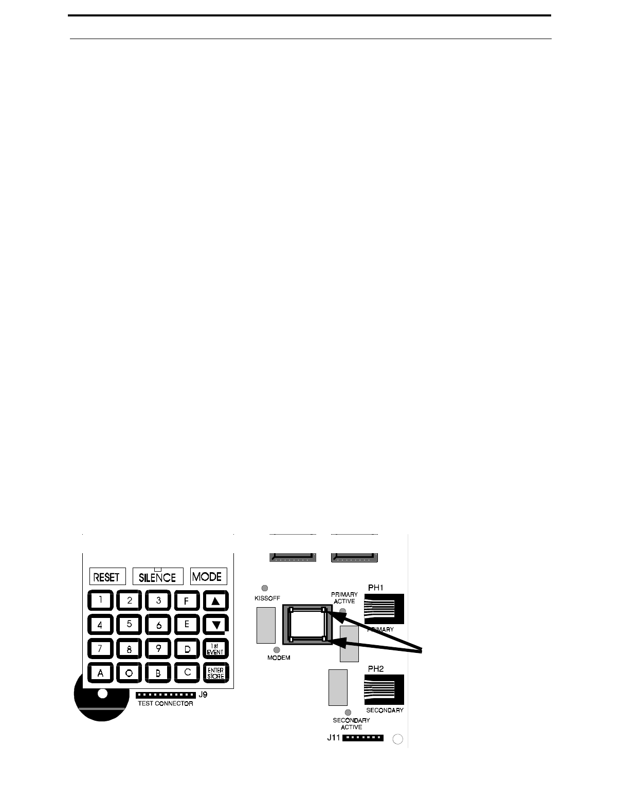
Document #50193 Rev. D 5/2/97 P/N 50193:D
85
Troubleshoot Mode
5.3.2 AC Line
Pressing A, followed by [ENTER/STORE], displays the AC input voltage as shown below. The AC ON indicator
will turn off when the AC line voltage drops below the Low Line threshold, and the trouble LED will turn on. Fol-
lowing is a list of the AC line voltage range:
5.3.3 Battery
Pressing B, followed by [ENTER/STORE], will display the Battery Voltage. Listed below are the critical battery
threshold conditions:
Note that voltage readings should be taken after allowing 48 hours to charge depleted batteries. If batteries do not
show normal readings, replace them.
5.3.4 Telephone Lines
Pressing C for touchtone dialing or D for rotary dialing, followed by the [ENTER/STORE] key, causes seizure of
the Primary phone line, which in turn lights the red LED, signifying Primary phone line active. After a delay of
three seconds, the control panel goes off-hook to acquire a dial tone.
The control panel keypad may be used as a telephone touchpad for number dialing. Once the first digit is pressed,
the display will move the C or D character one position to the left, while placing the digit to be dialed on the far-
thest right display position. Continue to press the phone numbers to be dialed. Successive depressions of the
[ENTER/STORE] key hangs up and picks up the phone (places the phone on or off the hook).
The secondary phone line may be tested by pressing the E key for touchtone dialing or the F key for rotary dialing
and then following the same procedure used for the primary phone line.
A handset may be temporarily connected across transformer T1 as illustrated in Figure 5-1. The handset, when
connected across T1, may be used only as an amplifier/speaker and telephone with the control panel used for num-
ber dialing.
Note that remote site upload or download is not possible while testing the phone lines in this portion of Trouble-
shoot Mode.
AC Line Voltage Low Line Normal High Line
MS-5210UD: 102 VAC 115 VAC 132 VAC
MS -5 210U D E: 204 VAC 2 20 VAC 264 VAC
Normal Low Battery No Battery
Battery Voltage: 27.6V 20.4V <17.4V
FIGURE 5-1:Handset/Speaker Connection
Both Primary and
Secondary Lines

Lamp Test
86
Document #50193 Rev.D 5/2/97 P/N 50193:D
5.3.5 NACs 1, 2, 3 and 4
•Pressing B1, followed by [ENTER/STORE], displays the voltage on NAC #1.
•Pressing B2, followed by [ENTER/STORE], displays the voltage on NAC #2.
•Pressing B3, followed by [ENTER/STORE], displays the voltage on NAC #3.
•Pressing B4, followed by [ENTER/STORE], displays the voltage on NAC #4.
NAC voltage readings are nominally -2.32 volts when an EOL resistor of correct value is in place. A reading of
0.00 volts will appear for a shorted output, -4.50 volts for an open output. Intermediate readings are also possible.
5.3.6 Resettable Power
Pressing the RESET key, followed by [ENTER/STORE], displays the resettable 24 volt power. Resettable 24
volt power must read 24 volts, + or - 10%.
5.4 Lamp Test
To perform a Lamp Test, press the MODE key followed by the 4-digit code 5267 and then the [ENTER/STORE]
key. This will test all system LEDs on the FACP. The LEDs will stay on for five seconds, then the control panel will
return to Normal Mode.
☛ 5267 spells LAMP on a Touch-Tone® phone.
5.5 Print Mode
Refer to Figure 2-13, “Remote Printer Connections,” on page 32 for proper PRT-24 Interface module connection to
the main circuit board before proceeding. A printer may be temporarily or permanently connected to the panel. Pro-
gram address '4' in Program Mode Level 3 to a '1' to enable printer supervision. Once enabled, normal system status
as well as panel operations will be printed. If the printer connection is removed, the system trouble LEDs will blink,
the system piezo sounders will pulse and the 4-character system LED display will read F__P.
Select Printer Mode by pressing the MODE key followed by the code 7746 then pressing the [ENTER/STORE] key.
The display will read Prn and the following time and date stamped data will be printed:
✓Entire program entries
✓History File
✓Walktest File
✓Troubleshoot Mode voltages
✓Current System Status
The fire protection remains active while in print mode. Remote site upload or download is allowed while in Print
Mode. An alarm on any zone will take priority, causing the panel to exit Print Mode.

Document #50193 Rev. D 5/2/97 P/N 50193:D
87
Printer Output
5.6 Printer Output
This section illustrates sample printouts for various panel modes.
Real Time Status
06-26-96 14:15:10
Zone 1 Verifying 2-Wire Smoke Detector Active 06-26-1996 14:15:20
Zone 2 2-Wire Smoke Detector Active 06-26-1996 14:15:24
Zone 2 Pull Station Active 06-26-1996 14:15:29
Zone 3 N.O. Contact Device Active 06-26-1996 14:15:34
Zone 4 Supervisory Active 06-26-1996 14:15:37
Zone 5 Waterflow, Silenceable Active 06-26-1996 14:15:45
Zone 6 Process Monitoring Active 06-26-1996 14:15:49
System Silenced 06-26-1996 14:15:53
NAC 1 Silence 06-26-1996 14:15:56
NAC 2 Silence 06-26-1996 14:15:59
Zone 1 Alarm Cleared 06-26-1996 14:16:03
Low Battery Detected 06-26-1996 14:16:09
Normal Battery 06-26-1996 14:16:15
Loss of AC Power 06-26-1996 14:16:19
AC Power Restore 06-26-1996 14:16:42
Drill Mode Entered 06-26-1996 14:16:51
System Reset 06-26-1996 14:17:25
Drill Mode Cleared 06-26-1996 14:17:33
Entering Walktest Mode
06-26-96 14:32:15
Zone 2 Pull Station Active 06-26-1996 14:33:20
Entering Trouble Shoot Mode 06-26-1996 14:47:12
Trouble Shoot Mode Data
06-26-96 14:47:12
Zone 1 Voltage =25.20
Zone 2 Voltage =25.18
Zone 3 Voltage =25.20
Zone 4 Voltage =25.20
Zone 5 Voltage =25.18
Zone 6 Voltage =25.18
Zone 7 Voltage =25.18
Zone 8 Voltage =25.20
Zone 9 Voltage =25.20
Zone 10 Voltage =25.20
AC Line Voltage =120.9
Battery Voltage =27.20
NAC 1 Voltage =-2.09
NAC 2 Voltage =-2.29
Resettable 24 Volts =26.03
Entering Lamp Test Mode
06-26-96 15:03:10
Entering Program Mode
06-26-96 15:08:13

Remote Site Upload/Download
88
Document #50193 Rev.D 5/2/97 P/N 50193:D
CHAPTER 6 Remote Site Upload/Download
The control panel may be programmed or interrogated off site via the public switched telephone network. Any per-
sonal computer with Windows® 3.1 or greater or Windows® 95, with a 1200 Baud Hayes™ compatible modem and
Fire•Lite Upload/Download software P/N PK-5210UD, may serve as a Service Terminal. For details on the remote
site upload/download software package, refer to the PK-5210UD manual. The Upload/Download software allows the
following:
•Download of the entire program
•Download of an individual program item at Levels 1 - 4
•Upload of the entire program
•Upload of an individual program item at Levels 1 - 4
•Download of a single program item (such as a Central Station phone number)
•Upload of the entire program plus History File, Walktest data, current status, system voltages or time & date
•Real-time upload, either continuous or 'snapshot' (one-time), of current status or system voltages
•Execution of control panel functions: Trouble Silence, Manual Evacuate, Manual Evacuate Restore, Zone/
NAC Disable, Zone/NAC Enable and Set Time & Date
CAUTION: Changes to program entries occur as a result of the downloading process. After successful downloading,
make certain to perform the following steps:
1. Print out all programmed data via Print Mode or manually view programmed entries and compare to intended
program data.
2. Test all affected panel operations.
3. Immediately correct any problems found.
6.1 Downloading Program: General
Any time that the control panel is downloaded, whether initiated at the jobsite or remotely, a secret code (factory
default 0000) is verified between the control panel and the Service Terminal. Changing the Secret Code may only be
accomplished at the Service Terminal and subsequently loaded into the control panel. Future upload or download
requests cause verification of the Secret Code by the control panel before processing of data is allowed. If the Secret
Code is not verified, the control panel will terminate the request immediately.
While the control panel is communicating with the Service Terminal, the panel's green Modem LED and one of the
red Line Seize LEDs will remain on steady. At the conclusion of a successful download transaction, the green
'Kissoff' LED will come on steady for one second. Upon termination of communication, the green Modem LED will
turn off and the red Line Seize LED will turn off.
In order to download the panel (whether initiated at the jobsite or remotely) the following must be true:
✓The control panel may be in any mode of operation including Normal, Program, History, Walk Test,
Print, Troubleshoot or Lamp Test. It is also possible during any of the function modes including Dis-
able, Enable and Drill. Downloading is not possible if the communicator is active during Central Sta-
tion communications or while testing the phone lines while in Troubleshoot Mode.
✓There cannot be any active communications ongoing with a Central Station receiver.
✓All active events must be successfully 'Kissed-off' by the Central Station(s). The Communicator must
be in a standby state with no new information waiting to be transmitted to a central station.
Two basic communication mechanisms are supported as follows:
!

Document #50193 Rev. D 5/2/97 P/N 50193:D
89
Downloading Program: General
•Download with callback - The Service Terminal calls the control panel. The control panel answers the call,
confirms the calling party then hangs up. The Service Terminal then waits for a callback from the control
panel. After the control panel calls the Central Station and successfully reports that a request for downloading
has been received, the control panel calls the Service Terminal back. Upon secret code verification, data trans-
fers occur. When the data transfers are completed and the Service Terminal disconnects from the control
panel, the panel calls the Central Station back to confirm either successful or nonsuccessful results.
•Download with callback disabled - The Service Terminal calls the control panel. No hang-up sequence occurs.
Data transfers proceed.
Note that Callback enable/disable is controlled by the master user at the Service Terminal on a per call basis.
With program address location 56 set to '1' in Program Mode Level 1, anytime a download with callback is initiated,
the first thing the control panel will do is one of the following:
•contact the primary Central Station
•contact both the primary and secondary Central Stations
•contact the first available Central Station phone number
Once contact has been established, the control panel will report a 'request for upload/download' message (depending
upon the program entry in Program Level 4 address location 42). Following 'kissoff' of the request by the Central
Station(s), the control panel will then call the appropriate Service Terminal and begin the downloading process.
With program address location 56 set to '1' in Program Mode Level 1, anytime a download with callback disabled is
initiated, the control panel and the Service Terminal will communicate and transfer data without first contacting a
Central Station. When the data transfers are completed and the control panel disconnects from the Service Terminal,
the control panel will call the Central Station and report one of the following conditions:
•Upload/download request received
•Upload and/or download successful
•Upload/download failed
To prevent the 'request for up/download' message(s) from being reported to the Central Station(s), make certain to
leave address 56 = 0 or disable all upload/download reports back to both Central Stations. Refer to Table 3-3 through
Table 3-8 for additional information.
During the downloading process, the fire protection remains active. Should a system trouble or alarm condition
occur, the control panel immediately terminates downloading and processes the trouble or alarm locally and trans-
mits the information to the Central Station(s).
6.1.1 Security Features
Remote site upload and download with the control panel has been carefully designed to include key security features
to ensure proper functionality. The key features are listed and explained below.
Secret Code Verification
A secret code is stored in the control panel by a Service Terminal to prevent unauthorized access. The secret code
is created at the Service Terminal by a Master user and cannot be viewed or changed by anyone other than a Master
user. Viewing of the secret code is prohibited at the control panel. Prior to allowing an upload or download of
data, the control panel will verify the secret code transmitted by the Service Terminal.
Time-out at Control Panel
Upon answering an incoming call on either the primary or secondary Central Station phone line, the panel will lis-
ten for a modem connection signal. If this signal is not received within 30 seconds, the panel will disconnect the
call.

Downloading Initiated at Control Panel
90
Document #50193 Rev.D 5/2/97 P/N 50193:D
Upon successful connection (i.e. secret code verified and callback completed, if applicable), if no communication
occurs within two minutes, the panel will disconnect the call.
Callback to Service Terminal
Anytime that the panel is remotely requested to allow an upload or download with callback, it will confirm the
source of the incoming call, hang-up and call the calling party (Service Terminal phone number) back.
Panel Identification Number (future)
The panel identification number will be used in the future to identify the panel to the Service Terminal (when the
panel calls the Service Terminal) automatically.
Calls initiated at the FACP must be coordinated at the Service Terminal manually. Note that the Service Terminal
will not pickup the incoming call unless operating on the communications screen. The Service Terminal will not
recognize an FACP initiated call unless the secret code is at the factory default settings.
Error Checking
As each block of data is received by the control panel, it is checked for accuracy. If an error is detected, the block
is retransmitted until correct, up to a maximum of four times. If the Secret Code is not verified and four errors
occur, the call is disconnected and the report that the upload/download was not successful is called to the Central
Station(s).
Central Station Acknowledge
There is an option whereby the control panel will report to one or both Central Station(s) that a request for upload-
ing or downloading has been received prior to processing the call. This is called the 'callback' option. If the Cen-
tral Station(s) does not acknowledge receipt of this request, up or downloading is prohibited. If acknowledged by
the Central Station(s), another message is transmitted informing the Central Station(s) of one of the following:
•downloading was successful
•uploading was successful
•uploading/downloading was not successful
Data Protection/Integrity
Options allow programming of single data entries, single programming levels (1 - 4) and the entire programming
of all four levels simultaneously. Use caution when selecting programming choices and verify all entries via an
upload or manual check at the FACP. Data blocks containing user programming options are protected from partial
programming due to faulty phone connections, line noise and other errors.
6.2 Downloading Initiated at Control Panel
Before initiating the Download procedure, make certain that the following conditions exist:
✓control panel is in Normal Mode
✓Central Station communications are off or Main Panel Options programming location 56 = 0
✓the communicator is in the standby state (red Line Seize, green Modem and green Kissoff LEDs are off)
Place the control panel into Program Mode and program one or both of the Service Terminal phone numbers. It is
also advisable at this time to coordinate this call with the Service Terminal operator to allow the Service Terminal
operator to easily identify the incoming call.
Exit the Program Mode and return the control panel to Normal Mode. Press the MODE key followed by the 4-digit
code 3696 and then the [ENTER/STORE] key.
☛ 3696 spells DOWN on a Touch-Tone® phone.

Document #50193 Rev. D 5/2/97 P/N 50193:D
91
Downloading Initiated at a Service Terminal
The display to the far left will flash the letter S. Press the digit '1' for Service Terminal phone #1 or '2' for Service Ter-
minal phone #2, followed by the [ENTER/STORE] key. The control panel will now call the appropriate Service Ter-
minal phone number. With the Service Terminal set up with the correct download customer file and operating in the
communications window, the downloading process may begin.
Once the called Service Terminal accepts the incoming call (control panel) and verifies the secret code, the download-
ing process is allowed to continue. Downloading progresses until all programmed information has been successfully
loaded into the control panel. Communication terminates upon the Service Terminal hanging up or upon the FACP
hanging up after a two minute time-out following completion of data transfer.
6.3 Downloading Initiated at a Service Terminal
Before initiating the Download procedure, make certain that the communicator is in the standby state; red Line Seize,
green Modem and green Kissoff LEDs are off.
Once an incoming call is accepted/answered by the control panel, the panel will:
1. Establish basic modem connection
2. Verify secret code
3. Verify callback vs. no callback request from the Service Terminal (if callback is requested, panel will perform
steps 4 through 10; if no callback is requested, panel will perform only steps 9 and 10)
4. Identify the Service Terminal location
5. Hang-up/disconnect call
6. Call the Central Station(s) and transmit a request for upload/download message (if programmed to do so). If
this message is accepted, the control panel will proceed to the next step
7. Return call to Service Terminal
8. Verify secret code
9. Begin downloading
10.Upon completion of download, call-back Central Station(s) and report a successful download or failed upload/
download status (if programmed to do so)
6.4 Uploading Initiated at a Service Terminal
Items that may be uploaded from the control panel to a Service Terminal include:
•All or portions of programmed data plus the real-time clock, time and date
•Entire Walk Test data file in real-time continuous or as a 'snapshot'
•Troubleshoot system voltages in real-time continuous or as a 'snapshot'
•Entire 256 event History File
•Current system status in real-time continuous or as a 'snapshot'
Uploading is possible at any time provided the following conditions are true:
✓The control panel may be in any mode of operation. Uploading is not possible if the communicator is
active or while testing the phone lines while in Troubleshoot Mode
✓There cannot be any active communications ongoing with the Central Station receiver
✓All active events must be successfully 'kissed-off' by the Central Stations (communicator must be in a
standby state with no new information waiting to be transmitted to a Central Station).
Once an incoming call is accepted/answered by the control panel, the panel will:

Simultaneous Data Transfers
92
Document #50193 Rev.D 5/2/97 P/N 50193:D
1. Establish basic modem connection
2. Verify secret code
3. Verify callback vs. no callback request from the Service Terminal (if callback is requested, the panel performs
steps 4 through 10; if no callback is requested, the panel performs only steps 9 and 10)
4. Identify the Service Terminal location
5. Hang-up/disconnect call
6. Call the Central Station(s) and transmit a request for upload/download message (if programmed to do so). If
this message is accepted, the control panel will proceed to the next step
7. Return call to Service Terminal
8. Verify secret code
9. Begin uploading
10.Upon completion of upload, call Central Station(s) back and report a successful upload or failed upload/down-
load status (if programmed to do so)
During the uploading process, the fire protection remains active. Should a system trouble or alarm condition
occur, the control panel immediately terminates uploading and processes the trouble or alarm locally and trans-
mits the information to the Central Station(s).
6.5 Simultaneous Data Transfers
Uploading and downloading may take place on a single telephone call. Control and selection of the data transaction
is coordinated at the Service Terminal. This eliminates multiple phone calls, allows instant verification of download
data files and simplifies the overall process.

Document #50193 Rev. D 5/2/97 P/N 50193:D
93
Battery Calculations
Appendix A Battery Calculations
Use the Total Standby and Alarm Load Currents calculated in Table A-2 and Table A-3 for the following battery
calculation.
Note:
1. 12 Ampere Hour battery can be located in the backbox.
2. Batteries larger than 12 Ampere Hour, up to 17 Ampere Hour, require the BB-17F battery box.
TABLE A-1: Battery Calculation
Standby Load
Current (amps)
[ ]
X
Required Standby Time in Hours
(24 or 60 Hours)
[ ]
= _______________
Alarm Load
Current (amps)
[ ] X
Required Alarm Time in Hours
(i.e. 5 min. = 0.084 hours)
[ ]
= _______________
Add Standby and Alarm Load for Required Ampere Hour Battery = _______________
Multiply by derating factor of 1.2 X 1.2 _______________

Battery Calculations
94
Document #50193 Rev.D 5/2/97 P/N 50193:D
A.1 Main Power Supply
The MS-5210UD provides regulated power for operating the fire alarm control panel, operating external devices and
operating the standby battery. The power for operating external devices is limited. Use Table A-2 (standby or non-
alarm) and Table A-3 (alarm) to determine if external loading is within the capabilities of the power supply.
Be certain to power 4-wire smoke detectors from TB2, Terminals 3 and 4. In Table A-2 , external devices are con-
nected to TB2 only.
1. Refer to the Device Compatibility Document for 2-wire smoke detector standby current.
2. Must use compatible listed Power Supervision Relay.
3. The total standby current must include both the resettable (TB2 Terminals 3 & 4) and nonresettable
(TB2 Terminals 1 & 2) power. Caution must be taken to ensure that current drawn from these out-
puts during alarm does not exceed maximum ratings specified (see Table A-2 ).
TABLE A-2: Regulated Load in Standby @24 VDC .
Device Type # of
Devices Current
(amps) Total Current
(amps)
Main Circuit Board 1 X 0.138 = 0.138
LED-10IM (1 max.) X 0.017 =
PRT-24 (1 max.) X 0 = 0
CAC-10F (1 max.) X 0.004 =
NAC-REM (1 max.) X 0.002 =
2-wire Detector
Heads [ ] X [ ]1=
4-wire Detector
Heads [ ] X [ ]1=
Power Supervision
Relays2[ ] X 0.025 =
Current Draw from
TB2 (nonalarm3)=
Sum Column for Standby Load = amps

Document #50193 Rev. D 5/2/97 P/N 50193:D
95
Battery Calculations
1. The current shown represents one zone on the Main Circuit Board in alarm. For all ten zones in alarm,
the current draw increases to 0.590 amps with communicator off and 0.610 amps with communicator on.
2. Current limitations of terminals:
TB2, Terminals 1 and 2 = 0.500 amps, regulated filtered, 24 VDC +/-5%, 120 Hz ripple @
10 mVRMS, nonresettable power (100 Hz ripple if MS-5210UDE)
TB2, Terminals 3 and 4 = 0.500 amps, regulated filtered, 24 VDC +/-5%, 120 Hz ripple @
10 mVRMS, resettable power (100 Hz ripple if MS-5210UDE)
3. Must use compatible listed Power Supervision Relay
4. Current limitation of Terminal TB4 circuits is 3.0 amps per Notification Appliance Circuit
5. Current limitations of NAC-REM module circuits is 1.5 amps per Notification Appliance Circuit.
6. Total current draw listed above cannot exceed:
• 3.6 amps with standard transformer installed (only)
• 6.6 amp with both the standard and optional transformers installed
TABLE A-3: Regulated Load in Alarm @24 VDC .
Device Type # of
Devices Current
(amps) Total Current
(amps)
Main Circuit Board 1 X 0.245 = 0.2451
LED-10IM (1 max.) X 0.017 =
PRT-24 (1 max.) X 0 = 0
CAC-10F (1 max.) X 0.020 =
NAC-REM (1 max.) X 0.075 =
4-wire Smoke Detector2[ ] X [ ] =
Power Supervision Relay3[ ] X 0.025 =
Notification Appliances4[ ] X [ ] =
Notification Appliances5[ ] x [ ] =
Current Draw from TB22
(alarm current) =
Sum Column for Standby Load6= amps

Main Panel Options Program Sheets
96
Document #50193 Rev.D 5/2/97 P/N 50193:D
Appendix B Main Panel Options Program Sheets
---To enter Programming Level 1, press the MODE key, 7764, '1', [ENTER/STORE]
❏00 ❏01 ❏02 ❏03 ❏04 ❏05 ❏06 ❏07 ❏08 ❏09 ❏10 ❏11 ❏12 ❏13 ❏14 ❏15
Addresses 00 to 15 store the Primary Central Station Phone Number. Enter 'F' to represent the end of number.
❏16 Primary Central Station Communication Format: Enter 0 - F.
❏17 ❏18 ❏19 ❏20 Primary Central Station Account Code: Valid keys are 0 - F.
❏21 ❏22 ❏23 ❏24 Primary Central Station 24-Hour Test Time. Enter military time (i.e. 1400 for 2:00 PM).
❏25 Primary Number Test Time Interval. Enter '0' for 24-hour; '1' for 12-hour; '2' for 8-hour; '3' for 6-hour.
❏26 ❏27 ❏28 ❏29 ❏30 ❏31 ❏32 ❏33 ❏34 ❏35 ❏36 ❏37 ❏38 ❏39 ❏40 ❏41
Addresses 26 to 41 store the Secondary Central Station Phone Number. Enter 'F' to represent the end of number.
❏42 Secondary Central Station Communication Format: Enter 0 - F.
❏43 ❏44 ❏45 ❏46 Secondary Central Station Account Code: Valid keys are 0 - F.
❏47 ❏48 ❏49 ❏50 Secondary Central Station 24-Hour Test Time. Enter military time (i.e. 1400 for 2:00 PM).
❏51 Secondary Number Test Time Interval. Enter '0' for 24-hour; '1' for 12-hour; '2' for 8-hour; '3' for 6-hour.
❏52 Alarm Presignal. Enter '0' to disable; '1' to enable.
❏53 ❏54 ❏55 Alarm Presignal Delay Time. Enter 0 - 179 additional seconds (default = 120 seconds).
❏56 Communicator/Fire Panel Selection. Enter '0' for fire panel only; '1' for fire panel/communicator operation.
❏57 Backup Reporting. Enter '0' to report to secondary phone number as backup only; '1' to report to both primary
and secondary phone number for all reports/messages; '2' reports go to first available receiver.
❏58 Touchtone/Rotary Select for Primary Phone. Enter '0' for touchtone dialing; '1' for rotary dialing.
❏59 Make/Break Ratio for Primary Phone. Enter '0' for 67/33 ratio; '1' for 62/38 ratio.
❏60 Touchtone/Rotary Select for Secondary Phone. Enter '0' for touchtone dialing; '1' for rotary dialing.
❏61 Make/Break Ratio for Secondary Phone. Enter '0' for 67/33 ratio; '1' for 62/38 ratio.
❏62 Future use.
❏63 Future use.

Document #50193 Rev. D 5/2/97 P/N 50193:D
97
Main Panel Options Program Sheets
❏64 Zone 1 Function Select. Enter '0' for 2-wire smoke detectors; '1' for pull station; '2' for normally-open contact
devices; '3' for supervisory devices; '4' for supervisory devices (autoresettable); '5' for waterflow (silenceable); '6' for
waterflow (nonsilenceable); '7' for process monitoring; '8' for autoresettable process monitoring; '9' for remote reset
switch; 'A' for remote silence switch; 'B' for remote acknowledge switch; 'C' for remote manual evacuate (drill)
switch.
❏65 Zone 2 Function Select. Enter '0' for 2-wire smoke detectors; '1' for pull station; '2' for normally-open contact
devices; '3' for supervisory devices; '4' for supervisory devices (autoresettable); '5' for waterflow (silenceable); '6' for
waterflow (nonsilenceable); '7' for process monitoring; '8' for autoresettable process monitoring; '9' for remote reset
switch; 'A' for remote silence switch; 'B' for remote acknowledge switch; 'C' for remote manual evacuate (drill)
switch.
❏66 Zone 3 Function Select. Enter '0' for 2-wire smoke detectors; '1' for pull station; '2' for normally-open contact
devices; '3' for supervisory devices; '4' for supervisory devices (autoresettable); '5' for waterflow (silenceable); '6' for
waterflow (nonsilenceable); '7' for process monitoring; '8' for autoresettable process monitoring; '9' for remote reset
switch; 'A' for remote silence switch; 'B' for remote acknowledge switch; 'C' for remote manual evacuate (drill)
switch.
❏67 Zone 4 Function Select. Enter '0' for 2-wire smoke detectors; '1' for pull station; '2' for normally-open contact
devices; '3' for supervisory devices; '4' for supervisory devices (autoresettable); '5' for waterflow (silenceable); '6' for
waterflow (nonsilenceable); '7' for process monitoring; '8' for autoresettable process monitoring; '9' for remote reset
switch; 'A' for remote silence switch; 'B' for remote acknowledge switch; 'C' for remote manual evacuate (drill)
switch.
❏68 Zone 5 Function Select. Enter '0' for 2-wire smoke detectors; '1' for pull station; '2' for normally-open contact
devices; '3' for supervisory devices; '4' for supervisory devices (autoresettable); '5' for waterflow (silenceable); '6' for
waterflow (nonsilenceable); '7' for process monitoring; '8' for autoresettable process monitoring; '9' for remote reset
switch; 'A' for remote silence switch; 'B' for remote acknowledge switch; 'C' for remote manual evacuate (drill)
switch.
❏69 Zone 6 Function Select. Enter '0' for 2-wire smoke detectors; '1' for pull station; '2' for normally-open contact
devices; '3' for supervisory devices; '4' for supervisory devices (autoresettable); '5' for waterflow (silenceable); '6' for
waterflow (nonsilenceable); '7' for process monitoring; '8' for autoresettable process monitoring; '9' for remote reset
switch; 'A' for remote silence switch; 'B' for remote acknowledge switch; 'C' for remote manual evacuate (drill)
switch.
❏70 Zone 7 Function Select. Enter '0' for 2-wire smoke detectors; '1' for pull station; '2' for normally-open contact
devices; '3' for supervisory devices; '4' for supervisory devices (autoresettable); '5' for waterflow (silenceable); '6' for
waterflow (nonsilenceable); '7' for process monitoring; '8' for autoresettable process monitoring; '9' for remote reset
switch; 'A' for remote silence switch; 'B' for remote acknowledge switch; 'C' for remote manual evacuate (drill)
switch.
❏71 Zone 8 Function Select. Enter '0' for 2-wire smoke detectors; '1' for pull station; '2' for normally-open contact
devices; '3' for supervisory devices; '4' for supervisory devices (autoresettable); '5' for waterflow (silenceable); '6' for
waterflow (nonsilenceable); '7' for process monitoring; '8' for autoresettable process monitoring; '9' for remote reset
switch; 'A' for remote silence switch; 'B' for remote acknowledge switch; 'C' for remote manual evacuate (drill)
switch.
❏72 Zone 9 Function Select. Enter '0' for 2-wire smoke detectors; '1' for pull station; '2' for normally-open contact
devices; '3' for supervisory devices; '4' for supervisory devices (autoresettable); '5' for waterflow (silenceable); '6' for
waterflow (nonsilenceable); '7' for process monitoring; '8' for autoresettable process monitoring; '9' for remote reset
switch; 'A' for remote silence switch; 'B' for remote acknowledge switch; 'C' for remote manual evacuate (drill)
switch.

Main Panel Options Program Sheets
98
Document #50193 Rev.D 5/2/97 P/N 50193:D
❏73 Zone 10 Function Select. Enter '0' for 2-wire smoke detectors; '1' for pull station; '2' for normally-open contact
devices; '3' for supervisory devices; '4' for supervisory devices (autoresettable); '5' for waterflow (silenceable); '6' for
waterflow (nonsilenceable); '7' for process monitoring; '8' for autoresettable process monitoring; '9' for remote reset
switch; 'A' for remote silence switch; 'B' for remote acknowledge switch; 'C' for remote manual evacuate (drill)
switch.
❏74 ❏75 Waterflow Retard Timer. Enter 0 - 89 additional seconds.
❏76 Alarm Verification. Enter '0' for no verification; '1' for verification of all 2-wire smoke zones.
❏77 AC Loss Delay. Enter '0' for 6 hours; '1' for 7 hours; '2' for 8 hours; '3' for 9 hours; '4' for 10 hours; '5' for 11
hours; '6' for 12 hours; '7' for 15 hours; '8' for 16 hours; '9' for 17 hours; 'A' for 18 hours; 'B' for 19 hours; 'C' for 20
hours; 'D' for 21 hours; 'E' for 22 hours; 'F' for 23 hours.
❏78 Programmable Relay #1 Definition. Enter '0' for alarm; '1' for supervisory; '2' for supervisory autoresettable; '3'
for trouble; '4' for communications fail; '5' for process monitoring; '6' for process monitoring autoresettable.
❏79 Programmable Relay #2 Definition. Enter '0' for alarm; '1' for supervisory; '2' for supervisory autoresettable; '3'
for trouble; '4' for communications fail; '5' for process monitoring; '6' for process monitoring autoresettable.
❏80 Notification Appliance Circuit #1 Selection. Enter '0' for enabled (silenceable); '1' for enable (nonsilenceable);
'2' for disable.
❏81 Silence Inhibit NAC #1. Enter '0' for no silence inhibit; '1' to inhibit silencing of NAC #1 for one minute.
❏82 Auto Silence NAC #1. Enter '0' for no auto silence; '1' for 5 minutes; '2' for 10 minutes; '3' for 15 minutes; '4'
for 20 minutes; '5' for 25 minutes; '6' for 30 minutes.
❏83 Coding NAC #1. Enter '0' for steady; '1' for March Time (120 ppm); '2' for California (10 seconds On, 5 sec-
onds Off); '3' for Temporal (½ second On, ½ second Off, ½ second On, ½ second Off, ½ second On, 1½ seconds Off).
❏84 Notification Appliance Circuit #2 Selection. Enter '0' for enabled (silenceable); '1' for enable (nonsilenceable);
'2' for disable.
❏85 Silence Inhibit NAC #2. Enter '0' for no silence inhibit; '1' to inhibit silencing of NAC #2 for one minute.
❏86 Auto Silence NAC #2. Enter '0' for no auto silence; '1' for 5 minutes; '2' for 10 minutes; '3' for 15 minutes; '4'
for 20 minutes; '5' for 25 minutes; '6' for 30 minutes.
❏87 Coding NAC #2. Enter '0' for steady; '1' for March Time (120 ppm); '2' for California (10 seconds On, 5 sec-
onds Off); '3' for Temporal (½ second On, ½ second Off, ½ second On, ½ second Off, ½ second On, 1½ seconds Off).
❏88 Trouble Reminder. Enter '0' to disable; '1' to enable.

Document #50193 Rev. D 5/2/97 P/N 50193:D
99
Main Panel Options Program Sheets
Main Panel Options Programming Sheets (Factory Default Settings)
---To enter Programming Level 1, press the MODE key, 7764, '1', [ENTER/STORE]
❏00 ❏01 ❏02 ❏03 ❏04 ❏05 ❏06 ❏07 ❏08 ❏09 ❏10 ❏11 ❏12 ❏13 ❏14 ❏15
Addresses 00 to 15 store the Primary Central Station Phone Number. Enter 'F' to represent the end of number.
❏16 Primary Central Station Communication Format: ('E' for Ademco Contact ID Format).
❏17 ❏18 ❏19 ❏20 Primary Central Station Account Code.
❏21 ❏22 ❏23 ❏24 Primary Central Station 24-Hour Test Time. 0000 = 12:00 midnight.
❏25 Primary Central Station Number Test Time Interval. '0' for 24-hour.
❏26 ❏27 ❏28 ❏29 ❏30 ❏31 ❏32 ❏33 ❏34 ❏35 ❏36 ❏37 ❏38 ❏39 ❏40 ❏41
Addresses 26 to 41 store the Secondary Central Station Phone Number. Enter 'F' to represent the end of number.
❏42 Secondary Central Station Communication Format: ('E' for Ademco Contact ID Format).
❏43 ❏44 ❏45 ❏46 Secondary Central Station Account Code.
❏47 ❏48 ❏49 ❏50 Secondary Central Station 24-Hour Test Time. 0000 = 12:00 midnight.
❏51 Secondary Number Test Time Interval. '0' for 24-hour.
❏52 Alarm Presignal. '0' for no alarm presignal.
❏53 ❏54 ❏55 Alarm Presignal Delay Time. 120 second alarm presignal delay.
❏56 Communicator/Fire Panel Selection. '0' for panel only operation.
❏57 Backup Reporting. '0' to report to Secondary Central Station phone # as backup only.
❏58 Touchtone/Rotary Select for Primary Phone. '0' for touchtone dialing.
❏59 Make/Break Ratio for Primary Phone. '0' for 67/33 ratio.
❏60 Touchtone/Rotary Select for Secondary Phone. '0' for touchtone dialing.
❏61 Make/Break Ratio for Secondary Phone. '0' for 67/33 ratio.
❏62 Future use. Leave default of '0'.
❏63 Future use. Leave default of '0'.
❏64 Zone 1 Function Select. '0' for 2-wire smoke detectors.
❏65 Zone 2 Function Select. '0' for 2-wire smoke detector.
❏66 Zone 3 Function Select. '0' for 2-wire smoke detectors.
F F F F F F F F F F F F F F F F
E
0 0 0 0
0 0 0 0
0
F F F F F F F F F F F F F F F F
E
0 0 0 0
0 0 0 0
0
0
1 2 0
0
0
0
0
0
0
0
0
0
0
0

Main Panel Options Program Sheets
100
Document #50193 Rev.D 5/2/97 P/N 50193:D
❏67 Zone 4 Function Select. '0' for 2-wire smoke detectors.
❏68 Zone 5 Function Select. '0' for 2-wire smoke detectors.
❏69 Zone 6 Function Select. '0' for 2-wire smoke detectors.
❏70 Zone 7 Function Select. '0' for 2-wire smoke detectors.
❏71 Zone 8 Function Select. '0' for 2-wire smoke detectors.
❏72 Zone 9 Function Select. '0' for 2-wire smoke detectors.
❏73 Zone 10 Function Select. '0' for 2-wire smoke detectors.
❏74 ❏75 Waterflow Retard Timer. '00' for no delay.
❏76 Alarm Verification. '0' for no verification.
❏77 AC Loss Delay. '0' for 6 hours.
❏78 Programmable Relay #1 Definition. '0' for alarm.
❏79 Programmable Relay #2 Definition. '3' for trouble.
❏80 Notification Appliance Circuit #1 Selection. '0' for enabled (silenceable).
❏81 Silence Inhibit NAC #1. '0' for no silence inhibit.
❏82 Auto Silence NAC #1. '0' for no auto silence.
❏83 Coding NAC #1. '0' for steady, no coding.
❏84 Notification Appliance Circuit #2 Selection. '0' for enabled (silenceable).
❏85 Silence Inhibit NAC #2. '0' for no silence inhibit.
❏86 Auto Silence NAC #2. '0' for no auto silence.
❏87 Coding NAC #2. '0' for steady, no coding.
❏88 Trouble Reminder. '0' to disable, no trouble reminder.
0
0
0
0
0
0
0
0 0
0
0
0
3
0
0
0
0
0
0
0
0
0

Document #50193 Rev. D 5/2/97 P/N 50193:D
101
Event Codes/Transmission Format Programming Sheets
Appendix C Event Codes/Transmission Format
Programming Sheets
---To enter Programming Level 2, press the MODE key, 7764, '2', [ENTER/STORE]
4+2 Standard and 4+2 Express Formats Primary Central Station
❏0❏1❏2❏3❏4❏5❏6❏7❏8❏9❏10 ❏11 ❏12
❏13 ❏14 ❏15 ❏16 ❏17 ❏18 ❏19 ❏20 ❏21 ❏22 ❏23 ❏24 ❏25
❏26 ❏27 ❏28 ❏29 ❏30 ❏31 ❏32 ❏33 ❏34 ❏35 ❏36 ❏37 ❏38
❏39 ❏40 ❏41 ❏42 ❏43 ❏44 ❏45 ❏46 ❏47 ❏48 ❏49 ❏50 ❏51
❏52 ❏53 ❏54 ❏55 ❏56 ❏57 ❏58 ❏59 ❏60 ❏61 ❏62 ❏63 ❏64
❏65 ❏66 ❏67 ❏68 ❏69 ❏70 ❏71 ❏72 ❏73 ❏74 ❏75 ❏76 ❏77
❏78 ❏79 ❏80 ❏81 ❏82 ❏83 ❏84 ❏85 ❏86 ❏87 ❏88 ❏89 ❏90
❏91 ❏92 ❏93 ❏94 ❏95 ❏96 ❏97 ❏98 ❏99 ❏100 ❏101 ❏102 ❏103
❏104 ❏105 ❏106 ❏107 ❏108 ❏109 ❏110 ❏111 ❏112 ❏113 ❏114 ❏115 ❏116
❏117 ❏118 ❏119 ❏120 ❏121 ❏122 ❏123 ❏124 ❏125 ❏126 ❏127 ❏128 ❏129
❏130 ❏131 ❏132 ❏133 ❏134 ❏135 ❏136 ❏137 ❏138 ❏139 ❏140 ❏141 ❏142
❏143 ❏144 ❏145 ❏146 ❏147 ❏148 ❏149 ❏150 ❏151 ❏152 ❏153 ❏154 ❏155
❏156 ❏157 ❏158 ❏159 ❏160 ❏161 ❏162 ❏163 ❏164 ❏165 ❏166 ❏167 ❏168
❏169 ❏170 ❏171 ❏172 ❏173 ❏174 ❏175 ❏176 ❏177 ❏178 ❏179 ❏180 ❏181
❏182 ❏183 ❏184 ❏185 ❏186 ❏187 ❏188 ❏189 ❏190 ❏191 ❏192 ❏193 ❏194
❏195 ❏196 ❏197 ❏198 ❏199 ❏200 ❏201 ❏202 ❏203 ❏204 ❏205 ❏206 ❏207
❏208 ❏209 ❏210 ❏211 ❏212 ❏213 ❏214 ❏215

Event Codes/Transmission Format Programming Sheets
102
Document #50193 Rev.D 5/2/97 P/N 50193:D
Event Codes/Transmission Formats Programming Sheets for 4+2 Standard
and 4+2 Express Formats Secondary Central Station
❏216 ❏217 ❏218 ❏219 ❏220 ❏221 ❏222 ❏223 ❏224 ❏225 ❏226 ❏227 ❏228
❏229 ❏230 ❏231 ❏232 ❏233 ❏234 ❏235 ❏236 ❏237 ❏238 ❏239 ❏240 ❏241
❏242 ❏243 ❏244 ❏245 ❏246 ❏247 ❏248 ❏249 ❏250 ❏251 ❏252 ❏253 ❏254
❏255 ❏256 ❏257 ❏258 ❏259 ❏260 ❏261 ❏262 ❏263 ❏264 ❏265 ❏266 ❏267
❏268 ❏269 ❏270 ❏271 ❏272 ❏273 ❏274 ❏275 ❏276 ❏277 ❏278 ❏279 ❏280
❏281 ❏282 ❏283 ❏284 ❏285 ❏286 ❏287 ❏288 ❏289 ❏290 ❏291 ❏292 ❏293
❏294 ❏295 ❏296 ❏297 ❏298 ❏299 ❏300 ❏301 ❏302 ❏303 ❏304 ❏305 ❏306
❏307 ❏308 ❏309 ❏310 ❏311 ❏312 ❏313 ❏314 ❏315 ❏316 ❏317 ❏318 ❏319
❏320 ❏321 ❏322 ❏323 ❏324 ❏325 ❏326 ❏327 ❏328 ❏329 ❏330 ❏331 ❏332
❏333 ❏334 ❏335 ❏336 ❏337 ❏338 ❏339 ❏340 ❏341 ❏342 ❏343 ❏344 ❏345
❏346 ❏347 ❏348 ❏349 ❏350 ❏351 ❏352 ❏353 ❏354 ❏355 ❏356 ❏357 ❏358
❏359 ❏360 ❏361 ❏362 ❏363 ❏364 ❏365 ❏366 ❏367 ❏368 ❏369 ❏370 ❏371
❏372 ❏373 ❏374 ❏375 ❏376 ❏377 ❏378 ❏379 ❏380 ❏381 ❏382 ❏383 ❏384
❏385 ❏386 ❏387 ❏388 ❏389 ❏390 ❏391 ❏392 ❏393 ❏394 ❏395 ❏396 ❏397
❏398 ❏399 ❏400 ❏401 ❏402 ❏403 ❏404 ❏405 ❏406 ❏407 ❏408 ❏409 ❏410
❏411 ❏412 ❏413 ❏414 ❏415 ❏416 ❏417 ❏418 ❏419 ❏420 ❏421 ❏422 ❏423
❏424 ❏425 ❏426 ❏427 ❏428 ❏429 ❏430 ❏431

Document #50193 Rev. D 5/2/97 P/N 50193:D
103
Event Codes/Transmission Format Programming Sheets
---To enter Programming Level 2, press the MODE key, 7764, '2', [ENTER/STORE]
Event Codes/Transmission Format Programming Reference Sheet (factory
defaults) 4+2 Standard and 4+2 Express Formats Primary Central Station
❏0❏1❏2❏3❏4❏5❏6❏7❏8❏9❏10 ❏11 ❏12
❏13 ❏14 ❏15 ❏16 ❏17 ❏18 ❏19 ❏20 ❏21 ❏22 ❏23 ❏24 ❏25
❏26 ❏27 ❏28 ❏29 ❏30 ❏31 ❏32 ❏33 ❏34 ❏35 ❏36 ❏37 ❏38
❏39 ❏40 ❏41 ❏42 ❏43 ❏44 ❏45 ❏46 ❏47 ❏48 ❏49 ❏50 ❏51
❏52 ❏53 ❏54 ❏55 ❏56 ❏57 ❏58 ❏59 ❏60 ❏61 ❏62 ❏63 ❏64
❏65 ❏66 ❏67 ❏68 ❏69 ❏70 ❏71 ❏72 ❏73 ❏74 ❏75 ❏76 ❏77
❏78 ❏79 ❏80 ❏81 ❏82 ❏83 ❏84 ❏85 ❏86 ❏87 ❏88 ❏89 ❏90
❏91 ❏92 ❏93 ❏94 ❏95 ❏96 ❏97 ❏98 ❏99 ❏100 ❏101 ❏102 ❏103
❏104 ❏105 ❏106 ❏107 ❏108 ❏109 ❏110 ❏111 ❏112 ❏113 ❏114 ❏115 ❏116
❏117 ❏118 ❏119 ❏120 ❏121 ❏122 ❏123 ❏124 ❏125 ❏126 ❏127 ❏128 ❏129
❏130 ❏131 ❏132 ❏133 ❏134 ❏135 ❏136 ❏137 ❏138 ❏139 ❏140 ❏141 ❏142
❏143 ❏144 ❏145 ❏146 ❏147 ❏148 ❏149 ❏150 ❏151 ❏152 ❏153 ❏154 ❏155
❏156 ❏157 ❏158 ❏159 ❏160 ❏161 ❏162 ❏163 ❏164 ❏165 ❏166 ❏167 ❏168
❏169 ❏170 ❏171 ❏172 ❏173 ❏174 ❏175 ❏176 ❏177 ❏178 ❏179 ❏180 ❏181
❏182 ❏183 ❏184 ❏185 ❏186 ❏187 ❏188 ❏189 ❏190 ❏191 ❏192 ❏193 ❏194
❏195 ❏196 ❏197 ❏198 ❏199 ❏200 ❏201 ❏202 ❏203 ❏204 ❏205 ❏206 ❏207
❏208 ❏209 ❏210 ❏211 ❏212 ❏213 ❏214 ❏215
1112131415161
718191A414243
4445464748494
A9792F1F2F3F4
F5F6F7F8F9FA6
1626364656667
68694B4C4D4E6
A6 B6 C6 D6 E6 FE1
E2 E3 E4 E5 E6 E7 E
8E9EA51525354
55565758595A9
893D1D2D3D4D5
D6 D7 D8 D9 DAA1 A
2A3A4A5A6A7A8
A95B5C5D5EAAA
BACADAEAF9991
71727374

Event Codes/Transmission Format Programming Sheets
104
Document #50193 Rev.D 5/2/97 P/N 50193:D
Event Codes/Transmission Formats Programming Reference Sheet (factory
defaults) for 4+2 Standard and 4+2 Express Formats Secondary Central
Station
❏216 ❏217 ❏218 ❏219 ❏220 ❏221 ❏222 ❏223 ❏224 ❏225 ❏226 ❏227 ❏228
❏229 ❏230 ❏231 ❏232 ❏233 ❏234 ❏235 ❏236 ❏237 ❏238 ❏239 ❏240 ❏241
❏242 ❏243 ❏244 ❏245 ❏246 ❏247 ❏248 ❏249 ❏250 ❏251 ❏252 ❏253 ❏254
❏255 ❏256 ❏257 ❏258 ❏259 ❏260 ❏261 ❏262 ❏263 ❏264 ❏265 ❏266 ❏267
❏268 ❏269 ❏270 ❏271 ❏272 ❏273 ❏274 ❏275 ❏276 ❏277 ❏278 ❏279 ❏280
❏281 ❏282 ❏283 ❏284 ❏285 ❏286 ❏287 ❏288 ❏289 ❏290 ❏291 ❏292 ❏293
❏294 ❏295 ❏296 ❏297 ❏298 ❏299 ❏300 ❏301 ❏302 ❏303 ❏304 ❏305 ❏306
❏307 ❏308 ❏309 ❏310 ❏311 ❏312 ❏313 ❏314 ❏315 ❏316 ❏317 ❏318 ❏319
❏320 ❏321 ❏322 ❏323 ❏324 ❏325 ❏326 ❏327 ❏328 ❏329 ❏330 ❏331 ❏332
❏333 ❏334 ❏335 ❏336 ❏337 ❏338 ❏339 ❏340 ❏341 ❏342 ❏343 ❏344 ❏345
❏346 ❏347 ❏348 ❏349 ❏350 ❏351 ❏352 ❏353 ❏354 ❏355 ❏356 ❏357 ❏358
❏359 ❏360 ❏361 ❏362 ❏363 ❏364 ❏365 ❏366 ❏367 ❏368 ❏369 ❏370 ❏371
❏372 ❏373 ❏374 ❏375 ❏376 ❏377 ❏378 ❏379 ❏380 ❏381 ❏382 ❏383 ❏384
❏385 ❏386 ❏387 ❏388 ❏389 ❏390 ❏391 ❏392 ❏393 ❏394 ❏395 ❏396 ❏397
❏398 ❏399 ❏400 ❏401 ❏402 ❏403 ❏404 ❏405 ❏406 ❏407 ❏408 ❏409 ❏410
❏411 ❏412 ❏413 ❏414 ❏415 ❏416 ❏417 ❏418 ❏419 ❏420 ❏421 ❏422 ❏423
❏424 ❏425 ❏426 ❏427 ❏428 ❏429 ❏430 ❏431
1112131415161
718191A414243
4445464748494
A9792F1F2F3F4
F5F6F7F8F9FA6
1626364656667
68694B4C4D4E6
A6 B6 C6 D6 E6 FE1
E2 E3 E4 E5 E6 E7 E
8E9EA51525354
55565758595A9
893D1D2D3D4D5
D6 D7 D8 D9 DAA1 A
2A3A4A5A6A7A8
A95B5C5D5EAAA
BACADAEAF9991
71727374

Document #50193 Rev. D 5/2/97 P/N 50193:D
105
Event Codes/Transmission Format Programming Sheets
---To enter Programming Level 2, press the MODE key, 7764, '2', [ENTER/STORE]
Event Codes/Transmission Format Programming Sheets for All 3+1, All 4+1
and 4+2 Expanded Formats Primary Central Station
❏0❏1❏2❏3❏4❏5❏6❏7❏8❏9❏10 ❏11 ❏12
❏13 ❏14 ❏15 ❏16 ❏17 ❏18 ❏19 ❏20 ❏21 ❏22 ❏23 ❏24 ❏25
❏26 ❏27 ❏28 ❏29 ❏30 ❏31 ❏32 ❏33 ❏34 ❏35 ❏36 ❏37 ❏38
❏39 ❏40 ❏41 ❏42 ❏43 ❏44 ❏45 ❏46 ❏47 ❏48 ❏49 ❏50 ❏51
❏52 ❏53 ❏54 ❏55 ❏56 ❏57 ❏58 ❏59 ❏60 ❏61 ❏62 ❏63 ❏64
❏65 ❏66 ❏67 ❏68 ❏69 ❏70 ❏71 ❏72 ❏73 ❏74 ❏75 ❏76 ❏77
❏78 ❏79 ❏80 ❏81 ❏82 ❏83 ❏84 ❏85 ❏86 ❏87 ❏88 ❏89 ❏90
❏91 ❏92 ❏93 ❏94 ❏95 ❏96 ❏97 ❏98 ❏99 ❏100 ❏101 ❏102 ❏103
❏104 ❏105 ❏106 ❏107
Event Codes/Transmission Format Programming Sheets for All 3+1, All 4+1
and 4+2 Expanded Formats Secondary Central Station
❏216 ❏217 ❏218 ❏219 ❏220 ❏221 ❏222 ❏223 ❏224 ❏225 ❏226 ❏227 ❏228
❏229 ❏230 ❏231 ❏232 ❏233 ❏234 ❏235 ❏236 ❏237 ❏238 ❏239 ❏240 ❏241
❏242 ❏243 ❏244 ❏245 ❏246 ❏247 ❏248 ❏249 ❏250 ❏251 ❏252 ❏253 ❏254
❏255 ❏256 ❏257 ❏258 ❏259 ❏260 ❏261 ❏262 ❏263 ❏264 ❏265 ❏266 ❏267
❏268 ❏269 ❏270 ❏271 ❏272 ❏273 ❏274 ❏275 ❏276 ❏277 ❏278 ❏279 ❏280
❏281 ❏282 ❏283 ❏284 ❏285 ❏286 ❏287 ❏288 ❏289 ❏290 ❏291 ❏292 ❏293
❏294 ❏295 ❏296 ❏297 ❏298 ❏299 ❏300 ❏301 ❏302 ❏303 ❏304 ❏305 ❏306
❏307 ❏308 ❏309 ❏310 ❏311 ❏312 ❏313 ❏314 ❏315 ❏316 ❏317 ❏318 ❏319
❏320 ❏321 ❏322 ❏323

Event Codes/Transmission Format Programming Sheets
106
Document #50193 Rev.D 5/2/97 P/N 50193:D
---To enter Programming Level 2, press the MODE key, 7764, '2', [ENTER/STORE]
Event Codes/Format Programming Reference Sheets Factory Defaults for All
3+1, All 4+1 and 4+2 Expanded Formats Primary Central Station
❏0❏1❏2❏3❏4❏5❏6❏7❏8❏9❏10 ❏11 ❏12
❏13 ❏14 ❏15 ❏16 ❏17 ❏18 ❏19 ❏20 ❏21 ❏22 ❏23 ❏24 ❏25
❏26 ❏27 ❏28 ❏29 ❏30 ❏31 ❏32 ❏33 ❏34 ❏35 ❏36 ❏37 ❏38
❏39 ❏40 ❏41 ❏42 ❏43 ❏44 ❏45 ❏46 ❏47 ❏48 ❏49 ❏50 ❏51
❏52 ❏53 ❏54 ❏55 ❏56 ❏57 ❏58 ❏59 ❏60 ❏61 ❏62 ❏63 ❏64
❏65 ❏66 ❏67 ❏68 ❏69 ❏70 ❏71 ❏72 ❏73 ❏74 ❏75 ❏76 ❏77
❏78 ❏79 ❏80 ❏81 ❏82 ❏83 ❏84 ❏85 ❏86 ❏87 ❏88 ❏89 ❏90
❏91 ❏92 ❏93 ❏94 ❏95 ❏96 ❏97 ❏98 ❏99 ❏100 ❏101 ❏102 ❏103
❏104 ❏105 ❏106 ❏107
Event Codes/Format Programming Reference Sheet Factory Defaults for All
3+1, All 4+1 and 4+2 Expanded Formats Secondary Central Station
❏216 ❏217 ❏218 ❏219 ❏220 ❏221 ❏222 ❏223 ❏224 ❏225 ❏226 ❏227 ❏228
❏229 ❏230 ❏231 ❏232 ❏233 ❏234 ❏235 ❏236 ❏237 ❏238 ❏239 ❏240 ❏241
❏242 ❏243 ❏244 ❏245 ❏246 ❏247 ❏248 ❏249 ❏250 ❏251 ❏252 ❏253 ❏254
❏255 ❏256 ❏257 ❏258 ❏259 ❏260 ❏261 ❏262 ❏263 ❏264 ❏265 ❏266 ❏267
❏268 ❏269 ❏270 ❏271 ❏272 ❏273 ❏274 ❏275 ❏276 ❏277 ❏278 ❏279 ❏280
❏281 ❏282 ❏283 ❏284 ❏285 ❏286 ❏287 ❏288 ❏289 ❏290 ❏291 ❏292 ❏293
❏294 ❏295 ❏296 ❏297 ❏298 ❏299 ❏300 ❏301 ❏302 ❏303 ❏304 ❏305 ❏306
❏307 ❏308 ❏309 ❏310 ❏311 ❏312 ❏313 ❏314 ❏315 ❏316 ❏317 ❏318 ❏319
❏320 ❏321 ❏322 ❏323
1111111111444
444444499FFFF
FFFFFF6666666
664444666666E
EEEEEEEEE5555
55555599DDDDD
DDDDDAAAAAAAA
A5555AAAAAA9 F
7777
1111111111444
444444499FFFF
FFFFFF6666666
664444666666E
EEEEEEEEE5555
55555599DDDDD
DDDDDAAAAAAAA
A5555AAAAAA9 F
7777

Document #50193 Rev. D 5/2/97 P/N 50193:D
107
Event Codes/Transmission Format Programming Sheets
---To enter Programming Level 2, press the MODE key, 7764, '2', [ENTER/STORE]
Event Codes/Transmission Format Programming Sheets for Ademco Contact
ID Primary Central Station
❏0❏1❏2❏3❏4❏5❏6❏7❏8❏9❏10 ❏11 ❏12
❏13 ❏14 ❏15 ❏16 ❏17 ❏18 ❏19 ❏20 ❏21 ❏22 ❏23 ❏24 ❏25
❏26 ❏27 ❏28 ❏29 ❏30 ❏31 ❏32 ❏33 ❏34 ❏35 ❏36 ❏37 ❏38
❏39 ❏40 ❏41 ❏42 ❏43 ❏44 ❏45 ❏46 ❏47 ❏48 ❏49 ❏50 ❏51
❏52 ❏53 ❏54 ❏55 ❏56 ❏57 ❏58 ❏59 ❏60 ❏61 ❏62 ❏63 ❏64
❏65 ❏66 ❏67 ❏68 ❏69 ❏70 ❏71 ❏72 ❏73 ❏74 ❏75 ❏76 ❏77
❏78 ❏79 ❏80 ❏81 ❏82 ❏83 ❏84 ❏85 ❏86 ❏87 ❏88 ❏89 ❏90
❏91 ❏92 ❏93 ❏94 ❏95 ❏96 ❏97 ❏98 ❏99 ❏100 ❏101 ❏102 ❏103
❏104 ❏105 ❏106 ❏107 ❏108 ❏109 ❏110 ❏111 ❏112 ❏113 ❏114 ❏115 ❏116
❏117 ❏118 ❏119 ❏120 ❏121 ❏122 ❏123 ❏124 ❏125 ❏126 ❏127 ❏128 ❏129
❏130 ❏131 ❏132 ❏133 ❏134 ❏135 ❏136 ❏137 ❏138 ❏139 ❏140 ❏141 ❏142
❏143 ❏144 ❏145 ❏146 ❏147 ❏148 ❏149 ❏150 ❏151 ❏152 ❏153 ❏154 ❏155
❏156 ❏157 ❏158 ❏159 ❏160 ❏161 ❏162 ❏163 ❏164 ❏165 ❏166 ❏167 ❏168
❏169 ❏170

Event Codes/Transmission Format Programming Sheets
108
Document #50193 Rev.D 5/2/97 P/N 50193:D
Event Codes/Transmission Format Programming Sheets for Ademco Contact
ID Secondary Central Station
❏216 ❏217 ❏218 ❏219 ❏220 ❏221 ❏222 ❏223 ❏224 ❏225 ❏226 ❏227 ❏228
❏229 ❏230 ❏231 ❏232 ❏233 ❏234 ❏235 ❏236 ❏237 ❏238 ❏239 ❏240 ❏241
❏242 ❏243 ❏244 ❏245 ❏246 ❏247 ❏248 ❏249 ❏250 ❏251 ❏252 ❏253 ❏254
❏255 ❏256 ❏257 ❏258 ❏259 ❏260 ❏261 ❏262 ❏263 ❏264 ❏265 ❏266 ❏267
❏268 ❏269 ❏270 ❏271 ❏272 ❏273 ❏274 ❏275 ❏276 ❏277 ❏278 ❏279 ❏280
❏281 ❏282 ❏283 ❏284 ❏285 ❏286 ❏287 ❏288 ❏289 ❏290 ❏291 ❏292 ❏293
❏294 ❏295 ❏296 ❏297 ❏298 ❏299 ❏300 ❏301 ❏302 ❏303 ❏304 ❏305 ❏306
❏307 ❏308 ❏309 ❏310 ❏311 ❏312 ❏313 ❏314 ❏315 ❏316 ❏317 ❏318 ❏319
❏320 ❏321 ❏322 ❏323 ❏324 ❏325 ❏326 ❏327 ❏328 ❏329 ❏330 ❏331 ❏332
❏333 ❏334 ❏335 ❏336 ❏337 ❏338 ❏339 ❏340 ❏341 ❏342 ❏343 ❏344 ❏345
❏346 ❏347 ❏348 ❏349 ❏350 ❏351 ❏352 ❏353 ❏354 ❏355 ❏356 ❏357 ❏358
❏359 ❏360 ❏361 ❏362 ❏363 ❏364 ❏365 ❏366 ❏367 ❏368 ❏369 ❏370 ❏371
❏372 ❏373 ❏374 ❏375 ❏376 ❏377 ❏378 ❏379 ❏380 ❏381 ❏382 ❏383 ❏384
❏385❏386

Document #50193 Rev. D 5/2/97 P/N 50193:D
109
Event Codes/Transmission Format Programming Sheets
---To enter Programming Level 2, press the MODE key, 7764, '2', [ENTER/STORE]
Event Codes/Transmission Format Programming Sheet Factory Default for
Ademco Contact ID Primary Central Station
❏0❏1❏2❏3❏4❏5❏6❏7❏8❏9❏10 ❏11 ❏12
❏13 ❏14 ❏15 ❏16 ❏17 ❏18 ❏19 ❏20 ❏21 ❏22 ❏23 ❏24 ❏25
❏26 ❏27 ❏28 ❏29 ❏30 ❏31 ❏32 ❏33 ❏34 ❏35 ❏36 ❏37 ❏38
❏39 ❏40 ❏41 ❏42 ❏43 ❏44 ❏45 ❏46 ❏47 ❏48 ❏49 ❏50 ❏51
❏52 ❏53 ❏54 ❏55 ❏56 ❏57 ❏58 ❏59 ❏60 ❏61 ❏62 ❏63 ❏64
❏65 ❏66 ❏67 ❏68 ❏69 ❏70 ❏71 ❏72 ❏73 ❏74 ❏75 ❏76 ❏77
❏78 ❏79 ❏80 ❏81 ❏82 ❏83 ❏84 ❏85 ❏86 ❏87 ❏88 ❏89 ❏90
❏91 ❏92 ❏93 ❏94 ❏95 ❏96 ❏97 ❏98 ❏99 ❏100 ❏101 ❏102 ❏103
❏104 ❏105 ❏106 ❏107 ❏108 ❏109 ❏110 ❏111 ❏112 ❏113 ❏114 ❏115 ❏116
❏117 ❏118 ❏119 ❏120 ❏121 ❏122 ❏123 ❏124 ❏125 ❏126 ❏127 ❏128 ❏129
❏130 ❏131 ❏132 ❏133 ❏134 ❏135 ❏136 ❏137 ❏138 ❏139 ❏140 ❏141 ❏142
❏143 ❏144 ❏145 ❏146 ❏147 ❏148 ❏149 ❏150 ❏151 ❏152 ❏153 ❏154 ❏155
❏156 ❏157 ❏158 ❏159 ❏160 ❏161 ❏162 ❏163 ❏164 ❏165 ❏166 ❏167 ❏168
❏169 ❏170
1111111111111
1111111111111
1111570570570
5705705705705
7057057060430
1380380380380
3803803803803
8038031030231
1351352321322
3263275215225
2652735435433
6330330308602
6084114164124
13

Event Codes/Transmission Format Programming Sheets
110
Document #50193 Rev.D 5/2/97 P/N 50193:D
Event Codes/Transmission Format Programming Sheet Factory Defaults for
Ademco Contact ID Secondary Central Station
❏216 ❏217 ❏218 ❏219 ❏220 ❏221 ❏222 ❏223 ❏224 ❏225 ❏226 ❏227 ❏228
❏229 ❏230 ❏231 ❏232 ❏233 ❏234 ❏235 ❏236 ❏237 ❏238 ❏239 ❏240 ❏241
❏242 ❏243 ❏244 ❏245 ❏246 ❏247 ❏248 ❏249 ❏250 ❏251 ❏252 ❏253 ❏254
❏255 ❏256 ❏257 ❏258 ❏259 ❏260 ❏261 ❏262 ❏263 ❏264 ❏265 ❏266 ❏267
❏268 ❏269 ❏270 ❏271 ❏272 ❏273 ❏274 ❏275 ❏276 ❏277 ❏278 ❏279 ❏280
❏281 ❏282 ❏283 ❏284 ❏285 ❏286 ❏287 ❏288 ❏289 ❏290 ❏291 ❏292 ❏293
❏294 ❏295 ❏296 ❏297 ❏298 ❏299 ❏300 ❏301 ❏302 ❏303 ❏304 ❏305 ❏306
❏307 ❏308 ❏309 ❏310 ❏311 ❏312 ❏313 ❏314 ❏315 ❏316 ❏317 ❏318 ❏319
❏320 ❏321 ❏322 ❏323 ❏324 ❏325 ❏326 ❏327 ❏328 ❏329 ❏330 ❏331 ❏332
❏333 ❏334 ❏335 ❏336 ❏337 ❏338 ❏339 ❏340 ❏341 ❏342 ❏343 ❏344 ❏345
❏346 ❏347 ❏348 ❏349 ❏350 ❏351 ❏352 ❏353 ❏354 ❏355 ❏356 ❏357 ❏358
❏359 ❏360 ❏361 ❏362 ❏363 ❏364 ❏365 ❏366 ❏367 ❏368 ❏369 ❏370 ❏371
❏372 ❏373 ❏374 ❏375 ❏376 ❏377 ❏378 ❏379 ❏380 ❏381 ❏382 ❏383 ❏384
❏385 ❏386
1111111111111
1111111111111
1111570570570
5705705705705
7057057060430
1380380380380
3803803803803
8038031030231
1351352321322
3263275215225
2652735435433
6330330308602
6084114164124
13

Document #50193 Rev. D 5/2/97 P/N 50193:D
111
Ademco Contact ID Format Event Code Descriptions
Appendix D Ademco Contact ID Format Event
Code Descriptions
This appendix describes the various Event Codes and their messages which are available for the Ademco Contact ID
Format.
The reporting structure for the Ademco Contact ID Format is as follows:
SSS 18 QXYZ GG CCC
where
SSSS = Four digit Subscriber ID Account Code (addresses 17 - 20 and 43 - 46)
18 = Identifies transmission as Contact ID to the receiver at the Central Station
Q = Event Qualifier where 1 = New Event and 3 = New Restore
XYZ = Event code (shown in Table 3-5 and Table 3-8 )
GG = Group number
CCC = Zone number
Notes:
1. GG Group Number is fixed at '00' and cannot be changed.
2. CCC Zone Number is transmitted as '001' for zone one up to '010' for zone 10.
Ademco Contact ID Reporting Structure
A typical printout from a Central Station receiver (such as the Ademco 685) of alarm and trouble reports in the
Ademco Contact ID Reporting Structure follows:
Notes:
1. 18, which is used in the reporting structure to identify the transmission as Contact ID, is not printed out in the
alarm and trouble report.
2. Q, which is the Event Qualifier for the reporting structure, is printed out in the report as an E for New Event or
R for New Restore.
Time Date Rcvr/Line ID SSSS QXYZ GG CCCC
11:28 03/25 11 7777 E110 00 C001 - general fire alarm on zone one
11:28 03/25 11 7777 E111 00 C002 - smoke detector alarm on zone two
11:28 03/25 11 7777 E380 00 C003 - fault on zone three
11:28 03/25 11 7777 E570 00 C009 - Zone nine disabled
11:28 03/25 11 7777 R110 00 C001 - Zone one alarm restored
11:28 03/25 11 7777 R111 00 C002 - smoke detector zone two restored
11:28 03/25 11 7777 R380 00 C003 - zone three fault restored
11:28 03/25 11 7777 R570 00 C009 - zone nine reenabled
11:28 03/25 11 7777 E158 00 C006 - high temperature, zone six
11:28 03/25 11 7777 E151 00 C007 - gas detected, zone seven

Ademco Contact ID Format Event Code Descriptions
112
Document #50193 Rev.D 5/2/97 P/N 50193:D
EVENT MESSAGE
Medical Alarms - 100
100 Medical EMERG - Personal Emergency - #
101 Pendant transmitter EMERG - Personal Emergency - #
102 Fail to report in EMERG - Fail to Check-in - #
Fire Alarms - 110
110 Fire Alarm FIRE - Fire Alarm - #
111 Smoke FIRE - Smoke Detector - #
112 Combustion FIRE - Combustion - #
113 Waterflow FIRE - Waterflow - #
114 Heat FIRE - Heat Sensor - #
115 Pull station FIRE - Pull Station - #
116 Duct FIRE - Duct Sensor - #
117 Flame FIRE - Flame Sensor - #
118 Near Alarm FIRE - Near Alarm - #
Panic Alarms - 120
120 Panic Alarm PANIC - Panic - #
121 Duress PANIC - Duress
122 Silent PANIC - Silent Panic - #
123 Audible PANIC - Audible Panic - #
Burglar Alarms - 130
130 Burglary BURG - Burglary - #
131 Perimeter BURG - Perimeter - #
132 Interior BURG - Interior - #
133 24-Hour BURG - 24-Hour - #
134 Entry/Exit BURG - Entry/Exit - #
135 Day/Night BURG - Day/Night - #
136 Outdoor BURG - Outdoor - #
137 Tamper BURG - Tamper - #
138 Near Alarm BURG - Near Alarm - #
General Alarms - 140
140 General Alarm ALARM - General Alarm - #
141 Polling loop open ALARM - Polling Loop Open - #
142 Polling loop short ALARM - Polling Loop Short - #
143 Expansion module failure ALARM - Exp. Module Fail - #
144 Sensor tamper ALARM - Sensor Tamper - #
145 Expansion module tamper ALARM - Exp. Module Tamper - #
EVENT CODE CLASSIFICATIONS
1 00
ALARMS 200
SUPERVISORY 300
TROUBLES 400
OPEN/CLOSE
REMOTE ACCESS
500
DISABLES/
BYPASSES
60 0
TEST/
MISC.
Medical
Fire
Panic
Burglary
General
24 Hour
Fire System
Sounder/Relay
System Peripheral
Communication
Protective Loop
Sensor
Open/Close
Remote Access
Access Control
System
Sounder/Relay
System Peripheral
Communication
Test

Document #50193 Rev. D 5/2/97 P/N 50193:D
113
Ademco Contact ID Format Event Code Descriptions
EVENT MESSAGE
24 Hour Non-Burglary - 150 and 160
150 24-Hour Non-Burg ALARM - 24-Hr. Non-Burg - #
151 Gas detected ALARM - Gas Detected - #
152 Refrigeration ALARM - Refrigeration - #
153 Loss of heat ALARM - Heating System - #
154 Water leakage ALARM - Eater Leakage - #
155 Foil break ALARM - Foil Break - #
156 Day trouble ALARM - Day Zone - #
157 Low bottled gas level ALARM - Low Gas Level - #
158 High temp ALARM - High Temperature - #
159 Low temp ALARM - Low Temperature - #
161 Loss of air flow ALARM - Air Flow - #
Fire Supervisory - 200 and 210
200 Fire supervisory SUPER. - Fire Supervisory - #
201 Low water pressure SUPER. - Low Water Pressure - #
202 Lox CO2 SUPER. - Low CO2
203 Gate valve sensor SUPER. - Gate Valve - #
204 Low water level SUPER. - Low Water Level - #
205 Pump activated SUPER. - Pump Activation - #
206 Pump failure SUPER. - Pump Failure - #
System Troubles - 300 and 310
300 System trouble TROUBLE - System Trouble
301 AC loss TROUBLE - AC Power
302 Low system battery TROUBLE - System Low Battery
303 RAM checksum bad TROUBLE - Bad RAM Checksum (Restore not applicable)
304 ROM checksum bad TROUBLE - Bad ROM Checksum (Restore not applicable)
305 System reset TROUBLE - System Reset (Restore not applicable)
306 Panel program changed TROUBLE - Programming Changed (Restore not applicable)
307 Self-test failure TROUBLE - Self Test Failure
308 System shutdown TROUBLE - System Shutdown
309 Battery test failure TROUBLE - Battery Test Failure
310 Ground fault TROUBLE - Ground Fault - #
311 No battery TROUBLE - No Battery
Sounder/Relay Troubles - 320
320 Sounder/Relay TROUBLE - Sounder Relay - #
321 Bell 1 TROUBLE - Bell/Siren #1
322 Bell 2 TROUBLE - Bell/Siren #2
323 Alarm relay TROUBLE - Alarm Relay
324 Trouble relay TROUBLE - Trouble Relay
325 Reversing TROUBLE - Reversing Relay
326 Bell 3 TROUBLE - Bell/Siren #3
327 Bell 4 TROUBLE - Bell/Siren #4
System Peripheral Troubles - 330 and 340
330 System peripheral TROUBLE - Sys. Peripheral - #
331 Polling loop open TROUBLE - Polling Loop Open
332 Polling loop short TROUBLE - Polling Loop Short
333 Expansion module failure TROUBLE - Exp. Module Fail - #
334 Repeater failure TROUBLE - Repeater Failure - #
335 Local printer paper out TROUBLE - Printer Paper Out
336 Local printer failure TROUBLE - Local Printer

Ademco Contact ID Format Event Code Descriptions
114
Document #50193 Rev.D 5/2/97 P/N 50193:D
EVENT MESSAGE
Communication Troubles - 350 and 360
350 Communication TROUBLE - Communication Trouble
351 Telco 1 fault TROUBLE - Phone Line #1
352 Telco 2 fault TROUBLE - Phone Line #2
353 Long range radio xmitter fault TROUBLE - Radio Transmitter
354 Fail to communicate TROUBLE - Fail to Communicate
355 Loss of radio supervision TROUBLE - Radio Supervision
356 Loss of central polling TROUBLE - Central Radio Polling
Protection Loop Troubles - 370
370 Protection loop TROUBLE - Protection Loop - #
371 Protection loop open TROUBLE - Protection Loop Open - #
372 Protection loop short TROUBLE - Protection Loop Short - #
373 Fire Trouble TROUBLE - Fire Loop - #
Sensor Troubles - 380
380 Sensor trouble TROUBLE - Sensor Trouble - #
381 Loss of supervision - RF TROUBLE - RF Sensor Supervision - #
382 Loss of supervision - RPM TROUBLE - RPM Sensor Supervision - #
383 Sensor tamper TROUBLE - Sensor Tamper - #
384 RF transmitter low battery TROUBLE - RF Sensor Batt. - #
Open/Close - 400
400 Open/Close OPENING CLOSING
401 Open/Close by user OPENING - User # CLOSING - User #
402 Group Open/Close OPENING - Group User #CLOSING - Group User #
403 Automatic Open/Close OPENING - Automatic CLOSING - Automatic
404 Late Open/Close OPENING - Late CLOSING - Late
405 Deferred Open/Close Opening not used Closing not used
406 Cancel OPENING - Cancel Closing not used
407 Remote arm/disarm OPENING - Remote CLOSING - Remote
408 Quick arm Opening not applicable CLOSING - Quick arm
409 Keyswitch Open/Close OPENING - Keyswitch CLOSING - Keyswitch
Remote Access - 410
411 Callback request made REMOTE - Callback Requested Restore not applicable
412 Success - download/access REMOTE - Successful Access Restore not applicable
413 Unsuccessful access REMOTE - Unsuccessful Access Restore not applicable
414 System shutdown REMOTE - System Shutdown
415 Dialer shutdown REMOTE - Dialer Shutdown
416 Success - upload/access REMOTE - Successful Access Restore not applicable
Access Control - 420
421 Access denied ACCESS - Access Denied - User # Restore not used
422 Access report by user ACCESS - Access Gained - User # Restore not used
System Disables - 500 and 510

Document #50193 Rev. D 5/2/97 P/N 50193:D
115
Ademco Contact ID Format Event Code Descriptions
EVENT MESSAGE
Sounder/Relay Disables - 520
520 Sounder/Relay disable DISABLE - Sounder/Relay - #
521 Bell 1 disable DISABLE - Bell/Siren - #1
522 Bell 2 disable DISABLE - Bell/Siren - #2
523 Alarm relay disable DISABLE - Alarm Relay
524 Trouble relay disable DISABLE - Trouble Relay
525 Reversing relay disable DISABLE - Reversing Relay
526 Bell 3 disable DISABLE - Bell/Siren - #3
527 Bell 4 disable DISABLE - Bell/Siren - #4
System Peripheral Disables - 530 and 540
Communication Disables - 550 and 560
551 Dialer disabled DISABLE - Dialer Disable
552 Radio transmitter disabled DISABLE - Radio Disable
Bypasses - 570
570 Zone bypass BYPASS - Zone Bypass - #
571 Fire bypass BYPASS - Fire Bypass - #
572 24-Hour zone bypass BYPASS - 24-Hour Bypass - #
573 Burglar bypass BYPASS - Burg. Bypass - #
574 Group bypass BYPASS - Group Bypass - #
Test Misc. - 600
601 Manual trigger test TEST - Manually Triggered Restore not applicable
602 Periodic test report TEST - Periodic Restore not applicable
603 Periodic RF transmission TEST - Periodic Radio Restore not applicable
604 Fire test TEST - Fire Test Restore not used
605 Status report to follow STATUS - Status Follows Restore not applicable
606 Listen-in to follow LISTEN - Listen-in Active Restore not applicable
607 Walk test mode TEST - Walk Test Mode
608 System abnormal test TEST - System Abnormal Test

Option Modules Programming Sheets
116
Document #50193 Rev.D 5/2/97 P/N 50193:D
Appendix E Option Modules Programming Sheets
---To enter Programming Level 3, press the MODE key, 7764, '3', [ENTER/STORE]
❏0 CAC-10F Class A Converter Card installed. Factory default is '0' for card not installed; enter '1' to install card.
❏1 LED-10IM EIA-485 Interface Module installed. Factory default is '0' for no module installed; enter '1' to install
card.
❏2 ❏3 Annunciator or ACM-8RF maximum monitored address on EIA-485 line. Factory default is address 2 = 0,
address 3 = 1. Enter the two digit address set on the switches of the annunciator or ACM-8RF Remote Relay module
with the highest (maximum) address.
❏4 Printer installed. Factory default is '0' for printer not installed; enter '1' to install printer (requires PRT-24 Printer
Interface Module.
❏5 Printer Baud Rate. Factory default is '0' for 2400 Baud; enter '1' for 4800 Baud; '2' for 9600 Baud.
❏6 NAC/Relay Option Module installed. Factory default is '0' for no module installed; enter '1' to install module.
❏7 Programmable Relay #3 Definition. This selection determines the panel condition which will cause Relay #3 to
activate. Factory default is '1' for supervisory; enter '0' for alarm; '2' for supervisory autoresettable, '3' for trouble; '4'
for communication fail; '5' for process monitoring; '6' for autoresettable process monitoring.
❏8 Programmable Relay #4 Definition. This selection determines the panel condition which will cause Relay #4 to
activate. Factory default is '4' for communication fail; enter '0' for alarm; '1' for supervisory; '2' for supervisory
autoresettable; '3' for trouble; '5' for process monitoring; '6' for autoresettable process monitoring.
❏9 NAC #3 Type Selection. Factory default is '0' for NAC #3 enabled (silenceable); enter '1' for enabled (nonsi-
lenceable); '2' for disabled.
❏10 NAC #3 Silence Inhibit. Factory default is '0' for no silence inhibit; enter '1' to inhibit silencing of NAC #3 for
one minute after an alarm.
❏11 NAC #3 Autosilence feature which silences signals after a selected period. Factory default is '0' for no autosi-
lence for NAC #3; enter '1' for 5 minutes; '2' for 10 minutes; '3' for 15 minutes; '4' for 20 minutes; '5' for 25 minutes;
'6' for 30 minutes.
❏12 NAC #3 Signal Coding. Factory default is '0' for steady (no coding); '1' for March Time code (120 PPM); '2' for
California Time code (10 secs. On, 5 secs. Off); '3' for Temporal Time code (0.5 secs. On, 0.5 secs. Off, 0.5 secs. On,
0.5 secs Off, 0.5 secs. On, 1.5 secs. Off).
❏13 NAC #4 Type Selection. Factory default is '0' for NAC #4 enabled (silenceable); enter '1' for enabled (nonsi-
lenceable); '2' for disabled.
❏14 NAC #4 Silence Inhibit. Factory default is '0' for no silence inhibit; enter '1' to inhibit silencing of NAC #3 for
one minute after an alarm.
❏15 NAC #4 Autosilence feature which silences signals after a selected period. Factory default is '0' for no autosi-
lence for NAC #4; enter '1' for 5 minutes; '2' for 10 minutes; '3' for 15 minutes; '4' for 20 minutes; '5' for 25 minutes;
'6' for 30 minutes.
❏16 NAC #4 Signal Coding. Factory default is '0' for steady (no coding); '1' for March Time code (120 PPM); '2' for
California Time code (10 secs. On, 5 secs. Off); '3' for Temporal Time code (0.5 secs. On, 0.5 secs. Off, 0.5 secs. On,
0.5 secs Off, 0.5 secs. On, 1.5 secs. Off).
❏17 Canadian Supervisory Annunciation. Factory default is '0' for non-Canadian Supervisory Annunciation; enter
'1' for Canadian Supervisory Annunciation.

Document #50193 Rev. D 5/2/97 P/N 50193:D
117
Option Modules Programming Sheets
Option Module Programming Reference Sheets Factory Defaults
---To enter Programming Level 3, press the MODE key, 7764, '3', [ENTER/STORE]
❏0 CAC-10F Class A Converter Card not installed.
❏1 LED-10IM EIA-485 Interface Module not installed. F
❏2 ❏3 Maximum annunciator or ACM-8RF monitored address on EIA-485 line.
❏4 Printer not installed.
❏5 Printer Baud Rate. ('0' = 2400 Baud)
❏6 NAC/Relay Option Module not installed.
❏7 Programmable Relay #3 Definition. ('1' = supervisory).
❏8 Programmable Relay #4 Definition. ('4' = communication fail).
❏9 NAC #3 Type Selection. ('0' for NAC #3 enabled (silenceable).
❏10 NAC #3 Silence Inhibit. ('0' for no silence inhibit).
❏11 NAC #3 Autosilence feature which silences signals after a selected period. ('0' for no autosilence for NAC #3).
❏12 NAC #3 Signal Coding. ('0' for steady (no coding).
❏13 NAC #4 Type Selection. ('0' for NAC #4 enabled (silenceable).
❏14 NAC #4 Silence Inhibit. ('0' for no silence inhibit).
❏15 NAC #4 Autosilence feature which silences signals after a selected period. ('0' for no autosilence for NAC #4).
❏16 NAC #4 Signal Coding. ('0' for steady (no coding).
❏17 Non-Canadian Supervisory Annunciation.
0
0
0 1
0
0
0
1
4
0
0
0
0
0
0
0
0
0

Upload/Download Program Sheets
118
Document #50193 Rev.D 5/2/97 P/N 50193:D
Appendix F Upload/Download Program Sheets
---To enter Programming Level 4, press the MODE key, 7764, '4', [ENTER/STORE]
❏0 ❏1 ❏2 ❏3 Panel Identification Number. Valid entries are 0 - F.
❏4 ❏5 ❏6 ❏7 ❏8 ❏9 ❏10 ❏11 ❏12 ❏13 ❏14 ❏15 ❏16 ❏17 ❏18 ❏19
Service Terminal #1 Phone Number. Addresses 4 - 19 store the phone number of Service Terminal #1. Enter 'F' to
represent the end of the number.
❏20 ❏21 Ring Count on Primary Phone Line. Enter number of rings prior to panel answering call. Valid entries
are 0 - 25 (0 = no answer). Factory default is 25.
❏22 FAX/Answer Machine, Primary Phone Line. Enter '0' for no sharing of phone line; '1' for sharing.
❏23 ❏24 ❏25 ❏26 ❏27 ❏28 ❏29 ❏30 ❏31 ❏32 ❏33 ❏34 ❏35 ❏36 ❏37 ❏38
Service Terminal #2 Phone Number. Addresses 23 - 38 store the phone number of Service Terminal #2. Enter 'F' to
represent the end of the number.
❏39 ❏40 Ring Count on Secondary Phone Line. Enter number of rings prior to panel answering call. Valid entries
are 0 - 25 (0 = no answer). Factory default is 25.
❏41 FAX/Answer Machine, Secondary Phone Line. Enter '0' for no sharing of phone line; '1' for sharing.
❏42 Upload/Download Backup Reporting. Enter '0' for Upload/Download reports to go to the Secondary Central
Station Phone Number on backup only; '1' for Upload/Download reports to always go to the Secondary; '2' for
Upload/Download reports to go to the first available Central Station phone number.
Upload/Download Programming Reference Sheets Factory Defaults
---To enter Programming Level 4, press the MODE key, 7764, '4', [ENTER/STORE]
❏0 ❏1 ❏2 ❏3 Panel Identification Number.
❏4 ❏5 ❏6 ❏7 ❏8 ❏9 ❏10 ❏11 ❏12 ❏13 ❏14 ❏15 ❏16 ❏17 ❏18 ❏19
Addresses 4 - 19 store the phone number of Service Terminal #1. Enter 'F' to represent the end of the number.
❏20 ❏21 Ring Count on Primary Phone Line.
❏22 FAX/Answer Machine, Primary Phone Line. ('0' for no sharing of phone line).
❏23 ❏24 ❏25 ❏26 ❏27 ❏28 ❏29 ❏30 ❏31 ❏32 ❏33 ❏34 ❏35 ❏36 ❏37 ❏38
Addresses 23 - 38 store the phone number of Service Terminal #2. Enter 'F' to represent the end of the number.
❏39 ❏40 Ring Count on Secondary Phone Line.
❏41 FAX/Answer Machine, Secondary Phone Line. Enter '0' for no sharing of phone line; '1' for sharing.
❏42 Upload/Download Backup Reporting. ('0' for Upload/Download reports to go to the Secondary Central Station
Phone Number on backup only).
0 0 0 0
F F F F F F F F F F F F F F F F
2 5
0
F F F F F F F F F F F F F F F F
2 5
0
0

Document #50193 Rev. D 5/2/97 P/N 50193:D
119
Wire Requirements
Appendix G Wire Requirements
Connecting external system accessories to the MS-5210UD main circuits must be carefully considered to ensure
proper operation. It is important to use the correct type of wire, wire gauge and wire run length per each MS-5210UD
circuit. Reference the chart below to specify wire requirements and limitations for each MS-5210UD.
TABLE 6-1: Wire Requirements
CIRCUIT CONNECTIONS WIRE REQUIREMENTS
CIRCUIT TYPE CIRCUIT
FUNCTION
WIRE TYPE AND
LIMITATIONS
RECOMMENDED
MAX. DISTANCE
(FEET)
WIRE GUAGE
Initiating Device
Circuit
(power-limited)
Connects to Initiat-
ing Devices
Untwisted, unshielded wire
(Do not exceed 100 ohms)
10,000 (3,000 m)
8,000 (2,400 m)
4,875 (1,480 m)
3,225 (975 m)
12 AWG (3.25 mm2) Belden 9583
WPW999
14 AWG (2.00 mm2) Belden 9581
WPW995
16 AWG (1.30 mm2) Belden 9575
WPW991
18 AWG (0.75 mm2) Belden 9574
WPW975
EIA-485
LED-10IM Inter-
face Module
(power-limited)
Connects to
annunciator mod-
ules and relay
module
Twisted, shielded pair with a
characteristic impedance of
120 ohms
6,000 (1,800 m) 18 AWG (0.75 mm2)
EIA-232
(power-limited)
PRT-24 output
connects to
remote printer and
PC computer
Twisted, shielded pair 50 (15 m) 18 AWG (0.75 mm2) minimum
24 VDC Regu-
lated, resettable,
nonresettable
(power-limited)
Connects to
annunciators and
other accessories
No more than 1.2 volt drop
allowed from supply source
to end of any branch
Distance limitation
set by 1.2 volt maxi-
mum line drop
12 AWG (3.25 mm2) - 18 AWG
(0.75 mm2)

Operation and Function Modes
120
Document #50193 Rev.D 5/2/97 P/N 50193:D
Appendix H Operation and Function Modes
TABLE 6-2: OPERATION MODES
CODE ACTIVITY NOTES
6676 (NORM) Returns to normal operation Fire protection on
7764 (PROG) Enters Program Mode 4 levels of programming may be entered.
Fire protection is off.
9255 (WALK) Enters Walktest Mode May select silent or audible walktest function.
Fire protection is off.
4478 (HIST) View History File Use display or printer to view History File.
Fire protection is on.
8768 (TROU) Activates internal system voltmeter for trou-
bleshooting and diagnosing problems
Fire protection is off while voltmeter function is
enabled.
7746 (PRIN)
Sends status, history file, walktest file, trou-
bleshoot voltages and entire programming
selections to printer.
Fire protection is on. Requires PRT-24 option module.
5267 (LAMP) Turns on all LEDs on the main PCB and all
system annunciators for 5 seconds Fire protection is on.
3696 (DOWN) Allows for downloading the entire program
file to the panel
Must have service terminal ready.
Fire protection remains on.
TABLE 6-3: FUNCTION MODES
CODE ACTIVITY NOTES
3472 (DISA) Allows disabling of any input zone or NAC May only disable one NAC or zone at a time.
Places system into trouble.
3622 (ENAB) Allows enabling (return to normal) of any zone
or NAC May only enable one NAC or zone at a time.
3745 (DRIL) Performs drill function by turning on all NAC
outputs
Transmission of drill function to central station is
defaulted to ON.
3337 (DEFP) Reprograms all entries for Program Levels 1
through 4 to the original factory default settings
Entry of code must be performed two times in rapid suc-
cession as a safety feature. Use caution when using this
feature.

Document #50193 Rev. D 5/2/97 P/N 50193:D
121
Notes

Notes
122
Document #50193 Rev.D 5/2/97 P/N 50193:D

Document #50193 Rev. D 5/2/97 P/N 50193:D
123
Notes

Fire-Lite® warrants its products to be free from defects in materials and workmanship
for eighteen (18) months from the date of manufacture, under normal use and service.
Products are date stamped at time of manufacture. The sole and exclusive obligation
of Fire-Lite® is to repair or replace, at its option, free of charge for parts and labor,
any part which is defective in materials or workmanship under normal use and service.
For products not under Fire-Lite® manufacturing date-stamp control, the warranty is
eighteen (18) months from date of original purchase by Fire-Lite®'s distributor unless
the installation instructions or catalog sets forth a shorter period, in which case the
shorter period shall apply. This warranty is void if the product is altered, repaired or
serviced by anyone other than Fire-Lite® or its authorized distributors or if there is a
failure to maintain the products and systems in which they operate in a proper and
workable manner. In case of defect, secure a Return Material Authorization form
from our customer service department. Return product, transportation prepaid, to
Fire-Lite®, 12 Clintonville Road, Northford, Connecticut 06472-1653.
This writing constitutes the only warranty made by Fire-Lite® with respect to its
products. Fire-Lite® does not represent that its products will prevent any loss by fire
or otherwise, or that its products will in all cases provide the protection for which they
are installed or intended. Buyer acknowledges that Fire-Lite® is not an insurer and
assumes no risk for loss or damages or the cost of any inconvenience, transportation,
damage, misuse, abuse, accident or similar incident.
Fire-Lite® GIVES NO WARRANTY, EXPRESSED OR IMPLIED, OF
MERCHANTABILITY, FITNESS FOR ANY PARTICULAR PURPOSE, OR
OTHERWISE WHICH EXTEND BEYOND THE DESCRIPTION ON THE FACE
HEREOF. UNDER NO CIRCUMSTANCES SHALL Fire-Lite® BE LIABLE FOR ANY
LOSS OF OR DAMAGE TO PROPERTY, DIRECT, INCIDENTAL OR
CONSEQUENTIAL, ARISING OUT OF THE USE OF, OR INABILITY TO USE
Fire-Lite® PRODUCTS. FURTHERMORE, Fire-Lite® SHALL NOT BE LIABLE FOR
ANY PERSONAL INJURY OR DEATH WHICH MAY ARISE IN THE COURSE OF,
OR AS A RESULT OF, PERSONAL, COMMERCIAL OR INDUSTRIAL USE OF ITS
PRODUCTS.
This warranty replaces all previous warranties and is the only warranty made by Fire-
Lite®. No increase or alteration, written or verbal, of the obligation of this warranty is
authorized.
"Fire-Lite" is a registered trademark.
Limited Warranty
12 Clintonville Road, Northford, CT 06472
Phone: (203) 484-7161
FAX: (203) 484-7118
Technical Publishing Document WARFBG-C.PM6 04/02/96
