ACM1 7 Installation And Op Manual 8 26 02 MSC 6K_SPEC_NEW 6K SPEC NEW
User Manual: MSC-6K_SPEC_NEW
Open the PDF directly: View PDF ![]() .
.
Page Count: 18
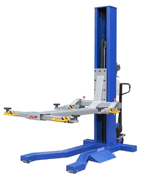
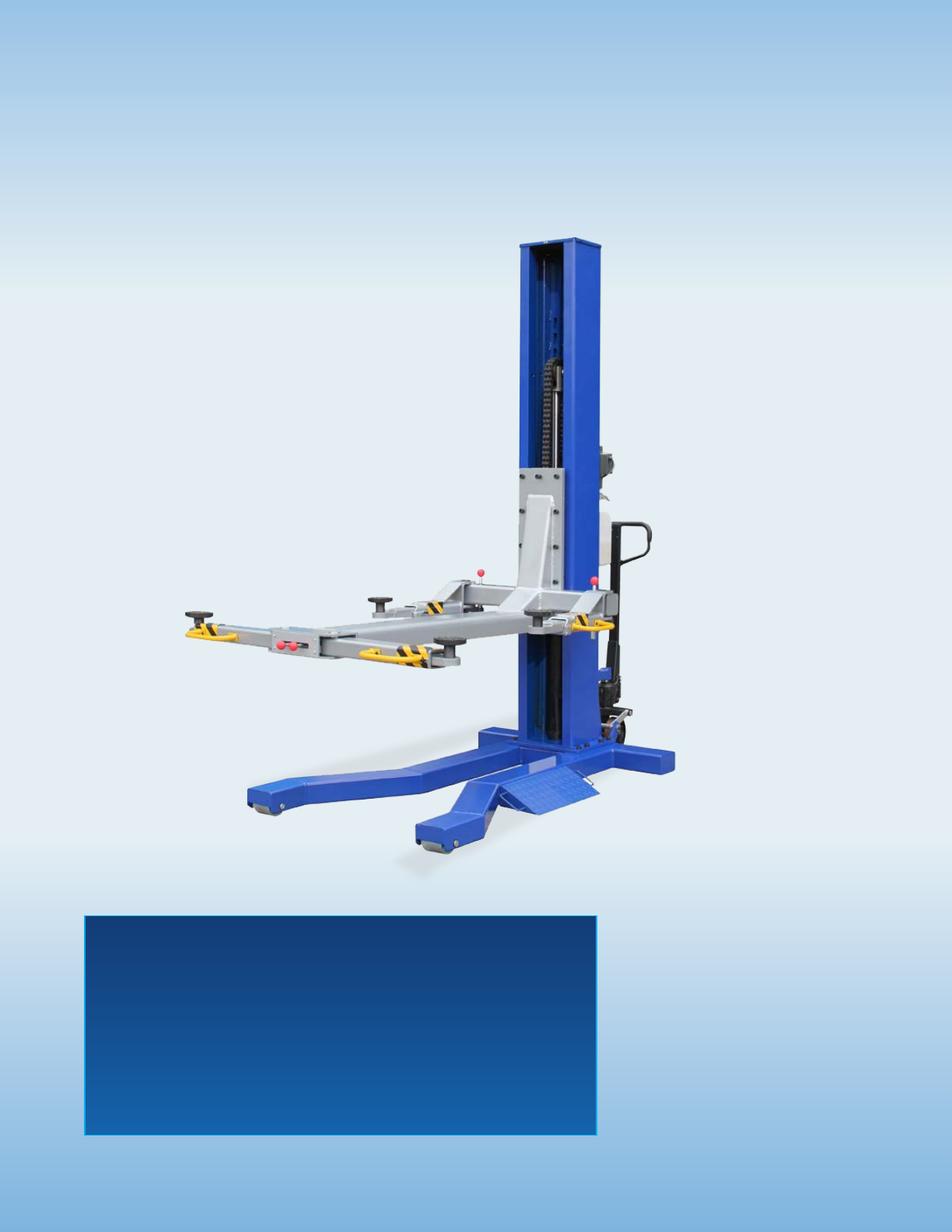
6000 lb Capacity
Mobile Single Column Lift
MSC-6K
INSTALLATION & OPERATION MANUAL

6,000 LB.
MOBILE
SINGLE COLUMN LIFT
Features:
✦Mobile lift uses
“pallet jack” style
hydraulics to raise
lift onto wheels
✦Rolls right under vehicle
or use the unique
drive over design to
easily position lifting
points
✦Thick 13” x 10” column
✦Chain over design uses
a 3”x 36” cylinder and
846 leaf chain
✦Single point lock
release
✦Powder coat paint
finish
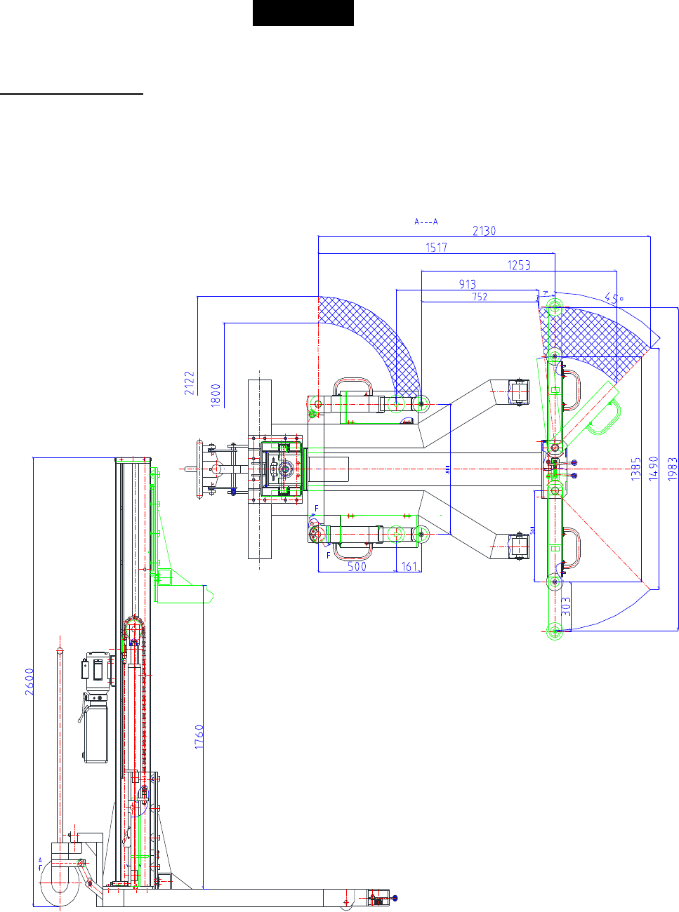
SPECIFICATIONS MSC-6K
Capacity 6,000 lbs.
Width overall 59”
Height overall 102”
Lifting height
72”
Lowered height 3 1⁄2”
Distance between lifting pads, column side to offside 60” max. - 54” min.
Distance between lifting pads, offside 81” max. - 54” min.
Power unit 110 vac
MSC-6K
Mobile
Single column
lift
A 6,000 lb. capacity
mobile single column style lift
featuring fully adjustable arms,
a thick 13” x 10” column,
846 leaf chain, a 3” x 36” cylinder
and a full 72” lifting height.

1905 N Main St Suite C, Cleburne, TX 76033
Ph 817-558-9337 Fax 817-558-9740
TUXEDO DISTRIBUTORS LIMITED WARRANTY
Structural Warranty:
The following parts and structural components carry a five year warranty:
Columns Top Rail Beam Uprights Arms Swivel Pins
Legs Carriages Tracks Overhead Beam Cross Rails
Limited One-Year Warranty:
Tuxedo Distributors, LLC (“Tuxedo”) offers a limited one-year warranty to the original purchaser of
Tuxedo lifts and Wheel Service in the United States and Canada. Tuxedo will replace, without charge, any
part found defective in materials or workmanship under normal use, for a period of one year after purchase.
The purchaser is responsible for all shipping charges. This warranty does not apply to equipment that has
been improperly installed or altered or that has not been operated or maintained according to specifications.
Other Limitations:
This warranty does not cover:
1. Parts needed for normal maintenance
2. Wear parts, including but not limited to cables, slider blocks, chains, rubber pads and pulleys
3. Replacement of lift and tire changer cylinders after the first 30 days. A seal kit and installation
instructions will be sent for repairs thereafter.
4. On-site labor
Upon receipt, the customer must visually inspect the equipment for any potential freight damage before
signing clear on the shipping receipt. Freight damage is not considered a warranty issue and therefore must
be noted for any potential recovery with the shipping company.
The customer is required to notify Tuxedo of any missing parts within 72 hours. Timely notification must
be received to be covered under warranty.
Tuxedo will replace any defective part under warranty at no charge as soon as such parts become available
from the manufacturer. No guarantee is given as to the immediate availability of replacement parts.
Tuxedo reserves the right to make improvements and/or design changes to its lifts without any obligation
to previously sold, assembled or fabricated equipment.
There is no other express warranty on the Tuxedo lifts and this warranty is exclusive of and in lieu of all
other warranties, expressed or implied, including all warranties of merchantability and fitness for a
particular purpose.
To the fullest extent allowed by law, Tuxedo shall not be liable for loss of use, cost of cover, lost profits,
inconvenience, lost time, commercial loss or other incidental or consequential damages.
This Limited Warranty is granted to the original purchaser only and is not transferable or
assignable.
Some states do not allow exclusion or limitation of consequential damages or how long an
implied warranty lasts, so the above limitations and exclusions may not apply. This warranty
gives you specific legal rights and you may have other rights, which may vary from state to state.
5
Important!
Be sure to read the operating instructions before operating your lift!
Getting Ready
Make sure you have made all necessary measurements to assure that your lift
will fit in your shop / garage and accommodate the car you intend to lift with it.
Make sure you have enough clearance at the top, and enough width to allow
walking around. Make sure you know that the circuit requirements are 110 volt,
single phase, 20 amp.
Fig. 1
6
Make sure you have someone to help you. The pieces to this lift are big, heavy,
and cumbersome. The lift column weighs about 320 pounds by itself. Base plate
and arms all weigh a couple of hundred pounds apiece. It is possible for two
people to install this lift if they have the appropriate lifting and handling
equipment, but it is definitely easier and faster if there are several people
available to help manhandle the pieces into place. As with any activities involving
big heavy materials, safety must be uppermost in your mind. This lift is more
difficult to install than some of our other units because of its one-post design, but
this very design makes it extremely effective for shop and residential garage use.
With proper preparation and installation, you will be very pleased with this lift.
Fig.2

7
Required Tools
1. Fork lift to unload lift on delivery
2. Fork lift and/or engine hoist for
moving pieces and positioning lift
column. You will also need a ten-foot
length of 3/8” chain
3. 1 and 5/16” wrench and socket with
ratchet
4. 1 and 1/8” socket and extension
5. ½” wrench
6. 11/16” wrench
7. Adjustable wrench
8. Small crowbar or large screwdriver
for aligning bolt holes
9. Pliers
10. Flat blade screwdriver
Installation
You will need common hand tools that most homeowners have, like a hammer,
screwdrivers and pliers, but in addition, you will need some tools that are not
common. Each installation is somewhat different, and depends on how much
room you have to work around the lift. Here is a chronological sequence of
installation steps, with the associated tools.
1 Unloading the lift
You’ll need a forklift that can handle about 2000 to 2300 pounds and operate on
a smooth surface.
2 Un-banding the lift
The steel bands which secure the lift parts to the pallets are heavy duty. You’ll
need a pair of metal shears or tin snips to cut the bands. Be very careful when
doing this because the bands will tend to fly apart when they are cut, and the
heavy lift parts may shift when freed from the bands. Stand to the side of the
bands when you cut them, and use gloves when removing the cut bands
because they have sharp edges.
3. Moving pieces
You can move the pieces to the garage with the forklift. Some of the smaller
pieces can be moved by two or more people carrying them. If you have several
people helping, some of the larger pieces can be moved manually.
8
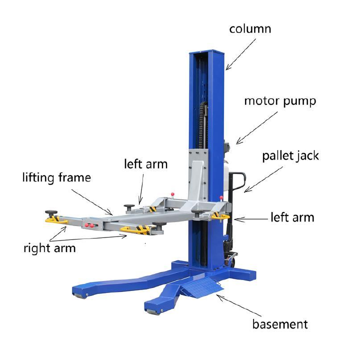
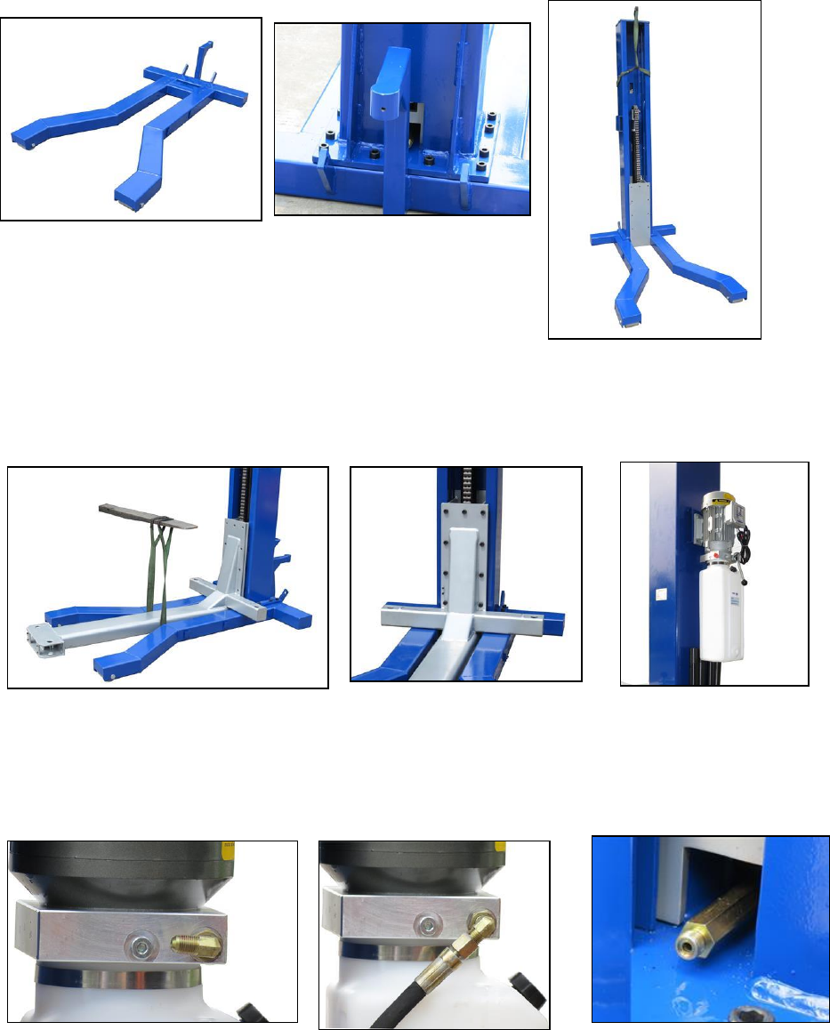
STEP 1
The first step is to take off the board and bracket for shipping. Please take out
every piece. Put the base plate on the ground. (Fig. 3)
Fig. 3 Fig. 5
STEP 2
Upright the column and then fix it on the
base plate with bolts (Fig.4 & 5) Fig. 4
STEP3
Put the lifting frame in front of the base plate. Then fix the frame on the carriage
with bolts. (Fig. 6 & 7)
Fig. 6 Fig. 7 Fig. 8
STEP4
Mount the hydraulic motor pump on the column with bolts and nuts. (Fig. 8)
Connect the hose fitting and the hose from pump to cylinder. (Fig. 9—14)
There is an O-ring between the hose and the connector of the cylinder.( Fig. 12)
Fig. 9 Fig. 10 Fig.11
9
Fig.12 (O-ring ) Fig. 13 Fig. 14
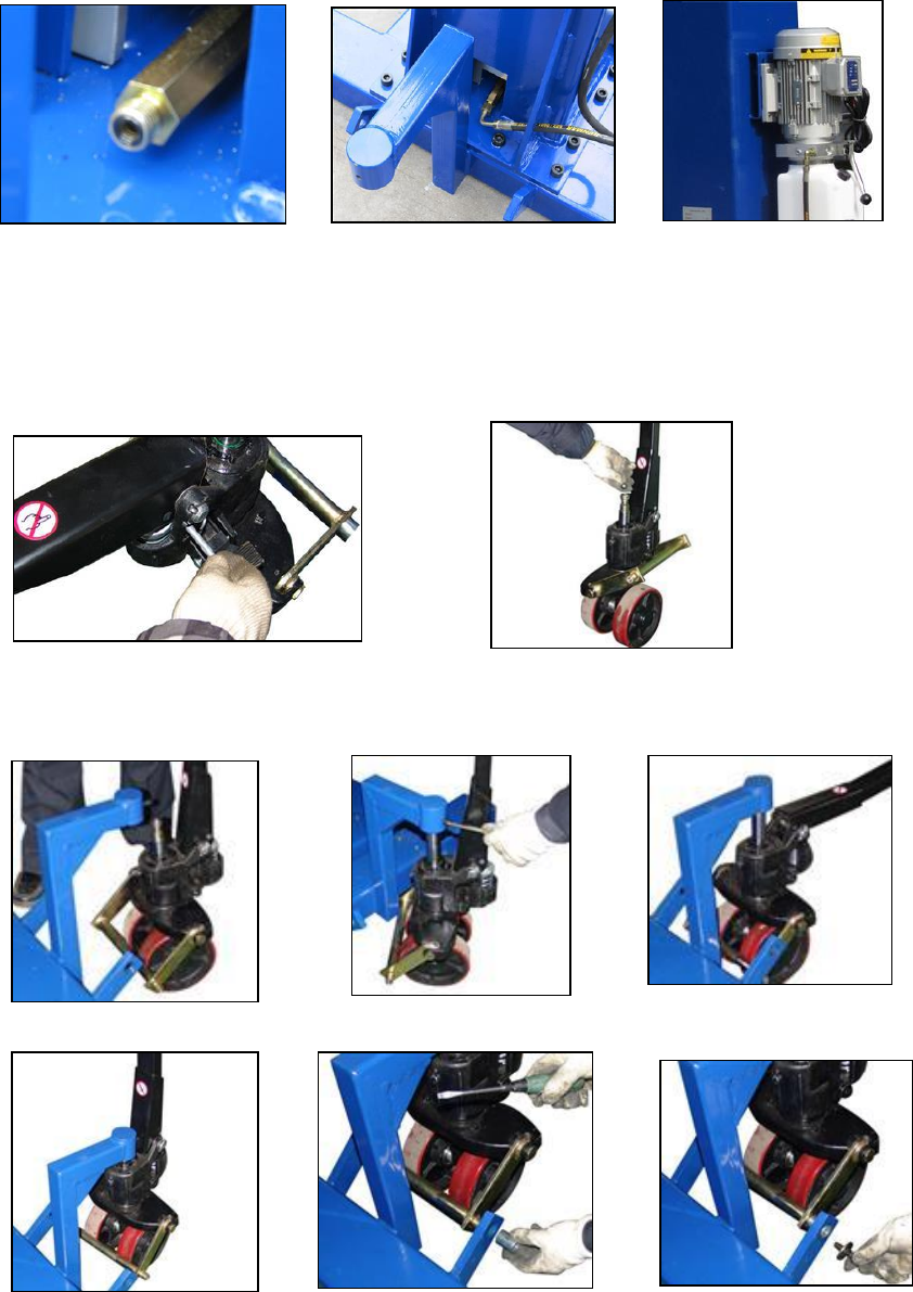
STEP5
Take out the lock pin on the pallet jack (Fig. 15). Put the steel ball on the top of
the jack ram (Fig.16)
Fig. 15 Fig. 16
Insert the ram into the hole of the base plate (Fig. 17). Lock the ram by threaded
pin (Fig.18). Adjust the length of the ram (Fig. 19 & 20).
Fig. 17 Fig. 18 Fig.19
Fig. 20 Fig. 21 Fig. 22
10
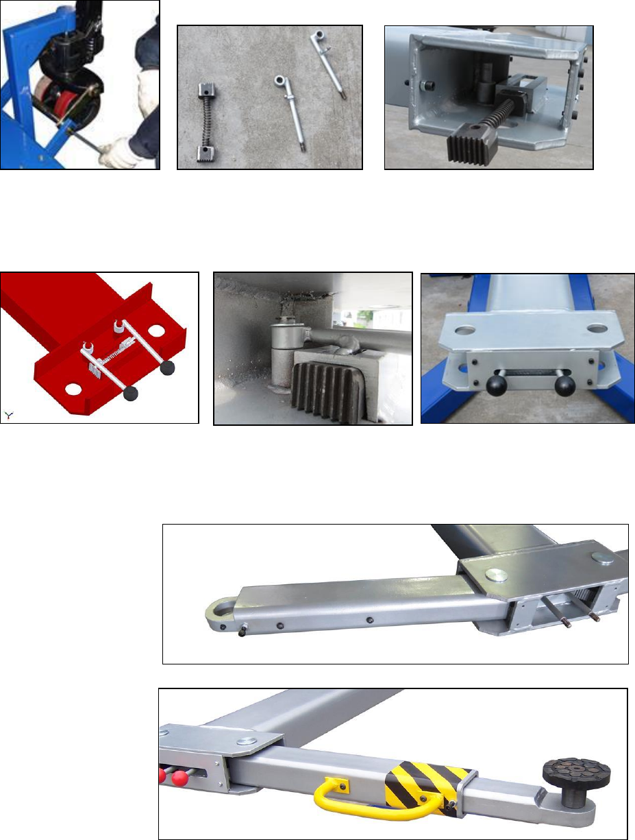
Put the slot of the bearing into the bracket (Fig. 21) then lock it by bolt (Fig. 22 &
23). Then the base plate with pallet jack is ready
Fig. 23 Fig. 24 Fig. 25
STEP 6
Gather the right arm lock parts (Fig. 24). Assemble them in the frame end. (Fig.
25-28)
Fig. 26 Fig.27 Fig. 28
STEP 7
Assemble the right arms to the frame. (Fig 29—30)
Fig. 29
Fig. 30
11
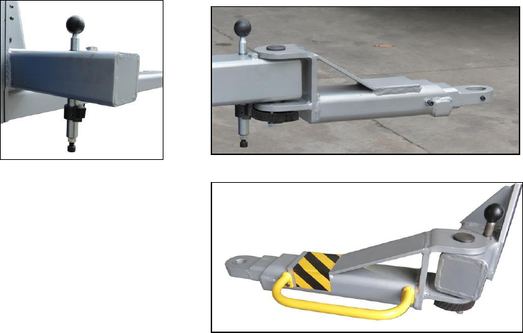
STEP 8
Assemble the left arm locks and arms to the frame. (Fig 31—33)
Fig. 31 Fig. 32
Fig. 33
STEP 9
Now you need to get the correct connection for the cable from motor to power
supply. Your lift comes with a cord attached to the motor pump. Because it is
short, you may need a long extension cord. But because there are so many
receptacle variations, you will need to install the proper plug on the end of the
cord to fit the power port. If you are not sure which plug to use, consult your
electrician. Remove the rubber cap from the top of the reservoir. Fill the
reservoir with 32 AWS hydraulic oil to near the top.
Now the lift is ready for operation.
12
OPERATING INSTRUCTIONS
The lift is very simple to operate. Push the power switch button on the motor
pump and hold while it turns the electric motor on. The motor operates an
internal pump that forces hydraulic oil into the lift piston, which extends the
roller chain and raises the lift. As the lift rises, an internal safety latch will pass
over the steel stops (rectangular blocks which protrude from the back, inside of
the lift column), and you will hear “clanks” as it does so. This sound is normal,
and indicates that the safety latch is passing over the stops properly. The lift is
raised to the desired height by holding the button in while it is rising, and
releasing the button when the lift has reached its desired position.
To be safe, it is required to release the hydraulic pressure inside the cylinder.
To do this, just press down on the release handle on the motor pump. Then the
lifting frame and carriage will sit on the safety lock inside the column.
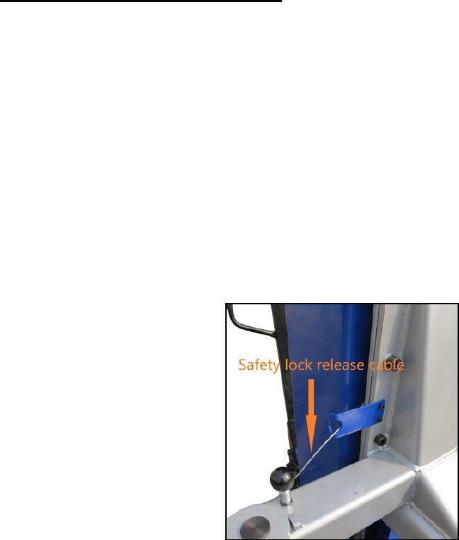
To lower the lift, depress the power
switch button to raise the lift
approximately 2". Then pull the safety
lock release cable to open the safety
latch (Fig. 34). After that press down the
release handle and hold. The weight of
the vehicle will cause the lift to lower by
gravity. No power is required to apply to
the motor pump in lowering, but the
safety latch must be disengaged to allow
the lift to lower past the stops.
Fig. 34
After the installation is complete, raise the lift about two feet high and then
lower it down. Repeat this process two or three times, and then top off the
hydraulic oil reservoir again, if necessary. This assures that hydraulic oil is
distributed everywhere in the system that it needs to be.
NOTE: Only top off the reservoir with the lift in the “down” position. If you
fill the reservoir in the “up” position and then lower the lift, there will be too
much hydraulic oil in the system, and it will squirt out of the top of the
control unit.

13
RAISING A VEHICLE
Drive the vehicle onto the ramps until it is centered. Set the parking brake.
Adjust the arms under the support position of the vehicle frame. Depress the
“up” button to raise the vehicle a little. Check all the arms to make sure
everything is making proper contact. Then lift up the vehicle to desired height.
BE CAREFUL NOT TO RAISE THE VEHICLE SO HIGH THAT IT STRIKES
THE CEILING! MAKE SURE ANTENNAS ARE REMOVED, IF
NECESSARY, AND BE AWARE OF ANYTHING THAT PROTRUDES FROM
THE CEILING, LIKE LIGHTBULBS, GARAGE DOOR OPENERS OR DOOR
TRACKS.
MISCELLANEOUS
The hydraulic oil should be replaced every two years, and the inside corners of
the lift arms should be re-greased with a general-purpose axle grease every
year, or as needed.
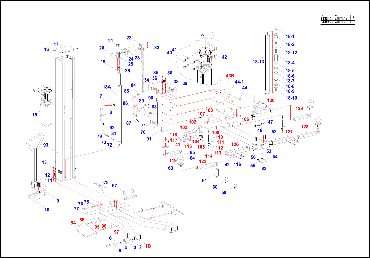
MSC-6K Parts List
Page 1 of 3
ITEM CODE DESCRIPTION QTY ITEM CODE DESCRIPTION QTY ITEM CODE DESCRIPTION QTY
1B 167251A*01-001B Base plate 1 18-4 167251A*01-018-4 Sheath 1 36 167251A*01-036 Position bar 1
2167251A*01-002 Elastic washer 4 18-5 167251A*01-018-5 O ring 1 38 167251A*01-038 Nut 2
3167251A*01-003 Pulley 2 18-6 167251A*01-018-6 Guide ring 1 39 167251A*01-039 robber support 4
4167251A*01-004 Bearing 4 18-7 167251A*01-018-7 O ring 1 40 167251A*01-040 Bolt 4
5167251A*01-005 Spindle 2 18-8 167251A*01-018-8 U ring 1 41 167251A*01-041 Flat washer 24
6167251A*01-006 Bushing 4 18-9 167251A*01-018-9 Piston 1 42 167251A*01-042 Nut 8
7167251A*01-007 Direct fitting 1 18-10 167251A*01-018-10 Nut 2 43B
167251A*01-043B
Hoist ass'y 1
8167251A*01-008 Hose 1 18-12 167251A*01-018-12 Piston rod 1 44 167251A*01-044 Bolt 8
9167251A*01-009 Dolly 1 18-13 167251A*01-018-13 Cylinder 1 44-1
167251A*01-044-1
Bolt 1
10 167251A*01-010 Pin 2 19 167251A*01-019 Nut 2 46 167251A*01-046 Spring 1
11 167251A*01-011 Elastic pin 2 20 167251A*01-020 Spindle 1 47 167251A*01-047 Cog-wheel 2
12 167251A*01-012 Ball bearing 1 21 167251A*01-021 Position bar 1 52 167251A*01-052 Pin 2
13 167251A*01-013 Bolt 8 22 167251A*01-022 Chain ass'y 1 53 167251A*01-053 Circlips 2
15 167251A*01-015 Power Unit 1 23 167251A*01-023 Nut 1 54 167251A*01-054 Handle(Right) 1
16 167251A*01-016 Bolt 4 24 167251A*01-024 Wheel 1 55 167251A*01-055 Handle 1
17 167251A*01-017 Cover 1 25 167251A*01-025 Wheel basement 1 56 167251A*01-056 Bolt 10
18A 167251A*01-018A Hydraulic cylinder ass'y 1 26 167251A*01-026 Nut 2 59 167251A*01-059 height adaptor(1) 4
18-1 167251A*01-018-1 Dust ring 1 34 167251A*01-034 Chain spindle 2 60 167251A*01-060 height adaptor(2) 4
18-2 167251A*01-018-2 Guide ring 1 35 167251A*01-035 Bolt 2 61 167251A*01-061 height adaptor(3) 4
* Easily Worn Parts
Page 2 of 3
Spare Parts List
ITEM CODE DESCRIPTION QTY ITEM CODE DESCRIPTION QTY ITEM CODE DESCRIPTION QTY
63 167251A*01-063 lifting pad 4 86 167251A*01-086 locking board 1 109 167251A*01-109 spring 2
64 167251A*01-064 Rubber washer 4 87 167251A*01-087 spring 1 110 167251A*01-110 gear shaft 2
65 167251A*01-065 Screw 4 88 167251A*01-088 return spring 1 111 167251A*01-111 cottor 2
67 167251A*01-067 Support 1 89 167251A*01-089 lock tune 1 112 167251A*01-112 small cone gear 2
70 167251A*01-070 Slide Block 8 90 167251A*01-090 thin nut 1 113 167251A*01-113 nut 2
71 167251A*01-071 Slide Block 4 91 167251A*01-091 Sliding support 1114 167251A*01-114 socket screw 2
72 167251A*01-072 Elastic washer 1 92 167251A*01-092 Connection hose 1115 167251A*01-115 bar 4
73 167251A*01-073 Washer 1 93 167251A*01-093 Column 1 116 167251A*01-116 socket screw 8
75 167251A*01-075 Bushing 2 94 167251A*01-094 ramp 2 117 167251A*01-117 spring wahser 16
76 167251A*01-076 Flat washer 2 95 167251A*01-095 spring washer 8 118 167251A*01-118 socket screw 8
77 167251A*01-077 Bolt 2 96 167251A*01-096 flat washer 8 119 167251A*01-119 left-front extention 1
78 167251A*01-078 Bolt 1 97 167251A*01-097 fixing hook 4 122 167251A*01-121 left-rear extention 1
79 167251A*01-079 O ring 1 102 167251A*01-102 shaft 2 126 167251A*01-125 left-rear arm 1
80 167251A*01-080 spring washer 2 103 167251A*01-103 left-front arm 1 127 167251A*01-126 right-rear arm 1
81 167251A*01-081 copper washer 1 104 167251A*01-104 big cone gear 2 128 167251A*01-127 right -rear extention 1
82 167251A*01-082 split pin 4 105 167251A*01-105 nut 4 129 167251A*01-128 right-front extention 1
83 167251A*01-083 ball 2 106 167251A*01-106 flat washer 4 130 167251A*01-129 right-front arm 1
84 167251A*01-084 selflock nut 1 107 167251A*01-107 Circlips 2
85 167251A*01-085 flat washer 1 108 167251A*01-108 hand ball 2
* Easily Worn Parts
Page 3 of 3
Spare Parts List

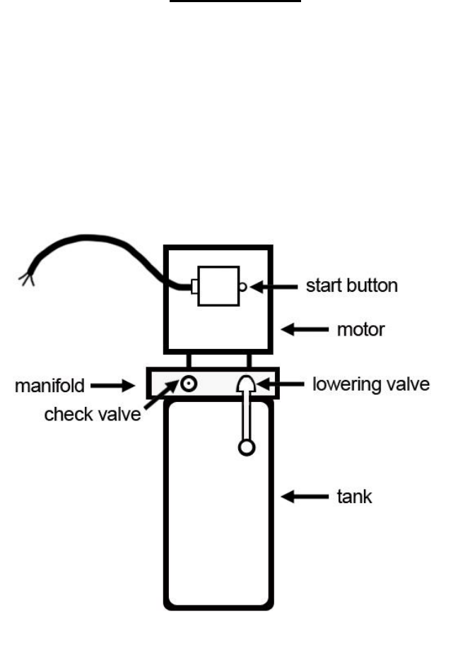
IMPORTANT
POWER UNIT PRIMING PROCEDURE
THE PROBLEM: Power unit runs fine but will not pump any fluid.
Step 1 – Locate the check valve, the flush plug to the left of the lowering valve.
(See drawing below.)
Step 2 – Using an Allen wrench and shop towel – with shop towel in place to catch
fluid – loosen the check valve plug 2 ½ turns to allow it to leak.
Step 3 – Push the START button for one second, then release for three seconds.
Repeat these steps until unit starts pumping fluid.
Step 4 – Tighten the check valve plug.
YOUR POWER UNIT SHOULD BE PRIMED
