MANUALE_TECNICO_KIT_IPOWER_ART.8595_8596_1ED_cod.2G40000303 MT_KIT_8595_8596 MT KIT 8595 8596
User Manual: MT_KIT_8595_8596
Open the PDF directly: View PDF ![]() .
.
Page Count: 104 [warning: Documents this large are best viewed by clicking the View PDF Link!]

Assistenza tecnica Italia 0346/750090
Commerciale Italia 0346/750091
Technical service abroad (+39)0346750092
Export department (+39) 0346750093
Comelit Group S.p.A. - Via Don Arrigoni 5 - 24020 Rovetta S. Lorenzo BG Italy - tel. (+39) 0346 750 011 - fax (+39) 0346 71436
www.comelit.eu www.simplehome.eu info@comelit.it commerciale.italia@comelit.it export.department@comelit.it
PT
MANUAL
TÉCNICO
IT
MANUALE
TECNICO
EN
TECHNICAL
MANUAL
FR
MANUEL
TECHNIQUE
NL
TECHNISCHE
HANDLEIDING
DE
TECHNISCHES
HANDBUCH
ES
MANUAL
TÉCNICO
Manuale tecnico kit iPower Art. 8595 / 8596
Technical manual iPower kit Art. 8595 / 8596
Manuel technique kit iPower Art. 8595 / 8596
Technische handleiding iPower kit Art. 8595 / 8596
Technisches Handbuch für das iPower-Set Art. 8595 / 8596
Manual técnico para kits iPower arts. 8595 y 8596
Manual técnico kit iPower art. 8595/8596

IT
EN
FR
NL
DE
ES
PT
2
Avvertenze
• Effettuare l’installazione seguendo scrupolosamente le istruzioni fornite dal costruttore ed in conformità alle norme vigenti.
• Tutti gli apparecchi devono essere destinati esclusivamente all’uso per cui sono stati concepiti. Comelit Group S.p.A. declina ogni responsabilità per un utilizzo improprio degli
apparecchi, per modifi che effettuate da altri a qualunque titolo e scopo, per l’uso di accessori e materiali non originali.
• Tutti i prodotti sono conformi alle prescrizioni delle direttive 2006/95/CE (che sostituisce la direttiva 73/23/CEE e successivi emendamenti) e ciò è attestato dalla presenza della
marcatura CE sugli stessi.
• Gli interventi di installazione, montaggio e assistenza agli apparecchi elettrici devono essere eseguiti esclusivamente da elettricisti specializzati.
• Togliere l’alimentazione prima di effettuare qualsiasi manutenzione.
• Rimettere le protezioni sui morsetti e chiudere lo sportellino di ispezione dopo ogni intervento.
• Il dispositivo è conforme alla norma EN60950-1 relativa alla sicurezza di apparecchiature per la tecnologia dell'informazione.
Warnings
• Install the equipment by carefully following the instructions given by the manufacturer and in compliance with the standards in force.
• All the equipment must only be used for the purpose it was designed for. Comelit Group S.p.A. declines any responsibility for improper use of the apparatus, for modifi cations made
by third parties for any reason or purpose, and for the use of accessories and materials which are not originals.
• All the products comply with the requirements of Directive 2006/95/EC (which replaces Directive 73/23/EEC and subsequent amendments), as certifi ed by the CE mark on the
products.
• Installation, mounting and assistance procedures for electrical devices must only be performed by specialised electricians.
• Cut off the power supply before carrying out any maintenance work.
• Place the protection back over the terminals and close the inspection door after every procedure.
• The device conforms to standard EN60950-1 relating to the safety of information technology equipment.
Avertissements
• Effectuer l'installation en suivant scrupuleusement les instructions fournies par le constructeur et conformément aux normes en vigueur.
• Tous les appareils doivent être strictement destinés à l'emploi pour lequel ils ont été conçus. Comelit Group S.p.A. décline toute responsabilité en cas de mauvais usage des
appareils, pour des modifi cations effectuées par d’autres personnes pour n’importe quelle raison et pour l'utilisation d’accessoires et matériaux non d'origine.
• Tous les produits sont conformes aux prescriptions de la directive 2006/95/CE (qui remplace la directive 73/23/CEE et amendements successifs). Cela est attesté par la présence
du marquage CE sur les produits.
• Les interventions d'installation, de montage et d'assistance aux appareils électriques doivent être effectuées exclusivement par des électriciens spécialisés.
• Couper l'alimentation avant d'effectuer toute opération d'entretien.
• Remettre les protections sur les bornes et fermer la porte d'inspection après chaque intervention.
• Le dispositif est conforme à la norme EN60950-1, Matériels de traitement de l'information - Sécurité - Partie 1.
Waarschuwingen
• Voer de installatiewerkzaamheden zorgvuldig uit volgens de door de fabrikant gegeven instructies en met inachtneming van de geldende normen.
• Alle componenten mogen alleen gebruikt worden voor de doeleinden waarvoor ze zijn ontworpen. Comelit Group S.p.A. is niet verantwoordelijk voor oneigenlijk gebruik van de
apparatuur, voor wijzigingen die om welke reden dan ook door derden zijn aangebracht, en voor het gebruik van accessoires en materialen die niet door de fabrikant zijn aangeleverd.
• Alle producten voldoen aan de eisen van de richtlijn 2006/95/EG (die de richtlijn 73/23/EEG en latere wijzigingen vervangt). Dit wordt bevestigd door het CE-label op de producten.
• De installatie-, montage- en servicewerkzaamheden aan de elektrische apparaten mogen uitsluitend door gespecialiseerde elektriciens worden verricht.
• Sluit de stroomtoevoer af, voordat u onderhoudswerkzaamheden uitvoert.
• Plaats de beschermingen weer op de klemmen en sluit het inspectieluik na de werkzaamheden.
• Het apparaat voldoet aan de norm EN60950-1 betreffende de veiligheid van apparatuur voor informatietechniek.
Wichtige Hinweise
• Der Einbau muss genau nach den Anweisungen des Herstellers und unter Einhaltung der einschlägigen Vorschriften erfolgen.
• Alle Geräte dürfen ausschließlich nur zu dem Zweck eingesetzt werden, für den sie entwickelt worden sind. Die Comelit Group S.p.A. übernimmt keine Haftung für einen
unsachgemäßen Gebrauch der Geräte, für durch Dritte vorgenommene Änderungen oder die Verwendung von Nicht-Original-Zubehör und -Ersatzteilen.
• Alle unsere Produkte erfüllen die Anforderungen der Richtlinien 2006/95/EG (geändert durch die Richtlinie 73/23/EWG und deren nachfolgende Ergänzungen), wie durch ihre CE-
Kennzeichnung bestätigt wird
• Kabelverlegung sowie Einbau und Wartung der elektrischen Geräte müssen von einem Elektrofachmann ausgeführt werden.
• Vor Wartungseingriffen immer erst die Spannungsversorgung unterbrechen.
• Nach jedem Eingriff wieder die Schutzabdeckungen an den Klemmen anbringen und die Inspektionsklappe schließen.
• Das Gerät erfüllt die Sicherheitsanforderungen an Einrichtungen der Informationstechnik gemäß EN 60950-1.
Advertencias
• La instalación se ha de efectuar en conformidad con las normas vigentes, siguiendo atentamente las instrucciones suministradas por el fabricante.
• Todos los aparatos deben destinarse exclusivamente al uso para el cual han sido construidos. Comelit Group S.p.A. declina toda responsabilidad por el uso impropio de los
aparatos, por cambios efectuados por terceros por cualquier motivo o fi nalidad y por el uso de accesorios y materiales no originales.
• Todos los productos son conformes a los requisitos de las Directivas 2006/95/CE (que sustituye la Directiva 73/23/CEE y sucesivas enmiendas) como demuestra la presencia de
la marca CE en ellos.
• La instalación, el montaje y el mantenimiento de los aparatos eléctricos deben ser efectuados exclusivamente por electricistas especializados.
• Antes de efectuar cualquier operación de mantenimiento hay que cortar la alimentación.
• Tras efectuar la intervención, hay que poner la protección de los bornes y cerrar la tapa de inspección.
• El dispositivo es conforme con la norma EN60950-1 sobre seguridad de aparatos electrónicos empleados en el sector de la información y comunicación.
Avisos
• Instalar o equipamento cuidadosamente, seguindo as instruções dadas pelo fabricante e em conformidade com a legislação em vigor.
• Todos os aparelhos devem ser exclusivamente destinados ao uso para o qual foram concebidos. Comelit Group S.p.A. declina qualquer responsabilidade pelo uso impróprio
do equipamento, quaisquer modifi cações efectuadas por qualquer motivo sem autorização prévia, como também pelo uso de acessórios e materiais que não tenham sido
originariamente fornecidas pela Comelit Group S.p.A.
• Todos os produtos estão em conformidade com os requisitos das directivas 2006/95/CE (que substituem as directivas 73/23/CEE e as alterações subsequentes). A prova é a marca
CE nos produtos.
• As intervenções de instalação, montagem e assistência a aparelhos eléctricos devem ser realizadas exclusivamente por electricistas especializados.
• Cortar a alimentação eléctrica antes de realizar qualquer tipo de manutenção.
• Voltar a meter as protecções nos bornes e fechar a janela de inspecção após as intervenções.
• O dispositivo está em conformidade com a norma EN60950-1 relativa à segurança de aparelhos para tecnologias de informação.

IT
3
SOMMARIO
1. Montaggio telaio posto esterno ....................................................................................................................................................................10
2. Cablaggio alimentatore Art. 1397 verso il posto esterno Art. 4891A - 4892A ..............................................................................................10
3A. Serratura in AC (Relé 1) ...............................................................................................................................................................................11
3B. Serratura in DC (Relé 1) ...............................................................................................................................................................................11
4. Comando locale temporizzato serratura (Relé 1) .........................................................................................................................................12
5. Montaggio modulo telecamera e orientamento ............................................................................................................................................12
6. Tabella impostazioni dip switch posto esterno ..............................................................................................................................................13
7A. Kit monofamiliare: cablaggio monofase ponte Art. 1398 ...............................................................................................................................14
7B. Kit bifamiliare: cablaggio monofase ponti Art. 1398 ......................................................................................................................................15
7C. Kit bifamiliare e multiutenza con contatore parti comuni: cablaggio dati ponti Art. 1398 ..............................................................................16
Kit bifamiliare e multiutenza con contatore parti comuni: cablaggio monofase alimentazione ponti Art. 1398 .............................................17
8. Distanze di collegamento .............................................................................................................................................................................18
9. Accensione alimentazione generale .............................................................................................................................................................20
10. Montaggio monitor ........................................................................................................................................................................................20
11. Kit bifamiliare: corrispondenza posto interno / pulsante di chiamata e alimentatore monitor / ponte Art. 1398 ...........................................21
12. Segnalazione anomalie e possibili soluzioni ................................................................................................................................................22
13. Utilizzo relé del modulo numero civico (Relé 2), vedi variante PW/AAA ......................................................................................................23
14. Espansione kit per multiutenza: montaggio posto esterno ...........................................................................................................................24
15. Multiutenza: programmazione pulsanti del posto esterno ............................................................................................................................25
Tabella di programmazione dei dip switch ....................................................................................................................................................25
16. Kit e Multiutenza: installazione monitor supplementari secondari ................................................................................................................26
17. Multiutenza: installazione monitor principali .................................................................................................................................................26
18. Impostazione lingua menu ............................................................................................................................................................................27
19. Accedere al menu installatore ......................................................................................................................................................................27
20. Confi gurazione password modem ................................................................................................................................................................28
21. Imposta indirizzo logico monitor principali (master) ......................................................................................................................................28
22. Imposta indirizzo logico monitor secondari (slave) .......................................................................................................................................28
23. Modifi ca indirizzi Rubrica Intercomunicante .................................................................................................................................................29
24. Modifi ca nomi Rubrica Intercomunicante .....................................................................................................................................................30
25. Confi gurazione pulsante chiave ....................................................................................................................................................................31
26. Confi gurazione pulsante privacy / dottore ....................................................................................................................................................31
27. Confi gurazione pulsanti 1 - 2 ........................................................................................................................................................................32
28. Attivazione ripetizione suoneria ....................................................................................................................................................................32
29. Attivazione risposta automatica ....................................................................................................................................................................32
30. Visualizza informazioni .................................................................................................................................................................................33
31. Confi gurazione tempi di chamata .................................................................................................................................................................33
32. Reset confi gurazione ....................................................................................................................................................................................34
33. Anomalie e possibili soluzioni .......................................................................................................................................................................34
Cablaggio kit monofamiliare Art. 8595 ..........................................................................................................................................................89
Cablaggio kit monofamiliare trifase Art. 8595 ...............................................................................................................................................90
Cablaggio kit bifamiliare Art. 8596 ................................................................................................................................................................91
Cablaggio kit bifamiliare trifase Art. 8596 .....................................................................................................................................................92
Cablaggio kit bifamiliare Art. 8596 con contatori parti comuni ......................................................................................................................93
Cablaggio kit monofamiliare con alimentatore supplementare per posto esterno ........................................................................................94
Cablaggio kit monofamiliare con 2 posti esterni ...........................................................................................................................................95
Cablaggio kit bifamiliare con 2 posti esterni .................................................................................................................................................96
Cablaggio sistema multiutenza .....................................................................................................................................................................97
Cablaggio sistema multiutenza con Art. 1396 ..............................................................................................................................................98
Cablaggio sistema multiutenza con singolo contatore di impianto ...............................................................................................................99
Variante collegamento relé del modulo numero civico (relé 2) .....................................................................................................................100
Variante collegamento relé temporizzato .....................................................................................................................................................100
Variante contatto segnalazione porta aperta ................................................................................................................................................101
Utilizzo della rete RC per fi ltro serratura sui contatti del relè ........................................................................................................................101
Connessione di dispositivi di ripetizione di chiamata (Art. 1229 o Art. 1122/A) ............................................................................................102
Variante collegamento chiamata fuori porta .................................................................................................................................................103

EN
4
TABLE OF CONTENTS
1. Installing the external unit frame ...................................................................................................................................................................10
2. Wiring between power supply unit Art. 1397 and external unit Art. 4891A - 4892A .....................................................................................10
3A. AC door lock (Relay 1) ..................................................................................................................................................................................11
3.B DC door lock (Relay 1) .................................................................................................................................................................................11
4. Timed local door lock command (Relay 1) ...................................................................................................................................................12
5. Installing and adjusting the orientation of the camera module .....................................................................................................................12
6. Table of external unit Dip switch settings ......................................................................................................................................................13
7A. Single-residence kit: single-phase wiring for bridge Art. 1398 ......................................................................................................................14
7B. Two-residence kit: single-phase wiring for bridges Art. 1398 ........................................................................................................................15
7C. Two-residence kit and multi-user system with shared utility meter: data wiring for bridges Art. 1398 ..........................................................16
Two-residence kit and multi-user system with shared utility meter: single-phase power supply wiring for bridges Art. 1398 .......................17
8. Connection distances ...................................................................................................................................................................................18
9. Switching on the main power supply ............................................................................................................................................................20
10. Installing the monitor ....................................................................................................................................................................................20
11. Two-residence kit: alignment between internal unit / call button and monitor power supply unit / bridge Art. 1398 .....................................21
12. Fault indication and troubleshooting .............................................................................................................................................................22
13. Using the info module relay (Relay 2), see PW/AAA variant ........................................................................................................................23
14. Expansion kit for multi-user system: installing the external unit ....................................................................................................................24
15. Multi-user system: programming the buttons on the external unit ................................................................................................................25
Dip switch programming table.......................................................................................................................................................................25
16. Kits and Multi-user system: installing additional secondary monitors ...........................................................................................................35
17. Multi-user system: installing main monitors ..................................................................................................................................................35
18. Setting the menu language ...........................................................................................................................................................................36
19. Entering the installer menu ...........................................................................................................................................................................36
20. Setting the modem password .......................................................................................................................................................................37
21. Setting the logical address of the main (master) monitors ...........................................................................................................................37
22. Setting the logical address of secondary (slave) monitors ...........................................................................................................................37
23. Changing Intercom Directory addresses ......................................................................................................................................................38
24. Changing Intercom Directory names ............................................................................................................................................................39
25. Programming the key button .........................................................................................................................................................................40
26. Programming the Privacy / Doctor button .....................................................................................................................................................40
27. Programming buttons 1 - 2 ...........................................................................................................................................................................41
28. Activating tone repetition ..............................................................................................................................................................................41
29. Automatic reply function ...............................................................................................................................................................................41
30. Viewing information ......................................................................................................................................................................................42
31. Setting call times ..........................................................................................................................................................................................42
32. Reset confi guration .......................................................................................................................................................................................43
33. Faults and troubleshooting ...........................................................................................................................................................................43
Wiring for single-residence kit Art. 8595 .......................................................................................................................................................89
Wiring for three-phase single-residence kit Art. 8595 ...................................................................................................................................90
Wiring for two-residence kit Art. 8596 ...........................................................................................................................................................91
Wiring for three-phase two-residence kit Art. 8596 .......................................................................................................................................92
Wiring for two-residence kit Art. 8596 with shared utility meters ..................................................................................................................93
Wiring for single-residence kit with additional external unit power supply unit .............................................................................................94
Wiring for single-residence kit with 2 external units ......................................................................................................................................95
Wiring for two-residence kit with 2 external units ..........................................................................................................................................96
Wiring for multi-user system .........................................................................................................................................................................97
Wiring for multi-user system with Art. 1396 ..................................................................................................................................................98
Wiring for multi-user system with single utility meter ....................................................................................................................................99
Variant with info module relay connection (relay 2) ......................................................................................................................................100
Variant with timed relay connection ..............................................................................................................................................................100
Variant with door open indication contact .....................................................................................................................................................101
Using the RC network for door lock fi lter on relay contacts ..........................................................................................................................101
Connection of call repetition devices (Art. 1229 or Art. 1122/A) ...................................................................................................................102
Variant with fl oor door call connection ..........................................................................................................................................................103

FR
5
SOMMAIRE
1. Montage cadre du poste externe ..................................................................................................................................................................10
2. Câblage alimentation Art. 1397 vers le poste externe Art. 4891A - 4892A ...................................................................................................10
3A.Gâche en AC (Relais 1) ..................................................................................................................................................................................11
3B. Gâche en DC (Relais 1) ...............................................................................................................................................................................11
4. Commande locale temporisée gâche (Relais 1) ...........................................................................................................................................12
5. Montage du module caméra et orientation ...................................................................................................................................................12
6. Tableau des réglages DIP switch du poste externe ......................................................................................................................................13
7A. Kit un usager : câblage monophasé pont Art. 1398 ......................................................................................................................................14
7.B Kit deux usagers : câblage monophasé ponts Art. 1398 ..............................................................................................................................15
7C. Kit deux usagers et multi-usagers avec compteur parties communes : câblage données ponts Art. 1398 ..................................................16
Kit deux usagers et multi-usagers avec compteur parties communes : câblage monophasé alimentation ponts Art. 1398.........................17
8. Distances de branchement ...........................................................................................................................................................................18
9. Allumage alimentation générale ...................................................................................................................................................................20
10. Montage moniteur .........................................................................................................................................................................................20
11. Kit deux usagers : correspondance poste interne / touche d’appel et alimentation moniteur / pont Art. 1398 .............................................21
12. Dépannage ...................................................................................................................................................................................................22
13. Utilisation relais du module numéro civique (Relais 2), voir variante PW/AAA ............................................................................................23
14. Extension kit pour multi-usagers : montage du poste externe ......................................................................................................................24
15. Multi-usagers : programmation des touches du poste externe .....................................................................................................................25
Tableau de programmation des DIP switches...............................................................................................................................................25
16. Kit et Multi-usagers : installation de moniteurs supplémentaires secondaires .............................................................................................44
17. Multi-usagers : installation des moniteurs principaux ...................................................................................................................................44
18. Confi guration de la langue menu ..................................................................................................................................................................45
19. Accéder au menu installateur .......................................................................................................................................................................45
20. Confi guration du mot de passe modem ........................................................................................................................................................46
21. Confi gurer l’adresse logique moniteurs principaux (maître) .........................................................................................................................46
22. Confi gurer l’adresse logique moniteurs secondaires (esclave) ....................................................................................................................46
23. Changer les adresses Répertoire intercommunicant ...................................................................................................................................47
24. Changer les adresses Répertoire intercommunicant ...................................................................................................................................48
25. Confi guration de la touche clé ......................................................................................................................................................................49
26. Confi guration de la touche privacy/docteur ..................................................................................................................................................49
27. Confi guration des touches 1 - 2 ....................................................................................................................................................................50
28. Activation de la répétition sonnerie ...............................................................................................................................................................50
29. Activation de la réponse automatique...........................................................................................................................................................50
30. Affi cher informations .....................................................................................................................................................................................51
31. Confi guration du temps d’appel ....................................................................................................................................................................51
32. Reset confi guration .......................................................................................................................................................................................52
33. Dépannage ...................................................................................................................................................................................................52
Câblage kit un usager Art. 8595 ...................................................................................................................................................................89
Câblage kit un usager Art. 8595 ...................................................................................................................................................................90
Câblage kit deux usagers Art. 8596 ..............................................................................................................................................................91
Câblage kit deux usagers Art. 8596 ..............................................................................................................................................................92
Câblage kit deux usagers Art. 8596 avec compteurs parties communes .....................................................................................................93
Câblage kit un usager avec alimentation supplémentaire pour poste externe .............................................................................................94
Câblage kit un usager avec 2 postes externes .............................................................................................................................................95
Câblage kit deux usagers avec 2 postes externes .......................................................................................................................................96
Câblage installation multi-usagers ................................................................................................................................................................97
Câblage installation multi-usagers avec Art. 1396 ........................................................................................................................................98
Câblage installation multi-usagers avec un compteur d’installation..............................................................................................................99
Variante connexion relais du module numéro civique (relais 2) ...................................................................................................................100
Variante connexion relais temporisé .............................................................................................................................................................100
Variante contact signalisation porte ouverte .................................................................................................................................................101
Utilisation du réseau RC pour fi ltre gâche sur les contacts du relais ...........................................................................................................101
Connexion de dispositifs de répétition d’appel (Art. 1229 ou Art. 1122/A)....................................................................................................102
Variante connexion appel palier....................................................................................................................................................................103

NL
6
INHOUD
1. Montage entreepaneelframe ........................................................................................................................................................................10
2. Bekabeling voedingstransformator Art. 1397 naar het entreepaneel Art. 4891A - 4892A ............................................................................10
3A. Slot met wisselstroom (relais 1) ....................................................................................................................................................................11
3B. Slot met gelijkstroom (Relais 1) ....................................................................................................................................................................11
4. Lokale slotbediening met tijdsinstelling (relais 1) .........................................................................................................................................12
5. Montage camera- en oriëntatiemodule .........................................................................................................................................................12
6. Instellingentabel dipswitch entreepaneel ......................................................................................................................................................13
7A. Kit voor eengezinswoningen: eenfasige bekabeling brug Art. 1398 .............................................................................................................14
7B. Kit voor tweegezinswoningen: eenfasige bekabeling bruggen Art. 1398 ......................................................................................................15
7C.
Kit voor tweegezinswoningen en multi-userinstallaties met teller voor de gemeenschappelijke delen: databekabeling bruggen Art. 1398
.......16
Kit voor tweegezinswoningen en multi-userinstallaties met teller voor de gemeenschappelijke delen: eenfasige voedingsbekabeling Art. 1398
....17
8. Aansluitafstanden .........................................................................................................................................................................................18
9. Inschakeling algemene voeding ...................................................................................................................................................................20
10. Montage van de monitor ...............................................................................................................................................................................20
11. Kit voor tweegezinswoningen: overeenstemming tussen binnentoestel / oproepknop en voedingstransformator monitor / brug Art. 1398 .21
12. Signalering van storingen en mogelijke oplossingen ....................................................................................................................................22
13. Gebruik van het relais van de huisnummermodule (relais 2), zie PW/AAA-variant ......................................................................................23
14. Uitbreiding van kit voor multi-userinstallaties: montage entreepaneel ..........................................................................................................24
15. Multi-userinstallaties: programmering van drukknoppen van het entreepaneel............................................................................................25
Programmeringstabel van de dipswitches ....................................................................................................................................................25
16. Kit en multi-usersysteem: installatie van extra secundaire monitors.............................................................................................................53
17. Multi-usersysteem: installatie van hoofdmonitors .........................................................................................................................................53
18. Instelling van de menutaal ............................................................................................................................................................................54
19. Het installateurmenu openen ........................................................................................................................................................................54
20. Confi guratie modemwachtwoord ..................................................................................................................................................................55
21. Stel het logische adres van de hoofdmonitors (master) in ............................................................................................................................55
22. Instelling van het logische adres van secundaire monitors (slave) ...............................................................................................................55
23. Wijziging van adressen van het namenregister voor de intercom ................................................................................................................56
24. Wijziging van namen in het namenregister voor de intercom .......................................................................................................................57
25. Confi guratie van de sleutelknop ...................................................................................................................................................................58
26. Confi guratie van de privacy-/artsknop ..........................................................................................................................................................58
27. Confi guratie drukknoppen 1 - 2 ....................................................................................................................................................................59
28. Inschakeling handenvrijfunctie......................................................................................................................................................................59
29. Inschakeling extra bel ...................................................................................................................................................................................59
30. Weergave van informatie ..............................................................................................................................................................................60
31. Confi guratie oproeptijden .............................................................................................................................................................................60
32. Confi guratie resetten ....................................................................................................................................................................................61
33. Storingen en mogelijke oplossingen .............................................................................................................................................................61
Bekabeling kit voor eengezinswoningen Art. 8595 .......................................................................................................................................89
Bekabeling kit voor eengezinswoningen, driefase, Art. 8595 .......................................................................................................................90
Bekabeling kit voor tweegezinswoningen Art. 8596 ......................................................................................................................................91
Bekabeling kit voor tweegezinswoningen, driefase, Art. 8596 ......................................................................................................................92
Bekabeling kit voor tweegezinswoningen Art. 8596 met teller voor gemeenschappelijke delen ..................................................................93
Bekabeling voor kit voor eengezinswoningen met extra voedingstransformator voor entreepaneel ............................................................94
Bekabeling kit voor eengezinswoningen met 2 entreepanelen .....................................................................................................................95
Bekabeling kit voor tweegezinswoningen met 2 entreepanelen ...................................................................................................................96
Bekabeling multi-userinstallatie ....................................................................................................................................................................97
Bekabeling multi-usersysteem met Art. 1396 ...............................................................................................................................................98
Bekabeling multi-usersysteem met afzonderlijke teller voor installatie .........................................................................................................99
Aansluitvariant voor relais huisnummermodule (relais 2) .............................................................................................................................100
Aansluitvariant relais met tijdsinstelling ........................................................................................................................................................100
Contactvariant van de signalering ‘deur open’ ..............................................................................................................................................101
Gebruik van het RC-net voor storingsfi lter op de contacten van het relais ...................................................................................................101
Aansluiting van een extra “bel” of voor het gelijktijdig met het belsignaal inschakelen van een relais (art. 1229 of art. 1122/A) ..................102
Aansluitvariant etagebeloproep ....................................................................................................................................................................103

DE
7
INHALTSVERZEICHNIS
1. Verdrahtung Netzteil Art. 1397 zur Außenstelle Art. 4891A - 4892A ............................................................................................................10
2. Montage des Rahmens der Außenstelle ......................................................................................................................................................10
3A. Türöffner in Wechselspannung (Relais 1) .....................................................................................................................................................11
3.B Türöffner in Gleichspannung (Relais 1) ........................................................................................................................................................11
4. Zeitgesteuerte lokale Türöffnertaste (Relais 1) .............................................................................................................................................12
5. Montage des Kameramoduls und Ausrichtung .............................................................................................................................................12
6. Tabelle mit den Dipschalter-Stellungen der Außenstelle ..............................................................................................................................13
7A. Set für Einfamilienhaus: Einphasenverdrahtung Brücke Art. 1398 ...............................................................................................................14
7B. Set für Zweifamilienhaus: Einphasenverdrahtung Brücken Art. 1398 ...........................................................................................................15
7C. Set für Zweifamilienhaus und Multi-User mit Zähler für Gemeinschaftsbereiche: Verdrahtung Daten Brücken Art. 1398 ............................16
Set für Zweifamilienhaus und Multi-User mit Zähler für Gemeinschaftsbereiche: Einphasenverdrahtung Stromversorgung Brücken Art. 1398
......17
8. Anschlussabstände ......................................................................................................................................................................................18
9. Einschaltung der allgemeinen Stromversorgung ..........................................................................................................................................20
10. Monitoreinbau ...............................................................................................................................................................................................20
11. Set für Zweifamilienhaus: Zuordnung Innenstelle / Ruftaste und Netzteil Monitor / Brücke Art. 1398 ..........................................................21
12. Anzeige von Betriebsstörungen und mögliche Abhilfe .................................................................................................................................22
13. Verwendung Relais des Hausnummern-Moduls (Relais 2), siehe Variante PW/AAA...................................................................................23
14. Erweiterung des Sets für Multi-User: Einbau der Außenstelle ......................................................................................................................24
15. Multi-User: Programmierung der Tasten der Außenstelle .............................................................................................................................25
Dipschalter-Programmiertabelle ...................................................................................................................................................................25
16. Set und Multi-User: Installation der Zusatzmonitore .....................................................................................................................................62
17. Multi-User: Installation der Hauptmonitoren .................................................................................................................................................62
18. Einstellung der Menüsprache .......................................................................................................................................................................63
19. Menü Installateur öffnen ...............................................................................................................................................................................63
20. Konfi guration des Modem-Passworts ...........................................................................................................................................................64
21. Logische Adresse der Hauptmonitoren (Master) ..........................................................................................................................................64
22. Logische Adresse der Zusatzmonitoren (Slave) ...........................................................................................................................................64
23. Adressen im Telefonbuch Intercom bearbeiten .............................................................................................................................................65
24. Namen im Telefonbuch Intercom bearbeiten ................................................................................................................................................66
25. Schlüsseltaste konfi gurieren .........................................................................................................................................................................67
26. Taste Privacy / Arztruf konfi gurieren .............................................................................................................................................................67
27. Konfi guration Tasten 1 - 2 .............................................................................................................................................................................68
28. Ruftonwiederholung aktivieren .....................................................................................................................................................................68
29. Aktivierung der automatischen Rufbeantwortung .........................................................................................................................................68
30. Informationen anzeigen ................................................................................................................................................................................69
31. Konfi guration der Rufzeiten ..........................................................................................................................................................................69
32. Konfi guration zurücksetzen ..........................................................................................................................................................................70
33. Betriebsstörungen und mögliche Abhilfe ......................................................................................................................................................70
Verdrahtung des Sets für Einfamilienhaus Art. 8595 ....................................................................................................................................89
Verdrahtung des Sets für Einfamilienhaus in Drehstrom Art. 8595 ...............................................................................................................90
Verdrahtung des Sets für Zweifamilienhaus Art. 8596 ..................................................................................................................................91
Verdrahtung des Sets für Zweifamilienhaus in Drehstrom Art. 8596 ............................................................................................................92
Verdrahtung des Sets für Zweifamilienhaus Art. 8596 mit Zählern für die Gemeinschaftsbereiche .............................................................93
Verdrahtung des Sets für Einfamilienhaus mit Zusatz-Netzteil für Außenstelle ............................................................................................94
Verdrahtung des Sets für Einfamilienhaus mit 2 Außenstellen .....................................................................................................................95
Verdrahtung des Sets für Zweifamilienhaus mit 2 Außenstellen ...................................................................................................................96
Verdrahtung des Multi-User-Systems ...........................................................................................................................................................97
Verdrahtung des Multi-User-Systems mit Art. 1396 ......................................................................................................................................98
Verdrahtung des Multi-User-Systems mit einzelnem Anlagenzähler ............................................................................................................99
Anschlussvariante für das Relais des Hausnummern-Moduls (Relais 2) .....................................................................................................100
Anschlussvariante des Zeitschaltrelais .........................................................................................................................................................100
Verwendung des RC-Glieds als Türöffner-Filter an den Relaiskontakten .....................................................................................................101
Variante Meldekontakt Tür offen ...................................................................................................................................................................101
Anschluss von Rufwiederholungsvorrichtungen (Art. 1229 oder Art. 1122/A) ..............................................................................................102
Anschlussvariante Etagenruf ........................................................................................................................................................................103

ES
8
ÍNDICE
1. Cableado del alimentador art. 1397 hacia la unidad externa arts. 4891A - 4892A.......................................................................................10
2. Montaje del bastidor de la unidad externa ....................................................................................................................................................10
3A. Cerradura de CA (relé 1) ..............................................................................................................................................................................11
3B. Cerradura de CC (relé 1) ..............................................................................................................................................................................11
4. Mando local temporizado de la cerradura (relé 1) ........................................................................................................................................12
5. Montaje del módulo telecámara y orientación ..............................................................................................................................................12
6. Tabla de confi guraciones de los DIP switches de la unidad externa ............................................................................................................13
7A. Kit unifamiliar: cableado monofásico del puente art. 1398 ...........................................................................................................................14
7B. Kit bifamiliar: cableado monofásico de los puentes art. 1398 .......................................................................................................................15
7C. Kit bifamiliar y multiusuarios con contador para partes comunes: cableado de datos de los puentes art. 1398 ..........................................16
Kit bifamiliar y multiusuarios con contador para partes comunes: cableado monofásico de alimentación de los puentes art. 1398 ...........17
8. Distancias de conexión .................................................................................................................................................................................18
9. Encendido de la alimentación general ..........................................................................................................................................................20
10. Montaje del monitor ......................................................................................................................................................................................20
11. Kit bifamiliar: correspondencia entre unidad interna / pulsador de llamada y alimentador del monitor / puente art. 1398 ...........................21
12. Señalización de anomalías y soluciones ......................................................................................................................................................22
13. Uso del relé del módulo informativo iluminado (relé 2), véase variante PW/AAA ........................................................................................23
14. Expansión del kit para multiusuarios: montaje de la unidad externa ............................................................................................................24
15. Multiusuarios: programación de los pulsadores de la unidad externa ..........................................................................................................25
Tabla de programación de los DIP switches .................................................................................................................................................25
16. Kit multiusuarios: instalación de monitores adicionales secundarios ...........................................................................................................71
17. Multiusuarios: instalación de los monitores principales ................................................................................................................................71
18. Confi guración del idioma de los menús ........................................................................................................................................................72
19. Acceder al menú instalador ..........................................................................................................................................................................72
20. Confi guración de la contraseña del módem .................................................................................................................................................73
21. Confi guración de la dirección lógica de los monitores principales (master) .................................................................................................73
22. Confi guración de la dirección lógica de los monitores secundarios (slave) .................................................................................................73
23. Modifi cación de las direcciones del directorio intercomunicante ..................................................................................................................74
24. Modifi cación de los nombres del directorio intercomunicante ......................................................................................................................75
25. Confi guración de la tecla llave ......................................................................................................................................................................76
26. Confi guración de la tecla Privacidad/Doctor .................................................................................................................................................76
27. Confi guración de las teclas 1 y 2 ..................................................................................................................................................................77
28. Activación de la repetición del timbre ...........................................................................................................................................................77
29. Activación de la respuesta automática .........................................................................................................................................................77
30. Visualizar informaciones ...............................................................................................................................................................................78
31. Confi guración de los tiempos de llamada .....................................................................................................................................................78
32. Reset confi guración ......................................................................................................................................................................................79
33. Anomalías y soluciones ................................................................................................................................................................................79
Cableado del kit unifamiliar art. 8595 ...........................................................................................................................................................89
Cableado del kit unifamiliar trifásico art. 8595 ..............................................................................................................................................90
Cableado del kit bifamiliar art. 8596 .............................................................................................................................................................91
Cableado del kit bifamiliar trifásico art. 8596 ................................................................................................................................................92
Cableado del kit bifamiliar art. 8596 con contadores para partes comunes .................................................................................................93
Cableado del kit unifamiliar con alimentador adicional para unidad externa ................................................................................................94
Cableado del kit unifamiliar con 2 unidades externas ..................................................................................................................................95
Cableado del kit bifamiliar con 2 unidades externas ....................................................................................................................................96
Cableado del sistema multiusuarios .............................................................................................................................................................97
Cableado del sistema multiusuarios con art. 1396 .......................................................................................................................................98
Cableado del sistema multiusuarios con un único contador de instalación..................................................................................................99
Variante para conexión del relé del módulo informativo iluminado (relé 2) ..................................................................................................100
Variante para la conexión del relé temporizado............................................................................................................................................100
Uso de la red RC para el fi ltro de la cerradura en los contactos del relé .....................................................................................................101
Variante para contacto de señalización de puerta abierta ...........................................................................................................................101
Conexión de dispositivos de repetición de llamada (arts. 1229 o 1122/A) ...................................................................................................102
Variante para la conexión de la llamada del timbre de planta ......................................................................................................................103

PT
9
ÍNDICE
1. Cablagem do alimentador art. 1397 para o ponto externo art. 4891A - 4892A ............................................................................................10
2. Montagem da moldura do ponto externo ......................................................................................................................................................10
3A. Fechadura em AC (Relé 1) ...........................................................................................................................................................................11
3B. Fechadura em DC (Relé 1) ...........................................................................................................................................................................11
4. Comando local da fechadura com temporizador (Relé 1) ............................................................................................................................12
5. Montagem do módulo câmara e orientação .................................................................................................................................................12
6. Tabela de confi gurações do dip switch do ponto externo .............................................................................................................................13
7A. Kit monofamiliar: cablagem monofásica ponte art. 1398 ..............................................................................................................................14
7B. Kit bifamiliar: cablagem monofásica ponte art. 1398 ....................................................................................................................................15
7C. Kit bifamiliar e multiutilizadores com contador nas partes comuns: cablagem dados pontes art. 1398 .......................................................16
Kit bifamiliar e multiutilizadores com contador nas partes comuns: cablagem monofásica alimentação pontes art. 1398 ..........................17
8. Distâncias de ligação ....................................................................................................................................................................................18
9. Acendimento da alimentação geral. .............................................................................................................................................................20
10. Montagem do monitor ...................................................................................................................................................................................20
11. Kit bifamiliar: correspondência ponto interno/tecla de chamada e alimentador monitor/ponte art. 1398 .....................................................21
12. Indicação de anomalias e possíveis soluções ..............................................................................................................................................22
13. Utilização do relé do módulo número de porta (Relé 2), consultar variante PW/AAA ..................................................................................23
14. Kit de expansão para multiutilizadores: montagem do ponto externo ..........................................................................................................24
15. Multiutilizadores: programação das teclas do ponto externo ........................................................................................................................25
Tabela de programação dos dip switches. ....................................................................................................................................................25
16. Kit e multiutilizadores: instalação de monitores adicionais secundários ......................................................................................................80
17. Multiutilizadores: instalação dos monitores principais ..................................................................................................................................80
18. Confi gurar o idioma do menu .......................................................................................................................................................................81
19. Aceder ao menu instalador ...........................................................................................................................................................................81
20. Confi gurar a password do modem ................................................................................................................................................................82
21. Confi gurar endereço lógico do monitor principal (master) ............................................................................................................................82
22. Confi gurar endereço lógico monitores secundários (slave) ..........................................................................................................................82
23. Modifi car endereços do directório intercomunicante ....................................................................................................................................83
24. Modifi car nomes no directório Intercomunicante ..........................................................................................................................................84
25. Confi guração da tecla chave ........................................................................................................................................................................85
26. Confi guração da tecla privacidade/médico ...................................................................................................................................................85
27. Confi guração das teclas 1 - 2 .......................................................................................................................................................................86
28. Activação da repetição da campainha ..........................................................................................................................................................86
29. Activação de Resposta automática ..............................................................................................................................................................86
30. Visualizar informações .................................................................................................................................................................................87
31. Confi guração dos tempos de chamada ........................................................................................................................................................87
32. Zerar confi guração........................................................................................................................................................................................88
33. Anomalias e possíveis soluções ...................................................................................................................................................................88
Cablagem kit monofamiliar art. 8595 ............................................................................................................................................................89
Cablagem kit monofamiliar trifásica art. 8595 ...............................................................................................................................................90
Cablagem kit bifamilar art. 8596 ...................................................................................................................................................................91
Cablagem kit bifamiliar trifásica art. 8596 .....................................................................................................................................................92
Cablagem kit bifamiliar art. 8596 com contador nas partes comuns ............................................................................................................93
Cablagem kit monofamiliar com alimentador adicional para o ponto externo ..............................................................................................94
Cablagem kit monofamiliar com 2 pontos externos ......................................................................................................................................95
Cablagem kit bifamiliar com 2 pontos externos ............................................................................................................................................96
Cablagem sistema multiutilizador .................................................................................................................................................................97
Cablagem sistema multiutilizadores com art. 1396 ......................................................................................................................................98
Cablagem sistema multiutilizadores com um único contador para a instalação ..........................................................................................99
Variante de ligação do relé do módulo número de porta (relé 2) .................................................................................................................100
Variante de ligação do relé com temporizador .............................................................................................................................................100
Utilização da rede RC para fi ltrar a fechadura nos contactos do relé ..........................................................................................................101
Variante contacto para a indicação de porta aberta. ....................................................................................................................................101
Ligação de dispositivos de repetição da chamada (art. 1229 ou art. 1122/A) ..............................................................................................102
Variante para ligação chamada campainha externa.....................................................................................................................................103
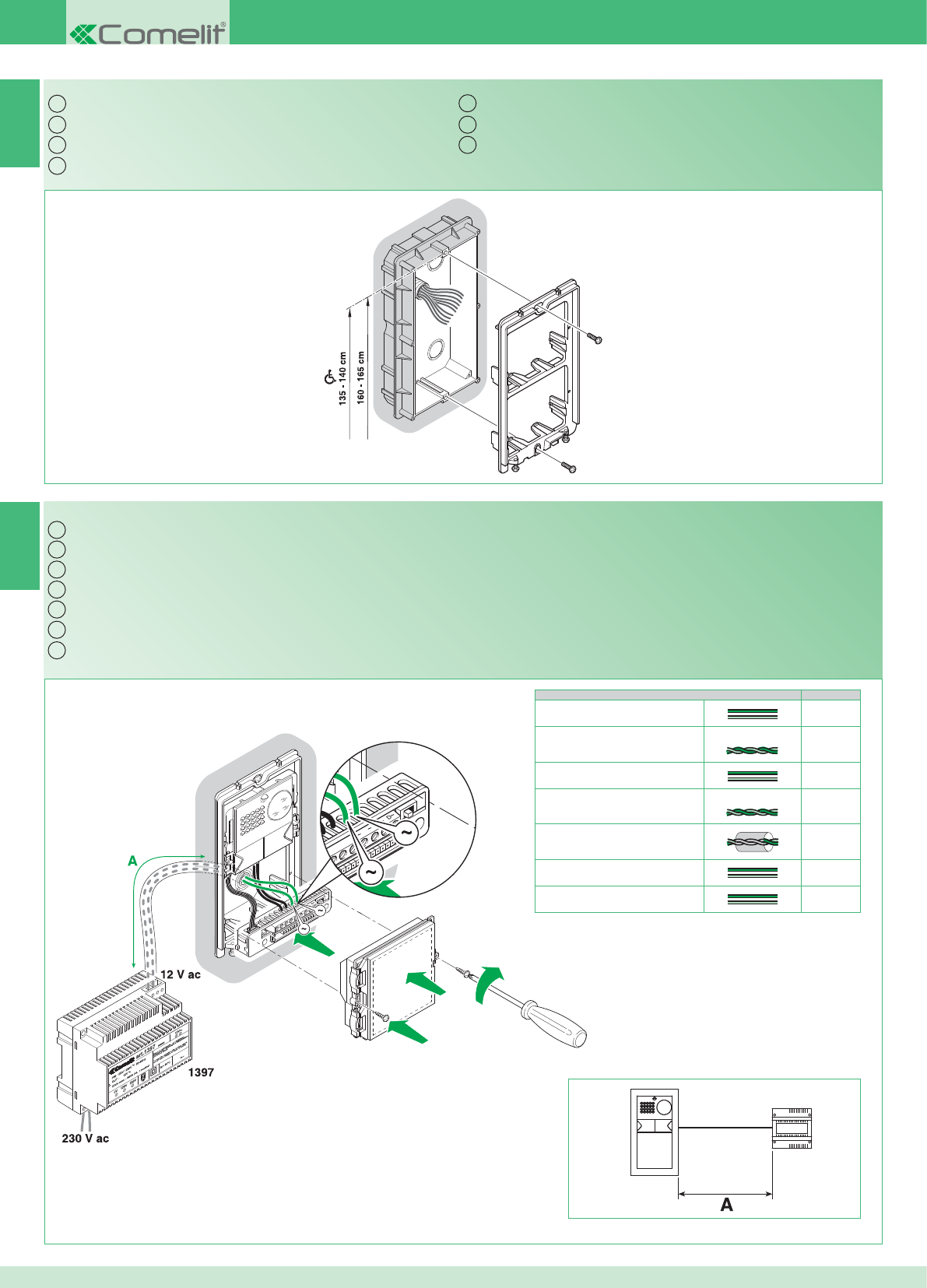
IT
EN
FR
NL
DE
ES
PT
NC CNO LP LP
NO LP LP
4891A
4892A
2G60000338
A Max
0,5 mm2 (Ø 0,8 mm - AWG 20) 10 m
0,5 mm2 (Ø 0,8 mm - AWG 20) Comelit Art. 4576-4578 10 m
1 mm2 (Ø 1,2 mm - AWG 17) 25 m
1 mm2 (Ø 1,2 mm - AWG 17) Comelit Art. 4577 25 m
1 mm2 (Ø 1,2 mm - AWG 17) 25 m
1,5 mm2 (Ø 1,4 mm - AWG 15) 40 m
2,5 mm2 (Ø 1,8 mm - AWG 13) 60 m
IT
EN
FR
NL
DE
ES
PT
2
1
4892A
1397
10
Montaggio telaio posto esterno
Cablaggio alimentatore Art. 1397 verso il posto esterno Art. 4891A - 4892A
Installing the external unit frame
Wiring between power supply unit Art. 1397 and external unit Art. 4891A - 4892A
Montage cadre du poste externe
Câblage alimentation Art. 1397 vers le poste externe Art. 4891A - 4892A
Montage entreepaneelframe
Bekabeling voedingstransformator Art. 1397 naar het entreepaneel Art. 4891A - 4892A
Montage des Rahmens der Außenstelle
Verdrahtung Netzteil Art. 1397 zur Außenstelle Art. 4891A - 4892A
Montaje del bastidor de la unidad externa
Cableado del alimentador art. 1397 hacia la unidad externa arts. 4891A - 4892A
Montagem da moldura do ponto externo
Cablagem do alimentador art. 1397 para o ponto externo art. 4891A - 4892A
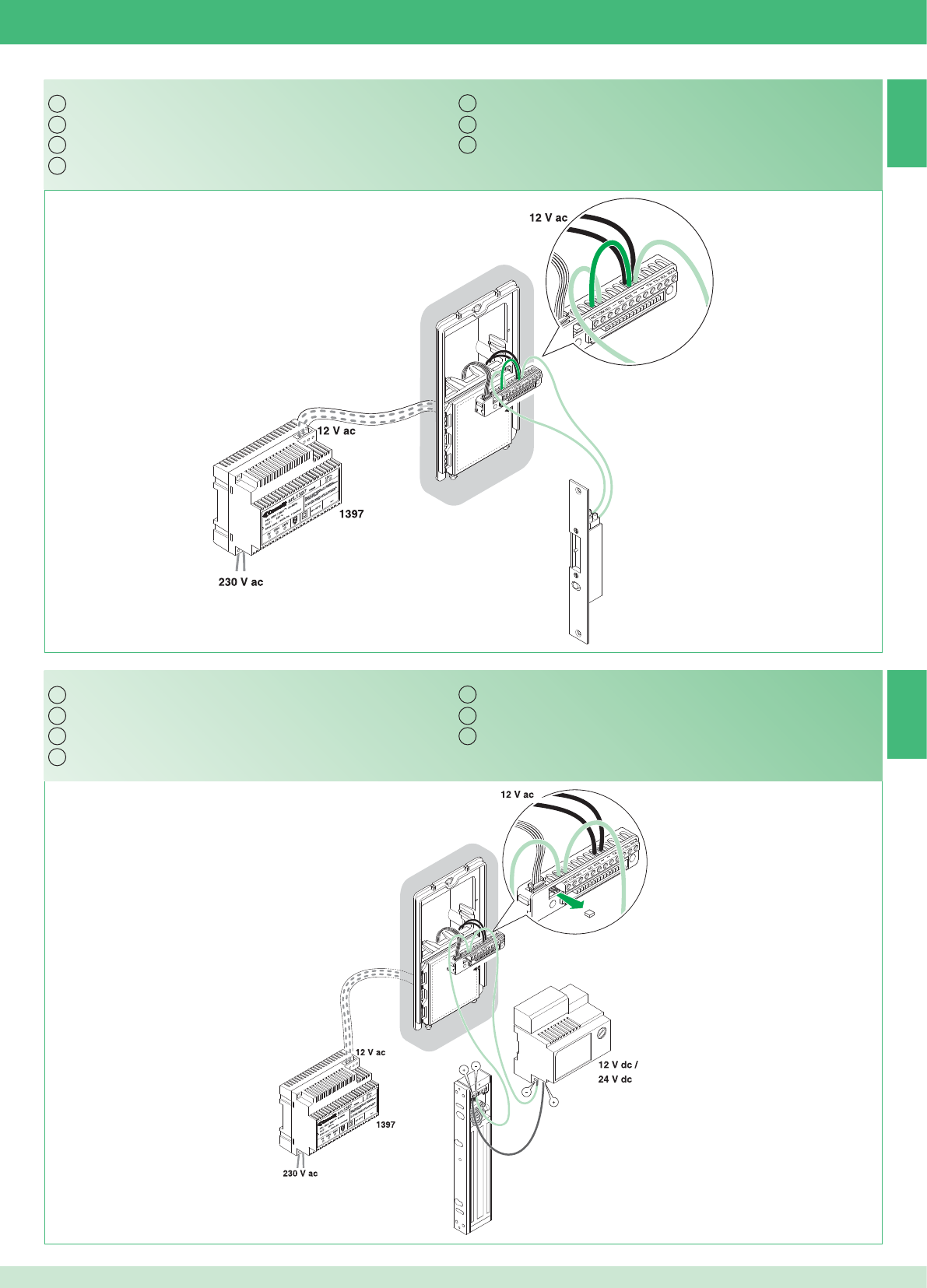
4891A
4892A
2G60000120
4891A
4892A
2G60000120
IT
EN
FR
NL
DE
ES
PT
IT
EN
FR
NL
DE
ES
PT
3A
3B
11
Serratura in AC (Relé 1)
Serratura in DC (Relé 1)
AC door lock (Relay 1)
DC door lock (Relay 1)
Gâche en AC (Relais 1)
Gâche en DC (Relais 1)
Slot met wisselstroom (relais 1)
Slot met gelijkstroom (Relais 1)
Türöffner in Gleichspannung (Relais 1)
Türöffner in Wechselspannung (Relais 1)
Cerradura de CA (relé 1)
Cerradura de CC (relé 1)
Fechadura em AC (Relé 1)
Fechadura em DC (Relé 1)
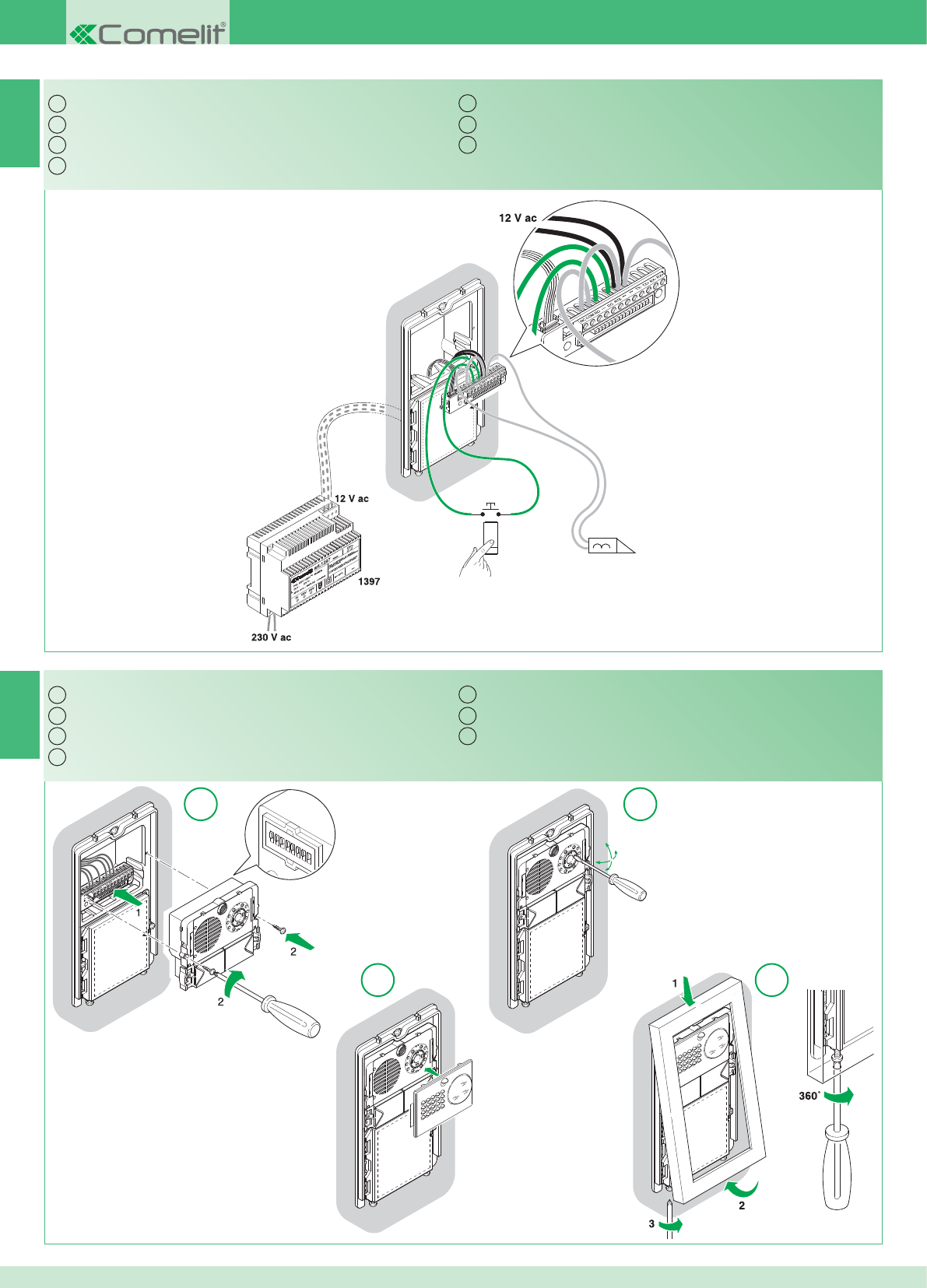
4891A
4892A
2G60000120
12345678
ONDIP
12
3 4
IT
EN
FR
NL
DE
ES
PT
IT
EN
FR
NL
DE
ES
PT
5
4
12
Comando locale temporizzato serratura (Relé 1)
Montaggio modulo telecamera e orientamento
Timed local door lock command (Relay 1)
Installing and adjusting the orientation of the camera module
Commande locale temporisée gâche (Relais 1)
Montage du module caméra et orientation
Lokale slotbediening met tijdsinstelling (relais 1)
Montage camera- en oriëntatiemodule
Zeitgesteuerte lokale Türöffnertaste (Relais 1)
Montage des Kameramoduls und Ausrichtung
Mando local temporizado de la cerradura (relé 1)
Montaje del módulo telecámara y orientación
Comando local da fechadura com temporizador (Relé 1)
Montagem do módulo câmara e orientação
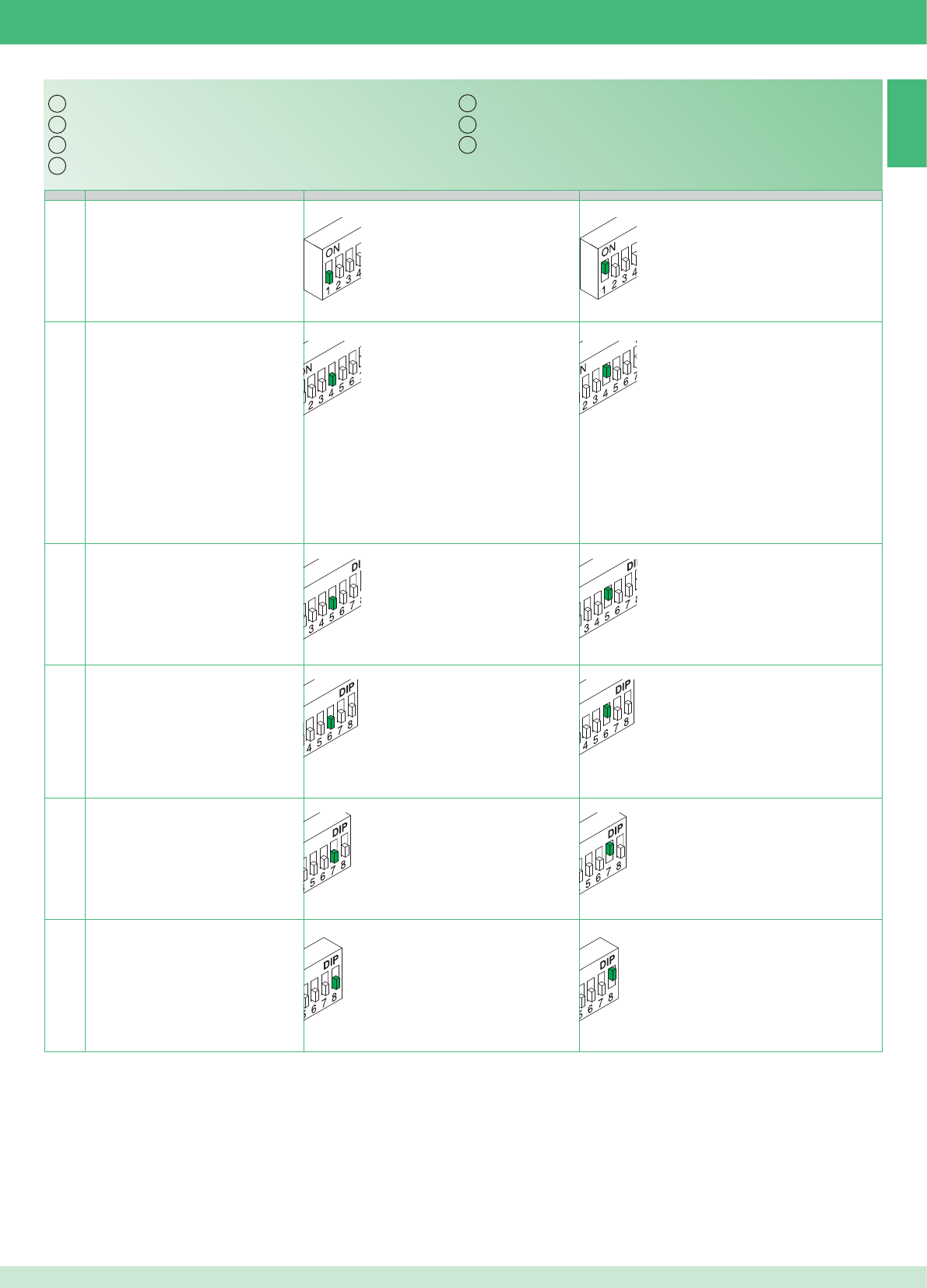
IT
EN
FR
NL
DE
ES
PT
6
DIP OFF ON
1
4
5
6
7
8
13
Tabella impostazioni dip switch posto esterno
Identifi cazione del posto esterno Posto esterno 1 Posto esterno 2
Utilizzo relé 2 (vedi punto 13) Si attiva solo su comando da staffa Si attiva anche automaticamente su chiamata da posto
esterno e autoaccensione
Tempo attivazione relé 1 (vedi punto 3) 2 secondi 8 secondi
Tempo attivazione relé 2 (vedi punto 13) 2 secondi; *(1 minuto se dip 4 ON) 8 secondi; *(3 minuti se dip 4 ON)
Tono conferma apri porta Non attivo Attivo
Tono conferma inizio e fi ne chiamata Non attivo Attivo
Table of external unit Dip switch settings
Identifying external unit External unit 1 External unit 2
Only activated on a command from the bracketUsing relay 2 (see paragraph 13)
Also activated automatically on receipt of a call from
the external unit and when the self-ignition function is
enabled
Relay 1 activation time (see paragraph 3) 2 seconds 8 seconds
Relay 2 activation time (see paragraph 13) 2 seconds; *(1 minute if Dip switch 4 ON) 8 seconds; *(3 minutes if Dip switch 4 ON)
Door open confi rmation tone Not active Active
Call start and end confi rmation tone Not active Active
Tableau des réglages DIP switch du poste externe
Identifi cation de la plaque de rue Plaque de rue 1 Plaque de rue 2
S’active uniquement sur commande par brideUtilisation relais 2 (voir point 13)
S’active également automatiquement sur appel depuis
la plaque de rue et auto-allumage
Temps activation relais 1 (voir point 3) 2 secondes 8 secondes
Temps activation relais 2 (voir point 13) 2 secondes ; *(1 minute si dip 4 ON) 8 secondes ; *(3 minutes si dip 4 ON)
Tonalité confi rmation ouvre porte Non actif Actif
Tonalité confi rmation début et fi n appel Non actif Actif
Instellingentabel dipswitch entreepaneel
Identifi catie van het entreepaneel Entreepaneel 1 Entreepaneel 2
Gebruik relais 2 (zie punt 13) Wordt alleen geactiveerd na een bediening
vanaf de grondplaat
Wordt ook automatisch geactiveerd na een oproep
vanaf het entreepaneel en een beeldoproep
Inschakelduur relais 1 (zie punt 3) 2 seconden 8 seconden
Inschakelduur relais 2 (zie punt 13) 2 seconden; *(1 minuut als dip 4 ON) 8 seconden; *(3 minuten als dip 4 ON)
bevestigingstoon deuropener Niet actief Actief
Bevestigingstoon begin en einde oproep Niet actief Actief
Tabelle mit den Dipschalter-Stellungen der Außenstelle
Identifi kation der Türstation Türstation 1 Türstation 2
Einschaltdauer Relais 1 (siehe Punkt 3) 2 Sekunden 8 Sekunden
Einschaltdauer Relais 2 (siehe Punkt 13) 2 Sekunden; *(1 Minute, falls DIP 4 ON) 8 Sekunden; *(3 Minuten, falls DIP 4 ON)
Verwendung von Relais 2 (siehe Punkt 13)
Schaltet sich nur nach Befehl von Grundplatte
ein.
Schaltet sich auch automatisch ein bei Ruf von
Türstation und Selbsteinschaltung
Bestätigungston Türöffner Nicht aktiv Aktiv
Bestätigungston Beginn und Ende der
Sprechverbindung
Nicht aktiv Aktiv
Tabla de confi guraciones de los DIP switches de la unidad externa
Identifi cación de la unidad externa Unidad externa 1 Unidad externa 2
Tiempo de activación del relé 1 (véasepunto 3) 2 segundos 8 segundos
Tiempo de activación del relé 2 (véase punto 13) 2 segundos *(1 minuto si el interruptor DIP 4
está en ON)
8 segundos *(3 minutos si el interruptor DIP 4 está
en ON)
Uso del relé 2 (véase punto 13)
Se activa sólo con el mando del soporte (placa)
Se activa también automáticamente cuando se
produce una llamada desde la unidad externa o el
autoencendido
Tono de confi rmación de la cerradura No activo Activo
Tono de confi rmación del inicio y fi n de lallamada
No activo Activo
Tabela de confi gurações do dip switch do ponto externo
Identifi cação do ponto externo Ponto externo 1 Ponto externo 2
Tempo activação do relé 1 (consultar ponto 3) 2 segundos 8 segundos
Tempo activação do relé 2 (consultar ponto13)
2 segundos; *(1 minutos se dip 4 ON) 8 segundos; *(3 minutos se dip 4 ON)
Utilização do relé 2 (consultar ponto 13)
Activa-se apenas se enviado um comando do
suporte
Activa-se também automaticamente em caso de
chamada do ponto externo e auto-ligação
Som de confi rmação de abertura de porta Inactivo Activo
Som de confi rmação do início e fi m dachamada
Inactivo Activo
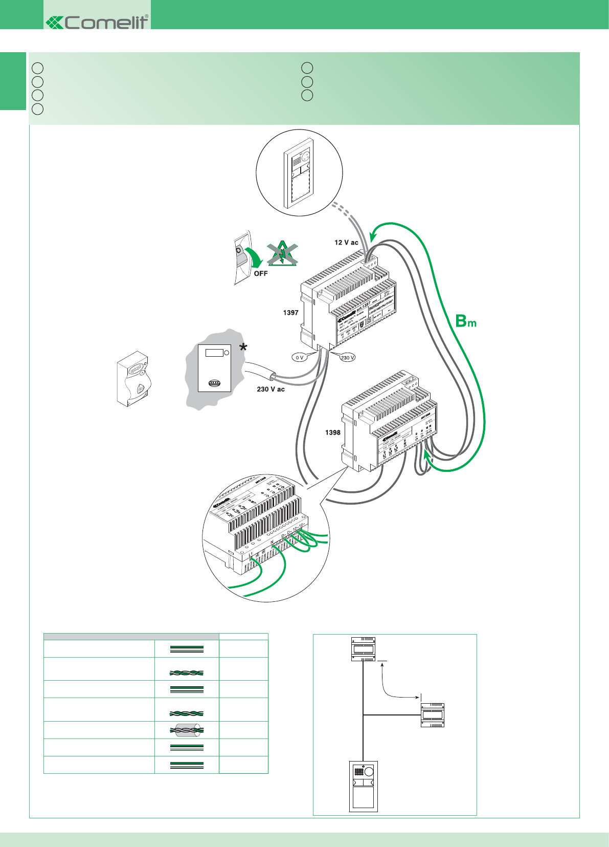
1398
4892A
1397
Bm
IT
EN
FR
NL
DE
ES
PT
7A
Bm Max
0,5 mm2 (Ø 0,8 mm - AWG 20) 130 m
0,5 mm2 (Ø 0,8 mm - AWG 20) Comelit Art. 4576-4578 150 m
1 mm2 (Ø 1,2 mm - AWG 17) 200 m
1 mm2 (Ø 1,2 mm - AWG 17) Comelit Art. 4577 200 m
1 mm2 (Ø 1,2 mm - AWG 17) 100 m
1,5 mm2 (Ø 1,4 mm - AWG 15) 250 m
2,5 mm2 (Ø 1,8 mm - AWG 13) 300 m
14
* Contatore
Kit monofamiliare: cablaggio monofase ponte Art. 1398
* Meter
Single-residence kit: single-phase wiring for bridge Art. 1398
* Compteur
Kit un usager : câblage monophasé pont Art. 1398
* Teller
Kit voor eengezinswoningen: eenfasige bekabeling brug Art. 1398
* Zähler
Set für Einfamilienhaus: Einphasenverdrahtung Brücke Art. 1398
* Contador
Kit unifamiliar: cableado monofásico del puente art. 1398
* Contador
Kit monofamiliar: cablagem monofásica ponte art. 1398
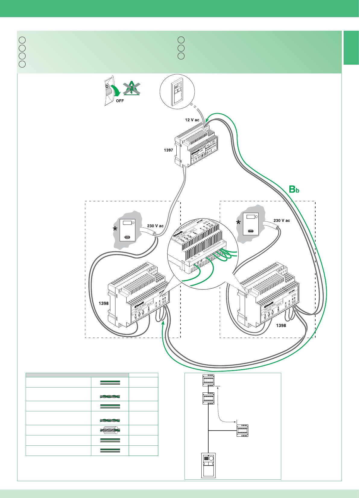
12~
D~D~L1N 12~
IT
EN
FR
NL
DE
ES
PT
7B
1398
4892A
1397
Bb
1398
Bb Max
0,5 mm2 (Ø 0,8 mm - AWG 20) 60 m
0,5 mm2 (Ø 0,8 mm - AWG 20) Comelit Art. 4576-4578 70 m
1 mm2 (Ø 1,2 mm - AWG 17) 150 m
1 mm2 (Ø 1,2 mm - AWG 17) Comelit Art. 4577 150 m
1 mm2 (Ø 1,2 mm - AWG 17) 50 m
1,5 mm2 (Ø 1,4 mm - AWG 15) 170 m
2,5 mm2 (Ø 1,8 mm - AWG 13) 200 m
15
* Contatore
Kit bifamiliare: cablaggio monofase ponti Art. 1398
* Meter
Two-residence kit: single-phase wiring for bridges Art. 1398
* Compteur
Kit deux usagers : câblage monophasé ponts Art. 1398
* Teller
Kit voor tweegezinswoningen: eenfasige bekabeling bruggen Art. 1398
* Zähler
Set für Zweifamilienhaus: Einphasenverdrahtung Brücken Art. 1398
* Contador
Kit bifamiliar: cableado monofásico de los puentes art. 1398
* Contador
Kit bifamiliar: cablagem monofásica ponte art. 1398
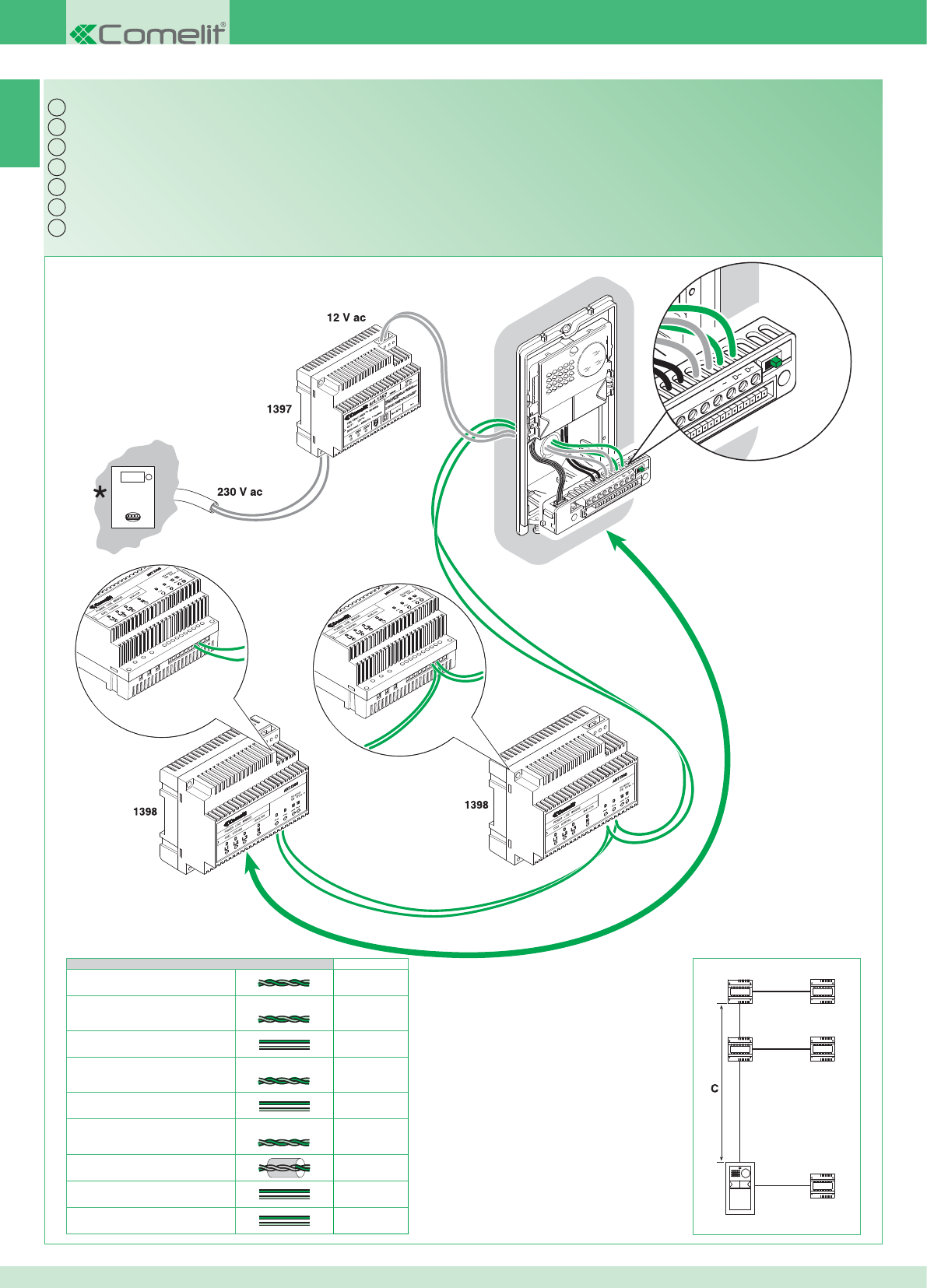
NC CNO LP LP
4891A
4892A
2G60000338
CCNO LP LP
C
4892A
1397
1397
1398
1397
1398
IT
EN
FR
NL
DE
ES
PT
7C
C Max
0,28 mm2 (Ø 0,6 mm - AWG 23) 800 m
0,2 mm2 (Ø 0,5 mm - AWG 24) UTP5 cat.5 500 m
0,5 mm2 (Ø 0,8 mm - AWG 20) 600 m
0,5 mm2 (Ø 0,8 mm - AWG 20) Comelit Art. 4576-4578 1000 m
1 mm2 (Ø 1,2 mm - AWG 17) 600 m
1 mm2 (Ø 1,2 mm - AWG 17) Comelit Art. 4577 1000 m
1 mm2 (Ø 1,2 mm - AWG 17) 400 m
1,5 mm2 (Ø 1,4 mm - AWG 15) 600 m
2,5 mm2 (Ø 1,8 mm - AWG 13) 600 m
16
Kit bifamiliare e multiutenza con contatore parti comuni: cablaggio dati ponti Art. 1398
* Contatore
Two-residence kit and multi-user system with shared utility meter: data wiring for bridges Art. 1398
* Meter
Kit deux usagers et multi-usagers avec compteur parties communes : câblage données ponts Art. 1398
* Compteur
Kit voor tweegezinswoningen en multi-userinstallaties met teller voor de gemeenschappelijke delen: databekabeling bruggen Art. 1398
* Teller
Set für Zweifamilienhaus und Multi-User mit Zähler für Gemeinschaftsbereiche: Verdrahtung Daten Brücken Art. 1398
* Zähler
Kit bifamiliar y multiusuarios con contador para partes comunes: cableado de datos de los puentes art. 1398
* Contador
Kit bifamiliar e multiutilizadores com contador nas partes comuns: cablagem dados pontes art. 1398
* Contador
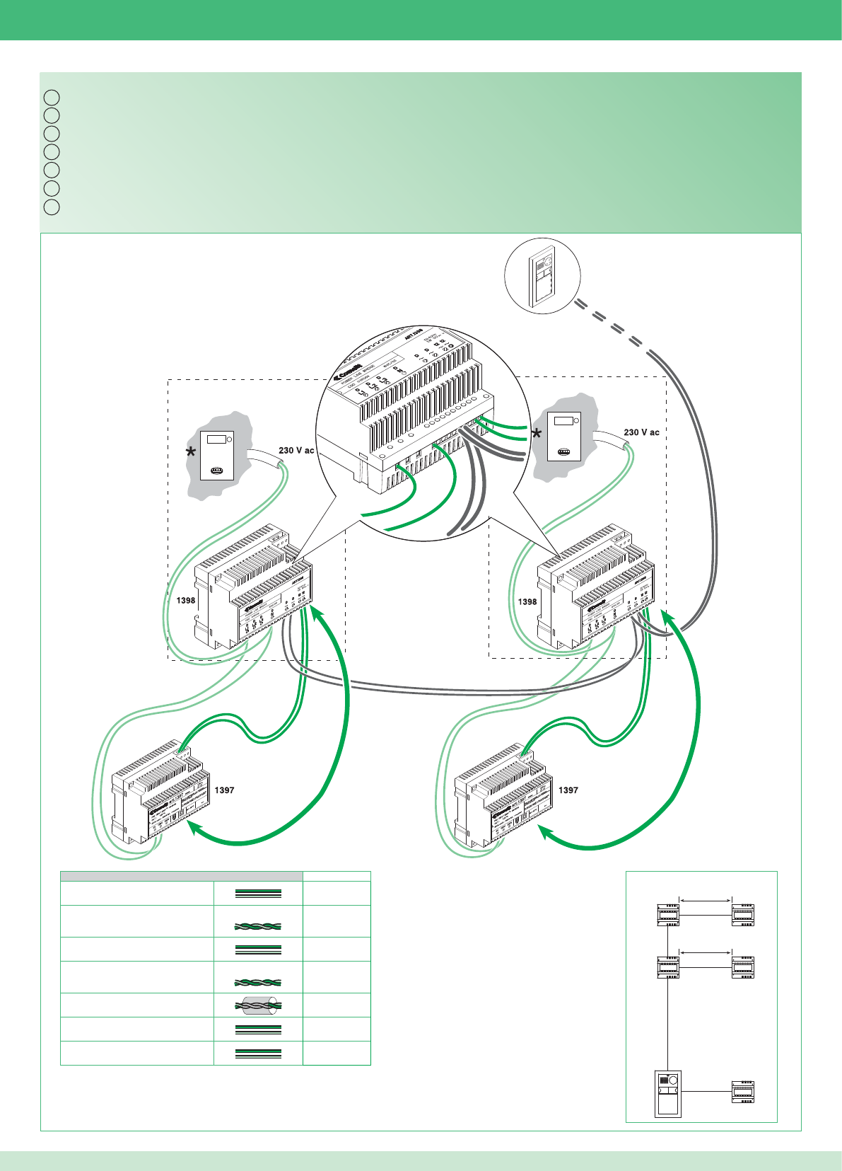
Bm
Bm
12~
D~D~L1 N 12~
IT
EN
FR
NL
DE
ES
PT
4892A
1397
1397
1398
1397
1398
Bm
Bm
Bm Max
0,5 mm2 (Ø 0,8 mm - AWG 20) 130 m
0,5 mm2 (Ø 0,8 mm - AWG 20) Comelit Art. 4576-4578 150 m
1 mm2 (Ø 1,2 mm - AWG 17) 200 m
1 mm2 (Ø 1,2 mm - AWG 17) Comelit Art. 4577 200 m
1 mm2 (Ø 1,2 mm - AWG 17) 100 m
1,5 mm2 (Ø 1,4 mm - AWG 15) 250 m
2,5 mm2 (Ø 1,8 mm - AWG 13) 300 m
17
Kit bifamiliare e multiutenza con contatore parti comuni: cablaggio monofase alimentazione ponti Art. 1398
Two-residence kit and multi-user system with shared utility meter: single-phase power supply wiring for bridges Art. 1398
Kit deux usagers et multi-usagers avec compteur parties communes : câblage monophasé alimentation ponts Art. 1398
Kit voor tweegezinswoningen en multi-userinstallaties met teller voor de gemeenschappelijke delen: eenfasige voedingsbekabeling Art. 1398
Set für Zweifamilienhaus und Multi-User mit Zähler für Gemeinschaftsbereiche: Einphasenverdrahtung Stromversorgung Brücken Art. 1398
Kit bifamiliar y multiusuarios con contador para partes comunes: cableado monofásico de alimentación de los puentes art. 1398
Kit bifamiliar e multiutilizadores com contador nas partes comuns: cablagem monofásica alimentação pontes art. 1398
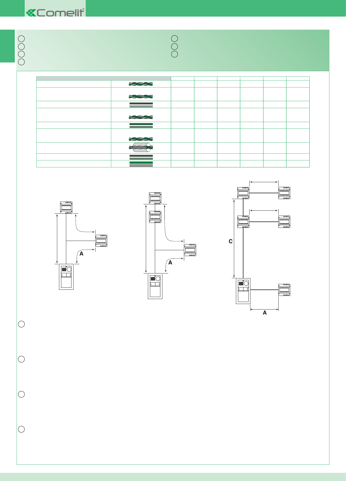
IT
EN
FR
NL
IT
EN
FR
NL
DE
ES
PT
1398
4892A
1397
Bm
Cm
4892A
1397
1397
1398
1397
1398
Bm
Bm
1398
4892A
1397
Bb
1398
Cb
8
A Max Bm Max Bb Max Cm Max Cb Max C Max
0,28 mm2 (Ø 0,6 mm - AWG 23) 800 m
0,2 mm2 (Ø 0,5 mm - AWG 24) UTP5 cat.5 500 m
0,5 mm2 (Ø 0,8 mm - AWG 20) 10 m 130 m 60 m A + Bm A + Bb 600 m
0,5 mm2 (Ø 0,8 mm - AWG 20) Comelit Art. 4576-4578 10 m 150 m 70 m A + Bm A + Bb 1000 m
1 mm2 (Ø 1,2 mm - AWG 17) 25 m 200 m 150 m A + Bm A + Bb 600 m
1 mm2 (Ø 1,2 mm - AWG 17) Comelit Art. 4577 25 m 200 m 150v m A + Bm A + Bb 1000 m
1 mm2 (Ø 1,2 mm - AWG 17) 25 m 100 m 50 m A + Bm A + Bb 400 m
1,5 mm2 (Ø 1,4 mm - AWG 15) 40 m 250 m 170 m A + Bm A + Bb 600 m
2,5 mm2 (Ø 1,8 mm - AWG 13) 60 m 300 m 200 m A + Bm A + Bb 600 m
18
A: Distanza valida con carico massimo di 2 posti esterni, 2 ponti Art. 1398 e l’attivazione di una sola serratura per volta tra quelle alimentate
dall’Art. 1397.
La distanza raddoppia se la serratura è alimentata in modo indipendente.
Bm: Kit monofamiliare (1 ponte Art. 1398) o bifamiliare / multiutenza con contatore parti comuni.
Bb: kit bifamiliare (2 ponti Art. 1398)
C: Distanza tra il posto esterno e l'Art. 1398 più lontano.
Distanze di collegamento
A: Distance applies with a maximum load of 2 external units, 2 bridges Art. 1398 and the activation of only one door lock at a time for those
powered by Art. 1397.
The distance doubles if the door lock is powered independently.
Bm: Single-residence kit (1 bridge Art. 1398) or two-residence kit / multi-user system with shared utility meter.
Bb: two-residence kit (2 bridges Art. 1398)
C: Distance between the external unit and the furthest bridge Art. 1398.
Connection distances
A : Distance valable avec une charge maximale de 2 postes externes, 2 ponts Art. 1398 et l'activation d'une seule gâche à la fois parmi celles
qui sont alimentées par l’Art. 1397.
Cette distance est doublée si la gâche est alimentée de manière indépendante.
Bm : Kit un usager (1 pont Art. 1398) ou deux usagers / multi-usagers avec compteur parties communes.
Bb : kit deux usagers (2 ponts Art. 1398)
C : Distance entre le poste externe et l'Art. 1398 le plus éloigné.
Distances de branchement
A: Afstand die geldig is bij een maximale belasting van 2 entreepanelen, 2 bruggen Art. 1398 en inschakeling van telkens één slot tegelijk van
degene die worden gevoed door Art. 1397.
Deze afstand verdubbelt als het slot zelfstandig wordt gevoed.
Bm: Kit voor eengezinswoningen (1 brug Art. 1398) of tweegezinswoningen / multi-userinstallaties met teller voor de gemeenschappelijke delen.
Bb: kit voor tweegezinswoning (2 bruggen Art. 1398)
C: Afstand tussen het entreepaneel en het verst weg gelegen Art. 1398.
Aansluitafstanden
Anschlussabstände
Distancias de conexión
Distâncias de ligação
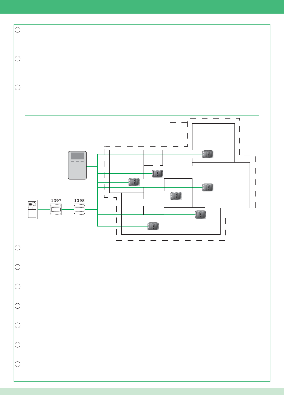
DE
ES
PT
IT
EN
FR
NL
DE
ES
PT
MAX 300m2
19
Estensione massima unità abitativa * servita dal ponte Art. 1398: 300m2 circa.
Attenzione! I gruppi di continuità impediscono il passaggio del segnale. L’insieme di tutti i punti di connessione (prese elettriche e ponti Art. 1398)
utilizzabili per il sistema devono trovarsi in ingresso o in uscita del gruppo di continuità.
* Ambiente residenziale monofase o trifase (non adatto per impianti industriali e alberghieri).
Maximum expanse of residential unit * served by bridge Art. 1398: approx. 300 m2.
Caution! Uninterruptible power supplies prevent the signal from passing through. All connection points (electrical sockets and bridges Art. 1398)
which may be used by the system should be positioned at the input or output of the uninterruptible power supply.
* Single-phase or three-phase residential installation (not suitable for industrial or hotel systems).
Surface maximale appartement * desservie par le pont Art. 1398 : 300 m2 environ.
Attention ! Les groupes de continuité empêchent le passage du signal. L’ensemble de tous les points de connexion (prises électriques et ponts
Art. 1398) utilisables pour le système doivent se situer à l'entrée ou à la sortie du groupe de continuité.
* Milieu résidentiel monophasé ou triphasé (inadapté aux installations industrielles ou hôtelières).
Maximale uitbreiding wooneenheid * die bediend wordt door de brug Art. 1398: circa 300 m2.
Let op! De UPS-groepen verhinderen dat het signaal kan passeren. Het geheel van alle aansluitpunten (stroomafnamepunten en bruggen Art.
1398) die bruikbaar zijn voor het systeem moeten zich aan de ingang of de uitgang van de UPS-groep bevinden.
* Een- of driefasige woonomgeving (niet geschikt voor industriële installaties en hotels).
A: Gültiger Abstand bei max. Last von 2 Außenstellen, 2 Brücken Art. 1398 und Aktivierung von jeweils nur einem der mit dem Art. 1397
gespeisten Türöffner.
Der Abstand verdoppelt sich, wenn der Türöffner unabhängig versorgt wird.
Bm: Set für Einfamilienhaus (1 Brücke Art. 1398) oder Zweifamilienhaus / Multi-User mit Zähler für Gemeinschaftsbereiche.
Bb: Set für Zweifamilienhaus (2 Brücken Art. 1398)
C: Abstand zwischen der Außenstelle und dem am weitesten entfernten Art. 1398.
Max. Größe der von der Brücke Art. 1398 versorgten Wohneinheit *: 300 m2 circa.
Achtung! USV verhindert den Signaldurchgang. Alle für das System verwendbaren Anschlusspunkte (Steckdosen und Brücken Art. 1398)
müssen sich im Ein- oder Ausgang der USV befi nden.
* Wohnbereich, Einphasen- oder Drehstrom (nicht geeignet für Industrie- und Hotelanlagen).
A: Distancia válida con una carga máxima de 2 unidades externas, 2 puentes art. 1398 y activación de una sola cerradura cada vez entre las
alimentadas por el art. 1397.
La distancia se duplica si la cerradura está alimentada de forma independiente.
Bm: kit unifamiliar (1 puente art. 1398) o bifamiliar / multiusuarios con contador para partes comunes.
Bb: kit bifamiliar (2 puentes art. 1398)
C: Distancia entre la unidad externa y el art. 1398 más lejano.
Superfi cie máxima de la vivienda* en la cual se emplea el puente art. 1398: 300 m2 aprox.
¡Atención! Los grupos de continuidad impiden el paso de la señal. El conjunto de todos los puntos de conexión (tomas eléctricas y puentes art.
1398) que es posible emplear en el sistema se han de encontrar en entrada o salida del grupo de continuidad.
* Instalación residencial monofásica o trifásica (no adecuada para instalaciones industriales y hoteleras).
A: Distância válida com um máximo de 2 pontos externos, 2 pontes art. 1398 e a activação de uma única fechadura de cada vez entre as
alimentadas pelo art. 1397.
A distância duplica se a fechadura for alimentada de forma independente.
Bm: Kit monofamiliar (1 ponte art. 1398) ou bifamiliar/multiutilizadores com contador nas partes comuns.
Bb: kit bifamiliar (2 pontes art. 1398)
C: Distância entre o ponto externo e o art. 1398 mais distante.
Extensão máxima unidade habitacional *servida pela ponte art. 1398: aprox. 300 m2.
Atenção! Os grupos de continuidade impedem a passagem do sinal. O conjunto de todos os pontos de ligação (tomadas eléctricas e pontes
art. 1398) utilizáveis para o sistema deve estar na entrada ou na saída do grupo de continuidade.
Ambiente residencial monofásica ou trifásica (não adequado a instalações industriais e hoteleiras).
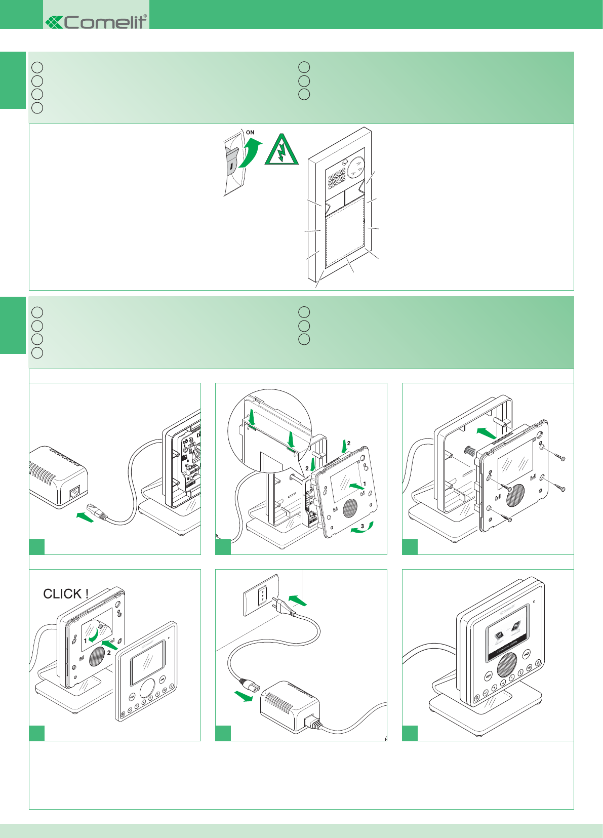
IT
EN
FR
NL
DE
ES
PT
1
1 2 3
4
IT
EN
FR
NL
DE
ES
PT
1
2
*
5 6
9
10
20
Accensione alimentazione generale
* Non utilizzare ciabatte con interruttore.
Montaggio monitor
Switching on the main power supply
* Do not use power strips fi tted with switches.
Installing the monitor
Allumage alimentation générale
* Ne pas utiliser de blocs multiprises avec interrupteur.
Montage moniteur
Inschakeling algemene voeding
* Geen meervoudige stekkerdozen met schakelaar gebruiken.
Montage van de monitor
Einschaltung der allgemeinen Stromversorgung
* Keine Mehrfachsteckdosen mit Schalter verwenden.
Monitoreinbau
Encendido de la alimentación general
* No utilizar regletas de enchufes con interruptor.
Montaje del monitor
Acendimento da alimentação geral.
* Não utilizar extensões com interruptor.
Montagem do monitor
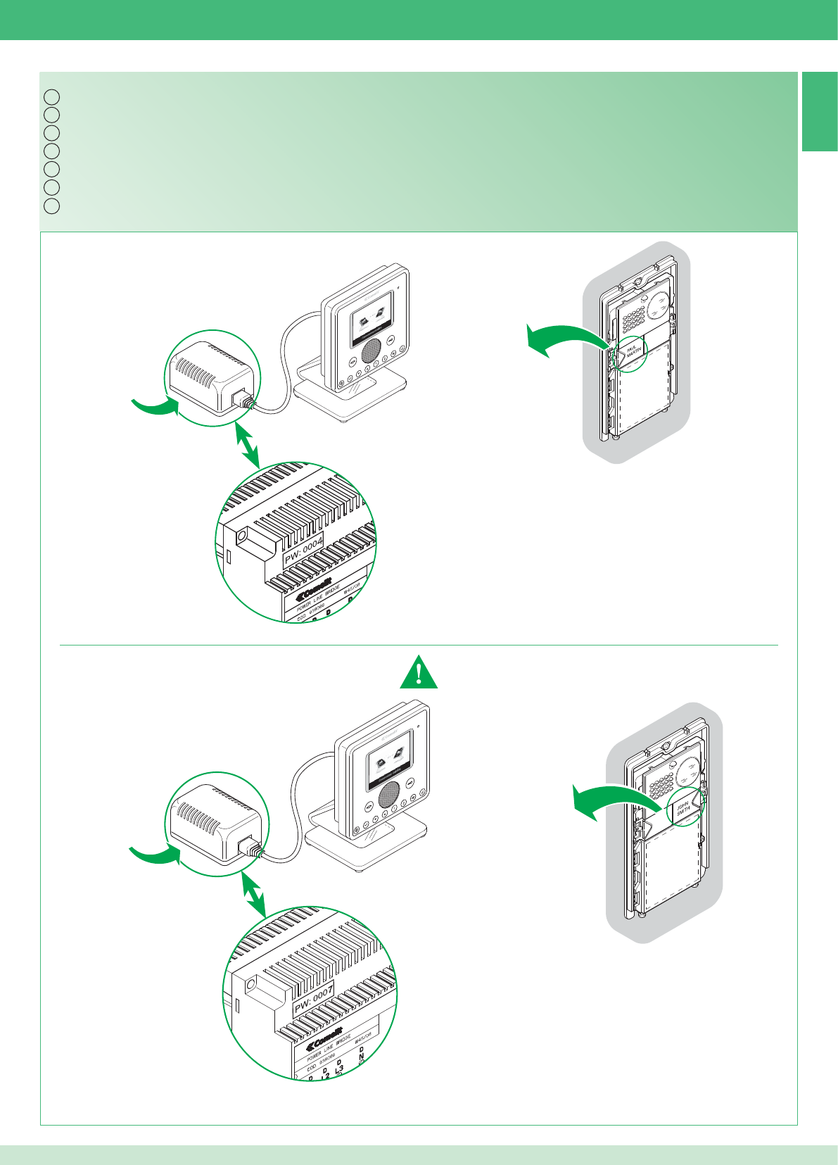
IT
EN
FR
NL
DE
ES
PT
Art. 1398
Art. 1398
11
PW: 0004
PW: 0007
Art. 1398
Art. 1398
21
Kit bifamiliare: corrispondenza posto interno / pulsante di chiamata e alimentatore monitor / ponte Art. 1398
Impostare Indirizzo: 2
Vedere punto 21
Indirizzo: 1Indirizzo: 1
Indirizzo: 2
Esempio
Esempio
Two-residence kit: alignment between internal unit / call button and monitor power supply unit / bridge Art. 1398
Address: 1 Address: 1
Set Address: 2
See point 21
Address: 2
Example
Example
Kit deux usagers : correspondance poste interne / touche d’appel et alimentation moniteur / pont Art. 1398
Adresse : 1 Adresse : 1
Confi gurer adresse : 2
Voir point 21
Adresse : 2
Exemple
Exemple
Kit voor tweegezinswoningen: overeenstemming tussen binnentoestel / oproepknop en voedingstransformator monitor / brug Art. 1398
Adres: 1 Adres: 1
Adres instellen: 2
Zie punt 21
Adres: 2
Voorbeeld
Voorbeeld
Set für Zweifamilienhaus: Zuordnung Innenstelle / Ruftaste und Netzteil Monitor / Brücke Art. 1398
Adresse: 1 Adresse: 1
Adresse einstellen: 2
Siehe Punkt 21 Adresse: 2
Beispiel
Beispiel
Kit bifamiliar: correspondencia entre unidad interna / pulsador de llamada y alimentador del monitor / puente art. 1398
Dirección: 1 Dirección: 1
Confi guración de la
dirección: 2
Véase punto 21
Dirección: 2
Ejemplo
Ejemplo
Kit bifamiliar: correspondência ponto interno/tecla de chamada e alimentador monitor/ponte art. 1398
Endereço: 1 Endereço: 1
Confi gurar endereço: 2
Consultar ponto 21
Endereço: 2
Exemplo
Exemplo
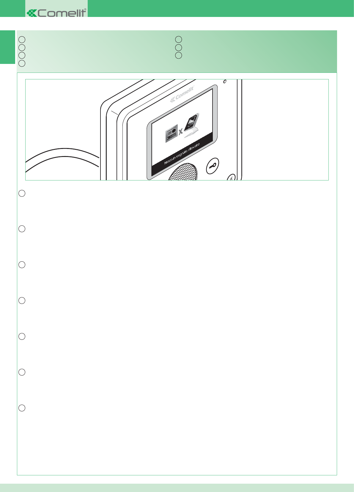
IT
EN
FR
NL
DE
ES
PT
IT
EN
FR
NL
DE
ES
PT
12
22
In caso di connessione mancante attendere 1 minuto.
Se la segnalazione si ripresenta assicurarsi:
1. Che il posto esterno sia correttamente cablato (punto 2) e che sia alimentato (punto 9).
2. Che il ponte Art. 1398 sia correttamente cablato (punto 7A, 7B o 7C).
3. Che ci sia corrispondenza tra la password del ponte Art. 1398 e l’alimentatore monitor della stessa unità abitativa.
4. Che siano rispettate le distanze di installazione (punti 2 e 8).
Segnalazione anomalie e possibili soluzioni
If there is no connection, wait for 1 minute.
If the indication appears again, make sure:
1. That the external unit is wired correctly (point 2) and that it is receiving power (point 9).
2. That the bridge Art. 1398 is wired correctly (point 7A, 7B or 7C).
3. That the password for bridge Art. 1398 is the same as the password for the power supply unit of the monitor in the same residential unit.
4. That the installation distances have been observed (points 2 and 8).
Fault indication and troubleshooting
À défaut de connexion, attendre 1 minute.
Si la signalisation réapparaît, s'assurer :
1. Que le poste externe soit correctement câblé (point 2) et alimenté en énergie électrique (point 9).
2. Que le pont Art. 1398 soit correctement câblé (point 7A, 7B ou 7C).
3. Qu'il y ait correspondance entre le mot de passe du pont Art. 1398 et l'alimentation moniteur de l'appartement.
4. Que les distances de montage (points 2 et 8) soient respectées.
Dépannage
Als de verbinding ontbreekt, 1 minuut wachten.
Als de signalering teruggekeerd is, moet u zich verzekeren van het volgende:
1. dat het entreepaneel correct bekabeld is (punt 2) en gevoed wordt (punt 9).
2. dat de brug Art. 1398 correct bekabeld is (punt 7A, 7B of 7C).
3. dat er overeenstemming is tussen het wachtwoord van de brug Art. 1398 en de voedingstransformator van de monitor van dezelfde wooneenheid.
4. dat de installatieafstanden in acht genomen zijn (punt 2 en 8).
Signalering van storingen en mogelijke oplossingen
Wenn keine Verbindung hergestellt wird, 1 Minute warten.
Wenn die Meldung wieder erscheint, überprüfen:
1. ob die Außenstelle korrekt verdrahtet ist (Punkt 2) und ob sie gespeist wird (Punkt 9).
2. ob die Brücke Art. 1398 korrekt verdrahtet ist (Punkt 7A, 7B oder 7C).
3. ob das Passwort der Brücke Art. 1398 und das Monitor-Netzteil derselben Wohneinheit übereinstimmen.
4. ob die Installationsabstände eingehalten wurden (Punkte 2 und 8).
Anzeige von Betriebsstörungen und mögliche Abhilfe
Si no se produce la conexión, esperar a que transcurra 1 minuto.
Si la señalización se vuelve a presentar, comprobar que:
1. la unidad externa esté correctamente cableada (punto 2) y alimentada (punto 9);
2. el puente art. 1398 esté correctamente cableado (puntos 7A, 7B o 7C);
3. la contraseña del puente art. 1398 sea igual a la del alimentador del monitor de la misma vivienda;
4. se respeten las distancias de instalación (puntos 2 y 8).
Señalización de anomalías y soluciones
Em caso de ligação em falta, aguardar 1 minuto.
Caso surja a indicação, certifi car-se de que:
1. o ponto externo se encontra correctamente cablado (ponto 2) e que é alimentado (ponto 9).
2. a ponte art. 1398 se encontra correctamente cablada (punto 7A, 7B ou 7C).
3. exista correspondência entre a password da ponte art. 1398 e o alimentador do monitor da mesma unidade habitacional.
4. as distâncias de instalação tenham sido respeitadas (pontos 2 e 8).
Indicação de anomalias e possíveis soluções
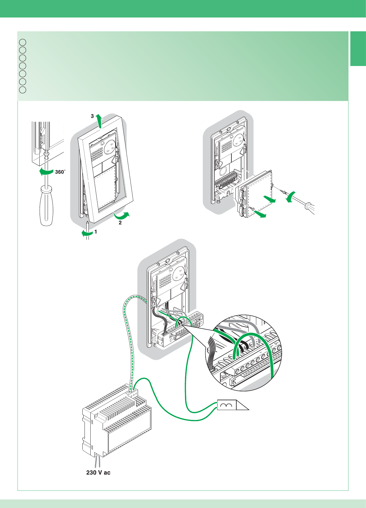
12
2 1
1
NC CNO LP LP
2G60000338
NC CNO LP LP
12/24 V ac/dc 2A MAX
IT
EN
FR
NL
DE
ES
PT
13
23
Utilizzare un alimentatore dedicato
Utilizzo relé del modulo numero civico (Relé 2), vedi variante PW/AAA
Use a special power supply unit
Using the info module relay (Relay 2), see PW/AAA variant
Utiliser une alimentation dédiée
Utilisation relais du module numéro civique (Relais 2), voir variante PW/AAA
Gebruik een speciale voedingstransformator
Gebruik van het relais van de huisnummermodule (relais 2), zie PW/AAA-variant
Ein eigenes Netzteil verwenden
Verwendung Relais des Hausnummern-Moduls (Relais 2), siehe Variante PW/AAA
Usar un alimentador dedicado
Uso del relé del módulo informativo iluminado (relé 2), véase variante PW/AAA
Utilizar um alimentador dedicado
Utilização do relé do módulo número de porta (Relé 2), consultar variante PW/AAA
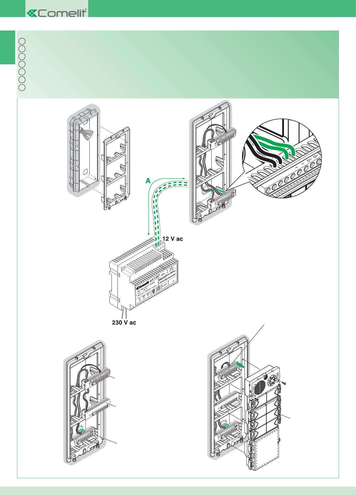
NC CNO LP LP
NC CNO LP LP
NC CNO LP LP
NC CNO LP LP
2G60000338
2G60000338
3323/3/4/6
2G60000120
3323/3/4/6
IT
EN
FR
NL
DE
ES
PT
14
24
Per il resto del cablaggio vedi pag. 16 -17
Espansione kit per multiutenza: montaggio posto esterno
For the remaining wiring see pages 16 -17
Expansion kit for multi-user system: installing the external unit
Pour le reste du câblage, voir pages 16 -17
Extension kit pour multi-usagers : montage du poste externe
Voor de rest van de bekabeling, zie pag. 16 -17
Uitbreiding van kit voor multi-userinstallaties: montage entreepaneel
Bezüglich der restlichen Verdrahtung siehe Seite 16 -17
Erweiterung des Sets für Multi-User: Einbau der Außenstelle
Para el resto del cableado, véanse págs. 16 y 17
Expansión del kit para multiusuarios: montaje de la unidad externa
Para a restante cablagem, consultar a pág. 16 -17
Kit de expansão para multiutilizadores: montagem do ponto externo
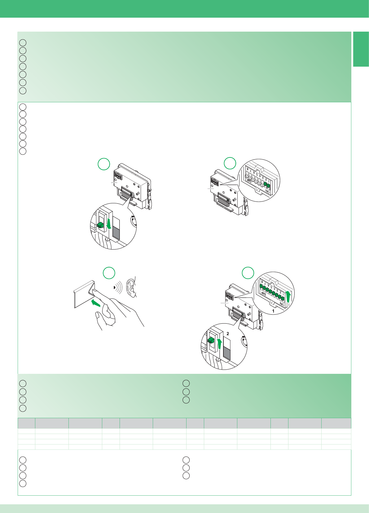
15
PR
2G60000124
PR
PR
PR
PR
2G60000124
2G60000124
12
34
IT
EN
FR
NL
DE
ES
PT
IT
EN
FR
NL
DE
ES
PT
Codice /
Code Dip switch ON Nome / Name Codice /
Code Dip switch ON Nome / Name Codice /
Code Dip switch ON Nome / Name Codice /
Code Dip switch ON Nome / Name
1 1 5 1,3 9 1,4 13 1,3,4
2 2 6 2,3 10 2,4 14 2,3,4
3 1,2 7 1,2,3 11 1,2,4
4 3 8 4 12 3,4
IT
EN
FR
NL
DE
ES
PT
IT
EN
FR
NL
DE
PT
ES
25
Tabella di programmazione dei dip switch
Multiutenza: programmazione pulsanti del posto esterno
L'espandibilità è possibile fi no ad un massimo di 14 appartamenti con indirizzo di diversi.
Programmazione e impostazioni monitor Planux pag. 26
Multi-user system: programming the buttons on the external unit
The system can be expanded up to a maximum of 14 apartments with different addresses.
Dip switch programming table
Planux monitor programming and settings page 35
Multi-usagers : programmation des touches du poste externe
Système évolutif jusqu'à un maximum de 14 appartements avec adresse de différentes.
Tableau de programmation des DIP switches
Programmation et confi guration du moniteur Planux page 44
Multi-userinstallaties: programmering van drukknoppen van het entreepaneel
De uitbreiding is mogelijk tot maximaal 14 appartementen met verschillende adressen.
Programmeringstabel van de dipswitches
Programmering en instelling van de monitor Planux pag. 53
Multi-User: Programmierung der Tasten der Außenstelle
Die Erweiterung ist bis zu 14 Wohnungen mit unterschiedlichen Adressen möglich.
Dipschalter-Programmiertabelle
Programmierung und Einstellungen Monitor Planux Seite 62
Multiusuarios: programación de los pulsadores de la unidad externa
Es posible una expansión de hasta 14 vivienda con direcciones diferentes.
Tabla de programación de los DIP switches
Programación y confi guraciones del monitor Planux, pág. 71
Multiutilizadores: programação das teclas do ponto externo
É possível expandir até um máximo de 14 unidades habitacionais com endereços diferentes.
Tabela de programação dos dip switches.
Programação e confi gurações do monitor Planux pág. 80
2 posti esterni Appartamenti
1234567891011121314
Numero staffe 14 14 - - - - - - - - - - - - - - - - - - - - - - - -
IT
16
17
26
E' possibile aggiungere monitor supplementari secondari distribuiti negli appartamenti seguendo le 2 seguenti regole:
1. Installare al massimo 14 staffe per appartamento.
2. Effettuare i seguenti calcoli sulla distribuzione prevista per le staffe:
}calcolare il numero totale delle staffe da installare nell'impianto (sia principali che secondarie) = A.
}individuare il numero di staffe più basso tra gli appartamenti = B
}calcolare la differenza tra il numero totale di staffe dell'impianto e quelle presenti nell'appartamento che ne ha di meno (A - B) ed assicurarsi
che il numero ottenuto sia:
Minore o uguale a 15 per impianti con 1 posto esterno.
Minore o uguale a 14 per impianti con 2 posti esterni.
Di seguito è riportato l'esempio di un KIT bifamiliare con 2 PE e 14 monitor per 2 appartamenti:
1 posto esterno Appartamenti
1234567891011121314
Numero staffe 2 3 4 5 3 - - - - - - - - - - - - - - - - - -
Di seguito è riportato l'esempio di un impianto con 1 PE e 17 monitor per 5 appartamenti:
1 posto esterno Appartamenti
1234567891011121314
Numero staffe 13 1 1 1 1 - - - - - - - - - - - - - - - - - -
Di seguito è riportato l'esempio di una confi gurazione non possibile di un impianto con 1 PE e 17 monitor per 5 appartamenti:
1. Prendere nota della password modem sull'etichetta del ponte Art. 1398 dell'unità abitattiva interessata.
2. Impostare sul monitor la password modem rilevata come descritto al punto 20.
3. Impostare l'indirizzo dei monitor supplementari secondari come descritto al punto 22
Avvertenza!
Procedimento:
Kit e Multiutenza: installazione monitor supplementari secondari
1. Prendere nota della password modem sull'etichetta del ponte Art. 1398 dell'unità abitattiva interessata.
2. Impostare sul monitor la password modem rilevata come descritto al punto 20.
3. Impostare l'indirizzo del monitor principale come descritto al punto 21
Multiutenza: installazione monitor principali
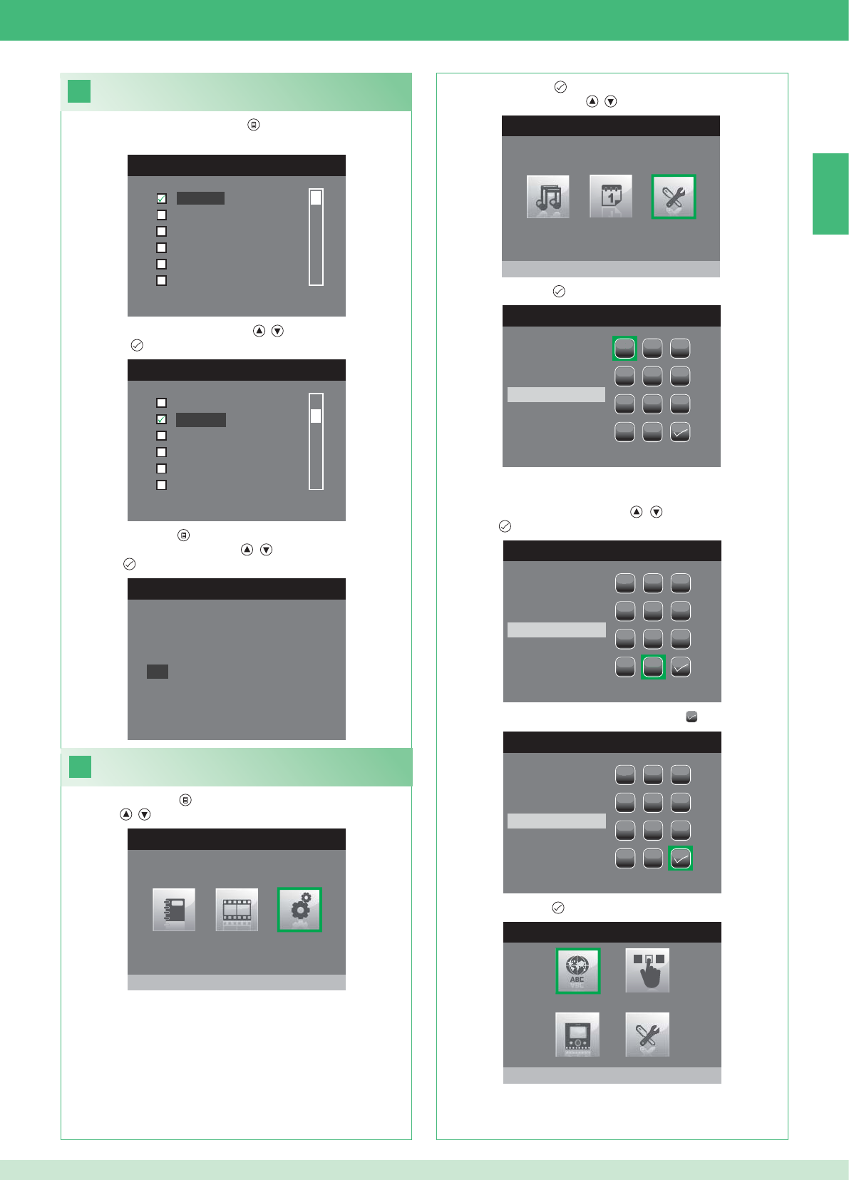
IT
18
MENU LINGUE
Italiano
English
Français
Español
Português
Deutsch
LANGUAGES MENU
Italiano
Français
Español
Português
Deutsch
English
19
MENU PRINCIPALE
Impostazioni
MENU IMPOSTAZIONI
Menu installatore
INSERIRE PASSWORD
1
1
23
456
789
0
C
INSERIRE PASSWORD
1
1
23
456
789
0
C
****
INSERIRE PASSWORD
1
1
23
456
789
0
C
****
MENU INSTALLATORE
Imposta lingua
English
NO
OK
27
Impostazione lingua menu
Al primo accesso al menu (pulsante ), viene richiesto di impostare
la lingua di utilizzo.
1. Selezionare la lingua con i pulsanti , e confermare premendo
il pulsante .
1. Premere il pulsante e Selezionare il menu Impostazioni con i
pulsanti , .
Accedere al menu installatore
2. Premere il pulsante per accedere e selezionare il menu Menu
installatore con i pulsanti , .
3. Premere il pulsante per accedere.
4. Selezionare le cifre con i pulsanti , e inserirle premendo il
pulsante .
5. Al termine dell'inserimento selezionare l'icona .
La password per il menu installatore è 0000. Non è possibile
modifi care la password,
6. Premere il pulsante per confermare.
2. Premere il pulsante per uscire.
3. Selezionare "OK" con i pulsanti , e confermare premendo il
pulsante .
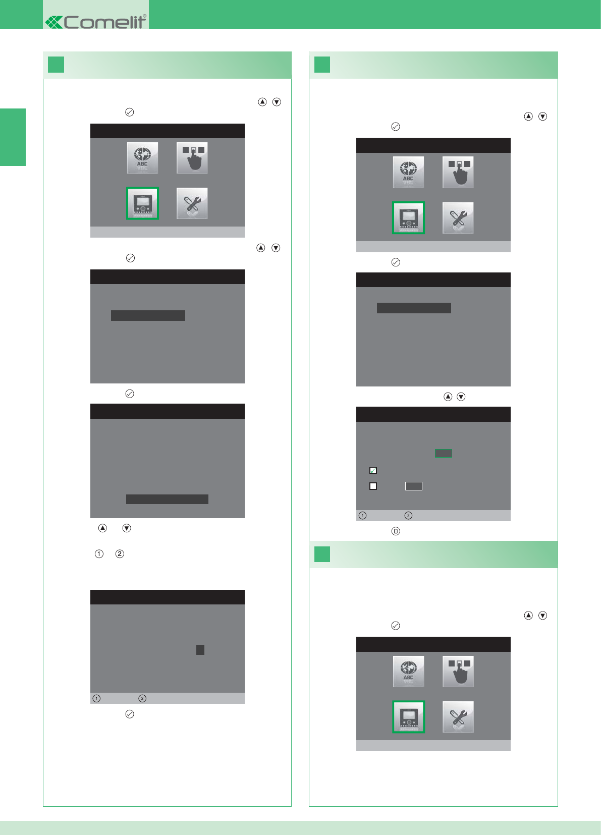
IT
20
MENU INSTALLATORE
Configura monitor
CONFIGURA MONITOR
Reset configurazione
Imposta tipo di rete
Informazioni
Configura staffa
Indirizzo logico
CONFIGURA PASSWORD
Sinistra Destra
Modem password: 1 0 0 7
CONFIGURAZIONE STAFFA
ID: A
PWD: 0007
MAC: 00:0D:BE:00:2C:65
Cambia password
IMPOSTA INDIRIZZO LOGICO
Indirizzo logico 0 2
Master
Slave 1 4
Sinistra Destra
22
MENU INSTALLATORE
Configura monitor
21
MENU INSTALLATORE
Configura monitor
CONFIGURA MONITOR
Reset configurazione
Imposta tipo di rete
Informazioni
Configura staffa
Indirizzo logico
28
1. Accedere al menu Installatore (Vedi punto 19).
Confi gurazione password modem
2. Selezionare il menu Confi gura Monitor con i pulsanti , e
premere il pulsante per accedere.
3. Selezionare il menu Confi gura staffa con i pulsanti , e
Premere il pulsante per accedere.
4. Premere il pulsante per accedere al menu Cambia Password.
5. Modifi care la password.
• I pulsanti e incrementano e decrementano il valore
selezionato
• I pulsanti e spostano a sinistra e a destra il cursore di
selezione.
6. Premere il pulsante per salvare la password modifi cata.
1. Accedere al menu Installatore (Vedi punto 19).
Imposta indirizzo logico monitor
principali (master)
2. Selezionare il menu Confi gura Monitor con i pulsanti , e
premere il pulsante per accedere
3. Premere il pulsante per accedere al menu Indirizzo logico.
4. Modifi care l'indirizzo con i pulsanti , .
5. Premere il pulsante per uscire e salvare le modifi che.
Impostare 1 solo monitor principale per ogni indirizzo logico.
1. Accedere al menu Installatore (Vedi punto 19).
Imposta indirizzo logico
monitor secondari (slave)
2. Selezionare il menu Confi gura Monitor con i pulsanti , e
premere il pulsante per accedere
Ogni monitor secondario della stessa unità abitativa deve avere un
Indirizzo Slave diverso
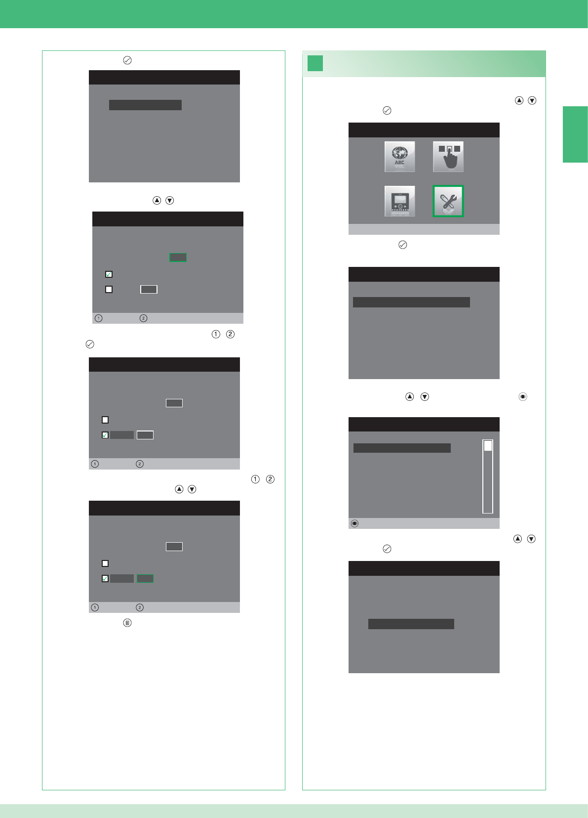
IT
CONFIGURA MONITOR
Reset configurazione
Imposta tipo di rete
Informazioni
Configura staffa
Indirizzo logico
IMPOSTA INDIRIZZO LOGICO
Indirizzo logico 0 2
Master
Slave 1 4
Sinistra Destra
IMPOSTA INDIRIZZO LOGICO
Indirizzo logico 0 2
Master
1 4
Sinistra Destra
Slave
IMPOSTA INDIRIZZO LOGICO
Indirizzo logico 0 2
Master
1 0
Sinistra Destra
Slave
23
MENU INSTALLATORE
Impostazioni speciali
MENU IMPOSTAZIONI SPECIALI
Imposta risposta automatica
Imposta tempi di chiamata
Imposta ripetizione suoneria
Rubrica intercomunicante
RUBRICA CHIAMATE INTERCOM
SECONDARIO 1
PRINCIPALE
GENERALE ESTERNA
GENERALE INTERNA
SECONDARIO 2
SECONDARIO 3
Modifica
CONFIGURA RUBRICA
Configura Indirizzo
Configura Nome
29
1. Accedere al menu Installatore (Vedi punto 19).
2. Selezionare il menu Impostazioni speciali con i pulsanti , e
premere il pulsante per accedere.
3. Premere il pulsante per accedere al menu Rubrica
intercomunicante.
4. Selezionare la voce della rubrica per cui si desidera modifi care
l'indirizzo con i pulsanti , e premere il pulsante per
accedere.
5. Selezionare il menu Confi gura indirizzo con i pulsanti , e
premere il pulsante per accedere.
7. Premere il pulsante per uscire e salvare le modifi che.
Modifi ca indirizzi Rubrica Intercomunicante
3. Premere il pulsante per accedere al menu Indirizzo logico.
4. Impostare l'indirizzo logico del monitor principale della stessa
unità abitativa con i pulsanti , .
5. Spostarsi sull'opzione Slave con i pulsanti , e premere il
pulsante per confermare.
6. Spostarsi sull'opzione Indirizzo Slave con i pulsanti , e
modifi care l'indirizzo con i pulsanti , .
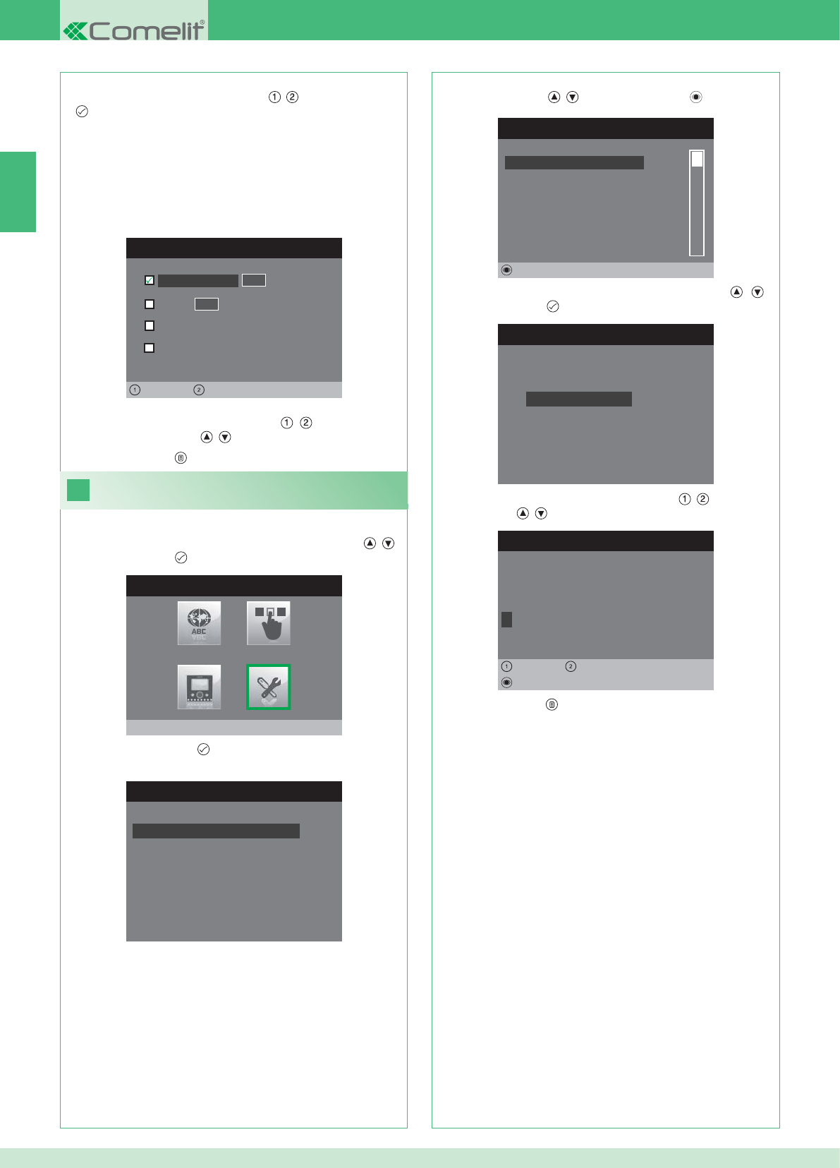
CONFIGURA INDIRIZZO
Appartamento 0 1
Staffa
Generale esterna
0 0
Sinistra Destra
Generale interna
24
MENU INSTALLATORE
Impostazioni speciali
MENU IMPOSTAZIONI SPECIALI
Imposta risposta automatica
Imposta tempi di chiamata
Imposta ripetizione suoneria
Rubrica intercomunicante
RUBRICA CHIAMATE INTERCOM
SECONDARIO 1
PRINCIPALE
GENERALE ESTERNA
GENERALE INTERNA
SECONDARIO 2
SECONDARIO 3
Modifica
CONFIGURA RUBRICA
Configura Indirizzo
Configura Nome
MODIFICA VOCE
G E N E R A L E I N T E R N A
Configura Nome
Cancella
Sinistra Destra
8. Premere il pulsante per uscire e salvare le modifi che.
IT
30
APPARTAMENTO: Invia una chiamata a tutti i monitor sia principali
che secondari con lo stesso l'indirizzo logico principale inserito.
STAFFA: Invia una chiamata al monitor con l'indirizzo logico inserito
dello stesso appartamento del monitor chiamante.
GENERALE INTERNA: Invia una chiamata a tutti i monitor dello
stesso appartamento (solo per impianti Kit).
GENERALE ESTERNA: Invia una chiamata a tutti i monitor dell'altro
appartamento (solo per impianti Kit).
6. Selezionare che tipo di chiamata si desidera abbinare alla voce
della rubrica spostandosi con i pulsanti , e premere il pulsante
per confermare.
7. Nel caso delle chiamate Appartamento e Staffa spostarsi sul
relativo scampo indirizzo con i pulsanti , ed inserire quello
desiderato con i pulsanti , .
Modifi ca nomi Rubrica Intercomunicante
1. Accedere al menu Installatore (Vedi punto 19).
2. Selezionare il menu Impostazioni speciali con i pulsanti , e
premere il pulsante per accedere.
3. Premere il pulsante per accedere al menu Rubrica
intercomunicante.
4. Selezionare la voce della rubrica per cui si desidera modifi care il
nome con i pulsanti , e premere il pulsante per accedere.
5. Selezionare il menu Confi gura Nome con i pulsanti , e
premere il pulsante per accedere.
6. Selezionare la lettera desiderata con i pulsanti , e modifi carla
con i pulsanti , .
7. Premere il pulsante per uscire e salvare le modifi che.
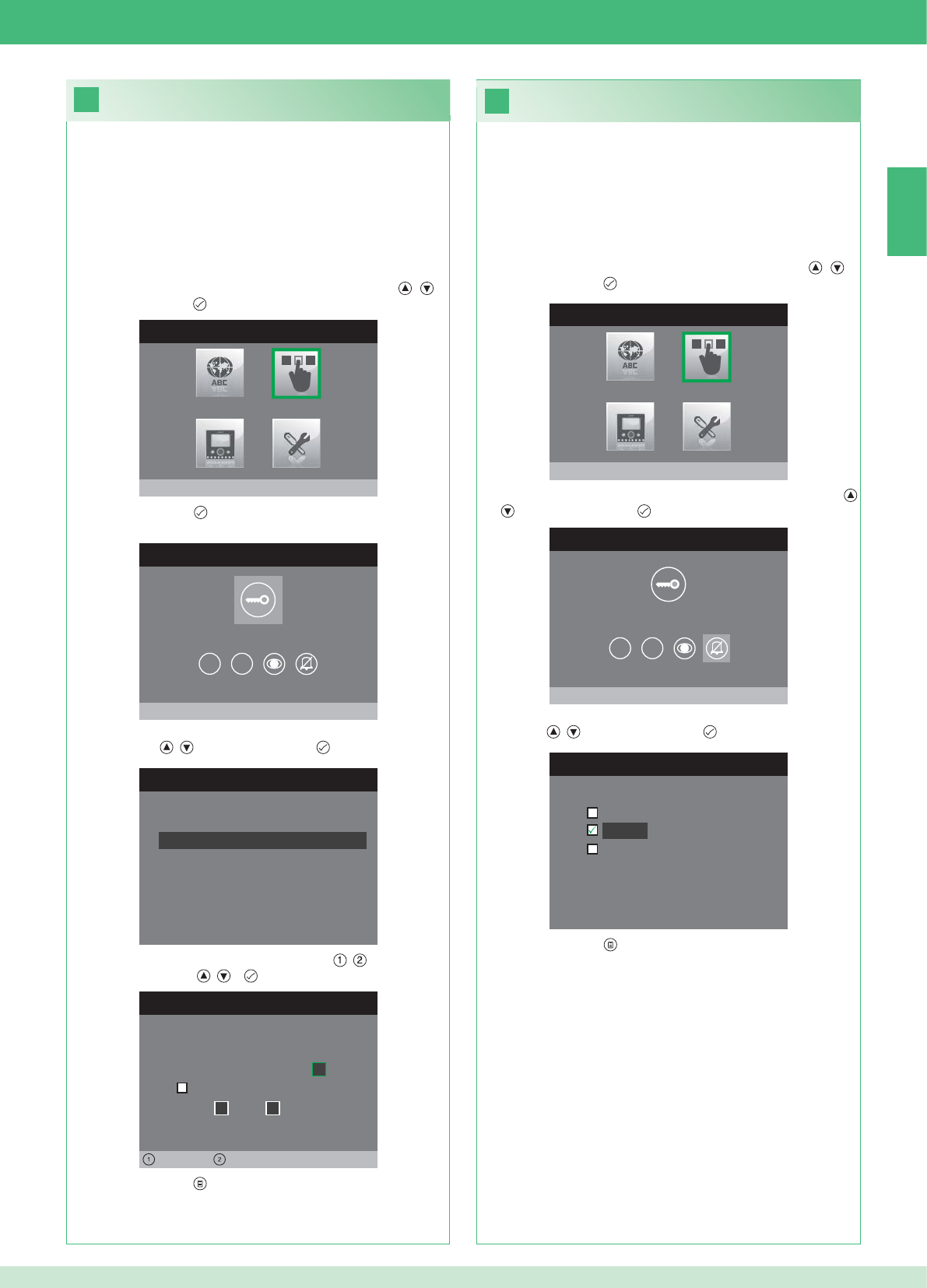
26
25
MENU INSTALLATORE
Configura pulsanti
MENU CONFIGURAZIONE PULSANTI
Configura pulsante chiave
1 2
CONFIGURA RELE’
Configuraz. in assenza chiamata
Configurazione durante chiamata
RELE’ DURANTE CHIAMATA
Porta chiamante, relé
Attiva:
2
Attiva:
Porta 1, relé 2
Sinistra Destra
MENU INSTALLATORE
Configura pulsanti
MENU CONFIGURAZIONE PULSANTI
Configura privacy / dottore
1 2
CONFIGURA PRIVACY / DOTTORE
Funzione dottore
Privacy
Funzione dottore + privacy
IT
31
• La funzione Privacy permette l'esclusione della suoneria di
chiamata dal posto esterno o intercomunicante.
• La funzione Dottore permette l'azionamento automatico
dell'apriporta (relé 1) su chiamata da posto esterno.
• La funzione Dottore + Privacy oltre a disattivare la suoneria del
posto interno come nella funzione Privacy, permette l'azionamento
automatico dell'apriporta (relé 1) su chiamata da posto esterno.
1. Accedere al menu Installatore (Vedi punto 19).
2. Selezionare il menu Confi gura pulsanti con i pulsanti , e
premere il pulsante per accedere.
3. Selezionare il menu Confi gura privacy / dottore con i pulsanti
, e premere il pulsante per accedere.
4. Selezionare la funzione che si desidera assegnare al pulsante con
i pulsanti , e premere il pulsante per confermare.
5. Premere il pulsante per uscire e salvare le modifi che.
Confi gurazione pulsante privacy / dottore
Confi gurazione pulsante chiave
Il kit dispone di 2 relé (relé 1 e relé 2) per ogni posto esterno connesso.
È possibile confi gurarne il funzionamento sia durante che in assenza
di chiamata (impianto a riposo).
Con ogni pulsante confi gurato per il comando dei relé, è possibile
attivare contemporaneamente 2 relé* al massimo.
In caso di chiamata, uno dei relé attivabili è necessariamente quello
della porta chiamante.
• PULSANTE CHIAVE
1. Accedere al menu Installatore (Vedi punto 19).
2. Selezionare il menu Confi gura pulsanti con i pulsanti , e
premere il pulsante per accedere.
3. Premere il pulsante per accedere al menu Confgura pulsante
chiave.
4. Selezionare la modalità per la quale si vuole modifi care la funzione
con i pulsanti , e premere il pulsante per confermare.
5. Selezionare i campi modifi cabili con i pulsanti , e modifi care il
valore con i pulsanti , o .
6. Premere il pulsante per uscire e salvare le modifi che.
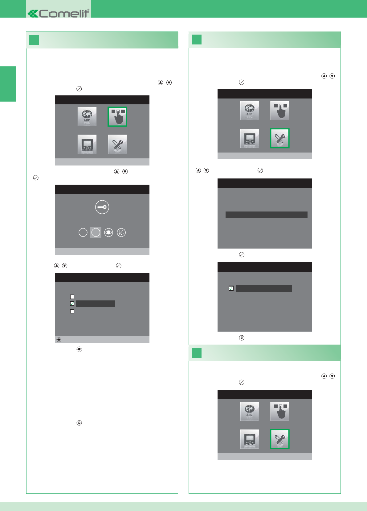
28
MENU INSTALLATORE
Impostazioni speciali
MENU IMPOSTAZIONI SPECIALI
Imposta ripetizione suoneria
Rubrica intercomunicante
Imposta risposta automatica
Imposta tempi di chiamata
29
MENU INSTALLATORE
Impostazioni speciali
27
IMPOSTA RIPETIZIONE SUONERIA
Ripetizione suoneria
MENU INSTALLATORE
Configura pulsanti
MENU CONFIGURAZIONE PULSANTI
Configura pulsante 2
1 2
CONFIGURA PULSANTE 2
Intercomunicante
Autoaccensione
Attivazione relé
Modifica
IT
32
Attivazione ripetizione suoneria
Con questa funzione attivata il monitor ripeterà la suoneria tre volte
dopo la ricezione di una chiamata.
1. Accedere al menu Installatore (Vedi punto 19).
2. Selezionare il menu Impostazioni speciali con i pulsanti , e
premere il pulsante per accedere
3. Selezionare il menu Imposta ripetizione suoneria con i pulsanti
, e premere il pulsante per accedere.
4. Premere il pulsante per attivare la funzione.
I pulsanti 1 e 2 possono essere programmati tutti con lo stesso
procedimento. Di seguito viene illustrata la programmazione del
pulsante 2.
1. Accedere al menu Installatore (Vedi punto 19).
2. Selezionare il menu Confi gura pulsanti con i pulsanti , e
premere il pulsante per accedere.
3. Selezionare il menu 2 con i pulsanti , e premere il pulsante
per accedere.
4. Selezionare la funzione che si desidera assegnare al pulsante con
i pulsanti , e premere il pulsante per confermare.
5. Premere il pulsante per confi gurare la funzione scelta.
Se è stata selezionata la funzione Intercomunicante:
}Associare il pulsante ad un posto interno INTERCOM X.
GENERALE INTERNA: Invia una chiamata a tutti i monitor dello
stesso appartamento.
GENERALE ESTERNA: Invia una chiamata a tutti i monitor dell'altro
appartamento.
Se è stata selezionata la funzione Autoaccensione:
}Associare il pulsante ad uno o entrambi i posti esterni.
Se è stata selezionata la funzione Attivazione relé:
}Seguire la procedura per la confi gurazione del pulsante chiave.
6. Premere il pulsante per uscire e salvare le modifi che.
5. Premere il pulsante per uscire e salvare le modifi che.
Attivazione risposta automatica
1. Accedere al menu Installatore (Vedi punto 19).
2. Selezionare il menu Impostazioni speciali con i pulsanti , e
premere il pulsante per accedere
Confi gurazione pulsanti 1 - 2
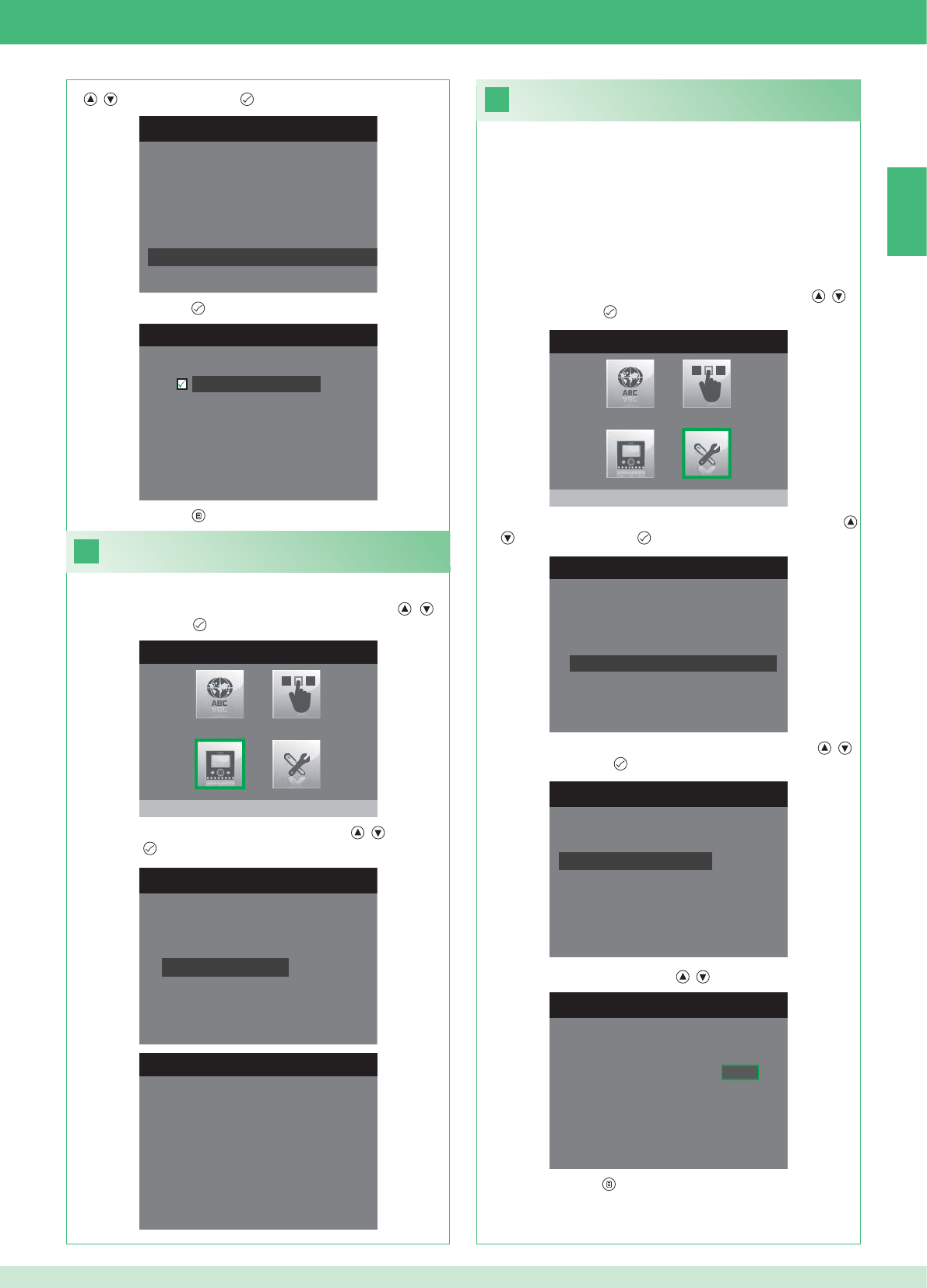
31
MENU INSTALLATORE
Impostazioni speciali
1. Accedere al menu Installatore (Vedi punto 19).
MENU IMPOSTAZIONI SPECIALI
Imposta ripetizione suoneria
Rubrica intercomunicante
Imposta risposta automatica
Imposta tempi di chiamata
IMPOSTA TEMPI DI CHIAMATA
Tempo conversazione
Tempo attesa risposta
Ritardo di spegnimento
Tempo conversazione intercom
IMPOSTA TEMPO ATTESA RISPOSTA
Tempo attesa risposta 0 6 5
MENU IMPOSTAZIONI SPECIALI
Imposta ripetizione suoneria
Rubrica intercomunicante
Imposta risposta automatica
Imposta tempi di chiamata
IMPOSTA RISPOSTA AUTOMATICA
Risposta automatica
30
MENU INSTALLATORE
Configura monitor
CONFIGURA MONITOR
Reset configurazione
Imposta tipo di rete
Informazioni
Configura staffa
Indirizzo logico
MENU INFORMAZIONI
MAC: 00:25:29:02:01:BC
IP: 169.254.155.40
ID: 00000001, SUB: 0
SW: /trunck@3534
SYS: iPower
IT
33
1. Accedere al menu Installatore (Vedi punto 19).
Visualizza informazioni
2. Selezionare il menu Confi gura Monitor con i pulsanti , e
premere il pulsante per accedere
3. Selezionare il menu Informazioni con i pulsanti , e premere
il pulsante per accedere.
Confi gurazione tempi di chamata
All’interno di questo menu è possibile modifi care:
• Tempo attesa risposta: tempo massimo oltre il quale la
comunicazione termina in assenza di risposta.
• Tempo conversazione: durata di una conversazione tra posto
interno e posto esterno.
• Tempo conversazione intercom: durata di una conversazione
intercomunicante.
• Ritardo di spegnimento: dopo una chiamata, tempo di attesa
dall’attivazione di un relé allo spegnimento del monitor.
2. Selezionare il menu Impostazioni speciali con i pulsanti , e
premere il pulsante per accedere
3. Selezionare il menu Imposta tempi di chiamata con i pulsanti
, e premere il pulsante per accedere.
4. Selezionare il valore che si vuole modifi care con i pulsanti ,
e premere il pulsante per accedere.
5. Modifi care il valore con i pulsanti , .
6. Premere il pulsante per uscire e salvare le modifi che.
3. Selezionare il menu Imposta risposta automatica con i pulsanti
, e premere il pulsante per accedere.
4. Premere il pulsante per attivare la funzione.
5. Premere il pulsante per uscire e salvare le modifi che.
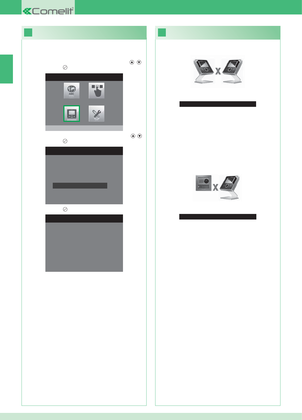
33
Nessun segnale rilevato
Nessun segnale rilevato
Connessione mancante con il posto esterno.
32
MENU INSTALLATORE
Configura monitor
CONFIGURA MONITOR
Imposta tipo di rete
Informazioni
Configura staffa
Indirizzo logico
Reset configurazione
1. Accedere al menu Installatore (Vedi punto 19).
RESET CONFIGURAZIONE
Vuoi proseguire?
IT
34
Anomalie e possibili soluzioni
Connessione mancante con il posto interno.
Soluzioni:
}Attendere 1 minuto.
}Assicurarsi che il monitor secondario abbia lo stesso indirizzo del
monitor principale dell'unità abitativa interessata (punto 22).
}Assicurarsi che il monitor principale sia alimentato (punto 10).
}Assicurarsi che sia stata inserita la password corretta (punto 20).
}Assicurarsi che siano state rispettate le distanze di installazione
(punto 8).
Soluzioni:
}Attendere 1 minuto.
}Assicurarsi che il posto esterno sia correttamente cablato (punto
2).
}Assicurarsi che il posto esterno sia alimentato (punto 9).
}Assicurarsi che il ponte Art. 1398 sia correttamente cablato (punto
7A, 7B, 7C).
}Assicurarsi che ci sia corrispondenza tra la password del ponte Art.
1398 e l'alimentatore monitor della stessa unità abitativa.
}Assicurarsi che siano state rispettate le distanze di installazione
(punto 8).
Attenzione: questa operazione ripristinerà tutte le impostazioni di
fabbrica, annullando tutte le modifi che apportate.
Reset confi gurazione
2. Selezionare il menu Confi gura Monitor con i pulsanti , e
premere il pulsante per accedere.
3. Selezionare il menu Reset confi gurazione con i pulsanti , e
premere il pulsante per accedere
4. Premere il pulsante per confermare.
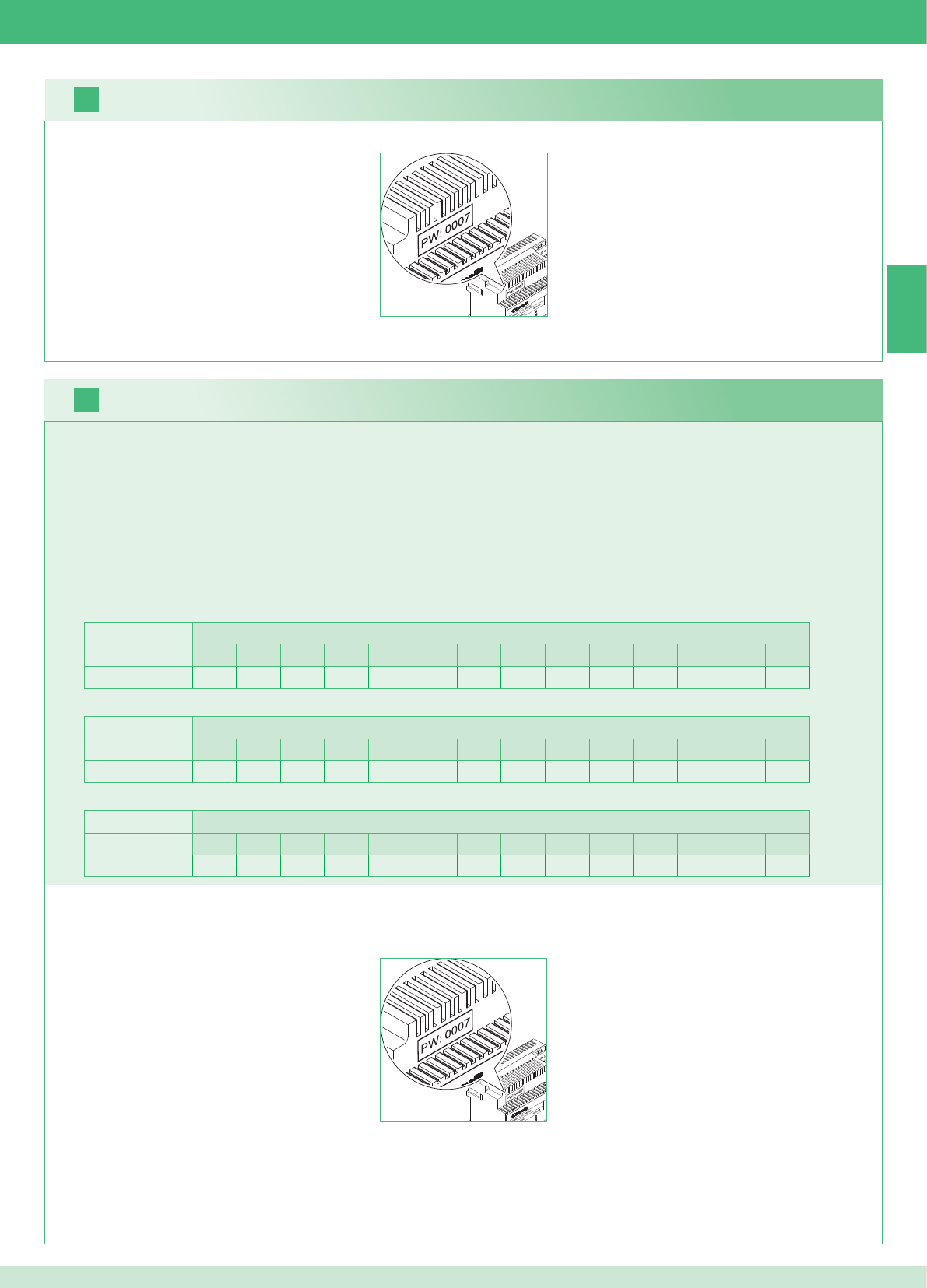
2 external units Apartments
1234567891011121314
Number of brackets 14 14 - - - - - - - - - - - - - - - - - - - - - - - -
16
17
EN
35
It is possible to install additional secondary monitors distributed in the apartments according to the two rules below:
1. Install maximum 14 brackets per apartment.
2. Carry out the following calculations on the distribution layout of the brackets:
}calculate the total number of brackets to install in the system (main and secondary brackets) = A.
}identify the apartment with the lowest number of brackets = B
}calculate the difference between the total number of brackets in the system and the number in the apartment with the fewest brackets (A - B)
and make sure that the number obtained is:
Less than or equal to 15 for systems with 1 external unit.
Less than or equal to 14 for systems with 2 external units.
The following example shows a two-residence KIT with 2 external units and 14 monitors for 2 apartments:
1 external unit Apartments
1234567891011121314
Number of brackets 2 3 4 5 3 - - - - - - - - - - - - - - - - - -
The following example shows a system with 1 external unit and 17 monitors for 5 apartments:
1 external unit Apartments
1234567891011121314
Number of brackets 13 1 1 1 1 - - - - - - - - - - - - - - - - - -
The following example shows an incorrect confi guration of a system with 1 external unit and 17 monitors for 5 apartments:
1. Make a note of the modem password on the label of bridge Art. 1398 for the relevant residential unit.
2. On the monitor set the recorded modem password as described in point 20.
3. Set the address of the additional secondary monitors as described in point 22.
Warning!
Procedure:
Kits and Multi-user system: installing additional secondary monitors
1. Make a note of the modem password on the label of bridge Art. 1398 for the relevant residential unit.
2. On the monitor set the recorded modem password as described in point 20.
3. Set the address of the main monitor as described in point 21
Multi-user system: installing main monitors
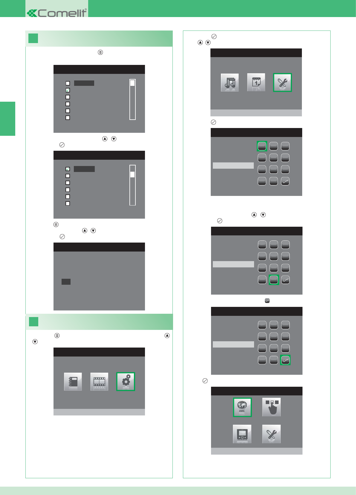
18
LANGUAGES MENU
Italiano
English
Français
Español
Português
Deutsch
MENU LINGUE
Français
Español
Português
Deutsch
English
Italiano
19
MAIN MENU
Settings
SETTINGS MENU
Installer menu
INSERT PASSWORD
1
1
23
456
789
0
C
INSERT PASSWORD
1
1
23
456
789
0
C
****
INSERT PASSWORD
1
1
23
456
789
0
C
****
INSTALLER MENU
Set language
Italiano
NO
OK
EN
36
Setting the menu language
When you fi rst access the menu ( button), you will be asked to set
the language.
1. Select the language using the , buttons and confi rm by
pressing the button.
1. Press the button and select the Settings menu using the ,
buttons.
Entering the installer menu
2. Press the button to enter and select the Installer Menu using
the , buttons.
3. Press the button to enter.
4. Select the digits using the , buttons and enter them by
pressing the button.
5. When you have fi nished, select the icon.
The password for the installer menu is 0000. It is not possible to
change the password.
6. Press to confi rm.
2. Press the button to exit.
3. Select "OK" using the , buttons and confi rm by
pressing the button.
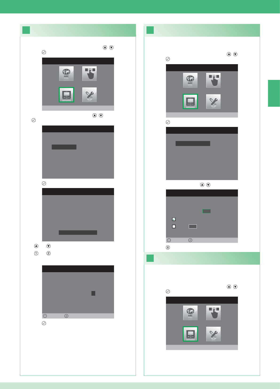
20
INSTALLER MENU
Program monitor
PROGRAM MONITOR
Reset configuration
Select network type
Information
Set bracket
Logical address
PASSWORD SETTING
Left Right
Modem password: 1 0 0 7
BRACKET SETTINGS
ID: A
PWD: 0007
MAC: 00:0D:BE:00:2C:65
Change Password
ADDRESS SETTING
Logical address 0 2
Master
Slave 1 4
Left Right
22
INSTALLER MENU
Program monitor
21
INSTALLER MENU
Program monitor
PROGRAM MONITOR
Reset configuration
Select network type
Information
Set bracket
Logical address
EN
37
1. Enter the Installer menu (See point 19).
Setting the modem password
2. Select the Program Monitor menu using the , buttons and
press the button to enter.
3. Select the Set bracket menu using the , buttons and press
the button to enter.
4. Press the button to enter the Change Password menu.
5. Change the password.
• The and buttons increase and decrease the selected value
• The and buttons move the selection cursor left and right.
6. Press the button to save the new password.
1. Enter the Installer menu (See point 19).
Setting the logical address of the
main (master) monitors
2. Select the Program Monitor menu using the , buttons and
press the button to enter.
3. Press the button to enter the Logical address menu.
4. Change the address using the , buttons.
5. Press the button to exit and save the changes.
Set 1 single main monitor for each logical address.
1. Enter the Installer menu (See point 19).
Setting the logical address of
secondary (slave) monitors
2. Select the Program Monitor menu using the , buttons and
press the button to enter.
Each secondary monitor in the same residential unit must have a
different Slave Address
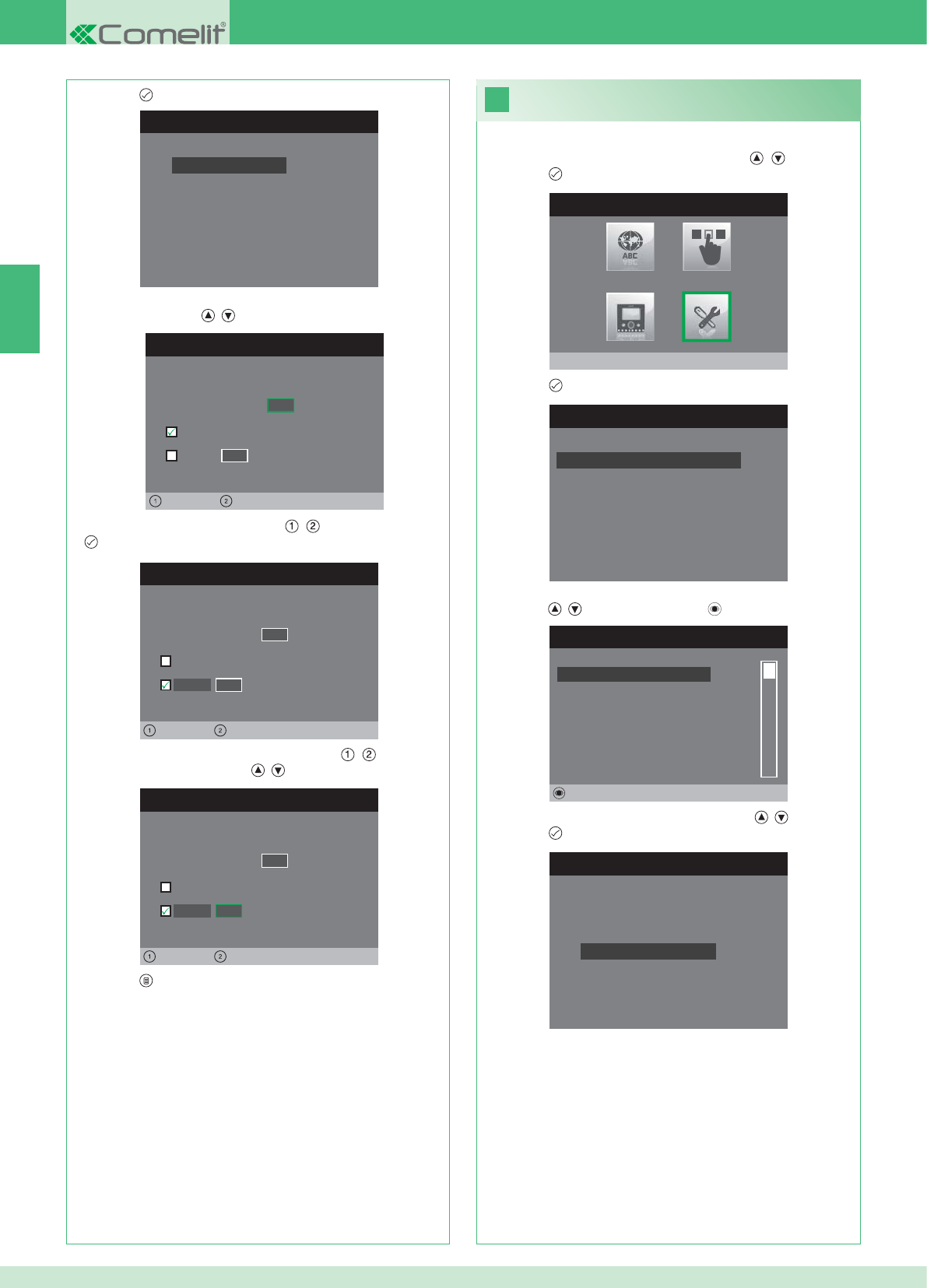
PROGRAM MONITOR
Reset configuration
Select network type
Information
Set bracket
Logical address
ADDRESS SETTING
Logical address 0 2
Master
Slave 1 4
Left Right
ADDRESS SETTING
Logical address 0 2
Master
1 4
Left Right
Slave
ADDRESS SETTING
Logical address 0 2
Master
1 0
Left Right
Slave
23
INSTALLER MENU
Special Settings
SPECIAL SETTINGS MENU
Set automatic reply
Set call times
Set tone repetition
Intercom Directory
INTERCOM DIRECTORY
SECONDARY 1
MAIN
GENERAL EXT
GENERAL INT
SECONDARY 2
SECONDARY 3
Modify
INTERCOM SETTINGS
Configure address
Configure name
EN
38
1. Enter the Installer menu (See point 19).
2. Select the Special Settings menu using the , buttons and
press the button to enter.
3. Press the button to enter the Intercom Directory menu.
4. Select the directory entry whose address you want to change
using the , buttons and press the button to enter.
5. Select the Confi gure Address menu using the , buttons and
press the button to enter.
7. Press the button to exit and save the changes.
Changing Intercom Directory addresses
3. Press the button to enter the Logical address menu.
4. Set the logical address of the main monitor in the same
residential unit using , buttons.
5. Move to the Slave option using the , buttons and press the
button to confi rm.
6. Move to the Slave Address option using the , buttons and
change the address using the , buttons.
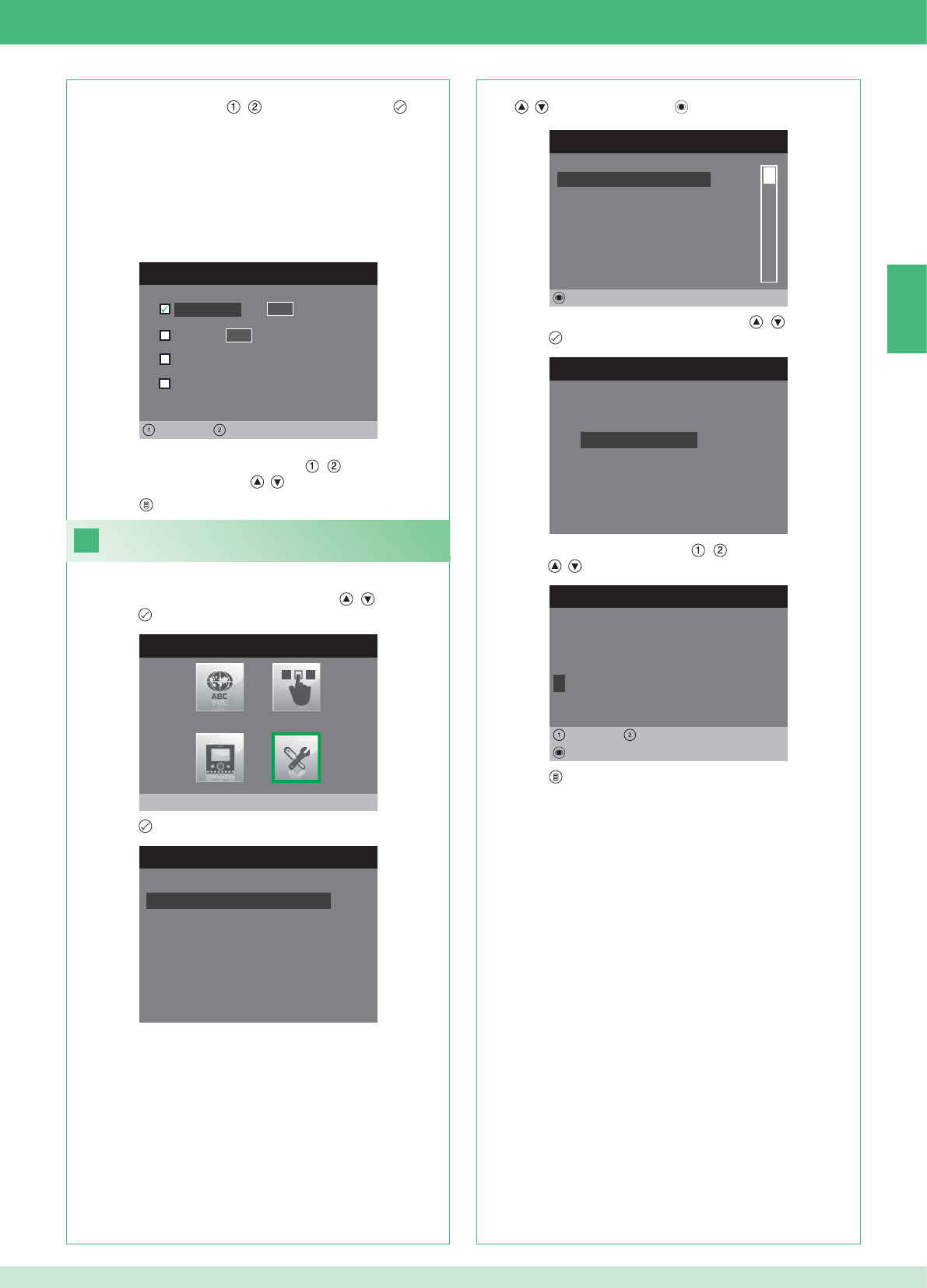
ADDRESS SETTING
Apartment 0 1
Bracket
General external
0 0
Left Right
General internal
24
INSTALLER MENU
Special Settings
SPECIAL SETTINGS MENU
Set automatic reply
Set call times
Set tone repetition
Intercom Directory
INTERCOM DIRECTORY
SECONDARY 1
MAIN
GENERAL EXT
GENERAL INT
SECONDARY 2
SECONDARY 3
Modify
INTERCOM SETTINGS
Configure address
Configure name
MODIFY NAME
G E N E R A L I N T
Configure name
Delete
Left Right
8. Press the button to exit and save the changes.
EN
39
APARTMENT: Sends a call to all main and secondary monitors with
the same specifi ed main logical address.
BRACKET: Sends a call to the monitor with the specifi ed logical
address in the same apartment as the calling monitor.
GENERAL INT: Sends a call to all monitors in the same apartment
(only for Kit systems).
GENERAL EXT: Sends a call to all monitors in the other apartment
(only for Kit systems).
6. Select the type of call that you want to assign to the directory
entry by moving with the , buttons and press the button
to confi rm.
7. In the case of Apartment and Bracket calls move to the
corresponding address fi eld using the , buttons and enter
the desired address using the , buttons.
Changing Intercom Directory names
1. Enter the Installer menu (See point 19).
2. Select the Special Settings menu using the , buttons and
press the button to enter.
3. Press the button to enter the Intercom Directory menu.
4. Select the directory entry whose name you want to change using
the , buttons and press the button to enter.
5. Select the Confi gure name menu using the , buttons and
press the button to enter.
6. Select the desired letter using the , buttons and change it
using the , buttons.
7. Press the button to exit and save the changes.
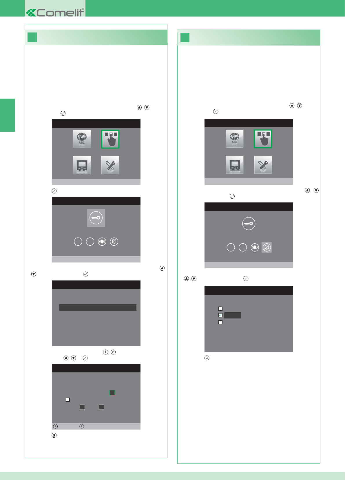
26
25
INSTALLER MENU
Buttons Programming
BUTTONS PROGRAMMING MENU
Program key button
1 2
SET RELAY
Configuration at rest time
Configuration during call
RELAY DURING CALL
Calling door, relay:
Activate:
2
Activate:
Door 1,relay 2
Left Right
INSTALLER MENU
Buttons Programming
BUTTONS PROGRAMMING MENU
Privacy/DoctorSettings
1 2
CONFIGURE PRIVACY/DOCTOR
Doctor mode
Privacy
Doctor mode + privacy
EN
40
• The Privacy function silences the ringtone of calls from an
external unit or intercom unit.
• The Doctor function enables automatic activation of the lock-
release (relay 1) in response to an external unit call.
• The Doctor + Privacy function, as well as disabling the external
unit ringtone in the same way as the Privacy function, also enables
automatic activation of the lock-release (relay 1) in response to an
external unit call.
1. Enter the Installer menu (See point 19).
2. Select the Buttons Programming menu using the , buttons
and press the button to enter.
3. Select the Confi gure Privacy/Doctor menu using the ,
buttons and press the button to enter.
4. Select the function that you want to assign to the button using the
, buttons and press the button to confi rm.
5. Press the button to exit and save the changes.
Programming the Privacy / Doctor button
Programming the key button
The kit has 2 relays (relay 1 and relay 2) for each connected external
unit.
Their operation can be programmed both during a call and in standby.
With each button programmed for the relay command, it is possible to
simultaneously activate up to 2 relays*.
In the case of calls, one of the relays that can be activated must be
the relay of the calling door.
• KEY BUTTON
1. Enter the Installer menu (See point 19).
2. Select the Buttons Programming menu using the , buttons
and press the button to enter.
3. Press the button to enter the Program key button menu.
4. Select the mode whose function you want to modify using the ,
buttons and press the button to confi rm.
5. Select the editable fi elds using the , buttons and change the
value using the , or buttons.
6. Press the button to exit and save the changes.
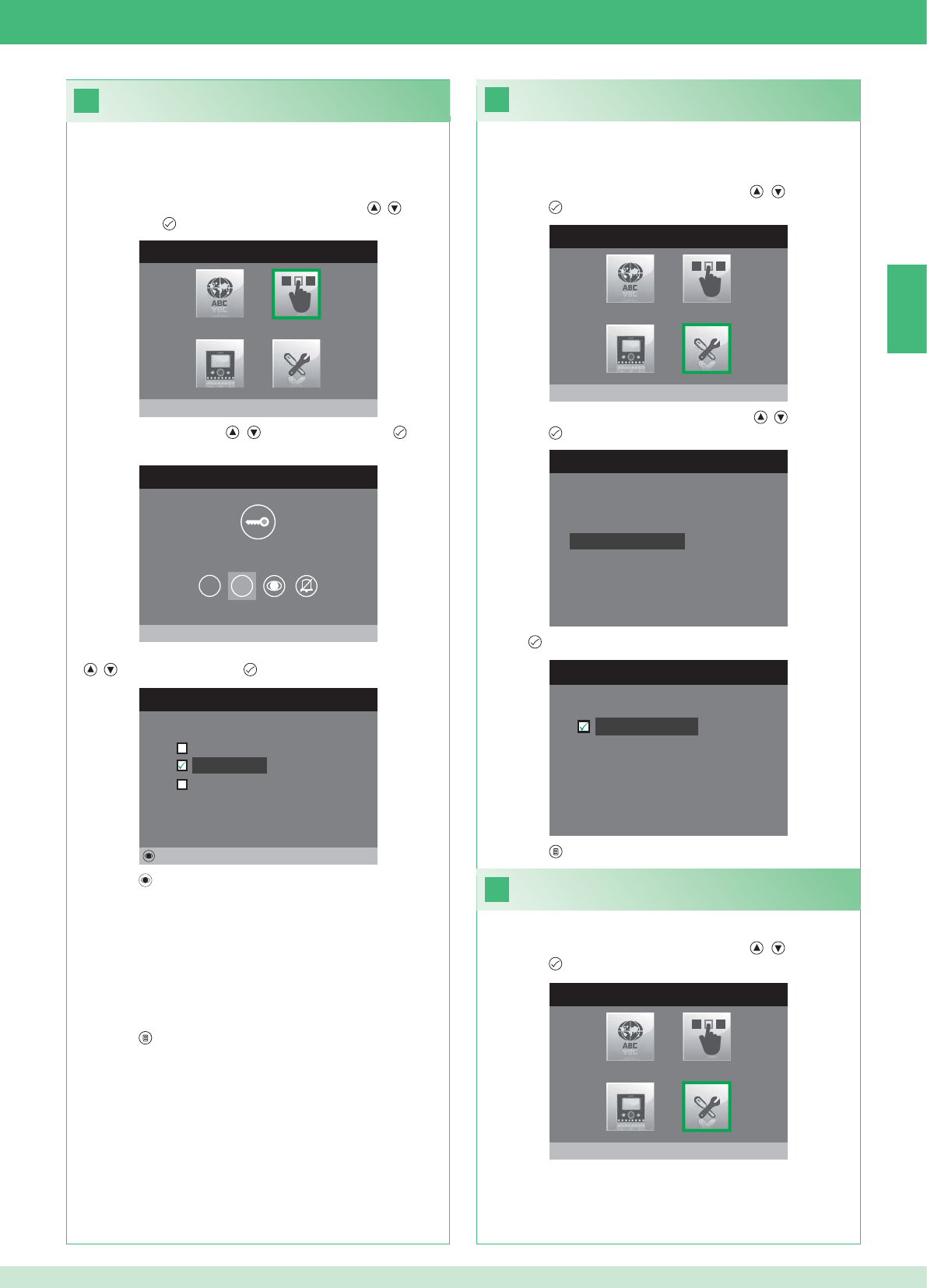
28
INSTALLER MENU
Special Settings
SPECIAL SETTINGS MENU
Set tone repetition
Intercom Directory
Set automatic reply
Set call times
29
27
SET TONE REPETITION
Tone repetition
INSTALLER MENU
Buttons Programming
BUTTONS PROGRAMMING MENU
Program Button 2
1 2
PROGRAM BUTTON 2
Intercom
Self Ignition
Relay activation
Modify
INSTALLER MENU
Special Settings
EN
41
Activating tone repetition
With this function activated, the monitor will repeat the ringtone three
times after receiving a call.
1. Enter the Installer menu (See point 19).
2. Select the Special Settings menu using the , buttons and
press the button to enter.
3. Select the Set tone repetition menu using the , buttons and
press the button to enter.
4. Press to activate the function.
Buttons 1 and 2 can both be programmed using the same procedure.
The programming of button 2 is illustrated below.
1. Enter the Installer menu (See point 19).
2. Select the Buttons Programming menu using the , buttons
and press the button to enter.
3. Select menu 2 using the , buttons and press the button
to enter.
4. Select the function that you want to assign to the button using the
, buttons and press the button to confi rm.
5. Press the button to program the selected function.
If the Intercom function has been selected:
}Assign the button to an internal unit INTERCOM X.
GENERAL INT: Sends a call to all monitors in the same apartment.
GENERAL EXT: Sends a call to all monitors in the other apartment.
If the Self Ignition function has been selected:
}Assign a button to one or both of the external units.
If the Relay activation function has been selected:
}Follow the procedure for programming the key button.
6. Press the button to exit and save the changes.
5. Press the button to exit and save the changes.
Automatic reply function
1. Enter the Installer menu (See point 19).
2. Select the Special Settings menu using the , buttons and
press the button to enter.
Programming buttons 1 - 2
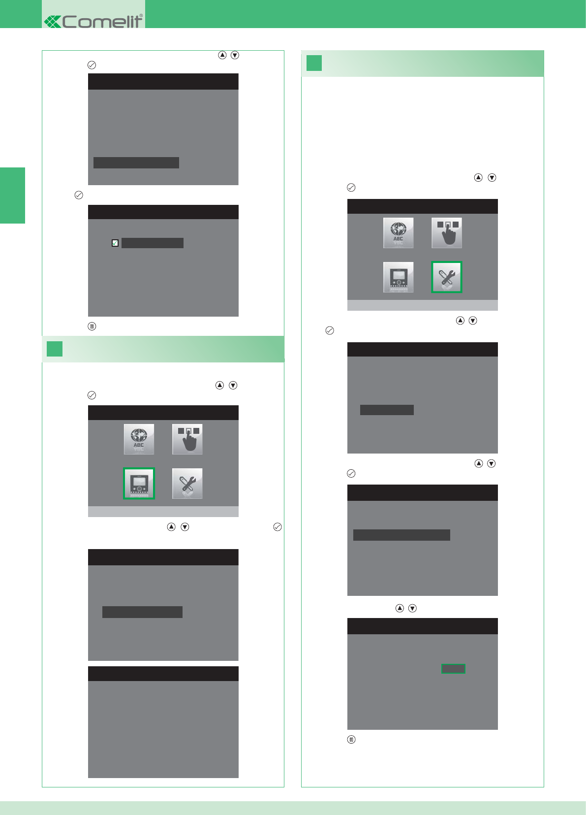
31
INSTALLER MENU
Special Settings
1. Enter the Installer menu (See point 19).
SPECIAL SETTINGS MENU
Set tone repetition
Intercom Directory
Set automatic reply
Set call times
SET CALL TIMES
Talk time
Reply waiting time
Reset wait time
Intercom talk time
SET REPLY WAITING TIME
Reply waiting time 0 6 5
SPECIAL SETTINGS MENU
Set tone repetition
Intercom Directory
Set automatic reply
Set call times
SET AUTOMATIC REPLY
Automatic reply
30
INSTALLER MENU
Program monitor
PROGRAM MONITOR
Reset configuration
Select network type
Information
Set bracket
Logical address
INFO MENU
MAC: 00:25:29:02:01:BC
IP: 169.254.155.40
ID: 00000001, SUB: 0
SW: /trunck@3534
SYS: iPower
EN
42
1. Enter the Installer menu (See point 19).
Viewing information
2. Select the Program Monitor menu using the , buttons and
press the button to enter.
3. Select the Info menu using the , buttons and press the
button to enter.
Setting call times
From this menu it is possible to modify:
• Reply waiting time: maximum time beyond which communication
ends without the call being answered.
• Talk time: duration of a conversation between internal unit and
external unit.
• Intercom talk time: duration of an intercom conversation.
• Reset wait time: after a call, wait time from activation of a relay to
switch-off of the monitor.
2. Select the Special Settings menu using the , buttons and
press the button to enter.
3. Select the Set call times menu using the , buttons and press
the button to enter.
4. Select the value that you want to edit using the , buttons and
press the button to enter.
5. Edit the value using the , buttons.
6. Press the button to exit and save the changes.
3. Select the Set automatic reply menu using the , buttons and
press the button to enter.
4. Press to activate the function.
5. Press the button to exit and save the changes.
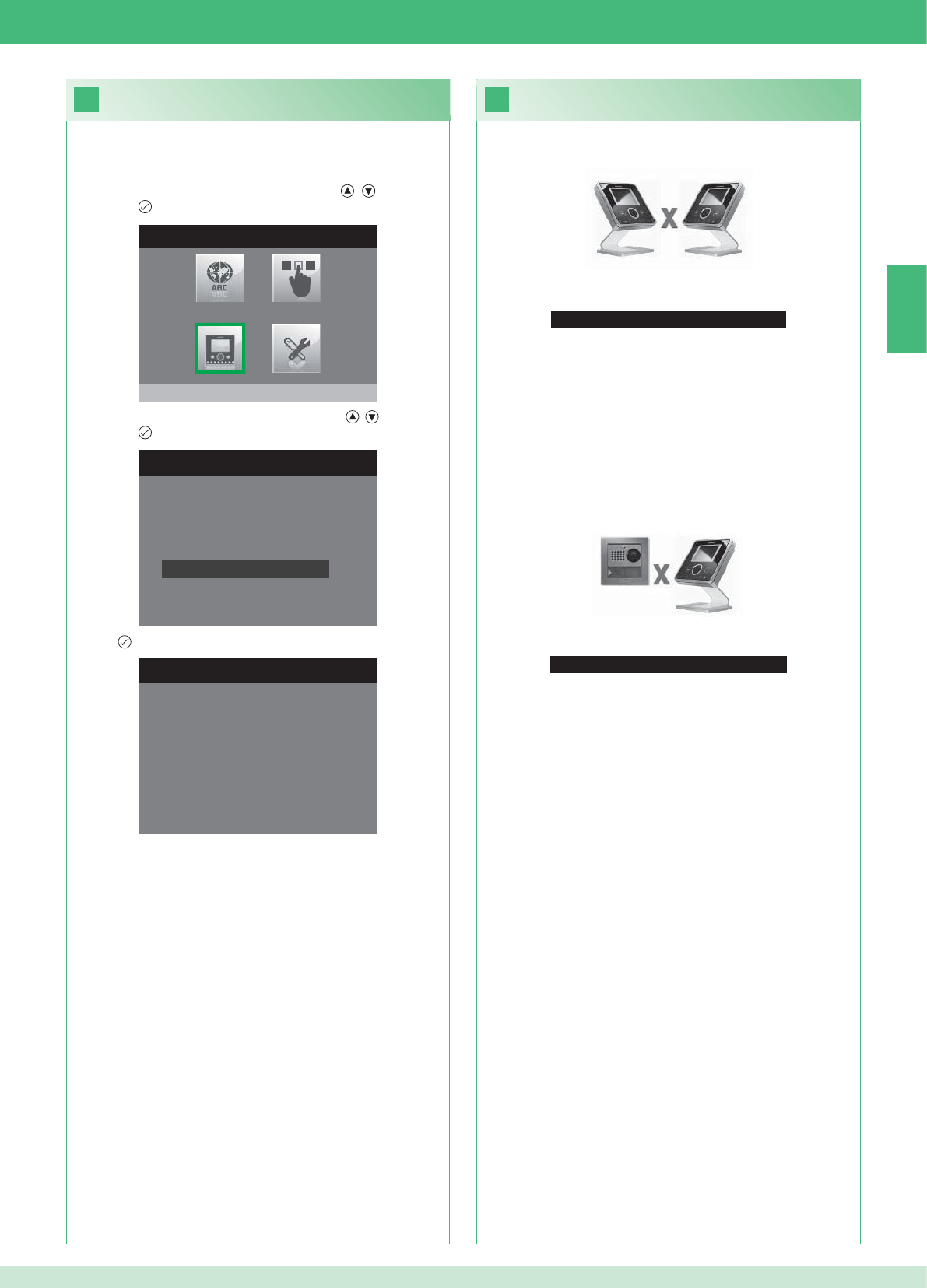
33
No Signal Detected
No Signal Detected
No connection with the external unit.
32
INSTALLER MENU
Program monitor
PROGRAM MONITOR
Select network type
Information
Set bracket
Logical address
Reset configuration
1. Enter the Installer menu (See point 19).
RESET CONFIGURATION
Continue?
EN
43
Faults and troubleshooting
No connection with the internal unit.
Solutions:
}Wait 1 minute.
}Make sure that the secondary monitor has the same address as
the main monitor in the relevant residential unit (point 22).
}Make sure that the main monitor is receiving power (point 10).
}Make sure that the correct password has been entered (point 20).
}Make sure that the installation distances have been observed
(point 8).
Solutions:
}Wait 1 minute.
}Make sure that the external unit is wired correctly (point 2).
}Make sure that the external unit is receiving power (point 9).
}Make sure that the bridge Art. 1398 is wired correctly (point 7A,
7B, 7C).
}Make sure that the password for bridge Art. 1398 is the same as
the password for the power supply unit of the monitor in the same
residential unit.
}Make sure that the installation distances have been observed
(point 8).
Caution: this operation will restore all the factory settings, deleting
all changes made.
Reset confi guration
2. Select the Program Monitor menu using the , buttons and
press the button to enter.
3. Select the Reset confi guration menu using the , buttons and
press the button to enter.
4. Press to confi rm.
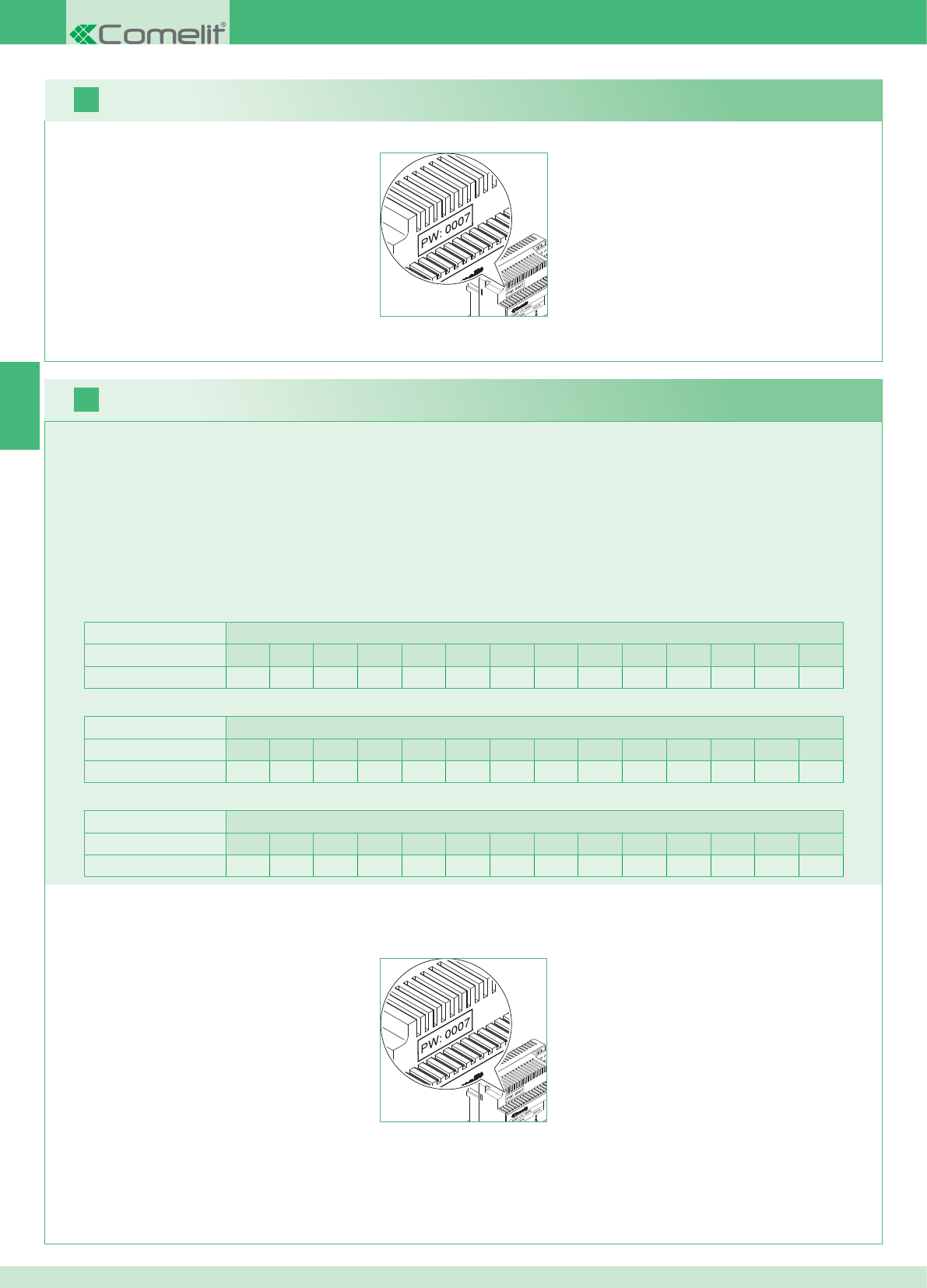
2 postes externes Appartements
1234567891011121314
Nombre d'étriers 14 14 - - - - - - - - - - - - - - - - - - - - - - - -
FR
16
17
44
Il est possible d'ajouter des moniteurs supplémentaires secondaires distribués dans les appartements en respectant les 2 règles suivantes :
1. Installer au maximum 14 étriers par appartement.
2. Effectuer les calculs suivants sur la distribution prévue pour les étriers :
}calculer le nombre total d'étriers à monter dans l'installation (tant principaux que secondaires) = A.
}déterminer le nombre d'étriers le plus bas entre les appartements = B
}calculer la différence entre le nombre total d'étriers de l'installation et ceux présents dans l'appartement qui en a le moins (A - B) et s'assurer
que le nombre obtenu est :
Inférieur ou égal à 15 par installation avec 1 poste externe.
Inférieur ou égal à 14 par installation avec 2 postes externes.
L'exemple ci-après montre un KIT deux usagers avec 2 PE et 14 moniteurs pour 2 appartements :
1 poste externe Appartements
1234567891011121314
Nombre d'étriers 2 3 4 5 3 - - - - - - - - - - - - - - - - - -
L'exemple ci-après montre une installation avec 1 PE et 17 moniteurs pour 5 appartements :
1 poste externe Appartements
1234567891011121314
Nombre d'étriers 13 1 1 1 1 - - - - - - - - - - - - - - - - - -
L'exemple ci-après montre une confi guration impossible d'une installation avec 1 PE et 17 moniteurs pour 5 appartements :
1. Noter le mot de passe modem sur l'étiquette du pont Art. 1398 de l'appartement intéressé.
2. Confi gurer sur le moniteur le mot de passe modem relevé comme décrit au point 20.
3. Confi gurer l'adresse du moniteur principal comme décrit au point 22
Avertissement !
Procédure :
Kit et Multi-usagers : installation de moniteurs supplémentaires secondaires
1. Noter le mot de passe modem sur l'étiquette du pont Art. 1398 de l'appartement intéressé.
2. Confi gurer sur le moniteur le mot de passe modem relevé comme décrit au point v.
3. Confi gurer l'adresse du moniteur principal comme décrit au point 21
Multi-usagers : installation des moniteurs principaux
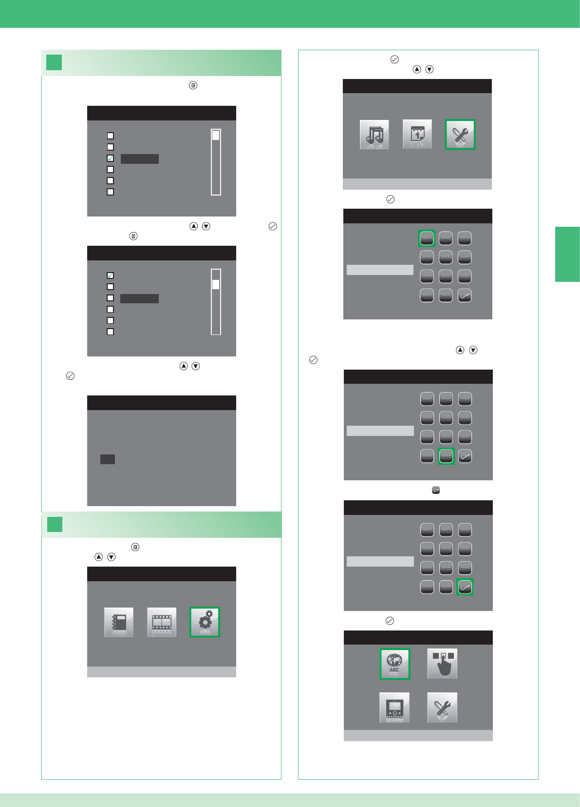
FR
18
MENU LANGUE
Italiano
English
Français
Español
Português
Deutsch
MENU LINGUE
Italiano
Español
Português
Deutsch
English
Français
19
MENU PRINCIPAL
Réglages
MENU REGLAGES
Menu installateur
INSÉRER MOT DE PASSE
1
1
23
456
789
0
C
INSÉRER MOT DE PASSE
1
1
23
456
789
0
C
****
INSÉRER MOT DE PASSE
1
1
23
456
789
0
C
****
MENU INSTALLATEUR
Configurer langue
NO
OK
Français
45
Confi guration de la langue menu
Lors du premier accès au menu (touche ), choisir la langue que
l'on désire utiliser.
1. Sélectionner la langue avec les touches , et confi rmer par .
2. Appuyer sur la touche pour sortir.
1. Appuyer sur la touche et sélectionner le menu Réglages avec
les touches , .
Accéder au menu installateur
2. Appuyer sur la touche pour accéder et sélectionner le menu
Installateur avec les touches , .
3. Appuyer sur la touche pour y accéder.
4. Sélectionner les chiffres avec les touches , et confi rmer par
.
5. Après la saisie, sélectionner l'icône .
Le mot de passe pour le menu installateur est 0000. Il n'est pas
possible de modifi er le mot de passe,
6. Appuyer sur la touche pour confi rmer.
3. Sélectionner « OK » avec les touches , et confi rmer
par .
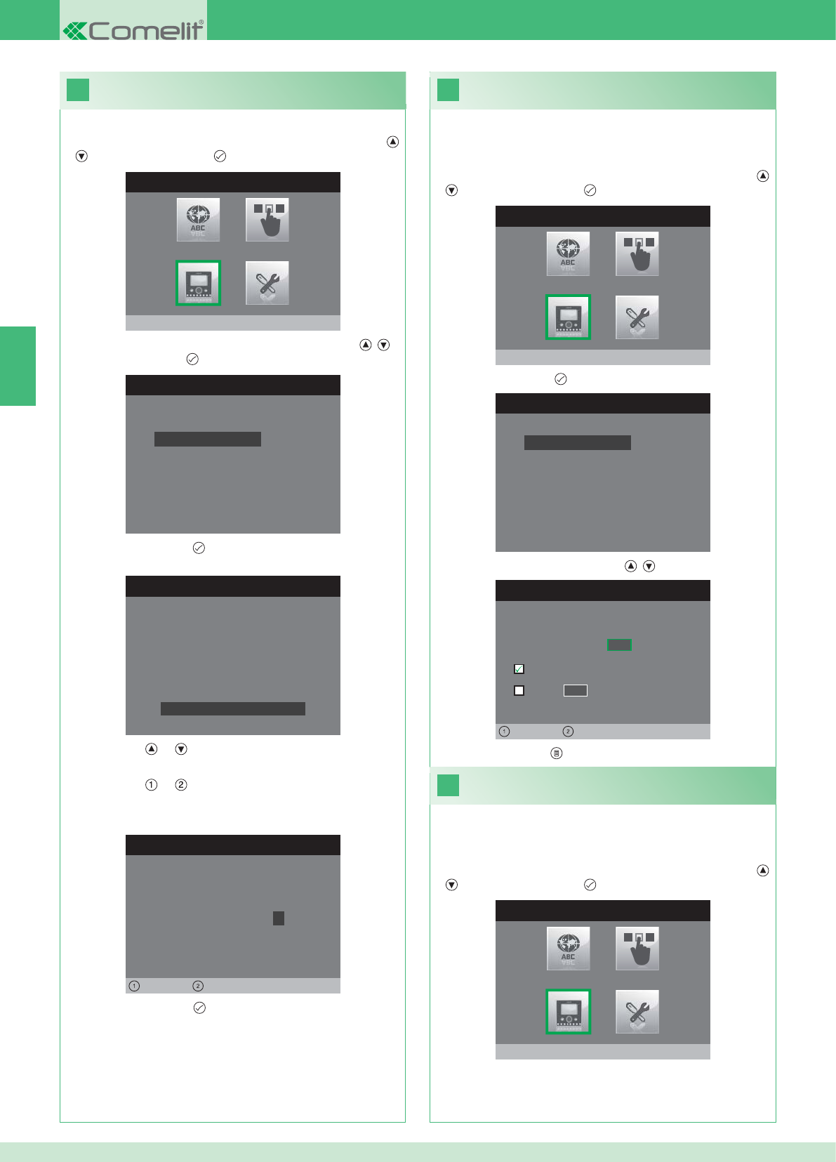
20
MENU INSTALLATEUR
Configurer moniteur
CONFIGURER MONITEUR
Reset configuration
Configurer type de réseau
Informations
Configurer etrier
Adresse logique
CONFIGURER MOT DE PASSE
Gauche Droit
Modem Mot de Passe: 1 0 0 7
CONFIGURATION ETRIER
ID: A
PWD: 0007
MAC: 00:0D:BE:00:2C:65
Changer Mot de Passe
CONFIGURER ADRESSE
Adresse logique 0 2
Master
Slave 1 4
Gauche Droit
22
MENU INSTALLATEUR
Configurer moniteur
21
MENU INSTALLATEUR
Configurer moniteur
CONFIGURER MONITEUR
Reset configuration
Configurer type de réseau
Informations
Configurer etrier
Adresse logique
FR
46
1. Accéder au menu Installateur (Voir point 19).
Confi guration du mot de passe modem
2. Sélectionner le menu Confi gurer moniteur avec les touches ,
et appuyer sur la touche pour y accéder.
3. Sélectionner le menu Confi gurer étrier avec les touches , et
appuyer sur la touche pour y accéder.
4. Appuyer sur la touche pour accéder au menu Changer mot
de passe.
5. Comment changer le mot de passe.
• Les touches et permettent d'augmenter et de diminuer la
valeur sélectionnée
• Les touches et permettent de déplacer vers la gauche et
vers la droite le curseur de sélection.
6. Appuyer sur la touche pour sauvegarder le nouveau mot de
passe.
1. Accéder au menu Installateur (Voir point 19).
Confi gurer l’adresse logique
moniteurs principaux (maître)
2. Sélectionner le menu Confi gurer moniteur avec les touches ,
et appuyer sur la touche pour y accéder
3. Appuyer sur la touche pour accéder au menu Adresse logique.
4. Changer l'adresse avec les touches , .
5. Appuyer sur la touche pour sortir et sauvegarder les modifi cations.
Confi gurer 1 seul moniteur principal pour chaque adresse
logique.
1. Accéder au menu Installateur (Voir point 19).
Confi gurer l’adresse logique moniteurs
secondaires (esclave)
2. Sélectionner le menu Confi gurer moniteur avec les touches ,
et appuyer sur la touche pour y accéder
Chaque moniteur secondaire du même appartement doit avoir une
Adresse esclave différente
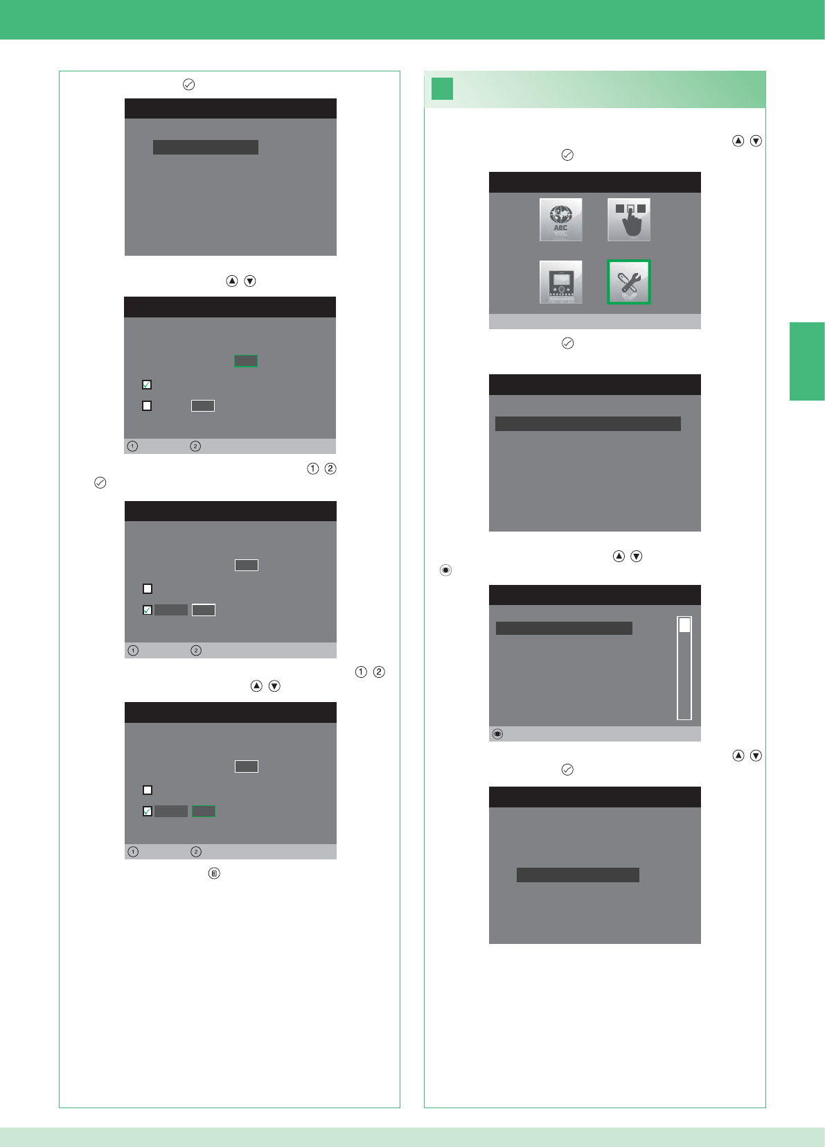
CONFIGURER MONITEUR
Reset configuration
Configurer type de réseau
Informations
Configurer etrier
Adresse logique
CONFIGURER ADRESSE
Adresse logique 0 2
Master
Slave 1 4
Gauche Droit
CONFIGURER ADRESSE
Adresse logique 0 2
Master
1 4
Gauche Droit
Slave
CONFIGURER ADRESSE
Adresse logique 0 2
Master
1 0
Gauche Droit
Slave
23
MENU INSTALLATEUR
Réglages Spéciaux
MENU REGLAGES SPECIAUX
Config. réponse automatique
Configurer temps d'appel
Configurer répétition sonnerie
Repertoire Intercommunicant
REPERT. APPELS INTERCOM
SECONDAIRE 1
PRINCIPAL
GENERAL EXTERNE
GENERAL INTERNE
SECONDAIRE 2
SECONDAIRE 3
Modifier
CONFIGURE INTERCOMMUNICANT
Configurer adresse
Configurer nom
FR
47
1. Accéder au menu Installateur (Voir point 19).
2. Sélectionner le menu Réglages spéciaux avec les touches ,
et appuyer sur la touche pour y accéder.
3. Appuyer sur la touche pour accéder au menu Répertoire
intercommunicant.
4. Sélectionner la rubrique (l'élément) du répertoire dont on désire
changer l'adresse avec les touches , et appuyer sur la touche
pour y accéder.
5. Sélectionner le menu Confi gurer adresse avec les touches ,
et appuyer sur la touche pour y accéder.
7. Appuyer sur la touche pour sortir et sauvegarder les
modifi cations.
Changer les adresses
Répertoire intercommunicant
3. Appuyer sur la touche pour accéder au menu Adresse logique.
4. Confi gurer l'adresse logique du moniteur principal du même
appartement avec les touches , .
5. Sélectionner le menu Esclave avec les touches , et confi rmer
par .
6. Se placer sur l'option Adresse esclave avec les touches , et
changer l'adresse avec les touches , .
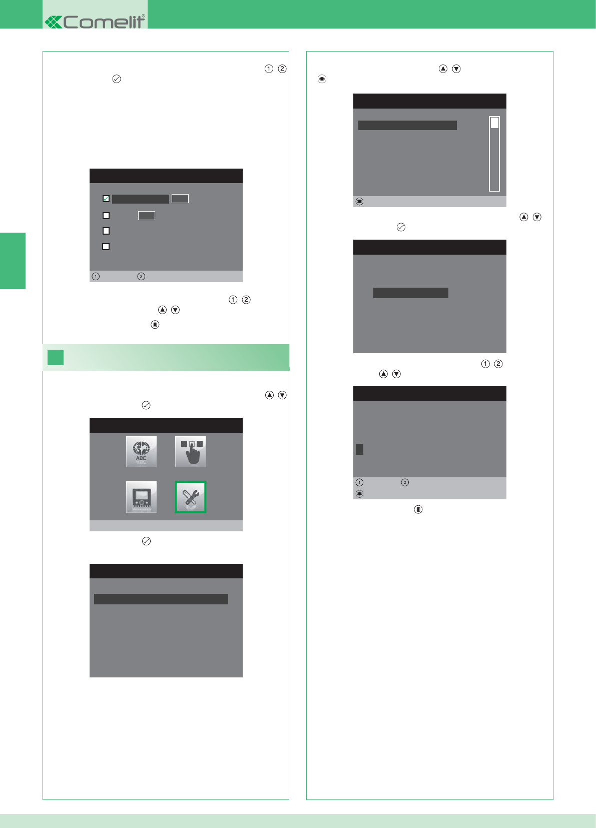
CONFIGURER ADRESSE
Appartement 0 1
Etrier
General externe
0 0
Gauche Droit
General interne
24
MENU INSTALLATEUR
Réglages Spéciaux
MENU REGLAGES SPECIAUX
Config. réponse automatique
Configurer temps d'appel
Configurer répétition sonnerie
Repertoire Intercommunicant
REPERT. APPELS INTERCOM
SECONDAIRE 1
PRINCIPAL
GENERAL EXTERNE
GENERAL INTERNE
SECONDAIRE 2
SECONDAIRE 3
Modifier
CONFIGURE INTERCOMMUNICANT
Configurer adresse
Configurer nom
CHANGER ELEMENT
G E N E R A L I N T E R N E
Configurer nom
Effacer
Gauche Droit
8. Appuyer sur la touche pour sortir et sauvegarder les
modifi cations.
FR
48
APPARTEMENT : Envoie un appel à tous les moniteurs principaux et
secondaires avec la même adresse logique.
ÉTRIER : Envoie un appel au moniteur avec l'adresse logique
insérée du même appartement du moniteur appelant.
GÉNÉRAL INTERNE : Envoie un appel à tous les moniteurs du
même appartement (seulement pour installations Kit).
GÉNÉRAL EXTERNE : Envoie un appel à tous les moniteurs de
l'autre appartement (seulement pour installations Kit).
6. Sélectionner le type d'appel que l'on veut associer à la rubrique
(l'élément) du répertoire en se déplaçant avec les touches ,
et confi rmer par .
7. Dans le cas des appels Appartement et Étrier, se déplacer sur le
champ adresse correspondant avec les touches , et insérer
celui désiré avec les touches , .
Changer les adresses Répertoire
intercommunicant
1. Accéder au menu Installateur (Voir point 19).
2. Sélectionner le menu Réglages spéciaux avec les touches ,
et appuyer sur la touche pour y accéder.
3. Appuyer sur la touche pour accéder au menu Répertoire
intercommunicant.
4. Sélectionner la rubrique (l'élément) du répertoire dont on désire
changer le nom avec les touches , et appuyer sur la touche
pour y accéder.
5. Sélectionner le menu Confi gurer nom avec les touches , et
appuyer sur la touche pour y accéder.
6. Sélectionner la lettre désirée avec les touches , et la modifi er
avec les touches , .
7. Appuyer sur la touche pour sortir et sauvegarder les
modifi cations.
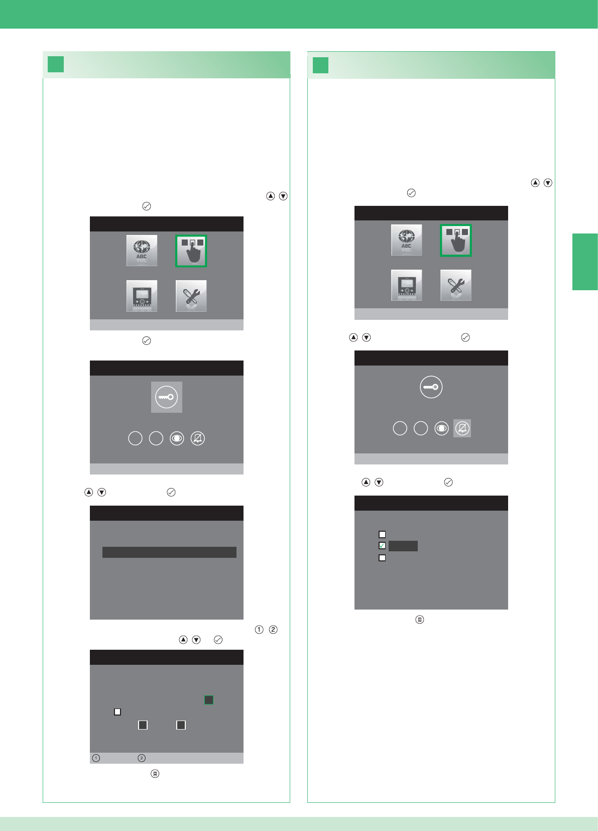
26
25
MENU INSTALLATEUR
Configurer Touches
MENU CONFIGURATION TOUCHES
Configurer touche clé
1 2
CONFIGURER RELAIS
Configuration au repos
Configuration pendant appel
RELAIS PENDANT APPEL
Porte appelante, relais
Active:
2
Active:
Porte 1, relais 2
Gauche Droit
MENU INSTALLATEUR
Configurer Touches
MENU CONFIGURATION TOUCHES
Configurer Privacy/Docteur
1 2
CONFIGURER PRIVACY/DOCTEUR
Fonction docteur
Privacy
Fonction docteur + privacy
FR
49
• La fonction Privacy permet d'exclure la sonnerie d'appel du poste
externe ou intercommunicant.
• La fonction Docteur permet d'actionner automatiquement l'ouvre-
porte (relais 1) sur appel du poste externe.
• La fonction Docteur + Privacy permet non seulement de
désactiver la sonnerie du poste interne comme dans la fonction
Privacy, mais aussi d'actionner automatiquement l'ouvre-porte
(relais 1) sur appel du poste externe.
1. Accéder au menu Installateur (Voir point 19).
2. Sélectionner le menu Confi gurer touches avec les touches ,
et appuyer sur la touche pour y accéder.
3. Sélectionner le menu Confi gurer privacy / docteur avec les
touches , et appuyer sur la touche pour y accéder.
4. Sélectionner la fonction que l'on désire affecter à la touche avec
les touches , et confi rmer par .
5. Appuyer sur la touche pour sortir et sauvegarder les
modifi cations.
Confi guration de la touche privacy/docteur
Confi guration de la touche clé
Le kit comprend 2 relais (relais 1 et relais 2) pour chaque poste
externe connecté.
Il est possible d'en confi gurer le fonctionnement tant pendant l'appel
qu'au repos.
Avec chaque touche confi gurée pour la commande du relais, il est
possible d'activer simultanément 2 relais au maximum.
En cas d'appel, un des relais* activables est nécessairement celui de
la porte appelante.
• TOUCHE CLÉ
1. Accéder au menu Installateur (Voir point 19).
2. Sélectionner le menu Confi gurer touches avec les touches ,
et appuyer sur la touche pour y accéder.
3. Appuyer sur la touche pour accéder au menu Confi gurer
touche clé.
4. Sélectionner le mode dont on désire modifi er la fonction avec les
touches , et confi rmer par .
5. Sélectionner les champs modifi ables avec les touches , et
modifi er la valeur avec les touches , ou .
6. Appuyer sur la touche pour sortir et sauvegarder les
modifi cations.
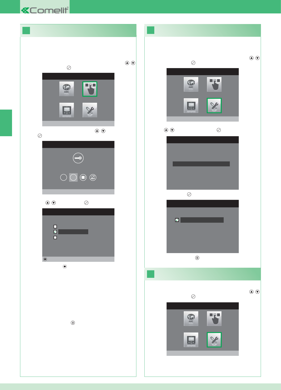
28
MENU INSTALLATEUR
Réglages Spéciaux
MENU REGLAGES SPECIAUX
Configurer répétition sonnerie
Repertoire Intercommunicant
Config. réponse automatique
Configurer temps d'appel
29
27
C
ONFIGURER REPETITION SONNERI
E
Répétition sonnerie
MENU INSTALLATEUR
Configurer Touches
MENU CONFIGURATION TOUCHES
Configurer Touche 2
1 2
CONFIGURER TOUCHE 2
Iintercommunicant
Auto-allumage
Activation relais
Modifier
MENU INSTALLATEUR
Réglages Spéciaux
FR
50
Activation de la répétition sonnerie
Si cette fonction est active (ON), le moniteur répétera la sonnerie
trois fois après la réception d'un appel.
1. Accéder au menu Installateur (Voir point 19).
2. Sélectionner le menu Réglages spéciaux avec les touches ,
et appuyer sur la touche pour y accéder
3. Sélectionner le menu Confi gurer répétition sonnerie avec les
touches , et appuyer sur la touche pour y accéder.
4. Appuyer sur la touche pour activer la fonction.
Les touches 1 et 2 peuvent être programmée avec la même
procédure. Voici la procédure de programmation de la touche 2.
1. Accéder au menu Installateur (Voir point 19).
2. Sélectionner le menu Confi gurer touches avec les touches ,
et appuyer sur la touche pour y accéder.
3. Sélectionner le menu 2 avec les touches , et appuyer sur la
touche pour y accéder.
4. Sélectionner la fonction que l'on désire affecter à la touche avec
les touches , et confi rmer par .
5. Appuyer sur la touche pour confi gurer la fonction choisie.
Si la fonction Intercommunicant a été sélectionnée :
}Associer la touche à un poste externe INTERCOM X.
GÉNÉRAL INTERNE : Envoie un appel à tous les moniteurs du
même appartement.
GÉNÉRAL EXTERNE : Envoie un appel à tous les moniteurs de
l'autre appartement.
Si la fonction Auto-allumage a été sélectionnée :
}Associer la touche à un poste externe ou aux deux postes externes.
Si la fonction Activation relais a été sélectionnée :
}Suivre la procédure pour la confi guration de la touche clé.
6. Appuyer sur la touche pour sortir et sauvegarder les
modifi cations.
5. Appuyer sur la touche pour sortir et sauvegarder les
modifi cations.
Activation de la réponse automatique
1. Accéder au menu Installateur (Voir point 19).
2. Sélectionner le menu Réglages spéciaux avec les touches ,
et appuyer sur la touche pour y accéder
Confi guration des touches 1 - 2
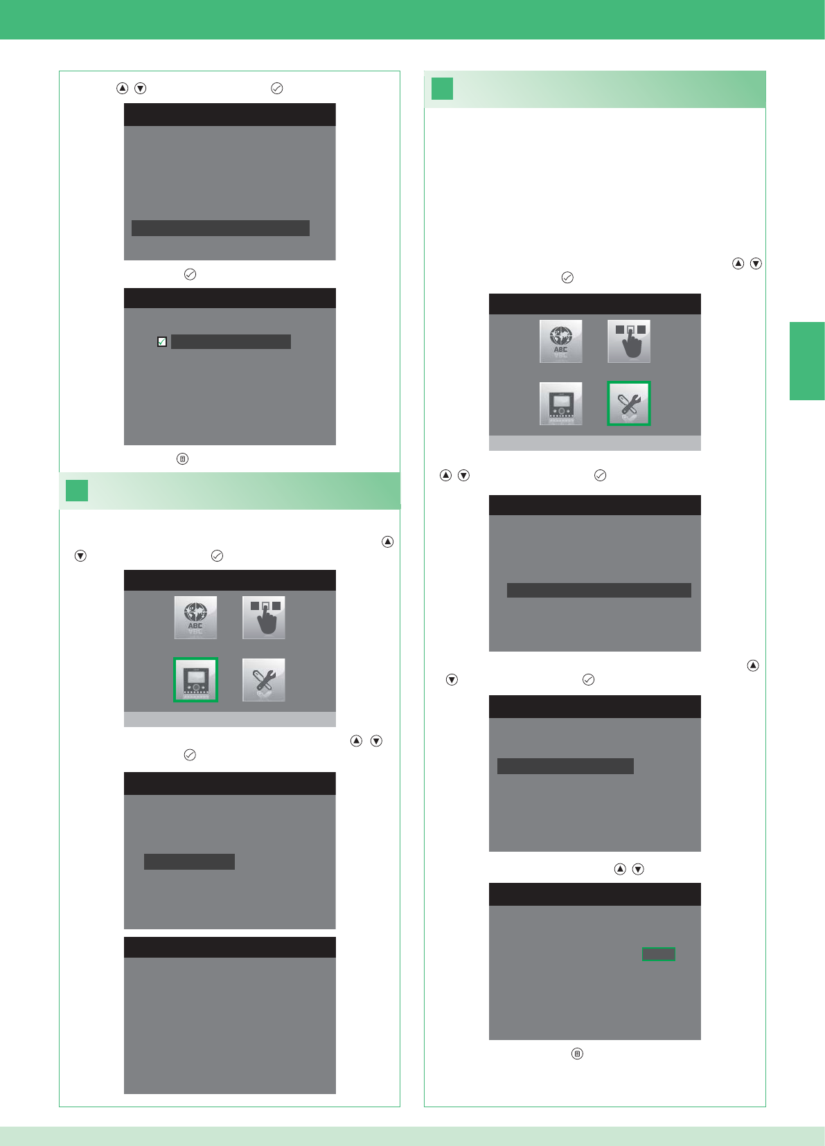
31
MENU INSTALLATEUR
Réglages Spéciaux
1. Accéder au menu Installateur (Voir point 19).
MENU REGLAGES SPECIAUX
Configurer répétition sonnerie
Repertoire Intercommunicant
Config. réponse automatique
Configurer temps d'appel
CONFIGURER TEMPS D'APPEL
Temps de conversation
Temps attente réponse
Temps de Reset
Temps conversation intercom
CONFIG. TEMPS ATTENTE REPONSE
Temps attente réponse 0 6 5
MENU REGLAGES SPECIAUX
Configurer répétition sonnerie
Repertoire Intercommunicant
Config. réponse automatique
Configurer temps d'appel
CONFIG. REPONSE AUTOMATIQUE
Réponse automatique
30
MENU INSTALLATEUR
Configurer moniteur
CONFIGURER MONITEUR
Reset configuration
Configurer type de réseau
Informations
Configurer etrier
Adresse logique
MENU INFORMATIONS
MAC: 00:25:29:02:01:BC
IP: 169.254.155.40
ID: 00000001, SUB: 0
SW: /trunck@3534
SYS: iPower
FR
51
1. Accéder au menu Installateur (Voir point 19).
Affi cher informations
2. Sélectionner le menu Confi gurer moniteur avec les touches ,
et appuyer sur la touche pour y accéder
3. Sélectionner le menu Informations avec les touches , et
appuyer sur la touche pour y accéder.
Confi guration du temps d’appel
Dans ce menu, il est possible de modifi er les paramètres ci-après :
• Temps d'attente réponse : délai maximum au-delà duquel la
communication est interrompue en absence de réponse.
• Temps de conversation : durée d'une conversation entre le poste
interne et le poste externe.
• Temps de conversation intercom. : durée d'une conversation
intercommunicante.
• Retard reset : après un appel, temps d'attente du moment de
l'activation d'un relais à l'extinction du moniteur.
2. Sélectionner le menu Réglages spéciaux avec les touches ,
et appuyer sur la touche pour y accéder.
3. Sélectionner le menu Confi gurer temps d'appel avec les touches
, et appuyer sur la touche pour y accéder.
4. Sélectionner la valeur que l'on désire modifi er avec les touches
, et appuyer sur la touche pour y accéder.
5. Changer la valeur avec les touches , .
6. Appuyer sur la touche pour sortir et sauvegarder les
modifi cations.
3. Sélectionner le menu Confi gurer réponse automatique avec les
touches , et appuyer sur la touche pour y accéder.
4. Appuyer sur la touche pour activer la fonction.
5. Appuyer sur la touche pour sortir et sauvegarder les modifi cations.
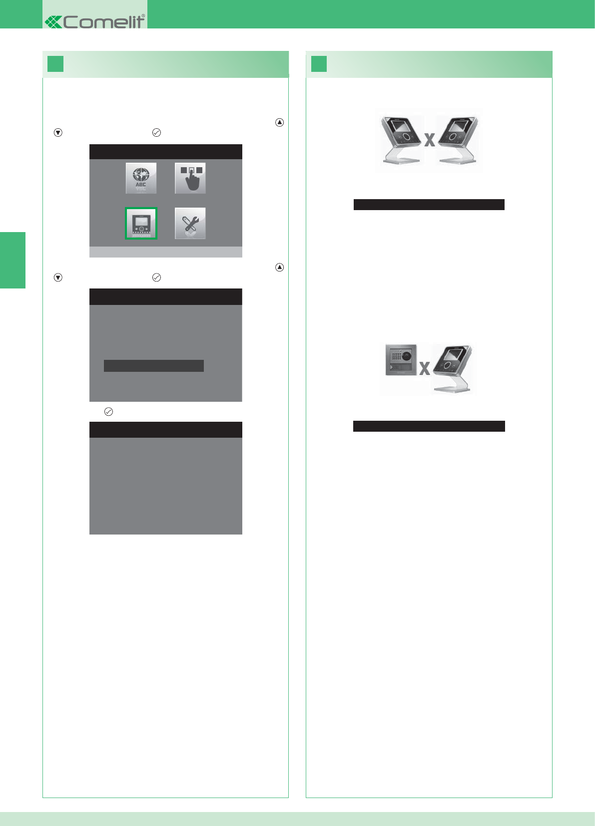
33
Aucun Signal Détecté
Aucun Signal Détecté
Absence de communication avec le poste externe.
32
MENU INSTALLATEUR
Configurer moniteur
CONFIGURER MONITEUR
Configurer type de réseau
Informations
Configurer etrier
Adresse logique
Reset configuration
1. Accéder au menu Installateur (Voir point 19).
RESET CONFIGURATION
Vz-vs continuer?
FR
52
Dépannage
Absence de connexion avec le poste interne.
Solutions :
}Attendre 1 minute.
}S'assurer que l'adresse du moniteur secondaire est la même que
celle du moniteur principal de l'appartement concerné (point 22).
}S'assurer que le moniteur principal est alimenté en énergie
électrique (point 10).
}S'assurer que le mot de passe a été correctement saisi (point 20).
}S'assurer que les distances de montage ont bien été respectées
(point 8).
Solutions :
}Attendre 1 minute.
}S'assurer que le poste externe est correctement câblé (point 2).
}S'assurer que le poste externe est alimenté en énergie électrique
(point 9).
}S'assurer que le pont Art. 1398 est correctement câblé (point 7A,
7B ou 7C).
}S'assurer qu'il y a correspondance entre le mot de passe du pont
Art. 1398 et l'alimentation du moniteur du même appartement.
}S'assurer que les distances de montage ont bien été respectées
(point 8).
Attention : cette opération rétablira tous les paramétrages d'usine,
annulant ainsi toutes les modifi cations apportées.
Reset confi guration
2. Sélectionner le menu Confi gurer moniteur avec les touches ,
et appuyer sur la touche pour y accéder.
3. Sélectionner le menu Reset confi guration avec les touches ,
et appuyer sur la touche pour y accéder
4. Confi rmer par .
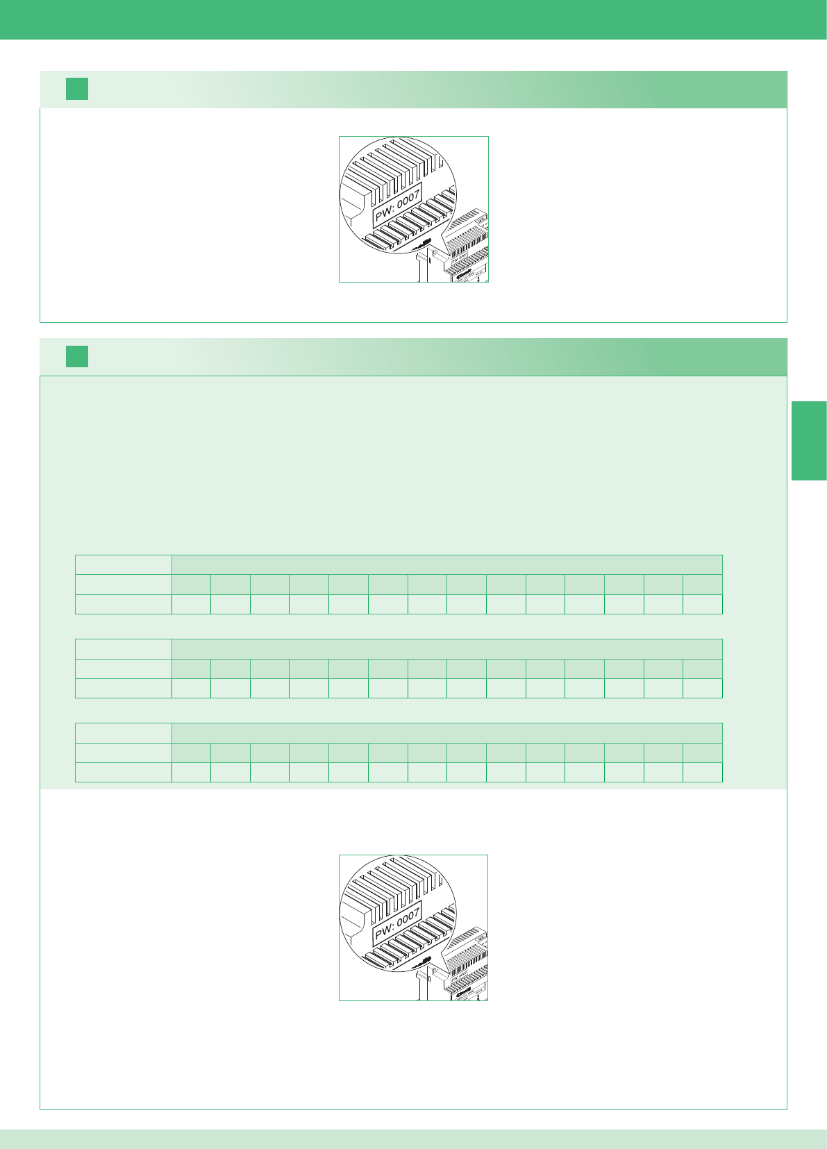
16
17
NL
53
Het is mogelijk aanvullende secundaire monitors toe te voegen in de appartementen, maar hierbij gelden 2 regels:
1. Installeer maximaal 14 grondplaten per appartement.
2. Maak de volgende berekeningen voor de voorziene verdeling van de grondplaten:
}bereken het totale aantal grondplaten dat in de installatie moet worden gemonteerd (zowel de hoofd- als secundaire monitors) = A.
}bekijk welk appartement het laagste aantal grondplaten heeft = B
}bereken het verschil tussen het totale aantal grondplaten van de installatie en het aantal dat aanwezig is in het appartement met de minsten
grondplaten (A - B) en verzeker u ervan dat het verkregen aantal:
kleiner is dan of gelijk aan 15 voor installaties met 1 entreepaneel.
kleiner is dan of gelijk aan 14 voor installaties met 2 entreepanelen.
Onderstaand vindt u een voorbeeld van een kit voor een tweegezinswoning met 2 entreepanelen en 14 monitors voor 2 appartementen:
1. Zoek het modemwachtwoord op op het etiket van de brug Art. 1398 van de betreffende wooneenheid.
2. Stel op de monitor het modemwachtwoord in dat is vastgesteld zoals beschreven in punt 20.
3. Stel het adres van de extra secundaire monitors in zoals beschreven in punt 22
Waarschuwing!
Werkwijze:
1. Zoek het modemwachtwoord op op het etiket van de brug Art. 1398 van de betreffende wooneenheid.
2. Stel op de monitor het modemwachtwoord in dat is vastgesteld zoals beschreven in punt v.
3. Stel het adres van de hoofdmonitor in zoals beschreven in punt 21
Kit en multi-usersysteem: installatie van extra secundaire monitors
Multi-usersysteem: installatie van hoofdmonitors
1 entreepaneel Appartementen
1234567891011121314
Aantal grondplaten 2 3 4 5 3 - - - - - - - - - - - - - - - - - -
Onderstaand vindt u een voorbeeld van een installatie met 1 entreepaneel en 17 monitors voor 5 appartementen:
1 entreepaneel Appartementen
1234567891011121314
Aantal grondplaten 13 1 1 1 1 - - - - - - - - - - - - - - - - - -
Hier volgt een voorbeeld van een niet-mogelijke confi guratie van een installatie met 1 entreepaneel en 17 monitors voor 5 appartementen:
2 entreepanelen Appartementen
1234567891011121314
Aantal grondplaten 14 14 - - - - - - - - - - - - - - - - - - - - - - - -
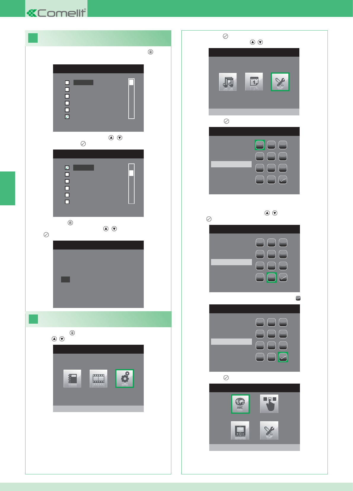
18
MENU TALEN
English
Français
Español
Português
Deutsch
Nederlands
MENU LINGUE
Français
Español
Português
Deutsch
English
Italiano
19
HOOFDMENU
Instellingen
MENU INSTELLINGEN
Menu installateur
WACHTWOORD INVOEREN
1
1
23
456
789
0
C
WACHTWOORD INVOEREN
1
1
23
456
789
0
C
****
WACHTWOORD INVOEREN
1
1
23
456
789
0
C
****
MENU INSTALLATEUR
Taal instellen
Italiano
NO
OK
NL
54
Als het menu voor het eerst geopend wordt (drukknop ), wordt
gevraagd om de taal in te stellen.
1. Selecteer de taal met de knoppen , en bevestig door het
indrukken van de knop .
1. Druk op de knop en selecteer het menu Instellingen met de
knoppen , .
2. Druk op de knop om het te openen en selecteer het menu Menu
installateur met de knoppen , .
3. Druk op de knop om het te openen.
4. Selecteer de cijfers met de knoppen , en voer hen in door op
de knop te drukken.
5. Selecteer aan het einde van de invoer het symbool .
Het wachtwoord voor het installateurmenu is 0000. Het
wachtwoord kan niet worden gewijzigd,
6. Druk op de knop ter bevestiging.
2. Druk op de knop om af te sluiten.
3. Selecteer "OK" met de knoppen , en bevestig door op de
knop te drukken.
Instelling van de menutaal
Het installateurmenu openen
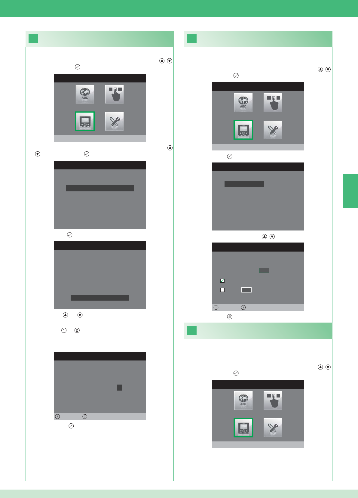
20
MENU INSTALLATEUR
Monitor configureren
MONITOR CONFIGUREREN
Configuratie resetten
Netwerk instellen
Informatie
Grondplaat configureren
Logisch adres
WACHTWOORD CONFIGUREREN
Links Rechts
Wachtwoord modem: 1 0 0 7
CONFIGURATIE GRONDPLAAT
ID: A
PWD: 0007
MAC: 00:0D:BE:00:2C:65
Wachtwoord wijzigen
ADRES CONFIGUREREN
Logisch adres 0 2
Master
Slave 1 4
Links Rechts
22
MENU INSTALLATEUR
Monitor configureren
21
MENU INSTALLATEUR
Monitor configureren
MONITOR CONFIGUREREN
Configuratie resetten
Netwerk instellen
Informatie
Grondplaat configureren
Logisch adres
NL
55
1. Open het menu Installateur (zie punt 19).
Confi guratie modemwachtwoord
2. Selecteer het menu Monitor confi gureren met de knoppen ,
en druk op de knop om het te openen.
3. Selecteer het menu Grondplaat confi gureren met de knoppen
, en druk op de knop om het te openen.
4. Druk op de knop om het menu Wachtwoord wijzigen te openen.
5. Wijzig het wachtwoord.
• De knoppen en verhogen en verlagen de geselecteerde
waarde
• De knoppen en verplaatsen de selectiecursor naar links en
naar rechts.
6. Druk op de knop om het gewijzigde wachtwoord op te slaan.
1. Open het menu Installateur (zie punt 19).
Stel het logische adres van de
hoofdmonitors (master) in
2. Selecteer het menu Monitor confi gureren met de knoppen ,
en druk op de knop om het te openen
3. Druk op de knop om het menu Logisch adres te openen.
4. Wijzig het adres met de knoppen , .
Stel slechts 1 hoofdmonitor in voor elk logisch adres.
1. Open het menu Installateur (zie punt 19).
Instelling van het logische adres van
secundaire monitors (slave)
2. Selecteer het menu Monitor confi gureren met de knoppen ,
en druk op de knop om het te openen
Elke secundaire monitor van dezelfde wooneenheid moet een ander
Slave adres hebben
5. Druk op de knop om af te sluiten en de wijzigingen op te slaan.
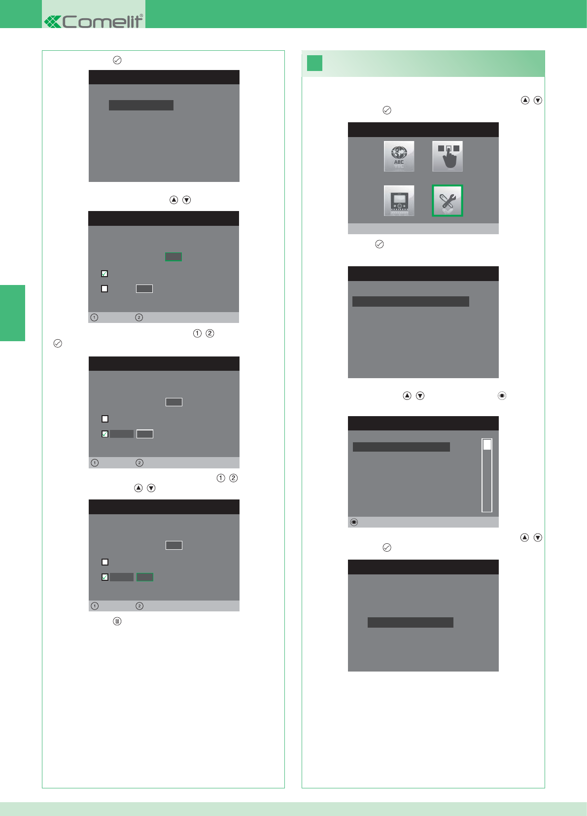
MONITOR CONFIGUREREN
Configuratie resetten
Netwerk instellen
Informatie
Grondplaat configureren
Logisch adres
ADRES CONFIGUREREN
Logisch adres 0 2
Master
Slave 1 4
Links Rechts
ADRES CONFIGUREREN
Logisch adres 0 2
Master
1 4
Links Rechts
Slave
ADRES CONFIGUREREN
Logisch adres 0 2
Master
1 0
Links Rechts
Slave
23
MENU INSTALLATEUR
Speciale instellingen
MENU SPECIALE INSTELLINGEN
Handenvrij instellen
Oproeptijden instellen
Extra bel instellen
Namenlijst voor intercom
NAMENLIJST INTERCOMOPROEPEN
SECUNDAIRE 1
PRIMAIRE
ALGEMEEN EXTERN
ALGEMEEN INTERN
SECUNDAIRE 2
SECUNDAIRE 3
Wijzigen
INTERCOM CONFIGUREREN
Adres configureren
Naam configureren
NL
56
1. Open het menu Installateur (zie punt 19).
2. Selecteer het menu Speciale instellingen met de knoppen ,
en druk op de knop om het te openen.
3. Druk op de knop om het menu Namenlijst voor intercom te
openen.
4. Selecteer het item van het namenregister waarvan u het adres wilt
wijzigen met de knoppen , en druk op de knop om het te
openen.
5. Selecteer het menu Adres confi gureren met de knoppen ,
en druk op de knop om het te openen.
7. Druk op de knop om af te sluiten en de wijzigingen op te slaan.
Wijziging van adressen van het
namenregister voor de intercom
3. Druk op de knop om het menu Logisch adres te openen.
4. Stel het logische adres van de hoofdmonitor van dezelfde
wooneenheid in met de knoppen , .
5. Ga naar de optie Slave met de knoppen , en druk op de knop
ter bevestiging.
6. Ga naar de optie Slave adres met de knoppen , en wijzig het
adres met de knoppen , .
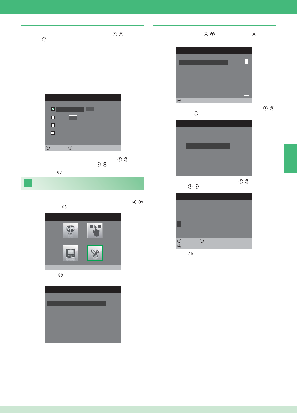
ADRES CONFIGUREREN
Appartement 0 1
Grondplaat
Algemeen extern
0 0
Links Rechts
Algemeen intern
24
MENU SPECIALE INSTELLINGEN
Handenvrij instellen
Oproeptijden instellen
Extra bel instellen
Namenlijst voor intercom
NAMENLIJST INTERCOMOPROEPEN
SECUNDAIRE 1
PRIMAIRE
ALGEMEEN EXTERN
ALGEMEEN INTERN
SECUNDAIRE 2
SECUNDAIRE 3
Wijzigen
INTERCOM CONFIGUREREN
Adres configureren
Naam configureren
NAAM WIJZIGEN
A L G E M E E N I N T E R N
Naam configureren
Wissen
Links Rechts
MENU INSTALLATEUR
Speciale instellingen
NL
57
APPARTEMENT: Zendt een oproep aan alle monitors, zowel de
hoofd- als de secundaire monitors, waarin hetzelfde logische
hoofdadres is ingevoerd.
GRONDPLAAT: Zendt een oproep naar de monitor met het logische
adres dat hetzelfde is als dat van het appartement van de monitor
van waaraf de oproep wordt gedaan.
ALGEMEEN INTERN: Zendt een oproep naar alle monitors van
hetzelfde appartement (alleen voor Kit-installaties).
ALGEMEEN EXTERN: Zendt een oproep naar alle monitors van het
andere appartement (alleen voor Kit-installaties).
6. Selecteer het type oproep dat u wilt combineren met het item in de
namenlijst door u te verplaatsen met de knoppen , en druk op
de knop ter bevestiging.
7. Ga in het geval van de oproepen Appartement en Grondplaat
naar het bijbehorende veld Adres met de knoppen , en voer
het gewenste adres in met de knoppen , .
Wijziging van namen in het namenregister
voor de intercom
1. Open het menu Installateur (zie punt 19).
2. Selecteer het menu Speciale instellingen met de knoppen ,
en druk op de knop om het te openen.
3. Druk op de knop om het menu Namenlijst voor intercom te
openen.
4. Selecteer het item van het namenregister waarvan u de naam wilt
wijzigen met de knoppen , en druk op de knop om het te
openen.
5. Selecteer het menu Naam confi gureren met de knoppen ,
en druk op de knop om het te openen.
6. Selecteer de gewenste letter met de knoppen , en wijzig hem
met de knoppen , .
7. Druk op de knop om af te sluiten en de wijzigingen op te slaan.
8. Druk op de knop om af te sluiten en de wijzigingen op te slaan.
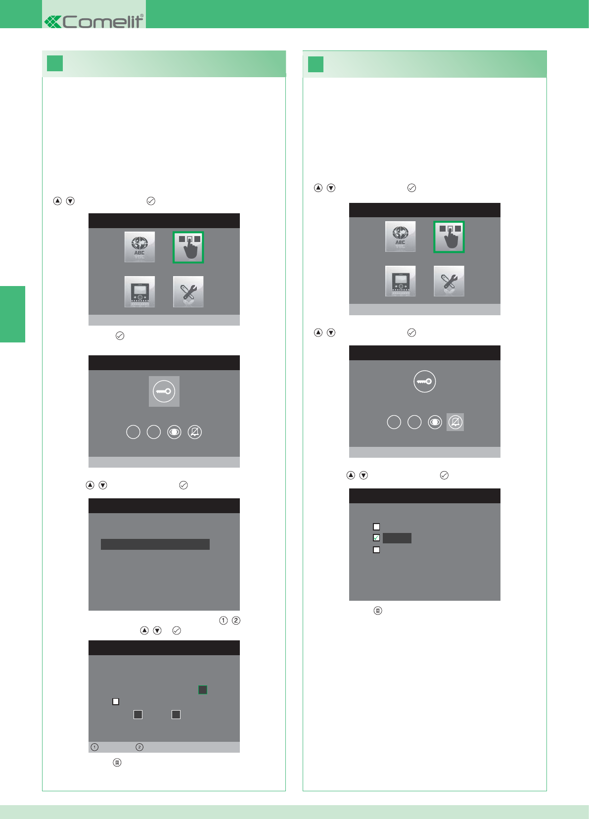
26
25
MENU INSTALLATEUR
Drukknoppen configureren
CONFIGURATIEMENU DRUKKNOPPEN
Sleutelknop configureren
1 2
RELAIS CONFIGUREREN
Configuratie zonder oproep
Configuratie tijdens oproep
RELAIS TIJDENS OPROEP
Bellende deur, relais
Actief:
2
Actief:
Deur 1, relais 2
Links Rechts
CONFIGURATIEMENU DRUKKNOPPEN
Privacy/arts configureren
1 2
PRIVACY/ARTS CONFIGUREREN
Artsfunctie
Privacy
Arts- en privacy functie
MENU INSTALLATEUR
Drukknoppen configureren
NL
58
• Met de Privacy-functie kan de beltoon van de oproep vanaf het
entreepaneel en van de intercomoproep worden uitgeschakeld.
• Met de Arts-functie kan de deuropener (relais 1) automatisch in
werking treden bij een oproep vanaf het entreepaneel.
• Met de Privacy- en arts-functie kan, naast de uitschakeling van
de beltoon van het binnentoestel, zoals bij de privacyfunctie,
de deuropener (relais 1) automatisch in werking treden bij een
oproep vanaf het entreepaneel.
1. Open het menu Installateur (zie punt 19).
2. Selecteer het menu Drukknoppen confi gureren met de knoppen
, en druk op de knop om het te openen.
3. Selecteer het menu Privacy/arts confi gureren met de knoppen
, en druk op de knop om het te openen.
4. Selecteer de functie die u aan de knop wilt toewijzen met de
knoppen , en druk op de knop ter bevestiging.
5. Druk op de knop om af te sluiten en de wijzigingen op te slaan.
Confi guratie van de privacy-/artsknop
Confi guratie van de sleutelknop
De kit bevat 2 relais (relais 1 en relais 2) voor elk aangesloten
entreepaneel.
De werking ervan kan zowel tijdens een oproep als in afwezigheid
ervan (installatie in ruststand) worden geconfi gureerd.
Met elke knop die geconfi gureerd is voor bediening van de relais,
kunnen tegelijkertijd maximaal 2 relais* worden geactiveerd.
Bij een oproep is een van de activeerbare relais noodzakelijkerwijze
die van de deur van waaraf de oproep wordt gedaan.
• SLEUTELKNOP
1. Open het menu Installateur (zie punt 19).
2. Selecteer het menu Drukknoppen confi gureren met de knoppen
, en druk op de knop om het te openen.
3. Druk op de knop om het menu Sleutelknop confi gureren te
openen.
4. Selecteer de modus waarvoor u de functie wilt wijzigen met de
knoppen , en druk op de knop ter bevestiging.
5. Selecteer de wijzigbare velden met de knoppen , en wijzig de
waarde met de knoppen , of .
6. Druk op de knop om af te sluiten en de wijzigingen op te slaan.
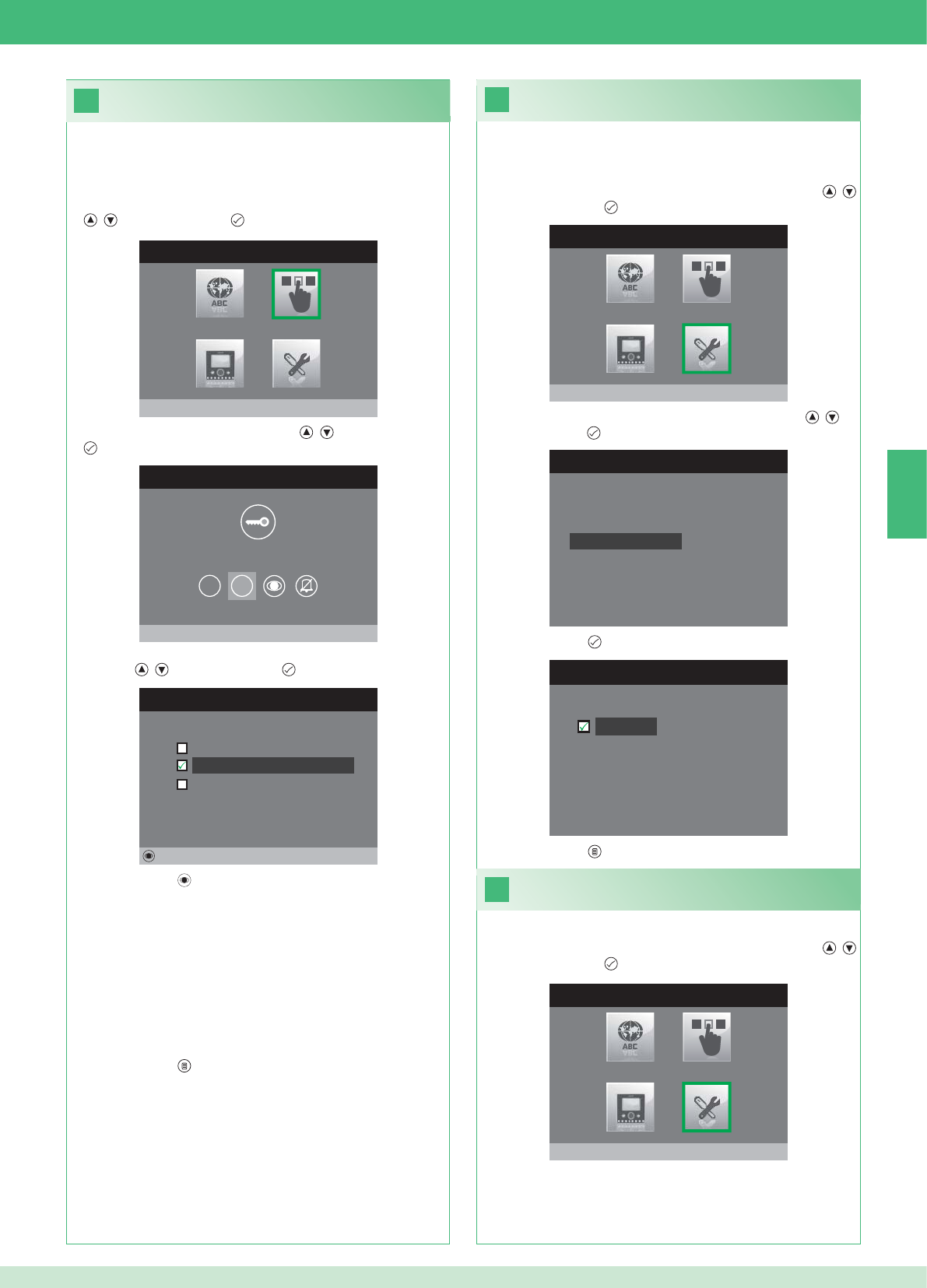
28
MENU INSTALLATEUR
Speciale instellingen
MENU SPECIALE INSTELLINGEN
Extra bel instellen
Namenlijst voor intercom
Handenvrij instellen
Oproeptijden instellen
29
27
EXTRA BEL INSTELLEN
Extra bel
CONFIGURATIEMENU DRUKKNOPPEN
Drukknop 2 configureren
1 2
DRUKKNOP 2 CONFIGUREREN
Intercom
Beeldoproep configureren
Relais inschakelen
Wijzigen
MENU INSTALLATEUR
Drukknoppen configureren
MENU INSTALLATEUR
Speciale instellingen
NL
59
Inschakeling extra bel
Als deze functie ingeschakeld is, herhaalt de monitor na ontvangst
van een oproep de beltoon drie keer.
1. Open het menu Installateur (zie punt 19).
2. Selecteer het menu Speciale instellingen met de knoppen ,
en druk op de knop om het te openen
3. Selecteer het menu Extra bel instellen met de knoppen , en
druk op de knop om het te openen.
4. Druk op de knop om de functie te activeren.
De knoppen 1 en 2 kunnen beide worden geprogrammeerd volgens
dezelfde werkwijze. Hier wordt de programmering van knop 2
geïllustreerd.
1. Open het menu Installateur (zie punt 19).
2. Selecteer het menu Drukknoppen confi gureren met de knoppen
, en druk op de knop om het te openen.
3. Selecteer het menu 2 met de knoppen , en druk op de knop
om het te openen.
4. Selecteer de functie die u aan de knop wilt toewijzen met de
knoppen , en druk op de knop ter bevestiging.
5. Druk op de toets om de gekozen functie in te schakelen.
Als de functie Intercom geselecteerd is:
}Koppel de knop aan een binnentoestel INTERCOM X.
ALGEMEEN INTERN: Zendt een oproep naar alle monitors van
hetzelfde appartement.
ALGEMEEN EXTERN: Zendt een oproep naar alle monitors van het
andere appartement.
Als de functie Beeldoproep geselecteerd is:
}Koppel de knop aan een of beide entreepanelen.
Als de functie Relais inschakelen geselecteerd is:
}Volg de procedure voor confi guratie van de sleutelknop.
6. Druk op de knop om af te sluiten en de wijzigingen op te slaan.
5. Druk op de knop om af te sluiten en de wijzigingen op te slaan.
Inschakeling handenvrijfunctie
1. Open het menu Installateur (zie punt 19).
2. Selecteer het menu Speciale instellingen met de knoppen ,
en druk op de knop om het te openen
Confi guratie drukknoppen 1 - 2
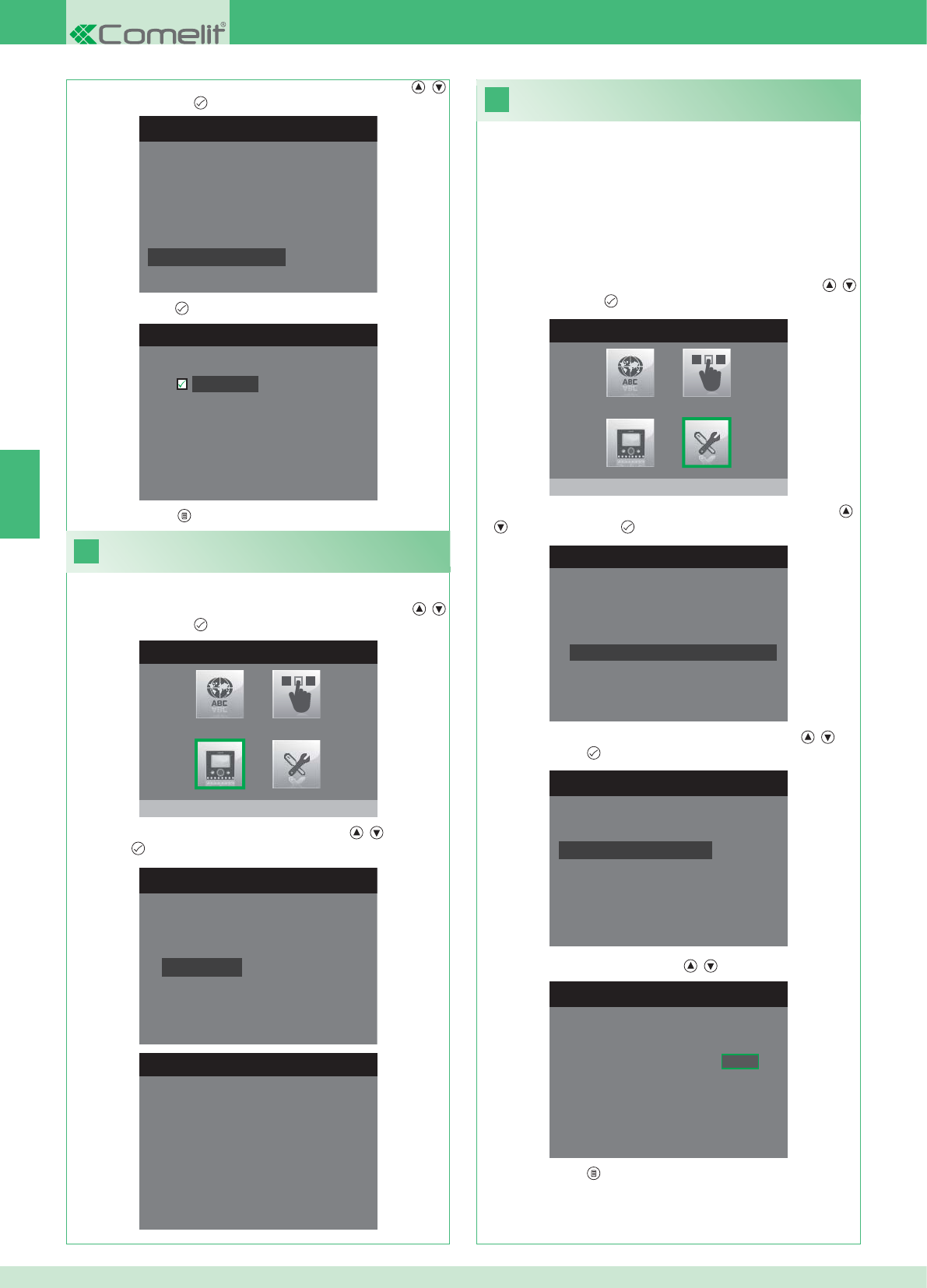
31
MENU INSTALLATEUR
Speciale instellingen
MENU SPECIALE INSTELLINGEN
Extra bel instellen
Namenlijst voor intercom
Handenvrij instellen
Oproeptijden instellen
OPROEPTIJDEN INSTELLEN
Gesprekstijd
Wachttijd antwoord
Uitschakelvertraging
Tijd intercomgesprek
ANTWOORDTIJD INSTELLEN
Wachttijd antwoord 0 6 5
MENU SPECIALE INSTELLINGEN
Extra bel instellen
Namenlijst voor intercom
Handenvrij instellen
Oproeptijden instellen
HANDENVRIJ INSTELLEN
Handenvrij
30
MENU INSTALLATEUR
Monitor configureren
MONITOR CONFIGUREREN
Configuratie resetten
Netwerk instellen
Informatie
Grondplaat configureren
Logisch adres
MENU INFORMATIE
MAC: 00:25:29:02:01:BC
IP: 169.254.155.40
ID: 00000001, SUB: 0
SW: /trunck@3534
SYS: iPower
NL
60
1. Open het menu Installateur (zie punt 19).
Weergave van informatie
2. Selecteer het menu Monitor confi gureren met de knoppen ,
en druk op de knop om het te openen
3. Selecteer het menu Informatie met de knoppen , en druk op
de knop om het te openen.
Confi guratie oproeptijden
In dit menu kan het volgende gewijzigd worden:
• Wachttijd antwoord: maximale tijd gedurende welke de communicatie
eindigt als er geen antwoord komt.
• Gesprekstijd: duur van een gesprek tussen binnentoestel en
entreepaneel.
• Tijd intercomgesprek: duur van een intercomgesprek.
• Uitschakelvertraging: na een oproep, de wachttijd vanaf de
inschakeling van een relais tot de uitschakeling van de monitor.
2. Selecteer het menu Speciale instellingen met de knoppen ,
en druk op de knop om het te openen
3. Selecteer het menu Oproeptijden instellen met de knoppen ,
en druk op de knop om het te openen.
4. Selecteer de waarde die u wilt wijzigen met de knoppen , en
druk op de knop om het te openen.
5. Wijzig de waarde met de knoppen , .
6. Druk op de knop om af te sluiten en de wijzigingen op te slaan.
3. Selecteer het menu Handenvrij instellen met de knoppen ,
en druk op de knop om het te openen.
4. Druk op de knop om de functie te activeren.
5. Druk op de knop om af te sluiten en de wijzigingen op te slaan.
1. Open het menu Installateur (zie punt 19).
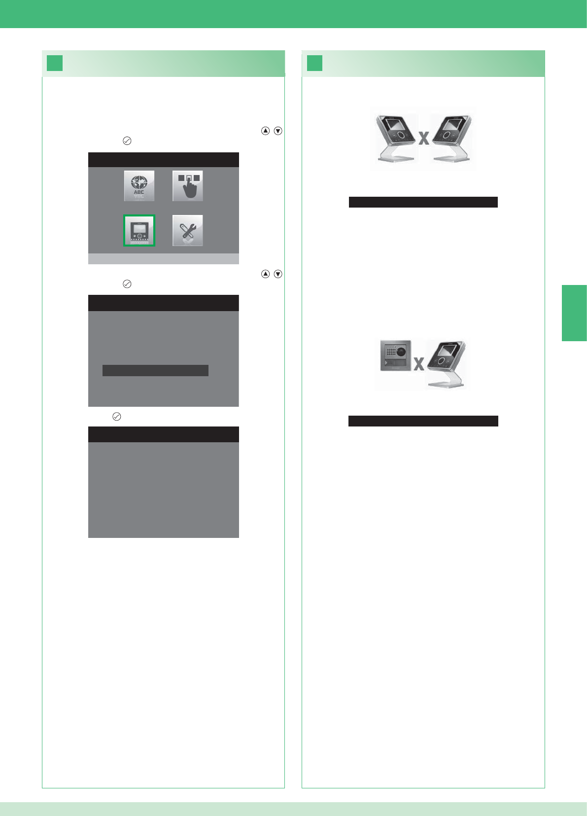
33
Geen signaal gedetecteerd
Geen signaal gedetecteerd
32
MENU INSTALLATEUR
Monitor configureren
MONITOR CONFIGUREREN
Netwerk instellen
Informatie
Grondplaat configureren
Logisch adres
Configuratie resetten
CONFIGURATIE RESETTEN
Doorgaan?
NL
61
Storingen en mogelijke oplossingen
Geen verbinding met binnentoestel.
Oplossingen:
}Wacht 1 minuut.
}Verzeker u ervan dat de secundaire monitor hetzelfde adres heeft
als de hoofdmonitor van de betreffende wooneenheid (punt 22).
}Verzeker u ervan dat de hoofdmonitor gevoed wordt (punt 10).
}Verzeker u ervan dat het juiste wachtwoord is ingevoerd (punt 20).
}Verzeker u ervan dat de installatie-afstanden zijn aangehouden
(punt 8).
Oplossingen:
}Wacht 1 minuut.
}Verzeker u ervan dat het entreepaneel goed bekabeld is (punt 2).
}Verzeker u ervan dat het entreepaneel gevoed wordt (punt 9).
}Verzeker u ervan dat de brug Art. 1398 goed bekabeld is (punt 7A,
7B, 7C).
}Verzeker u ervan dat er overeenstemming is tussen het wachtwoord
van de brug Art. 1398 en de voedingstransformator van de monitor
van dezelfde wooneenheid.
}Verzeker u ervan dat de installatie-afstanden zijn aangehouden
(punt 8).
Let op: met deze handeling worden alle fabrieksinstellingen
teruggehaald en worden alle aangebrachte wijzigingen ongedaan
gemaakt.
Confi guratie resetten
2. Selecteer het menu Monitor confi gureren met de knoppen ,
en druk op de knop om het te openen.
3. Selecteer het menu Confi guratie resetten met de knoppen ,
en druk op de knop om het te openen
4. Druk op de knop ter bevestiging.
Geen verbinding met het entreepaneel.
1. Open het menu Installateur (zie punt 19).
2 Außenstellen Wohnungen
1234567891011121314
Anzahl Grundplatten 14 14 -- -- -- -- -- -- -- -- -- -- -- --
DE
16
17
62
Es können mehrere, in den Wohnungen verteilte Zusatzmonitore hinzugefügt werden, wobei jedoch 2 Regeln befolgt werden müssen:
1. Höchstens 14 Grundplatten pro Wohnung installieren.
2. Die folgenden Berechnungen zur vorgesehenen Verteilung für die Grundplatten durchführen:
}Die Gesamtanzahl der in der Anlage zu installierenden Grundplatten berechnen (sowohl Haupt- als auch Zusatzgeräte) = A.
}Die Anzahl in der Wohnung mit den wenigsten Grundplatten = B
}Die Differenz zwischen der Gesamtanzahl der in Anlage vorhandenen Grundplatten und der Anzahl in der Wohnung mit den wenigsten
Grundplatten ermitteln (A - B). Das Resultat muss:
bei Anlagen mit 1 Außenstelle kleiner oder gleich 15 sein.
bei Anlagen mit 2 Außenstellen kleiner oder gleich 14 sein.
Beispiel eines SETS für Zweifamilienhaus mit 2 Außenstellen und 14 Monitoren für 2 Wohnungen:
1 Außenstelle Wohnungen
1234567891011121314
Anzahl Grundplatten 2 3 4 5 3 -- -- -- -- -- -- -- -- --
Beispiel einer Anlage mit 1 Außenstelle und 17 Monitoren für 5 Wohnungen:
1 Außenstelle Wohnungen
1234567891011121314
Anzahl Grundplatten 13 1 1 1 1 -- -- -- -- -- -- -- -- --
Beispiel einer nicht möglichen Konfi guration einer Anlage mit 1 Außenstelle und 17 Monitoren für 5 Wohnungen:
1. Das Modem-Passwort auf dem Etikett der Brücke Art. 1398 der fraglichen Wohneinheit notieren.
2. Am Monitor das wie unter Punkt 20 ermittelte Modem-Passwort einstellen.
3. Die Adresse der Zusatzmonitore wie unter Punkt 22 beschrieben einstellen.
Wichtiger Hinweis!
Vorgehensweise:
Set und Multi-User: Installation der Zusatzmonitore
1. Das Modem-Passwort auf dem Etikett der Brücke Art. 1398 der fraglichen Wohneinheit notieren.
2. Am Monitor das wie unter Punkt v ermittelte Modem-Passwort einstellen.
3. Die Adresse des Hauptmonitors wie unter Punkt 21 beschrieben einstellen.
Multi-User: Installation der Hauptmonitoren
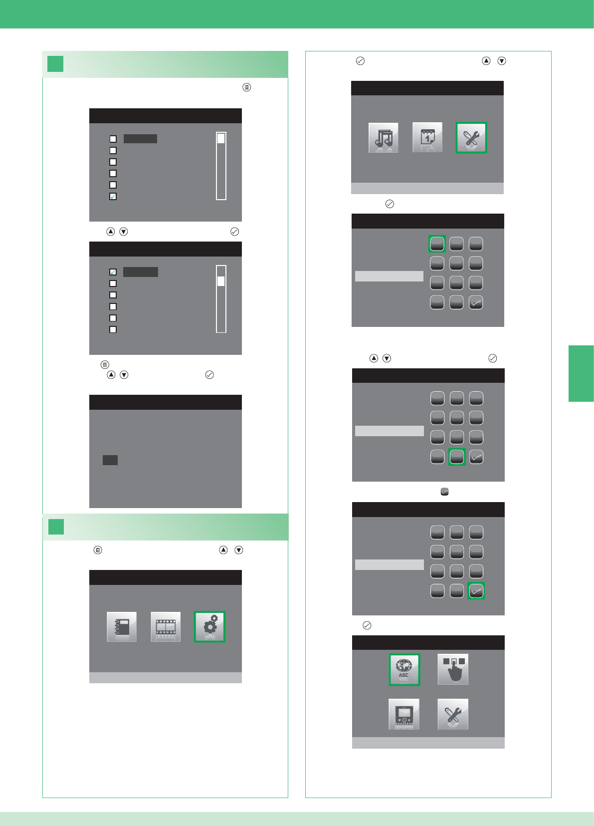
DE
18
MENÜ SPRACH
Italiano
English
Français
Español
Português
Deutsch
MENU LINGUE
Français
Español
Português
Deutsch
English
Italiano
19
HAUPTMENÜ
Einstellungen
MENÜ EINSTELLUNGEN
Menü installateur
PASSWORT EINGEBEN
1
1
23
456
789
0
C
PASSWORT EINGEBEN
1
1
23
456
789
0
C
****
PASSWORT EINGEBEN
1
1
23
456
789
0
C
****
MENÜ INSTALLATEUR
Sprache einstellen
Italiano
NO
OK
63
Einstellung der Menüsprache
Wenn das Menü zum ersten Mal geöffnet wird (Taste ) wird die
Einstellung der zu verwendenden Sprache verlangt.
1. Mit den Tasten , die Sprache wählen und mit bestätigen.
1. Die Taste drücken und mit den Tasten , das Menü
Einstellungen wählen.
Menü Installateur öffnen
2. Die Taste drücken und mit den Tasten , das Menü
Installateur wählen.
3. Menü mit der Taste öffnen.
4. Mit den Tasten , die Zahlen wählen und mit übernehmen.
5. Am Ende der Eingabe das Symbol wählen.
Das Passwort für das Menü Installateur ist 0000. Dieses
Passwort kann nicht geändert werden.
6. Mit der Taste bestätigen.
2. Mit der Taste beenden.
3. Mit den Tasten , „OK“ wählen und mit bestätigen.
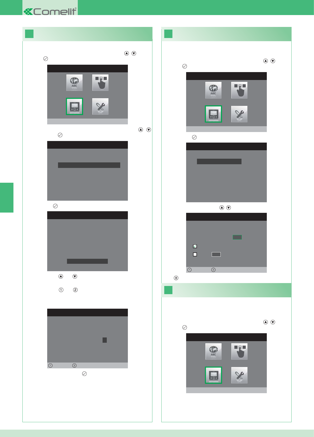
20
MENÜ INSTALLATEUR
Monitor konfigurieren
MONITOR KONFIGURIEREN
Reset Konfiguration
Netzart einstellen
Info
Grundplatte konfigurieren
Logische Adresse
PASSWORT KONFIGURIEREN
Links Rechts
Passwort Modem: 1 0 0 7
KONFIGURATION GRUNDPLATTE
ID: A
PWD: 0007
MAC: 00:0D:BE:00:2C:65
Passwort ändern
ADRESSE KONFIGURIEREN
Logische Adresse 0 2
Master
Slave 1 4
Links Rechts
22
21
MENÜ INSTALLATEUR
Monitor konfigurieren
MONITOR KONFIGURIEREN
Reset Konfiguration
Netzart einstellen
Info
Grundplatte konfigurieren
Logische Adresse
MENÜ INSTALLATEUR
Monitor konfigurieren
DE
64
1. Das Menü Installateur öffnen (siehe Punkt 19).
Konfi guration des Modem-Passworts
2. Das Menü Monitor konfi gurieren mit den Tasten , wählen
und mit öffnen.
3. Das Menü Grundplatte konfi gurieren mit den Tasten ,
wählen und mit öffnen.
4. Mit der Taste das Menü Passwort ändern öffnen.
5. Passwort ändern.
• Mit den Tasten und wird der ausgewählte Wert erhöht bzw.
verringert.
• Mit den Tasten und wird die Einfügemarke nach links bzw.
nach rechts bewegt.
6. Das geänderte Passwort mit bestätigen.
1. Das Menü Installateur öffnen (siehe Punkt 19).
Logische Adresse der
Hauptmonitoren (Master)
2. Das Menü Monitor konfi gurieren mit den Tasten , wählen
und mit öffnen.
3. Mit der Taste das Menü Logische Adresse öffnen.
4. Die Adresse mit den Tasten , ändern.
5. Mit beenden und Änderungen speichern.
Für jede logische Adresse nur 1 Hauptmonitor einstellen.
1. Das Menü Installateur öffnen (siehe Punkt 19).
Logische Adresse der
Zusatzmonitoren (Slave)
2. Das Menü Monitor konfi gurieren mit den Tasten , wählen
und mit öffnen.
Jeder Zusatzmonitor derselben Wohneinheit muss eine andere
Slave- Adresse haben
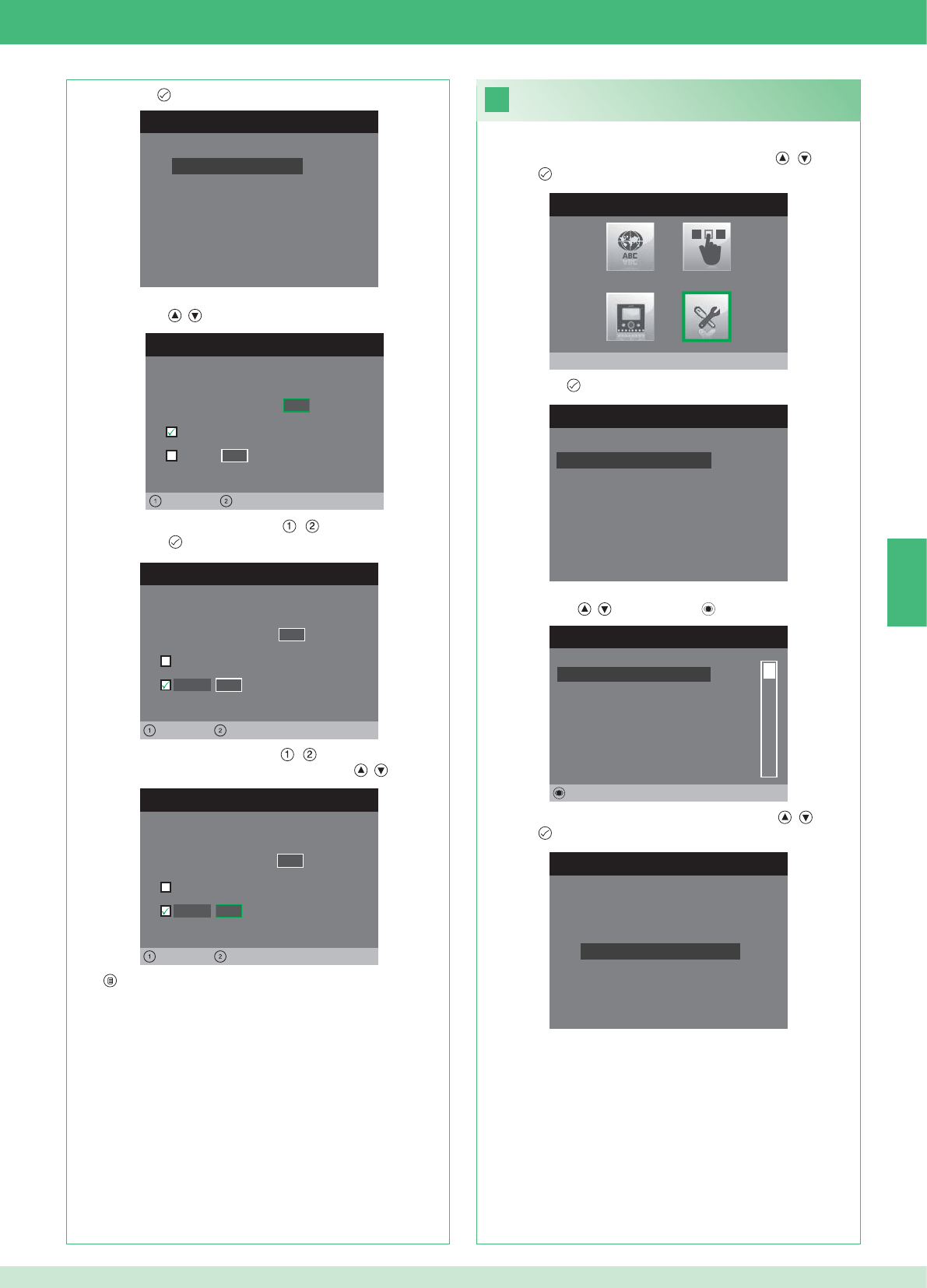
MONITOR KONFIGURIEREN
Reset Konfiguration
Netzart einstellen
Info
Grundplatte konfigurieren
Logische Adresse
ADRESSE KONFIGURIEREN
Logische Adresse 0 2
Master
Slave 1 4
Links Rechts
ADRESSE KONFIGURIEREN
Logische Adresse 0 2
Master
1 4
Links Rechts
Slave
ADRESSE KONFIGURIEREN
Logische Adresse 0 2
Master
1 0
Links Rechts
Slave
23
MENU INSTALLATORE
Spezialeinstellungen
MENÜ SPEZIALEINSTELLUNGEN
Automatische Antwort einstellen
Rufzeiten einstellen
Wiederholung Tonruf einstellen
Telefonbuch Intercom
INTERCOM TELEFONBUCH
SEKUNDÄR 1
PRIMÄR
ALLGEMEIN EXTERN
ALLGEMEIN INTERN
SEKUNDÄR 2
SEKUNDÄR 3
Ändern
INTERCOM KONFIGURIEREN
Adresse konfigurieren
Name konfigurieren
DE
65
1. Das Menü Installateur öffnen (siehe Punkt 19).
2. Das Menü Sondereinstellungen mit den Tasten , wählen
und mit öffnen.
3. Mit der Taste das Menü Telefonbuch Intercom öffnen.
4. Den Telefonbucheintrag, dessen Adresse bearbeitet werden soll,
mit den Tasten , wählen und mit öffnen.
5. Das Menü Adresse konfi gurieren mit den Tasten , wählen
und mit öffnen.
7. Mit beenden und Änderungen speichern.
Adressen im Telefonbuch Intercom
bearbeiten
3. Mit der Taste das Menü Logische Adresse öffnen.
4. Die logische Adresse des Hauptmonitors derselben Wohneinheit
mit den Tasten , eingeben.
5. Die Einfügemarke mit den Tasten , auf die Option Slave
setzen und mit bestätigen.
6. Die Einfügemarke mit den Tasten , auf die Option Slave-
Adresse setzen und die Adresse mit den Tasten , ändern
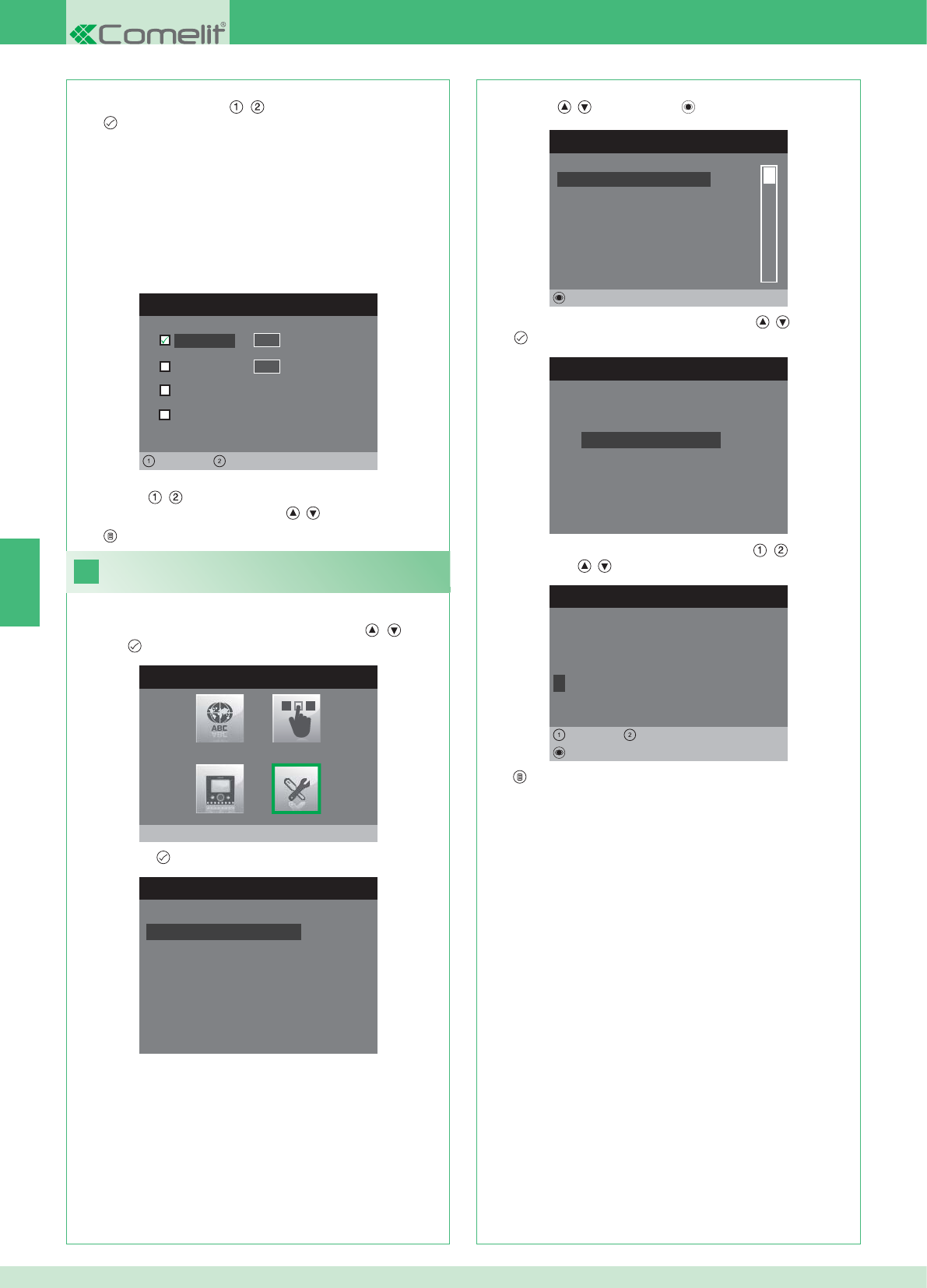
ADRESSE KONFIGURIEREN
Wohnung 0 1
Grundplatte
Allgemein extern
0 0
Links Rechts
Allgemein intern
24
MENU INSTALLATORE
Spezialeinstellungen
MENÜ SPEZIALEINSTELLUNGEN
Automatische Antwort einstellen
Rufzeiten einstellen
Wiederholung Tonruf einstellen
Telefonbuch Intercom
INTERCOM TELEFONBUCH
SEKUNDÄR 1
PRIMÄR
ALLGEMEIN EXTERN
ALLGEMEIN INTERN
SEKUNDÄR 2
SEKUNDÄR 3
Ändern
INTERCOM KONFIGURIEREN
Adresse konfigurieren
Name konfigurieren
NAME ÄNDERN
A L L G E M E I N I N T E R N
Name konfigurieren
Löschen
Links Rechts
8. Mit beenden und Änderungen speichern.
DE
66
WOHNUNG: Einen Ruf an alle Monitoren, sowohl Haupt- als
auch Zusatzgeräte, mit derselben eingegebenen logischen
Hauptadresse tätigen.
GRUNDPLATTE: Tätigt einen Ruf an den Monitor mit der
eingegebenen logischen Adresse derselben Wohnung, in dem
sich auch der anrufende Monitor befi ndet.
ALLGEMEIN INTERN: Tätigt einen Ruf an alle Monitoren derselben
Wohnung (nur Anlagen Set).
ALLGEMEIN EXTERN: Tätigt einen Ruf an alle Monitoren der
anderen Wohnung (nur Anlagen Set).
6. Die Rufart wählen, die dem Telefonbucheintrag zugewiesen werden
soll. Dazu mit den Tasten , durch die Rufarten scrollen und
mit bestätigen.
7. Bei den Rufarten Wohnungen und Grundplatte Einfügemarke mit
den Tasten , auf das jeweilige Feld Adresse setzen und die
gewünschte Adresse mit den Tasten , eingeben.
Namen im Telefonbuch Intercom bearbeiten
1. Das Menü Installateur öffnen (siehe Punkt 19).
2. Das Menü Sondereinstellungen mit den Tasten , wählen
und mit öffnen.
3. Mit der Taste das Menü Telefonbuch Intercom öffnen.
4. Den Telefonbucheintrag, dessen Name bearbeitet werden soll, mit
den Tasten , wählen und mit öffnen.
5. Das Menü Name konfi gurieren mit den Tasten , wählen und
mit öffnen.
6. Den gewünschten Buchstaben mit den Tasten , wählen und
mit den Tasten , ändern.
7. Mit beenden und Änderungen speichern.
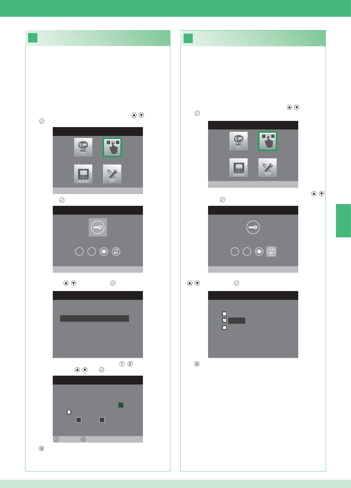
26
25
MENÜ INSTALLATEUR
Tasten konfigurieren
MENÜ TASTENKONFIGURATION
Schlüsseltaste konfigurieren
1 2
RELAIS KONFIGURIEREN
Konfiguration ohne Anruf
Konfiguration während Anruf
RELAIS WÄHREND ANRUF
Rufende Tür, Relais
Aktiv:
2
Aktiv:
Tür 1, Relais 2
Links Rechts
MENÜ TASTENKONFIGURATION
Privacy/Arzt konfigurieren
1 2
PRIVACY/ARZT KONFIGURIEREN
Funktion Arzt
Privacy
Funktion Arzt + Privacy
MENÜ INSTALLATEUR
Tasten konfigurieren
DE
67
• Die Funktion Privacy dient zum Stummschalten des Läutwerks
bei einem Ruf von der Außenstelle bzw. Internruf.
• Die Funktion Arztruf dient zur automatischen Betätigung des
Türöffners (Relais 1) bei einem Ruf von der Außenstelle.
• Die Funktion Arztruf + Privacy deaktiviert nicht nur das Läutwerk
der Innenstelle wie bei der Funktion Privacy, sondern aktiviert
auch die automatische Betätigung des Türöffners (Relais 1) bei
einem Ruf von der Außenstelle.
1. Das Menü Installateur öffnen (siehe Punkt 19).
2. Das Menü Tasten konfi gurieren mit den Tasten , wählen und
mit öffnen.
3. Das Menü Privacy / Arztruf konfi gurieren mit den Tasten ,
wählen und mit öffnen.
4. Die Funktion, die der Taste zugewiesen werden soll, mit den Tasten
, wählen und mit bestätigen.
5. Mit beenden und Änderungen speichern.
Taste Privacy / Arztruf konfi gurieren
Schlüsseltaste konfi gurieren
Das Set enthält 2 Relais (Relais 1 und Relais 2) pro angeschlossene
Außenstelle.
Deren Funktionsweise sowohl während eines Rufs als auch ohne
aktiven Ruf (Anlage in Standby) kann konfi guriert werden.
Mit jeder für die Ansteuerung der Relais konfi gurierten Taste können
maximal 2 Relais* gleichzeitig aktiviert werden.
Im Falle eines Anrufs ist eines der aktivierbaren Relais zwingend das
der anrufenden Tür.
• SCHLÜSSELTASTE
1. Das Menü Installateur öffnen (siehe Punkt 19).
2. Das Menü Tasten konfi gurieren mit den Tasten , wählen und
mit öffnen.
3. Mit der Taste das Menü Schlüsseltaste konfi gurieren öffnen.
4. Die Betriebsart, für die die Funktionsweise geändert werden soll,
mit den Tasten , wählen und mit bestätigen.
5. Die bearbeitbaren Felder mit den Tasten , wählen und den
Wert mit den Tasten , bzw. ändern.
6. Mit beenden und Änderungen speichern.
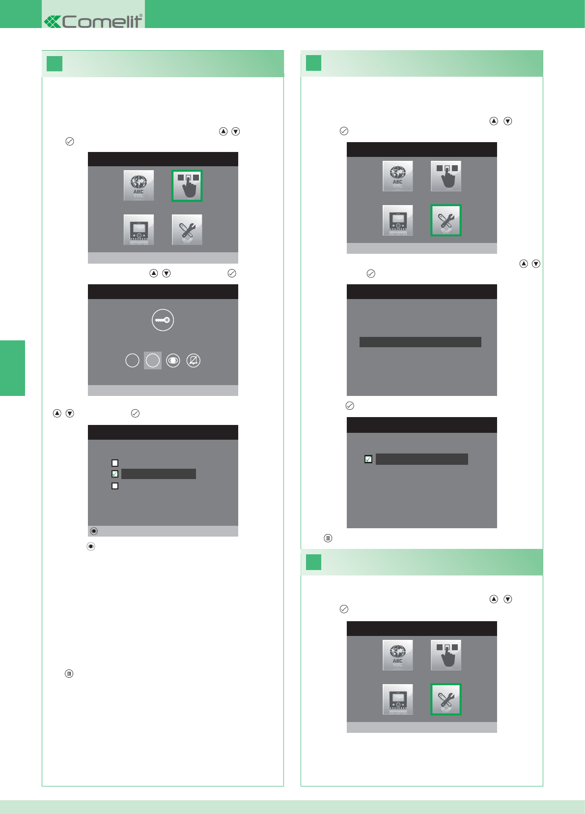
28
MENU INSTALLATORE
Spezialeinstellungen
MENÜ SPEZIALEINSTELLUNGEN
Wiederholung Tonruf einstellen
Telefonbuch Intercom
Automatische Antwort einstellen
Rufzeiten einstellen
29
27
WIEDERHOLUNG RUFTON EINSTEL.
Wiederholung Rufton
MENÜ TASTENKONFIGURATION
Taste 2 konfigurieren
1 2
TASTE 2 KONFIGURIEREN
Intercom
Selbsteinschaltung
Aktivierung Relais
Ändern
MENÜ INSTALLATEUR
Tasten konfigurieren
MENU INSTALLATORE
Spezialeinstellungen
DE
68
Ruftonwiederholung aktivieren
Wenn diese Funktion aktiviert ist, wiederholt der Monitor den Rufton
drei Mal nach Eingang eines Rufs.
1. Das Menü Installateur öffnen (siehe Punkt 19).
2. Das Menü Sondereinstellungen mit den Tasten , wählen
und mit öffnen
3. Das Menü Wiederholung Rufton einstellen mit den Tasten ,
wählen und mit öffnen.
4. Die Taste drücken, um die Funktion zu aktivieren:
Die Tasten 1 und 2 können alle auf die gleiche Weise programmiert
werden. Nachstehend wird die Programmierung von Taste 2
beschrieben.
1. Das Menü Installateur öffnen (siehe Punkt 19).
2. Das Menü Tasten konfi gurieren mit den Tasten , wählen und
mit öffnen.
3. Das Menü 2 mit den Tasten , wählen und mit öffnen.
4. Die Funktion, die der Taste zugewiesen werden soll, mit den Tasten
, wählen und mit bestätigen.
5. Die Taste drücken, um die gewählte Funktion zu konfi gurieren.
Wenn die Funktion Intercom gewählt wurde:
}Die Taste einer Innenstelle INTERCOM X zuweisen.
ALLGEMEIN INTERN: Tätigt einen Ruf an alle Monitoren derselben
Wohnung.
ALLGEMEIN EXTERN: Tätigt einen Ruf an alle Monitoren der
anderen Wohnung.
Wenn die Funktion Selbsteinschaltung gewählt wurde:
}Die Taste einer oder beiden Außenstellen zuweisen.
Wenn die Funktion Aktivierung Relais gewählt wurde:
}Genauso vorgehen, wie für die Konfi guration der Schlüsseltaste
beschrieben.
6. Mit beenden und Änderungen speichern.
5. Mit beenden und Änderungen speichern.
Aktivierung der automatischen
Rufbeantwortung
1. Das Menü Installateur öffnen (siehe Punkt 19).
2. Das Menü Sondereinstellungen mit den Tasten , wählen
und mit öffnen
Konfi guration Tasten 1 - 2
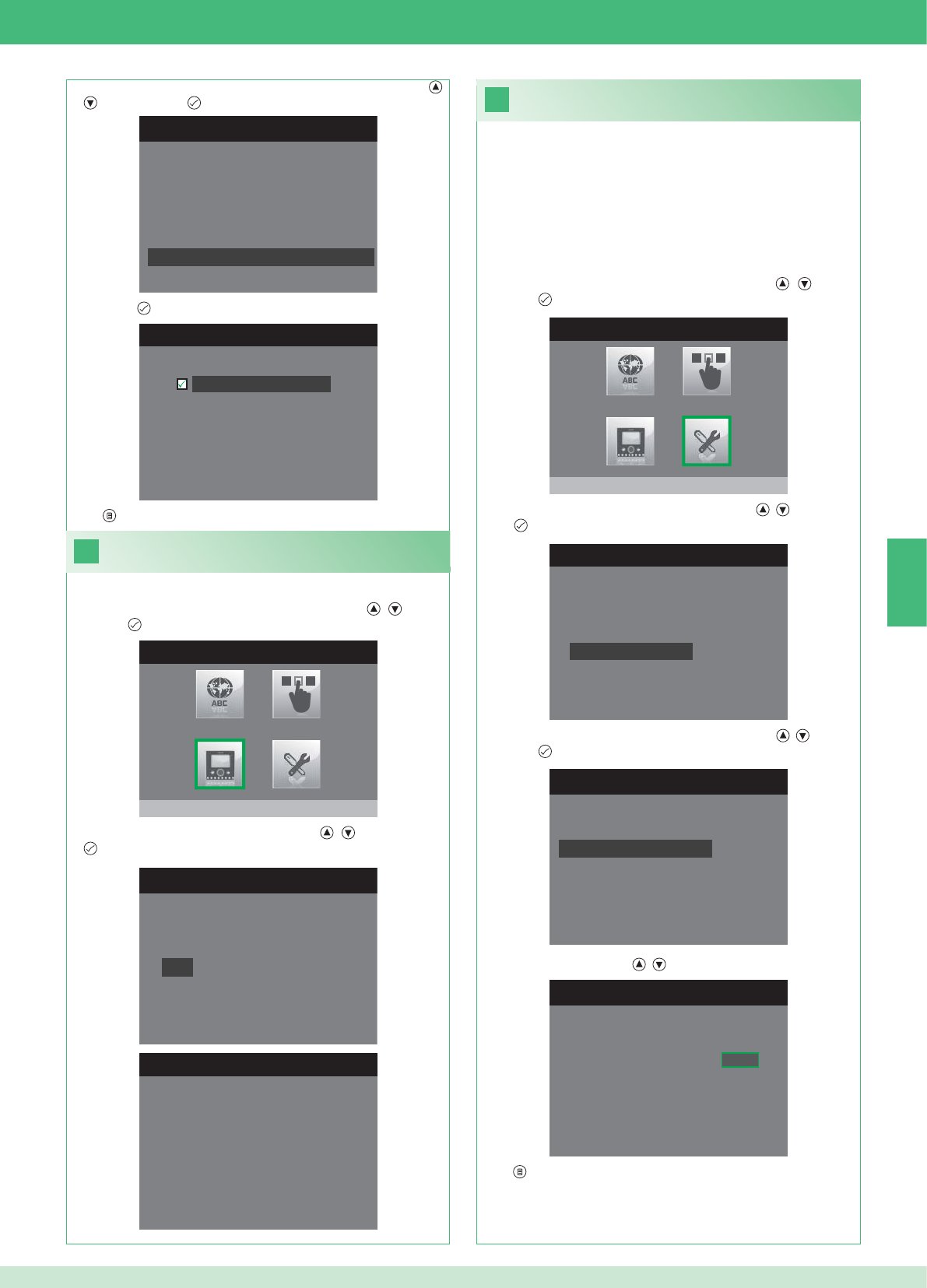
31
1. Das Menü Installateur öffnen (siehe Punkt 19).
MENÜ SPEZIALEINSTELLUNGEN
Wiederholung Tonruf einstellen
Telefonbuch Intercom
Automatische Antwort einstellen
Rufzeiten einstellen
RUFZEITEN EINSTELLEN
Gesprächsdauer
Wartezeit Antwort
Ausschaltverzögerung
Gesprächsdauer Intercom
WARTEZEIT ANTWORT EINSTELL.
Wartezeit Antwort 0 6 5
MENÜ SPEZIALEINSTELLUNGEN
Wiederholung Tonruf einstellen
Telefonbuch Intercom
Automatische Antwort einstellen
Rufzeiten einstellen
AUTOMATISCHE ANTWORT EINST.
Automatische Antwort
30
MONITOR KONFIGURIEREN
Reset Konfiguration
Netzart einstellen
Info
Grundplatte konfigurieren
Logische Adresse
MENÜ INFORMATIONEN
MAC: 00:25:29:02:01:BC
IP: 169.254.155.40
ID: 00000001, SUB: 0
SW: /trunck@3534
SYS: iPower
MENÜ INSTALLATEUR
Monitor konfigurieren
MENU INSTALLATORE
Spezialeinstellungen
DE
69
1. Das Menü Installateur öffnen (siehe Punkt 19).
Informationen anzeigen
2. Das Menü Monitor konfi gurieren mit den Tasten , wählen
und mit öffnen.
3. Das Menü Informationen mit den Tasten , wählen und mit
öffnen.
Konfi guration der Rufzeiten
In diesem Menü können folgende Einstellungen geändert werden:
• Wartezeit Antwort: max. Zeit, nach der die Verbindung unterbrochen
wird, wenn der Ruf nicht angenommen wird.
• Gesprächsdauer: Dauer eines Gesprächs zwischen Innen- und
Außenstelle.
• Gesprächsdauer Intercom: Dauer eines Interngesprächs.
• Ausschaltverzögerung: nach einem Ruf, Wartezeit ab Aktivierung
eines Relais bis zum Ausschalten des Monitors.
2. Das Menü Sondereinstellungen mit den Tasten , wählen
und mit öffnen
3. Das Menü Rufzeiten einstellen mit den Tasten , wählen und
mit öffnen.
4. Den Wert, der geändert werden soll, mit den Tasten , wählen
und mit öffnen.
5. Den Wert mit den Tasten , ändern.
6. Mit beenden und Änderungen speichern.
3. Das Menü Automatische Antwort einstellen mit den Tasten ,
wählen und mit öffnen.
4. Die Taste drücken, um die Funktion zu aktivieren:
5. Mit beenden und Änderungen speichern.
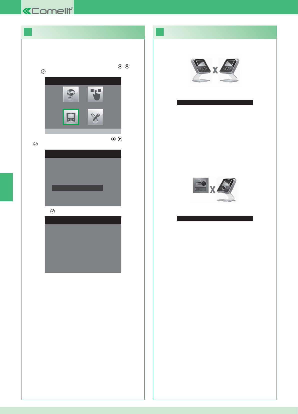
33
Kein Signal erfasst
Kein Signal erfasst
Keine Verbindung mit der Außenstelle.
32
MONITOR KONFIGURIEREN
Netzart einstellen
Info
Grundplatte konfigurieren
Logische Adresse
Reset Konfiguration
1. Das Menü Installateur öffnen (siehe Punkt 19).
RESET KONFIGURATION
Fortfahren?
MENÜ INSTALLATEUR
Monitor konfigurieren
DE
70
Betriebsstörungen und mögliche Abhilfe
Keine Verbindung mit der Innenstelle.
Abhilfe:
}1 Minute warten.
}Sicherstellen, dass der Zusatzmonitor dieselbe Adresse wie der
Hauptmonitor der fraglichen Wohneinheit hat (Punkt 22).
}Sicherstellen, dass der Hauptmonitor mit Strom versorgt wird
(Punkt 10).
}Sicherstellen, dass das korrekte Passwort eingegeben wurde
(Punkt 20).
}Sicherstellen, dass die Installationsabstände eingehalten wurden
(Punkt 8).
Abhilfe:
}1 Minute warten.
}Sicherstellen, dass die Außenstellen korrekt verdrahtet ist
(Punkt 2).
}Sicherstellen, dass die Außenstellen mit Strom versorgt wird
(Punkt 9).
}Sicherstellen, dass die Brücke Art. 1398 korrekt verdrahtet ist
(Punkt 7A, 7B, 7C).
}Sicherstellen, dass das Passwort der Brücke Art. 1398 und das
Monitor-Netzteil derselben Wohneinheit übereinstimmen.
}Sicherstellen, dass die Installationsabstände eingehalten wurden
(Punkt 8).
Achtung: Mit diesem Vorgang werden alle Werkseinstellungen
wieder hergestellt und alle vorgenommenen Änderungen rückgängig
gemacht.
Konfi guration zurücksetzen
2. Das Menü Monitor konfi gurieren mit den Tasten , wählen
und mit öffnen.
3. Das Menü Reset Konfi guration mit den Tasten , wählen und
mit öffnen.
4. Mit der Taste bestätigen.
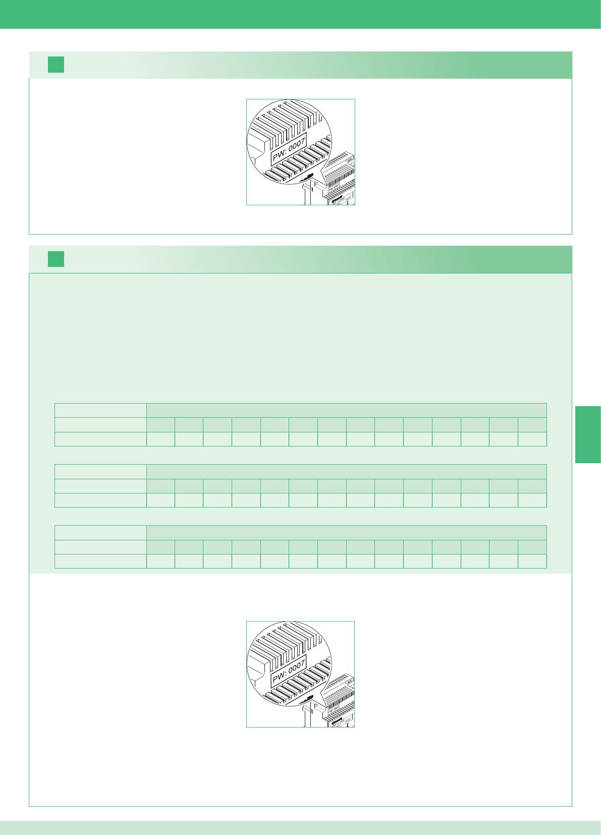
2 unidades externas Viviendas
1234567891011121314
Número de placas soporte 14 14 - - - - - - - - - - - - - - - - - - - - - - - -
16
17
ES
71
Es posible añadir monitores adicionales secundarios, distribuidos en las viviendas, respetando las dos reglas siguientes:
1. Instalar 14 placas soporte como máximo por vivienda.
2. Efectuar los siguientes cálculos para la distribución prevista de las placas soporte:
}calcular el número total de placas soporte que se han de montar en la instalación (tanto principales como secundarias) = A.
}determinar el número de placas soporte más bajo entre las viviendas = B
}calcular la diferencia entre el número total de placas de soporte de la instalación y las existentes en la vivienda que tiene menos (A - B) y
comprobar que el número obtenido sea:
Menor o igual a 15 para instalaciones con 1 unidad externa.
Menor o igual a 14 para instalaciones con 2 unidades externas.
A continuación se presenta un ejemplo de kit bifamiliar con 2 unidades externas y 14 monitores para 2 viviendas:
1 unidad externa Viviendas
1234567891011121314
Número de placas soporte 2 3 4 5 3 - - - - - - - - - - - - - - - - - -
A continuación se presenta un ejemplo de una instalación con 1 unidad externa y 17 monitores para 5 viviendas:
1 unidad externa Viviendas
1234567891011121314
Número de placas soporte 13 1 1 1 1 - - - - - - - - - - - - - - - - - -
A continuación se presenta un ejemplo de una confi guración no permitida, consistente en una instalación con 1 unidad externa y 17 monitores para 5 viviendas:
1. Anotar el código del módem, indicado en la etiqueta del puente art. 1398 de la vivienda implicada.
2. Confi gurar, en el monitor, el código del módem, determinado según se describe en el punto 20.
3. Confi gurar la dirección de los monitores adicionales secundarios según se describe en el punto 22
Advertencia
Procedimiento:
Kit multiusuarios: instalación de monitores adicionales secundarios
1. Anotar el código del módem, indicado en la etiqueta del puente art. 1398 de la vivienda implicada.
2. Confi gurar, en el monitor, el código del módem, determinado según se describe en el punto v.
3. Confi gurar la dirección del monitor principal según se describe en el punto 21
Multiusuarios: instalación de los monitores principales
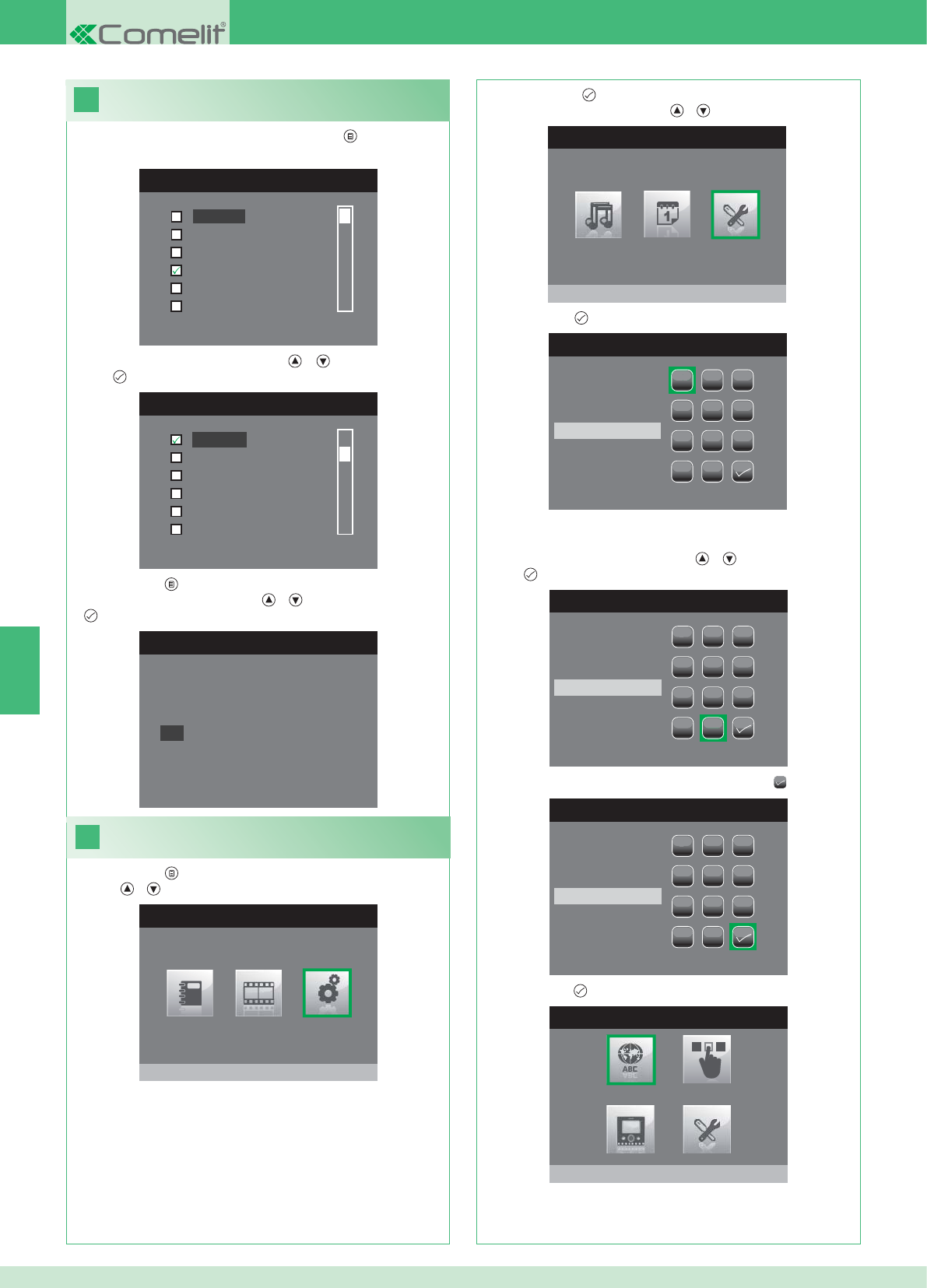
18
MENÚ IDIOMA
Italiano
English
Français
Español
Português
Deutsch
MENU LINGUE
Français
Español
Português
Deutsch
English
Italiano
19
MENÚ PRINCIPAL
Programaciones
MENÚ PROGRAMACIONES
Menú instalador
INTRODUCIR CONTRASEÑA
1
1
23
456
789
0
C
INTRODUCIR CONTRASEÑA
1
1
23
456
789
0
C
****
INTRODUCIR CONTRASEÑA
1
1
23
456
789
0
C
****
MENÚ INSTALADOR
Programa idioma
Italiano
NO
OK
ES
72
Confi guración del idioma de los menús
Cuando se accede al menú por primera vez (tecla ), se solicita que
se elija el idioma.
1. Seleccionar el idioma con las teclas y y confi rmarlo con la
tecla .
1. Pulsar la tecla y seleccionar el menú Programaciones con las
teclas y .
Acceder al menú instalador
2. Pulsar la tecla para confi rmar la selección y seleccionar el
menú Instalador con las teclas y .
3. Pulsar la tecla para confi rmar la selección.
4. Seleccionar las cifras con las teclas y y confi rmarlas con la
tecla .
5. Una vez escrita la contraseña, seleccionar la tecla .
La contraseña para acceder al menú del instalador es 0000. Esta
contraseña no se puede modifi car.
6. Pulsar la tecla para confi rmar.
2. Pulsar la tecla para salir.
3. Seleccionar "OK" con las teclas y y confi rmarlo con la tecla
.
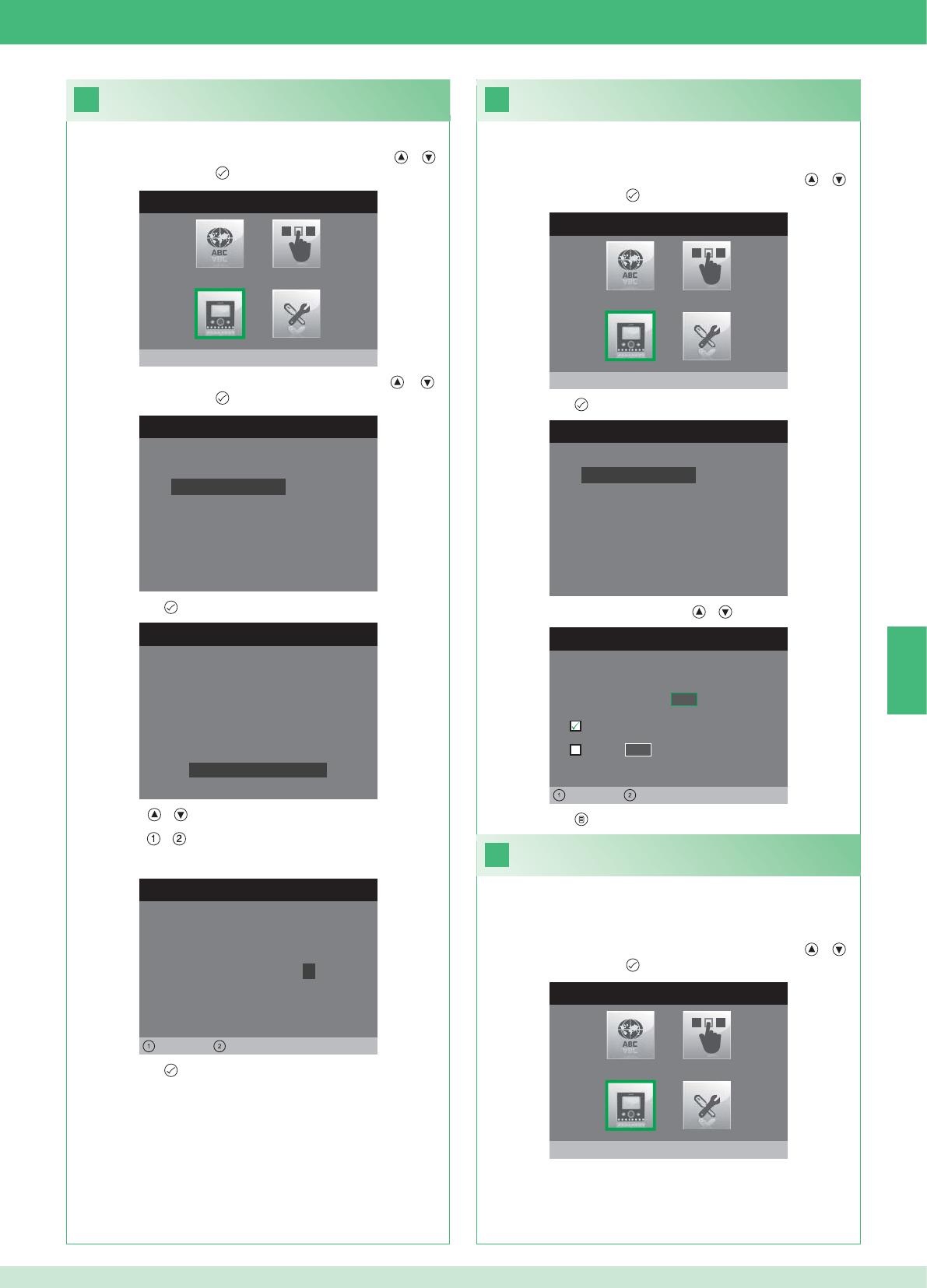
20
MENÚ INSTALADOR
Configura monitor
CONFIGURA MONITOR
Reajuste configuración
Programa tipo de red
Informaciones
Configura placa
Dirección lógica
CONFIGURA CONTRASEÑA
Izquierda Derecha
Módem contraseña: 1 0 0 7
CONFIGURACIÓN PLACA
ID: A
PWD: 0007
MAC: 00:0D:BE:00:2C:65
Cambia contraseña
CONFIGURA DIRECCIÓN
Dirección lógica 0 2
Master
Slave 1 4
Izquierda Derecha
22
21
CONFIGURA MONITOR
Reajuste configuración
Programa tipo de red
Informaciones
Configura placa
Dirección lógica
MENÚ INSTALADOR
Configura monitor
MENÚ INSTALADOR
Configura monitor
ES
73
1. Acceder al menú Instalador (véase punto 19).
Confi guración de la contraseña del módem
2. Seleccionar el menú Confi gura monitor con las teclas y y
confi rmarlo con la tecla .
3. Seleccionar el menú Confi gura placa con las teclas y y
confi rmarlo con la tecla .
4. Pulsar la tecla para acceder al menú Cambia contraseña.
5. Modifi car la contraseña.
• Las teclas y aumentan o disminuyen el valor seleccionado.
• Las teclas y desplazan a la izquierda o la derecha el cursor.
6. Pulsar la tecla para guardar la contraseña modifi cada.
1. Acceder al menú Instalador (véase punto 19).
Confi guración de la dirección lógica de los
monitores principales (master)
2. Seleccionar el menú Confi gura monitor con las teclas y y
confi rmarlo con la tecla .
3. Pulsar la tecla para acceder al menú Dirección lógica.
4. Modifi car la dirección con las teclas y .
5. Pulsar la tecla para salir y guardar las modifi caciones.
Confi gurar 1 solo monitor principal para cada dirección lógica.
1. Acceder al menú Instalador (véase punto 19).
Confi guración de la dirección lógica
de los monitores secundarios (slave)
2. Seleccionar el menú Confi gura monitor con las teclas y y
confi rmarlo con la tecla .
Todos los monitores secundarios de la misma vivienda han de tener
una Dirección Slave diferente.

CONFIGURA MONITOR
Reajuste configuración
Programa tipo de red
Informaciones
Configura placa
Dirección lógica
CONFIGURA DIRECCIÓN
Dirección lógica 0 2
Master
Slave 1 4
Izquierda Derecha
CONFIGURA DIRECCIÓN
Dirección lógica 0 2
Master
1 4
Izquierda Derecha
Slave
CONFIGURA DIRECCIÓN
Dirección lógica 0 2
Master
1 0
Izquierda Derecha
Slave
23
MENÚ INSTALADOR
Programaciones Especiales
MENÚ PROGRAMACIONES ESPEC.
Programa respuesta automática
Programa tiempos de llamada
Programa repetición timbre
Directorio intercomunicante
DIRECTORIO LLAMADAS INTERCOM
SECUNDARIA 1
PRINCIPAL
GENERAL EXTERNA
GENERAL INTERNA
SECUNDARIA 2
SECUNDARIA 3
Modificar
CONFIGURA INTERCOMUNICANTE
Configura dirección
Configura nombre
ES
74
1. Acceder al menú Instalador (véase punto 19).
2. Seleccionar el menú Programaciones Especiales con las teclas
y y confi rmarlo con la tecla .
3. Pulsar la tecla para acceder al menú Directorio
intercomunicante.
4. Seleccionar el registro de la agenda cuya dirección se desea
modifi car con las teclas y y confi rmarlo con la tecla
5. Seleccionar el menú Confi gura dirección con las teclas y y
confi rmarlo con la tecla .
7. Pulsar la tecla para salir y guardar las modifi caciones.
Modifi cación de las direcciones del
directorio intercomunicante
3. Pulsar la tecla para acceder al menú Dirección lógica.
4. Confi gurar la dirección lógica del monitor principal de la misma
vivienda con las teclas y .
5. Ir a la opción Slave con las teclas y y confi rmarla con la
tecla .
6. Ir a la opción Dirección Slave con las teclas y y modifi carla
con las teclas y .
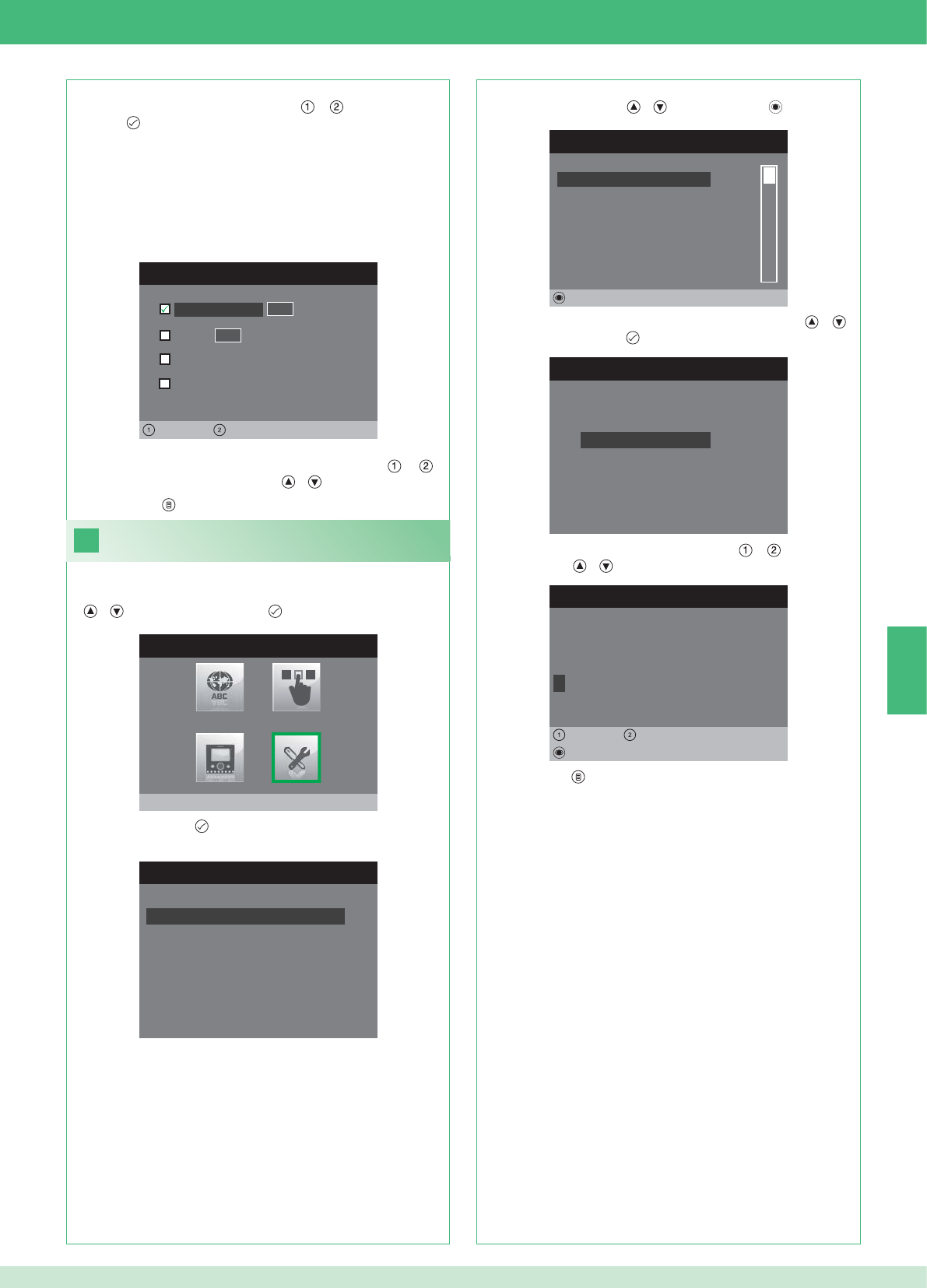
CONFIGURA DIRECCIÓN
Vivienda 0 1
Placa soporte
General externa
0 0
Izquierda Derecha
General interna
24
CONFIGURA INTERCOMUNICANTE
Configura dirección
Configura nombre
MODIFICA VOZ
G E N E R A L I N T E R N A
Configura nombre
Borrar
Izquierda Derecha
8. Pulsar la tecla para salir y guardar las modifi caciones.
MENÚ INSTALADOR
Programaciones Especiales
MENÚ PROGRAMACIONES ESPEC.
Programa respuesta automática
Programa tiempos de llamada
Programa repetición timbre
Directorio intercomunicante
DIRECTORIO LLAMADAS INTERCOM
SECUNDARIA 1
PRINCIPAL
GENERAL EXTERNA
GENERAL INTERNA
SECUNDARIA 2
SECUNDARIA 3
Modificar
ES
75
VIVIENDA: envía una llamada a todos los monitores, principales y
secundarios, con la misma dirección lógica principal.
PLACA SOPORTE: envía una llamada al monitor con la dirección
lógica de la misma vivienda del monitor que llama.
GENERAL INTERNA: envía una llamada a todos los monitores de la
misma vivienda (solo para instalaciones con kit).
GENERAL EXTERNA: envía una llamada a todos los monitores de
otra vivienda (solo para instalaciones con kit).
6. Seleccionar qué tipo de llamada se desea asociar al registro de la
agenda desplazándose con las teclas y y confi rmarlo con
la tecla .
7. En el caso de llamadas de tipo Vivienda y Placa soporte, ir
al correspondiente campo Dirección con las teclas y e
introducir la deseada con las teclas y .
Modifi cación de los nombres del directorio
intercomunicante
1. Acceder al menú Instalador (véase punto 19).
2. Seleccionar el menú Programaciones Especiales con las teclas
y y confi rmarlo con la tecla .
3. Pulsar la tecla para acceder al menú Directorio
intercomunicante.
4. Seleccionar el registro de la agenda cuyo nombre se desea
modifi car con las teclas y y confi rmarlo con .
5. Seleccionar el menú Confi gura Nombre con las teclas y y
confi rmarlo con la tecla .
6. Seleccionar la letra deseada con las teclas y y modifi carla
con las teclas y .
7. Pulsar la tecla para salir y guardar las modifi caciones.
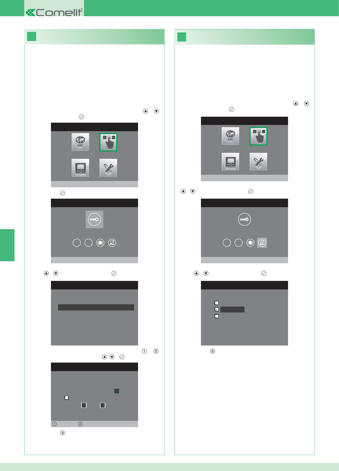
26
25
MENÚ INSTALADOR
Configura teclas
MENÚ CONFIGURACIÓN TECLAS
Configura tecla llave
1 2
CONFIGURA RELÉ
Configurac. en ausencia llamada
Configuración durante llamada
RELÉ DURANTE LLAMADA
Puerta llamante, relé
Activa:
2
Activa:
Puerta 1, relé 2
Izquierda Derecha
MENÚ CONFIGURACIÓN TECLAS
Configura privacidad/doctor
1 2
CONFIGURA PRIVACIDAD/DOCTOR
Función doctor
Privacidad
Función doctor + privacidad
MENÚ INSTALADOR
Configura teclas
ES
76
• La función Privacidad permite excluir el tono de llamada desde la
unidad externa o intercomunicante.
• La función Doctor permite accionar automáticamente el
abrepuertas (relé 1) tras una llamada desde la unidad externa.
• La función Privacidad + Doctor, además de desactivar el tono
de llamada en la unidad interna, como en la función Privacidad,
permite accionar automáticamente el abrepuertas (relé 1) tras
una llamada desde la unidad externa.
1. Acceder al menú Instalador (véase punto 19).
2. Seleccionar el menú Confi gura teclas con las teclas y y
confi rmarlo con la tecla .
3. Seleccionar el menú Confi gura privacidad/doctor con las teclas
y y confi rmarlo con la tecla .
4. Seleccionar la función que se desea asignar a la tecla con las
teclas y y confi rmarla con la tecla .
5. Pulsar la tecla para salir y guardar las modifi caciones.
Confi guración de la tecla Privacidad/Doctor
Confi guración de la tecla llave
El kit dispone de 2 relés (relé 1 y relé 2) para cada unidad externa
conectada.
Es posible confi gurar el funcionamiento cuando no hay ninguna
llamada en curso (instalación en reposo) o durante una llamada.
Con cada tecla confi gurada para mandar los relés, es posible activar
al mismo tiempo 2 relés* como máximo.
En caso de llamada, uno de los relés activables tiene que ser
obligatoriamente el relé de la puerta desde la que se llama.
• TECLA LLAVE
1. Acceder al menú Instalador (véase punto 19).
2. Seleccionar el menú Confi gura teclas con las teclas y y
confi rmarlo con la tecla .
3. Pulsar la tecla para acceder al menú Confi gura tecla llave.
4. Seleccionar la modalidad cuya función se desea modifi car con las
teclas y y confi rmarla con la tecla .
5. Seleccionar los campos modifi cables con las teclas y y
modifi car los valores con las teclas , o .
6. Pulsar la tecla para salir y guardar las modifi caciones.
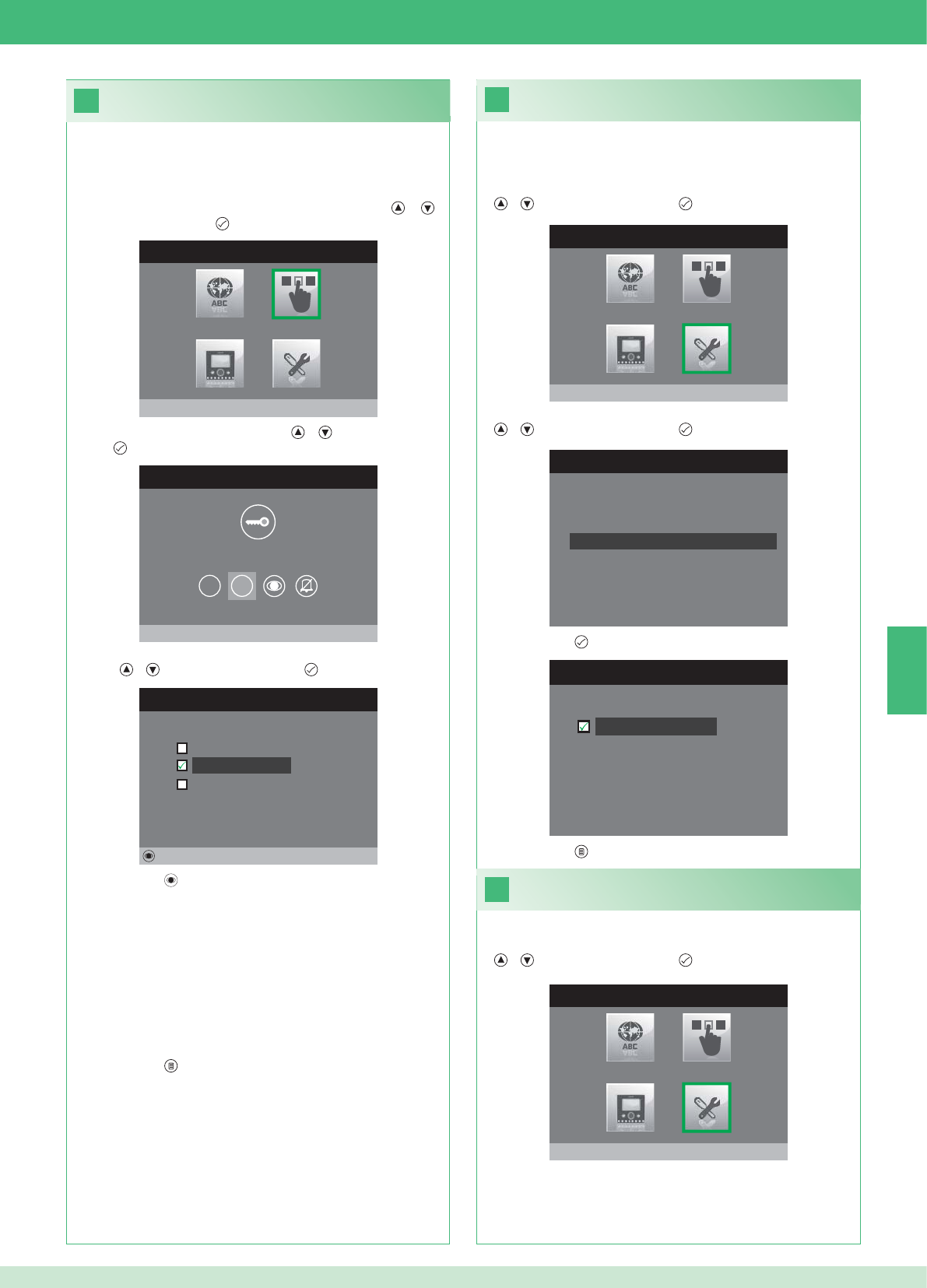
28
MENÚ INSTALADOR
Programaciones Especiales
MENÚ PROGRAMACIONES ESPEC.
Programa repetición timbre
Directorio intercomunicante
Programa respuesta automática
Programa tiempos de llamada
29
27
PROGRAMA REPETICIÓN TIMBRE
Repetición timbre
MENÚ CONFIGURACIÓN TECLAS
Configura tecla 2
1 2
CONFIGURA TECLA 2
Intercomunicante
Autoencendido
Activación relé
Modificar
MENÚ INSTALADOR
Configura teclas
MENÚ INSTALADOR
Programaciones Especiales
ES
77
Activación de la repetición del timbre
Si esta función está activada, el timbre se repite tres veces cuando
se produce una llamada.
1. Acceder al menú Instalador (véase punto 19).
2. Seleccionar el menú Programaciones Especiales con las teclas
y y confi rmarlo con la tecla .
3. Seleccionar el menú Programa repetición timbre con las teclas
y y confi rmarlo con la tecla .
4. Pulsar la tecla para activar la función.
Las teclas 1 y 2 se pueden programar con el mismo procedimiento. A
continuación, se describe cómo programar la tecla 2.
1. Acceder al menú Instalador (véase punto 19).
2. Seleccionar el menú Confi gura teclas con las teclas y y
confi rmarlo con la tecla .
3. Seleccionar el menú 2 con las teclas y y confi rmarlo con la
tecla .
4. Seleccionar la función que se desea asignar a la tecla con las
teclas y y confi rmarla con la tecla .
5. Pulsar la tecla para activar la función elegida
Si se ha seleccionado la función Intercomunicante:
}Asociar la tecla a una unidad interna INTERCOM X.
GENERAL INTERNA: envía una llamada a todos los monitores de
la misma vivienda.
GENERAL EXTERNA: envía una llamada a todos los monitores de
otra vivienda.
Si se ha seleccionado la función Autoencendido:
}Asociar la tecla a una o ambas unidades externas.
Si se ha seleccionado la función Activación relé:
}Seguir el procedimiento para confi gurar la tecla llave.
6. Pulsar la tecla para salir y guardar las modifi caciones.
5. Pulsar la tecla para salir y guardar las modifi caciones.
Activación de la respuesta automática
1. Acceder al menú Instalador (véase punto 19).
2. Seleccionar el menú Programaciones Especiales con las teclas
y y confi rmarlo con la tecla .
Confi guración de las teclas 1 y 2
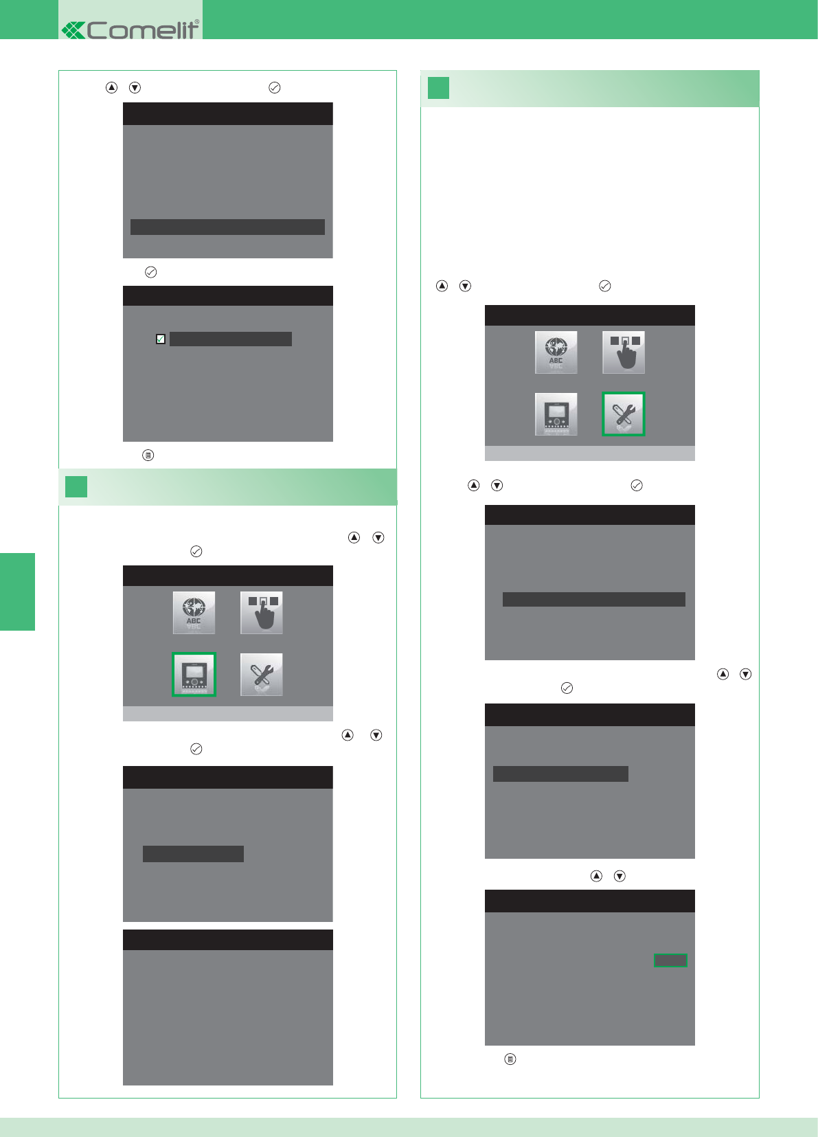
31
MENÚ INSTALADOR
Programaciones Especiales
1. Acceder al menú Instalador (véase punto 19).
MENÚ PROGRAMACIONES ESPEC.
Programa repetición timbre
Directorio intercomunicante
Programa respuesta automática
Programa tiempos de llamada
PROGRAMA TIEMPOS LLAMADA
Tiempo conversación
Tiempo espera respuesta
Retraso de apagado
Tiempo conversación intercom
PROGRAMA TIEMPO ESPERA RESP.
Tiempo espera respuesta 0 6 5
MENÚ PROGRAMACIONES ESPEC.
Programa repetición timbre
Directorio intercomunicante
Programa respuesta automática
Programa tiempos de llamada
PROGRAMA RESP. AUTOMÁTICA
Respuesta automática
30
MENÚ INSTALADOR
Configura monitor
CONFIGURA MONITOR
Reajuste configuración
Programa tipo de red
Informaciones
Configura placa
Dirección lógica
MENÚ INFORMACIONES
MAC: 00:25:29:02:01:BC
IP: 169.254.155.40
ID: 00000001, SUB: 0
SW: /trunck@3534
SYS: iPower
ES
78
1. Acceder al menú Instalador (véase punto 19).
Visualizar informaciones
2. Seleccionar el menú Confi gura monitor con las teclas y y
confi rmarlo con la tecla .
3. Seleccionar el menú Informaciones con las teclas y y
confi rmarlo con la tecla .
Confi guración de los tiempos de llamada
En este menú es posible modifi car:
• Tiempo espera respuesta: tiempo máximo de espera de
una respuesta cuya superación implica la interrupción de la
comunicación.
• Tiempo conversación: duración de una conversación entre la unidad
interna y la unidad externa
• Tiempo conversación intercom: duración de una conversación
intercomunicante
• Retraso de apagado: tras una llamada, tiempo de espera desde la
activación de un relé hasta el apagado del monitor.
2. Seleccionar el menú Programaciones Especiales con las teclas
y y confi rmarlo con la tecla .
3. Seleccionar el menú Programa tiempos de llamada con las
teclas y y confi rmarlo con la tecla .
4. Seleccionar el valor que se desea modifi car con las teclas y
y confi rmarlo con la tecla .
5. Modifi car el valor con las teclas y .
6. Pulsar la tecla para salir y guardar las modifi caciones.
3. Seleccionar el menú Programa respuesta automática con las
teclas y y confi rmarlo con la tecla .
4. Pulsar la tecla para activar la función.
5. Pulsar la tecla para salir y guardar las modifi caciones.
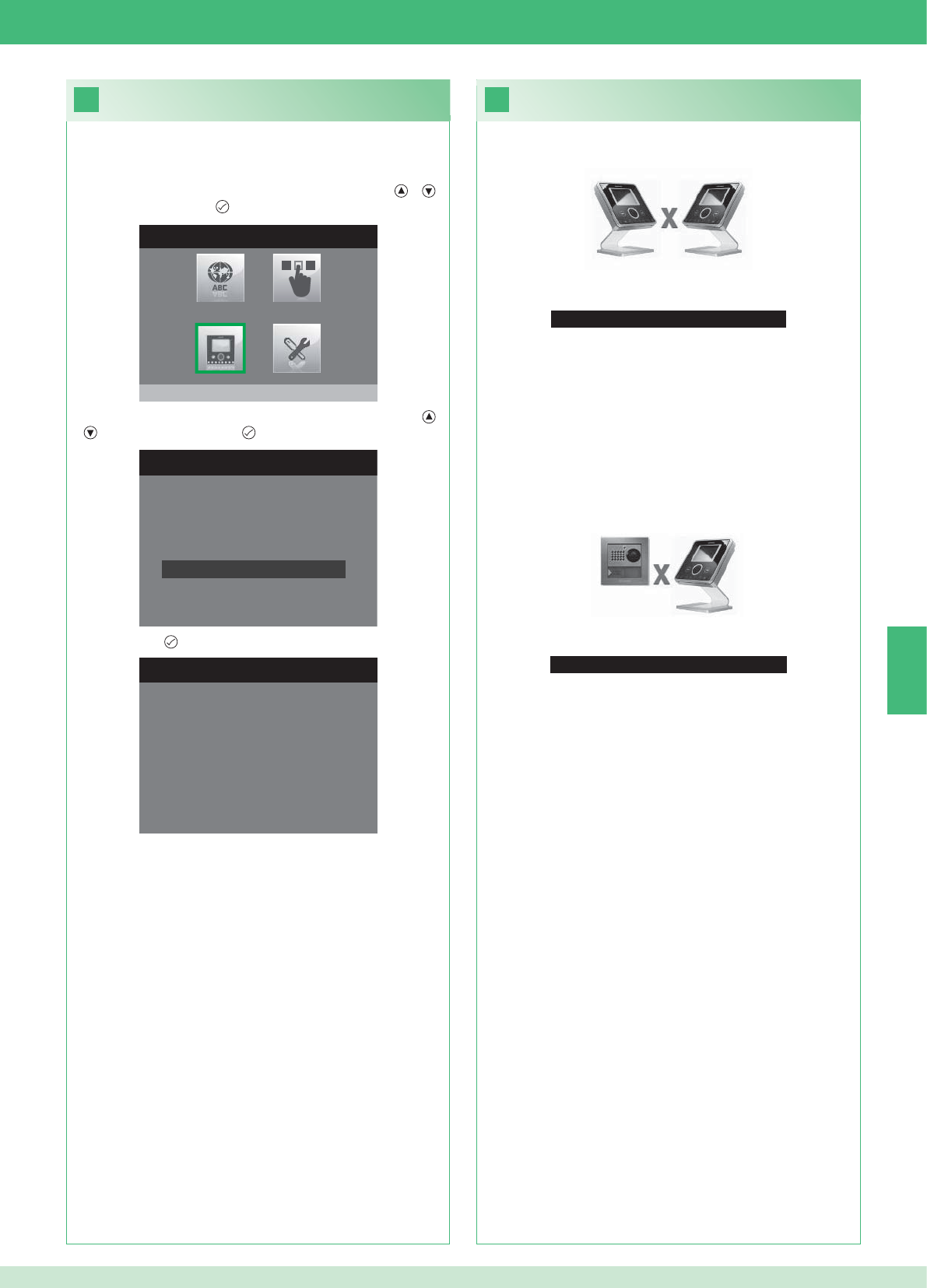
33
Ninguna señal detectada
Ninguna señal detectada
No se produce la conexión con la unidad externa.
32
CONFIGURA MONITOR
Programa tipo de red
Informaciones
Configura placa
Dirección lógica
Reajuste configuración
1. Acceder al menú Instalador (véase punto 19).
RESET CONFIGURACIÓN
¿Continuar?
MENÚ INSTALADOR
Configura monitor
ES
79
Anomalías y soluciones
No se produce la conexión con la unidad interna.
Soluciones:
}Esperar a que transcurra un minuto.
}Comprobar que el monitor secundario tenga la misma dirección
que el monitor principal de la vivienda en cuestión (punto 22).
}Comprobar que el monitor principal esté alimentado (punto 10).
}Comprobar que se haya introducido la contraseña correcta
(punto 20).
}Comprobar que se respeten las distancias de instalación (punto 8).
Soluciones:
}Esperar a que transcurra un minuto.
}Comprobar que la unidad externa esté correctamente cableada
(punto 2).
}Comprobar que la unidad externa esté correctamente alimentada
(punto 9).
}Comprobar que el puente art. 1398 esté correctamente cableado
(puntos 7A, 7B o 7C).
}Comprobar que la contraseña del puente art. 1398 sea igual a la
del alimentador del monitor de la misma vivienda.
}Comprobar que se respeten las distancias de instalación (punto 8).
Atención: esta operación restablece todas las programaciones de
fábrica y anula todas las modifi caciones efectuadas por el usuario.
Reset confi guración
2. Seleccionar el menú Confi gura monitor con las teclas y y
confi rmarlo con la tecla .
3. Seleccionar el menú Reajuste confi guración con las teclas y
y confi rmarlo con la tecla .
4. Pulsar la tecla para confi rmar.
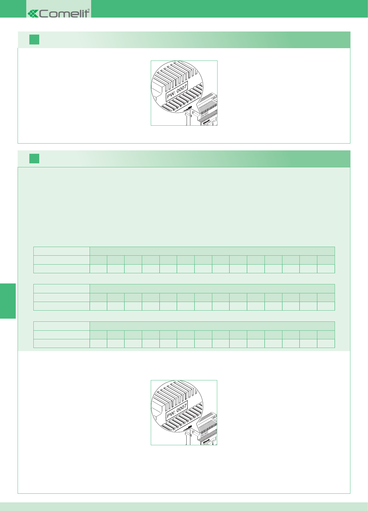
2 pontos externos Unidades habitacionais
1234567891011121314
Número de suportes 14 14 - - - - - - - - - - - - - - - - - - - - - - - -
PT
16
17
80
Pode adicionar-se monitores adicionais secundários distribuídos pelas unidades habitacionais, seguindo as seguintes 2 regras:
1. Introduzir no máximo 14 suportes por unidade habitacional.
2. Realizar os seguintes cálculos relativamente à distribuição prevista para os suportes:
}calcular o número total de suportes a instalar na instalação (quer principais, quer secundárias) = A.
}identifi car o número de suportes inferior entre as unidades habitacionais = B
}calcular a diferença entre o número total de suportes da instalação e as presentes na unidade habitacional que tem o número inferior (A - B)
e certifi car-se de que o número obtido seja:
menor ou igual a 15 para instalações com 1 ponto externo;
menor ou igual a 14 para instalações com 2 pontos externos.
A seguir indica-se o exemplo de um Kit bifamiliar com 2 pontos externos e 14 monitores para 2 unidades habitacionais:
1 ponto externo Unidades habitacionais
1234567891011121314
Número de suportes 2 3 4 5 3 - - - - - - - - - - - - - - - - - -
A seguir indica-se o exemplo de uma instalação com 1 ponto externo e 17 monitores para 5 unidades habitacionais:
1 ponto externo Unidades habitacionais
1234567891011121314
Número de suportes 13 1 1 1 1 - - - - - - - - - - - - - - - - - -
A seguir indica-se o exemplo de uma confi guração não possível de uma instalação com 1 ponto externo e 17 monitores para 5 unidades habitacionais:
1. Tomar nota da password do modem que se encontra na etiqueta da ponte art. 1398 da unidade habitacional de interesse.
2. Confi gurar no monitor a password do modem obtida como descrito no ponto 20.
3. Confi gurar o endereço dos monitores adicionais como descrito no ponto 22.
Aviso!
Procedimento:
Kit e multiutilizadores: instalação de monitores adicionais secundários
1. Tomar nota da password do modem que se encontra na etiqueta da ponte art. 1398 da unidade habitacional de interesse.
2. Confi gurar no monitor a password do modem obtida como descrito no ponto v.
3. Confi gurar o endereço do monitor principal como descrito no ponto 21.
Multiutilizadores: instalação dos monitores principais
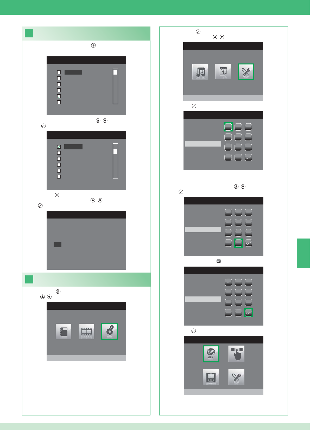
PT
18
MENU IDIOMA
Italiano
English
Français
Español
Português
Deutsch
MENU LINGUE
Français
Español
Português
Deutsch
English
Italiano
19
MENU PRINCIPAL
Configurações
MENU CONFIGURAÇÕES
Menu instalador
INSERIR PASSWORD
1
1
23
456
789
0
C
INSERIR PASSWORD
1
1
23
456
789
0
C
****
INSERIR PASSWORD
1
1
23
456
789
0
C
****
MENU INSTALADOR
Configura idioma
Italiano
NO
OK
81
Confi gurar o idioma do menu
No primeiro acesso ao menu (tecla ), é solicitada ao utilizador a
confi guração do idioma de utilização.
1. Seleccionar o idioma com as teclas , e confi rmar premindo
a tecla .
1. Premir a tecla e seleccionar o menu Confi gurações com as
teclas , .
Aceder ao menu instalador
2. Premir a tecla para aceder e seleccionar o menu Menu
instalador com as teclas , .
3. Premir a tecla para aceder.
4. Seleccionar os dígitos com as teclas , e confi rmar premindo
a tecla .
5. No fi m, seleccionar o ícone .
A password para o menu instalador é 0000. Não é possível
modifi car a password.
6. Premir a tecla para confi rmar.
2. Premir a tecla para sair.
3. Seleccionar "OK" com as teclas , e confi rmar premindo a
tecla .
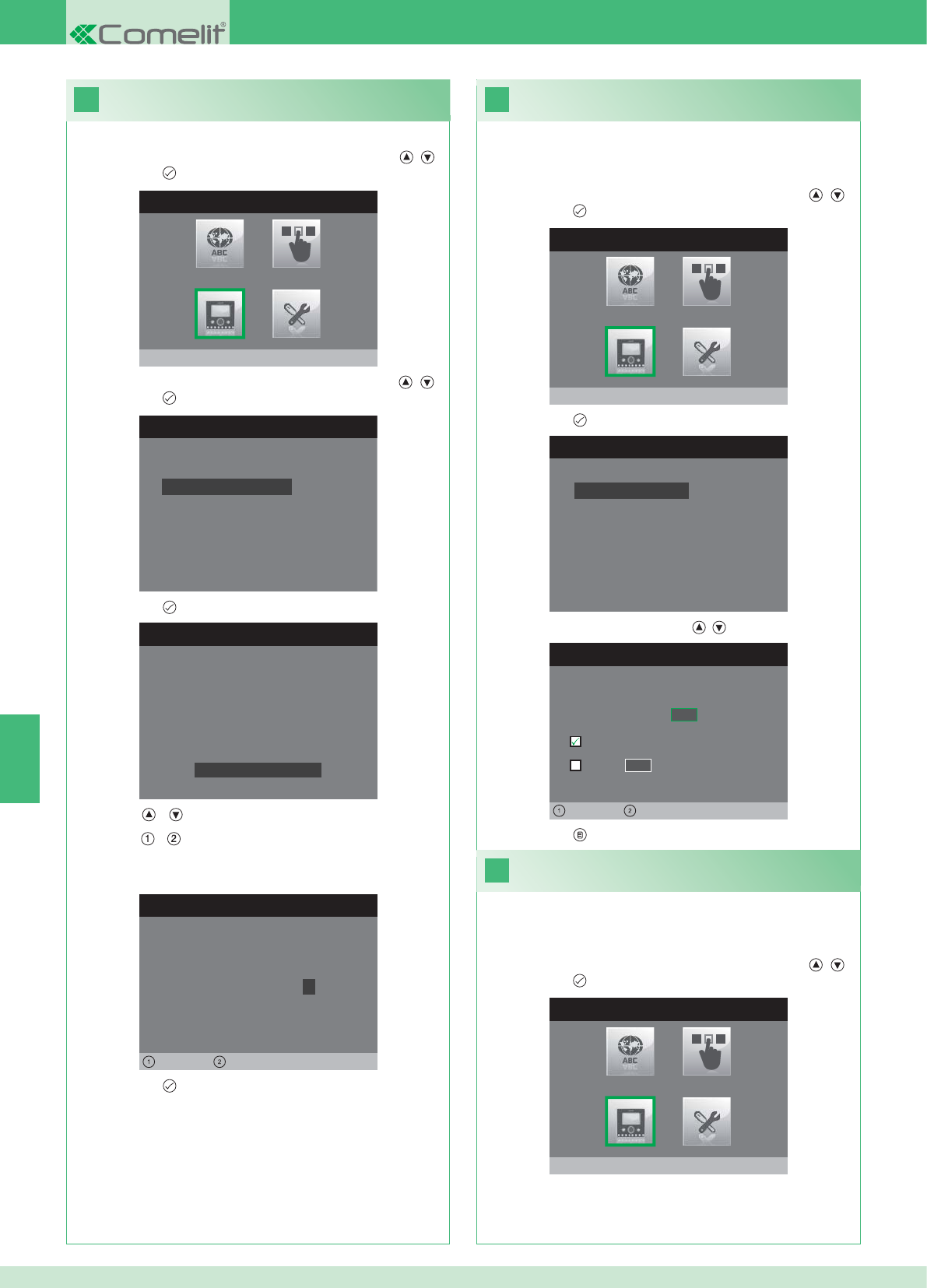
20
MENU INSTALADOR
Configura monitor
CONFIGURA MONITOR
Zerar configuração
Configuração do tipo de rede
Informações
Configura suporte
Endereço lógico
CONFIGURA PASSWORD
Esquerda Direita
Modem password: 1 0 0 7
CONFIGURAÇÃO SUPORTE
ID: A
PWD: 0007
MAC: 00:0D:BE:00:2C:65
Trocar password
CONFIGURA ENDEREÇO
Endereço lógico 0 2
Master
Slave 1 4
Esquerda Direita
22
21
CONFIGURA MONITOR
Zerar configuração
Configuração do tipo de rede
Informações
Configura suporte
Endereço lógico
MENU INSTALADOR
Configura monitor
MENU INSTALADOR
Configura monitor
PT
82
1. Aceder ao menu Instalador (Consultar o ponto 19).
Confi gurar a password do modem
2. Seleccionar o menu Confi gurar Monitor com as teclas , e
premir a tecla para aceder
3. Seleccionar o menu Confi gura suporte com as teclas , e
premir a tecla para aceder.
4. Premir a tecla per aceder ao menu Trocar Password.
5. Modifi car a password
• As teclas e aumentam e diminuem o valor seleccionado.
• As teclas e deslocam o cursor de selecção para a esquerda
e direita.
6. Premir a tecla para guardar a password modifi cada.
1. Aceder ao menu Instalador (Consultar o ponto 19).
Confi gurar endereço lógico do
monitor principal (master)
2. Seleccionar o menu Confi gura Monitor com as teclas , e
premir a tecla para aceder.
3. Premir a tecla para aceder ao menu Endereço lógico.
4. Modifi car o endereço com as teclas , .
5. Premir a tecla para sair e guardar as modifi cações.
Confi gurar apenas 1 monitor principal para cada endereço
lógico.
1. Aceder ao menu Instalador (Consultar o ponto 19).
Confi gurar endereço lógico
monitores secundários (slave)
2. Seleccionar o menu Confi gura Monitor com as teclas , e
premir a tecla para aceder.
Cada monitor secundário da mesma unidade habitacional deve ter
um Endereço Slave diferente.
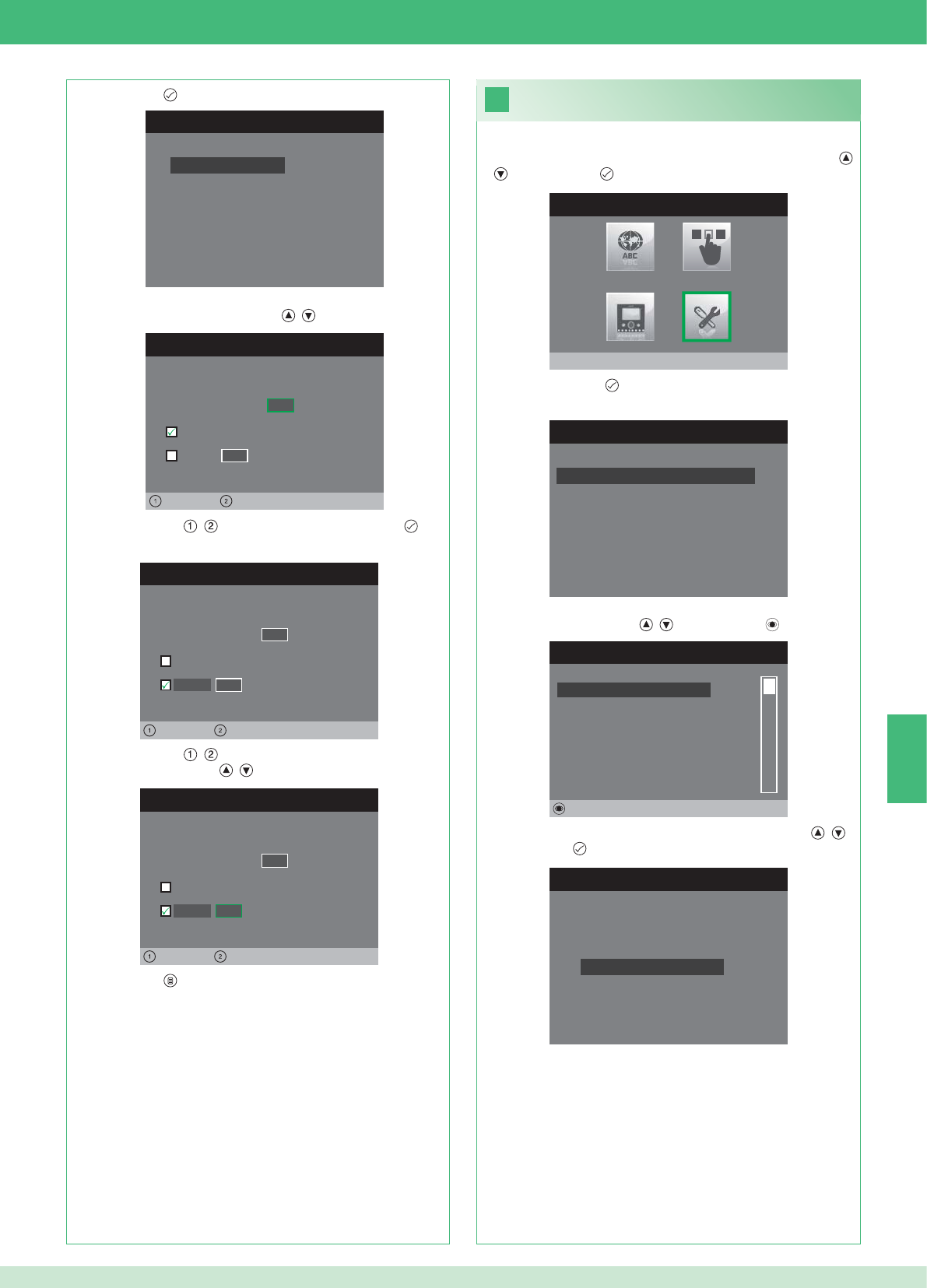
CONFIGURA ENDEREÇO
Endereço lógico 0 2
Master
Slave 1 4
Esquerda Direita
CONFIGURA ENDEREÇO
Endereço lógico 0 2
Master
1 4
Sinistra Direita
Slave
CONFIGURA ENDEREÇO
Endereço lógico 0 2
Master
1 0
Esquerda Direita
Slave
23
MENU INSTALADOR
Configurações Especiais
MENU CONFIGURAÇÕES ESPECIAIS
Config.resposta automática
Programa tempos chamada
Configura repetição toque
Directório Intercomunicante
DIRECTÓRIO CHAMADAS INTERCOM
SECUNDÁRIO 1
PRINCIPAL
GERAL EXTERNA
GERAL INTERNA
SECUNDÁRIO 2
SECUNDÁRIO 3
Alterar
CONFIGURA INTERCOMUNICANTE
Configura endereço
Configura Nome
CONFIGURA MONITOR
Zerar configuração
Configuração do tipo de rede
Informações
Configura suporte
Endereço lógico
PT
83
1. Aceder ao menu Instalador (Consultar o ponto 19).
2. Seleccionar o menu Confi gurações especiais com as teclas ,
e premir a tecla para aceder.
3. Premir a tecla para aceder ao menu Directório
Intercomunicante.
4. Seleccionar o item do directório para o qual se deseja modifi car
o endereço com as teclas , e premir a tecla para aceder.
5. Seleccionar o menu Confi gura endereço com as teclas , e
premir a tecla para aceder.
7. Premir a tecla para sair e guardar as modifi cações.
Modifi car endereços do directório
intercomunicante
3. Premir a tecla para aceder ao menu Endereço lógico.
4. Confi gurar o endereço lógico do monitor principal da mesma
unidade habitacional com as teclas , .
5. Colocar as teclas , na opção Slave e premir a tecla para
aceder.
6. Colocar as teclas , na opção Endereço Slave e modifi car o
endereço com as teclas , .
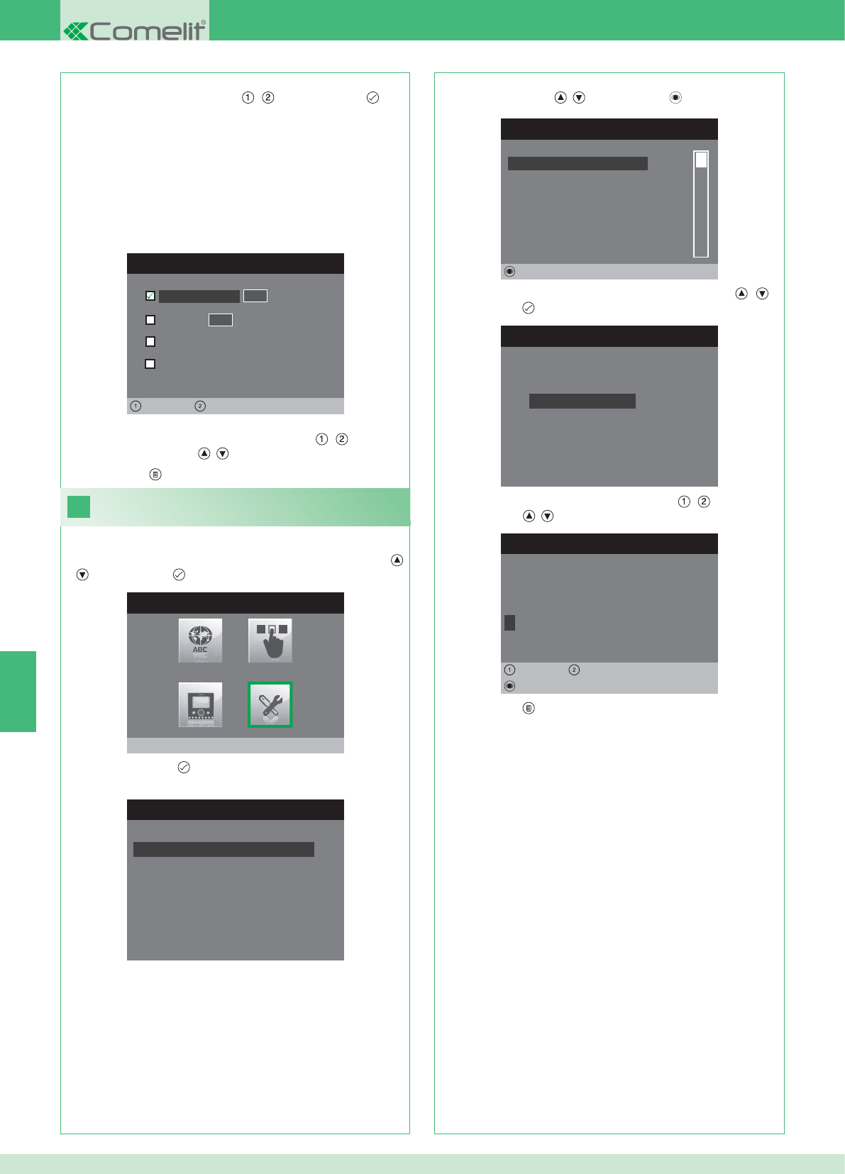
CONFIGURA ENDEREÇO
Apartamento 0 1
Suporte
Geral externa
0 0
Esquerda Direita
Geral interna
24
MENU INSTALADOR
Configurações Especiais
MENU CONFIGURAÇÕES ESPECIAIS
Config.resposta automática
Programa tempos chamada
Configura repetição toque
Directório Intercomunicante
DIRECTÓRIO CHAMADAS INTERCOM
SECUNDÁRIO 1
PRINCIPAL
GERAL EXTERNA
GERAL INTERNA
SECUNDÁRIO 2
SECUNDÁRIO 3
Alterar
CONFIGURA INTERCOMUNICANTE
Configura endereço
Configura Nome
ALTERA NOME
G E R A L I N T E R N A
Configura Nome
Apagar
Esquerda Direita
8. Premir a tecla para sair e guardar as modifi cações.
PT
84
APARTAMENTO: Envia uma chamada a todos os monitores quer
principais, quer secundários com o mesmo endereço lógico
principal inserido.
SUPORTE: Envia uma chamada ao monitor com o endereço lógico
inserido do mesmo apartamento do monitor chamante.
GERAL NTERNA: Envia uma chamada a todos os monitores da
mesma unidade habitacional (apenas para instalações Kit).
GERAL EXTERNA: Envia uma chamada a todos os monitores de
outra unidade habitacional (apenas para instalações Kit).
6. Seleccionar o tipo de chamada que se deseja atribuir ao item do
directório deslocando as teclas , e premir a tecla para
confi rmar.
7. No caso de chamadas Apartamento e Suporte deslocar para
o respectivo campo endereço com as teclas , e inserir o
desejado com as teclas , .
Modifi car nomes no directório
Intercomunicante
1. Aceder ao menu Instalador (Consultar o ponto 19).
2. Seleccionar o menu Confi gurações especiais com as teclas ,
e premir a tecla para aceder.
3. Premir a tecla para aceder ao menu Directório
Intercomunicante.
4. Seleccionar o item do directório para o qual se deseja modifi car o
nome com as teclas , e premir a tecla para aceder.
5. Seleccionar o menu Confi gura nome com as teclas , e
premir a tecla para aceder.
6. Seleccionar a letra desejada com as teclas , e modifi cá-la
com as teclas , .
7. Premir a tecla para sair e guardar as modifi cações.
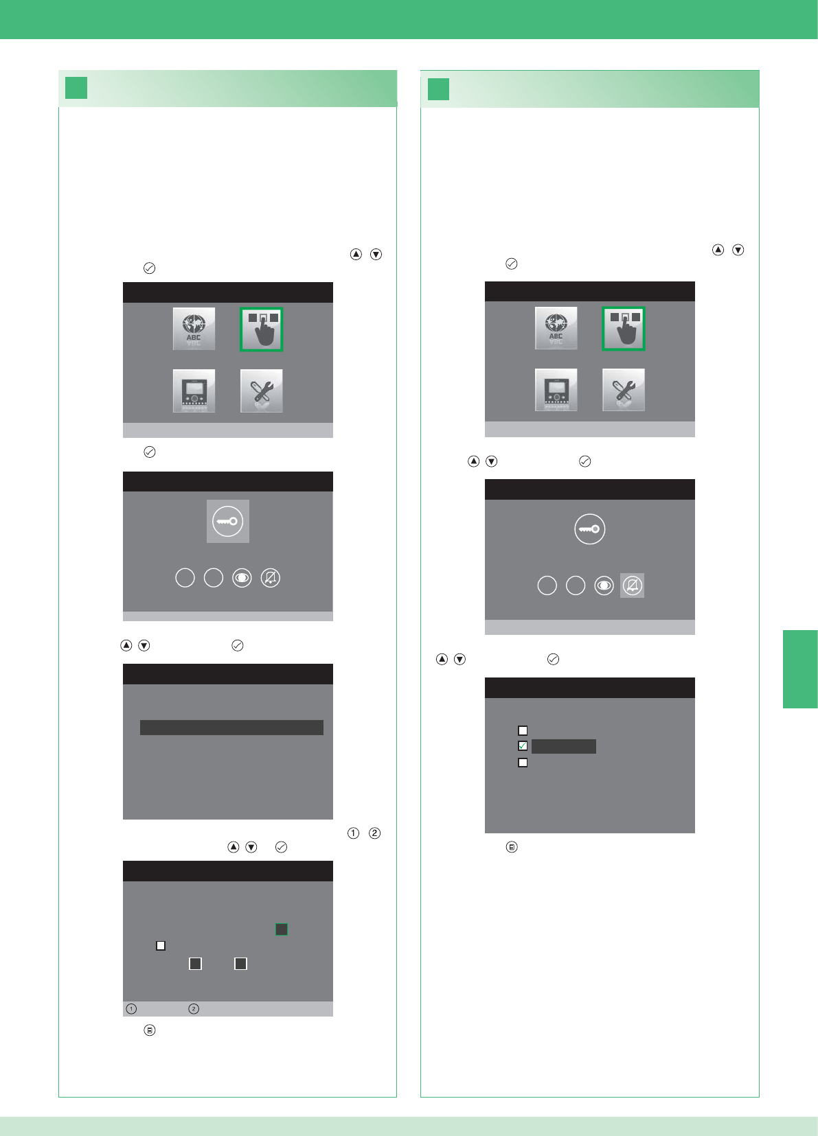
26
25
MENU INSTALADOR
Configura teclas
MENU CONFIGURAÇÃO TECLAS
Configura tecla chave
1 2
CONFIGURA RELÉ
Configur. na ausência chamada
Configuração durante chamada
RELÉ DURANTE CHAMADA
Porta chamadora, relé
Activa:
2
Activa:
Porta 1, relé 2
Esquerda Direita
MENU CONFIGURAÇÃO TECLAS
Configura privacidade/médico
1 2
CONFIGURA PRIVACIDADE/DOCTOR
Função médico
Privacidade
Função médico + privacidade
MENU INSTALADOR
Configura teclas
PT
85
• A função Privacidade permite excluir as chamadas do ponto
externo e da central.
• A função Médico permite o accionamento automático da abertura
da porta (relé 1) aquando de uma chamada do ponto externo.
• A função Privacidade + Médico, além de desactivar a campainha
do ponto interno, como na função "Privacidade", permite o
accionamento automático da abertura da porta (relé 1) aquando
de uma chamada do ponto externo.
1. Aceder ao menu Instalador (Consultar o ponto 19).
2. Seleccionar o menu Confi gura teclas com as teclas , e
premir a tecla para aceder.
3. Seleccionar o menu Confi gura privacidade/médico com as
teclas , e premir a tecla para aceder.
4. Seleccionar a função que se deseja atribuir à tecla com as teclas
, e premir a tecla para confi rmar.
5. Premir a tecla para sair e guardar as modifi cações.
Confi guração da tecla privacidade/médico
Confi guração da tecla chave
O kit possui 2 relés (relé 1 e relé 2) para cada ponto externo ligado.
É possível confi gurar o funcionamento quer durante, quer em
ausência de chamada (instalação em repouso).
Com cada tecla confi gurada para o comando dos relés, é possível
activar simultaneamente 2 relés* no máximo.
Em caso de chamada, um dos relés activáveis deverá ser o da porta
chamadora.
• TECLA CHAVE
1. Aceder ao menu Instalador (Consultar o ponto 19).
2. Seleccionar o menu Confi gura teclas com as teclas , e
premir a tecla para aceder.
3. Premir a tecla para aceder ao menu Confi gura tecla chave.
4. Seleccionar o modo para o qual se deseja modifi car a função com
as teclas , e premir a tecla para confi rmar.
5. Seleccionar os campos modifi cáveis com as teclas , e
modifi car o valor com as teclas , ou .
6. Premir a tecla para sair e guardar as modifi cações.
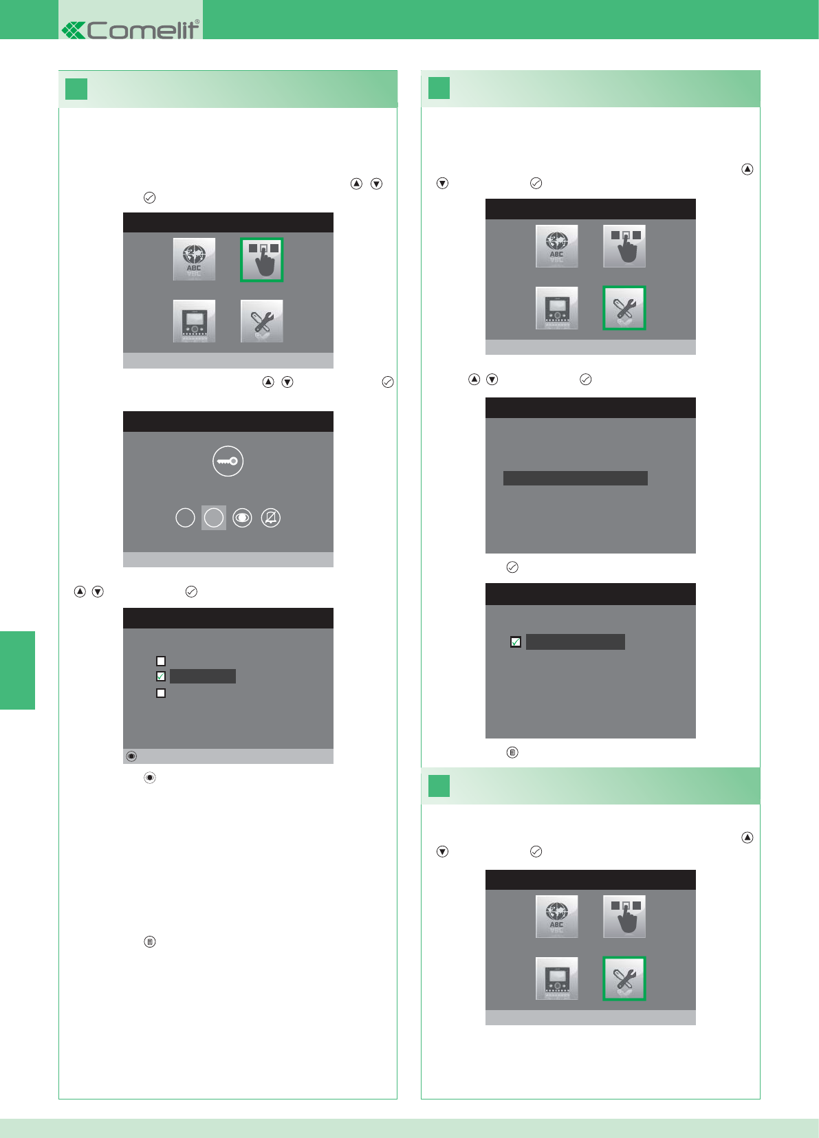
28
MENU INSTALADOR
Configurações Especiais
MENU CONFIGURAÇÕES ESPECIAIS
Configura repetição toque
Directório Intercomunicante
Config.resposta automática
Programa tempos chamada
29
27
CONFIGURA REPETIÇÃO TOQUE
Repetição toque
MENU CONFIGURAÇÃO TECLAS
Configura tecla 2
1 2
CONFIGURA TECLA 2
Intercomunicante
Autoligação
Activação relé
Alterar
MENU INSTALADOR
Configura teclas
MENU INSTALADOR
Configurações Especiais
PT
86
Activação da repetição da campainha
Com esta função activada, o monitor repetirá a campainha três vez
ao receber uma chamada.
1. Aceder ao menu Instalador (Consultar o ponto 19).
2. Seleccionar o menu Confi gurações especiais com as teclas ,
e premir a tecla para aceder.
3. Seleccionar o menu Confi gura repetição campainha com as
teclas , e premir a tecla para aceder.
4. Premir a tecla para activar a função:
As teclas 1 e 2 podem ser ambas programadas através do mesmo
procedimento. A seguir ilustra-se a programação da tecla 2.
1. Aceder ao menu Instalador (Consultar o ponto 19).
2. Seleccionar o menu Confi gura teclas com as teclas , e
premir a tecla para aceder.
3. Seleccionar o menu 2 com as teclas , e premir a tecla
para aceder.
4. Seleccionar a função que se deseja atribuir à tecla com as teclas
, e premir a tecla para confi rmar.
5. Premir a tecla para confi gurar a função pretendida.
Se foi seleccionada a função Intercomunicante:
}Associar a tecla a um ponto interno INTERCOM X.
GERAL INTERNA: Envia uma chamada a todos os monitores da
mesma unidade habitacional.
GERAL EXTERNA: Envia uma chamada a todos os monitores de
outra unidade habitacional.
Se foi seleccionada a função Autoligação:
}Associar a tecla a um ou ambos os pontos externos.
Se foi seleccionada a função Activação relé:
}Seguir os procedimentos para a confi guração da tecla chave.
6. Premir a tecla para sair e guardar as modifi cações.
5. Premir a tecla para sair e guardar as modifi cações.
Activação de Resposta automática
1. Aceder ao menu Instalador (Consultar o ponto 19).
2. Seleccionar o menu Confi gurações especiais com as teclas ,
e premir a tecla para aceder.
Confi guração das teclas 1 - 2
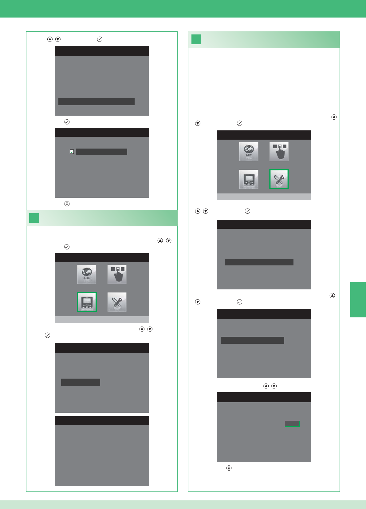
31
1. Aceder ao menu Instalador (Consultar o ponto 19).
MENU CONFIGURAÇÕES ESPECIAIS
Configura repetição toque
Directório Intercomunicante
Config.resposta automática
Programa tempos chamada
CONFIGURA TEMPOS CHAMADA
Tempo conversação
Tempo espera resposta
Atraso de desligamento
Tempo conversação intercom
CONFIGURA TEMPO ESPERA RESP.
Tempo espera resposta 0 6 5
MENU CONFIGURAÇÕES ESPECIAIS
Configura repetição toque
Directório Intercomunicante
Config.resposta automática
Programa tempos chamada
CONFIGURA RESP. AUTOMÁTICA
Resposta automática
30
CONFIGURA MONITOR
Zerar configuração
Configuração do tipo de red
e
Informações
Configura suporte
Endereço lógico
MENU INFORMAÇÕES
MAC: 00:25:29:02:01:BC
IP: 169.254.155.40
ID: 00000001, SUB: 0
SW: /trunck@3534
SYS: iPower
MENU INSTALADOR
Configura monitor
MENU INSTALADOR
Configurações Especiais
PT
87
1. Aceder ao menu Instalador (Consultar o ponto 19).
Visualizar informações
2. Seleccionar o menu Confi gura Monitor com as teclas , e
premir a tecla para aceder.
3. Seleccionar o menu Informações com as teclas , e premir a
tecla para aceder.
Confi guração dos tempos de chamada
No interior deste menu é possível modifi car:
• Tempo espera de resposta: tempo máximo para além do qual a
comunicação termina em ausência de resposta.
• Tempo conversação: duração de uma conversação entre ponto
interno e ponto externo.
• Tempo conversação intercom: duração de uma conversação
intercomunicante.
• Atraso de desligamento: após uma chamada, tempo de espera
desde a activação de um relé ao desligamento do monitor.
2. Seleccionar o menu Confi gurações especiais com as teclas ,
e premir a tecla para aceder.
3. Seleccionar o menu Confi gura tempos chamada com as teclas
, e premir a tecla para aceder.
4. Seleccionar o menu que se pretende modifi car com as teclas ,
e premir a tecla para aceder.
5. Modifi car o valor com as teclas , .
6. Premir a tecla para sair e guardar as modifi cações.
3. Seleccionar o menu Confi gura resposta automática com as
teclas , e premir a tecla para aceder.
4. Premir a tecla para activar a função:
5. Premir a tecla para sair e guardar as modifi cações.

33
Nenhum sinal detectado
Nenhum sinal detectado
Ligações em falta com o ponto externo.
32
CONFIGURA MONITOR
Configuração do tipo de re
d
Informações
Configura suporte
Endereço lógico
Zerar configuração
1. Aceder ao menu Instalador (Consultar o ponto 19).
ZERAR CONFIGURAÇÃO
Quer continuar?
MENU INSTALADOR
Configura monitor
PT
88
Anomalias e possíveis soluções
Ligação em falta com o ponto interno.
Soluções:
}Aguardar 1 minutor.
}Certifi car-se de que o monitor secundário tem o mesmo endereço
do monitor principal da unidade habitacional de interesse
(ponto 22).
}Certifi car-se de que o monitor principal seja alimentado (ponto 10).
}Certifi car-se de que foi inserida a password correcta (ponta 20).
}Certifi car-se de que foram respeitadas as distâncias de instalação
(ponto 8).
Soluções:
}Aguardar 1 minutor.
}Certifi car-se de que o monitor principal seja correctamente
cablado (ponto 2).
}Certifi car-se de que o monitor principal seja alimentado (ponto 9).
}Certifi car-se de que a ponte art. 1398 se encontra correctamente
cablada (punto 7A, 7B ou 7C).
}Certifi car-se de que exista correspondência entre a password da
ponte art. 1398 e o alimentador do monitor da mesma unidade
habitacional.
}Certifi car-se de que foram respeitadas as distâncias de instalação
(ponto 8).
Atenção: esta operação irá repor todas as confi gurações de fábrica,
anulando todas as modifi cações realizadas.
Zerar confi guração
2. Seleccionar o menu Confi gura Monitor com as teclas , e
premir a tecla para aceder
3. Seleccionar o menu Zerar confi guração com as teclas , e
premir a tecla para aceder.
4. Premir a tecla para confi rmar.
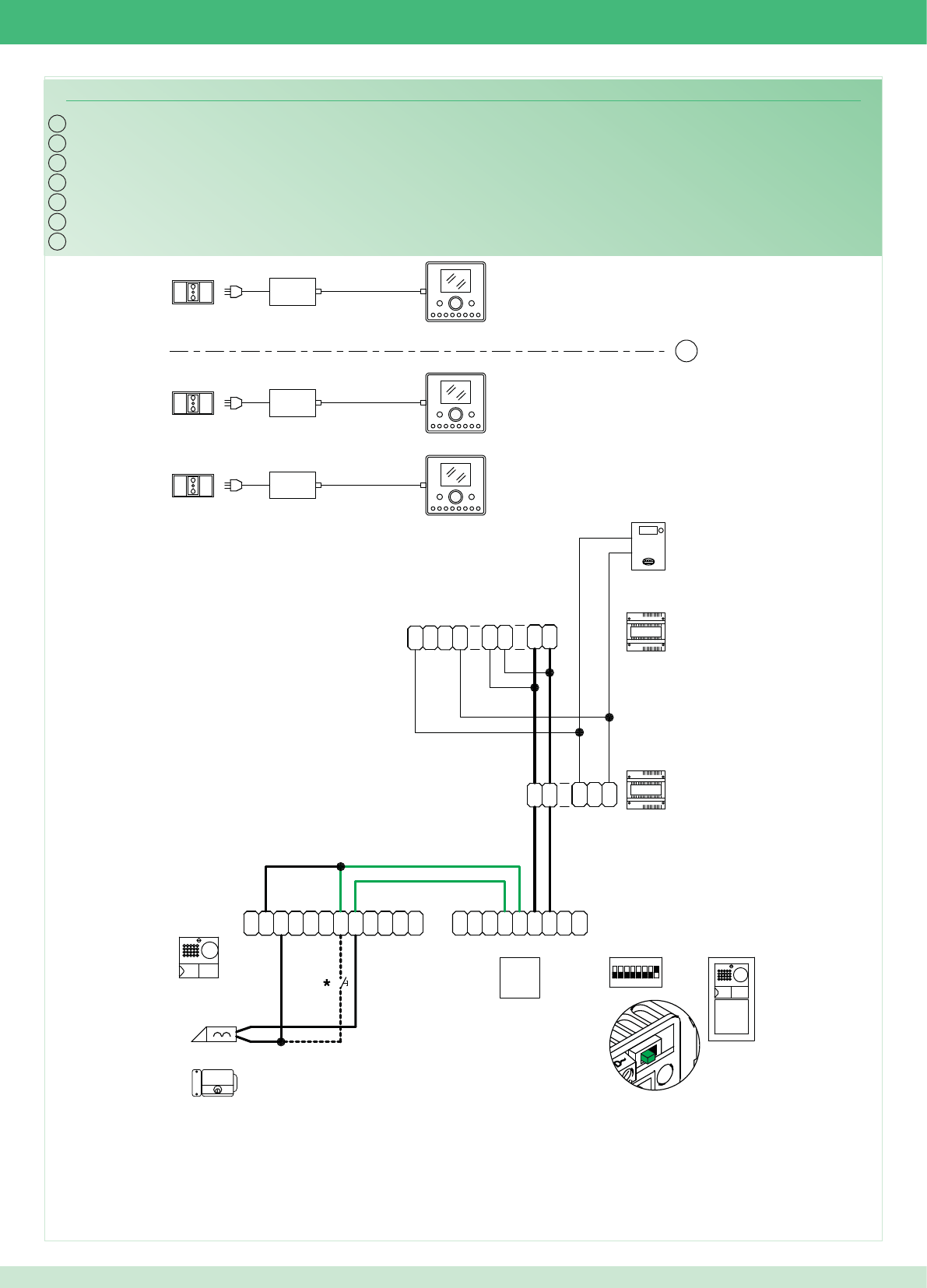
IT
EN
FR
NL
DE
PWK/13A
~
1
22
1
~
0
3
2
0
1397
1
2
0
4891A
-
M
O
C
TX
~
C
N
O
N
O
D
R
T
E
~
-
+
TX RX
+
-
RX
1234 6758
ON
1
~
DD
~
~
N
O
N
C
~
CP
L
P
L
~
1
22
1
~
1398
~~
DD
D
NL3
D
L2
D
L1
D
LP LP
2G60000120
2G60000338
2G60000338
1
14
2
1
6240
6201+
6240
6201+
6240
6201+
2G60000336
ES
PT
89
Cablaggio kit monofamiliare Art. 8595
*Pulsante comando apriporta locale
Wiring for single-residence kit Art. 8595
*Local door-opener button
Câblage kit un usager Art. 8595
*Bouton commande ouvre-porte local
Bekabeling kit voor eengezinswoningen Art. 8595
*Bedieningsknop lokale deuropener
Verdrahtung des Sets für Einfamilienhaus Art. 8595
*Lokale Türöffnertaste
Cableado del kit unifamiliar art. 8595
*Pulsador abrepuertas local
Cablagem kit monofamiliar art. 8595
*Botão de comando abertura da porta local
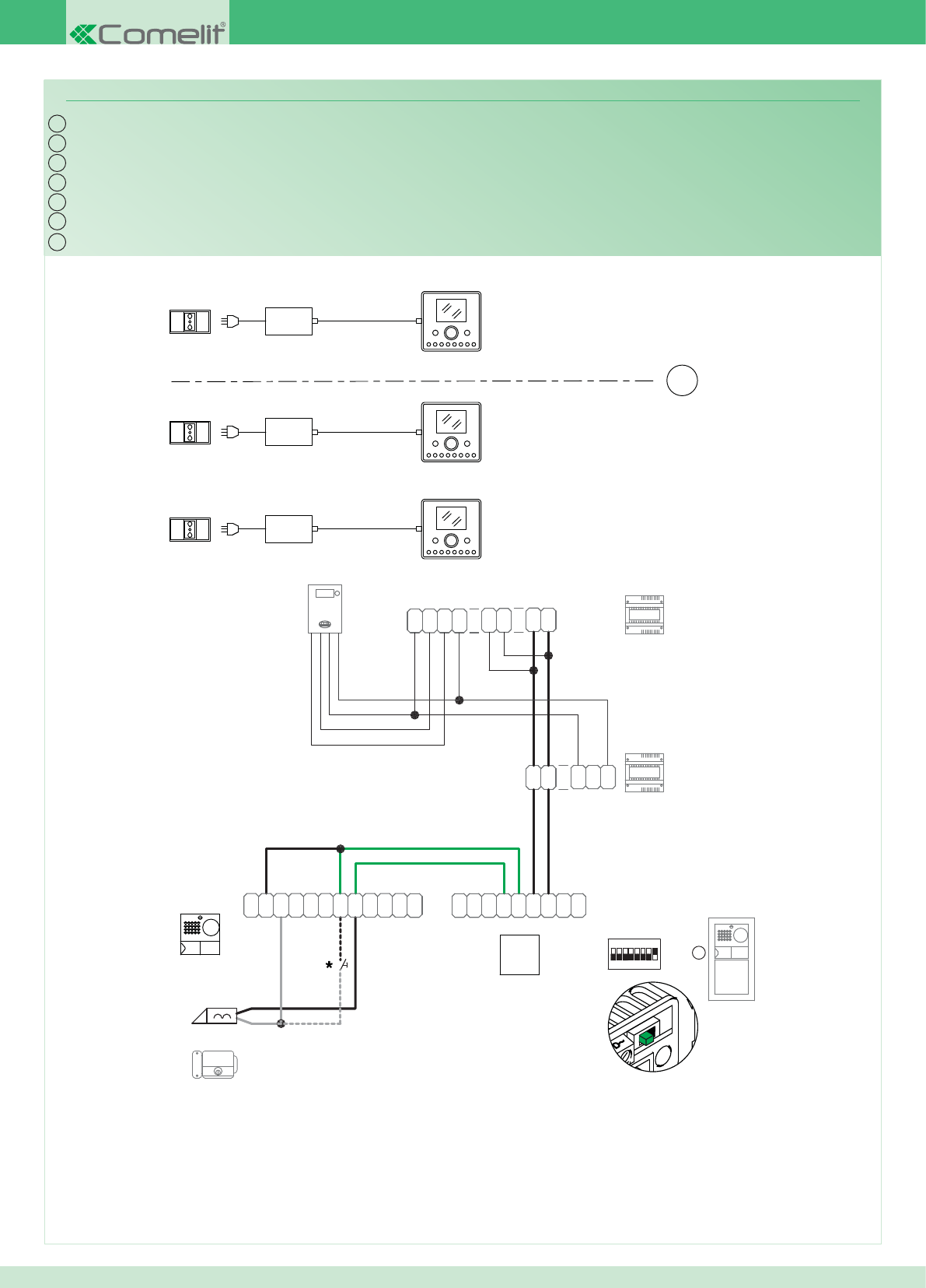
IT
EN
FR
NL
DE
ES
PT
PWK/16
~
1
22
1
~0
3
2
0
1397
1
2
0
D
L1
D
L2
D
L3 N
DDD
~~
1398
~
1
22
1
~
L
P
L
P
C
~
C
N
O
N
~~
DD
~
1
ON
85764321
RX
-
+
RXTX
+
-
~
E
T
R
D
O
N
O
N
C
~
TX
C
O
M
-
4891A
LP LP
2G60000120
2G60000338
2G60000338
1
2
14
1
6240
6201+
6201+
6240
6201+
6240
2G60000336
90
Cablaggio kit monofamiliare trifase Art. 8595
*Pulsante comando apriporta locale
Wiring for three-phase single-residence kit Art. 8595
*Local door-opener button
Câblage kit un usager Art. 8595
*Bouton commande ouvre-porte local
Bekabeling kit voor eengezinswoningen, driefase, Art. 8595
*Bedieningsknop lokale deuropener
Verdrahtung des Sets für Einfamilienhaus in Drehstrom Art. 8595
*Lokale Türöffnertaste
Cableado del kit unifamiliar trifásico art. 8595
*Pulsador abrepuertas local
Cablagem kit monofamiliar trifásica art. 8595
*Botão de comando abertura da porta local
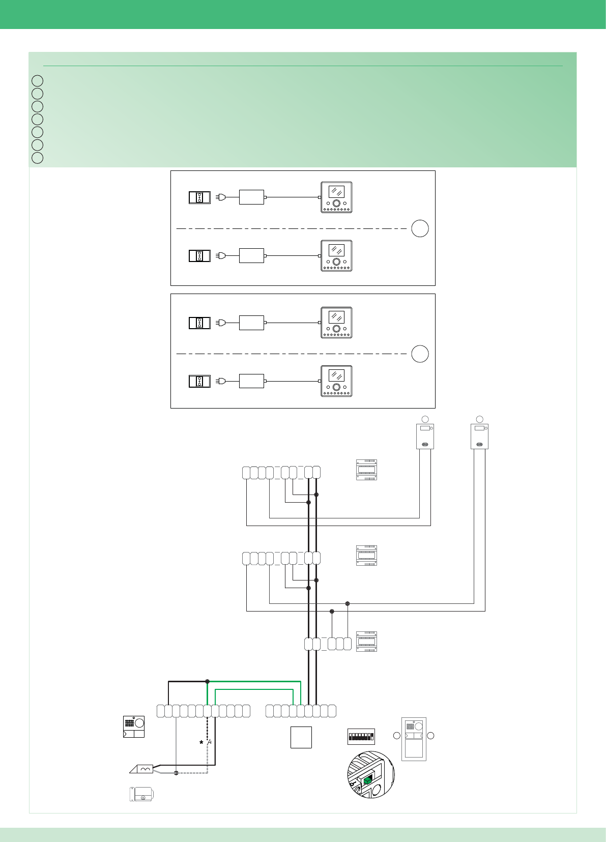
IT
EN
FR
NL
DE
PWK/15A
~
1
22
1
~
0
3
2
0
1397
1
2
0
D
L1
D
L2
D
L3 N
DDD
~~
1398
~
1
22
1
~
~
1
22
1
~
1398
~~
DD
D
NL3
D
L2
D
L1
D
2
4892A
-
M
O
C
TX
~
C
N
O
N
O
D
R
T
E
~
-
+
TX RX
+
-
RX
1234 6758
ON
1
~
DD
~
~
N
O
N
C~
CP
L
P
L
21
LP LP
2G60000120
2G60000338
2G60000338
1
14
14
1
1
2
6240
6201+
6201+
6240
6201+
6240
6201+
6240
2G60000336
ES
PT
91
Cablaggio kit bifamiliare Art. 8596
*Pulsante comando apriporta locale
Wiring for two-residence kit Art. 8596
*Local door-opener button
Câblage kit deux usagers Art. 8596
*Bouton commande ouvre-porte local
Bekabeling kit voor tweegezinswoningen Art. 8596
*Bedieningsknop lokale deuropener
Verdrahtung des Sets für Zweifamilienhaus Art. 8596
*Lokale Türöffnertaste
Cableado del kit bifamiliar art. 8596
*Pulsador abrepuertas local
Cablagem kit bifamilar art. 8596
*Botão de comando abertura da porta local
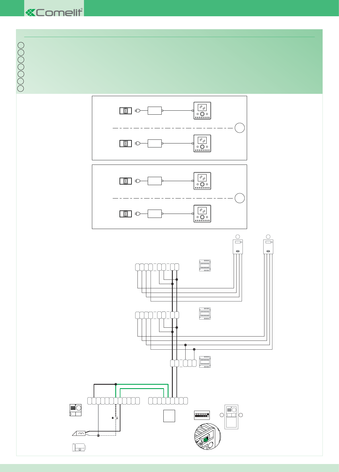
IT
EN
FR
NL
DE
PWK/17
~
1
22
1
~0
3
2
0
1397
1
2
0
D
L1
D
L2
D
L3 N
DDD
~~
1398
~
1
22
1
~
~
1
22
1
~
1398
~~
DD
D
NL3
D
L2
D
L1
D
2
4892A
-
M
O
C
TX
~
C
N
O
N
O
D
R
T
E
~
-
+
TX RX
+
-
RX
1234 6758
ON
1
~
DD
~
~
N
O
N
C
~
CP
L
P
L
2 1
LP LP
2G60000120
2G60000338
2G60000338
1
14
14
1
1
2
6240
6201+
6201+
6240
6201+
6240
6201+
6240
2G60000336
*Pulsante comando apriporta locale
*Local door-opener button
*Bouton commande ouvre-porte local
*Bedieningsknop lokale deuropener
*Lokale Türöffnertaste
*Pulsador abrepuertas local
*Botão de comando abertura da porta local
ES
PT
92
Cablaggio kit bifamiliare trifase Art. 8596
Wiring for three-phase two-residence kit Art. 8596
Câblage kit deux usagers Art. 8596
Bekabeling kit voor tweegezinswoningen, driefase, Art. 8596
Verdrahtung des Sets für Zweifamilienhaus in Drehstrom Art. 8596
Cableado del kit bifamiliar trifásico art. 8596
Cablagem kit bifamiliar trifásica art. 8596
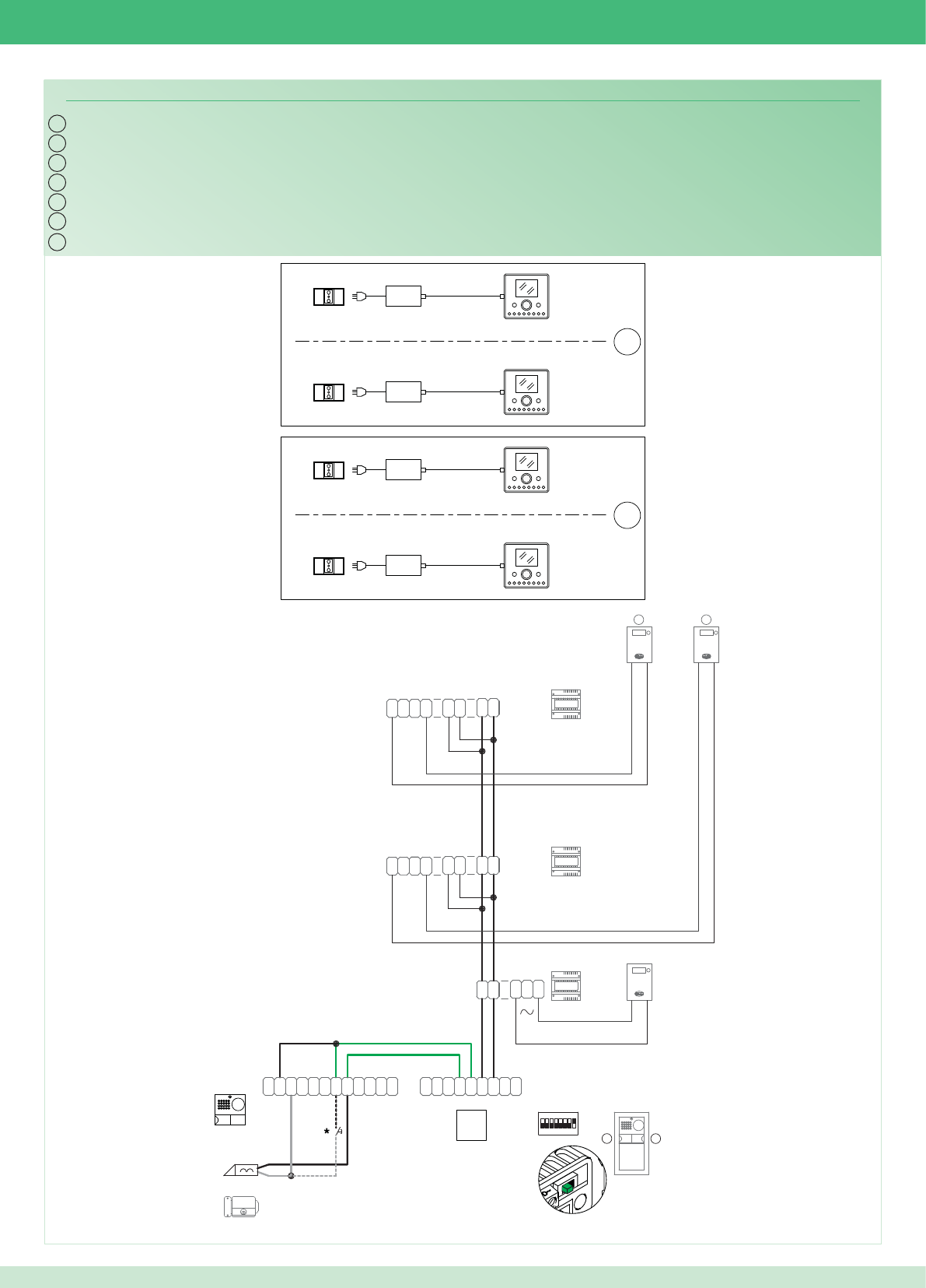
IT
EN
FR
NL
DE
ES
PT
PWK/15B
~
1
22
1
~
0
3
2
0
1397
1
2
0
D
L1
D
L2
D
L3 N
DDD
~~
1398
~
1
22
1
~
1398
~
1
22
1
~
~~
DD
D
NL3
D
L2
D
L1
D
L
P
L
P
C
~
C
N
O
N
~
~
DD
~
1
ON
85764321
RX
-
+
RXTX
+
-
~
E
T
R
D
O
N
O
N
C
~
TX
C
O
M
-
4892A
2
21
LP LP
2G60000120
2G60000338
2G60000338
1
14
14
1
2
1
6240
6201+
6201+
6240
6201+
6240
6201+
6240
2G60000336
*Pulsante comando apriporta locale
*Local door-opener button
*Bouton commande ouvre-porte local
*Bedieningsknop lokale deuropener
*Lokale Türöffnertaste
*Pulsador abrepuertas local
*Botão de comando abertura da porta local
93
Cablaggio kit bifamiliare Art. 8596 con contatori parti comuni
Wiring for two-residence kit Art. 8596 with shared utility meters
Câblage kit deux usagers Art. 8596 avec compteurs parties communes
Bekabeling kit voor tweegezinswoningen Art. 8596 met teller voor gemeenschappelijke delen
Verdrahtung des Sets für Zweifamilienhaus Art. 8596 mit Zählern für die Gemeinschaftsbereiche
Cableado del kit bifamiliar art. 8596 con contadores para partes comunes
Cablagem kit bifamiliar art. 8596 com contador nas partes comuns
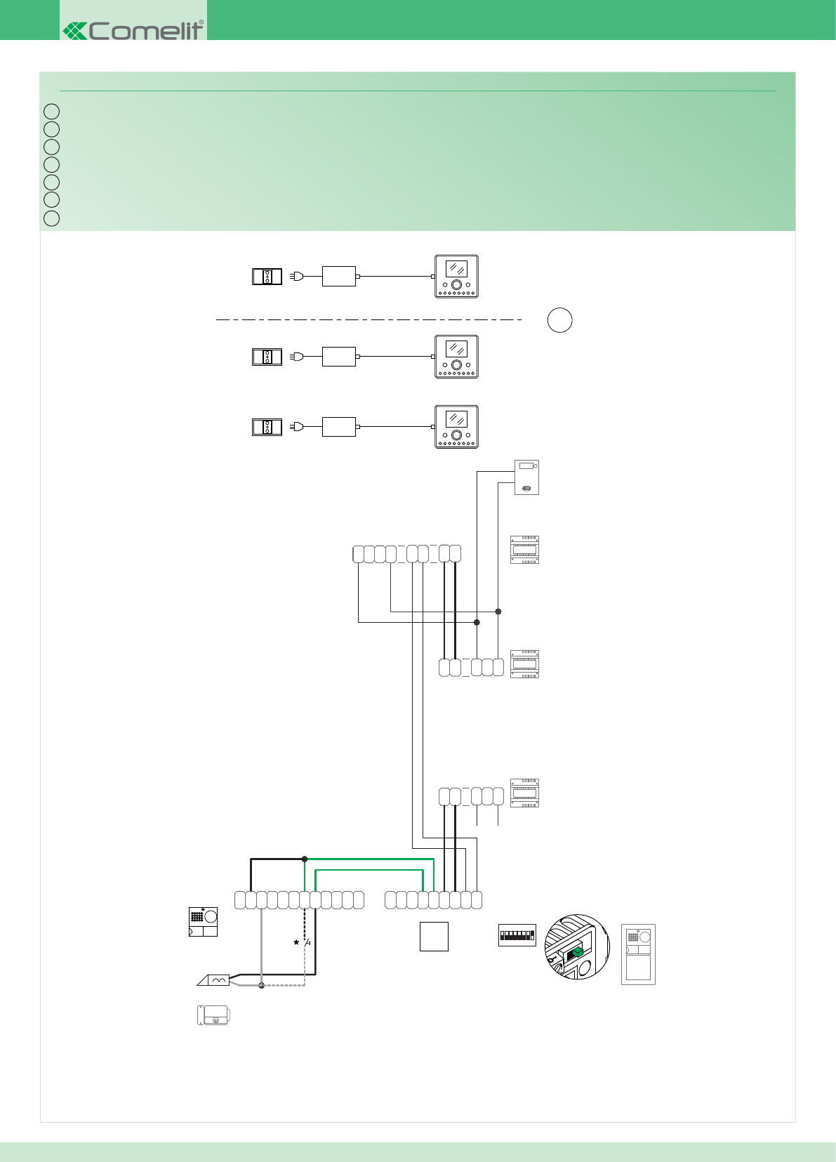
IT
EN
FR
NL
DE
ES
PT
PWK/13B
~
1
22
1
~
0
3
2
0
1397
1
2
0
D
L1
D
L2
D
L3 N
DDD
~~
1398
~
1
22
1
~
0
2
1
0
2
3
0
~
1
22
1
~
1397
~
L
P
L
P
C
~
C
N
O
N
~
~
DD
~
1
ON
85764321
RX
-
+
RXTX
+
-
~
E
T
R
D
O
N
O
N
C
~
TX
C
O
M
-
4891A
2G60000336
LP LP
2G60000338
2G60000120
2G60000338
1
2
14
1
6240
6201+
6201+
6240
6201+
6240
*Pulsante comando apriporta locale
*Local door-opener button
*Bouton commande ouvre-porte local
*Bedieningsknop lokale deuropener
*Lokale Türöffnertaste
*Pulsador abrepuertas local
*Botão de comando abertura da porta local
94
Cablaggio kit monofamiliare con alimentatore supplementare per posto esterno
Wiring for single-residence kit with additional external unit power supply unit
Câblage kit un usager avec alimentation supplémentaire pour poste externe
Bekabeling voor kit voor eengezinswoningen met extra voedingstransformator voor entreepaneel
Verdrahtung des Sets für Einfamilienhaus mit Zusatz-Netzteil für Außenstelle
Cableado del kit unifamiliar con alimentador adicional para unidad externa
Cablagem kit monofamiliar com alimentador adicional para o ponto externo
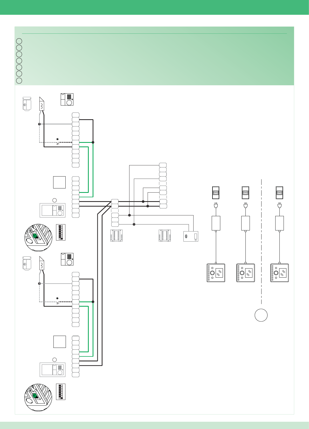
IT
EN
FR
NL
DE
ES
PT
PWK/18
~
1
22
1
~0
3
2
0
1397
1
2
0
D
L1
D
L2
D
L3 N
DDD
~~
1398
~
1
22
1
~
4891A
-
M
O
C
TX
~
C
N
O
N
O
D
R
T
E~
-
+
TX RX
+
-
RX
1234 6758
ON
1
~
DD
~
~
N
O
N
C
~
CP
L
P
LL
P
L
P
C
~
C
N
O
N
~~
DD
~
1
RX
-
+
RXTX
+
-
~
E
T
R
D
O
N
O
N
C
~
TX
C
O
M
-
ON
85764321
4891A
LP LP
2G60000120
2G60000338
2G60000338
LP LP
2G60000120
2G60000338
2G60000338
1
2
14
1
6240
6201+
6240
6201+
6240
6201+
2G60000336
2G60000336
*Pulsante comando apriporta locale
*Local door-opener button
*Bouton commande ouvre-porte local
*Bedieningsknop lokale deuropener
*Lokale Türöffnertaste
*Pulsador abrepuertas local
*Botão de comando abertura da porta local
95
Cablaggio kit monofamiliare con 2 posti esterni
Wiring for single-residence kit with 2 external units
Câblage kit un usager avec 2 postes externes
Bekabeling kit voor eengezinswoningen met 2 entreepanelen
Verdrahtung des Sets für Einfamilienhaus mit 2 Außenstellen
Cableado del kit unifamiliar con 2 unidades externas
Cablagem kit monofamiliar com 2 pontos externos
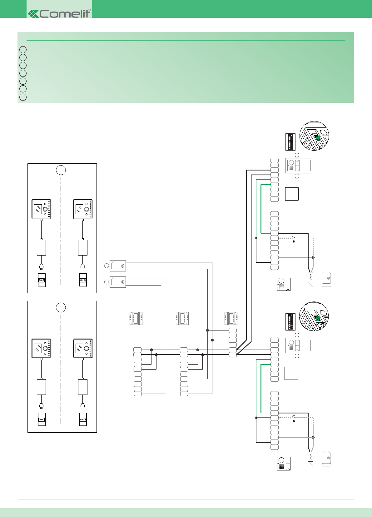
IT
EN
FR
NL
DE
ES
PT
PWK/19
~
1
22
1
~
0
3
2
0
1397
1
2
0
D
L1
D
L2
D
L3 N
DDD
~~
1398
~
1
22
1
~
~
1
22
1
~
1398
~~
DD
D
NL3
D
L2
D
L1
D
L
P
L
P
C
~
C
N
O
N
~
~
DD
~
1
ON
85764321
RX
-
+
RXTX
+
-
~
E
T
R
D
O
N
O
N
C
~
TX
C
O
M
-
4892A
2 2
4892A
-
M
O
C
TX
~
C
N
O
N
O
D
R
T
E~
-
+
TX RX
+
-
RX
1234 6758
ON
1
~
DD
~
~
N
O
N
C
~
CP
L
P
L
12
LP LP
2G60000120
2G60000338
2G60000338
LP LP
2G60000120
2G60000338
2G60000338
1
14 14
1
12
6240
6201+
6240
6201+
6240
6201+
6240
6201+
2G60000336
2G60000336
*Pulsante comando apriporta locale
*Local door-opener button
*Bouton commande ouvre-porte local
*Bedieningsknop lokale deuropener
*Lokale Türöffnertaste
*Pulsador abrepuertas local
*Botão de comando abertura da porta local
96
Cablaggio kit bifamiliare con 2 posti esterni
Wiring for two-residence kit with 2 external units
Câblage kit deux usagers avec 2 postes externes
Bekabeling kit voor tweegezinswoningen met 2 entreepanelen
Verdrahtung des Sets für Zweifamilienhaus mit 2 Außenstellen
Cableado del kit bifamiliar con 2 unidades externas
Cablagem kit bifamiliar com 2 pontos externos
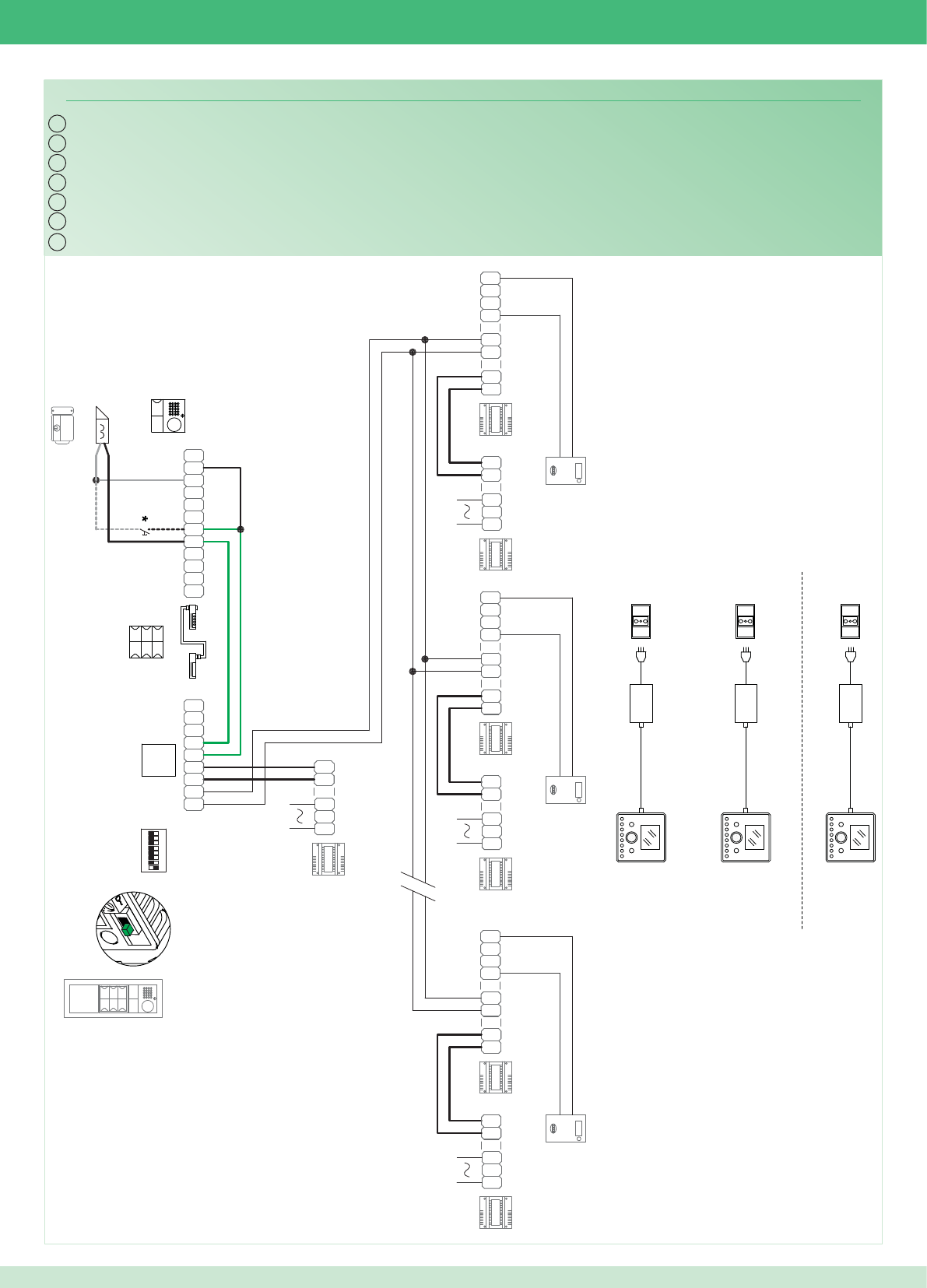
IT
EN
FR
NL
DE
ES
PT
PWK/14
~
1
22
1
~
0
3
2
0
1397
1
2
0
D
L1
D
L2
D
L3 N
DDD
~~
1398
~
1
22
1
~
4891A
~
1
22
1
~
1398
~~
DD
D
NL3
D
L2
D
L1
D D
L1
D
L2
D
L3 N
DDD
~~
1398
~
1
22
1
~
-
M
O
C
TX
~
C
N
O
N
O
D
R
T
E~
-
+
TX RX
+
-
RX
1234 6758
ON
~
DD
~
~
N
O
N
C
~
CP
L
P
L
0
2
1
1397
0
2
3
0
~
1
22
1
~ ~
1
22
1
~
0
3
2
0
1397
1
2
0
~
1
22
1
~
0
3
2
0
1397
1
2
0
LP LP
2G60000120
2G60000338
2G60000338
1
2
14
6201+
6240
6240
6240
6201+
6201+
2G60000336
3323/3_4_6
J1J1
J2
*Pulsante comando apriporta locale
*Local door-opener button
*Bouton commande ouvre-porte local
*Bedieningsknop lokale deuropener
*Lokale Türöffnertaste
*Pulsador abrepuertas local
*Botão de comando abertura da porta local
97
Cablaggio sistema multiutenza
Wiring for multi-user system
Câblage installation multi-usagers
Bekabeling multi-userinstallatie
Verdrahtung des Multi-User-Systems
Cableado del sistema multiusuarios
Cablagem sistema multiutilizador
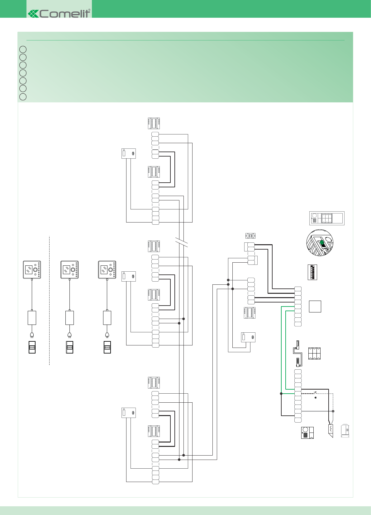
IT
EN
FR
NL
DE
ES
PT
PWK/20
~
1
22
1
~
0
3
2
0
1397
1
2
0
D
L1
D
L2
D
L3 N
DDD
~~
1398
~
1
22
1
~
4891A
~
1
22
1
~
1398
~~
DD
D
NL3
D
L2
D
L1
D D
L1
D
L2
D
L3 N
DDD
~~
1398
~
1
22
1
~
-
M
O
C
TX
~
C
N
O
N
O
D
R
T
E~
-
+
TX RX
+
-
RX
1234 6758
ON
~
DD
~
~
N
O
N
C
~
CP
L
P
L
0
2
1
1397
0
2
3
0
~
1
22
1
~ ~
1
22
1
~
0
3
2
0
1397
1
2
0
~
1
22
1
~
0
3
2
0
1397
1
2
0
1396
~~
DD
~
DD
~
IN
OUT
PARTI COMUNI
LP LP
2G60000338
2G60000338
1
2
6201+
6240
6240
6240
6201+
6201+
14
2G60000120
2G60000336
3323/3_4_6
J1J1
J2
*Pulsante comando apriporta locale
*Local door-opener button
*Bouton commande ouvre-porte local
*Bedieningsknop lokale deuropener
*Lokale Türöffnertaste
*Pulsador abrepuertas local
*Botão de comando abertura da porta local
98
Cablaggio sistema multiutenza con Art. 1396
Wiring for multi-user system with Art. 1396
Câblage installation multi-usagers avec Art. 1396
Bekabeling multi-usersysteem met Art. 1396
Verdrahtung des Multi-User-Systems mit Art. 1396
Cableado del sistema multiusuarios con art. 1396
Cablagem sistema multiutilizadores com art. 1396
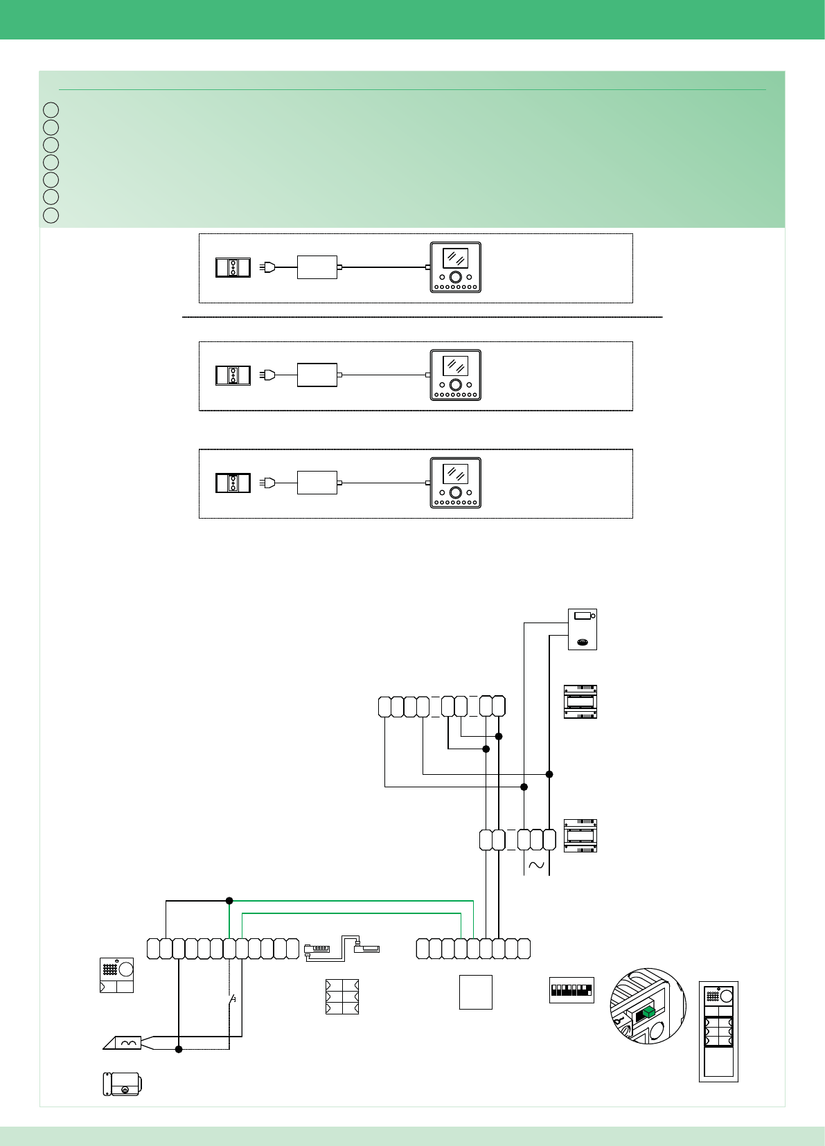
IT
EN
FR
NL
DE
ES
PT
PWK/21
4891A
1
2
14
6201+
6240
6240
6240
-
M
O
C
TX
~
C
N
O
N
O
D
R
T
E
~
-
+
TX RX
+
-
RX
1234 6758
ON
~
DD
~
~
N
O
N
C
~
CP
L
P
L
6201+
6201+
~
1
22
1
~
0
3
2
0
1397
1
2
0
~
1
22
1
~
1398
~~
DD
D
NL3
D
L2
D
L1
D
*
2G60000338
NCCNO LP LP
2G60000338
2G60000120
2G60000336
3323/3_4_6
J1J1
J2
*Pulsante comando apriporta locale
*Local door-opener button
*Bouton commande ouvre-porte local
*Bedieningsknop lokale deuropener
*Lokale Türöffnertaste
*Pulsador abrepuertas local
*Botão de comando abertura da porta local
99
Cablaggio sistema multiutenza con singolo contatore di impianto
Wiring for multi-user system with single utility meter
Câblage installation multi-usagers avec un compteur d’installation
Bekabeling multi-usersysteem met afzonderlijke teller voor installatie
Verdrahtung des Multi-User-Systems mit einzelnem Anlagenzähler
Cableado del sistema multiusuarios con un único contador de instalación
Cablagem sistema multiutilizadores com um único contador para a instalação
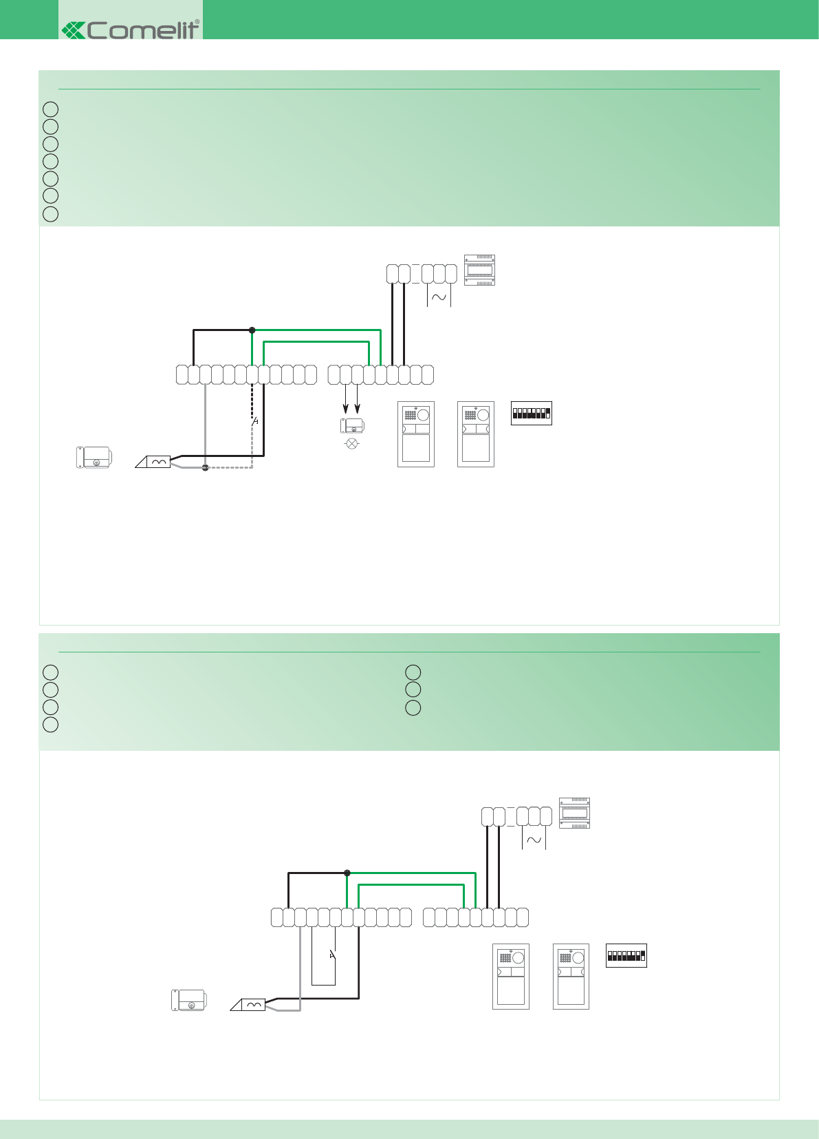
~
1
22
1
~
0
3
2
0
1397
1
2
0
4891A
-
M
O
C
TX
~
C
N
O
N
O
D
R
T
E~
-
+
TX RX
+
-
RX
1234 6758
ON
11
4892A
2
~
DD
~
~
N
O
N
C
~
CP
L
P
L
AC-DC
12V/24V
*
IT
EN
FR
NL
DE
ES
PT
PW/AAF
L
P
L
P
C
~
C
N
O
N
~
~
DD
~
2
4892A
11
ON
85764321
RX
-
+
RXTX
+
-
~
E
T
R
D
O
N
O
N
C
~
TX
C
O
M
-
4891A
0
2
1
1397
0
2
3
0
~
1
22
1
~
IT
EN
FR
NL
DE
ES
PT
PW/AAG
100
Variante collegamento relé del modulo numero civico (relé 2)
Variante collegamento relé temporizzato
Vedi tabella programazione posto
esterno per uso relé numero 2
* Contatto libero 12 - 24 V AC/DC Max 2A.
Utilizzare un alimentatore dedicato
Variant with info module relay connection (relay 2)
Variant with timed relay connection
See table - programming external unit
for use with relay number 2
* Free contact 12-24 V AC/DC Max 2A.
Use a special power supply unit
Variante connexion relais du module numéro civique (relais 2)
Variante connexion relais temporisé
Voir tableau de programmation du poste
externe pour utilisation relais numéro 2
* Contact franc 12 - 24 V AC/DC Max 2A.
Utiliser une alimentation dédiée
Aansluitvariant voor relais huisnummermodule (relais 2)
Aansluitvariant relais met tijdsinstelling
Zie de programmeertabel van het entreepaneel
voor gebruik van relais nummer 2
* Potentiaalvrij contact 12 - 24 V AC/DC.
Max.
2A
. Gebruik een speciale voedingstransformator
Anschlussvariante für das Relais des Hausnummern-Moduls (Relais 2)
Anschlussvariante des Zeitschaltrelais
Siehe Programmiertabelle Außenstelle
für den Einsatz von Relais Nummer 2
* Freier Kontakt 12 - 24 V AC/DC max. 2A.
Eigenes Netzteil verwenden
Variante para conexión del relé del módulo informativo iluminado (relé 2)
Variante para la conexión del relé temporizado
Véase tabla de programación de la
unidad externa para el uso del relé 2
* Contacto libre 12 - 24 Vca/cc, máx. 2A.
Utilizar un alimentador dedicado
Variante de ligação do relé do módulo número de porta (relé 2)
Variante de ligação do relé com temporizador
Consultar a tabela de programação
do ponto externo para o uso do relé
número 2
* Contacto livre 12 - 24 V AC/DC máx. 2A.
Utilizar um alimentador dedicado
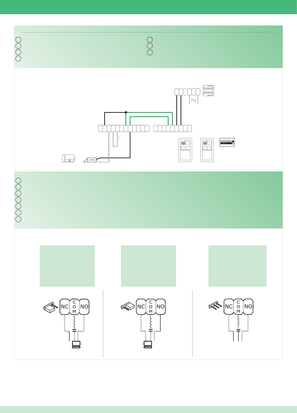
*
L
P
L
P
C
~
C
N
O
N
~
~
DD
~
2
4892A
11
ON
85764321
RX
-
+
RXTX
+
-
~
E
T
R
D
O
N
O
N
C
~
TX
C
O
M
-
4891A
0
2
1
1397
0
2
3
0
~
1
22
1
~
IT
EN
FR
NL
DE
ES
PT
PW/AAH
IT
EN
FR
NL
DE
ES
PT
Sui contatti COM. NO.
On contacts COM. NO.
Sur les contacts COM. NO.
Bij contacten COM. NO.
An den Kontakten COM- NO
En los contactos COM. NO.
Nos contactos C. NO.
Esclusa: contatto pulito
Disabled: clean contact
Exclue : contact libre
Uitgesloten: contact tussen
Deaktiviert: Schließerkontakt
Excluido: contacto libre
Excluída: contacto limpo
Sui contatti COM. NC.
On contacts COM. NC.
Sur les contacts COM. NC.
Bij contacten COM. NC.
An den Kontakten COM- NC
En los contactos COM. NC.
Nos contactos C. NC.
101
Variante contatto segnalazione porta aperta
Utilizzo della rete RC per fi ltro serratura sui contatti del relè
Variant with door open indication contact
Using the RC network for door lock fi lter on relay contacts
Variante contact signalisation porte ouverte
Utilisation du réseau RC pour fi ltre gâche sur les contacts du relais
Contactvariant van de signalering ‘deur open’
Gebruik van het RC-net voor storingsfi lter op de contacten van het relais
Variante Meldekontakt Tür offen
Verwendung des RC-Glieds als Türöffner-Filter an den Relaiskontakten
Variante para contacto de señalización de puerta abierta
Uso de la red RC para el fi ltro de la cerradura en los contactos del relé
Variante contacto para a indicação de porta aberta.
Utilização da rede RC para fi ltrar a fechadura nos contactos do relé
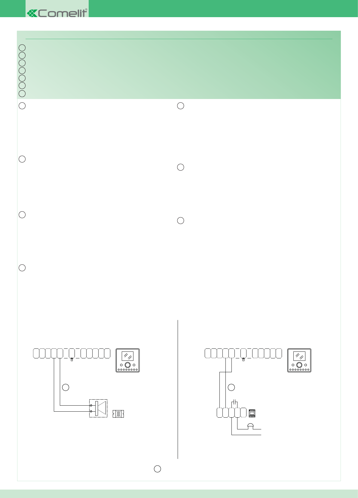
AL
OUT
1V
0
-
OP
+
OP
1
N
C
0
V
P
F
C
N
A
P
V
0S
+
6202+
6231
*
1229
20 m MAX
*
*
O
N
C
N
C
-
+
12/24V
AC/DC
1122/A
(12V)
470nF
+
S
0
V
P
A
N
C
F
PV
0C
N
1
OP
+
OP
-
0
V1
OUT
AL
6231
6202+
IT
EN
FR
NL
DE
ES
PT
PW/AAL
IT
EN
FR
NL
DE
ES
PT
102
Connessione di dispositivi di ripetizione di chiamata (Art. 1229 o Art. 1122/A)
La somma totale del numero di posti interni con stesso codice
utente e del numero di dispositivi di ripetizione chiamata collegati ai
suddetti posti interni non può superare il numero di 14. Connettere
un solo dispositivo di ripetizione chiamata per ogni posto interno.
Utilizzare cavo schermato per il collegamento e non far passare i
cavi in prossimità di carichi induttivi pesanti o cavi di alimentazione
(230V / 400V). In caso di connessione di carichi induttivi si consiglia
l’inserimento di una capacità di 470nF in parallelo ai contatti C-NO
dell’Art. 1122/A.
Connection of call repetition devices (Art. 1229 or Art. 1122/A)
The total number of internal units with the same user code summed
with the number of call repetition devices connected to these internal
units cannot exceed 14. Connect only one call repetition device for
each internal unit. Use shielded cable for the connection and do not
run the cables near heavy inductive loads or power supply cables
(230V / 400V). If inductive loads are connected, it is recommended
to insert a 470nF capacitance in parallel with the C-NO contacts of
Art. 1122/A.
Connexion de dispositifs de répétition d’appel (Art. 1229 ou Art. 1122/A)
Le nombre total de postes internes ayant le même code usager et de
dispositifs de répétition d'appel branchés à ces postes internes ne
peut pas être supérieur à 14. Brancher un seul dispositif de répétition
d'appel pour chaque poste interne. Pour la connexion, utiliser un
câble blindé et ne pas faire passer les câbles à proximité de charges
inductives lourdes ou de câbles d'alimentation (230V / 400V). En cas
de connexion de charges inductives, il est conseillé d’installer une
capacité de 470nF en parallèle aux contacts C-NO de l’Art. 1122/A.
Aansluiting van een extra “bel” of voor het gelijktijdig met het belsignaal inschakelen van een relais (art. 1229 of art. 1122/A)
De som van het aantal binnentoestellen met dezelfde gebruikerscode
en het aantal belherhalingsinrichtingen die op bovenstaande
binnentoestellen zijn aangesloten, mag niet groter dan 14 zijn. Sluit
één extra belherhalingsinrichting aan per binnentoestel. Gebruik een
afgeschermde kabel voor deze verbinding en leid de kabels niet in
de nabijheid van hoge inductieve belastingen of netvoedingskabels
(230V / 400V). Bij het aansluiten van inductieve belastingen wordt
aangeraden een condensator van 470nF parallel met de C-NO-
contacten van art.1122/A te plaatsen.
Anschluss von Rufwiederholungsvorrichtungen (Art. 1229 oder Art. 1122/A)
Die sich aus der Anzahl der Innenstellen mit dem gleichen
Benutzercode und der Anzahl der mit diesen Innenstellen verbundenen
Rufwiederholungsvorrichtungen ergebende Gesamtsumme darf
nicht höher als 14 sein Jeweils nur eine Rufwiederholeinrichtung pro
Innenstelle anschließen. Zur Verbindung ist ein geschirmtes Kabel
zu verwenden, wobei die Kabel nicht in Nähe von großen induktiven
Lasten oder von Versorgungskabeln (230V/400V) verlegt werden
dürfen. Im Fall des Anschlusses von induktiven Lasten empfi ehlt sich
die Verbindung mit einer Kapazität von 470nF in Parallelschaltung zu
den Schließerkontakten von Art. 1122/A.
Conexión de dispositivos de repetición de llamada (arts. 1229 o 1122/A)
Las unidades internas con el mismo código de usuario y los
dispositivos de repetición de llamada conectados a dichas unidades
internas no pueden sumar más de 14. Conectar un único dispositivo
de repetición de llamada para cada unidad interna. Utilizar cable
blindado para la conexión y no tender los cables cerca de cargas
inductivas pesadas o cables de alimentación (230 V / 400 V). En
caso de conexión de cargas inductivas es aconsejable la conexión
de una capacidad de 470nF en paralelo a los contactos C-NO del
art. 1122/A.
Ligação de dispositivos de repetição da chamada (art. 1229 ou art. 1122/A)
A soma total do número de pontos internos com o mesmo código
de utilizador e do número de dispositivos de repetição de chamada
ligados aos pontos internos não pode ser superior a 14. Ligar apenas
um dispositivo de repetição de chamada para cada posto interno.
Usar cabo blindado para a ligação e não fazer passar os cabos na
proximidade de cargas indutivas pesadas ou cabos de alimentação
(230 V/400 V) Em caso de conexão de cargas indutivas aconselha-se
a introdução de uma resistência de 470nF em paralelo aos contactos
C-NO do art.1122/A.
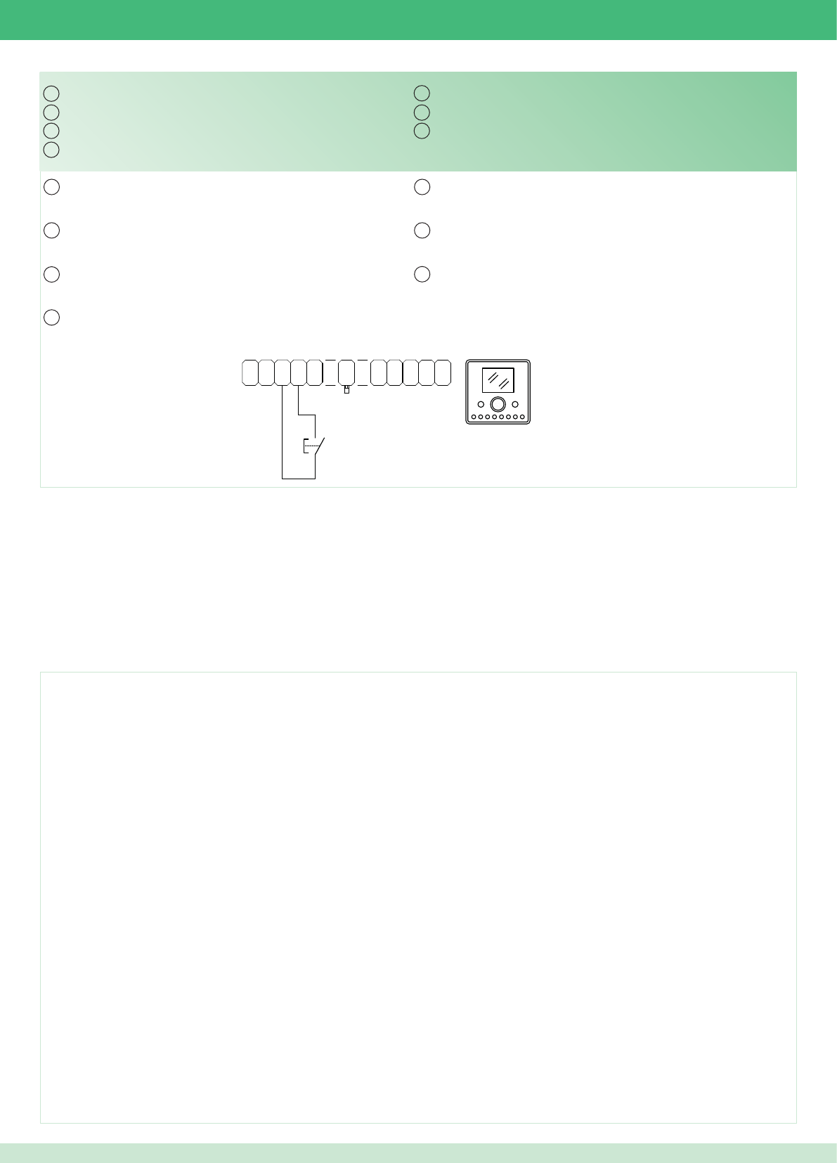
AL
OUT
1V
0
-
OP
+
OP
1
N
C
0
V
P
F
C
N
A
P
V
0S
+
6202+
6231
IT
EN
FR
NL
DE
ES
PT
IT
EN
FR
NL
DE
ES
PT
103
Variante collegamento chiamata fuori porta
In caso di più citofoni o staffe monitor con lo stesso codice utente
collegare il pulsante CFP su uno solo; tutti i dispositivi suoneranno
contemporaneamente.
Fonts are (c) Bitstream (see below). DejaVu changes are in public domain.
Glyphs imported from Arev fonts are (c) Tavmjong Bah (see below)
Bitstream Vera Fonts Copyright
------------------------------
Copyright (c) 2003 by Bitstream, Inc. All Rights Reserved. Bitstream Vera is a trademark of Bitstream, Inc.
Permission is hereby granted, free of charge, to any person obtaining a copy of the fonts accompanying this license (“Fonts”) and associated documentation fi les (the “Font Software”), to reproduce and distribute the Font Software,
including without limitation the rights to use, copy, merge, publish, distribute, and/or sell copies of the Font Software, and to permit persons to whom the Font Software is furnished to do so, subject to the following conditions:
The above copyright and trademark notices and this permission notice shall be included in all copies of one or more of the Font Software typefaces.
The Font Software may be modifi ed, altered, or added to, and in particular the designs of glyphs or
characters in the Fonts may be modifi ed and additional glyphs or characters may be added to the Fonts, only if the fonts are renamed to names not containing either the words “Bitstream” or the word “Vera”.
This License becomes null and void to the extent applicable to Fonts or Font Software that has been modifi ed and is distributed under the “Bitstream Vera” names.
The Font Software may be sold as part of a larger software package but no copy of one or more of the Font Software typefaces may be sold by itself.
THE FONT SOFTWARE IS PROVIDED “AS IS”, WITHOUT WARRANTY OF ANY KIND, EXPRESS OR IMPLIED, INCLUDING BUT NOT LIMITED TO ANY WARRANTIES OF MERCHANTABILITY, FITNESS FOR A PARTICULAR
PURPOSE AND NONINFRINGEMENT OF COPYRIGHT, PATENT, TRADEMARK, OR OTHER RIGHT. IN NO EVENT SHALL BITSTREAM OR THE GNOME FOUNDATION BE LIABLE FOR ANY CLAIM, DAMAGES OR OTHER
LIABILITY, INCLUDING ANY GENERAL, SPECIAL, INDIRECT,
INCIDENTAL, OR CONSEQUENTIAL DAMAGES, WHETHER IN AN ACTION OF CONTRACT, TORT OR
OTHERWISE, ARISING FROM, OUT OF THE USE OR INABILITY TO USE THE FONT SOFTWARE OR
FROM OTHER DEALINGS IN THE FONT SOFTWARE.
Except as contained in this notice, the names of Gnome, the Gnome Foundation, and Bitstream Inc., shall not be used in advertising or otherwise to promote the sale, use or other dealings in this Font Software without prior written
authorization from the Gnome Foundation or Bitstream Inc., respectively. For further information, contact: fonts at gnome dot org.
Arev Fonts Copyright
------------------------------
Copyright (c) 2006 by Tavmjong Bah. All Rights Reserved.
Permission is hereby granted, free of charge, to any person obtaining a copy of the fonts accompanying this license (“Fonts”) and associated documentation fi les (the “Font Software”), to reproduce and distribute the modifi cations to
the Bitstream Vera Font Software, including without limitation the rights to use, copy, merge, publish, distribute, and/or sell copies of the Font Software, and to permit persons to whom the Font Software
is furnished to do so, subject to the following conditions:
The above copyright and trademark notices and this permission notice shall be included in all copies of one or more of the Font Software typefaces.
The Font Software may be modifi ed, altered, or added to, and in particular the designs of glyphs or characters in the Fonts may be modifi ed and additional glyphs or characters may be added to the Fonts, only if the fonts are renamed
to names not containing either the words “Tavmjong Bah” or the word “Arev”.
This License becomes null and void to the extent applicable to Fonts or Font Software that has been modifi ed and is distributed under the “Tavmjong Bah Arev” names.
The Font Software may be sold as part of a larger software package but no copy of one or more of the Font Software typefaces may be sold by itself.
THE FONT SOFTWARE IS PROVIDED “AS IS”, WITHOUT WARRANTY OF ANY KIND, EXPRESS OR IMPLIED, INCLUDING BUT NOT LIMITED TO ANY WARRANTIES OF MERCHANTABILITY, FITNESS FOR A PARTICULAR
PURPOSE AND NONINFRINGEMENT OF COPYRIGHT, PATENT, TRADEMARK, OR OTHER RIGHT. IN NO EVENT SHALL TAVMJONG BAH BE LIABLE FOR ANY CLAIM, DAMAGES OR OTHER LIABILITY, INCLUDING ANY
GENERAL, SPECIAL, INDIRECT, INCIDENTAL, OR CONSEQUENTIAL DAMAGES, WHETHER IN AN ACTION OF CONTRACT, TORT OR OTHERWISE, ARISING FROM, OUT OF THE USE OR INABILITY TO USE THE FONT
SOFTWARE OR FROM OTHER DEALINGS IN THE FONT SOFTWARE.
Except as contained in this notice, the name of Tavmjong Bah shall not be used in advertising or otherwise
to promote the sale, use or other dealings in this Font Software without prior written authorization from
Tavmjong Bah. For further information, contact: tavmjong @ free. fr.
Variant with fl oor door call connection
If there are multiple telephones or brackets with the same user
code, connect the CFP button to one only; all of the devices will ring
together.
Variante connexion appel palier
En cas de plusieurs interphones (parlophones) ou d'étriers moniteur
avec le même code usager, ne connecter la touche CFP que sur un
seul appareil ; tous les dispositifs sonneront en même temps.
Aansluitvariant etagebeloproep
Bij meerdere deurtelefoons of grondplaten met dezelfde
gebruikerscode moet de knop CFP op slechts één code worden
aangesloten; alle inrichtingen bellen tegelijkertijd.
Anschlussvariante Etagenruf
Im Fall mehrerer Sprechstellen oder Monitor-Grundplatten mit dem
gleichen Benutzercode ist die CFP Taste nur an eine Vorrichtung
anzuschließen; sämtliche Vorrichtungen werden gleichzeitig klingeln.
Variante para la conexión de la llamada del timbre de planta
En caso de varios telefonillos o placas soporte de monitor con el
mismo código de usuario, conectar la tecla CFP a uno sólo; todos los
dispositivos se activarán al mismo tiempo.
Variante para ligação chamada campainha externa
Caso existam mais intercomunicadores ou suportes com o mesmo
código de utilizador, ligar a tecla CFP apenas a um deles; todos os
dispositivos tocam simultaneamente.

1° edizione 02/2011 cod. 2G40000303
Assistenza tecnica Italia 0346/750090
Commerciale Italia 0346/750091
Technical service abroad (+39)0346750092
Export department (+39) 0346750093
Comelit Group S.p.A.
Via Don Arrigoni 5
24020 Rovetta S. Lorenzo (BG)
Tel. +39 0346 750011
Fax +39 0346 71436
www.comelit.eu
info@comelit.it
[ I ]
Comelit Group Belgium
Z.3 Doornveld 170
1731 Zellik ( Asse)
Tel. +32 (0) 24115099 - Fax +32 (0) 24115097
www.comelit.be - info@comelit.be
[ B ]
Comelit Group Germany GmbH
Brusseler Allee 23- 41812 Erkelenz
Tel. +49 (0) 243190151-23 • +49 (0) 243190151-24
Fax +49 (0) 24319015125
www.comelit.de - info@comelit.de
[ D ]
Comelit Espana S.L.
Josep Estivill 67-69 - 08027 Barcelona
Tel. +34 932 430 376 - Fax +34 934 084 683
www.comelit.es - info@comelit.es
[ E ]
Comelit Immotec
Siège: 18, rue Séjourné- 94000 CRETEIL CEDEX
Tél. +33 (0) 1 43 53 97 97
Fax +33 (0) 1 43 53 97 87
www.comelit.fr - contact@comelit-immotec.fr
[ F ]
Comelit Hellas
9 Epiru str.
16452 Argiroupolis - Athens Greece
Tel. +30 210 99 68 605-6
Fax +30 210 99 45 560
www.comelit.gr - telergo@otenet.gr
[ GR ]
Comelit Ireland
Suite 3 Herbert Hall
16 Herbert Street - Dublin 2
Tel. +353 (0) 1 619 0204
Fax +353 (0) 1 619 0298
www.comelit.ie - info@comelit.ie
[ IRL ]
Comelit Nederland BV
buitendijks 1-3356 lx Papendrecht
Tel. +31 (0) 786511201
Fax +31 (0) 786170955
www.comelit.nl - info@comelit.nl
[ NL ]
Comelit (Shanghai)
Electronics Co.,Ltd
5 Floor No. 4 Building No.30,
Hongcao Road, Hi-Tech Park Caohejing,
Shanghai, China
Tel. +86-21-64519192/9737/3527
Fax +86-21-64517710
www.comelit.com.cn comelit@comelit.com.cn
[ PRC ]
Comelit Russia
Partiyniy per., n.1, korp.58, stroenie 1,
6 fl oor, off. 21, 115093, Moscow
+7(495)644-20-97
www.comelit.ru - info@comelit.ru
Comelit Far East
Block 1160, Depot Road #06-04
Telok Blangah Industrial Estate
Singapore 109674
Tel. +65-6748 8563 - Fax +65-6748 8584
offi ce@comelit.sg
[ SG ]
Comelit Group U.A.E.
Middle East Offi ce
P.O. Box 54433
Dubai U.A.E.
Tel. +971 4 299 7533 Fax +971 4 299 7534
www.comelit.ae
info@comelit.ae
[ UAE ]
Comelit Usa
250 W. Duarte Rd. Suite B
Monrovia, CA 91016
Tel. +1 626 930 0388
Fax +1 626 930 0488
www.comelitusa.com
sales@comelitusa.com
[ USA ]
Comelit Group UK Ltd
Unit 4 Mallow Park
Watchmead Welwyn
Garden City Herts
AL7 1GX
Tel: +44 (0)1707377203
Fax: +44 (0)1707377204
www.comelitgroup.co.uk
info@comelitgroup.co.uk
[ UK ]
