MXU500 Cap01 (info Generali)
User Manual: MXU500 cap01 (info generali)
Open the PDF directly: View PDF ![]() .
.
Page Count: 41

1. GENERAL INFORMATION
1-0
MXU 500
1
__________________________________________________________________________________
__________________________________________________________________________________
__________________________________________________________________________________
__________________________________________________________________________________
__________________________________________________________________________________
GENERAL INFORMATION
__________________________________________________________________________________
SERIAL NUMBER---------------------------------------------------------- 1- 1
SPECIFICATIONS ---------------------------------------------------------- 1- 2
SERVICE PRECAUTIONS ------------------------------------------------ 1- 3
TORQUE VALUES --------------------------------------------------------- 1-11
SPECIAL TOOLS ----------------------------------------------------------- 1-15
LUBRICATION POINTS -------------------------------------------------- 1-19
CABLE & HARNESS ROUTING ---------------------------------------- 1-21
TROUBLESHOOTING----------------------------------------------------- 1-35
1
1. GENERAL INFORMATION
1-1
MXU 500
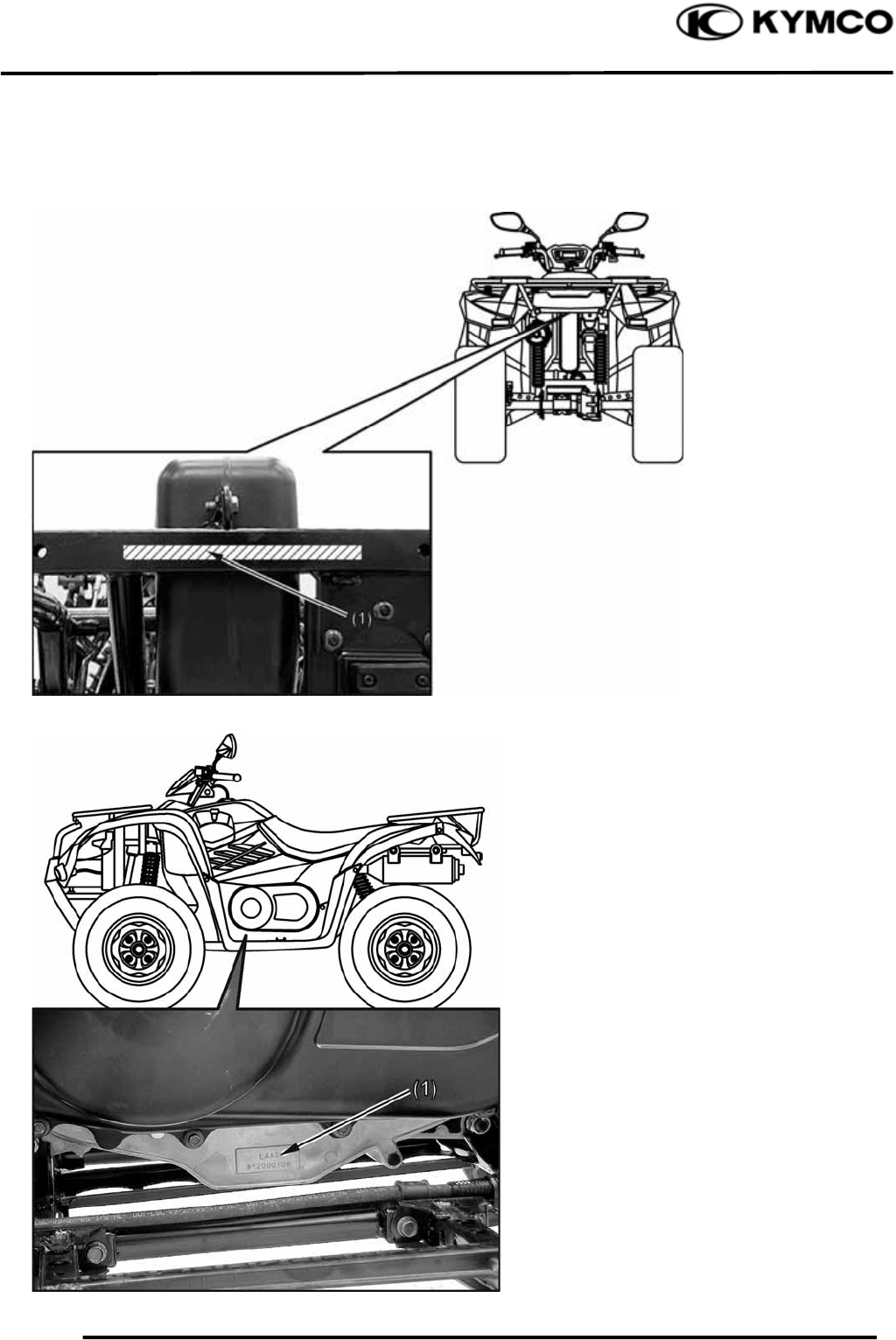
SERIAL NUMBER
(1) Location of Engine Serial Numbe
r
(1) Location of Frame Serial Numbe
r
1. GENERAL INFORMATION
1-2
MXU 500
SPECIFICATIONS
Model No. LAA0
Name & Type MXU 500
Overall length 2203 mm (88.12 in)
Overall width 1223 mm (48.92 in)
Overall height 1240 mm (49.6 in)
Wheel base 1293 mm (51.72 in)
Engine type O.H.C.
Displacement 498.5 cm3
(30.48 cu-in)
Fuel used 92# nonleaded gasoline
Front wheel 154 kg (338.8 lbs)
Rear wheel 134 kg (294.8 lbs)
Dry weight
Total 288 kg (633.6 lbs)
Front wheel 164 kg (360.8 lbs)
Rear wheel 144 kg (316.8 lbs)
Curb weight
Total 308 kg (648 lbs)
Front wheel 25X8-12
Tires Rear wheel 25X10-12
Ground clearance 235 mm (9.4 in)
Min. turning radius 3350 mm (134 in)
Starting system Electric/Recoil
starter
Type Gasoline, 4-stroke
Cylinder arrangement Single cylinder
Combustion chamber type Semi-sphere
Valve arrangement O.H.C., chain drive
Bore x stroke 92X75 mm
(3.68X3 in)
Compression ratio 10.5:1
Compression pressure 15 kgf/cm²
(1500kPa, 213 psi)
Opens 5° BTDCIntake valve
(at 1mm lift) Closes 45° ABDC
Opens 45° BBDCExhaust valve
(at 1mm lift) Closes 5° ATDC
Intake 0.1 mm (0.004 in)Valve clearance
(cold) Exhaust 0.1 mm (0.004 in)
Idle speed (rpm) 1500 rpm
Cooling type Liquid cooled
Lubrication type Forced pressure &
Wet sump
Oil pump type Trochoid
Oil filter type Full-flow filtration
Oil capacity 3.6 L (3.17 lmp qt,
3.82 Us qt)
Oil exchanging capacity 3 L (2.64 lmp qt,
3.18 Us qt)
After draining and oil
filter cartridge change
3.2 L (2.82 lmp qt,
3.39 Us qt)
Air cleaner type & No Wet type element
Fuel capacity 17 L (3.57 lmp gal,
4.42 US gal
Type CVK
ON ROAD #128Main
jet OFF ROAD #130
Slow jet #40
Choke jet #90
Type Full transistor digital
ignition
Ignition timing 5°/1500 rpm
Spark plug CR7E (NGK)
Spark plug gap 0.6~0.7mm
(0.024~0.028 in)
Battery Capacity 12V18AH
Clutch type Wet, centrifugal
automatic
Clutch operation system Automatic (V-belt)
Primary reduction system V-belt
Secondary reduction
system Shaft drive
High reduction ratio 3.76
Low reduction ratio 6.464
Reverse ratio 5.31
FR/RR tire rolling
circumference
1995/1995 mm
(79.8/79.8 in)
Front
Tire pressure
Rear
0.28 kg/cm²
(28 Kpa, 3.2 psi)
Left 36°
Turning angle
Right 36°
Front Disk brake
Brake system type Rear Disk brake
Front Double wishbone
Suspension type Rear Link suspension
Frame type Double cradle
Engine
I
g
nition S
y
stem
Drive Train Moving Device
Lubrication System Fuel S
y
stem
Carbureto
r
Electrical Equipment
1. GENERAL INFORMATION
1-3
MXU 500
SERVICE PRECAUTIONS
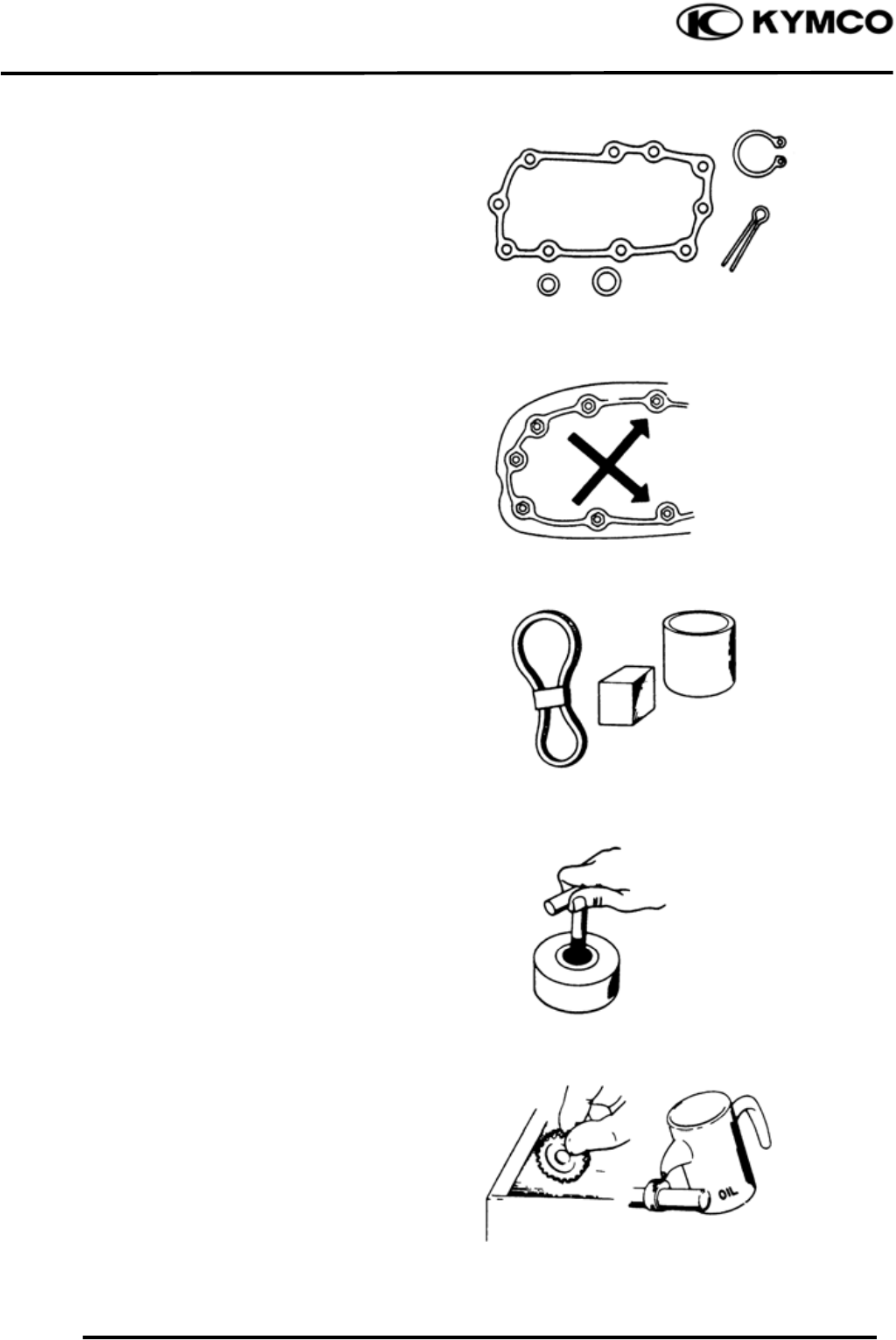
Make sure to install new gaskets, O-rings,
circlips, cotter pins, etc. when reassembling.
When tightening bolts or nuts, begin with
larger-diameter to smaller ones at several
times, and tighten to the specified torque
diagonally.
Use genuine parts and lubricants.
When servicing the motorcycle, be sure to
use special tools for removal and
installation.
After disassembly, clean removed parts.
Lubricate sliding surfaces with engine oil
before reassembly.
1. GENERAL INFORMATION
1-4
MXU 500
Apply or add designated greases and
lubricants to the specified lubrication
points.
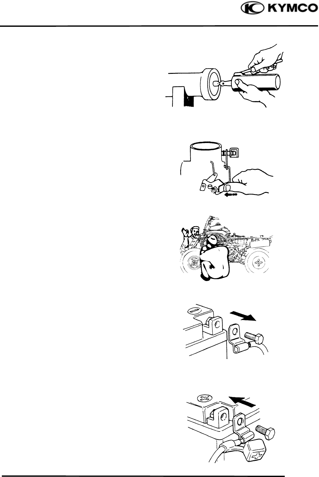
After reassembly, check all parts for proper
tightening and operation.
When two persons work together, pay
attention to the mutual working safety.
Disconnect the battery negative (-) terminal
before operation.
When using a spanner or other tools, make
sure not to damage the motorcycle surface.
After operation, check all connecting points,
fasteners, and lines for proper connection
and installation.
When connecting the battery, the positive (+)
terminal must be connected first.
After connection, apply grease to the battery
terminals.
Terminal caps shall be installed securely.
1. GENERAL INFORMATION
1-5
MXU 500
If the fuse is burned out, find the cause and
repair it. Replace it with a new one
according to the specified capacity.
After operation, terminal caps shall be
installed securely.
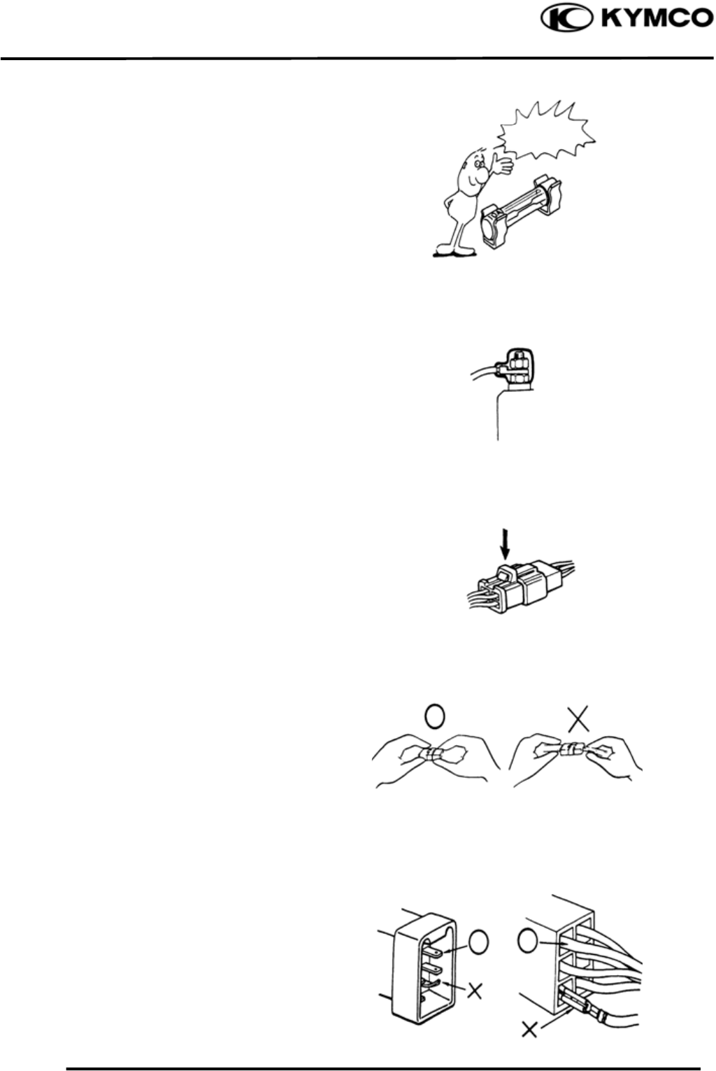
When taking out the connector, the lock on
the connector shall be released before
operation.
Hold the connector body when connecting
or disconnecting it.
Do not pull the connector wire.
Check if any connector terminal is bending,
protruding or loose.
Confir
m
Capacity
1. GENERAL INFORMATION
1-6
MXU 500
The connector shall be inserted
completely.
If the double connector has a lock, lock it
at the correct position.
Check if there is any loose wire.
Before connecting a terminal, check for
damaged terminal cover or loose
negative terminal.
Check the double connector cover for
proper coverage and installation.
Insert the terminal completely.
Check the terminal cover for proper
coverage.
Do not make the terminal cover opening
face up.
Secure wire harnesses to the frame with
their respective wire bands at the designated
locations.
Tighten the bands so that only the insulated
surfaces contact the wire harnesses.
Snapping!
1. GENERAL INFORMATION
1-7
MXU 500
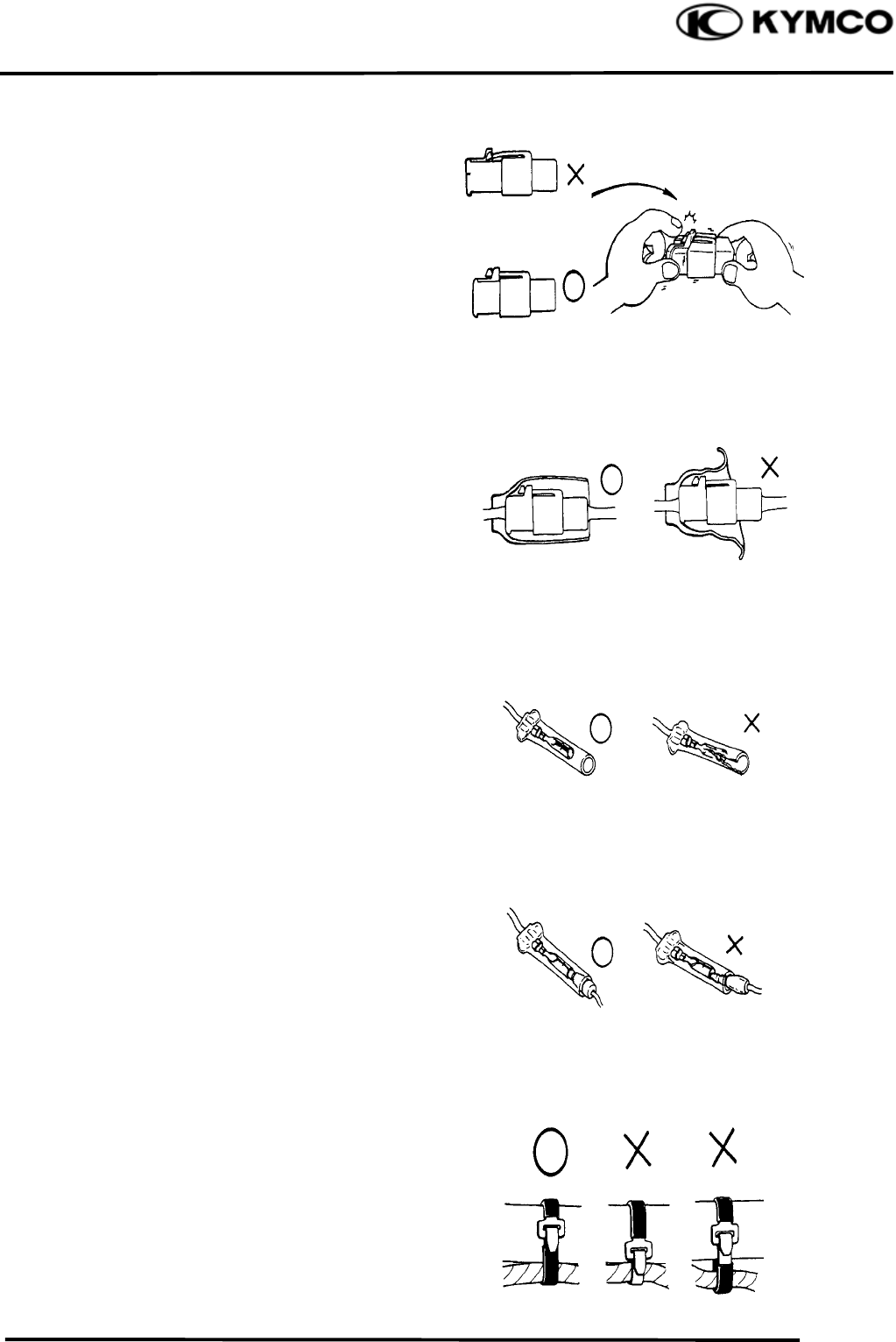
After clamping, check each wire to make
sure it is secure.
Do not squeeze wires against the weld or its
clamp.
After clamping, check each harness to make
sure that it is not interfering with any
moving or sliding parts.
When fixing the wire harnesses, do not
make it contact the parts which will
generate high heat.
Route wire harnesses to avoid sharp edges
or corners. Avoid the projected ends of
bolts and screws.
Route wire harnesses passing through the
side of bolts and screws. Avoid the
projected ends of bolts and screws.
N
o Contact !
1. GENERAL INFORMATION
1-8
MXU 500
Route harnesses so they are neither
pulled tight nor have excessive slack.
Protect wires and harnesses with electrical
tape or tube if they contact a sharp edge or
corner.
When rubber protecting cover is used to
protect the wire harnesses, it shall be
installed securely.
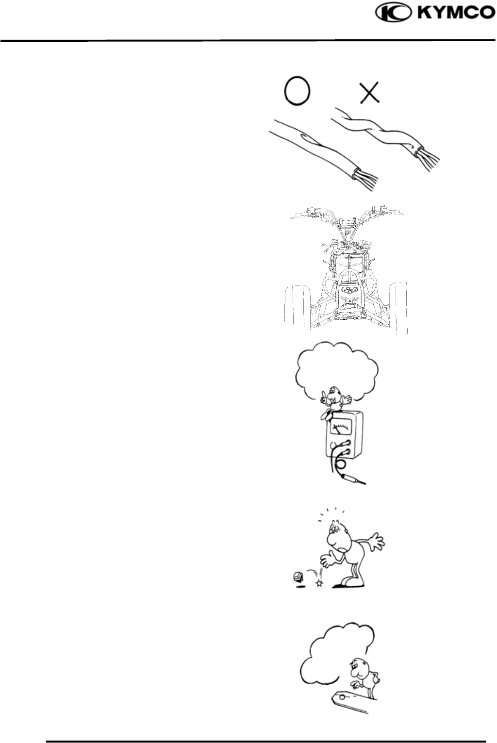
Do not break the sheath of wire.
If a wire or harness is with a broken sheath,
repair by wrapping it with protective tape or
replace it.
When installing other parts, do not press or
squeeze the wires.
Do not pull
too tight!
Do not press or
squeeze the wire.
1. GENERAL INFORMATION
1-9
MXU 500
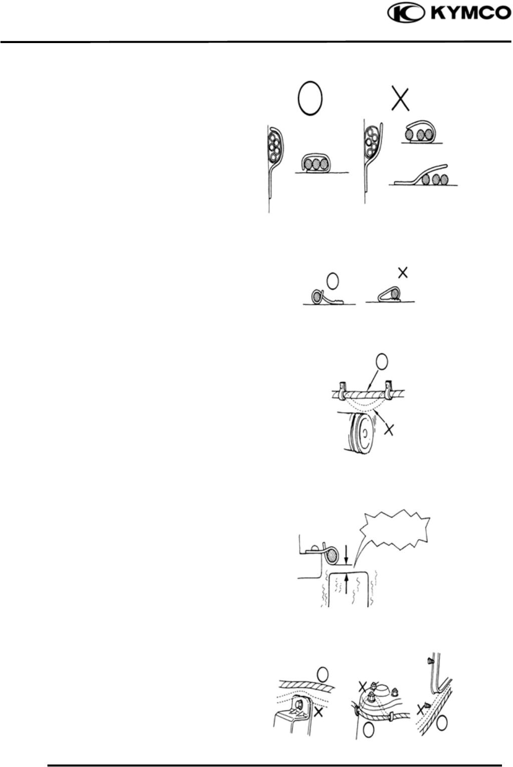
After routing, check that the wire harnesses
are not twisted or kinked.
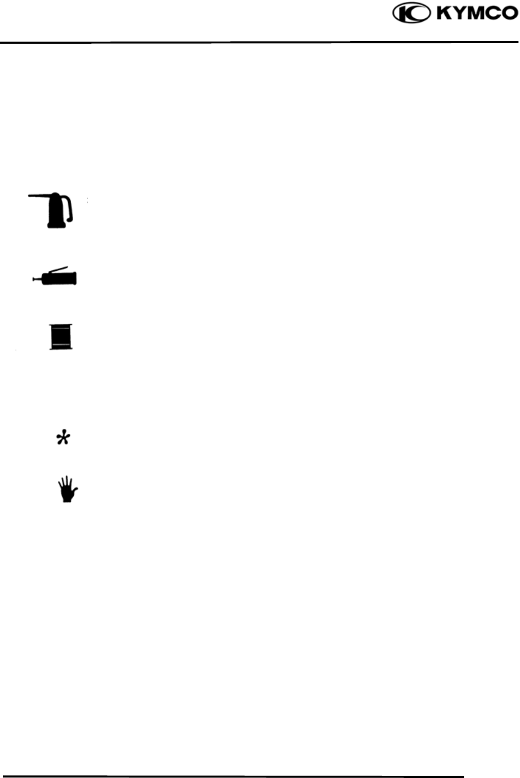
Wire harnesses routed along with handlebar
should not be pulled tight, have excessive
slack or interfere with adjacent or
surrounding parts in all steering positions.
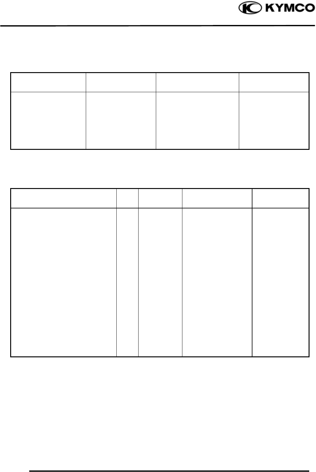
When a testing device is used, make sure to
understand the operating methods
thoroughly and operate according to the
operating instructions.
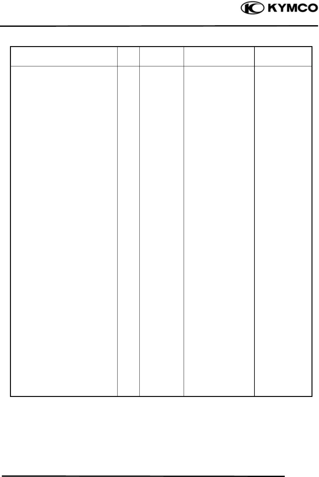
Be careful not to drop any parts.
When rust is found on a terminal, remove
the rust with sand paper or equivalent
before connecting.
Do you understand
the instrument? Is the
instrument set
correctly?
Remove Rust !
1. GENERAL INFORMATION
1-10
MXU 500
Symbols:
The following symbols represent the
servicing methods and cautions included in
this service manual.
: Apply engine oil to the
specified points. (Use
designated engine oil for
lubrication.)
: Apply grease for lubrication.
: Transmission Gear Oil (90#)
: Caution
: Warning
En
g
ine Oil
Grease
Gear Oil
1. GENERAL INFORMATION
1-11
MXU 500
TORQUE VALUES
STANDARD TORQUE VALUES
Item Torque
kgf-m (N-m, lbf-ft) Item Torque
kgf-m (N-m, lbf-ft)
5mm bolt and nut
6mm bolt and nut
8mm bolt and nut
10mm bolt and nut
12mm bolt and nut
14mm bolt and nut
0.5 (5, 3.6)
1 (10, 7.2)
2.2 (22, 16)
3.5 (35, 25)
5.5 (55, 40)
7 (70, 50)
4mm screw
5mm screw
6mm screw, SH bolt
6mm flange bolt and nut
8mm flange bolt and nut
10mm flange bolt and nut
0.3 (3, 2.2)
0.4 (4, 2.9)
0.9 (9, 6.5)
1.2 (12, 9)
2.7 (27, 20)
4 (40, 29)
Torque specifications listed below are for important fasteners.
ENGINE
Item Q‘ty Thread dia.
(mm)
Torque
kgf-m (N-m, lbf-ft) Remarks
MAINTENANCE:
Spark plug
Tappet ADJ nut
Engine oil filter cap
Engine oil filter cartridge
Engine drain plug
LUBRICATION SYSTEM:
Oil pump screw
Oil pipe bolt
COOLING SYSTEM:
Water pump bolt
Fan motor bolt
Fan motor switch
1
4
1
1
1
1
2
2
4
1
10
5
30
20
12
4
16
6
5
16
1.2 (12, 8.6)
0.9 (9, 6.5)
1.5 (15, 11)
1 (10, 7.2)
2.5 (25, 18)
0.3 (3, 2)
3.5 (35, 25.2)
1.3 (13, 9)
0.53 (5, 2.8)
1.8 (17, 13)
Apply oil
Apply oil
Apply oil
(Cont’d)
1. GENERAL INFORMATION
1-12
MXU 500
Item Q‘ty Thread dia.
(mm)
Torque
kgf-m (N-m, lbf-ft) Remarks
CYLINDER HEAD:
Cylinder head bolt
Cylinder head bolt
Cylinder head nut
Cylinder head cover
Breather separator bolt
Cam chain tensioner bolt
Tensioner sealing bolt
Rocker arm shaft
Chain guide pivot bolt
Water joint bolt
CYLINDER:
Cylinder bolt
DRIVE/DRIVEN PULLEY:
Drive pulley nut
Wet clutch nut
Driven pulley nut
Driven pulley assembly plate nut
TRANSMISSION:
Crankcase bolt
Drive bevel gear nut
Driven bevel gear nut
Stopper lever bolt
Stopper lever boss nut
Shift came stopper plug
Output shaft bearing nut
Drive shaft bearing bolt
STARTER SYSTEM:
Starter pulley nut
4
9
2
4
3
2
1
2
2
2
2
1
1
1
1
19
1
1
1
1
1
1
4
1
10
8
6
6
6
6
10
18
8
6
6
20
25
16
36
6
20
20
8
12
20
85
8
14
4.8 (48, 34.6)
2.3 (23, 17)
1 (10, 7)
1 (10, 7)
1.3 (13, 9)
1.2 (12, 8.6)
1 (10, 7)
4.5 (45, 32.4)
2 (20, 15)
1.2 (12, 8.6)
1 (10, 7.2)
14 (140, 100.8)
14 (140, 100.8)
10 (100, 72)
7.5 (75, 54)
1.2 (12, 8.6)
14 (140, 100.8)
14 (140, 100.8)
2.5 (25, 18)
3 (30, 21.6))
4.8 (48, 35)
11 (110, 79.2)
3 (30, 21.6)
5.5 (55, 40)
Apply oil
Apply oil
Apply oil
Apply oil
Apply oil
Apply oil
Apply oil
Apply oil
Apply oil
1. GENERAL INFORMATION
1-13
MXU 500
FRAME
Item Q‘ty Thread
dia.
(mm)
Torque
K
g
f-
m
(
N-m,
lbf-ft)
Remarks
MAINTENANCE:
Rear drive gear oil drain bolt
Rear drive gear oil filler cap
Rear drive gear oil level check bolt
Front drive gear oil drain bolt
Front drive gear oil filler cap
Front drive gear oil level check bolt
Tie-rod adjusting nut
Front wheel hub nut
Rear wheel hub nut
EXHAUST MUFFLER:
Exhaust muffler mounting bolt
Exhaust pipe mounting nut
Exhaust muffler band bolt
ENGINE ASSEMBLY:
Engine mounting bolt/nut
Engine hanger nut
DRIVE TRAIN:
Front drive:
Front propeller shaft bolt
Front drive gear case mounting bolt
Shifting fork shaft plug
Front drive gear case bolt
2WD/4WD shift motor mounting bolt
2WD/4WD shift motor mounting bolt
Rear drive:
Rear drive gear case mounting nut
Rear drive gear case bolt
Rear drive gear case bolt
1
1
1
1
1
1
4
2
2
2
2
1
3
4
3
2
1
9
1
2
8
2
6
8
30
8
14
18
6
10
18
16
8
8
8
10
8
10
10
8
8
8
6
10
10
8
2 (20, 15)
1.5 (15, 11)
2 (20, 15)
3.2 (32, 23)
3.5 (35 25.5)
1 (10, 7.2)
3.5 (35 25.5)
7 (70, 50)
10 (100, 72)
3.5 (35, 25)
3.5 (35, 25)
2.1 (21, 15)
6 (60, 43.5)
3.5 (35, 25)
4.5 (45, 32.4)
4 (40, 29)
1.5 (15, 11)
2.3 (23, 16.5)
2.3 (23, 16.5)
1.2 (12, 8.5)
5.5 (55, 40)
5 (49, 36)
2.5 (25, 19)
Castle nut
Castle nut
Apply threebond: 1215
Apply threebond: 1215
Apply threebond: 1215
Apply threebond: 1215
Apply threebond: 1215
(Cont’d)

1. GENERAL INFORMATION
1-14
MXU 500
Item Q‘ty Thread
dia.
(mm)
Torque
K
g
f-
m
(
N-m,
lbf-ft)
Remarks
STEERING SYSTEM:
Handlebar holder bolt
Steering bracket
Steering column nut
Tie-rod ball joint nut
WHEEL:
Front wheel nut
Rear wheel nut
SUSPENSION:
Front:
Front swing arm bolt/nut
Knuckle ball joint nut
Front shock absorber mount bolt/nut
Rear:
Rear shock absorber mount bolt/nut
Right pivot bolt
Left pivot bolt
Left pivot lock nut
Axle housing mounting bolt/nut
BRAKE SYSTEM:
Front brake disc bolt
Rear brake disc bolt
Brake caliper mounting bolt
Brake hose oil bolt
Master cylinder holder bolt
Brake pad mounting bolt
Bleed valve nut
Delay valve mounting bolt
Delay valve plug
4
2
1
4
8
8
6
4
4
4
1
1
1
8
8
4
8
10
4
8
5
2
1
8
8
14
10
10
10
10
12
10
10
30
30
30
10
8
8
8
10
6
8
6
6
20
2.5 (25, 18)
2.2 (22, 16)
7 (70, 50)
2.1 (21, 16)
6.5 (65, 46)
6.5 (65, 46)
4.5 (45, 32)
3 (30, 22)
4 (40, 29)
4 (40, 29)
11.8 (118, 85)
1.1 (11, 8)
11.8 (118, 85)
5.5 (55, 40)
3.5 (35, 25.2)
3.5 (35, 25.2)
3.2 (32, 24)
3.5 (35, 25)
1.2 (12, 8.6)
1.8 (18, 13)
0.6 (6, 4.32)
1.2 (12, 8.6)
5 (50, 36)
Castle nut
Castle nut
OFF ROAD: 4 Q’ty
ON ROAD only
ON ROAD only
1. GENERAL INFORMATION
1-15
MXU 500
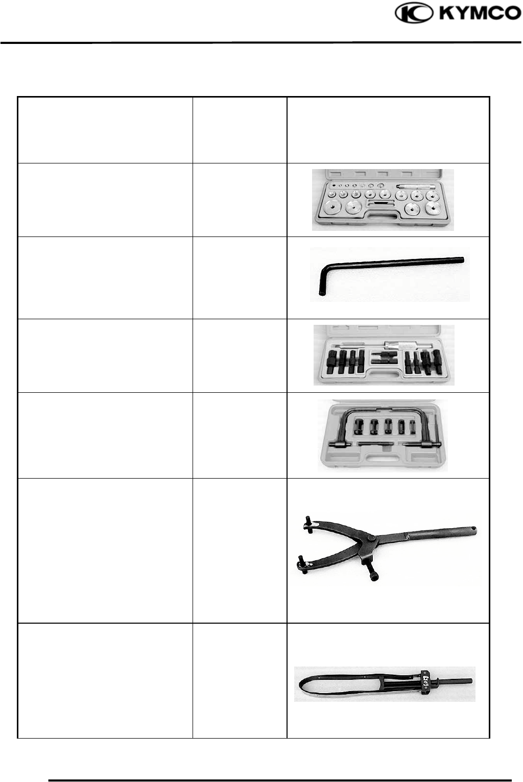
SPECIAL TOOLS
Tool Name Tool No.
Illustration
(Note: the special tools may differ
slightly from those shown in the
figure of this manual.)
Oil seal and bearing
installer A120E00014
Valve adjuster
(Refer to the “VALVE
CLEARANCE” section in the
chapter 3.)
A120E00036
Bearing puller A120E00037
Valve spring compressor
(Refer to the “CYLINDER HEAD
DISASSEMBLY/INSPECTION/
ASSEMBLY” section in the
cha
p
ter 8.
)
A120E00040
Universal holder
(Refer to the “DRIVE PULLEY,
DRIVE V-BELT AND DRIVEN
PULLEYREMOVAL/
INSPECTION/
INSTALLATION” section and
“CLUTCH REMOVAL/
INSTALLATION” section in the
chapter 10.)
A120E00056
Drive pulley holder
(Refer to the “DRIVE PULLEY,
DRIVE V-BELT AND DRIVEN
PULLEYREMOVAL/
INSPECTION/
INSTALLATION” section in the
chapter 10.)
A120E00058
(Cont’d)
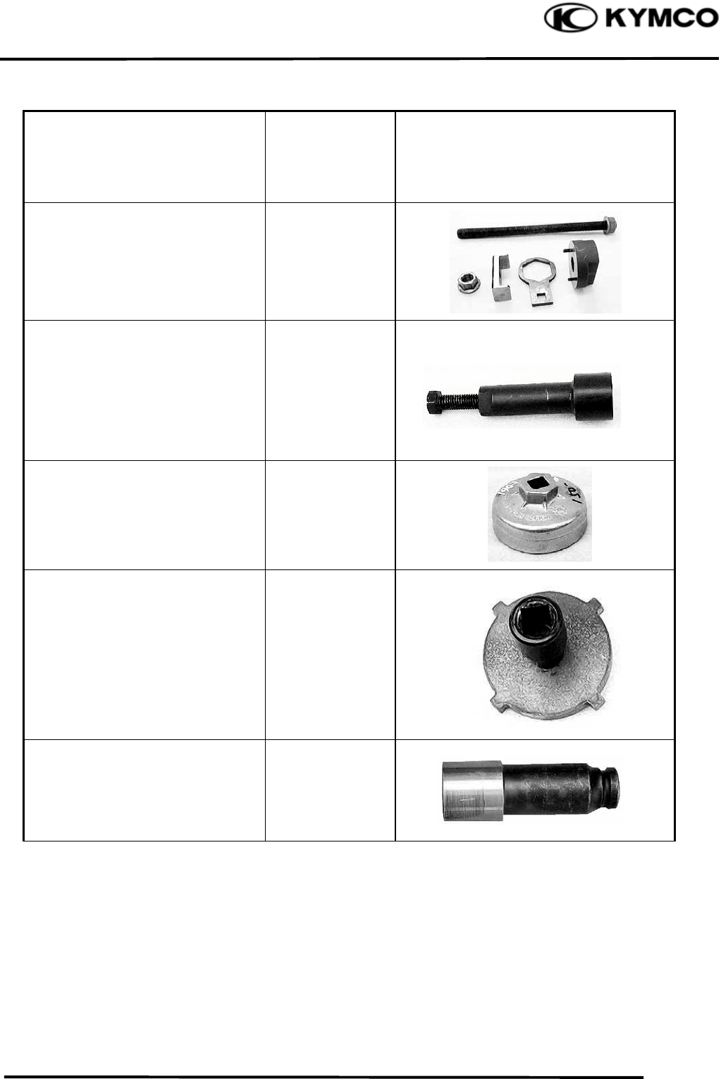
1. GENERAL INFORMATION
1-16
MXU 500
Tool Name Tool No.
Illustration
(Note: the special tools may differ
slightly from those shown in the
figure of this manual.)
Driven pulley holder
(Refer to the “DRIVEN PULLEY
DISASSEMBLY/INSPECTION/
ASSEMBLY” section in the chapter
10.
)
A120E00059
Flywheel puller
(Refer to the “STARTER
CLUTCH REMOVAL/
INSPECTION/
INSTALLATION” section in the
chapter 19.)
A120E00060
Oil filter cartridge wrench
(Refer to the “(Refer to the
“ENGINE OIL” section in the
chapter 3.)
A120E00061
Output shaft bearing nut
wrench
(Refer to the “(Refer to the
“BEARING REPLACEMENT
IN THE RIGHT
CRANKCASE” section in the
chapter 11.)
A120E00066
Lock nut wrench
(Refer to the “CLUTCH
REMOVAL/INSTALLATION”
section in the chapter 10)
A120E00067
(Cont’d)

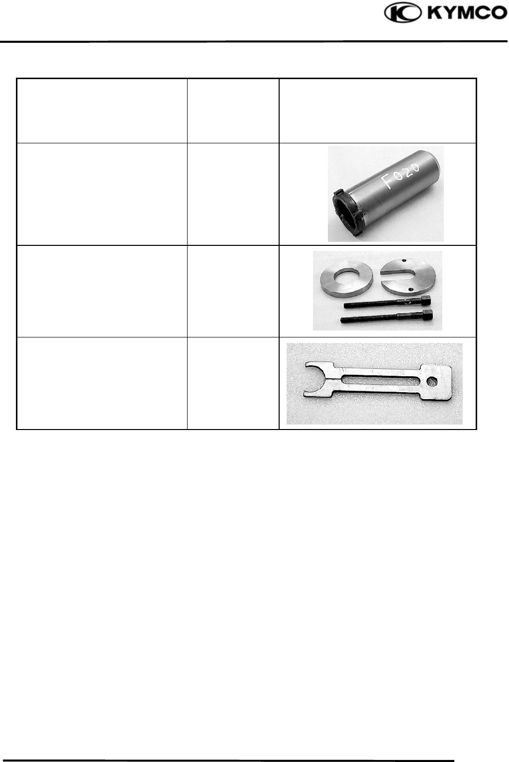
1. GENERAL INFORMATION
1-17
MXU 500
Tool Name Tool No.
Illustration
(Note: the special tools may differ
slightly from those shown in the
figure of this manual.)
Crankshaft bearing puller A120E00068
Ball joint remover
(Refer to the “STEERING
KNUCKLE REMOVAL/
INSPECTION/
INSTALLATION” section in the
chapter 15)
A120F00012
Left pivot lock nut wrench
(Refer to the “REAR SWING
ARM REMOVAL/
INSTALLATION” section in the
chapter 15)
A120F00013
Joint yoke puller
(Refer to the “FRONT DRIVE
DISASSEMBLY/INSPECTION/
ASSEMBLY” section in the
chapter 13)
A120F00016
Drive shaft puller
(Refer to the “FRONT DRIVE
SHAFT REOMVAL/
INSPECTION/
INSTALLATION” section in the
chapter 13)
A120F00017
Yoke bearing puller
(Refer to the “FRONT DRIVE
DISASSEMBLY/INSPECTION/
ASSEMBLY” section in the
chapter 13)
A120F00018
(Cont’d)
1. GENERAL INFORMATION
1-18
MXU 500
Tool Name Tool No.
Illustration
(Note: the special tools may differ
slightly from those shown in the
figure of this manual.)
Pinion bearing lock nut
wrench
(Refer to the “REAR DRIVE
DISASSEMBLY/INSPECTION/
ASSEMBLY” section in the chapter
13.)
A120F00020
Pinion puller
(Refer to the “REAR DRIVE
DISASSEMBLY/INSPECTION/
ASSEMBLY” section in the chapter
13.)
A120F00021
C-ring remover
(Refer to the “FRONT DRIVE
DISASSEMBLY/INSPECTION/
ASSEMBLY” section in the
chapter 13)
A120F00022
1. GENERAL INFORMATION
1-19
MXU 500
LUBRICATION POINTS
ENGINE
Lubrication Points Lubricant
Valve guide/valve stem movable part
Camshaft protruding surface
Valve rocker arm friction surface
Camshaft drive chain
Cylinder lock bolt
Piston surroundings and piston ring grooves
Piston pin surroundings
Cylinder inside wall
Connecting rod/piston pin hole
Connecting rod big end
Clutch
Crankshaft
Balance shaft
Crankshaft one-way clutch movable part
Recoil starter pulley
Oil pump drive chain
Starter reduction gear
Starter one-way clutch
O-ring face
Oil seal lip
Output shaft
Bevel gear
Drive shaft
Countershaft
Main shaft
Transmission gear shaft bearing part
•Genuine KYMCO Engine Oil (SAE5W-50)
•API SJ Engine Oil
Front drive gear and bearing part Gear oil: SAE 90#
Rear drive gear and bearing part Gear oil: SAE 80#
1. GENERAL INFORMATION
1-20
MXU 500
FRAME
The following is the lubrication points for the frame.
Use general purpose grease for parts not listed.
Apply clean engine oil or grease to cables and movable parts not specified. This will avoid
abnormal noise and rise the durability of the ATV.
Steering Column Uppe
r
Throttle Cable
Steering Column Lowe
r
Front Swing Arm Bush
Front Swing Arm Bush
1. GENERAL INFORMATION
1-21
MXU 500
CABLE & HARNESS ROUTING
Remove the fuel tank and fuel valve
together (refer to the “FUEL TANK”
section in the chapter 5).
*
Remove the front cooling duct (refer to
the “ENGINE REMOVAL” section in
the chapter 7).
*
Remove the rear cooling duct (refer to
the “ENGINE REMOVAL” section in
the chapter 7).
*
1. GENERAL INFORMATION
1-22
MXU 500
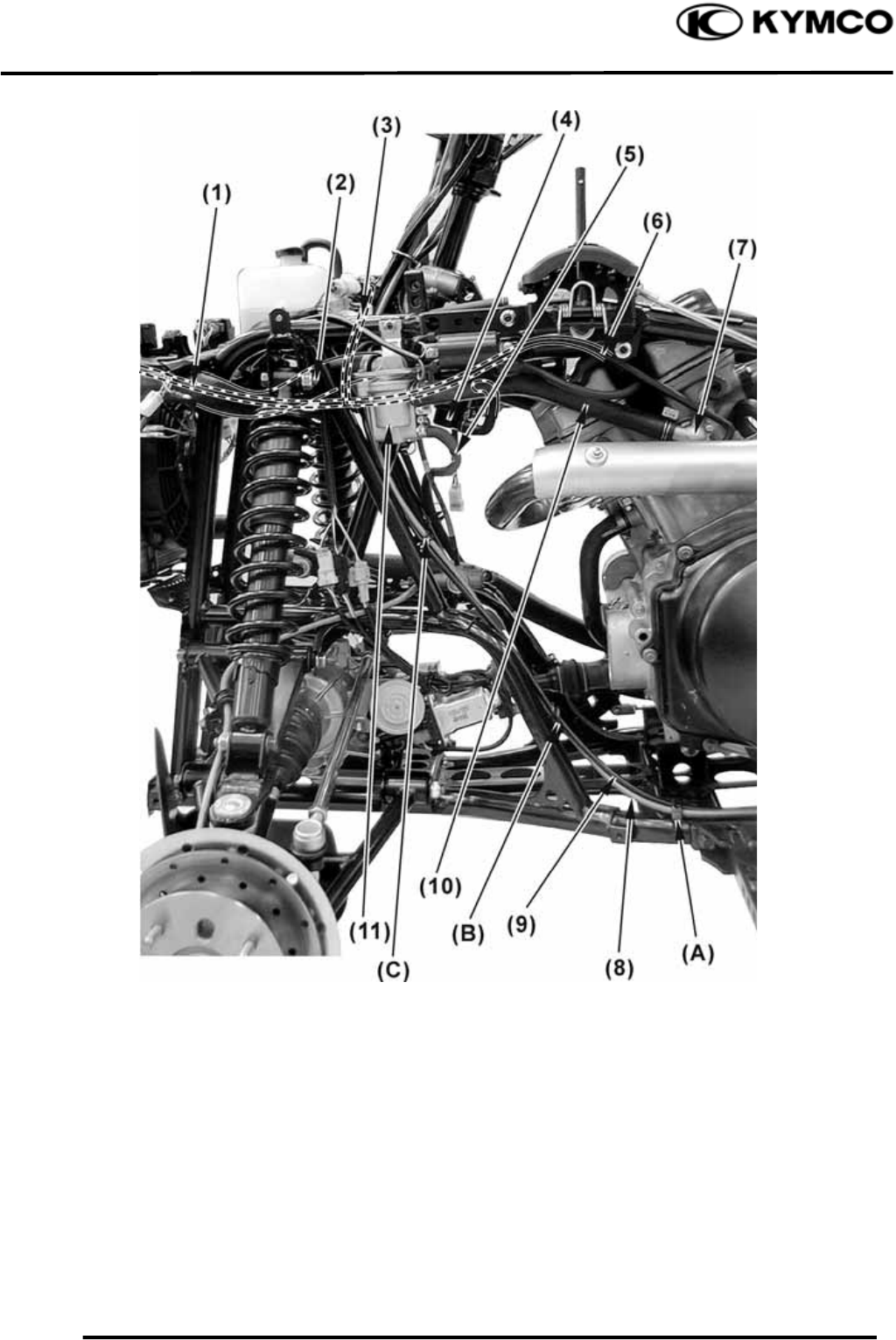
(1) Throttle cable (7) Brake light switch wire
(2) Instrument connector (8) Rear brake hose (Brake lever)
(3) Ignition switch wire (9) 2WD/4WD switch wire
(4) Accessory socket connectors (10) Choke cable
(5) Left handlebar switch (11) Front brake hose
(6) Rear parking brake cable (ON ROAD) (12) Brake light switch wire
(A) Pass the brake light switch wire and left handlebar switch wire through the band.
(B) Passe the throttle cable, chock cable, brake light switch wires, 2WD/4WD switch wire, front brake
hose, rear brake hose, instrument connector wire, accessory socket connector wire, rear parking
brake cable (ON ROAD), left handlebar switch wire and ignition switch wire through the guide.
(C) Pass the 2WD/4WD switch wire through the band.
1. GENERAL INFORMATION
1-23
MXU 500
(1) Fan EMI filter (12) Ignition coil wire
(2) Headlight connector (13) 2WD /4WD start switch
Right front signal light connectors (ON ROAD) /2WD/4WD motor connectors
(3) Harness wire (14) Left handlebar switch connectors
(4) Siphon hose (15) Upper radiator hose
(5) Over flow hose (Reserve tank) (16) Headlight connector
(6) Ignition switch connector Left front signal light
(7) Air bleed hose connectors (ON ROAD)
(8) 2WD/4WD switch connector (17) Air bleed hose
(9) Fuel tank flow hose (connect the fuel tank cover, Note) (18) LO beam relay
(10) Air bleed hose (19) HI beam relay
(11) Ignition coil (20) 2WD/4WD change ECU
(A) Pass the air bleed hose through the guide.
Note: The fuel tank flow hose may locate the frame right side for some model.
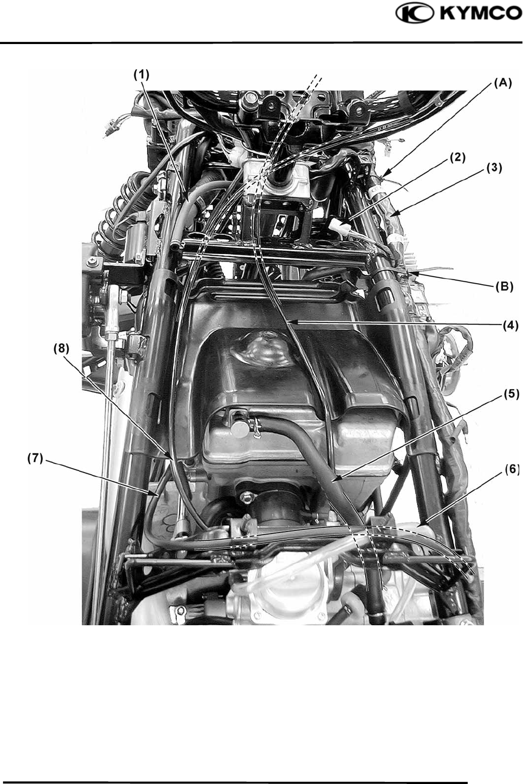
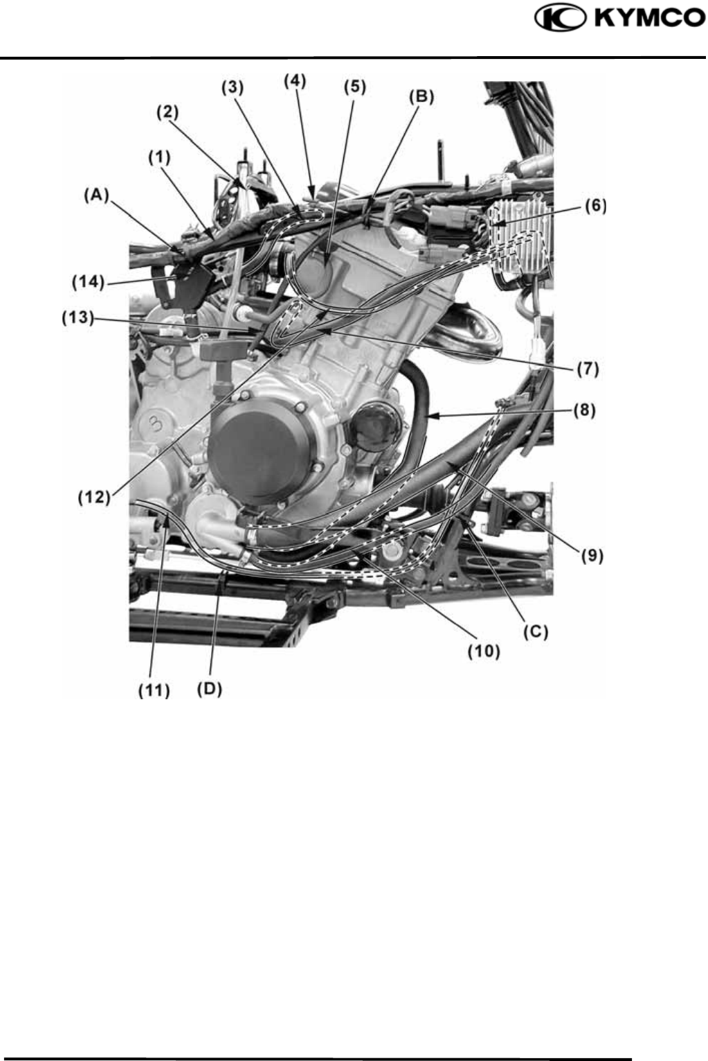
1. GENERAL INFORMATION
1-24
MXU 500
(1) Fuel tank flow hose (connect the fuel tank cover, Note) (5) Crankcase breather hose
(2) Hazard connector (ON ROAD) (6) Over flow (carburetor)
(3) Harness wire (7) Water temperature sensor wire
(4) Throttle cable (8) Choke cable
(A) Pass the harness wire through the band.
(B) Pass the harness wire through the band.
Note: The fuel tank flow hose may locate the frame right side for some model.
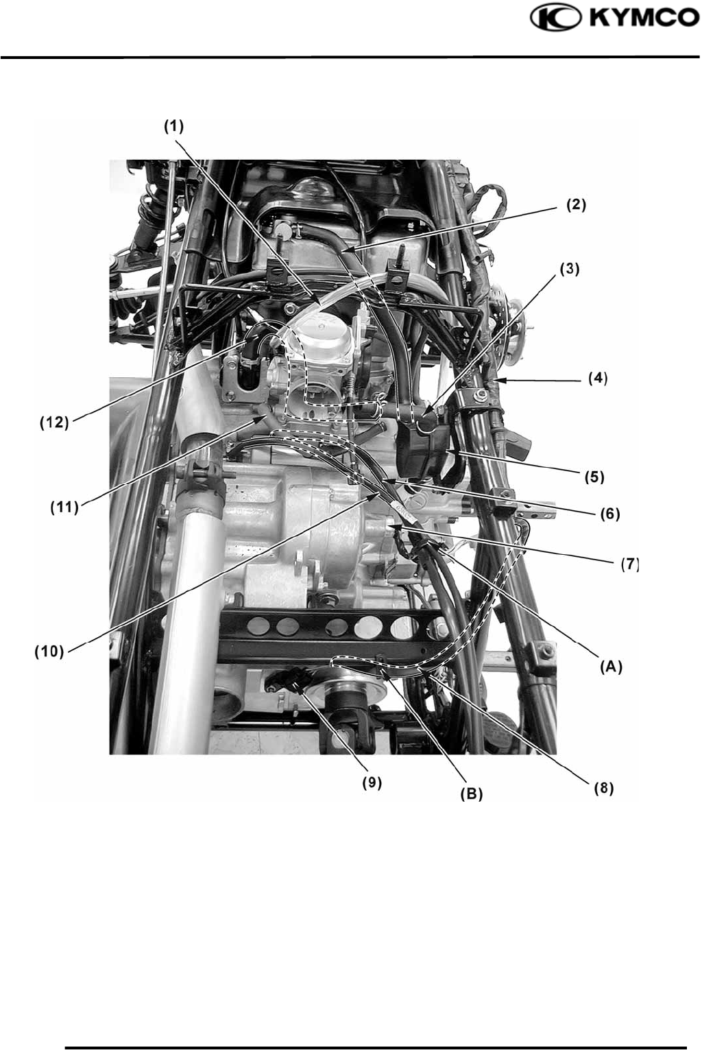
1. GENERAL INFORMATION
1-25
MXU 500
(1) Over flow (carburetor) (7) Gear position light switch
(2) Crankcase breather hose (8) Speed sensor wire
(3) Crankcase breather hose (9) Speed sensor
(4) Harness wire (10) Engine ground cable
(5) Crankcase breather hose joint (11) Fuel hose
(6) Starter motor cable (12) AICV air supply hose
(A) Pass the starter motor cable, engine ground cable and gear position light wire through the band.
(B) Pass the speed sensor wire through the band.
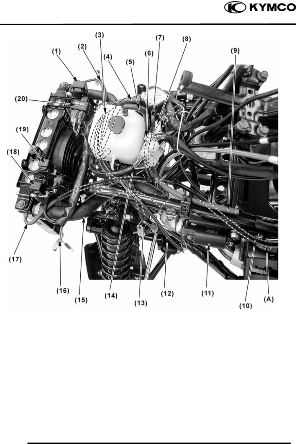
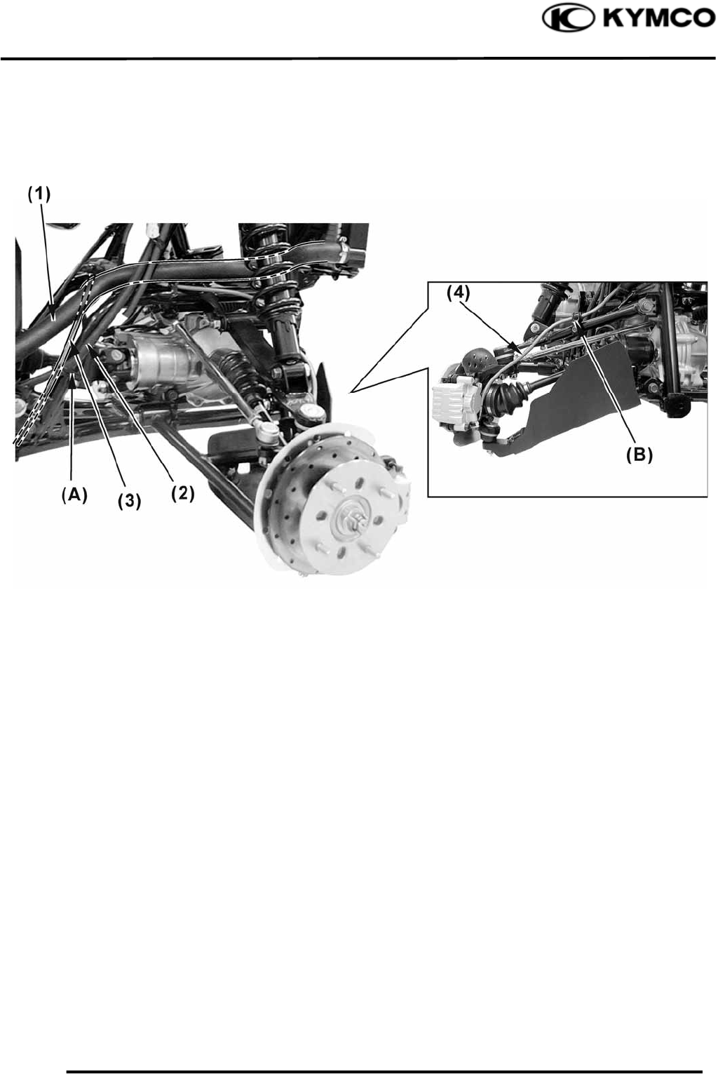
1. GENERAL INFORMATION
1-26
MXU 500
(1) Upper radiator hose (10) Rear parking brake cable (ON ROAD)
(2) Ignition coil wire (11) Front brake hose
(3) Air bleed hose (12) 2WD /4WD start switch//2WD/4WD motor connectors
(4) Air bleed hose (13) Thermostat
(5) Ignition coil (14) Fan motor switch
(6) Water hose (15) Headlight connector
(7) Water bypass hose Left front turn signal light connectors (ON ROAD)
(8) Delay valve (ON ROAD) (16) Air bleed hose
(8) Brake fluid joint (OFF ROAD) (17) Front brake hose
(9) Rear brake hose (Brake lever)
(A) Pass the rear parking cable (ON ROAD) and rear brake hose through the guide.
(B) Pass the rear parking cable (ON ROAD) and rear brake hose through the guide.
(C) Pass the front brake hose through the guide.
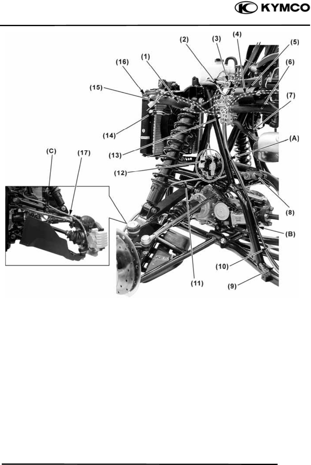
1. GENERAL INFORMATION
1-27
MXU 500
(1) Air bleed hose (7) Water joint
(2) Upper radiator hose (8) Rear brake hose (Brake lever)
(3) Air bleed hose (9) Rear parking brake cable (ON ROAD)
(4) AICV control solenoid valve (10) Water hose
(5) Water bypass hose (11) Thermostat
(6) Air bleed hose
Pass the rear parking brake and rear brake hose through the guide (A), (B) and (C).
1. GENERAL INFORMATION
1-28
MXU 500
(1) Rear brake hose (Brake pedal) (3) Rear brake hose (Brake lever)
(2) Rear parking brake cable (ON ROAD)
● Pass the rear parking brake cable (ON ROAD) and rear brake hose (Brake lever) through the guide
(A), (B), (C), band (D) and guide (E).
1. GENERAL INFORMATION
1-29
MXU 500
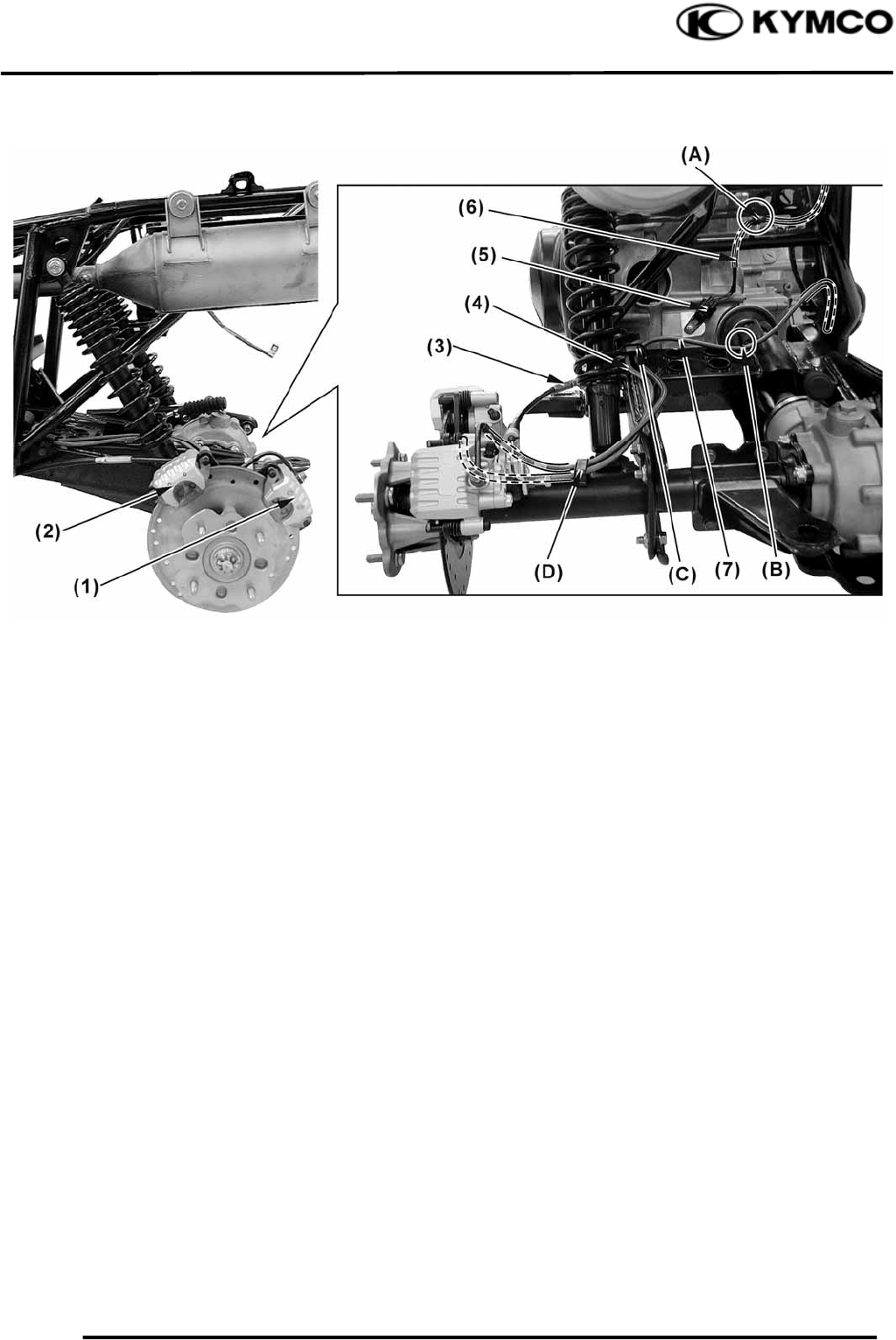
(1) Rear caliper (Brake pedal) (5) Speed sensor
(2) Rear caliper (Brake lever) (6) Speed sensor wire
(3) Rear parking brake cable (ON ROAD) (7) Rear brake hose (Brake pedal)
(4) Rear brake hose (Brake lever)
(A) Pass the speed sensor wire through the guide.
(B) Pass the rear brake hose (Brake pedal) through the guide.
(C) Pass the rear brake hose (Brake pedal) and rear brake hose (Brake lever) through the guide.
(D) Pass the rear brake hose (Brake pedal) and rear brake hose (Brake lever) through the guide.
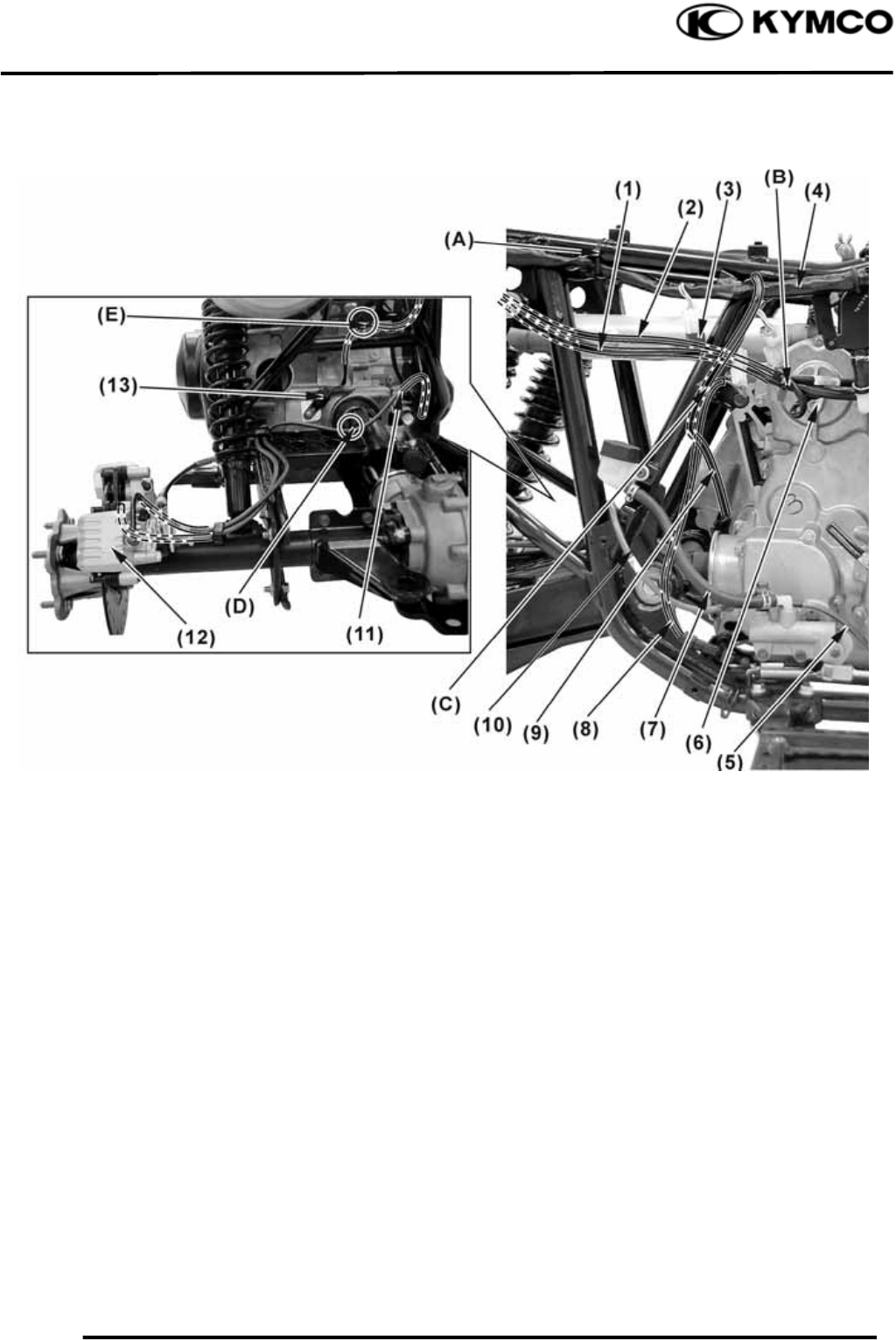
1. GENERAL INFORMATION
1-30
MXU 500
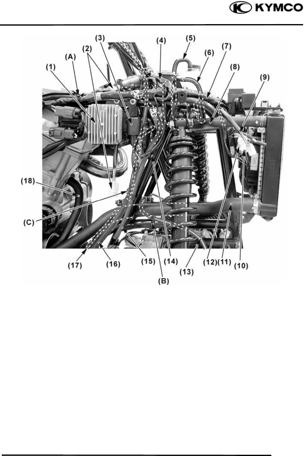
(1) Regulator/Rectifier (10) Fan motor connector
(2) Hazard connector (ON ROAD) (11) Low radiator hose
(3) Flasher relay (ON ROAD) (12) EMI filter
(4) Instrument wire (13) Front brake hose
(5) Over flow hose (reserve tank) (14) Horn (ON ROAD)
(6) Siphon hose (15) Fuel flow hose
(7) Harness wire (16) Water bypass hose
(8) Coolant filler hose (17) Combined brake hose ( ON ROAD)
(9) Headlight connector (18) water hose
Right front turn signal light connectors (ON ROAD)
(A) Pass the harness wire through the band.
(B) Pass the front brake hose through the guide.
(C) Pass the fuel flow hose and water bypass hose through the guide.
1. GENERAL INFORMATION
1-31
MXU 500
(1) Low radiator hose (3) Combined brake hose (ON ROAD)
(2) Water bypass hose (4) Front brake hose
(A) Pass the front brake hose (combined) and water bypass hose through the guide.
(B) Pass the front brake hose through the guide.
1. GENERAL INFORMATION
1-32
MXU 500
(1) Harness wire (8) Water hose
(2) Over flow (carburetor) (9) Low radiator hose
(3) Crankcase breather hose (10) Water bypass hose
(4) Fuel unit connectors (11) Combined brake hose (ON ROAD)
(5) Fuel hose (12) AICV vacuum hose (Note)
(6) AICV air supply hose (13) A.C.G. wire
(7) AICV air supply hose (Note) (14) Crankcase breather housing
(A) Pass the harness wire through the guide.
(B) Pass the A.C.G. wire through the guide.
(C) Pass the combined brake hose (ON ROAD) and water bypass hose through the guide.
(D) Pass the combined brake hose (ON ROAD) through the guide.
Note: Pass the AICV air supply hose and AICV vacuum hose through the guide (B).
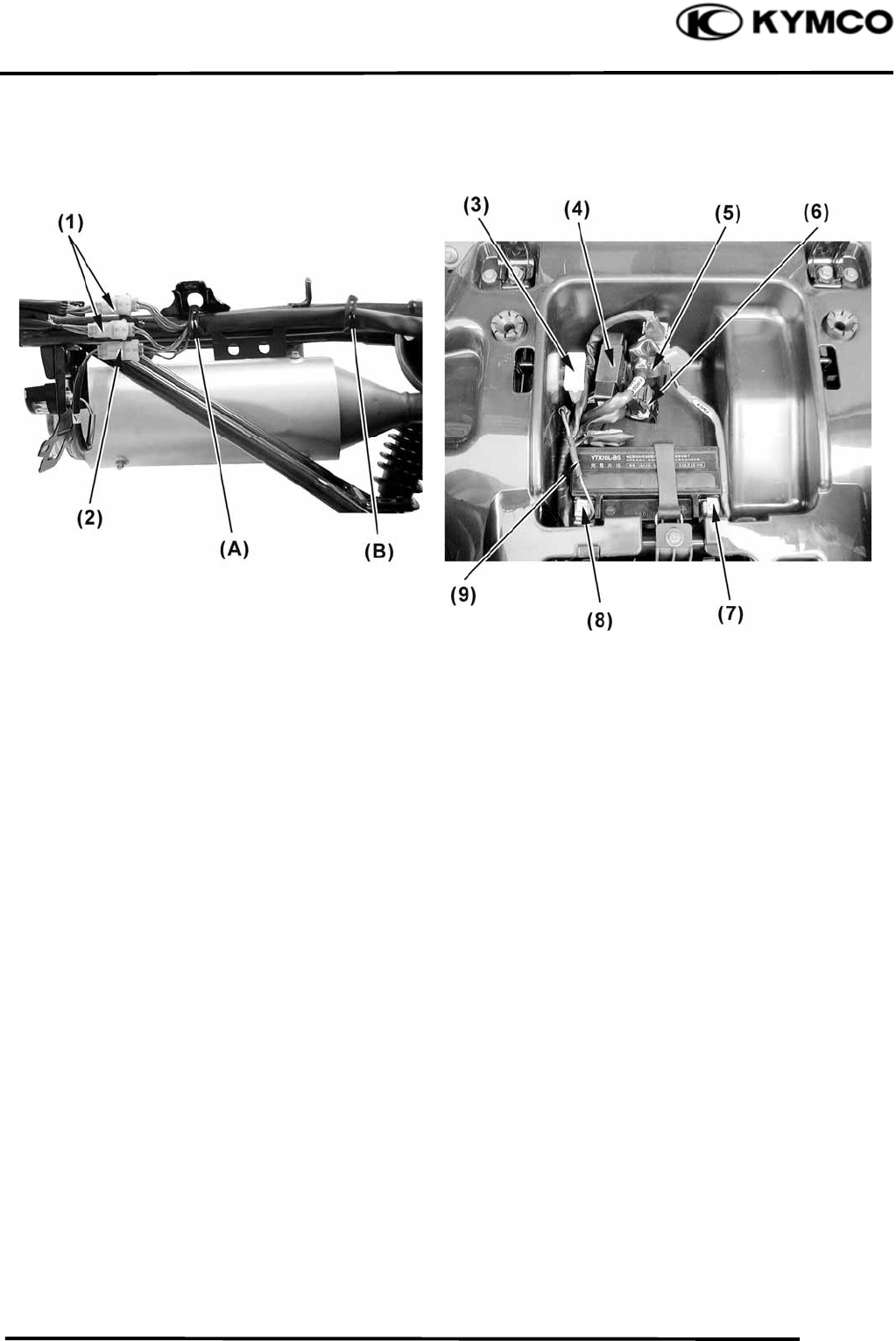
1. GENERAL INFORMATION
1-33
MXU 500
(1) Starter motor cable (8) Brake light switch
(2) Engine ground cable (9) Speed sensor wire
(3) Clutch diode (10) Rear brake hose (Brake pedal)
(4) Harness wire (11) Rear brake hose (Brake pedal)
(5) Combined brake hose (ON ROAD) (12) Rear caliper (Brake pedal)
(6) Gear position light switch (13) Speed sensor
(7) Brake fluid filler hose
(A) Pass the harness wire through the band.
(B) Pass the gear position light switch wire, starter motor cable and engine ground cable through the
band.
(C) Pass the speed sensor wire and brake light switch wire through the guide.
(D) Pass the rear brake hose (Brake pedal) through the guide.
(E) Pass the speed sensor wire through the guide.
1. GENERAL INFORMATION
1-34
MXU 500
(1) Taillight/Brake light/Rear turn signal light connectors (OFF ROAD)
(1) Taillight/Brake light/Rear turn signal light connectors (ON ROAD)
(2) License light connector (ON ROAD)
(3) Fuse box
(4) Ignition unit
(5) Starter MAG
(6) Starter relay
(7) Positive terminal lead
(8) Negative terminal lead
(9) Frame ground wire
● Pass the harness wire through the guide (A) and (B).
1. GENERAL INFORMATION
1-35
MXU 500
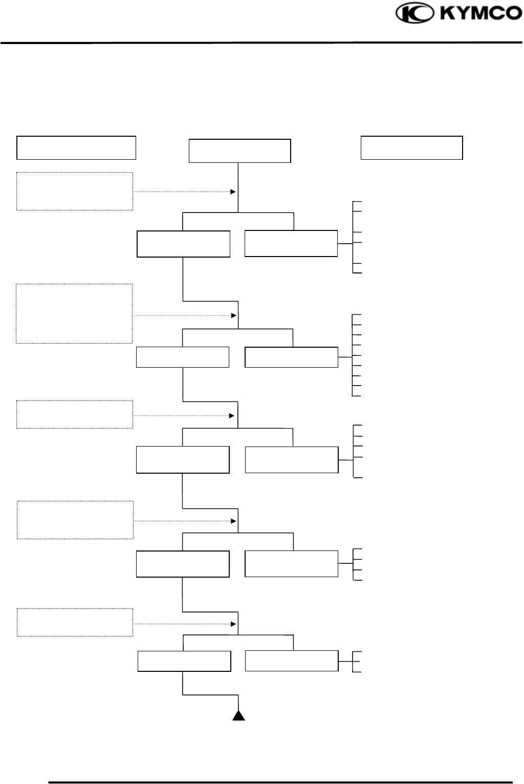
TROUBLESHOOTING
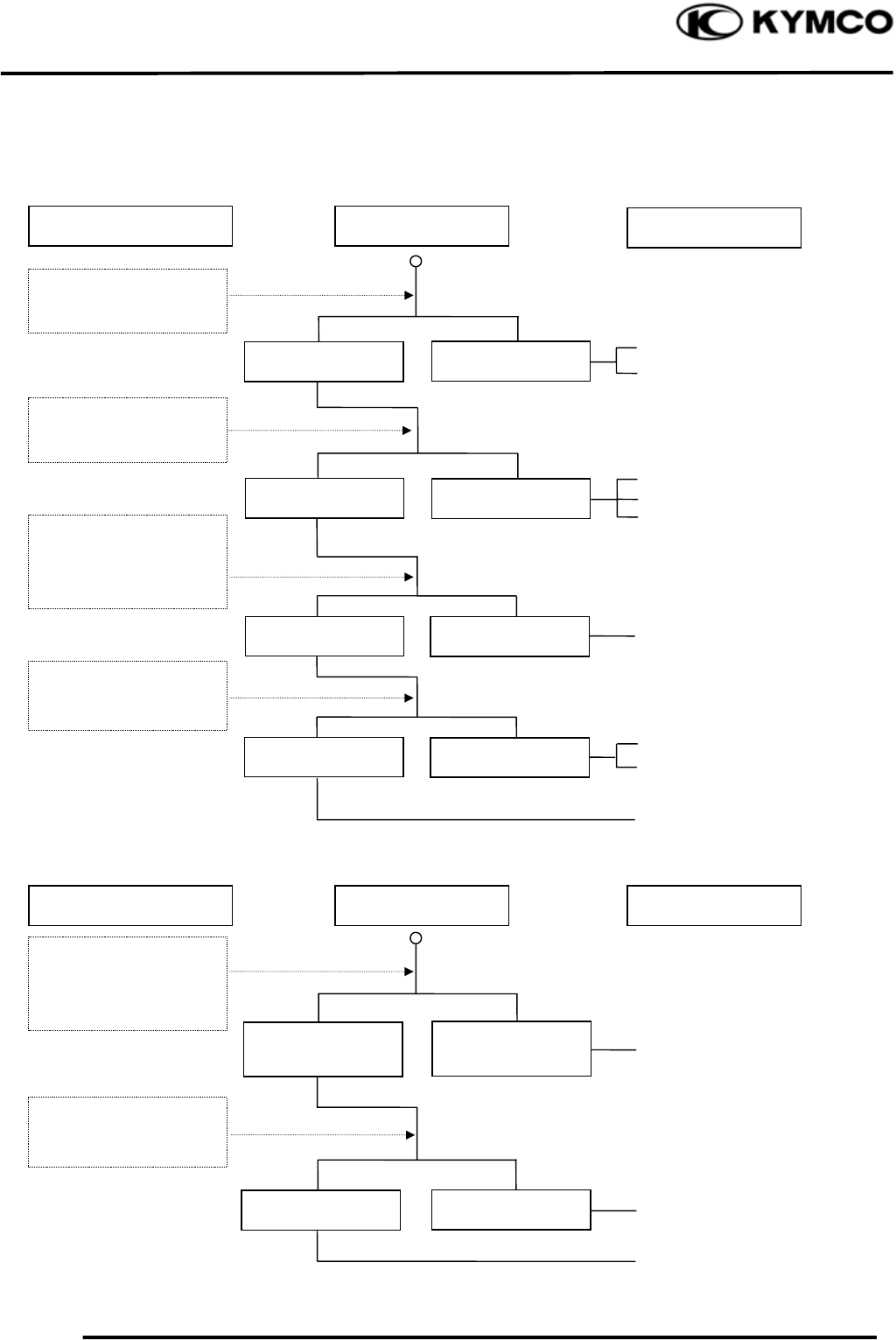
ENGINE WILL NOT START OR IS HARD TO START
Empty fuel tank
Clogged fuel line between fuel
tank and carburetor
Clogged float oil passage
Clogged fuel tank cap breather
hole
Clogged fuel filter
Clogged fuel valve passage
Faulty spark plug
Fouled spark plug
Faulty ignition unit
Faulty change gear control unit
Faulty pulser coil
Broken or shorted ignition coil
Broken or shorted exciter coil
Faulty ignition switch
Weak or dead battery
Faulty starter clutch
Valve clearance too small
Valve stuck open
Worn cylinder, piston and piston
rings
Leaking cylinder head gasket
Air leaking through intake pipe
Leaking intake manifold
Incorrect ignition timing
Incorrectly adjusted air screw
Flooded carburetor
Clogged air cleaner
Throttle valve excessively open
Check if fuel reaches
carburetor by loosening
drain screw
Remove spark plug and
install it into spark plug
cap to test spark by
connecting it to engine
ground
Inspection/Adjustment Probable Cause
Spark jumps
Normal
compression
Engine does no
t
fire
Weak or no spark
Low or no
compression
Engine fires bu
t
does not start
Test cylinde
r
compression
Start engine by follow-
ing normal starting
p
rocedure
Remove spark plug and
inspect again
Symptom
Fuel reaches
carburetor
Fuel does no
t
reach carburetor
Wet spark plug
Dry spark plug
1. GENERAL INFORMATION
1-36
MXU 500
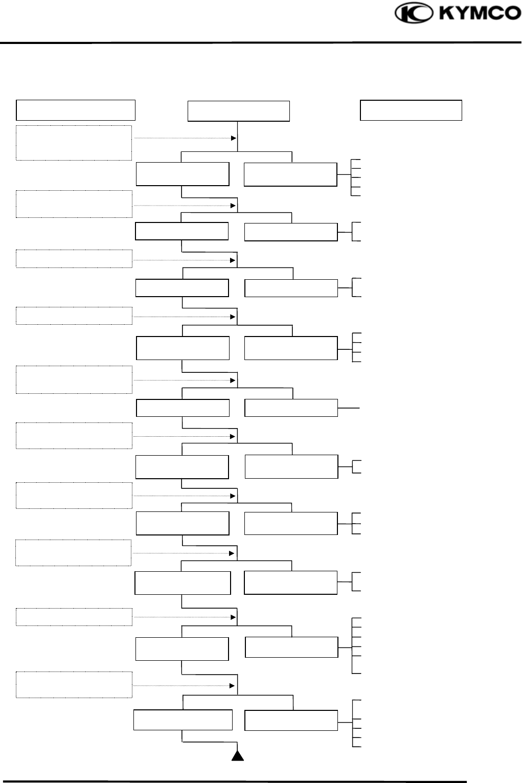
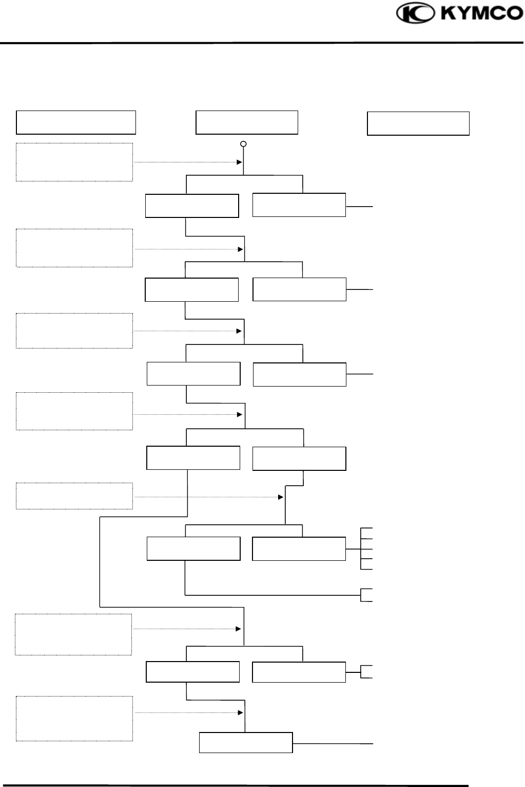
ENGINE LACKS POWER
Clogged air cleaner
Restricted fuel flow
Clogged fuel tank cap breather hole
Clogged exhaust muffler
Carburetor fuel level too low
Faulty ignition unit
Faulty pulser coil
Improper valve clearance
adjustment
Excessively worn valve seat
(protruded valve stem)
Improper valve and seat contact
Worn cylinder and piston rings
Leaking cylinder head gasket
Improper valve timing
Clean and unclog
Fouled spark plug
Incorrect heat range plug
Oil level too high
Oil level too low
Oil not changed
Clogged oil line
Faulty oil pump
Coolant level too low
Worn cylinder and piston rings
Mixture too lean
Poor quality fuel
Excessive carbon build-up in
combustion chamber
Ignition timing too early
Excessive carbon build-up in
combustion chamber
Poor quality fuel
Clutch slipping
Mixture too lean
Ignition timing too early
Start engine and
accelerate lightly for
observation
Inspection/Adjustment Symptom Probable Cause
Engine speed
increases
Correct timin
g
Engine speed does no
t
increase sufficientl
y
Incorrect timin
g
Check ignition timing
(using a timing light)
Test cylinder compression
Check carburetor fo
r
clogging
Rapidly accelerate or run
at hi
g
h s
p
eed
Remove spark plug and
ins
p
ec
t
Check if engine overheats
Check valve clearance
Correc
t
Incorrec
t
N
ormal
com
p
ression
Abnormal
compression
Remove oil dipstick and
check oil level and condition
Remove cylinder head oil
p
i
p
e bolt and ins
p
ec
t
Engine overheats
Engine does no
t
overheats
Plug not fouled o
r
discolored
Plug fouled o
r
discolored
Correct and no
t
contaminated
Incorrect o
r
contaminated
Valve train lubricated
p
ro
p
erl
y
Valve train no
t
lubricated
p
ro
p
erl
y
Engine does not knock Engine knocks
Not clo
gg
ed Clo
gg
ed
1. GENERAL INFORMATION
1-37
MXU 500
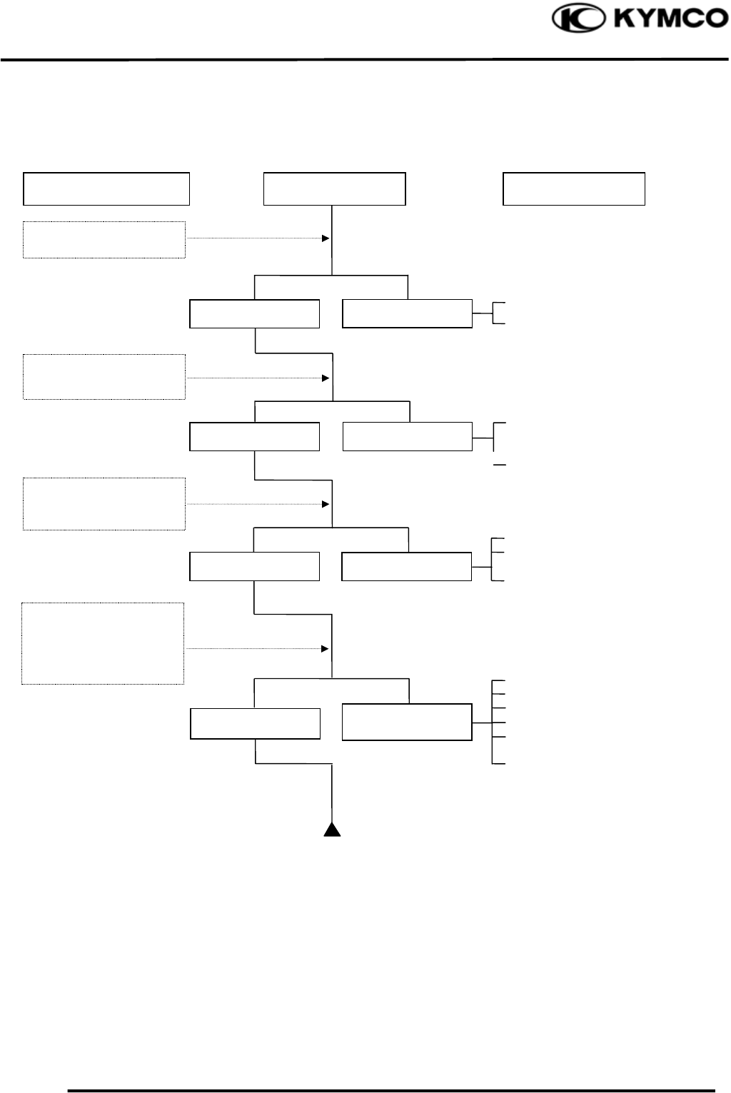
POOR PERFORMANCE (ESPECIALLY AT IDLE AND LOW SPEEDS)
Faulty ignition unit
Faulty pulser coil
Mixture too rich (turn screw
out)
Mixture too lean (turn screw in)
Deteriorated O-ring
Carburetor not securely
tightened
Damaged insulator rubber
Faulty or fouled spark plug
Faulty ignition unit
Faulty A.C. generator
Faulty ignition coil
Broken or shorted spark plug
wire
Faulty ignition switch
Remove spark plug and
install it into spark plug
cap to test spark by
connecting it to engine
g
round
Inspection/Adjustment Symptom Probable Cause
Check ignition timing
Check carburetor gaske
t
for air leaks
Check carburetor ai
r
screw adjustment
Correct timing Incorrect timing
Correctly adjusted
No air leak Air leaks
Good spark Weak or inter-
mittent spark
Incorrectly adjusted
1. GENERAL INFORMATION
1-38
MXU 500
POOR PERFORMANCE (AT HIGH SPEED)
Faulty ignition unit
Faulty pulser coil
Improperly adjusted valve
clearance
Worn valve seat
Empty fuel tank
Clogged fuel tube or filter
Clogged Fuel tank cap breather
hole
Clean and unclog
Cam timing gear aligning marks
not aligned
Faulty spring
Inspection/Adjustment Symptom Probable Cause
Check ignition timing
Check carburetor jets
for clogging
Check fuel pump fo
r
fuel supply
Correct timing Incorrect timing
Check valve spring
tension
Check valve clearance
Fuel flows freely Fuel flow restricted
Correc
t
Incorrec
t
Not clogged Clogged
Correctly adjusted Incorrectly adjusted
Not weakened Weak spring
Check valve timing
1. GENERAL INFORMATION
1-39
MXU 500
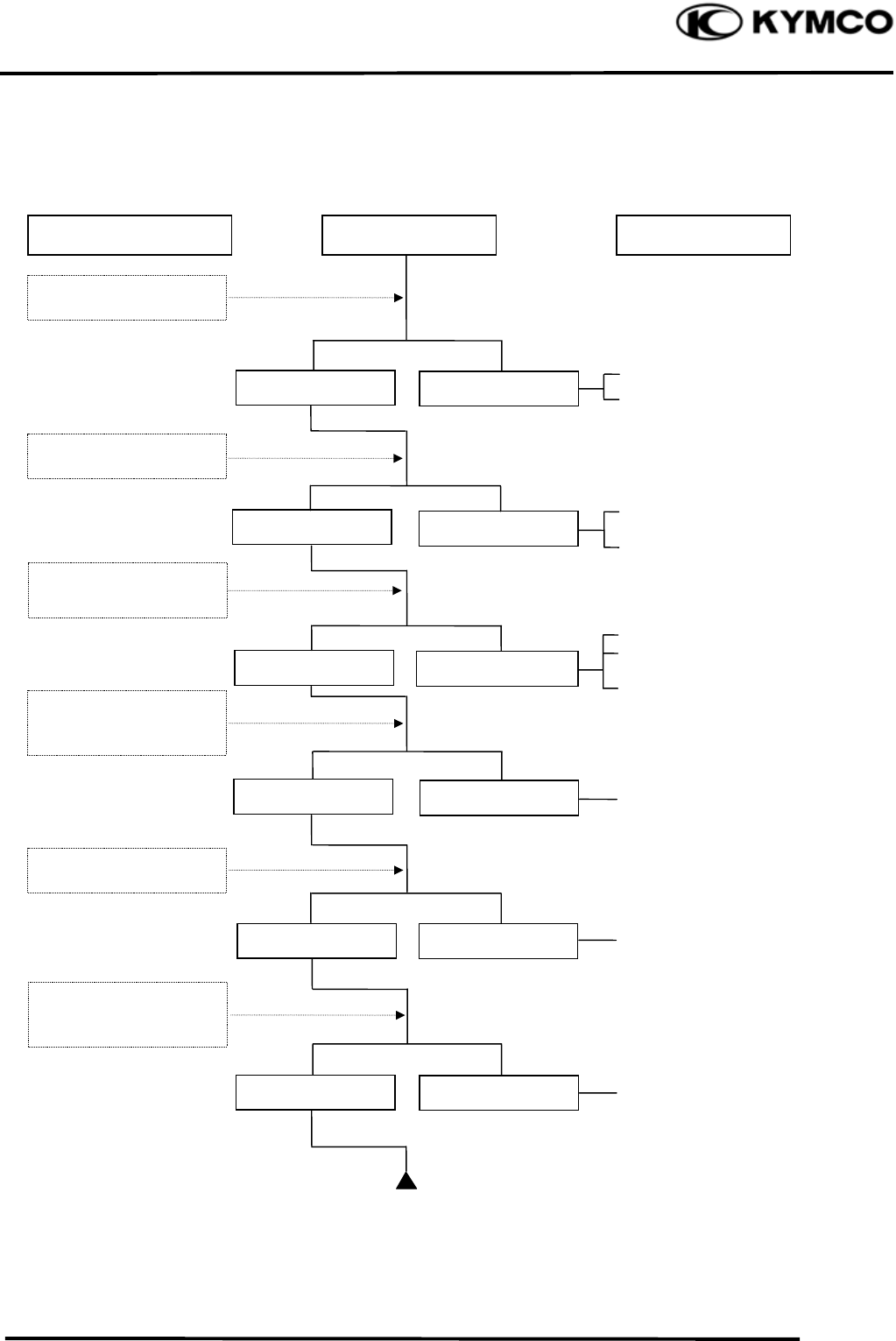
POOR CHARGING (BATTERY OVER DISCHARGING OR OVERCHARGING)
Undercharging
Dead battery
Faulty battery
Faulty A.C. generator coil
Broken yellow wire
Shorted pink and yellow
wires
Broken red wire
Faulty regulator/rectifier
Poorly connected coupler
Faulty A.C. generator
Overcharging
Broken green wire
Poorly connected coupler
Faulty regulator/rectifier
Start engine and tes
t
limit voltage of battery
terminals
Connect battery (+) wire
to regulator/rectifier
coupler red wire and
battery (-) wire to engine
g
round and test volta
g
e
Inspection/Adjustment
Inspection/Adjustment
Symptom
Symptom
Probable Cause
Probable Cause
Normal voltage
B
attery
h
as vo
l
tage
with ignition
switch “ON”
Normal
Voltage does no
t
increase
B
attery
h
as no
voltage with ignition
switc
h
“ON”
Resistance too high
Normal voltage No voltage
Measure resistance
between AC generator
coil terminals
Normal Abnormal
Check regulator/rectifier
coupler for loose
connection
Normal Abnormal
Connect battery (+) wire
to regulator/rectifier
coupler green wire and
battery (-) wire to engine
g
round and test volta
g
e
Check regulator/rectifier
coupler for loose
connection
1. GENERAL INFORMATION
1-40
MXU 500
NO SPARK AT SPARK PLUG
Faulty spark plug
Loose spark plug cap
Poorly connected coupler
Faulty ignition switch
Weak battery
Faulty pulser coil
Faulty ignition coil
Faulty charging system
Broken wire harness
Poorly connected coupler
Faulty ignition unit
Faulty change gear control
unit
Faulty ignition coil
Replace with a new
spark plug and inspect
a
g
ain
Check ignition unit
coupler for looseness
Inspection/Adjustment Symptom Probable Cause
Normal
Abnormal
Normal
Abnormal
Normal Abnormal
Abnormal
Measure resistance
between terminals of
i
g
nition unit cou
p
le
r
Check related parts
Check ignition coil with
a ignition unit tester
Weak or no spark
Not loose
Good spark
Loose
Good Good
Check spark plug cap
and high-tension wire
for looseness
Check ignition unit
with a ignition unit
teste
r
