Manual De Instalacion UPS Liebert E XL
User Manual: Manual-de-Instalacion-UPS-Liebert-eXL
Open the PDF directly: View PDF ![]() .
.
Page Count: 40
- Contacting Emerson Network Power for Support
- Important Safety Instructions
- SAVE THESE INSTRUCTIONS
- 1.0 Mechanical Installation
- 2.0 UPS Electrical Installation
- 3.0 Optional Equipment
- 4.0 Installation Drawings
- Figure 5 Typical main components, 625-800kVA Liebert eXL single-module UPS
- Figure 6 Outline Drawing, 625-800kVA Liebert eXL single-module UPS
- Figure 7 Base drawing, 625-800kVA Liebert eXL single-module UPS
- Figure 8 Input and battery terminal detail, 625-800kVA Liebert eXL single-module UPS
- Figure 9 Output and bypass terminal detail, 625-800kVA Liebert eXL single-module UPS
- Figure 10 Input, output and bypass terminal spacing details, 625-800kVA Liebert eXL single-module UPS
- Figure 11 Low-voltage cable routing
- Figure 12 Shipping split, 625-800kVA Liebert eXL single-module UPS
- Figure 13 Shipping split, 625-800kVA Liebert eXL single-module UPS, continued
- Figure 14 Kickplate installation
- Table 5 Key to items in Figure 14
- Figure 15 Cabling for single input configuration
- Figure 16 Optional Input Contact Isolator Board
- Table 6 Input Contact Isolator Board control wiring connections
- Figure 17 Control wiring, Programmable Relay Board
- Table 7 Programmable Relay Board pinout
- 5.0 Specifications
- Table 8 Liebert eXL UPS specifications
- Table 9 Current ratings—rectifier input
- Table 10 Current ratings—bypass input
- Table 11 Current ratings—output
- Table 12 Current ratings—DC source
- Notes on Tables
- Figure 18 Inverter overload data
- Figure 19 Rectifier overload data
- Figure 20 Bypass overload data
- Table 13 Recommended conduit and cable sizes for use with 80% rated breakers
- Table 14 Recommended conduit and cable sizes for use with 100% rated breakers
- Table 15 Recommended lug sizes
- Table 16 Recommended torque values
Liebert® eXL™
Installation Manual – 625-800kVA, 1.0PF, 60Hz, Three-Phase, Single-Module

CONTACTING EMERSON NETWORK POWER FOR SUPPORT
To contact Emerson Network Power Liebert Services for information or repair service in the United
States, call 800-543-2378. Liebert Services offers a complete range of start-up services, repair
services, preventive maintenance plans and service contracts.
For repair or maintenance service outside the 48 contiguous United States, contact Liebert Services,
if available in your area. For areas not covered by Liebert Services, the authorized distributor is
responsible for providing qualified, factory-authorized service.
For Liebert Services to assist you promptly, please have the following information available:
Part numbers: _________________________________________________________________
Serial numbers:________________________________________________________________
Rating: _______________________________________________________________________
Date purchased: _______________________________________________________________
Date installed:_________________________________________________________________
Location: ______________________________________________________________________
Input voltage/frequency:________________________________________________________
Output voltage/frequency: ______________________________________________________
Battery reserve time:___________________________________________________________
Product Warranty Registration
To register for warranty protection, visit the Service and Support section of our Web site at:
www.liebert.com
Click on Product Registration and fill out the form.

i
TABLE OF CONTENTS
IMPORTANT SAFETY INSTRUCTIONS . . . . . . . . . . . . . . . . . . . . . . . . . . . . . . . . . . . . . . . . . . . . . . . .1
SAVE THESE INSTRUCTIONS . . . . . . . . . . . . . . . . . . . . . . . . . . . . . . . . . . . . . . . . . . . . . . . . .1
1.0 MECHANICAL INSTALLATION . . . . . . . . . . . . . . . . . . . . . . . . . . . . . . . . . . . . . . . . . . . . . . . .4
1.1 Introduction . . . . . . . . . . . . . . . . . . . . . . . . . . . . . . . . . . . . . . . . . . . . . . . . . . . . . . . . . . . . . . . . 4
1.2 Preliminary Checks . . . . . . . . . . . . . . . . . . . . . . . . . . . . . . . . . . . . . . . . . . . . . . . . . . . . . . . . . . 4
1.3 Environmental Considerations . . . . . . . . . . . . . . . . . . . . . . . . . . . . . . . . . . . . . . . . . . . . . . . . . 5
1.3.1 UPS Room . . . . . . . . . . . . . . . . . . . . . . . . . . . . . . . . . . . . . . . . . . . . . . . . . . . . . . . . . . . . . . . . . . . 5
1.3.2 Storage . . . . . . . . . . . . . . . . . . . . . . . . . . . . . . . . . . . . . . . . . . . . . . . . . . . . . . . . . . . . . . . . . . . . . 5
1.4 Positioning . . . . . . . . . . . . . . . . . . . . . . . . . . . . . . . . . . . . . . . . . . . . . . . . . . . . . . . . . . . . . . . . . 5
1.4.1 Moving the Cabinets. . . . . . . . . . . . . . . . . . . . . . . . . . . . . . . . . . . . . . . . . . . . . . . . . . . . . . . . . . . 5
1.4.2 Clearances. . . . . . . . . . . . . . . . . . . . . . . . . . . . . . . . . . . . . . . . . . . . . . . . . . . . . . . . . . . . . . . . . . . 6
1.4.3 Raised-Floor Installations . . . . . . . . . . . . . . . . . . . . . . . . . . . . . . . . . . . . . . . . . . . . . . . . . . . . . . 6
1.4.4 Kick Plate Installation . . . . . . . . . . . . . . . . . . . . . . . . . . . . . . . . . . . . . . . . . . . . . . . . . . . . . . . . . 6
1.5 System Composition . . . . . . . . . . . . . . . . . . . . . . . . . . . . . . . . . . . . . . . . . . . . . . . . . . . . . . . . . . 6
1.6 Cable Entry. . . . . . . . . . . . . . . . . . . . . . . . . . . . . . . . . . . . . . . . . . . . . . . . . . . . . . . . . . . . . . . . . 6
1.7 Cable routing . . . . . . . . . . . . . . . . . . . . . . . . . . . . . . . . . . . . . . . . . . . . . . . . . . . . . . . . . . . . . . . 6
2.0 UPS ELECTRICAL INSTALLATION . . . . . . . . . . . . . . . . . . . . . . . . . . . . . . . . . . . . . . . . . . . .8
2.1 External Protective Devices. . . . . . . . . . . . . . . . . . . . . . . . . . . . . . . . . . . . . . . . . . . . . . . . . . . . 8
2.2 Power Cables . . . . . . . . . . . . . . . . . . . . . . . . . . . . . . . . . . . . . . . . . . . . . . . . . . . . . . . . . . . . . . . 8
2.3 Sizing the Input Breaker Feeding a Liebert eXL UPS. . . . . . . . . . . . . . . . . . . . . . . . . . . . . . . 9
2.3.1 Power Cable Connection Procedure. . . . . . . . . . . . . . . . . . . . . . . . . . . . . . . . . . . . . . . . . . . . . . . 9
2.4 Control Cable and Communication . . . . . . . . . . . . . . . . . . . . . . . . . . . . . . . . . . . . . . . . . . . . . 10
2.4.1 Dry Contacts . . . . . . . . . . . . . . . . . . . . . . . . . . . . . . . . . . . . . . . . . . . . . . . . . . . . . . . . . . . . . . . . 12
2.5 Grounding . . . . . . . . . . . . . . . . . . . . . . . . . . . . . . . . . . . . . . . . . . . . . . . . . . . . . . . . . . . . . . . . . 13
2.5.1 Three-Wire Input connections . . . . . . . . . . . . . . . . . . . . . . . . . . . . . . . . . . . . . . . . . . . . . . . . . . 13
2.5.2 High Resistance Grounding (see attached document) . . . . . . . . . . . . . . . . . . . . . . . . . . . . . . . 13
2.5.3 Preferred Grounding Configuration, Battery Systems. . . . . . . . . . . . . . . . . . . . . . . . . . . . . . . 13
2.6 No CB2 Option . . . . . . . . . . . . . . . . . . . . . . . . . . . . . . . . . . . . . . . . . . . . . . . . . . . . . . . . . . . . . 14
2.7 Internal Breaker Settings . . . . . . . . . . . . . . . . . . . . . . . . . . . . . . . . . . . . . . . . . . . . . . . . . . . . 15
3.0 OPTIONAL EQUIPMENT . . . . . . . . . . . . . . . . . . . . . . . . . . . . . . . . . . . . . . . . . . . . . . . . . . .16
3.1 Single-Module System Options . . . . . . . . . . . . . . . . . . . . . . . . . . . . . . . . . . . . . . . . . . . . . . . . 16
3.1.1 Battery Temperature Sensor . . . . . . . . . . . . . . . . . . . . . . . . . . . . . . . . . . . . . . . . . . . . . . . . . . . 16
3.1.2 Matching Liebert eXL Battery Cabinet. . . . . . . . . . . . . . . . . . . . . . . . . . . . . . . . . . . . . . . . . . . 16
3.1.3 Remote Alarm Status Panel. . . . . . . . . . . . . . . . . . . . . . . . . . . . . . . . . . . . . . . . . . . . . . . . . . . . 16
3.2 Communication and Monitoring . . . . . . . . . . . . . . . . . . . . . . . . . . . . . . . . . . . . . . . . . . . . . . . 16
3.2.1 Alber Monitoring System . . . . . . . . . . . . . . . . . . . . . . . . . . . . . . . . . . . . . . . . . . . . . . . . . . . . . . 16
4.0 INSTALLATION DRAWINGS. . . . . . . . . . . . . . . . . . . . . . . . . . . . . . . . . . . . . . . . . . . . . . . . .17
5.0 SPECIFICATIONS . . . . . . . . . . . . . . . . . . . . . . . . . . . . . . . . . . . . . . . . . . . . . . . . . . . . . . . .27

ii
FIGURES
Figure 1 Cabinet arrangement—Liebert eXL and battery cabinets . . . . . . . . . . . . . . . . . . . . . . . . . . . . . . . . 7
Figure 2 Liebert eXL customer connections . . . . . . . . . . . . . . . . . . . . . . . . . . . . . . . . . . . . . . . . . . . . . . . . . . 11
Figure 3 No CB2 option . . . . . . . . . . . . . . . . . . . . . . . . . . . . . . . . . . . . . . . . . . . . . . . . . . . . . . . . . . . . . . . . . . 14
Figure 4 Internal Breaker settings . . . . . . . . . . . . . . . . . . . . . . . . . . . . . . . . . . . . . . . . . . . . . . . . . . . . . . . . . 15
Figure 5 Typical main components, 625-800kVA Liebert eXL single-module UPS . . . . . . . . . . . . . . . . . . . 17
Figure 6 Outline Drawing, 625-800kVA Liebert eXL single-module UPS . . . . . . . . . . . . . . . . . . . . . . . . . . 18
Figure 7 Base drawing, 625-800kVA Liebert eXL single-module UPS . . . . . . . . . . . . . . . . . . . . . . . . . . . . . 18
Figure 8 Input and battery terminal detail, 625-800kVA Liebert eXL single-module UPS . . . . . . . . . . . . 19
Figure 9 Output and bypass terminal detail, 625-800kVA Liebert eXL single-module UPS . . . . . . . . . . . 20
Figure 10 Input, output and bypass terminal spacing details, 625-800kVA Liebert eXL single-module
UPS . . . . . . . . . . . . . . . . . . . . . . . . . . . . . . . . . . . . . . . . . . . . . . . . . . . . . . . . . . . . . . . . . . . . . . . . . . 20
Figure 11 Low-voltage cable routing. . . . . . . . . . . . . . . . . . . . . . . . . . . . . . . . . . . . . . . . . . . . . . . . . . . . . . . . . 21
Figure 12 Shipping split, 625-800kVA Liebert eXL single-module UPS . . . . . . . . . . . . . . . . . . . . . . . . . . . . 22
Figure 13 Shipping split, 625-800kVA Liebert eXL single-module UPS, continued . . . . . . . . . . . . . . . . . . . 23
Figure 14 Kickplate installation . . . . . . . . . . . . . . . . . . . . . . . . . . . . . . . . . . . . . . . . . . . . . . . . . . . . . . . . . . . . 24
Figure 15 Cabling for single input configuration . . . . . . . . . . . . . . . . . . . . . . . . . . . . . . . . . . . . . . . . . . . . . . . 25
Figure 16 Optional Input Contact Isolator Board . . . . . . . . . . . . . . . . . . . . . . . . . . . . . . . . . . . . . . . . . . . . . . 25
Figure 17 Control wiring, Programmable Relay Board . . . . . . . . . . . . . . . . . . . . . . . . . . . . . . . . . . . . . . . . . . 26
Figure 18 Inverter overload data . . . . . . . . . . . . . . . . . . . . . . . . . . . . . . . . . . . . . . . . . . . . . . . . . . . . . . . . . . . 30
Figure 19 Rectifier overload data . . . . . . . . . . . . . . . . . . . . . . . . . . . . . . . . . . . . . . . . . . . . . . . . . . . . . . . . . . . 31
Figure 20 Bypass overload data . . . . . . . . . . . . . . . . . . . . . . . . . . . . . . . . . . . . . . . . . . . . . . . . . . . . . . . . . . . . 32
TABLES
Table 1 UPS Digital Inputs . . . . . . . . . . . . . . . . . . . . . . . . . . . . . . . . . . . . . . . . . . . . . . . . . . . . . . . . . . . . . . 12
Table 2 UPS Output . . . . . . . . . . . . . . . . . . . . . . . . . . . . . . . . . . . . . . . . . . . . . . . . . . . . . . . . . . . . . . . . . . . . 12
Table 3 UPS control contacts to Battery Interface Boards . . . . . . . . . . . . . . . . . . . . . . . . . . . . . . . . . . . . . 13
Table 4 UPS control contacts to Remote Status Panel. . . . . . . . . . . . . . . . . . . . . . . . . . . . . . . . . . . . . . . . . 13
Table 5 Key to items in Figure 14 . . . . . . . . . . . . . . . . . . . . . . . . . . . . . . . . . . . . . . . . . . . . . . . . . . . . . . . . 24
Table 6 Input Contact Isolator Board control wiring connections. . . . . . . . . . . . . . . . . . . . . . . . . . . . . . . . 25
Table 7 Programmable Relay Board pinout . . . . . . . . . . . . . . . . . . . . . . . . . . . . . . . . . . . . . . . . . . . . . . . . . 26
Table 8 Liebert eXL UPS specifications . . . . . . . . . . . . . . . . . . . . . . . . . . . . . . . . . . . . . . . . . . . . . . . . . . . . 27
Table 9 Current ratings—rectifier input . . . . . . . . . . . . . . . . . . . . . . . . . . . . . . . . . . . . . . . . . . . . . . . . . . . 28
Table 10 Current ratings—bypass input . . . . . . . . . . . . . . . . . . . . . . . . . . . . . . . . . . . . . . . . . . . . . . . . . . . . 28
Table 11 Current ratings—output. . . . . . . . . . . . . . . . . . . . . . . . . . . . . . . . . . . . . . . . . . . . . . . . . . . . . . . . . . 28
Table 12 Current ratings—DC source. . . . . . . . . . . . . . . . . . . . . . . . . . . . . . . . . . . . . . . . . . . . . . . . . . . . . . . 28
Table 13 Recommended conduit and cable sizes for use with 80% rated breakers . . . . . . . . . . . . . . . . . . . 33
Table 14 Recommended conduit and cable sizes for use with 100% rated breakers . . . . . . . . . . . . . . . . . . 34
Table 15 Recommended torque values . . . . . . . . . . . . . . . . . . . . . . . . . . . . . . . . . . . . . . . . . . . . . . . . . . . . . . 35
Table 16 Recommended lug sizes . . . . . . . . . . . . . . . . . . . . . . . . . . . . . . . . . . . . . . . . . . . . . . . . . . . . . . . . . . 35

Important Safety Instructions
1Liebert
® eXL™
IMPORTANT SAFETY INSTRUCTIONS
SAVE THESE INSTRUCTIONS
This manual contains important instructions that should be followed during installation of your
Liebert eXL UPS. Read this manual thoroughly, paying special attention to the sections that apply to
your installation, before working with the UPS. Retain this manual for use by installing
personnel.
!
WARNING
Risk of electrical shock. Can cause personal injury or death.
This UPS has several circuits that are energized with high DC as well as AC voltages. Check
for voltage with both AC and DC voltmeters before working within the UPS. Check for voltage
with both AC and DC voltmeters before making contact.
Only properly trained and qualified personnel wearing appropriate safety headgear, gloves,
shoes and glasses should be involved in installing the UPS or preparing the UPS for
installation. When performing maintenance with any part of the equipment under power,
service personnel and test equipment should be standing on rubber mats.
In case of fire involving electrical equipment, use only carbon dioxide fire extinguishers or
those approved for use in fighting electrical fires.
Extreme caution is required when performing installation and maintenance.
Special safety precautions are required for procedures involving handling, installation and
maintenance of the UPS system. Observe all safety precautions in this manual before
handling or installing the UPS system. Observe all precautions in the Operation and
Maintenance Manual, SL-26030, before as well as during performance of all maintenance
procedures. Observe all DC safety precautions before working on or near the DC system.
!
AVERTISSEMENT
Risque de décharge électrique pouvant causer des blessures graves, voire mortelles.
Ce système ASC comporte plusieurs circuits à haute tension c.a et c.c. Vérifiez les tensions au
moyen de voltmètres c.a. et c.c. avant d’utiliser le système ASC. Vérifiez les tensions avec des
voltmètres c.a. et c.c. avant d’établir tout contact.
Seuls des employés qualifiés et dûment formés portant un casque, des gants, des chaussures
et des lunettes de sécurité adéquats doivent se charger d’installer le système ASC ou de le
préparer pour l’installation.Les responsables de l’entretien et l’équipement d’essai doivent
reposer sur des tapis de caoutchouc lors de toute intervention sur une pièce d’équipement sous
tension.
En cas d’incendie associé à du matériel électrique, n’utilisez que des extincteurs à dioxyde de
carbone ou homologués pour la lutte contre les incendies d’origine électrique.
Les opérations d’installation et d’entretien requièrent une extrême prudence.
Des précautions de sécurité spéciales sont requises pour les procédures associées à la
manutention, à l’installation et à l’entretien du système ASC. Observez toutes les précautions
de sécurité décrites dans le présent manuel avant de manipuler ou d’installer le système ASC.
Observez également toutes les précautions décrites dans le manuel d’utilisation et
d’entretien, SL-26030, avant et pendant toutes les procédures d’entretien. Observez toutes les
précautions de sécurité appropriées lorsque vous travaillez sur à proximité d’une source c.c.
de sécurité appropriées dès que vous vous trouvez à proximité d’une source c.c.

Important Safety Instructions
Liebert® eXL™2
!
WARNING
Risk of heavy unit falling over. Improper handling can cause equipment damage, injury or
death.
Exercise extreme care when handling UPS cabinets to avoid equipment damage or injury to
personnel. The UPS module weight is up to 5735lb (2601kg).
Locate center of gravity symbols and determine unit weight before handling each
cabinet. Test lift and balance the cabinets before transporting. Maintain minimum tilt from
vertical at all times.
Slots at the base of the module cabinets are intended for forklift use. Base slots will support
the unit only if the forks are completely beneath the unit.
Read all of the following instructions before attempting to move, lift, or remove packaging
from unit, or prepare unit for installation.
!
AVERTISSEMENT
Le centre de gravité élevé de l’appareil présente un risque de renversement. Une mauvaise
manutention peut entraîner des dommages matériels, des blessures et même la mort.
Faites preuve d’une extrême prudence lors de la manutention des armoires ASC afin d’éviter
de les endommager ou de blesser le personnel. Le module ASC pèse jusqu’à 2 601kg (5 735lb).
Identifiez les symboles de centre de gravité et déterminez le poids de l’appareil avant de
manipuler chaque armoire. Testez le levage et l’équilibre des armoires avant de transporter
l’appareil. Maintenez en tout temps l'inclinaison verticale minimale.
Les fentes situées à la base des armoires du module sont conçues pour utiliser le chariot
élévateur. Les fentes situées à la base peuvent soutenir le système seulement si les fourches
se trouvent complètement sous le système.
Lisez toutes les instructions ci-dessous avant de tenter de déplacer, lever, déballer ou
préparer le système en vue de son installation.
!
WARNING
Risk of electrical shock and fire. Can cause equipment damage, personal injury or death.
Under typical operation and with all UPS doors closed, only normal safety precautions are
necessary. The area around the UPS system should be kept free of puddles of water, excess
moisture and debris.
Only test equipment designed for troubleshooting should be used. This is particularly true for
oscilloscopes. Always check with an AC and DC voltmeter to ensure safety before making
contact or using tools. Even when the power is turned Off, dangerously high potential electric
charges may exist at the capacitor banks and at the DC connections.
All wiring must be installed by a properly trained and qualified electrician. All power and
control wiring must comply with all applicable national, state and local codes.
One person should never work alone, even if all power is disconnected from the equipment. A
second person should be standing by to assist and to summon help in case of an accident.

Important Safety Instructions
3Liebert
® eXL™
NOTICE
If optional filtering is installed, this unit complies with the limits for a Class A digital device,
pursuant to Part 15 Subpart J of the FCC rules. These limits provide reasonable protection
against harmful interference in a commercial environment. This unit generates, uses and
radiates radio frequency energy and, if not installed and used in accordance with this
instruction manual, may cause harmful interference to radio communications. Operation of
this unit in a residential area may cause harmful interference that the user must correct at
his own expense.
!
AVERTISSEMENT
Risque de décharge électrique et d’incendie. pouvant entraîner des dommages matériels, des
blessures et même la mort.
Les précautions de sécurité habituelles suffisent lorsque le système ASC est en mode de
fonctionnement normal et que toutes les portes sont fermées. La zone entourant le système
ASC doit être exempte de flaques d’eau, d’humidité excessive et de débris.
Seuls des équipements d’essai conçus pour le dépannage doivent être utilisés. Cette mise en
garde couvre notamment les oscilloscopes. Utilisez toujours un voltmètre c.a. et c.c. pour
vérifier les tensions avant d’établir un contact ou d’utiliser des appareils. Des tensions
dangereusement élevées peuvent demeurer dans les batteries de condensateurs et au niveau
des raccords c.c., même une fois l’alimentation coupée.
Tous les raccords doivent être effectués par un électricien dûment formé et qualifié. Tous les
câbles d’alimentation et de commande doivent être conformes aux codes nationaux et locaux
en vigueur.
Une personne ne devrait jamais travailler seule, même si toute l’alimentation d’entrée est
coupée. Une deuxième personne devrait toujours être présente pour porter assistance ou
chercher de l’aide en cas d’accident.
NOTE
Materials sold hereunder cannot be used in the patient vicinity (e.g., use where UL, cUL or
IEC 60601-1 is required). Medical applications such as invasive procedures and electrical life
support equipment are subject to additional terms and conditions.

Mechanical Installation
Liebert® eXL™4
1.0 MECHANICAL INSTALLATION
1.1 Introduction
This section describes the requirements that must be taken into account when planning the
positioning and cabling of the Liebert eXL uninterruptible power supply and related equipment.
This chapter is a guide to general procedures and practices that should be observed by the installing
personnel. The particular conditions of each site will determine the applicability of such procedures.
NOTICE
Three-phase input supply required.
The standard Liebert eXL UPS is suitable for connection to three-phase, three-wire (+ Earth)
TN-C and TN-S.
NOTICE
Do not apply electrical power to the UPS equipment before the arrival of the commissioning
engineer.
1.2 Preliminary Checks
Before installing the UPS, please carry out the following preliminary checks:
• Visually examine the UPS equipment for transit damage, both internally and externally. Report
any damage to the shipper immediately.
• Verify that the correct equipment is being installed. The equipment supplied has an identification
tag on the interior doors reporting the type, size and main calibration parameters of the UPS.
• Verify that the UPS room satisfies the environmental conditions stipulated in the equipment
specification, paying particular attention to the ambient temperature and air exchange system.
!
WARNING
Risk of electrical shock. Can cause injury or death.
Special care must be taken when working with the batteries associated with this equipment.
When they are connected together, the battery terminal voltage will exceed 400VDC and is
potentially lethal.
!
AVERTISSEMENT
Risque de décharge électrique pouvant causer des blessures graves, voire mortelles.
Des précautions particulières doivent être prises lors de travaux touchant les batteries
associées à cet équipement.
Lorsque les batteries sont branchées ensemble, la tension à la borne d’une batterie dépasse
400 V c.c. et est potentiellement mortelle.
NOTE
All equipment not referred to in this manual is shipped with details of its own mechanical and
electrical installation.

Mechanical Installation
5Liebert
® eXL™
1.3 Environmental Considerations
1.3.1 UPS Room
The UPS module is intended for indoor installation and should be located in a cool, dry, clean-air
environment with adequate ventilation to keep the ambient temperature within the specified
operating range (see Environmental Parameters in Table 8).
The Liebert eXL UPS is cooled with the aid of internal fans. To permit air to enter and exit and
prevent overheating or malfunctioning, do not cover the ventilation openings.
The Liebert eXL UPS is equipped with air filters located behind the front doors. A schedule for
inspection of the air filters is required. The period between inspections will depend upon
environmental conditions.
When bottom entry is used, the conduit plate must be installed.
1.3.2 Storage
Should the equipment not be installed immediately, it must be stored in a room for protection against
excessive humidity and/or heat sources (see Environmental Parameters in Table 8).
1.4 Positioning
The cabinet is structurally designed to handle lifting from the base.
Access to the power terminals, auxiliary terminal blocks and power switches is from the front.
The door can be opened to give access to the power connection bars, auxiliary terminal blocks and
power isolators. Front door can be opened to 90 degrees, and interior doors can be removed for more
flexibility in installations.
1.4.1 Moving the Cabinets
The route to be travelled between the point of arrival and the unit’s position must be planned to make
sure that all passages are wide enough for the unit and that floors are capable of supporting its
weight (for instance, check that doorways, lifts, ramps, etc. are adequate and that there are no
impassable corners or changes in the level of corridors).
Ensure that the UPS weight is within the designated surface weight loading (lb/in2) of any handling
equipment. For weight details, see Table 8.
The UPS can be handled with a forklift or similar equipment. Ensure any lifting equipment used in
moving the UPS cabinet has sufficient lifting capacity. When moving the unit by forklift, care must be
taken to protect the panels. Do not exceed a 15-degree tilt with the forklift. Bottom structure will
support the unit only if the forks are completely beneath the unit.
Handling with straps is not authorized.
NOTE
The UPS is suitable for mounting on concrete or other non-combustible surface only.
NOTE
The UPS must be placed on a non-combustible surface suitable to support the weight of the
unit.
!
WARNING
Risk of heavy unit falling over. Improper handling can cause equipment damage, injury or
death.
Because the weight distribution in the cabinet is uneven, use extreme care while handling
and transporting. Take extreme care when handling UPS cabinets to avoid equipment
damage or injury to personnel.
The UPS module weight is up to 5735lb (2601kg)).
Locate center of gravity symbols and determine unit weight before handling each
cabinet. Test lift and balance the cabinets before transporting. Maintain minimum tilt from
vertical at all times.

Mechanical Installation
Liebert® eXL™6
1.4.2 Clearances
The Liebert eXL has no ventilation grilles at either side or at the rear of the UPS. Clearance around
the front of the equipment should be sufficient to permit free passage of personnel with the doors fully
opened. It is important to leave a distance of 24in. (610mm) between the top of the UPS and any
overhead obstacles to allow the module to be serviced and to permit adequate circulation of air coming
out of the unit.
1.4.3 Raised-Floor Installations
If the equipment is to be located on a raised floor, it should be mounted on a pedestal suitably
designed to accept the equipment point loading. Refer to Figure 7 to design this pedestal.
1.4.4 Kick Plate Installation
If the unit is to be installed in a position that does not permit access to rear kick plates, then the kick
plates should be installed before the unit is placed in its final position.
1.5 System Composition
A UPS system can include a number of equipment cabinets, depending on the individual system
design requirements: e.g., UPS cabinet, battery cabinet, maintenance bypass cabinet. In general, all
the cabinets used in a particular installation are of the same height. Refer to the drawings provided in
4.0 - Installation Drawings for the positioning of the cabinets as shown in Figure 1.
1.6 Cable Entry
Cables can enter the UPS cabinet from bottom or top into the Input/Output (I/O) of the unit; see the
figures in 4.0 - Installation Drawings.
1.7 Cable routing
Per NEC 300.20 (NEC 2014 or equivalent), all phase conductors and ground conductors must be
grouped together when they are installed in ferrous enclosures or go through ferrous material. This is
to avoid heating from induction currents.
!
AVERTISSEMENT
Le centre de gravité élevé de l’appareil présente un risque de renversement. Une mauvaise
manutention peut entraîner des dommages matériels, des blessures et même la mort.
En raison de la distribution inégale du poids de l’armoire, vous devez faire preuve d’extrême
prudence lors de sa manipulation et de son transport. Faites preuve d’une extrême prudence
lors de la manutention des armoires ASC afin d’éviter de les endommager ou de blesser le
personnel.
Le module ASC pèse jusqu’à 2 601kg (5 375 lb).
Identifiez les symboles de centre de gravité et déterminez le poids de l’appareil avant de
manipuler chaque armoire. Testez le levage et l’équilibre les armoires avant de transporter
l’appareil. Maintenez en tout temps l'inclinaison verticale minimale
Mechanical Installation
7Liebert
® eXL™
Figure 1 Cabinet arrangement—Liebert eXL and battery cabinets
Liebert
eXL
UPS
Battery
Cabinet
(Matching)
Liebert
eXL
UPS
Additional
Battery
Cabinet(s)
(Matching)
Battery
Cabinet
(Matching)
Liebert
eXL
UPS
Additional
Battery
Cabinet(s)
(Matching)
Battery
Cabinet
(Matching)
Liebert
eXL
UPS
Additional
Battery
Cabinet(s)
(Matching)
Battery cabinets can be bolted to the right of the UPS.
However, the cabling must be routed externally.
Battery cabinets can be bolted to the left of
the UPS and the cabling routed internally.
If the cabinets are to be bolted together,
the side panels and hangers must be
removed before beginning.

UPS Electrical Installation
Liebert® eXL™8
2.0 UPS ELECTRICAL INSTALLATION
This chapter provides guidelines for qualified installers who must have knowledge of local wiring
practices pertaining to the equipment to be installed.
2.1 External Protective Devices
For safety, circuit breakers must be installed in the input AC supply and external battery system.
Given that every installation has its own characteristics, this section provides guidelines for qualified
installation personnel with knowledge of operating practices, regulatory standards and the
equipment to be installed.
External overcurrent protection must be provided. See Figures 18,19 and 20 for overload capacity.
2.2 Power Cables
The UPS requires both power and control cabling. All control cables, whether shielded or not, should
be run separately from the power cables in metal conduits or metal ducts that are electrically bonded
to the metalwork of the cabinets to which they are connected.
The cable design must comply with the voltages and currents in Tables 9 through 12, follow local
wiring practices and take into consideration the environmental conditions (temperature and physical
support media), room temperature and conditions of installation of the cable and system’s overload
capacity (see 5.0 - Specifications).
!
WARNING
Risk of electrical shock. Can cause injury or death.
The UPS contains high DC as well as AC voltages. Check for voltage with both AC and DC
voltmeters before working within the UPS.
Only properly trained and qualified personnel wearing appropriate safety headgear, gloves,
shoes and glasses should be involved in installing the UPS or preparing the UPS for
installation.
!
AVERTISSEMENT
Risque de décharge électrique pouvant causer des blessures graves, voire mortelles.
Le système ASC contient des tensions c.c. et c.a. élevées. Vérifiez les tensions au moyen de
voltmètres c.a. et c.c. avant d’utiliser le système ASC.
Seuls des employés qualifiés et dûment formés portant un casque, des gants, des chaussures
et des lunettes de sécurité adéquats doivent se charger d’installer le système ASC ou de le
préparer pour l’installation.
!
WARNING
Risk of electrical shock. Can cause injury or death.
Before cabling the UPS, ensure that you are aware of the location and operation of the
external isolators that connect the UPS input/bypass supply to the power distribution panel.
Check that these supplies are electrically isolated, and post any necessary warning signs to
prevent their inadvertent operation.
!
AVERTISSEMENT
Risque de décharge électrique pouvant causer des blessures graves, voire mortelles.
Avant de procéder au câblage du système ASC, assurez-vous que vous êtes au courant de
l’emplacement et du fonctionnement des isolateurs externes qui raccordent l’alimentation
d’entrée ou de dérivation au panneau de distribution électrique.
Vérifiez que ces raccords sont isolés électriquement et installez tous les panneaux
d’avertissement nécessaires pour empêcher leur utilisation accidentelle.
UPS Electrical Installation
9Liebert
® eXL™
When sizing battery cables, a maximum voltage drop of 2VDC is permissible at the current ratings
given in Table 12.
The following are guidelines only and are superseded by local regulations and codes of practice where
applicable:
• The grounding conductor should be sized according to the fault rating, cable lengths, type of
protection, etc. The grounding cable connecting the UPS to the main ground system must follow
the most direct route possible.
• Consideration should be given to the use of paralleled smaller cables for heavy currents, as this
can ease installation considerably.
• AC and DC cables must be run in conduits according to local codes, national codes and standard
best practices. This will prevent creation of excess EMI fields.
2.3 Sizing the Input Breaker Feeding a Liebert eXL UPS
Nominal input current (considered continuous) is based on full-rated output load. Maximum current
includes nominal input current and maximum battery recharge current (considered noncontinuous).
Continuous and noncontinuous current are defined in the NEC.
Maximum input current is controlled by the current limit setting, which is adjustable. Values shown
are for default current limit of 125%. If a smaller input feed breaker is used, the input current limit
can be adjusted; see your Emerson representative for more information. The input current limit
should not be set less than 105% of the current needed to support the inverter at full load for normal
operation. This results in sufficient power to recharge the battery in a reasonable time and to operate
over the published input voltage range.
2.3.1 Power Cable Connection Procedure
The rectifier input, bypass, output and battery power cables (all require lug-type terminations) are
connected to busbars in the I/O sections (refer to 4.0 - Installation Drawings).
Equipment Ground
The equipment ground busbars are in the I/O sections (refer to 4.0 - Installation Drawings). The
grounding conductor must be connected to the ground busbar and bonded to each cabinet in the
system.
All cabinets and cabling should be grounded in accordance with local regulations.
NOTE
Proper grounding reduces problems in systems caused by electromagnetic interference.
!
WARNING
Failure to follow adequate grounding procedures can result in electric shock hazard to
personnel, or the risk of fire, should a ground fault occur.
All operations described in this section must be performed by properly trained and qualified
electricians or technical personnel. If any difficulties are encountered, contact Emerson
Network Power. See the back page of this manual for contact information.
!
AVERTISSEMENT
Le non-respect des procédures de mise à la terre peut entraîner des risques d’électrocution du
personnel, ou des risques d’incendie en cas de défectuosité de la mise à la terre.
Toutes les opérations décrites dans cette section ne doivent être effectuées que par des
électriciens ou des techniciens professionnels dûment formés et qualifiés . En cas de
difficultés, communiquez avec Emerson Network Power. Pour obtenir les renseignements de
contact, consultez la dernière page de ce manuel.

UPS Electrical Installation
Liebert® eXL™10
Once the equipment has been positioned and secured, connect the power cables as described below
(refer to the appropriate cable connection drawing in 4.0 - Installation Drawings):
1. Verify that the UPS equipment is isolated from its external power source and all the UPS power
isolators are open. Check that these supplies are electrically isolated and post any necessary
warning signs to prevent their inadvertent operation.
2. Open exterior and interior panels on the front of the I/O sections.
3. Connect the ground to the equipment ground busbar located in the I/O sections.
4. Make power connections and tighten the connections to the proper torque.
Ensure correct phase rotation.
5. For control connection details, see 2.4 - Control Cable and Communication.
6. Close and secure the interior and exterior doors.
7. Attach the kick plates to the bottom of the unit. See Figure 14.
2.4 Control Cable and Communication
Based on your site’s specific needs, the UPS may require auxiliary connections to manage the battery
system (external battery circuit breaker), communicate with a building management system or
provide alarm signaling to external devices, or for Remote Emergency Power Off (REPO). The
external interface connections, arranged for this purpose, are next to the option box in the Rectifier
section (refer to 4.0 - Installation Drawings).
!
WARNING
Risk of electrical shock. Can cause injury or death.
If the load equipment will not be ready to accept power on the arrival of the commissioning
engineer, ensure that the system output cables are safely isolated at their termination.
!
AVERTISSEMENT
Risque de décharge électrique pouvant causer des blessures graves, voire mortelles.
Si les équipements branchés ne sont pas prêts à être alimentés à l’arrivée de l'ingénieur de
mise en service, assurez-vous que les bornes des câbles de sortie du système soient isolées de
façon sécuritaire.
!
WARNING
Risk of electrical shock. Can cause injury or death.
When connecting the cables between the battery extremities to the circuit breaker, always
connect the circuit breaker end of the cable first.
!
AVERTISSEMENT
Risque de décharge électrique pouvant causer des blessures graves, voire mortelles.
Lors du raccordement de câbles entre des bornes de batterie et un disjoncteur, branchez
toujours en premier l’extrémité du câble qui se raccorde au disjoncteur.
NOTE
If any fault bracing brackets were removed during installation, they MUST be replaced.
UPS Electrical Installation
11 Liebert® eXL™
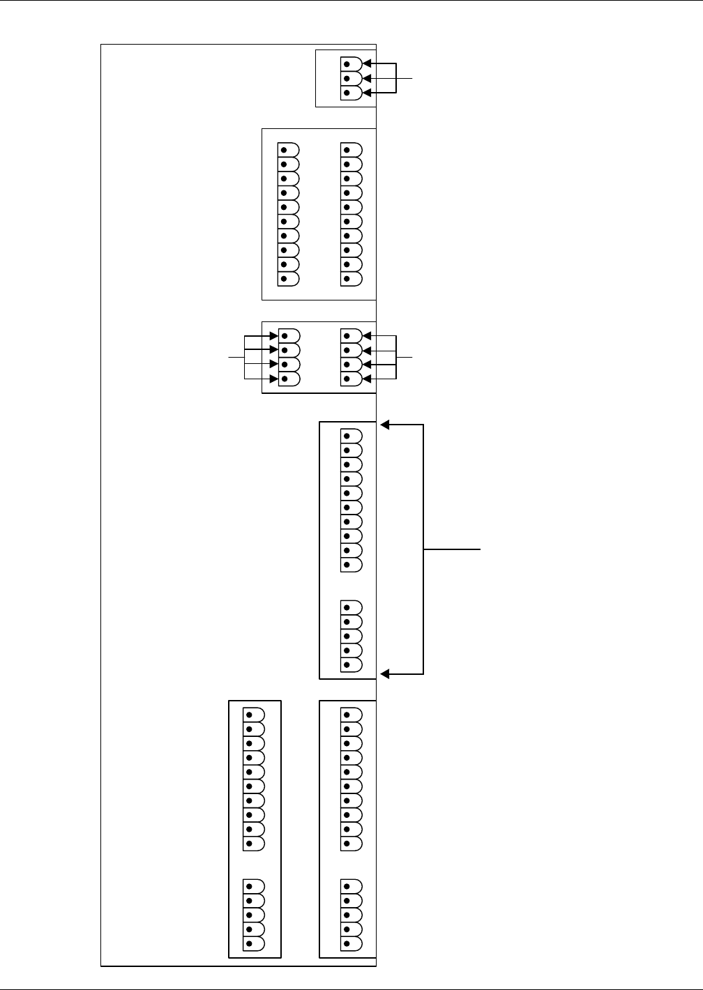
Figure 2 Liebert eXL customer connections
TB1-Remote
Status Panel
TB2 – Digital Inputs
TB3-SKRU Enable
Liebert eXL Control
Drawer
1
2
3
1
2
3
4
5
6
7
8
9
10
11
12
13
14
15
16
17
18
19
20
1
2
3
4
1
2
3
4
5
6
7
8
9
10
1
2
3
4
5
1
2
3
4
5
1
2
3
4
5
1
2
3
4
5
6
7
8
9
10
1
2
3
4
TB1154 – DC
Communication
1
2
3
4
5
6
7
8
9
10
Reserved for Remote Breaker
Options to be added

UPS Electrical Installation
Liebert® eXL™12
2.4.1 Dry Contacts
Table 1 UPS Digital Inputs
Item
Terminal
Block Pin
Connects to
(Description of External Item)
Maintenance Bypass Breaker (MBB) TB2 1 MBB Aux Contact, Closed = CB Is Closed
TB2 2 MBB Aux Contact Common
Maintenance Isolation Breaker (MIB) TB2 3 MIB Aux Contact, Closed = CB is Closed
TB2 4 MIB Aux Contact Common
Bypass Isolation Breaker (BIB) TB2 5 BIB Aux Contact, Closed = CB is Closed
TB2 6 BIB Aux Contact Common
Not Used TB2 7 —
TB2 8 —
Not Used TB2 9 —
REPO/EPO (N.O.) TB2 11 REPO Switch, Normally Open Contact
TB2 12 REPO Switch, Normally Open Common
REPO/EPO (Form-C or N.C.) TB2 13 REPO Switch, Normally Closed Contact
TB2 14 REPO Switch, Normally Closed Common
REPO/EPO (Form-C) TB2 15 REPO Switch, Normally Open Contact
Key Status TB2 17 Key Status Switch, Closed = Key Released
TB2 18 Key Status Switch, Common
Not Used TB2 19 —
TB2 20 —
1. All contacts have:
Maximum voltage: 24VDC
Maximum current: 10mA
Wire range: #14-22AWG
Maximum length: 500' (150m)
2. All external wire furnished by others
3. All wiring must be in accordance with national and local electrical codes.
4. If using REPO/EPO with Form-C contacts, Pins 13-15 must be used.
5. If using REPO/EPO with normally closed (N.C.) contacts only, a jumper must be placed across Pins 13 and 14.
Table 2 UPS Output
Item
Terminal
Block Pin
Connects to
(Description of
External Item)
Maximum
Voltage
Maximum
Current
Wire
Range
Maximum
Length
SKRU Enable TB3
1Maintenance Bypass
Cabinet, Common
120VAC 1A #14AWG 164ft (50m)
2 Normally Closed (NC)
3 Normally Open (NO)
1. To prevent signal interference, low-voltage (<48V) and low-current (5A) cable groups should be run in separate, grounded
conduit from high-voltage or high-current cable groups.
2. All external wire furnished by others.
3. All wiring must be in accordance with national and local electrical codes.

UPS Electrical Installation
13 Liebert® eXL™
2.5 Grounding
2.5.1 Three-Wire Input connections
This module must NOT be used when single-phase loads are directly connected to the UPS. Note that
whenever the UPS module transfers to or from bypass, two AC sources (UPS output and bypass) are
briefly connected together and circulating current must flow. In this configuration, the current flows
through the ground path and may trip ground fault interrupters (GFI’s), distorting the output voltage
waveform. Proper adjustment of GFI’s is necessary to avoid unwanted tripping. The time delay
should be set to at least 0.2 seconds to prevent tripping when the UPS performs a transfer or
retransfer operation.
NOTICE
Failure to set the ground fault interrupters properly could cause loss of power to the critical
load.
2.5.2 High Resistance Grounding (see attached document)
The Liebert eXL is not compatible with high-resistance ground systems. See your local Emerson
representative for details.
2.5.3 Preferred Grounding Configuration, Battery Systems
Open-rack battery systems, depending on local code requirements and customer preference, are
normally:
• Floating (ungrounded) OR
• Center-tapped and floating
Battery cabinet systems must be connected as floating (ungrounded) systems.
Center-tapped or grounded battery systems are not possible with battery cabinet systems.
Whether the battery system is open-rack or cabinet, the metal rack parts or cabinet must be grounded
to the UPS module ground bus.
Table 3 UPS control contacts to Battery Interface Boards
Item
Terminal
Block Pin
Connects to
(Description of
External Item)
Maximum
Voltage
Maximum
Current
Wire
Range
Maximum
Length
Battery Cabinet
Communication TB1154
1 CAN +24V
24VDC 2A 18AWG 1000ft
(305m)
2CAN Common
3 CANbus High
4 CANbus Low
1. To prevent signal interference, low voltage (<48V) and low current (5A) cable groups should be run in separate grounded
conduit from high voltage or high current cable groups.
2. All external wire furnished by others.
3. All wiring must be in accordance with national and local electrical codes.
4. The maximum length must take into account all battery communications connections in the system.
Table 4 UPS control contacts to Remote Status Panel
Item
Terminal
Block Pin
Connects To
(Description of
External Item)
Maximum
Voltage
Maximum
Current
Wire
Range
Maximum
Length
Remote Status Panel TB1
1CAN +24V
24VDC 150mA 18AWG 1000ft
(305m)
2 CAN Common
3 CANbus High
4 CANbus Low
1. To prevent signal interference, low voltage (<48V) and low current (5A) cable groups should be run in separate grounded
conduit from high voltage or high current cable groups.
2. All external wire furnished by others.
3. All wiring must be in accordance with national and local electrical codes.
UPS Electrical Installation
Liebert® eXL™14
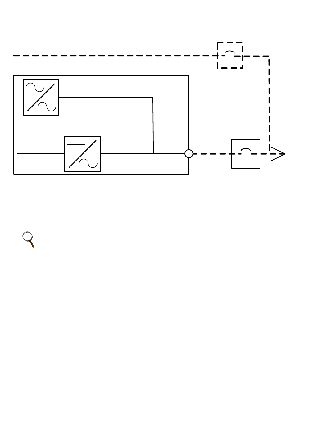
2.6 No CB2 Option
Figure 3 No CB2 option
If a module does not have the inverter output breaker CB2, an overcurrent protection device with a
manual disconnect must be supplied by others in a readily accessible location.
This overcurrent protection device must be appropriately sized. See Table 11 for rated module output
current. For system breaker coordination, see Figures 18 through 20 for the overload capabilities of
the modules.
NOTE
This option does not allow the Liebert eXL module to be isolated from critical load. Emerson
recommends installing a wraparound maintenance bypass. If a wraparound bypass is not
installed, according to the latest OSHA safety regulations, the output of the module may need
to be shut down to maintain the module.
FBO
FBO
Critical Load
UPS Module
Maintenance Bypass
3-Wire + GND
AC Output
3-Wire + GND
UPS Electrical Installation
15 Liebert® eXL™
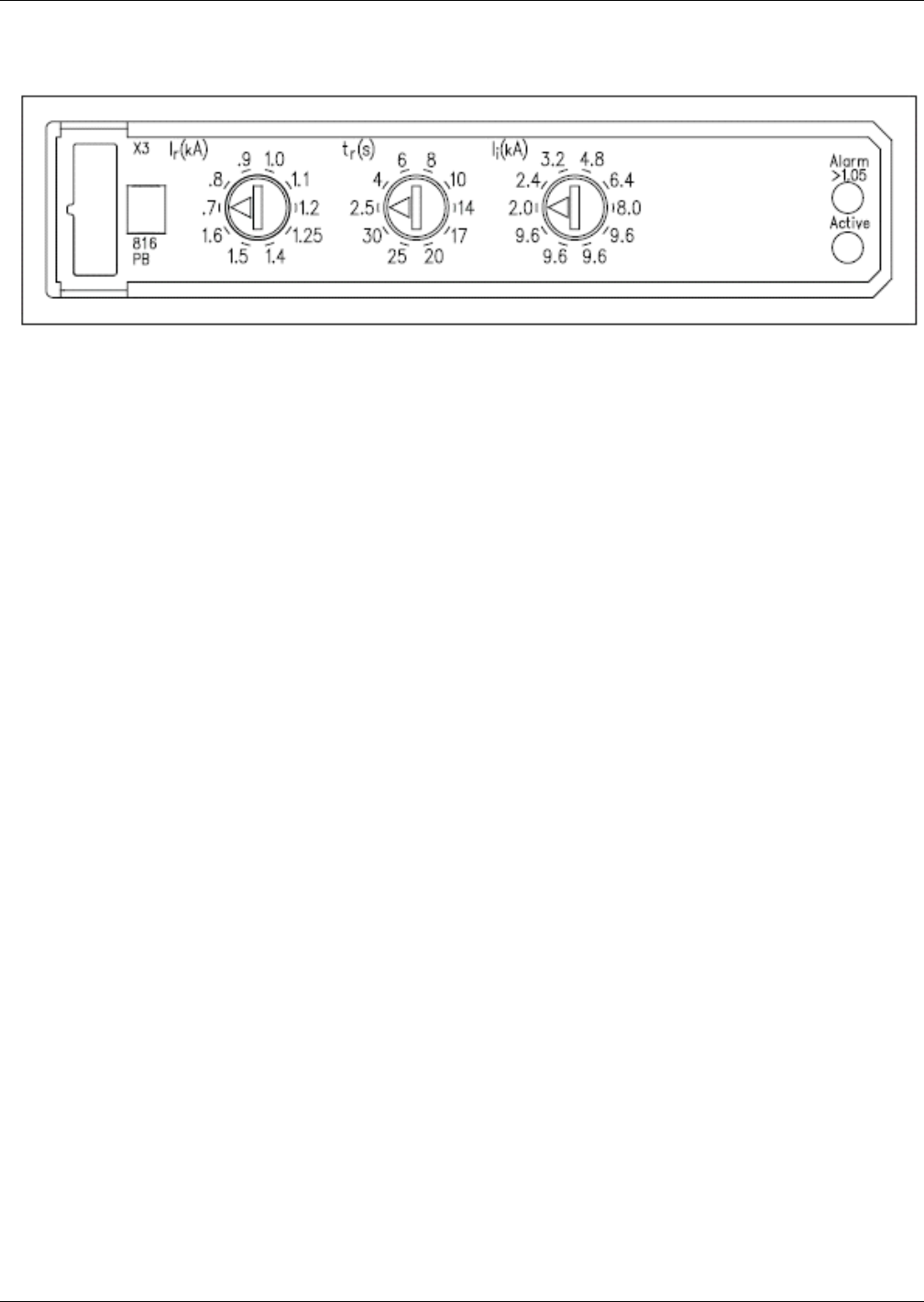
2.7 Internal Breaker Settings
Figure 4 Internal Breaker settings
All internal breakers—CB1, CB2 and BFB—were installed and set at the factory. Each has three
settings (refer to Figure 4):
•I
r—Trip setting. It is factory-set to the value appropriate to the module.
NOTICE
Risk of incorrect adjustment. Can cause equipment damage.
The trip setting (Ir) must not be adjusted. Changing this setting may damage the module.
•T
r—Long Term Trip Delay. It is factory set to its maximum value. It may be adjusted to a more
appropriate setting based on a site coordination study.
•I
i—Instantaneous Trip. It is factory-set to the maximum value. It may be changed to a more
appropriate setting based on a site coordination study.

Optional Equipment
Liebert® eXL™16
3.0 OPTIONAL EQUIPMENT
3.1 Single-Module System Options
3.1.1 Battery Temperature Sensor
The optional external battery temperature sensor kit, supplied separately from the battery circuit
breaker, contains one probe and one temperature transport board.
3.1.2 Matching Liebert eXL Battery Cabinet
The optional matching Liebert eXL Battery Cabinet can be used to obtain the desired autonomy time.
The battery cabinets are designed to be either attached to the UPS or separate from the UPS (for
details, see the Liebert eXL Battery Cabinet installation manual, SL-26035, available at Emerson
Network Power’s Liebert Web site: www.liebert.com).
3.1.3 Remote Alarm Status Panel
The remote alarm status panel has LED alarm lights. An audible alarm sounds upon any alarm
condition. The surface- or flush-mounted NEMA 1 enclosed panel indicates: Load on UPS, Load on
Bypass, Battery Discharging, Low Battery Warning, Overload Warning, Ambient Overtemp Warning,
UPS Alarm Condition, New Alarm Condition (For a Second UPS Alarm Condition).
3.2 Communication and Monitoring
The Liebert eXL has these monitoring options:
• Liebert IntelliSlot® Unity-DP (Dual Protocol) Card
The Liebert IntelliSlot Unity Card provides Web, embedded Emerson® LIFE™ Technology,
Emerson Protocol, SNMP, BACnet IP/MSTP, Modbus TCP/RTU, SMTP, SMS, and telnet
communication and control capabilities in one unified communication platform. The platform
supports 10/100 Mbit Ethernet, IPv4 and IPv6, HTTP/HTTPS for device Web page access, SMTP
interface for e-mail, SMS interface for text messaging, Emerson Protocol for communicating with
Trellis™ and Liebert Nform® software applications and LIFE technology for supporting Liebert
Remote Service Delivery.
SNMP v1/v2c/v3, Modbus TCP/IP, BACnet IP, Modbus RTU, BACnet MSTP and YDN23 third-
party protocols are also supported for building management and network management
applications. The Liebert IntelliSlot Unity card provides ground fault isolated 10/100 baseT
Ethernet and RS-485 network connectivity.
• Programmable Relay Board
• Input Contact Isolator Board
3.2.1 Alber Monitoring System
The matching Liebert eXL Battery Cabinet has space for an Alber battery monitoring system. The
battery monitoring system can be factory-installed or field-installed later.
The Alber Battery Monitor by Emerson continuously checks all critical battery parameters, such as
cell voltage, overall string voltage, current and temperature. Automatic periodic tests of internal
resistance of each battery will verify the battery’s operating integrity. Capabilities include automatic
internal patented DC resistance tests and trend analysis, providing the ability to analyze
performance, aid in troubleshooting and detect failing cells before they fail.
Installation Drawings
17 Liebert® eXL™
4.0 INSTALLATION DRAWINGS
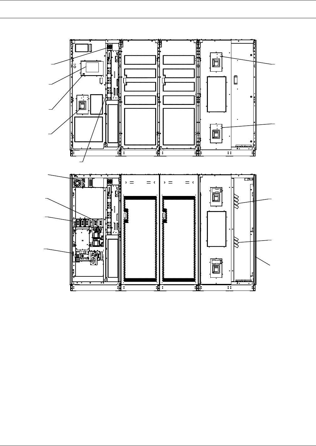
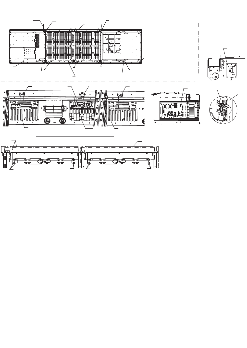
Figure 5 Typical main components, 625-800kVA Liebert eXL single-module UPS
Core Output/Bypass
Core
U46-8C-2000
Rev. 0
FRONT DOORS REMOVED
DOORS AND INNER SKINS REMOVED
Option Box
(5 Slots)
Liebert
IntelliSlot
Housings
Main Input
Circuit Breaker
(CB1)
Module Output
Circuit Breaker
(CB2)
Backfeed
Circuit Breaker
(BFB)
Keylock or
EMO Button
(optional)
Input
Ground
Input
Busbars
DC
Input
Output
Busbars
Output
Ground
Bypass
Busbars
High Voltage
Sense Connectors
Input
HMI Screen
(On Exterior Door)
Installation Drawings
Liebert® eXL™18
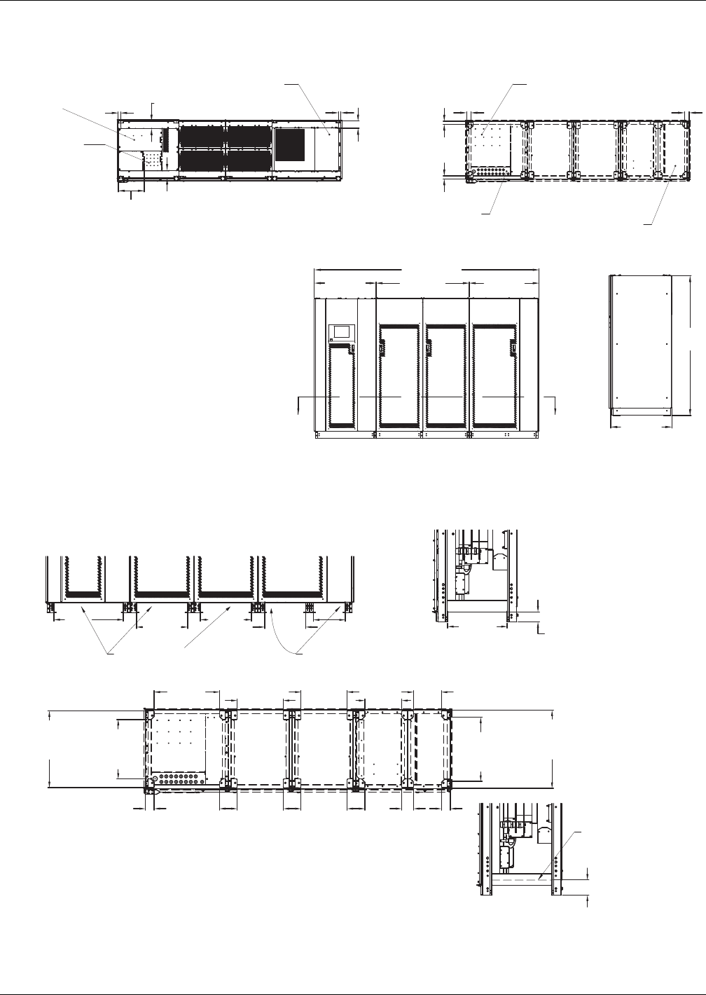
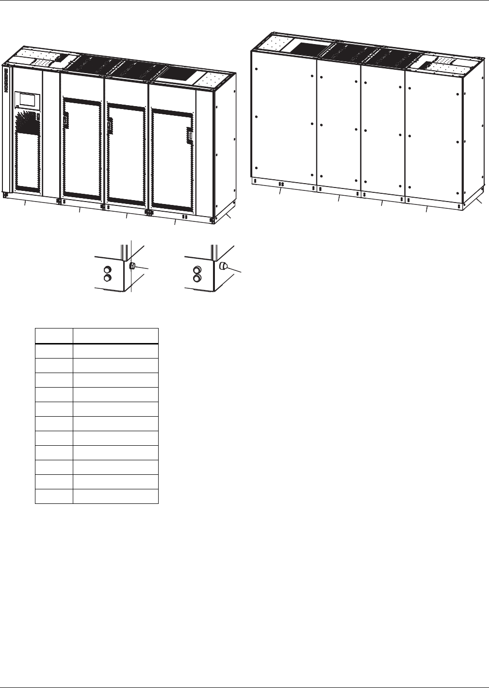
Figure 6 Outline Drawing, 625-800kVA Liebert eXL single-module UPS
Figure 7 Base drawing, 625-800kVA Liebert eXL single-module UPS
BOTTOM VIEW
Output/Bypass
A A
Section A - (Top Looking Down)
Core
Input Core
1.6 (40)
1.6 (40)
33.9 [862] 38.5 [978]51.2 [1300]
33.4 (850)
See Note 9
76.7
(1950)
123.6 (3140)
4.2 (106)
U46-8C-2001
Rev. 0
Notes
1. All dimensions are in inches (mm).
2. 24" (610) minimum clearance above unit required
for air exhaust, and 36" (914) front access required
for service.
3. Keep cabinet within 15 degrees of vertical while handling.
4. Top and bottom cable entry available through removable
access plates. Remove punch to suit conduit size and
replace.
5. Unit bottom is structurally adequate for forklift handling.
6. Control wiring and power wiring must be run in
separate conduits.
7. All wiring is to be in accordance with national and local
electrical codes.
8. Width dimension includes side panels. Subtract
1.4" (35mm) when removing both side panels.
9. Depth dimension includes the front door and rear panel.
The front door has an accent strip that adds 0.9" (24)
to the overall dimension.
10. See technical information drawing for shipping split weights.
11. Low Voltage cables must be appropriately separated from
the high voltage cables (both conduit routing and internal routing) FRONT VIEW
TOP VIEW
Right Side View
Bypass\Output
Cable Exit, Area
with Panel Removed
12.5 x 23.2
(318 x 590)
Low Voltage
Cable Entry/exit,
Area With
Panel Removed
8.8 x 9.8
(224x250)
Rectifier\DC
Cable Entry,
A
rea with Panel
Removed
12.5x21.9 (318x556)
Panel to
Frame
1.3 (33)
Panel to
Frame
4 (101)
Panel to
Frame
1.3 (33)
Panel to
Frame
2.4 (60)
Panel to
Frame
2.6 (65)
Panel to Frame
14.3 (363)
Panel to
Frame
Typ. Oppo.
Side 4.2 (106)
Low Voltage Cable
Entry \Exit, Area
With Panel Removed
4.9 x 21.8 (125 x 553)
See
Bottom
View
Front
Front
Panel to Frame
Typ. Oppo.Side
Rectifier\DC Cable Entry,
Area with Panel Removed
23.5 x 21.8 (597 x 553)
Bypass\Output
Cable Exit, Area with
Panel Removed
10.9 (278) X 28.4 (722)
1. All dimensions are in inches (mm).
2. Unit bottom is structurally adequate
for forklift handling.
Forklift Openings
Forklift Openings
(Top Looking Down)
Front
Front
Conduit
Plate
Behind Support
Rail
Input
Front
Core Output/BypassCore
Oppo. Side, Typ
U46-8l-1000
Rev. 0
Right Side
Lift Clearance
FRONT VIEW
27.8
(705)
16.4
(416) 12.8 (324)
BOTTOM VIEW
Footprint Spacing
26.2
(665)
6.1 (155)
3.9
(99) Oppo. Side
Typ
BOTTOM OUTPUT
Right Side
Bottom Cable Entry Panels
18.5
(470)
18.5
(470)
14.8
(376)
11.2
(284)
7.1
(180)
3.5
(90)
7.1
(180)
7.1
(180)
4.7
(120)
3.5
(90)
20.5
(520) 20.5
(520)
23.8 (605)
Oppo. Side Typ.
25.6 (651)
Pillar Spacing
Inside
31.3 (795)
Pillar Spacing
Outside
23.8 (605)
Foot Spacing
Inside
30.8 (781)
Foot Spacing
Outside
Installation Drawings
19 Liebert® eXL™
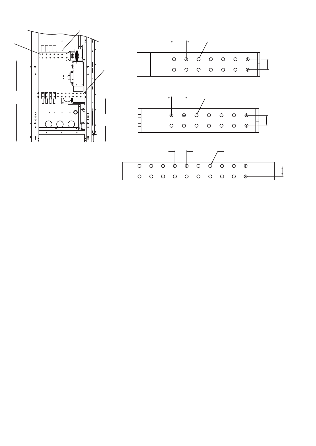
Figure 8 Input and battery terminal detail, 625-800kVA Liebert eXL single-module UPS
U46-8E-3200B
Rev. 0
23
(584)
42.8
(1088)
2.05 (52)
Typ.
1.75 (44)
1.97 (50)
Typ.
1.75 (44)
1.75 (44)
Ø.56 (14)
Typ.
Ø.56 (14)
Typ.
Ø.56 (14)
Typ.
2.08 (53)
Typ.
Notes
1. All dimensions are in inches (mm).
2. Control wiring and power wiring must be run in
separate conduits.
3. All wiring is to be in accordance with national and local electrical codes.
4. Based on NEC 408.56 minimum spacing, all live parts, including lugs, must be at
least 1" (25mm) from any other live part from a different phase or the
chassis frame. If lug stacking is required, the method of stacking and
required minimum spacing are the responsibility of the installing contractor
and authority having jurisdiction (AHJ).
LEFT SIDE VIEW
INPUT
#1 Input Phase Busbar 20.5 x 4
#1
#2
#3
SE-551827
#2 DC Pos. / Neg. Busbar 20.1 x 4
SE-551825
SE-552357
#3 Input Ground Busbar 25.4 x 3
Installation Drawings
Liebert® eXL™20
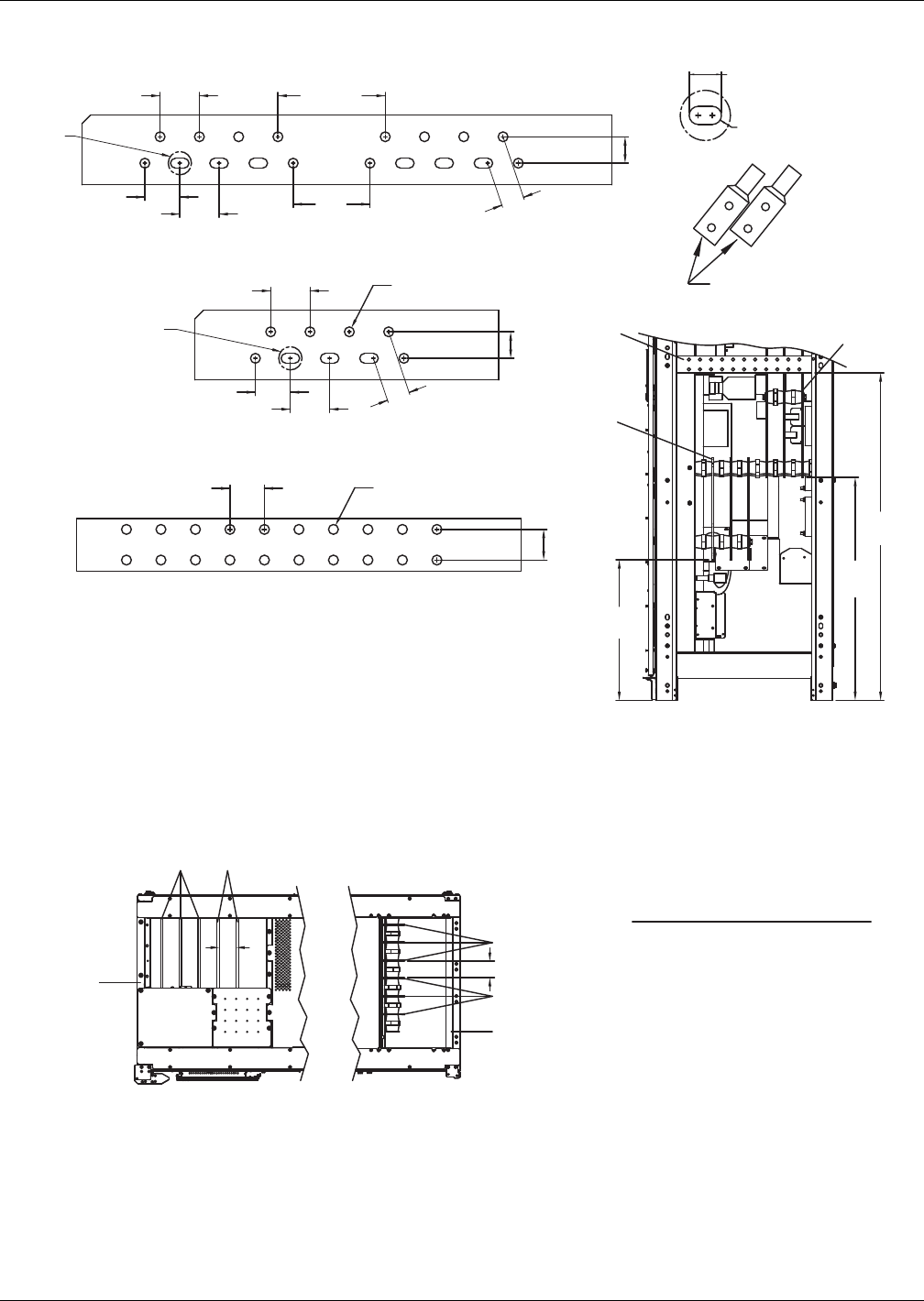
Figure 9 Output and bypass terminal detail, 625-800kVA Liebert eXL single-module UPS
Figure 10 Input, output and bypass terminal spacing details, 625-800kVA Liebert eXL single-module UPS
25.1
(637)
39.8
(1011)
58.4
(1484)
1.75
(44)
1.52 (38.6)
2.25 (57)
TYP.
2.0 (51)
TYP.
SEE
DETAIL
A
1.52
(38.6)
2.25
(57) Typ.
2.0 (51)
Typ.
2.25 (57)
Typ.
2.25 (57)
Typ.
6.15 (156)
4.4
(112)
1.97 (50)
Typ.
SEE
DETAIL
A
# 6 # 4
# 5
SE-552357
DETAIL A
1.06 (27)
Ø.56
(14) Typ.
1.75
(44)
TYP.
Dual Hole Lug.
Pad Width (Max.)
SE-552271
# 4 Bypass Input Busbar 30.36 x 4
SE-551097
1.75
(44)
TYP.
U46-8E-3200C
Rev. 0
Ø.56 (14)
Typ.
Ø.56 (14)
Typ.
Notes
1. All dimensions are in inches (mm).
2. Control wiring and power wiring must be run in
separate conduits.
3. All wiring is to be in accordance with national and local electrical codes.
4. Based on NEC 408.56 minimum spacing, all live parts, including lugs, must be at
least 1" (25mm) from any other live part from a different phase or the
chassis frame. If lug stacking is required, the method of stacking and
required minimum spacing are the responsibility of the installing contractor
and authority having jurisdiction (AHJ).
RIGHT SIDE VIEW
OUTPUT/BYPASS
#5 Output Phase Busbar 17.39 x 4
#6 Output Ground Busbar 25.4 x 3
U46-8E-3200A
Rev. 0
3
[75]
Typ. 3 (75) Typ.Between
Busbars
TOP VIEW
#1 Input Phase Busbar
#2 DC Pos. / Neg. Busbar
#3 Input Ground Busbar
#4 Bypass Input Busbar
#5 Phase Output Busbar
#6 Output Ground Busbar
SEE BUSBAR DETAIL PAGES 2 & 3
1. All dimensions are in inches [mm].
2. Control wiring and power wiring must be run in
separate conduits.
3. All wiring is to be in accordance with national and local electrical codes.
4. See Page 2, Drawing U46-8E-3200B and Page 3, Drawing U46-8E-3200C.
Input Output/Bypass
#2#1
#3
BC
A+
-
#6
#4
A
B
C
#5
A
B
C
(Front)
Installation Drawings
21 Liebert® eXL™
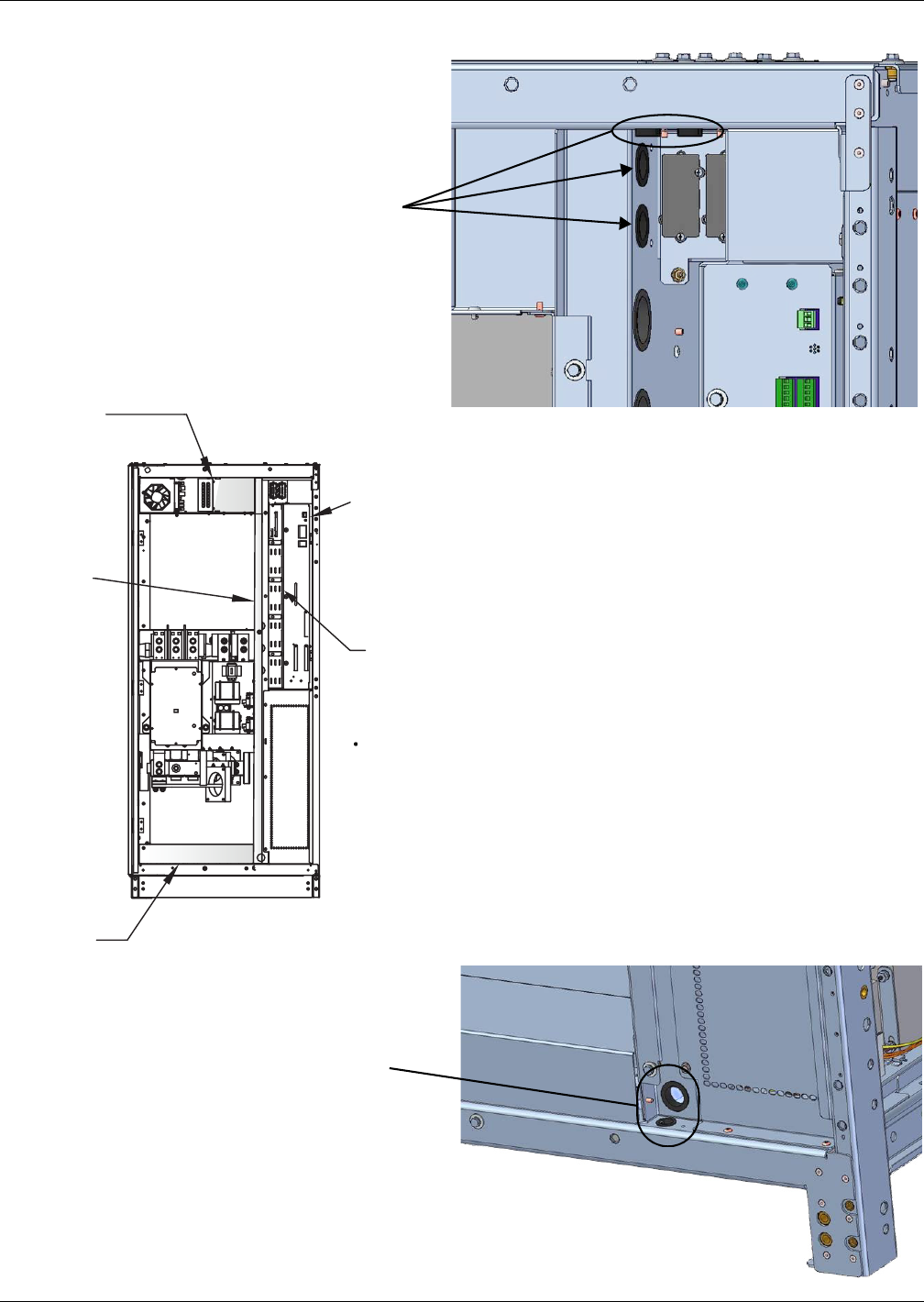
Figure 11 Low-voltage cable routing
Use these entry holes for
Liebert IntelliSlot® Unity™
card cables only
Use these entry holes for
Liebert IntelliSlot® Unity™
card cables only
DOORS AND INNER SKINS REMOVED
INPUT
Low Voltage
Control Cable
Top Entry
Low Voltage
Wire Way
Low-Voltage
Control Cable
Bottom Entry
Provide at least 18" (457mm) of service loop
to all control connections to permit opening
the service drawer without removing the connections.
The extra service loop can either be left hanging
or loosely attached to the corner post.
Service Drawer
Openings to Control Wire Way
To Ensure Isolation:
A
ll wirin
g
must have insulation rated
for 600V or hi
g
her
.
•
A
ll cables not rated
C
lass 1 must be
k
ept separate
d
an
d
secure
d
awa
y
from high-voltage Class 1 cables
.
Installation Drawings
Liebert® eXL™22
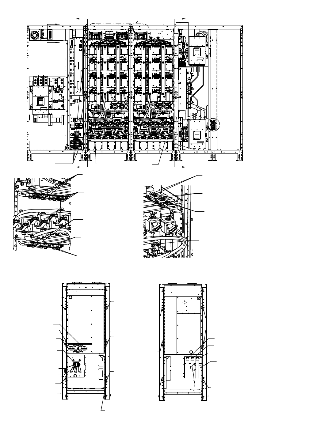
Figure 12 Shipping split, 625-800kVA Liebert eXL single-module UPS
See Detail C See Detail D
SEE DETAIL E
Cabinet-to-Cabinet Mounting Hardware
M10 Large Flat Washer (1)
M10 Split Lock Washer (1)
M10 X 30 Bolt (1)
(Typ 12 Places) (Labeled "MH")
M10 Large Flat Washer (1)
M10 Split Lock Washer (1)
M10 X 30 Bolt (1)
(Typ 12 Places) (Labeled "Mh")
Ph A - Flex From Input Cabinet
M8 Large Flat Washer (2)
M8 Belleville Washer (4)
M8 x 40 Bolt (2)
Torque 20.0 Nm (180 in-lb)
Ph C - Flex From Input Cabinet
M8 Large Flat Washer (2)
M8 Belleville Washer (4)
M8 x 40 Bolt (2)
Torque 20.0 Nm (180 in-lb)
Ph C - Flex From Bypass Cabinet
M8 Large Flat Washer (2)
M8 Belleville Washer (4)
M8 x 40 Bolt (2)
Torque 20.0 Nm (180 in-lb)
Ph B - Flex From Bypass Cabinet
M8 Large Flat Washer (2)
M8 Belleville Washer (4)
M8 x 40 Bolt (2)
Torque 20.0 Nm (180 in-lb)
Ph A - Flex From Bypass Cabinet
M8 Large Flat Washer (2)
M8 Belleville Washer (4)
M8 x 40 Bolt (2)
Torque 20.0 Nm (180 in-lb)
Output Ground- From Bypass Cabinet
M6 Carriage Bolt (2)
M6 Large Flat Washer (1)
M6 Belleville Washer (1)
M6 Nut (1)
Torque 9.0 Nm (80 in-lb)
Ph B - Flex From Input Cabinet
M8 Large Flat Washer (2)
M8 Belleville Washer (4)
Torque 20.0 Nm (180 in-lb)
Batt Neg (-) Flex From Input Cabinet
M8 Large Flat Washer (4)
M8 Large Flat Washer (4)
M8 X 40 Bolt (4)
Torque 20.0 Nm (180 in-lb)
Batt Pos (+) Flex From Input Cabinet
M8 Large Flat Washer (4)
M8 Belleville Washer (8)
M8 x 40 Bolt (4)
Torque 20.0 Nm (180 in-lb)
EMI Plates (3)
M6 Large Flat Washer (3)
M6 Split Lock Washer (3)
M6 X 25 Bolt (3)
P99
A
A
B
B
SECTION A-A SECTION B-B
G
G
H
F
F
DETAIL D
DETAIL C
Note: When mounting shipping splits together,
no gaps allowed between the corner posts.
The corner posts must make contact with
each other from bottom to top.
BATT +
BATT -
Input Ph A
Input Ph B
Input Ph C
Front Front
NOTE: For easier installation, pre-bend
the flex bus to about 90 degrees
before putting the splits together.
Install MH
From Core 1
Install MH
From Core 1
Install MH
From Core 1
Output A
Output B
Output C
Install MH
From Input
Output
Gnd
Install MH
From Input
Install MH
From Input
Install MH
From Bypass
Install MH
From Bypass
Install MH
From Bypass
Install MH
From Core 2
Install MH
From Bypass
Install MH
From Bypass
Installation Drawings
23 Liebert® eXL™
Figure 13 Shipping split, 625-800kVA Liebert eXL single-module UPS, continued
Route Harness From Input in Duct
to Core 1 (Connectors - J400, J11)
Bypass (Connectors - J13, J100, J200, J300)
Core 1 & 2 Prechg (See Section J-J)
Connect to Input Harness
(Connectors P400, P11)
Route Harness from Bypass
(Connectors - P13, P100, P200, P300)
in Duct to Input
Front
Wiring Duct
Rear
Wiring Duct
Route Harness From Input in Duct
to Core 1 (Connectors - P1, P2, P3, P66)
Core 2 (Connectors - P1, P2, P3)
Bypass (Connectors - P99a, P1)
Core 1
(Connectors - P1, P2, P3)
See Detail E
Core 1
(Connectors - P1, P2, P3)
See Detail E
Core 1 (Connectors - P66)
See Detail E
Bypass
(Connectors - P1)
See Section G-G
Bypass
(Connector - CB2 I/F Bd P99)
See Detail H
Route Harness from Bypass
in Duct to Input (Connector - P20)
Input (Connector
HVAB P20)
See Section F-F
Core 1 PRECHR PHA
(Brown Wire)
Core 2 PRECHR PHA
(Brown Wire)
Core 1 PRECHR PHB
(Orange Wire)
Core 2 PRECHR PHB
(Orange Wire)
WIRE DUCT
Core 1 Connector BD Core 2 Connector BD
Core 1 FIB 1
From Input
From Bypass
From Input
From Input
From Input
From Input
From Input
From Bypass
Bypass Cabinet
CB2 I/F BD
Bypass Cabinet
Bypass Connector DB
Input Cabinet HVAB
JJ
SECTION J-J
DETAIL E SECTION F-F
P20
SECTION G-G
P1
DETAIL H
P99
DETAIL C
Installation Drawings
Liebert® eXL™24
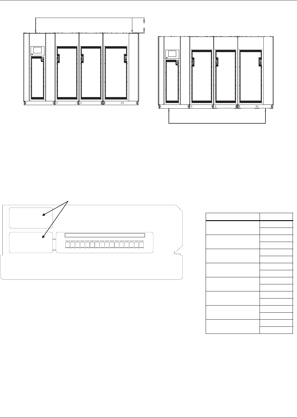
Figure 14 Kickplate installation
Table 5 Key to items in Figure 14
Item # Description
3 Panel Core Front
4 Panel Core Rear
5 Panel Input Front
6 Panel Input Rear
7 Panel Output Front
8 Panel Output Rear
9 Panel Side
10 Screw, M10
11 Flat Washer, M10
12 Split Washer, M10
13 Screw Cap
5337
9
8446
9
11 Typical
10
Typical
12 Typical
RIGHT HAND FRONT
LEFT HAND REAR
13
Typical
Installation Drawings
25 Liebert® eXL™
Figure 15 Cabling for single input configuration
Figure 16 Optional Input Contact Isolator Board
OUTPUT/BYPASS
CORE
INPUT CORE
OUTPUT/BYPASS
CORE
INPUT CORE
Note 1
NOTES
1. 24" (610) minimum clearance above unit required for air exhaust.
2. Top and bottom cable entry available through removable access plates. Remove punch to suit conduit size and
replace.
3. All wiring is to be in accordance with national and local electrical codes.
4. See Table 13 and 14 for cable sizing
5. Connection between the rectifier and bypass busbars are supplied by others.
6. Based on NEC 408.56 minimum spacing, all live parts, including lugs, must be at least 1 inch (25.4mm) from any
other live part from a different phase or the chassis frame. If lug stacking is required, the method of stacking
and required minimum spacing is the responsibility of the installing contractor and authority having
jurisdiction. See Figures 8-10 for busbar details.
123 67894105 111213141516
J51
No Customer Connection
Table 6 Input Contact Isolator Board
control wiring connections
Input Contact Pin No.
11
2
23
4
35
6
47
8
59
10
611
12
713
14
815
16
1. Customer control wiring connection points are terminals 1 through 16 (see
Table 6).
2. Customer provided normally open dry contacts for user alarm messages.
3. All control wiring (by others) must be run separate from power wiring.
4. Signal voltage: 100mA @ 12VDC.
5. Maximum cable length 500 ft. (152m) with #16AWG and flexible stranded
cable.
6. All wiring must be in accordance with national and local electrical codes.
Installation Drawings
Liebert® eXL™26
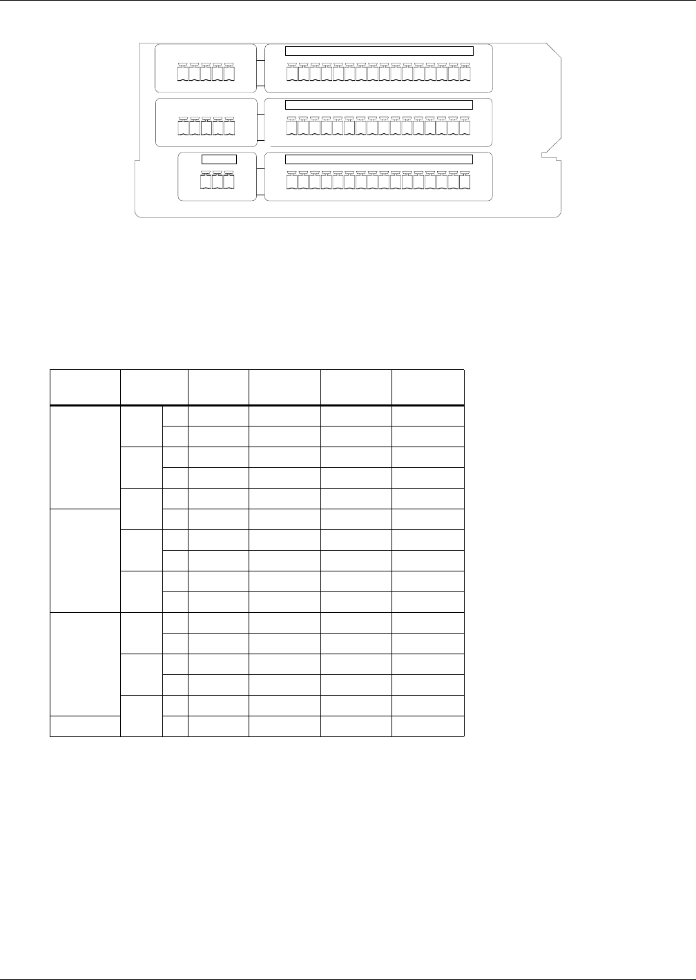
Figure 17 Control wiring, Programmable Relay Board
Table 7 Programmable Relay Board pinout
Terminal
Block Channel Pin No. Common
Normally
Closed
Normally
Open
J71
CH1 A1-3 1 2 3
B4-6 4 5 6
CH2 A7-9 7 8 9
B 10-12 10 11 12
CH3 A 13-15 13 14 15
J72
B1-3 1 2 3
CH4 A4-6 4 5 6
B7-9 7 8 9
CH5 A 10-12 10 11 12
B 13-15 13 14 15
J73
CH6 A1-3 1 2 3
B4-6 4 5 6
CH7 A7-9 7 8 9
B 10-12 10 11 12
CH8 A 13-15 13 14 15
J74 B 1-3 1 2 3
Note: Pin 16 not used on J71, J72, and J73.
123 67894105 111213141516
123 67894105 111213141516
123 67894105 111213141516
123
J74
J71
J72
J73
1. Customer control wiring connection points are terminals 1 through 15. (Pin 16 not used on J71, J72, and
J73.)
2. Programmable Relay Board option includes eight signal channels with two Form-C dry contacts per
channel (see Table 7).
3. All control wiring (by others) must be run separate from power wiring.
4. Contact ratings: 1A @ 30VDC or 125VAC @ 0.45A
5. Maximum cable length 500 ft. (152m) with #16AWG and flexible stranded cable.
6. All wiring must be in accordance with national and local electrical codes.

Specifications
27 Liebert® eXL™
5.0 SPECIFICATIONS
Table 8 Liebert eXL UPS specifications
Model Size 625-800kVA
Input Parameters
Input Voltage to Rectifier, VAC 480V 3-phase, 3-wire
Input Voltage to Bypass, VAC 480V 3-phase, 3-wire
Input Voltage Range, VAC +10% to -30%
Input Frequency, Hz 60
Permissible Input Frequency Range, Hz 55 to 65
Reflected Input THDi, Nominal Voltage, Full Load, % <5%
Power Walk-In, sec 1 to 30 (selectable) in 1 sec. Increment
Battery & DC Parameters
Battery Type VRLA (Valve Regulated Lead Acid) or FLA
(Flooded Lead Acid)
Nominal Battery Bus, VDC 480V
Battery Float Voltage, VDC 540V
Minimum End of Discharge Voltage, VDC 384V (for VRLA / Flooded Lead Acid)
DC Ripple Voltage in Float & Const V Ch. Mode, % <1 (RMS value) < 3,4% Vpp
Temperature Compensated Battery Charging Optional (with temperature probe)
Output Parameters
Inverter Type IGBT-based Sine Wave PWM Controlled
Output Power, kW 625 | 750 | 800
Output Voltage, VAC 480V 3-ph, 3-wire
Output Voltage Regulation, % < 1% (3-phase RMS average)
Output Voltage Regulation (50% Unbalanced Load) < 2% (3-phase RMS average)
Output Frequency, Hz 60
Output Frequency Regulation, % ± 0.1
Output THDv Linear Load at Nominal Voltage, % <3%
Output THDv at Nominal Voltage Including a 100kVA
Non-Linear Load per EN 62040-3, % 6% (max)
Capacity to Handle High Crest Factor Load 3:1
Capacity to handle Step Load, % 0-100 or 100-0
Step Load Transient Recovery (linear loads), % IEC 62040-3, Section 5.3.1 Figure 1
Unbalance Loads Current Capacity 100% of nominal phase current
Load Power Factor Supported (Without Derating) 0.7 Leading to 0.7 Lagging
Voltage Displacement, ° (Electrical Degree) 120° ±1° (with 50% unbalanced load)
Overload Conditions, % FL See Figures 18,19 and 20
Physical Parameters and Standards, in (mm)
Width, With Static Bypass 123.6 (3140)
Depth 33.5 (850)
Height 76.7 (1950)
Weight, Unpackaged, lb. (kg) approximate
with Static Bypass (SMS) 5735 lb (2601kg)
Maximum Heat Dissipation, Full Load, BTU/hr 76,000 | 91,000 | 96,000
Cooling Air, CFM <4,800
Color Black (ZP-7021)
Front Door Opening (for serviceability) 90°
Degree of Protection for UPS Enclosure IP 20 (with and without front door open)
Minimum Clearance, Top, in (mm) 24 (610)
Minimum Clearance, Back, in (mm) 0
Minimum Clearance, Sides, in (mm) 0
Location of Cable Entrance Top or Bottom
Specifications
Liebert® eXL™28
Standards and Conformities
UL 1778, 4th Ed.
CSA 22.2 107.3
FCC Part 15, Class A (with optional filters installed)
IEC62040-2, Level 4, Criteria A
ANSI C62.41, Category A3 &B3
ISTA
WEEE
Environmental Parameters
Storage Temperature Range, °F (°C) -13 to 158 (-25 to 70)
Operating Temperature Range, °F (°C)
32°F to 95°F (0°C to 35°C) at full rated load
1.5% maximum kW / degrees C derating up to 50°C
122°F (50°C) absolute maximum with derating
Relative Humidity 95% or less Non-Condensing
(Operating and Non-Operating)
Maximum Altitude Above MSL, ft (m)
4920 (1500) (as per IEC 62040/3) - 1% Maximum kW
derate / 328 rise between 4921-9842 (100m rise between
1500-3000m)
Width dimensions are with side panels attached. Subtract 1.4" (35mm) for dimensions without side panels.
Depth dimensions include the front door and rear panel.
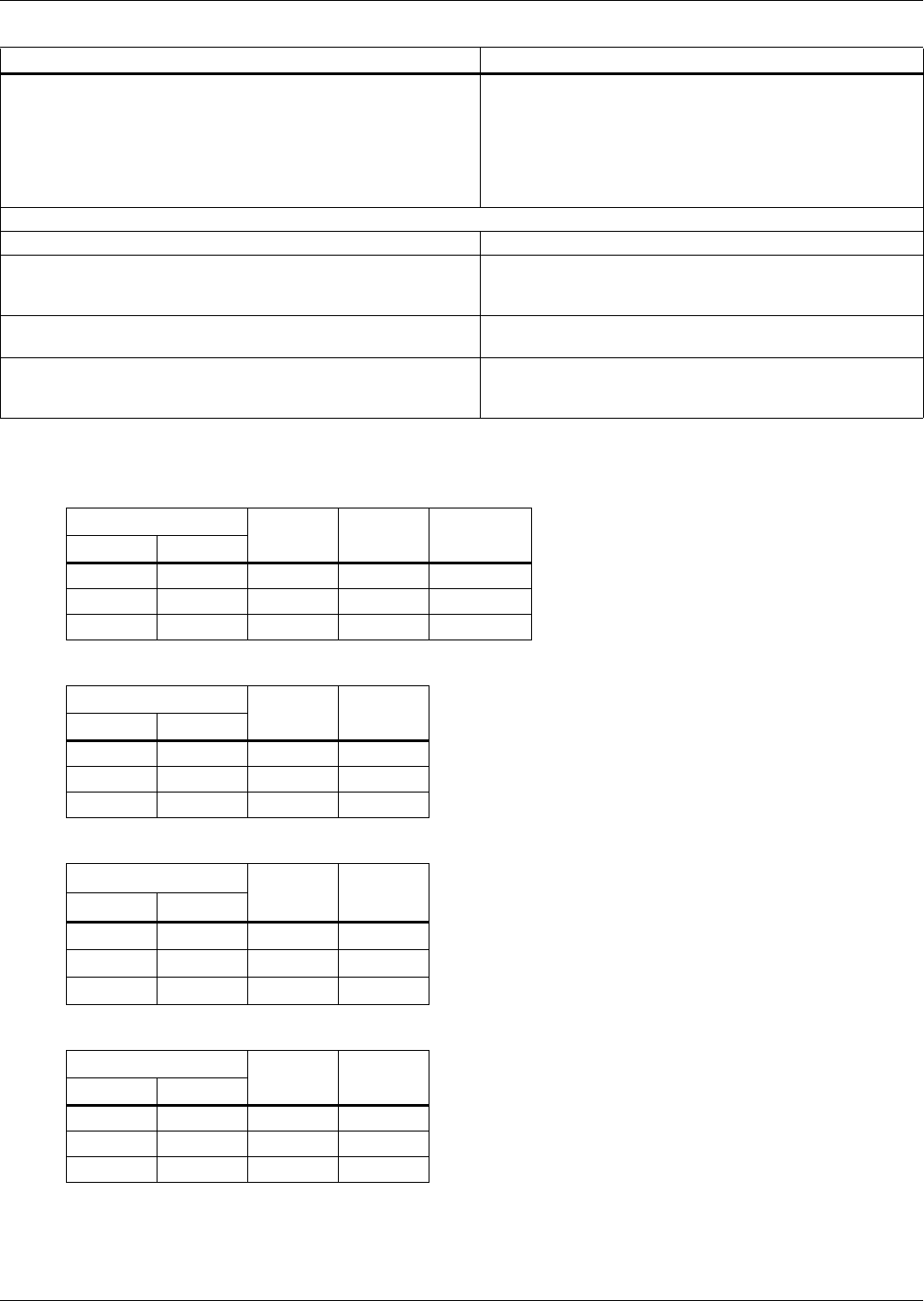
Table 9 Current ratings—rectifier input
UPS Rating Voltage
VAC
Nominal
Current
Maximum
CurrentkVA kW
625 625 480 779 818
750 750 480 935 982
800 800 480 995 1044
Table 10 Current ratings—bypass input
UPS Rating Voltage
VAC
Nominal
CurrentkVA kW
625 625 480 752
750 750 480 902
800 800 480 962
Table 11 Current ratings—output
UPS Rating Voltage
VAC
Nominal
CurrentkVA kW
625 625 480 752
750 750 480 902
800 800 480 962
Table 12 Current ratings—DC source
UPS Rating Voltage
VAC
Nominal
CurrentkVA kW
625 625 480 1624
750 750 480 1949
800 800 480 2079
Table 8 Liebert eXL UPS specifications (continued)
Model Size 625-800kVA

Specifications
29 Liebert® eXL™
Notes on Tables
1. Nominal rectifier AC input current (considered continuous) is based on full rated output load.
Maximum current includes nominal input current and maximum battery recharge current
(considered non-continuous).
2. The rectifier overload current is controlled by the input current limit setting, which is adjustable
from 25 to 200% (default:125%).
3. For breaker coordination while the module is overloaded, see the current versus time values on
the overload curves.
4. Nominal battery voltage is shown at 2.0 volts/cell.
5. DC Source current based at 401VDC.

Specifications
Liebert® eXL™30
Figure 18 Inverter overload data
631.1
324.8
194.7
120.0
75.9
49.0 32.4 21.8 14.9 10.4 7.3 5.2 3.8 2.8 2.1 1.5 1.2 0.9 0.2
0.0
100.0
200.0
300.0
400.0
500.0
600.0
700.0
100% 110% 120% 130% 140% 150% 160% 170% 180% 190% 200%
% Load
Time (sec)
Continuous
106%: 15005 secs

Specifications
31 Liebert® eXL™
Figure 19 Rectifier overload data
341.0
204.5
126.0
79.6
51.5 34.0 22.9 15.6 10.9 7.7 5.5 4.0 3.1 2.3 1.7 1.3 1.0 0.2
694.2
0.0
100.0
200.0
300.0
400.0
500.0
600.0
700.0
100% 110% 120% 130% 140% 150% 160% 170% 180% 190% 200%
% Load
Time (sec)
Continuous
106%: 16506 secs

Specifications
Liebert® eXL™32
Figure 20 Bypass overload data
324.8
194.7
120.0
75.9
49.0
32.4 21.8 14.9 10.4 7.3 5.2 3.8 2.8 2.1 1.5 1.2 0.9 0.2
500.0
0.0
50.0
100.0
150.0
200.0
250.0
300.0
350.0
400.0
450.0
500.0
100% 110% 120% 130% 140% 150% 160% 170% 180% 190% 200%
% Load
Time (sec)
Continuous

Specifications
33 Liebert® eXL™
Table 13 Recommended conduit and cable sizes for use with 80% rated breakers
Rectifier Input
UPS Rating Voltage
VAC
(# of conduits); size of conduits; # -size of phase cables per conduit;
size of cable for ground per conduit
kVA kW Copper Conductors Aluminum Conductors
625 625 480 (3) 3.5"C 3-600kcmil; #2/0AWG (4) 3.0"C 3-500kcmil; #4/0AWG
750 750 480 (4) 3.5"C 3-600kcmil; #2/0AWG (5); 3.0"C; 3-600kcmil; #4/0AWG
800 800 480 (4) 3.5"C 3-600kcmil; #3/0AWG (5); 3.0"C; 3-600kcmil; 250 kcmil
Bypass Input
UPS Rating Voltage
VAC
(# of conduits); size of conduits; # -size of phase cables per conduit;
size of cable for ground per conduit
kVA kW Copper Conductors Aluminum Conductors
625 625 480 (2) 3.5"C; 3-750kcmil; #1/0AWG (3) 3.0"C; 3-600kcmil; #3/0AWG
750 750 480 (3) 3.5"C; 3-600kcmil; #2/0AWG (4) 3.0"C; 3-500kcmil; #4/0AWG
800 800 480 (4); 3.5"C; 3-600kcmil; #2/0AWG (5) 3.0"C; 3-600kcmil; #4/0AWG
Output
UPS Rating Voltage
VAC
(# of conduits); size of conduits; # -size of phase cables per conduit;
size of cable for ground per conduit
kVA kW Copper Conductors Aluminum Conductors
625 625 480 (2) 3.5"C; 3-750kcmil; #1/0AWG (3) 3.0"C; 3-600kcmil; #3/0AWG
750 750 480 (3) 3.5"C; 3-600kcmil; #2/0AWG (4) 3.0"C; 3-500kcmil; #4/0AWG
800 800 480 (4) 3.5"C; 3-600kcmil; #2/0AWG (5); 3.0"C; 3-600kcmil; #4/0AWG
Battery
UPS Rating Voltage
VAC
(# of conduits); size of conduits; # -size of phase cables per conduit;
size of cable for ground per conduit
kVA kW Copper Conductors Aluminum Conductors
625 625 480 (6) 3.0"C; 2-600kcmil; #250kcmil (7) 3.5"C 2-700kcmil; #400kcmil
750 750 480 (6) 3.0"C; 2-600kcmil; #250kcmil (7) 3.5"C 2-700kcmil; #400kcmil
800 800 480 (7) 3.0"C 2-750kcmil; 350kcmil (8) 3.5"C 2-700kcmil; 600kcmil
1. Recommended cable sizes are 167°F (75°C) (THW) wire at 86°F (30°C) ambient. Unless otherwise noted, use copper or
aluminum conductors suitable for at least 75°C.
2. Recommended cables and conduits are based on breaker trip setting adjusted to the NEC 100 calculation of 125%
continuous current (nominal current) plus 100% of non-continuous current (maximum current minus nominal current) listed in
Tables 9 through 12.
3. Conduit size is based on FMC type conduit.
4. Emerson recommends that the site planner choose the appropriate cable type based on the particular installation
requirements.

Specifications
Liebert® eXL™34
Table 14 Recommended conduit and cable sizes for use with 100% rated breakers
Rectifier Input
UPS Rating Voltage
VAC
(# of conduits); size of conduits; # -size of phase cables per conduit; size of
cable for ground per conduit
kVA kW Copper Conductors Aluminum Conductors
625 625 480 (3) 3.0"C 3-500kcmil; #2/0AWG (3) 3.0"C 3-600kcmil; #4/0AWG
750 750 480 (3) 3.0"C 3-500kcmil; #2/0AWG (3) 3.0"C 3-600kcmil; #4/0AWG
800 800 480 (3); 3.5"C 3-600kcmil; #3/0AWG (4) 3.0"C 3-500kcmil; 250 kcmil
Bypass Input
UPS Rating Voltage
VAC
(# of conduits); size of conduits; # -size of phase cables per conduit; size of
cable for ground per conduit
kVA kW Copper Conductors Aluminum Conductors
625 625 480 (2) 3.0"C 3-500kcmil; #1/0AWG (2) 3.5"C 3-750kcmil; #3/0AWG
750 750 480 (3) 3.0"C 3-500kcmil; #2/0AWG (3) 3.0"C 3-600kcmil; #4/0AWG
800 800 480 (3) 3.0"C 3-500kcmil; #2/0AWG (3) 3.0"C 3-600kcmil; #4/0AWG
Output
UPS Rating Voltage
VAC
(# of conduits); size of conduits; # -size of phase cables per conduit; size of
cable for ground per conduit
kVA kW Copper Conductors Aluminum Conductors
625 625 480 (2) 3.0"C 3-500kcmil; #1/0AWG (2) 3.5"C 3-750kcmil; #3/0AWG
750 750 480 (3) 3.0"C 3-500kcmil; #2/0AWG (3) 3.0"C 3-600kcmil; #4/0AWG
800 800 480 (3) 3.0"C 3-500kcmil; #2/0AWG (3) 3.0"C 3-600kcmil; #4/0AWG
Battery
UPS Rating Voltage
VAC
(# of conduits); size of conduits; # -size of phase cables per conduit; size of
cable for ground per conduit
kVA kW Copper Conductors Aluminum Conductors
625 625 480 (5) 3.0"C 2-600kcmil; #250kcmil (6) 3.0"C 2-600kcmil; #400kcmil
750 750 480 (5) 3.0"C 2-600kcmil; #250kcmil (6) 3.0"C 2-600kcmil; #400kcmil
800 800 480 (6) 3.0"C 2-600kcmil; 350kcmil (7) 3.5"C 2-700kcmil; 600kcmil
1. Recommended cable sizes are 167°F (75°C) (THW) wire at 86°F (30°C) ambient. Unless otherwise noted, use copper or
aluminum conductors suitable for at least 75°C.
2. Recommended cables and conduits are based on breaker trip setting adjusted to the maximum rated current for the rectifier
input and the nominal current for the bypass and output listed in Tables 9 through 12.
3. Conduit size is based on FMC type conduit.
4. Emerson recommends that the site planner choose the appropriate cable type based on the particular installation
requirements.

Specifications
35 Liebert® eXL™
Table 15 Recommended lug sizes
Cable Size
T&B Copper
One Hole
T&B Copper
Two Hole
T&B Aluminum
One Hole
T&B Aluminum
Two Hole
#8AWG 54930BE 54850BE 60104-TB —
#6AWG 54905BE 256-30695-868 60109-TB —
#4AWG 54906BE 256-30695-733 60114-TB —
#2-3AWG 54942BE 54811BE 60120 —
#1AWG 54947BE 54857BE 60126 —
#1/0AWG 54950BE 256-30695-593 60132 —
#2/0AWG 54951BE 54862BE 60138 60238
#3/0AWG 54965BE 54864BE 60144 60244
#4/0AWG 54970BE 54866BE 60150 60250
250kcmil 54913BE 54868BE 60156 60256
300kcmil 54914BE 54870BE 60162 60262
350kcmil 54915BE 54872BE 60165 60267
400kcmil 54916BE 54874BE 60168 60269
500kcmil 54918BE 54876BE 60171 60273
600kcmil 54920BE 54878BE 60176 60275
750kcmil 54922BE 54880BE 60178 60277 (700kcmil)
Table 16 Recommended torque values
Grade 5 Steel: Unified Thread System Torque, lbf.*in. Class 8.8 Steel: Metric Thread System Torque, N*m
Fastener Finish Plain Steel Zinc Plating Fastener Finish Plain Steel Zinc Plating
Size
Threads/
Inch, Tpi
No Washer/
Flat Washer
No Washer/
Flat Washer Size
Thread
Pitch, Tp
No Washer/
Flat Washer
No Washer/
Flat Washer
1/4 20 101 91 M5 0.8 6.1 5.5
28 116 104 0.5 6.9 6.2
5/16 18 209 188 M6 110 9
24 231 208 0.75 11 10
3/8 16 370 333 M8 1.25 25 23
24 420 378 127 24
7/16 14 593 534 M10 1.5 50 45
20 662 596 1.25 53 47
1/2 13 904 814 M12 1.75 87 78
20 1,020 918 1.25 95 86
9/16 12 1305 1,175 M14 2 139 125
18 1456 1310 1.5 151 136

While every precaution has been taken to ensure the accuracy
and completeness of this literature, Liebert Corporation assumes no
responsibility and disclaims all liability for damages resulting from use of
this information or for any errors or omissions.
© 2014 Liebert Corporation
All rights reserved throughout the world. Specifications subject to change
without notice.
® Liebert is a registered trademark of Liebert Corporation.
All names referred to are trademarks
or registered trademarks of their respective owners.
Technical Support / Service
Web Site
www.liebert.com
Monitoring
liebert.monitoring@emerson.com
800-222-5877
Outside North America: +00800 1155 4499
Single-Phase UPS & Server Cabinets
liebert.upstech@emerson.com
800-222-5877
Outside North America: +00800 1155 4499
Three-Phase UPS & Power Systems
800-543-2378
Outside North America: 614-841-6598
Environmental Systems
800-543-2778
Outside the United States: 614-888-0246
Locations
United States
1050 Dearborn Drive
P.O. Box 29186
Columbus, OH 43229
Europe
Via Leonardo Da Vinci 8
Zona Industriale Tognana
35028 Piove Di Sacco (PD) Italy
+39 049 9719 111
Fax: +39 049 5841 257
Asia
29/F, The Orient Square Building
F. Ortigas Jr. Road, Ortigas Center
Pasig City 1605
Philippines
+63 2 687 6615
Fax: +63 2 730 9572
Emerson Network Power
Liebert
www.emerson.com
www.EmersonNetworkPower.com
SL-26025_REV1_05-14
