Mascot_21__Gang_Reel_manual%202010 !! Mascot Gang Reel Mower
Preview ! Mascot-Gang-Reel-Mower Reel Lawn Mower Manuals - Lawn Mower Manuals – The Best Lawn Mower Manuals Collection
User Manual: !! Reel Lawn Mower Manuals - Lawn Mower Manuals – The Best Lawn Mower Manuals Collection
Open the PDF directly: View PDF ![]() .
.
Page Count: 8

21” Gang Reel Mower
OWNERS MANUAL
Mascot Sharpening & Sales
434-B Newport Road
Ronks, PA 17572
717-656-6486
For Repair Parts Call:
MODEL 358
Set of 3 Mowers
MODEL 5-96
Set of 5 Mowers
IMPORTANT:
Read all instructions
carefully before assembling
and using this product.
Also the mower units for:
MODEL F-358
MODEL F-592
MODEL F-7-130”
Tri-Wheel Deluxe
Remember, any power equipment can cause injury if operated improperly or
if the user does not understand how to operate the equipment. Exercise
caution at all times, when using power equipment.
Rules For Safe Operations
LOOK FOR THIS SYMBOL TO POINT OUT
IMPORTANT SAFETY PRECAUTIONS. IT
MEANS — ATTENTION! BECOME ALERT.
YOUR SAFETY IS INVOLVED.
1. Read the towing vehicle and gang reel manuals
and know how to operate your vehicle, before
using with gang reel attachment.
2. Do not allow children to operate the towing
vehicle.
3. Do not allow adults to operate the towing vehi-
cle without proper instruction.
4. Do not carry passengers, either on the towing
vehicle or on the gang reel assemblies.
5. Keep children and pets a safe distance away.
6. Clear the work area of foreign objects.
7. Do not try to make any adjustments to the
gang reels while unit if in motion.
8. Always begin with transmission in first row
(low) gear, and gradually increase speed as
required.
21” GANG REEL CARTON CONTENTS
Solid Bar with J-Hook
Tow Bar Plate Assembly
Reel Assembly
2
Remove gang mower and loose parts from carton.
Refer to carton contents figure on page 2 to correct-
ly identify parts. Correct assembly of the two bar
hitch is important in operating performance of the
gang mowers.
Adjustments (Hitch Assembly)
1. Cutting height of the gang mower is adjustable
from 5/8 to 3 inches. See instructions for
changing adjustment from high to low cut.
2. The tow bar should be parallel to the ground
for operation. The tow bar in this position is
approximately 9 inches above the ground level.
When tow bar is in inverted position, it is
approximately 11 inches above the ground
level.
3. Regardless of cutting height, tow bar should be
parallel to the ground. The hitch for your gang mower has
been designed to give dependable operating per-
formance and flexibility under many lawn mowing
conditions.
It is easily and quickly attached to your towing vehi-
cle. The clevis pin and spring assembly provided
with each hitch permits independent floating action
so that the mower will follow the contour of the
lawn. See figure 3.
Always begin with transmission in first (low gear,
and gradually increase speed as required.
3
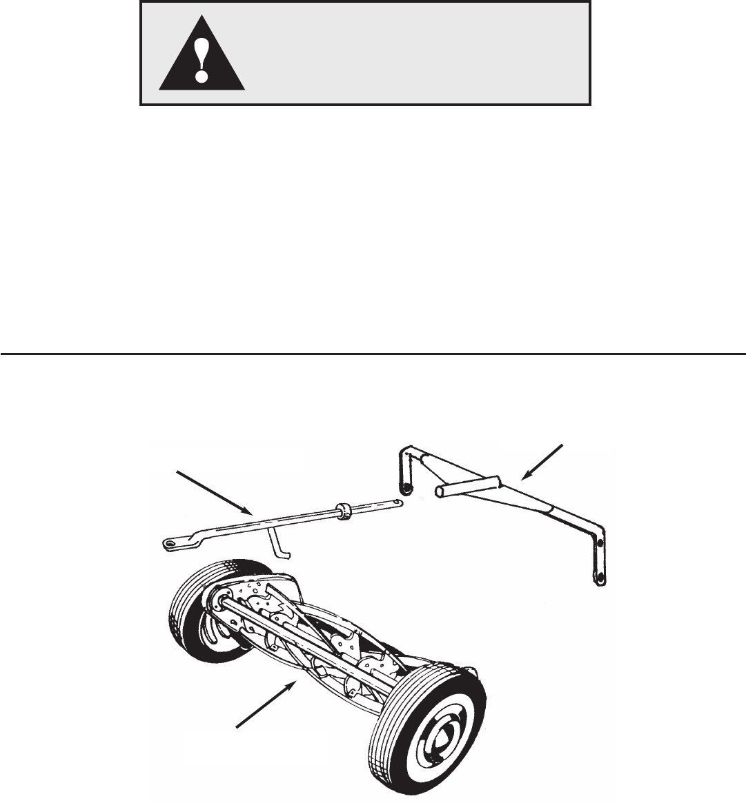
Hitch Assembly (Tow Bar)
Figure 2
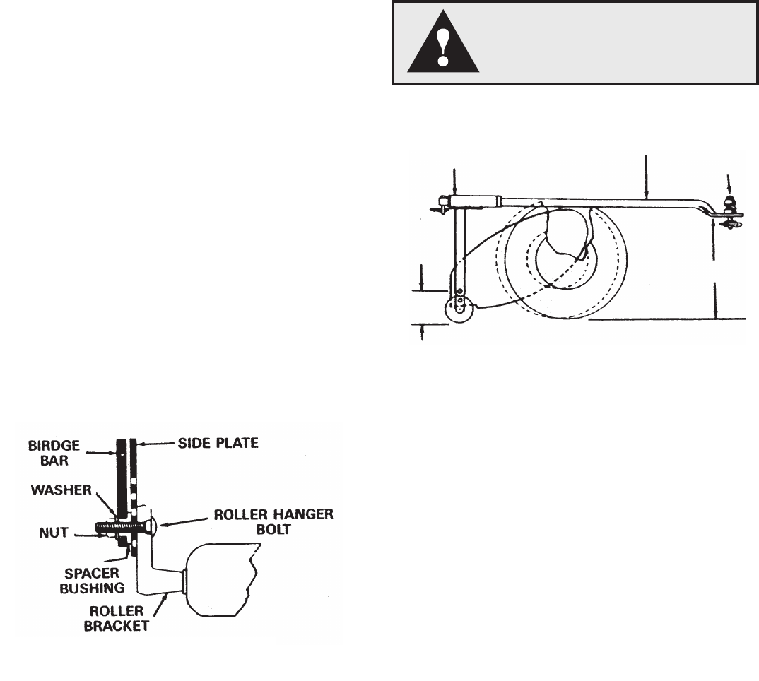
Operation
Do not carry passengers, either
on the towing vehicle or on the
gang reel assemblies.
Figure 3
Model #45-0194
Cut Height Roller Wheel
in Inches Setting Setting
1 . . . . . . . . . . . . . . . . . . 2 . . . . . . . . . . . . . . 4
11/4. . . . . . . . . . . . . . . . 5 . . . . . . . . . . . . . . 3
11/2. . . . . . . . . . . . . . . . 3 . . . . . . . . . . . . . . 3
13/4. . . . . . . . . . . . . . . . 1 . . . . . . . . . . . . . . 3
2 . . . . . . . . . . . . . . . . . . 4 . . . . . . . . . . . . . . 2
21/4. . . . . . . . . . . . . . . . 3 . . . . . . . . . . . . . . 2
21/2. . . . . . . . . . . . . . . . 2 . . . . . . . . . . . . . . 2
23/4. . . . . . . . . . . . . . . . 3 . . . . . . . . . . . . . . 1
3 . . . . . . . . . . . . . . . . . . 1 . . . . . . . . . . . . . . 1
TOW BAR
TOW BAR
PLATE BOLTS
9”
2-5/8”
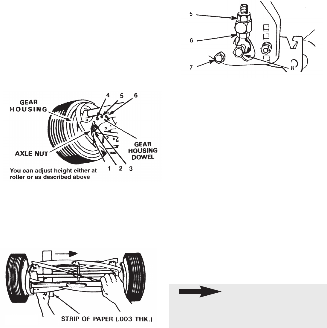
1. Loosen axle nut approximately 3 turns.
Disengage gear housing dowel from end plate
by moving wheel and gear housing outward.
Move wheel to desired setting. See figure 6
2. Be sure dimple and shoulder nut seat in side
plate holes.
3. Tighten axle nut security.
4. Adjust to level chassis and attain desired height
to cut.
TO ADJUST ROLLER
1. Remove both roller hanger bolts.
2. Raise or lower to desired cut.
3. Set both sides of roller at same height, replace
bolts and tighten.
PAPER TEST FOR REEL TO CUTTER BAR
ADJUSTMENT
(See figure 5)
1. Insert strip of .003 thick bond paper approxi-
mately 2” wide between cutter bar and reel.
2. Turn reel slowly backward, with wheels off
ground.
3. Adjust cutter bar so that reel blades pinch paper
without cutting it.
TO TIGHTEN CUTTER BAR ADJUSTMENT
(See figure 6)
1. Loosen top nut (Ref. 5) one quarter turn.
2. Tighten lower nut (Ref. 6)
3. Bolt (Ref. 7 and 8) must be tight after adjustment
(both sides)
TO LOOSEN CUTTER BAR ADJUSTMENT
(See figure 6)
1. Loosen lower nut (Ref. 6)one quarter turn.
2. Tighten top nut (Ref. 5)
3. Bolts (REf. 7 and 8) must be tight after adjust-
ment (both sides)
Lubrication/Maintenance
1. Seals on all bearings hold dirt out and grease in.
No lubrication is required.
2. Oil roller shaft between the rollers once or twice a
year so that rolls will roll freely.
3. If wheels are disassembled for repair, lubricate
pinions with an all purpose automotive chassis
grease.
Sharpening
Sharpening is required when the mower will not cut
satisfactory without the reel blades wiping on the
cutter bar.
Adjustments (Hitch Assembly)
See Chart on Page 3
Figure 5
Figure 6
4
When cutter bar is removed for sharpening,
left hand pivot bolt (Item 7), must be turned
counterclockwise to be removed. Right hand
pivot bolt must be turned clockwise.
NOTE
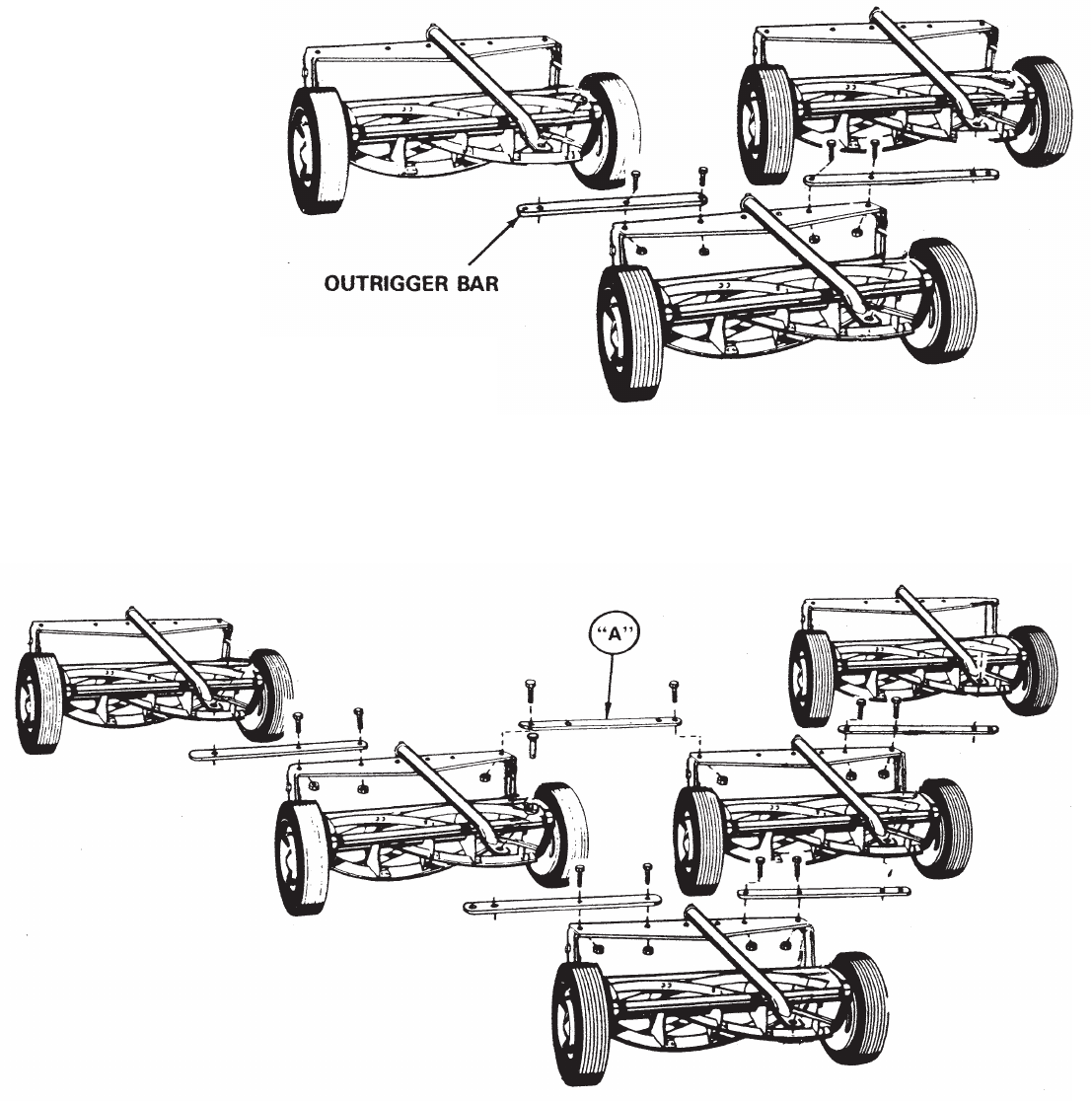
Model 358
INSTRUCTIONS FOR ASSEMBLING
THREE UNIT GANG
5
Model 5-96
INSTRUCTIONS FOR ASSEMBLING
FIVE UNIT GANG
Assemble mowers into gang unit using outrig-
ger bars as shown. Mount bolts MUST be placed
in holes indicated and nuts tightened securely.
Assemble mowers into gang unit using outrigger
bars as shown. Mounting bolts MIST be placed in
holes indicated and nuts tightened securely.
Outrigger bar “A” is used as a stabilizing bar
between mowers 2 and 3. When attaching this bar
the mounting bolts MUST be placed in the end
holes as shown. Tighten nuts securely then loosen
each nut one full turn to permit bar to pivot.
Model 45-0194 21” Single Gang Reel
6
When cutter bar is removed
for sharpening, left hand
pivot bolt (Item 7), must be
turned counterclockwise to
be removed. Right hand
pivot bolt must be turned
clockwise.
NOTE
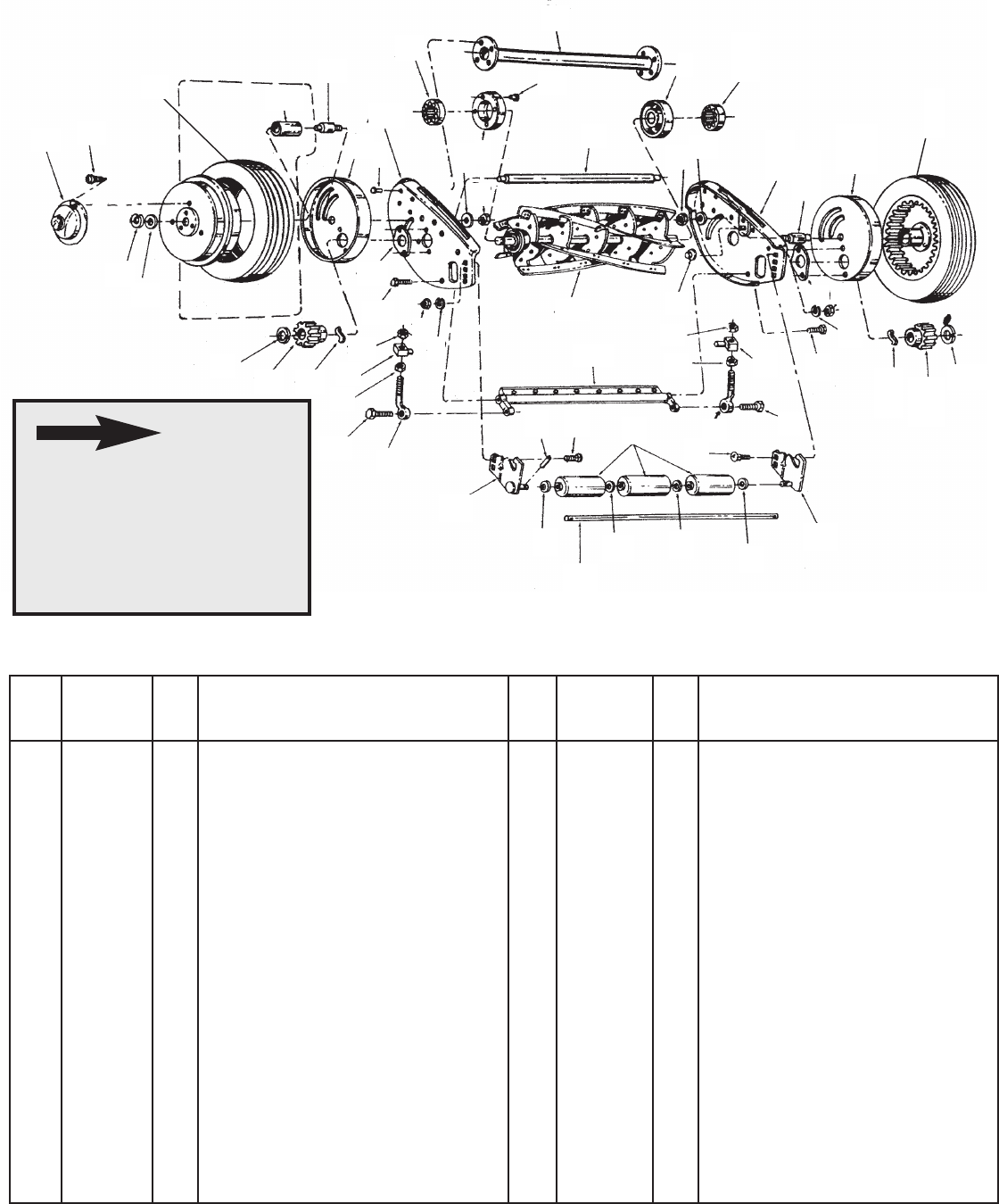
REPAIR PARTS FOR MODEL NO. 45-0194 21” GANG REEL MOWER
2 2624-110 1 Spacer End Plate
6 44060 8 Rivet 3/16 x 3/8 PLTD
16 1509-086 1 Screw Front L.H. Thd.
19 46324 2 Trunnion for Adjusment Screw
21 0455-000 1 Cutter Screw R.H.
9 1108-95 2 Drive Wheel Assembly
25 1511-029 6 Scr. #10-32 x 1-3/8 Thread Cutting
29 1112-015 1 Spacer Tube Assembly - for 21”
30 44738 2 Nut - 5/16-24 Hex Lock
31 1657-019 2 2 Piece Washer Bushing
32 1118-013 1 Gear Housing R.H.
35 0323-000 1 Pawl
36 0428-000 1 Pinion Gear L.H.
37 1650-001 2 Retaining Ring
40 1650-021 2 Retaining Ring *
41 2674-033 2 Hub Cap
42 43079 2 Carriage Bolt 5/16-18 x 1 *
44 1658-012 3 Roller, each section - 3 required
45 1129-181 1 End Plate R.H. - 21” gang only
47 1631-51 2 Axle
50 44232 2 Bearing
51 1548-007 1 Roller Shaft Pin
53 1629-028 3 Retainer
65 0451-000 2 Cutter Bar Adjusting Bolt
66 0453-000 2 Screw - rear
110 0425-000 1 Pinion Gear R.H.
113 1632-084 1 Roller Shaft - gang and 21” push
114 1129-180 1 End Plate L.H. - 21”
120 1652-052 1 Old Style Bronze Bearing
131 1118-014 1 Gear Housing L.H.
134 1629-009 3 Bearing Retainer
140 2132-045 1 Roller Bracket R.H.
141 2132-044 1 Roller Bracket L.H.
149 3134-024 1 Cutter Bar Assembly - 21”
155 3135-036 1 Reel Assembly - 21”
156 Operators Manual
REF. PART QTY. DESCRIPTION REF. PART QTY. DESCRIPTION
NO. NO. NO. NO
.
* Purchase Common Hardware Locally.
155
40
45
47
9
47
110
35
31
30
2
47
50
114
131
631 7
47
120
39
37
40
25
18
9
36 35
20
20
19
66 65
21
38
39
134
134 38
39
16
19
140
43
43
43
113
43
141
51 42 44
42
65 66
20
20
155
149
9
30
16 7
MODEL 45-0194 21” SINGLE GANG REEL
7
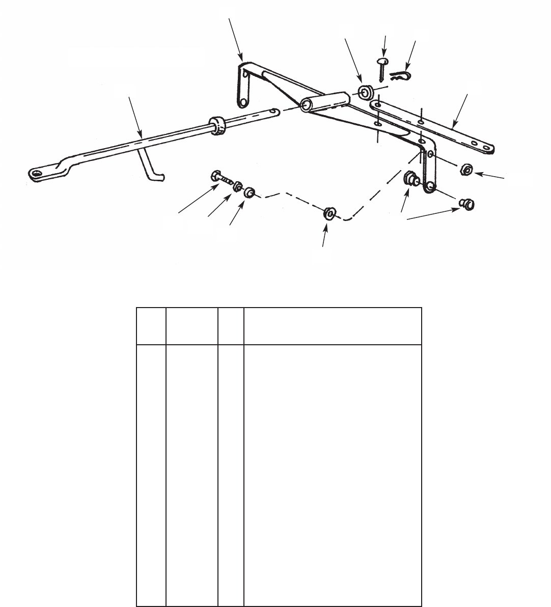
Trailer Hitch
REPAIR PARTS LIST FOR HITCH (TWO BAR)
3 43063 6 Bolt 5/16 x 18 x 1” *
4 1540-058 1 Washer
5 0041-042 1 Clevis Pin
6 43055 1 Hairpin Cotter
8 1697-005 1 Outrigger Bar
10 43064 6 Hex Lock Nut 5/16-18
69 2830 Old Style Tube Hitch - no J Hook
70 3600 1 Bridge and Tow Bar Plate Assembly
- new style is welded together
75 3000 4 2 Step Bushings
- on each side for bracket
111 2820 1 Tow Bar Assembly
- solid shaft with J Hook
117 43081 1 Washer 11/32 x 7/8 *
118 1513-45 2 Shoulder Bolt
119 0141-000 2 Washer
120 1624-135 2 Spacer
121 43013 2 Hex L-Nut 1/4-20 *
156 1 Owners Manual
REF. PART QTY. DESCRIPTION
NO. NO.
* Purchase Common Hardware Locally.
75
120
119
117
118
70
111
121
8
6
54
For Repair Parts Call
Mascot Sharpening & Sales
434-B Newport Road
Ronks, PA 17572
717-656-6486
