Meade ED And Achromat Collimation 178ED Refractor
User Manual: 178ED
Open the PDF directly: View PDF ![]() .
.
Page Count: 10

©2003-2004, Meade Refractor Group, Yahoo.com
http://groups.yahoo.com/group/meade_refractors
1
Meade ED/APO Refractor Optical Collimation and Centering
Meade AR5 and AR6 Achromatic Collimation
General Refractor Collimation
Contributors:
--Bill Bucklew for the pictures of the lens cell.
--Martin Christoph for his drawing of the lens cell (schematic).
--Philip Houston for compiling this procedure.
--Barry Simon http://groups.yahoo.com/group/unitrontelescopes.com
--Dennis Steele for editing, publishing and other chores.
©2003-2004, Meade Refractor Group, Yahoo.com
http://groups.yahoo.com/group/meade_refractors
2
Introduction
Generally, excellent telescopes can only perform well when the optical elements are in correct adjustment.
Fast Newtonians (below f/6) and Schmidt Cassegrains are notoriously sensitive to accurate collimation.
High magnification viewing demands the most of any lens or mirror system.
Meade’s high-end ED refractors have a reputation for high performance, but they are often plagued by
imperfect images. A typical story of how frustrating this can be is told in scopereviews.com (for the 178ED).
The factory manuals for these instruments give no hint of how to deal with optical defects; it’s as if they don’t
exist. Yet many members of this group (groups.yahoo.com/groups/meade_refractors) and others have
reported strange star images and blurry planetary images. Some have found good advice or through their
own experimentation and made the right adjustments. They were rewarded with the sharp high power
images when viewing.
Meade’s policy seems to be that lens adjustments are factory only. This costs $100 plus postage and can
take 4 to 12 weeks. The bad news is that they return your scope by UPS ground; it will likely be jolted out of
adjustment again. This document explains how anyone can make the necessary tests and adjustments. It’s
not quite as easy as adjusting a Newtonian or SCT, but the high success rate in our group is better than
anyone has reported from Meade + UPS.
How Good Is Your Scope?
Determining if your ED refractor’s optics are well adjusted is easily determined with a method that is
particularly sensitive and is called the star test. View a star high in the sky at high power (30x to 60x per
inch of aperture). If the seeing conditions are good, the image will show a small, round, bright spot called
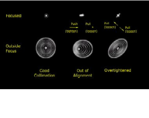
the Airy disc. Small, concentric rings of light should surround this. Examine the star image slightly inside
and outside of focus. A circle containing concentric, circular rings should appear. The ideal telescope
shows rings of similar size and brightness on both sides of focus (Figure 1-A). Most refractors show some
differences here and there will be various colors between the rings. ED refractors have much less of these
scattered colors than ordinary achromats.
The optical errors that Meade ED refractors are prone to will cause the in-focus star to have ring segments
piled up on one side of the brighter Airy disc. This is described as flaring or appears as a comet tail. The
out-of-focus images will show eccentric circles, bulging out in the same direction as the flaring. These
images are a result mostly of coma (Figure 1-B). Coma can be caused by tilted optics or, in refractors, if the
centers of the lens elements are not lined up on the same axis. Another error, Figure 1-C below, shows a
lens with its alignment screws over tightened.
A B C
Figure 1
©2003-2004, Meade Refractor Group, Yahoo.com
http://groups.yahoo.com/group/meade_refractors
3
Definitions
There are two very different adjustments on the Meade ED lens cells. The three pairs of push-pull screws
that are visible from the front of the scope affect the tilt of the whole objective lens assembly with respect to
the tube: this is called COLLIMATION.
There are also three holes on the edge of the lens cell, which contain pairs of stacked setscrews. The outer,
lock screws must be removed to allow adjustment of the inner setscrews (using a 5/64-inch or 1/16-inch hex
wrench). These setscrews move radially, like finder bracket screws. They move a spacer ring, which in turn
moves the rear (ED) element laterally, with respect to the stationary front element. This is called adjusting
the lens CENTERING.
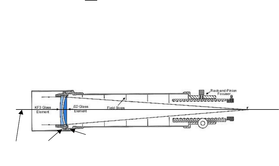
The term OPTICAL AXIS in a refracting telescope refers to a line from the center of the objective to the
center of the focuser and eyepiece. In a typical refractor with two glass elements, each element has its own
optical axis, which is defined by its shape. If the elements are perfectly made they will have axes that pass
through their exact centers. If not, they will perform better if they are shifted slightly so that the axes of both
are on the same line (centering). The lens cell is also adjusted so that this line extends through the center
of the focuser (collimation).
*This drawing doesn't show the push/pull screws explicitly. The screws are on the front of the cell, 120-degrees apart.
Optical axis push/pull collimation screws * Figure 2
Radial "centering" screws
©2003-2004, Meade Refractor Group, Yahoo.com
http://groups.yahoo.com/group/meade_refractors
4
COLLIMATION
Collimation can be very critical in fast systems, but in the Meade EDs, at f/9, it is not very problematic.
These lenses have fairly steep curves between the elements. This makes them very sensitive to correct
centering. A centering error of 0.002" in one of these scopes is noticeable; an error of 0.010" is very
serious. The smaller figure is equal to about 1/16 of a turn of a radial setscrew. In contrast, the collimation
adjustment is far less sensitive to small errors; a full turn of one of these screws will be less noticeable.
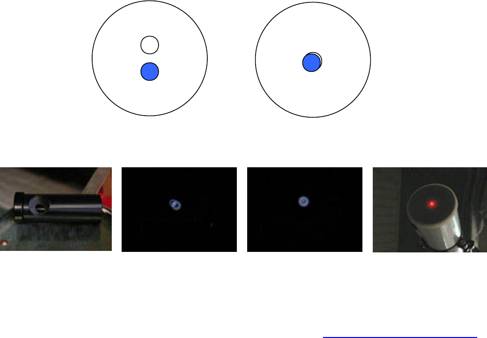
LASER COLLIMATION: Laser collimation tools depend on a narrow beam coming from the laser, reflecting
from the center of the lens, and returning to the collimator. If the original beam does not land on the center
of the lens, it will not return to the collimator (unless the lens is tilted out of square by just the right amount).
Before using a laser collimator to adjust a lens, it is important to see that it hits the lens on center. Taping a
sheet of paper over the lens cell with a mark at its center can do this. If the laser beam misses the mark, the
focuser is not lined up with the tube. Significant focuser adjustment may not be worth the effort. Errors of
less than 10mm may not be significant. It is also possible to exert pressure on the focusing tube and bring
the laser-beam into the center of the lens for the purposes of collimation. Use a rubber band and a weight of
some sort, or use a camera tripod to push or pull on the focusing tube as needed.
ANOTHER METHOD FOR LASER COLLIMATION:
Laser Alternative: Some people find that the laser in the focuser method just described is confusing
because of multiple reflections. The part about getting the focuser aligned right first is also a nuisance.
There is another laser method of squaring the lens to the tube axis (collimation) that many will find easier.
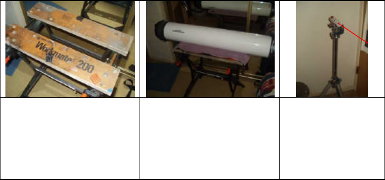
First you place the telescope tube on a steady table, supported in a way that it can be rotated on its axis.
You can use loose mounting rings or one-half rings. You can also use heavy wood blocks with V-shaped
notches that support the tube. It’s a good idea to line the wood with pieces of carpet or felt to keep from
scratching the optical tube assembly (OTA). Another alternative is the ³Workmate² table. The Workmate top
can be opened (similar to a vice) and adjusted to accept the OTA. Use a towel to allow smooth rotation
without risk of scratching your telescope.
Aim the OTA lens toward a wall or white screen and mount the laser so that its beam falls roughly in the
center of the lens. The reflected beam should return near the laser, forming a spot on the screen. Now
rotate the tube. This must be done without allowing the support to move or the tube to move very far toward
or away from the laser. If there is any collimation error, the reflected beam spot will be seen to move in a
circle. If it is stationary, the lens is square with the tube.
In the event the spot moves in a circle, mark one point where it falls. Then rotate the tube one half turn; the
spot will now be on the opposite side of its orbit. Adjust the 3 pairs of push-pull screws on the front of your
lens cell to move the spot half way toward to the mark. This will improve the collimation. After a couple of
repetitions of this procedure, you will find the spot remains stationary as the tube rotates. This will be the
case regardless of the angle of incidence of the laser beam (as long as the tube hasn’t moved along its
length.
This ends the procedure and squares (or collimates) the lens at 90-degrees to the optical axis. If you have a
Cheshire eyepiece, you can easily confirm the OTA’s collimation.
1: A “Workmate” tabletop is opened
just enough to allow the OTA to sit
easily in its groove. Any sturdy
surface that maintains the OTA in
place can work fine.
2: The OTA in place on the tabletop.
Use a towel or some carpet to a
smooth rotation of the tube along its
optical axis
3: A laser pointer or
collimator is held (I used a
rubber band) to a photo
tripod at the same height
as the center of the OTA’s
lens (any laser pointer will
work fine).
©2003-2004, Meade Refractor Group, Yahoo.com
http://groups.yahoo.com/group/meade_refractors
5
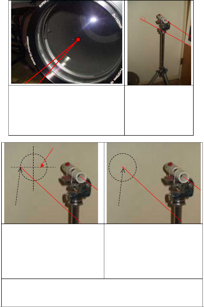
4: The laser beam points to the approximate center of the lens,
then reflects back to the wall or screen behind and beside the
laser pointer.
5: As you rotate the OTA along the
its “length”, if the lens needs
collimation it will scribe a circle on
the wall or screen (since the lens is
convex, you’ll notice the dot is
larger than its original size. This is
normal). Adjust the push/pull screws
on front of the lens-cell one-half the
distance toward the center.
ONE FINAL NOTE FOR ACHROMAT USERS: Owners of Meade's AR5 and AR6 series of achromatic
refractors (and most other refractors with adjustable push/pull cells) will not require lens element centering
as described below. Achromatic lenses are made with shallower curves that make them less sensitive to
small centering errors. ED apochromats, on the other hand, require a centered as well as collimated
objective lens.
6: If your lens needs collimation, you will notice a circle
of the laser-dot. Mark one location and rotate the tube
180-degrees so that the dot is now opposite the
location first marked. Then, with the push/pull
collimation screws on the front of the lens cell, adjust
the dot one-half the way toward the center.
Note: If you adjust the cell all the way to the center, you
will have simply “flipped” the lens and it will be out of
collimation in the other direction!!
7: Once you’ve adjusted the push/pull screws on the
front of the OTA’s lens-cell, and you rotate the tube
along its optical axis, when the lens is properly
collimated, you will find that the laser dot “stands still”
on the wall or screen. When this is achieved, you are
done!!
Note: The various laser beams and dots are simulated, as I couldn’t photograph them. The dotted lines (cross
hairs) in 6 represent the location of the laser dot and the associated push/pull movement. If you were to move
the dot to the center, you would simply shift the collimation to the other side of the cell (flipping the
“uncollimated” lens from one side to the other.
Move one
-
half the
distance
©2003-2004, Meade Refractor Group, Yahoo.com
http://groups.yahoo.com/group/meade_refractors
6
The Meade AR5 and AR6 lens cells are machined to fairly close tolerances. Hence, the lenses are kept in
reasonably close alignment. Occasionally slight centering errors occur and can be detected by using the
star test detection method. Loosening the retaining ring, which screws into the front of the cell then rattling
the glass slightly by thumping the side of the cell will often correct the problem. After tightening the ring, the
elements are often found to have shifted into a better alignment. This is a procedure that calls for some luck
or patience (and care). Most AR5 and AR6 telescopes are made to high standards and have no need of
any centering work.
CHESHIRE EYEPIECE: A Cheshire eyepiece is a broad source, which defines a point of origin in the center
of the focuser. The four reflections from the lens surfaces can be seen through the center of the Cheshire
(don’t worry if you can only see two or three). These reflections will be strung out in a line if there is a
collimation error. They will be superimposed if collimation is correct, showing concentric circles or some
other symmetrical image, depending on the design of the Cheshire. Focuser alignment is not important
here. Generally, two brighter circles will be seen, one white, one blue. The blue circle is reflected from the
inside of the KF3 (outer) lens. The white circle is reflected from the inside of the ED (inner) lens. With the
dew shield removed and the lens covered (black felt is good or use Meade’s lens cover), adjust the
push/pull screws on the front of the cell. Bring these two circles together, one on top of the other (a good
homemade design is shown in our photo archive). Another may be found in the book STAR
TESTING.ASTRONOMICAL TELESCOPES, p.122, from Willmann-Bell. This also explains other aspects of
collimation adjustment.
Cheshire Eyepiece
An image of the Cheshire Eyepiece
as it appears “misaligned”. Adjust the
push/pull screws on the front of the
cell to bring the images into
alignment. There is one light source,
but one image is reflected from the
ED glass while the second image is
reflected from the KD3 glass
Cheshire image aligned
View of a laser collimator in the
focuser and shown projected through
a cover over the objective. An
aligned focuser will project the laser
through the “center” of the lens.
Thank you to Barry Simon and the yahoo.com Unitron group for permission to use these photographs -- http://groups.yahoo.com/group/UnitronTelescopes.
Collimation adjustment does not need to be as precise as centering, but the closer the better. The design of
Meade’s ED lens cell is such that collimation is much more stable than centering. It is still important to
check particularly with used scopes as a previous owner may have tried to correct a centering error by
adjusting the collimation screws.
The actual adjustment requires loosening the pull screws (larger heads) and tightening the push setscrews
to move that side of the lens outward. The reverse will move it inward. Make small changes (1/4 turn to
start) to screw pairs and see if there is improvement. This can be faster with two people, if one looks while
the other adjusts.
Figure 3
Out of Collimation Close to Collimation
(Continue until circles merge into one)
©2003-2004, Meade Refractor Group, Yahoo.com
http://groups.yahoo.com/group/meade_refractors
7
When starting with a badly misadjusted lens, it may be helpful to loosen all six screws until the lens cell can
be held flat against the tube flange. You may wish to insert some space between the tube flange and the
lens cell. This can be accomplished with a spacer (a 1/8th drill bit, for example). Then screw in the push
setscrews to contact plus one turn. Tightening the pull screws to remove slack. This will put things pretty
close, and leave space with which to work. When tests indicate good collimation, be sure that all six screws
are snug and check again (DO NOT over tighten). This should stay put for a long while, but it doesn’t hurt to
check it again after making changes to the lens centering. How To Adjust Centering
Referring to Figure 1, if your telescope gives faulty star tests as described above, and has reasonably good
collimation, it will need lens centering adjustment. View a star image at 30x to 60x per inch of aperture.
Rotate the eyepiece and diagonal to assure that they are not the problem. If the flared star holds position
with the telescope, then centering the lens is required.
When making adjustments it is best to eliminate the diagonal to avoid confusion as to which screws to turn.
Straight through viewing may require an extension. A good bright star around 45 degrees above the horizon
is an acceptable compromise between the awkwardness of higher angles and the poor seeing conditions
below. If a diagonal must be used to access the zenith region or if no extension is
available, the diagonal should be of known good quality. You may wish to use a
“pointer” attached to the front of the lens cell. Masking tape works well. With the
tape stuck to the outer edge of the retaining ring, and the length about 1/3 the
diameter of the lens, you may move the “pointer” until it lines up with the flare or
coma of the star-test. The screw nearest the tape is turned CLOCKWISE. The
example here shows a pointer made of heavier paper held in place with a
clothespin.
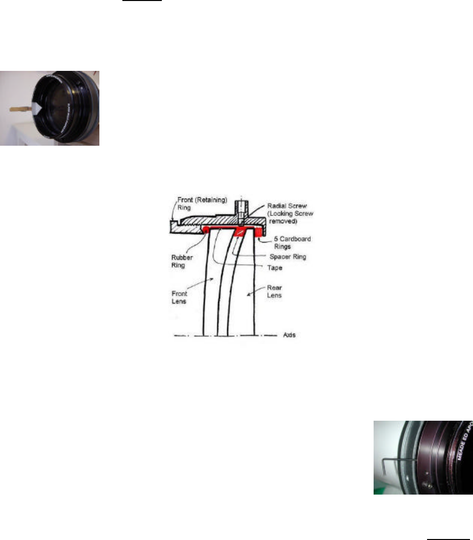
Referring to Figure 4, the adjustment is made on setscrews in the three radial holes at the edge of the lens
cell. These are only visible after the hood is removed. There should be two setscrews in each hole. The
outer lock screws must be removed before the inner adjustment screws can be turned. The tool for this is a
5/64-inch or 1/16-inch hex wrench (allen wrench).
The comet tail flare of a star in focus, or the bulging side of the out of focus
bull’s-eye, indicates the side of the lens where a radial setscrew needs to move
inward or clockwise. Before doing this, the opposing setscrews must be backed
out enough to allow the lens element to move. If the flare falls between two
setscrews, back out the opposite setscrew and then screw in the two adjacent
setscrews. Proceed in small steps of no more than 1/4 turn at a time. Check
progress frequently.
The radial setscrews may be hard to turn; they must push a heavy lens element against a frictional
resistance. The retaining ring at the front of the cell must remain snug, as this helps constrain the stationary
lens element while the other moves laterally. Meade MAY have used Locktite on the setscrews of some
lens cells; this will make them harder to turn. BE PATIENT! WORK SLOWLY.
When the in focus star has a nice even diffraction ring (or rings) instead of an off center pile of ring
segments, the lens centering is correct. At this point, the out of focus image will be a bull’s-eye of
symmetrical, concentric rings. The setscrews must be snug to preserve this adjustment. The three lock set-
Pointer
Fig 4

©2003-2004, Meade Refractor Group, Yahoo.com
http://groups.yahoo.com/group/meade_refractors
8
screws can then be replaced above the adjusting setscrews. These should be tightened very slowly and
evenly to avoid disturbing the adjustment of the inner setscrews. They DO NOT need to be very tight, and
Locktite is NOT recommended. It may be necessary to adjust again after a heavy jolt.
If the out of focus star image becomes triangular or takes some other non-circular shape, this is a sign of
pinched optics, possibly caused by over-tightening the setscrews. If this happens, reduce the tightness
slightly. An example of over-tightened setscrews is shown in Fig. 1C.
Problems?
Most owners of Meade ED telescopes who have made the adjustment of their lens centering have reported
great improvement in the final optical quality. One of our members, who followed this general procedure,
found that the star image initially improved, but then got worse. Further adjustment of his setscrews failed to
help. He also noted that the rubber o-ring just under the retaining ring of his lens cell had slipped out along
one side. The retaining ring being too loose may have caused this. The o-ring is apparently important in
holding the front lens element steady as the rear element is shifted laterally. A possible remedy would be to
unscrew the retaining ring from the front of the cell, remove the o-ring, back out the radial setscrews, and
center the lens elements within the cell. Wipe any dust off of the o-ring before replacing it. Finally, tighten
the retaining ring enough to compress the o-ring slightly (perhaps 1/4 to 1/2 turn past first contact). An o-
ring that is too tight will distort the glass and cause pinched optics effects, similar to Fig 1C.
Artificial Stars
Some in our group have reported making the centering adjustment with an artificial star. Artificial stars can
be as simple as a sun glint reflected from some distant power pole insulator or a ball bearing. A more useful
source may be a homemade pinhole backed by a strong light. Such procedures have the advantage of
being stationary and may be less troubled by atmospheric conditions. A pinhole source could even be used
indoors if it is small enough and you have enough extensions to reach focus. For a pinhole source to be
useful in testing a telescope, it must be smaller than the Airy disc. A pinhole diameter of .001 inches needs
to be 208 inches (17 feet) away. This example would be barely adequate to test a 102mm telescope. A
178mm scope would need to be nearly twice as far away or have a pinhole half as large. Some books
advise that an artificial star must be at least 50 times the focal length away. This may be valid for a true star
test, but it is not necessary to check for centering errors. You will find a fairly complete discussion of artificial
stars in Harold Richard Suiter’s book Star Testing Astronomical Telescopes published by Willmann-Bell, Inc.
A picture of a pinhole star is posted in our photo archives. Artificial stars may be constructed or purchased.
Check www.eztelescope.com for a commercially available artificial star. Further information on how to build
an artificial star is available at: http://home.stny.rr.com/mrgrytt/ArtificialStar.html
©2003-2004, Meade Refractor Group, Yahoo.com
http://groups.yahoo.com/group/meade_refractors
9
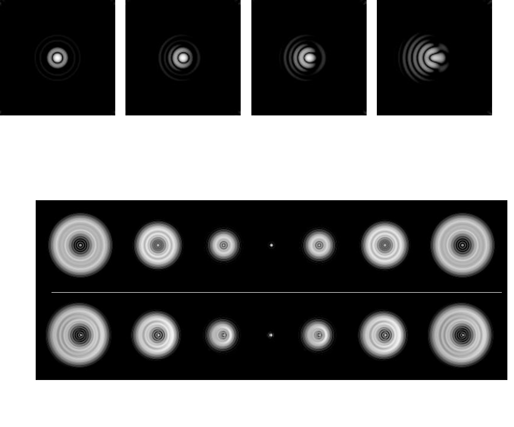
Addendum 1 -- Star Tests Reference:
The “airy disk” is a star image you’ll see under high power on a brighter star and at or very near focus. If
necessary, you can use a Barlow. It’s best not to use a star diagonal, but rather, look directly through the
telescope.
A: Airy Disk with lens correctly
collimated and centered. B: Airy Disk with lens just out of
collimation and centering. Use
the “radial” screw at 3 o’clock
and turn clockwise.
C: Same as “B” with greater
collimation and/or centering
error.
D: Same as “B” with an
extreme amount of collimation
and/or centering error.
OUTSIDE OF FOCUS
Farther from Lens
At Focus
INSIDE OF FOCUS
Closer to Lens
Collimated/
Centered
Out of
Collimation/
Centered
NOTE: These star tests are patterns as seen with a telescope with a central obstruction (an SCT or Newtonian). Hence, the pattern shows the
darkened center. In a refractor, the center will not be darkened.
©2003-2004, Meade Refractor Group, Yahoo.com
http://groups.yahoo.com/group/meade_refractors
10
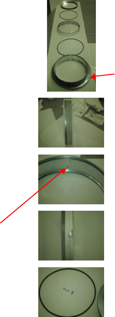
Addendum --2 Meade 178 ED/APO Lens Cell:
These 5 pieces make the cell assembly. From the top to
bottom are the:
1) Retaining ring.
2) O-Ring
3) Lens assembly
4) O-Ring
5) Lens cell
Holes for the push/pull screws.
Here, the tape has been removed showing the ED glass
element and the metal spacer ring. The “radial” screws push
against the metal spacer ring, moving the ED glass with
respect to the outer element. The outer element is in a “fixed”
position.
“Radial adjustment holes”. These holes are space 120-
degrees apart on the side of the lens cell itself. There can be 2
or 3 allen screws in the holes. The first screw pushes against
the spacer element. The 2nd and 3rd screw (if present), lock the
first screw into place. Be sure to remove “all” screws before
starting this procedure, and then reinsert the 1st screw.
Otherwise, you may be pushing against a lock screw.
Here, the tape has been removed on a small portion of the ED
element and spacer ring. Note that Bill placed the arrow there,
so he knew which surface went “down”, into the cell and
toward the focuser.
This is a picture of the O-Ring and radial screws after they’ve
been removed from the cell.
There are some differences between the cells of different size telescopes. We know, for example,
that the 5” cell has 5 cardboard rings in the rear of the cell, under the ED glass. The cell shown in
these pictures is from the 7”. Instead of the cardboard rings, there is an additional rubber O-Ring.
Otherwise, the rest of the cell is the same.
Thank you to Bill Bucklew for providing these pictures.
