Mechanical Products Catalog
User Manual: Mechanical Products Catalog
Open the PDF directly: View PDF ![]() .
.
Page Count: 244 [warning: Documents this large are best viewed by clicking the View PDF Link!]

GRINNELL MECHANICAL PRODUCTS
General Catalog

2 www.grinnell.com
TABLE OF CONTENTS
TABLE OF CONTENTS
General Data Section .............8 – 14
Why Grooved? ..........................8
Why GRINNELL? .........................9
Product Features and Benefits ...............10
Agency Listings and Approvals, General Code
Groups, Associations, Laboratories, Government
Agencies, and Approval Bodies ..............11
Product Design and Testing .................12
ISO 9001:2000 Certified ..................13
GRINNELL Website ......................14
Grooved Couplings .............15 – 34
Grooved Couplings Table of Contents ..........16
Coupling Specifications ...................17
Figure 772 Rigid Couplings .............18 - 19
Figure 707 Heavy Duty Flexible Couplings . . .20 - 21
Figure 705 Flexible Couplings ...............22
Figure 770 High Pressure Rigid Couplings ......23
Figure 716 Flexible Reducing Couplings ........24
Figure 780 Grooved Snap Couplings ..........25
Figure 702 Mechanical Outlet Couplings ....26 - 27
Figure 71 Flange Adapters
(ANSI Class 125/150) ................28 - 29
Figure 71 Flange Adapters
(PN10/PN16). . . . . . . . . . . . . . . . . . . . . . .30 - 31
Figure 71 Flange Adapters
(AS2129 Table E) .......................32
Flange Adapter Washers ..................33
Coupling Installation Information .............34
Grooved Fittings ...............35 – 74
Grooved Fittings Table of Contents ............36
Fittings Specifications .....................37
Figure 210 90° Cast Elbows ................38
Figures 210LR & 310LR 90° Long Radius Elbows . . 38
Figure 201 45° Cast Elbows ................39
Figures 201LR & 301LR 45° Long Radius Elbows . . 39
Figures 212 & 312 221⁄2° Elbows ............40
Figures 211 & 311 111⁄4° Elbows ............41
Figure 315 Groove x Male Thread 90° Elbows . . . 42
Figure 316 Reducing Base Support Elbow .......42
Long Radius 3D Elbows ...................43
Long Radius 5D Elbows ...................44
Long Radius 6D Elbows ...................45
Figures 219 & 319 Tees ...................46
Figure 320 Groove x Groove x Male Thread Tees . 47
Figures 221 & 321 Reducing Tees .........48 - 50
Figure 323 Groove x Groove x Male Thread
Reducing Tee
s ........................51 - 52
Figures 250 & 350
Concentric Reducer
s ......53 - 55
Figures 251 & 351 Eccentric Reducers ......56 - 58
Figure
372 Concentric Reducers,
Small End Threaded (Male) ..................... 59
Figure 395 Hose Adapter Nipples, Groove x Hose 60
Figure 380 Female Thread Adapters
Groove x Female Thread ..................60
Figures 391, 392 & 393 Adapter Nipples .......61
Figures 397, 398 & 399
Concentric Swaged Nipples ................62
Figure 324 90° True Wyes .................63
Figure 314 45° Laterals ...................64
Figure 325 45° Reducing Laterals .........65 - 67
Figure 330 Tee Wyes ..................68 - 69
Figure 331 Reducing Tee Wyes ..............70
Figures 227 & 327 Crosses ................71
Figures 260 & 360 End Caps ...............72
Figure 341 & 342 Flange Adapters (ANSI) .....73
Figure 343 & 344 Flange Adapters (PN16). . . . . . 74
Mechanical Tees ................75 – 82
Mechanical Tees Table of Contents ............76
Mechanical Tees Specifications ..............76
Figure 730 Mechanical Tees & Crosses –
Threaded ..........................77 - 79
Figure 730 Mechanical Tees & Crosses –
Grooved ..........................80 - 82
Valves .......................83 – 96
Valves Table of Contents ...................84
Model B8101 Low Profile Butterfly Valves .......85
Model B302 Grooved End Butterfly Valves . . .86 - 89
Model 308 Butterfly Valves ..............90 - 91
Model BV835 Ball Valves ...............92 - 93
Model 590 Grooved End Check Valves .....94 - 95
Model TD830 Triple Duty Valves .............96
Circuit Balancing Valves .........97 – 104
Circuit Balancing Valves Table of Contents ......98
CB800 Circuit Balancing Valves .............99
Model CB800 Solder Ends ................100
Model CB800 Threaded Ends ..............100
Model CB800 Grooved Ends ..............101
Model CB800 Flanged Ends, ANSI Class 125# . . 102
Model CB800 Flanged Ends, PN16/PN10 .....103
Model CB800 Insulation Kits ...............104
Model CB800 MC2 Measuring Computer ......104
Accessories .................105 – 116
Accessories Table of Contents ..............106
Figure S853 “Y” Strainers ................107
Figure S810 Suction Diffusers ..........108 - 109
Figure S855 Tee Strainers .................110
Figure 7550 Expansion Joint ...........111 - 116

3
TABLE OF CONTENTS
Refer to back cover for country-specific customer care numbers.
TABLE OF CONTENTS
Copper Systems ..............117 – 130
Copper Systems Table of Contents ...........118
Copper Systems Specifications .............119
Figure 640 Pivot-Bolt Rigid Coupling .........120
Figure 672 Rigid Coupling ................121
Figure 61 Flange Adapter. . . . . . . . . . . . . . . . . 122
Figure 610 90° Elbows ..................123
Figure 601 45° Elbows ..................123
Figure 619 Tee ........................124
Figure 660 Cap .......................124
Figure 621 Reducing Tee .................125
Figure 618 Reducing Tee .................126
Figures 650 Concentric Reducer ............127
Figures 652 Concentric Reducer ............127
Model B680 Butterfly Valve with Lever Handle . . . 128
Figures 407GT & 407T Dielectric Waterways . . . 129
Figures 407GG Dielectric Waterways ........130
Model 1039-66 Roll Groover ..............130
Stainless Steel Systems ........131 – 142
Stainless Steel Systems Table of Contents ......132
Stainless Steel Systems Coupling Specifications . . 133
Stainless Steel Systems Fitting Specifications ....133
Figure 472 Stainless Steel Rigid Couplings .....134
Figure 405 Stainless Steel Flexible Couplings . . . 135
Figure 410 90° Stainless Steel Elbows ........136
Figure 401 45° Stainless Steel Elbows ........136
Figure 419 Tees .......................137
Figure 460 End Caps ....................138
Figure 421 Reducing Tees .................139
Figure 450 Concentric Reducers ............140
Figure 451 Eccentric Reducers .............141
Figure 441 Flange Adapters (ANSI Class 150#) . 142
Plain End Systems ............143 – 154
Plain End Systems Table of Contents ..........144
Plain End Systems Coupling Specifications .....145
Plain End Systems Fitting Specifications .......145
Figure 909 Plain End Couplings ............146
Figure 910 90° Plain End Elbows ...........147
Figure 901 45° Plain End Elbows ...........147
Figure 910LR 90° Plain End Long Radius Elbows . 148
Figure 901LR 45° Plain End Long Radius Elbows . 148
Figure 919 Plain End Tees ................149
Figure 921 Plain End Reducing Tees ..........149
Figure 927 Plain End Crosses ..............150
Figure 960 Plain End Caps ................150
Figure 924 Plain End True Wyes ............151
Figure 914 Plain End Laterals ..............151
Figure 999 Plain End Swaged Nipples ........152
Figures 991, 992, 993 Plain End Adapter Nipples 153
Figure 941 & 942 Plain End Flange Adapters . . . 154
Stainless Steel G-PRESS Systems . .155 – 168
G-PRESS Systems Table of Contents ..........156
G-PRESS Systems Specifications .........157 - 158
Figure 407 Straight Couplings (Press x Press) . . . 159
Figure 408 Slip Couplings (Press x Press) ......159
Figure 468 90° Elbows (Press x Press) ........160
Figure 467 90° Elbows (Male x Female) .......160
Figure 471 45° Elbows (Press x Press) ........161
Figure 470 45° Elbows (Male x Female) .......161
Figure 442 Equal Tees (Press x Press x Press) ....162
Figure 473 Reducing Tees (Press x Press x Press) . 162
Figure 478 Tee and Reducing Tee Adapters
(Press x Press x Female NPT) ...............163
Figure 474 Reducers (Female Press x Male Press) . 164
Figure 476 Straight Connectors
(Female Press x Male NPT) ................164
Figure 479 Straight Connectors
(Female Press x Female NPT) ...............165
Figure 485 3-Piece Unions (Press x Press) ......165
Figure 484 End Caps (Female Press) .........166
Figure 466 Van Stone Flange Adapters
(Female Press x Flange) ..................166
Figure 475 Flange Adapters
(Female Press x Flange) ..................167
Figure 469 Ball Valves (Press x Press) .........167
HDPE Systems ...............169 – 174
HDPE Systems Table of Contents ............170
HDPE Specifications .....................170
Figure 9095 HDPE Couplings ..............171
Figure 9097 HDPE Transition Couplings .......172
Figure 9094 Flange Couplings .............173
HDPE Pipe Wall Thickness and Standard
Dimension Ratios .......................174
G-MINE PVC Systems ..........175 – 190
G-MINE PVC Systems Table of Contents .......176
G-MINE PVC Systems Specifications ..........177
Figure 72900 SDR Pipe (Spline x Spline) ......178
Figure 72901 SDR Pipe with Coupling
(Male Spline x Female Spline) ..............179
Figure 72904 Couplings (Spline x Spline) ......180
Figure 72905 Couplings (Spline x Solvent Weld) . 180
Figure 72919 Reducing Couplings
(Male Spline x Female Spline) ..............181
Figure 72940 Male Outlet Couplings
(Male Spline x Female Spline x Female Thread) . . 181
Figure 72930 Outlet Couplings
(Spline x Spline x Female Thread) ...........182

4 www.grinnell.com
TABLE OF CONTENTS
TABLE OF CONTENTS
Figure 72906 Spline x Plain End Nipples
(Spline x Plain End) .....................182
Figure 72907 Nipples (Spline x Groove) ......183
Figure 72908 Nipples (Spline x Male Thread) . . . 183
Figure 72909 Nipples (Plain End x Male Thread) . 184
Figure 72911 Nipples (Spline x Spline) .......184
Figure 72910 90° Elbows (Spline x Spline) .....185
Figure 72912 45° Elbows (Spline x Spline) .....185
Figure 72913 90° Sweep Elbows (Spline x Spline) 186
Figure 72914 45° Sweep Elbows (Spline x Spline) 186
Figure 72915 Caps (Female Spline) &
Plugs (Male Spline) .....................187
Figure 72916 Flange Adapters (Spline x Flange) . 187
Figure 72917 Tees (Spline x Spline x Spline) ....188
Figure 72918 Reducing Tees
(Spline x Spline x Spline) .................188
Model B8200L G-MINE Butterfly Valves
(Spline x Spline) .......................189
Figure 72999 Splines ...................190
Figure ITGM Insertion Tools ................190
Figure 72899 Replacement Gaskets ..........190
Gaskets ....................191 – 198
GRINNELL Gasket Types ..................192
Gasket Styles .........................193
GRINNELL Gasket Grade & Recommendations . . . 194
Gasket Air, Water & Chemical
Recommendations ..................195 - 197
GRINNELL Gasket Lubricants ...............198
Preparation Equipment ........199 – 212
Preparation Equipment Table of Contents ......200
Roll Groove Standard Specifications .........201
Cut Groove Standard Specifications ..........202
Roll Groove Standard Specifications - Copper . . . 203
Pipe Tape ............................204
Model 1112 Portable Roll Groovers ..........205
Model 1023 Portable Roll Groovers ..........205
Model 1012 Portable Roll Groovers ..........206
Model 1022 Portable Roll Groovers ..........206
Model 1041 Portable Roll Groovers ..........206
Model 1039-66 MINI-MITES Field Portable .....207
Model 1039 MINI-MITES Field Portable .......207
Model 1034 MINI-MITES Field Portable .......207
Model 1066 MINI-MITES Field Portable .......207
Model 2021 Automated Roll Groovers ........208
Model 2050 Automated Roll Groovers ........209
Model 2112 Automated Roll Groovers ........209
Model 1000 Portable Cut Groover. . . . . . . . . . . 210
Model 4031 Pipe Support Stands ...........211
Model 4000 Pipe Support Stands ...........211
Model 4033 Pipe Support Stands ...........211
Model 4040 Pipe Support Stands ...........211
Model 3013 Porta-Bore ..................212
Model 4037 Nipple Bracket ...............212
Pressure & Design Data ........213 – 226
Design Data ..........................214
Thermal Movement ................ 215 - 216
Misalignment and Deflection ...............217
Pipe Support Data ................. 218 - 220
Flexible Joints .........................218
Rigid Joints ...........................218
Rotation Movement .....................219
Linear Movement .......................219
Angular Movement .....................220
Pipe Support ..........................220
Vertical Piping ........................221
Maximum Pressure Ratings (psi) on
ANSI 304/316 Stainless Steel ........ 222 - 223
Global Pipe Size Designations .............224
Metric/Imperial Conversion Chart ...........225
Flange Drilling Specifications ..............226
GRINNELL Mechanical Services . . . 227 – 230
Indices ....................231 – 242
Figure Number Indices ...............232 - 233
Product Name Indices ...............234 - 237
Keyword Indices ...................238 - 242
10-Year Limited Warranty .......... 243
Contact Information ..........Back Cover

5

6 www.grinnell.com
GENERAL DATA
GENERAL DATA
The products and specifications published herein are for general evaluation and reference purposes only and are subject to change by GRINNELL Mechanical Products without notice. For the
most up-to-date information, visit www.grinnell.com. The information provided in this catalog should not be relied on as a substitute for professional advice concerning specific applications.
ALTHOUGH GRINNELL MECHANICAL PRODUCTS ENDEAVORS TO ENSURE ACCURACY, ALL INFORMATION HEREIN IS PROVIDED ON AN “AS IS” BASIS, WITHOUT WARRANTY OF ANY
KIND, EITHER EXPRESS OR IMPLIED. Without limiting the foregoing, GRINNELL Mechanical Products does not warrant the accuracy, adequacy, or completeness of any such information. All
users of the information provided herein assume the risk of use or reliance on such information and GRINNELL Mechanical Products shall not be liable for any damages for such use including,
but not limited to, indirect, special, incidental, or consequential damages. Terms and Conditions of sale can be found on www.grinnell.com.
GRINNELL
MECHANICAL
PRODUCTS
GRINNELL, a premium brand of Tyco International, delivers
quality piping solutions for a full range of mechanical,
HVAC, mining, commercial, industrial, institutional, and
governmental applications. Available products offer
contractors, engineers, and distributors faster, more cost-
effective tools for joining pipe over traditional welding
methods. Innovative GRINNELL products include couplings,
fittings, mechanical tees, valves, and accessories as well
as complete systems for joining copper, stainless steel, plain
end, G-PRESS press-fit, HDPE, and G-MINE PVC components.
Comprehensive, competitively priced engineering and planning
support services provide labor and cost savings. All GRINNELL
products are backed by an industry-leading, 10-year limited warranty
except for G-MINE products, which carry a six-month warranty. For more
information, visit www.grinnell.com.
Regional Headquarters
Corporate Headquarters
Research and Development
MAKING CONNECTIONS…
Global Headquarters
Lansdale, Pennsylvania, USA
Research and Development
Cranston, Rhode Island, USA
REGIONAL HEADQUARTERS
North Asia
Shanghai, China
South Asia
Singapore
Australia
Sunshine, Victoria
Middle East
Dubai, United Arab Emirates
Europe
Enschede, The Netherlands
Paris, France
Manchester, U.K.
Rodgau, Germany
Budapest, Hungary
Milan, Italy
Wien, Austria
Mechelen, Belgium
Madrid, Spain
Lørenskog, Norway
Lammhult, Sweden
South America, Central America,
and Caribbean
Pompano, Florida, USA
Mexico
Tlalnepantla, Mexico


8 www.grinnell.com
GENERAL DATA
GENERAL DATA
Reduced Installation Time and Cost
Methods such as welding and soldering are
labor intensive and can be very expensive in high-cost
regions. Pipe grooving reduces installation cost by up to
30%, allowing contractors to minimize labor costs and
remain within budget.
Retrofits and Repairs
When an owner is faced with the issue of not being able
to shut down a facility for important retrofits, GRINNELL
Mechanical Products is the right solution. GRINNELL
Couplings and Fittings allow an installer to fabricate
on-site and around complex problems and obstacles. Fire
permits are not required and building residents do not
have to evacuate due to welding fumes.
Pipe Expansion Support
GRINNELL Flexible Couplings absorb linear and angular
movements of pipe work due to temperature changes,
eliminating or minimizing the use of braided and bellow
type flex connectors. GRINNELL Mechanical Services
offers customers assistance with designing flexible
couplings into thermal expansion projects.
Compatibility With
Hazardous Environments
Grooved Pipe does not require welding, threading, or
cutting, eliminating cutting oils, fumes, and flames.
It is the ideal method for joining pipe in enclosed,
flammable, or hazardous sites like tunnels and mines. And
it doesn't require burn or hot-works permits.
Connection Consistency
When construction calls for robust piping applications,
GRINNELL Grooved Products maintain high pressures at
each connection without sacrificing quality and reliability.
GRINNELL Grooved Systems allow for quick assembly
that is simple and consistent from one worker to the next.
Projects are completed on time, and crews can readily
move on to their next installations.
No Special Tools
Grooved Products are assembled onto a standard groove.
No special tools or additional training to complete the job
are required.
Why Grooved?

9
GENERAL DATA
Refer to back cover for country-specific customer care numbers.
GENERAL DATA
The Best Warranty in the Industry
GRINNELL Mechanical Products are backed by a
10-Year Limited Warranty, except for G-MINE which is
6 months. Our customers are proud to work with products
manufactured by a market leader with an established
brand name and a consistent history.
GRINNELL Mechanical Services
Our Services Group works seamlessly with engineers
and contractors to create the most cost-effective and
time-efficient piping solutions from design...to build.
Our experts specialize in CAD blocks, cost
comparisons, thermal movement analysis, and BIM.
Green Solutions
All GRINNELL Mechanical Products cast in our Anniston,
Alabama Plant are manufactured with 90% recycled metal
that would otherwise contribute to our world’s solid waste
stream. All waste paper, used cardboard, scrap wood,
and EPDM waste from our plants is recycled.
Industry Pioneer
GRINNELL Mechanical Products has been in the
pipe-joining business for over 160 years. We have
strategic stocking locations throughout the world to serve
our customers. We have the best channel partners who
are focused, as we are, on innovation and growth.
Great Service
At GRINNELL Mechanical Services, the customer
always comes first. We pride ourselves on providing
knowledgeable sales support, timely technical service,
and quality customer care to all global customers.
Global Presence
You can find our products in buildings and installations
all over the world. We provide global solutions that
flexibly address the challenges our customers face,
including design in one country for construction
in another.
Why GRINNELL?
10 www.grinnell.com
GENERAL DATA
GENERAL DATA
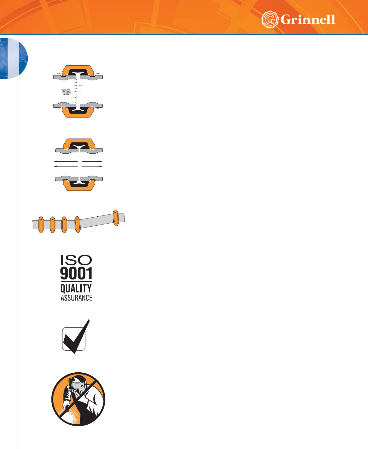
NOISE AND VIBRATION
The resiliency of GRINNELL Grooved Couplings and versatility of various
available gaskets provide excellent noise and vibration dampening. The
engineered design of these couplings provides for pipe end gapping that helps to
dissipate, isolate, and minimize noise and vibration transmission throughout the
piping system.
DEPENDABILITY
The coupling housings are designed to engage into the grooves and provide a
secure joint. The pipe ends are sealed by a pressure responsive gasket that is
encapsulated by the ductile iron housing.
MISALIGNMENT
GRINNELL Flexible Couplings will accommodate misalignments. The maximum
deflection information per coupling can be found in this catalog.
SUPERIOR QUALITY
GRINNELL Piping Products are manufactured according to the
ISO 9001:2000 Quality Assurance standard.
LONGEVITY AND PERFORMANCE
GRINNELL Piping Products are designed to last the lifetime of the pipeline and
have been tested and approved by prominent approval agencies. Rolled groov-
ing does not remove any metal from the pipe. Therefore, pipe integrity is fully
maintained when grooved systems are used to join pipe.
CLEAN
Unlike with welding, GRINNELL Piping Products do not lead to
hazardous fumes or to the possible introduction of foreign materials
in the pipeline.
Product Features and Benefits
11
GENERAL DATA
Refer to back cover for country-specific customer care numbers.
GENERAL DATA
Agency Listings and Approvals
General Code Groups, Associations, Laboratories,
Government Agencies, and Approval Bodies
ACS
ACTIVFIRE
Active Fire Protection
Product Certification
AP SAD
AMERICAN BUREAU
OF SHIPPING (ABS)
AMERICAN NATIONAL STANDARDS
INSTITUTE (ANSI)
AMERICAN WATER WORKS ASSOCIATION
(AWWA) AWWA C-606
AMERICAN PETROLEUM INSTITUTE (API)
API Std. 5L, Sect. 7.5
AMERICAN SOCIETY OF HEATING,
REFRIGERATION AND AIR CONDITIONING
ENGINEERS (ASHRAE)
AMERICAN SOCIETY OF
MECHANICAL ENGINEERS (ASME)
• Power Piping, B-31.1
• Chemical Plant and Petroleum Refinery
Piping, B-31.3
• Refrigeration Piping, B-31.5
• Building Services Piping, B31.9
• Elevator, Escalator, A17.1
ARPA
BUILDING OFFICIALS AND CODE
ADMINISTRATORS (BOCA)
BUREAU VERITAS (BV)
CNBOP
Centrum Naukowo-Badawcze
Ochrony Przeciwpozarowe
COAST GUARD
Approved each vessel individually
CORPS OF ENGINEERS (COE)
GEGS 15000
CRN
Canadian Registration Number
CSTB
DNV
Det Norske Veritas
DVGW
Deutscher Verein des
Gas-und Wasserfaches e.V.
FACTORY MUTUAL
ENGINEERING CORP. (FM)
Approved for Fire Protection Services
FEDERAL AVIATION ADMINISTRATION (FAA)
HVAC, Plumbing and Fire Protection
FEDERAL HOUSING ADMINISTRATION (FHA)
GENERAL SERVICES ADMINISTRATION (GSA)
15000 Series
GERMANISCHER LLOYD
INTERNATIONAL ASSOCIATION
OF PLUMBING AND
MECHANICAL OFFICIALS (IAPMO)
ICC-ES
National Evaluation Service, Inc.
IPC
Association Connecting
Electronics Industries
LLOYD’S
Lloyd’s Register
of Shipping
LOSS PREVENTION
CERTIFICATION BOARD (LPCB)
Approved for Fire Protection Services
MATERIAL EQUIPMENT AND
ACCEPTANCE (MEA)
MILITARY SPECIFICATIONS (MIL)
• MIL-P – 10388 Fittings
• MIL-C – 10387 Couplings
• MIL-P – 11087A (CE) Steel Pipe
• Grooved MIL-I – 45208 Inspection
NATIONAL AERONAUTICS AND SPACE
ADMINISTRATION (NASA)
NATIONAL INSTITUTE OF HEALTH (NIH)
Department of Health – 5000 Series
NAVAL FACILITIES ENGINEERING
COMMAND (NAVFAC)
NFGS 15000 Series
NATIONAL FIRE PROTECTION
ASSOCIATION (NFPA)
NATIONAL SANITATION
FOUNDATION (NSF)
The Public Health and Safety Company
PAVUS
PCT
PRESSURE EQUIPMENT DIRECTIVE
RINA
Registro Italiano Navale
T/S/U
SOUTHERN BUILDING CODE CONGRESS
INTERNATIONAL (SBCCI)
Standard Plumbing
UNDERWRITERS
LABORATORIES, INC. (UL)
Listed for Fire
Protection Services
UNDERWRITERS
LABORATORIES OF CANADA (ULC)
Listed for Fire Protection Services
UNIFORM
PLUMBING
CODE (UPC)
VERBAND DER
SACHVERSICHERE E.V. (VDS)
Approved for Fire Protective Service
VETERANS AFFAIRS (VA)
15000 Series
WATERMARK
Pending Approved for Potable Water
Service (AU)
WRAS
Water Regulations
Advisory Scheme (UK)
WSD
Pending Approved for Potable Water
Service (HK)
97/23/EC
Our products bear the seal of approval from the following agencies, associations and laboratories.
97/23/EC

12 www.grinnell.com
GENERAL DATA
GENERAL DATA
Product Design and Testing
Pre-Manufactured/Product Design
All GRINNELL Mechanical Products are designed and tested at our state-of-the-art Research and Development Technology Center
in Cranston, Rhode Island, USA.
Casting
GRINNELL castings poured
at our foundry are made of
ductile iron ASTM A536m,
Grade 65-45-12. A rigorous
quality control program
monitors all steps of the
manufacturing process.
Samples are continuously
tested chemically and
physically to ensure all
products meet our high
material specifications.
Rubber Injection
We manufacture our gaskets
using rubber injection
presses and tooling to mold
different types of rubber
compounds specifically
designed for the many
applications required by
our customers. Physical
tests are performed on
finished gasket samples
to verify compliance with
specifications including
ASTM D 2000.
Paint Process
Using a computer controlled
process, each product is
spray-washed, dried, pre-
heated, dipped, and fully
cured prior to assembly or
packaging. All integral parts
are inspected to maintain
consistent paint coverage
and surface condition.
Tooling
Using product designs
from our Research and
Development Department,
our pattern center and
contracted pattern makers
design and build patterns
and molds that produce
products to the highest
tolerances. Tooling is
continually inspected by our
in-house certified specialists
to ensure finished products
meet our specifications and
requirements of approving
agencies.
Foundry and Assembly
13
GENERAL DATA
Refer to back cover for country-specific customer care numbers.
GENERAL DATA
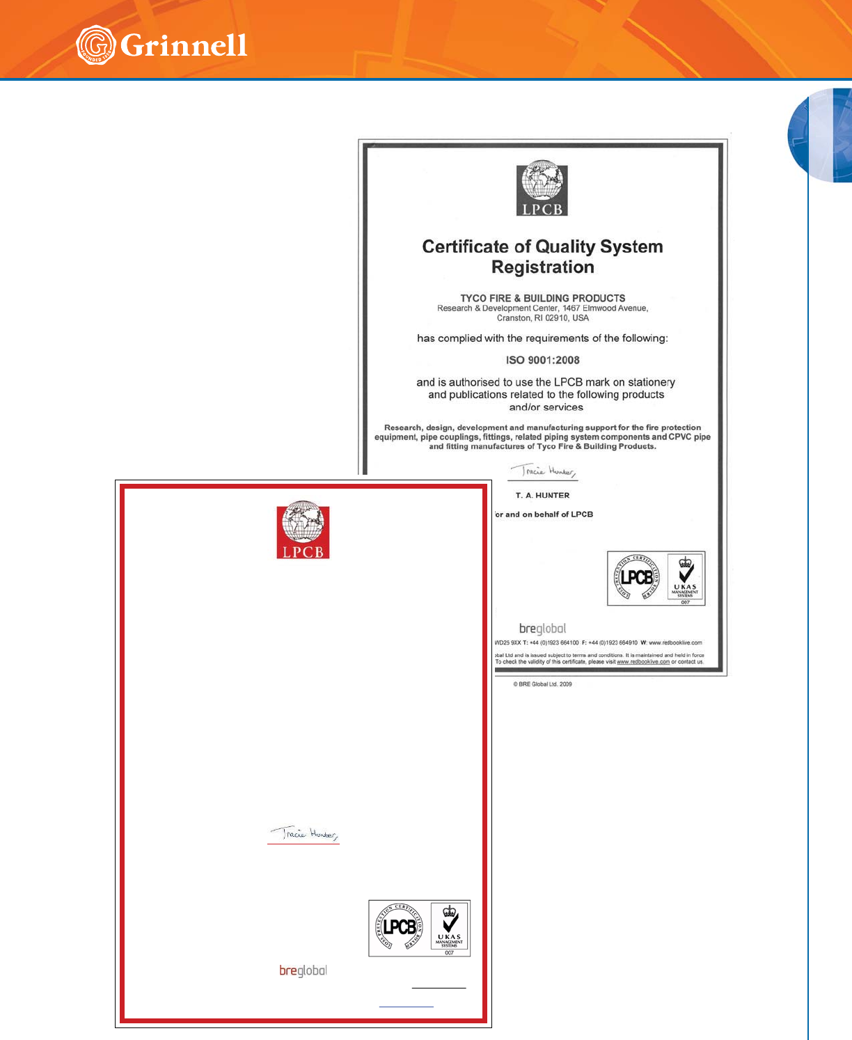
ISO 9001:2000 Certified
%5( *OREDO /WG
&HUWLILFDWHRI4XDOLW\ 6\VWHP
5HJLVWUDWLRQ
7<&2 )/2: &21752/ 0 6'1 %+'
7<&2 ),5( 68335(66,21 %8,/',1* 352'8&76 0$/$<6,$
/RW & & -DODQ 6XEDQJ 7DPDQ 3HULQGXVWULDQ 6XEDQJ
6XEDQJ 6HODQJRU 0DOD\VLD
KDV FRPSOLHG ZLWKWKH UHTXLUHPHQWV RI WKHIROORZLQJ
,62
DQG LV DXWKRULVHGWR XVHWKH /3&% PDUN RQ VWDWLRQHU\
DQG SXEOLFDWLRQV UHODWHG WR WKH IROORZLQJ SURGXFWV
DQGRU VHUYLFHV
$VVHPEO\ RI FRXSOLQJV DQG PDUNHWLQJ RI FRXSOLQJV DQG ILWWLQJV
7$+XQWHU
IRU DQG RQ EHKDOI RI /3&%
&HUWLILFDWH 1R
,VVXH 1XPEHU
'DWH RI ,VVXH 'HFHPEHU
'DWH RI ([SLU\ 'HFHPEHU
/3&% LV SDUW RI %5( *OREDO /LPLWHG :DWIRUG :' ;; 7 ) : ZZZUHGERRNOLYHFRP
7KLV FHUWLILFDWH UHPDLQV WKH SURSHUW\ RI %5( *OREDO /WG DQG LV LVVXHG VXEMHFW WR WHUPV DQG FRQGLWLRQV,W LV PDLQWDLQHG DQG KHOG LQ IRUFH
WKURXJK DW OHDVW DQQXDO UHYLHZ DQG YHULILFDWLRQ 7R FKHFN WKH YDOLGLW\ RI WKLV FHUWLILFDWH SOHDVH YLVLW ZZZUHGERRNOLYHFRP RU FRQ WDF W XV
14 www.grinnell.com
GENERAL DATA
GENERAL DATA
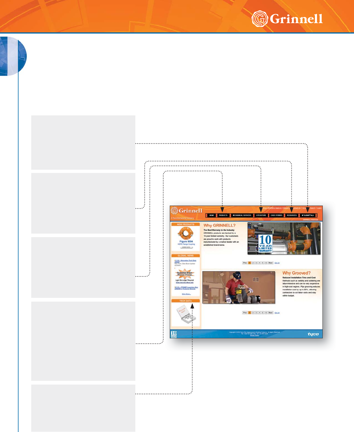
GRINNELL Website
www.grinnell.com
Literature Tab
The Literature tab showcases all
marketing materials for viewing,
downloading, or saving to your
preferred location. Marketing
literature includes catalogs, brochures,
installation manuals, flyers, and
price books.
Tech Data
The Tech Data icon provides direct
access to technical information on all
of our products. It also provides access
to online registration for automatic
e-mail updates.
Resources Tab
Useful for everyday operations, the
Resources tab includes a conversion
calculator to convert many units of
measurement and a Product Cross
Reference tool to search for GRINNELL
Mechanical Product equivalents.
My Submittals Tab
This tool, useful in bidding, allows you
to sign-up for a GRINNELL account.
You can then create, save, print,
and manage project submittals. Your
account information is available
24/7 through our website.
To learn more about GRINNELL Mechanical Products, visit www.grinnell.com.
Our Website provides a wide variety of tools and information at your fingertips.
Browse These Website Features
GRINNELL Home Page
Products Tab
The Products tab organizes all
product information such as pricing,
technical data, 3D CAD drawings,
and part summary sheets. All product
information is available for printing
and saving to your preferred location.
Searching for any product by name
or figure number and downloading
custom submittal sheets are also
available through this tab.
15
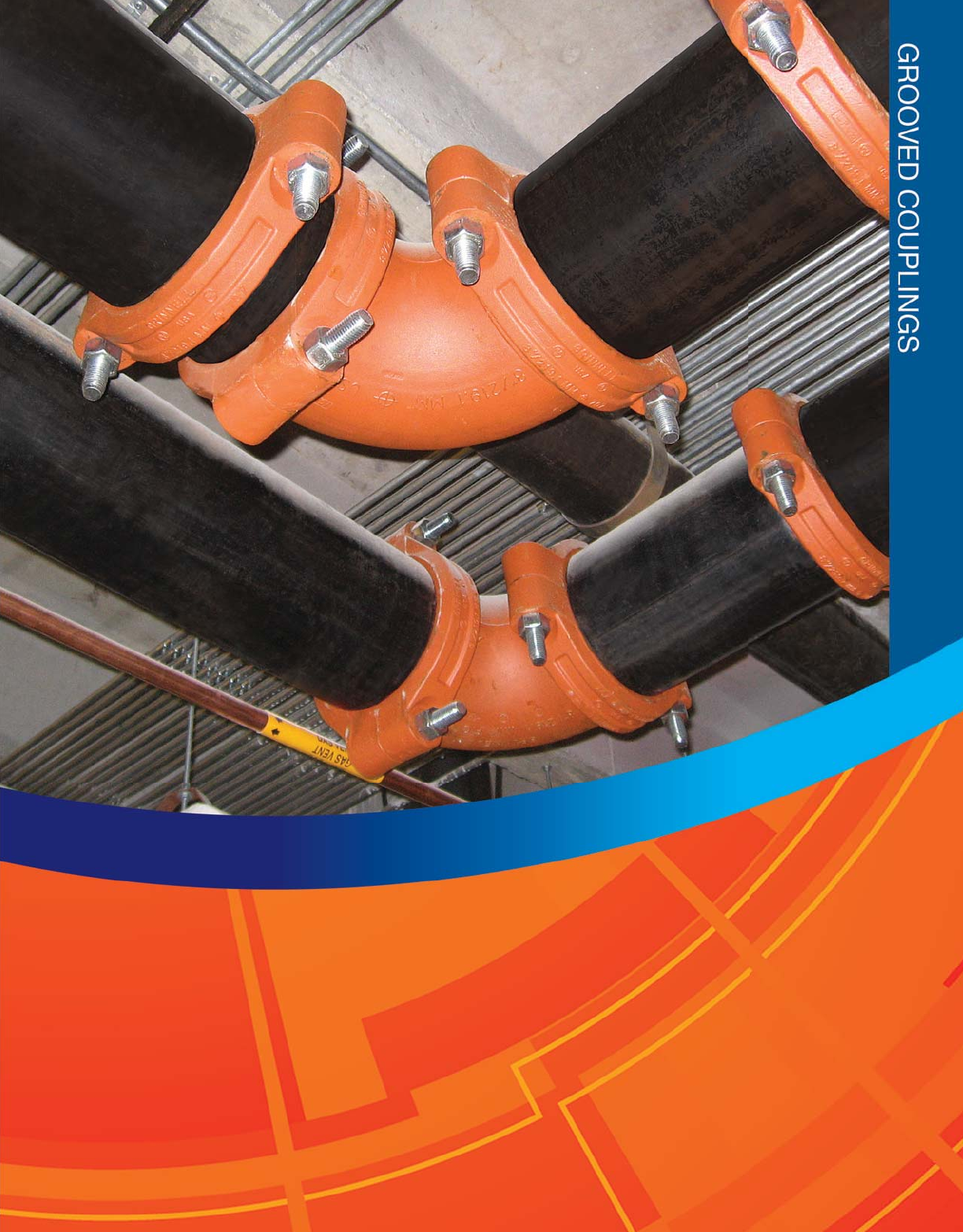
GROOVED COUPLINGS
16 www.grinnell.com
GROOVED COUPLINGS
GRINNELL Couplings are designed for grooved end pipe and
are available in nominal sizes of 1" (25mm) to 24" (600mm)
including BS, ISO, and JIS outside diameters.
The GRINNELL Coupling Design provides economical
advantages when compared to welded or flanged systems.
GRINNELL Couplings provide a universal method for
connecting pipe, fittings, and pipe system components.
GRINNELL Couplings and Gaskets permit a wide selection of
combinations for specific applications.
Field modifications are easily accommodated with GRINNELL
Mechanical Products as the couplings can be easily rotated,
eliminated and/or added to facilitate necessary modifications.
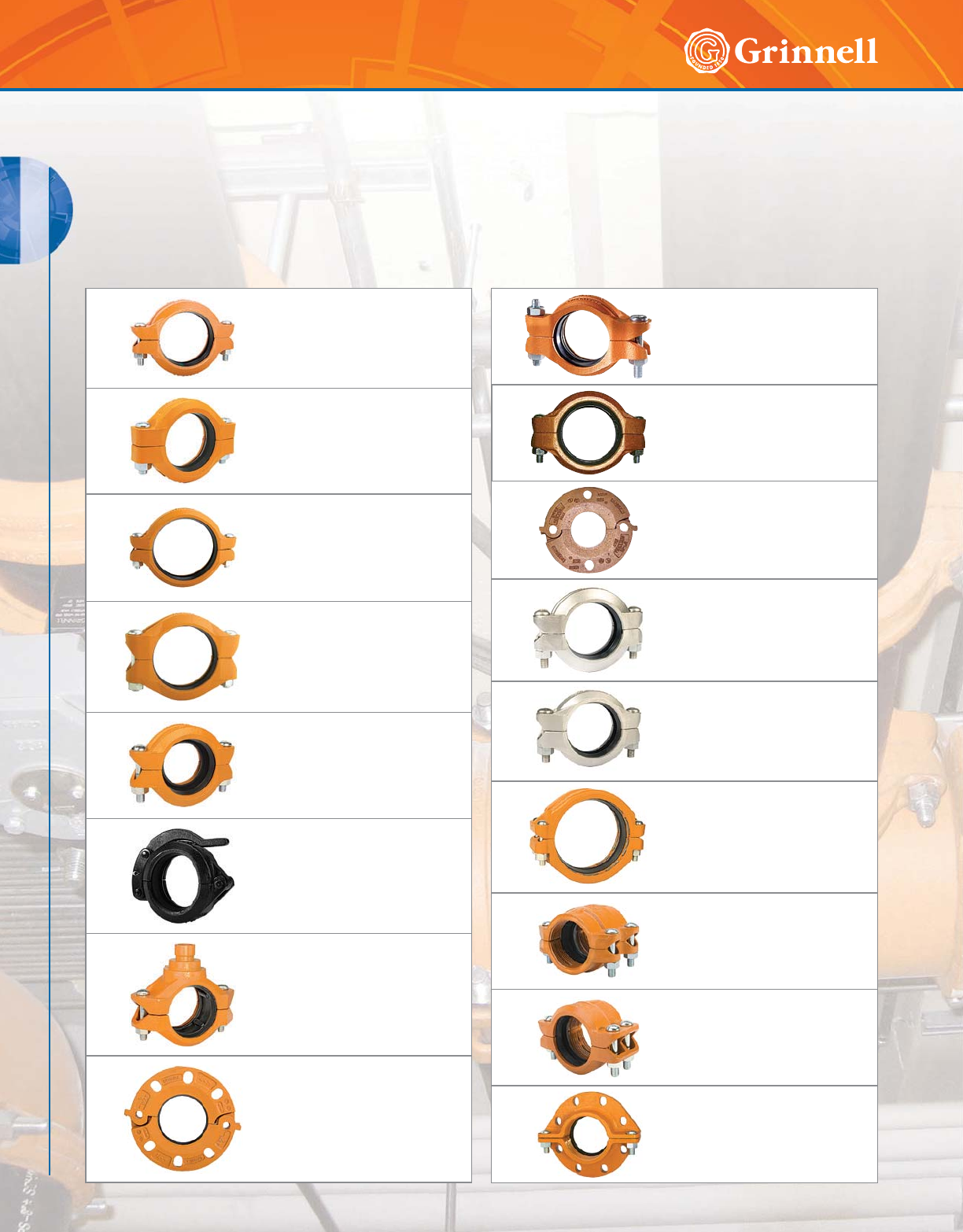
Grooved Couplings Table of Contents
Figure 772
Rigid Couplings
Pages 18 - 19
Figure 707
Heavy Duty Flexible Couplings
Pages 20 - 21
Figure 705
Flexible Couplings
Page 22
Figure 770
High Pressure Rigid Couplings
Page 23
Figure 716
Flexible Reducing Couplings
Page 24
Figure 780
Grooved Snap Couplings
Page 25
Figure 702
Mechanical Outlet Couplings
Pages 26 - 27
Figure 71
Flange Adapters
Pages 28 - 33
Figure 640
Pivot-Bolt Rigid Couplings
Page 120
Figure 672
Rigid Couplings
Page 121
Figure 61
Flange Adapters
Page 122
Figure 472
Stainless Steel Rigid Couplings
Page 134
Figure 405
Stainless Steel Flexible
Couplings
Page 135
Figure 909
Plain End Couplings
Page 146
Figure 9095
HDPE Couplings
Page 171
Figure 9097
HDPE Transition Couplings
Page 172
Figure 9094
HDPE Flange Couplings
Page 173
GROOVED COUPLINGS
GROOVED COUPLINGS
17
Refer to back cover for country-specific customer care numbers.
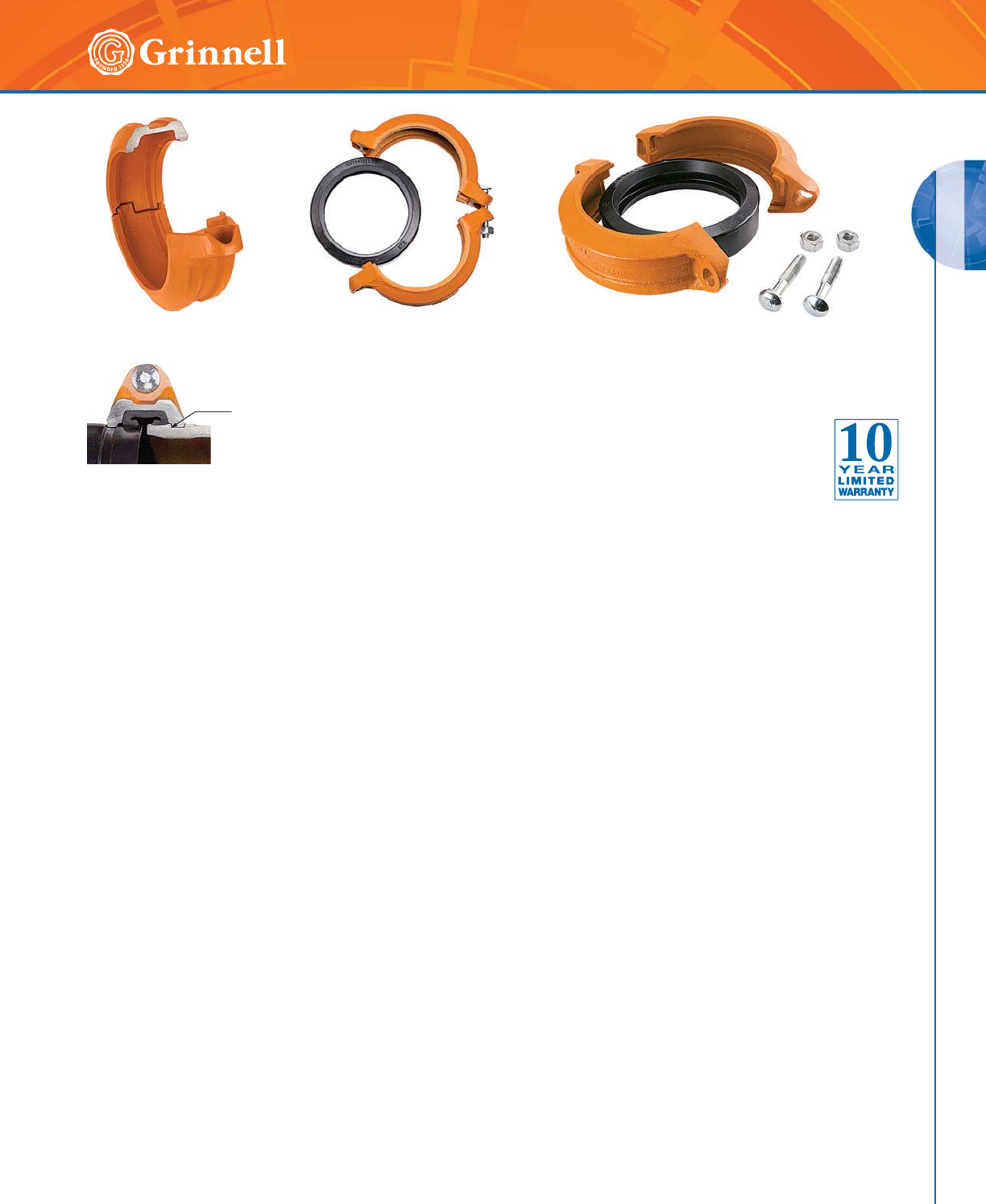
Full contact between Figure 772
Coupling key and groove diameter
Ductile Iron Housing Specifications
• ASTM A 536 – Standard specification for ductile iron
castings, Grade 65-45-12
• Tensile strength, minimum 65,000 psi (4481.6 bar)
• Yield strength, minimum 45,000 psi (3102.6 bar)
• Elongation in 2" (50mm), minimum 12%
• ASTM A 153 – Standard specification for hot-dip
galvanizing
Bolt/Nut Specifications
• ANSI: Carbon steel oval neck bolts and nuts are heat-
treated and conform to the physical properties of ASTM
A 183 Grade 2 and SAE J429 Grade 5 with a minimum
tensile strength of 110,000 psi (7584.2 bar).
Carbon Steel heavy hex nuts conform to the physical
properties of ASTM A 183 Grade 2 and SAE J995
Grade 5. Bolts and nuts are zinc-electroplated
conforming to ASTM B 633.
• Metric: Carbon steel oval neck track head bolts (Gold
color coded) are heat treated and conform to the physical
properties of ASTM F 568 M with a minimum tensile
strength of 760 MPa.
Carbon Steel heavy hex nuts conform to the physical
properties of ASTM A 563 M Class 9. Bolts and nuts are
zinc-electroplated conforming to ASTM B 633.
• Stainless steel bolts and nuts are available upon request.
Coatings
• Orange – Non-lead paint (standard)
• Red – Non-lead paint (optional, regional)
• Hot-Dipped, Zinc Galvanized (optional)
Gasket Specifications
• Grade “E” EPDM gaskets have a Green color code
identification and conform to ASTM D 2000 for service
temperatures from -30°F to 230°F (-34°C to 110°C). They
are recommended for hot water not to exceed 230°F
(110°C), plus a variety of dilute acids, oil free air, and
many chemical services. They are not recommended for
petroleum services. For low temperature and vacuum
systems, a Tri-Seal Grade “E” EPDM gasket with a rigid
coupling is recommended.
• Grade “T” Nitrile gaskets have an Orange color code
identification and conform to ASTM D 2000 for service
temperatures from -20°F to 180°F (-29°C to 82°C). They
are recommended for petroleum products, vegetable oils,
mineral oils, and air with oil vapors.
• Grade “L” Silicone gaskets are Red and conform to
ASTM D 2000 for service temperatures from -30°F to
350°F (-34°C to 177°C). They are recommended for air
without hydrocarbons, or dry heat.
• Grade “O” Fluoroelastomer gaskets have a Blue
color code and conform to ASTM D 2000 for service
temperatures from +20°F to 300°F (-7°C to 149°C).
They are recommended for oxidizing acids, petroleum
products, hydraulic fluids, lubricants, and halogenated
hyrdrocarbons.
• Grade “EN” NSF-61 Approved gaskets have a
Copper color code and are for potable water systems
up to 180°F (82°C). They are not recommended for
petroleum service.
• Grade “EHT” EPDM NSF-61 Certified center-stop,
push-on style gaskets for copper tubing systems, have a
Red and Copper stripped color code. For closed-loop
heating systems from -30°F to 250°F (-34°C to 120°C)
and potable water systems up to 180°F (up to 82°C).
Recommended for use in low temperature and vacuum
systems. They are not recommended for petroleum service.
MATERIAL SPECIFICATIONS
Additional Features:
• Two-piece, tongue-and-groove design allows for fast and
easy installation.
• Standard industry groove does not require special tools.
• Backed by the industry’s best 10-Year Limited
Warranty, except for G-MINE which is 6
months. Review terms and conditions of sale
on www.grinnell.com.
Warning: For a one time field test only the maximum joint
working pressure may be increased to 1½ x the figures shown.
GROOVED COUPLINGS
GROOVED COUPLINGS
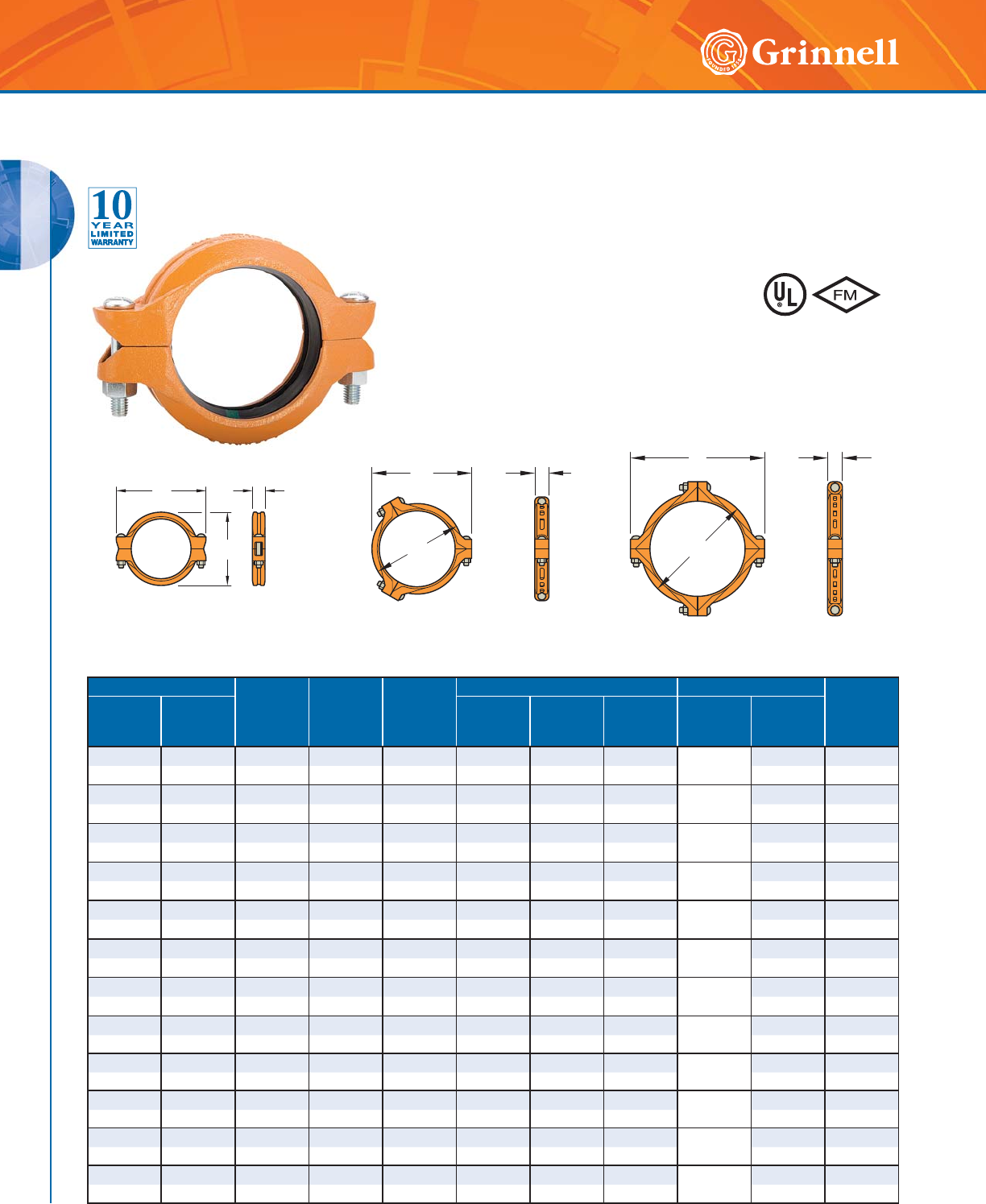
18 www.grinnell.com
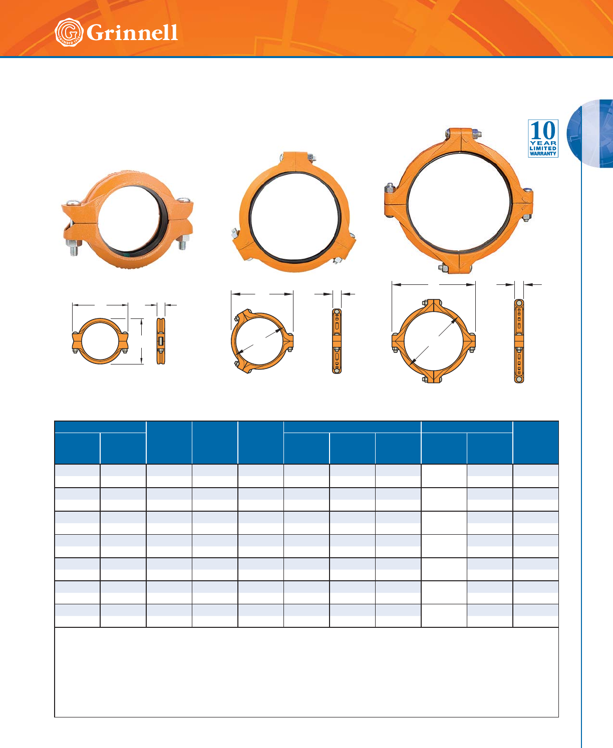
Figure 772 Rigid Couplings
(Page 1 of 2)
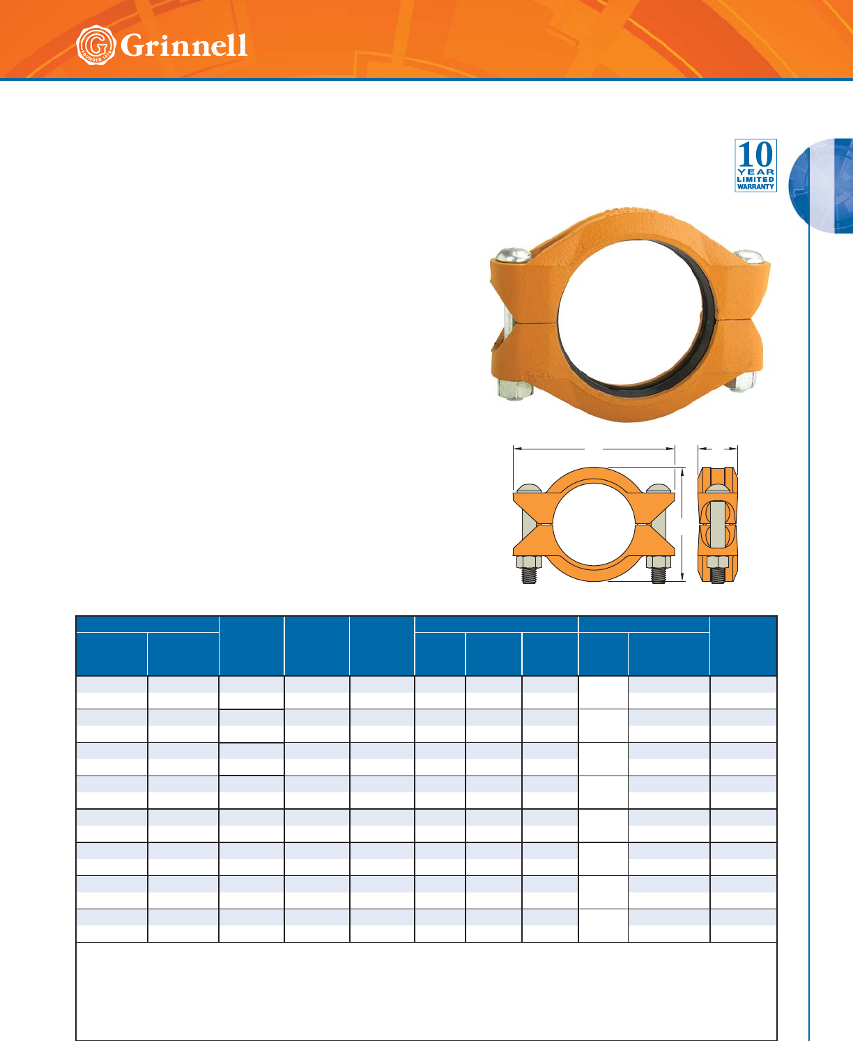
Tech Data Sheet: G141 The GRINNELL Figure 772 Rigid Coupling provides a rigid joint by firmly
gripping along the full 360° circumference of the pipe grooves. This
coupling offers a dependable method of joining pipe and is an economical
alternative to welding, threading, or using flanges. The GRINNELL Figure
772 Rigid Coupling is UL Listed for grounding and bonding, and is suitable
for bonding systems with a maximum service entrance capacity of 200
amps. Sizes 11⁄4" – 8" (32mm – 200mm) feature a
clamshell design that makes installation easier and
faster.
Pipe Size Max.†
Pressures
psi
bar
Max.†
End Load
Lbs.
kN
Max.*‡ End
Gap
Inches
mm
Dimensions - Inches mm Coupling Bolts Approx.
Weight
Lbs.
kg
Nominal
Inches
mm
O.D.
Inches
mm
AB CQty.
Size
Inches
mm
11⁄41.660 750 1,623.2 0.06 2.75 4.38 1.81 2
3⁄8 x 21⁄42.0
32 42,4 51,7 7,22 1,5 69,9 111,3 46,0 M10 x 57 0,9
11⁄21.900 750 2,126.5 0.08 3.00 4.62 1.81 2
3⁄8 x 21⁄42.2
40 48,3 51,7 9,46 2,0 76,2 117,3 46,0 M10 x 57 1,0
2 2.375 750 3,322.6 0.13 3.41 5.70 1.88 2
1⁄2 x 3 3.0
50 60,3 51,7 14,78 3,3 86,6 145,0 47,8 M12 x 89 1,4
21⁄22.875 750 4,868.9 0.13 3.91 6.30 1.88 2
1⁄2 x 3 3.3
65 73,0 51,7 21,66 3,3 99,3 160,0 47,8 M12 x 89 1,5
76,1mm 3.000 750 5,301.4 0.13 4.19 6.43 2.00 2–3.4
65 76,1 51,7 23,58 3,3 106,4 163,0 50,8 M12 x 89 1,5
3 3.500 750 7,215.8 0.13 4.63 6.93 1.88 2
1⁄2 x 3 4.0
80 88,9 51,7 32,10 3,3 117,6 176,0 47,8 M12 x 89 1,8
4 4.500 750 11,928.2 0.19 5.81 8.07 1.97 2
1⁄2 x 3 4.6
100 114,3 51,7 53,06 4,8 147,6 205,0 50,0 M12 x 89 2,1
139,7mm 5.500 750 17,818.7 0.19 7.02 9.72 2.06 2–7.5
125 139,7 51,7 79,26 4,8 178,3 246,9 52,3 M16 x 83 3,4
5 5.563 750 18,229.3 0.19 7.09 9.71 2.04 2
5⁄8 x 31⁄47.5
125 141,3 51,7 81,09 4,8 180,1 246,6 51,8 M16 x 83 3,4
165,1mm 6.500 700 23,228.2 0.19 8.09 10.53 2.13 2–7.6
150 165,1 48,3 103,18 4,8 205,5 267,5 54,1 M16 x 83 3,4
6 6.625 700 24,130.1 0.19 8.09 10.53 2.13 2
5⁄8 x 31⁄47.6
150 168,3 48,3 107,34 4,8 205,5 267,5 54,1 M16 x 83 3,4
8 8.625 600 35,055.8 0.19 10.56 13.56 2.62 2
3⁄4 x 43⁄416.9
200 ◗219,1 41,4 155,94 4,8 268,2 344,4 66,5 M20 x 121 7,7
A
C
B
A
BC
B
A
C
11⁄4" - 14" (32mm - 350mm) 16" - 18" (400mm - 450mm) 20" - 24" (500mm - 600mm)
)RUDGGLWLRQDOOLVWLQJVRU
DSSURYDOVVHHSDJHRU
YLVLWRXUZHEVLWHDW
ZZZJULQQHOOFRP
GROOVED COUPLINGS
GROOVED COUPLINGS
19
Refer to back cover for country-specific customer care numbers.
Pipe Size Max.†
Pressures
psi
bar
Max.†
End Load
Lbs.
kN
Max.*‡ End
Gap
Inches
mm
Dimensions - Inches mm Coupling Bolts Approx.
Weight
Lbs.
kg
Nominal
Inches
mm
O.D.
Inches
mm
AB CQty.
Size
Inches
mm
10 10.750 500 45,381.3 0.13 12.84 16.41 2.62 21 x 61⁄225.9
250 ◗273,0 34,5 201,87 3,3 326,1 416,8 66,5 M24 x 165 11,7
12 12.750 400 51,070.5 0.13 15.41 18.84 2.62 21 x 61⁄235.4
300 ◗323,9 27,6 227,17 3,3 391,4 478,5 66,5 M24 x 165 16,0
14 14.000 300 46,181.4 0.13 16.68 20.38 2.93 21 x 51⁄2•45.0
350 355,6 20,7 205,43 3,3 423,7 517,6 74,4 –20,4
16 16.000 300 60,318.6 0.13 18.50 22.64 2.93 31 x 51⁄2•60.6
400 406,4 20,7 268,31 3,3 469,9 575,1 74,4 –27,5
18 18.000 300 76,340.7 0.25 21.31 25.12 3.06 31 x 51⁄2• 79.0
450 457,2 20,7 339,58 6,4 541,3 638,0 77,7 –35,8
20 20.000 300 94,247.8 0.25 23.50 27.88 3.06 411⁄8 x 53⁄4•97.0
500 508,0 20,7 419,23 6,4 596,9 708,2 77,7 –44,0
24 24.000 250 113,097.3 0.25 27.63 32.00 3.19 411⁄8 x 53⁄4•120.0
600 609,6 17,2 503,08 6,4 701,8 812,8 81,0 –54,4
* Maximum available gap between pipe ends. Minimum gap = 0.
† Maximum Pressure and End Load are total from all loads based on standard weight steel pipe. Pressure ratings and end loads may differ for other
pipe materials and/or wall thicknesses. Contact GRINNELL Mechanical Products for details.
‡ Max End Gap is for cut grooved standard weight pipe. Values for roll grooved pipe will be half that of cut grooved.
• Only available in ANSI bolt sizes.
◗ Sizes are available to JIS standards. Contact GRINNELL Mechanical Products for details.
For information on larger sizes, European sizes or other alternative sizes, contact GRINNELL Mechanical Products.
See page 17 for coupling specifications and pages 191 - 198 for gasket information.
Figure 772 Rigid Couplings
(Page 2 of 2)
Tech Data Sheet: G141
A
C
B
A
BC
B
A
C
11⁄4" - 14" (32mm - 350mm) 16" - 18" (400mm - 450mm) 20" - 24" (500mm - 600mm)
GROOVED COUPLINGS
GROOVED COUPLINGS
20 www.grinnell.com
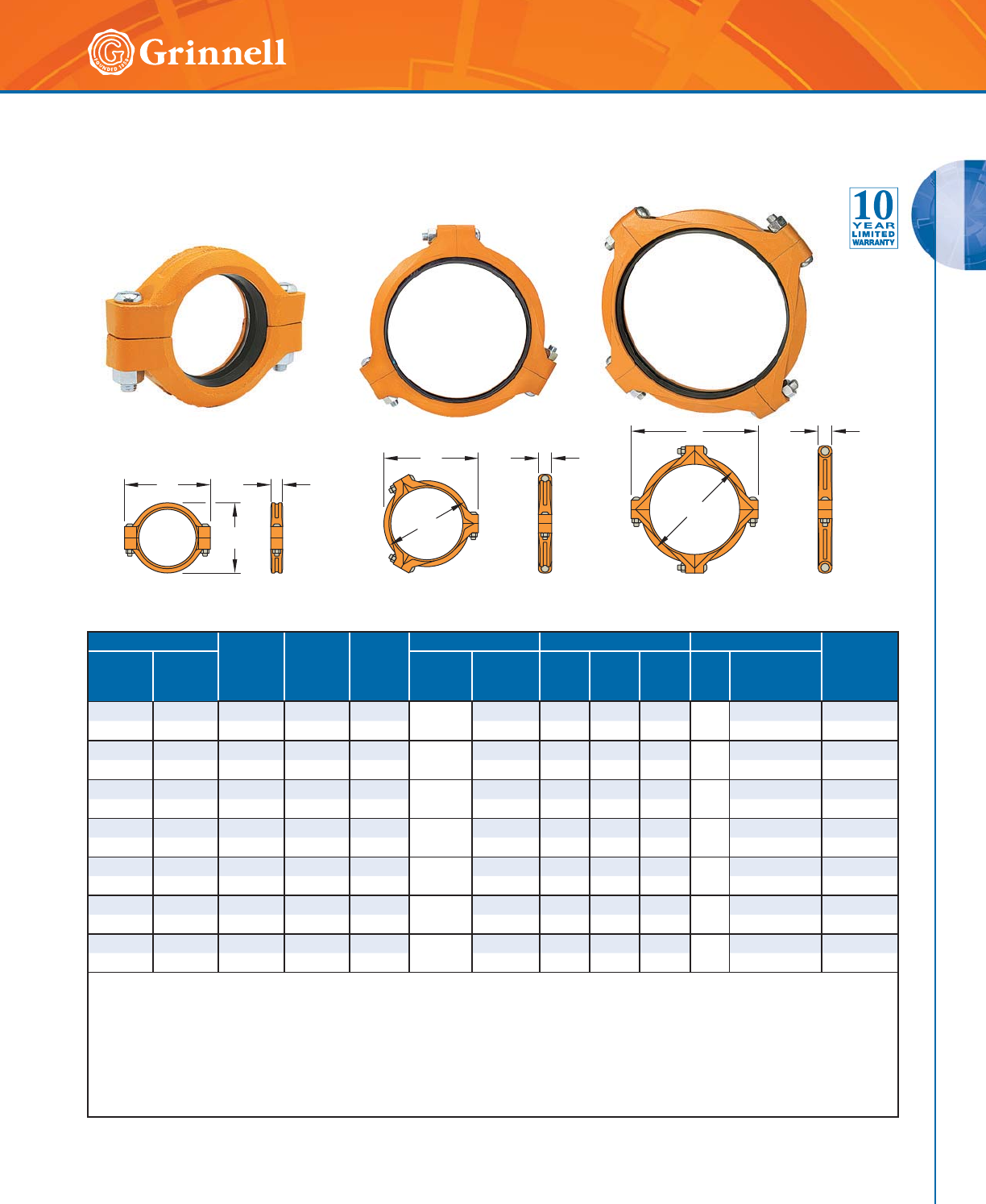
Figure 707 Heavy Duty Flexible Couplings
(Page 1 of 2)
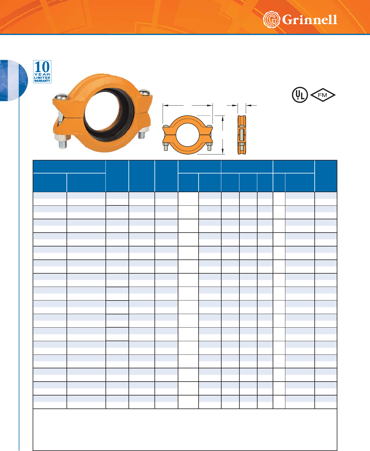
Tech Data Sheet: G130 The GRINNELL Figure 707 Heavy Duty Flexible Coupling allows for angular
and linear deflection, thermal expansion and contraction, and misalignments
of the pipe. Flexible couplings can act as an “expansion joint”, allowing
linear and angular movement of the pipes when properly installed. This
coupling is capable of pressures up to 1,000 psi (68,9 bar), depending on
pipe size and wall thickness. Suitable for use in a variety
of applications, the Figure 707 Coupling provides a
dependable method of joining pipe.
Pipe Size Max.†
Pressures
psi
bar
Max.†
End Load
Lbs
kN
Max.*‡
End Gap
Inches
mm
Deflection ‡ Dimensions - Inches mm Coupling Bolts Approx.
Weight
Lbs.
kg
Nominal
Inches
mm
O.D.
Inches
mm
Degrees
Per
Coupling
Inches/Ft
mm/m AB C Qty.
Size
Inches
mm
1 1.315 1000 1,360.0 0.13 5° 26' 1.14 2.38 4.00 1.81 2
1⁄2 x 3 2.0
25 33,7 68,9 6,10 3,3 98,4 60,5 101,6 46,0 M12 x 89 0,9
11⁄41.660 1000 2,164.9 0.13 4° 19' 0.90 2.76 4.37 1.81 2
1⁄2 x 3 2.2
32 42,4 68,9 9,63 3,3 75,0 70,0 111,0 46,0 M12 x 89 1,0
11⁄21.900 1000 2,835.3 0.13 3° 46' 0.79 2.97 4.63 1.81 2
1⁄2 x 3 2.5
40 48,3 68,9 12,61 3,3 65,8 75,4 117,6 46,0 M12 x 89 1,1
2 2.375 1000 4,430.1 0.13 3° 1' 0.63 3.54 5.25 1.88 2
1⁄2 x 3 3.0
50 60,3 68,9 19,71 3,3 52,5 89,9 133,4 47,8 M12 x 89 1,4
21⁄22.875 1000 6,491.8 0.13 2° 29' 0.52 4.06 5.75 1.88 2
1⁄2 x 3 3.5
65 73,0 68,9 28,88 3,3 43,3 103,1 146,1 47,8 M12 x 89 1,6
76,1mm 3.000 1000 7,068.6 0.13 2° 23' 0.50 4.19 5.75 1.88 2–4.0
65 76,1 68,9 31,44 3,3 41,7 106,4 146,1 47,8 M12 x 89 1,8
3 3.500 1000 9,621.1 0.13 2° 3' 0.43 4.69 6.38 1.88 2
1⁄2 x 3 4.0
80 88,9 68,9 42,80 3,3 35,8 119,1 162,1 47,8 M12 x 89 1,8
4 4.500 1000 15,904.3 0.25 3° 11' 0.67 5.95 8.25 2.06 2
5⁄8 x 31⁄47.0
100 114,3 68,9 70,75 6,4 55,8 151,1 209,6 52,3 M16 x 83 3,2
139,7mm 5.500 1000 23,758.3 0.25 2° 30' 0.52 7.02 10.00 2.04 2
3⁄4 x 43⁄48.3
125 139,7 68,9 105,6 6,4 43,6 178,3 254,0 51,8 M20 x 121 3,8
5 5.563 1000 24,305.7 0.25 2° 35' 0.54 7.08 10.00 2.06 2
3⁄4 x 43⁄410.0
125 141,3 68,9 108,12 6,4 45,1 179,8 254,0 52,3 M20 x 121 4,5
165,1mm 6.500 1000 33,183.1 0.25 2° 12' 0.46 8.19 11.25 2.06 2–12.0
150 165,1 68,9 147,61 6,4 38,4 208,0 285,8 52,3 M20 x 121 5,4
6 6.625 1000 34,471.6 0.25 2° 10' 0.45 8.30 11.25 2.06 2
3⁄4 x 43⁄411.1
150 168,3 68,9 153,34 6,4 37,8 210,8 285,8 52,3 M20 x 121 5,0
88.62580046,741.00.25
1° 40' 0.35 10.68 14.00 2.47 2
7⁄8 x 61⁄221.4
200 ◗219,1 55,2 207,91 6,4 29,2 271,3 355,6 62,7 M22 x 165 9,7
C
A
B
CB
A
CB
A
1" - 12" (25mm - 300mm) 14" - 18" (350mm - 450mm) 20" - 24" (500mm - 600mm)
)RUDGGLWLRQDOOLVWLQJVRU
DSSURYDOVVHHSDJHRU
YLVLWRXUZHEVLWHDW
ZZZJULQQHOOFRP
GROOVED COUPLINGS
GROOVED COUPLINGS
21
Refer to back cover for country-specific customer care numbers.
Pipe Size Max.†
Pressures
psi
bar
Max.†
End Load
Lbs
kN
Max.*‡
End Gap
Inches
mm
Deflection ‡ Dimensions - Inches mm Coupling Bolts Approx.
Weight
Lbs.
kg
Nominal
Inches
mm
O.D.
Inches
mm
Degrees
Per
Coupling
Inches/Ft
mm/m AB C Qty.
Size
Inches
mm
10 10.750 800 72,610.1 0.25 1° 20' 0.28 13.06 16.44 2.63 21 x 61⁄229.0
250 ◗273,0 55,2 322,99 6,4 23,3 331,7 417,6 66,8 M24 x 165 13,2
12 12.750 800 102,141.0 0.25 1° 7' 0.23 15.39 18.84 2.63 21 x 61⁄237.0
300 ◗323,9 55,2 454,35 6,4 19,5 390,9 478,5 66,8 M24 x165 16,8
14 14.000 300 46,181.4 0.25 1° 2' 0.22 16.67 20.38 2.94 31 x 51⁄2•46.0
350 355,6 20,7 205,43 6,4 18,0 423,4 517,7 74,7 –20,9
16 16.000 300 60,318.6 0.25 0° 54' 0.19 18.83 22.64 2.94 31 x 51⁄2• 59.0
400 406,4 20,7 268,31 6,4 15,8 478,3 575,1 74,7 –26,8
18 18.000 300 76,340.7 0.25 0° 48' 0.17 21.31 25.12 3.06 31 x 51⁄2•78.0
450 457,2 20,7 339,58 6,4 14,0 541,3 638,0 77,7 –35,4
20 20.000 300 94,247.8 0.25 0° 43' 0.15 23.47 27.88 3.06 411⁄8 x 53⁄4• 89.0
500 508,0 20,7 419,23 6,4 12,5 596,1 708,2 77,7 –40,4
24 24.000 250 113,097.3 0.25 0° 36' 0.13 27.58 32.00 3.19 411⁄8 x 53⁄4•112.0
600 609,6 17,2 503,08 6,4 10,5 700,5 812,8 81,0 –50,8
* Maximum available gap between pipe ends. Minimum gap = 0.
† Maximum Pressure and End Load are total from all loads based on standard weight steel pipe. Pressure ratings and end loads may differ for other
pipe materials and/or wall thicknesses. Contact GRINNELL Mechanical Products for details.
‡ Max End Gap and Deflection is for cut grooved standard weight pipe. Values for roll grooved pipe will be half that of cut grooved.
• Only available in ANSI bolt sizes.
◗ Sizes are available to JIS standards. Contact GRINNELL Mechanical Products for details.
For information on larger sizes, European sizes or other alternative sizes, contact GRINNELL Mechanical Products.
See page 17 for coupling specifications and pages 191 - 198 for gasket information.
C
A
B
CB
A
CB
A
1" - 12" (25mm - 300mm) 14" - 18" (350mm - 450mm) 20" - 24" (500mm - 600mm)
Figure 707 Heavy Duty Flexible Couplings
(Page 2 of 2)
Tech Data Sheet: G130
GROOVED COUPLINGS
GROOVED COUPLINGS
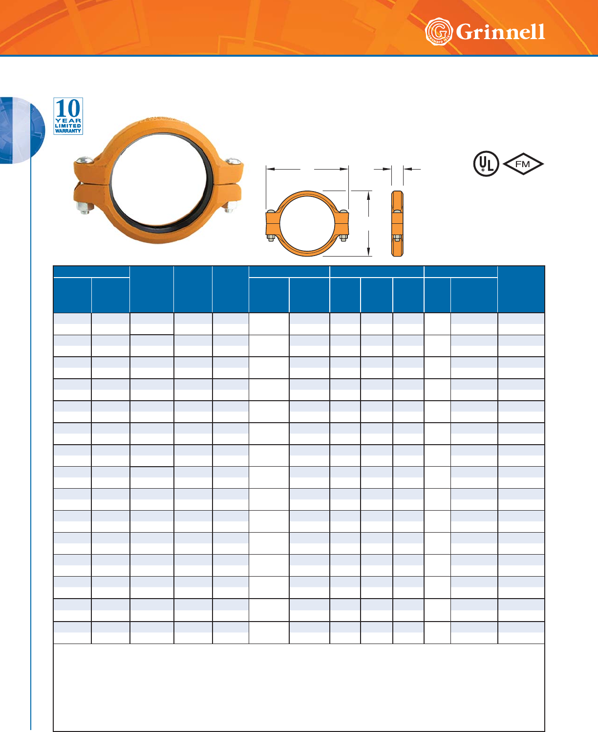
22 www.grinnell.com
The GRINNELL Figure 705 Flexible Coupling allows for angular and linear
deflection, thermal expansion and contraction, and misalignments of pipe.
It is capable of pressures up to 500 psi (34,5 bar), depending on pipe
size and wall thickness. Suitable for use in a variety of applications, the
GRINNELL Figure 705 Coupling provides a dependable method of
joining pipe.
Pipe Size Max.†
Pressures
psi
bar
Max.†
End Load
Lbs.
kN
Max.*‡
End Gap
Inches
mm
Deflection ‡ Dimensions - Inches mm Coupling Bolts Approx.
Weight
Lbs.
kg
Nominal
Inches
mm
O.D.
Inches
mm
Degrees
Per
Coupling
Inches/Ft
mm/m ABCQty.
Size
Inches
mm
11.315500410.00.13
5° 30' 1.16 2.24 3.94 1.81 2
3⁄8 x 13⁄41.3
25 33.7 34,5 1,86 3,3 96,7 56,9 100,1 46,0 M10 x 44 0,6
11⁄41.660 500 1,082.1 0.13 4° 19' 0.90 2.56 4.19 1.81 2
3⁄8 x 21⁄41.8
32 42,4 34,5 4,81 3,3 75,0 65,0 106,4 46,0 M10 x 57 0,8
11⁄21.900 500 1,417.6 0.13 3° 46' 0.79 2.75 4.44 1.81 2
3⁄8 x 21⁄41.8
40 48,3 34,5 6,30 3,3 65,8 69,9 112,8 46,0 M10 x 57 0,8
22.3755002,215.10.13
3° 1' 0.63 3.25 4.88 1.88 2
3⁄8 x 21⁄41.8
50 60,3 34,5 9,85 3,3 52,5 82,6 124,0 47,8 M10 x 57 0,8
21⁄22.875 500 3,245.9 0.13 2° 29' 0.52 3.69 5.50 1.88 2
3⁄8 x 21⁄42.0
65 73,0 34,5 14,43 3,3 43,3 93,7 139,7 47,8 M10 x 57 0,9
76,1mm 3.000 500 3,534.3 0.13 2° 23' 0.50 4.00 5.75 1.88 2–3.1
65 76,1 34,5 15,72 3,3 41,7 101,6 146,10 47,8 M12 x 89 1,4
33.5005004,810.60.13
2° 3' 0.43 4.38 6.50 1.88 2
1⁄2 x 3 3.3
80 88,9 34,5 21,39 3,3 35,8 111,3 165,1 47,8 M12 x 89 1,5
44.5005007,952.20.25
3° 11' 0.67 5.69 7.75 2.06 2
1⁄2 x 3 4.0
100 114,3 34,5 35,35 6,4 55,6 144,5 196,9 52,3 M12 x 89 1,8
139,7mm 5.500 450 10,691.2 0.25 2° 36' 0.55 6.81 9.75 2.06 2–6.6
125 139,7 31 47,56 6,4 45,5 173,0 247,7 52,3 M16 x 83 3,0
5 5.563 450 10,937.6 0.25 2° 35' 0.54 6.88 9.75 2.06 2
5⁄8 x 31⁄46.6
125 141,3 31 48,63 6,4 45,0 174,8 247,7 52,3 M16 x 83 3,0
165,1mm 6.500 450 14,932.4 0.25 2° 12' 0.46 7.75 10.69 2.06 2–7.0
150 165,1 31 66,36 6,4 38,3 196,9 271,5 52,3 M16 x 83 3,2
66.62545015,512.20.25
2° 10' 0.45 7.94 10.69 2.06 2
5⁄8 x 31⁄47.0
150 168,3 31 68,97 6,4 37,8 201,7 271,5 52,3 M16 x 83 3,2
88.62545026,291.80.25
1° 40' 0.35 10.19 13.56 2.50 2
3⁄4 x 43⁄411.8
200 ◗219,1 31 116,89 6,4 29,2 258,8 344,4 63,5 M20 x 121 5,4
10 10.750 350 31,766.9 0.25 1° 20' 0.28 12.69 16.38 2.63 21 x 61⁄226.8
250 ◗273,0 24,1 141,31 6,4 23,3 322,3 416,1 66,8 M24 x 165 12,2
12 12.750 350 44,686.7 0.25 1° 7' 0.23 14.94 18.88 2.63 21 x 61⁄232.2
300 ◗323,9 24,1 198,78 6,4 19,5 379,5 479,6 66,8 M24 x 165 14,6
* Maximum available gap between pipe ends. Minimum gap = 0.
† Maximum Pressure and End Load are total from all loads based on standard weight steel pipe. Pressure ratings and end loads may differ for other
pipe materials and/or wall thickness. Contact GRINNELL Mechanical Products for details.
‡ Max End Gap and Deflection is for cut grooved standard weight pipe. Values for roll grooved pipe will be half that of cut grooved.
* Maximum available gap between pipe ends. Minimum gap = 0.
◗ Sizes are available to JIS standards. Contact GRINNELL Mechanical Products for details.
For information on larger sizes, European sizes or other alternative sizes, contact GRINNELL Mechanical Products.
See page 17 for coupling specifications and pages 191 - 198 for gasket information.
BC
A
)RUDGGLWLRQDOOLVWLQJVRU
DSSURYDOVVHHSDJHRU
YLVLWRXUZHEVLWHDW
ZZZJULQQHOOFRP
Figure 705 Flexible Couplings
Tech Data Sheet: G110
GROOVED COUPLINGS
GROOVED COUPLINGS
23
Refer to back cover for country-specific customer care numbers.
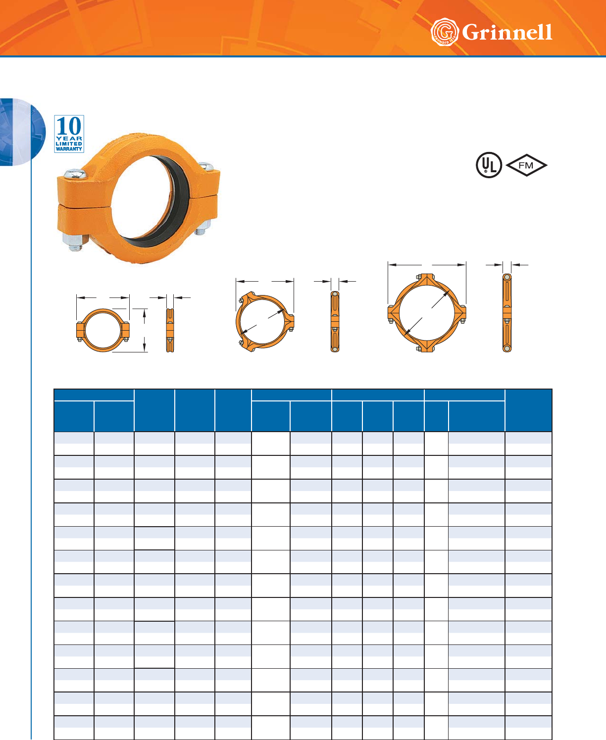
Figure 770 High Pressure Rigid Couplings
Tech Data Sheet: G138
The Figure 770 Rigid Coupling provides a rigid joint by firmly gripping
along the circumference of the pipe grooves. This coupling offers a
dependable method for joining pipe and is an economical alternative to
welding, threading, or using flanges. It is capable of pressures up to 1000
psi (68,9 bar) depending on pipe size and wall thickness.
Pipe Size Max.†
Pressures
psi
bar
Max.†
End Load
Lbs.
kN
Max.*‡
End Gap
Inches
mm
Dimensions - Inches mm Coupling Bolts Approx.
Weight
Lbs.
kg
Nominal
Inches
mm
O.D.
Inches
mm
AB C Qty.
Size
Inches
mm
2 2.375 1000 4,430.1 0.14 3.53 5.72 1.88 2
5⁄8 x 23⁄43.4
50 60,3 68,9 19,71 3,6 89,7 145,3 47,8 M16 x 70 1,5
21⁄22.875 1000 6,491.8 0.14 4.06 6.00 1.88 2
5⁄8 x 31⁄24.0
65 73,0 68,9 28,88 3,6 103,1 152,4 47,8 M16 x 89 1,8
3 3.500 1000 9,621.1 0.14 4.78 6.76 1.88 2
5⁄8 x 31⁄25.3
80 88,9 68,9 42,79 3,6 121,4 171,7 47,8 M16 x 89 2,4
4 4.500 1000 15,904.3 0.25 6.01 8.50 2.10 2
3⁄4 x 41⁄47.3
100 114,3 68,9 70,74 6,4 152,7 215,9 53,3 M20 x 108 3,3
6 6.625 1000 34,471.6 0.25 8.51 11.25 2.10 2
7⁄8 x 51⁄215.0
150 168,3 68,9 153,33 6,4 216,2 285,8 53,3 M22 x 140 6,8
8 8.625 800 46,741.0 0.25 10.93 13.75 2.60 21 x 51⁄225.0
200 219,1 55,2 207,90 6,4 277,6 349,3 66,0 M24 x 140 11,3
10 10.750 800 72,610.1 0.25 13.46 16.00 2.60 21 x 61⁄234.0
250 273,0 55,2 322,97 6,4 341,9 406,4 66,0 M24 x165 15,4
12 12.750 800 102,141.0 0.25 15.52 18.00 2.60 21 x 61⁄240.0
300 323,9 55,2 454,32 6,4 394,2 457,2 66,0 M24 x165 18,1
* Maximum available gap between pipe ends. Minimum gap = 0.
† Maximum Pressure and End Load are total from all loads based on standard weight steel pipe. Pressure ratings and end loads may differ for other
pipe materials and/or wall thickness. Contact GRINNELL Mechanical Products for details.
‡ Max End Gap and Deflection is for cut grooved standard weight pipe. Values for roll grooved pipe will be half that of cut grooved.
For information on larger sizes, contact GRINNELL Mechanical Products.
See page 17 for coupling specifications and pages 191 - 198 for gasket information.
C
A
B
Additional Features:
• Full 360° gripping of the groove circumference provides a
strong rigid connection.
• Tongue-and-groove design simplifies installation.
• Backed by the industry’s best 10-Year Limited Warranty.
GROOVED COUPLINGS
GROOVED COUPLINGS
24 www.grinnell.com
Figure 716 Flexible Reducing Couplings
Tech Data Sheet: G120 The GRINNELL Figure 716 Flexible Reducing Coupling allows for a direct
transition between two different pipe sizes and replaces two couplings
and a reducing fitting. It is capable of pressures up to 500 psi (34,5 bar)
depending on pipe size and wall thickness. A flexible reducing coupling is
not recommended for low-temperature applications.
Pipe Size Max.†
Pressures
psi
bar
Max.†
End
Load
Lbs./kN
Max.*‡
End Gap
Inches
mm
Deflection ‡ Dimensions
Inches mm Coupling Bolts Approx.
Weight
Lbs.
kg
Nominal
Inches
mm
O.D.
Inches
mm
Degrees
Per
Coupling
Inches/Ft
mm/m AB C Qty.
Size
Inches
mm
2 x 11⁄22.375 x 1.900 500 1,417.6 0.13 1° 53' 0.39 3.50 5.06 1.88 2
3⁄8 x 21⁄42.8
50 x 40 60,3 x 48,3 34,5 6,31 3,3 32,9 88,9 128,5 47,8 M10 x 57 1,3
21⁄2 x 2 2.875 x 2.375 500 2,215.1 0.13 1° 33' 0.32 4.00 5.50 1.88 2
3⁄8 x 21⁄43.3
65 x 50 73,0 x 60,3 34,5 9,85 3,3 27,1 101,6 139,7 47,8 M120 x 57 1,5
76.1 x 2 3.000 x 2.375 500 2,215.1 0.13 1° 34' 0.33 4.19 5.88 1.88 2–3.3
65 x 50 76,1 x 60,3 34,5 9,85 3,3 27,3 106,4 149,4 47,8 M12 x 89 1,5
3 x 2 3.500 x 2.375 500 2,215.1 0.13 1° 17' 0.27 4.69 6.50 1.88 2
1⁄2 x 3 4.3
80 x 50 88,9 x 60,3 34,5 9,85 3,3 22,4 119,1 165,1 47,8 M12 x 89 2,0
3 x 21⁄23.500 x 2.875 500 3,245.9 0.13 1° 17' 0.27 4.69 6.50 1.88 2
1⁄2 x 3 3.9
80 x 65 88,9 x 73,0 34,5 14,44 3,3 22,4 119,1 165,1 47,8 M12 x 89 1,8
3 x 76,1mm 3.500 x 3.000 500 3,534.3 0.13 1° 17' 0.27 4.69 6.50 1.88 2–4.2
80 x 65 88,9 x 76,1 34,5 15,72 3,3 22,4 119,1 165,1 47,8 M12 x 89 1,9
4 x 2 4.500 x 2.375 500 2,215.1 0.19 2° 38' 0.55 6.00 8.13 2.00 2
5⁄8 x 31⁄45.2
100 x 60 114,3 x 60,3 34,5 9,85 4,8 46,0 152,4 206,5 50,8 M16 x 83 2,4
4 x 21⁄24.500 x 2.875 500 3,245.9 0.19 2° 38' 0.55 6.00 8.13 2.00 2
5⁄8 x 31⁄46.7
100 x 65 114,3 x 73,0 34,5 14,44 4,8 46,0 152,4 206,5 50,8 M16 x 83 3,0
114,3 x 76,1mm 4.500 x 3.000 500 3,534.3 0.19 2° 38' 0.55 6.00 8.13 2.00 2–6.2
100 x 65 114,3 x 76,1 34,5 15,72 4,8 46,0 152,4 206,5 50,8 M16 x 83 2,8
4 x 3 4.500 x 3.500 500 4,810.6 0.19 2° 38' 0.55 6.00 8.13 2.00 2
5⁄8 x 31⁄46.2
100 x 80 114,3 x 88,9 34,5 21,40 4,8 46,0 152,4 206,5 50,8 M16 x 83 2,8
139,7mm x 4 5.500 x 4.500 500 7,952.2 0.25 2° 38' 0.55 7.06 9.50 2.06 2– 9.6
125 x 100 139,7 x 114,3 34,5 35,37 6,4 46,0 179,3 241,3 52,3 M20 x 121 4,4
5 x 4 5.563 x 4.500 500 7,952.2 0.25 2° 5' 0.44 7.13 9.56 2.06 2
3⁄4 x 43⁄49.6
125 x 100 141,3 x 114,3 34,5 35,37 6,4 36,4 181,1 242,8 52,3 M20 x 121 4,4
165mm x 4 6.500 x 4.500 400 6,361.7 0.25 1° 50' 0.38 8.18 10.81 2.06 2–12.8
150 x 100 165,1 x 114,3 27,6 28,30 6,4 32,0 207,8 274,6 52,3 M20 x 121 5,8
6 x 4 6.625 x 4.500 400 6,361.7 0.25 1° 44' 0.36 8.38 10.88 2.06 2
3⁄4 x 43⁄412.8
150 x 100 168,3 x 114,3 27,6 28,30 6,4 30,0 212,9 276,4 52,3 M20 x 121 5,8
6 x 5 6.625 x 5.563 400 9,722.3 0.25 1° 44' 0.36 8.38 10.88 2.06 2
3⁄4 x 43⁄413.8
150 x 125 168,3 x 141,3 27,6 43,25 6,4 30,0 212,9 276,4 52,3 M20 x 121 6,3
8 x 6 8.625 x 6.625 400 13,788.6 0.25 1° 15' 0.26 10.69 13.75 2.25 2
7⁄8 x 61⁄220.0
200 x 150 219,1 x 168,3 27,6 61,33 6,4 21,0 271,5 349,3 57,2 M22 x 165 9,1
* Maximum available gap between pipe ends. Minimum gap = 0.
† Maximum Pressure and End Load are total from all loads based on standard weight steel pipe. Pressure ratings and end loads may differ on other
pipe materials and/or wall thickness. Contact GRINNELL Mechanical Products for details.
‡ Max End Gap and Deflection is for cut grooved standard weight pipe. Values for roll grooved pipe will be half that of cut grooved.
For information on larger sizes, contact GRINNELL Mechanical Products.
See page 17 for coupling specifications and pages 191 - 198 for gasket information.
B
A
C)RUDGGLWLRQDOOLVWLQJVRU
DSSURYDOVVHHSDJHRU
YLVLWRXUZHEVLWHDW
ZZZJULQQHOOFRP
GROOVED COUPLINGS
GROOVED COUPLINGS
25
Refer to back cover for country-specific customer care numbers.
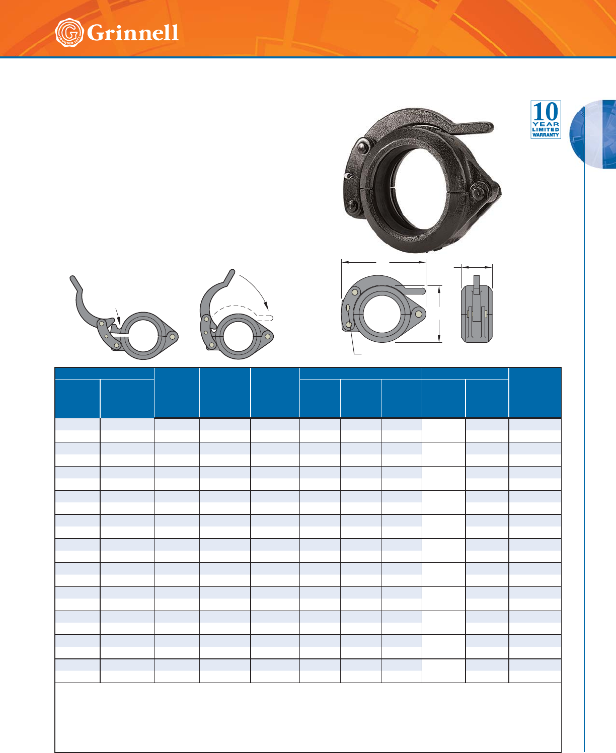
The GRINNELL Figure 780 Grooved Snap Coupling is designed
for quickly connecting and disconnecting cut or rolled grooved
piping systems. It utilizes a hinged lever mechanism for quickly
joining grooved piping segments securely without nuts and bolts.
Coupling housing segments are locked in place using a split pin.
Pipe Size Max. † *
Working
Pressure
psi
bar
Max. *
End Load
Lbs.
kN
Max. End
Gap
Inches
mm
Dimensions - Inches mm Deflection Approx.
Weight
Lbs.
kg
Nominal
Inches
mm
O.D.
Inches
mm
AB C
Degrees
Per
Coupling
Inches/Ft
mm/m
11⁄21.900 300 851 0.06 2.95 4.65 1.85 3° 48' 0.80 2.2
40 48,3 20,1 3,8 1,6 75,0 118,0 47,0 66,4 1,0
2 2.375 300 1,329 0.06 3.39 4.76 1.89 3° 31' 0.74 2.4
50 60,3 20,1 5,9 1,6 86,0 121,0 48,0 61,5 1,1
21⁄22.875 300 1,947 0.06 3.62 5.91 1.89 2° 30' 0.52 3.1
65 73,0 20,1 8,7 1,6 92,0 150,0 48,0 43,7 1,4
76,1 3.000 300 2,121 0.06 3.62 5.91 1.89 2° 24' 0.50 3.1
65 76,1 20,1 9,4 1,6 92,0 150,0 48,0 41,9 1,4
3 3.500 300 2,886 0.06 4.69 6.42 1.89 2° 24' 0.50 4.0
80 88,9 20,1 12,8 1,6 119,0 163,0 48,0 41,9 1,8
4 4.500 300 4,771 0.13 6.50 8.07 2.05 3° 12' 0.67 5.9
100 114,3 20,1 21,2 3,2 165,0 205,0 52,0 55,9 2,7
139,7mm 5.500 300 7,127 0.13 7.44 9.96 2.05 2° 37' 0.55 10.8
125 139,7 20,1 31,7 3,2 189,0 253,0 52,0 45,7 4,9
55.5653007,2890.137.449.962.05
2° 36' 0.54 10.8
125 141,3 20,1 32,4 3,2 189,0 253,0 52,0 45,4 4,9
165,1mm 6.500 300 9,955 0.13 8.39 10.94 2.05 2° 14' 0.47 12.8
150 165,1 20,1 44,3 3,2 213,0 278,0 52,0 39,0 5,8
6 6.625 300 10,341 0.13 8.50 11.06 2.05 2° 10' 0.45 12.8
150 168,3 20,1 46,0 3,2 216,0 281,0 52,0 37,8 5,8
8 8.625 300 17,528 0.13 10.95 14.02 2.44 1° 40' 0.35 20.5
200 219,1 20,1 78,0 3,2 278,0 356,0 62,0 29,1 9,3
† Pressure ratings listed are cold water pressure or maximum working pressure within the service temperature range of the gasket used
in the coupling.
* Maximum Working Pressures and End Loads listed are total of internal and external pressures and loads based on Schedule 40 steel pipe
grooved in accordance with Standard Cut Groove or Roll Groove Specifications.
For information on larger sizes, contact GRINNELL Mechanical Products.
See page 17 for coupling specifications and pages 191 - 198 for gasket information.
C
B
A
Split Pin
Figure 780 Grooved Snap Couplings
Tech Data Sheet: G145
Additional Features:
• Unique two-step closing feature allows for safe and quick
installation.
• Sizes 5" to 8" (125mm to 200mm) feature a cross-ribbed
housing design for extra strength.
• Rated for pressures up to 300 psi (20,7 bar).
• Backed by the industry’s best 10-Year Limited Warranty.
GROOVED COUPLINGS
GROOVED COUPLINGS
26 www.grinnell.com
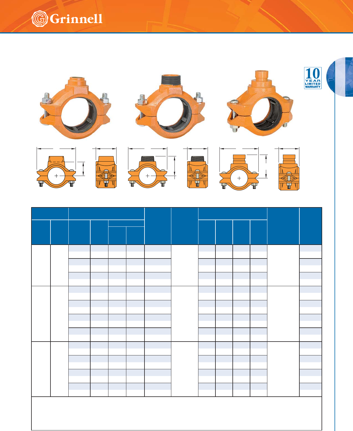
Figure 702 Mechanical Outlet Couplings
(Page 1 of 2)
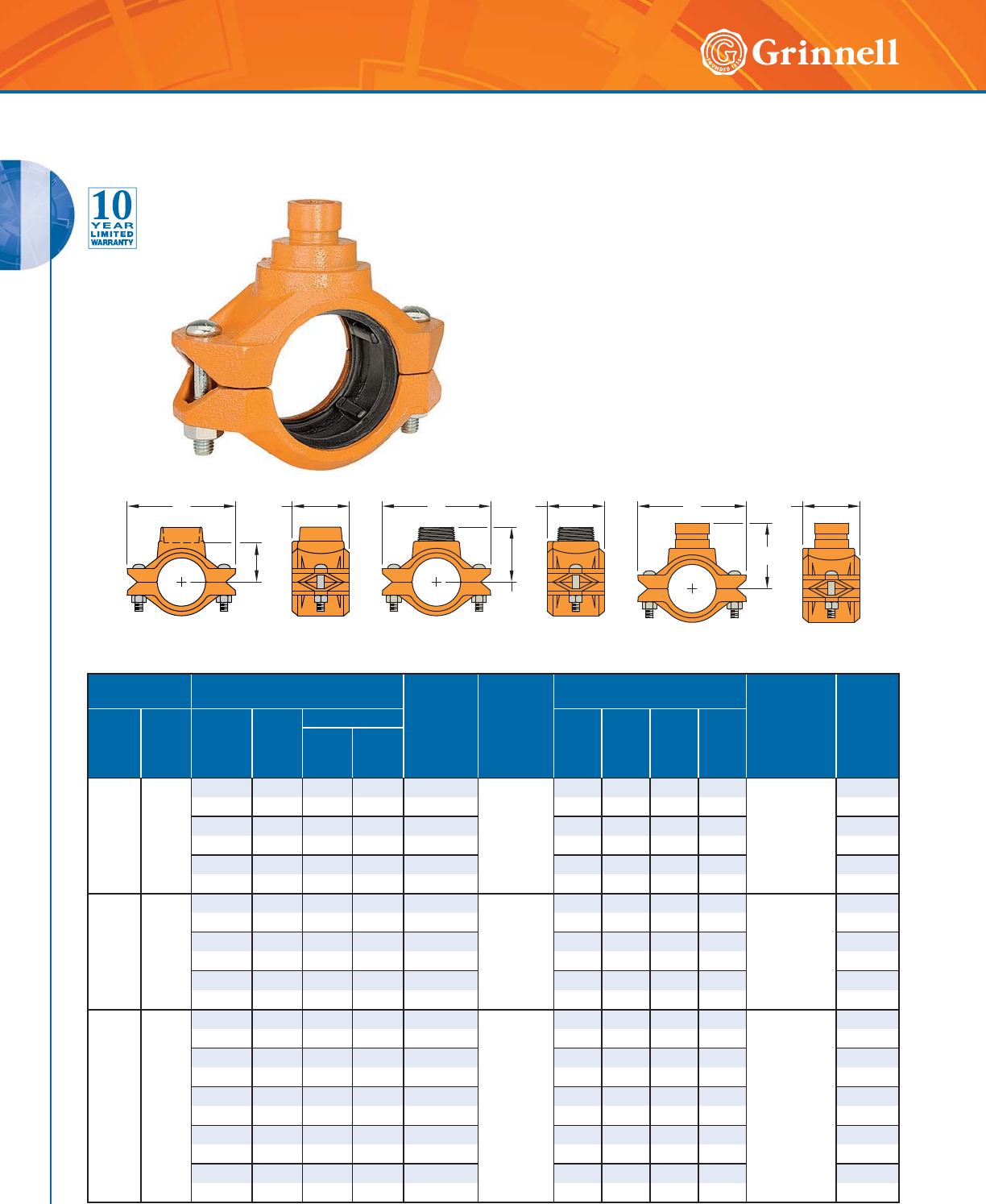
Tech Data Sheet: G220 The GRINNELL Figure 702 Mechanical Outlet Coupling has the
combined features of a coupling and a reducing outlet, eliminating the
need for a mechanical tee or other associated couplings. The coupling
is available in grooved, male-threaded, or female-threaded outlets. This
design makes installation faster, safer, and more cost effective on the
job site.
Additional features:
• Available in sizes 11⁄2" to 6" (40mm - 150mm)
• Rated for pressures up to 500 psi (34,5 bar)
• Suitable for vacuum service up to 10" HG (254mm HG)
Figure 702
Outlet Coupling with Female NPT Outlet
Figure 702
Outlet Coupling with Male NPT Outlet
Figure 702
Outlet Coupling with Grooved Outlet
Run Pipe Size Branch Size End Gap
Range
Inches
mm
Max.
Run End
Load
Lbs.
kN
Dimensions
Inches mm Coupling
Bolt Size
Inches
Approx.
Weight
Lbs.
kg
Nominal
Inches
mm
O.D.
Inches
mm
Female ◆
Thread
Inches
mm
Male ◆
Thread
Inches
mm
Grooved
ABC T
Nominal
Inches
mm
O.D.
Inches
mm
11⁄2
40
1.900
48,3
1⁄2–––0.81-0.88
1418
6,3
–4.502.752.06
3⁄8 x 21⁄8 •
2.6
21,3 – – – 20-22 – 114,3 70,0 52,0 1,2
3⁄4– – – 0.81-0.88 – 4.50 2.75 2.06 2.6
26,7 – – – 20-22 – 114,3 70,0 52,0 1,2
1 – – – 0.81-0.88 – 4.50 2.75 1.94 2.9
33,7 – – – 20-22 – 114,3 70,0 49,0 1,3
2
50
2.375
60,3
1⁄2–––0.81-0.88
2215
9,9
–5.002.752.32
3⁄8 x 21⁄8 •
3.1
21,3 – – – 20-22 – 127,0 70,0 59,0 1,4
3⁄4–––0.81-0.88 –5.002.752.32 3.1
26,7 – – – 20-22 – 127,0 70,0 59,0 1,4
1 1 1 1.315 0.81-0.88 3.50 5.00 2.75 2.20 3.3
33,7 33,7 25 33,7 20-22 89,0 127,0 70,0 56,0 1,5
21⁄2
65
2.875
73,0
1⁄2–––1.25-1.50
3246
14,4
– 6.33 3.25 2.20
1⁄2 x 23⁄8 •
4.8
21,3 – – – 32-38 – 161,0 83,0 56,0 2,2
3⁄4– – – 1.25-1.50 – 6.33 3.25 2.56 4.6
26,7 – – – 32-38 – 161,0 83,0 65,0 2,1
1 – – – 1.25-1.50 – 6.33 3.25 2.44 4.4
33,7 – – – 32-38 – 161,0 83,0 62,0 2,2
–1
1⁄411⁄41.660 1.25-1.50 3.70 6.33 3.25 – 5.1
– 42,4 32 42,4 32-38 94,0 161,0 83,0 – 2,3
–1
1⁄211⁄21.900 1.25-1.50 3.70 6.33 3.25 – 5.9
– 48,3 40 48,3 32-38 94,0 161,0 83,0 – 2,4
CB
A
A
C
BCB
T
GROOVED COUPLINGS
GROOVED COUPLINGS
27
Refer to back cover for country-specific customer care numbers.
Run Pipe Size Branch Size End Gap
Range
Inches
mm
Max.
Run End
Load
Lbs.
kN
Dimensions
Inches mm Coupling
Bolt Size
Inches
Approx.
Weight
Lbs.
kg
Nominal
Inches
mm
O.D.
Inches
mm
Female ◆
Thread
Inches
mm
Male ◆
Thread
Inches
mm
Grooved
ABC T
Nominal
Inches
mm
O.D.
Inches
mm
3
80
3.500
88,9
3⁄4–––1.25-1.50
21.4
4811
– 6.87 3.25 2.83
1⁄2 x 3 •
5.9
26,7 – – – 32-38 – 175,0 83,0 72,0 2,4
1 1 1 1.315 1.25-1.50 4.00 6.87 3.25 2.75 6.2
33,7 33,4 25 33,7 32-38 102,0 175,0 83,0 70,0 2,8
–1
1⁄211⁄21.900 1.25-1.50 4.00 6.87 3.25 – 6.4
– 48,3 40 48,3 32-38 102,0 175,0 83,0 – 2,9
4
100
4.500
114 ,3
3⁄4–––1.63-1.81
35.4
7952
–8.313.663.70
5⁄8 x 31⁄2 •
9.2
26,7 – – – 41-46 – 211,0 93,0 94,0 4,2
1 – – – 1.63-1.81 – 8.31 3.66 3.58 9.5
33,7 – – – 41-46 – 211,0 93,0 91,0 4,3
11⁄211⁄211⁄21.900 1.63-1.81 4.88 8.31 3.66 3.31 9.5
48,3 48,3 40 48,3 41-46 124,0 211,0 93,0 84,0 4,3
– 2 2 2.375 1.63-1.81 4.88 8.31 3.66 – 9.9
– 60,3 50 60,3 41-46 124,0 211,0 93,0 – 4,5
6
150
6.625
168,3
––––1.63-1.81
76.7
17,235
–10.863.70 –
5⁄8 x 31⁄2 •
13.2
– – – – 41-46 – 276,0 94,0 – 6,0
1 – – – 1.63-1.81 – 10.86 3.70 4.76 13.2
33,7 – – – 41-46 – 276,0 94,0 121,0 6,0
11⁄211⁄211⁄21.900 1.63-1.81 6.06 10.86 3.70 4.76 13.6
48,3 48,3 40 48,3 41-46 154,0 276,0 94,0 121,0 6,2
–222.3751.63-1.81 6.0610.863.70– 14.3
– 60,3 50 60,3 41-46 154,0 276,0 94,0 – 6,5
◆ Threads are NPT. Some size outlets are available with BSP threads. Contact GRINNELL Mechanical products for details.
• Only available in ANSI bolt sizes.
Flow characteristics chart is available in technical data sheet G220.
For information on larger sizes, contact GRINNELL Mechanical Products.
See page 17 for coupling specifications and pages 191 - 198 for gasket information.
Figure 702
Outlet Coupling with Female NPT Outlet
Figure 702
Outlet Coupling with Male NPT Outlet
Figure 702
Outlet Coupling with Grooved Outlet
CB
A
A
C
BCB
T
Figure 702 Mechanical Outlet Couplings
(Page 2 of 2)
Tech Data Sheet: G220
GROOVED COUPLINGS
GROOVED COUPLINGS
28 www.grinnell.com
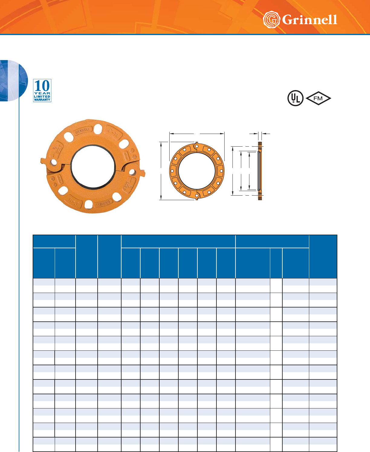
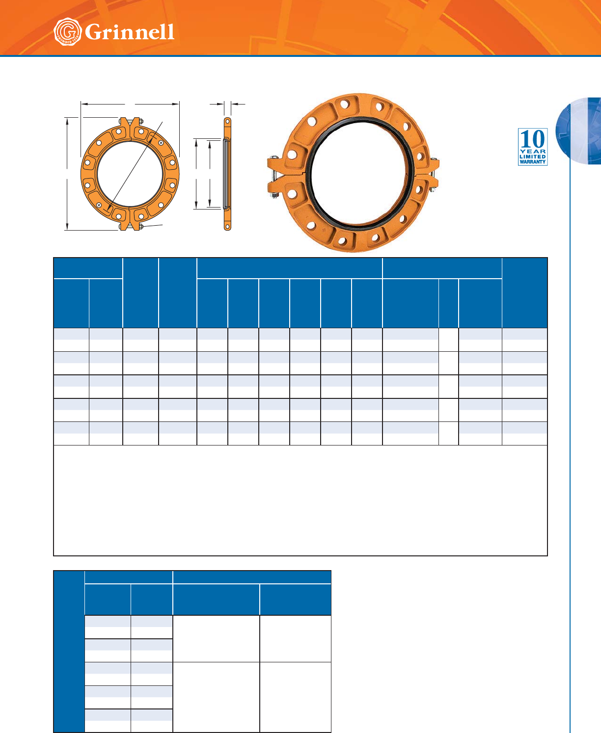
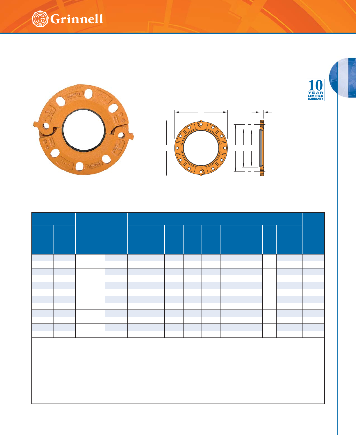
Figure 71 Flange Adapters
(ANSI Class 125/150)
(Page 1 of 2)
Tech Data Sheet: G150
The Figure 71 Flange Adapter is capable of pressures up to 300 psi (20,7
bar) depending on pipe size and wall thickness. It provides a direct transition
from flanged components to a grooved piping system. I.P.S. size flange bolt
patterns conform to ANSI Class 125 and 150.
The gasket seal is designed with an optimal amount
of rubber to provide a dependable seal and to avoid
the gasket pocket from overfilling, which may cause
assembly difficulties.
Pipe Size
Max †
Pressure
psi
bar
Max End
Load †
Lbs.
N
Dimensions - Inches mm Recommended
Flange Mating Bolts ‡ Approx.
Wt.
Lbs
kg
Nominal
Inches
mm
O.D.
Inches
mm
ABC*D*EF
Size
Dia. x Lg
Inches
mm
Qty.
Bolt
Torque
Range
Lbs.-ft.
Nm
2 2.375 300 1,324 6.38 4.75 0.75 2.38 3.41 7.25 5⁄8 x 3 4110-140 4.1
50 60,3 20,7 5889 162,1 120,7 19,1 60,5 86,6 184,2 – 149-190 1,9
21⁄22.875 300 1,948 7.00 5.50 0.88 2.88 3.91 7.88 5⁄8 x 3 4110-140 5.4
65 73,0 20,7 8665 178,0 140,0 22,0 73,0 99,0 200,0 – 149-190 2,4
76,1mm 3.000 300 2,121 7.28 5.71 0.88 3.00 4.03 8.08 5⁄8 x 3 4110-140 5.8
65 76,1 20,7 9435 184,9 145,0 22,0 76,1 102,4 205,2 – 149 -190 2,6
3 3.500 300 2,886 7.50 6.00 0.94 3.50 4.53 9.88 5⁄8 x 3 4110-140 6.0
80 88,9 20,7 12,838 190,5 152,4 23,9 88,9 115,1 251,0 – 149-190 2,7
4 4.500 300 4,771 9.00 7.50 0.94 4.50 5.53 9.90 5⁄8 x 3 8110-140 8.1
100 114,3 20,7 21,222 228,6 190,5 23,9 114,3 140,5 251,5 – 149-190 3,7
139,7mm 5.500 300 7,127 9.84 8.27 1.00 5.50 6.66 10.64 3⁄4 x 31⁄28220-250 9.2
125 139,7 20,7 31,702 249,9 210,1 25,4 139,7 169,2 270,3 – 298-339 4,2
5 5.563 300 7,292 10.00 8.50 1.00 5.56 6.72 11.38 3⁄4 x 31⁄28220-250 9.2
125 141,3 20,7 32,436 254,0 215,9 25,4 141,2 170,7 289,1 – 298-339 4,2
165,1mm 6.500 300 9,955 11.22 9.45 1.00 6.50 7.66 12.10 3⁄4 x 31⁄28220-250 11.0
150 165,1 20,7 44,282 285,0 240,6 25,4 165,1 194,6 307,3 – 298-339 5,0
6 6.625 300 10,341 11.00 9.50 1.00 6.62 7.78 11.88 3⁄4 x 31⁄28220-250 10.5
150 168,3 20,7 45,999 279,4 241,3 25,4 168,1 197,6 301,8 – 298-339 4,8
8 8.625 300 17,528 13.50 11.75 1.13 8.62 9.94 14.38 3⁄4 x 31⁄28220-250 16.2
200 219,1 20,7 77,968 342,9 298,5 28,7 218,9 252,5 365,3 – 298-339 7,3
10 10.750 300 27,229 16.00 14.25 1.19 10.75 12.31 16.88 7⁄8 x 4 12 320-400 20.7
250 273,0 20,7 121,121 406,4 362,0 30,2 273,1 312,7 428,8 – 434-542 9,4
12 12.750 300 38,303 19.00 17.00 1.25 12.75 14.31 20.00 7⁄8 x 4 12 320-400 31.8
300 323,9 20,7 170,380 482,6 431,8 31,8 323,9 363,5 508,0 – 434-542 14,4
CA
FBED
Sizes 2" - 12" (50mm - 300mm)
)RUDGGLWLRQDOOLVWLQJVRU
DSSURYDOVVHHSDJHRU
YLVLWRXUZHEVLWHDW
ZZZJULQQHOOFRP
GROOVED COUPLINGS
GROOVED COUPLINGS
29
Refer to back cover for country-specific customer care numbers.
Sizes 14" - 24" (350mm - 600mm)
F
CA
ED
B
Segment
Bolt
Pipe Size
Max †
Pressure
psi
bar
Max End
Load †
Lbs.
N
Dimensions - Inches mm Recommended
Flange Mating Bolts ‡ Approx.
Wt.
Lbs
kg
Nominal
Inches
mm
O.D.
Inches
mm
ABC*D*EF
Size
Dia. x Lg
Inches
mm
Qty.
Bolt
Torque
Range
Lbs.-ft.
Nm
14** 14.000 300 46,181 21.00 18.76 1.44 14.00 15.03 24.00 1 x 41⁄4 • 12 360-520 46.7
350 355,6 20,7 205,423 533,4 476,5 36,5 355,6 381,8 609,6 – 488-705 21,2
16** 16.000 300 60,315 23.50 21.26 1.50 16.00 17.00 26.50 1 x 41⁄4 • 16 360-520 59.0
400 406,4 20,7 268,294 596,9 540,0 38,10 406,4 431,7 673,1 – 488-705 26,8
18** 18.000 300 76,455 25.00 22.76 1.63 18.00 19.01 29.00 11⁄8 x 43⁄4 • 16 450-725 62.5
450 457,2 20,7 340,089 635,0 578,1 41,3 457,2 482,8 736,6 – 610-982 28,3
20** 20.000 300 94,245 27.50 25.00 1.75 20.00 21.03 31.50 11⁄8 x 43⁄4 • 20 450-725 73.3
500 508,0 20,7 419,223 698,5 635,0 44,5 508,0 534,2 800,1 – 610-982 33,2
24** 24.000 250 135,720 32.00 29.50 1.93 24.00 25.05 36.00 11⁄4 x 51⁄2 • 20 620-1000 100.6
600 609,6 17,2 603,713 812,8 749,3 49,0 609,6 636,3 914,4 – 841-1356 45,6
* Dimensions D and E represent minimum and maximum sealing surfaces.
** For segment bolt torque recommendations, refer to Table A below.
• Metric segment bolt are available upon request.
† Maximum Pressure and End Load are total from all loads based on standard weight steel pipe. Pressure ratings and end loads may differ on other
pipe materials and/or wall thickness. Contact GRINNELL Mechanical Products for details.
‡ Mating bolts and nuts are not supplied. Flange mating bolts must be at least SAE J429, Grade 5 or stronger. Bolt lengths are standard; responsibility
lies with the purchaser to verify the correct length for the intended application.
For information on larger sizes, contact GRINNELL Mechanical Products.
See page 17 for coupling specifications and pages 191 - 198 for gasket information.
See page 33 for Flange Adapter Washers and page 226 Flange Drilling Specifications.
TABLE A
SEGMENT BOLT TORQUE
Pipe Size Segment Bolts
Nominal
Inches
mm
O.D.
Inches
mm
Size - Dia. x Lg
Inches
mm
Bolt Torque Range
Lbs.-ft.
Nm
14 14.000
5⁄8 x 43⁄4
–
100-130
149-190
350 355,6
16 16.000
400 406,4
18 18.000
3⁄4 x 43⁄4
–
130-180
176-244
450 457,2
20 20.000
500 508,0
24 24.000
600 609,6
Figure 71 Flange Adapters
(ANSI Class 125/150)
(Page 2 of 2)
Tech Data Sheet: G150
GROOVED COUPLINGS
GROOVED COUPLINGS
30 www.grinnell.com
Pipe Size
PN10/
PN16
Max †
End
Load
Lbs.
N
Dimensions - Inches mm Recommended
Flange Mating Bolts ‡ Approx.
Wt.
Lbs
kg
Nominal
Inches
mm
O.D.
Inches
mm
ABC*D*EF
Size
Dia. x Lg
Inches
mm
Qty.
Bolt
Torque
Range
Nm
22.375
PN10 / PN16 1,324 6.38 4.92 0.75 2.38 3.41 7.25 – 4110-140 4.0
50 60,3 5889 162,1 125,0 19,1 60,5 86,6 184,2 M16 x 76 149-190 1,8
21⁄22.875 PN10 / PN16 1,948 7.00 5.50 0.88 2.88 3.91 5.13 – 4110-140 5.4
65 73,0 8665 177,8 139,7 22,4 73,6 99,3 130,3 M16 x 76 149-190 2,4
76,1mm 3.000 PN10 1,948 7.28 5.71 0.88 3.00 4.03 8.09 – 4110-140 5.7
65** 76,1 8665 184,9 145,0 22,4 76,1 102,4 205,5 M16 x 76 149-190 2,6
76,1mm 3.000 PN16 1,948 7.28 5.70 0.88 3.00 4.03 8.08 – 4110-140 5.6
65** 76,1 8665 184,9 144,8 22,4 76,1 102,4 205,2 M16 x 76 149-190 2,5
3** 3.500 PN10 2,886 7.26 5.76 0.94 3.50 4.53 7.86 – 4110-140 5.4
80 88,9 12,838 184,4 146,3 23,9 88,9 115,1 199,6 M16 x 76 149-190 2,4
3** 3.500 PN16 2,886 7.88 6.30 0.94 3.50 4.53 8.76 – 8110-140 5.6
80 88,9 12,838 200,2 160,0 23,9 88,9 115,1 222,5 M16 x 76 149-190 2,5
4** 4.500 PN10 4,771 8.50 7.00 0.94 4.50 5.53 9.26 – 8110-140 7.8
100 114,3 21,222 215,9 177,8 23,9 114,3 140,5 235,2 M16 x 76 149-190 3,5
4** 4.500 PN16 4,771 8.66 7.09 0.94 4.50 5.53 9.43 – 8110-140 8.0
100 114,3 21,222 219,9 180,1 23,9 114,3 140,5 239,5 M16 x 76 149-190 3,6
139,7mm 5.500 PN10 7,292 9.84 8.27 1.00 5.50 6.53 10.69 – 8110-140 9.2
125** 139,7 32,436 249,9 210,1 25,4 139,7 165,9 271,5 M16 x 89 149-190 4,2
139,7mm 5.500 PN16 7,127 9.84 8.26 1.00 5.50 6.66 12.22 – 8110-140 9.2
125** 139,7 31,702 249,9 209,8 24,5 139,7 169,2 310,4 M16 x 89 149-190 4,2
165,1mm 6.500 PN10 9,955 11.00 9.26 1.00 6.50 7.66 11.76 – 8220-250 10.4
150** 165,1 44,282 279,4 234,2 24,5 165,1 194,6 298,7 M20 x 89 298-339 4,7
165,1mm 6.500 PN16 9,955 11.22 9.46 1.00 6.50 7.66 12.10 – 8220-250 10.5
150** 165,1 44,282 285,0 240,3 24,5 165,1 194,6 307,3 M20 x 89 298-339 4,8
66.625
PN10 / PN16 17,528 11.00 9.49 1.00 6.62 7.78 11.88 – 8220-250 10.6
150 168,3 77,968 279,4 241,1 25,4 168,1 197,6 301,8 M20 x 89 298-339 4,8
CA
FBED
Sizes 2" - 12" (50mm - 300mm)
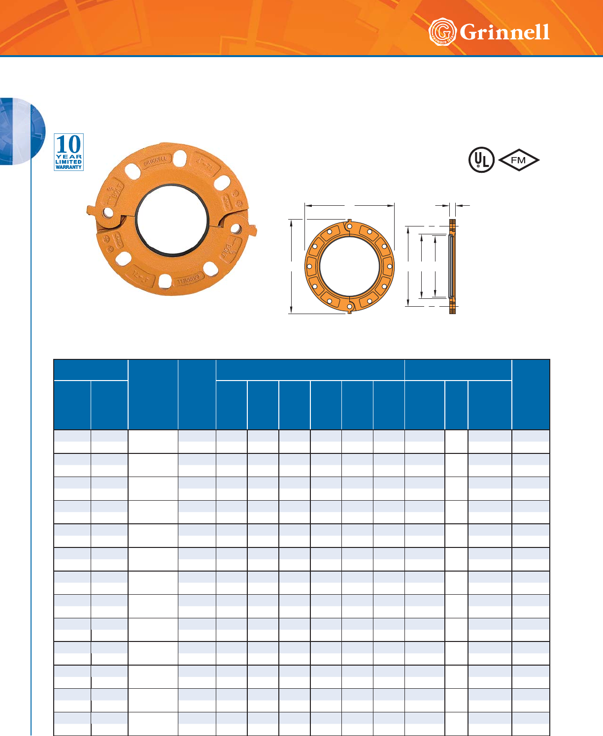
Figure 71 Flange Adapters
(PN10/PN16)
(Page 1 of 2)
Tech Data Sheet: G150
The Figure 71 Flange Adapter is capable of pressures up to 300 psi
(20,7 bar) depending on pipe size and wall thickness. It provides a direct
transition from flanged components to a grooved piping system. I.P.S. size
flange bolt patterns conform to PN10/PN16
The gasket seal is designed with an optimal amount
of rubber to provide a dependable seal and to avoid
the gasket pocket from overfilling, which may cause
assembly difficulties. )RUDGGLWLRQDOOLVWLQJVRU
DSSURYDOVVHHSDJHRU
YLVLWRXUZHEVLWHDW
ZZZJULQQHOOFRP
GROOVED COUPLINGS
GROOVED COUPLINGS
31
Refer to back cover for country-specific customer care numbers.
CA
FBED
Sizes 2" - 12" (50mm - 300mm)
Pipe Size
PN10/
PN16
Max †
End
Load
Lbs.
N
Dimensions - Inches mm Recommended
Flange Mating Bolts ‡ Approx.
Wt.
Lbs
kg
Nominal
Inches
mm
O.D.
Inches
mm
ABC*D*EF
Size
Dia. x Lg
Inches
mm
Qty.
Bolt
Torque
Range
Nm
8** 8.625 PN10 17,528 13.26 11.50 1.125 8.62 9.94 14.12 – 8220-250 15.4
200 219,1 77,968 336,8 292,1 28,6 218,9 254,5 358,6 M20 x 89 298-339 6,9
8** 8.625 PN16 17,528 13.38 11.62 1.125 8.62 9.94 14.28 – 12 220-250 16.6
200 219,1 77,968 339,8 295,1 28,6 218,9 254,5 362,7 M20 x 89 298-339 7,5
10** 10.750 PN10 27,229 15.56 13.78 1.188 10.75 12.31 16.50 – 12 220-250 21.2
250 273,0 121,121 395,2 350,0 30,2 273,1 312,4 419,1 M20 x 102 298-339 9,6
10** 10.750 PN16 38,303 16.00 13.98 1.188 10.75 12.31 16.88 – 12 320-400 22.5
250 273,0 170,380 406,4 355,1 30,2 273,1 312,7 428,8 M22 x 102 434-542 10,2
12** 12.750 PN10 38,303 17.52 15.74 1.25 12.75 14.31 18.52 – 12 320-400 24.8
300 323,9 170,380 445,0 399,8 31,8 323,9 363,5 470,4 M22 x 102 434-542 11,2
12** 12.750 PN16 38,303 18.12 16.14 1.25 12.75 14.31 19.14 – 12 320-400 28.9
300 323,9 170,380 460,2 410,0 31,8 323,9 363,5 486,2 M22 x 102 434-542 13,1
Maximum Pressure rating is 300 psi (20,7 bar).
* Dimensions D and E represent minimum and maximum sealing surfaces.
** For noted sizes, PN10 and PN16 dimensional values differ.
† Maximum End Load is total from all loads based on standard weight steel pipe. Pressure ratings and end loads may differ on other pipe materials
and/or wall thickness. Contact GRINNELL Mechanical Products for details.
‡ Mating Bolts and Nuts are not supplied. Flange Mating Bolts must be at least SAE J429, Grade 5 or stronger. Bolt lengths are standard;
responsibility lies with the purchaser to verify the correct length for the intended application.
For information on larger sizes, contact GRINNELL Mechanical Products.
See page 17 for coupling specifications and pages 191 - 198 for gasket information.
See page 33 for Flange Adapter Washers and page 226 Flange Drilling Specifications.
Figure 71 Flange Adapters
(PN10/PN16)
(Page 2 of 2)
Tech Data Sheet: G150
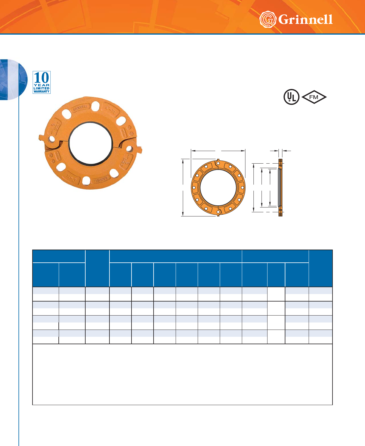
GROOVED COUPLINGS
GROOVED COUPLINGS
32 www.grinnell.com
CA
FBED
Sizes 3" - 8" (80mm - 200mm)
Pipe Size Max †
End
Load
Lbs.
N
Dimensions - Inches mm Recommended
Flange Mating Bolts ‡ Approx.
Wt.
Lbs
kg
Nominal
Inches
mm
O.D.
Inches
mm
ABC*D*EF
Size
Dia. x Lg
Inches
mm
Qty.
Bolt
Torque
Range
Nm
3 3.500 2,886 7.88 6.30 0.94 3.50 4.53 8.75 – 8–6.4
80 88,9 12,838 200,2 160,0 23,9 88,9 115,1 222,3 M16 x 76 149-190 2,9
4 4.500 4,771 9.00 7.09 0.94 4.50 5.53 9.90 – 8–7.7
100 114,3 21,222 228,6 180,1 23,9 114,3 140,5 251,5 M16 x 76 149-190 3,5
6 6.625 10,341 11.25 9.45 1.00 6.50 7.53 12.12 – 8–10.6
150 168,3 45,999 285,8 240,0 25,4 165,1 191,3 307,8 M20 x 89 298-339 4,8
8 8.625 27,229 13.38 11.61 1.13 8.62 9.94 14.31 – 12 –15.0
200 219,1 121,121 339,9 294,9 28,7 218,9 252,5 363,5 M20 x 89 298-339 6,8
* Dimensions D and E represent minimum and maximum sealing surfaces.
† Maximum End Load is total from all loads based on standard weight steel pipe. Pressure ratings and end loads may differ on other pipe materials
and/or wall thickness. Contact GRINNELL Mechanical Products for details.
‡ Mating Bolts and Nuts are not supplied. Flange Mating Bolts must be at least SAE J429, Grade 5 or stronger. Bolt lengths are standard; responsibility
lies with the purchaser to verify the correct length for the intended application.
Maximum Pressure rating is 300 psi (20,7 bar).
For information on larger sizes, contact GRINNELL Mechanical Products.
See page 17 for coupling specifications and pages 191 - 198 for gasket information.
See page 33 for Flange Adapter Washers and page 226 Flange Drilling Specifications.
Figure 71 Flange Adapters
(AS2129 Table E)
Tech Data Sheet: G150 The Figure 71 Flange Adapter is capable of pressures up to 300 psi
(20,7 bar) depending on pipe size and wall thickness. It provides a direct
transition from flanged components to a grooved piping system. I.P.S. size
flange bolt patterns conform to AS2129 Table E.
The gasket seal is designed with an optimal amount
of rubber to provide a dependable seal and to avoid
the gasket pocket from overfilling, which may cause
assembly difficulties. )RUDGGLWLRQDOOLVWLQJVRU
DSSURYDOVVHHSDJHRU
YLVLWRXUZHEVLWHDW
ZZZJULQQHOOFRP

GROOVED COUPLINGS
GROOVED COUPLINGS
33
Refer to back cover for country-specific customer care numbers.
Flange Adapter Washers
Pipe Size Dimensions - Inches mm
Nominal
Inches
mm
O.D.
Inches
mm
AB
22.3753.942.25
50 60,3 100,1 57,2
21⁄22.875 4.69 2.75
65 73,0 119,1 69,9
76,1mm 3.000 4.89 2.88
65 76,1 124,2 73,2
33.5005.193.38
80 88,9 131,8 85,9
44.5006.694.38
100 114,3 169,9 111,3
139,7mm 5.500 7.45 5.32
125 139,7 189,2 135,1
55.5637.565.38
125 141,3 192,0 136,7
165,1mm 6.500 8.47 6.32
150 165,1 215,1 160,5
66.6258.566.44
150 168,3 217,4 163,6
88.62510.818.44
200 219,1 274,6 214,4
A
B
Pipe Size Dimensions - Inches mm
Nominal
Inches
mm
O.D.
Inches
mm
AB
10 10.750 13.19 10.50
250 273,0 335,0 266,7
12 12.750 15.94 12.50
300 323,9 404,9 317,5
14 14.000 17.50 13.50
350 355,6 444,5 342,9
16 16.000 20.00 15.50
400 406,4 508,0 393,7
18 18.000 21.38 17.50
450 457,2 542,9 444,5
20 20.000 23.63 19.50
500 508,0 600,1 495,3
24 24.000 28.00 23.50
600 609,6 711,2 596,9
For information on additional sizes, PN10, PN16, and AS2129 Table E
sizes, contact GRINNELL Mechanical Products.
Available in stainless steel ASTM A 666 Type 304-2B. Contact
GRINNELL Mechanical Products.
See Flange Drilling Specifications on page 226.
Flange Adapter Washer
GRINNELL
Flange Adapter
Grooved Pipe
Mating Flange
Component
Gasket
Carbon steel Flange Adapter Washers are required when
the Figure 61 and Figure 71 Flange Adapter is used against
surfaces such as:
• Rubber surfaces
• Adapting to AWWA cast flanges
• Rubber faced wafer valves
• Serrated flange surfaces
Contact GRINNELL Mechanical Products for additional
information.
MATERIAL SPECIFICATIONS
• Cold rolled steel sheet per ASTM A 1008-00 CS
Types A, B, or C
• Zinc Electrodeposited coating per ASTM B 633-07
SC2 Type III
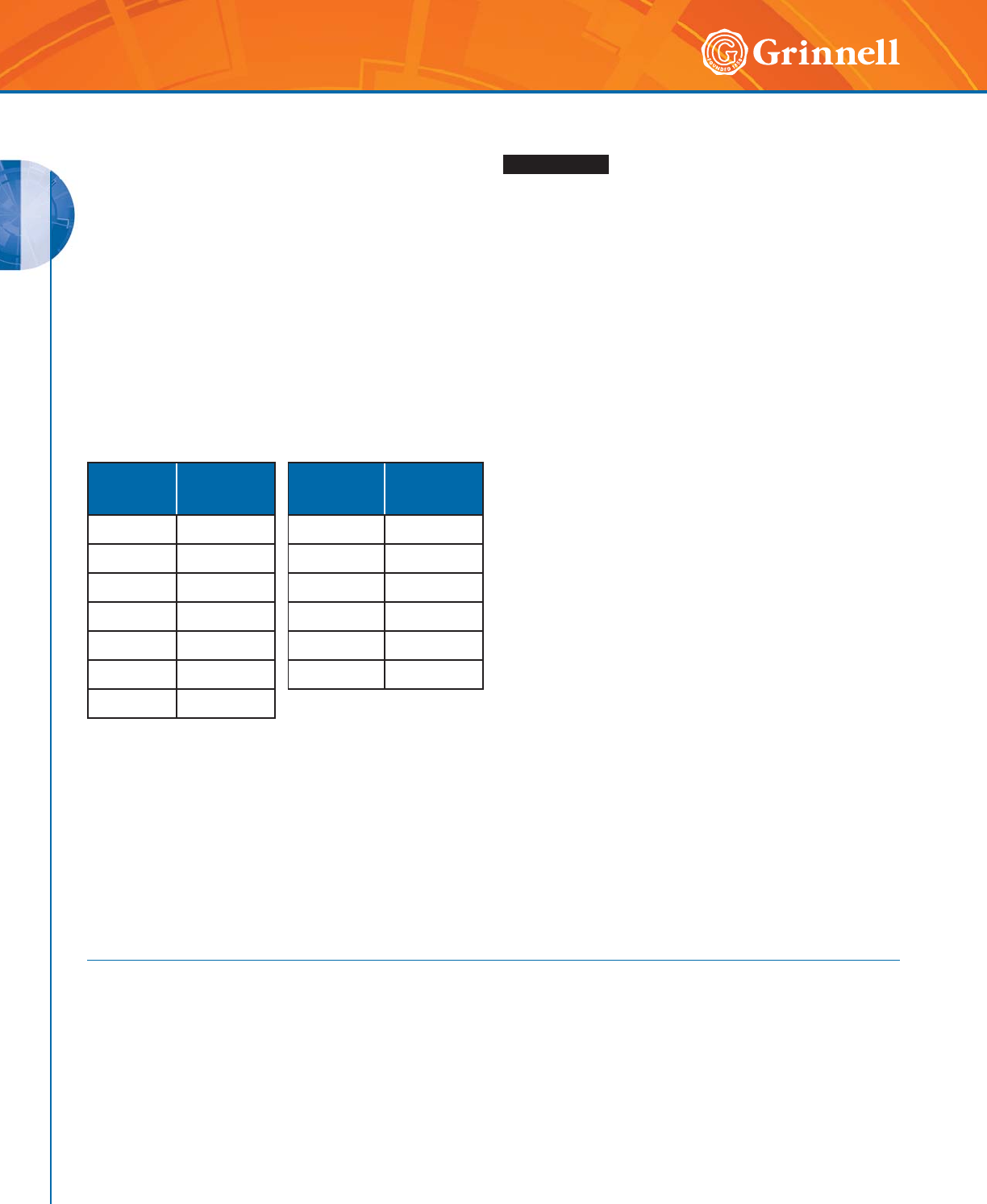
GROOVED COUPLINGS
GROOVED COUPLINGS
34 www.grinnell.com
These installation instructions do not take the place of nor
do they eliminate the need for the installer to fully read and
understand the complete GRINNELL Mechanical Products
Installation Handbook (refer to IH-1000M). Always review the
GRINNELL Mechanical Products Installation Handbook and
individual product tech data sheets for the latest instructions,
techniques, and care and maintenance information. This
document does not supersede or replace the GRINNELL
Mechanical Products Installation Handbook or individual
product tech data sheets. Current documentation can be
obtained by contacting GRINNELL Mechanical Products or
visiting www.grinnell.com.
Coupling Installation Information
Tech Data Sheet: G900
Installation Handbook: IH-1000M
Bolt Size
ANSI
Inches
Bolt Torque
Range
Ft.- Lbs.
Bolt Size
Metric
Bolt Torque
Range
Nm
3⁄830-40 M10 40-60
1⁄290-110 M12 120-150
5⁄8100-130 M16 135-175
3⁄4150-200 M20 200-270
7⁄8180-220 M22 245-300
1200-250 M24 270-340
11⁄8225-275
WARNING
Failure to follow these instructions may result in improper prod-
uct installation, joint failure or leakage, serious personal injury,
and/or property damage.
The following instructions should be used as a guideline for the
proper installation of GRINNELL Grooved Products.
1. Always read and understand the instructions.
2. To avoid serious personal injury always wear appropriate
personal protective equipment (ppe), such as safety glass-
es, hard hat and foot protection.
3. Never remove any piping component without verifying that
the system is de-pressurized and drained. Failure to due so
may result in serious personal injury.
4. Ensure that the supplied gasket is suitable for the intended
application. To prevent deterioration of the gasket material,
a petroleum lubricant should never be used. Use a recom-
mended lubricant to install the gasket.
5. The pipe groove dimensions must be in accordance with
Standard Roll Groove or Cut Groove Specifications. Refer
to Pages 201 to 203 or Tech Data Sheet G710 for addition-
al information.
6. Ensure that the coupling keys are engaged in the grooves.
7. Always tighten nuts evenly by alternating sides. Uneven
tightening can cause the gasket to pinch or bind. If a gasket
becomes pinched, replace it immediately.
8. Torque values are supplied as a guideline and may be used
when setting the torque on power impact wrenches. Always
refer to the power impact wrench manufacturer’s instruc-
tions for settings.
9. Exceeding the suggested torque values may cause damage
to the coupling and/or result in pipe-joint failure. Minimum
bolt torque is required for coupling to meet the published
performance parameters.
10. Always inspect each joint to ensure that the coupling is
properly installed.
EDPM, Tri-Seal gaskets are recommended for freezer
applications. Reducing Couplings are not recommended for
freezer applications. For dry pipe and freezer applications,
use the Tri-Seal freezer gasket with a petroleum-free silicone
lubricant. Standard lube is not recommended for this
application as it freezes and can cause leakage.
*Note: The samples that were tested contained the GRINNELL
Figure 707 high pressure flexible couplings, and the
GRINNELL Figure 260 end caps of the appropriate size.
These were used on the assembly to test system components as
related in a field environment. The rated or working pressure
of these items is 1,000 psi (68.9 bar)
*Note: The material of both the fittings and couplings used in
this testing is found on page nine of the GRINNELL Mechanical
Handbook. This material is Ductile Iron Casting Grade 65-45-
12, which has an elongation in 2” (51mm) of 12%.
The Component Proof Test in ASME A17.1 – 2004,
section 3.19.1.3 requires testing to section 8.2.8.5, or five
times the rated pressure.
The calculation of the factor of safety located in section
8.2.8.5 would then be calculated as F = (5.04 / 12 – 2.8)
+ 2.7. This then, according to section 8.2.8.5, would be
a requirement safety factor of 3.25. The minimum pressure
requirement of these components then would be 3,250 psig
(224.1 bar)
ASME Standard Note
Bolt Torque
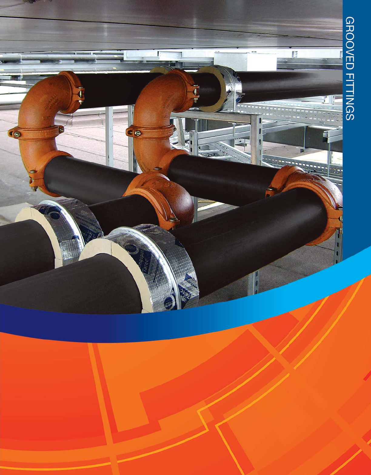
35
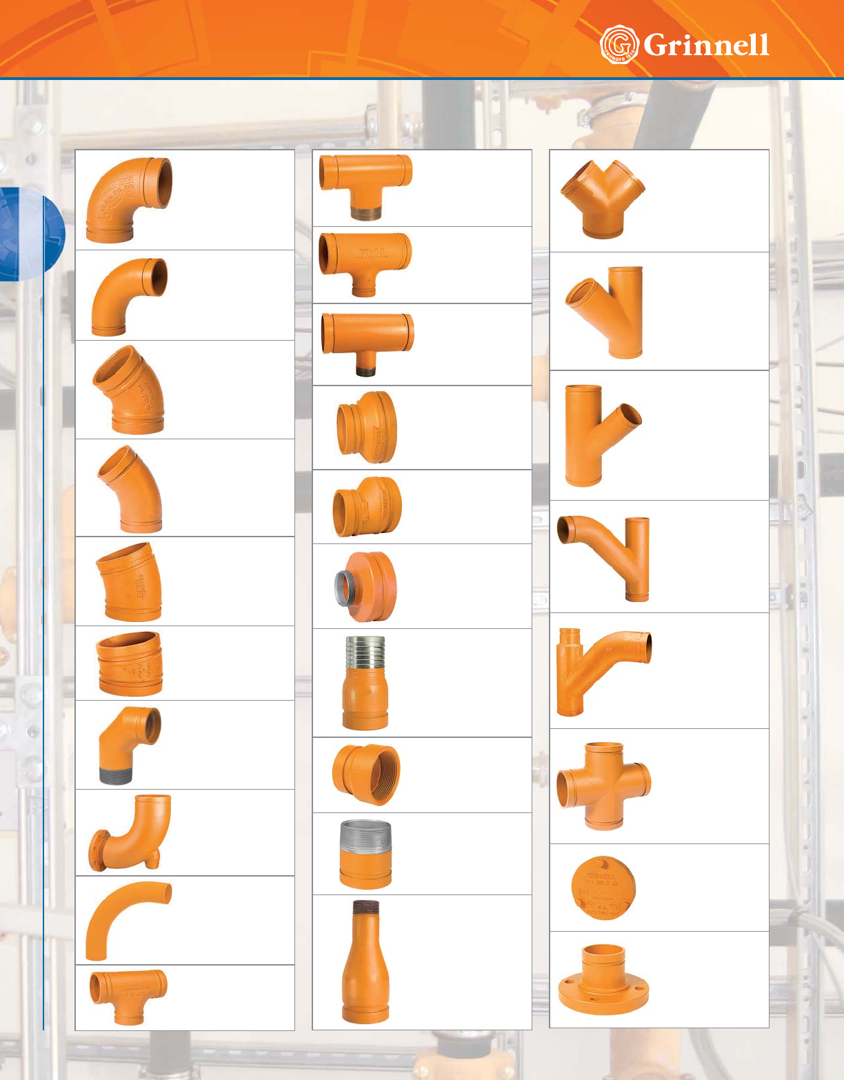
GROOVED FITTINGS
36 www.grinnell.com
GROOVED FITTINGS
Grooved Fittings Table of Contents
Figure 210
90° Elbows
Page 38
Figures 210LR &
310LR
90° Long Radius
Elbows
Page 38
Figure 201
45° Elbows
Page 39
Figures 201LR &
301LR
45° Long Radius
Elbows
Page 39
Figures 212 &
312
221⁄2° Elbows
Page 40
Figures 211 &
311
111⁄4° Elbows
Page 41
Figure 315
Groove x Male Thread
90° Elbows
Page 42
Figure 316
Reducing Base
Support Elbows
Page 42
Figures 3D, 5D
& 6D
111⁄4° to 90°
Long Radius Elbows
Pages 43 - 45
Figure 219 & 319
Tees
Page 46
Figure 320
Tees Groove x Groove
x Male Thread
Page 47
Figures 221 &
321
Reducing Tees
Pages 48 - 50
Figure 323
Reducing Tees Groove
x Groove x Thread
Pages 51 - 52
Figures 250 &
350
Concentric
Reducers
Pages 53 - 55
Figures 251 &
351
Eccentric Reducers
Pages 56 - 58
Figure 372
Groove x Male Thread
Concentric Reducers
Page 59
Figure 395
Hose Adapter Nipples
Page 60
Figure 380
Female Thread
Adapters
Page 60
Figures 391, 392
& 393
Adapter Nipples
Page 61
Figures 397, 398
& 399
Concentric Swaged
Nipples
Page 62
Figure 324
True Wyes
Page 63
Figure 314
45° Laterals
Page 64
Figure 325
45° Reducing
Laterals
Pages 65 - 67
Figure 330
Tee Wyes
Pages 68 - 69
Figure 331
Reducing Tee Wyes
Page 70
Figures 227 &
327
Crosses
Page 71
Figures 260 &
360
End Caps
Page 72
Figures 341, 342,
343, & 344
Flange Adapters
Pages 73 - 74
GROOVED FITTINGS
GROOVED FITTINGS
37
Refer to back cover for country-specific customer care numbers.
GRINNELL Grooved Fittings in ductile iron and fabricated
steel provide an economical and efficient method of changing
direction, adding an outlet, and reducing or capping piping
systems.
GRINNELL Grooved Fittings are rated at the pressure rating of
the coupling in use.
MATERIAL SPECIFICATIONS
Ductile Iron Fitting Specifications
• ASTM A 536 - Standard specification for
ductile iron castings, Grade 65-45-12
• Tensile Strength, minimum 65,000 psi (4481,6 bar)
• Yield Strength, minimum 45,000 psi (3102,6 bar)
• Elongation in 2" (50mm), minimum 12%
• ASTM A 153 – Standard specification for hot-dip
galvanizing
Fabricated Steel Fitting
Specifications
• Carbon Steel: According to ASTM A 53, Grade B
• Tensile Strength, minimum 60,000 psi (4136,9 bar)
• Yield Strength, minimum 35,000 psi (2413,2 bar)
• Sizes 11⁄4" – 10" (32mm – 250mm) Schedule 40
• Sizes 12" – 24" (300mm – 600mm) STD (.375)
Coatings
• Orange – Non-lead paint (standard)
• Red – Non-lead paint (optional, regional)
• Hot-Dipped, Zinc Galvanized (optional)
Threads
• NPT (standard)
• BSPT (optional, regional)
Pipe Size Elbows
90°
Feet
m
Elbows
45°
Feet
m
Tee
Branch
Feet
m
Tee
Run
Feet
m
Nominal
Inches
mm
O.D.
Inches
mm
11.3151.6 0.74.31.6
25 33,4 0,5 0,2 1,3 0,5
11⁄41.660 1.9 1.0 4.8 1.9
32 42,4 0,6 0,3 1,5 0,6
11⁄21.900 2.3 1.2 5.8 2.3
40 48,3 0,7 0,4 1,8 0,7
22.3753.2 1.6 8.0 3.2
50 60,3 1,0 0,5 2,5 1,0
21⁄22.875 3.9 2.0 9.8 3.9
65 73,0 1,2 0,6 3,0 1,2
76,1mm 3.000 4.1 2.1 10.3 4.1
65 76,1 1,2 0,6 3,1 1,2
3 3.500 4.9 2.4 12.2 4.9
80 88,9 1,5 0,7 3,7 1,5
4 4.500 6.5 3.3 16.3 6.5
100 114,3 2,0 1,0 5,0 2,0
139,7mm 5.500 8.0 4.1 20.0 8.0
125 139,7 2,4 1,3 6,1 2,4
5 5.563 8.2 4.1 20.5 8.2
125 141,3 2,5 1,3 6,3 2,5
165,1mm 6.500 9.5 4.8 23.8 9.5
150 165,1 2,9 1,4 7,2 2,9
6 6.625 9.9 5.0 24.8 9.9
150 168,3 3,0 1,5 7,6 3,0
88.62513.16.632.813.1
200 219,1 4,0 2,0 10,0 4,0
10 10.750 16.5 8.3 41.3 16.5
250 273,0 5,0 2,5 12,6 5,0
12 12.750 19.9 9.9 49.7 19.9
300 323,9 6,1 3,0 15,1 6,1
14 14.000 23.0 18.0 67.9 23.0
350 3 55,6 7,0 5 , 5 20,7 7,0
16 16.000 25.9 20.0 78.1 25.9
400 4 0 6,4 7,9 6,1 23, 8 7,9
18 18.000 28.9 23.0 85.0 28.9
450 457,2 8,8 7,0 25,9 8,8
20 20.000 33.1 25.9 100.1 33.1
500 508,0 10,1 7,9 30,5 10,1
24 24.000 40.0 29.9 115.2 40.0
600 609,6 12,2 9,1 35,1 12,2
For reducing tee branches, use value corresponding to the branch size.
For example, for a 8" x 8" x 2" (200mm x 200mm x 50mm) tee,
use a branch value of 2" (50mm) is 8.0' (2,5m).
For sizes not listed, interpolate from the values shown.
Expressed as Equivalent Straight Pipe.
Fitting Friction Resistance Chart
Fittings Specifications
Tech Data Sheet: G180
)RUDGGLWLRQDOOLVWLQJVRU
DSSURYDOVVHHSDJHRU
YLVLWRXUZHEVLWHDW
ZZZJULQQHOOFRP
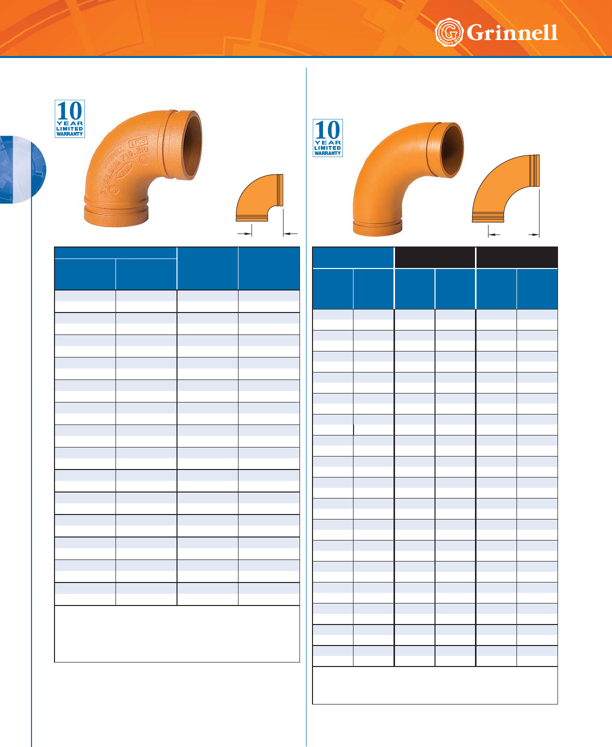
GROOVED FITTINGS
GROOVED FITTINGS
38 www.grinnell.com
Pipe Size C to E
Inches
mm
Approx.
Weight
Lbs.
kg
Nominal
Inches
mm
O.D.
Inches
mm
11⁄41.660 2.75 1.0
32 42,4 69,9 0,5
11⁄21.900 2.75 1.3
40 48,3 69,9 0,6
22.3753.251.8
50 60,3 82,6 0,8
21⁄22.875 3.75 3.1
65 73,0 95,3 1,4
76,1mm 3.000 3.75 3.2
65 76,1 95,3 1,5
3 3.500 4.25 4.8
80 88,9 108,0 2,2
4 4.500 5.00 7.5
100 114,3 127,0 3,4
139,7mm 5.500 5.50 11.3
125 139,7 139,7 5,1
55.5635.5011.6
125 141,3 139,7 5,3
165,1mm 6.500 6.50 16.9
150 165,1 165,1 7,7
6 6.625 6.50 16.6
150 168,3 165,1 7,5
8 8.625 7.75 29.6
200 ◗219,1 196,9 13,4
10 10.750 9.00 48.5
250 ◗273,0 228,6 22,0
12 12.750 10.00 66.4
300 ◗323,9 254,0 30,1
◗ Sizes are available to JIS standards. Contact GRINNELL Mechanical
Products for details.
For information on larger sizes, European sizes or other alternative
sizes, contact GRINNELL Mechanical Products.
See page 37 for fitting specifications.
C to E
Pipe Size Figure 210LR -
Cast
Figure 310LR -
Fabricated
Nominal
Inches
mm
O.D.
Inches
mm
C to E
Inches
mm
Approx.
Weight
Lbs.
kg
C to E
Inches
mm
Approx.
Weight
Lbs.
kg
22.3754.382.4 – –
50 60,3 111,3 1,1 – –
21⁄22.875 5.00 5.1 – –
65 73,0 127,0 2,3 – –
76,1mm 3.000 5.00 4.4 – –
65 76,1 127,0 2,0 – –
3 3.500 5.88 6.6 – –
80 88,9 149,4 3,0 – –
44.5007.5011.6 – –
100 114,3 190,5 5,3 – –
139,7mm 5.500 9.50 19.0 – –
125 139,7 241,3 8,6 – –
5 5.563 9.50 20.0 – –
125 141,3 241,3 9,1 – –
165,1mm 6.500 10.75 26.4 – –
150 165,1 273,1 12,0 – –
6 6.625 10.75 29.5 – –
150 168,3 273,1 13,4 – –
88.62514.2562.1 – –
200 219,1 362,0 28,2 – –
10 10.750 – – 18.00 103.7
250 273,0 – – 457, 2 47,0
12 12.750 – – 21.00 147.8
300 323,9 – – 533,4 67,0
14 14.000 21.00 131.0 21.00 155.0
350 355,6 533,4 59,4 533,4 70,3
16 16.000 24.00 180.0 24.00 206.0
400 406,4 609,6 81,6 609,6 93,4
18 18.000 – – 27.00 262.0
450 457,2 – – 685,8 118,8
20 20.000 – – 33.00 324.0
500 508,0 – – 838,2 147,0
24 24.000 – – 36.00 466.0
600 609,6 – – 914,4 211,4
For information on larger sizes, European sizes or other alternative
sizes, contact GRINNELL Mechanical Products.
See page 37 for fitting specifications.
C to E
Figure 310LR
90° Fabricated Elbow
(Shown)
Figure 210 90° Cast Elbows
Tech Data Sheet: G180
Figures 210LR & 310LR
90° Long Radius Elbows
Tech Data Sheet: G180
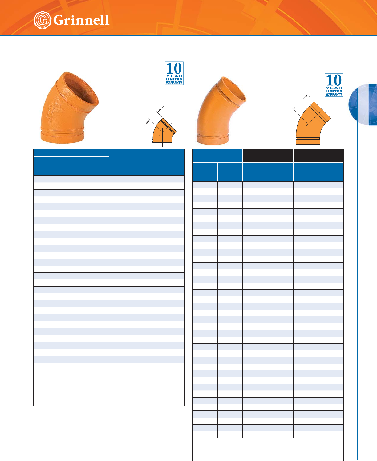
GROOVED FITTINGS
GROOVED FITTINGS
39
Refer to back cover for country-specific customer care numbers.
Pipe Size C to E
Inches
mm
Approx.
Weight
Lbs.
kg
Nominal
Inches
mm
O.D.
Inches
mm
11⁄41.660 1.75 0.8
32 42,4 44,5 0,4
11⁄21.900 1.75 0.9
40 48,3 44,5 0,4
22.3752.001.3
50 60,3 50,8 0,6
21⁄22.875 2.25 2.1
65 73,0 57,2 1,0
76,1mm 3.000 2.25 2.2
65 76,1 57,2 1,0
33.5002.503.5
80 88,9 63,5 1,6
4 4.500 3.00 5.5
100 114,3 76,2 2,5
139,7mm 5.500 3.25 7.7
125 139,7 82,6 3,5
55.5633.258.1
125 141,3 82,6 3,7
165,1mm 6.500 3.50 11.0
150 165,1 88,9 5,0
66.6253.5011.2
150 168,3 88,9 5,1
8 8.625 4.25 19.0
200 ◗219,1 108,0 8,6
10 10.750 4.75 28.0
250 ◗273,0 120,7 12,7
12 12.750 5.25 48.0
300 ◗323,9 133,4 22,0
◗ Sizes are available to JIS standards. Contact GRINNELL Mechanical
Products for details.
For information on larger sizes, European sizes or other alternative
sizes, contact GRINNELL Mechanical Products.
See page 37 for fitting specifications.
C to E
Pipe Size Figure 201LR -
Cast
Figure 301LR -
Fabricated
Nominal
Inches
mm
O.D.
Inches
mm
C to E
Inches
mm
Approx.
Weight
Lbs. kg
C to E
Inches
mm
Approx.
Weight
Lbs. kg
11⁄41.660 – – 2.50 1.1
32 42,4 – – 63,5 0,5
11⁄21.900 – – 2.50 1.3
40 48,3 – – 63,5 0,6
2 2.375 – – 2.75 1.8
50 60,3 – – 69,9 0,8
21⁄22.875 – – 3.00 2.9
65 73,0 – – 76,2 1,3
76,1mm 3.000 – – 3.00 3.1
65 76,1 – – 76,2 1,4
33.500– – 3.384.6
80 88,9 – – 85,9 2,1
4 4.500 – – 4.00 7.5
100 114,3 – – 101,6 3,4
139,7mm 5.500 – – 5.00 12.5
125 139,7 – – 127,0 5,7
5 5.563 – – 5.00 12.5
125 141,3 – – 127,0 5,7
165,1mm 6.500 – – 5.50 12.0
150 165,1 – – 139,7 5,4
6 6.625 – – 5.50 12.0
150 168,3 – – 139,7 5,4
8 8.625 – – 7.25 34.0
200 219,1 – – 184,2 15,4
10 10.750 – – 8.50 56.0
250 273,0 – – 215,9 25,4
12 12.750 – – 10.00 98.0
300 323,9 – – 254,0 44,5
14 14.000 8.75 60.0 – –
350 355,6 228,3 27,2 – –
16 16.000 10.00 97.0 – –
400 406,4 254,0 44,0 – –
18 18.000 – – 11.25 145.0
450 457,2 – – 285,8 65,8
20 20.000 – – 12.50 180.0
500 508,0 – – 317,5 81,6
24 24.000 – – 15.00 250.0
600 609,6 – – 381,0 133,4
For information on larger sizes, European sizes or other alternative
sizes, contact GRINNELL Mechanical Products.
See page 37 for fitting specifications.
C to E
Figure 201 45° Cast Elbows
Tech Data Sheet: G180
Figures 201LR & 301LR
45° Long Radius Elbows
Tech Data Sheet: G180
Figure 301LR
45° Fabricated Elbow
(Shown)
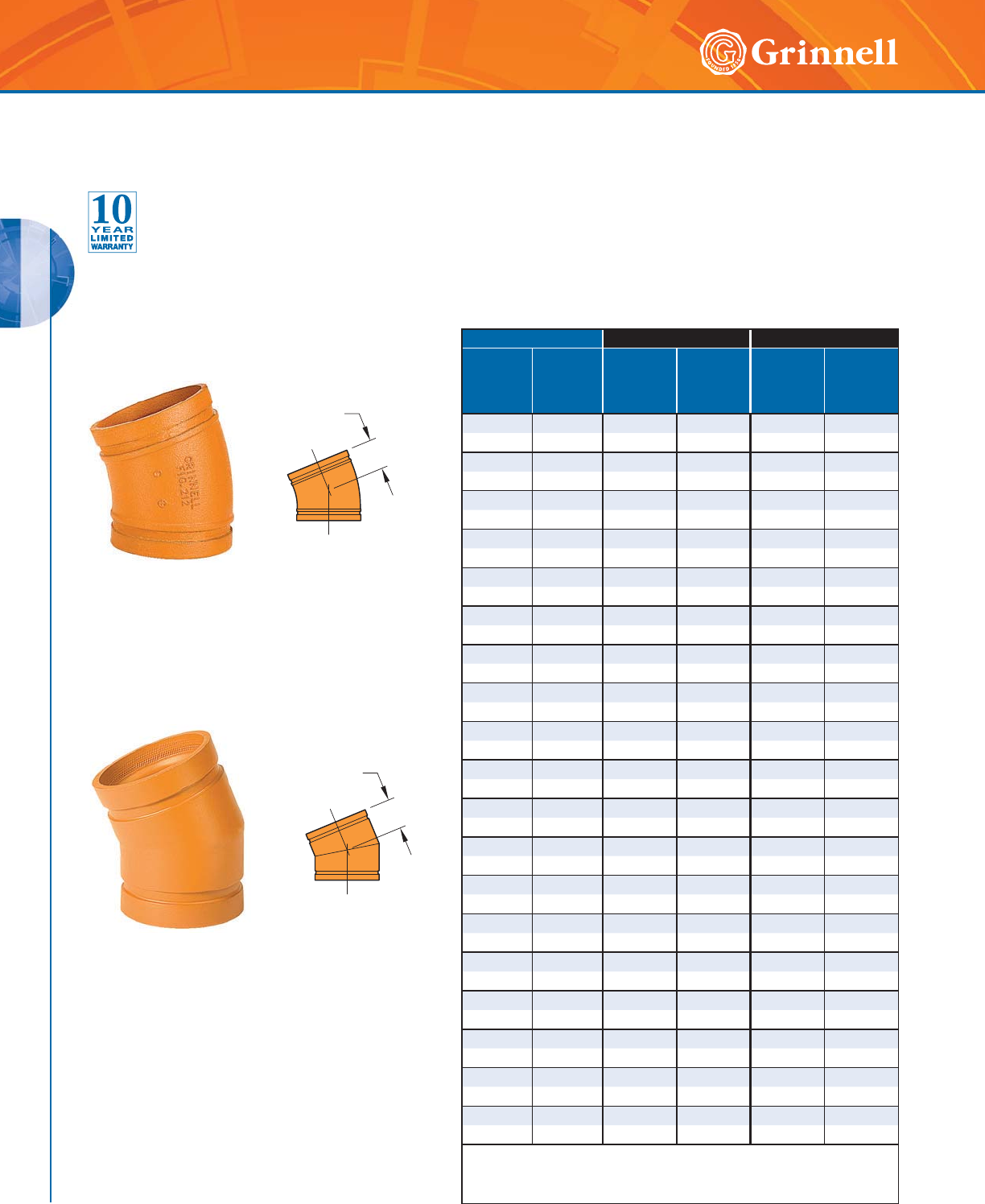
GROOVED FITTINGS
GROOVED FITTINGS
40 www.grinnell.com
Figure 312
221⁄2° Fabricated Elbow
Figure 212
221⁄2° Cast Elbow
Pipe Size Figure 212 - Cast Figure 312 - Fabricated
Nominal
Inches
mm
O.D.
Inches
mm
C to E
Inches
mm
Approx.
Weight
Lbs.
kg
C to E
Inches
mm
Approx.
Weight
Lbs.
kg
11⁄41.660 1.75 0.8 – –
32 42,4 44,5 0,4 – –
11⁄21.900 1.75 1.0 – –
40 48,3 44,5 0,5 – –
2 2.375 1.88 1.3 – –
50 60,3 47,8 0,6 – –
21⁄22.875 2.00 1.9 – –
65 73,0 50,8 0,9 – –
76,1mm 3.000 2.00 2.0 – –
65 76,1 50,8 0,9 – –
3 3.500 2.25 2.9 – –
80 88,9 57,2 1,3 – –
44.5002.63 4.7 – –
100 114,3 66,8 2,1 – –
139,7mm 5.500 2.88 6.9 – –
125 139,7 73,2 3,1 – –
55.5632.88 6.9 – –
125 141,3 73,2 3,1 – –
165,1mm 6.500 – – 3.13 9.4
150 165,1 – – 79,5 4,3
6 6.625 3.13 9.4 – –
150 168,3 79,5 4,3 – –
88.6253.8816.9 – –
200 219,1 98,6 7,7 – –
10 10.750 – – 4.38 14.0
250 273,0 – – 111,3 6,4
12 12.750 – – 4.88 22.0
300 323,9 – – 124,0 10,0
14 14.000 – – 5.00 46.0
350 355,6 – – 127,0 20,9
16 16.000 – – 5.00 52.2
400 406,4 – – 127,0 23,7
18 18.000 – – 5.50 65.0
450 457,2 – – 139,7 29,5
20 20.000 – – 6.00 80.0
500 508,0 – – 152,4 36,3
24 24.000 – – 7.00 112.0
600 609,6 – – 177,8 50,8
For information on larger sizes, European sizes or other alternative sizes,
contact GRINNELL Mechanical Products.
See page 37 for fitting specifications.
C to E
C to E
Figures 212 & 312
221⁄2° Elbows
Tech Data Sheet: G180
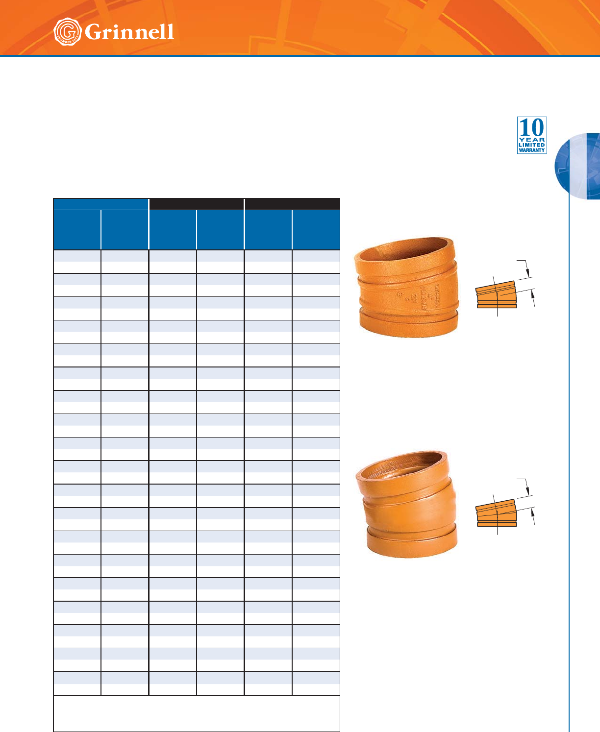
GROOVED FITTINGS
GROOVED FITTINGS
41
Refer to back cover for country-specific customer care numbers.
Figure 311
111⁄4° Fabricated Elbow
Figure 211
111⁄4° Cast Elbow
Pipe Size Figure 211 - Cast Figure 311 - Fabricated
Nominal
Inches
mm
O.D.
Inches
mm
C to E
Inches
mm
Approx.
Weight
Lbs.
kg
C to E
Inches
mm
Approx.
Weight
Lbs.
kg
11⁄41.660 1.38 0.7 – –
32 42,4 35,1 0,3 – –
11⁄21.900 1.38 0.8 – –
40 48,3 35,1 0,4 – –
2 2.375 1.38 1.1 – –
50 60,3 35,1 0,5 – –
21⁄22.875 1.50 1.6 – –
65 73,0 38,1 0,7 – –
76,1mm 3.000 1.50 1.7 – –
65 76,1 3 8,1 0,7 – –
33.5001.502.2 – –
80 88,9 38,1 1,0 – –
44.5001.753.4 – –
100 114,3 44,5 1,5 – –
139,7mm 5.500 2.00 5.1 – –
125 139,7 50,8 2,3 – –
55.5632.005.2 – –
125 141,3 50,8 2,4 – –
165,1mm 6.500 2.00 6.4 – –
150 165,1 50,8 2,9 – –
66.6252.006.5 – –
150 168,3 50,8 2,9 – –
8 8.625 2.00 9.2 – –
200 219,1 50,8 4,2 – –
10 10.750 – – 2.13 9.1
250 273,0 – – 54,1 4,1
12 12.750 – – 2.25 16.7
300 323,9 – – 57,2 7,6
14 14.000 – – 3.50 32.1
350 355,6 – – 88,9 14,6
16 16.000 – – 4.00 42.0
400 406,4 – – 101,6 19,1
18 18.000 – – 4.50 53.2
450 457,2 – – 114,3 24,2
20 20.000 – – 5.00 65.7
500 508,0 – – 127,0 29,8
24 24.000 – – 6.00 96.0
600 609,6 – – 152,4 43,5
For information on larger sizes, European sizes or other alternative sizes, contact
GRINNELL Mechanical Products.
See page 37 for fitting specifications.
C to E
C to E
Figures 211 & 311
111⁄4° Elbows
Tech Data Sheet: G180
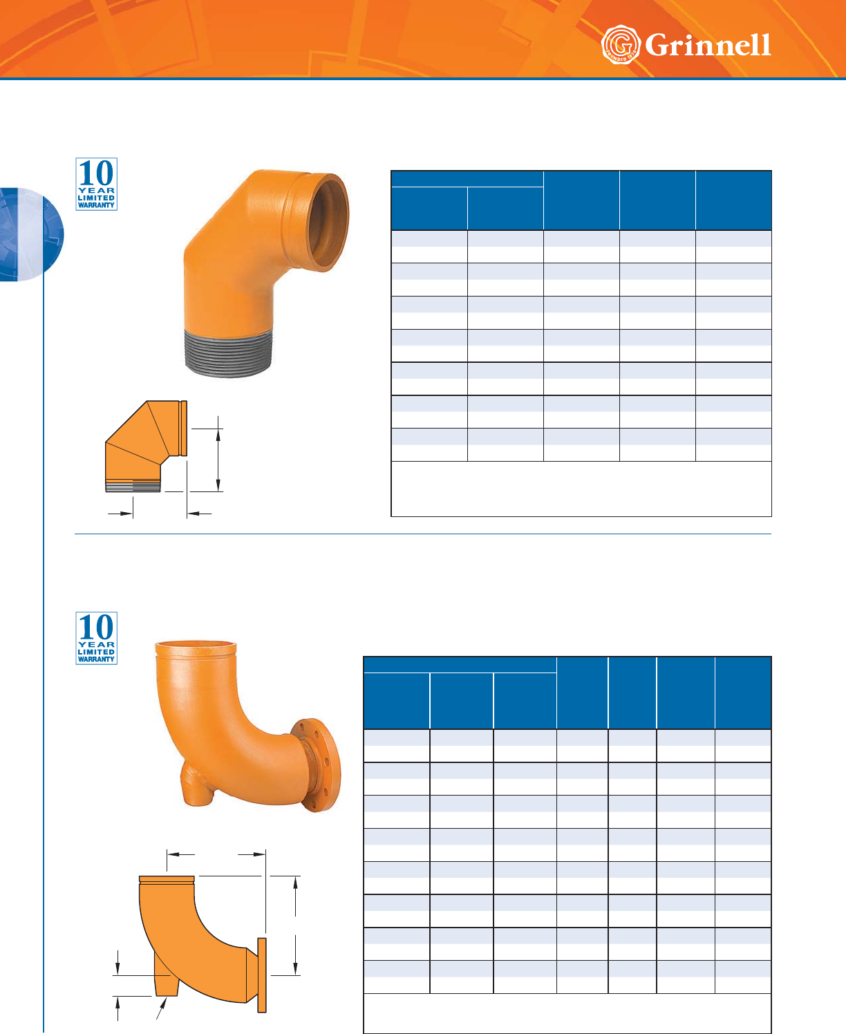
GROOVED FITTINGS
GROOVED FITTINGS
42 www.grinnell.com
Pipe Size C to GE
Inches
mm
C to TE
Inches
mm
Approx.
Weight
Lbs.
kg
Nominal
Inches
mm
O.D.
Inches
mm
11⁄41.660 2.75 2.75 0.9
32 42,4 69,9 69,9 0,4
11⁄21.900 2.75 2.75 1.2
40 48,3 69,9 69,9 0,5
2 2.375 3.25 4.25 2.0
50 60,3 82,6 108,0 0,9
21⁄22.875 3.75 3.75 3.1
60 73,0 95,3 95,3 1,4
3 3.500 4.25 6.00 5.7
80 88,9 108,0 152,4 2,6
4 4.500 5.00 7.25 9.8
100 114,3 127,0 184,2 4,4
6 6.625 6.50 6.50 17.6
150 168,3 165,1 165,1 8,0
Note: Available with BSP and NPT type threads.
For information on larger sizes, contact GRINNELL Mechanical Products.
See page 37 for fitting specifications.
C to TE
C to GE
C to E
B
H
C to E
Figure 315 90° Elbows
(Groove x Male Thread)
Tech Data Sheet: G180
Figure 316 Reducing Base Support Elbow
(Groove x Flange)
Tech Data Sheet: G180
Pipe Size
C to E
Inches
mm
H
Inches
mm
B Dia.
NPSC
Threaded
Inches
mm
Approx.
Wt. Ea.
Lbs
Kg
Nominal
Inches
mm
Grooved End
O.D.
Inches
mm
Flanged End
O.D.
Inches
mm
6 x 4 6.625 4.500 12.0 2.5 1.5 38.5
150 x 100 168,3 114,3 304,8 63,5 38,1 17,5
6 x 5 6.625 5.563 12.5 2.5 1.5 45.4
150 x 125 168,3 141,3 317,5 63,5 38,1 20,6
8 x 5 8.625 5.563 15.5 3.0 1.5 65.5
200 x 125 219,1 141,3 393,7 76,2 38,1 29,7
8 x 6 8.625 6.625 15.5 3.0 1.5 73.0
20 0 x 150 219,1 168,3 393,7 76, 2 38,1 3 3 ,1
10 x 6 10.750 6.625 18.5 3.5 1.5 100.0
250 x 150 273,1 168,3 469,9 88,9 38,1 45,4
10 x 8 10.750 8.625 19.0 3.5 1.5 126.5
250 x 200 273,1 219,1 482,6 88,9 38,1 57,4
12 x 8 12.750 8.625 22.0 4.0 1.5 155.0
300 x 200 323,9 219,1 558,8 101,6 38,1 70,3
12 x 10 12.750 10.750 22.0 4.0 1.5 186.0
300 x 250 323,9 273,1 558,8 101,6 38,1 84,4
For information on larger sizes, contact GRINNELL Mechanical Products.
See page 37 for fitting specifications.
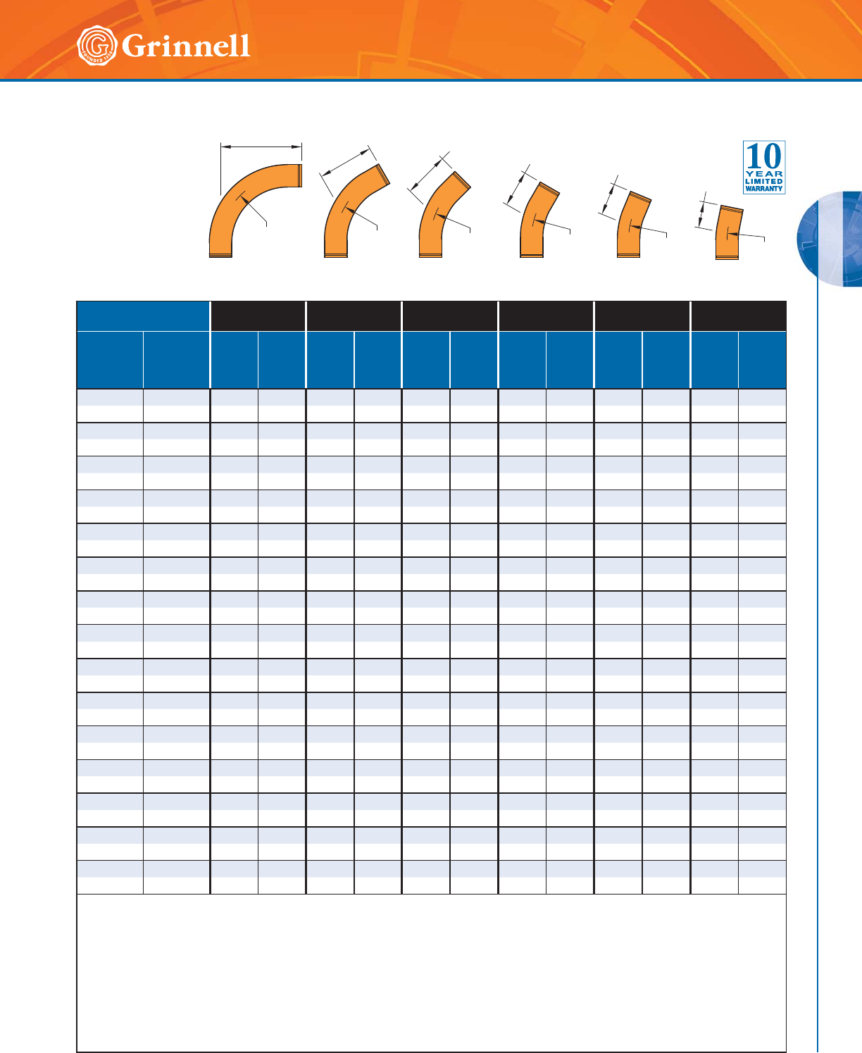
GROOVED FITTINGS
GROOVED FITTINGS
43
Refer to back cover for country-specific customer care numbers.
Pipe Size 310-3D
90° Elbow
306-3D
60° Elbow
301-3D
45° Elbow
303-3D
30° Elbow
312-3D
221⁄2° Elbow
311-3D
111⁄4° Elbow
Nominal
Inches
mm
O.D.
Inches
mm
C to E
Inches
mm
Approx
Weight
Lbs
Kg
C to E
Inches
mm
Approx
Weight
Lbs
Kg
C to E
Inches
mm
Approx
Weight
Lbs
Kg
C to E
Inches
mm
Approx
Weight
Lbs
Kg
C to E
Inches
mm
Approx
Weight
Lbs
Kg
C to E
Inches
mm
Approx
Weight
Lbs
Kg
22.375105.37
1⁄24.7 61⁄24.2 53⁄43.8 51⁄43.5 41⁄22.9
50 60,3 254 2,4 191 2,1 165 1,9 146 1,7 133 1,6 114 1,3
21⁄22.875 111⁄29.5 81⁄48.2 71⁄47.6 6 6.4 51⁄25.8 43⁄44.9
65 73,0 292 4,3 210 3,7 184 3,4 152 2,9 140 2,6 121 2,2
33.5001314.79
1⁄412.6 73⁄411.2 61⁄29.7 53⁄48.5 5 7.3
80 88,9 330 6,7 235 5,7 197 5,1 165 4,4 146 3,9 127 3,3
31⁄24.000 141⁄218.6 10 14.4 81⁄212.3 63⁄410.2 6 9.2 5 7.6
90 101,6 368 8,4 254 6,5 216 5,6 171 4,6 152 4,2 127 3,4
44.5001624.11120.4917.87
1⁄414.8 61⁄213.4 51⁄410.5
100 114,3 406 10,9 279 9,3 229 8,1 184 6,7 165 6,1 133 4,8
55.5632040.913
3⁄434.5 111⁄430.1924.9822.26
1⁄217.6
125 141,3 508 18,6 349 15,7 286 13,7 229 11,3 203 10,1 165 8
66.6252463.716
1⁄253.7 131⁄246.9 103⁄438.6 91⁄234.2 73⁄427.1
150 168,3 610 28,9 419 24,4 343 21,3 273 17,5 241 15,5 197 12,3
8 8.625 32 128.0 22 108.0 18 94.3 141⁄278.7 123⁄469.3 101⁄255.7
200 219,1 813 58,1 559 49,0 457 42,8 368 35,7 324 31,4 267 25,3
10 10.750 40 226.5 271⁄4189.4 221⁄2166.9 18 138.2 16 123.2 13 97.3
250 273,1 1016 102,8 692 85,9 572 75,7 457 62,7 406 55,9 330 44,1
12 12.750 48 332.9 323⁄4278.8 27 245.3 213⁄4204.7 191⁄4181.6 151⁄2141.8
300 323,9 1219 151 832 126,5 686 111,3 552 92,9 489 82,4 394 64,3
14 14.000 56 427.6 381⁄4358.5 311⁄2315.0 251⁄4261.4 221⁄2233.7 181⁄4184.4
350 355,6 1422 194 972 162,6 800 142,9 641 118,6 572 106 464 83,6
16 16.000 64 560.3 433⁄4470.1 36 412.8 29 334.5 251⁄2303.2 203⁄4239.9
4 0 0 40 6 , 4 16 2 6 2 54 ,1 1111 213 , 2 914 187, 2 73 7 151,7 6 48 137,5 5 27 10 8 ,8
18 18.000 72 710.7 491⁄4596.9 401⁄2523.7 321⁄2435.1 283⁄4385.7 23.35 304.5
450 457,2 1829 322,4 1251 270,7 1029 237,5 826 197,4 730 175 593 138,1
20 20.000 80 879.3 543⁄4738.7 45 647.8 36 536.4 32 478.1 26 377.7
500 508,0 2032 398,8 1391 335,1 1143 293,8 914 243,3 813 216,9 660 171,3
24 24.000 96 1270.3 651⁄21,063.6 533⁄4931.0 431⁄4775.7 381⁄4687.2 31 540.9
600 609,6 2438 576,2 1664 482,4 1365 422,3 1099 351,9 972 311,8 787 245,3
Long radius Elbows 3D, 5D, and 6D, in sizes up to and including 4" (100mm), are provided with 4" (100mm) long integral tangent.
Remaining sizes provided with integral tangents with lengths equal to nominal pipe size.
Grooved or plain-end available; specify choice on order.
Material is standard wall steel pipe to ASTM A 53, Grade B. (Other materials available on request).
Elbow bends to conform to above radii.
C to E tolerances: 2" - 6" (50mm - 150mm) ± 1⁄8" (3,2 mm); 8" - 16" (200mm - 400mm) ± 1⁄4" (6,4 mm);
18" - 24" (450mm - 600mm) ± 3⁄8" (9,5mm).
All weights are approximate, based on calculated weight of pipe.
For information on larger sizes, contact GRINNELL Mechanical Products.
See page 37 for fitting specifications.
Figure 301-3D
(45°)
C to E
R = 3D
Figure 303-3D
(30°)
C to E
R = 3D
Figure 306-3D
(60°)
C to E
R = 3D
Figure 310-3D
(90°)
C to E
R = 3D
C to E
R = 3D
Figure 312-3D
(22.5°)
Figure 311-3D
(11.25°)
R = 3D
C to E
Long Radius 3D Elbows
Tech Data Sheet: G180
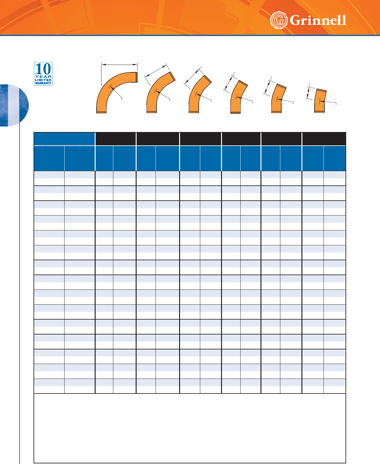
GROOVED FITTINGS
GROOVED FITTINGS
44 www.grinnell.com
Pipe Size 310-5D
90° Elbow
306-5D
60° Elbow
301-5D
45° Elbow
303-5D
30° Elbow
312-5D
221⁄2° Elbow
311-5D
111⁄4° Elbow
Nominal
Inches
mm
O.D.
Inches
mm
C to E
Inches
mm
Approx
Weight
Lbs
Kg
C to E
Inches
mm
Approx
Weight
Lbs
Kg
C to E
Inches
mm
Approx
Weight
Lbs
Kg
C to E
Inches
mm
Approx
Weight
Lbs
Kg
C to E
Inches
mm
Approx
Weight
Lbs
Kg
C to E
Inches
mm
Approx
Weight
Lbs
Kg
22.375147.29
3⁄46.1 81⁄45.5 63⁄44.6 6 4.1 5 3.3
50 60,3 356 3,3 248 2,8 210 2,5 171 2,1 152 1,9 127 1,5
21⁄22.875 161⁄213.3 111⁄411.2 91⁄49.8 71⁄28.3 61⁄27.2 51⁄45.6
65 73,0 419 6 286 5,1 235 4,4 191 3,8 165 3,3 133 2,5
33.5001921.012
3⁄417.5 101⁄415.1 8 12.3 7 10.8 51⁄28.3
80 88,9 483 9,5 324 7,9 260 6,8 203 5,6 178 4,9 140 3,8
31⁄24.000 211⁄226.9 121⁄420.0 111⁄416.5 83⁄413.0 71⁄211.3 53⁄48.7
90 101,6 546 12,2 311 9,1 286 7,5 222 5,9 191 5,1 146 3,9
4 4.500 24 35.4 151⁄228.9 121⁄225.4 91⁄220.1 8 17.1 6 12.5
100 114,3 610 16,1 394 13,1 318 11,5 241 9,1 203 7,8 152 5,7
55.563306019
1⁄249.2 151⁄242.3 113⁄433.7 10 28.9 71⁄221.2
125 141,3 762 27,2 495 22,3 394 19,2 298 15,3 254 13,1 191 9,6
66.6253693.523
1⁄476.1 181⁄265.5 14 52.7 12 45.0 9 32.9
150 168,3 914 42,4 591 34,5 470 29,7 356 23,9 305 20,4 229 14,9
88.62548187.931152.924
1⁄2130.8 183⁄4105.2 16 90.5 12 66.2
200 219,1 1219 85,2 787 69,4 622 59,3 476 47,7 406 41,1 305 30
10 10.750 60 332.6 39 272.5 303⁄4232.5 231⁄2186.8 20 160.3 15 117.2
250 273,1 1524 150,9 991 123,6 781 105,5 597 84,7 508 72,7 381 53,2
12 12.750 72 488.8 463⁄4400.0 37 342.7 28 272.3 24 235.5 18 172.2
300 323,9 1829 221,7 1187 181,4 940 155,4 711 123,5 610 106,8 457 78,1
14 14.000 84 627.7 541⁄2513.3 43 438.3 323⁄4350.7 28 302.5 21 221.2
350 355,6 2134 284,7 1384 232,8 1092 198,8 832 159,1 711 137,2 533 100,3
16 16.000 96 822.5 621⁄4672.2 491⁄4575.6 371⁄2460.6 32 396.4 24 289.8
400 406,4 2438 373,1 1581 304,9 1251 261,1 953 208,9 813 179,8 610 131,5
18 18.000 108 1,043.5 70 852.5 551⁄4728.2 421⁄4585.3 36 506.9 27 367.8
450 457,2 2743 473,3 1778 386,7 1403 330,3 1073 265,5 914 229,9 686 166,8
20 20.000 120 1,290.9 773⁄41,054.2 611⁄2902.5 463⁄4720.7 40 622.1 30 454.9
500 508,0 3048 585,5 1975 478,2 1562 409,4 1187 326,9 1016 282,2 762 206,3
24 24.000 144 1,864.4 931⁄41,521.8 733⁄41,302.5 561⁄41,044.0 48 898.5 353⁄4651.2
600 609,6 3658 845,7 2369 690,3 1873 590,8 1429 473,6 1219 407,6 908 295,4
Long radius Elbows 3D, 5D, and 6D, in sizes up to and including 4" (100mm), are provided with 4" (100mm) long integral tangent.
Remaining sizes provided with integral tangents with lengths equal to nominal pipe size.
Grooved or plain-end available; specify choice on order.
Material is standard wall steel pipe to ASTM A 53, Grade B. (Other materials available on request).
Elbow bends to conform to above radii.
C to E tolerances: 2" - 6" (50mm - 150mm) ± 1⁄8" (3,2 mm); 8" - 16" (200mm - 400mm) ± 1⁄4" (6,4 mm);
18" - 24" (450mm - 600mm) ± 3⁄8" (9,5mm).
All weights are approximate, based on calculated weight of pipe.
For information on larger sizes, contact GRINNELL Mechanical Products.
See page 37 for fitting specifications.
Figure 301-5D
(45°)
C to E
R = 5
D
Figure 303-5D
(30°)
C to E
R = 5D
Figure 306-5D
(60°)
C to E
R = 5D
Figure 310-5D
(90°)
C to E
R = 5D
C to E
R = 5D
Figure 312-5D
(22.5°)
Figure 311-5D
(11.25°)
R = 5D
C to E
Long Radius 5D Elbows
Tech Data Sheet: G180
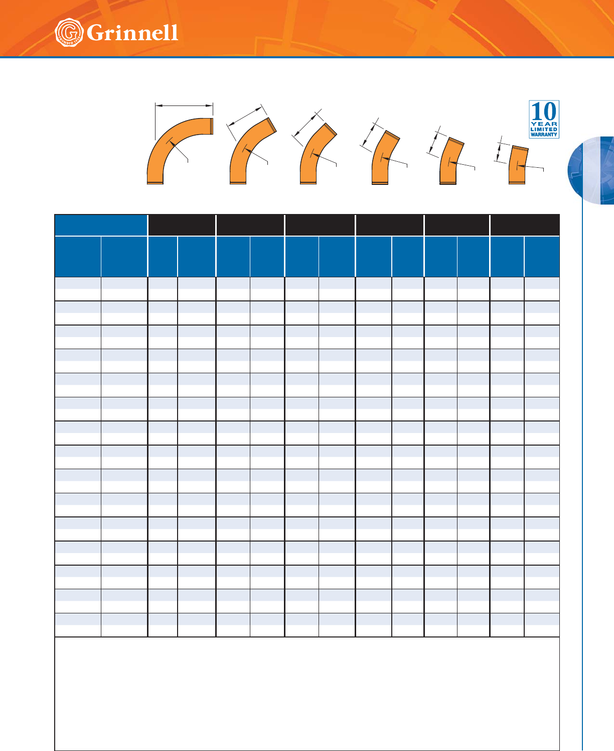
GROOVED FITTINGS
GROOVED FITTINGS
45
Refer to back cover for country-specific customer care numbers.
Pipe Size 310-6D
90° Elbow
306-6D
60° Elbow
301-6D
45° Elbow
303-6D
30° Elbow
312-6D
221⁄2° Elbow
311-6D
111⁄4° Elbow
Nominal
Inches
mm
O.D.
Inches
mm
C to E
Inches
mm
Approx
Weight
Lbs
Kg
C to E
Inches
mm
Approx
Weight
Lbs
Kg
C to E
Inches
mm
Approx
Weight
Lbs
Kg
C to E
Inches
mm
Approx
Weight
Lbs
Kg
C to E
Inches
mm
Approx
Weight
Lbs
Kg
C to E
Inches
mm
Approx
Weight
Lbs
Kg
22.375168.2116.996.07
1⁄45.0 61⁄24.5 51⁄43.6
50 60,3 406 3,7 279 3,1 229 2,7 184 2,3 165 2 133 1,6
21⁄22.875 19 13.0 123⁄412.7 101⁄411.0 8 8.9 7 7.8 51⁄26.0
65 73,0 483 5,9 324 5,8 260 5 203 4 178 3,5 140 2,7
33.5002224.114
1⁄219.9 111⁄217.1 83⁄413.6 71⁄211.7 53⁄48.7
80 88,9 559 10,9 368 9,0 292 7,8 222 6,2 191 5,3 146 3,9
31⁄24.000 25 31.1 161⁄422.8 123⁄418.6 93⁄414.4 81⁄412.3 6 9.2
90 101,6 635 14,1 413 10,3 324 8,4 248 6,5 210 5,6 152 4,2
4 4.500 28 41.1 18 33.6 14 28.4 101⁄222.5 83⁄418.9 61⁄213.8
100 114,3 711 18,6 457 15,2 356 12,9 267 10,2 222 8,6 165 6,3
5 5.563 35 69.6 221⁄456.2 171⁄248.1 13 37.7 11 32.3 8 22.9
125 141,3 889 31,6 565 25,5 445 21,8 330 17,1 279 14,7 203 10,4
66.62542108.426
3⁄487.7 21 74.8 153⁄459.3 131⁄450.5 91⁄235.3
150 168,3 1067 49,2 679 39,8 533 33,9 400 26,9 337 22,9 241 16
88.62556217.835
3⁄4176.7 28 150.4 21 119.2 171⁄2100.4 123⁄471.5
200 219,1 1422 98,8 908 80,1 711 68,2 533 54,1 445 45,5 324 32,4
10 10.750 70 385.6 443⁄4313.1 35 266.3 26 208.9 22 178.8 16 127.1
250 273,1 1778 174,9 1137 142 889 120,8 660 94,8 559 81,1 406 57,7
12 12.750 84 566.7 531⁄2458.5 413⁄4388.9 311⁄4307.5 261⁄4261.1 19 184.4
300 323,9 2134 257,1 1359 208 1060 176,4 794 139,5 667 118,4 483 83,6
14 14.000 98 727.8 621⁄2589.6 483⁄4499.9 361⁄2395.4 303⁄4336.9 221⁄4238.0
350 355,6 2489 330,1 1588 267,4 1238 226,8 927 179,4 781 152,8 565 108
16 16.000 112 953.6 711⁄2773.3 553⁄4655.5 413⁄4518.6 351⁄4443.0 251⁄2312.9
400 406,4 2845 432,5 1816 350,8 1416 297,3 1060 235,2 895 200,9 648 141,9
18 18.000 126 1,209.9 801⁄2981.9 623⁄4832.7 47 658.5 391⁄2559.5 283⁄4398.7
450 457,2 3200 548,8 2045 445,4 1594 377,7 1194 298,7 1003 253,8 730 180,8
20 20.000 140 1,496.6 891⁄41,212.0 693⁄41,029.8 521⁄4815.0 44 694.1 313⁄4488.7
500 508,0 3556 678,8 2267 549,8 1772 467,1 1327 369,7 1118 314,8 806 221,7
24 24.000 168 2,161.6 1071⁄41,752.9 833⁄41,488.2 621⁄21,173.0 52.34 992.5 381⁄4709.3
600 609,6 4267 980,5 2724 795,1 2127 675 1588 532,1 1329 450,2 972 321,7
Long radius Elbows 3D, 5D, and 6D, in sizes up to and including 4" (100mm), are provided with 4" (100mm) long integral tangent.
Remaining sizes provided with integral tangents with lengths equal to nominal pipe size.
Grooved or plain-end available; specify choice on order.
Material is standard wall steel pipe to ASTM A 53, Grade B. (Other materials available on request).
Elbow bends to conform to above radii.
C to E tolerances: 2" - 6" (50mm - 150mm) ± 1⁄8" (3,2 mm); 8" - 16" (200mm - 400mm) ± 1⁄4" (6,4 mm);
18" - 24" (450mm - 600mm) ± 3⁄8" (9,5mm).
All weights are approximate, based on calculated weight of pipe.
For information on larger sizes, contact GRINNELL Mechanical Products.
See page 37 for fitting specifications.
Figure 301-6D
(45°)
C to E
R = 6D
Figure 303-6D
(30°)
C to E
R = 6D
Figure 306-6D
(60°)
C to E
R = 6D
Figure 310-6D
(90°)
C to E
R = 6D
C to E
R = 6D
Figure 312-6D
(22.5°)
Figure 311-6D
(11.25°)
R = 6D
C to E
Long Radius 6D Elbows
Tech Data Sheet: G180
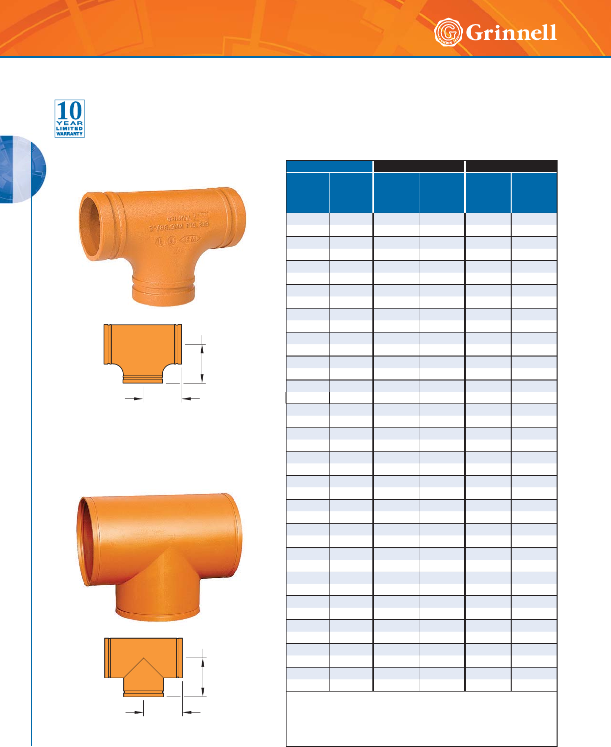
GROOVED FITTINGS
GROOVED FITTINGS
46 www.grinnell.com
Figure 219
Cast Tee
Figure 319
Fabricated Tee
Pipe Size Figure 219 - Cast Figure 319 - Fabricated
Nominal
Inches
mm
O.D.
Inches
mm
C to E
Inches
mm
Approx
Weight
Lbs
Kg
C to E
Inches
mm
Approx
Weight
Lbs
Kg
11⁄41.660 2.75 1.7 – –
32 42,4 69,9 0,8 – –
11⁄21.900 2.75 2.1 – –
40 48,3 69,9 1,0 – –
22.3753.25 2.8 – –
50 60,3 82,6 1,3 – –
21⁄22.875 3.75 4.4 – –
65 73,0 95,3 2,0 – –
76,1mm 3.000 3.75 6.5 – –
65 76,1 95,3 2,9 – –
33.5004.25 6.5 – –
80 88,9 108,0 2,9 – –
4 4.500 5.00 10.7 – –
100 114,3 127,0 4,8 – –
139,7mm 5.500 5.50 15.2 – –
125 139,7 139,7 6,9 – –
5 5.563 5.50 15.5 – –
125 141,3 139,7 7,0 – –
165,1mm 6.500 6.50 24.2 – –
150 165,1 165,1 11,0 – –
6 6.625 6.50 23.0 – –
150 168,3 165,1 10,4 – –
216,3mm 8.500 7.75 43.0 – –
200 216,3 196,9 19,5 – –
88.6257.7543.7 – –
200 ◗219,1 196,9 19,8 – –
10 10.750 9.00 57.0 – –
250 ◗273,0 228,6 25,9 – –
12 12.750 10.00 110.0 – –
300 ◗323,9 254,0 49,9 – –
14 14.000 11.00 135.0 – –
350 355,6 279,0 61,2 – –
16 16.000 12.00 136.0 – –
400 406,4 305,0 61,7 – –
18 18.000 – – 15.50 218.0
450 457,2 – – 394,0 98,9
20 20.000 – – 17.25 275.0
500 508,0 – – 438,0 125,0
24 24.000 – – 20.00 379.0
600 609,6 – – 508,0 172,0
◗ Sizes are available to JIS standards. Contact GRINNELL Mechanical
Products for details.
For information on larger sizes, European sizes or other alternative sizes,
contact GRINNELL Mechanical Products.
See page 37 for fitting specifications.
C to E
C to E
C to E
C to E
Figures 219 & 319 Tees
Tech Data Sheet: G180
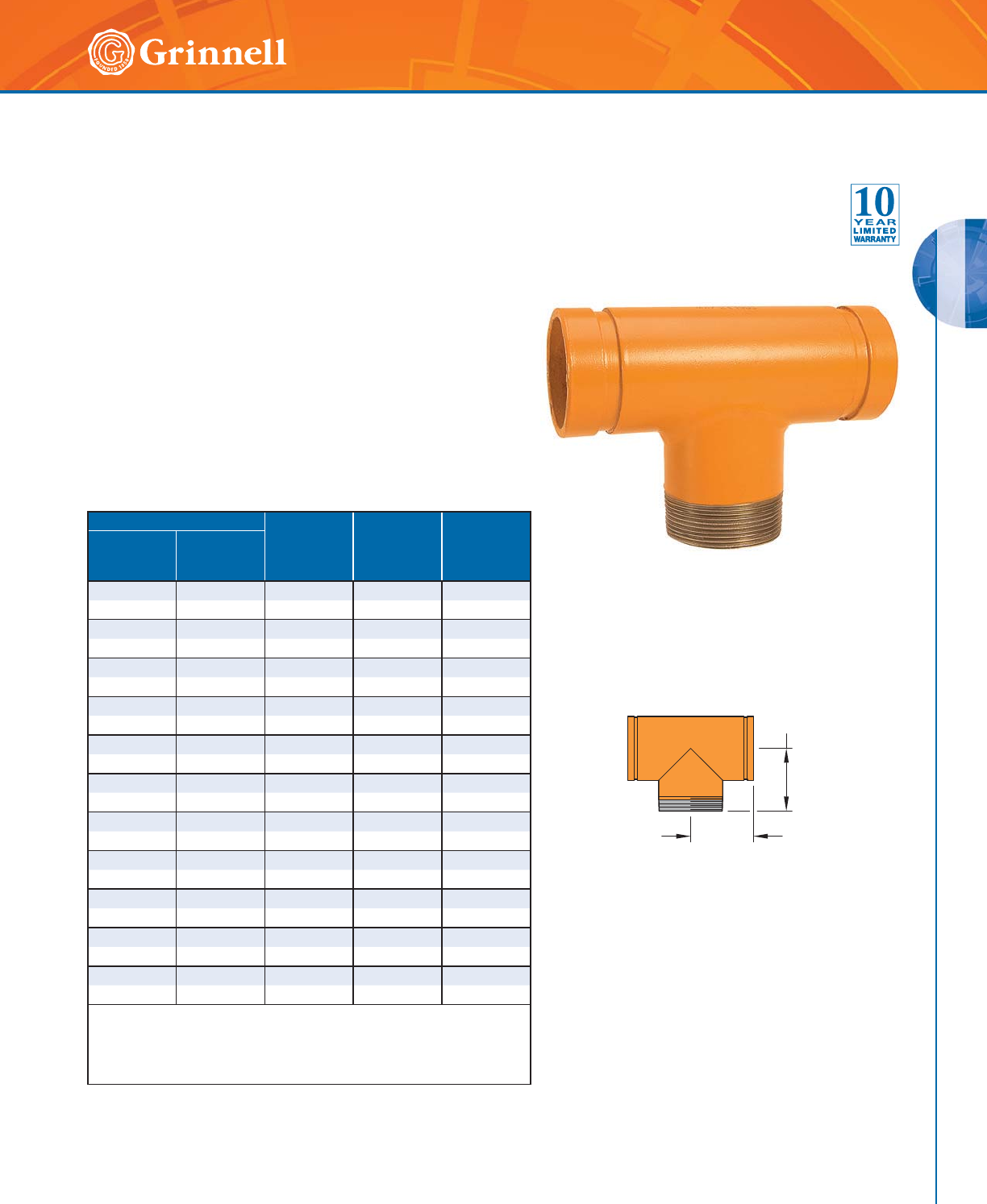
GROOVED FITTINGS
GROOVED FITTINGS
47
Refer to back cover for country-specific customer care numbers.
Pipe Size C to GE
Inches
mm
C to TE
Inches
mm
Approx.
Weight
Lbs
Kg
Nominal
Inches
mm
O.D.
Inches
mm
11⁄41.660 2.75 2.75 1.5
32 42,4 69,9 69,9 0,7
11⁄21.900 2.75 2.75 1.9
40 48,3 69,9 69,9 0,9
2 2.375 3.25 4.25 3.2
50 60,3 82,6 108,0 1,5
21⁄22.875 3.75 3.75 4.0
60 73,0 95,3 95,3 1,8
3 3.500 4.25 6.00 6.0
80 88,9 108,0 152,4 2,7
4 4.500 5.00 7.25 11.0
100 114,3 127,0 184,2 5,0
5 5.563 5.50 5.50 23.0
125 141,3 139,7 139,7 10,5
6 6.625 6.50 6.50 23.0
150 168,3 165,1 165,1 10,5
8 8.625 7.75 7.75 38.7
200 219,1 196,9 196,9 17,6
10 10.750 9.00 9.00 72.1
250 273,0 228,6 228,6 32,8
12 12.750 10.00 10.00 92.5
300 323,9 254,0 254,0 42,0
For information on larger sizes, European sizes or other alternative sizes, contact
GRINNELL Mechanical Products.
Available with BSP threads. Contact GRINNELL Mechanical Products for details.
See page 37 for fitting specifications.
C to TE
C to GE
Figure 320 Tees
(Groove x Groove x Male Thread)
Tech Data Sheet: G180
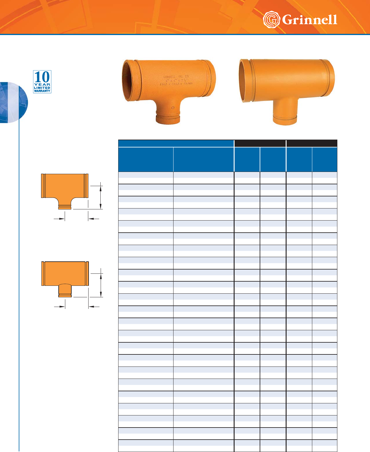
GROOVED FITTINGS
GROOVED FITTINGS
48 www.grinnell.com
Pipe Size Figure 221 - Cast Figure 321 - Fabricated
Nominal
Inches
mm
O.D.
Inches
mm
C to E
Inches
mm
Approx.
Weight
Lbs
Kg
C to E
Inches
mm
Approx.
Weight
Lbs
Kg
11⁄2 x 11⁄2 x 11⁄41.900 x 1.900 x 1.660 – – 2.75 1.5
40 x 40 x 32 48,3 x 48,3 x 42,4 – – 69,9 0,7
2 x 2 x 1 2.375 x 2.375 x 1.315 – – 3.25 1.6
50 x 50 x 25 60,3 x 60,3 x 33,4 – – 88,6 0,74
2 x 2 x 11⁄22.375 x 2.375 x 1.900 3.25 2.7 – –
50 x 50 x 40 60,3 x 60,3 x 48,3 82,6 1,2 – –
21⁄2 x 21⁄2 x 1 2.875 x 2.875 x 1.315 – – 3.75 2.3
65 x 65 x 25 73,0 x 73,0 x 33,4 – – 95,3 1,1
21⁄2 x 21⁄2 x 11⁄42.875 x 2.875 x 1.660 – – 3.75 4.2
65 x 65 x 32 73,0 x 73,0 x 42,4 – – 95,3 1,9
21⁄2 x 21⁄2 x 11⁄22.875 x 2.875 x 1.900 3.75 4.2 – –
65 x 65 x 40 73,0 x 73,0 x 48,3 95,3 1,9 – –
21⁄2 x 21⁄2 x 2 2.875 x 2.875 x 2.375 3.75 4.2 – –
65 x 65 x 50 73,0 x 73,0 x 60,3 95,3 1,9 – –
76,1mm x 76,1mm x 11⁄23.000 x 3.000 x 1.900 3.75 4.5 – –
65 x 65 x 40 76,1 x 76,1 x 48,3 95,3 2,0 – –
76,1mm x 76,1mm x 2 3.000 x 3.000 x 2.375 3.75 4.3 – –
65 x 65 x 50 76,1 x 76,1 x 60,3 95,3 2,0 – –
3 x 3 x 1 3.500 x 3.500 x 1.315 4.25 5.6 – –
80 x 80 x 25 88,9 x 88,9 x 33,4 108,0 2,5 – –
3 x 3 x 11⁄23.500 x 3.500 x 1.900 4.25 5.9 – –
80 x 80 x 40 88,9 x 88,9 x 48,3 108,0 2,7 – –
3 x 3 x 2 3.500 x 3.500 x 2.375 4.25 6.0 – –
80 x 80 x 50 88,9 x 88,9 x 60,3 108,0 2,7 – –
3 x 3 x 21⁄23.500 x 3.500 x 2.875 4.25 6.2 – –
80 x 80 x 65 88,9 x 88,9 x 73,0 108,0 2,8 – –
3 x 3 x 76,1mm 3.500 x 3.500 x 3.000 4.25 6.0 – –
80 x 80 x 65 88,9 x 88,9 x 76,1 108,0 2,7 – –
4 x 4 x 1 4.500 x 4.500 x 1.315 – – 5.00 8.0
100 x 100 x 25 114,3 x 114,3 x 33,4 – – 127,0 3,7
4 x 4 x 11⁄44.500 x 4.500 x 1.660 – – 5.00 9.8
100 x 100 x 32 114,3 x 114,3 x 42,4 – – 127,0 4,4
4 x 4 x 11⁄24.500 x 4.500 x 1.900 – – 5.00 9.9
100 x 100 x 40 114,3 x 114,3 x 48,3 – – 127,0 4,5
4 x 4 x 2 4.500 x 4.500 x 2.375 5.00 9.1 – –
100 x 100 x 50 114,3 x 114,3 x 60,3 127,0 4,1 – –
4 x 4 x 21⁄24.500 x 4.500 x 2.875 5.00 9.5 – –
100 x 100 x 65 114,3 x 114,3 x 73,0 127,0 4,3 – –
4 x 4 x 76,1mm 4.500 x 4.500 x 3.000 5.00 9.5 – –
100 x 100 x 65 114,3 x 114,3 x 76,1 127,0 4,3 – –
4 x 4 x 3 4.500 x 4.500 x 3.500 5.00 9.7 – –
100 x 100 x 80 114,3 x 114,3 x 88,9 127,0 4,4 – –
139,7mm x 139,7mm x 3 5.500 x 5.500 x 3.500 5.50 12.7 – –
125 x 125 x 80 139,7 x 139,7 x 88,9 139,7 5,8 – –
139,7mm x 139,7mm x 4 5.500 x 5.500 x 4.500 5.50 13.4 – –
125 x 125 x 100 139,7 x 139,7 x 114,3 139,7 6,1 – –
Figure 221 Reducing Tee
Cast
Figure 321 Reducing Tee
Fabricated
C to E
C to E
C to E
C to E
Figure 221 Reducing Tee Cast Figure 321 Reducing Tee Fabricated
Figures 221 & 321 Reducing Tees
(Page 1 of 3)
Tech Data Sheet: G180
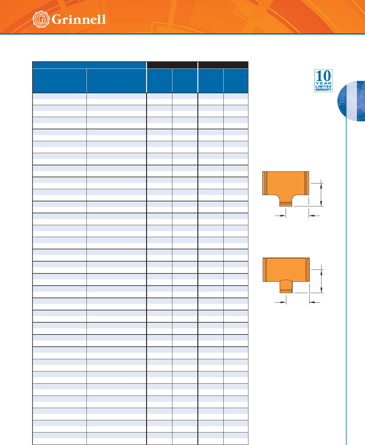
GROOVED FITTINGS
GROOVED FITTINGS
49
Refer to back cover for country-specific customer care numbers.
Figure 221 Reducing Tee
Cast
Figure 321 Reducing Tee
Fabricated
Pipe Size Figure 221 - Cast Figure 321 - Fabricated
Nominal
Inches
mm
O.D.
Inches
mm
C to E
Inches
mm
Approx.
Weight
Lbs
Kg
C to E
Inches
mm
Approx.
Weight
Lbs
Kg
5 x 5 x 2 5.563 x 5.563 x 2.375 – – 5.50 14.5
125 x 125 x 50 141,3 x 141,3 x 60,3 – – 139,7 6,6
5 x 5 x 21⁄25.563 x 5.563 x 2.875 5.50 18.0 – –
125 x 125 x 65 141,3 x 141,3 x 73,0 139,7 8,2 – –
5 x 5 x 3 5.563 x 5.563 x 3.500 5.50 14.0 – –
125 x 125 x 80 141,3 x 141,3 x 88,9 139,7 6,4 – –
5 x 5 x 4 5.563 x 5.563 x 4.500 5.50 13.9 – –
125 x 125 x 100 141,3 x 141,3 x 114,3 139,7 6,3 – –
165,1mm x 165,mm x 3 6.500 x 6.500 x 3.500 6.50 18.0 – –
150 x 150 x 80 165,1 x 165,1 x 88,9 165,1 8,2 – –
165,1mm x 165,mm x 4 6.500 x 6.500 x 4.500 6.50 19.5 – –
150 x 150 x 100 165,1 x 165,1 x 114,3 165,1 8,9 – –
6 x 6 x 2 6.625 x 6.625 x 2.375 6.50 19.4 – –
150 x 150 x 50 168,3 x 168,3 x 60,3 165,1 8,8 – –
6 x 6 x 21⁄26.625 x 6.625 x 2.875 6.50 21.2 – –
150 x 150 x 65 168,3 x 168,3 x 73,0 165,1 9,8 – –
6 x 6 x 76,1mm 6.625 x 6.625 x 3.000 6.50 21.2 – –
150 x 150 x 65 168,3 x 168,3 x 76,1 165,1 9,8 – –
6 x 6 x 3 6.625 x 6.625 x 3.500 6.50 21.0 – –
150 x 150 x 80 168,3 x 168,3 x 88,9 165,1 9,5 – –
6 x 6 x 4 6.625 x 6.625 x 4.500 6.50 21.8 – –
150 x 150 x 100 168,3 x 168,3 x 114,3 165,1 9,9 – –
6 x 6 x 139,7mm 6.625 x 6.625 x 5.500 6.50 23.0 – –
150 x 150 x 125 168,3 x 168,3 x 139,7 165,1 10,4 – –
6 x 6 x 5 6.625 x 6.625 x 5.563 – – 6.50 27.0
150 x 150 x 125 168,3 x 168,3 x 141,3 – – 165,1 12,2
8 x 8 x 2 8.625 x 8.625 x 2.375 – – 7.75 36.2
200 x 200 x 50 ◗219,1 x 219,1 x 60,3 – – 196,9 16,4
8 x 8 x 21⁄28.625 x 8.625 x 2.875 – – 7.75 36.4
200 x 200 x 65 ◗219,1 x 219,1 x 73,0 – – 196,9 16,5
8 x 8 x 3 8.625 x 8.625 x 3.500 – – 7.75 36.5
200 x 200 x 80 ◗219,1 x 219,1 x 88,9 – – 196,9 16,6
8 x 8 x 4 8.625 x 8.625 x 4.500 7.75 37.2 – –
200 x 200 x 100 ◗219,1 x 219,1 x 114,1 196,9 16,9 – –
8 x 8 x 139,7mm 8.625 x 8.625 x 5.500 7.75 37.7 – –
200 x 200 x 125 ◗219,1 x 219,1 x 139,7 196,9 17,1 – –
8 x 8 x 5 8.625 x 8.625 x 5.563 – – 7.75 36.8
200 x 200 x 125 ◗219,1 x 219,1 x 141,3 – – 196,9 16,7
8 x 8 x 165,1mm 8.625 x 8.625 x 6.500 7.75 37.7 – –
200 x 200 x 150 ◗219,1 x 219,1 x 165,1 196,9 17,1 – –
8 x 8 x 6 8.625 x 8.625 x 6.625 7.75 37.4 – –
200 x 200 x 150 ◗219,1 x 219,1 x 168,3 196,9 17,0 – –
10 x 10 x 2 10.750 x 10.750 x 2.375 – – 9.00 57.1
250 x 250 x 50 ◗273,0 x 273,0 x 60,3 – – 228,6 25,9
10 x 10 x 3 10.750 x 10.750 x 3.500 – – 9.00 57.4
250 x 250 x 80 ◗273,0 x 273,0 x 88,9 – – 228,6 26,0
10 x 10 x 4 10.750 x 10.750 x 4.500 – – 9.00 58.0
250 x 250 x 100 ◗273,0 x 273,0 x 114,3 – – 228,6 26,3
10 x 10 x 5 10.750 x 10.750 x 5.563 – – 9.00 57.8
250 x 250 x 125 ◗273,0 x 273,0 x 141,3 – – 228,6 26,2
10 x 10 x 6 10.750 x 10.750 x 6.625 – – 9.00 66.0
250 x 250 x 150 ◗273,0 x 273,0 x 168,3 – – 228,6 27,2
10 x 10 x 8 10.750 x 10.750 x 8.625 – – 9.00 62.0
250 x 250 x 200 ◗273,0 x 273,0 x 219,1 – – 228,6 28,1
12 x 12 x 3 12.750 x 12.750 x 3.500 – – 10.00 80.2
300 x 300 x 80 ◗323,9 x 323,9 x 88,9 – – 254,0 36,4
12 x 12 x 4 12.750 x 12.750 x 4.500 – – 10.00 80.5
300 x 300 x 100 ◗323,9 x 323,9 x 114,3 – – 254,0 36,5
C to E
C to E
C to E
C to E
Figures 221 & 321 Reducing Tees
(Page 2 of 3)
Tech Data Sheet: G180
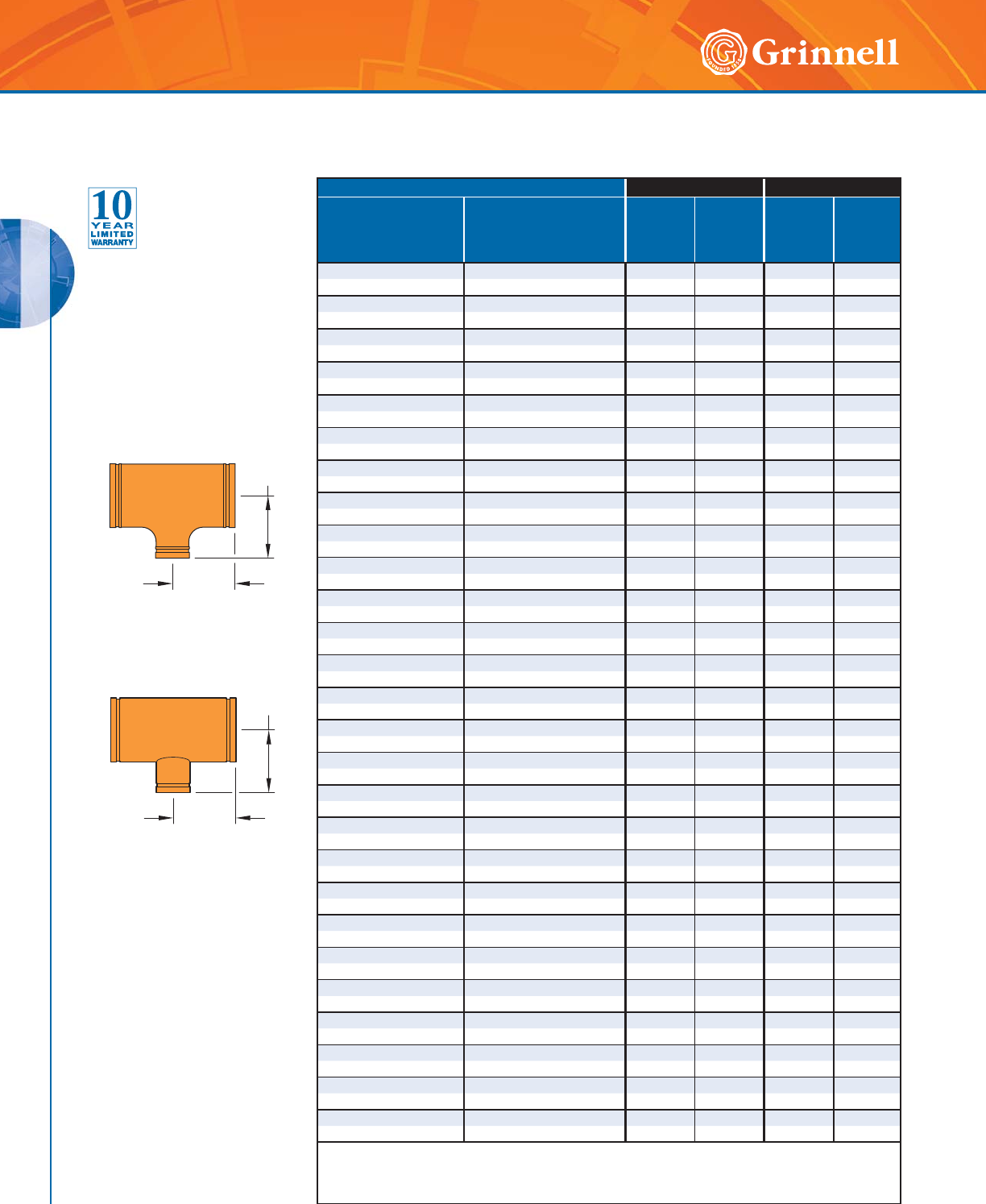
GROOVED FITTINGS
GROOVED FITTINGS
50 www.grinnell.com
Pipe Size Figure 221 - Cast Figure 321 - Fabricated
Nominal
Inches
mm
O.D.
Inches
mm
C to E
Inches
mm
Approx.
Weight
Lbs
Kg
C to E
Inches
mm
Approx.
Weight
Lbs
Kg
12 x 12 x 5 12.750 x 12.750 x 5.563 – – 10.00 80.7
300 x 300 x 125 ◗323,9 x 323,9 x 141,3 – – 254,0 36,6
12 x 12 x 6 12.750 x 12.750 x 6.625 – – 10.00 80.9
300 x 300 x 150 ◗323,9 x 323,9 x 168,3 – – 254,0 36,7
12 x 12 x 8 12.750 x 12.750 x 8.625 – – 10.00 76.3
300 x 300 x 200 ◗323,9 x 323,9 x 219,1 – – 254,0 34,6
12 x 12 x 10 12.750 x 12.750 x 10.750 – – 10.00 77.6
300 x 300 x 250 ◗323,9 x 323,9 x 273,0 – – 254,0 35,2
14 x 14 x 6 14.000 x 14.000 x 6.625 – – 11.00 103.3
350 x 350 x 150 355,6 x 355,6 x 168,3 – – 279,4 46,9
14 x 14 x 8 14.000 x 14.000 x 8.625 – – 11.00 103.4
350 x 350 x 200 355,6 x 355,6 x 219,1 – – 279,4 46,9
14 x 14 x 10 14.000 x 14.000 x 10.750 – – 11.00 104.3
350 x 350 x 250 355,6 x 355,6 x 273,0 – – 279,4 47,3
14 x 14 x 12 14.000 x 14.000 x 12.750 – – 11.00 105.3
350 x 350 x 300 355,6 x 355,6 x 323,9 – – 279,4 47,8
16 x 16 x 4 16.000 x 16.000 x 4.500 – – 12.00 110.7
400 x 400 x 100 406,4 x 406,4 x 114,3 – – 304,8 50,2
16 x 16 x 8 16.000 x 16.000 x 8.625 – – 12.00 128.5
400 x 400 x 200 406,4 x 406,4 x 219,1 – – 304,8 58,3
16 x 16 x 10 16.000 x 16.000 x 10.750 – – 12.00 129.3
400 x 400 x 250 406,4 x 406,4 x 273,0 – – 304,8 58,6
16 x 16 x 12 16.000 x 16.000 x 12.750 – – 12.00 130.2
400 x 400 x 300 406,4 x 406,4 x 323,9 – – 304,8 59,1
16 x 16 x 14 16.000 x 16.000 x 14.000 – – 12.00 140.4
400 x 400 x 350 406,4 x 406,4 x 355,6 – – 304,8 63,7
18 x 18 x 8 18.000 x 18.000 x 8.625 – – 15.50 192.7
450 x 450 x 200 457,2 x 457,2 x 219,1 – – 393,7 87,4
18 x 18 x 10 18.000 x 18.000 x 10.750 – – 15.50 193.6
450 x 450 x 250 457,2 x 457,2 x 273,0 – – 393,7 87,8
18 x 18 x 12 18.000 x 18.000 x 12.750 – – 15.50 196.3
450 x 450 x 300 457,2 x 457,2 x 323,9 – – 393,7 89,0
18 x 18 x 14 18.000 x 18.000 x 14.000 – – 15.50 201.3
450 x 450 x 350 457,2 x 457,2 x 355,6 – – 393,7 91,3
18 x 18 x 16 18.000 x 18.000 x 16.000 – – 15.50 203.2
450 x 450 x 400 457,2 x 457,2 x 406,4 – – 393,7 92,2
20 x 20 x 14 20.000 x 20.000 x 14.000 – – 17.25 247.9
500 x 500 x 350 508,0 x 508,0 x 355,6 – – 450,9 112,4
20 x 20 x 16 20.000 x 20.000 x 16.000 – – 17.25 250.1
500 x 500 x 400 508,0 x 508,0 x 406,4 – – 450,9 113,4
20 x 20 x 18 20.000 x 20.000 x 18.000 – – 17.25 252.2
500 x 500 x 450 508,0 x 508,0 x 457,2 – – 450,9 114,4
24 x 24 x 10 24.000 x 24.000 x 10.750 – – 20.00 330.9
600 x 600 x 250 609,6 x 609,6 x 273,0 – – 508,0 150,1
24 x 24 x 12 24.000 x 24.000 x 12.750 – – 20.00 334.5
600 x 600 x 300 609,6 x 609,6 x 323,9 – – 508,0 151,7
24 x 24 x 14 24.000 x 24.000 x 14.000 – – 20.00 340.3
600 x 600 x 350 609,6 x 609,6 x 355,6 – – 508,0 154,4
24 x 24 x 16 24.000 x 24.000 x 16.000 – – 20.00 342.6
600 x 600 x 400 609,6 x 609,6 x 406,4 – – 508,0 155,4
24 x 24 x 18 24.000 x 24.000 x 18.000 – – 20.00 344.7
600 x 600 x 450 609,6 x 609,6 x 457,2 – – 508,0 156,4
24 x 24 x 20 24.000 x 24.000 x 20.000 – – 20.00 346.8
600 x 600 x 500 609,6 x 609,6 x 508,0 – – 508,0 157,3
◗ Sizes are available to JIS standards. Contact GRINNELL Mechanical Products for details.
For information on larger sizes, contact GRINNELL Mechanical Products.
See page 37 for fitting specifications.
Figures 221 & 321 Reducing Tees
(Page 3 of 3)
Tech Data Sheet: G180
Figure 221 Reducing Tee
Cast
Figure 321 Reducing Tee
Fabricated
C to E
C to E
C to E
C to E
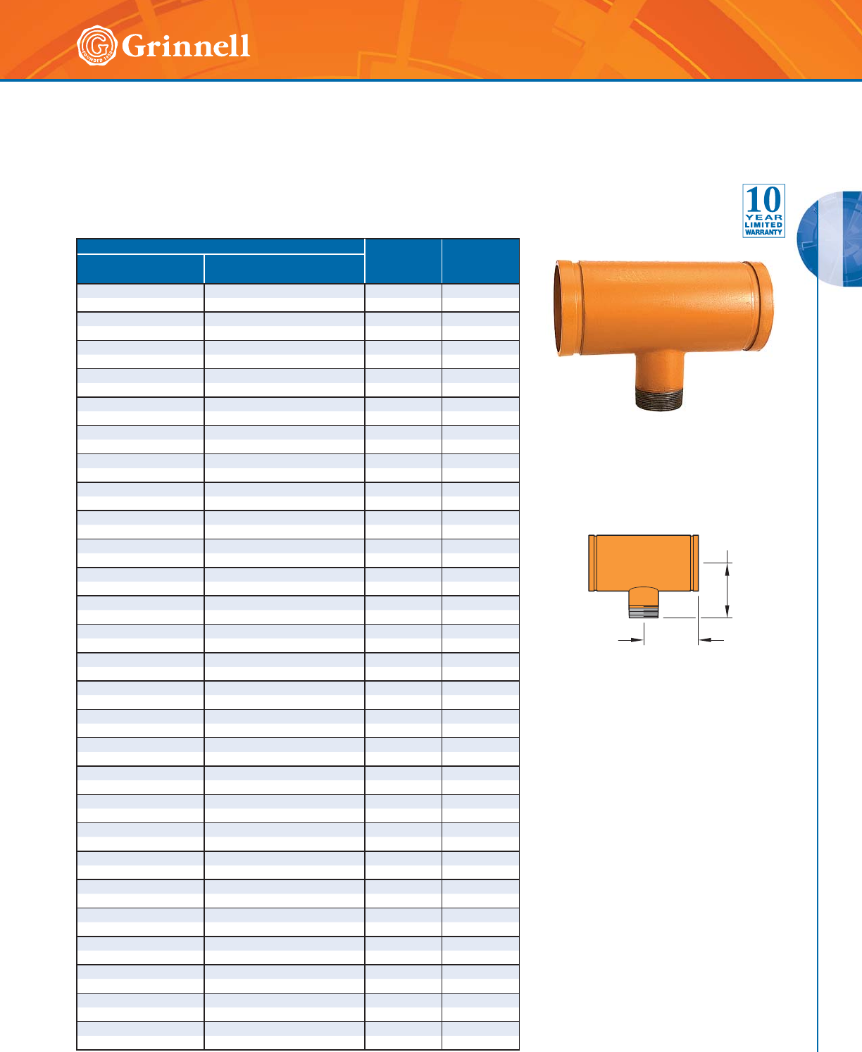
GROOVED FITTINGS
GROOVED FITTINGS
51
Refer to back cover for country-specific customer care numbers.
C to E
C to E
Figure 323 Reducing Tee
s
(
Groove x Groove x Male Thread)
(Page 1 of 2)
Tech Data Sheet: G180
Pipe Size C to GE &
C to TE
Inches mm
Approx.
Weight
Lbs. kg
Nominal
Inches mm
O.D.
Inches mm
11⁄2 x 11⁄2 x 11⁄41.900 x 1.900 x 1.660 3.25 1.8
40 x 40 x 32 48,3 x 48,3 x 42,4 82,6 0,8
2 x 2 x 1 2.375 x 2.375 x 1.315 3.25 2.2
50 x 50 x 25 60,3 x 60,3 x 33,4 82,6 1,0
2 x 2 x 11⁄42.375 x 2.375 x 1.660 3.25 2.3
50 x 50 x 32 60,3 x 60,3 x 42,4 82,6 1,0
2 x 2 x 11⁄22.375 x 2.375 x 1.900 3.25 1.4
50 x 50 x 40 60,3 x 60,3 x 48,3 82,6 1,1
21⁄2 x 21⁄2 x 1 2.875 x 2.875 x 1.315 3.75 3.6
65 x 65 x 25 73,0 x 73,0 x 33,4 95,3 1,6
21⁄2 x 21⁄2 x 11⁄42.875 x 2.875 x 1.660 3.75 3.8
65 x 65 x 32 73,0 x 73,0 x 42,4 95,3 1,7
21⁄2 x 21⁄2 x 11⁄22.875 x 2.875 x 1.900 3.75 4.0
65 x 65 x 40 73,0 x 73,0 x 48,3 95,3 1,8
21⁄2 x 21⁄2 x 2 2.875 x 2.875 x 2.375 3.75 4.2
65 x 65 x 50 73,0 x 73,0 x 60,3 95,3 1,9
3 x 3 x 1 3.500 x 3.500 x 1.315 4.25 5.7
80 x 80 x 25 88,9 x 88,9 x 33,4 108,0 2,6
3 x 3 x 11⁄23.500 x 3.500 x 1.900 4.25 5.8
80 x 80 x 40 88,9 x 88,9 x 48,3 108,0 2,6
3 x 3 x 2 3.500 x 3.500 x 2.375 4.25 5.9
80 x 80 x 50 88,9 x 88,9 x 60,3 108,0 2,7
3 x 3 x 21⁄23.500 x 3.500 x 2.875 4.25 6.3
80 x 80 x 65 88,9 x 88,9 x 73,0 108,0 2,9
4 x 4 x 1 4.500 x 4.500 x 1.315 5.00 6.9
100 x 100 x 25 114,3 x 114,3 x 33,4 127,0 3,1
4 x 4 x 11⁄44.500 x 4.500 x 1.660 5.00 7.6
100 x 100 x 32 114,3 x 114,3 x 42,4 127,0 3,4
4 x 4 x 11⁄24.500 x 4.500 x 1.900 5.00 8.3
100 x 100 x 40 114,3 x 114,3 x 48,3 127,0 3,8
4 x 4 x 2 4.500 x 4.500 x 2.375 5.00 9.6
100 x 100 x 50 114,3 x 114,3 x 60,3 127,0 4,4
4 x 4 x 21⁄24.500 x 4.500 x 2.875 5.00 10.0
100 x 100 x 65 114,3 x 114,3 x 73,0 127,0 4,5
4 x 4 x 3 4.500 x 4.500 x 3.500 5.00 10.3
100 x 100 x 80 114,3 x 114,3 x 88,9 127,0 4,7
5 x 5 x 2 5.563 x 5.563 x 2.375 5.50 14.0
125 x 125 x 50 141,3 x 141,3 x 60,3 139,7 6,4
5 x 5 x 21⁄25.563 x 5.563 x 2.875 5.50 14.3
125 x 125 x 65 141,3 x 141,3 x 73,0 139,7 6,5
5 x 5 x 3 5.563 x 5.563 x 3.500 5.50 14.6
125 x 125 x 80 141,3 x 141,3 x 88,9 139,7 6,6
5 x 5 x 4 5.563 x 5.563 x 4.500 5.50 15.1
125 x 125 x 100 141,3 x 141,3 x 114,3 139,7 6,8
6 x 6 x 2 6.625 x 6.625 x 2.375 6.50 21.3
150 x 150 x 50 168,3 x 168,3 x 60,3 165,1 9,7
6 x 6 x 21⁄26.625 x 6.625 x 2.875 6.50 21.7
150 x 150 x 65 168,3 x 168,3 x 73,0 165,1 9,8
6 x 6 x 3 6.625 x 6.625 x 3.500 6.50 22.0
150 x 150 x 80 168,3 x 168,3 x 88,9 165,1 10,0
6 x 6 x 4 6.625 x 6.625 x 4.500 6.50 22.5
150 x 150 x 100 168,3 x 168,3 x 114,3 165,1 10,2
6 x 6 x 5 6.625 x 6.625 x 5.563 6.50 23.1
150 x 150 x 125 168,3 x 168,3 x 141,3 165,1 10,5
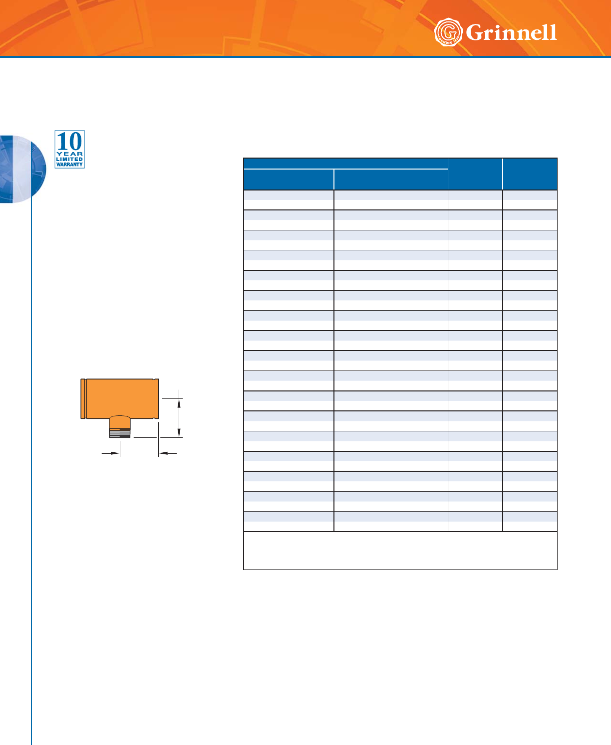
GROOVED FITTINGS
GROOVED FITTINGS
52 www.grinnell.com
Pipe Size C to GE &
C to TE
Inches mm
Approx.
Weight
Lbs. kg
Nominal
Inches mm
O.D.
Inches mm
8 x 8 x 2 8.625 x 8.625 x 2.375 7.75 32.7
200 x 200 x 50 219,1 x 219,1 x 60,3 196,9 14,8
8 x 8 x 3 8.625 x 8.625 x 3.500 7.75 33.5
200 x 200 x 80 219,1 x 219,1 x 88,9 196,9 15,2
8 x 8 x 4 8.625 x 8.625 x 4.500 7.75 34.5
200 x 200 x 100 219,1 x 219,1 x 114,1 196,9 15,6
8 x 8 x 5 8.625 x 8.625 x 5.563 7.75 34.7
200 x 200 x 125 219,1 x 219,1 x 141,3 196,9 15,7
8 x 8 x 6 8.625 x 8.625 x 6.625 7.75 35.6
200 x 200 x 150 219,1 x 219,1 x 168,3 196,9 16,1
10 x 10 x 2 10.750 x 10.750 x 2.375 9.00 52.2
250 x 250 x 50 273,0 x 273,0 x 60,3 228,6 23,7
10 x 10 x 3 10.750 x 10.750 x 3.500 9.00 53.0
250 x 250 x 80 273,0 x 273,0 x 88,9 228,6 24,0
10 x 10 x 4 10.750 x 10.750 x 4.500 9.00 53.6
250 x 250 x 100 273,0 x 273,0 x 114,3 228,6 24,3
10 x 10 x 5 10.750 x 10.750 x 5.563 9.00 54.2
250 x 250 x 125 273,0 x 273,0 x 141,3 228,6 24,6
10 x 10 x 6 10.750 x 10.750 x 6.625 9.00 54.9
250 x 250 x 150 273,0 x 273,0 x 168,3 228,6 24,9
10 x 10 x 8 10.750 x 10.750 x 8.625 9.00 55.3
250 x 250 x 200 273,0 x 273,0 x 219,1 228,6 25,1
12 x 12 x 3 12.750 x 12.750 x 3.500 10.00 74.6
300 x 300 x 80 323,9 x 323,9 x 88,9 254,0 33,8
12 x 12 x 4 12.750 x 12.750 x 4.500 10.00 75.1
300 x 300 x 100 323,9 x 323,9 x 114,3 254,0 34,1
12 x 12 x 5 12.750 x 12.750 x 5.563 10.00 75.6
300 x 300 x 125 323,9 x 323,9 x 141,3 254,0 34,3
12 x 12 x 6 12.750 x 12.750 x 6.625 10.00 76.2
300 x 300 x 150 323,9 x 323,9 x 168,3 254,0 34,6
12 x 12 x 8 12.750 x 12.750 x 8.625 10.00 76.3
300 x 300 x 200 323,9 x 323,9 x 219,1 254,0 34,6
12 x 12 x 10 12.750 x 12.750 x 10.750 10.00 77.6
300 x 300 x 250 323,9 x 323,9 x 273,0 254,0 35,2
Available with BSP threads. Contact GRINNELL Mechanical Products for details.
For information on larger sizes, contact GRINNELL Mechanical Products.
See page 37 for fitting specifications.
Figure 323 Reducing Tee
s
(
Groove x Groove x Male Thread)
(Page 2 of 2)
Tech Data Sheet: G180
C to E
C to E
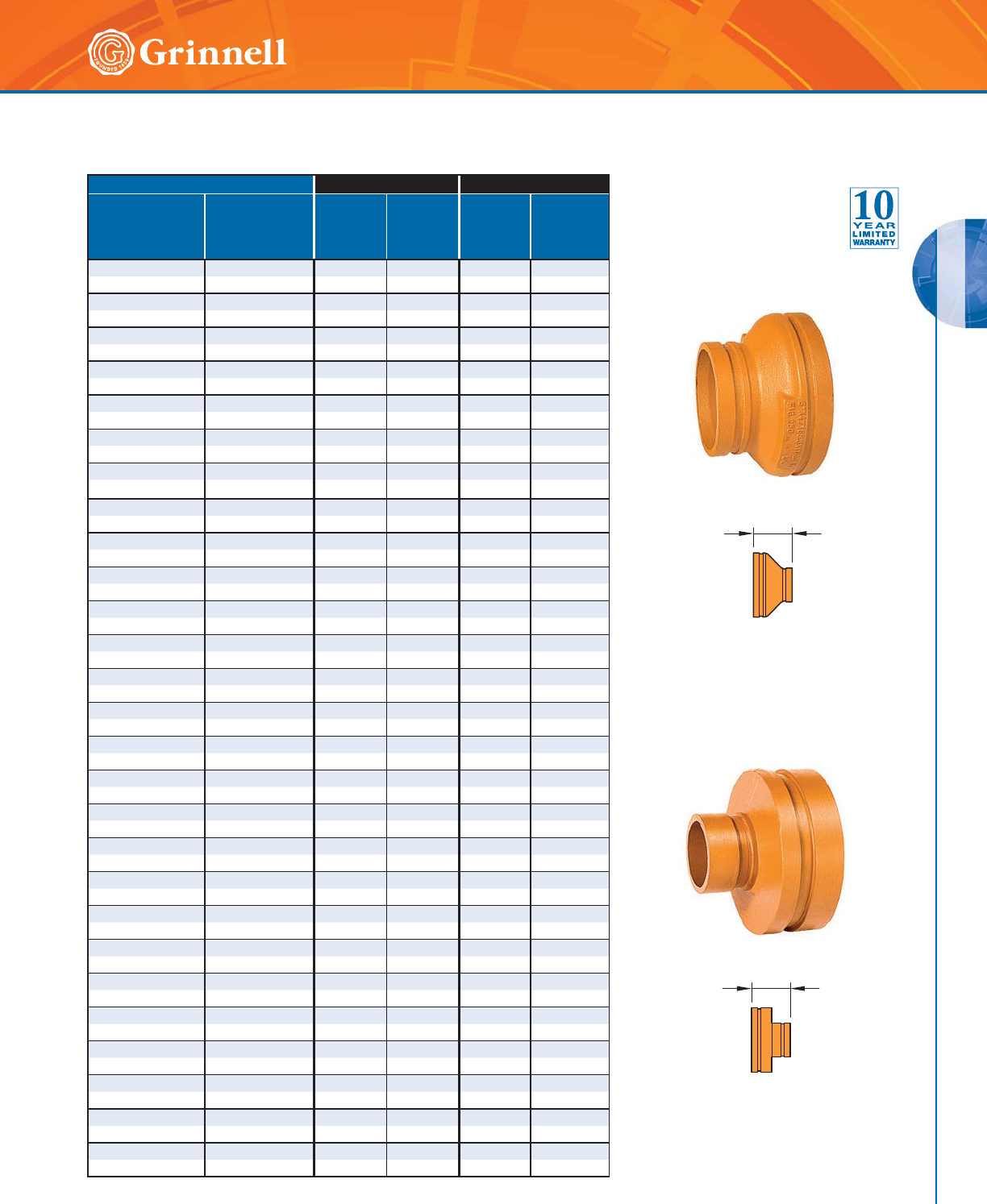
GROOVED FITTINGS
GROOVED FITTINGS
53
Refer to back cover for country-specific customer care numbers.
Figure 250
Concentric Reducer Cast
Figure 350
Concentric Reducer Fabricated
Pipe Size Figure 250 - Cast Figure 350 - Fabricated
Nominal
Inches
mm
O.D.
Inches
mm
E to E
Inches
mm
Approx.
Weight
Lbs.
kg
E to E
Inches
mm
Approx.
Weight
Lbs.
kg
11⁄4 x 1 1.660 x 1.315 2.50 0.7 — —
32 x 25 42,4 x 33,4 63,5 0,3 — —
11⁄2 x 1 1.900 x 1.315 — — 2.50 0.7
40 x 25 48,3 x 33,4 — — 63,5 0,3
11⁄2 x 11⁄41.900 x 1.660 2.50 0.8 — —
40 x 32 48,3 x 42,4 63,5 0,3 — —
2 x 1 2.375 x 1.315 2.50 0.9 — —
50 x 25 60,3 x 33,4 63,5 0,4 — —
2 x 11⁄42.375 x 1.660 2.50 0.9 — —
50 x 32 60,3 x 42,4 63,5 0,4 — —
2 x 11⁄22.375 x 1.900 2.50 1.0 — —
50 x 40 60,3 x 48,3 63,5 0,5 — —
21⁄2 x 1 2.875 x 1.315 — — 2.50 1.2
65 x 25 73,0 x 33,4 — — 63,5 0,5
21⁄2 x 11⁄42.875 x 1.660 2.50 1.4 — —
65 x 32 73,0 x 42,4 63,5 0,6 — —
21⁄2 x 11⁄22.875 x 1.900 2.50 1.4 — —
65 x 40 73,0 x 48,3 63,5 0,6 — —
21⁄2 x 2 2.875 x 2.375 2.50 1.3 — —
65 x 50 73,0 x 60,3 63,5 0,6 — —
76,1mm x 11⁄43.000 x 1.660 2.50 1.4 — —
65 x 32 76,1 x 42,4 63,5 0,6 — —
76,1mm x 11⁄23.000 x 1.900 2.50 1.4 — —
65 x 40 76,1 x 48,3 63,5 0,6 — —
76,1mm x 2 3.000 x 2.375 2.50 1.5 — —
65 x 50 76,1 x 60,3 63,5 0,7 — —
3 x 1 3.500 x 1.315 — — 2.50 1.3
80 x 25 88,9 x 33,4 — — 63,5 0,6
3 x 11⁄43.500 x 1.660 — — 2.50 1.3
80 x 32 88,9 x 42,4 — — 63,5 0,6
3 x 11⁄23.500 x 1.900 2.50 1.8 — —
80 x 40 88,9 x 48,3 63,5 0,8 — —
3 x 2 3.500 x 2.375 2.50 1.7 — —
80 x 50 88,9 x 60,3 63,5 0,8 — —
3 x 21⁄23.500 x 2.875 2.50 1.8 — —
80 x 65 88,9 x 73,0 63,5 0,8 — —
3 x 76,1mm 3.500 x 3.000 2.50 2.0 — —
80 x 65 88,9 x 76,1 63,5 0,9 — —
4 x 1 4.500 x 1.315 — — 3.00 2.9
100 x 25 114,3 x 33,4 — — 76,2 1,1
4 x 11⁄44.500 x 1.660 — — 3.00 2.2
100 x 32 114,3 x 42,4 — — 76,2 1,0
4 x 11⁄24.500 x 1.900 — — 3.00 2.3
100 x 40 114,3 x 48,3 — — 76,2 1,0
4 x 2 4.500 x 2.375 3.00 2.4 — —
100 x 50 114,3 x 60,3 76,2 1,1 — —
4 x 21⁄24.500 x 2.875 3.00 2.7 — —
100 x 65 114,3 x 73,0 76,2 1,2 — —
4 x 76,1mm 4.500 x 3.000 3.00 3.2 — —
100 x 65 114,3 x 76,1 76,2 1,5 — —
4 x 3 4.500 x 3.500 3.00 2.8 — —
100 x 80 114,3 x 88,9 76,2 1,3 ——
139,7mm x 3 5.500 x 3.500 3.50 4.2 — —
125 x 80 139,7 x 88,9 88,9 1,9 — —
E to E
E to E
Figures 250 & 350
Concentric Reducer
s
(Page 1 of 3)
Tech Data Sheet: G180
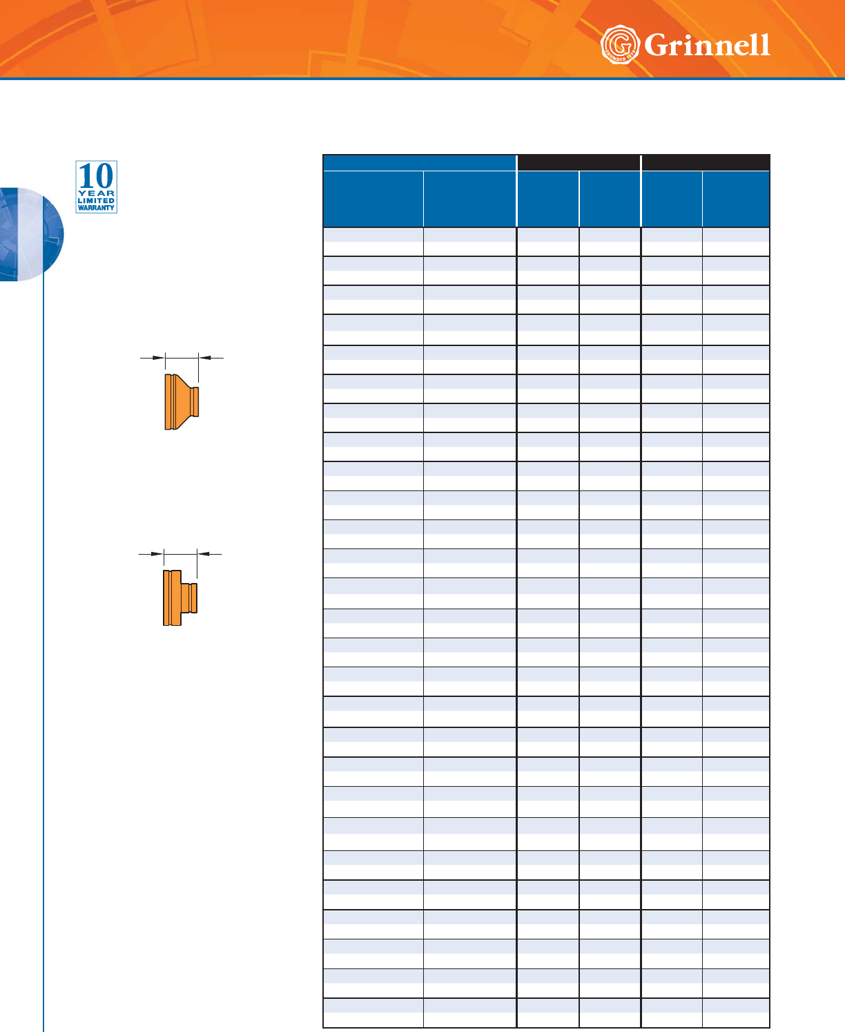
GROOVED FITTINGS
GROOVED FITTINGS
54 www.grinnell.com
Pipe Size Figure 250 - Cast Figure 350 - Fabricated
Nominal
Inches
mm
O.D.
Inches
mm
E to E
Inches
mm
Approx.
Weight
Lbs.
kg
E to E
Inches
mm
Approx.
Weight
Lbs.
kg
139,7mm x 4 5.500 x 4.500 3.50 4.4 — —
125 x 100 139,7 x 114,3 88,9 2,0 — —
5 x 2 5.563 x 2.375 — — 3.50 4.6
125 x 50 141,3 x 60,3 — — 88,9 2,1
5 x 21⁄25.563 x 2.875 — — 3.50 4.5
125 x 65 141,3 x 73,0 — — 88,9 2,0
5 x 3 5.563 x 3.500 3.50 4.2 — —
125 x 80 141,3 x 88,9 88,9 1,9 — —
5 x 4 5.563 x 4.500 3.50 4.4 — —
125 x 100 141,3 x 114,3 88,9 2,0 — —
165,1mm x 3 6.500 x 3.500 4.00 5.5 — —
150 x 80 165,1 x 88,9 101,6 2,5 — —
165,1mm x 4 6.500 x 4.500 4.00 6.0 — —
150 x 100 165,1 x 114,3 101,6 2,7 — —
165,1 x 139,7mm 6.500 x 5.500 4.00 5.6 — —
150 x 125 165,1 x 139,7 101,6 2,5 — —
6 x 2 6.625 x 2.375 4.00 5.3 — —
150 x 50 168,3 x 60,3 101,6 2,4 — —
6 x 21⁄26.625 x 2.875 4.00 5.6 — —
150 x 65 168,3 x 73,0 101,6 2,5 — —
6 x 76,1mm 6.625 x 3.000 4.00 6.1 — —
150 x 65 168,3 x 76,1 101,6 2,7 — —
6 x 3 6.625 x 3.500 4.00 5.8 — —
150 x 80 168,3 x 88,9 101,6 2,6 — —
6 x 4 6.625 x 4.500 4.00 6.0 — —
150 x 100 168,3 x 114,3 101,6 2,7 — —
6 x 139,7mm 6.625 x 5.500 4.00 6.3 — —
150 x 125 168,3 x 139,7 101,6 2,3 — —
6 x 5 6.625 x 5.563 4.00 6.2 — —
150 x 125 168,3 x 141,3 101,6 2,8 — —
8 x 21⁄2 8.625 x 2.875 — — 5.00 12.1
200 x 65 ◗219,1 x 73,0 — — 127,0 5,5
8 x 3 8.625 x 3.500 5.00 11.5 — —
200 x 80 ◗219,1 x 88,9 127,0 5,2 — —
8 x 4 8.625 x 4.500 5.00 10.7 — —
200 x 100 ◗219,1 x 114,3 127,0 4,9 — —
8 x 139,7mm 8.625 x 5.500 5.00 10.0 — —
200 x 125 ◗219,1 x 139,7 127,0 4,5 — —
8 x 5 8.625 x 5.563 5.00 10.8 — —
200 x 125 ◗219,1 x 141,3 127,0 4,9 — —
8 x 165,1mm 8.625 x 6.500 5.00 11.0 — —
200 x 150 ◗219,1 x 165,1 127,0 5,0 — —
8 x 6 8.625 x 6.625 5.00 11.3 — —
200 x 150 ◗219,1 x 168,3 127,0 5,1 — —
10 x 4 10.750 x 4.500 — — 6.00 20.5
250 x 100 ◗273,0 x 114,3 — — 152,4 9,3
10 x 5 10.750 x 5.563 — — 6.00 20.1
250 x 125 ◗273,0 x 141,3 — — 152,4 9,1
10 x 165,1mm 10.750 x 6.500 6.00 17.8 — —
250 x 150 ◗273,0 x 165,1 152,4 8,0 — —
10 x 6 10.750 x 6.625 6.00 16.3 — —
250 x 150 ◗273,0 x 168,3 152,4 7,4 — —
10 x 8 10.750 x 8.625 6.00 18.3 — —
250 x 200 ◗273,0 x 219,1 152,4 8,3 — —
Figures 250 & 350
Concentric Reducer
s
(Page 2 of 3)
Tech Data Sheet: G180
E to E
Figure 250
Cast Concentric
Reducer
Figure 350
Fabricated Concentric
Reducer
E to E
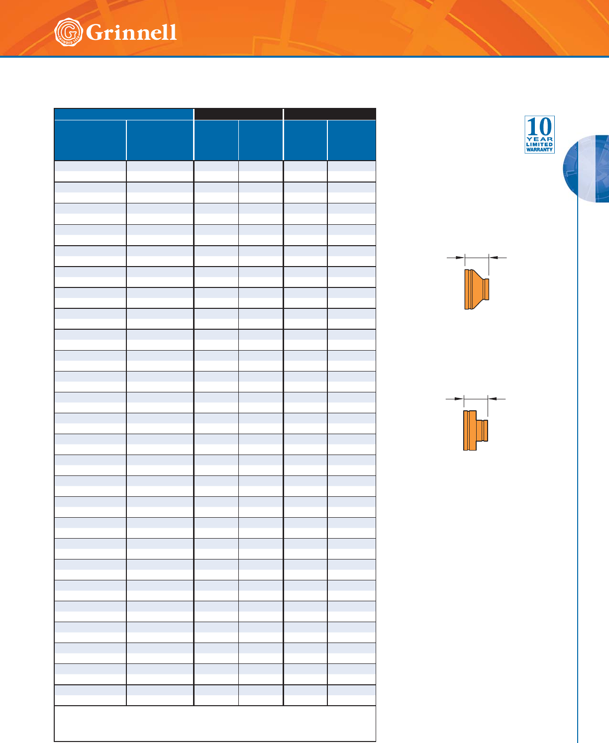
GROOVED FITTINGS
GROOVED FITTINGS
55
Refer to back cover for country-specific customer care numbers.
Pipe Size Figure 250 - Cast Figure 350 - Fabricated
Nominal
Inches
mm
O.D.
Inches
mm
E to E
Inches
mm
Approx.
Weight
Lbs.
kg
E to E
Inches
mm
Approx.
Weight
Lbs.
kg
12 x 4 12.750 x 4.500 7.00 23.0 — —
300 x 100 ◗323,9 x 114,3 177,8 10,4 — —
12 x 6 12.750 x 6.625 7.00 23.6 — —
300 x 150 ◗323,9 x 168,3 177,8 10,7 — —
12 x 8 12.750 x 8.625 7.00 25.2 — —
300 x 200 ◗323,9 x 219,1 177,8 11,4 — —
12 x 10 12.750 x 10.750 7.00 28.2 — —
300 x 250 ◗323,9 x 273,0 177,8 12,8 — —
14 x 6 14.000 x 6.625 — — 13.0 54.3
350 x 150 355,6 x 168,3 — — 330,2 24,6
14 x 8 14.000 x 8.625 — — 13.0 54.5
350 x 200 355,6 x 219,1 — — 330,2 24,7
14 x 10 14.000 x 10.750 — — 13.0 55.8
350 x 250 355,6 x 273,0 — — 330,2 25,3
14 x 12 14.000 x 12.750 — — 13.0 57.3
350 x 300 355,6 x 323,9 — — 330,2 26,0
16 x 8 16.000 x 8.625 — — 14.0 65.4
400 x 200 406,4 x 219,1 — — 355,6 29,7
16 x 10 16.000 x 10.750 — — 14.0 66.7
400 x 250 406,4 x 273,0 — — 355,6 30,2
16 x 12 16.000 x 12.750 — — 14.0 68.1
400 x 300 406,4 x 323,9 — — 355,6 30,9
16 x 14 16.000 x 14.000 — — 14.0 71.0
400 x 350 406,4 x 355,6 — — 355,6 32,2
18 x 12 18.000 x 12.750 — — 15.0 83.6
450 x 300 457,2 x 323,9 — — 381,0 37,9
18 x 14 18.000 x 14.000 — — 15.0 86.2
450 x 350 457,2 x 355,6 — — 381,0 39,1
18 x 16 18.000 x 16.000 — — 15.0 87.2
450 x 400 457,2 x 406,4 — — 381,0 39,6
20 x 10 20.000 x 10.750 — — 20.0 124.7
500 x 250 508,0 x 273,0 — — 508,0 56,6
20 x 12 20.000 x 12.750 — — 20.0 124.7
500 x 300 508,0 x 323,9 — — 508,0 56,6
20 x 14 20.000 x 14.000 — — 20.0 129.0
500 x 350 508,0 x 355,6 — — 508,0 58,5
20 x 16 20.000 x 16.000 — — 20.0 131.1
500 x 400 508,0 x 406,4 — — 508,0 59,5
20 x 18 20.000 x 18.000 — — 20.0 133.4
500 x 450 508,0 x 457,2 — — 508,0 60,5
24 x 10 24.000 x 10.750 — — 20.0 149.1
600 x 250 609,6 x 273,0 — — 508,0 67,6
24 x 12 24.000 x 12.750 — — 20.0 150.4
600 x 300 609,6 x 323,9 — — 508,0 68,2
24 x 14 24.000 x 14.000 — — 20.0 151.6
600 x 350 609,6 x 355,6 — — 508,0 68,8
24 x 16 24.000 x 16.000 — — 20.0 152.8
600 x 400 609,6 x 406,4 — — 508,0 69,3
24 x 18 24.000 x 18.000 — — 20.0 154.1
600 x 450 609,6 x 457,2 — — 508,0 69,9
24 x 20 24.000 x 20.000 — — 20.0 155.5
600 x 500 609,6 x 508,0 — — 508,0 70,5
◗ Sizes are available to JIS standards. Contact GRINNELL Mechanical Products for details.
For information on larger sizes, contact GRINNELL Mechanical Products.
See page 37 for fitting specifications.
Figures 250 & 350
Concentric Reducer
s
(Page 3 of 3)
Tech Data Sheet: G180
E to E
Figure 250
Cast Concentric
Reducer
Figure 350
Fabricated Concentric
Reducer
E to E
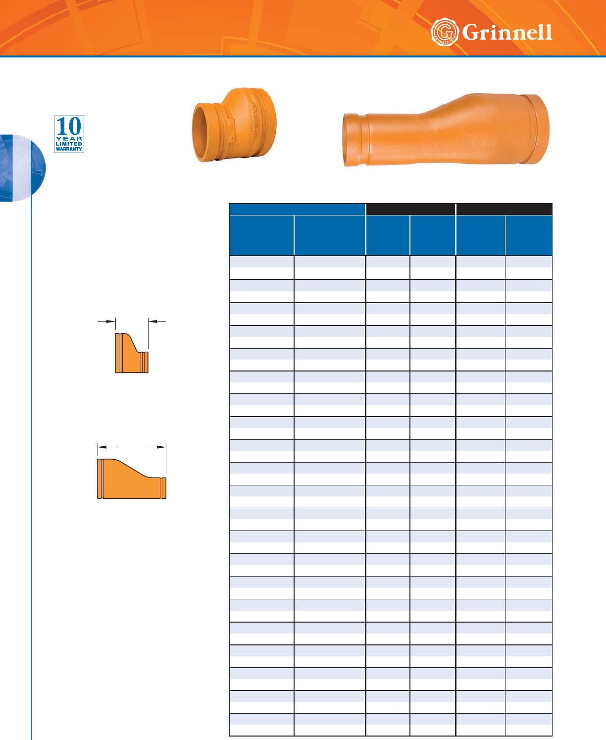
GROOVED FITTINGS
GROOVED FITTINGS
56 www.grinnell.com
Pipe Size Figure 251 - Cast Figure 351 - Fabricated
Nominal
Inches
mm
O.D.
Inches
mm
E to E
Inches
mm
Approx.
Weight
Lbs.
kg
E to E
Inches
mm
Approx.
Weight
Lbs.
kg
11⁄2 x 1 1.900 x 1.315 — — 8.5 1.9
40 x 25 48,3 x 33,4 — — 215,9 0,9
11⁄2 x 11⁄41.900 x 1.660 — — 8.5 2.2
40 x 32 48,3 x 42,4 — — 215,9 1,0
2 x 1 2.375 x 1.315 — — 9.0 2.2
50 x 25 60,3 x 33,4 — — 223,6 1,0
2 x 11⁄42.375 x 1.660 — — 9.0 2.4
50 x 32 60,3 x 42,4 — — 228,6 1,1
2 x 11⁄22.375 x 1.900 — — 9.0 2.5
50 x 40 60,3 x 48,3 — — 228,6 1,1
21⁄2 x 1 2.875 x 1.315 — — 9.5 3.2
65 x 25 73,0 x 33,4 — — 241,3 1,5
21⁄2 x 11⁄42.875 x 1.660 — — 9.5 3.4
65 x 32 73,0 x 42,4 — — 241,3 1,5
21⁄2 x 11⁄22.875 x 1.900 — — 9.5 3.6
65 x 40 73,0 x 48,3 — — 241,3 1,6
21⁄2 x 2 2.875 x 2.375 — — 9.5 4.0
65 x 50 73,0 x 60,3 — — 241,3 1,8
3 x 1 3.500 x 1.315 — — 9.5 4.0
80 x 25 88,9 x 33,4 — — 241,3 1,8
3 x 11⁄43.500 x 1.660 — — 9.5 4.3
80 x 32 88,9 x 42,4 — — 241,3 2,0
3 x 11⁄23.500 x 1.900 — — 9.5 4.5
80 x 40 88,9 x 48,3 — — 241,3 2,0
3 x 2 3.500 x 2.375 3.5 2.0 — —
80 x 50 88,9 x 60,3 88,9 0,9 — —
3 x 21⁄23.500 x 2.875 3.5 2.2 — —
80 x 65 88,9 x 73,0 88,9 1,0 — —
4 x 1 4.500 x 1.315 — — 10.0 5.9
100 x 25 114,3 x 33,4 — — 254,0 2,7
4 x 11⁄44.500 x 1.660 — — 10.0 6.3
100 x 32 114,3 x 42,4 — — 254,0 2,9
4 x 11⁄24.500 x 1.900 — — 10.0 6.4
100 x 40 114,3 x 48,3 — — 254,0 2,9
4 x 2 4.500 x 2.375 4.0 3.0 — —
100 x 50 114,3 x 60,3 101,6 1,4 — —
4 x 21⁄24.500 x 2.875 4.0 3.1 — —
100 x 65 114,3 x 73,0 101,6 1,4 — —
4 x 3 4.500 x 3.500 4.0 3.3 — —
100 x 80 114,3 x 88,9 101,6 1,5 — —
5 x 2 5.563 x 2.375 — — 11.0 9.3
125 x 50 141,3 x 60,3 — — 279,4 4,2
Figure 351
Fabricated Eccentric Reducer
(Segment Welded)
Figure 251
Cast Eccentric Reducer
Figure 351
Fabricated Eccentric Reducer
(Segment Welded)
Figure 251
Cast Eccentric Reducer
E to E
E to E
Figures 251 & 351 Eccentric Reducers
(Page 1 of 3)
Tech Data Sheet: G180
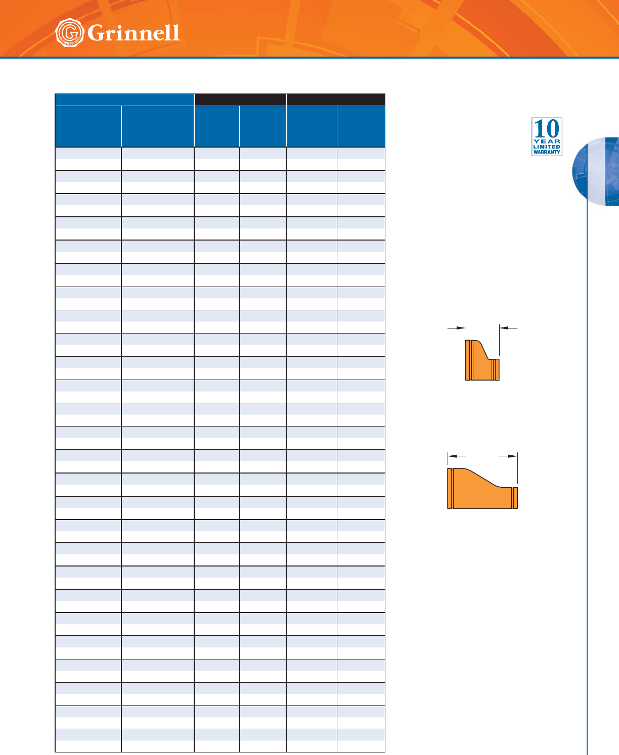
GROOVED FITTINGS
GROOVED FITTINGS
57
Refer to back cover for country-specific customer care numbers.
Pipe Size Figure 251 - Cast Figure 351 - Fabricated
Nominal
Inches
mm
O.D.
Inches
mm
E to E
Inches
mm
Approx.
Weight
Lbs.
kg
E to E
Inches
mm
Approx.
Weight
Lbs.
kg
5 x 21⁄25.563 x 2.875 — — 11.0 9.9
125 x 65 141,3 x 73,0 — — 279,4 4,5
5 x 3 5.563 x 3.500 — — 11.0 10.7
125 x 80 141,3 x 88,9 — — 279,4 4,9
5 x 4 5.563 x 4.500 5.0 5.7 — —
125 x 100 141,3 x 114,3 127,5 2,6 — —
165,1mm x 3 6.500 x 3.500 — — 11.5 13.6
150 x 80 165,1 x 88,9 — — 292,1 6,2
165,1mm x 4 6.500 x 4.500 — — 11.5 14.9
150 x 100 165,1 x 114,3 — — 292,1 6,8
6 x 2 6.625 x 2.375 — — 11.5 12.2
150 x 50 168,3 x 60,3 — — 292,1 5,5
6 x 21⁄26.625 x 2.875 — — 11.5 12.8
150 x 65 168,3 x 73,0 — — 292,1 5,8
6 x 3 6.625 x 3.500 5.5 7.4 — —
150 x 80 168,3 x 88,9 139,7 3,4 — —
6 x 4 6.625 x 4.500 5.5 7.5 — —
150 x 100 168,3 x 114,3 139,7 3,4 — —
6 x 5 6.625 x 5.563 5.5 8.1 — —
150 x 125 168,3 x 141,3 139,7 3,7 — —
8 x 3 8.625 x 3.500 — — 12.0 17.9
200 x 80 219,1 x 88,9 — — 304,8 8,1
8 x 4 8.625 x 4.500 — — 12.0 19.7
200 x 100 219,1 x 114,3 — — 304,8 9,8
8 x 5 8.625 x 5.563 — — 12.0 21.4
200 x 125 219,1 x 141,3 — — 304,8 9,7
8 x 6 8.625 x 6.625 — — 12.0 23.2
200 x 150 219,1 x 168,3 — — 304,8 10,5
10 x 4 10.750 x 4.500 — — 13.0 29.7
250 x 100 273,0 x 114,3 — — 330,2 13,5
10 x 5 10.750 x 5.563 — — 13.0 31.7
250 x 125 273,0 x 141,3 — — 330,2 14,4
10 x 6 10.750 x 6.625 — — 13.0 34.0
250 x 150 273,0 x 168,3 — — 330,2 15,4
10 x 8 10.750 x 8.625 — — 13.0 34.4
250 x 200 273,0 x 219,1 — — 330,2 15,6
12 x 4 12.750 x 4.500 — — 14.0 44.8
300 x 100 323,9 x 114,3 — — 355,6 20,3
12 x 6 12.750 x 6.625 — — 14.0 45.2
300 x 150 323,9 x 168,3 — — 355,6 20,5
12 x 8 12.750 x 8.625 — — 14.0 47.7
300 x 200 323,9 x 219,1 — — 355,6 21,6
12 x 10 12.750 x 10.750 — — 14.0 52.0
300 x 250 323,9 x 273,0 — — 355,6 23,6
14 x 6 14.000 x 6.625 — — 19.0 78.0
350 x 150 355,6 x 168,3 — — 482,6 35,4
14 x 8 14.000 x 8.625 — — 19.0 80.0
350 x 200 355,6 x 219,1 — — 482,6 36,3
14 x 10 14.000 x 10.750 — — 19.0 84.0
350 x 250 355,6 x 273,0 — — 482,6 38,1
14 x 12 14.000 x 12.750 — — 19.0 88.0
350 x 300 355,6 x 323,9 — — 482,6 39,9
Figures 251 & 351 Eccentric Reducers
(Page 2 of 3)
Tech Data Sheet: G180
Figure 351
Fabricated Eccentric Reducer
(Segment Welded)
Figure 251
Cast Eccentric Reducer
E to E
E to E
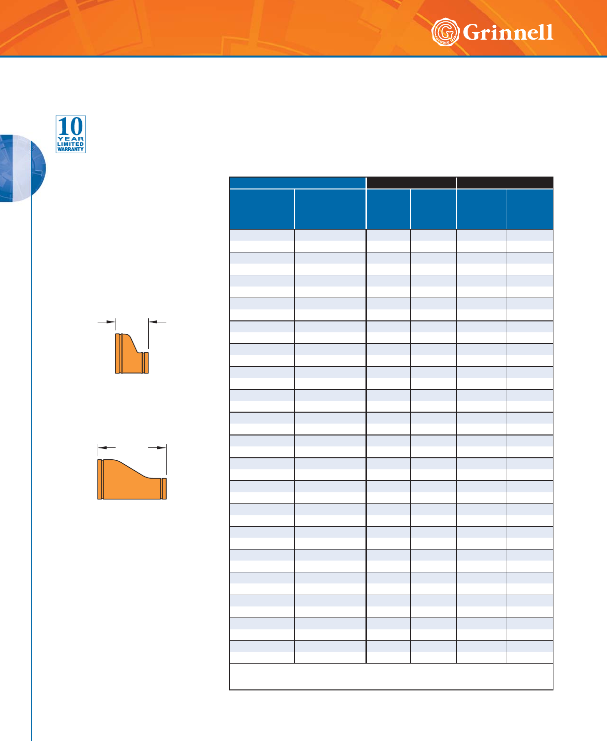
GROOVED FITTINGS
GROOVED FITTINGS
58 www.grinnell.com
Pipe Size Figure 251 - Cast Figure 351 - Fabricated
Nominal
Inches
mm
O.D.
Inches
mm
E to E
Inches
mm
Approx.
Weight
Lbs.
kg
E to E
Inches
mm
Approx.
Weight
Lbs.
kg
16 x 8 16.000 x 8.625 — — 20.0 91.0
400 x 200 406,4 x 219,1 — — 508,0 41,3
16 x 10 16.000 x 10.750 — — 20.0 96.0
400 x 250 406,4 x 273,0 — — 508,0 43,5
16 x 12 16.000 x 12.750 — — 20.0 99.0
400 x 300 406,4 x 323,9 — — 508,0 44,9
16 x 14 16.000 x 14.000 — — 20.0 104.0
400 x 350 406,4 x 355,6 — — 508,0 47,2
18 x 10 18.000 x 10.750 — — 21.0 110.0
450 x 250 457,2 x 273,1 — — 533,0 49,9
18 x 12 18.000 x 12.750 — — 21.0 113.0
450 x 300 457,2 x 323,9 — — 533,0 51,3
18 x 14 18.000 x 14.000 — — 21.0 117.0
450 x 350 457,2 x 355,6 — — 533,0 53,1
18 x 16 18.000 x 16.000 — — 21.0 121.0
450 x 400 457,2 x 406,4 — — 533,0 54,9
20 x 10 20.000 x 10.750 — — 26.0 145.0
500 x 250 508,0 x 273,0 — — 660,4 65,8
20 x 12 20.000 x 12.750 — — 26.0 149.0
500 x 300 508,0 x 323,9 — — 660,4 67,6
20 x 14 20.000 x 14.000 — — 26.0 152.0
500 x 350 508,0 x 355,6 — — 660,4 68,9
20 x 16 20.000 x 16.000 — — 26.0 156.0
500 x 400 508,0 x 406,4 — — 660,4 70,8
20 x 18 20.000 x 18.000 — — 26.0 160.0
500 x 450 508,0 x 457,2 — — 660,4 72,6
24 x 10 24.000 x 10.750 — — 26.0 147.0
600 x 250 609,6 x 273,0 — — 660,4 78,9
24 x 12 24.000 x 12.750 — — 26.0 179.0
600 x 300 609,6 x 323,9 — — 660,4 81,2
24 x 14 24.000 x 14.000 — — 26.0 184.0
600 x 350 609,6 x 355,6 — — 660,4 83,5
24 x 16 24.000 x 16.000 — — 26.0 189.0
600 x 400 609,6 x 406,4 — — 660,4 85,7
24 x 18 24.000 x 18.000 — — 26.0 194.0
600 x 450 609,6 x 457,2 — — 660,4 88,0
24 x 20 24.000 x 20.000 — — 26.0 199.0
600 x 500 609,6 x 508,0 — — 660,4 90,3
For information on larger sizes, contact GRINNELL Mechanical Products.
See page 37 for fitting specifications.
Figures 251 & 351 Eccentric Reducers
(Page 3 of 3)
Tech Data Sheet: G180
Figure 351
Fabricated Eccentric Reducer
(Segment Welded)
Figure 251
Cast Eccentric Reducer
E to E
E to E
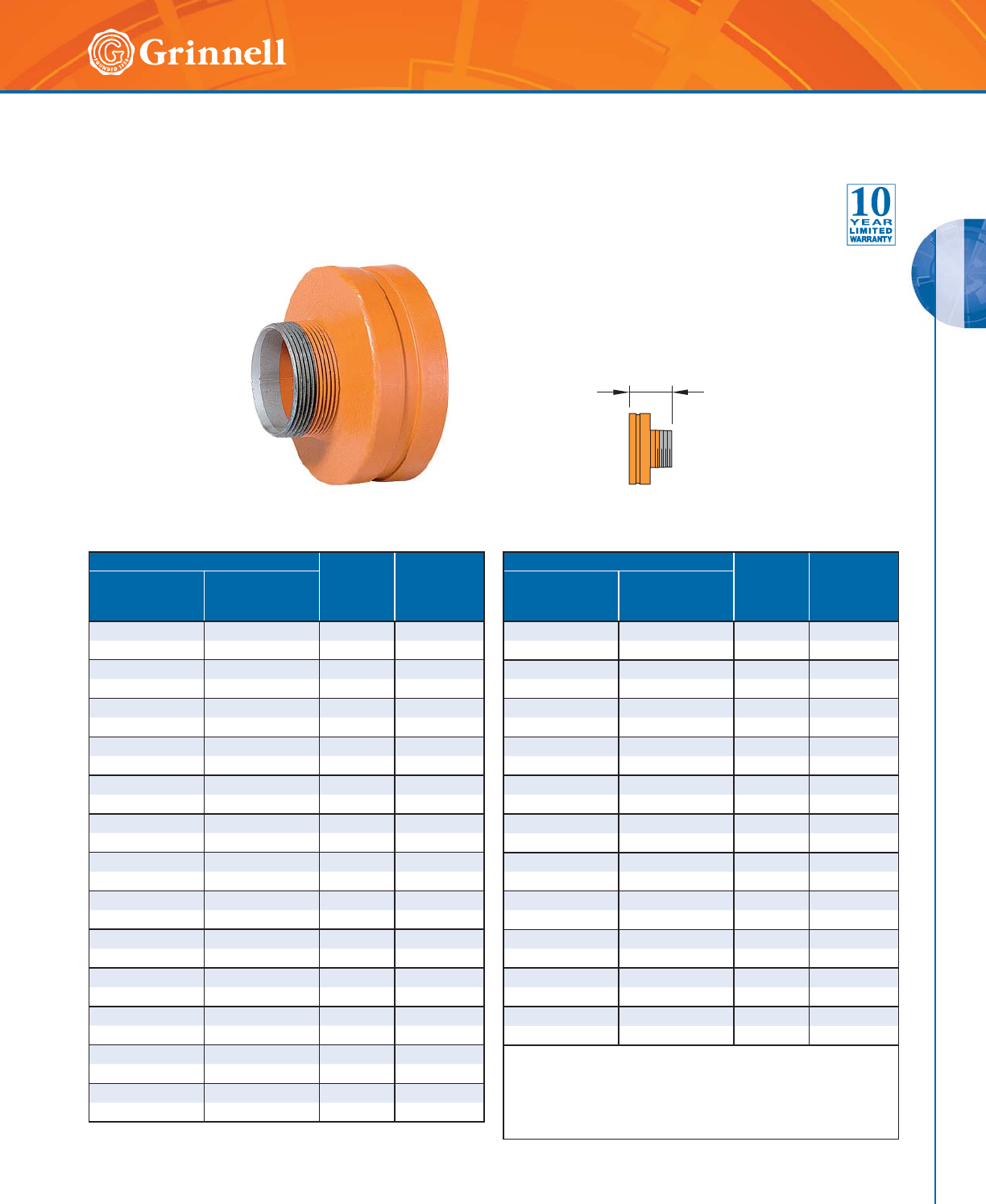
GROOVED FITTINGS
GROOVED FITTINGS
59
Refer to back cover for country-specific customer care numbers.
Pipe Size E to E
Inches
mm
Approx.
Weight
Lbs.
kg
Nominal
Inches
mm
O.D.
Inches
mm
11⁄2 x 1 1.900 x 1.315 2.50 0.6
40 x 25 48,3 x 33,7 63,5 0,3
2 x 3⁄42.375 x 1.050 2.50 1.0
50 x 20 60,3 x 26,7 63,5 0,5
2 x 1 2.375 x 1.315 2.50 0.8
50 x 25 60,3 x 33,7 63,5 0,4
2 x 11⁄42.375 x 1.660 2.50 0.8
50 x 32 60,3 x 42,4 63,5 0,4
2 x 11⁄22.375 x 1.900 2.50 0.8
50 x 40 60,3 x 48,3 63,5 0,4
21⁄2 x 11⁄42.875 x 1.660 2.50 1.0
65 x 32 73,0 x 42,4 63,5 0,5
21⁄2 x 11⁄22.875 x 1.900 2.50 1.3
65 x 40 73,0 x 48,3 63,5 0,6
21⁄2 x 2 2.875 x 2.375 2.50 1.2
65 x 50 73,0 x 60,3 63,5 0,5
3 x 1 3.500 x 1.315 2.50 1.3
80 x 25 88,9 x 33,7 63,5 0,6
3 x 11⁄23.500 x 1.900 2.50 1.3
80 x 40 88,9 x 48,3 63,5 0,6
3 x 2 3.500 x 2.375 2.50 1.3
80 x 50 88,9 x 60,3 63,5 0,6
3 x 21⁄23.500 x 2.875 2.50 1.5
80 x 65 88,9 x 73,0 63,5 0,7
31⁄2 x 3 4.000 x 3.500 2.50 1.5
90 x 80 101,6 x 88,9 63,5 0,7
E to E
Pipe Size E to E
Inches
mm
Approx.
Weight
Lbs.
kg
Nominal
Inches
mm
O.D.
Inches
mm
4 x 1 4.500 x 1.315 3.00 1.8
100 x 25 114,3 x 33,4 76,2 0,8
4 x 11⁄24.500 x 1.900 3.00 2.3
100 x 40 114,3 x 48,3 76,2 1,0
4 x 2 4.500 x 2.375 3.00 2.3
100 x 50 114,3 x 60,3 76,2 1,0
4 x 21⁄24.500 x 2.875 3.00 2.3
100 x 65 114,3 x 73,0 76,2 1,0
4 x 3 4.500 x 3.500 3.00 2.6
100 x 80 114,3 x 88,9 76,2 1,2
5 x 4 5.563 x 4.500 3.50 4.5
125 x 100 141,3 x 114,3 88,9 2,0
6 x 1 6.625 x 1.315 4.00 5.2
150 x 25 168,3 x 33,4 101,6 2,4
6 x 2 6.625 x 2.375 4.00 6.0
150 x 50 168,3 x 60,3 101,6 2,7
6 x 3 6.625 x 3.500 4.00 6.0
150 x 80 168,3 x 88,9 101,6 2,7
6 x 4 6.625 x 4.500 4.00 5.9
150 x 100 168,3 x 114,3 101,6 2,7
6 x 5 6.625 x 5.563 4.00 5.8
150 x 125 168,3 x 141,3 101,6 2,6
Available with BSP threads. Contact GRINNELL Mechanical Products
for details.
For information on larger sizes, European sizes or other alternative
sizes, contact GRINNELL Mechanical Products.
See page 37 for fitting specifications.
Figure
372 Concentric Reducers
(Small End Male Thread)
Tech Data Sheet: G180
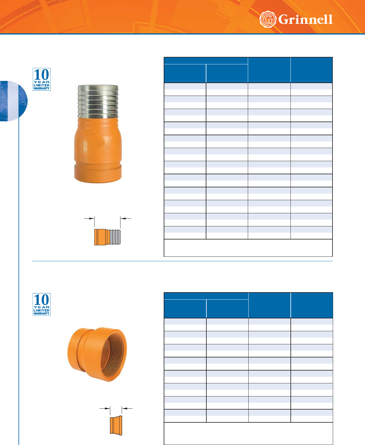
GROOVED FITTINGS
GROOVED FITTINGS
60 www.grinnell.com
Pipe Size E to E
Inches
mm
Approx. Weight
Lbs.
kg
Nominal
Inches
mm
O.D.
Inches
mm
11.3153.250.4
25 33,4 82,6 0,2
11⁄41.600 3.63 0.7
32 42,4 92,1 0,3
11⁄21.900 4.00 0.8
40 48,3 101,6 0,4
22.3754.631.3
50 60,3 117,5 0,6
21⁄22.875 5.50 2.1
65 73,0 139,7 1,0
3 3.500 6.00 3.3
80 88,9 152,4 1,5
44.5007.255.5
100 114,3 184,2 2,5
55.5639.758.1
125 141,3 247,7 3,7
6 6.625 11.00 13.2
150 168,3 279,4 6,0
88.62512.5024.0
200 219,1 317,5 10,9
10 10.750 14.00 29.0
250 273,0 355,6 13,2
12 12.750 16.00 46.0
300 323,9 406,4 20,9
For information on larger sizes, contact GRINNELL Mechanical Products.
See page 37 for fitting specifications.
E to E
Pipe Size E to E
Inches
mm
Approx. Weight
Lbs.
kg
Nominal
Inches
mm
O.D.
Inches
mm
11.3152.0630.7
25 33,4 52,4 0,3
11⁄41.600 2.312 1.4
32 42,4 58,7 0,6
11⁄21.900 2.312 1.5
40 48,3 58,7 0,7
22.3752.5001.6
50 60,3 63,5 0,7
21⁄22.875 2.500 1.9
65 73,0 63,5 0,9
76,1mm 3.000 2.500 1.9
65 76,1 63,5 0,9
3 3.500 2.750 2.5
80 88,9 69,9 1,1
4 4.500 3.250 4.5
100 114,3 82,5 2,0
Available with BSP threads. Contact GRINNELL Mechanical Products for details.
For information on larger sizes, contact GRINNELL Mechanical Products.
See page 37 for fitting specifications.
E to E
Figure 395 Hose Adapter Nipples
(Groove x Hose)
Tech Data Sheet: G180
Figure 380 Female Thread Adapters
(Groove x Female Thread)
Tech Data Sheet: G180
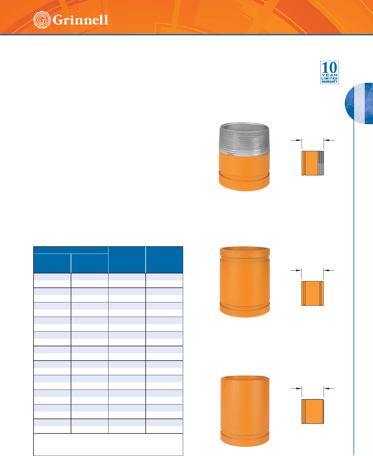
GROOVED FITTINGS
GROOVED FITTINGS
61
Refer to back cover for country-specific customer care numbers.
Figure 391
Fabricated Adapter Nipple
Groove x Male Thread
Figure 392
Fabricated Adapter Nipple
Groove x Groove
Figure 393
Fabricated Adapter Nipple
Groove x Plain
Pipe Size E to E
Inches
mm
Approx. Weight
Lbs.
kg
Nominal
Inches
mm
O.D.
Inches
mm
11⁄41.600 4.00 0.8
32 42,4 101,6 0,4
11⁄21.900 4.00 0.9
40 48,3 101,6 0,4
22.3754.001.2
50 60,3 101,6 0,5
21⁄22.875 4.00 1.9
65 73,0 101,6 0,9
3 3.500 4.00 2.5
80 88,9 101,6 1,1
4 4.500 6.00 5.4
100 114,3 154,4 2,4
55.5636.007.3
125 141,3 154,4 3,3
6 6.625 6.00 9.4
150 168,3 154,4 4,3
88.6256.0014.2
200 219,1 154,4 6,4
10 10.750 8.00 27.0
250 273,0 203,2 12,2
12 12.750 8.00 33.0
300 323,9 203,2 15,0
For information on larger sizes, contact GRINNELL
Mechanical Products.
See page 37 for fitting specifications.
E to E
E to E
E to E
Figures 391, 392 & 393 Adapter Nipples
Tech Data Sheet: G180
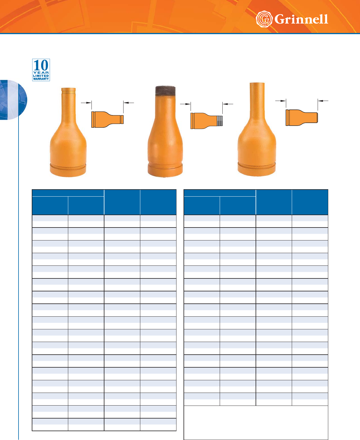
GROOVED FITTINGS
GROOVED FITTINGS
62 www.grinnell.com
Pipe Size E to E
Inches
mm
Approx.
Weight
Lbs.
kg
Nominal
Inches
mm
O.D.
Inches
mm
2 x 1 2.375 x 1.315 6.50 2.0
50 x 25 60,3 x 33,4 165,1 0,9
2 x 11⁄42.375 x 1.660 6.50 2.0
50 x 32 60,3 x 42,4 165,1 0,9
2 x 11⁄22.375 x 1.900 6.50 2.0
50 x 40 60,3 x 48,3 165,1 0,9
21⁄2 x 1 2.875 x 1.315 7.00 3.5
65 x 25 73,0 x 33,4 177,8 1,6
21⁄2 x 11⁄42.875 x 1.660 7.00 3.5
65 x 32 73,0 x 42,4 177,8 1,6
21⁄2 x 11⁄22.875 x 1.900 7.00 3.5
65 x 40 73,0 x 48,3 177,8 1,6
21⁄2 x 2 2.875 x 2.375 7.00 3.5
65 x 50 73,0 x 60,3 177,8 1,6
3 x 1 3.500 x 1.315 8.00 5.0
80 x 25 88,9 x 33,4 203,2 2,3
3 x 11⁄43.500 x 1.600 8.00 5.0
80 x 32 88,9 x 42,4 203,2 2,3
3 x 11⁄23.500 x 1.900 8.00 5.0
80 x 40 88,9 x 48,3 203,2 2,3
3 x 2 3.500 x 2.375 8.00 5.0
80 x 50 88,9 x 60,3 203,2 2,3
3 x 21⁄23.500 x 2.875 8.00 5.0
80 x 65 88,9 x 73,0 203,2 2,3
4 x 1 4.500 x 1.315 9.00 8.0
100 x 25 114,3 x 33,4 228,6 3,6
4 x 11⁄44.500 x 1.660 9.00 8.0
100 x 32 114,3 x 42,4 228,6 3,6
4 x 11⁄24.500 x 1.900 9.00 8.0
100 x 40 114,3 x 48,3 228,6 3,6
4 x 2 4.500 x 2.375 9.00 8.0
100 x 50 114,3 x 60,3 228,6 3,6
4 x 21⁄24.500 x 2.875 9.00 8.0
100 x 65 114,3 x 73,0 228,6 3,6
E to E E to E
E to E
Pipe Size E to E
Inches
mm
Approx.
Weight
Lbs.
kg
Nominal
Inches
mm
O.D.
Inches
mm
4 x 3 4.500 x 3.500 9.00 8.0
100 x 80 114,3 x 88,9 228,6 3,6
5 x 11⁄25.563 x 1.900 11.00 12.0
125 x 40 141,3 x 48,3 279,4 5,4
5 x 2 5.563 x 2.375 11.00 12.0
125 x 50 141,3 x 60,3 279,4 5,4
5 x 21⁄25.563 x 2.875 11.00 12.0
125 x 65 141,3 x 73,0 279,4 5,4
5 x 3 5.563 x 3.500 11.00 12.0
125 x 80 141,3 x 88,9 279,4 5,4
5 x 4 5.563 x 4.500 11.00 12.0
125 x 100 141,3 x 114,3 279,4 5,4
6 x 1 6.625 x 1.315 12.00 19.0
150 x 25 168,3 x 33,4 304,8 8,6
6 x 11⁄46.625 x 1.660 12.00 19.0
150 x 32 168,3 x 42,4 304,8 8,6
6 x 11⁄26.625 x 1.900 12.00 19.0
150 x 40 168,3 x 48,3 304,8 8,6
6 x 2 6.625 x 2.375 12.00 19.0
150 x 50 168,3 x 60,3 304,8 8,6
6 x 21⁄26.625 x 2.875 12.00 19.0
150 x 65 168,3 x 73,0 304,8 8,6
6 x 3 6.625 x 3.500 12.00 19.0
150 x 80 168,3 x 88,9 304,8 8,6
6 x 4 6.625 x 4.500 12.00 19.0
150 x 100 168,3 x 114,3 304,8 8,6
6 x 5 6.625 x 5.563 12.00 19.0
150 x 125 168,3 x 141,3 304,8 8,6
8 x 6 8.625 x 6.625 ◆◆
200 x 150 219,1 x 168,3 - -
◆ These sizes are available. Contact GRINNELL Mechanical Products
for details.
For information on larger sizes, contact GRINNELL
Mechanical Products.
See page 37 for fitting specifications.
Figures 397, 398 & 399 Concentric Swaged Nipples
Tech Data Sheet: G180
Figure 397
Fabricated Swaged Nipple
Groove x Groove
Figure 398
Fabricated Swaged Nipple
Groove x Male Thread
Figure 399
Fabricated Swaged Nipple
Groove x Plain End
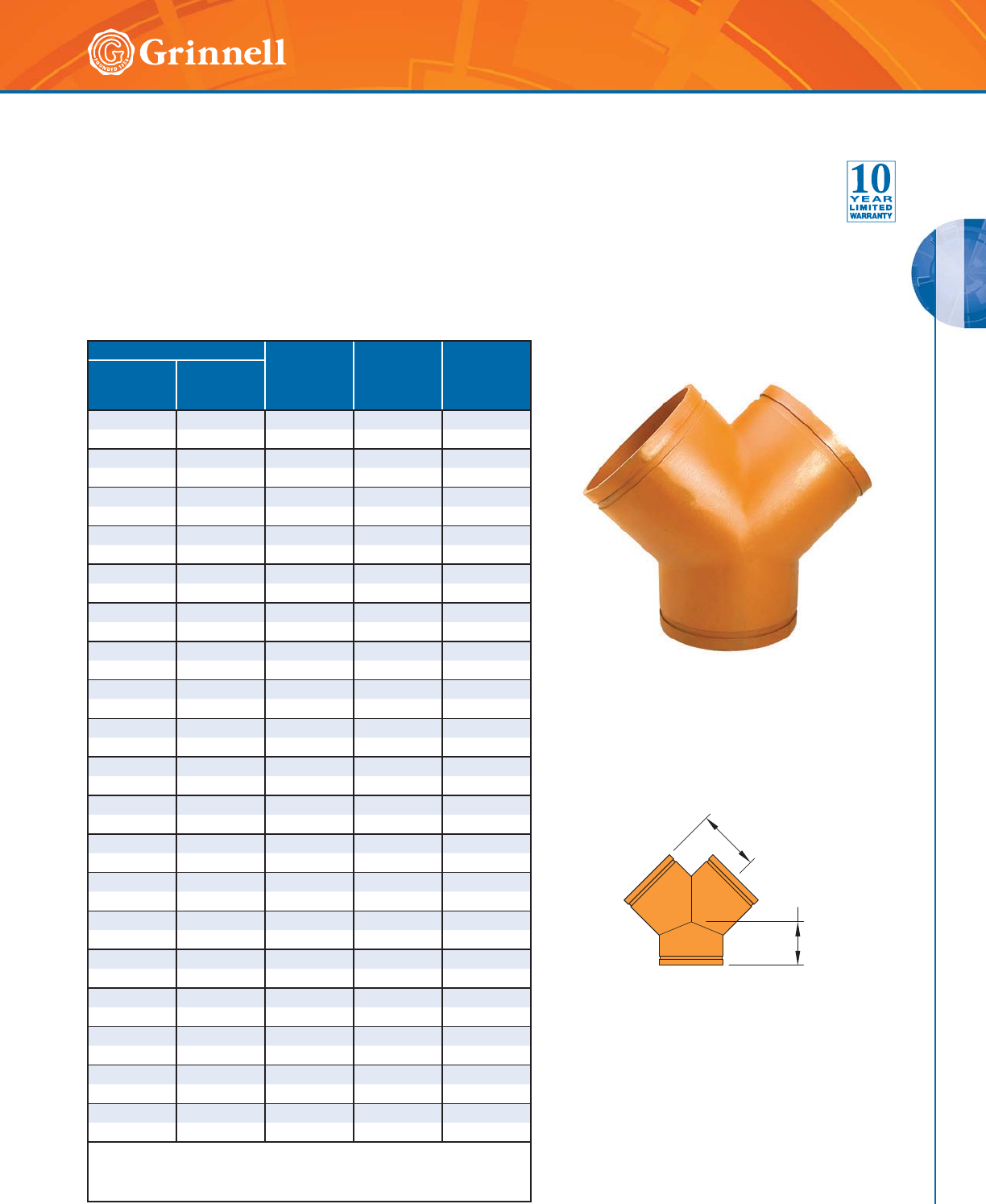
GROOVED FITTINGS
GROOVED FITTINGS
63
Refer to back cover for country-specific customer care numbers.
Pipe Size C to LE
Inches
mm
C to SE
Inches
mm
Approx.
Weight
Lbs.
kg
Nominal
Inches
mm
O.D.
Inches
mm
11⁄41.660 2.75 2.50 1.4
32 42,4 69,9 63,5 0,6
11⁄21.900 2.75 2.75 1.7
40 48,3 69,9 69,9 0,8
2 2.375 3.25 2.75 2.5
50 60,3 82,6 69,9 1,1
21⁄22.875 3.75 3.00 4.4
65 73,0 95,3 76,2 2,0
76,1mm 3.000 3.75 3.00 4.4
65 76,1 95,3 76,2 2,0
3 3.500 4.25 3.25 6.4
80 88,9 108,0 82,6 2,9
4 4.500 5.00 3.75 10.5
100 114,3 127,0 95,3 4,8
139,7mm 5.500 5.50 4.00 15.2
125 139,7 139,7 101,6 6,9
55.5635.504.0015.2
125 141,3 139,7 101,6 6,9
165,1mm 6.500 6.50 4.50 22.9
150 165,1 165,1 114,3 10,4
6 6.625 6.50 4.50 22.9
150 168,3 165,1 114,3 10,4
88.6257.756.0041.9
200 219,1 196,9 152,4 19,0
10 10.750 9.00 6.50 66.2
250 273,0 228,6 165,71 30,0
12 12.750 10.00 7.00 87.7
300 323,9 254,0 177,8 39,8
14 14.000 11.00 7.50 105.3
350 355,6 279,4 190,5 47,8
16 16.000 12.00 8.00 129.1
400 406,4 304,8 203,2 58,6
18 18.000 15.50 8.50 184.4
450 457,2 393,7 215,9 83,6
20 20.000 17.25 9.00 225.8
500 508,0 438,2 238,6 102,4
24 24.000 20.00 10.00 308.5
600 609,6 508,0 254,0 139,9
For information on larger sizes, European sizes or other alternative sizes, contact
GRINNELL Mechanical Products.
See page 37 for fitting specifications.
C to SE
C to LE
Figure 324 90° True Wyes
Tech Data Sheet: G180
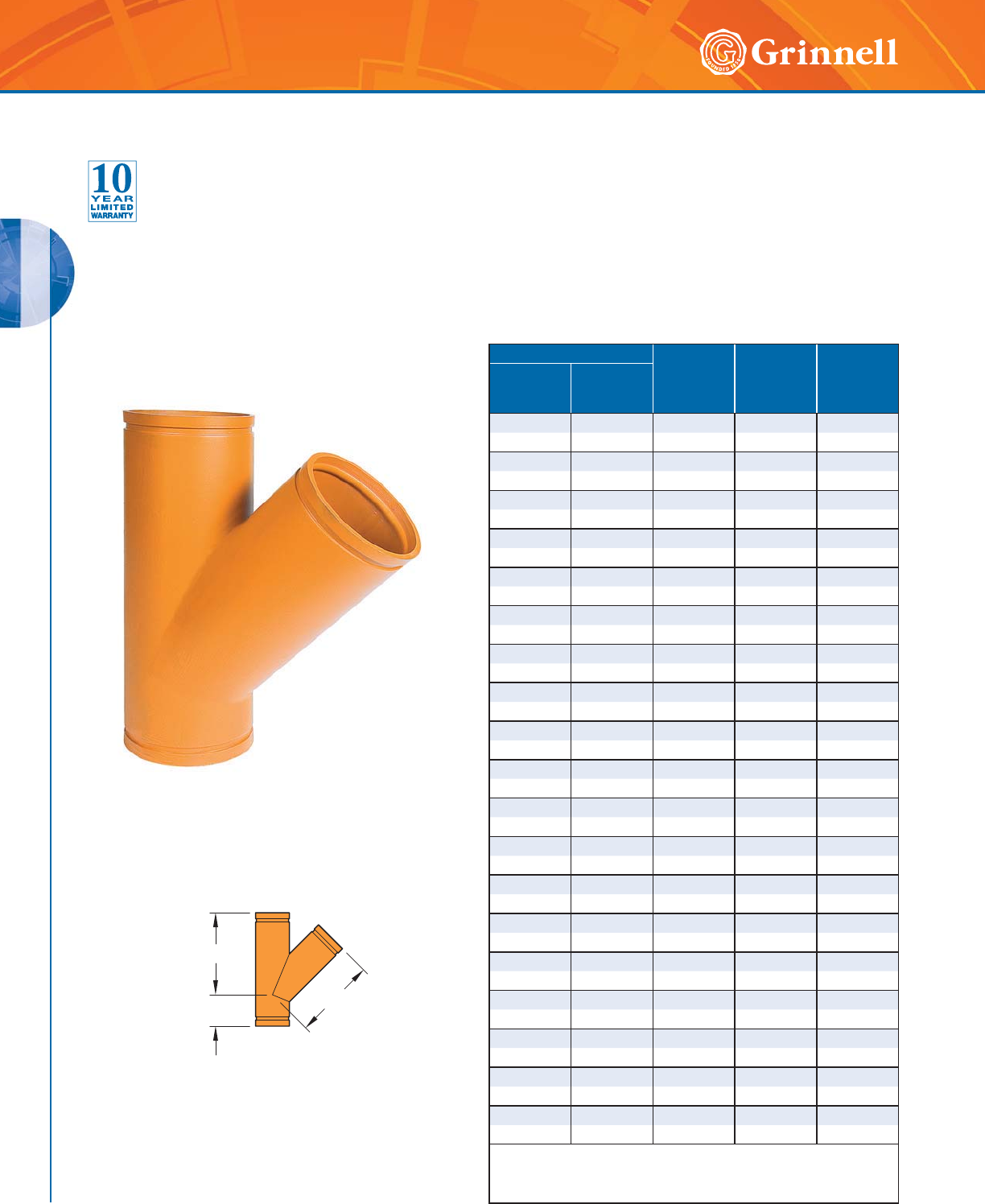
GROOVED FITTINGS
GROOVED FITTINGS
64 www.grinnell.com
Pipe Size C to LE
Inches
mm
C to SE
Inches
mm
Approx.
Weight
Lbs.
kg
Nominal
Inches
mm
O.D.
Inches
mm
11⁄41.660 5.75 2.50 1.4
32 42,4 146,1 63,5 0,6
11⁄21.900 6.25 2.75 1.7
40 48,3 158,8 69,9 0,8
2 2.375 7.00 2.75 2.5
50 60,3 177,8 69,9 1,1
21⁄22.875 7.75 3.00 4.4
65 73,0 196,9 76,2 2,0
76,1mm 3.000 7.75 3.00 4.4
65 76,1 196,9 76,2 2,0
33.5008.503.256.4
80 88,9 215,9 82,6 2,9
4 4.500 10.50 3.75 10.5
100 114,3 266,7 95,3 4,8
139,7mm 5.500 12.50 4.00 30.0
125 139,7 317,5 102,0 13,6
5 5.563 12.50 4.00 15.2
125 141,3 317,5 101,6 6,9
165,1mm 6.500 14.00 4.50 22.9
150 165,1 355,6 114,3 10,4
6 6.625 14.00 4.50 22.9
150 168,3 355,6 114,3 10,4
8 8.625 18.00 6.00 41.9
200 219,1 457,2 152,4 19,0
10 10.750 20.50 6.50 66.2
250 273,0 520,7 165,71 30,0
12 12.750 23.00 7.00 87.7
300 323,9 584,2 177,8 39,8
14 14.000 26.50 7.50 105.3
350 355,6 673,1 190,5 47,8
16 16.000 29.00 8.00 129.1
400 406,4 736,6 203,2 58,6
18 18.000 32.00 8.50 184.4
450 457,2 812,8 215,9 83,6
20 20.000 35.00 9.00 225.8
500 508,0 889,0 238,6 102,4
24 24.000 40.00 10.00 308.5
600 609,6 1016,0 254,0 139,9
For information on larger sizes, contact GRINNELL
Mechanical Products.
See page 37 for fitting specifications.
C to LE
C to SE C to LE
Figure 314 45° Laterals
Tech Data Sheet: G180
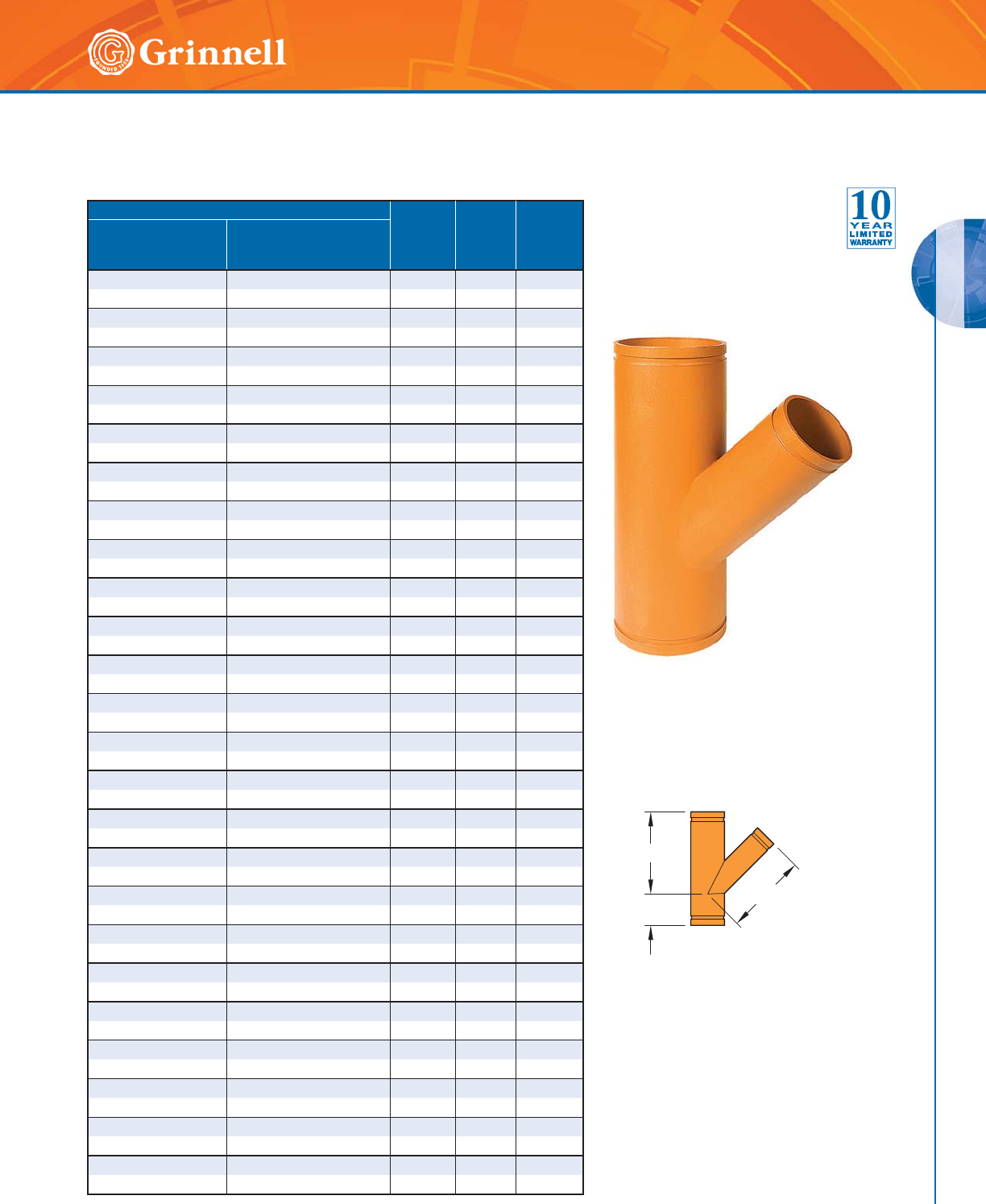
GROOVED FITTINGS
GROOVED FITTINGS
65
Refer to back cover for country-specific customer care numbers.
Pipe Size C to LE
Inches
mm
C to SE
Inches
mm
Approx.
Weight
Lbs.
kg
Nominal
Inches
mm
O.D.
Inches
mm
3 x 3 x 2 3.500 x 3.500 x 2.375 8.50 3.25 9.0
80 x 80 x 50 88,9 x 88,9 x 60,3 215,9 82,6 4,1
3 x 3 x 21⁄23.500 x 3.500 x 2.875 8.50 3.25 10.0
80 x 80 x 65 88,9 x 88,9 x 73,0 215,9 82,6 4,5
3 x 3 x 76,1mm 3.500 x 3.500 x 3.000 8.50 3.25 11.5
80 x 80 x 76,1 88,9 x 88,9 x 76,1 216,0 83,0 5,2
4 x 4 x 2 4.500 x 4.500 x 2.375 10.50 3.75 14.7
100 x 100 x 50 114,3 x 114,3 x 60,3 266,7 95,3 6,7
4 x 4 x 21⁄24.500 x 4.500 x 2.875 10.50 3.75 16.0
100 x 100 x 65 114,3 x 114,3 x 73,0 266,7 95,3 7,3
4 x 4 x 76,1mm 4.500 x 4.500 x 3.000 10.50 3.75 16.9
100 x 100 x 65 114,3 x 114,3 x 76,1 267,0 95,0 7,7
4 x 4 x 3 4.500 x 4.500 x 3.500 10.50 3.75 16.9
100 x 100 x 80 114,3 x 114,3 x 88,9 266,7 95,3 7,7
139,7 x 139,7mm x 2 5.500 x 5.500 x 2.375 12.50 4.00 22.4
125 x 125 x 50 139,7 x 139,7 x 60,3 318,1 102,0 10,2
139,7 x 139,7mm x 3 5.500 x 5.500 x 3.500 12.50 4.00 26.5
125 x 125 x 80 139,7 x 139,7 x 88,9 318,0 102,0 12,0
139,7 x 139,7mm x 4 5.500 x 5.500 x 4.500 12.50 4.00 30.4
125 x 125 x 100 139,7 x 139,7 x 114,3 318,0 102,0 13,8
5 x 5 x 2 5.563 x 5.563 x 2.375 12.50 4.00 22.4
125 x 125 x 50 141,3 x 141,3 x 60,3 317,5 101,6 10,2
5 x 5 x 21⁄25.563 x 5.563 x 2.875 12.50 4.00 23.5
125 x 125 x 65 141,3 x 141,3 x 73,0 317,5 101,6 10,7
5 x 5 x 3 5.563 x 5.563 x 3.500 12.50 4.00 24.9
125 x 125 x 80 141,3 x 141,3 x 88,9 317,5 101,6 11,3
5 x 5 x 4 5.563 x 5.563 x 4.500 12.50 4.00 26.9
125 x 125 x 100 141,3 x 141,3 x 114,3 317,5 101,6 12,2
165,1 x 165,1mm x 2 6.500 x 6.500 x 2.375 14.00 4.50 33.1
150 x 150 x 50 165,1 x 165,1 x 60,3 356,0 114,0 15,0
165,1 x 165,1mm x 3 6.500 x 6.500 x 3.500 14.00 4.50 37.0
150 x 150 x 80 165,1 x 165,1 x 88,9 356,0 114,0 16,8
165,1 x 165,1mm x 4 6.500 x 6.500 x 4.500 14.00 4.50 39.9
150 x 150 x 100 165,1 x 165,1 x 114,3 356,0 114,0 18,1
165,1 x 165,1 x 139,7mm 6.500 x 6.500 x 5.500 14.00 4.50 45.0
150 x 150 x 125 165,1 x 165,1 x 139,7 356,0 114,0 20,4
6 x 6 x 2 6.625 x 6.625 x 2.375 14.00 4.50 31.7
150 x 150 x 50 168,3 x 168,3 x 60,3 355,6 114,3 14,4
6 x 6 x 21⁄26.625 x 6.625 x 2.875 14.00 4.50 34.0
150 x 150 x 65 168,3 x 168,3 x 73,0 355,6 114,3 15,0
6 x 6 x 3 6.625 x 6.625 x 3.500 14.00 4.50 34.4
150 x 150 x 80 168,3 x 168,3 x 88,9 355,6 114,3 15,6
6 x 6 x 4 6.625 x 6.625 x 4.500 14.00 4.50 36.5
150 x 150 x 100 168,3 x 168,3 x 114,3 355,6 114,3 16,6
6 x 6 x 139,7mm 6.625 x 6.625 x 5.500 14.00 4.50 45.0
150 x 150 x 125 168,3 x 168,3 x 139,7 356,0 114,0 20,4
6 x 6 x 5 6.625 x 6.625 x 5.563 14.00 4.50 39.1
150 x 150 x 125 168,3 x 168,3 x 141,3 355,6 114,3 17,7
C to SE
C to LE
C to LE
Figure 325 45° Reducing Laterals
(Page 1 of 3)
Tech Data Sheet: G180
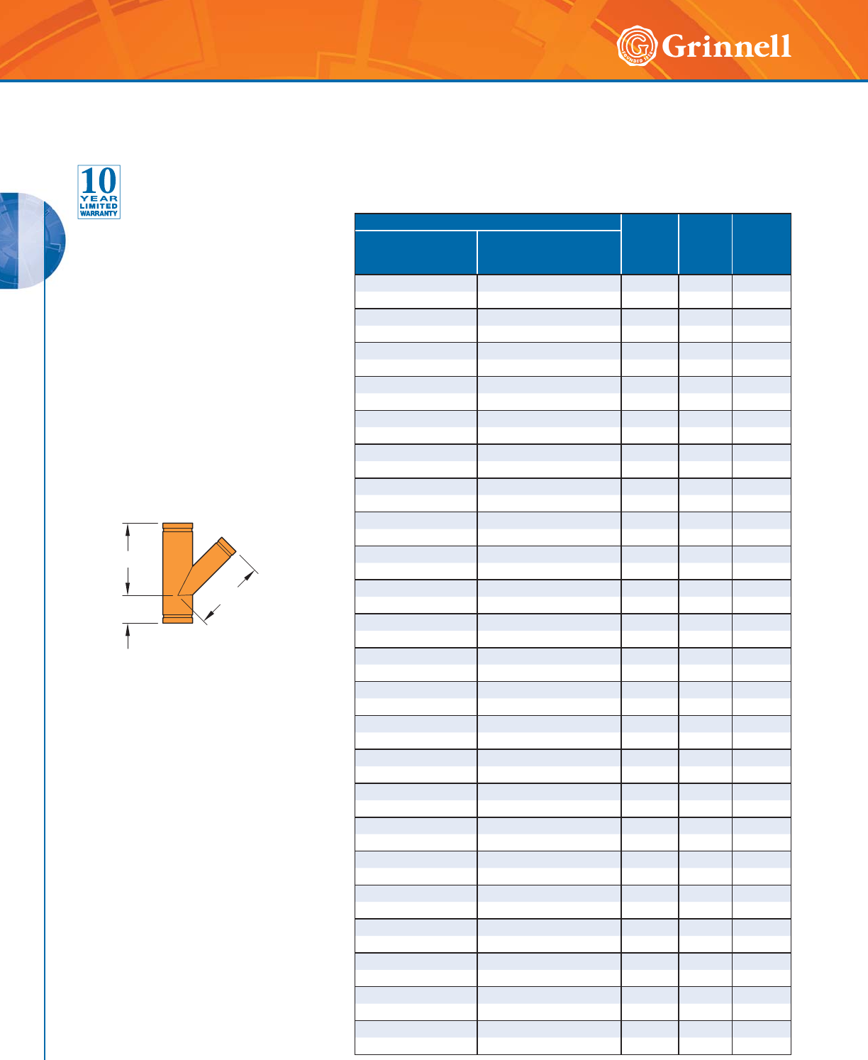
GROOVED FITTINGS
GROOVED FITTINGS
66 www.grinnell.com
C to SE
C to LE
C to LE
Pipe Size C to LE
Inches
mm
C to SE
Inches
mm
Approx.
Weight
Lbs.
kg
Nominal
Inches
mm
O.D.
Inches
mm
8 x 8 x 4 8.625 x 8.625 x 4.500 18.00 6.00 58.9
200 x 200 x 100 219,1 x 219,1 x 114,1 457,2 152,4 26,7
8 x 8 x 139,7mm 8.625 x 8.625 x 5.500 18.00 6.00 67.9
200 x 200 x 125 219,1 x 219,1 x 139,7 457,0 152,0 30,8
8 x 8 x 5 8.625 x 8.625 x 5.563 18.00 6.00 62.2
200 x 200 x 125 219,1 x 219,1 x 141,3 457,2 152,4 28,2
8 x 8 x 6 8.625 x 8.625 x 6.625 18.00 6.00 66.1
200 x 200 x 150 219,1 x 219,1 x 168,3 457,2 152,4 30,0
10 x 10 x 4 10.750 x 10.750 x 4.500 20.50 6.50 87.3
250 x 250 x 100 273,0 x 273,0 x 114,3 520,7 165,1 39,6
10 x 10 x 139,7mm 10.750 x 10.750 x 5.500 20.50 6.50 100.1
250 x 250 x 125 273,0 x 273,0 x 139,7 521,0 165,0 45,4
10 x 10 x 5 10.750 x 10.750 x 5.563 20.50 6.50 90.7
250 x 250 x 125 273,0 x 273,0 x 141,3 520,7 165,1 41,1
10 x 10 x 6 10.750 x 10.750 x 6.625 20.50 6.50 94.7
250 x 250 x 150 273,0 x 273,0 x 168,3 520,7 165,1 43,0
10 x 10 x 8 10.750 x 10.750 x 8.625 20.50 6.50 99.2
250 x 250 x 200 273,0 x 273,0 x 219,1 520,7 165,1 45,0
12 x 12 x 4 12.750 x 12.750 x 4.500 23.00 7.00 120.6
300 x 300 x 100 323,9 x 323,9 x 114,3 584,2 177,8 54,7
12 x 12 x 6 12.750 x 12.750 x 6.625 23.00 7.00 128.5
300 x 300 x 150 323,9 x 323,9 x 168,3 584,2 177,8 58,3
12 x 12 x 8 12.750 x 12.750 x 8.625 23.00 7.00 133.1
300 x 300 x 200 323,9 x 323,9 x 219,1 584,2 177,8 60,4
12 x 12 x 10 12.750 x 12.750 x 10.750 23.00 7.00 142.3
300 x 300 x 250 323,9 x 323,9 x 273,0 584,2 177,8 64,5
14 x 14 x 4 14.000 x 14.000 x 4.500 26.50 7.50 167.9
350 x 350 x 100 355,6 x 355,6 x 114,3 673,1 190,5 76,2
14 x 14 x 6 14.000 x 14.000 x 6.625 26.50 7.50 177.2
350 x 350 x 150 355,6 x 355,6 x 168,3 673,1 190,5 80,4
14 x 14 x 8 14.000 x 14.000 x 8.625 26.50 7.50 182.5
350 x 350 x 200 355,6 x 355,6 x 219,1 673,1 190,5 82,8
14 x 14 x 10 14.000 x 14.000 x 10.750 26.50 7.50 193.0
350 x 350 x 250 355,6 x 355,6 x 273,0 673,1 190,5 87,5
14 x 14 x 12 14.000 x 14.000 x 12.750 26.50 7.50 203.8
350 x 350 x 300 355,6 x 355,6 x 323,9 673,1 190,5 92,4
16 x 16 x 6 16.000 x 16.000 x 6.625 29.00 8.00 217.2
400 x 400 x 150 406,4 x 406,4 x 168,3 736,6 203,0 98,5
16 x 16 x 8 16.000 x 16.000 x 8.625 29.00 8.00 223.0
400 x 400 x 200 406,4 x 406,4 x 219,1 736,6 203,0 101,2
16 x 16 x 10 16.000 x 16.000 x 10.750 29.00 8.00 234.1
400 x 400 x 250 406,4 x 406,4 x 273,0 736,6 203,0 106,2
16 x 16 x 12 16.000 x 16.000 x 12.750 29.00 8.00 245.4
400 x 400 x 300 406,4 x 406,4 x 323,9 736,6 203,0 111,3
16 x 16 x 14 16.000 x 16.000 x 14.000 29.00 8.00 261.0
400 x 400 x 350 406,4 x 406,4 x 355,6 736,6 203,0 118,4
Figure 325 45° Reducing Laterals
(Page 2 of 3)
Tech Data Sheet: G180
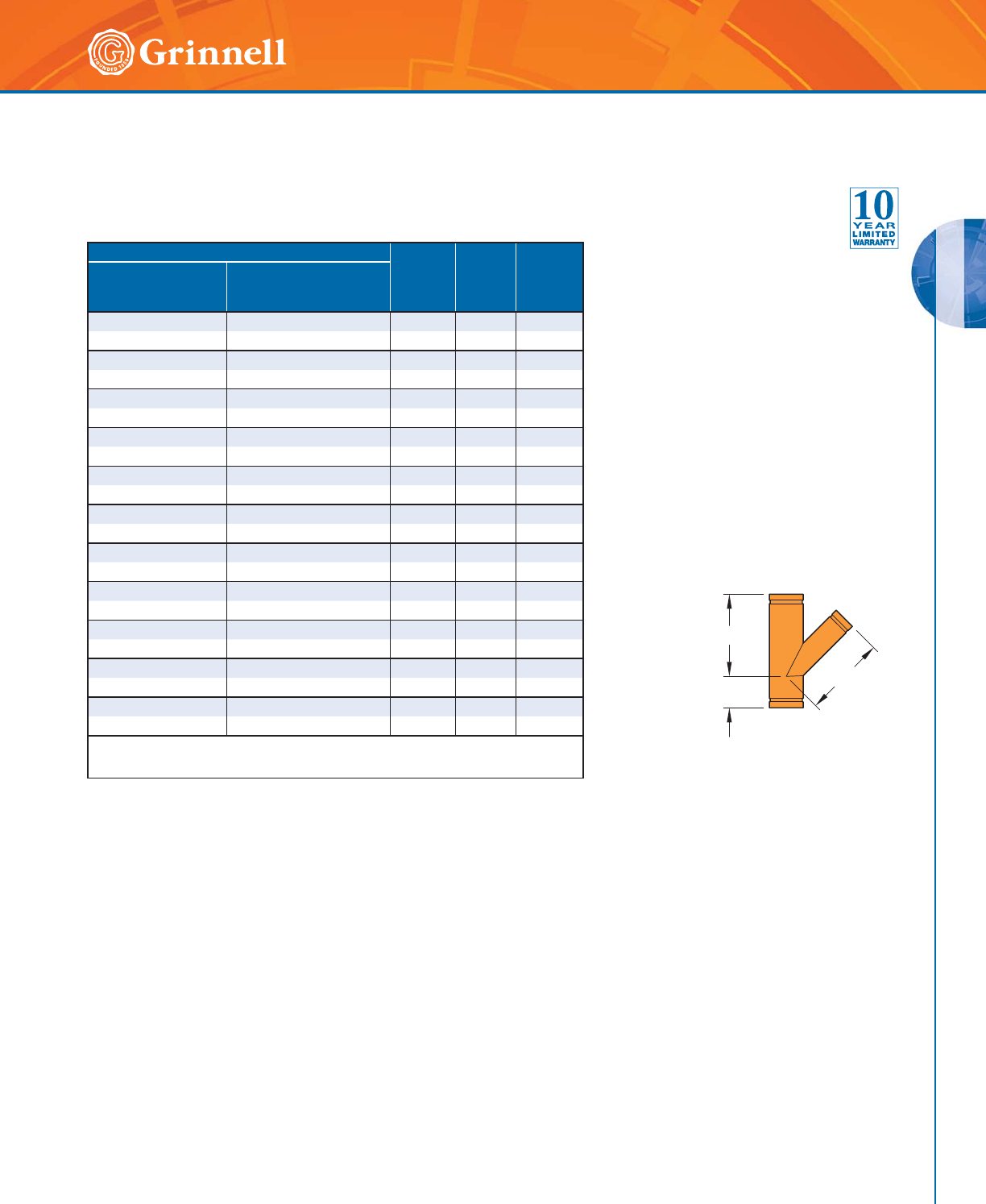
GROOVED FITTINGS
GROOVED FITTINGS
67
Refer to back cover for country-specific customer care numbers.
Pipe Size C to LE
Inches
mm
C to SE
Inches
mm
Approx.
Weight
Lbs.
kg
Nominal
Inches
mm
O.D.
Inches
mm
18 x 18 x 6 18.000 x 18.000 x 6.625 32.00 8.50 265.1
450 x 450 x 150 457,2 x 457,2 x 168,3 812,8 215,9 120,2
18 x 18 x 8 18.000 x 18.000 x 8.625 32.00 8.50 271.5
450 x 450 x 200 457,2 x 457,2 x 219,1 812,8 215,9 123,2
18 x 18 x 10 18.000 x 18.000 x 10.750 32.00 8.50 283.7
450 x 450 x 250 457,2 x 457,2 x 273,0 812,8 215,9 128,7
18 x 18 x 12 18.000 x 18.000 x 12.750 32.00 8.50 296.0
450 x 450 x 300 457,2 x 457,2 x 323,9 812,8 215,9 134,3
18 x 18 x 14 18.000 x 18.000 x 14.000 32.00 8.50 312.6
450 x 450 x 350 457,2 x 457,2 x 355,6 812,8 215,9 141,8
18 x 18 x 16 18.000 x 18.000 x 16.000 32.00 8.50 322.6
450 x 450 x 400 457,2 x 457,2 x 406,4 812,8 215,9 146,3
20 x 20 x 12 20.000 x 20.000 x 12.750 35.00 9.00 351.4
500 x 500 x 300 508,0 x 508,0 x 323,9 889,0 228,6 159,4
20 x 20 x 14 20.000 x 20.000 x 14.000 35.00 9.00 369.1
500 x 500 x 350 508,0 x 508,0 x 355,6 889,0 228,6 167,4
20 x 20 x 16 20.000 x 20.000 x 16.000 35.00 9.00 379.7
500 x 500 x 400 508,0 x 508,0 x 406,4 889,0 228,6 172,2
24 x 24 x 16 24.000 x 24.000 x 16.000 40.00 10.00 495.6
600 x 600 x 400 609,6 x 609,6 x 406,4 1016,0 254,0 224,8
24 x 24 x 20 24.000 x 24.000 x 20.000 40.00 10.00 518.4
600 x 600 x 500 609,6 x 609,6 x 508,0 1016,0 254,0 235,1
For information on larger sizes, contact GRINNELL Mechanical Products.
See page 37 for fitting specifications.
Figure 325 45° Reducing Laterals
(Page 3 of 3)
Tech Data Sheet: G180
C to SE
C to LE
C to LE
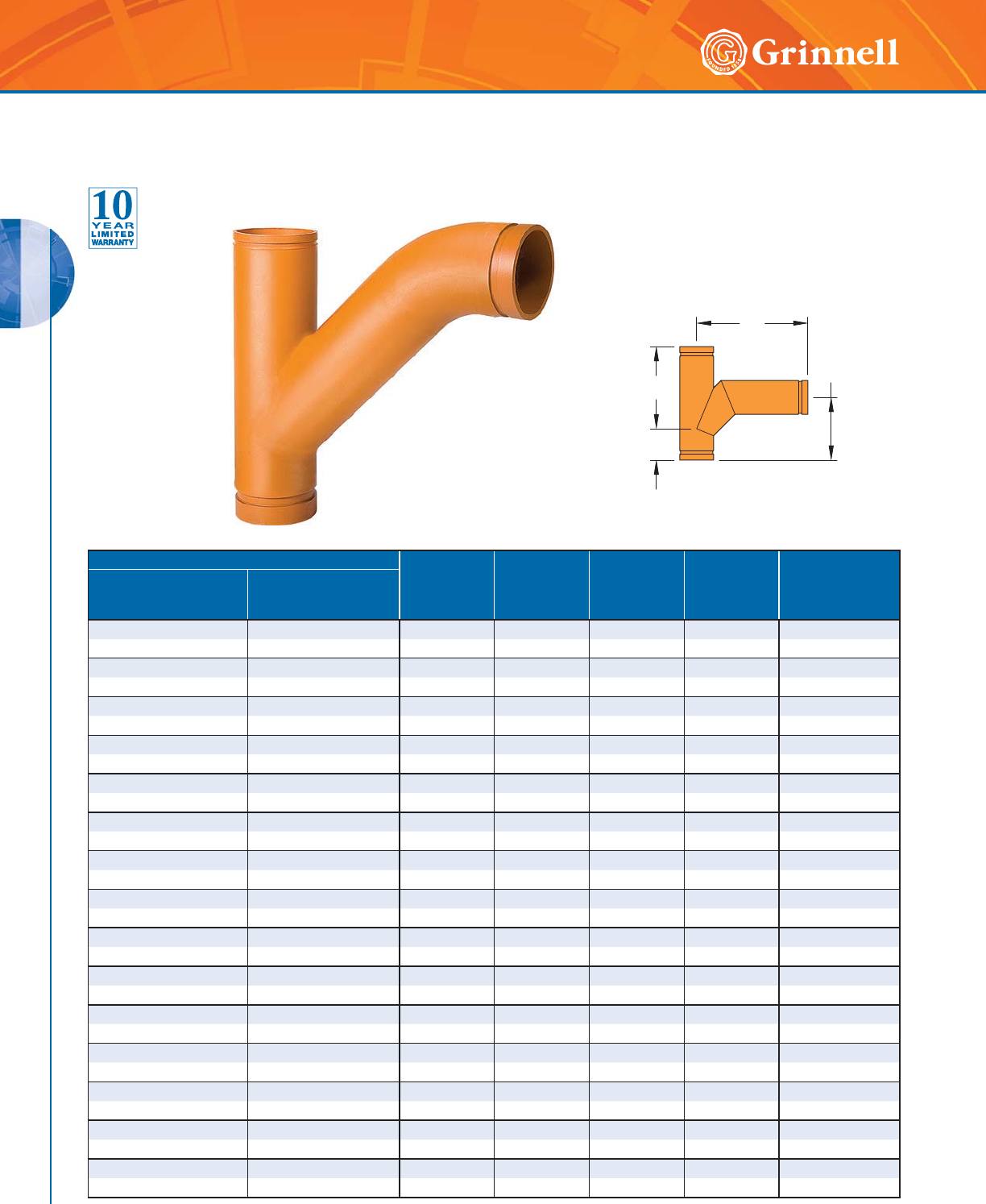
GROOVED FITTINGS
GROOVED FITTINGS
68 www.grinnell.com
Pipe Size G
Inches
mm
H
Inches
mm
E1
Inches
mm
E2
Inches
mm
Approx
Wt.
Lbs.
kg
Nominal
Inches
mm
O.D.
Inches
mm
2 x 2 x 2 2.375 x 2.375 x 2.375 2.75 7.00 9.00 7.37 5.7
50 x 50 x 50 60,3 x 60,3 x 60,3 69,9 177,8 228,6 187,2 2,6
21⁄2 x 21⁄2 x 21⁄22.875 x 2.875 x 2.875 3.00 7.75 10.50 8.84 10.2
65 x 65 x 65 73,0 x 73,0 x 73,0 76,2 196,9 266,7 224,5 4,6
3 x 3 x 3 3.500 x 3.500 x 3.500 3.25 8.50 11.50 9.31 14.4
80 x 80 x 80 88,9 x 88,9 x 88,9 82,6 215,9 292,1 236,5 6,5
4 x 4 x 3 4.500 x 4.500 x 3.500 3.75 10.50 12.88 10.17 20.5
100 x 100 x 80 114,3 x 114,3 x 88,9 95,3 266,7 327,2 258,3 9,3
4 x 4 x 4 4.500 x 4.500 x 4.500 3.75 10.50 13.63 11.87 24.6
100 x 100 x 100 114,3 x 114,3 x 114,3 95,3 266,7 346,2 301,5 11,2
5 x 5 x 3 5.563 x 5.563 x 3.500 4.00 12.50 14.25 13.25 28.4
125 x 125 x 80 141,3 x 141,3 x 88,9 101,6 317,5 362,0 336,6 12,9
5 x 5 x 4 5.563 x 5.563 x 4.500 4.00 12.50 15.13 13.63 32.8
125 x 125 x 100 141,3 x 141,3 x 114,3 101,6 317,5 384,3 346,1 14,9
5 x 5 x 5 5.563 x 5.563 x 5.563 4.00 12.50 16.13 14.00 38.8
125 x 125 x 125 141,3 x 141,3 x 141,3 101,6 317,5 409,7 355,6 17,6
6 x 6 x 3 6.625 x 6.625 x 3.500 4.50 14.00 15.31 14.81 37.9
150 x 150 x 80 168,3 x 168,3 x 88,9 114,3 355,6 388,9 376,2 17,2
6 x 6 x 4 6.625 x 6.625 x 4.500 4.50 14.00 16.25 15.25 42.5
150 x 150 x 100 168,3 x 168,3 x 114,3 114,3 355,6 412,8 387,4 19,3
6 x 6 x 5 6.625 x 6.625 x 5.563 4.50 14.00 17.25 15.63 48.5
150 x 150 x 125 168,3 x 168,3 x 141,3 114,3 355,6 438,2 396,9 22,0
6 x 6 x 6 6.625 x 6.625 x 6.625 4.50 14.00 18.25 16.00 56.3
150 x 150 x 150 168,3 x 168,3 x 168,3 114,3 355,6 463,6 406,4 25,5
8 x 8 x 3 8.625 x 8.625 x 3.500 6.00 18.00 18.19 19.18 67.3
200 x 200 x 80 219,1 x 219,1 x 88,9 152,4 457,2 462,0 487,2 30,5
8 x 8 x 4 8.625 x 8.625 x 4.500 6.00 18.00 19.00 19.50 72.3
200 x 200 x 100 219,1 x 219,1 x 114,3 152,4 457,2 482,6 495,3 32,8
8 x 8 x 5 8.625 x 8.625 x 5.563 6.00 18.00 20.00 19.87 78.8
200 x 200 x 125 219,1 x 219,1 x 141,3 152,4 457,2 508,0 504,7 35,7
E1
E2
H
G
E1
E2
H
G
Figure 330 Tee Wyes
(Page 1 of 2)
Tech Data Sheet: G180
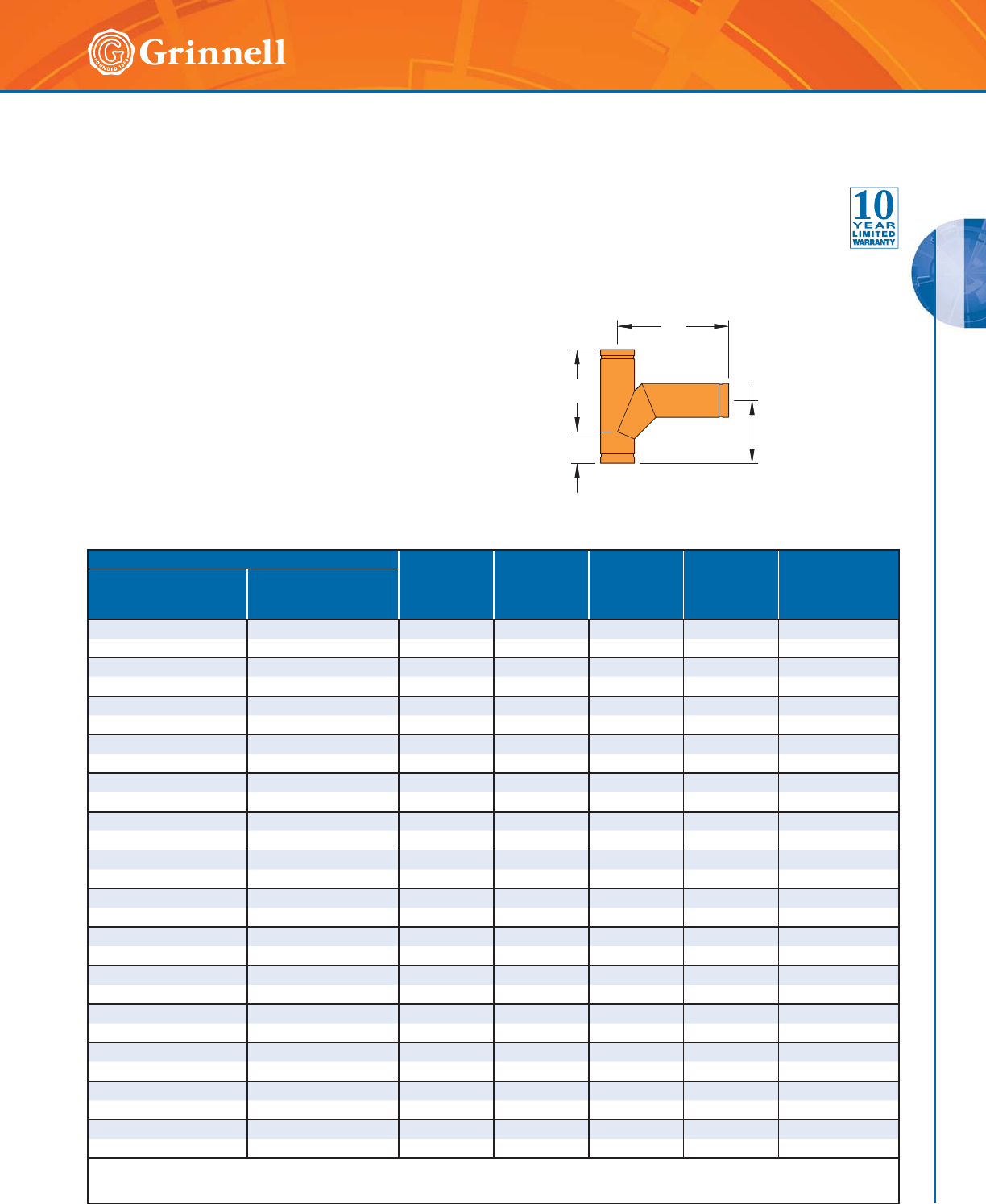
GROOVED FITTINGS
GROOVED FITTINGS
69
Refer to back cover for country-specific customer care numbers.
E1
E2
H
G
E1
E2
H
G
Pipe Size G
Inches
mm
H
Inches
mm
E1
Inches
mm
E2
Inches
mm
Approx
Wt.
Lbs.
kg
Nominal
Inches
mm
O.D.
Inches
mm
8 x 8 x 6 8.625 x 8.625 x 6.625 6.00 18.00 21.13 20.37 87.4
200 x 200 x 150 219,1 x 219,1 x 168,3 152,4 457,2 536,7 517,4 39,6
8 x 8 x 8 8.625 x 8.625 x 8.625 6.00 18.00 23.25 21.25 109.0
200 x 200 x 200 219,1 x 219,1 x 219,1 152,4 457,2 590,6 539,8 49,4
10 x 10 x 3 10.750 x 10.750 x 3.500 6.50 20.50 19.88 21.38 101.7
250 x 250 x 80 273,0 x 273,0 x 88,9 165,1 520,7 505,0 543,1 46,1
10 x 10 x 4 10.750 x 10.750 x 4.500 6.50 20.50 20.75 21.75 106.9
250 x 250 x 100 273,0 x 273,0 x 114,3 165,1 520,7 527,1 552,5 48,5
10 x 10 x 5 10.750 x 10.750 x 5.563 6.50 20.50 21.88 22.25 113.8
250 x 250 x 125 273,0 x 273,0 x 141,3 165,1 520,7 555,8 565,2 51,6
10 x 10 x 6 10.750 x 10.750 x 6.625 6.50 20.50 22.88 22.63 122.1
250 x 250 x 150 273,0 x 273,0 x 168,3 165,1 520,7 581,2 574,7 55,4
10 x 10 x 8 10.750 x 10.750 x 8.625 6.50 20.50 27.25 25.75 151.1
250 x 250 x 200 273,0 x 273,0 x 219,1 165,1 520,7 692,2 654,1 68,5
10 x 10 x 10 10.750 x 10.750 x 10.750 6.50 20.50 27.25 24.38 175.1
250 x 250 x 250 273,0 x 273,0 x 273,0 165,1 520,7 692,2 619,1 79,4
12 x 12 x 3 12.750 x 12.750 x 3.500 7.00 23.00 20.75 22.75 134.5
300 x 300 x 80 323,9 x 323,9 x 88,9 177,8 584,2 527,1 577,9 61,0
12 x 12 x 4 12.750 x 12.750 x 4.500 7.00 23.00 21.50 23.00 139.4
300 x 300 x 100 323,9 x 323,9 x 114,3 177,8 584,2 546,1 584,2 63,2
12 x 12 x 6 12.750 x 12.750 x 6.625 7.00 23.00 23.75 24.00 154.5
300 x 300 x 150 323,9 x 323,9 x 168,3 177,8 584,2 603,3 609,6 70,0
12 x 12 x 8 12.750 x 12.750 x 8.625 7.00 23.00 26.00 25.00 175.8
300 x 300 x 200 323,9 x 323,9 x 219,1 177,8 584,2 660,4 635,0 79,7
12 x 12 x 10 12.750 x 12.750 x 10.750 7.00 23.00 28.00 25.75 205.4
300 x 300 x 250 323,9 x 323,9 x 273,0 177,8 584,2 711,2 654,1 93,2
12 x 12 x 12 12.750 x 12.750 x 12.750 7.00 23.00 31.00 27.50 240.1
300 x 300 x 300 323,9 x 323,9 x 323,9 177,8 584,2 787,4 698,5 108,9
For information on larger sizes, contact GRINNELL Mechanical Products.
See page 37 for fitting specifications.
Figure 330 Tee Wyes
(Page 2 of 2)
Tech Data Sheet: G180
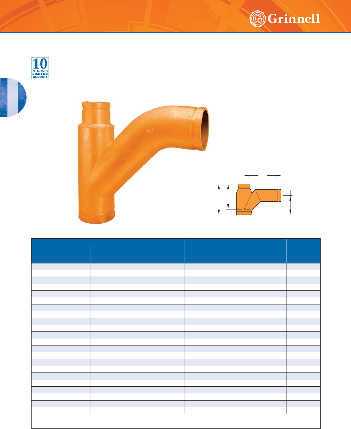
GROOVED FITTINGS
GROOVED FITTINGS
70 www.grinnell.com
Pipe Size G
Inches
mm
H
Inches
mm
E1
Inches
mm
E2
Inches
mm
Approx Wt.
Lbs.
kg
Nominal
Inches
mm
O.D.
Inches
mm
4 x 3 x 3 4.500 x 3.500 x 3.500 9.01 7.38 10.75 7.25 13.7
100 x 80 x 80 114,3 x 88,9 x 88,9 228,9 187,5 273,1 184,2 6,2
4 x 3 x 4 4.500 x 3.500 x 4.500 14.25 10.50 13.63 11.87 24.5
100 x 80 x 100 114,3 x 88,9 x 114,3 362,0 266,7 346,2 301,5 11,1
5 x 3 x 3 5.563 x 3.500 x 3.500 11.00 9.75 11.50 7.71 19.0
125 x 80 x 80 141,3 x 88,9 x 88,9 279,5 247,7 292,1 195,8 8,6
5 x 3 x 5 5.563 x 3.500 x 5.563 16.50 12.50 16.13 13.95 38.5
125 x 80 x 125 141,3 x 88,9 x 141,3 419,1 317,5 409,7 354,3 17,5
5 x 4 x 3 5.563 x 4.500 x 3.500 11.01 9.13 11.88 8.71 19.5
125 x 100 x 80 141,3 x 114,3 x 88,9 279,7 231,9 301,88 221,2 8,8
5 x 4 x 4 5.563 x 4.500 x 4.500 11.01 9.13 12.75 9.00 23.1
125 x 100 x 100 141,3 x 114,3 x 114,3 279,7 231,9 323,9 228,6 10,5
6 x 4 x 6 6.625 x 4.500 x 6.625 18.50 14.00 18.25 13.75 56.2
150 x 100 x 150 168,3 x 114,3 x 168,3 469,9 355,6 463,6 349,3 25,5
6 x 5 x 3 6.625 x 5.563 x 3.500 12.00 10.75 13.00 9.25 25.6
150 x 125 x 80 168,3 x 141,3 x 88,9 304,9 273,1 330,2 235,0 11,6
6 x 5 x 4 6.625 x 5.563 x 4.500 12.00 10.75 13.88 9.62 29.3
150 x 125 x 100 168,3 x 141,3 x 114,3 304,9 273,1 352,6 244,3 13,3
8 x 6 x 4 8.625 x 6.625 x 4.500 13.00 12.00 14.75 10.25 40.2
200 x 150 x 100 219,1 x 168,3 x 114,3 330,2 304,8 374,7 260,3 18,2
8 x 6 x 8 8.625 x 6.625 x 8.625 24.00 18.00 23.25 21.25 108.6
200 x 150 x 200 219,1 x 168,3 x 219,1 609,6 457,2 590,6 539,8 49,3
For information on larger sizes, contact GRINNELL Mechanical Products.
See page 37 for fitting specifications.
E1
GH
E2
Figure 331 Reducing Tee Wyes
Tech Data Sheet: G180
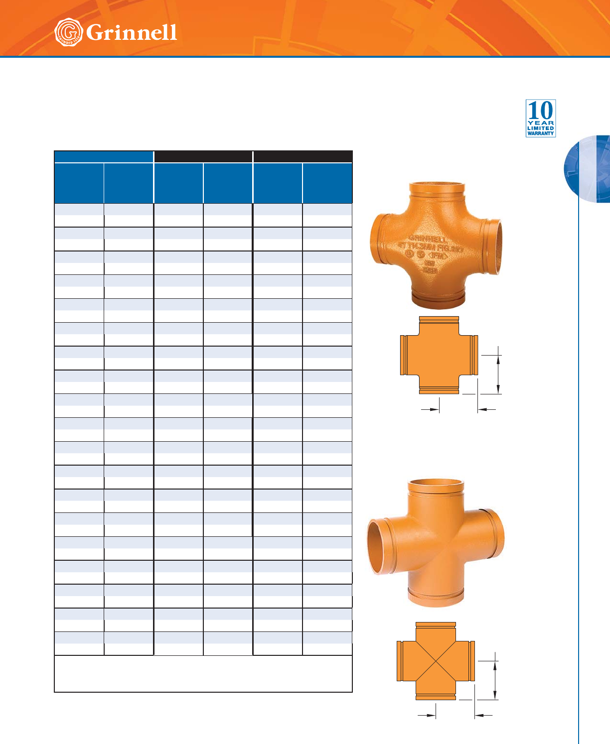
GROOVED FITTINGS
GROOVED FITTINGS
71
Refer to back cover for country-specific customer care numbers.
Figures 227 & 327 Crosses
Tech Data Sheet: G180
Pipe Size Figure 227 - Cast Figure 327 - Fabricated
Nominal
Inches
mm
O.D.
Inches
mm
C to E
Inches
mm
Approx
Weight
Lbs.
kg
C to E
Inches
mm
Approx
Weight
Lbs.
kg
11⁄41.660 2.75 2.2 2.75 2.2
32 42,4 69,9 1,0 69,9 1,0
11⁄21.900 2.75 2.5 2.75 2.5
40 48,3 69,9 1,1 69,9 1,1
2 2.375 3.25 3.7 3.25 3.7
50 60,3 82,6 1,7 82,6 1,7
21⁄22.875 3.75 5.8 3.75 5.8
65 73,0 95,3 2,6 95,3 2,6
76,1mm 3.000 3.75 6.0 3.75 6.0
65 76,195,32,795,32,7
3 3.5004.258.64.258.6
80 88,9 108,0 3,9 108,0 3,9
4 4.500 5.00 20.7 5.00 20.7
100 114,3 127,0 9,4 127,0 9,4
139,7mm 5.500 5.50 17.6 5.50 17.6
125 139,7 139,7 8,0 139,7 8,0
5 5.563 – – 5.50 18.5
125 141,3 – – 139,7 8,4
165,1mm 6.500 6.50 27.3 6.50 27.3
150 165,1 165,1 12,4 165,1 12,4
6 6.625 6.50 28.6 6.50 28.6
150168,3165,113,0165,113,0
8 8.625 7.75 48.0 7.75 48.0
200 219,1 196,9 21,7 196,9 21,7
10 10.750 9.00 75.0 9.00 75.0
250 273,0 228,6 34,0 228,6 34,0
12 12.750 10.00 95.8 10.00 95.8
300 323,9 254,0 43,4 254,0 43,4
14 14.000 – – 11.00 136.8
350 355,6 – – 279,4 62,0
16 16.000 – – 12.00 167.3
400 406,4 – – 304,8 75,9
18 18.000 – – 15.50 259.5
450 457,2 – – 393,7 117,7
20 20.000 – – 17.25 321.7
500 508,0 – – 438,2 145,9
24 24.000 – – 20.00 442.7
600 609,6 – – 508,0 200,8
For information on larger sizes, European sizes or other alternative sizes, contact
GRINNELL Mechanical Products.
See fitting specifications on page 37.
C to E
C to E
C to E
C to E
Figure 327
Fabricated Cross
Figure 227
Cast Cross
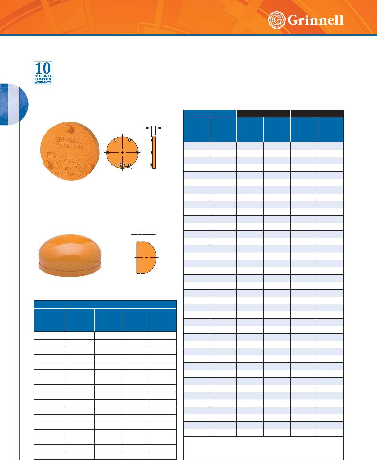
GROOVED FITTINGS
GROOVED FITTINGS
72 www.grinnell.com
Figure 360 Cap
Fabricated
Figure 260 Cap
Cast
Figure 260/360 Cap with Tap
Size
(in) (mm)
1⁄2"
13mm
Tap
3⁄4"
19mm
Tap
1"
25mm
Tap
2"
50mm
Tap
1 (25) •–––
11⁄4 (32) •–––
11⁄2 (40) •–––
2 (50) ••––
21⁄2 (65) ••––
3 (80) ••••
4 (100) ••••
5 (125) ••••
6 (150) ••••
8 (200) ••••
10 (250) ••••
12 (300) •••–
14 (350) ––––
16 (400) ––––
18 (450) ––––
20 (500) ––––
24 (600) ––––
Pipe Size Figure 260 - Cast Figure 360 - Fabricated
Nominal
Inches
mm
O.D.
Inches
mm
E to E
Inches
mm
Approx
Weight
Lbs.
kg
E to E
Inches
mm
Approx
Weight
Lbs.
kg
1 1.315 0.83 0.2 – –
25 33,4 21,1 0,1 – –
11⁄41.660 0.83 0.3 – –
32 42,4 21,1 0,1 – –
11⁄21.900 0.83 0.4 – –
40 48,3 21,1 0,2 – –
2 2.375 0.92 0.7 – –
50 60,3 23,4 0,3 – –
21⁄22.875 0.92 1.0 – –
65 73,0 23,4 0,5 – –
76,1mm 3.000 0.86 1.3 – –
65 76,1 21,8 0,6 – –
33.5000.921.4 – –
80 88,9 23,4 0,6 – –
4 4.500 1.00 2.6 – –
100 114,3 25,4 1,2 – –
139,7mm 5.500 0.92 4.7 – –
125 139,7 23,4 2,1 – –
55.5631.005.0 – –
125 141,3 25,4 2,3 – –
165,1mm 6.500 0.92 6.4 – –
150 165,1 23,4 2,9 – –
66.6251.006.2 – –
150 168,3 25,4 2,8 – –
88.6251.067.1 – –
200 219,1 27,0 3,2 – –
10 10.750 1.02 24.5 – –
250 273,0 25,8 11,1 – –
12 12.750 1.02 31.0 – –
300 323,9 25,8 14,1 – –
14 14.000 – – 8.50 36.5
350 355,6 – – 215,9 16,6
16 16.000 – – 9.00 43.5
400 406,4 – – 228,6 19,7
18 18.000 – – 10.00 57.0
450 457,2 – – 254,0 25,6
20 20.000 – – 11.00 75.7
500 508,0 – – 279,4 34,3
24 24.000 – – 12.50 101.0
600 609,6 – – 317,5 45,8
For information on larger sizes, European sizes or other alternative sizes,
contact GRINNELL Mechanical Products.
See page 37 for fitting specifications.
E to E
E to E
NPT
Figures 260 & 360 End Caps
Tech Data Sheet: G180
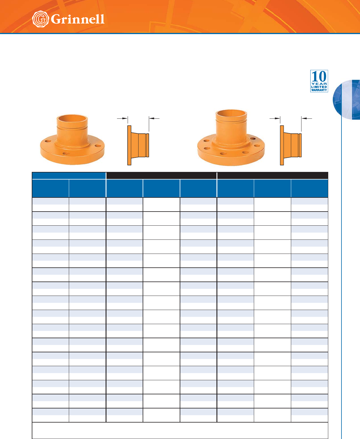
GROOVED FITTINGS
GROOVED FITTINGS
73
Refer to back cover for country-specific customer care numbers.
Pipe Size Figure 341 - ANSI Class 150# Figure 342 - ANSI Class 300#
Nominal
Inches
mm
O.D.
Inches
mm
E to E
Inches
mm
Mating Flange
Bolt
Qty.
Approx. Weight
Lbs.
kg
E to E
Inches
mm
Mating Flange
Bolt
Qty.
Approx. Weight
Lbs.
kg
11⁄41.660 4.00 43.7 4.00 44.6
32 42,4 101,6 1,7 101,6 2,1
11⁄21.900 4.00 43.9 4.00 47.1
40 48,3 101,6 1,8 101,6 3,2
22.3754.00 46.4 4.00 88.2
50 60,3 101,6 2,8 101,6 3,7
21⁄22.875 4.00 48.8 4.00 811.9
65 73,0 101,6 4,0 101,6 5,4
3 3.500 4.00 410.4 4.00 815.5
80 88,9 101,6 4,7 101,6 7,0
4 4.500 6.00 818.2 6.00 828.0
100 114,3 152,4 8,3 152,4 12,7
55.5636.00 822.0 6.00 837.0
125 141,3 152,4 10,0 152,4 16,8
66.6256.00 828.1 6.00 12 48.0
150 168,3 152,4 12,7 152,4 21,8
88.6256.00 843.7 6.00 12 79.0
200 219,1 152,4 19,8 152,4 35,8
10 10.750 8.00 12 68.2 8.00 16 122.0
250 273,0 203,2 30,9 203,2 55,3
12 12.750 8.00 12 96.1 8.00 16 183.0
300 323,9 203,2 43,6 203,2 83,0
14 14.000 8.00 12 123.0 8.00 20 199.0
350 355,6 203,2 55,8 203,2 90,3
16 16.000 8.00 16 151.0 8.00 20 255.0
400 406,4 203,2 68,5 203,2 155,7
18 18.000 8.00 16 165.0 8.00 24 303.0
450 457,2 203,2 74,8 203,2 137,4
20 20.000 8.00 20 205.0 8.00 24 365.0
500 508,0 203,2 93,0 203,2 165,6
24 24.000 8.00 20 265.0 8.00 24 550.0
600 609,6 203,2 120,2 203,2 249,5
For information on larger sizes, contact GRINNELL Mechanical Products.
See page 37 for fitting specifications.
Figure 341
Fabricated Flange Adapter
ANSI Class 150#
E to E E to E
Figure 342
Fabricated Flange Adapter
ANSI Class 300#
Figure 341 Flange Adapters (ANSI Class 150#)
Figure 342 Flange Adapters (ANSI Class 300#)
Tech Data Sheet: G180
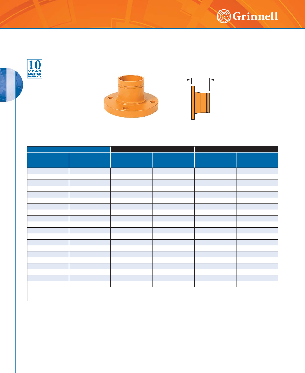
GROOVED FITTINGS
GROOVED FITTINGS
74 www.grinnell.com
Pipe Size Figure 343 - PN16# Figure 344 - PN16 BS 4504
Nominal
Inches
mm
O.D.
Inches
mm
E to E
Inches
mm
Approx. Weight
Lbs.
kg
E to E
Inches
mm
Approx. Weight
Lbs.
kg
22.3753.745.07 – –
50 60,3 95,0 2,3 – –
76,1mm 3.000 3.74 7.27 – –
65 76,1 95,0 3,3 – –
3 3.500 3.94 8.82 – –
80 88,9 100,0 4,0 – –
44.5004.0210.14– –
100 114,3 102,0 4,6 – –
139,7mm 5.500 4.13 13.23 – –
125 139,7 105,0 6,0 – –
165,1mm 6.500 4.13 15.87 – –
150 165,1 105,0 7,2 – –
66.6254.1315.87– –
150 168,3 105,0 7,2 – –
8 8.625 4.41 22.49 4.41 22.49
200 219,1112,010,2112,010,2
10 10.750 5.43 39.68 5.43 39.68
250 273,0 138,0 18,0 138,0 18,0
12 12.750 5.43 49.38 5.43 49.38
300 323,9 138,0 22,4 138,0 22,4
For information on larger sizes, contact GRINNELL Mechanical Products.
See page 37 for fitting specifications.
E to E
Figure 343 Flange Adapters (PN16)
Figure 344 Flange Adapters (PN16 BS 4504)
Tech Data Sheet: G180
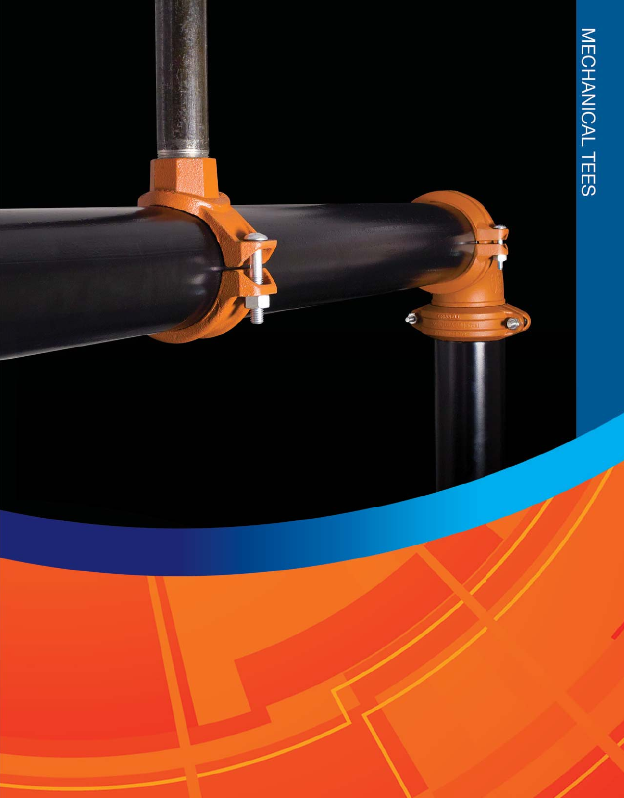
75
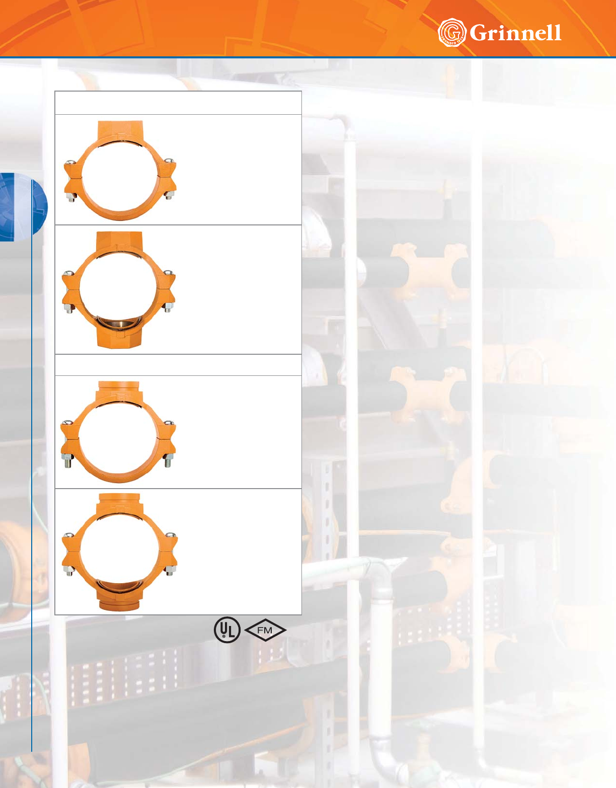
MECHANICAL TEES
76 www.grinnell.com
MECHANICAL TEES
The GRINNELL Figure 730 Mechanical Tee is rated at 500 psi
(34,5 bar) on standard weight pipe. It can be used in place of a
tee, a cross connection, or a welded outlet where a threaded or
grooved outlet is needed. The Mechanical Tee is ideal for use in
retrofit or equipment hookup installations as it can be positioned
along the pipe at the proper location in the field, ensuring exact
lineup of the branch outlet connection. The GRINNELL Figure
730 can be used on steel or HDPE pipe.
All GRINNELL Figure 730 Mechanical Tees are provided with
a ductile iron lower housing section for increased strength and
dependability. This design provides stability and rigidity while
inhibiting damage to the pipe during tightening.
MATERIAL SPECIFICATIONS
Housing Specifications
• ASTM A 536 – Standard specification for
ductile iron castings, Grade 65-45-12
• Tensile Strength, minimum 65,000 psi (4481,6 bar)
• Yield Strength, minimum 45,000 psi (3102,6 bar)
• Elongation in 2" (50mm), minimum 12%
• ASTM A 153 – Standard specification for hot-dip
galvanizing
Bolt/Nut Specifications
• ANSI: Carbon steel oval neck bolts and nuts are heat-
treated and conform to the physical properties of ASTM
A 183 Grade 2 and SAE J429 Grade 5 with a minimum
tensile strength of 110,000 psi (7584.2 bar).
Carbon Steel heavy hex nuts conform to the physical
properties of ASTM A 183 Grade 2 and SAE J995
Grade 5. Bolts and nuts are zinc-electroplated
conforming to ASTM B 633.
• Metric: Carbon steel oval neck track head bolts (Gold
color coded) are heat treated and conform to the physical
properties of ASTM F 568 M with a minimum tensile
strength of 760 MPa.
Carbon steel heavy hex nuts conform to the physical
properties of ASTM A 563 M Class 9. Bolts and nuts are
zinc-electroplated conforming to ASTM B 633.
• Stainless steel bolts and nuts are available upon request.
Gasket Specifications
• Grade “E” EPDM gaskets have a Green color code
identification and conform to ASTM D 2000 for service
temperatures from -30°F to 230°F (-34°C to 110°C). They
are recommended for hot water not to exceed 230°F
(110°C), plus a variety of dilute acids, oil free air, and
many chemical services. They are not recommended for
petroleum services.
• Grade “T” Nitrile gaskets have an Orange color code
identification and conform to ASTM D 2000 for service
temperatures from -20°F to 180°F (-29°C to 82°C). They
are recommended for petroleum products, vegetable oils,
mineral oils, and air with oil vapors.
Threaded Tees and Crosses
Figure 730
Female Threaded Tees
Pages 77 - 79
Figure 730
Female Threaded Crosses
Pages 77 - 79
Grooved Tees and Crosses
Figure 730
Grooved Tees
Pages 80 - 82
Figure 730
Grooved Crosses
Pages 80 - 82
)RUDGGLWLRQDOOLVWLQJVRU
DSSURYDOVVHHSDJHRU
YLVLWRXUZHEVLWHDW
ZZZJULQQHOOFRP
Mechanical Tees Table of Contents
Coatings
• Orange – Non-lead paint (standard)
• Red – Non-lead paint (optional, regional)
• Hot-Dipped, Zinc Galvanized (optional)
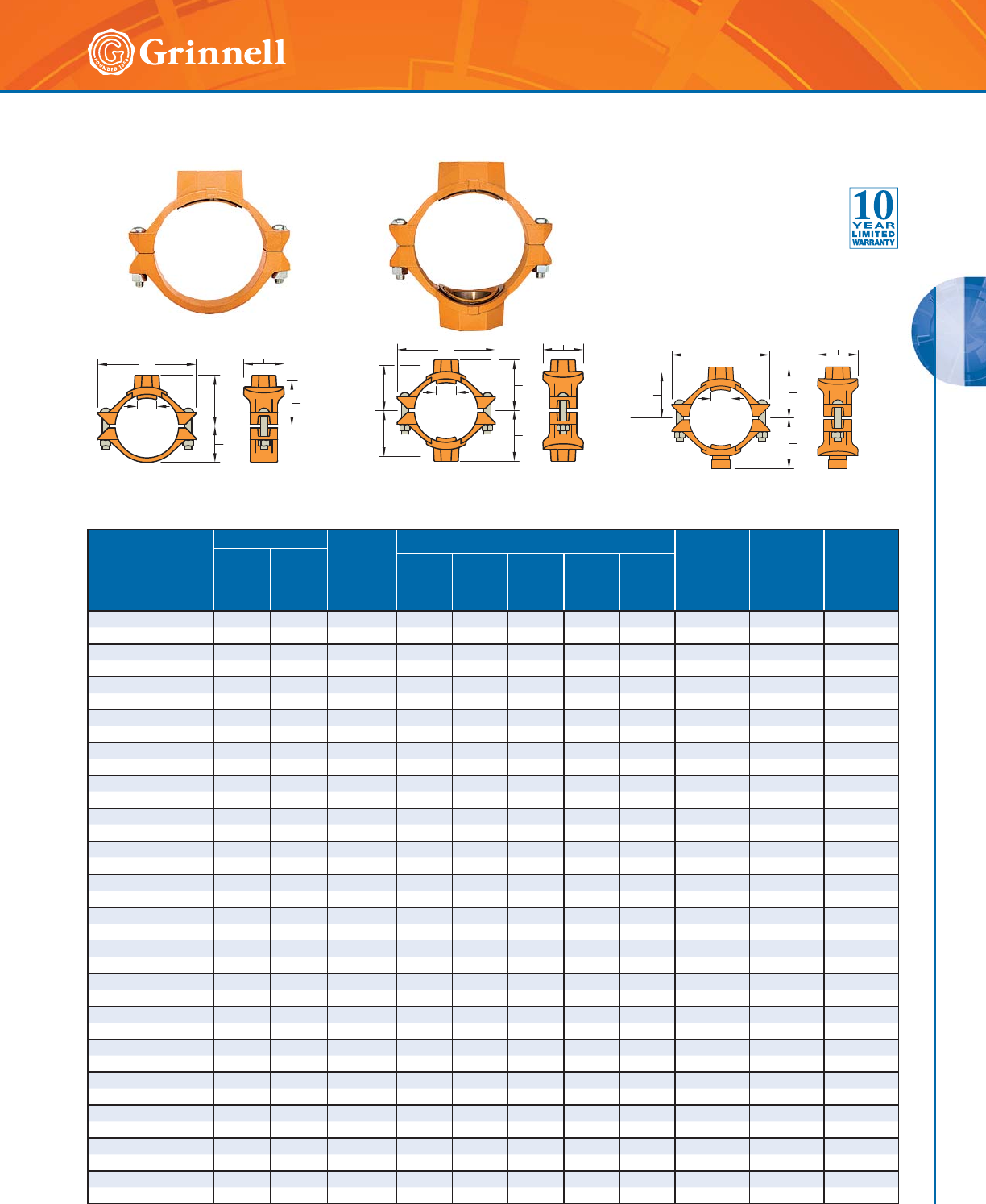
MECHANICAL TEES
MECHANICAL TEES
77
Refer to back cover for country-specific customer care numbers.
Nominal Size Run x
Branch
Inches
mm
Hole Dia.† Max.‡
Branch
End Load
Lbs.
kN
Dimensions - Inches mm Bolt
Size
Inches
mm
Tee
Approx.
Weight
Lbs.
kg
Cross
Approx.
Weight
Lbs.
kg
Min.
Inches
mm
Max.
Inches
mm
ABCDE
2 x 1⁄21.50 1.63 277.1 2.62 4.88 3.07 2.12 1.59 3⁄8 x 21⁄42.5 3.4
50 x 15 38,1 41,3 1,2 66,5 124,0 78,0 53,8 40,4 M10 x 57 1,1 1,5
2 x 3⁄41.50 1.63 433.0 2.62 4.88 3.07 2.12 1.59 3⁄8 x 21⁄42.3 3.0
50 x 20 38,1 41,3 1,9 66,5 124,0 78,0 53,8 40,4 M10 x 57 1,0 1,4
2 x 1 1.50 1.63 679.1 2.62 4.88 3.07 2.12 1.59 3⁄8 x 21⁄42.2 3.2
50 x 25 38,1 41,3 3,0 66,5 124,0 78,0 53,8 40,4 M10 x 57 1,0 1,5
2 x 11⁄41.75 1.88 1082.1 2.78 4.88 3.32 1.93 1.59 3⁄8 x 21⁄42.4 3.4
50 x 32 44,5 47,6 4,8 70,6 124,0 84,3 49,0 40,4 M10 x 57 1,1 1,5
2 x 11⁄21.75 1.88 1417.6 2.75 4.88 3.32 1.93 1.59 3⁄8 x 21⁄42.5 3.9
50 x 40 44,5 47,6 6,3 69,9 124,0 84,3 49,0 40,4 M10 x 57 1,1 1,8
21⁄2 x 1⁄21.50 1.63 277.1 2.88 5.25 3.07 2.38 1.81 3⁄8 x 21⁄42.4 3.4
65 x 15 38,1 41,3 1,2 73,2 133,4 78,0 60,5 46,0 M10 x 57 1,1 1,5
21⁄2 x 3⁄41.50 1.63 433.0 2.88 5.25 3.07 2.38 1.81 3⁄8 x 21⁄42.4 3.4
65 x 20 38,1 41,3 1,9 73,2 133,4 78,0 60,5 46,0 M10 x 57 1,1 1,5
21⁄2 x 1 1.50 1.63 679.1 2.88 5.25 3.07 2.38 1.81 3⁄8 x 21⁄42.4 3.4
65 x 25 38,1 41,3 3,0 73,2 133,4 78,0 60,5 46,0 M10 x 57 1,1 1,5
21⁄2 x 11⁄42.00 2.13 1082.1 3.00 5.25 3.56 2.19 1.81 3⁄8 x 21⁄42.5 3.8
65 x 32 50,8 54,0 4,8 76,2 133,4 90,4 55,6 46,0 M10 x 57 1,1 1,7
21⁄2 x 11⁄22.00 2.13 1417.6 3.07 5.25 3.59 2.17 1.81 3⁄8 x 21⁄42.6 4.1
65 x 40 50,8 54,0 6,3 78,0 133,4 91,2 55,1 46,0 M10 x 57 1,2 1,9
21⁄2 x 2 2.00 2.13 2215.1 3.19 5.25 4.00 2.4 4 1.81 3⁄8 x 21⁄4 2.7 4.1
65 x 50 50,8 54,0 9,9 81,0 133,4 101,6 62,0 46,0 M10 x 57 1,2 1,9
76,1mm x 1⁄21.50 1.63 277.1 2.94 5.62 3.07 2.44 1.87 – 2.5 3.5
65 x 15 38,1 41,3 1,2 74,5 142,7 78,0 62,0 47,5 M10 x 57 1,1 1,6
76,1mm x 3⁄41.50 1.63 433.0 2.94 5.62 3.07 2.44 1.87 – 2.5 3.5
65 x 20 38,1 41,3 1,9 74,5 142,7 78,0 62,0 47,5 M10 x 57 1,1 1,6
76,1mm x 1 1.50 1.63 679.1 2.94 5.62 3.07 2.4 4 1.87 – 2.5 3.5
65 x 25 38,1 41,3 3,0 74,5 142,7 78,0 62,0 47,5 M10 x 57 1,1 1,6
76,1mm x 11⁄42.00 2.13 1082.1 3.06 5.62 3.56 2.25 1.87 – 3.3 5.1
65 x 32 50,8 54,0 4,8 77,7 142,7 90,4 57,2 47,5 M10 x 57 1,5 2,3
76,1mm x 11⁄22.00 2.13 1417.6 3.13 5.62 3.56 2.25 1.87 – 3.6 5.7
65 x 40 50,8 54,0 6,3 79,5 142,7 90,4 57,2 47,5 M10 x 57 1,6 2,6
76,1mm x 2 2.00 2.13 2215.1 3.25 5.62 4.00 2.50 1.87 – 3.7 5.8
65 x 50 50,8 54,0 9,9 82,6 142,7 101,6 63,5 47,5 M10 x 57 1,7 2,6
3 x 1⁄21.50 1.63 277.1 3.19 6.13 3.07 2.56 2.21 1⁄2 x 3 3.7 5.2
80 x 15 38,1 41,3 1,2 81,0 155,7 78,0 65,0 56,1 M12 x 89 1,7 2,4
Figure 730 Branch Outlet with Female
NPT/BSP Threaded Branch
(Tee Configuration)
Figure 730 Branch Outlet with Female
NPT/BSP Threaded Branch
(Cross Configuration)
Figure 730 Branch Outlet with a Female
NPT/BSP Threaded Branch and a Grooved
Branch (Cross Configuration)
BC
Hole
Dia.
A
E
D
Takeout
A
A
D
D
Hole
Dia.
BC
Takeout
A
A
D
BC
Hole
Dia.
Takeout
Figure 730 Mechanical Tees & Crosses – Threaded
(Page 1 of 3)
Tech Data Sheet: G210
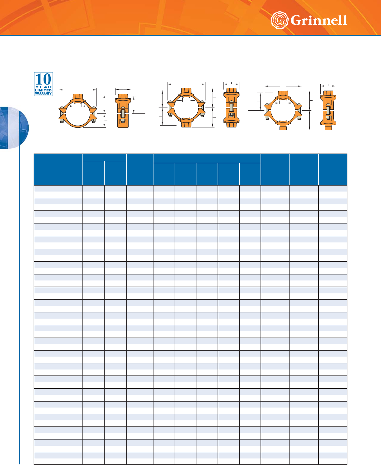
MECHANICAL TEES
MECHANICAL TEES
78 www.grinnell.com
Figure 730 Mechanical Tees & Crosses – Threaded
(Page 2 of 3)
Tech Data Sheet: G210
Nominal Size Run x
Branch
Inches
mm
Hole Dia.† Max.‡
Branch
End Load
Lbs.
kN
Dimensions - Inches mm Bolt
Size
Inches
mm
Tee
Approx.
Weight
Lbs.
kg
Cross
Approx.
Weight
Lbs.
kg
Min.
Inches
mm
Max.
Inches
mm
ABCDE
3 x 3⁄41.50 1.63 433.0 3.19 6.13 3.07 2.56 2.21 1⁄2 x 3 3.7 5.2
80 x 20 38,1 41,3 1,9 81,0 155,7 78,0 65,0 56,1 M12 x 89 1,7 2,4
3 x 1 1.50 1.63 679.1 3.19 6.13 3.07 2.56 2.21 1⁄2 x 3 3.7 5.2
80 x 25 38,1 41,3 3,0 81,0 155,7 78,0 65,0 56,1 M12 x 89 1,7 2,4
3 x 11⁄41.75 1.88 1082.1 3.34 6.13 3.32 2.50 2.21 1⁄2 x 3 3.5 4.6
80 x 32 44,5 47,6 4,8 84,8 155,7 84,3 63,5 56,1 M12 x 89 1,6 2,1
3 x 11⁄22.00 2.13 1417.6 3.38 6.13 3.56 2.48 2.21 1⁄2 x 3 3.7 5.2
80 x 40 50,8 54,0 6,3 85,9 155,7 90,4 63,0 56,1 M12 x 89 1,7 2,4
3 x 2 2.50 2.63 2215.1 3.50 6.13 4.09 2.75 2.21 1⁄2 x 3 4.7 6.8
80 x 50 63,5 66,7 9,9 88,9 155,7 103,9 69,9 56,1 M12 x 89 2,1 3,1
4 x 1⁄21.50 1.63 277.1 3.69 7.13 3.07 3.06 2.78 1⁄2 x 3 4.8 5.6
100 x 15 38,1 41,3 1,2 93,7 181,1 78,0 77,7 70,6 M12 x 89 2,2 2,5
4 x 3⁄41.50 1.63 433.0 3.69 7.13 3.07 3.06 2.78 1⁄2 x 3 4.8 5.6
100 x 20 38,1 41,3 1,9 93,7 181,1 78,0 77,7 70,6 M12 x 89 2,2 2,5
4 x 1 1.50 1.63 679.1 3.69 7.13 3.07 3.06 2.78 1⁄2 x 3 4.8 5.6
100 x 25 38,1 41,3 3,0 93,7 181,1 78,0 77,7 70,6 M12 x 89 2,2 2,5
4 x 11⁄41.75 1.88 1082.1 3.92 7.13 3.32 3.00 2.78 1⁄2 x 3 4.8 5.6
100 x 32 44,5 47,6 4,8 99,6 181,1 84,3 76,2 70,6 M12 x 89 2,2 2,5
4 x 11⁄22.00 2.13 1417.6 4.00 7.13 3.56 2.98 2.78 1⁄2 x 3 5.1 6.4
100 x 40 50,8 54,0 6,3 101,6 181,1 90,4 75,7 70,6 M12 x 89 2,3 2,5
4 x 2 2.50 2.63 2215.1 4.00 7.13 4.06 3.25 2.78 1⁄2 x 3 5.5 7.3
100 x 50 63,5 66,7 9,9 101,6 181,1 103,1 82,6 70,6 M12 x 89 2,5 3,3
4 x 21⁄22.75 2.88 3245.9 4.00 7.13 4.38 3.12 2.78 1⁄2 x 3 6.2 8.7
100 x 65 69,9 73,0 14,4 101,6 181,1 111,3 79,2 70,6 M12 x 89 2,8 3,9
4 x 76,1mm 2.75 2.88 3534.3 4.00 7.13 4.38 3.12 2.78 – 6.2 8.7
100 x 65 69,9 73,0 15,7 101,6 181,1 111,3 79,2 70,6 M12 x 89 2,8 3,9
4 x 3 3.5 0 3.6 3 4 8 10.6 4.13 7.13 5.13 3.31 2.78 1⁄2 x 3 7.8 11.9
100 x 80 88,9 92,1 21,4 104,9 181,1 130,3 84,1 70,6 M12 x 89 3,5 5,4
5 x 11⁄22.00 2.13 1417.6 4.63 8.13 3.56 4.00 3.37 5⁄8 x 43⁄47.8 9.4
125 x 40 50,8 54,0 6,3 117,6 206,5 90,4 101,6 85,6 M16 x 121 3,5 4,3
5 x 2 2.50 2.63 2215.1 4.63 8.13 4.06 3.88 3.37 5⁄8 x 43⁄47.8 9.4
125 x 50 63,5 66,7 9,9 117,6 206,5 103,1 98,6 85,6 M16 x 121 3,5 4,3
5 x 21⁄22.75 2.88 3245.9 4.75 8.13 4.38 3.88 3.37 5⁄8 x 43⁄48.9 11.5
125 x 65 69,9 73,0 14,4 120,7 206,5 111,3 98,6 85,6 M16 x 121 4,0 5,2
5 x 76,1mm 2.75 2.88 3534.3 4.75 8.13 4.38 3.88 3.37 – 8.9 11.5
125 x 65 69,9 73,0 15,7 120,7 206,5 111,3 98,6 85,6 M16 x 121 4,0 5,2
5 x 3 3.50 3.63 4810.6 5.00 8.13 5.13 4.06 3.37 5⁄8 x 43⁄412.7 13.3
125 x 80 88,9 92,1 21,4 127,0 206,5 130,3 103,1 85,6 M16 x 121 5,8 6,0
165,1mm x 11⁄42.00 2.13 1082.1 5.13 9.25 3.56 4.25 3.90 – 7.7 9.5
150 x 32 50,8 54,0 4,8 130,3 235,0 90,4 108,0 99,1 M16 x 121 3,5 4,3
165,1mm x 11⁄22.00 2.13 1417.6 5.13 9.25 3.56 4.04 3.90 – 7.7 9.5
150 x 40 50,8 54,0 6,3 130,3 235,0 90,4 102,6 99,1 M16 x 121 3,5 4,3
165,1mm x 2 2.50 2.63 2215.1 5.13 9.25 4.06 4.31 3.90 – 8.2 9.5
150 x 50 63,5 66,7 9,9 130,3 235,0 103,1 109,5 99,1 M16 x 121 3,7 4,3
Figure 730 Branch Outlet with Female
NPT/BSP Threaded Branch
(Tee Configuration)
Figure 730 Branch Outlet with Female
NPT/BSP Threaded Branch
(Cross Configuration)
Figure 730 Branch Outlet with a Female
NPT/BSP Threaded Branch and a Grooved
Branch (Cross Configuration)
BC
Hole
Dia.
A
E
D
Takeout
A
A
D
D
Hole
Dia.
BC
Takeout
A
A
D
BC
Hole
Dia.
Takeout
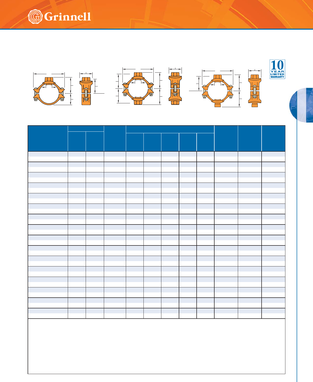
MECHANICAL TEES
MECHANICAL TEES
79
Refer to back cover for country-specific customer care numbers.
Figure 730 Mechanical Tees & Crosses – Threaded
(Page 3 of 3)
Tech Data Sheet: G210
Nominal Size Run x
Branch
Inches
mm
Hole Dia.† Max.‡
Branch
End Load
Lbs.
kN
Dimensions - Inches mm Bolt
Size
Inches
mm
Tee
Approx.
Weight
Lbs.
kg
Cross
Approx.
Weight
Lbs.
kg
Min.
Inches
mm
Max.
Inches
mm
ABCDE
165,1mm x 21⁄22.75 2.88 3245.9 5.13 9.25 4.38 4.18 3.90 – 9.0 11.3
150 x 65 69,9 73,0 14,4 130,3 235,0 111,3 106,2 99,1 M16 x 121 4,1 5,1
165,1mm x 76,1mm 2.75 2.88 3 5 84.3 5.13 9.25 4.38 4.18 3.90 – 9.0 11.3
150 x 65 69,9 73,0 15,7 130,3 235,0 111,3 106,2 99,1 M16 x 121 4,1 5,1
165,1mm x 3 3.50 3.63 4810.6 5.50 9.25 5.13 4.37 3.90 – 10.5 14.1
150 x 80 88,9 92,1 21,4 139,7 235,0 130,3 111,0 99,1 M16 x 121 4,8 6,4
165,1mm x 4 4.50 4.63 7952.2 5.38 9.25 6.13 4.56 3.90 – 12.1 17.3
150 x 100 114,3 117,5 35,4 136,7 235,0 155,7 115,8 99,1 M16 x 121 5,5 7,8
6 x 11⁄42.00 2.13 1082.1 5.13 9.25 3.56 4.25 3.90 5⁄8 x 43⁄47.5 8.7
150 x 32 50,8 54,0 4,8 130,3 235,0 90,4 108,0 99,1 M16 x 121 3,4 3,9
6 x 11⁄22.00 2.13 1417.6 5.13 9.25 3.56 4.04 3.90 5⁄8 x 43⁄47.5 8.7
150 x 40 50,8 54,0 6,3 130,3 235,0 90,4 102,6 99,1 M16 x 121 3,4 3,9
6 x 2 2.50 2.63 2215.1 5.13 9.25 4.06 4.31 3.90 5⁄8 x 43⁄47.7 9.5
150 x 50 63,5 66,7 9,9 130,3 235,0 103,1 109,5 99,1 M16 x 121 3,5 4,3
6 x 21⁄22.75 2.88 3245.9 5.13 9.25 4.38 4.18 3.90 5⁄8 x 43⁄48.9 11.3
150 x 65 69,9 73,0 14,4 130,3 235,0 111,3 106,2 99,1 M16 x 121 4,0 5,1
6 x 76,1mm 2.75 2.88 3245.9 5.13 9.25 4.38 4.18 3.90 5⁄8 x 43⁄48.9 11.3
150 x 65 69,9 73,0 14,4 130,3 235,0 111,3 106,2 99,1 M16 x 121 4,0 5,1
6 x 3 3.50 3.63 4810.6 5.50 9.25 5.13 4.37 3.90 5⁄8 x 43⁄410.3 14.1
150 x 80 88,9 92,1 21,4 139,7 235,0 130,3 111,0 99,1 M16 x 121 4,7 6,4
6 x 4 4.50 4.63 7952.2 5.38 9.25 6.13 4.56 3.90 5⁄8 x 43⁄411.9 17.3
150 x 100 114,3 117,5 35,4 136,7 235,0 155,7 115,8 99,1 M16 x 121 5,4 7,8
8 x 2 2.75 2.88 3245.9 6.25 12.50 4.06 5.12 4.90 3⁄4 x 43⁄412.1 14.1
200 x 50 69,9 73,0 14,4 158,8 317,5 103,1 130,0 124,5 M20 x 121 5,5 6,4
8 x 21⁄22.75 2.88 3245.9 6.25 12.50 4.38 5.12 4.90 3⁄4 x 43⁄412.6 15.0
200 x 65 69,9 73,0 14,4 158,8 317,5 111,3 130,0 124,5 M20 x 121 5,7 6,8
8 x 76,1mm 2.75 2.88 3534.3 6.25 12.50 4.38 5.12 4.90 – 12.6 15.0
200 x 65 69,9 73,0 15,7 158,8 317,5 111,3 130,0 124,5 M20 x 121 5,7 6,8
8 x 3 3.50 3.63 4810.6 6.50 12.50 5.13 5.37 4.90 3⁄4 x 43⁄413.6 16.9
200 x 80 88,9 92,1 21,4 165,1 317,5 130,3 136,4 124,5 M20 x 121 6,1 7,7
8 x 4 4.50 4.63 7952.2 6.38 12.50 6.13 5.56 4.90 3⁄4 x 43⁄415.2 20.0
200 x 100 114,3 117,5 35,4 162,1 317,5 155,7 141,2 124,5 M20 x 121 6,9 9,1
† Proper hole preparation is required for effective sealing and performance. Check the pipe seal surface within 5⁄8" (15,9mm) of the hole to ensure it is
free from conditions affecting proper gasket sealing. Remove any sharp or rough edges from the hole or upper housing contact area that might affect
assembly, proper seating of the locating collar, or flow from the outlet. For crosses, ensure double outlet holes are aligned on opposite sides of the
pipe. The use of threaded products other than steel pipe, such as dry pendent sprinklers, may not be compatible with the female threaded outlet on the
Mechanical Tee. Always confirm compatibility by contacting GRINNELL Mechanical Products.
‡ Maximum pressures and end loads are total from all loads based on standard weight steel pipe. Pressure ratings and end loads may differ on other
pipe materials and/or wall thickness. Contact GRINNELL Mechanical Products for details.
Threads are NPT. Some size outlets are available with BSP threads. Contact GRINNELL Mechanical Products for details.
For information on larger sizes, European sizes or other alternative sizes, contact GRINNELL Mechanical Products.
See page 76 for mechanical tee specifications and pages 191 - 198 for gasket information.
Figure 730 Branch Outlet with Female
NPT/BSP Threaded Branch
(Tee Configuration)
Figure 730 Branch Outlet with Female
NPT/BSP Threaded Branch
(Cross Configuration)
Figure 730 Branch Outlet with a Female
NPT/BSP Threaded Branch and a Grooved
Branch (Cross Configuration)
BC
Hole
Dia.
A
E
D
Takeout
A
A
D
D
Hole
Dia.
BC
Takeout
A
A
D
BC
Hole
Dia.
Takeout
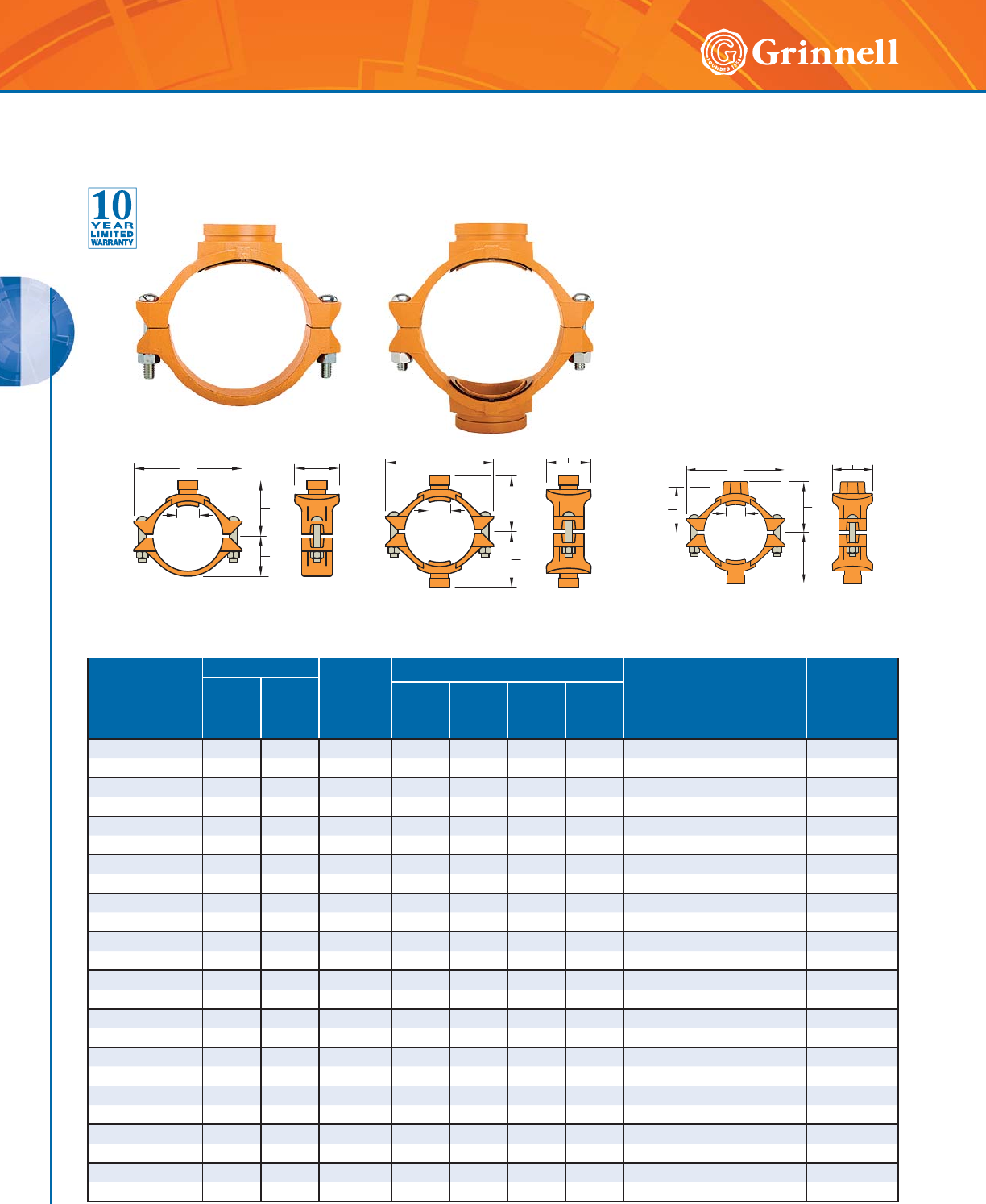
MECHANICAL TEES
MECHANICAL TEES
80 www.grinnell.com
Nominal Size
Run x Branch
Inches
mm
Hole Dia.† Max.‡
End Load
Branch
Lbs.
kN
Dimensions - Inches mm Bolt
Size
Inches
mm
Tee
Approx. Weight
Lbs.
kg
Cross Approx.
Weight
Lbs.
kg
Min.
Inches
mm
Max.
Inches
mm
ABC D
2 x 11⁄41.75 1.88 1082.1 2.78 4.88 3.32 1.59 3⁄8 x 21⁄42.5 3.3
50 x 32 44,5 47,6 4,8 70,6 124,0 84,3 40,4 M10 x 57 1,1 1,5
2 x 11⁄21.75 1.88 1417.6 2.62 4.88 3.32 1.59 3⁄8 x 21⁄42.4 3.7
50 x 40 44,5 47,6 6,3 66,5 124,0 84,3 40,4 M10 x 57 1,1 1,7
21⁄2 x 11⁄42.00 2.13 1082.1 3.00 5.25 3.56 1.81 3⁄8 x 21⁄42.5 3.8
65 x 32 50,8 54,0 4,8 76,2 133,4 90,4 46,0 M10 x 57 1,1 1,7
21⁄2 x 11⁄22.00 2.13 1417.6 3.07 5.25 3.59 1.81 3⁄8 x 21⁄42.5 3.9
65 x 40 50,8 54,0 6,3 78,0 133,4 91,2 46,0 M10 x 57 1,1 1,8
21⁄2 x 2 2.00 2.13 2215.1 3.19 5.25 4.00 1.81 3⁄8 x 21⁄42.5 3.8
65 x 50 50,8 54,0 9,9 81,0 133,4 101,6 46,0 M10 x 57 1,1 1,7
76,1mm x 11⁄42.00 2.13 1082.1 3.06 5.62 3.56 1.87 – 2.5 3.8
65 x 32 50,8 54,0 4,8 77,7 142,7 90,4 47,5 M10 x 57 1,1 1,7
76,1mm x 11⁄22.00 2.13 1417.6 3.13 5.62 3.56 1.87 – 2.5 3.9
65 x 40 50,8 54,0 6,3 79,5 142,7 90,4 47,5 M10 x 57 1,1 1,8
76,1mm x 2 2.00 2.13 2215.1 3.25 5.62 4.00 1.87 – 2.5 3.8
65 x 50 50,8 54,0 9,9 82,6 142,7 101,6 47,5 M10 x 57 1,1 1,7
3 x 11⁄41.75 1.88 1082.1 3.34 6.13 3.32 2.21 1⁄2 x 3 3.5 4.6
80 x 32 44,5 47,6 4,8 84,8 155,7 84,3 56,1 M12 x 89 1,6 2,1
3 x 11⁄22.00 2.13 1417.6 3.38 6.13 3.56 2.21 1⁄2 x 3 3.6 5.0
80 x 40 50,8 54,0 6,3 85,9 155,7 90,4 56,1 M12 x 89 1,6 2,3
3 x 2 2.50 2.63 2215.1 3.50 6.13 4.09 2.21 1⁄2 x 3 4.5 6.4
80 x 50 63,5 66,7 9,9 88,9 155,7 103,9 56,1 M12 x 89 2,0 2,9
4 x 11⁄41.75 1.88 1082.1 3.92 7.13 3.32 2.78 1⁄2 x 3 4.8 5.6
100 x 32 44,5 47,6 4,8 99,6 181,1 84,3 70,6 M12 x 89 2,2 2,5
Figure 730 Branch Outlet
with Grooved Branch
(Tee Configuration)
Figure 730 Branch Outlet
with Grooved Branch
(Cross Configuration)
Hole
Dia.
A
D
BC
Hole
Dia.
BC
A
A
Figure 730 Mechanical Tees & Crosses – Grooved
(Page 1 of 3)
Tech Data Sheet: G210
Figure 730 Branch Outlet with a Female
NPT/BSP Threaded Branch and a Grooved
Branch (Cross Configuration)
A
A
D
BC
Hole
Dia.
Takeout
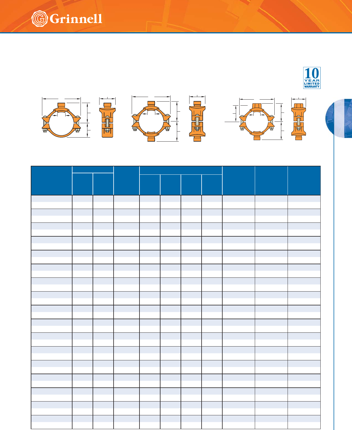
MECHANICAL TEES
MECHANICAL TEES
81
Refer to back cover for country-specific customer care numbers.
Figure 730 Mechanical Tees & Crosses – Grooved
(Page 2 of 3)
Tech Data Sheet: G210
Figure 730 Branch Outlet
with Grooved Branch
(Tee Configuration)
Figure 730 Branch Outlet
with Grooved Branch
(Cross Configuration)
Nominal Size
Run x Branch
Inches
mm
Hole Dia.† Max.‡
End Load
Branch
Lbs.
kN
Dimensions - Inches mm Bolt
Size
Inches
mm
Tee
Approx. Weight
Lbs.
kg
Cross Approx.
Weight
Lbs.
kg
Min.
Inches
mm
Max.
Inches
mm
ABC D
4 x 11⁄22.00 2.13 1417.6 4.00 7.13 3.56 2.78 1⁄2 x 3 5.0 6.2
100 x 40 50,8 54,0 6,3 101,6 181,1 90,4 70,6 M12 x 89 2,3 2,8
4 x 2 2.50 2.63 2215.1 4.00 7.13 4.06 2.78 1⁄2 x 3 5.3 6.9
100 x 50 63,5 66,7 9,9 101,6 181,1 103,1 70,6 M12 x 89 2,4 3,1
4 x 21⁄22.75 2.88 3245.9 4.00 7.13 4.38 2.78 1⁄2 x 3 5.9 8.2
100 x 65 69,9 73,0 14,4 101,6 181,1 111,3 70,6 M12 x 89 2,7 3,7
4 x 76,1mm 2.75 2.88 3534.3 4.00 7.13 4.38 2.78 – 5.9 8.2
100 x 65 69,9 73,0 15,7 101,6 181,1 111,3 70,6 M12 x 89 2,7 3,7
4 x 3 3.50 3.63 4 810.6 4.13 7.13 5.13 2.78 1⁄2 x 3 7.4 11.1
100 x 80 88,9 92,1 21,4 104,9 181,1 130,3 70,6 M12 x 89 3,4 5,0
5 x 11⁄22.00 2.13 1417.6 4.63 8.13 3.56 3.37 5⁄8 x 43⁄47.7 9.2
125 x 40 50,8 54,0 6,3 117,6 206,5 90,4 85,6 M16 x 121 3,5 4,2
5 x 2 2.50 2.63 2215.1 4.63 8.13 4.06 3.37 5⁄8 x 43⁄47.6 9.0
125 x 50 63,5 66,7 9,9 117,6 206,5 103,1 85,6 M16 x 121 3,4 4,1
5 x 21⁄22.75 2.88 3245.9 4.75 8.13 4.38 3.37 5⁄8 x 43⁄48.6 11.0
125 x 65 69,9 73,0 14,4 120,7 206,5 111,3 85,6 M16 x 121 3,9 5,0
5 x 76,1mm 2.75 2.88 3534.3 4.75 8.13 4.38 3.37 – 8.6 11.0
125 x 65 69,9 73,0 15,7 120,7 206,5 111,3 85,6 M16 x 121 3,9 5,0
5 x 3 3.50 3.63 4810.6 5.00 8.13 5.13 3.37 5⁄8 x 43⁄412.3 12.5
125 x 80 88,9 92,1 21,4 127,0 206,5 130,3 85,6 M16 x 121 5,6 5,7
165,1mm x 11⁄42.00 2.13 1082.1 5.13 9.25 3.56 3.90 – 7.7 9.5
150 x 32 50,8 54,0 4,8 130,3 235,0 90,4 99,1 M16 x 121 3,5 4,3
165,1mm x 11⁄22.00 2.13 1417.6 5.13 9.25 3.56 3.90 – 7.6 9.3
150 x 40 50,8 54,0 6,3 130,3 235,0 90,4 99,1 M16 x 121 3,4 4,2
165,1mm x 2 2.50 2.63 2215.1 5.13 9.25 4.06 3.90 – 8.0 9.1
150 x 50 63,5 66,7 9,9 130,3 235,0 103,1 99,1 M16 x 121 3,6 4,1
165,1mm x 21⁄22.75 2.88 3245.9 5.13 9.25 4.38 3.90 – 8.8 10.8
150 x 65 69,9 73,0 14,4 130,3 235,0 111,3 99,1 M16 x 121 4,0 4,9
165,1mm x 76,1mm 2.75 2.88 3534.3 5.13 9.25 4.38 3.90 – 8.8 10.8
150 x 65 69,9 73,0 15,7 130,3 235,0 111,3 99,1 M16 x 121 4,0 4,9
165,1mm x 3 3.50 3.63 4810.6 5.50 9.25 5.13 3.90 – 10.1 13.3
150 x 80 88,9 92,1 21,4 139,7 235,0 130,3 99,1 M16 x 121 4,6 6,0
165,1mm x 4 4.50 4.63 7952.2 5.38 9.25 6.13 3.90 – 11.6 16.3
150 x 100 114,3 117,5 35,4 136,7 235,0 155,7 99,1 M16 x 121 5,3 7,4
Hole
Dia.
A
D
BC
Hole
Dia.
BC
A
A
Figure 730 Branch Outlet with a Female
NPT/BSP Threaded Branch and a Grooved
Branch (Cross Configuration)
A
A
D
BC
Hole
Dia.
Takeout
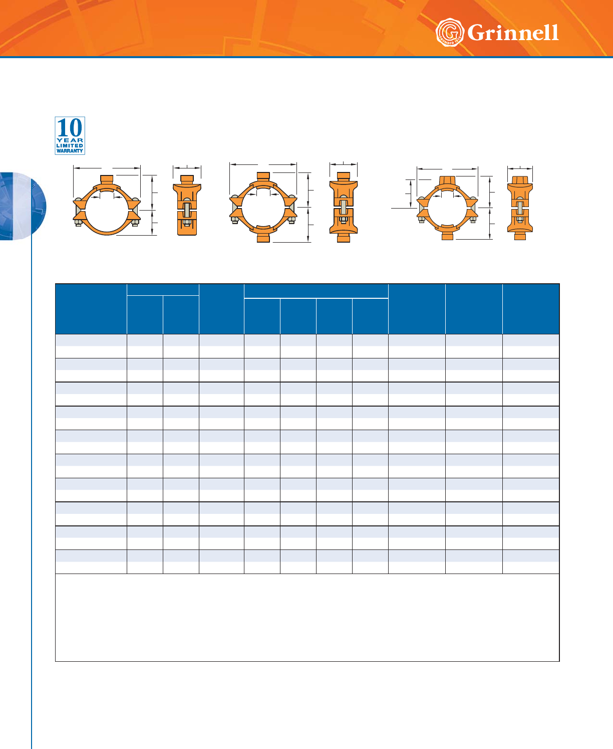
MECHANICAL TEES
MECHANICAL TEES
82 www.grinnell.com
Nominal Size
Run x Branch
Inches
mm
Hole Dia.† Max.‡
End Load
Branch
Lbs.
kN
Dimensions - Inches mm Bolt
Size
Inches
mm
Tee
Approx. Weight
Lbs.
kg
Cross Approx.
Weight
Lbs.
kg
Min.
Inches
mm
Max.
Inches
mm
ABC D
6 x 11⁄42.00 2.13 1082.1 5.13 9.25 3.56 3.90 5⁄8 x 43⁄47.7 9.5
150 x 32 50,8 54,0 4,8 130,3 235,0 90,4 99,1 M16 x 121 3,5 4,3
6 x 11⁄22.00 2.13 1417.6 5.13 9.25 3.56 3.90 5⁄8 x 43⁄47.6 9.3
150 x 40 50,8 54,0 6,3 130,3 235,0 90,4 99,1 M16 x 121 3,4 4,2
6 x 2 2.50 2.63 2215.1 5.13 9.25 4.06 3.90 5⁄8 x 43⁄48.0 9.1
150 x 50 63,5 66,7 9,9 130,3 235,0 103,1 99,1 M16 x 121 3,6 4,1
6 x 21⁄22.75 2.88 3245.9 5.13 9.25 4.38 3.90 5⁄8 x 43⁄48.8 10.8
150 x 65 69,9 73,0 14,4 130,3 235,0 111,3 99,1 M16 x 121 4,0 4,9
6 x 3 3.50 3.63 4810.6 5.50 9.25 5.13 3.90 5⁄8 x 43⁄410.1 13.3
150 x 80 88,9 92,1 21,4 139,7 235,0 130,3 99,1 M16 x 121 4,6 6,0
6 x 4 4.50 4.63 7952.2 5.38 9.25 6.13 3.90 5⁄8 x 43⁄411.6 16.3
150 x 100 114,3 117,5 35,4 136,7 235,0 155,7 99,1 M16 x 121 5,3 7,4
8 x 21⁄22.75 2.88 3245.9 6.25 12.50 4.38 4.90 3⁄4 x 43⁄412.3 14.5
200 x 65 69,9 73,0 14,4 158,8 317,5 111,3 124,5 M20 x 121 5,6 6,6
8 x 76,1mm 2.75 2.88 3534.3 6.25 12.50 4.38 4.90 – 12.3 14.5
200 x 65 69,9 73,0 15,7 158,8 317,5 111,3 124,5 M20 x 121 5,6 6,6
8 x 3 3.50 3.63 4810.6 6.50 12.50 5.13 4.90 3⁄4 x 43⁄413.2 16.1
200 x 80 88,9 92,1 21,4 165,1 317,5 130,3 124,5 M20 x 121 6,0 7,3
8 x 4 4.50 4.63 7952.2 6.38 12.50 6.13 4.90 3⁄4 x 43⁄414.7 19.0
200 x 100 114,3 117,5 35,4 162,1 317,5 155,7 124,5 M20 x 121 6,7 8,6
† Proper hole preparation is required for effective sealing and performance. Check the pipe seal surface within 5⁄8" (15,9mm) of the hole to ensure it
is free from conditions affecting proper gasket sealing. Remove any sharp or rough edges from the hole or upper housing contact area that might
affect assembly, proper seating of the locating collar, or flow from the outlet. For crosses, ensure double outlet holes are aligned on opposite sides
of the pipe.
‡ Maximum pressures and end loads are total from all loads based on standard weight steel pipe. Pressure ratings and end loads may differ on other
pipe materials and/or wall thickness. Contact GRINNELL Mechanical Products for details.
For information on larger sizes, European sizes or other alternative sizes, contact GRINNELL Mechanical Products.
See page 76 for mechanical tee specifications and pages 191 - 198 for gasket information.
Figure 730 Mechanical Tees & Crosses – Grooved
(Page 3 of 3)
Tech Data Sheet: G210
Figure 730 Branch Outlet
with Grooved Branch
(Tee Configuration)
Figure 730 Branch Outlet
with Grooved Branch
(Cross Configuration)
Hole
Dia.
A
D
BC
Hole
Dia.
BC
A
A
Figure 730 Branch Outlet with a Female
NPT/BSP Threaded Branch and a Grooved
Branch (Cross Configuration)
A
A
D
BC
Hole
Dia.
Takeout

83
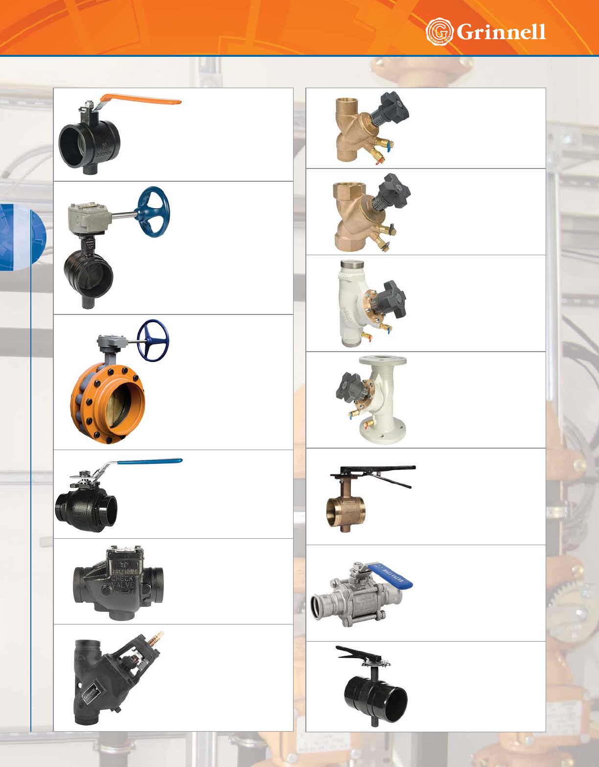
VALVES
84 www.grinnell.com
VALVES
Model B8101
Low Profile Butterfly Valves
Page 85
Model B302
Grooved End
Butterfly Valves
Pages 86 - 89
Model 308
Butterfly Valves
Pages 90 - 91
Model BV835
Ball Valves
Pages 92 - 93
Model 590
Grooved End Check Valves
Pages 94 - 95
Model TD830
Triple Duty Valves
Page 96
Valves Table of Contents
Model CB800
Solder
Balancing Valves
Page 100
Model CB800
Threaded
Balancing Valves
Page 100
Model CB800
Grooved
Balancing Valves
Page 101
Model CB800
Flanged
Balancing Valves
ANSI & PN16/PN10
Page 102 - 103
Model B680
Copper Systems
Butterfly Valves
Page 128
Model 469
G-PRESS Systems
Ball Valves
Page 167
Model B8200L
G-MINE PVC Systems
Butterfly Valves
Page 189
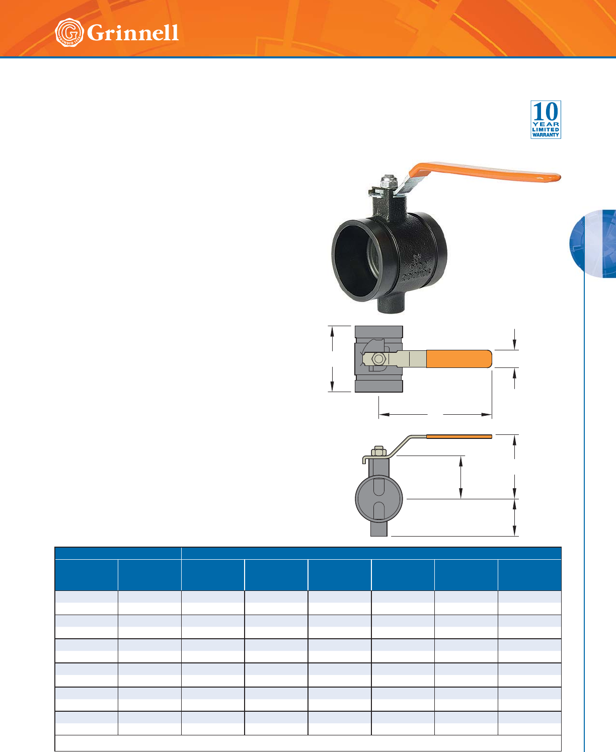
VALVES
VALVES
85
Refer to back cover for country-specific customer care numbers.
Model B8101 Low Profile Butterfly Valves
Tech Data Sheet: G330
The GRINNELL Model B8101 Low Profile Butterfly Valve has
a rated working pressure of 200 psi (13,8 bar) and provides
efficient control of fluid in piping systems. Flow can be from
either direction and the valve may be positioned in any
orientation. The ductile iron body is epoxy-coated to resist
atmospheric corrosion. The disc is EPDM encapsulated ductile
iron compatible with a variety of chemicals and temperature
ranges.
MATERIAL SPECIFICATIONS
Body
• Ductile iron
Body Coating
• Black epoxy-coated
Disc
• Ductile iron
Disc Seal
• Grade “E” EPDM encapsulated rubber
-20°F to 250°F (-29°C to 121°C) with intermittent service
at 250°F (121°C) and continuous service at 225°F
(107°C)
• Optional: Grade “T” Nitrile encapsulated rubber
-20°F to 180°F (-29°C to 82°C)
Stem
• Two-piece stainless steel, splined
Stem Seal
• O-rings, upper and lower stem
Handle
• Carbon steel zinc-plated
Performance
• Pressure drop, contact GRINNELL Mechanical Products.
Pipe Size Dimensions - Inches mm
Nominal
Inches
mm
O.D.
Inches
mm
ABCDEF
2 2.375 3.39 5.98 0.98 1.81 1.97 3.15
50 60,3 86,0 152,0 25,0 46,0 50,0 80,0
21⁄22.875 3.78 5.98 0.98 2.05 2.40 3.58
65 73,0 96,0 152,0 25,0 52,0 61,0 91,0
3 3.500 3.78 8.27 0.98 2.56 2.64 4.21
80 88,9 96,0 210,0 25,0 65,0 67,0 107,0
4 4.500 4.53 8.27 0.98 3.27 3.27 4.84
100 114,3 115,0 210,0 25,0 83,0 83,0 123,0
5 5.563 5.50 12.25 1.26 4.00 4.00 6.75
125 141,3 139,7 311,2 32,0 101,6 101,6 171,5
6 6.625 5.20 12.01 1.26 4.29 4.29 6.85
150 168,3 132,0 305,0 32,0 109,0 109,0 174,0
For information on larger sizes, contact GRINNELL Mechanical Products.
A
B
F
D
C
E
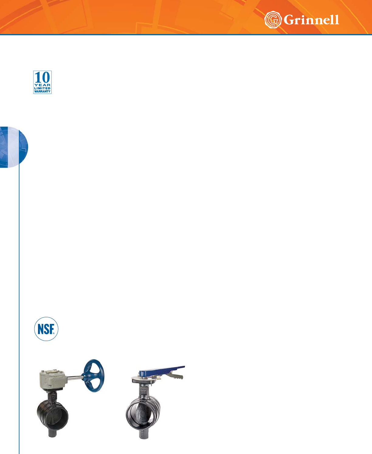
VALVES
VALVES
86 www.grinnell.com
GRINNELL Model B302 Butterfly Valves are capable of
pressures of 300 psi (20,7 bar) for sizes 2" – 8" (50mm
– 200mm) and 200 psi (13,8 bar) for sizes 10" and 12"
(250mm – 300mm). The valves are designed for efficient
control of: on/off or throttling/balancing service; fluid flow;
and “bubble tight” shut-off in piping systems. Flow may be
from either direction, and the valve may be positioned in
any orientation. The valves are available with either a gear
operator, for sizes 2" – 12" (50mm – 300mm), or lever-lock
operator, for sizes 2" – 8" (50mm – 200mm). The valves are
furnished with grooved ends for use with grooved couplings
and can be easily adapted to flanged components utilizing
GRINNELL Figure 71 Class 150 Flange Adapters.
The body and disc construction provides for increased
strength and durability. The disc seal and body coatings
are compatible with a variety of chemicals and temperature
range. (Contact GRINNELL Mechanical Products for specific
recommendations on seal and coating selection).
The GRINNELL Model B302 Butterfly Valve with Gear
Operator is a self-locking worm gear type. It is equipped with
adjustable stops at the open and shut positions.
The GRINNELL Model B302 Butterfly Valve with Lever-Lock
Operator has a throttling plate that provides throttling notches
every 10° for manual control in balancing up to 90° or shut
off service. The lever may be padlocked in any one of the
positions, including opened or closed, by virtue of a locking
hole located in the handle and lever.
Conforms To MSS SP-67
MATERIAL SPECIFICATIONS
Ductile Iron Body
• ASTM A 395 – Standard specification for ductile
iron castings, Grade 60-40-18
• Tensile strength, minimum 60,000 psi (4136,9 bar)
• Yield strength, minimum 40,000 psi (2757,9 bar)
• Elongation in 2" (50mm), minimum 18%
Disc
• Ductile iron ASTM A 395 w/EPDM or Buna-N
encapsulation
Body Coating
• Black Polymide-Coated
O-Ring
• EPDM, Fluoroelastomer, or Buna-N
Upper and Lower Stem
• Type 416 Stainless Steel ASTM A 582
Gear Operator
• Cast iron housing
Lever-Lock Operator
• Handle – Iron Polymer-Coated
• Lever-Lock – Steel Zinc-Plated
• Throttling Plate – Steel Zinc-Plated
Disc Seal Specifications Encapsulated
Rubber
• EPDM – For service temperatures from -20°F to 250°F
(-29°C to 121°C), intermittent service at 250°F (121°C)
and continuous service at 225°F (107°C). Recommended
for hot water not to exceed the temperature ratings
above, plus a variety of dilute acids, alkalines, and
many chemical services. They are not recommended for
petroleum oil, strong acid, strong alkaline, or compressed
air services.
• Nitrile – For service temperatures from -20°F to 180°F
(-29°C to 82°C). Recommended for solvents, oils,
water, and hydraulic fluid resistance. They are not
recommended for highly polar solvents such as acetone
and methyl ethyl ketone, chlorinated hydrocarbons,
ozone, or nitro hydrocarbons and some aviation fuels.
• Fluoroelastomer – For service temperatures +20°F
to 300°F (-7°C to 149°C). Recommended for oxidizing
acids, petroleum products, hydraulic fluids, lubricants,
and halogenated hydrocarbons.
Model B302
with Lever-Lock Operator
Model B302
with Gear Operator
Model B302 Grooved End Butterfly Valves
(Page 1 of 4)
Tech Data Sheet: G310
Note: replacement lever handles and gear wheels are available,
contact GRINNELL Mechanical Products.
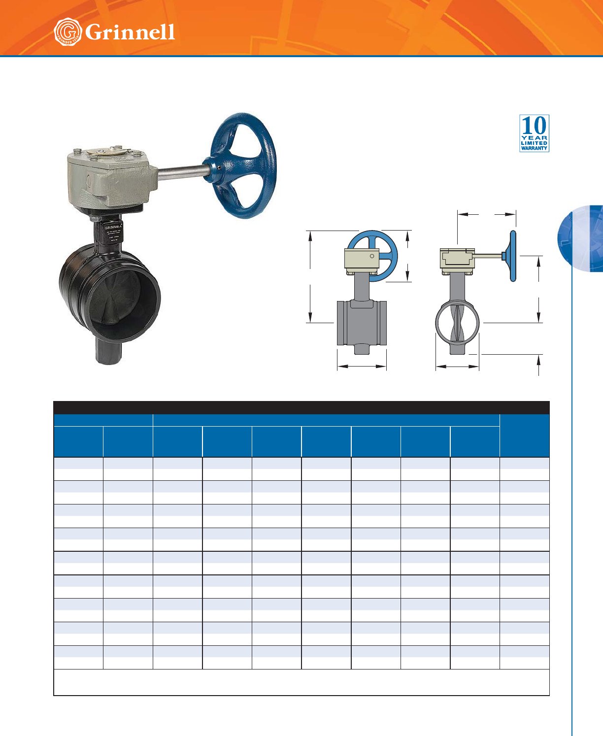
VALVES
VALVES
87
Refer to back cover for country-specific customer care numbers.
Model B302 - Gear Operator
Pipe Size Dimensions - Inches mm
Approx.
Weight
Lbs.
kg
Nominal
Inches
mm
O.D.
Inches
mm
ABCDEGH
2 2.375 8.46 3.14 7.64 2.89 3.33 5.50 5.91 14.5
50 60,3 214,9 79,8 194,1 73,4 84,6 139,7 150,1 6,6
21⁄22.875 8.65 3.25 7.64 3.46 3.85 5.69 5.91 15.5
65 73,0 219,7 82,6 194,1 87,9 97,8 144,5 150,1 7,0
3 3.500 8.99 3.54 7.64 3.97 3.85 5.94 5.91 17.0
80 88,9 226,1 89,9 194,1 100,8 97,8 150,9 150,1 7,7
4 4.500 9.79 4.35 7.64 5.03 4.56 8.00 5.91 20.5
100 114,3 248,7 110,5 194,1 127,8 115,8 203,2 150,1 9,3
5 5.563 9.30 4.84 7.64 6.27 5.86 7.33 5.91 25.0
125 141,3 236,2 122,9 194,1 159,3 148,8 186,2 150,1 11,3
6 6.625 13.53 5.93 9.53 7.25 5.86 8.61 9.84 33.0
150 168,3 343,7 150,6 242,1 184,2 148,8 218,7 249,9 15,0
8 8.625 14.47 6.87 9.53 9.25 5.26 9.55 9.84 45.0
200 219,1 367,5 174,5 242,1 235,0 133,6 242,6 249,9 20,4
10 10.750 16.53 9.17 11.54 11.25 6.29 11.61 18.0 83.0
250 273,1418,9232,9293,1285,6159,8294,9457,2 37,6
12 12.750 17.52 10.17 11.54 13.14 6.52 12.60 18.0 100.0
300 323,9 445,0 258,3 293,1 333,8 165,6 320,0 457,2 45,4
*End of disc does not extend beyond valve body.
For information on larger sizes, contact GRINNELL Mechanical Products.
G
A
B
D
E
C
H
Model B302 Grooved End Butterfly Valves
(Page 2 of 4)
Tech Data Sheet: G310
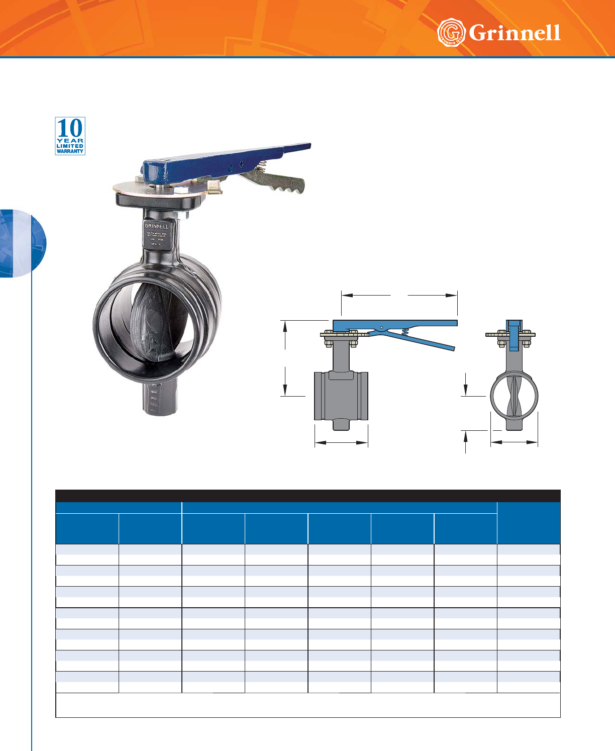
VALVES
VALVES
88 www.grinnell.com
Model B302 - Lever Lock Operator
Pipe Size Dimensions - Inches mm
Approx.
Weight
Lbs.
kg
Nominal
Inches
mm
O.D.
Inches
mm
ABCDE
2 2.375 5.31 3.14 10.50 2.89 3.33 6.7
50 60,3 134,9 79,8 266,7 73,4 84,6 3,0
2
1
⁄
2
2.875 5.41 3.25 10.50 3.46 3.85 7.5
65 73,0 137,4 82,6 266,7 87,9 97,8 3,4
3 3.500 5.62 3.54 10.50 3.97 3.85 8.7
80 88,9 142,7 89,9 266,7 100,8 97,8 3,9
4 4.500 6.57 4.35 10.50 5.03 4.56 12.2
100 114,3 166,9 110,5 266,7 127,8 115,8 5,5
5 5.563 7.07 4.84 10.50 6.27 5.86 17.3
125 141,3 179,6 122,9 266,7 159,3 148,8 7,8
6 6.625 8.40 5.93 13.75 7.25 5.86 27.4
150 168,3 213,4 150,6 349,3 184,2 148,8 23,4
8 8.625 9.37 6.87 13.75 9.25 5.26 32.5
200 219,1 238,0 174,5 349,3 235,0 133,6 14,7
*End of disc does not extend beyond valve body.
For information on larger sizes or availability in select regions, contact GRINNELL Mechanical Products.
C
E
A
B
D
Model B302 Grooved End Butterfly Valves
(Page 3 of 4)
Tech Data Sheet: G310
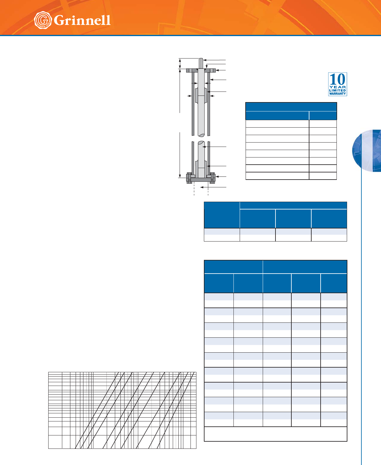
VALVES
VALVES
89
Refer to back cover for country-specific customer care numbers.
Torque
Stem Extensions
Stem extensions can be provided to permit remote
operation of the valve in any required length. Stem
extensions are available in lengths up to 10 ft. (3
meters). The top flange of the extension stem, plug
shaft diameter, and distance across the flats on the
plug shaft are the same size as the valve selected.
This design allows interchangeability of gear
operators, actuators, and adapter bushings from
the valve mounting flange to the extension stem top
flange.
Adjustable Sprocket Rim
The Babbitt Adjustable Sprocket Rim provides for
remote operation of the butterfly valves in high, out-
of-reach locations. Specify the sprocket number size,
and chain length. (Chain length = Height x 0,6m +
0,6m).
MATERIAL LIST
Part Material
1. Plug Steel
2. Top Flange Bushing Bronze
3. Top Flange Steel
4. Housing (Steel Pipe) Steel
5. Plug and Rod Coupling Steel
6. Rod Steel
7. Rod and Stem Coupling Steel
8. Bottom Flange Steel
Pipe Size Torque
Lbs - In., N - m
Nominal
Inches
mm
O.D.
Inches
mm
100 psi
6,9 bar
200 psi
13,8 bar
300 psi
20,7 bar
22.37548 67 83
50 60,3 5,42 7,56 9,38
21⁄22.875 48 67 83
65 73,0 5,42 7,56 9,38
33.500100134168
80 88,9 11,25 15,13 18,98
44.500185251317
100 114,3 20,88 16,20 35,81
55.563294410499
125 141,3 33,21 46,31 56,37
6 6.625 520 705 890
150 168,3 58,71 79,65 100,55
8 8.625 1,070 1,495 1,798
200 219,1 120,88 168,90 203,14
10 10.750 1,550 2,214 2,654
250 273,0 175,12 250,15 299,85
12 12.750 2,150 3,024 3,662
300 323,9 242,91 341,66 413,74
For information on larger sizes, contact GRINNELL
Mechanical Products.
Torque is the rotary effort required to operate a valve. This
turning force in a butterfly valve is determined by three
factors:
• Friction of the disc to seat for sealing
• Bearing friction
• Dynamic torque
Breakaway Torque is the total of the torques resulting
from bearing friction and seat/disc interference friction
at a given pressure differential. This value is normally the
highest required torque to operate a valve, and is used in
sizing actuators. The torques listed are valid for water and
lubricating fluids at ambient temperature. For dry and non-
lubricating fluids, contact a GRINNELL Mechanical Products
representative.
Butterfly valves, sizes 8" (200mm) and larger, when used
on liquids, show a marked increase in dynamic torque,
which tends to close the valve. For this reason, gear
operated or actuated valves are recommended.
The torque listed is for EPDM. When calculating torques for
Buna-N or Fluoroelastomer, multiply listed torque by 1.25.
Performance
1
2
3
4
5
6
7
8
Valve
Customer
Specified
Length
B
A
C
Model B302 Grooved End Butterfly Valves - Options
(Page 4 of 4)
Tech Data Sheet: G310
2"
3"
6"
8"
2 /
2
"
10000
5000
4000
3000
2000
1000
500
400
300
200
100
50
40
30
20
10
0.1
0.2
0.3
0.5
0.4
1
2
3
4
5
4"
10"
12"
30000
20000
FLOW RATE (GPM)
PRESSURE DROP IN PSI
1
5"
Pipe Size
Nominal
Inches
mm
Dimensions - Inches mm
ABC
2 - 12 2.88 1.125 1.12
50 - 300 73,2 28,6 28,4
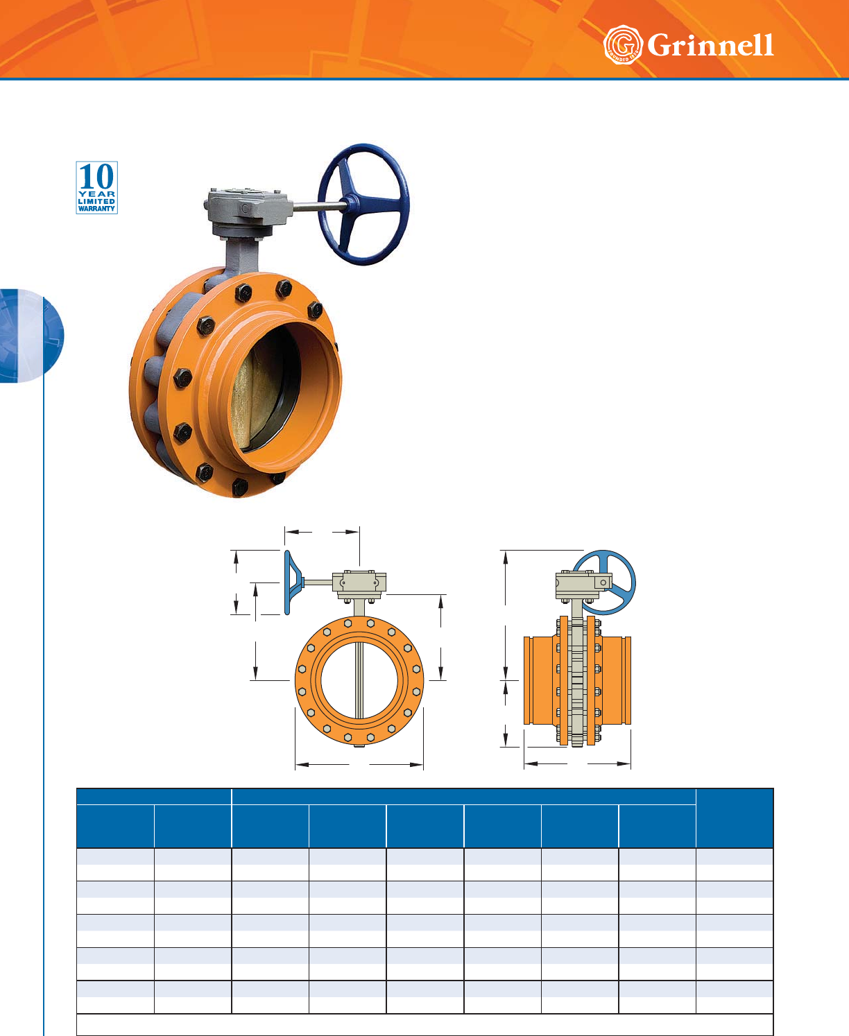
VALVES
VALVES
90 www.grinnell.com
E
G
A
H
B
D
C
J
Pipe Size Dimensions - Inches mm Approx.
Weight
Lbs.
kg
Nominal
Inches
mm
O.D.
Inches
mm
A B C D E F
14 14.000 23.25 10.75 10.00 21.00 13.06 15.25 378.0
350 355,6 590,6 273,1 254,0 533,4 331,7 387,4 171,8
16 16.000 24.75 12.50 10.00 23.50 14.33 16.75 452.0
400 406,4 628,7 317,5 254,0 596,9 364,0 425,5 205,5
18 18.000 25.75 14.00 10.00 25.00 15.40 17.75 548.0
450 457,2 654,1 355,6 254,0 635,0 391,2 450,9 249,1
20 20.000 27.25 15.00 10.00 27.50 16.38 18.25 728.0
500 508,0 692,2 381,0 254,0 698,5 416,1 463,6 330,9
24 24.000 30.12 16.75 10.25 32.00 18.26 21.12 1097.0
600 609,6 765,0 425,5 260,4 812,8 463,8 536,4 498,6
For information on larger sizes, contact GRINNELL Mechanical Products.
The GRINNELL Model 308 Butterfly Valve provides
dependable, long-term service and superior control of fluid
flow in piping systems. Flow may be from either direction,
and the valve may be positioned in any orientation.
The valve is furnished with grooved ends for use with
grooved couplings. The body and disc design provides
exceptional flow characteristics and low operating torque.
The disc has a streamlined profile that optimizes flow. The
body is lined with an elastomer seat that is reinforced with a
phenolic backing ring, reducing seat distortion, and wear.
The GRINNELL Model 308 Butterfly Valve includes a
gear operator with adjustable stops at the open and shut
positions.
The maximum Working Pressure is 150 psi (10,3 bar) with
316 S.S. Stem and 200 psi (13,8 bar) with 416 S.S. Stem.
Special order is available upon request: Vacuum Service to
29.5" (750mm) Hg.
Model 308 Butterfly Valves
(Page 1 of 2)
Tech Data Sheet: G320
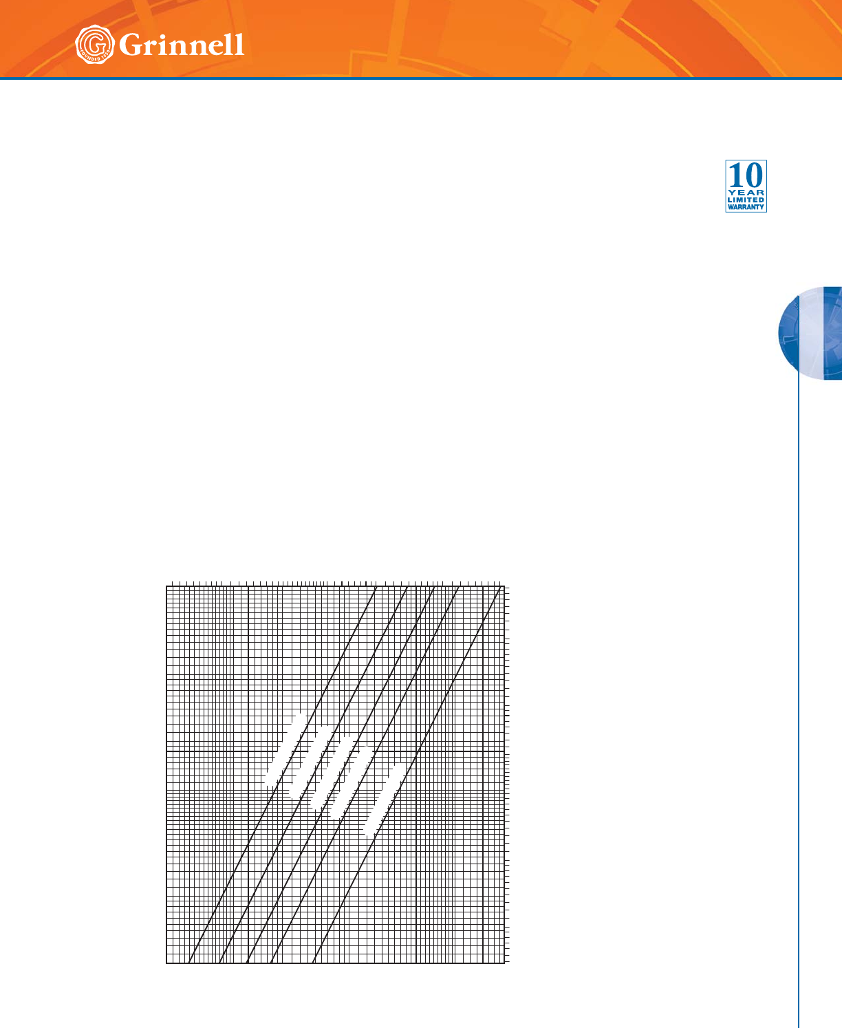
VALVES
VALVES
91
Refer to back cover for country-specific customer care numbers.
2.0
0.4
0.1
0.2
0.3
0.9
0.6
0.5
0.8
0.7
1.0
3.0
4.0
5.0
50003000 100000700005000030000200007000 10000
10000070000500003000020000 200000 300000
0,200
0,040
0,010
0,020
0,030
0,090
0,080
0,100
0,300
0,070
0,060
0,050
0,009
0,008
0,007
FLOW RATE IN LITRES PER MINUTE (LPM)
(1 GPM = 3,785 LPM)
FLOW RATE IN GALLONS PER MINUTE (GPM)
NOMINAL PRESSURE DROP IN BAR
(1 PSI = 0,06895 BAR)
IN POUNDS PER SQUARE INCH (PSI)
NOMINAL PRESSURE DROP
24 INCH (DN600)
20 INCH (DN500)
18 INCH (DN450)
16 INCH (DN400)
14 INCH (DN350)
Note:
For design purposes, a safety factor of 15% to 20% should be applied to the values in the above table.
MATERIAL SPECIFICATIONS
Body
• Cast iron conforming to ASTM A 126, Class B
Body Seat (Liner)
• Grade E EPDM, grade T nitrile or fluoroelastomer
Contact GRINNELL Mechanical Products for specific
recommendations on seat material.
Body Coating
• Epoxy coated
Disc
• Stainless steel conforming to ASTM A 351,
Grade CF8M
• Aluminum bronze conforming to ASTM B 148,
C95400
• Ductile iron conforming to ASTM A 536,
Grade 65-45-12
Drive and Bottom Shaft
• Stainless steel conforming to ASTM A 582, Type 416
or Stainless steel conforming to ASTM A 276,
Type 316
Gear Operator
• Cast iron housing
Upper and Lower Bearings
• Reinforced Teflon*
Plug
• Cast iron ASTM A 126
Seat Material
• Grade E EPDM – For service temperatures from
-40°F to 230°F (-40°C to 110°C). Recommended for
water service, dilute acids, alkalies, oil-free air, and
many chemical services. They are not recommended
for use in petroleum services.
• Grade T Nitrile – For service temperatures from
-20°F to 180°F (-29°C to 82°C). Recommended for
petroleum products, air with oil vapors, vegetable oils,
and mineral oils. They are not recommended for use
in hot water services.
Contact GRINNELL Mechanical Products for specific
recommendations on seat material.
* Teflon is an trademark of Dupont
Model 308 Butterfly Valves
(Page 2 of 2)
Tech Data Sheet: G320
Performance
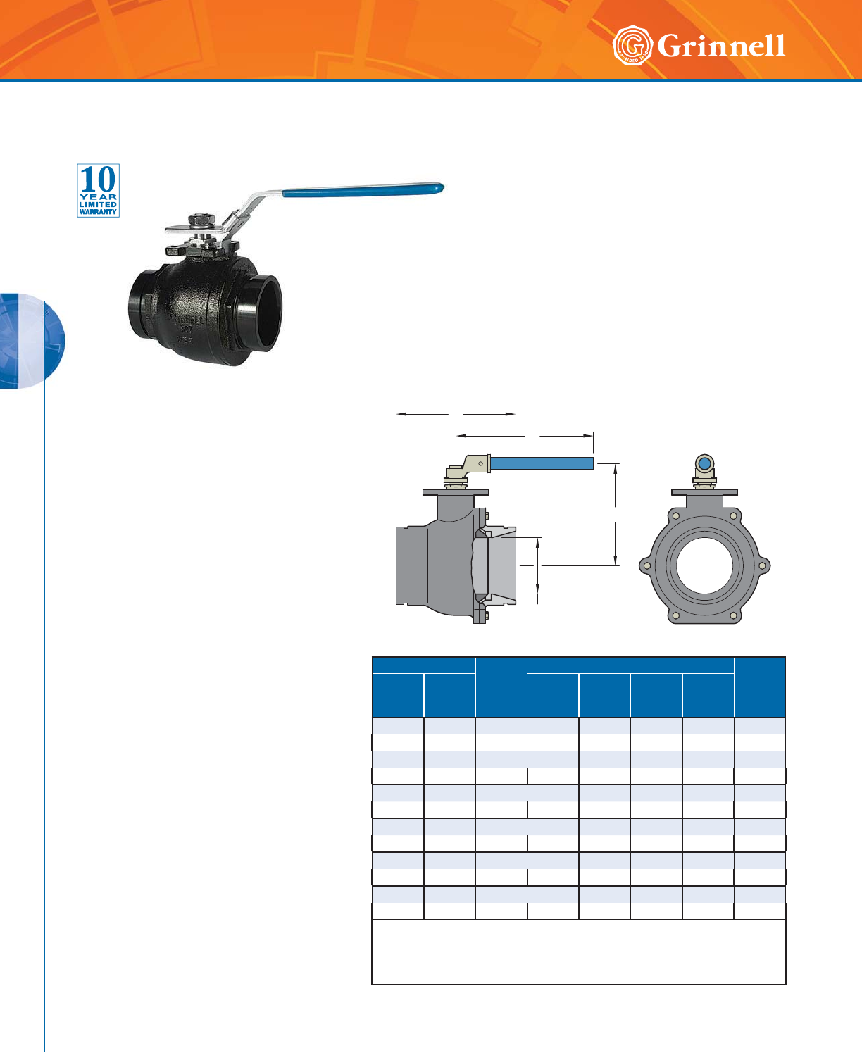
VALVES
VALVES
92 www.grinnell.com
Model BV835 Ball Valves
(Page 1 of 2)
Tech Data Sheet: G380 GRINNELL Model BV835 Ball Valves provide for
efficient control of fluid in piping systems. Flow may
be from either direction, and the valves may be
positioned in any orientation. The valves are furnished
with grooved ends for use with GRINNELL Grooved
Couplings. The handle is provided with a device for
padlocking in either the open or closed position.
The GRINNELL Model BV835 is furnished with grooved
ends and features a handle that accepts a padlock
device for locking in either the open or closed position.
Flow may be from either direction and the valves may be
positioned in any orientation.
Pipe Size Operating
Torque *
Lbs - in
N-m
Dimensions - Inches mm Approx.
Weight
Lbs.
kg
Nominal
Inches
mm
O.D.
Inches
mm
ABC D
11⁄21.900 62 5.12 3.39 7.00 1.25 4.8
40 48,3 7 130 86 178 32 2,2
2 2.375 150 5.50 3.75 7.00 1.50 6.4
50 60,3 17 140 95 178 38 2,9
21⁄22.875 186 6.25 5.20 10.43 2.00 10.6
65 73,0 21 159 132 265 50 4,8
3 3.500 248 6.56 5.63 10.43 2.50 13.4
80 88,9 28 167 143 265 63 6,1
44.5003989.453.7010.433.5055.0
100 114,3 45 240 94 265 90 25,0
6 6.625 531 10.15 8.70 23.60 4.92 79.2
150 168,3 60 258 221 600 125 36,0
* For the first opening or closing of the valve when the valve is not continuously
operated, an additional torque of 2.0 – 2.5 times the listed operating torque is
normally required.
For information on larger sizes, contact GRINNELL Mechanical Products.
Maximum Working Pressure
1,000 psi (68,9 bar) 2" – 3" (50mm – 80mm)
800 psi (55,2 bar) 4" (100mm)
600 psi (41,4 bar) 6" (150mm)
Shell Test
1.5 times WOG x 60 seconds, hydrostatic, at
ambient temperature
Seat Test
80 psi (5,5 bar) x 60 seconds, pneumatic
MATERIAL
SPECIFICATIONS
Body
• Ductile iron conforming to
ASTM A 536, Grade 65-45-12
Body Coating
• Black enamel
Ball
• Type 304 Stainless Steel
Body Seal
• R-PTFE
Seats
• Virgin TFE
O-Ring
• Fluoroelastomer (Viton)
Stem
• Carbon steel, nickel-plated,
- Type 304 Stainless Steel available
Lever Handle
• Carbon steel, zinc plated with plastic grip,
- Type 304 Stainless Steel available
Gear Operator
• Manual with hand wheel, cast iron body
C
A
B
D
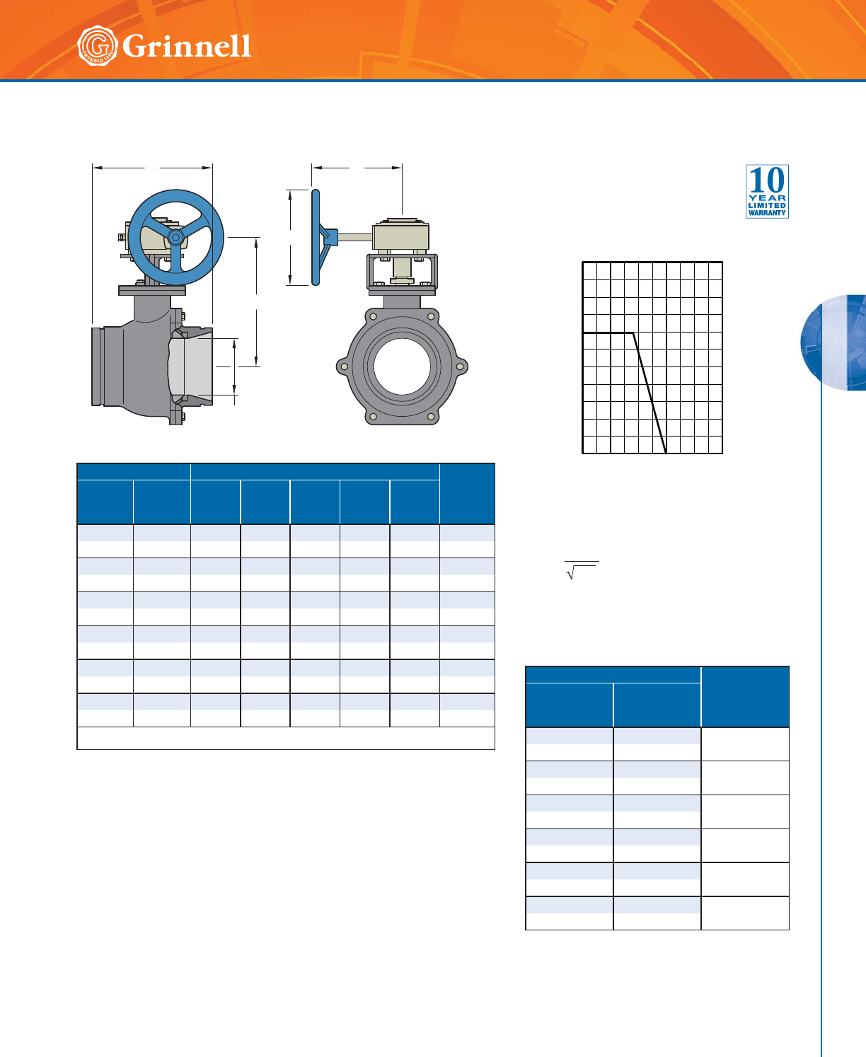
VALVES
VALVES
93
Refer to back cover for country-specific customer care numbers.
Model BV835 Ball Valves
(Page 2 of 2)
Tech Data Sheet: G380
Pressure
Performance
Flow Data - Cv Values
Pipe Size Dimensions - Inches mm Approx.
Weight
Lbs.
kg
Nominal
Inches
mm
O.D.
Inches
mm
ABC DE
11⁄21.9005.124.8881.256 15.0
40 48,3 130 124 203 32 152 7,0
2 2.375 5.50 5.38 8 1.50 6 18.0
50 60,3 140 137 203 38 152 8,0
21⁄22.875 6.25 5.68 8 2.00 6 22.0
65 73,0 159 145 203 50 152 10,0
3 3.500 6.56 7.16 8 2.50 6 31.0
80 88,9 167 182 203 63 152 14,0
4 4.500 9.45 8.00 8 3.50 6 73.0
100 114,3 240 203 203 90 152 33,0
6 6.625 10.15 10.89 14 4.92 12 123.4
150 168,3 258 277 356 125 305 56,0
For information on larger sizes, contact GRINNELL Mechanical Products.
Pipe Size
Cv
Value
Nominal
Inches
mm
O.D.
Inches
mm
11⁄21.900 130
40 48,3
22.375
180
50 60,3
21⁄22.875 320
65 73,0
33.500
600
80 88,9
44.500
1020
100 114,3
66.625
3300
150 168,3
0
0
2,000
4,000
6,000
8,000
10,000
50 100
Temperature (C°)
Pressure (kPa)
200 250
Values for flow of water at 60°F (16°C)
&Y 4
¨3
Where: Cv = Flow coefficient
Q = Flow (GPM)
ΔP = Pressure drop (psi)
General Notes
• Pressure ratings listed are CWP (cold water pressure) or maximum working pressure
within the service temperature range of the gasket used in the coupling. For additional
information, contact GRINNELL Mechanical Products.
• Maximum working pressures and end loads listed are total of internal and external
pressures and loads based on Schedule 40 steel pipe with roll grooves to ANSI/AWWA
C606-04 specifications. For information on other pipe schedules, contact GRINNELL
Mechanical Products.
• Warning: Piping systems must always be depressurized and drained before attempting
disassembly and/or removal of any components.
C
E
B
D
A
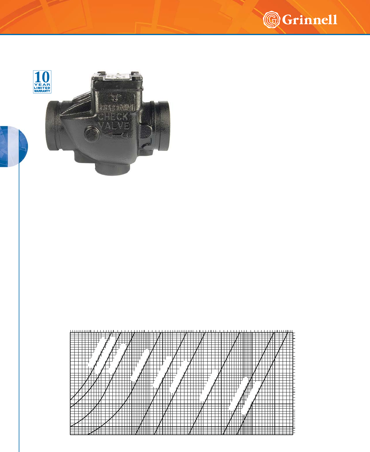
VALVES
VALVES
94 www.grinnell.com
Model 590 Grooved End Check Valves
(Page 1 of 2)
Tech Data Sheet: G350
MATERIAL SPECIFICATIONS
Ductile Iron Body and
Cap Specifications
• ASTM A 536 – Standard specification for ductile iron
castings, Grade 65-45-12
• Tensile strength, minimum 65,000 psi (4481,6 bar)
• Yield strength, minimum 45,000 psi (3102,6 bar)
• Elongation in 2" (50mm), minimum 12%
Seat
• Nickel
Coating
•Non-Lead paint
Performance
Seal Specifications
• Grade “E” EPDM seals have a Green color code
identification and conform to ASTM D 2000 for
service temperatures from -30°F to 230°F (-34°C to
110°C). They are recommended for hot water not to
exceed 230°F (110°C), plus a variety of dilute acids,
oil free air, and many chemical services. They are not
recommended for petroleum services.
• Grade “T” Nitrile seals have an Orange color
code identification and conform to ASTM D 2000 for
service temperatures from -20°F to 180°F (-29°C to
82°C). They are recommended for petroleum
products, vegetable oils, mineral oils, and air with
oil vapors.
GRINNELL Model 590 Check Valves are capable of
pressures up to 300 psi (20,7 bar). These valves are
designed as compact and rugged swing-type units that
allow water flow in one direction and prevent flow in the
opposite direction. They are manufactured with a ductile iron
body, nickel seat, and a stainless steel clapper assembly for
sizes 2" – 8" (50mm – 200mm), and a ductile iron clapper
assembly for sizes 10" – 12" (250mm – 300mm). A resilient
elastomer seal facing on the spring loaded clapper ensures a
leak tight seal and a non-sticking operation. The GRINNELL
Model 590 Check Valve is designed to minimize water
hammer caused by flow reversal.
The valves are furnished with grooved ends and can be
installed using GRINNELL Couplings. The GRINNELL Model
590 can be installed with GRINNELL Figure 71 Flange
Adapters or ANSI class 300 Flange Adapters. All GRINNELL
Model 590 Check Valves are designed with a removable
cover for ease during field maintenance.
0,04
0,05
0,07
0,06
0,09
0,08
0,10
0,20
0,30
IN POUNDS PER SQUARE INCH (PSI)
NOMINAL PRESSURE DROP
NOMINAL PRESSURE DROP IN BAR
(1 PSI = 0,06895 BAR)
0.5
0.6
1.0
0.9
0.8
0.7
4.0
2.0
3.0
5.0
200 300 400 600 1000 2000 3000 4000 6000 10000
700 1000 2000 3000 5000 7000 10000 20000 30000
15000
50000
100
500
FLOW RATE IN LITRES PER MINUTE (LPM)
(1 GPM = 3,785 LPM)
FLOW RATE IN GALLONS PER MINUTE (GPM)
2-1/2 INCH (DN65)
3 INCH (DN80)
5 INCH (DN125)
8 INCH (DN200)
6 INCH (DN150)
4 INCH (DN100)
10 INCH (DN250)
2 INCH (DN50)
12 INCH (DN300)
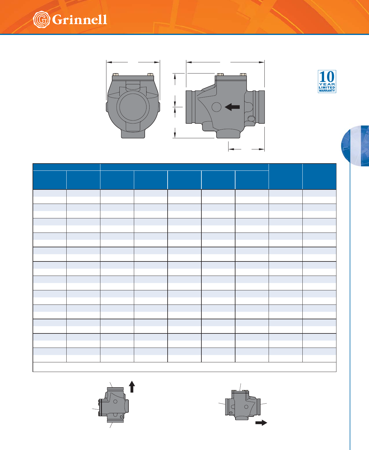
VALVES
VALVES
95
Refer to back cover for country-specific customer care numbers.
Pipe Size Dimensions - Inches mm Cover
Bolt Torq.
Lb.-ft.
Nm
Approx.
Weight
Lbs.
kg
Nominal
Inches
mm
O.D.
Inches
mm
ABCDE
2 2.375 6.75 4.38 2.55 2.57 3.25 15 9.0
50 60,3 171,5 111,3 64,8 65,3 82,3 21 4,5
21⁄22.875 8.00 5.42 3.41 3.09 3.88 39 10.0
65 73,0 203,2 136,7 86,6 78,5 98,6 54 4,5
76,1mm 3.000 8.00 5.42 3.41 3.09 3.88 39 10.0
65 76,1 203,2 136,7 86,6 78,5 98,6 54 4,5
3 3.500 8.38 5.76 3.60 3.31 3.88 39 11.0
80 88,9 212,9 146,3 91,4 84,1 98,6 54 5,0
4 4.500 9.63 6.74 4.61 3.63 4.53 39 25.0
10 0 114, 3 24 5 ,6 171, 2 117,1 9 2, 2 115 ,4 5 4 11, 3
139,7mm 5.500 10.50 7.50 5.29 4.13 4.90 39 29.0
125 139,7 266,7 190,5 134,4 104,9 124,5 54 13,2
5 5.563 10.50 7.50 5.29 4.13 4.90 39 29.0
125 141,3 266,7 190,5 134,4 104,9 124,5 54 13,2
165,1mm 6.500 11.50 8.05 5.75 4.50 5.00 60 47.0
150 165,1 292,1 204,4 146,1 114,3 127,0 82 21,3
6 6.625 11.50 8.05 5.75 4.50 5.00 60 47.0
150 168,3 292,1 204,4 146,1 114,3 127,0 82 21,3
8 8.625 14.00 10.25 7.75 5.62 5.45 120 66.0
200 219,1 355,6 260,4 196,9 142,7 138,4 164 30,0
10 10.750 18.00 13.00 10.21 6.38 7.50 120 109.7
250 273,1 457,2 330,2 259,3 162,1 190,5 164 49,4
12 12.750 21.0 14.28 11.31 7.26 7.62 120 151.0
300 323,9 533,4 362,7 287,2 184,4 193,5 164 68,0
For information on larger sizes, contact GRINNELL Mechanical Products.
BA
C
D
E
HORIZONTAL ORIENTATIONVERTICAL ORIENTATION
FLOW
FLOW
COVER
COVER
OUTLET
INLET
OUTLET
INLET
Model 590 Grooved End Check Valves
(Page 2 of 2)
Tech Data Sheet: G350
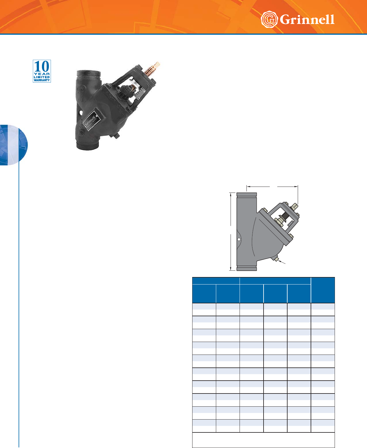
VALVES
VALVES
96 www.grinnell.com
Model TD830 Triple Duty Valves
Tech Data Sheet: G390
The GRINNELL Model TD830 Triple Duty Valve is designed for
installation in pump discharge piping where it functions as a
spring-loaded silent check valve, a balancing valve, and a shut-off
valve.
The GRINNELL Model TD830 Triple Duty Valve operates
automatically and quietly. Line pressure of approximately 0.25
psi (0,02 bar) opens the disc. To prevent flow reversal and water
hammer, the spring closes the disc as the line flow approaches
zero in order. The flow through the valve can be adjusted from
bubble tight shut-off to full-flow by the threaded rising stem.
Pipe Size Dimensions - Inches mm Approx.
Weight
Lbs.
kg
Nominal
Inches
mm
O.D.
Inches
mm
AB
OPEN
C
NPT
2 2.375 9.38 9.63 1⁄223.0
50 60,3 238,1 244,5 15 10,0
21⁄22.875 10.25 9.63 1⁄224.0
65 73,0 260,4 244,5 15 10,9
33.50011.2510.13
1⁄233.0
80 88,9 285,8 257,2 15 15,0
44.50015.6312.63
1⁄284.0
100 114,3 397,9 320,8 15 38,0
5 5.563 15.625 11.125 1⁄284.0
125 141,3 397,9 282,6 15 38,0
6 6.625 19.63 17.50 3⁄4156.0
150 168,3 498,5 444,5 20 70,0
8 8.625 23.63 18.00 3⁄4300.0
200 219,1 600,0 457,2 20 136,0
10 10.750 28.00 21.75 1 392.0
250 273,1 711,2 552,5 25 178,0
12 12.750 31.63 25.00 1 496.0
300 323,9 803,3 635,0 25 225,0
14 14.000 33.50 25.000 1 790.0
340 355,6 851,0 635,0 25 358,3
For information on larger sizes, contact GRINNELL
Mechanical Products.
A
B
C
The GRINNELL Model TD830 Triple Duty Valve can be
installed quickly into grooved end piping systems using
two GRINNELL Couplings. The externally guided disc has
a soft seat to ensure a leak-tight seal. It lifts 1
/3" (8mm) for
each 1" (25,4mm) of pipe diameter. The rising stem design
incorporates a graduated position indicator to ensure
accurate disc positioning for throttling service.
The yoke and valve stem are unwetted external parts so they
cannot be corroded or eroded by the line fluid. All mating
threaded parts are made of dissimilar, non-galling metals. An
NPT drain plug is provided, as well as bosses for gauge taps
at the inlet and outlet.
Maximum working pressure is 640 psi (44,1 bar) at 100°F
(38°C) and 565 psi (39 bar) at 300°F (149°C).
Note: Pressure and temperature can be limited by gasket material. Contact
GRINNELL Mechanical Products.
MATERIAL SPECIFICATIONS
Body and Yoke
• Ductile iron conforming to ASTM A 395, Grade
60-40-18 or A 536
Disc
• Aluminum bronze ASTM B 142, C 950
Disc Guide and Flanged Gland
• Cast iron conforming to ASTM A 126-B
Spring
• 302 stainless steel
Stem
• Type 316 stainless steel
Stem Guide
• Ductile iron conforming to ASTM A 536 or A 395
O-Rings
• EPDM
Seat
• Bronze
Seat Guide
• Bronze conforming to ASTM B 584 (81-3-7-9)
Finish
• Black paint
Performance
• Pressure drop, contact GRINNELL Mechanical Products.
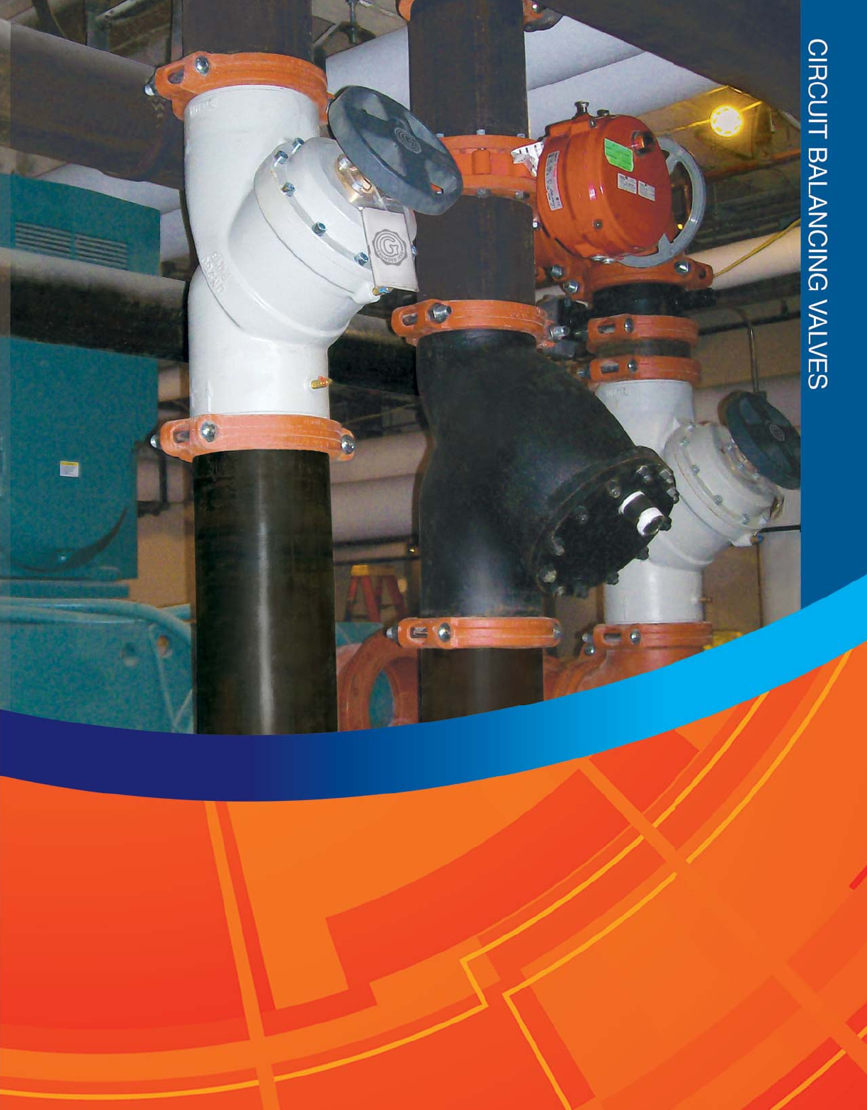
97
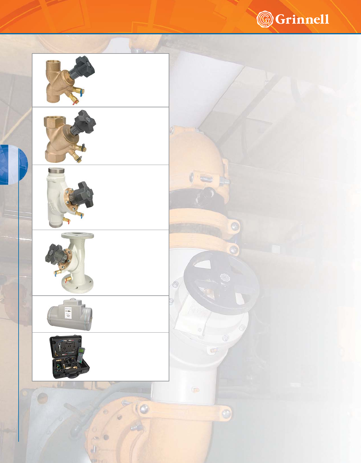
CIRCUIT BALANCING VALVES
98 www.grinnell.com
CIRCUIT BALANCING VALVES
GRINNELL Model CB800 Circuit Balancing Valves are
designed to achieve accurate and efficient balancing of
hydronic heating or cooling systems. Circuit Balancing
Valves provide superior accuracy in measuring flows rather
than ball type circuit setters.
The CB800 valve serves 5 functions:
• Throttling
• Measuring differential pressure
• Draining
• Filling
• Positive shutoff
These valves are rated at 300 psi (20,7 bar) at
300°F (150°C).
The valve is made of dezincification-resistant brass and
bronze components. Threaded and solder connections are
available for sizes 1⁄2" – 2" (15mm – 50mm) sizes with
bronze bodies. Flanged (125#) and grooved connections
are available for sizes 21⁄2" – 12" (65mm – 300mm) with
cast iron bodies.
The Y-Pattern style provides low pressure drop. The globe
style valve allows for precise throttling. The easy-to-adjust
digital/vernier handwheel provides a minimum of 70 unique
handwheel positions. The handwheel and test ports are located
on one side for easy access. A built-in memory stop ensures
the setting can be returned to a balanced position after shutoff.
The self-sealing pressure/temperature test ports use standard
insertion probes to eliminate additional components.
The GRINNELL Circuit Balancing Valve is installed with flow
in the direction of the arrow, and may be in the horizontal
or vertical position. The handwheel can be positioned up or
down, or on either side.
Model CB800
Solder Ends
Circuit Balancing Valves
Page 100
Model CB800
Threaded Ends
Circuit Balancing Valves
Page 100
Model CB800
Grooved Ends
Circuit Balancing Valves
Page 101
Model CB800
Flanged Ends
Circuit Balancing Valves
ANSI & PN16/PN10
Page 102 - 103
Model CB800
Insulation Kits
Page 104
Model CB800
MC2 Computer
Page 104
Circuit Balancing Valves Table of Contents
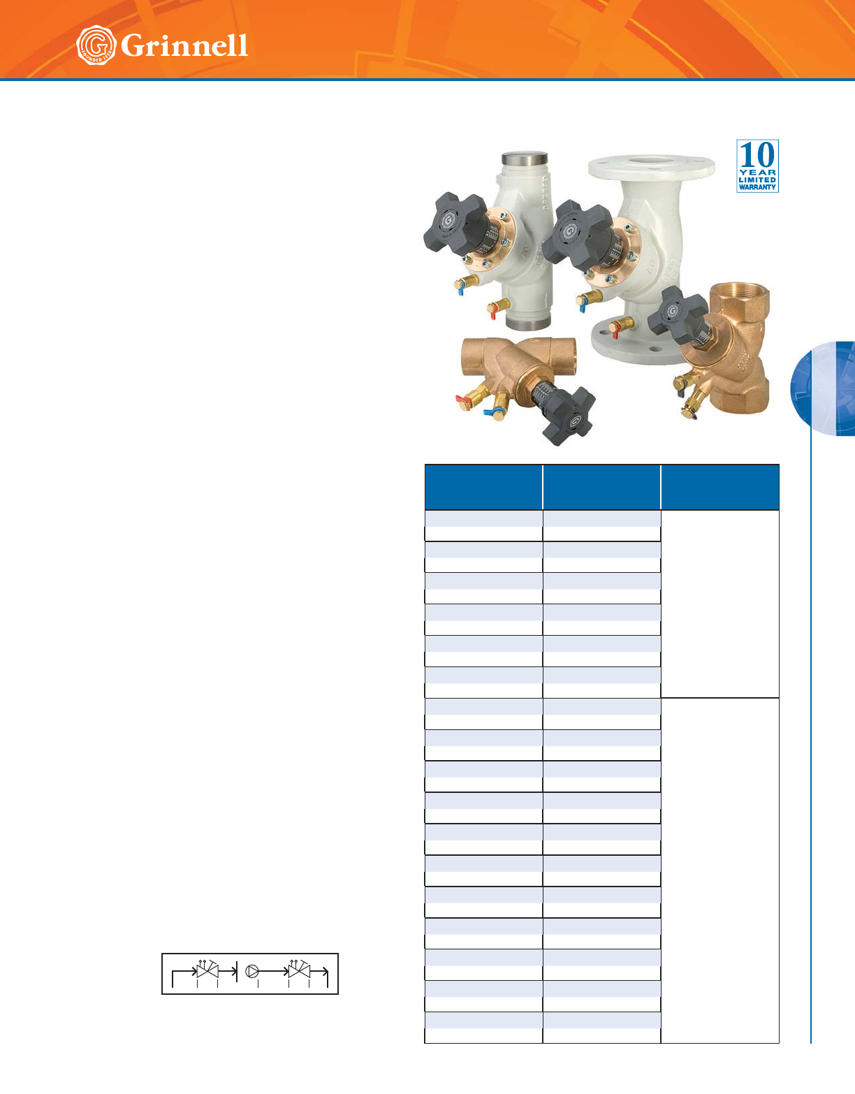
CIRCUIT BALANCING VALVES
CIRCUIT BALANCING VALVES
99
Refer to back cover for country-specific customer care numbers.
CB800 Circuit Balancing Valves
Tech Data Sheet: G450
MATERIAL SPECIFICATIONS
Body
• Sizes 1⁄2" – 2" (15mm – 50mm) solder or NPT threaded
connection: brass-resistant to dezincification (DZR)
• Sizes 21⁄2" – 12" (65mm – 300mm), grooved or flanged
connection: Cast Iron conforming to
ASME ANSI B16.5
Valve Stem and Disc
• Brass resistant to dezincification (DZR)
O Ring
• EPDM E
Handwheel
• Thermoplastic
For accessories and replacement parts contact GRINNELL
Mechanical Products for details.
Valve Sizing
All balancing valves are sized to perform in a normal
operation range between 25% and 100% of the full open
position, at a minimum differential pressure between 1 –
3 ft. (0,3m – 0,9m) of water. It is recommended that for
improved accuracy, the valve is set to open 70%+.
When maximum flow is known but a pressure drop through
the balancing valve is unknown, select a balancing valve
for a maximum pressure drop of 2 ft. (0,6m) water 0.8 psi
(0,06 bar) in the full open position as shown in the table to
the right.
Accurate flow measurement requires that the velocity
distribution near the balancing valve remains constant,
regardless of the total flow through the pipe. Fittings, such
as elbows and tees, disturb the normal flow profile which is
established through straight pipe. Pumps create even greater
disturbances. Failure to allow water flows around fittings
and pumps to normalize can affect measuring accuracy by
as much as 20% when the valve is in the fully open position.
Minimum lengths (diameters, D) of straight pipe before and
after the balancing valve prevent these errors.
Valves are designed for vertical, horizontal, or inclined
installation.
Size
Inches
mm
Flow Rate
GPM
LPM
Connection
Type
1⁄22.6 - 4.2
Thread
15 0,687 - 1,110
3⁄43.4 - 6.2
20 0,898 - 1,638
1 6.2 - 9.6
25 1,638 - 2,536
11⁄49.4 - 21.0
32 2,483 - 5,548
11⁄215 - 30
40 3,96 - 7,93
2 22 - 42
50 5,812 - 11,096
21⁄239 - 106
Flanged or
Grooved
65 10,30 - 28,01
76,1mm 39 - 106
65 10,30 - 28,01
3 60 - 132
80 15,85 - 34,87
4 100 - 217
100 26,42 - 57,33
139,7mm 112 - 317
125 29,59 - 83,75
5 112 - 317
125 29,59 - 83,75
165,1mm 220 - 437
150 58,12 - 115,46
6 220 - 437
150 58,12 - 115,46
8 223 - 881
200 58,92 - 232,76
10 292 - 1298
250 77,15 - 342,93
12 616 - 1731
300 162,75 - 457,33
Minimum Pipe Diameters from Fittings
3D 2D Pump10D 2D
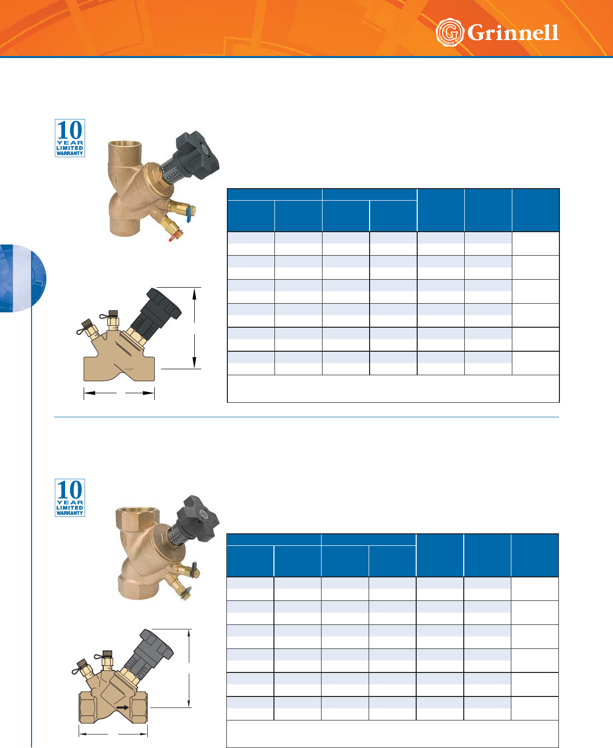
CIRCUIT BALANCING VALVES
CIRCUIT BALANCING VALVES
100 www.grinnell.com
Pipe Size Dimensions - Inches mm Approx.
Weight
Lbs.
kg
Limits
PSI/°F
PN/°C
Handwheel
Turns
Nominal
Inches
mm
O.D.
Inches
mm
LH
1⁄20.840 3.13 4.13 1.4 235/300 7
15 21,3 79,5 104,9 0,6 16/150
3⁄41.050 3.31 4.56 1.4 235/300 7
20 26,7 84,1 115,8 0,6 16/150
1 1.315 3.38 4.69 2.2 235/300 7
25 33,7 85,6 119,1 1,0 16/150
11⁄41.660 4.38 5.38 3.0 235/300 10
32 42,4 111,3 136,7 1,4 16/150
11⁄21.900 4.75 5.44 3.9 235/300 10
40 48,3 120,7 138,2 1,7 16/150
2 2.375 5.94 5.81 5.6 235/300 10
50 60,3 150,9 147,6 2,6 16/150
For information on larger sizes, contact GRINNELL Mechanical Products.
See circuit balancing valve specifications on pages 99.
L
H
Model CB800 Circuit Balancing Valves
Threaded Ends
Tech Data Sheet: G450
Model CB800 Circuit Balancing Valves
Solder Ends
Tech Data Sheet: G450 The GRINNELL Model CB800 Balancing Valve provides features for achieving
accurate and efficient balancing of hydronic heating or cooling systems. One valve
serves five functions: throttling, measuring (pressure and temperature), positive
shutoff, draining and filling. The GRINNELL Solder-by-Solder Model CB800 Valve,
available in sizes 1⁄2" to 2" (15mm to 50mm), is composed of dezincification
resistant brass.
The GRINNELL Model CB800 Balancing Valve provides features for achieving
accurate and efficient balancing of hydronic heating or cooling systems. One valve
serves five functions: throttling, measuring (pressure and temperature), positive
shutoff, draining and filling. The GRINNELL Thread-by-Thread Model CB800 Valve,
available in sizes 1⁄2" to 2" (15mm to 50mm), is composed of dezincification
resistant brass.
/
+
Pipe Size Dimensions - Inches mm Approx.
Weight
Lbs.
kg
Limits
PSI/°F
PN/°C
Handwheel
Turns
Nominal
Inches
mm
O.D.
Inches
mm
LH
1⁄20.840 3.50 4.50 1.4 235/300 7
15 21,3 88,9 114,3 0,6 16/150
3⁄41.050 3.81 4.56 1.4 235/300 7
20 26,7 96,8 115,8 0,6 16/150
1 1.315 4.31 4.69 2.2 235/300 7
25 33,7 109,5 119,1 1,0 16/150
11⁄41.660 5.06 5.38 3.0 235/300 10
32 42,4 128,5 136,7 1,4 16/150
11⁄21.900 5.56 5.44 3.9 235/300 10
40 48,3 141,2 138,2 1,7 16/150
2 2.375 6.56 5.81 5.6 235/300 10
50 60,3 166,6 147,6 2,6 16/150
For information on larger sizes, contact GRINNELL Mechanical Products.
See circuit balancing valve specifications on pages 99.
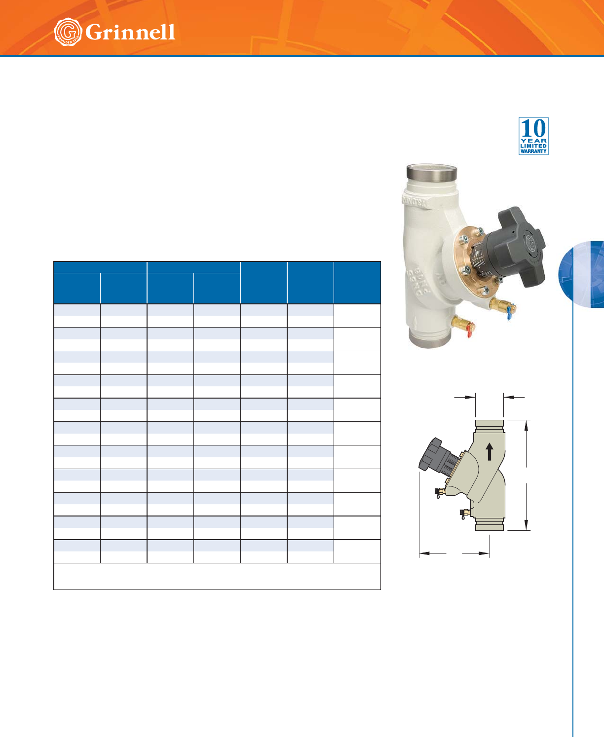
CIRCUIT BALANCING VALVES
CIRCUIT BALANCING VALVES
101
Refer to back cover for country-specific customer care numbers.
Pipe Size Dimensions - Inches mm Approx.
Weight
Lbs.
kg
Limits
PSI/°F
PN/°C
Handwheel
Turns
Nominal
Inches
mm
O.D.
Inches
mm
LH
21⁄22.875 11.44 7.38 18.7 300/300 8
65 73,0 290,6 187,5 8,5 20,7/150
76,1mm 3.000 11.44 7.38 18.7 300/300 8
65 76,1 290,6 187,5 8,5 20,7/150
3 3.500 12.25 8.00 27.5 300/300 8
80 88,9 311,2 203,2 12,5 20,7/150
4 4.500 13.75 9.44 45.1 300/300 8
100 114,3 349,3 239,8 20,5 20,7/150
139,7mm 5.500 15.75 11.13 70.4 300/300 8
125 139,7 400,0 282,7 32,0 20,7/150
5 5.563 15.75 11.13 70.4 300/300 8
125 141,3 400,0 282,7 32,0 20,7/150
165,1mm 6.500 18.88 11.25 95.7 300/300 8
150 165,1 479,6 285,8 43,5 20,7/150
6 6.625 18.88 11.25 95.7 300/300 8
150 168,3 479,6 285,8 43,5 20,7/150
8 8.625 23.63 18.44 255.2 300/300 12
200 219,1 600,2 468,4 116,0 20,7/150
10 10.750 28.75 18.88 376.2 300/300 12
250 273,1 730,3 479,6 171,0 20,7/150
12 12.750 33.44 20.25 519.2 300/300 12
300 323,9 849,4 514,4 136,0 20,7/150
For information on larger sizes, contact GRINNELL Mechanical Products.
See circuit balancing valve specifications on pages 99.
OD
L
H
Model CB800 Circuit Balancing Valves
Grooved Ends
Tech Data Sheet: G450
The GRINNELL Model CB800 Balancing Valve provides features for
achieving accurate and efficient balancing of hydronic heating or cooling
systems. The GRINNELL Groove-by-Groove Model CB800 Valve, available
sizes 21⁄2" to 12" (65mm to 300mm), is composed of cast iron.
The CB800 valve serves 5 functions:
• Throttling
• Measuring differential pressure
• Draining
• Filling
• Positive shutoff
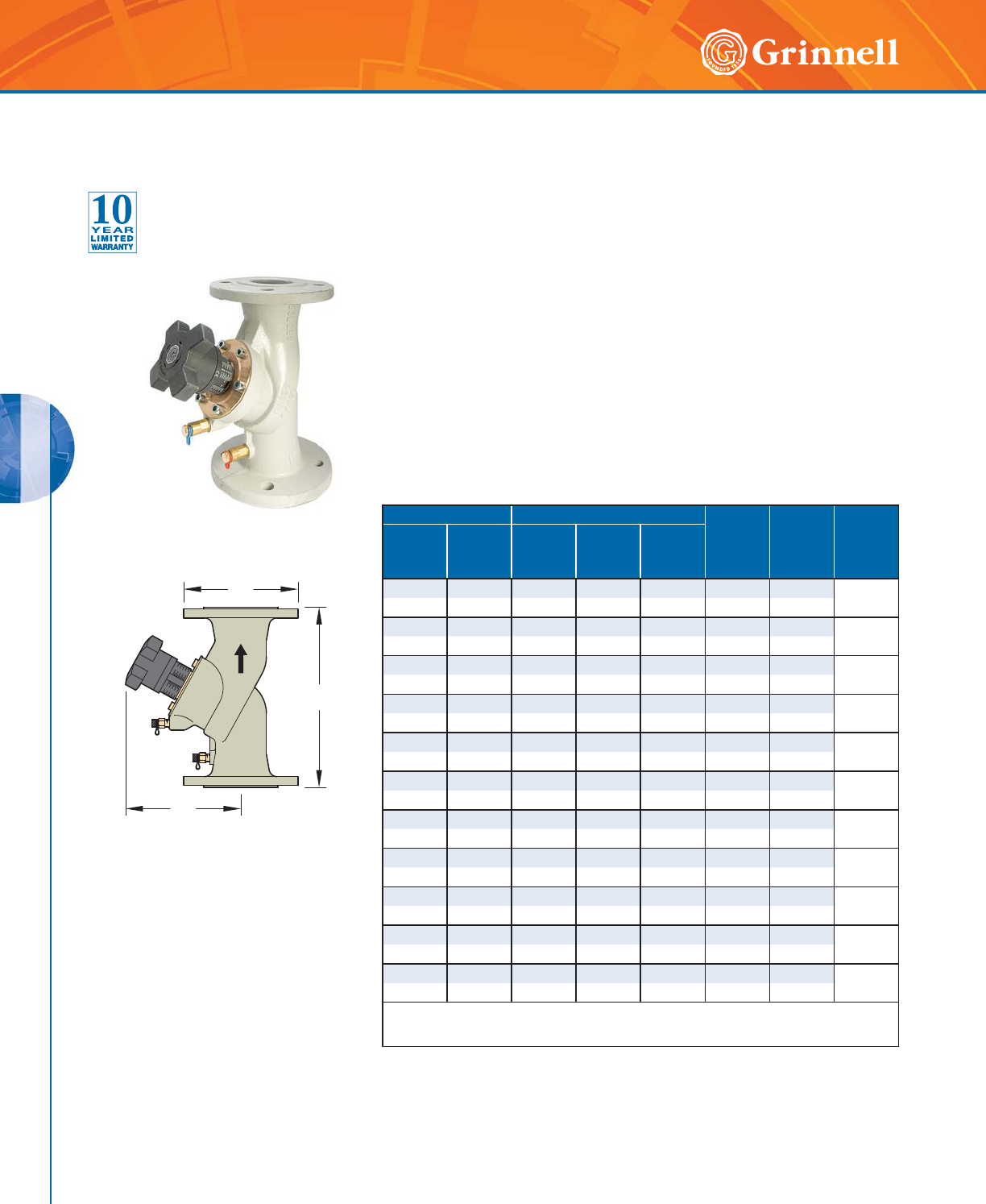
CIRCUIT BALANCING VALVES
CIRCUIT BALANCING VALVES
102 www.grinnell.com
H
D
L
Pipe Size Dimensions - Inches mm Approx.
Weight
Lbs.
kg
Limits
PSI/°F
PN/°C
Handwheel
Turns
Nominal
Inches
mm
O.D.
Inches
mm
LHD
21⁄22.875 11.4 7.4 7.3 18.7 235/300 8
65 73,0 290 188 185 13,5 16/150
76,1mm 3.000 11.4 7.4 7.3 18.7 235/300 8
65 76,1 290 188 185 13,5 16/150
3 3.500 12.2 8.0 7.9 39.6 235/300 8
80 88,9 310 203 200 18,0 16/150
4 4.500 13.8 9.4 8.7 61.6 235/300 8
100 114,3 350 240 220 28,0 16/150
139,7mm 5.500 15.7 11.1 9.8 89.1 235/300 8
125 139,7 400 283 250 40,5 16/150
5 5.563 15.7 11.1 9.8 89.1 235/300 8
125 141,3 400 283 250 40,5 16/150
165,1mm 6.500 18.9 11.2 11.2 113.3 235/300 8
150 165,1 480 285 285 51,5 16/150
6 6.625 18.9 11.2 11.2 113.3 235/300 8
150 168,3 480 285 285 51,5 16/150
8 8.625 23.6 18.4 13.4 284.9 235/300 12
200 219,1 600 467 340 129,5 16/150
10 10.750 28.7 18.9 15.9 431.2 235/300 12
250 273,1 730 480 405 196,0 16/150
12 12.750 33.5 20.3 19.1 580.8 235/300 12
300 323,9 850 515 485 264,0 16/150
For information on larger sizes, contact GRINNELL Mechanical Products.
See circuit balancing valve specifications on pages 99.
Model CB800 Circuit Balancing Valves
Flanged Ends, ANSI Class 125#
Tech Data Sheet: G450
The GRINNELL Model CB800 Balancing Valve provides features for achieving
accurate and efficient balancing of hydronic heating or cooling systems. One
valve serves five functions: throttling, measuring (pressure and temperature),
positive shutoff, draining, and filling. The GRINNELL Flange-by-Flange Model
CB800 Valve, available in sizes 21⁄2" to 12" (65mm to 300mm), is composed of
cast iron.
The CB800 valve serves 5 functions:
• Throttling
• Measuring differential pressure
• Draining
• Filling
• Positive shutoff
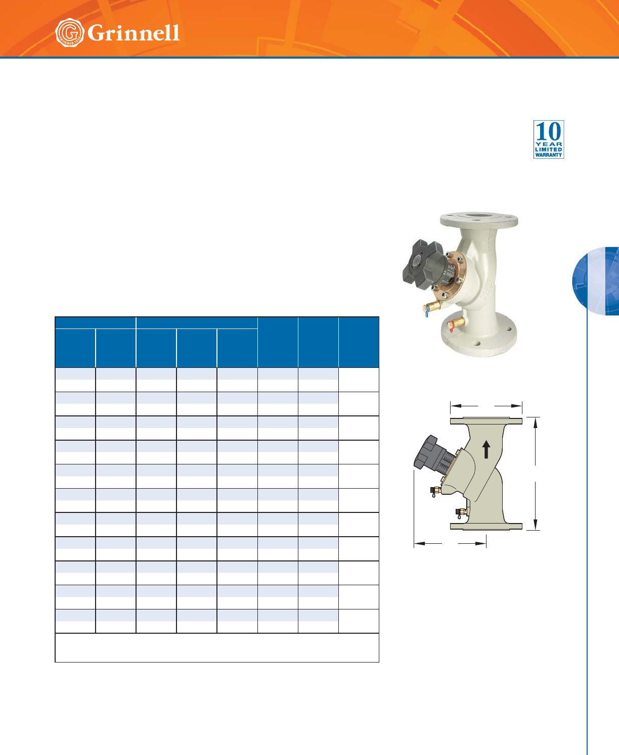
CIRCUIT BALANCING VALVES
CIRCUIT BALANCING VALVES
103
Refer to back cover for country-specific customer care numbers.
H
D
L
Pipe Size Dimensions - Inches mm Approx.
Weight
Lbs.
kg
Limits
PSI/°F
PN/°C
Handwheel
Turns
Nominal
Inches
mm
O.D.
Inches
mm
LHD
21⁄22.875 11.4 7.4 7.3 18.7 235/300 8
65 73,0 290 188 185 13,5 16/150
76,1mm 3.000 11.4 7.4 7.3 18.7 235/300 8
65 76,1 290 188 185 13,5 16/150
3 3.500 12.2 8.0 7.9 39.6 235/300 8
80 88,9 310 203 200 18,0 16/150
4 4.500 13.8 9.4 8.7 61.6 235/300 8
100 114,3 350 240 220 28,0 16/150
139,7mm 5.500 15.7 11.1 9.8 89.1 235/300 8
125 139,7 400 283 250 40,5 16/150
5 5.563 15.7 11.1 9.8 89.1 235/300 8
125 141,3 400 283 250 40,5 16/150
165,1mm 6.500 18.9 11.2 11.2 113.3 235/300 8
150 165,1 480 285 285 51,5 16/150
6 6.625 18.9 11.2 11.2 113.3 235/300 8
150 168,3 480 285 285 51,5 16/150
8 8.625 23.6 18.4 13.4 284.9 235/300 12
200 219,1 600 467 340 129,5 16/150
10 10.750 28.7 18.9 15.9 431.2 235/300 12
250 273,1 730 480 405 196,0 16/150
12 12.750 33.5 20.3 18.1 580.8 235/300 12
300 323,9 850 515 460 264,0 16/150
For information on larger sizes, contact GRINNELL Mechanical Products.
See circuit balancing valve specifications on pages 99.
Model CB800 Circuit Balancing Valves
Flanged Ends, PN16/PN10
Tech Data Sheet: G450
The GRINNELL Model CB800 Balancing Valve provides features for achieving
accurate and efficient balancing of hydronic heating or cooling systems. One
valve serves five functions: throttling, measuring (pressure and temperature),
positive shutoff, draining, and filling. The GRINNELL Flange-by-Flange Model
CB800 Valve, available in sizes 21⁄2" to 12" (65mm to 300mm), is composed of
cast iron.
The CB800 valve serves 5 functions:
• Throttling
• Measuring differential pressure
• Draining
• Filling
• Positive shutoff
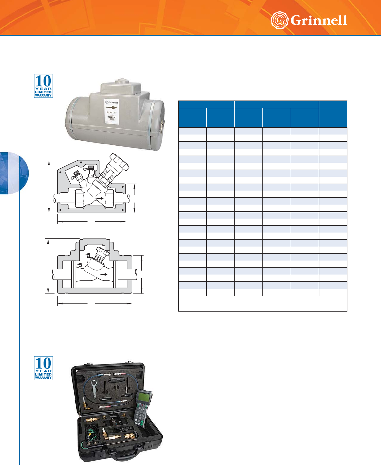
CIRCUIT BALANCING VALVES
CIRCUIT BALANCING VALVES
104 www.grinnell.com
Model CB800 Circuit Balancing Valves
MC2 Measuring Computer
Tech Data Sheet: G450 The GRINNELL Model MC2 computer is a hand-held computer-
balancing instrument designed to measure the flow in GRINNELL
Balancing Valves from 1⁄2" – 12" (15mm – 300mm). The GRINNELL
Model MC2 computer:
• Automatically calculates the flow rate for a valve.
• Measures differential pressure and temperature.
• Compares the actual and nominal flow values.
• Displays the required presetting value.
All results may be saved in the hand-held computer and can be
downloaded to a PC at a later time.
The easy-to-operate touch button keypad protects against water
and dirt particles. The hand-held computer is supplied with a
rechargeable power pact. All parts of the hand-held computer are
stored in a convenient carrying case.
Note: Only available in select regions, contact GRINNELL
Mechanical Products.
H
D
H
D
L
L
Pipe Size Dimensions - Inches mm Approx.
Weight
Lbs.
kg
Nominal
Inches
mm
O.D.
Inches
mm
DHL
1⁄20.840 2.72 5.35 7.20 0.3
15 21,3 69 136 183 0.15
3⁄41.050 3.31 5.63 7.68 0.4
20 26,7 77 143 195 0.18
1 1.315 3.35 5.94 9.57 0.5
25 33,7 85 151 243 0.22
11⁄41.660 3.82 6.77 10.00 0.4
32 42,4 97 172 254 0.20
11⁄21.900 4.13 7.28 9.84 0.7
40 48,3 105 185 250 0.33
2 2.375 4.72 8.23 10.87 0.9
50 60,3 120 209 276 0.43
21⁄22.875 10.2 16.1 19.9 6.7
65 73,0 260 410 505 3.06
33.50011.016.320.97.2
80 88,9 280 415 530 3.25
4 4.500 12.6 20.5 22.8 11.4
100 114,3 320 520 580 5.16
55.56314.222.124.411.6
125 141,3 360 560 620 5.24
6 6.625 15.7 23.6 28.7 13.2
150 168,3 400 600 730 5.97
8 8.625 17.6 30.0 31.5 ◆
200 219,1 450 760 800 -
For information on larger sizes, contact GRINNELL Mechanical Products.
◆ Contact GRINNELL Mechanical Products for details.
Model CB800 Circuit Balancing Valves
Insulation Kits
Tech Data Sheet: G450 The insulation shells have a CFC-free inner core made of
polyurethane foam with a 0.06" (1,5mm) plastic coat. It consists of
two double shells which are tightened by two metal straps.
Available for sizes 1⁄2" – 8" (15mm – 200mm). Specify size and end-
connection type.
Sizes
1/2" thru 2"
Sizes
2-1/2" thru 8"
105
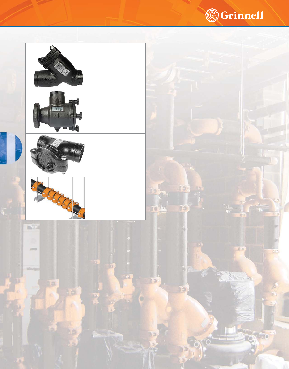
ACCESSORIES
106 www.grinnell.com
ACCESSORIES
GRINNELL accessories are designed to provide protection
for Mechanical piping system equipment. GRINNELL Suction
Diffusers and Strainers reduce maintenance time and labor
and allow easy access to the piping system.
Figure S853
"Y" Strainers
Page 107
Figure S810
Suction Diffusers
Pages 108 - 109
Figure S855
Tee Strainers
Page 110
Figure 7550
Expansion Joints
Pages 111 - 116
Accessories Table of Contents
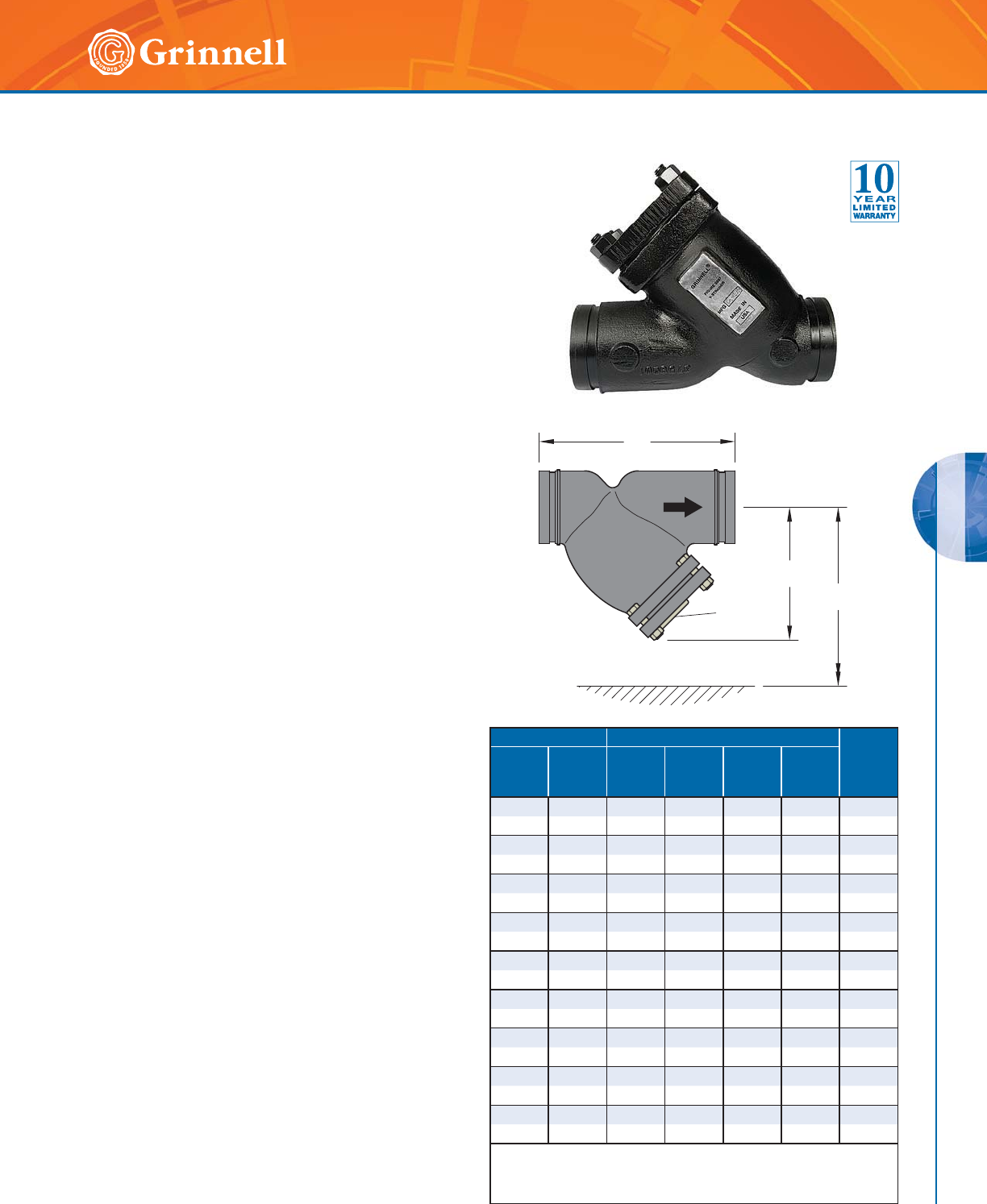
ACCESSORIES
ACCESSORIES
107
Refer to back cover for country-specific customer care numbers.
Figure S853 “Y” Strainers
Tech Data Sheet: G420
A
B
D
(NPT)
C
The GRINNELL Figure S853 “Y” Strainer is rated for 640
psi (44,1 bar) at 100°F (38°C) and 150 psi (10,3 bar)
at 565°F (296°C). The “Y” Strainer provides economical
strainer protection for piping equipment such as pumps,
meters, valves, compressors, and traps. The inlet and outlet
ends are suitable for installation with Figure 705, 707, and
772 Couplings.
The Figure S853 “Y” Strainer screen has the following
standard perforations:
• Sizes 2" – 4" (50mm – 100mm) = 1⁄16 " (1,6mm)
• Sizes 5" – 12" (125mm – 300mm) = 1⁄8" (3,2mm)
All covers have an NPT blow-off outlet (pipe plugs not
included) and recessed seat in the cover to ensure screen
alignment.
Self-cleaning occurs by opening the valve (not supplied)
connected to the blow-off outlet. Indicate when ordering
strainers that are mounted in vertical piping so that the cover
will be rotated to position the blow-off at the lowest point.
Note: Pressure and temperature can be limited by gasket material.
Contact GRINNELL Mechanical Products.
MATERIAL SPECIFICATIONS
Ductile Iron Body and Cover
Specifications
• ASTM A 536, Grade 65-45-12 – Standard
specification for ductile iron castings
• Tensile strength, minimum 65,000 psi (4481,6 bar)
• Yield strength, minimum 45,000 psi (3102,6 bar)
• Elongation in 2" (50mm), minimum 12%
Screen
• Type 304 Stainless Steel ASTM A 240.
(Other alloys are available, contact GRINNELL
Mechanical Products)
Gasket
• Non-asbestos
Coating
• Black enamel paint
Performance
• Pressure drop, contact GRINNELL
Mechanical Products.
Pipe Size Dimensions - Inches mm Approx.
Weight
Lbs.
kg
Nominal
Inches
mm
O.D.
Inches
mm
ABC*
D
Screen
Removal
2 2.375 7.88 5.25 0.50 7.00 12.0
50 60,3 200,2 133,4 12,7 177,8 5,4
21⁄22.875 10.00 6.50 1.00 9.75 18.0
65 73,0 254,0 165,1 25,4 247,7 8,2
3 3.500 10.13 7.00 1.00 10.00 23.0
80 88,9 257,3 177,8 25,4 254,0 10,4
4 4.500 12.13 8.25 1.50 12.00 42.0
100 114,3 308,1 209,6 38,1 304,8 19,1
5 5.563 15.63 11.25 2.00 17.00 80.0
125 141,3 397,0 285,8 50,8 431,8 36,3
6 6.625 18.50 13.50 2.00 20.00 112.0
150 168,3 469,9 342,9 50,8 508,0 50,8
8 8.625 21.63 15.50 2.00 22.75 205.0
200 219,1 549,4 393,7 50,8 577,9 93,0
10 10.750 29.13 19.25 2.00 29.25 277.0
250 273,1 739,8 489,0 50,8 743,0 125,6
12 12.750 33.75 22.88 2.00 35.24 470.0
300 323,9 857,3 581,0 50,8 895,4 213,2
* Blow-off outlet threads conforming to BSP are available upon request.
Contact GRINNELL Mechanical Products.
For information on larger sizes, contact GRINNELL Mechanical Products.
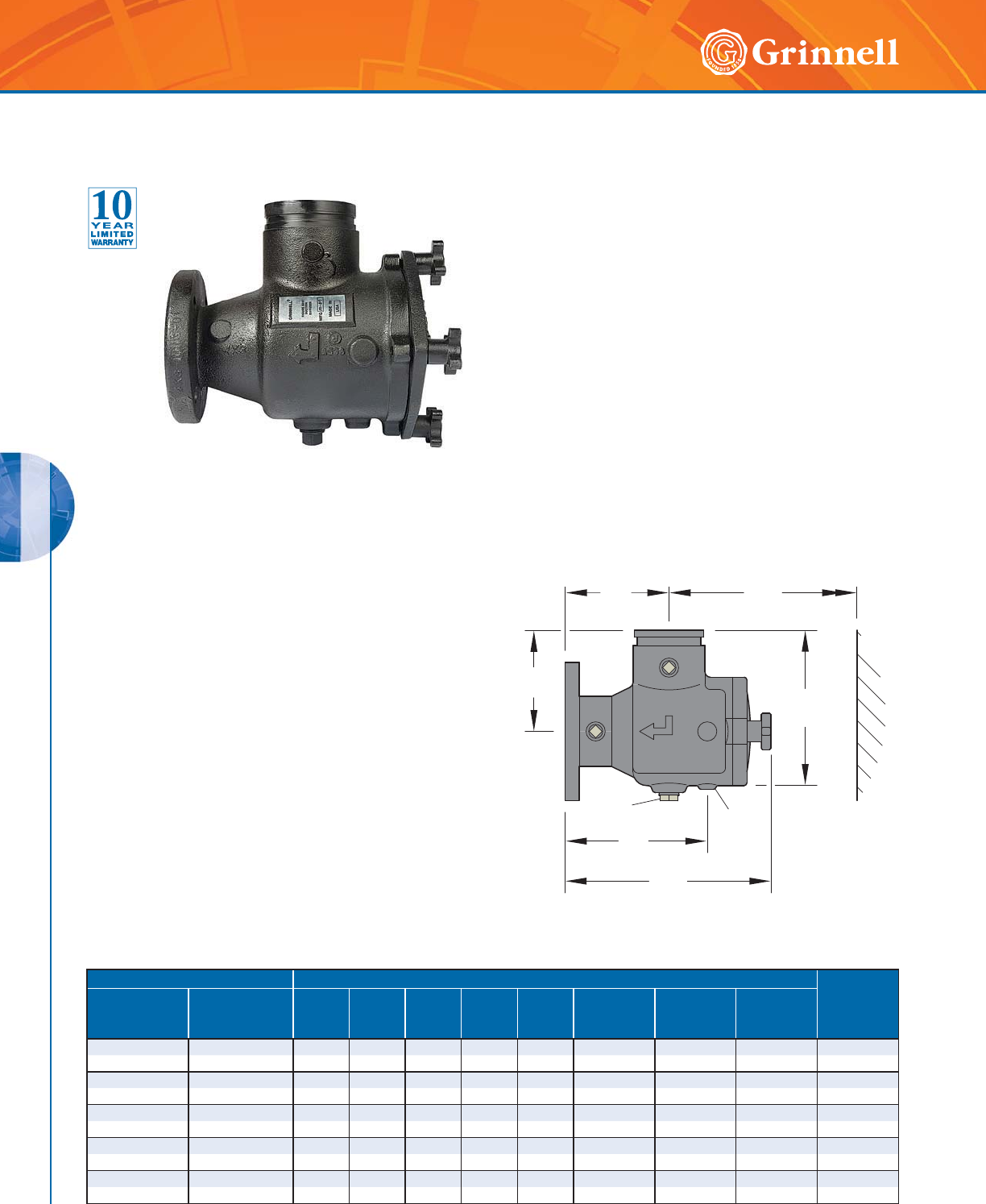
ACCESSORIES
ACCESSORIES
108 www.grinnell.com
Figure S810 Suction Diffusers
(Page 1 of 2)
Tech Data Sheet: G410 The GRINNELL Figure S810 Suction Diffuser is compact and
rugged for direct mounting to the suction side of a pump
in either a horizontal or vertical position. In addition to
removing foreign particles, this diffuser also provides proper
flow conditions to the pump. Where space is limited, this
diffuser can be used to replace the straight pipe normally
required to reduce turbulence.
The GRINNELL Figure S810 Suction Diffuser’s permanent
perforated stainless steel screen helps remove foreign
particles. The inlet end is suitable for installation with
GRINNELL Couplings. The outlet end is provided with a
150# ANSI flat face flange. Integral straightening vanes in
the diffuser outlet reduce turbulence so that stress and erosion
on the pump is minimized.
Maximum working pressure is 300 psi (20,7 bar) at 100°F
(38°C) and 165 psi (11,4 bar) at 300°F (149°C).
Note: Pressure and temperature can be limited by O-ring material.
Contact GRINNELL Mechanical Products.
AF
D
B
H
E
G
C
Pipe Size Dimensions - Inches mm Approx.
Weight
Lbs.
kg
Nominal
Inches
mm
O.D.
Inches
mm
ABCDE
F
Screen
Removal
G
Plug
NPT
H
Pipe
Support ID
2 x 2 2.375 x 2.375 4.50 4.50 6.69 6.13 10.19 8.81 0.75 0.824 19
50 x 50 60,3 x 60,3 114,3 114,3 169,9 155,7 258,8 223,8 20 20,9 8,6
21⁄2 x 2 2.875 x 2.375 5.00 5.00 7.50 6.56 10.88 9.13 0.75 1.38 20
65 x 50 73,0 x 60,3 127,0 127,0 190,5 166,6 276,4 231,9 20 35,1 9,1
21⁄2 x 21⁄22.875 x 2.875 5.00 5.00 7.50 6.56 10.88 9.13 0.75 1.38 22
65 x 65 73,0 x 73,0 127,0 127,0 190,5 166,6 276,4 231,9 20 35,1 10,0
3 x 2 3.500 x 2.375 5.50 5.50 8.44 7.38 11.56 9.63 0.75 1.38 38.0
80 x 50 88,9 x 60,3 139,7 139,7 214,4 187,5 293,6 244,6 20 35,1 17,2
3 x 21⁄23.500 x 2.875 5.50 5.50 8.44 7.38 11.56 9.63 0.75 1.38 39.0
80 x 65 88,9 x 73,0 139,7 139,7 214,4 187,5 293,6 244,6 20 35,1 17,7
MATERIAL SPECIFICATIONS
Body and Cover
• Ductile iron conforming to ASTM A 126B
Knobs
• Ductile iron conforming to ASTM A 536, Grade
65-45-12 for sizes 3" x 2" thru 10" x 8" (80mm x
50mm thru 250mm x 200mm)
Stud/nuts carbon steel conforming to ASTM A 193-4,
for sizes 10" x 10" (250mm x 250mm) and larger
Screen
•
5⁄32" (4,0mm) perforated type 304 stainless steel for
sizes 3" x 2" thru 6" x 6"
(80mm x 50mm thru 150mm x 150mm);
•
1⁄8" (3,2mm) perforated type 304 stainless steel for
sizes 8" x 5" (200 x 125mm) and larger
• Sleeve is 20 mesh type 304 stainless steel
Coating
• Black enamel paint
Performance
• Pressure drop, contact GRINNELL
Mechanical Products.
ACCESSORIES
ACCESSORIES
109
Refer to back cover for country-specific customer care numbers.
Pipe Size Dimensions - Inches mm Approx.
Weight
Lbs.
kg
Nominal
Inches
mm
O.D.
Inches
mm
ABCDE
F
Screen
Removal
G
Plug
NPT
H
Pipe
Support ID
3 x 3 3.500 x 3.500 5.50 5.50 8.44 7.38 11.56 9.63 0.75 1.38 40.0
80 x 80 88,9 x 88,9 139,7 139,7 214,4 187,5 293,6 244,6 20 35,1 18,1
4 x 2 4.500 x 2.375 5.75 5.75 9.13 7.63 11.81 11.18 0.75 1.38 48.0
100 x 50 114,3 x 60,3 146,1 146,1 231,9 193,8 300,0 284,0 20 35,1 21,8
4 x 21⁄24.500 x 2.875 6.50 6.50 10.48 8.75 13.13 9.63 1.00 1.38 49.0
100 x 65 114,3 x 73,0 165,1 165,1 266,2 222,3 333,5 244,6 25 35,1 22,2
4 x 3 4.500 x 3.500 6.50 6.81 10.44 8.75 13.13 11.50 1.00 1.38 50.0
100 x 80 114,3 x 88,9 165,1 173,0 265,2 222,3 333,5 292,1 25 35,1 22,7
4 x 4 4.500 x 4.500 6.50 6.81 10.44 8.75 13.13 11.50 1.00 1.38 52.0
100 x 100 114,3 x 114,3 165,1 173,0 265,2 222,3 333,5 292,1 25 35,1 23,6
5 x 3 5.563 x 3.500 6.50 6.50 10.48 8.75 13.13 11.50 1.00 1.38 94.0
125 x 80 141,3 x 88,9 165,1 165,1 266,2 222,3 333,5 292,1 25 35,1 42,6
5 x 4 5.563 x 4.500 6.50 6.50 11.94 10.00 15.75 14.00 1.00 1.38 96.0
125 x 100 141,3 x 114,3 165,1 165,1 303,3 254,0 400,1 355,6 25 35,1 43,5
5 x 5 5.563 x 5.563 7.50 7.50 11.94 10.00 15.75 14.88 1.00 1.38 101.0
125 x 125 141,3 x 141,3 190,5 190,5 303,3 254,0 400,1 378,0 25 35,1 45,8
6 x 3 6.625 x 3.500 8.00 8.00 13.31 10.50 16.88 16.56 1.00 1.38 103.0
150 x 80 168,3 x 88,9 203,2 203,2 338,1 266,7 428,8 420,6 25 35,1 46,7
6 x 4 6.625 x 4.500 8.00 8.00 13.31 10.50 16.88 16.56 1.00 1.38 106.0
150 x 100 168,3 x 114,3 203,2 203,2 338,1 266,7 428,8 420,6 25 35,1 48,1
6 x 5 6.625 x 5.563 8.00 8.00 13.31 10.50 16.88 16.56 1.00 1.38 110.0
150 x 125 168,3 x 141,3 203,2 203,2 338,1 266,7 428,8 420,6 25 35,1 49,9
6 x 6 6.625 x 6.625 8.00 8.00 13.31 10.50 16.88 16.56 1.00 1.38 113.0
150 x 150 168,3 x 168,3 203,2 203,2 338,1 266,7 428,8 420,6 25 35,1 51,2
8 x 5 8.625 x 5.563 9.00 9.00 14.38 11.50 17.88 16.88 1.00 1.38 135.0
200 x 125 219,1 x 141,3 228,6 228,6 365,3 292,1 454,2 428,8 25 35,1 61,2
8 x 6 8.625 x 6.625 9.00 10.00 15.31 11.50 17.88 16.88 1.00 1.38 137.0
200 x 150 219,1 x 168,3 228,6 254,0 388,9 292,1 454,2 428,8 25 35,1 62,1
8 x 8 8.625 x 8.625 9.00 10.00 16.31 11.75 20.75 22.88 1.25 1.38 222.0
200 x 200 219,1 x 219,1 228,6 254,0 414,3 298,5 527,1 581,2 32 35,1 100,7
10 x 6 10.750 x 6.625 9.48 9.48 15.50 11.94 18.31 16.88 1.25 1.38 230.0
250 x 150 273,1 x 168,3 240,8 240,8 393,7 303,3 465,1 428,8 32 35,1 104,3
10 x 8 10.750 x 8.625 9.00 11.75 18.44 11.75 20.75 22.88 1.25 1.38 236.0
250 x 200 237,1 x 219,1 228,6 298,5 468 ,4 2 9 8,5 5 27,1 5 81,2 32 35,1 107,0
10 x 10 10.750 x 10.750 11.00 11.75 20.00 14.00 26.38 30.75 1.25 1.38 343.0
250 x 250 273,1 x 273,1 279,4 298,5 508,0 355,6 670,1 781,1 32 35,1 155,6
12 x 8 12.000 x 8.625 9.00 9.00 19.63 11.75 20.75 22.88 1.25 1.38 357.0
300 x 200 323,9 x 219,1 228,6 228,6 498,6 298,5 527,1 581,2 32 35,1 161,9
12 x 10 12.000 x 10.750 11.00 12.88 21.00 14.00 26.38 30.75 1.25 1.38 357.0
300 x 250 323,9 x 273,1 279,4 327,2 533,4 355,6 670,1 781,1 32 35,1 161,9
12 x 12 12.000 x 12.000 12.00 12.00 22.06 15.25 26.18 30.75 1.25 1.38 357.0
300 x 300 323,9 x 323,9 304,8 304,8 560,3 387,4 665,0 781,1 32 35,1 161,9
14 x 10 14.000 x 10.750 11.00 11.00 22.50 14.00 26.38 30.75 1.25 1.38 507.0
350 x 250 355,6 x 273,1 279,4 279,4 571,5 355,6 670,1 781,1 32 35,1 229,9
14 x 12 14.000 x 12.000 12.00 12.00 22.38 15.25 26.18 31.00 1.25 1.38 601.0
350 x 300 355,6 x 323,9 304,8 304,8 568,5 387,4 665,0 787,4 32 35,1 272,6
14 x 14 14.000 x 14000 14.00 14.00 25.00 17.50 27.75 33.13 2.00 1.38 706.0
350 x 350 355,6 x 355,6 355,6 355,6 635,0 444,5 704,9 841,5 50 35,1 320,2
16 x 14 16.000 x 14.000 14.00 14.00 26.00 17.50 27.88 31.00 2.00 1.38 750.0
400 x 350 406,4 x 355,6 355,6 355,6 660,4 444,5 708,2 787,4 50 35,1 340,1
For information on larger sizes, contact GRINNELL Mechanical Products.
Figure S810 Suction Diffusers
(Page 2 of 2)
Tech Data Sheet: G410
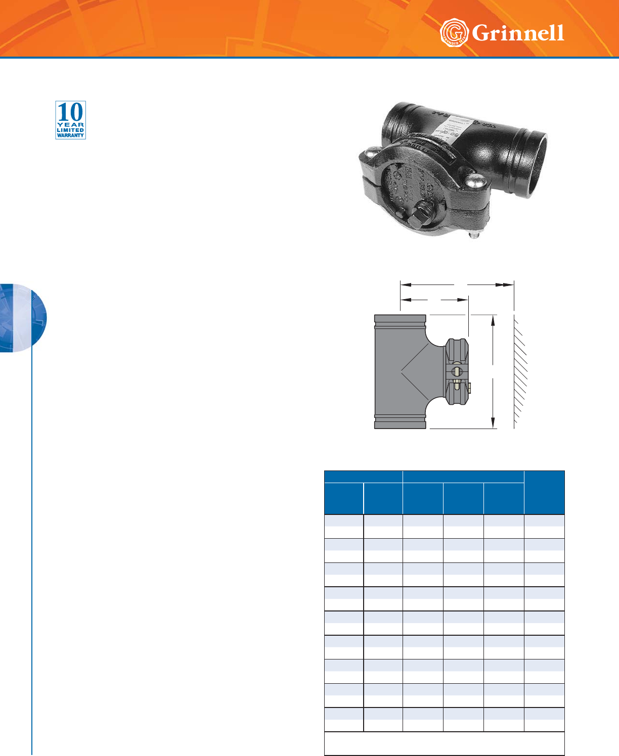
ACCESSORIES
ACCESSORIES
110 www.grinnell.com
Figure S855 Tee Strainers
Tech Data Sheet: G430
The Tee Strainer is designed to remove particles from pipelines
where a compact, accessible strainer is needed for the
protection of pumps, meters, valves, and similar mechanical
equipment. The inlet and outlet ends are suitable for
installation with GRINNELL Couplings that provide quick and
easy installation.
The cover is secured by a GRINNELL Figure 772 Coupling for
easy access to the screen. The cover is tapped and plugged to
allow for draining.
The GRINNELL Figure S855 Tee Strainer is rated for the
following pressures:
• Sizes 2" – 5" (50mm – 125mm): 750 psi (51,7 bar) at
100°F (38°C)
• Size 6" (150mm): 700 psi (48,3 bar) at 100°F (38°C)
• Size 8" (200mm): 600 psi (41,7 bar) at 100°F (38°C)
• Size 10" (250mm): 500 psi (34,5 bar) at 100°F (38°C)
• Size 12" (300mm): 400 psi (27,6 bar) at 100°F (38°C)
The Figure S855 Tee Strainer perforated screen has the
following perforations:
• Sizes 2" – 6" (50mm – 150mm) = 1⁄8" (3,2mm)
• Sizes 8" – 12" (200mm – 300mm) = 5⁄32" (4,0mm)
Note: Other perforation screen sizes are available upon request. Specify
particle retention size when ordering nonstandard screens.
MATERIAL SPECIFICATIONS
Ductile Iron Body and Cover
• ASTM A 395, Grade 60-40-18 or A 536 – Standard
specification for ductile iron castings
• Tensile strength, minimum 65,000 psi (4481,6 bar)
• Yield strength, minimum 45,000 psi (3102,6 bar)
• Elongation in 2" (50mm), minimum 12%
Screen
• 20 gauge type 304 stainless steel ASTM A 240
for Sizes 2" – 6" (50mm – 150mm)
• 18 gauge type 304 stainless steel ASTM A 240
for Sizes 8" – 12" (200mm – 300mm)
Coating
• Black enamel paint
• Orange – Non-lead paint
• Red – Non-lead paint (optional, regional)
Performance
• Pressure drop, contact GRINNELL
Mechanical Products.
Pipe Size Dimensions - Inches mm Approx.
Weight
Lbs.
kg
Nominal
Inches
mm
O.D.
Inches
mm
AB
D
Screen
Removal
2 2.375 6.50 4.25 7.50 6.0
50 60,3 165,0 108,0 191,0 2,7
21⁄22.875 7.50 4.75 8.75 11.0
65 73,0 191,0 110,0 222,0 5,0
33.5008.505.2510.0012.0
80 88,9 216,0 133,0 254,0 5,4
4 4.500 10.00 6.13 12.00 20.0
100 114,3 254,0 156,0 305,0 9,0
5 5.563 11.00 6.63 13.50 30.0
125 141,3 279,0 168,0 342,0 13,0
6 6.625 13.00 7.63 16.00 40.0
150 168,3 330,0 194,0 406,0 18,0
8 8.625 15.50 9.13 19.44 81.0
200 219,1 394,0 232,0 494,0 36,0
10 10.750 18.00 10.38 22.94 126.0
250 273,0 457,0 264,0 583,0 57,0
12 12.750 20.00 11.38 25.94 174.0
300 323,9 508,0 289,0 659,0 79,0
For information on larger sizes, contact GRINNELL
Mechanical Products.
A
B
D

ACCESSORIES
ACCESSORIES
111
Refer to back cover for country-specific customer care numbers.
Figure 7550 Expansion Joint
(Page 1 of 6)
Tech Data Sheet: G460
GRINNELL Grooved Expansion Joints are custom-designed,
thermal movement solutions that utilize the proven design
characteristics of GRINNELL Flexible Couplings.
Expansion joints are designed to be used in both hot and
cold applications. When pipe heats up, the expansion
joint contracts to absorb the thermal expansion of the pipe.
When pipe cools down, the expansion joint expands to
absorb the thermal contraction of the pipe.
The expansion joints are factory fabricated and calibrated
to the specific thermal movement conditions of the piping
runs. The joints are manufactured from machined grooved
nipples and GRINNELL Flexible Couplings, providing
dependable, high pressure performance.
Expansion Joints should be anchored and guided in
accordance with standard industry practices. Refer to the
appropriate coupling data sheet for pressure/temperature
ratings and materials of construction.
Nipples are manufactured from standard wall, A 53B black
steel pipe.
Figure 7550 Expansion joints are custom designed to your
specifications. Contact GRINNELL Mechanical Services for
additional information.
Nominal Pipe Size
11⁄4" to 16" (32mm to 400mm):
Inches mm
Pipe
Finish
F
Black
F
Galvanized
F
Stainless Steel
Coupling
Finish
F
Orange
Paint
F
RAL Red
F
Galvanized
F
Stainless
Steel
Gasket
Material*
F
Grade “E”
EPDM
F
Grade “T”
Nitrile
F
Grade “O”
Fluoroelastomer
F
Grade “L”
Silicone
Factory
Preset
F
Fully
Expanded
F
Fully
Compressed
Intermediate**
%
Total
Required
Movement:
1.00" 1.25" 1.50" 1.75"
* These products are assembled with a silicone-based lubricant.
** For intermediate factory preset indicate percentage of movement
from compressed position.
Ordering Procedure
GRINNELL Mechanical Products are available globally through
a network of distribution centers. Visit www.grinnell.com for
the nearest distributor. When placing an order, indicate the full
product name.
Use the worksheet shown below to specify information required
for ordering expansion joints.
Specify quantity, nominal pipe size, (ANSI or O.D.), figure
number (Figure 7550 Flexible Coupling), and type of gasket:
• Grade “E” EPDM
• Grade “L” Silicone
• Grade “O” Fluoroelastomer
• Grade “T” Nitrile
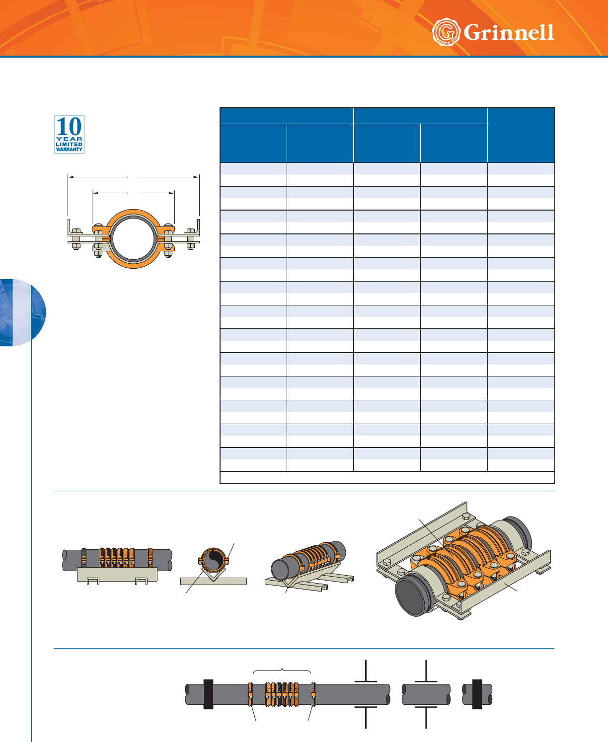
ACCESSORIES
ACCESSORIES
112 www.grinnell.com
Figure 7550 Expansion Joint
(Page 2 of 6)
Tech Data Sheet: G460 Pipe Size Dimensions - Inches mm Coupling
Movement
Capability
Inches
mm
Nominal
Inches
mm
O.D.
Inches
mm
Y
Coupling
Length
W
Overall
Width
11⁄41.660 4.190 9.750 0.125
32 42,4 106,4 247,7 3,18
11⁄21.900 4.440 9.625 0.125
40 48,3 112,8 244,5 3,18
22.3754.88010.8750.125
50 60,3 124,0 276,2 3,18
21⁄22.875 5.500 10.750 0.125
65 73,0 139,7 273,1 3,18
33.5006.50011.7500.125
80 88,9 165,1 298,5 3,18
44.5007.75012.9370.250
100 114,3 196,9 328,6 6,35
55.5639.75014.2500.250
125 141,3 247,7 362,0 6,35
6 6.625 10.690 15.500 0.250
150 168,3 271,5 393,7 6,35
8 8.625 13.560 18.250 0.250
200 219,1 344,4 463,6 6,35
10 10.750 16.380 20.125 0.250
250 273,0 416,1 511,2 6,35
12 12.750 18.880 22.375 0.250
300 323,9 479,6 568,3 6,35
14 14.000 20.380 24.125 0.250
350 355,6 517,7 612,8 6,35
16 16.000 22.640 27.870 0.250
400 406,4 575,1 707,9 6,35
Refer to Technical Data Sheet G460 for additional dimensions and information.
W
Y
EXPANSION
JOINT
ENSURE SUPPORT
CRADLE FLANGES CONTACT
ONLY TANGENT TO
COUPLING HOUSINGS
SUPPORT
CRADLE
(FABRICATED
BY OTHERS)
DO NOT ALLOW
SUPPORT CRADLE FLANGES TO
INTERFERE WITH COUPLING
LOBES, NUTS OR BOLTS
ANCHOR ANCHOREND COUPLINGS GUIDES
EXPANSION JOINT
(
NOT INCLUDED
)
Figure 7550 Expansion Joints
Typical Installation
Figure 7550 Expansion Joints
Retaining Bracket Detail
RETAINING
BRACKET
EXPANSION
JOINT
Figure 7550 Expansion Joints
Nominal Dimensions for End Elevation View
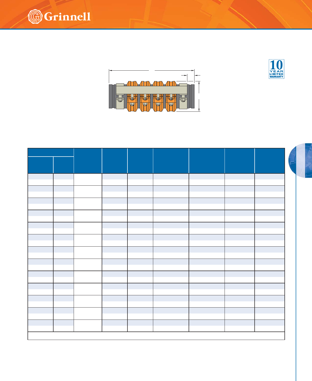
ACCESSORIES
ACCESSORIES
113
Refer to back cover for country-specific customer care numbers.
Figure 7550 Expansion Joint
(Page 3 of 6)
Tech Data Sheet: G460
Nominal Pipe Size Flexible*
Coupling
Figure /
Quantity
X
Coupling
Height
Inches
mm
Z
Tie
Location
Inches
mm
L
Compressed
Length
Inches
mm
L
Expanded
Length
Inches
mm
Total
Movement
Capability
Inches
mm
Approx.
Weight
Lbs.
kg
ANSI
Inches
mm
O.D.
Inches
mm
11⁄41.660 705 / 8 2.560 1.25 26.625 27.625 1.000 26
32 42,4 65,02 31,75 676,27 701,67 25,40 11,8
11⁄21.900 705 / 8 2.750 1.25 26.625 27.625 1.000 28
40 48,3 69,85 31,75 676,27 701,67 25,40 12,7
22.375
705 / 8 3.250 1.25 26.625 27.625 1.000 31
50 60,3 82,55 31,75 676,27 701,67 25,40 14,1
21⁄22.875 705 / 8 3.690 1.25 26.625 27.625 1.000 37
65 73,0 93,73 31,75 676,27 701,67 25,40 16,8
33.500
705 / 8 4.380 1.25 26.625 27.625 1.000 49
80 88,9 111,25 31,75 676,27 701,67 25,40 22,2
44.500
705 / 4 5.690 1.25 17.500 18.500 1.000 36
100 114,3 144,53 31,75 444,50 469,90 25,40 16,3
55.563
705 / 4 6.880 1.25 17.500 18.500 1.000 53
125 141,3 174,75 31,75 444,50 469,90 25,40 24,0
66.625
705 / 4 7.9 4 0 1.25 17.500 18.500 1.00 0 59
150 168,3 201,68 31,75 444,50 469,90 25,40 26,8
88.625
705 / 4 10.190 1.375 19.125 20.125 1.000 104
200 219,1 258,83 34,93 488,95 511,17 25,40 47,2
10 10.750 705 / 4 12.690 1.375 21.500 22.500 1.000 179
250 273,0 322,33 34,93 546,10 571,50 25,40 81,2
12 12.750 705 / 4 14.940 1.375 21.500 22.500 1.000 235
300 323,9 379,48 34,93 546,10 571,50 25,40 106,6
14 14.000 707 / 4 16.670 1.500 23.125 24.125 1.000 305
350 355,6 423,42 38,10 587,40 612,77 25,40 138,4
16 16.000 707 / 4 18.830 1.500 24.125 25.125 1.000 371
400 406,4 478,28 38,10 612,77 638,17 25,40 168,2
* 11⁄4" - 8" Figure 405 Stainless Steel Couplings available upon request.
L
Z
X
Figure 7550-1 Expansion Joints - 1" Total Movement Length
Nominal Dimensions for Side Elevation View
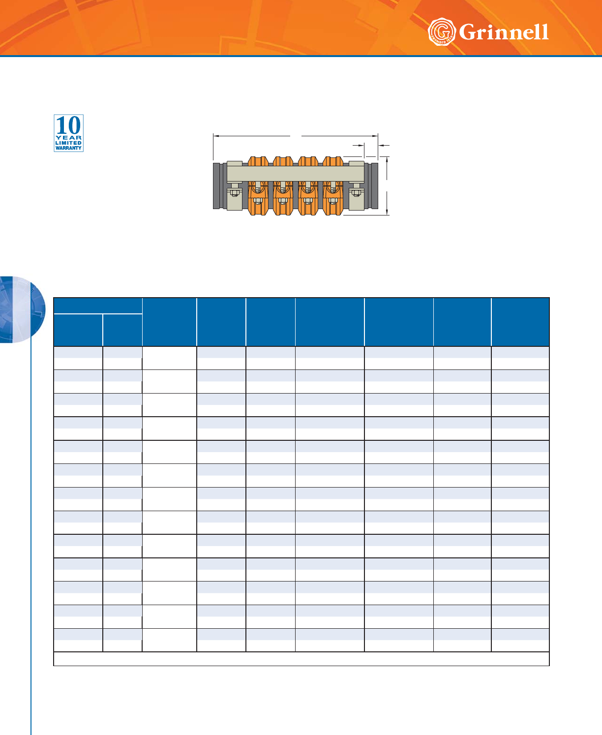
ACCESSORIES
ACCESSORIES
114 www.grinnell.com
Nominal Pipe Size Flexible*
Coupling
Figure /
Quantity
X
Coupling
Height
Inches
mm
Z
Tie
Location
Inches
mm
L
Compressed
Length
Inches
mm
L
Expanded
Length
Inches
mm
Total
Movement
Capability
Inches
mm
Approx.
Weight
Lbs.
kg
ANSI
Inches
mm
O.D.
Inches
mm
11⁄41.660 705 / 10 2.560 1.25 31.375 32.625 1.250 31
32 42,4 65,02 31,75 796,92 828,67 31,75 14,1
11⁄21.900 705 / 10 2.750 1.25 31.375 32.625 1.250 33
40 48,3 69,85 31,75 796,92 828,67 31,75 15,0
22.375
705 / 10 3.250 1.25 31.375 32.625 1.250 37
50 60,3 82,55 31,75 796,92 828,67 31,75 16,8
21⁄22.875 705 / 10 3.690 1.25 31.375 32.625 1.250 45
65 73,0 93,73 31,75 796,92 828,67 31,75 20,4
33.500
705 / 10 4.380 1.25 31.375 32.625 1.250 59
80 88,9 111,25 31,75 796,92 828,67 31,75 26,8
44.500
705 / 5 5.690 1.25 20.000 21.250 1.250 43
10 0 114,3 144,53 31,75 508,0 0 539,75 31,75 19,5
55.563
705 / 5 6.880 1.25 20.000 21.250 1.250 64
125 141,3 174,75 31,75 508,00 539,75 31,75 29,0
66.625
705 / 5 7.940 1.25 20.000 21.250 1.250 70
150 168,3 201,68 31,75 508,00 539,75 31,75 31,8
88.625
705 / 5 10.190 1.375 22.000 23.250 1.250 125
200 219,1 258,83 34,93 558,80 590,55 31,75 56,7
10 10.750 705 / 5 12.690 1.375 24.500 25.750 1.250 215
250 273,0 322,33 34,93 622,30 654,05 31,75 97,5
12 12.750 705 / 5 14.940 1.375 24.500 25.750 1.250 281
300 323,9 379,48 34,93 622,30 654,05 31,75 127,5
14 14.000 707 / 5 16.670 1.500 26.500 27.750 1.250 365
350 355,6 423,42 38,10 673,10 704,85 31,75 138,4
16 16.000 707 / 5 18.830 1.500 27.500 28.750 1.250 441
400 406,4 478,28 38,10 698,50 730,25 31,75 168,2
* 11⁄4" - 8" Figure 405 Stainless Steel Couplings available upon request.
Figure 7550 Expansion Joint
(Page 4 of 6)
Tech Data Sheet: G460
Figure 7550-13 Expansion Joints - 11⁄4" Total Movement Length
Nominal Dimensions for Side Elevation View
L
Z
X
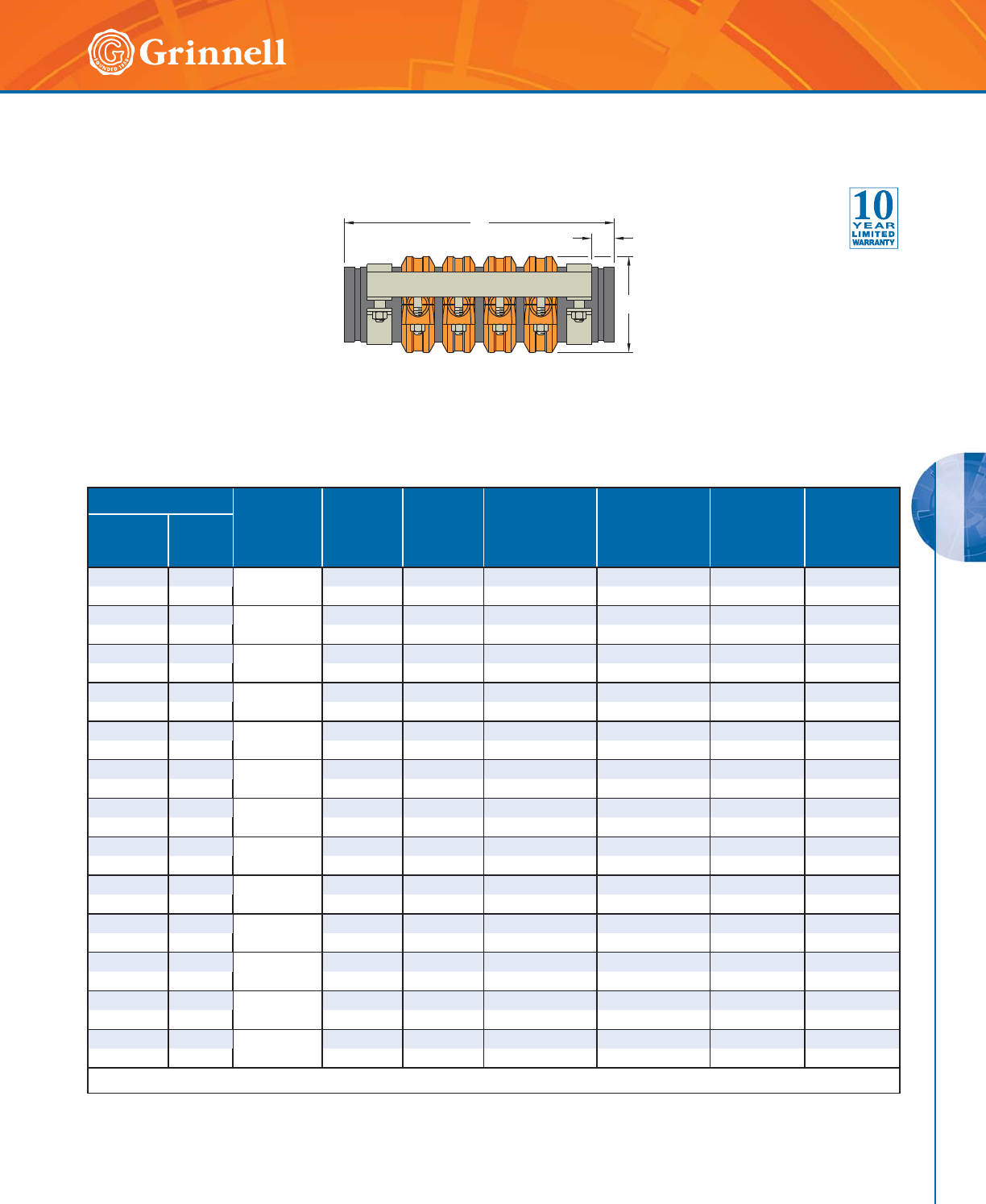
ACCESSORIES
ACCESSORIES
115
Refer to back cover for country-specific customer care numbers.
Figure 7550 Expansion Joint
(Page 5 of 6)
Tech Data Sheet: G460
Figure 7550-15 Expansion Joints - 11⁄2" Total Movement Length
Nominal Dimensions for Side Elevation View
Nominal Pipe Size Flexible*
Coupling
Figure /
Quantity
X
Coupling
Height
Inches
mm
Z
Tie
Location
Inches
mm
L
Compressed
Length
Inches
mm
L
Expanded
Length
Inches
mm
Total
Movement
Capability
Inches
mm
Approx.
Weight
Lbs.
kg
ANSI
Inches
mm
O.D.
Inches
mm
11⁄41.660 705 / 12 2.560 1.25 36.125 37.625 1.500 37
32 42,4 65,02 31,75 917,57 955,68 38,10 16,8
11⁄21.900 705 / 12 2.750 1.25 36.125 37.625 1.500 39
40 48,3 69,85 31,75 917,57 955,68 38,10 17,7
22.375
705 / 12 3.250 1.25 36.125 37.625 1.500 43
50 60,3 82,55 31,75 917,57 955,68 38,10 19,5
21⁄22.875 705 / 12 3.690 1.25 36.125 37.625 1.500 52
65 73,0 93,73 31,75 917,57 955,68 38,10 23,6
33.500
705 / 12 4.380 1.25 36.125 37.625 1.500 69
80 88,9 111,25 31,75 917,57 955,68 38,10 31,3
44.500
705 / 6 5.690 1.25 22.500 24.000 1.500 50
10 0 114,3 144,53 31,75 571,50) 609,60 ) 38,10 22,7)
55.563
705 / 6 6.880 1.25 22.500 24.000 1.500 74
125 141,3 174,75 31,75 571,50 609,60 38,10 33,6
66.625
705 / 6 7.940 1.25 22.500 24.000 1.500 81
150 168,3 201,68 31,75 571,50 609,60 38,10 36,7
88.625
705 / 6 10.190 1.375 24.875 26.375 1.500 145
200 219,1 258,83 34,93 631,82 669,93 38,10 65,8
10 10.750 705 / 6 12.690 1.375 27.500 29.000 1.500 251
250 273,0 322,33 34,93 698,50 736,60 38,10 113,8
12 12.750 705 / 6 14.940 1.375 27.500 29.000 1.500 328
300 323,9 379,48 34,93 698,50 736,60 38,10 148,8
14 14.000 707/ 6 16.670 1.500 29.875 31.375 1.500 425
350 355,6 423,42 38,10 758,82 796,93 38,10 192,8
16 16.000 707 / 6 18.830 1.500 30.875 32.375 1.500 512
400 406,4 478,28 38,10 784,22 822,32 38,10 232,2
* 11⁄4" - 8" Figure 405 Stainless Steel Couplings available upon request.
L
Z
X
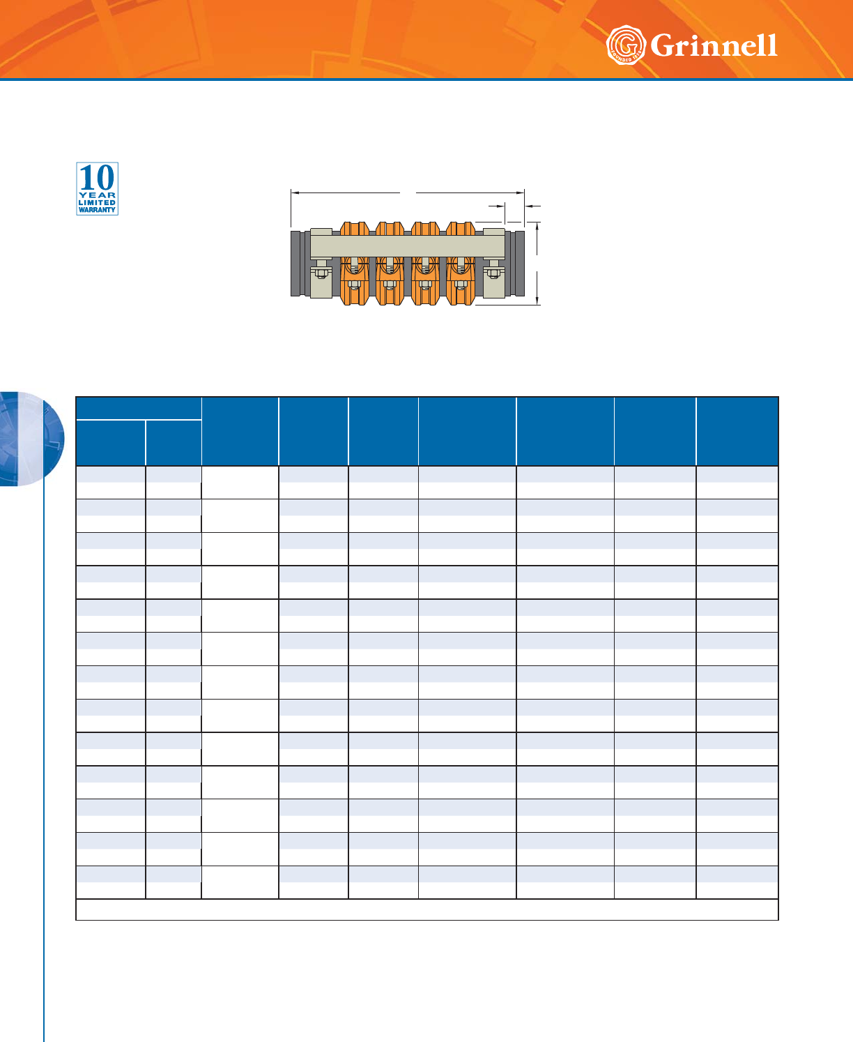
ACCESSORIES
ACCESSORIES
116 www.grinnell.com
Nominal Pipe Size Flexible*
Coupling
Figure /
Quantity
X
Coupling
Height
Inches
mm
Z
Tie
Location
Inches
mm
L
Compressed
Length
Inches
mm
L
Expanded
Length
Inches
mm
Total
Movement
Capability
Inches
mm
Approx.
Weight
Lbs.
kg
ANSI
Inches
mm
O.D.
Inches
mm
11⁄41.660 705 / 14 2.560 1.25 40.875 42.625 1.750 42
32 42,4 65,02 31,75 1038,22 1082,67 44,45 19,0
11⁄21.900 705 / 14 2.750 1.25 40.875 42.625 1.750 45
40 48,3 69,85 31,75 1038,22 1082,67 44,45 20,4
22.375
705 / 14 3.250 1.25 40.875 42.625 1.750 49
50 60,3 82,55 31,75 1038,22 1082,67 44,45 22,2
21⁄22.875 705 / 14 3.690 1.25 40.875 42.625 1.750 60
65 73,0 93,73 31,75 1038,22 1082,67 44,45 27,2
33.500
705 / 14 4.380 1.25 40.875 42.625 1.750 79
80 88,9 111,25 31,75 1038,22 1082,67 44,45 35,8
44.500
705 / 7 5.690 1.25 25.000 26.750 1.750 57
10 0 114,3 144,53 31,75 635,00 679,45 44,45 25,9
55.563
705 / 7 6.880 1.25 25.000 26.750 1.750 84
125 141,3 174,75 31,75 635,00 679,45 44,45 38,1
66.625
705 / 7 7.940 1.25 25.000 26.750 1.750 92
150 168,3 201,68 31,75 635,00 679,45 44,45 41,7
88.625
705 / 7 10.190 1.375 27.750 29.500 1.750 166
200 219,1 258,83 34,93 704,85 749,30 44,45 75,3
10 10.750 705 / 7 12.690 1.375 30.500 32.250 1.750 287
250 273,0 322,33 34,93 774,70 819,15 44,45 130,2
12 12.750 705 / 7 14.940 1.375 30.500 32.250 1.750 375
300 323,9 379,48 34,93 774,70 819,15 44,45 170,1
14 14.000 707 / 7 16.670 1.500 33.250 35.000 1.750 486
350 355,6 423,42 38,10 844,55 889,00 44,45 220,5
16 16.000 707 / 7 18.830 1.500 34.250 36.000 1.750 583
400 406,4 478,28 38,10 869,95 914,40 44,45 264,4
* 11⁄4" - 8" Figure 405 Stainless Steel Couplings available upon request.
Figure 7550 Expansion Joint
(Page 6 of 6)
Tech Data Sheet: G460
Figure 7550-75 Expansion Joints - 13⁄4" Total Movement Length
Nominal Dimensions for Side Elevation View
L
Z
X
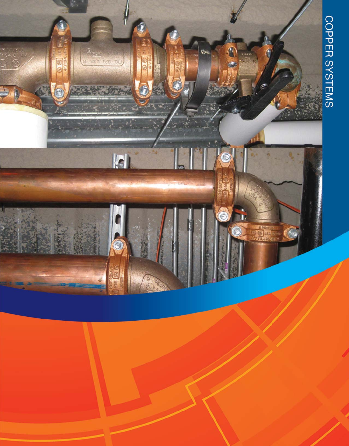
117

COPPER SYSTEMS
118 www.grinnell.com
COPPER SYSTEMS
Copper Systems Table of Contents
GRINNELL Copper Grooved Systems are designed for joining copper tube size components 2" to 8" (DN 50 to DN 200) type K,
L, M, and DWV. All couplings and fittings are rated for working pressures up to 300 psi (20,7 bar) depending on copper tubing
size and type (see pressure rating chart).
Figure 640
Pivot-Bolt Rigid Couplings
Page 120
Figure 618
Reducing Tees
Page 126
Figure 672
Rigid Couplings
Page 121
Figures 650
Concentric Reducers
Page 127
Figure 61
Flange Adapters
Page 122
Figures 652
Concentric Reducers
Page 127
Figure 610
90° Elbows
Page 123
Model B680
Butterfly Valves
Page 128
Figure 601
45° Elbows
Page 123
Figure 407GT
Dielectric Waterway
Page 129
Figure 619
Tees
Page 124
Figure 407T
Dielectric Waterway
Page 129
Figure 660
Caps
Page 124
Figure 407GG
Dielectric Waterway
Transition Fitting
Page 130
Figure 621
Reducing Tees
Page 125
Model 1039-66
Copper Roll Groover
Page 130
COPPER SYSTEMS
COPPER SYSTEMS
119
Refer to back cover for country-specific customer care numbers.
MATERIAL SPECIFICATIONS
The applicable material specifications for ductile iron and
rubber gaskets apply:
Ductile Iron Housing Specifications
• ASTM A 536 – Standard Specification for Ductile Iron
Castings Grade 65-45-12
Coatings
• Copper – Acrylic Enamel
Gasket Specifications
• Tri-Seal Grade “EN” EPDM, NSF 61 Approved
compound, has a Copper color code, for potable water
systems up to 180°F (82°C). Not recommended for
petroleum service.
• Grade “EHT” EPDM NSF-61 Certified
Center-Stop, Push-On Style gaskets for copper tubing
systems, have a Red and Copper stripped color code.
For closed-loop heating systems from -30°F to 250°F
(-34°C to 120°C) and potable water systems up to
180°F (82°C). Recommended for use in low temperature
and vacuum systems. They are not recommended for
petroleum service.
Bolt/Nut Specifications
• ANSI: Carbon steel oval neck bolts and nuts are heat-
treated and conform to the physical properties of ASTM
A 183 Grade 2 and SAE J429 Grade 5 with a minimum
tensile strength of 110,000 psi (7584 bar).
Carbon Steel heavy hex nuts conform to the physical
properties of ASTM A 183 Grade 2 and SAE J995 Grade
5. Bolts and nuts are zinc-electroplated conforming to
ASTM B 633.
Carbon Steel pivot bolts are heat treated with a minimum
tensile strength of 130,000 psi (8963 bar).
• Metric: Carbon steel oval neck track head bolts (Gold
color coded) are heat treated and conform to the physical
properties of ASTM F 568 M with a minimum tensile strength
of 760 MPa.
Carbon Steel heavy hex nuts conform to the physical
properties of ASTM A 563 M Class 9. Bolts and nuts are
zinc-electroplated conforming to ASTM B 633.
• Stainless steel bolts and nuts are available upon request.
Cast fittings in 90° and 45° elbows, tees, caps, concentric reducers, and reducing tees are cast with a copper alloy conforming
to CDA C89833. Cast fittings are stronger and more durable than wrot copper fittings and are less susceptible to damage in
transit or during installation. Reducing fittings are available with Groove x Groove or Groove x Cup End configurations.
Fittings are standard radius, full flow, designed for installation with GRINNELL Copper System Figure 640 Couplings, Figure 672
Couplings, or Figure 61 Flange Adapters.
Fittings are rated at the pressure rating of the Figure 640 Couplings, Figure 672 Couplings, or Figure 61 Flange Adapters being
used.
MATERIAL SPECIFICATIONS
Cast Copper Alloy Fittings
• Copper Alloy Conforming to CDA C89833
• UL Classified in Accordance with ANSI/NSF61 and
Bears the UL Water Quality Mark
Wrot Copper Fittings
• ASTM B 75 C12200; Wall Thickness Per
ASTM B 88 Type L
(For Figure 652 Groove by Copper Fittings Only)
Fitting Specifications
Tech Data Sheet: G520
Coupling Specifications
)RUDGGLWLRQDOOLVWLQJVRUDSSURYDOV
VHHSDJHRUYLVLWRXUZHEVLWHDW
ZZZJULQQHOOFRP
&HUWLILHGWR
16)$16,
)RUDGGLWLRQDOOLVWLQJVRUDSSURYDOV
VHHSDJHRUYLVLWRXUZHEVLWHDW
ZZZJULQQHOOFRP
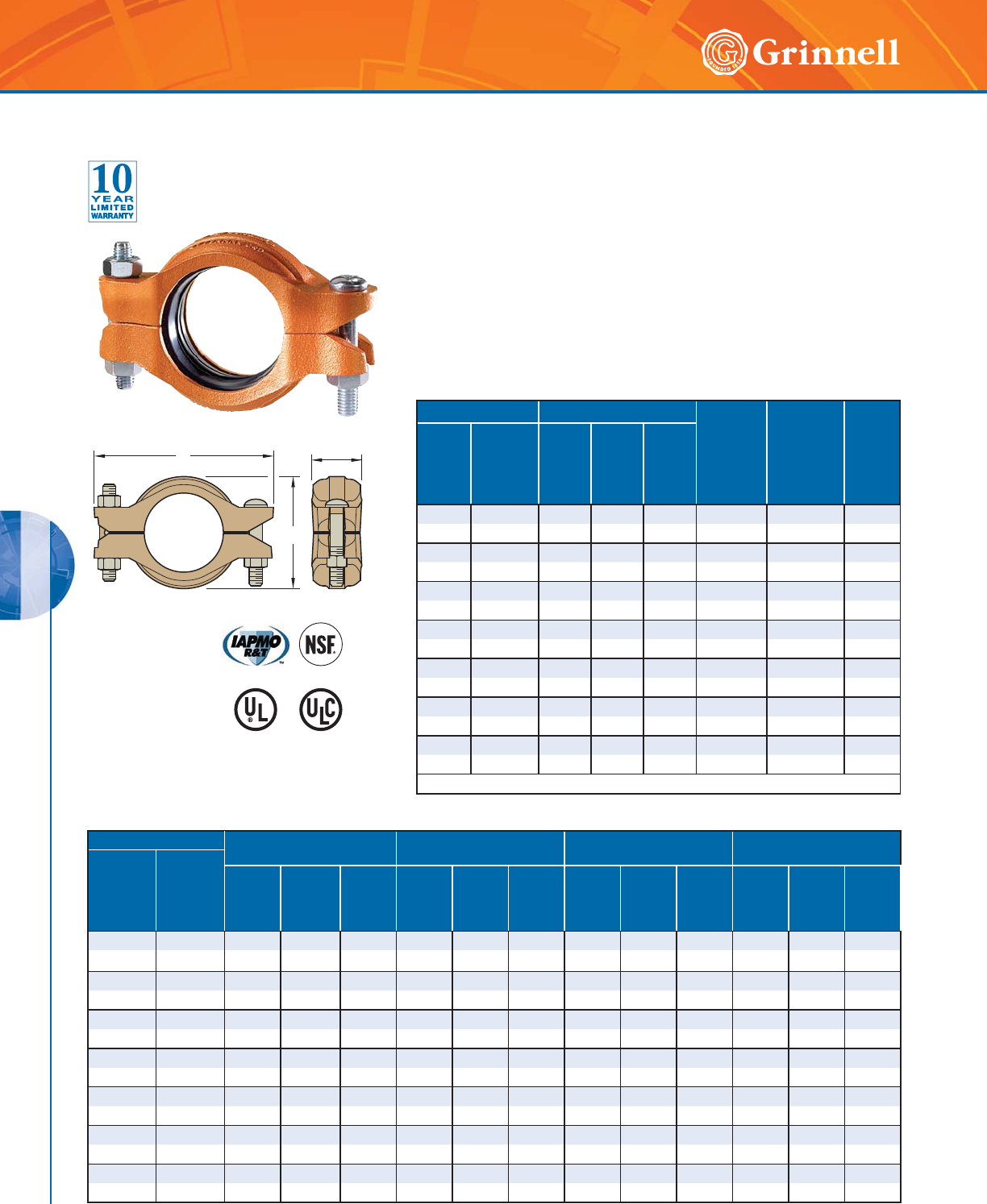
COPPER SYSTEMS
COPPER SYSTEMS
120 www.grinnell.com
)RUDGGLWLRQDOOLVWLQJVRUDSSURYDOV
VHHSDJHRUYLVLWRXUZHEVLWHDW
ZZZJULQQHOOFRP
&HUWLILHGWR
16)$16,
Pipe Size Type “K”
ASTM B-88
Type “L”
ASTM B-88
Type “M”
ASTM B-88
DWV
ASTM B-306
Nominal
Size
Inches
mm
Copper
Tubing O.D.
Inches
mm
Wall
Thick
Inches
mm
Max.
Working
Pressure
psi/bar
Max.
End
Load
lbs/kN
Wall
Thick
Inches
mm
Max.
Working
Pressure
psi/bar
Max.
End
Load
lbs/kN
Wall
Thick
Inches
mm
Max.
Working
Pressure
psi/bar
Max.
End
Load
lbs/kN
Wall
Thick
Inches
mm
Max.
Working
Pressure
psi/bar
Max.
End
Load
lbs/kN
2 2.125 0.083 300 1.065 0.070 300 1.065 0.058 250 890 – – –
50 54,0 2,1 20,7 4,74 1,8 20,7 4,74 1,5 17,2 3,96 – – –
21⁄22.625 0.095 300 1.625 0.080 300 1.625 0.065 250 1.350 – – –
65 66,7 2,4 20,7 7,23 2,0 20,7 7,23 1,7 17,2 6,01 – – –
3 3.125 0.109 300 2.300 0.090 300 2.300 0.072 250 1.415 0.045 100 765
80 79,4 2,8 20,7 10,23 2,3 20,7 10,23 1,8 17,2 6,30 1,1 6,9 3,40
4 4.125 0.134 300 4.005 0.110 300 4.005 0.095 250 3.340 0.058 100 1.335
100 104 ,8 3 ,4 20,7 17,8 2 2,8 2 0 ,7 17,82 2,4 17,2 14,8 6 1,5 6 , 9 5,94
5 5.125 0.160 30 0 6.190 0.125 300 6.190 0.109 200 4.125 0.072 100 2.060
125 130,7 4,1 20,7 27,55 3,2 20,7 27,55 2,8 13,8 18,36 1,8 6,9 9,17
6 6.125 0.192 300 8.840 0.140 300 8.840 0.122 200 5.890 0.083 100 2.945
150 155,6 4,9 20,7 39,34 3,6 20,7 39,34 3,1 13,8 26,21 2,1 6,9 13,10
8 8.125 0.271 300 15.550 0.200 300 15.550 0.170 200 10.370 0.109 100 5.180
200 206,4 6,9 20,7 69,2 5,1 20,7 69,20 4,3 13,8 46,10 2,8 6,9 23,0
Performance Pressure
Figure 640 Pivot-Bolt Rigid Installation-Ready Coupling
Tech Data Sheet: G512
BC
A
Pipe Size Dimensions
Pivot
Bolt Size
Dia. x Lg.
Coupling
Bolt Size
Dia. x Lg.
Approx.
Weight
lbs
kg
Nominal
Inches
mm
Copper
Tubing
O.D.
Inches
mm
A
Inches
mm
B
Inches
mm
C
Inches
mm
22.1253.345.861.90
1⁄2 x 33⁄41⁄2 x 35⁄83.1
50 54,0 84,9 148,8 48,3 – – 1,4
21⁄22.625 3.85 6.36 1.90 1⁄2 x 33⁄41⁄2 x 35⁄83.2
65 66,7 97,8 161,5 48,3 – – 1,5
33.1254.356.861.91
1⁄2 x 33⁄41⁄2 x 35⁄83.6
80 79,4 110,5 174,2 48,5 – – 1,6
44.1255.487.991.93
1⁄2 x 33⁄41⁄2 x 35⁄84.2
100 104,8 139,2 202,9 49,0 – – 1,9
55.1256.579.732.00
5⁄8 x 41⁄25⁄8 x 41⁄26.9
125 130,7 166,9 247,1 50,8 – – 3,1
66.1257.5710.732.02
5⁄8 x 41⁄25⁄8 x 41⁄27.5
150 155,6 192,3 272,5 51,3 – – 3,4
8 8.125 9.57 12.73 2.04 5⁄8 x 41⁄25⁄8 x 41⁄28.8
200 206,4 243,1 323,3 51,8 – – 4,0
See page 119 for specifications and pages 191 - 198 for gasket information.
The GRINNELL Figure 640 Pivot-Bolt Rigid Coupling joins rolled grooved,
hard-drawn copper tubing systems (CTS). It provides a rigid joint by firmly
gripping the entire circumference of the copper tube groove.
GRINNELL Pivot-Bolt Couplings have been tested and proven to install in
less than half the time of other standard grooved couplings. Simply push
the gasket onto the pipe, swing the coupling body over the gasket, and
tighten only one bolt. In comparison with other installation-ready couplings,
the GRINNELL Pivot-Bolt Coupling allows clear visual confirmation that the
gasket is properly seated on the gasket sealing surfaces.
The Figure 640 Pivot-Bolt Rigid Coupling is capable of pressures up to
300 psi (20,7 bar).
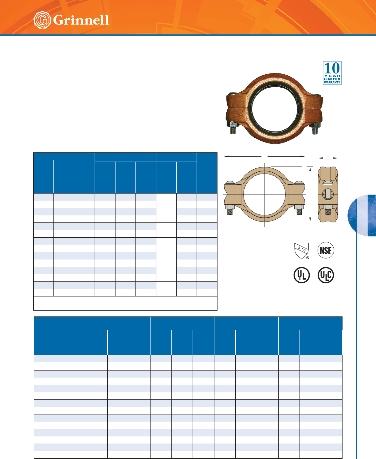
COPPER SYSTEMS
COPPER SYSTEMS
121
Refer to back cover for country-specific customer care numbers.
Figure 672 Rigid Coupling
Tech Data Sheet: G510
Pipe Size
Max.*
Gap
Inches
mm
Dimensions Coupling Bolts
Approx.
Weight
lbs
kg
Nominal
Inches
mm
Copper
Tubing
O.D.
Inches
mm
A
Inches
mm
B
Inches
mm
C
Inches
mm
Qty. Size
Inches
22.1250.063.094.651.76 2
3⁄8 x 21⁄41.7
50 54,0 1,5 78,6 118,1 44,7 – 0,8
21⁄22.625 0.06 3.59 5.56 1.76 2
3⁄8 x 21⁄41.9
65 66,7 1,5 91,3 141,2 44,7 – 0,9
3 3.125 0.06 4.12 6.25 1.76 2
1⁄2 x 3 3.1
80 79,4 1,5 104,7 158,8 44,7 – 1,4
4 4.125 0.09 5.33 7.75 1.86 2
1⁄2 x 3 4.3
100 104,8 2,3 135,3 196,9 47,2 – 2,0
5 5.125 0.09 6.48 9.25 1.86 2
5⁄8 x 31⁄46.0
125 130,7 2,3 164,6 235,0 47,2 – 2,7
66.1250.097.4810.251.86 2
5⁄8 x 31⁄46.6
150 155,6 2,3 190,0 260,4 47,2 – 3,0
8 8.125 0.09 9.64 12.75 1.86 2
3⁄4 x 43⁄410.2
200 206,4 2,3 244,8 323,9 47,2 – 4,6
* Maximum available gap between pipe ends, minimum gap = 0.
See page 119 for specifications and pages 191 - 198 for gasket information.
BC
A
)RUDGGLWLRQDOOLVWLQJVRUDSSURYDOV
VHHSDJHRUYLVLWRXUZHEVLWHDW
ZZZJULQQHOOFRP
&HUWLILHGWR
16)$16,
The GRINNELL Figure 672 Rigid Coupling, size range 2" to 8" (50mm -
200mm) is capable of pressures up to 300 PSI (20,7 bar) depending on
copper tubing size and type. It provides a rigid joint by firmly gripping
along the circumference of the copper tube grooves. The GRINNELL
Figure 672 Coupling is supplied with a NSF61 approved grade EPDM
EN tri-seal gasket.
GRINNELL Figure 672 Rigid Couplings are a proven dependable method
of joining copper tubing and are an economical alternative to soldering
(sweating) joints and can be used on type K, L, M, DWV copper tube.
Pipe Size Type “K”
ASTM B-88
Type “L”
ASTM B-88
Type “M”
ASTM B-88
DWV
ASTM B-306
Nominal
Size
Inches
mm
Copper
Tubing O.D.
Inches
mm
Wall
Thick
Inches
mm
Max.
Working
Pressure
psi/bar
Max.
End
Load
lbs/kN
Wall
Thick
Inches
mm
Max.
Working
Pressure
psi/bar
Max.
End
Load
lbs/kN
Wall
Thick
Inches
mm
Max.
Working
Pressure
psi/bar
Max.
End
Load
lbs/kN
Wall
Thick
Inches
mm
Max.
Working
Pressure
psi/bar
Max.
End
Load
lbs/kN
2 2.125 0.083 300 1.065 0.070 300 1.065 0.058 250 890 0.042 – –
50 54,0 2,1 20,7 4,74 1,8 20,7 4,74 1,5 17,2 3,96 1,1 – –
21⁄22.625 0.095 300 1.625 0.080 300 1.625 0.065 250 1.350 – – –
65 66,7 2,4 20,7 7,23 2,0 20,7 7,23 1,7 17,2 6,01 – – –
3 3.125 0.109 300 2.300 0.090 300 2.300 0.072 250 1.415 0.045 100 765
80 79,4 2,8 20,7 10,23 2,3 20,7 10,23 1,8 17,2 6,30 1,1 6,9 3,40
4 4.125 0.134 300 4.005 0.110 300 4.005 0.095 250 3.340 0.058 100 1.335
100 104 ,8 3 ,4 2 0,7 17,82 2,8 20,7 17, 82 2,4 17, 2 14,8 6 1,5 6 , 9 5, 94
5 5.125 0.160 30 0 6.190 0.125 300 6.19 0.109 200 4.125 0.0 72 100 2.0 6 0
125 130,7 4,1 20,7 27,55 3,2 20,7 27,55 2,8 13,8 18,36 1,8 6,9 9,17
6 6.125 0.192 300 8.840 0.140 300 8.840 0.122 200 5.890 0.083 100 2.945
150 155,6 4,9 20,7 39,34 3,6 20,7 39,34 3,1 13,8 26,21 2,1 6,9 13,10
8 8.125 0.271 300 15.550 0.200 300 15.550 0.170 200 10.370 0.109 100 5.180
200 206,4 6,9 20,7 69,2 5,1 20,7 69,20 4,3 13,8 46,10 2,8 6,9 23,0
Performance Pressure
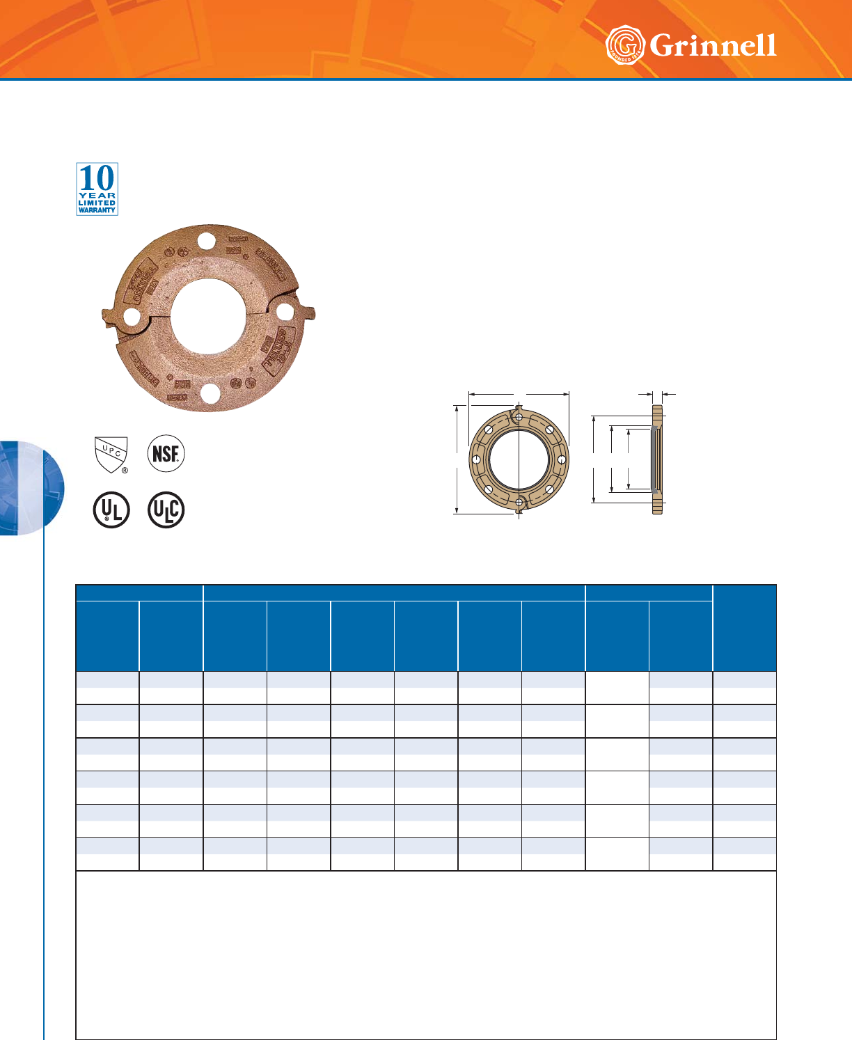
COPPER SYSTEMS
COPPER SYSTEMS
122 www.grinnell.com
Figure 61 Flange Adapter
(ANSI Class 125/150)
Tech Data Sheet: G515
Pipe Size Dimensions Bolts**
Approx.
Weight
lbs
kg
Nominal
Size
Inches
mm
Copper
Tubing
O.D.
Inches
mm
A
Inches
mm
B
Inches
mm
C
Inches
mm
D*
Inches
mm
E*
Inches
mm
F
Inches
mm
Qty.
Size
Inches
mm
2 2.125 6.38 4.75 0.75 2.3 2.83 7.25 4
5⁄8 x 3 3.7
50 54,0 162,1 120,7 19,1 58,4 71,9 184,2 – 1,7
21⁄22.625 7.00 5.50 0.88 2.79 3.33 7.88 4
5⁄8 x 3 5.4
65 66,7 178,0 140,0 22,0 70,9 84,6 200,0 – 2,4
3 3.125 7.50 6.00 0.94 3.28 3.85 8.38 4
5⁄8 x 3 6.1
80 79,4 190,5 152,4 23,9 83,3 97,8 212,9 – 2,8
4 4.125 9.00 7.50 0.94 4.24 4.85 9.90 8
5⁄8 x 3 7.6
100 104,8 228,6 190,5 23,9 107,7 123,2 251,5 – 3,4
5 5.125 10.00 8.50 1.00 5.24 5.84 10.88 8
3⁄4 x 31⁄29.5
125 130,2 254,0 215,9 25,4 133,1 148,3 276,4 – 4,3
6 6.125 11.00 9.50 1.00 6.24 6.96 11.88 8
3⁄4 x 31⁄210.9
150 155,6 279,4 241,3 25,4 158,5 176,8 301,8 – 4,9
* Dimensions D and E represent minimum and maximum sealing surfaces.
** Bolts are not supplied. Bolt lengths shown are standard; it is the responsibility of the purchaser to verify correct length for the intended application.
Note: Phenolic Type “F” Flange Adapter Washer (page 33) are required when the Figure 61 Flange Adapter is used against surfaces such as:
- Rubber surfaces
- Adapting to AWWA cast flanges
- Rubber faced wafer valves
- Serrated flange surfaces
Figure 61 Flange Adapters are not recommended for applications that incorporate tie rods for anchoring or on a standard fitting
within 90° of each other.
For information on larger sizes, contact GRINNELL Mechanical Products.
See page 119 for specifications and pages 191 - 198 for gasket information.
The GRINNELL Figure 61 Flange Adapter is capable of pressures up
to 300 PSI (20,7 bar) depending on copper tubing size and type. It
provides a direct transition from flanged components to a grooved
copper tube system. I.P.S. size flange bolt patterns conform to ANSI
Class 125 and 150. The GRINNELL Figure 61 Flange Adapter is
supplied with NSF 61 approved grade EPDM EN Gasket.
BEDF
AC
)RUDGGLWLRQDOOLVWLQJVRUDSSURYDOV
VHHSDJHRUYLVLWRXUZHEVLWHDW
ZZZJULQQHOOFRP
&HUWLILHGWR
16)$16,
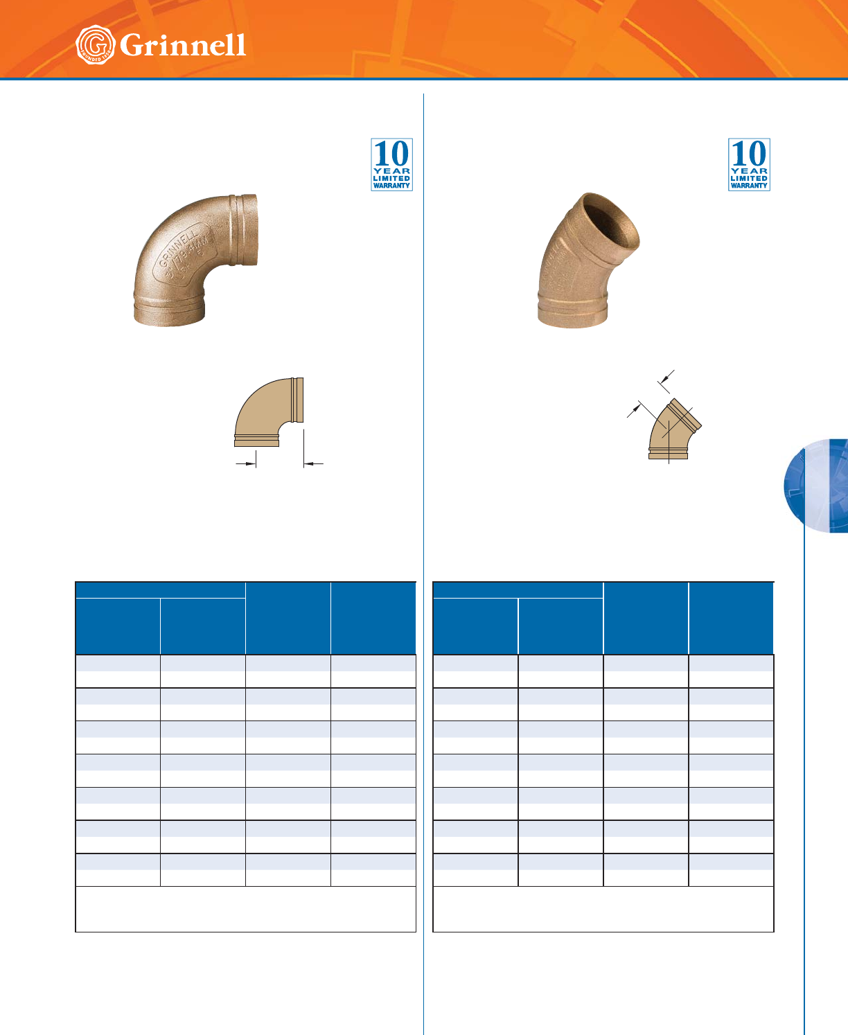
COPPER SYSTEMS
COPPER SYSTEMS
123
Refer to back cover for country-specific customer care numbers.
C to E
C to E
Pipe Size
C to E
Inches
mm
Approx.
Weight
lbs
kg
Nominal Size
Inches
mm
Copper Tubing
O.D.
Inches
mm
22.1252.911.9
50 54,0 73,9 0,9
21⁄22.625 3.31 2.7
65 66,7 84,1 1,2
3 3.125 3.81 3.6
80 79,4 96,8 1,6
44.1254.757.1
100 104,8 120,7 3,2
55.1255.9411.9
125 130,2 150,9 5,4
66.1256.9416.7
150 155,6 176,7 7,6
8 8.125 7.75 25.3
200 206,4 196,9 11,5
For information on larger sizes, contact GRINNELL Mechanical
Products.
See page 119 for specifications.
Pipe Size
C to E
Inches
mm
Approx.
Weight
lbs
kg
Nominal Size
Inches
mm
Copper Tubing
O.D.
Inches
mm
22.1252.191.6
50 54,0 55,6 0,7
21⁄22.625 2.31 2.1
65 66,7 58,7 1,0
3 3.125 2.59 2.7
80 79,4 65,8 1,2
44.1253.195.5
100 104,8 81,0 2,5
5 5.125 3.25 7.7
125 130,2 82,6 3,5
66.1253.510.1
150 155,6 88,9 4,6
8 8.125 4.25 16.6
200 206,4 108,0 7,5
For information on larger sizes, contact GRINNELL Mechanical
Products.
See page 119 for specifications.
Figure 610 90° Elbow
Tech Data Sheet: G520
Figure 601 45° Elbow
Tech Data Sheet: G520
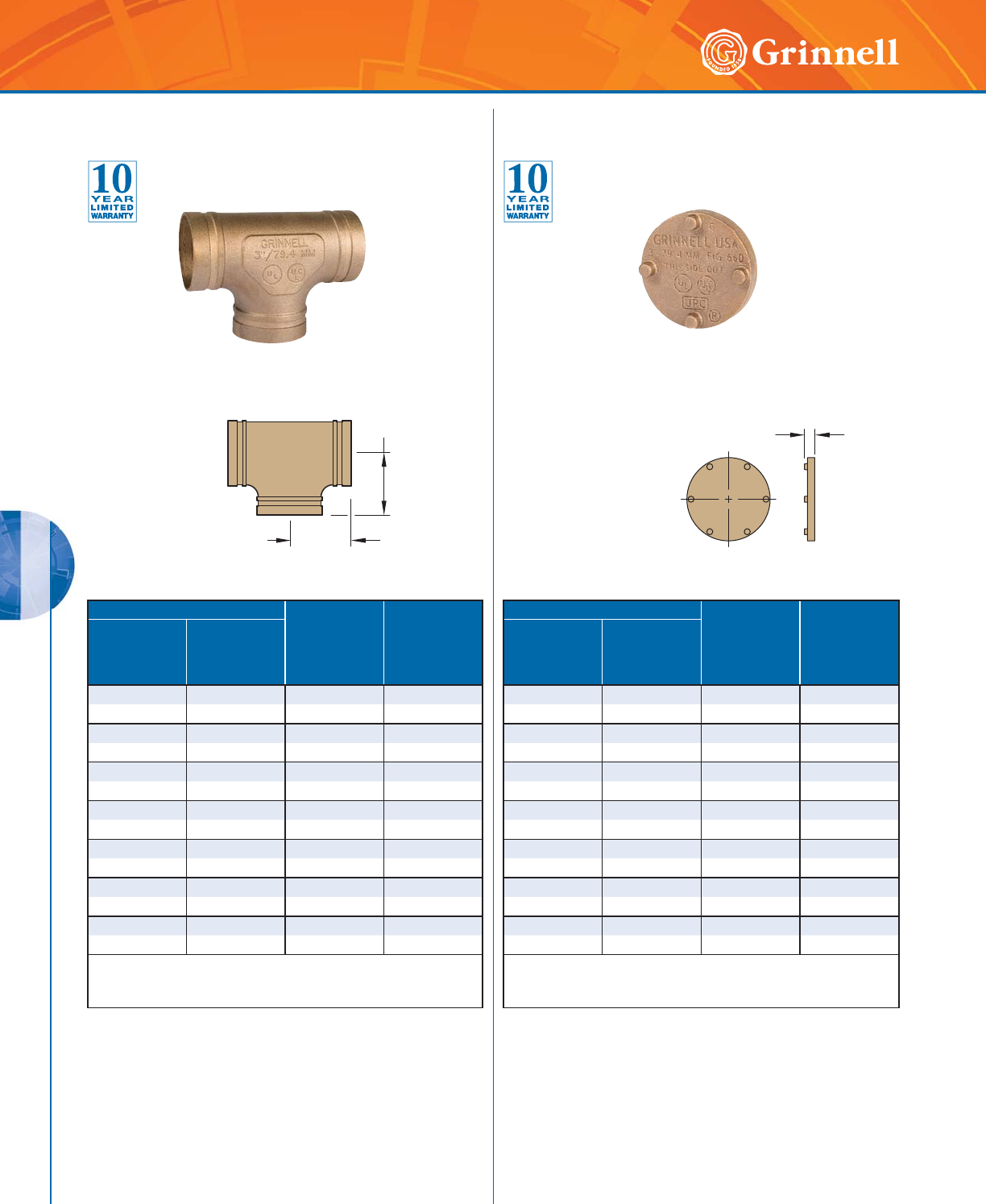
COPPER SYSTEMS
COPPER SYSTEMS
124 www.grinnell.com
C to E
C to E
E to E
Pipe Size
C to E
Inches
mm
Approx.
Weight
lbs
kg
Nominal Size
Inches
mm
Copper Tubing
O.D.
Inches
mm
2 2.125 2.69 2.5
50 54,0 68,3 1,1
21⁄22.625 3.20 3.8
65 66,7 81,3 1,7
33.1253.524.7
80 79,4 89,4 2,1
4 4.125 4.25 9.0
100 104,8 108,0 4,1
55.1255.9417.7
125 130,2 150,9 8,0
66.1256.9424.8
150 155,6 176,3 11,3
88.1257.7546.2
200 206,4 196,9 21,0
For information on larger sizes, contact GRINNELL Mechanical
Products.
See page 119 for specifications.
Pipe Size
E to E
Inches
mm
Approx.
Weight
lbs
kg
Nominal Size
Inches
mm
Copper Tubing
O.D.
Inches
mm
2 2.125 0.92 0.6
50 54,0 23,4 0,3
21⁄22.625 0.92 1.0
65 66,7 23,4 0,4
33.1250.921.3
80 79,4 23,4 0,6
44.1250.922.2
100 104,8 23,4 1,0
5 5.125 0.92 5.8
125 130,2 23,4 2,6
66.1250.928.1
150 155,6 23,4 3,7
8 8.125 1.03 14.1
200 206,4 26,2 6,4
For information on larger sizes, contact GRINNELL Mechanical
Products.
See page 119 for specifications.
Figure 619 Tee
Tech Data Sheet: G520
Figure 660 Cap
Tech Data Sheet: G520
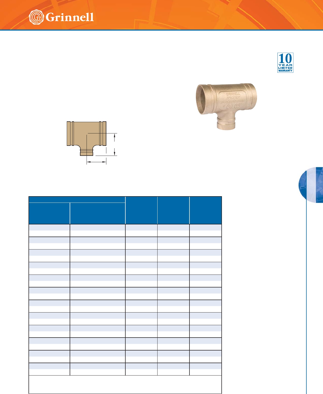
COPPER SYSTEMS
COPPER SYSTEMS
125
Refer to back cover for country-specific customer care numbers.
Figure 621 Reducing Tee
Tech Data Sheet: G520
C to RE
C to E
Pipe Size
C to E
Inches
mm
C to RE
Inches
mm
Approx.
Weight
lbs
kg
Nominal
Size
Inches
mm
Copper Tubing
O.D.
Inches
mm
21⁄2 x 21⁄2 x 2 2.625 x 2.625 x 2.125 3.28 3.38 3.5
65 x 65 x 50 66,7 x 66,7 x 54,0 83,3 85,9 1,6
3 x 3 x 2 3.125 x 3.125 x 2.125 3.00 3.38 3.8
80 x 80 x 50 79,4 x 79,4 x 54,0 76,2 85,9 1,7
3 x 3 x 21⁄23.125 x 3.125 x 2.625 3.25 3.5 4.3
80 x 80 x 65 79,4 x 79,4 x 66,7 82,6 88,9 2,0
4 x 4 x 2 4.125 x 4.125 x 2.125 3.66 4.13 6.9
100 x 100 x 50 104,8 x 104,8 x 54,0 93,0 104,9 3,2
4 x 4 x 21⁄24.125 x 4.125 x 2.625 3.94 4.06 7.5
100 x 100 x 65 104,8 x 104,8 x 66,7 100,1 103,1 3,4
4 x 4 x 3 4.125 x 4.125 x 3.125 4.19 4.16 8.7
100 x 100 x 80 104,8 x 104,8 x 79,4 106,4 105,7 4,0
5 x 5 x 3 5.125 x 5.125 x 3.125 3.75 4.63 10.0
125 x 125 x 80 130,2 x 130,2 x 79,4 95,3 117,6 4,5
5 x 5 x 4 5.125 x 5.125 x 4.125 4.25 4.56 11.4
125 x 125 x 100 130,2 x 130,2 x 104,8 108,0 115,8 5,2
6 x 6 x 21⁄26.125 x 6.125 x 2.625 3.63 5.13 11.5
150 x 150 x 65 155,6 x 155,6 x 66,7 92,2 130,3 5,2
6 x 6 x 3 6.125 x 6.125 x 3.125 3.69 5.19 11.9
150 x 150 x 80 155,6 x 155,6 x 79,4 93,7 131,8 5,4
6 x 6 x 4 6.125 x 6.125 x 4.125 4.19 5.13 13.7
150 x 150 x 100 155,6 x 155,6 x 104,8 106,4 130,3 6,2
6 x 6 x 5 6.125 x 6.125 x 5.125 4.69 5.19 15.9
150 x 150 x 125 155,6 x 155,6 x 130,2 119,1 131,8 7,2
For information on larger sizes, contact GRINNELL Mechanical Products.
Dimensional information in this chart is for cast fittings.
See page 119 for specifications.
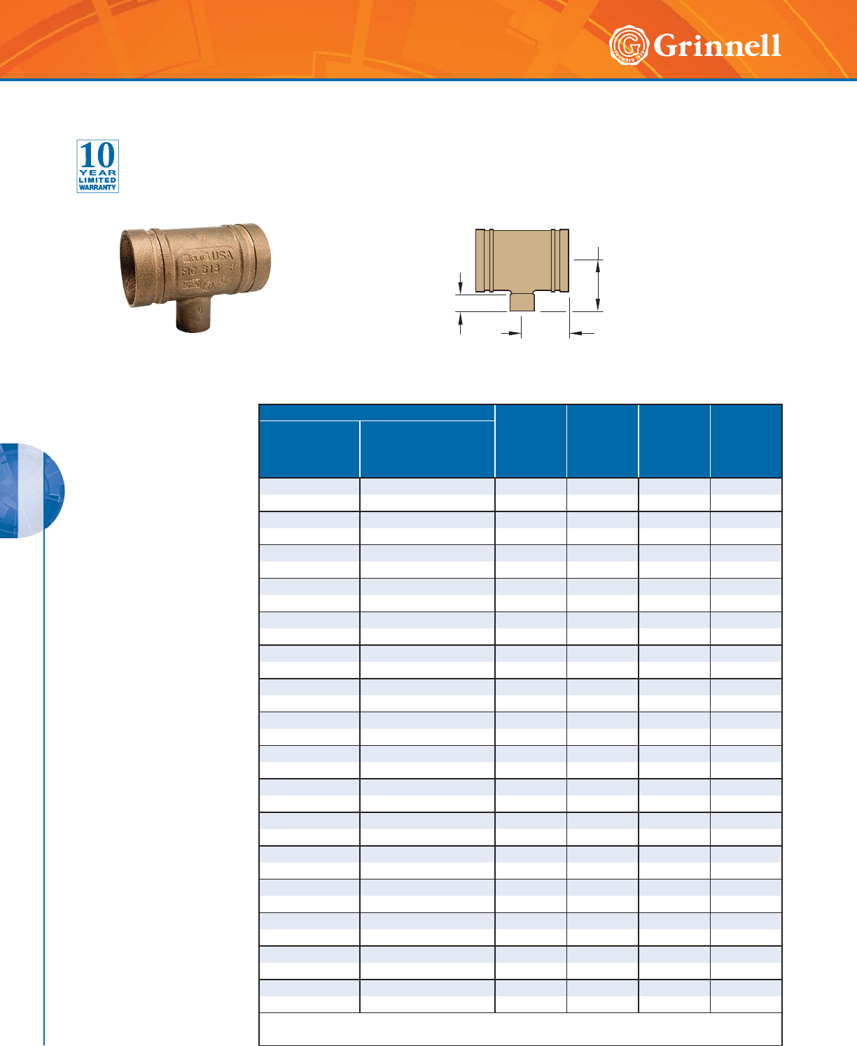
COPPER SYSTEMS
COPPER SYSTEMS
126 www.grinnell.com
Pipe Size
C to E
Inches
mm
C to RE
Inches
mm
Cup
Inches
mm
Approx.
Weight
lbs
kg
Nominal
Size
Inches
mm
Copper Tubing
O.D.
Inches
mm
2 x 2 x 3⁄42.125 x 2.125 x 0.825 2.20 2.04 0.75 1.6
50 x 50 x 20 54,0 x 54,0 x 21,0 55,9 51,8 19,0 0,7
2 x 2 x 1 2.125 x 2.125 x 1.125 2.33 2.26 0.91 1.8
50 x 50 x 25 54,0 x 54,0 x 25,4 59,1 57,4 23,1 0,8
2 x 2 x 11⁄42.125 x 2.125 x 1.375 2.48 2.41 0.97 2.0
50 x 50 x 32 54,0 x 54,0 x 34,9 63,0 61,2 24,6 0,9
2 x 2 x 11⁄22.125 x 2.125 x 1.625 2.55 2.34 1.09 2.0
50 x 50 x 40 54,0 x 54,0 x 38,1 64,7 59,4 27,7 0,9
21⁄2 x 21⁄2 x 3⁄42.625 x 2.625 x 0.875 2.27 2.24 0.75 2.2
65 x 65 x 20 66,7 x 66,7 x 21,0 57,7 57,0 19,0 1,0
21⁄2 x 21⁄2 x 1 2.625 x 2.625 x 1.125 2.40 2.46 0.91 2.3
65 x 65 x 25 66,7 x 66,7 x 25,4 61,0 62,5 23,1 1,0
21⁄2 x 21⁄2 x 11⁄42.625 x 2.625 x 1.375 2.52 2.63 0.97 2.5
65 x 65 x 32 66,7 x 66,7 x 34,9 64,0 66,8 24,6 1,1
21⁄2 x 21⁄2 x 11⁄22.625 x 2.625 x 1.625 2.70 2.74 1.09 2.7
65 x 65 x 40 66,7 x 66,7 x 38,1 68,6 69,6 27,7 1,2
3 x 3 x 3⁄43.125 x 3.125 x 0.875 2.45 2.64 0.75 2.9
80 x 80 x 20 79,4 x 79,4 x 21,0 62,2 67,1 19,0 1,3
3 x 3 x 1 3.125 x 3.125 x 1.125 2.54 2.85 0.91 3.0
80 x 80 x 25 79,4 x 79,4 x 25,4 64,5 72,4 23,1 1,4
3 x 3 x 11⁄43.125 x 3.125 x 1.375 2.63 2.95 0.97 3.1
80 x 80 x 32 79,4 x 79,4 x 34,9 66,8 74,9 24,6 1,4
3 x 3 x 11⁄23.125 x 3.125 x 1.625 2.85 3.06 1.09 3.4
80 x 80 x 40 79,4 x 79,4 x 38,1 72,4 77,7 27,7 1,5
4 x 4 x 3⁄44.125 x 4.125 x 0.875 2.95 3.06 0.75 5.2
100 x 100 x 20 104,8 x 104,8 x 21,0 94,7 77,7 19,0 2,4
4 x 4 x 1 4.125 x 4.125 x 1.125 3.10 3.28 0.91 5.5
100 x 100 x 25 104,8 x 104,8 x 25,4 78,7 83,3 23,1 2,5
4 x 4 x 11⁄44.125 x 4.125 x 1.375 3.25 3.53 0.97 5.7
100 x 100 x 32 104,8 x 104,8 x 34,9 82,5 89,7 24,6 2,6
4 x 4 x 11⁄24.125 x 4.125 x 1.625 3.35 3.71 1.09 6.1
100 x 100 x 40 104,8 x 104,8 x 38,1 85,1 94,2 27,7 2,8
For information on larger sizes, contact GRINNELL Mechanical Products.
See page 119 for specifications.
C to RE
C to E
Cup
Figure 618
Reducing Tee
Groove x Groove x Cup
Figure 618 Reducing Tee
Tech Data Sheet: G520

COPPER SYSTEMS
COPPER SYSTEMS
127
Refer to back cover for country-specific customer care numbers.
Figures 650
Concentric Reducer
Tech Data Sheet: G520
E to E
Pipe Size
E to E
Inches
mm
Approx.
Weight
lbs
kg
Nominal
Size
Inches
mm
Copper Tubing
O.D.
Inches
mm
21⁄2 x 2 2.625 x 2.125 3.29 1.4
65 x 50 66,7 x 54,0 83,6 0,6
3 x 2 3.125 x 2.125 2.50 1.4
80 x 50 79,4 x 54,0 63,5 0,6
3 x 21⁄23.125 x 2.625 2.50 1.4
80 x 65 79,4 x 66,7 63,5 0,6
4 x 2 4.125 x 2.125 4.75 3.0
100 x 50 104,8 x 54,0 120,7 1,4
4 x 21⁄24.125 x 2.625 3.00 2.3
100 x 65 104,8 x 66,7 76,2 1,0
4 x 3 4.125 x 3.125 3.00 2.3
100 x 80 104,8 x 79,4 76,2 1,0
5 x 3 5.125 x 3.125 3.88 3.7
125 x 80 130,2 x 79,4 98,6 1,7
5 x 4 5.125 x 4.125 3.38 3.7
125 x 100 130,2 x 104,8 85,9 1,7
6 x 3 6.125 x 3.125 4.38 5.1
150 x 80 155,6 x 79,4 111,3 2,3
6 x 4 6.125 x 4.125 3.88 5.2
150 x 100 155,6 x 104,8 98,6 2,4
6 x 5 6.125 x 5.125 3.38 4.8
150 x 125 155,6 x 130,2 85,9 2,2
8 x 6 8.125 x 6.125 5.00 9.7
200 x 150 206,4 x 155,6 127.0 4,4
For information on larger sizes, contact GRINNELL Mechanical
Products.
See page 119 for specifications.
Pipe Size
E to E
Inches
mm
Cup
Inches
mm
Approx.
Weight
lbs
kg
Nominal
Size
Inches
mm
Copper Tubing
O.D.
Inches
mm
2 x 1 2.125 x 1.125 2.70 0.91 0.5
50 x 25 54,0 x 25,4 68,6 23,1 0,2
2 x 11⁄42.125 x 1.375 3.00 0.97 0.4
50 x 32 54,0 x 34,9 76,2 24,6 0,2
2 x 11⁄22.125 x 1.625 2.94 1.09 0.4
50 x 40 54,0 x 38,1 74,7 27,7 0,2
21⁄2 x 1 2.625 x 1.125 3.25 0.91 0.5
65 x 25 66,7 x 25,4 82,6 23,1 0,2
21⁄2 x 11⁄42.625 x 1.375 3.52 0.97 0.6
65 x 32 66,7 x 34,9 89,4 24,6 0,3
21⁄2 x 11⁄22.625 x 1.625 3.45 1.09 0.6
65 x 40 66,7 x 38,1 87,6 27,7 0,3
21⁄2 x 2 2.625 x 2.125 3.38 1.34 0.6
65 x 50 66,7 x 54,0 85,9 34,0 0,3
3 x 11⁄23.125 x 1.625 3.68 1.09 0.7
80 x 40 79,4 x 38,1 93,5 27,7 0,3
3 x 2 3.125 x 2.125 4.10 1.34 1.0
80 x 50 79,4 x 54,0 104,1 34,0 0,5
4 x 2 4.125 x 2.125 4.75 1.34 1.4
100 x 50 104,8 x 54,0 120,7 34,0 0,6
For information on larger sizes, contact GRINNELL Mechanical
Products.
See page 119 for specifications.
E to E
Cup
Figures 652
Concentric Reducer
Tech Data Sheet: G520
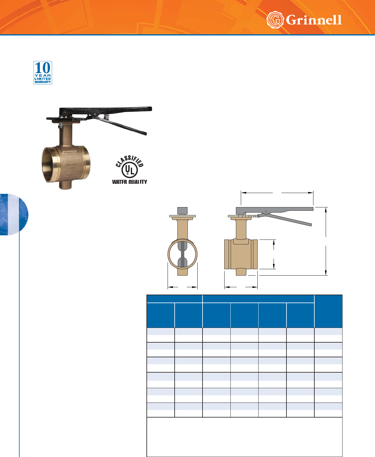
COPPER SYSTEMS
COPPER SYSTEMS
128 www.grinnell.com
Model B680 Butterfly Valve with Lever Handle
Tech Data Sheet: G530
B
A
D
O.D.
C
Pipe Size Dimensions
Weight
lbs
kg
Nominal
Size
Inches
mm
Copper
Tubing O.D.
Inches
mm
A
Inches
mm
B
Inches
mm
C
Inches
mm
D
Inches
mm
22.1253.195.312.4510.04.9
50 54,0 81,0 135,0 57,0 254,0 2,2
21⁄22.625 3.75 5.91 2.63 10.0 5.9
65 66,7 96,0 150,0 67,0 254,0 2,7
3 3.125 3.75 7.68 3.13 10.0 6.6
80 79,4 96,0 195,0 79,0 254,0 3,0
4 4.125 4.63 8.78 4.13 10.0 11.0
100 104,8 118,0 223,0 105,0 254,0 5,0
5 5.125 5.88 9.80 5.13 10.0 17.6
125 130,2 149,0 249,0 130,0 254,0 8,0
6 6.125 5.88 10.86 6.13 10.0 21.6
150 155,6 149,0 276,0 156,0 254,0 9,8
For information on larger sizes, contact GRINNELL Mechanical Products.
Notes: Pressure ratings listed are CWP (cold water pressure) or maximum working pressure
within the service temperature range of the gasket used in the coupling.
Maximum working pressures and end loads listed are total of internal and external pressures
and loads based on roll-grooved Type K – ASTM B 88 copper tubing.
See page 119 for specifications.
The GRINNELL Model B680 is a lever handle bronze body butterfly
valve designed for use with grooved copper tubing (CTS), fittings and
couplings. The valve is rated to 300 psi (20,7 bar) and features a 10
position locking lever handle and EPDM encapsulated ductile iron disc.
MATERIAL SPECIFICATIONS
Body
• Cast Bronze to ASTM B 584-87 Copper
Alloy UNS C90500
Disc
• Ductile Iron to ASTM A 536 Grade
65-45-12 Encapsulated with EPDM
Upper and Lower Shafts
• Stainless Steel Type 416 of
ASTM A 582
• UL Classified in Accordance with
ANSI/NSF 61
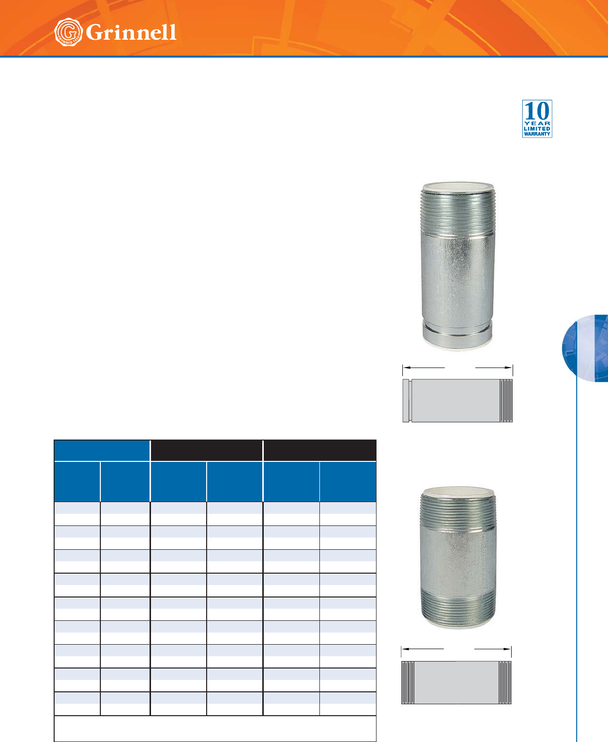
COPPER SYSTEMS
COPPER SYSTEMS
129
Refer to back cover for country-specific customer care numbers.
Figures 407GT & 407T Dielectric Waterways
Tech Data Sheet: G465
Clearflow* Fittings protect plumbing systems through an innovative steel-to-
plastic design that establishes a dielectric waterway. The dielectric fittings
separate dissimilar metals in the electrolyte (waterway), eliminating the local
galvanic cell.
The Clearflow Fittings metal-to-metal joint design maintains external electrical
continuity, thereby preventing stray current corrosion. This feature is critical
when stray current is present due to intentional or non-intentional grounding of
direct current (DC) sources, such as phone systems and appliances.
Fittings meet the requirements of ASTM F 492 for continuous use at
temperatures up to 230°F (110°C).
Test data/results and listings by Pittsburgh Testing Laboratory can be provided
upon request. Contact GRINNELL Mechanical Products
Figure 407GT
Dielectric Waterway
Figure 407T
Dielectric Waterway
Pipe Size Figure 407GT
Grooved x Male Thread
Figure 407T
Male Thread x Male Thread
Nominal
Inches
mm
Copper
Tubing O.D.
Inches
mm
End to End
Inches
mm
Approx.
Weight
Lbs.
kg
End to End
Inches
mm
Approx.
Weight
Lbs.
kg
1⁄20.625 – – 3.0 0.2
15 15,9 – – 76,2 0,1
3⁄40.875 – – 3.0 0.2
20 22,2 – – 76,2 0,1
1 1.125 4.0 0.3 4.0 0.3
25 28,6 101,6 0,1 101,6 0,1
11⁄41.375 4.0 0.6 4.0 0.6
32 34,9 101,6 0,3 101,6 0,3
11⁄21.625 4.0 0.8 4.0 0.8
40 41,3 101,6 0,4 101,6 0,4
2 2.125 4.0 1.0 4.0 1.0
50 54,0 101,6 0,5 101,6 0,5
21⁄22.625 6.0 1.6 6.0 1.6
65 66,7 152,4 0,7 152,4 0,7
3 3.125 6.0 2.0 6.0 2.0
80 79,4 152,4 0,9 152,4 0,9
4 4.125 6.0 4.5 6.0 4.5
100 104,8 152,4 2,0 152,4 2,0
For information on larger sizes, contact GRINNELL Mechanical Products.
See fitting specifications on page 37. * Clearflow is a Registered Trademark of Perfection Corp.
E to E
E to E
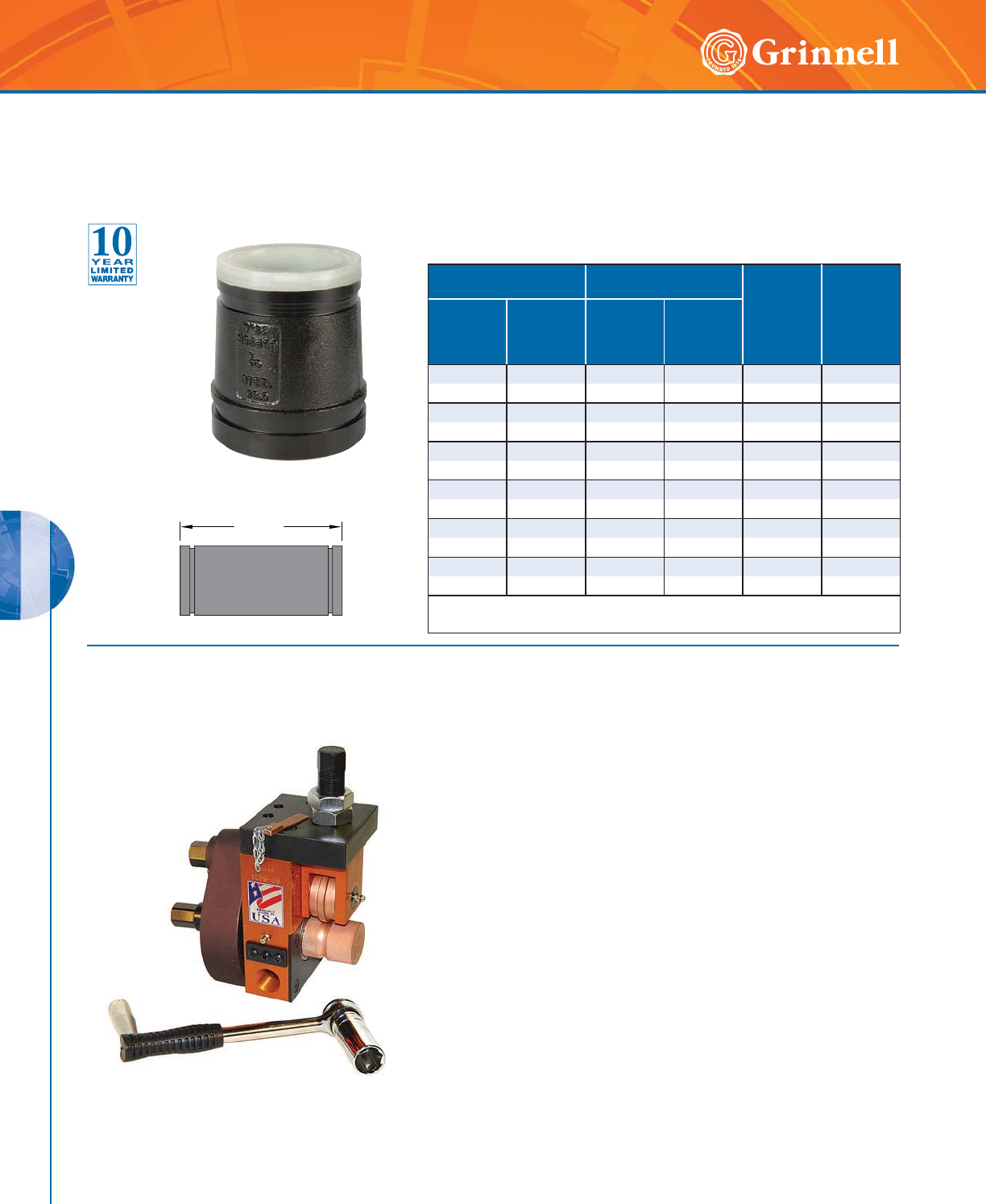
COPPER SYSTEMS
COPPER SYSTEMS
130 www.grinnell.com
Figure 407GG Dielectric
Waterway Transition
Fitting
Tech Data Sheet: G465
The GRINNELL Figure 407GG Transition Fitting protects systems through
an innovative steel-to-plastic design that establishes a dielectric waterway.
The transition fitting separates dissimilar metals in the electrolyte
(waterway) eliminating the local galvanic cell.
The GRINNELL Figure 407GG Transition Fitting allows the connection
between steel (IPS) size pipe and copper tube (CTS) size.
Pipe Size Outside Diameter
Inches mm End to End
Inches
mm
Approx.
Weight
lbs
kg
Nominal
Size
Inches
mm
Copper
Tubing O.D.
Inches
mm
Steel
(IPS)
Copper
(CTS)
2 2.125 2.375 2.125 4.00 1.3
50 54,0 60,3 54,0 101,6 0,6
21⁄22.625 2.875 2.625 4.00 3.3
65 66,7 73,0 66,7 101,6 1,5
3 3.125 3.500 3.125 4.00 4.5
80 79,4 88,9 79,4 101,6 2,1
4 4.125 4.5 00 4.125 4.00 5.8
100 104,8 114,3 104,8 101,6 2,6
5 5.125 5.5 63 5.125 4.00 7.8
125 130,2 141,3 130,2 101,6 3,5
6 6.125 6.625 6.125 4.00 10.1
150 155,6 168,3 155,6 101,6 4,6
For information on larger sizes, contact GRINNELL Mechanical Products.
See fitting specifications on page 37.
Capacity:
• 2" – 8" (50 - 200mm) Copper Tube K, L, M and DWV
• 11⁄4" – 6" (32 - 150mm) SCH 40 (7mm)
Model 1039 – 66 Mini-Mite Roll Groover service tool goes from
in-place grooving and can be chucked in a Ridgid Model 300 in
seconds with no gearbox removal.
Model 1039 – 66 Mini-Mite is self contained and can be entirely
operated with its own multi-function crank. No additional tools are re-
quired. With ratchet hand crank, roll grooves 11⁄4" – 6" (32 - 150mm),
Schedule 40 or thin wall steel pipe on the scaffold or anywhere
power is unavailable. All hex drives on Model 1039 – 66 Mini-Mite
are 15/
16" (23,8mm).
Mini-Mites require no modifications or parts changes to groove any
pipe or tubing in their size range.
Standard equipment includes a multi-step depth gauge, copper rolls
for 2" – 8" (50 - 200mm). Steel rolls for 11⁄4" – 6" (32 - 150mm) may
be ordered separately.
See Preparation Equipment section on pages 199 - 212 for more
information and options.
Model 1039-66 Copper Roll Groover
E to E
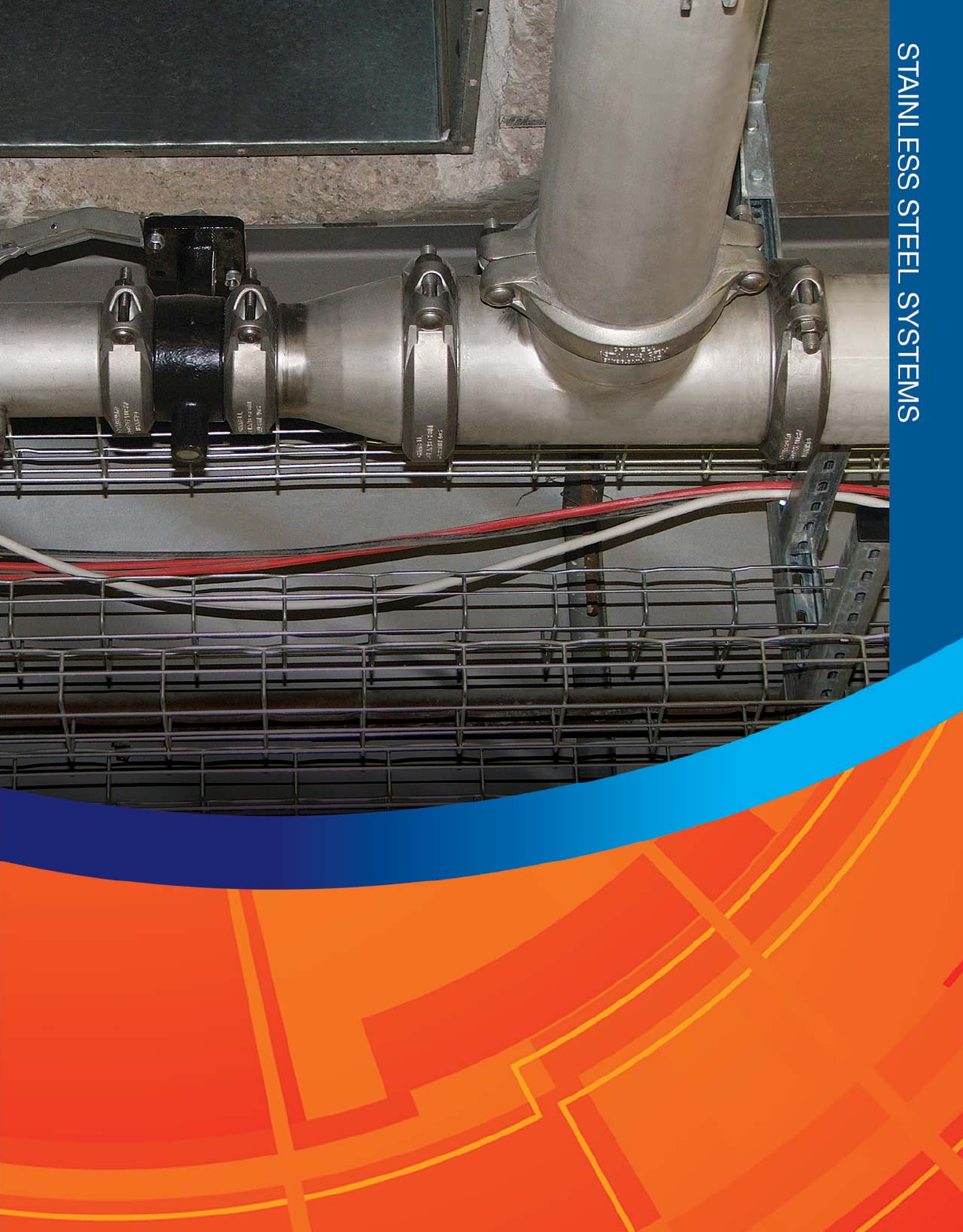
131
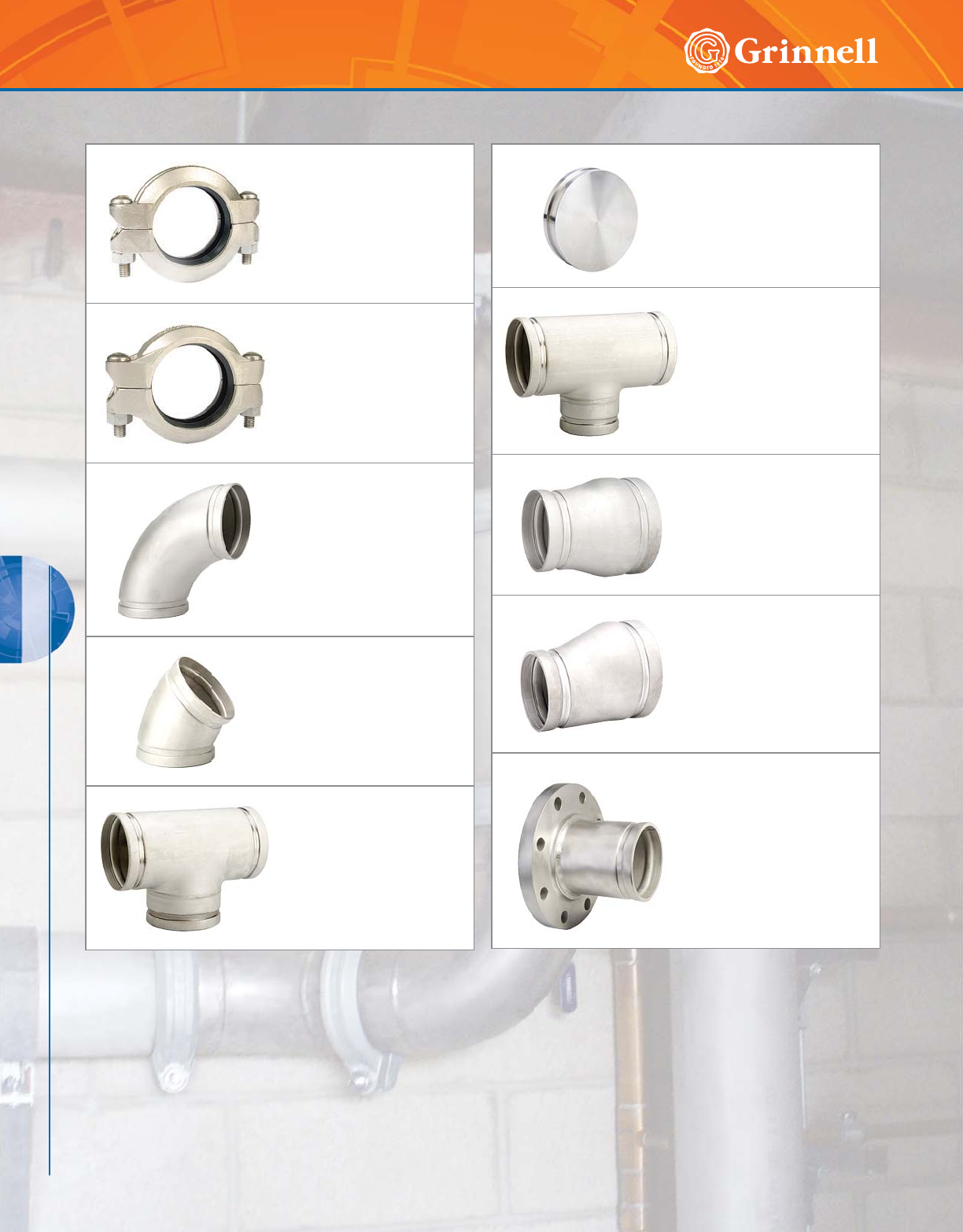
STAINLESS STEEL SYSTEMS
132 www.grinnell.com
STAINLESS STEEL SYSTEMS
Figure 472
Stainless Steel Rigid Couplings
Page 134
Figure 405
Stainless Steel Flexible
Couplings
Page 135
Figure 410
Stainless Steel 90° Elbows
Page 136
Figure 401
Stainless Steel 45° Elbows
Page 136
Figure 419
Stainless Steel Tees
Page 137
Figure 460
Stainless Steel End Caps
Page 138
Figure 421
Stainless Steel Reducing Tees
Page 139
Figure 450
Stainless Steel Concentric Reducers
Page 140
Figure 451
Stainless Steel Eccentric Reducers
Page 141
Figure 441
Stainless Steel Flange
Adapters
Page 142
Stainless Steel Systems Table of Contents

STAINLESS STEEL SYSTEMS
STAINLESS STEEL SYSTEMS
133
Refer to back cover for country-specific customer care numbers.
MATERIAL SPECIFICATIONS
Stainless Steel Housing Specifications
• Type 316L, ASTM A 743/A 743M – Standard
specification for castings, iron-chromium,
iron-chromium-nickel, corrosion resistant;
for general application Grade CR-8M.
• Tensile strength, minimum 70,000 psi (4826,3 bar)
• Yield strength, minimum 30,000 psi (2068,4 bar)
• Elongation in 2" (50mm) minimum 30%
Bolt/Nut Specifications
• Stainless steel bolts are metric track head bolts
conforming to ASTM A 193M Class 2, Type 316
Grade B8M
• Class 2 stainless steel nuts are heavy hex nuts
conforming to ASTM A 194M, Type 316, Grade 8M
• Bolts are coated with an anti-galling agent
Gasket Specifications
• Grade “E” EPDM gaskets have a Green color code
identification and conform to ASTM D 2000 for service
temperatures from -30°F to 230°F (-34°C to 110°C). They
are recommended for hot water not to exceed 230°F
(110°C) plus a variety of dilute acids, oil free air, and
many chemical services. They are not recommended for
petroleum services.
• Grade “EN” EPDM gaskets have a Copper color code
identification and are NSF-61 approved for cold and hot
portable water up to 180°F (82°C).
• Grade “T” Nitrile gaskets have an Orange color code
identification and conform to ASTM D 2000 for service
temperatures from -20°F to 180°F (-29°C to 82°C). They
are recommended for petroleum products, vegetable oils,
mineral oils, and air with oil vapors.
• Grade “O” Fluoroelastomer gaskets have a Blue
color code and conform to ASTM D 2000. They are
recommended for oxidizing acids, petroleum products,
hydraulic fluids, lubricants, and halogenated hydrocarbons.
Fitting Specifications
Tech Data Sheet: G570
Coupling Specifications
MATERIAL SPECIFICATIONS
• Fabricated: 304/316L stainless steel conforming to
ASTM A 312, Schedule 10 and Schedule 40
• Full-flow: 304/316L stainless steel conforming to
ASTM A 403 WPW or A 403 CR
Fittings are available in full-flow and fabricated versions in
304 and 316L S.S. Fabricated fittings are available with
Schedule 10 or Schedule 40 wall thickness.
For pressure ratings of fittings, refer to data sheet G570.
)RUDGGLWLRQDOOLVWLQJVRU
DSSURYDOVVHHSDJHRU
YLVLWRXUZHEVLWHDW
ZZZJULQQHOOFRP
For local country potable water approvals, contact GRINNELL Mechanical Products.
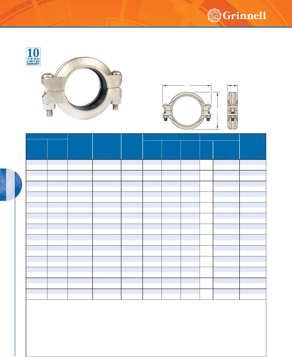
STAINLESS STEEL SYSTEMS
STAINLESS STEEL SYSTEMS
134 www.grinnell.com
Figure 472 Stainless Steel Rigid Couplings
Tech Data Sheet: G560 The GRINNELL Figure 472 Rigid Coupling is made of cast 316L stainless
steel and is capable of pressure up to 600 psi (41,4 bar).
The GRINNELL Figure 472 Patented Coupling universal tongue-
and-groove design allows the housing to grip along the full 360° of
circumference of the pipe. Sizes 11⁄4" – 4" (32mm – 100mm) have
gripping teeth to prevent rotation during installation.
BC
A
Pipe Size Max.†
Pressures
psi
bar
Max.†
End Load
Lbs.
kN
Max.*‡
End Gap
Inches
mm
Dimensions - Inches mm Coupling Bolts Approx.
Weight
Lbs.
kg
Nominal
Inches
mm
O.D.
Inches
mm
AB C Qty.
Size**
Inches
mm
11⁄41.660 600 1,298.5 0.06 2.75 4.38 1.81 2
3⁄8 x 21⁄42.0
32 42,4 41,4 5,78 1,5 69,9 111,3 46,0 M10 x 57 0,9
11⁄21.900 600 1,701.1 0.08 3.00 4.62 1.81 2
3⁄8 x 21⁄42.1
40 48,3 41,4 7,57 2,0 76,2 117,3 46,0 M10 x 57 1,0
2 2.375 600 2,658.0 0.13 3.41 5.12 1.88 2
3⁄8 x 21⁄41.9
50 60,3 41,4 11,82 3,3 86,6 130,0 47,8 M10 x 57 0,9
21⁄22.875 600 3,895.0 0.13 3.91 5.63 1.88 2
3⁄8 x 21⁄43.2
65 73,0 41,4 17,32 3,3 99,3 143,0 47,8 M10 x 57 1,5
76,1mm 3.000 600 4,241.0 0.13 4.19 5.72 2.00 2–3.5
65 76,1 41,4 18,86 3,3 106,4 145,3 50,8 M10 x 57 1,6
3 3.500 600 5,772.5 0.13 4.63 6.25 1.88 2
1⁄2 x 3 3.5
80 88,9 41,4 25,68 3,3 117,6 158,8 47,8 M12 x 89 1,6
4 4.500 600 9,542.3 0.19 5.81 7.50 1.97 2
1⁄2 x 3 5.6
100 114,3 41,4 42,44 4,8 147,6 190,5 50,0 M12 x 89 2,5
139,7mm 5.500 600 14,254.6 0.19 7.02 9.72 2.06 2–8.5
125 139,7 41,4 63,40 4,8 178,3 246,9 52,3 M16 x 83 3,9
5 5.563 600 14,583.0 0.19 7.09 9.71 2.04 2
5⁄8 x 31⁄48.5
125 141,3 41,4 64,87 4,8 180,1 246,6 51,8 M16 x 83 3,9
6 6.625 600 20,682.4 0.19 8.09 10.53 2.13 2
5⁄8 x 31⁄49.4
150 168,3 41,4 92,00 4,8 205,5 267,5 54,1 M16 x 83 4,3
8 8.625 600 35,054.7 0.19 10.56 13.56 2.62 2
3⁄4 x 43⁄419.4
200 ◗219,1 41,4 155,92 4,8 268,2 344,4 66,5 M20 x 121 8,8
10 10.750 600 54,455.9 0.13 12.84 16.41 2.62 21 x 61⁄232.0
250 ◗273,0 41,4 242,22 3,3 326,1 416,8 66,5 M24 x 165 14,5
12 12.750 600 76,603.5 0.13 15.41 18.84 2.62 21 x 61⁄243.0
300 ◗323,9 41,4 340,73 3,3 391,4 478,5 66,5 M24 x 165 19,5
Figure 472 Rigid Couplings have an Anti-Rotation Feature of “gripping teeth” along the coupling keys in sizes
11
⁄4" - 4" (32mm - 100mm ),
making the Figure 472 perfectly suited for installations where the likelihood of rotation is greatest.
* Maximum available gap between pipe ends. Minimum gap = 0.
† Maximum Pressure and End Load are total from all loads based on standard weight stainless steel pipe. Pressure ratings and end loads may differ
for other pipe materials and/or wall thickness. Contact GRINNELL Mechanical Products for details.
‡ Max end gap is for cut grooved standard weight stainless steel pipe. Values for roll grooved pipe will be half that of cut grooved.
** Contact GRINNELL Mechanical Products for availability of inch bolt sizes vs. metric bolt sizes.
◗ Sizes are available to JIS standards. Contact GRINNELL Mechanical Products for details.
For information on larger sizes, contact GRINNELL Mechanical Products.
See page 133 for stainless steel coupling specifications and pages 191 - 198 for gasket information.
Refer to pressure ratings for Schedule 5, 10, and 40 pipe on pages 222 - 223, or contact GRINNELL Mechanical Products.
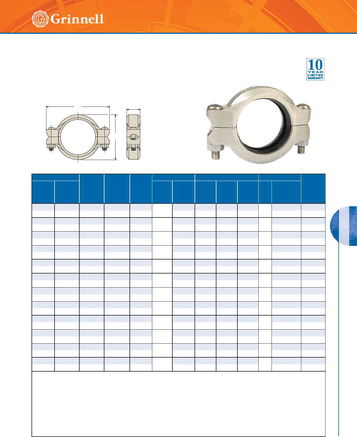
STAINLESS STEEL SYSTEMS
STAINLESS STEEL SYSTEMS
135
Refer to back cover for country-specific customer care numbers.
The GRINNELL Figure 405 Flexible Coupling is made of
316L stainless steel and is capable of pressures up to 750
psi (51,7 bar), depending on pipe size and wall thickness.
BC
A
Pipe Size Max.†
Pressures
psi
bar
Max.†
End Load
Lbs.
kN
Max.*‡
End Gap
Inches
mm
Deflection ‡ Dimensions - Inches mm Coupling Bolts Approx.
Weight
Lbs.
kg
Nominal
Inches
mm
O.D.
Inches
mm
Degrees
per
coupling
In/Ft
mm/m AB C Qty.
Size**
Inches
mm
1 1.315 750 1,018.6 0.13 5° 26' 0.90 2.20 3.82 1.81 2
3⁄8 x 21⁄41.5
25 33,4 51,7 4,53 3,3 95,1 56,0 97,0 46,0 M10 x 57 0,6
11⁄41.660 750 1,623.1 0.13 4° 19' 0.90 2.56 4.19 1.81 2
3⁄8 x 21⁄41.5
32 42,4 51,7 7,22 3,3 75,0 65,0 106,4 46,0 M10 x 57 0,7
11⁄21.900 750 2,126.4 0.13 3° 46' 0.79 2.75 4.44 1.81 2
3⁄8 x 21⁄41.6
40 48,3 51,7 9,46 3,3 65,8 69,9 112,8 46,0 M10 x 57 0,7
22.3755002,215.00.13
3° 1' 0.63 3.25 4.88 1.88 2
3⁄8 x 21⁄41.7
50 60,3 34,5 9,85 3,3 52,5 82,6 124,0 47,8 M10 x 57 0,8
21⁄22.875 500 3,245.8 0.13 2° 29' 0.52 3.69 5.50 1.88 2
3⁄8 x 21⁄42.0
65 73,0 34,5 14,44 3,3 43,3 93,7 139,7 47,8 M10 x 57 0,9
76,1mm 3.000 500 3,534.2 0.13 2° 23' 0.50 4.00 5.75 1.88 2–3.1
65 ◗76,1 34,5 15,72 3,3 41,7 101,6 146,10 47,8 M12 x 89 1,4
33.5005004,810.40.13
2° 3' 0.43 4.38 6.50 1.88 2
1⁄2 x 3 3.1
80 88,9 34,5 21,40 3,3 35,8 111,3 165,1 47,8 M12 x 89 1,4
44.5003255,168.70.25
3° 11' 0.67 5.69 7.75 2.06 2
1⁄2 x 3 4.0
100 114,3 22,4 22,99 6,4 55,8 144,5 196,9 52,3 M12 x 89 1,8
139,7mm 5.500 200 4,751.5 0.25 2° 36' 0.55 6.81 9.75 2.06 2–7.2
125 ◗139,7 13,8 21,13 6,4 45,5 173,0 247,7 52,3 M16 x 83 3,3
5 5.563 200 4,861.0 0.25 2° 35' 0.54 6.88 9.75 2.06 2
5⁄8 x 31⁄47.1
125 141,3 13,8 21,62 6,4 45,0 174,8 247,7 52,3 M16 x 83 3,2
6 6.625 200 6,894.1 0.25 2° 10' 0.45 7.94 10.69 2.06 2
5⁄8 x 31⁄47.1
150 168,3 13,8 30,67 6,4 37,5 201,7 271,5 52,3 M16 x 83 3,2
88.62520011,684.90.25
1° 40' 0.35 10.19 13.56 2.50 2
3⁄4 x 43⁄414.5
200 219,1 13,8 51,97 6,4 29,2 258,8 344,4 63,5 M20 x 121 6,6
Values for roll grooved pipe will be half that of cut grooved.
* Maximum available gap between pipe ends. Minimum gap = 0.
† Maximum Pressure and end load are total from all loads based on standard weight stainless steel pipe. Pressure ratings and end loads may differ
for other pipe materials and/or wall thickness. Contact GRINNELL Mechanical Products for details.
‡ Max End Gap and Deflection is for cut grooved standard weight stainless steel pipe.
** Contact GRINNELL Mechanical Products for availability of inch bolt sizes vs. metric bolt sizes.
◗ Sizes are available to JIS standards. Contact GRINNELL Mechanical Products for details.
For information on larger sizes, contact GRINNELL Mechanical Products.
See page 133 for stainless steel coupling specifications and pages 191 - 198 for gasket information.
Refer to pressure ratings for Schedule 5, 10, and 40 pipe on pages 222 - 223, or contact GRINNELL Mechanical Products.
Figure 405 Stainless Steel Flexible Couplings
Tech Data Sheet: G565
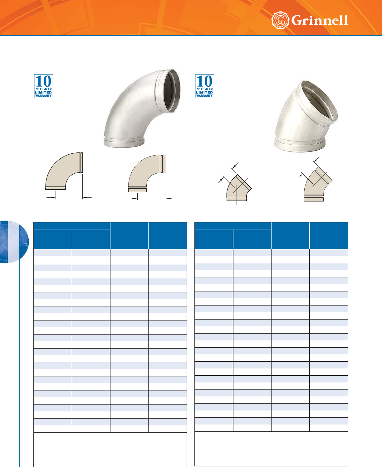
STAINLESS STEEL SYSTEMS
STAINLESS STEEL SYSTEMS
136 www.grinnell.com
Pipe Size C to E
Inches
mm
Approx.
Weight
Lbs.
kg
Nominal
Inches
mm
O.D.
Inches
mm
11.3152.881.0
25 33,4 73,2 0,45
11⁄41.660 3.13 1.0
32 42,4 79,5 0,45
11⁄21.900 3.50 1.0
40 48,3 88,9 0,45
22.3754.501.1
50 60,3 114,3 0,50
21⁄22.875 5.00 1.7
65 73,0 127,0 0,77
76,1mm 3.000 5.12 3.1
65 76,1 130,0 1,41
33.5004.502.6
80 88,9 114,3 1,18
4 4.500 6.00 4.7
100 114,3 152,4 2,13
55.5637.508.4
125 141,3 190,5 3,81
6 6.625 9.00 10.3
150 168,3 228,6 4,67
8 8.625 12.00 17.6
200 219,1 304,8 7,98
10 10.750 15.00 49.2
250 273,0 381,0 22,32
12 12.750 18.00 78.4
300 323,9 457,2 35,56
For information on larger sizes, contact GRINNELL
Mechanical Products.
Schedule 40 fittings available upon request, contact GRINNELL
Mechanical Products.
See page 133 for stainless steel fitting specifications.
Pipe Size C to E
Inches
mm
Approx.
Weight
Lbs.
kg
Nominal
Inches
mm
O.D.
Inches
mm
11.3152.00 0.6
25 33,4 50,8 0,27
11⁄41.660 2.00 0.8
32 42,4 50,8 0,36
11⁄21.900 3.50 1.0
40 48,3 88,9 0,45
2 2.375 2.75 1.2
50 60,3 69,9 0,54
21⁄22.875 2.81 1.7
65 73,0 71,4 0,77
76,1mm 3.000 2.87 3.1
65 76,1 73,0 1,41
3 3.500 2.00 1.3
80 88,9 50,8 0,59
4 4.500 2.50 2.3
100 114,3 63,5 1,04
55.5633.134.2
125 141,3 79,4 1,90
66.6253.755.1
150 168,3 95,3 2,31
88.6255.0013.8
200 219,1 127,0 6,26
10 10.750 6.25 24.6
250 273,0 158,8 11,16
12 12.750 7.50 39.2
300 323,9 190,5 17,78
For information on larger sizes, contact GRINNELL
Mechanical Products.
Schedule 40 fittings available upon request, contact GRINNELL
Mechanical Products.
See page 133 for stainless steel fitting specifications.
C to E
C to E
Figure 410
Fabricated 90° Elbow
Figure 401
Fabricated 45° Elbow
Figure 410A
Full-Flow 90° Elbow
Figure 401A
Full-Flow 45° Elbow
C to E
C to E
Figure 410 90°
Stainless Steel Elbows
Tech Data Sheet: G570
Figure 401 45°
Stainless Steel Elbows
Tech Data Sheet: G570
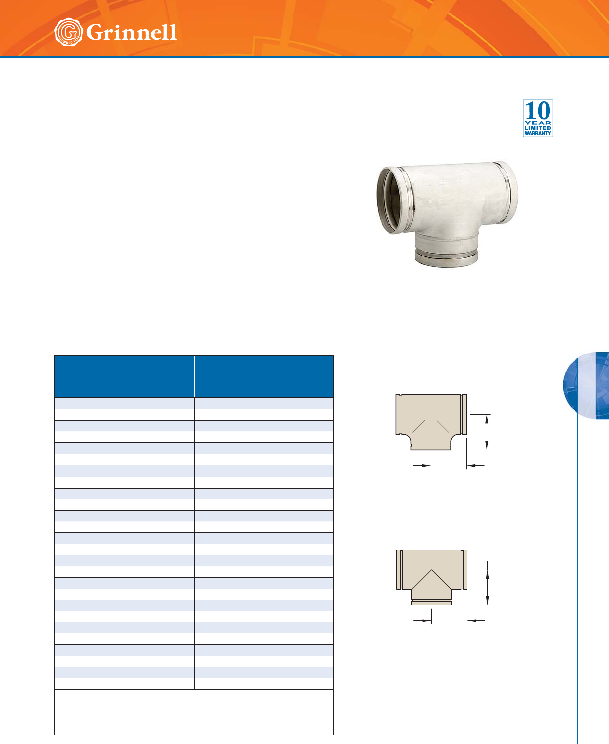
STAINLESS STEEL SYSTEMS
STAINLESS STEEL SYSTEMS
137
Refer to back cover for country-specific customer care numbers.
Pipe Size C to E
Inches
mm
Approx.
Weight
Lbs.
kg
Nominal
Inches
mm
O.D.
Inches
mm
11.3152.881.0
25 33,4 73,2 0,45
11⁄41.660 3.38 1.5
32 42,4 85,9 0,68
11⁄21.900 3.38 1.6
40 48,3 85,9 0,73
2 2.375 2.75 2.3
50 60,3 69,9 1,04
21⁄22.875 3.07 2.2
65 73,0 78,0 1,00
76,1mm 3.000 2.99 3.1
65 76,1 76,0 1,41
3 3.500 3.77 3.1
80 88,9 95,8 1,41
4 4.500 4.47 4.9
100 114,3 113,5 2,22
55.5635.917.1
125 141,3 150,1 3,49
66.6255.9111.7
150 168,3 150,1 5,31
8 8.625 7.79 20.0
200 219,1 197,9 9,07
10 10.750 8.89 34.4
250 273,0 225,8 15,60
12 12.750 10.39 52.5
300 323,9 263,9 23,81
For information on larger sizes, contact GRINNELL Mechanical Products.
Schedule 40 fittings available upon request, contact GRINNELL Mechanical
Products.
See page 133 for stainless steel fitting specifications.
C to E
C to E
Figure 419
Fabricated Tee
Figure 419A
Full-Flow Tee
C to E
C to E
Figure 419 Tees
Tech Data Sheet: G570
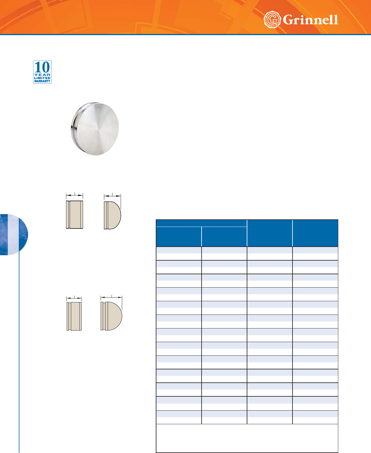
STAINLESS STEEL SYSTEMS
STAINLESS STEEL SYSTEMS
138 www.grinnell.com
Pipe Size Nominal
E to E
Inches
mm
Approx.
Weight
Lbs.
kg
Nominal
Inches
mm
O.D.
Inches
mm
11.3151.080.2
25 33,4 27,5 0,09
11⁄41.660 1.08 0.4
32 42,4 27,5 0,09
11⁄21.900 1.08 0.5
40 48,3 27,5 0,09
22.3751.080.7
50 60,3 27,5 0,09
21⁄22.875 1.08 1.0
65 73,0 27,5 0,45
76,1mm 3.000 2.36 3.1
65 76,1 60,0 1,41
33.5001.082.0
80 88,9 27,5 0,91
44.5001.133.1
100 114,3 28,7 1,41
55.5633.001.5
125 * 141,3 76,2 0,68
66.6253.501.5
150 * 168,3 88,9 0,68
88.6254.003.1
200 * 219,1 101,6 1,41
10 10.750 5.00 6.0
250 * 273,0 127,0 2,72
12 12.750 6.00 7.8
300 * 323,9 152,4 3,54
* Dished Cap
For information on larger sizes, contact GRINNELL Mechanical Products.
Schedule 40 fittings available upon request, contact GRINNELL Mechanical Products.
See page 133 for stainless steel fitting specifications.
Figure 460A
Full-Flow End Cap
Figure 460
Fabricated End Cap
5" - 12"
(125 - 300mm)
5" - 12"
(125 - 300mm)
1" - 4"
(25 - 100mm)
1" - 4"
(25 - 100mm)
E to E E to E
E to E
E to E
Figure 460 End Caps
Tech Data Sheet: G570
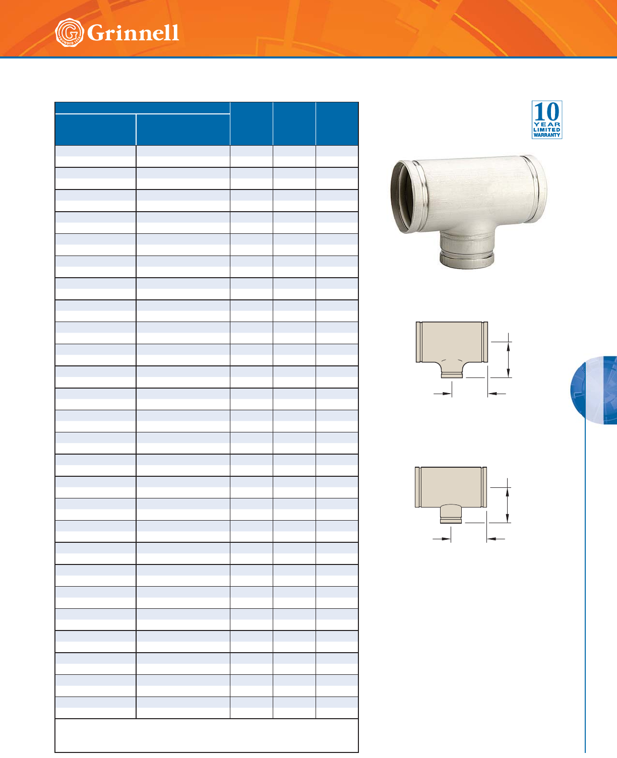
STAINLESS STEEL SYSTEMS
STAINLESS STEEL SYSTEMS
139
Refer to back cover for country-specific customer care numbers.
Pipe Size C to E
Inches
mm
C to B
Inches
mm
Approx.
Weight
Lbs.
kg
Nominal
Inches
mm
O.D.
Inches
mm
11⁄2 x 11⁄2 x 1 1.900 x 1.900 x 1.315 3.38 3.38 1.6
40 x 40 x 25 48,3 x 48,3 x 33,4 85,9 85,9 0,73
11⁄2 x 11⁄2 x 11⁄41.900 x 1.900 x 1.660 3.38 3.38 1.6
40 x 40 x 32 48,3 x 48,3 x 42,4 85,9 85,9 0,73
2 x 2 x 1 2.375 x 2.375 x 1.315 3.25 3.38 2.2
50 x 50 x 25 60,3 x 60,3 x 33,4 82,6 69,9 1,00
2 x 2 x 11⁄42.375 x 2.375 x 1.660 3.25 3.25 2.4
50 x 50 x 32 60,3 x 60,3 x 42,4 82,6 82,6 1,09
2 x 2 x 11⁄22.375 x 2.375 x 1.900 2.75 2.75 2.4
50 x 50 x 40 60,3 x 60,3 x 48,3 69,9 69,9 1,09
21⁄2 x 21⁄2 x 1 2.375 x 2.375 x 1.315 3.75 3.75 3.1
50 x 50 x 40 60,3 x 60,3 x 33,4 95,3 95,3 1,41
21⁄2 x 21⁄2 x 11⁄22.375 x 2.375 x 1.900 3.75 3.75 3.4
50 x 50 x 40 60,3 x 60,3 x 48,3 95,3 95,3 1,54
21⁄2 x 21⁄2 x 2 2.375 x 2.375 x 2.375 3.07 3.07 3.6
50 x 50 x 40 60,3 x 60,3 x 60,3 78,0 78,0 1,63
3 x 3 x 1 3.500 x 3.500 x 1.315 4.25 4.25 4.3
80 x 80 x 25 88,9 x 88,9 x 33,4 108,0 108,0 1,95
3 x 3 x 11⁄43.500 x 3.500 x 1.660 4.25 4.25 4.3
80 x 80 x 32 88,9 x 88,9 x 42,2 108,0 108,0 1,95
3 x 3 x 11⁄23.500 x 3.500 x 1.900 4.25 4.25 4.4
80 x 80 x 40 88,9 x 88,9 x 48,3 108,0 108,0 2,00
3 x 3 x 2 3.500 x 3.500 x 2.375 3.77 3.23 4.4
80 x 80 x 50 88,9 x 88,9 x 60,3 95,8 82,0 2,00
3 x 3 x 21⁄23.500 x 3.500 x 2.875 3.77 3.23 4.4
80 x 80 x 65 88,9 x 88,9 x 73,0 95,8 82,0 2,00
4 x 4 x 2 4.500 x 4.500 x 2.375 4.47 3.82 4.4
100 x 100 x 50 114,3 x 114,3 x 60,3 113,5 97,0 2,00
4 x 4 x 21⁄24.500 x 4.500 x 2.875 5.00 5.00 4.4
100 x 100 x 65 114,3 x 114,3 x 73,0 113,5 113,5 2,00
4 x 4 x 3 4.500 x 4.500 x 3.500 4.47 3.38 4.9
100 x 100 x 80 114,3 x 114,3 x 88,9 113,5 69,9 2,22
6 x 6 x 11⁄26.625 x 6.625 x 1.900 5.91 5.91 9.3
150 x 150 x 40 168,3 x 168,3 x 48,3 150,1 150,1 4,22
6 x 6 x 2 6.625 x 6.625 x 2.375 5.91 5.91 9.3
150 x 150 x 50 168,3 x 168,3 x 88,9 150,1 150,1 4,22
6 x 6 x 3 6.625 x 6.625 x 3.500 5.91 4.88 9.3
150 x 150 x 80 168,3 x 168,3 x 60,3 150,1 124,0 4,22
6 x 6 x 4 6.625 x 6.625 x 4.500 5.91 5.12 9.3
150 x 150 x 100 168,3 x 168,3 x 114,3 150,1 130,0 4,22
8 x 8 x 4 8.625 x 8.625 x 4.500 7.79 6.31 18.1
200 x 200 x 100 219,1 x 219,1 x 114,1 197,9 160,3 8,21
8 x 8 x 6 8.625 x 8.625 x 6.625 7.79 6.62 18.1
200 x 200 x 150 219,1 x 219,1 x 168,3 197,9 168,1 8,21
10 x 10 x 6 10.750 x 10.750 x 6.625 8.89 7.70 29.3
250 x 250 x 150 273,0 x 273,0 x 168,3 225,8 195,6 13,29
10 x 10 x 8 10.750 x 10.750 x 8.625 8.89 8.59 31.7
250 x 250 x 200 273,0 x 273,0 x 219,1 225,8 218,2 14,38
12 x 12 x 8 12.750 x 12.750 x 8.625 10.39 9.51 44.0
300 x 300 x 200 323,9 x 323,9 x 219,1 263,9 242,0 19,96
12 x 12 x 10 12.750 x 12.750 x 10.750 10.39 9.89 44.0
300 x 300 x 250 323,9 x 323,9 x 273,0 263,9 251,2 19,96
For information on larger sizes, contact GRINNELL Mechanical Products.
Schedule 40 fittings available upon request, contact GRINNELL Mechanical Products.
See page 133 for stainless steel fitting specifications.
C to B
C to E
Figure 450
Fabricated Reducing Tee
Figure 421A
Full-Flow Reducing Tee
C to B
C to E
Figure 421 Reducing Tees
Tech Data Sheet: G570
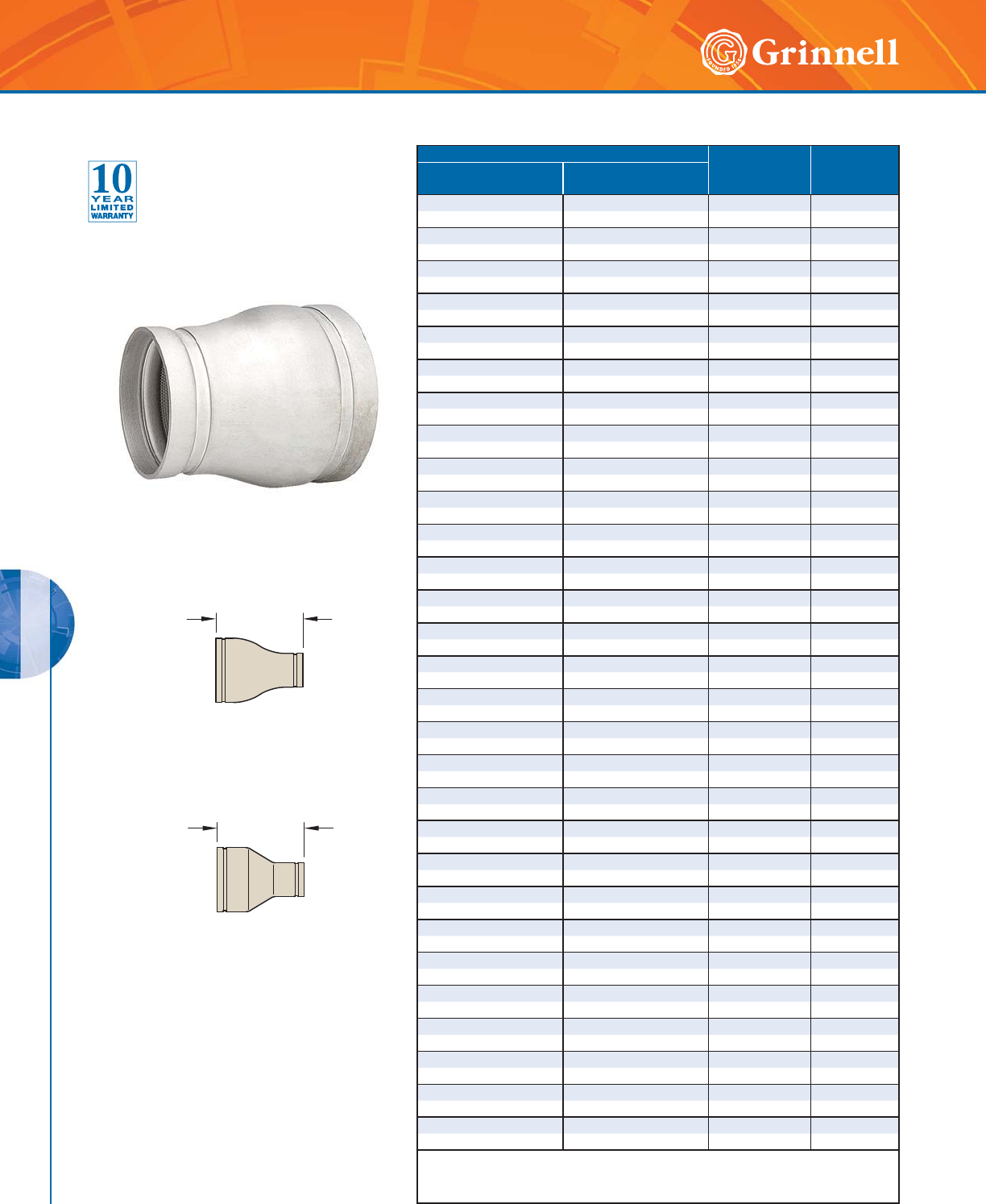
STAINLESS STEEL SYSTEMS
STAINLESS STEEL SYSTEMS
140 www.grinnell.com
Pipe Size E to E
Inches mm
Approx.
Weight
Lbs. kg
Nominal
Inches mm
O.D.
Inches mm
11⁄2 x 1 1.900 x 1.315 3.75 1.4
40 x 25 48,3 x 33,7 95,3 0,64
11⁄2 x 11⁄41.900 x 1.660 3.75 1.4
40 x 32 48,3 x 42,4 95,3 0,64
2 x 1 2.375 x 1.315 3.75 1.5
50 x 25 60,3 x 33,7 95,3 0,68
2 x 11⁄42.375 x 1.660 3.75 2.5
50 x 32 60,3 x 42,4 95,3 1,13
2 x 11⁄22.375 x 1.900 5.00 2.5
50 x 40 60,3 x 48,3 127,0 1,13
21⁄2 x 11⁄22.875 x 1.900 5.00 3.5
65 x 40 73,0 x 48,3 127,0 1,59
21⁄2 x 2 2.875 x 2.375 5.00 3.5
65 x 50 73,0 x 60,3 127,0 1,59
3 x 1 3.500 x 1.315 5.00 4.0
80 x 25 88,9 x 33,7 127,0 1,81
3 x 11⁄43.500 x 1.660 5.00 4.3
80 x 32 88,9 x 42,4 127,0 1,95
3 x 11⁄23.500 x 1.900 5.00 4.4
80 x 40 88,9 x 48,3 127,0 2,00
3 x 2 3.500 x 2.375 5.00 4.8
80 x 50 88,9 x 60,3 127,0 2,17
3 x 21⁄23.500 x 2.875 5.00 4.8
80 x 65 88,9 x 73,0 127,0 2,17
4 x 2 4.500 x 2.375 5.00 4.8
100 x 50 114,3 x 60,3 127,0 2,17
4 x 21⁄24.500 x 2.875 5.00 4.8
100 x 65 114,3 x 73,0 127,0 2,17
4 x 3 4.500 x 3.500 5.00 5.0
100 x 80 114,3 x 88,9 127,0 2,27
5 x 3 5.563 x 3.500 9.00 7.0
125 x 80 141,3 x 88,9 228,6 3,18
5 x 4 5.563 x 4.500 9.00 7.0
125 x 100 141,3 x 114,3 228,6 3,18
6 x 2 6.625 x 2.375 9.00 7.0
150 x 50 168,3 x 60,3 228,6 3,18
6 x 21⁄26.625 x 2.875 15.00 7.0
150 x 65 168,3 x 73,0 381,0 3,18
6 x 3 6.625 x 3.500 5.50 6.9
150 x 80 168,3 x 88,9 139,7 3,13
6 x 4 6.625 x 4.500 5.50 7.0
150 x 100 168,3 x 114,3 139,7 3,18
8 x 4 8.625 x 4.500 6.00 9.6
200 x 100 219,1 x 114,3 152,4 4,35
8 x 6 8.625 x 6.625 6.00 9.6
200 x 150 219,1 x 168,3 152,4 4,35
10 x 4 10.750 x 4.500 10.00 12.4
250 x 100 273,0 x 114,3 254,0 5,62
10 x 6 10.750 x 6.625 7.00 12.4
250 x 150 273,0 x 168,3 177,8 5,62
10 x 8 10.750 x 8.625 7.00 14.9
250 x 200 273,0 x 219,1 177,8 6,76
12 x 6 12.750 x 6.625 14.00 22.0
300 x 150 323,9 x 168,3 355,6 9,98
12 x 8 12.750 x 8.625 14.00 22.0
300 x 200 323,9 x 219,1 355,6 9,98
12 x 10 12.750 x 10.750 14.00 26.0
300 x 250 323,9 x 273,0 355,6 11,79
For information on larger sizes, contact GRINNELL Mechanical Products.
Schedule 40 fittings available upon request, contact GRINNELL Mechanical Products.
See page 133 for stainless steel fitting specifications.
E to E
E to E
Figure 450
Fabricated Concentric Reducer
Figure 450A
Full-Flow Concentric Reducer
Figure 450 Concentric Reducers
Tech Data Sheet: G570
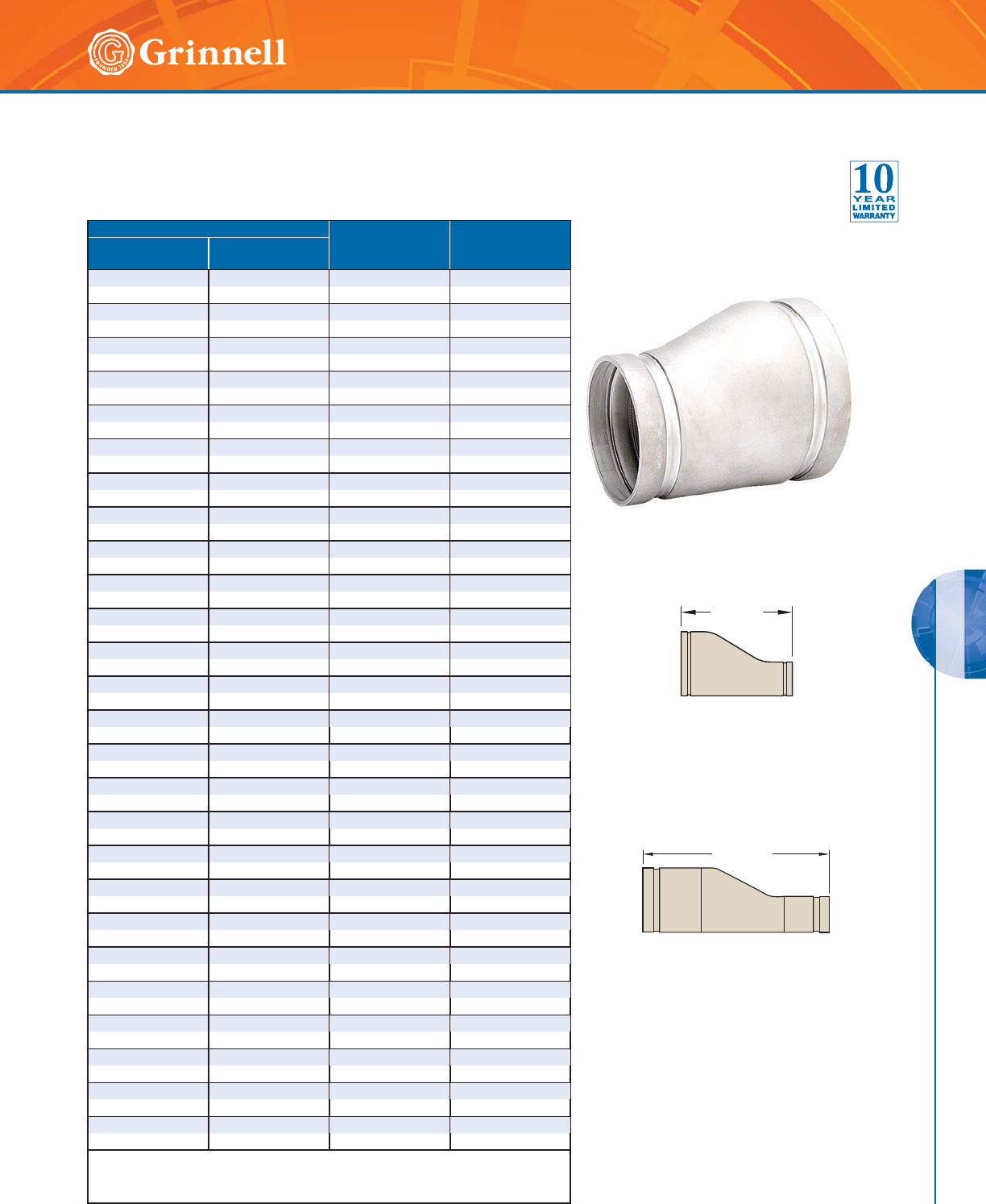
STAINLESS STEEL SYSTEMS
STAINLESS STEEL SYSTEMS
141
Refer to back cover for country-specific customer care numbers.
Pipe Size E to E
Inches mm
Approx.
Weight
Lbs. kg
Nominal
Inches mm
O.D.
Inches mm
11⁄2 x 1 1.900 x 1.315 3.75 1.4
40 x 25 48,3 x 33,7 95,3 0,64
11⁄2 x 11⁄41.900 x 1.660 3.75 1.4
40 x 32 48,3 x 42,4 95,3 0,64
2 x 1 2.375 x 1.315 3.75 1.5
50 x 25 60,3 x 33,7 95,3 0,68
2 x 11⁄42.375 x 1.660 3.75 2.5
50 x 32 60,3 x 42,4 95,3 1,13
2 x 11⁄22.375 x 1.900 5.00 2.5
50 x 40 60,3 x 48,3 127,0 1,13
21⁄2 x 2 2.875 x 2.375 5.00 3.5
65 x 50 73,0 x 60,3 127,0 1,59
3 x 1 3.500 x 1.315 5.00 4.3
80 x 25 88,9 x 33,4 127,0 1,95
3 x 2 3.500 x 2.375 5.00 4.3
80 x 50 88,9 x 60,3 127,0 1,95
3 x 21⁄23.500 x 2.875 5.00 4.5
80 x 65 88,9 x 73,0 127,0 1,95
4 x 2 4.500 x 2.375 5.00 4.8
100 x 50 114,3 x 60,3 127,0 2,18
4 x 21⁄24.500 x 2.875 5.00 5.8
100 x 65 114,3 x 73,0 127,0 2,63
4 x 3 4.500 x 3.500 5.00 5.9
100 x 80 114,3 x 88,9 127,0 2,68
5 x 3 5.563 x 3.500 9.00 5.9
125 x 80 141,3 x 88,9 228,6 2,68
5 x 4 5.563 x 4.500 9.00 7.0
125 x 100 141,3 x 114,3 228,6 3,18
6 x 2 6.625 x 2.375 9.00 7.0
150 x 50 168,3 x 60,3 228,6 3,17
6 x 21⁄26.625 x 2.875 9.00 7.0
150 x 65 168,3 x 73,0 228,6 3,17
6 x 3 6.625 x 3.500s 9.00 7.0
150 x 80 168,3 x 88,9 228,6 3,18
6 x 4 6.625 x 4.500 5.00 7.0
150 x 100 168,3 x 114,3 127,0 3,18
8 x 3 8.625 x 3.500 10.00 9.3
200 x 80 219,1 x 88,9 254,0 4,22
8 x 4 8.625 x 4.500 12.00 9.3
200 x 100 219,1 x 114,3 304,8 4,22
8 x 6 8.625 x 6.625 8.00 7.0
200 x 150 219,1 x 168,3 203,2 3,18
10 x 6 10.750 x 6.625 13.00 12.4
250 x 150 273,0 x 168,3 330,2 5,62
10 x 8 10.750 x 8.625 13.00 11.5
250 x 200 273,0 x 219,1 330,2 5,22
12 x 6 12.750 x 6.625 14.00 21.1
300 x 150 323,9 x 168,3 355,6 9,57
12 x 8 12.750 x 8.625 14.00 21.1
300 x 200 323,9 x 219,1 355,6 9,57
12 x 10 12.750 x 10.750 14.00 21.1
300 x 250 323,9 x 273,0 355,6 9,57
For information on larger sizes, contact GRINNELL Mechanical Products.
Schedule 40 fittings available upon request, contact GRINNELL Mechanical Products.
See page 133 for stainless steel fitting specifications.
E to E
Figure 451
Fabricated Eccentric Reducer
Figure 451A
Full-Flow Eccentric Reducer
E to E
Figure 451 Eccentric Reducers
Tech Data Sheet: G570
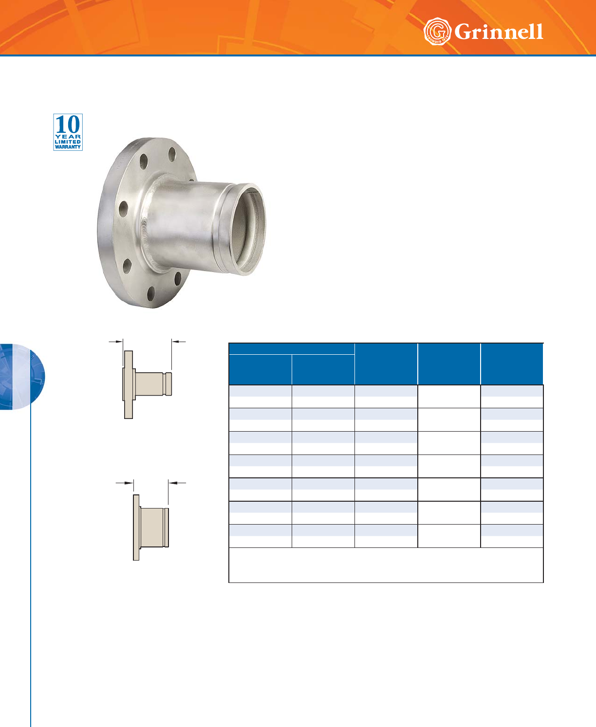
STAINLESS STEEL SYSTEMS
STAINLESS STEEL SYSTEMS
142 www.grinnell.com
Pipe Size E to E
Inches
mm
Mating Flange
Bolt
Qty.
Approx. Weight
Lbs.
kg
Nominal
Inches
mm
O.D.
Inches
mm
22.3754.00 46.4
50 60,3 101,6 2,8
21⁄22.875 4.00 48.8
65 73,0 101,6 4,0
3 3.500 4.00 410.4
80 88,9 101,6 4,7
4 4.500 6.00 818.2
100 114,3 152,4 8,3
55.5636.00 822.0
125 141,3 152,4 10,0
66.6256.00 828.1
150 168,3 152,4 12,7
88.6256.00 843.7
200 219,1 152,4 19,8
For information on larger sizes or PN16 sizes, contact GRINNELL Mechanical Products.
Schedule 40 fittings available upon request, contact GRINNELL Mechanical Products.
See page 133 for stainless steel fitting specifications.
E to E
Figure 441
Fabricated Flange Adapter
Figure 441A
Full-Flow Flange Adapter
E to E
Figure 441 Flange Adapters
(ANSI Class 150#)
Tech Data Sheet: G568
143
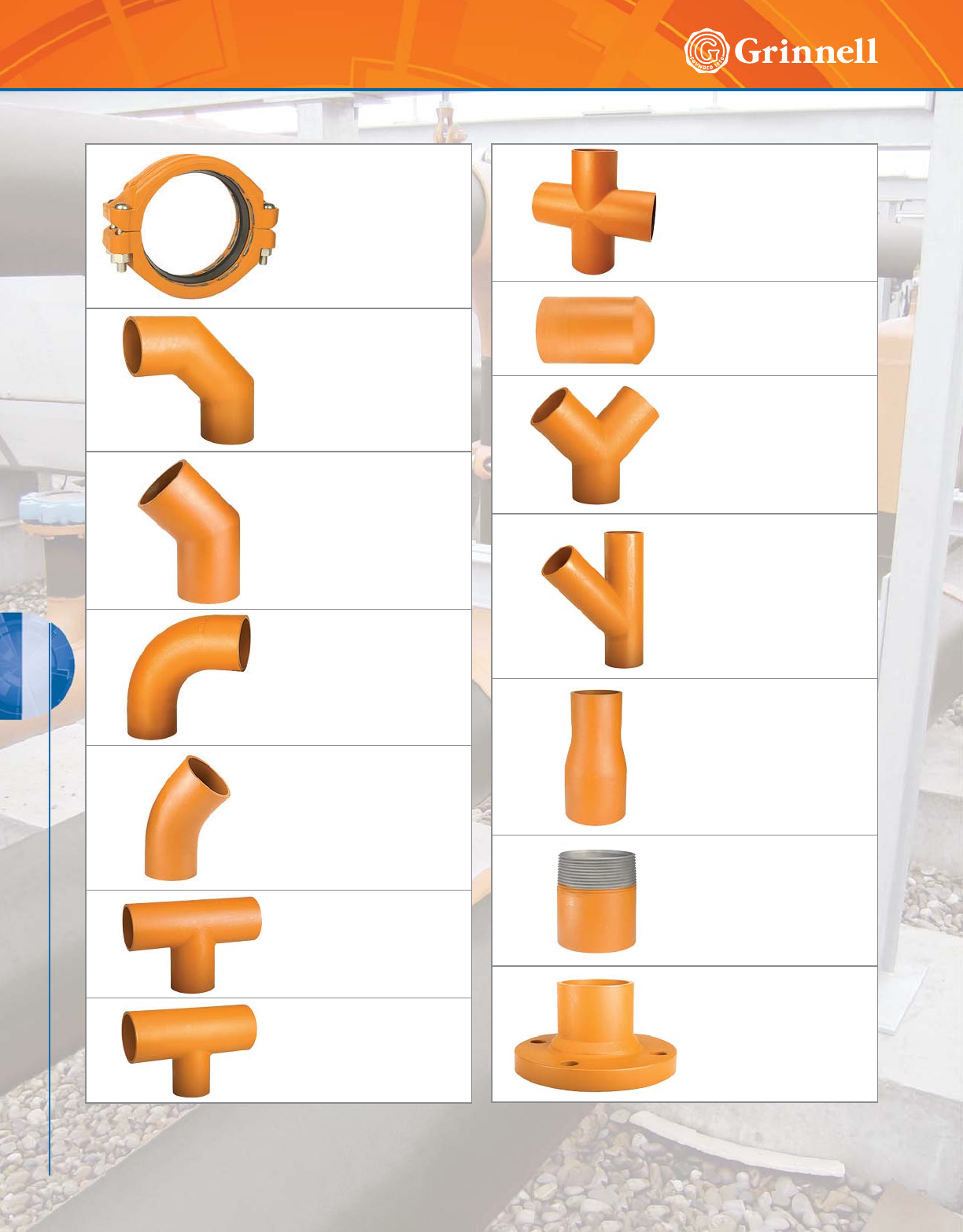
PLAIN END SYSTEMS
144 www.grinnell.com
PLAIN END SYSTEMS
Figure 909
Plain End Couplings
Page 146
Figure 910
Plain End 90° Elbows
Page 147
Figure 901
Plain End 45° Elbows
Page 147
Figure 910LR
Plain End Long Radius
90° Elbows
Page 148
Figure 901LR
Plain End Long Radius
45° Elbows
Page 148
Figure 919
Plain End Tees
Page 149
Figure 921
Plain End Reducing Tees
Page 149
Figure 927
Plain End Crosses
Page 150
Figure 960
Plain End Caps
Page 150
Figure 924
Plain End True Wyes
Page 151
Figure 914
Plain End Laterals
Page 151
Figure 999
Plain End Swaged Nipples
Page 152
Figures 991, 992 & 993
Plain End Adapter Nipples
Page 153
Figure 941 & 942
Plain End Flange Adapters
Page 154
Plain End Systems Table of Contents

PLAIN END SYSTEMS
PLAIN END SYSTEMS
145
Refer to back cover for country-specific customer care numbers.
The GRINNELL Plain End Piping System is designed for use in both maintenance and new system applications and
eliminates the need for pipe end preparation. The GRINNELL Figure 909 Plain End Coupling features case-hardened gripping
teeth that securely grip onto the pipe surface. The coupling is designed for schedule 40 steel pipe and is not for use with steel
pipe with a Brinell hardness greater than 150 HB, nor is it switchable for plastic pipe, cast, or ductile iron pipe.
Contact GRINNELL Mechanical Products about other materials and pipe schedules. Follow bolt torque ratings to ensure a
properly assembled coupling.
Coupling Ductile Iron Housing
Specifications
• ASTM A 536 – Standard specification for ductile iron
castings, Grade 65-45-12
• Tensile strength, minimum 65,000 psi (4481,6 bar)
• Yield strength, minimum 45,000 psi (3102,6 bar)
• Elongation in 2" (50mm), minimum 12%
• ASTM A 153 – Standard specification for hot-dipped
galvanizing
Coatings
• Orange – Non-lead paint (standard)
• Red – Non-lead paint (optional, regional)
• Hot-Dipped, Zinc galvanized (optional)
Bolt/Nut Specifications
• ANSI: Carbon steel oval neck bolts and nuts are heat-
treated and conform to the physical properties of ASTM
A 183 Grade 2 and SAE J429 Grade 5 with a minimum
tensile strength of 110,000 psi (7584.2 bar).
Carbon Steel heavy hex nuts conform to the physical
properties of ASTM A 183 Grade 2 and SAE J995
Grade 5. Bolts and nuts are zinc-electroplated
conforming to ASTM B 633.
• Metric: Carbon steel oval neck track head bolts (Gold
color coded) are heat treated and conform to the physical
properties of ASTM F 568 M with a minimum tensile
strength of 760 MPa.
Carbon Steel heavy hex nuts conform to the physical
properties of ASTM A 563 M Class 9. Bolts and nuts are
zinc-electroplated conforming to ASTM B 633.
• Stainless steel bolts and nuts are available upon request.
Gasket Specifications
• Grade “E” EPDM gaskets have a Green color code
identification and conform to ASTM D 2000 for service
temperatures from -30°F to 230°F (-34°C to 110°C). They
are recommended for hot water not to exceed 230°F
(110°C), plus a variety of dilute acids, oil free air, and
many chemical services. They are not recommended for
petroleum services. For low temperature and vacuum
systems, a Tri-Seal Grade “E” EPDM gasket with rigid
coupling is recommended.
• Grade “T” Nitrile gaskets have an Orange color code
identification and conform to ASTM D 2000 for service
temperatures from -20°F to 180°F (-29°C to 82°C). They
are recommended for petroleum products, vegetable oils,
mineral oils, and air with oil vapors.
Fitting Specifications
• Carbon steel: according to ASTM A 53, Grade B
• Tensile strength, minimum 60,000 psi (4136,9 bar)
• Yield strength, minimum 35,000 psi (2413,2 bar)
• Sizes 11⁄4" – 10" (32mm – 250mm) – Schedule 40
• Sizes 12" – 24" (300mm – 600mm) – Std. Wall (0.375)
Coatings
• Orange – Non-lead paint (standard)
• Red – Non-lead paint (optional, regional)
• Hot-Dipped, Zinc galvanized (optional)
MATERIAL SPECIFICATIONS
Fitting Specifications
Tech Data Sheet: G192
Coupling Specifications
Tech Data Sheet: G190
Plain end fittings are manufactured to provide minimum
pressure drop and uniform flow. Fittings are designed for use
with the Figure 909 Plain End Couplings only.
Plain end fittings are available in a variety of styles.
Fitting dimensions may vary, contact GRINNELL Mechanical
Products.
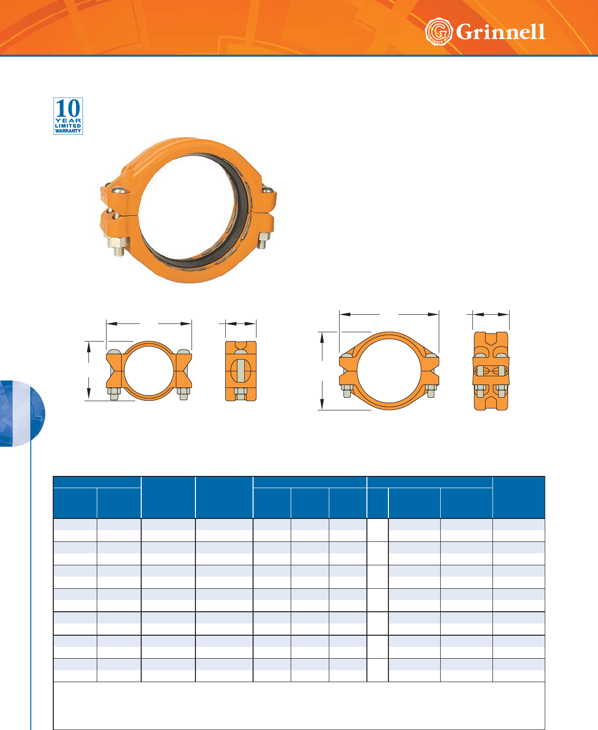
PLAIN END SYSTEMS
PLAIN END SYSTEMS
146 www.grinnell.com
The GRINNELL Figure 909 Plain End Coupling utilizes
hardened gripping teeth to securely grip onto plain and
beveled end pipe surfaces. It is capable of pressures up
to 750 psi (51,7 bar) depending on pipe size and wall
thickness.
The GRINNELL Figure 909 Plain End Coupling is designed
for Schedule 40 steel pipe and is not for use with steel
pipe with a Brinnell hardness greater than 150 HB, plastic,
cast, or ductile iron pipes. Contact GRINNELL Mechanical
Products for recommendations on other materials and pipe
schedules.
Pipe Size Max.†
Pressures
psi
bar
Max.†
End Load
Lbs.
kN
Dimensions - Inches mm Coupling Bolts Approx.
Weight
Lbs.
kg
Nominal
Inches
mm
O.D.
Inches
mm
AB C Qty.
Size
Inches
mm
Bolt Torque
Lbs.-ft
Nm
2 2.375 750 3322.6 3.69 5.75 3.31 2
5⁄8 x 31⁄2150 5.4
50 60,3 51,7 14,78 93,7 146,1 84,1 M16 x 90 203,0 2,4
21⁄22.875 600 3895.1 4.17 6.25 3.31 2
5⁄8 x 31⁄2150 5.9
65 73,0 41,4 17,33 105,9 158,8 84,1 M16 x 90 203,0 2,7
3 3.500 600 5772.7 4.81 7.56 3.31 2
3⁄4 x 43⁄4200 9.0
80 88,9 41,4 25,68 122,2 192,0 84,1 M20 x 121 271,0 4,1
4 4.500 450 7,156.9 5.93 8.63 3.88 2
3⁄4 x 43⁄4200 13.5
100 114,3 31 31,83 150,6 219,2 98,6 M20 x 121 271,0 6,1
6 6.625 300 10,341.5 8.19 11.68 4.25 21 x 61⁄2250 23.5
150 168,3 20,7 46,00 208,0 296,7 108,0 M24 x 165 339,0 10,7
8 8.625 250 14,606.6 10.69 13.63 4.91 4
7⁄8 x 51⁄2250 35.1
200 219,1 17,2 64,97 271,5 346,2 124,7 M22 x 140 339,0 15,9
10 10.750 250 22,690.6 13.13 15.88 4.91 4
7⁄8 x 51⁄2300 48.5
250 273,0 17,2 100,93 333,5 403,4 124,7 M22 x 140 407,0 22,0
† Maximum Pressure and End Load are total from all loads based on standard weight steel pipe.
Pressure ratings and end loads may differ for other pipe materials and/or wall thickness. Contact GRINNELL Mechanical Products for details.
For information on additional sizes or larger sizes, contact GRINNELL Mechanical Products.
See page 145 for plain end coupling specifications and pages 191 - 198 for gasket information.
2" - 6" (50mm - 150mm) (2 Bolts) 8" - 10" (200mm - 250mm) (4 Bolts)
B
CC
B
A A
Figure 909 Plain End Couplings
Tech Data Sheet: G190
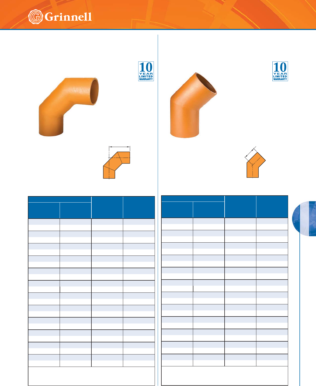
PLAIN END SYSTEMS
PLAIN END SYSTEMS
147
Refer to back cover for country-specific customer care numbers.
Pipe Size C to E
Inches
mm
Approx.
Weight
Lbs.
kg
Nominal
Inches
mm
O.D.
Inches
mm
2 2.375 4.75 1.8
50 60,3 120,7 0,8
21⁄22.875 5.50 3.1
65 73,0 139,7 1,4
76,1mm 3.000 5.50 3.2
65 76,1 139,7 1,5
33.5006.254.8
80 88,9 158,8 2,2
4 4.50 0 7.75 7.5
100 114,3 196,9 3,4
139,7mm 5.500 9.75 11.3
125 139,7 248,0 5,1
5 5.563 9.75 11.6
125 141,3 248,0 5,3
165,1mm 6.500 10.00 16.9
150 165,1 254,0 7,7
6 6.625 10.00 16.6
150 168,3 254,0 7,5
8 8.625 11.00 29.6
200 219,1 279,4 13,4
10 10.750 11.50 48.5
250 273,0 292,1 22,0
12 12.750 13.50 66.4
300 323,9 342,9 30,1
For information on larger sizes, contact GRINNELL
Mechanical Products.
See page 145 for plain end fitting specifications.
Pipe Size C to E
Inches
mm
Approx.
Weight
Lbs.
kg
Nominal
Inches
mm
O.D.
Inches
mm
22.3753.131.3
50 60,3 79,5 0,6
21⁄22.875 3.50 2.1
65 73,0 88,9 1,0
76,1mm 3.000 3.50 2.2
65 76,1 88,9 1,0
3 3.500 3.75 3.5
80 88,9 95,3 1,6
44.5004.255.5
100 114,3 108,0 2,5
139,7mm 5.500 5.00 7.7
125 139,7 127,0 3,5
55.5635.008.1
125 141,3 127,0 3,7
165,1mm 6.500 5.75 11.0
150 165,1 146,1 5,0
66.6255.7511.2
150 168,3 146,1 5,1
8 8.625 6.00 19.0
200 219,1 152,4 8,6
10 10.750 6.50 28.0
250 273,0 165,1 12,7
12 12.750 7.00 48.0
300 323,9 177,8 22,0
For information on larger sizes, contact GRINNELL
Mechanical Products.
See page 145 for plain end fitting specifications.
C to E C to E
Figure 910 90°
Plain End Elbows
Tech Data Sheet: G192
Figure 901 45°
Plain End Elbows
Tech Data Sheet: G192
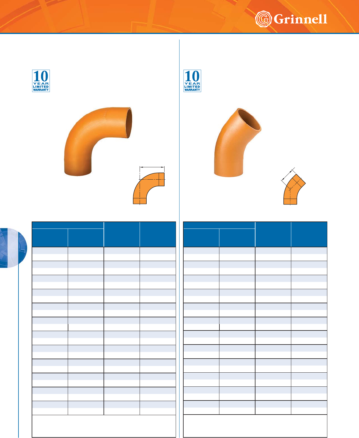
PLAIN END SYSTEMS
PLAIN END SYSTEMS
148 www.grinnell.com
Pipe Size C to E
Inches
mm
Approx.
Weight
Lbs.
kg
Nominal
Inches
mm
O.D.
Inches
mm
22.3753.131.8
50 60,3 79,5 0,8
21⁄22.875 3.50 2.9
65 73,0 88,9 1,3
76,1mm 3.000 3.50 3.1
65 76,1 88,9 1,4
33.5003.754.6
80 88,9 95,3 2,1
44.5004.507.5
100 114,3 114,3 3,4
139,7mm 5.500 5.00 12.5
125 139,7 127,0 5,7
5 5.563 5.00 12.5
125 141,3 127,0 5,7
165,1mm 6.500 5.88 12.0
150 165,1 149,4 5,4
6 6.625 5.88 12.0
150 168,3 149,4 5,4
8 8.625 7.13 34.0
20 0 219,1 181,1 15,4
10 10.750 8.38 56.0
250 273,0 212,9 25,4
12 12.750 9.36 98.0
300 323,9 244,6 44,5
For information on larger sizes, contact GRINNELL
Mechanical Products.
See page 145 for plain end fitting specifications.
Pipe Size C to E
Inches
mm
Approx.
Weight
Lbs.
kg
Nominal
Inches
mm
O.D.
Inches
mm
22.3754.252.7
50 60,3 108,0 1,2
21⁄22.875 5.50 4.2
65 73,0 139,7 1,9
76,1mm 3.000 5.50 4.4
65 76,1 139,7 2,0
3 3.500 6.25 6.5
80 88,9 158,8 2,9
4 4.500 8.00 11.5
100 114,3 203,3 5,2
139,7mm 5.500 9.75 19.0
125 139,7 248,0 8,6
55.5639.7519.4
125 141,3 248,0 8,8
165,1mm 6.500 11.13 26.4
150 165,1 282,7 12,0
66.62511.1327.9
150 168,3 282,7 12,6
88.62514.1354.5
200 219,1 358,9 24,7
10 10.750 17.13 103.7
250 273,0 435,1 47,0
12 12.750 20.13 147.8
300 323,9 511,3 67,0
For information on larger sizes, contact GRINNELL
Mechanical Products.
See page 145 for plain end fitting specifications.
C to E C to E
Figure 910LR 90° Plain End
Long Radius Elbows
Tech Data Sheet: G192
Figure 901LR 45° Plain End
Long Radius Elbows
Tech Data Sheet: G192
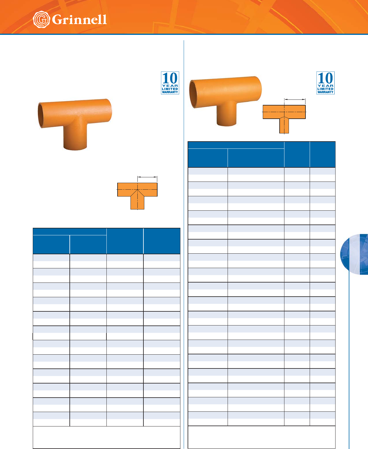
PLAIN END SYSTEMS
PLAIN END SYSTEMS
149
Refer to back cover for country-specific customer care numbers.
Pipe Size C to E
Inches
mm
Approx.
Weight
Lbs.
kg
Nominal
Inches
mm
O.D.
Inches
mm
22.3753.252.7
50 60,3 82,6 1,2
21⁄22.875 3.75 4.4
65 73,0 95,3 2,0
76,1mm 3.000 3.75 6.5
65 76,1 95,3 2,9
33.5004.256.5
80 88,9 108,0 2,9
4 4.500 5.00 10.7
100 114,3 127,0 4,8
139,7mm 5.500 5.50 15.2
125 139,7 139,7 6,9
5 5.563 5.50 15.5
125 141,3 139,7 7,0
165,1mm 6.500 6.50 24.2
150 165,1 165,1 11,0
6 6.625 6.50 23.0
150 168,3 165,1 10,4
8 8.625 10.00 43.7
200 219,1 254,0 19,8
10 10.750 11.50 57.0
250 273,0 292,1 25,9
12 12.750 13.50 110.0
300 323,9 342,9 49,9
For information on larger sizes, contact GRINNELL
Mechanical Products.
See page 145 for plain end fitting specifications.
Pipe Size C to E
Inches
mm
Approx.
Weight
Lbs.
kg
Nominal
Inches
mm
O.D.
Inches
mm
3 x 3 x 2 3.500 x 3.500 x 2.375 5.13 7.1
80 x 80 x 50 88,9 x 88,9 x 60,3 130,3 3,2
4 x 4 x 2 4.500 x 4.500 x 2.375 5.88 9.1
100 x 100 x 50 114,3 x 114,3 x 60,3 149,4 4,1
4 x 4 x 21⁄24.500 x 4.500 x 2.875 5.88 9.5
100 x 100 x 65 114,3 x 114,3 x 73,0 149,4 4,3
4 x 4 x 3 4.500 x 4.500 x 3.500 5.88 9.7
100 x 100 x 80 114,3 x 114,3 x 88,9 149,4 4,4
6 x 6 x 2 6.625 x 6.625 x 2.375 7.63 19.4
150 x 150 x 50 168,3 x 168,3 x 60,3 193,8 8,8
6 x 6 x 3 6.625 x 6.625 x 3.500 7.63 21.0
150 x 150 x 80 168,3 x 168,3 x 88,9 193,8 9,5
6 x 6 x 4 6.625 x 6.625 x 4.500 7.63 21.8
150 x 150 x 100 168,3 x 168,3 x 114,3 193,8 9,9
8 x 8 x 2 8.625 x 8.625 x 2.375 10.00 36.2
200 x 200 x 50 219,1 x 219,1 x 60,3 254,0 16,4
8 x 8 x 3 8.625 x 8.625 x 3.500 10.00 36.5
200 x 200 x 80 219,1 x 219,1 x 88,9 254,0 16,6
8 x 8 x 4 8.625 x 8.625 x 4.500 10.00 37.2
200 x 200 x 100 219,1 x 219,1 x 114,1 254,0 16,9
8 x 8 x 5 8.625 x 8.625 x 5.563 10.00 36.8
200 x 200 x 125 219,1 x 219,1 x 141,3 254,0 16,7
8 x 8 x 6 8.625 x 8.625 x 6.625 10.00 37.4
200 x 200 x 150 219,1 x 219,1 x 168,3 254,0 17,0
10 x 10 x 4 10.750 x 10.750 x 4.500 11.50 58.0
250 x 250 x 100 273,0 x 273,0 x 114,3 292,1 26,3
10 x 10 x 6 10.750 x 10.750 x 6.625 11.50 66.0
250 x 250 x 150 273,0 x 273,0 x 168,3 292,1 27,2
10 x 10 x 8 10.750 x 10.750 x 8.625 11.50 62.0
250 x 250 x 200 323,9 x 323,9 x 219,1 292,1 28,1
12 x 12 x 6 12.750 x 12.750 x 6.625 13.50 80.9
250 x 250 x 100 323,9 x 323,9 x 168,3 342,9 36,7
12 x 12 x 8 12.750 x 12.750 x 8.625 13.50 76.3
250 x 250 x 150 323,9 x 323,9 x 219,1 342,9 34,6
12 x 12 x 10 12.750 x 12.750 x 10.750 13.50 77.6
250 x 250 x 200 323,9 x 323,9 x 273,0 342,9 35,2
For information on larger sizes, contact GRINNELL
Mechanical Products.
See page 145 for plain end fitting specifications.
C to E
C to E
Figure 919
Plain End Tees
Tech Data Sheet: G192
Figure 921
Plain End Reducing Tees
Tech Data Sheet: G192
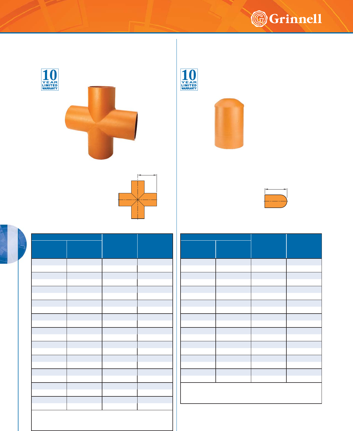
PLAIN END SYSTEMS
PLAIN END SYSTEMS
150 www.grinnell.com
Pipe Size E to E
Inches
mm
Approx.
Weight
Lbs.
kg
Nominal
Inches
mm
O.D.
Inches
mm
22.3754.253.7
50 60,3 108,0 1,7
21⁄22.875 4.75 5.8
65 73,0 120,7 2,6
76,1mm 3.000 4.75 6.0
65 76,1 120,7 2,7
33.5005.138.6
80 88,9 130,3 3,9
44.5005.8820.7
100 114,3 149,4 9,4
5 5.563 6.88 18.5
125 141,3 175,0 8,4
165,1mm 6.500 7.63 27.3
150 165,1 193,8 12,4
6 6.625 7.63 28.6
150 168,3 193,8 13,0
8 8.625 10.00 48.0
200 219,1 254,0 21,7
10 10.750 11.50 75.0
250 273,0 292,1 34,0
12 12.750 13.50 95.8
300 323,9 342,9 43,4
For information on larger sizes, contact GRINNELL
Mechanical Products.
See page 145 for plain end fitting specifications.
Pipe Size E to E
Inches
mm
Approx.
Weight
Lbs.
kg
Nominal
Inches
mm
O.D.
Inches
mm
22.3754.002.3
50 60,3 102,0 1,0
21⁄22.875 5.00 3.0
65 73,0 127,0 1,4
3 3.500 6.00 4.5
80 88,9 152,4 2,0
4 4.500 7.00 7.5
100 114,3 178,0 3,4
5 5.563 8.50 12.5
125 141,3 216,0 5,7
6 6.625 10.00 17.0
150 168,3 254,0 7,7
8 8.625 11.00 29.0
200 219,1 279,4 13,2
10 10.750 13.00 24.5
250 273,0 330,2 11,1
12 12.750 14.00 31.0
300 323,9 355,6 14,1
For information on larger sizes, contact GRINNELL
Mechanical Products.
See page 145 for plain end fitting specifications.
C to E
E to E
Figure 927
Plain End Crosses
Tech Data Sheet: G192
Figure 960
Plain End Caps
Tech Data Sheet: G192
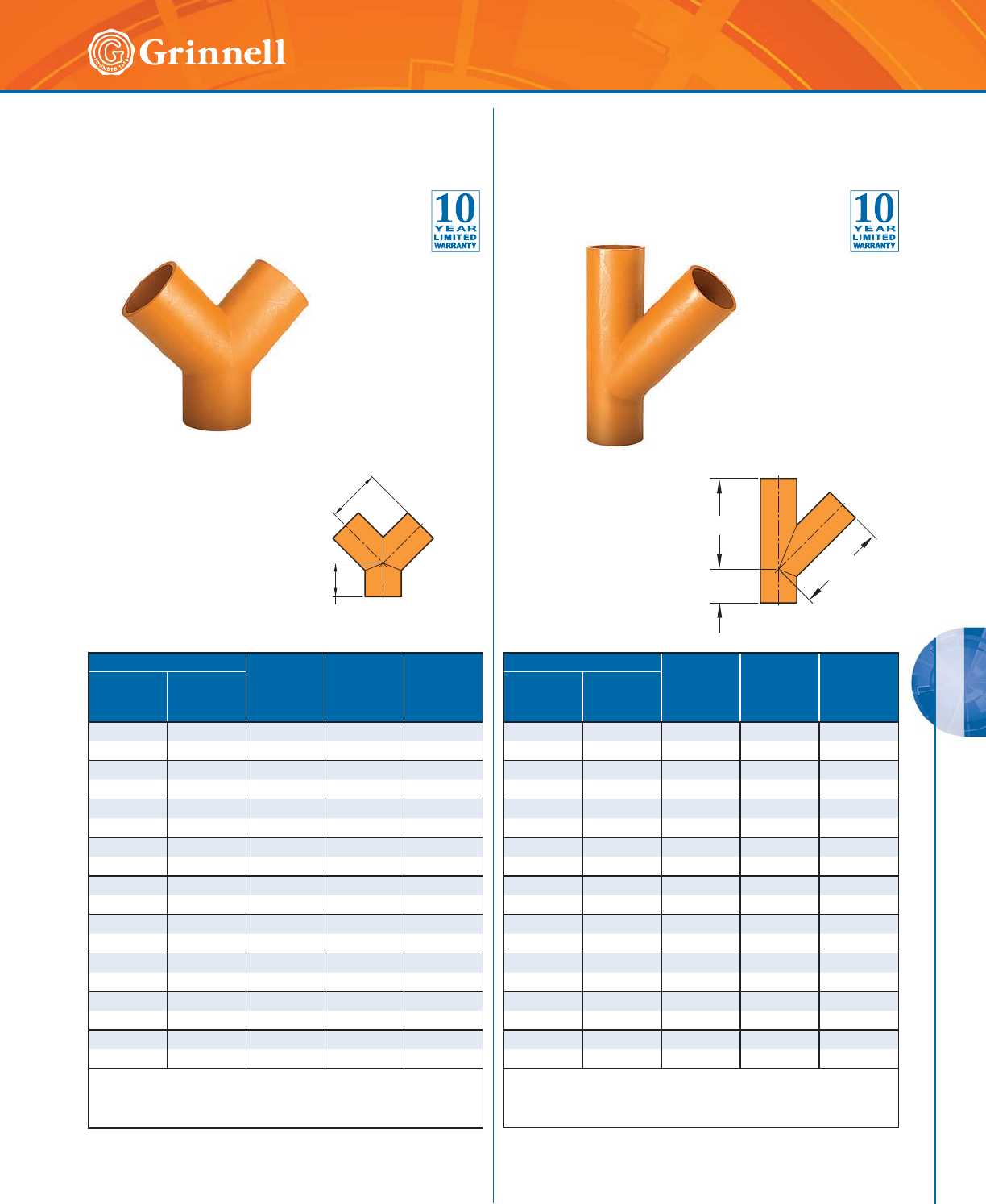
PLAIN END SYSTEMS
PLAIN END SYSTEMS
151
Refer to back cover for country-specific customer care numbers.
Pipe Size C to LE
Inches
mm
C to SE
Inches
mm
Approx.
Weight
Lbs.
kg
Nominal
Inches
mm
O.D.
Inches
mm
2 2.375 4.25 2.75 2.5
50 60,3 108,0 69,9 1,1
21⁄22.875 4.75 3.00 4.4
65 73,0 120,7 76,2 2,0
3 3.500 5.13 3.25 6.4
80 88,9 130,3 82,6 2,9
4 4.500 5.88 3.75 10.5
10 0 114,3 149,4 95,3 4,8
55.5636.884.0015.2
125 141,3 175,0 101,6 6,9
66.6257.634.5022.9
150 168,3 193,8 114,3 10,4
8 8.625 10.00 6.00 41.9
200 219,1 254,0 152,4 19,0
10 10.750 11.50 6.50 66.2
250 273,0 292,1 165,1 30,0
12 12.750 13.50 7.00 87.7
300 323,9 342,9 177,8 39,8
For information on larger sizes, contact GRINNELL
Mechanical Products.
See page 145 for plain end fitting specifications.
Pipe Size C to LE
Inches
mm
C to SE
Inches
mm
Approx.
Weight
Lbs.
kg
Nominal
Inches
mm
O.D.
Inches
mm
2 2.375 7.25 2.75 4.5
50 60,3 184,2 69,9 2,0
21⁄22.875 7.75 3.00 7.7
65 73,0 197,0 76,2 3,5
33.5008.753.2511.0
80 88,9 222,3 82,6 5,0
4 4.500 10.75 3.75 18.7
100 114,3 273,1 95,3 8,5
5 5.563 12.75 4.00 29.4
125 141,3 324,0 101,6 13,3
6 6.625 14.00 4.50 42.2
150 168,3 355,6 114,3 19,1
8 8.625 18.00 6.00 70.9
200 219,1 457,2 152,4 32,2
10 10.750 20.75 6.50 66.2
250 273,0 527,1 165,1 30,0
12 12.750 24.50 7.00 87.7
300 323,9 622,3 177,8 39,8
For information on larger sizes, contact GRINNELL
Mechanical Products.
See page 145 for plain end fitting specifications.
C to SE
C to LE
C to LE
C to SE
C to LE
Figure 924
Plain End True Wyes
Tech Data Sheet: G192
Figure 914
Plain End Laterals
Tech Data Sheet: G192
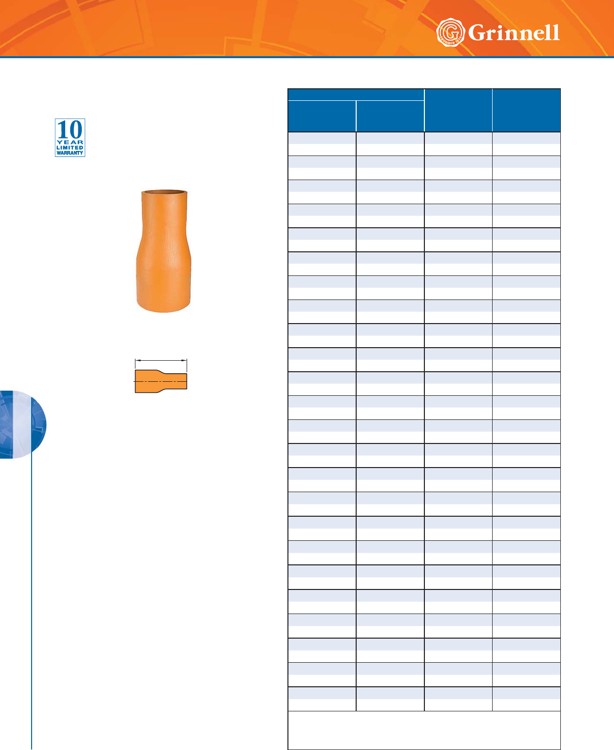
PLAIN END SYSTEMS
PLAIN END SYSTEMS
152 www.grinnell.com
Pipe Size E to E
Inches
mm
Approx.
Weight
Lbs.
kg
Nominal
Inches
mm
O.D.
Inches
mm
21⁄2 x 2 2.875 x 2.375 7.00 3.5
65 x 50 73,0 x 60,3 177,8 1,6
3 x 2 3.500 x 2.375 8.00 5.0
80 x 50 88,9 x 60,3 203,2 2,3
3 x 21⁄23.500 x 2.875 8.00 5.0
80 x 65 88,9 x 73,0 203,2 2,3
4 x 2 4.500 x 2.375 9.00 8.0
100 x 50 114,3 x 60,3 228,6 3,6
4 x 21⁄24.500 x 2.875 9.00 8.0
100 x 65 114,3 x 73,0 228,6 3,6
4 x 3 4.500 x 3.500 9.00 8.0
100 x 80 114,3 x 88,9 228,6 3,6
5 x 2 5.563 x 2.375 11.00 12.0
125 x 50 141,3 x 60,3 279,4 5,4
5 x 3 5.563 x 3.500 11.00 12.0
125 x 80 141,3 x 88,9 279,4 5,4
5 x 4 5.563 x 4.500 11.00 12.0
125 x 100 141,3 x 114,3 279,4 5,4
6 x 2 6.625 x 2.375 12.00 19.0
150 x 50 168,3 x 60,3 304,8 8,6
6 x 21⁄26.625 x 2.875 12.00 19.0
150 x 65 168,3 x 73,0 304,8 8,6
6 x 3 6.625 x 3.500 12.00 19.0
150 x 80 168,3 x 88,9 304,8 8,6
6 x 4 6.625 x 4.500 12.00 19.0
150 x 100 168,3 x 114,3 304,8 8,6
6 x 5 6.625 x 5.563 12.00 19.0
150 x 125 168,3 x 141,3 304,8 8,6
8 x 3 8.625 x 3.500 13.00 ◆
200 x 80 219,1 x 88,9 330,2 -
8 x 4 8.625 x 4.500 13.00 ◆
200 x 100 219,1 x 114,3 330,2 -
8 x 6 8.625 x 6.625 13.00 ◆
200 x 150 219,1 x 168,3 330,2 -
10 x 3 10.750 x 3.500 15.00 ◆
250 x 80 273,0 x 88,9 381,0 -
10 x 4 10.750 x 4.500 15.00 ◆
250 x 100 273,0 x 114,3 381,0 -
10 x 6 10.750 x 6.625 15.00 ◆
250 x 150 273,0 x 168,3 381,0 -
10 x 8 10.750 x 8.625 15.00 ◆
250 x 200 273,0 x 219,1 381,0 -
12 x 6 12.750 x 6.625 16.00 ◆
300 x 150 323,9 x 168,3 406,4 -
12 x 8 12.750 x 8.625 16.00 ◆
300 x 200 323,9 x 219,1 406,4 -
12 x 10 12.750 x 10.750 16.00 ◆
300 x 250 323,9 x 273,0 406,4 -
◆ These sizes are available. Contact GRINNELL Mechanical Products for details.
For information on larger sizes, contact GRINNELL Mechanical Products.
See page 145 for plain end fitting specifications.
E to E
Figure 999
Plain End Swaged Nipples
Tech Data Sheet: G192
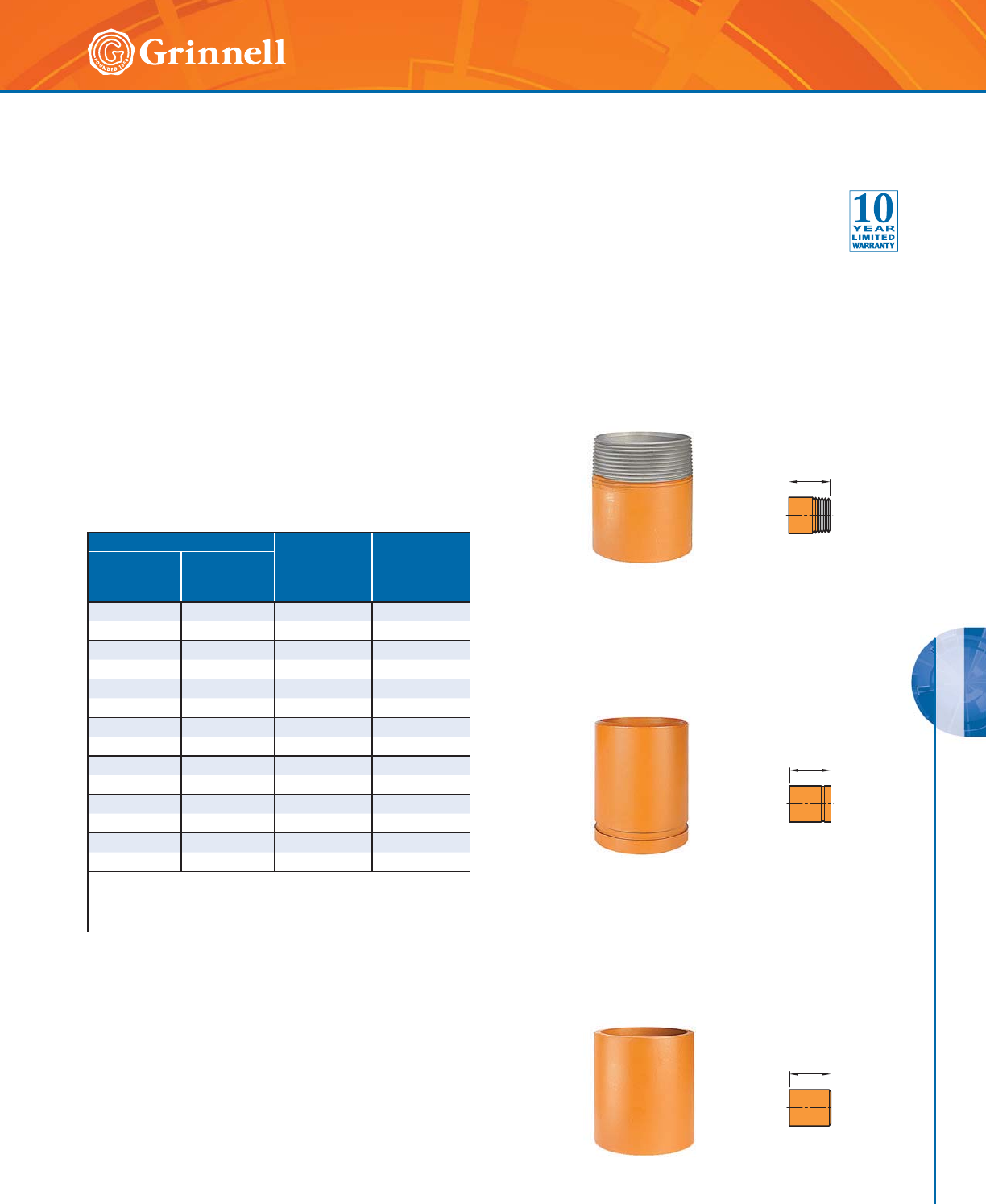
PLAIN END SYSTEMS
PLAIN END SYSTEMS
153
Refer to back cover for country-specific customer care numbers.
Pipe Size E to E
Inches
mm
Approx.
Weight
Lbs.
kg
Nominal
Inches
mm
O.D.
Inches
mm
22.3754.00 1.2
50 60,3 101,6 0,5
21⁄22.875 4.00 1.9
65 73,0 101,6 0,9
3 3.500 4.00 2.5
80 88,9 101,6 1,1
4 4.500 6.00 5.4
100 114,3 154,4 2,4
55.5636.00 7.3
125 141,3 154,4 3,3
6 6.625 6.00 9.4
150 168,3 154,4 4,3
88.6256.0014.2
200 219,1 154,4 6,4
For information on larger sizes, contact GRINNELL
Mechanical Products.
See page 145 for plain end fitting specifications.
Figure 991
Fabricated Adapter Nipple
Plain x Male Thread
Figure 992
Fabricated Adapter Nipple
Plain x Groove
Figure 993
Fabricated Adapter Nipple
Plain x Bevel
E to E
E to E
E to E
Figures 991, 992, 993
Plain End Adapter Nipples
Tech Data Sheet: G192
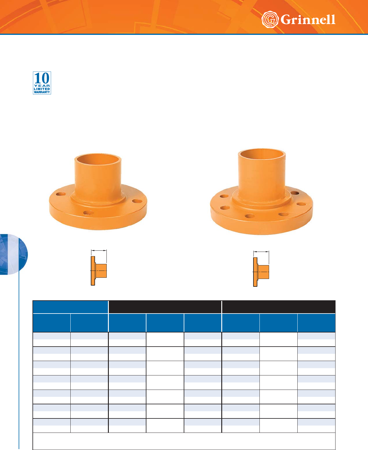
PLAIN END SYSTEMS
PLAIN END SYSTEMS
154 www.grinnell.com
Pipe Size Figure 941
ANSI Class 150#
Figure 942
ANSI Class 300#
Nominal
Inches
mm
O.D.
Inches
mm
E to E
Inches
mm
Mating Flange
Bolt
Qty.
Approx. Weight
Lbs.
kg
E to E
Inches
mm
Mating Flange
Bolt
Qty.
Approx. Weight
Lbs.
kg
22.3754.00 46.4 4.00 88.2
50 60,3 101,6 2,8 101,6 3,7
21⁄22.875 4.00 48.8 4.00 811.9
65 73,0 101,6 4,0 101,6 5,4
3 3.500 4.00 410.4 4.00 815.5
80 88,9 101,6 4,7 101,6 7,0
4 4.500 6.00 818.2 6.00 828.0
100 114,3 152,4 8,3 152,4 12,7
55.5636.00 822.0 6.00 837.0
125 141,3 152,4 10,0 152,4 16,8
66.6256.00 828.1 6.00 12 48.0
150 168,3 152,4 12,7 152,4 21,8
88.6256.00 843.7 6.00 12 79.0
200 219,1 152,4 19,8 152,4 35,8
For information on larger sizes, contact GRINNELL Mechanical Products.
See page 145 for plain end fitting specifications.
Figure 941
Plain End Flange Adapter
ANSI Class 150#
Figure 942
Plain End Flange Adapter
ANSI Class 300#
E to E E to E
Figure 941 Plain End Flange Adapters (ANSI Class 150#)
Figure 942 Plain End Flange Adapters (ANSI Class 300#)
Tech Data Sheet: G192
155
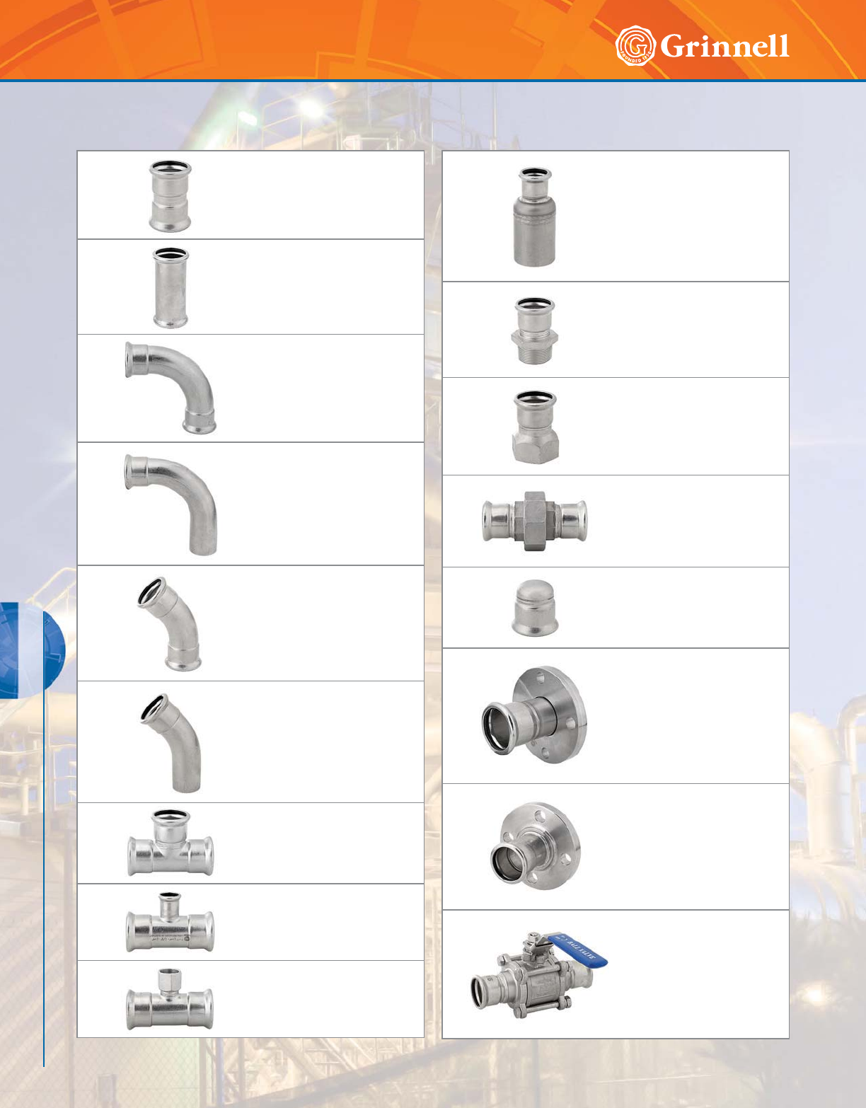
156 www.grinnell.com
G-PRESS SYSTEMS
STAINLESS STEEL G-PRESS SYSTEMS
Figure 407
Straight Couplings
(Press x Press)
Page 159
Figure 408
Slip Couplings
(Press x Press)
Page 159
Figure 468
90° Elbows
(Press x Press)
Page 160
Figure 467
90° Elbows
(Male x Female Press)
Page 160
Figure 471
45° Elbows
(Press x Press)
Page 161
Figure 470
45° Elbows
(Male x Female Press)
Page 161
Figure 442
Equal Tees
(Press x Press x Press)
Page 162
Figure 473
Reducing Tees
(Press x Press x Press)
Page 162
Figure 478
Tee and Reducing Tee Adapters
(Press x Press x Female NPT)
Page 163
Figure 474
Reducers
(Female Press x Male Press)
Page 164
Figure 476
Straight Connectors
(Female Press x Male NPT)
Page 164
Figure 479
Straight Connectors
(Female Press x Female NPT)
Page 165
Figure 485
Unions
(Press x Press)
Page 165
Figure 484
End Caps
(Female Press)
Page 166
Figure 466
Van Stone Flange Adapters
(Female Press x Flange)
Page 166
Figure 475
Flange Adapters
(Female Press x Flange)
Page 167
Figure 469
Ball Valves
(Press x Press)
Page 168
Stainless Steel G-PRESS Systems Table of Contents
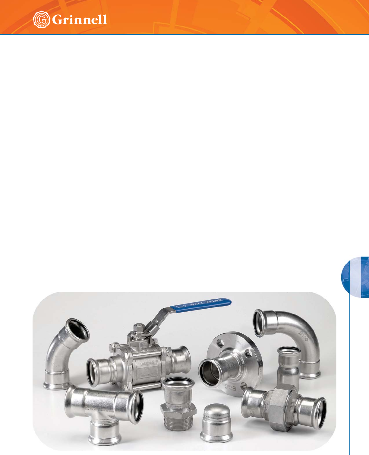
STAINLESS STEEL G-PRESS SYSTEMS
157
Refer to back cover for country-specific customer care numbers.
G-PRESS SYSTEMS
MATERIAL SPECIFICATIONS
Fitting Housing
Stainless Steel per ANSI 316/316L with a wall thickness of
0.059" (1,5mm) and the following characteristics:
• Hygienic material often used in food and the
pharmaceutical industry
• Higher surface roughness friction factor resulting in less
flow loss
• Excellent corrosion resistance in chlorinated
environments
For local country potable water approvals, contact GRINNELL
Mechanical Products
Working Pressure
• Pressure range from full vacuum to 300 psi (20,7 bar) on
Schedule 5 stainless steel pipe
Specifications
Tech Data Sheet: G550
The GRINNELL G-PRESS Stainless Steel Press-Fitting System
provides a complete line of mechanically joined press fittings
in the 1⁄2" to 2" (15 to 50mm) sizes. This press system is
designed to work with Schedule 5 Stainless Steel IPS pipe
sizes. Press joints can be readily achieved using several
commercially available press tools. Several press by male and
female threaded options are available to connect threaded
components. Conversion to flanged connections can be made
with the Class 125/150 Flange Adapter. Where breaks in
the system may be needed, the Union Coupling can make
connections / disconnections easily.
This system makes it easy to quickly and safely install a wide
range of civil, industrial, and naval systems. The GRINNELL
G-PRESS Stainless Steel System has a highly corrosion resistant
316 Stainless Steel housing and a variety of O-Ring Seal
materials making it suitable for use in numerous installations
such as HVAC, plumbing, and industrial applications.
O-Ring Specifications
O-ring style gasket is resistant to hot water, ageing, and
additives commonly used in drinking water.
• EPDM O-Ring (Black color) -4°F to 230°F (-20°C to
110°C) For Hot water, dilute acids, alkalies, oil free
air and many chemical services. Excellent oxidation
resistance. NOT FOR USE WITH HYDROCARBONS.
• Nitrile O-Ring (Brown color) -13°F to 230°F (-25°C to
110°C) Petroleum products, vegetable oils, mineral oils
and air with oils. NOT FOR USE WITH HOT WATER OR
HOT DRY AIR.
• Fluoroelastomer O-Ring (Green color) 32°F to 302°F
(0°C to 150°C) For oxidizing acids, petroleum products,
hydraulic fluids, lubricants, halogenated hydrocarbons.
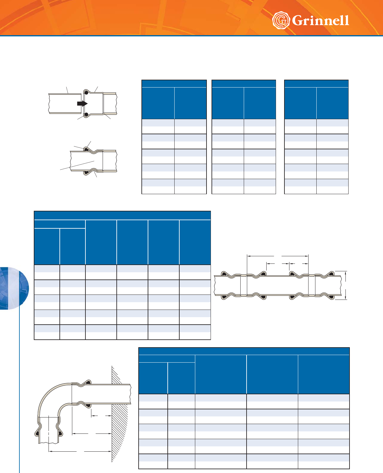
STAINLESS STEEL G-PRESS SYSTEMS
158 www.grinnell.com
G-PRESS SYSTEMS
G-PRESS Systems Specifications
Tech Data Sheet: G550
Miminum Fitting Distances
Pipe Size A
Minimum Wall to
Fitting Distance
Inches
mm
B
Minimum Horizontal
Pipe Distance
from Wall
Inches
mm
C
Minimum Vertical
Pipe Distance
from Wall
Inches
mm
Nominal
Inches
mm
O.D.
Inches
mm
1⁄20.840 1.38 1.38 3.35
15 21,3 35 35 85
3⁄41.050 1.38 1.38 3.50
20 26,7 35 35 89
1 1.315 1.38 1.38 3.74
25 33,4 35 35 95
11⁄21.660 1.38 1.38 4.76
40 42,2 35 35 121
2 2.375 1.38 1.38 5.79
50 60,3 35 35 147
Miminum Fitting Distances
Pipe Size A
Minimum
Distance
Between
Fittings
Inches
mm
L
Minimum
Pipe Length
Between
Fittings
Inches
mm
E
Socket
Insertion
Depth
Inches
mm
D
Fitting
Housing
Diameter
Inches
mm
Nominal
Inches
mm
O.D.
Inches
mm
1⁄20.840 0.39 1.97 1.38 3.35
15 21,3 10 50 35 85
3⁄41.050 0.39 1.97 1.38 3.50
20 26,7 10 50 35 89
1 1.315 0.39 1.97 1.38 3.74
25 33,4 10 50 35 95
11⁄21.660 0.39 2.44 1.38 4.76
40 42,2 10 62 35 121
2 2.375 0.79 3.15 1.38 5.79
50 60,3 20 80 35 147
Pipe Size Pipe Tolerance Pipework Support
Nominal
Inches
mm
O.D.
Inches
mm
Pipe OD
Tolerance
+/-
Inches
mm
Pipe Wall
Thickness
Schedule 5
Inches
mm
Vertical
Intervals
Inches
mm
Horizontal
Intervals
Inches
mm
1⁄20.840 0.008 0.065 71 47
15 21,3 0,20 1,65 1800 1200
3⁄41.050 0.01 0.065 79 59
20 26,7 0,25 1,65 2000 1500
1 1.315 0.013 0.065 94 71
25 33,4 0,33 1,65 2400 1800
11⁄21.660 0.016 0.065 118 94
40 42,2 0,41 1,65 3000 2400
22.3750.0240.065 118 94
50 60,3 0,61 1,65 3000 2400
A
B
C
Press Deformation
On Fitting Housing
Area Beyond O-ring
Bead As Shown
Prepared
Pipe-end
G-PRESS
Fitting Housing
O-ring Pipe
Stop
Compressed
O-ring
O-ring
Bead
Completed
Fitting
And Pipe
Joint
L
AE
D
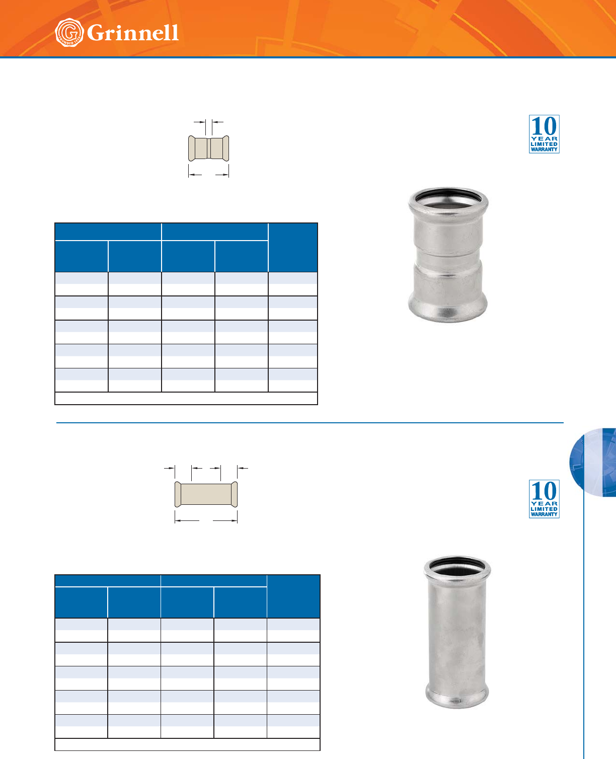
STAINLESS STEEL G-PRESS SYSTEMS
159
Refer to back cover for country-specific customer care numbers.
G-PRESS SYSTEMS
Figure 407 Straight Couplings
(Press x Press)
Tech Data Sheet: G550
Figure 408 Slip Couplings
(Press x Press)
Tech Data Sheet: G550
A
B
AA
B
Pipe Size Dimensions - Inches mm Weight
lbs
kg
Nominal
Inches
mm
O.D.
Inches
mm
AB
1⁄20.840 0.42 2.09 0.13
15 21,3 10,7 53,1 0,1
3⁄41.050 0.44 2.33 0.18
20 26,7 11,2 59,2 0,1
1 1.315 0.43 2.48 0.23
25 33,4 10,9 63,0 0,1
11⁄21.660 0.43 2.84 0.40
40 42,2 10,9 72,1 0,2
2 2.375 0.50 4.05 0.74
50 60,3 12,7 102,9 0,3
See page 157 - 158 for G-PRESS specifications.
Pipe Size Dimensions - Inches mm Weight
lbs
kg
Nominal
Inches
mm
O.D.
Inches
mm
AB
1⁄20.840 0.83 2.95 0.18
15 21,3 21,1 74,9 0,1
3⁄41.050 0.95 3.40 0.25
20 26,7 24,1 86,4 0,1
11.3151.023.830.34
25 33,4 25,9 97,3 0,2
11⁄21.660 1.20 4.81 0.63
40 42,2 30,5 122,2 0,3
2 2.375 1.77 6.76 1.13
50 60,3 45,0 171,7 0,5
See page 157 - 158 for G-PRESS specifications.
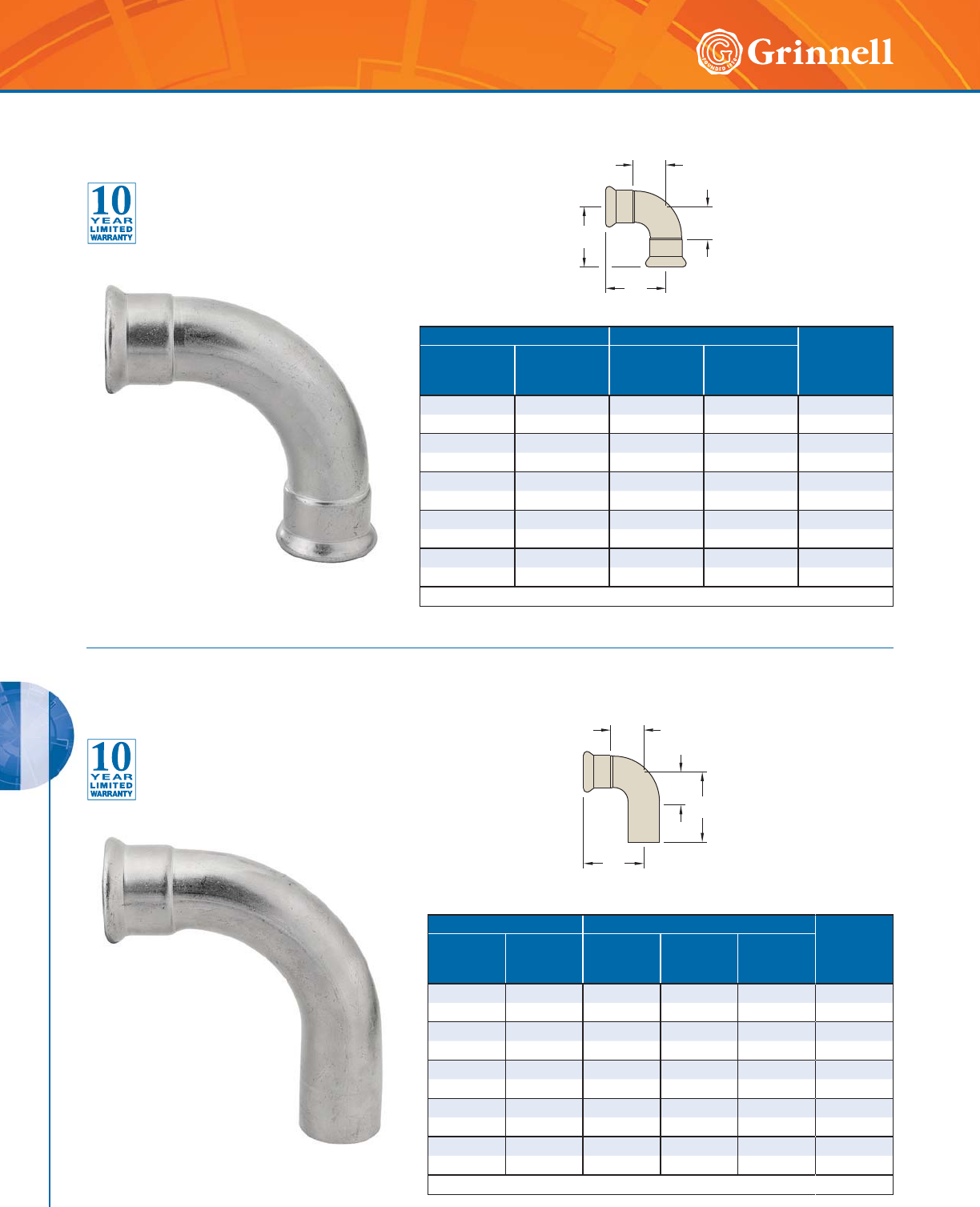
STAINLESS STEEL G-PRESS SYSTEMS
160 www.grinnell.com
G-PRESS SYSTEMS
Figure 468 90° Elbows
(Press x Press)
Tech Data Sheet: G550
Figure 467 90° Elbows
(Male x Female)
Tech Data Sheet: G550
A
B
B
A
A
C
B
A
Pipe Size Dimensions - Inches mm Weight
lbs
kg
Nominal
Inches
mm
O.D.
Inches
mm
AB
1⁄20.840 1.57 2.41 0.22
15 21,3 39,9 61,2 0,1
3⁄41.050 1.89 2.84 0.33
20 26,7 48,0 72,1 0,2
11.3152.373.400.48
25 33,4 60,2 86,4 0,2
11⁄21.660 2.56 3.76 0.79
40 42,2 65,0 95,5 0,4
2 2.375 3.23 5.00 1.39
50 60,3 82,0 127,0 0,6
See page 157 - 158 for G-PRESS specifications.
Pipe Size Dimensions - Inches mm Weight
lbs
kg
Nominal
Inches
mm
O.D.
Inches
mm
ABC
1⁄20.840 1.57 2.87 2.41 0.24
15 21,3 39,9 72,9 61,2 0,1
3⁄41.050 1.89 3.27 2.84 0.33
20 26,7 48,0 83,1 72,1 0,2
1 1.315 2.37 3.82 3.40 0.37
25 33,4 60,2 97,0 86,4 0,2
11⁄21.660 2.48 4.06 3.69 0.77
40 42,2 63,0 103,1 93,7 0,4
2 2.375 3.23 5.52 5.00 1.34
50 60,3 82,0 140,2 127,0 0,6
See page 157 - 158 for G-PRESS specifications.
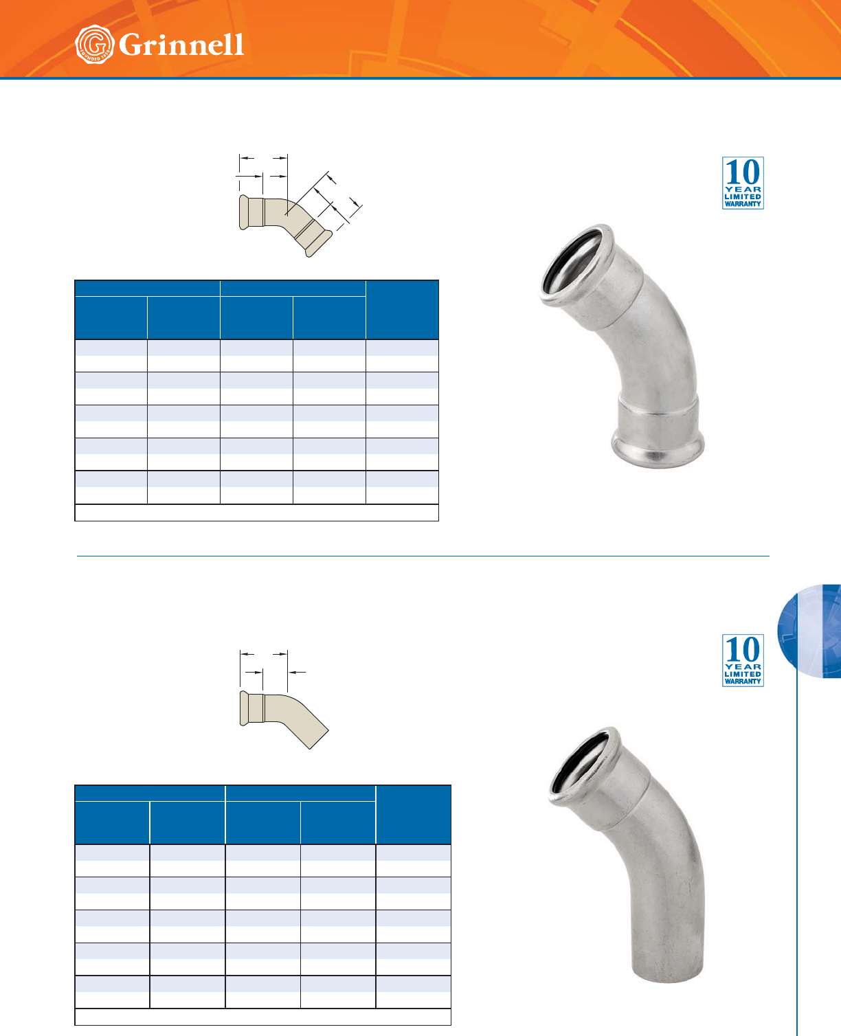
STAINLESS STEEL G-PRESS SYSTEMS
161
Refer to back cover for country-specific customer care numbers.
G-PRESS SYSTEMS
B
A
B
A
A
B
Pipe Size Dimensions - Inches mm Weight
lbs
kg
Nominal
Inches
mm
O.D.
Inches
mm
AB
1⁄20.840 0.79 1.62 0.18
15 21,3 20,1 41,1 0,1
3⁄41.050 0.90 1.85 0.24
20 26,7 22,9 47,0 0,1
11.3151.132.140.37
25 33,4 28,7 54,4 0,2
11⁄21.660 1.17 2.37 0.59
40 42,2 29,7 60,2 0,3
2 2.375 1.48 3.24 1.06
50 60,3 37,6 82,3 0,5
See page 157 - 158 for G-PRESS specifications.
Pipe Size Dimensions - Inches mm Weight
lbs
kg
Nominal
Inches
mm
O.D.
Inches
mm
AB
1⁄20.840 0.79 1.62 0.20
15 21,3 20,1 41,1 0,1
3⁄41.050 0.90 1.85 0.26
20 26,7 22,9 47,0 0,1
11.3151.132.140.37
25 33,4 28,7 54,4 0,2
11⁄21.660 1.17 2.37 0.60
40 42,2 29,7 60,2 0,3
2 2.375 1.48 3.24 1.06
50 60,3 37,6 82,3 0,5
See page 157 - 158 for G-PRESS specifications.
Figure 471 45° Elbows
(Press x Press)
Tech Data Sheet: G550
Figure 470 45° Elbows
(Male x Female)
Tech Data Sheet: G550
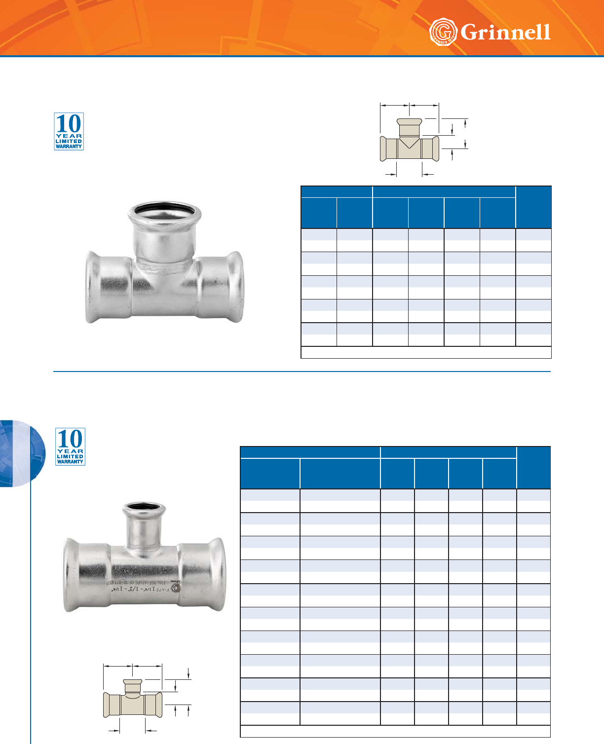
STAINLESS STEEL G-PRESS SYSTEMS
162 www.grinnell.com
G-PRESS SYSTEMS
Figure 442 Equal Tees
(Press x Press x Press)
Tech Data Sheet: G550
B
A
D
CC
B
A
CC
D
Pipe Size Dimensions - Inches mm Weight
lbs
kg
Nominal
Inches
mm
O.D.
Inches
mm
ABCD
1⁄20.840 1.28 0.80 1.48 1.64 0.24
15 21,3 32,5 20,3 37,6 41,7 0,1
3⁄41.050 1.50 0.92 1.70 1.87 0.33
20 26,7 38,1 23,4 43,2 47,5 0,2
1 1.315 1.78 1.07 1.91 2.09 0.46
25 33,4 45,2 27,2 48,5 53,1 0,2
11⁄21.660 2.40 1.36 2.41 2.57 0.84
40 42,2 61,0 34,5 61,2 65,3 0,4
2 2.375 3.22 1.61 3.39 3.39 1.48
50 60,3 81,8 40,9 86,1 86,1 0,7
See page 157 - 158 for G-PRESS specifications.
Pipe Size Dimensions - Inches mm Weight
lbs
kg
Nominal
Inches
mm
O.D.
Inches
mm
ABCD
3⁄4 x 3⁄4 x 1⁄21.050 x 1.050 x 0.840 1.50 0.91 1.70 1.74 0.31
20 x 20 x 15 26,7 x 26,7 x 21,3 38,1 23,1 43,2 44,2 0,1
1 x 1 x 1⁄21.315 x 1.315 x 0.840 1.78 1.06 1.91 1.89 0.40
25 x 25 x 15 33,4 x 33,4 x 21,3 45,2 26,9 48,5 48,0 0,2
1 x 1 x 3⁄41.315 x 1.315 x 1.050 1.78 1.07 1.91 2.02 0.42
25 x 25 x 20 33,4 x 33,4 x 26,7 45,2 27,2 48,5 51,3 0,2
11⁄2 x 11⁄2 x 1⁄21.900 x 1.900 x 0.840 2.40 1.35 2.41 2.19 0.68
40 x 40 x 15 48,3 x 48,3 x 21,3 61,0 34,3 61,2 55,6 0,3
11⁄2 x 11⁄2 x 3⁄41.900 x 1.900 x 1.050 2.40 1.37 2.41 2.31 0.70
40 x 40 x 20 48,3 x 48,3 x 26,7 61,0 34,8 61,2 58,7 0,3
11⁄2 x 11⁄2 x 1 1.900 x 1.900 x 1.315 2.40 1.36 2.41 2.39 0.75
40 x 40 x 25 48,3 x 48,3 x 33,4 61,0 34,5 61,2 60,7 0,3
2 x 2 x 1⁄22.375 x 2.375 x 0.840 3.22 1.60 3.39 2.44 1.17
50 x 50 x 15 60,3 x 60,3 x 21,3 81,8 40,6 86,1 62,0 0,5
2 x 2 x 3⁄42.375 x 2.375 x 1.050 3.22 1.62 3.39 2.56 1.19
50 x 50 x 20 60,3 x 60,3 x 26,7 81,8 41,1 86,1 65,0 0,5
2 x 2 x 1 2.375 x 2.375 x 1.315 3.22 1.61 3.39 2.62 1.23
50 x 50 x 25 60,3 x 60,3 x 33,4 81,8 40,9 86,1 66,5 0,6
2 x 2 x 11⁄22.375 x 2.375 x 1.900 3.22 1.61 3.39 2.82 1.32
50 x 50 x 40 60,3 x 60,3 x 48,3 81,8 40,9 86,1 71,6 0,6
See page 157 - 158 for G-PRESS specifications.
Figure 473 Reducing Tees
(Press x Press x Press)
Tech Data Sheet: G550
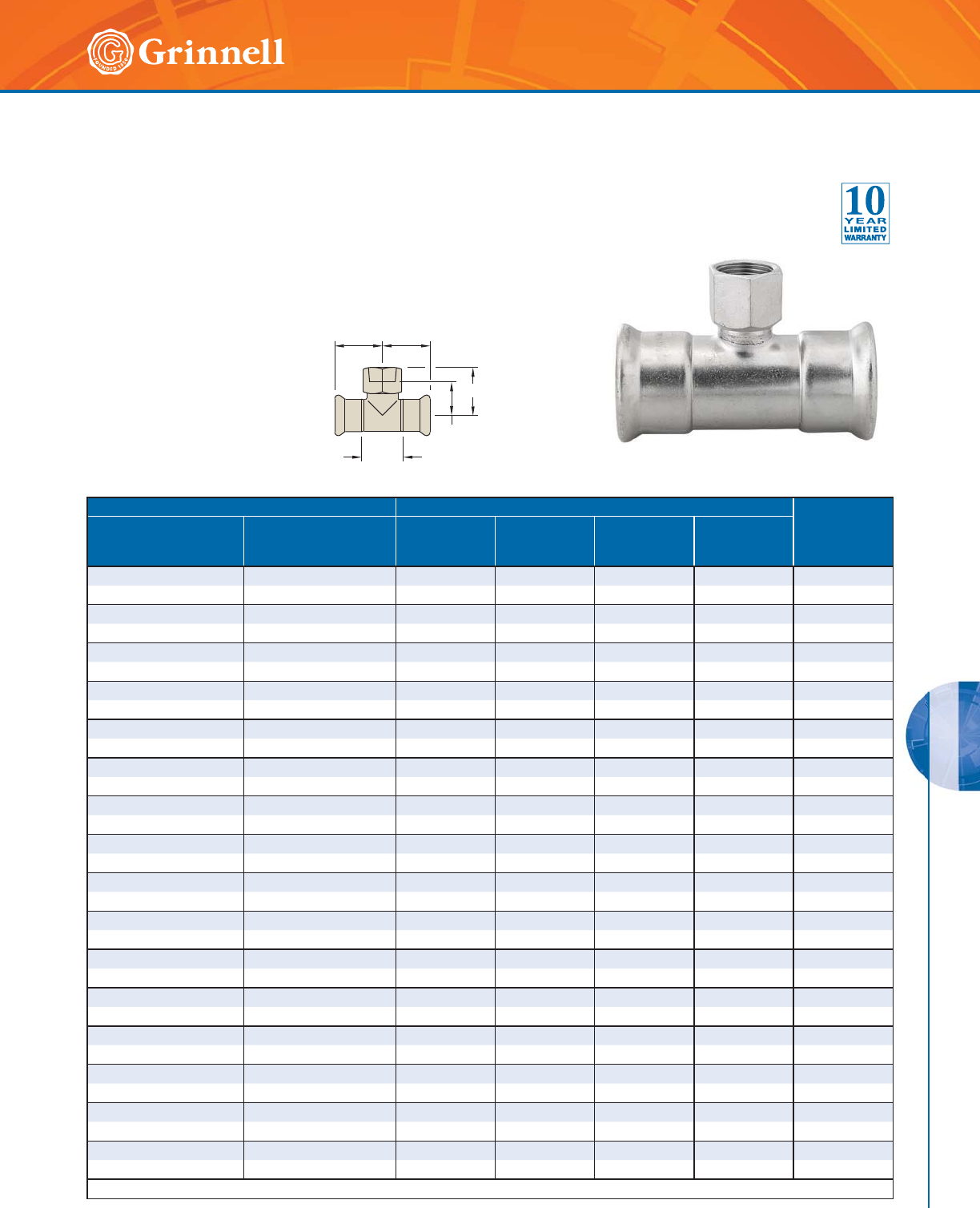
STAINLESS STEEL G-PRESS SYSTEMS
163
Refer to back cover for country-specific customer care numbers.
G-PRESS SYSTEMS
B
A
C
D
C
Pipe Size Dimensions - Inches mm Weight
lbs
kg
Nominal
Inches
mm
O.D.
Inches
mm
ABCD
1⁄2 x 1⁄2 x 1⁄20.840 x 0.840 x 0.840 1.28 0.93 1.48 1.52 0.26
15 x 15 x 15 21,3 x 21,3 x 21,3 32,5 23,6 37,6 38,6 0,1
1⁄2 x 1⁄2 x 3⁄40.840 x 0.840 x 1.050 1.28 1.30 1.48 1.84 0.37
15 x 15 x 20 21,3 x 21,3 x 26,7 32,5 33,0 37,6 46,7 0,2
3⁄4 x 3⁄4 x 1⁄21.050 x 1.050 x 0.840 1.50 1.04 1.70 1.63 0.33
20 x 20 x 15 26,7 x 26,7 x 21,3 38,1 26,4 43,2 41,4 0,2
3⁄4 x 3⁄4 x 3⁄41.050 x 1.050 x 1.050 1.50 1.27 1.70 1.81 0.40
20 x 20 x 20 26,7 x 26,7 x 26,7 38,1 32,3 43,2 46,0 0,2
3⁄4 x 3⁄4 x 1 1.050 x 1.050 x 1.315 1.50 1.29 1.70 1.97 0.46
20 x 20 x 25 26,7 x 26,7 x 33,4 38,1 32,8 43,2 50,0 0,2
1 x 1 x 1⁄21.315 x 1.315 x 0.840 1.78 1.19 1.91 1.78 0.42
25 x 25 x 15 33,4 x 33,4 x 21,3 45,2 30,2 48,5 45,2 0,2
1 x 1 x 3⁄41.315 x 1.315 x 1.050 1.78 1.42 1.91 1.96 0.48
25 x 25 x 20 33,4 x 33,4 x 26,7 45,2 36,1 48,5 49,8 0,2
1 x 1 x 11⁄41.315 x 1.315 x 1.660 1.78 1.38 1.91 2.13 0.66
25 x 25 x 32 33,4 x 33,4 x 42,2 45,2 35,1 48,5 54,1 0,3
11⁄2 x 11⁄2 x 1⁄21.900 x 1.900 x 0.840 2.40 1.48 2.41 2.07 0.70
40 x 40 x 15 48,3 x 48,3 x 21,3 61,0 37,6 61,2 52,6 0,3
11⁄2 x 11⁄2 x 3⁄41.900 x 1.900 x 1.050 2.40 1.71 2.41 2.25 0.77
40 x 40 x 20 48,3 x 48,3 x 26,7 61,0 43,4 61,2 57,2 0,4
11⁄2 x 11⁄2 x 1 1.900 x 1.900 x 1.315 2.40 1.59 2.41 2.27 0.84
40 x 40 x 25 48,3 x 48,3 x 33,4 61,0 40,4 61,2 57,7 0,4
11⁄2 x 11⁄2 x 11⁄21.900 x 1.900 x 1.900 2.40 1.74 2.41 2.58 1.21
40 x 40 x 40 48,3 x 48,3 x 48,3 61,0 44,2 61,2 65,5 0,6
2 x 2 x 1⁄22.375 x 2.375 x 0.840 3.22 1.73 3.39 2.32 1.19
50 x 50 x 15 60,3 x 60,3 x 21,3 81,8 43,9 86,1 58,9 0,5
2 x 2 x 3⁄42.375 x 2.375 x 1.050 3.22 1.96 3.39 2.50 1.26
50 x 50 x 20 60,3 x 60,3 x 26,7 81,8 49,8 86,1 63,5 0,6
2 x 2 x 1 2.375 x 2.375 x 1.315 3.22 1.84 3.39 2.52 1.32
50 x 50 x 25 60,3 x 60,3 x 33,4 81,8 46,7 86,1 64,0 0,6
2 x 2 x 2 2.375 x 2.375 x 2.375 3.22 2.14 3.39 3.19 1.90
50 x 50 x 50 60,3 x 60,3 x 60,3 81,8 54,4 86,1 81,0 0,9
See page 157 - 158 for G-PRESS specifications.
Figure 478 Tee and Reducing Tee Adapters
(Press x Press x Female NPT)
Tech Data Sheet: G550
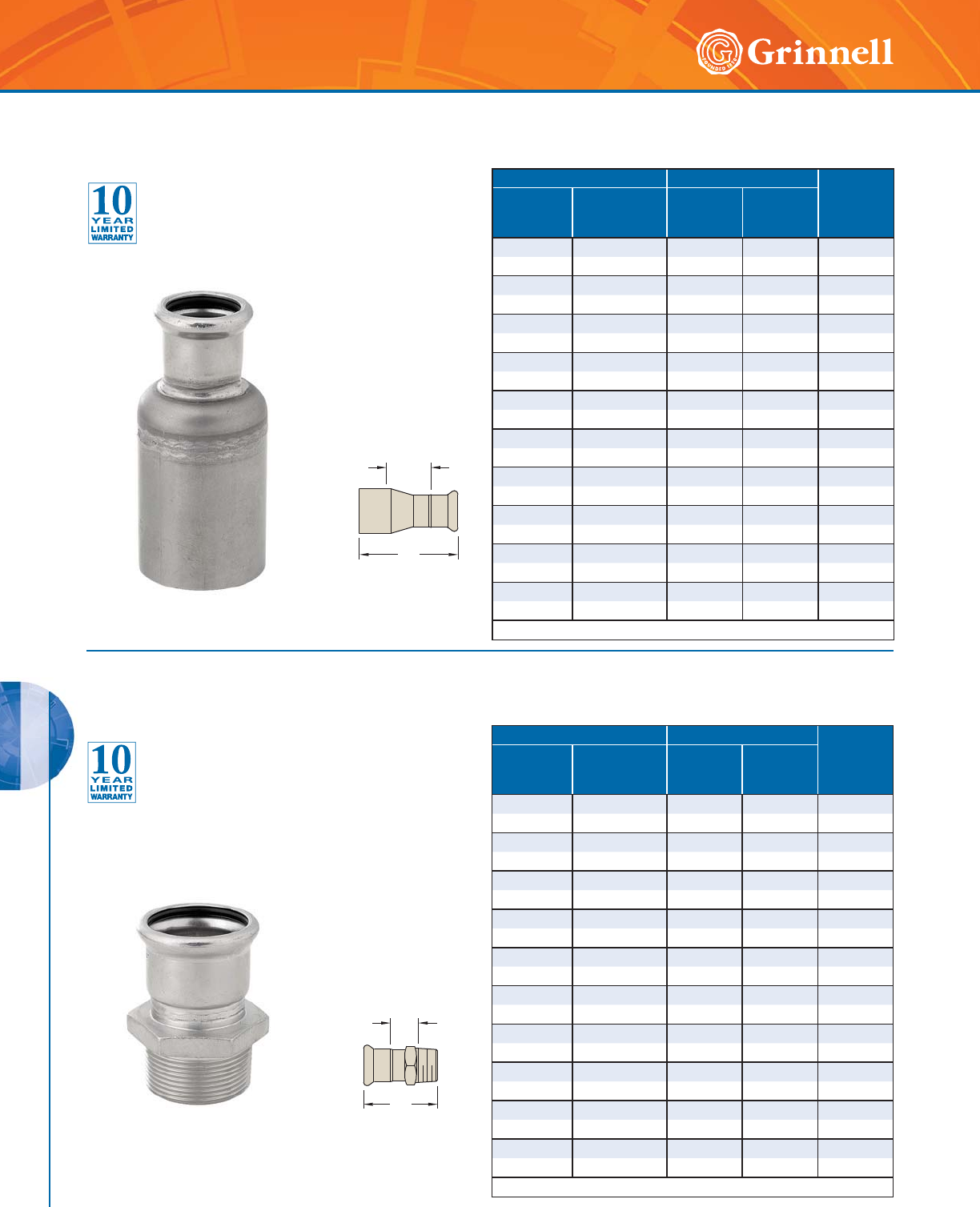
STAINLESS STEEL G-PRESS SYSTEMS
164 www.grinnell.com
G-PRESS SYSTEMS
B
A
A
B
Figure 474 Reducers
(Female Press x Male Press)
Tech Data Sheet: G550
Figure 476 Straight Connectors
(Female Press x Male NPT)
Tech Data Sheet: G550
Pipe Size Dimensions - Inches mm Weight
lbs
kg
Nominal
Inches
mm
O.D.
Inches
mm
AB
3⁄4 x 1⁄21.050 x 0.840 1.21 3.04 0.18
20 x 15 26,7 x 21,3 30,7 77,2 0,1
1 x 1⁄21.315 x 0.840 2.58 4.34 0.28
25 x 15 33,4 x 21,3 65,5 110,2 0,1
1 x 3⁄41.315 x 1.050 1.75 3.76 0.26
25 x 20 33,4 x 26,7 44,5 95,5 0,1
11⁄2 x 1⁄21.900 x 0.840 1.15 3.42 0.33
40 x 15 48,3 x 21,3 29,2 86,9 0,1
11⁄2 x 3⁄41.900 x 1.050 1.60 3.55 0.55
40 x 20 48,3 x 26,7 40,6 90,2 0,2
11⁄2 x 1 1.900 x 1.315 1.29 3.56 0.37
40 x 25 48,3 x 33,4 32,8 90,4 0,2
2 x 1⁄22.375 x 0.840 1.62 4.23 0.53
50 x 15 60,3 x 21,3 41,1 107,4 0,2
2 x 3/4 2.375 x 1.050 1.59 4.34 0.35
50 x 20 60,3 x 26,7 40,4 110,2 0,2
2 x 1 2.375 x 1.315 1.55 4.37 0.57
50 x 25 60,3 x 33,4 39,4 111,0 0,3
2 x 11⁄22.375 x 1.900 2.64 5.30 0.70
50 x 40 60,3 x 48,3 67,1 134,6 0,3
See page 157 - 158 for G-PRESS specifications.
Pipe Size Dimensions - Inches mm Weight
lbs
kg
Nominal
Inches
mm
O.D.
Inches
mm
AB
1⁄2 x 1⁄20.840 x 0.840 0.72 2.14 0.15
15 x 15 21,3 x 21,3 18,3 54,4 0,1
1⁄2 x 3⁄40.840 x 1.050 0.81 2.35 0.20
15 x 20 21,3 x 26,7 20,6 59,7 0,1
1⁄2 x 1 0.840 x 1.315 0.83 2.44 0.29
15 x 20 21,3 x 33,4 21,1 62,0 0,1
3⁄4 x 3⁄41.050 x 1.050 0.83 2.43 0.22
20 x 20 26,7 x 26,7 21,1 61,7 0,1
3⁄4 x 1 1.050 x 1.315 0.85 2.52 0.31
20 x 25 26,7 x 33,4 21,6 64,0 0,1
1 x 1 1.315 x 1.315 0.83 2.64 0.29
25 x 25 33,4 x 33,4 21,1 67,10 0,1
1 x 11⁄21.315 x 1.900 0.92 2.90 0.62
25 x 40 33,4 x 48,3 23,4 73,7 0,3
11⁄2 x 11⁄21.900 x 1.900 0.92 3.09 0.68
40 x 40 48,3 x 48,3 23,4 78,5 0,3
2 x 11⁄22.375 x 1.900 0.91 3.17 0.97
50 x 40 60,3 x 48,3 23,1 80,5 0,4
2 x 2 2.375 x 2.375 0.91 3.74 1.01
50 x 50 60,3 x 60,3 23,1 95,0 0,5
See page 157 - 158 for G-PRESS specifications.
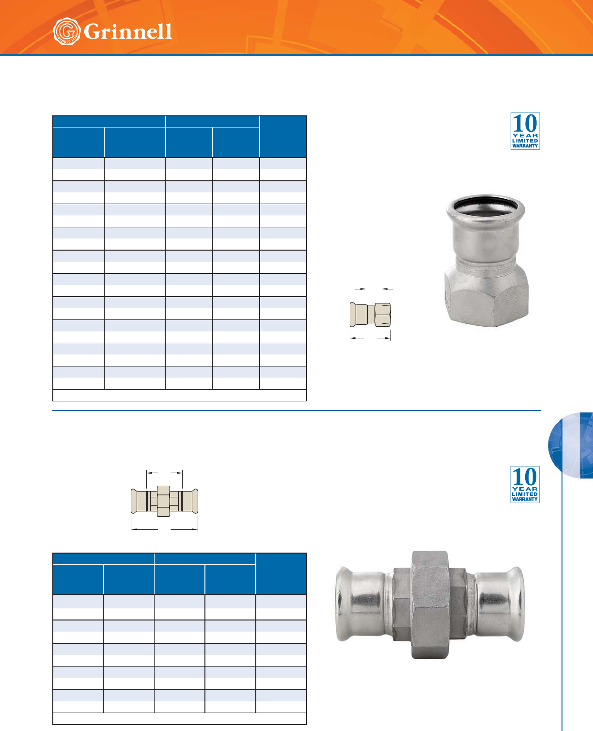
STAINLESS STEEL G-PRESS SYSTEMS
165
Refer to back cover for country-specific customer care numbers.
G-PRESS SYSTEMS
Figure 479 Straight Connectors
(Female Press x Female NPT)
Tech Data Sheet: G550
A
B
B
A
Pipe Size Dimensions - Inches mm Weight
lbs
kg
Nominal
Inches
mm
O.D.
Inches
mm
AB
1⁄2 x 3⁄40.840 x 1.050 0.93 2.47 0.31
15 x 20 21,3 x 26,7 23,6 62,7 0,1
1⁄2 x 1 0.840 x 1.315 0.98 2.47 0.26
15 x 25 21,3 x 33,4 24,9 62,7 0,1
3⁄4 x 3⁄41.050 x 1.050 1.00 2.56 0.51
20 x 20 26,7 x 26,7 25,4 65,0 0,2
3⁄4 x 1 1.050 x 1.315 1.00 2.56 0.44
20 x 25 26,7 x 33,4 25,4 65,0 0,2
1 x 1 1.315 x 1.315 0.86 2.56 0.31
25 x 25 33,4 x 33,4 21,8 65,0 0,1
1 x 11⁄21.315 x 1.900 1.26 3.06 1.28
25 x 40 33,4 x 48,3 32,0 77,7 0,6
11⁄2 x 11⁄21.900 x 1.900 1.01 3.06 0.82
40 x 40 48,3 x 48,3 25,7 77,7 0,4
11⁄2 x 2 1.900 x 2.375 1.39 3.65 1.21
40 x 50 48,3 x 60,3 35,3 92,7 0,5
2 x 11⁄22.375 x 1.900 1.36 3.98 1.83
50 x 40 60,3 x 48,3 34,5 101,1 0,8
2 x 2 2.375 x 2.375 1.15 3.98 1.17
50 x 50 60,3 x 60,3 29,2 101,1 0,5
See page 157 - 158 for G-PRESS specifications.
Figure 485 3-Piece Unions
(Press x Press)
Tech Data Sheet: G550
Pipe Size Dimensions - Inches mm Weight
lbs
kg
Nominal
Inches
mm
O.D.
Inches
mm
AB
1⁄20.840 2.35 4.02 0.62
15 21,3 59,7 102,1 0,3
3⁄41.050 2.64 4.54 0.82
20 26,7 67,1 115,3 0,4
11.3152.724.760.97
25 33,4 69,1 120,9 0,4
11⁄21.660 3.88 6.29 2.36
40 42,2 98,6 159,8 1,1
22.3754.728.263.70
50 60,3 119,0 209,8 1,7
See page 157 - 158 for G-PRESS specifications.
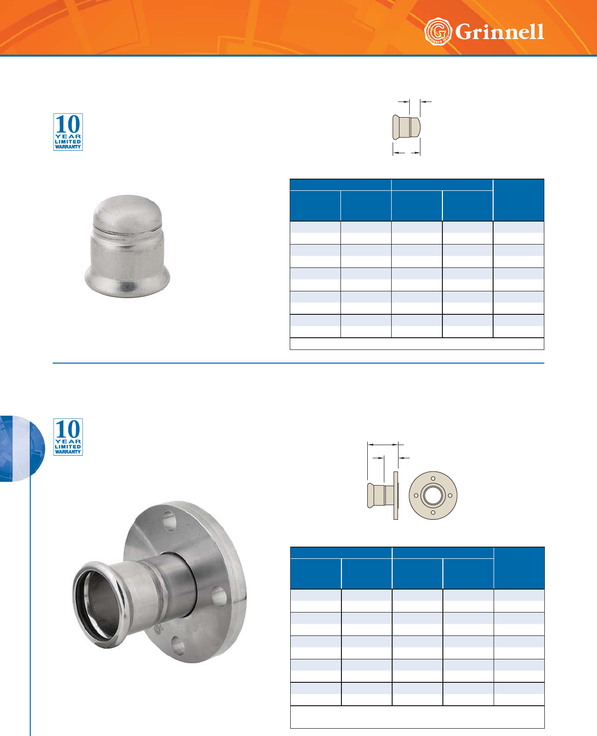
STAINLESS STEEL G-PRESS SYSTEMS
166 www.grinnell.com
G-PRESS SYSTEMS
A
B
A
B
Pipe Size Dimensions - Inches mm Weight
lbs
kg
Nominal
Inches
mm
O.D.
Inches
mm
AB
1⁄20.840 0.72 1.56 0.09
15 21,3 18,3 39,6 0,1
3⁄41.050 0.79 1.74 0.13
20 26,7 20,1 44,2 0,1
1 1.315 0.83 1.85 0.18
25 33,4 21,1 47,0 0,1
11⁄21.660 0.95 2.15 0.33
40 42,2 24,1 54,6 0,1
22.3751.142.910.55
50 60,3 29,0 73,9 0,2
See page 157 - 158 for G-PRESS specifications.
Pipe Size Dimensions - Inches mm Weight
lbs
kg
Nominal
Inches
mm
O.D.
Inches
mm
AB
1⁄20.8 40 3.11 1.17 0.93
15 21,3 79,0 29,8 0,4
3⁄41.050 3.23 1.42 1.37
20 26,7 82,0 36,1 0,6
1 1.315 3.30 1.78 1.87
25 33,4 83,8 45,2 0,8
11⁄21.660 3.45 2.59 2.98
40 42,2 87,6 65,8 1,4
2 2.375 4.56 3.45 4.75
50 60,3 115,8 87,6 2,2
See page 157 - 158 for G-PRESS specifications.
Flange material is AISI 304 and the body is AISI 316/316L.
Figure 484 End Caps
(Female Press)
Tech Data Sheet: G550
Figure 466 Van Stone Flange Adapters
(Female Press x Flange)
Tech Data Sheet: G550
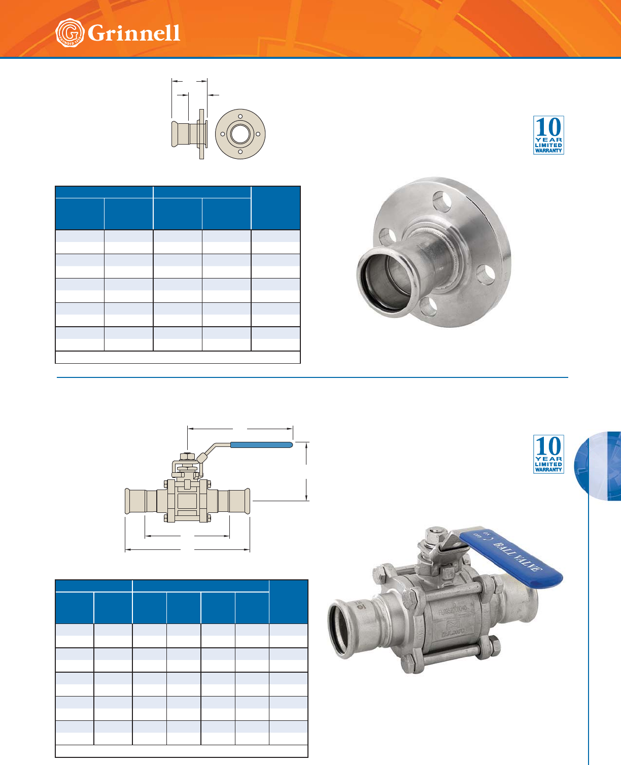
STAINLESS STEEL G-PRESS SYSTEMS
167
Refer to back cover for country-specific customer care numbers.
G-PRESS SYSTEMS
Figure 469 Ball Valves
(Press x Press)
Tech Data Sheet: G550
A
B
A
D
C
B
Pipe Size Dimensions - Inches mm Weight
lbs
kg
Nominal
Inches
mm
O.D.
Inches
mm
AB
1⁄20.840 1.95 0.94 0.90
15 21,3 49,5 23,9 0,4
3⁄41.050 2.15 1.16 1.30
20 26,7 54,6 29,5 0,6
1 1.315 2.52 1.44 1.83
25 33,4 64,0 36,6 0,8
11⁄21.660 3.39 2.08 3.03
40 42,2 86,1 52,9 1,4
2 2.375 4.87 2.90 4.91
50 60,3 123,7 73,7 2,2
See page 157 - 158 for G-PRESS specifications.
Pipe Size Dimensions - Inches mm Weight
lbs
kg
Nominal
Inches
mm
O.D.
Inches
mm
ABCD
1⁄20.8403.163.942.444.84 1.24
15 21,3 80,3 100,1 62,0 122,9 0,6
3⁄41.050 3.59 4.92 2.44 5.49 1.73
20 26,7 91,2 125,0 62,0 139,4 0,8
1 1.315 3.99 5.87 3.03 6.03 2.46
25 33,4 101,3 149,1 77,0 153,2 1,1
11⁄21.6605.057.483.947.45 5.93
40 42,2 128,3 190,0 100,1 189,2 2,7
2 2.375 5.84 7.48 4.25 9.38 8.48
50 60,3 148,3 190,0 108,0 238,3 3,8
See page 157 - 158 for G-PRESS specifications.
Figure 475 Flange Adapters
(Female Press x Flange)
Tech Data Sheet: G550

STAINLESS STEEL G-PRESS SYSTEMS
168 www.grinnell.com
G-PRESS SYSTEMS
Notes

169
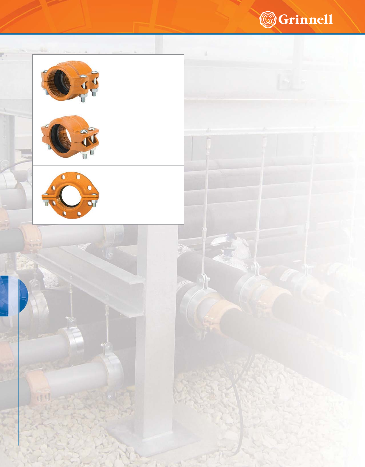
HDPE SYSTEMS
170 www.grinnell.com
HDPE SYSTEMS
Figure 9095
HDPE Couplings
Page 171
Figure 9097
HDPE Transition Couplings
Page 172
Figure 9094
HDPE Flange Couplings
Page 173
Coupling Ductile Iron Housing
Specifications
• ASTM A 536 – Standard specification for ductile iron
castings, Grade 65-45-12
Bolt/Nut Specifications
• ANSI: Carbon steel oval neck bolts & nuts are heat-
treated and conform to the physical properties of
ASTM A 183 Grade 2 and SAE J429 Grade 5 with a
minimum tensile strength of 110,000 psi (7584,2 bar).
Carbon Steel heavy hex nuts conform to the physical
properties of ASTM A 183 Grade 2 and SAE J995
Grade 5. Bolts and nuts are zinc-electroplated
conforming to ASTM B 633.
• Metric: Carbon steel oval neck track head bolts (Gold
color coded) are heat treated and conform to the
physical properties of ASTM F 568 M with a minimum
tensile strength of 760 MPa.
Carbon Steel heavy hex nuts conform to the physical
properties of ASTM A 563 M Class 9. Bolts and nuts
are zinc-electroplated conforming to ASTM B 633.
• Stainless steel bolts and nuts are available upon
request.
Gasket Specifications
• Grade “E” EPDM gaskets have a Green color
code identification and conform to ASTM D 2000 for
service temperatures from -30°F to 230°F (-34°C to
110°C). They are recommended for hot water not to
exceed 230°F (110°C), plus a variety of dilute acids,
oil free air, and many chemical services. They are not
recommended for petroleum services.
• Grade “T” Nitrile (Color code: Orange stripe)
Recommended for petroleum products, air with oil
vapors, vegetable and mineral oils within the specified
temperature range. Also good for water services under
150°F (66°C). Temperature range: -20°F to +180°F
(-29°C to +82°C).
Do not use for HOT WATER above 150°F (66°C) or
HOT DRY AIR above 140°F (60°C).
Coatings
• Orange – Non-lead paint (standard)
• Red – Non-lead paint (optional, regional)
• Hot-Dipped, Zinc galvanized (optional)
MATERIAL SPECIFICATIONS
HDPE Systems Table of Contents
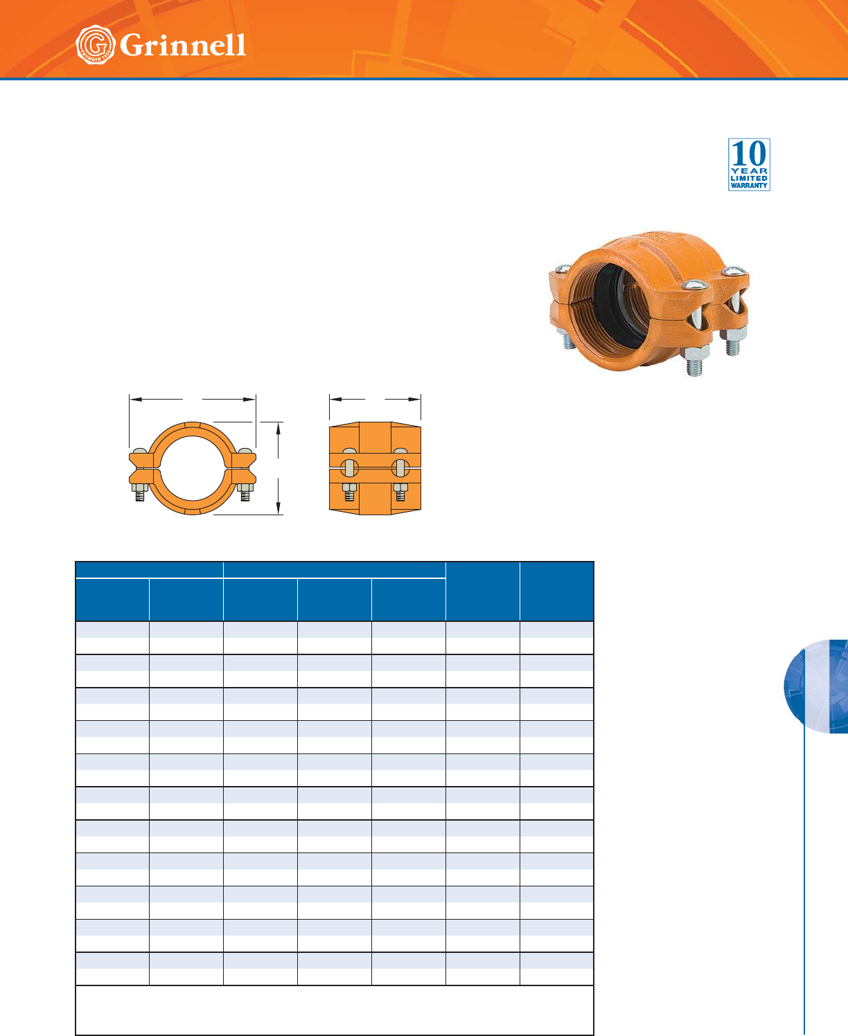
HDPE SYSTEMS
HDPE SYSTEMS
171
Refer to back cover for country-specific customer care numbers.
The GRINNELL Figure 9095 HDPE Coupling is specially designed
for joining sections of high-density polyethylene (HDPE) piping. The
GRINNELL Figure 9095 features a four-bolt coupling design with
machined gripping teeth to positively secure high-density polyethylene
piping and create a leak-tight joint.
The contoured housing features an integrated ramp design that helps
avoid obstacles while relocating pipe runs. This coupling is ideal for
mining, irrigation, and tunnelling applications.
B
A
C
Pipe Size Dimensions - Inches mm Coupling
Bolt Size
Inches
Approx.
Weight
Lbs.
kg
Nominal
Inches
mm
O.D.
Inches
mm
AB C
22.3753.395.244.61
1⁄2 x 23⁄85.7
50 60,3 86,0 133,0 117,0 – 2,6
3 3.500 4.61 6.50 4.02 1⁄2 x 23⁄47.9
80 88,9 117,0 165,0 102,0 – 3,6
4 4.500 5.75 7.99 5.75 1⁄2 x 3 11.4
10 0 114,3 146,0 203,0 146,0 – 5,2
66.6257.8710.755.87
5⁄8 x 31⁄218.0
150 168,3 200,0 273,0 149,0 – 8,2
88.62510.3913.115.98
5⁄8 x 31⁄227.5
200 219,1 264,0 333,0 152,0 – 12,5
10 10.750 12.52 15.63 6.50 3⁄4 x 43⁄444.0
250 273,0 318,0 397,0 165,0 – 20,0
12 12.750 14.37 17.64 7.87 3⁄4 x 43⁄456.1
300 323,9 365,0 448,0 200,0 – 25,5
14 14.000 16.26 19.37 10.12 1 x 6 90.6
350 355,6 413,0 492,0 257,0 – 41,2
16 16.000 18.39 21.38 10.12 1 x 6 97.2
400 4 0 6,4 467,0 543,0 257,0 – 44 , 2
18 18.000 20.28 23.43 10.24 1 x 6 111.1
450 457,2 515,0 595,0 260,0 – 50,5
20 20.000 22.36 25.63 10.24 1 x 6 136.0
500 508,0 568,0 651,0 260,0 – 61,8
For information on larger sizes, contact GRINNELL Mechanical Products.
See page 170 for HDPE coupling specifications and pages 191 - 198 for gasket information.
See page 174 for pipe wall thickness and standard dimension ratio information.
Figure 9095 HDPE Couplings
Tech Data Sheet: G580
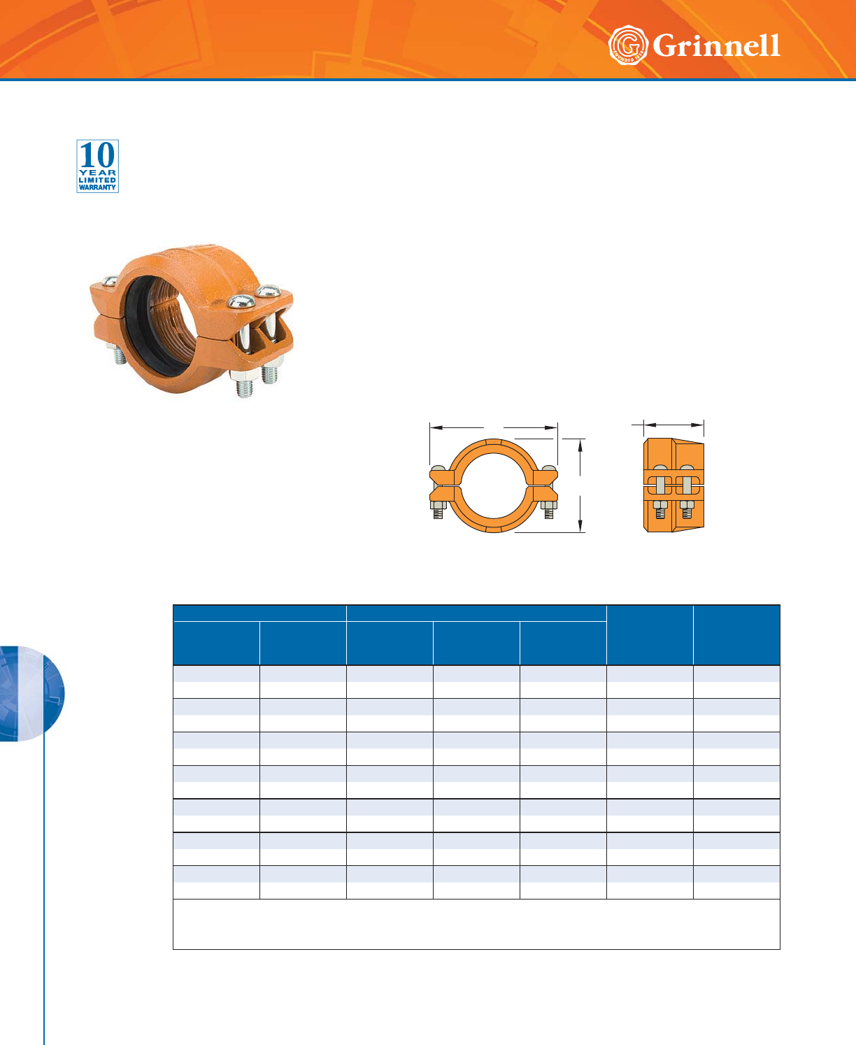
HDPE SYSTEMS
HDPE SYSTEMS
172 www.grinnell.com
The GRINNELL Figure 9097 HDPE Transition Coupling provides for an
efficient transition from grooved piping systems to high-density polyethylene
(HDPE) piping. The GRINNELL Figure 9097 features a four-bolt coupling
design with one side of machine gripping teeth and a grooved end creating
a leak-tight joint between high-density polyethylene and grooved piping
systems.
The contoured housing features the same integrated ramp design as the
GRINNELL Figure 9095, which helps avoid obstacles while relocating
pipe runs. This coupling is ideal for mining, irrigation, and tunnelling
applications.
Pipe Size Dimensions - Inches mm Coupling
Bolt Size
Inches
Approx.
Weight
Lbs.
kg
Nominal
Inches
mm
O.D.
Inches
mm
AB C
2 2.375 3.39 5.99 3.11 1⁄2 x 23⁄84.4
50 60,3 86,0 152,0 79,0 – 2,0
33.5004.497.133.11
1⁄2 x 3 5.9
80 88,9 114,0 181,0 79,0 – 2,7
44.5005.758.503.74
1⁄2 x 3 8.4
10 0 114,3 146,0 216,0 95,0 – 3,8
66.6258.0011.263.74
5⁄8 x 31⁄212.5
150 168,3 203,0 286,0 95,0 – 5,7
8 8.625 10.51 13.63 4.25 5⁄8 x 31⁄221.3
200 219,1 267,0 346,0 108,0 – 9,7
10 10.750 12.64 17.00 5.00 3⁄4 x 43⁄435.2
250 273,0 321,0 432,0 127,0 – 16,0
12 12.750 14.76 19.49 5.00 3⁄4 x 43⁄443.1
300 323,9 375,0 495,0 127,0 – 19,6
For information on larger sizes, contact GRINNELL Mechanical Products.
See page 170 for HDPE coupling specifications and pages 191 - 198 for gasket information.
See page 174 for pipe wall thickness and standard dimension ratio information.
B
A
C
Figure 9097 HDPE Transition Couplings
Tech Data Sheet: G582
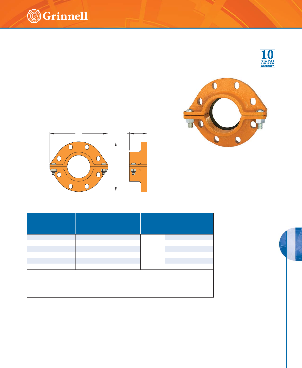
HDPE SYSTEMS
HDPE SYSTEMS
173
Refer to back cover for country-specific customer care numbers.
Figure 9094 Flange Couplings
Tech Data Sheet: G584
The GRINNELL Figure 9094 HDPE Flange Coupling provides for
an efficient transition from high-density polyethylene (HDPE) piping
to ANSI class 125# or 150# flanged piping system. This coupling
is ideal for mining, irrigation, and tunnelling applications.
Pipe Size Dimensions - Inches mm Coupling Bolts ‡ Approx.
Weight
Lbs.
kg
Nominal
Inches
mm
O.D.
Inches
mm
AB C Quantity
Bolt Size
Inches
4 4.500 9.00 10.25 3.10 8
5⁄8 x 31⁄415.0
100 114,3 229,0 260,0 79,0 – 6,8
6 6.625 11.00 12.25 3.75 8
3⁄4 x 31⁄221.5
150 168,3 279,0 311,0 95,0 – 9,8
88.62513.5014.753.428
3⁄4 x 33⁄428.8
200 219,1 343,0 375,0 87,0 – 13,1
‡ Mating bolts and nuts are not supplied. Flange mating bolts must be at least SAE J429, Grade 5 or stronger.
It is the responsibility of the purchaser to verify correct length for the intended application.
For information on larger sizes, contact GRINNELL Mechanical Products.
See page 170 for HDPE coupling specifications and pages 191 - 198 for gasket information.
See page 174 for pipe wall thickness and standard dimension ratio information.
C
B
A
HDPE SYSTEMS
HDPE SYSTEMS
174 www.grinnell.com
Pipe Size Pipe Wall Thickness and Standard Dimension Ratio
Nominal
Inches
mm
O.D.
Inches
mm
Tol.
+/-
Inches
mm
Max. Pipe
Ovality
+/-
Inches
mm
SDR
7.3
Inches
mm
SDR
9
Inches
mm
SDR
11
Inches
mm
SDR
15.5
Inches
mm
SDR
17
Inches
mm
SDR
21
Inches
mm
SDR
32.5
Inches
mm
2 2.375 0.006 0.035 0.325 0.264 0.216 0.153 0.140 0.113 –
50 60,3 0,15 0,89 8,3 6,7 5,5 3,9 3,6 2,9 –
3 3.500 0.016 0.040 0.479 0.389 0.318 0.226 0.206 0.167 0.108
80 88,9 0,41 1,02 12,2 9,9 8,1 5,7 5,2 4,2 2,7
4 4.500 0.020 0.040 0.616 0.500 0.409 0.290 0.265 0.214 0.138
100 114,3 0,51 1,02 15,6 12,7 10,4 7,4 6,7 5,4 3,5
6 6.625 0.030 0.050 0.908 0.736 0.602 0.427 0.327 0.265 0.204
150 168,3 0,76 1,27 23,1 18,7 15,3 10,8 8,3 6,7 5,2
8 8.625 0.039 0.075 1.182 0.958 0.784 0.556 0.507 0.340 0.265
200 219,1 0,99 1,91 30,0 24,3 19,9 14,1 12,9 8,6 6,7
10 10.750 0.048 0.075 1.473 1.194 0.977 0.694 0.632 0.512 0.331
250 273,0 1,22 1,91 37,4 30,3 24,8 17,6 16,1 13,0 8,4
12 12.750 0.057 0.075 1.747 1.417 1.159 0.823 0.750 0.607 0.392
300 323,9 1,45 1,91 44,4 36,0 29,4 20,9 19,1 15,4 10,0
Per Specification for Polyethylene (P.E.) Plastic Pipe ASTM F714, D2447, D3035.
HDPE Pipe Wall Thickness
and Standard Dimension Ratios
Tech Data Sheet: G580, G582, G584

175
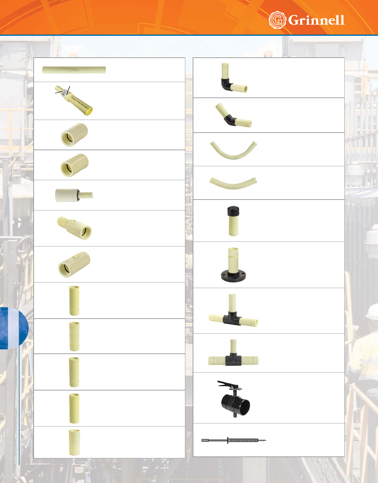
176 www.grinnell.com
G-MINE PVC SYSTEMS
G-MINE PVC SYSTEMS
Figure 72900
SDR Pipe (Spline x Spline)
Page 178
Figure 72901
SDR Pipe with Coupling
(Male Spline x Female Spline)
Page 179
Figure 72904
Couplings (Spline x Spline)
Page 180
Figure 72905
Weld Couplings
(Spline x Solvent Weld)
Page 180
Figure 72919
Reducing Couplings
(Male Spline x Female Spline)
Page 181
Figure 72940
Outlet Couplings
(Male Spline x Female Spline x
Female Thread)
Page 181
Figure 72930
Outlet Couplings
(Spline x Spline x
Female Thread)
Page 182
Figure 72906
End Nipples
(Spline x Plain End)
Page 182
Figure 72907
Nipples
(Spline x Groove)
Page 183
Figure 72908
Nipples
(Spline x Male Thread)
Page 183
Figure 72909
Nipples
(Plain End x Male Thread)
Page 184
Figure 72911
Nipples
(Spline x Spline)
Page 184
Figure 72910
90° Elbows
(Spline x Spline)
Page 185
Figure 72912
45° Elbows
(Spline x Spline)
Page 185
Figure 72913
90° Sweep Elbows
(Spline x Spline)
Page 186
Figure 72914
45° Sweep Elbows
(Spline x Spline)
Page 186
Figure 72915
Caps & Plugs
(Spline)
Page 187
Figure 72916
Flange Adapters
(Spline x Flange)
Page 187
Figure 72917
Tees
(Spline x Spline x Spline)
Page 188
Figure 72918
Reducing Tees
(Spline x Spline x Spline)
Page 188
Figure B8200L
Butterfly Valves
(Spline x Spline)
Page 189
Figures 72999, 72899,
and ITGM
Spare Parts
Page 190
G-MINE PVC Systems Table of Contents
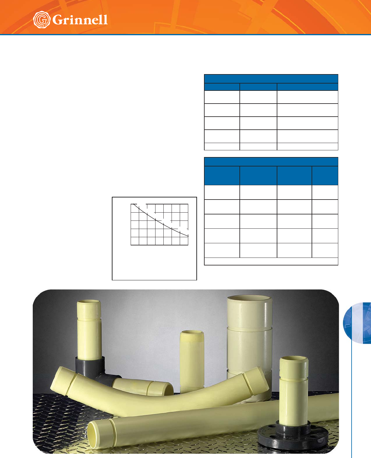
G-MINE PVC SYSTEMS
177
Refer to back cover for country-specific customer care numbers.
G-MINE PVC SYSTEMS
Approvals:
• All G-MINE Pipe and Fittings are NSF-14 Compliant except
for SDR 13.5 which is NSF-61.
Materials:
• Pipe and fittings are made of high- strength PVC (Poly Vinyl
Chloride) conforming to ASTM D 1784.
• G-MINE PVC Joints meet the requirements of ASTM D 3139.
• O-rings are Teflon-coated, Nitrile Butadiene Rubber (NBR) or
Polyisoprene Rubber conforming to ASTM F 477.
• Spline is Nylon. Available in Acid-resistant Polyvinylidene
Flouride.
PVC Temperature Service Factor:
• All pressure ratings for PVC pipe are determined in a water
environment of 73.4°F (23°C) ( (±3.6°F). As the temperature
of the environment increases, PVC Pipe becomes more ductile.
This is represented by the
graph (Figure 1).
• The PVC material’s impact
strength increases and the
tensile strength decreases
as the temperature rises.
Because of this effect,
the pressure rating of the
pipe and fittings must be
decreased to allow for safe
operation of the line at
elevated temperatures.
G-MINE PVC Systems
Tech Data Sheet: G590
70 80 90 100 110 120 130 140
PVC SERVICE FACTOR
TEMPERATURE, °F
0
0.20
0.40
0.60
0.80
1.00
0.40
0.75
1.000.88
0.62
0.50
0.300.22
FIGURE 1
PVC TEMPERATURE
SERVICE FACTOR
Pipe Specifications:
Nominal Property Values
Pipe Property Test Method Value
Izod Impact ASTM D 256 1.15 Ft.-Lbs./In. of Notch
(16.8 N/m)
Tensile
Strength ASTM D 638 7,000 psi (482 bar)
Modulus of
Elasticity ASTM D 638 400,000 psi (27579 bar)
Deflection
Temperature ASTM D 648 158°F (70°C)
Flammability ASTM D 635 Self-Extinguishing
Pipe Imact Strength Production Specification
Nominal Size
Inches
SDR 21
(Ft. - Lbs.)
(N/m)
SDR 17
(Ft. - Lbs.)
(N/m)
SDR 13.5*
(Ft. - Lbs.)
(N/m)
2—170170
- 2480 2480
3—245245
- 3575 3575
4255320320
3721 4670 4670
6 380 470 470
5545 6859 6859
8495610610
7223 8902 8902
*High-pressure pipe
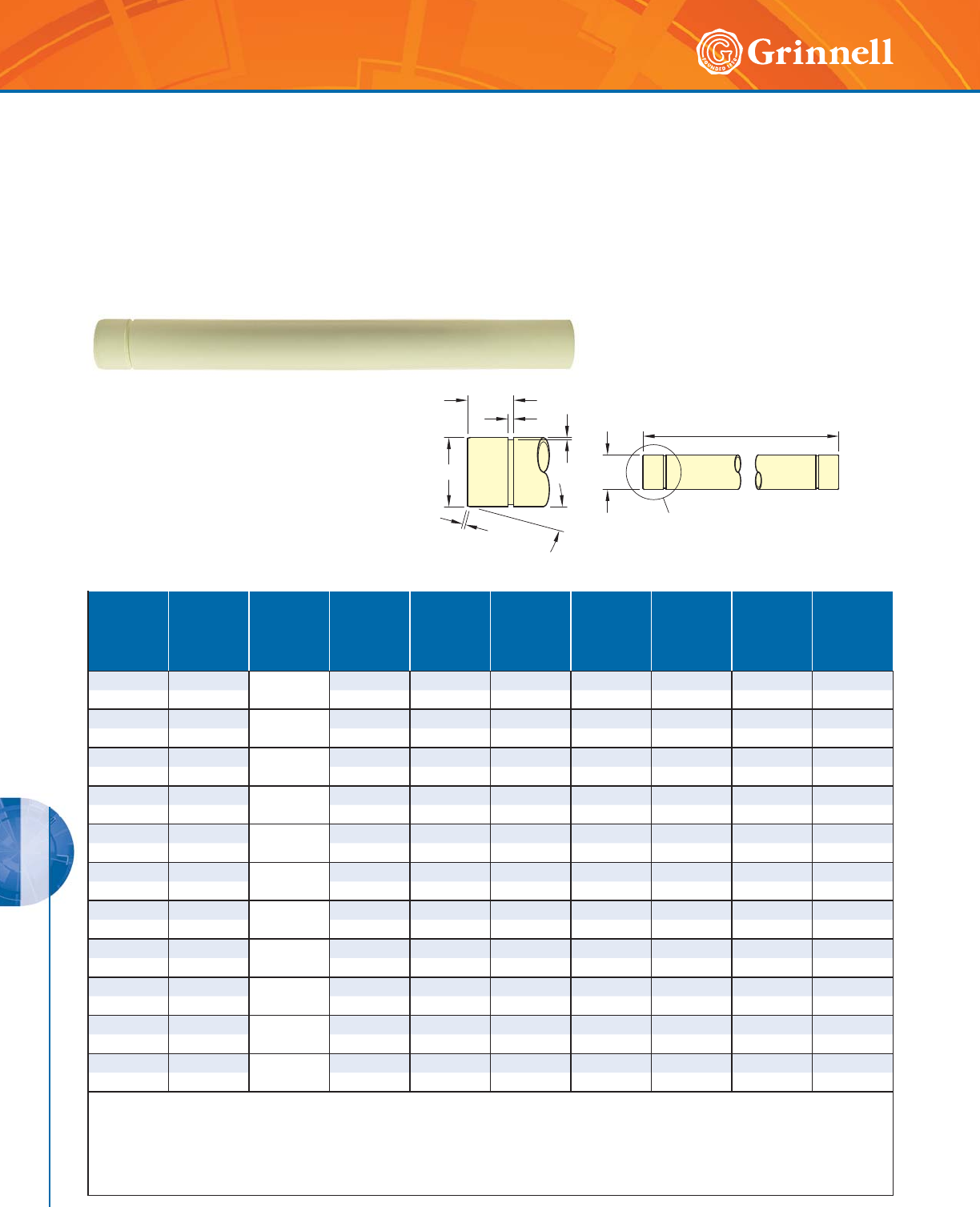
G-MINE PVC SYSTEMS
178 www.grinnell.com
G-MINE PVC SYSTEMS
Figure 72900 SDR Pipe
(Spline x Spline)
Tech Data Sheet: G590
Nom.
Size
In.
mm
O.D.
In.
mm
SDR
Max.
Pressure
Rating
psi bar
P
In.
mm
C
In.
mm
G1
Width
In.
mm
G2
Depth
In.
mm
Min.
Wall
Thk.
In.
mm
Approx.
Pipe
Weight
Lbs./Ft.
Kg/M
22.375
SDR
17
250 0.188 1.75 0.250 0.100 0.140 0.64
50 60,3 17,2 4,8 44,5 6,4 2,5 3,6 0,3
33.50
SDR
17
250 0.188 2.50 0.375 0.135 0.206 1.37
80 88,9 17,2 4,8 63,5 9,5 3,4 5,2 0,6
4 L 4.50 SDR
21
200 0.188 3.00 0.375 0.135 0.214 1.86
100 114,3 13,8 4,8 76,2 9,5 3,4 5,4 0,8
44.50
SDR
17
250 0.188 3.00 0.375 0.135 0.265 2.25
100 114,3 17,2 4,8 76,2 9,5 3,4 6,7 1,0
4 H 4.50 SDR
13.5
315 0.18 8 3.0 0 0.375 0.135 0.3 33 2.85
100 114,3 21,7 4,8 76,2 9,5 3,4 8,5 1,3
6 L 6.625 SDR
21
200 0.313 3.00 0.375 0.135 0.316 3.99
150 168,3 13,8 8,0 76,2 9,5 3,4 8,0 1,8
66.625
SDR
17
250 0.313 3.00 0.375 0.135 0.390 4.87
150 168,3 17,2 8,0 76,2 9,5 3,4 9,9 2,2
6 H 6.625 SDR
13.5
315 0.313 3.00 0.375 0.135 0.491 6.07
150 168,3 21,7 8,0 76,2 9,5 3,4 12,5 2,8
8 L 8.625 SDR
21
200 0.625 3.16 0.500 0.145 0.410 6.71
200 219,1 13,8 16,7 80,3 12,7 3,7 10,4 3,0
88.625
SDR
17
250 0.625 3.16 0.500 0.145 0.508 8.16
200 219,1 17,2 16,7 80,3 12,7 3,7 12,9 3,7
8 H 8.625 SDR
13.5
315 0.625 3.16 0.500 0.145 0.639 10.30
200 219,1 21,7 16,7 80,3 12,7 3,7 16,2 4,7
Laying length is 20 foot (6,1 m) (19 foot (5,8m) lengths are available for export from USA).
G-MINE Pipe is produced with thickened ends to accommodate the G-MINE groove while maintaining their designed pressure rating. Grooving the non-
thickened pipe body will result in less-than-designed pressure rating for the new joint and ultimately the entire system. When fabrication is required
for non-thickened end products, apply a Figure 72905 G-MINE x Solvent Weld Transition Coupling.
10" and 12" (250 and 300mm) are available upon request. Contact GRINNELL Mechanical Products.
See G-MINE specifications on page 177.
The GRINNELL Figure 72900 G-MINE PVC Pipe provides a flexible piping
system that is non-corrosive and resistant to harsh environments, acids,
and most chemicals. Its specially formulated compound contains impact
modifiers and UV (Ultraviolet) inhibitors that provide higher impact strength
over an extended period of time. Pipe is available in 20 foot (6,1m) laying
lengths (19 foot (5,8m) lengths are available for export from USA).
GROOVE DETAIL
O.D.
SEE GROOVE DETAIL
15°
P
G2O.D.
G1
C
PIPE LENGTH, 20'-0"
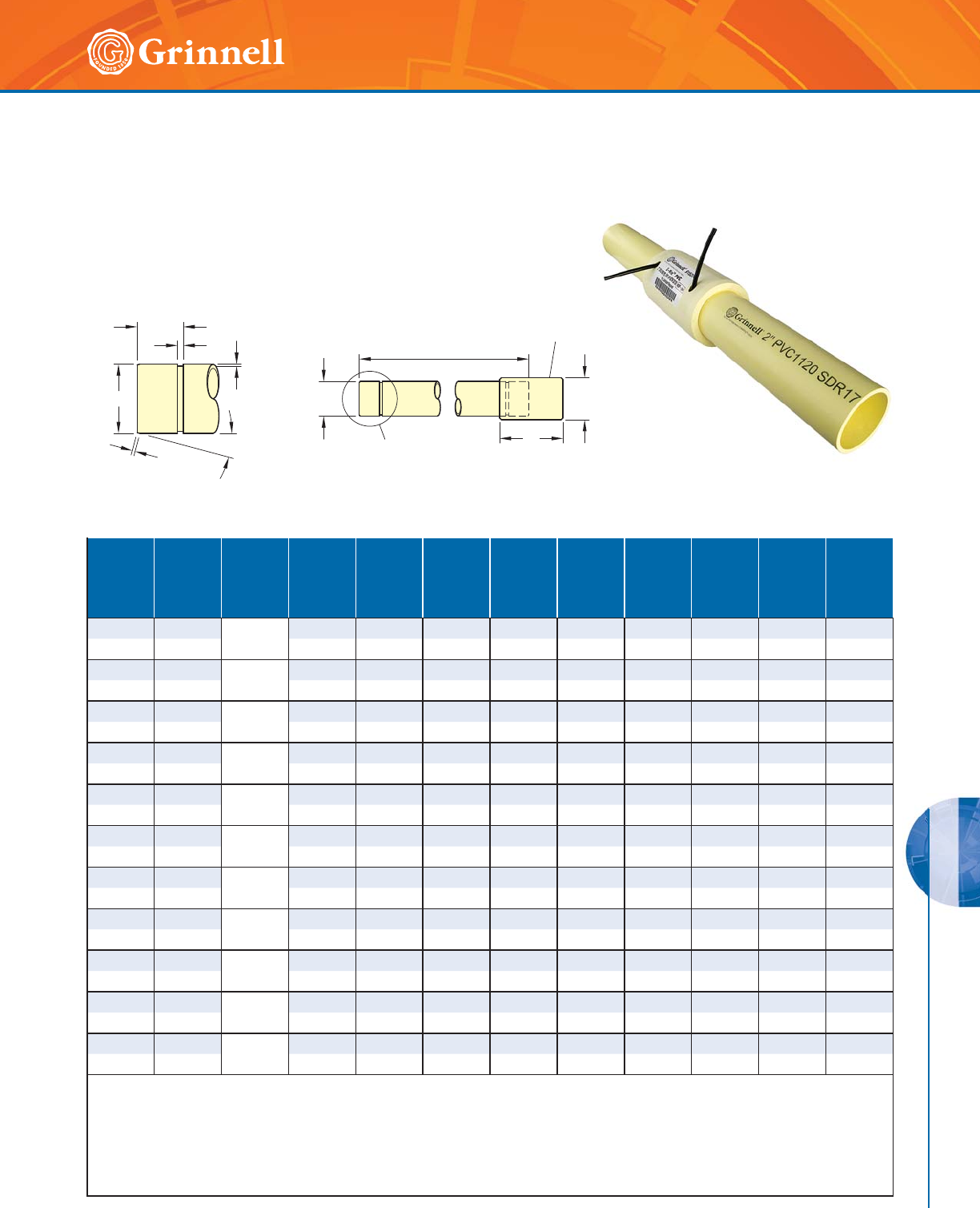
G-MINE PVC SYSTEMS
179
Refer to back cover for country-specific customer care numbers.
G-MINE PVC SYSTEMS
The GRINNELL Figure 72901 G-MINE PVC Pipe and Coupling (packaged
together) provide a flexible piping system that is non-corrosive and resistant
to harsh environments, acids, and most chemicals. GRINNELL Figure 72901
includes a G-MINE PVC Pipe and Coupling, an O-Ring and a Spline. Pipe
laying length is 20 foot (6,1m) (19 foot (5,8m) lengths are available for export
from USA).
Figure 72901 SDR Pipe with Coupling
(Male Spline x Female Spline)
Tech Data Sheet: G590
GROOVE DETAIL
P
15°
O.D. O.D.
G2
SEE GROOVE DETAIL L
B.O.D.
C
G1PIPE LENGTH, 20'-0"
G-MINE COUPLING
FIGURE 72904
Nom.
Size
In.
mm
O.D.
In.
mm
SDR
Max.
Pressure
Rating
psi bar
B.O.D.
In.
mm
L
In.
mm
P
In.
mm
C
In.
mm
G1
Width
In.
mm
G2
Depth
In.
mm
Min.
Wall
Thk.
In.
mm
Approx.
Pipe
Weight
Lbs./Ft.
Kg/M
22.375
SDR
17
250 3.20 5.25 0.188 1.75 0.250 0.100 0.14 0.69
50 60,3 17,2 81 133,4 4,8 44,5 6,4 2,5 3,6 0,31
33.50
SDR
17
250 4.38 7.25 0.188 2.50 0.375 0.135 0.21 1.48
80 88,9 17,2 111 184,2 4,8 63,5 9,5 3,4 5,2 0,67
4 L* 4.50 SDR
21
200 5.47 8.25 0.188 3.00 0.375 0.135 0.21 2.11
100 114,3 13,8 139 209,6 4,8 76,2 9,5 3,4 5,4 0,96
44.50
SDR
17
250 5.47 8.25 0.188 3.00 0.375 0.135 0.27 2.50
100 114,3 17,2 139 209,6 4,8 76,2 9,5 3,4 6,7 1,13
4 H* 4.50 SDR
13.5
315 5.9 6 8.25 0.188 3.00 0.375 0.135 0.3 3 3.10
100 114,3 21,7 151 209,6 4,8 76,2 9,5 3,4 8,5 1,41
6 L* 6.625 SDR
21
200 7.84 8.25 0.313 3.00 0.375 0.135 0.32 4.30
150 168,3 13,8 199 209,6 8,0 76,2 9,5 3,4 8,0 1,96
66.625
SDR
17
250 7.84 8.25 0.313 3.00 0.375 0.135 0.39 5.18
150 168,3 17,2 199 209,6 8,0 76,2 9,5 3,4 9,9 2,34
6 H* 6.625 SDR
13.5
315 8.37 8.25 0.313 3.00 0.375 0.135 0.49 6.59
150 168,3 21,7 213 209,6 8,0 76,2 9,5 3,4 12,5 2,99
8 L* 8.625 SDR
21
200 10.19 10.13 0.625 3.16 0.500 0.145 0.41 7.26
200 219,1 13,8 259 257,3 16,7 80,3 12,7 3,7 10,4 3,29
88.625
SDR
17
250 10.95 10.13 0.625 3.16 0.500 0.145 0.51 8.71
200 219,1 17,2 278 257,3 16,7 80,3 12,7 3,7 12,9 3,95
8 H* 8.625 SDR
13.5
315 10.95 10.13 0.625 3.16 0.500 0.145 0.64 11.30
200 219,1 21,7 278 257,3 16,7 80,3 12,7 3,7 16,2 5,13
Laying length is 20 foot (6,1 m) (19 foot (5,8m) lengths are available for export from USA).
G-MINE Pipe is produced with thickened ends to accommodate the G-MINE groove while maintaining their designed pressure rating. Grooving the non-
thickened pipe body will result in less-than-designed pressure rating for the new joint and ultimately the entire system. When fabrication is required
for non-thickened end products, apply a Figure 72905 G-MINE x Solvent Weld Transition Coupling.
G-MINE Coupling, Gaskets (O-rings) and Splines included.
Refer to Figure 72904 for weight of G-MINE Coupling.
See G-MINE specifications on page 177.
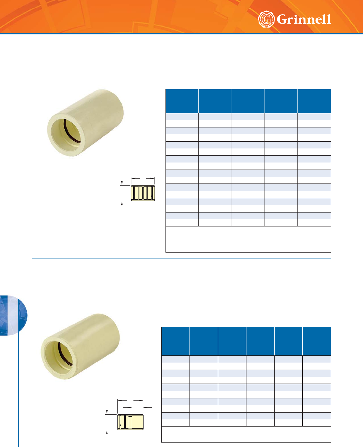
G-MINE PVC SYSTEMS
180 www.grinnell.com
G-MINE PVC SYSTEMS
The GRINNELL Figure 72904 G-MINE Coupling provides a connection
between two pieces of G-MINE PVC Pipe. G-MINE Couplings are
designed for non-permanent use applications and are supplied with
O-rings (gaskets) for ease of assembly and disassembly.
Figure 72904 Couplings
(Spline x Spline)
Tech Data Sheet: G590
L
B.O.D.
Nominal
Size
Inches
mm
B.O.D.
Inches
mm
L
Inches
mm
Max.
Pressure
Rating
psi bar
Approx.
Weight
Lbs.
Kg
2 3.20 5.25 250 1.05
50 81 133,4 17,2 0,5
3 4.375 7.25 250 2.17
8 0 111 184 , 2 17, 2 1,0
4 5.47 8.25 250 4.92
100 139 209,6 17,2 2,2
4H 5.96 8.25 315 5.00
100 151 209,6 21,7 2,3
67.848.252506.20
150 199 209,6 17,2 2,8
6 H 8.37 8.25 315 10.40
150 213 209,6 21,7 4,7
8 10.19 10.125 250 10.93
200 259 257, 3 17,2 5,0
8 H 10.95 10.125 315 20.00
200 278 257,3 21,7 9,1
G-MINE Gaskets (O-rings) and Splines included.
10" and 12" (250 and 300mm) are available upon request. Contact GRINNELL
Mechanical Products.
See G-MINE specifications on page 177.
The GRINNELL Figure 72905 G-MINE Transition Coupling (Female x Solvent
Weld) provides an efficient transition from G-MINE PVC Pipe to plain-end
PVC pipe.
Figure 72905 Couplings
(Spline x Solvent Weld)
Tech Data Sheet: G590
L2
B.O.D.
L1
Nominal
Size
Inches
mm
B.O.D.
Inches
mm
Max.
Pressure
Rating
psi bar
L1
Inches
mm
L 2
Inches
mm
Approx.
Weight
Lbs.
Kg
2 3.20 250 5.50 2.375 1.00
50 81,3 17,2 139,7 60,5 0,5
34.3752508.003.502.20
8 0 111,1 17, 2 2 03 , 2 8 8 , 9 1, 0
4 5.47 250 9.00 4.00 3.50
100 138,9 17,2 228,6 101,6 1,6
6 7.84 250 9.00 4.00 6.40
150 199,1 17,2 228,6 101,6 2,9
8 10.19 250 10.125 4.50 11.30
200 258,8 17,2 257,3 114,3 5,1
G-MINE Gasket O-ring and Spline included.
See G-MINE specifications on page 177.
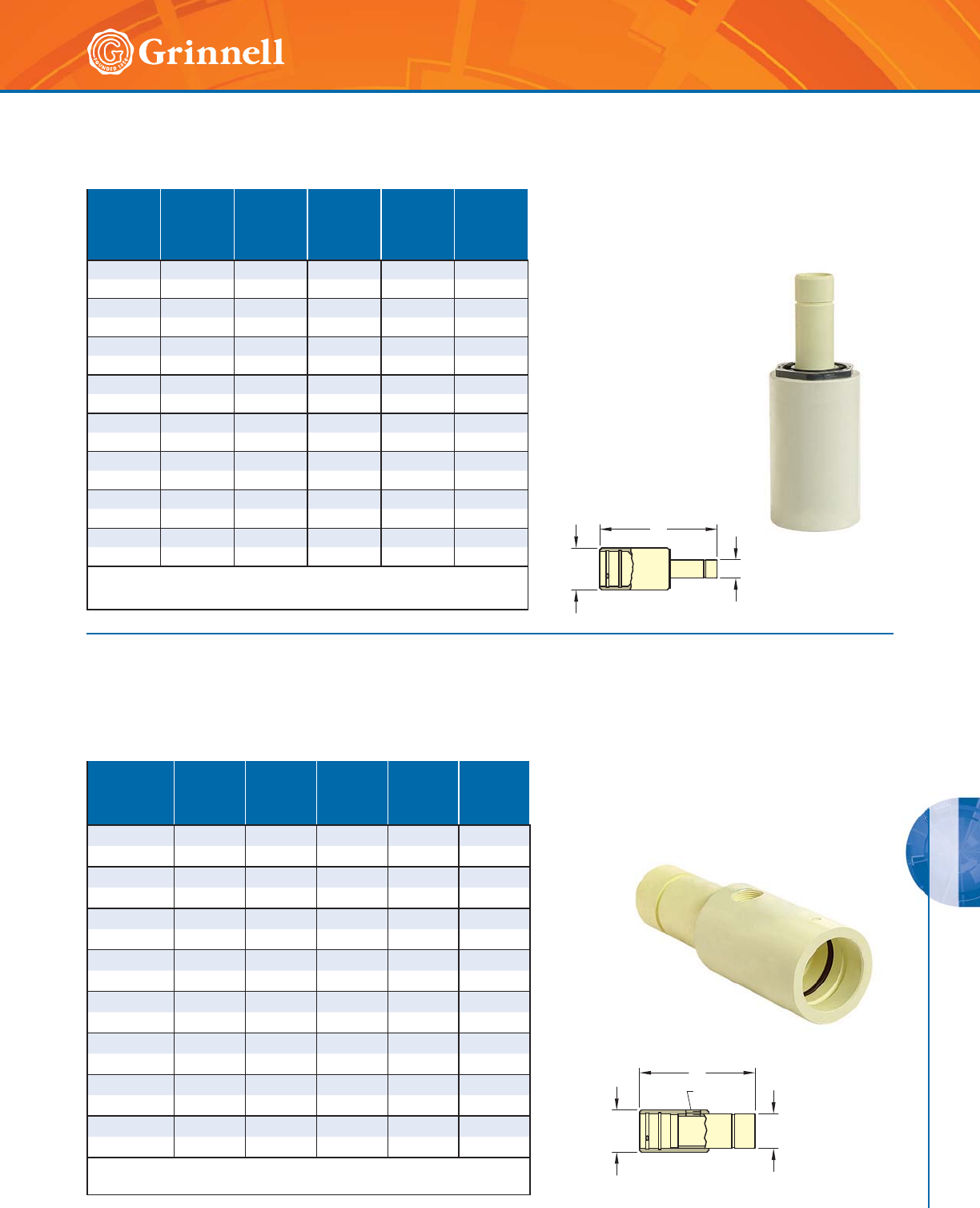
G-MINE PVC SYSTEMS
181
Refer to back cover for country-specific customer care numbers.
G-MINE PVC SYSTEMS
The GRINNELL Figure 72919 G-MINE Reducing
Coupling (Female x Male) allows for a direct
transition between two different pipe sizes.
Figure 72919 Reducing Couplings
(Male Spline x Female Spline)
Tech Data Sheet: G590
B.O.D.
L O.D.
Nominal
Size
Inches
mm
O.D.
Inches
mm
B.O.D.
Inches
mm
Max.
Pressure
Rating
psi bar
L
Inches
mm
Approx.
Weight
Lbs.
Kg
4 x 2 2.375 5.47 250 15.25 5.00
100 x 50 60,3 139 17,2 387,4 2,3
4 x 3 3.50 5.47 250 16.56 5.70
100 x 80 88,9 139 17,2 420,6 2,6
6 x 2 2.375 7.84 250 15.75 10.40
150 x 50 60,3 199 17,2 400,1 4,7
6 x 3 3.50 7.84 250 16.50 11.00
150 x 80 88,9 199 17,2 419,1 5,0
6 x 4 4.50 7.84 250 17.38 11.10
150 x 100 114,3 199 17,2 441,5 5,0
8 x 2 2.375 10.19 250 17.00 11.10
200 x 50 60,3 259 17,2 431,8 5,0
8 x 4 4.50 10.19 250 15.63 24.10
200 x 100 114,3 259 17,2 397,0 10,9
8 x 6 6.625 10.19 250 18.50 24.60
200 x 150 168,3 259 17,2 469,9 11,2
G-MINE Gasket (O-ring) and Spline included.
See G-MINE specifications on page 177.
Figure 72940 Outlet Couplings
(Male Spline x Female Spline x Female Thread)
Tech Data Sheet: G590
The GRINNELL Figure 72940 G-MINE Threaded Outlet
Coupling (Female x Male x Female NPT) provides a
threaded branch outlet connection.
B.O.D.
NPT
O.D.
L1
Nominal Size
Run x Outlet
Inches x NPT
O.D.
Inches
mm
B.O.D.
Inches
mm
Max.
Pressure
Rating
psi bar
L
Inches
mm
Approx.
Weight
Lbs.
Kg
2 x 3⁄42.375 3.20 250 10.13 1.60
50 x 20 60,3 81 17,2 257,3 0,7
2 x 1 2.375 3.20 250 10.13 1.50
50 x 25 60,3 81 17,2 257,3 0,7
3 x 11⁄23.50 4.375 250 13.50 3.60
80 x 40 88,9 111 17,2 342,9 1,6
4 x 11⁄24.50 5.47 250 15.00 5.80
100 x 40 114,3 139 17,2 381,0 2,6
6 x 11⁄26.625 7.84 250 17.00 11.50
150 x 40 168,3 199 17,2 431,8 5,2
6 x 2 6.625 7.84 250 17.00 11.40
150 x 50 168,3 199 17,2 431,8 5,2
8 x 11⁄28.625 10.19 250 19.00 20.60
200 x 40 219,1 259 17,2 482,6 9,3
8 x 2 8.625 10.19 250 19.00 21.40
200 x 50 219,1 259 17,2 482,6 9,7
G-MINE Gasket (O-ring) and Spline included.
See G-MINE specifications on page 177.
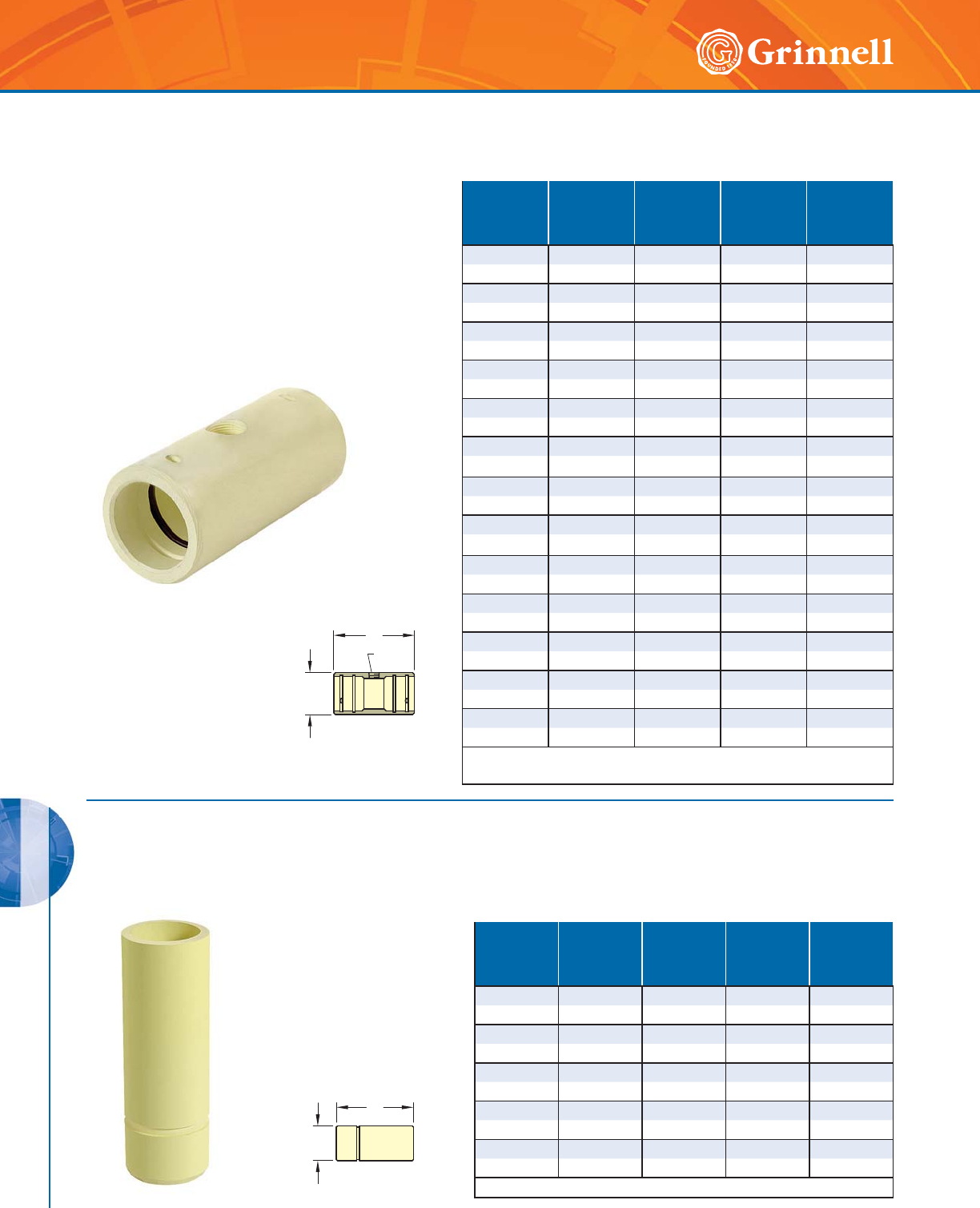
G-MINE PVC SYSTEMS
182 www.grinnell.com
G-MINE PVC SYSTEMS
The GRINNELL Figure 72930 G-MINE Threaded Outlet
Coupling (Female x Female x Female NPT) provides a
connection between two pieces of G-MINE PVC Pipe and
includes a threaded branch connection.
Figure 72930 Outlet Couplings
(Spline x Spline x Female Thread)
Tech Data Sheet: G590
NPT
B.O.D.
L
Nominal Size
Run x Outlet
Inches x NPT
B.O.D.
Inches
mm
Max.
Pressure
Rating
psi bar
L
Inches
mm
Approx.
Weight
Lbs.
Kg
2 x 3⁄43.20 200 7.00 1.50
50 x 20 81 13,8 177,8 0,7
2 x 1 3.20 200 7.00 1.40
50 x 25 81 13,8 177,8 0,6
3 x 3⁄44.375 200 9.50 2.60
80 x 20 111 13,8 241,3 1,2
3 x 1 4.375 200 9.50 2.90
80 x 25 111 13,8 241,3 1,3
3 x 11⁄24.375 160 9.50 2.70
80 x 4 0 111 11,0 241,3 1,2
4 x 3⁄45.47 200 10.50 4.10
100 x 20 139 13,8 266,7 1,9
4 x 1 5.47 200 10.50 4.10
100 x 25 139 13,8 266,7 1,9
4 x 11⁄25.47 160 10.50 4.00
100 x 40 139 11,0 266,7 1,8
6 x 3⁄47.8 4 2 0 0 11.25 7.90
150 x 20 199 13,8 285,8 3,6
6 x 1 7.84 200 11.25 7.90
150 x 25 199 13,8 285,8 3,6
6 x 11⁄27.84 200 11.25 7.90
150 x 40 199 13,8 285,8 3,6
8 x 1 10.19 200 12.50 15.00
200 x 25 259 13,8 317,5 6,8
8 x 11⁄210.19 200 12.50 15.00
200 x 40 259 13,8 317,5 6,8
G-MINE Gaskets (O-rings) and Splines included.
See G-MINE specifications on page 177.
The GRINNELL Figure 72906 G-MINE Nipple (Male x Plain-End)
provides an economical and efficient method of converting a solvent
weld-end pipe run to a G-MINE grooved connection.
Figure 72906 Nipples
(Spline x Plain End)
Tech Data Sheet: G590
O.D.
L
Nominal
Size
Inches
mm
O.D.
Inches
mm
Max.
Pressure
Rating
psi bar
L
Inches
mm
Approx.
Weight
Lbs.
Kg
2 2.375 250 7.00 0.60
50 6 0,3 17,2 177,8 0,3
3 3.50 250 9.00 1.40
80 88,9 17,2 228,6 0,6
44.5025010.002.30
100 114,3 17,2 254,0 1,0
6 6.625 250 12.00 5.20
150 168,3 17,2 304,8 2,4
8 8.625 250 13.00 9.70
200 219,1 17,2 330,2 4,4
See G-MINE specifications on page 177.
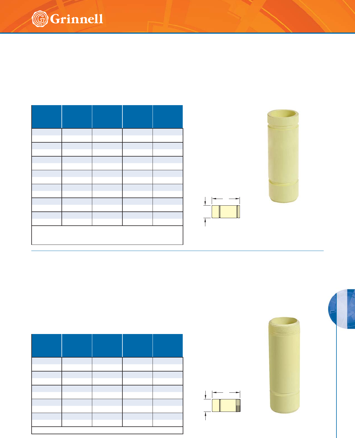
G-MINE PVC SYSTEMS
183
Refer to back cover for country-specific customer care numbers.
G-MINE PVC SYSTEMS
The GRINNELL Figure 72907 G-MINE Transition Coupling (G-MINE
x Grooved) provides an efficient transition from G-MINE PVC Pipe to
grooved steel pipe that meets AWWA C-606 IPS Groove Standards.
Figure 72907 Nipples
(Spline x Groove)
Tech Data Sheet: G590
O.D.
L
Nominal
Size
Inches
mm
O.D.
Inches
mm
Max.
Pressure
Rating
psi bar
L
Inches
mm
Approx.
Weight
Lbs.
Kg
2 2.375 250 7.00 0.60
50 6 0,3 17,2 177,8 0,3
3 3.50 250 9.00 1.60
80 88,9 17,2 228,6 0,7
4 4.50 250 10.00 2.50
100 114,3 17,2 254,0 1,1
4 H 4.50 250 10.00 3.10
100 114,3 17,2 254,0 1,4
6 6.625 250 12.00 5.20
150 168,3 17,2 304,8 2,4
6 H 6.625 250 12.00 7.20
150 168,3 17,2 304,8 3,3
8 8.625 250 13.50 9.00
20 0 219,1 17,2 342,9 4,1
Requires thrust blocking to eliminate end loads; use only with
GRINNELL Flexible Couplings only.
See G-MINE specifications on page 177.
The GRINNELL Figure 72908 G-MINE Threaded Nipple (Male x Male
NPT) provides an economical and efficient method of connecting a
G-MINE piping system to a female threaded adapter or device.
Figure 72908 Nipples
(Spline x Male Thread)
Tech Data Sheet: G590
O.D.
L
Nominal
Size
Inches
mm
O.D.
Inches
mm
Max.
Pressure
Rating
psi bar
L
Inches
mm
Approx.
Weight
Lbs.
Kg
2 2.375 200 7.00 0.60
50 60,3 13,8 177,8 0,3
3 3.50 190 9.00 1.30
80 88,9 13,1 228,6 0,6
44.5016010.002.40
100 114,3 11,0 254,0 1,1
66.62514012.005.20
150 168,3 9,7 304,8 2,4
8 8.625 120 13.00 9.00
200 219,1 8,3 330,2 4,1
See G-MINE specifications on page 177.
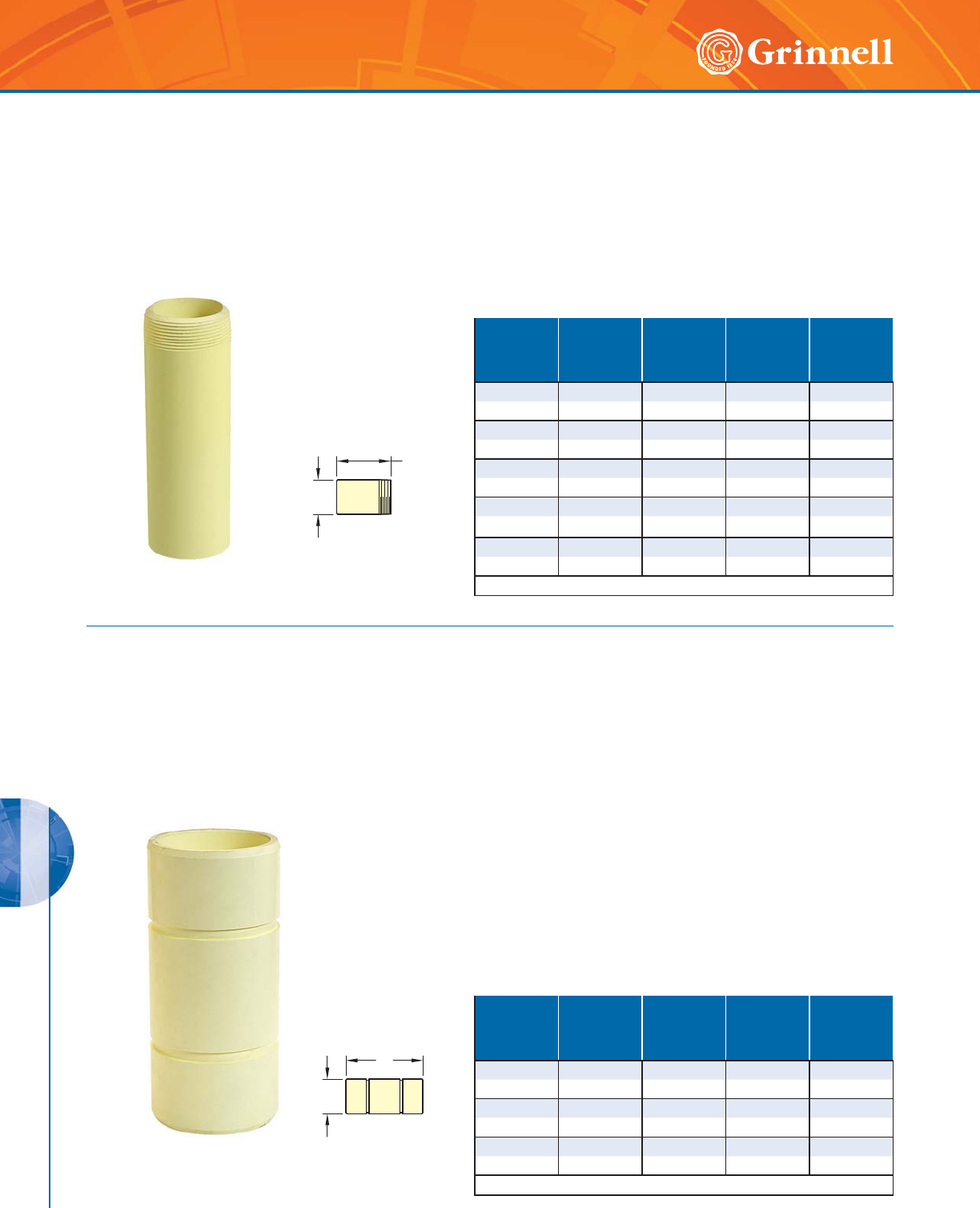
G-MINE PVC SYSTEMS
184 www.grinnell.com
G-MINE PVC SYSTEMS
The GRINNELL Figure 72909 G-MINE Threaded Nipple (Plain-
end x Male NPT) provides an economical and efficient method
of connecting a solvent weld-end pipe run to a female threaded
adapter or device.
Figure 72909 Nipples
(Plain End x Male Thread)
Tech Data Sheet: G590
O.D.
L
Nominal
Size
Inches
mm
O.D.
Inches
mm
Max.
Pressure
Rating
psi bar
L
Inches
mm
Approx.
Weight
Lbs.
Kg
22.3752005.250.60
50 60,3 13,8 133,4 0,3
33.501906.501.25
80 88,9 13,1 165,1 0,6
44.501607.002.50
100 114,3 11,0 177,8 1,1
6 6.625 140 9.00 5.70
150 168,3 9,7 228,6 2,6
8 8.625 120 9.80 10.25
200 219,1 8,3 248,9 4,7
See G-MINE specifications on page 177.
The GRINNELL Figure 72911 G-MINE Nipple (Male x Male)
provides an economical and efficient method of connecting two
female G-MINE components.
Figure 72911 Nipples
(Spline x Spline)
Tech Data Sheet: G590
O.D.
L
Nominal
Size
Inches
mm
O.D.
Inches
mm
Max.
Pressure
Rating
psi bar
L
Inches
mm
Approx.
Weight
Lbs.
Kg
44.5025010.002.30
100 114,3 17,2 254,0 1,0
6 6.625 250 12.00 5.20
150 168,3 17,2 304,8 2,4
8 8.625 250 13.00 9.70
200 219,1 17,2 330,2 4,4
See G-MINE specifications on page 177.
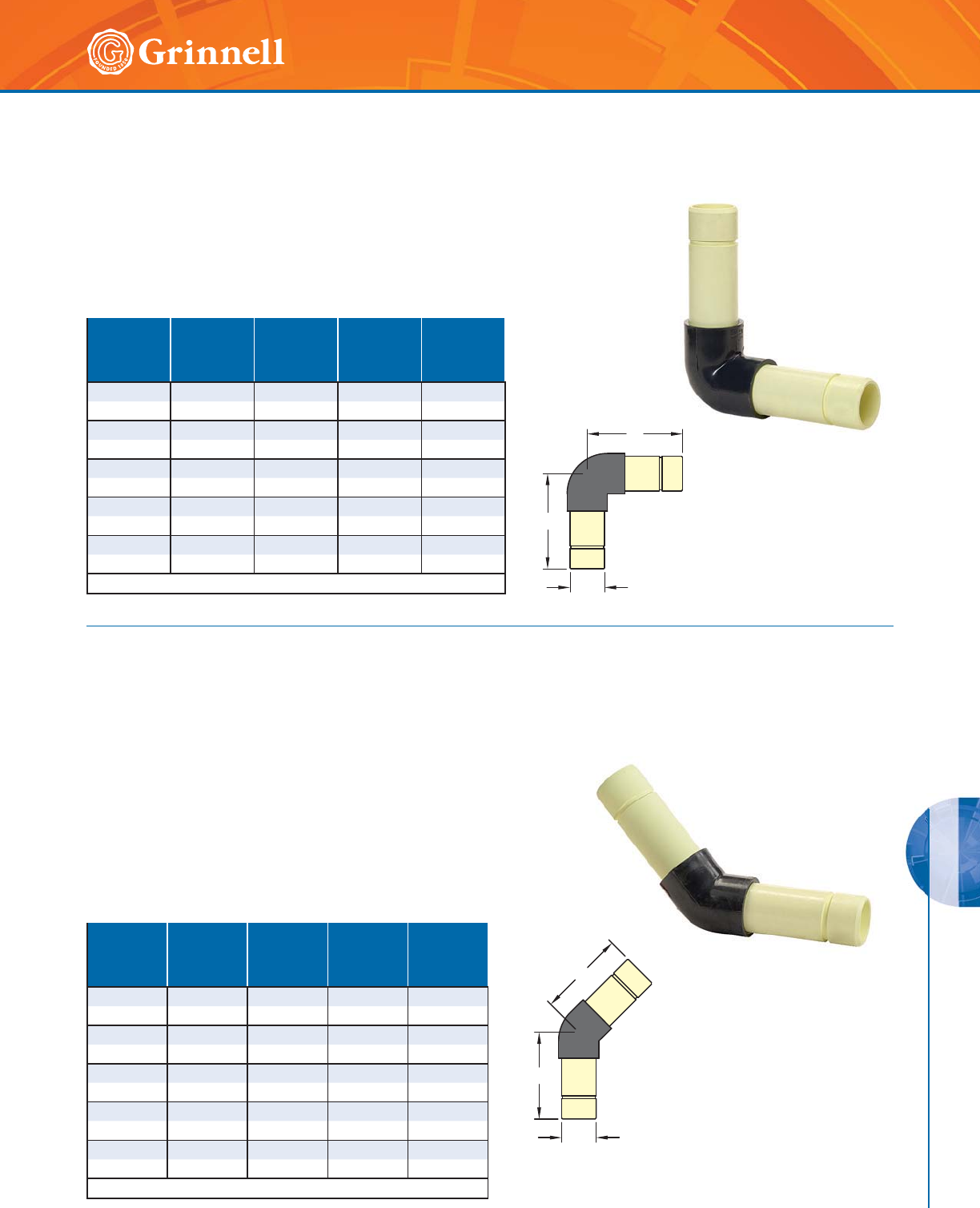
G-MINE PVC SYSTEMS
185
Refer to back cover for country-specific customer care numbers.
G-MINE PVC SYSTEMS
The GRINNELL Figure 72910 G-MINE 90° Degree Elbow (Male
x Male) provides an economical and efficient method of changing
pipe direction.
Figure 72910 90° Elbows
(Spline x Spline)
Tech Data Sheet: G590
O.D.
L
L
Nominal
Size
Inches
mm
O.D.
Inches
mm
Max.
Pressure
Rating
psi bar
L
Inches
mm
Approx.
Weight
Lbs.
Kg
22.3752508.001.70
50 60,3 17,2 203,2 0,8
3 3.5 0 250 10.18 4.10
80 88,9 17,2 258,6 1,9
4 4.50 250 12.375 7.50
100 114,3 17,2 314,5 3,4
6 6.625 250 15.625 17.40
150 168,3 17,2 397,0 7,9
8 8.625 250 18.00 33.70
200 219,1 17,2 457,2 15,3
See G-MINE specifications on page 177.
The GRINNELL Figure 72912 G-MINE 45° Degree Elbow (Male
x Male) provides an economical and efficient method of changing
pipe direction.
Figure 72912 45° Elbows
(Spline x Spline)
Tech Data Sheet: G590
Nominal
Size
Inches
mm
O.D.
Inches
mm
Max.
Pressure
Rating
psi bar
L
Inches
mm
Approx.
Weight
Lbs.
Kg
22.3752507.751.60
50 60,3 17,2 196,9 0,7
33.502509.753.90
80 88,9 17,2 247,7 1,8
44.5025011.257.10
100 114,3 17,2 285,8 3,2
6 6.625 250 13.00 16.10
150 168,3 17,2 330,2 7,3
8 8.625 250 15.00 30.90
200 219,1 17,2 381,0 14,0
See G-MINE specifications on page 177.
O.D.
L
L
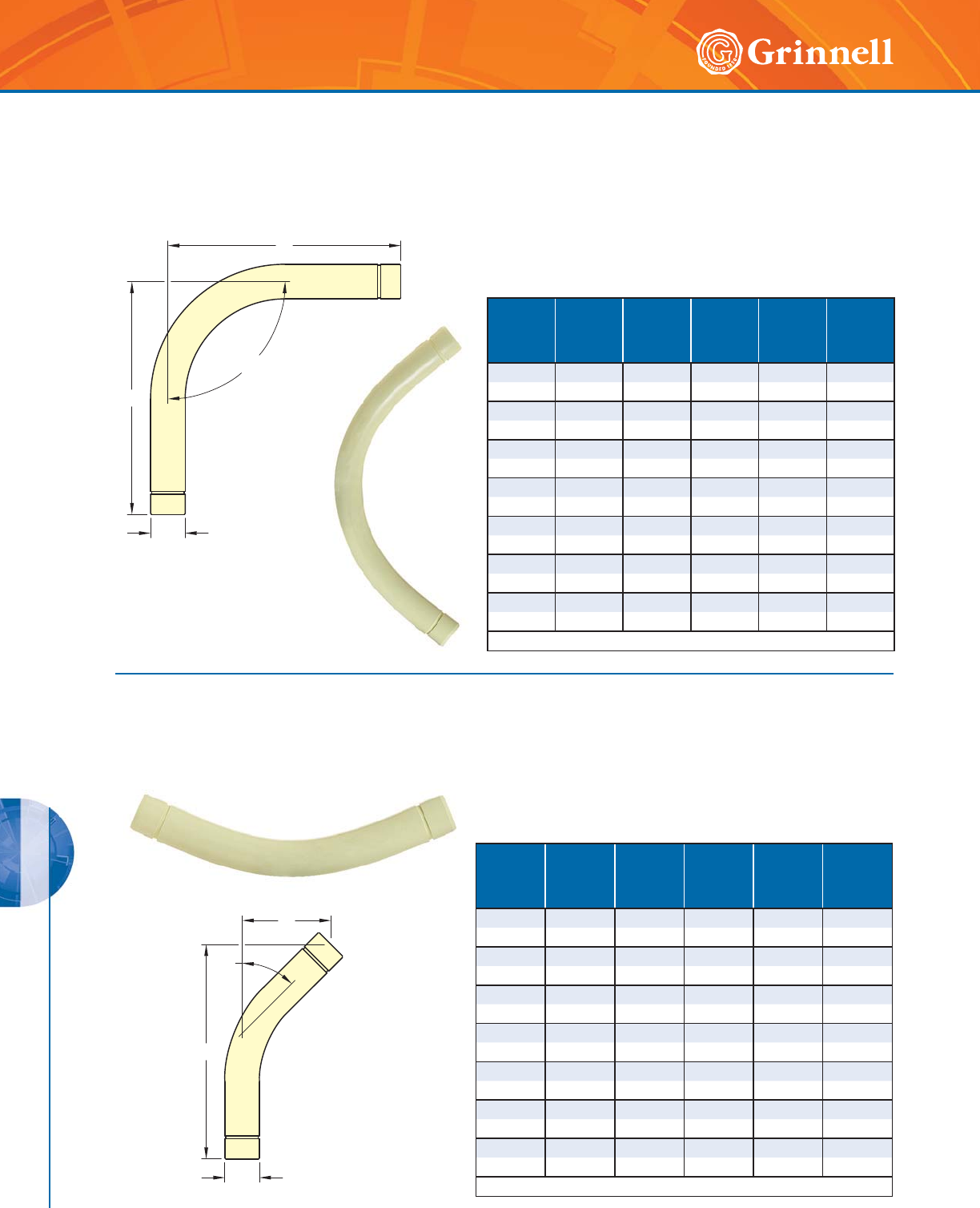
G-MINE PVC SYSTEMS
186 www.grinnell.com
G-MINE PVC SYSTEMS
The GRINNELL Figure 72913 G-MINE 90° Degree Sweep
Elbow provides an economical and efficient method of
changing pipe direction.
Figure 72913 90° Sweep Elbows
(Spline x Spline)
Tech Data Sheet: G590
L
O.D.
90°
W
Nominal
Size
Inches
mm
O.D.
Inches
mm
Max.
Pressure
Rating
psi bar
L
Inches
mm
W
Inches
mm
Approx.
Weight
Lbs.
Kg
22.37525016.0616.062.40
50 60,3 17,2 408 408 1,1
3 3.50 250 23.125 23.125 6.40
80 88,9 17,2 587,4 587,4 2,9
44.5025030.2530.2512.70
100 114,3 17,2 408,0 408,0 5,8
4 H 4.50 315 30.25 30.25 14.90
100 114,3 21,7 768,4 768,4 6,8
6 6.625 250 42.00 42.00 31.00
150 168,3 17,2 1066,8 1066,8 14,1
6 H 6.625 315 42.00 42.00 45.30
150 168,3 21,7 1066,8 1066,8 20,6
8 8.625 250 46.625 46.625 59.00
2 0 0 219,1 17, 2 1184 , 3 1184 , 3 2 6, 8
See G-MINE specifications on page 177.
The GRINNELL Figure 72914 G-MINE 45° Degree Sweep
Elbow provides an economical and efficient method of
changing pipe direction.
Figure 72914 45° Sweep Elbows
(Spline x Spline)
Tech Data Sheet: G590
L
O.D.
45°
W
Nominal
Size
Inches
mm
O.D.
Inches
mm
Max.
Pressure
Rating
psi bar
L
Inches
mm
W
Inches
mm
Approx.
Weight
Lbs.
Kg
22.37525018.1257.502.00
50 60,3 17,2 460,4 190,5 0,9
33.5025025.6910.754.90
80 88,9 17,2 652,5 273,1 2,2
4 4.50 250 28.75 11.875 7.50
100 114,3 17,2 730,3 301,6 3,4
4 H 4.50 315 28.75 11.875 11.60
100 114,3 21,7 730,3 301,6 5,3
6 6.625 250 39.19 16.25 18.30
150 168,3 17,2 995,4 412,8 8,3
6 H 6.625 315 39.19 16.25 26.20
150 168,3 21,7 995,4 412,8 11,9
8 8.625 250 52.00 21.57 35.00
200 219,1 17,2 1320,8 547,7 15,9
See G-MINE specifications on page 177.
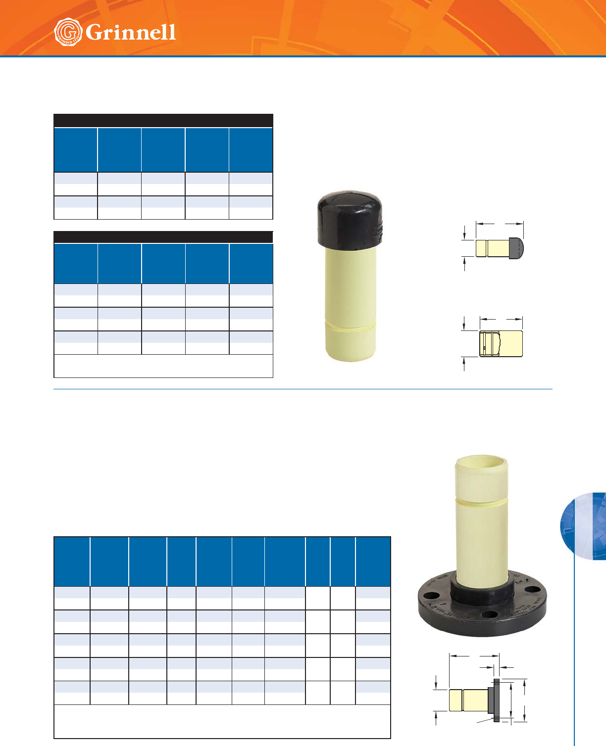
G-MINE PVC SYSTEMS
187
Refer to back cover for country-specific customer care numbers.
G-MINE PVC SYSTEMS
The GRINNELL Figure 72915 G-MINE End Plug and End Cap provide
an economical and efficient method of capping a piping system.
Figure 72915 Caps & Plugs
(Spline)
Tech Data Sheet: G590
B.O.D.
L
L
O.D.
Figure 72915 End Plug
Nominal
Size
Inches
mm
O.D.
Inches
mm
Max.
Pressure
Rating
psi bar
L
Inches
mm
Approx.
Weight
Lbs.
Kg
22.3752507.500.90
50 60 17,2 190,5 0,4
3 3.50 250 10.00 2.00
80 89 17,2 254,0 0,9
Figure 72915 End Cap*
Nominal
Size
Inches
mm
B.O.D.
Inches
mm
Max.
Pressure
Rating
psi bar
L
Inches
mm
Approx.
Weight
Lbs.
Kg
4 5.47 250 9.00 4.20
100 139 17,2 228,6 1,9
6 7.84 250 9.00 9.00
150 199 17,2 228,6 4,1
8 10.19 250 10.125 17.00
200 259 17,2 257,3 7,7
* G-MINE Gasket (O-ring) and Spline included.
See G-MINE specifications on page 177.
The GRINNELL Figure 72916 G-MINE Flange Adapter provides a
direct transition from flanged components to G-MINE PVC piping
components.
Figure 72916 Flange Adapters
(Spline x Flange 150psi)
Tech Data Sheet: G590
A
BOLT
SIZE
O.D.1O.D.2
L
R
Nominal
Size
Inches
mm
Outlet 1
O.D.
Inches
mm
Max.
Pressure
Rating
psi bar
L
Inches
mm
Flange 2
O.D.
Inches
mm
R
Inches
mm
Bolt
Circle
Diameter
Inches
mm
Bolt
Size
Bolt
Holes
Approx.
Weight
Lbs.
Kg
22.3751507.196.000.814.75
5/841.6
50 60,3 10,3 182,6 152,4 20,6 120,7 0,7
3 3.50 150 9.25 7.50 1.06 6.00 5/843.2
80 88,9 10,3 235,0 190,5 26,9 152,4 1,5
4 4.50 150 10.25 9.00 1.125 7.50 5/885.0
100 114,3 10,3 260,4 228,6 28,7 190,5 2,3
6 6.625 150 12.44 11.00 1.28 9.50 3/489.0
150 168,3 10,3 316 279,4 32,5 241,3 4,1
88.62515013.3813.501.37511.75
3/4816.0
200 219,1 10,3 339,9 342,9 35,1 298,5 7,3
All flanges are Van Stone style with glass-filled PVC ring.
ANSI Class 125 and 150 bolt pattern.
See G-MINE specifications on page 177.
Figure 72915
End Cap (Female Spline)
Figure 72915
End Plug (Male Spline)
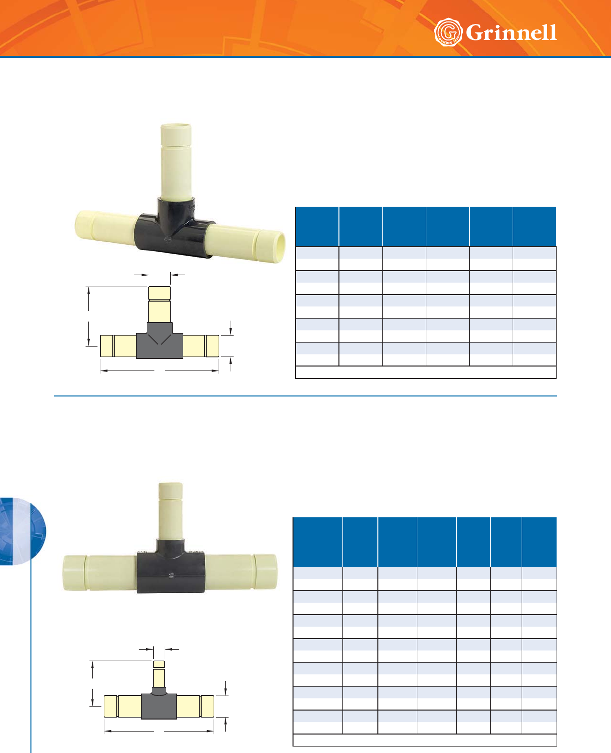
G-MINE PVC SYSTEMS
188 www.grinnell.com
G-MINE PVC SYSTEMS
The GRINNELL Figure 72917 G-MINE Tee (Male) provides an
economical and efficient method of adding a G-MINE PVC Branch
Run to a piping system.
Figure 72917 Tees
(Spline x Spline x Spline)
Tech Data Sheet: G590
L
F
O.D.
O.D.
Nominal
Size
Inches
mm
O.D.
Inches
mm
Max.
Pressure
Rating
psi bar
L
Inches
mm
F
Inches
mm
Approx.
Weight
Lbs.
Kg
2 2.375 250 16.50 10.875 2.30
50 60,3 17,2 419,1 276,4 1,0
3 3.50 250 21.50 11.25 5.80
80 88,9 17,2 546,1 280,0 2,6
4 4.50 250 24.75 12.375 10.70
10 0 114,3 17,2 628,7 314,5 4,9
6 6.625 250 31.00 15.50 25.00
150 168,3 17,2 787,4 393,7 11,3
8 8.625 250 36.25 17.75 48.00
200 219,1 17,2 920,8 450,9 21,8
See G-MINE specifications on page 177.
The GRINNELL Figure 72918 G-MINE Reducing Tee (Male) provides
an economical and efficient method of adding a reduced diameter
G-MINE PVC Branch Run to a piping system.
Figure 72918 Reducing Tees
(Spline x Spline x Spline)
Tech Data Sheet: G590
L
F
O.D.1
O.D.2
Nominal Size
Run x Run
x Branch
Inches
mm
Run
O.D. 1
Inches
mm
Outlet
O.D. 2
Inches
mm
Max.
Pressure
Rating
psi bar
L
Inches
mm
F
Inches
mm
Approx.
Weight
Lbs.
Kg
3 x 2 3.50 2.375 250 21.00 8.84 5.00
80 x 50 88,9 60,3 17,2 533,4 224,5 2,3
4 x 2 4.50 2.375 250 22.875 9.47 10.10
100 x 50 114,3 60,3 17,2 581,2 240,5 4,6
4 x 3 4.50 3.50 250 24.19 11.66 10.80
100 x 80 114,3 88,9 17,2 614,4 296,2 4,9
6 x 2 6.625 2.375 250 28.125 11.75 22.83
150 x 50 168,3 60,3 17,2 714,5 298,5 10,4
6 x 3 6.625 3.50 250 28.125 12.75 24.20
150 x 80 168,3 88,9 17,2 714,5 323,9 11,0
6 x 4 6.625 4.50 250 29.19 13.75 24.40
150 x 100 168,3 114,3 17,2 741,4 349,3 11,1
8 x 6 8.625 6.625 250 33.50 16.81 50.90
200 x 150 219,1 168,3 17,2 850,9 427,0 23,1
See G-MINE specifications on page 177.
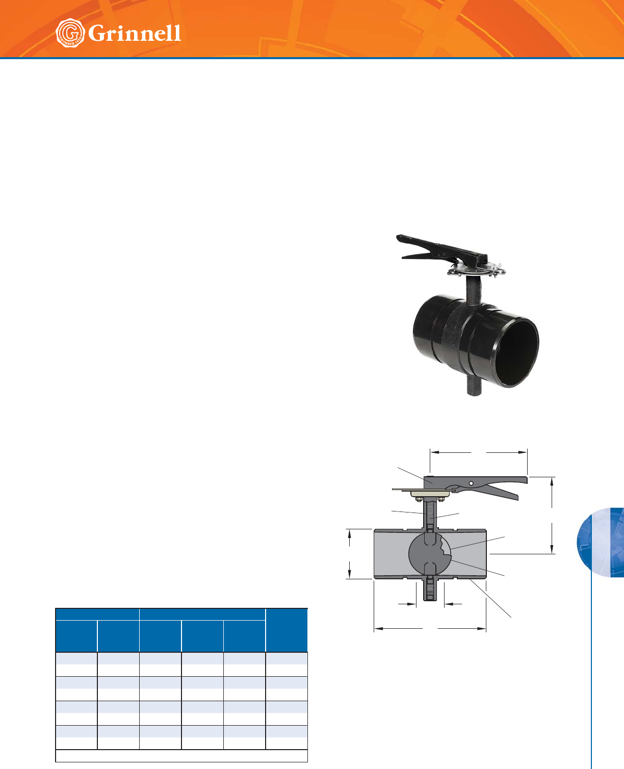
G-MINE PVC SYSTEMS
189
Refer to back cover for country-specific customer care numbers.
G-MINE PVC SYSTEMS
Model B8200L G-MINE Butterfly Valves
(Spline x Spline)
Tech Data Sheet: G592
Nominal Pipe Size Dimensions Inches mm Approx.
Weight
Lbs
kg
ANSI
Inches
mm
O.D.
Inches
mm
ABL
2 2.3 7 5 7.95 5.16 7.50 8.8
50 60,3 202,0 131,0 191,1 4,0
3 3.500 7.95 5.75 9.18 17.6
80 88,9 202,0 146,0 233,2 8,0
4 4.50 0 7.95 7.05 10.18 2 6.4
100 114,3 202,0 179,0 258,6 12,0
6 6.625 10.28 8.39 10.41 50.6
150 168,3 261,0 213,1 264,6 23,0
See G-MINE specifications on page 177.
MATERIAL SPECIFICATIONS
Maximum Working Pressure
• 320 psi (22,1 bar)
Working Temperature Range
• 32°F to 140°F (0°C to 60°C)
Body
• Ductile iron conforming to ASTM A 536, Grade 65-45-12
Body Coating
• Black epoxy-coated
Disc
• Ductile iron conforming to ASTM A 536, Grade 65-45-12
Disc Seal
• Grade “T” Nitrile encapsulated rubber
Stem
• Two-piece Type 316 Stainless Steel Splines
Stem Seal
• EPDM O-rings, upper and lower stem
Handle
• Zinc-plated carbon steel
GRINNELL Model B8200 Butterfly Valves are designed for use
with the G-MINE PVC Piping System. Available sizes include
2" to 6" (50 to 150mm) diameters. Precision machined
grooves in the valve body provide easy alignment of the valve
and G-MINE Coupling, allowing for the insertion of the spline
to connect the GRINNELL Model B8200 Valve to the G-MINE
PVC System. Flow may enter the valve from either direction
and valve can be orientated in any direction.
STEM
SEALS
O.D.
HANDLE
BODY
STEM
DISC
SEAL
DISC
B
A
L
T/O
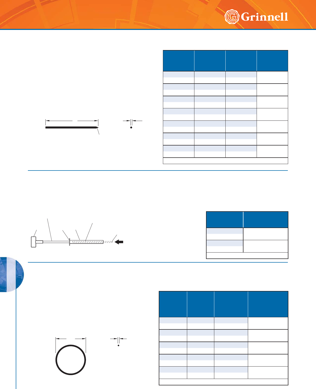
G-MINE PVC SYSTEMS
190 www.grinnell.com
G-MINE PVC SYSTEMS
The GRINNELL Figure ITGM G-MINE Spline Insertion Tool assists with
the insertion of the spline into the groove, locking the fitting to the pipe.
Figure ITGM Insertion Tools
Tech Data Sheet: G590
The GRINNELL Figure 72899 G-MINE Gasket (O-ring)
provides a hydraulic seal. Most G-MINE Fittings and Couplings
are manufactured to include an O-ring, a flexible elastomeric
seal. G-MINE O-rings are Teflon-coated, Nitrile Butadiene
Rubber (NBR) or Polyisoprene Rubber conforming to ASTM F
477 (Solvent weld and plain end fittings are designed for use
without o-ring).
Figure 72899 Replacement Gaskets
Tech Data Sheet: G590
C.S.
DIA.
O.D.
Nominal
Size
Inches
mm
O.D.
Inches
mm
Cross
Section
Diameter C.S.
Inches
mm
Material
Teflon*-Coated
22.7700.210
Nitrile Butadiene
Rubber
50 70,4 5,3
33.8950.210
Nitrile Butadiene
Rubber
80 98,9 5,3
44.8950.210
Nitrile Butadiene
Rubber
100 124,3 5,3
67.1760.275
Nitrile Butadiene
Rubber
150 182,3 7,0
89.3500.375
Polyisoprene
Rubber
200 237,5 9,5
See G-MINE specifications on page 177.
3/81*(5
+$1'/(
/2$'63/,1(
,172%$55(/
63/,1(
127,1&/8'('
:,7+722/
%$55(/
32,17('
,16(57,21(1'
2)63/,1(
)/$1*(
Nominal Size
Inches
mm
Part Number
3 - 6 ITGM 36
80 - 150
8ITGM 8
200
See G-MINE specifications on page 177.
The GRINNELL Figure 72999 G-MINE Spline securely locks the
coupling or fitting to the pipe. The spline is made of Nylon and
is also available in Acid-Resistant Polypropylene.
Figure 72999 Splines
Tech Data Sheet: G590
/&6
',$
,16(57,21(1'
Nominal Size
Inches
mm
L
Inches
mm
Cross Section
Diameter C.S.
Inches
mm
Configuration
2 10.50 0.19 ROUND
50 266,7 4,8
3 16.00 0.25 ROUND
80 406,4 6,4
418.000.25
ROUND
100 457,2 6,4
4 H 18.00 0.25 SQUARE
100 457,2 6,4
624.000.25
ROUND
150 609,6 6,4
6 H 24.00 0.25 SQUARE
150 609,6 6,4
832.000.31
SQUARE
200 812,8 8,0
See G-MINE specifications on page 177.
* Registered trademark of Dupont.
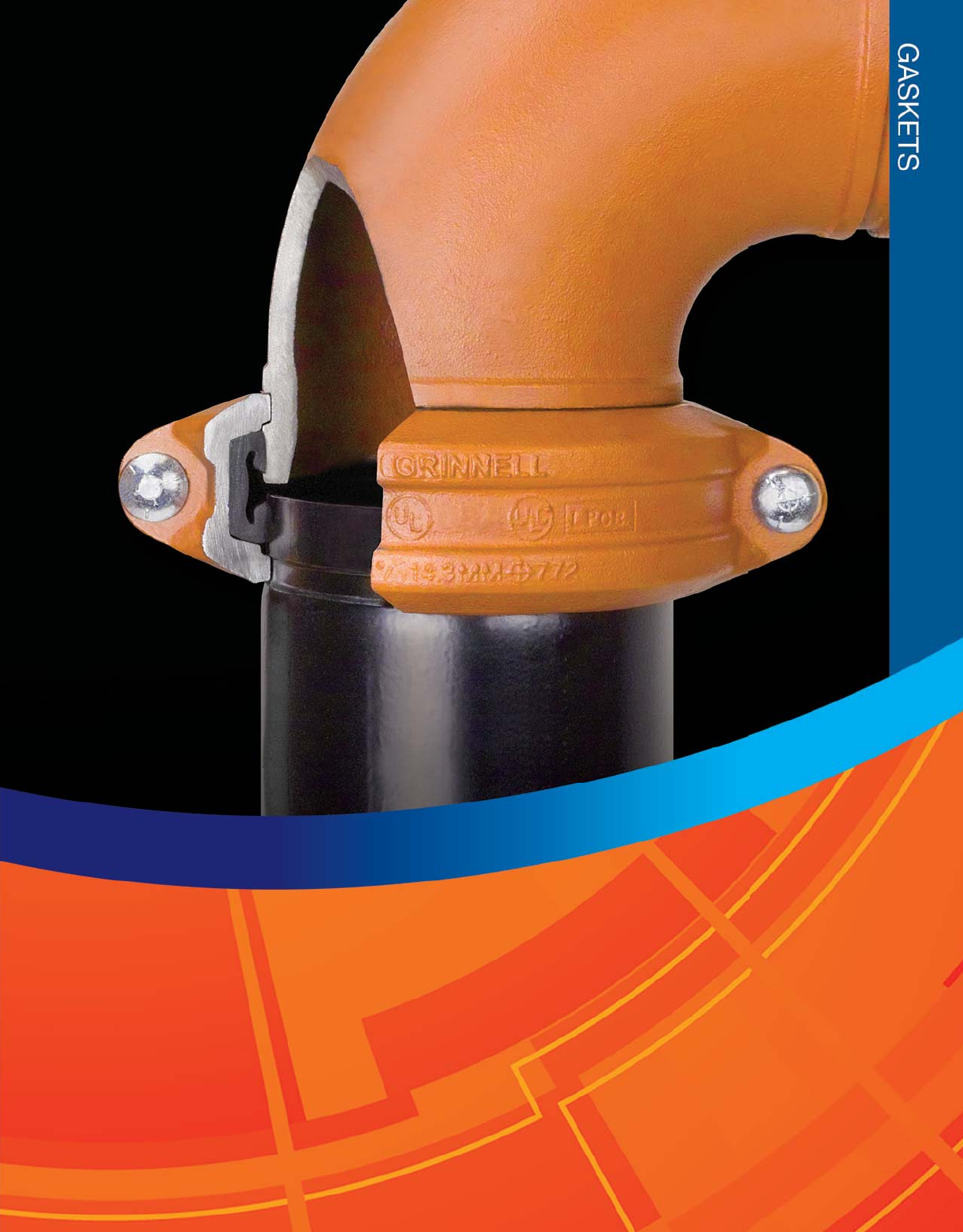
191
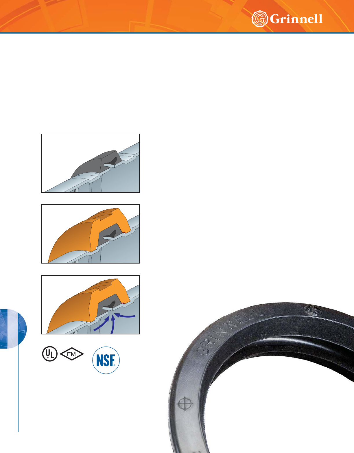
GASKETS
GASKETS
192 www.grinnell.com
Pressure responsive gaskets are offered in a variety of types.
Although they each serve a specific function they all utilize the
same sealing design.
The GRINNELL gasket is designed to provide a three-way
sealing action.
(1) Installation of the gasket over the outside sealing surface of
the pipe compresses the lip seal and forms the initial seal.
(2) The installation of the housing segments around the gasket
and into the pipe groove properly positions the gasket.
Tightening of the housing segments forms the gasket to the
inside of the housing and compresses it around the pipe-
sealing surface thus increasing the gasket’s sealing against
the pipe.
(3) The introduction of the system pressure energizes the
pressure responsive seal of the gasket and further
enhances the sealing action.
First Seal
C-shaped rubber gasket seals
on pipe ends.
Second Seal
The housings compress the
gasket to increase the sealing
capacity.
Third Seal
The system pressure or vacuum will
then maximize the leak-tight seal.
)RUDGGLWLRQDOOLVWLQJVRU
DSSURYDOVVHHSDJHRU
YLVLWRXUZHEVLWHDW
ZZZJULQQHOOFRP
GRINNELL Gasket Types
Tech Data Sheet: G610
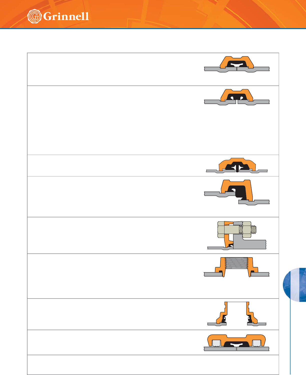
GASKETS
GASKETS
193
Refer to back cover for country-specific customer care numbers.
Standard
The standard style gasket, with a “C” shape configuration, is the most commonly
used. It is provided as the standard gasket in the Figure 705, 707, 770, 772, 405,
and 472 GRINNELL Couplings. The gasket is available in Grade “E” and “EN”
EPDM, Grade “T” Nitrile, Grade “L” Silicone, and Grade “O” Fluoroelastomer.
Tri-Seal
The tri-seal gasket is designed to close off the gap or gasket cavity. This is
accomplished by positioning the center “rib” of the gasket over the gap between the
pipes. The tri-seal gasket has two tapered sealing edges in addition to the center rib
for additional strength and sealing.
The Tri-Seal gasket can be used with the Figure 705, 707, 770, 772, 672, 405, and
472 GRINNELL Couplings. It is recommended for use in low temperature and vacuum
services (greater than 10" Hg (250mm Hg)) applications and potable water systems.
Note only a petroleum-free silicone based lubricant is recommended for low temperature
applications. The gasket is available in Grade “E”, “EN” EPDM, and Grade “T” Nitrile.
Note: Rigid couplings are recommended for vacuum and low temperature applications.
Center-Stop, Push-On
The Grade “EHT” EPDM Center-Stop, Push-On Style Gasket is specially designed for
easy installation of the GRINNELL Figure 640 Pivot-Bolt Coupling.
Reducing Coupling
The reducing gasket is provided with ribs used to position the larger pipe so that the
sealing lip is located on the sealing surface of the pipe. This gasket is used only with
the Figure 716 GRINNELL Reducing Coupling and is available in Grade “E” EPDM
and Grade “T” Nitrile.
Reducing couplings are not recommended for low temperature applications.
Flange Adapter
This gasket is specifically designed for use with the Figure 61 and 71 Flange
Adapter. The gasket has an optimum amount of rubber to provide a dependable seal
between both the pipe and mating surface. The gasket is available in Grade “E”
EPDM and Grade “T” Nitrile.
Mechanical Tee and Strap
The gasket provides a compression type seal, which is designed to conform to
the exterior curve (OD) of the pipe. This design is unique to both the Figure 730
Mechanical Tee (threaded and grooved) and Figure 40-5 Strap. The gasket is
available in Grade “E” EPDM and Grade “T” Nitrile.
Note: When used in low temperature applications, use a petroleum-free silicone based lubricant,
otherwise no lubricant is required on Mechanical Tee and Strap gaskets.
Outlet Coupling
This gasket is specifically designed for use with the GRINNELL Figure 702 Outlet
Coupling.
Plain End Coupling
This gasket is designed for use with the Figure 909 Plain End Coupling.
GRINNELL gaskets are designed exclusively for use with GRINNELL manufactured coupling housings. The mixing of other
manufacturer’s gaskets or housings with GRINNELL gaskets or housings may result in pipe joint leakage or failure and will void the
GRINNELL Mechanical Products Limited Warranty.
Gasket Styles
Tech Data Sheet: G610

GASKETS
GASKETS
194 www.grinnell.com
The Gasket Recommendation Table has been developed to
assure maximum service life. The table was developed from
information supplied by the material manufacturers of the
elastomer, technical reference literature, and testing conducted
by GRINNELL Mechanical Products.
In evaluating the gasket grade for intended service
applications the following consideration must be reviewed:
system operating temperature, fluid or solution concentration,
and duration of service.
All gasket recommendations are based on a temperature of
70°F (21°C) unless otherwise noted.
Technical and Engineering Services should be consulted if
combinations of service solutions are being considered.
Middle East email: Mechserv-EMEA@GRINNELL.com
U.S.A.: Phone 866-500-4768 or 1-401-781-8220
Contact GRINNELL Mechanical Products for recommendations
for services not listed.
Gasket recommendations apply to GRINNELL gaskets and
valves only.
Grade Temperature
Range
Compound Color
Code
General
Service Application
“E” -30°F to 230°F
(-34°C to 110°C) EPDM Green
Hot water, dilute acids, alkalies, oil free air, and many
chemical services not involving petroleum products.
Excellent oxidation resistance.
Not for use with hydrocarbons.
Not recommended for steam service.
“E”
Tri- Seal
-30°F to 230°F
(-34°C to 110°C) EPDM Green
Hot water, dilute acids, alkalies, and many chemical
services not involving petroleum products.
Excellent oxidation resistance.
Not for use with hydrocarbons.
Recommended for low temperature and vacuum services.
“EN” and
“EN” Tri-Seal
for IPS Pipe
Potable Water
up to 180°F (82°C) EPDM Green/Yellow
Stripe
IPS Sizes Only,
NSF 61 Approved for potable water.
Not recommended for hydrocarbons.
“EN” Tri-Seal for
Copper Tubing
Potable Water
up to 180°F (82°C) EPDM Copper
CTS Sizes Only,
NSF 61 Approved for potable water.
Not recommended for hydrocarbons.
“EHT” Center-
Stop
Push-On Style
Copper Tubing
For closed-loop
heating systems
-30°F to 250°F
(-34°C to 120°C)
Potable Water up to
180°F (82°C)
EPDM
Red and
Copper
Striped
CTS Sizes Only,
NSF 61 Approved for potable water.
Recommended for use in low temperature and vacuum
systems
Not recommended for hydrocarbons.
“T” and
“T” Tri- Seal
-20°F to 180°F
(-29°C to 82°C) Nitrile Orange
Compressed air, petroleum products, vegetable oils,
mineral oils, and air with oils.
High-End oil vapor temperature, decrease to 150°F (66°C).
Not recommended for hot water systems.
Not recommended for hot dry air systems.
“O” and
“O” Tri- Seal
+20°F to 300°F
(-7°C to 149°C) Fluoroelastomer Blue Oxidizing acids, petroleum products, hydraulic fluids,
lubricants, halogenated hydrocarbons.
“L” -30°F to 350°F
(-34°C to 177°C) Silicone * Red Gasket Air without hydrocarbons, dry heat.
* To prevent gasket from deteriorating, NEVER use silicone-based lubricants with Grade “L” Silicone gaskets.
For local country potable water approvals contact GRINNELL Mechanical Products.
GRINNELL Gasket Grade & Recommendations
Tech Data Sheet: G610
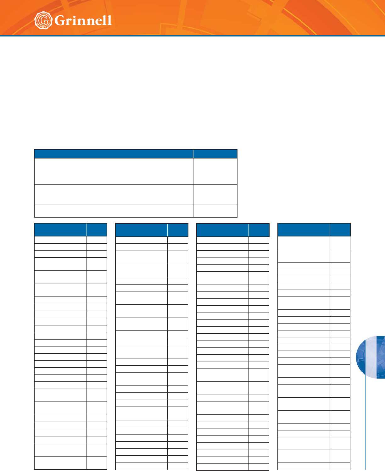
GASKETS
GASKETS
195
Refer to back cover for country-specific customer care numbers.
• Contact GRINNELL Mechanical Products for an
engineering evaluation and recommendation where the
gasket grade is shown in parenthesis.
• Specify gasket grade when ordering.
• For vacuum or low temperature systems, use tri-seal
gasket. For low temperature applications, use a
petroleum-free silicone lubricant.
• Gasket Grade "EHT" can be used where "E" is marked.
• Check gasket color code to be certain it is recommended
for the service intended.
• Unless otherwise noted, all gasket listings are based upon
a temperature of 70°F (21°C).
• For services not listed, contact GRINNELL Mechanical
Products for recommendation.
• Where more than one gasket is shown, the preferred
gasket grade is listed first.
Service Gasket Grade
Air, (no oil vapors) Temp. -30°F to 230°F (-34°C to 110°C) E
Air, Oil Vapor Temp. -20°F to 150°F (-29°C to 66°C) T
Water, Temp. to 230°F (110°C)
(NOT RECOMMENDED FOR STEAM SERVICE)
E
Water, Acid Mine E/T
Water, Chlorine E
Water, Deionized E
Water, Seawater E
Water, Waste (NO PETROLEUM PRODUCTS) E
Chemical
Composition
Gasket
Grade
ASTM #3 Oil T
Acetaldehyde E
Acetamide T
Acetic Acid up to
10% 100°C/38°C E
Acetic Acid up to 10-
50% 100°C/38°C L
Acetic Acid, Glacial
100°C/38°C L
Acetic Anhydride E
Acetone E
Acetonitrile T
Acetylene E/T
Adipic Acid T
Alkalis E
Allyl Alcohol to 96% E
Alum Sulfuric Acid O
Alums E/T
Aluminum Chloride E/T
Aluminum Fluoride E/T
Aluminum Hydroxide E
Aluminum Nitrate E/T
Aluminum
Oxychloride T
Aluminum
Phosphate E
Aluminum Salts T
Aluminum Sulfate E/T
Ammonia Gas, Cold E
Ammonia, Liquid E
Ammonium
Bifluoride T
Ammonium
Carbonate E
Chemical
Composition
Gasket
Grade
Ammonium Chloride E/T
Ammonium Fluoride E
Ammonium
Hydroxide E
Ammonium
Metaphosphate E
Ammonium Nitrate T
Ammonium Nitrite E
Ammonium
Persulfate, to 10% E
Ammonium
Phosphate T
Ammonium
Sulfamate T
Ammonium Sulfate E/T
Ammonium Sulfide E
Ammonium
Thiocyanate E
Amyl Acetate E
Amyl Alcohol E
Amyl
Chloronaphthalene T
Anderol O
Aniline E
Aniline Dyes E
Aniline
Hydrochloride E
Aniline Oil E
Antimony Chloride E
Antimony Trichloride E
Argon Gas E/O
Aroclor(S) O
Arsenic Acid, to 75% T
Barium Carbonate E
Chemical
Composition
Gasket
Grade
Barium Chloride E/T
Barium Hydroxide E/T
Barium Sulfide T
Benzaldehyde E
Benzene O
Benzine (see
Petroleum Ether) O
Benzoic Acid E
Benzol O
Benzyl Alcohol E
Benzyl Benzoate E
Black Sulfate Liquor T
Blast Furnace Gas T
Bleach,12% Active E
Borax Solutions E
Bordeaux Mixture E
Boric Acid E/T
Bromine O
Butane Gas T
Butanol
(see Butyl Alcohol) E/T
Butyl Acetate
Ricinoleate E
Butyl Alcohol E/T
Butyl
“Cellosolve Adipate” E/T
Butyl Phenol E
Butyl Stearate T
Butylene T
Butylene Glycol E
Calcium Acetate T
Calcium Bisulphite T
Calcium Chloride E/T
Calcium Hydroxide E/T
Chemical
Composition
Gasket
Grade
Calcium
Hypochlorite E
Calcium
Hypochloride E
Calcium Nitrate E/T
Calcium Sulfate E/T
Calcium Sulfide E/T
Caliche Liquors T
Carbitol E/T
Carbonic Acid,
Phenol O
Carbon Bisulfide O
Carbon Dioxide, Dry E/T
Carbon Dioxide, Wet E/T
Carbon Disulfide O
Carbon Monoxide E
Carbon Tetrachloride O
Caustic Potash E/T
Cellosolve Acetate E
Cellosolve
(Alcohol Ether) E
Cellulose Acetate E
Cellulube 220
(Tri-Aryl-Phosphate) E
Cellulube Hydraulic
Fluids E
China Wood Oil,
Tung Oil T
Chloric Acid to 20% E
Chlorine, Dry O
Chlorine, Water 4000
PPM (max.) E
Chlorinated Paraffin
(Chlorocosane) T
Chloroacetic Acid E
Gasket Air, Water & Chemical Recommendations
(Page 1 of 3)
Tech Data Sheet: G610
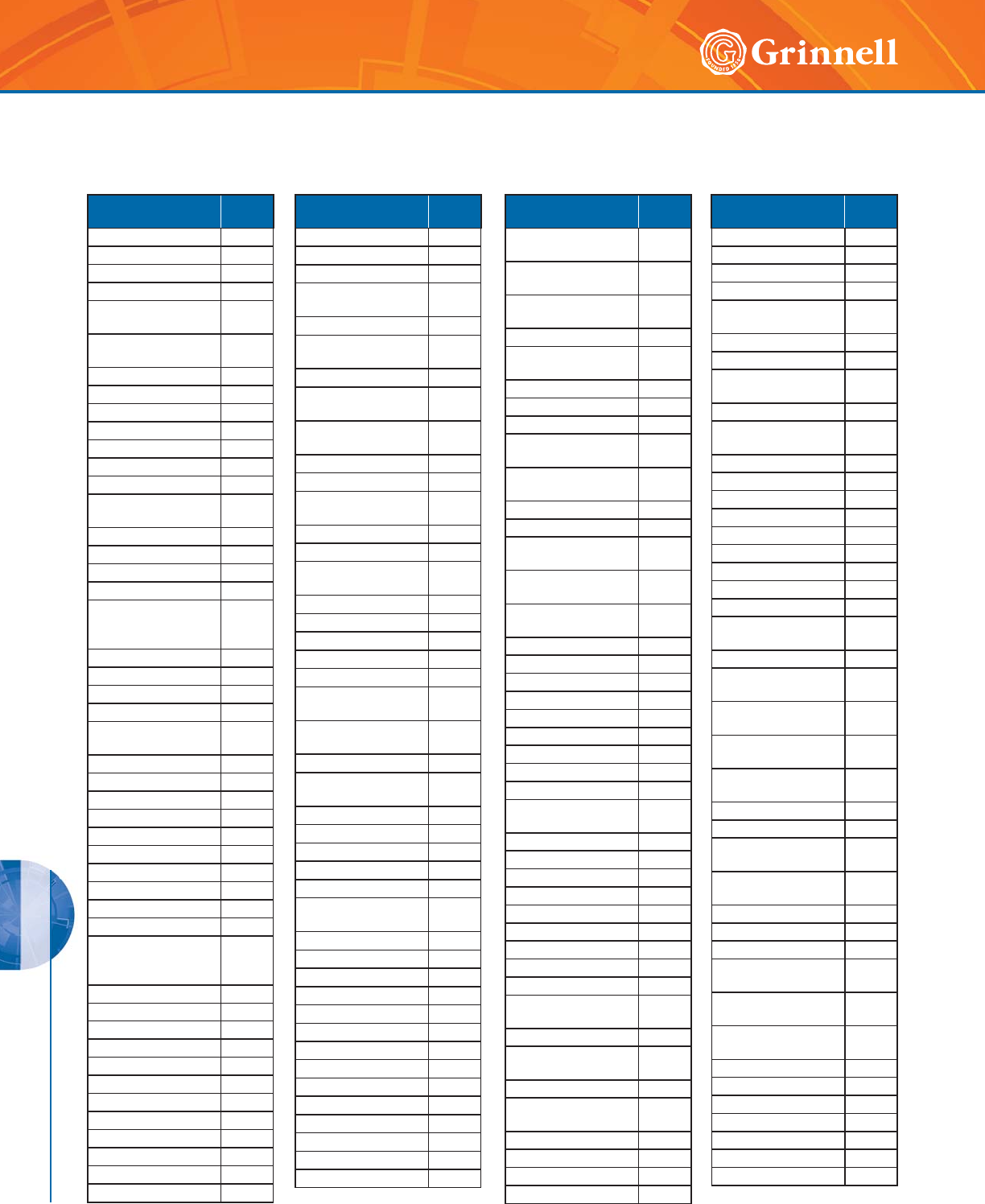
GASKETS
GASKETS
196 www.grinnell.com
Chemical
Composition
Gasket
Grade
Chloroacetone E
Chlorobenzene O
Chloroform O
Chrome Alum T
Chrome Plating
Solutions O
Chromic Acid, to
25% O
Citric Acid E/T
Coke Oven Gas T/O
Copper Chloride T
Copper Cyanide E/T
Copper Fluoride E
Copper Nitrate E/T
Copper Sulfate E/T
Creosol, Cresylic
Acid O
Creosote, Coal Tar O
Creosote, Wood O
Cupric Fluoride T
Cupric Sulfate T
Cyclohexane
(Alicyclic
Hydrocarbon)
O
Cyclohexanone E
Deionized Water E
Dextrim T
Dibutyl Phthalate E
Dichloro Difloro
Methane T
Dicyclohexylamine T
Diesel Oil T
Diethyl Ether T
Diethyl Sebacate E
Diethylamine T
Diethylene Glycol E/T
Digester Gas T
Dimethylamine T
Dioctyl Phthalate E
Dioxane E
Dipentene
(Terpene-
Hydrocarbon)
T
Dipropylene Glycol T
Dowtherm A O
Dowtherm E O
Dowtherm SR-1 T/E
Ethane E
Ethanolamine E
Ethyl Acetoacetate E
Ethyl Acrylate L
Ethyl Alcohol E
Ethyl Cellulose E
Ethyl “Cellusolve” E
Ethyl Chloride E
Chemical
Composition
Gasket
Grade
Ethyl Ether T
Ethyl Oxalate E
Ethyl Silicate T
Ethylene
Chlorohydrin E
Ethylene Diamine T
Ethylene Dichloride
(Dichloroethane) O
Ethylene Glycol E/T
Ferric Chloride, to
35% E/T
Ferric Chloride,
Saturated E
Ferric Hydroxide E
Ferric Sulfate T
Fire Fighting
Foam Concentrate E/O
Fluboric Acid E/T
Fly Ash E
FM200
HFC-227ea E
Fog Oil T
Formaldehyde E/T
Formamide E/T
Formic Acid E
Freon 11, 130°F/54°C T
Freon 12,
130°F/54°C T
Freon 113
130°F/54°C T
Freon 114,130°F/54°C T
Freon
134a,176°/80°C E/T
Fructose E/T
Fuel Oil T
Fumaric Acid E
Furfuryl Alcohol E
Gasoline, Refined T
Gasoline, Refined,
Unleaded O
Glue E/T
Glycerin E/T
Glycerol E/T
Glycol E/T
Glycolic Acid E
Grease T
Green Sulfate Liquor T
Halon 1301 E
Heptane T
Hexaldehyde E
Hexane T
Hexanol Tertiary T
Hexyl Alcohol T
Hexylene Glycol T
Chemical
Composition
Gasket
Grade
Hydrobromic Acid,
to 40% E
Hydrochloric Acid, to
36%, 75°F/24°C E
Hydrochloric Acid, to
36%,158°F/70°C O
Hydrocyanic Acid E
Hydrofluoric Acid, to
75%, 75°F/24°C O
Hydrofluosilicic Acid E
Hydrogen Gas, Cold E/T
Hydrogen Gas, Hot E
Hydrogen Peroxide,
to 50% L
Hydrogen Peroxide,
to 90% O
Hydrogen Sulfide E
Hydroquinone T
Hydroxylamine
Sulfate E
Hypochlorous Acid,
Dilute E
Iso Octane,
100°F/38°C T
Isobutyl Alcohol E
Isopropyl Acetate E
Isopropyl Alcohol E
Isopropyl Ether T
JP-3 T
JP-4 T
JP-5, 6, 7, 8 T
Kerosene T
Ketones E
Latex (1% Styrene &
Butadiene) O
Lauric Acid T
Lavender Oil T
Lead Acetate T
Lead Chloride E
Lead Sulfate T
Lime and H2O E/T
Linoleic Acid O
Lithium Bromide T
Lithium Chloride T
Lubricating Oil,
Refined T
Lubricating Oil, Sour T
Lubricating Oil, to
150°F/66°C T
Magnesium Chloride E/T
Magnesium
Hydroxide E/T
Magnesium Sulfate E/T
Maleic Acid T
Malic Acid T
Mercuric Chloride E/T
Chemical
Composition
Gasket
Grade
Mercuric Cyanide T
Mercurous Nitrate E/T
Mercury T
Methane T
Methyl Alcohol,
Methanol E/T
Methyl Chloride O
Methyl Ethyl Ketone E
Methyl Isobutyl
Carbinol E
Methylene Chloride O
Methylene Dichloride
100°F/38°C O
MIL-L7808 O
MIL-05606 O
MIL-08515 O
Mineral Oils T
Naptha, 160°F/71°C O
Napthenic Acid T
Natural Gas T
Nevoil E
Nickel Chloride E/T
Nickel Plating
Solution 125°F/52°C E/T
Nickel Sulfate E/T
Nitric Acid to 10%,
75°F/24°C E
Nitric Acid, 10-50%,
75°F/24°C O
Nitric Acid, 50-86%,
75°F/24°C O
Nitric Acid, Red
Fuming O
Nitromethane E
Nitrous Oxide E
NOVEC 1230
FK-5-1-12 E
Ogisogiric Acid, to
75%, 150°F/66°C O
Oil, Crude Sour T
Oil, Motor T
Oleic Acid T
Oronite 8200 Silicate
Ester Fluid O
Orthodichloro-
benzene O
OS-45 Silicate
Ester Fluid O
OS-45-1 O
Oxalic Acid E
Oxygen, Cold E
Ozone E
Palmitic Acid T
Pentane T
Perchloroethylene O
Gasket Air, Water & Chemical Recommendations
(Page 2 of 3)
Tech Data Sheet: G610
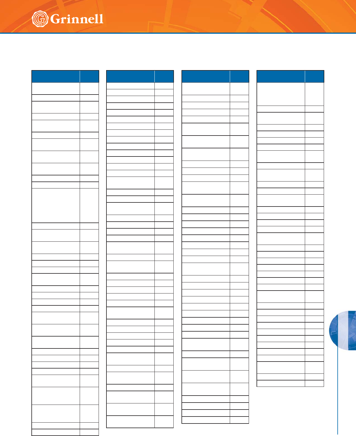
GASKETS
GASKETS
197
Refer to back cover for country-specific customer care numbers.
Chemical
Composition
Gasket
Grade
Petroleum Ether (see
Benzene) O
Petroleum Oils T
Phenol (Carbolic
Acid) O
Phenylhydrazine E
Phenylhydrazine
Hydrochloride E
Phosphate Ester E
Phosphoric Acid, to
75% and 70°F E/T
Phosphoric Acid, to
85% and 200°F O
Photographic
Solutions T
Phthalic Anhydride E
Polybutene T
Polyvinyl Acetate,
Solid
(In Liquid State is
50% solution of
Methanol or 60%
solution of H2O)
E
Potassium Alum E/T
Potassium
Bicarbonate E/T
Potassium
Bichromate E/T
Potassium Borate E
Potassium Bromate E
Potassium Bromide E/T
Potassium
Carbonate E/T
Potassium Chlorate E
Potassium Chloride E
Potassium Chromate T
Potassium Cyanide E/T
Potassium
Dichromate E
Potassium
Ferricyanide E
Potassium
Ferrocyanide E
Potassium Fluoride E
Potassium Hydroxide T
Potassium Nitrate T
Potassium Perborate E
Potassium
Perchlorate T
Potassium
Permanganate,
Saturated to 10%
E
Potassium
Permaganate
Saturate 10-25%
E
Potassium Persulfate T
Potassium Silicate E/T
Chemical
Composition
Gasket
Grade
Potassium Sulfate T
Prestone T
Propane Gas T *
Propanol E
Propargyl Alcohol E
Propyl Alcohol T
Propylene Dichloride L
Propylene Glycol E
Pyranol 1467 T
Pyranol 1476 T
Pyroguard “C” T
Pyroguard “D” T
Pyroguard 55 E
Pyrrole E
Ref. Fuel (70 ISO
Octane, 30 Toluene) T
Rosin Oil T
Salicylic Acid E
Secondary Butyl
Alcohol T
Sewage E/T
Silver Nitrate E
Silver Sulfate E
Skydrol, 200°F/93°C L
Skydrol 500
Phosphate Ester E
Soap Solutions E/T
Soda Ash,
Sodium Carbonate E/T
Sodium Acetate E
Sodium Alum T
Sodium Benzoate E
Sodium Bicarbonate E/T
Sodium Bisulfate E/T
Sodium Bisulfite
(Black Liquor) E/T
Sodium Bromide E/T
Sodium Carbonate E/T
Sodium Chlorate E
Sodium Chloride E/T
Sodium Cyanide E/T
Sodium Dichromate,
to 20% E/T
Sodium Ferricyanide E/T
Sodium
Ferrocyanide E/T
Sodium Fluoride E/T
Sodium Hydro
Sulfide T
Sodium Hydroxide
to 50% E
Sodium
Hypochlorite, to 20% E
Chemical
Composition
Gasket
Grade
Sodium
Metaphosphate T
Sodium Nitrate E
Sodium Nitrite E/T
Sodium Perborate E
Sodium Peroxide E
Sodium Phosphate,
Dibasic T
Sodium Phosphate,
Monobasic T
Sodium Phosphate,
Tribasic T
Sodium Silicate T
Sodium Sulfate E/T
Sodium Sulfide T
Sodium Sulfite
Solution, to 20% T
Sodium Thiosulfate,
“Hypo” T
Sohovis 47 T
Sohovis 78 T
Solvasol #1 T
Solvasol #2 T
Solvasol #3 T
Solvasol #73 T
Spindle Oil T
Stannic Chloride T
Stannous Chloride,
to 15% T
Starch T
Stearic Acid T
Stoddard Solvent T
Styrene O
Sulfonic Acid E
Sulphite Acid Liquor E
Sulfur E
Sulfur Chloride O
Sulfur Dioxide, Dry E/T
Sulfur Dioxide,
Liquid E
Sulfur Trioxide, Dry O
Sulfuric Acid, to
25%, 150°F/66°C E
Sulfuric Acid, 25-
50%, 200°F/93°C O
Sulfuric Acid, 50-
95%, 150°F/66°C O
Sulfuric Acid, Fuming O
Sulfuric Acid, Oleum O
Sulfurous Acid O
Tall Oil T
Chemical
Composition
Gasket
Grade
Tanning Liquors
(50g. alum. solution,
50g. dichromate
solution)
T
Tar taric Acid E
Tertiary Butyl
Alcohol E/T
Tetrabutyl Titanate E
Tetrachloroethylene O
Thionyl Chloride T
Terpineol T
Titanium
Tetrachloride O
Toluene, 30% T
Transmission Fluid,
Type A O
Triacetin T
Trichloroethane O
Trichloroethylene, to
200°F/93° O
Tricresyl Phosphate E
Triethanolamine E/T
Trisodium Phosphate E
Tung Oil T
Turbo Oil #15 Diester
Lubricant O
Turpentine T
Urea T
Vegetable Oils T
Vinyl Acetate E
Vi-Pex T
Water, to 150°F/66°C E/T
Water, to 200°F/93°C E
Water, to
230°F/110°C E
Water, Acid Mine E/T
Water, Chlorine E
Water, Deionized E
Water, Potable EN
Water, Seawater E
Water, Waste E/T
White Liquor E
Wood Oil T
Xylene O
Zinc Chloride, to
50% E
Zinc Nitrate E
Zinc Sulfate E/T
Gasket Air, Water & Chemical Recommendations
(Page 3 of 3)
Tech Data Sheet: G610
* Conditional, contact GRINNELL
Mechanical Products
GASKETS
GASKETS
198 www.grinnell.com
Application
La-Co
Industries
Lubri-Joint
Dow Corning*
7 Release Compound
(Silicone)
Chilled Water • •
Heating • •
Compressed Air • •
Drainage • •
Sewage • •
Low Temp./Vacuum • •
Fire Protection • •
During installation of a GRINNELL Coupling, always lubricate
the gasket. For couplings using the tri-seal gasket in a low
temperature application, use a petroleum-free silicone based
lubricant. For mechanical tees and straps when used in low
temperature applications, use a petroleum-free silicone based
lubricant, otherwise no lubricant is required.
GRINNELL Mechanical Piping Products recommends two kinds
of lubricant:
• La-Co Industries Lubri-Joint
• Dow Corning* 7 Release Compound (Silicone)
Check lubricant chart to be certain the proper lubricant is
recommended for the service intended. For information on
health safety, contact GRINNELL Mechanical Products for
Material Safety Data Sheets (MSDS).
Gasket
Size
Lubri-Joint
1 qt (946 ml)
Container
Silicone
5.3 oz (150 g) Tube
11⁄4" / 32mm 650 116
11⁄2" / 40mm 570 94
2" / 50mm 440 73
3" / 80mm 300 50
4" / 100mm 220 36
6" / 150mm 135 22
8" / 200mm 110 18
10" / 250mm 85 14
12" / 300mm 65 10
14" / 350mm 55 9
16" / 400mm 50 8
18" / 450mm 38 6
20" / 500mm 33 5
24" / 600mm 20 3
The table below will give an indication on the approximate
number of gaskets which can be lubricated with one
container of lubricant.
Available in:
• 1 Quart (0,95 Liter)
• 1 Gallon (3,8 Liter)
Silicone Gasket Lubricant recommended for use with tri-seal
gasket (Dow Corning D.C. No. 7)* available in:
• 5.3 oz (150 grams) Tube
• 8 lb (3,6 kg) Can
* Dow Corning is a registered trademark
of Dow Corning Corporation.
GRINNELL Gasket Lubricants
Tech Data Sheet: G610

199
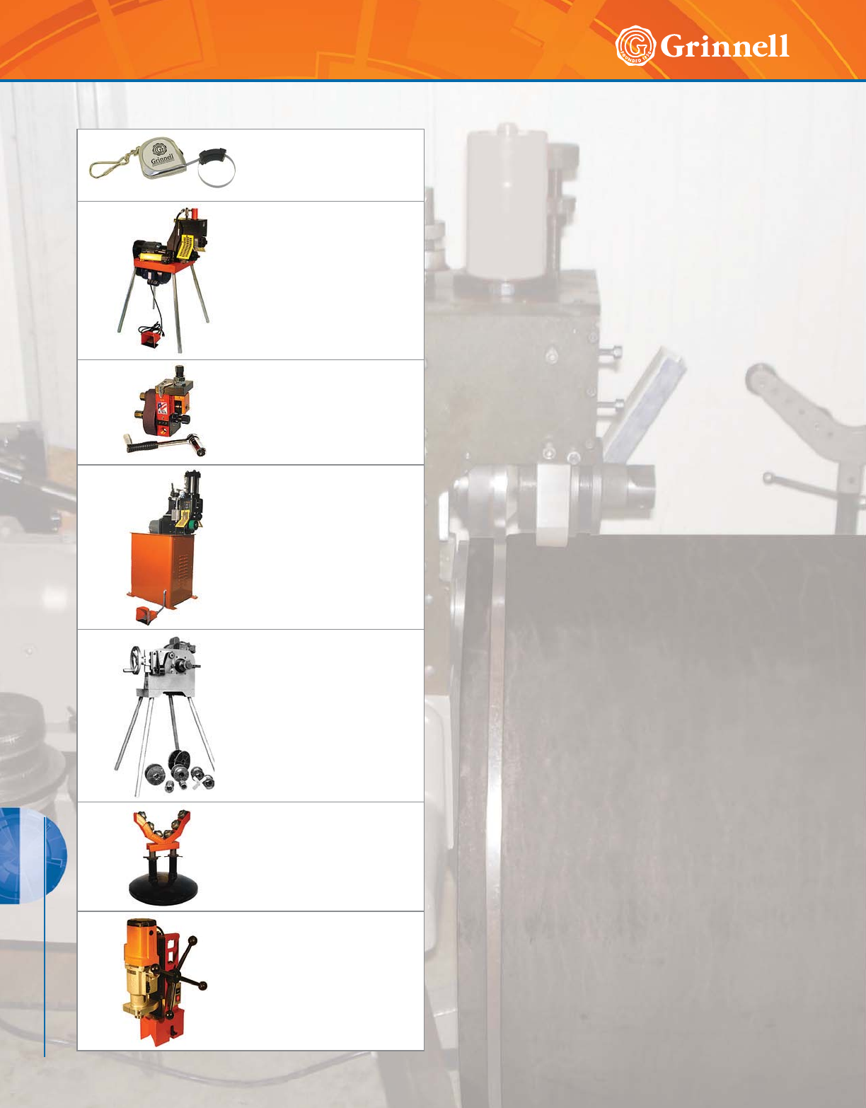
PREPARATION EQUIPMENT
200 www.grinnell.com
PREPARATION EQUIPMENT
Pipe Tape
Page 204
Portable
Roll Groovers
Pages 205 - 206
Field Portable
Roll Groovers
Page 207
Automated
Roll Groovers
Page 208 - 209
Portable
Cut Groovers
Page 210
Pipe Support
Stands
Page 211
Hole Cutting
Tools
Page 212
Preparation Equipment Table of Contents
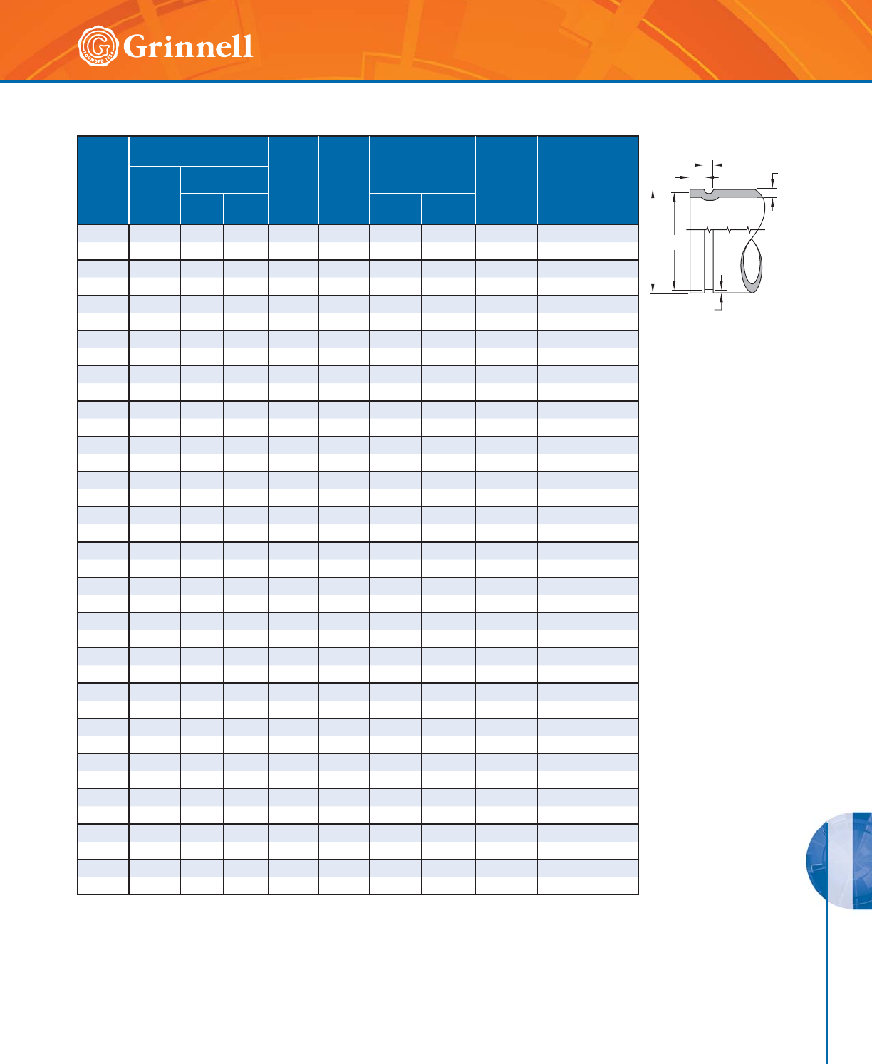
PREPARATION EQUIPMENT
PREPARATION EQUIPMENT
201
Refer to back cover for country-specific customer care numbers.
(1) The maximum allowable tolerances for IPS Pipe from
square cut ends is:
0.030" (0,76mm) for sizes 11⁄4" thru 3" (32 – 80mm);
0.045" (1,14mm) for sizes 4" – 6" (100 – 150mm); and
0.060" (1,52mm) for sizes 8" (200mm) and above.
(2) Gasket Seating Surface “A” must be free from score marks,
ridges, indentations, projections, loose paint, scale, dirt
chips, grease, rust, etc. that would prevent a positive seal.
(3) Groove Diameter “C” must be of uniform depth
around the circumference of the pipe.
(4) Groove Depth “D” is a reference dimension only.
The Groove Diameter “C” must be maintained.
(5) Minimum Wall Thickness “T” is the minimum
wall thickness that should be roll grooved.
(6) Maximum allowable pipe end flare diameter
is measured at the pipe end diameter.
Nominal
Pipe
Size
Inches
mm
Pipe O.D.
Inches mm A
±0.030"
±0,76mm
Inches
mm
B
±0.030"
±0,76mm
Inches
mm
C
Groove Diameter
Inches
mm
D
Groove
Depth
(ref. only)
Inches
mm
T
Minimum
Wall
Inches
mm
Maximum
Allow
Flare
Diameter
Inches
mm
O.D.
Tolerance
+- Actual
Tol.
+0.000
11⁄41.660 0.016 0.016 0.625 0.281 1.535 -0.015 0.062 0.065 1.77
32 42,4 0,41 0,41 15,88 7,14 38,99 -0,38 1,60 1,65 44,96
11⁄21.900 0.019 0.019 0.625 0.281 1.775 -0.015 0.062 0.065 2.01
40 48,3 0,48 0,48 15,88 7,14 45,09 -0,38 1,60 1,65 51,05
2 2.375 0.024 0.024 0.625 0.344 2.250 -0.015 0.062 0.065 2.48
50 60,3 0,61 0,61 15,88 8,74 57,15 -0,38 1,60 1,65 62,99
21⁄22.875 0.029 0.029 0.625 0.344 2.720 -0.018 0.078 0.083 2.98
65 73,0 0,74 0,74 15,88 8,74 69,09 -0,46 1,98 2,11 75,69
76,1mm 3.000 0.030 0.030 0.625 0.344 2.845 -0.018 0.076 0.083 3.10
65 76,1 0,76 0,76 15,88 8,74 72,26 -0,46 1,93 2,11 78,74
3 3.500 0.035 0.031 0.625 0.344 3.344 -0.018 0.078 0.083 3.60
80 88,9 0,89 0,79 15,88 8,74 84,94 -0,46 1,98 2,11 91,44
4 4.500 0.045 0.031 0.625 0.344 4.334 -0.020 0.083 0.083 4.60
10 0 114 , 3 1,14 0 ,7 9 15 , 8 8 8 ,74 110 ,0 8 - 0 , 51 2,11 2 ,11 116 , 84
139,7mm 5.500 0.056 0.031 0.625 0.344 5.334 -0.022 0.083 0.109 5.60
125 139,7 1,42 0,79 15,88 8,74 135,48 -0,56 2,11 2,77 142,24
5 5.563 0.056 0.031 0.625 0.344 5.395 -0.022 0.084 0.109 5.66
125 141,3 1,42 0,79 15,88 8,74 137,03 -0,56 2,13 2,77 143,76
165,1mm 6.500 0.063 0.031 0.625 0.344 6.330 -0.022 0.085 0.109 6.60
150 165,1 1,60 0,79 15,88 8,74 160,78 -0,56 2,16 2,77 167,64
6 6.625 0.063 0.031 0.625 0.344 6.455 -0.022 0.085 0.109 6.73
150 168,3 1,60 0,79 15,88 8,74 163,96 -0,56 2,16 2,77 170,94
8 8.625 0.063 0.031 0.750 0.469 8.441 -0.025 0.092 0.109 8.80
200 219,1 1,60 0,79 19,05 11,91 214,40 -0,64 2,34 2,77 223,52
10 10.750 0.063 0.031 0.750 0.469 10.562 -0.027 0.094 0.134 10.92
250 273,0 1,60 0,79 19,05 11,91 268,27 -0,69 2,39 3,40 277,37
12 12.750 0.063 0.031 0.750 0.469 12.531 -0.030 0.109 0.156 12.92
300 323,9 1,60 0,79 19,05 11,91 318,19 -0,76 2,77 3,96 328,17
14 14.000 0.063 0.031 0.938 0.469 13.781 -0.030 0.109 0.156 14.10
350 355,6 1,60 0,79 23,83 11,91 350,04 -0,76 2,77 3,96 358,14
16 16.000 0.063 0.031 0.938 0.469 157.81 -0.030 0.109 0.165 16.10
400 406,4 1,60 0,79 23,83 11,91 400,84 -0,76 2,77 4,19 408,94
18 18.000 0.063 0.031 1.000 0.469 17.781 -0.030 0.109 0.165 18.16
450 457,2 1,60 0,79 25,40 11,91 451,64 -0,76 2,77 4,19 461,26
20 20.000 0.063 0.031 1.000 0.469 19.781 -0.030 0.109 0.188 20.16
500 508,0 1,60 0,79 25,40 11,91 502,44 -0,76 2,77 4,78 512,06
24 24.000 0.063 0.031 1.000 0.500 23.656 -0.030 0.172 0.218 24.20
600 609,6 1,60 0,79 25,40 12,70 600,86 -0,76 4,37 5,54 614,68
A
BT
COD
D
Roll Groove Standard Specification for Steel & Other IPS Pipe
Tech Data Sheet: G710
GRINNELL Roll Grooves
conform to AWWA
C-606 specification.
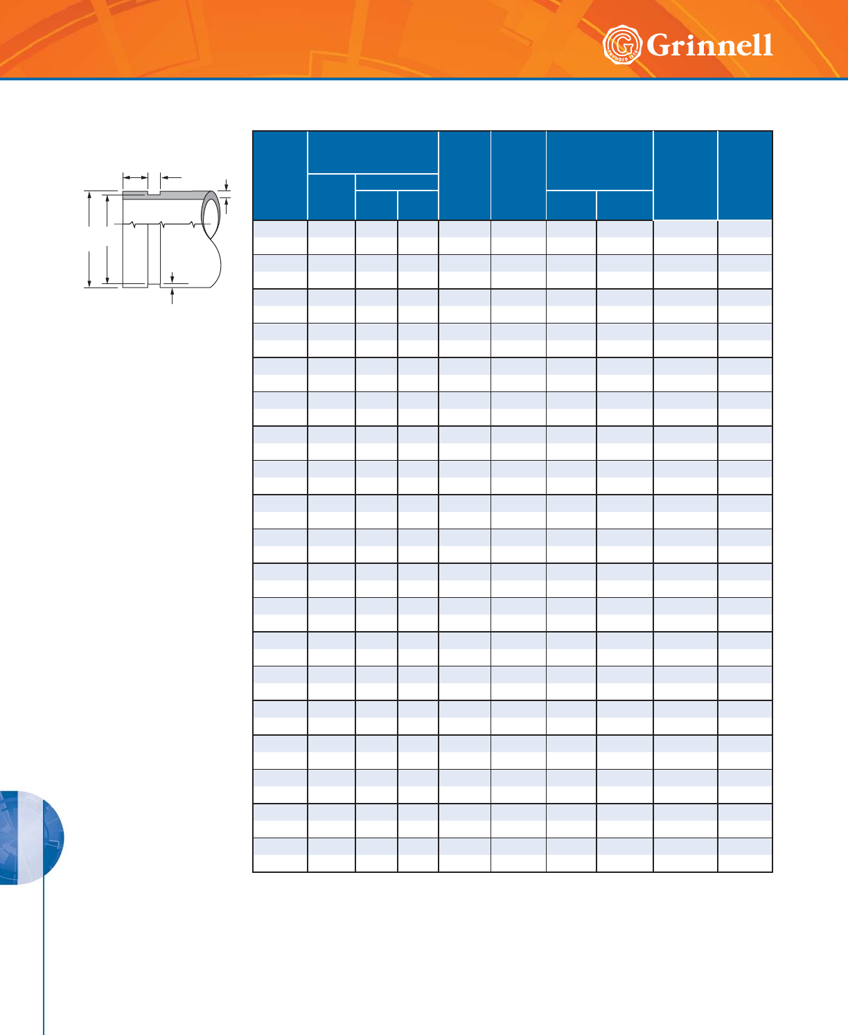
PREPARATION EQUIPMENT
PREPARATION EQUIPMENT
202 www.grinnell.com
(1) The maximum allowable tolerances for IPS Pipe from
square cut ends is:
0.030" (0,76mm) for sizes 11⁄4" thru 3" (32 – 80mm );
0.045" (1,14mm) for sizes 4" – 6" (100 – 150mm); and
0.060" (1,52mm) for sizes 8" (200mm) and above.
(2) Gasket Seating Surface “A” must be free from score marks,
ridges, indentations, projections, loose paint, scale, dirt
chips, grease, rust, etc. that would prevent a positive seal.
(3) Groove Diameter “C” must be of uniform depth around the
circumference of the pipe.
(4) Groove Depth “D” is a reference dimension only. The
Groove Diameter “C” must be maintained.
(5) Minimum Wall Thickness “T” is the minimum wall thickness
that should be cut grooved.
T
B
D
C
OD
A
Nominal
Pipe
Size
Inches
mm
Pipe O.D.
Inches
mm
A
±0.030"
± 0,76mm
Inches
mm
B
±0.030"
± 0,76mm
Inches
mm
C
Groove Diameter
Inches
mm
D
Groove
Depth
(ref. only)
Inches
mm
T
Minimum
Wall
Inches
mm
O.D.
Tolerance
+- Actual
Tol.
+0.000
11⁄41.660 0.016 0.016 0.625 0.313 1.535 -0.015 0.062 0.062
32 42,4 0,41 0,41 15,88 7,95 38,99 -0,38 1,60 1,60
11⁄21.900 0.019 0.019 0.625 0.313 1.775 -0.015 0.062 0.062
40 48,3 0,48 0,48 15,88 7,95 45,09 -0,38 1,60 1,60
2 2.375 0.024 0.024 0.625 0.313 2.250 -0.015 0.062 0.062
50 60,3 0,61 0,61 15,88 7,95 57,15 -0,38 1,60 1,60
21⁄22.875 0.029 0.029 0.625 0.313 2.720 -0.018 0.078 0.078
65 73,0 0,74 0,74 15,88 7,95 69,09 -0,46 1,98 1,98
76,1mm 3.000 0.030 0.030 0.625 0.313 2.845 -0.018 0.076 0.076
65 76,1 0,76 0,76 15,88 7,95 72,26 -0,46 1,93 1,93
3 3.500 0.035 0.031 0.625 0.313 3.344 -0.018 0.078 0.078
80 88,9 0,89 0,79 15,88 7,95 84,94 -0,46 1,98 1,98
4 4.500 0.045 0.031 0.625 0.375 4.334 -0.020 0.083 0.083
10 0 114,3 1,14 0,79 15,88 9,53 110,08 - 0,51 2,11 2,11
139,7mm 5.500 0.056 0.031 0.625 0.375 5.334 -0.020 0.083 0.083
125 139,7 1,42 0,79 15,88 9,53 135,48 -0,51 2,11 2,11
5 5.563 0.056 0.031 0.625 0.375 5.395 -0.022 0.084 0.084
125 141,3 1,42 0,79 15,88 9,53 137,03 -0,56 2,13 2,13
165,1mm 6.500 0.063 0.031 0.625 0.375 6.330 -0.022 0.085 0.085
150 165,1 1,60 0,79 15,88 9,53 160,78 -0,56 2,16 2,16
6 6.625 0.063 0.031 0.625 0.375 6.455 -0.022 0.085 0.085
150 168,3 1,60 0,79 15,88 9,53 163,96 -0,56 2,16 2,16
8 8.625 0.063 0.031 0.750 0.438 8.441 -0.025 0.092 0.092
200 219,1 1,60 0,79 19,05 11,13 214,40 -0,64 2,34 2,34
10 10.750 0.063 0.031 0.750 0.500 10.562 -0.027 0.094 0.094
250 273,0 1,60 0,79 19,05 12,70 268,27 -0,69 2,39 2,39
12 12.750 0.063 0.031 0.750 0.500 12.531 -0.030 0.109 0.109
300 323,9 1,60 0,79 19,05 12,70 318,19 -0,76 2,77 2,77
14 14.000 0.063 0.031 0.938 0.500 13.781 -0.030 0.109 0.281
350 355,6 1,60 0,79 23,83 12,70 350,04 -0,76 2,77 7,14
16 16.000 0.063 0.031 0.938 0.500 157.81 -0.030 0.109 0.312
400 406,4 1,60 0,79 23,83 12,70 400,84 -0,76 2,77 7,92
18 18.000 0.063 0.031 1.000 0.500 17.781 -0.030 0.109 0.312
450 457,2 1,60 0,79 25,40 12,70 451,64 -0,76 2,77 7,92
20 20.000 0.063 0.031 1.000 0.500 19.781 -0.030 0.109 0.312
500 508,0 1,60 0,79 25,40 12,70 502,44 -0,76 2,77 7,92
24 24.000 0.063 0.031 1.000 0.562 23.656 -0.030 0.172 0.375
600 609,6 1,60 0,79 25,40 14,27 600,86 -0,76 4,37 9,53
Cut Groove Standard Specification for Steel & Other IPS Pipe
Tech Data Sheet: G710
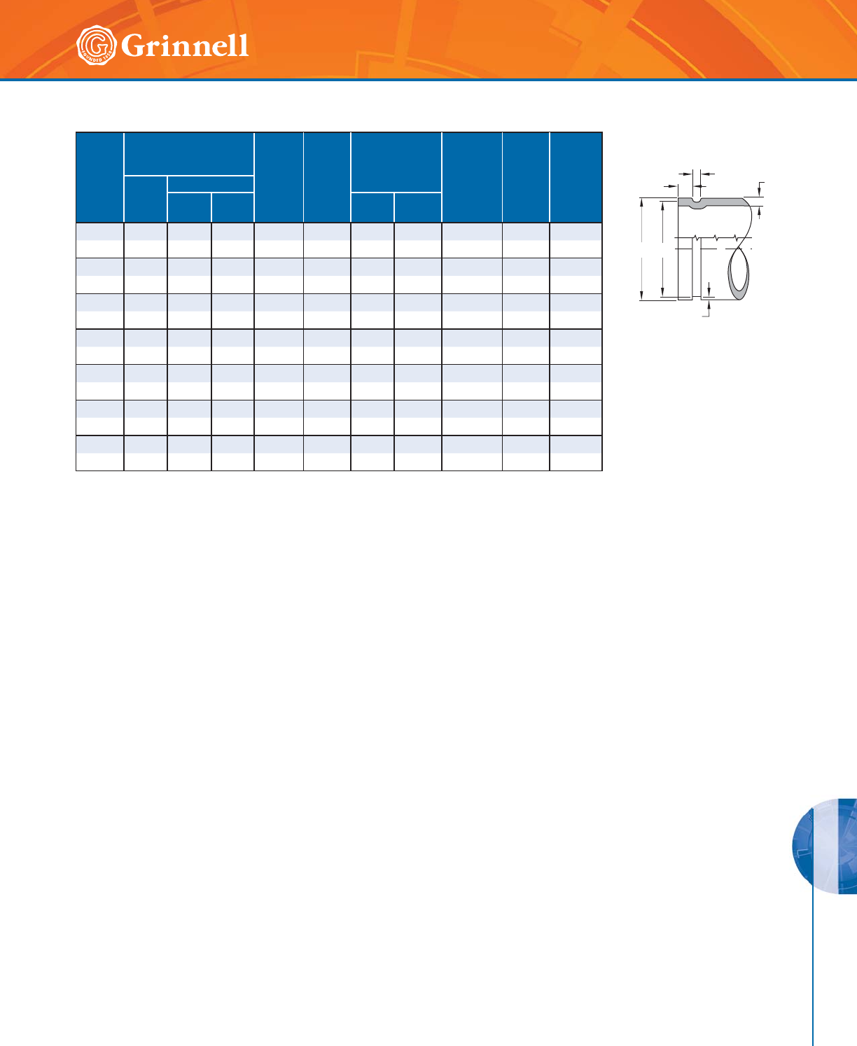
PREPARATION EQUIPMENT
PREPARATION EQUIPMENT
203
Refer to back cover for country-specific customer care numbers.
Roll Groove Standard Specification for Copper Tubing
Tech Data Sheet: G720
(1) Nominal Tubing, ASTM B-88 drawn copper tubing size.
(2) Outside Diameter “OD”, of roll grooved tubing shall not
vary more than the tolerance listed. The maximum toler-
ance from square cut ends is: 0.030" (0,76mm) for sizes
2" – 3" (54,0 – 79,4mm); 0.045" (1,14mm) for sizes 4" –
6" (104,8 – 155,6mm); measured from true square line.
(3) Gasket Seating Surface “A”, must be free from roll marks,
indentations, projections, loose scale, dirt, chips, grease,
etc. that would prevent a positive seal.
(4) Groove Width Bottom “B”, to be free of loose dirt, chips
and scale that may interfere with proper
coupling assembly.
(5) The Groove Diameter “C”, must be uniform in depth for
the entire circumference of the tubing. Groove must be
maintained within the tolerance listed.
(6) Groove Depth “D”, is a reference dimension only. The
Groove Diameter “C” must be maintained.
(7) Minimum Wall Thickness “T”, per ASTM B-306 drain waste
and vent (DWV) is minimum wall thickness copper tubing,
which may be roll grooved.
(8) Maximum Flare Diameter is the O.D. at the most extreme
tubing diameter.
Nominal
Tubing
Size
Inches
mm
Tubing O.D.
Inches
mm
A
±0.030"
±0.76mm
Inches
mm
B
±0.030"
±0.76mm
Inches
mm
C
Groove Diameter
Inches
mm
D
Nominal
Groove
Depth
Inches
mm
T
Minimum
Wall
Inches
mm
Maximum
Flare
Diameter
Inches
mm
O.D.
Tolerance
+- Actual
Tol.
0.000
2" 2.125 0.002 0.002 0.610 0.300 2.029 -0.020 0.048 0.058 2.220
50 54,0 0,05 0.05 15,5 7,6 51,5 -0,51 1,2 1,5 56,4
21⁄2" 2.625 0.002 0.002 0.610 0.300 2.525 -0.020 0.050 0.065 2.720
65 66,7 0,05 0,05 15,5 7,6 64,1 -0,51 1,2 1,7 69,1
3" 3.125 0.002 0.002 0.610 0.300 3.025 -0.020 0.050 DWV 3.220
80 79,4 0,05 0,05 15,5 7,6 76,8 -0,51 1,2 – 81,8
4" 4.125 0.002 0.002 0.610 0.300 4.019 -0.020 0.053 DWV 4.220
100 104,8 0,05 0,05 15,5 7,6 102,1 -0,51 1,4 – 107,2
5" 5.125 0.002 0.002 0.610 0.300 4.999 -0.020 0.053 DWV 5.220
125 130,2 0,05 0,05 15,5 7,6 127,0 -0,51 1,4 – 132,6
6" 6.125 0.002 0.002 0.610 0.300 5.999 -0.020 0.063 DWV 6.220
150 155,6 0,05 0,05 15,5 7,6 152,3 -0,51 1,6 – 158,0
8" 8.125 0.002 0.004 0.610 0.300 7.959 -0.020 0.083 DWV 8.220
200 206,4 0,05 0,10 15,5 7,6 202,2 -0,51 2,1 – 208,8
A
BT
COD
D

PREPARATION EQUIPMENT
PREPARATION EQUIPMENT
204 www.grinnell.com
Model PT 1000 was developed to check the groove di-
ameter in roll-grooved pipe. The tape measures the groove
in steel pipe 1" – 12" (25mm - 305mm) and copper tube
2" – 8" (50mm - 200mm).
The loop extending from the metal housing consists of a
clear-plastic window with a vertical indicator line and the
adjustable metal measuring tape. The adjustable measuring
tape has groove tolerance blocks (thick black lines) that are
visible through the plastic view window. The groove toler-
ance blocks are marked with the associated pipe diameters.
Model PT 2000 measures the groove in steel pipe from
1" – 36" (25mm - 915mm) in 100th’s of inches.
Note: The GRINNELL Roll Pipe Measuring Tape is not a calibrated tool and is to be used for reference only. To ensure accuracy, always check grooved pipe
dimensions with calibrated gauges or calipers. For Roll Groove Standard Specifications for Steel Pipe and Other IPS Pipe, refer to Data Sheet G710. For Roll
Groove Standard Specification for Copper Tube, refer to Data Sheet G720.
Pipe Tape
Portable Roll Groovers With Electric Motor
Pace Model
Size Range - Inches mm
Drive
Schedule 40 Schedule 10 Std. Wall Copper
1112 1" – 12" 11⁄4" - 12" – 2" – 6" 11⁄2 HP, 110 v
25mm - 300mm 32mm - 300mm – 50mm - 150mm
1023 11⁄4" – 12" 11⁄4" - 24" 12" – 24" 2" – 6" 11⁄2 HP, 110 v
32mm - 300mm 32mm - 600mm 300mm - 600mm 50mm - 150mm
Roll Grooving Machines are available for rent. Contact your GRINNELL Mechanical Products representative for details and availability.
*Please specify power outlet when ordering
Self-contained portable roll grooving machines are supplied with electric motors for roll grooving pipe on the job site. Each
machine comes in a shipping/storage box and includes a hydraulic hand pump, top and bottom rolls, guards and foot switch.
Additional rolls may be ordered with machines. Contact GRINNELL Mechanical Products.
PREPARATION EQUIPMENT
PREPARATION EQUIPMENT
205
Refer to back cover for country-specific customer care numbers.
Model 1112 Portable Roll Groovers With Electric Motor
Model 1023 Portable Roll Groovers With Electric Motor
• Schedule 40 Capacity 1" – 12" (25mm - 300mm)
• Copper Tube 2" – 6" (50mm - 150mm) (K, L, M and DWV)
• Pipe Rotation Speed of 35 RPM
• Spindle height from floor is 35" (889mm)
• Hydraulic Pressure at Roller is 15,000 PSI (1034,2 bar) Max
• Electric Motor 11⁄2 HP, 60 Hz, 110 v.1 PH*
Floor Space Required: 32" x 32" (813mm x 813mm)
Weight: 220 lbs (99,8 kg)
Standard Equipment:
Electric Drive Motor, Groove Depth Gauge, Hydraulic Hand Pump,
Top and Bottom Rolls 1" – 12" (25mm - 300mm),
Shipping/Storage Box, Guards, Foot Switch
Optional Equipment:
Top and Bottom copper Rolls, Nipple Bracket, Mounting Feet
* Other current characteristics available contact GRINNELL
Mechanical Products.
• Schedule 40 11⁄4" – 12" (32mm – 300mm)
• Standard Wall 12" – 24" (300mm – 600mm)
• Copper Tube 2" – 6" (50mm - 150mm)
(K, L, M and DWV)
• Pipe Rotation Speed of 30 RPM
• Spindle height from floor is 33" (838mm)
• Hydraulic Pressure at Roller is 16,000 PSI (1103,2 bar) Max
• Electric Motor 11⁄2 HP, 60 Hz, 110 v or 220v
Floor Space Required: 311⁄2" x 331⁄2" (800mm - 851mm)
Weight: 430 lbs (195 kg)
Standard Equipment:
Electric Motor, Groove Depth Gauge, Hydraulic Pump,
Shipping/Storage Box, Rolls as Specified on Price List,
Guards, Foot Switch
Optional Equipment:
Top and Bottom Copper Rolls, Nipple Bracket, Mounting Feet
PREPARATION EQUIPMENT
PREPARATION EQUIPMENT
206 www.grinnell.com
Portable Roll Groovers For Ridgid® 300 Pipe Threader
Models 1012, 1022 and 1041 Roll Grooving Machines are designed to be mounted quickly and easily
on a Ridgid® Model 300 unit.*
Model 1012 Portable Roll Groovers
Model 1022 Portable Roll Groovers
Model 1041 Portable Roll Groovers
• Schedule 40 1" – 12" (25mm - 300mm)
• Copper Tube Capacity 2" – 6" (50mm - 150mm) (K, L, M and DWV)
• Hydraulic Hand Pump
Weight: 125 lbs (56,7 kg)
Standard Equipment:
Top and Bottom Rolls 1" – 12" (25mm - 300mm), Groove Depth Gauge,
Hydraulic Hand Pump, Guards
Optional Equipment:
Top and Bottom Copper Rolls, Pipe Nipple, and Stabilizer Bracket
• Schedule 40 Capacity 11⁄4" – 12" (32mm - 300mm)
• Standard Wall Capacity 12" – 16" (300mm - 400mm)
• Copper Tube Capacity 2" – 6" (50mm - 150mm) (K, L, M)
• Hydraulic Pressure at Roller is 16,000 PSI (1103,2 bar) Max
Weight: 285 lbs (129 kg)
Standard Equipment:
Top and Bottom Rolls 11⁄4" – 16" (32mm - 400mm), Hydraulic Hand Pump, Grooved
Depth Gauge, Shipping/Storage Box, Pipe Nipple and Stabilizer Bracket, Guards
Optional Equipment:
Top and Bottom Copper Rolls
• Schedule 40 Capacity 1" – 6" (25mm - 150mm)
• Schedule 10 Capacity 1" – 12" (25mm - 300mm)
• Copper Tube Capacity 2" – 6" (50mm - 150mm) (K, L, M and DWV)
• Hydraulic Pressure at Roller is 8,000 PSI (551,6 bar) Max
Weight: 94 lbs (42 kg)
Standard Equipment:
Top and Bottom Rolls 1" – 12" (25mm - 300mm), Hydraulic Hand Pump,
Grooved Depth Gauge and Guards
Optional Equipment:
Top and Bottom Copper Rolls
Pace Model Size Range - Inches mm Drive
Schedule 40 Schedule 10 Std. Wall Copper
1012 1" – 12" – – 2" – 6" Ridgid® 300
25mm - 300mm ––50mm - 150mm
1022 11⁄4" – 12" – 12" – 16" 2" – 6" Ridgid® 300
32mm - 300mm –300mm - 400mm 50mm - 150mm
1041 1" – 6" 1" – 12" – 2" – 6" Ridgid® 300
25mm - 150mm 25mm - 300mm –50mm - 150mm
* Ridgid is a registered trademark of Ridgid Tool Company.
PREPARATION EQUIPMENT
PREPARATION EQUIPMENT
207
Refer to back cover for country-specific customer care numbers.
MINI-MITES Field Portable
Field Portable Mini-Mites are designed to be adapted for use with Ridgid® Model 300 machines. Model 1039-66 can be
operated with its own hand ratchet so that no other tools are required.
Model 1039-66 MINI-MITES Field Portable
Model 1039 MINI-MITES Field Portable
Model 1034 MINI-MITES Field Portable
Model 1066 MINI-MITES Field Portable
• Copper Tube Capacity 2" – 8" (50mm - 200mm) (K, L, M and DWV)
• Manual Grooving With Ratchet Hand Crank
• Can be Used with Ridgid® Model 300 With No
Gearbox Removal
• Self-contained
Standard Equipment:
Copper Rolls 2" – 8" (50mm - 200mm), Multi-Function Ratchet Hand Crank
Optional Equipment:
Top and Bottom Rolls Steel Pipe
• Schedule 40 Capacity 11⁄4" – 6" (32mm - 150mm)
• Manual Grooving With Ratchet Hand Crank
• Can be Used with Ridgid® Model 300 With No Gearbox Removal
• Self-contained
Standard Equipment:
Steel Rolls 11⁄4" – 6" (32mm - 150mm), Multi-Function Ratchet Hand Crank
Optional Equipment:
Top and Bottom Rolls Copper Tube
• Schedule 40 Capacity 11⁄4" – 6" (32mm - 150mm)
• Used with the Ridgid® Model 300 Threader
Standard Equipment:
Steel Pipe Rolls 11⁄4" – 6" (32mm - 150mm)
• Copper Tube Capacity 2" – 8" (50mm - 200mm)
(K, L, M and DWV)
• Used With the Ridgid® Model 300 Threader
Standard Equipment:
Copper Rolls 2" – 8" (50mm - 200mm)
Pace Model Size Range - Inches mm Drive
Schedule 40 Schedule 10 Std. Wall Copper
1039-66 – – – 2" – 8" Ridgid® 300,
hand crank
–––50mm - 200mm
1039-66 11⁄4" – 6" – – – Ridgid® 300,
hand crank
32mm - 150mm –––
1034 11⁄4" – 6" – – – Ridgid® 300
32mm - 150mm –––
1066 –––2" – 8"
Ridgid® 300
–––50mm - 200mm
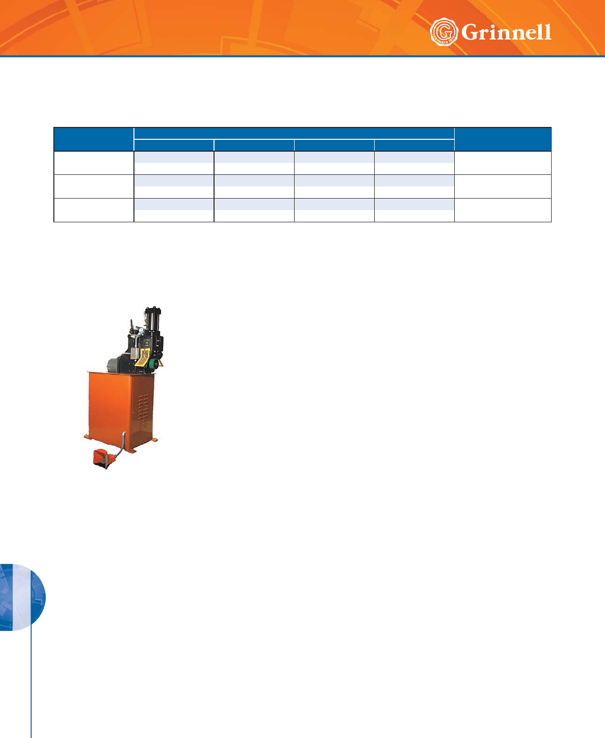
PREPARATION EQUIPMENT
PREPARATION EQUIPMENT
208 www.grinnell.com
AUTOMATED ROLL GROOVERS
Pace Model Size Range - Inches mm Drive
Schedule 40 Schedule 10 Std. Wall Copper
2021 11⁄4" – 12" – 12" – 24" 2" – 8" 3 HP, 220 v
32mm - 300mm – 300mm - 600mm 50mm - 200mm
2050 4" – 12" 4" – 30" – – 5 HP, 220 v
100mm - 200mm 100mm - 800mm – –
2112 1" – 12" – – 2" – 8" 11⁄2 HP, 110 v
25mm - 300mm – – 50mm - 200mm
The Automated Roll Grooving Machines are designed for use in the shop. The machines have a self-contained hydraulic system
that produces consistent quality roll grooves in high production runs.
Model 2021 AUTOMATED ROLL GROOVERS
• Schedule 40 11⁄4" – 12" (32mm - 300mm)
• Standard Wall 12" – 24" (300mm - 600mm)
• Copper Tubing 2" – 8" (50mm - 200mm) (K, L, M and DWV)
• Pipe Rotation Speed of 30 RPM
• Hydraulic Pressure at the Roller is 16,000 PSI (1103,2 bar) Max
• Electric Motor 3 HP, 60 Hz, 220 v, 3 PH
• Hydraulic Pump Motor 1 HP, 60 Hz, 220 v, 3 PH
• Ships Completely Assembled With 4" – 6"
(100m - 150mm) Top and Bottom Rollers
Floor Space Required: 30" x 20" (762mm - 508mm)
Standard Equipment:
Electric Drive Motor, Limit Switch for Depth Gauging, Groove Depth Gauge,
Hydraulic Pump, Model 4037 Nipple Bracket, Rolls As Specified in Price List,
Guards, Foot Switch
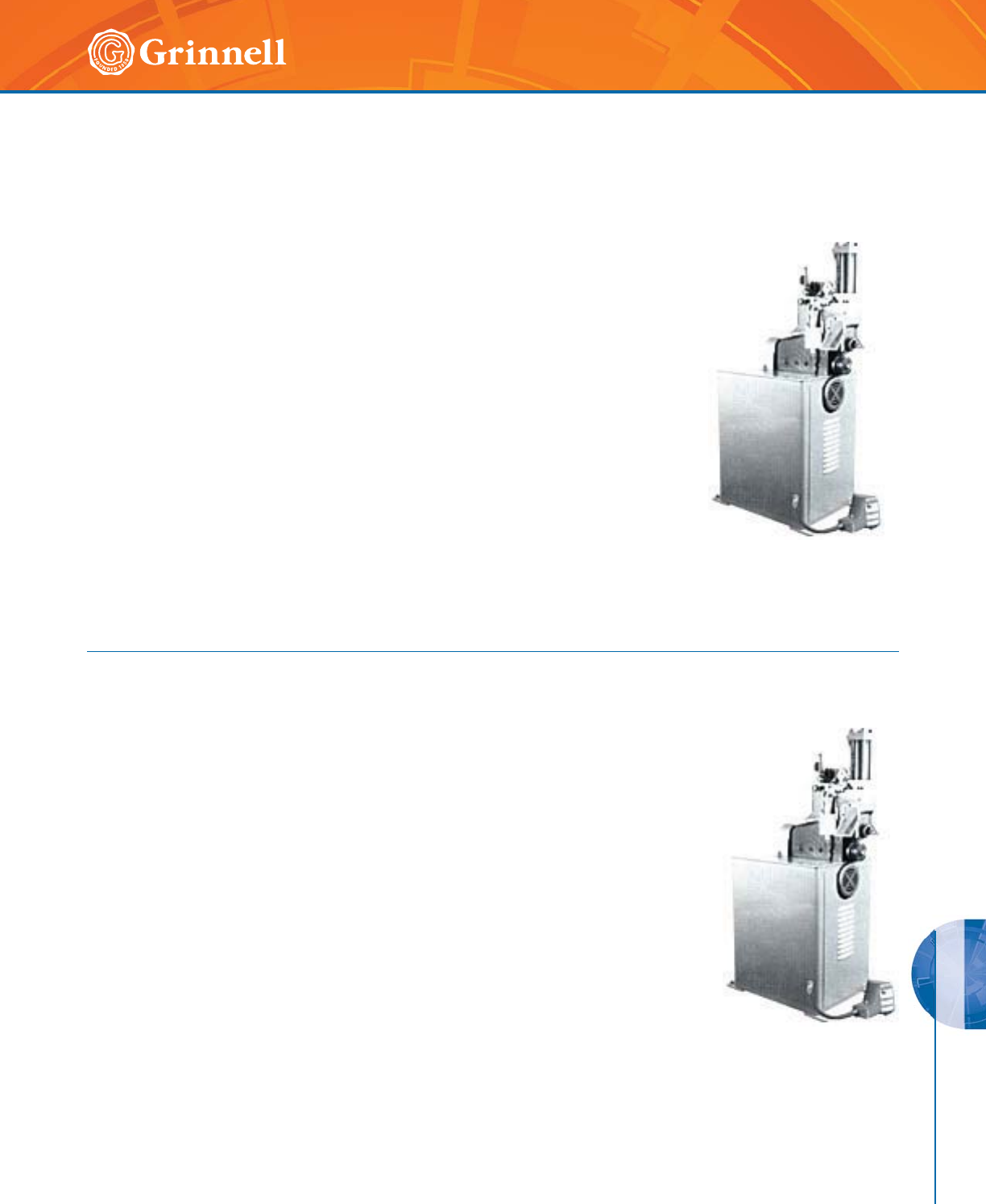
PREPARATION EQUIPMENT
PREPARATION EQUIPMENT
209
Refer to back cover for country-specific customer care numbers.
AUTOMATED ROLL GROOVERS
• Schedule 40 1" – 12" (40mm - 150mm)
• Copper Tubing 2" – 8" (50mm - 200mm) (K, L, M and DWV)
• Pipe Rotation Speed of 35 RPM
• Spindle height from floor is 35" (889mm)
• Hydraulic Pressure at the Roller is 15,000 PSI (1034 bar) Max
• Electric Motor 1⁄2 HP, 60 Hz, 110 v, 1 PH
• Hydraulic Pump Motor 1 HP, 60 Hz, 110 v, 1 PH
• Ships Completely Assembled With 1" – 12" (100mm - 150mm)
Top and Bottom rollers
Floor Space Required: 30" x 22" (762mm - 559mm)
Weight: 470 lbs (213 kg)
Standard Equipment:
Electric Drive Motor, Limit Switch for Depth Gauging, Groove Depth Gauge,
Hydraulic Pump, Model 4037 Nipple Bracket, Rolls As Specified in Price List,
Guards, Foot Switch
• Schedule 40 4" – 12" (100mm - 300mm)
• Schedule 10 4" – 30" (100mm - 800mm)
• Pipe Rotation Speed of 30 RPM
• Hydraulic Pressure at the Roller is 20,000 PSI (1378 Bar) Max
• Spindle height from floor is 36" (914mm)
• Electric Drive Motor 5 HP, 60 Hz, 220 V.3PH
• Hydraulic Pump Motor 2 HP, 60 Hz, 220 V.3PH
• Ships Completely Assembled With 4" – 6"
(100mm - 150mm) Top and Bottom rollers
Floor Space Required: 40" x 36" (1016mm - 914mm)
Weight: 1,500 lbs (680 kg)
Standard Equipment:
Electric Drive Motor, Limit Switch for Depth Gauging, Groove Depth Gauge,
Hydraulic Pump Motor, Hydraulic Pump , Rolls As Specified in Price List,
Guards, Foot Switch
Model 2112 AUTOMATED ROLL GROOVERS
Model 2050 AUTOMATED ROLL GROOVERS
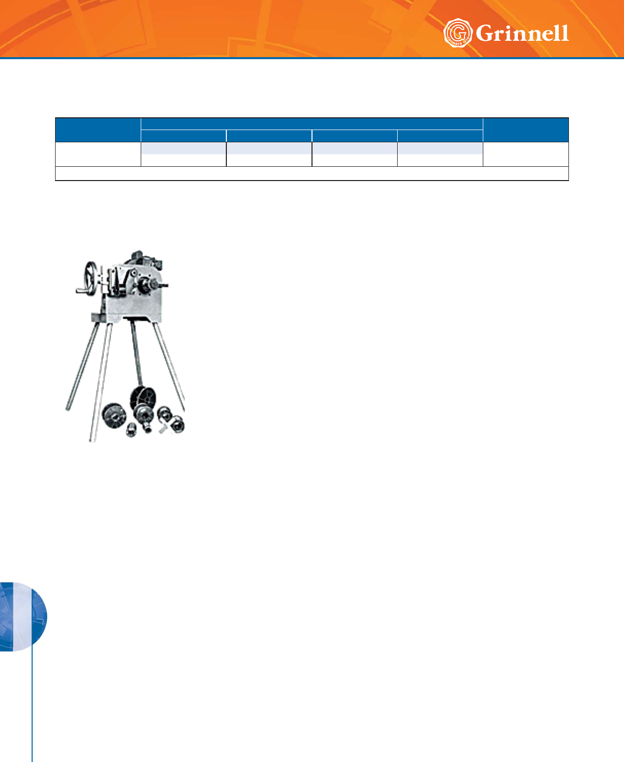
PREPARATION EQUIPMENT
PREPARATION EQUIPMENT
210 www.grinnell.com
Model 1000 PORTABLE CUT GROOVER
Pace Model Size Range - Inches mm Drive
Schedule 40 Schedule 10 Schedule 80 Std. Wall
1000 2" – 12" * – 21⁄2" – 8" – 1 HP, 115-230 v
50mm - 300mm – 65mm - 200mm –
* With optional collet chucks for 10" – 12" (250mm - 300mm) pipe.
• Schedule 40 2" – 12" (50mm - 300mm)
• Schedule 80 21⁄2" – 8" (65mm - 200mm)
• Tooling for Cut Grooving Ductile Iron Pipe Also Available
• Special collet chucks for Non-Standard Dimension Pipe Can Be Supplied
• Motor is 1 HP, 115-230 v, 1 PH
Weight: 185 lbs (84 kg)
Height: 38" (965,2 mm)
Standard Equipment:
Collet chucks for 2" – 8” (50mm - 200mm), 4 High Speed Steel Grooving Blades,
Groove Gauge, Shipping/Storage Box
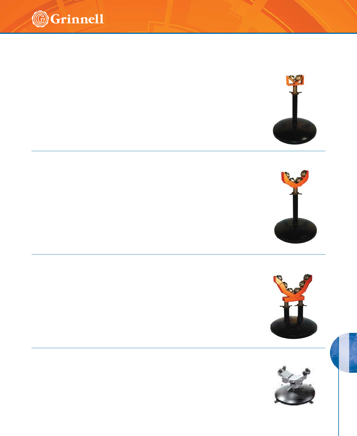
PREPARATION EQUIPMENT
PREPARATION EQUIPMENT
211
Refer to back cover for country-specific customer care numbers.
Model 4031 Pipe Support Stands
ACCESSORIES
Model 4000 Pipe Support Stands
Model 4033 Pipe Support Stands
Model 4040 Pipe Support Stands
Capacity: 1" – 4" (25mm - 100mm) Pipe; 600 lbs (272,2 kg) max
A 22" (559mm) diameter base with 2" (50mm) column gives this stand plenty of strength for
supporting any pipe size in its size range. The saddle has two roller bar bearings for free rota-
tion of the pipe, and absorbs vibration to ensure a smooth, uniform groove. Saddle height is
adjustable over a 10" (250mm) range.
Capacity: 2" – 8" (50mm - 200mm) Pipe; 900 lbs (408,2 kg) max
The base of this stand is the same as used in the Model 4031. A saddle with four roller
bearings provides greater side support for the pipe and increases dampening of vibration
without impairing the unit's free-rolling characteristics. Saddle height is adjustable over a 10"
(250mm) range.
Capacity: 2" – 14" (50mm - 350mm) Pipe; 1,200 lbs (544,3 kg) max
This extra-heavy-duty pipe support stand uses two 2" (50mm) columns on a 22" (550mm)
diameter base to give it exceptional stability and resistance to vibration and pendulum effect.
Each column incorporates a sturdy, threaded post infinitely adjustable over a 10" (250mm)
range. The saddle utilizes six roller bearings in an array that provides excellent support for all
pipes in its size range.
Capacity: 12" – 24" (300mm - 600mm) Pipe; 4,000 lbs (1814,4 kg) max
Fabricated of 6" (150mm) diameter steel pipe welded to a 36" (914,4mm) base, the stand
can support up to two tons of pipe during grooving operations. Pipe saddle height is adjust-
able over a 5" (127mm) range.
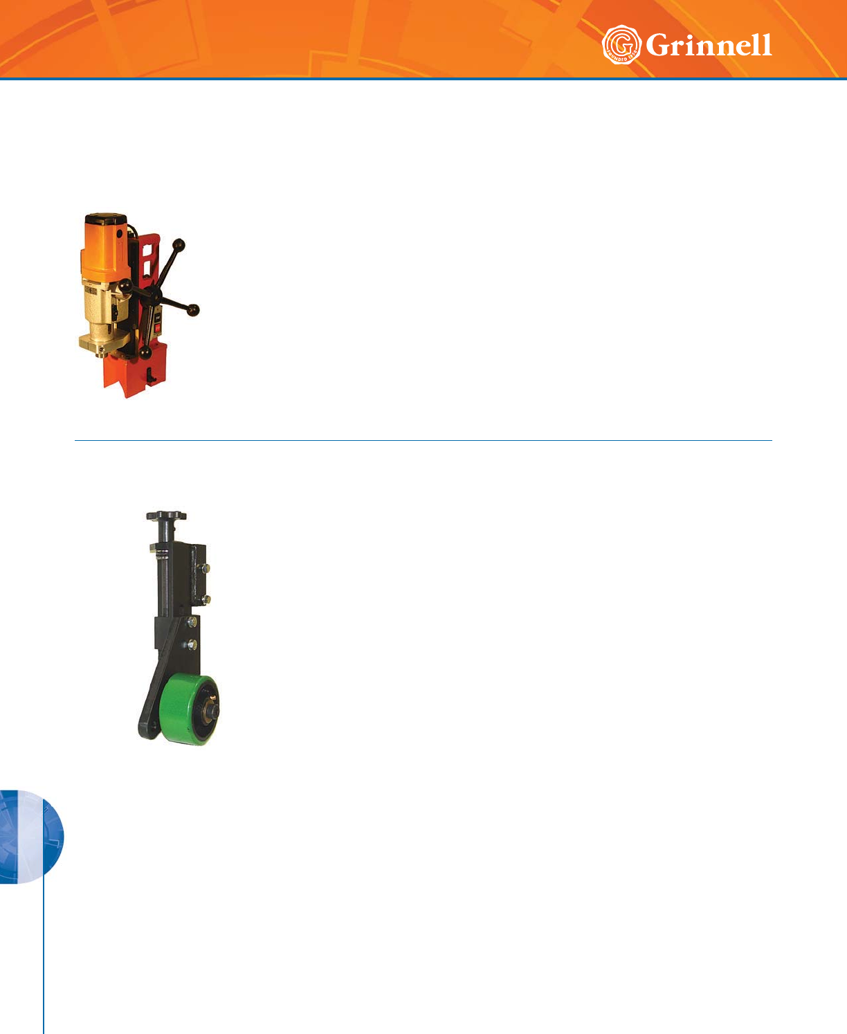
PREPARATION EQUIPMENT
PREPARATION EQUIPMENT
212 www.grinnell.com
Model 3013 Porta-Bore
ACCESSORIES
• Solid Alloy Aluminum Construction
• Motor is a 10 Amp draw industrial drill motor 110 v with internal 4-speed gear
box 110, 175, 245, 385 RPM
• Circuit breaker assures no safety hazard to the operator or machine
• Chain clamp is standard on all units and clamps to 11⁄4" – 12" (32mm - 300mm)
pipe diameters
• Optional speed toggle clamps; 11⁄4" – 6" (32mm - 150mm) pipe
• Oil feed
Weight: 42 lbs (19 kg)
• Capacity: 8" – 24" (200mm - 600mm) Pipe
• Fits Models 1020, 1021, 1023, 2020, 2021, and 2050 Roll Groovers
Model 4037 Nipple Bracket
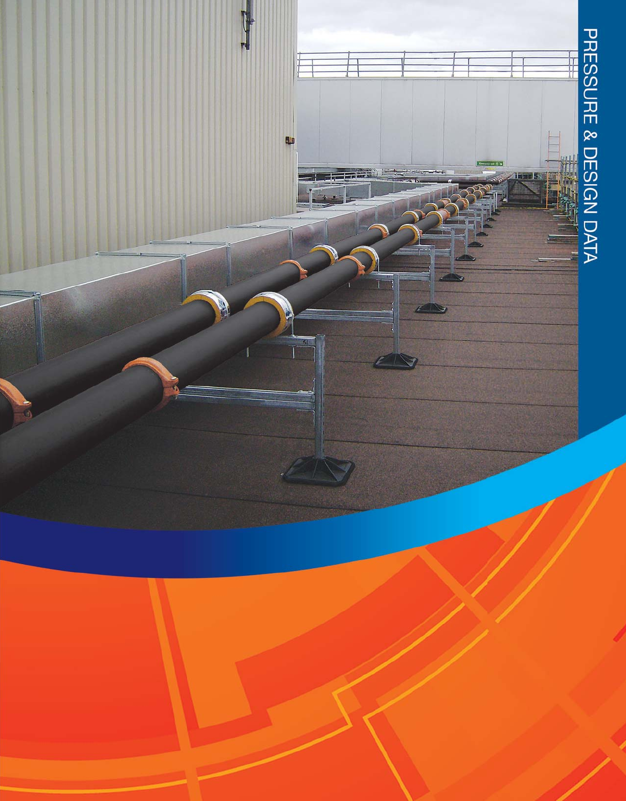
213
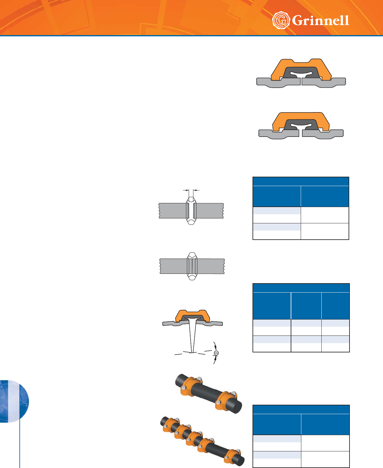
DESIGN DATA
PRESSURE & DESIGN DATA
214 www.grinnell.com
Angular Deflection
GRINNELL Flexible Couplings are
capable of accommodating angular
deflection.
Expansion/Contraction
GRINNELL Flexible Couplings are capable of
accommodating pipe thermal movements provided they
are properly gapped and a sufficient quantity of flexible
couplings are used. Note that flexible couplings will not
accommodate both full maximum linear movement and
the maximum available angular deflection concurrently at
the same joint.
If it is desired to have both deflection and linear
movement available, then the system should have
sufficient flexible joints to accommodate the
requirement.
Rigid Joints
GRINNELL Rigid Couplings provide rigid gripping of the pipe. They are designed
to bring the pipe ends close together and to ensure the coupling clamps firmly onto
the pipe OD and the bottom of the grooves. Because rigid couplings clamp around
the entire pipe surface, they provide resistance to flexural and torsional loads and
therefore permit longer spacing to ASME/ANSI B 31.1 (Power Piping) and ASME/
ANSI B 39.1 (Building Services) requirements.
Flexible Joints
GRINNELL Flexible Couplings act as an “expansion joint”, allowing linear and
angular movement of the pipe. They are designed with the coupling keys engaging
the pipe without gripping on the bottom of the grooves, while still providing for a
restrained mechanical joint. This is particularly useful to allow for pipe expansion/
contraction and piping misalignment.
Deflection
Pipe Size
Inches
mm
Maximum Pipe
Deflection
Reduction
11⁄4 – 3 50%
42,4 – 88,9
4 – 24 25%
114,3 – 610,0
For thermal expansion with flexible
couplings, the pipe ends at each joint
should be fully gapped to the maximum
amount. This can be accomplished
by pressurizing the system and then
anchoring the system.
For thermal contraction with flexible
couplings, the pipe ends at each joint
should be fully butted. The system can then
be anchored in place to prevent the pipe
ends from opening up to the maximum end
gap when pressurized. Pipe Ends Butted
for Contraction
End Gap Reduction
Pipe Size
Inches
mm
Maximum Pipe End
Gap
11⁄4 – 3 50%
42,4 – 88,9
4 – 24 25%
114,3 – 610,0
Pipe End Movements
Pipe Size
Inches
mm
Cut
Grooved
Inches
mm
Roll
Grooved
Inches
mm
11⁄4 – 3 0 – 0.063 0 – 0.031
42,4 – 88,9 0 – 1,6 0 – 0,8
4 – 24 0 – 0.188 0 – 0.094
114,3 – 610,0 0 – 2,4 0 – 2,4
* Roll grooved joints provide half the available
movement of cut grooved joints.
End Gap
Pipe Ends Gapped
for Expansion
For design purposes, the maximum
pipe end gap should be reduced to
account for field practices as follows:
The following values should be used
as available pipe end movements for
GRINNELL Figure 705, 707, and 716
Flexible Couplings:
The deflection published is a maximum
value. For design purposes the
maximum deflection should be reduced
to account for field practices as shown:
Linear Movement (Flexible Couplings)
Design
Tech Data Sheets: G810, G820, G830
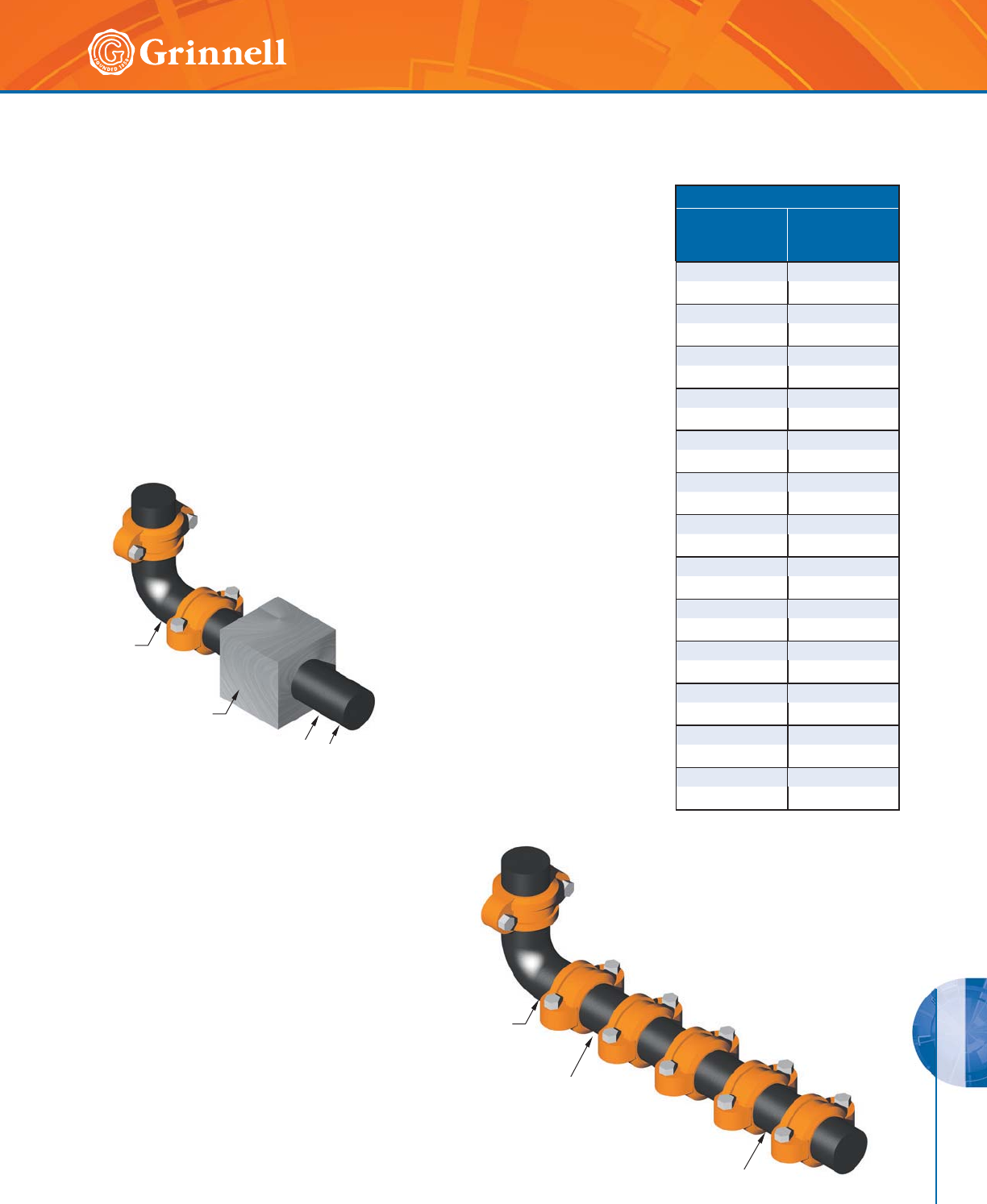
DESIGN DATA
PRESSURE & DESIGN DATA
215
Refer to back cover for country-specific customer care numbers.
Activation Force
Pipe Size
Inches
mm
Activation Force
lbs
N
11⁄435
42,4 156
11⁄245
48,3 200
270
60,3 311
21⁄2100
73,0 645
76,1mm 110
76,1 489
3145
88,9 645
4240
114,3 1068
5375
141,3 1668
165,1mm 500
165,1 2224
6 520
168,3 2313
8880
219,1 3914
10 1365
273,0 6072
12 1915
323,9 8518
The following guidelines are similar to any
expansion joint:
It is recommended that anchors be installed at changes of direction on the pipe lines to
control the pipe movement. The thermal expansion/contraction in the piping system can be
accommodated using GRINNELL Flexible Couplings. In designing anchoring systems, it is
suggested that the following be taken into consideration:
• Pressure Thrusts
• Frictional Resistance of Any Guides or Supports
• Centrifugal Thrust Due to Velocity at Changes of Direction
• Activation Force Required to Compress or Expand a Flexible Coupling
Three methods are available as examples to
accommodate thermal expansion/contraction:
(1) Design the system with rigid couplings
and place expansion joints at the proper
locations. Expansion joints may be a
series of flexible grooved couplings of a
sufficient quantity to accommodate the
movement.
(2) Design the system with flexible and/
or rigid couplings and allow the pipe to
move in directions desired, with the use
of anchors and guides if so required.
With this method, it is important
to ensure that movement at branch
connections, changes of direction,
equipment hookup, etc., will not cause
damage or harmful stresses.
(3) Design the system with flexible couplings
utilizing the expansion/contraction
capabilities of these products.
The following example illustrates this method:
• 6" (150mm) Schedule 40 steel pipe, roll grooved,
150' (45,7m) long, anchored at each end
• Maximum Temperature = 200°F (93.3°C)
• Minimum Temperature = 40°F (4.4°C)
• Install Temperature = 80°F (26.6°C)
Thermal Movement
Tech Data Sheets: G810, G820, G830
$QFKRU
3RVLWLRQ
([SDQVLRQ
-RLQW)LJ
,QWHUPHGLDWH
*XLGHV
:
$QFKRU
3RVLWLRQ
,QWHUPHGLDWH
*XLGHV
,QWHUPHGLDWH
*XLGHV
)OH[LEOH
&RXSOLQJV
DESIGN DATA
PRESSURE & DESIGN DATA
216 www.grinnell.com
Thermal Movement
Tech Data Sheets: G810, G820, G830
Directions to calculate the number of couplings required to
compensate for the thermal expansion and contraction of
pipe (by example):
(1) Thermal Contraction
Utilize the Thermal Expansion Table. Allowance for the minimum
installation temperature, in this case 80°F to 40°F (26.6°C to
4.4°C), is calculated as:
80°F = 0.61" per 100'
40°F = 0.30" per 100'
Difference = 0.31" per 100'
For 150' of pipe = 0.31" x 1.5 = 0.47" per 150'
(26.6°C = 15,5mm per 30,5m
4.4°C = 7,6mm per 30,5m
Difference = 7,9mm per 30,5m
For 45,7m of pipe = 7,9mm x 1.5 = 11,9mm per 45,7m)
(2) Thermal Expansion
Utilize the Thermal Expansion Table. Allowance for the minimum
installation temperature, in this case 26.6°C to 93.3°C (80°F to
200°F), is calculated as:
200°F = 1.52" per 100'
80°F = 0.61" per 100'
Difference = 0.91" per 100'
For 150' of pipe = 0.91 x 1.5 = 1.36" per 150'
(93.3°C = 38,6mm per 30,5m
26.6°C = 15,5mm per 30,5m
Difference = 23,1mm per 30,5m
For 45,7m of pipe = 23,1mm x 1.5 = 34,5mm per 45,7m)
(3) Couplings Required
Available linear movement for a 6" (150mm) Figure 707 Flexible
Coupling on roll grooved pipe = 0.094" (2,4mm)
per coupling.
Fully butted together for contraction only. Therefore the number
of Figure 707 Flexible Couplings required:
• 0.47" / 0.094" per coupling = 5.0
(11,9mm / 2,4mm per coupling = 4.96)
• Use 5 Figure 707 couplings for pipe contraction
(b) Fully gapped apart for expansion only. Therefore the number
of Figure 707 Flexible Couplings required:
• 1.36" / 0.094" per coupling = 14.47
(34,5mm / 2,4mm per coupling = 14.38)
• Use 15 Figure 707 Flexible Couplings for pipe expansion
Thermal Expansion of Carbon Steel in Inches/100 Feet
(milliMeters/30.5 Meters)
Between 0°F (-18°C) and Indicated Temperature
Temperature
F°
C°
Thermal Expansion
Inches/100 Feet
mm/30.5M
-40 -0.30
-40 -7,62
-30 -0.23
-34,4 -5,84
-20 -0.15
-28,9 -3,81
-10 -0.08
-23,3 -2,03
00.00
-17,8 0,00
10 0.08
-12,2 2,03
20 0.15
-6,7 3,81
30 0.23
-1,1 5,84
40 0.30
4,4 7,62
50 0.38
10,0 9,65
60 0.46
15,6 11,68
70 0.53
21,1 13,46
80 0.61
26,7 15,50
90 0.68
32,2 17,27
100 0.76
37,8 19,30
110 0.84
43,3 21,34
120 0.91
48,9 23,11
130 0.99
54,4 25,15
140 1.06
60,0 26,92
150 1.14
65,6 28,96
160 1.22
71,1 30,99
170 1.29
76,7 32,77
180 1.37
82,2 34,80
190 1.44
87,8 36,58
200 1.52
93,3 38,61
210 1.60
98,9 40,64
220 1.67
104,4 42,42
230 1.75
110,0 44,45
Mean Coef. of thermal expansion = 0.00000633 in/in/°F Source:
ASME B31.9
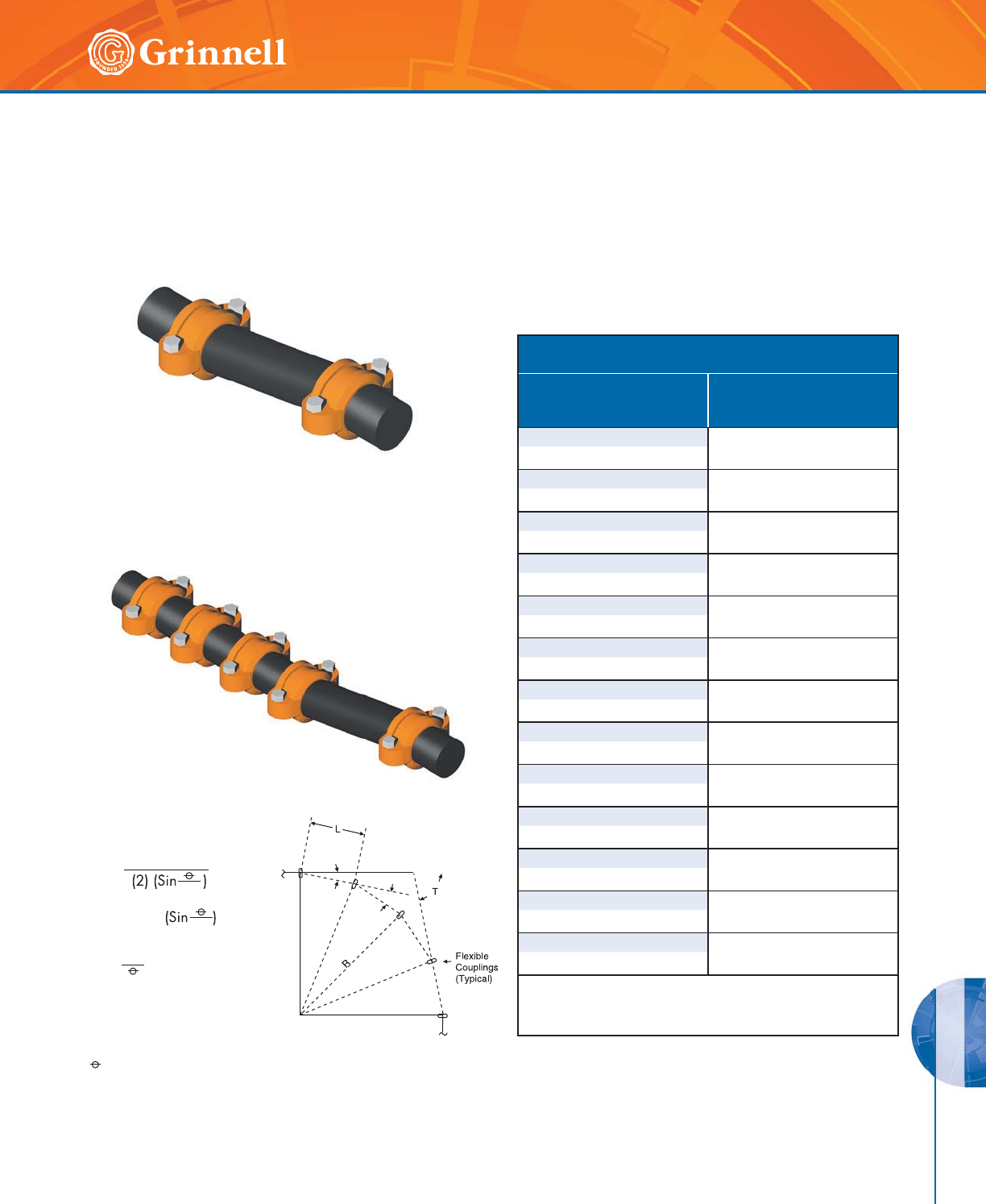
DESIGN DATA
PRESSURE & DESIGN DATA
217
Refer to back cover for country-specific customer care numbers.
R =
L = (2) (R)
N =
L
2
2
T
R = Radius of curve
L = Pipe length
= Deflection from centerline, in degrees,
for each coupling (see table)
N = Number of flexible couplings needed
T = Total deflection, in degrees, required
GRINNELL Flexible Couplings provide for restrained
joints and allow for deflection to aid where the pipe or
equipment is misaligned.
Note that flexible couplings will not accommodate both
full maximum linear movement and the maximum available
angular deflection concurrently at the same joint.
Design Deflection for
Roll Grooved Pipe
Deflection O
(Roll Grooved Pipe)
Pipe Size
Inches
mm
Figures
705 &
707
11⁄4
1.08°
42,4
11⁄2
0.94°
48,3
20.75°
60,3
21⁄2
0.62°
73,0
76,1mm 0.60°
76,1
30.51°
88,9
41.19°
114 ,3
50.97°
141,3
165,1mm 0.83°
165,1
60.81°
168,3
80.63°
219,1
10 0.50°
273,0
12 0.42°
323,9
Incorporates the recommended safety factor reduction for field
practices (50% for sizes 11⁄4 – 3" (32mm - 80mm) and 25% for
sizes 4" – 12" (100mm - 300mm)).
If it is desired to have both deflection and linear movement
available, then the system should have sufficient flexible
joints to accommodate the requirement.
Flexible couplings are also useful in laying out curved
piping systems.
Misalignment and Deflection
Tech Data Sheets: G810, G820, G830
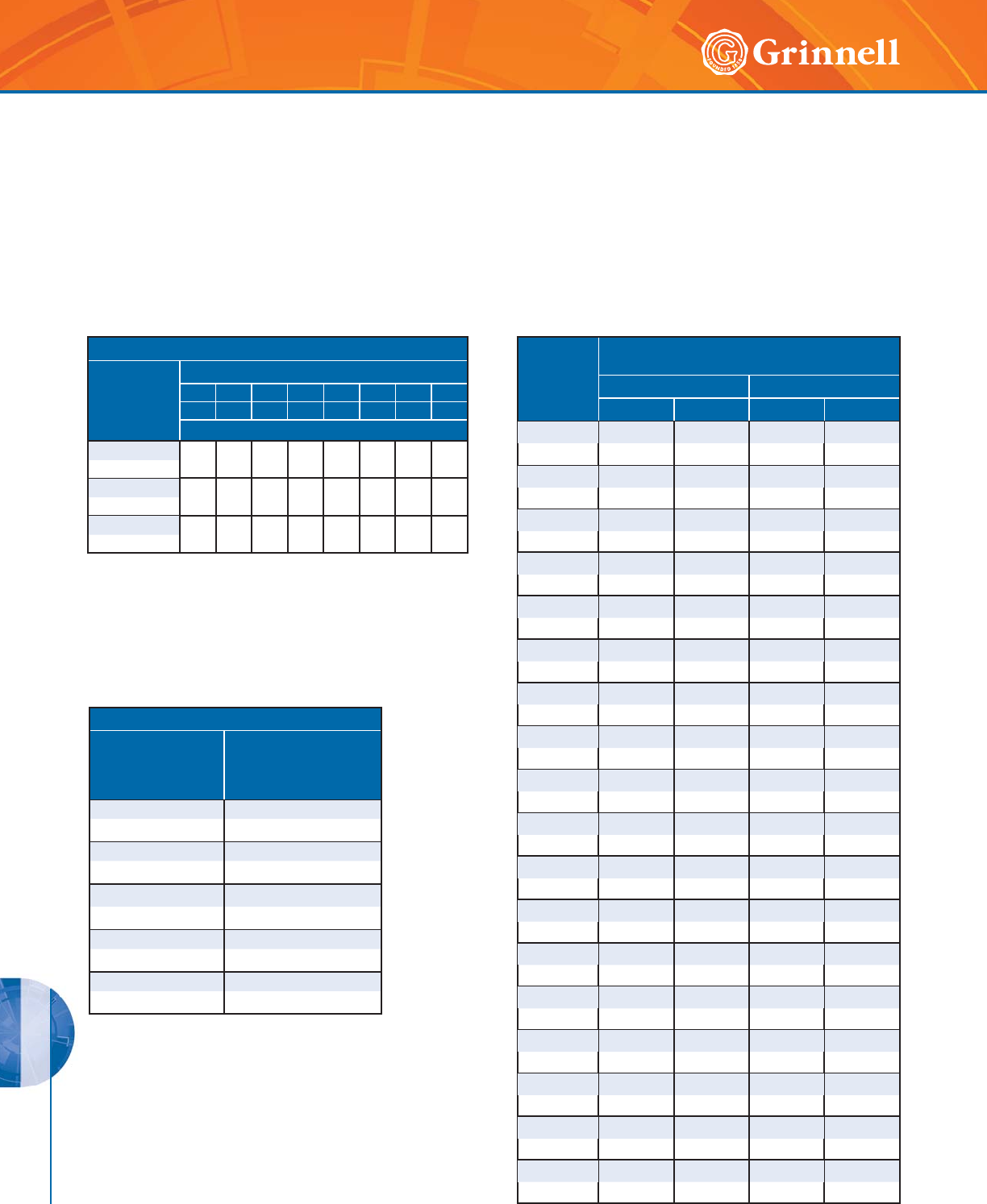
DESIGN DATA
PRESSURE & DESIGN DATA
218 www.grinnell.com
All piping systems require that the support system accommodate the weight of the pipe, joint connections, fluid, and other
system components. In addition, consideration may be necessary in reducing stresses, accommodating thermal expansion or
contraction, building settlement, seismic movement, etc. The following tables provide guidelines for grooved steel piping products
without concentrated loads between supports.
Pipe Size
Inches
mm
Suggested Maximum Span
Between Supports – Feet Meters
Water Service Air Service
IIIIII
11⁄4711911
42,4 2,1 3,4 2,7 3,4
11⁄2712913
48,3 2,1 3,7 2,7 4,0
2 10131315
60,3 3,0 4,0 4,0 4,6
21⁄211 14 14 16
73,0 3,4 4,3 4,3 4,9
76,1mm 11 14 14 16
76,1 3,4 4,3 4,3 4,9
3 12151517
88,9 3,7 4,6 4,6 5,2
414171721
114,3 4,3 5,2 5,2 6,4
516192024
141,3 4,9 5,8 6,1 7,3
165,1mm 17 20 21 25
165,1 5,2 6,1 6,4 7,6
617202125
168,3 5,2 6,1 6,4 7,6
819212428
219,1 5,8 6,4 7,3 8,5
10 19 21 24 31
273,0 5,8 6,4 7,3 9,4
12 23 21 30 33
323,9 7,0 6,4 9,1 10,1
14 23 21 30 33
355,6 7,0 6,4 9,1 10,1
16 27 21 35 33
406,4 8,2 6,4 10,7 10,1
18 27 21 35 33
457,2 8,2 6,4 10,7 10,1
20 30 21 39 33
508,0 9,1 6,4 11,9 10,1
24 32 21 42 33
609,6 9,8 6,4 12,8 10,1
Number of Hangers Per Pipe Length
Pipe Size
Inches
mm
Pipe Length in Feet Meters
3.3 3.7 4.6 6.7 7.6 9.1 10.7 12.2
10 12 15 22 25 30 35 40
Average Number of Hangers Per Pipe Length
11⁄4 - 2 22234456
42,4 – 60,3
21⁄2 - 4 12222344
73,0 – 114,3
5 - 24 11222333
141,3 – 609,6
Flexible Joints
For pipe runs when linear movement is accommodated by the
flexible coupling:
For pipe runs when linear movement is not required:
Note: The requirements of ANSI, ASME or other code groups
may require additional supports.
Distance Between Supports
Nominal Size
Inches
mm
Maximum Distance
Between Supports
Feet
Meters
11⁄4 - 11⁄212
42,4 - 48,3 3,7
2 - 8 15
60,3 - 219,1 4,6
10 - 12 16
273,0 - 323,9 4,9
14 - 16 18
355,6 - 406,4 5,5
18 - 24 20
457,2 - 609,6 6,1
Rigid Joints
For pipe runs with rigid couplings:
Pipe Support
Tech Data Sheets: G810, G820, G830
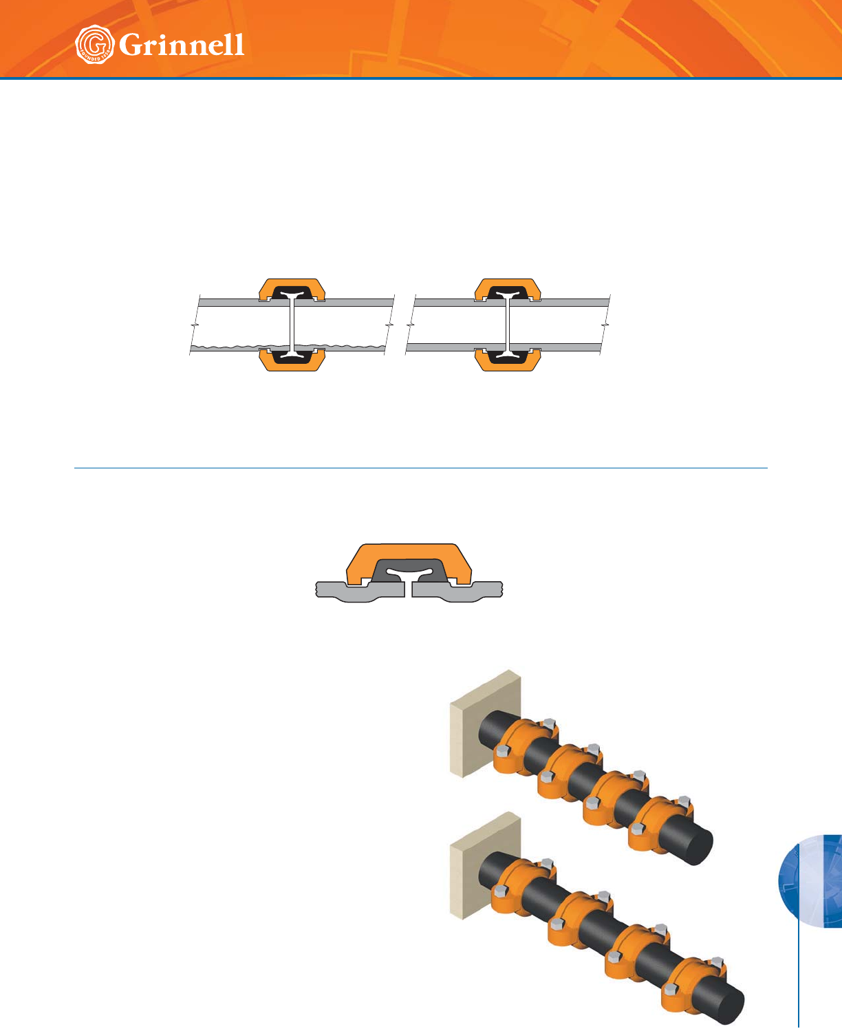
DESIGN DATA
PRESSURE & DESIGN DATA
219
Refer to back cover for country-specific customer care numbers.
Pipe Support
Tech Data Sheets: G810, G820, G830
Rotational Movement
GRINNELL Flexible Couplings are suitable for use in seismic as well as mining applications. The inherent capability of the flexible
coupling to allow for linear movement, angular deflection, and rotational movement make it an excellent choice for reducing
stresses in a piping system and to increase pipe life in slurry applications.
For mining applications where the pipe needs to be rotated, the system should be depressurized. The pipe coupling bolts/nuts
can be loosened, pipe rotated, the bolts/nuts re-tightened, and the system be put back in service.
Even distribution of pipe wear can be achieved with this method on the inner service of the pipe.
Note: Precautions are necessary to monitor pipe wall thickness to evaluate pressure capability of the pipe with reduced wall.
Linear Movement
Flexible couplings are designed with the couplings keys engaging the pipe without gripping on the bottom of the groove while
still providing for a restrained mechanical joint.
The inherent flexibility of the coupling must be considered when deciding on support arrangements for the piping system as
movement can occur in more than one plane (linear movement, angular deflection, and rotational movement).
Upon system pressurization, each pipe end within the flexible
couplings will expand to the maximum published value. The
coupling keys make contact with the face of the groove and
restrain the joint. In piping systems, this movement will be
accumulative.
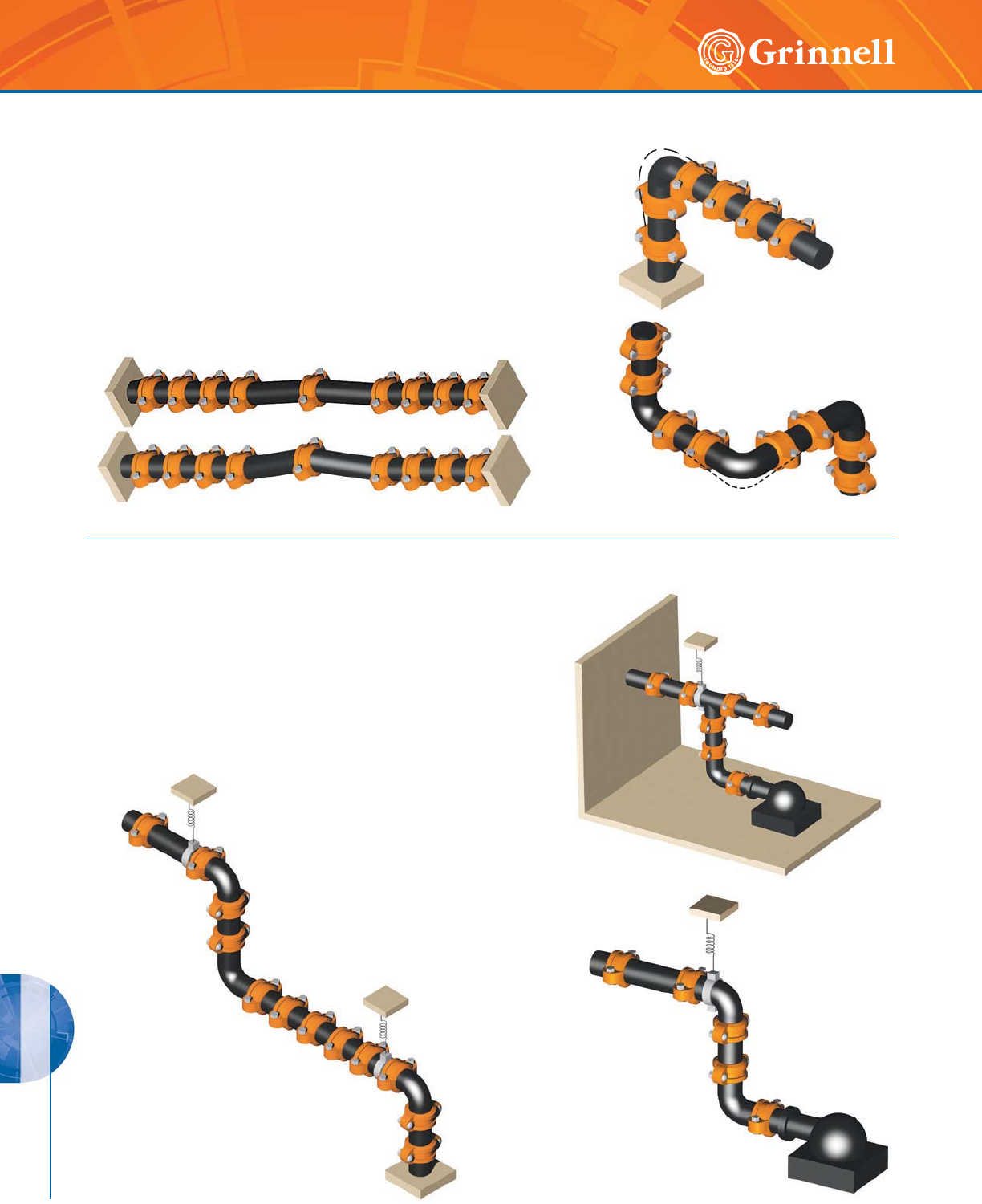
DESIGN DATA
PRESSURE & DESIGN DATA
220 www.grinnell.com
Angular Movement
System movement can be accommodated by providing for sufficient
offset lengths. Temperature increases/decreases can further increase this
movement.
When systems are anchored with partially deflected joints, the system
can move to the fully deflected condition upon pressurization resulting
in the “snaking” of the piping system. Lightweight hangers may not be
suitable to prevent the lateral motion.
Pipe Support
Pipe hanger positioning is important when considering pipe “sagging”
due to the flexible nature of the piping system. Proper positioning of
hangers near the elbow, for example, should be considered.
The use of spring hangers or other methods can be considered to
accommodate vibrations. Base supports, pressure thrust anchors, and
pipe offsets can be used to direct pipe movement.
The use of rigid couplings can be considered to reduce the movement
available with flexible couplings. Consideration of other methods of
accommodation of pipe movements may be required.
Pipe Support
Tech Data Sheets: G810, G820, G830
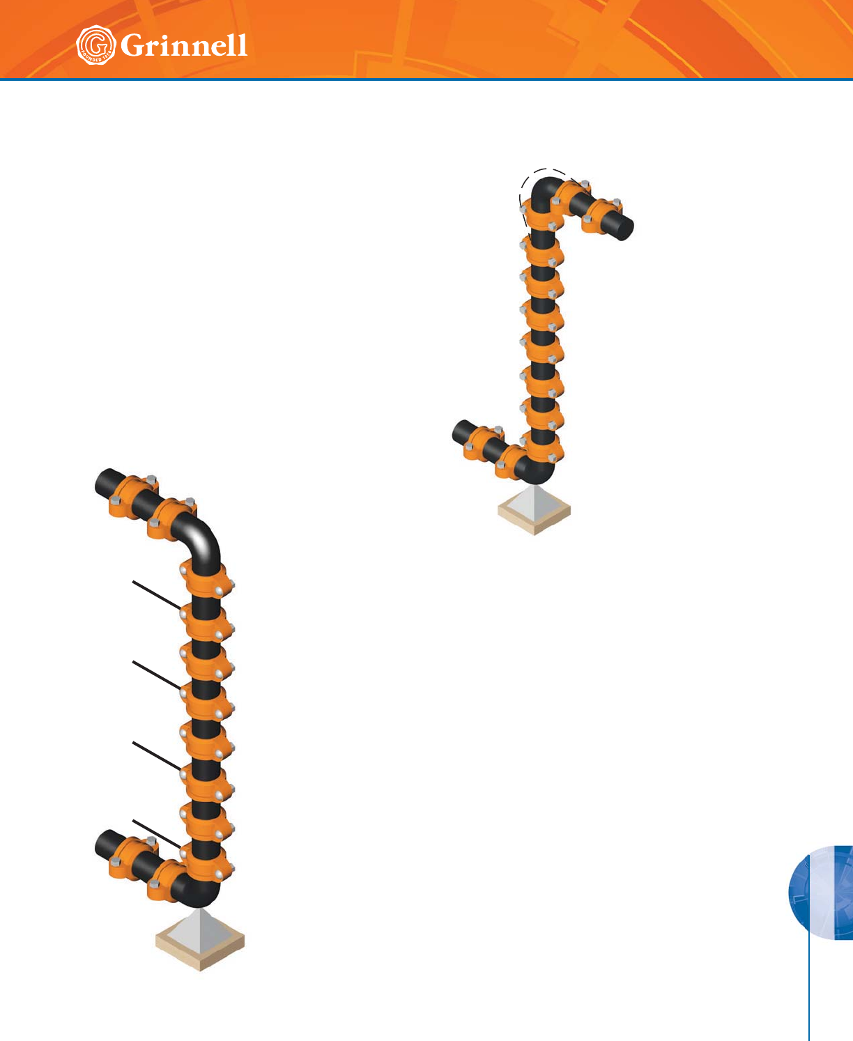
DESIGN DATA
PRESSURE & DESIGN DATA
221
Refer to back cover for country-specific customer care numbers.
Vertical Piping
Tech Data Sheets: G810, G820, G830
Risers comprised of rigid couplings can be considered
instead of welded or flanged systems. Where thermal
movement exists, expansion joints and/or flexible
couplings with offsets may be required.
When using flexible couplings, the movement that occurs in long lengths of
piping needs to be considered. Each joint can move up to the maximum pipe end
separation published. This movement can accumulate and result in the growth of the
piping system, for example at the top. Offsets may be necessary.
Should the riser contain branch connections, the movement which occurs at these
locations with flexible couplings will also need to be considered.
One solution would be to anchor the vertical piping at appropriate locations to
prevent movement which can cause stresses at the branches or equipment. The use
of rigid couplings can be an advantage.
As always, good piping practice should prevail. It is the designer’s responsibility to
select products suitable for the intended service and to ensure that pressure ratings
and performance data is not exceeded. Never remove any piping component or
correct or modify any piping deficiencies without first depressurizing and draining
the system. Material and gasket selection should be verified to be compatible for the
specific application.
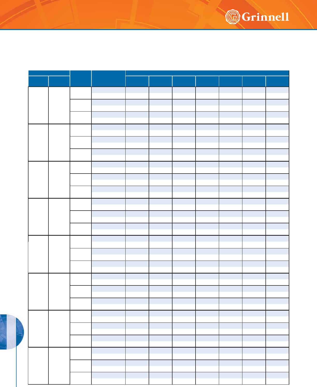
DESIGN DATA
PRESSURE & DESIGN DATA
222 www.grinnell.com
Maximum Pressure Ratings (psi) on
ANSI 304/316 Stainless Steel
Tech Data Sheets: G810, G820, G830
Pipe Size Pipe
Schedule
Wall Thickness
Inches
mm
Maximum Pressure Rating - psi bar
Inches
mm O.D. Figure
705
Figure
707
Figure
772
Figure
405
Figure
472
Figure
770
Figure
71
1
25
1.315
33,4
50.065 –400–325–––
1,7 – –22– – –
10 0.109 –500–500– – –
2,8 – –34– – –
40 0.133 –750–500–––
3,4 – –34– – –
11/4
32
1.660
42,4
50.0625 325 400 400 325 200 – –
2,0 2228282214 – –
10 0.109 500 500 500 500 300 – –
2,8 3434343421 – –
40 0.140 500 750 750 750 600 – –
3,6 3452525241 – –
11/2
32
1.900
48,3
50.065 325 400 400 325 200 – –
1,7 2228282214 – –
10 0.109 500 500 500 500 300 – –
2,8 3434343421 – –
40 0.145 500 750 750 750 600 – –
3,7 3452525241 – –
2
50
2.375
60,3
50.065 250 325 325 225 200 325 175
1,7 17 22 22 16 14 22 12
10 0.109 500 500 500 350 300 500 275
2,8 34343424213419
40 0.154 500 750 750 500 600 700 275
3,9 34525234415219
21/2
65
2.875
73,0
50.083 250 325 325 225 200 325 175
2,1 17 22 22 16 14 22 12
10 0.120 400 500 500 350 300 500 275
3,0 28 34 34 24 21 34 19
40 0.203 500 750 750 500 600 750 275
5,2 34525234415219
76,1mm
65
3.000
76,1
50.079 250 325 325 225 200 – 175
2,0 17 22 22 16 14 – 12
10 0.118 300 500 500 350 300 – 275
3,0 21 34 34 24 21 – 19
40 0.205 500 500 750 500 600 – 275
5,2 3434523441 – 19
3
80
3.500
88,9
50.083 250 325 325 225 200 325 175
2,1 17 22 22 16 14 22 12
10 0.120 300 500 500 350 300 500 275
3,0 21343424213419
40 0.216 500 500 750 500 600 750 275
5,5 34345234415219
4
100
4.500
114 ,3
50.083 200 250 250 200 200 250 175
2,1 14171714141712
10 0.120 300 400 500 300 300 400 275
3,0 21283421212819
40 0.237 500 750 750 325 600 750 275
6,0 34525222415219
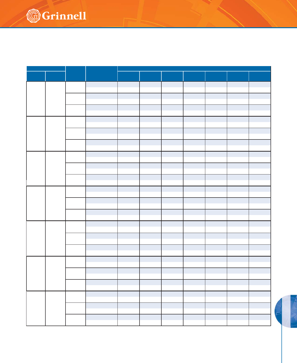
DESIGN DATA
PRESSURE & DESIGN DATA
223
Refer to back cover for country-specific customer care numbers.
Pipe Size Pipe
Schedule
Wall Thickness
Inches
mm
Maximum Pressure Rating - psi bar
Inches
mm O.D. Figure
705
Figure
707
Figure
772
Figure
405
Figure
472
Figure
770
Figure
71
139,7mm
125
5.500
139,7
50.109 200 – 250 200 200 – 175
2,8 14 – 17 14 14 – 12
10 0.134 300 – 500 300 300 – 275
3,4 21 – 34 21 21 – 19
40 0.258 500 – 750 325 600 – 275
6,6 34 – 52 22 41 – 19
5
125
5.563
141,3
50.118 125 200 200 125 200 200 125
3,0 9 14 145 9 14 14 9
10 0.201 200 300 300 200 300 300 200
5,1 14212114212114
40 0.252 300 500 500 200 600 750 250
6,4 21 34 34 14 41 52 17
165,1mm
150
6.500
165,1
50.109 125 200 200 125 200 – 125
2,8 91414914– 9
10 0.134 200 300 300 200 300 – 200
3,4 1421211421 – 14
40 0.280 300 500 500 200 600 – 250
7,1 21 34 34 14 41 – 17
6
150
6.625
168,3
50.118 75 125 200 125 200 125 75
3,0 5 9149149 5
10 0.201 200 200 200 200 300 300 125
5,1 14141414212114
40 0.252 300 500 450 200 600 750 150
6,4 21 34 31 14 41 52 10
8
200
8.625
219,1
50.109 50 752005020075N/R
2,8 3 5143145N/R
10 0.148 751253007530030075
3,8 5 921521215
40 0.322 300 400 400 200 600 600 125
8,2 21 28 28 14 41 41 9
10
250
10.750
273,0
50.134 N/R N/R N/R – N/R N/R N/R
3,4 –
10 0.165 757575 –30030075
4,2 555–21215
40 0.365 75 325 325 – 600 600 125
9,3 5 22 22 – 41 41 9
12
300
12.750
323,9
50.156 N/R N/R N/R – N/R N/R N/R
4,0 –
10 0.180 50 125 125 – 125 250 50
4,6 399–9173
40 0.375 50 250 250 – 300 600 125
9,5 3 17 17 – 21 41 9
Maximum Pressure Ratings (psi) on
ANSI 304/316 Stainless Steel (cont.)
Tech Data Sheets: G810, G820, G830
For parts installed in accordance with Bureau Veritas rules and regulations, a one-time only field-test is required to a maximum
working pressure of 1-1/2 times the rated pressure, as per BV NR 467, Pt. C, Ch. 1, Sec. 10, [20.4.2.], where applicable.
Tests are to be attended by a local BV Surveyor. Refer to the specific technical data sheet for coupling pressure ratings. Grooved
fittings described in this document that meet BV Approval include Figures: 71, 201, 210, 219, 260, 301, 303, 311, 312,
321,327, 341, 350, 522, 577, 705, 707, 716, 730, and 772.
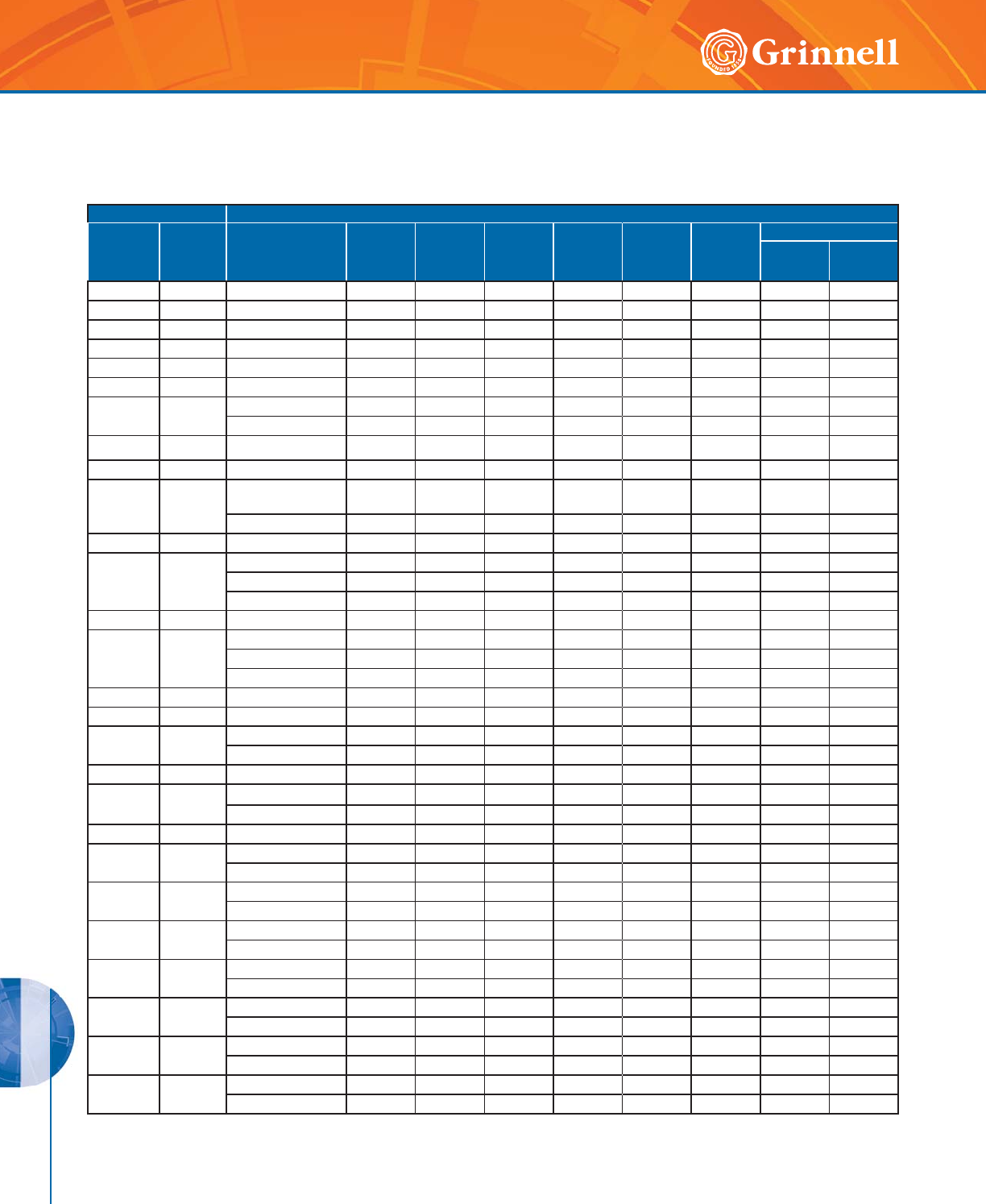
DESIGN DATA
PRESSURE & DESIGN DATA
224 www.grinnell.com
Global Pipe Size Designations
GRINNELL Mechanical Products product data is utilized worldwide and all technical data is shown in both metric and imperial
terms. The following chart shows a comparison between typical metric and IPS pipe sizes.
IMPORTANT NOTE:
Nominal designations are used where the actual OD of the pipe matches the ANSI size.
Otherwise both the nominal and actual OD are listed.
China sizes are listed as actual OD in mm.
** China sizes are tubing sizes.
Nominal Size (DN) Outside Diameter (OD)
Inches
(Imperial)
mm
(Metric)
mm
(Specification
Reference)
DIN
mm
BS
mm
ISO
mm
JIS
mm
ANSI
Inches
GB
China
mm
India
IS 1239 IS3589
1⁄215 21,3mm DN 15 DN 15 DN 15 21,7mm 1⁄2DN 15 DN 15 –
3⁄420 26,7mm 26,9mm DN 20 DN 20 27,2mm 3⁄4DN 20 DN 20 –
125 33,4mm 33,7mm DN 25 DN 25 34mm 1DN 25 DN 25 –
11⁄432 42,2mm 42,4mm DN 32 DN 32 42,7mm 11⁄4DN 32 DN 32 –
11⁄240 48,3mm DN 40 DN 40 DN 40 48,6mm 11⁄2DN 40 DN 40 –
250 60,3mm DN 50 DN 50 DN 50 60,5mm 2DN 50 DN 50 –
21⁄265 73,1mm ––––
21⁄2–––
76,1mm BS/ISO 76,1mm 76,1mm 76,1mm 76,3mm –76,1mm ** 76,1mm –
380 88,9mm DN 80 DN 80 DN 80 DN 80 3DN 80 DN 80 –
31⁄290101,6mm ––––––––
4100
108mm China
(& old DIN)
DIN
133mm ––––108mm ** – –
114,3mm DN 100 DN 100 DN 101 DN 100 4DN 100 DN 100 –
–127mm127mm ––––––––
5125
133mm China–––––133mm ** – –
139,7mm BS /ISO DN 125 139,7mm 139,7mm 139,8mm –139,7mm 139,7mm –
141,3mm ––––5–––
–152,4mm152,4mm ––––––––
6150
159mm China–––––159mm –
165,1mm JIS/BS – 165,1mm – 165,2mm ––165,1mm–
168,3mm DN 150–DN 150– 6DN 150 – DN 150
–175193,7mm –––––––193,7mm
–203,2mm203,2mm ––––––––
8200 216,3mm JIS – – – 216,3mm ––––
219,1mm DN 200 DN 200 DN 200 – 8DN 200 DN 200 DN 200
–254mm254mm ––––––––
10 250 267,4mm JIS – – – 267,4mm ––––
273mm DN 250 DN 250 DN 250 – 10 DN 250 DN 250 DN 250
–304,8mm304,8mm ––––––––
12 300 318,5mm JIS – – – 318,5mm ––––
323,9mm DN 300 DN 300 DN 300 – 12 –––
14 350 355,6mm DN 350 DN 350 DN 350 DN 350 14 DN 350 – –
377mm China–––––377mm – –
16 400 406,4mm DN 400 DN 400 DN 400 DN 400 16 DN 400 – –
426mm China–––––426mm – –
18 450 457,2mm DN 450 DN 450 DN 450 DN 450 18 DN 450 – –
480mm China–––––480mm – –
20 500 508mm DN 500 DN 500 DN 500 DN 500 20 DN 500 – –
530mm China–––––530mm – –
22 550 558,8mm – – – DN 550 22 559mm – –
580mm China–––––580mm – –
24 600 610mm DN 600 DN 600 DN 600 DN 600 24 DN 600 – –
630mm China–––––630mm – –
DESIGN DATA
PRESSURE & DESIGN DATA
225
Refer to back cover for country-specific customer care numbers.
Metric/Imperial Conversion Chart
Convert Metric to Imperial Convert Imperial to Metric
Millimeters X0.03937 Inches X25,4
(mm) (in)
Meters X3.281 Feet X0,3048
(m) (ft)
Kilograms X2.205 Pounds X0,4536
(kg) (lb)
Grams X0.03527 Ounces X28,35
(g) (oz)
Kilopascals X0.145 Pressure X6,894
(kPa) (psi)
Bar X14.5 Pressure X0,069
(psi)
Newtons X0.2248 End Load X4,45
(N) (lb)
Newton Meters X0.738 Torque X1,356
(N•m) (lbft)
Celsius C + 17.78 × 1.8 Temp. F – 32 ÷ 1,8
(°C) (°F)
Watts X1.341 × 10-3 Horsepower X745,7
(w) (hp)
Liters per min. X0.2642 Gal. per Min. X3,785
(L/M) (gpm)
Cubic Meters per min. X264.2 10-3 Gal. per Min. X3,7865
(m3/m) (gpm)
This chart is provided as a guide for converting metric and imperial measurements.
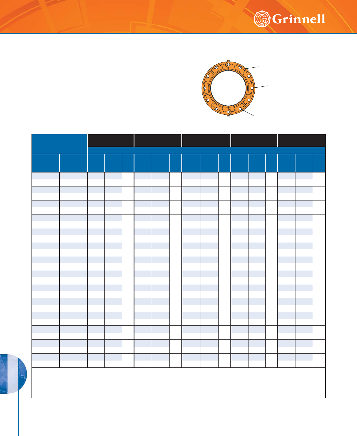
DESIGN DATA
PRESSURE & DESIGN DATA
226 www.grinnell.com
Valve Size
ANSI B16.1
(Class 125#) 1
ISO 2084
(PN10) 2
ISO 2084
(PN16) 3
JIS B 2210
(10K)
AS 2129
(Table E)
Dimensions - Inches mm
Nominal
Inches
mm
O.D.
Inches
mm
AB
Qty.
NAB
Qty.
NAB
Qty.
NAB
Qty.
NAB
Qty.
N
2 2.375 4.75 0.75 44.92 0.71 44.92 0.71 44.72 0.75 44.49 0.71 4
50 60,3 120,6 19,0 125,0 18,0 125,0 18,0 120,0 19,0 114,0 18,0
21⁄22.875 5.50 0.75 45.71 0.71 45.71 0.71 45.51 0.75 45.00 0.71 4
65 73,0 139,7 19,0 145,0 18,0 145,0 18,0 140,0 19,0 127,0 18,0
3 3.500 6.00 0.75 46.30 0.71 86.30 0.71 85.91 0.75 85.75 0.71 4
80 88,9 152,4 19,0 160,0 18,0 160,0 18,0 150,0 19,0 146,0 18,0
44.5007.500.75
87.09 0.71 87.09 0.71 86.89 0.75 87.0 0 0.71 8
100 114,3 190,5 19,1 180,0 18,0 180,0 18,0 175,0 19,0 178,0 18,0
55.5638.500.88
88.27 0.71 88.27 0.71 88.27 0.91 88.27 0.71 8
125 141,3 215,9 22,4 210,0 18,0 210,0 18,0 210,0 23,0 210,0 18,0
6 6.625 9.50 0.88 89.45 0.87 89.45 0.87 89.45 0.91 89.25 0.87 8
150 168,3 241,3 22,4 240,0 22,0 240,0 22,0 240,0 23,0 235,0 22,0
88.62511.750.88
811.61 0.87 811.61 0.87 12 11.42 0.91 12 11.50 0.87 8
200 219,1 298,5 22,2 295,0 22,0 295,0 22,0 290,0 23,0 292,0 22,0
10 10.750 14.25 1.00 12 13.78 0.87 12 13.98 1.02 12 13.98 0.87 12 14.02 0.87 12
250 273,0 362,0 25,4 350,0 22,0 355,0 26,0 355,0 22,0 356,0 22,0
12 12.750 17.00 1.00 12 15.75 0.87 12 16.14 1.02 12 15.75 0.98 16 15.98 1.02 12
300 323,9 431,8 25,4 400,0 22,0 410,0 26,0 400,0 25,0 406,0 26,0
14 14.000 18.76 1.12 12 18.11 0.87 16 18.50 1.02 16 17.52 0.98 16 18.50 1.02 12
350 355,6 476,5 28,4 460,0 22,0 470,0 26,0 445,0 25,0 470,0 26,0
16 16.000 21.25 1.12 16 20.28 1.02 16 20.67 1.18 16 20.08 1.06 16 20.51 1.02 12
400 406,4 539,8 28,4 515,0 26,0 525,0 30,0 510,0 27,0 521,0 26,0
18 18.000 22.75 1.25 16 22.24 1.02 20 23.03 1.18 20 22.24 1.06 20 22.99 1.02 16
450 457,2 577,9 31,8 565,0 26,0 585,0 30,0 565,0 27,0 584,0 26,0
20 20.000 25.00 1.25 20 24.41 1.02 20 25.59 1.30 20 24.41 1.06 20 25.24 1.02 16
500 508,0 635,0 31,8 620,0 26,0 650,0 33,0 620,0 27,0 641,0 26,0
24 24.000 29.50 1.38 20 28.54 1.18 20 30.31 1.42 20 28.74 1.30 24 29.76 1.30 16
600 609,6 749,3 35,1 725,0 30,0 770,0 36,0 730,0 33,0 756,0 33,0
1 Same drilling as for B16.5 (Class 150#) and B16.42 (Class 250#).
2 Same drilling as for BS 4504 Section 3.2 (PN10) and DIN 2532 (PN10).
3 Same drilling as for BS 4504 Section 3.2 (PN16) and DIN 2532 (PN16).
For additional information, contact GRINNELL Mechanical Products.
Flange Drilling Specifications
“B” Dimension
Bolt Hole Diameter
“A” Dimension
Bolt Circle Diameter
Quantity “N”
Number of Bolt Holes
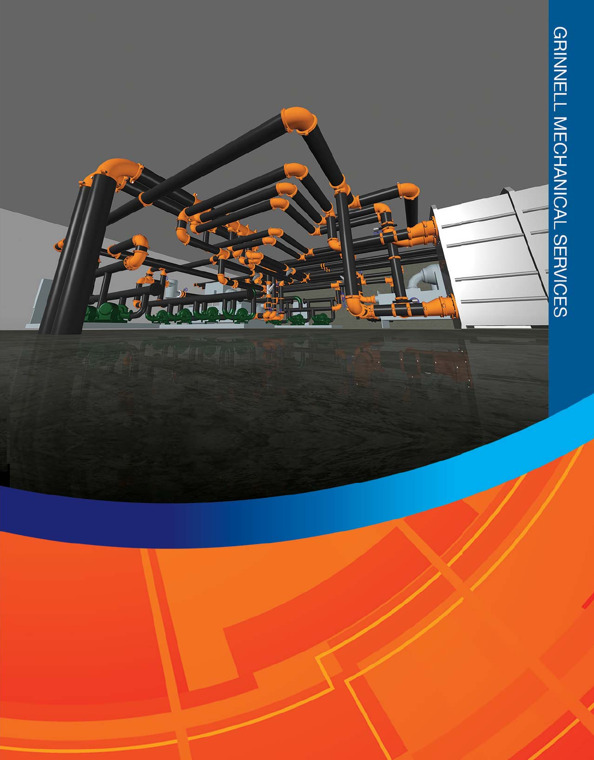
227
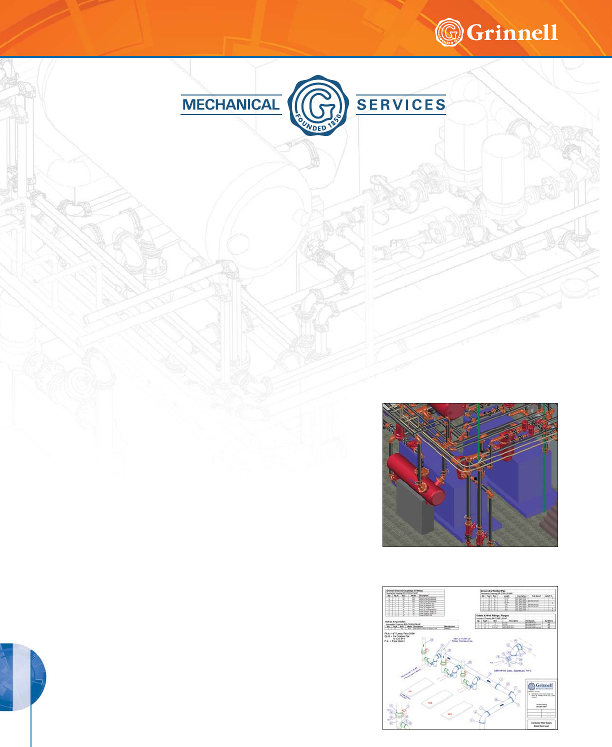
MECH. SERVICES
GRINNELL MECHANICAL SERVICES
228 www.grinnell.com
Common Challenges You Face
• High Material Handling Costs • Piping Interferences and Clashes
• Material Backorders • Space Constraints
• High Installation Costs • Lack of Skilled Labor
• Excessive Material Leftovers • Compressed Delivery Schedules
Solutions We Provide
Our Mechanical Design Department provides a strategic extension of your
own design team.
Our Project Planning jump-starts your design process, reducing indirect
operations at the job site while identifying conflicts between your project
documents.
Our Virtual Layout Process helps to identify interferences and space
constraints before they become work-delay issues.
Our Building Information Modeling Expertise supports your BIM drafting
and coordination. We deliver 3D Modeling in your preferred project format for
clash detection.
Our Design Flexibility incorporates the best joining technology available for
your specific need by using grooved systems with combinations of welded,
flanged, and pressed connections.
GRINNELL Mechanical Services, a department of GRINNELL Mechanical Products, works with engineers and contractors to
create the most cost-effective and time-efficient piping solutions from design…to build.
Supporting Your Mechanical Business...
From Design... To Build
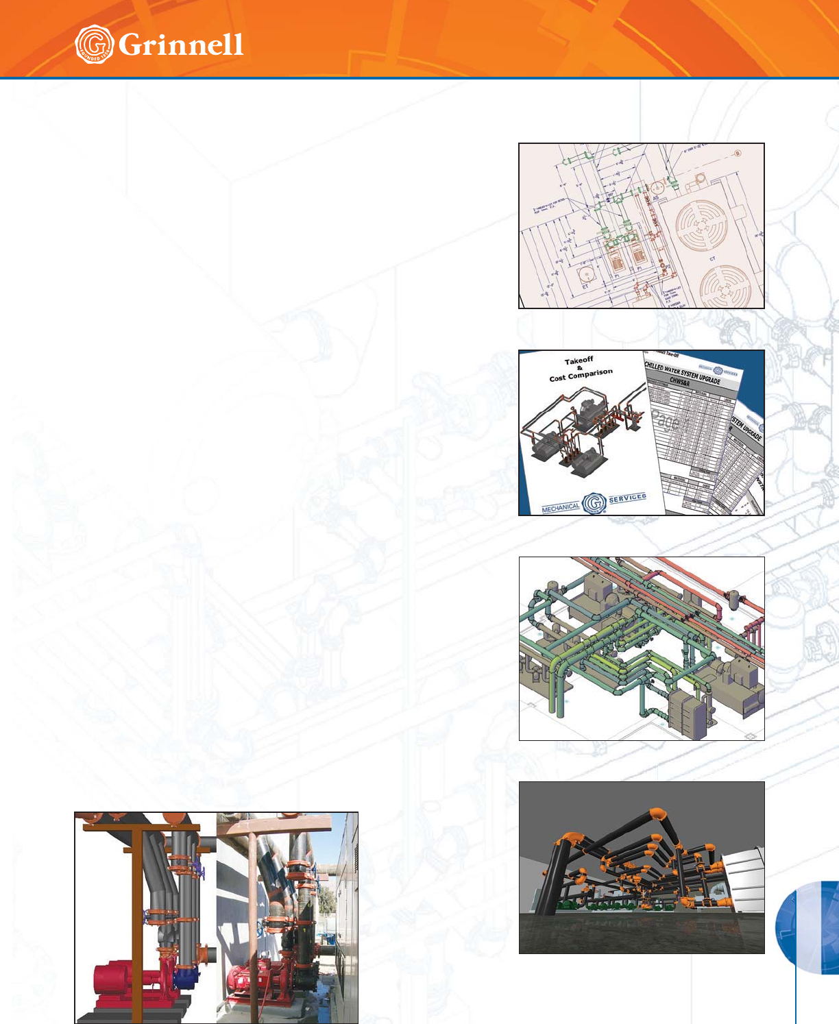
MECH. SERVICES
GRINNELL MECHANICAL SERVICES
229
Refer to back cover for country-specific customer care numbers.
Results We Deliver
Shop Drawings - This service creates easy-to-follow, tagged 3D
Isometric Drawings with complete Bill of Material (BOM) tables and
fully dimensioned piping plans of your mechanical equipment rooms.
We provide pipe cut lengths to minimize field cutting and fitting and to
simplify your installations.
Pump Assemblies and Equipment Connections - Our
3D Modeling with tagged BOM tables provides clear, accurate
representations of grooved piping hook-ups. Based on equipment
submittals and bid drawings (flow diagrams, HVAC details, and plan
views), we create detailed assemblies that you can use for submittals,
reviews, and assembly instructions.
Cost Comparisons - Using industry-standard, man-hour data
estimations and our BOMs, we compare the cost savings of grooved
piping solutions over traditional welded/flanged joining methods. By
utilizing the benefits of grooved piping, our technical experts recommend
ways to save you money.
Crate and Tag Handling - We provide an effective material handling
process to help increase your labor productivity by 25% or more. We
deliver complete, tagged pump or equipment hook-up BOMs directly to
equipment rooms for easy access, eliminating your need to reference
multiple shipments and back orders and reducing your material waste
and overages.
Thermal Movement Analyzes - We assist specifiers and installers on
the proper use of grooved couplings for thermal expansion compensation
in piping systems. Our in-depth assessments of your systems offer cost-
effective design solutions, reduce rework, and help you meet project
performance requirements.
CAD Blocks and Families - We offer traditional AutoCAD* blocks,
AutoCAD MEP parametric block catalogs, and Revit* families with
manageable file sizes, accurate dimensions, and part numbers to save
you time and money.
Training - In a state-of-the-art educational facility, our training includes
informative classroom lectures on leading industry technologies, hands-on
demonstrations of grooved products, and on-site performance testing of
product assemblies.
Technical Expertise - We provide direct access to the individuals who
design, test, and build our products every day. Contact us; we’ll be glad
to assist you.
* AutoCAD is a registered trademark of Autodesk, Inc.
* Revit is a registered trademark of Autodesk, Inc.

MECH. SERVICES
GRINNELL MECHANICAL SERVICES
230 www.grinnell.com
Technical Expertise
Training
Design Work

231

INDICES
INDICES
232 www.grinnell.com
Figure Number Index
61 ....................................122
71 ..................................28 - 32
201 ....................................39
201LR & 301LR ............................39
210 ....................................38
210LR & 310LR ............................38
211 & 311 ...............................41
212 & 312 ...............................40
219 & 319 ...............................46
221 & 321 ............................48 - 50
227 & 327 ...............................71
250 & 350 ............................53 - 55
251 & 351 ............................56 - 58
260 & 360 ...............................72
301-3D .................................43
301-5D .................................44
301-6D .................................45
303-3D .................................43
303-5D .................................44
303-6D .................................45
306-3D .................................43
306-5D .................................44
306-6D .................................45
308 .................................90 - 91
310-3D .................................43
310-5D .................................44
310-6D .................................45
311-3D .................................43
311-5D .................................44
311-6D .................................45
312-3D .................................43
312-5D .................................44
312-6D .................................45
314 ....................................64
315 ....................................42
316 ....................................42
320 ....................................47
323 .................................51 - 52
324 ....................................63
325 .................................65 - 67
330 .................................68 - 69
331 ....................................70
341 & 342 ...............................73
343 & 344 ...............................74
372 ....................................59
380 ....................................60
391, 392, & 393 ..........................61
395 ....................................60
397, 398, & 399 ..........................62
401 ...................................136
405 ...................................135
407 ...................................159
407GG ................................130
407GT & 407T ...........................129
408 ...................................159
410 ...................................136
419 ...................................137
421 ...................................139
441 ...................................142
442 ...................................162
450 ...................................140
451 ...................................141
460 ...................................138
466 ...................................166
467 ...................................160
468 ...................................160
469 ...................................167
470 ...................................161
471 ...................................161
472 ...................................134
473 ...................................162
474 ...................................164
475 ...................................167
476 ...................................164
478 ...................................163
479 ...................................165
484 ...................................166
485 ...................................165
590 .................................94 - 95
601 ...................................123
610 ...................................123
618 ...................................126
619 ...................................124
621 ...................................125
Figure Number ................................................Page Figure Number ................................................Page

INDICES
INDICES
233
Refer to back cover for country-specific customer care numbers.
Figure Number Index
640 ...................................120
650 ...................................127
652 ...................................127
660 ...................................124
672 ...................................121
702 .................................26 - 27
705 ....................................22
707 .................................20 - 21
716 ....................................24
730 .................................77 - 82
770 ....................................23
772 .................................18 - 19
780 ....................................25
901 ...................................147
901LR .................................148
909 ...................................146
910 ...................................147
910LR .................................148
914 ...................................151
919 ...................................149
921 ...................................149
924 ...................................151
927 ...................................150
941 & 942 ..............................154
960 ...................................150
991, 992, & 993 .........................153
999 ...................................152
1000 ..................................210
1012 ..................................206
1022 ..................................206
1023 ..................................205
1034 ..................................207
1039 ..................................207
1039-66 ...........................130, 207
1041 ..................................206
1066 ..................................207
1112 ..................................205
2021 ..................................208
2050 ..................................209
2112 ..................................209
3013 ..................................212
4000 ..................................211
4031 ..................................211
4033 ..................................211
4037 ..................................212
4040 ..................................211
7550 ..............................111 - 116
9094 ..................................173
9095 ..................................171
9097 ..................................172
72899 .................................190
72900 .................................178
72901 .................................179
72904 .................................180
72905 .................................180
72906 .................................182
72907 .................................183
72908 .................................183
72909 .................................184
72910 .................................185
72911 .................................184
72912 .................................185
72913 .................................186
72914 .................................186
72915 .................................187
72916 .................................187
72917 .................................188
72918 .................................188
72919 .................................181
72930 .................................182
72940 .................................181
72999 .................................190
B302 ................................86 - 89
B680 ..................................128
B8101 ..................................85
B8200L ................................189
BV835 ...............................92 - 93
CB800 ..............................99 - 104
S810 ..............................108 - 109
S853 ..................................107
S855 ..................................110
TD830 ..................................96
Figure Number ................................................Page Keywords .......................................................Page

INDICES
INDICES
234 www.grinnell.com
Product Name Indices
Accessories ....................................................................211 - 212
ANSI 304/316 Stainless Steel .......................................................222 - 223
Automated Roll Groovers ...........................................................208 - 209
CB800 Circuit Balancing Valves ...........................................................99
Figure 61 Flange Adapter (ANSI Class 125/150) ..............................................122
Figure 71 Flange Adapters (ANSI Class 125/150) .......................................... 28 - 29
Figure 71 Flange Adapters (AS2129 Table E) ..................................................32
Figure 71 Flange Adapters (PN10/PN16) ................................................. 30 - 31
Figure 201 45° Cast Elbows ..............................................................39
Figure 201LR & 301LR, 45° Long Radius Elbows ................................................39
Figure 210 90° Cast Elbows ..............................................................38
Figure 210LR & 310LR, 90° Long Radius Elbows ................................................38
Figure 211 & 311 , 111⁄4° Elbows ..........................................................41
Figure 212 & 312 , 221⁄2° Elbows ..........................................................40
Figure 219 & 319 Tees .................................................................46
Figure 221 & 321 Reducing Tees ....................................................... 48 - 51
Figure 227 & 327 Crosses ...............................................................71
Figure 250 & 350 Concentric Reducers .................................................. 53 - 55
Figure 251 & 351 Eccentric Reducers ................................................... 56 - 58
Figure 260 & 360 End Caps ..............................................................72
Figure 314 45° Laterals .................................................................64
Figure 315 90° Elbows (Groove x Male Thread) ................................................42
Figure 316 Reducing Base Support Elbow (Groove x Flange) ........................................42
Figure 320 Tees (Groove x Groove x Male Thread) ..............................................47
Figure 323 Reducing Tees (Groove x Groove x Male Thread) .................................... 51 - 52
Figure 324 90° True Wyes ...............................................................63
Figure 325 45° Reducing Laterals ...................................................... 65 - 67
Figure 330 Tee Wyes ............................................................... 68 - 69
Figure 331 Reducing Tee Wyes ............................................................70
Figure 341 Flange Adapters (ANSI Class 150#) ................................................73
Figure 342 Flange Adapters (ANSI Class 300#) ................................................73
Figure 343 Flange Adapters (ANSI Class 150#) ................................................74
Figure 344 Flange Adapters (ANSI Class 300#) ................................................74
Figure 372 Concentric Reducers (Small End Male Thread) ..........................................59
Figure 380 Female Thread Adapters (Groove x Female Thread) ......................................60
Figure 391, 392 & 393 Adapter Nipples .....................................................61
Figure 395 Hose Adapter Nipples (Groove x Hose) ..............................................60
Figure 397, 398 & 399 Concentric Swaged Nipples .............................................62
Figure 401 45° Stainless Steel Elbows ......................................................136
Figure 405 Stainless Steel Flexible Couplings .................................................135
Figure 407 Straight Couplings (Press x Press) .................................................159
Figure 407GG Dielectric Waterway Transition Fitting ............................................130
Figure 407GT & 407T Dielectric Waterways ..................................................129
Figure 408 Slip Couplings (Press x Press) ....................................................159
Figure 410 90° Stainless Steel Elbows ......................................................136
Figure 419 Tees .....................................................................137
Product Name ................................................................................................................................. Page

INDICES
INDICES
235
Refer to back cover for country-specific customer care numbers.
Product Name Indices
Figure 421 Reducing Tees ...............................................................139
Figure 441 Flange Adapters (ANSI Class 150#) ...............................................142
Figure 442 Equal Tees (Press x Press x Press) ..................................................162
Figure 450 Concentric Reducers ..........................................................140
Figure 451 Eccentric Reducers ...........................................................141
Figure 460 End Caps ..................................................................138
Figure 466 Van Stone Flange Adapters (Female Press x Flange) .....................................166
Figure 467 90° Elbows (Male x Female) .....................................................160
Figure 468 90° Elbows (Press x Press) ......................................................160
Figure 469 Ball Valves (Press x Press) .......................................................167
Figure 470 45° Elbows (Male x Female) .....................................................161
Figure 471 45° Elbows (Press x Press) ......................................................161
Figure 472 Stainless Steel Rigid Couplings ...................................................134
Figure 473 Reducing Tees (Press x Press x Press) ...............................................162
Figure 474 Reducers (Female Press x Male Press) ...............................................164
Figure 475 Flange Adapters (Female Press x Flange) ............................................167
Figure 476 Straight Connectors (Female Press x Male NPT) ........................................164
Figure 478 Tee and Reducing Tee Adapters (Press x Press x Female NPT) ...............................163
Figure 479 Straight Connectors (Female Press x Female NPT) .......................................165
Figure 484 End Caps (Female Press) .......................................................166
Figure 485 3-Piece Unions (Press x Press) ....................................................165
Figure 601 45° Elbow .................................................................123
Figure 610 90° Elbow .................................................................123
Figure 618 Reducing Tee ...............................................................126
Figure 619 Tee ......................................................................124
Figure 621 Reducing Tee ...............................................................125
Figure 640 Pivot-Bolt Rigid Installation-Ready Coupling ...........................................120
Figure 650, Concentric Reducer ..........................................................127
Figure 652, Concentric Reducer ..........................................................127
Figure 660 Cap .....................................................................124
Figure 672 Rigid Coupling ..............................................................121
Figure 702 Mechanical Outlet Couplings .....................................................26
Figure 702 Mechanical Outlet Couplings .....................................................27
Figure 705 Flexible Couplings .............................................................22
Figure 707 Heavy Duty Flexible Couplings ................................................ 20 - 21
Figure 716 Flexible Reducing Couplings ......................................................24
Figure 72899 Replacement Gaskets ........................................................190
Figure 72900 SDR Pipe (Spline x Spline) ....................................................178
Figure 72901 SDR Pipe with Coupling (Male Spline x Female Spline) .................................179
Figure 72904 Couplings (Spline x Spline) ....................................................180
Figure 72905 Couplings (Spline x Solvent Weld) ...............................................180
Figure 72906 Nipples (Spline x Plain End) ...................................................182
Figure 72907 Nipples (Spline x Groove) ....................................................183
Figure 72908 Nipples (Spline x Male Thread) .................................................183
Figure 72909 Nipples (Plain End x Male Thread) ...............................................184
Figure 72910 90° Elbows (Spline x Spline) ...................................................185
Product Name ................................................................................................................................. Page

INDICES
INDICES
236 www.grinnell.com
Product Name Indices
Figure 72911 Nipples (Spline x Spline) .....................................................184
Figure 72912 45° Elbows (Spline x Spline) ...................................................185
Figure 72913 90° Sweep Elbows (Spline x Spline) ..............................................186
Figure 72914 45° Sweep Elbows (Spline x Spline) ..............................................186
Figure 72915 Caps & Plugs (Spline) .......................................................187
Figure 72916 Flange Adapters (Spline x Flange 150psi) ..........................................187
Figure 72917 Tees (Spline x Spline x Spline) ..................................................188
Figure 72918 Reducing Tees (Spline x Spline x Spline) ...........................................188
Figure 72919 Reducing Couplings (Male Spline x Female Spline) ....................................181
Figure 72930 Outlet Couplings (Spline x Spline x Female Thread) ...................................182
Figure 72940 Outlet Couplings (Male Spline x Female Spline x Female Thread) ..........................181
Figure 72999 Splines .................................................................190
Figure 730 Mechanical Tees & Crosses – Grooved ........................................... 80 - 82
Figure 730 Mechanical Tees & Crosses – Threaded .......................................... 77 - 79
Figure 7550 Expansion Joint .........................................................111 - 116
Figure 770 High Pressure Rigid Couplings ....................................................23
Figure 772 Rigid Couplings .......................................................... 18 - 19
Figure 780 Grooved Snap Couplings ........................................................25
Figure 901 45° Plain End Elbows .........................................................147
Figure 901LR 45° Plain End Long Radius Elbows ...............................................148
Figure 909 Plain End Couplings ..........................................................146
Figure 9094 Flange Couplings ...........................................................173
Figure 9095 HDPE Couplings ............................................................171
Figure 9097 HDPE Transition Couplings .....................................................172
Figure 910 90° Plain End Elbows .........................................................147
Figure 910LR 90° Plain End Long Radius Elbows ...............................................148
Figure 914 Plain End Laterals ............................................................151
Figure 919 Plain End Tees ..............................................................149
Figure 921 Plain End Reducing Tees ........................................................149
Figure 924 Plain End True Wyes ..........................................................151
Figure 927 Plain End Crosses ............................................................150
Figure 941 Plain End Flange Adapters (ANSI Class 150#) ........................................154
Figure 942 Plain End Flange Adapters (ANSI Class 300#) ........................................154
Figure 960 Plain End Caps ..............................................................150
Figure 991, 992, 993 Plain End Adapter Nipples ..............................................153
Figure 999 Plain End Swaged Nipples ......................................................152
Figure ITGM Insertion Tools ..............................................................190
Figure S810 Suction Diffusers ........................................................108 - 109
Figure S853 “Y” Strainers ..............................................................107
Figure S855 Tee Strainers ...............................................................110
Flange Adapter Washers ................................................................33
Flexible Joints .......................................................................218
Gasket Styles .......................................................................193
G-MINE PVC Systems ..................................................................177
GRINNELL Gasket Lubricants .............................................................198
GRINNELL Gasket Types ................................................................192
Product Name ................................................................................................................................. PageProduct Name ................................................................................................................................. Page

INDICES
INDICES
237
Refer to back cover for country-specific customer care numbers.
Product Name Indices
Long Radius 3D Elbows .................................................................43
Long Radius 5D Elbows .................................................................44
Long Radius 6D Elbows .................................................................45
MINI-MITES Field Portable ..............................................................207
Model 1000 Portable Cut Groover. . . . . . . . . . . . . . . . . . . . . . . . . . . . . . . . . . . . . . . . . . . . . . . . . . . . . . . . . 210
Model 1012 Portable Roll Groovers ........................................................206
Model 1022 Portable Roll Groovers ........................................................206
Model 1023 Portable Roll Groovers With Electric Motor ..........................................205
Model 1034 MINI-MITES Field Portable .....................................................207
Model 1039 MINI-MITES Field Portable .....................................................207
Model 1039-66 Copper Roll Groover .......................................................130
Model 1039-66 MINI-MITES Field Portable ...................................................207
Model 1041 Portable Roll Groovers ........................................................206
Model 1066 MINI-MITES Field Portable .....................................................207
Model 1112 Portable Roll Groovers With Electric Motor ..........................................205
Model 2021 Automated Roll Groovers ......................................................208
Model 2050 Automated Roll Groovers ......................................................209
Model 2112 Automated Roll Groovers ......................................................209
Model 3013 Porta-Bore ................................................................212
Model 308 Butterfly Valves ........................................................... 90 - 91
Model 4031 Pipe Support Stands .........................................................211
Model 4037 Nipple Bracket .............................................................212
Model 590 Grooved End Check Valves .................................................. 94 - 95
Model B302 Grooved End Butterfly Valves ................................................ 86 - 88
Model B680 Butterfly Valve with Lever Handle .................................................128
Model B8101 Low Profile Butterfly Valves .....................................................85
Model B8200L G-MINE Butterfly Valves (Spline x Spline) .........................................189
Model BV835 Ball Valves ............................................................ 92 - 93
Model CB800 Circuit Balancing Valves, Flanged Ends, ANSI Class 125# ..............................102
Model CB800 Circuit Balancing Valves, Flanged Ends, PN16/PN10 .................................103
Model CB800 Circuit Balancing Valves, Grooved Ends ...........................................101
Model CB800 Circuit Balancing Valves, Insulation Kits ...........................................104
Model CB800 Circuit Balancing Valves, MC2 Measuring Computer ..................................104
Model CB800 Circuit Balancing Valves, Solder Ends ............................................100
Model CB800 Circuit Balancing Valves, Threaded Ends ..........................................100
Model TD830 Triple Duty Valves ...........................................................96
Pipe Support ....................................................................218 - 220
Pipe Tape ..........................................................................204
Portable Roll Groovers For Ridgid® 300 Pipe Threader ...........................................206
Portable Roll Groovers With Electric Motor ...................................................204
Rigid Joints .........................................................................218
Thermal Movement ...............................................................215 - 216
Vertical Piping ......................................................................221
Product Name ................................................................................................................................. Page

INDICES
INDICES
238 www.grinnell.com
Keyword Indices
Keywords ....................................................................................................................................... Page
“Y” Strainers. . . . . . . . . . . . . . . . . . . . . . . . . . . . . . . . . . . . . . . . . . . . . . . . . . . . . . . . . . . . . . . . . . . . . . . . 107
111⁄4° Elbows ........................................................................41
221⁄2° Elbows ........................................................................40
3-Piece Unions (Press x Press) ............................................................165
45° Cast Elbows ......................................................................39
45° Elbow .........................................................................123
45° Elbows (Male x Female) .............................................................161
45° Elbows (Press x Press) ..............................................................161
45° Elbows (Spline x Spline) .............................................................185
45° Laterals .........................................................................64
45° Long Radius Elbows .................................................................39
45° Plain End Elbows ..................................................................147
45° Plain End Long Radius Elbows .........................................................148
45° Reducing Laterals .............................................................. 65 - 67
45° Stainless Steel Elbows ..............................................................136
45° Sweep Elbows (Spline x Spline) ........................................................186
90° Cast Elbows ......................................................................38
90° Elbow .........................................................................123
90° Elbows (Groove x Male Thread) ........................................................42
90° Elbows (Male x Female) .............................................................160
90° Elbows (Press x Press) ..............................................................160
90° Elbows (Spline x Spline) .............................................................185
90° Long Radius Elbows .................................................................38
90° Plain End Elbows ..................................................................147
90° Plain End Long Radius Elbows .........................................................148
90° Stainless Steel Elbows ..............................................................136
90° Sweep Elbows (Spline x Spline) ........................................................186
90° True Wyes .......................................................................63
Accessories ....................................................................211 - 212
Adapter Nipples ......................................................................61
Adapter Nipples, Plain End .............................................................153
ANSI 304/316 Stainless Steel .......................................................222 - 223
Automated Roll Groovers ...........................................................208 - 209
Ball Valves ...................................................................... 92 - 93
Ball Valves (Press x Press) ...............................................................167
Butterfly Valve with Lever Handle ..........................................................128
Butterfly Valves ................................................................... 90 - 91
Cap .............................................................................124
Caps & Plugs (Spline). . . . . . . . . . . . . . . . . . . . . . . . . . . . . . . . . . . . . . . . . . . . . . . . . . . . . . . . . . . . . . . . . . 187
Caps, End ......................................................................72, 138
Caps, End (Female Press) ...............................................................166
Caps, Plain End .....................................................................150
Cast Elbows, 45° .....................................................................39
Cast Elbows, 90° .....................................................................38
Circuit Balancing Valves ............................................................ 99 - 104
Circuit Balancing Valves, Flanged Ends, ANSI Class 125# ........................................102
Circuit Balancing Valves, Flanged Ends, PN16/PN10 ............................................103
Circuit Balancing Valves, Grooved Ends .....................................................101
Circuit Balancing Valves, Insulation Kits .....................................................104
Circuit Balancing Valves, MC2 Measuring Computer ............................................104
Circuit Balancing Valves, Solder Ends .......................................................100

INDICES
INDICES
239
Refer to back cover for country-specific customer care numbers.
Keyword Indices
Keywords ....................................................................................................................................... Page
Circuit Balancing Valves, Threaded Ends .....................................................100
Concentric Reducers ........................................................53 - 55, 127, 140
Concentric Reducers (Small End Male Thread) ..................................................59
Concentric Swaged Nipples ..............................................................62
Connectors, Straight (Female Press x Female NPT) ..............................................165
Connectors, Straight (Female Press x Male NPT) ................................................164
Copper Roll Groover ..................................................................130
Coupling Specifications ................................................................119
Couplings (Spline x Solvent Weld) .........................................................180
Couplings (Spline x Spline) ..............................................................180
Couplings, Flexible Reducing .............................................................24
Couplings, Outlet (Male Spline x Female Spline x Female Thread) ...................................181
Couplings, Outlet (Spline x Spline x Female Thread) .............................................182
Couplings, Plain End ..................................................................146
Couplings, Rigid ..............................................................18 - 19, 121
Couplings, Slip (Press x Press) ............................................................159
Couplings, Stainless Steel Flexible ........................................................135
Couplings, Stainless Steel Rigid ..........................................................134
Crosses ............................................................................71
Crosses, Plain End ...................................................................150
Cut Groove Standard Specification for Steel & Other IPS Pipe ......................................202
Cut Groover, Portable .................................................................210
Design ............................................................................214
Dielectric Waterway Transition Fitting .......................................................130
Dielectric Waterways ..................................................................129
Eccentric Reducers ..............................................................56 - 58, 141
Elbows, 111⁄4° .......................................................................41
Elbows, 221⁄2° .......................................................................40
Elbows, 45° .............................................39, 123, 136, 147 - 148, 161, 185 - 186
Elbows, 45° Cast .....................................................................39
Elbows, 45° Long Radius ................................................................39
Elbows, 45° Plain End .................................................................147
Elbows, 45° Plain End Long Radius ........................................................148
Elbows, 45° Stainless Steel .............................................................136
Elbows, 45° Sweep (Spline x Spline) .......................................................186
Elbows, 90° ........................................ 38, 42, 123, 136, 147 - 148, 160, & 185 - 186
Elbows, 90° (Groove x Male Thread) ........................................................42
Elbows, 90° (Male x Female) ............................................................160
Elbows, 90° (Press x Press) ..............................................................160
Elbows, 90° (Spline x Spline) ............................................................185
Elbows, 90° Cast .....................................................................38
Elbows, 90° Long Radius ................................................................38
Elbows, 90° Plain End .................................................................147
Elbows, 90° Plain End Long Radius ........................................................148
Elbows, 90° Stainless Steel .............................................................136
Elbows, 90° Sweep (Spline x Spline) .......................................................186
End Caps .......................................................................72, 138
End Caps (Female Press) ...............................................................166
Equal Tees (Press x Press x Press) ..........................................................162
Expansion Joint ..................................................................111 - 116
Female Thread Adapters (Groove x Female Thread) ..............................................60

INDICES
INDICES
240 www.grinnell.com
Figure ITGM Insertion Tools ..............................................................190
Fitting Specifications ..................................................................119
Flange Adapter (ANSI Class 125/150) .....................................................122
Flange Adapter Washers ................................................................33
Flange Adapters (Spline x Flange 150psi) ....................................................187
Flange Adapters (ANSI Class 125/150) .................................................. 28 - 29
Flange Adapters (ANSI Class 150# & ANSI Class 300#) ..........................................73
Flange Adapters (PN16 & PN16 BS 4504) ....................................................74
Flange Adapters (ANSI Class 150#) .......................................................142
Flange Adapters (AS2129 Table E) .........................................................32
Flange Adapters (Female Press x Flange) ....................................................167
Flange Adapters (PN10/PN16) ........................................................ 30 - 31
Flange Adapters, Plain End .............................................................154
Flange Couplings ....................................................................173
Flange Drilling Specifications ............................................................226
Flexible Couplings .....................................................................22
Flexible Couplings, Stainless Steel ........................................................135
Flexible Joints ...................................................................214, 218
Flexible Reducing Couplings ..............................................................24
Gasket Air, Water & Chemical Recommendations ...........................................195 - 197
Gasket Styles .......................................................................193
Global Pipe Size Designations ...........................................................224
G-MINE Butterfly Valves (Spline x Spline) ....................................................189
G-MINE PVC Systems ..................................................................177
GRINNELL Gasket Grade & Recommendations .................................................194
GRINNELL Gasket Lubricants .............................................................198
GRINNELL Gasket Types ................................................................192
GRINNELL Website ....................................................................14
Grooved End Butterfly Valves ......................................................... 86 - 88
Grooved End Butterfly Valves - Options .......................................................89
Grooved End Check Valves ........................................................... 94 - 95
Grooved Snap Couplings ................................................................25
HDPE Couplings .....................................................................171
HDPE Pipe Wall Thickness and Standard Dimension Ratios ........................................174
HDPE Transition Couplings ..............................................................172
Heavy Duty Flexible Couplings ........................................................ 20 - 21
High Pressure Rigid Couplings .............................................................23
Hose Adapter Nipples (Groove x Hose) ......................................................60
Joint, Expansion .................................................................111 - 116
Joints, Flexible or Rigid ............................................................214, 218
Laterals, 45° ........................................................................64
Laterals, 45° Reducing ............................................................. 65 - 67
Laterals, 45° Reducing ............................................................. 65 - 67
Laterals, Plain End ...................................................................151
Long Radius 3D Elbows .................................................................43
Long Radius 5D Elbows .................................................................44
Long Radius 6D Elbows .................................................................45
Low Profile Butterfly Valves ...............................................................85
Maximum Pressure Ratings (psi) on ........................................................222
Maximum Pressure Ratings (psi) on ........................................................223
Mechanical Outlet Couplings ......................................................... 26 - 27
Keyword Indices
Keywords ....................................................................................................................................... Page

INDICES
INDICES
241
Refer to back cover for country-specific customer care numbers.
Mechanical Tees & Crosses – Grooved ................................................... 80 - 82
Mechanical Tees & Crosses – Threaded .................................................. 77 - 79
Metric/Imperial Conversion Chart .........................................................225
MINI-MITES Field Portable ..............................................................207
Misalignment and Deflection .............................................................217
Model 2021 Automated Roll Groovers ......................................................208
Nipple Bracket ......................................................................212
Nipples (Plain End x Male Thread) .........................................................184
Nipples (Spline x Groove) ..............................................................183
Nipples (Spline x Male Thread) ...........................................................183
Nipples (Spline x Plain End) .............................................................182
Nipples (Spline x Spline) ...............................................................184
Nipples, Adapter .....................................................................61
Nipples, Plain End Adapter .............................................................153
Nipples, Plain End Adapter .............................................................153
Nipples, Plain End Swaged .............................................................152
Outlet Couplings (Male Spline x Female Spline x Female Thread) ....................................181
Outlet Couplings (Spline x Spline x Female Thread) .............................................182
Performance Pressure ..................................................................120
Pipe Support ....................................................................218 - 220
Pipe Support Stands. . . . . . . . . . . . . . . . . . . . . . . . . . . . . . . . . . . . . . . . . . . . . . . . . . . . . . . . . . . . . . . . . . . 211
Pipe Tape ..........................................................................204
Pivot-Bolt Rigid Installation-Ready Coupling ...................................................120
Plain End Adapter Nipples ..............................................................153
Plain End Caps ......................................................................150
Plain End Couplings ...................................................................146
Plain End Crosses ....................................................................150
Plain End Flange Adapters (ANSI Class 150# & ANSI Class 300#) ..................................154
Plain End Laterals ....................................................................151
Plain End Reducing Tees ................................................................149
Plain End Swaged Nipples ..............................................................152
Plain End Tees .......................................................................149
Plain End True Wyes ..................................................................151
Portable Cut Groover ..................................................................210
Portable Roll Groovers .................................................................206
Portable Roll Groovers With Electric Motor ...............................................204 - 205
Porta-Bore .........................................................................212
Reducers (Female Press x Male Press) .......................................................164
Reducers, Concentric .......................................................53 - 55, 127, 140
Reducers, Concentric (Small End Male Thread) .................................................59
Reducers, Eccentric .............................................................56 - 58, 141
Reducing Base Support Elbow (Groove x Flange) ................................................42
Reducing Couplings (Male Spline x Female Spline) ..............................................181
Reducing Couplings, Flexible .............................................................24
Reducing Laterals, 45° ............................................................. 65 - 67
Reducing Tee Wyes ....................................................................70
Reducing Tees ........................................................ 48 - 50, 125 - 126, 139
Reducing Tees (Groove x Groove x Male Thread) ............................................ 51 - 52
Reducing Tees (Press x Press x Press) .......................................................162
Reducing Tees (Spline x Spline x Spline) .....................................................188
Reducing Tees, Plain End ...............................................................149
Keyword Indices
Keywords ....................................................................................................................................... Page

INDICES
INDICES
242 www.grinnell.com
Keyword Indices
Keywords ....................................................................................................................................... Page
Replacement Gaskets ..................................................................190
Rigid Couplings ...............................................................18 - 19, 121
Rigid Couplings, Stainless Steel ..........................................................134
Rigid Joints .........................................................................218
Roll Groove Standard Specification for Copper Tubing ...........................................203
Roll Groove Standard Specification for Steel & Other IPS Pipe ......................................201
Roll Groover, Copper .................................................................130
Roll Groovers For Ridgid® 300 Pipe Threader, Portable ..........................................206
Roll Groovers With Electric Motor, Portable ..............................................204 - 205
Roll Groovers, Automated ..........................................................208 - 209
Roll Groovers, Model 2021 Automated .....................................................208
Roll Groovers, Portable ................................................................206
SDR Pipe (Spline x Spline) ..............................................................178
SDR Pipe with Coupling (Male Spline x Female Spline) ...........................................179
Slip Couplings (Press x Press) ............................................................159
Splines ...........................................................................190
Stainless Steel Flexible Couplings .........................................................135
Stainless Steel Rigid Couplings ...........................................................134
Straight Connectors (Female Press x Female NPT) ...............................................165
Straight Connectors (Female Press x Male NPT) ................................................164
Straight Couplings (Press x Press) ..........................................................159
Strainers, Tee .......................................................................110
Suction Diffusers .................................................................108 - 109
Swaged Nipples, Plain End .............................................................152
Tee and Reducing Tee Adapters (Press x Press x Female NPT) .......................................163
Tee Strainers ........................................................................110
Tee Wyes ....................................................................... 68 - 69
Tees ......................................................................46, 124, 137
Tees (Groove x Groove x Male Thread). . . . . . . . . . . . . . . . . . . . . . . . . . . . . . . . . . . . . . . . . . . . . . . . . . . . . . . 47
Tees (Spline x Spline x Spline) ............................................................188
Tees, Equal (Press x Press x Press) .........................................................162
Tees, Plain End ......................................................................149
Tees, Plain End Reducing ...............................................................149
Thermal Movement ...............................................................215 - 216
Triple Duty Valves .....................................................................96
True Wyes, 90° ......................................................................63
True Wyes, Plain End .................................................................151
Unions, 3-Piece (Press x Press) ............................................................165
Valves, Ball ..................................................................... 92 - 93
Valves, Ball (Press x Press) ..............................................................167
Valves, Butterfly .................................................................. 90 - 91
Valves, Butterfly with Lever Handle .........................................................128
Valves, Circuit Balancing ........................................................... 99 - 104
Van Stone Flange Adapters (Female Press x Flange) .............................................166
Vertical Piping ......................................................................221
Wyes, 90° True ......................................................................63
Wyes, Plain End True .................................................................151
Wyes, Tee ...................................................................... 68 - 69

10-YEAR LIMITED WARRANTY
243
Refer to back cover for country-specific customer care numbers.
Limited Warranty
Products manufactured by Tyco International (Tyco) under
the GRINNELL brand are warranted solely to the original
Buyer for ten (10) years against defects in material and
workmanship when paid for and properly installed and
maintained under normal use and service, except for the
G-MINE line of products, which are warranted solely to the
original Buyer for six (6) months against defects in material
and workmanship when paid for and properly installed and
maintained under normal use and service. This warranty
will expire ten (10) years from date of shipment by Tyco. No
warranty is given for products or components manufactured by
companies not affiliated by ownership with Tyco or for products
and components which have been subject to misuse, improper installation or maintenance,
corrosion, or other external sources of damage. Materials found by Tyco to be defective
shall be either repaired or replaced, at Tyco’s sole option. Tyco neither assumes, nor
authorizes any person to assume for it, any other obligation in connection with the sale
of products or parts of products. Tyco shall not be responsible for system design errors or
inaccurate or incomplete information supplied by Buyer or Buyer’s representatives.
In no event shall Tyco be liable, in contract, tort, strict liability or under any other legal
theory, for incidental, indirect, special or consequential damages, including but not limited
to labor charges, regardless of whether Tyco was informed about the possibility of such
damages, and in no event shall Tyco’s liability exceed an amount equal to the sales price.
The foregoing warranty is made in lieu of any and all other warranties, express or implied,
including warranties of merchantability and fitness for a particular purpose.
This Limited Warranty sets forth the exclusive remedy for claims based on failure of or defect
in products, materials or components, whether the claim is made in contract, tort, strict
liability or any other legal theory.
This warranty will apply to the full extent permitted by law. The invalidity, in whole or part,
of any portion of this warranty will not affect the remainder.

© Copyright 2011 GRINNELL. GRINNELL is a mark and/or registered mark. GM-GENCATG-201110_EN
Global Locations
Global Headquarters
United States of America
1400 Pennbrook Parkway
Lansdale, PA 19446
Tel: +800-558-5236
Fax: +800-877-1295
South America Headquarters
United States of America
1802 S.W. 2nd Street
Pompano Beach, FL 33069
Tel: +954-781-0866
Fax: +954-781-9330
Mexico Headquarters
Mexico
President Juarez Av 2007 Lot 6
San Jeronimo Tepetlacalco
Tlalnepantla, Estado de Mexico
Mexico 54090
Tel: +525 55 321 2350
Fax: +525 55 321 2358
Asia Pacific Headquarters
Singapore
2 Serangoon North Avenue 5, #07-01
Singapore 554911
Tel: +65 6577 4360
Fax: +65 6481 8791
Europe Headquarters
The Netherlands
Kopersteden 1
P.O. Box 198
7500 AD Enschede
Tel: +31 (0)53 428 4444
Fax: +31 (0)53 428 3377
Middle East Headquarters
United Arab Emirates
PO Box 61355
Warehouse TB01, R/A 8
Jebel Ali Free Zone, Dubai
Tel: +971 4 8838689
Fax: +971 48838674
