2016 Meridian 400SLD Bulk Seed Tender Operators Manual Operator
User Manual: Meridian-400SLD-Seed-Tender-Operator-Manual
Open the PDF directly: View PDF ![]() .
.
Page Count: 84


3
PRODUCT WARRANTY
R E G I S T R A T I O N F O R M
WARRANTY REGISTRATION
This form must be lled out by the dealer and signed by both the dealer and the customer at the time
of delivery. Please mail or fax the completed form for validation of the equipment registration.
Customer’s Name______________________________________________________
Address ______________________________________________________________
City, State, Postal Code____ _____________________, _______, ___________
Phone Number (_______) _______- ___________
PRODUCT INFORMATION
Seed Tender Model # ___________ # rebmuN laireS _______________________
I have thoroughly instructed the buyer on the above-described equipment, including review of the Operator’s
Manual content, equipment care, adjustments, operational use, safety procedures, and applicable warranty
policy.
Dealer/Company Name____________________________________
City, State, Postal Code _________________________, ________________, ______________
Dealer’s Signature___________________________________________ Date ____/____/______
The above equipment and Operator’s Manual have been received by me, and I have been thoroughly instructed as
to care, adjustments, safe operation, and applicable warranty policy.
Owner’s Signature_____________________________________ Date ____/____/_______
2902 Expansion Blvd. Storm Lake, Iowa 50588 Phone: 800-437-2334 Fax: 712-732-1028 Email: iowa_warranty@meridianmfg.com
Cut Here to Remove Page

PRODUCT WARRANTY
R E G I S T R A T I O N F O R M
DEALER INSPECTION REPORT
____Wheel nuts/bolts must be tightened to proper torque on all wheels
____Wiring harness plug must be in working condition and t into tow vehicle’s receptacle
____Make sure breakaway cable and pin is supplied with trailer
____Make sure battery is fully charged and in good working order
____Make sure license plate light is operating
____Verify that tow vehicle is large enough to safely tow the trailer
____Make sure all four 1993 Diesel Fuel Placards are installed
____If equipped, check gasoline engine fuel level
____If equipped, check gasoline engine oil level
____If equipped, start gasoline engine
____Inspect brake and lighting wiring harness connection
____Check air pressure in tires
____Make sure electric brakes are in working condition
____Make sure all guards/shields are installed correctly
____Make sure all safety signs are installed and ledgible
____Reectors and lights must be clean and working
____Review safety and operating instructions with owner
____Make sure safety chains are properly attached and are in good working condition
____Inspect customer’s hitch for 2-5/16” ball
____Make sure hitch-to-tongue bolts are tight
____Make sure owner is instructed to check wheel bolt/nut torque at
5, 10, 25, and 50 miles; then check annually
____Verify receipt of all options ordered
____Make sure turn signal lights are operating
____Make sure brake lights are operating
DEALER INSPECTION FORM
Review safety and operating instructions with owner.
Verify receipt of all options ordered.
Verify that tow vehicle is large enough to safely tow seed tender.
Check gasoline engine fuel level. Add as needed.
Check gasoline engine oil level. Add as needed.
Start gasoline engine and make sure it operates properly.
Check oil level in hydraulic tank. Add as needed.
Check air pressure in tires. Add as needed.
Make sure wheel nuts/bolts are tightened to proper torque on all wheels.
Make sure hitch-to-tongue and hitch-to-frame bolts are tightened to proper torque.
Make sure conveyor tube rotates 180 degrees and locks into towing position.
Make sure the weighing system is working properly.
Make sure the remote control unit is working properly.
Make sure all guards/shields are installed correctly.
Make sure all safety signs are installed and legible.
Reectors and lights must be clean and working properly.
Inspect brake and lighting wiring harness connections. All lights must be functioning.
Make sure seed tender battery is fully charged and in good working order.
Make sure breakaway brake system battery is fully charged and in good working order.
Make sure electric brakes are in working condition.
Inspect customer’s hitch for 2-5/16” ball or fth wheel.
Make sure safety chains are properly attached and are in good working condition.
Wiring harness plug must be in working condition and t into tow vehicle’s receptacle.
Make sure breakaway brake cable and pin is supplied with trailer.
Make sure license plate light is operating.
Make sure turn signal lights are operating.
Make sure brake lights are operating.
Make sure owner is instructed to check wheel bolt/nut torque at 5, 10, 25, and 50 miles; then check annually.

5
CERTIFICATE OF ORIGIN
LICENSING INFORMATION
DEALER :
___________________________Business
___________________________Contact
___________________________Address
___________________________City, State, Zip
SOLD TO :
___________________________Business
___________________________Contact
___________________________Address
________________________ City, State, Zip
TENDER MODEL #_________________________________________________________
TENDER WEIGHT__________________________________________________________
TENDER SERIAL #__________________________________________________________
(One serial number is issued on complete tender packages. Those trailers do not receive a serial number.)
TRAILER MODEL #:_________________________________
TRAILER SERIAL #________________________________________ TRAILER WEIGHT :_________________
Tender 110 BST Wagon 80110 1,004#
Tender 110 BST -T (trailer included) 80111 1,830#
Tender 22 5 R ST Wagon 80131 1733#
Ten der 22 5 RST -BH 80601 3375#
Tender 225RST -GN 80602 4097 #
Tender 225RST -BWT -BH 80603 3577#
Tender 225RST -BWT -GN 80604 4299#
Tender 240RT6 80249 2,545#
Tender 240RT6 -BWT -BH 80253 4,475#
Tender 240RT6 -BH 80250 4,174#
Tender 240RT8 80251 2,604#
Tender 240RT8 -BWT -BH 80248 4,534#
Tender 240RT8 -GN 8025 5 4,232#
Tender 240 RT8 -BWT -GN 80243 4,491#
Tender 375RT6 Wagon 80381 3,094#
Tender 375RT6 -BH 80324 5,636#
Tender 375RT6 -BWT -BH 80337 5,942#
Tender 375RT6 -GN 80338 6637#
Tender 375RT8 80382 3476#
Tender 37 5RT8 Wagon 80376 3106#
Tender 37 5RT8 –BH 80326 5760#
Tender 375RT8 -GN 80327 6441#
Tender 375RT8 -BWT -BH 80339 5990#
Tender 37 5RT8 -GN 80340 6672#
240 –Rear Facing (BH trailer included) 80121 3720#
240 –Front Facing (BH trailer included) 80136 3720#
Tender 375 (no trailer) 80349 4207#
Tender 375-BH 80345 6071#
Tender 375-GN 80346 6721#
Tender 375-BWT -BH 80347 6079#
Tender 375BWT -GN 80348 6729#
Tender 375RT8 -BWT (trailer included) 80377 5,913#
Tender 375RT8 -T (trailer included) 80379 5,607#
Tender T itan 2SE -T (trailer included) 80201 2,254#
Tender Titan 2SE -BWT 80616 2302#
Tender T itan 2-T (11’ 10” discharge) 80134 1820#
Tender Titan 2 -T (15’ 6” discharge) 80135 1868#
Tender T4SE Wagon 80401 2,803#
Tender T4SE -T (trailer included) 80402 4,431#
Ten der T4SE -BWT (trailer included) 80403 4,833#
Tender T4SE -T -GN 80609 4893 #
Tender 4SE -T -GN -BWT 80608 5235 #
Tender 400 -6SLD 80352 3375 #
Tender 400BH -6SLD 80353 5040 #
Tender 400GN -6SLD 80354 5690 #
Tender 400 -8SLD 80355 3530#
Tender400BH -8SLD 80356 5195#
Tender 400GN -8SLD 80357 5845 #
2902 E xpansion Blvd .
Storm Lake , IA 50588
PH# 712 -732-1780
FAX# 712 -732-1028
Date: ____/____/_______
Cut Here to Remove Page
7
IMPORTANT INFORMATION
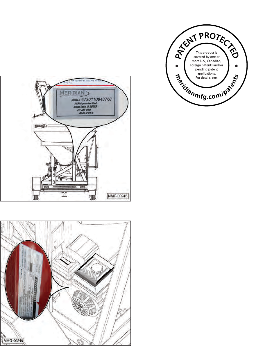
SERIAL NUMBER LOCATION
Report the serial number of your Meridian
400 SLD Seed Tender and engine when ordering
parts or requesting service or other information.
The serial number plates are located where
indicated. Please mark the number in the space
provided for easy reference.
Seed Tender
Engine
Model Number: 400 SLD
Serial Number: ____________________________
Engine Serial Number: ______________________
PATENT INFORMATION
Meridian continuously enhances its product
offering through product improvements and new
product innovations. Marketplace feedback,
technological innovation, new materials and
manufacturing methods, and a philosophy of
continuous improvement constantly challenge
the company to develop new and better ways of
addressing market needs. Meridian is committed
to innovation and reinvestment and as a result,
the company maintains a portfolio of patents and
intellectual property. For more information on our
patents please see our website:
www.meridianmfg.com/patents

8
CONTENTS
1. INTRODUCTION .......................................................... 11
1.1 Congratulations . . . . . . . . . . . . . . . . . . . . . . . . . . . . . . . . . . . . 11
1.2 Operator Orientation . . . . . . . . . . . . . . . . . . . . . . . . . . . . . . . . . . 11
1.3 Owner/Operator . . . . . . . . . . . . . . . . . . . . . . . . . . . . . . . . . . . . 11
2. SAFETY.................................................................12
2.1 General Safety . . . . . . . . . . . . . . . . . . . . . . . . . . . . . . . . . . . . . 13
2.2 Equipment Safety Guidelines . . . . . . . . . . . . . . . . . . . . . . . . . . . . . 14
2.3 Safety Training . . . . . . . . . . . . . . . . . . . . . . . . . . . . . . . . . . . . . 14
2.4 Safety Signs . . . . . . . . . . . . . . . . . . . . . . . . . . . . . . . . . . . . . . 15
2.4.1 How to Install Safety Signs . . . . . . . . . . . . . . . . . . . . . . . . . . . 15
2.5 Preparation. . . . . . . . . . . . . . . . . . . . . . . . . . . . . . . . . . . . . . . 15
2.6 Operating Safety . . . . . . . . . . . . . . . . . . . . . . . . . . . . . . . . . . . . 15
2.7 Maintenance Safety . . . . . . . . . . . . . . . . . . . . . . . . . . . . . . . . . . 16
2.8 Lock-Out or Tag-Out Safety . . . . . . . . . . . . . . . . . . . . . . . . . . . . . . 16
2.9 Storage Safety . . . . . . . . . . . . . . . . . . . . . . . . . . . . . . . . . . . . . 17
2.10 Transport Safety . . . . . . . . . . . . . . . . . . . . . . . . . . . . . . . . . . . 17
2.11 Refuelling Safety . . . . . . . . . . . . . . . . . . . . . . . . . . . . . . . . . . . 17
2.12 Battery Safety. . . . . . . . . . . . . . . . . . . . . . . . . . . . . . . . . . . . . 17
2.13 Sign-Off Form. . . . . . . . . . . . . . . . . . . . . . . . . . . . . . . . . . . . . 18
3. SAFETY SIGN LOCATIONS .................................................19
4. SPECIFICATIONS.........................................................22
4.1 Overall Seed Tender
Specications . . . . . . . . . . . . . . . . . . . . . . . . . . . . . . . . . . . . . . . . 22
4.2 Bolt Specications . . . . . . . . . . . . . . . . . . . . . . . . . . . . . . . . . . . 23
4.2.1 Bolt Torque Values . . . . . . . . . . . . . . . . . . . . . . . . . . . . . . . 23
4.2.2 Grade Markings Chart . . . . . . . . . . . . . . . . . . . . . . . . . . . . . 23
5. MACHINE COMPONENTS AND CONTROLS ...................................24
5.1 Component Nomenclature and Location. . . . . . . . . . . . . . . . . . . . . . . . 24
5.2 Engine and Controls . . . . . . . . . . . . . . . . . . . . . . . . . . . . . . . . . . 25
5.3 Control System Functions . . . . . . . . . . . . . . . . . . . . . . . . . . . . . . . 26
5.3.1 Control Functions . . . . . . . . . . . . . . . . . . . . . . . . . . . . . . . . 26
5.3.2 Setting the Weight to Dispense. . . . . . . . . . . . . . . . . . . . . . . . . 27
5.3.3 Setting Active Slide Gate . . . . . . . . . . . . . . . . . . . . . . . . . . . . 27
5.3.4 Auto Reset Function . . . . . . . . . . . . . . . . . . . . . . . . . . . . . . 27
5.3.5 Control System Compliance Information . . . . . . . . . . . . . . . . . . . . 27
5.4 Wireless Remote Transmitter . . . . . . . . . . . . . . . . . . . . . . . . . . . . . 28
5.4.1 Functions of Keypad Buttons . . . . . . . . . . . . . . . . . . . . . . . . . . 28
5.4.2 Display Panel . . . . . . . . . . . . . . . . . . . . . . . . . . . . . . . . . . 30
5.4.3 Display Messages . . . . . . . . . . . . . . . . . . . . . . . . . . . . . . . 30
6. PRE-OPERATING INSTRUCTIONS ...........................................31
6.1 Machine Break-In Period. . . . . . . . . . . . . . . . . . . . . . . . . . . . . . . . 31
6.1.1 Before Starting . . . . . . . . . . . . . . . . . . . . . . . . . . . . . . . . . 31
6.1.2 Inspections for 1/2, 5, and 10 Hours . . . . . . . . . . . . . . . . . . . . . . 31
6.2 Pre-Operation Checklist . . . . . . . . . . . . . . . . . . . . . . . . . . . . . . . . 32
7. OPERATION .............................................................33
7.1 Connecting the Trailer . . . . . . . . . . . . . . . . . . . . . . . . . . . . . . . . . 33
7.1.1 Bumper Hitch . . . . . . . . . . . . . . . . . . . . . . . . . . . . . . . . . . 33
7.1.2 Gooseneck Hitch . . . . . . . . . . . . . . . . . . . . . . . . . . . . . . . . 34
7.2 Opening and Closing Roll-Up Tarp. . . . . . . . . . . . . . . . . . . . . . . . . . . 35
7.3 Operation. . . . . . . . . . . . . . . . . . . . . . . . . . . . . . . . . . . . . . . . 36
7.3.1 Conventional Loading (Filling the Seed Tender) . . . . . . . . . . . . . . . . 36
7.3.2 Loading Using Self-Filling Feature (Filling the Seed Tender). . . . . . . . . . 37
7.3.2 Unloading (Filling the Planter) . . . . . . . . . . . . . . . . . . . . . . . . . 43

9
8. STORAGE ...............................................................46
8.1 General Information . . . . . . . . . . . . . . . . . . . . . . . . . . . . . . . . . . 46
8.2 Placing in Storage . . . . . . . . . . . . . . . . . . . . . . . . . . . . . . . . . . . 46
8.3 Removing from Storage . . . . . . . . . . . . . . . . . . . . . . . . . . . . . . . . 46
9. MAINTENANCE ..........................................................47
9.1 Greasing . . . . . . . . . . . . . . . . . . . . . . . . . . . . . . . . . . . . . . . . 47
9.2 Grease Fitting Locations . . . . . . . . . . . . . . . . . . . . . . . . . . . . . . . . 47
10. SERVICE PROCEDURES..................................................48
10.1 Remote Control Unit . . . . . . . . . . . . . . . . . . . . . . . . . . . . . . . . . 48
10.1.1 Battery Replacement Tips . . . . . . . . . . . . . . . . . . . . . . . . . . . 48
10.1.2 Battery Replacement . . . . . . . . . . . . . . . . . . . . . . . . . . . . . 48
10.1.3 Remote Control Transmitter and Receiver Synchronization. . . . . . . . . . 48
10.1.4 Changing Sleep Time on the Transmitter . . . . . . . . . . . . . . . . . . . 49
10.1.5 Weigh System . . . . . . . . . . . . . . . . . . . . . . . . . . . . . . . . . 49
10.2 Hydraulic System . . . . . . . . . . . . . . . . . . . . . . . . . . . . . . . . . . . 49
10.2.1 Hydraulic Oil Change . . . . . . . . . . . . . . . . . . . . . . . . . . . . . 49
10.2.2 Hydraulic Pressure Relief Valves. . . . . . . . . . . . . . . . . . . . . . . . . 50
10.2.3 Hydraulic Motor Coupling . . . . . . . . . . . . . . . . . . . . . . . . . . . 50
10.3 Engine . . . . . . . . . . . . . . . . . . . . . . . . . . . . . . . . . . . . . . . . 50
10.3.1 Approved Fuel . . . . . . . . . . . . . . . . . . . . . . . . . . . . . . . . . 50
10.3.3 Change Engine Oil . . . . . . . . . . . . . . . . . . . . . . . . . . . . . . 51
10.3.4 Clean Air Cleaner . . . . . . . . . . . . . . . . . . . . . . . . . . . . . . . 51
10.5 Belt Delivery Tube . . . . . . . . . . . . . . . . . . . . . . . . . . . . . . . . . . 51
10.5.1 Unplugging . . . . . . . . . . . . . . . . . . . . . . . . . . . . . . . . . . 51
10.5.2 Belt Tension Adjustment. . . . . . . . . . . . . . . . . . . . . . . . . . . . 52
10.5.3 Belt Tracking Adjustment . . . . . . . . . . . . . . . . . . . . . . . . . . . 52
10.5.4 Belt Replacement . . . . . . . . . . . . . . . . . . . . . . . . . . . . . . . 52
10.6 Trailer Breakaway System . . . . . . . . . . . . . . . . . . . . . . . . . . . . . . 53
10.6.1 Testing the Battery. . . . . . . . . . . . . . . . . . . . . . . . . . . . . . . 53
10.6.2 Changing Battery . . . . . . . . . . . . . . . . . . . . . . . . . . . . . . . 53
10.7 Wheel Bolt Torque Requirements. . . . . . . . . . . . . . . . . . . . . . . . . . . 54
10.8 Trailer Hitch Bolts . . . . . . . . . . . . . . . . . . . . . . . . . . . . . . . . . . . 54
10.9 Service Record Chart. . . . . . . . . . . . . . . . . . . . . . . . . . . . . . . . . 54
10.9 Service Record Chart (Continued) . . . . . . . . . . . . . . . . . . . . . . . . . . 55
10.10 Service Checks . . . . . . . . . . . . . . . . . . . . . . . . . . . . . . . . . . . 56
10.10.1 Daily (8 Hours) . . . . . . . . . . . . . . . . . . . . . . . . . . . . . . . . 56
10.10.2 Weekly (50 Hours) . . . . . . . . . . . . . . . . . . . . . . . . . . . . . . 56
10.10.3 Annually (400 Hours). . . . . . . . . . . . . . . . . . . . . . . . . . . . . 56
10.11 Axle Maintenance . . . . . . . . . . . . . . . . . . . . . . . . . . . . . . . . . . 57
10.11.1 First 200 Miles . . . . . . . . . . . . . . . . . . . . . . . . . . . . . . . . 57
10.11.2 3,000 Miles or 3 Months . . . . . . . . . . . . . . . . . . . . . . . . . . . 57
10.11.3 6,000 Miles or 6 Months . . . . . . . . . . . . . . . . . . . . . . . . . . . 57
10.11.4 12,000 Miles or 12 Months . . . . . . . . . . . . . . . . . . . . . . . . . . 57
10.12 Tires . . . . . . . . . . . . . . . . . . . . . . . . . . . . . . . . . . . . . . . . . 57
11. OEM LITERATURE .......................................................58
11.1 Honda® Engine . . . . . . . . . . . . . . . . . . . . . . . . . . . . . . . . . . . . 58
11.2 Retractable Compartment Tarp . . . . . . . . . . . . . . . . . . . . . . . . . . . . 58
11.3 Axle . . . . . . . . . . . . . . . . . . . . . . . . . . . . . . . . . . . . . . . . . . 58

10
12. TROUBLESHOOTING .....................................................59
12.1 Troubleshooting Chart . . . . . . . . . . . . . . . . . . . . . . . . . . . . . . . . 59
12.2 Control Panel Indicator LEDs. . . . . . . . . . . . . . . . . . . . . . . . . . . . . 60
12.2.2 Error Codes . . . . . . . . . . . . . . . . . . . . . . . . . . . . . . . . . . 60
12.2.1 Error Code Outputs . . . . . . . . . . . . . . . . . . . . . . . . . . . . . . 60
12.2.3 Control System Wiring Locations . . . . . . . . . . . . . . . . . . . . . . . 61
13. WARRANTY .............................................................62
13.1 Warranty Statement . . . . . . . . . . . . . . . . . . . . . . . . . . . . . . . . . . 62
14. PARTS..................................................................63
14.1 400 SLD Seed Tender 80137. . . . . . . . . . . . . . . . . . . . . . . . . . . . . 63
14.2 Conveyor (8”) 80634 . . . . . . . . . . . . . . . . . . . . . . . . . . . . . . . . . 63
14.2.1 Pan Detail . . . . . . . . . . . . . . . . . . . . . . . . . . . . . . . . . . . 64
14.2.2 Collection Chute Detail . . . . . . . . . . . . . . . . . . . . . . . . . . . . 65
14.2.3 Tube Detail . . . . . . . . . . . . . . . . . . . . . . . . . . . . . . . . . . 66
14.2.4 Discharge Detail. . . . . . . . . . . . . . . . . . . . . . . . . . . . . . . . 67
14.3 Ladder, Slide Gate, View Port, and Sample Gate . . . . . . . . . . . . . . . . . . 68
14.4 Axle/wheel Detail . . . . . . . . . . . . . . . . . . . . . . . . . . . . . . . . . . . 70
14.5 Hydraulic Power System . . . . . . . . . . . . . . . . . . . . . . . . . . . . . . . 71
14.5.1 Engine And Hydraulic Pump. . . . . . . . . . . . . . . . . . . . . . . . . . 71
14.5.2 Hydraulic Hoses And Fittings . . . . . . . . . . . . . . . . . . . . . . . . . 72
14.5.3 Hydraulic Manifold. . . . . . . . . . . . . . . . . . . . . . . . . . . . . . . 74
14.6 Weigh System . . . . . . . . . . . . . . . . . . . . . . . . . . . . . . . . . . . . 75
14.7 Decals and Lighting. . . . . . . . . . . . . . . . . . . . . . . . . . . . . . . . . . 76
14.8 Turret detail . . . . . . . . . . . . . . . . . . . . . . . . . . . . . . . . . . . . . . 78
14.9 Bumper Hitch Detail . . . . . . . . . . . . . . . . . . . . . . . . . . . . . . . . . 79
14.10 Gooseneck Detail . . . . . . . . . . . . . . . . . . . . . . . . . . . . . . . . . . 80
11
1. INTRODUCTION
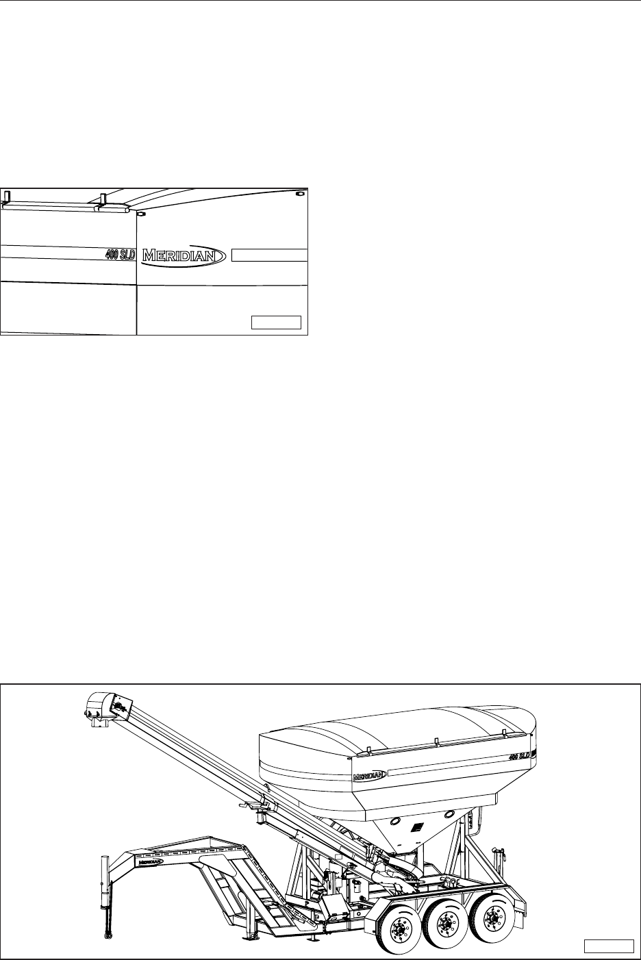
1.1 CONGRATULATIONS
Congratulations on your choice of a Meridian
Manufacturing Group 400 SLD Seed Tender Bulk
Seed Tender to complement your seed delivery
system in your farming operation. This equipment
has been designed and manufactured to meet
the exacting standards for such equipment in the
agricultural industry and will keep your seed delivery
system at optimum efciency.
MMG-00247
The Bulk Seed Tender system is designed to
handle any kind of bulk seed, quickly transport
it, and then transfer it into planters and drills, as
required. This unit is designed to not only off-load
bulk seed into the planting equipment, but it can
also load itself from a bulk seed storage container
or truck.
Safe, efcient, and trouble-free operation of
your Bulk Seed Tender requires that you and
anyone else who will be operating or maintaining
the machine, read and understand the Safety,
Operation, Maintenance, and Troubleshooting
information contained within this Operator’s
Manual.
This manual covers the 400 SLD model
manufactured by Meridian Manufacturing Group,
Inc. Use the Table of Contents and Index as a
guide to locate required information.
MMG-00248
1.2 OPERATOR ORIENTATION
The directions left, right, front and rear, as
mentioned throughout this manual, are as seen
from the truck drivers’ seat and facing in the
direction of travel.
1.3 OWNER/OPERATOR
It is the responsibility of the owner or operator
to read this manual and to train all other
operators before they start working with the
machine. Follow all safety instructions exactly.
Safety is everyone’s business. By following
recommended procedures, a safe working
environment is provided for the operator,
bystanders, and the area around the work site.
Untrained operators are not qualied and must
not operate the machine.
In addition to the design and conguration
of equipment, hazard control and accident
prevention are dependent upon the awareness,
concern, prudence, and proper training of
personnel involved in the operation, transport,
maintenance, and storage of equipment. It
is the responsibility of the owner or operator
to read this manual and to train all operators
before they start working with the machine.
Follow all safety instructions as laid out in this
manual.
Keep this manual handy for easy reference and
to pass on to new operators or owners. Call your
Meridian Manufacturing Group, Inc. dealer if you
need assistance, information, or additional copies
of the manuals.
The information, specications, and illustrations
in this manual are those in effect at the time
of printing. We reserve the right to change
specications or design at any time without notice.

12
2. SAFETY
The Safety Alert symbol identies important safety messages on the Meridian Bulk Seed Tender Models
and in the manual. When you see this symbol, be alert to the possibility of personal injury or death. Follow
the instructions in the safety message.
If you have any questions not answered in this manual, require additional copies of the manual, or the
manual is damaged, please contact your dealer or Meridian Manufacturing Group, 2902 Expansion Blvd.,
Storm Lake, Iowa, 50588, toll free 1-800-437-2334, phone (712) 732-1780, or fax (712) 732-1028.
SIGNAL WORDS:
Note the use of the signal words DANGER, WARNING, and CAUTION with the safety messages. The
appropriate signal word for each message has been selected using the following guidelines:
SAFETY ALERT SYMBOL
This Safety Alert symbol means
ATTENTION! BECOME ALERT!
YOUR SAFETY IS INVOLVED!
WHY IS SAFETY IMPORTANT TO YOU?
3 Big Reasons
• Accidents Disable and Kill •
• Accidents Cost •
• Accidents Can Be Avoided •
DANGER - Indicates an
imminently hazardous situation
that, if not avoided, will result in
death or serious injury. This signal
word is to be limited to the most
extreme situations typically for
machine components which, for
functional purposes, cannot be
guarded.
WARNING - Indicates a
potentially hazardous situation
that, if not avoided, could result
in death or serious injury, and
includes hazards that are
exposed when guards are
removed. It may also be used to
alert against unsafe practices.
CAUTION - Indicates a
potentially hazardous situation
that, if not avoided, may result
in minor or moderate injury. It
may also be used to alert against
unsafe practices.
WARNING
DANGER
CAUTION
13
YOU are responsible for the SAFE operation and
maintenance of your Meridian Manufacturing
Group bulk seed tender Model 400 SLD Seed
Express delivery system. YOU must ensure that
you and anyone else who is going to operate,
maintain, or work around the Bulk Seed Tender
be familiar with the operating and maintenance
procedures and related SAFETY information
contained in this manual. This manual will take you
step-by-step through your working day and alert
you to all good safety practices that should be
adhered to while operating the Bulk Seed Tender
system.
Remember, YOU are the key to safety. Good
safety practices not only protect you but also
the people around you. Make these practices a
working part of your safety program. Be certain
that EVERYONE operating this equipment is
familiar with the recommended operating and
maintenance procedures and follow all the safety
precautions. Most accidents can be prevented.
Do not risk injury or death by ignoring good safety
practices.
• Bulk Seed Tender system owners must
give operating instructions to operators or
employees before allowing them to operate
the machine, and then annually thereafter
per OSHA (Occupational Safety and Health
Administration) regulation 1928.57.
• The most important safety feature on this
equipment is a SAFE operator. It is the
operator’s responsibility to read and follow
ALL Safety and Operating instructions in the
manual. Most accidents can be avoided.
• A person who has not read and understood
all operating and safety instructions is not
qualied to operate the machine. An untrained
operator exposes himself and bystanders to
possible serious injury or death. Always be
and stay alert to any possible unsafe operating
or maintenance procedures or conditions.
• Do not modify the equipment in any way.
Unauthorized modication may impair the
function and/or safety of the components
and systems and could affect the life of the
equipment, possibly invalidating the warranty
coverage.
• Think SAFETY! Work SAFELY!
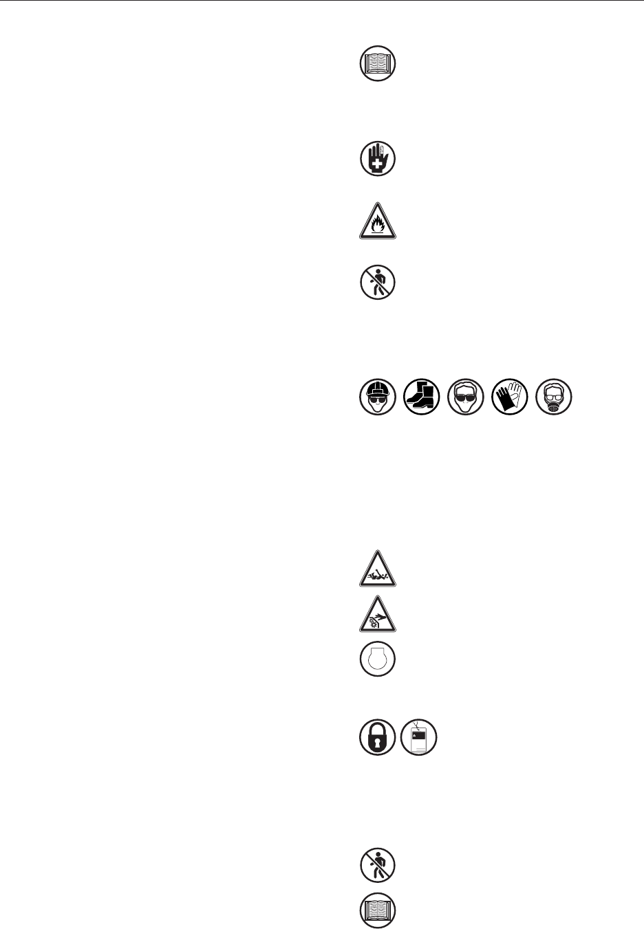
2.1 GENERAL SAFETY
1. Read and understand the Operator’s
Manual and all safety signs before
operating, maintaining, adjusting, lling,
unloading, or unplugging the Bulk Seed
Tender system.
2. Have a rst aid kit available for use
should the need arise and know how to
use it.
3. Have a re extinguisher available for
use should the need arise and know
how to use it.
4. Do not allow riders.
5. When working around or operating this
equipment, wear appropriate personal
protective equipment. This list includes but is
not limited to:
• A hard hat
• Protective shoes with slip resistant soles
• Protective goggles, glasses, or face shield
• Heavy gloves and protective clothing
• Respirator
6. Do not allow long hair, loose tting
clothing, or jewelry around equipment.
7. Install and secure all guards before
starting.
8.
STOP
Stop engine, remove ignition key, and
wait for all moving parts to stop before
servicing, repairing, adjusting, loading,
lling, or unplugging.
9.
do not
operate
signed by
date
WARNING
Establish a lock-out or tag-out
policy for the work site. Be sure
all personnel are trained in and
follow all procedures. Lock-out
or tag-out all power sources
before working around loading/
unloading equipment.
10. Clear the area of people, especially
small children, before starting.
11. Review safety related items annually
with all personnel who will be
operating, using, or maintaining the
bulk seed tender system.

14
2.2 EQUIPMENT SAFETY
GUIDELINES
1. Safety of the operator and bystanders is
one of the main concerns in designing and
developing a machine. However, every year
many accidents occur which could have been
avoided by a few seconds of thought and a
more careful approach to handling equipment.
You, the operator, can avoid many accidents
by observing the following precautions in this
section. To avoid personal injury or death,
study the following precautions and insist
those working with you, or for you, follow
them.
2. In order to provide a better view, certain
photographs or illustrations in this manual
may show an assembly with a safety shield
removed. However, equipment should never
be operated in this condition. Keep all shields
in place. If shield removal becomes necessary
for repairs, replace the shield prior to use.
3. Never use alcoholic beverages or sedative
drugs while operating this equipment. Consult
your doctor about operating this machine while
taking prescription medications.
4. Under no circumstances should young
children be allowed to work with this
equipment. Do not allow persons to
operate or assemble this unit until they
have read this manual and have developed
a thorough understanding of the safety
precautions and how it works. Review the
safety instructions with all users annually.
5. This equipment is dangerous to children
and persons unfamiliar with its operation.
The operator should be a responsible,
properly trained, and physically able person
familiar with farm machinery and trained in
this equipment’s operations. If the elderly
are assisting with farm work, their physical
limitations need to be recognized and
accommodated.
6. Never exceed the limits of a piece of
machinery. If its ability to do a job, or to do so
safely, is in question - DON’T TRY IT.
7. Do not modify the equipment in any way.
Unauthorized modication may result in
serious injury or death and may impair the
function and life of the equipment.
8. In addition to the design and conguration
of this implement, including Safety Signs
and Safety Equipment, hazard control and
accident prevention are dependent upon the
awareness, concern, prudence, and proper
training of personnel involved in the operation,
transport, maintenance, and storage of the
machine. Refer to Safety Messages and
operation instruction in each of the appropriate
sections of the auxiliary equipment and
machine Manuals. Note all Safety Signs
afxed to the auxiliary equipment.
2.3 SAFETY TRAINING
1. Safety is a primary concern in the design and
manufacture of our products. Unfortunately,
our efforts to provide safe equipment can
be wiped out by a single careless act of an
operator or bystander.
2. In addition to the design and conguration
of equipment, hazard control and accident
prevention are dependent upon the
awareness, concern, prudence, and proper
training of personnel involved in the operation,
transport, maintenance, and storage of this
equipment.
3. The best safety feature is an informed, careful
operator. It is the operator’s responsibility
to read and comply with ALL Safety and
Operating instructions in the manual.
Accidents can be avoided.
4. Working with unfamiliar equipment can lead
to injuries. Read this manual, as well as the
manual for your auxiliary equipment, before
assembling or operating to acquaint yourself
with the machines. If this machine is used
by any person other than yourself, it is your
responsibility to make certain that the operator
reads and understands the operator’s manuals
and is instructed in safe and proper use.
5. Know your controls and how to immediately
stop augers, conveyors, and any other
auxiliary equipment in an emergency. Read
this manual and the one provided with all
auxiliary equipment.
6. Train all new personnel and review instructions
frequently with employees. Be certain only a
properly trained and physically able person
will operate the machinery. A person who has
not read and understood all operating and
safety instructions is not qualied to operate
the machine. An untrained operator exposes
himself and bystanders to possible serious
injury or death.

15
2.4 SAFETY SIGNS
1.
N
I
NG
AR Keep safety signs clean and legible at
all times. Replace any safety sign or
instruction sign that is missing or not
legible. Refer to the Safety Sign
Location section for additional
information.
2. When parts that displayed a safety sign are
replaced, the replacement should also display
the safety sign.
3. Replacement safety signs (labels) are
available from your authorized Dealer Parts
Department or the factory at no cost.
2.4.1 How to Install Safety Signs
• Be sure that the installation area is clean and
dry.
• Be sure temperature is above 50°F (10°C).
• Determine exact position before you remove
the backing paper.
• Remove the smallest portion of the split back-
ing paper.
• Align the sign over the specied area and
carefully press the small portion with the
exposed sticky backing in place.
• Slowly peel back the remaining paper and
carefully smooth the remaining portion of the
sign in place.
• Small air pockets can be pierced with a pin
and smoothed out using a piece of sign back-
ing paper.
2.5 PREPARATION
1. Never operate the seed delivery
system and auxiliary equipment until
you have read and completely
understand this manual, the auxiliary
equipment Operator’s Manual, and
each of the Safety Messages found on
the safety signs on the delivery system
and auxiliary equipment.
2. PROLONGED EXPOSURE TO LOUD
NOISE MAY CAUSE PERMANENT
HEARING LOSS! Motors or equipment
can be noisy enough to cause
permanent or partial hearing loss. We
recommend that you wear hearing
protection on a full-time basis if the
noise in the operator’s position
exceeds 80db. NOTE: Hearing loss
from loud noise (tractors, chain saws,
radios, and other such sources close to
the ear) is cumulative over a lifetime
with uncertain natural recovery.
3. Clear working area of debris, trash, or
hidden obstacles that might be hooked
or snagged, causing injury, damage, or
tripping.
4. Operate only in daylight or good articial light.
5. Be sure machine is properly attached to
the trailer, adjusted, and in good operating
condition.
6. Ensure that all guards, shielding, and
safety signs are properly installed and
in good condition.
7. Before starting, give the machine a
“once over” for any loose bolts, worn
parts, cracks, leaks, frayed belts, and
make necessary repairs. Always follow
maintenance instructions.
2.6 OPERATING SAFETY
1. Make sure that anyone who will be
operating the bulk seed delivery
system or working on or around the
unit reads and understands all the
operating, maintenance, and safety
information in the operator’s manual.
2. Keep all bystanders, especially
children, away from the machine when
loading or unloading, or when
authorized personnel are carrying out
maintenance work.
3.
do not
operate
signed by
date
WARNING
Establish a lock-out or tag-out
policy for the work site. Be sure
all personnel are trained in and
follow all procedures. Lock-out
or tag-out all power sources
before servicing the unit or
working around loading/
unloading equipment.
16
4.
STOP
Stop engine, remove ignition key, and
wait for all moving parts to stop before
servicing, repairing, adjusting, loading,
lling, or unplugging.
5. Keep working area clean and
free of debris to prevent slipping
or tripping.
6. Do not allow riders on the trailer or
frame when transporting.
7. Keep hands, feet, hair, and clothing
away from rotating parts.
8. Do not place hands, ngers, or arms
between moving parts.
9. Stay away from overhead power lines.
Electrocution can occur without direct
contact.
10. Install and secure all guards before
starting.
11. Use care when climbing on frame or
ladder to prevent slipping or falling.
12. Fasten frame securely to trailer before
transporting.
13. Always empty compartment 2 rst to prevent
an unbalanced load. An unbalanced load can
cause the tender to upend.
14. Review safety related items annually
with all personnel who will be
operating, using, or maintaining the
seed delivery system.
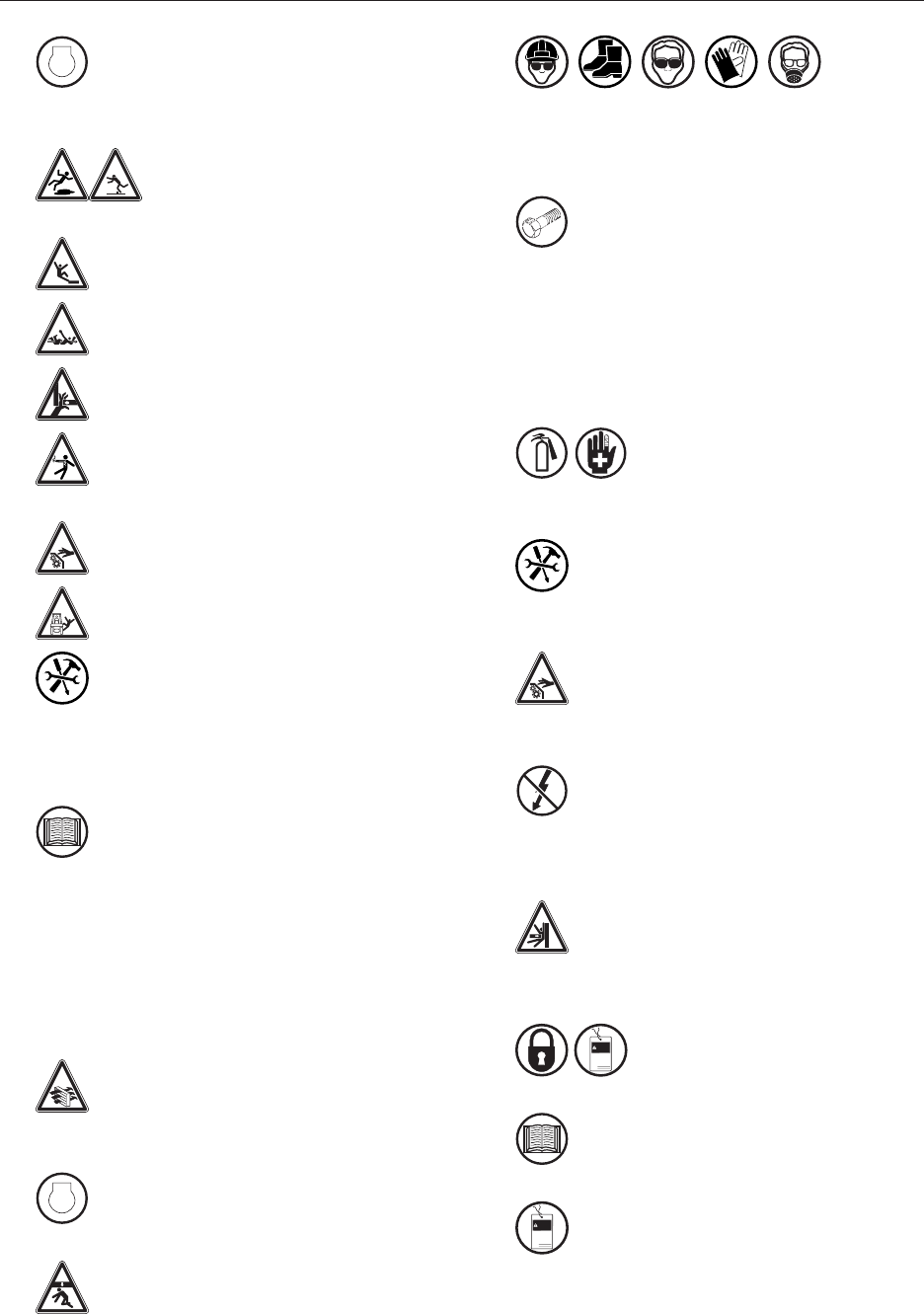
2.7 MAINTENANCE SAFETY
1. Good maintenance is your responsibility. Poor
maintenance is an invitation for trouble.
2. Follow good shop practices.
3. Ensure proper ventilation. Never
operate the engine in a closed building.
The exhaust fumes may cause
asphyxiation.
4.
STOP
Before working on this machine, shut
off the engine and remove the ignition
keys.
5. Never work under equipment unless it
is securely blocked.
6.
Always use personal protection devices, such
as eye, hand, and hearing protectors, when
performing any service or maintenance.
7. OEM Where replacement parts are
necessary for periodic maintenance
and servicing, genuine factory
replacement parts must be used to
restore your equipment to the original
specications. The manufacturer will
not be responsible for injuries or
damages caused by use of unapproved
parts and/or accessories.
8. A re extinguisher and rst aid
kit should be readily accessible
while performing maintenance
on this equipment.
9. Periodically tighten all bolts, nuts, and
screws and ensure all cotter pins are
properly installed to ensure unit is in
safe condition.
10. When completing a maintenance or
service function, make sure all safety
shields and devices are installed before
placing unit in service.
11. Turn OFF all electrical power and tag
or lockout the power source before
performing any electrical test or before
connecting or disconnecting valve coils
or other electrical loads.
12. Never operate or test any function of
the equipment when people are in an
area of a potential crush hazard.
2.8 LOCK-OUT OR TAG-OUT SAFETY
1.
do not
operate
signed by
date
WARNING
Establish a formal Lock-Out or
Tag-Out program for your
operation.
2. Train all operators and service
personnel before allowing them to work
around the seed delivery system.
3.
do not
operate
signed by
date
WARNING
Provide tags on the machine and a
sign-up sheet to record tag-out details.

17
2.9 STORAGE SAFETY
1. Store the unit in an area away from human
activity.
2. Do not permit children to play on or around the
stored machine.
3. Store the unit in a dry, level area. Support the
frame with planks, if required.
2.10 TRANSPORT SAFETY
1. Comply with local, state, and federal
laws governing safety and conveyance
of farm machinery on public roads.
2. Ensure all lights, reectors, and other lighting
requirements are installed and in good
working condition.
3. Ensure that the trailer is equipped with brakes
that are in good working order. Be familiar with
their operation.
4. Do not exceed a safe travel speed. Slow down
for rough terrain and when cornering.
5. Fasten frame securely to trailer before
transporting.
6. Be sure the trailer is securely hitched to the
towing vehicle and a retainer is used through
the hitch jaws. Always attach a safety chain
between the hitch and the towing vehicle.
7. Stay away from overhead power lines.
Electrocution can occur without direct
contact.
8. Plan your route to avoid heavy trafc.
9. Install auger spout transport lock before
transporting.
10. Do not drink and drive.
11. Be a safe and courteous driver. Yield to
oncoming trafc in all situations, including
narrow bridges, intersections, etc. Watch
for trafc when operating near or crossing
roadways.
12. Never allow riders on the tender or the
trailer.
2.11 REFUELLING SAFETY
1.
G
Handle fuel with care. It is highly
ammable.
2. Allow engine to cool for ve minutes
before refuelling. Clean up spilled fuel
before restarting engine.
3. Do not refuel the machine while
smoking or when near open ame or
sparks.
4. Fill fuel tank outdoors.
5. Prevent res by keeping machine clean
of accumulated trash, straw, grease,
and debris.
2.12 BATTERY SAFETY
1. Keep all sparks and ames away from
batteries, as gas given off by electrolyte
is explosive.
2. Avoid contact with battery electrolyte: wash off
any spilled electrolyte immediately.
3. Wear safety glasses when working
near batteries.
4. Do not tip batteries more than 45 degrees, to
avoid electrolyte loss.
5. To avoid injury from spark or short
circuit, disconnect battery ground cable
before servicing any part of electrical
system.

18
2.13 SIGN-OFF FORM
Meridian Manufacturing Group follows the general
Safety Standards specied by the American
Society of Agricultural Engineers (ASAE) and
Occupational Safety and Health Administration
(OSHA). Anyone who will be operating and/or
maintaining the Meridian Manufacturing Group
Bulk Seed Tender Model 400 SLD seed delivery
system must read and clearly understand ALL
Safety, Operating, and Maintenance information
presented in this manual.
Do not allow anyone to operate this equipment
until such information has been reviewed. Annually
review this information before the season start-up.
SIGN-OFF FORM
Date Employee’s Signature Employer’s Signature
Make these periodic reviews of SAFETY and
OPERATION a standard practice for all of your
equipment. We feel an untrained operator is
unqualied to operate this machine.
A sign-off sheet is provided for your record keeping
to show that all personnel who will be working
with the equipment have read and understand the
information in the Operator’s Manual and have
been instructed in the operation of the equipment.
19
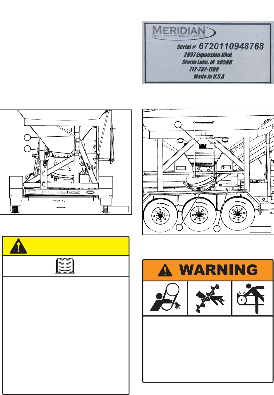
3. SAFETY SIGN LOCATIONS
The types of safety signs and locations on the
equipment are shown in the following pages.
Good SAFETY AWARENESS requires that you
familiarize yourself with the various safety signs,
the type of warning and the area, or a particular
function related to that area.
REMEMBER - If safety signs have been
damaged, removed, become illegible, or parts
replaced without signs, new signs must be
applied. New safety signs are available from your
authorized dealer free of charge.
MMG-00270
1
2
1. CAUTION — Read and Understand (#19934)
CAUTION
19934
• Read and understand the Operator’s Manual before using. Review
safety instructions annually.
• Stop engine, remove ignition key, and wait for all moving parts to stop
before servicing, repairing, adjusting, loading, fi lling, or unplugging.
• Keep working area clean and free of debris to prevent slipping or
tripping.
• Do not allow riders on the trailer or frame when transporting.
• Only enter seed compartment when it is empty.
• Keep hands, feet, hair, and clothing away from moving parts.
• Do not place hands, arms, or body between seed box and frame or lid
to prevent pinching or crushing. Components can move unexpectedly.
• Do not place hands, fi ngers, or arms between unloading auger tube
segments when placing in unloading confi guration.
• Stay away from overhead power lines. Electrocution can occur
without direct contact.
• Install and secure all guards before starting.
• Use care when climbing on frame or ladder to prevent slipping or
falling.
• Do not smoke when refuelling or working around machine.
• Fasten frame securely to trailer before transporting.
• In two compartment seed tenders, always empty Compartment 2 fi rst
to prevent an unbalanced load. An unbalanced load can cause hitch
to upend.
2. Product Serial Number Decal (#19984)
MMG-00272
3
4
5
3. WARNING — Rotating Parts (#19936)
19936
ROTATING PART HAZARD
KEEP AWAY
To prevent serious injury or death from rotating parts:
• Stop engine, remove ignition key, and wait for all moving
parts to stop before servicing, adjusting, repairing or
unplugging.
• Install and secure all guards before operating.
• Do not operate with rotating parts exposed.

20
4. WARNING — Fall Hazard (#19939)
FALLING HAZARD
19939
Avoid serious injury or death from falling:
Gri the ladder ith oth
hands hen liming to
revent sliing or falling
ee rungs lean to
revent sliing
5. WARNING — Hot Surface (#20088)
6. WARNING — Automatic Operation (#15056)
15056
THIS MACHINE IS AUTOMATICALLY,
AND REMOTELY CONTROLLED. THE
HOPPER GATES WILL OPEN AND
CLOSE DURING THE OPERATION OF
THIS MACHINE WITHOUT WARNING.
DO NOT PLACE HANDS AND OR
OTHER BODY PARTS THROUGH THE
GATE OPENINGS WHILE OPERATING
THIS MACHINE.
MAINTAIN A SAFE DISTANCE WHILE
OPERATING THIS MACHINE.
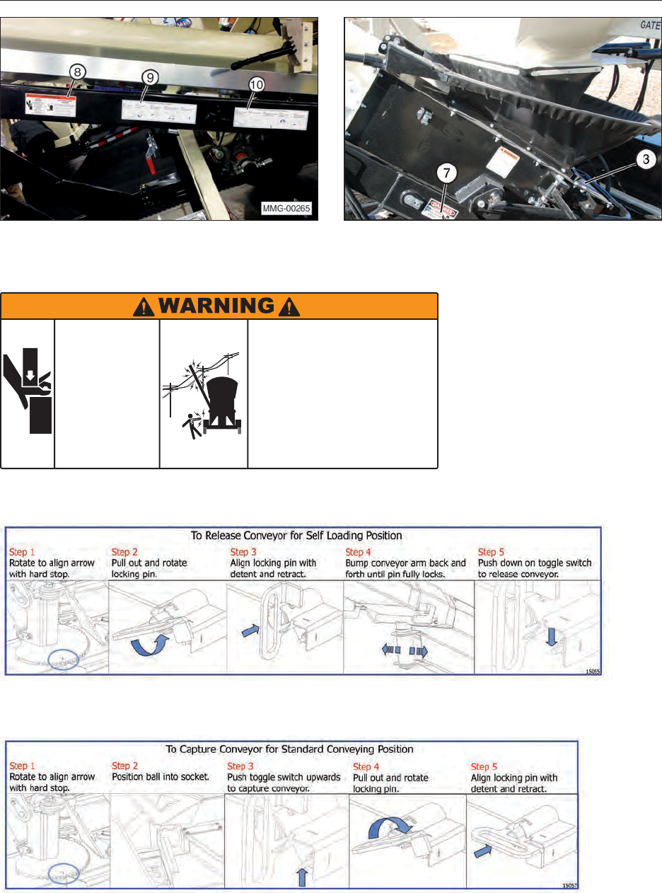
7. WARNING — Pinch Point (#20087)
21
8. WARNING — Crush Hazard / Electrocution
(#17509)
CRUSH
HAZARD
ELECTROCUTION
HAZARD
Avoid contact with overhead power
lines or electrically powered objects.
• Be aware of your surroundings when
raising or lowering conveyor.
• Maintain at least 20 feet between
equipment and any electrical hazard.
• Contact with electricity can result
in serious personal injury or death.
Keep hands and
arms clear of
conveyor tube
when placing it
in storage
position.
Weight of tube
will cause
crushing injuries.
17509
9. Instruction — Release Conveyor (#15055)
10. Instruction — Capture Conveyor (#15057)
22
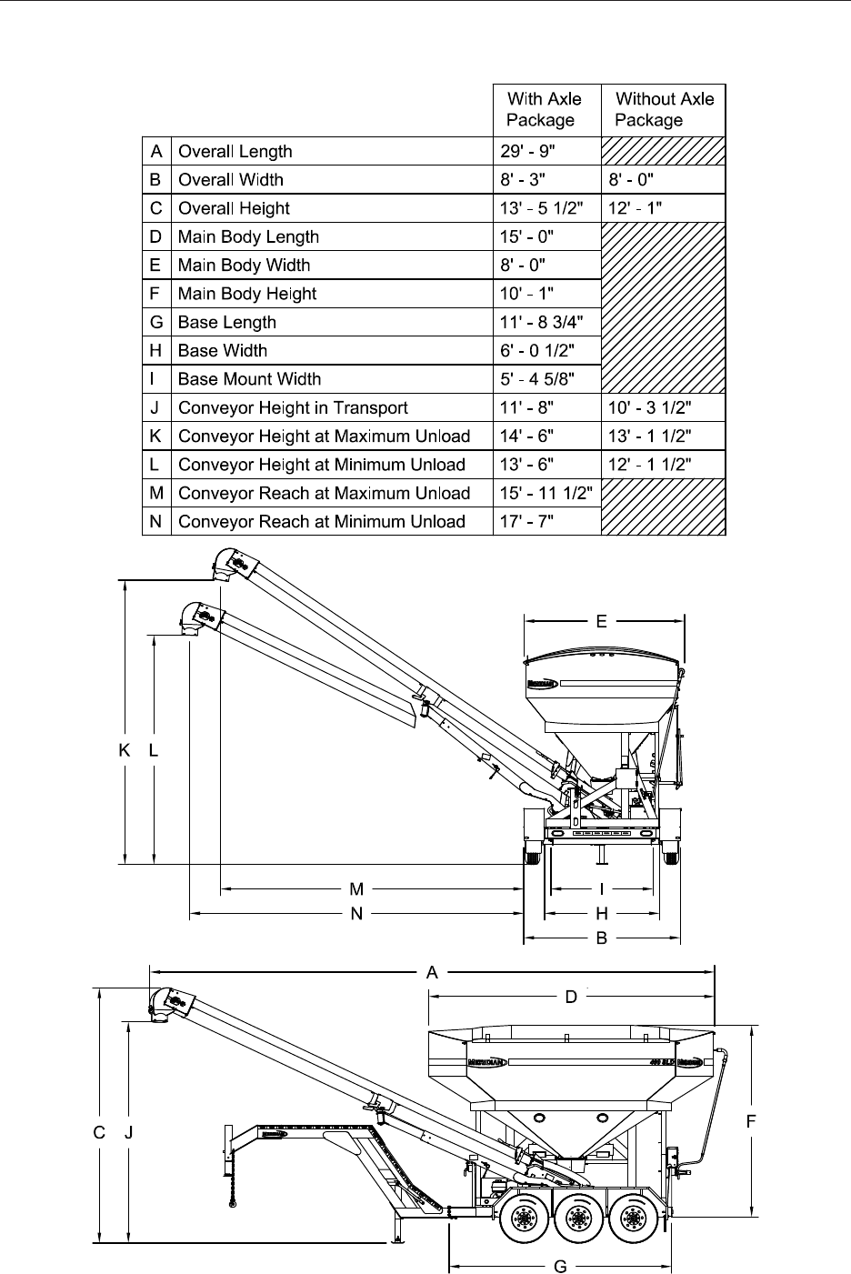
4. SPECIFICATIONS
4.1 OVERALL SEED TENDER
SPECIFICATIONS
23
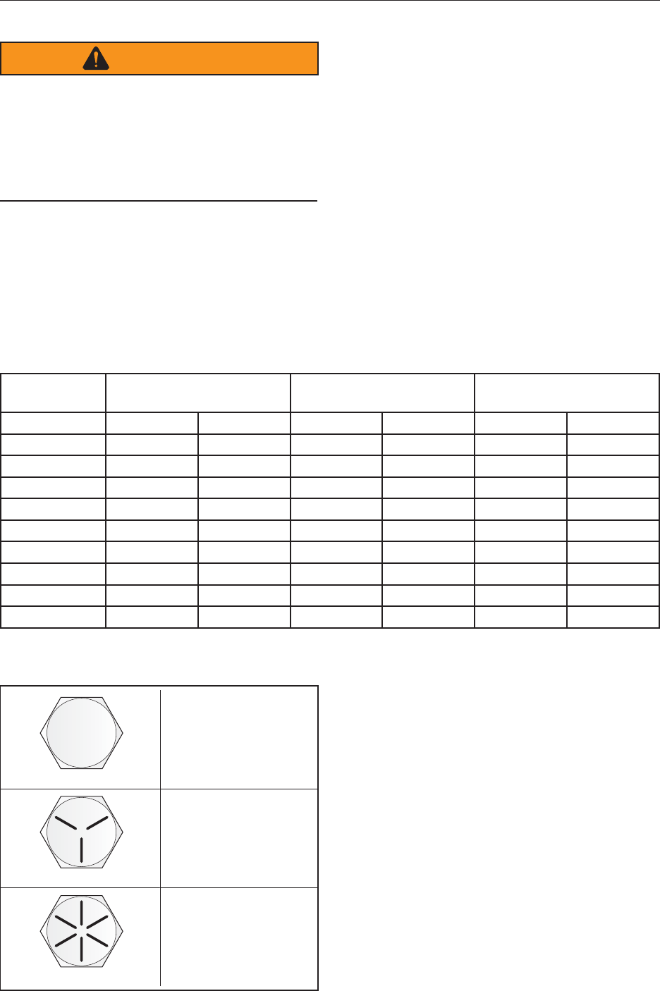
4.2 BOLT SPECIFICATIONS
WARNING
The torque value for bolts and capscrews are
identied by their head markings. Replacing
higher “Grade” bolts (Grade 8) with lower
Grade bolts (Grade 5) will lead to equipment
failure and can result in injury or death. Always
use replacement bolts with the same Grade
markings as the removed bolt.
4.2.1 Bolt Torque Values
Torque gures indicated above are valid for non-
greased or non-oiled threads and heads unless
otherwise specied. Therefore, do not grease or
oil bolts or cap screws unless otherwise instructed
in this manual. When using locking elements,
increase torque values by 5%.
Bolt
Diameter “A” SAE Grade 2
N·m (lb-ft) SAE Grade 5
N·m (lb-ft) SAE Grade 8
N·m (lb-ft)
1/4" 8 (6) 12 (9) 17 (12)
5/16" 13 (10) 25 (19) 36 (27)
3/8" 27 (20) 45 (33) 63 (45)
7/16" 41 (30) 72 (53) 100 (75)
1/2" 61 (45) 110 (80) 155 (115)
9/16" 95 (70) 155 (115) 220 (165)
5/8" 128 (95) 215 (160) 305 (220)
3/4" 225 (165) 390 (290) 540 (400)
7/8" 230 (170) 570 (420) 880 (650)
1" 345 (225) 850 (630) 1320 (970)
4.2.2 Grade Markings Chart
No Marking
Grade 2
Low or Medium
Carbon Steel
Grade 5
Medium Carbon
Steel Quenched
and Tempered
Grade 8
Medium Carbon
Alloy Steel,
Quenched and
Tempered
3 Radial Lines
6 Radial Lines
24
5. MACHINE COMPONENTS AND CONTROLS
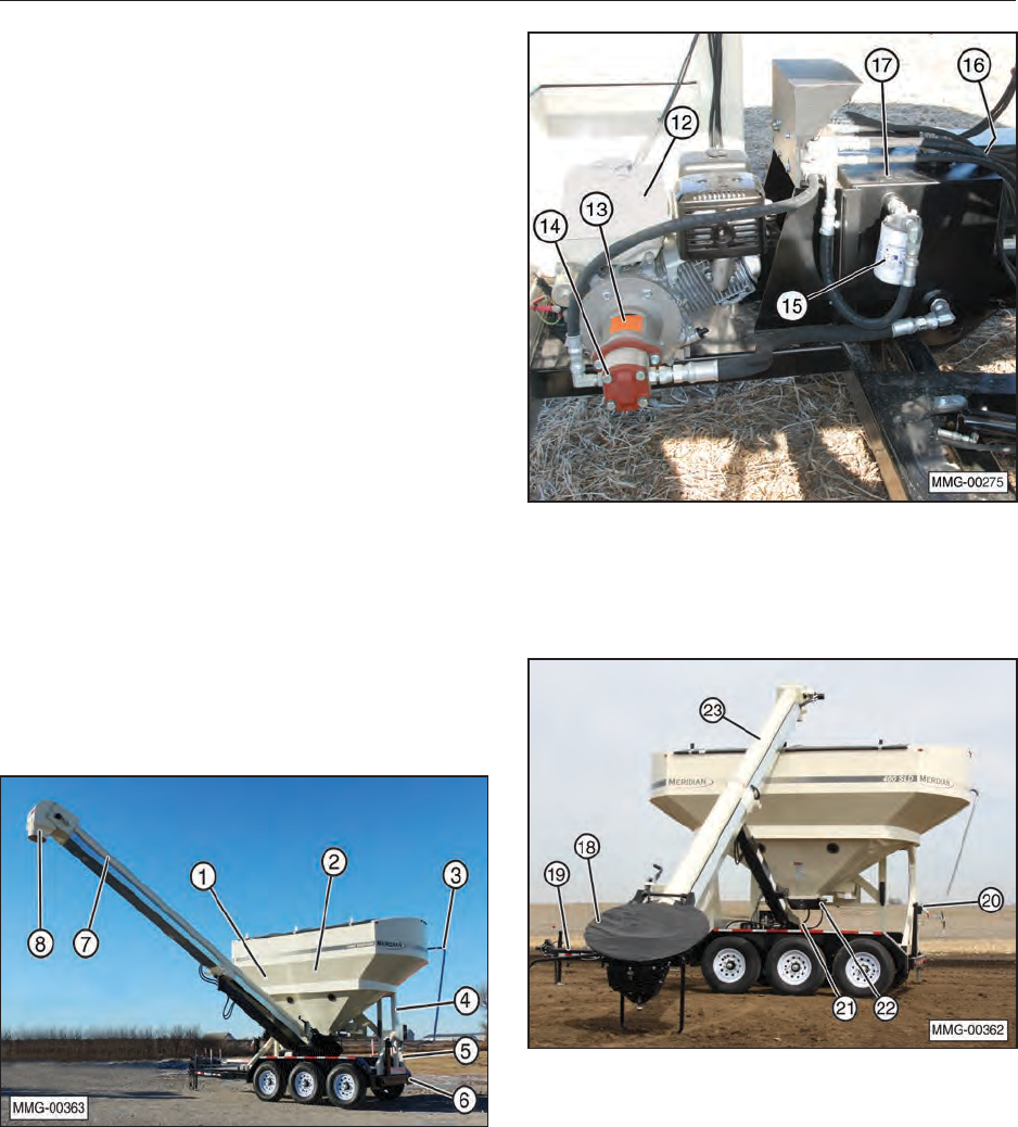
5.1 COMPONENT NOMENCLATURE
AND LOCATION
The Meridian 400 SLD Seed Tender models are
designed as bulk seed transfer units to transfer
large amounts of seed into a planter or drill.
Large bulk seed containers are loaded into the
seed tender compartments (1 & 2) using two
methods. The seed can be loaded into one of two
compartments from a seed box or other means.
The seed tender can also load itself using its
conveyor (23). The center-mounted conveyor (7)
then transfers the seed from the compartments
into planters or drills. Slide gates (22) on the
compartments control the ow of seed into the
conveyor.
A gasoline engine (12) mounted on the frame
powers a hydraulic pump, which operates the
hydraulic motor for the conveyor and the control
cylinders (raise, lower, and rotate the conveyor;
open and close the slide gates).
The conveyor is mounted on a pivoting platform
(21) that rotates 135°. An optional spout on
the end of the conveyor allows for convenient
distribution.
(1) Compartment 1. (2) Compartment 2.
(3) Roll Tarp and Open/Close Bar. (4) Seed
Tender Frame. (5) Control Panel and Wireless
Remote Control (not shown). (6) Trailer (Standard
or Gooseneck). (7) Conveyor in Planter Loading
Position. (8) Delivery Spout.
(12) Gasoline Engine to Power Hydraulic Pump.
(13) Coupling (Engine to Pump). (14) Hydraulic
Pump. (15) Hydraulic Oil Filter. (16) Hydraulic
Tank Oil Level Sight Gauge. (17) Hydraulic Tank.
(18) Hopper and Cover. (19) Breakaway Trailer
Brake System. (20) Transport Lock (Field and
Road). (21) Pivot Platform. (22) Bin Slide Gates
and Cylinders. (23) Conveyor in Self-loading
Position.
25
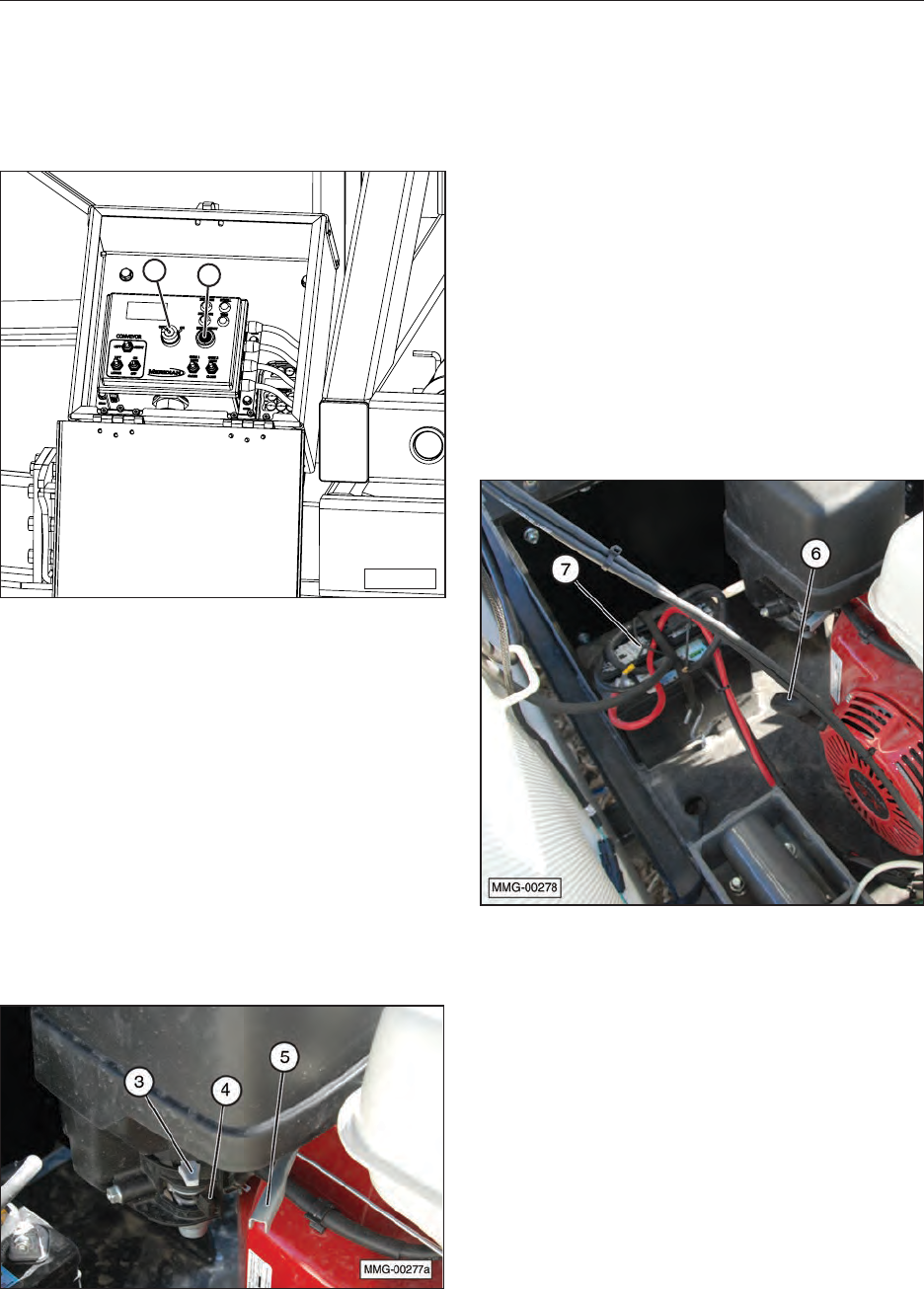
5.2 ENGINE AND CONTROLS
A Honda® engine is used with the unit. Always
read the engine Operator’s Manual supplied
with the seed tender for the detailed operating
procedures.
MMG-00249
12
1. Electrical System Key Switch (located in
Control Box 5)
This key switch controls the power to the
electrical system. Turn the key clockwise to turn
the electrical system ON. The key must be in
the ON position for the engine to start. Turn the
key counterclockwise to stop the engine and
turn OFF the electrical system.
2. Engine Start Button (located in
Control Box 5)
Press and hold this button until the engine
starts. Also set the choke lever on the engine
when starting the engine. Turn the key switch
counterclockwise to turn OFF the engine.
3. Choke Lever
The choke lever controls the fuel/air mixture to
the engine. Close the choke when starting if the
engine is cold. Open the choke as the engine
warms. Always open the choke fully during
operation.
4. Fuel Shut-Off Valve
Each engine is equipped with a valve between
the fuel tank and the carburetor. Slide the fuel
valve toward the block to turn ON and away
for OFF. Turn the fuel OFF when not in use or
before transporting.
5. Throttle Lever
This lever controls the engine RPM. Move
the lever laterally to increase or decrease the
RPM. Always run at maximum throttle while
operating.
5.
6. Starting Rope
This retracting rope and T-handle is an optional
method used to turn the engine over for
starting. Grasp the T-handle rmly and pull the
rope sharply to start the engine. Key on master
control must be ON to pull-start.
7. Battery (12 Volt)
A 12 Volt battery supplies the power to start the
gasoline engine. When the engine is operating
a trickle charge is sent to the battery to keep it
fully charged.
26
5.3 CONTROL SYSTEM FUNCTIONS
The MEGA REMOTE system is a state-of-the-art
microprocessor based Radio Frequency (RF)
control system. It provides the operator the ability
to operate the seed tender from the control panel
or from the wireless handheld remote transmitter.
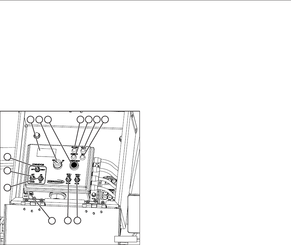
5.3.1 Control Functions
The controls on this panel are intended to be used
only as a backup resource. All of the functions
of the seed tender can more easily be controlled
using the handheld remote transmitter.
MMG-00279
13
5
4
6
7 8
2910 11 12
13
On/Off Key Switch (1)
This key switch controls the power to the
electrical system. Turn the key clockwise to
turn the electrical system ON. The key must be
in the ON position for the engine to start or the
handheld remote transmitter to function. Turn the
key counterclockwise to turn OFF the electrical
system.
Starting the Engine (2)
Press and hold this button until the engine starts.
Also set the choke lever on the engine when
starting the engine. Turn the key counterclockwise
to turn OFF the engine.
LCD Display (3)
Turning key switch (1) to the ON position will turn
the LCD backlight ON. It will stay on until the key
is turned to the OFF position.
Conveyor Lift and Lower (4)
This switch raises and lowers the conveyor. Press
the switch UP to raise the conveyor. Press the
switch DOWN to lower the conveyor.
Conveyor Swing Left and Swing Right (5)
This switch positions the conveyor to the right
or left. Press the switch to the LEFT to position
the conveyor towards the front of the unit. Press
the switch to the RIGHT to position the conveyor
towards the rear of the unit.
Conveyor Start and Stop (6)
This toggle switch starts and stops the conveyor
belt. Press the toggle switch UP to start the
conveyor. Press the toggle switch DOWN to stop
the conveyor.
Slide Gate 1 (7)
This switch opens and closes the slide gate at the
bottom of the compartment 1. Press and hold the
switch UP to open the slide gate; press and hold
the switch DOWN to close the slide gate. The
opening can be varied to provide the desired ow
rate of seed onto the conveyor belt.
Slide Gate 2 (8)
This switch opens and closes the slide gate at
the bottom of compartment 2. Press and hold the
switch UP to open the slide gate; press and hold
the switch DOWN to close the slide gate. The
opening can be varied to provide the desired ow
rate of seed onto the conveyor belt.
Increase (9)
Increases the weight when setting the Weight to
Dispense function.
From the Main Display screen, to lighten the LCD
display contrast press the Increase button.
Press and hold both the Increase and Decrease
buttons simultaneously for ten seconds to enable
or disable the display screen.
Decrease (10)
Decreases the weight when setting the Weight to
Dispense function.
From the Main Display screen, to darken the LCD
display contrast press the Increase button.
Press and hold both the Increase and Decrease
buttons simultaneously for ten seconds to enable
or disable the display screen.
Scroll (11)
Press the scroll button to scroll between the
various display pages.
— Main Display screen (shows weight)
— Weight To Dispense screen (shows amount of
seed that will be delivered to planter)
— Active Slide Gate screen
— Auto Reset screen

27
Tare (12)
To “Tare” or zero the scale when the receiver
display is on the main display page showing the
weight, press and hold the tare push button on
either the remote transmitter or the receiver for
three seconds. The display will then show the
weight as zero.
RS232 Connector for Diagnostics (13)
5.3.2 Setting the Weight to Dispense
1. Select the Weight To Dispense screen using
scroll button (11).
2. Press and hold Tare button (12) for ve
seconds.
3. The rst character of the weight will start
blinking.
4. Use the Increase (9) or Decrease (10) buttons
to select the appropriate number.
5. Use the Scroll button to move to the next digit.
Use the Increase (9) or Decrease (10) buttons
to select the appropriate number. Repeat this
until the desired weight has been entered.
6. Finally, holding the Tare button for another ve
seconds to save the new weight.
NOTE: The weight of the seed is calculated
when it is inside the compartments and as it ows
through the slide gates. Any seed in the seed pan
or the conveyor has already been weighed and
does not affect the total weight.
5.3.3 Setting Active Slide Gate
1. Select the Active Slide Gate screen using
scroll button (11).
2. Use the Increase/Decrease buttons to set the
slide gate to either #1 or #2.
3. When the Auto Reset button is pressed on the
remote transmitter, the slide gate selected will
open automatically.
5.3.4 Auto Reset Function
1. Using the Weight To Dispense screen, select
the desired weight of seed to be delivered to
the planter.
2. Using the Active Slide Gate screen, select
either compartment 1 (Slide Gate 1) or
compartment 2 (Slide Gate 2).
3. Press the Auto Reset button on the remote
transmitter. The unit monitors the weight
of seed being dispensed. As the weight
approaches the desired Weight To Dispense,
the slide gate will begin to close. If the weight
stops changing too soon, the unit will open the
slide gate slowly in order to get the desired
amount.
5.3.5 Control System Compliance
Information
This equipment has been tested and found
to comply with the limits for a Class B digital
device, pursuant to part 15 of the FCC Rules.
These limits are designed to provide reasonable
protection against harmful interference. This
equipment generates radio frequency energy
and if not installed and used in accordance with
the instructions, may cause harmful interference
to radio communications. However, there is no
guarantee that interference will not occur in a
particular installation. If this equipment does cause
harmful interference to the reception of other
electronics, which can be determined by turning
the equipment off and on, DO NOT operate this
equipment around those devices.
This equipment has been certied to comply with
the limits for a Class B computing device, pursuant
to FCC Rules. In order to maintain compliance
with FCC regulations, shielded cables must be
used with this equipment. Operation with non-
approved equipment or unshielded cables is
likely to result in interference to electronic device
reception. The user is cautioned that changes and
modications made to the equipment without the
approval of the manufacturer could void the user’s
authority to operate this equipment.

28
5.4 WIRELESS REMOTE
TRANSMITTER
Each radio remote transmitter is designed to
operate with a unique radio ID code and RF
channel sequence. Each receiver is programmed
to respond only to the remote transmitter with the
correct ID code/RF channel sequence for which
it is set. This feature allows multiple systems to
work in close proximity to one another without
interference.
If the remote transmitter goes out of range for
more than two seconds, all outputs except
CONVEYOR will turn off as a safety feature.
In the event that a remote transmitter becomes
damaged and a new one is needed, the receiver
can be reprogrammed to respond to the new
remote transmitter. Refer to “10.1.3 Remote
Control Transmitter and Receiver Synchronization”
on page 48 of this manual.
All of the normal functions of the seed tender can
be controlled by the remote transmitter.
5.4.1 Functions of Keypad Buttons
Use the buttons on the keypad to operate the
desired functions of the seed tender.
POWER (1)
Press Power button (1) to turn remote transmitter
ON. Press and hold the button to turn it OFF.
To save battery life, the remote transmitter will
automatically turn off when it is idle (no functions
are used) for a period greater than the sleep time
(default is 15 minutes). Refer to “10.1.4 Changing
Sleep Time on the Transmitter” on page 49 to
change the sleep time on the transmitter.
NOTE: The remote transmitter will NOT
automatically shut off as long as the receiver has
power applied to it.
ENG STOP (2)
Press Engine Stop button to turn OFF engine.
CONV (3)
The Conveyor button starts and stops the
conveyor belt. Press the INC button to start the
conveyor. Press STOP button to stop conveyor.
GATE 1 (4)
The Slide Gate 1 buttons open and close the slide
gate at the bottom of compartment 1. Press the
OPEN button to open the slide gate, and press
the CLOSE button to close the slide gate. The
opening can be varied to provide the desired ow
rate of seed onto the conveyor belt.

29
CONV (5)
This Conveyor button positions the conveyor to the
right or left. Press the LEFT button to position the
conveyor towards the front of the unit. Press the
RIGHT button to position the conveyor towards the
rear of the unit.
GATE 2 (6)
The Slide Gate 2 buttons open and close the slide
gate at the bottom of compartment 2. Press the
OPEN button to open the slide gate, and press
the CLOSE button to close the slide gate. The
opening can be varied to provide the desired ow
rate of seed onto the conveyor belt.
CONV (7)
This Conveyor button raises and lowers the
conveyor. Press the LIFT button to raise the
conveyor. Press the LOWER button to lower the
conveyor.
TARE (8)
The tare button will reset the scale to zero in order
to measure only the content being added to one
compartment without measuring the weight of the
seed tender itself. This allows an exact measurement
of the seed to be placed in the compartment.
ENG START (9)
Press the engine start button to start the engine.
If the engine has not been started recently set the
choke to ON.
AUTO RESET (10)
Pressing the AUTO RESET button on the remote
transmitter will dispense the Weight To Dispense
out the selected gate. The gate that was selected
in the Active Gate screen will open in #s. The
unit will monitor the weight being dispensed. As
the weight approaches the desired Weight To
Dispense, the gate will begin to close. If the weight
stops changing too soon, the unit will open the
gate slowly in order to get the desired amount.
1. The auto reset mode does not turn the
CONVEYOR on. The desired speed for the
CONVEYOR should be set manually.
2. If the transmitter is in the middle of auto
dispense mode and the remote goes out
of range, the unit will close all open gates
regardless the status of dispensing.
3. If the remote goes into the sleep mode during
the auto dispense mode, the unit will abort the
auto dispense mode and close the active gate.
4. Pressing any of the gate function buttons on
the transmitter will close the active gate and
stop the auto dispense mode.
5. If during the auto dispense mode the POWER
button is pressed, the active gate will close.

30
ENABLE/DISABLE DISPLAY
Hold both INCREASE and DECREASE push
buttons on the control panel simultaneously for 10
seconds to enable or disable the display.
BAR PAGE
On the BAR PAGE where all weights are shown
separately, holding down the TARE button on the
control panel for 10 seconds will zero the reading
for all the bars.
5.4.2 Display Panel
(1) Weight Displayed in Pounds. (2) Signal
Strength. (3) Percentage of Battery Life.
5.4.3 Display Messages
Pressing the POWER button turns the remote
transmitter ON and displays the message
“Meridian Mega Remote”.
If the “NO LINK” message appears, the remote
transmitter is not communicating with the control
panel on the seed tender. Make sure the ON/OFF
key switch is in the ON position.
The remote transmitter will display the WEIGHT of
the seed in the seed compartments in pounds. It
also displays the battery life of the two AA batteries
in a percentage of remaining life.
When the POWER button is pressed and held,
the message “Transmitter is turning OFF” will be
displayed.

31
6. PRE-OPERATING INSTRUCTIONS
6.1 MACHINE BREAK-IN PERIOD
A special break-in procedure has been developed
to ensure the integrity of the seed tender when
rst put into service. Follow the Before Starting
instructions and then follow the Inspections for 1/2,
5, and 10 Hours instructions at the appropriate
interval.
After completing these instructions, follow the
normal service schedule in the Maintenance
section and engine manual.
6.1.1 Before Starting
1. Read and follow the instructions in the Honda®
engine and the Meridian Operator’s Manuals.
2. Review and follow Set-Up Instructions and
the Pre-operation Checklist before starting
machine.
3. Initially check wheel bolt torque and then
again at 10, 25, and 50 miles. Refer to the
Wheel Bolt Torque Requirements section in
this manual for tightening instructions.
4. If needed, adjust the height of the hitch
assembly. Refer to the appropriate hitch
section in this manual for either the standard
trailer hitch or the gooseneck hitch.
5. Start the engine and check the controls. Be
sure that they function properly.
6.1.2 Inspections for 1/2, 5, and 10
Hours
1. Recheck machine uid levels. Rell as
required.
2. Recheck the tension and alignment of the
delivery belt.
3. Recheck hardware and fasteners; frame to
trailer tie-downs, all fasteners, and wheel
bolts. Tighten to their specied torque.
4. At 10 hours, change the engine oil with the
specied oil.

32
6.2 PRE-OPERATION CHECKLIST
Efcient and safe operation of the Meridian Bulk
Seed Tender system requires that each operator
reads and follows the operating procedures and all
related safety precautions outlined in this section.
A pre-operational checklist is provided for the
operator. It is important for both personal safety
and maintaining the efcient operation of the
delivery system that this checklist be followed.
Before operating the delivery system and each
time thereafter, the following areas should be
checked:
1. Lubricate the machine, as outlined and shown
in the Grease/Lubrication Location Diagram
in the Maintenance section of this manual.
Follow the prescribed schedule.
2. Check the engine uid levels, fuel, and
crankcase oil. Add as required.
IMPORTANT
The engine warranty is void if the engine is run
without oil.
3. Check hardware and fasteners; seed tender
frame to trailer tie-downs, hitch bolts, trailer
hitch to trailer bolts, and all other fasteners.
Tighten to their specied torque.
4. Make sure the wheel bolt lug nuts are tight.
5. Check the tires and ensure that they are
inated to their specied pressure.
6. Remove all entangled material.
7. Visually inspect the conveyor and frame for
damage.
8. Test the breakaway brake unit and the trailer
brakes.
• Make sure the trailer brakes are operating
properly.
• Make sure the trip wire to the breakaway
switch is connected to the tow vehicle.
• Make sure the pin is correctly installed in
the breakaway switch.
• Press the Test button. The indicator should
illuminate green. If the red light illuminates,
the battery charge is low. Refer to the
Breakaway system in the Maintenance
section for instructions on charging the
battery.
9. Check the uid level in the hydraulic tank. Add
uid as needed.
10. Check the tension of the delivery belt. Follow
the instructions in the manual to correct the
tension and/or alignment.
11. When the machine is operating, check the
alignment of the delivery belt. Follow the
instructions in the manual to correct the
tension and/or alignment.
33
7. OPERATION
• Make sure that anyone operating the seed
delivery system or working on or around the
unit reads and understands all the operating,
maintenance, and safety information in the
Operator’s Manual.
• Keep all bystanders, especially children,
away from the machine when loading or
unloading is being done, or when authorized
personnel are carrying out maintenance work.
• Establish a lock-out tag-out policy for the
worksite. Be sure all personnel are trained in
and follow all procedures. Lock-out tag-out
all power sources before servicing the unit or
working around loading/unloading equipment.
• Stop engine, remove ignition key, and wait
for all moving parts to stop before servicing,
repairing, adjusting, loading, lling, or
unplugging.
• Keep working area clean and free of debris to
prevent slipping or tripping.
• Do not allow riders on the trailer or frame
when transporting.
• Keep hands, feet, hair, and clothing away
from moving parts.
• Do not place hands, arms, or body between
the seed box and frame or lid to prevent
pinching or crushing. Components can move
unexpectedly.
• Stay away from overhead power lines.
Electrocution can occur without direct
contact.
• Install and secure all guards before starting.
• Use care when climbing on frame or ladder to
prevent slipping or falling.
• Do not smoke when refueling or working
around machine.
• Fasten frame securely to trailer before
transporting.
• Review safety related items annually with all
personnel who will be operating, using, or
maintaining the seed delivery system.
OPERATING SAFETY
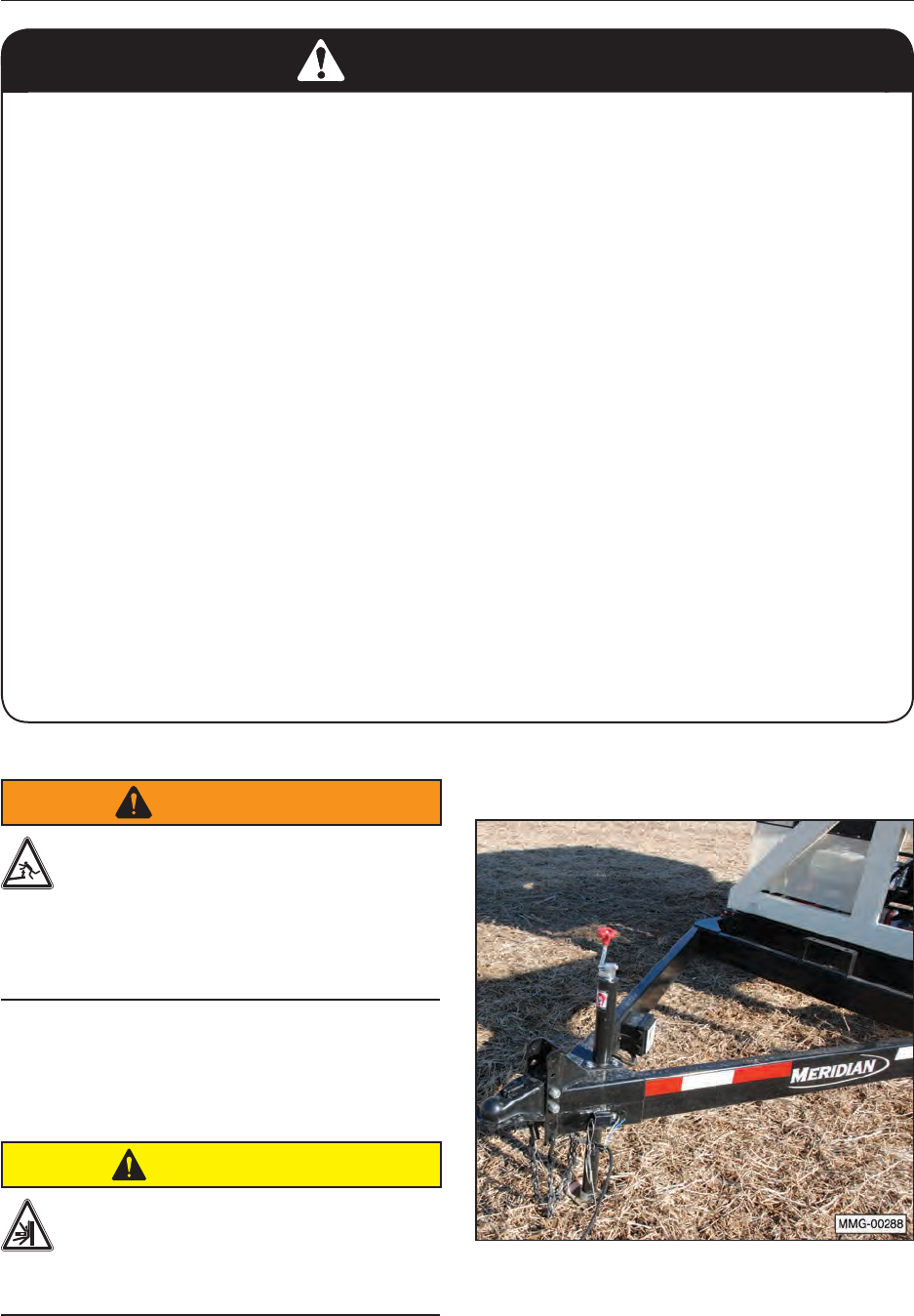
7.1 CONNECTING THE TRAILER
WARNING
To prevent serious injury or death from
upending hazard, do not stand over hitch
when unhooking the trailer from the tow
vehicle. Load or ll compartment 1 rst
to keep weight on the hitch. Unload or
empty compartment 2 rst to keep weight
on the hitch.
7.1.1 Bumper Hitch
1. Complete the Pre-operation Checklist.
CAUTION
Ensure that all bystanders, especially
small children, are clear of the working
area. Ensure there is enough room and
clearance to safely back up to the
machine.
2. Use the trailer jack to lift the hitch above
the height of the receiver on the tow vehicle
(standard hitch assembly shown).
34
3. Slowly back the tow vehicle until the hitch and
ball are aligned.
4. Lower the hitch onto the ball.
5. Raise the jack and place it in its stowed
position.
6. Release the latch to lock the hitch around the
ball and install the retainer clip to secure the
connection.
7. Attach the safety chain securely to the truck
frame to prevent unexpected separation.
Cross the chains when attaching.
8. Connect the wiring harness for the lights and
brakes.
9. Connect the breakaway system cable to the
tow vehicle.
10. Route all the cables in a manner that will
prevent snagging. Be sure to provide slack for
turning.
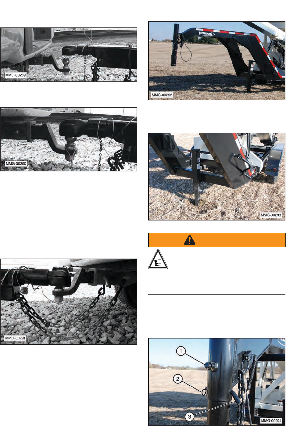
7.1.2 Gooseneck Hitch
1. Adjust the trailer jack to set the trailer in a level
position.
WARNING
Crush Hazard. The adjustable height
tube in Step 2 is very heavy and can
cause severe injury if it falls free. Once
the lock bolt is loosened and the hitch pin is
removed, the tube is free to fall to the ground if
not properly supported.
2. Loosen lock bolt (1) on the adjustable height
tube. Remove the keeper pin (2) and remove
the tube lock pin (3).
35
3. Adjust the tube height for the tow vehicle
which would keep the trailer in a level position.
4. Reinstall the pin and keeper. Tighten the tube
lock bolt.
5. Raise the gooseneck ball hitch to go over the
lowered tailgate of the tow vehicle and to clear
the height of the gooseneck ball.
6. Open the clamp latch on the gooseneck
coupler.
7. Position the trailer’s coupler directly over the
ball in the bed of the tow vehicle.
8. Lower the gooseneck trailer into position and
latch the clamp.
9. Attach the safety chains.
10. Connect the trailer light wiring to your vehicle’s
connector and check all of your lights,
including your brake lights.
11. Completely raise the trailer jack to the storage/
transport position.
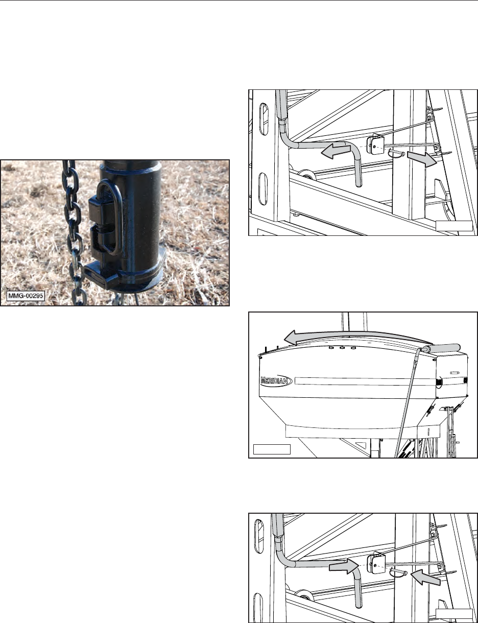
7.2 OPENING AND CLOSING
ROLL-UP TARP
1. Remove the retaining pin from the crank
holder. Using both hands, carefully remove
the crank from the holder.
MMG-00257
2. Extend the crank handle assembly to a
comfortable operating position.
3. Roll the tarp to the fully opened position.
MMG-00259
4. Place the crank back in the holder and reinsert
the pin.
MMG-00258
36
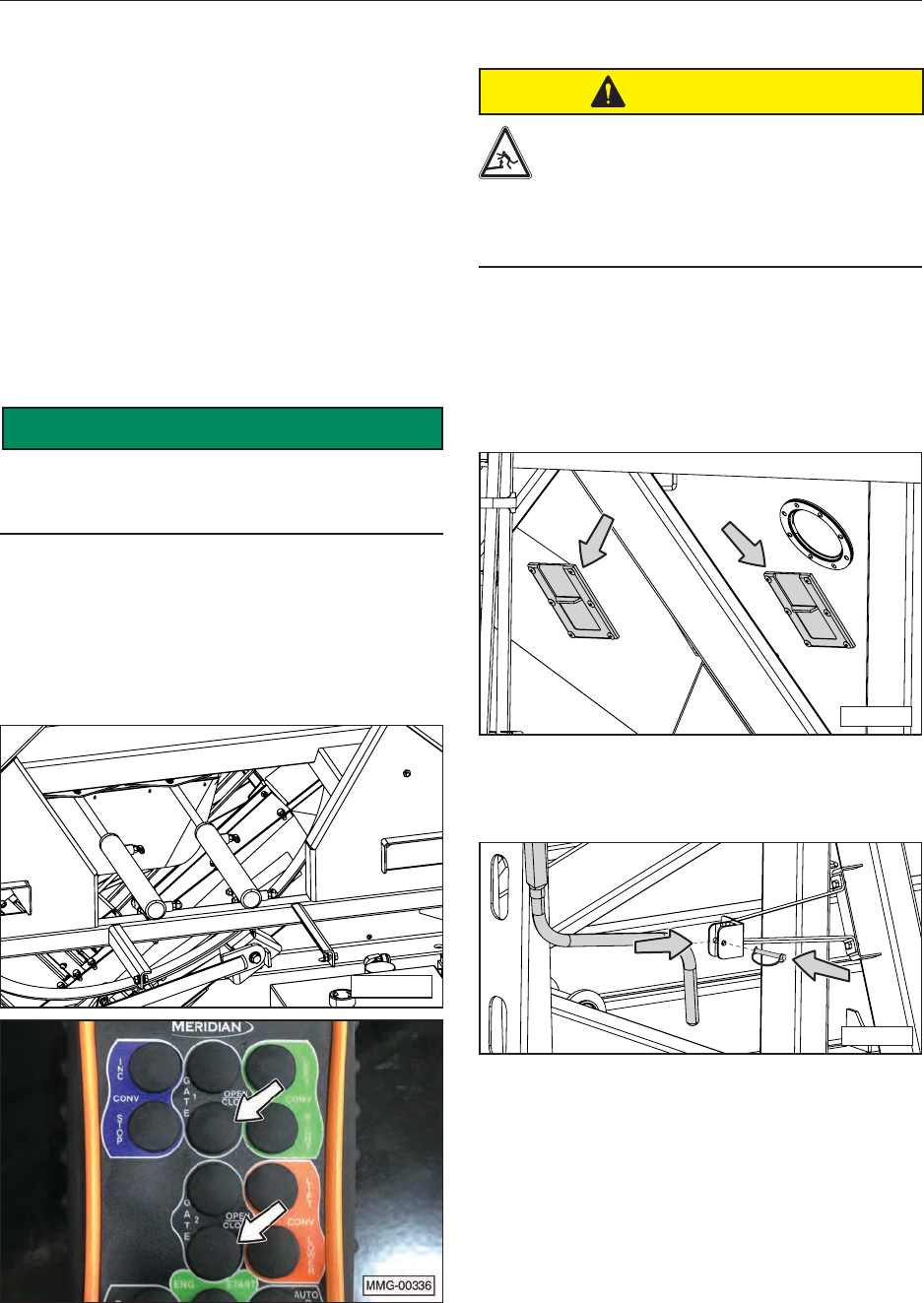
7.3 OPERATION
7.3.1 Conventional Loading (Filling the
Seed Tender)
This Operation section provides a step-by-step
procedure for rst loading seed into the seed
tender compartments by 1) using the self-lling
feature at the farm or 2) using the conventional
top ll method. It then shows how to unload the
tender into a planter in the eld or another type of
container.
1. Connect the seed tender to a tow vehicle of
sufcient size to safely transport the unit to its
desired destination.
SAFETY
INSTRUCTIONS
To prevent possible injury, do not load the seed
tender unless it is securely fastened to a tow
vehicle.
2. Before loading the seed tender compartments,
make sure the two slide gates are in the
fully closed position. The gasoline engine
(hydraulic system) must be operating to
close the hydraulically controlled slide gate
cylinders.
MMG-00323
3. Open the roll-up tarp.
CAUTION
Always load compartment 1 rst to
maintain a positive tongue weight.
Negative tongue weight can cause the
hitch to rapidly swing upward if not
securely fastened to the tow vehicle,
which can result in personal injury.
4. Fill the front seed compartment rst to
maintain a positive tongue weight.
NOTE: Two sample slide gates, one in each
compartment, can be used to retrieve samples of
the seed from the compartment.
MMG-00335
5. Close the roll-up tarp and secure the handle in
the storage position.
MMG-00258
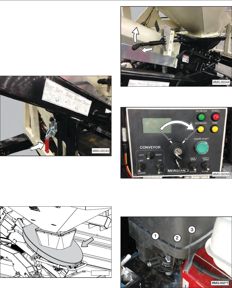
37
7.3.2 Loading Using Self-Filling
Feature (Filling the Seed Tender)
Using the self-lling feature, the seed
compartments can be loaded with the seed
tender’s conveyor from a storage box, storage bin,
grain truck, or other means directly into the seed
compartments.
1. Unlatch the conveyor arm from the transport
position by releasing the latch.
2. If not already removed, remove the protective
cover from the seed pan. It may be necessary
to lower the hopper in order to remove the
cover. To lower the hopper, pull out on the
sliding lock collar and raise the handle to lower
the hopper.
MMG-00325
3. Turn the key switch to the ON position.
4. Move fuel valve lever (2) to the ON position.
5. To start a cold engine, move choke lever (1) to
the CLOSED position.
6. Start the engine and move throttle lever (3) to
run the engine at full speed.
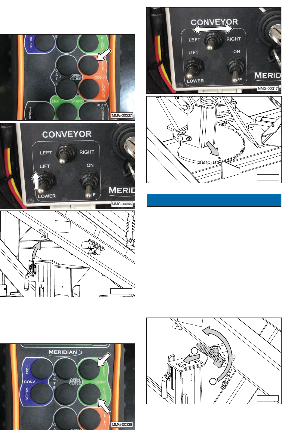
38
7. Using the remote control unit or the control
panel, slightly raise the conveyor from the
transport position.
MMG-00322b
8. Using the remote control unit or the control
panel, rotate conveyor to align the triangular
indicator on the conveyor pivot plate with the
alignment plate on the frame, as shown.
MMG-00324
NOTICE
The indicator mark and the alignment plate must be
aligned for the conveyor arm locking pin to engage.
This pin locks the inner and outer tubes of the
conveyor arm together. These two tubes must be
locked together before releasing the conveyor hitch
receiver (ball coupling). If the tubes are not locked
together, the inner tube will slide down inside the
outer tube and will require an external lifting device
to raise it back into the correct position.
9. To lock the conveyor arm tubes together, pull
the handle of the lock pin outward slightly and
rotate it 90° counterclockwise.
MMG-00328
1
2
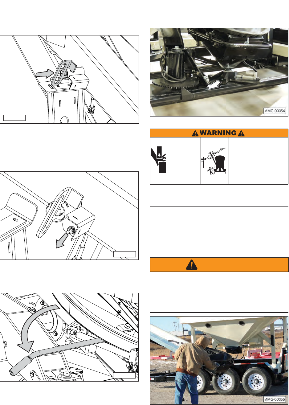
39
10. Release and push the lock pin inward to lock
the inner and outer tubes of the conveyor arm
together. Make sure the pin is fully engaged.
MMG-00329
11. Once the tubes are locked together, move
the toggle switch downward to unlock the
conveyor hitch receiver (ball coupling) on the
conveyor.
MMG-00330
12. Rotate hopper guide handle 90° into the
position shown.
MMG-00326
13. Slide the ball coupling out of the conveyor
hitch receiver.
CRUSH
HAZARD
ELECTROCUTION
HAZARD
Avoid contact with overhead power
lines or electrically powered objects.
• Be aware of your surroundings when
raising or lowering conveyor.
• Maintain at least 20 feet between
equipment and any electrical hazard.
• Contact with electricity can result
in serious personal injury or death.
Keep hands and
arms clear of
conveyor tube
when placing it
in storage
position.
Weight of tube
will cause
crushing injuries.
17509
Be observant of overhead power lines or other
electrical hazards.
14. When the ball coupling is free of the conveyor
hitch receiver, lift the bottom of the conveyor
arm over the fender and hold it off the ground
until it is in its nal position.
WARNING
If two people are positioning the conveyor arm,
one at the controls and the other holding the
conveyor arm, be extremely careful to prevent
a crush hazard. Do not place any part of your
body between stationary and moving parts.
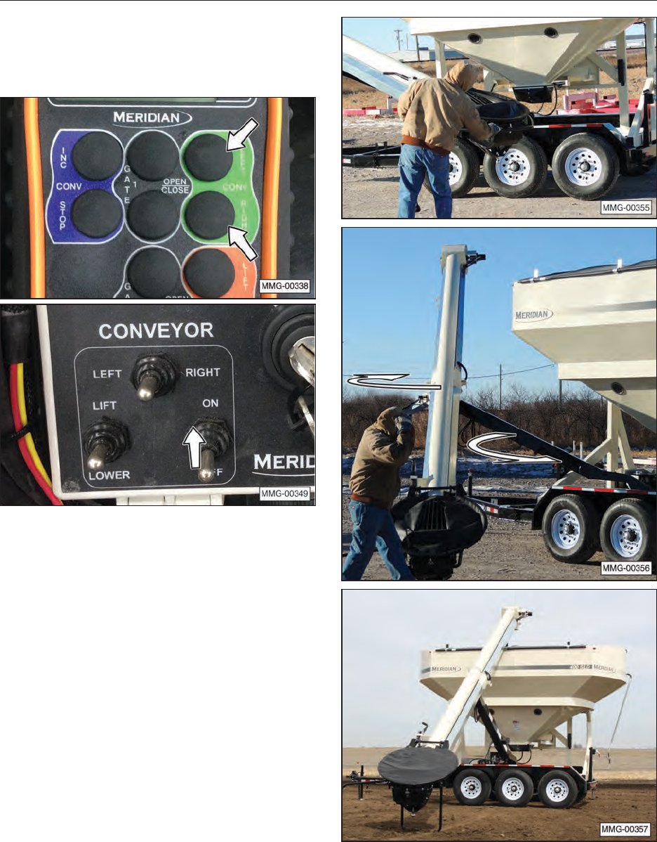
40
15. Use the conveyor left or the conveyor right
buttons (switches) to position conveyor arm
into the desired position. The photos show the
self-lling position.
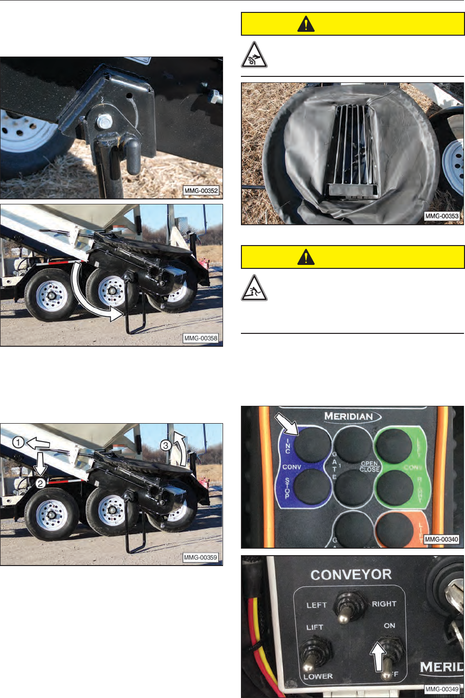
41
16. If desired, release the stand lock pin and
rotate the stand downward. Engage the lock
pin when the stand is fully extended.
17. Raise the hopper by pulling the lock collar
outward and lowering the handle. Lock the
handle into place when the hopper is at the
desired height.
CAUTION
To prevent personal injury, do not use
the conveyor if the guard (metal bars)
has been removed.
CAUTION
Always load compartment 1 rst to maintain
a positive tongue weight. Negative tongue
weight can cause the hitch to rapidly swing
upward if not securely fastened to the tow vehicle,
which can result in personal injury.
18. Start the conveyor. Refer to section 5.3 for
setting automatic seed delivery functions.
Do not open the slide gates when the
conveyor is in the self‑lling position.
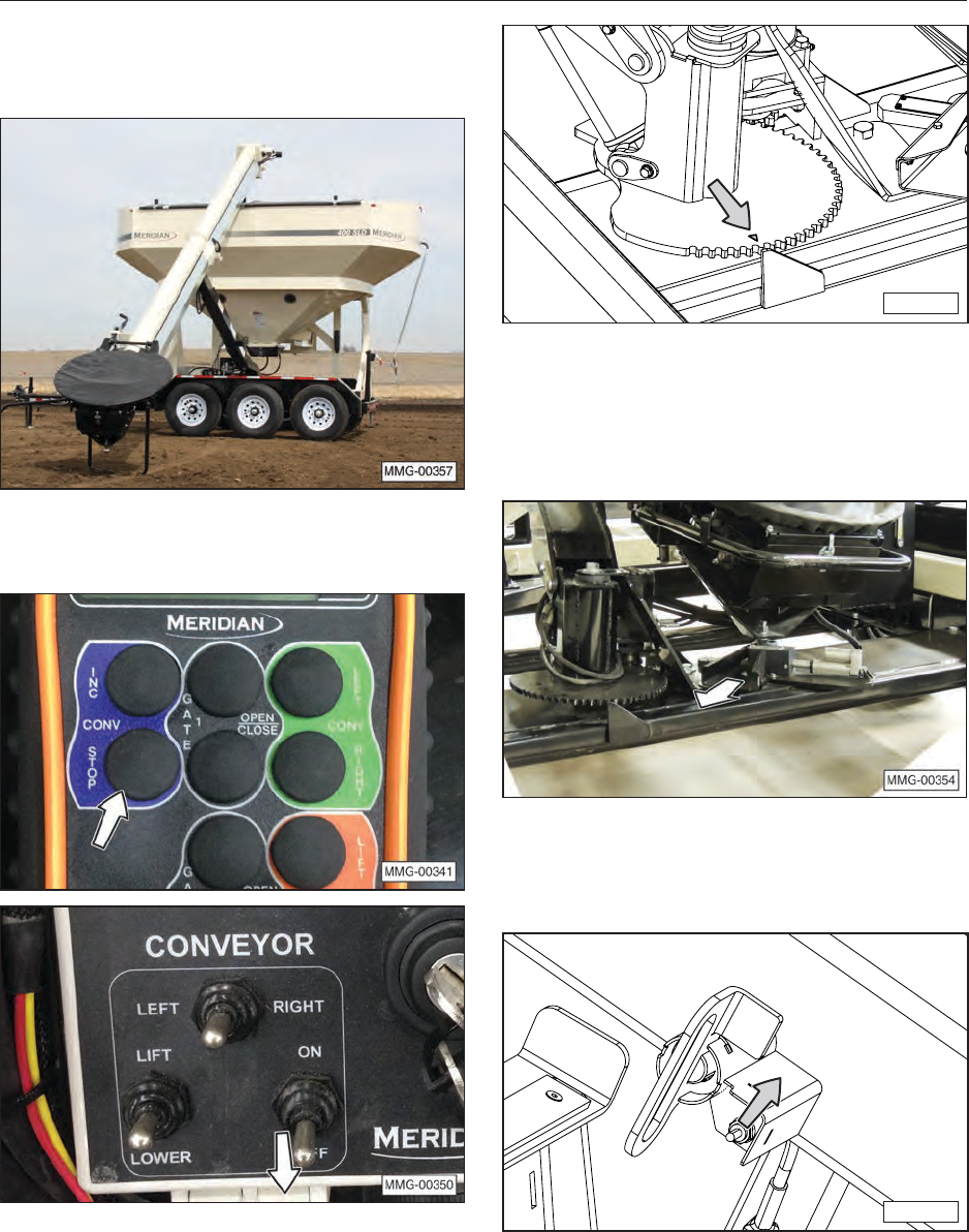
42
19. Allow the seed to ow into the conveyor from
the external source to ll the seed tender or
other container.
20. When the seed tender or other container is
lled, stop the conveyor.
21. Return the conveyor arm to the storage
position by rst rotating the conveyor arm to
align the triangular indicator on the conveyor
pivot plate with the alignment plate on the
frame, as shown.
MMG-00324
22. Lower the hopper. Raise the stand, if used.
23. Guide the ball coupling into conveyor hitch
receiver. Make sure ball coupling is free of dirt
and debris before placing it into the receiver.
24. Press and hold the toggle switch upward to
lock the ball coupling into the conveyor hitch
receiver.
MMG-00330a
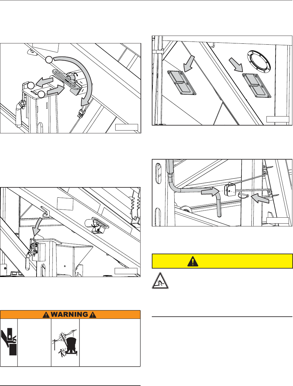
43
25. Pull out on locking pin and rotate 90°
clockwise to shield toggle switch. Release the
locking pin and make sure it is rmly seated in
the open position.
MMG-00331
1
3
2
26. Rotate conveyor to the transport position;
either front or back.
27. Lower the conveyor arm onto transport
support and lock into place with latch.
MMG-00322a
NOTE: Do not move the seed tender unless the
conveyor is locked in the transport position.
CRUSH
HAZARD
ELECTROCUTION
HAZARD
Avoid contact with overhead power
lines or electrically powered objects.
• Be aware of your surroundings when
raising or lowering conveyor.
• Maintain at least 20 feet between
equipment and any electrical hazard.
• Contact with electricity can result
in serious personal injury or death.
Keep hands and
arms clear of
conveyor tube
when placing it
in storage
position.
Weight of tube
will cause
crushing injuries.
17509
Be observant of overhead power lines or other
electrical hazards.
28. Move the seed tender to the location of the
planting equipment following all safe towing
practices.
NOTE: Two sample slide gates, one in each
compartment, are used to retrieve samples of the
seed from the compartment.
MMG-00335
29. If necessary, close the roll-up tarp and secure
the handle in the storage position.
MMG-00258
7.3.2 Unloading (Filling the Planter)
CAUTION
Always unload compartment 2 rst to
maintain a positive tongue weight.
Negative tongue weight can cause the
hitch to rapidly swing upward if not
securely fastened to the tow vehicle,
which can result in personal injury.
1. Before unloading, shut off engine on the tow
vehicle, set the parking brake, and remove the
ignition key.
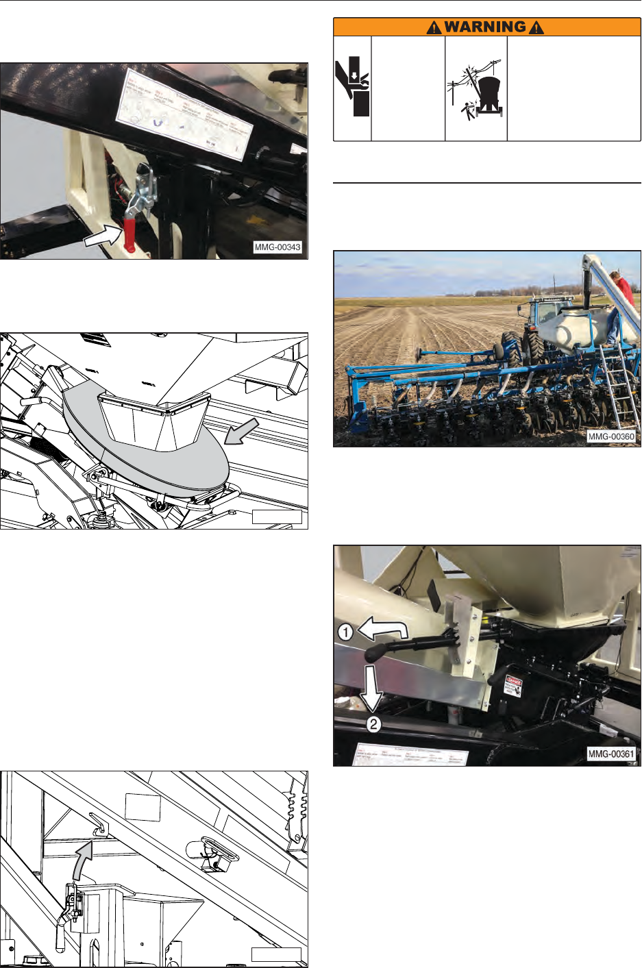
44
2. Unlatch conveyor from the transport position
by releasing the latch.
3. If necessary, remove the protective cover from
the hopper.
MMG-00325
4. Turn the key switch on the control panel to the
ON position.
5. Move the fuel valve lever to the ON position.
6. To start a cold engine, move the choke lever to
the CLOSED position.
7. Start the engine and move the throttle lever to
run the engine at full speed.
8. Slightly raise the conveyor out of the transport
position.
MMG-00322b
CRUSH
HAZARD
ELECTROCUTION
HAZARD
Avoid contact with overhead power
lines or electrically powered objects.
• Be aware of your surroundings when
raising or lowering conveyor.
• Maintain at least 20 feet between
equipment and any electrical hazard.
• Contact with electricity can result
in serious personal injury or death.
Keep hands and
arms clear of
conveyor tube
when placing it
in storage
position.
Weight of tube
will cause
crushing injuries.
17509
Be observant of overhead power lines or other
electrical hazards.
9. Position the conveyor to place the spout over
the planter’s seed box.
10. Position the hopper to prevent spillage of the
seed. Make sure the handle is locked into
the desired position before opening the seed
compartment slide gates.
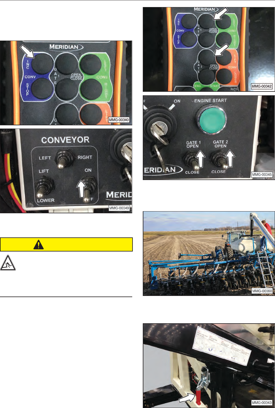
45
11. Manually start the conveyor or use the Auto
Reset feature to automatically dispense a
preselected amount of seed. Refer to section
5.4 Auto Reset Function for instructions.
CAUTION
Always unload compartment 2 rst to
maintain a positive tongue weight.
Negative tongue weight can cause the
hitch to rapidly swing upward if not
securely fastened to the tow vehicle,
which can result in personal injury.
12. Open the slide gate on either compartment 1
or 2 with the remote control unit or the control
panel for the desired seed ow.
The button and/or switch is only activated
while pressed and held. The ow of seed into
the conveyor can be controlled by the amount
the slide gate is opened.
13. When the planter is lled, close the slide gate
and then stop the conveyor belt.
14. Return the conveyor to the transport position
and latch before moving the seed tender.

46
8. STORAGE
8.1 GENERAL INFORMATION
After planting or when the machine will not be
used for a period of time, completely inspect
all major systems of the seed tender. Replace
or repair any worn or damaged components to
prevent unnecessary downtime at the beginning of
the next season.
IMPORTANT
To prevent component damage, store the seed
tender in a dry, level area. If the seed tender is not
attached to a trailer, support the frame with planks
to raise the unit off the ground.
8.2 PLACING IN STORAGE
CAUTION
Store the unit in an area away from
human activity. To prevent the possibility
of serious injury, do not permit children
to play on or around the stored machine.
1. Remove all seed from the seed tender.
2. Place the gasoline engine fuel valve in the
OFF position.
3. Thoroughly wash the machine with a pressure
washer or water hose to remove all dirt, mud,
or debris.
4. Inspect rotating parts for entangled material.
Remove all entangled materials.
5. Check the condition of the conveyor belt.
Replace or adjust, as required.
6. Check the condition of the hydraulic pump to
engine shaft connectors and spider. Replace
or adjust, as required.
7. Touch up paint nicks and scratches to prevent
rusting.
8. Remove the ignition key and store in a secure
place.
9. Remove the battery and store it in a cool, dry
area on wooden blocks or a wooden pallet.
Charge it monthly to maintain an adequate
charge.
10. It is best to store the machine inside and if that
is not possible, cover with a waterproof tarp
and tie down securely.
8.3 REMOVING FROM STORAGE
When removing the machine from storage, follow
this procedure:
1. Remove the tarp, if covered.
2. Install and connect the battery.
3. Review and follow the Pre-Operation
Checklist.
4. Review and follow the Service Checks in the
Maintenance section.
IMPORTANT
If the machine has been stored for more than
twelve months, warm the engine by running it for
two to three minutes and drain the oil. Change
the oil while the oil is warm to remove any
condensation. Refer to the Engine Oil Change in
the Maintenance section.
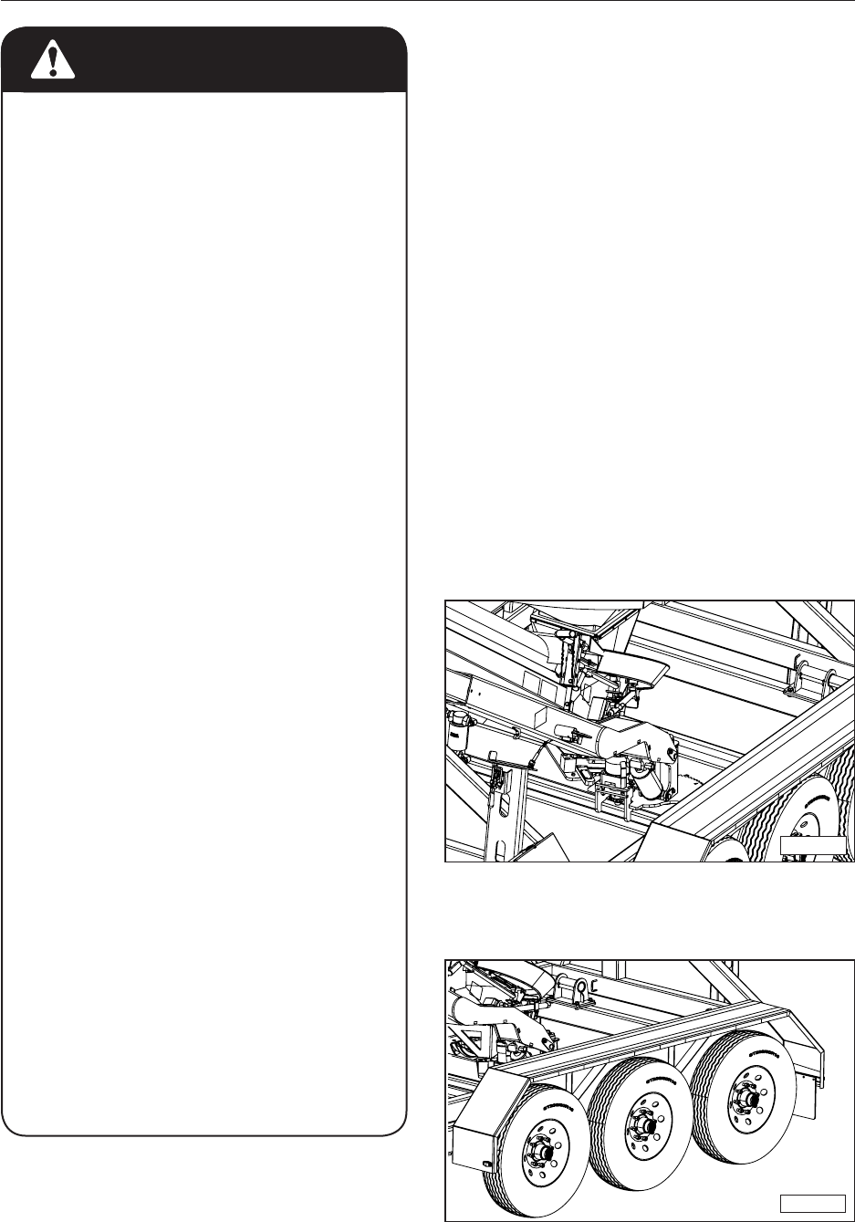
47
9. MAINTENANCE
MAINTENANCE SAFETY
• Good maintenance is your responsibility.
• Follow good shop practices.
- Keep service area clean and dry.
- Be sure electrical outlets and tools
are properly grounded.
- Use adequate light.
• Make sure there is plenty of ventilation.
Never operate the engine in a closed
building. Exhaust fumes may cause
asphyxiation.
• Before working on this machine, shut OFF
the engine, and remove the ignition keys.
• Never work under equipment unless it is
securely blocked.
• Always use personal protection devices,
such as eye, hand, and hearing
protectors when performing any service or
maintenance.
• Where replacement parts are necessary
for periodic maintenance and servicing,
genuine factory replacement parts must
be used to restore your equipment to the
original specications. The manufacturer
will not be responsible for injuries or
damages caused by use of unapproved
parts and/or accessories.
• A re extinguisher and rst aid kit should
be readily accessible while performing
maintenance on this equipment.
• Periodically tighten all bolts, nuts, and
screws and check that all cotter pins are
properly installed to ensure the unit is in a
safe operating condition.
• When completing a maintenance or
service function, make sure all safety
shields and devices are installed before
placing unit in service.
9.1 GREASING
Use the Service Checks information in the
Maintenance section to keep a record of all
scheduled maintenance.
1. Use an SAE multi-purpose high temperature
grease or a multi-purpose lithium base grease.
2. Use only a handheld grease gun for all
greasing. An air-powered greasing system
can damage the seals on bearings and lead to
early failures.
3. Wipe grease tting with a clean cloth before
greasing to avoid injecting dirt and grit.
4. Replace and repair broken ttings
immediately.
5. If ttings will not take grease, remove and
clean thoroughly. Also, clean lubricant
passageway. Replace tting if necessary.
9.2 GREASE FITTING LOCATIONS
The lift cylinder is equipped with grease zerks on
each end.
MMG-00261
Each wheel hub is equipped with a grease zerk
under the center dust cap.
MMG-00260
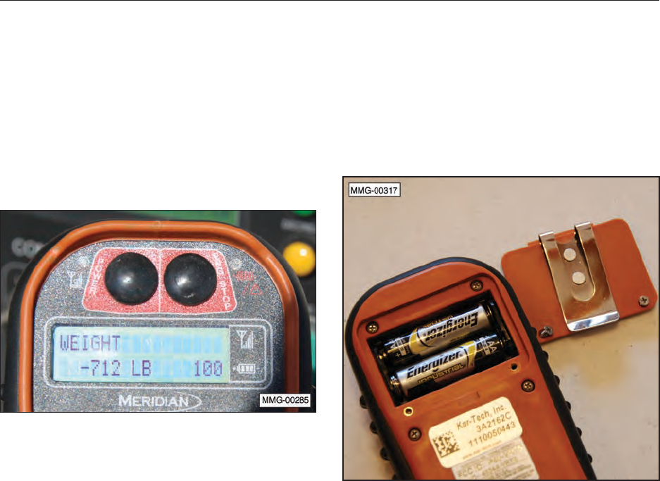
48
10. SERVICE PROCEDURES
10.1 REMOTE CONTROL UNIT
The remote transmitter unit is powered by two
AA batteries. The display window on the remote
transmitter indicates the remaining battery life.
When batteries are new, the display indicates
100% power. As the remote transmitter is used,
the power decreases. When red indicator light
(2) turns ON, the batteries should be replaced
immediately, or discontinue the use of the remote
transmitter.
10.1.1 Battery Replacement Tips
• Check the batteries at least every six months (for
low Voltage, leakage, etc.).
• Always use the correct size and type of battery.
Replace old batteries with new 1.5 Volt AA,
alkaline batteries.
• Always replace both batteries at the same time.
• Do not mix types, brands, or ages of replacement
batteries.
• Do not install the batteries backwards. Make sure
you insert the batteries with the + (plus) and –
(minus) terminals aligned correctly.
• Remove the batteries from the controller if not
expected to be in use for several months.
• Do not attempt to recharge a battery unless it is
specically marked “rechargeable.”
• Dispose of old batteries properly.
10.1.2 Battery Replacement
1. Remove the two Phillips head screws from the
cover on the back of the unit.
2. Replace the batteries, making sure they are
correctly positioned.
10.1.3 Remote Control Transmitter and
Receiver Synchronization
To reprogram the ID code to the receiver, use the
following procedure.
NOTE: Do not interrupt this procedure before it
has completed or the system may not operate
correctly.
1. Turn the remote transmitter and receiver OFF.
2. Press and hold the POWER button on the
handheld remote transmitter for more than ten
seconds. The LCD display will indicate when
to apply power to the receiver.
3. When directed, apply power to the receiver.
Green LED stays on constantly when
reprogramming is in progress.
4. When the process is completed, the green
LED will blink on and off. Test the remote
transmitter to make sure it functions properly.
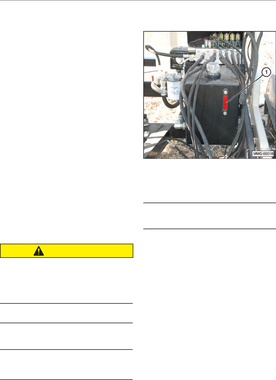
49
10.1.4 Changing Sleep Time on the
Transmitter
To change the sleep time on the transmitter, use
the following procedure.
1. With the transmitter off, press and hold
ENGINE STOP, CONVEYOR STOP and
POWER button.
2. Wait for a few seconds, then release the
buttons.
3. The green and red LEDs will start blinking
together.
4. Use CONVEYOR INC and CONVEYOR STOP
to increase/decrease the sleep time.
5. Select the desired sleep time.
6. Press POWER button to save and exit.
10.1.5 Weigh System
Clean transmitter regularly with a damp cloth and
mild detergent.
Inspect electrical wiring for wear points or other
damage. Repair as required.
Inspect all connections for looseness or corrosion.
Tighten and/or “seal” as necessary.
CAUTION
When performing any inspection or maintenance
on the remote system, always use care to
prevent injury or damage to the equipment.
The following are general precautions, which
should be closely followed in carrying out any
maintenance work.
Do not have hydraulic power available to the
valves when performing electrical tests.
Never operate or test any function if any person
is in an area where they could be hurt by being
hit or squeezed by the hydraulic equipment.
Turn power off before connecting or
disconnecting valve coils or other electrical
loads.
10.2 HYDRAULIC SYSTEM
10.2.1 Hydraulic Oil Change
An oil and lter change is recommended annually
or every 400 hours of operation using an AW HVI
Hydraulic ISO 32 oil.
IMPORTANT
Never run the hydraulic pump unless the hydraulic
oil tank is full (indicated in sight level gauge). (1)
1. Place a large waste oil container under the
tank drain port. The hydraulic tank holds
approximately ten gallons of oil.
2. Drain the hydraulic tank by removing the drain
plug from the tank. Allow the tank to drain
completely.
3. Remove and replace the oil lter. Apply a thin
coat of oil to the rubber seal of the new oil
lter. Hand-tighten only.
4. Re-install the drain plug.
5. Fill the tank to the ll line at the top of the
gauge with approximately ten gallons of AW
HVI Hydraulic ISO 32 oil. Replace the cap.
6. Start the engine and cycle all the cylinders
several times.
7. Recheck the oil level in the tank and add as
needed.
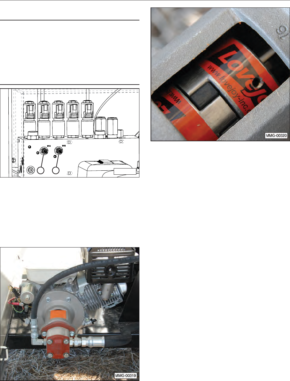
50
10.2.2 Hydraulic Pressure Relief Valves
IMPORTANT
There are two pressure relief valves (1 and 2)
which have been factory preset for the most
efcient operation of the seed tender. DO NOT
adjust these relief valves. If the unit is not
operating properly, refer to the Troubleshooting
section, call an authorized dealer, or call the
factory.
MMG-00262
1 2
10.2.3 Hydraulic Motor Coupling
Changing the pump coupling does not require the
hydraulic tank to be drained. If the pump must
be disconnected, drain the hydraulic tank and be
prepared to catch any oil that remains in the two
hydraulic hoses.
1. Remove the orange protective cover from the
adapter assembly.
2. Remove the two pump mounting bolts.
3. Pull the pump away from the adapter to
separate the coupling halves.
4. Loosen the setscrews in each coupling half
and remove the old couplings. Install new
couplings on the engine shaft and the pump
shaft. When completely assembled, the shaft
length in each coupling half should be the
same. Tighten the pump end setscrews to 78
to 87 lb-in. Do not tighten the engine shaft
coupling at this time.
5. Place the urethane spider in the pump
coupling. Align and install the pump and pump
coupling.
6. Tighten the pump bolts to a “Grade 5” bolt
toque for that size of bolt. Refer to the 4.2 Bolt
Specications section.
7. Slide the engine coupling against the other
coupling half and tighten the setscrew.
8. Replace the orange protective cover.
NOTE: If the adapter plate was removed, tighten
the four retaining bolts to “Grade 5” bolt torque for
that size of bolt.
10.3 ENGINE
For any questions concerning the Honda® engine
not provided in this manual, refer to the OEM
manual that was provided with the seed tender.
To contact Honda®, refer to the OEM Literature
section in this manual.
10.3.1 Approved Fuel
Use a regular unleaded automotive gasoline for all
operating conditions. The fuel tank capacity is 1.0
liter (2.1 US pints).
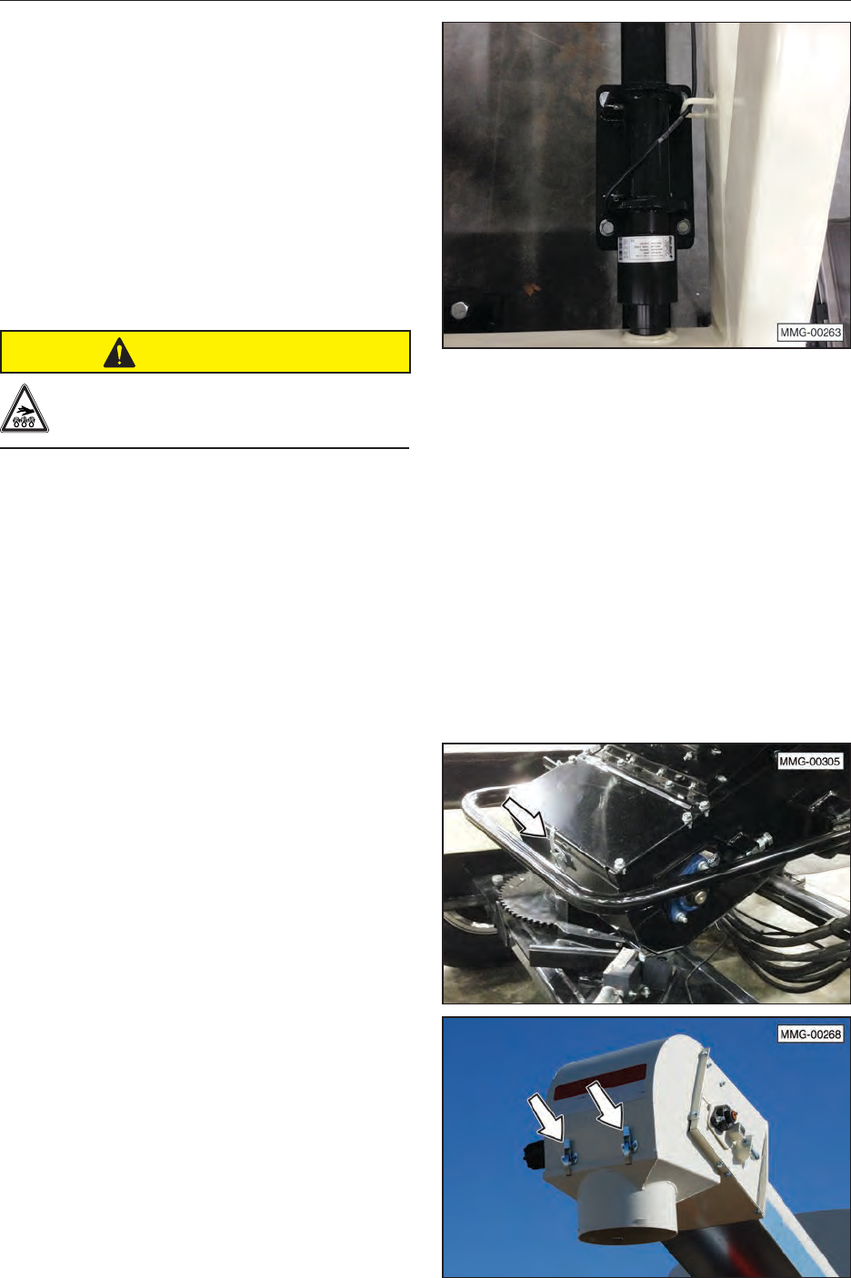
51
10.3.2 Engine Oil
Use a typical SAE 10W-30 or 10W-40 multi-
viscosity motor oil for normal operating conditions.
Consult your engine manual for the recommended
oil in cold temperatures. The crankcase capacity
is 1.1 liters (1.16 US qt.).
10.3.3 Change Engine Oil
1. Review the Operator’s Manual for the engine.
2. Allow the engine to cool before changing oil.
Draining works best when oil is warm.
CAUTION
Burn Hazard. Hot engine oil can burn
skin.
3. Be sure the engine key switch is in the OFF
position and the fuel valve is turned OFF.
4. Place a pan under the drain plug.
5. Remove the drain plug and allow oil to drain
for ten minutes.
6. Reinstall the engine drain plug and tighten.
7. Dispose of the oil in an approved container.
Follow industrial disposal regulations.
8. Fill the engine with SAE 10W-30 oil for general
usage. If the engine is operated in more
extreme conditions, refer to the OEM manual
for oil recommendations.
9. Run the engine for one minute and recheck
the oil level. Add oil as needed.
10.3.4 Clean Air Cleaner
Check the air cleaner daily before each usage.
Clean it every three months or 50 hours of
operation (clean it more frequently when used in
dusty conditions).
10.4 LOAD CELLS
Four load cells are used with the weighing system.
There is no maintenance required for these load
cells. If the seed tender does not seem to be
functioning correctly, refer to the Troubleshooting
section, call an authorized dealer, or call the
factory.
10.5 BELT DELIVERY TUBE
10.5.1 Unplugging
If the conveyor becomes plugged, follow this
procedure:
1. Position the conveyor with easy access to
both ends.
2. Stop the engine and remove the ignition key.
Place a lock-out tag on the control box to
prevent accidental starting of the conveyor.
3. Open the lower access door at the bottom of
the conveyor and/or open the delivery spout
cover.
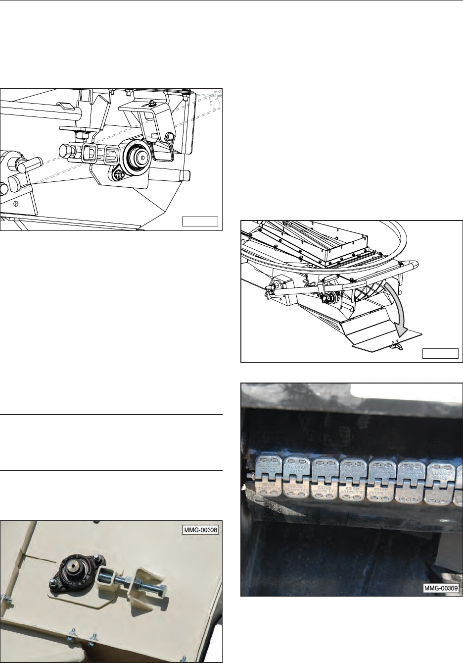
52
4. Remove obstruction.
5. Close and secure the lower access door and
delivery spout cover.
10.5.2 Belt Tension Adjustment
MMG-00333
1. Loosen the locknut on each side of the belt
tension mechanism.
2. Tighten the two adjusting bolts equally to 23
lb-ft. While holding the adjusting bolt in place,
retighten both locking nuts.
3. Start the conveyor and make sure the belt
is tracking in the center of the drive drum. If
the belt is not tracking properly, use the Belt
Tracking Adjustment procedure to correct the
problem.
IMPORTANT
The drive drum at the bottom of the conveyor must
be square (drive shaft must be equal distance from
end of unit) for the belt to track properly.
10.5.3 Belt Tracking Adjustment
1. Loosen the locknuts on the adjusting bolt.
2. Tighten or loosen the bolt to correct the
tracking problem.
3. Place both locking nuts on either side of
the lock plate and tighten the locking nuts
together.
4. Start the conveyor and make sure the belt
is tracking in the center of the drive drum.
Readjust if needed.
10.5.4 Belt Replacement
Use the old belt to thread the new belt into the
delivery tube.
1. Unlatch and open the access door.
MMG-00334
2. Loosen the lower drive drum adjusting bolts to
their loosest position.
3. Disconnect the two ends of the conveyor belt.
4. Attach the replacement belt to the end of the
old conveyor belt.
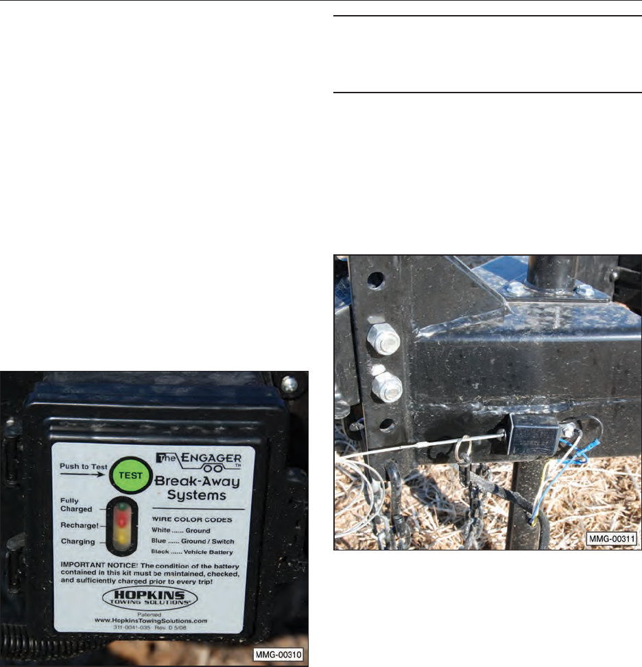
53
5. Slowly pull the old belt out of the delivery tube
and thread the new one into position.
6. Disconnect the old belt and connect the ends
of the new belt together.
7. Readjust the belt tension.
8. Close and latch the access door.
9. Start the conveyor to make sure the belt is
tracking properly.
10. Recheck the tension and alignment of the
belt frequently during the rst ten hours of
operation and adjust as needed.
NOTE: Typically a belt will seat itself during the
rst ten hours of operation and then require less or
no adjustment.
10.6 TRAILER BREAKAWAY SYSTEM
10.6.1 Testing the Battery
1. Disconnect the trailer plug from the tow
vehicle; otherwise, you are testing the tow
vehicle’s battery.
2. Press the green TEST button on the control
box located inside the frame of the trailer. The
green indicator light should illuminate if the
battery is fully charged. If the yellow or red
indicator lights illuminate, the unit’s battery
should be charged before towing the trailer.
IMPORTANT
If the battery is weak or dead (red indicator, even
after charging), as indicated by the indicator light,
the battery must be replaced.
3. Plug the trailer into the tow vehicle. The
yellow “Charging” light should be ON.
4. Test the system by pulling the pin out of the
breakaway switch. The battery will activate
the brakes. (Note: Do not use this kit as a
parking brake). The battery should be charged
and tested prior to each trailer outing.
10.6.2 Changing Battery
The battery in the breakaway system is
rechargeable, but not replaceable. If the battery
will not hold a charge, replace the unit.
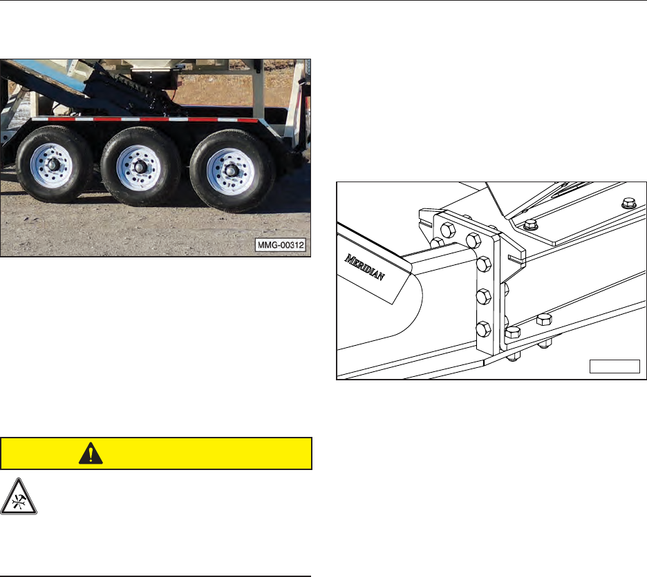
54
10.7 WHEEL BOLT TORQUE
REQUIREMENTS
1. Initially check the wheel bolt torque at 5,
10, 25, and 50 miles and after each wheel
removal.
NOTE: Torque wrenches are the best method
to ensure the proper amount of torque is being
applied to a wheel nut.
CAUTION
To prevent injury due to possible
dangerous separation of wheels from the
axle, the wheel nuts must be maintained
at the proper torque levels. Properly
maintained wheel nuts prevent loose
wheels and broken studs.
2. Tighten the wheel nuts in three stages.
— First stage: 20 to 25 foot pounds.
— Second stage: 50 to 60 foot pounds.
— Third stage: 90 to 120 foot pounds.
3. Tighten the wheel nuts in a clockwise,
cross-axle alternating pattern.
10.8 TRAILER HITCH BOLTS
The front hitch section of the seed tender is bolted
to the trailer frame. This design allows the same
trailer to use either a standard hitch assembly or
a gooseneck trailer hitch. These hitch assemblies
are interchangeable, if needed.
Check the torque on the trailer hitch bolts at least
once per year. Tighten the bolts to 115 lb-ft.
MMG-00332
10.9 SERVICE RECORD CHART
The chart on the following page should be copied
and lled out as maintenance is performed on the
machine. Refer to the Lubrication, Maintenance,
and Service sections for additional instructions.

55
10.9 SERVICE RECORD CHART
(CONTINUED)
Date
Serviced by
8 hours or daily
Check Engine Fluid Levels
Check Hydraulic Tank Oil Level
Test Breakaway Brake System
Inspect Tires
Check Remote Control Battery Life
Check Conveyor Belt Tension and
Alignment
50 Hours or Weekly
Clean Engine Air Intake Filter
Check Tire Pressure
Check Conveyor Belt Tension and
Alignment
Clean remote transmitter with a damp cloth
and mild detergent.
200 Hours or SEMI/ANNUAL
Adjust Brakes
Inspect Brake Magnets
400 hours or annually
Change Engine Oil
Check Wheel Bolt Torque
Check Frame and Trailer Hold-Downs
Check Hydraulic Motor Coupling
Check Conveyor Tube Slide Plates
Check Load Cells
Inspect Brake Lining Wear, Brake Cylinder,
and Brake Wiring
Grease Wheel Bearings and Check Hub for
Wear
Inspect Axle Grease Seal
Inspect all electrical wiring connections for
looseness or corrosion.
Thoroughly Clean Machine
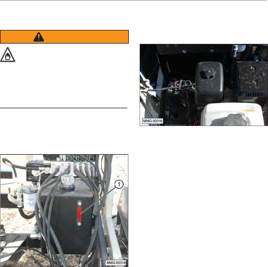
56
10.10 SERVICE CHECKS
10.10.1 Daily (8 Hours)
WARNING
Gasoline is a highly combustible fuel.
Improper use, handling, or storage of
gasoline can be dangerous. Never touch
or ll a hot engine. DO NOT ll the
engine’s fuel tank near an open ame
while smoking or while engine is
running. DO NOT ll tank in an enclosed
area with poor ventilation. Wipe up spills
immediately.
1. Check engine oil level and ll as needed.
2. Check engine fuel level and ll as needed.
3. Check hydraulic uid level (1) and ll as
needed.
4. Test trailer breakaway system. Refer to
“10.6 Trailer Breakaway System” on page
53of this manual.
5. Initially check wheel bolt torque at 5,10, 25,
and 50 miles. Refer to “10.7 Wheel Bolt
Torque Requirements” on page 54 of this
manual for tightening instructions.
6. Check remote transmitter battery life
and change them, if needed. Refer to
“10.1 Remote Control Unit” on page 48 of
this manual for additional information.
7. Check delivery belt for proper tracking. Refer
to “10.5.3 Belt Tracking Adjustment” on page
52 of this manual.
10.10.2 Weekly (50 Hours)
1. Change engine oil.
2. Clean or change engine air lter.
3. Check the tension on the delivery belt. Adjust
tension if needed. Refer to “10.5.2 Belt
Tension Adjustment” on page 52 of this
manual for instructions.
4. Check tire pressure. Inate the tires to the
recommended pressure stated on the tire.
10.10.3 Annually (400 Hours)
1. Check wheel bolt torque. Refer to 10.7 Wheel
Bolt Torque Requirements section in this
manual for tightening instructions.
2. Check frame and trailer hold-down bolts.
3. Check hydraulic motor to engine shaft coupling
and spider. Refer to the Changing Hydraulic
Motor Coupling section for instructions.
4. Thoroughly clean the seed tender.
5. Check the tires for wear, and replace if needed.

57
10.11 AXLE MAINTENANCE
10.11.1 First 200 Miles
1. Adjust brakes. Refer to OEM manual for
procedure.
10.11.2 3,000 Miles or 3 Months
1. Adjust brakes. Refer to OEM manual for
procedure.
2. Check torque on wheel nuts. Refer to the
section in this manual.
3. Inspection tires for wear. Refer to OEM
manual for procedure.
10.11.3 6,000 Miles or 6 Months
1. Inspect brake magnets for wear. Refer to
OEM manual for procedure.
2. Inspect suspension parts for wear. Refer to
OEM manual for procedure.
10.11.4 12,000 Miles or 12 Months
1. Inspect brake lining wear, check brake cylinder
for leaks, and inspect brake wiring for damage.
Refer to OEM manual for procedure.
2. Grease the wheel bearings and check the hub
for wear. Refer to OEM manual for procedure.
3. Inspect grease seal for leakage. Refer to
OEM manual for procedure.
4. Inspect springs for any wear or loss of arch.
Refer to OEM manual for procedure.
10.12 TIRES
Check the tires for normal and/or abnormal tire
wear. Replace tires that are damaged or worn
beyond normal tread life. Refer to the axle OEM
manual for a Tire Wear Diagnostic Chart.
Replace the tires with Meridian part number 18131
or an equivalent tire:
3T235/80R16
TR643
Load Range E
For Trailer Service Only
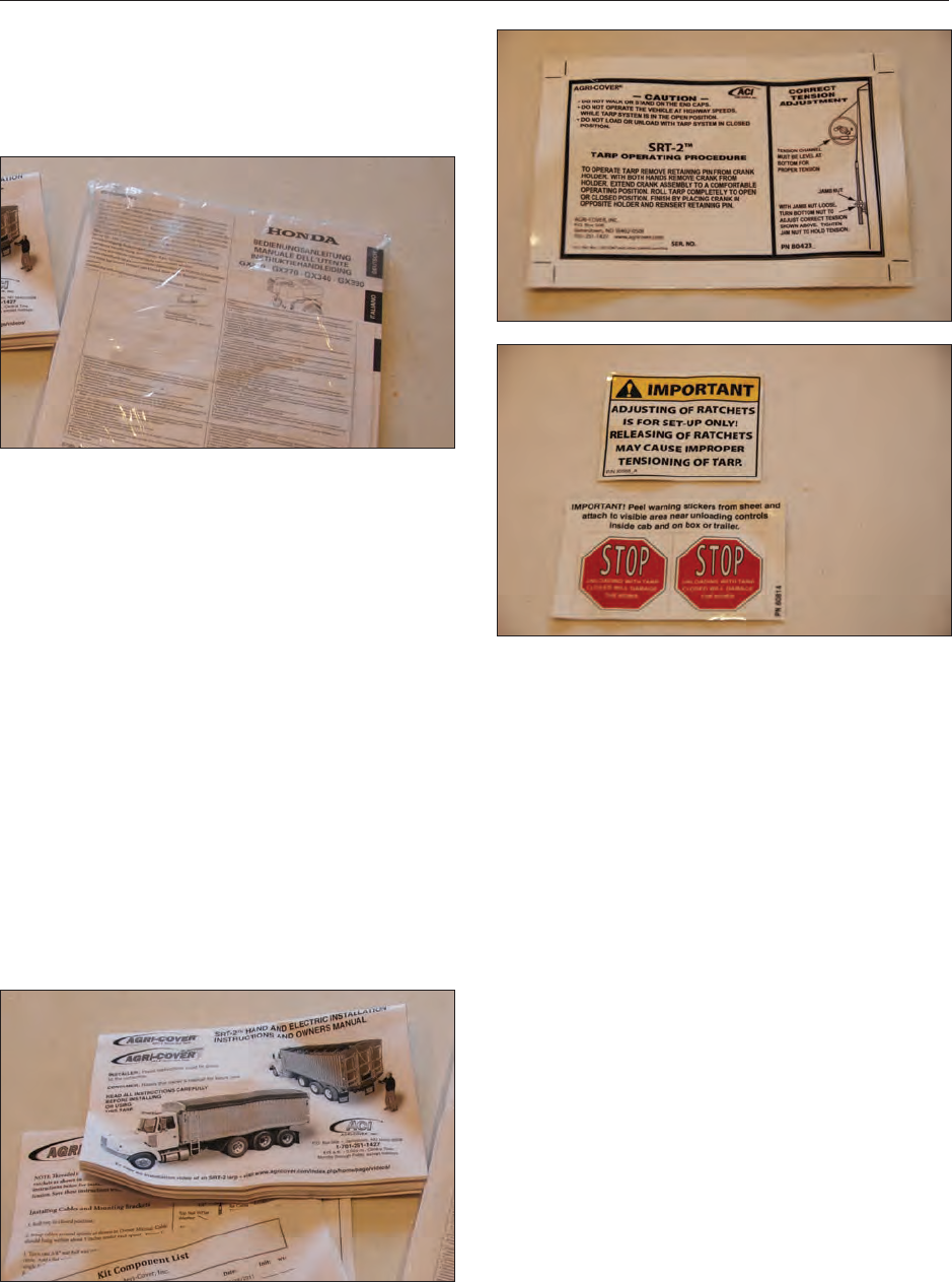
58
11. OEM LITERATURE
11.1 HONDA® ENGINE
For any questions concerning the Honda® G340X
Engine, refer to the OEM manual that was
provided with the seed tender.
Additional information can be obtained from:
United States Power Equipment Division
Customer Relations Ofce
4900 Marconi Drive
Alpharetta, GA 30005-8847
(770) 497-6400
Honda® Canada, Inc.
715 Milner Avenue
Toronto, ON M1B 2K8
(888) 946-6329
11.2 RETRACTABLE COMPARTMENT
TARP
For any questions concerning the Agri-Cover,
refer to the OEM manual that was provided with
the seed tender.
Three decals are also provided showing the
correct operation and maintenance for the tarp.
Attaching these decals is the responsibility of the
purchaser.
Additional information can be obtained from:
ACI Agri-Cover
PO Box 508
Jamestown, ND 58402
Phone: (866) 414-5422
Fax: (701) 251-1512
customerrelations@agricover.com
11.3 AXLE
For any questions concerning the Axis Products
axle, refer to the OEM manual that was provided
with the seed tender. An Owner’s Manual and
parts listing is provided with the seed tender.
Additional information can be obtained from:
Axis Products, Inc.
3403 Reedy Drive
Elkhart, IN 46514
Phone: (574) 266-8282

59
12. TROUBLESHOOTING
12.1 TROUBLESHOOTING CHART
PROBLEM CAUSE SOLUTION
Engine will not start. No fuel. Fill the fuel tank.
Low engine oil. Fill the crankcase with oil.
Cold engine. Open choke.
Ignition key switch off. Turn ignition key switch on.
Battery dead. Recharge or replace battery.
Engine problem. Refer to engine manual.
Conveyor belt will not start. No power. Start engine and increase speed above
1400 RPM.
Drive motor coupling. Repair or replace coupling.
Belt tension. Increase belt tension.
No hydraulic oil. Check oil level.
Electrical or hydraulic functions
are not working properly. Transmitter power is OFF. Turn Power ON.
Receiver power is OFF. Turn Power ON.
Battery cable or battery. Check battery cable and make sure battery
is fully charged.
Error in the control system. Check LED Error Code light.
Improper ground. Check for proper grounding electrical
circuit.
Hydraulic valve or motor. Ensure hydraulic pump is working properly
and hydraulic tank is lled with oil.
Intermittent function. Check receiver antenna for damage and
proper connection.
Loose connector at the valve coil.
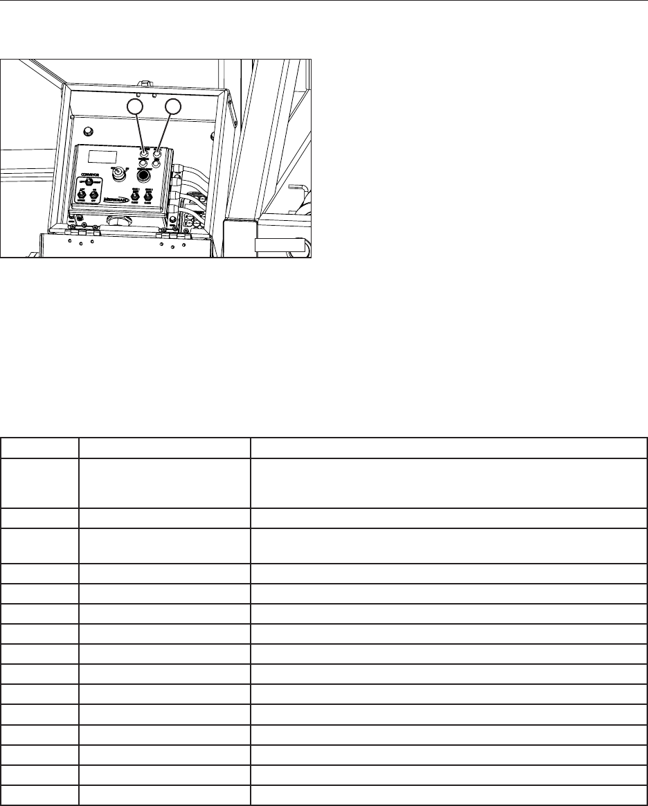
60
12.2 CONTROL PANEL INDICATOR
LEDS
MMG-00300
1 2
12.2.2 Error Codes
Error Code Cause Solution
1 RF Communication Transmitter is OFF.
Transmitter went into sleep mode.
Interference in RF communication link.
2 Wrong ID Transmitter and receiver are not synchronized.
3 Scale Bar Fault RS-232 communication cable between scale unit and receiver is
damaged, disconnected, or the scale unit is OFF.
4 Low Battery System voltage is below 10.5 Volts.
5 Conveyor Speed Fault Check for short or open circuit.
6 Engine Start Fault Check for short or open circuit.
7 Engine Stop Fault Check for short or open circuit.
8 Conveyor Lift Fault Check for short or open circuit.
9 Conveyor Lower Fault Check for short or open circuit.
10 Conveyor Left Fault Check for short or open circuit.
11 Conveyor Right Fault Check for short or open circuit.
12 Slide Gate 1 Open Fault Check for short or open circuit.
13 Slide Gate 1 Close Fault Check for short or open circuit.
14 Slide Gate 2 Open Fault Check for short or open circuit.
15 Slide Gate 2 Close Fault Check for short or open circuit.
NOTE: Error codes are invalid during manual
operation.
12.2.1 Error Code Outputs
The receiver module can identify problems with
the system in the form of an error code. Check
red indicator light (1) on the receiver to diagnose
system problems.
Each of the outputs from the receiver module is
designed with built-in short circuit and overload
protection. The outputs can also detect a no -load
or broken wire condition.
These error conditions are indicated by the red
LED indicator on the receiver module or the
HISTOGRAM page on the optional Palm Pilot™.
Refer to the Error Code Chart for explanation
of the error codes. Green LED indicator light
(2) will blink on the receiver during normal
communication.
The ON/OFF outputs will indicate an error under
no load or broken wire status if NOT activated,
and will detect a short if activated.

61
12.2.3 Control System Wiring
Locations
Pin Description
A Conveyor Speed CR Proportional Output - Orange/Black
B Engine Start Output
C Engine Stop Output
D Conveyor Lift Output - Red
E Conveyor Lower Output - Blue
F NC
G NC
H Power
J NC
K NC
L Conveyor Left Output - White
M Conveyor Right Output - Green
N Ground
O Slide Gate One Open Output – Red/Black
P Slide Gate One Close Output – Blue/Black
Q Slide Gate Two Open Output – Green/Black
R Slide Gate Two Close Output- Black/White
S NC
T NC
U NC
V NC
W NC
X NC

62
13. WARRANTY
13.1 WARRANTY STATEMENT
Limited Materials and Workmanship Warranty
For Bulk Seed Tenders
Meridian Manufacturing Group (hereinafter referred to as the Manufacturer) hereby warrants the Bulk Seed Tender(s) sold by it to be free from
any defect in material or workmanship under normal use and service for a period of one (1) year from the date of shipment. The Manufacturer’s
obligation under this warranty shall be limited to the repair or replacement only, FOB the original point of shipment, of any defective parts or
portions of the seed tender or accessories manufactured by Meridian. Any warranty claim must be reported to the Manufacturer within one (1)
year from the date of shipment.
THIS WARRANTY IS SUBJECT TO THE FOLLOWING LIMITATIONS, PROVISIONS AND CONDITIONS:
1. This warranty does not apply:
a) To any product sold by the Manufacturer where it is used in areas exposed to corrosive or aggressive conditions including salt water, acids, alkaloid,
ash, cement dust, animal waste or other corrosive chemicals from either inside or outside the bin.
b) For failures or defects arising out of damage during shipment or during storage on site.
c) To materials replaced or repaired under this warranty except to the extent of the remainder of the applicable warranty.
d) To damage resulting from misuse, negligence, accident or improper site preparation by others.
e) Iftheproducthasbeenalteredormodiedbyothers.
f) If in the case of coating failures the failure is the result of damage, lack of proper maintenance or failure to remove road salt or other contaminants
that may have come in contact with the bin surface.
g) To loss of time, inconvenience, loss of material, down time or any other consequential damage.
h) For a function that is different than original designed intent.
2. TheobligationoftheManufacturerunderthiswarrantyshallnotariseunlesstheManufacturerisnotiedandthiswarrantyispresentedtogetherwitha
writtenstatementspecifyingtheclaimordefectwithinthirty(30)daysafterthefailureisrstdetectedormadeknowntotheownerandwithinone(1)
year from the shipment date. The Manufacturer in its sole discretion shall determine if the claim is valid and whether correction of the defect or failure
shall be made by repair or replacement of the materials.
3. Thecoatingwarrantyisbasedonthemanufacturer’sperformancespecicationforPolyesterPowdernishesanddoesnotincluderepairofminor
blemishes or rusting that is normally part of the general maintenance of the seed tender. This warranty does not cover excessive wear on interior coatings.
SeeattachmentforfullPerformanceSpecicationdetailsonPolyesterPowderFinishes.
4. The obligation of the Manufacturer hereunder extends only to the original owner and to the Meridian dealer to whom the materials may have been initially
sold. This warranty shall not be subject to any assignment or transfer without the written consent of the Manufacturer.
5. Thecustomershallacknowledgethatithasmadeitsownindependentdecisiontoapprovetheuseofthesuppliedmaterialsandalsothespecic
fabricationandconstructionproceduresutilizedtocompletetheseedtender,andhassatiseditselfastothesuitabilityoftheseproductsforthisparticular
application.
6. The foregoing sets forth the only warranties applicable to said materials and said warranties are given expressly and in lieu of all other warranties,
expressedorimplied,statutoryorotherwise,ofmerchantabilityortnessforaparticularpurposeandallwarrantieswhichexceedordifferfromsaid
warranties herein are disclaimed by the Manufacturer.
7. The owners sole and exclusive remedy against the Manufacturer shall be limited to the applicable warranty set forth herein and the endorsements, if
any, issued together with this document and no other remedy (including but not limited to the recovery of assembly or disassembly costs, shipping costs,
direct,incidental,special,indirectorconsequentialdamagesforlostprots,lostsales,injurytopersonorpropertyoranyotherloss,whetherarisingfrom
breach of contract, breach of warranty, tort, including negligence, strict liability or otherwise) shall be available to the owner or Meridian Dealer or any
other person or entitles whether by direct action or for contribution or indemnity or otherwise.
8. ThenancialobligationoftheManufacturerunderthiswarrantyshallbelimitedtotherepairorreplacementoftheproductasoriginallysuppliedandin
no event shall exceed the original cost of the product supplied.
9. The Manufacturer shall not have any obligation under any warranty herein until all accounts for materials, installation and erection of the said product
thereof and for labor and other work performed by the Manufacturer or its dealers have been paid in full by the owner.
Warranty Claim Procedure
1. Registering product with Meridian Manufacturing.
2. Contact the dealer unit was purchased from upon discovery of any defects.
3. A completed warranty claim form submitted by dealer to Meridian warranty representative for review and course of action.
4. Warranty repair work will only be performed by Meridian, the dealer or an approved representative. No warranty work completed prior to approval.
Failure to follow procedure may affect any or all reimbursement.
5. Claims will be adjudicated at the sole discretion of the manufacturer and in accordance with the terms and conditions of the applicable limited warranty.
6. A complete list of warranty procedures can be procured from the Warranty Department or found in your owner’s manual.
Effective July 1, 2009
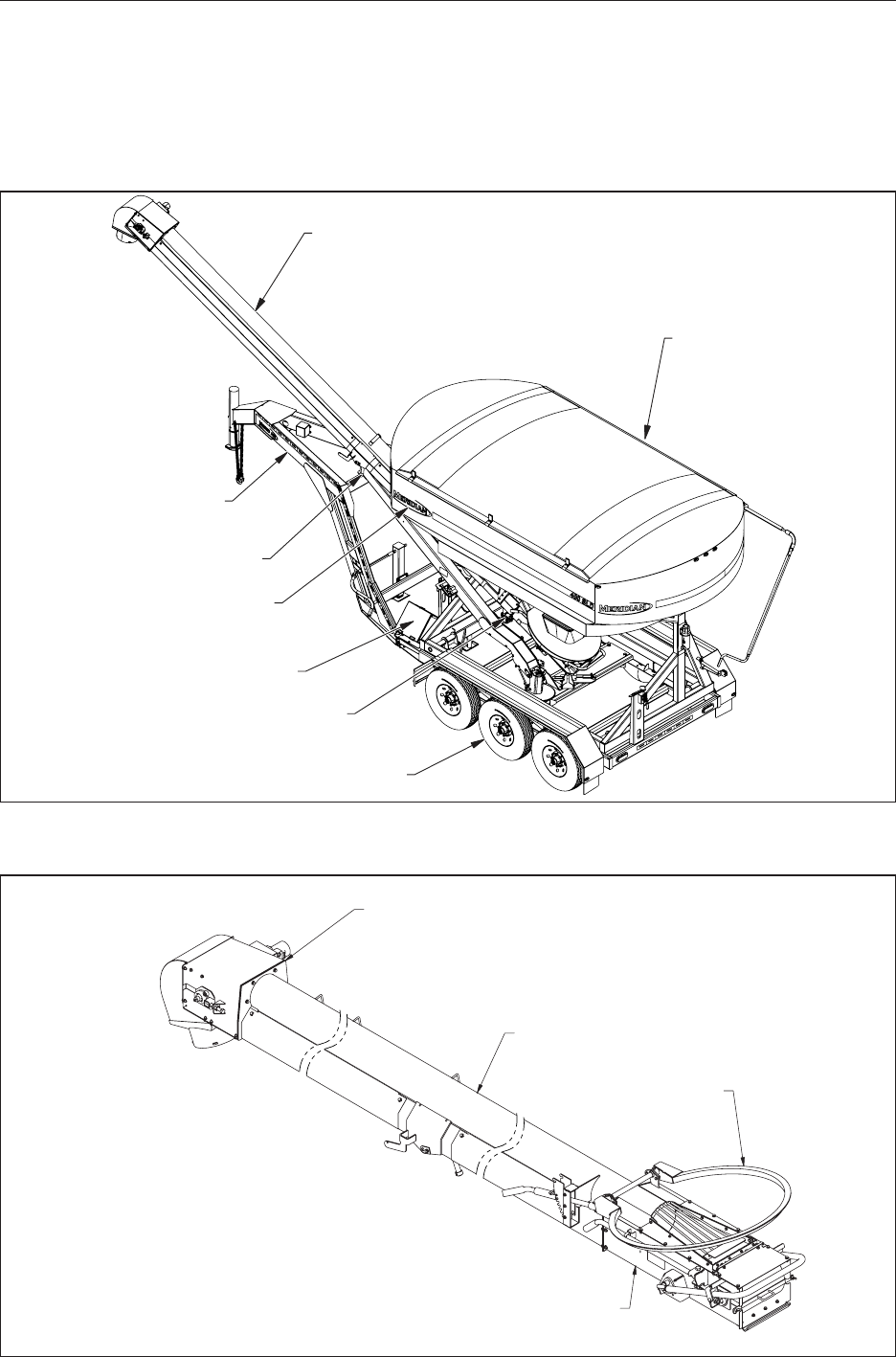
63
14. PARTS
The following pages contain a list of serviceable
parts for the 400 SLD Seed Tender unit.
Parts are available from your authorized Dealer
Parts Department.
14.1 400 SLD SEED TENDER 80137
14.2 - 8” CONVEYOR DETAILS
14.10 - GOOSENECK DETAIL
14.9 - BUMPER HITCH DETAIL
14.3 - LADDER DETAIL
SLIDE GATE DETAIL
SAMPLE GATE DETAIL
14.7 - LIGHT AND DECAL DETAIL
14.5 - POWER SYSTEM DETAIL
14.8 - TURRET DETAIL
14.6 - WEIGH SYSTEM DETAIL
14.4 - AXLE / WHEEL DETAIL
14.2 CONVEYOR (8”) 80634
14.2.3 — TU T
14.2.1— T
14.2.2— T
UT T
14.2.4 — T
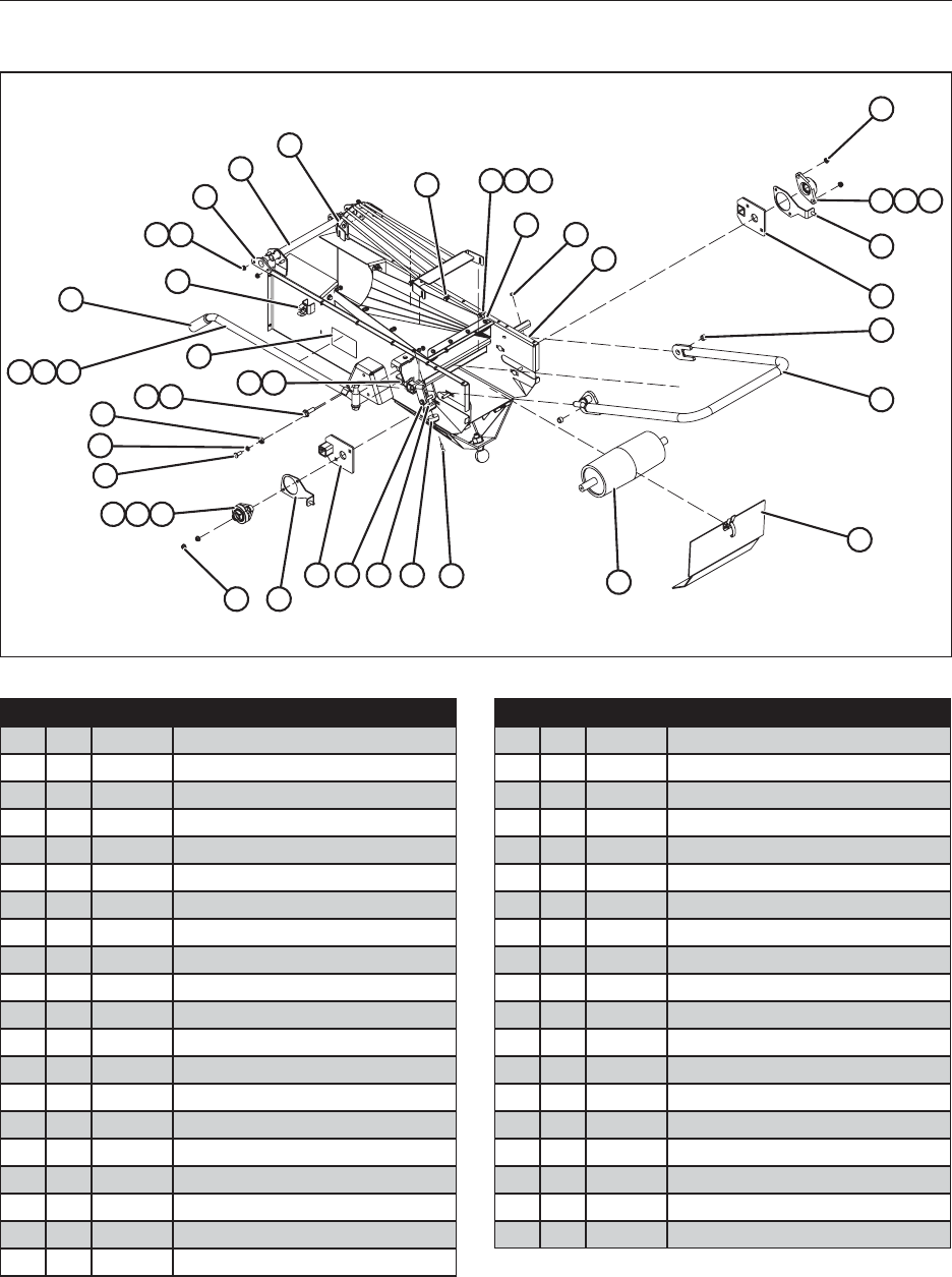
64
14.2.1 Pan Detail
28
27
26
23
22
141516 21
1718
1920
2425
29
33 34
35
5
6
10
36
37
38
39
1
234
10
5
11
12
13
789
6
7 8 9
30 31 32
Item Qty. Part No. Description
1 6 19301 Bolt, Hex, 1/4-20 x 1”
2 2 19133 Bumper, Rubber
3 4 19335 Bolt, Carriage, 3/8-16 x 1-1/2”
4 1 19118 Ring, Snap, Square, Zinc, 3/8 x 2-1/4”
5 18 19564 Nut, Hex, Flanged, 3/8-16
6 2 25248 Weldment, Scoop Bracket
7 4 27040 Housing, Roller Bearing
8 4 21258 Bearing
9 4 21258 Bearing, Collar
10 2 25842 Weldment, Roller Side Plate
11 2 19069 Screw, Rnd Head Phillips, 3/8-16 x 1”
12 2 19349 Washer, Lock, 3/8”
13 2 19093 Bearing, Roller, 7/8” OD
14 1 19566MS Nut, Hex, Flanged, 5/8-11
15 1 19376 Bolt, Hex, 5/8-11 x 4”
16 1 25273 Weldment, Swing Handle
17 3 19380 Bolt, Hex, 5/8-11 x 4-1/2”
18 2 19663 Nut, Square, 5/8-11
19 2 19575 Bolt, Hex, Flanged, 1/2-13 x 1-1/2”
20 4 19595 Nut, Hex, Flanged, 1/2-13
Item Qty. Part No. Description
21 2 20087 Decal, Pinch Point, Hand
22 2 19447 Grip, Handle
23 1 19095 Holder, Tool
24 8 19310 Bolt, Hex, 5/16-18 x 1”
25 42 19318 Nut, Hex, Flanged, 5/16-18
26 2 19404 Bushing, Nylon 1”
27 1 26029 Pin, Hopper Loop Pivot
28 1 25429 Guard, Hopper Weldment
29 11 19560 Bolt, Hex, 1/4-20 x 3/4”
30 12 19128 Nut, Hex, Nylon, 1/4-20
31 12 19307 Washer, Flat, 1/4
32 1 25241 Seal, Hopper Retainer (Rear)
33 5 19126 Nut, Hex, Flanged, 3/8-16
34 1 19126 Nut, 1/4-20
35 1 25781 Weldment, Pan
36 2 25664 Bushing, 0.75 OD x 0.507 ID x 0.5
37 1 25251 Weldment, Stand
38 1 23684 Cover
39 1 19554 Roller, Idler Assembly
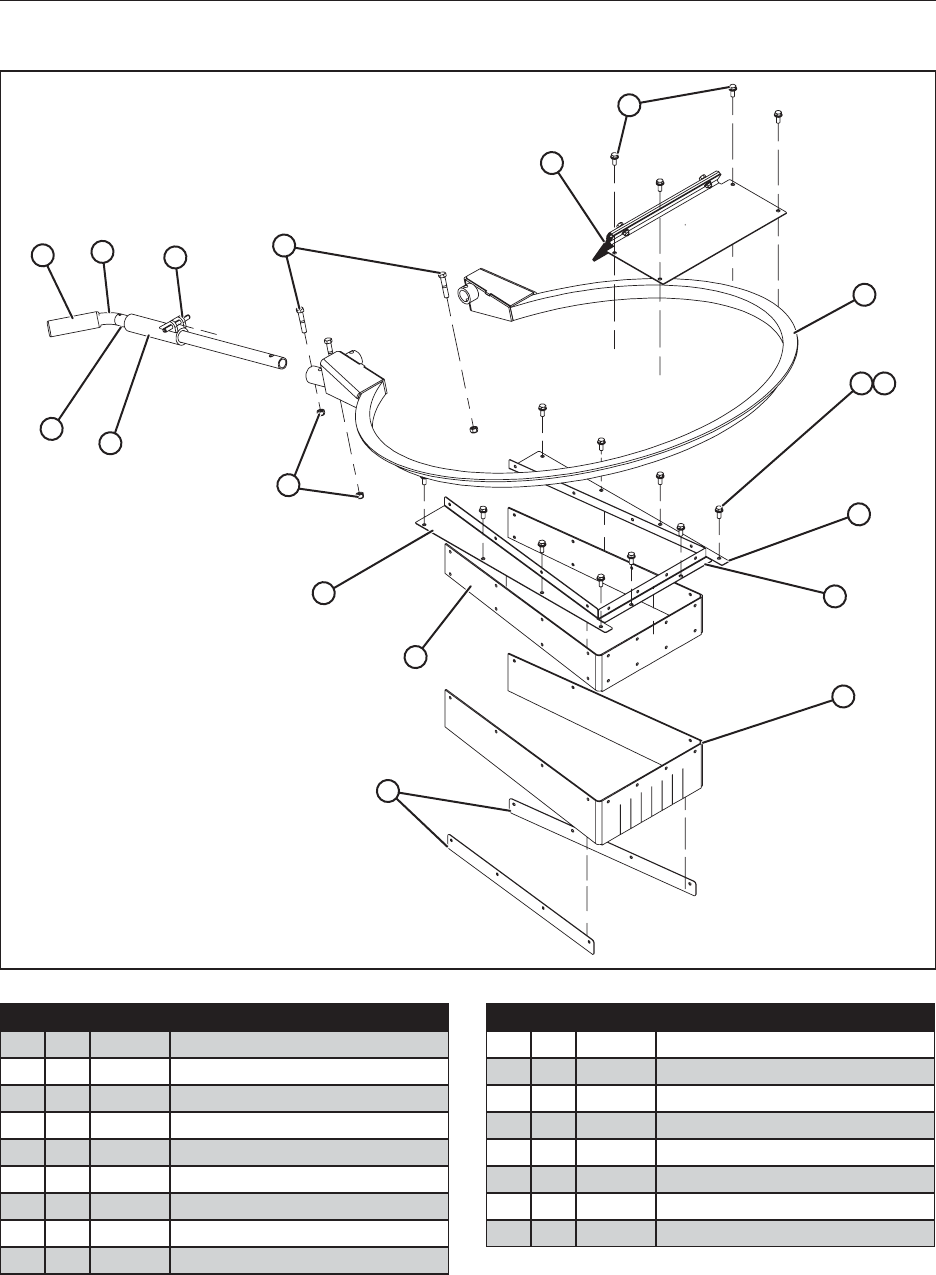
65
14.2.2 Collection Chute Detail
78910
11
12
13
12 13
14
2
15
16
1
3
65
4
Item Qty. Part No. Description
1 2 25242 Seal, Hopper Retainer, Side
2 1 25240 Retainer, Hopper, Rubber
3 1 25787 Plate, Left Cap
4 3 19347 Locknut, Nylon, 3/8-16
5 1 25277 Weldment, Hopper Lever Lock Collar
6 1 19284 Pin, Spring, 3/16 x 1-1/8”
7 2 19447 Grip, Handle
8 1 25290 Lever, Hopper
9 1 19177 Pin, Slotted Spring
Item Qty. Part No. Description
10 3 19328 Bolt, Hex, 3/8-16 x 2
11 1 25844 Holder, Brush Assembly
12 24 19568 Bolt, Hex, Flanged, 5/16-18 x 3/4”
13 1 26032 Weldment, Hopper Loop
14 1 25786 Plate, Right Cap
15 1 25672 Plate, Hopper Cap (Rear)
16 1 25240 Seal, Rubber, Hopper
17 1 25660 Cover (Ns)
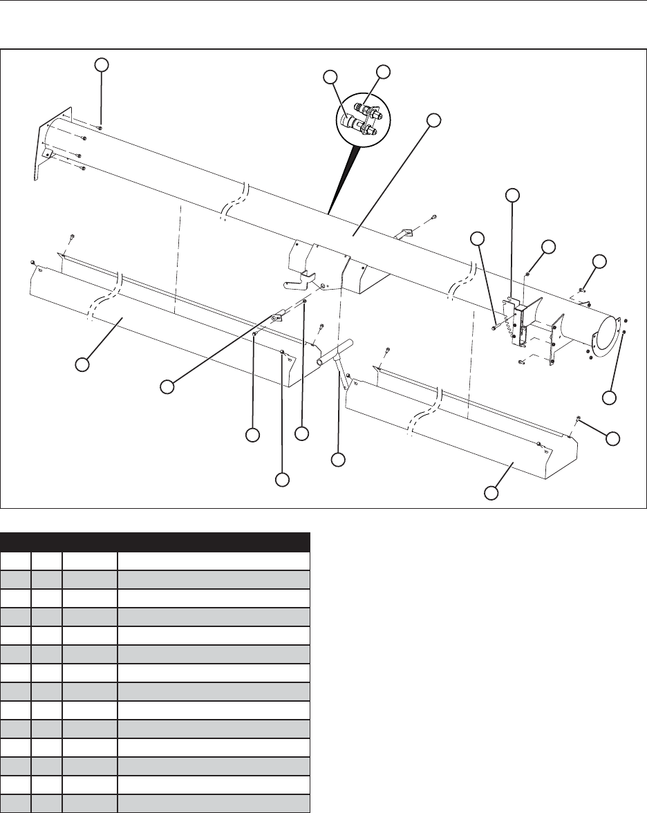
66
14.2.3 Tube Detail
1
4
5
7
8
6
7
1
9
13
10
11
12
14
1
23
Item Qty. Part No. Description
1 18 19577 Bolt, Hex, Flanged, 3/8-16 x 3/4
2 1 17707 Coupler, Quick (Female) 4050-15P
3 1 17708 Coupler, Quick (Male) 8010-15P
4 1 36209 Weldment, Conveyor Tube
5 2 25666 Plate, Lock, Stainless
6 10 19315 Bolt, Carriage, 5/16-18 x 3/4
7 12 19318 Nut, Hex, Flanged, 5/16-18
8 8 19569 Bolt, Hex, Flanged, 3/8-16 x 1”
9 1 23815 Guard, Belt
10 1 30469 Weldment, Rocker Pin
11 4 19325 Bolt, Hex, 3/8-16 x 1”
12 2 25696 Pin, Hammerstrap, 1 x 3-3/4”
13 4 19564 Nut, Hex, Flanged, 3/8-16
14 1 23618 Guard, Belt
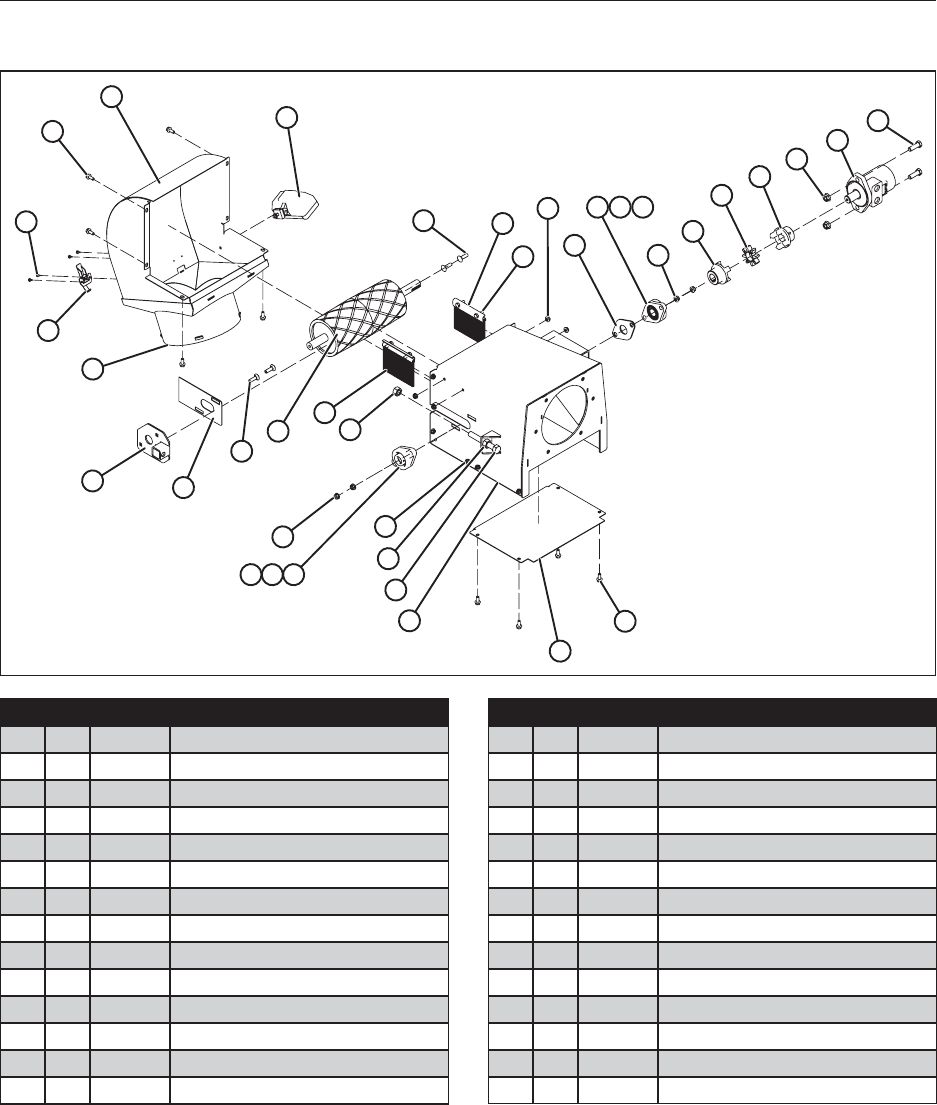
67
14.2.4 Discharge Detail
1
2
3
4
56
9
78
9
10 11 12
14
17
15
27
12
28
26
13
14
15
16
17
20
21
22 21 23 24
25
4
18 19
18
19
Item Qty. Part No. Description
1 1 25827 Weldment, Discharge Hood Transition
2 2 21257 Latch, Over-Center
3 4 19548 Rivet, 1/8”
4 24 19568 Bolt, Hex, Flanged, 5/16-18 x 3/4”
5 1 25829 Weldment, Discharge Hood
6 1 18188 Light, Work (Optional)
7 1 25278 Plate, Discharge Roller Slide
8 1 25838 Plate, Transition Seal
9 4 19695 Bolt, Carriage, 3/8-16 x 1-1/4”
10 1 19533 Roller, Drive Assembly
11 2 25810 Brush, 5-1/4”
12 4 19382 Nut, Hex, 5/8-11
13 2 25809 Retainer, Brush
14 8 19310 Bolt, Hex, 5/16-18 x 1”
Item Qty. Part No. Description
15 42 19318 Nut, Hex, Flanged, 5/16-18
16 1 25839 Plate, Bearing Spacer
17 4 27040 Housing, Roller Bearing
18 4 21258 Bearing
19 4 21258-00c Bearing, Collar
20 18 19564 Nut, Hex, Flanged, 3/8-16
21 2 19249 Coupler, Lovejoy
22 1 19291 Coupling, Red Spider
23 4 19595 Nut, Hex, Flanged, 1/2-13
24 1 19768 Motor, Hydraulic 4.5 cubic inch
25 2 19355 Cap Screw, 1/2-13 x 1-1/2”
26 1 25799 Plate, Discharge Bottom
27 1 25805 Weldment, Discharge Transition
28 3 19380 Bolt, Hex, 5/8-11 x 4-1/2”
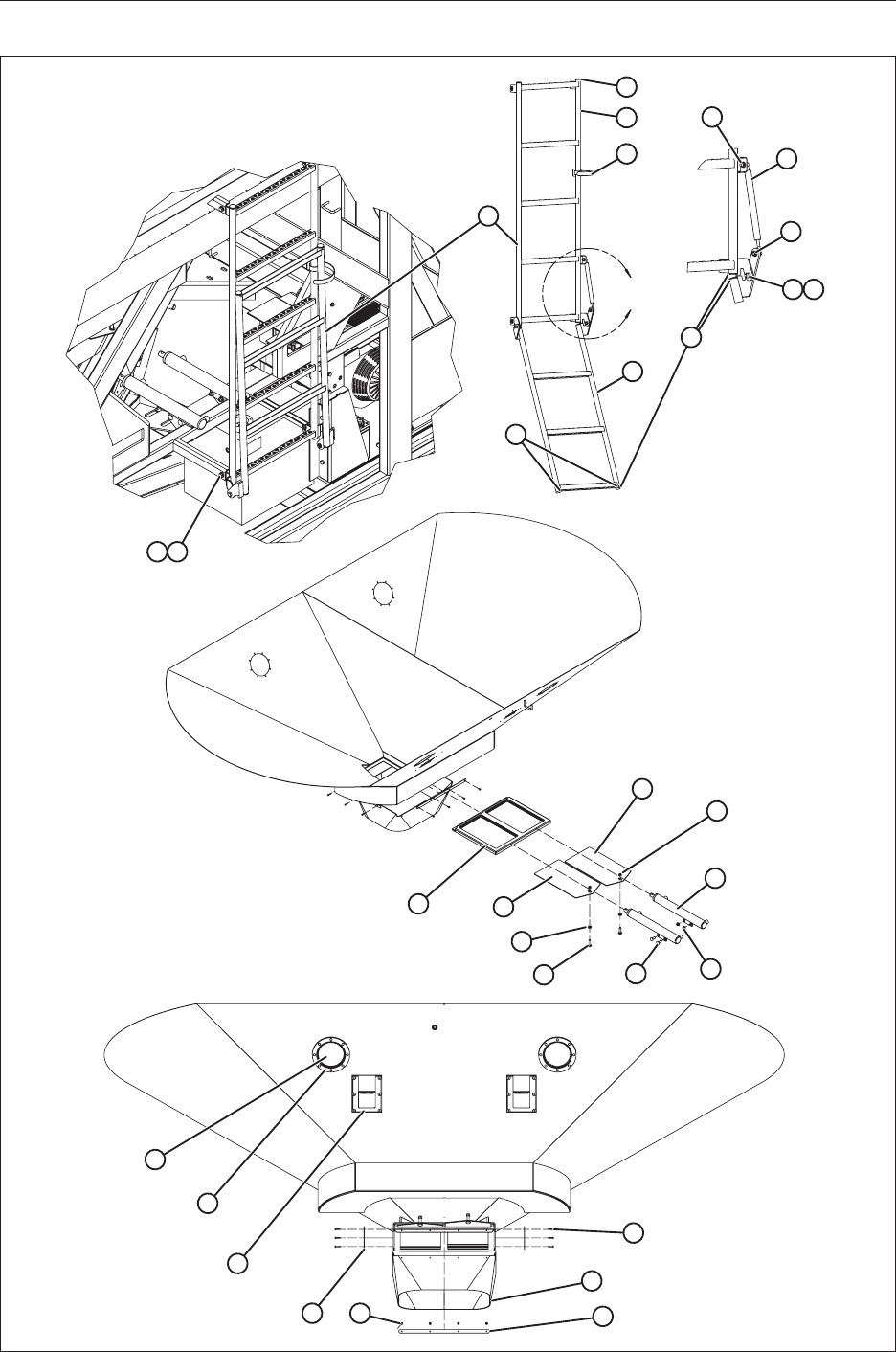
68
14.3 LADDER, SLIDE GATE, VIEW PORT, AND SAMPLE GATE
DETAIL C
C
10
10
14 15 16
17
18
12
L3
L1
L7 L6
L8
L2
L9
L3
L4 L5
L8
3
11
12
13
45
6
8
7
5
9

69
Item Qty. Part No. Description
1 24 19564 Nut, Hex, Flanged, 3/8-16
2 9 19577 Bolt, Hex, Flanged, 3/8-16 x 3/4
3 1 25899 Ladder Assembly
L1 1 25673 Ladder, Top Assembly
L2 1 25674 Ladder, Swing Assembly
L3 8 19063 Plug, 1" Tube
L4 2 19325 Bolt, Hex, 3/8-16 x 1
L5 2 19347 Locknut, 3/8-16 Nylon
L6 1 19064 Shock, 120 Lb. Gas Spring Assist
L7 1 19138 Cable, Self Gripping Velcro
L8 2 19318 Nut, Hex, Flanged, 5/16-18
L9 2 19067 Pad, Rubber
4 1 25793 Insert, Slide Gate UHMW
5 2 25794 Slide, Gate
6 6 19348 Washer, Flat, 3/8
7 2 19335 Bolt, Carriage, 3/8-16 x 1-1/2
8 4 19334 Bolt, Carriage, 3/8-16 x 1
9 2 19149 Cylinder, Gate
10 7 19347 Locknut, Nylon, 3/8-16
11 4 47008 View Glass, S.S. Ring Assembly
12 12 19129 Rivet, 3/16 x 1/2
13 2 36150 Gate, Sample
14 2 25279 Retainer, Gate Skirt Side
15 4 19699 Screw, Self Drilling, 8-32 x 1/2
16 1 25276 Retainer, Gate Skirt
17 1 25662 Skirt, Gate
18 10 19779 Screw, Self Drilling, Zinc, 8-18 x 3/4
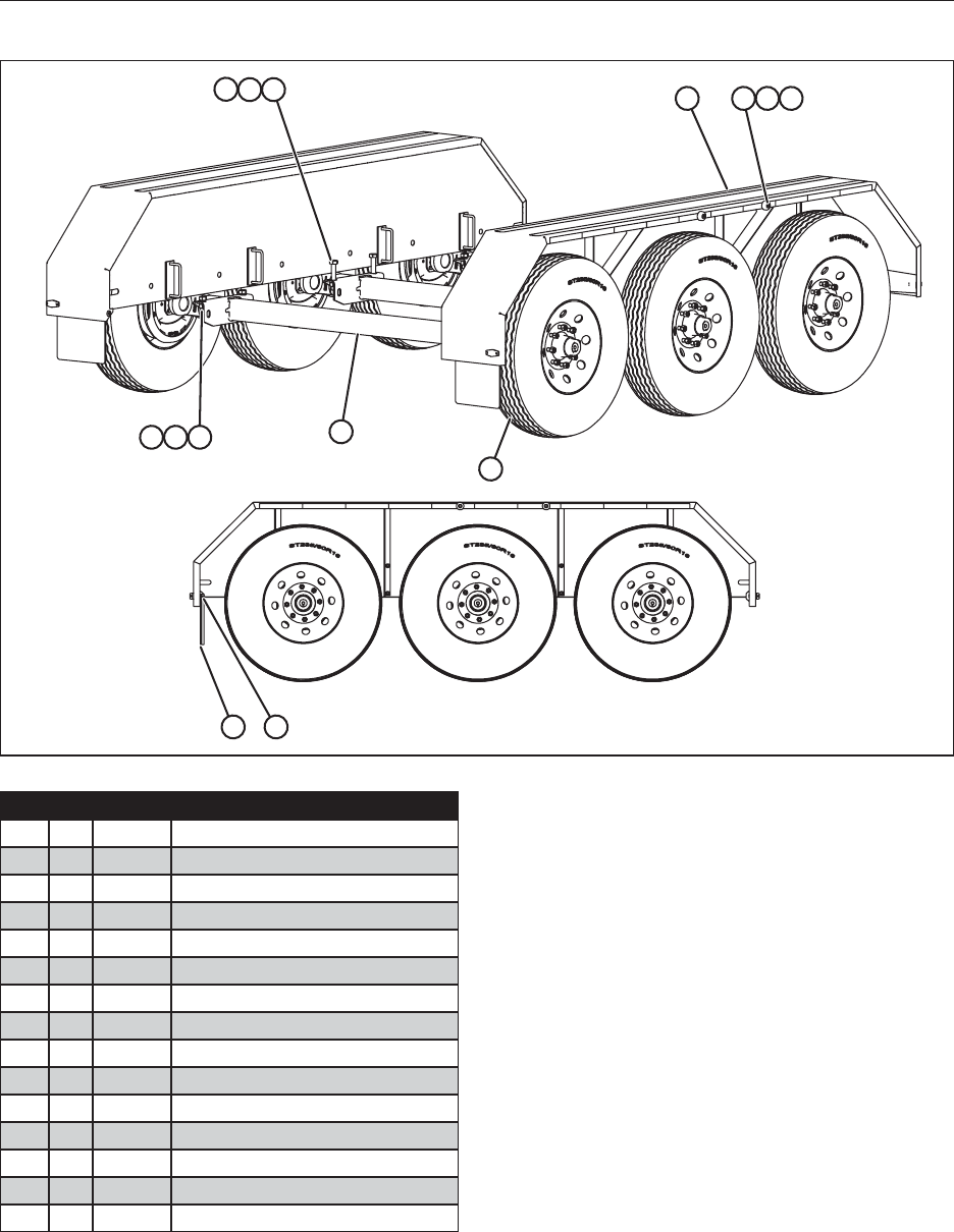
70
14.4 AXLE/WHEEL DETAIL
51
3
2
456
789
6
10 11
12
Item Qty. Part No. Description
1 2 40145 Fender Assembly, Triple Axle
2 3 18193 Axle, 7000 lbs.
3 6 18131 ST235/80R16
4 8 19388 Bolt, Hex, 3/4-10 x 2
5 12 19396 Washer, Helical Spring Lock, 3/4
6 12 19394 Nut, Hex, 3/4-10
7 2 19133 Bumper, Rubber
8 2 19560 Bolt, Hex, 1/4-20 X 3/4
9 2 19126 Nut, Hex, Flanged, 1/4-20
10 2 19274 Flap, Mud
11 818482 Screw, Hex, Self-Tap 10-24 x 1/2
12 4 19650 BOLT, HEX, 3/4-10 X 4-1/2
13 2 23873 Plate, Hitch (NS)
14 1 14048 Wire Harness Fender 2012 (NS)
* (NS) Not Shown
Note: Quantities shown are for the triple axle model.
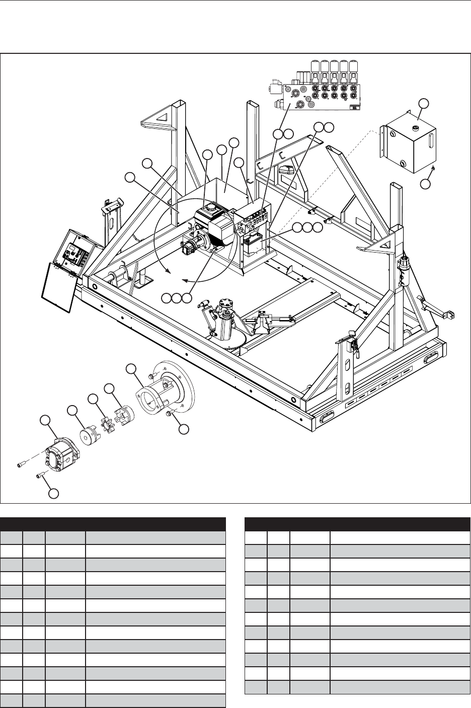
71
14.5 HYDRAULIC POWER SYSTEM
14.5.1 Engine And Hydraulic Pump
18
17
25
19
20
21
22
23
24
12 13
14 15 16
10
A
DETAIL A
11
9
7
3
1
8
2
4 5 6
Item Qty. Part No. Description
1 6 19597 Screw, Self Drilling,1/4-14 x 3/4
2 1 26119 Trim, Edge (10-5/8)
3 1 21270 Honda G340 (w/o Ignition Switch)
4 4 19328 Bolt, Hex, 3/8-16 x 2
5 6 19347 Locknut, Nylon, 3/8-16
6 6 19348 Washer, Flat, 3/8
7 1 26120 Trim, Edge (27-5/16)
8 1 23838 Plate, Motor Guard
9 1 26115 Cover, Manifold, Plastic
10 1 19165 Valve, Manifold
11 12 19568 Bolt, Hex, Flanged, 5/16-18 x 3/4
12 4 19325 Bolt, Hex, 3/8-16 x 1-3/4
13 24 19564 Nut, Hex, Flanged, 3/8-16
Item Qty. Part No. Description
14 1 18658 Cable, Battery, Set (33-1/2)
15 1 21286 Battery, SP-30
16 1 21319 Strap, Rubber Bungee (6”)
17 1 19294 Tank Assembly, Hydraulic, 10 Gallon
18 10 19569 Bolt, Hex, Flanged, 3/8-16 x 1
19 1 19289 Housing, Bell
20 1 19247 Coupling w/ Setscrew, Engine Side
21 1 19290 Coupler, Spider, Black
22 1 19248 Coupling w/ Setscrew, Pump Side
23 1 19295 Pump, Hydraulic
24 2 18577 Capscrew, Socket Head
25 1 18006 Plug, Drain
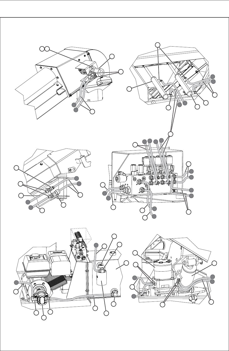
72
14.5.2 Hydraulic Hoses And Fittings
2
3
4
1
5
11
9
5
14
7
8
6
67
7
8
13
16 19
20
21
23
24
25
26
16
17
17
12
12
13
15
29
28
30
27
31
M
N
C
ABCD
E
F
G
H
I
J
L
K
M
N
I
J
L
K
F
E
B
A
D
G
H
15
29
18
22
10

73
Item Qty. Part No. Description
1 2 19355 Bolt, Hex
2 2 19595 Nut, Hex, Flanged, 1/2-13
3 1 19768 Motor, Hydraulic
4 2 17999
5 2 32338 Hose, Hydraulic
6 2 19149 Cylinder, Gate
7 4 18284 O-ring, Boss to 7/16-20 SAE 37°
8 2 32331 Hose, Hydraulic Valve to Gate, 1-1/4”
9 1 17707 Coupler, Quick (Female) 4050-15P
10 1 17708 Coupler, Quick (Male) 8010-15P
11 2 17623 O-ring, Boss to 3/4-16 SAE 37°
12 1 32335 Hose, Conveyor Motor Pressure ,1/2” Dia.
13 1 32336 Hose, Conveyor Motor Return, 1/2” Dia.
14 2 32332 Hose, Valve to Gate, 2-1/4” Dia.
15 2 32329 Hose, Raise and Lower, 1/4” Dia.
16 1 32333 Hose, Valve T-port to Return Filter, 3/4” Dia.
17 2 32334 Hose, Pump Pressure, 1/2” Dia.
18 1 5404-16-12
19 1 17133 Adapter, Elbow, 3/4 NPT to 1-1/16-12 SAE 37°
20 1 19294 Tank, 10 Gallon Hydraulic Assembly
21 1 17754 Elbow, Adapter, 1 NPT to 1-5/16-12 SAE 37°
22 1 CP-752-10 Filter, 10 Micron Oil
23 1 32330 Hose, Tank to Pump, 1” Dia.
24 1 18285 Adapter, 1-1/16-12 Male SAE O-ring
Boss to 1-1/16-12 Male SAE 37°
25 1 19295 Pump, Hydraulic
26 1 18292 Adapter, Elbow 7/8-14 Male SAE O-ring
Boss (Long) to 7/8-14 Male SAE 37°
27 1 18578 Motor, 28.3 cubic inch, Pivot Plate
28 2 17699 Adapter, 1/2-14 Male BSPP to 7/16-20 SAE
29 2 32328 Hose, Valve to Rotate Motor 1/4” Dia.
30 2 17720 Adapter, 7/16-20 SAE O-ring Boss
to 7/16-20 SAE 37°
31 1 17718 Cylinder, 3-1/2” Bore x 1.2 Stroke x
1-3/4” Rod
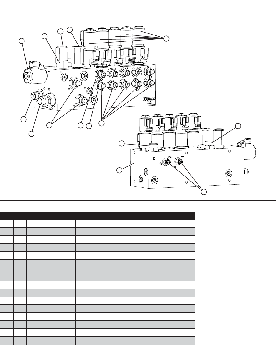
74
14.5.3 Hydraulic Manifold
1
2
10
87
6
9
1
11
14
12
5
3413
Item Qty. Part No. Description
1 1 C12133 Body, Five Function Seed Tender
2 1 6400-12-12 Fitting, Straight, -12 MJIC x -12 MORB
3 2 6400-08-08 Fitting, Straight, -8 MJIC x -8 MORB
4 1 4500210 Orice Check Disc, 0.037
5 8 6400-04-06 Fitting, Straight, -6 MJIC x -6 MORB
6 8 SV9-8-A-0-00
300AA00061A
C11374
Cartridge, Solenoid
Coil, P Series 12 Vdc Deutsch
Spacer, Coil
7 1 RV1-10-I-0-30/24 Cartridge, Relief Valve 2400 PSI
8 1 RV1-10-I-0-30/26 Cartridge, Relief Valve 2600 PSI
9 1 PCS4-10-0-80 Cartridge, Pressure Compensator 80 PSI
10 1 ESV1-10-C-0-00 Prop. Poppet Valve Normally Closed
11 1 PFR1-10-F-0-/1.25 Cartridge, Prioirty Flow, 1.25 GPM
12 1 RDH042S30 Cartridge, Relief Valve 100-3000 PSI
13 1 4500220 Orice Check Disc, 0.046
14 1 PFR1-10-F-0-/0.50 Cartridge, Prioirty Flow, 0.50 GPM
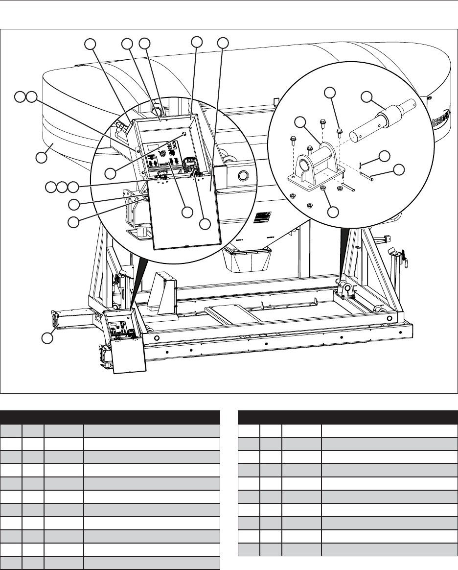
75
14.6 WEIGH SYSTEM
13
14
15
17
18
19
16
9
678
5
3
4
9
12
10
20
21
1112
13
Item Qty. Part No. Description
1 1 21257 Latch Assembly
2 1 23929 Enclosure Box
3 1 23930 Enclosure Box Lid
4 1 17610 Transmitter, Solid State 3A2222a
5 1 17612 Solid State Control Box 3B2223a2a
6 2 17625 Hinge
7 14 18941 Screw, Machine, Pan Head, #10
8 14 17722 Nut, #10-32 Nylon
9 7 19564 Nut, Hex, Flanged, 3/8-1 6
10 1 24689 Weldment, Enclosure Mount
11 4 19126 Nut, Hex, Flanged, 1/4-20
Item Qty. Part No. Description
12 4 17769 Bolt, Hex, Flanged, 1/4-20 x 0.75
13 12 19129 Rivet, 3/16” x 1/2”
14 8 19795 Pin, Cotter 1/8 x 1 Square Cut Type
15 8 18641 Pin, 3/8” x 3” Headed
16 4 30458 Mount, Load Cell
17 4 13147 Bar, Load Cell
18 16 18943 Bolt, Hex, Flanged, 1/2-13 x 1.25
19 16 19595 Nut, Hex, Flanged, 1/2-13
20 1 30449 Weldment, Main Body
21 1 30454 Weldment, Undercarriage
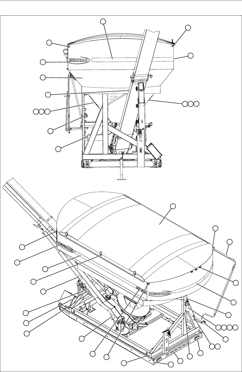
76
14.7 DECALS AND LIGHTING
1
10
2
3
4
7
8
9
11
2
5 6
6 5 4
1
3
2
9
9
11
29
27
26
25
17
24 23 22 21 20
15
13
18
17
17
12
12
12
28
19
14 15 16

77
Item Qty. Part No. Description
1 2 20089 Decal, Gradient
2 2 18151 Light, Amber Clearance
3 2 15054 Decal, 400 SLD
4 2 15056 Decal, Gate Pinch Point
5 1 19052 Decal, Gate 1
6 1 19053 Decal, Gate 2
7 1 20088 Decal, Warning Hot Surface
8 1 18188 Light, Work
9 2 20087 Decal, Pinch Point Hand
10 1 19939 Decal, Falling Hazard
11 4 20082 Decal, Meridian
12 1 26095 Kit, Agri Cover Tarp
13 1 17730 Manual, 400 SLD Owners
14 1 18128 Tube, Storage
15 3 19309 Bolt, Hex, 5/16-18 x 3/4
16 5 19318 Nut, Hex, Flanged, 5/16-18
17 5 18229 Light, Red Clearance
18 1 19934 Decal, Caution Read Manual
19 6 19568 Bolt, Hex, Flanged, 5/16-18 x 3/4
20 1 19984 Decal, Serial Number
21 2 18117 Light, Tail
22 3 18096 Tape, Reective, Meridian 2x6x6
23 2 19111 Plug, 6” x 2” Tube (0.188” Wall)
24 4 18420 Plug, 5” X 3” Tube (0.188” Wall)
25 1 17509 Decal, Warning, Crush/Electrocution Hazard
26 1 15055 Decal, Instruction, Release Conveyor
27 1 15057 Decal, Instruction, Capture Conveyor
28 3 14069 Sleeve, Tarp Stop Flat (FS627)
29 2 20090 Decal, Gradient
30 1 14044 Harness, Clearance Light (NS)
31 1 14046 Harness, Work Light (NS)
32 1 14067 Harness, Undercarriage Wire (NS)
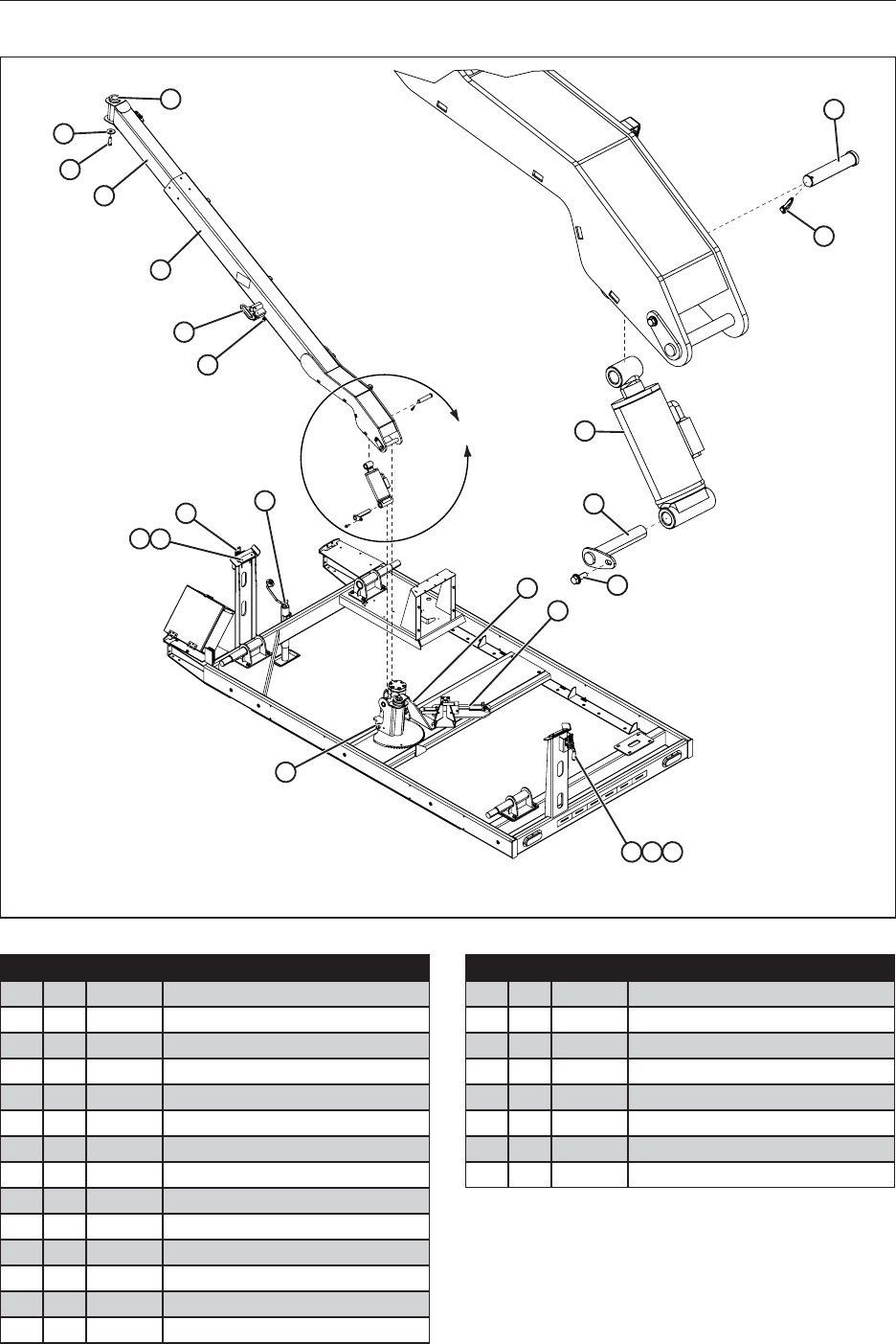
78
14.8 TURRET DETAIL
6
5
4
3
1
19 20 21
14
16
A
DETAIL A
7
8
17
2
18
22
9
12
10
11
13
15
Item Qty. Part No. Description
1 4 19126 Nut, Hex, Flanged, 1/4-20
2 4 19114 Screw, Countersunk Cap 1/4-20 x 1
3 2 25849 Pad, Wear, Extend Arm
4 1 18164 Jack, 5K, 10” Stroke Top Wind
5 1 14002 Switch
6 1 30468 Pin, Lock
7 1 30453 Weldment, Conveyor Arm Bottom
8 1 36031 Weldment, Conveyor Arm Top
9 3 18476 Bolt, Hex, 3/4-10 x 1-1/2
10 1 23757 Plate, Retainer, Swivel, Conveyor
11 1 17758 Bushing
12 1 12582 Pin, Clevis 1 x 4-45/64 Eff. Length
13 1 19794 Pin, Lynch 3/16 x 1
14 1 17718 Cylinder
Item Qty. Part No. Description
15 1 30461 Pin, Cylinder
16 5 19569 Bolt, Hex, Flanged, 3/8-16 x 1
17 1 23901 Plate, Reinforcement
18 1 30459 Receiver, Conveyor Hitch
19 12 19568 Bolt, Hex, Flanged, 5/16-18 x 3/4
20 10 19318 Nut, Hex, Flanged, 5/16-18
21 2 19624 Latch, Horizontal
22 1 30452 Weldment, Conveyor Pivot Plate
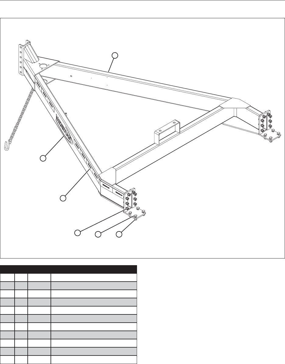
79
14.9 BUMPER HITCH DETAIL
6
1
5
32 4
Item Qty. Part No. Description
1 2 19911 Decal, White, Meridian Trailer
2 24 19116 Bolt, Hex, 1/2-13 x 1-1/2” long Grade 8
3 24 19373 Washer, Lock, 1/2"
4 24 19115 Nut, Hex, 1/2-13, Grade 8
5 21 18096 Tape, Reective, Meridian 2 x 6 x 6”
6 1 25851 Weldment, Bumper Hitch
7 1 14047 Wire Harness, Tongue (NS)
8 1 18192 Mount, Jack Stand A-Frame (NS)
9 1 19298 Coupler, Hitch 2-5/16 Adjustable (NS)
10 1 19275 Breakaway, Battery (NS)
* (NS) Not Shown
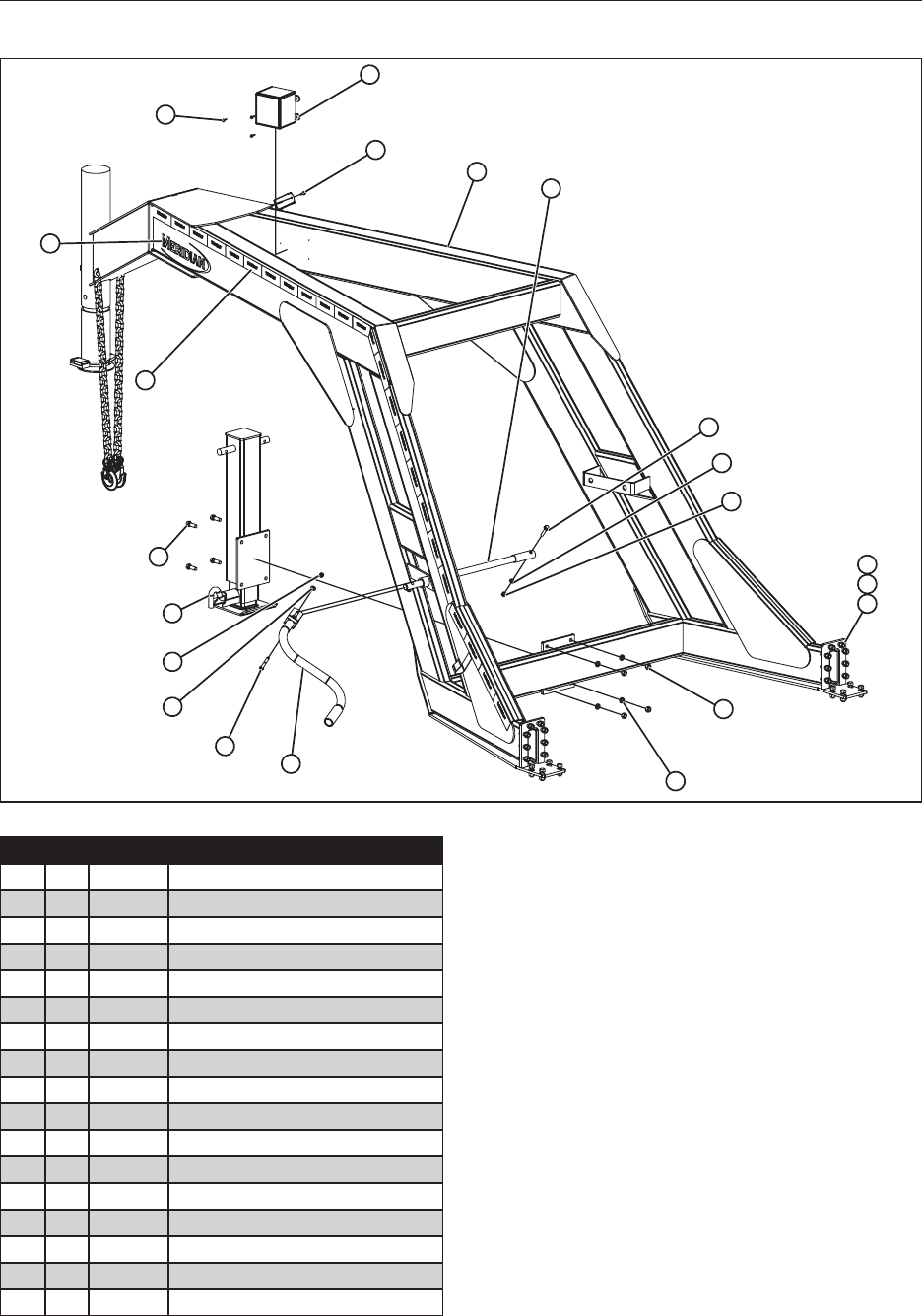
80
14.10 GOOSENECK DETAIL
93
4
6
5
2
4
8
1
5
6
11
10
12
14
16
15
17
16
15
13
Item Qty. Part No. Description
1 2 19911 Decal, White, Meridian Trailer
2 1 18197 Crank, Handle, Gooseneck Jack
3 1 25325 Extension, Handle, Gooseneck Jack
4 28 19116 Bolt, Hex, 1/2-13 x 1-1/2” Grade 8
5 28 19373 Washer, Lock, 1/2”
6 28 19115 Nut, Hex 1/2-13, Grade 8
7 1 14043 Wire Harness, Tongue (NS)
8 26 18096 Tape, Reective, Meridian 2 x 6 x 6
9 1 25336 Weldment, Gooseneck
10 1 19275 Breakaway, Battery BA10-150
11 319779 Screw, Self Drilling, #8-18 x 3/4
12 1 19597 Screw, Self Drilling 1/4-14 x 3/4
13 1 25322 Weldment, Jack, Gooseneck - 12k
14 1 19626 Bolt, Hex, Flanged, 3/8-16 x 1-3/4
15 2 19347 Locknut, nylon, 3/8-16
16 3 19348 Washer, Flat, 3/8
17 1 19592 Bolt, Hex, 3/8-16 x 2-1/2

81
NOTES

82
NOTES

84
MERIDIAN MANUFACTURING INC.
With over 65 years of experience,
Meridian is your storage and handling expert.
© 2014 Meridian Manufacturing Inc. Registered Trademarks Used Under License.
Form No. 17730
Printed In U.S.A. (03-2014)
Storm Lake Office
2902 Expansion Blvd.
Storm Lake, IA 50588
PH: 712.732.1780
TF: 800.437.2334
FX: 712.732.1028
Lethbridge Office
3125 - 24 Ave. N.
Lethbridge, AB T1H 5G2
PH: 403.320.7070
TF: 800.661.1436
FX: 403.320.7579
Winkler Office
Box 760, 275 Hespler Ave.
Winkler, MB R6W 4A8
PH: 204.325.7883
TF: 800.665.7259
FX: 204.325.5556
Regina Office
PO Box 1996
Regina, SK S4P 3E1
PH: 306.545.4044
TF: 800.667.5904
FX: 306.545.4216
Camrose Office
4232 - 38 St.
Camrose, AB T4V 4B2
PH: 780.672.4516
TF: 800.830.2467
FX: 780.672.4759
Cambridge Office
605 Sheldon Drive
Cambridge, ON N1T 2K1
PH: 519.620.6004
TF: 855.346.3712
FX: 519.620.6041
