Meridian 520 Fuel Trailer Operator Manual Web 12 15 USA LR
User Manual: Meridian-520-Fuel-Trailer-Operator-Manual-Web-12-15-15-USA-LR
Open the PDF directly: View PDF ![]() .
.
Page Count: 80
3
PRODUCT WARRANTY
R E G I S T R A T I O N F O R M
WARRANTY REGISTRATION
This form must be lled out by the dealer and signed by both the dealer and the customer at the time
of delivery. Please mail or fax the completed form for validation of the equipment registration.
Customer’s Name______________________________________________________
Address ______________________________________________________________
City, State, Postal Code____ _____________________, _______, ___________
Phone Number (_______) _______- ___________
PRODUCT INFORMATION
Fuel Trailer Model # ___________ # rebmuN laireS _______________________
I have thoroughly instructed the buyer on the above-described equipment, including review of the Operator’s
Manual content, equipment care, adjustments, operational use, safety procedures, and applicable warranty
policy.
Dealer/Company Name____________________________________
City, State, Postal Code _________________________, ________________, ______________
Dealer’s Signature_____________________________ ____________ Date ____/____/______
The above equipment and Operator’s Manual have been received by me, and I have been thoroughly instructed as
to care, adjustments, safe operation, and applicable warranty policy.
Owner’s Signature_____________________________________ Date ____/____/_______
2902 Expansion Blvd. Storm Lake, Iowa 50588 Phone: 800-437-2334 Fax: 712-732-1028 Email: iowa_warranty@meridianmfg.com
Cut Here to Remove Page

PRODUCT WARRANTY
R E G I S T R A T I O N F O R M
DEALER INSPECTION REPORT
____Wheel nuts/bolts must be tightened to proper torque on all wheels
____Wiring harness plug must be in working condition and t into tow vehicle’s receptacle
____Make sure breakaway cable and pin is supplied with trailer
____Make sure breakaway battery and/or optional battery for accessories are fully charged
and in good working order
____Make sure license plate light is operating
____Verify that tow vehicle is large enough to safely tow the trailer
____Make sure all four 1993 Diesel Fuel Placards are installed
____If equipped, check gasoline engine fuel level
____If equipped, check gasoline engine oil level
____If equipped, start gasoline engine
____Inspect brake and lighting wiring harness connection
____Check air pressure in tires
____Make sure electric brakes are in working condition
____Make sure all guards/shields are installed correctly
____Make sure all safety signs are installed and legible
____Reectors and lights must be clean and working
____Review safety and operating instructions with owner
____Make sure safety chains are properly attached and are in good working condition
____Inspect customer’s hitch for 2-5/16” ball
____Make sure adjustable height hitch-to-tongue bolts are tight
____Make sure owner is instructed to check wheel bolt/nut torque at
5, 10, 25, and 50 miles; then check annually
____Verify receipt of all options ordered
____Make sure turn signal lights are operating
____Make sure brake lights are operating

5
2902 Expansion Blvd.
Storm Lake, IA 50588
Phone: 712-732-1780
Fax: 712-732-1028
CERTIFICATE OF ORIGIN
LICENSING INFORMATION Date: ____/___/_______
DEALER:
___________________________Business
___________________________Contact
___________________________Address
___________________________City, State, Zip
SOLD TO:
___________________________Business
___________________________Contact
___________________________Address
___________________________City, State, Zip
FUEL TRAILER MODEL # _________________________________________________________
FUEL TRAILER WEIGHT __________________________________________________________
68607 — 520 Fuel Trailer - Bone White
68608 — 520 Fuel Trailer - Meridian Red
68609 — 520 Fuel Trailer - Gloss Black
Cut Here to Remove Page
7
IMPORTANT INFORMATION
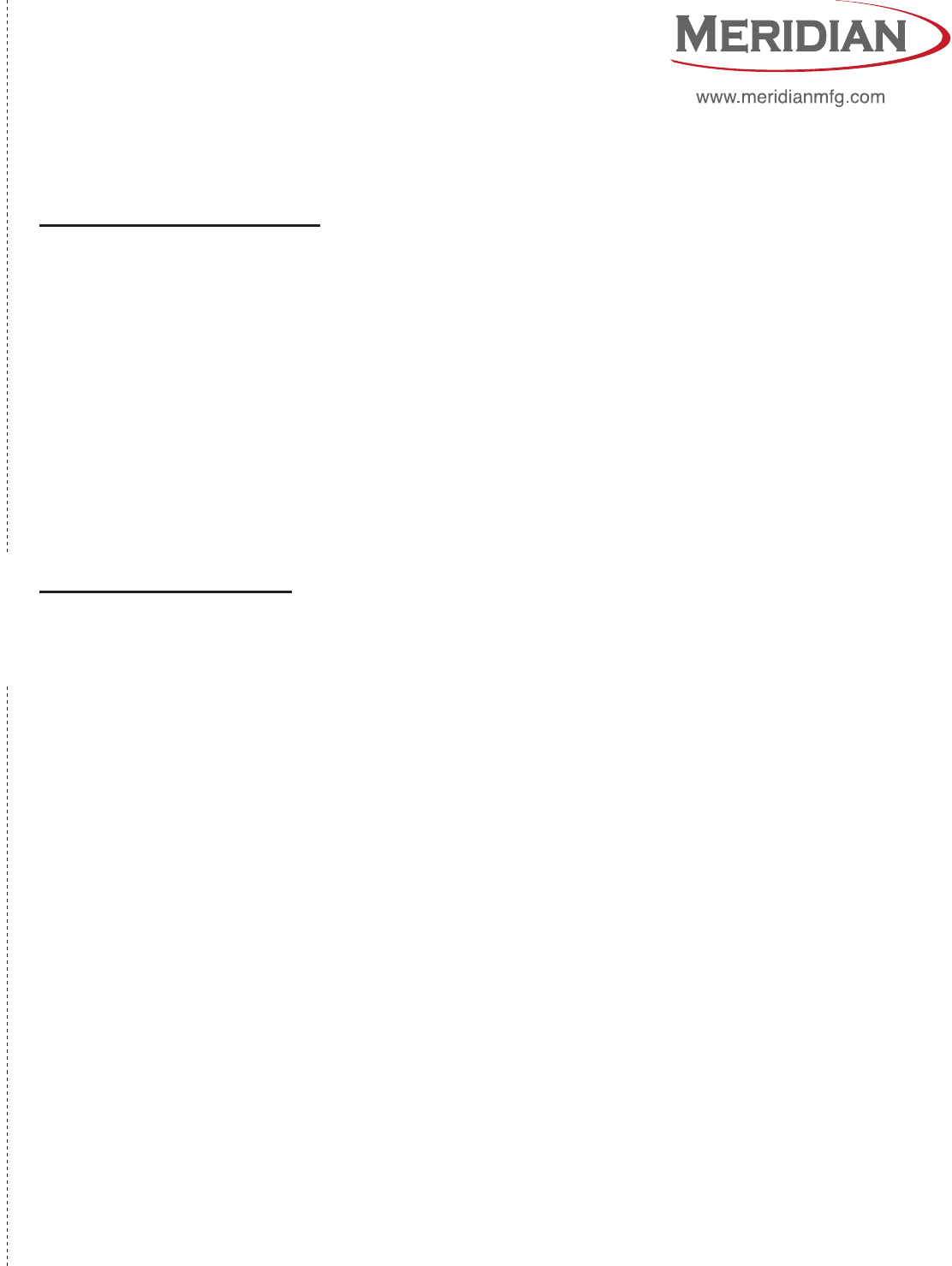
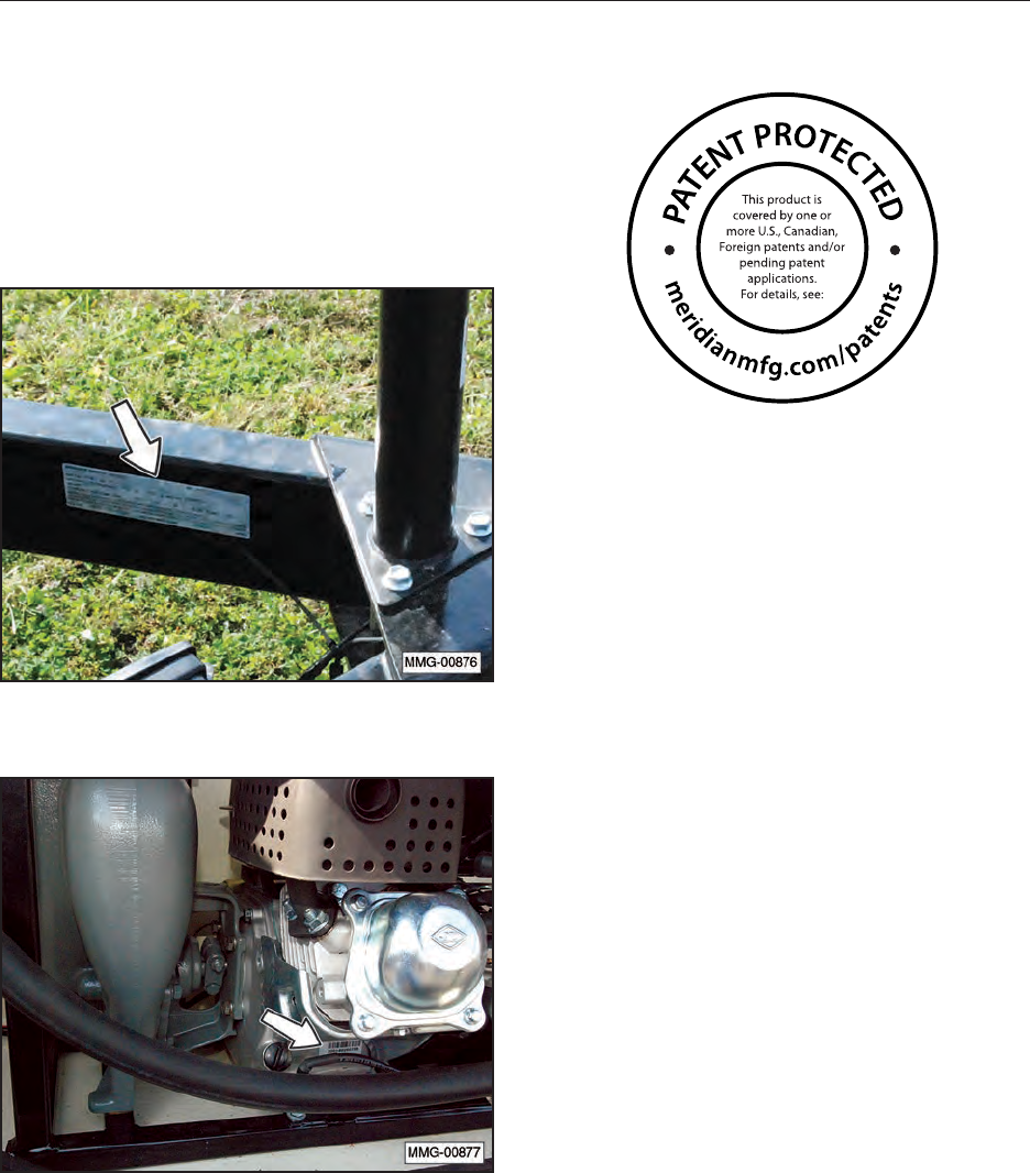
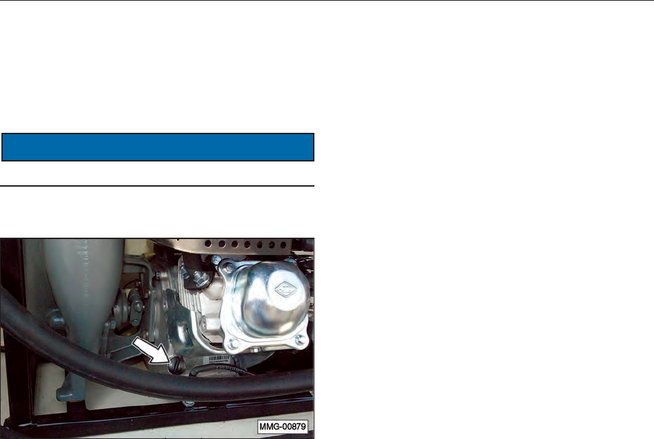
SERIAL NUMBER LOCATION
Please provide the serial number of your Meridian
Fuel Trailer and engine when ordering parts or
requesting service or other information.
The serial number plates are located where
indicated. Please record the numbers in the space
provided below for easy reference.
Fuel Trailer
Engine
Fuel Trailer Serial Number: __________________
Engine Serial Number: ______________________
PATENT INFORMATION
Meridian continuously enhances its product
offering through product improvements and new
product innovations. Marketplace feedback,
technological innovation, new materials and
manufacturing methods, and a philosophy of
continuous improvement constantly challenge
the company to develop new and better ways of
addressing market needs. Meridian is committed
to innovation and reinvestment and as a result,
the company maintains a portfolio of patents and
intellectual property. For more information on our
patents please see our website:
www.meridianmfg.com/patents

8
CONTENTS
1. INTRODUCTION .......................................................... 11
1.1 Congratulations . . . . . . . . . . . . . . . . . . . . . . . . . . . . . . . . . . . . 11
1.2 Operator Orientation . . . . . . . . . . . . . . . . . . . . . . . . . . . . . . . . . . 11
1.3 Owner/Operator . . . . . . . . . . . . . . . . . . . . . . . . . . . . . . . . . . . . 11
1.4 Disposal of Equipment at End of Useful Life. . . . . . . . . . . . . . . . . . . . . . 11
1.5 Continuous Improvement Process. . . . . . . . . . . . . . . . . . . . . . . . . . . 11
1.6 Before Starting Gas Engine . . . . . . . . . . . . . . . . . . . . . . . . . . . . . . 12
2. SAFETY.................................................................13
2.1 Additional Safety Words . . . . . . . . . . . . . . . . . . . . . . . . . . . . . . . . 14
2.2 Safety Training . . . . . . . . . . . . . . . . . . . . . . . . . . . . . . . . . . . . . 14
2.3 Safety Icon Nomenclature . . . . . . . . . . . . . . . . . . . . . . . . . . . . . . . 15
2.3.1 Personal Protection/Important Information . . . . . . . . . . . . . . . . . . . 15
2.3.2 Prohibited Actions. . . . . . . . . . . . . . . . . . . . . . . . . . . . . . . . 15
2.3.3 Hazard Avoidance . . . . . . . . . . . . . . . . . . . . . . . . . . . . . . . 15
2.4 General Safety . . . . . . . . . . . . . . . . . . . . . . . . . . . . . . . . . . . . . 16
2.5 Safety Signs . . . . . . . . . . . . . . . . . . . . . . . . . . . . . . . . . . . . . . 16
2.6 Preparation. . . . . . . . . . . . . . . . . . . . . . . . . . . . . . . . . . . . . . . 16
2.7 Operating Safety . . . . . . . . . . . . . . . . . . . . . . . . . . . . . . . . . . . . 16
2.8 Transport Safety . . . . . . . . . . . . . . . . . . . . . . . . . . . . . . . . . . . . 17
2.9 Storage Safety . . . . . . . . . . . . . . . . . . . . . . . . . . . . . . . . . . . . . 17
2.10 Maintenance Safety. . . . . . . . . . . . . . . . . . . . . . . . . . . . . . . . . . 17
2.11 Diesel Fuel Safety. . . . . . . . . . . . . . . . . . . . . . . . . . . . . . . . . . . 17
2.11.1 Inhalation Hazard . . . . . . . . . . . . . . . . . . . . . . . . . . . . . . . 17
2.11.2 Fire and Explosion Hazards . . . . . . . . . . . . . . . . . . . . . . . . . . 17
2.11.3 Ingestion. . . . . . . . . . . . . . . . . . . . . . . . . . . . . . . . . . . . 17
2.11.4 Eye Protection . . . . . . . . . . . . . . . . . . . . . . . . . . . . . . . . . 17
2.11.5 Skin Protection. . . . . . . . . . . . . . . . . . . . . . . . . . . . . . . . . 18
2.11.6 Storage Precautions. . . . . . . . . . . . . . . . . . . . . . . . . . . . . . 18
2.11.7 U.S. Federal, State, and Local Regulatory Information . . . . . . . . . . . . 18
2.12 Battery Safety. . . . . . . . . . . . . . . . . . . . . . . . . . . . . . . . . . . . . 18
2.12.1 General Hazards . . . . . . . . . . . . . . . . . . . . . . . . . . . . . . . 18
2.12.2 Ventilation Hazard . . . . . . . . . . . . . . . . . . . . . . . . . . . . . . . 18
2.12.3 Shock Hazards . . . . . . . . . . . . . . . . . . . . . . . . . . . . . . . . 19
2.12.4 Explosion Hazards. . . . . . . . . . . . . . . . . . . . . . . . . . . . . . . 19
2.13 Sign-Off Form. . . . . . . . . . . . . . . . . . . . . . . . . . . . . . . . . . . . . 20
3. SAFETY SIGN LOCATIONS.................................................21
3.1 General Information . . . . . . . . . . . . . . . . . . . . . . . . . . . . . . . . . . 21
3.2 How to Install Safety Signs. . . . . . . . . . . . . . . . . . . . . . . . . . . . . . . 21
3.3 Decal Locations . . . . . . . . . . . . . . . . . . . . . . . . . . . . . . . . . . . . 21
3.4 Installing 1993 Diesel Fuel Placards. . . . . . . . . . . . . . . . . . . . . . . . . . 23
4. SPECIFICATIONS.........................................................24
4.1 Overall Dimensions . . . . . . . . . . . . . . . . . . . . . . . . . . . . . . . . . . 24
4.2 Specications . . . . . . . . . . . . . . . . . . . . . . . . . . . . . . . . . . . . . 24
4.3 Bolt Specications . . . . . . . . . . . . . . . . . . . . . . . . . . . . . . . . . . . 25
4.3.1 Bolt Torque Values . . . . . . . . . . . . . . . . . . . . . . . . . . . . . . . 25
4.3.2 Grade Markings Chart . . . . . . . . . . . . . . . . . . . . . . . . . . . . . 25
5. EQUIPMENT COMPONENTS AND CONTROLS.................................26
5.1 Component Nomenclature and Location. . . . . . . . . . . . . . . . . . . . . . . . 26
5.2 Electric Pump (12 Volt). . . . . . . . . . . . . . . . . . . . . . . . . . . . . . . . . 27
5.3 Gasoline Engine Safety Signs . . . . . . . . . . . . . . . . . . . . . . . . . . . . . 28
6. PRE-OPERATING INSTRUCTIONS ...........................................29
6.1 Equipment Break-In Period . . . . . . . . . . . . . . . . . . . . . . . . . . . . . . 29
6.1.1 Inspections for 1/2, 4, and 10 Hours . . . . . . . . . . . . . . . . . . . . . . 29
6.2 Daily Pre-Operation Checklist . . . . . . . . . . . . . . . . . . . . . . . . . . . . . 30

9
7. TOWING ................................................................31
7.1 Transport Safety . . . . . . . . . . . . . . . . . . . . . . . . . . . . . . . . . . . . 31
7.2 Connecting the Trailer . . . . . . . . . . . . . . . . . . . . . . . . . . . . . . . . . 32
8. OPERATION .............................................................34
8.1 Operating Safety . . . . . . . . . . . . . . . . . . . . . . . . . . . . . . . . . . . . 34
8.2 Fire Extinguisher . . . . . . . . . . . . . . . . . . . . . . . . . . . . . . . . . . . . 35
8.3 Pre-operation Checks . . . . . . . . . . . . . . . . . . . . . . . . . . . . . . . . . 35
8.4 DEF and Diesel Fuel Tanks . . . . . . . . . . . . . . . . . . . . . . . . . . . . . . 36
8.4.1 Filling the Fuel Trailer with Diesel Fuel . . . . . . . . . . . . . . . . . . . . . 36
8.4.2 Filling Machinery Using 12 Volt Electric Diesel Fuel Pump. . . . . . . . . . . 37
8.4.3 Filling Machinery Using Engine Powered Diesel Fuel Pump . . . . . . . . . . 38
8.4.4 Filling the DEF Solution Tank . . . . . . . . . . . . . . . . . . . . . . . . . . 40
8.4.5 Filling the DEF Tank on Machinery . . . . . . . . . . . . . . . . . . . . . . . 41
8.5 DEF Solution. . . . . . . . . . . . . . . . . . . . . . . . . . . . . . . . . . . . . . 42
8.5.1 DEF Solution Safety Practices . . . . . . . . . . . . . . . . . . . . . . . . . 42
8.5.2 General Information. . . . . . . . . . . . . . . . . . . . . . . . . . . . . . . 42
8.5.3 First Aid Measures . . . . . . . . . . . . . . . . . . . . . . . . . . . . . . . 42
8.5.4 Storage . . . . . . . . . . . . . . . . . . . . . . . . . . . . . . . . . . . . . 43
8.5.5 Using DEF . . . . . . . . . . . . . . . . . . . . . . . . . . . . . . . . . . . 43
8.5.6 DEF Disposal . . . . . . . . . . . . . . . . . . . . . . . . . . . . . . . . . . 43
9. STORAGE ...............................................................44
9.1 General Information . . . . . . . . . . . . . . . . . . . . . . . . . . . . . . . . . . 44
9.2 Placing in Storage . . . . . . . . . . . . . . . . . . . . . . . . . . . . . . . . . . . 44
9.3 Removing from Storage . . . . . . . . . . . . . . . . . . . . . . . . . . . . . . . . 44
9.4 Winterizing the DEF System . . . . . . . . . . . . . . . . . . . . . . . . . . . . . . 44
10. MAINTENANCE .........................................................45
10.1 Safety. . . . . . . . . . . . . . . . . . . . . . . . . . . . . . . . . . . . . . . . . 45
10.1.1 General Safety. . . . . . . . . . . . . . . . . . . . . . . . . . . . . . . . . 45
10.2 Wheel Bearings. . . . . . . . . . . . . . . . . . . . . . . . . . . . . . . . . . . . 45
10.3 Battery . . . . . . . . . . . . . . . . . . . . . . . . . . . . . . . . . . . . . . . . 46
10.3.1 Battery Safety . . . . . . . . . . . . . . . . . . . . . . . . . . . . . . . . . 46
10.3.2 Battery Replacement and Maintenance Tips . . . . . . . . . . . . . . . . . 46
10.3.3 Battery Maintenance. . . . . . . . . . . . . . . . . . . . . . . . . . . . . . 46
10.4 Gasoline Engine (Optional). . . . . . . . . . . . . . . . . . . . . . . . . . . . . . 47
10.4.1 Approved Fuel . . . . . . . . . . . . . . . . . . . . . . . . . . . . . . . . . 47
10.4.2 Engine Oil . . . . . . . . . . . . . . . . . . . . . . . . . . . . . . . . . . . 47
10.4.3 Change Engine Oil . . . . . . . . . . . . . . . . . . . . . . . . . . . . . . 47
10.4.4 Air Filter Inspection . . . . . . . . . . . . . . . . . . . . . . . . . . . . . . 48
10.4.5 Engine Circuit Protection . . . . . . . . . . . . . . . . . . . . . . . . . . . 48
10.4.6 Engine to Pump Connection. . . . . . . . . . . . . . . . . . . . . . . . . . 49
10.5 Trailer Breakaway System . . . . . . . . . . . . . . . . . . . . . . . . . . . . . . 49
10.5.1 Testing the Battery. . . . . . . . . . . . . . . . . . . . . . . . . . . . . . . 49
10.5.2 Changing Battery . . . . . . . . . . . . . . . . . . . . . . . . . . . . . . . 49
10.5.3 Replacing Battery . . . . . . . . . . . . . . . . . . . . . . . . . . . . . . . 49
10.6 Wheel Bolt Torque . . . . . . . . . . . . . . . . . . . . . . . . . . . . . . . . . . 50
10.7 Axle Bolts, Trailer Hitch Bolts, and Tank Hold-Down Bolts . . . . . . . . . . . . . . 50

10
11. SERVICE ...............................................................51
11.1 Service Record Chart . . . . . . . . . . . . . . . . . . . . . . . . . . . . . . . . . 51
11.2 Service Checks . . . . . . . . . . . . . . . . . . . . . . . . . . . . . . . . . . . . 52
11.2.1 Daily (8 Hours). . . . . . . . . . . . . . . . . . . . . . . . . . . . . . . . . 52
11.2.2 Weekly (50 Hours). . . . . . . . . . . . . . . . . . . . . . . . . . . . . . . 52
11.2.3 Semiannual (200 Hours). . . . . . . . . . . . . . . . . . . . . . . . . . . . 52
11.2.4 Annually (400 Hours) . . . . . . . . . . . . . . . . . . . . . . . . . . . . . 52
11.3 Axle Maintenance . . . . . . . . . . . . . . . . . . . . . . . . . . . . . . . . . . . 53
11.3.1 First 200 Miles . . . . . . . . . . . . . . . . . . . . . . . . . . . . . . . . . 53
11.3.2 3,000 Miles or 3 Months . . . . . . . . . . . . . . . . . . . . . . . . . . . . 53
11.3.3 6,000 Miles or 6 Months . . . . . . . . . . . . . . . . . . . . . . . . . . . . 53
11.3.4 12,000 Miles or 12 Months . . . . . . . . . . . . . . . . . . . . . . . . . . 53
11.4 Tires. . . . . . . . . . . . . . . . . . . . . . . . . . . . . . . . . . . . . . . . . . 53
11.5 Welding Repairs . . . . . . . . . . . . . . . . . . . . . . . . . . . . . . . . . . . 53
12. OEM LITERATURE .......................................................54
12.1 Engine and DEF Pump . . . . . . . . . . . . . . . . . . . . . . . . . . . . . . . . 54
12.2 Axle . . . . . . . . . . . . . . . . . . . . . . . . . . . . . . . . . . . . . . . . . . 54
12.3 Diesel Fuel Pump. . . . . . . . . . . . . . . . . . . . . . . . . . . . . . . . . . . 55
12.3.1 Electric Diesel Fuel Pump . . . . . . . . . . . . . . . . . . . . . . . . . . . 55
12.3.2 Gasoline Diesel Fuel Pump . . . . . . . . . . . . . . . . . . . . . . . . . . 55
13. TROUBLESHOOTING ....................................................56
13.1 Troubleshooting Chart . . . . . . . . . . . . . . . . . . . . . . . . . . . . . . . . 56
14. WARRANTY ............................................................59
14.1 Warranty Statement. . . . . . . . . . . . . . . . . . . . . . . . . . . . . . . . . . 59
15. PARTS.................................................................60
15.1 520 Fuel Trailer . . . . . . . . . . . . . . . . . . . . . . . . . . . . . . . . . . . . 61
15.2 40027 Trailer Assembly. . . . . . . . . . . . . . . . . . . . . . . . . . . . . . . . 62
15.3 40028 Electric Fuel Pump . . . . . . . . . . . . . . . . . . . . . . . . . . . . . . 64
15.4 60623 12V Pump & Hose Reel Package . . . . . . . . . . . . . . . . . . . . . . . 65
15.5 60625 40 GPM Pump, Hose, and Nozzle Package . . . . . . . . . . . . . . . . . 66
15.6 40039 Component Mount Assembly . . . . . . . . . . . . . . . . . . . . . . . . . 67
15.7 40041 Hose Hook Assembly . . . . . . . . . . . . . . . . . . . . . . . . . . . . . 68
15.8 60622 40 GPM Pump and Reel Package . . . . . . . . . . . . . . . . . . . . . . 69
15.9 30723 Hose Reel Upgrade . . . . . . . . . . . . . . . . . . . . . . . . . . . . . . 70
15.10 60626 DEF System, 55 Gal . . . . . . . . . . . . . . . . . . . . . . . . . . . . . 71
15.11 30724 DEF Hose Reel Upgrade. . . . . . . . . . . . . . . . . . . . . . . . . . . 72
15.12 60624 Dual Hose Reel Upgrade, Diesel & DEF. . . . . . . . . . . . . . . . . . . 73
15.13 60621 Ultra Package, 520 Fuel Trailer . . . . . . . . . . . . . . . . . . . . . . . 74
15.14 Spare Tire Kit . . . . . . . . . . . . . . . . . . . . . . . . . . . . . . . . . . . . 75
11
1. INTRODUCTION
1.1 CONGRATULATIONS
Congratulations on your choice of a Meridian
Manufacturing Inc. Fuel Trailer to complement
your farming operation. This equipment has been
designed and manufactured to meet the exacting
standards for such equipment in the agricultural
industry and will keep your operation running at
optimum efciency.
The Fuel Trailer is designed to transport diesel fuel
and diesel exhaust uid (DEF) to your machinery.
Safe, efcient, and trouble‑free operation of
your Fuel Trailer requires that you, and anyone
else who will be operating or maintaining the
equipment, read and understand the Safety,
Operation, Maintenance, and Troubleshooting
information contained within this Operator’s
Manual.
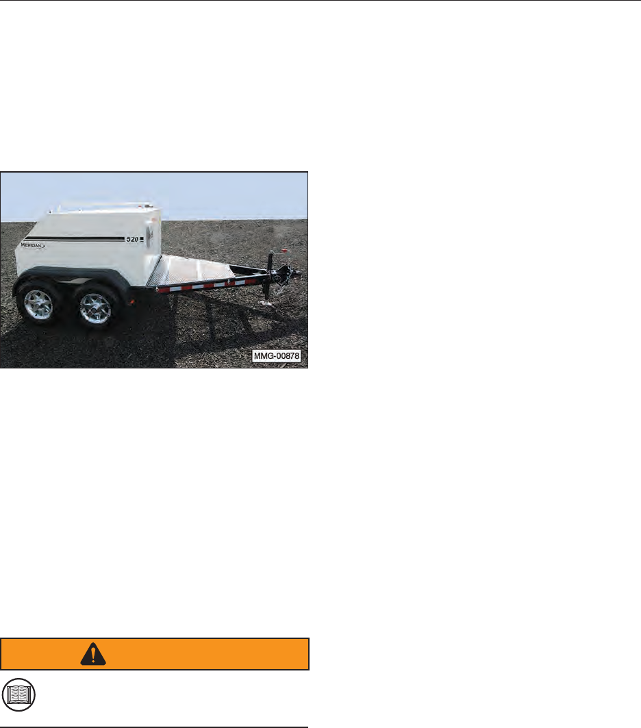
This manual covers the 520 Fuel Trailer model
manufactured by Meridian Manufacturing Inc. Use
the Table of Contents as a guide to locate required
information.
WARNING
Do not ll or tow the unit until you read
and understand the information contained
in this manual.
1.2 OPERATOR ORIENTATION
The directions left, right, front, and rear, as
mentioned throughout this manual, are as seen
from the truck drivers’ seat and facing in the
direction of travel.
1.3 OWNER/OPERATOR
It is the responsibility of the owner or operator
to read this manual and to train all other
operators before they start working with the
equipment. Follow all safety instructions
exactly. Safety is everyone’s business. By
following recommended procedures, a safe
working environment is provided for the
operator, bystanders, and the area around
the work site. Untrained operators are not
qualied and must not operate the equipment.
In addition to the design and conguration
of equipment, hazard control and accident
prevention are dependent upon the awareness,
concern, prudence, and proper training of
personnel involved in the lling, operation,
transport, maintenance, and storage of this
equipment. It is the responsibility of the owner
or operator to read this manual and to train all
operators before they start working with the
equipment. Follow all safety instructions as
laid out in this manual.
Keep this manual handy for easy reference and
to pass on to new operators or owners. Call your
Meridian Manufacturing Inc. dealer if you need
assistance, information, or additional copies of the
manuals.
The information, specications, and illustrations
in this manual are those in effect at the time
of printing. We reserve the right to change
specications or design at any time without notice.
1.4 DISPOSAL OF EQUIPMENT AT
END OF USEFUL LIFE
The Fuel Trailer has been designed for the specic
purpose of transporting diesel fuel and diesel
exhaust uid (DEF) to your machinery using
country roads, local highways, and on agricultural
farm land. When this unit is no longer capable
of performing its designed purpose, it should
be dismantled and scrapped. Do not use any
materials or components from this unit for any
other purpose.
1.5 CONTINUOUS IMPROVEMENT
PROCESS
Meridian’s desire is to manufacture, for our
customers, the best equipment possible. Because
of our continuous improvement process, some
images may be different than the actual product.
12
1.6 BEFORE STARTING GAS ENGINE
Before starting the gasoline engine for the rst
time, check the engine oil level. Add oil as
necessary. Operating the engine without oil will
damage the engine and void the warranty.
NOTICE
Check the engine oil level and add as needed.
13
2. SAFETY
The Safety Alert symbol identies important safety messages on the Meridian Fuel Trailer Models and in
the manual. When you see this symbol, be alert to the possibility of personal injury or death. Follow the
instructions in the safety message.
If you have any questions not answered in this manual, require additional copies of the manual, or the
manual is damaged, please contact your dealer or Meridian Manufacturing Group, 2902 Expansion Blvd.,
Storm Lake, Iowa, 50588, toll free 1-800-437-2334, phone (712) 732-1780, or fax (712) 732-1028.
SIGNAL WORDS:
Note the use of the signal words DANGER, WARNING, and CAUTION with the safety messages. The
appropriate signal word for each message has been selected using the following guidelines:
SAFETY ALERT SYMBOL
This Safety Alert symbol means
ATTENTION! BECOME ALERT!
YOUR SAFETY IS INVOLVED!
WHY IS SAFETY IMPORTANT TO YOU?
3 Big Reasons
• Accidents Disable and Kill •
• Accidents Cost •
• Accidents Can Be Avoided •
DANGER - Indicates an
imminently hazardous situation
that, if not avoided, will result
in death or serious injury. This
signal word is to be limited to the
most extreme situations typically
for equipment components which,
for functional purposes, cannot be
guarded.
WARNING - Indicates a
potentially hazardous situation
that, if not avoided, could result
in death or serious injury, and
includes hazards that are
exposed when guards are
removed. It may also be used to
alert against unsafe practices.
CAUTION - Indicates a
potentially hazardous situation
that, if not avoided, may result
in minor or moderate injury. It
may also be used to alert against
unsafe practices.
DANGER
WARNING
CAUTION

14
2.1 ADDITIONAL SAFETY WORDS
NOTICE
Indicates that equipment or property damage can
result if instructions are not followed.
SAFETY
INSTRUCTIONS
Safety instructions (or equivalent) signs
indicate specic safety-related instructions or
procedures.
Note: Contains additional information
important to a procedure.
2.2 SAFETY TRAINING
1. Safety is a primary concern in the design and
manufacture of our products. Unfortunately,
our efforts to provide safe equipment can
be wiped out by a single careless act of an
operator or bystander.
2. Know your controls and how to immediately
stop the equipment in an emergency. Read
this manual and the one provided with all
auxiliary equipment.
YOU are responsible for the SAFE operation and
maintenance of your Meridian Manufacturing
Inc. Fuel Trailer. YOU must ensure that you and
anyone else who is going to operate, maintain,
or work around the Fuel Trailer be familiar with
the operating and maintenance procedures and
related SAFETY information contained in this
manual. This manual will take you step-by-step
through your working day and alert you to all good
safety practices that should be adhered to while
operating the Fuel Trailer system.
Remember, YOU are the key to safety. Good
safety practices not only protect you but also
the people around you. Make these practices a
working part of your safety program. Be certain
that EVERYONE operating this equipment is
familiar with the recommended operating and
maintenance procedures and follow all the safety
precautions. Most accidents can be prevented.
Do not risk injury or death by ignoring good safety
practices.
• Fuel Trailer owners must give operating
instructions to operators or employees
before allowing them to operate the
equipment, and then annually thereafter
per OSHA (Occupational Safety and Health
Administration) regulation 1928.57.
• The most important safety feature on this
equipment is a SAFE operator. It is the
operator’s responsibility to read and follow
ALL Safety and Operating instructions in the
manual. Most accidents can be avoided.
• A person who has not read and understood
all operating and safety instructions is not
qualied to operate the equipment. An
untrained operator exposes himself and
bystanders to possible serious injury or death.
Always be and stay alert to any possible
unsafe operating or maintenance procedures
or conditions.
• Do not modify the equipment in any way.
Unauthorized modication may impair the
function and/or safety of the components
and systems and could affect the life of the
equipment, possibly invalidating the warranty
coverage.
• Think SAFETY! Work SAFELY!
15
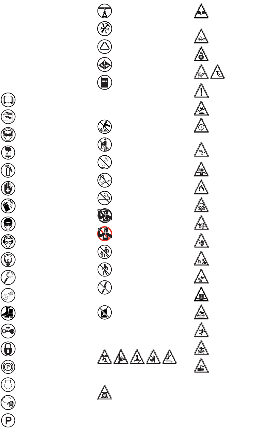
2.3 SAFETY ICON
NOMENCLATURE
Pictorial icons signal a type of
hazard and warn of personal
protection issues, prohibited
actions, and hazard avoidance.
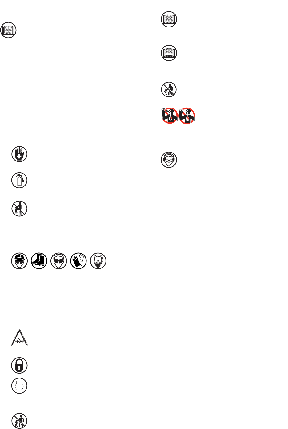
2.3.1 Personal
Protection/Important
Information
Read the manual
Damaged safety signs
Eye protection
Eye flush
Fire extinguisher
First aid kit
Hand protection
Head protection
Hearing protection
Breathing protection
Inspect equipment
OEM
OEM parts only
Protective shoes
Remove key
Lock compartment
Set parking brake
STOP Stop engine
THINK
SAFETY! Think safety
Transmission in park
Use proper support
Use proper tools
Visibility
Weight rating
Fill to proper level
2.3.2 Prohibited Actions
Do not alter or modify
Do not ride
Do not weld
No open flame
No smoking
No alcohol
No drugs
No young children
No bystanders
No electrostatic
discharge
No improper disposal
2.3.3 Hazard Avoidance
Crush hazard
Crush hazard (chock
wheels)
Defective or broken
part
Entanglement hazard
Explosive force hazard
Fall hazard
Safety alert symbol
Slipping hazard
Tire pressure
(maintain)
Tripping injury
Hazardous vapors
Fire hazard
Poison hazard
Ventilation hazard
Shock hazard
Explosion hazard
Safety shields
Weight limit
Hot surface
Electrocution hazard
Hot oil hazard
Chemical burn hazard
16
2.4 GENERAL SAFETY
Read and understand the Operator’s
Manual and all safety signs before
operating, maintaining, adjusting, lling, or
towing the Fuel Trailer.
This trailer was designed for a specic
application; transporting diesel fuel and
diesel exhaust uid (DEF). DO NOT
modify or use this trailer for any application
other than which it was designed.
Trailers that are lled or operated
improperly or by untrained personnel can
be dangerous, exposing the operators and/
or bystanders to possible serious injury or
death.
1. Have a rst aid kit available for use
should the need arise and know how to
use it.
2. Have a re extinguisher available for
use should the need arise and know
how to use it.
3. Do not allow riders.
4. When working around or operating this
equipment, wear appropriate personal
protective equipment. This list includes but is
not limited to:
• A hard hat.
• Protective shoes with slip resistant soles.
• Protective goggles, glasses, or face shield.
• Heavy gloves and protective clothing.
• Respirator, if necessary.
5. Do not allow long hair, loose tting
clothing, or jewelry around equipment
with rotating parts.
6. Securely latch compartment doors
before towing.
7.
STOP
Stop engine, remove ignition key, and
wait for all moving parts to stop before
servicing, repairing, adjusting, lling, or
towing.
8. Clear the area of people, especially
small children, before refueling
machinery.
9. Review safety related items annually
with all personnel who will be
operating, using, or maintaining the
Fuel Trailer.
10. Provide the end user with the owner/
operator literature. Fuel Trailer owners
must provide operating instructions to
anyone using the trailer.
11. Under no circumstances should young
children be allowed to work with or
around the Fuel Trailer.
12. Do not attempt to ll, tow, or
operate this trailer under the
inuence of drugs or alcohol.
Consult your doctor before using this trailer
while taking prescription medications.
13. Hearing Loss – Prolonged Exposure To
Loud Noise May Cause Permanent
Hearing Loss!
Working environments with noise-producing
equipment can cause partial to total hearing
loss. We recommend using hearing protection
any time noise levels exceed 80db. Noise
levels over 85db, on a long-term basis, can
cause severe hearing loss. Noise levels over
90db over a period of time can cause
permanent and even total hearing loss.
Hearing loss from loud noise is cumulative
over a lifetime without hope of natural
recovery.
Note: In order to provide a better view, certain
photographs or illustrations in this manual
may show an assembly with a safety shield
removed. However, equipment should
never be operated in this condition. Keep
all shields in place. If shield removal
becomes necessary for repairs, replace the
shield prior to use.
2.5 SAFETY SIGNS
Refer to the Safety Signs Locations section for
safety information.
2.6 PREPARATION
Refer to the Pre-Operating Instructions section for
safety information.
2.7 OPERATING SAFETY
Refer to the Operation section for safety
information.
17
2.8 TRANSPORT SAFETY
Refer to the Towing section for safety information.
2.9 STORAGE SAFETY
Refer to the Storage section for safety information.
2.10 MAINTENANCE SAFETY
Refer to the Maintenance section for safety
information.
2.11 DIESEL FUEL SAFETY
2.11.1 Inhalation Hazard
DANGER
Always avoid breathing fuel vapors or
mists which may cause dizziness,
drowsiness, moderate eye irritation,
and/or skin irritation (rash). Excessive exposure
may cause irritations to the nose, throat, lungs,
and respiratory tract. Central nervous system
(brain) effects may include headache, dizziness,
loss of balance and coordination,
unconsciousness, coma, respiratory failure,
and death.
In case of inhalation, remove person to fresh
air. If person is not breathing, provide articial
respiration. If necessary, provide additional
oxygen once breathing is restored if trained to
do so. Seek medical attention immediately.
2.11.2 Fire and Explosion Hazards
WARNING
Diesel fuel presents a moderate re
hazard. Vapors may be ignited rapidly
when exposed to heat, spark, open ame,
or other source of ignition. When mixed with air
and exposed to an ignition source, ammable
vapors can burn in the open or explode in
conned spaces. Being heavier than air, vapors
may travel long distances to an ignition source
and ash back. Runoff to sewer may cause re
or explosion hazard.
2.11.3 Ingestion
WARNING
The major health threat of ingestion
occurs from the danger of aspiration
(breathing) of liquid drops into the lungs,
particularly from vomiting. Aspiration may
result in chemical pneumonia (uid in the
lungs), severe lung damage, respiratory failure,
and even death. Ingestion will cause
gastrointestinal disturbances, including
irritation, nausea, vomiting and diarrhea, and
central nervous system (brain) effects similar to
alcohol intoxication. In severe cases, tremors,
convulsions, loss of consciousness, coma,
respiratory arrest, and death may occur.
In case of ingestion DO NOT INDUCE VOMITING.
Do not give liquids. Obtain immediate medical
attention. If spontaneous vomiting occurs, lean
victim forward to reduce the risk of aspiration.
Monitor for breathing difculties.
Small amounts of material which enter the
mouth should be rinsed out until the taste is
dissipated.
2.11.4 Eye Protection
WARNING
Safety glasses or goggles are
recommended where there is a possibility
of splashing or spraying. Contact with
liquid or vapor may cause mild irritation.
In case of contact with eyes, immediately
ush with clean, low-pressure water for
at least 15 minutes. Hold eyelids open to
ensure adequate ushing. Seek medical
attention.
18
2.11.5 Skin Protection
CAUTION
Contact with diesel fuel may cause skin
irritation with prolonged or repeated
contact. Wearing gloves constructed of
nitrile, neoprene, or PVC are recommended
when in close contact with diesel fuel. Chemical
protective clothing should also be worn. Long-
term, repeated exposure to diesel fuel may
cause skin cancer.
In case of contact with skin, remove
contaminated clothing. Wash contaminated
areas thoroughly with soap and water or
waterless hand cleanser. Obtain medical
attention if irritation or redness develops.
2.11.6 Storage Precautions
CAUTION
Keep away from ame, sparks, excessive
temperatures, and open ame. Keep
trailer ll port closed because an empty
tank may contain explosive vapors. Do not
pressurize, cut, heat, weld, or expose tanks to
sources of ignition.
Store the trailer in a well-ventilated area.
Avoid storage near incompatible
materials.
2.11.7 U.S. Federal, State, and Local
Regulatory Information
SAFETY
INSTRUCTIONS
Diesel fuel is on the EPA TSCA Inventory.
Any spill or uncontrolled release of this
product, including any substantial threat
of release, may be subject to federal, state
and/or local reporting requirements. This
product may also be subject to other regulations
at the state and/or local level. Always consult
the regulations applicable to your area prior to
operation.
2.12 BATTERY SAFETY
2.12.1 General Hazards
SAFETY
INSTRUCTIONS
Wear protective eye wear and gloves.
DO NOT attempt to recharge a frozen battery.
Remove the battery from the vehicle/equipment,
bring it into a warm room, and let it thaw before
charging or testing.
Inspect the battery cables to make sure they
are free of rust and corrosion and have no
exposed wires. Never use electrical tape to
cover exposed wires.
Automotive lead-acid batteries contain sulfuric
acid in the electrolyte. The acid inside the
battery is highly corrosive and can burn your
skin if it leaks out of the battery and gets on
your skin. Acid may leak out of the battery if the
case is cracked or damaged.
Maintenance-free batteries should always
remain in an upright position (do not turn it
sideways or upside down).
On equipment with a battery designed into
the fuel trailer, it is usually a good idea to
disconnect the battery before doing electrical
repairs. Disconnect the negative battery cable
from the battery to prevent accidental damage
to onboard electronics or wiring to prevent a
short circuit.
NEVER disconnect a battery when the ignition
is ON in the tow vehicle, or while the engine is
idling or running, as this can damage electrical
and/or electronic components in the tow
vehicle.
2.12.2 Ventilation Hazard
SAFETY
INSTRUCTIONS
Whenever servicing a battery, work in a well
ventilated area to prevent gas buildup.

19
2.12.3 Shock Hazards
SAFETY
INSTRUCTIONS
Batteries only produce 12 Volts so there is NO
danger of being shocked. However, 12 Volt
batteries can generate several hundred amps of
current, which is roughly the amount of current
used by a welding arc. Do not short the battery
by touching the positive or negative terminals
with a metal tool. This current is capable of
damaging tools, equipment, and causing
personal injury. It can also cause the battery to
explode.
Before working around a battery, remove
all jewelry, particularly rings and necklaces.
The electrical charge from a battery can be
transmitted through a metal tool and into a
metal ring or watch.
2.12.4 Explosion Hazards
SAFETY
INSTRUCTIONS
Always remove the battery’s ground cable
(black) before removing the positive (red). If the
negative cable is removed rst, it will not be
possible to inadvertently complete a circuit,
thus causing electrical shock.
A short circuit can occur if the positive terminal
is connected to the battery and the person
working with the battery comes into contact
with a grounded object. Always remove the
ground cable rst.
Do not smoke around a battery, or use anything
that produces an open ame or spark.
Batteries can explode. Batteries give off
hydrogen gas, which is ammable and can
explode if a spark occurs near the battery (as
when connecting a jumper cable).

20
2.13 SIGN-OFF FORM
Meridian Manufacturing Inc. follows the general
Safety Standards specied by the American
Society of Agricultural Engineers (ASAE) and
Occupational Safety and Health Administration
(OSHA). Anyone who will be operating and/or
maintaining the Meridian Manufacturing Inc. Fuel
Trailer must read and clearly understand ALL
Safety, Operating, and Maintenance information
presented in this manual.
Do not allow anyone to operate this equipment
until such information has been reviewed.
Annually review this information before the season
start-up.
SIGN-OFF FORM
Date Employee’s Signature Employer’s Signature
Make these periodic reviews of SAFETY and
OPERATION a standard practice for all of your
equipment. We feel an untrained operator is
unqualied to operate this equipment.
A sign-off sheet is provided for your recordkeeping
to show that all personnel who will be working
with the equipment have read and understand the
information in the Operator’s Manual and have
been instructed in the operation of the equipment.
21
3. SAFETY SIGN LOCATIONS
3.1 GENERAL INFORMATION
The types of safety signs and locations on the
equipment are shown in the following pages.
Good SAFETY AWARENESS requires that you
familiarize yourself with the various safety signs,
the type of warning and the area, or a particular
function related to that area.
1.
N
I
NG
AR If safety signs have been damaged,
removed, become illegible, or parts
replaced without signs, new signs must
be applied.
2. Replacement parts that displayed a safety
sign should also display the current sign.
3. Replacement safety signs (labels) are
available from your authorized Dealer Parts
Department or the factory at no cost.
3.2 HOW TO INSTALL SAFETY SIGNS
1. Be sure that the installation area is clean and
dry.
2. Be sure the temperature is above 50°F (10°C).
3. Determine the exact position before you
remove the backing paper.
4. Remove the smallest portion of the split
backing paper.
5. Align the sign over the specied area and
carefully press the small portion with the
exposed sticky backing in place.
6. Slowly peel back the remaining paper and
carefully smooth the remaining portion of the
sign in place.
7. Small air pockets can be pierced with a pin
and smoothed out using a piece of sign
backing paper.
3.3 DECAL LOCATIONS
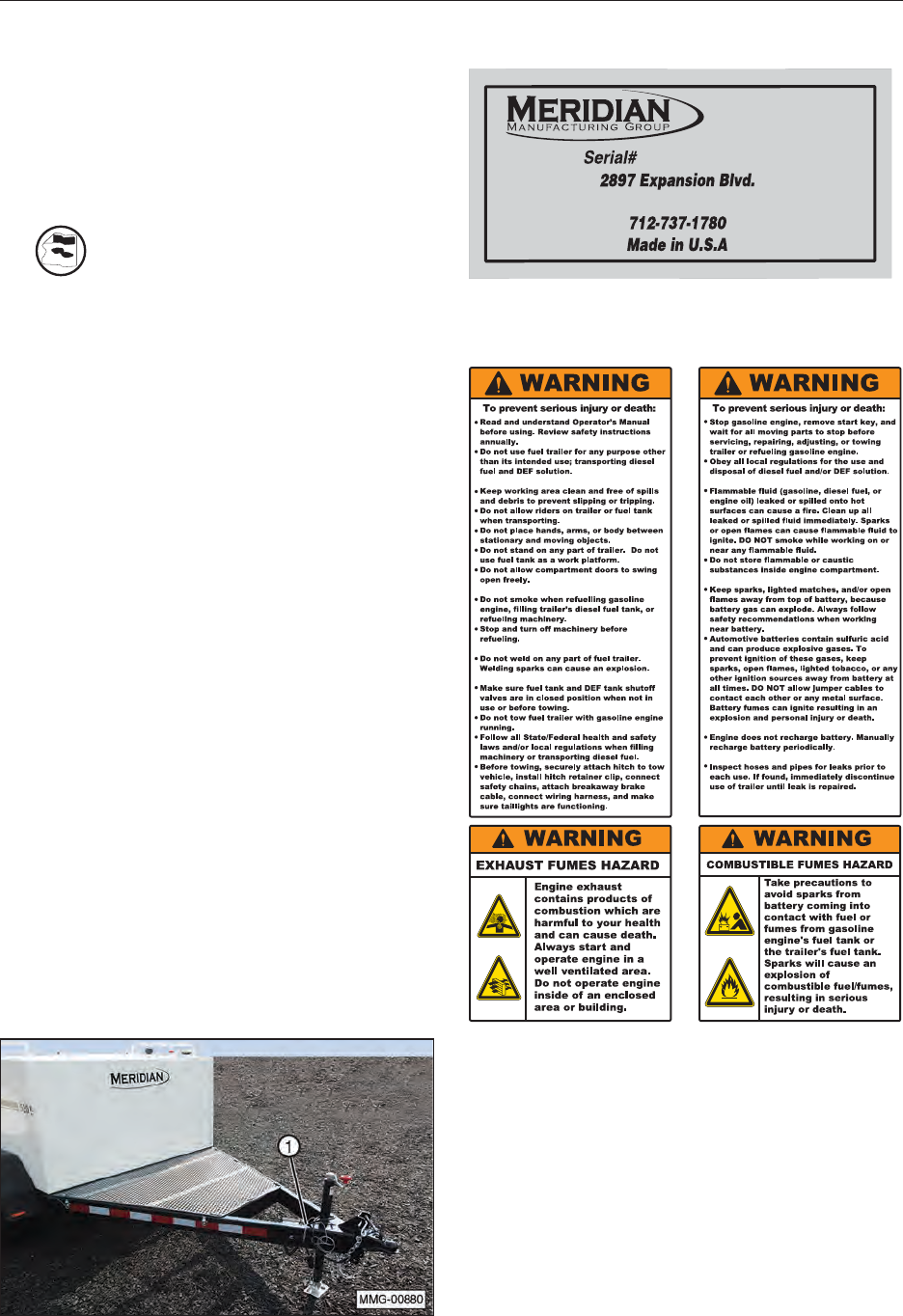
1. Product Serial Number Decal (#19984)
Storm Lake, IA 50588
6720110948768
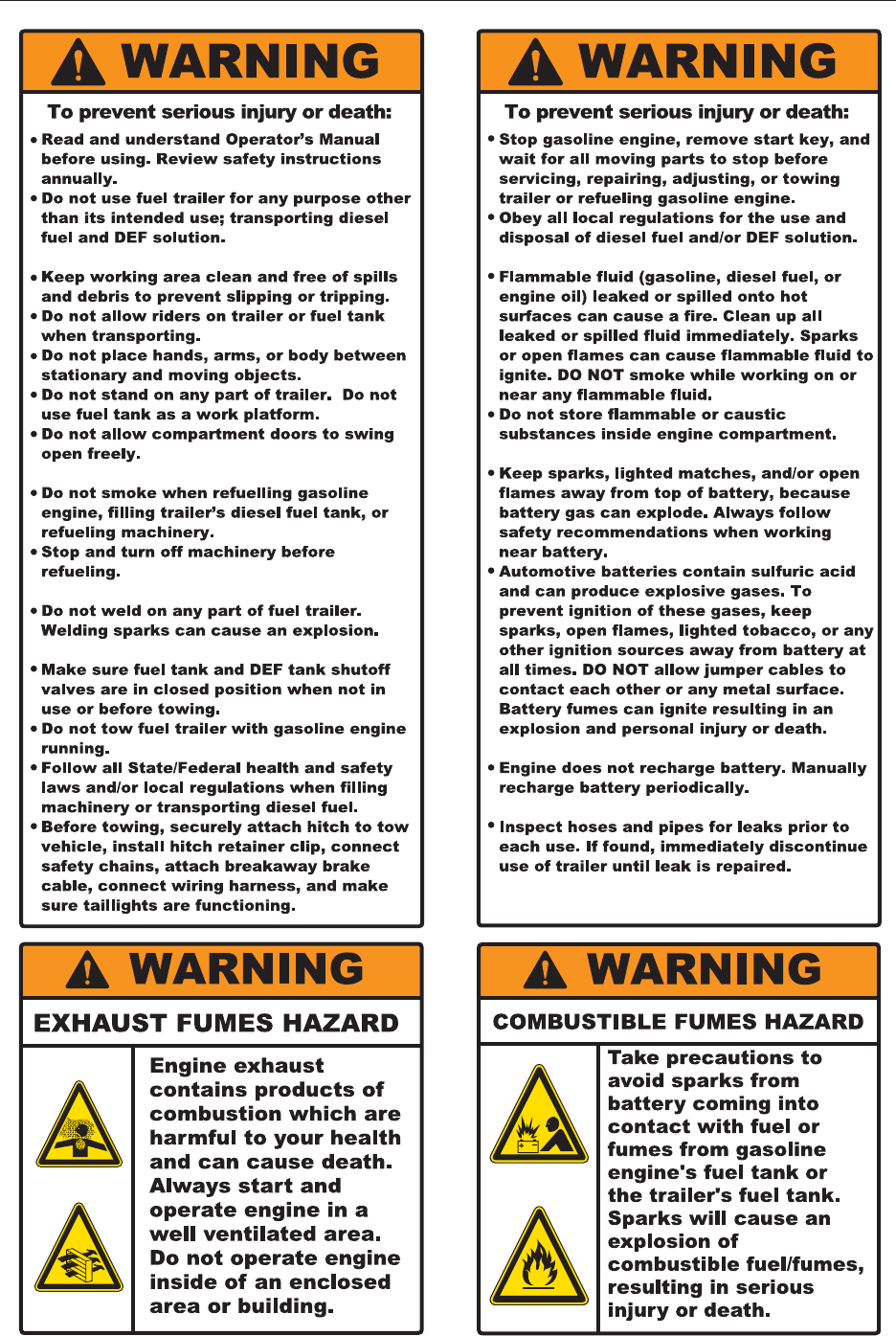
2. WARNING — Read and Understand (#17731)
(located in rear compartment)
17731
22
17731
23
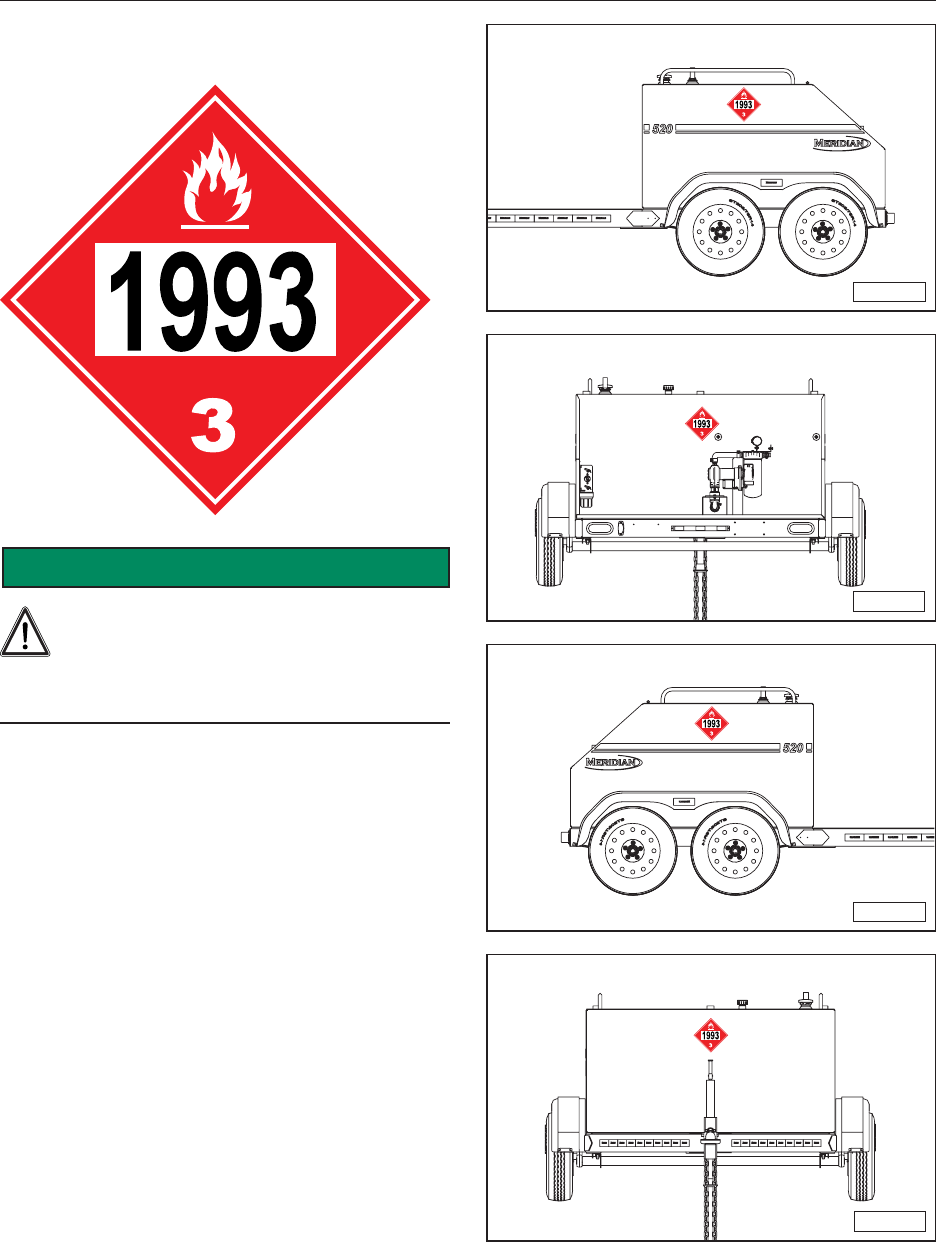
3.4 INSTALLING 1993 DIESEL FUEL
PLACARDS
SAFETY
INSTRUCTIONS
Before transporting fuel, make sure the
diesel fuel placards are displayed on all
four sides of the trailer. It is the
responsibility of the owner to properly install
and display these placards.
Fuel trailers are shipped with four diesel fuel
placards that are not installed. Federal regulations
require that the placards be installed before lling
the tank with diesel fuel.
Install one placard on each of the four sides.
Note: Install the placards prior to lling the fuel
tank with diesel fuel. Trailers that have
never been lled with fuel do not require the
placards in order to be towed.
MMG-00883
MMG-00884
MMG-00881
MMG-00882
24
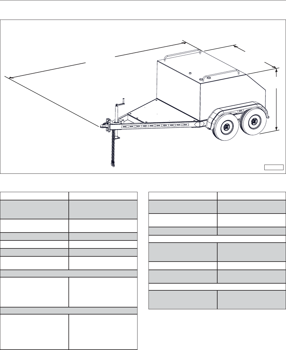
4. SPECIFICATIONS
4.1 OVERALL DIMENSIONS
MMG-00932
153-1/4” 3-5/1”
5-1/4”
4.2 SPECIFICATIONS
Description Specication
Diesel Fuel Pump Rated for diesel fuel only
Flow – 15 gpm standard
Flow – 40 gpm optional
Diesel Fuel Hose Length 12’ long hose standard
25’ long hose optional
Filter (diesel fuel) 10 Micron
Diesel Fuel Tank Capacity 520 gallons
Empty Weight 1,600 lbs.
Fill Opening 2” with vented and lockable
ll cap
Electric (12 Volt) Pump
(Standard)
Power – DC 12 Volt
Size – 1/4 horsepower
Duty cycle – 30 minutes
Thermal protection switch
Flow – 15 gpm
Gasoline Engine Option
Size – 6.5 horsepower
Electric start
Low-oil sensor
40 gpm pump
One-year manufacturers
warranty from OEM
Description Specication
DEF Solution Pump Power – 12 Volt
Flow – 9 gpm
DEF Hose Length 25’ long hose on hose hook
Retracting reel optional
DEF Solution Tank Capacity 55 gallons
Electrical System 12V battery (optional) for
engine’s electric start and
DEF pump
Breakaway Brake System Standard
Wiring Harness Standard 7-pin automotive
connector
Axles and Tires 3500 pound axle with electric
drum brakes (each axle)
14” x 10-ply tires
25
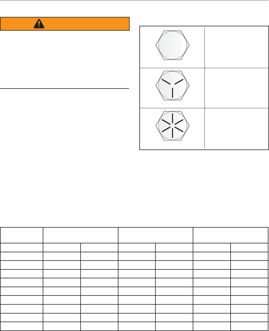
4.3 BOLT SPECIFICATIONS
WARNING
EQUIPMENT FAILURE
The torque value for bolts and capscrews is
identied by their head markings. Replacing
higher “Grade” bolts (Grade 8) with lower
Grade bolts (Grade 5) will lead to equipment
failure and can result in injury or death. Always
use replacement bolts with the same Grade
markings as the removed bolt.
4.3.1 Bolt Torque Values
Torque gures indicated above are valid for non‑
greased or non-oiled threads and heads unless
otherwise specied. Therefore, do not grease or
oil bolts or capscrews unless otherwise instructed
in this manual. When using locking elements,
increase torque values by 5%.
Bolt
Diameter “A”
SAE Grade 2
ft-lbs (N·m)
SAE Grade 5
ft-lbs (N·m)
SAE Grade 8
ft-lbs (N·m)
1/4" 6 (8) 9 (12) 12 (17)
5/16" 10 (13) 19 (25) 27 (36)
3/8" 20 (27) 33 (45) 45 (63)
7/16" 30 (41) 53 (72) 75 (100)
1/2" 45 61) 80 (110) 115 (155)
9/16" 70 (95) 115 (155) 165 (220)
5/8" 95 (128) 160 (215) 220 (305)
3/4" 165 (225) 290 (390) 400 (540)
7/8" 170 (230) 420 (570) 650 (880)
1" 225 (345) 630 (850) 970 (1320)
4.3.2 Grade Markings Chart
No Marking
Grade 2
Low or Medium
Carbon Steel
Grade 5
Medium Carbon
Steel Quenched
and Tempered
Grade 8
Medium Carbon
Alloy Steel,
Quenched and
Tempered
3 Radial Lines
6 Radial Lines
26
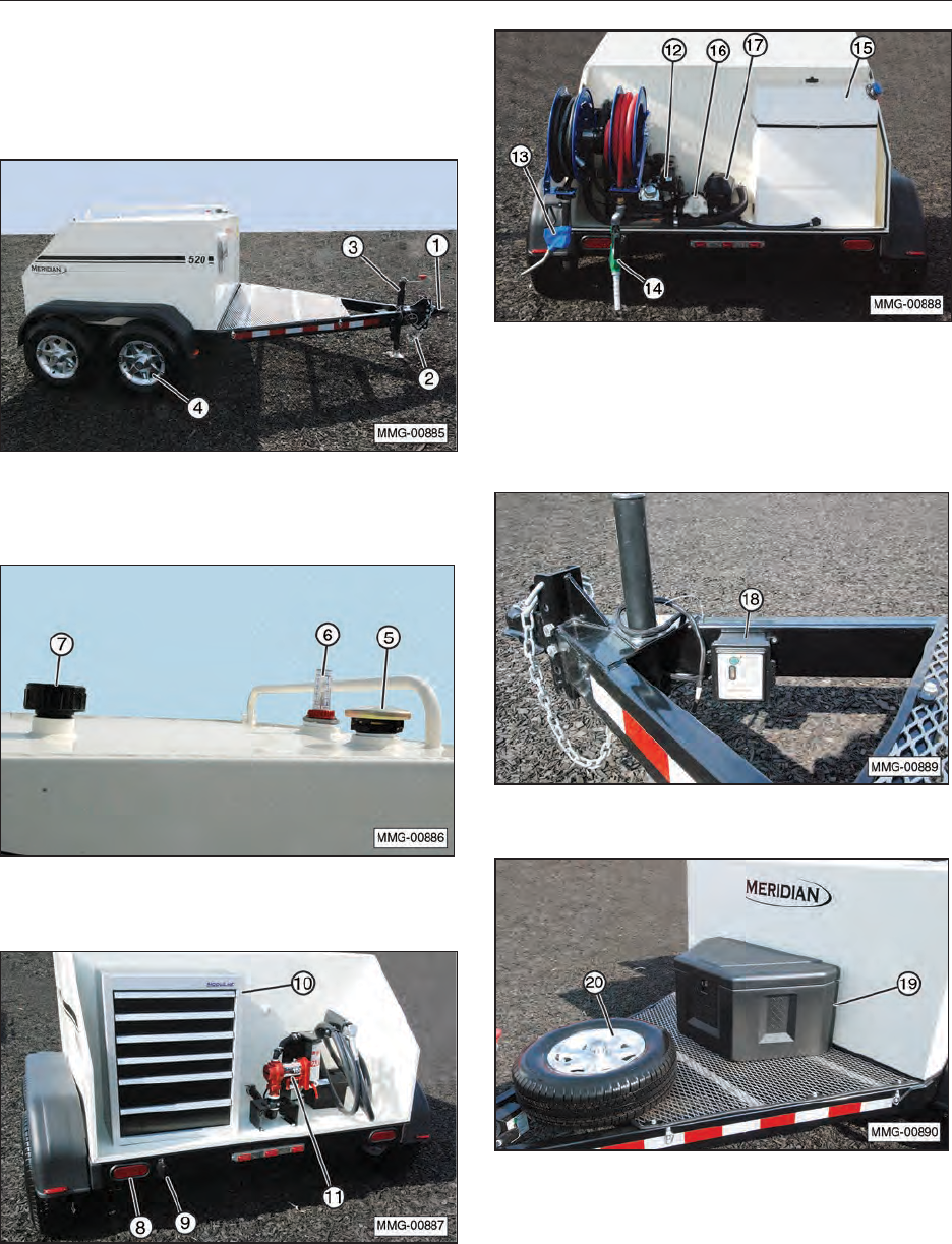
5. EQUIPMENT COMPONENTS AND CONTROLS
5.1 COMPONENT NOMENCLATURE
AND LOCATION
The Fuel Trailer contains the following components
and controls.
(1) Adjustable height hitch for 2-5/16” ball. (2) Safety
towing chains. (3) Jack. (4) 3500 lb axles with steel
(standard) or aluminum (optional) wheels.
(5) Fuel tank ll opening with vented and lockable cap.
(6) Fill level indicator. (7) Tank vent.
(8) DOT approved taillights and turn signals.
(9) License plate light. (10) Optional rear tool box.
(11) 12V DC 15 GPM (standard) diesel fuel pump.
(12) Optional gasoline engine and 40 GPM diesel fuel
pump. (13) DEF solution hose and retractable reel
with auto shut-off nozzle. (14) Diesel fuel hose and
retractable reel with auto shut-off nozzle. (15) DEF
solution tank (55 gallons). (16) DEF solution pump.
(17) 12 Volt battery and battery box.
(18) Breakaway Brake System.
(19) Optional front storage box. (20) Optional spare tire.
27
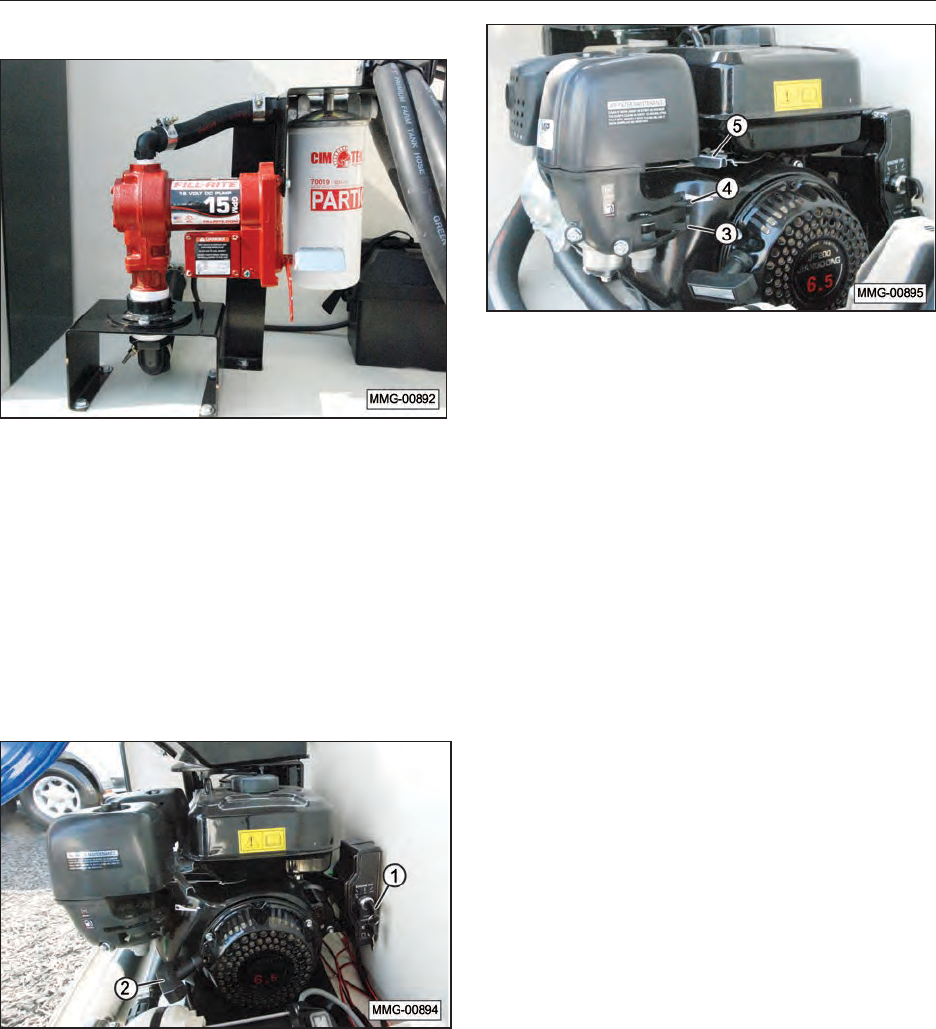
5.2 ELECTRIC PUMP (12 VOLT)
The standard fuel trailer is equipped with a 12 Volt
electric fuel pump. The fuel pump has 18’ power
cables with factory clamps.
5.3 GASOLINE ENGINE AND
CONTROLS
An optional gasoline engine may be supplied with
this unit. Always read the OEM engine Operator’s
Manual supplied with the fuel trailer for the
detailed engine operating procedures.
1. Engine Key Switch
Turn the key switch to the START position to
start the engine. When the engine starts, then
release the key and allow it to return to the ON
position.
2. Starting Rope
This retracting rope and T-bar is an optional
method used to start the engine. Grasp the
T‑bar rmly and pull the rope sharply to start
the engine. The key switch must be ON for the
engine to start.
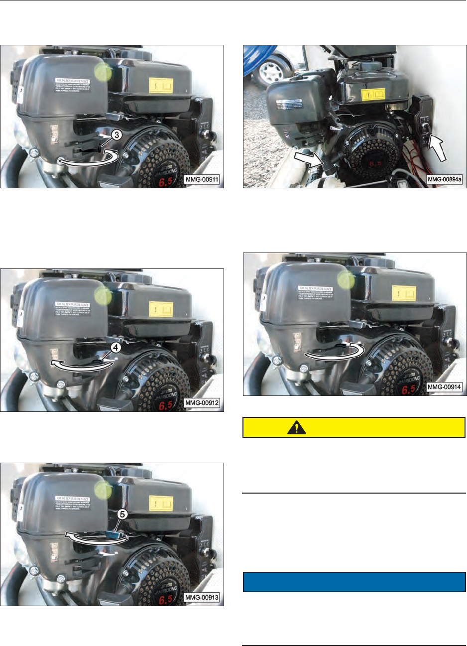
3. Fuel Shut-Off Lever
Each engine is equipped with a fuel valve
between the fuel tank and the carburetor. The
fuel valve lever must be in the ON position (to
the right) for the engine to run. Slide the fuel
valve toward the engine to turn ON and away
for OFF (to the left).
Before transporting or when the engine is not
in use, move the fuel valve lever to the OFF
position to prevent carburetor ooding and to
reduce the possibility of fuel leakage.
4. Choke Lever
The choke lever controls the fuel/air mixture
to the engine. Close the choke when starting
if the engine is cold. Open the choke as the
engine warms. Always open the choke fully
during operation.
5. Throttle Lever
This lever controls the engine RPM. Move the
lever to increase or decrease the RPM. Always
run at maximum throttle while operating the
pump.
28
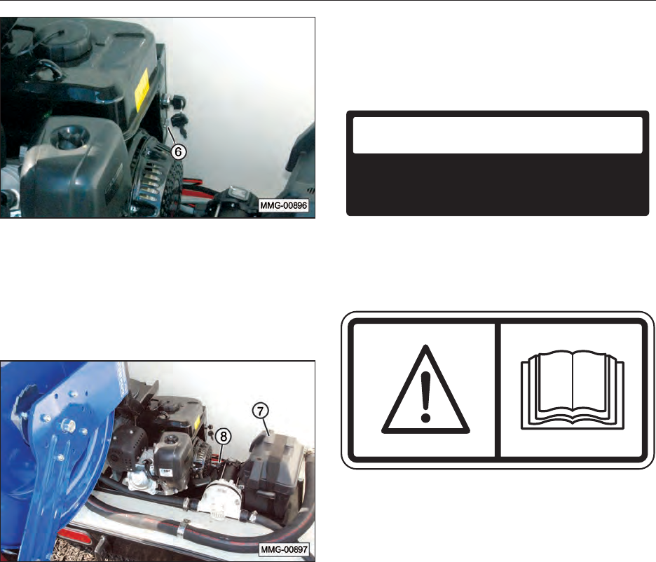
6. Engine Circuit Protection
The circuit protector protects the battery
charging circuit. A short circuit, or a battery
connected with reverse polarity, will trip the
circuit breaker. The green indicator inside
the circuit protector will pop out to show that the
circuit protector has switched off.
7. Battery (12 Volt)
A 12 Volt battery supplies the power to start the
gasoline engine or operate the 12 Volt electric
diesel pump. The battery is not charged when
the engine is operating. If the battery is not
charging using an external charger, check the
fuse. Replace the fuse if necessary.
8. Fuse
A 7.5 amp fuse protects the electrical system of
the trailer.
5.3 GASOLINE ENGINE SAFETY
SIGNS
1. Maintain Air Cleaner — (contact OEM
manufacturer for replacement of this decal)
AIR FILTER MAINTENANCE
CLEAN IT WITH AGENT EVERY 50 HOURS. IF
TOO DUSTY, CLEAN EVERY 10 HOURS. AFTER
FULLY DRY, INSERT IT INTO CLEAN OIL. USE IT
WHEN SURPLUS OIL IS REMOVED.
2. Read Operating Manual Before Using Engine
(contact OEM manufacturer for replacement of
this decal)
29
6. PRE-OPERATING INSTRUCTIONS
6.1 EQUIPMENT BREAK-IN PERIOD
A special break-in procedure has been developed
to ensure the integrity of the fuel trailer when
rst put into service. Follow the instructions and
then follow the Inspections for 1/2, 4, and 10 hour
instructions at the appropriate interval.
After completing these instructions, follow the
normal service schedule in the Maintenance and
Service sections and engine manual.
1. Read and follow the instructions in the OEM
engine and pump manuals, and this manual.
2. Before starting the gasoline engine
(if equipped) for the rst time, check the
engine oil level. Add oil as necessary.
Operating the engine without oil will damage
the engine and void the warranty.
NOTICE
Check the engine oil level and add as needed.
Oil ll location.
3. On gasoline engine/pump combinations, make
sure the fuel pump is primed before the rst
use. The pump will retain sufficient liquid for
self-priming thereafter.
To prime the pump:
a. Remove the fill plug on top of the pump
housing.
b. Fill the pump housing with filtered diesel
fuel.
c. Replace the plug.
4. Start the engine and check the controls. Be
sure that they function properly.
5. Review and follow the Daily Pre-Operation
Checklist before starting the equipment.
6. Initially check the wheel bolt torque and
then again at 10, 25, and 50 miles. Refer to
“10.6 Wheel Bolt Torque” on page 50 for
tightening instructions.
6.1.1 Inspections for 1/2, 4, and 10
Hours
1. On gasoline engine/pump combinations,
recheck the engine to pump shaft connection
after 1/2 hour and again after 4 hours.
2. Recheck all hardware and fasteners after 4
hours of operation. Tighten to specied torque.
3. At 10 hours, change the engine oil with the
specied oil. Refer to “10.4.3 Change Engine
Oil” on page 47.
30
6.2 DAILY PRE-OPERATION
CHECKLIST
Efcient and safe operation of the Fuel Trailer
requires that each operator reads and follows
the operating procedures and all related safety
precautions outlined in this section.
A pre-operation checklist is provided for the
operator. It is important for both personal safety
and maintaining the efcient operation of the
delivery system that this checklist be followed.
Before operating for the rst time and each time
thereafter, the following areas should be checked:
1. Use only a truck or tractor of adequate power
and weight to pull the trailer.
2. Make sure the trailer is positively hitched to
the tow vehicle.
3. Attach safety chains from the trailer to the tow
vehicle. Crisscross the chains under the hitch
to support it should an unplanned separation
occur.
4. Visually inspect the wiring harness and plug
for damage. Do not use the trailer if damage
is found.
5. Check the engine oil and fuel levels. Add as
required.
IMPORTANT
The engine warranty is void if the engine is run
without oil.
6. Make sure there is sufcient fuel in the tank to
prime the fuel pump and provide a steady ow
of fuel. Do not run the pump dry.
7. Visually check all hardware and fasteners for
missing parts and make sure the fasteners are
properly tightened.
8. Visually make sure the wheel bolt lug nuts are
properly tightened.
9. Visually check the tires and ensure they are
inated to their specied pressure. Correct
under‑ination or over‑ination pressures. The
specied ination pressure is on the tires.
10. Remove any entangled crop material from
under the trailer.
11. Test the breakaway brake unit and the trailer
brakes.
a. Make sure the trailer brakes are operating
properly.
b. Make sure the trip wire to the breakaway
switch is connected to the tow vehicle.
c. Make sure the key is correctly installed in
the breakaway switch.
d. Press the Test button. The indicator
should illuminate green. If the red light
illuminates, the battery charge is low.
Refer to “10.5.1 Testing the Battery” on
page 49 for instructions on testing the
battery.
Note: The breakaway brake system is standard
equipment. This system applies the brakes
automatically and immediately whenever
the breakaway cable is properly connected
and the trailer separates from the tow
vehicle.
12. Make sure lights, reectors, Diesel Fuel
Placards, and SMV/SIS emblem required by
local highway authorities are installed.
13. Clean and make sure taillights, signal lights,
and side running lights are working properly.
31
7. TOWING
7.1 TRANSPORT SAFETY
SAFETY
INSTRUCTIONS
The following safety instructions are provided to
help prevent injury or limit equipment damage.
1. Comply with local, state, and federal
laws governing safety and conveyance
of farm related equipment on public
roads.
2. Always refer to the tow vehicle owner’s
manual Trailer Towing section to
determine the vehicle’s towing capacity
and to ensure compatibility and maximum
safety.
3. THINK
SAFETY! Before attaching the trailer to the tow
vehicle, be familiar with its controls and
how to stop it quickly in the event of an
emergency. Read and understand this manual
and the one provided with your tow vehicle
before towing the trailer.
4. Ensure that the trailer is equipped with brakes
that are in good working order. Be familiar
with their operation.
5. Make sure the diesel fuel tank is
securely fastened to the trailer before
transporting.
6. Be sure the trailer is securely hitched to the
tow vehicle and a retainer clip is inserted
through the hitch. Always attach safety chains
between the hitch and the tow vehicle.
7. Stay away from electrical power
sources. Electrocution can occur
without direct contact.
8. Plan your route to avoid heavy trafc.
9. Do not drink and drive.
10. Be a safe and courteous driver. Yield to
oncoming trafc in all situations, including
narrow bridges, intersections, etc. Watch
for trafc when operating near or crossing
roadways.
11. Never allow riders on the fuel
trailer.
12. Department of Transportation (DOT) requires
that all highway safety devices, such as
fenders, mud aps, and lighting, are properly
installed and in working condition before using
the trailer.
13. Under no circumstances should
young children be allowed to
work with or around the Fuel
Trailer. When moving the trailer, make sure all
bystanders, especially small children, stay
clear of the working area.
14. Do not exceed a maximum safe travel
speed, which may be lower than the
recommended or posted speed. Slow
down for corners and rough terrain.
15. Shift towing vehicle to a lower gear
before going down steep downgrades
to use engine as a retarding force.
Keep towing vehicle in gear at all times.
16. If equipped, clean reectors,
SMV or SIS sign, and lights
before towing. Make sure all
the lights and reectors required by highway
and transport authorities are in place and can
be seen clearly by all overtaking and
oncoming trafc.
17. Make sure all local, state, and federal
regulations, regarding the transport of
equipment on public roads and
highways, are met. Check with the local
authorities regarding trailer transport on public
roads. Obey all applicable laws and
regulations.
18. Make sure the hitch and hitch ball on
the towing vehicle are rated greater
than the trailer’s “gross vehicle weight
rating” (GVWR).
19. Inspect the hitch and hitch ball for wear
or damage. Make sure the hitch and
coupling are compatible. DO NOT tow
the trailer using a defective hitch or coupling.
20. Connect and crisscross the chains
under the hitch to support the hitch
should an unplanned separation occur.
21. If equipped, attach the breakaway cable
to the rear of the towing vehicle. Do not
attach the cable to the trailer hitch.
22. Check the tires for high/low pressure,
cuts, bubbles, damaged rims, or
missing lug nuts. Do not use the trailer
if any damage is found.
23. Make sure the directional and brake
lights on the trailer are connected and
working properly.
32
7.2 CONNECTING THE TRAILER
WARNING
Ensure that all bystanders, especially
small children, are clear of the working
area. Ensure there is enough room and
clearance to safely back up to the trailer.
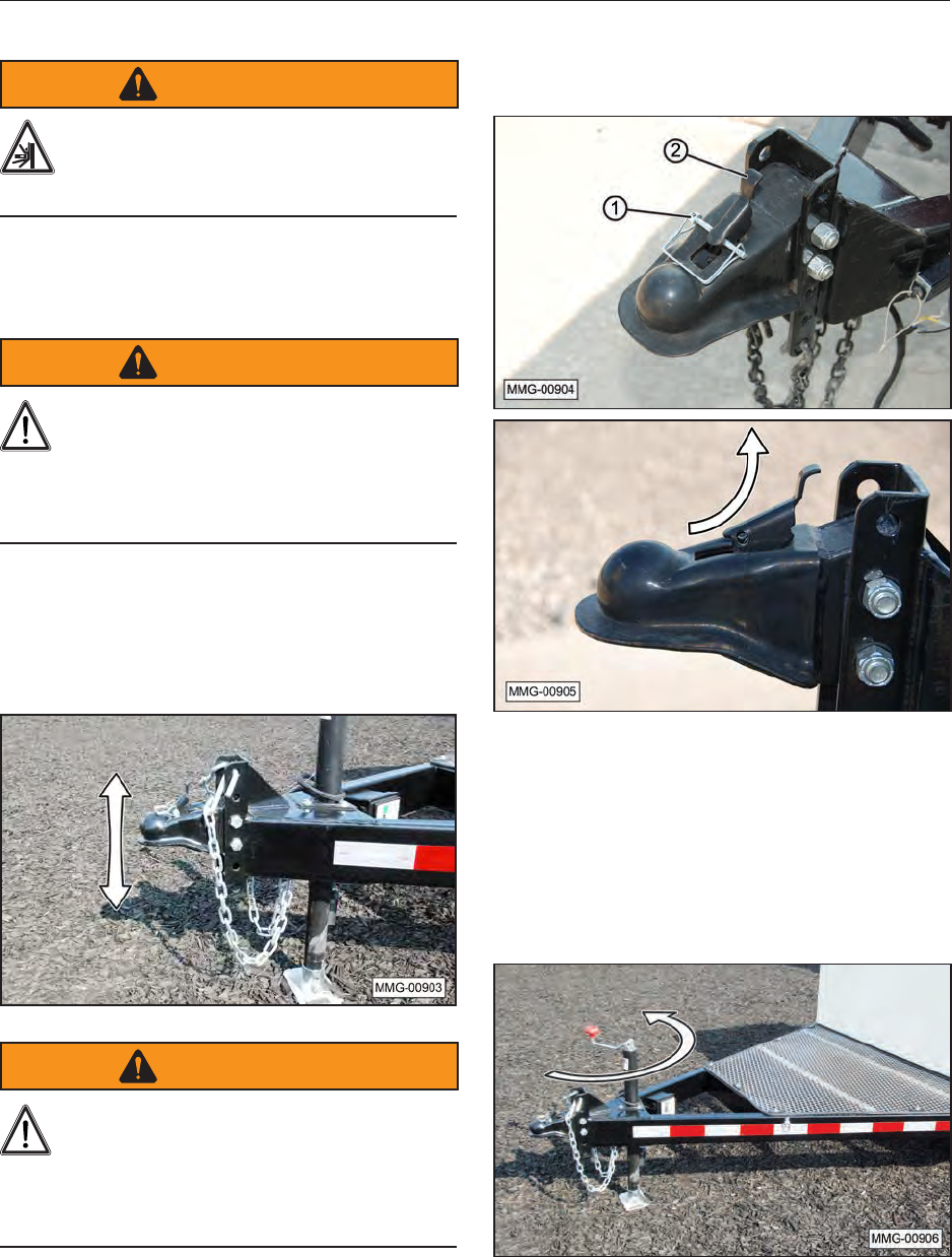
1. On a at surface, use the trailer jack to level
the trailer.
WARNING
Towing the fuel trailer with diesel fuel,
when it is not in a level position, could
cause an upward force on the tongue,
separating the trailer from the tow vehicle.
Make sure the trailer is set up with downward
pressure on the tongue assembly.
2. Adjust the height of the receiver to align with
the tow ball or be lower than the tow ball.
Once aligned, tighten both bolts to 70 ft-lb
(95 N·m).
WARNING
The receiver must be bolted to the frame
with two OEM approved bolts. The use of
only one bolt could cause the receiver
assembly to separate from the trailer, resulting
in injury or death to bystanders. Do not use the
trailer if only one bolt is installed.
3. Remove retainer clip (1). Release or open
the receiver by lifting locking lever (2) into the
open position.
4. Using the jack, raise the hitch above the ball
on the tow vehicle.
5. Slowly back the tow vehicle until the hitch and
ball are aligned.
6. Lower the hitch onto the ball.
7. Raise the jack.
33
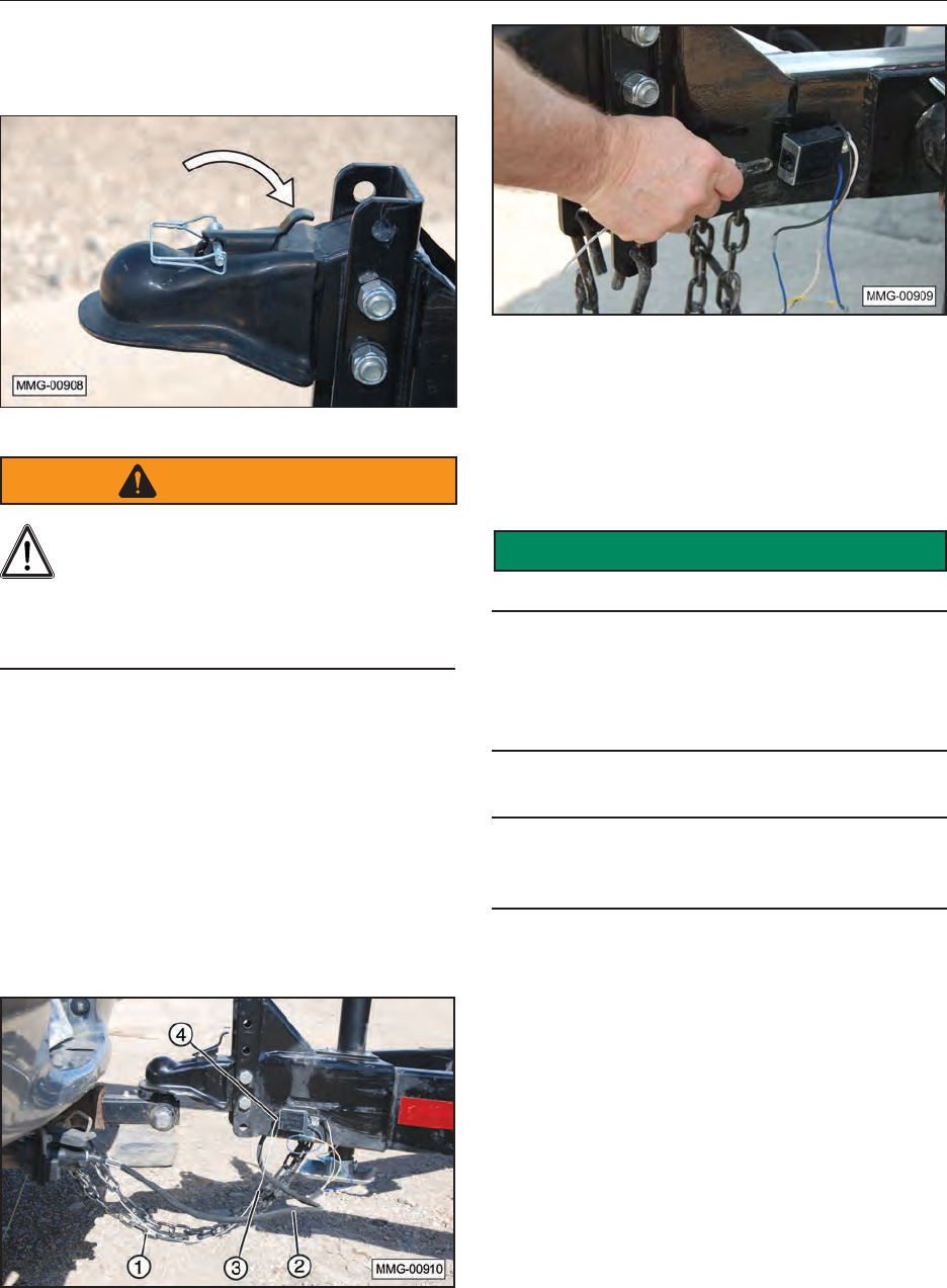
8. Close the receiver lock lever and install the
retainer clip to prevent unwanted opening of
the receiver.
WARNING
If the safety chains are damaged in any
way, do not use the trailer until proper
chains are installed. Substandard or
damaged safety chains could allow the trailer to
separate from the tow vehicle, resulting in
equipment damage, personal injury, or death.
9. Attach safety chains (1) securely to the tow
vehicle to prevent unexpected separation.
Cross the chains when attaching.
10. Connect wiring harness (2) with the seven-pin
connector for the lights and brakes.
11. Connect breakaway system cable (3) to the
tow vehicle. Make sure key (4) on the end of
the cable is properly plugged into the receiving
unit.
(The photo reects a different trailer model; however,
the hookup method is the same.)
(The key must be completely plugged into the socket for
the system to operate properly.)
12. Route the wiring harness and breakaway
brake cable in a manner that will prevent them
from dragging. Be sure to provide enough
slack for turning.
SAFETY
INSTRUCTIONS
Before towing the trailer, make sure:
1. The trailer lights and brakes are working
properly. If the trailer’s electrical equipment
is not functioning properly, it may be due to
incompatible or crossed wiring from the tow
vehicle to the trailer.
2. The trailer brakes apply when the brake pedal
is depressed.
3. The breakaway brake system activates and
applies the brakes when the cable key is
pulled from its socket.
34
8. OPERATION
8.1 OPERATING SAFETY
DANGER
Explosion/Fire Hazard
The Fuel Trailer is only intended for
use with diesel fuel or non-hazardous
liquids such as diesel exhaust uid
(DEF). DO NOT use this trailer with
any ammable liquid, such as gasoline or
kerosene. Transporting any other ammable or
combustible liquid could result in a re and
explosion causing serious injury or death.
WARNING
Read And Understand Manual
To prevent personal injury or even death,
be sure you read and understand all of
the instructions in this manual and other related
OEM equipment manuals! The Fuel Trailer, if
not used and maintained properly, can be
dangerous to users unfamiliar with its operation.
Do not allow lling, towing, refueling,
maintaining, adjusting, or cleaning of this trailer
until the user has read this manual and has
developed a thorough understanding of the
safety precautions and functions of the trailer.
DO NOT modify or use this trailer for any
application other than which it was designed.
Trailers that are lled or operated improperly or
by untrained personnel can be dangerous;
exposing themselves and/or bystanders to
possible serious injury or death.
1. Make sure that anyone who will be
operating the Fuel Trailer or working
on or around the unit reads and
understands all the operating,
maintenance, and safety information in
the operator’s manual.
2. Keep all bystanders, especially
children, away from the equipment
when lling or refueling.
3. Keep working area clean and
free of debris to prevent slipping
or tripping.
4. Keep hands, feet, hair, and clothing
away from rotating parts on the
machinery being refueled.
5. Do not place hands, ngers, or arms
between moving parts.
6. Stay away from overhead power lines.
Electrocution can occur without direct
contact.
7. Use care when climbing on machinery
to prevent slipping or falling.
8. Know and follow applicable national,
state, and local safety codes
concerning safe handling of petroleum
fuels.
9. Gasoline is a highly
ammable fuel. The
improper use, handling, or
storage of gasoline can be dangerous. Never
ll a hot engine. DO NOT ll the engine’s fuel
tank near an open ame while smoking or
while engine is running. DO NOT ll tank in
an enclosed area with poor ventilation. Clean
up any gasoline spills immediately.
10.
STOP
Before lling the
trailer, make
sure the engine
of the tow vehicle is stopped, the transmission
is placed in park, the key is removed, and the
parking brake is set.
11. Only store gasoline in containers with
approved labels, as required by federal
or state authorities.
12. Manually control the nozzle valve throughout
the lling process. Keep your face away from
the nozzle or fuel tank opening.
13. Avoid prolonged breathing of gasoline
vapors.
14. Keep gasoline away from your eyes
and skin, because it may cause
irritation.
15. Use gasoline only in open areas that
get plenty of fresh air. Never use
gasoline to wash your hands. Remove
gasoline-soaked clothing immediately.
16. Fill fuel tanks no more than 95 percent
full to allow for expansion. Replace
and tighten the machine’s fuel cap.
35
17. Never dispose of gasoline by pouring it
onto the ground or into a sewer, street
drain, stream or other body of water, or
putting it into the trash. These actions are
environmentally harmful and may result in a
re, explosion, or soil, surface or groundwater
contamination. Fines and criminal penalties
may be associated with improper disposal.
18. The mufer becomes very hot during
operation and remains hot for a while
after stopping the engine. Be careful
not to touch the mufer while it is hot. Let the
engine cool before storing it indoors.
19. Exhaust gas contains poisonous
carbon monoxide. Avoid
inhalation of exhaust gas. Never
run the engine in a closed garage or conned
area.
20. Never exceed the weight limits of this
trailer. Refer to the Specications
section in this manual for maximum
load ratings.
21. An ignition source is always a concern
in refueling. Gasoline for the gas
powered engine is very explosive,
especially the fumes. The most common
source of electrostatic discharge (spark) is
from the operator. The person refueling the
equipment should always make a point of
touching something nearby to ground and
discharge themselves before refueling the gas
engine.
8.2 FIRE EXTINGUISHER
A user‑supplied re extinguisher is recommended
whenever using the fuel trailer.
The extinguisher bracket should be mounted in an
accessible location on the trailer. Do not install the
re extinguisher onto the diesel fuel tank.
Follow the manufacturer’s instructions to
periodically check and maintain the re
extinguisher.
8.3 PRE-OPERATION CHECKS
1. The gasoline engine may not be shipped with
oil. Add oil to the gasoline engine prior to
starting for the rst time.
2. Make sure the diesel fuel pump is properly
primed before attempting to refuel any
machinery.
3. Review the OEM instructions provided with all
equipment used on the fuel trailer for operating
and safety precautions.
4. When towing the trailer with a truck, the 12
Volt electrical system is designed so the
vehicle’s charging system will charge the
trailer’s battery. Charging will only occur when
the tow vehicle’s engine/alternator is running
and the wiring harness is properly congured.
This system will not recharge a depleted or
dead battery; only help to maintain its current
charge state. Use the following to make sure
the tow vehicle is compatible with the fuel
trailer:
a. Make sure the tow vehicle is equipped
with a standard 7-pin automotive wiring
harness socket. If the tow vehicle is not
equipped with a 7-pin connector which
is properly congured, the trailer battery
will not be charged without custom wiring
from the tow vehicle’s alternator/charging
system.
b. If equipped, check the 7-pin socket on the
tow vehicle, using a Volt meter, to make
sure Pin 4 and 7 are supplying 12 Volts
of power. If any other pin has the 12 Volt
supply the battery will not be recharged.
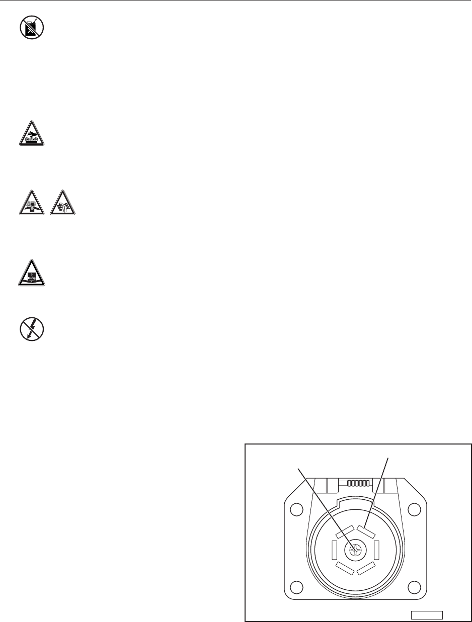
Note: To properly charge the battery, the tow
vehicle’s socket must be congured with
Pin 4 (black) along with center Pin 7 (red/
orange) connected to the 12 Volt supply.
MMG-00238
Pin 7
Pin 4
c. If there is no voltage on any of the pins,
check the fuse in the truck’s fuse panel.
The fuse for the charge line may not be
installed or is blown.
36
Note: If the tow vehicle’s wiring connections do
not correspond to the fuel trailers wiring
harness, the breakaway brake system
battery will also not be charged during
normal operation.
5. Always make sure the trailer lights and brakes
are working properly before towing the trailer.
Do not tow a trailer that is not operating
properly.
6. The fuel trailer can be towed with a tractor,
however it is electrically wired for a 7-pin
automotive wiring harness application. An ag
tractor will not properly operate the trailer’s
brake, battery charging system, or lights
without special wiring modication. Do not tow
the fuel trailer on public roads without proper
brakes and lighting.
8.4 DEF AND DIESEL FUEL TANKS
8.4.1 Filling the Fuel Trailer with Diesel
Fuel
1. Before lling the fuel tank, follow all the safety
recommendations, such as attaching the fuel
trailer to the tow vehicle, placing the fuel trailer
on a level surface, blocking both sides of the
wheels to prevent unexpected movement, etc.
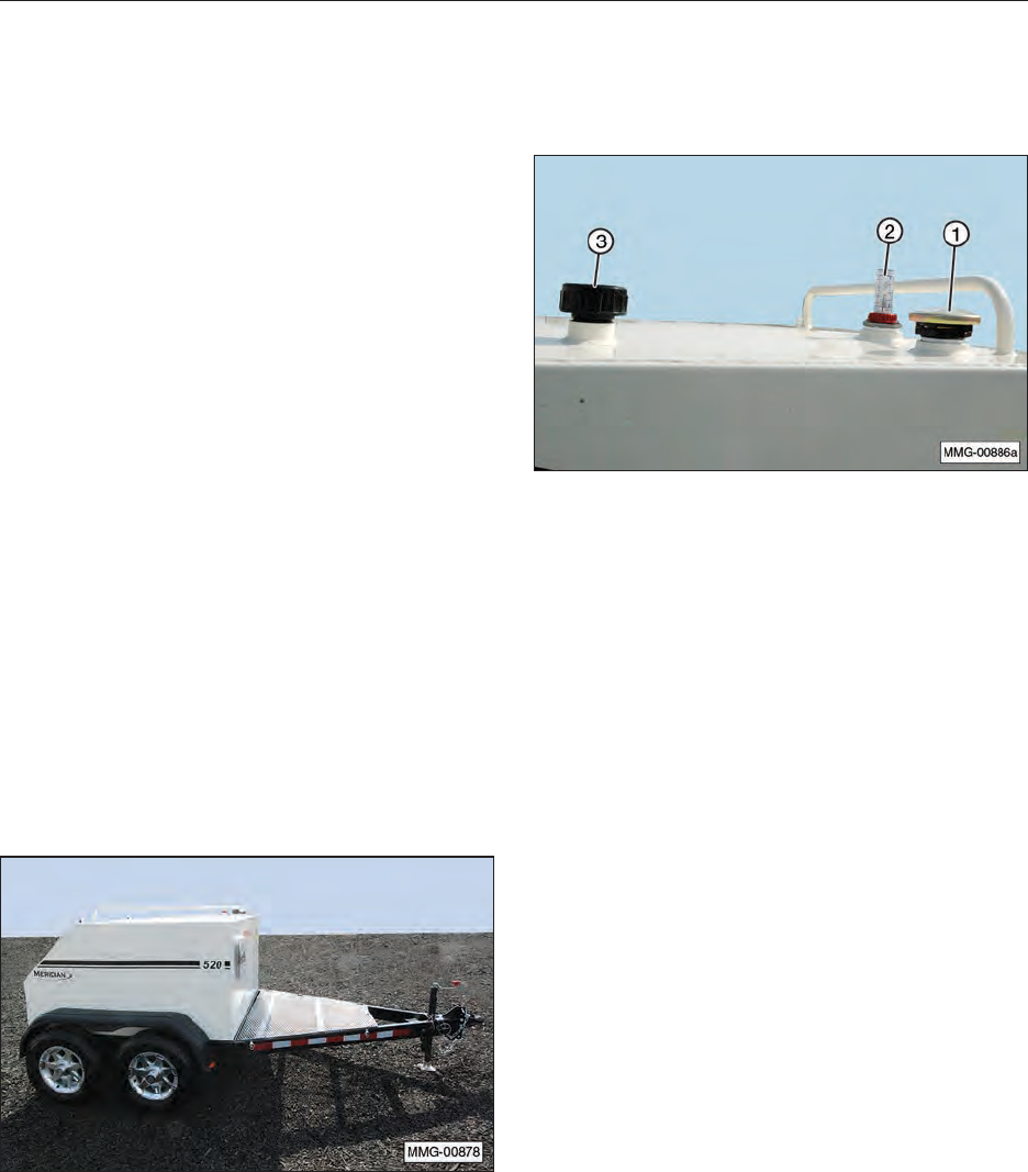
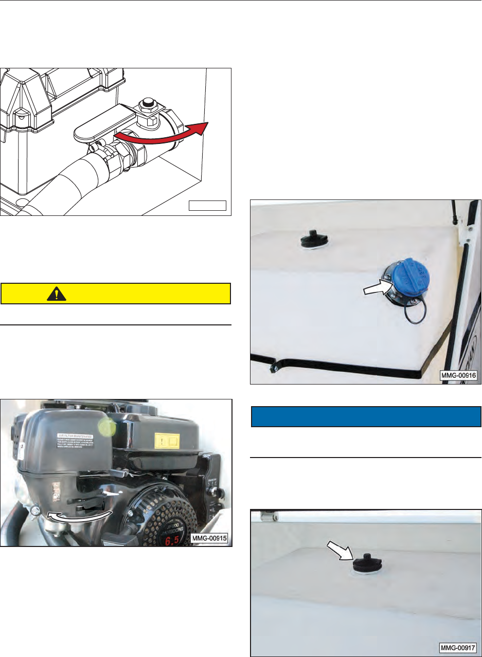
2. Fill the trailer with diesel fuel using ll spout
(1). Use sight gauge (2) on top of the tank to
prevent overlling. Never obstruct breather (3)
at any time.
37
8.4.2 Filling Machinery Using 12 Volt
Electric Diesel Fuel Pump
1. Position the fuel trailer near the machinery
being refueled.
WARNING
12 Volt batteries can present a hazardous,
explosive environment. Before making
any battery connections, ensure the
pump’s ON/OFF switch is in the OFF position.
Also make sure the pump’s battery connections
are tight before operating the pump.
2. Connect the clamps of the electrical cables for
the fuel pump to a 12 Volt power source; either
a dedicated battery or the tow vehicle.
a. Connect the end of the RED jumper
cable to the POSITIVE (+) post on the
battery (power source). Make sure the
NEGATIVE (–) cable is not touching a
grounded surface.
Note: In many cases the POSITIVE battery post
is slightly larger than the NEGATIVE post
and will be marked with a PLUS (+) sign.
There may also be a RED plastic protective
cover over the positive battery post.
b. Connect the end of the BLACK jumper cable
NEGATIVE (-) to a heavy metal ground on
the frame of the trailer or tow vehicle.
SAFETY
INSTRUCTIONS
If the cable must be connected to the NEGATIVE
(-) post on the battery itself, be extremely careful to
prevent any sparks that can ignite hydrogen fumes
around or on top of the dead battery, causing it to
explode.
3. Extend the hose to easily reach the ll spout of
the machinery being refueled.
CAUTION
Once the pump is turned ON, the fuel hose is
pressurized and will pump fuel. Do not squeeze
the handle on the fuel nozzle until it is inside the
fuel tank of the machinery being refueled.
NOTICE
The standard 12V pump is not compatible with
biodiesel fuel blends greater than 20% (B20).
Damage to the seals will occur. For fuel with more
than 20% biodiesel, use the optional gasoline
engine powered pump, or a 12V pump specically
designed for biodiesel fuel blends.
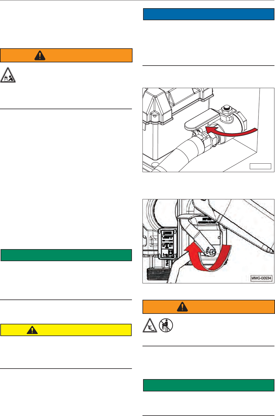
4. Open the fuel tank shut-off valve.
MMG-00935
5. Move the ON/OFF lever upward to the “ON”
position to apply power to the pump.
Fuel Pump Lever in “ON” Position.
WARNING
Do not use fuel tank as a work
platform. Do not stand on fenders.
Do not ride on trailer or allow others
to ride on trailer.
6. Refuel the machinery. Release the nozzle
when the desired amount of fuel has been
dispensed.
SAFETY
INSTRUCTIONS
The standard nozzle is not equipped with an
automatic shutoff. Be prepared to manually shut
off ow at the nozzle.
38
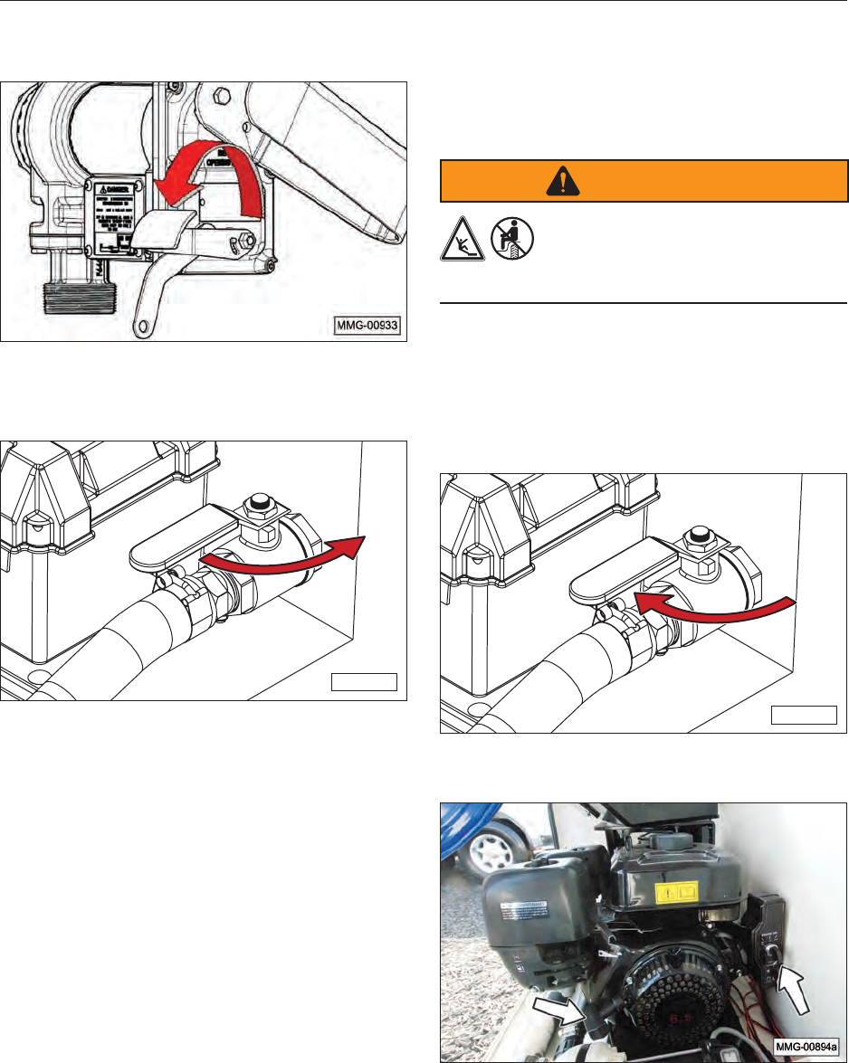
7. Move the ON/OFF lever downward to the
“OFF” position to turn off the pump.
Fuel Pump Lever in “OFF” Position.
8. Close the fuel tank shut-off valve.
MMG-00936
9. Remove the dispensing nozzle from the
machinery being refueled and secure the hose
onto the hose rack.
10. Remove the battery cables.
a. Remove the BLACK cable NEGATIVE (–)
from the metal ground on the frame of the
trailer or tow vehicle.
b. Remove the RED jumper cable from the
POSITIVE (+) post on the battery (power
source). Make sure the NEGATIVE (–)
cable is not touching a grounded surface.
8.4.3 Filling Machinery Using Engine
Powered Diesel Fuel Pump
This petroleum pump is a self-priming centrifugal
pump and only requires priming prior to its initial
start. The pump will retain sufficient liquid for self-
priming thereafter.
To prime the pump:
1. Remove the fill plug on top of the pump
housing.
2. Fill the pump housing with the fluid to be
pumped.
3. Replace the plug.
To fill the machinery:
WARNING
Do not use fuel tank as a work
platform. Do not stand on fenders.
Do not ride on trailer or allow others
to ride on trailer.
1. Position the fuel trailer near the machinery
being refueled.
2. Extend the hose to easily reach the ll spout of
the machinery being refueled.
3. Open the fuel tank shut-off valve.
MMG-00935
4. Start the engine.
39
a. Turn engine fuel lever (3) to the ON
position.
b. To start a cold engine, move choke lever
(4) to the left (closed). In warm weather,
start the engine with the choke in the middle
position. To restart a hot engine, move the
choke lever to the right (open) position.
c. Move throttle lever (5) away from the
SLOW position to the FAST position.
d. Use engine pull cord or electric start and
start the engine.
e. If the choke lever is in the closed position,
gradually move it to the right (open)
position after the engine starts to run.
CAUTION
Once the pump is started, the fuel hose is
pressurized and will pump fuel. Do not squeeze
the handle on the fuel nozzle until it is inside the
fuel tank of the machinery being refueled.
5. Place the fuel nozzle into the receiving
tank and squeeze the handle to start fuel
ow. When the tank is full, the nozzle will
automatically shut off the ow.
NOTICE
When lling machinery from the fuel trailer, never
allow the pump to run dry. Operating the pump
without fuel can cause damage to pump and/or
gasoline engine.
40
6. When fueling is complete, turn the gasoline
engine off.
7. Close the fuel tank shut-off valve.
MMG-00936
8. Rewind the fuel hose onto the hose rack or
reel and place the nozzle back into the nozzle
holder.
CAUTION
Turn off the fuel when the engine is not in use.
9. Place the engine’s fuel lever in the OFF
position before towing the fuel trailer on the
open road.
8.4.4 Filling the DEF Solution Tank
Review the section on DEF Solution in this
manual before lling the DEF tank or servicing
the machinery. Because of our continuous
improvement process, some images may be
different than the actual product.
1. Fill the DEF tank using the ll port. The uid
level will be evident through the side of the
white poly tank. Do not overll the tank.
Note: To prevent contamination of the DEF uid,
keep the DEF nozzle and the ll port on the
tank clean and free of dust and dirt.
NOTICE
Observe the uid level through the side of the white
poly tank. Do not overll the tank.
Note: Ensure breather on top of the tank is not
blocked and is properly tightened.
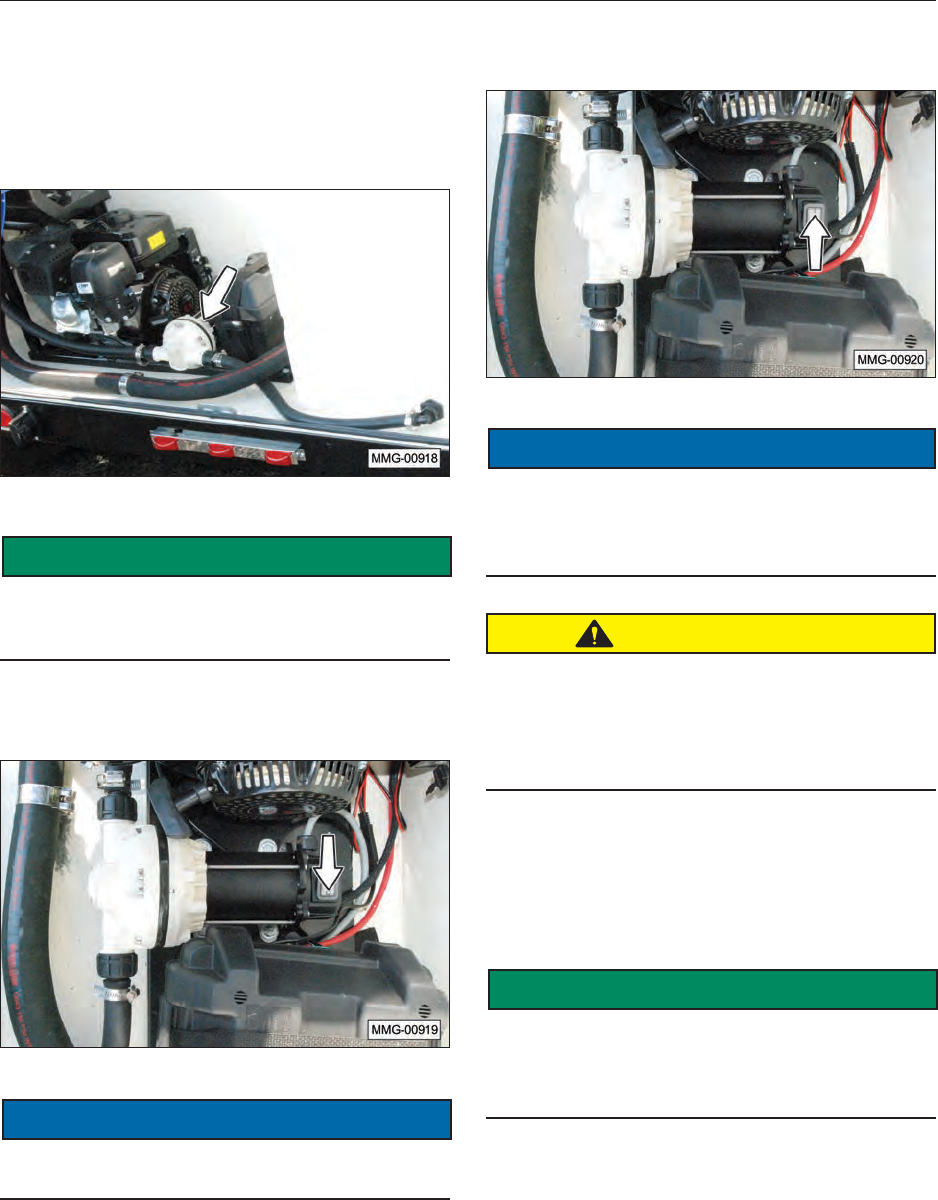
41
8.4.5 Filling the DEF Tank on
Machinery
The DEF transfer pump is a 12 Volt DC,
self-priming, positive-displacement diaphragm
pump.
SAFETY
INSTRUCTIONS
This pump should only be used to pump DEF
solution from the fuel trailer to the machinery being
serviced. Do not pump any other type of uid.
1. Ensure the power switch on the DEF pump is
in the OFF position.
NOTICE
To avoid contaminating the DEF solution and
possible nozzle malfunction, keep the nozzle clean.
2. Extend the DEF hose to easily reach the ll
opening of the machinery being serviced.
3. Turn the power switch to the ON position to
start the DEF pump.
NOTICE
DO NOT operate the pump at voltages which
exceed the 12 Volt rating indicated on the name
plate. Operating the pump with more than 12 Volts
will cause the motor to overheat.
CAUTION
Once the pump is turned ON, the DEF hose is
pressurized and will pump DEF solution. Do
not squeeze the handle on the nozzle until it
is inside the DEF tank of the machinery being
serviced.
Note: If the pump does not operate, make sure
the in-line fuse is working.
4. Fill the machine’s DEF tank. Once the DEF
tank is lled, turn the pump OFF. Do not run
the pump any longer than necessary.
SAFETY
INSTRUCTIONS
Even though the nozzle is equipped with an
automatic shutoff, do not leave the nozzle
unattended during lling. Be prepared to manually
shut off ow at the nozzle, if necessary.
5. Turn the power switch to the OFF position to
stop the DEF pump.
6. Rewind the DEF hose onto the hose rack or
reel.
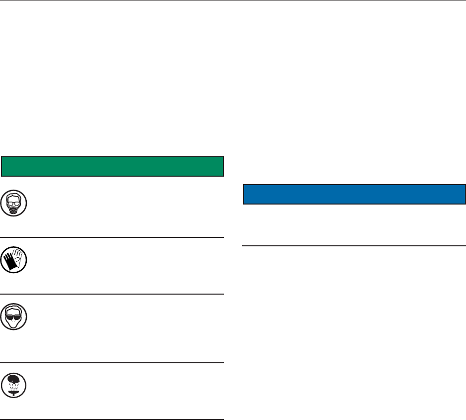
42
8.5 DEF SOLUTION
The information concerning DEF provided in
this manual has been obtained from sources
considered technically accurate and reliable.
Review the safety information concerning potential
product hazards. Since the actual product use
is beyond our control, it is assumed that the user
has been fully trained to meet any local, state, or
federal regulations.
8.5.1 DEF Solution Safety Practices
SAFETY
INSTRUCTIONS
Respiratory protection is not usually
required. If signicant spray or mist
occurs, wear a NIOSH approved or
equivalent dust respirator.
The use of gloves, impermeable to the
specic material handled, is advised to
prevent skin contact, possible irritation,
or absorption.
Approved eye protection to safeguard
against potential eye contact, irritation,
or injury is recommended. Depending on
the conditions of use, a face shield may
be necessary.
A source of clean water should be
available in the work area for ushing
eyes and skin. Impervious clothing
should be worn, as needed.
8.5.2 General Information
1. DEF has not been shown to be harmful to
humans or animals.
2. DEF is not explosive, does not burn, and will
not aid in combustion.
3. DEF is non-toxic. If you get it on your skin or
clothes, rinse with plenty of water.
4. DEF is a colorless liquid. However, it is best to
avoid spilling on clothing or vehicle upholstery
as it may leave a stain.
NOTICE
DEF is very corrosive to certain types of material.
Care should be taken when lling the trailer or the
machinery.
8.5.3 First Aid Measures
Eye: If irritation or redness develops, move away
from exposure and into fresh air. Flush eyes with
clean water immediately for at least 15 minutes. If
symptoms persist, seek medical attention.
Skin: Remove contaminated shoes and clothing
and cleanse affected area(s) thoroughly by
washing with mild soap and water. If irritation
or redness develops and persists, seek medical
attention.
Inhalation (Breathing): If respiratory conditions
develop, move away from source of exposure and
into fresh air. If symptoms persist, seek medical
attention. If victim is not breathing, clear airway
and immediately begin articial respiration. If
breathing difculties develop, oxygen should
be administered by qualied personnel. Seek
immediate medical attention.
Ingestion (Swallowing): First aid is not normally
required; however, if swallowed and symptoms
develop, seek medical attention.
43
8.5.4 Storage
1. Keep DEF containers tightly closed.
2. To avoid solidication, do not store DEF at
temperatures below 23°F (‑5°C). Solidied
DEF, which has been warmed up carefully at
temperatures not exceeding 86°F (30°C), will
not be impaired in quality and can be used as
soon as the warmed up solution is free from
solids. Frozen DEF can be thawed and used
without concerns of product degradation;
however, damage to the container or
equipment will likely occur. Store only in
approved containers.
3. Protect containers against physical damage.
4. In order to prevent decomposition of the urea,
as well as the evaporation of water in the case
of vented containers, prolonged transportation
or storing above 77°F (25°C) should be
avoided. (See Table Below).
Constant Ambient
Storage Temperature
°F (°C)
Minimum Shelf Life
(Months)
≤50 (10) 36
≤77* (25) 18
≤86 (30) 12
≤95 (35) 6
>95 (35) **
* To prevent decomposition of the DEF solution, prolonged
transportation or storage above 77°F (25°C ) should be avoided.
** Signicant loss of shelf life. Check every batch before use.
Source: ISO 22241-3:2008(E)
8.5.5 Using DEF
1. Only ll the DEF tank with ISO certied DEF
that has been delivered in dedicated, sealed
DEF packages.
2. Wear appropriate protective clothing and
equipment, such as safety glasses, gloves,
etc. while pumping DEF.
3. Wash thoroughly after handling DEF.
4. Never add DEF into the diesel fuel tank.
5. Never add diesel fuel into the DEF tank.
6. Avoid contact with DEF on eyes, skin, and
clothing.
7. If spilled, rinse the area with water.
8. Do not use DEF that has been diluted with
water or other substances.
8.5.6 DEF Disposal
For proper disposal of waste DEF, as a non-
hazardous liquid waste, it should be solidied with
stabilizing agents such as sand, y ash, or clay
absorbent, so that no free liquid remains before
disposal in an industrial waste landll.
44
9. STORAGE
9.1 GENERAL INFORMATION
When the fuel trailer will not be used for an
extended period of time, perform a complete
inspection. Replace or repair any worn or
damaged components to prevent unnecessary
downtime at the beginning of the next season.
9.2 PLACING IN STORAGE
CAUTION
Store the trailer in an area away from
human activity. To prevent the possibility
of serious injury, do not permit children
to play on or around the stored equipment.
1. Remove all fuel from the fuel trailer.
2. Place the gasoline engine fuel valve in the
OFF position.
3. Drain the gasoline engine fuel tank and
carburetor for seasonal or long term storage.
If this is not possible, add a fuel additive to the
gas tank.
4. Remove the engine’s ignition key and store in
a secure place.
5. Thoroughly wash the equipment with a
pressure washer or water hose to remove all
dirt, mud, or debris.
6. Remove any entangled material from the
underside of the trailer.
7. Check the condition of the fuel pump and DEF
pump. Replace or adjust, as required.
8. Touch up paint nicks and scratches to prevent
rusting.
9. Remove the battery, if applicable, and store
it in a cool, dry area on wooden blocks or a
wooden pallet. Charge it monthly to maintain
an adequate charge. This will help to extend
the service life of the battery.
10. It is best to store the equipment inside. If
possible, avoid any area with high humidity.
Humidity promotes rust and corrosion.
9.3 REMOVING FROM STORAGE
When removing the equipment from storage,
follow this procedure:
1. Install and connect the battery, if applicable.
2. Add new fuel to the gasoline engine’s fuel
tank.
3. Review and follow the Daily Pre-Operation
Checklist.
4. Review and follow the service checks in the
Services section.
IMPORTANT
If the equipment has been stored for more than
12 months, warm the engine by running it for two
to three minutes and then drain the oil. Change
the oil while the oil is warm to remove any
condensation. Refer to the Change Engine Oil
section in the Maintenance section.
9.4 WINTERIZING THE DEF SYSTEM
Since the majority of the DEF solution is water,
freezing of this solution can cause damage to the
components of the DEF system. It is recommended
that the solution be removed from the DEF tank and
stored in a DEF compatible container.
NOTICE
Do not allow DEF uid to freeze in the tank.
Since DEF solution is mostly water, freezing and
expansion of the solution will cause damage to the
tank and the pump. The warranty is void if freezing
occurs.
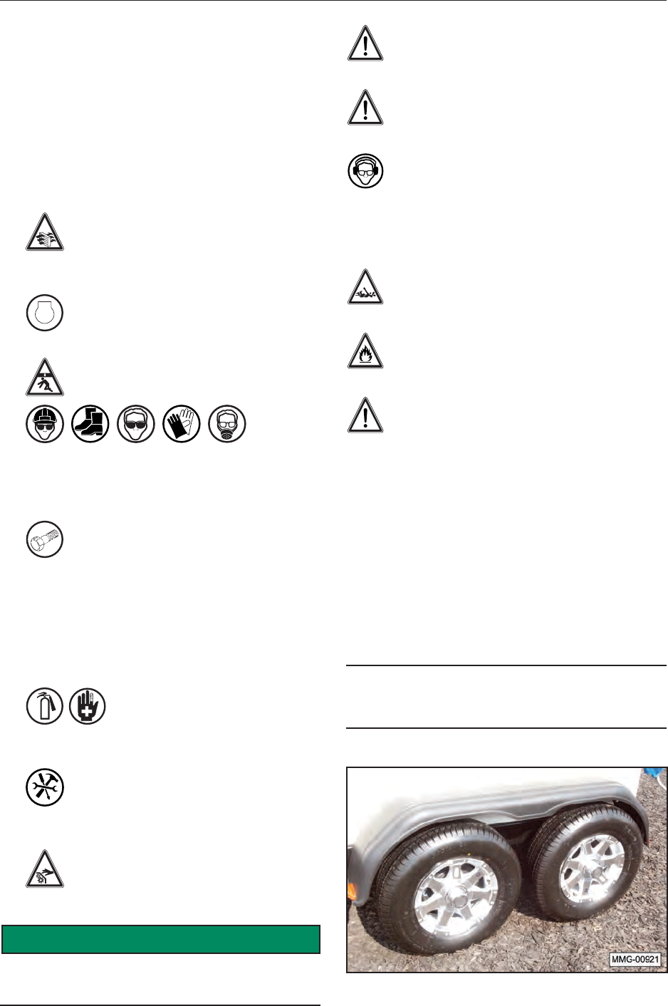
45
10. MAINTENANCE
10.1 SAFETY
10.1.1 General Safety
1. Good maintenance is your responsibility. Poor
maintenance is an invitation for trouble.
2. Follow good shop practices. Keep service
area clean and dry. Be sure electrical outlets
and tools are properly grounded. Use
adequate light.
3. Ensure proper ventilation. Never
operate the engine in a closed building.
The exhaust fumes may cause
asphyxiation.
4.
STOP
Before working on this equipment, shut
off the engine and remove the ignition
keys.
5. Never work under equipment unless it
is securely blocked.
6.
Always use personal protection devices, such
as eye, hand, and hearing protectors, when
performing any service or maintenance.
7. OEM Where replacement parts are
necessary for periodic maintenance
and servicing, genuine factory
replacement parts must be used to
restore your equipment to the original
specications. The manufacturer will
not be responsible for injuries or
damages caused by use of unapproved
parts and/or accessories.
8. A re extinguisher and rst aid
kit should be readily accessible
while performing maintenance
on this equipment.
9. Periodically tighten all bolts, nuts, and
screws and ensure all cotter pins are
properly installed to ensure the unit is
in safe condition.
10. When completing a maintenance or
service function, make sure all safety
shields and devices are installed before
placing the unit in service.
SAFETY
INSTRUCTIONS
The following safety instructions are provided to
help prevent injury or limit equipment damage.
DO NOT operate the engine with the fuel
tank cap loose or missing.
DO NOT clean engine air lter with gasoline
or other types of low ash point solvents.
DO NOT operate the unit without a
functional exhaust system. Prolonged
exposure to sound levels in excess of 85
dBA can cause permanent hearing loss. Wear
hearing protection when working around a running
engine.
Keep hands, feet, and loose clothing away
from moving parts on the engine.
Keep area around exhaust free of debris to
reduce the chance of an accidental re.
Do not operate the gas engine if any of the
following conditions exist during operation:
1. Noticeable change in engine speed.
2. Sparking occurs.
3. Engine misres or there is excessive engine
vibration.
10.2 WHEEL BEARINGS
Each axle is equipped with a grease zerk under
the center dust cap of the wheel. Add grease
sparingly to the wheel bearings, using only wheel
bearing grease. The wheel bearings should be
repacked annually. Check for excessive end play
and tighten, if necessary.
IMPORTANT
Over-greasing wheel bearings can cause them to
overheat, resulting in damage and/or failure.
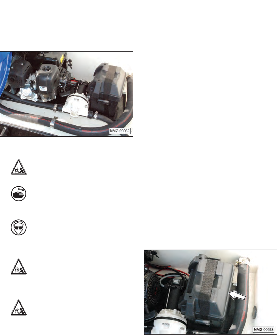
46
10.3 BATTERY
Inspect the battery (if equipped) at least once
every six months and before using the fuel trailer
at the beginning of the season. Always follow the
safety instructions when servicing a battery.
10.3.1 Battery Safety
1. Keep all sparks and ames away from
batteries, as gas given off by electrolyte
is explosive.
2. Avoid contact with battery electrolyte:
wash off any spilled electrolyte
immediately because battery acid can
cause severe chemical burns.
3. Wear safety glasses when working
near batteries.
4. Do not tip batteries more than 45 degrees, to
avoid electrolyte loss.
5. To avoid injury from spark or short
circuit, disconnect the battery ground
cable before servicing any part of the
electrical system. Never short circuit
the battery; it may explode.
6. Protect battery terminals, battery-
charger terminals, and cables against
accidental contact which can cause
sparks, explosions, or component
damage.
7. Never attempt to jump-start a frozen battery.
10.3.2 Battery Replacement and
Maintenance Tips
• Check the battery at least every six months for
low voltage, leakage, etc.
• Always use the correct size and type of battery.
When replacement is necessary, use a SP-30
Lawn and Garden battery with at least 225 CCA
and 290 CA ratings.
• Do not install the battery cable to the wrong
terminal. Make sure the RED cable is connected
to the + (plus) terminal and the BLACK cable is
connected to the – (minus) terminal.
• Remove the battery from the fuel trailer if not
expected to be in use for several months.
• Use recommended practices when recharging a
dead battery.
• Remove any corrosion from the battery post
using a wire brush terminal cleaner. Corrosion
can also be removed using a baking soda paste
and water to neutralize and remove the acid
from the battery terminals.
• Dispose of old batteries properly.
10.3.3 Battery Maintenance
1. Make sure the top of the battery box is
installed and in good condition (not cracked,
cut, or damaged).
2. The battery is not charged when the engine is
operating. If the battery is not charging using
an external charger, check the fuse. Replace
the fuse if necessary.
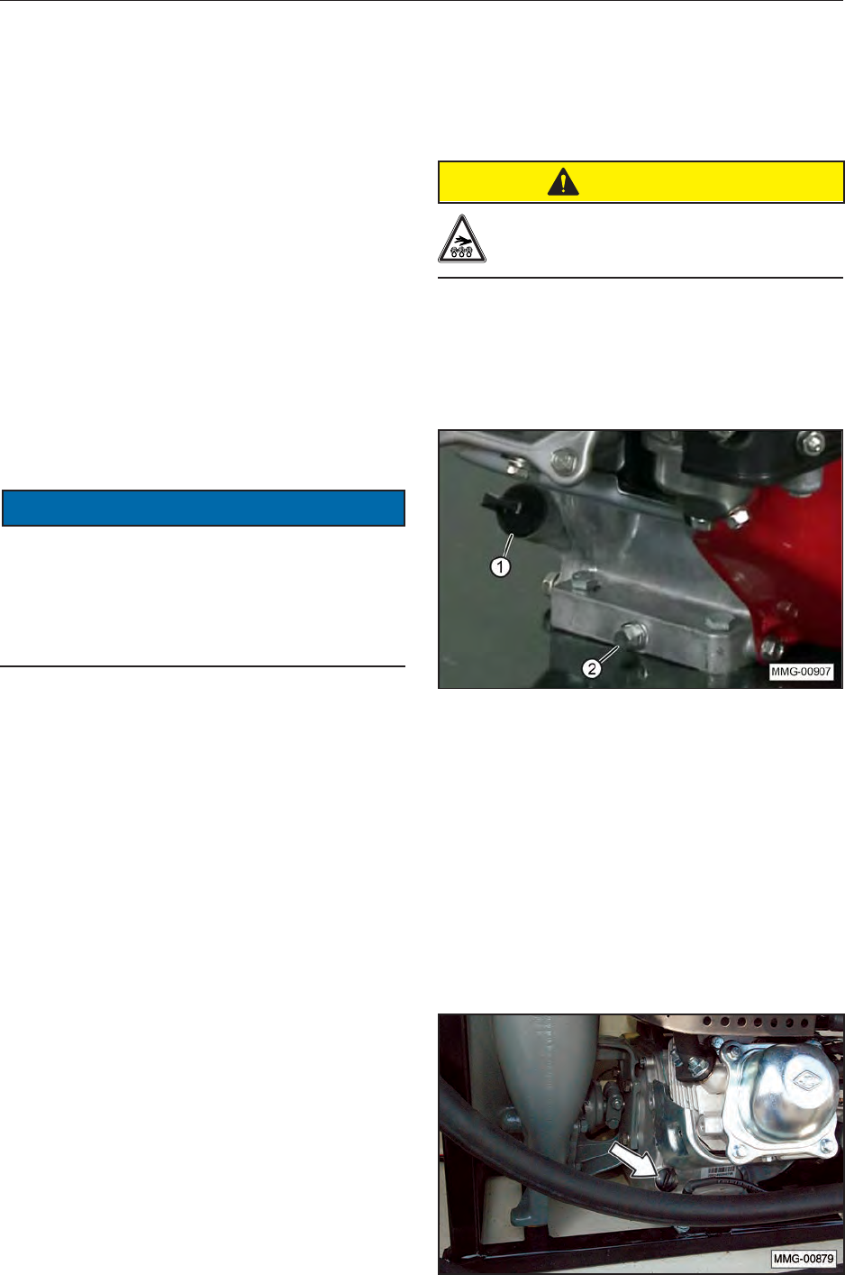
47
10.4 GASOLINE ENGINE (OPTIONAL)
Gasoline engines are not typically shipped with oil.
Check and add oil to engine prior to operating, as
needed.
For any questions concerning the gasoline engine
not provided in this manual, refer to the OEM
manual that was provided with the fuel trailer.
For contact information on the manufacturer, refer
to the OEM Literature section in this manual.
10.4.1 Approved Fuel
Use a regular unleaded automotive gasoline for
all operating conditions. The fuel tank capacity is
approximately 1 gallon (3.8 liters).
The fuel trailer engines are designed for good
performance and efcient operation using gasoline
containing from 0 to 10% ethanol.
NOTICE
E85 is an alternative fuel and Meridian’s equipment
is not designed for this type of fuel. E85 is not
gasoline. It is made by combining 85% ethanol
with 15% gasoline. The fuel trailer engine is not
currently certied or designed to run on E85 or any
other alternative fuel.
Always refer to the OEM Owner’s manual for a list
of recommended fuel and the current approved
additives.
10.4.2 Engine Oil
Use a typical SAE 10W-30 multi-viscosity motor
oil for normal operating conditions. Consult your
engine manual for the recommended oil in cold
temperatures. The crankcase capacity is 1.16 US
qt. (1.1 liters).
10.4.3 Change Engine Oil
1. Review the Operator’s Manual for the engine.
2. Allow the engine to cool before changing the
oil. Draining works best when the oil is warm.
CAUTION
BURN HAZARD
Hot engine oil can burn skin.
3. Be sure the engine key switch is in the OFF
position and the fuel valve is turned OFF.
4. Place a suitable container below the engine to
catch the used oil. Remove ller cap (1), drain
plug (2), and washer.
5. Allow the oil to drain completely, then reinstall
the drain plug and washer. Tighten the drain
plug securely.
6. Dispose of the oil in an approved manner.
Follow local disposal regulations.
7. Fill the engine crankcase with SAE 10W-30 oil
for general usage. If the engine is operated
in more extreme conditions, refer to the OEM
manual for oil recommendations.
8. Run the engine for one minute and recheck
the oil level. Add oil as needed.
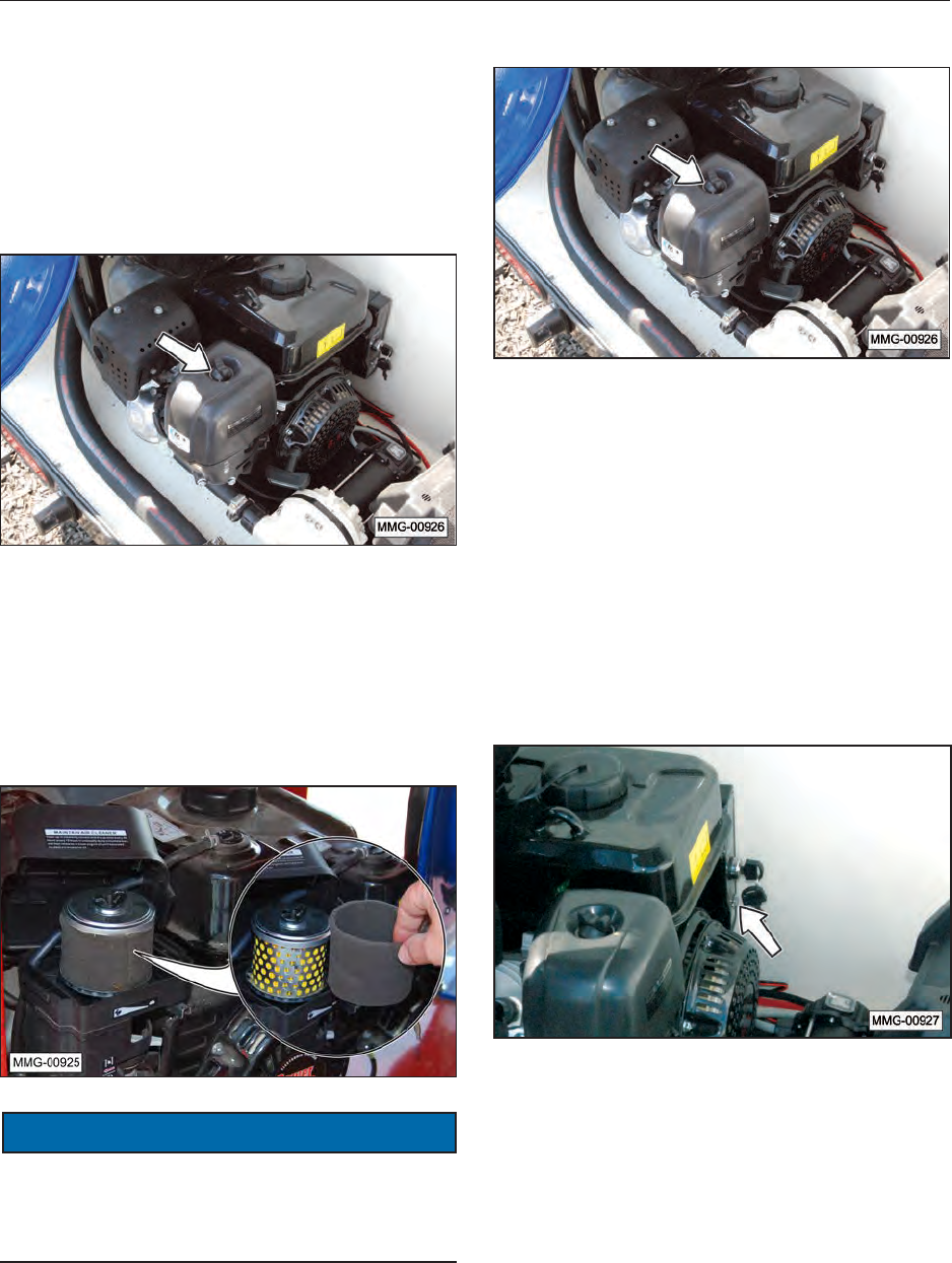
48
10.4.4 Air Filter Inspection
A dirty air lter will restrict air ow to the carburetor,
reducing engine performance. If you operate the
engine in very dusty areas, clean the air lter more
often than specied in the maintenance schedule.
1. Remove the air cleaner cover and inspect the
lter and foam cover weekly.
2. Remove any debris from the foam cover.
Thoroughly clean or replace the foam cover
every three months or 50 hours of operation
(clean it more frequently when used in dusty
conditions).
3. Clean or replace dirty lter elements. Always
replace damaged lter elements.
NOTICE
Operating the engine without an air lter, or with a
damaged air lter, will allow dirt to enter the engine,
causing rapid engine wear. This type of damage is
not covered by any warranty.
4. Replace the cover.
10.4.5 Engine Circuit Protection
The circuit protector protects the battery charging
circuit. A short circuit, or a battery connected with
reverse polarity, will trip the circuit breaker.
The green indicator inside the circuit protector
will pop out to show that the circuit protector has
switched off. If this occurs, determine the cause
of the problem and correct it before resetting the
circuit protector.
Push the circuit protector button to reset.
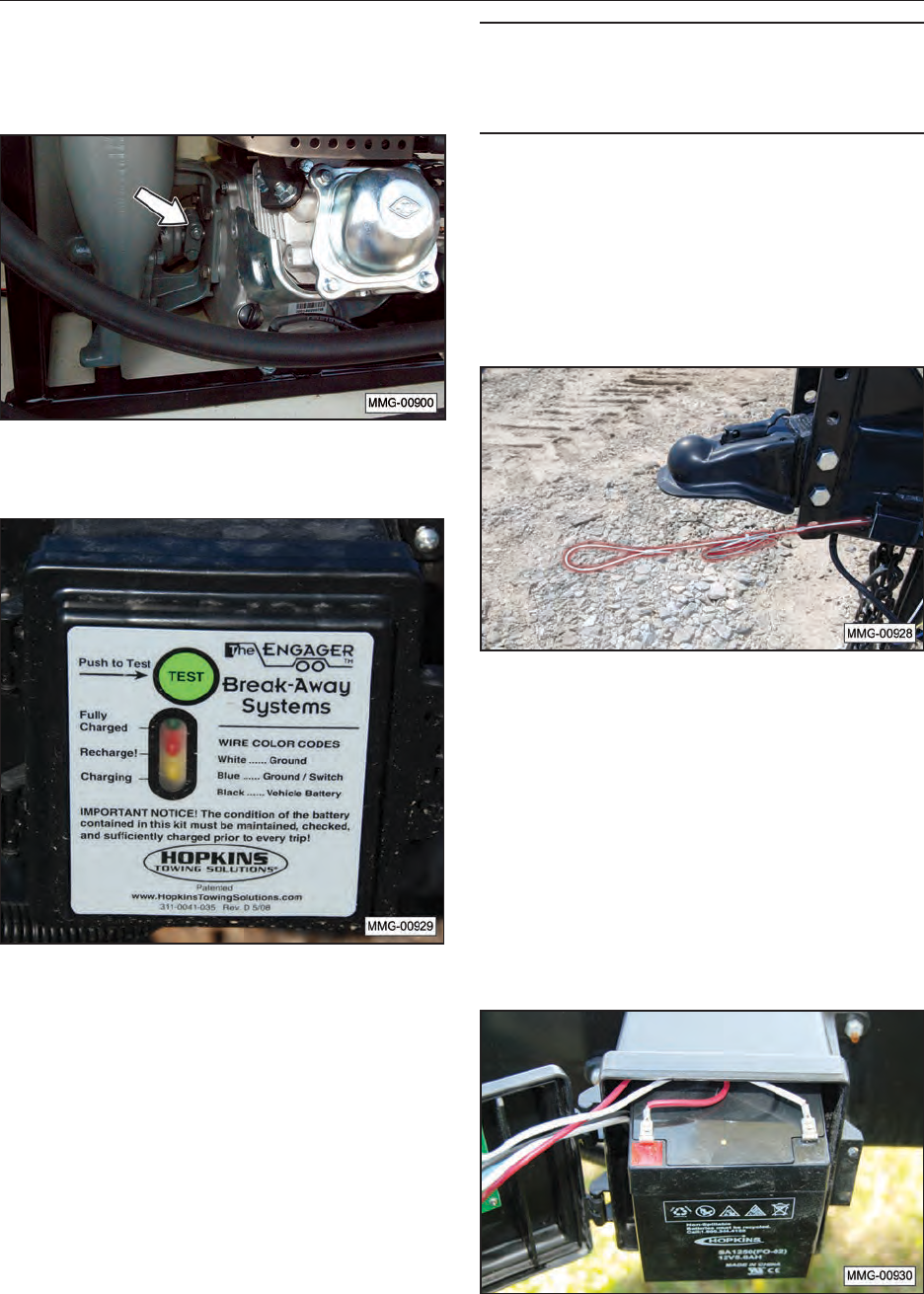
49
10.4.6 Engine to Pump Connection
Check the coupling between the pump and engine
annually.
10.5 TRAILER BREAKAWAY SYSTEM
10.5.1 Testing the Battery
1. Disconnect the trailer plug from the tow
vehicle; otherwise, you are testing the tow
vehicle’s battery.
2. Press the green TEST button on the control
box located inside the frame of the trailer. The
green indicator light should illuminate if the
battery is fully charged. If the yellow or red
indicator lights illuminate, the unit’s battery
should be charged before towing the trailer.
IMPORTANT
If the battery is weak or dead (red indicator, even
after charging), as indicated by the indicator light,
the battery must be replaced.
3. Plug the trailer into the tow vehicle. The
yellow “Charging” light should be ON.
4. Test the system by pulling the pin out of the
breakaway switch. The battery will activate
the brakes. (Note: Do not use this kit as a
parking brake). The battery should be charged
and tested prior to each trailer outing.
10.5.2 Changing Battery
The battery in the breakaway system is
rechargeable. If the battery will not hold a charge,
replace the battery.
10.5.3 Replacing Battery
The battery in the breakaway system is
replaceable. If the battery will not hold a charge,
replace the battery. Contact the OEM supplier for
a replacement battery.
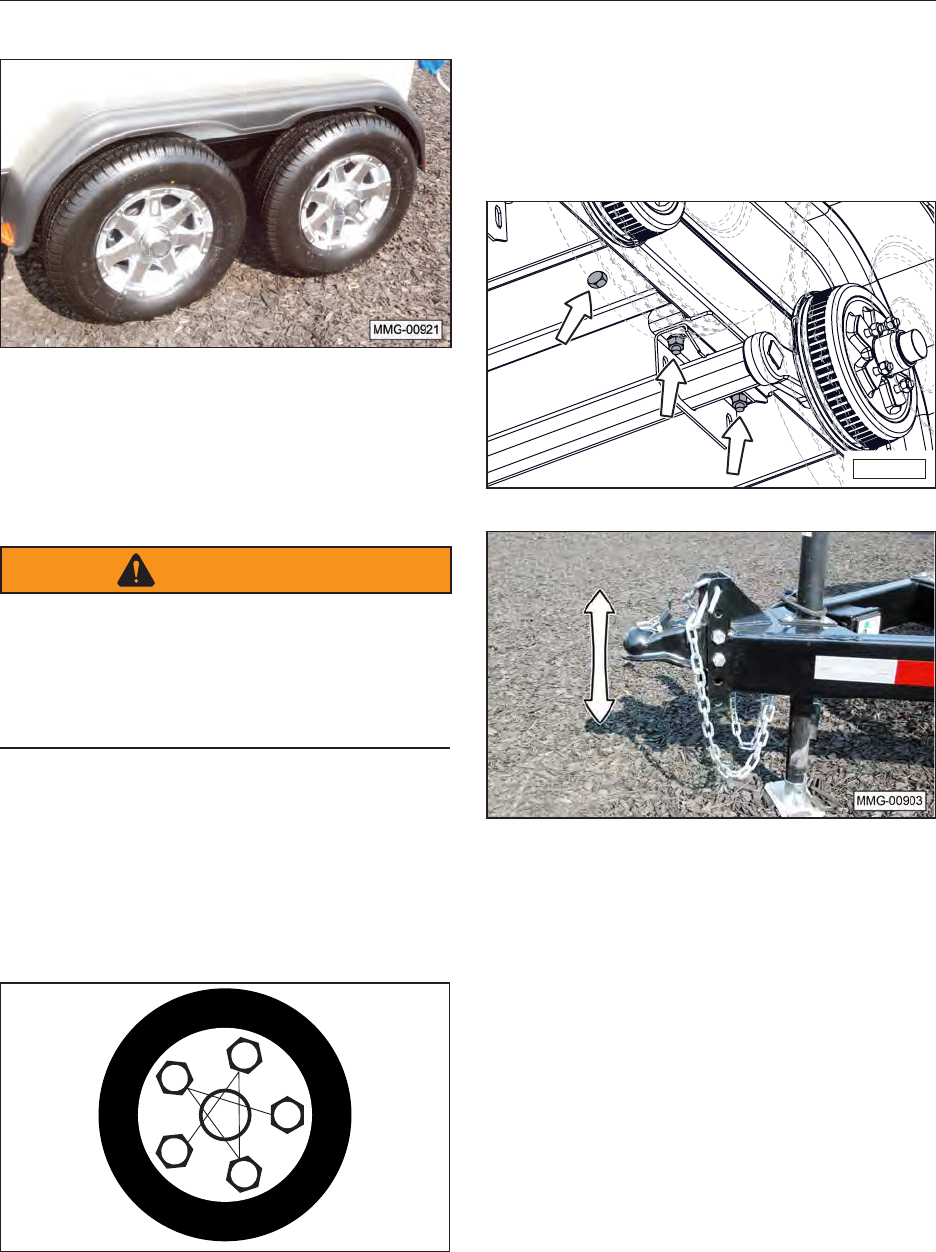
50
10.6 WHEEL BOLT TORQUE
1. Initially check the wheel bolt torque at 10, 25,
and 50 miles and after each wheel removal.
Note: Torque wrenches are the best method to
ensure the proper amount of torque is being
applied to a wheel nut.
WARNING
WHEEL SEPARATION HAZARD
Separation of wheels from the axle can cause
serious injury or death. To prevent separation,
the wheel nuts must be maintained at the proper
torque levels. Properly maintained wheel nuts
prevent loose wheels and broken studs.
2. Tighten the wheel nuts in three stages.
— First stage: 20 to 25 foot pounds.
— Second stage: 50 to 60 foot pounds.
— Third stage: 90 foot pounds.
3. Tighten the wheel nuts in a clockwise,
cross-axle alternating pattern.
1
4
2
3
5
10.7 AXLE BOLTS, TRAILER HITCH
BOLTS, AND TANK HOLD-DOWN
BOLTS
Check the torque on the axle to frame bolts, tank
hold-down bolts, and trailer hitch bolts at least
once per year.
MMG-00931

51
11. SERVICE
11.1 SERVICE RECORD CHART
The chart on the following page should be copied
and lled out as maintenance is performed on the
equipment. Refer to the Lubrication, Maintenance,
and Service sections for additional instructions.
Date
Serviced by
8 hours or daily
Check Engine Fluid Levels
Test Breakaway Brake System Battery
Inspect Tires and Wheel Bolts
Inspect Taillights and Running Lights
Inspect 7-pin Connector Plug
50 Hours or Weekly
Clean Engine Air Intake Filter
Check Tire Pressure
200 Hours or Semiannual
Adjust Brakes
Inspect Brake Magnets
Make sure the battery box is securely
holding battery onto frame, check
electrolyte levels in the cells, clean
terminals to remove any dirt or corrosion.
Check and/or Replace Diesel Fuel Filter
400 hours or annually
Change Engine Oil
Check Wheel Bolt Torque
Check Tank Hold-Down Bolts
Check Bolt-On Hitch Tongue Bolts
Inspect Brake Lining Wear, Brake Cylinder,
and Brake Wiring
Repack Wheel Bearings and Check Hub for
Wear
Inspect Axle Grease Seal
Inspect Diesel Fuel Pump
Inspect DEF Solution Pump
Inspect all Diesel Fuel and DEF Solution
Hoses
Inspect all electrical wiring connections for
looseness or corrosion. Tighten and/or
seal, as necessary.
Check the tires for wear, and replace if
needed.
Thoroughly Clean the Fuel Trailer
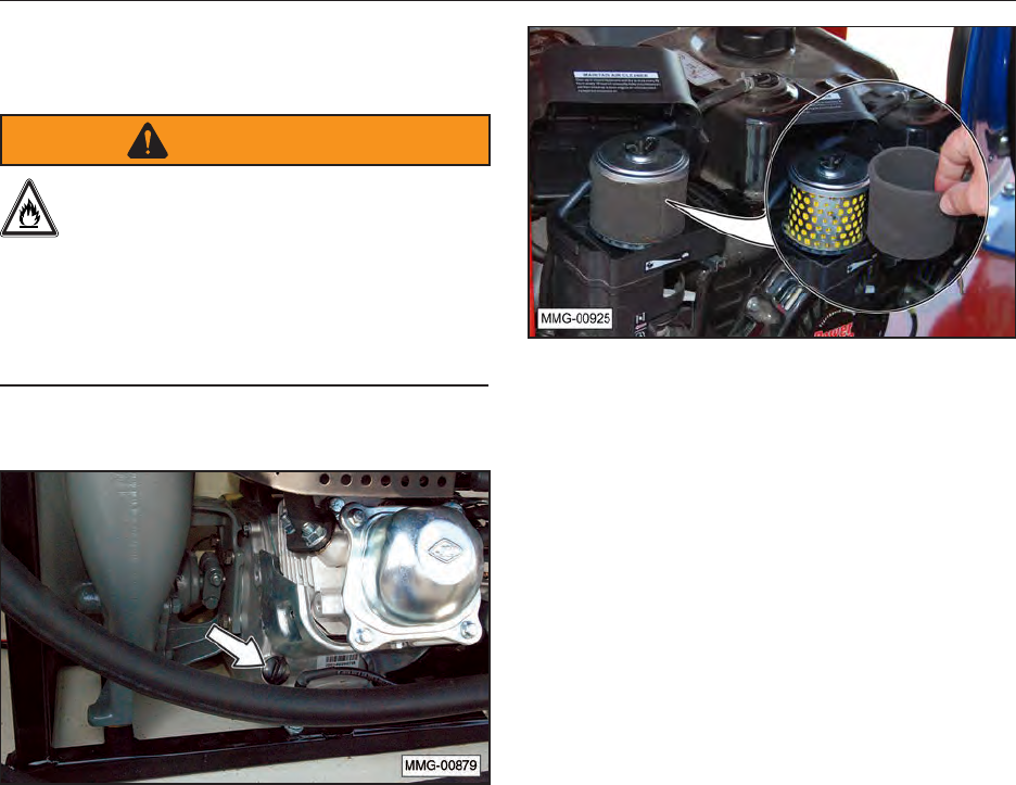
52
11.2 SERVICE CHECKS
11.2.1 Daily (8 Hours)
WARNING
Gasoline is a highly combustible fuel.
Improper use, handling, or storage of
gasoline can be dangerous. Never touch
or ll a hot engine. DO NOT ll the engine’s fuel
tank near an open ame while smoking or while
engine is running. DO NOT ll tank in an
enclosed area with poor ventilation. Wipe up
spills immediately.
1. Check engine oil and fuel levels and ll, as
needed.
2. Test the trailer breakaway brake system.
Refer to “10.5.1 Testing the Battery” on page
49.
3. Inspect the tires for wear or damage and
check wheel bolt torque.
4. Inspect the taillights and running lights to
make sure they are working properly.
5. Inspect the 7-pin wiring harness connector for
damage.
11.2.2 Weekly (50 Hours)
1. Clean or replace the foam lter element.
Replace the paper air lter, as required.
2. Check the tire pressure. Inate the tires to the
recommended pressure stated on the tire.
11.2.3 Semiannual (200 Hours)
1. Adjust the brakes.
2. Inspect the brake magnets.
3. Make sure the battery box is securely holding
battery onto frame, check electrolyte levels in
the cells, clean terminals to remove any dirt or
corrosion.
4. Check and/or replace the diesel fuel lter.
11.2.4 Annually (400 Hours)
1. Change engine oil. Refer to “10.4.3 Change
Engine Oil” on page 47.
2. Check the wheel bolt torque. Refer to
“10.6 Wheel Bolt Torque” on page 50.
3. Repack the wheel bearings and check for
excessive end play in the bearings.
4. Inspect brake lining wear, brake cylinder, and
brake wiring.
5. Check the tank hold-down bolts. Refer to
“10.7 Axle Bolts, Trailer Hitch Bolts, and Tank
Hold-Down Bolts” on page 50.
6. Check the trailer hitch bolts.
7. Check the tires for wear, and replace if needed.
8. Inspect all diesel fuel and DEF solution pumps
and hoses.
9. Check the trailer lights to make sure they are
working properly.
10. Thoroughly clean the fuel trailer.
53
11.3 AXLE MAINTENANCE
11.3.1 First 200 Miles
1. Adjust brakes. Refer to OEM manual for
procedure.
11.3.2 3,000 Miles or 3 Months
1. Adjust brakes. Refer to OEM manual for
procedure.
2. Check torque on wheel nuts. Refer to the
section in this manual.
3. Inspect tires for wear. Refer to OEM manual
for procedure.
11.3.3 6,000 Miles or 6 Months
1. Inspect brake magnets for wear. Refer to
OEM manual for procedure.
2. Inspect suspension parts for wear. Refer to
OEM manual for procedure.
11.3.4 12,000 Miles or 12 Months
1. Inspect brake lining wear, check brake cylinder
for leaks, and inspect brake wiring for damage.
Refer to OEM manual for procedure.
2. Grease the wheel bearings and check the hub
for wear. Refer to OEM manual for procedure.
3. Inspect grease seal for leakage. Refer to
OEM manual for procedure.
11.4 TIRES
Check the tires for normal and/or abnormal tire
wear. Replace tires that are damaged or worn
beyond normal tread life. Refer to the axle OEM
manual for a Tire Wear Diagnostic Chart.
Replace the tires with:
ST205/75R14
Load Range D
For Trailer Service Only
11.5 WELDING REPAIRS
WARNING
PERSONAL INJURY HAZARD
Repairs or modications to the trailer,
trailer tongue, or trailer hitch can result
in serious injury or death should these repairs
fail.
Repair welding must be done with care
and with procedures that may be beyond
the capabilities of the ordinary welder.
Before performing any type of welding repair to the
fuel trailer, contact Meridian for approval.
IMPORTANT NOTICE
Anyone performing a welding repair should be
certied in accordance to the American Welding
Society (AWS) standards.
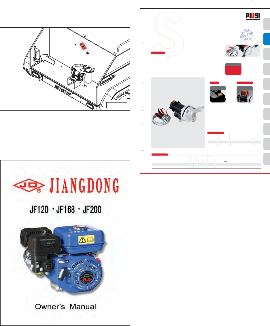
54
12. OEM LITERATURE
OEM literature can be stored on the fuel trailer
using the document storage tube.
MMG-00951
12.1 ENGINE AND DEF PUMP
For any questions concerning the engine, diesel
fuel pump, or DEF solution pump, refer to the
OEM manual that was provided with the fuel
trailer.
WINDSCREEN WATER UREA OIL KEROSENE GREASE GASOLINE FOOD DIESEL BIODIESEL ANTIFREEZE
PUMPS
UZZARABLUE DC PUMP
S
PERFORMANCE
EN. The careful analisys of the market and
the experience of handling agressive fluid,
such as UREA, leads PIUSI to develop a new
type of diaphragm pump equipped with
electric motor without any dinamic seals. This
solution allows to obtain a reliable industrial
pump together with self priming capabilities.
SUZZARABLUE DC PUMP
Technical features:
- Voltage 12 / 24 V
- Hose tail connection 3/4”
- Absence of dinamic seals
- ON/OFF switch
- 2 m cable with clamps
- handle availble
- Duty cycle 20 min
ES. Un minucioso estudio del mercado y la
experiencia en manejar liquidos agresivos,
tal como UREA, han empujado PIUSI en
desarrolar un nuevo tipo de bomba a
membrana equipado con motor electrico sin
estanquidad dinamica. Esta solucion permite
de obtener una bomba industrial con una
mayor fiabilidad y autocebante.
SUZZARABLUE DC PUMP
Propriedad:
- 12 / 24 V voltaje
- Conexion 3/4”
- Sin estanquidad dinamica
- ON/OFF interruptor
- 2 m de cable con pinzas
- Ciclo de trabajo de 20 min
FEATURES UPON REQUEST
On/off switch
included
Kit handle
(optional)
Code R16175010
Flow-rate
up to
l/min
36
(up to 9.2 gpm)
DISPENSERSPUMPS
NOZZLE
METERS
SPECIAL
EQUIPMENTS
FLUID
MONITORING
ACCESSORIES METERSNOZZLEFILTERING
Code Description
Fluids Flow-rate Voltage Cables Inlet - Outlet On/Off
type l/min gpm AC V./Hz
DC Volt
rpm Power Amp.
max.
mod. BSP switch
PRODUCTS’ RANGE TECHNICAL DATA
F0020400A SuzzaraBlue DC pump 12V 36 9,2 12 2800 260 22 YES 3/4” YES
F00204010 SuzzaraBlue DC pump 24V 36 9,2 24 2800 310 13 YES 3/4” YES
Code
Weight Packaging
kg lbs mm inch pcs/box
F0020400A 3,6 7,9 350x180x280 13,8x7,1x11 1
F00204010 3,6 7,9 350x180x280 13,8x7,1x11 1
PRODUCTS’ RANGE WEIGHT AND PACKAGING
SUZZARABLUE
DC PUMP
5553 Anglers Ave., Suite 104, Fort Lauderdale, FL 33312 - Tel. 954.584.1552
www.piusiusa.com
The Company reserves the right to modify the information contained in this catalogue without any prior notice. DC PUMP
Additional information can be obtained from:
Piusi USA
3901 Anglers Ave.
Fort Lauderdale, FL 33312
Phone: (954) 584-1552
Fax: 954-584-1554
piusiusa@piusiusa.com
12.2 AXLE
For any questions concerning the Dexter axle,
refer to the OEM manual that was provided with
the fuel trailer. An Owner’s Manual and parts
listing is provided with the fuel trailer.
Additional information can be obtained from:
Dexter Axle Co, Inc.
2900 Industrial Parkway East
Elkhart, IN 46516
Phone: (574) 295-7888
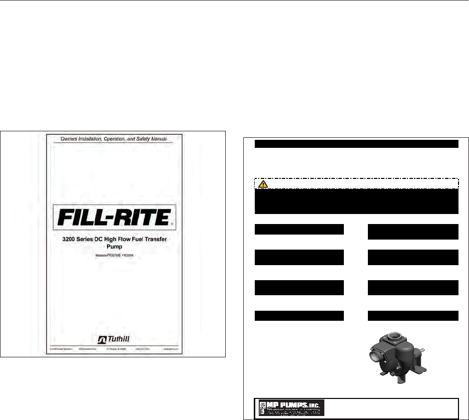
55
12.3 DIESEL FUEL PUMP
12.3.1 Electric Diesel Fuel Pump
Fill-Rite Electric Fuel Pumps
Tuthill Corporation
8825 Aviation Drive
Ft. Wayne, IN 46809
Toll Free: 800-634-2695
12.3.2 Gasoline Diesel Fuel Pump
Flow Max Diesel Fuel Pumps
MP Pumps, Inc.
34800 Bennett
Fraser, MI, 48026-1686
Phone: 586-293-8240
Toll Free: 800-563-8006
Fax: 586-293-8469
Do not install a piping system that does Do not continue to operate the pumping
not allow for any flex due to expansion from system when unusual noise or vibration
Do not allow severe temperature changes Do not perform service or maintenance
pumping system.
Drain pump completely before switching Do not mount pump in conditions that high
PO Biodiesel, Diesel and Fuel Oil.
PG Gasoline, Kerosene, Avgas
Jet A and JP 8 Fuel.
PE Ethanol and E-85.
occurs.
Do not continue to operate the pumping
system when a known leak exists or the
system starts to smoke.
or hot.
FORM 3074-A (2/08)
.segnalf pmup eht no tsixe sdaol gnipip .depmup eb ot si taht epyt leuf
WARNING!
to occur in a short time period within the when the pumping system is pressurized
Do not operate the pump in a manner that
it was not intended to be used.
heat generated by the pumping system.
PRINTED IN THE U.S.A.
MODELS:
This pump was designed to handle volatile and flammable fluids. To reduce the risk of fire or
explosion keep pump in well ventilated area free of explosive atmosphere. Do not smoke where
the fuel is being handled, also keep away from any sparks or open flame. Do not operate pump
with either the suction or discharge valves fully closed as this will over heat the pump. If pump
becomes overheated allow to cool before next use.
PETROLEUM SELF-PRIMING CENTRIFUGAL PUMPS
INSTRUCTION BULLETIN
Read this bulletin in full before installing, operating or servicing this pump. If any of the warnings of
this bulletin are ignored serious injury or death could occur.

56
13. TROUBLESHOOTING
13.1 TROUBLESHOOTING CHART
PROBLEM CAUSE SOLUTION
Gasoline engine will not start. No fuel. Fill the fuel tank.
Low engine oil. Fill the crankcase with oil.
Cold engine. Close choke.
Ignition key switch off. Turn ignition key switch on.
Battery dead. Recharge or replace battery.
Engine problem. Refer to engine manual.
Wrong fuel type. Do not use gasoline containing more than
10% ethanol.
Poor fuel quality. Store gasoline in a clean, plastic, sealed
container approved for fuel storage. Close
vent cap (if equipped) when not in use and
store container away from direct sunlight.
If fuel is stored longer than three months,
adding a fuel stabilizer is recommended.
Dirty air lter. Clean or replace the lter.
Electrical functions are not work-
ing properly. Battery cable or battery. Check battery cable and make sure battery
is fully charged.
Improper ground. Check for proper grounding of electrical
circuit.
DEF pump is not working
properly. Pump stops working. The DEF pump is for intermittent duty
only. Once the maximum thermal limit
is reached, the motor must be allowed
to return to ambient temperature before
resuming operation.
Pump will not start. Check in-line fuse.
Check for correct Voltage (±10%) and
electrical connections.
Check motor for open or grounded circuit.
Check for locked drive assembly.
Pump will not prime.
(no discharge but motor runs) DEF tank is empty.
Inlet or outlet pipes and/or hose are
blocked with debris.
Check for severe vacuum leak.
Check for proper Voltage with the pump
operating (±10%).
Check pump for damage.
Pump leaks. Diaphragm may be ruptured, pinched, or
punctured. Contact OEM for repair op-
tions.
Check for loose pump head or drive
screws.

57
PROBLEM CAUSE SOLUTION
Electric diesel fuel pump will not
prime. Suction line is damaged. Check for leaks in suction line
Fuel level in tank is below the
pump inlet. Maintain the fuel level above the height of
the fuel pump inlet.
Bypass valve open. Valve problems; must move freely and be
free of debris. Contact OEM for cleaning
and/or repair options.
Vanes sticking. Vanes and slots may have nicks, burrs or
wear. Contact OEM for repair options.
Excessive rotor or vane wear. Rotor and vane wear or damage. Contact
OEM for repair options.
Outlet blocked. Check pump outlet, hose, nozzle, and lter
for blockage.
Vapor lock. Check breather on top of tank for
obstruction.
Electric diesel fuel pump low
capacity. Excessive dirt in screen. Remove and clean screen.
Suction line problem. Check suction line for leaks or restrictions
or air leaks (not airtight).
Bypass valve sticking. Valve problems; must move freely and be
free of debris. Contact OEM for cleaning
and/or repair options.
Vanes sticking. Vanes and slots may have nicks, burrs or
wear. Contact OEM for repair options.
Excessive rotor or vane wear. Rotor and vane wear or damage. Contact
OEM for repair options.
Hose or nozzle damage. Replace hose or nozzle.
Plugged lter. Replace lter.
Low uid level. Fill tank.
Electric diesel fuel pump runs
slowly. Incorrect voltage. Check incoming line voltage while pump is
running. Must be 12 Volts.
Vanes sticking. Vanes and slots may have nicks, burrs or
wear. Contact OEM for repair options.
Wiring problem. Check for loose connections.
Motor problem. Contact OEM for replacement options.
Electric diesel fuel pump stalls,
fuse blows, or circuit breaker trips
repeatedly.
Bypass valve sticking. Valve problems; must move freely and be
free of debris. Contact OEM for cleaning
and/or repair options.
Low voltage. Check incoming line voltage while pump is
running. Must be 12 Volts.
Excessive rotor or vane wear. Rotor and vane wear or damage. Contact
OEM for repair options.
Debris in pump cavity. Clean debris from pump cavity.
Electric diesel fuel pump over-
heats. Diesel fuel may be too viscous
(too thick). Viscous uids can only be pumped for
short periods of time (less than 30 min-
utes).
Clogged screen. Remove and clean screen.
Restricted suction pipe. Remove restriction.
Motor failure. Contact OEM for replacement options.
Pump rotor lock-up. Contact OEM for cleaning and/or repair
options.

58
PROBLEM CAUSE SOLUTION
Electric diesel fuel pump does not
operate. No power. Check incoming 12 Volt power source.
Switch failure. Replace switch with OEM parts.
Motor failure. Contact OEM for replacement options.
Thermal protector failure. Contact OEM for replacement options.
Incorrect or loose wiring. Repair wiring.
Electric diesel fuel pump leaks. Bad O-ring gasket. Replace all O-ring gaskets.
Dirty shaft seal. Clean seal and seal cavity.
Bad shaft seal. Replace seal.
Incompatible uid. Do not pump any uid other than diesel
fuel.
Loose fasteners. Tighten fasteners.
Electric diesel fuel pump hums
but will not operate. Motor failure. Contact OEM for replacement options.
Broken key. Remove all debris and replace key.
Gasoline engine diesel fuel pump
will not prime. No liquid in the pump housing. Prime pump housing.
Trying to prime against too high a
discharge head. Prime pump housing.
Gasoline engine diesel fuel pump
will not pump. Air leak in the suction line. Check for loose connections or pin holes in
the hose.
Collapsed suction line or clogged
strainer. Clean strainer or replace suction line.
Worn impeller - too much
clearance between impeller and
wear plate.
Replace impeller.
Notes: Notes: Notes:

59
14. WARRANTY
14.1 WARRANTY STATEMENT
Limited Materials and Workmanship Warranty
For Fuel Trailers
Meridian Manufacturing Inc. (hereinafter referred to as the Manufacturer) hereby warrants the Fuel Trailer(s) sold by it to be free from any defect
in material or workmanship under normal use and service for a period of one (1) year from the date of shipment. The Manufacturer’s obligation
under this warranty shall be limited to the repair or replacement only, FOB the original point of shipment, of any defective parts or portions of the
fuel trailer or accessories manufactured by Meridian. Any warranty claim must be reported to the Manufacturer within one (1) year from the date
of shipment.
THIS WARRANTY IS SUBJECT TO THE FOLLOWING LIMITATIONS, PROVISIONS AND CONDITIONS:
1. This warranty does not apply:
a) To any product sold by the Manufacturer where it is used in areas exposed to corrosive or aggressive conditions including salt water, acids, alkaloid,
ash, cement dust, animal waste or other corrosive chemicals from either inside or outside the bin.
b) For failures or defects arising out of damage during shipment or during storage on site.
c) To materials replaced or repaired under this warranty except to the extent of the remainder of the applicable warranty.
d) To damage resulting from misuse, negligence, accident or improper site preparation by others.
e) Iftheproducthasbeenalteredormodiedbyothers.
f) If in the case of coating failures the failure is the result of damage, lack of proper maintenance or failure to remove road salt or other contaminants
that may have come in contact with the bin surface.
g) To loss of time, inconvenience, loss of material, down time or any other consequential damage.
h) For a function that is different than original designed intent.
2. TheobligationoftheManufacturerunderthiswarrantyshallnotariseunlesstheManufacturerisnotiedandthiswarrantyispresentedtogetherwitha
writtenstatementspecifyingtheclaimordefectwithinthirty(30)daysafterthefailureisrstdetectedormadeknowntotheownerandwithinone(1)
year from the shipment date. The Manufacturer in its sole discretion shall determine if the claim is valid and whether correction of the defect or failure
shall be made by repair or replacement of the materials.
3. Thecoatingwarrantyisbasedonthemanufacturer’sperformancespecicationforPolyesterPowdernishesanddoesnotincluderepairofminor
blemishes or rusting that is normally part of the general maintenance of the fuel trailer. This warranty does not cover excessive wear on interior coatings.
SeeattachmentforfullPerformanceSpecicationdetailsonPolyesterPowderFinishes.
4. The obligation of the Manufacturer hereunder extends only to the original owner and to the Meridian dealer to whom the materials may have been initially
sold. This warranty shall not be subject to any assignment or transfer without the written consent of the Manufacturer.
5. Thecustomershallacknowledgethatithasmadeitsownindependentdecisiontoapprovetheuseofthesuppliedmaterialsandalsothespecic
fabricationandconstructionproceduresutilizedtocompletethefueltrailer,andhassatiseditselfastothesuitabilityoftheseproductsforthisparticular
application.
6. The foregoing sets forth the only warranties applicable to said materials and said warranties are given expressly and in lieu of all other warranties,
expressedorimplied,statutoryorotherwise,ofmerchantabilityortnessforaparticularpurposeandallwarrantieswhichexceedordifferfromsaid
warranties herein are disclaimed by the Manufacturer.
7. The owners sole and exclusive remedy against the Manufacturer shall be limited to the applicable warranty set forth herein and the endorsements, if
any, issued together with this document and no other remedy (including but not limited to the recovery of assembly or disassembly costs, shipping costs,
direct,incidental,special,indirectorconsequentialdamagesforlostprots,lostsales,injurytopersonorpropertyoranyotherloss,whetherarisingfrom
breach of contract, breach of warranty, tort, including negligence, strict liability or otherwise) shall be available to the owner or Meridian Dealer or any
other person or entitles whether by direct action or for contribution or indemnity or otherwise.
8. ThenancialobligationoftheManufacturerunderthiswarrantyshallbelimitedtotherepairorreplacementoftheproductasoriginallysuppliedandin
no event shall exceed the original cost of the product supplied.
9. The Manufacturer shall not have any obligation under any warranty herein until all accounts for materials, installation and erection of the said product
thereof and for labor and other work performed by the Manufacturer or its dealers have been paid in full by the owner.
Warranty Claim Procedure
1. Registering product with Meridian Manufacturing.
2. Contact the dealer unit was purchased from upon discovery of any defects.
3. A completed warranty claim form submitted by dealer to Meridian warranty representative for review and course of action.
4. Warranty repair work will only be performed by Meridian, the dealer or an approved representative. No warranty work completed prior to approval.
Failure to follow procedure may affect any or all reimbursement.
5. Claims will be adjudicated at the sole discretion of the manufacturer and in accordance with the terms and conditions of the applicable limited warranty.
6. A complete list of warranty procedures can be procured from the Warranty Department or found in your owner’s manual.
Effective July 1, 2009

60
15. PARTS
The following pages contain a list of serviceable parts for the Fuel Trailer unit.
Parts are available from your authorized Dealer Parts Department.
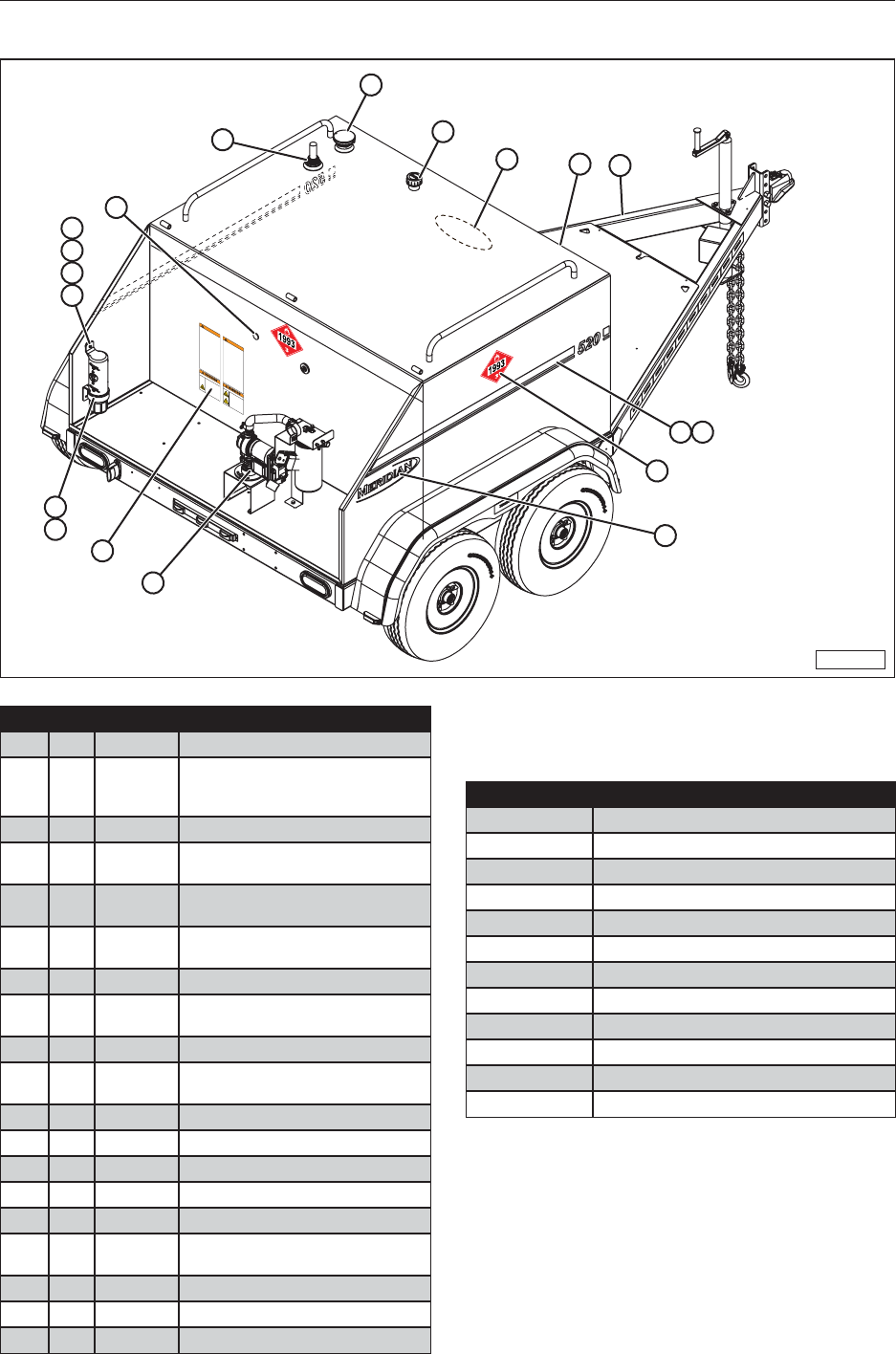
61
15.1 520 FUEL TRAILER
MMG-00937
Engine exhaust
contains products of
combustion which are
harmful to your health
and can cause death.
Always start and
operate engine in a
well ventilated area.
Do not operate engine
inside of an enclosed
area or building.
EXHAUST FUMES HAZARD
Tae precautions to
avoid spars from
battery coming into
contact with fuel or
fumes from gasoline
engine
s fuel tan or
the trailer
s fuel tan.
Spars will cause an
explosion of
combustible fuel
fumes
resulting in serious
inury or death.
MUSTE FUMES HAZARD
AR
To prevent serious inury or death
Read and understand perator
s Manual
before using. Review safety instructions
annually.
Do not use fuel trailer for any purpose other
than its intended use
transporting diesel
fuel and DEF solution.
eep woring area clean and free of spills
and debris to prevent slipping or tripping.
Do not allow riders on trailer or fuel tan
when transporting.
Do not place hands
arms
or body between
stationary and moving obects.
Do not stand on any part of trailer. Do not
use fuel tan as a wor platform.
Do not allow compartment doors to swing
open freely.
Do not smoe when refuelling gasoline
engine
filling trailers diesel fuel tan
or
refueling machinery.
Stop and turn off machinery before
refueling.
Do not weld on any part of fuel trailer.
elding spars can cause an explosion.
Mae sure fuel tan and DEF tan shutoff
valves are in closed position when not in
use or before towing.
Do not tow fuel trailer with gasoline engine
running.
Follow all StateFederal health and safety
laws and
or local regulations when filling
machinery or transporting diesel fuel.
efore towing
securely attach hitch to tow
vehicle
install hitch retainer clip connect
safety chains attach breaaway brae
cable
connect wiring harness
and mae
sure taillights are functioning.
AR
To prevent serious inury or death
Stop gasoline engine
remove start ey and
wait for all moving parts to stop before
servicing repairing adu
sting or towing
trailer or refueling gasoline engine.
bey all local regulations for the use and
disposal of diesel fuel and
or DEF solution.
Flammable fluid gasoline diesel fuel or
engine oil leaed or spilled onto hot
surfaces can cause a fire. lean up all
leaed or spilled fluid immediately. Spars
or open flames can cause flammable fluid to
ignite. D T smoe while woring on or
near any flammable fluid.
Do not store flammable or caustic
substances inside engine compartment.
eep spars
lighted matches and
or open
flames away from top of battery because
battery gas can explode. Always follow
safety recommendations when woring
near battery.
Automotive batteries contain sulfuric acid
and can produce explosive gases. To
prevent ignition of these gases
eep
spars open flames lighted tobacco or any
other ignition sources away from battery at
all times. D T allow
umper cables to
contact each other or any metal surface.
attery fumes can ignite resulting in an
explosion and personal inury or death.
Engine does not recharge battery. Manually
recharge battery periodically.
nspect hoses and pipes for leas prior to
each use. f found
immediately discontinue
use of trailer until lea is repaired.
17731
16
6
7
521
4 10
18
12
9
11
13
14
15
17
3
19 8
Item Qty. Part No. Description
1 1 40027 Trailer Assembly, 520
2 1 30716 BW
30716 MR
30716 BLK
Tank, 520 Gallon, Bone White
Tank, 520 Gallon, Meridian Red
Tank, 520 Gallon, Gloss Black
3 1 40028 Basic 12V Pump Package, 520
4 1 10214
10215 Decal, 520, Right Side, Black
Decal, 520, Right Side, White
5 1 17507
17508 Decal, Front, Meridian, 24”, Black
Decal, Front, Meridian, 24”, White
6 1 11527 2” NPT Vapor Control Cap
(60001 CIM TEK)
7 1 11212 Breather Cap (AS-NY-7-20-10M)
8 2 17728
19911 Decal, Meridian Trailer, Black
Decal, Meridian Trailer, White
9 1 18128 Holder, Manual
10 1 10212
10213 Decal, 520, Left Side, Black
Decal, 520, Left Side, White
11 1 10219 Magnet
12 1 10217 Pad, Wear
13 1 17722 Nut, Nylon, #10-32 UNF
14 1 17591 Washer, Flat, #10
15 1 10220
Screw, Machine, Flat Head, #10-32 x 1
16 1 11211 Krueger Sentry Therma Gauge
(H-2-36-SSR)
17 1 10253 Manual (Inside Holder)
18 4 11514 1993 Placard
19 1 17731 Decal, Warning
Available Options (Not Shown)
Part No. Description
60623
12V Pump & Hose Reel Package, 520
60625
40 GPM Pump, Hose & Nozzle, 520
60622
40 GPM Pump, Hose & Reel, 520
60626 DEF System, 55 Gal.
60621 Ultra Package, 520 Fuel Trailer
30723 Diesel Hose Reel Upgrade
30724 DEF Hose Reel Upgrade
60624 Dual Hose Reel Upgrade, Diesel & DEF
30726 Spare Tire Kit, Steel Wheel
30727 Spare Tire Kit, Aluminum Wheel
17579
Rear Compartment Toolbox, HD, Moduline
30728 Tongue Mounted Toolbox, Poly
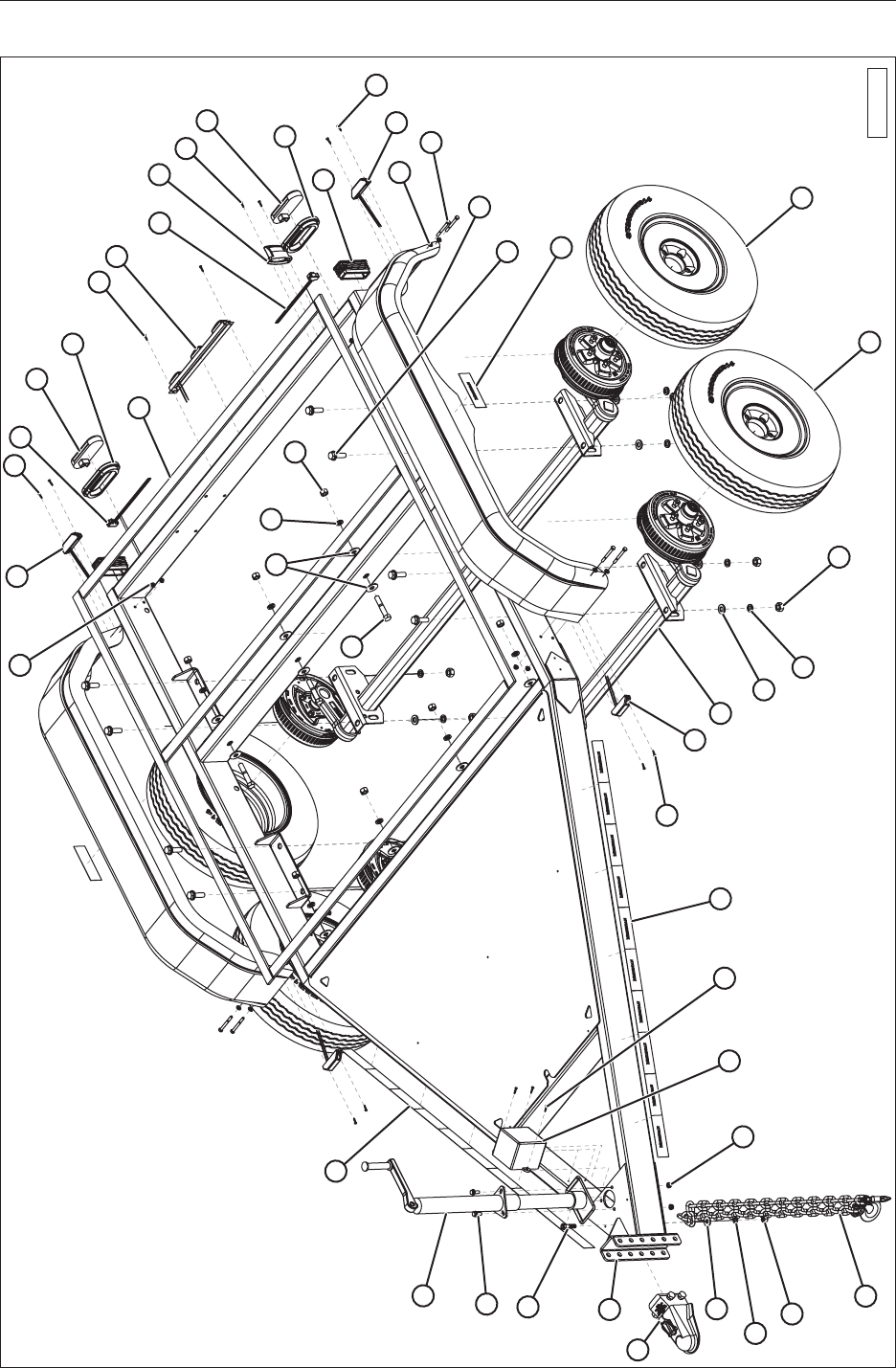
62
15.2 40027 TRAILER ASSEMBLY
MMG-00938
23 918 35 12
13
24
18 15
35 10
18
12
13
16
18
9
4
22
3
17
2
2
27
21
26
1
14
18
17
18
7
19
6
31
30
29
11
5
28
20
8
17 33
21
32
34
25

63
Item Qty. Part No. Description
1 2 14214 Axle, 3000#, 8in, 62 1/8 CL to CL
2 4 14209
14208 ST205/75R14, Tire and Steel Rim
ST205/75R14, Tire and Aluminum
Rim
3 2 14210 Fender, Tandem, 14”, Poly,
6X1506.002
4 8 19321 Washer, Flat, 5/16
5 1 30714 Trailer, 520, Painted
6 2 19171 Chains, Safety, with Hook
7 1 19275 Battery Breakaway, BA10-150
8 1 18192 Jack, Top-Wind (5000 lb. CAP.)
9 2 17669 Clearance Light, Red
10 1 17674 Light, License Plate
11 1 24688 Coupler Hitch Assembly, 2 5/16”
W/Safety Pin
12 2 17670 Taillight, Red
13 2 17671 Seal, Taillight
14 2 17668 Clearance Light, Amber
15 1 11554 LED Strip Light (Truck-Lite 15050R)
16 2 19619 Plug, Tube, 2” x 5”
17 11’ 18096 Tape, Reective Meridian 2x6x6
18 15 19779 #8-18 X 3/4” Self Drilling Zinc Screw
19 3 19564 Nut, Hex, Flanged, 3/8-16 UNC
20 3 19569 Bolt, Hex, Flanged, 3/8-16 x 1.0”
21 16 18460 Washer, Lock, 5/8”, Steel
22 8 19314 Bolt, Hex, 5/16-18 x 3”
23 8 19318 Nut, Hex, Flanged, 5/16-18 UNC
24 28’
6” 17672 Neoprene Strip, 3/16 x 1-1/2 (60’ 6”)
25 8 19567 Bolt, Hex, Flanged, 5/8-11 x 2.0”
26 8 17787 Washer, Flat, 5/8”
27 8 18489 Nut, Hex, Heavy, 5/8-11
28 1 15059 Bolt, Hex, 1/2-13 x 2”
29 1 18487 Washer, Flat, 1/2”
30 1 19373 Washer, Lock, 1/2”, Steel
31 1 17234 Nut, Lock, Nylon, 1/2-13, Grade 8
32 8 19382 Nut, Hex, 5/8-11
33 8 17589 Bolt, Hex, 5/8-11 x 3.5”
34 16 19384 Washer, Flat, 5/8”
35 2 10045 Plug, S/T/T, 11” (Truck-Lite 94993-
3)
36 8’ 17019 1/2” Heat Shrink Polyolen Black
2:1 WayTech 22438C (Not Shown)
37 1 10221 Wire Harness (Not Shown)
38 1 17532 Decal, Trailer VIN# (Not Shown)
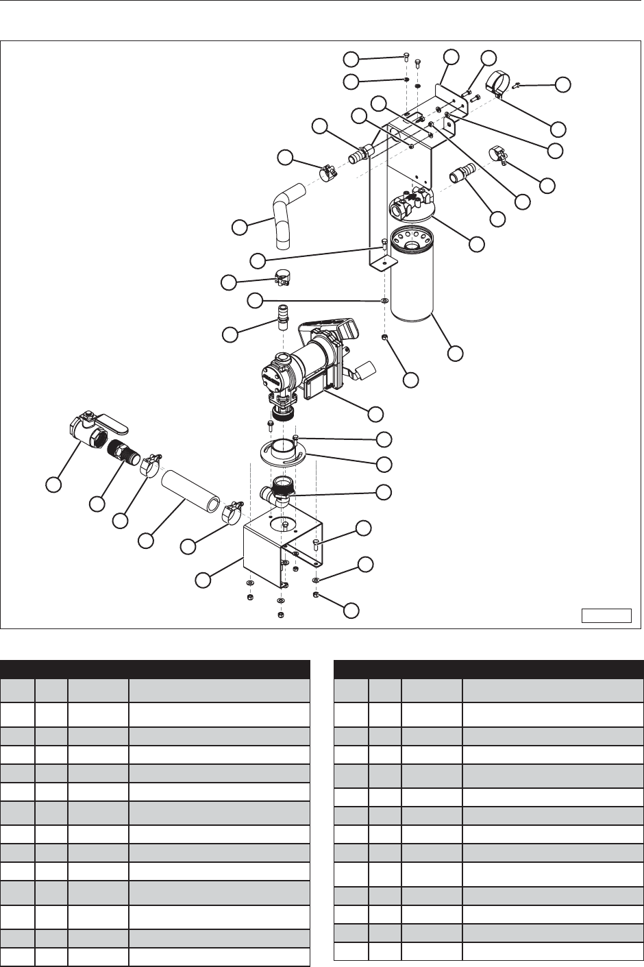
64
15.3 40028 ELECTRIC FUEL PUMP
MMG-00939
17
18
23
22
6
8
7
8
25
26
12
27
2
1
6
20
8
21
13
24
28
5
10
19
11
16
25
26
27
9
4
3
4
15
14
Item Qty. Part No. Description
1 1 25173 Filter Head 1” NPT for F40 Filter
(700ACCF7017)
2 1 11220 Diesel Filter - 40 GPM-50 PSI 10
Micron
3 1 50200 Hose, Diesel, 1-1/2” ID, Suction
4 2 17380 Clamp, T-Bolt, 1.844” to 2.062”
5 1 50324 Bracket, Hose/Filter, 520
6 2 11510
1” NPT x 1” Barb Adapter-Polypr-Blk
7 1 50199 Hose, Diesel, 1” ID (12V Pump To
Filter)
8 3 11513 Clamp, T-Bolt, 1.344” to 1.562”
9 1 50325 Bracket, Pump, 12V, 520
10 1 14207 Fuel Pump, 12V, 15 GPM
11 1 32439 Coupler Weldment, 12V Diesel
Pump Mount
12 1 10257 Fitting, Barbed, 1” x 3/4” NPT M,
Black Poly
13 2 17253
Hook/Loop Cable Tie, 2-1/2 Max Ø
14 1 17646 1-1/2” Ball Valve
Item Qty. Part No. Description
15 1 10093
Fitting, Hose Barb, 1-1/2 x 1-1/2 NPT,
STL
16 1 10082
Hose Barb, 2” NPT x 1-1/2” x 90 Deg,
Poly
17 2 19309 Bolt, Hex, 5/16-18 UNC x 0.75
18 2 19322 Washer, Lock, 5/16”, Steel
19 2 19581 Bolt, Hex, Flanged, 5/16-18 UNC
x 1.0
20 4 19586 5/16-18 UNC Nylon Lock Nut
21 4 19321 Washer, Flat, 5/16”
22 1 19128 1/4-20 UNC Nylon Hex Nut
23 1 19307 Washer, Flat, 1/4”
24 1 17769 Bolt, Hex, Flanged, Serrated,
Steel, Mild, 1/4-20 UNC x 0.75
25 5 19325 Bolt, Hex, 3/8-16 UNC x 1.0
26 5 19348 Washer, Flat, 3/8”
27 5 19347 3/8-16 UNC Nylon Lock Nut
28 2 19310 Bolt, Hex, 5/16-18 UNC x 1.0
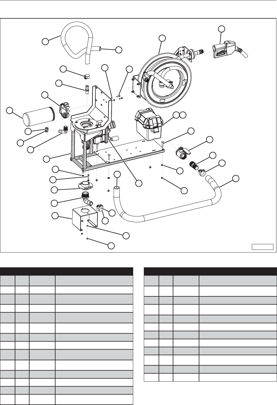
65
15.4 60623 12V PUMP & HOSE REEL PACKAGE
MMG-00940
18
13
15
9
10
13
24
1
22
20
5
3
2
23
22
17
4
12
19
B
B
16
17
6
7
11
8 26
20
25
A
A
14
21
Item Qty. Part No. Description
1 1 40039 Component Mount Assembly, 520
Fuel Trailer
2 1 50325 Bracket, Pump, 12V, 520
3 1 10082
Hose Barb, 2” NPT x 1-1/2” x 90 Deg,
Poly
4 1 14207 Fuel Pump, 12V, 15 GPM
5 1 32439. Coupler Weldment, 12V Diesel
Pump Mount
6 1 10093
Fitting, Hose Barb, 1-1/2 x 1-1/2 NPT,
STL
7 1 17646 1-1/2” Ball Valve
8 2 11219 Battery Box, Small
9 1 25173 Filter Head 1” NPT for F40 Filter
(700ACCF7017)
10 1 11220 Diesel Filter - 40 GPM-50 PSI 10
Micron
11 4 10205 Bolt, Carriage, 3/8-16 UNC x 2”
12 4 19347 3/8-16 UNC Nylon Lock Nut
13 2 11513 Clamp, T-Bolt, 1.344” to 1.562”
14 1 21020 Diesel Nozzle, 1” Outlet
[Fill-Rite] Green
Item Qty. Part No. Description
15 1 10257 Fitting, Barbed, 1” x 3/4” NPT M,
Black Poly
16 1 50329 Hose, Diesel 1.5” ID x 60” Suction
520 Tank-Pump
17 2 17380 Clamp, T-Bolt, 1.844” to 2.062”
18 1 50330 Hose, Diesel 1” ID x 36” L 520
(Pump-Filter)
19 4 19348 Washer, Flat, 3/8”
20 4 19310 Bolt, Hex, 5/16-18 UNC x 1.0
21 2 19322 Washer, Lock, 5/16”, Steel
22 4 19321 Washer, Flat, 5/16”
23 2 19586 5/16-18 UNC Nylon Lock Nut
24 1 11511 Ø1” NPT x Ø1” Hose Barb Elbow-
Polypr-Black
25* 1 30723 520 Diesel Hose Reel Upgrade
26 1 21286 Battery, SP-30 (Not supplied)
*See additional page for parts breakdown.
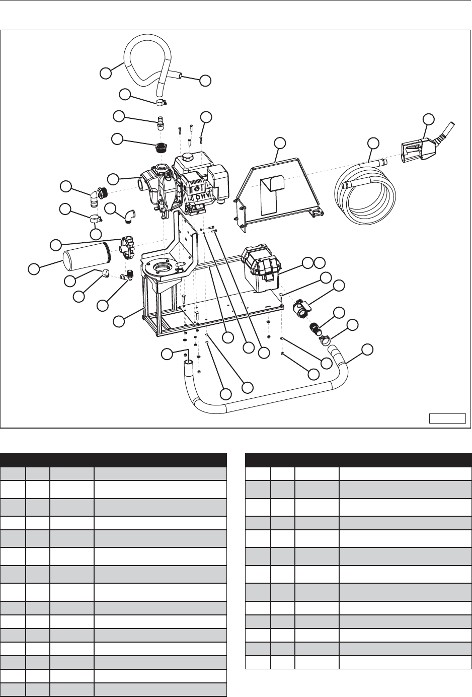
66
15.5 60625 40 GPM PUMP, HOSE, AND NOZZLE PACKAGE
MMG-00941
20
7
A
26 23
22
27
4 28
916
17
19
18
24
14
25
12
12
13
5
6
15
15
11
10
1
8
B
19 21
3
2
A
B
Item Qty. Part No. Description
1 1 11074
Engine, 6.5 HP, Pump, MP-40 GPM
2 1 11220 Diesel Filter - 40 GPM-50 PSI 10
Micron
3 1 25173 Filter Head 1” NPT for F40 Filter
(700ACCF7017)
4 1 11219 Battery Box, Small
5 1 40039 Component Mount Assembly, 520
Fuel Trailer
6 1 11511 Ø1” NPT x Ø1” Hose Barb Elbow-
Polypr-Black
7 4 19311 Hex Head Cap Screw,
5/16-18 UNC x 1 1/2”
8 1 10082
Hose Barb, 2” NPT x 1-1/2” x 90 Deg,
Poly
9 4 10205 Bolt, Carriage, 3/8-16 UNC x 2”
10 1 10204 Reducer, 2” NPT to 1” NPT, Poly
11 1 11510
1” NPT x 1” Barb Adapter-Polypr-Blk
12 6 19322 Washer, Lock, 5/16”, Steel
13 4 19738 Nut, Hex, 5/16-18 UNC
14 4 19347 3/8-16 UNC Nylon Lock Nut
15 2 11513 Clamp, T-Bolt, 1.344” to 1.562”
Item Qty. Part No. Description
16 1 17646 1-1/2” Ball Valve
17 2 10093
Fitting, Hose Barb, 1-1/2 x 1-1/2 NPT,
STL
18 1 50329 Hose, Diesel 1.5” ID x 60” Suction
520 Tank-Pump
19 2 17380 Clamp, T-Bolt, 1.844” to 2.062”
20 1 50330 Hose, Diesel 1” ID x 36” L 520
(Pump-Filter)
21 1 18196 Elbow, 1” NPT, Female x Male, 90
Deg, Galv.
22 1 21021 Diesel Nozzle, 1” Ultra Hi-Flow,
Green
23 1 50332 Hose, Fuel, Dispensing, 1” x 25’
Hi-Test
24 4 19348 Washer, Flat, 3/8”
25 2 19310 Bolt, Hex, 5/16-18 UNC x 1.0
26* 1 40041 Hose Hook Assembly
27 1 18661 Battery Cable Set, (29”)
28 1 21286 Battery, SP-30 (Not supplied)
*See additional page for parts breakdown.
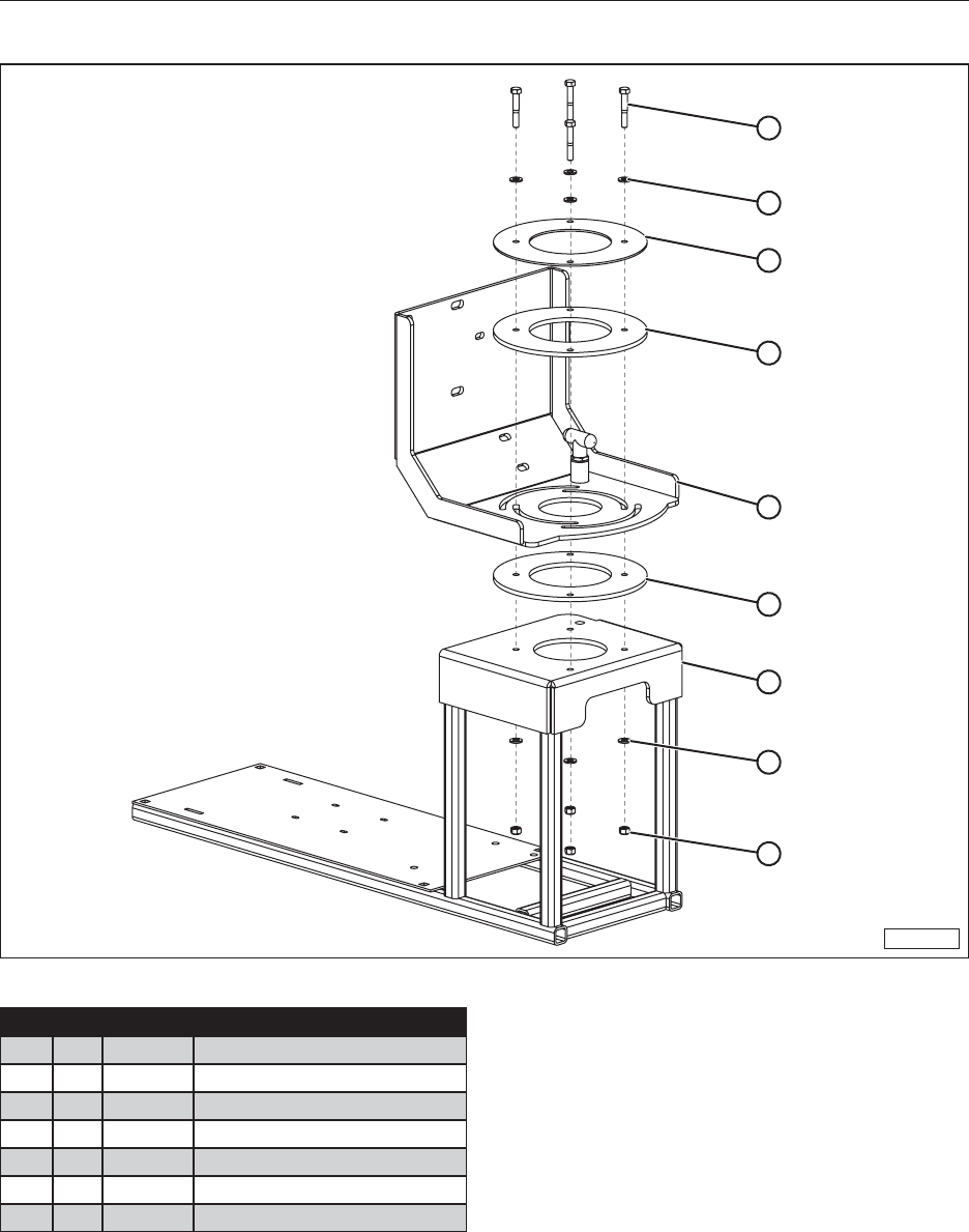
67
15.6 40039 COMPONENT MOUNT ASSEMBLY
MMG-00942
4
5
2
3
6
3
1
5
7
Item Qty. Part No. Description
1 1 30729
Weldment, Component Frame
2 1 50318 Plate, Swivel Flange
3 2 50319 Spacer, Swivel Bracket
4 4 19312 Bolt, Hex, 5/16-18 UNC x 2”
5 8 19321 Washer, Flat, 5/16”
6 1 30730 Weldment, Swivel Bracket
7 4 19586 5/16-18 UNC Nylon Lock Nut
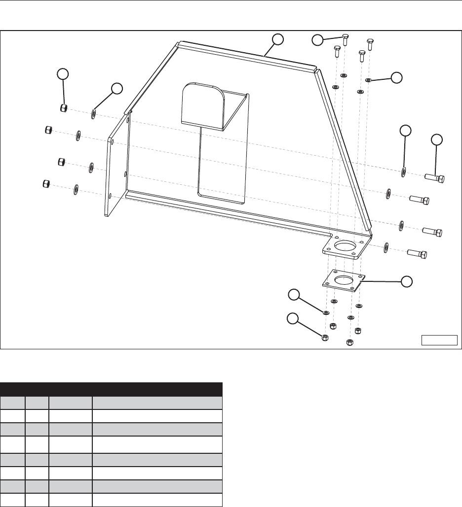
68
15.7 40041 HOSE HOOK ASSEMBLY
MMG-00943
7
6
14
5
68
2
5
3
Item Qty. Part No. Description
1 1 50331
Hook, Hose
2 1 10211 Wiper, Nozzle
3 4 18321 Nut, Hex, Nylon, 1/4-20 UNC, SS
4 4 50323 Screw, Cap, Hex Head,
1/4-20 UNC x 3/4” SS
5 8 17768 Washer, Flat, 1/4”, SS
6 8 17767 Washer, Flat, 3/8”
7 4 19347 3/8-16 UNC Nylon Lock Nut
8 4 19326
Bolt, Hex, 3/8-16 UNC x 1.25
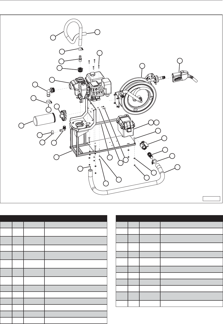
69
15.8 60622 40 GPM PUMP AND REEL PACKAGE
MMG-00944
20
15
11
10
1
8
19
3
2
15 6
5
7
A
A
B
23
25
24
4 26
9
16
17
19
18
21
14
12
13
22
12
B
Item Qty. Part No. Description
1 1 11074
Engine, 6.5 HP, Pump, MP-40 GPM
2 1 11220 Diesel Filter - 40 GPM-50 PSI 10
Micron
3 1 25173 Filter Head 1” NPT for F40 Filter
(700ACCF7017)
4 1 11219 Battery Box, Small
5 1 40039* Component Mount Assembly, 520
Fuel Trailer
6 1 11511 Ø1” NPT x Ø1” Hose Barb Elbow-
Polypr-Black
7 4 19311 Hex Head Cap Screw,
5/16-18 UNC x 1 1/2”
8 1 10082
Hose Barb, 2” NPT x 1-1/2” x 90 Deg,
Poly
9 4 10205 Bolt, Carriage, 3/8-16 UNC x 2”
10 1 10204 Reducer, 2” NPT to 1” NPT, Poly
11 1 11510
1” NPT x 1” Barb Adapter-Polypr-Blk
12 6 19322 Washer, Lock, 5/16”, Steel
13 4 19738 Nut, Hex, 5/16-18 UNC
14 4 19347 3/8-16 UNC Nylon Lock Nut
Item Qty. Part No. Description
15 2 11513 Clamp, T-Bolt, 1.344” to 1.562”
16 1 17646 1-1/2” Ball Valve
17 1 10093
Fitting, Hose Barb, 1-1/2 x 1-1/2 NPT,
STL
18 1 50329 Hose, Diesel 1.5” ID x 60” Suction
520 Tank-Pump
19 2 17380 Clamp, T-Bolt, 1.844” to 2.062”
20 1 50330 Hose, Diesel 1” ID x 36” L 520
(Pump-Filter)
21 4 19348 Washer, Flat, 3/8”
22 2 19310 Bolt, Hex, 5/16-18 UNC x 1.0
23* 1 30723 520 Diesel Hose Reel Upgrade
24 1 18661 Battery Cable Set, (29”)
25 1 21021 Diesel Nozzle, 1” Ultra Hi-Flow,
Green
26 1 21286 Battery, SP-30 (Not supplied)
*See additional page for parts breakdown.
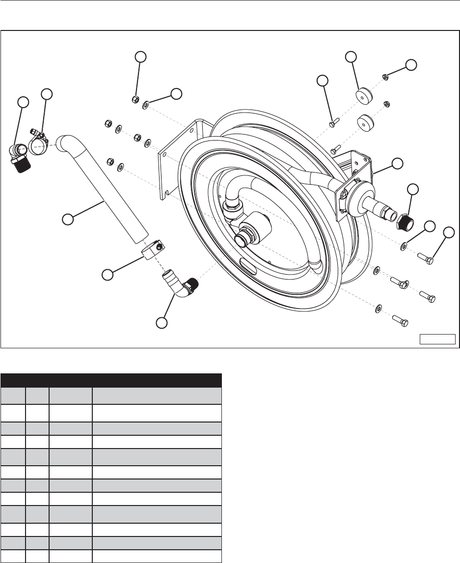
70
15.9 30723 HOSE REEL UPGRADE
MMG-00946
93
7
6
12
10 11
1
5
68
2
3
4
Item Qty. Part No. Description
1 1 14213
Hose Reel, Diesel, Ø3/4” x 25’
#SHF-N-525-FM
2 1 11229 Elbow, 90 Deg, 3/4” NPT x 1”
Hose Barb, Poly
3 2 11513 Clamp, T-Bolt, 1.344” to 1.562”
4 1 50323 Hose To Filter, 1”ID, 520
5 1 10206 Reducer, Bushing, 1” NPT To 3/4”
NPT, Steel
6 8 19348 Washer, Flat, 3/8”
7 4 19347 3/8-16 UNC Nylon Lock Nut
8 4 19326
Bolt, Hex, 3/8-16 UNC x 1.25
9 1 11511 Ø1” NPT x Ø1” Hose Barb Elbow-
Polypr-Black
10 2 19133 Rubber Bumper
11 2 19126
Nut, Hex, Flanged, 1/4-20 UNC
12 2 19099 Bolt, Hex, 1/4-20 UNC x .875
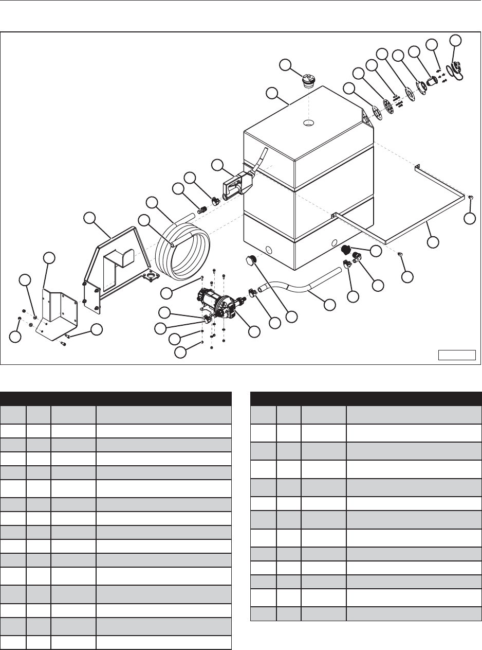
71
15.10 60626 DEF SYSTEM, 55 GAL
MMG-00945
4
210
812
3
13
6
5
7
17
19
18
16
25 A
A
26
29
27 28
22
23
19
24
119 9
21
20
14
20
11
15
19
Item Qty. Part No. Description
1 1 17014
Pump, 12V DC DEF PIUSI
#F0020400A
2 1 11542 Tank, DEF, 55 Gal
3 1 11221 Cap, DEF, Vented
4 1 11213 Vent, Ø2” NPS Dual Action (4 psi)
5 1 38670 Top Weldment, Filler Neck, SS
6 1 17348 Mis-Filling Prevention Device,
OPW 21GU
7 1 17343 Gasket, Fill Neck, Top
8 1 17345
Bolt Plate, Fill Neck, Bottom
9 1 17353 Plug 1-1/2” NPT SCH80
10 1 17344 Gasket, Fill Neck, Bottom
11 1 10162
Reducer, 1-1/4” NPT to 1” NPT, Poly
12 6 17346 Screw, Phillips, Flat, 1/4-20 x 7/8”
SS
13 6 17347 Screw, Phillips, Round Hd, 1/4-20
x 3/8” SS
14 1 50326 Strap, Tank 520 DEF Tank
15 1 10207 Elbow, 90 Deg, 1” NPT x 3/4”
Hose Barb, Poly
16 1 50327 Hose, DEF - 25FT
Item Qty. Part No. Description
17 1 11207 Nozzle, DEF, 3/4” Out, 3/4” NPT
(OPW19DEF0500)
18 1 10209 Hose Barb, 3/4” Hose ID x 3/4”
NPT, Brass
19 4 10186 Clamp, T-Bolt 1-5/32”-1-15/32”
Kuriyama TBC-SS031
20 2 10210 Bolt, Hex, 1/2”-13 UNC x 1/2”,
Steel, Zinc
21 1 50328 Hose, DEF 3/4” ID x 24” Suction,
520 Tank-Pump
22 4 19128 Nut, Hex, Nylon, 1/4”-20 UNC
23 4 18485 Washer, 1/4 - narrow - Type A
Steel, Mild
24 4 17769 Bolt, Hex, Flanged, Serrated,
Steel, Mild 1/4-20 UNC X 0.75
25* 1 40041 Hose Hook Assembly
26 1 50322 Bracket, DEF Reel
27 2 19347 Nut, Lock,Nylon, 3/8-16 UNC
28 2 19326 Bolt, Hex, 3/8-16 UNC x 1.25,
Steel, Mild
29 2 19348 Washer, Flat, 3/8”
*See additional page for parts breakdown.
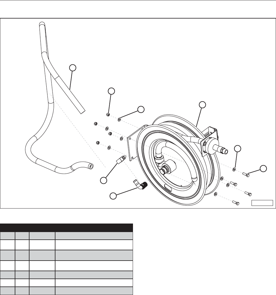
72
15.11 30724 DEF HOSE REEL UPGRADE
MMG-00947
4
5
71
3
2
6
7
Item Qty. Part No. Description
1 1 11502
Hose Reel, DEF, 25’ (Cox Reel)
2 1 10163 Elbow, 90 Deg, 3/4” NPT x 3/4”
Hose Barb, Poly
3 1 10186 Clamp, T-Bolt, 1-5/32”-1-15/32”
Kuriyama TBC-SS031
4 1 50323 Hose, DEF, 3/4” ID x 92” Suction
520 Pump-Reel
5 4 19347 3/8-16 UNC Nylon Lock Nut
6 4 19326 Bolt, Hex, 3/8-16 UNC x 1.25
7 8 19348 Washer, Flat, 3/8”
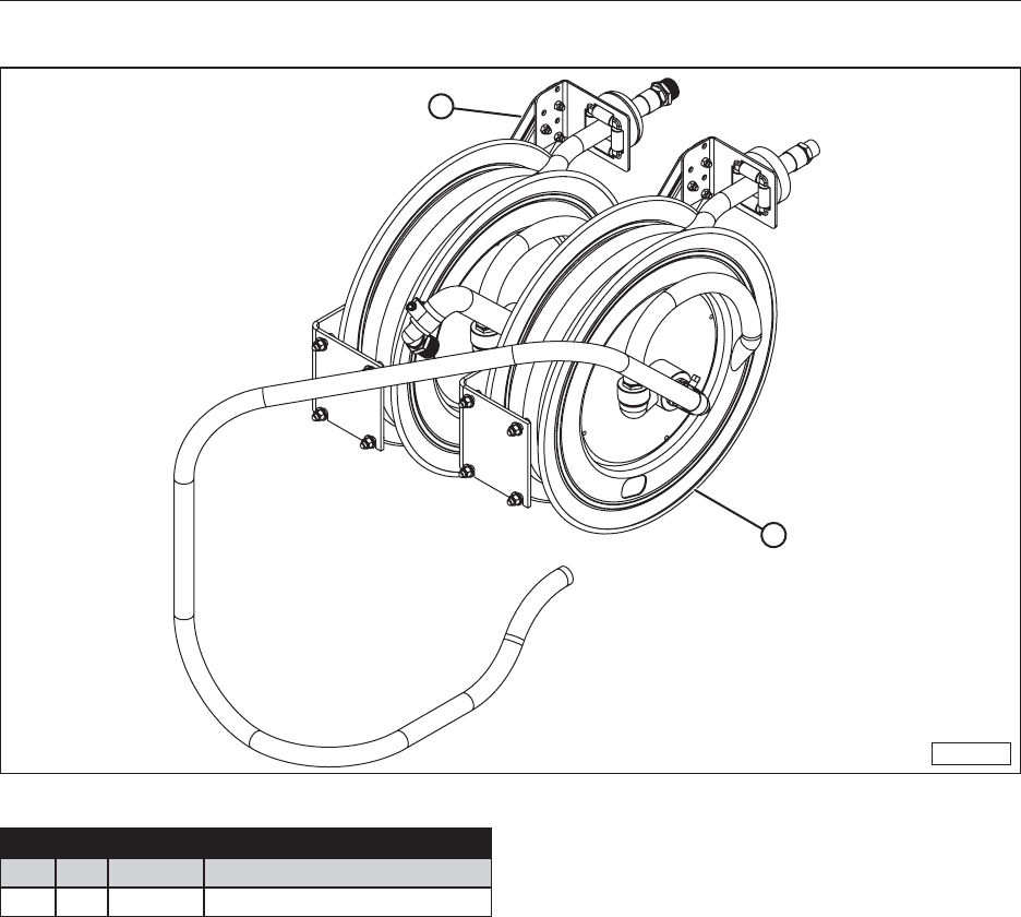
73
15.12 60624 DUAL HOSE REEL UPGRADE, DIESEL & DEF
MMG-00948
2
1
Item Qty. Part No. Description
1* 1 30724
520 DEF Hose Reel Upgrade
2* 1 30723
520 Diesel Hose Reel Upgrade
*See additional page for parts breakdown.
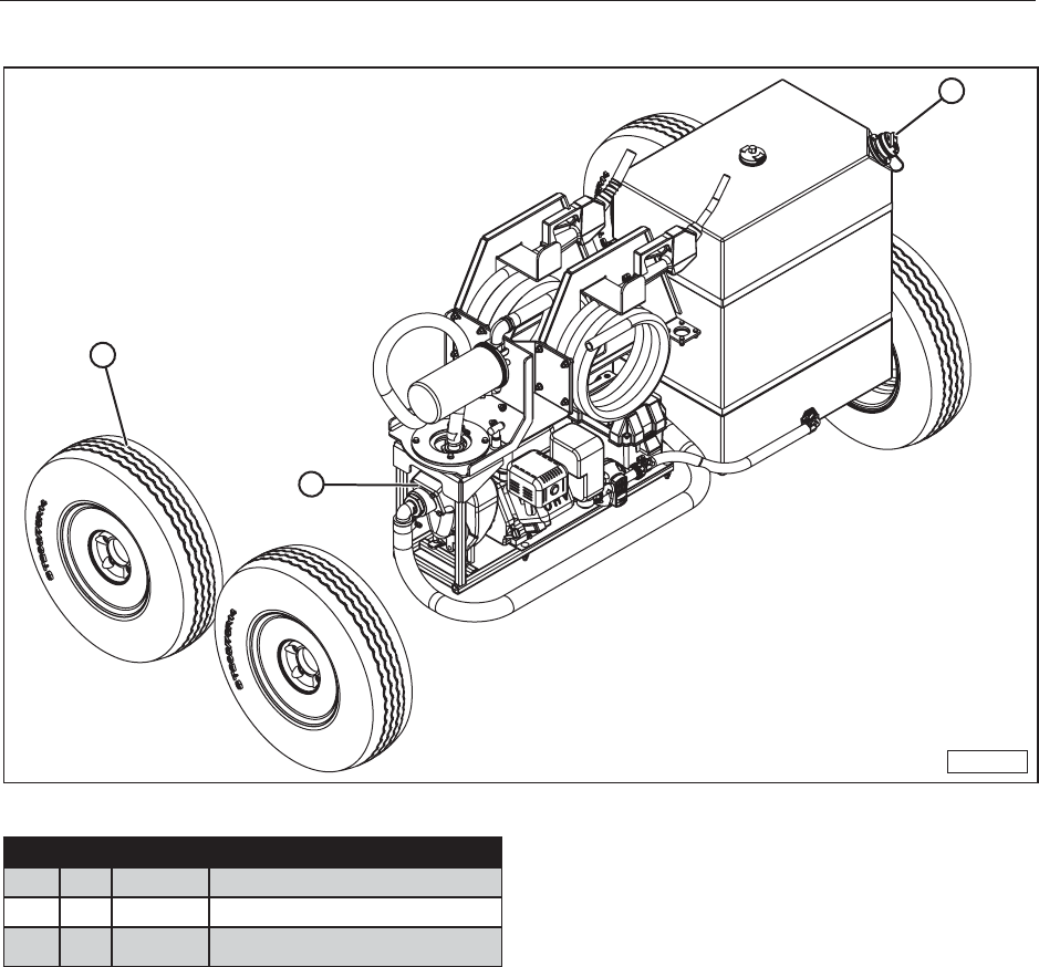
74
15.13 60621 ULTRA PACKAGE, 520 FUEL TRAILER
MMG-00949
2
3
1
Item Qty. Part No. Description
1* 1 60626 DEF System, 55 Gal
2 1 30725
Aluminum Wheels Upgrade
3* 1 60625 40 GPM Pump, Hose, and Nozzle
Package
*See additional page for parts breakdown.
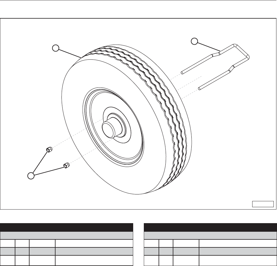
75
15.14 SPARE TIRE KIT
MMG-00950
2
1
3
Item Qty. Part No. Description
30726 Tire and Steel Wheel
1 1 14209 ST205/75R14, Tire and Steel Rim
2 1 10218 Carrier, Spare Tire
3 2 10218
LUGNUT 7/16-20 UNF Lug Nut
(Comes With 10218)
Item Qty. Part No. Description
30727 Tire and Aluminum Wheel
1 1 14208 ST205/75R14, Tire and Aluminum Rim
2 1 10218 Carrier, Spare Tire
3 2 10218
LUGNUT 7/16-20 UNF Lug Nut
(Comes With 10218)

76
NOTES

77
NOTES

78
NOTES
MERIDIAN MANUFACTURING INC.
With over 65 years of experience,
Meridian is your storage and handling expert.
Storm Lake Office
2902 Expansion Blvd.
Storm Lake, IA 50588
PH: 712.732.1780
TF: 800.437.2334
FX: 712.732.1028
Lethbridge Office
3125 - 24 Ave. N.
Lethbridge, AB T1H 5G2
PH: 403.320.7070
TF: 800.661.1436
FX: 403.320.7579
Winkler Office
Box 760, 275 Hespler Ave.
Winkler, MB R6W 4A8
PH: 204.325.7883
TF: 800.665.7259
FX: 204.325.5556
Regina Office
PO Box 1996
Regina, SK S4P 3E1
PH: 306.545.4044
TF: 800.667.5904
FX: 306.545.4216
Camrose Office
4232 - 38 St.
Camrose, AB T4V 4B2
PH: 780.672.4516
TF: 800.830.2467
FX: 780.672.4759
Cambridge Office
605 Sheldon Drive
Cambridge, ON N1T 2K1
PH: 519.620.6004
TF: 855.346.3712
FX: 519.620.6041
© 2015 Meridian Manufacturing, Inc. Registered Trademarks Used Under License. Form No. 10253
Printed in U.S.A. (11/15)
