Meridian Bin Fill Conveyor Operators Manual Operator
User Manual: Meridian-Bin-Fill-Conveyor-Operator-Manual
Open the PDF directly: View PDF ![]() .
.
Page Count: 64


3
PRODUCT WARRANTY
REGISTRATION FORM - BIN FILL CONVEYOR
WARRANTY REGISTRATION
This form must be lled out by the dealer and signed by both the dealer and the customer at the time
of delivery. Please mail or fax the completed form for validation of the equipment registration.
Customer’s Name__________________________________________________
Address _________________________________________________________
City, State, Postal Code_________________________, _______, ___________
Phone Number (_______) _______- ___________
PRODUCT INFORMATION
Conveyor Model #___________ # rebmuN laireS _______________________
DEALER INSPECTION REPORT
____Conveyor frame raises and lowers properly
____Conveyor belt properly aligned
____Unit lubricated where necessary
____Air pressure correct in tires
____All guards/shields installed correctly
____All safety signs installed and legible
____Reectors in place and clean
____Safety and operating instructions reviewed
____Inspect customer’s hitch for 1-7/8” ball
____Veried the receipt of all options ordered
I have thoroughly instructed the buyer on the above-described equipment, including review of the Operator’s
Manual content, equipment care, adjustments, operational use, safety procedures, and applicable warranty
policy.
Dealer/Company Name____________________________________
City, State, Postal Code _________________________, _________, ______________
Dealer’s Signature______________________________________ Date ____/____/______
The above equipment and Operator’s Manual have been received by me, and I have been thoroughly instructed as
to care, adjustments, safe operation, and applicable warranty policy.
Owner’s Signature_____________________________________ Date ____/____/_______
2902 Expansion Blvd. Storm Lake, Iowa 50588 Phone: 800-437-2334 Fax: 712-732-1028 Email: iowa_warranty@meridianmfg.com
____Conveyor belt properly tensioned
____Conveyor drive belts properly tensioned
____Raise and lower A-frame
Cut Here to Remove Page

5
2902 Expansion Blvd.
Storm Lake, IA 50588
Phone: 712-732-1780
Fax: 712-732-1028
CERTIFICATE OF ORIGIN
LICENSING INFORMATION Date: ____/___/_______
DEALER :
___________________________Business
___________________________Contact
___________________________Address
___________________, ___ _____City, State, Zip
SOLD TO :
___________________________Business
___________________________Contact
___________________________Address
___________________, ___ _____City, State, Zip
CONVEYOR MODEL # _________________________________________________________
CONVEYOR SERIAL # __________________________________________________________
Bin Fill Conveyors models.
BIN FILL CONVEYOR
SL-E-55 (55 foot)
SL-E-65 (65 foot)
SL-E-75 (75 foot)
SL-H-55 (55 foot)
SL-H-65 (65 foot)
SL-H-75 (75 foot)
Cut Here to Remove Page
7
IMPORTANT INFORMATION
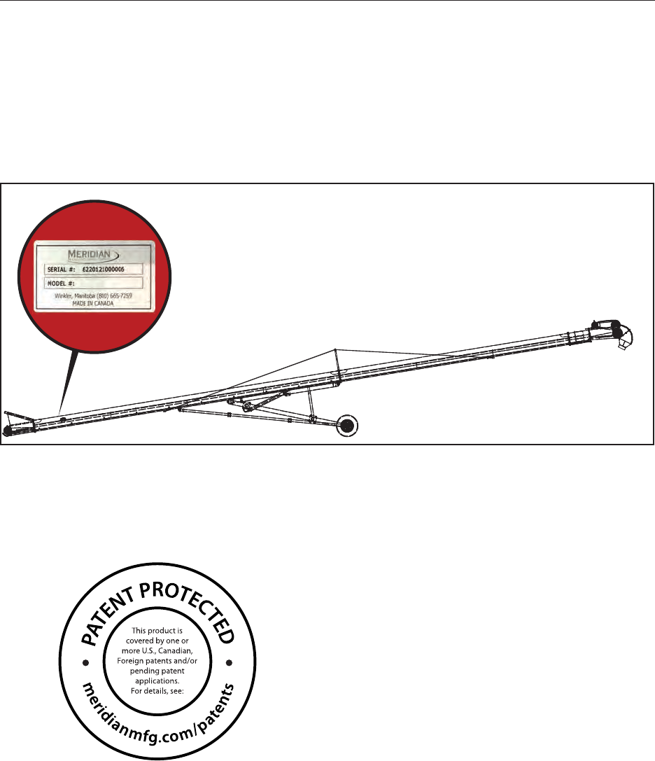
SERIAL NUMBER LOCATION
Please provide the serial number of your Meridian
Conveyor when ordering parts or requesting
service or other information.
The serial number plates are located where
indicated. Please record the numbers in the space
provided below for easy reference.
BF-001
SL-E(H)-55
Model Number: ___________________________
Serial Number: ____________________________
PATENT INFORMATION
Meridian continuously enhances its product
offering through product improvements and new
product innovations. Marketplace feedback,
technological innovation, new materials and
manufacturing methods, and a philosophy of
continuous improvement constantly challenge
the company to develop new and better ways of
addressing market needs. Meridian is committed
to innovation and reinvestment and as a result,
the company maintains a portfolio of patents and
intellectual property. For more information on our
patents please see our website:
www.meridianmfg.com/patents

8
CONTENTS
1.0 INTRODUCTION .........................................................10
1.1 Congratulations. . . . . . . . . . . . . . . . . . . . . . . . . . . . . . . . . . . . 10
1.2 Intended Use . . . . . . . . . . . . . . . . . . . . . . . . . . . . . . . . . . . . . 10
1.3 Owner/Operator . . . . . . . . . . . . . . . . . . . . . . . . . . . . . . . . . . . 10
1.4 Ownership Changes . . . . . . . . . . . . . . . . . . . . . . . . . . . . . . . . . 10
1.5 End of Life Disposal . . . . . . . . . . . . . . . . . . . . . . . . . . . . . . . . . 10
1.6 Reporting Hazards . . . . . . . . . . . . . . . . . . . . . . . . . . . . . . . . . . 10
2.0 SAFETY................................................................ 11
2.1 General Safety . . . . . . . . . . . . . . . . . . . . . . . . . . . . . . . . . . . . 12
2.2 Equipment Safety Guidelines . . . . . . . . . . . . . . . . . . . . . . . . . . . . 13
2.3 Safety Training . . . . . . . . . . . . . . . . . . . . . . . . . . . . . . . . . . . . 13
2.4 Safety Signs . . . . . . . . . . . . . . . . . . . . . . . . . . . . . . . . . . . . . 14
2.5 Assembly Instructions . . . . . . . . . . . . . . . . . . . . . . . . . . . . . . . . 14
2.6 Transport Safety . . . . . . . . . . . . . . . . . . . . . . . . . . . . . . . . . . . 14
2.7 Pre-operating Instructions . . . . . . . . . . . . . . . . . . . . . . . . . . . . . . 14
2.8 Operating Safety . . . . . . . . . . . . . . . . . . . . . . . . . . . . . . . . . . . 14
2.9 Electrical and Hydraulic Safety. . . . . . . . . . . . . . . . . . . . . . . . . . . . 14
2.10 Storage Safety . . . . . . . . . . . . . . . . . . . . . . . . . . . . . . . . . . . 14
2.11 Maintenance Safety . . . . . . . . . . . . . . . . . . . . . . . . . . . . . . . . . 14
2.12 Lock-Out or Tag-Out Safety. . . . . . . . . . . . . . . . . . . . . . . . . . . . . 14
2.13 Sign-Off Form . . . . . . . . . . . . . . . . . . . . . . . . . . . . . . . . . . . . 15
3.0 SAFETY SIGNS..........................................................16
3.1 Safety Sign Locations . . . . . . . . . . . . . . . . . . . . . . . . . . . . . . . . 16
3.2 How to Install Safety Signs. . . . . . . . . . . . . . . . . . . . . . . . . . . . . . 16
3.3 Decal Locationsw. . . . . . . . . . . . . . . . . . . . . . . . . . . . . . . . . . . 16
4.0 SPECIFICATIONS........................................................18
4.1 OverallSpecications . . . . . . . . . . . . . . . . . . . . . . . . . . . . . . . . 18
4.2 ElectricalSpecications . . . . . . . . . . . . . . . . . . . . . . . . . . . . . . . 18
4.3 BoltSpecications . . . . . . . . . . . . . . . . . . . . . . . . . . . . . . . . . . 19
4.3.1 Bolt Torque Values. . . . . . . . . . . . . . . . . . . . . . . . . . . . . . . 19
4.3.2 Grade Markings Chart. . . . . . . . . . . . . . . . . . . . . . . . . . . . . 19
5.0 CONVEYOR COMPONENT NOMENCLATURE.................................20
6.0 ASSEMBLY INSTRUCTIONS ...............................................21
6.1 Required Tools and Equipment. . . . . . . . . . . . . . . . . . . . . . . . . . . . 21
6.2 Unloading Instructions . . . . . . . . . . . . . . . . . . . . . . . . . . . . . . . . 21
6.3 Assemble the Sections . . . . . . . . . . . . . . . . . . . . . . . . . . . . . . . . 22
6.4 Tensioning Conveyor Belt . . . . . . . . . . . . . . . . . . . . . . . . . . . . . . 23
6.5 Adjust Conveyor Belt Tracking . . . . . . . . . . . . . . . . . . . . . . . . . . . . 24
6.6 Initial Conveyor Assembly . . . . . . . . . . . . . . . . . . . . . . . . . . . . . . 25
6.7 Final Check and Testing . . . . . . . . . . . . . . . . . . . . . . . . . . . . . . . 25
7.0 TOWING ...............................................................26
7.1 General Towing Safety . . . . . . . . . . . . . . . . . . . . . . . . . . . . . . . . 26
7.2 Maximum Towing Speed . . . . . . . . . . . . . . . . . . . . . . . . . . . . . . . 26
7.3 Inspection Before Towing. . . . . . . . . . . . . . . . . . . . . . . . . . . . . . . 26
7.4 Safety Chains . . . . . . . . . . . . . . . . . . . . . . . . . . . . . . . . . . . . 26
7.5 Bystanders . . . . . . . . . . . . . . . . . . . . . . . . . . . . . . . . . . . . . . 26
7.6
Connection to Tow Vehicle. . . . . . . . . . . . . . . . . . . . . . . . . . . . . . . .27
8.0 PRE-OPERATING INSTRUCTIONS ..........................................28
8.1 Safety. . . . . . . . . . . . . . . . . . . . . . . . . . . . . . . . . . . . . . . . . 28
8.2 Machine Break-In Period . . . . . . . . . . . . . . . . . . . . . . . . . . . . . . . 28
8.2.1 Before Starting. . . . . . . . . . . . . . . . . . . . . . . . . . . . . . . . . 28
8.2.2 Inspections for 1/2, 5, and 10 Hours. . . . . . . . . . . . . . . . . . . . . . 28
8.3 Daily Pre-Operation Checklist . . . . . . . . . . . . . . . . . . . . . . . . . . . . 28

9
9.0 OPERATION ............................................................29
9.1 Safety . . . . . . . . . . . . . . . . . . . . . . . . . . . . . . . . . . . . . . . . . 29
9.2 Before Each Use . . . . . . . . . . . . . . . . . . . . . . . . . . . . . . . . . . . 29
9.3 Conveyor Belt Operation . . . . . . . . . . . . . . . . . . . . . . . . . . . . . . . 29
9.4 Raising and lowering . . . . . . . . . . . . . . . . . . . . . . . . . . . . . . . . . 30
9.4.1 Hydraulic Safety . . . . . . . . . . . . . . . . . . . . . . . . . . . . . . . . 30
9.4.2 Hydraulic Power Supply . . . . . . . . . . . . . . . . . . . . . . . . . . . . 30
10.0 STORAGE .............................................................31
10.1 Storage Safety . . . . . . . . . . . . . . . . . . . . . . . . . . . . . . . . . . . 31
10.2 General Information. . . . . . . . . . . . . . . . . . . . . . . . . . . . . . . . . 31
10.3 Placing in Storage. . . . . . . . . . . . . . . . . . . . . . . . . . . . . . . . . . 31
10.4 Removing from Storage. . . . . . . . . . . . . . . . . . . . . . . . . . . . . . . 31
11.0 MAINTENANCE.........................................................32
11.1 Safety . . . . . . . . . . . . . . . . . . . . . . . . . . . . . . . . . . . . . . . . 32
11.1.1 General Safety . . . . . . . . . . . . . . . . . . . . . . . . . . . . . . . . 32
11.1.2 Lock-Out or Tag-Out Safety . . . . . . . . . . . . . . . . . . . . . . . . . 33
11.2 Lubrication. . . . . . . . . . . . . . . . . . . . . . . . . . . . . . . . . . . . . . 33
11.3 Replace or Tighten Drive Belts . . . . . . . . . . . . . . . . . . . . . . . . . . . 34
11.3.1 Adjusting Drive Belt Tension . . . . . . . . . . . . . . . . . . . . . . . . . 34
11.3.2 Replacing Drive Belts . . . . . . . . . . . . . . . . . . . . . . . . . . . . 35
11.4 Maintenance Intervals. . . . . . . . . . . . . . . . . . . . . . . . . . . . . . . . 35
10.4.1 Daily (8 Hours) . . . . . . . . . . . . . . . . . . . . . . . . . . . . . . . . 35
10.4.2 Weekly (50 Hours) . . . . . . . . . . . . . . . . . . . . . . . . . . . . . . 35
10.4.3 Annually (400 Hours). . . . . . . . . . . . . . . . . . . . . . . . . . . . . 35
11.5 Tires . . . . . . . . . . . . . . . . . . . . . . . . . . . . . . . . . . . . . . . . . 35
11.5.1 Tire Safety . . . . . . . . . . . . . . . . . . . . . . . . . . . . . . . . . . 35
11.5.2 Wheel Bearings . . . . . . . . . . . . . . . . . . . . . . . . . . . . . . . 36
11.6 Welding Repairs. . . . . . . . . . . . . . . . . . . . . . . . . . . . . . . . . . . 36
11.7 Wheel Bolt Torque Requirements . . . . . . . . . . . . . . . . . . . . . . . . . 36
11.8 Conveyor Service Record. . . . . . . . . . . . . . . . . . . . . . . . . . . . . . 37
12.0 TROUBLESHOOTING ...................................................38
12.1 Troubleshooting Chart . . . . . . . . . . . . . . . . . . . . . . . . . . . . . . . 38
13.0 WARRANTY ...........................................................39
13.1 Warranty Statement. . . . . . . . . . . . . . . . . . . . . . . . . . . . . . . . . 39
14.0 PARTS................................................................41
14.1 General Information. . . . . . . . . . . . . . . . . . . . . . . . . . . . . . . . . 41
14.2 Disposal of Equipment at End of Useful Life . . . . . . . . . . . . . . . . . . . . 41
14.3 Bin Fill Conveyor, Complete (55’, 65’, 75’) . . . . . . . . . . . . . . . . . . . . . 42
14.4 Bin Fill Conveyor Sub-assembly (55’, 65’, 75’) . . . . . . . . . . . . . . . . . . . 44
14.5 Tube Center Assembly (55’, 65’, 75’) . . . . . . . . . . . . . . . . . . . . . . . . 46
14.6 Arm Scissor Assembly . . . . . . . . . . . . . . . . . . . . . . . . . . . . . . . 48
14.6.1 A-Frame, Lower (55’, 65’, 75’) . . . . . . . . . . . . . . . . . . . . . . . . 48
14.6.2 Arm Scissor Assembly, Bottom (55’, 65’). . . . . . . . . . . . . . . . . . . 49
14.6.3 Arm Scissor Assembly, Bottom (75’) . . . . . . . . . . . . . . . . . . . . . 50
14.6.4 Arm Scissor Assembly, Top (55’, 65’). . . . . . . . . . . . . . . . . . . . . 51
14.6.5 Arm Scissor Assembly, Top (75’) . . . . . . . . . . . . . . . . . . . . . . . 52
14.7 Hub, Spindle, Tire, and Rim Assembly (55’, 65’, 75’) . . . . . . . . . . . . . . . . 53
14.8 Tube Assembly with Ends (55’, 65’, 75’) . . . . . . . . . . . . . . . . . . . . . . 54
14.9 Receiving End (55’ 65’ 75’) . . . . . . . . . . . . . . . . . . . . . . . . . . . . . 56
14.10 Discharge End (55’, 65’, 75’) . . . . . . . . . . . . . . . . . . . . . . . . . . . 58
14.11 Tension System Assembly (55’, 65’, 75’). . . . . . . . . . . . . . . . . . . . . . 60
10
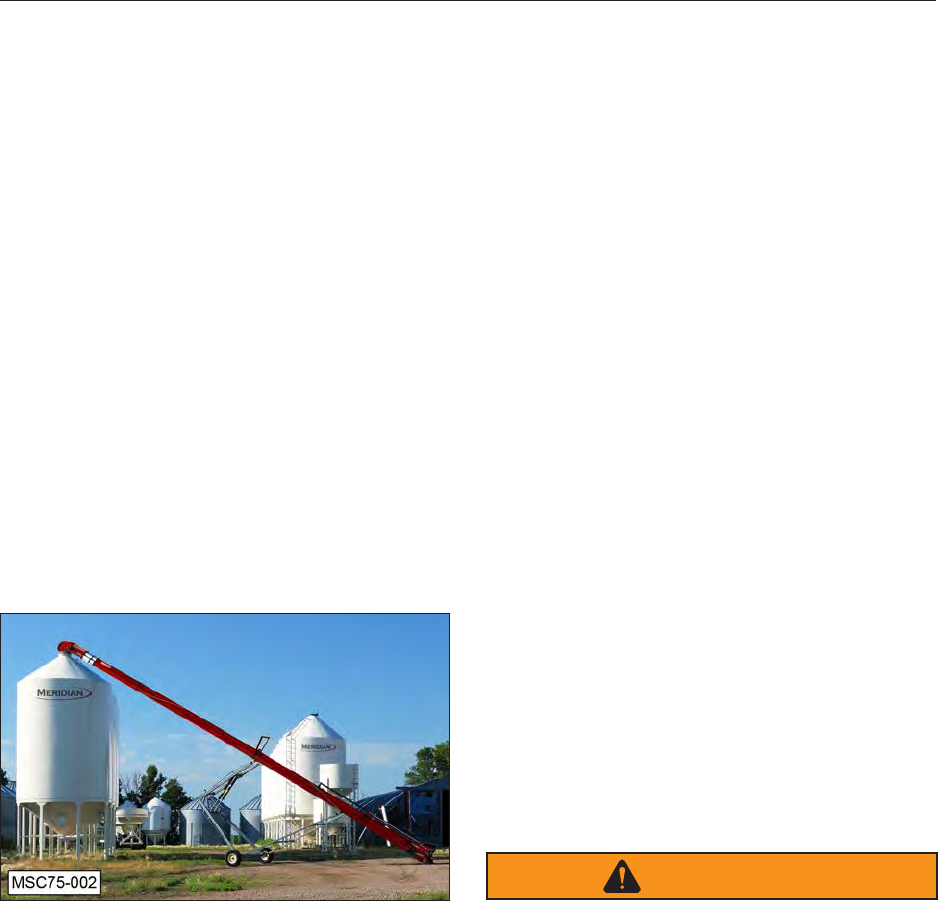
1.0 INTRODUCTION
1.1 CONGRATULATIONS
Congratulations on your choice of a Meridian
Conveyor. This conveyor has been designed and
manufactured to meet the exacting standards for
such equipment in the agricultural industry and
will keep your seed delivery system at optimum
efciency.
Safe,efcient,andtrouble‑freeoperationofyour
conveyor requires that you and anyone else who
will be operating or maintaining the site, read and
understand the Safety, Operation, Maintenance,
and Troubleshooting information contained within
this manual.
This manual covers the start-up procedures,
operating procedures and maintenance of the
conveyor designed by Meridian. Use the Table of
Contents as a guide to locate required information.
1.2 INTENDED USE
This 55’, 65’, and 75’ conveyors are designed to
elevate grain into a bin. It is not intended to
convey any other product, such as fertilizer.
1.3 OWNER/OPERATOR
It is the responsibility of the owner or operator
to read this manual and to train all other
operators before they start working with
the conveyor. Follow all safety instructions
exactly. Safety is everyone’s business. By
following recommended procedures, a safe
working environment is provided for the
operator, bystanders, and the area around
the work site. Untrained operators are not
qualied and must not operate the conveyor.
In addition to the design and conguration
of equipment, hazard control and accident
prevention are dependent upon the awareness,
concern, prudence, and proper training of
personnel involved in the operation, transport,
maintenance, and storage of the conveyor. It
is the responsibility of the owner or operator
to read this manual and to train all operators
before they start working with the conveyors.
Follow all safety instructions as provided in
this manual.
Keep this manual accessible for easy reference.
Call your Meridian dealer if you need assistance,
information, or additional copies of the manuals.
Theinformation,specications,andillustrations
in this manual are those in effect at the time
of printing. We reserve the right to change
specications,ordesign,atanytimewithout
notice.
1.4 OWNERSHIP CHANGES
If any of the equipment associated with
this conveyor changes ownership, then the
new owner(s) must be given all applicable
documentation associated with all the
components/equipment on the site. The new
owners need to notify the individual manufactures
of the ownership change so that updates to
product, or documentation, can be forwarded to
the new owner(s). This should be done even if
the equipment is out of warranty because many
manufacturerssupplyupdatenoticationsaslong
as they have valid ownership information.
1.5 END OF LIFE DISPOSAL
When a piece of equipment, or one of its
components, reaches its end of life usability, then
dispose of the device in accordance with all local,
state, and federal laws and regulations.
WARNING
DO NOT use an entire assembly, or even a
component of an assembly, for anything other than
the manufacture’s original intended use. Not only is
the warranty voided, but the component can fail in
the unintended application creating a hazard to the
conveyor and the personnel using that conveyor.
1.6 REPORTING HAZARDS
If any of the equipment associated with this
conveyor appears to pose a hazard, then it is the
duty of the individual to report it immediately. If the
hazard is the conveyor, then the manufacture and
sitemanagermustbenotied.Ifthehazardisa
process,thenthesitemanagermustbenotied.
Unreported hazards can lead to serious injury, or
death, to personnel.

11
2.0 SAFETY
TheSafetyAlertsymbolidentiesimportantsafetymessagesontheMeridianequipmentandinthe
manuals. When you see this symbol, be alert to the possibility of personal injury or death. Follow the
instructions in the safety message.
If you have any questions not answered in this manual, require additional copies of the manual, or the
manual is damaged, please contact your dealer or Meridian Manufacturing, Inc. 2902 Expansion Blvd.,
Storm Lake, Iowa, 50588, toll free 1-800-437-2334, phone (712) 732-1780, or fax (712) 732-1028.
SIGNAL WORDS:
Note the use of the signal words DANGER, WARNING, and CAUTION with the safety messages. The
appropriate signal word for each message has been selected using the following guidelines:
SAFETY ALERT SYMBOL
This Safety Alert symbol means
ATTENTION! BECOME ALERT!
YOUR SAFETY IS INVOLVED!
WHY IS SAFETY IMPORTANT TO YOU?
3 Big Reasons
• Accidents Disable and Kill •
• Accidents Cost •
• Accidents Can Be Avoided •
DANGER - Indicates an
imminently hazardous situation
that, if not avoided, will result in
death or serious injury. This signal
word is to be limited to the most
extreme situations typically for
machine components which, for
functional purposes, cannot be
guarded.
WARNING - Indicates a
potentially hazardous situation
that, if not avoided, could result
in death or serious injury, and
includes hazards that are
exposed when guards are
removed. It may also be used to
alert against unsafe practices.
CAUTION - Indicates a
potentially hazardous situation
that, if not avoided, may result
in minor or moderate injury. It
may also be used to alert against
unsafe practices.
WARNING
DANGER
CAUTION

12
YOU are responsible for the SAFE operation and
maintenance of your Meridian conveyor. YOU
must ensure that you and anyone else who is
going to operate, maintain, or work on the site
be familiar with the operating and maintenance
procedures and related SAFETY information
contained in this manual. This manual will take
you step-by-step through your working day and
alert you to all good safety practices that should be
adhered to while operating the conveyor.
Remember, YOU are the key to safety. Good
safety practices not only protect you but also
the people around you. Make these practices a
working part of your safety program. Be certain
that EVERYONE operating this conveyor is
familiar with the recommended operating and
maintenance procedures and follow all the safety
precautions. Most accidents can be prevented.
Do not risk injury or death by ignoring good safety
practices.
• Conveyor owners must give operating
instructions to operators and employees
before allowing them to operate the
conveyor, and then annually thereafter per
OSHA (Occupational Safety and Health
Administration) regulation 1928.57.
• The most important safety feature on this
conveyor is a SAFE operator. It is the
operator’s responsibility to read and follow
ALL Safety and Operating instructions in the
manual. Most accidents can be avoided.
• A person who has not read and understood
all operating and safety instructions is not
qualiedtooperatetheconveyor.Anuntrained
operator exposes himself and bystanders to
possible serious injury or death. Always be
and stay alert to any possible unsafe operating
or maintenance procedures or conditions.
• Do not modify the conveyor in any way.
Unauthorizedmodicationmayimpairthe
function and/or safety of the components
and systems and could affect the life of the
conveyor, possibly invalidating the warranty
coverage.
• Improper operation, lubrication, maintenance
or repair of this conveyor can be dangerous
and could result in injury or death.
• Think SAFETY! Work SAFELY!
2.1 GENERAL SAFETY
1. Read and understand the Operator’s
Manual for all safety signs before
operating or maintaining the conveyor.
2. Havearstaidkitavailableforuse
should the need arise and know how to
use it.
3. Haveareextinguisheravailablefor
use should the need arise and know
how to use it.
4. Do not allow riders on the conveyor
when it is moving.
5. When working around or operating this
conveyor, wear appropriate personal
protective equipment. This list includes but is
not limited to:
• A hard hat
• Protective shoes with slip resistant soles
• Protective goggles, glasses, or face shield
• Heavy gloves and protective clothing
• Respirator
6. Donotallowlonghair,loosetting
clothing, or jewelry around the
conveyor as it can be caught in moving
parts.
7. Install and secure all guards before
starting the conveyor.
8.
STOP
Stop the conveyor and wait for all
moving parts to stop before servicing,
repairing,adjusting,loading,lling,or
unplugging.
9.
do not
operate
signed by
date
WARNING
Establish a lock-out or tag-out
policy for the work site. Be sure
all personnel are trained in and
follow all procedures. Lock-out
or tag-out all power sources
before working around the
conveyor.
10. Clear the area of people, especially
small children, before starting.
11. Review safety related items annually
with all personnel who will be
operating, using, or maintaining the
conveyor.

13
2.2 EQUIPMENT SAFETY
GUIDELINES
1. Safety of the operator and bystanders is
one of the main concerns in designing and
developing a conveyor. However, every year
many accidents occur which could have been
avoided by a few seconds of thought and a
more careful approach to handling equipment.
You, the operator, can avoid many accidents
by observing the following precautions in this
section. To avoid personal injury or death,
study the following precautions and insist
those working with you, or for you, follow
them.
2. In order to provide a better view, certain
photographs or illustrations in this manual
may show an assembly with a safety shield
removed. However, the conveyor should never
be operated in this condition. Keep all shields
in place. If shield removal becomes necessary
for repairs, replace the shield prior to use.
3. Never use alcoholic beverages, or sedative
drugs, while operating this conveyor. Consult
your doctor about operating this conveyor
while taking prescription medications.
4. Under no circumstances should young
children be allowed to work with this conveyor.
Do not allow persons to operate or assemble
this conveyor until they have read this manual
and have developed a thorough understanding
of the safety precautions and how the
conveyor works. Review the safety instructions
with all users annually.
5. This conveyor is dangerous to children and
persons unfamiliar with its operation. The
operator should be a responsible, properly
trained, and physically able person familiar
with farm machinery and trained in this
conveyor’s operations. If the elderly are
assisting with farm work, their physical
limitations need to be recognized and
accommodated.
6. Never exceed the limits of the conveyor. If
its ability to do a job, or to do so safely, is in
question - DO NOT TRY IT.
7. Do not modify the conveyor in any way.
Unauthorizedmodicationmayresultin
serious injury or death and may impair the
function and life of the conveyor.
8. Inadditiontothedesignandconguration
of this conveyor, including Safety Signs
and Safety Equipment, hazard control and
accident prevention are dependent upon the
awareness, concern, prudence, and proper
training of personnel involved in the operation,
transport, maintenance, and storage of the
conveyor. Also refer to safety messages
and operation instruction in manuals for the
auxiliary equipment. Make sure all Safety
Signsareafxedtotheauxiliaryequipment.
2.3 SAFETY TRAINING
1. Safety is a primary concern in the design and
manufacture of our conveyor. Unfortunately,
our efforts to provide a safe conveyor can
be cancelled by a single careless act of an
operator or bystander.
2. Inadditiontothedesignandconguration
of conveyor, hazard control and accident
prevention are dependent upon the
awareness, concern, prudence, and proper
training of personnel involved in the operation,
transport, maintenance, and storage of this
conveyor.
3. The best safety feature is an informed, careful
operator. It is the operator’s responsibility
to read and comply with ALL Safety and
Operating instructions in the manual.
Accidents can be avoided.
4. Working with unfamiliar conveyor can lead
to injuries. Read this manual, as well as the
manual for any auxiliary equipment, before
assembling or operating to acquaint yourself
with the conveyor. If this conveyor is used
by any person other than yourself, it is your
responsibility to make certain that the operator
reads and understands the operator’s manuals
and is instructed in safe and proper use.
5. Know your controls and how to immediately
stop the, conveyor belt, and any other auxiliary
equipment in an emergency. Read this
manual and the one provided with all auxiliary
equipment.
6. Train all new personnel and review instructions
frequently with employees. Be certain only a
properly trained and physically able person
will operate the conveyor. A person who has
not read and understood all operating and
safetyinstructionsisnotqualiedtooperate
the conveyor. An untrained operator exposes
himself and bystanders to possible serious
injury or death.

14
2.4 SAFETY SIGNS
Refer to the Safety Signs (Section 3.0) for safety
information.
2.5 ASSEMBLY INSTRUCTIONS
Refer to the Assembly section (Section 6.0) for
safety information.
2.6 TRANSPORT SAFETY
Refer to the Towing section (Section 7.0) for safety
information.
2.7 PRE-OPERATING INSTRUCTIONS
Refer to the Pre-Operating section (Section 8.0)
for safety information.
2.8 OPERATING SAFETY
Refer to the Operation section (Section 9.0) for
safety information.
2.9 ELECTRICAL AND HYDRAULIC
SAFETY
Refer to the Operation section (Section 9.0) for
safety information.
2.10 STORAGE SAFETY
Refer to the Storage section (Section 10.0) for
safety information.
2.11 MAINTENANCE SAFETY
Refer to the Maintenance section (Section 11.0)
for safety information.
2.12 LOCK-OUT OR TAG-OUT
SAFETY
Refer to the Maintenance section (Section 11.0)
for safety information.

15
2.13 SIGN-OFF FORM
Meridian follows the general Safety Standards
speciedbytheAmericanSocietyofAgricultural
Engineers (ASAE) and Occupational Safety
and Health Administration (OSHA). Anyone
who will be operating and/or maintaining the
Meridian Manufacturing conveyor must read and
clearly understand ALL Safety, Operating, and
Maintenance information presented in this manual.
Do not allow anyone to operate this conveyor until
such information has been reviewed. Annually
review this information before the season start-up.
SIGN-OFF FORM
Date Employee’s Signature Employer’s Signature
Make these periodic reviews of SAFETY and
OPERATION a standard practice for all of your
conveyor. We believe an untrained operator is
unqualiedtooperatethisconveyor.
A sign-off sheet is provided for your record keeping
to show that all personnel who will be working
with the conveyor have read and understand the
information in the Operator’s Manual and have
been instructed in the operation of the conveyor.
16
3.0 SAFETY SIGNS
3.1 SAFETY SIGN LOCATIONS
The types of safety signs and locations on the
conveyor are shown in the following pages.
Good SAFETY AWARENESS requires that you
familiarize yourself with the various safety signs,
the type of warning and the area, or a particular
function related to that area.
1.
N
I
NG
AR If safety signs have been damaged,
removed, become illegible, or parts
replaced without signs, new signs must
be applied.
2. Replacement parts that displayed a safety
sign should also display the current sign.
3. Replacement safety signs (labels) are
available from your authorized Dealer Parts
Department or the factory at no cost.
3.2 HOW TO INSTALL SAFETY SIGNS
1. Be sure the installation area is clean and dry.
2. Be sure temperature is above 50°F (10°C).
3. Determine exact position before you remove
the backing paper.
4. Remove the smallest portion of the split
backing paper.
5. Alignthesignoverthespeciedareaand
carefully press the small portion with the
exposed sticky backing in place.
6. Slowly peel back the remaining paper and
carefully smooth the remaining portion of the
sign in place.
7. Small air pockets can be pierced with a pin
and smoothed out using a piece of sign
backing paper.
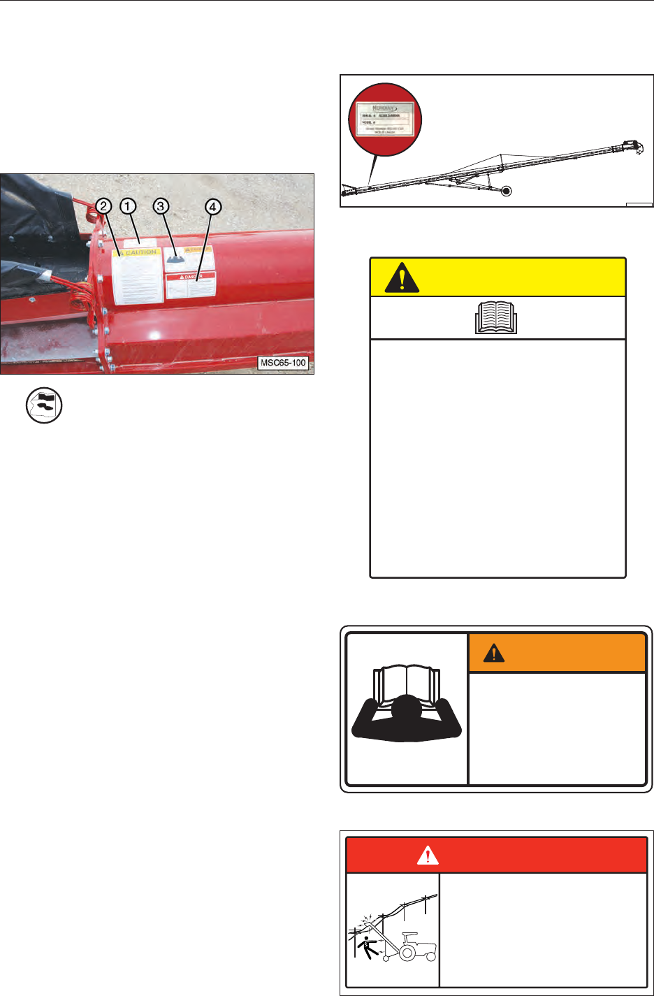
3.3 DECAL LOCATIONS
1. Product Serial Number Decal (#19984)
BF-001
SL-E(H)-55
2. CAUTION — Read and Understand (#19934)
CAUTION
19934
• Read and understand the Operator’s Manual before using. Review
safety instructions annually.
• Stop engine, remove ignition key, and wait for all moving parts to stop
before servicing, repairing, adjusting, loading, fi lling, or unplugging.
• Keep working area clean and free of debris to prevent slipping or
tripping.
• Do not allow riders on the trailer or frame when transporting.
• Only enter seed compartment when it is empty.
• Keep hands, feet, hair, and clothing away from moving parts.
• Do not place hands, arms, or body between seed box and frame or lid
to prevent pinching or crushing. Components can move unexpectedly.
• Do not place hands, fi ngers, or arms between unloading auger tube
segments when placing in unloading confi guration.
• Stay away from overhead power lines. Electrocution can occur
without direct contact.
• Install and secure all guards before starting.
• Use care when climbing on frame or ladder to prevent slipping or
falling.
• Do not smoke when refuelling or working around machine.
• Fasten frame securely to trailer before transporting.
• In two compartment seed tenders, always empty Compartment 2 fi rst
to prevent an unbalanced load. An unbalanced load can cause hitch
to upend.
3. WARNING — Read and Understand (#1654)
To Prevent Serious Injury or Death:
• Avoid unsafe operation or
maintenance.
• Do not operate or work on this
machine without reading and
understanding the operator’s
manual.
• If manual is lost, contact your
nearest dealer for a new manual.
WARNING
4. DANGER: Electrocution Hazard (1656-01)
1656-01
ELECTROCUTION HAZARD
To prevent serious injury or death from
electrocution:
Stay away from overhead power lines when
transporting or raising the machine.
This machine is not grounded.
Electrocution can occur without direct
contact.
DANGER
17
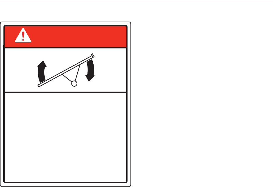
5. DANGER: Upending Hazard (1655-00-01)
UPENDING HAZARD
The intake end of the machine must
always have downward weight.
Always test it before releasing it from
the vehicle or holddown.
Failure to do so will cause upending,
which will result in serious injury or death.
Lift the intake slowly and keep it no
higher than the tractor tow bar when
attaching or releasing it.
Immediately lower the machine to
transport position before moving.
DANGER
1655
18
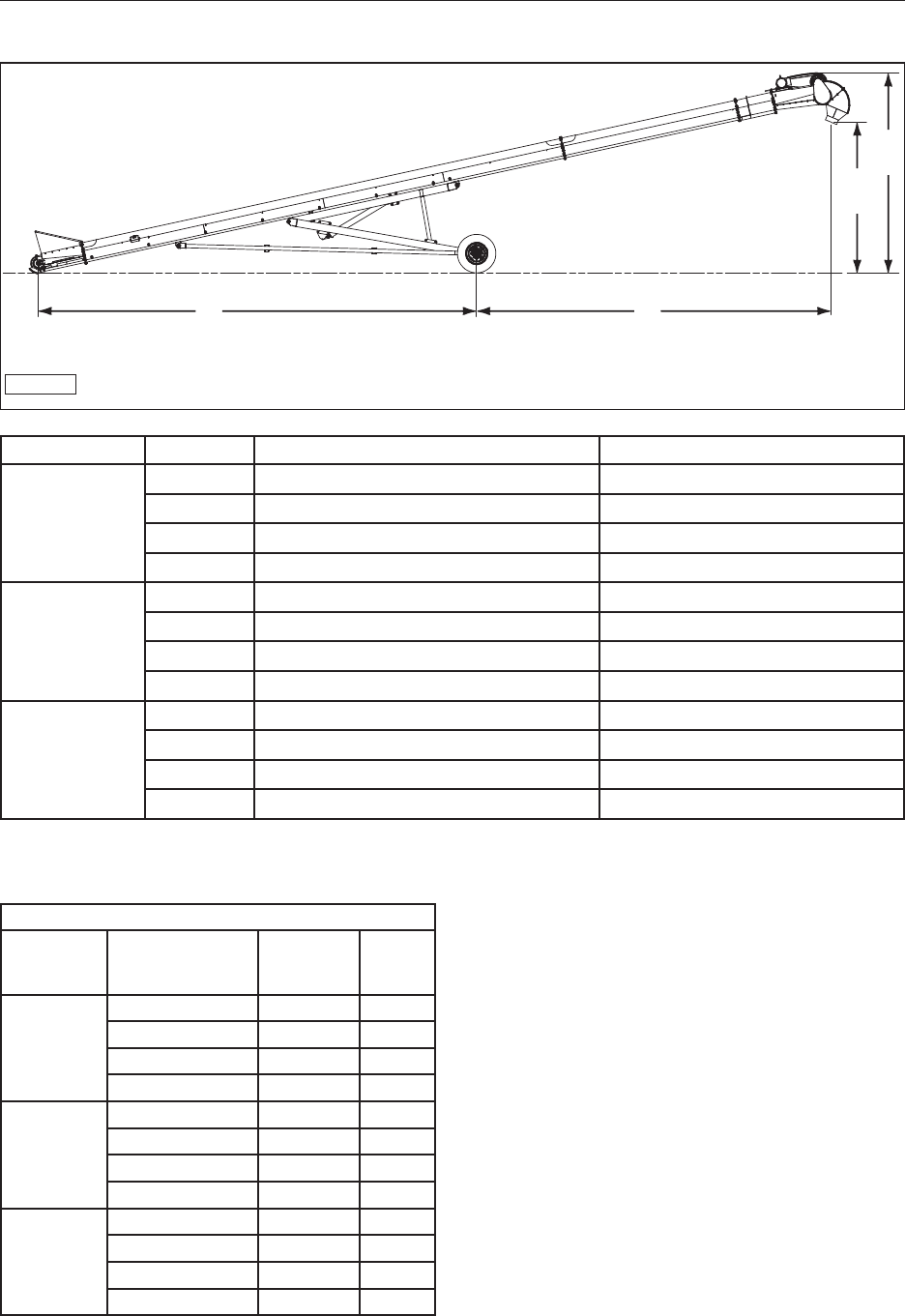
4.0 SPECIFICATIONS
4.1 OVERALL SPECIFICATIONS
BF-003
C
D
A B
Model Dimension Minimum Maximum
55’
SL-E(H)-55
A 320" (813 cm) 361” (917 cm)
B 158” (401 cm) 291” (739 cm)
C 121” (307 cm) 461” (1171 cm)
D 163” (414 cm) 491” (1247 cm)
65’
SL-E(H)-65
A 355” (902 cm) 406” (1031 cm)
B 256” (650 cm) 367” (932 cm)
C 128” (325 cm) 494” (1255 cm)
D 169” (429 cm) 525” (1334 cm)
75’
SL-E(H)-75
A 401” (1019 cm) 495” (1257 cm)
B 318” (808 cm) 401” (1019 cm)
C 131” (323 cm) 553” (1404 cm)
D 172” (437 cm) 583” (1480 cm)
4.2 ELECTRICAL SPECIFICATIONS
ELECTRICAL MOTOR SPECIFICATIONS
CONVEYOR
LENGTH
MOTOR SIZE
AND VOLTAGE MOTOR
PART
NUMBER
FULL
LOAD
AMPS
55’
10HP 1PH 220V 18374 39.24
10HP 3PH 220V 18375 25
10HP 3PH 460V 18375 12.5
10HP 3PH 600V 18376 10
65’
10HP 1PH 220V 18374 39.24
10HP 3PH 220V 18375 25
10HP 3PH 460V 18375 12.5
10HP 3PH 600V 18376 10
75’
10HP 1PH 220V 18374 39.24
10HP 3PH 220V 18375 25
10HP 3PH 460V 18375 12.5
10HP 3PH 600V 18376 10
19
4.3 BOLT SPECIFICATIONS
WARNING
The torque value for bolts and capscrews are
identied by their head markings. Replacing
higher “Grade” bolts (Grade 8) with lower
“Grade” bolts (Grade 5) will lead to conveyor
failure and can result in injury or death. Always
use replacement bolts with the same Grade
markings as the removed bolt.
4.3.1 Bolt Torque Values
Torqueguresindicatedabovearevalidfornon‑
greased or non-oiled threads and heads unless
otherwisespecied.Therefore,donotgreaseor
oil bolts or capscrews unless otherwise instructed
in this manual. When using locking elements,
increase torque values by 5%.
Bolt
Diameter “A” SAE Grade 2
N·m (ft-lbs) SAE Grade 5
N·m (ft-lbs) SAE Grade 8
N·m (ft-lbs)
1/4" 8 (6) 12 (9) 17 (12)
5/16" 13 (10) 25 (19) 36 (27)
3/8" 27 (20) 45 (33) 63 (45)
7/16" 41 (30) 72 (53) 100 (75)
1/2" 61 (45) 110 (80) 155 (115)
9/16" 95 (70) 155 (115) 220 (165)
5/8" 128 (95) 215 (160) 305 (220)
3/4" 225 (165) 390 (290) 540 (400)
7/8" 230 (170) 570 (420) 880 (650)
1" 345 (225) 850 (630) 1320 (970)
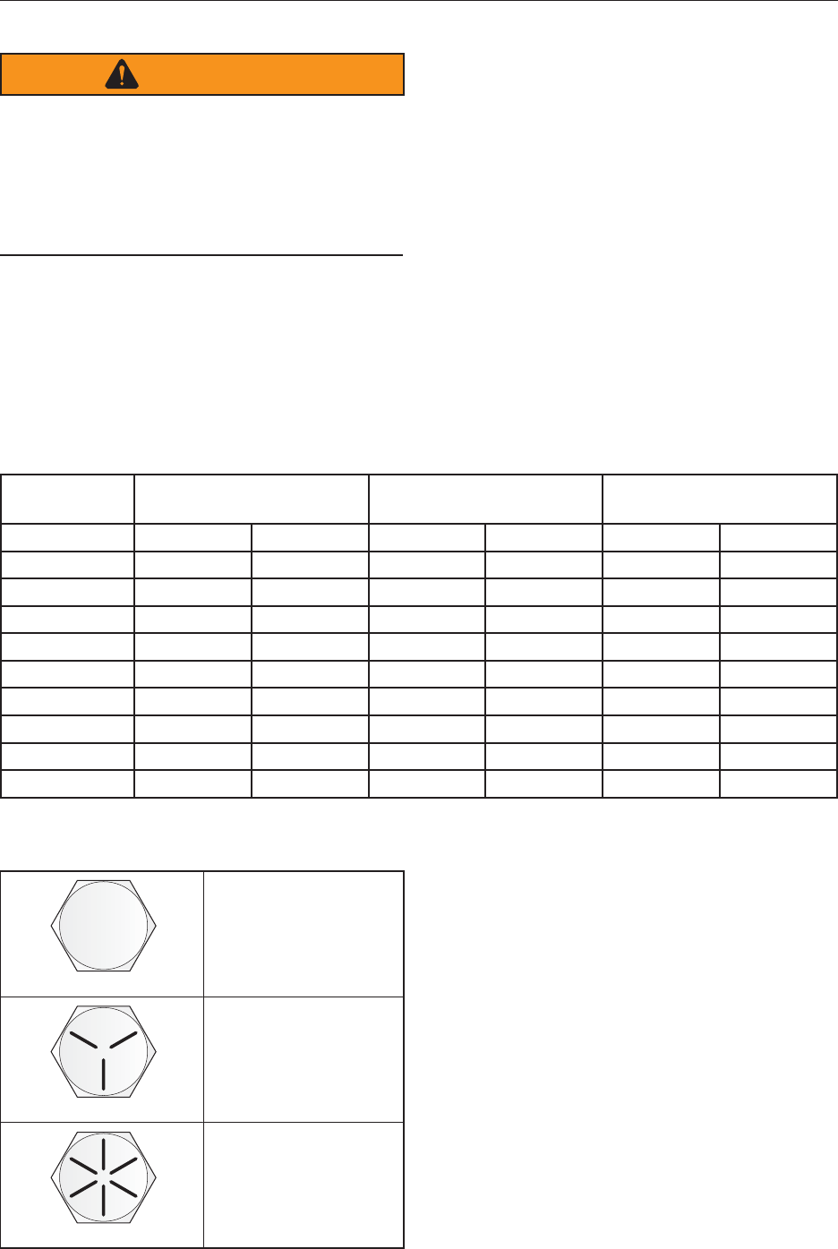
4.3.2 Grade Markings Chart
No Marking
Grade 2
Low or Medium
Carbon Steel
Grade 5
Medium Carbon
Steel Quenched
and Tempered
Grade 8
Medium Carbon
Alloy Steel,
Quenched and
Tempered
3 Radial Lines
6 Radial Lines
20
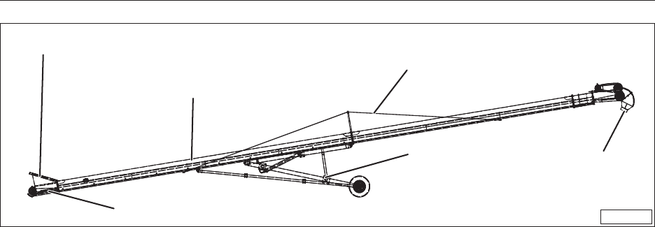
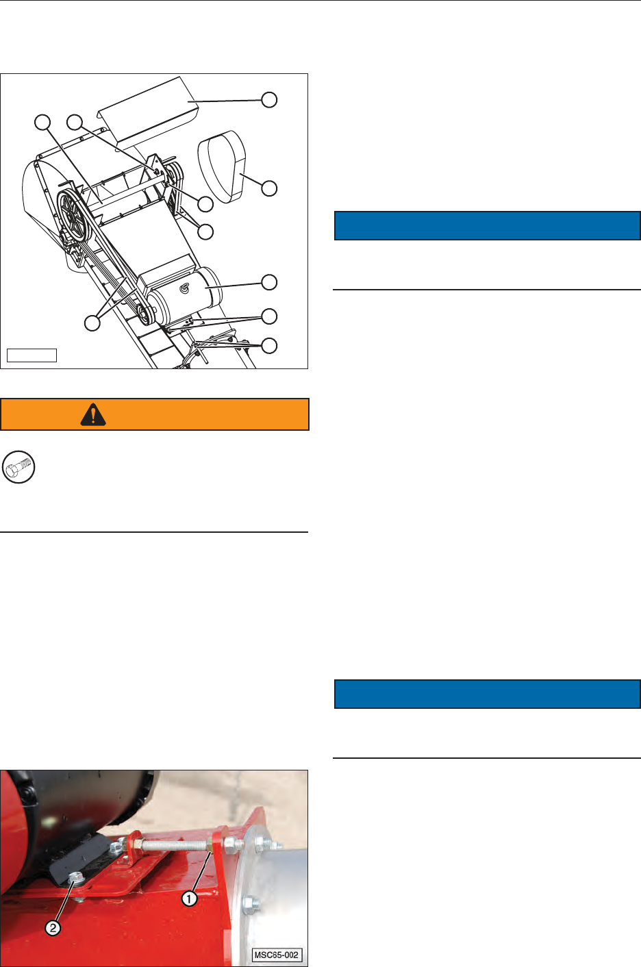
5.0 CONVEYOR COMPONENT NOMENCLATURE
BF-002
SUPPORT
CABLES
TUBE
STRUCTURE
HOPPER
RECEIVING END
SCISSOR
LIFT DISCHARGE
HOOD
The end of the conveyor that would be connected
to a towing vehicle is the back, or Rear, end of the
conveyor.
The Discharge Hood is the upper end of the
conveyor and is considered the Front end of the
conveyor.
The frame that has the lift cylinders and trailer tires
is called the Scissor Lift.
The Hopper is located at the rear end of the
conveyor where the grain is deposited from the
transport vehicle.
When standing at the hopper end, facing toward
the front end of the conveyor, the side to the left
is considered the Left Side of the conveyor. The
side to the right is considered the Right Side of
the conveyor.

21
6.0 ASSEMBLY INSTRUCTIONS
6.1 REQUIRED TOOLS AND
EQUIPMENT
The following are the minimum tools that are
required to assemble the conveyor:
• 1/2” Impact wrench
• 1/2” Torque wrench
• At least one lifting strap at least 9 ft. long
and rated for at least 5,000 lbs.
• At least one lifting strap at least 12 ft. long
and rated for at least 5,000 lbs.
• Two lifting units (forklifts, cranes, front end
loaders, etc.) with a minimum lifting capacity
of 5,000 lbs. each
• 1/4 inch stranded cable or equivalent rope
to feed the belt through the conveyor tube
(the length should be 5’ longer the length of
the conveyor).
• String or twine used to feed the cable
through the conveyor tube (the length should
be 5’ longer the length of the conveyor).
• Wrench and socket set
• Needle nose pliers
• Mechanics wire
6.2 UNLOADING INSTRUCTIONS
The conveyor will be shipped in two sections. The
lower portion (bottom end) will include everything
except the upper end of the conveyor tube, the
conveyor belt, and the tires. The upper portion
includes the upper end of the conveyor tube and
the discharge hood.
WARNING
LIFTING HAZARD
Review the following chart to
determine the weight of the
load before making the lifts
in the next procedures. Failure to have a
properly rated lifting device can cause the load
to fall, resulting in property and/or person
injury, even death.
Approximate Load Weights
Model Front (upper) End Rear (lower) End
55’ Hyd. 917 lbs (416 kg) 3110 lbs (1411 kg)
65’ Hyd. 1166 lbs (529 kg) 3109 lbs (1410 kg)
75’ Hyd. 1338 lbs (607 kg) 3322 lbs (1507 kg)
1. Remove the upper section from the truck
using lifting straps.
2. Place one long strap over the hopper end of
the tube structure of the lower section and
attach it to the lifting unit.
3. Place a second strap around the scissor lift
and over the tube structure and attach it to the
lifting unit.
4. Lift the lower section until the load has cleared
the truck bed. Pull the truck away and lower
the load toward the ground.
5. Install the wheels and tires. Lower this section
to the ground.
6. Disconnect the straps.
22
6.3 ASSEMBLE THE SECTIONS
1. Using properly rated lifting tools, raise the
lifting frame to elevate the hopper end of the
rear section until the conveyor tube is parallel
with the ground.
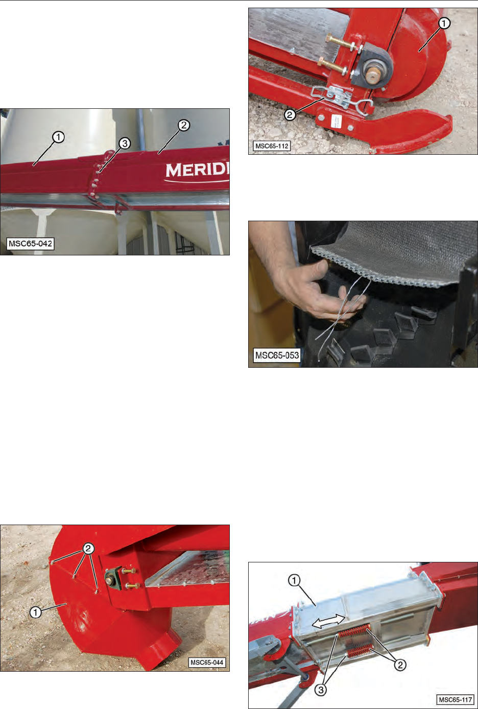
2. Attach front and rear sections together.
a. Attach the second lifting unit to front
section (1) and lift the section parallel to
the ground.
b. Align the front (1) and rear (2) sections.
c. Before bolting the sections together, feed
a cable or rope through both sections to
install the delivery belt.
d. Install bolts (3) and evenly tighten them
tothetorquespecicationsshowninthe
chart in this manual.
Note: The 75’ conveyor has an additional bracket
that needs to be included when bolting the
angestogether.Thisbracketsupportsthe
tension cables that support the front end of
the conveyor.
3. Remove bolts (2) and discharge hood (1) to
access the upper belt roller.
4. Open lower access cover (1) by releasing
latches (2) on each side of the conveyor tube
to access the lower belt roller.
5. Attach one end of the conveyor belting to the
1/4” cable or rope, using wire through the
loops of the belt connector.
6. Pull the conveyor belt into the tube structure
with the cable or rope.
7. Feed the cable or rope back through the lower
chamber of the conveyor tube.
8. Pull the conveyor belt back through the lower
chamber so that both ends of the belt are
accessible.
9. Using nuts (3), loosen the tension on springs
(2) and slide belt tensioner unit (1) together
enough to allow the ends of the belt to be
connected.
23
10. Join the two ends of the belt together by
feeding the plastic covered steel cable through
the connector loops.
Note: An Allen wrench or small rod can be
inserted to help align the loops while
pushing the cable in from the opposite
side.
11. Once installed, place a retainer washer on
each end of the cable and crimp it in place to
hold the cable.
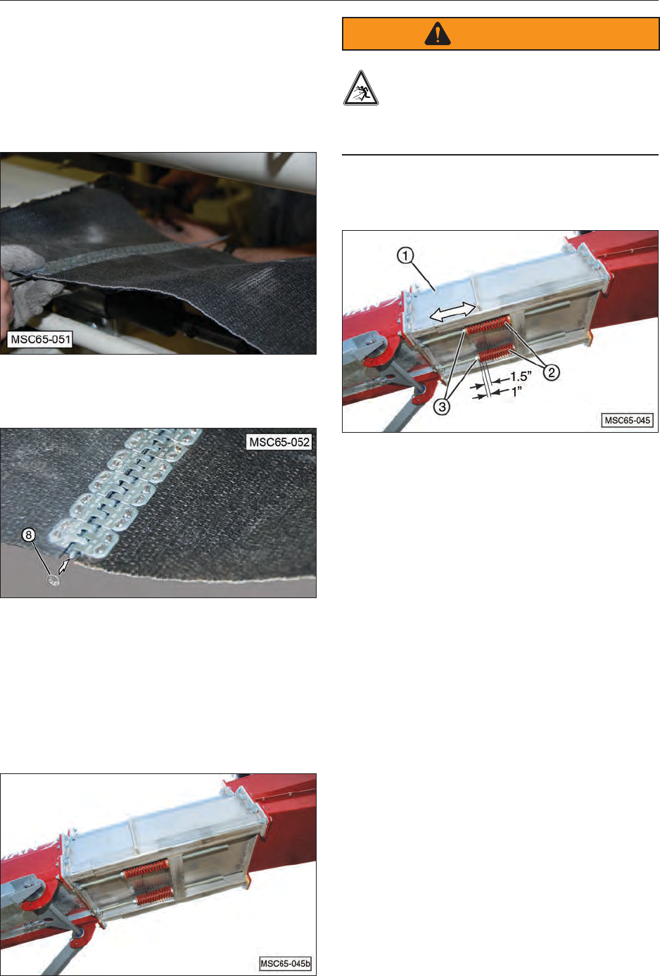
6.4 TENSIONING CONVEYOR BELT
The belt tensioner section contains two springs
to provide the appropriate amount of tension on
the conveyor belt, and guarding against over-
tightening the belt, which can reduce belt service
life.
WARNING
Spring Tension Hazard
Compressed springs can contain enough
energy to cause serious bodily injury and
even death. Use extreme caution when working
around springs that are compressed.
1. Turn adjusting nuts (3) clockwise toward
springs (2) until the nut is snug against the
spring.
2. Place a mark on the underside of the conveyor
tube at the end of the spring near the adjusting
nut.
3. Measure 1” (25 mm) from the mark toward the
other end of the spring and make a second
mark.
4. Measure 1-1/2” (38 mm) from the original
mark toward the other end of the spring and
make a third mark.
5. The second and third marks are 1/2” (12 mm)
apart and will locate the end of the spring
when the belt is properly tensioned.
Note: These two marks will provide reference
points when making future belt tension
checks.
6. Thread nuts (3) equal amounts to place
approximately the same tension on each
spring.
7. After nuts (3) move approximately 1” (25 mm)
(and every 1” (25 mm) thereafter), move the
discharge end of the conveyor up and down a
few times to allow the tension system to slide
out.
8. Tighten the belt until the ends of both springs
(2) are between mark #2 and mark #3.
24
6.5 ADJUST CONVEYOR BELT
TRACKING
1. Start the belt moving while listening for
any unusual noises. Stop the conveyor
immediately if unusual noises are heard.
2. If necessary, remove discharge hood (1) by
removing bolts (2). Open lower cover (1) by
releasing latches (2).
3. The belt should track in the middle of the top
and bottom rollers, as shown.
4. Loosen jam nuts (1) on both sides of the
conveyor tube.
Note: The upper and lower roller tracking
adjustments for the belt are on both sides
of the conveyor tube.
5. Turn adjusting screws (2) to adjust the tracking
of the belt.
6. Once the belt tracking is adjusted, tighten jam
nuts (1).
7. Recheck the belt tension.
8. Close the lower access cover and lock the
latches in place.
9. If removed, reinstall the discharge hood.

25
6.6 INITIAL CONVEYOR ASSEMBLY
Meridian Bin Fill Conveyors come mostly
assembled. A minimum amount of tools are
requiredtochecktheconveyorbeforetherstuse.
Complete the Final Check and Testing in the next
section to ensure all fasteners are tight and the
conveyor assembly is ready to use.
6.7 FINAL CHECK AND TESTING
All the items below must have the “Yes” column
checked before operating the conveyor. If the line
refers to an option item that is not installed on the
conveyor being tested, then “n/a” should be placed
on that line.
ITEM TO CHECK YES NO
All covers/shields are in place.
Conveyor belt tracks in the center of the top roller.
Conveyor belt tension is correct.
Drive belt tension is correct.
Bottom rubber scraper is in place.
Bottom belt guide is installed.
Hopper canvas is installed.
Height support arm secures conveyor height properly.
Electric drive motor functions properly (if equipped).
Conveyor belt operates in the proper direction (electric motor option).
Gasoline engine runs properly (if equipped).
Engine oil at proper level (gasoline engine only).
Touch up paint is applied where needed.
All hazard labels are attached.
Tiresareproperlyinated.
26
7.0 TOWING
7.1 GENERAL TOWING SAFETY
SAFETY
INSTRUCTIONS
• Comply with local, state, and federal laws
governing safety and conveyance of farm
machinery on public roads.
• Ensurealllights,reectors,andotherlighting
requirements are installed and in good working
condition.
• Stay away from overhead power lines
(minimum 10 feet). Electrocution can
occur without direct contact.
1656-01
ELECTROCUTION HAZARD
To prevent serious injury or death from
electrocution:
Stay away from overhead power lines when
transporting or raising the machine.
This machine is not grounded.
Electrocution can occur without direct
contact.
DANGER
• Planyourroutetoavoidheavytrafc.
• Fully lower the lift frame before transporting.
• Do not drink and drive.
• Be a safe and courteous driver. Yield to
oncomingtrafcinallsituations,including
narrow bridges, intersections, etc. Watch
fortrafcwhenoperatingnearorcrossing
roadways.
• Useapprovedaccessorylighting,ags,orother
warning devices to protect operators of other
vehicles on the highway during daylight and
nighttime transport.
• When towing the conveyor on the road or
highway,useashingamberwarninglights
and/or a slow moving vehicle (SMV)
identicationemblem.
7.2 MAXIMUM TOWING SPEED
SAFETY
INSTRUCTIONS
• Do not exceed a towing speed of more than
20 mph (32 KPH).
• Remember, tires supplied by the
manufacturer are designed to operate
LESS THAN 20 mph (32 KPH). Do not
exceed or tire failure may occur.
• Ensure your speed will enable an emergency
stop. Keep speed to a minimum. Reduce speed
prior to turns to avoid the risk of overturning.
Avoid sudden uphill turns on steep slopes.
7.3 INSPECTION BEFORE TOWING
SAFETY
INSTRUCTIONS
• Be sure the conveyor is securely hitched to the
towing vehicle and a retainer pin or padlock is
used through the hitch. Always attach a safety
chain between the hitch and the towing vehicle.
• Make sure the hitch and coupling on the towing
vehicle are rated equal to or greater than the
unit’s “gross vehicle weight rating” (GVWR).
• Checkthetiresfortreadwear,ination
pressure, and overall condition.
• Inspect the hitch and coupling for wear or
damage. DO NOT tow the conveyor using
a defective hitch or coupling!
• Make sure the lug nuts holding the wheels
aretight(torquetospecications)andthat
none are missing.
• When towing the conveyor on the
highway, make sure the “Slow Moving
Vehicle” placard is clearly visible.
• Do not allow anyone to stand between the
tongue or hitch and the towing vehicle
when backing up to the conveyor.
7.4 SAFETY CHAINS
SAFETY
INSTRUCTIONS
• If the conveyor will be transported on a public
highway, the safety chain must be attached to
the tow vehicle.
• Always follow state and local regulations
regarding a safety chain when towing
farm equipment on a public highway.
7.5 BYSTANDERS
SAFETY
INSTRUCTIONS
• Make sure the area is clear of children,
animals, and other obstacles before
using/moving the conveyor!
This is particularly important ion areas
with high noise levels, as you may not
hear people shouting.
• Never allow riders on the conveyor.
•
27
7.6
CONNECTION TO TOW VEHICLE
1. Insert the tow hitch into the frame bracket and
install the keeper pins.
MMG-00366
CAUTION
Lifting Hazard
The end of larger model conveyors
can be too heavy for one person to lift.
If not equipped with a jack, get help to
connect conveyor to the tow vehicle.
2. Adjust the height using the jack with its
attached jockey wheel (1).
MMG-00364
1
3. Slowly back the tow vehicle until the hitch and
ball are aligned.
CAUTION
Crush Hazard
Use care when lifting or attaching
the conveyor to the tow vehicle.
Never place any part of your body under the
tongue assembly.
4. Lower the pintle onto a 1-7/8 inch ball and
secure.
5. Place the jack in its stowed position.

28
8.0 PRE-OPERATING INSTRUCTIONS
8.1 SAFETY
1. Never operate the conveyor system or
auxiliary equipment until you have read
and completely understand this
manual, the auxiliary equipment
Operator’s Manual, and each of the
Safety Messages found on the safety
signs on the conveyor and auxiliary
equipment.
2. PROLONGED EXPOSURE TO LOUD
NOISE MAY CAUSE PERMANENT
HEARING LOSS! Motors or equipment
can be noisy enough to cause
permanent or partial hearing loss. We
recommend that you wear hearing
protection on a full-time basis if the
noise in the operator’s position
exceeds 80 dB. NOTE: Hearing loss
from loud noise (tractors, chain saws,
radios, and other such sources close to
the ear) is cumulative over a lifetime
with uncertain natural recovery.
3. Clear working area of debris, trash, or
hidden obstacles that might be hooked
or snagged, causing injury, damage, or
tripping.
4. Operateonlyindaylightorgoodarticiallight.
5. Be sure conveyor is properly positioned,
adjusted, and in good operating condition.
6. Ensure all guards, shielding, and safety
signs are properly installed and in good
condition.
7. Before starting, give the conveyor a
“once over” for any loose bolts, worn
parts, cracks, leaks, frayed belts, and
make necessary repairs. Always follow
maintenance instructions.
8.2 MACHINE BREAK-IN PERIOD
A special break-in procedure has been developed
to ensure the integrity of the conveyor when
rstputintoservice.FollowtheBeforeStarting
instructions and then follow the Inspections for 1/2,
5, and 10 Hours instructions at the appropriate
interval.
After completing these instructions, follow the
normal service schedule in the Maintenance
section.
8.2.1 Before Starting
1. Read and follow the instructions in the
Meridian Operator’s Manuals.
2. Review and follow the Pre-operation Checklist
before starting conveyor.
3. Initially check wheel bolt torque and then
again at 10, 25, and 50 miles. Refer to the
Wheel Bolt Torque Requirements section in
this manual for tightening instructions.
4. Start the conveyor and check the controls. Be
sure they function properly.
8.2.2 Inspections for 1/2, 5, and 10
Hours
1. Recheck the tension and alignment of the
conveyor belts.
2. Recheck hardware and fasteners; all
fasteners, and wheel bolts. Tighten to their
speciedtorque.
8.3 DAILY PRE-OPERATION
CHECKLIST
EfcientandsafeoperationoftheMeridian
conveyor requires that each operator reads and
follows the operating procedures and all related
safety precautions outlined in this section.
A preoperational checklist is provided for the
operator. It is important for both personal safety
andmaintainingtheefcientoperationofthe
conveyor that this checklist be followed.
Before operating the conveyor and each time
thereafter, the following areas should be checked:
1. Lubricate the conveyor, as outlined and shown
in the lubrication photos in the Maintenance
section of this manual. Follow the prescribed
schedule.
2. Check hardware and fasteners; conveyor
frame to transport wheels, bolts, hitch bolts,
and all other fasteners. Tighten to their
speciedtorque.
3. Make sure the wheel bolt lug nuts are tight.
4. Check the tires and ensure that they are
inatedtotheirspeciedpressure.
5. Remove all entangled material.
6. Visually inspect the conveyor belts, conveyor
belt tube, and delivery spout for damage.
7. Check the tension of the conveyor belt. Follow
the instructions in the manual to correct the
tension and/or alignment.
29
9.0 OPERATION
9.1 SAFETY
WARNING
To prevent serious injury or death, follow these
safety instructions
Entanglement Hazard
Keep hands and clothing clear of moving
parts.
Crush Hazard (rollover)
Do not clean, lubricate, or make
adjustments without blocking the wheels.
Overturn Hazard
Choose a level (at) route when
transporting the conveyor. Avoid the
edges of ditches, gullies, or steep hillsides.
Safe Distance
Keep all bystanders, pets, and livestock
clear of the work area, particularly when
moving the conveyor.
SAFETY
INSTRUCTIONS
Make sure anyone operating the
conveyor or working on or around the
conveyor reads and understands all the
operating, maintenance, and safety
information in the operator’s manual and
other related OEM equipment manuals
before using or towing the conveyor.
9.2 BEFORE EACH USE
1. Ensure all safety guards are in place.
2. Ensure bystanders are away from moving
parts.
3. If equipped, check all electrical cords for
damage and bare wires. Repair, or replace,
damaged wiring before using the conveyor.
4. Check the belts for any tears and signs of
wear. Replace if necessary.
9.3 CONVEYOR BELT OPERATION
The conveyor belt operates on 220, 460, or 600
Volts AC. An owner installed ON/OFF switch,
similar to the one shown below, can be used to
start and stop the conveyor belt. This particular
switch can be padlocked in the OFF position to
prevent unwanted usage of the conveyor.
Potential ON/OFF Switch
Use an owner supplied control switch to start and
stop the conveyor belt.
WARNING
Ensure all workers in the area of the
conveyor have been instructed on how
to stop the conveyor in case of
emergency.
30
9.4 RAISING AND LOWERING
9.4.1 Hydraulic Safety
WARNING
Ensure all personnel operating this
conveyor, and associated equipment,
have been trained in the recognition of
potential hydraulic system risks.
If the electrical and hydraulic components
are not properly maintained, risk of injury
or even death can arise during operation
of the system.
Burn Hazard
Hot hydraulic oil will cause severe burns
if it contacts your skin.
Do not test for hydraulic leaks with your
hand because high pressure uid can
be injected into your blood stream. Use
a piece of paper to test for leaks. Oil
introduced to the blood stream can cause
gangrene which can lead to loss of limb
and/or death. Seek medical attention
immediately if sprayed with high pressure
uid.
9.4.2 Hydraulic Power Supply
A separate hydraulic power supply must be used
toraiseandlowerthebinllconveyor.Thispower
supply can be the hydraulic system of a tractor or
a self-contained unit having an engine, a hydraulic
pump, and a control valve.
The hydraulic power supply should have at least
a 2 HP motor and be capable of 1500 psi (10350
kPa) of pressure to properly operate the lift
cylinders.
Thetwohydrauliccylindersonthebinll
conveyors need a minimum of 6 gallons (27 liters)
ofhydraulicuidtofullyextend.Thismeansthe
reservoirmusthavethatamountofuidavailable.
NOTICE
The conveyor cylinders hold approximately
6 gallons (27 liters) of oil. If a tractor or self-
contained power supply is used to raise
the conveyor, it must have enough uid to
raise the cylinders without causing damage
to the pump due to a lack of oil from the
reservoir. If the conveyor remains in a raised
position, then the hydraulic reservoir will
need to be relled to a proper operating level.
If a tractor or self-contained power supply is
used to lower a conveyor, then the excess uid
[6 gallons (27 liters)] must be removed from the
reservoir as the conveyor is being lowered to
prevent reservoir damage from overlling.

31
10.0 STORAGE
10.1 STORAGE SAFETY
CAUTION
Crush Hazard
Use care when lifting or attaching
the conveyor to the tow vehicle.
Never place any part of your body under the
tongue assembly.
10.2 GENERAL INFORMATION
After harvesting, or when the conveyor will not be
used for a period of time, completely inspect all
major systems of the conveyor. Replace or repair
any worn or damaged components to prevent
unnecessary downtime during the next use.
10.3 PLACING IN STORAGE
1. Remove all seed from the conveyor.
2. Store the conveyor in a dry, level area.
3. Thoroughly wash the conveyor with a pressure
washer or water hose to remove all dirt, mud,
or debris. Inspect rotating parts for entangled
material. Remove all entangled materials.
4. Check the condition of the conveyor belts and
delivery spout. Replace or adjust, as required.
5. Touch up paint nicks and scratches to prevent
rusting.
6. It is best to store the conveyor inside and if
that is not possible, cover with a waterproof
tarp and tie down securely.
10.4 REMOVING FROM STORAGE
When removing the conveyor from storage, follow
this procedure:
1. Remove the tarp, if covered.
2. Review and follow the Pre-Operation
Checklist.
3. Review and follow the Service Checks in the
Maintenance section.
32
11.0 MAINTENANCE
11.1 SAFETY
11.1.1 General Safety
SAFETY
INSTRUCTIONS
1. Good maintenance is your responsibility. Poor
maintenance is an invitation for trouble.
2. Follow good shop practices. Keep service
area clean and dry. Be sure electrical outlets
and tools are properly grounded. Use
adequate light.
3. Never work under conveyor unless it is
securely blocked.
4.
Always use personal protection devices, such
as eye, hand, and hearing protectors, when
performing any service or maintenance.
5. OEM Where replacement parts are
necessary for periodic maintenance
and servicing, genuine factory
replacement parts must be used to
restore your conveyor to the original
specications.Themanufacturerwill
not be responsible for injuries or
damages caused by use of unapproved
parts and/or accessories.
6. Areextinguisherandrstaid
kit should be readily accessible
while performing maintenance
on this conveyor.
7. Periodically tighten all bolts, nuts, and
screws and ensure all cotter pins are
properly installed to ensure the
conveyor is in safe condition.
8. When completing a maintenance or
service function, make sure all safety
shields and devices are installed before
placing the conveyor in service.
9. Turn OFF all electrical power and
tag-out or lock-out the power source
before performing any electrical test or
before connecting or disconnecting
valve coils or other electrical loads.
10. Never operate or test any function of
the conveyor when people are in an
area of a potential crush hazard.
11. Block the wheels before performing
maintenance or repairs.
12. Use support blocks or safety
stands rated to support the
load when changing tires or
performing maintenance.
13. Keep hands, feet, clothing, jewelry, and
long hair away from any moving parts
to prevent them from getting caught.
14. Understand the service procedure
before performing the work. Keep area
clean and dry.
15.
N
I
NG
AR Replace all worn or damaged safety
and instruction decals.
16. Keep all parts in good condition and
properly installed. Fix damage
immediately. Replace worn or broken
parts.
17. Do not leave tools lying on the
conveyor.
18. Do not modify conveyor or
safety devices. Do not weld on
the conveyor. Unauthorized
modicationsmayimpairits
function and safety.
If conveyor has been altered in
any way from the original
design, the manufacturer does
not accept any liability for injury
or warranty.
19. OEM Never replace hex bolts with less than
Grade 5 bolts unless otherwise
specied.
20.
0
Before attempting repairs and/or
maintenance on this conveyor,
ensure the electrical ON/OFF
switch on the hydraulic power
unit is switched OFF. Use a
pressure gauges to ensure the
system is depressurized.
33
11.1.2 Lock-Out or Tag-Out Safety
1.
do not
operate
signed by
date
WARNING
Establish a formal Lock-Out or
Tag-Out program for your
operation.
2. Train all operators and service
personnel before allowing them to work
around the conveyor.
3.
do not
operate
signed by
date
WARNING
Provide tags on the conveyor and a
sign-up sheet to record tag-out details.
11.2 LUBRICATION
Use the Service Checks information in the
Maintenance section to keep a record of all
scheduled maintenance.
1. Use an SAE multi-purpose high temperature
grease or a multi-purpose lithium base grease.
2. Use only a handheld grease gun for all
greasing. An air-powered greasing system
can damage the seals on the bearings and
lead to early failures.
3. Wipegreasettingwithacleanclothbefore
greasing to avoid injecting dirt and grit.
4. Replacebrokenttingsimmediately.
5. Ifttingswillnottakegrease,removeand
clean thoroughly. Also, clean lubricant
passageway.Replacedamagedttings.
6. Cleanupanyspilleduidsimmediatelyto
eliminate the slip/fall hazard.
The following images show areas where
lubrication is needed.
Conveyor Belt Lower Roller
Conveyor Belt Upper Roller
Scissor Lift Pivots
34
11.3 REPLACE OR TIGHTEN DRIVE
BELTS
MSC65-114
57
6
8
9
3
2
1
10
4
WARNING
OEM OEM Replacement Parts Only
Using parts from other manufacturers can
result in failure of that part, causing
conveyor damage and possible serious injury
or death.
There are two sets of matched V-belts (4 and 8)
used to drive the conveyor belt drive roller at the
discharge end of the conveyor tube.
This speed reduction provides the proper speed
to move the seed and also provides the torque
needed to drive the conveyor belt while not
overloading the electric motor.
11.3.1 Adjusting Drive Belt Tension
1. Remove covers (9 and 10).
To tighten left side belts (4):
a. Loosen motor mounting bolts (2) enough
to slide the motor.
b. Loosen jam nut (1) and tighten the
adjusting bolt.
c. Use hand pressure to push on the belts
halfway between the pulleys. The amount
ofdeectionshouldbeapproximately1/2”
(1.27 cm).
NOTICE
Do not overtighten the belts. Overtightening can
reduce belt and bearing life.
d. When correctly adjusted, tighten the jam
nuts.
e. Tighten motor mounting bolts (2).
2. To tighten right side drive belts (8):
a. Loosen pivot bolt (7).
b. Loosen bolt (6) at the adjusting slot
enough that it will slide in the slot.
c. Place a pry bar under speed reducer shaft
(5) and move the shaft to place tension on
drive belts (8).
d. Tighten adjuster bolt (6) while holding
tension on the belts.
e. Use hand pressure to push on the belts
halfway between the pulleys. The amount
ofdeectionshouldbeapproximately1/2”
(1.27 cm).
NOTICE
Do not overtighten the belts. Overtightening can
reduce belt and bearing life.
f. Tighten pivot bolt (7).
g. Reinstall covers (9 and 10).
35
11.3.2 Replacing Drive Belts
To replace the belts, loosen the belt tension,
replace the belts, and adjust them using the
Adjusting Drive Belt Tension procedure.
Note: These belts must be replaced as a matched
set or the service life of the belts will be
dramatically reduced.
11.4 MAINTENANCE INTERVALS
10.4.1 Daily (8 Hours)
1. Initially check wheel bolt torque at 10, 25, and
50 hours of operation.
2. Check conveyor belt for proper tension and
tracking.
10.4.2 Weekly (50 Hours)
1. Check the tension on the conveyor belt.
Adjust tension as needed.
2. Checkthetirepressure.Inatethetirestothe
recommended pressure stated on the tire.
10.4.3 Annually (400 Hours)
1. Check wheel bolt torque.
2. Repack the wheel bearings and check for
excessive end play in the bearings.
3. Check frame and conveyor tube for cracks and
damage.
4. Thoroughly clean the entire conveyor.
11.5 TIRES
11.5.1 Tire Safety
WARNING
Explosive Separation Hazard
Do not attempt to mount tires unless you
have the proper equipment and
experience to do the job. Failure to
follow proper procedures when mounting
a tire on a wheel or rim can produce an
explosive separation, which may result
in serious injury or death.
WARNING
Explosive Hazard
Never weld or heat a wheel and tire
assembly. The heat can cause an
increase in air pressure, resulting in a
tire explosion. Welding can structurally
weaken or deform the wheel.
Flying Objects Hazard
Inating or servicing tires can be
dangerous. Whenever possible, trained
personnel should be called to service
and/or mount tires
When inating tires, use a clip-on chuck
and extension hose. Always stand to the
side of the tire when inating, and NOT in
front of or over the tire assembly.
Make sure the tires are inated evenly.
Crush Hazard
Make sure the conveyor is
completely supported with suitable
stands before removing a wheel
assembly.
SAFETY
INSTRUCTIONS
Always maintain the correct tire pressure.
Do not inate the tires above the
recommended pressure.
0
Check tires for low pressure, cuts,
bubbles, damaged rims, or missing lug
bolts and nuts.
Do not exceed 20 mph (32 kph) or tire
failure will occur.
Keep wheel lug nuts tight.
36
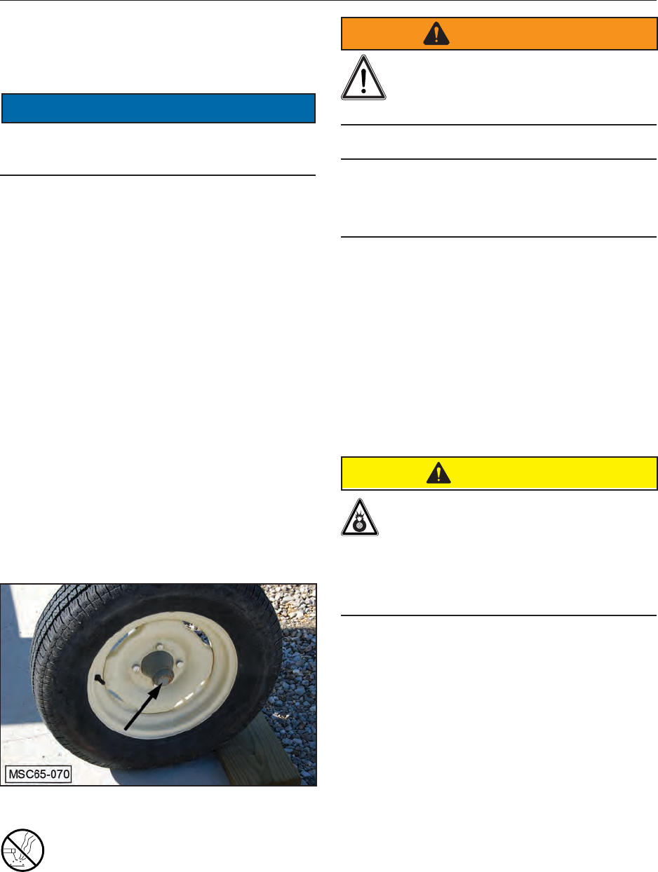
11.5.2 Wheel Bearings
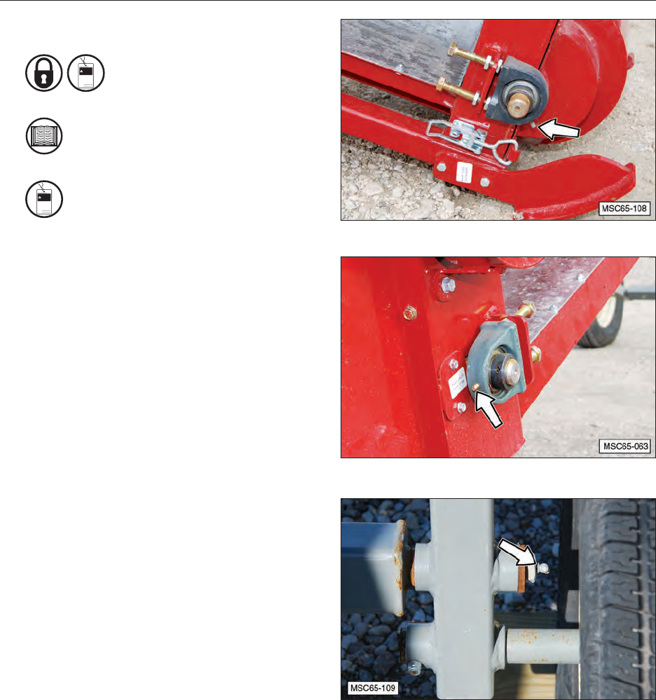
Each hub for the trailer tires has wheel bearings
that are lubricated with grease.
NOTICE
To prevent damage, use only wheel bearing
grease when repacking the wheel bearings.
The wheel bearings should be checked and
repacked annually for excessive end play.
To adjust the wheel bearings.
1. Block the other wheel and raise the axle with
a jack enough to allow the wheel and tire to
freely rotate.
2. Remove the dust cap (shown by arrow).
3. Remove the cotter pin from the castle nut
and turn the castle nut clockwise until no play
exists in the wheel bearings.
4. Then rotate the castle nut counter-clockwise
until the next available slot in the nut is aligned
to the hole in the axle shaft.
5. Install the cotter pin, bend over the ends of the
cotter pin to retain it.
6. Install the dust cap.
7. Lower the conveyor to the ground.
11.6 WELDING REPAIRS
Repair welding must be done with care
and with procedures that may be beyond
the capabilities of the ordinary welder.
Before performing any type of welding repair to the
conveyor, contact Meridian for approval.
WARNING
Personal Injury Hazard
Repairs or modications to the conveyor
can result in serious injury or death
should these repairs fail.
IMPORTANT NOTICE
Anyone performing a welding repair should be
certiedinaccordancetotheAmericanWelding
Society (AWS) standards.
11.7 WHEEL BOLT TORQUE
REQUIREMENTS
1. Initially check the wheel bolt torque at 10, 25,
and 50 miles and after each wheel removal.
Note: Torque wrenches are the best method
to ensure the proper amount of torque is
being applied to a wheel nut.
CAUTION
EXPLOSIVE FORCE HAZARD
To prevent injury due to possible
dangerous separation of wheels from the
axle, the wheel nuts must be maintained
at the proper torque levels. Properly
tightened wheel nuts prevent loose
wheels and broken studs.
2. Tighten the wheel nuts in a clockwise,
cross-axle alternating pattern to no more than
to 135 N·m (100 lb.ft.).

37
11.8 CONVEYOR SERVICE RECORD
Date:
Serviced by:
8 hours or daily
InspectTireInation.
Check Conveyor Belt Tension and
Alignment.
Lubricate All Bearings.
50 Hours or Weekly
Check Tire Pressure.
Check Conveyor Belt Tension and
Alignment.
400 hours or annually
Check Wheel Bolt Torque.
Check Scissor Lift for Cracks and Damage.
Check All Lift Linkage Pivot Pins for
Damage and make sure Retaining Pins are
in Place.
Check conveyor belt for damage.
Check Conveyor Tube for Damage.
Check All Roller Bearings for Unusual
Noise While Belt Is Operating.
Check/Grease Wheel Bearings.
Inspect Axle Grease Seal.
Inspect Tires for Damage.
Check Hopper Canvas for Damage.
Thoroughly Clean Conveyor.

38
12.0 TROUBLESHOOTING
12.1 TROUBLESHOOTING CHART
PROBLEM CAUSE SOLUTION
Conveyor belt will not start. No electrical power. Connect electric motor to proper power
supply.
Electrical control broken. Repair or replace control.
Drive motor belts are slipping. Adjust drive belt tension.
Drive motor belts are broken. Replace matched set of belts.
Speed reducer to drive roller belts are
slipping. Adjust belt tension.
Speed reducer to drive roller belts are
broken. Replace matched set of belts.
Drive roller slipping on conveyor belt. Increase conveyor belt tension.
Drive motor defective. Check electrical supply to motor. If supply
is correct, then repair or replace motor.
Conveyor belt rubbing side of
conveyor tube. The belt is not properly aligned. See Adjust Conveyor Belt Tracking in this
manual.
Scissor Lift will not lift the discharge
end of conveyor. Broken lift cable. Repair or replace lift cable.
No electrical power to electric winch. Connect electric cable to proper power
supply.
Control switch of electric winch
broken. Repair or replace control switch.
Electric winch motor defective. Repair or replace motor.
Hand-crank winch is defective. Repair or replace hand-crank winch.

39
13.0 WARRANTY
13.1 WARRANTY STATEMENT
Limited Materials and Workmanship Warranty
For Conveyors
Meridian Manufacturing Group (hereinafter referred to as the Manufacturer) hereby warrants the Conveyor(s) sold by it to be free from defect
in material or workmanship under normal use and service for a period of one (1) year parts and labor and a subsequent one (1) year on parts only
effective from the date of retail sale. The Manufacturer’s obligation under this warranty shall be limited to the repair or replacement only, FOB the
original point of shipment, of any defective parts or portions of the conveyor or accessories manufactured by Meridian. Any warranty claim must
be reported to the Manufacturer within one (1) year from the date of shipment.
THIS WARRANTY IS SUBJECT TO THE FOLLOWING LIMITATIONS, PROVISIONS AND CONDITIONS:
1. This warranty does not apply:
a) To any product sold by the Manufacturer where it is used in areas exposed to corrosive or aggressive conditions including salt water, acids, alkaloid,
ash, cement dust, animal waste or other corrosive chemicals from either inside or outside the bin.
b) For failures or defects arising out of damage during shipment or during storage on site.
c) To materials replaced or repaired under this warranty except to the extent of the remainder of the applicable warranty.
d) To damage resulting from misuse, negligence, accident or improper site preparation by others.
e) Iftheproducthasbeenalteredormodiedbyothers.
f) If in the case of coating failures the failure is the result of damage, lack of proper maintenance or failure to remove road salt or other contaminants
that may have come in contact with the bin surface.
g) To loss of time, inconvenience, loss of material, down time or any other consequential damage.
h) For a function that is different than original designed intent.
2. TheobligationoftheManufacturerunderthiswarrantyshallnotariseunlesstheManufacturerisnotiedandthiswarrantyispresentedtogetherwitha
writtenstatementspecifyingtheclaimordefectwithinthirty(30)daysafterthefailureisrstdetectedormadeknowntotheownerandwithinone(1)
year from the shipment date. The Manufacturer in its sole discretion shall determine if the claim is valid and whether correction of the defect or failure
shall be made by repair or replacement of the materials.
3. Thecoatingwarrantyisbasedonthemanufacturer’sperformancespecicationforPolyesterPowdernishesanddoesnotincluderepairofminor
blemishes or rusting that is normally part of the general maintenance of the conveyor. This warranty does not cover excessive wear on interior coatings.
SeeattachmentforfullPerformanceSpecicationdetailsonPolyesterPowderFinishes.
4. The obligation of the Manufacturer hereunder extends only to the original owner and to the Meridian dealer to whom the materials may have been initially
sold. This warranty shall not be subject to any assignment or transfer without the written consent of the Manufacturer.
5. Thecustomershallacknowledgethatithasmadeitsownindependentdecisiontoapprovetheuseofthesuppliedmaterialsandalsothespecic
fabricationandconstructionproceduresutilizedtocompletetheconveyor,andhassatiseditselfastothesuitabilityoftheseproductsforthisparticular
application.
6. The foregoing sets forth the only warranties applicable to said materials and said warranties are given expressly and in lieu of all other warranties,
expressedorimplied,statutoryorotherwise,ofmerchantabilityortnessforaparticularpurposeandallwarrantieswhichexceedordifferfromsaid
warranties herein are disclaimed by the Manufacturer.
7. The owners sole and exclusive remedy against the Manufacturer shall be limited to the applicable warranty set forth herein and the endorsements, if
any, issued together with this document and no other remedy (including but not limited to the recovery of assembly or disassembly costs, shipping costs,
direct,incidental,special,indirectorconsequentialdamagesforlostprots,lostsales,injurytopersonorpropertyoranyotherloss,whetherarisingfrom
breach of contract, breach of warranty, tort, including negligence, strict liability or otherwise) shall be available to the owner or Meridian Dealer or any
other person or entitles whether by direct action or for contribution or indemnity or otherwise.
8. ThenancialobligationoftheManufacturerunderthiswarrantyshallbelimitedtotherepairorreplacementoftheproductasoriginallysuppliedandin
no event shall exceed the original cost of the product supplied.
9. The Manufacturer shall not have any obligation under any warranty herein until all accounts for materials, installation and erection of the said product
thereof and for labor and other work performed by the Manufacturer or its dealers have been paid in full by the owner.
Warranty Claim Procedure
1. Registering product with Meridian Manufacturing.
2. Contact the dealer unit was purchased from upon discovery of any defects.
3. A completed warranty claim form submitted by dealer to Meridian warranty representative for review and course of action.
4. Warranty repair work will only be performed by Meridian, the dealer or an approved representative. No warranty work completed prior to approval.
Failure to follow procedure may affect any or all reimbursement.
5. Claims will be adjudicated at the sole discretion of the manufacturer and in accordance with the terms and conditions of the applicable limited warranty.
6. A complete list of warranty procedures can be procured from the Warranty Department or found in your owner’s manual.
Effective July 1, 2009

40
NOTES

41
14.0 PARTS
14.1 GENERAL INFORMATION
The following pages contain a list of serviceable
parts for the Bin Fill Conveyors. Three models, 55’,
65’, and 75’.
Parts are available from your authorized Dealer
Parts Department.
14.2 DISPOSAL OF EQUIPMENT AT
END OF USEFUL LIFE
The Meridian conveyors are designed for the
specicpurposeofconveyinggrain.When
this conveyor is no longer capable of doing
its designed purpose, it should be dismantled
and scrapped. Do not use any materials or
components from this conveyor for any other
purpose.
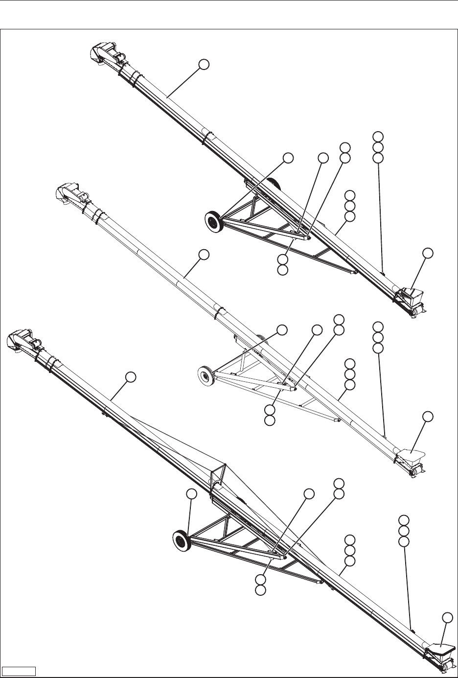
42
14.3 BIN FILL CONVEYOR, COMPLETE (55’, 65’, 75’)
BF-14-1
1
5 4 2 6
10
11
12
13
3
9
7
8
3
1
1
5 4 2
6
10
11
12
13
3
9
7
8
3
5 4 2
6
10
11
12
13
3
9
7
8
3
55’
65’
75’

43
Item Qty Part # Description
1 1 37726
37733
37711
Sub-Assembly, 55’ Conveyor Red
Sub-Assembly, 65’ Conveyor Red
Sub-Assembly, 75’ Conveyor Red
2 2 37693 Pin, Assembly 6" Gray
3 4 27578 Pin, Hairpin Cotter
4 2 27572 Cylinder, Hydraulic 4in-48
5 2 37696 Assembly, Tire And Rim
6 1 27575 Switch, Moeller (owner-supplied)
7 15 27576 Clamp, Cable 7/8 In
8 15 18482 Screw, Hex, Self-Tap 10-24 x 0.5
9 2 37695 Pin, Assembly 4 In Gray
10 1 27577 Tube, SS 3/8 In Hyd Line
11 1 27590 Tube, Hydraulic Line
12 10 27499 Tube, Clamp 3/8" Standard Series
13 1 27793 Anti-Splash Cover W/Hold Downs (optional)
NS 1 27549
27550
27551
Main Conveyor Belt 55’ (Not Shown)
Main Conveyor Belt 65’ (Not Shown)
Main Conveyor Belt 75’ (Not Shown)
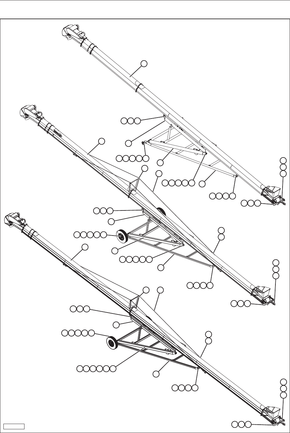
44
14.4 BIN FILL CONVEYOR SUB-ASSEMBLY (55’, 65’, 75’)
BF-14-2
1
55’
65’
75’
3
4
5
234
7
6
11
20
8910
910121315
141617
91012
1819
1
3
4
5
234
7
6
23 21
11
20
8910
910121315
141617
91012
1819
1
3
4
22
24
23 21
22
24
5
234
7
6
20
8910
91011121315
141617
91012
1819

45
ITEM QTY PART # DESCRIPTION
1 1 37710
37732
37722
Assembly, Tube W/Ends 75’ Red
Assembly, Tube W/Ends 65’ Red
Assembly, Tube W/Ends 55’ Red
2 4 19564 Nut, Hex, Flanged, 3/8-16
3 4 19331 Bolt, Hex, 3/8-16 x 3.5
4 1 37650 Support, Boot, Left Red
5 1 37651 Support, Boot, Right Red
6 1 37678 A-Frame, Lower 55/65/75
7 2 18459 Hex, Structural, A325 1-8 x 3-1/2” Steel, Mild
8 4 27552 Hinge Bushing
9 6 18457 Washer, Helical Spring Lock 1” Steel, Mild
10 6 18789 Nut, Hex 1-8 Steel, Mild
11 137671
37671
37712
Arm Scissor, Bottom 55’
Arm Scissor, Bottom 65’
Arm Scissor, Bottom 75’
12 4 18458 Bolt, Hex, 1-8 x 3-1/2” Steel, Mild
13 4 27553 Hinge Bushing Spacer
14 2 37604 3/4” Bolt With 1/4” Grease Zerk
15 2 27887 Plate, Reinforcement
16 2 37696 Assembly, Tire And Rim
17 2 37691 Assembly, Hub And Spindle
18 2 19330 Bolt, Hex, 3/8-16 x 3 Steel, Mild
19 2 19343 Nut, Hex 3/8-16
20 1 37687
37687
37721
Arm Scissor Top 55’
Arm Scissor Top 65’
Arm Scissor Top 75’
21 2 27585 Cable, Tension
22 4 27587 Eyebolt 5/8" x 8" Shank
23 1 27584 Plate, Cable Tension System
24 2 18360 Clamp, 1/2” Cable
25 2 27634 Bushing, Spacer Scissor Lift Conveyor Frame
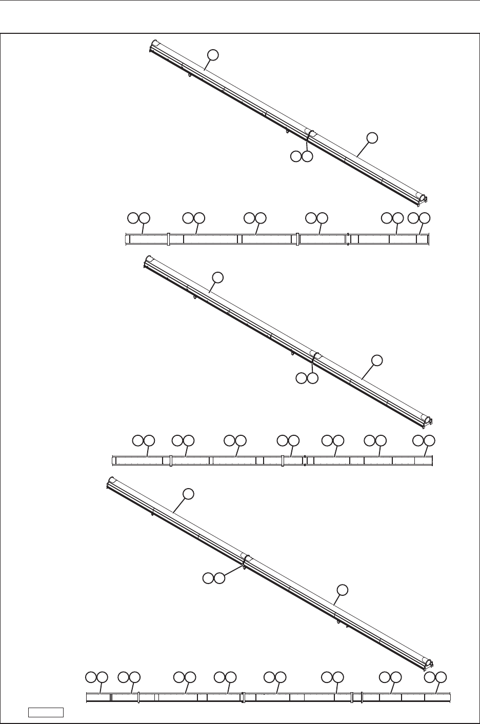
46
14.5 TUBE CENTER ASSEMBLY (55’, 65’, 75’)
BF-14-3
1
2
78
39 49 49 59 49 69
1
2
89
37 47 47 57 47 47 67
1
2
89
67 47 47 47 57 47 47 37
55’
65’
75’

47
ITEM QTY PART # DESCRIPTION
1 1 37707 Tube Bottom
2 1 37708 Tube Top
3 — 27783 10" Tube, Galvanized Cover
4 — 27785 10" Tube, Bottom Galvanized Cover
5 — 27503 10" Tube, Galvanized Cover
6 — 27504
27508
27516
10” 55’ Tube Galvanized Cover
10” 65’ Tube Galvanized Cover
10” 75’ Tube Galvanized Cover
7 — 19597 1/4-14 x 3/4" Hex Washer Head Self Drilling Screw
8 — 19595 Nut, Hex, Flanged, 1/2-13
9 — 19575 Bolt, Hex, Flanged, 1/2-13 x 1-1/2”
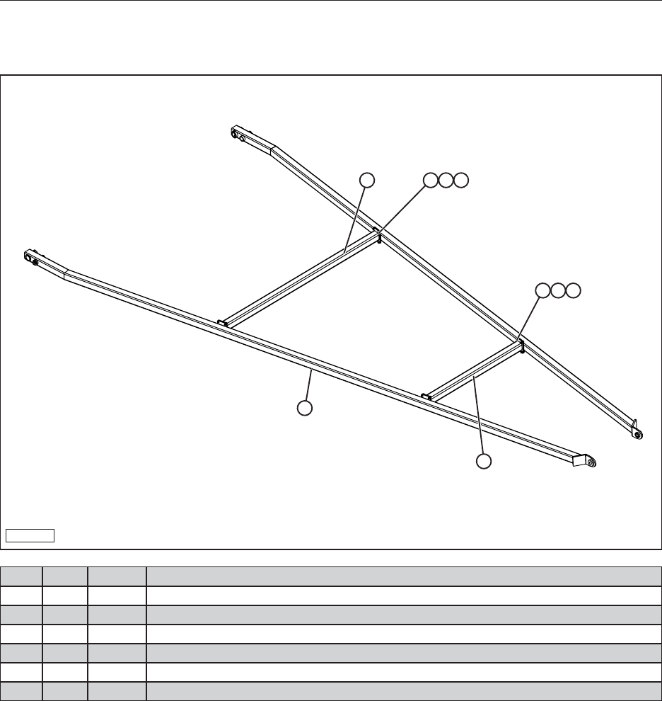
48
14.6 ARM SCISSOR ASSEMBLY
14.6.1 A-Frame, Lower (55’, 65’, 75’)
BF-14-10
2
1
3
4 5 6
4 5 6
ITEM QTY PART # DESCRIPTION
1 1 37675 Crossmember, A-Frame Top Gray
2 1 37677 Crossmember, Lower Bottom Gray
3 2 37673 Arm Side, A-Frame Lower Gray
4 16 19325 Bolt, Hex, 3/8-16 x 1
5 16 18355 Washer, Regular Helical Spring Lock, 3/8”
6 16 19343 Nut, Hex, 3/8-16
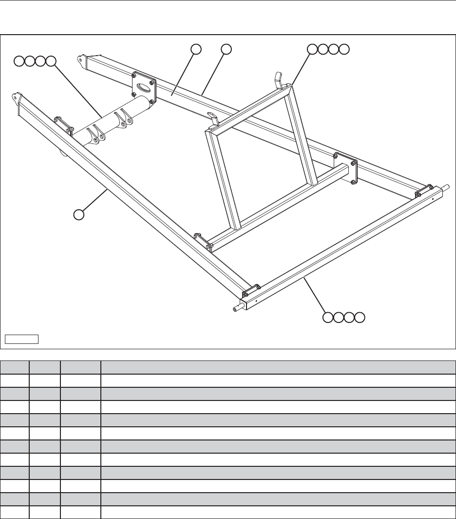
49
14.6.2 Arm Scissor Assembly, Bottom (55’, 65’)
BF-14-4A
1A
1
4 6 7 9
2 5 8 10
9 7 6 3
ITEM QTY PART # DESCRIPTION
A 1 37671 Arm Scissor Assembly (55’ And 65’)
1 2 37663 Arm Rh Scissor Bottom Gray
2 1 37670 Axle 55’ And 65’ Electric Gray
3 1 37667 Mount Cyl Arm Scissor Gray
4 1 37690 Assembly Conveyor Hold-Up Gray
5 8 19375 Bolt, Hex, 5/8-11 x 2 Steel, Mild
6 16 19388 Bolt, Hex, 3/4-10 x 2
7 16 19396 Washer, Helical Spring Lock 3/4 Steel, Mild
8 8 18460 Washer, Helical Spring Lock 5/8 Steel, Mild
9 16 19652 Nut, Hex, Heavy 3/4-10
10 8 18489 Nut, Hex, Heavy 5/8-11
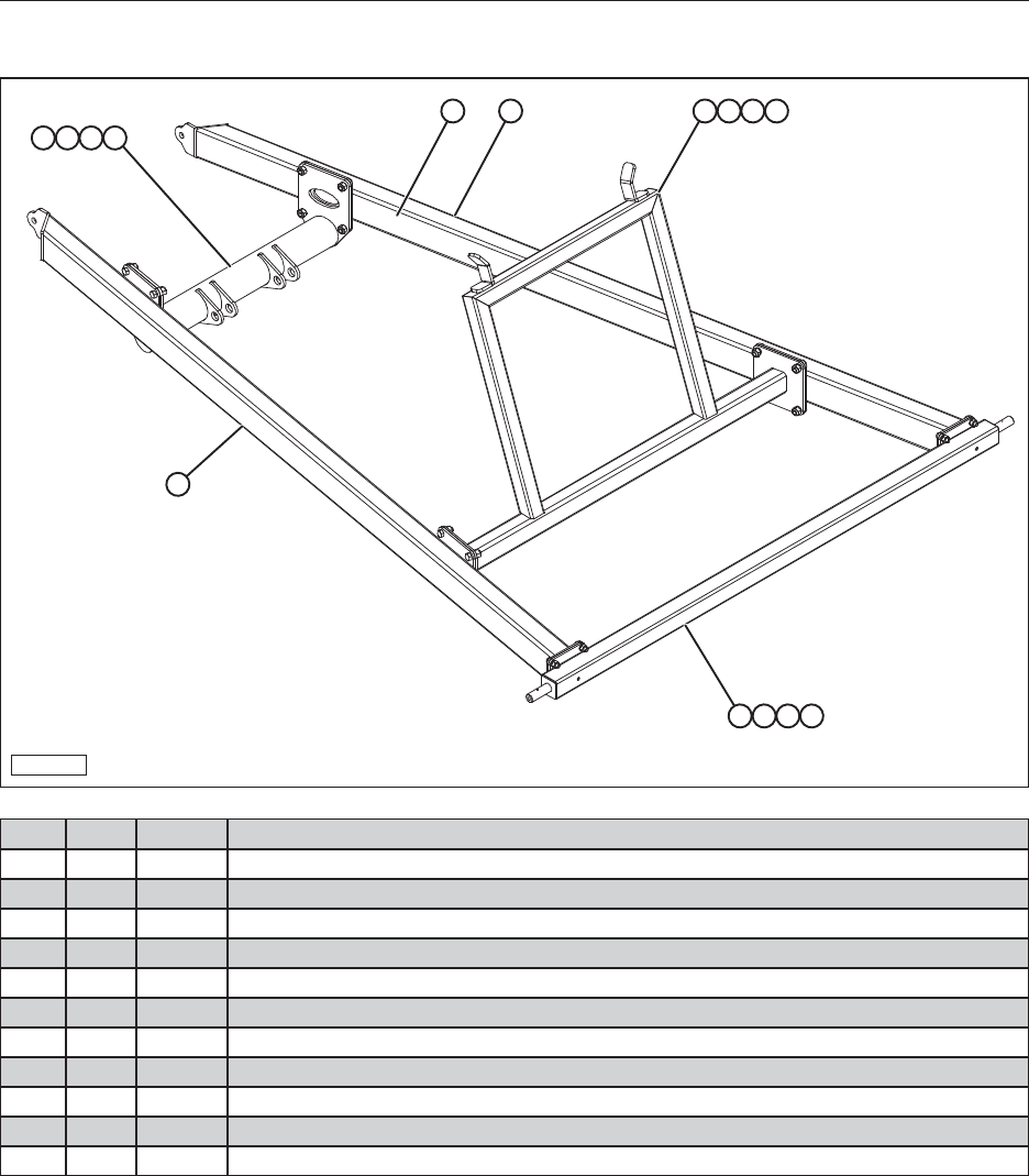
50
14.6.3 Arm Scissor Assembly, Bottom (75’)
BF-14-4
3A
3
4 6 7 9
1 5 8 10
9 7 6 2
ITEM QTY PART # DESCRIPTION
A 1 37712 Arm Scissor Assembly (75’)
1 1 37670 Axle 75’ Electric Gray
2 1 37716 Mount Cyl Arm Scissor Bottom Gray
3 2 37714 Assy Arm Rh Scissor Bottom Gray
4 1 37718 Crossmember A-Frame Lower Gray
5 8 19375 Bolt, Hex, 5/8-11 x 2 Steel, Mild
6 16 19388 Bolt, Hex, 3/4-10 x 2
7 16 19396 Washer, Helical Spring Lock 3/4 Steel, Mild
8 8 18460 Washer, Helical Spring Lock 5/8 Steel, Mild
9 16 19652 Nut, Hex, Heavy 3/4-10
10 8 18489 Nut, Hex, Heavy 5/8-11
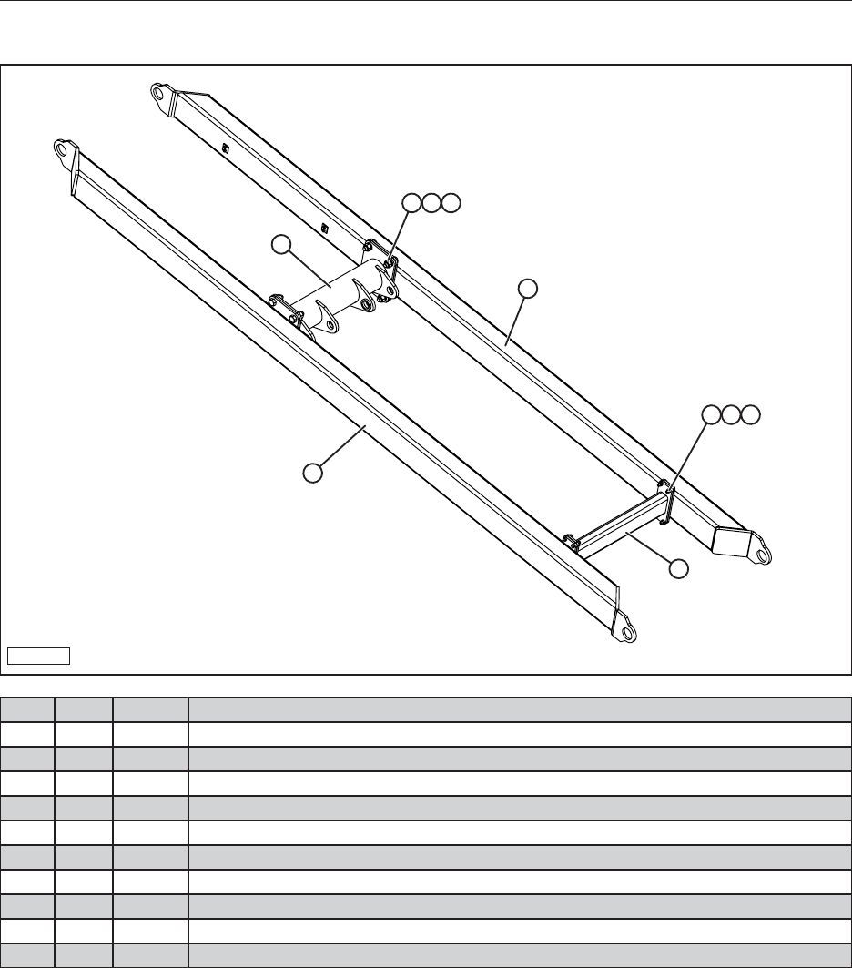
51
14.6.4 Arm Scissor Assembly, Top (55’, 65’)
BF-14-11
7
10
8
9
1 2 3
4 5 6
ITEM QTY PART # DESCRIPTION
1 8 18355 Washer, Regular Helical Spring Lock, 3/8”
2 8 19327 Bolt, Hex, 3/8-16 x 1-1/2
3 8 19343 Nut, Hex, 3/8-16
4 8 19388 Bolt, Hex, 3/4-10 x 2
5 8 19394 Nut, Hex, Steel, Mild, 3/4-10
6 8 19396 Washer, Helical Spring Lock, Steel, Mild, 3/4
7 1 37680 Side Arm Scissor Top Gray
8 1 37682 Side Arm Scissor Top Gray
9 1 37684 Mount Cylinder Arm Scissor Top Gray
10 1 37686 Crossmember Scissor Upper Top Gray
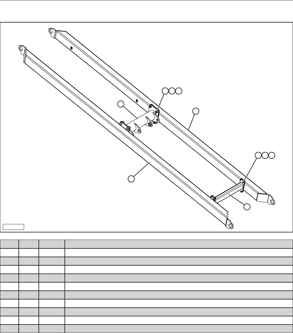
52
14.6.5 Arm Scissor Assembly, Top (75’)
BF-14-12
10
8
9
7
1 2 3
4 5 6
ITEM QTY PART # DESCRIPTION
1 8 18355 Washer, Regular Helical Spring Lock, 3/8”
2 8 19327 Bolt, Hex, 3/8-16 x 1-1/2
3 8 19343 Nut, Hex, 3/8-16
4 8 19388 Bolt, Hex, 3/4-10 x 2
5 8 19394 Nut, Hex, Steel, Mild, 3/4-10
6 8 19396 Washer, Helical Spring Lock, Steel, Mild, 3/4
7 1 37684 Mount Cylinder Arm Scissor Top Gray
8 1 37686 Crossmember Scissor Upper Top Gray
9 1 37720 Side Arm Scissor Top 75’ Gray
10 1 38782 Side Arm Scissor Top 75’ Hyd Gray
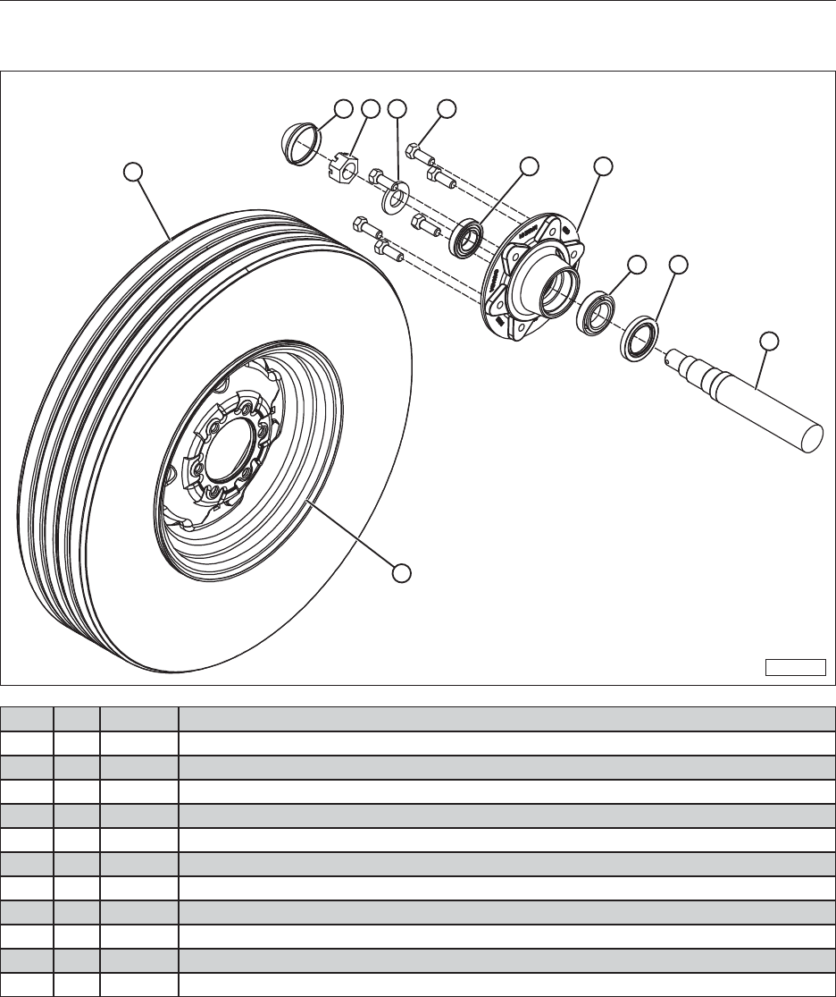
53
14.7 HUB, SPINDLE, TIRE, AND RIM ASSEMBLY (55’, 65’, 75’)
BF-14-5
3 2 4 1
8 5
6 7
9
11
10
ITEM QTY PART DESCRIPTION
1 6 27565 Hub Wheel Bolt
2 1 27566 Hub Spindle Nut
3 1 27560 Dust Cap Hub
4 1 27567 Hub Spindle Washer
5 1 27561 Hub 6-Bolt
6 1 27563 Hub Inner Bearing
7 1 27564 Hub H611 Grease Seal
8 1 27562 Hub Outer Bearing
9 1 27568 Spindle
10 1 27573 16” Tire
11 1 27574 16” Rim
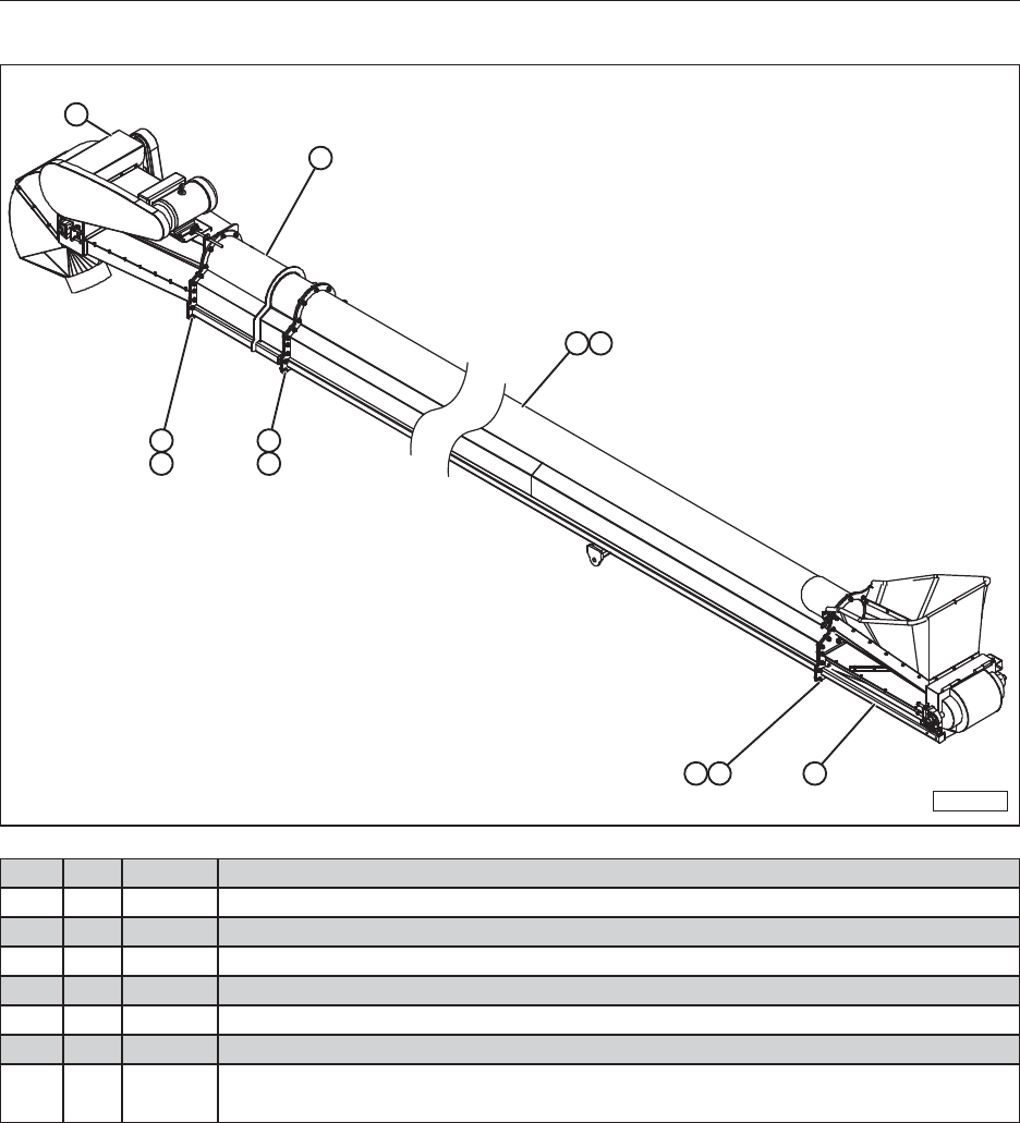
54
14.8 TUBE ASSEMBLY WITH ENDS (55’, 65’, 75’)
BF-14-6
4
3
2 7
6 5 1
55 66
ITEM QTY PART # DESCRIPTION
1 1 37637 Receiving End Red
2 1 — Tube Center Assembly
3 1 38592 Tension System Assm
4 1 37641 Discharge Assembly Red
5 59 19575 Bolt, Hex, Flanged, 1/2-13 x 1-1/2”
6 59 19595 Nut, Hex, Flanged, 1/2-13
7 1 27549
27550
27551
Belt Meridian 55’ Conveyor
Belt Meridian 65’ Conveyor
Belt Meridian 75’ Conveyor

55
NOTES
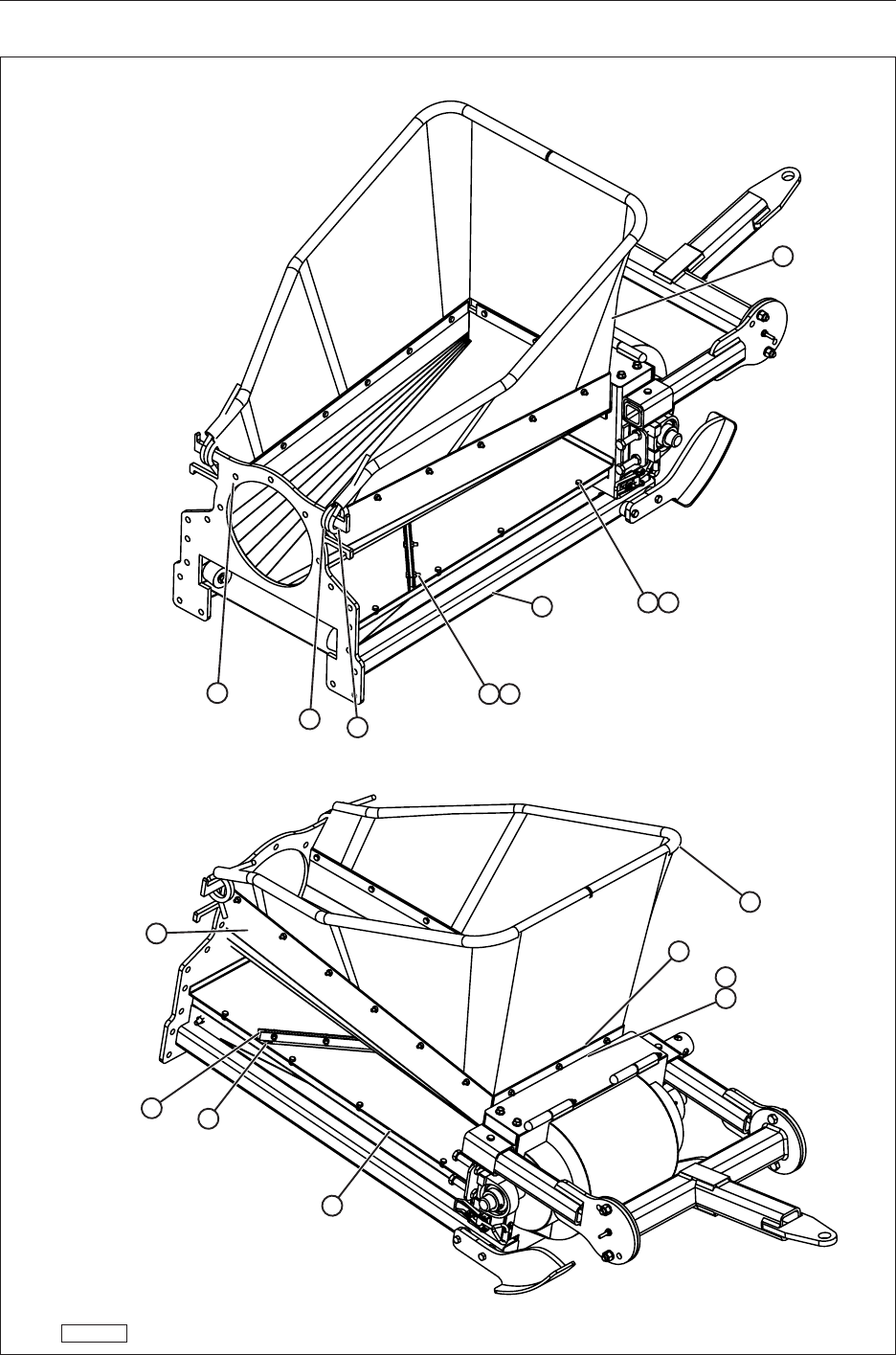
56
14.9 RECEIVING END (55’ 65’ 75’)
BF-14-8
8
911
10
16
4
2
15
1
5
12
6
7
314
1312

57
ITEM QTY PART # DESCRIPTION
1 1 27792
11048
17723
17724
Hopper, Canvas (Tall, Narrow)
Hopper, Canvas (Short, Narrow)
Hopper, Canvas (Short, Wide)
Hopper, Canvas (Tall, Wide)
2 1 27456 4” Brush
3 2 27790 Canvas Hopper, Hold Down Plate
4 1 27791 Canvas Hopper, Back Hold Down Plate
5 1 37638 Receiving End Assm Red
6 2 27468 Spring New Holland Left
7 2 27477 Spring New Holland Right
8 1 27794 Bottom Belt Cover, Galvanized
9 1 27798 Scraper Holder
10 1 27796 Bottom Belt Cover, Galvanized
11 1 27799 Rubber Scraper
12 29 19305 Nut, Hex 1/4-20
13 8 19300 Bolt, Hex, 1/4-20 x 1/2” Steel, Mild
14 21 19301 Bolt, Hex, 1/4-20 x 1”
15 1 27518 Brush Hold Down 15-3/4”
16 1 36006 Receiving Canvas Tube
Note: If you wish to change from the narrow canvas hopper to a wide hopper,
you can purchase one of the follwing kits:
Part #38658 - Tall/Wide Hopper Kit (includes wide canvas tube and wide/tall canvas)
Part #38659 - Short/Wide Hopper Kit (includes wide canvas tube and wide/short canvas)
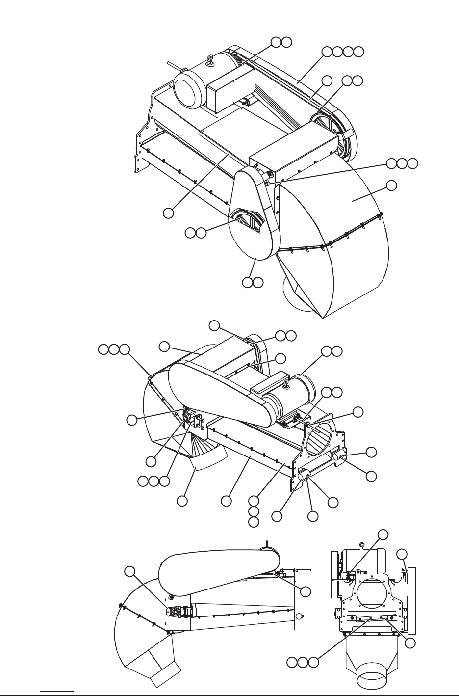
58
14.10 DISCHARGE END (55’, 65’, 75’)
BF-14-9
3 41
136
9
1
42
35
21 27 28 29
17
19
43 44
22 27
2 35
6 28
7 25
34
37
8
18
34
5
15
18 20 10
13
26 14
24
23
23
4
10
12
11
12
11
16
3031
383940
3233

59
ITEM QTY PART # DESCRIPTION
1 2 18345 12" Double Belt B Belt Pulley
2 1 27466 4-1/4" Double Belt B Belt Pulley
3 1 27465 5" Double Belt B Belt Pulley
4 1 27844 Speed Reducer Shaft
5 1 27845 Inclined Conveyor Driving Roller
6 1 — Motor, (See Section 4.2 for Part Numbers)
7 1 27849 Electric Motor V-Belt Tension Rod
8 1 27731 Speed Reducer Shaft Cover
9 1 27733 Removable Top Cover
10 1 27781 Meridian Belt Tray Cover
11 2 19330 Bolt, Hex, 3/8-16 x 3 Steel, Mild
12 2 18473 Washer, 3/8 - Wide - Type A Steel, Mild
13 14 18484 Bolt, Hex, 1/4-20 x 5/8” Steel, Mild
14 2 27756 Discharge End, Plastic Belt Guide
15 2 27467 Bearing Block Assembly Kal-Pa206
16 4 19369 MS Nut, Hex 1/2-13 Steel, Mild
17 2 27441 Two-Bolt Flange Bearing Assembly
18 1 37646 Discharge Chute Weldment Red
19 1 37648 Discharge Chute Transition Red
20 1 37642 Discharge Weldment Red
21 1 37644 Motor V-Belt Cover Red
22 1 37643 Roller V-Belt Cover Red
23 2 37645 Electric Motor Bolt Weldment Red
24 2 37647 Roller Insert Cover Red
25 1 27632 Electric Discharge Motor Slide Red
26 19 19305 Nut, Hex 1/4-20
27 4 18478 Screw, Flanged, Self-Tapping Type D 3/8-16 x 3/4" Plain Indented Washer
28 5 18680 Bolt, Hex, Flanged, Steel, Mild 3/8-16 x 1-1/4”
29 1 19564 Nut, Hex, Flanged, 3/8-16
30 4 18475 Hex Head Bolt M14 x 100
31 8 18474 Hex Jam Nut - Metric M14 x 2
32 22 19581 Bolt, Hex, Flanged, 5/16-18 x 1
33 16 19318 Nut, Hex, Flanged, 5/16-18
34 12 19597 1/4-14 x 3/4" Hex Washer Head Self Drilling Screw
35 2 27517 Bushing Split Taper H114
36 2 18358 V-Belt B83
37 2 18426 V-Belt B48
38 1 27779 Rubber Scraper
39 1 27931 Scraper Holder, Discharge End
40 5 — Bolt, 1/4-20 x 1-1/4”
41 1 17843 Bushing Split Taper H138
42 1 17839 Bushing Split Taper H1
43 4 18464 Bolt, Hex, 1/2-13 x 1-1/2”, Steel, Mild
44 4 19595 Nut, Hex, Flanged, 1/2-13
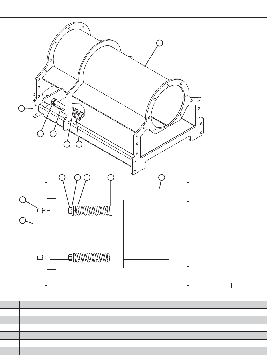
60
14.11 TENSION SYSTEM ASSEMBLY (55’, 65’, 75’)
BF-14-7
1
2
3 6
5 4
2
6
3 5 4 5 1
ITEM QTY PART DESCRIPTION
1 1 38594 Top, Tension System Assm
2 1 38593 Tension System Assm
3 6 19394 Nut, Hex 3/4-10 Steel, Mild
4 2 18683 Spring, Compression, 8" Long 2-3/16" O.D.
5 4 27896 Tension System Spring Holder Galvanized.
6 2 27716 Tension System, Tension Rod

61
NOTES

62
NOTES

NOTES

MERIDIAN MANUFACTURING INC.
With over 65 years of experience,
Meridian is your storage and handling expert.
© 2013 Meridian Manufacturing Inc. Registered Trademarks Used Under License. Printed In Canada (09/13)
Winkler Office
Box 760, 275 Hespler Ave.
Winkler, MB R6W 4A8
PH: 204.325.7883
TF: 800.665.7259
FX: 204.325.5556
Storm Lake Office
2902 Expansion Blvd.
Storm Lake, IA 50588
PH: 712.732.1780
TF: 800.437.2334
FX: 712.732.1028
Lethbridge Office
3125 - 24 Ave. N.
Lethbridge, AB T1H 5G2
PH: 403.320.7070
TF: 800.661.1436
FX: 403.320.7579
Regina Office
PO Box 1996
Regina, SK S4P 3E1
PH: 306.545.4044
TF: 800.667.5904
FX: 306.545.4216
Camrose Office
4232 - 38 St.
Camrose, AB T4V 4B2
PH: 780.672.4516
TF: 800.830.2467
FX: 780.672.4759
