PDF Mitel SX 100 & 200 Gen. 205 Vol. 2
SX-100 & SX-200 Gen. 205 Vol 2 SX-100 & SX-200 Gen. 205 Vol 2
User Manual: PDF T E X T F I L E S
Open the PDF directly: View PDF ![]() .
.
Page Count: 729 [warning: Documents this large are best viewed by clicking the View PDF Link!]

SX-100/200 SUPERSWITCH
Generic 205 - Volume II
sx-100”/sx-200TM
SUPERSWITCH
VOLUME II (GENERIC 205)
DOCUMEjNT
LIST
SECTION
MITL9105/9110-98-000
MlTL9105/9110-98-200
MITL9105/9110-98-205
MITL9105/9110-98-210
MlTL9105/9110-98-215
I-:,
-‘,
~lTL9105/9110-98-320
-.
._..
.\--.
$-:
‘llTL9105/9110-98-350
;.
Tl!TLE
LOCATOR
.:
:
DOCUMENTATION INDEX
SHIPPING, RECEIVING AND
INSTALLATION
INSTALLATION FORMS
SYSTEM PROGRAMMING
INSTALLATION TEST
PROCEDURES
EXTENSION TEST PROCEDURES
TROUBLESHOOTING
MITEL
STANDARD PRACTICE SECTION
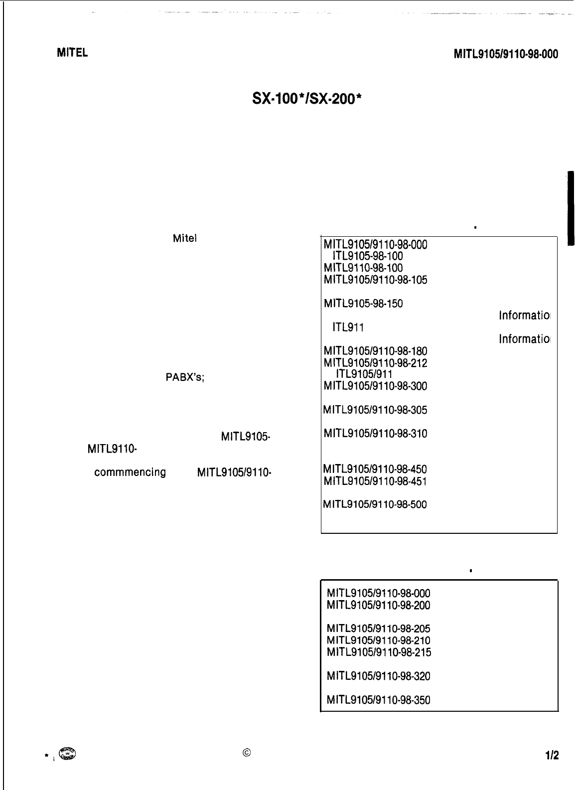
MITL9105/9110-98-000
Issue 2, August 1980
SX=l
oo*/sx-200*
SUPERSWITCH*
ELECTRONIC PRIVATE AUTOMATIC BRANCH EXCHANGES
DOCUMENTATION INDEX
1. GENERAL
1.01 This section lists
Mite1
Standard Practices
which have been issued pertaining to the
SX-100 and SX-200 Private Automatic Branch Ex-
changes.
2. DOCUMENTATION INDEX
2.01
The complete set of Practices are contain-
ed in two volumes as listed in Tables 2-1
and 2-2. Volume I basically covers the description
and operation of the
PABX’s;
while Volume II is
concerned with the installation and maintenance
aspects of the systems.
2.02 Sections commencing with
MITL9105
and
MITLSllO-
contain information specific to
the SX-100 and SX-200 PABX respectively, while
those
commmencing
with
MITL9105/9110-
em-
brace both types of PABX.
TABLE 2-l
DOCUMENTATION INDEX
-
VOLUME I
MITL9105/9110-98-000
Documentation Index
M lTL910598-100
General Description
MITLSllO-98-100
General Description
MlTL9105/9110-98-105
Feature and Services
Description
MITL9105-98-150
Physical Description
and Ordering
lnformatioi
M ITL911 O-98-1 50
Physical Description
and Ordering
lnformatioi
MITL9105/9110-98-180
Engineering Information
MITL9105/9110-98-212
Multi Digit Toll Control
M ITL91051911 O-98-220 Speed Call
MITL9105/9110-98-300
Attendant Console
Description-Commercial
MITL9105/9110-98-305
Attendant Console
Description-Hotel/Motel
MITL9105/9110-98-310
Programming and
Maintenance Console
Description
MITL9105/9110-98-450
Traffic Measurement
MITL9105/9110-98-451
Station Message Detail
Recording
MITL9105/9110-98-500
General Maintenance
Information
TABLE 2-2
DOCUMENTATION INDEX
-
VOLUME II
MITL9105/9110-98-000
Documentation Index
MITL9105/9110-98-200
Shipping Receiving
and Installation
MITL9105/9110-98-205
Installation Forms
MITL9105/9110-98-210
System Programming
MITL9105/9110-98-215
Installation Test
Procedures
MITL9105/9110-98-320
Extension Test
Procedures
MITL9105/9110-98-350
Troubleshooting
I
*;cE3
0
MITEL Corporation 1980 Page
l/2
MITEL STANDARD PRACTICE SECTION
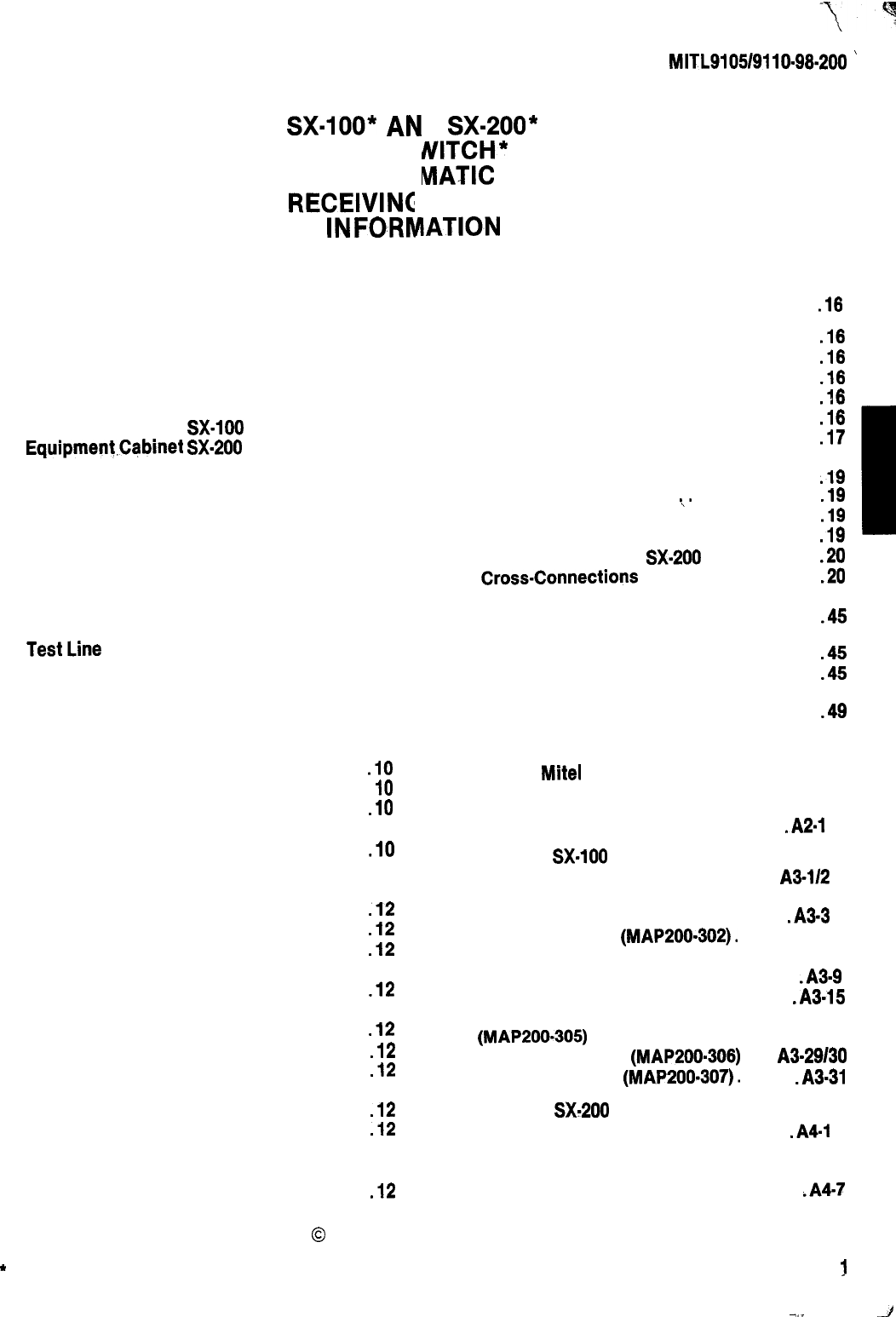
MITL9105/9110-98.200
’
Issue 3, June 1980
1.
2.
3.
4.
5.
8.
7.
SX-lOO*
Ah
SUPERS
ELECTRONIC PRIVATE AUTO
SHIPPING,
RECEIVING
INFORA
D SX-200*
MITCH*
MATIC
BRANCH EXCHANGE
AND INSTALLATION
IATION
CONTENTS PAGE
INTRODUCTION
......................
2
General
.............................
2
Documentation
.......................
2
8.
9.
REPACKING FOR RESHIPMENT . . . . . . . .18
IDENTIFICATION .....................
2
General
.............................
2
Equipment Cabinet SX.100
.............
3
Equipment,Cabinet
SX.200
.............
3
Equipment Shelves.
....................
3
Circuit Cards.
........................
7
Equipment Shelf and Card
Identification
.........................
8
Features and Services
.................
8
Attendant Console
....................
8
Connecting Cables
.....
.
...............
8
Power Fail Transfer
...................
8
Power Fail Transfer Reset
..............
9
TestLine
............................
9
Reserve Power Supply
.................
9
Paging, Dictation, and Music
On Hold Equipment
....................
9
Night Relays
.........................
9
10.
11.
12.
INSTALLATION REQUIREMENTS
......
.18
Environmental Requirements
..........
.I8
Floor Space
.........................
.I8
Equipment Cabinet Location
..........
.I8
Power Supply Requirements
...........
.18
Equipment Ground
...................
.17
CABLING AND CROSS CONNECTIONS .
.I9
General
.............
\.
.............
.19
Telephone Set and Trunk Cabling.
......
.19
Cable Terminations SX-100
............
.19
Cable Terminations SX.200
............
.20
Cross.Connections
...................
-20
FCC Cross Connect Field
Recommendations.
..................
.45
DESIGNATIONS
.....................
.45
General
.............................
.45
INSTALLATION .......................
.49
General
...........................
..4 9
SHIPPING AND RECEIVING
...........
.I0
Introduction
.........................
IO
System Shipment
....................
.lO
PACKAGING
........................
.lO
System Package
.....................
.10
Consoles............................1 2
Equipment Shelves.
..................
.12
Reserve Power Shelf
.................
.I2
Printed Circuit Cards
.................
.12
DELIVERY CHECK
...................
.12
UNPACKING AND HANDLING .........
.12
Cabinet
............................
.12
Shelves and Circuit Cards
.............
.12
APPENDIX 1
Mite1
Action Procedures . . . . .
Al-l
APPENDIX 2 FCC Interconnection
Requirements. . . . . . . . . . . . . . . . . . . . . . . . . . .A2.1
APPENDIX 3 SX.100 Installation
Procedures . . . . . . . . . . . . . . . . . . . . . . . . . . .
A3.112
Unpack SX-100 Equipment
(MAP200.301) . . . . . . . . . . . . . . . . . . . . . . .A3-3
Unpack Consoles (MAP200-302). . . . . . . . A3.5
Install Console Faceplate
Designations (MAP200.303) . . . . . . . . . . .A3.9
Inspect Equipment (MAP200.304) . . . . .A3.15
Install and Connect Equipment
(MAP200-305) . . . . . . . . . . . . . . . . . . . . . . A3.19
Set Card Switches (MAP200-308) . . .
A3-29130
Power-Up System (MAP200-307). . . . . . .A3.31
INSPECTION
........................
.12 APPENDIX 4 SX.200 Installation
Cabinet
............................
.I2
Procedures . . . . . . . . . . . . . . . . . . . . . . . . . . . .
.A4.l
Shelves
........................... ..12
Unpack Equipment Cabinet
Cards.. ........................... ..12
(MAP200.401) . . . . . . . . . . . . . . . . . . . . . . . A4.3
Defective Items.
.....................
.I2
Unpack Consoles (MAP200.402). . . . . . . .A4-7
0
MITEL Corporation 1980
*
Registered Trademark of MITEL Corporation Page
!
-.
-I
SECTION
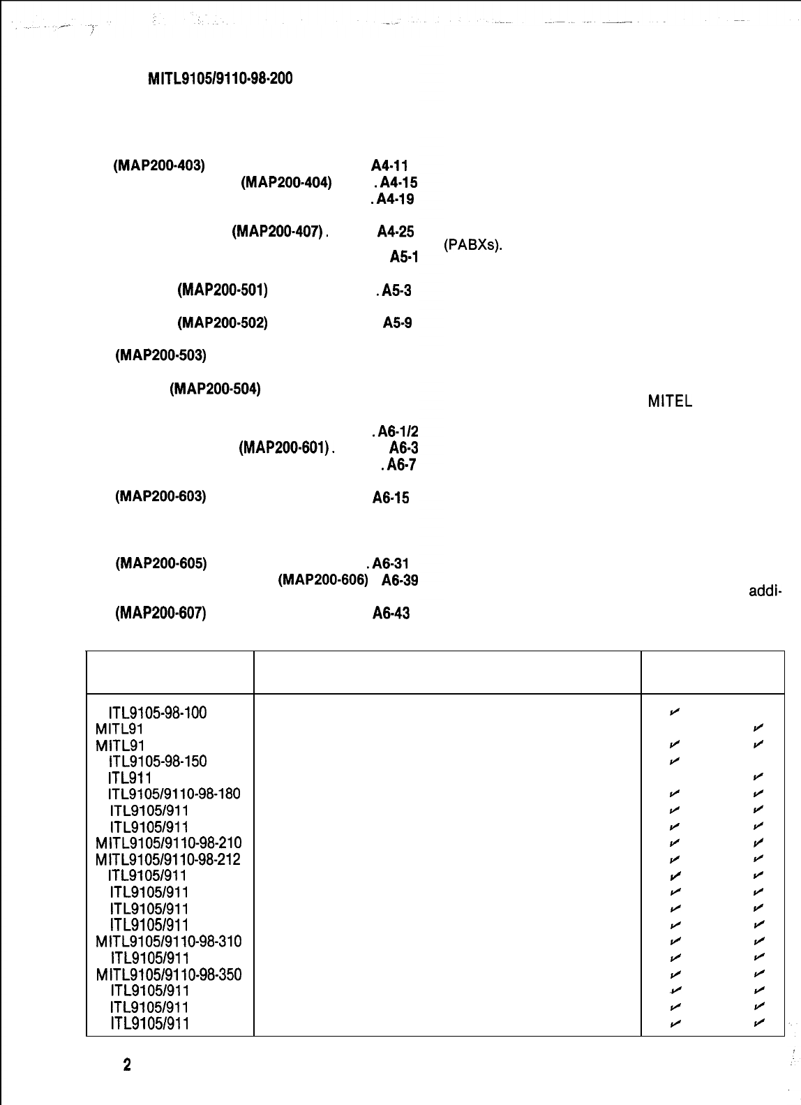
MITL910519110.98.200
CONTENTS PAGE
Install Console Faceplate Designations
(MAP200-403) . . . . . . . . . . . . . . . . . . . . . . A4.11
Inspect Equipment (MAP200-404) . . . . .A4.15
Connect Cables (MAP200.405) . . . . . . . .A4.19
Set Card Switches (MAP200.408) . . . A4.23124
Power-Up System (MAP200-407). . . . . . . A4-25
APPENDIX 5 Card Switch Settings . . . . . . . . . A5.1
Set CO Trunk Option and Status
Switches (MAP200-501) . . . . . . . . . . . . . . .A5-3
Set E and M/Tie Trunk Option
Switches (MAP200-502) . . . . . . . . . . . . . . . A5-9
Set DID Tie Trunk Option Switches
(MAP200-503) . . . . . . . . . . . . . . . . . . . . . . A5.17
Set Scanner Card Baud Rate
Switch
(MAP200-504) . . . . . . . . . . . . . . A5.23
APPENDIX 8 Additional Equipment
Installation . . . . . . . . . . . . . . . . . . . . . . .A8-112
Shelf 2 Installation (MAP200.601). . . . . . . A6-3
Install New Cards (MAP200.602). . . . . . . .A6-7
Reserve Power Supply Installation
(MAP200-603) . . . . . . . . . . . . . . . . . . . . . . A6-15
Console Interface Board Installation
(MAP200.604) . . . . . . . . . . . . . . . . . . . . . . A6.23
Backplane Translator Board Installation
(MAP200-605) . . . . . . . . . . . . . . . . . . . . . .A6-31
Installation of RCP Card (MAP200-606) . A6-39
Reserve Power Supply Installation (SX-100)
(MAP200-607) . . . . . . . . . . . . . . . . . . . . . . A6-43
1. INTRODUCTION
General
1.01
This section provides general identifica-
tion, installation, shipping, receiving and
cabling information for the SX-100 and SX-200
Electronic Private Automatic Branch Exchanges
(PABXs).
The systems consist of two major com-
ponents, the equipment cabinet, containing the
switching equipment and power supply and the
attendant console(s).
Reason for Reissue
1.02
This section is reissued to include Generic
205 features and applicable details.
Documentation
1.03 Table l-l lists all
MITEL
practices,
associated with the Electronic PABX.
2. IDENTIFICATION
General
2.01 The SX-100 and SX-200 are multicustomer
electronic switching systems providing the
following capacities:
l SX-100: Capacity of 160 ports with 112
ports available for lines, trunks and
addi-
tional receivers
TABLE l-l DOCUMENTATION
Applicable to
Document No. Title sx-1 00
sx-200
M ITL910598-100
General Description
H
MITLSI
10-98-100
General Description
J
MITLSI
0519110-98-105
Features Description
r/
J
M ITL9105-98-150
Physical Description and Ordering Information
r/
M ITL911 O-98-1 50
Physical Description and Ordering Information
r/
M ITL9105/9110-98-180
Engineering Information
c/
r/
M ITL9105/911 O-98-200
Shipping, Receiving and Installation
r/
/
M ITL9105/911 O-98-205
Installation Forms
J
r/
MITL9105/9110-98-210
System Programming
J
H
MITL9105/9110-98-212
Toll Control
I/
J
M ITL9105/911 O-98-21 5
System Test Procedures (Installation)
H
fl
M ITL91051911 O-98-220 Speed Call
r/ r/
M ITL9105/911 O-98-300
Attendant Console Description
r/
fl
M ITL9105/911 O-98-305
Attendant Console (Hotel/Motel) Description
J
fl
MITL9105/9110-98-310
Programming and Maintenance Console Description
r/ r/
M ITL9105/911 O-98-320
Station Test Procedures
r/ r/
MITL9105/9110-98-350
Troubleshooting Instructions
J
r/
M ITL9105/911 O-98-450
Traffic Measurement
Hfl
M ITL91051911 O-98-451
Station Message Detail Recording
r/
ti
M ITL9105/911 O-98-500
General Maintenance Information
r/
fl
Page
2
SECTION MITL9105/9110-98-200
l SX-200: Capacity of 256 ports with 208
ports available for lines, trunks and addi-
tional receivers
2.02 The systems are electrically compatible
with most existing station, key telephone,
Private Branch Exchange (PBX) and Central Office
(CO) equipment. The
PABXs
provide:
2.05
Reserve power for the SX-200 system, if re-
quired, may be supplied from the optional
battery pack shelf located at the bottom of the
equipment cabinet. In the case of the SX-100
reserve power supply it forms a separate base
unit upon which the SX-100 can be installed.
.
service to a maximum of four individual
customers
Equipment Shelves
lthe use of a flexible numbering plan
lthe simultaneous use of DTMF and rotary
dial stations
.
optional use of attendant consoles
-
2 max-
imum
lthe sharing of attendant consoles between
tenants
.
extensive selection of standard and op-
tional features
l freedom from scheduled maintenance
.
automatic diagnostics
lsix power fail transfer trunks (SX-100)
ltwelve power fail transfer trunks (SX-200)
loptional reserve power supply
Equipment Cabinet, SX-100
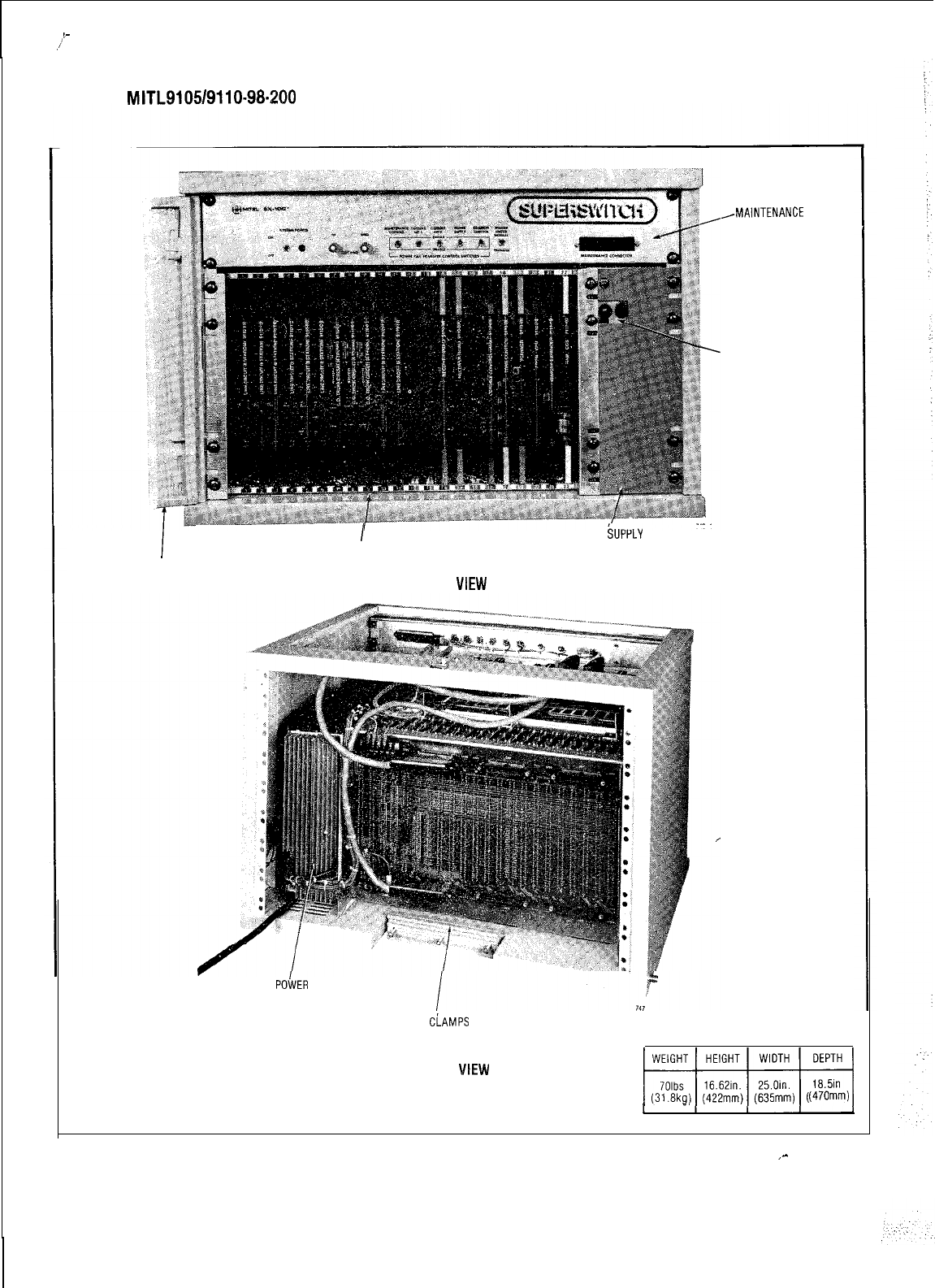
2.03 The SX-100 equipment cabinet (Fig. 2-1)
consists of a metal frame enclosed by back
and top panels. Access to the equipment shelf is
provided by the front door of the cabinet. The rear
panel allows access to the line and trunk cable
plugs.
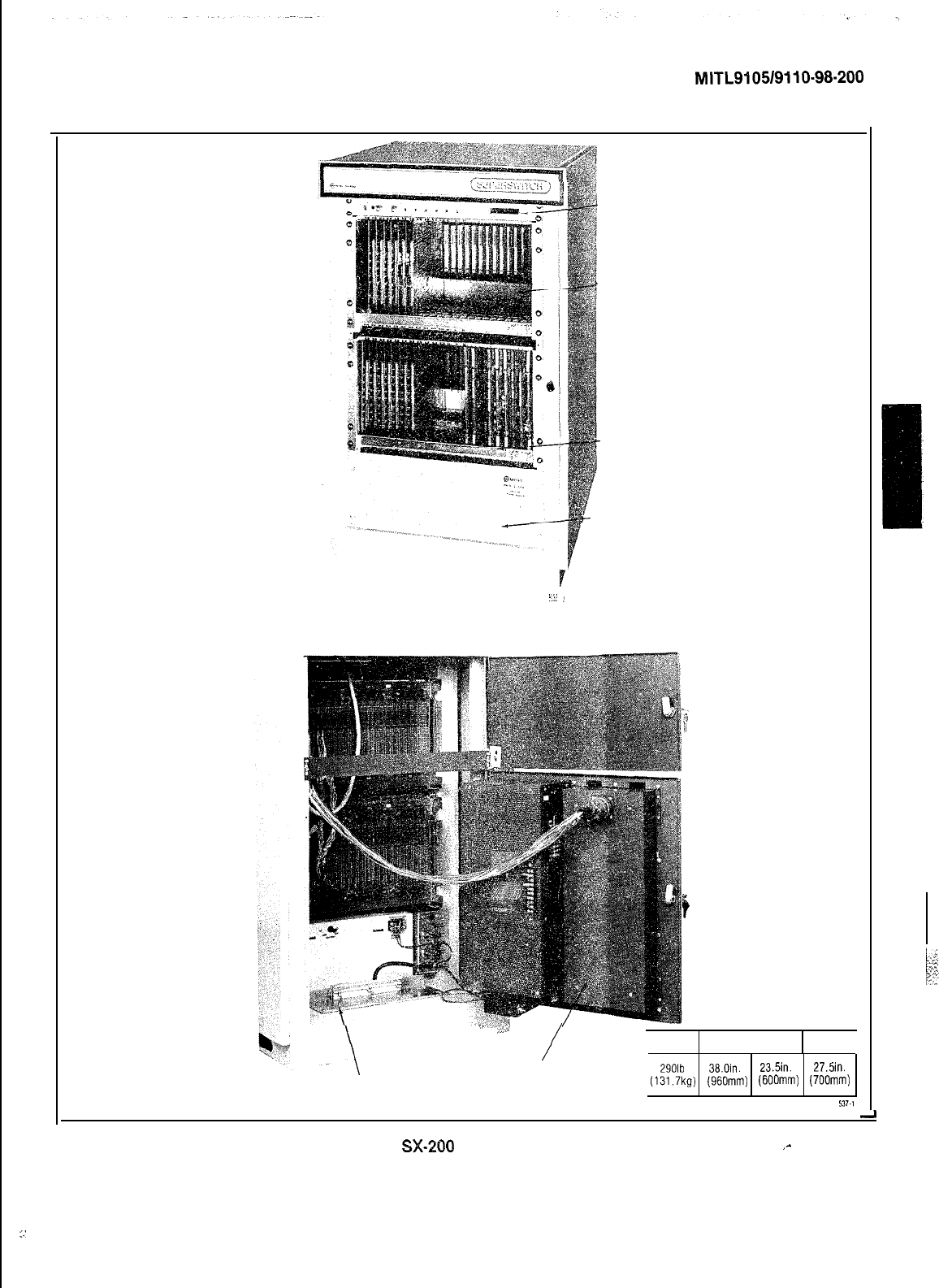
Equipment Cabinet, SX-200
2.04 The SX-200 equipment cabinet (Fig. 2-2)
consists of a metal frame which is enclosed
by side and top panels. Access to the equipment
shelves is provided by the front door of the
cabinet. The hinged rear panels hold the power
supply and allow access to the line and trunk
cable plugs.
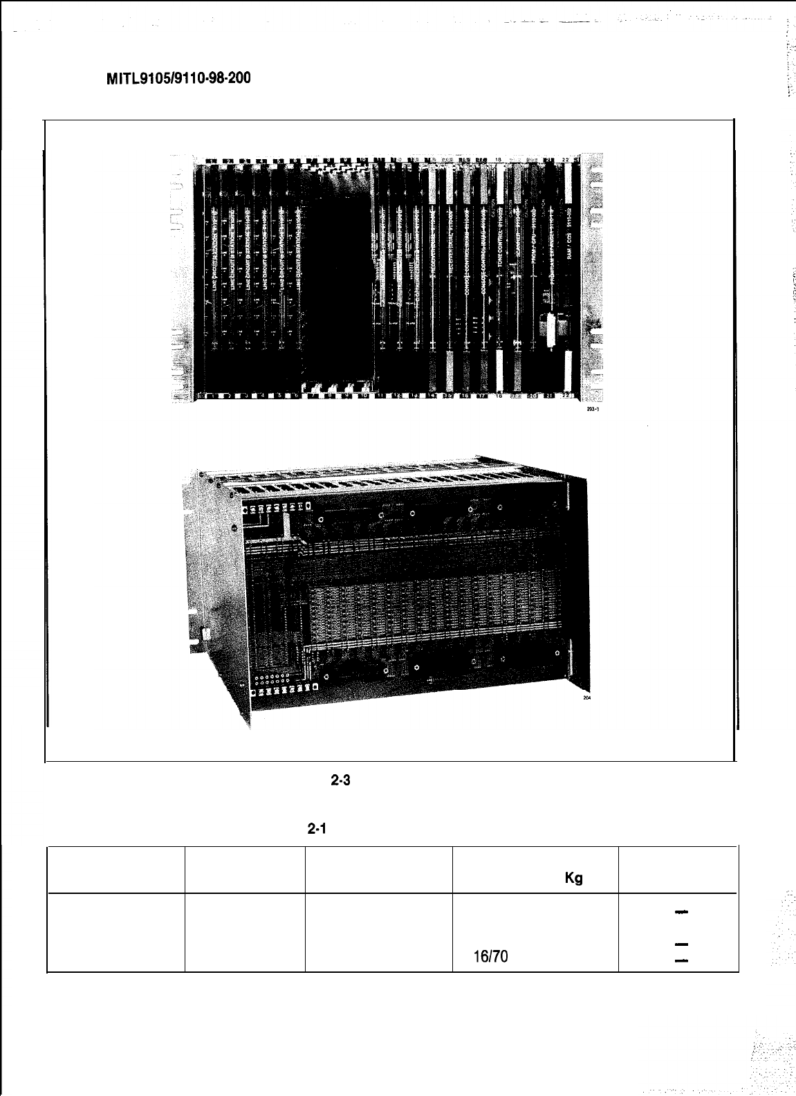
2.06
The SX-100 is equipped with one shelf, but
the SX-200 may be equipped with one or two
equipment shelves depending on the number of
lines and trunks required. Each equipment shelf
(Fig. 2-3) is
10.75in.
(273mm) high,
19in.
(485mm)
wide and 16.375in. (415mm) deep. The shelves are
mounted in the equipment cabinet with the
backplane assembly towards the rear of the
cabinet. The shelves are held in position by moun-
ting screws which locate the shelves in the main
frame.
2.07 The physical characteristics and part
numbers of the shelves, power supplies and
maintenance panel are given in Table 2-1. The
weight for each shelf is for a shelf containing a
full complement of circuit cards.
2.08 The equipment shelves used in the SX-100
and the SX-200 are identical. Fig. 2-3 shows
two views of an equipment shelf.
2.09
The equipment shelves hold up to 22 circuit
cards. Each card plugs into a connector
mounted on the shelf backplane. A locking bar
assembly which passes through the sides of the
shelf ensures that the circuit packs are seated
correctly in the backplane connectors.
2.10 A number of card positions within each
shelf are reserved for control cards. These
card positions are identified by color coded iden-
tification strips along the top and bottom edges of
the shelf. Only cards with locking clips of the
same color as the identification strip should be
plugged into that card position. Circuit card
and/or system damage may otherwise occur.
2.11
Card positions, 14, 13, and 12 on equipment
shelf 1, may be used for line, trunk or
receiver cards. These positions are marked with a
blue and black identification strip, indicating that
any card coded with either of the identification
color codes may be used in these positions.
Page 3
-
,-
,!’
SECTION
MITL9105/9110-98-200
I
CABINET DOOR
I
POWER
bUPPLY
EQUIPMENT SHELF
FRONT VIEW
PRIMARY
PO’iVER
SUPPLY
CABLE
CLAMPS
,MAINTENANCE
PANEL
PRIMARY POWER SWITCH
REAR
VIEW
t7fqqqq
(31.6kg)
(422mm) (635mm)
(47Omm)
Fig. 2-l SX-100 Equipment Cabinet
,-
Page 4
SECTION
MITL9105/9110-98-200
q
i@
MAINTENANCE PANEL
Front View
-:.
,I
i
EQUIPMENT SHELF 2
1
EQUIPMENT SHELF 1
c
RESERVE POWER SHELF
.’
P‘
/
WEIGHT HEIGHT WIDTH
DEPTH
\
PRIMARY
POWER SUPPLY
290lb 38.0in. 23.5in. 27.5in.
CABLE ENTRY
(131.7kg)
(96Omm)
(600mm)
(700mm)
Rear View
537.1
Fig. 2-2
SX-260
Equipment Cabinet
‘^
..’
Page 5
SECTION
MITL9105/9110-98.200
Fig.
2-3
Equipment Shelf
TABLE
2-l
PHYSICAL CHARACTERISTICS
SX-100 Part SX-200 Part Weight Maximum No.
Shelf Type Number Number Ibs
Kg
Circuit Cards
Maintenance Panel
9105-025 9110-125
2
0.9
-
Equipment Shelf
9110-012 9110-012
38 17 22
Reserve Power 9105014 9110-014
125 57
-
Primary Power
9105-008
911 O-008
or
108
16170 7132
-
Page 8
SECTION
MITL9105/9110-98.200
2.12 Line or trunk cards can be placed in any
position identified with black color code
strips. It is recommended that line cards be plac-
ed in the lowest numbered card positions and
trunk cards in the highest card positions for the
following reasons:
l the maintenance test line is permanently
wired to card position 1, hardware position
001
.separation of line and trunk cards allow
ease of identification of card type during in-
stallation and maintenance
.ease of system programming
NOTE:
If more than one receiver card is used,
the second receiver card MUST be plac-
ed in card position 14, the third in posi-
tion 13, and the fourth in position 12. It is
therefore recommended that these card
positions be used for trunk cards only
when all other card positions are in use.
Circuit Cards
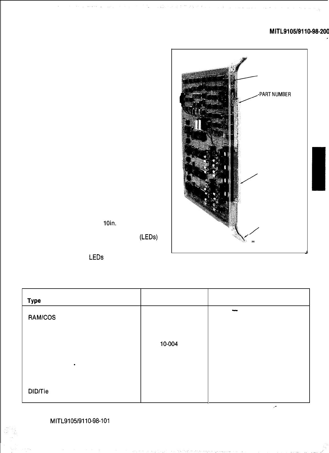
2.13
The circuit cards (Fig. 2-4) used in the equip-
ment shelves measure
loin.
(254mm) high,
13in. (330mm) deep, and are manufactured from
fiberglass board. The light emitting diodes
(LEDs)
mounted at the front of each card indicate the
operational status of the card. The transparent
front panel protects the
LEDs
while allowing their
status to be observed.
Type
Equipment Shelf (Note 1)
RAMlCOS
Card
Memory Expander
PROM/RAM Expander
PROM/CPU Card
Scanner Card
Tone Control Card
Console Control Card
Remote Control
-
PABX Card (Note 2)
Receiver Card (Dual or Quad)
CO Trunk Card (4 trunk)
E&M Trunk Card (2 trunk)
DID/Tie
Trunk Card (2 trunk)
Line Card (8 station)
-CAUTION
NOTICE
-PARTNUMBER
-TRANSPARENT
FRONT PANEL
@ii
2
CARD EXTRACTOR
a
A
TABLE 2-2
EQUIPMENT CODING
Fig. 2-4 Typical Circuit Card
Part
Number
9110-012
911 O-002
9110-019
9110-l 19
911 O-003
91 lo-004 or -104
911 O-005
911 O-006
9110-017
911 O-009
or
-016
9110-011 or
-211
9110-013
911 O-031
9110-110
Note: 1. All equipment shelves are identical.
Card Extractor
Color Code
-
White
Brown
Brown
Red
Orange
Yellow
Green
Green
Blue
Black
Black
Black
Black
,-
2. The RCP is supplied only if required that the PABX be accessed by RMAT facilities (see Section
MITL9105/9110-98-101
Remote Maintenance Administration and Test System).
Page 7
I
SECTION MITL91051911 O-98-200
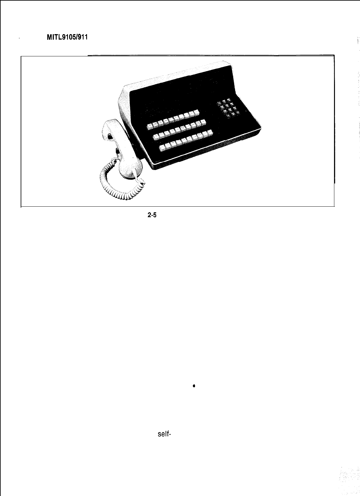
Fig.
2-5
Attendant Console
2.14 On the front panel of each card, is the card
part number and its type. Cards which must
not be removed or inserted while the system
power is on carry a Caution notice as shown in
Fig. 2-4.
2.15
Each card is equipped with two card extrac-
tors which enable the card to be easily
removed. In the locked position the card extrac-
tors in conjunction with the locking bar ensure
that the circuit cards are held firmly in position.
Equipment Shelf and Card Identification
2.16 Table 2-2 lists all shelf and card part
numbers, types and color codes.
Features and Services
2.17 The features and service codes are entered
into the system memory through a console.
No wiring or strapping is required when assigning
features.
Attendant Console
2.18 The attendant console (Fig. 2-5) is a
self-
contained unit, connected to the equipment
cabinet by a plug-ended 25 pair cable.
Page 8
2.19 The console is equipped with two sets of
handset/headset jacks. These jacks will ac-
cept all standard handsets or headsets presently
in general use.
Connecting Cables
2.20 All connections to the attendant console
and the equipment cabinet, are made using
plug or connector-ended 25 pair cables.
Power Fail Transfer
2.21
In the event of a major alarm condition the
power fail transfer relays located on the
Power Fail Transfer card, will connect Central Of-
fice trunks to selected station lines (maximum 6
trunks for SX-100, 12 trunks for SX-200). Power fail
transfer will take place under any of the following
conditions:
.
commercial power failure (if no reserve
power supply is used)
.common control failure
.operating voltages out of accepted
tolerance
.manual transfer from a console or the
equipment cabinet

(a) Incoming Calls After a power fail transfer
has occurred, ringing of extensions for in-
coming calls is applied directly to the
selected extension line from the Central Of-
fice (CO).
(b) Outgoing Calls To place an outgoing call
through a ground start CO trunk, with the
system in the power fail transfer mode, the
extension originating the call must be
equipped with a ground key. When the
ground key is momentarily pressed, a
ground is applied to the Ring side of the
line, energizing the CO equipment. One
side of the ground key must be connected
to a ground and the other to the Ring con-
ductor of the station line. Call origination
over loop start trunks does not require the
use of a ground start key.
Power Fail Transfer Reset
2.22 The system may be returned to normal
operation from power fail transfer in one of
three ways.
(a)
Major Alarm
If the system was placed in the
power fail transfer mode because of a ma-
jor alarm condition it will return to normal
operation and turn off the major alarm lamp
when the alarm condition is corrected.
(b) Manual Reset When the system has been
placed in the power fail transfer mode by
operation of the transfer switch, the major
alarm lamp will light, indicating that
transfer has taken place. Setting the
transfer switch to NORMAL will reset the
system to normal operation and turn off the
alarm lamp if the alarm condition has been
corrected. If the alarm condition has not
been corrected the alarm lamp will remain
lit indicating that the system has remained
in the power fail transfer mode.
(c)
Reset From Commercial Power Failure
The
system will automatically return to normal
operation when commercial power is
restored.
Note: When the system returns to normal
operation from the power fail transfer
mode all connections established
SECTION
MITL9105/9110-98-200
through the power fail transfer circuits
will be maintained until the completion
of the calls.
’
Test Line
2.23
The test line, permanently assigned to hard-
ware position 001, has the Tip and Ring con-
nections wired to the two terminals on the face of
the maintenance panel. The service person can:
.seize individual trunks
.seize individual receivers
.
seize individual speech paths
.initialize card slots
l busy out selected receivers, trunks or
speech paths.
.
clear all alarms and raise associated
busy-
out conditions
l
reset the systems (Generic 203, 204)
linitiate a system dump (Generic 204)
lcontrol the printer (Generic 204)
Reserve Power Supply
2.24 The optional reserve power supply (in the
form of batteries and charging system) is
housed in the SX-200 equipment cabinet; or in a
package that forms a base for the SX-100 cabinet.
The power supply is designed to maintain system
operation for a minimum of two hours in the event
of main power failure.
Paging, Dictation, and Music on Hold Equipment
2.25 All paging, dictation and music on hold
equipment is located external to the PABX.
This equipment should be located in an environ-
ment specified by the individual supplier and con-
nected to the PABX through the cross-connect
field.
Night Relays
2.28 Four relays are provided for use during
night service. One is operated permanently
during night service, and the other three may be
assigned to various trunks to ring night bells.
Page 9
SECTION MITL9105/911 o-98-200
Power, supplied from the power supply and re-
quired to operate night bells must be connected
at the cross-connect field.
3. SHIPPING AND RECEIVING
Introduction
3.01
This part describes the procedures to be us-
ed when shipping or receiving the Elec-
tronic PABX equipment.
System Shipment
3.02
The PABX cabinet is shipped in a single car-
ton containing the equipment cabinet. The
consoles and reserve power supply, if required are
packaged and shipped separately from the
system equipment package.
4. PACKAGING
System Package
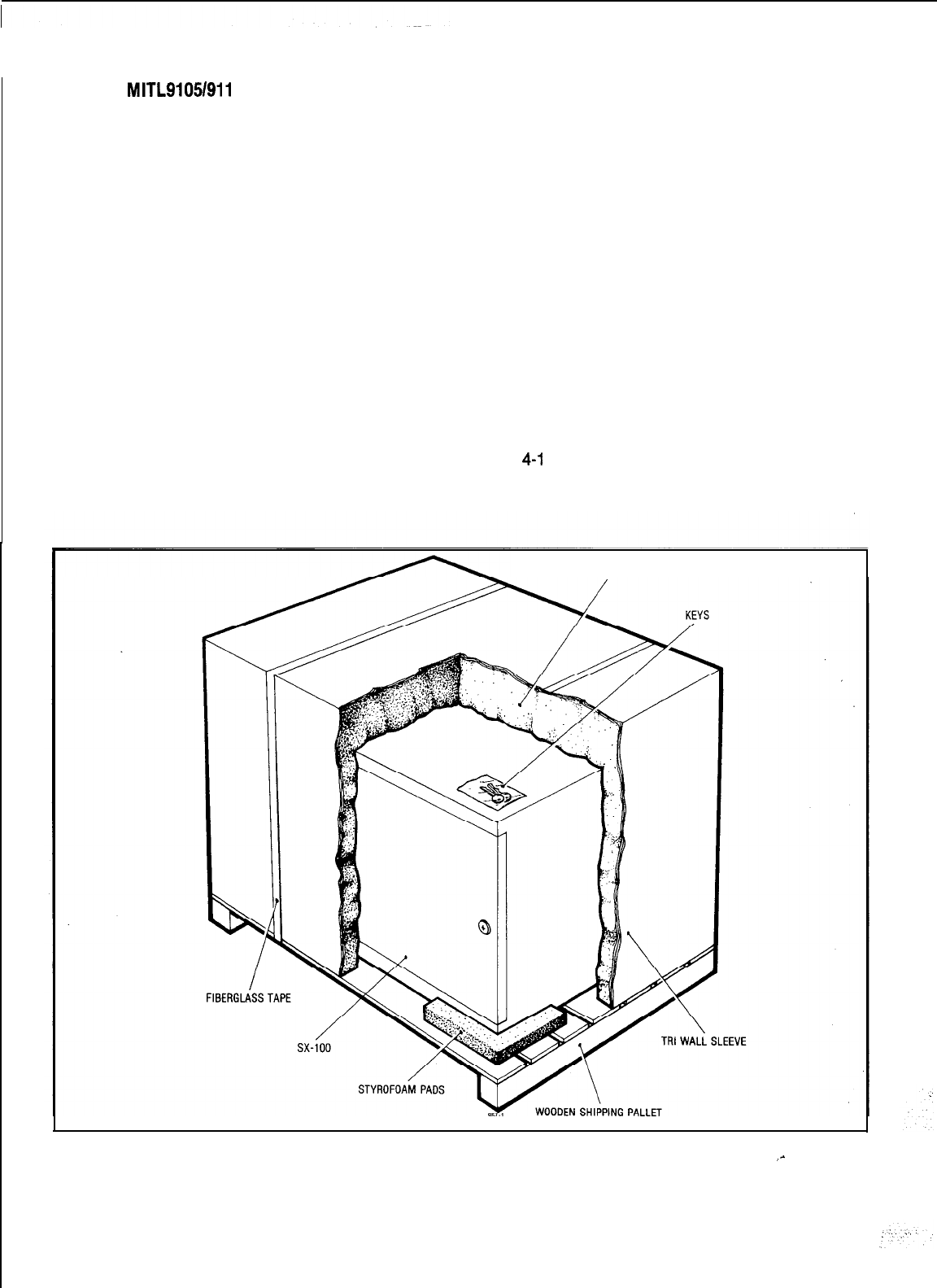
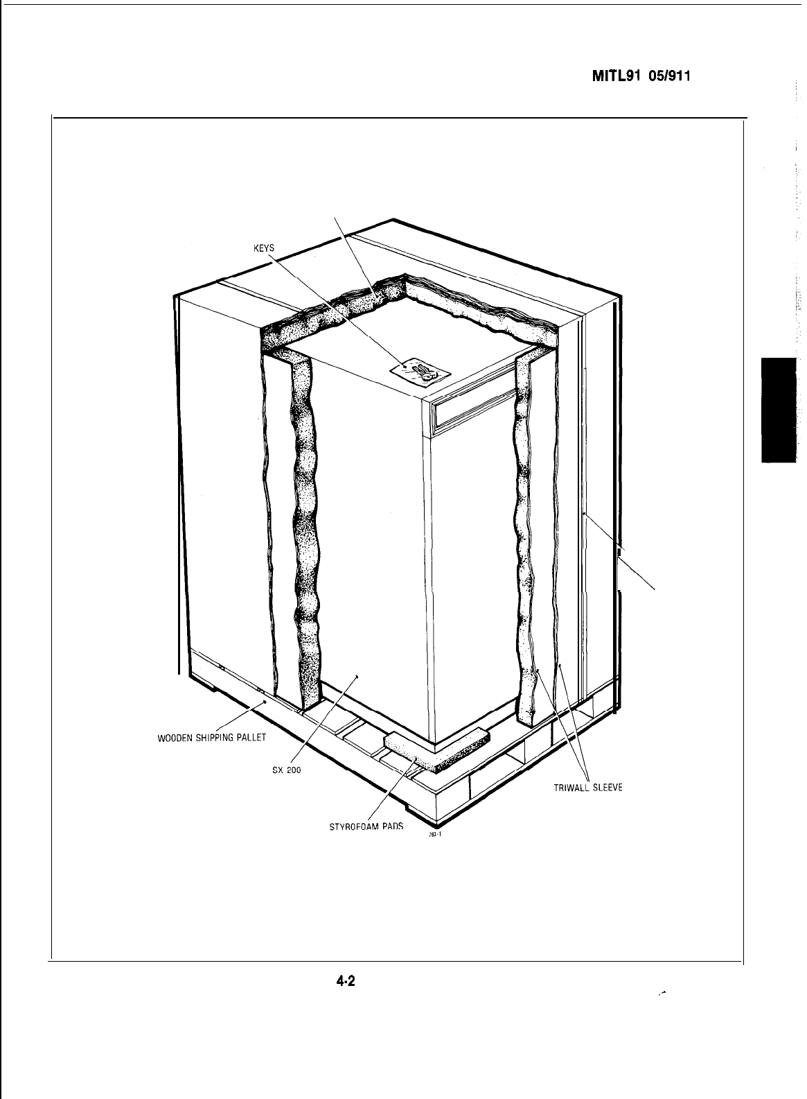
4.01
The equipment is shipped with some cards
and all shelves in position. The equipment
cabinet is enclosed in a polyethylene sheet and
positioned on the shock absorbant shipping
pallet. Foam sheet is placed around and on top of
the cabinet to protect it from damage and the
complete assembly encased in a tri-board sleeve.
Four transportation straps are then fastened to
the pallet to prevent any movement of the cabinet
package. The tri-wall cap is placed over the
sleeve, and the complete assembly secured to the
shipping pallet by two metal retaining straps.
Figs.
4-l
and 4-2 respectively show the packaging
arrangements for the SX-100 and SX-200.
STYROFOAM
Fig. 4-l System Packaging
_-
Page 10
SECTION
MITLSI
05/911 O-98-200
STYROFOAM
\
FIBERGLASS TAPE
Fig.
4-2
System Packaging
,-
Page 11

i
SECTlON
M ITL9105/911 o-98-200
Consoles
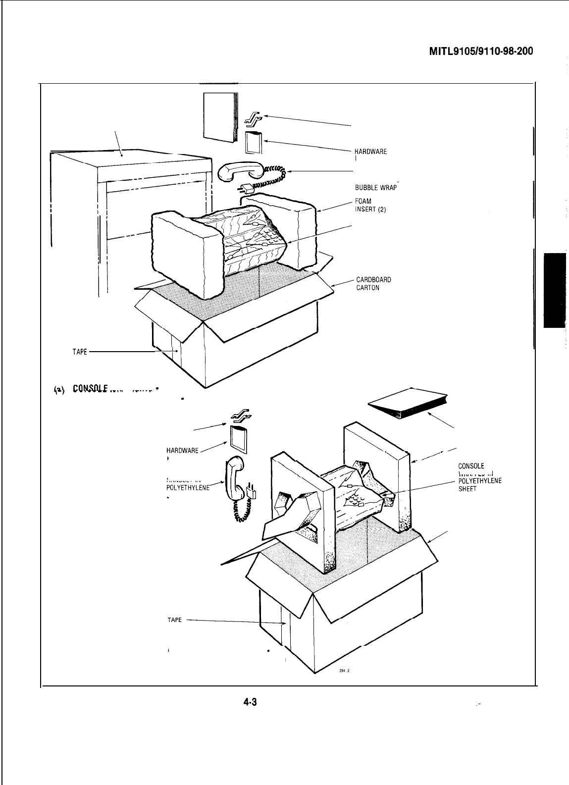
4.02
Each console is wrapped in a polyethylene
sheet and placed in a cardboard packing
carton and protected with shock absorbent foam
inserts. The handset and cradle are placed in
bags and inserted in the corners of the box at one
end. The console manual is placed at the other
end of the box, and the Extension Features Opera-
tion booklets are distributed in the box to fill the
available space. The completed package is
secured with fibreglass tape (See Fig. 4-3).
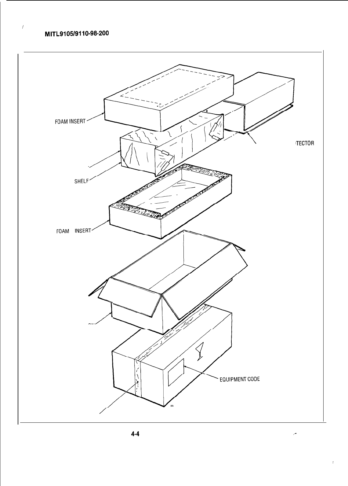
Equipment Shelves
4.03 Equipment shelves, when shipped
separately, are packaged in a similar man-
ner. A shelf, with all cards removed, is enclosed in
a cardboard protector to prevent damage to the
shelf backplane. The protected shelf is then wrap-
ped in a polyethylene sheet and placed in a form-
ed foam insert. The complete assembly is finally
encased in a packing carton and secured by
fibreglass tape (Fig. 4-4).
Reserve Power Shelf
4.04 The method of packaging the reserve power
shelf is the same as for equipment shelves,
except a heavy duty commercial packing carton is
used in place of the regular packing cartons, due
to the weight of the battery packs in the reserve
power shelf.
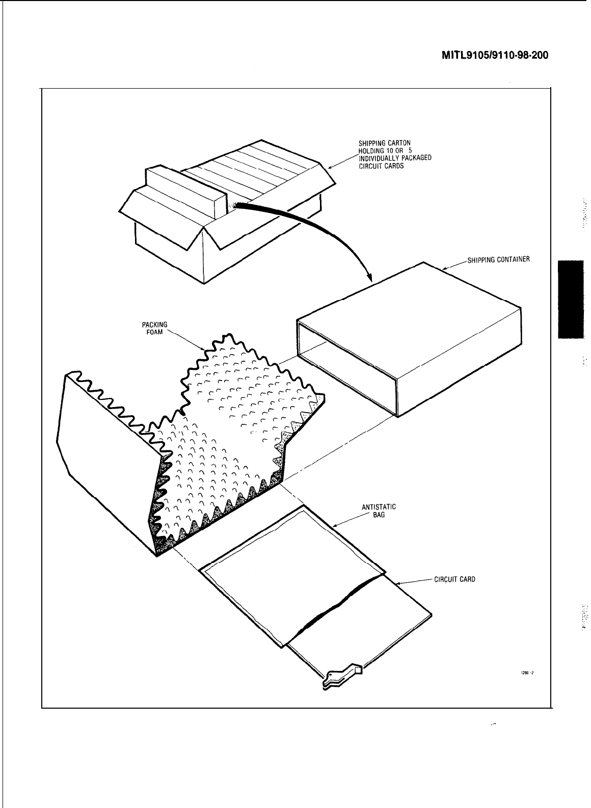
Printed Circuit Cards
4.05 All printed circuit cards, if shipped
separately, are packaged as shown in Fig.
4-5. If a large number of circuit cards are to be
shipped, they are individually packed and shipped
in groups of ten per carton.
5. DELIVERY CHECK
5.01 At the time of delivery at the installation
site all items delivered must be checked
against the order form and packaging slip. Any
discrepancies must be reported immediately.
6. UNPACKING AND HANDLING
Cabinet
6.01 The procedure to be used when handling
and unpacking the equipment are detailed
in Appendices 3 and 4.
Page 12
-
Shelves and Circuit Cards
6.02 Shelves and circuit cards shipped separate-
ly from the equipment cabinet should not
be unpacked before they are required for use.
When required, the shelf and cards are to be
transported to the equipment location packaged
in their original containers when possible.
7. INSPECTION
Cabinet
7.01
After positioning and unpacking the equip-
ment, a visual inspection should be per-
formed prior to installation to ensure that:
(a)
The cabinet has not been dented or scratch-
ed during shipment.
(b) The door on the front of the cabinet opens
and closes easily.
(c) The shelves are mounted firmly in the
cabinet.
(d)
The shelves are not bent or otherwise
damaged.
(e) All cards are seated firmly in their connec-
tors.
(f) Rear doors open and close easily.
(g) All components mounted in the rear panel
power supply are secure.
(h) All interconnecting cables and plugs are
secure.
(j)
All connections to the power supply are
tight.
Shelves
7.02
Inspect the shelf to ensure that:
(a) Edge connector contacts are undamaged
and do not contain any foreign matter.
(b) No circuit card guides are broken.
(c) No wires are broken.
,-
SECTION
MITL9105/9110-98-200
SX-200 CABINET
-MANUAL
&-------
CRADLE
BAG
HANDSET IN
POLYETHYLENE
CONSOLE
WRAPPED IN
POLYETHYLENE
SHEET
TAPE
‘V
CGNSOLE
PACKAGING
-
-
8-I
-
-
.
-
-
-
-.-._.
__..._
(FOR SHIPMENT IN SX-200 1
-
SHELF CABINET)
CRADLE
j
lnl
HARDWARE/q
r(\
BAG
m
HANDSET IN
POLYETHYLENC
BUBBLE WRAP
V‘3ul
IP
d-
MANUAL
(b) CONSOLE PACKAGING
-
(FOR SEPARATE SHIPMENT)
FOAM INSERTS (2)
WRAPPED IN
CARDBOARD
/CARTON
Fig.
4-3
Console Packaging
_-
Page 13
r
I
SECTION
MITL9105/9110-98-200
CARDBOARDPRO
POLYETHYLENESHEET
5
PACKINGCARTON
1TECTOR
FIBERGLASSTAPE
/
Fig.
4-4
Equipment Shelf Packaging
_-
Page 14
:
SECTION
MITL9105/9110-98.200
1
Fig. 4-5 Circuit Card Packaging
Page15 i

SECTION
MITL9105/9110-98-200
(d) The backplane is not cracked.
(e)
No connector pins are broken or bent.
Cards
CAUTION:
Hand/e Circuit Cards by their edges
only. Handling the board faces or
components may cause damage.
7.03 If printed circuit cards are shipped
separately from the equipment, inspect
each circuit card to ensure that:
(a) The fibreboard is not cracked.
(b) No loose leads or components are ap-
parent.
(c) The card front panel is not broken.
Circuit cards shipped in the equipment do not re-
quire individual inspection unless equipment
shelf damage has been found.
Defective Items
7.04
If any defective item is found it should be
tagged and returned to the supplier in ac-
cordance with accepted procedures. (See Part 8)
8. REPACKING FOR RESHIPMENT
8.01
When the PABX equipment is shipped from
one location to another, all items must be
packaged to prevent damage. Figs. 4-1 through
4-5 show how the equipment was originally
packaged. This method of packaging should be
followed as closely as possible.
8.02 If the original packaging material is no
longer available, the returned parts should
be wrapped in several layers of air-cushion type
wrap, placed in a suitable container, and sur-
rounded with paper to minimize movement of the
items.
9. INSTALLATION REQUIREMENTS
Environmental Requirements
9.01 The PABX equipment cabinet may be in-
stalled in any location which fullfills the
re-
Page 16
quirements of 9.02, and is within the following
temperature and humidity limits:
l
Temperature 0
-
40 “C (32
-
113 “F)
lRelative Humidity 10
-
90%
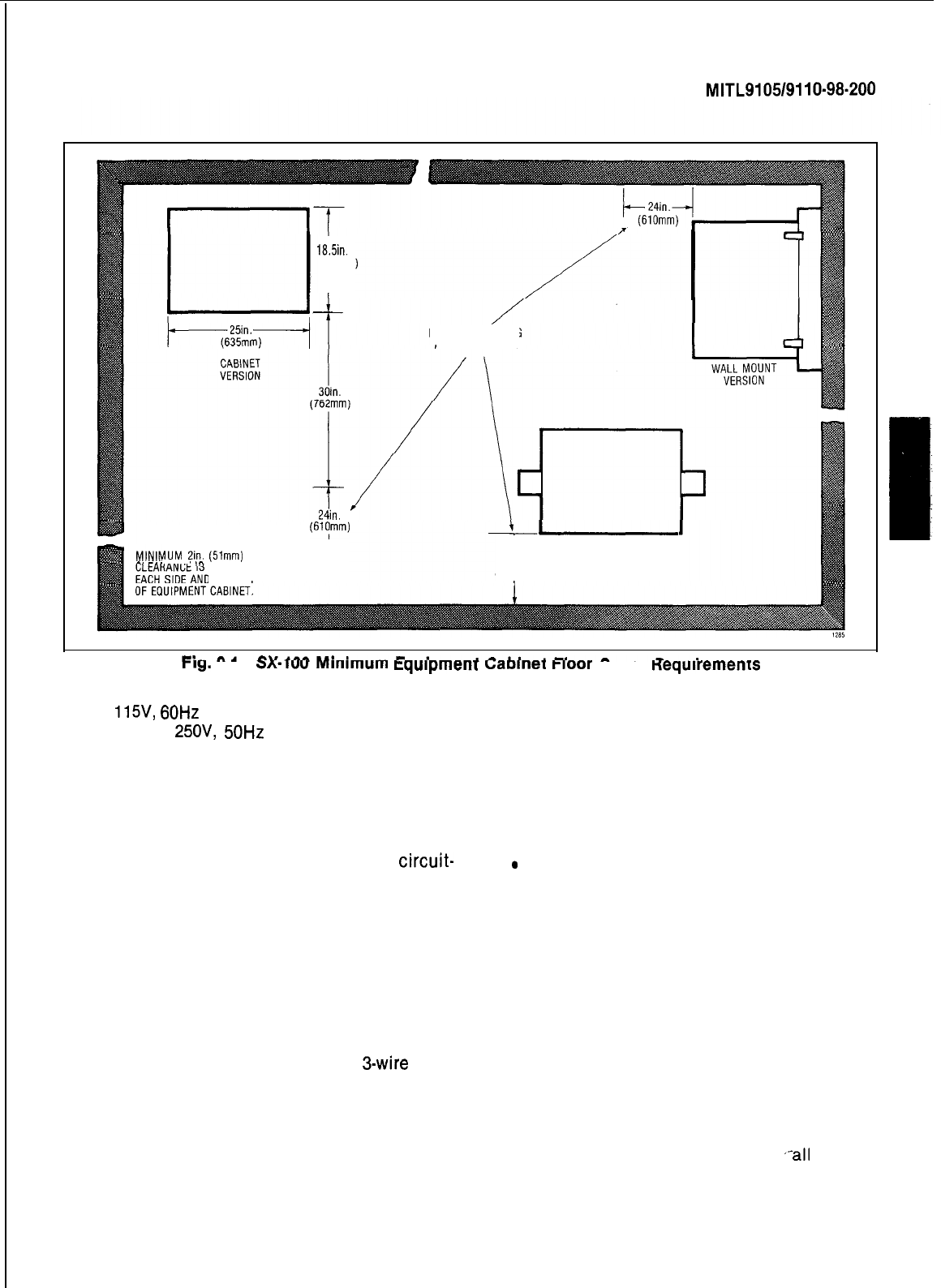
Floor Space
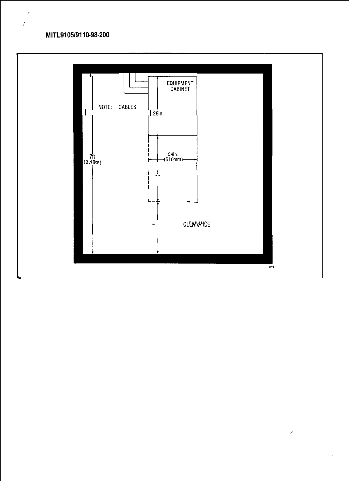
9.02 The minimum floor space for installation
and subsequent maintenance of the SX-100
and SX-200 Electronic
PABXs
is shown in Figs.
9-l
and 9-2 respectively.
Equipment Cabinet Location
9.03 The following requirement must be met
when selecting a location for the PABX
equipment. For cooling purposes the PABX
cabinet equipments use natural air convection
flow. For this reason the bottom areas of the
cabinets must be allowed free air flow, and must
not be obstructed, for example, by rug pile block-
ing the air vent entries.
The location MUST BE:
l dry and clean
.well ventilated
.well lit
.easily accessible
The location MUST NOT BE:
.
near a sprinkler system, sweating pipes,
steam pipes or steam vents
.in areas with extreme heat or cold
.in areas where corrosive fumes or exhaust
from machinery is present
.in passageways used for moving equip-
ment
.next to a reproducing or copying machine.
A minimum clearance of 10 feet (3m) must
be provided and the room should be ven-
tilated by an exhaust fan if the reproducing
machine is not equipped with a filtering
system
Power Supply Requirements
9.04 The customer must provide a single phase
power receptacle, with the following recom-
mendations:
_-
SECTION
MITL9105/9110-98-200
I
18.5in.
(470mm)
I
MINIMUM WORKING
AREA CLEARANCE
(Slpm)
“““‘IUM
2in.
(51mm)
-I-
. ..‘--
‘^
REQUIRED
ON
1 AT REAR
f-
RACK MOUNT
24in.
VERSION
(610mm) (23in.)
I
rig.
Y-I
3~.iuu
Mmlmum
equipmenr
LaDme
rloor
space
nequlremenrs
l
115V,
60Hz
fused, and capable of delivering
4A; or
25OV,
50Hz
fused, and capable of
delivering 2A
lthe power receptacle should be wired and
fused independently from all other recep-
tacles
.a warning tag should be attached to
circuit-
breaker-type fuses to prevent unauthorized
manual operation
lthe power receptacle must not be controll-
ed by a switch
l the live and neutral conductors at the
receptacle shall be wired to their proper
respective connections
lthe power receptacle must be a
3-wire
type,
with the third wire connected to the ground
of the electrical system
lthe receptacle should be easily accessible
for the removal of the plug for maintenance
lthe receptacle location should be selected
to prevent accidental removal of the power
cord
lthe power cord between the cabinet and the
receptacle should not present a hazard to
the subscriber
.
a warning tag should be attached to the
plug end of the power cord to prevent ac-
cidental removal of the cord by the
subscriber
Equipment Grounding
9.05 The following is a description of the re-
quired PBX equipment grounding practice:
(a) All circuit commons within the cabinet
shall derive ground from a single ground
concentration point within the cabinet.
Each cabinet’s ground concentration point
shall derive ground from a single ground
concentration point serving
,-all
system
Page 17
1
+
NOTE:
,I~j~~
m
1 ENTER FROM ONE 1
2&n.
SIDE ONLY
(711mm)
I
7ft
I’)
,Qm\
Ii
;
30in
;
(762mm)
I
L-
t
------
-
-1
SECTION
MITL9105/9110-98-200
I
MINIMUM 2in (51mm)
I
74in
-
(610mm) ,-’ cna”r’CE IS REQUIRED ONULLnnnlY’
EACH SID E AND AT THE REAR
OF THE EQUIPMENT CABINET
L
Fig. 9-2 SX-200 Minimum Equipment Cabinet Floor Space Requirements
cabinets and peripherals colocated with
the system.
(b) The system cabinets and all associated
ducting hardware along with all colocated
peripherals shall not be exposed to any
ground source other than the system single
point ground described in (a) above.
(c) AC service wires bringing ac power to the
cabinets shall not share an enclosure or
raceway with any other system grounds, DC
power distribution wires, or signaling wires.
All non-connectorized ac power termina-
tions shall be enclosed by raceways and
termination boxes whether these
enclosures appear outside or within system
cabinets. This is to ensure that ac service
wires cannot fault to circuitry within system
cabinets or associated ducting hardware.
(d) All system hardware shall be provided with
an ac fault return path to the system single
point ground which in turn shall be provided
with a reliable path to the equipment groun-
ding conductor (i.e. green wire ground or
safety ground). The path from system
equipment to system single point ground
need not be a direct dedicated path but can
be any reliable path to other system hard-
ware which receives the above grounding
path.
(e) All sources of external ground (i.e. system
signaling ground to the approved ground
source, etc.) shall connect only to the
system single point ground. The intent of
providing for a system single point ground
is to minimize ground loops and prevent
lightning from finding a path through
system components.
,-
Page 18
:
SECTION
MITL9105/9110-98-200
!
(f) A separate grounding conductor (minimum
size, 14AWG) shall be separately run from
the system single point ground to the com-
munications ground system on the cross-
connect field.
Telephone Set and Trunk Cabling
10. CABLING AND CROSS-CONNECTIONS
General
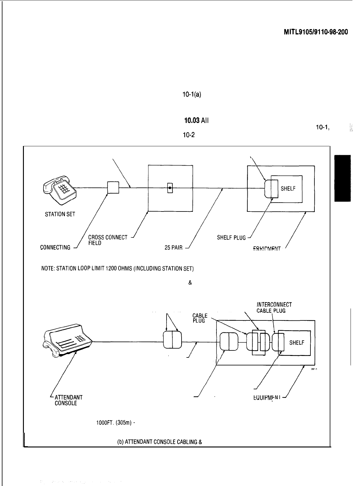
10.02 Telephone set and trunk cabling terminates
on the building cross-connect terminal in
the normal manner. The cabling requirements and
limits for stations and consoles are shown in Fig.
10-l(a) and (b).
Cable Terminations, SX-100
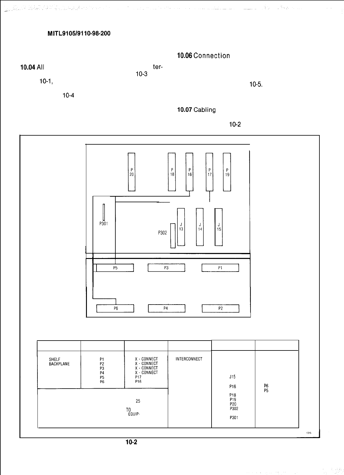
10.01 This part details the cabling and cross-
10.03All
interconnecting cables must be ter-
connections required when installing the minated in accordance with Tables
10-1,
PABX.
10-2
and Fig. 10-2.
1
TWO CONDUCTOR WIRE
OR EQUIVALENT CABLE CONNECTOR
BLOCK CABLE
CABINET
NOTE:STATION LOOPLlMlT1200OHMS(INCLUDINGSTATlONSET)
(a)
STATION CABLING
&
LIMITS
CABLE
INTERCONNECT
INTFRCONNFCT
CONNECTORS
BOARD \
25 PAIR
PLUG-ENDED CABLE
SHELFCONNECTOR
CONSOLE INTERCONNECT
BOARD CABINET
NOTE: CABLING LIMIT
lOOOFT.
(305m)-
26 AWG MINIMUM
CABLE CONSOLETO EQUIPMENT CABINET.
(b)ATlENDANTCONSOLECABLlNG& LIMITS
Fig. 10-I Station and Console Cabling Requirements
Page 19
SECTION
MITL9105/9110-98-200
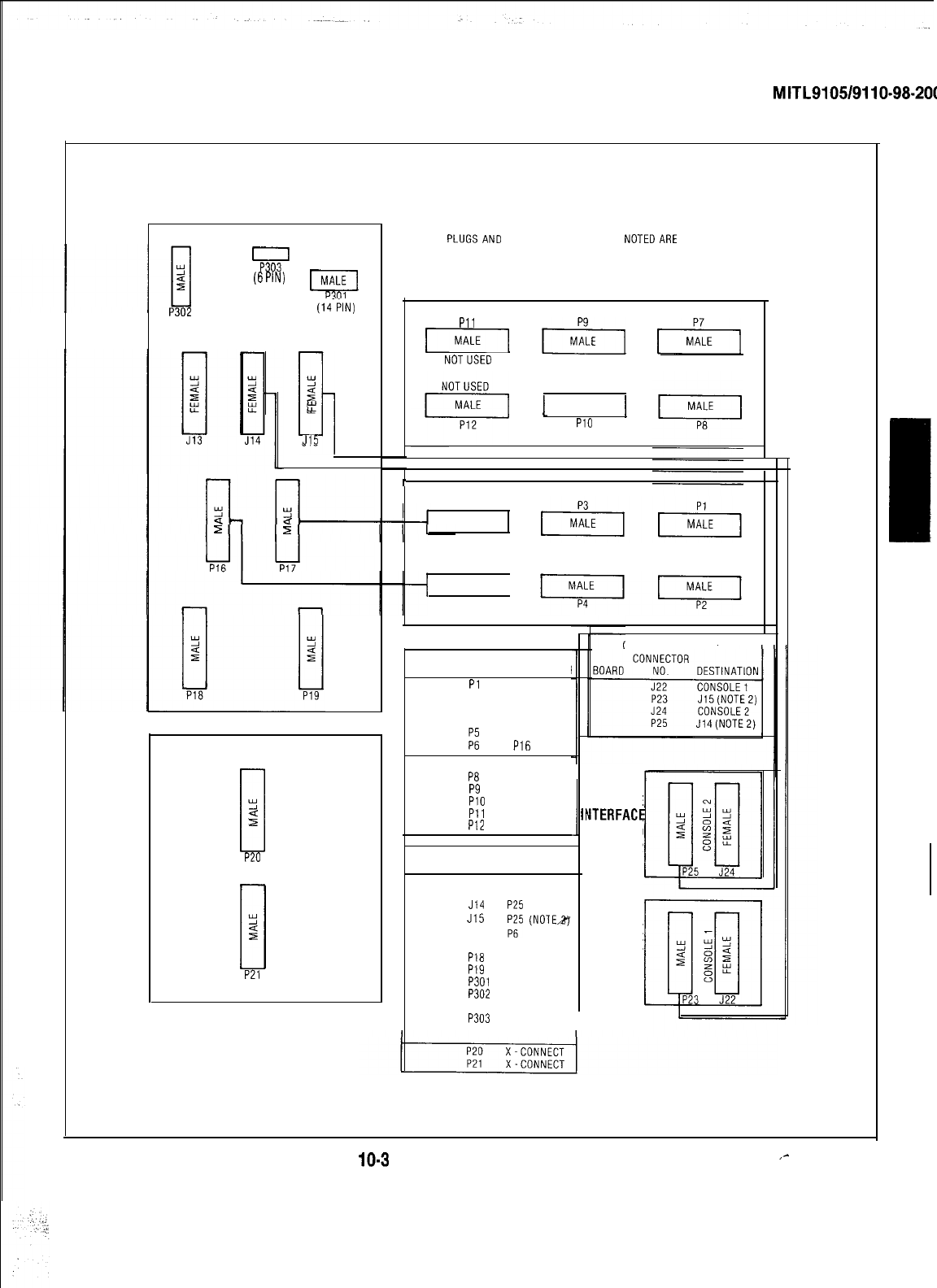
Cable Terminations, SX-200
10.08Connection
between the equipment
10.04All
interconnecting cables must be
ter-
cabinet, cross connect field, stations,
minated in accordance with Fig.
10-3
and trunks and consoles should be made using
Tables
10-1,
10-2, 10-3, and 10-5. In addition if 26AWG connector ended cable in accordance
Shelf 2 is installed the interconnecting cables with Tables IO-1 through
10-5.
listed in Table
10-4
must be terminated.
Cross-Connections
10.07Cabling
connections between shelf 1, the
10.05 Jumpers should be run using Z type 24AWG interconnect board, and cross connect field
cross-connecting cables. are shown in Figs
10-2
and 10-3.
P301
(14 PIN)
P302
(25 PIN)
BOARD
CONNECTOR
NO. DESTINATION BOAR0
NOTE: ALL PLUGS AND CONNECTORS
EXCEPT AS NOTED ARE STANDARD
25
PAIR (AMPHENOL TYPE). THE MALE AND
FEMALE DESIGNATORS REFER
TO
THE
CONNECTORS MOUNTED ON THE
EDIJIP-
MENT.NOTTOTHECABLECONNECTORS.
CONNECTOR
NO.
J13
J14
J15
PI6
P17
P16
P19
P20
P302
P301
DESTINATION
MAINTENANCE
CONSOLE
ATTENDANT
CONSOLE 2
ATTENDANT
CONSOLE1
P6
Pi
X-CONNECT
X-CONNECT
X-CONNECT
PRINTER OR
RECORDING DEVICE
MAINTENANCE
PANEL
Fig.
10-2
SX-100 Connector Locations
Page 20
SECTION
MITL9105/9110-98-200
NOTES:
1.
ALL
PLUGSAND
CONNECTORS EXCEPT AS
NOTEDARE
STANDARD 25 PAIR
(AMPHENOLTYPE).THE MALEANDFEMALE DESIGNATORS REFERTOTHE
CONNECTORSMOUNTEDON THE EQUIPMENT, NOTTOTHE CABLE CONNECTORS
52
(6
w
piiq
P301
P302
(25 PIN)
2.
SEE APPENDIX 6. MAP200-604 FOR CONSOLE INTERFACEBOARD CONNECTIONS.
(liPIN)
I
Pll
piq
p2-j
*M*LE
NOTUSED
SHELF 2
Y
s
n
kf
J15
1
MALE
1
PlO
r
P5
MALE
SHELF 1
MALE
P6
CONSOLE INTERFACE
I
CONNECTOR
SHELF NO
DESTINATION
Pl
X-CONNECT
P2
X-CONNECT
1
P3
X-CONNECT
P4
X-CONNECT
FZ P17
P16
INTERCONNECT BOARD
P7
X-CONNECT
PB
X-CONNECT
2
P9
X-CONNECT
PlO
X-CONNECT
Pll
SPECIAL
CONSOLE
h
P12 FEATURES
ITERFACE
BOARD
1II
Y
0
2
P20
CONNECTOR
2
BOARD NO. DESTINATION
J13
MAINTENANCE
INTER-
J14
CONSOLE
CONNECT
J15 P25 (NOTE 2)
P16
;;"
(NoTEX(
CONSOLE
P17 P5
INTERFACE
P18
X-CONNECT
BOARD
P19
X-CONNECT
P301
POWERSUPPLY
1
P302
PRINTER OR
MODEM
Y
u
s
P2l
POWER FAILTRANSFER BOARD
P303
MAINTENANCE
PANEL
Fig.
10-3
SX-200 Connector Locations
,-
Page 21
SECTION
MITL9105/9110-98-200
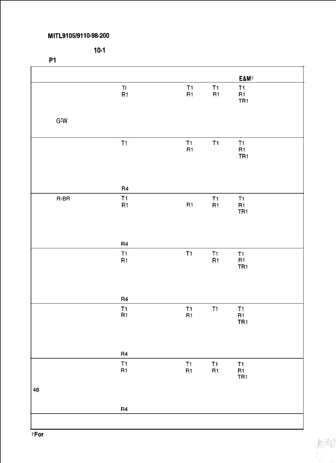
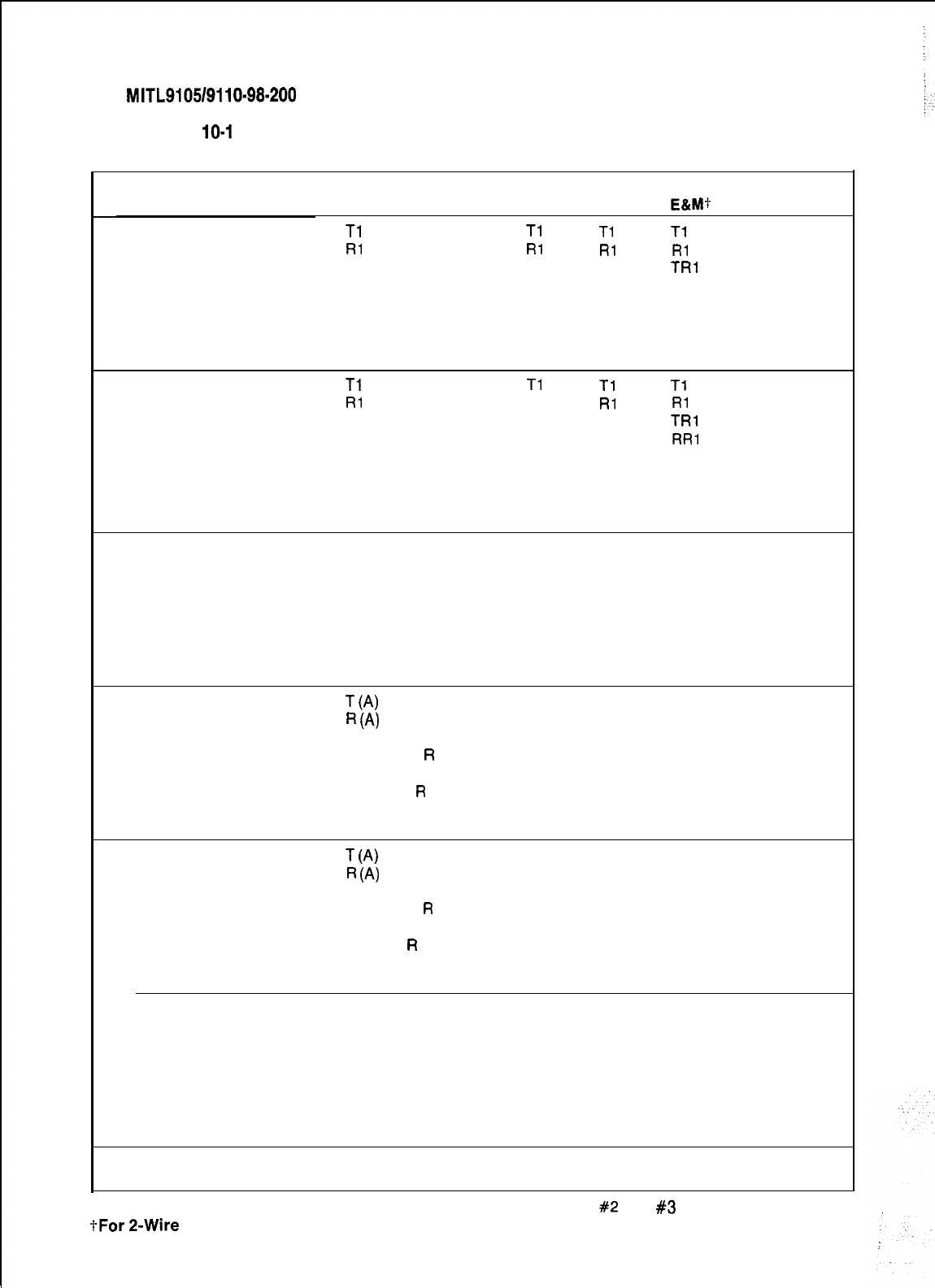
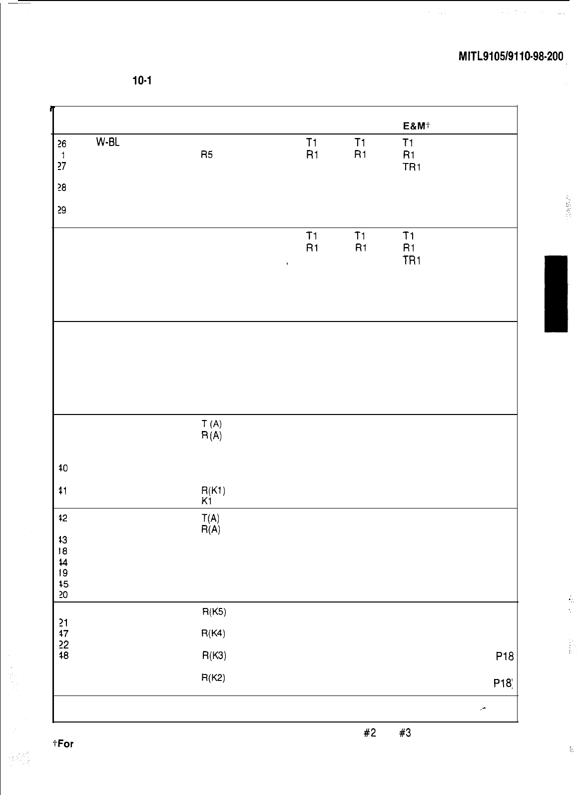
TABLE
10-l
SHELF 1 EXTERNAL PLUG AND JACK CONNECTIONS
PLUG
Pl
(Connects to Cross Connect Field)
Pair Lead Designation Lead Designation Trunks Card
Pin
Color Line
co
DID/TIE E&M+ Positions
26
W-BL
TI
reserved for
Tl Tl Tl
1
BL-W
Rl
test line
Rl Rl RI
27
w-o
T2
XT2
TRI
2
o-w
R2 XT1 RR1
1
26
W-G
T3 T2
El
3
GiW
R3 R2
Ml
29
W-BR T4
4
BR-W
R4
30
w-s
Tl Tl
Tl
Tl
5
s-w RI
Rl
RI
Rl
31
R-BL T2
XT2
TRI
6
BL-R R2 XT1 RR1 2
32 R-O T3 T2
El
7O-R R3 R2
Ml
33 R-G T4
aG-R R4
34 R-BR
Tl
Tl
Tl
Tl
9BR-R
Rl Rl Rl Rl
35 R-S T2
XT2
TRl
10
S-R R2 XT1 RR1
36 BK-BL T3 T2
El
3
11
BL-BK R3 R2
Ml
37
BK-0 T4
12
0-BK
R4
38 BK-G
Tl
Tl
Tl Tl
13
G-BK
Rl
RI
Rl Rl
39 BK-BR T2
XT2
TRI
14 BR-BK R2 XT1 RR1
40 BK-S
T3
T2
El
4
15
S-BK
R3 R2
Ml
41
Y-BL T4
16
BL-Y
R4
42
Y-O
Tl Tl
Tl Tl
17
O-Y
Rl Rl
RI
Rl
43
Y-G
T2
XT2
TRI
la G-Y
R2 XT1 RR1
44
Y-BR
T3 T2
El
5
19
BR-Y
R3 R2
Ml
45
Y-S
T4
20
S-Y
R4
46
V-BL
Tl
Tl
Tl Tl
21
BL-V
Rl Rl Rl Rl
47
v-o
T2
XT2
TRl
22
o-v
R2 XT1 RR1
48
V-G
T3 T2
El
6
23
G-V
R3 R2
Ml
49
V-BR T4
24
BR-V
R4
50
v-s SPARE SPARE
25
s-v SPARE SPARE
tFor
P-Wire E&M Trunk operation DO NOT connect RR and TR leads
Page 22
SECTION
MITL9105/9110-98.200
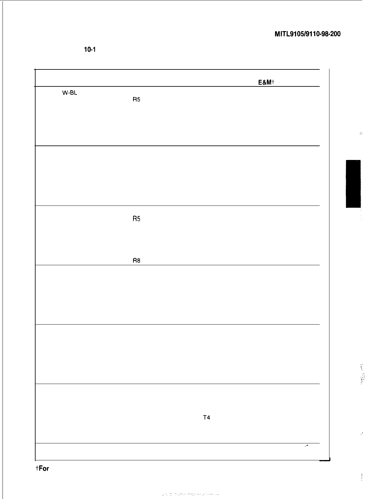
TABLE
10-l
SHELF 1 EXTERNAL PLUG AND JACK CONNECTIONS (CONT’D)
PLUG P2 (Connects to Cross Connect Field)
Fair Lead Designation Lead Designation Trunks
Pin
Color Lines
co DID/TIE
E&Mt
26
W-EL
T5 T3 T2 T2
1
BL-W
R5 R3 R2 R2
27
w-o
T6
XT4
TR2
2
o-w
R6
XT3
RR2
28
W-G T7 T4
E2
3
G-W
R7 R4
M2
29
W-BR
T8
4
BR-W
R8
30
w-s
T5 T3 T2 T2
5
s-w
R5 R3 R2 R2
31
R-BL T6
XT4 TR2
6
BL-R R6
XT3
RR2
32 R-O T7
T4
E2
7O-R R7 R4
M2
33 R-G T8
8G-R R8
34 R-BR T5 T3
T2 T2
9
BR-R R5 R3 R2 R2
35 R-S T6
XT4
TR2
10 S-R R6
XT3
RR2
36 BK-BL
T7
T4 E2
11
BL-BK R7 R4
M2
37
BK-0
T8
12
0-BK
R8
38
BK-G
T5 T3 T2 T2
13
G-BK
R5 R3 R2 R2
39 BK-BR T6
XT4
TR2
14 BR-BK R6
XT3
RR2
40
BK-S T7 T4
E2
15
S-BK
R7 R4 M2
41
Y-BL
T8
16
BL-Y
R8
42
Y-O
T5 T3 T2 T2
17
O-Y
R5 R3 R2 R2
43
Y-G T6 XT4
TR2
18
G-Y
R6
XT3
RR2
44
Y-BR
T7 T4 E2
19
BR-Y
R7 R4
M2
45
Y-S
T8
20
S-Y
R8
46
V-BL
T5 T3
T2
T2
21
BL-V
R5 R3 R2 R2
47
v-o T6 XT4 TR2
22
o-v
R6
XT3
RR2
48
V-G
T7 14 E2
23
G-V
R7 R4
M2
49
V-BR
T8
24
BR-V
R8
50
v-s SPARE SPARE
25
s-v SPARE SPARE
I-For P-Wire E&M Trunk operation
DO NOT connect RR and TR leads
Card
Position:
1
2
3
4
5
6
,-
:.
1
1
i
:.
/
::
:::.
‘.
.’
I
:
Page 23
!’
SECTION
MITL9105/9110-98-200
PL
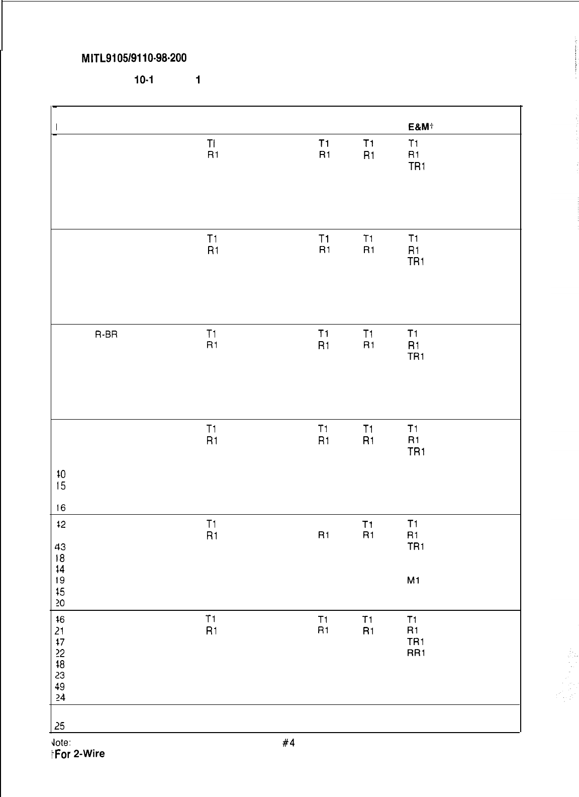
TABLE
10-l
SHELF
1
EXTERNAL PLUG AND JACK CONNECTIONS (CONT’D)
G P3 (Connects to Cross Connect Field)
Pin
26
1
27
2
28
3
29
4
30
5
31
6
32
7
33
8
34
9
3.5
10
36
11
37
12
38
13
39
14
10
15
$1
16
$2
17
$3
18
$4
19
15
?O
$6
?l
$7
?2
$8
23
$9
24
50
25
1
‘
1
Pair Lead Designation
Color
Line
W-BL
TI
BL-W
RI
w-o
T2
o-w
R2
W-G
T3
G-W
R3
W-BR
T4
BR-W
R4
w-s
Tl
s-w
Rl
R-BL T2
BL-R R2
R-O T3
O-R R3
R-G T4
G-R R4
R-BR
Tl
BR-R
Rl
R-S T2
S-R R2
BK-BL T3
BL-BK R3
BK-0
T4
0-BK
R4
BK-G
Tl
G-BK
Rl
BK-BR T2
BR-BK R2
BK-S T3
S-BK
R3
Y-BL T4
BL-Y
R4
Y-O
Tl
O-Y
Rl
Y-G
T2
G-Y
R2
Y-BR
T3
BR-Y
R3
Y-S
T4
S-Y
R4
v-BL
Ti
BL-V
Rl
v-o
T2
o-v
R2
V-G
T3
G-V
R3
V-BR
T4
BR-V
R4
v-s SPARE
s-v SPARE
Lead Designation Trunks
co
DID/TIE
E&M:
Tl Tl
Tl
Rl Rl Rl
XT2
TRl
XT1 RR1
T2
El
R2
Ml
Tl
Tl Tl
Rl RI Rl
XT2
TRl
XT1 RR1
T2
El
R2
Ml
Tl
Tl Ti
Rl Rl Rl
XT2
TRl
XT1 RR1
T2 El
R2
Ml
Tl Tl Tl
Rl Rl Rl
XT2
TRl
XT1 RR1
T2
El
R2
Ml
Tl
Tl
Tl
RI Rl RI
XT2
TRI
XT1 RR1
T2
El
R2
Ml
Tl Tl Tl
Rl Rl Rl
XT2
TRl
XT1 RR1
T2
El
R2
Ml
SPARE
SPARE
Card
Positions
7
8
9
10
11
12
See Note
dote: Position 12 can be used for lines, trunks, or receiver
#4
card.
IFor
2-Wire
E&M Trunk operation DO NOT connect RR and TR leads
Page 24
SECTION MITL91051911 O-98-200
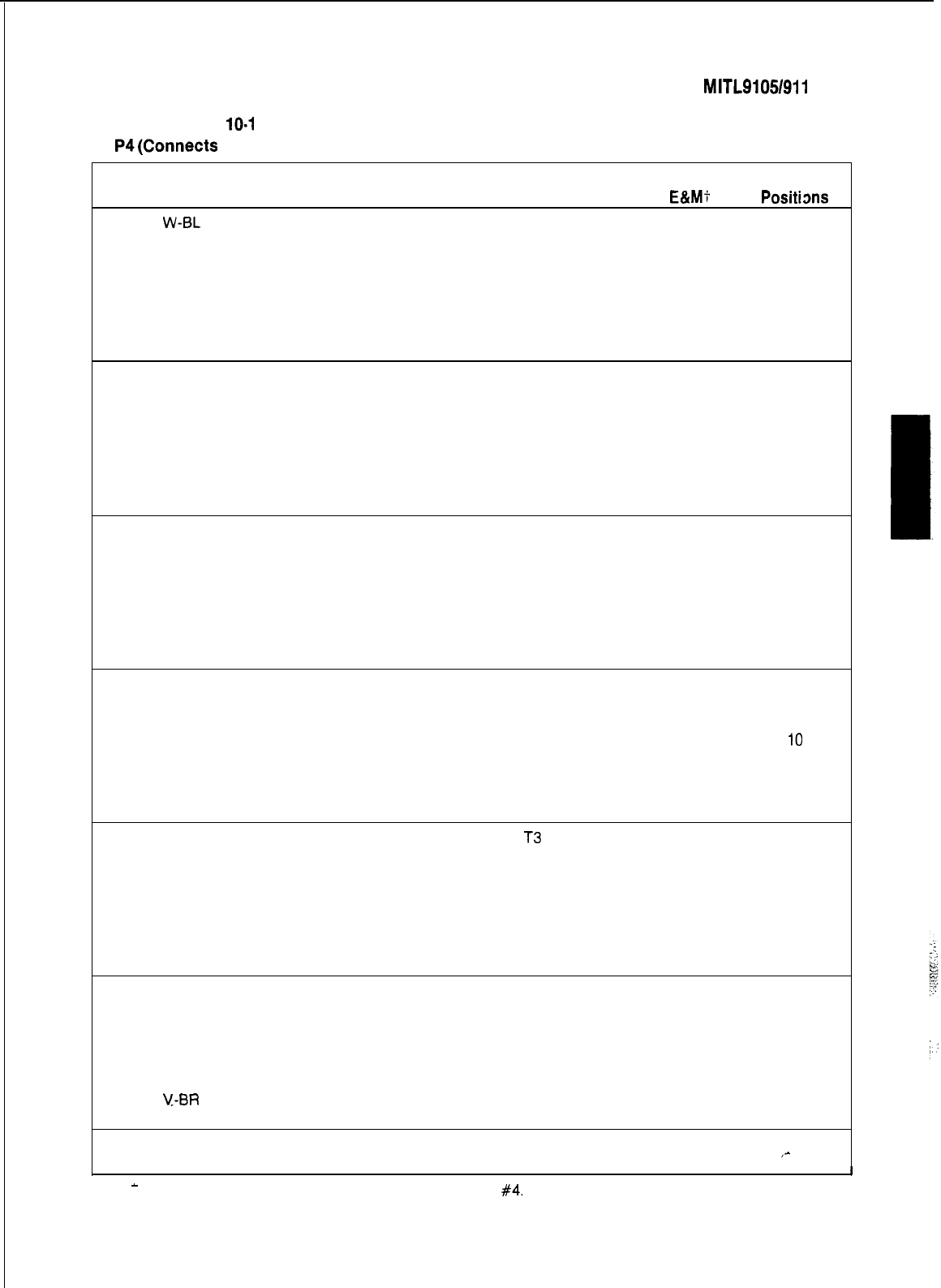
TABLE
10-l
SHELF 1 EXTERNAL PLUG AND JACK CONNECTIONS (CONT’D)
PLUG P4(Connects to Cross Connect Field)
Pair
Lead Designation Lead Designation Trunks
Card
Pin
Color
Lines
co DID/TIE
E&Mt Positims
26
w-BL
T5 T3 T2 T2
1
BL-w
R5 R3 R2 R2
27
w-o
T6
XT4
TR2
2
o-w
R6
XT3
RR2
7
28
W-G
T7
T4
E2
3
G-W
R7 R4
M2
29
W-BR
T8
4
BR-W
R8
30
w-s
T5 T3 T2 T2
5
s-w
R5 R3 R2 R2
31
R-BL T6
XT4
TR2
6
BL-R R6
XT3
RR2
32 R-O T7 T4 E2 8
7
O-R R7 R4 M2
33 R-G T8
8
G-R R8
34 R-BR T5 T3 T2 T2
9
BR-R R5 R3 R2 R2
35 R-S T6
XT4 TR2
10
S-R R6
XT3
RR2
36 BK-BL T7 T4 E2
9
11
BL-BK R7 R4 M2
37
BK-0
T8
12
0-BK
R8
38 BK-G T5
T3
T2 T2
13
G-BK
R5 R3 R2 R2
39 BK-BR T6
XT4
TR2
14
BR-BK
R6
XT3
RR2
10
40 BK-S T7
T4
E2
15
S-BK
R7 R4 M2
41
Y-BL
T8
16
BL-Y
R8
42
Y-O
T5 13 T2 T2
17
O-Y
R5 R3 R2 R2
43
Y-G
T6
XT4
TR2
18
G-Y
R6
XT3
RR2
44
Y-BR
T7 T4 E2
11
19
BR-Y
R7 R4
M2
45
Y-S
T8
20
S-Y
R8
46
V-BL
T5 T3 T2 T2
21
BL-V
R5 R3 R2 R2
47
v-o
T6
XT4 TR2
22
o-v
R6
XT3
RR2
48
V-G
T7 T4 E2
12
23
G-V
R7 R4
M2
See Note
49
V-BR
T8
24
BR-V
R8
50
v-s SPARE SPARE
,-
25
s-v SPARE SPARE
-
Note: Position 12 can be used for lines. trunks or receiver card
#4.
i-For P-Wire E&M Trunk operation DO NOT connect RR and TR leads
-I
Page 25
SECTION
MITL9105/9110-98-200
PLUG P5
TABLE
10-l
(Connects to
SHELF 1
Plug P17)
EXTERNAL PLUG
AND
JACK CONNECTIONS (CONT’D)
Pin
Pair
Color Lead Designation
Line Lead Designation Trunks
co DID/TIE
E&M:
Card
Positions
26
1
27
2
28
3
29
4
W-BL
BL-W
w-o
o-w
W-G
G-W
W-BR
%R-W
Tl
Rl
T2
R2
T3
R3
T4
R4
Tl
Rl
XT2
XT1
T2
R2
Tl
Rl
Tl
Rl
TRl
RR1
El
Ml
13
See Note
30
w-s
5
s-w
31
R-BL
6
BL-R
32 R-O
7
O-R
33 R-G
8G-R
Tl
RI
T2
R2
T3
R3
T4
R4
Tl
Rl
XT2
XT1
T2
R2
Tl
Rl
Tl
Rl
TRl
RR1
El
Ml
14
See Note
34
9
35
10
36
11
37
12
R-BR
BR-R
R-S
S-R RECEIVER No. 1
15
BK-BL
BL-BK
BK-0
0-BK
38
13
39
14
40
15
41
16
BK-G
G-BK
BK-BR
BR-BK
BK-S
S-BK
Y-BL
BL-Y
-I-
(4
R
(A)
S DATA OUT T (A)
S DATA OUT
R
(A)
S DATA IN T (A)
S DATA ON
R
(A)
PA2 Control B
PA2 Control A
ATTENDANT CONSOLE
No. 216
42
17
43
18
44
19
45
20
Y-O
O-Y
Y-G
G-Y
Y-BR
BR-Y
Y-S
S-Y
T
(A)
R
(A)
S DATA OUT T (A)
S DATA OUT
R
(A)
S DATA IN T (A)
S DATA IN
R
(A)
PA1 Control B
PA1 Control A
ATTENDANT CONSOLE
No. 1 17
46
V-BL
21
BL-V
MUSIC IN B
MUSIC IN A MUSIC ON HOLD
47
v-o SPARE
22
o-v SPARE
18
48
V-G PA1 OUT B
23
G-V PA1 OUT A
49
V-BR PA2 OUT B
24
BR-V PA2 OUT A
50
v-s SPARE SPARE
25
s-v SPARE SPARE
Note: Positions 14 and 13 can be used for lines or trunks, or for receiver cards
#2
and
#3
respectively.
tFor
2-Wire
E&M Trunk operation DO NOT connect RR and TR leads
Page 28
SECTION
MITL910519110-98-200
j
TABLE
10-l
SHELF 1 EXTERNAL PLUG AND JACK CONNECTIONS (CONT’D)
PLUG P8 (Connects to Plug P18)
Pin
?6
1
?7
2
?8
3
29
4
30
5
31
6
32
7
33
8
34
9
35
10
36
11
37
12
38
13
39
14
10
15
$1
16
$2
17
$3
18
t4
19
$5
20
16
21
17
22
$8
23
49
24
50
25
Pair
Color
W-EL
BL-W
w-o
o-w
W-G
G-W
W-BR
BR-W
w-s
s-w
R-BL
BL-R
R-O
O-R
R-G
G-R
R-BR
BR-R
R-S
S-R
BK-BL
BL-BK
BK-0
0-BK
BK-G
G-BK
BK-BR
BR-BK
BK-S
S-BK
Y-BL
BL-Y
Y-O
O-Y
Y-G
G-Y
Y-BR
BR-Y
Y-S
S-Y
V-BL
BL-V
v-o
o-v
V-G
G-V
V-BR
BR-V
v-s
s-v
Lead Designation
Lead Designation Trunks
Card
Line
co DID/TIE
E&M?
Positions
T5
Tl Tl Tl
R5
Rl Rl Rl
T6
13
XT2
TRl
R6 Lines
XT1
RR1 See Note
T7 T2 El
R7
T8 R2
Ml
R8
T5
Tl Tl Tl
R5
Rl Rl Rl
T6
Lines
’
XT2
TRl
R6
XT1
RR1
14
T7
T2 El
See Note
R7
T8 R2
Ml
R8
RECEIVER No. 1
15
T
(4
R
(A)
S DATA OUT T(B) ATTENDANT CONSOLE
S DATA OUT R(B) SPARE
S DATA IN T(B)
16
S DATA IN R(B)
NOT USED
R(Kl)
Kl
NIGHT BELL 1
(See Notes for Plug P18)
T(A)
W-V
S DATA OUT T(B) MAINTENANCE
S DATA OUT R(B) CONSOLE
17
S DATA IN T(B)
S DATA IN R(B)
UART IN
UART OUT
YW
K5 NIGHT BELL 1
RF41
K4
NIGHT SERVICE
18
WW
NIGHT BELL 3
(See Notes For Plug
Pi8
K3
WW
K2 NIGHT BELL 2
(See Notes for Plug
P18:
SPARE SPARE
,-
SPARE SPARE
:
-..
‘.
Note: Positions 14 and 13 can be used for lines or trunks or for receiver cards
#2
and
#3
respectively.
tFor
P-Wire E&M Trunk operation DO NOT connect RR and TR leads
Page 27
SECTION
MITL9105/9110-98.200
TABLE
10-2
INTERCONNECT BOARD PLUG AND JACK CONNECTIONS
CONNECTOR J13 MAINTENANCE CONSOLE CONNECTOR J14 ATTENDANT CONSOLE NO 2
(Connected
To
Maintenance
Panel)
Pin
26
1
27
2
28
3
29
4
30
5
31
6
32
7
33
8
34
9
35
10
36
11
37
12
38
13
39
14
40
15
41
16
42
17
43
18
44
19
45
20
46
21
47
22
48
23
49
24
50
25
Pair
Color Lead Designation
W-BL ELECTROSTATIC GROUND
BL-W ELECTROSTATIC GROUND
w-o ELECTROSTATIC GROUND
o-w ELECTROSTATIC GROUND
W-G ELECTROSTATIC GROUND
G-W ELECTROSTATIC GROUND
W-BP
ELECTROSTATIC GROUND
BR-W
ELECTROSTATIC GROUND
w-s DATA IN COMMON
s-w DATA IN
R-BL
ELECTROSTATIC GROUND
BL-R
ELECTROSTATIC GROUND
R-O
DATA OUT COMMON
O-R
DATA 0
UT
R-G ELECTROSTATIC GROUND
G-R ELECTROSTATIC GROUND
R-BR
ELECTROSTATIC GROUND
BR-R
ELECTROSTATIC GROUND
R-S
CUTOVER SWB
S-R
CUTOVER SWA
BK-BL
ELECTROSTATIC GROUND
BL-BK
ELECTROSTATIC GROUND
BK-0 MAJOR ALARM
0-BK MAJOR ALARM
BK-G
TIP
G-BK
RING
BK-BR
ELECTROSTATIC GROUND
BR-BK
ELECTROSTATIC GROUND
BK-S
ELECTROSTATIC GROUND
S-BK
ELECTROSTATIC GROUND
Y-BL ELECTROSTATIC GROUND
BL-Y
ELECTROSTATIC GROUND
Y-O ELECTROSTATIC GROUND
O-Y ELECTROSTATIC GROUND
Y-G ov
G-Y
-46V
Y-BR
OV
BR-Y -48V
Y-S
ov
S-Y -48V
V-BL
OV
BL-V -48V
v-o ov
o-v -48V
V-G ov
G-V -48V
V-BR
OV
BR-V -48V
v-s ov
s-v -48V
ee Note For
515)
Pin
26
1
27
2
26
3
29
4
30
5
31
6
32
7
33
8
34
9
35
10
36
11
37
12
38
13
39
14
40
15
41
16
42
17
43
18
44
19
45
20
46
21
47
22
48
23
49
24
50
25
Pair
Color Lead Designation
W-BL
ELECTROSTATIC GROUND
BL-W
ELECTROSTATIC GROUND
w-o ELECTROSTATIC GROUND
o-w ELECTROSTATIC GROUND
W-G
ELECTROSTATIC GROUND
G-W ELECTROSTATIC GROUND
W-BR
ELECTROSTATIC GROUND
BR-W
ELECTROSTATIC GROUND
w-s DATA IN COMMON
s-w DATA IN
R-BL
ELECTROSTATIC GROUND
BL-R
ELECTROSTATIC GROUND
R-O
DATA OUT COMMON
O-R
DATA OUT
R-G ELECTROSTATIC GROUND
G-R ELECTROSTATIC GROUND
-~-__
R-BR
ELECTROSTATIC GROUND
BR-R
ELECTROSTATIC GROUND
R-S
CUTOVER SWB
S-R
CUTOVER SWA
BK-BL
ELECTROSTATIC GROUND
BL-BK
ELECTROSTATIC GROUND
BK-0 MAJOR ALARM
0-BK MAJOR ALARM
BK-G
TIP
G-BK
RING
BK-BR
ELECTROSTATIC GROUND
BR-BK
ELECTROSTATIC GROUND
BK-S
ELECTROSTATIC GROUND
S-BK
ELECTROSTATIC GROUND
Y-BL ELECTROSTATIC GROUND
BL-Y
ELECTROSTATIC GROUND
Y-O ELECTROSTATIC GROUND
O-Y ELECTROSTATIC GROUND
Y-G
ov
G-Y -48V
Y-BR
OV
BR-Y -48V
Y-S ov
S-Y -48V
V-BL
OV
BL-V
-46V
v-o ov
o-v -48V
V-G ov
G-V -48V
V-BR
OV
BR-V -48V
v-s ov
s-v -48V
Page 28
:

SECTION
MITL9105/9110-98-200
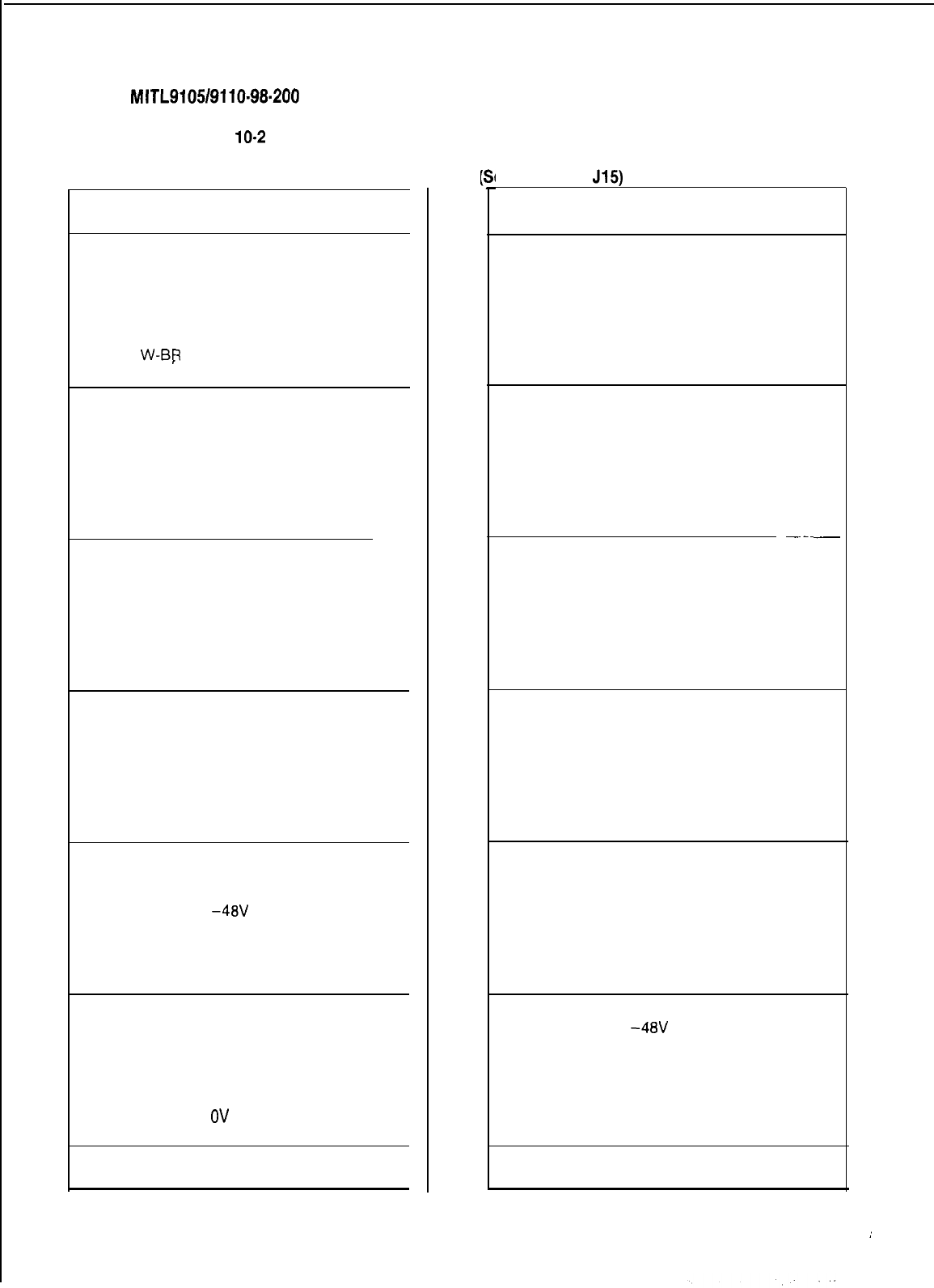
TABLE
10-2
INTERCONNECT BOARD PLUG AND JACK CONNECTIONS (CONT’D)
CONNECTOR J15 ATTENDANT CONSOLE NO 1
(See Note)
Pin Pair
Color Lead Desianation
26
W-BL
1
BL-W
27
w-o
2
o-w
28 W-G
3
G-W
29 W-BR
4BR-W
ELECTROSTATIC GROUND
ELECTROSTATIC GROUND
ELECTROSTATIC GROUND
ELECTROSTATIC GROUND
ELECTROSTATIC GROUND
ELECTROSTATIC GROUND
ELECTROSTATIC GROUND
ELECTROSTATIC GROUND
30 w-s
5s-w
31
R-BL
6BL-R
32 R-O
7O-R
33
R-G
8
G-R
DATA IN COMMON
DATA IN
ELECTROSTATIC GROUND
ELECTROSTATIC GROUND
DATA OUT COMMON
DATA 0 UT
ELECTROSTATIC GROUND
ELECTROSTATIC GROUND
34 R-BR
9BR-R
35 R-S
IO S-R
36 BK-BL
11
BL-BK
37
BK-0
12
0-BK
38 BK-G
13
G-BK
39 BK-BR
14
BR-BK
40 BK-S
15
S-BK
41
Y-BL
16 BL-Y
ELECTROSTATIC GROUND
ELECTROSTATIC GROUND
CUTOVER SWB
CUTOVER SWA
ELECTROSTATIC GROUND
ELECTROSTATIC GROUND
MAJOR ALARM
MAJOR ALARM
TIP
RING
ELECTROSTATIC GROUND
ELECTROSTATIC GROUND
ELECTROSTATIC GROUND
ELECTROSTATIC GROUND
ELECTROSTATIC GROUND
ELECTROSTATIC GROUND
42
Y-O
17
O-Y
43
Y-G
18
G-Y
44
Y-BR
19
BR-Y
45
Y-S
20
S-Y
ELECTROSTATIC GROUND
ELECTROSTATIC GROUND
ov
-48V
ov
-48V
ov
-48V
46
V-BL
21
BL-V
47
v-o
22
o-v
48
V-G
23
G-V
49
V-BR
24
BR-V
ov
-48V
ov
-48V
ov
-48V
ov
-48V
50
v-s
ov
25
s-v -48V
NOTE: Connector J15 connected either direct to
Attendant Console 1 or via plug P23 and
jack J22 to console. Connector
J14
similarly connected either direct to at-
tendant console 2 or via plug P25 and
jack J22.
Page29

SECTION
MITL9105/9110-98.200
TABLE
10-2
INTERCONNECT BOARD PLUG AND JACK CONNECTIONS (CONT’D)
PLUG P18 (Interconnect Cable to P8)
Pin
26
1
27
2
28
3
29
4
30
5
31
6
32
7
33
8
34
9
35
10
36
11
37
12
38
13
39
14
40
15
41
16
42
17
43
18
44
19
45
20
46
21
47
22
48
23
49
24
50
25
Pair
Color
w-BL
BL-W
w-o
o-w
W-G
G-W
W-BR
BR-W
w-s
s-w
R-BL
BL-R
R-O
O-R
R-G
G-R
R-BR
BR-R
R-S
S-R
BK-BL
BL-BK
BK-0
0-BK
BK-G
G-BK
BK-BR
BR-BK
BK-S
S-BK
Y-BL
BL-Y
Y-O
O-Y
Y-G
G-Y
Y-BR
BR-Y
Y-S
S-Y
V-BL
BL-V
v-o
o-v
V-G
G-V
V-BR
BR-V
v-s
s-v
Lead Designation
Line
T5
R5
T6
R6
T7
R7
T8
R8
T5
R5
T6
R6
T7
R7
T8
R8
SPARE
SPARE
SPARE
SPARE
SPARE
SPARE
NIGHT BELL 1 B
NIGHT BELL IA
TIP
RING
DATA IN COMMON
DATA IN
DATA OUT COMMON
DATA OUT
UART B
UART A
ALARM B
ALARM A
NIGHT SERVICE B
NIGHT SERVICE A
NIGHT BELL
38
NIGHT BELL 3A
NIGHT BELL
2B
NIGHT BELL
2A
SPARE
SPARE
Lead Designation Trunks
co
DID/TIE E&M-f
T3 T2 T2
R3 R2 R2
TX3
TR2
RX4 RR2
T4
E2
R4
M2
T3 T2 T2
R3 R2 R2
TX3
TR2
RX4 RR2
T4 E2
R4
M2
RECEIVER 1
See Notes for Plug P18
MAINTENANCE
CONSOLE
See Notes for Plug P18
See Notes for Plug P18
Card
Positions
13
14
15
16
17
18
tFor
2-Wire
E&M Trunk
operation DO
NOT connect
RR and TR leads
Page 30

SECTION
MITL9105/9110~98-200
TABLE
IO-2
INTERCONNECT BOARD PLUG AND JACK CONNECTIONS (CONT’D)
PLUG
PI7
(Interconnect Cable to P5)
Pin
26
1
27
2
28
3
29
4
30
5
31
6
32
7
33
8
34
9
35
10
36
11
37
12
38
13
39
14
40
15
41
16
42
17
43
18
44
19
45
20
46
21
47
22
48
23
49
24
50
25
Pair
Color
W-BL
BL-W
w-o
o-w
W-G
G-W
W-BR
BR-W
w-s
s-w
R-BL
BL-R
R-O
O-R
R-G
G-R
R-BR
BR-R
R-S
S-R
BK-BL
BL-BK
BK-0
0-BK
BK-G
G-BK
BK-BR
BR-BK
BK-S
S-BK
Y-BL
BL-Y
Y-O
O-Y
Y-G
G-Y
Y-BR
BR-Y
Y-S
S-Y
V-BL
BL-V
v-o
o-v
V-G
G-V
V-BR
BR-V
v-s
s-v
Lead Designation
Line
Tl
Rl
T2
R2
T3
R3
T4
R4
Tl
Rl
T2
R2
T3
R3
T4
R4
TIP (A)
RING (A)
S DATA IN
R
(A)
S DATA IN T (A)
S DATA OUT
R
(A)
S DATA OUT T (A)
PA2 CONTROL B
PA2 CONTROL A
TIP
RING
DATA IN COMMON
DATA IN
DATA OUT COMMON
DATA OUT
PA1 CONTROL B
PA1 CONTROL A
MUSIC IN B
MUSIC IN A
MAINT TIP
MAINT
RING
PA1 OUT B
PA1 OUT A
PA2 OUT B
PA2 OUT A
SPARE
SPARE
Lead Designation Trunk
co
DID/TIE E&M:
TI
Tl
Tl
Rl Rl Rl
XT2
TRl
XT1 RR1
T2 El
R2
Ml
Tl Tl Tl
Rl Rl Rl
XT2
TRl
XT1 RR1
T2
El
R2
Ml
RECEIVER 1
ATTENDANT
CONSOLE
No. 2
ATTENDANT
CONSOLE
No. 1
(See Notes For
Plug P18)
Card
Position
13
14
15
16
17
18
,-
tFor
a-Wire
E&M Trunk operation DO NOT connect RR and TR leads
Page 31
SECTION
MITL9105/9110-98-200
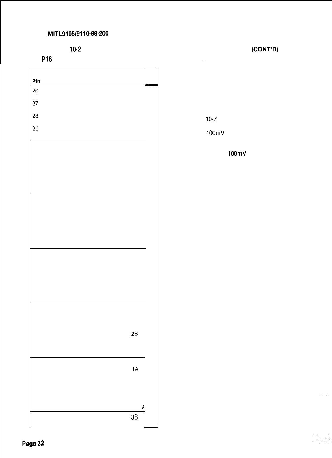
TABLE
10-2
INTERCONNECT BOARD PLUG AND JACK CONNECTIONS
(CONT’D)
PLUG
PI8
(Miscellaneous Connections to Cross Connect Field)
‘in
!6
1
?7
2
28
3
29
4
30
5
31
6
32
7
33
8
34
9
35
10
36
11
37
12
38
13
39
14
40
15
41
16
42
17
43
18
44
19
45
20
46
21
47
22
48
23
49
24
50
25
Pair
Color
w-BL
BL-W
w-o
o-w
W-G
G-W
W-BR
BR-W
w-s
s-w
R-BL
BL-R
R-O
O-R
R-G
G-R
R-BR
BR-R
R-S
S-R
BK-BL
BL-BK
BK-0
0-BK
BK-G
G-BK
BK-BR
BR-BK
BK-S
S-BK
Y-BL
BL-Y
Y-O
O-Y
Y-G
G-Y
Y-BR
BR-Y
Y-S
S-Y
V-BL
BL-V
v-o
o-v
V-G
G-V
V-BR
BR-V
v-s
s-v
Lead
Designation
SPARE
SPARE
SPARE
SPARE
SPARE
SPARE
SPARE
SPARE
SPARE
SPARE
SPARE
SPARE
SPARE
SPARE
SPARE
SPARE
SPARE
SPARE
SPARE
SPARE
SPARE
SPARE
SPARE
SPARE
SPARE
SPARE
SPARE
SPARE
SPARE
MUSIC IN B
MUSIC IN A
PA2 OUT B
PA2 OUT A
NIGHT BELL
28
NIGHT BELL 2A
PA1 OUT B
PA1 OUT A
NIGHT BELL 1 B
NIGHT BELL
1A
PA 1 CONTROL
B
PA 1 CONTROL A
PA 2 CONTROL
B
PA 2 CONTROL A
NIGHT SERVICE E
NIGHT SERVICE
P
NIGHT BELL
38
NIGHT BELL 3A
Note:
(1) Night service relay operates permanently when
in night service.
Night Bell continuous rating:
Open circuit voltage 120Vrms
Closed circuit current 75mArms
See Fig.
10-7
for connections
(2) Music in
1OOmV
Impedance 600 Ohms
(3) PA Output Level
1OOmV
Impedance 600 Ohms
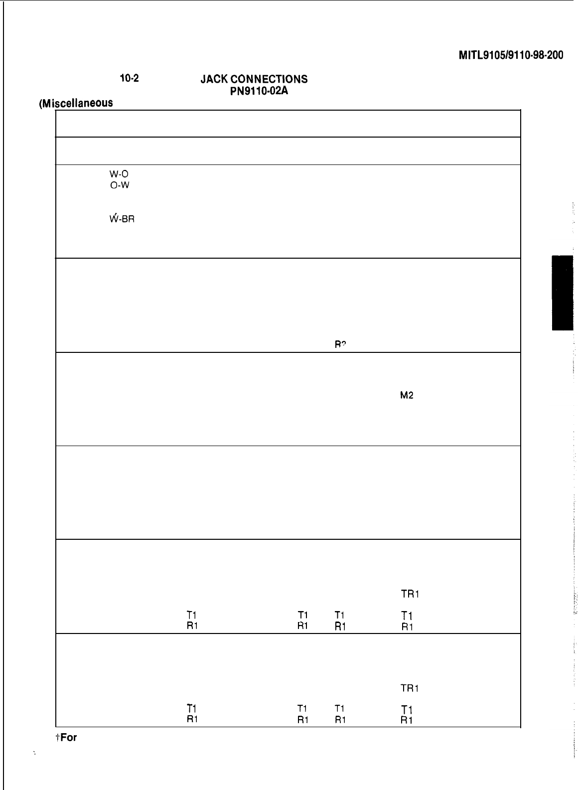
SECTION
MITL9105/9110-98-200
:
TABLE
10-2
PLUG AND
JACK
CONNECTlONS
PLUG PI9 ON INTERCONNECT CARD
PN9110-02A
iscellaneous
Connections to Cross Connect Field)
(M
Pin
26
Pair Lead Line
Color Designation
W-BL SPARE
Lead Designation Trunk
CARD
co DID/TIE E&M: POSITIONS
1
BL-W SPARE
27
2
28
3
29
4
30
5
w-o
o-w
W-G
G-W
RECEIVER 1
ti-BR
15
BR-W
w-s
s-w
31
R-BL
T8
6
BL-R R8
32 R-O
T7 T4
E2
7
O-R R7 R4
M2 14
33
R-G
T6
XT3
TR2
8
G-R
R6
XT4
RR2
34 R-BR
T5
T3 T2 T2
9BR-R R5
R3
R’
R2
35 R-S
10 S-R
36 BK-BL
11
BL-BK
37
BK-0
12
0-BK
38 BK-G
13
G-BK
T8
R8
T7 T4 E2
R7 R4
T6
XT3
M2
13
TR2
R6
XT4
RR2
T5 T3 T2
T2
R5
R3 R2
R2
39 BK-BR
14 BR-BK
40 BK-S
15
S-BK
RECEIVER 115
41
Y-BL
16
BL-Y
42
Y-O
17
O-Y
43
Y-G T4
18
G-Y
R4
44
Y-BR
T3 T2
El
19
BR-Y
R3 R2
Ml 14
45
Y-S
T2 XT1
TRl
20
S-Y
R2
XT2
RR1
46
V-BL
Tl Tl Tl
Tl
21
BL-V
Rl
Rl
Rl Rl
47
v-o
T4
22
o-v
R4
48
V-G
T3 T2
El
23
G-V
R3 R2
Ml
49
V-BR
T2 XT1
TRl
13
24
BR-V
R2
XT2
RR1
50
v-s
Tl Tl Tl
Tl
/-
25
s-v
Rl Ri Rl Rl
TO INTERCONNECT BOARD (CONT’D)
I-For
P-Wire E&M Trunk operation DO NOT connect RR and TR leads
:
Page33 I
SECTION
MITL910519110~98~200
TABLE
IO-2
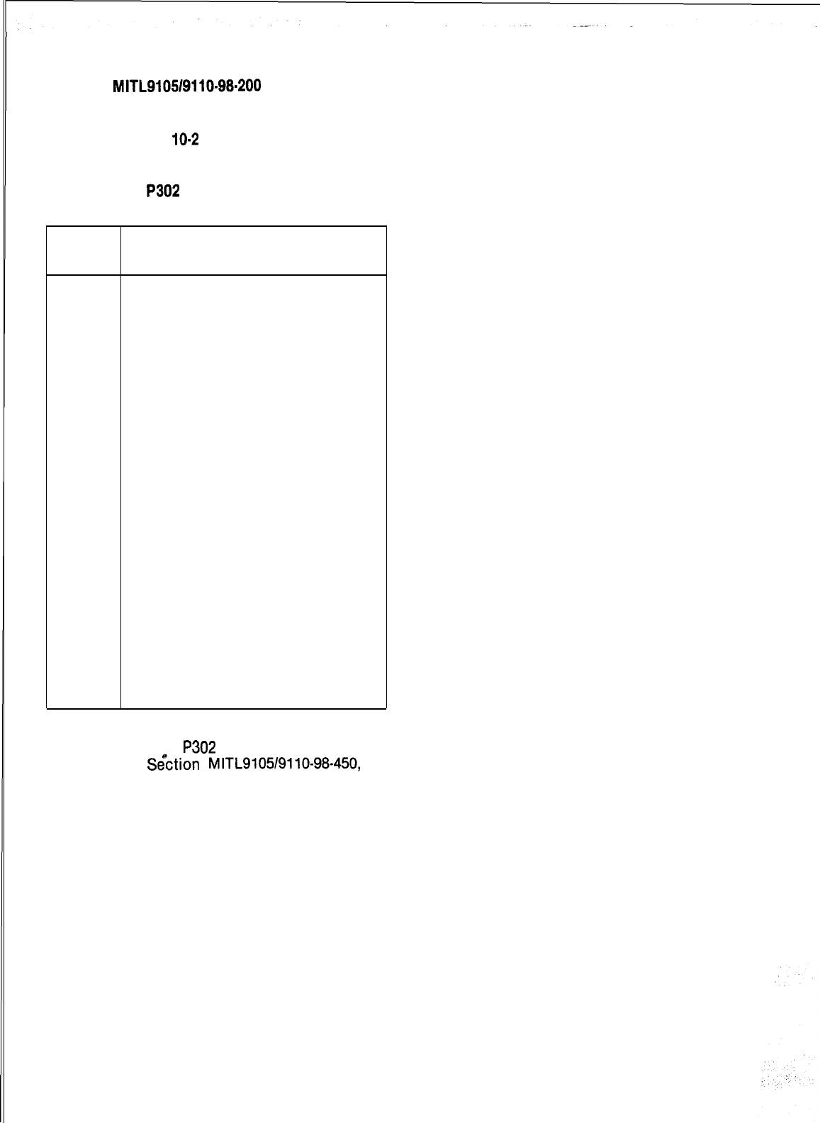
INTERCONNECT BOARD PLUG AND JACK CONNECTIONS (CONT’D)
CONNECTOR
P302
DATA PORT (SEE NOTES)
Pin
1
2
3
4
5
6
7
8
9
10
11
12
13
14
15
16
17
18
19
20
21
22
23
24
25
Lead
Designation
ov
TRANSMIT DATA
RECEIVE DATA
CLEAR TO SEND
DATA SET READY
SIGNAL GROUND
CARRIER DETECT
DATA TERM READY
Note 1. Connector
P302
is common to the SX-100 and SX-200 PABX.
2.
See
S&.ztion
MITL9105/9110-98-450,
Traffic Measurement, for applications of the connector.
Page 34
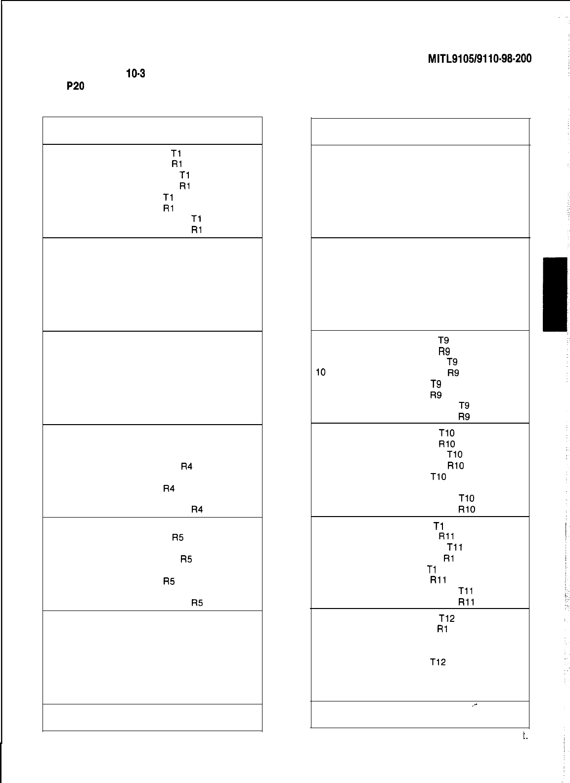
SECTION
MITL9105/9110-98-200
TABLE
10-3
POWER FAIL TRANSFER BOARD PLUG AND JACK CONNECTIONS
PLUG
P20
(Power Fail Transfer Connections to Cross
Connect Field)
Pin
26
1
27
2
28
3
29
4
30
5
31
6
32
7
33
8
34
9
35
10
36
11
37
12
38
13
39
14
40
15
41
16
42
17
43
18
44
19
45
20
46
21
47
22
48
23
49
24
50
25
Pair Lead
Color
Designation
W-BL STATION
Tl
BL-W STATION
RI
w-o LINE CARD
Tl
o-w LINE CARD
Rl
W-GR TRUNK
Tl
GR-W TRUNK
Rl
W-BR TRUNK CARD
Tl
BR-W TRUNK CARD
Rl
w-s STATION T2
s-w STATION R2
R-BL
LINE CARD T2
BL-R LINE CARD R2
R-O TRUNK T2
O-R TRUNK R2
R-G
TRUNK CARD T2
G-R.
TRUNK CARD R2
R-BR
STATION T3
BR-R
STATION R3
R-S
LINE CARD T3
S-R LINE CARD R3
BK-BL TRUNK T3
BL-BK TRUNK R3
BK-0 TRUNK CARD T3
0-BK TRUNK CARD R3
BK-G STATION T4
G-BK STATION R4
BK-BR
LINE CARD T4
BR-BK LINE CARD
R4
BK-S
TRUNK T4
S-BK TRUNK
R4
Y-BL TRUNK CARD T4
BL-Y TRUNK CARD
R4
Y-O STATION T5
O-Y STATION
R5
Y-G LINE CARD T5
G-Y LINE CARD
R5
Y-BR
TRUNK T5
BR-Y TRUNK
R5
Y-S TRUNK CARD T5
S-Y TRUNK CARD
R5
V-BL STATION T6
BL-V STATION R6
v-o
LINE CARD T6
o-v
LINE CARD R6
V-G TRUNK T6
G-V
TRUNK R6
V-BR TRUNK CARD T6
BR-V
TRUNK CARD R6
v-s SPARE
s-v SPARE Note:
PLUG P21
(Power Fail Transfer Connections to Cross
Connect Field)
Pin
26
1
27
2
28
3
29
4
30
5
31
6
32
7
33
8
34
9
35
IO
36
11
37
12
38
13
39
14
40
15
41
16
42
17
43
18
44
19
45
20
46
21
47
22
48
23
49
24
50
25
Pair
Color Lead Designation
W-BL STATION T7
BL-W
STATION R7
w-o
LINE CARD T7
o-w
LINE CARD R7
W-G
TRUNK T7
G-W
TRUNK R7
W-BR TRUNK CARD T7
BR-W TRUNK CARD R7
w-s STATION T8
s-w STATION R8
R-BL LINE CARD T8
BL-R LINE CARD R8
R-O TRUNK T8
O-R TRUNK R8
R-G
TRUNK CARD T8
G-R TRUNK CARD R8
R-BR
STATION
T9
BR-R
STATION
R9
R-S
LINE CARD
T9
S-R
LINE CARD
R9
BK-BL
TRUNK
T9
BL-BK
TRUNK
R9
BK-0 TRUNK CARD
T9
0-BK TRUNK CARD
R9
BK-G
STATION
TlO
G-BK STATION
RlO
BK-BR
LINE CARD
TIO
BR-BK
LINE CARD
RlO
BK-S
TRUNK
TlO
S-BK TRUNK RIO
Y-BL TRUNK CARD
TlO
BL-Y TRUNK CARD
RlO
Y-O
STATION
Tl
1
O-Y STATION
Rll
Y-G LINE CARD
Tll
G-Y
LINE CARD
RI
1
Y-BR
TRUNK
Tl
1
BR-Y TRUNK
Rll
Y-S TRUNK CARD
Tll
S-Y TRUNK CARD
Rll
V-BL STATION
T12
BL-V STATION
RI
2
v-o
LINE CARD T12
o-v
LINE CARD R12
V-G TRUNK
T12
G-V
TRUNK R12
V-BR TRUNK CARD T12
BR-V
TRUNK CARD R12,-
v-s SPARE
s-v SPARE
Plug 21 is not installed on SX-100 equipmenl
t.
Page 35138

SECTION
MITL9105/9110-98-200
TABLE
10-4
SHELF 2 EXTERNAL PLUG AND JACK CONNECTIONS
PLUG P7 (Connects to Cross Connect Field)
Pin
26
1
27
2
28
3
29
4
30
5
31
6
32
7
33
8
34
9
35
IO
36
11
37
12
38
13
39
14
40
15
41
16
42
17
43
18
44
19
45
20
46
21
47
22
48
23
49
24
50
25
-
Pair Lead Designation
Color
Line
W-BL
TI
BL-W
Rl
w-o
T2
o-w
R2
W-G T3
G-W
R3
W-BR T4
BR-W R4
w-s
Tl
s-w
Rl
R-BL T2
BL-R R2
R-O T3
O-R R3
R-G T4
G-R R4
R-BR
Tl
BR-R
Rl
R-S T2
S-R R2
BK-BL T3
BL-BK R3
BK-0
T4
0-BK
R4
BK-G
Tl
G-BK
Rl
BK-BR T2
BR-BK R2
BK-S T3
S-BK
R3
Y-BL
T4
BL-Y R4
Y-O
Tl
O-Y
RI
Y-G
T2
G-Y
R2
Y-BR
T3
BR-Y
R3
Y-S
T4
S-Y
R4
V-BL
Tl
BL-V
Rl
v-o
T2
,0-v
R2
V-G
T3
G-V
R3
V-BR
T4
B&V
R4
v-s SPARE
s-v SPARE
Lead Designation Trunks
co
DID/TIE E&M+
Tl
Tl Tl
Rl Rl Rl
XT2
TRl
XT1 RR1
T2
El
R2
Ml
Tl Tl Tl
Rl Rl Rl
XT2
TRl
XT1 RR1
T2
El
R2
Ml
Tl Tl Tl
Rl Rl Rl
XT2
TRl
XT1 RR1
T2
El
R2
Ml
Tl
Tl
Tl
Rl Rl Rl
XT2
TRl
XT1 RR1
T2
El
R2
Ml
Tl Tl Tl
Rl RI Rl
XT2
TRl
XT1 RR1
T2
El
R2
Ml
Tl
Tl
Tl
RI RI Rl
XT2
TRI
XT1 RR1
T2
El
R2
Ml
SPARE
SPARE
Card
Positions
1
2
3
4
5
6
,-
tFor
P-Wire E&M Trunk operation DO NOT connect RR and TR leads
,:
.
.
:
.-
Page 37
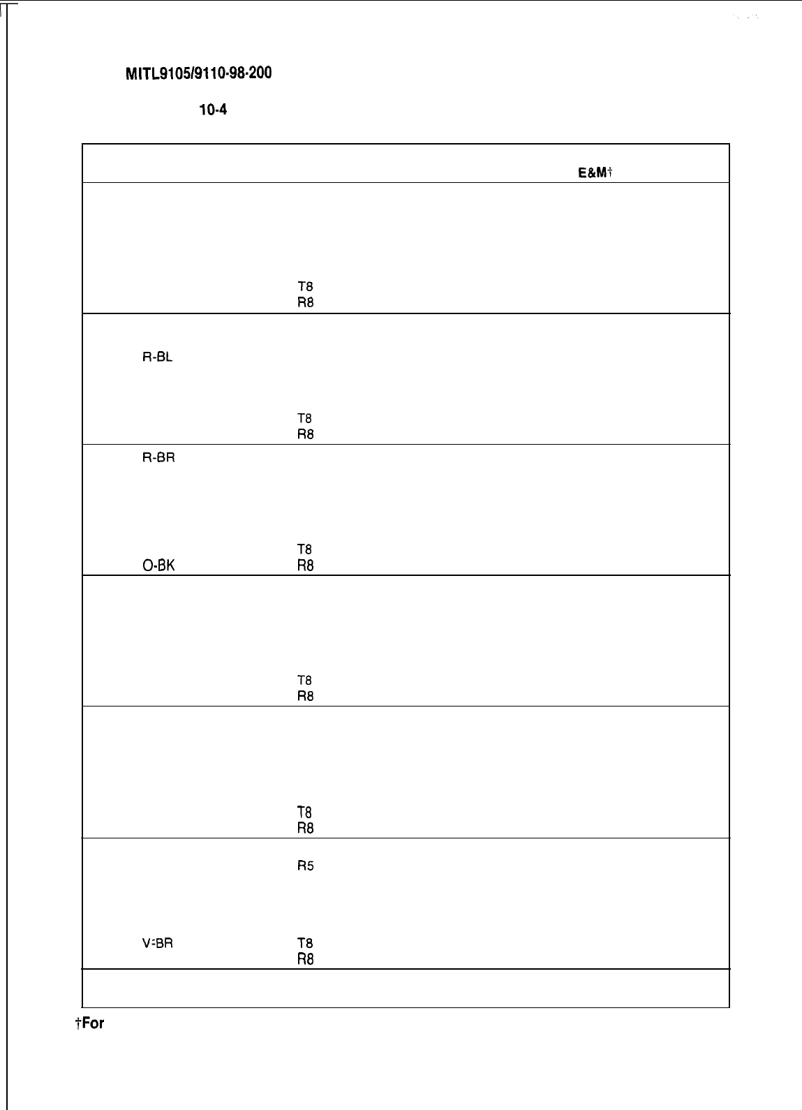
SECTION
MITL9105/9110-98-200
TABLE
10-4
SHELF 2 EXTERNAL PLUG AND JACK CONNECTIONS (CONT’D)
PLUG P8 (Connects to Cross Connect Field)
Pair
Lead Designation Lead Designation Trunks
Card
Pin
Color Lines co DID/TIE
E&M?
Positions
26
W-BL
T5 T3 T2 T2
1
BL-W R5 R3 R2 R2
27
w-o
T6
XT4
TR2
2
o-w
R6
XT3
RR2
1
28
W-G T7 T4
E2
3
G-W
R7 R4
M2
29 W-BR T8
4BR-W R8
30
W-S
T5 T3 T2 T2
5
s-w
R5 R3 R2 R2
31
R-BL T6
XT4
TR2
6
BL-R R6
XT3
RR2
32 R-O T7
T4
E2 2
7
O-R R7 R4
M2
33 R-G T8
8
G-R R8
34 R-BR T5 T3 T2 T2
9
BR-R R5 R3 R2 R2
35 R-S T6
XT4
TR2
10
S-R R6
XT3
RR2
36 BK-BL T7 T4 E2 3
11
BL-BK R7 R4 M2
37
BK-0
T8
12
0-BK
R8
38
BK-G
T5
T3 T2 T2
13
G-BK
R5 R3 R2 R2
39 BK-BR
T6 XT4 TR2
14
BR-BK R6
XT3
RR2 4
40 BK-S
T7 T4
E2
15
S-BK
R7 R4
M2
41
Y-BL
T8
16
BL-Y
R8
42
Y-O T5 T3 T2 T2
17
O-Y
R5 R3 R2 R2
43
Y-G T6 XT4
TR2
18
G-Y
R6
XT3
RR2
44
Y-BR
T7
T4
E2
5
19
BR-Y
R7 R4 M2
45
Y-S
T8
20
S-Y
R8
46
V-BL
T5 T3 T2 T2
21
BL-V
R5 R3 R2 R2
47
v-o
T6
XT4 TR2
22
o-v
R6
XT3
RR2
48
V-G T7 T4
E2
6
23
G-V
R7 R4
M2
49 VLBR
T8
24
BR-V
R8
50
v-s SPARE SPARE
25
s-v SPARE SPARE
tFor
P-Wire E&M Trunk operation DO NOT connect RR and TR leads
Page 38
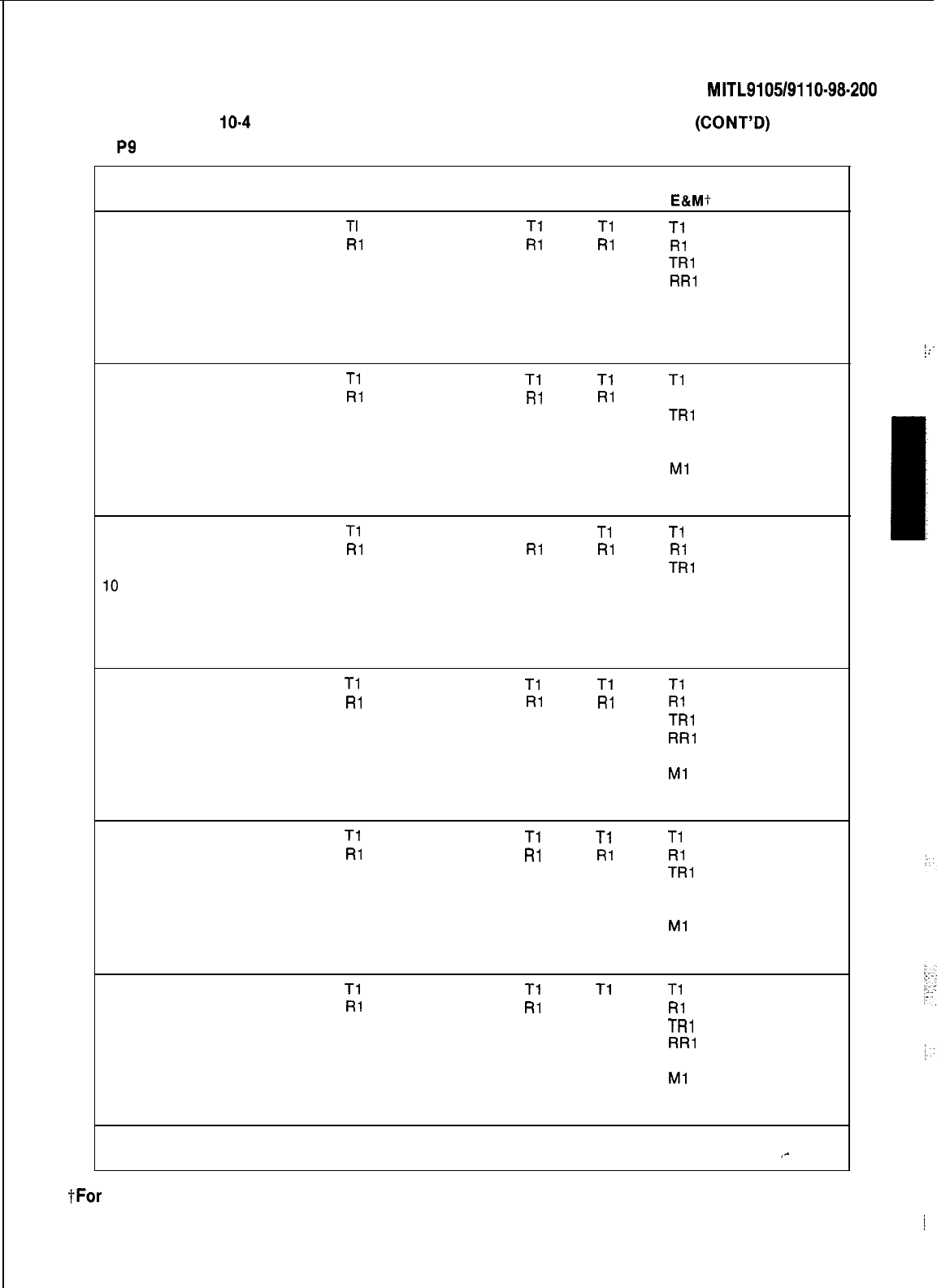
SECTION
MITL9105/9110-98-200
TABLE
10-4
SHELF 2 EXTERNAL PLUG AND JACK CONNECTIONS
(CONT’D)
PLUG
P9
(Connects to Cross Connect Field)
Pin
26
1
27
2
28
3
29
4
30
5
31
6
32
7
33
8
34
9
35
IO
36
11
37
12
38
13
39
14
40
15
41
16
42
17
43
18
44
19
45
20
46
21
47
22
48
23
49
24
50
25
Pair Lead Designation
Color Line
W-BL
TI
BL-W
Rl
w-o
T2
o-w
R2
W-G T3
G-W
R3
W-BR T4
BR-W
R4
w-s
Tl
s-w
RI
R-BL T2
BL-R R2
R-O T3
O-R R3
R-G
T4
G-R R4
R-BR
Tl
BR-R
RI
R-S T2
S-R R2
BK-BL T3
BL-BK R3
BK-0
T4
0-BK
R4
BK-G
Tl
G-BK
Rl
BK-BR T2
BR-BK R2
BK-S T3
S-BK
R3
Y-BL T4
BL-Y
R4
Y-O
Tl
O-Y
Rl
Y-G
T2
G-Y
R2
Y-BR
T3
BR-Y
R3
Y-S
T4
S-Y
R4
V-BL
Tl
BL-V
RI
v-o T2
o-v
R2
V-G
T3
G-V
R3
V-BR T4
BR-V
R4
v-s SPARE
s-v SPARE
Lead Designation Trunks
co
DID/TIE
E&Mt
Tl
Tl
Tl
Rl RI
I31
XT2
TRl
XT1 RR1
T2
El
R2
Ml
Tl Tl
Tl
RI Rl
Rl
XT2
TRI
XT1 RR1
T2
El
R2
Ml
Tl
Tl Tl
RI Rl RI
XT2
TRl
XT1 RR1
T2
El
R2
Ml
Tl
Tl
Tl
RI RI Rl
XT2
TRl
XT1 RR1
T2
El
R2
Ml
Tl Tl
Tl
Rl Rl RI
XT2
TRl
XT1 RR1
T2 El
R2
Ml
Tl Tl
Tl
Rl
Rl
Rl
XT2
TRl
XT1 RR1
T2
El
R2
Ml
SPARE
SPARE
Card
Positions
7
8
9
10
11
12
,-
tFor
P-Wire E&M Trunk operation DO NOT connect RR and TR leads
Page 39
‘:
:.
i
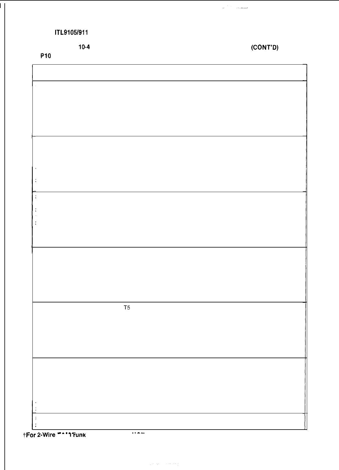
SECTION M ITL9105/911 O-98-200
TABLE
10-4
SHELF 2 EXTERNAL PLUG AND JACK CONNECTIONS
(CONT’D)
PLUG
PI0
(Connects to Cross Connect Field)
t
Pair
Pin
Color
26
W-BL
1
BL-W
27
w-o
2
o-w
28
W-G
3
G-W
29 W-BR
4
BR-W
30
w-s
5
s-w
31
R-BL
6BL-R
32 R-O
7O-R
33
R-G
8G-R
34 R-BR
9BR-R
35
R-S
10
S-R
36
BK-BL
11
BL-BK
37
BK-0
12
0-BK
38 BK-G
13
G-BK
39 BK-BR
14
BR-BK
40 BK-S
15
S-BK
41
Y-BL
16
BL-Y
42
Y-O
17
O-Y
43
Y-G
18
G-Y
44
Y-BR
19
BR-Y
45
Y-S
20
S-Y
46
V-BL
21
BL-V
47
v-o
22
o-v
48
V-G
23
G-V
49
V-BR
24
BR-V
50
v-s
25
s-v
A._..
--mm-
.
tFor
z-wrre
t&M
I
rum
operation DO NOT connect RR and TR leads
Lead Designation Lead Designation Trunks Card
Lines
co DID/TIE E&MI-
Positions
T5 T3
T2
T2
R5 R3 R2 R2
T6 XT4 TR2
R6
XT3
RR2
7
T7 T4
E2
R7 R4
M2
T8
R8
T5
T3 T2 T2
R5 R3 R2 R2
T6
XT4
TR2
R6
XT3
RR2
T7
T4 E2 8
R7 R4
M2
T8
R8
T5 T3 T2 T2
R5 R3 R2 R2
T6
XT4
TR2
R6
XT3
RR2
T7 T4
E2 9
R7 R4
M2
T8
R8
T5 T3
T2
T2
R5 R3 R2 R2
T6
XT4
TR2
R6
XT3
RR2
10
T7
T4
E2
R7 R4 M2
T8
R8
T5 T3
T2 T2
R5 R3 R2 R2
T6
XT4
TR2
R6
XT3
RR2
T7 T4 E2
11
R7 R4
M2
T8
R8
T5 T3 T2 T2
R5 R3 R2 R2
T6
XT4
TR2
R6
XT3
RR2
T7 T4 E2
12
R7 R4
M2
T8
R8
SPARE SPARE
SPARE SPARE
. .
--
_.--
Page 40
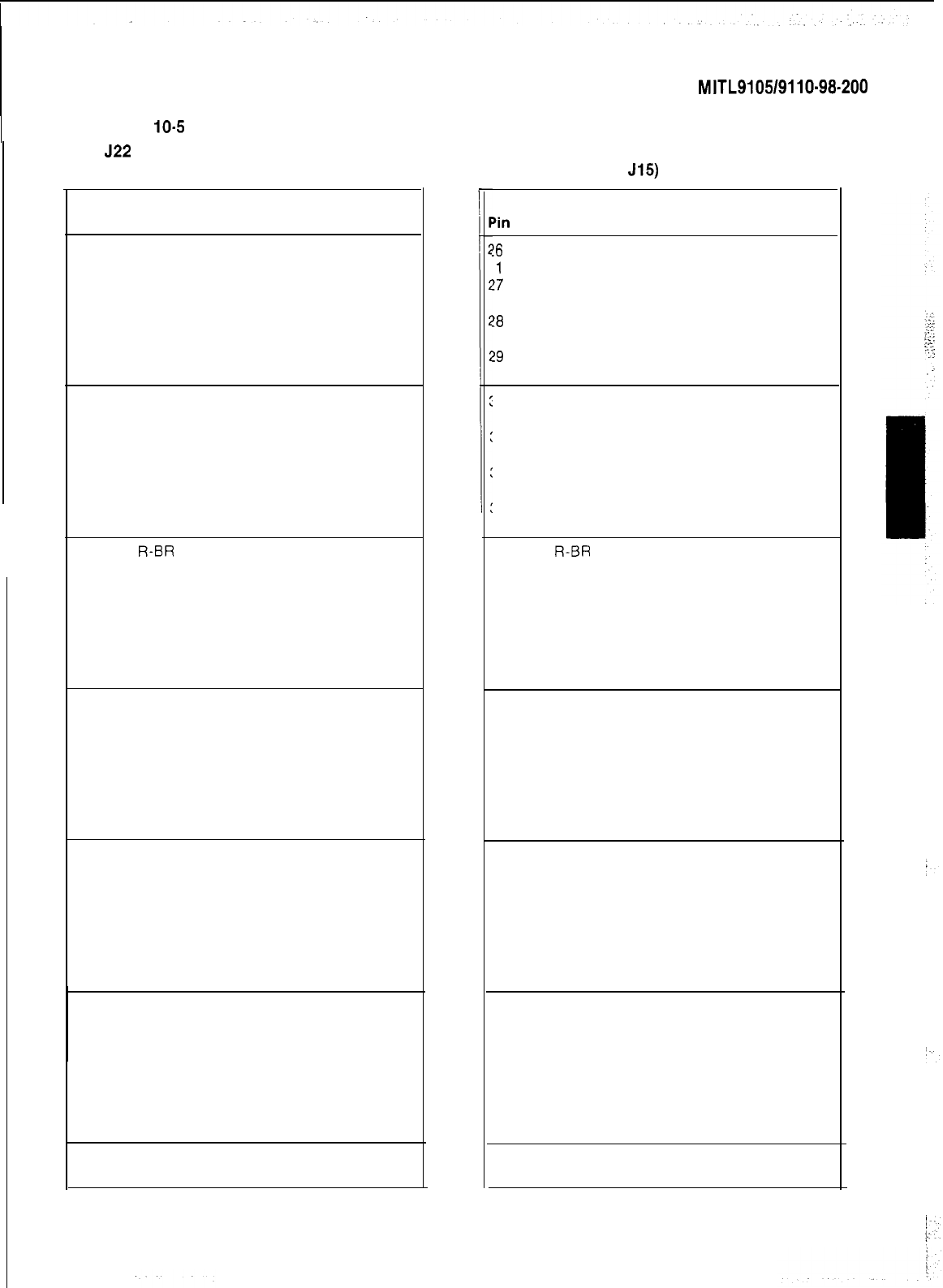
SECTION
MITL9105/9110-98-200
TABLE
IO-5
CONSOLE INTERFACE BOARD PLUG AND JACK CONNECTIONS (SX-200 ONLY)
JACK
522
(Connects to Attendant Console 1)
PLUG P23
(Connects to Jack
J15)
Pin
26
1
27
2
28
3
29
4
30
5
31
6
32
7
33
8
34
9
35
10
36
11
37
12
38
13
39
14
40
15
41
16
42
17
43
18
44
19
4.5
20
46
21
47
22
48
23
49
24
50
25
Pair
Color Lead Designation
W-BL ELECTROSTATIC GROUND
BL-W
ELECTROSTATIC GROUND
w-o ELECTROSTATIC GROUND
o-w ELECTROSTATIC GROUND
W-G
ELECTROSTATIC GROUND
G-W ELECTROSTATIC GROUND
W-BR
ELECTROSTATIC GROUND
BR-W
ELECTROSTATIC GROUND
w-s DATA IN COMMON
s-w DATA IN
R-BL
ELECTROSTATIC GROUND
BL-R
ELECTROSTATIC GROUND
R-O
DATA OUT COMMON
O-R
DATA 0
UT
R-G ELECTROSTATIC GROUND
G-R ELECTROSTATIC GROUND
R-BR
ELECTROSTATIC GROUND
BR-R
ELECTROSTATIC GROUND
R-S
CUTOVER SWB
S-R
CUTOVER SWA
BK-BL
ELECTROSTATIC GROUND
BL-BK
ELECTROSTATIC GROUND
BK-0 MAJOR ALARM
0-BK MAJOR ALARM
BK-G
TIP
G-BK RING
BK-BR
ELECTROSTATIC GROUND
BR-BK
ELECTROSTATIC GROUND
BK-S
ELECTROSTATIC GROUND
S-BK
ELECTROSTATIC GROUND
Y-BL ELECTROSTATIC GROUND
BL-Y
ELECTROSTATIC GROUND
Y-O ELECTROSTATIC GROUND
O-Y ELECTROSTATIC GROUND
Y-G
ov
G-Y -48V
Y-BR
OV
BR-Y
-48V
Y-S
ov
S-Y
-48V
V-BL OV
BL-V
-48V
v-o ov
o-v -48V
V-G
ov
G-V -48V
V-BR OV
BR-V -48V
v-s ov
s-v -48V
‘in
!6
1
!7
2
!8
3
!9
4
30
5
31
6
32
7
33
8
34
9
35
10
36
11
37
12
38
13
39
14
40
15
41
16
42
17
43
18
44
19
45
20
46
21
47
22
48
23
49
24
50
25
Pair
Color Lead Designation
W-BL
ELECTROSTATIC GROUND
BL-W
ELECTROSTATIC GROUND
w-o ELECTROSTATIC GROUND
o-w ELECTROSTATIC GROUND
W-G
ELECTROSTATIC GROUND
G-W
ELECTROSTATIC GROUND
W-BR
ELECTROSTATIC GROUND
BR-W
ELECTROSTATIC GROUND
w-s DATA IN COMMON
s-w DATA IN
R-BL
ELECTROSTATIC GROUND
BL-R
ELECTROSTATIC GROUND
R-O
DATA OUT COMMON
O-R
DATA OUT
R-G
ELECTROSTATIC GROUND
G-R ELECTROSTATIC GROUND
R-BR
ELECTROSTATIC GROUND
BR-R
ELECTROSTATIC GROUND
R-S
CUTOVER SWB
S-R
CUTOVER SWA
BK-BL
ELECTROSTATIC GROUND
BL-BK
ELECTROSTATIC GROUND
BK-0 MAJOR ALARM
0-BK MAJOR ALARM
BK-G TIP
G-BK RING
BK-BR
ELECTROSTATIC GROUND
BR-BK
ELECTROSTATIC GROUND
BK-S
ELECTROSTATIC GROUND
S-BK
ELECTROSTATIC GROUND
Y-BL
ELECTROSTATIC GROUND
BL-Y
ELECTROSTATIC GROUND
Y-O ELECTROSTATIC GROUND
O-Y ELECTROSTATIC GROUND
Y-G
ov
G-Y -48V
Y-BR OV
BR-Y
-48V
Y-S
ov
S-Y
-48V
V-BL OV
BL-V
-48V
v-o ov
o-v -48V
V-G
ov
G-V -48V
V-BR OV
BR-V
-48V
v-s ov
/-
s-v -48V
Page 41
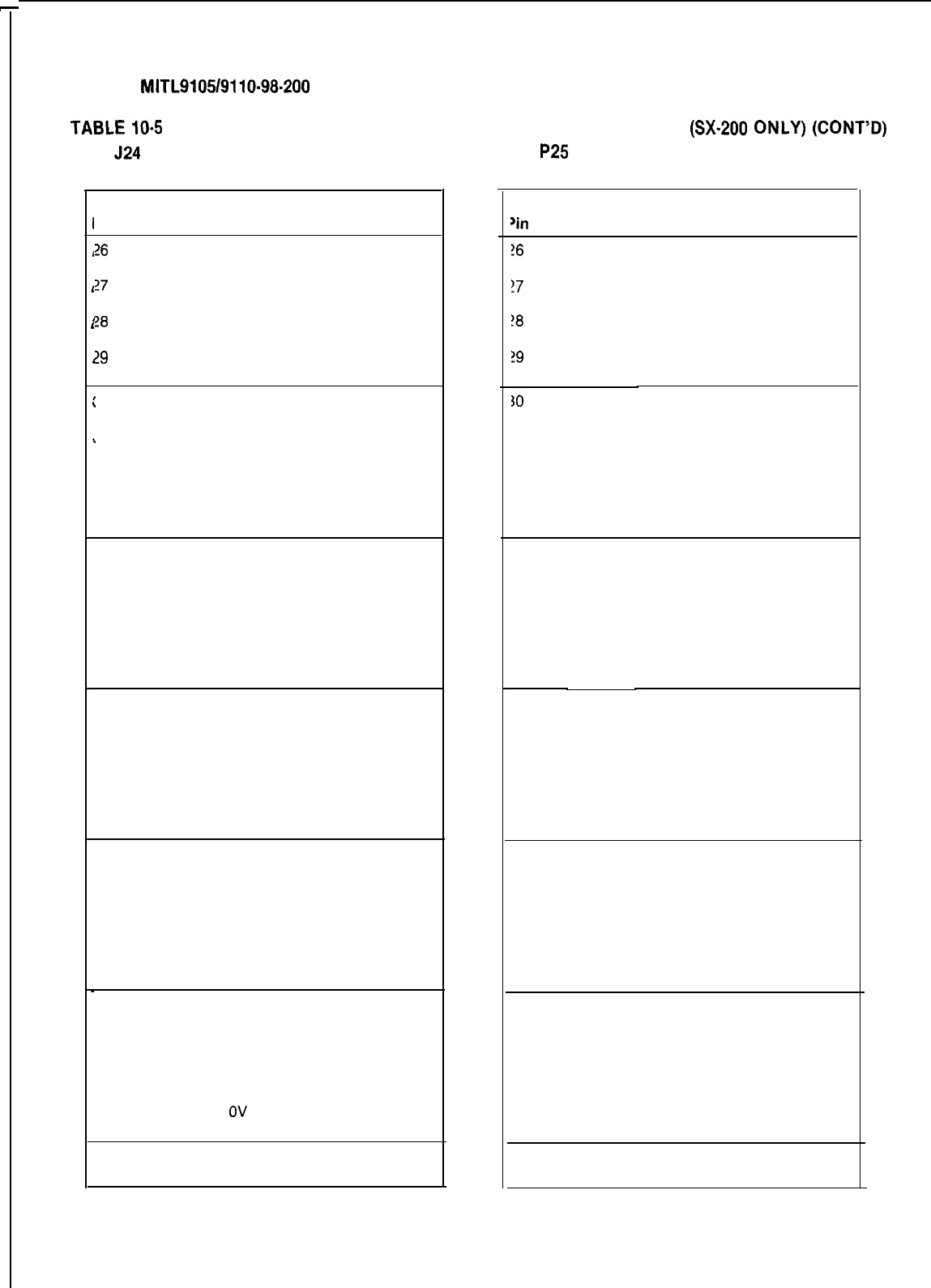
SECTION
MlTL9105/9110-98-200
TABLE
IO-5
CONSOLE INTERFACE BOARD PLUG AND JACK CONNECTIONS
(SX-200
ONLY)
(CONT’D)
JACK
524
PLUG
P25
(Connects to Jack J14)
(Connects to Attendant Console 2)
I
Pin
26
1
1
?7
1
2
I
!8
‘
3
?9
1
4
,
30
.
5
31
,
6
32
7
33
8
34
9
35
10
36
11
37
12
38
13
39
14
40
15
41
16
42
17
43
18
44
19
45
20
46
21
47
22
48
23
49
24
50
25
-
Pair
Color Lead Designation
W-BL ELECTROSTATIC GROUND
BL-W ELECTROSTATIC GROUND
w-o ELECTROSTATIC GROUND
o-w ELECTROSTATIC GROUND
W-G
ELECTROSTATIC GROUND
G-W ELECTROSTATIC GROUND
W-BR
ELECTROSTATIC GROUND
BR-W
ELECTROSTATIC GROUND
w-s DATA IN COMMON
s-w DATA IN
R-BL
ELECTROSTATIC GROUND
BL-R
ELECTROSTATIC GROUND
R-O
DATA OUT COMMON
O-R
DATA OUT
R-G
ELECTROSTATIC GROUND
G-R ELECTROSTATIC GROUND
R-BR
ELECTROSTATIC GROUND
BR-R
ELECTROSTATIC GROUND
R-S
CUTOVER SWB
S-R
CUTOVER SWA
BK-BL
ELECTROSTATIC GROUND
BL-BK
ELECTROSTATIC GROUND
BK-0 MAJOR ALARM
0-BK MAJOR ALARM
BK-G
TIP
G-BK
RING
BK-BR
ELECTROSTATIC GROUND
BR-BK
ELECTROSTATIC GROUND
BK-S
ELECTROSTATIC GROUND
S-BK
ELECTROSTATIC GROUND
Y-BL
ELECTROSTATIC GROUND
BL-Y
ELECTROSTATIC GROUND
Y-O ELECTROSTATIC GROUND
O-Y ELECTROSTATIC GROUND
Y-G
ov
G-Y -48V
Y-BR OV
BR-Y
-48V
Y-S ov
S-Y
-48V
V-BL OV
BL-V
-48V
v-o ov
o-v -48V
V-G
ov
G-V -48V
V-BR
OV
BR-V -48V
v-s ov
s-v -48V
‘in
!6
1
!7
2
!8
3
!9
4
Pair
Color
W-BL
Lead Designation
ELECTROSTATIC GROUND
BL-W
ELECTROSTATIC GROUND
w-o ELECTROSTATIC GROUND
o-w ELECTROSTATIC GROUND
W-G
ELECTROSTATIC GROUND
G-W ELECTROSTATIC GROUND
W-BR
ELECTROSTATIC GROUND
BR-W
ELECTROSTATIC GROUND
30
w-s DATA IN COMMON
5
s-w DATA IN
31
R-BL
ELECTROSTATIC GROUND
6
BL-R
ELECTROSTATIC GROUND
32
R-O
DATA OUT COMMON
7
O-R
DATA OUT
33
R-G
ELECTROSTATIC GROUND
8
G-R ELECTROSTATIC GROUND
34
R-BR
ELECTROSTATIC GROUND
9BR-R
ELECTROSTATIC GROUND
35 R-S
CUTOVER SWB
10
S-R
CUTOVER SWA
36 BK-BL
ELECTROSTATIC GROUND
11
BL-BK
ELECTROSTATIC GROUND
37
BK-0 MAJOR ALARM
12
0-BK MAJOR ALARM
38 BK-G TIP
13
G-BK
RING
39 BK-BR
ELECTROSTATIC GROUND
14
BR-BK
ELECTROSTATIC GROUND
40 BK-S
ELECTROSTATIC GROUND
15 S-BK
ELECTROSTATIC GROUND
41
Y-BL
ELECTROSTATIC GROUND
16
BL-Y
ELECTROSTATIC GROUND
42
Y-O ELECTROSTATIC GROUND
17
O-Y ELECTROSTATIC GROUND
43 Y-G
ov
18
G-Y -48V
44
Y-BR
OV
19 BR-Y
-48V
45 Y-S
ov
20 S-Y
-48V
46 V-BL OV
21
BL-V
-48V
47
v-o ov
22
o-v -48V
48 V-G
ov
23
G-V -48V
49 V-BR OV
24 BR-V
-48V
50
v-s ov
25 S-V
-48V
Page 42
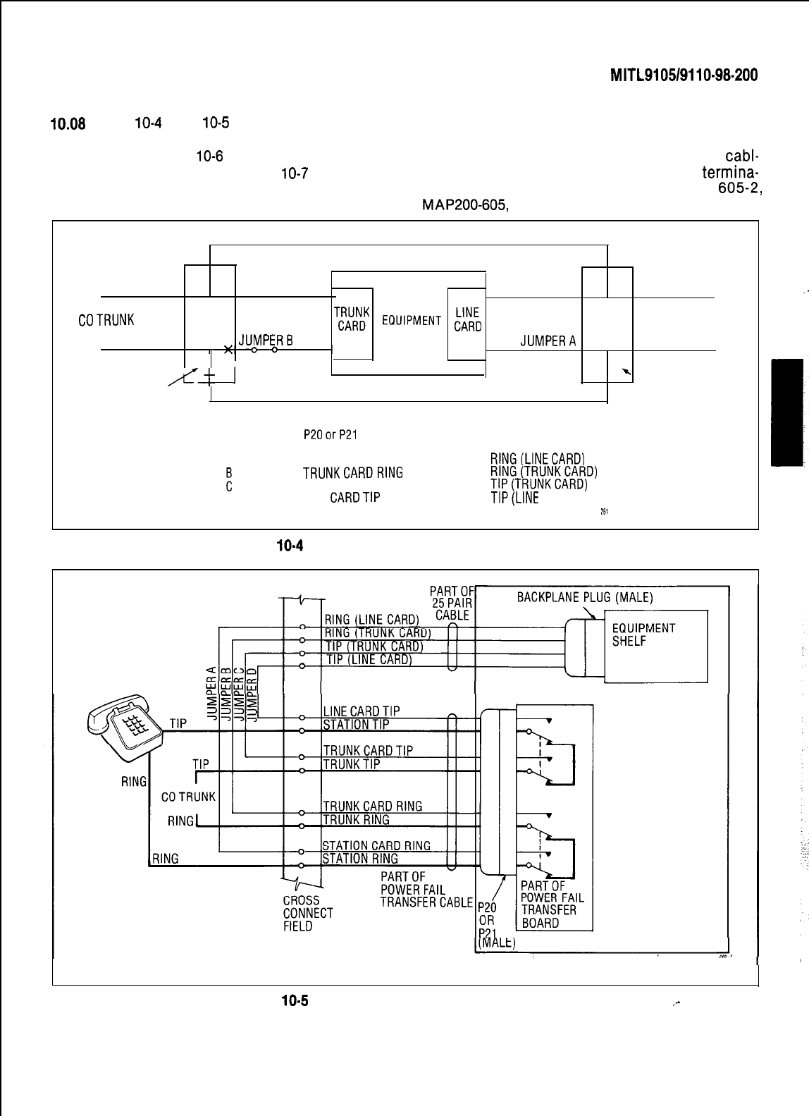
SECTION
MITL9105/9110-98.200
IO.08
Figs.
10-4
and
10-5
illustrate typical block
10.09
When backplane translator boards are used
and wiring diagrams for a power fail with the lines and trunk circuits different
transfer circuit. Fig.
10-6
illustrates typical night terminal connections result. In this case the
cabl-
bell wiring connections and Fig.
10-7
shows the ing arrangements must conform to the
termina-
connections for music and PA requirements. tion connections shown in Fig.
6052,
MAP200-605,
Appendix 6.
TIP
JUMPERC JUMPERD
TIP
PABX
COTRUNK
T;;;DK
ECIUIPMENT
;A;; STATION
RING
JUMPER6
CABINET
JUMPERA
RING
/c--
1
-.
POWER FAIL POWER FAIL
TRANSFER BOARD TRANSFER BOARD
FROM
JUMPER P200rP21
TO
INTERCONNECT BOARD
A
LINE CARD RING
RlNG(LINECARD)
i
TRUNKCARDRING
RlNG(TRUNKCARD)
TRUNKCARDTIP
TIP(TRUNKCARD)
D
LINE CARDTIP
TIP(LINE
CARD)
261
Fig.
10-4
Power Fail Transfer Block Diagram
STATION
RELAYS SHOWN IN
TRANSFER POSITION
PABX EQUIPMENT CABLE
Fig.
10-5
Power Fail Transfer Wiring Diagram
,-
Page 43
.
.
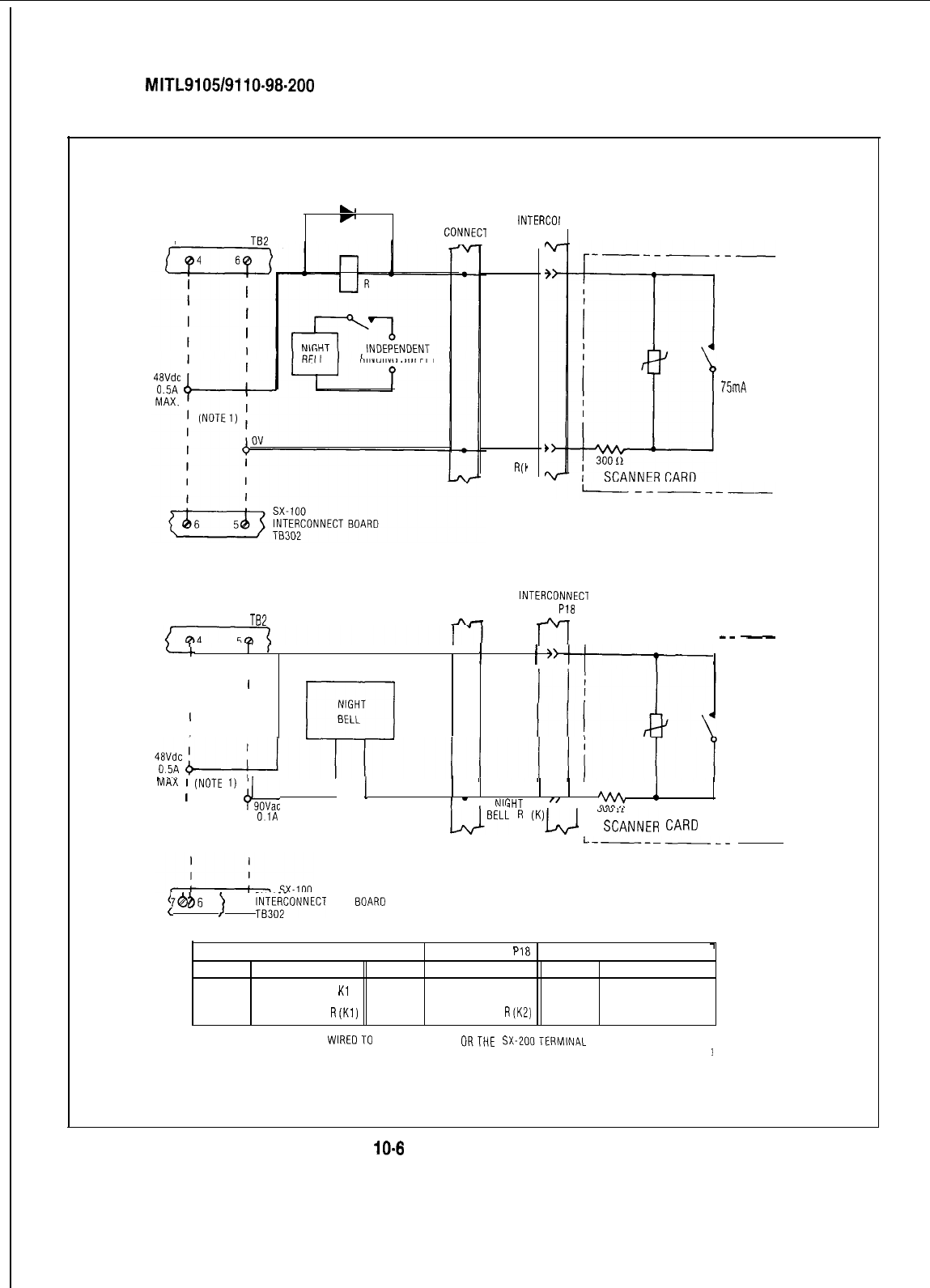
SECTION
MITL9105/9110-98-200
NIGHT BELL CONNECTION AUXILIARY RELAY
sx-200
POWER SUPPLY TB2
La
F
CROSS
CONNECl
RINGINGSUPPLY
INTERCOt UNE
BOARD f
'18
NIGHT
BELL K
NIGHT
BELL
R('
CT
NIGHT BELL RELAY DIRECT DRIVE
sx-200
POWER SUPPLY TE2
CROSS INTERCONNECl
CONNECT
BOARD P18
r-l
r-----
T
I
' =
/
NIGHT
f
'-
I I
BELL K '
II
II
NIGHT
I
I
II
r-l
BELL
NIGHT
BELL
CONTACT
MAX CURRENT
75mA
--
-
NIGHT
BELL
CONTACT
MAX CURRENT
75mA
MAX
;
(NOTE
1)
+,,,,,
1
1
I
1
-
I
NIGHT
I
”
I ’
%
!
I1
OlA
I
, MAX
LJBELL
I7
‘“‘La)
(
%G-dNER
CARD
I I
L-------
j
636
7b
)
RECONNECT
BOARD
INTERCONNECT BOARDPLUG P18
1
PIN
DESTINATION
PIN
DESTINATION
PIN
DESTINATION
46 NIGHT BELL 1
Kl
44 NIGHT BELL
2
K2 50 NIGHT BELL 3 K3
21
NIGHT BELL 1 R(K1)
19
NIGHT BELL 2 R(K2) 25 NIGHT BELL 3 R(K3)
NOTE 1. THE FACILITY IS
WIREOTO
EITHERTHESX-100
ORTHE
SX-ZOOTERMINAL
BLOCKS, AS INDICATED BY THE DASHED LINES
ii?
3
Fig.
IO-8
Night Bell Connections
Page 44
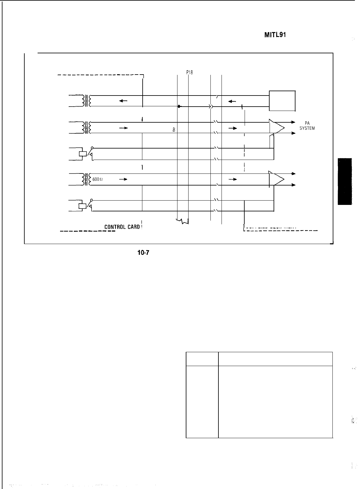
SECTION
MITLSI
051911 O-98-200
_____
------------------~
INTERCONNECT
CROSS
BOARD PI8
CONNECT r---- -__----_-_-
I
A 17 I
SPEECH PATH
32
illi
I
/
I
60011
C
MUSIC
B 42
-
I
=
>>
I
SOURCE
I
I
I
A 20
\\
\
+
FROM JUNCTOR
3lII
j
60011
I
SEIZED FOR PA
-
I
6
45
-
I
SYs'tEM
\\
I
/
*
1
I
ACTIVATE CONTACT RATING
PA1 CONTROL
34
MAX 75mA
I
I
I
FROM JUNCTOR
3
j
6OOil
I
SEIZED FOR PA
-
ACTIVATE
34
CONTACT RATING
PA2 CONTROL
MAX 75mA
I
I
I
TONE
CONTROLCARD:
-----A_____
--__--------
A 22
B 47
A 18
B 43
A 23
B 48
\\
I
;
CONTROL
\\
, PAIR 1
I
\
,
I
*
PA
-
I SYSTEM
\
*
2
I
I
\\
I
I CONTROL
\\
PAIR 2
CUSTOMER
’
SUPPLIED EQUIPMENT
L----------------
1268
Fig.
IO-7
Music and PA Connections
FCC CROSS CONNECT FIELD
RECOMMENDATIONS
10.10 Trunk circuits must be connected to the
telephone company interface jack sequen-
tially. A cross connect field is necessary to
separate the lines and trunks which occur in the
same cable that is connected to the shelf connec-
tor.
10.11 All cables containing trunk circuit pairs
must be connectorized; thus, the cross con-
nect field must also be connectorized. Refer to
Appendix 2 for details.
11.
DESIGNATIONS
General
11.01 Designations are an integral part of the in-
stallation procedures. Correct identifica-
tion of all cables and terminations improves ser-
vice by reducing search time.
11.02 This part describes one method of iden-
tification. Modular cross-connecting fields
are referenced to throughout this description as
the SX-200 system crossconnection may show the
cross connect field with other PBX equipment.
This procedure for terminating the cables and
equipment are shown in Table 11-l and Fig. 11-1,
11-2 and 11-3.
TABLE
II-I
TERMINATING PROCEDURE
STEP
ACTION
1
Mount cross connecting blocks
2
Run and connect building cables
3
Identify cables using identification
tape
4
Attach designation strips to
required cross connecting blocks
(Fig. 11-2 and 11-3)
5
Run and connect equipment cables
6
Run and connect required jumpers
.
.:
Page 45
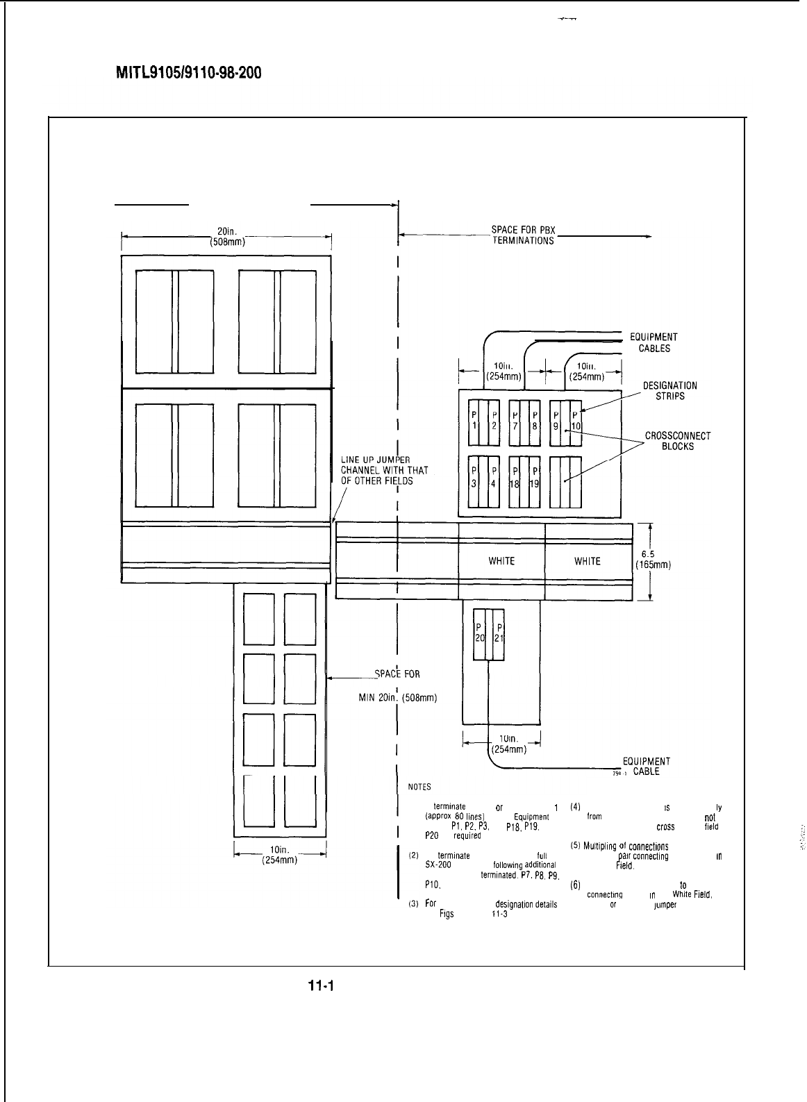
SECTION
MITL910519110-98-200
RED, GREEN &BLUE FIELDS WHITE FIELD
SPACE FOR KEY EQUIPMENT,
BUILDING CABLES &STATION
CABLING
I
GROWTH-
(1) To
termmate
SX-100
or
Shell Number 1
(41
The attendant console
IS
cabled direct
lY
(approx
60
hnes)
SX-200
Equipment
Cables
Pl.
P2.
P3.
P4.
P18.
P19.
and
P20
are
required
lrom
the equipment cabinet and is
nol
X-Connected at the
CK?SS
connect
field
(5)
Mulflplmg
01
connecrmns
will be made
To
termmale
the 2nd Shell for a
lull
on a 25
pair
connecting
block located
m
5X-200
system the
lollawmg
additional
the Red
Field.
cables must be
terminated.
P7.
PB.
Pg.
PlO.
and P21
(6)
An alternate layout may be
10
place all
connectma
blocks
m
the
Whde
Field,
For
Connector block
deslgnatlon
details
see
Figs
11-2 and
11-3
above
or
below the
jumper
channel
Fig.
11-l
Typical Terminal Layout
Page 46
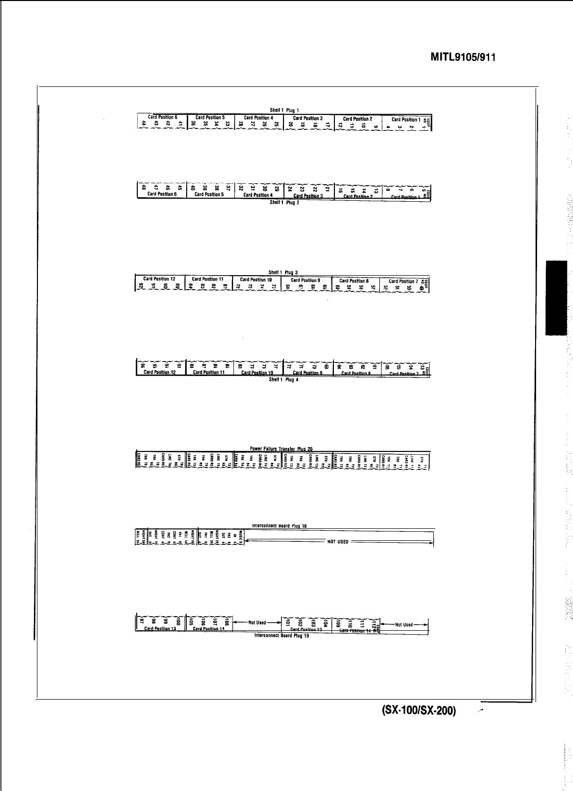
SECTION MITL9105/911 O-98-200
Fig. 11-2 Cross Connecting Block Designation Strips (SX-lOO/SX-200)
‘-
Page 47
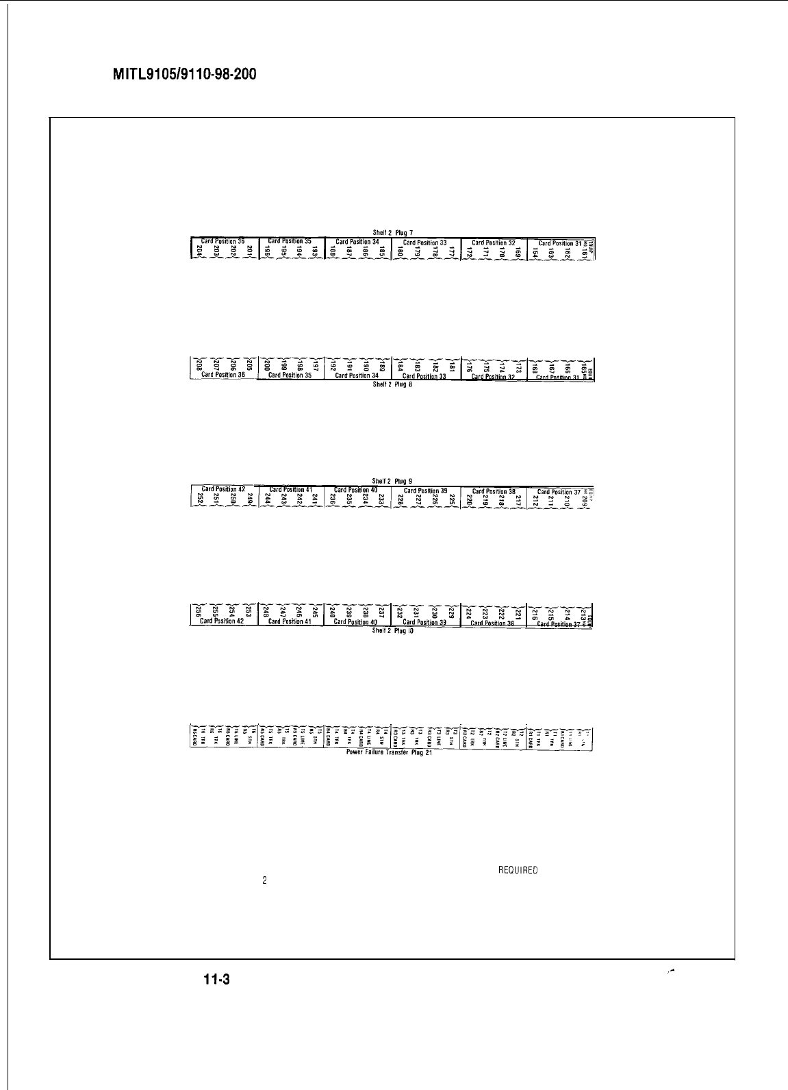
SECTION
MITL9105/9110-98-200
NOTES:
1. PLUG DESIGNATION STRIPS FOR PLUGS 7 THROUGH 10 ONLY REIIUIRED WHEN
SHELF
2
IS INSTALLED IN SX-ZOO
2
PLUG DESIGNATION STRIP FOR P
L
UG 21 IS APPLICABLE TO SX-ZOO ONLY
Fig.
11.3
Cross Connecting Block Designation Strips (SX-200 Only)
‘^
Page 48

12. INSTALLATION
General
12.01 The SX-100 and SX-200 systems should be
installed in accordance with the following
steps:
(a)
Consult Appendix 1 for a review of
Mite1
Ac-
tion Procedures (MAP’s)
(b) Consult Appendix 2 for certain FCC inter-
connection requirements
(c) For installation of SX-100 equipment pro-
ceed with the steps listed in Table
A3-1,
Ap-
pendix 3
Cd)
(e)
m
SECTION
MITL9105/9110-98-200
For installation of SX-200 equipment pro-
ceed with the steps listed in Table
A4-1,
Ap-
pendix 4
Appendix 5 lists setting of trunk card swit-
ches which are required to be performed
during the installation of the PABX equip-
ment
Appendix 6 lists miscellaneous installation
procedures which may be required during
the PABX installation or the installation of
additional equipment
Page 49
j
49 Pages
SECTION
MITL9105/9110-98-200
APPENDIX 1
MITEL ACTION PROCEDURES
GENERAL
Al.01 Task oriented functions in this section are
implemented using
MITEL
ACTION
PROCEDURES (MAP’s).
Al.09 START/FINISH/JUMP TO Block: Used to
indicate the start and finish of a MAP.
Al.02 A MAP is a step by step procedure using a
flow chart principle, written and il-
lustrated where necessary to a level of detail that Also used to indicate ‘jump to’ points within the
allows both experienced and inexperienced per- MAP, for example “go to
[r-r]”
or “from [n]” or
sonnel to carry out the tasks detailed. A MAP con- “return to [n]“. The symbol is a rectangle with
tains two levels of information as follows: semi circular ends. Text is
centred
in the symbol.
(a) For experienced personnel, a series of
steps (level one) each numbered [n] and
annotated with minimal information.
(b) For inexperienced personnel, each step
referred to in (a) above is amplified by a
connected series of numbered
substeps
[nA]
(level two).
Al.03 A typical example of a MAP is shown in
Fig. Al, with the two levels detailed
MAP SYMBOLS
Al.04 There are four basic symbol shapes which
may be used in a MAP, and are
defined as follows.
Al.05 AND Block: Used to indicate a level one
step that must be performed. Con-
sists of a square with the word AND
centred
in the
block.
Al.08 OR Block: Used to indicate a choice of
level one steps, one of which must be
performed. Consists of a rectangle, with the text
centred
in the block, and with the word OR ap-
pearing between the alternative operations.
Al.07 The rectangle is also used to border in-
structions which imply that the operative
must perform a task outside the scope of the
MAP. The text is
centred
in the rectangle.
Al.08 DECISION Block: Used to indicate a
decision within the level one steps which
must be made. The symbol is based on a hexagon
with the top and bottom sides extended. Decision
text is
centred
in the symbol.
THE OPERATORS USE OF MAP’S
Experienced Operator
Al.10 For the experienced operator to complete
a task using a MAP, reference to the se-
quential short form level one steps is usually all
that is necessary. Using Fig. Al as an example,
the experienced operator would proceed as
follows.
Al.11 At
[l]
makes a decision based on the infor-
mation within the block. If the answer is
YES the operator must proceed to a different
MAP. If the answer is NO the operator is faced
with another decision at block
[2].
Al.12 At
[2]
if the decision is NO there is no re-
quirement to proceed further and the test
is abandoned. This naturally results in a FINISH
block. If the decision is YES the operator pro-
ceeds to
[3]
and
[4]
in succession, i.e. dials the DID
station number and completes the call to the
check extension.
Al.13 The description of the instructions carried
out in Al.05 and Al.06 have assumed
that the level of competence of the operator is
such that short form level one steps contain suffi-
cient information, and therefore the operator reads
only the centre column of the MAP, top to bot-
tom of the page.
,-
Al-l
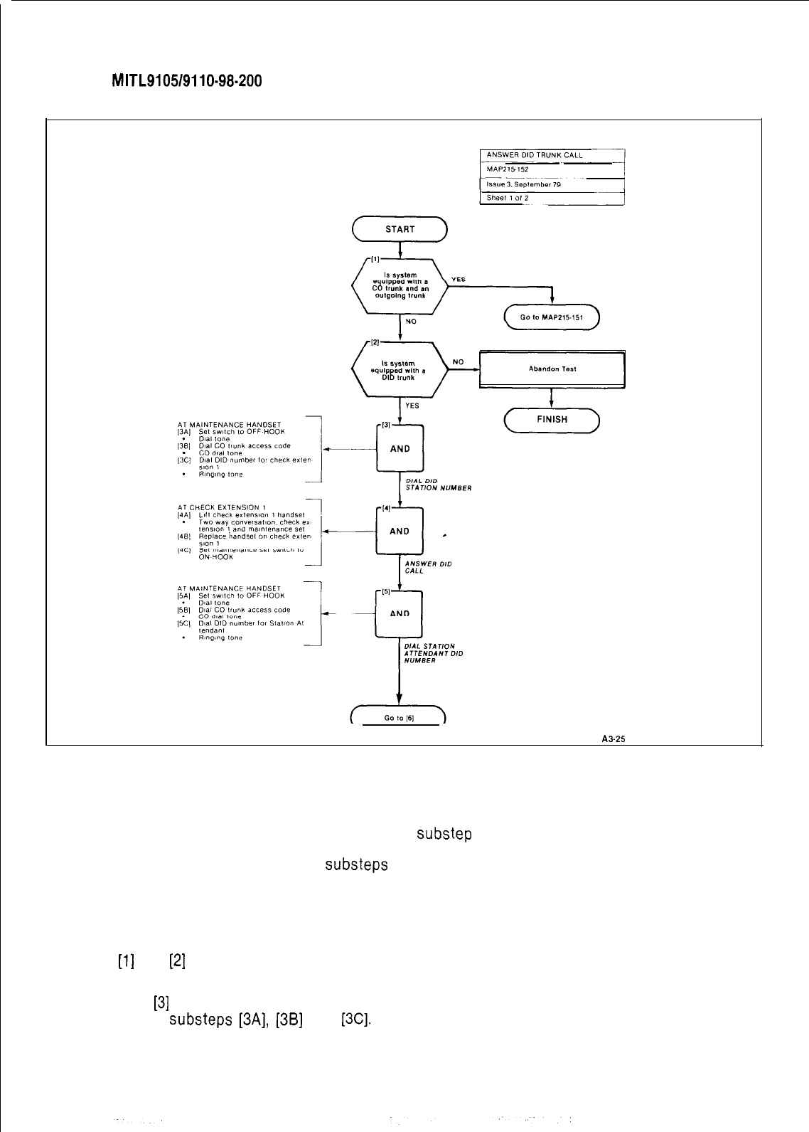
SECTION
MITL9105/9110-98-200
SECTION MITL9110.98.215
A3-25
Fig. Al Typical Map Page
Inexperienced Operator
Al.14 If the operator’s experience is such that
the level one instructions do not contain
sufficient information, the level two
substeps
should be referred to as follows.
Al.15 Using Fig. Al as an example the path
followed should be:
(a)
At
[l]
and
[2]
make the decisions called for
at these steps as before.
(b) At step
[3]
dial the DID station number by
performing
substeps
[3A],
[3B]
and
[3C].
In terms of steps and substeps, the operative
follows a decision, decision then step and
substep
paths in the example shown.
TOOLS, TEST EQUIPMENT AND SPECIAL
INSTRUCTIONS
Al.16 Any tools, test equipment or special in-
structions that the operator requires or
needs to know are stated on the first page of each
MAP. If the MAP is long, and contains a number of
sub procedures, these are listed in synopsis form
on the first page.
Al-2
SECTION
MITL9105/9110-98-200
APPENDIX 2
FCC INTERCONNECTION REQUIREMENTS
A. TELEPHONE COMPANY INTERCONNECTION
General
A.01
This equipment has been approved by the Federal Communications Commission (FCC) as not be-
ing harmful to the telephone network when connected directly to the telephone lines through the
standard
50-pin
blue ribbon plug prescribed by the FCC Rule. This section is applicable to telephone in-
terconnection in the United States.
.‘:
Notification
A.02
Prior to the interconnection of this equipment, the local telephone company is to be notified; in-
form the company that you have FCC-registered equipment which you wish to connect to their
trunks. Give them the following information:
The PABX being connected is a
Mite1
Incorporated Model SX-100 or a Model SX-200.
The 14 digit FCC Registration Number for the SX-100 is
BN285B67126PFE
The 14 digit FCC Registration Number for the SX-200 is
BN285B67126PFE.
The Ringer Equivalence Number which is
2.1B.
The jacks or connectors required are
RJ2lX,
RJ2EX
or
RJ2GX
as shown in Table
A2-1.
Connection Limitations
A.03 Due to the FCC Part 68 Rule, no connection can be made to party lines and to coin telephone ser-
vice.
Network Changes
A.04 The telephone company may make changes to its communication service; such changes may in-
elude
the change of trunk circuits, changes in the operational characteristics of its trunk, etc.
:.
Before doing this, however, the company shall provide official notification, so that the operation of the
PABX service will not be interrupted.
Maintenance Limitations
A.05 This equipment has been registered with the FCC for direct connection to the telephone network.
Under the FCC Program, the user is restricted from making any changes or repairs and from
perfor-
ming any maintenance operations other than those specifically included in this Standard Practice.
A.08 Circuit cards may be removed by the user; however, replacement cards are to be supplied only by
MITEL or its authorized agent. No field repair of circuit cards by the user is authorized.
A.07 No cabling or wiring changes within the console are permitted by the user. Plug-ended cables, as
detailed in this Standard Practice, are to be used for all external connections between the console
and the telephone company interface jack.
A.08 Power supply components and cabling is only to be changed or maintained by
MITEL
or by an
authorized agent of MITEL.
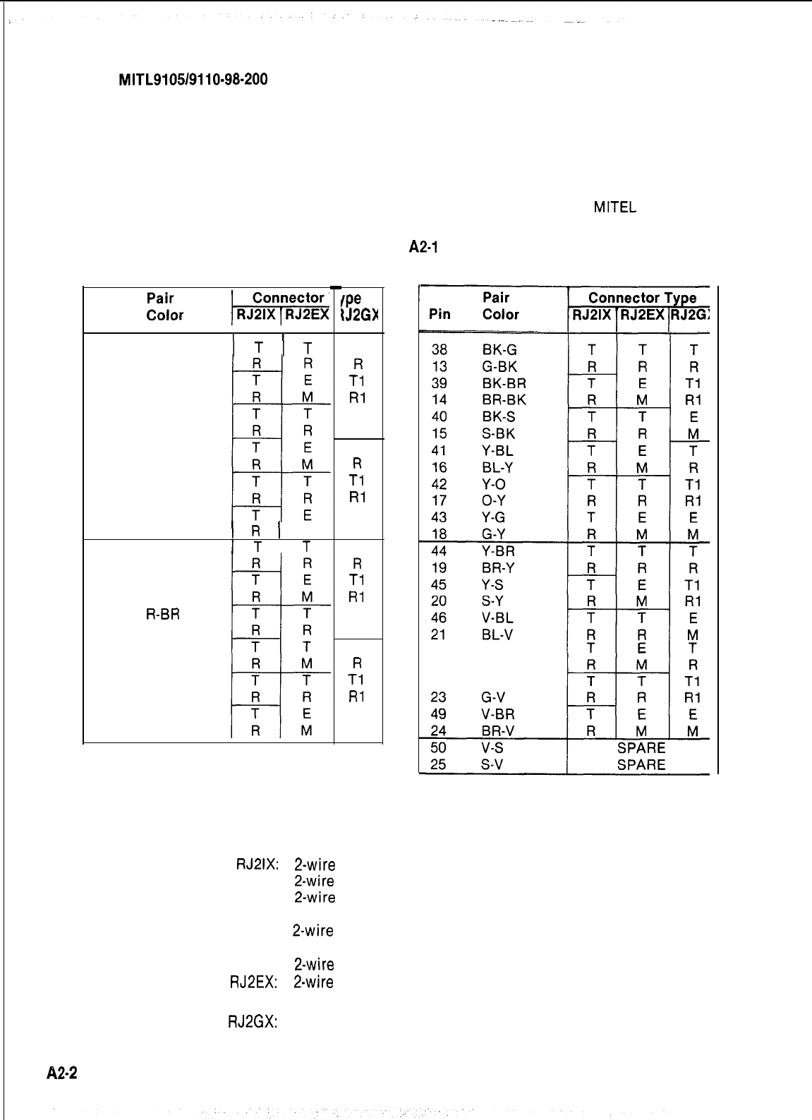
SECTION
MITL9105/9110-98-200
Trouble Corrections
A.09 Most troubles are diagnosed by the circuitry of the system, and the console read-out indicates the
circuit and card that is malfunctioning. Card replacement can be made by the user.
A.1 0
For more complex malfunctions, appropriate field service is provided by
MITEL
or its authorized
agents.
TABLE
A2-1
USOC CONNECTOR PIN DESIGNATIONS
-
Pin
Zilbr
/Ki%$Z%
26 W-BL
1
T
1
T
1
BL-W
27
w-o
2
o-w
28
W-G
3
G-W
29
W-BR
4BR-W
30 w-s
5
s-w
31
R-BL
6
BL-R
1
R
)
M
32
R-O
1
T
1
T
7
O-R
33
R-G
8
G-R
34
R-BR
9
BR-R
35
R-S
10
S-R
36
BK-BL
11
BL-BK
37
BK-0
12
0-BK
EL
IJ2GX
T
R
Tl
Rl
E
M
T
R
Tl
Rl
E
M
T
R
Tl
Rl
E
M
E
R
Tl
Rl
E
M
47 v-o
22 o-v
48 V-G
Remarks
The types of Universal Service Order Code (USOC) connectors shown have pin designations according
to type of interface required by the Telephone Company. Use of these connectors are determined
as follows:
RJ2lX: 2-wire
loop, or ground start trunk
2-wire
reverse battery (DID)
2-wire
off-premises extension
(Class A through E)
2-wire
Automatic Identified Outward
Dialing (AIOD)
2-wire
message register
RJ2EX: 2-wire
tie trunk with E and M Type I
signaling
RJ2GX:
I-wire tie trunk with E and M Type I
signaling
82-2
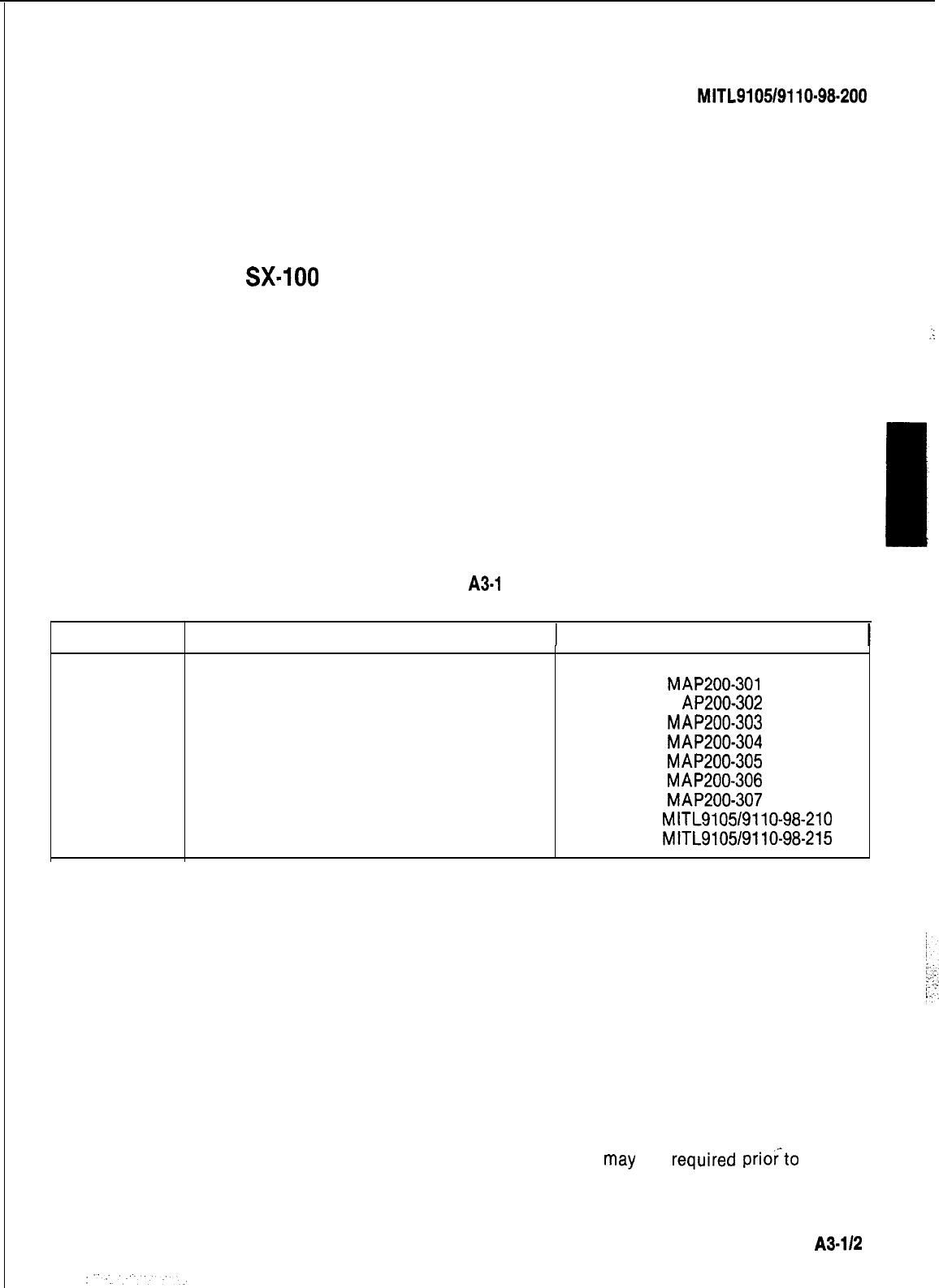
SECTION
MITL9105/9110-98-200
APPENDIX 3
SX-100
INSTALLATION PROCEDURES
.
.
:
.(
!
1. GENERAL
A3.01
The MAP’s contained in this Appendix detail the procedures to be performed to complete the
installation of an SX-100 PABX.
Step
Procedure
1
Unpack SX-100 Equipment
2
Unpack Console(s)
3
Install Console Faceplate Designation
4
Inspect Equipment
5
Install and Connect Equipment
6
Set Card Switches (Appendix 5)
7
Power-Up System (See Note)
8
Program System
9
Perform System Tests
TABLE
A3-1
SX-100 INSTALLATION PROCEDURE
Reference
MAP200-301
M AP200-302
MAP200-303
MAP200-304
MAP200-305
MAP200-306
MAP200-307
Section
MITL9105/9110-98-210
Section
MITL9105/9110-98-215
Note: Appendix 6 lists miscellaneous installation requirements which
may
be
required
priofto
power-
up of system. This appendix should be reviewed for applicability.
A3-112
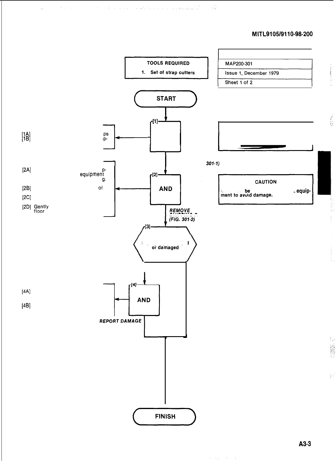
SECTION
MITL9105/9110-98-200
AT RECEIVING DOCK
[lA]
Cut and remove retaining straps
[lB]
Remove tri wall box from shipp-
ing package (Fig. 301-l)
l-
WI
-I
I
WARNING
I
1
AND
I
I
Gloves must be worn when unpacking
equipment cabinet.
I
I
[2A]
Position equipment so that a
prox. ten inches of
equipmen
overhangs shipping pallet (Fi
301-2)
[2B]
Tip equipment so that rear
01
cabinet touches floor
[2C]
Remove shipping pallet from
under equipment
[2D]
&;,“y
lower equipment onto
UNPACK SX-100 EQUIPMENT
1
I
REMOVE EXTERNAL
PACKING (FIG.
301.1)
.:
.:
::
z.:
Care must
b!
taken while moving
equip-
[4A]
Identify type of damage by referr-
ing to the Damage Report Form
at rear of this Section
[4B]
Complete appropriate portion of
Form
SHIPPING PALLET
Was the shipment
improperly packaged
YES
I
NO
A3-3
:
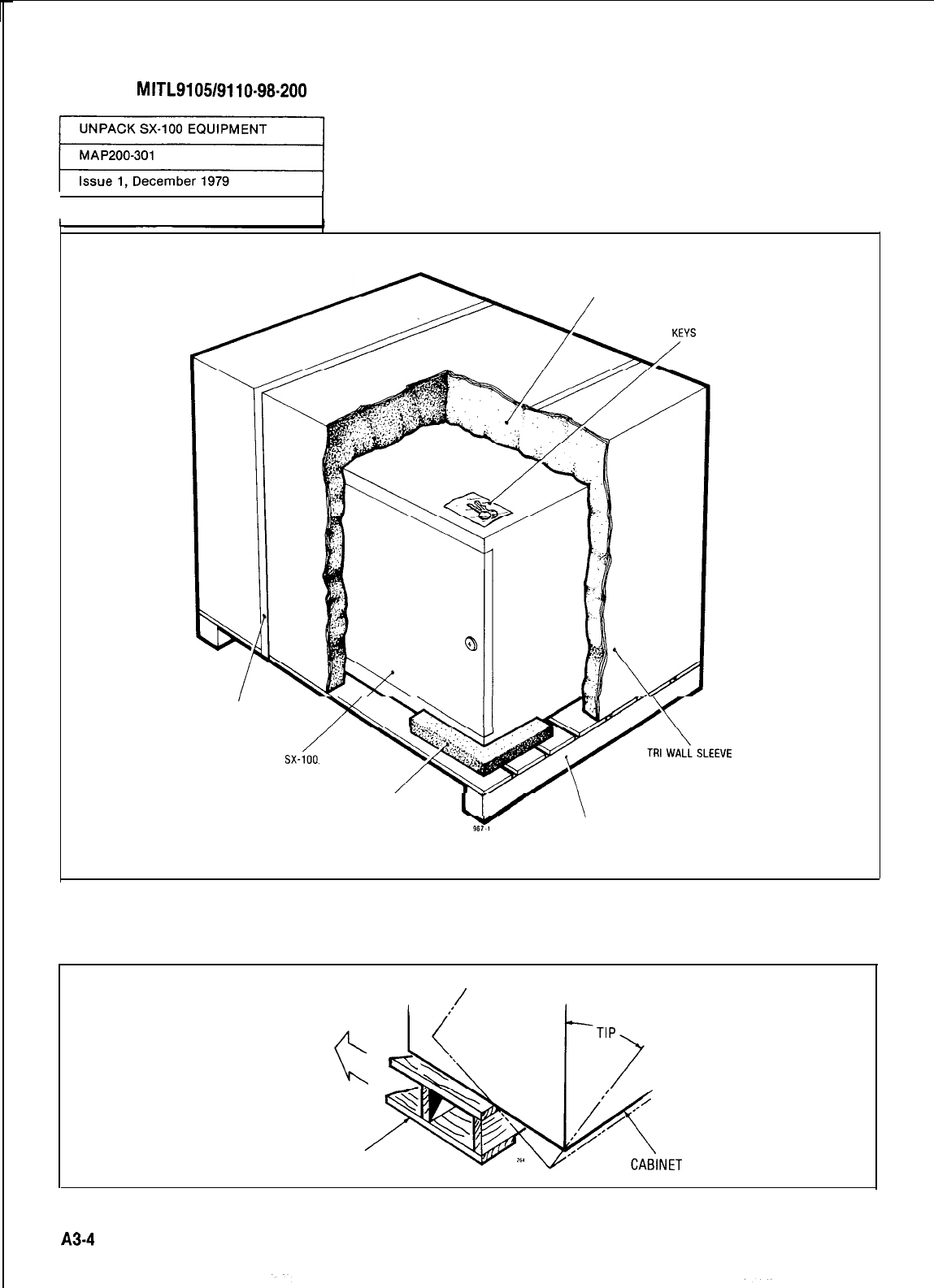
SECTION
MITL9105/9110-98-200
Sheet 2 of 2
STYROFOAM
FIBERGLASSTAPE
STYROFOAM PADS
WOODEN SHIPPING PALLET
REMOVE
SHIPPING PALLET
A34
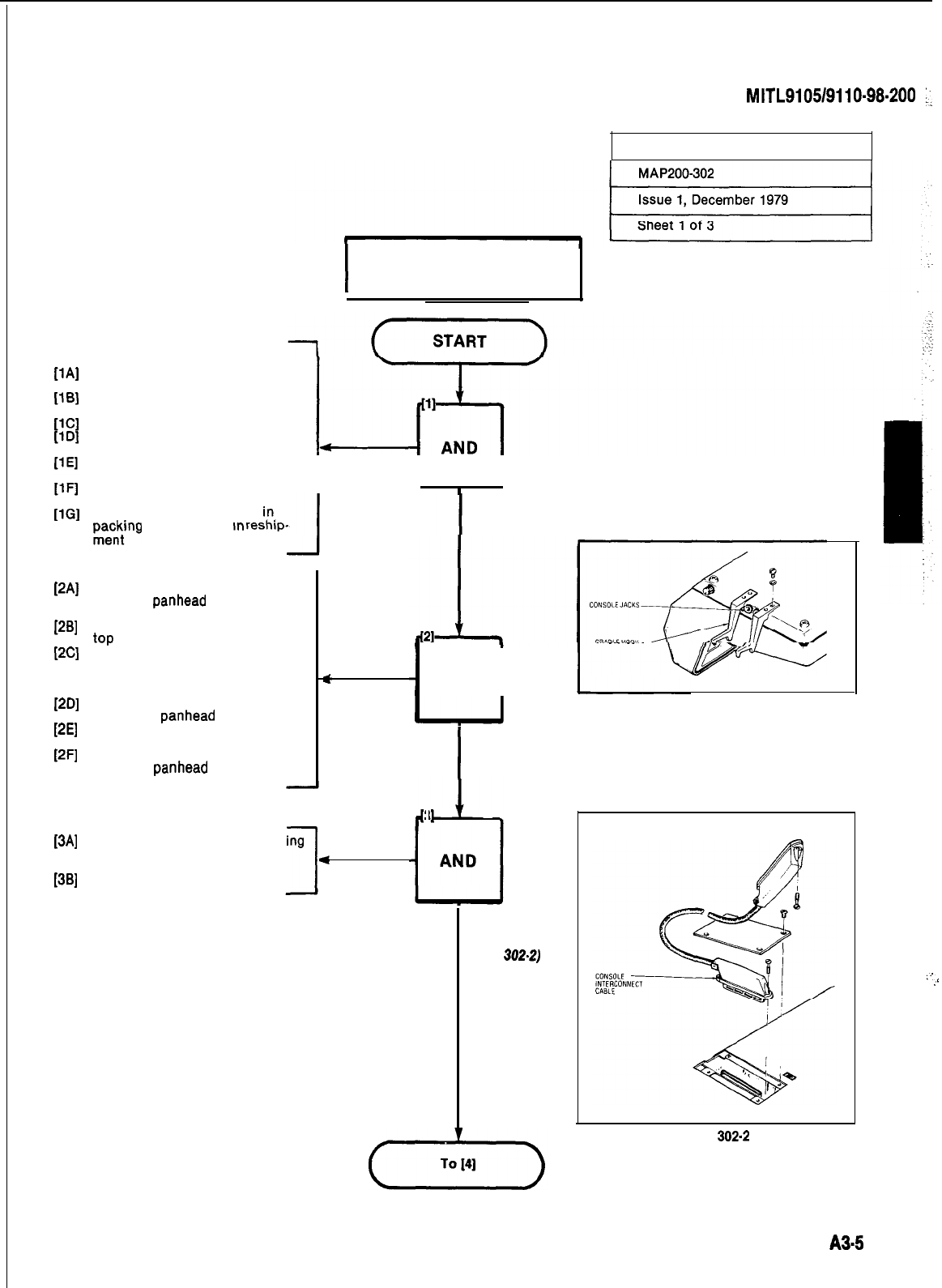
SECTION
MITL9105/9110-98-200
:.
UNPACK CONSOLES
I
TOOLS REQUIRED
1 Screwdriver 0.25 inch blade
AT CONSOLE LOCATION
[lA]
Remove fiberglass tape from top
of packing case
Open packing case and remove
foam sheet
Remove cardboard insert
Remove console accessory bag
from insert
Remove console from packing
case
Remove polyethylene sheet from
I
I
I
I
console
Place all packing material
in.
P,a,c,:‘ng
case for use
m
reshlp-
PAI
ml
WI
WI
WI
[=I
Remove the two cradle hooks
and four panhead screws from
accessory bag
Place console face down on desk
top
Position one cradle hook as
shown in Fig. 302-l. (Cradle hook
may be placed at other end of
console if preferred)
Attach cradle hook to console
using two panhead screws
Position remaining cradle hook
(Fig. 302-l)
Attach cradle hook to console
with two panhead screws
[34
Remove the four screws securing
the connector cover plate (Fig.
302-2)
e
Remove connector cover plate
1
1381
UNPACK CONSOLE
AND
I
I
INSTALL CRADLE HOOKS
(FIG. 302-l)
3
REMOVE
CONNECTOR
COVER PLATE
(FIG.
302-2)
Fig. 302-l
Fig.
302.2
:_
:
A3-5
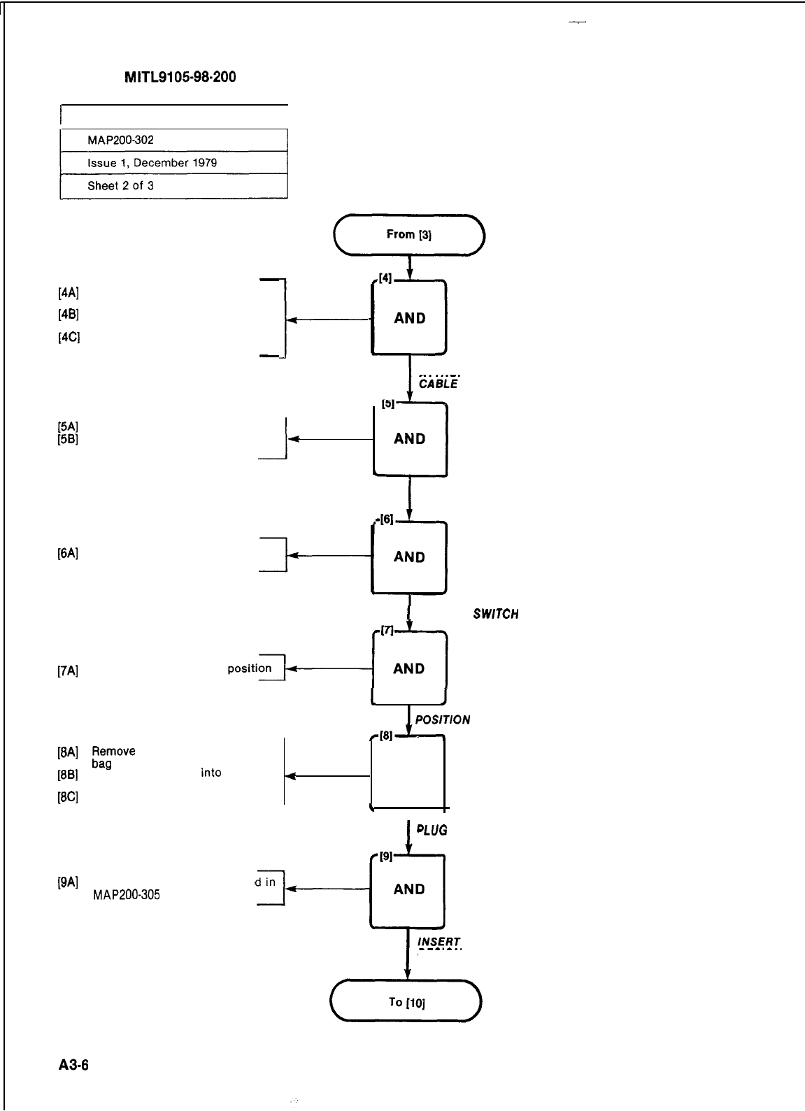
-
SECTION
MITL910598-200
I
UNPACK CONSOLES I
-
[4A] Remove the securing screw from
the console connector
[4B] Position and press home console
connector
[4C] Secure connector to console with
the securing screw
-
l-
[5A] Replace connector cover plate
[5B] Replace the four cover plate
screws
i-
[6A] Set Power Fail Transfer (PFT)
switch to NORMAL
ATTACH CONNECTOR
REPLACE CONNECTOR
COVER PLATE
461
1
SET PFT
SWTCH
[7A] Place console in correct
1
I
POSlTlON
CONSOLE
[8A]
;tFove
handset from accessory
[8B]
Place handset plug
into
<
AND
console jack
[8C] Place handset on cradle hook *
.
I
WI
Insert designations as detaile
MAP200-305
PLUG
IN HANDSET
DESIGNATIONS
A3-8
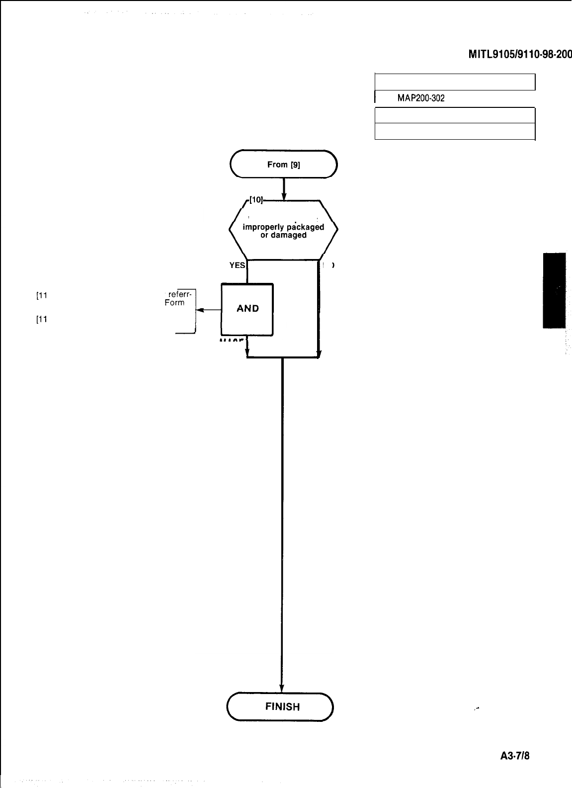
[ll
A] Identify type of damage by
ing to the Damage Report
at rear of this Section
[ll
B] Complete appropriate portion of
Form
-
Was the shipment
REPORT DAMAGE
NO
SECTION
MITL9105/9110-98-200
UNPACK CONSOLES
I
MAP200-302
I
Issue 1, December 1979
Sheet 3 of 3
_-
A3-718
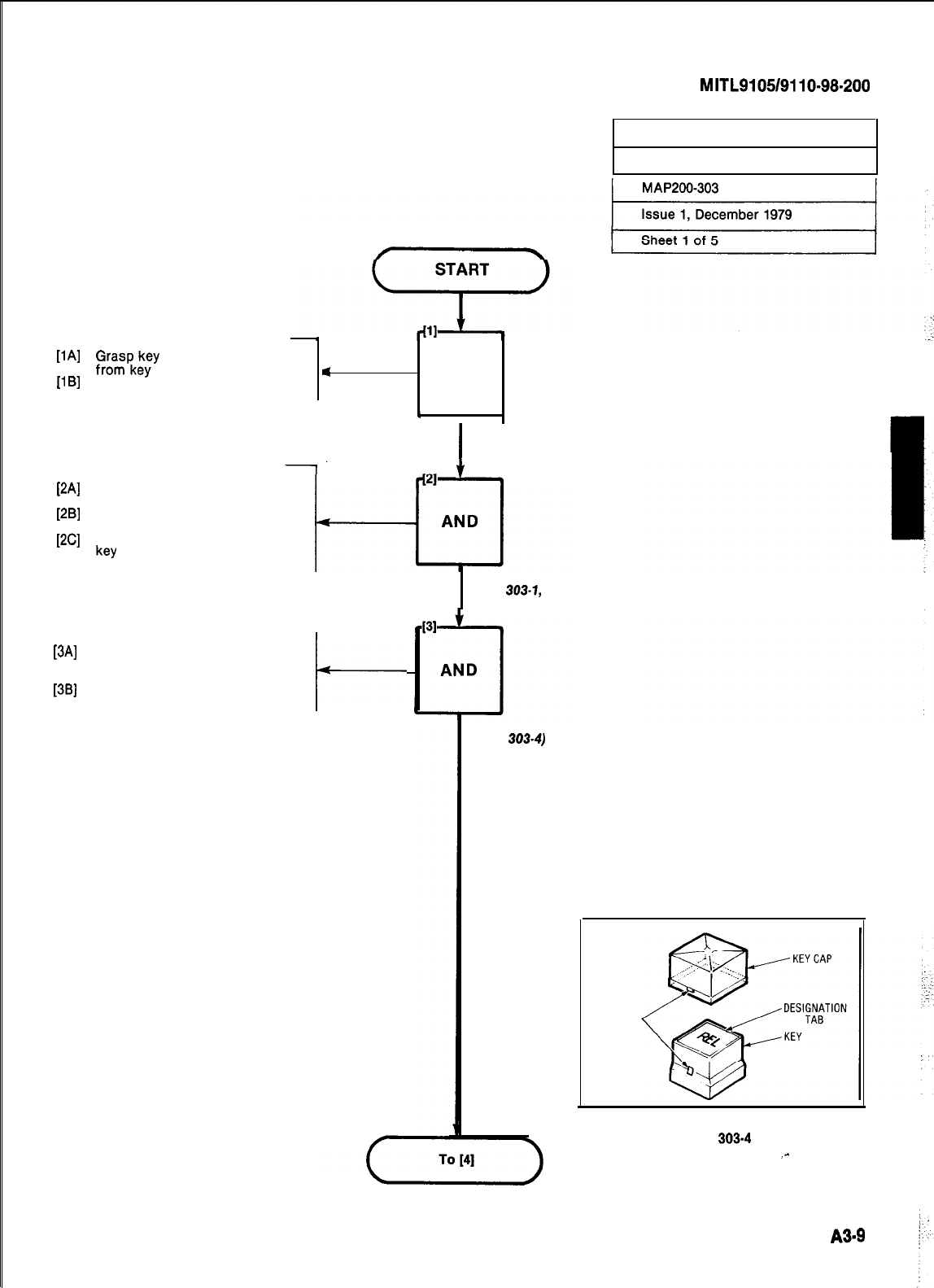
SECTION
MITL9105/9110-98.200
INSTALL CONSOLE
FACEPLATE DESIGNATIONS
[lA] f~;pkekyey
cap and pull upward
[lB]
Remove key designation tab
<
AND
4
I
I
REMOVE KEY CAP
Check required console layout
(Figs 303-1, -2 or -3)
Push out required designation
tab from designation sheet
Place designation tab on top of
key
PAI
PI
WI
INSERT DESIGNATION TAB
(FIG.
303-1,
-2 OR -3)
[3A]
Place key cap over key checking
that locking tabs are lined up
[3B]
correctly. (Fig. 303-4)
Push down on key top
I-
REPLACE KEY CAP
(FIG.
303-4)
LOCKINGTAB
Fig.
3034
_-
AS9
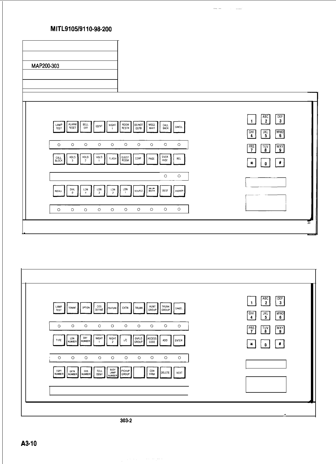
SECTION
MITL9105/9110-98-200
INSTALL CONSOLE
FACEPLATE DESIGNATIONS
MAP200-303
Issue 1, December 1979
Sheet 2 of 5
00 0 0 00 0 0
“-_I
r7
Fig. 303-l Attendant Console Key Designations, Hotel/Motel
1
_-
Fig.
303-2
Maintenance Console Key Designation
L
I
A3-10
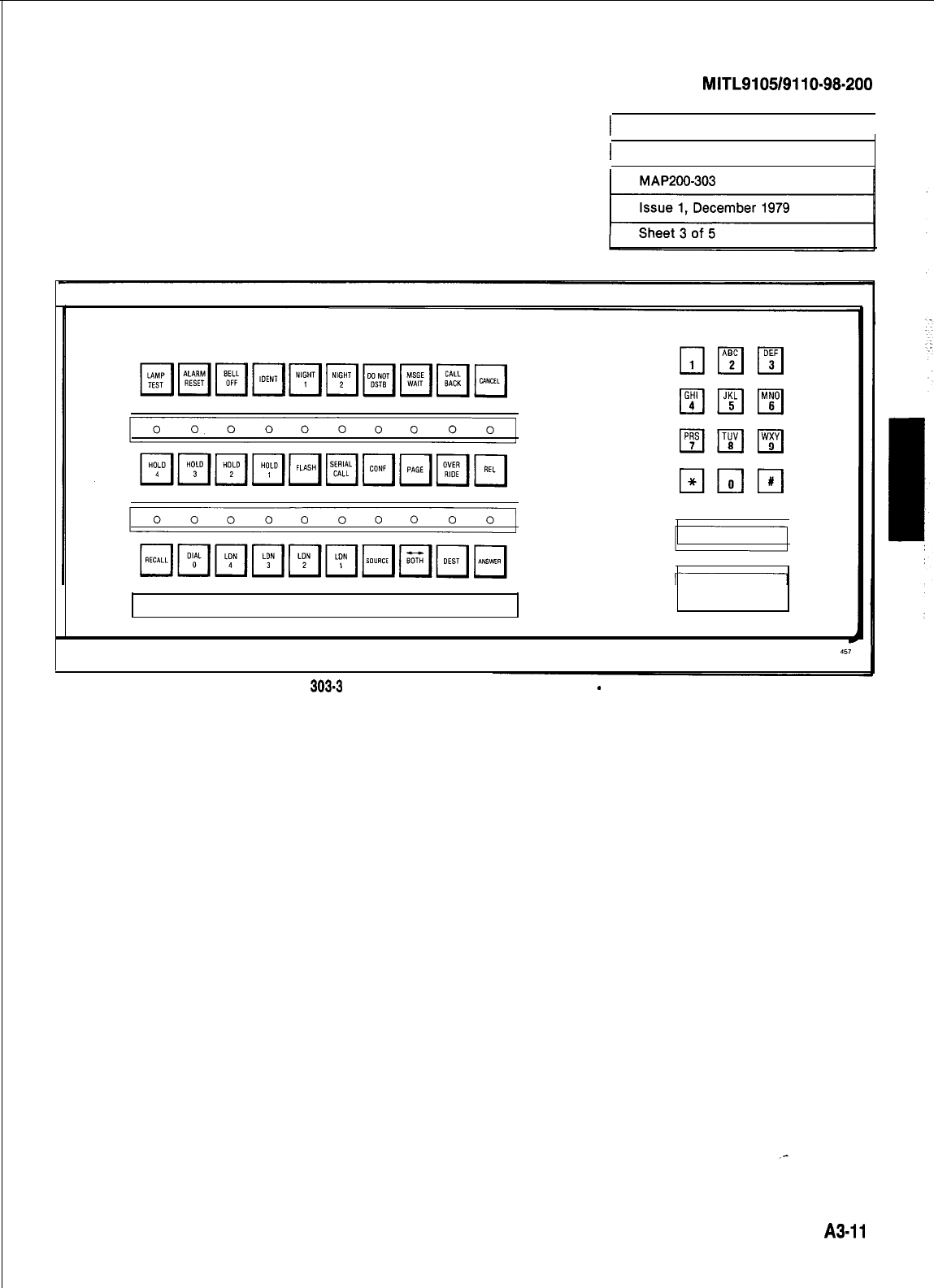
SECTION
MITL9105/9110~98~200
t
INSTALL CONSOLE
I
1 FACEPLATE DESIGNATIONS
0 0 0 0 0 0 0 0 0 0
Fig.
303-3
Attendant Console Key Designations
-
Commercial
A3-11
I
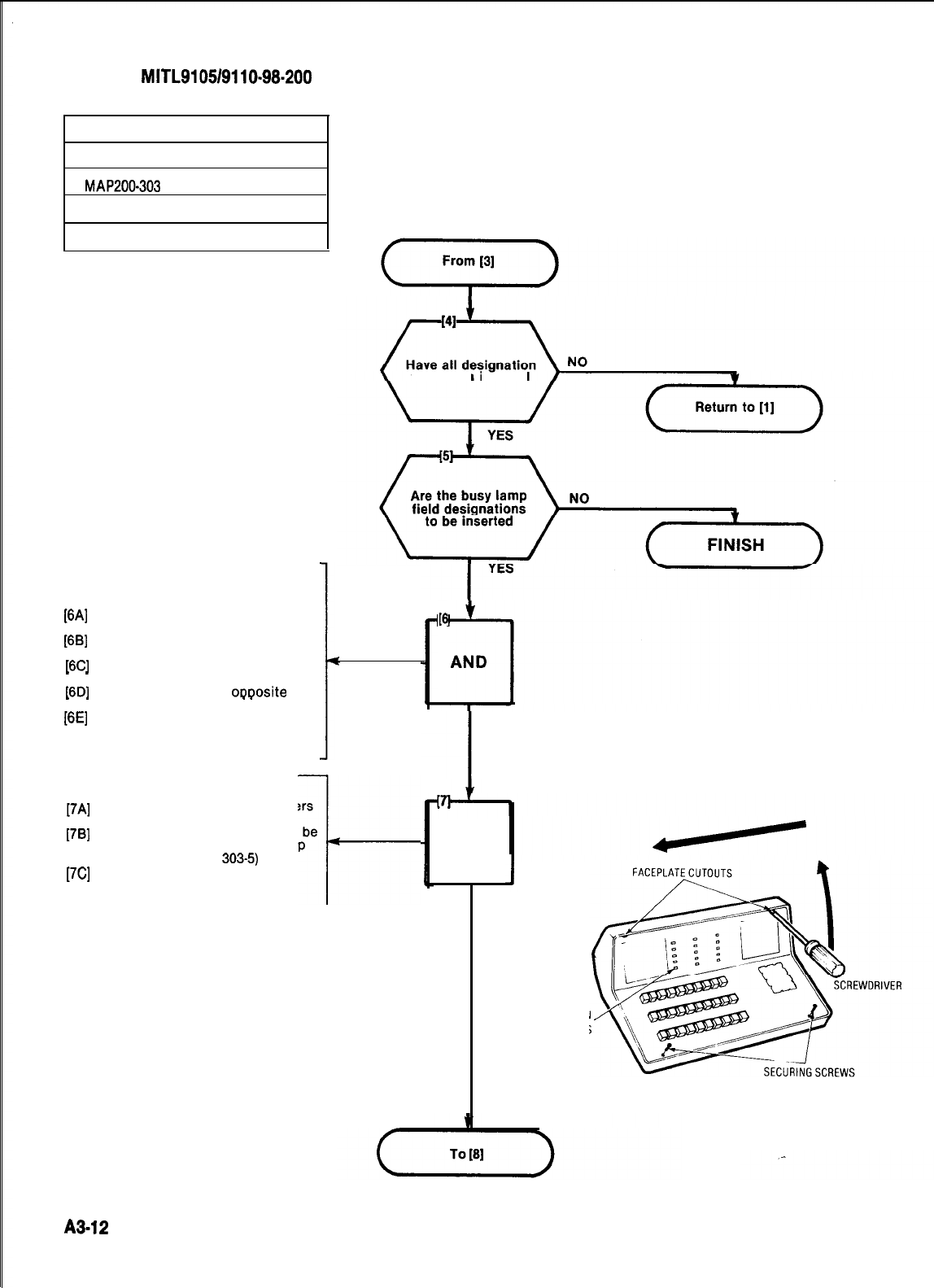
SECTION MITL9105/9110-98.200
INSTALL CONSOLE
FACEPLATE DESIGNATIONS
MAP200-303
Issue 1, December 1979
Sheet 4 of 5
tabs been inserted
[6A]
Remove the two faceplate secur-
ing screws (Fig. 303-5)
[SB]
Insert screwdriver blade into
faceplate cutout (Fig. 303-5)
16Cl
Move screwdriver to the vertical
_
_
position
16Dl
Slide screwdriver to
oooosite
end
.
. .
.
of console
[6E]
Remove console faceplate
t
c
[7A]
Cut required busy lamp numbers
from designation sheet
[7B]
Position number so that it will be
seen clearly through busy lamp
field window (Fig.
303-5)
[7C]
Press number firmly in place
I-
[6
REMOVE CONSOLE
FACEPLATE (FIG. 303-S)
AND
J
ATTACH BUSY
LAMP NUMBER
DESIGNATION
WINDOWS
Fig. 303-5
A3-12
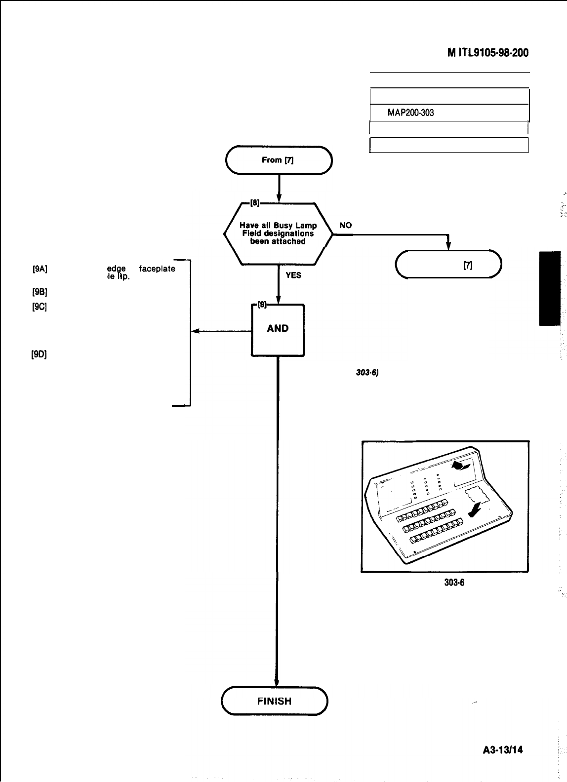
[9A]
Place bottom
ed$
of
faceplate-
against console
up.
[9B]
Place faceplate over keys.
[9C]
Press down firmly on console
faceplate and press one corner
under the top edge of the con-
sole housing as shown in Fig.
303-6
[9D] Continuing the downward
pressure, press the remainder of
top edge of the faceplate under
the housing lip.
El Replace the two faceplate
screws.
-
SECTION
M
ITL910!598.200
INSTALL CONSOLE
FACEPLATE DESIGNATIONS
MAP266303
I
Issue 1, December 1979
I
w
’
Sheet 5 of 5
1
Return to
VI
.
.
:.
.:-
:
!I
REPLACE CONSOLE
FACEPLATE (FIG.
303-6)
Fig.
303.6
.:
-.
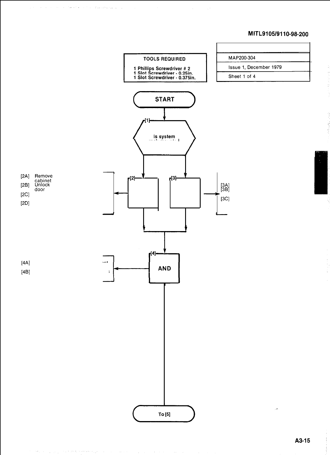
SECTION
MITL9105/9110-98-200
INSPECT EQUIPMENT
rack mounted
NO
YES
[2A]
;;;;w;
keys taped to top of
-PI
v
.
d31
'
[2B]
tdJ;$ck
and open cabinet front
[3A]
Inspect shelf mounting
[2C]
Remove the vertical and horizon-
-
AND AND
-
[3B]
Using the Phillips screwdriver
tighten all shelf retaining screws
tal shelf securing straps
[3C]
Remove the vertical and horizon-
[2D]
Using the Phillips screwdriver
tighten all shelf retaining screws tal shelf securing straps
.
-
CHECK SHELVES CHECK SHELVES
ARE SECURE ARE SECURE
[4Al
[4W
Check card complement against
invoice
Visually check cards and shelves
for damage
CHECK CARDS
AND SHELVES
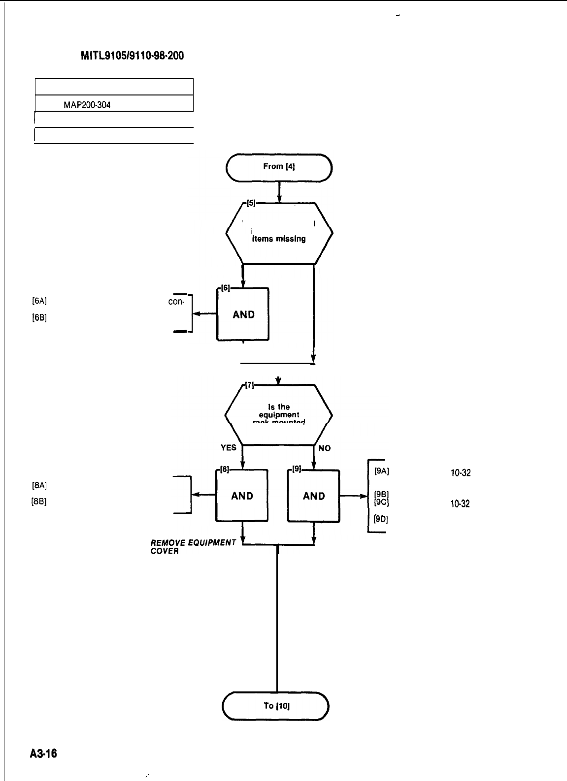
-
SECTION
MITL9105/9110-98-200
INSPECT EQUIPMENT
MAP200-304
I
Issue 1. December 1979
I
I
Sheet 2 of 4
I
[6A]
Tag any damaged items and
cz
tinue with inspection
[6B]
Enter damage details on Damage
Report form
-
Were any damaged
items found or
YES
1
I
TAG DAMAGED
ITEMS 1
[8A]
Remove the eight 6-32 screws
from the equipment cover
[8B]
Remove the equipment cover
NO
rack mounted
Remove four
lo-32
screws from
the panel at the rear of the
cabinet
Remove the back panel
Remove four
lo-32
screws from
the top panel
[9D]
Remove the top panel
REMOVE THE
TOP AND BACK
PANELS
A3-16
.:
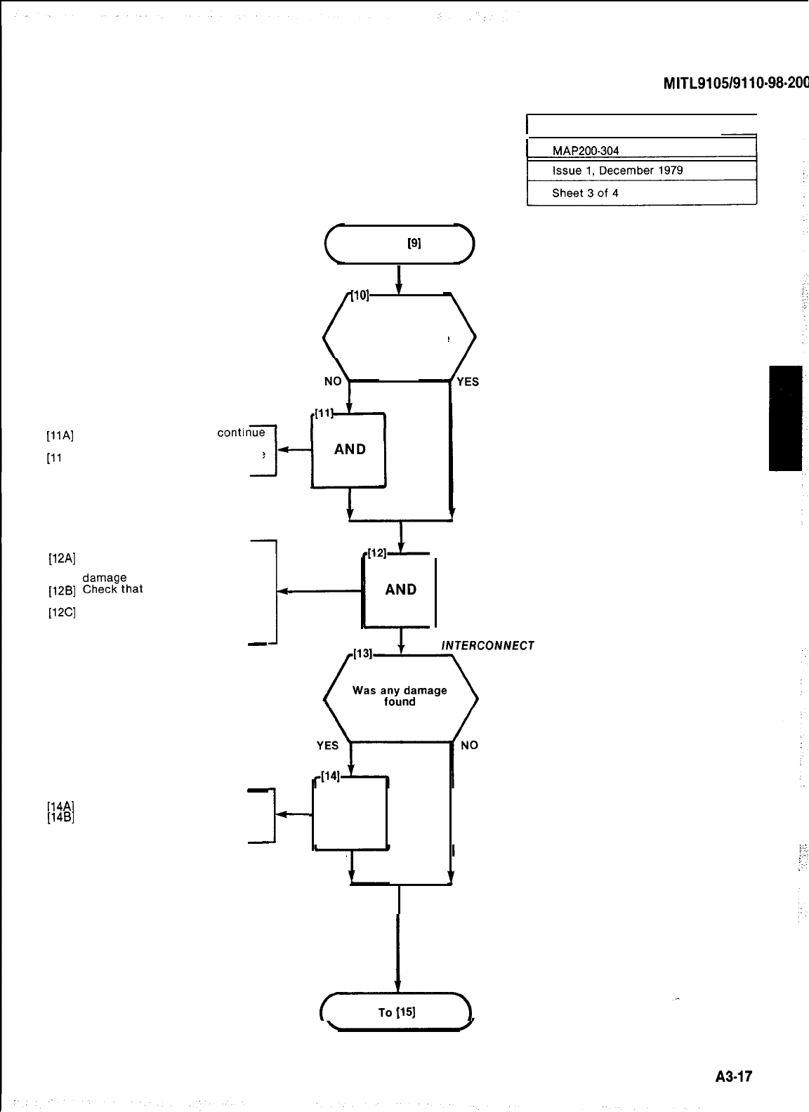
From
[9]
WI
1
Is power supply
free from damage
[llA]
Tag defective items and
with inspection
[ll
B] Enter damage details on Damage
Report form
TAG AND REPORT
DEFECT/YE ITEMS
[12A]
Check that all cable connectors
are seated firmly and free from
[12B]
%i:??hat
all cable harnesses
are free from damage
[12C]
Visually check backplane and in-
terconnect board for damage (in-
cluding fuses)
-
-
[14A]
Tag any damaged items
[14B]
Enter damage details on Damage
Report form
-
t
SECTION
MITL9105/9110-98.200
I
INSPECT EQUIPMENT
I
1
MAP200-304
CHECK BACKPLANE AND
/NTERCONNECT
BOARD
-
AND
-
AND
TAG AND REPORTTAG AND REPORT
DAMAGED ITEMSDAMAGED ITEMS
‘I‘I
I
A
To
[15]
!
A3-17
j
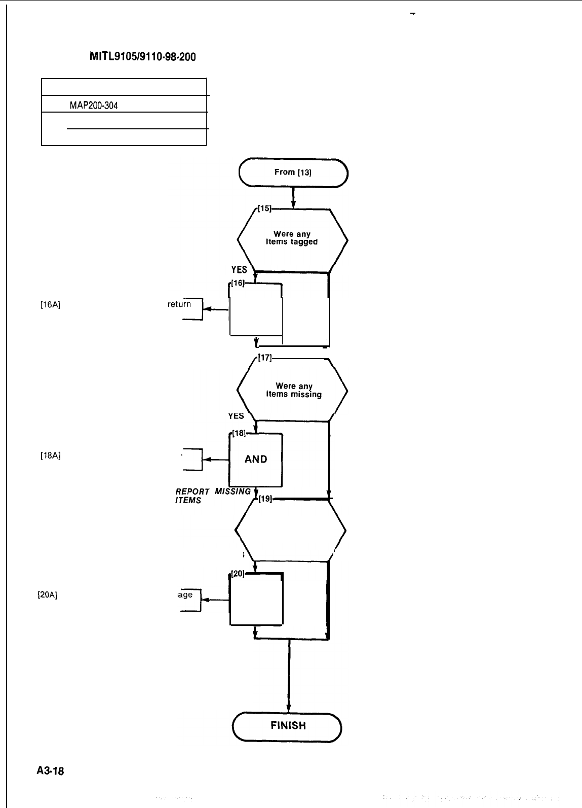
-
SECTION
MITL9105/9110-98-200
INSPECT EQUIPMENT
MAP200-304
Issue 1, December 1979
--
Sheet 4 of 4
l16Al
Repack tagged
to supplier items
and
See Damage Report and com-
plete appropriate section
NO
AND
RETURN TAGGED
t
ITEMS
V
/
1171
t
Were there other
discrepancies
during inspection
YES
[20A]
Report discrepancies on Dam
Report form AND
REPORT
DISCREPANCIES
NO
‘NO
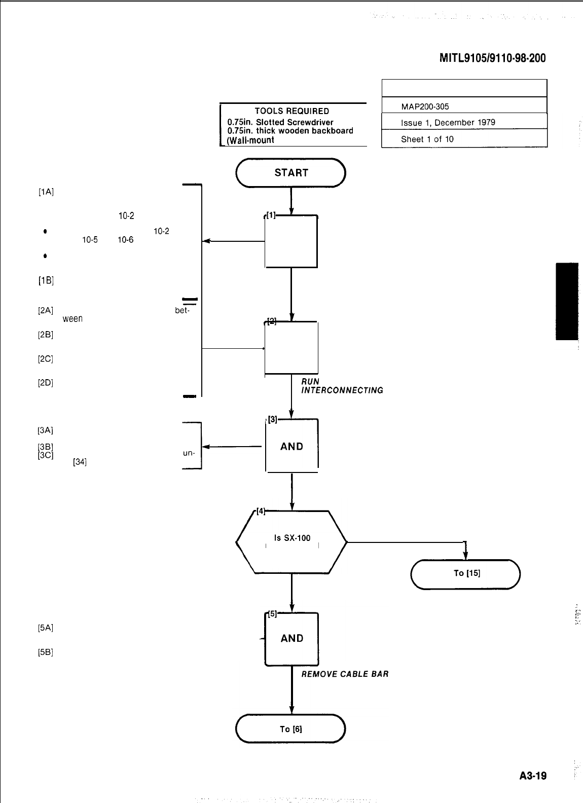
PAI
.
.
.
U
Bl
PA1
V.31
WI
PDI
PAI
WI
Terminate 25 pair cable connec-
tions at cross-connect field
Refer to Part 10 Table 10-l and
Fig. 10-l and
10-2
for line, trunk
and console connections
Refer to Part 10 Table
10-2
and
Fig.
10-5
and
10-6
for Power Fail
Transfer connections
Refer to Part 11 Fig. 11-l and
11-2 for typical layout and
designations
Mark each cable connector or
plug with the corresponding
cabinet plug number
-
Run required 25 pair cables
be?
ween
cabinet and cross-connect
field
Run required power fail transfer
cables between cabinet and
cross-connect field
Run required 25 pair console
cable from each console to
cabinet
Mark each cable connector with
its cabinet plug number
-
1
“,:;gj;:
;;;gJ~;;board
1
(Wall.mount
installation only)
*
AND
I
SECTION
MITL9105/9110-98-200
INSTALL EQUIPMENT
MAP200-305
TERMINATE CABLES AT
CROSS-CONNECT FIELD
l
-
AND
l
RUN
25 PAIR
/NTERCONNECT/NG
CABLES
Remove shipping strap from
shelf
Remove all cards from shelf
Place all cards in secure area un-
til
[34]
l-
,131
i
AND
I
REMOVE CARDS
FROM SHELF
rack mounted
YES
NO
J
Remove two 6-32 screws from the
cable bar across the back of the
rack (Fig. 305-l)
Remove cable bar I-
..
L:
”
::.
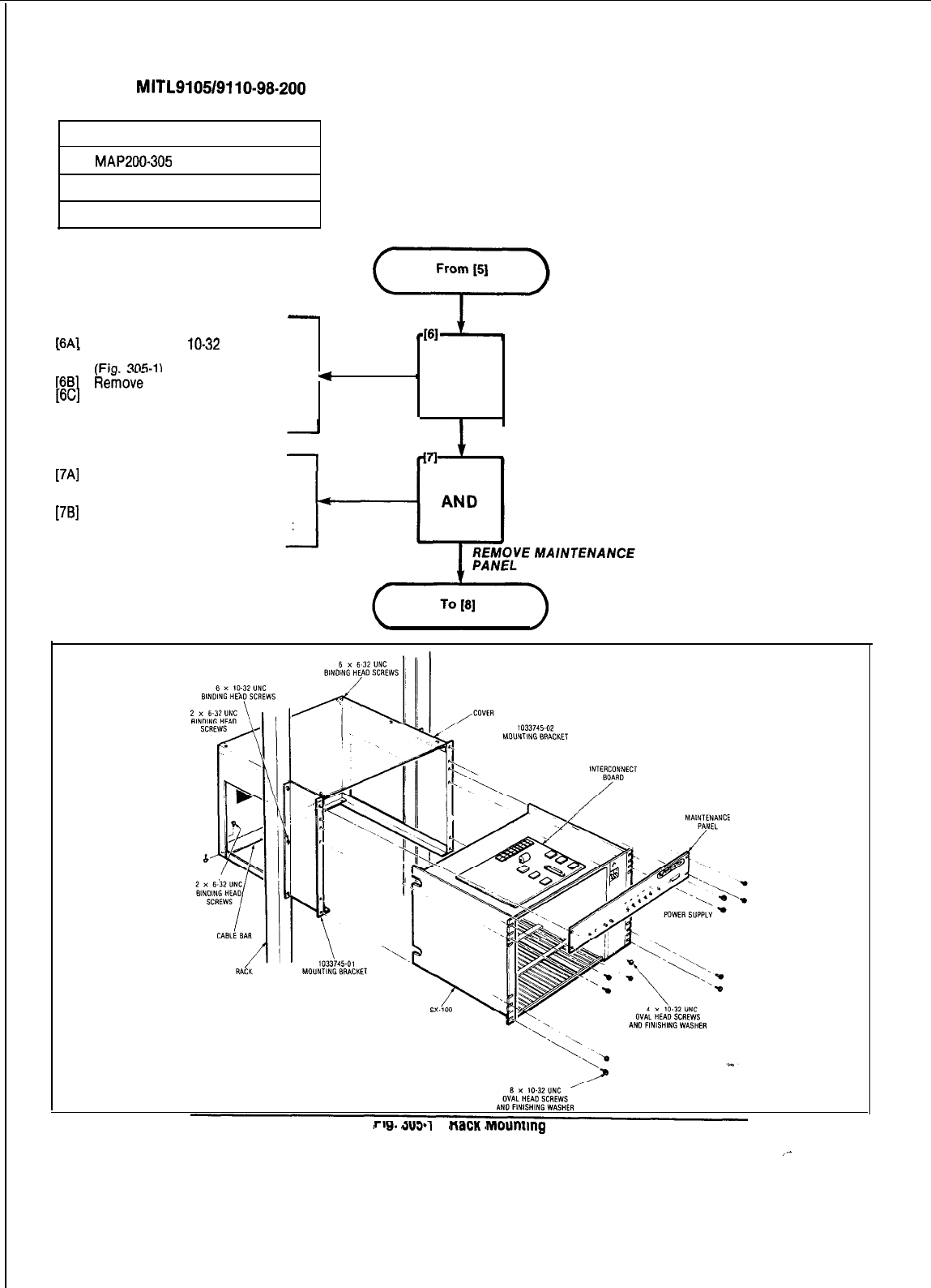
SECTION
MITL9105/9110-98.200
INSTALL EQUIPMENT
MAP200-305
Issue 1, December 1979
Sheet 2 of 10
18A1
Remove three
lo-32
screws and
washers from the front of SX-100
IFio.
305-l)
[6B]
ii&&e
the mounting bracket
[6C]
Repeat steps 6A and 6B for se-
cond mounting bracket
*
1 AND
REMOVE MOUNTING BRACKETS
[7A]
Remove four 8-32 screws and
washers from front of
maintenance panel
[7B]
Remove the maintenance panel
from the front of the equipment
rng.
JUJ‘l
nacn
mounmg
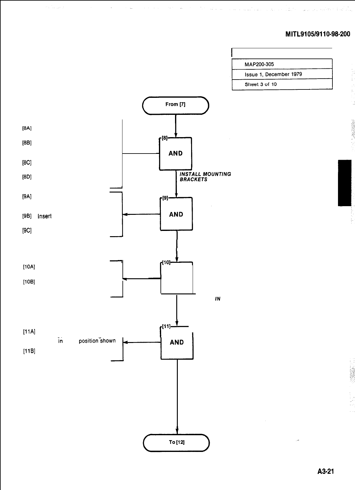
PA1
WI
WI
PDI
WI
WI
WI
IllAl
FlBl
Locate the mounting area for the
mounting brackets on equipment
rack
Place mounting brackets as
shown in Fig. 305-1, with lip of
the brackets at the bottom facing
in
Place six 10-32, 0.5 inch binding
head screws in holes shown in
Fig. 305-l
Tighten all screws with a 0.25
inch slotted screwdriver
Place cable holder bar across the
bottom of the rear of the moun-
ting brackets. The bar should
rest on the lip of the brackets
Insert
one 6-32, 0.5 inch long
binding head screw in each end
of the bar (Fig. 305-l)
Tighten all screws with a 0.25
inch slotted screwdriver
SECTION
MITL9105/9110-98-200
j
I
INSTALL EQUIPMENT
I
INSERT CABLE HOLDER
-
Place SX-100 on mounting
brackets with the backplane fac-
ing the rear
Slide SX-100 back until the rear
W
AND
of the faceplate makes contact
with the mounting bracket .
.
PLACE SX-100
RACK MOUNT
IN
UN/T
Insert 10-32, 0.5 inch long binding
head screws and finishina 1
I
llll~
1
I
washers
k-r
each
positionshown
in Fig. 305-l
Tighten all screws with a 0.25
inch slotted screwdriver
t--r-J
INSERT AND TIGHTEN
SCREWS TO RACK MOUNT
THE SX-100
~3.21
I
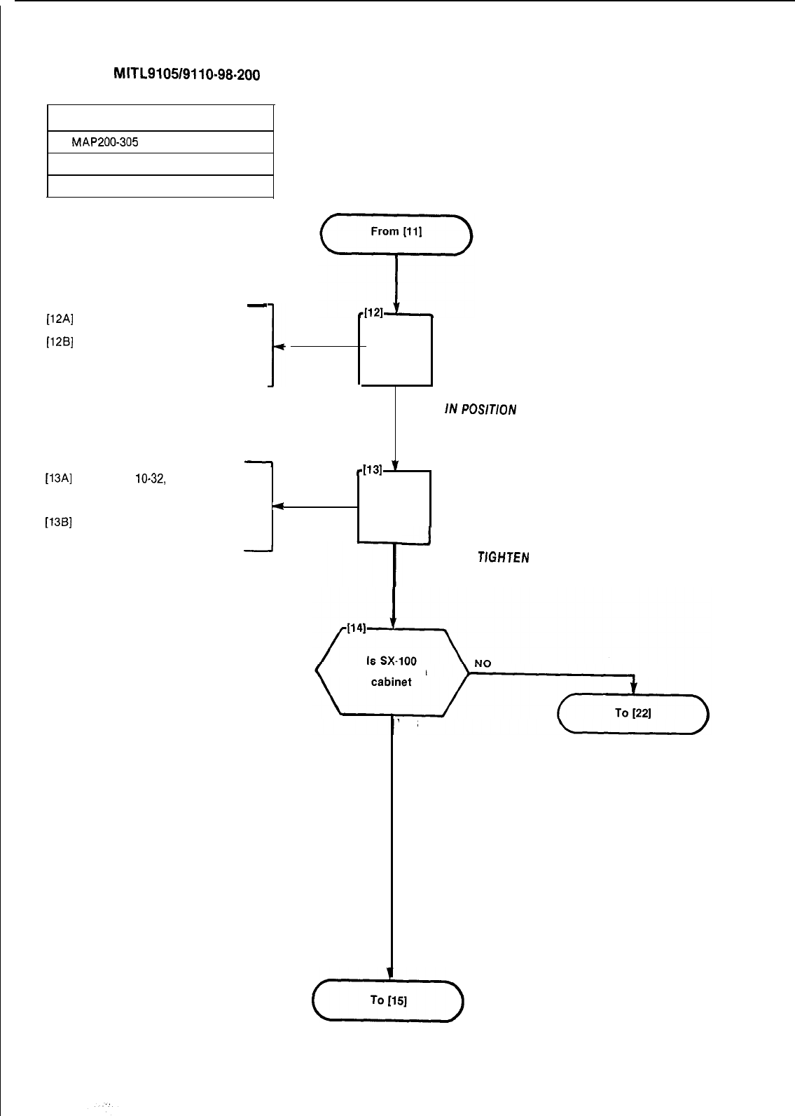
-
[12A]
Place maintenance panel in posi-
tion shown in Fig. 305-l
[12B]
Slide maintenance panel back
until the rear of the faceplate
makes contact with the mounting
bracket
SECTION
MITL9105/9110-98.200
INSTALL EQUIPMENT
MAP200-305
Issue 1, December 1979
Sheet 4 of 10
AND
.
PLACE MAINTENANCE
PANEL
IN
POSlTlON
-
[13A]
Insert four
10-32,
0.5 inch long
binding head screws and
finishing washers in positions
shown in Fig. 305-l
4
4131
v
AND
[13B]
Tighten all screws with a 0.25
inch slotted screwdriver
I
INSERT AND
TlGHTEN
SCREWS AND MOUNT
MAINTENANCE PANEL
mounted in a
YES
A3-22
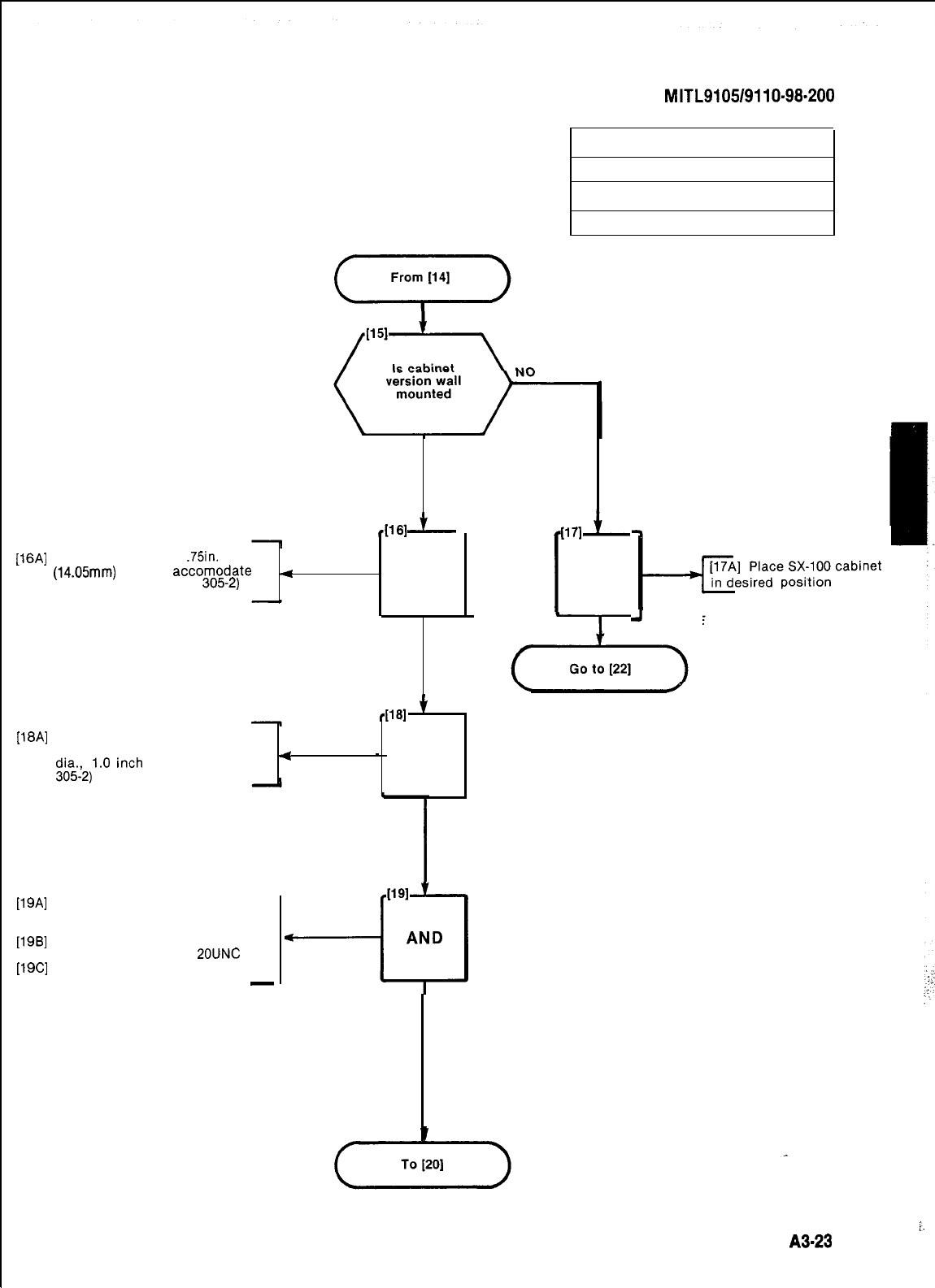
SECTION
MITL9105/9110-98-200
INSTALL EQUIPMENT
MAP200305
Issue 1, December 1979
Sheet 5 of 10
YES
I
I171
L
AND
4
elk
[16A]
Secure a backboard
.75in.
(14.05mm)
thick to
accomodate -=
mounting bracket (Fig.
3052)
AND
SECURE
BACKBOARD
4161
’
[18A]
Secure mounting bracket to
backboard with eight, 0.25 inch
4
clay2)1.0
inch
long screws (Fig.
-
AND
J
LOCATE
sx-100
SECURE MOUNTING BRACKET
[19A]
Place one pivot pin on each side
at the back of the bottom of the
cabinet
[198]
Secure pin from the inside of the
cabinet with a 0.25 x
POUNC
nut
[19C]
Tighten nut until pin is secure
-
PLACE AND SECURE SX-100
PIVOT PINS
;.
!
A3-23
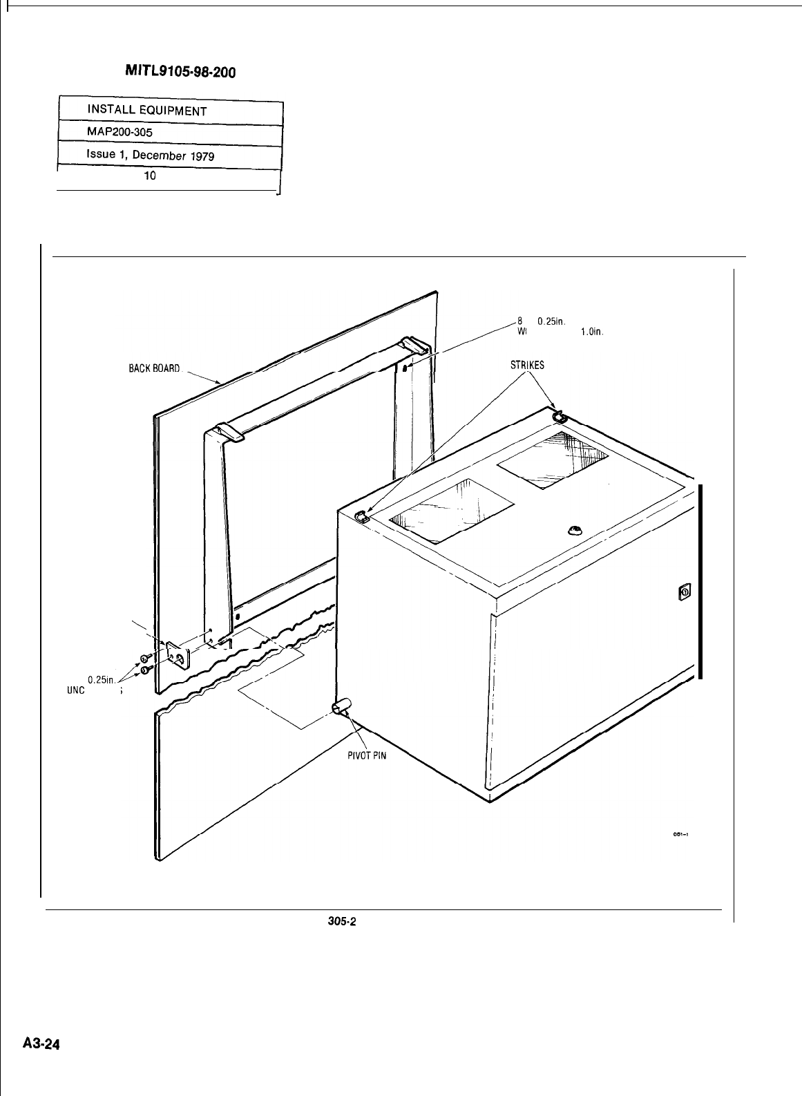
SECTION
MITL9105.98.200
Sheet 6 of
lo
1
PIVOT BRACKET
\
4 x a-32
x
0.25lll.
UNC
SCREWS
x
0.25in.
DIA.
OOD SCREWS
l.Oin.
LONG
Fig.
3052
Wall Mounting
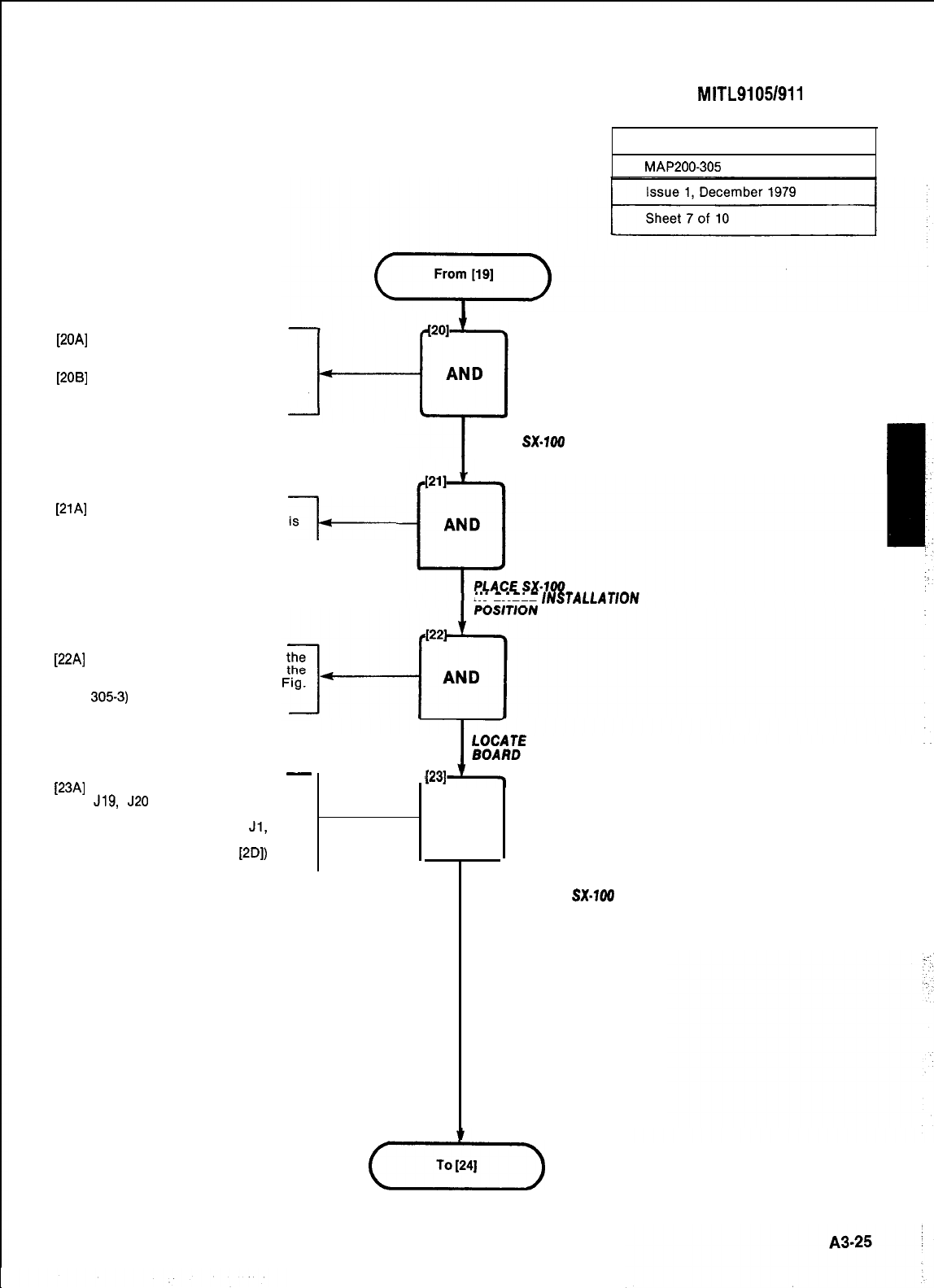
SECTION
MITL9105/911
O-98-200
INSTALL EQUIPMENT
MAP200-305
[20A]
Place SX-100 in wall ‘mount
bracket, pivot pins first as shown
in Fig. 305-2
[208]
Secure SX-100 pivot pins with
pivot brackets and four 8-32 slot-
ted screws
[21A]
Allow SX-100 to swing down
(gently) so that the backplane IS
revealed
+-
PLACE
SX-100
IN WALL
MOUNT BRACKET
IN CABLE
/NSTALLAT/ON
[22A]
Locate interconnect board on
top of the SX-100 behind
maintenance panel (See
3053)
-
[23A]
Locate the following cables; J18,
J19,
J20
from cross-connect, con-
sole cables 1 and/or 2, printer
cable or storage device,
Jl,
J2,
J3, J4, Commercial Power cable,
and ground strap (See
[2D])
fOMM;E
THE INTERCONNECT
031
AND
.
LOCATE CABLES TO BE
RUN INTO THE
SX-700
(-x7=)
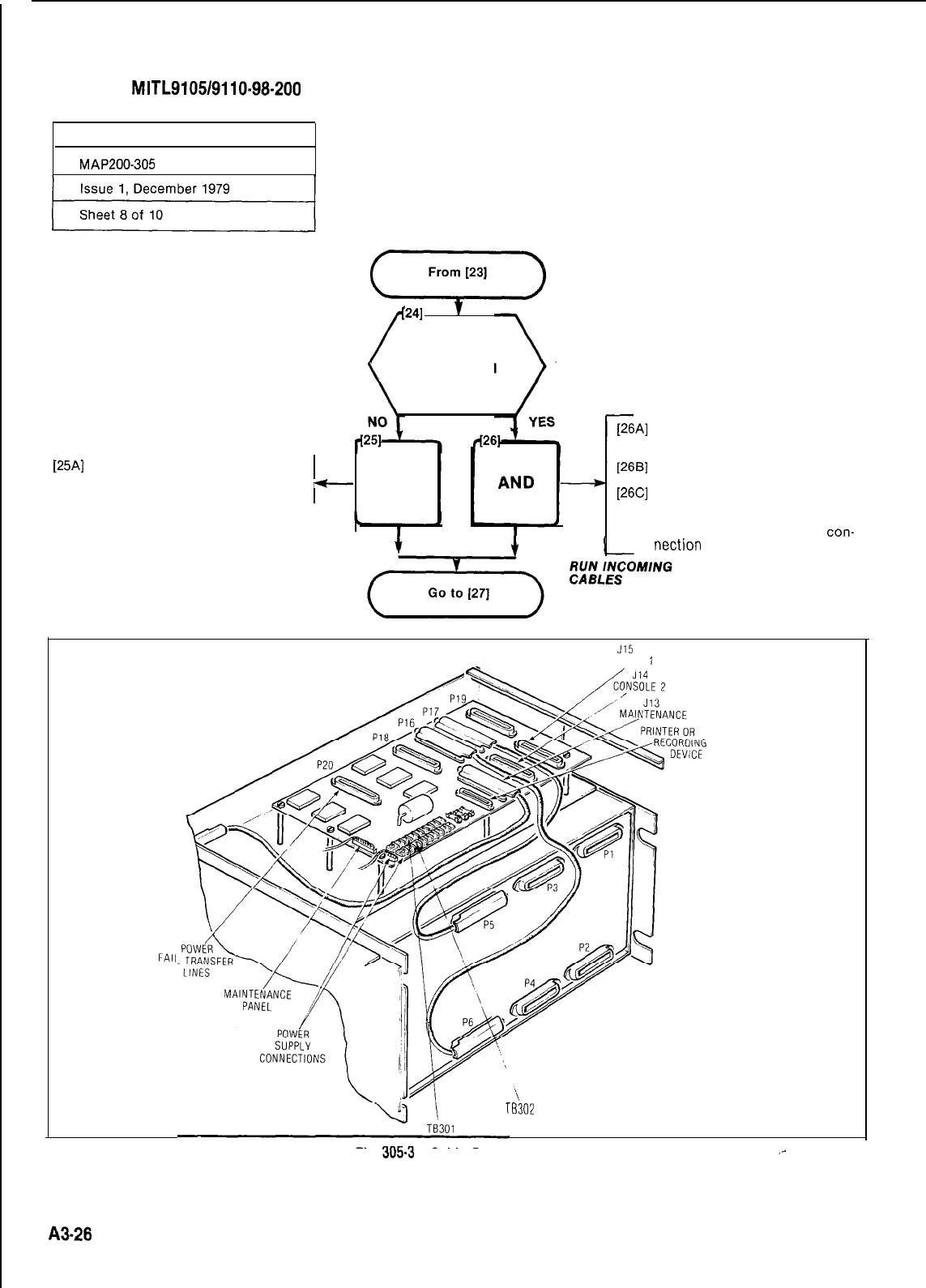
SECTION
MITL9105/9110-98-200
INSTALL EQUIPMENT
MAP200-305
1241
v
Is sx-100
rack mounted
[25A]
Run all incoming cables from
beneath the SX-100 through the
cable clamp
-
AND
GA]
Run all incoming cables along
the rack vertical to a point just
under the SX-100
[26B]
Run the cables up to the rear of
the SX-100 from the bottom
[26C]
Secure all cables with nylon
cable ties to the rear across the
cable bar (insure there is suffi-
cient cable inside to reach
con-
I
nection
points)
RUN INCOMING
CABLES
FAII
J15
CONSOLE
1
TB30'2
Fig.
305-3
Cable Connections
_-
A3-28
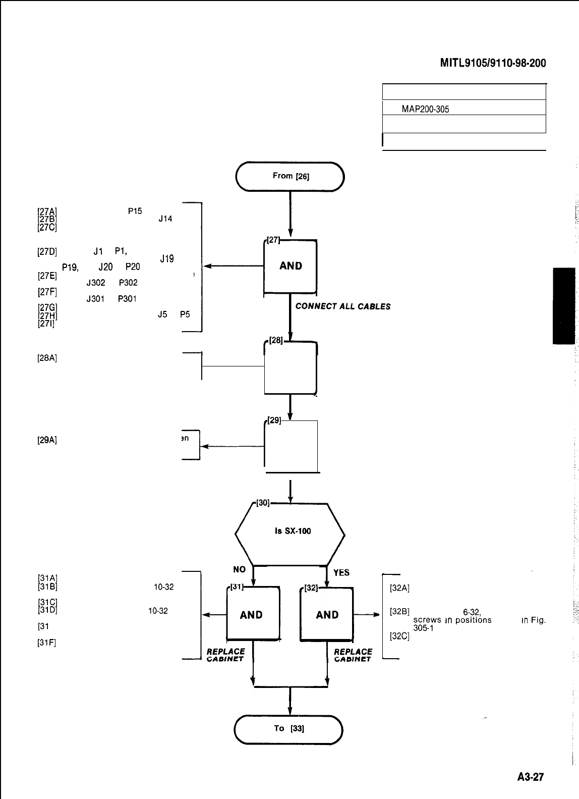
SECTION
MITL9105/9110-98-200
INSTALL EQUIPMENT
MAP200-305
issue 1, December 1979
I
Sheet 9 of 10 I
[27A]
Connect console
P15
to J15
[27B]
Connect console P14 to
J14
[27C]
Connect maintenance cable from
the back of the maintenance
panel P13 to J13
[27D]
Connect
Jl
to
Pl,
J2 to P2, J3 to
P3, J4 to P4, J18 to P18,
J19
to
P19,
and
J20
to
P20
[27E]
Connect printer or storage device
cable
J302
to
P302
(if required)
[27F]
Connect maintenance panel
cable
J301
to
P301
[27G]
Connect ground strap
[27H]
Connect J16 to P16 and
J5
to
P5
[27l]
Connect J17 to P17 and J6 to P6
[28A]
Tighten down all connector
screws with 0.25 inch slotted
screwdriver AND
4
TIGHTEN CONNECTORS
p1
I
[2gA] Using nylon cable straps tighten
around free end on all connec-
tors until connector is secure
-&-+
AND
I
I
J
I
T/E DOWN OTHER END
OF ALL CONNECTORS
[31A]
Replace back of cabinet
[31B]
Secure back with four,
lo-32
screws
[31C]
Replace top of cabinet
[31D]
Secure top with four,
lo-32
screws
[31
E] Swing SX-100 upwards and
secure with strikes
[31F]
If necessary adjust strikes by
screwing them in or out
rack mounted
PANELS COVER
[32A]
Place cover on SX-100 with
screen in the back as shown in
Fig. 305-l
[32B]
Place eight,
6-32,
0.5 inch long
;;;;s
rn
posrtrons
shown
tn
Frg.
[32C]
Tighten all screws with a 0.25
inch slotted screwdriver
A3-27
I
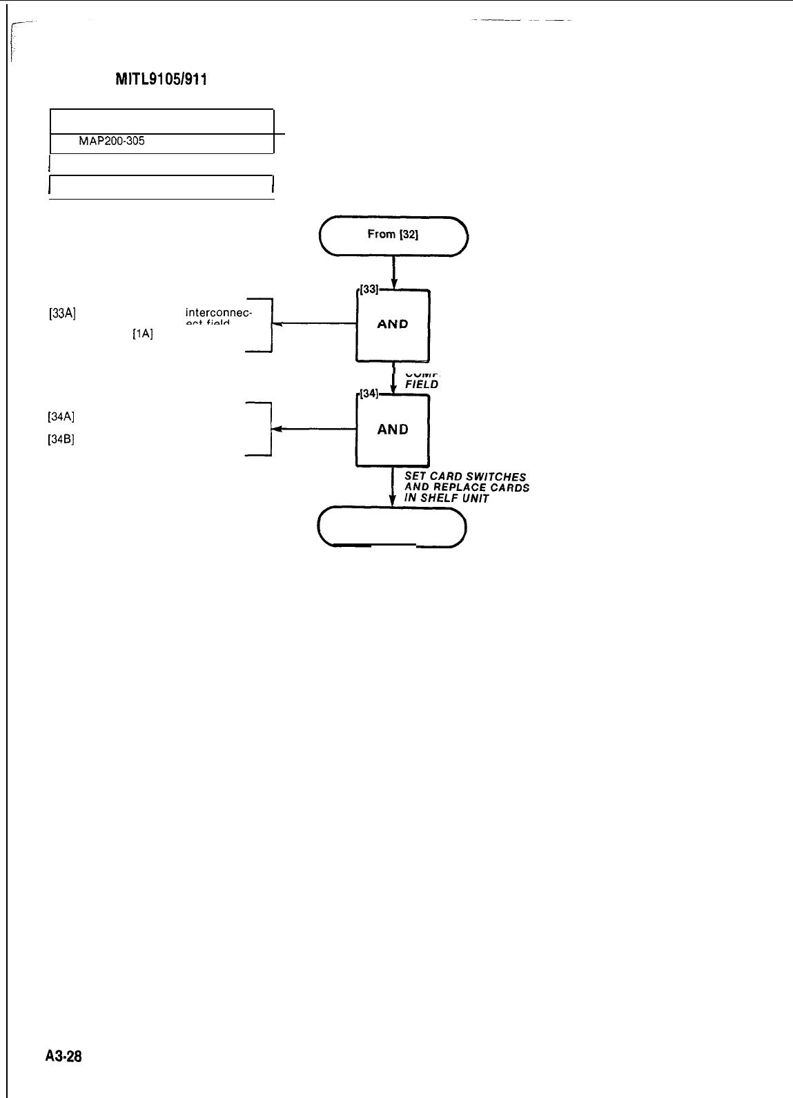
SECTION
MITLSI
05/911
o-98-200
INSTALL EQUIPMENT
MAP200-305
I
Issue 1, December 1979
I
I
Sheet 10 of 10
I
[33A]
Complete required
tions at cross-connect field.
Refer to
[iA]
for references
COMPLETE CROSS-CONNECT
INTERCONNECTIONS
[34A]
Set card switches as required
(Appendix A5)
[346]
Replace cards in shelf unit
FINISH
A3-28
1SET CARD SWITCHES
I
MAP200-306
Issue 1, December 1979
Sheet 1 of 1
The setting of switches, to result in the required
mode of operation on the Trunk Cards is detailed
in the MAP’s contained in Appendix A-5. The in-
staller should ensure that these cards are proper-
ly switched for the correct mode of operation prior
to performing “Power-Up” as detailed in
MAP200-307.
.;
A3-29130
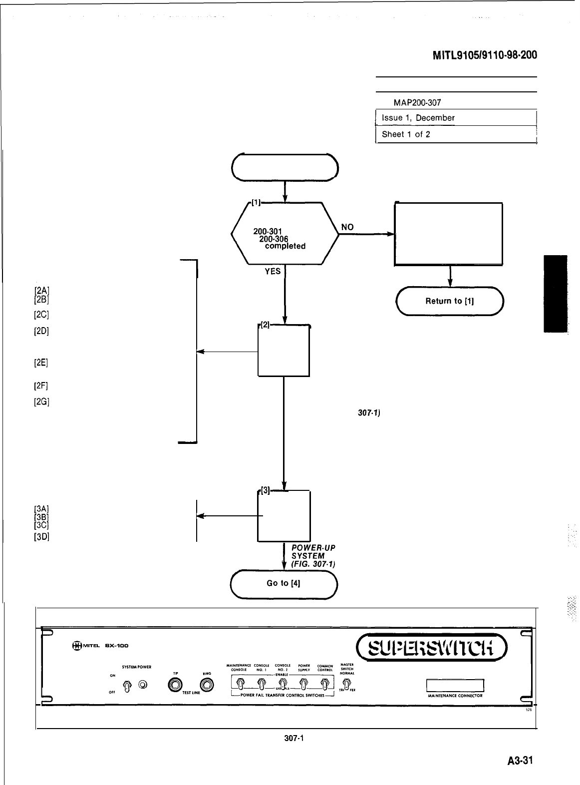
SECTION
MITL910519110-98-200
IPOWER-UP SYSTEM
I
I
MAP200-307
I
/
;;IItl,,
,D;;mber
1979
/
START
Have MAP’s
200-301
through
200-306
been
AT FRONT OF EQUIPMENT CABINET
[2A]
Unlock and open door if fitted
[2B]
Check that all cards are seated
correctly
[2C]
Check that locking bars are
secure
[2D]
Set all Power Fail Transfer Con-
trol switches on Maintenance
Panel to “DISABLE” (See Fig.
307-l)
4
AND
[2E]
Set POWER FAIL TRANSFER
CONTROL SWITCHES for con-
soles connected to “ENABLE”
[2F]
Set Power Fail MASTER SWITCH
to “NORMAL” CHECK CARDS
[2G]
Set POWER FAIL TRANSFER AND SET
SWITCHES to power supply and MAINTENANCE
common control to “ENABLE” SWITCHES (FIG.
307.1)
[3A]
Set AC Power Switch to OFF
[3B]
Plug power cord into outlet
4
AND
[3C]
Set AC Power Switch to ON
[3D]
Close equipment cabinet door
Complete required MAP’s
Fig.
307-l
A3-31
I
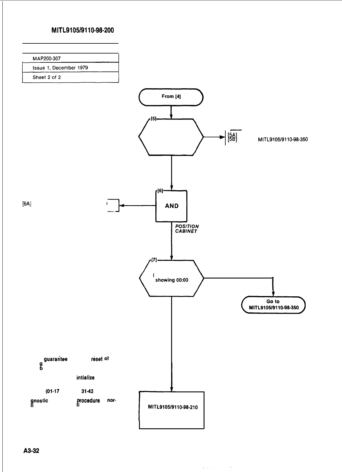
SECTION
MITL9105/9110-98-200
1 POWER-UP SYSTEM
I
1
MAP200-307
Wait 10 sec. Is
Power LED lit
NO
-
)
5A
f
I
Set AC Power Switch to OFF
58
Go to
MITL9105/9110-98-350
YES
[6A]
Place equipment cabinet in its
final position if required
Note
Occasionally, when circuit cards are
plugged into the PABX, the logic circuits
on the card may not reset completely. In
order to guarantee complete r&et
01
all
card lo
%
ic, a slot initialization procedure
must e
performed. This procedure
allows the service personnel to insert a
card into a shelf and intialize the card
slot. To initialize the card slot dial 555 +
5 + nn, where nn is the 2 digit card slot
number
(01-17
shelf 1,
31-42
shelf 2).
Since inserting a card may cause
diafi
nostic errors, this
r
rocedure
is
nor-
ma
y followed by dia rng 555 + 1 to
clear all system errors.
Is Console clock NO
I
YES
(iii&L)
I
Go to Section
MITL9105/9110-98-210
and Program
System
A3-32
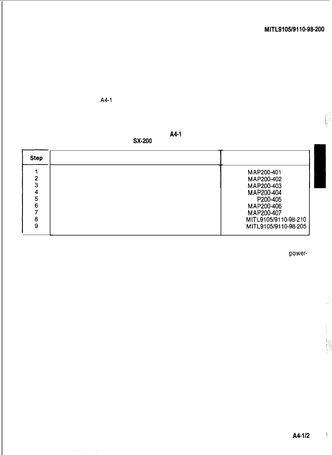
SECTION
MITL9105/9110-98.200
:
APPENDIX 4
SX-200 INSTALLATION PROCEDURES
1. General
A4.01
The following Table
A4-1
details the procedures to be performed to complete the installation of
an SX-200 PABX.
_’
i:
:
IL
:
TABLE
A4-1
SX-200
INSTALLATION
Procedure
Unpack Equipment Cabinet
Unpack Consoles
Install Console Faceplate Designation
Inspect Equipment
Connect Cables
Set Card Switches (Appendix 5)
Power-Up System (See Note)
Program System
Perform System Tests
Reference
MAP200-401
MAP200-402
MAP200-403
MAP200-404
MA P200-405
MAP200-406
MAP200-407
Section
MITL9105/9110-98-210
Section
MITL9105/9110-98-205
‘I
J
Note: Appendix 6 lists miscellaneous installation requirements which may be required prior to
power-
up of system. This appendix should be reviewed for applicability.
A4-l/2
:
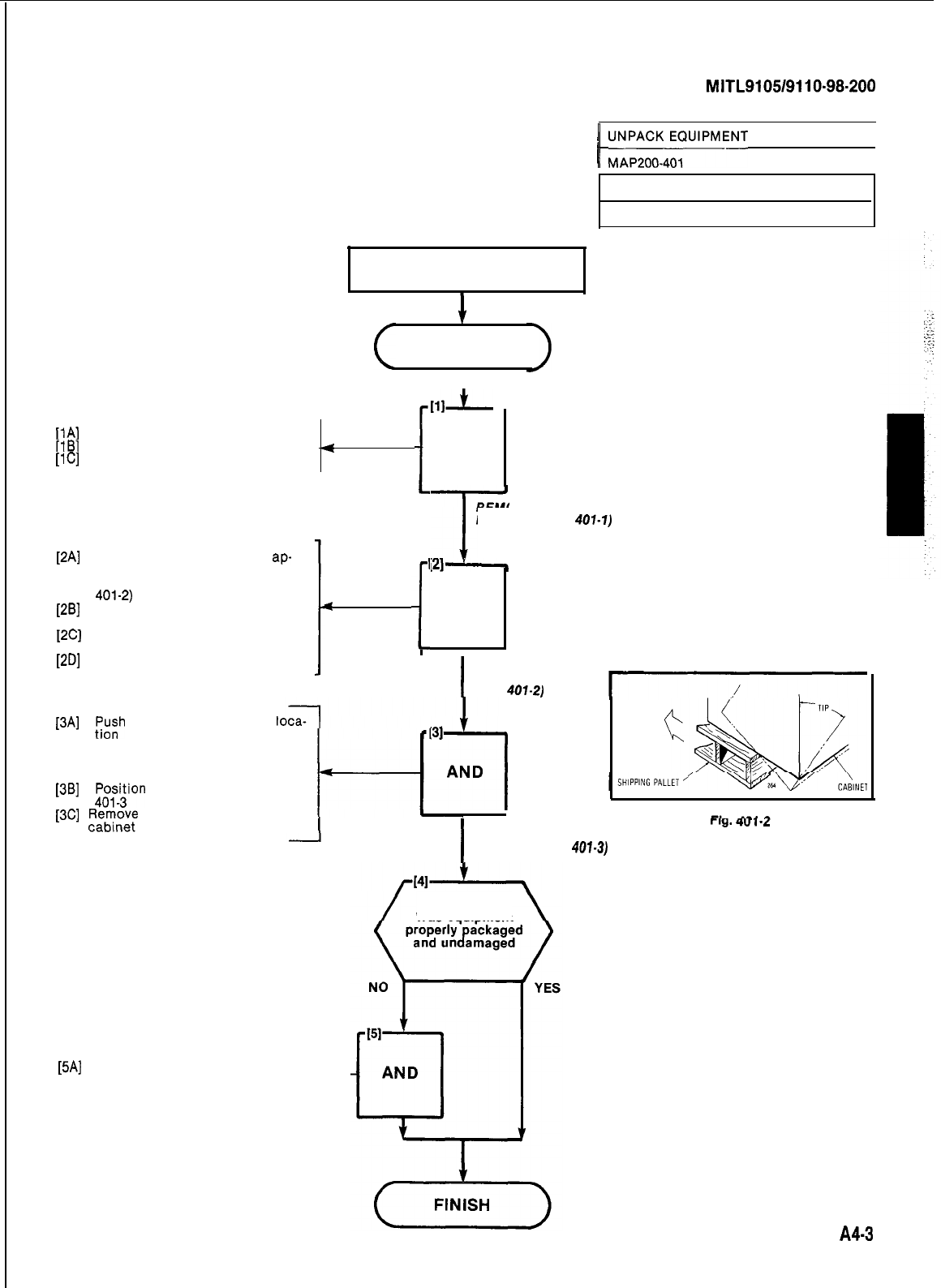
SECTION
MITL9105/9110-98-200
WARNING
TOOLS REQUIRED
1. Set of strap cutters
I
Gloves must be worn when unpacking
equipment cabinet. START
I
[lA)
[lB]
Cut and remove retaining straps
Open tri wall outer sleeve
[lC]
Remove inner tri wall sleeve
4
[2A]
Position equipment so that
ap-
prox. ten inches of cabinet
overhangs shipping pallet (Fig.
401-2)
[26]
Tip equipment so that rear of
cabinet touches floor
[2C]
Remove shipping pallet from
under cabinet
[2D]
Gently lower cabinet onto floor
[3A]
;;;h
cabinet to its required
CAUTION
Care must be taken while moving
cabinet to avoid damage.
[36] r;;W;ion
cabinet as shown in Fig.
[3C]
!+zmv;
plastic sheet from
<
[5A]
Complete relevant entries on
Damage Report Form -I--
COMPLETE
DAMAGE
REPORT
i
I
I
lil$
AND
/
~~~~4~~UIPMENT
CABINET1
REMOVE EXTERNAL
PACKING (FIG.
401.1)
AND
’ issue 1, January 1980
Sheet 1 of 3
I
REMOVE
SHIPPING PALLET
(FIG.
401-2)
REMOVE
:31
Was equipment
I
l-If&
4”
I-L
POSITION
CABINET (FIG.
401-3)
A43
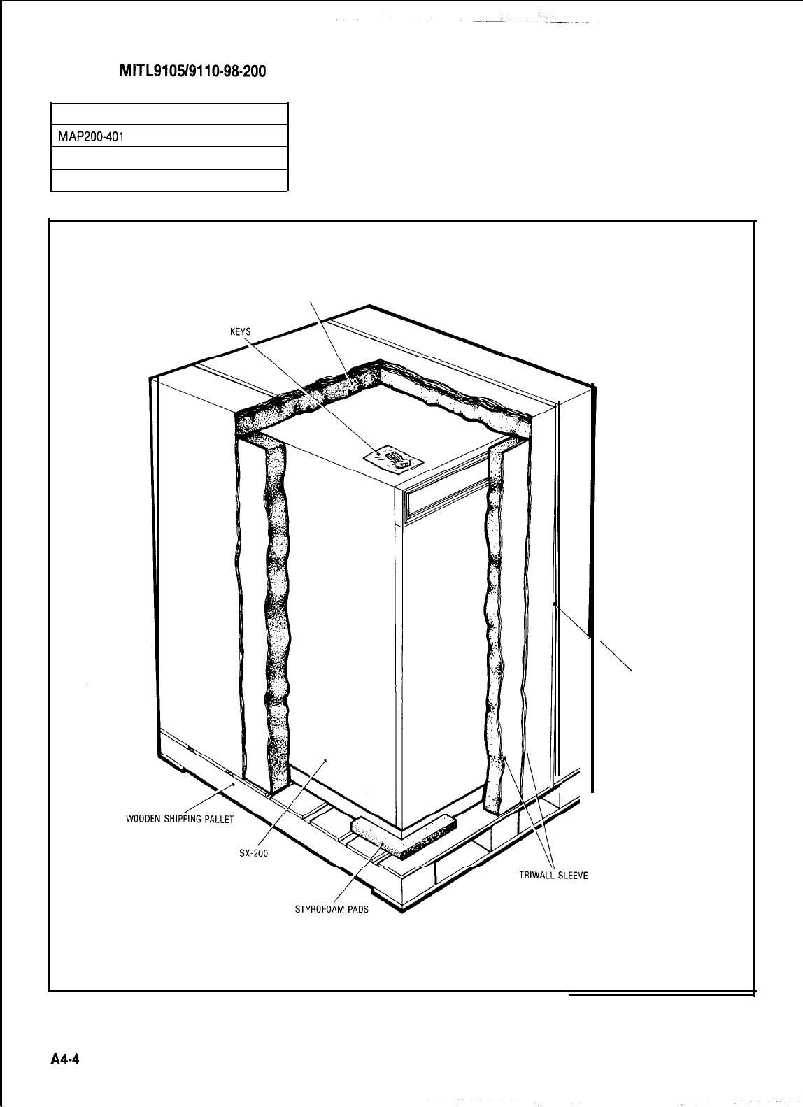
SECTION
MITL9105/9110-98-200
UNPACK EQUIPMENT CABINET
MAP200-401
Issue 1, January 1980
Sheet 2 of 3
STYROFOAM
\
FIBERGLASS TAPE
A4-4
Fig. 401-l
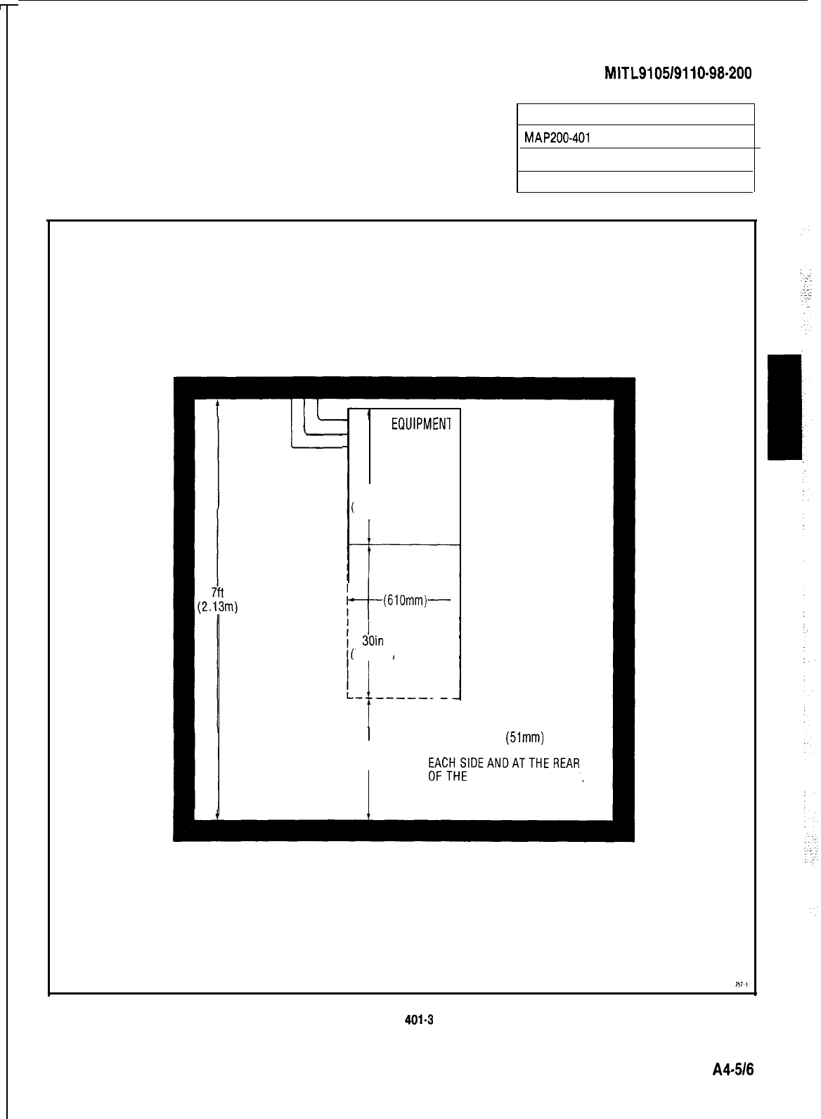
SECTION
MITL910519110-98-200
UNPACK EQUIPMENT CABINET
MAP200-401
Issue 1, January 1980
Sheet 3 of 3
L-
I
NOTE: CABLES
ENTERFROM ONE
SIDE ONLY
EQUIPMEN
CABINET
28in.
71 lmm)
t
24in.
(610mm)-
jOin
762mm)
I
24in
MINIMUM 2in
(51mm)
(610mm)
CLEARANCE IS REQUIREDON
EACHSIDEANDATTHEREAR
OFTHE
EQUIPMENTCABINET
Fig.
401-3
A4516
:
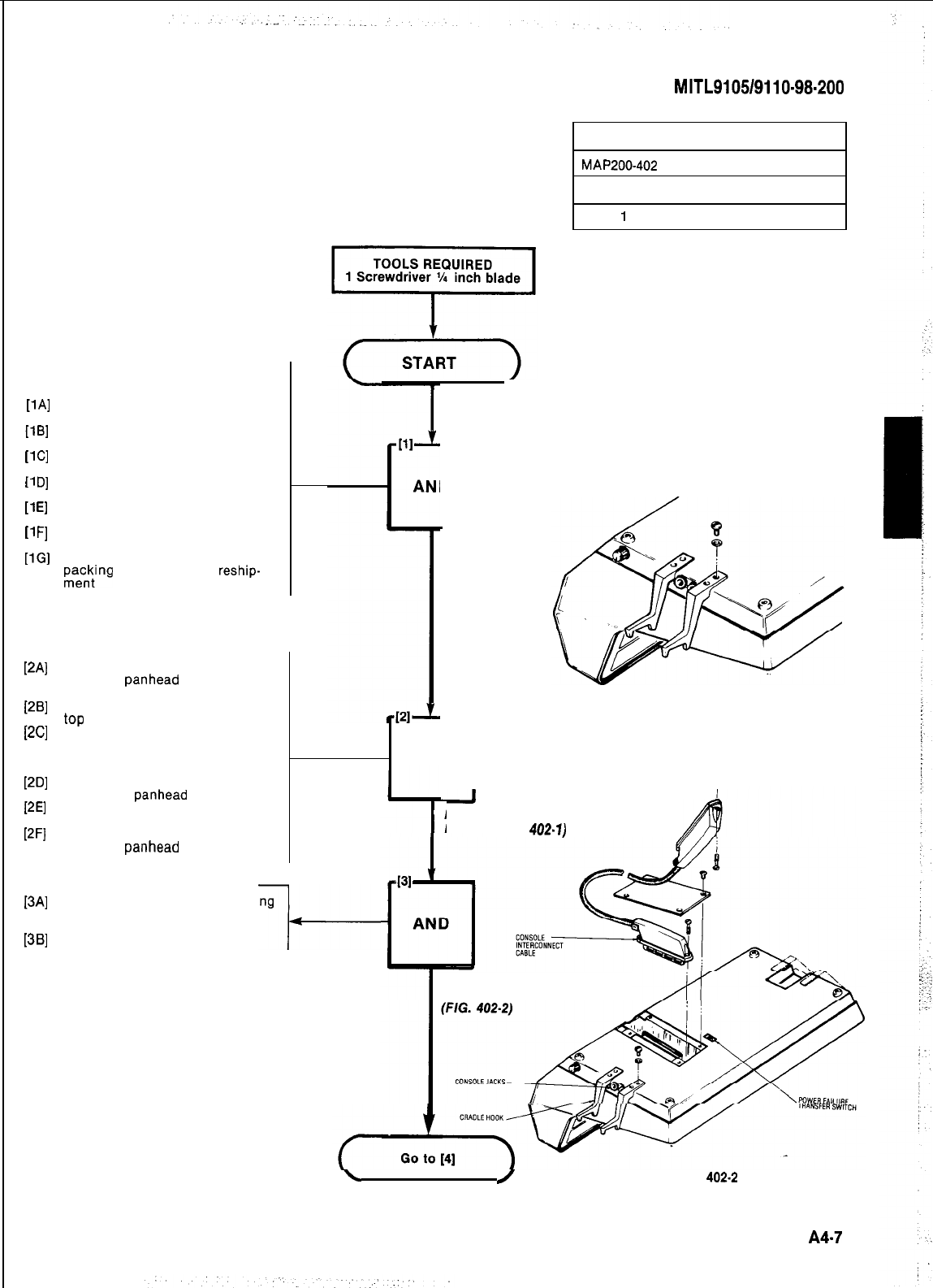
SECTION
MITL9105/9110-98.200
UNPACK CONSOLES
MAP200-402
issue 1, January 1980
Sheet
1
of 3
At Console Location
[1Al
11
Bl
11
Cl
11
Dl
[l
El
11
Fl
PGI
WI
PBI
PC1
WI
PEI
PFI
134
[3Bl
Remove fiberglass tape from top
of packing case
Open packing case and remove
foam sheet
Remove foam inserts from ends
of console (if installed)
Remove console accessory bag
from insert
Remove console from packing
case
Remove polyethylene sheet from
console
Place all packing materials in
re\yng
case for use in
reship-
Remove the two cradle hooks
and four
panhead
screws from
accessory bag
Place console face down on desk
top
Position one cradle hook as
shown in Fig. 402-l. (Cradle hook
may be placed at other end of
console if preferred)
Attach cradle hook to console
using two
panhead
screws
Position remaining cradle hook
(Fig. 402-l)
Attach cradle hook to console
with two
panhead
screws
Remove the four screws securing
the connector cover plate (Fig.
402-2)
Remove connector cover plate
-I-
AN
1
Fig. 402-I
D
D
1
UNPACK
CONSOLE
I
INSTALL CRADLE
HOOKS (FIG.
402.1)
REMOVE CONNECTOR
COVER PLATE
\/
Fig.
402.2
A47
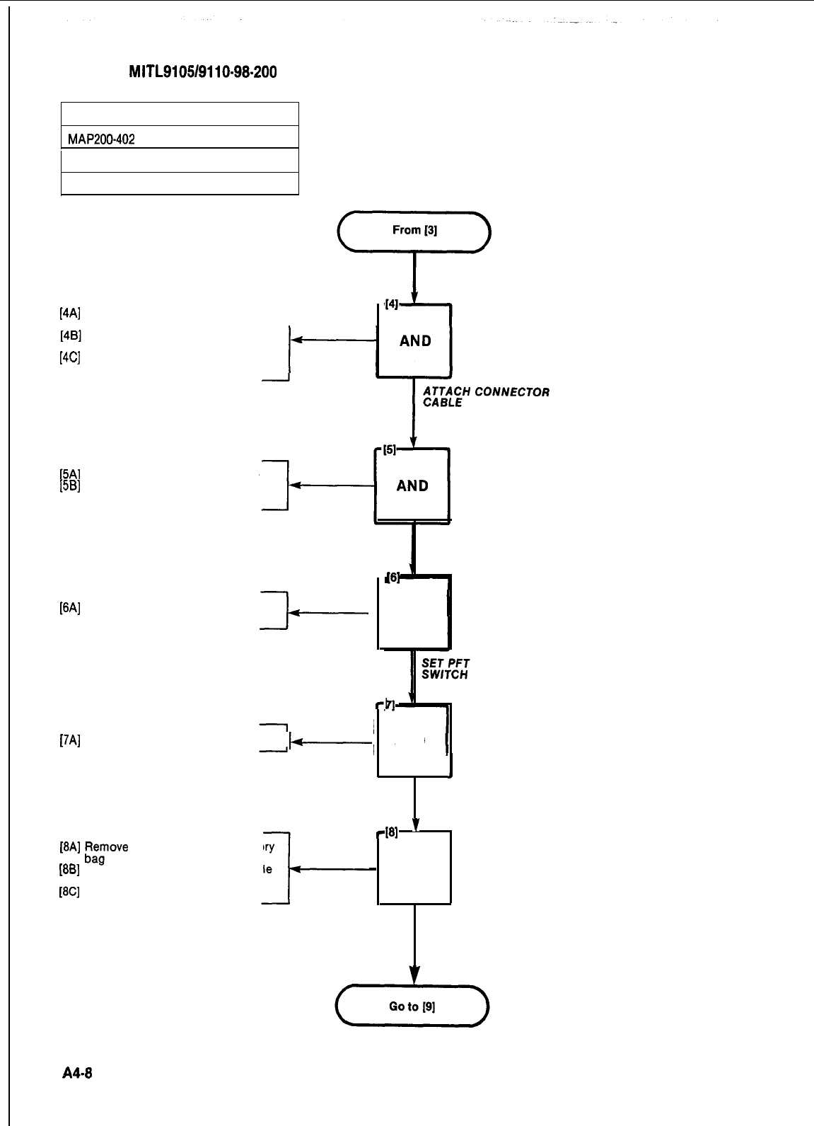
SECTION
MITL9105/9110~98-200
UNPACK CONSOLES
MAP200-402
Issue 1, January 1980
Sheet 2 of 3
[4A] Remove the securing screw from
the console connector
1
Position and press home console
connector
[4C] Secure connector to console with
the securing screw
[5A]
[5B] Replace connector cover plate
Replace the four cover plate
screws
[6A] Set Power Fail Transfer (PFT)
switch to NORMAL
[7A]
Place console in correct position
b-
[8A]
f;;ove
handset from accessory
1881
PI,” handset plug into console
[8C] Place handset on cradle hook
l-
REPLACE CONNECTORREPLACE CONNECTOR
COVER PLATECOVER PLATE
PI
AND
-I
AND
1
POSITION
-181
’
-
AND
PLUG IN
HANDSET
CONSOLE
A4-8
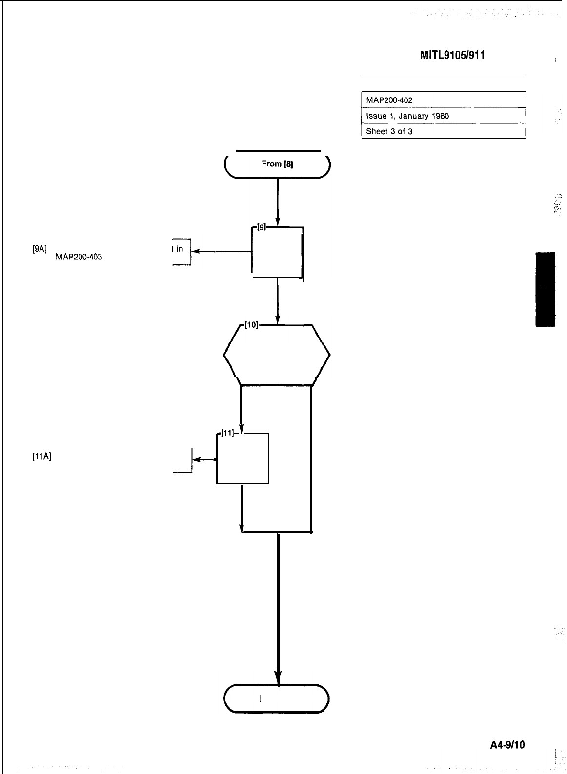
SECTION
MITL91051911
O-98-200
:
[9A]
Insert designations as detailed in
MAP2000403
3-1
AND
[llA]
Complete relevant entries on
Damage Report Form
-I+
I
INSERTINSERT
DESIGNATIONSDESIGNATIONS
Was equipmentWas equipment
properly packagedproperly packaged
and undamagedand undamaged
NONO
YES
411
’
411
’
-
AND
-
AND
COMPLETECOMPLETE
DAMAGEDAMAGE
REPORTREPORT
‘t‘t
YY
FINISH
1 UNPACK CONSOLES I
&:
/
“‘-,.
:::..
:.-:,
1..
1
A4-9110
:
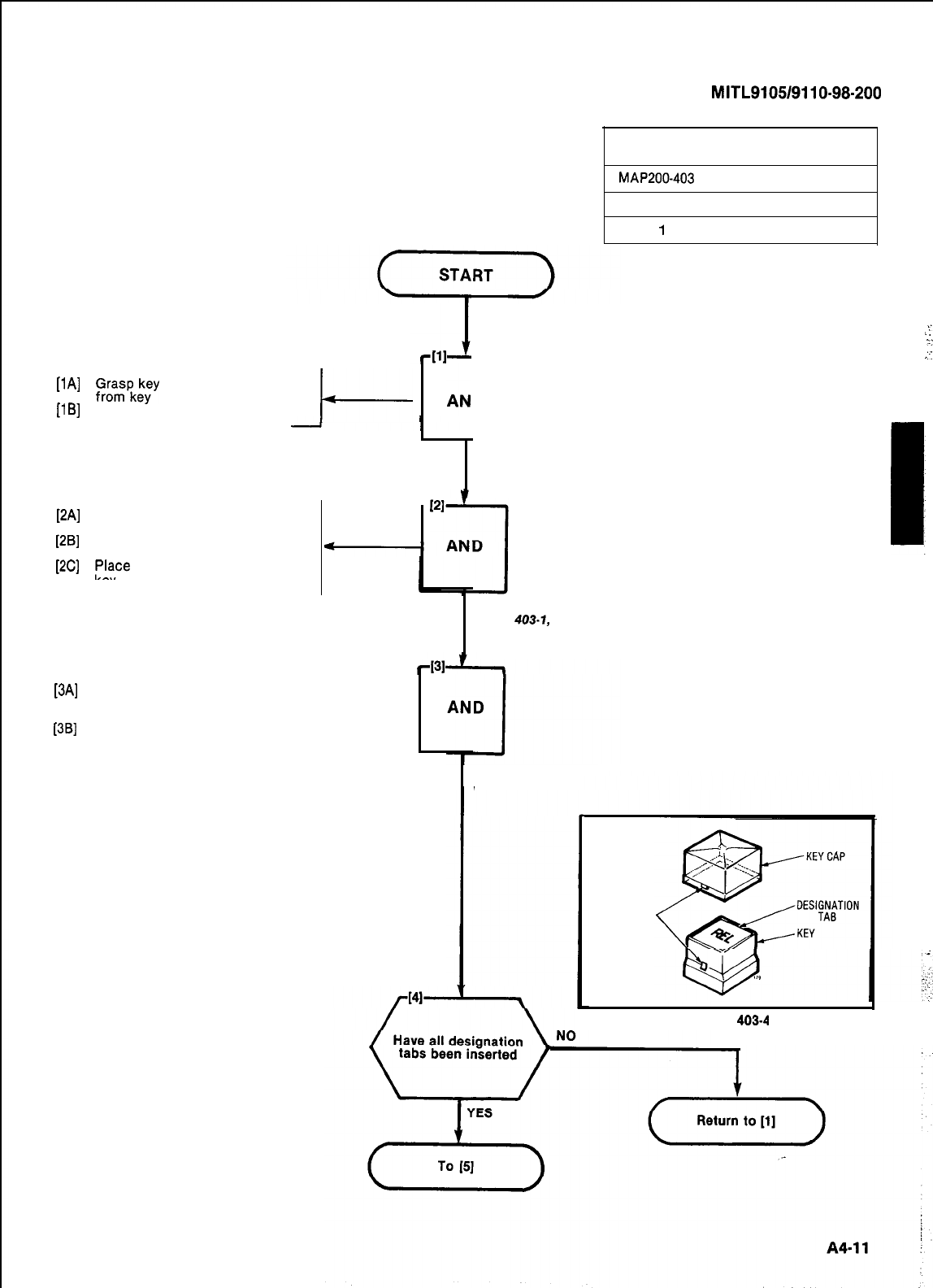
SECTION
MITL9105/9110-98-200
INSTALL CONSOLE
FACEPLATE DESIGNATIONS
MAP200-403
Issue 1, January 1980
Sheet
1
of 4
[lA]
;rrapk;y
cap and pull upward
[lB]
Remove key designation tab
I-
[2A]
Check required console layout
[2B]
(Figs 403-1, -2 or -3)
Push out required designation
[2C]
tab from designation sheet
F%ce
designation tab on top of
[3B]
correctly. (Fig. 403-4)
Push down on key top t-
[3A]
Place key cap over key checking
that locking tabs are lined up
1
D
REMOVE KEY CAP
INSERT DESIGNATION TAB
(FIGS
403-1,
-2 OR -3)
REPLACE KEY CAP
(FIG. 403-4)
LOCKINGTAB
Fig.
403-4
:-
;.
y
::
I:
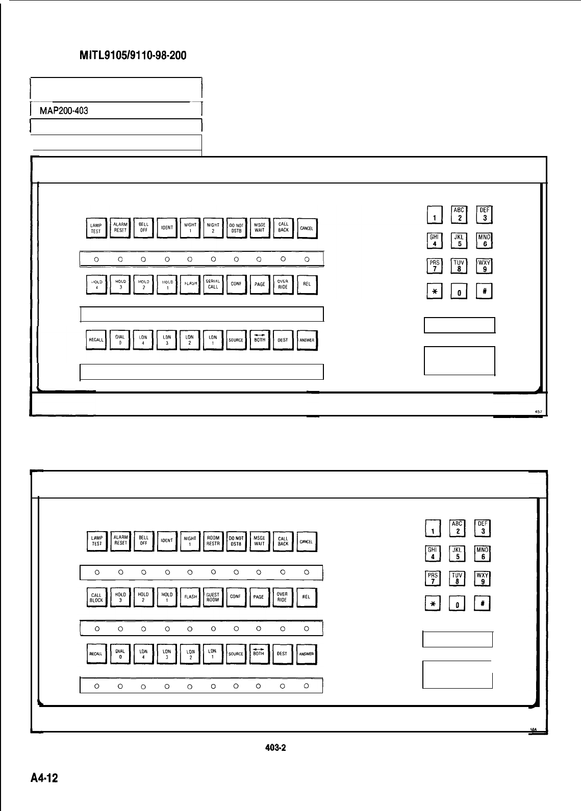
SECTION
MITL9105/9110-98-200
I
INSTALL CONSOLE
FACEPLATE DESIGNATIONS
I
I--
MAP200-403 ~~
-1
1 Issue 1, January 1980
Sheet 2 of 4
00 00 00 0 000
II
00 00 00 0 00 0
Fig. 403-l Commercial
A4.12
Fig.
403-2
Hotel/Motel
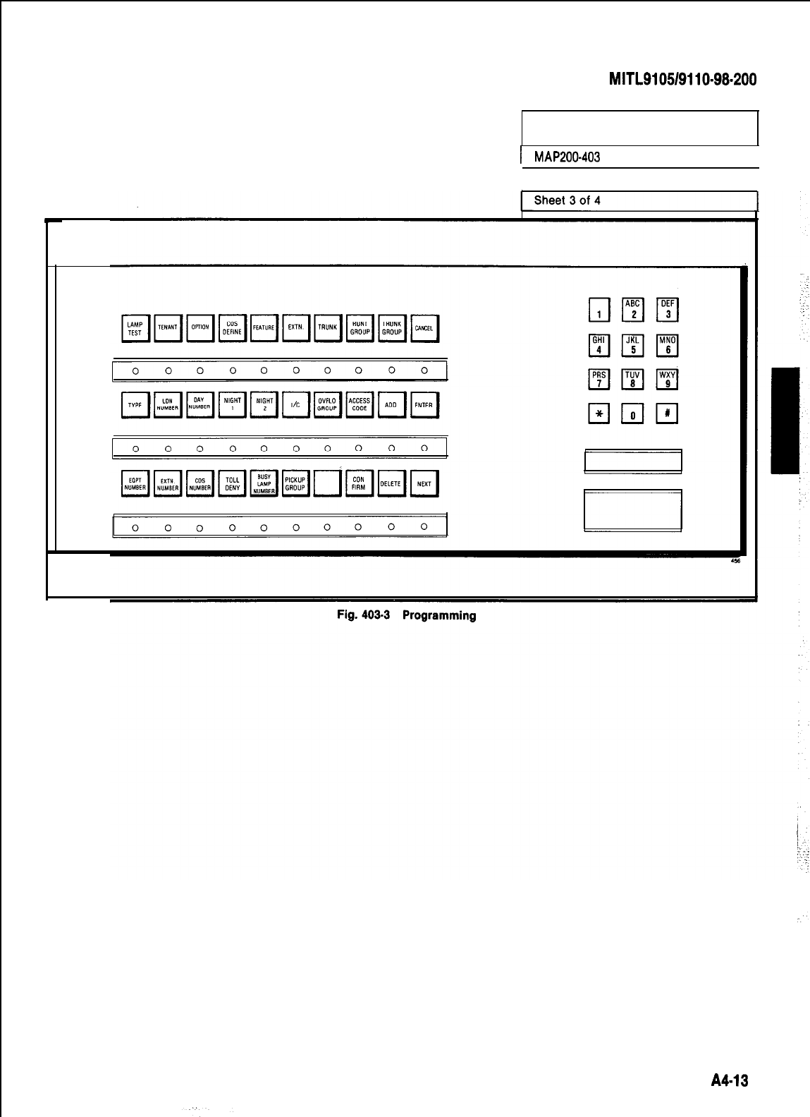
SECTION
MITL9105/9110-98-200
INSTALL CONSOLE
FACEPLATE DESIGNATIONS
I
MAP200-403
I
Issue 1, January 1980
I
I
A4-13
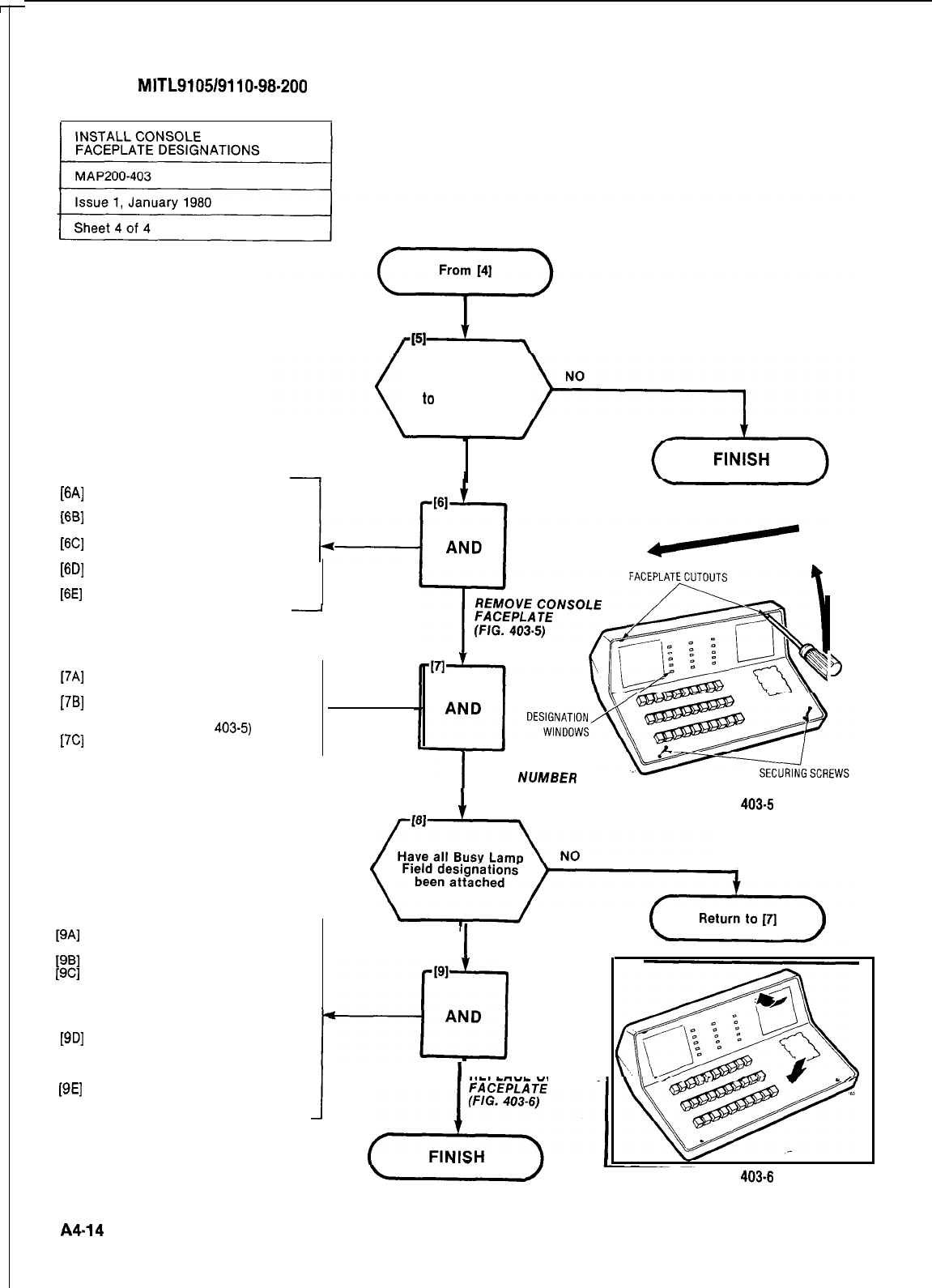
SECTION
MITL9105/9110-98-200
Are the busy lamp
field designations
to
be inserted
YES
r-w
WI
WI
[f3W
WI
17Al
[7Bl
[7Cl
WI
WI
Remove the two faceplate secur-
ing screws (Fig. 403-5)
Insert screwdriver blade into
faceplate cutout (Fig. 403-5)
Move screwdriver to the vertical
position
Slide screwdriver to opposite end
of console
Remove console faceplate
-
Cut required busy lamp numbers
from designation sheet
Position number so that it will be
seen clearly through busy lamp
field window (Fig.
403-5)
Press number firmly in place
Place bottom edge of faceplate
against console lip
Place faceplate over keys
Press down firmly on console
faceplate and press one corner
under the top edge of the con-
sole housing as shown in Fig.
403-6
Continuing the downward
pressure, press the remainder of
top edge of the faceplate under
the housing lip
Replace the two faceplate
screws
I
ATTACH BUSY
LAMP
NUMBER
Fig.
403-5
I
YES
PI
-cl
AND
REPLACE CONSOLE
4
SCREWDRIVER
Fig.
403-6
A4-14
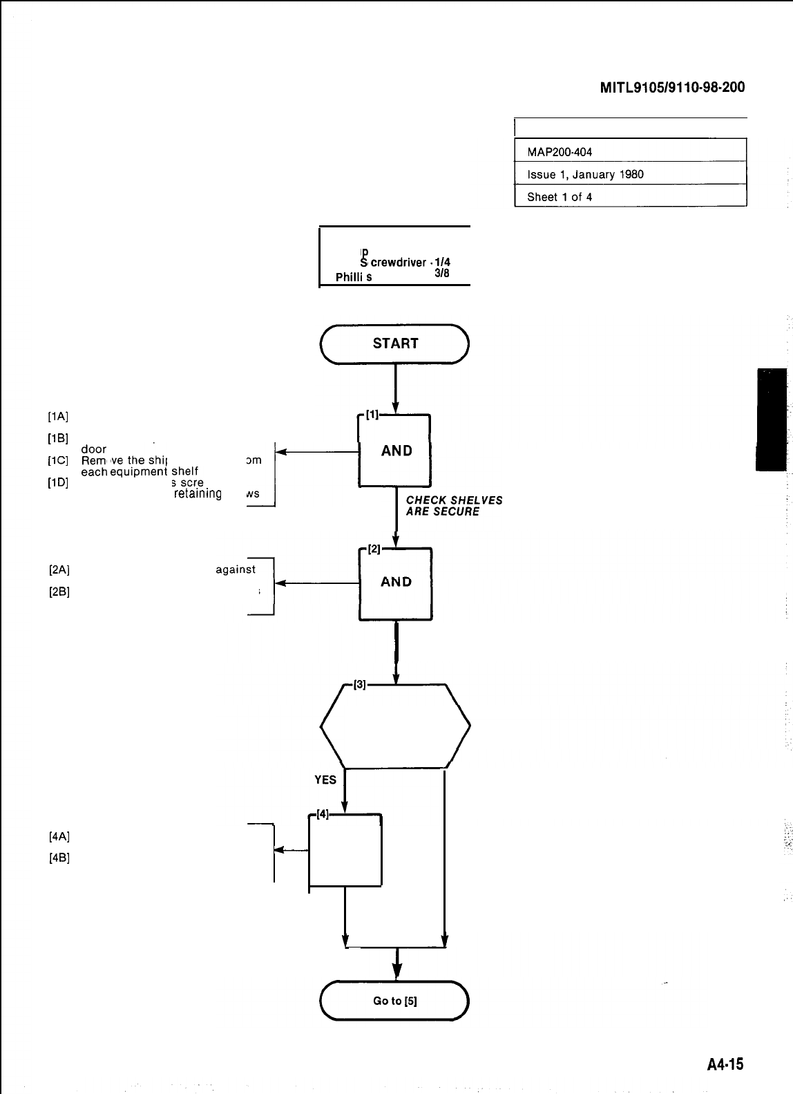
SECTION
MITL9105/9110-98.200
PAI
11
Bl
PC1
[l
Dl
PA1
[=I
[4Al
1481
Tag any damaged items and con-
tinue with inspection
Fill in relevant section of
c-
AND
Damage Report
TAG
DAMAGED
ITEMS
Y
1 INSPECT EQUIPMENT I
TOOLS REQUIRED
1
Philli
s
Screwdriver #
1
Slot
l
crewdriver.
114
2 I
in.
1
Slot Screwdriver.
38
in.
Remove keys taped to top of
cabinet
Unlock and open cabinet front
1
~~~~
wwm*nt
she)f,
Remove the shipping straps from
Using the Phillips screwdriver
J-1
A~~i/~~i~ikvEs
tighten all shelf
retamrng
screws
Check card complement
invoice
Visually check cards and shelves
for damage
I
CHECK CARDS
AND SHELVES
Were any damaged
items found
or items missing
NO
A4-15
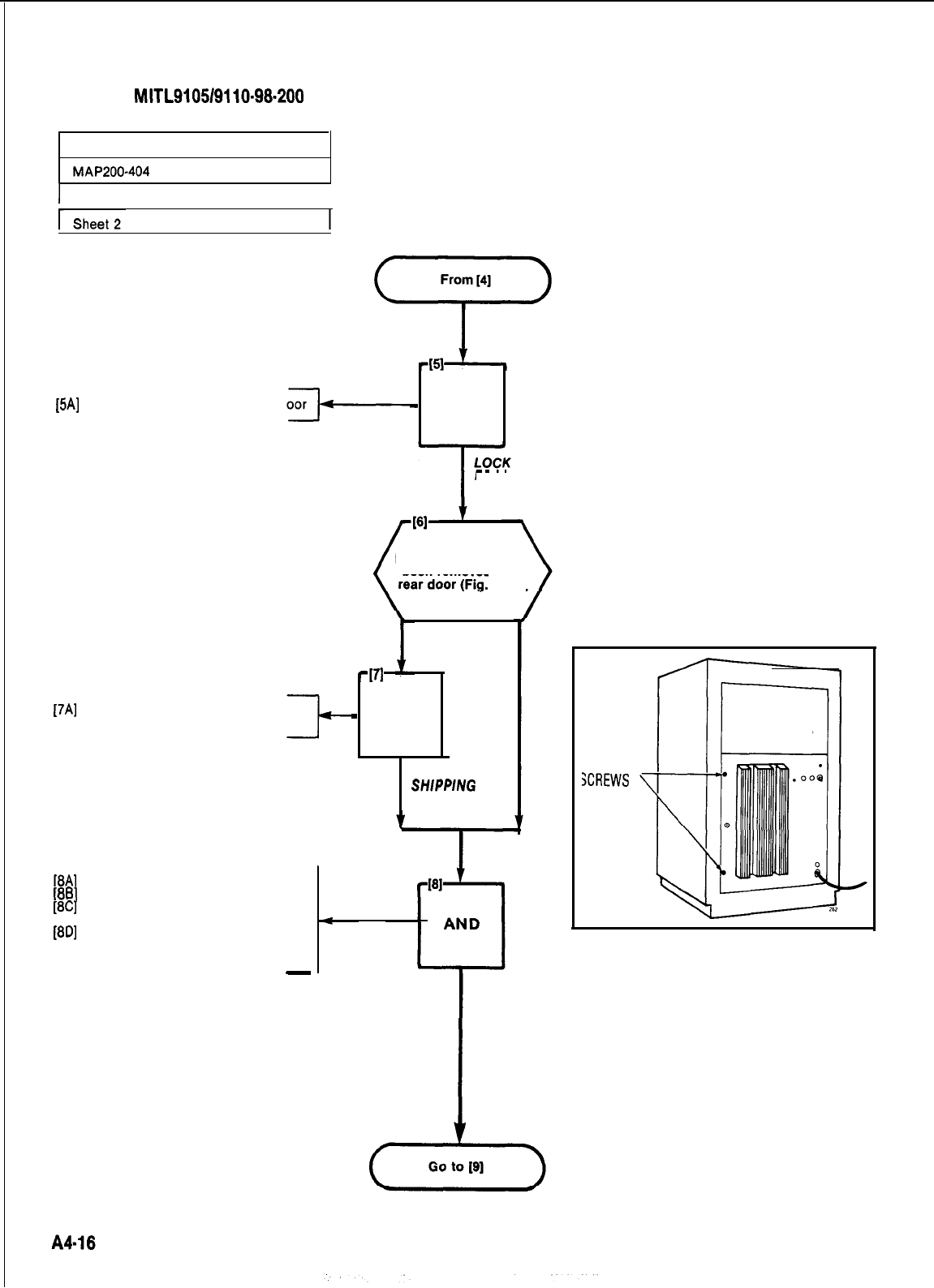
SECTION MITL9105/9110-98-200
INSPECT EQUIPMENT
MAP200-404
1 Issue 1, January 1980
I
I
~~~~
Sheet 2 of 4
-
AND
FRONT DOOR
[5A]
Close and lock cabinet front d
[7A]
Remove the shipping screws
from rear door
[8A]
Unlock and swing open rear door
[8B]
Open power supply door
[8C]
Visually check power supply for
[8D]
loose or damaged components
Check that power supply cable
harness is secure and free from
damage
-
NO
-171
-
AND
REMOVE
SHlPPlNG
SCREWS
YES
Have shipping screws
been removed from
404-l)
SHIPPING
XREWS
Fig. 401-l
INSPECT
POWER SUPPLY
(FIG. 404-l)
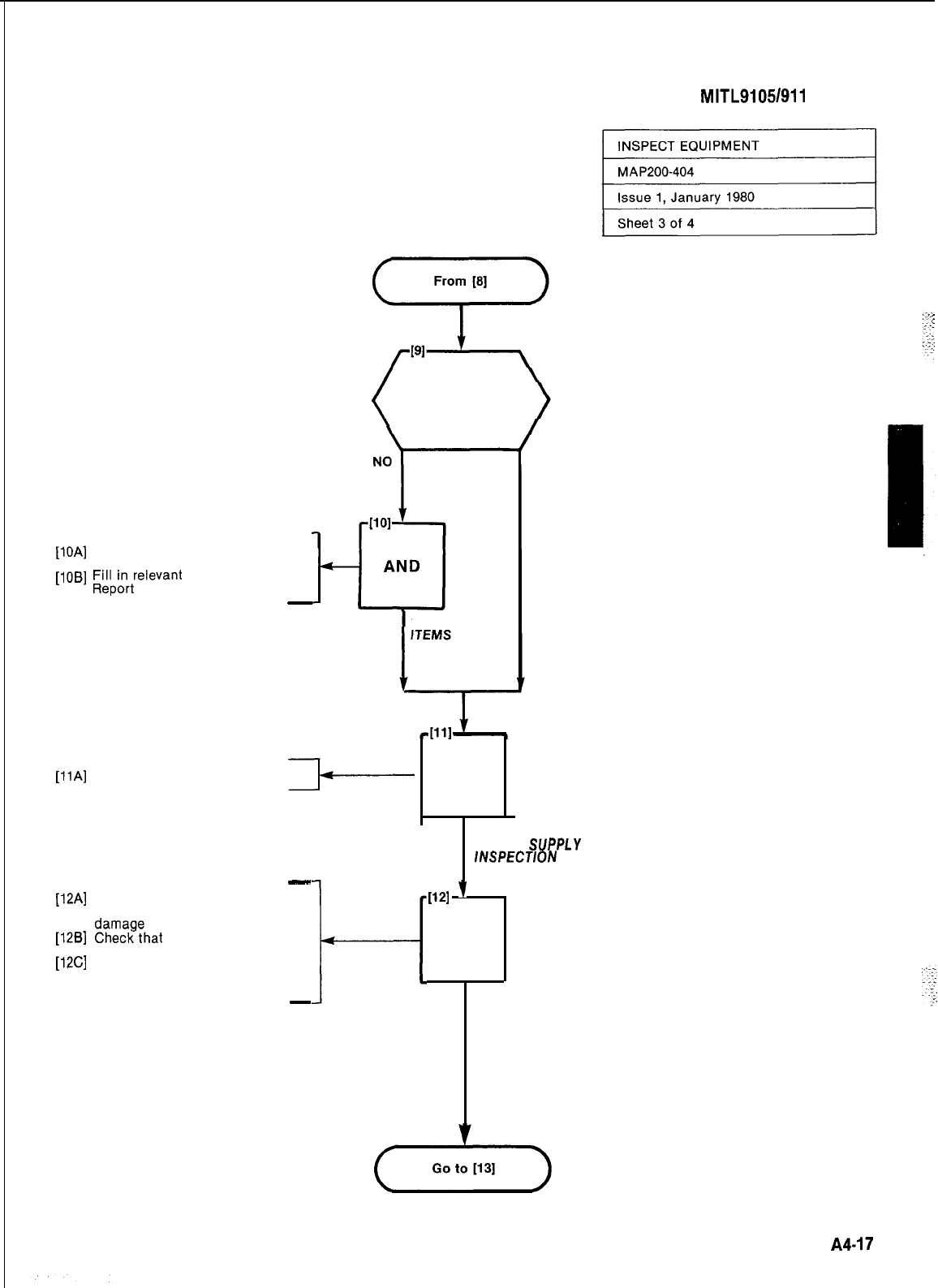
SECTION
MITL9105/911
o-98-200
[10A]
Tag any defective item and con-
tinue with inspection
[loBI
LW&;elevant
portion of Damage
-
TAG DAMAGED
Is power supplyIs power supply
free from damagefree from damage
[llA]
Close power supply door
YES
-
[12A]
Check that all cable connectors
are seated firmly and free from
[12B]
%z:??hat
all cable harnesses
are free from damage
[12C]
Visually check backplane for
damage. (including fuse inspec-
tion)
-
H
AND
COMPLETE
POWER
SUPPLY
/NSPECT/ON
‘I121
’
AND
CHECK
BACKPLANE
A4-17
:
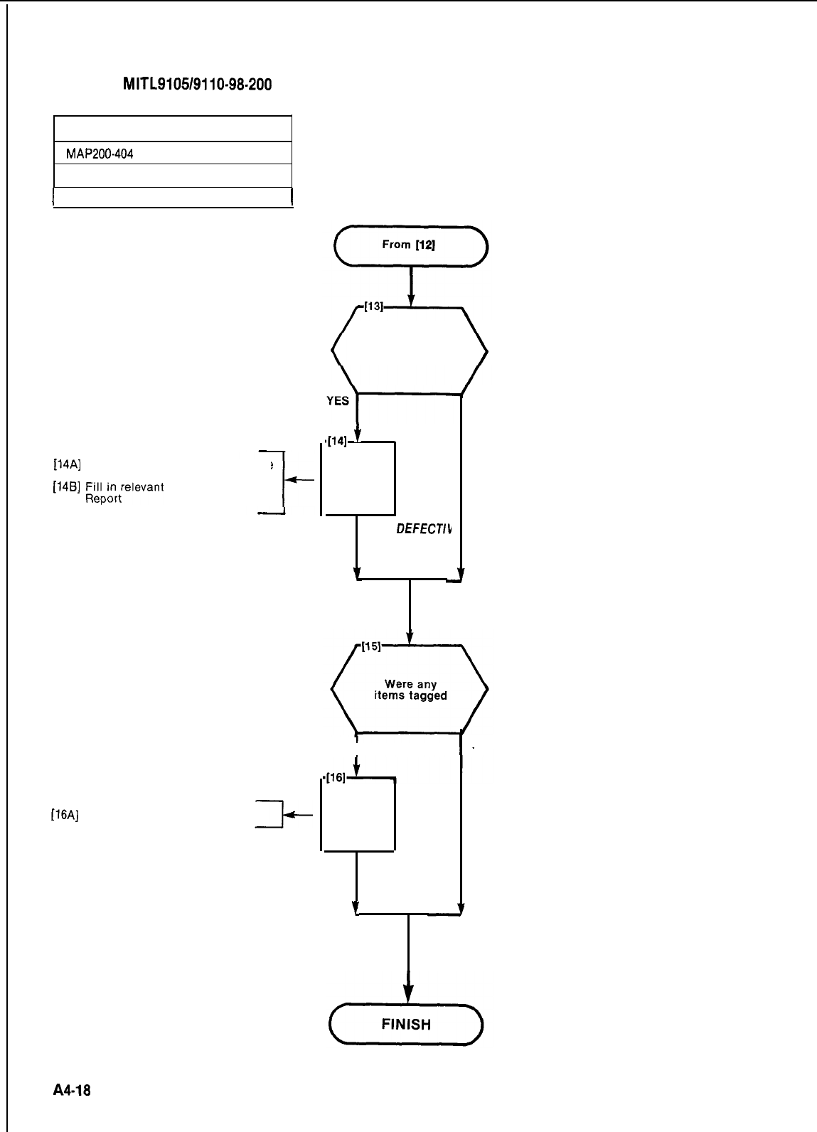
SECTION
MITL9105/9110-98-200
INSPECT EQUIPMENT
MAP200-404
Issue 1, January 1960
I
Sheet 4 of 4
I
[14A]
Tag defective items and continue
[14A]
Tag defective items and
with inspectionwith inspection
[148]
;;‘$rrelevant
portion of Damage
[148]
;;‘$rrelevant
portion of Damage
t-
[16A]
Repack tagged items
Was any damage
to backplane found
D41
f
AND
TAG
DEFECT/b
ITEMS
NO
YES
I
AND
RETURN
TAGGED
ITEMS
7
NO
A4-18
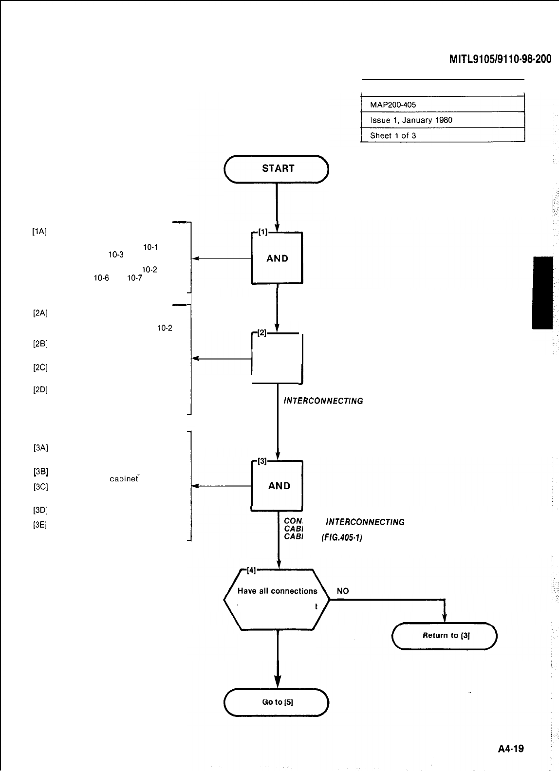
PAI
.
.
PA1
PBI
WI
WI
-
Make required connections at
cross connect field
Refer to Part 10 Table
10-l
and
Fig. 10-l and
10-3
for line, trunk
and console connections
Refer to Part 10 Table
10-2
and
Fig. 10-5,
10-6
and
10-7
Miscellaneous connections
-
Mark each cable connector or
plug with the corresponding
cabinet plug number (Fig.
10-2
and 405-l)
Run required 25 pair cables bet-
ween cabinet and cross-connect
field
Run required power fail transfer
cables between cabinet and
cross-connect field
Run required 25 pair console
cable from each console to
cabinet
At Equipment Cabinet
[3A]
Feed lowest numbered cable
through cable duct in side of
cabinet
MB]
Feed the cable through cable en-
_
_
try in base of
cabinet-
[3C]
Pull through sufficient cable to
allow connector to reach re-
quired cabinet plug (Fig. 405-l)
[3D]
Attach cable connector to cor-
responding cabinet jack
[3E]
Tighten connector retaining
screw
SECTION
MITL9105/9110-98-200
!
START
‘r’
I
MAKE CONNECTIONS AT
CROSS CONNECT FIELD
--I
PII
AND
J
CONNECT CABLES
I
RUN 25 PAIR
lNTERCONNECT/NG
CABLES
(FIG. 405-l)
CONNECT
/NTERCONNECT/NG
CABLE TO EQUIPMENT
T
CABINET
(FIG.405-1)
been made
to equipment cabinet
YES
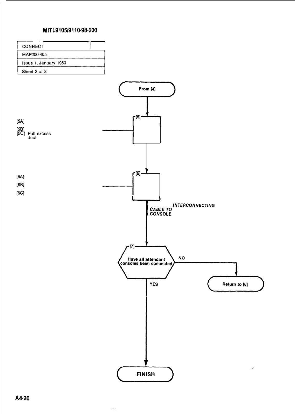
SECTION
MITL9105/9110-98.200
ICONNECT
CABLES
-(
[5A]
Dress cables down side of
cabinet (Fig. 405-l)
[5B]
Attach strain reliefs
[5C]
PuEtexcess
cable through cable
WI
Set Power Fail Transfer switch
on base of console to NORMAL
1681
-
-
Connect attendant console cable
to console
[6C]
Tighten connector retaining
screw
-----I
AND
I
ATTACH STRAIN
RELIEFS (FIG. 405-I)
-4
(61
‘I
AND
CONNECT
INTERCONNECTlNG
W?kE[;
ATTENDANT
_-
A4-20

SECTION
MITL9105/9110-98-200
,.
J15\
J14\
J13-
P17-
P16-
P19-
Pl8'
P5Y
P20-
P6-
P21'
PlO
/
P8
/
P3
/pl
/p4
-P2
Fig.
405.1
A4-21122
SECTION
MITLSI
05/911
o-98-200
1 SET CARD SWITCHES I
. .
.:
_‘.’
.
.
.
.
The setting of switches, to result in the required
mode of operation on the Trunk Cards is detailed
in the MAP’s contained in Appendix A-5. The in-
staller should ensure that these cards are proper-
ly switched for the correct mode of operation prior
to performing “Power-Up” as detailed in
MAP200-407.
A4.23124
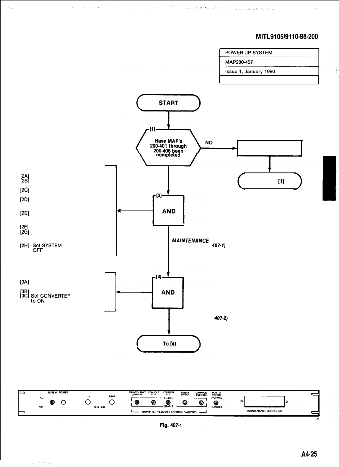
-
At Front of Cabinet
[2A]
Unlock and open door
[2B]
Check that all cards are seated
correctly
[2C]
Check that locking bar(s) are
secure
[2D]
Set all POWER FAIL TRANSFER
CONTROL switches to DISABLE
(Fig. 407-l)
[2E]
Set POWER FAIL TRANSFER
CONTROL switches for consoles
connected to ENABLE
[2F]
Set MASTER switch to NORMAL
[2G]
Set POWER FAIL TRANSFER
switches for power supply and
common control to ENABLE
[2H]
E&GFSYSTEM
POWER switch to
At Rear of Cabinet
[3A]
Plug power supply power cord in-
to the power outlet
[3B]
AC POWER ON LED lit
[3C]
~~;CNONVERTER
INPUT switch
.CONVERTER INPUT LED lit
SECTION
MITL9105/9110-98-200
1 Sheet 1 of 3
Complete required MAP’s
<
YES
CHECK CARDS
AND SET
MAlNTENANCE
SWITCHES (FIG.
407-1)
-
(
I
APPLY POWER
TO SYSTEM (FIG.
To
I41
407.2).
Return to
[l]
A425
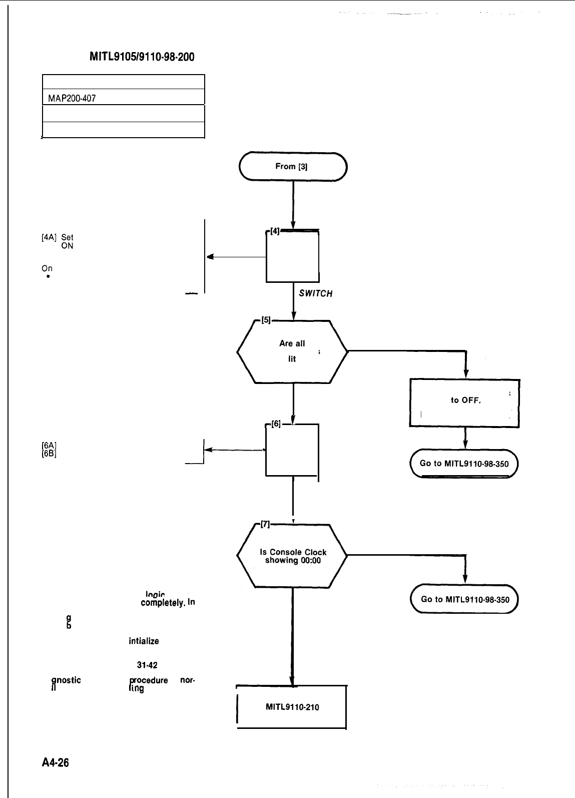
SECTION
MITL9105/9110-98-200
POWER-UP SYSTEM
MAP200-407
Issue 1, January 1960
Sheet 2 of 3
A
At Front of Cabinet
[4A]
gz;
SYSTEM POWER switch to
.SYSTEM POWER LED lit
0;
POWER SUPPLY
EQUIPMENT SHELF POWER ON
LED lit
-
[6A]
Close and lock all doors
[6B]
Position cabinet
4
AND
SWTCH POWER ON
required LED’s NO
YES
461
’
-
AND
Set all Power Switches
Remove Power Cord(s).
Note
Occasionally, when circuit cards are
plugged into the PABX. the
looic
circuits
on the card may not reset
coriipletely.
In
order to guarantee complete reset of all
card
lo
must
Ii
ic, a slot initialization procedure
e performed. This procedure
allows the service personnel to insert a
card into a shelf and
intialize
the card
slot. To initialize the card slot dial 555 +
5 + nn, where nn is the 2 digit card slot
number (01-17 shelf 1,
31.42
shelf 2).
Since inserting a card may cause
dia
nostic
errors, this
rocedure
is
nor-
ma y followed by dia
mg
555 + 1 to
1
r
clear all system errors.
POSITION CABINET
YES
NO
+q
I
Go to SECTION
MITL9110-210
and program system
A4-28
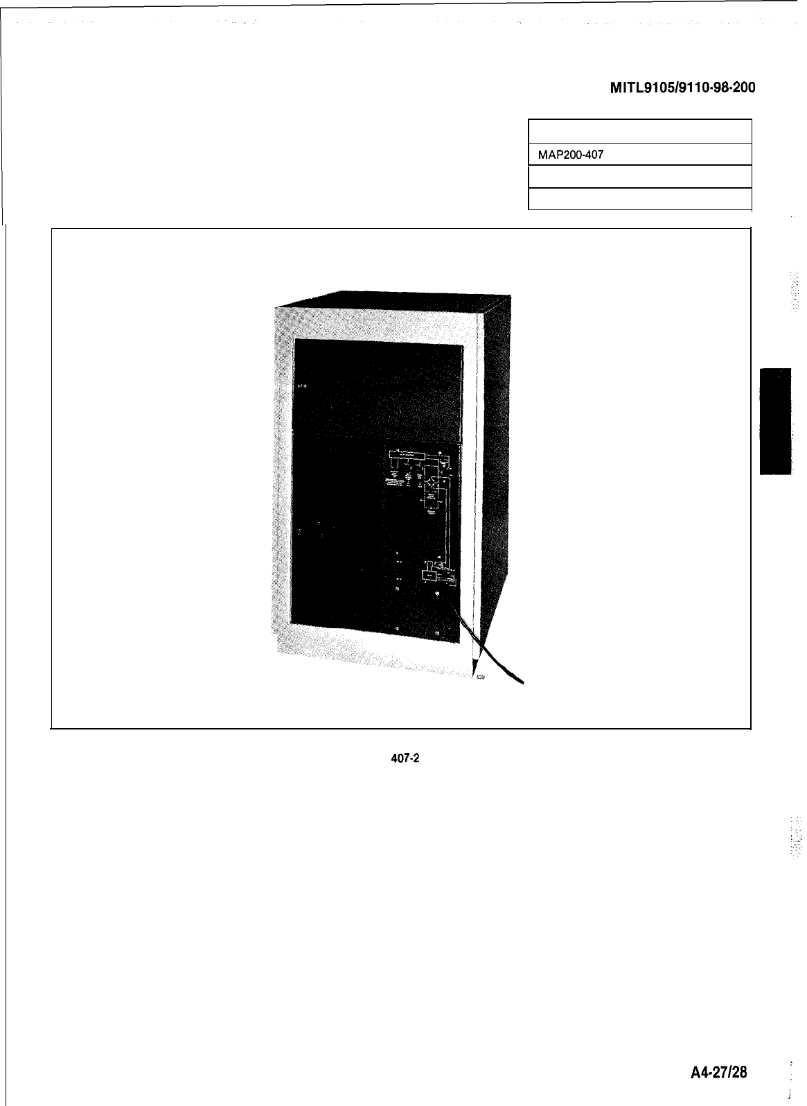
SECTION
MITL9105/9110-98-200
POWER-UP SYSTEM
MAP200-407
Issue 1, January 1980
Sheet 3 of 3
Fig.
407-2
A427l28
1
j

SECTION MITL91051911 o-98-200
APPENDIX 5
CARD SWITCH SETTINGS
1. General
A5.01
The
MAPS
contained in this Appendix (see Table
A5-1)
detail the procedures to be performed to
result in the correct settings of the Trunk Card switches i.e. those required to meet the particular
needs of the installation.
A502
These procedures are performed during the installation of the SX-100 or SX-200 PABX systems,
(referenced in Appendices 3 and 4).
TABLE
A5-1
SETTING TRUNK CARD SWITCHES
Step Procedure
1
Set CO Trunk Option and Status Switches
2
Set E and M/Tie Trunk Option Switches
3
Set DID Tie Trunk Option Switches
4
Set Scanner Card Baud Rate Switch
Reference
MAP200501
MAP200502
M AP200-503
MAP200-504
1
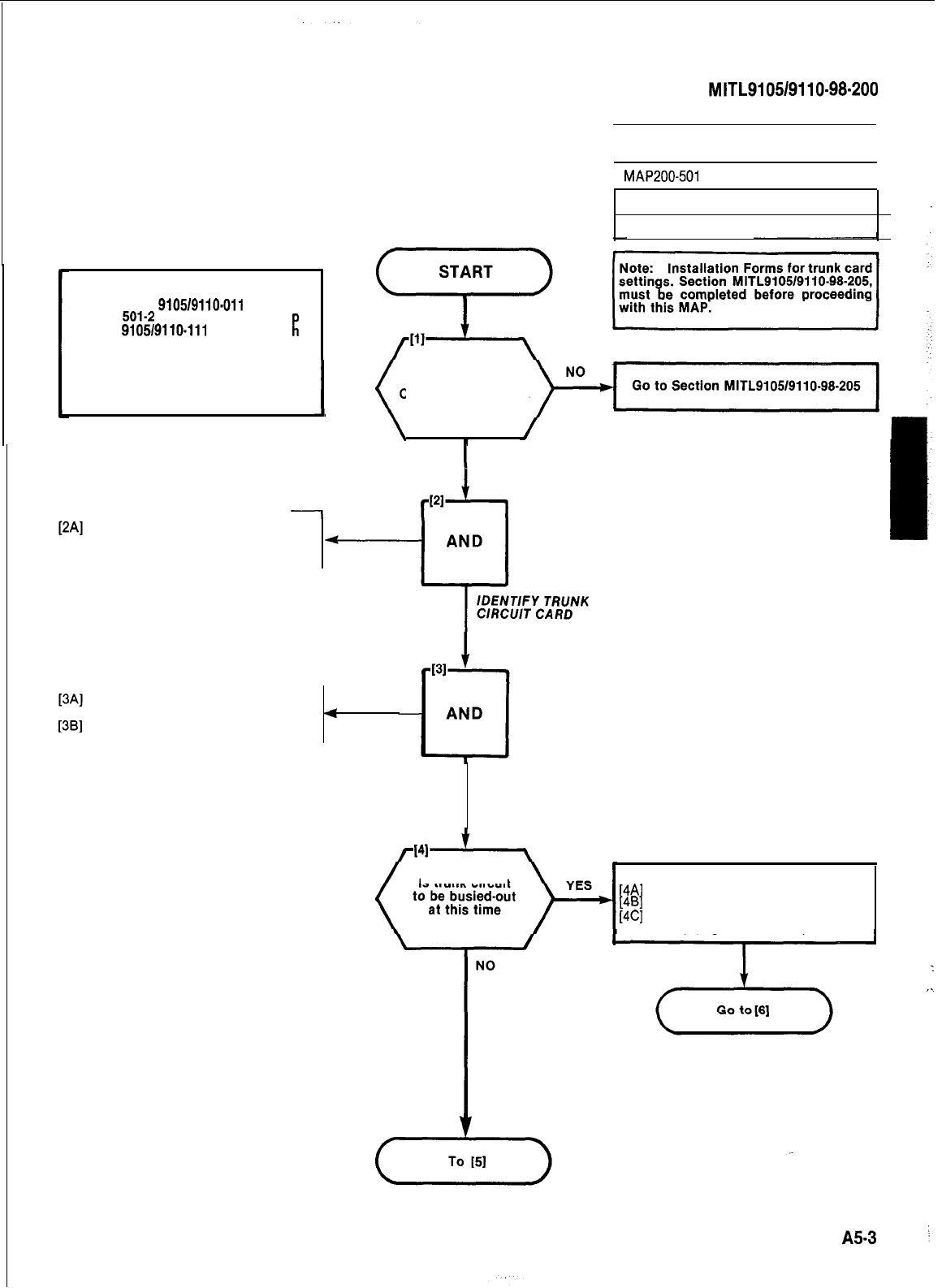
SECTION
MITL9105/9110-98-200
Note: See Fig. 501-l for Trunk Card
Type
9105/9110-011
and Fig.
501-2
for Trunk Card
9105/9110-111
or -211. Ty e
rl
T e
notes for each Fig. should be
read in conjunction with the
installation Form data to
determine proper switch set-
tings.
Identify trunk circuit by card
position type and unit number
(Figs 501-1, -2 and -3)
Lift card extractors at top and
bottom of card
Remove trunk card from the shelf
SET CO TRUNK OPTION
AND STATUS SWITCHES
I
1
MAP200-501
I
I
YES
Issue 2, August 1980
Sheet 1 of 6
I
(
Have Installation
Forms for Trunk
Card switch settings
been completed
4
REMOVE
TRUNK
CARD
Is trunk circuit Make Trunk Busy
[4A]
Identify trunk circuit
[4B]
[4C]
Set trunk switch to Incoming Idle
Set trunk switch to Outgoing
Busy (Fig. 501-l and -2)
1
,.
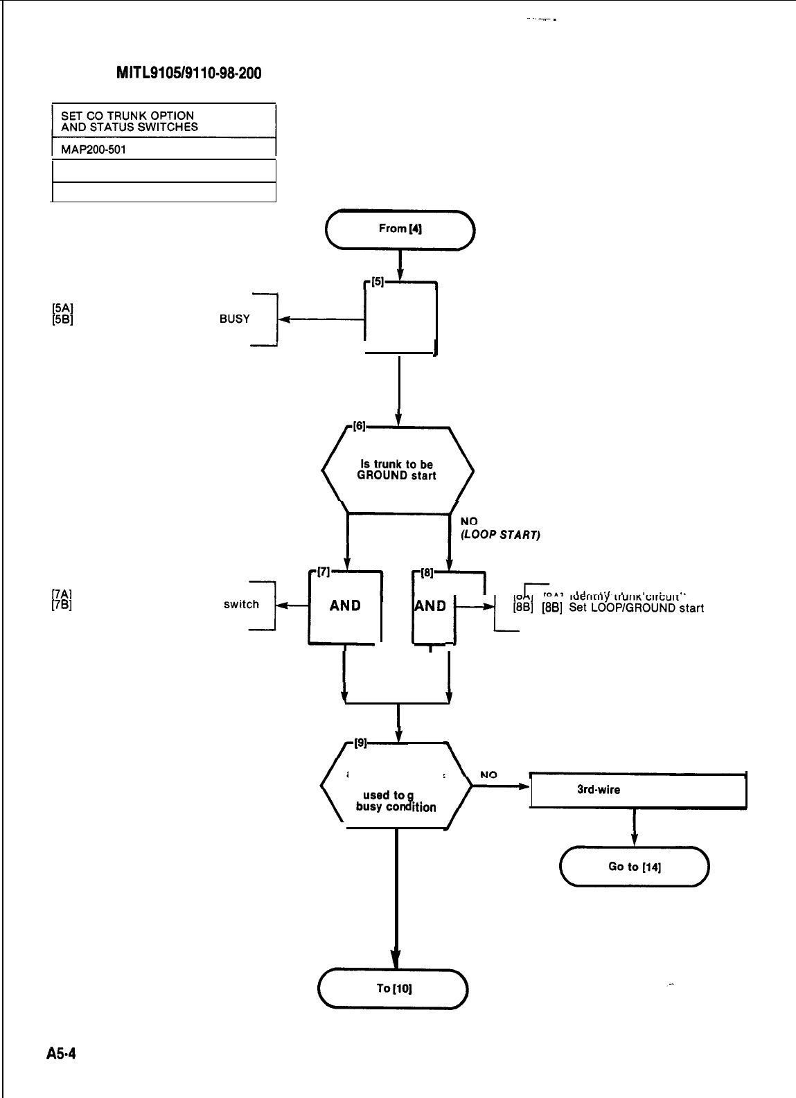
SECTION
MITL9105/9110-98.200
Issue 2, August 1980
Sheet 2 of 6
Identify trunk circuit
Set conditions on Trunk
switch (see Note)
BUSY-~-+
AND
1
I
1
SET TRUNK
BUSY CONDITION
SWITCHES (SEE NOTE)
161
0
Is trunk to be
GROUND start
(GROUND START)
[7A]
identify trunk circuit
[7B]
Set LOOP/GROUND start
to GND (See Note)
SET LOOP/GROUND
START SWITCH TO 2
YES
1
[8B]
~~;l’~%%&$~~start
switch
l\lD
F
to LOOP (See Note)
I
SET LOOP/GROUND
START SWITCH TO 1
,
f
I
Is trunk used
as Dictation Trunk
or is XT lead
ive
8
Ition
Set 3rd.wire switch to CLOSED
YES
(Yk-)
A5-4
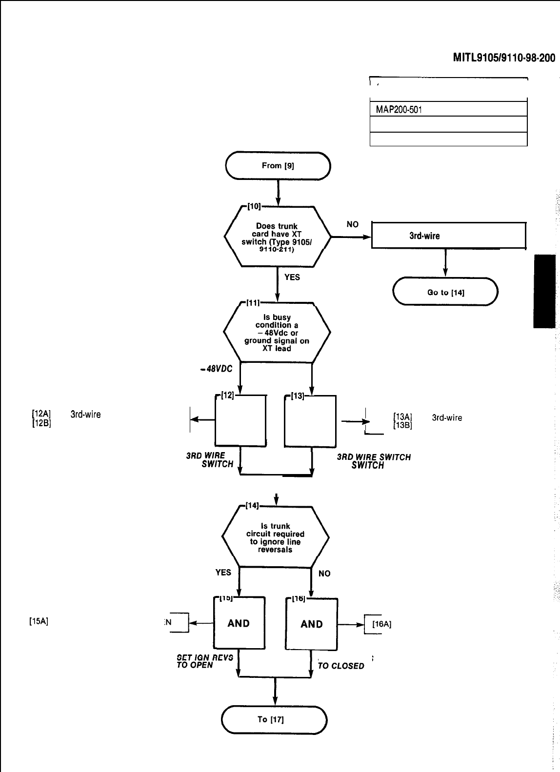
SECTION
MITL9105/9110-98-200
SET CO TRUNK OPTION
AND STATUS SWITCHES
I
MAP200401
Issue 2, August 1980
Sheet 3 of 8
Set
3rd.wire
switch to OPEN
(12A]
Set
3rd-wire
switch to OPEN
[12B]
Set XT switch to OPEN
-
48VL.X
-114
’
-
AND
GND
-1131
’
.
AND
e
[13Al
Set
3rd-wire
switch to OPEN
[13B]
Set XT switch to CLOSED
-
SET
3RD
WRE
A ND XT
SWTCH
SET
3RD
WIRE
SWTCH
TO OPEN
TO OPEN AND XT
SWTCH
TO CLOSED
I
[15A]
Set IGN REVS switch to OPE Set IGN REVS switch to CLOSED
I
SET IGN REVS
AS-5
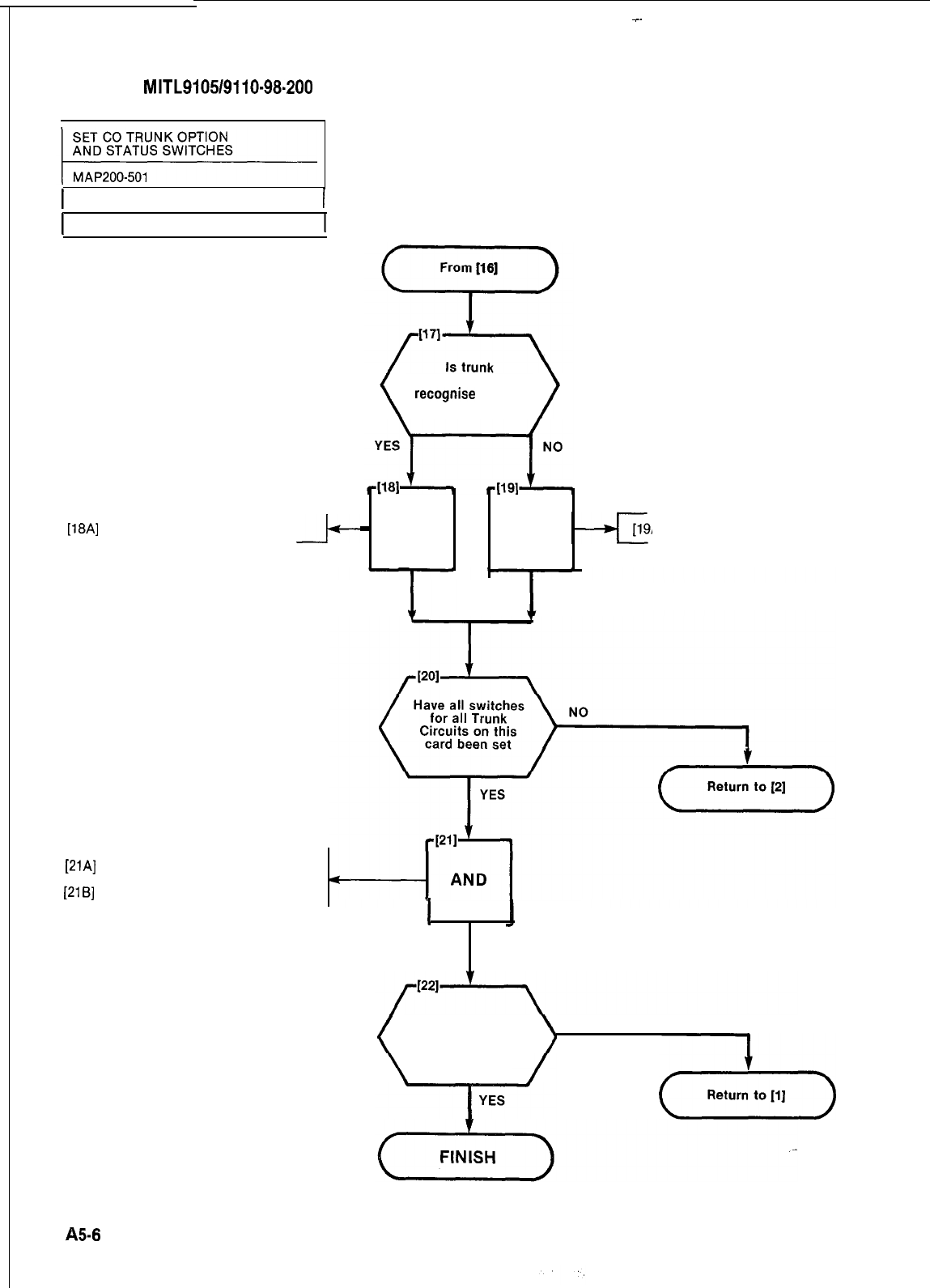
r
-.
SECTION
MITL9105/9110-98.200
1 Issue 2, August 1980
I
1 Sheet 4 of 6
circuit required to
recognise
release
time at 50ms
-
AND AND
A]
Set REL TIME switch to CLOSED
SET REL SET REL
TIME SWITCH TIME SWITCH
TO OPEN TO CLOSED
[18A]
Set REL TIME switch to OPEN
[21A]
Check extractor color code mat-
ches slot color code
[21B]
Lock card in position
I
REPLACE CARD
Have all trunk NO
switches on all trunk
cards been set
(-A-)
85-8
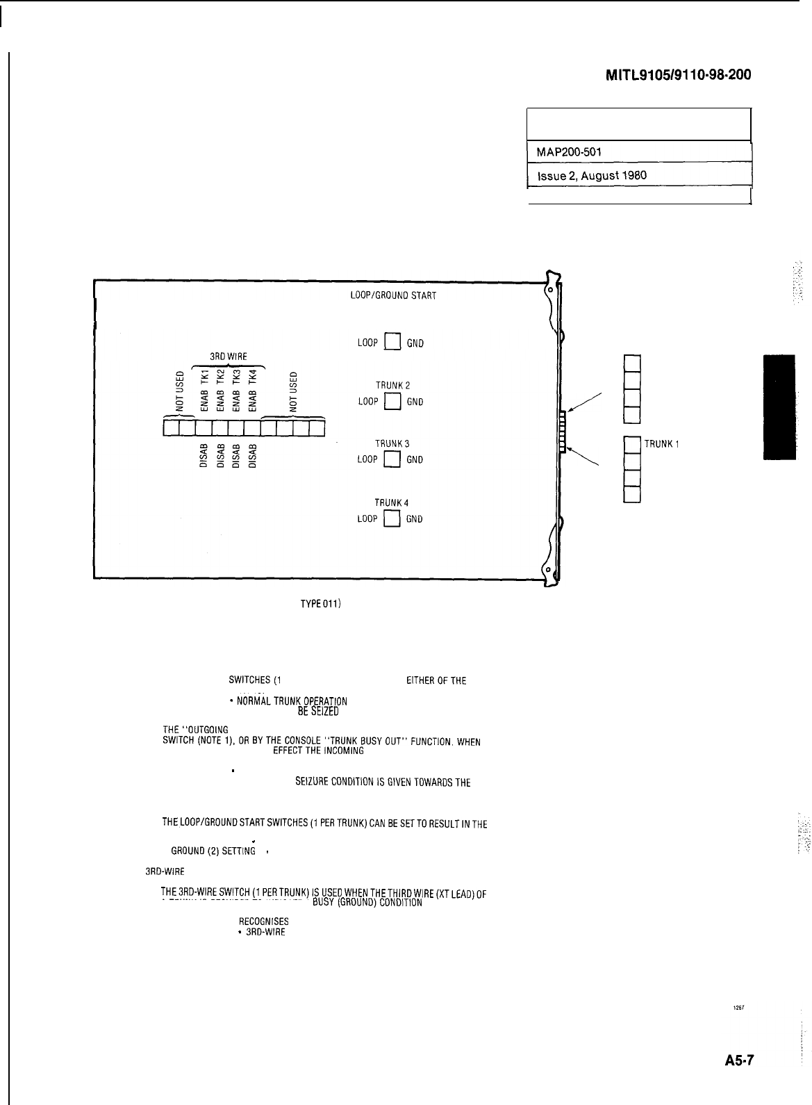
SECTION
MITL9105/9110-98-200
SET CO TRUNK OPTION
AND STATUS SWITCHES
Sheet 5 of 6
I
SWITCHES
TRUNK1 TRUNKBUSY
SWITCHES
3RDWlRE
TRUNK1
OUTGOING
/
1
TRUNK2
TRUNK3
TRUNK4
\
i
TRUNK1
TRUNK2
INCOMING
TRUNK3
TRUNK4
BUSY IDLE
COTRUNK CARD- SINGLE ASSEMBLY
( TYPEOll)
NOTES:
TRUNKBUSY SWITCHES
1. OUTGOING BUSY SWlTCHES(1 PER TRUNK)CAN BE SET FOR
EITHEROFTHE
FOLLOWING CONDITIONS:
IDLE SETTING
_
NORtiALTRUNKOPERATlON
BUSY SETTING -TRUNKCANNOT BESEIZED FOR OUTGOING CALL
2.
THE"OUTGOING
BUSY" CONDITION MAY BE SET EITHER BY THE OUTGOING BUSY
SWlTCH(NOTEl),OR
BYTHECONSOLE"TRUNKBUSYOUT"FUNCTION.WHEN
THIS CONDITION IS IN
EFFECTTHEINCOMING
BUSYSWITCH AFFECTSTHETRUNK
CONDITION AS FOLLOWS:
IDLE SETTING
-
NO ANSWER WILL BE GIVEN TO INCOMING CO CALLS
BUSY SETTING -APERMANENT
SElZURECONDlTlONISGlVENTOWARDSTHE
CO
LOOP/GROUND START SWITCHES
3.
THELOOP/GROUNDSTARTSWlTCHES(1PERTRUNK)CANBESETTORESULTINTHE
FOLLOWING CONDITIONS:
LOOP (1)SETTlNG
_
USED FOR LOOP-STARTTYPETRUNKS
GROUND(2)SETTlNG
-
USED FOR GROUND-STARTTYPETRUNKS
3RD-WIRE SWITCHES
4.
THE3RD-WIRESWlTCH(1PERTRUNK)ISUSEDWHENTHETHlRDWlRE(XTLEAD)OF
ATRUNKIS REQUIREDTO INDICATE A BUSY(GROUND)CONDlTlON ON EXTERNAL
EQUIPMENT (e.g. DICTATION TRUNK). THE SWITCH SETTINGS AREAS FOLLOWS:
OPEN SETTING RECOGNISES GROUNDASA BUSY CONDITION
CLOSED SETTING
-
JRD-WIRE CONDITION IS INEFFECTIVE
Fig. 501-l Single Assembly Card
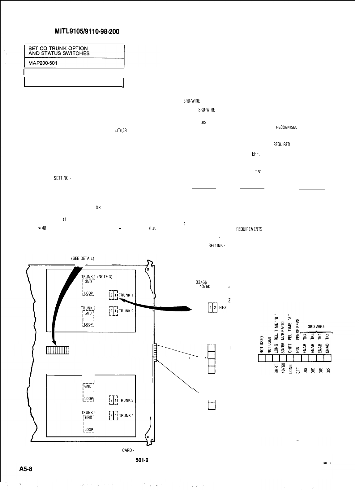
SECTION
MITL9105/9110-98-200
1Issue 2, August 1980
I
Sheet 6 of 6
NOTES.
I
TRUNK BUSY SWITCHES
1. OUTGOING BUSY SWITCHES (1 PER TRUNK) CAN BE SET FOR EITHER OF THE
FOLLOWING CONDITIONS:
IDLE SETTING NORMAL TRUNK OPERATION
BUSY SETTING TRUNK CANNOT BE SEIZED FOR OUTGOING CALL
2THE “OUTGOING BUSY” CONDITION MAY BE SET EITHER BY THE OUTGOING BUSY
SWITCH (NOTE 1). OR BY THE CONSOLE “TRUNK BUSY OUT” FUNCTION. WHEN
THIS CONDITION IS IN EFFECT THE INCOMING BUSY SWITCH AFFECTS THE TRUNK
CONDITION AS FOLLOWS
IDLE SETTING ND ANSWER WILL BE GIVEN TO INCOMING CO CALLS
BUSY SETTING A PERMANENT SEIZURE CONDITION IS GIVEN TOWARDS THE CO
LOOP/GROUND START SWITCHES
3. THE LOOP/GROUND START SWITCHES (1 PER TRUNK) CAN BE SET TO RESULT IN THE
FOLLOWING CONDITIONS
LOOP (1)
SETTING.
USED FOR LOOP-START TYPE TRUNKS
GROUND (2) SETTING USED FOR GROUND-START TYPE TRUNKS
4. THE 3RD WIRE (XT) LEAD WHEN REQUIRED IS CONNECTED TO THE CO TO
PROVIDE CERTAIN FACILITIES. THESE INCLUDE THE RECORDING OF METER
PULSES (EXTENDED FROM THE CO); OR ANOTHER REQUIREMENT MAY BE A
BUSY CONDITION WHEN DICTATION
OR
CODE CALLING EQUIPMENT AT THE
CO HAS BEEN TAKEN INTO SERVICE BY OTHER TRUNKS.
THE XT SWITCH
(1
PER TRUNK) IS USED IN CONJUNCTION WITH THE 3RD WIRE
SWITCH (NOTE 5) AND CAN BE SET TO PROVIDE FOR THE FOLLOWING CONDITIONS
-
48
SETTING THE CIRCUIT RESPONDS TO A
-
4BVDC SIGNAL
(i.e.
WHEN
IT IS A METER PULSE OR A BUSY CONDITION). A GROUND OR
OPEN SIGNAL IS THE IDLE CONDITION
GND SETTING
-
THE CIRCUIT RESPONDS TO A GROUND SIGNAL (i.e. WHEN
IT IS A METER PULSE OR A BUSY CONDITION). AN OPEN OR
-48VDC SIGNAL IS THE IDLE CONDITION
TRUNK 3
3RD-WIRE
SWITCH
5.
THE
BRD-WIRE
SWITCHES (1 PER TRUNK) ENABLE THE XT SWITCH (NOTE 4) AND
THEIR SETTINGS GIVE THE FOLLOWING CONDITIONS:
ENAB SETTING ENABLES THE CORRESPONDING XT SWITCH
DIS
SETTING MAKES THE XT SWITCH INEFFECTIVE i.e. A BUSY CONDITION
ON THE XT LEAD CANNOT BE
RECOGNISED
SENSE REVS SWITCH
6. IF LINE REVERSALS ON THE TRUNK CIRCUITS ARE REOUIRED TO HAVE NO EFFECT
THE SENSE REVS SWITCH IS SET TO IGN (IGNORE). IF LINE REVERSALS ARE TO BE
EFFECTIVE THE SWITCH IS SET TO
EFF.
RELEASE TIMING SWITCHES
7.
RELEASE TIMING SWITCHES “A” AND
“B”
OPERATE IN CONJUNCTION TO PRODUCE
THE RELEASE TIMES SHOWN FOR THE FOLLOWING SETTINGS:
“A” SETTING “B” SETTING RELEASE TIME
SHORT SHORT
49ms
LONG SHORT
490ms
SHORT LONG
2500ms
LONG LONG
INFINITE (NON-RELEASE)
HI-Z SWITCH
8. THE HI-Z SWITCH ALLOWS THE PROPER IMPEDANCE ON INCOMING CALLS. TO BE
PRESENTED ACCORDING TO REOUIREMENTS. THE TWO SETTINGS FOR THE SWITCH
RESULT IN THE FOLLOWING:
HI-Z SETTING
-
PRESENTS THE NORMAL IMPEDANCE TO INCOMING RINGING
SIGNALS, BUT A HIGH BLOCKING IMPEDANCE TO VOICE SIGNALS
NORM SETTING. PRESENTS A NORMAL IMPEDANCE TO BOTH RINGING SIGNALS
AND VOICE SIGNALS
M/B RATIO SWITCH
9. THE MAKE/BREAK RATIO SWITCH SETS THE RATIO OF THE MAKE-TO-BREAK
INTERVALS OF THE OUTPULSING ON THE TRUNK. THE SWITCH SETTINGS RESULT IN
THE FOLLOWING CONDITIONS:
33166
SETTING 33% MAKE; 66% BREAK
40160
SETTING
-
40% MAKE; 60% BREAK
GND HIGH
2
B,
Xl
-48 NORMAL
BUSY IDLE
OUTGOING
\
TRUNK
1
TRUNK 2
TRUNK 3
TRUNK 4
\
q TRUNKI
\
H
TRUNK 2
INCOMING TRUNK 3
DETAIL
tl
TRUNK 4
TRUNK BUSY
SWITCHES
CO TRUNK
CARD.
MODULAR ASSEMBLIES
Fig.
501-2
Mother Board Assembly Card
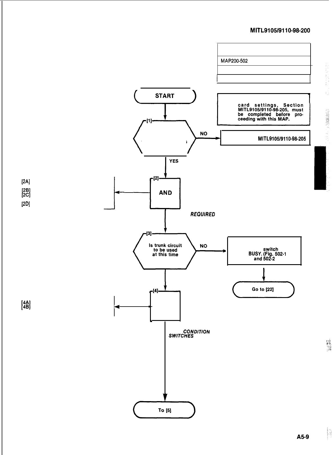
SECTION
MITL9105/9110-98.200
WI
WI
Locate required trunk circuit cardLocate required trunk circuit card
9110-0139110-013
Note card positionNote card position
Lift card locking clips located atLift card locking clips located at
the top and bottom of the cardthe top and bottom of the card
Remove trunk card 9110-013Remove trunk card 9110-013
SET E&M/TIE TRUNK
OPTION SWITCHES
MAP200-502
Issue 2, August 1980
I
Sheet 1 of 7
Note: Installation Forms for trunk
Have Installation
Forms for Trunk
Card switch settings
been completed
Go to Section MITL9105/9110-98-205
YES
PI
-?I
AND
I
REMOVE
REQUlRED
TRUNK CARD
I
4A]
Identify trunk circuit
48) Set conditions on Trunk BUSY
4
switch (see Note)
I
YES
-
AND
t
SET TRUNK
BUSY
CONDlTlON
SWTCHES
(SEE NOTE)
Set Outgoing
Busy syitch
to
BUa;;
#i502-1
I
(,,,,,,,)
..:.
.,
‘::
.
.,.
:;
:
I-:
;-ii
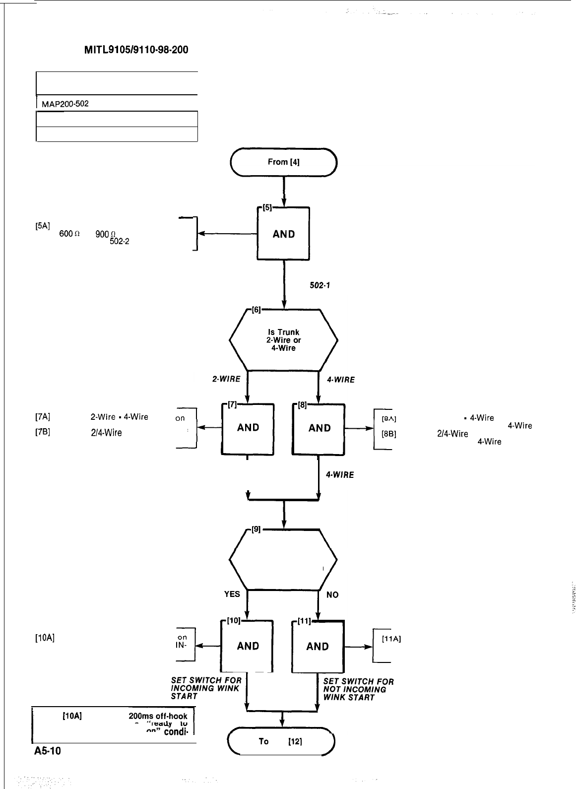
SECTION
MITL9105/9110-98-200
SET E&M/TIE TRUNK
OPTION SWITCHES
1
I
MAP200-602
I
Issue 2, August 1980
Sheet 2 of 7
-
[5A]
Set Trunk Impedance switches to
600n
or
9000
as required. Fig,
502-l or Fig.
502-2
[51
-cl
AND
I
SET IMPEDANCE
SWITCHES
FIG.
502.1
OR 502.2
[7A]
Set the
2-Wire
-
4-Wire
switch
face of the circuit card to P-Wire
[7B]
Set the
2/4-Wire
switch on rear of
the circuit card to P-Wire
SET SWITCHES FOR
Z-WIRE TRUNK
I
[lOA]
Set the Incoming Wink switch
the face of the circuit card to
COMING WINK
Set the P-Wire
-
4-Wire
switch on
face of the circuit card to
4-Wire
Set the
2/4-Wire
switch on rear of
the circuit card to
4-Wire
Do Incoming Tie
Trunk calls require
Wink Start operation
SET SWITCHES FOR
4.WIRE
TRUNK
Set the Incoming Wink switch on
the face of the circuit card to
NOT INCOMING WINK
Note:
[lOA]
results in a
signal sent as a
receive dial information”
condi-
I
tion.
I
A!%10
L
To
1121
)
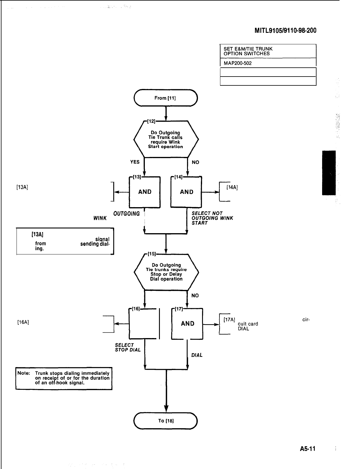
SECTION
MITL9105/9110-98-200
[13A]
Set the Outgoing Wink Start
switch on the face of the circuit
card to OUTGOING WINK
Issue 2, August 1980
Sheet 3 of 7
[14A]
Set the Outgoing Wink Start
I+
switch on the face of the circuit
card to NOT OUTGOING WINK
SELECT
OUTGOlNG
WINK
START
I
Note:
[13A]
results in waiting period of
160 to 220ms off-hook.
sigyal
;rgrn
far end before
sendmg
dial-
TN0
YES
rW1
L
I171
ii-d-
AND
[17A]
Set Stop Dial switch on the
cir-
giLcard
face plate to NOT STOP
[16A]
Set Stop Dial switch on circuit
card face plate to STOP DIAL
---k-l
AND J
l-
-I
-
SELECT
NOT STOP
DJAL
A5-11
I
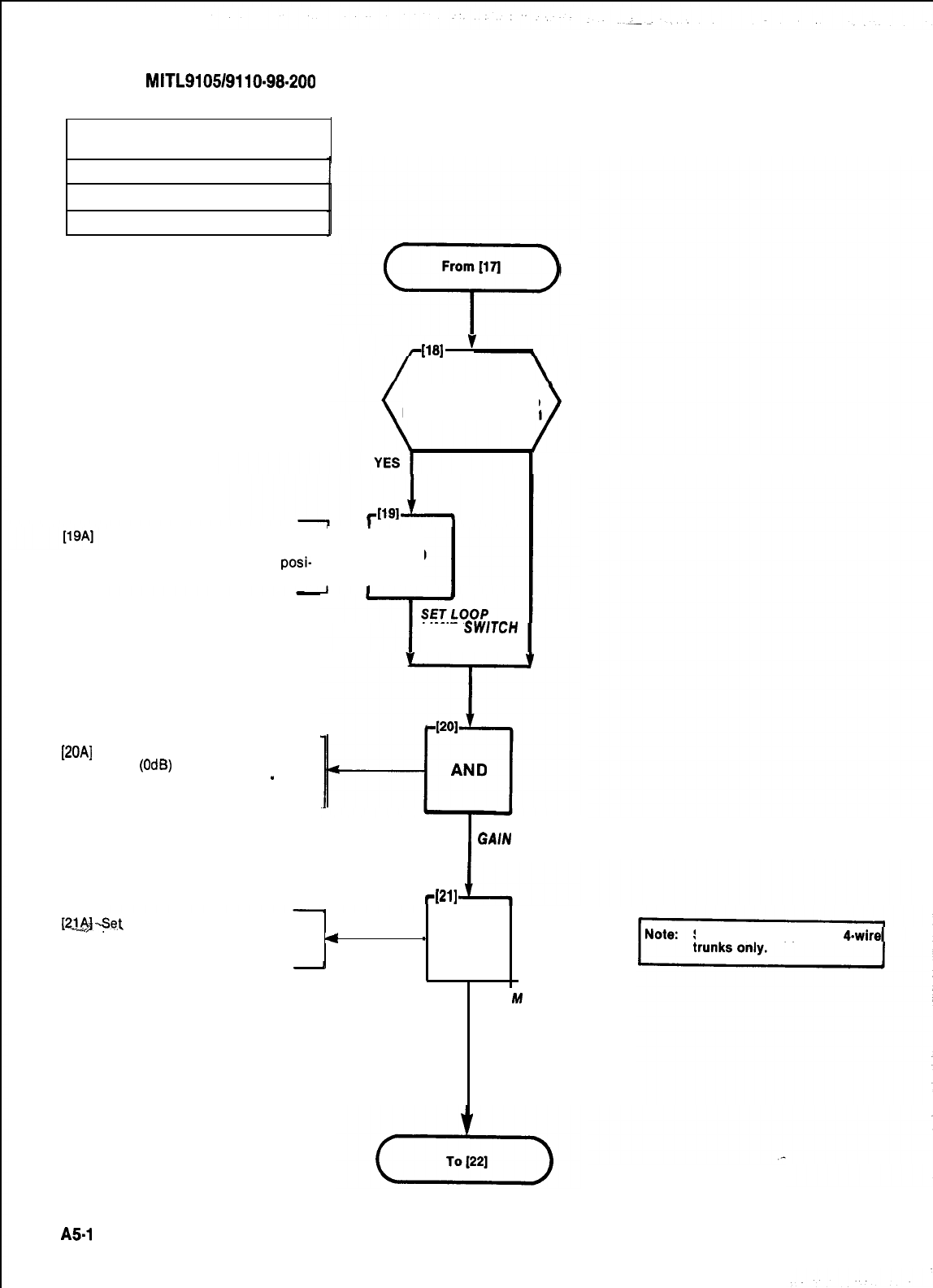
SECTION
MITL9105/9110-98-200
SET E&M/TIE TRUNK
OPTION SWITCHES
MAP200602
lssue 2, August 1980
Sheet 4 of 7
From
[la
c
.
WI
”
Is trunk cardIs trunk card
equipped with a Loopequipped with a Loop
Limit switch Fig. 502-lLimit switch Fig. 502-l
Set Loop Limit switch on rear of
circuit card to the OPEN position
for short loop and CLOSED
posi-
H
AND
tion for long loop (Fig. 502-l)
[20A]
Set Gain Switches to Normal
GAIN
(OdB)
or SPECIAL GAIN as
required. (+ 7dB Incoming
-
18dB
Outgoing). See Note
LIMIT
SWlTCH
NO
I
SET TRUNK
GAIN
SWITCH
-1211
[2J&I-Se.t
M INVERT switch to M INV if
inversion of the M lead signal is
4
required (Fig. 502-2)
-
7 AND
SET
M
INVERT
SWITCH
Special gain applies to &wire
AS-1
2
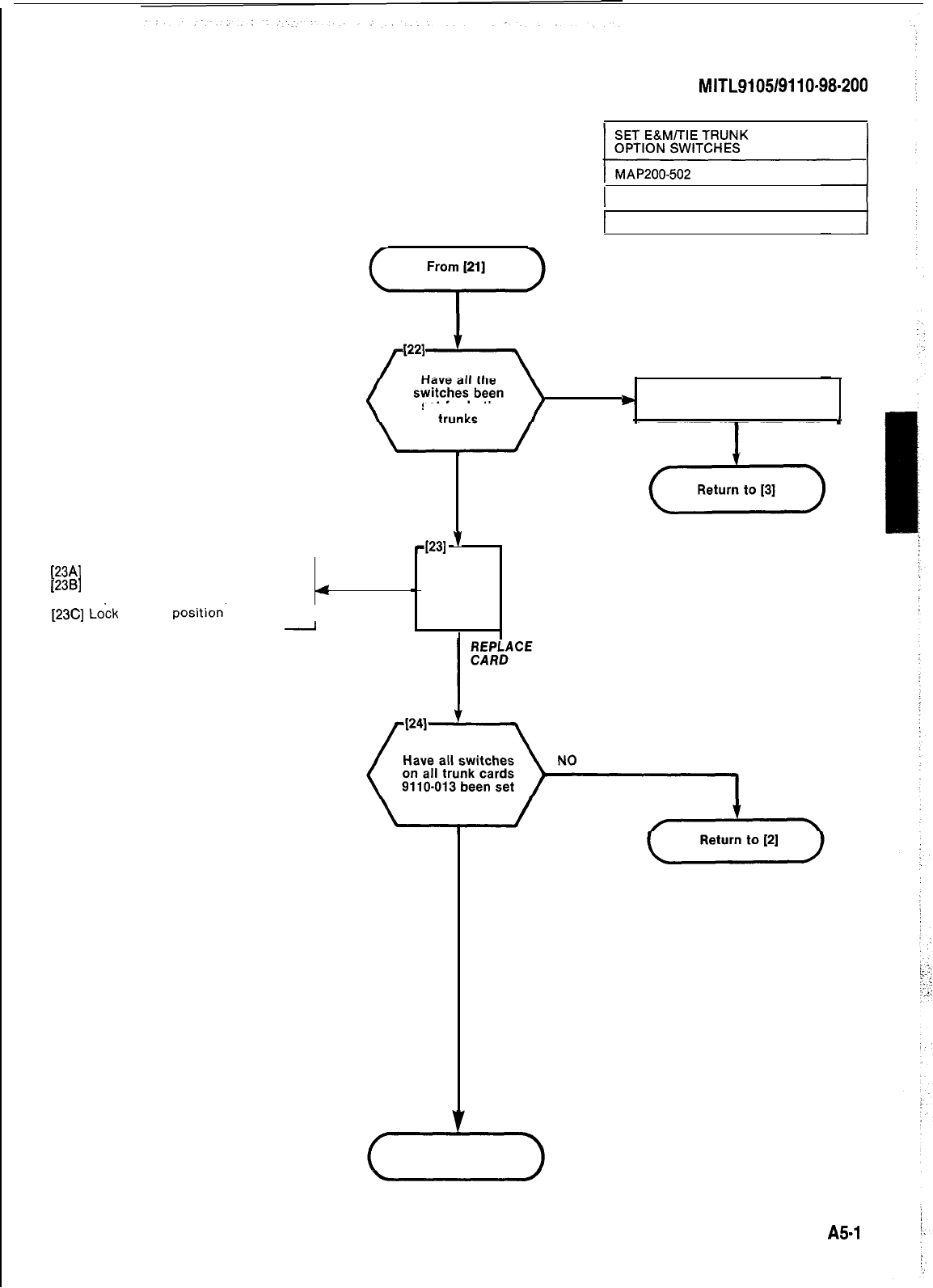
SECTION
MITL9105/9110-98-200
[23A]
Replace card in original card slot
[236]
Check that color coded locking
clips match the card position color
4
[23C]
Lock
card in
position-
I
-
1 Issue 2, August 1980
1 Sheet 5 of 7
NO
set
for both
*
Set switches for other trunk
4
YES
4231
'
-
AND
YES
AS-1 3
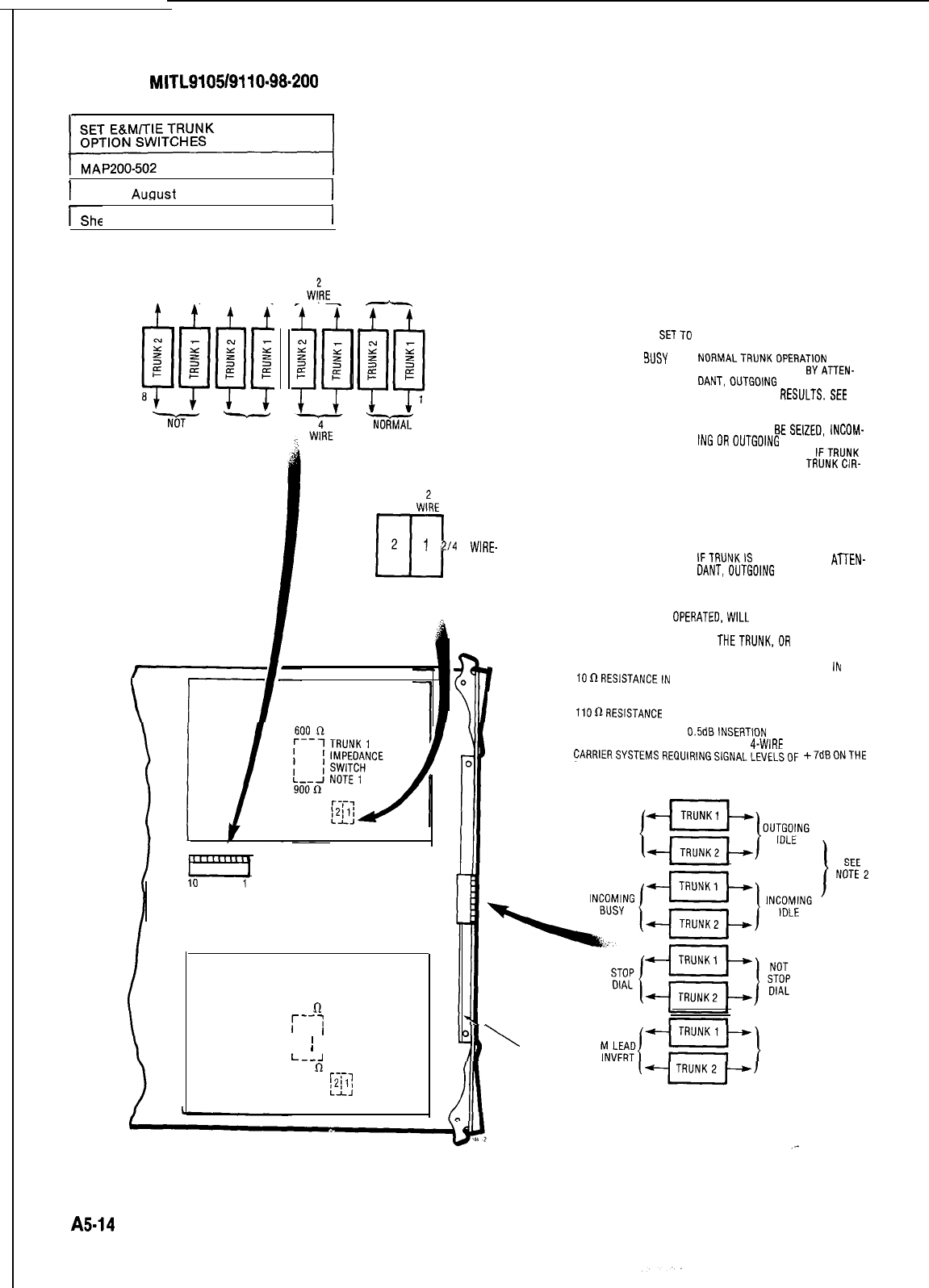
SECTION
MITL9105/9110-98-200
I
Issue 2.
Auaust
1980
I
1
Sheet 6 of 7
I
OUTGOING
INCOMING
WINK WINK
--
NioT
-
NOT
OUTGOING
INCOMING
WINK WINK
SPECIAL
GAIN
(NOTE 5)
-
.7iGKz
GAIN
LONG
LOOP
(NOTE 3)
W:RE
LOOP LIMIT
2
TRUNK1
SWITCH
m
1
214
WIRE-
LOOP SWITCH
SHORT 4
LOOP WIRE INCOMING BUSYSWITCH, WHEN
OPERATED,WlLL
PROVIDE AN OUTGOING
SEIZE SIGNAL WHENEVER THE TRUNK IS MADE OUTGOING BUSY (EITHER
FROM THE OUTGOING BUSY SWITCH ON
THETRUNK,OR
FROM THE CON-
SOLE).
NOTE 1:
TRUNK IMPEDANCE SWITCHES ARE LOCATEDON THE REAR
FACE OFTHETRUNK CARD.
NOTE 2: OUTGOING/INCOMING SWITCH SETTINGS
OUTGOING BUSY INCOMING BUSY
SWITCH SET TO SWITCH
SETTO
RESULT
IDLE
SUSY
NORMALTRUNKOPERATION
-IF
TRUNK IS MADE BUSY
BYATTEN-
DANT,OUTGOlNG
BUSY, INCOMING
BUSY CONDITION
RESULTS.SEE
BELOW.
BUSY
BUSY
BUSY
TRUNKCANNOT
BESEIZEO,
INCOM-
INGOROUTGOING
FROM THE PABX.
RECOMMENDEDSETTING
IFTRUNK
IS NOTCONNECTEDTO
TRUNKCIR-
CUIT.
IDLE
OUTGOING CALLS RECEIVE BUSY
TONE. INCOMING CALLS RECEIVE
RINGINGTONE BUTCANNOTBE
ANSWERED
IDLE IDLE
IFTRUNKIS
MADE BUSY BY
ATTEN-
DANT,OUTGOlNG
BUSY, INCOMING
IDLE CONDITION RESULTS. SEE
BELOW.
[NOTE 4)
iiJ
OPEN
600
R
:--:
TRUNK2
,
1 IMPEDANCE
, 1 SWITCH
L--A
NOTE1
900
R
r-,-7
!2!11
I
NOTE 3: LONG LOOPSETTING AT LOOP LIMIT SWITCH RESULTS
IN
10RRESlSTANCEIN
SERIES WITH M LEAD
,NOTE 4: SHORT LOOPSETTING OF LOOP LIMIT SWITCH RESULTS IN
11OflRESISTANCE
IN SERIES WITH M LEAD
NOTE5: NORMALGAIN PROVIDES
0.5dBlNSERTlON
LOSSTHROUGH THE
PABX. SPECIAL GAIN PROVIDES FOR
4-WIRE
OPERATION WITH
CARRIERSYSTEMSREQUIRINGSIGNALLEVELSOF
+7dBONTHE
Rx PAIR. AND -16dB ON THE TX PAIR.
OUTGOING
BUSY
\
FACEPLATE
M LEAD
NORMAL
Fig. 502-l
A5-14
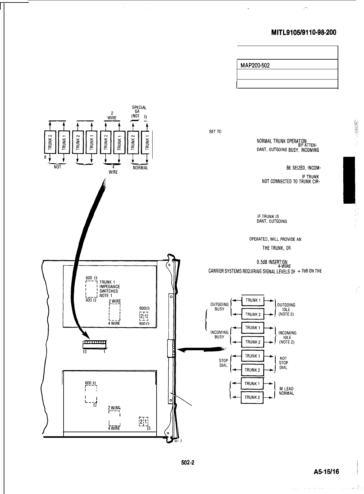
.
:..
SECTION
MITL9105/9110-98.200
I
1
SET E&M/TIE TRUNK
OPTION SWITCHES
MAP200302
Issue 2, August 1980
1
Sheet 7 of 7
NOTE 1: TRUNK IMPEDANCE SWITCHES ARE LOCATED ON THE REAR
FACEOFTHETRUNKCARO.
NOTE 2: OUTGOING/INCOMING SWITCH SETTINGS
:
:_:
OUTGOING BUSY INCOMING BUSY RESULT
SWITCH
SETTO
SWITCH SET TO
SPE(
IA
(NZ
IN
E:
-
NoriMAL
GAIN
OUTGOING INCOMING
WINK WINK
IDLE BUSY
NORMALTRUNKOPERATION
-IF
TRUNK IS MADE BUSY BYATTEN-
DANT.OUTGOlNG
BUSY,lNCOMlNG
BUSY CONDITION RESULTS. SEE
BELOW.
Ni)T
NOT
OUTGOING INCOMING
WINK WINK W;RE BUSY BUSY
TRUNKCANNOT
BESEIZED,INCOM-
ING OR OUTGOING FROM THE PABX.
RECOMMENDED SETTING
IFTRUNK
IS
NOTCONNECTEDTOTRUNKCIR-
CUIT.
BUSY
IDLE
OUTGOING CALLS RECEIVE BUSY
TONE. INCOMING CALLS RECEIVE
RINGINGTONE BUT CANNOT BE
ANSWERED
IDLE IDLE
IFTRUNKIS
MADE BUSY BYATTEN-
DANT.OUTGOlNG BUSY, INCOMING
IDLE CONDITION RESULTS. SEE
BELOW.
INCOMING BUSYSWITCH. WHEN
OPERATED,WlLLPROVlDEAN
OUTGOING
SEIZE SIGNAL WHENEVER THE TRUNK IS MADEOUTGOING BUSY (EITHER
FROM THE OUTGOING BUSY SWITCH ON
THETRUNK,OR
FROM THE CON-
SOLE).
NOTE 3: NORMAL GAIN PROVIDES 0.5dBlNSERTlON LOSSTHROUGH THE
PABX. SPECIAL GAIN PROVIDES FOR 4-WIRE OPERATION WITH
CARRlERSYSTEMSREOUIRINGSlGNALLEVELSOF
+7dBONTHE
Rx PAIR, AND -16dB ON THE T
X
PAIR.
M LEAD
INVERT
\
FACEPLATE
:--7
TRUNK2
,
'
I--J
1
IMPEDANCE
SWITCHES NOTE1
900
0pt7E
-I
I '
I
'
600R
I I
1
1
L--J
4WIRE 900
R
I
3
2
i_
\
A5-15118
1
Fig.
502-2
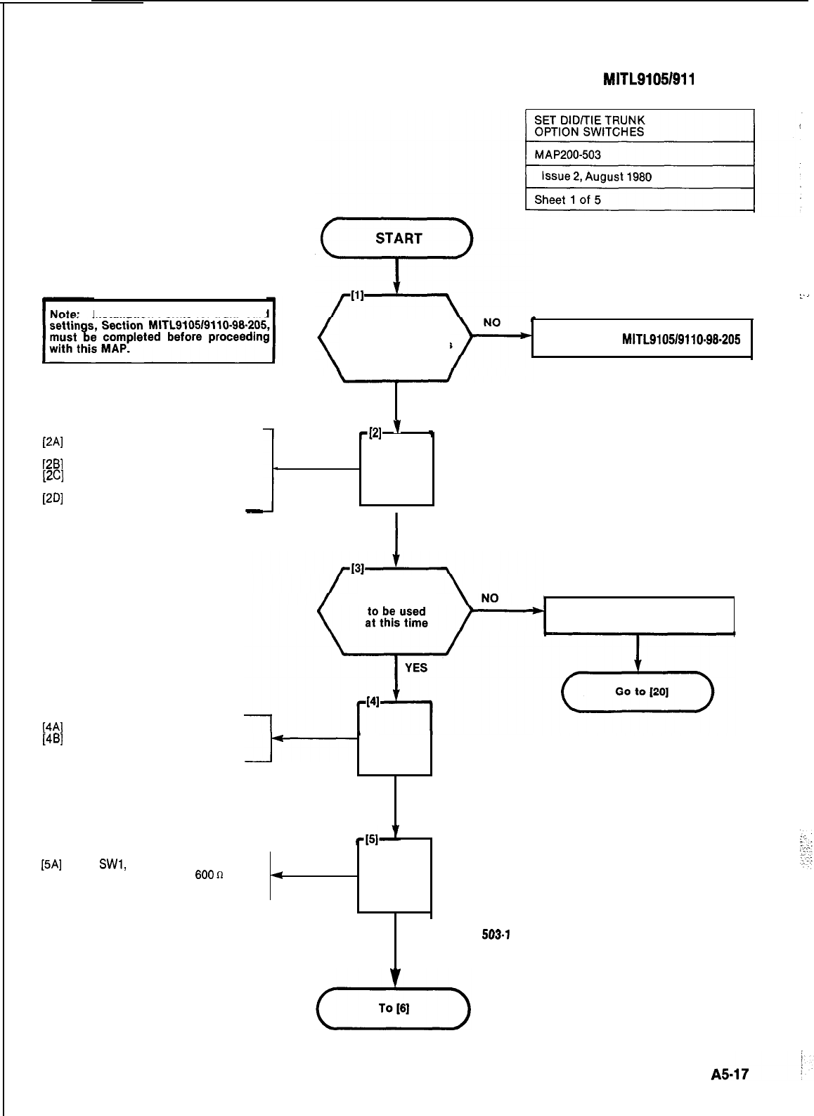
SECTION MITL91051911 o-98-200
Installation Forms for trunk card
[2A]
Locate required trunk circuit card
9110-031
[2B]
Note card position
[2C]
Lift card locking clips located at
the top and bottom of the card
[2D]
Remove trunk card 9110-031
-
Have Installation
Forms for Trunk
Card switch settings
been completed
L.
_
.
.
c
Go to Section
MITL9105/9110-98-205
YES
421
’
+
lAND I
I
I
REMOVE REQUIRED
TRUNK CARD
Is trunk circuit Set Outgoing Busy switches
to BUSY. Fig. 503-l
[4A]
Identify trunk circuit
[4B]
Set conditions on Trunk BUSY
switch (see Note) AND
.
SET TRUNK
BUSY CONDITION
SWITCHES (SEE NOTE)
[5A]
Set
SWl,
SW2 and SW3 Trunk
Impedance switch to
600n
or
4
AND
900
as required. Fig. 503-l
SET IMPEDANCE
SWITCH. F/G.
503-I
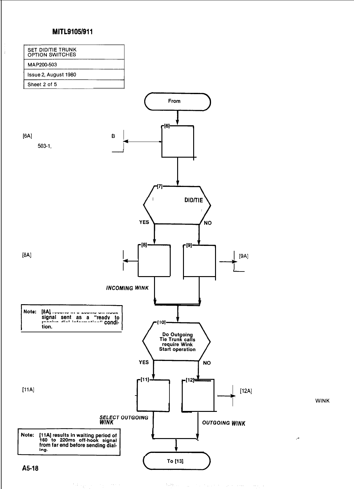
SECTION
MITL91054911
O-98.200
From
9
[6A]
Set trunk type switches A and
6
to configuration required. Fig.
<
503-1,
Table 503-l
-
AND
-
SET TRUNK
TYPE SWITCHES
FIG. 503-l
Do Incoming
DID/TIE
Trunk calls require
Wink Start operation
[BA]
Set the Incoming Wink switch on
the face of the circuit card to IN-
1
AND
-
[9A]
Set the Incoming Wink switch on
COMING WINK AND the face of the circuit card to
NOT INCOMING WINK
-
SET SWITCH FOR
lNCOM/NG
WlNK
SET SWITCH FOR
START NOT INCOMING
WINK START
(8A]
results in a 200ms off-hook
receive dial information”
condi-
[llA]
Set the Outgoing Wink Start
switch on the face of the circuit
card to OUTGOING WINK Ii--
AND
WINK
START SELECT NOT
OUTGOlNG
WlNK
START
v
,-
AND
-
[12A]
Set the Outgoing Wink Start
switch on the face of the circuit
card to NOT OUTGOING
WINK
A5-18
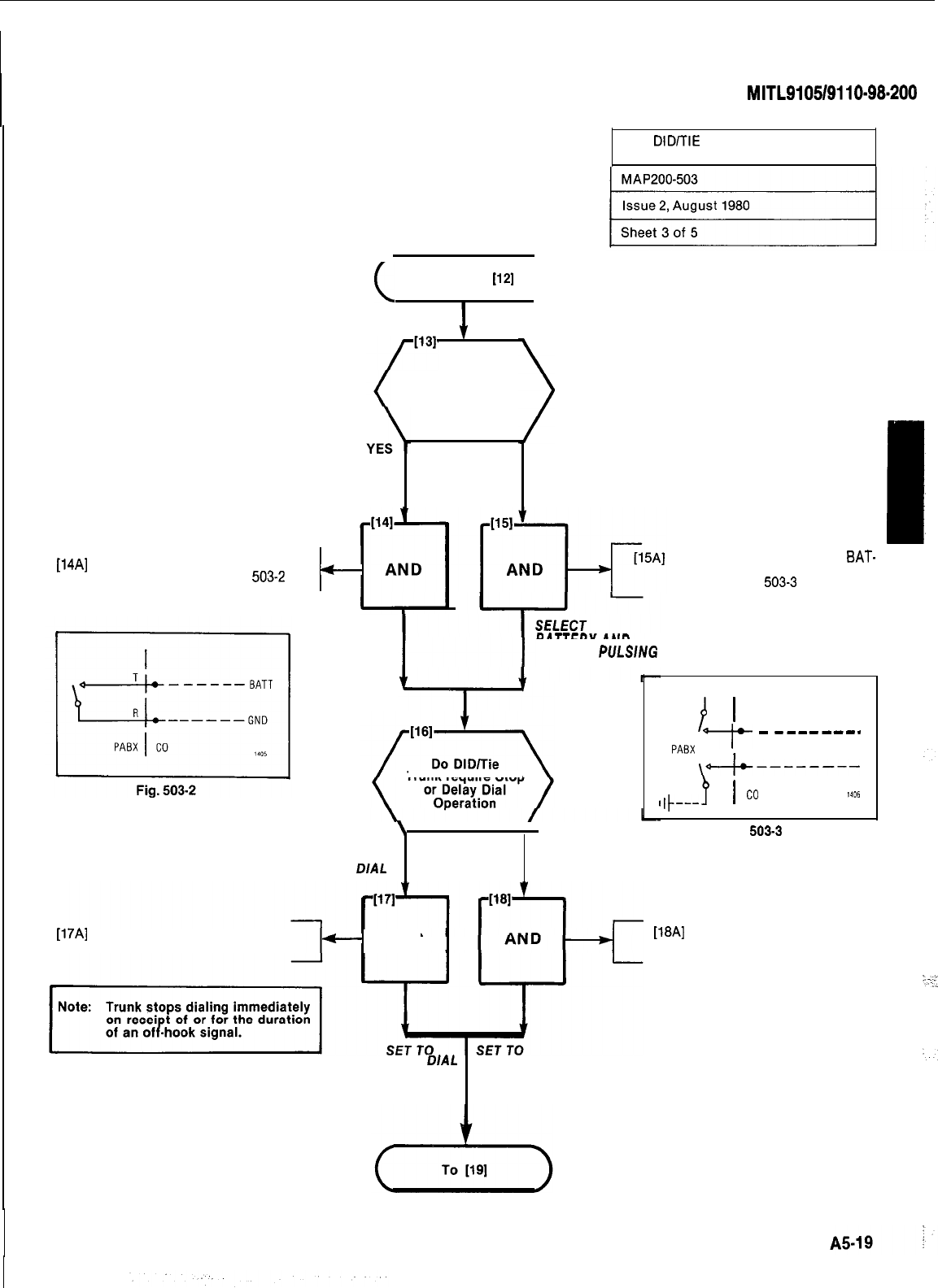
SECTION
MITL9105/9110~98~200
~
SET
DID/TIE
TRUNK
OPTION SWITCHES
(
From
[12]
)
Is trunk signaling
to be loop pulse
LOOP PULSE
NO
BATTERY AND
GROUND PULSING
[14A]
Set the BG-PULS switch to LOOP
-
PULSING Fig. 503-l and
503-2
Set the PG-PULS switch to
BAT-
TERY and GROUND PULSING.
Fig. 503-l and
503-3
SELECT
LOOP
PULSING
I
BATTERY AND
GROUND
PULSlNG
Trunk require Stop
\
YES
‘NO
STOP
DIAL
Fig.
503-3
[17A]
Set the STOP DIAL switch to
STOP DIAL Fig. 503-l
c-
AND
[18A]
Set the STOP DIAL switch to
NOT STOP DIAL. Fig. 503-l
STOP
DIAL
NOT STOP DIAL
BATT
/
’
PABX
_I_
-
--------
I
\++--------
I#---
4
I
co
1406
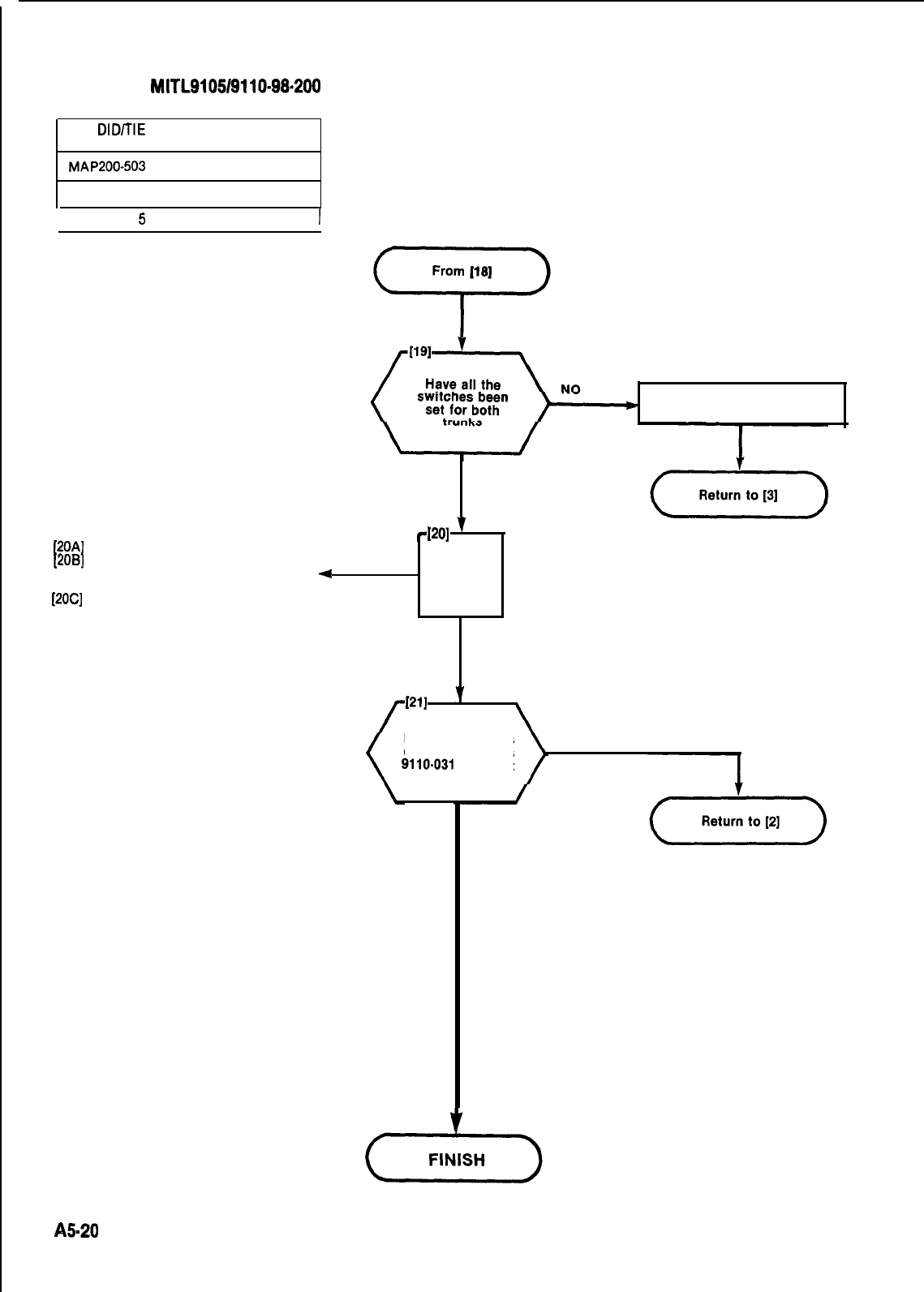
SECTION MITL9105/9110-98.200
SET DID/TIE TRUNK
OPTION SWITCHES
MAP200-503
Issue 2, August 1980
1 Sheet 4 of
5
I
Set switches for other trunk
YES
[20A] Replace card in original card slot
[2OB]
Check that the color coded lock-
ing clips match the card position
+
color
1
4201
v
[2OC]
Lock card in position
AND
REPLACE
CARD
Have all switches
on all trunk cards
9110-031
been set
NO
YES
85.20
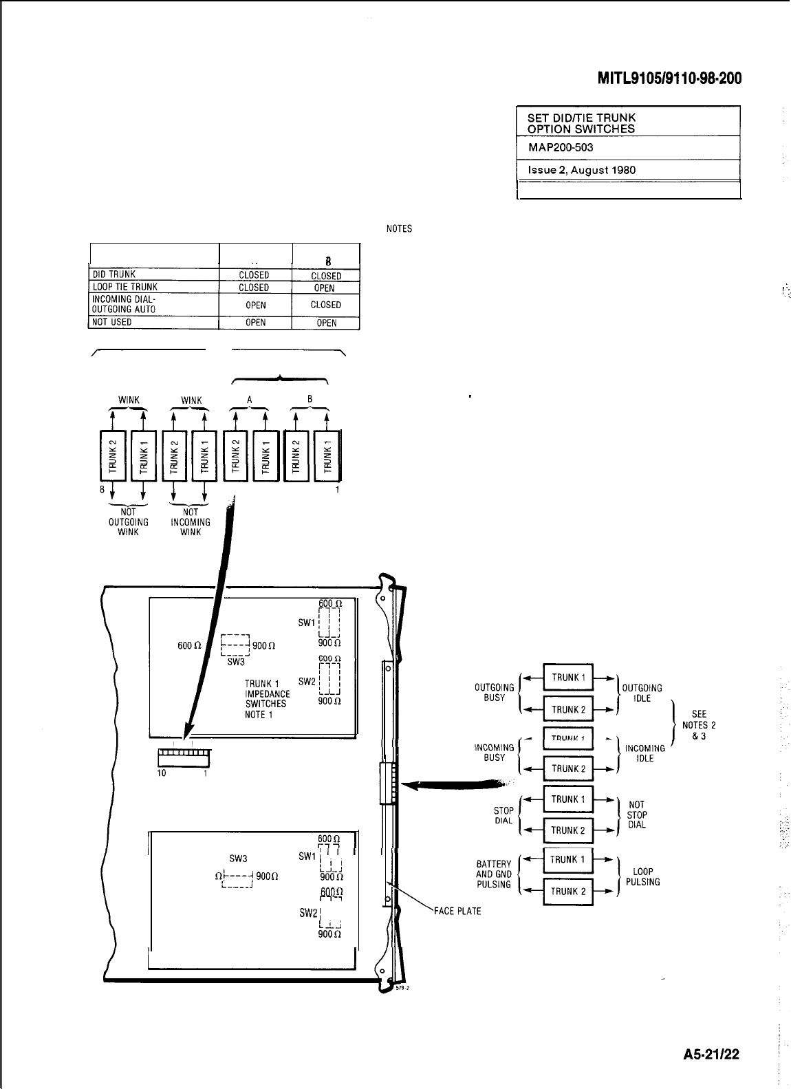
TABLE 503-l
TRUNK TYPE
SWITCH SWITCH
AR
OPEN
.-\
SEE TABLE 503-l
OUTGOING INCOMING SWITCH SWITCH
OPEN
SW3 SWlI
I I
r---7
600
fit---j
9000
LL:
soon
i----J
600
(1
C-7-7
TRUNK 2
i i i
IMPEDANCE SW21
I ;
1 I
SWITCHES
NOTE 1 kOiii
SECTION
MITL9105/9110-98.200
I
Sheet 5 of 5
1.
TRUNK IMPEDANCE SWITCHES ARE LOCATED ON THE REAR FACE OF THE TRUNK
CARD.
TRUNK BUSY SWITCHES
. .
..:
2.
OUTGOING BUSY SWITCHES (1 PER TRUNK) CAN BE SET FOR EITHER OF THE
:.
I:
FOLLOWING CONDITIONS:
IDLE SETTING NORMAL TRUNK OPERATION
. .
BUSY SETTING TRUNK CANNOT BE SEIZED FOR OUTGOING CALL
3.
THE "OUTGOING BUSY" CONDITION MAY BE SET EITHER BY THE OUTGOING BUSY
SWITCH (NOTE 2). OR BY THE CONSOLE "TRUNK BUSY OUT' FUNCTION. WHEN
THIS CONDITION IS IN EFFECT THE INCOMING BUSY SWITCH AFFECTS THE TRUNK
CONDITION AS FOLLOWS:
IDLE SETTING
-
NO ANSWER WILL BE GIVEN TO INCOMING TRUNK CALLS
BUSY SETTING
-
A PERMANENT SEIZURE CONDITION IS GIVEN TOWARDS THE TRUNK
I
Fig. 503-l
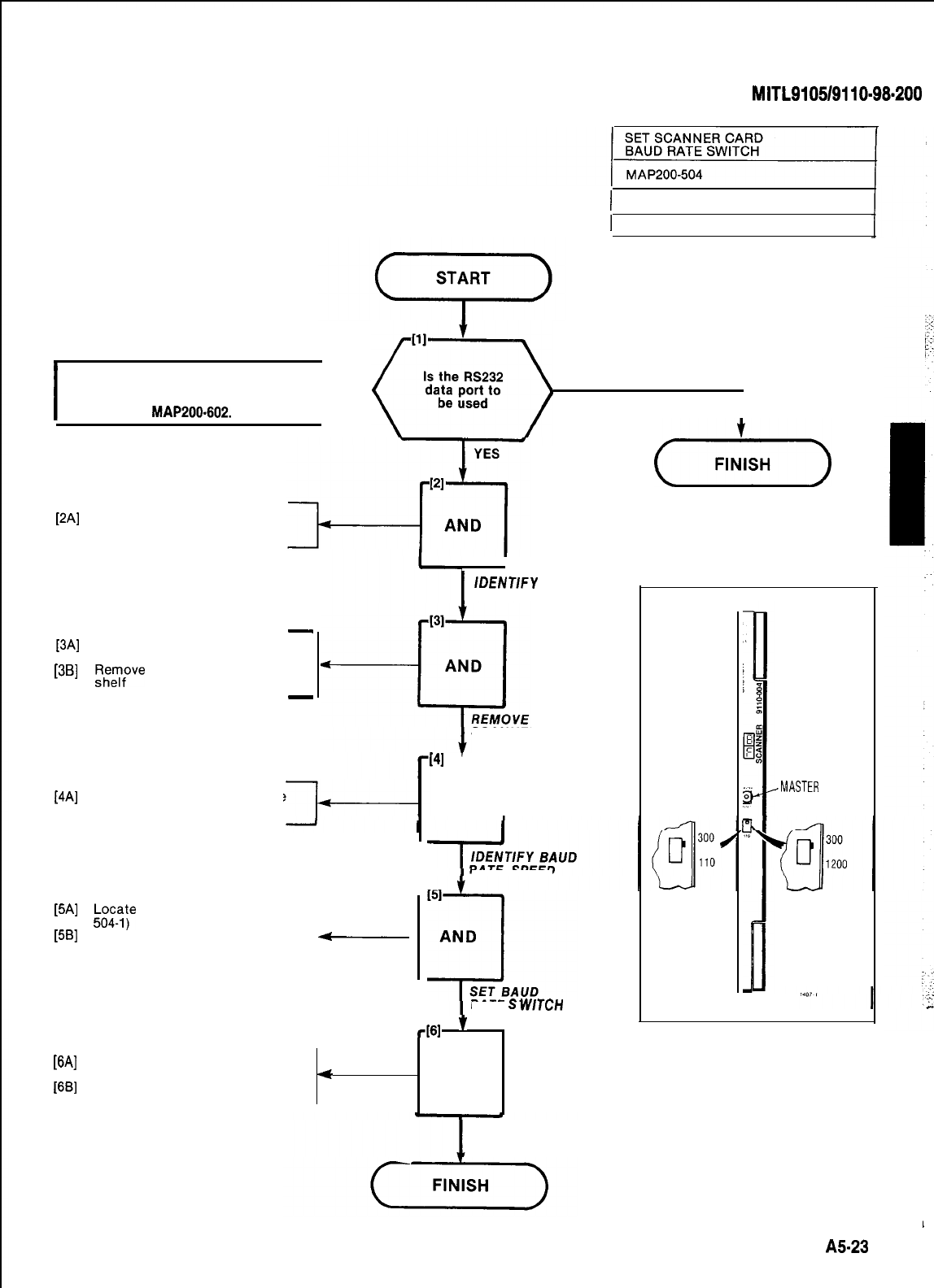
SECTION
MITL9105/9110-98.200
:
I
CAUTION
Do not remove Scanner Card from an ac-
tive PABX without following relevant
procedures in MAP200-602.
I
)
Issue 1, January 1980
NO
I
-
[3A]
Lift card extractors at top and
bottom of card
[3B]
FIRz;ve
Scanner card from the
-
1 Sheet 1 of 1
[2A]
Identify Scanner card by card
slot position (19) in shelf 1
I
/DENT//V
SCANNER CARD
SCANNER CARD
[4A]
Identify the required baud rate
from the circuit requirements
[5A]
&a$?
the baud rate switch (Fig.
[5B]
Place the switch to the required
-
baud rate
1
(41
’
1
AND
RATE SPEED
RATE
S
WTCH
461
’
[6A]
Replace Scanner card in Slot 19
of Shelf 1
4
AND
[6B]
Lock card in position
REPLACE CARD
(,,.,,,)
SCANNER,
DISPLAY
BAUD
RATE
SWITCH
PIN -004
SYSTEM
<MASTER
RESET
BAUD
RATE
SWITCH
P/N -104
Fig. 504-l
1
A!523
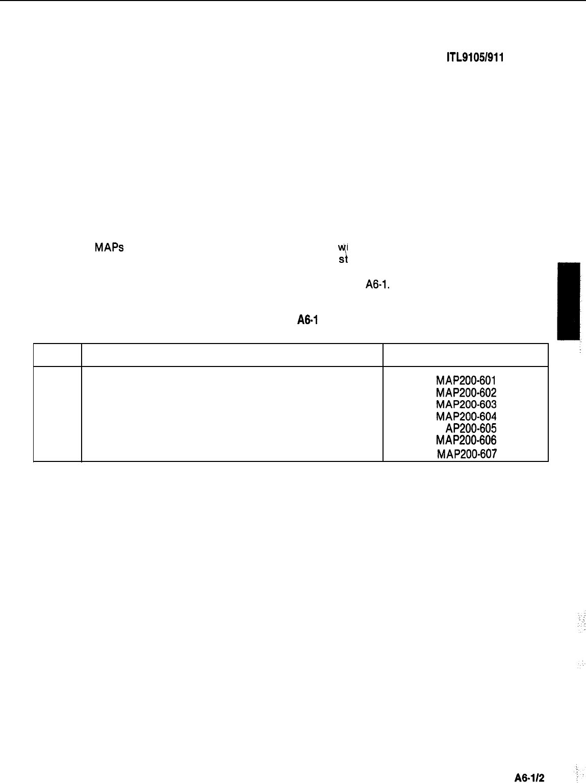
SECTION M ITL91051911 O-98-200
APPENDIX 6
ADDITIONAL EQUIPMENT INSTALLATION
1. General
A8.01
The
MAPS
contained in this Appendix are concerned
“i
ith additional installation requirements
which may be required during initial or subsequent ins allation
phases.
A6.02
A list of these additional requirements are shown in Table
A6-1.
TABLE
A6-1
ADDITIONAL INSTALLATION REQUIREMENTS
Step Procedure Reference
1
Shelf 2 Installation (SX-200)
MAP200-601
2
Install New Cards
MAP200-602
3
Reserve Power Supply installation (SX-200)
MAP200-603
4
Console Interface Board Installation (SX-200)
MAP200-604
5
Backplane Translator Board Installation
M AP200-605
6
Installation of RCP Card
MAP200-606
7
Reserve Power Supply Installation (SX-100) MAP200-607
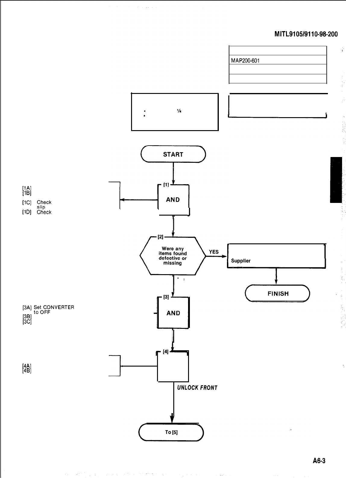
PAI
11
Bl
[l
Cl
11
Dl
Unpack shelf
Check backolane for cracks and
SECTION
MITL9105/9110-98-200
:
SHELF 2 INSTALLATION (SX-200)
MAP200-601
issue 1, January 1980
Sheet 1 of 3
Tools Required
1
-
Screwdriver
Vi
blade
1
-
Screwdriver No. 10 Phillips
bent pins
z,/;ck
hardware against packing
Check
fuses (if supplied)
I
I
I
I
UNPACK AND
CHECK SHELF
I
Note: This MAP applies only to SX-200
equipment. I
At Rear of Cabinet
[3A]
F;;(Z($NVERTER
INPUT switch
[3B]
Set BATT switch to OFF
[3C]
A-
Remove power plug(s) from outlet
Complete Damage Report Form and
return with defective items to the
At Front of the Equipment Cabinet
[4A]
Unlock front door
[4B]
Open front door
7
I
NO
I
POWER DOWN
SYSTEM
l
AND
UNLOCKFRONT
DOOR
:
A8-3
:
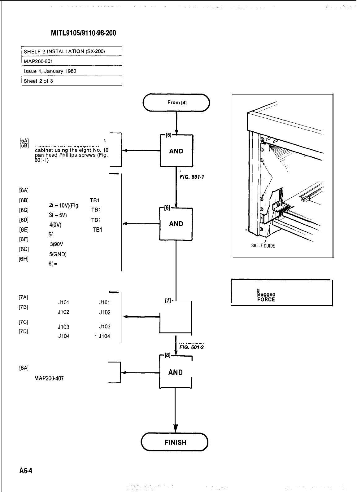
SECTION
MITL9105/9110-98-200
SHELF 2 INSTALLATION (SX-200)
ui
[5A]
Place shelf onto shelf guides
[5B]
Fasten shelf to equipment
-
On Shelf 2
_.
WI
At Rear of Equipment Cabinet
,Remove insulation tube from all
cables
WI
WI
WI
ml
m-1
w.3
PHI
[7Al
1781
17Cl
[7Dl
IW
Connect violet wire to
TBl
ter-
minal
2(
-
lOV)(Fig.
601-2)
Connect yellow wire to
TBl
ter-
minal
3(
-
5V)
Connect brown wire to
TBl
ter-
minal
4(OV)
Connect orange wire to
TBl
ter-
minal
5(
+ 8V)
Connect gray wire to TB2 ter-
minal
3(9OV
RINGING)
Connect brown wire to TB2 ter-
minal
S(GND)
Connect blue wire to TB2 ter-
minal
6(
-
48V)
-
Connect interconnect cable 101
to shelf 2
JlOl
and shelf 1
JlOl
Connect interconnect cable 102
to shelf 2
J102
and shelf 1
J102
(Fig. 601-2)
Connect interconnect cable 103
to shelf 2
J103
and shelf 1
J103
Connect interconnect cable 104
to shelf 2
J104
and shelf
1
J104
I
INSTALL SHELF
r
(61.
r
[71-
CONNECT CABLE
HARNESS
FIG. 601-2
7
AND
Perform the “Power-Up” pro-
cedure in accordance with
MAP200-407
J-+-l
AND
I
-
I
I
POWER
UP
A8-4
I
CAUTION
Ensure ta ged end of each interconnect
cable is p u ged into shelf 2.
B
DO NOT
FOkE
CONNECTOR
CONNECT SHELF
INTERCONNECT CABLES
rP31
SECURING SCREWS
IELF
&IDE
Fig. 601-l
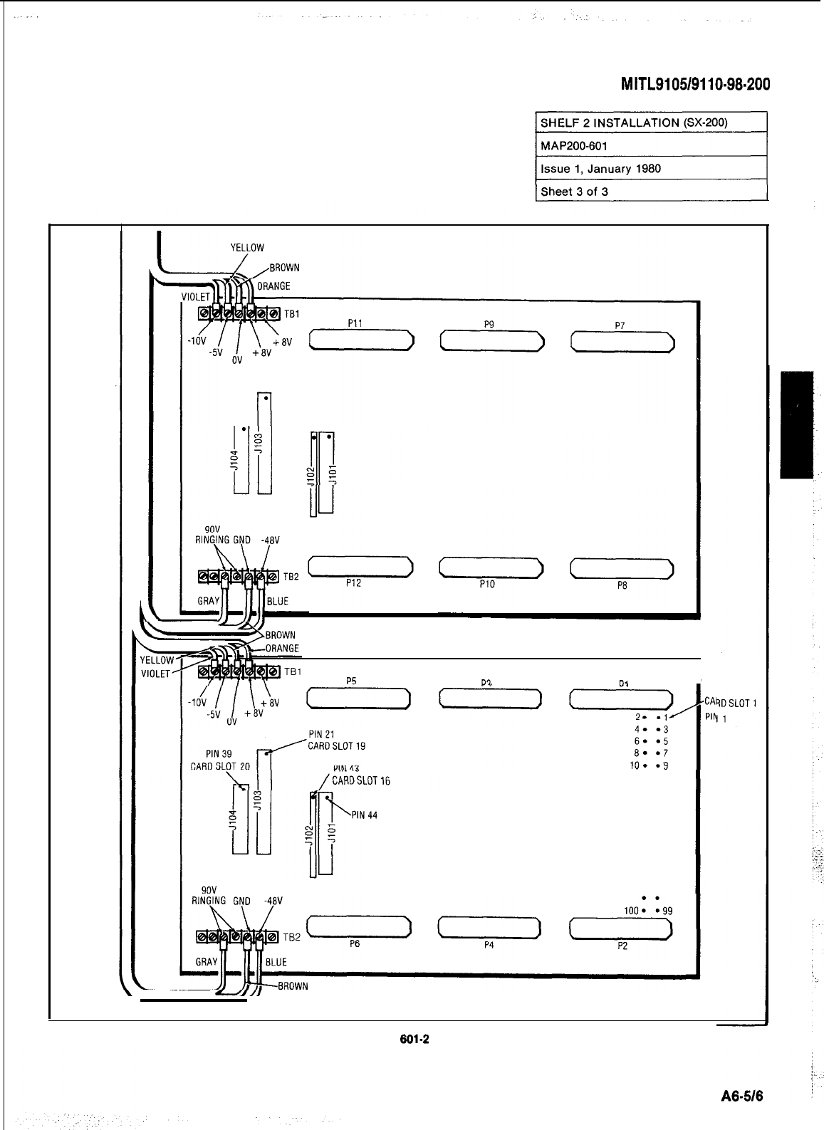
SECTION
MITL9105/9110-98.200
SHELF 2 INSTALLATION (SX-200)
al
SHELF 2
P5
P'1
D,
I
(-
SHELF 1
Fig.
601-2
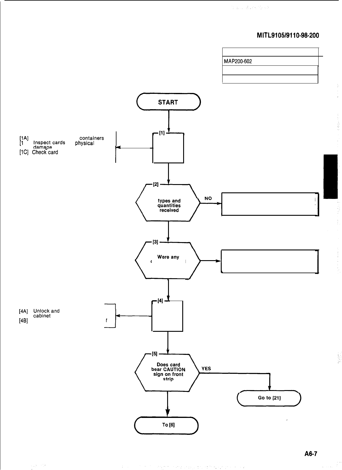
-
AND
UNPACK AND
INSPECT CARDS
[lA]
Unpack cards from
covtainers
[l
B]
l$sp;;;cards
for
physlcal
e
[lC]
ChecKcard
types and quantities
against invoice
I
[4A]
$$cktand
open front door of
1461
Remove locking bars from shelf
SECTION
MITL9105/9110-98.200
INSTALL NEW CARDS
MAP200-602
Issue 1, January 1980
Sheet 1 of 8
Were correct Repack items in original containers and
return to supplier, with completed sec-
tion of Damage Report
YES
cards damaged
NO
YES
Tag defective items, repack in original
)
containers and return to supplier with
completed section of Damage Report
‘
-
AND
OPEN
FRONT
DOOR
NO
I
A8-7
j
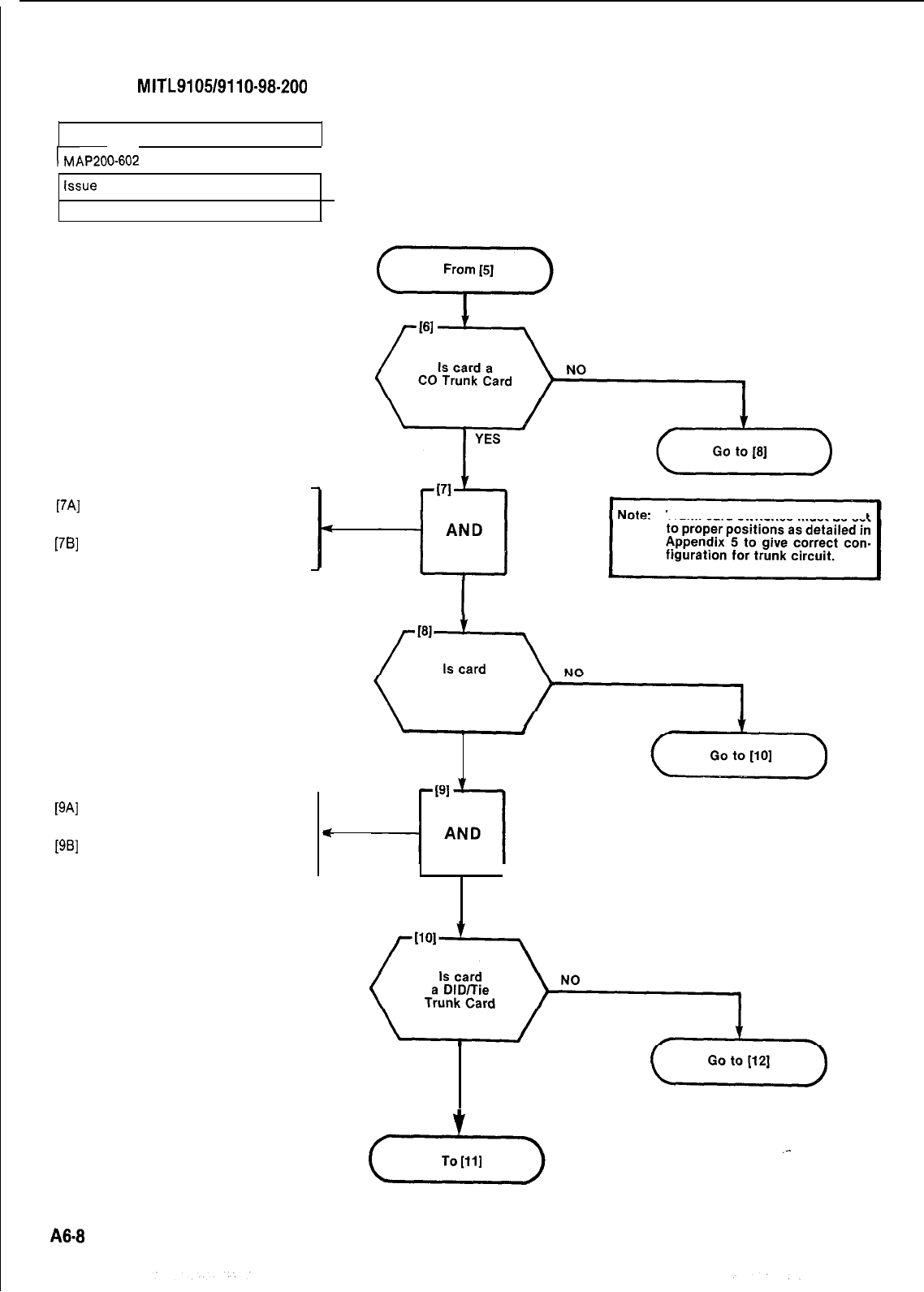
SECTION
MITL9105/9110-98-200
INSTALL NEW CARDS
GO-602
I
tssue
1, January 1980
Sheet 2 of 8
[7A]
Determine settings of trunk card
switches from installation forms
[7B]
and Appendix 5 (Note)
Set trunk card switches to proper
positions
[9A]
Determine settings of trunk card
switches from installation forms
[9B]
and Appendix 5 (Note)
Set trunk card switches to proper
positions
I
SET CO TRUNK
CARD SWITCHES
Trunk card switches must be set
an
E and M/Tie
Trunk Card
YES
I
J
SET E&M/TIE TRUNK
CARD SWITCHES
YES
A8-8
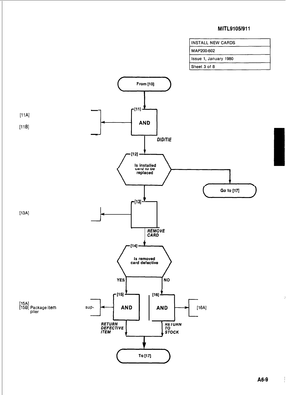
SECTION
MITL9105/911
o-98-200 j
-
[llA]
Determine settings of trunk card
[llA]
Determine settings of trunk card
switches from installation formsswitches from installation forms
and Appendix 5 (Note)and Appendix 5 (Note)
[llB]
Set trunk card switches to proper
[llB]
Set trunk card switches to proper
positionspositions
-
[13A] Release card extractor and
remove card from shelf slot
From
[lo]
“r>
Pll
l--L3
AND
SET
DIDITIE
TRUNK
CARD SWITCHES
NO
YES
431
’
4
AND
-
&
Mf;VE
INSTALLED
[15A]
Tag defective item
[15B]
t%$age
Item
and return to
sup-
WI
3-f
AND
[16A]
Place card in stock
:
A8-9
i
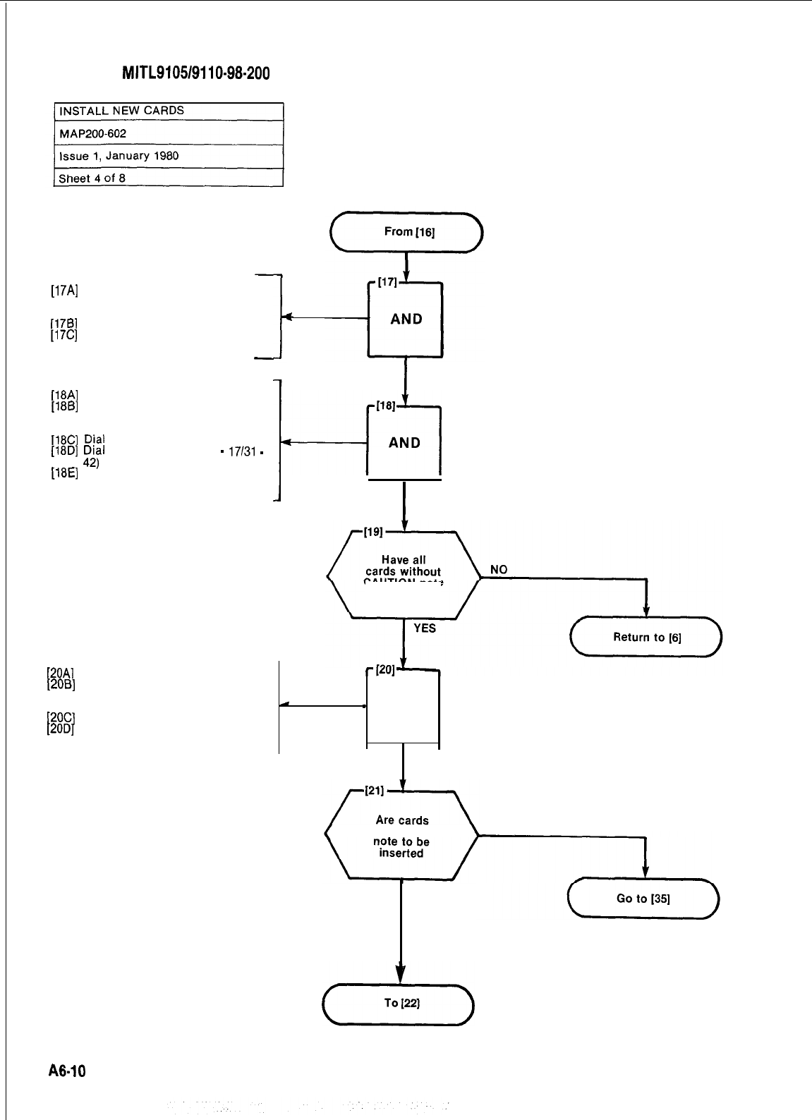
SECTION
MITL9105/9110-98-200
[17A]
Check proper card slot and color
codes of card extractor against
shelf slot
[178]
Slide new card into shelf slot
[17C]
Lock card by pressing the extrac-
tors inward
-
[18A]
Access the test line
[186]
Dial the maintenance access
code (555 used for the purpose of
this documentation)
[18C]
Dial
5
[18D]
:;;I
card slot number (1
-
17/31
-
[18E]
Replace handset of test line
telephone
+
I
PLUG IN
NEW CARD
h31
4-l
AND
I
INITIALIZE
NEW CARD
CAUTION note
been inserted
[20A]
Access the test line
[20B]
Dial the test access code (555
used for the purpose of this
documentation)
c
1
AND
[2OC]
Dial 1
[20D]
Replace handset of the test line
telephone CLEAR MINOR
ERRORS
with CAUTION NO
YES
(-+-)
A6-10
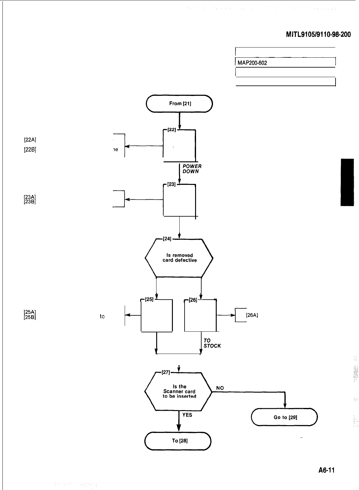
[22A]
Set all POWER switches to the
[22A]
Set all POWER switches to the
OFF positionOFF position
--l--f
[226]
Remove the power cord from the
[226]
Remove the power cord from the
4
AND
power outletpower outlet
P34
Release card extractors
[23~1
Remove card from shelf slot
Tag defective
Package item
plier
item
and return
to
AND
REMOVE
INSTALLED
CARD
YES
NO
SECTION
MITL9105/9110-98.200
j
1 INSTALL NEW CARDS
I
1 Issue 1, January 1980
I
Sheet 5 of 8
-1251)
4261
’
-
sup-
4
AND AND
RETURN RETURN
DEFECT/YE
ITEM
2OCK
Y
7
I
Place card in stock
A6-11
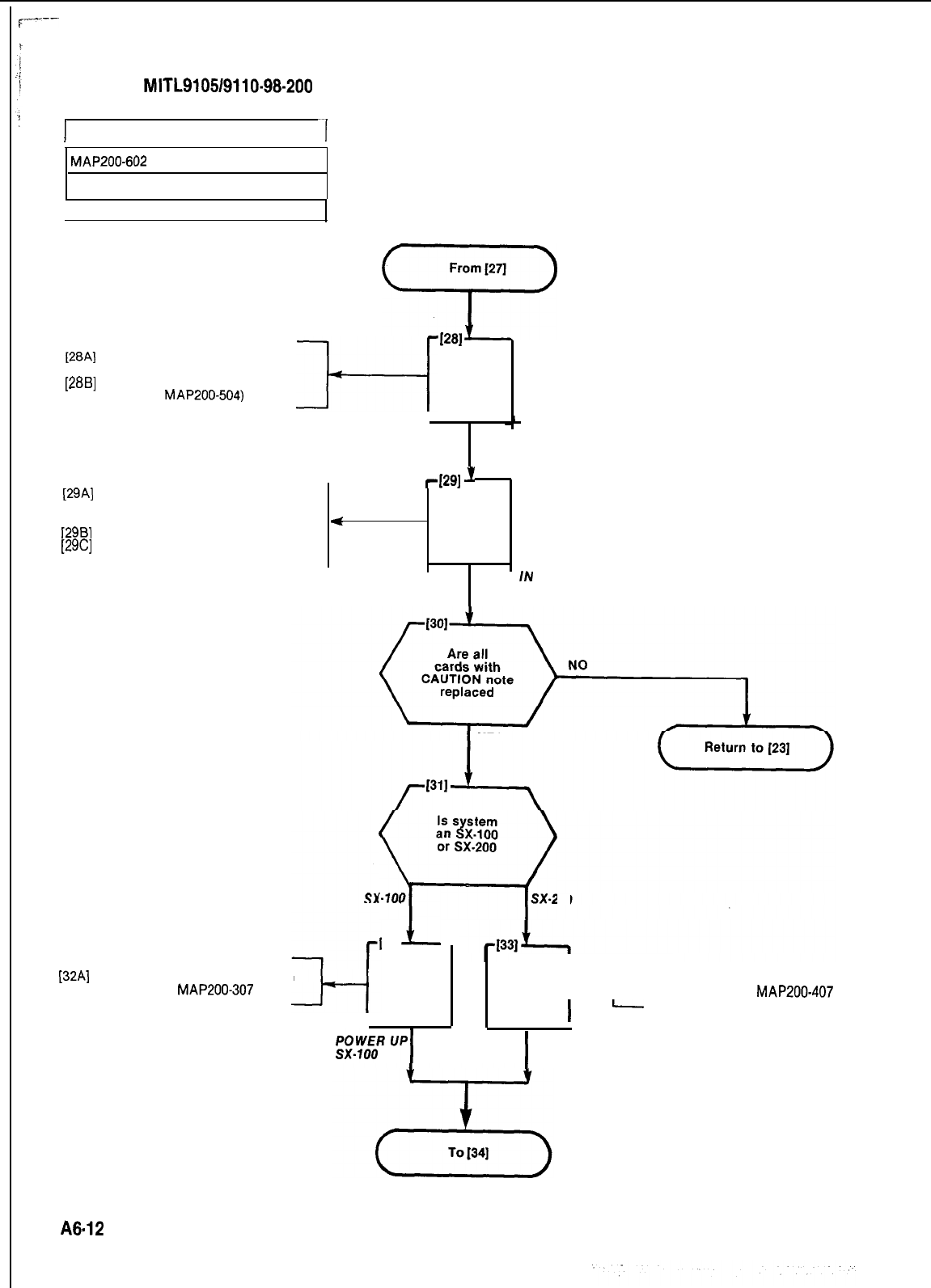
SECTION
MITL910519110-98-200
I
INSTALL NEW CARDS
--I
MAP200-602
Issue 1, January 1980
Sheet 6 of 8
From
1271
57
1281
[28A]
Identify proper baud rate if
RS232 port is used
l--l
[28B]
Set baud rate switch to proper AND
rate (See
MAP200-504)
[29A]
Check proper card slot and color
codes of card extractor against
shelf slot
12981
Slide new card into shelf slot
[29C]
Lock card by pressing the extrac-
tors inward
SET SCANNER
CARD BAUD
SWITCH
4291
J
4
AND
PLUG
IN
NEW CARD
YES
IS s
H
stem
an X.100
or SX-200
%)
sx-200
1321
1
AND AND l-4--
133A] Power up system as detailed in
Appendix 4,
MAP200-407
[32A]
Power up system as detailed in
Appendix 3,
MAP200-307
I
-
I
POWER UP
sx-200
A6.12
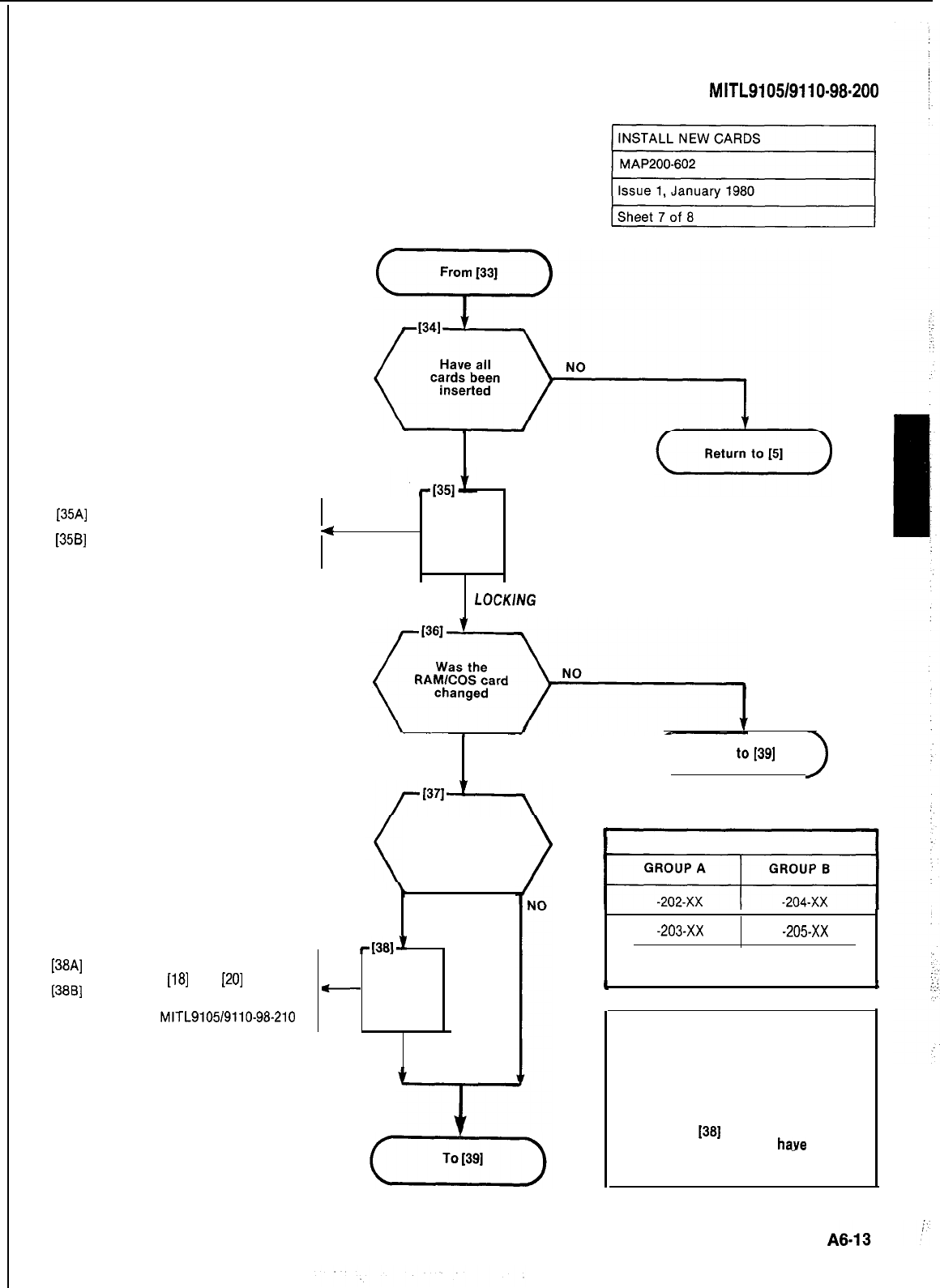
SECTION
MITL9105/9110-98.200
YES
[35A]
Replace the locking bars across
the front of the shelf
[356]
Slide and securely fasten the
4
AND
locking device
REPLACE
LOCK/NG
BARS
[38A]
Perform initialization procedure
as in Steps
[18]
and
[20]
(3881
Reprogram the system in accor-
dance with the procedures stated
in Section
MITL9105/9110-98-210
Was there
a change in
software (see
Note 1)
YES
4381’
-
AND
INITIALIZE
AND
REPROGRAM
YES
( Go
to[39]
)
TABLE 602-l
GENERIC AND REVISION LEVELS
-203-Xx -20.5xx
-XX indicates revision
level and number
I
t
NOTES
1.
The equipment may be installed with
different software packages (Table
602-l). If the PROM/CPU and
Memory Expander (or PROM/RAM
Expander) cards installed differ in
group type from those previously in-
stalled a software change occurs,
2.
and Step
1361
must be performed.
The above cards must
haye
identical
generic and revision level numbers
when installed.
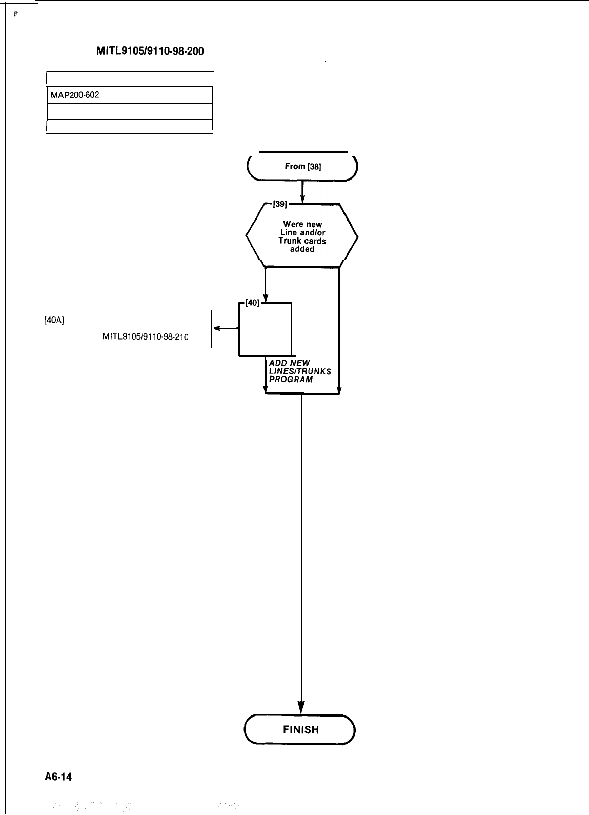
SECTION
MITL9105/9110-98.200
)
INSTALL NEW CARDS
1
MAP200-602
issue 1, January 1980
1 Sheet 8 of 8
[40A]
Add new line and trunk programs
following procedure stated in
Section
MITL9105/9110-98-210
NO
YES
-
AND
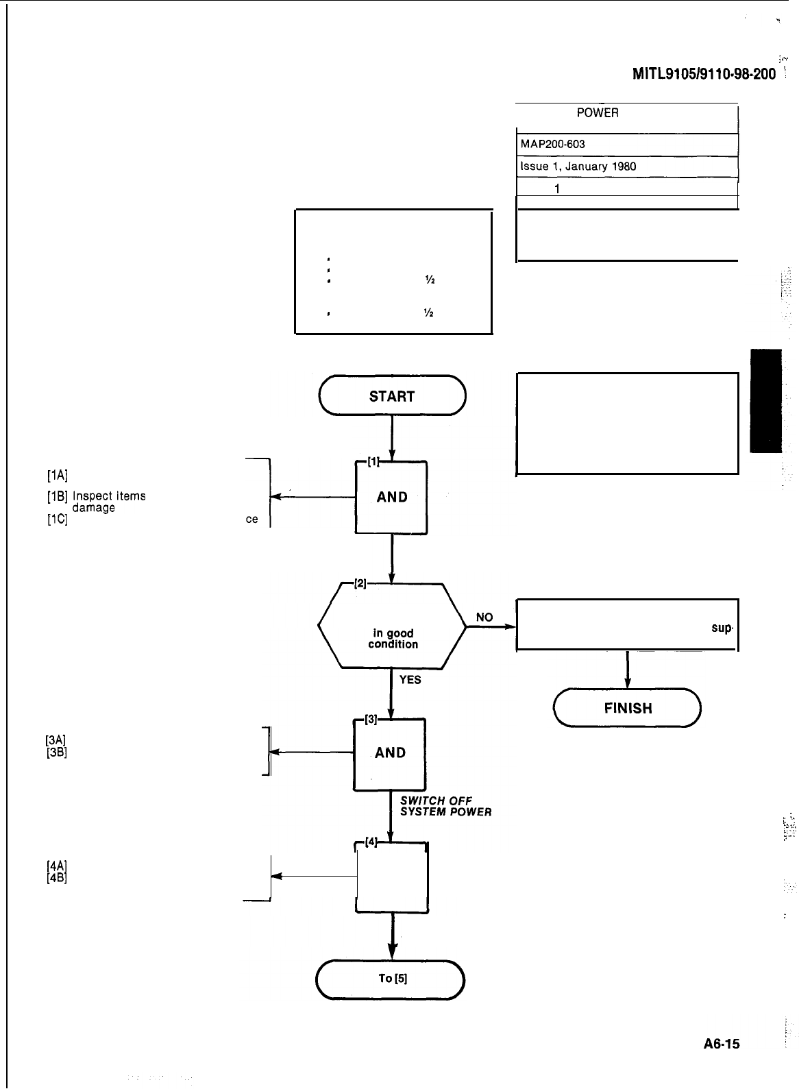
Tools Required
Non Predrilled Cabinet
1
-
Electric drill
1 e No. 22 (0.157 inch) twist drill
1
-
Slot screwdriver
l/z
inch
Predrilled Cabinet
1
-
Slot screwdriver
‘/2
inch
[lA]
Unpack reserve power supply
equipment
[IB]
ln;$x&items
for physical
[lC]
-I-
Check item types against invoice
[3A]
Set ALL POWER switches to OFF
[3B]
Remove power cord(s) from
power outlet(s)
UNPACK AND
INSPECT ITEMS
;
^
SECTION
MITL9105/9110-98.200
:
RESERVE
POWER
SUPPLY
INSTALLATION (SX-200)
Sheet
1
of 7
Note: This MAP applies only to
SX-200 equipment. I
CAUTION
Check that the BATTERY switch on
the reserve battery pack is set to
OFF.
Check that the three switches on the
battery charging unit is set to OFF.
Were correct
items received Complete Damage Report Form and
return with defective items to the
sup.
plier.
1
(4Al
[4B]
Unlock and open front door
Set all power switches to OFF
4
position AND
OPEN FRONT
DOOR A ND POWER DOWN
/
:
i.
‘:.
.._.
.T<.!
2-z
‘.
:
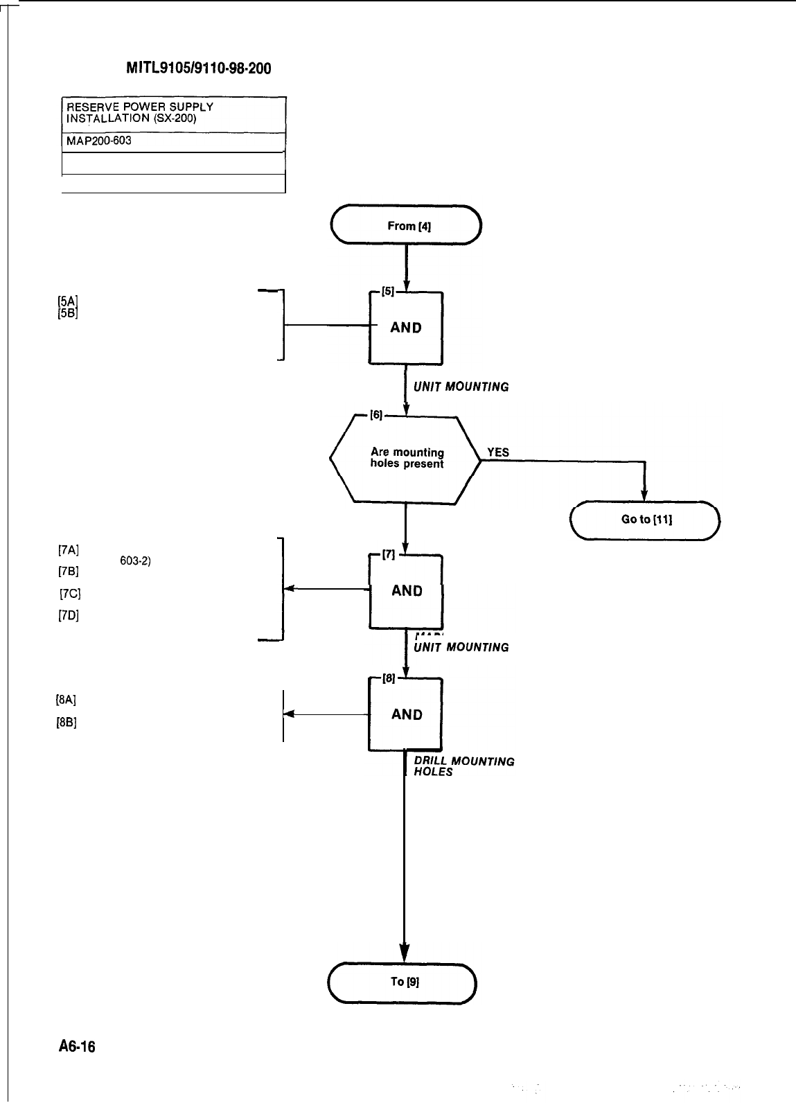
SECTION
MITL9105/9110-98-200
Issue 1, January 1980
1
Sheet 2 of 7
-
EAI
[5B]
Open rear cabinet door
Check bottom of cabinet right
hand center support bar for the
charging unit mounting holes
(Fig. 603-l)
[7A]
Place charging unit in position
[7B]
(Fig.
603-2)
Mark the position of the two
[7C]
charging unit mounting holes
Mark the position of the rear
[7D]
charging unit mounting hole
Remove the charging unit from
the equipment cabinet
-
I
CHECK CHARGING
UN/T
MOUNT/NG
HOLES
c
[8A]
Center punch the position of the
[8B]
three mounting holes
Using the No. 22 drill, drill the
4
three mounting holes
NO
171
r”1
MARK CHARGING
UN/T
MOUNTlNG
HOLES
A6-16
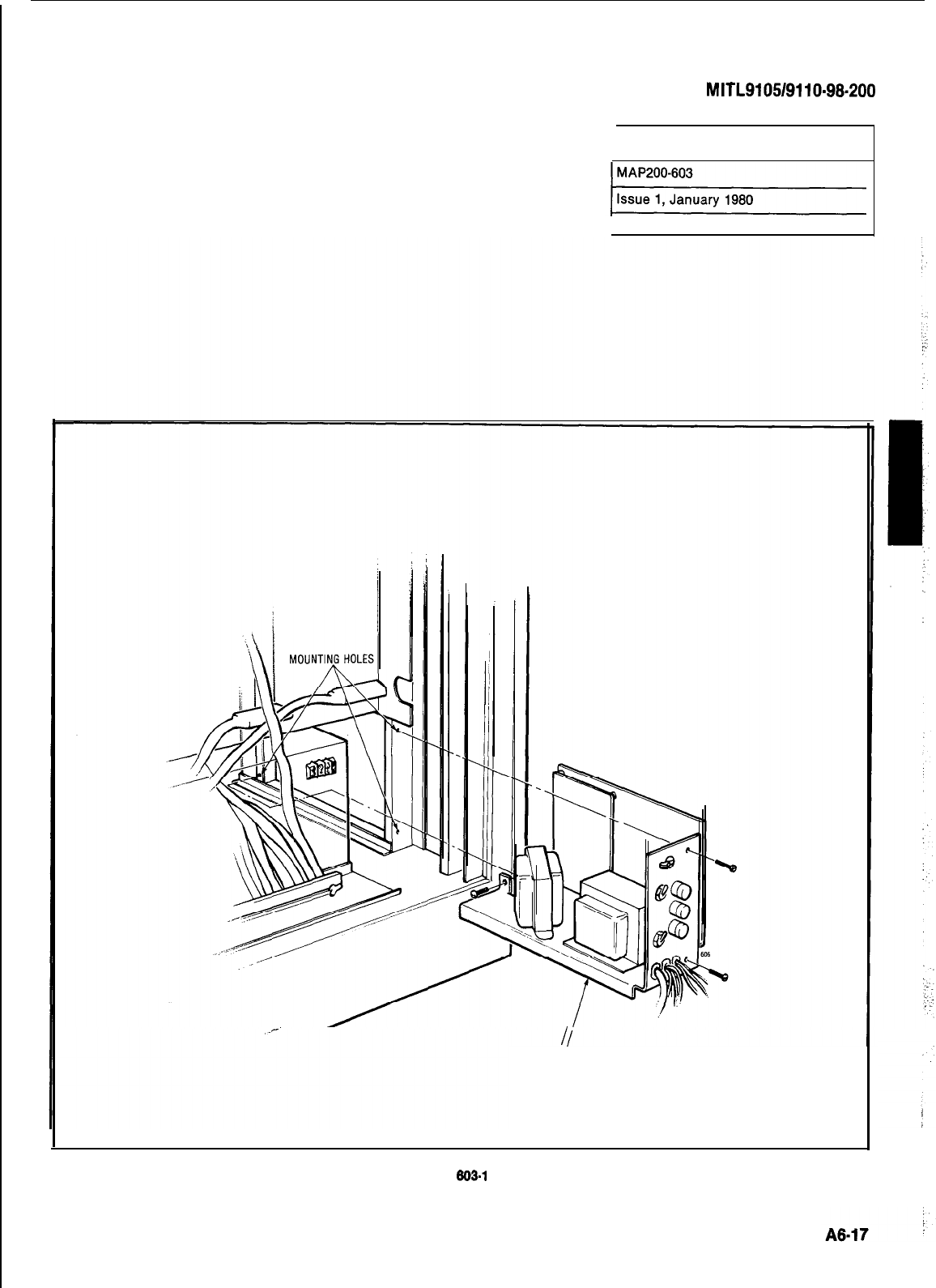
SECTION
MITL9105/9110-98-200
RESERVE POWER SUPPLY
INSTALLATION 6X-200)
[Sheet 3 of 7
I
CHARGING
UNIT
Fig.
803-i
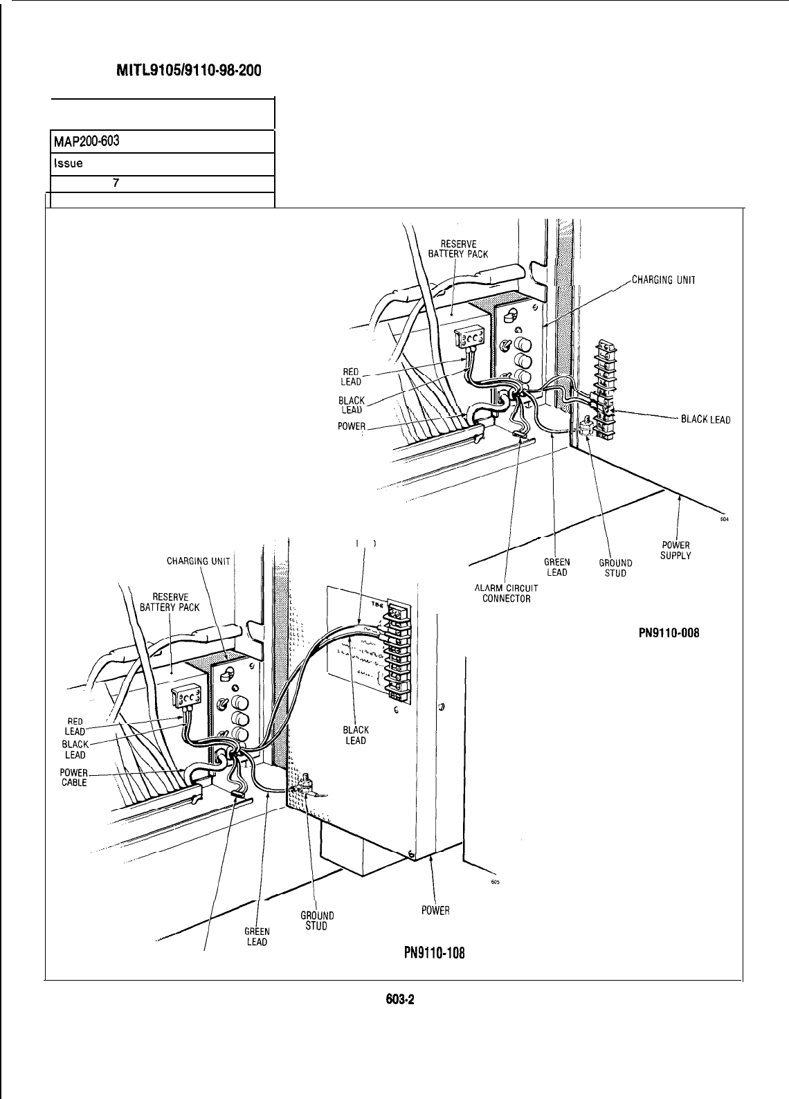
SECTION
MITL9105/9110-98-200
RESERVE POWER SUPPLY
INSTALLATION (SX-200)
MAP200-603
Issue
1, January 1980
Sheet 4 of
7
CABLE
RED
LEAD
+I
in
(J
g
!
,CHARG,NG
“N,T
C------RED LEAD
w
BLACK
LEAD
POWER SUPPLY TYPE
PN9110-008
GRdUND
,,j[y
STUD
ALARM CIRCUIT
CONNECTOR
POiiER
SUPPLY
POWER SUPPLY TYPE
PN9110-108
Fig.
603.2
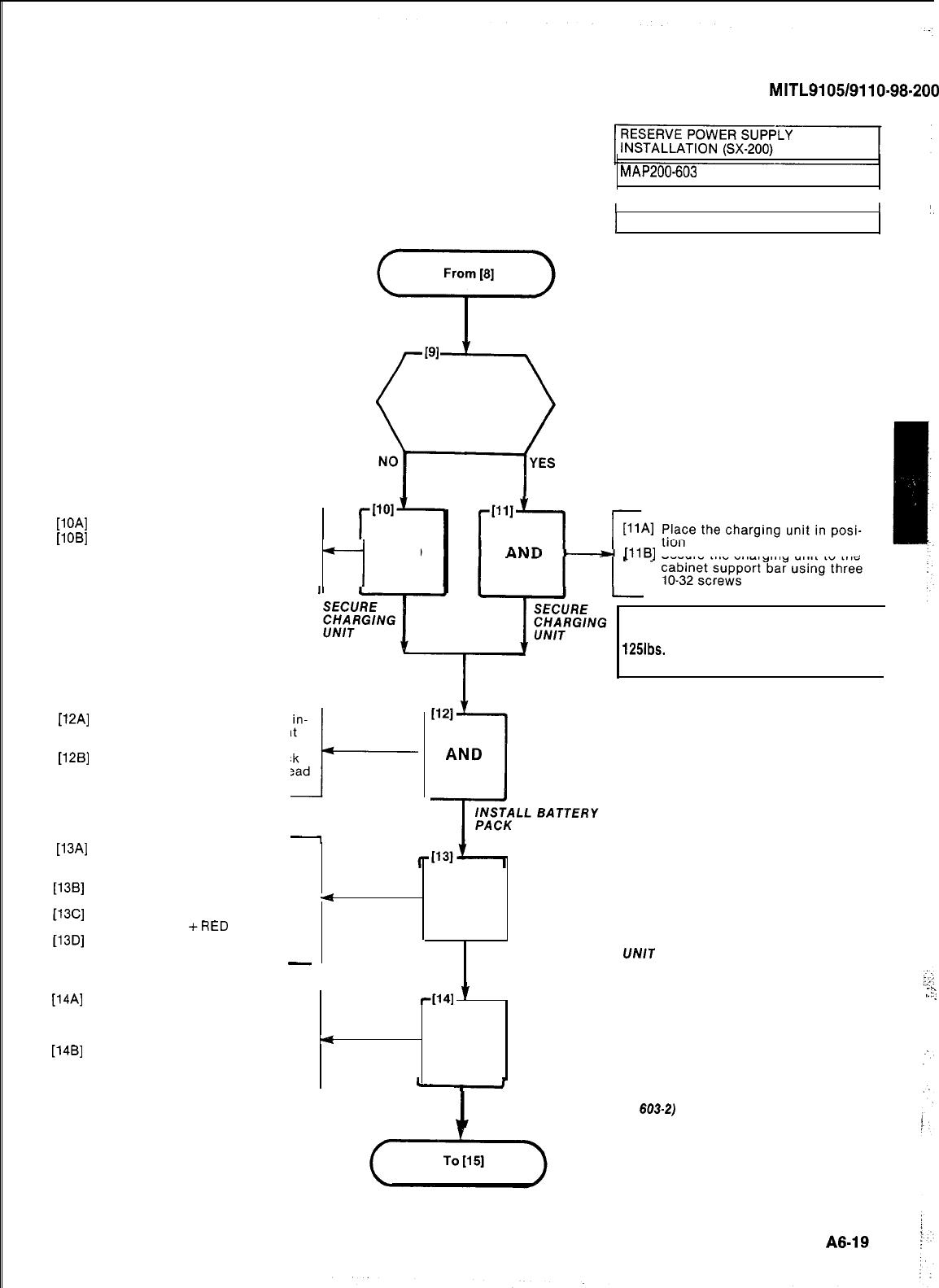
SECTION
MITL9105/9110-98-200
[lOA]
Place charging unit in position
[lOB]
Secure the charging unit to the
cabinet support bar using three
No. 10 slotted self tapping
screws
MAP200-603
1 Issue 1, January 1980 I
II
‘.
1 Sheet 5 of 7
Was cabinet
predrilled
7
AND
[liB]
Secure the charging unit to the
[12A]
Slide the reserve battery pack in-
to the bottom of the equipment
cabinet from the front
[12B]
Secure the reserve battery pack
to the cabinet with four pan head
screws
l-
-
CAUTION
The reserve battery pack weight is
125lbs.
Care must be taken when lifting
the battery pack. I
UNIT
[13Al
On the charging unit, feed the
Red and Black leads marked “TO
BATTERY” to the battery pack
Check that the BATTERY switch
on the battery pack is set to OFF
Connect the Red lead to the ter-
minal marked
+RED
Connect the Black lead to the
terminal marked -BLACK
-
4
AND
.
,
CONNECT CHARGING
TO BATTERY PACK
[14A]
On the charging unit, feed the
-[141
*
:
,-
._
,-;
Red, Black and Green lead mark-
ed “TO POWER SUPPLY” to the
power supply
4
[14B]
Connect the Red, Black and AND
Green leads as shown in Fig.
603-2
CONNECT CHARGING UN/T
TO BATTERY PACK (FIG.
603-2)
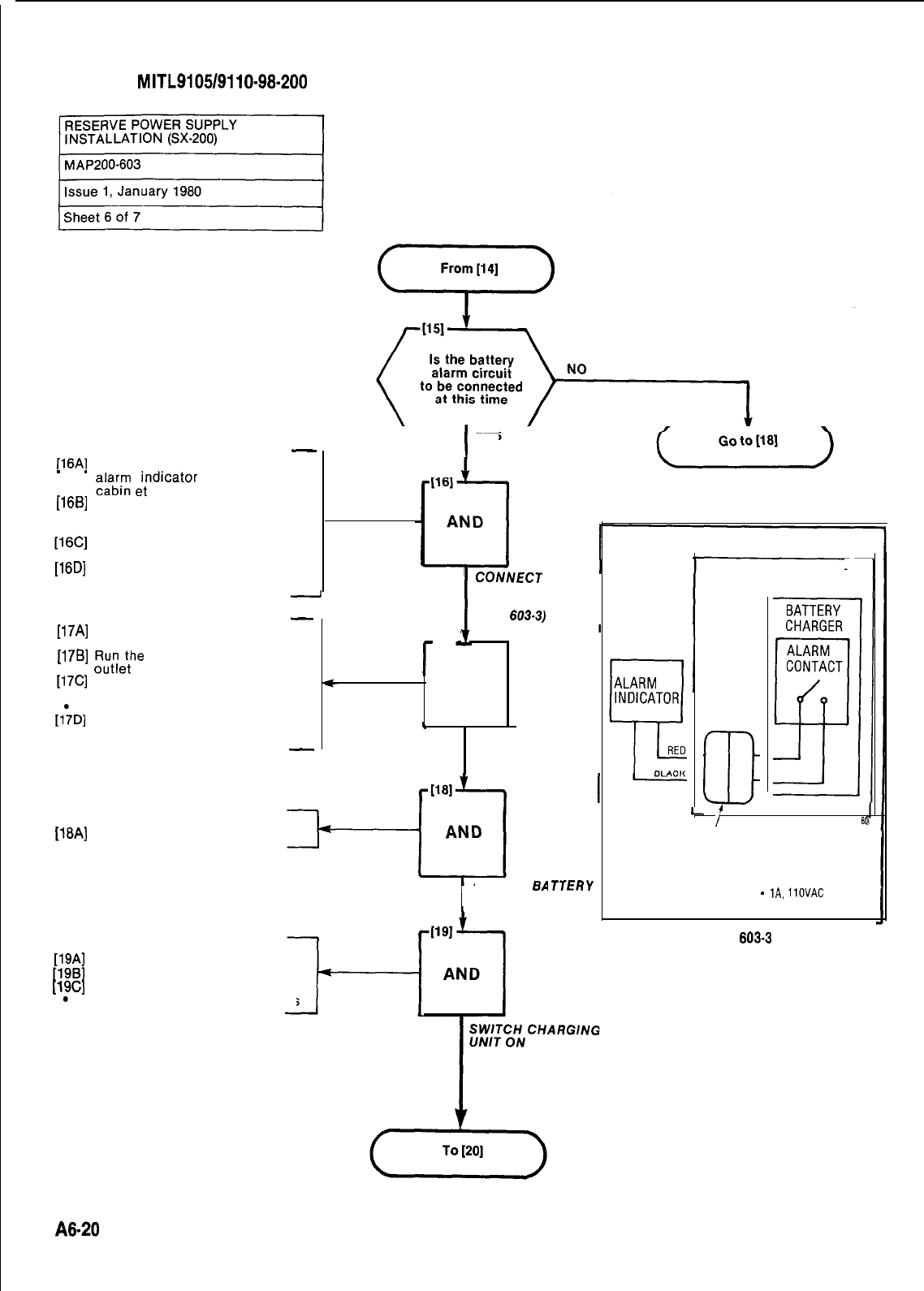
SECTION
MITL9105/9110-98-200
-
fl6Al
Run two wire cable from the
-
.
$u;,
eitndicator
to the equipment
(1661
Feed the cable through the
equipment cabinet cable duct.
(Fig. 603-3)
SC]
Connect the two wires to the
Molex plug supplied
[16D]
Insert the Molex plug into the
receptacle
-
-
[17A]
Feed the charging unit power
lead through the cable duct
[176]
,“,“I;,:“e
power lead to the power
[17C]
Plug system power lead into
power outlet
AC power LED in on
I&D]
Plug charging unit power lead in-
to power outlet
-
I
YES
r
1171
t
AND
c
PLUG IN SYSTEM
I
CONNECT
BATTERY
ALARM
(FIG.
603-3)
On Battery Pack
[16A]
Set BATTERY switch to ON
I
SWITCH
BA
PACK ON
On Charging Unit
[19Al
Set AC switch to ON
[19B]
Set DC switch to ON
[l?c]
Set BATTERY switch to ON
BATTERY CHARGING LED lights
I
TTERY
EQUIPMENT CABINET
m
I
601
I-
ALARM CIRCUIT
CONNECTOR
RELAY CONTACT RATING
RESISTIVE LOAD-2A. 28VOC
-
lA,
1lOVAC
Fig.
603-3
A8-20
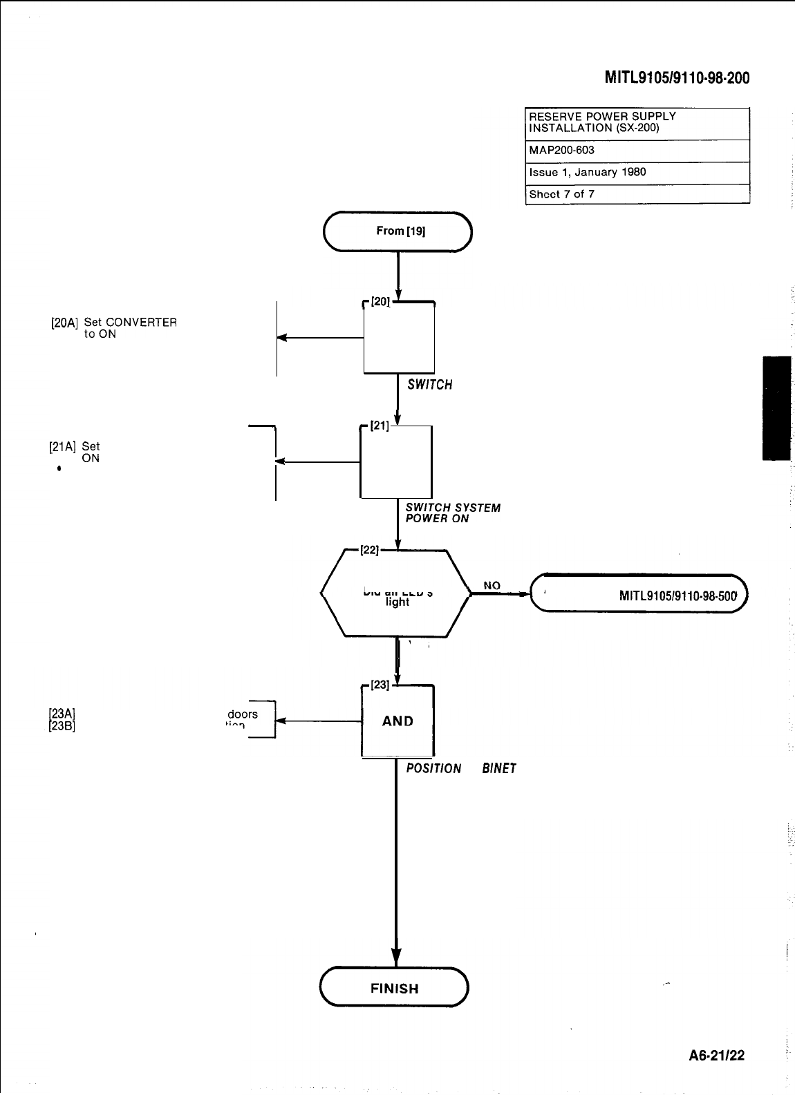
From
[19]
‘r>
On Power Supply
[20A]
tS,e;iONVERTER
INPUT switch
4
.CONVERTER INPUT LED lit AND
.
RESERVE BATTERY CON-
NECTED LED lit
.
SWTCH
POWER
SUPPLY ON
-
On Maintenance Panel
[21A]
p;
SYSTEM POWER switch to
SYSTEM POWER LED lit
4
.
.
Power Supply EQUIPMENT
SHELF POWER LED lit
rP11
$-
. AND
Spr$lT;;;STEM
SECTION
MITL9105/9110-98-200
Did all LED’s Go to Section
MITL9105/9110-98-500
YES
[23A]
Close and lock all cabinet
[23B]
Place cabinet in final position
POSlTiON
CA
B/NET
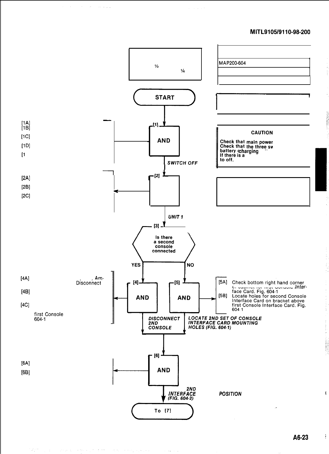
tit/
11
Cl
(1
Dl
[1
El
PA1
WI
PC1
[4Al
[4Bl
[4Cl
WI
WI
-
Open front and rear doors
Set system POWER switch to
OFF
Set all other power switches on
rear of cabinet to off
Set the battery switch on the
reserve battery pack to off
Remove the power cords from
the commercial outlets
Tools Required
1 Wrench
‘/2
inch
1 Slotted screwdriver
l/4
inch
START
7
SYSTEM POWER
Remove locking bars from Shelf
Unit 1
Unscrew the shelf retaining
screws from Shelf Unit 1
<
AND
Carefully withdraw Shelf Unit 1
from the cabinet by 2 inches (See
Note)
MOVE SHELF
UNIT
7
,,
FORWARD
\
Locate 2nd console (male)
Am-
phenol connector.
D/sconnect
from J14
Check bottom right hand corner
of cabinet for first Console Inter-
face Card. Fig. 604-l
Locate holes for second Console
Interface Card on bracket above
f6i;mt,Consoie
Interface Card. Fig.
SECTION
MITL9105/9110-98-200
CONSOLE INTERFACE BOARD
INSTALLATION (SX-200)
I
MAP200-604
Issue 1, January 1980
Sheet 1 of 7
I
Note: This MAP applies only to
SX-200 equipment.
I
1
r;That
rn~~~~~
is off
1
Check that the three switches on the
battery
charging
unit are set to OFF.
If there is a reserve battery pack set it
NOTE
Step 2 is required to make room to affix
Console card to bracket in Step 7.
of cabinet for first Console
Inter-
Place Console Interface Card as
shown in Fig. 604-2
Insure the ground strap of the
Console Interface Card is at the
bottom facing the system
t-
PLACE
2ND
CONSOLE
/NTEf?FACE
CARD IN
POSlTlON
I
A8-23
j
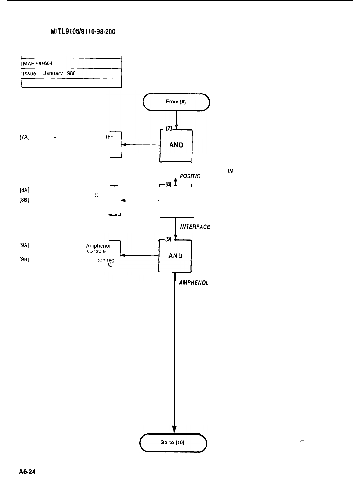
SECTION
MITL9105/9110-98-200
CONSOLE INTERFACE BOARD
INSTALLATION (SX-200)
I
1 Sheet 2 of 7
[7A]
Insert 8
-
10 x 32 screws into
Console Interface Card affixing it
to the mounting bracket Fig.
604-2
[8A]
Locate system ground stud
-
loosen nut with wrench
%
inch
[8B]
Attach ground strap for Console
Interface Card to system ground
stud and tighten lug. Fig. 604-2
-
1
I
SECURE 2ND CONSOLE
INTERFACE CARD
JN
POSlTIO
N
7181
f
.
4
_
AND
A
I
ATTACH CONSOLE
lNTERFACE
CARD
GROUND STRAP
[9A]
Locate the incoming
connector of the 2nd
[9B]
and install it into J24 (Fig. 604-2)
Tighten the screw on the
connec-
tor with a slotted screwdriver
l/4
inch
AFFIX SECOND CONSOLE
AMPHENOL
CONNECTOR
TO J24 OF CONSOLE
INTERFACE CARD
A8-24
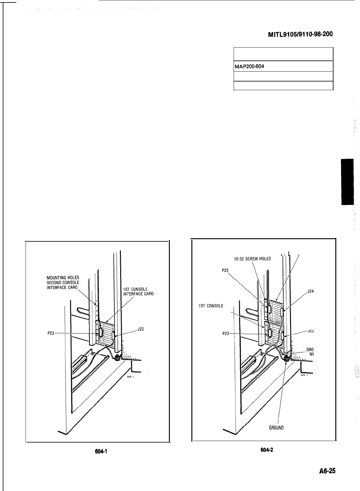
SECTION
MITL9105/9110~98-200
CONSOLE INTERFACE BOARD
INSTALLATION (SX-200)
MAP200.604
Issue 1, January 1980
Sheet 3 of 7
2NDCONSOLE
III
I
INTERFACE CARD
ISTCONSOLE
INTERFACE CARD
UND
RE
GROIJND
STUD
Fig. 804-l Fig. 804-2
A6-25
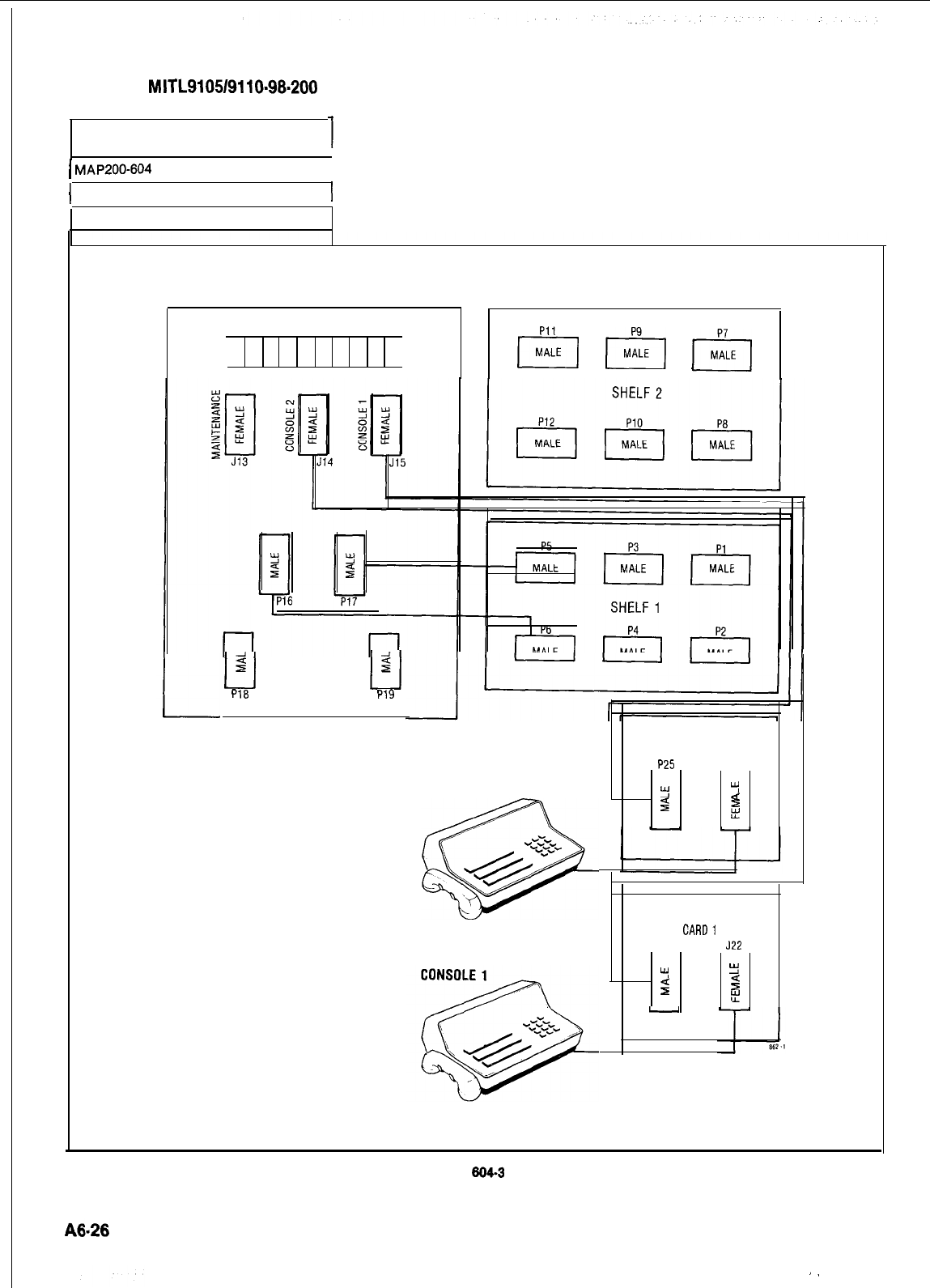
SECTION
MITL9105/9110~98~200
CONSOLE INTERFACE BOARD
INSTALLATION (SX-200)
7
1
MAP200-604
I
1 Issue 1, January 1960
Sheet 4 of 7
INTERCONNECT BOARD
1 I
I
Pll
0000000000
0000000000
/-Q-q
[-e-j
p-j
Ll
2
P18
u
2
PI9
CONSOLE 2
CONSOLE INTERFACE
CARD2
P25 J24
!Y
5
2d
z
CONSOLE INTERFACE
CARD1
P23 J22
Y
!2
2
ifi
F
-
Fig.
604.3
).
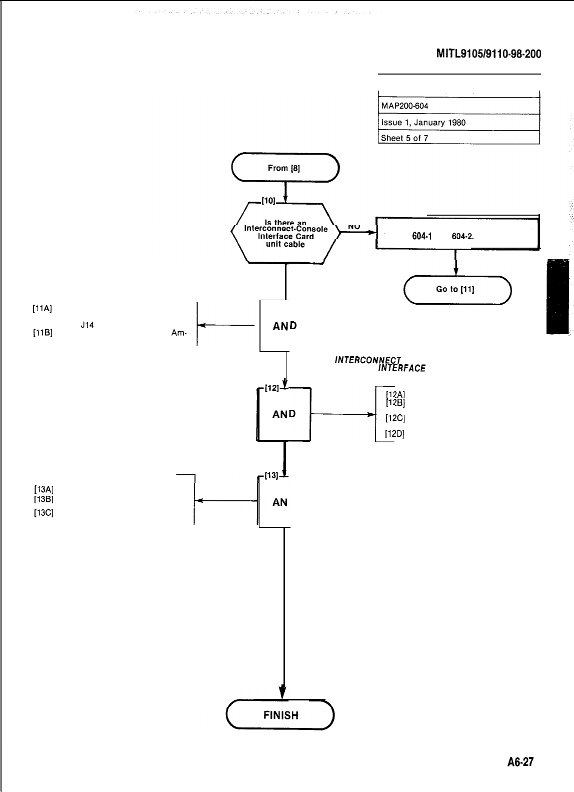
SECTION
MITL9105/9110-98-200
CONSOLE INTERFACE BOARD
INSTALLATION (SX-200)
I
[llA]
Connect the Interconnect Con-
sole Interface Card cable bet-
ween
J14
and P25 (Fig. 604-3)
[llB]
Tighten down top screws on
Am-
phenol connectors
t-
[13A]
Close rear door
[t3B]
Plug power cord into commercial
outlet
[13C]
Turn all switches on
Construct Cable in accordance with
Tables
804.1
and
604-2.
1
(d-)
D
-
YES
CONNECT
lNTERCONNECT
CABLE JO CONSOLE
/NJERFACE
CARD
[12A]
Replace Shelf Unit 1 in cabinet
[12B]
Replace and tighten up retaining
I-+
D
screws
[12C]
Replace locking bars across
front of shelf
[12D]
Securely fasten locking device
REPLACE
SHELF
UN/T
1
D
POWER SYSTEM UP
:
:
A8-27
j
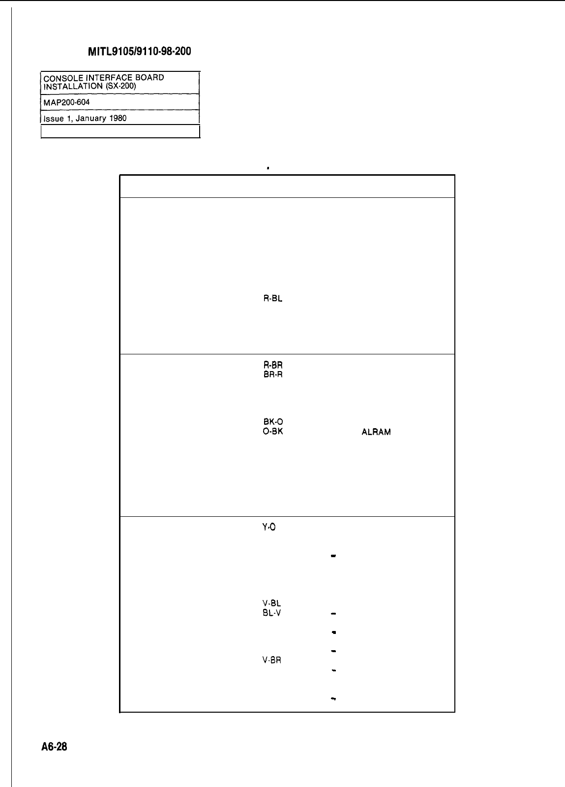
SECTION
MITL9105/9110-98-200
Sheet 6 of 7
TABLE 604-i
INTERCONNECT BLOCK
-
CONSOLE INTERFACE CARD
Pin
Pair
No. Colour
26
W-BL
1
BL-W
27
w-o
2
o-w
28
W-G
3
G-W
29
W-BR
4
BR-W
30
w-s
5
s-w
31
R-BL
6
BL-R
32
R-O
7
O-R
33 R-G
8
G-R
Lead Designation
ELECTROSTATIC GROUND
ELECTROSTATIC GROUND
ELECTROSTATIC GROUND
ELECTROSTATIC GROUND
ELECTROSTATIC GROUND
ELECTROSTATIC GROUND
ELECTROSTATIC GROUND
ELECTROSTATIC GROUND
DATA IN COMMON
DATA IN
ELECTROSTATIC GROUND
ELECTROSTATIC GROUND
DATA OUT COMMON
DATA OUT
ELECTROSTATIC GROUND
ELECTROSTATIC GROUND
34
R-BR
9
BR-R
35 R-S
10 S-R
36
BK-BL
11
BL-BK
37
BK-0
12
O-BK
38
BK-G
13
G-BK
39
BK-BR
14
BR-BK
40
BK-S
15
S-BK
41
Y-BL
16
BL-Y
42
Y-0
17 O-Y
43 Y-G
18 G-Y
44
Y-BR
19
BR-Y
45 Y-S
20 S-Y
46
v-BL
21
BL-v
47
v-o
22
o-v
48 V-G
23 G-V
49
V-BR
24
BR-V
ELECTROSTATIC GROUND
ELECTROSTATIC GROUND
CUTOVER SWB
CUTOVER SWA
ELECTROSTATIC GROUND
ELECTROSTATIC GROUND
MAJOR ALARM
MAJOR
ALRAM
TIP
RING
ELECTROSTATIC GROUND
ELECTROSTATIC GROUND
ELECTROSTATIC GROUND
ELECTROSTATIC GROUND
ELECTROSTATIC GROUND
ELECTROSTATIC GROUND
ELECTROSTATIC GROUND
ELECTROSTATIC GROUND
ov
-
48V
ov
-48v
ov
-48v
ov
-
48V
ov
-
48V
ov
-
48V
ov
-
48V
50
v-s ov
25
s-v
-
48V
A6-28
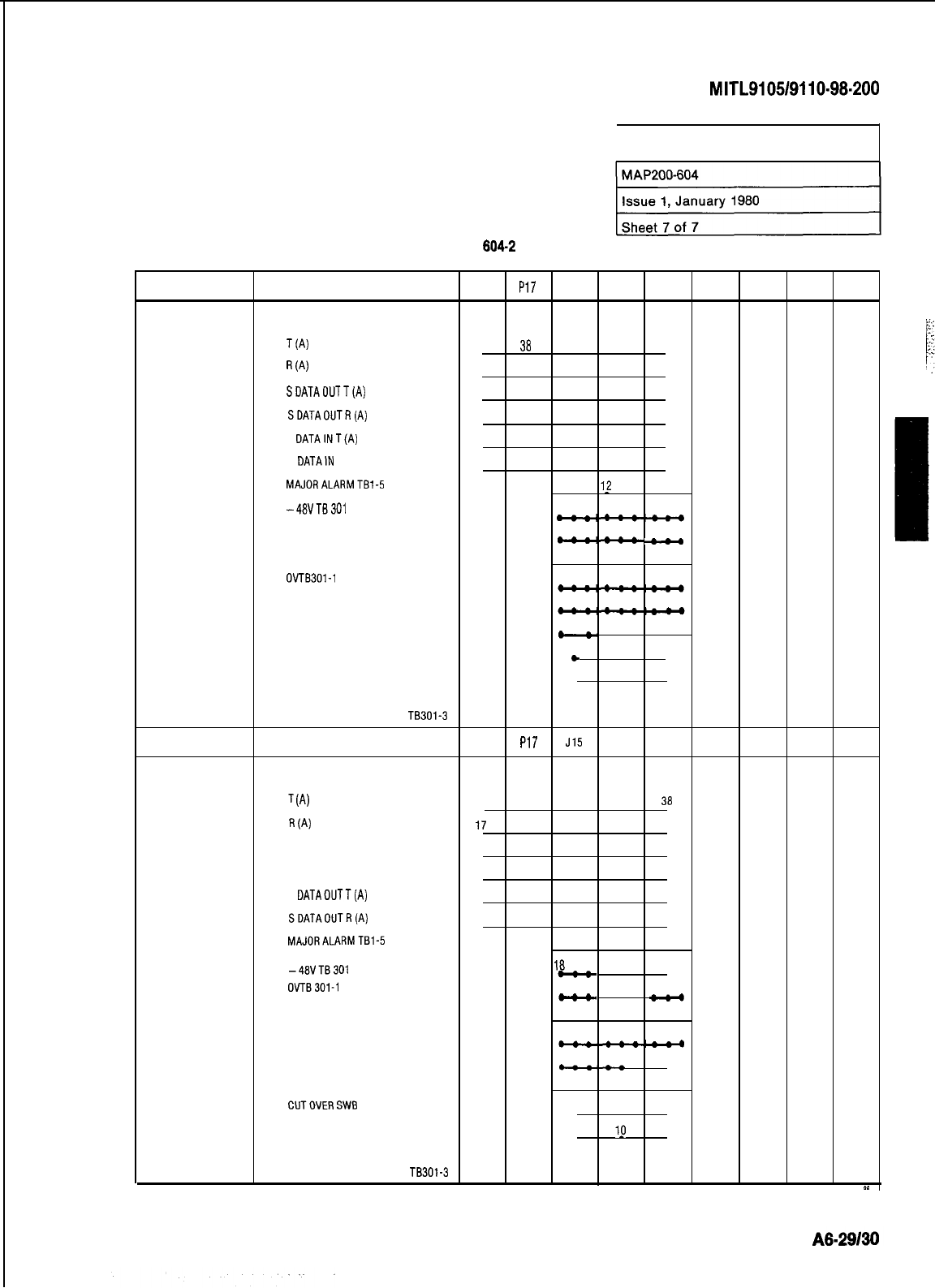
SECTION
MITL9105/9110-98.200
CONSOLE INTERFACE BOARD
INSTALLATION (SX-200)
TABLE
604-2
POSITION
16
17
LEAD DESIGNATION P5 PI7 J14 P25 J24
CONSOLE2
T(A) 38 38 38 38 38
R
(A)
13 13 13 13 13
SDATAOUlT(A)
39 39 32 32 32
SDATAOUTR(A)
14 14
7 7 7
S DATAINT(A) 40 40 30 30 30
S DATAIN R(A) 15 15
55 5
MAJORALARMTBl-5
12 37
1_2
37 12 37
-48VTB301
181920 181920 181920
21 22 23 21 22 23
212223
-
24 25 24 25 24 25
.
OVlBSOl-1
434445 434445 434445
464748
46 4748
464748
49 50 49 50 49 50
CUT OVER SWA 35 35 35
*
.
CUTOVERSWB
10 10
10
ALL UNLISTED PINS
GO TO ESG TB301-3
P5 PI7 J15 P23 J22
CONSOLE1
T
(4
42 42 38 38 30
.
R
(A)
17 17 13 13 13
SDATAINT(A)
18 .
18
555
SDATAIN R(A) 43 43 30 30
30 .
S
DATADUTT(A)
19 .
19 7 7
. 7
SDATAOUTR(A)
44 44 32 32 32
MAJORALARMTBl-5
12 37 12 37 12 37
-48VTB301
18 19 20 18 1920 1819 20
OVTB301-1 21 2223 21 2223
212223
24 25 24 25 24 25
434445 434445 434445
46 4748
464748 464740
49 50 49 50 49 50
CIJTOVERSWB
35 35 35
CUTOVERSWA
10 19 10
ALL UNLISTED PINS
GO TO ESG TB301-3
*c
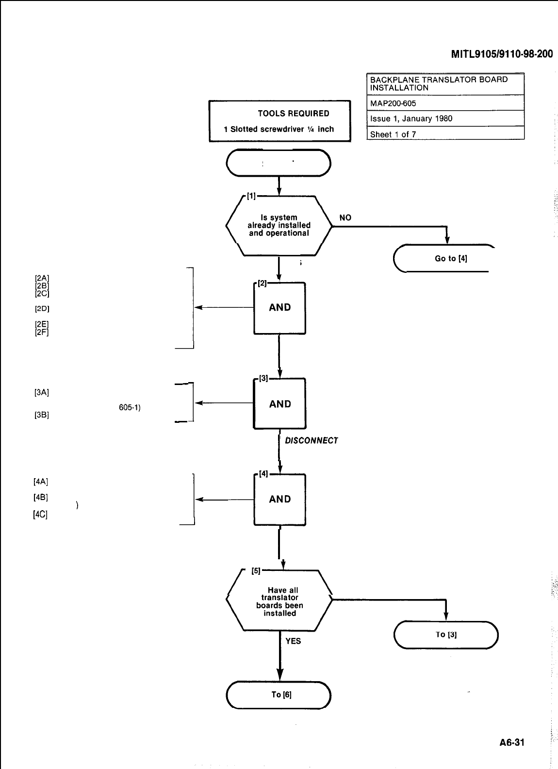
Open front door
Open rear door (SX-200)
Set SYSTEM POWER switch to
off
Set all power switches on rear
door to off
Set battery switch (SX-200) to off
Remove power cable(s) from
power outlet(s)
-
[3A]
Unscrew the 4-40 screw from the
cable connectors on the
backplane (Fig.
6051)
[3B]
Remove cable connectors
-
SECTION
MITL9105/9110-98-200
START
1
YES
I
POWER
DOWN
SYSTEM
]4Al
1481
[4Gl
Plug the translator board into the
backplane connectors (Fig. 605-l)
Install four 6-32 screws (Fig.
605-l
)
Tighten all screws with a slotted
0.25 inch blade screwdriver
I
LUSCONNECT
CABLES TO
X-CONNECT
(
Goto[4]
)
I.
I
INSTALL TRANSLATOR
BOARD
/
‘“..rr.\
NO
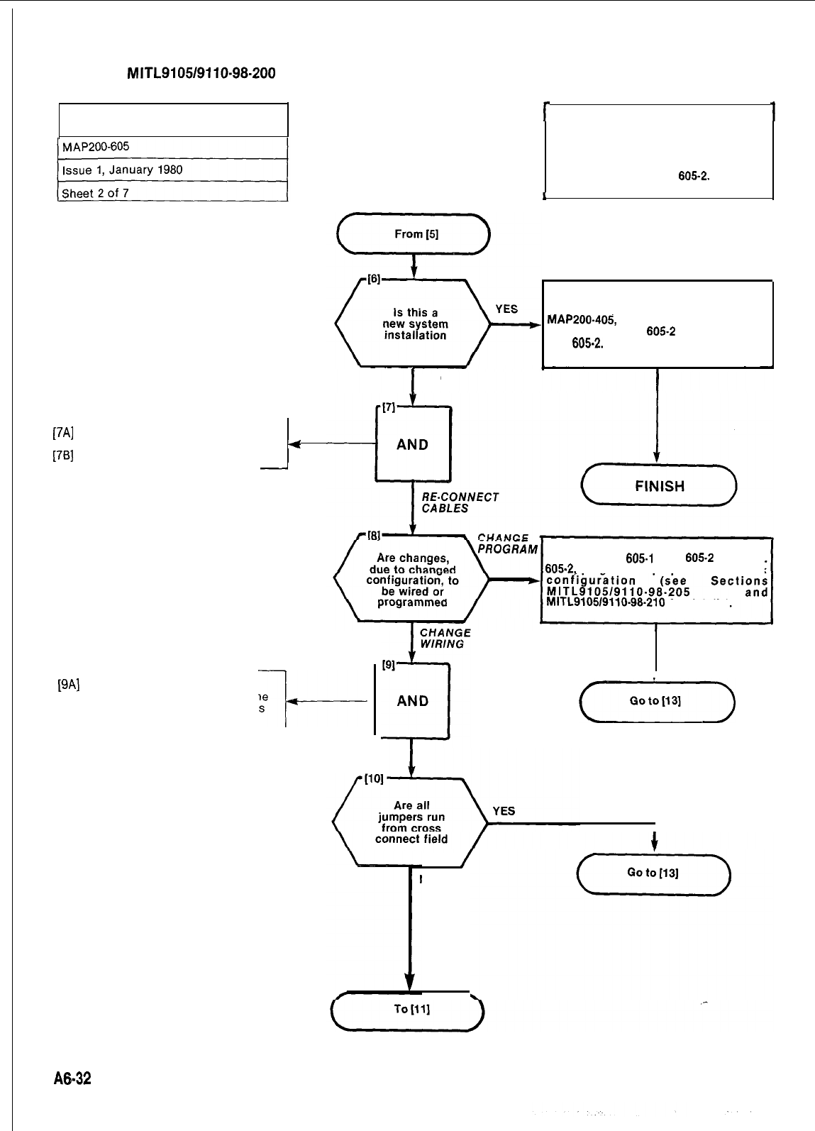
SECTION
MITL9105/9110-98-200
BACKPLANE TRANSLATOR BOARD
INSTALLATION
I
NO
r
1
[7A]
Reconnect connector plugs ac-
cording to Fig. 605-l
4
[7B]
Tighten connector screws
-
Note Installation of translator boards
changes pin-out configuration on plugs.
Lines and trunks must therefore be con-
figured to accommodate the equipment
numbers shown in Fig.
605-2.
J
J
Perform procedure outlined at
MAP200.405,
but using the data in
Tables 605-i and
605-2
and referring to
Fig.
605-2.
[9A]
Change the jumpers on the
cross-connect field to reflect the
new configuration, using Tables
605-l and 605-2 and Fig. 605-2
---I---
Using Tables
605.1
and
605-2
and Fig.
605-2,
program the proper line and trunk
MITL910519110-96.210
for details).
(..,.,,)
/
NO
A&32
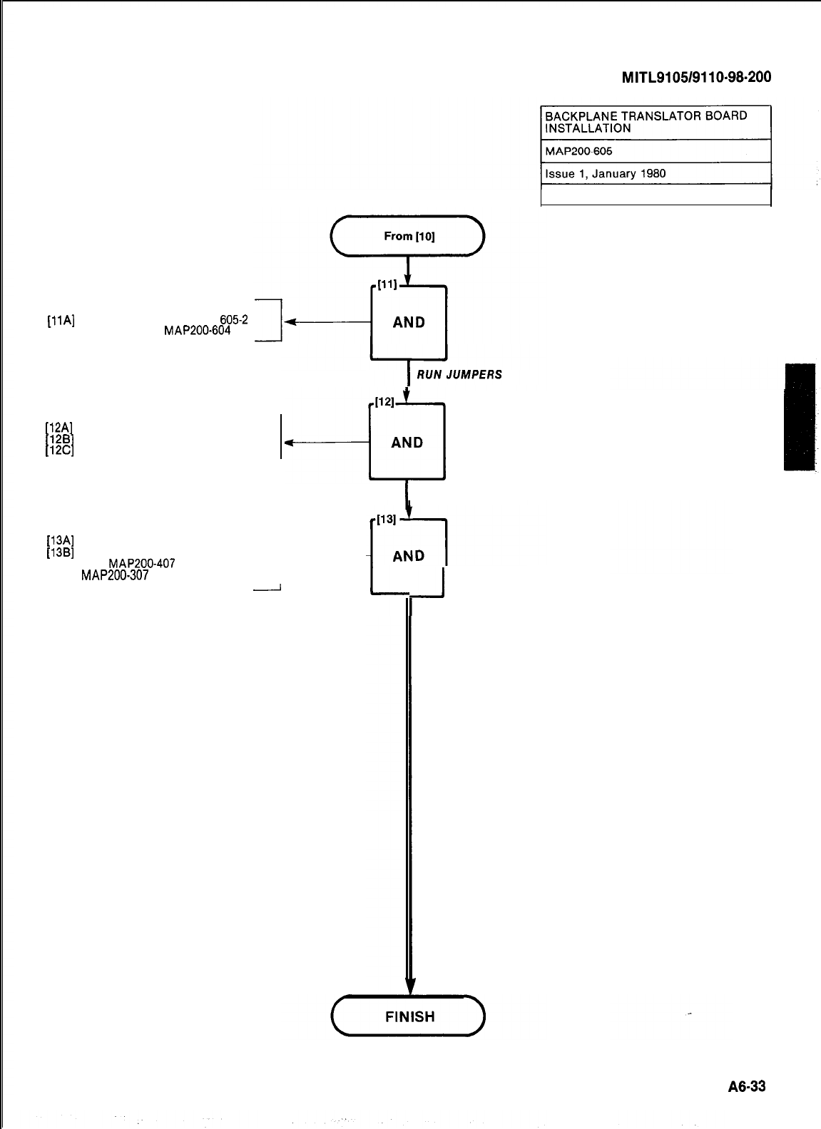
[IlA]
Run jumpers as per Fig.
6052
and reference
MAP200-604
[12A]
Close front door of cabinet
[12B]
Close rear door of cabinet
[12C]
Lock rear door of cabinet
I121
--cl
AND
[13A]
Replace power cord(s)
[13B]
Power up system in accordance
with
MAP200-407
(SX-200) or
MAP200-307
(SX-100) ---I---
l
SECURE DOORS
-
SECTION
MITL9105/9110-98-200
-J
POWER UP SYSTEM
Sheet 3 of 7
A8-33
1
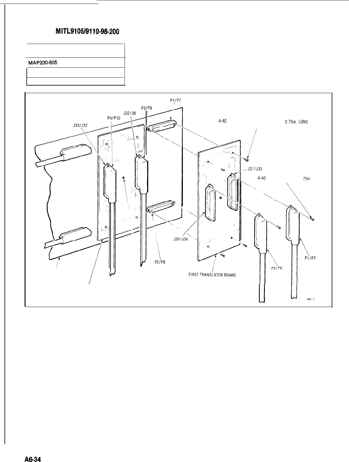
SECTION
MITL9105/9110~98-200
BACKPLANE TRANSLATOR BOARD
INSTALLATION
r
MAP200-605
Issue 1, January 1980
Sheet 4 of 7
Pl/P7
4 X
4-40
SLOTTED RETAINING SCREWS
O.751n.
LONG
2 X 4-40 SLOTTED SCREWS 0
751n
LONG
BACKPLANE
+
PLASTIC SPACER
SECONDTRANSLATORBOARD
Fig. 606-l Translator Board Installation
A6-34
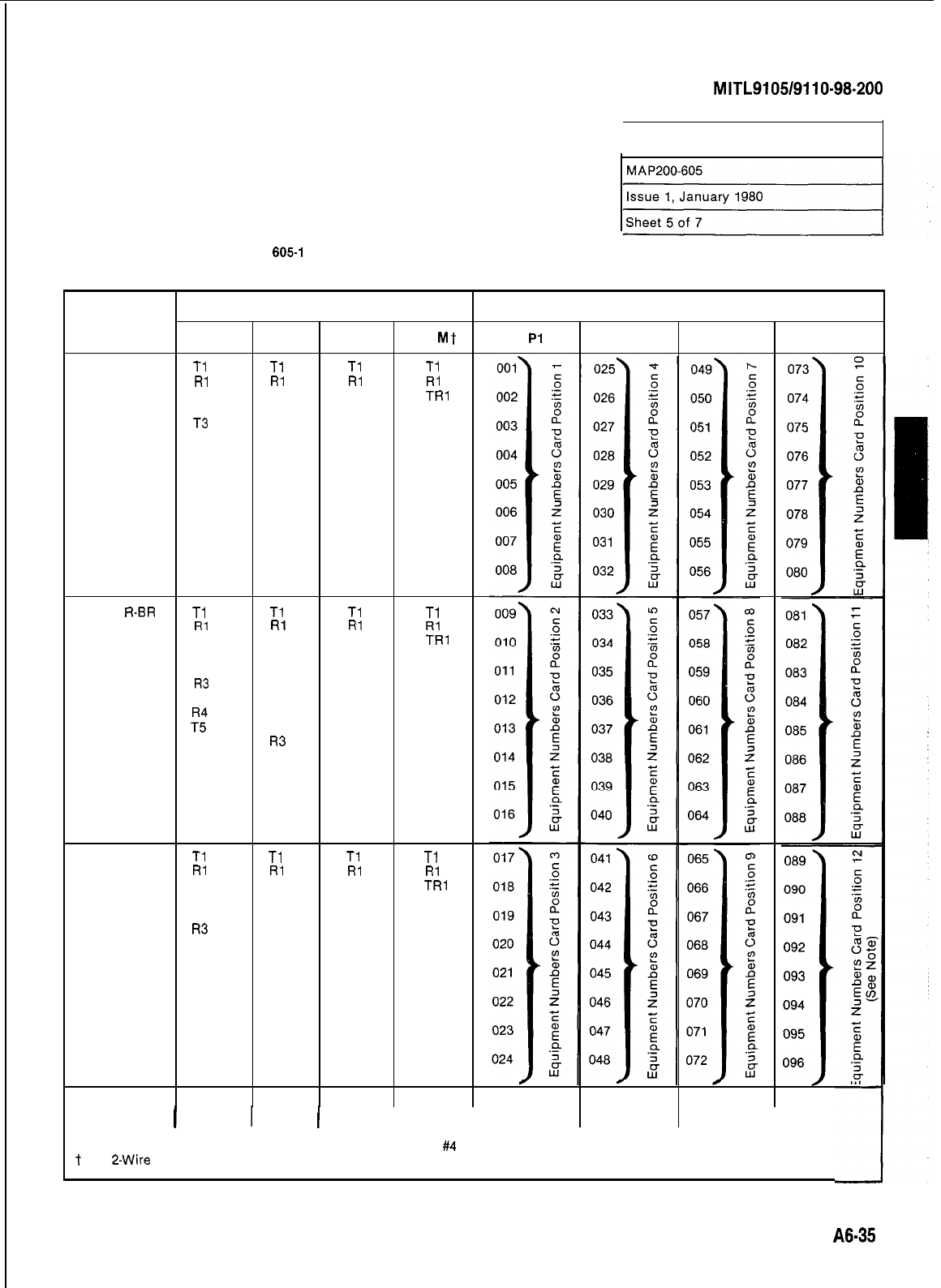
SECTION
MITL9105/9110-98-200
BACKPLANE TRANSLATOR BOARD
INSTALLATION
TABLE
605.1
BACKPLANE TRANSLATOR BOARD CONNECTIONS (SHELF 1)
TO CROSS-CONNECT FIELD
Line and Trunk Connections
Pair
Shelf 1 Translator Board Plug Numbers
Pin
Color
Extn
co DID/Tie E &
Mt Pl
P2 P3 P4
26
W-BL
Tl Tl Tl Ti
1
BL-W
Rl Rl Rl Rl
27
w-o
T2 XT2
TRl
2
o-w
R2 XT1 RR1
28
W-G
T3 T2 El
3
G-W
R3 R2
Ml
29
W-BR T4
4
BR-W R4
30
w-s
T5 T3 T2 T2
5
s-w
R5 R3 R2 R2
31
R-BL T6
XT4 TR2
6
BL-R R6
XT3 RR2
32 R-O T7 T4 E2
7
O-R R7 R4 M2
33 R-G T8
8G-R R8
34
R-BR
Tl Tl Tl Tl
9
BR-R
Rl Rl Rl Rl
35 R-S T2 XT2
TRl
10 S-R R2 XT1 RR1
36
BK-BL T3
T2 El
11
BL-BK
R3 R2
Ml
37
BK-0 T4
12
0-BK
38
BK-G
7:
T3 T2 T2
13
G-BK R5
R3 R2 R2
39
BK-BR T6
XT4 TR2
14
BR-BK R6
XT3
RR2
40
BK-S T7
T4 E2
15
S-BK R7
R4 M2
41
Y-BL T8
16
BL-Y
R8
42 Y-O
Tl Tl Tl Tl
17 O-Y
Rl Rl Rl Rl
43 Y-G T2 XT2
TRl
18 G-Y R2 XT1 RR1
44
Y-BR T3
T2
El
19
BR-Y
R3 R2
Ml
45 Y-S T4
20 S-Y R4
46
V-BL T5
T3 T2 T2
21
BL-V
R5 R3 R2 R2
47
v-o
T6 XT4 TR2
22
o-v
R6 XT3 RR2
48 V-G T7 T4 E2
23 G-V R7 R4 M2
49
V-BR
T8
24
BR-V
R8
50
v-s SPARE
25
s-v
1
SPARE 1
I
I I
I
Note: Position 12 can be used for lines, trunks or receiver
#4
card.
t
For
2-Wire
E&M Trunk operation DO NOT connect RR and TR leads.
A8-35
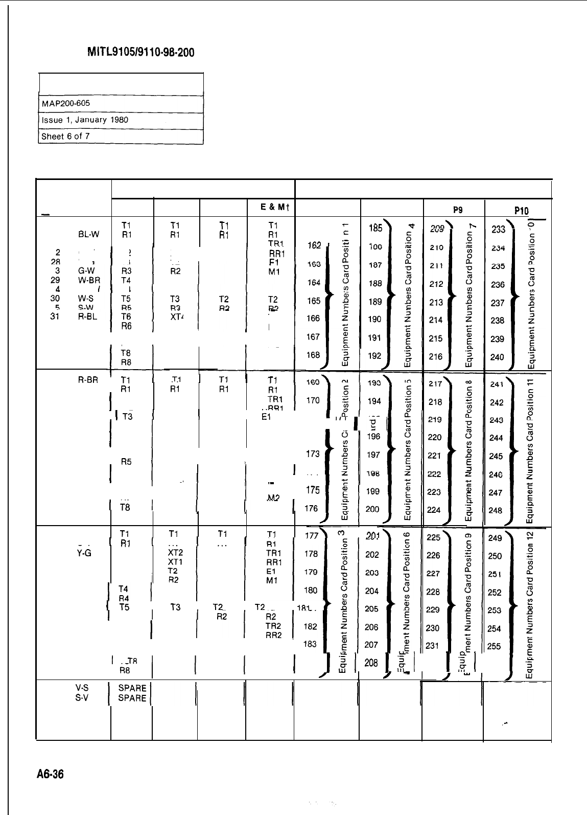
SECTION
MITL910519110-98-200
BACKPLANE TRANSLATOR BOARD
INSTALLATION
TABLE 605.2 BACKPLANE TRANSLATOR BOARD CONNECTIONS (SHELF 2)
TO CROSS-CONNECT FIELD
Line and Trunk Connections
Pair
Shelf 2 Translator Board Plug Numbers
Pin
Color
Extn
co DID/Tie
E&Mt
P7 P8 P9
PllI
26
W-BL
Tl Ti Tl Tl
1
EL-W
Rl Rl Rl Rl
161
;
27
w-o
T2 XT2
TRI
I
iRK
\
-t
.m\
p-
wM\
0
-IA:,
E
3
R/ii
Fi
I
o-w
W-G
I
R2
T3 XT1
T2
I
BR-W
1
R4
XT;
I
.-
TR2
RR2
I
6
BL-R
32 R-O T7 T4 E2
7
O-R
I
R7
I
R4
I I
M2
I
33 R-G
8G-R
34
R-BR
Tl
I
1
Tl
1
Tl
1
Tl
9
BR-R
Rl
i;
35 R-S
10 S-R
I
T2
R2
ii
XT2
XT1
36
BK-BL
1
Ti
1 Ti 1I
iii“
I 171
11
BL-BK
37
BK-0
12
0-BK
R3
I
I
T4
R4
R2
Ml
“‘I;[
I
172
38
BK-G T5
I
T3
I
T2
I
T2
13
I
179
G-BK
R5 R3 R2 R2
39
14
BK-BR
BR-BK
I
T6
R6 XT4
XT3
I
I”
TR2
1
174
RR2 I
40
BK-S T7
I
II
.-
T4 E2
15
S-BK
R7
I
l.-
RA M3
41
Y-BL
I
T8
I
16 BL-Y R8
42 Y-O
Tl Tl Tl Tl
177\
c-2
I
3nj
17
43
Q-Y
1
RI
v-d
...
1RI 1RI 1
T2
18 G-Y R2
44
Y-BR T3
19
BR-Y R3
45 Y-S
20 S-Y
46
V-BL
I
T5
I
~3
I
~2
I
~2
I
IFII
i
21
BL-V 1 R5 1 R3 1
47
v-o
I
T6 XT4
22
o-v
R6 XT3
I
48 V-G T7 T4 E2
23 G-V
I
R7
I
R4
I
I
M2
I
49
V-BR
I
TR
I
24
BR-V
ki
I
I I
I
/
I!
/
-
1
1
184
1
;
1
208
1
$
1 232
1
z
1 256
50
25
A6-36
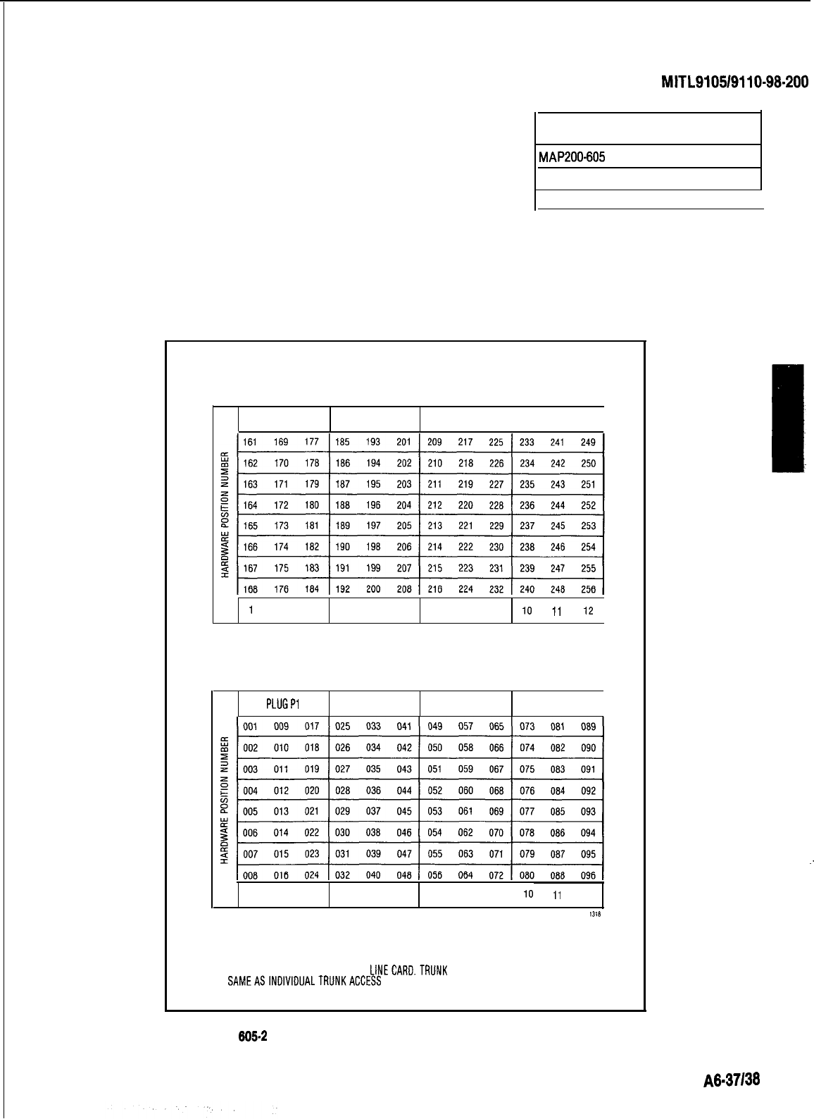
SECTION
MITL9105/9110-98.200
BACKPLANE TRANSLATOR BOARD
INSTALLATION
MAP200-605
Issue 1, January 1980
Sheet 7 of 7
I
HARDWARE/EQUIPMENT NUMBERING
PLUG7 PLUG8 PLUG9
I
PLUG10
1
1
2 3
45 67 8
9
10
11
I2
SHELF 2(SX-200)
PLUGPl
PLUGP2 PLUGP3 PLUGP4
I
I
2 3
4
5
6
7 a
9
IO
ti
12
1318
SHELF
1
NOTE:
EQUIPMENT POSITION 001 IS RESERVED FORTHETEST LINE AND MUST
THEREFORE BE EQUIPPED WITH A
LlNECARD.TRUNK
EQUIPMENT NUMBER IS
SAMEASINDIVIDUALTRUNKACCESS
CODE.
Fig.
605.2 BACKPLANE TRANSLATOR BOARD PLUG APPEARANCES
I
:
A6.37138
j
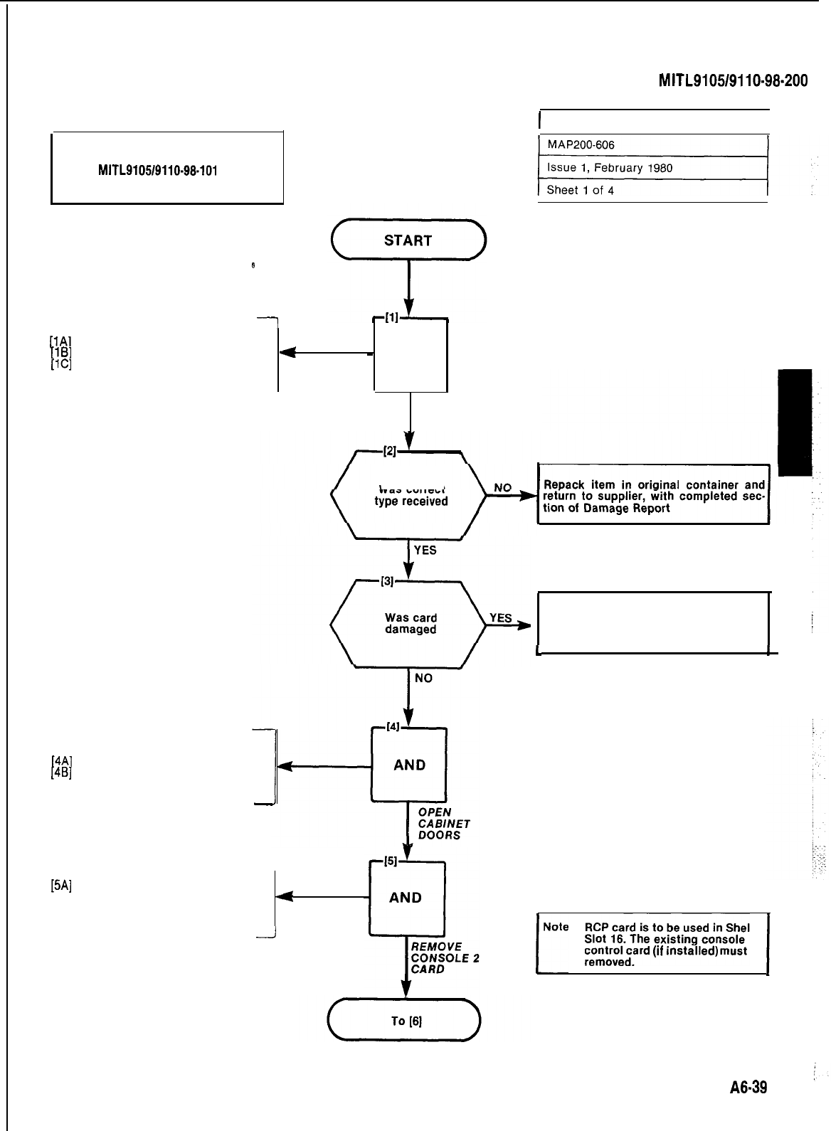
Note: The RCP card provides a remote
access facility. See Section
MITL9105/9110-98-101
Remote
Maintenance, Administration
and Test Description for details.
B
1
[lA]
Unpack card from container
[lB]
Inspect card for physical damage
[lC]
Check card type against invoice
[4A]
Unlock and open cabinet doors
[4B]
Remove locking bars from shelf
-
SECTION
MITL9105/9110-98-200
!
4
-
AND
l
UNPACK AND
INSPECT CARD
Was correct
[5A]
Release card extractor for Con-
sole Control Card (slot 16) and
remove card
1
4
-J
1 INSTALLATION OF RCP CARD
I
I
Tag defective item, repack in original
container and return to supplier with
completed section of Damage Report
I.
I
I
:
RCP card is to be used in Shelf 1
rote
;;;;.“,‘““‘*LnL
1
control card
(If
mstalled)
must be
A6.39
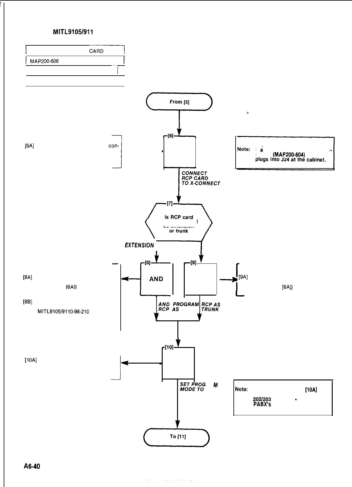
SECTION fbllTL9105/911 O-98-200
1 INSTALLATION OF RCP
CARD1
(
MAP200-606
I
Issue 1, February 1980
-1
Sheet 2 of 4
1
-
AND
[6A]
Run and terminate a 25 pair
con-
nectorized cable between J14
(cabinet) and cross-connect field --
-
[8A]
Run jumper between pins 38 (Tip)
and 13 (Ring) of cross-connect
cable (Step
16A1)
to
predesignated equipment number
allotted for RCP card
[8B]
Program RCP card as designated
extension. See
MITL9105/9110-98-210
for pro-
gramming procedures
.
J
to be connected
as extension
EXTENSlON
I
1
TRUNK
1
[lOA]
Set thumbwheel switches on
Tone Control card to 7772
I
(
J
-PI
v
I.
AND
-
WIRE WIRE
$VpD
;iOGRAM
;fCPNAS
EXTENSION
401
f
-
AND
.
f$‘$R+loG
RA
M
7772
If
a’
console interface card is in
stalled
(MAP200-604)
the cable
[9A]
Run jumper between pins 38 (Tip)
and 13 (Ring) of cross-connect
cable (Step
[6A])
to trunk line
Note:
Switch settings Step
[lOA]
must
remain at 7772 for Generic
202/203
software
-
installed
PABX’s
on completion of in-
stallation.
A8-40
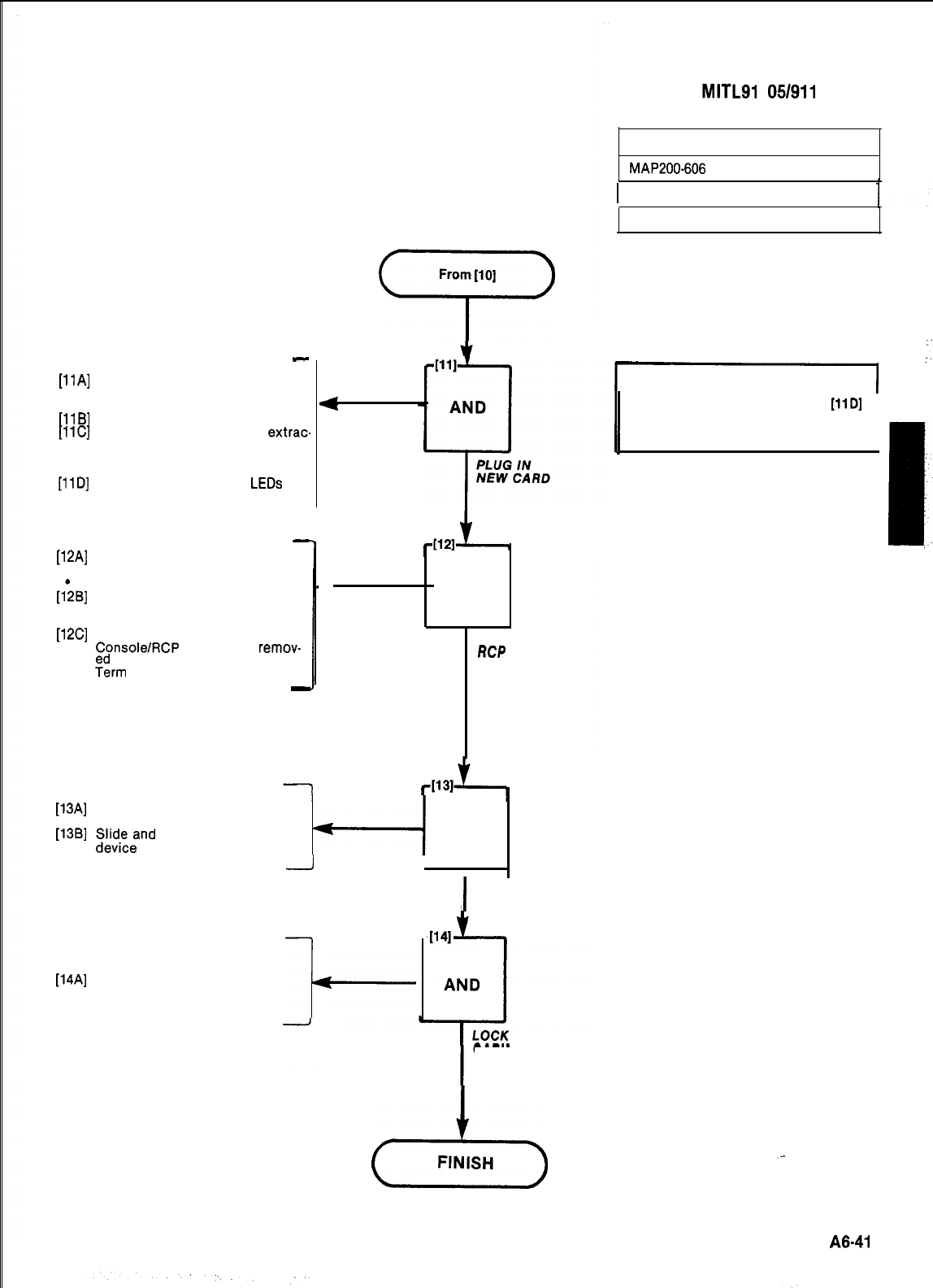
SECTION
MITLSI
051911 O-98-200
-
[llA]
Check proper card slot and color
codes of card extractor against
shelf slot
[llB]
Slide new card into shelf slot
[llC]
Lock card by pressing the
extrac
tors inward
.Data LED turns on and off with
diagnostics (Table 606-l)
[llD]
Verify that AL1 and AL2
LEDs
are
not lit (See Note)
-
[12A]
Dial allotted RCP number
.Answer tone heard
Term LED turns on
[l;B]
Verify that during a 10 second
period the answer tone increased
in level in three distinct steps
[12C]
Press RELEASE key
.
ConsolelRCP
connection
remov-
.
%m
LED turns off
-
[13A]
Replace locking bars across
front of shelf
[13B]
Sl&ydi;znd
securely fasten locking
From [lo]
7)
4
lAND
DIAL
RCP
NUMBER
--i
AND
I
II
I
REPLACE
LOCKING BARS
[14A]
Lock cabinet doors
I-
CABINET DOORS
23
FINISH
INSTALLATION OF RCP CARD
MAP200-606
1 Issue 1, February 1980
Sheet 3 of 4
r-----l
-I
1
Note: If AL2 LED is lit at Step
[llD]
1
replace the RCP card
A8-41
1
,-
SECTION
MITL9105/9110-98-200
INSTALLATION OF RCP CARD
MAP200-606
Issue 1, February 1980
Sheet 4 of 4
TABLE 606-l
RCP LED INDICATIONS
DESIGNATION DESCRIPTION OF INDICATIONS
DATA
1.
LED lit when the RCP is connected to the RMAT Controller and data
is being transmitted.
2.
LED lit during diagnostic tests. Tests consist of three 10 second
periods followed by 17 seconds during which LED is off.
TERM
AL1
AL2
LED is lit when the RCP answers the RMAT Controller
Alarm LED AL1 is lit when alarm is activated by the watchdog timer
Alarm LED flashes if failure occurs during the RCP self-test
diagnotics.
The LED is lit steadily if a checksum or RAM failure occurs during
initialization.
A6-42
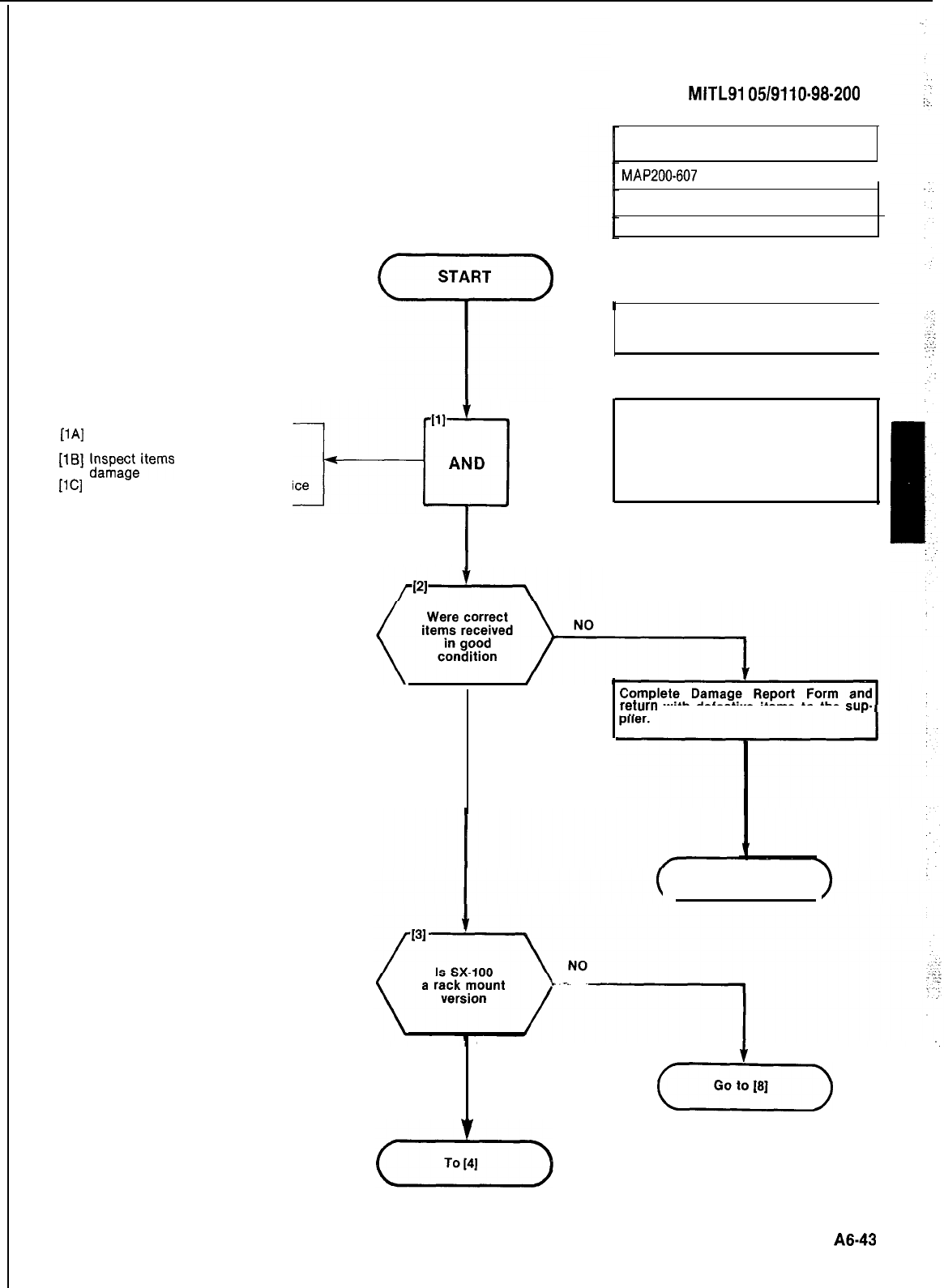
r
START
T
111
[lA]
Unpack reserve power supply
equipment
[lB]
F;;.p;;items
for physical
l-----o
AND
[lC]
Check item types against invoice
I
UNPACK AND
INSPECT ITEMS
SECTION
MITLSI
05/9110-98-200
RESERVE POWER SUPPLY
INSTALLATION (SX-100)
MAP200-607
I
issue 1, April 80
Sheet 1 of 11
h
1
Note: This MAP applies only to SX-100
equipment.
I
CAUTION
Check that the BATTERY switch on the
reserve battery pack is set to OFF.
Check that the three switches on the
battery charging unit are set to OFF.
YES
re!urn
with defective items to the
sup-
FINISH
YES
(Tz--)
A643
”
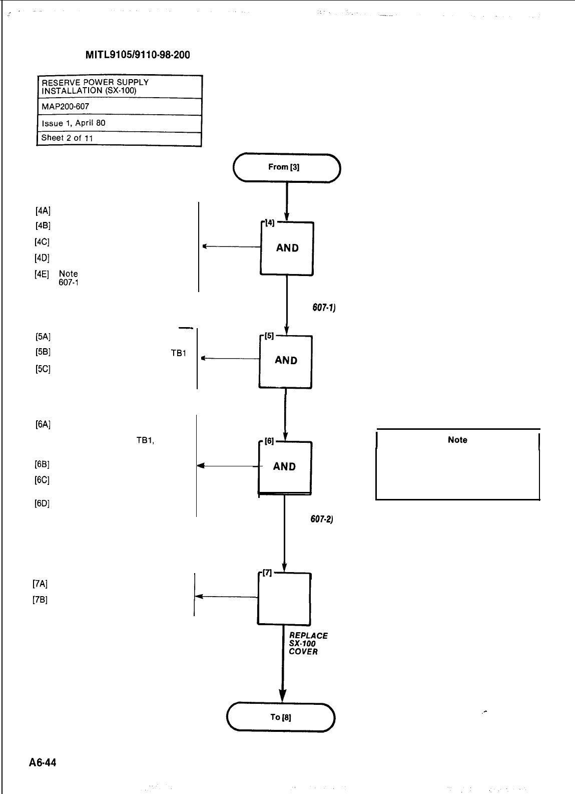
SECTION
MITL9105/9110-98-200
SX-100 EQUIPMENT
[4A]
Switch off AC and DC circuit
breakers
[4B]
Remove AC cord from power
receptacle
[4C]
Remove the eight 6-32 screws
[4D]
securing the cover
Remove the cover and expose
the interconnect card
[4E]
&I~;
location of TB302 in Fig.
RESERVE POWER SUPPLY
-
WI
WI
WI
WI
WI
F3Cl
WI
]7Al
]7Bl
Ensure all switches are off (see
CAUTION block above)
Remove cable harness from
TBl
terminals (Fig. 607-2) and discard
Install Reserve Power Supply in
position near base of rack
Measure, cut and run required
lengths of cable to interconnect
TB302, SX-100 and
TBl,
Reserve
Power Supply. See NOTE and
Fio. 607-2
Loosen cable securing clamps at
sx-100
Feed new cable under clamps,
and terminate each end as
shown in Fig. 607-2
Tighten cable securing clamps
From
[3]
‘r’
I41
$
---u
AND
DEACTIVATE
SYSTEM A ND
EXPOSE TERMINATIONS
(Fig.
607-1)
I
INSTALL
RESERVE POWER
SUPPLY
4
Replace the cover over the
SX-100 (see Step 4D)
Secure the cover with the screws
removed at Step 4C
t-
TERMINATE
POWER CABLES
(Fig.
607-2)
AND
Interconnecting cable must be of equal
construction to standard cable harness,
i.e. red, black and green insulated flexi-
ble strand leads of at least 14AWG
gauge.
.-
A8.44
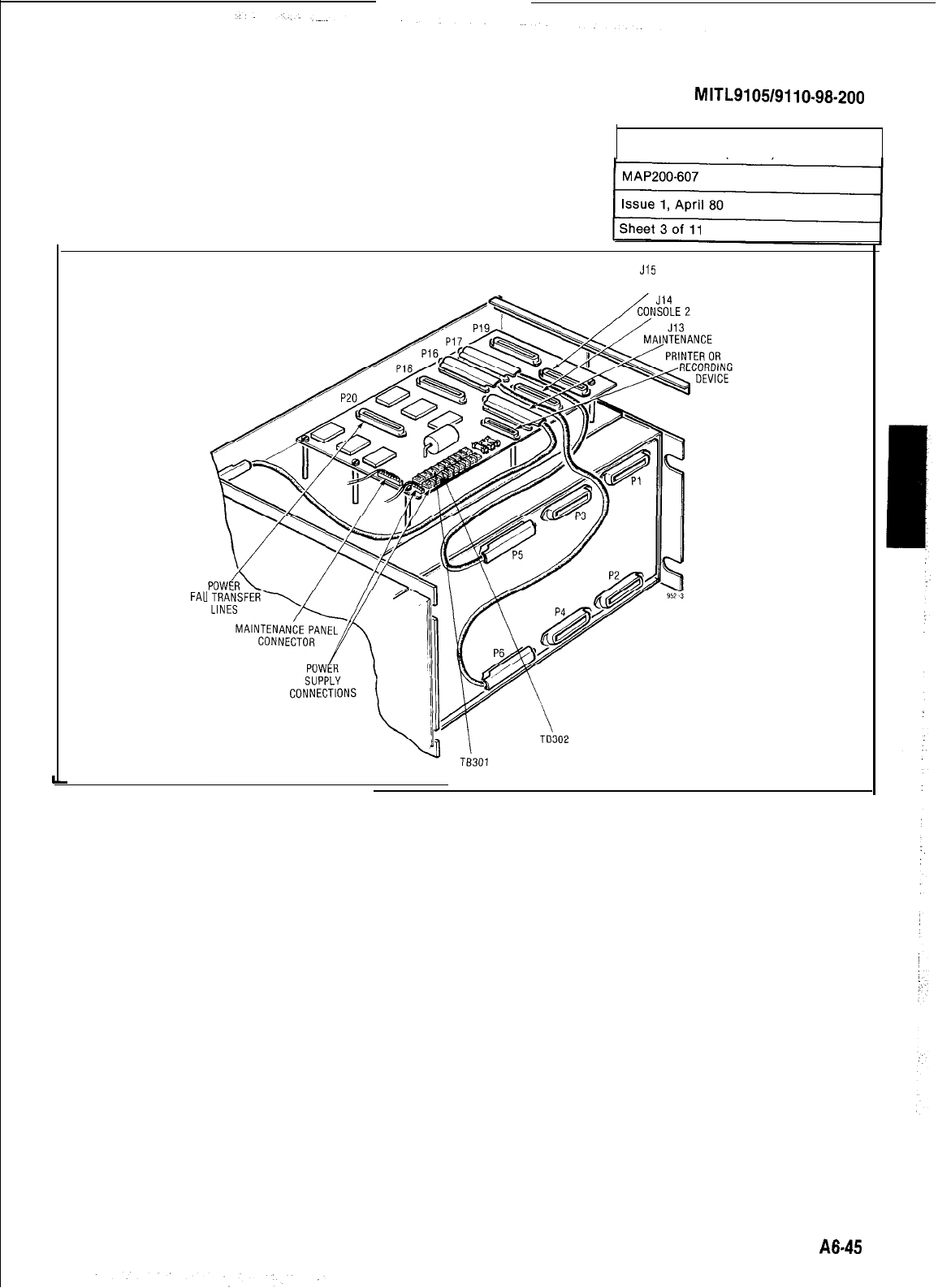
SECTION
MITL9105/9110-98-200
RESERVE POWER SUPPLY
INSTALLATION 6X-1001
J15
CONSOLE 1
FAII
Fig. 607-l Cable Connections
A845
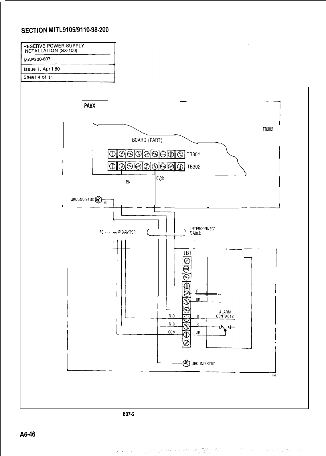
SECTION
MITL9105/9110-98.200
r
--
-
SX-100
PABX
\
NOTE: SEE FIG. 607-l FOR
'
LOCATION OF
TEl302
INTERCONNECT BOARD(PART)
I
I
-48Vdc
OVdc
BK
R
--I
-
--
Tfl
Al ARM
INnI,-ATnR
/
I
\
INTERCONNECl
ll"P.,
r
,- .._..,...I ,,.l,“.,,l.,
IF REQUIRED (SEE
\
I I I,
LHtlU
STEP 27)
.I
HARNESS
r
TBI
0
l-!-l
-es
.-
BATTERY
Q
CHARGER
@
RESERVE BATTERY
SUPPLY
i@
GROUNDSTUD
Fig.
607-2
Cable Harness Interconnections
A6-46
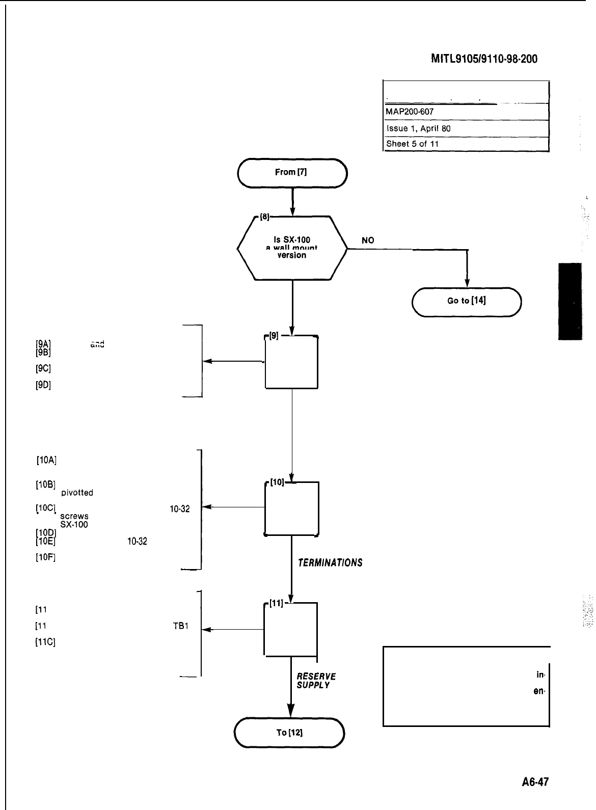
SECTION
MITL910519110~98~200
SX-100 EQUIPMENT
[9A] Unlock and open front door
[9B] Switch off AC and DC circuit
breakers
[9C] Remove AC cord from power
receptacle
[9D] Close and lock front door
[IOA] Release the strikes at the top of
the SX-100 (supporting the
weight of the unit by hand)
[IOB]
Allow the SX-100 to be gently
pivotted down and rest against
the backboard
[IOC]
Unlock (or remove the four
10-32
gx[w;
from) the top cover of the
[lOD] Remove the top cover
[lOE]
Remove the four
lo-32
screws
from the rear panel of the SX-100
[lOF] Remove the rear panel
-
RESERVE POWER SUPPLY
[ll
A] Ensure all switches are off (see
CAUTION block above)
[ll
B] Remove cable harness from
TBl
terminals (Fig. 607-2) and discard
[11C] Install Reserve Power Supply in a
suitably protected location near
the SX-100 equipment (see NOTE)
RESERVE POWER SUPPLY
INSTALLATION (SX-100)
YES
+I
’
-
-
AND
DEACTIVATE
sx-100
AND
c
I
EXPOSE
sx-100
TERMlNAT/ONS
-Ill1
’
AND
.
INSTALL
z;;MyYE
POWER
.
.
d3
I
Go to
[14]
A8-47
Note
1
The Reserve Power Supply should be
in.
stalled in a location which affords pro-
tection against mechanical or
en.
vironmental damage and which requires
an interconnecting cable run of no more
than 50 feet.
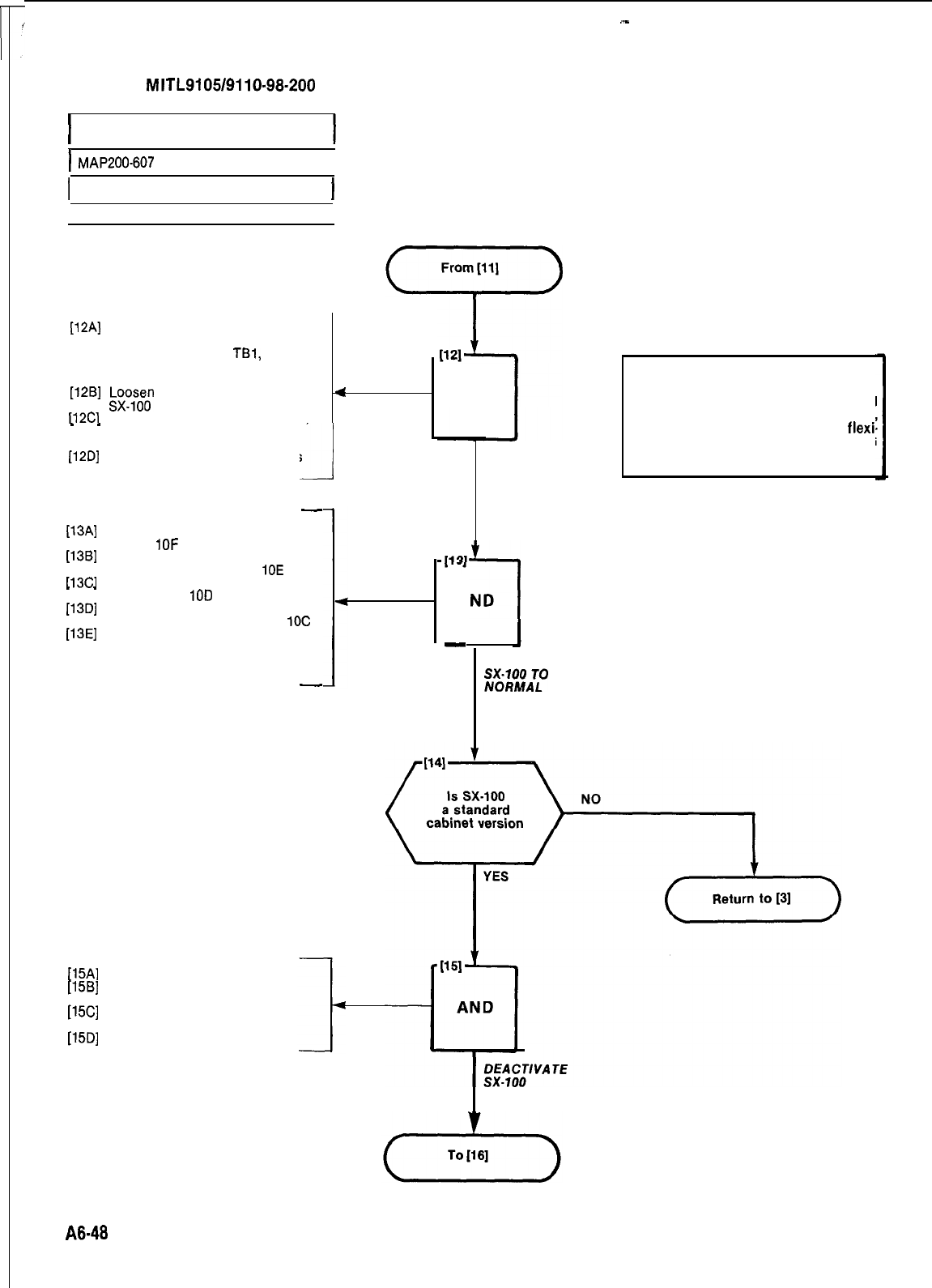
SECTION
MITL9105/9110~98-200
I
RESERVE POWER SUPPLY
INSTALLATION (SX-100)
1
MAP200-607
1
I
Issue 1, April 80
1
Sheet 6 of 11
I
[12A]
Measure, cut and run required
[12A]
Measure, cut and run required
lengths of cable to interconnectlengths of cable to interconnect
TB302, SX-100 and
TBl,
ReserveTB302, SX-100 and
TBl,
Reserve
Power Supply. See NOTE andPower Supply. See NOTE and
Fig. 607-2Fig. 607-2
-I-
[12B]
$o;;;
cable securing clamps at
[12B]
$o;;;
cable securing clamps at
4
112Cl
Feed new cables under clamps,
112Cl
Feed new cables under clamps,
_
_
and terminate each end as
shown in Fig. 607-2
-J
[12D]
Tighten cable securing clamps
-
[13A]
Replace the back panel removed
at Step
1OF
[13B]
Secure the back panel with the
screws removed at Step
10E
Il3Cl
Replace the too cover removed at
_
_
Step
1OD
[13D]
Lock the cover (or secure with
the screws removed at Step
1OC
[13E]
Swing the SX-100 equipment up
to its normal position, and en-
sure that the strikes latch and
engage properly
-
SX-100 EQUIPMENT
[15A]
Unlock and open front door
[15B]
Switch off AC and DC circuit
breakers
[15C]
Remove AC cord from power
receptacle
[15D]
Close and lock front door
AND
TERMINATE
POWER
CABLES
L
i
AND
Note
Interconnecting cable must be of equal
construction to standard cable harness,
i.e. red, black and green insulated
flexi,
ble strand leads of at least 14 AWG
gauge.
l
-
RESTORE
;;&gA;O
POSITION
A848
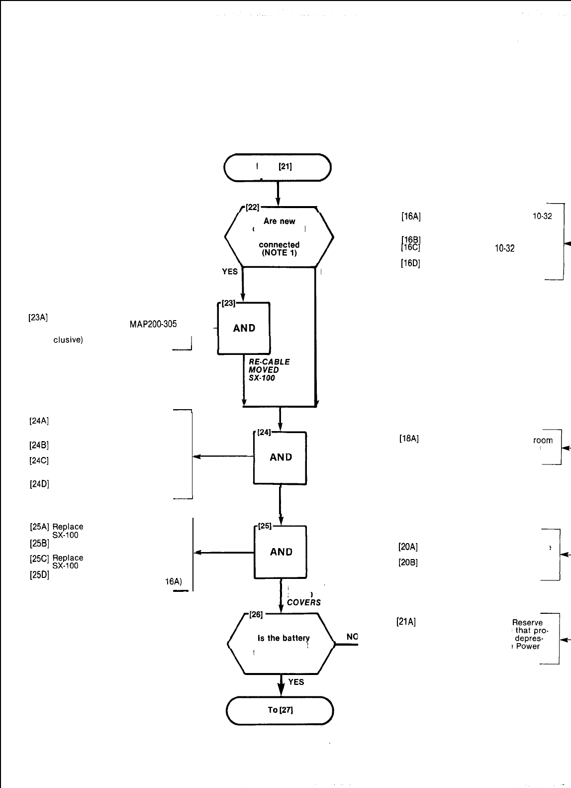
[23A]
Install new connectorized cables
in accordance with
MAP200-305
(from Steps 22 through 29 in- ---L-
elusive)
-
-
[24A]
Locate the free end of the cable
harness terminated on the
Reserve Power Supply
[24B]
Feed the free end under the
SX-100 cable clamp
[24C]
Terminate the conductors to
TB302 of the SX-100 as shown in
Fig. 607-2
[24D]
Tighten screws securing the
SX-100 cable clamp
connectorizedconnectorized
cables to becables to be
From
[21]
-
[25A]
!$$~s~
the rear panel on the
[25B]
Secure the panel with the screws
removed at Step 16C
[25C]
Fk~;k~~
the top cover on the
[25D]
Lock the cover (or secure with
the screws removed at Step
16A)
-
NO
[16A]
Unlock (or remove the four
lo-32
screws from) the top cover of the
sx-100
[16B]
Remove the top cover
[16C]
Remove the four
lo-32
screws
from the rear panel of the SX-100
[16D]
Remove the rear panel
-
I
TERMINATE
POWER
CABLES
REPLACE
sx-100
alarm circuit
to be connectedto be connected
[18A]
Move SX-100 aside to make
for new power supply position
(see NOTE 1)
RESERVE POWER SUPPLY
[20A]
Ensure all switches are OFF (see
CAUTION block)
[2OB]
Place Reserve Power Supply in
required position
[21A]
Place SX-100 on top of
Power Supply, ensuring
trusions in base fit into
sions on top of Reserve
Supply (Fig. 607-3)
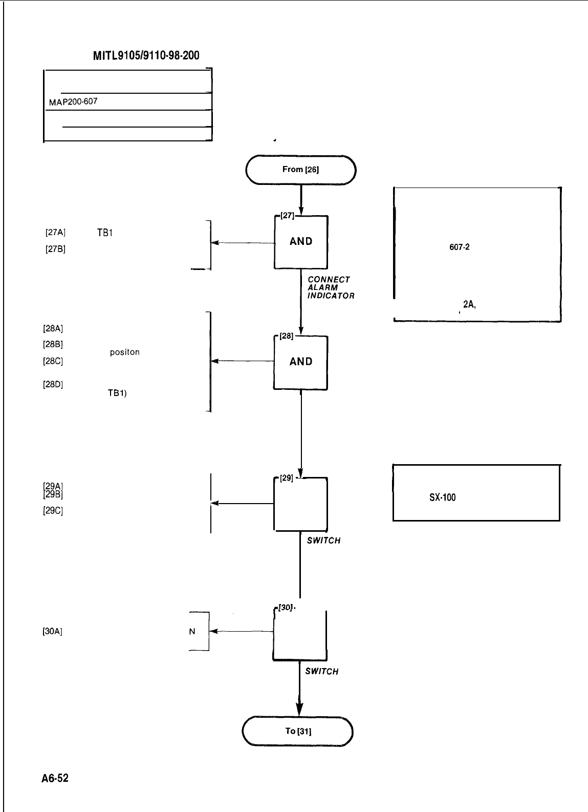
SECTION
MITL9105/9110-98-200
RESERVE POWER SUPPLY
INSTALLATION (SX-100)
MAP200-607
Issue 1, April 80
Sheet 10 of 11
[27A]
Locate
TBl
(Fig. 607-2) on
Reserve Power Supply
[27B]
Run required leads from alarm in-
dicator to TBI (see NOTE)
-
RESERVE POWER SUPPLY
[28A]
Insert power cord into power
outlet receptacle
[28B]
Set the AC switch on the charger
to the ON
positon
[28C]
Set the DC, then the BATT swit-
ches on the charger to the ON
position
[28D]
Set the BATTERY circuit breaker
(at left of
TBl)
to the ON position
.Battery charging LED lights
SX-100 EQUIPMENT
[29A]
Unlock and open front door
[29B]
Insert power cord into power
outlet receptacle (see NOTE)
[29C]
Switch AC and DC circuit
breakers to ON
.CONVERTER LED lit
CONNECT
POWER JO
RESERVE POWER
SUPPLY
-1291
’
t
4
AND
.
I*
SWITCH
POWER
SUPPLY ON
L
ON MAINTENANCE PANEL
[30A]
Set System Power switch to ON
.SYSTEM POWER LED lit
pi
AND
SWlTCH
SYSTEM
POWER ON
I
Note
Alarm contacts are provided by the
charging unit. These are available for
customer-provided alarm indicating
equipments to indicate power-fail condi-
tions. Fig.
607-2
shows the normal
operational condition i.e. a power-fail
condition causes the normally open (NO)
and common (COM) contacts to close.
The alarm contact electrical ratings are
as follows:
I
Resistive Load .
2A,
26Vdc
-
1 A, 40Vdc
I
I
Note
Ensure
SX.100
circuit breakers are off
(Step 4A) prior to Step 29A.
A6-52
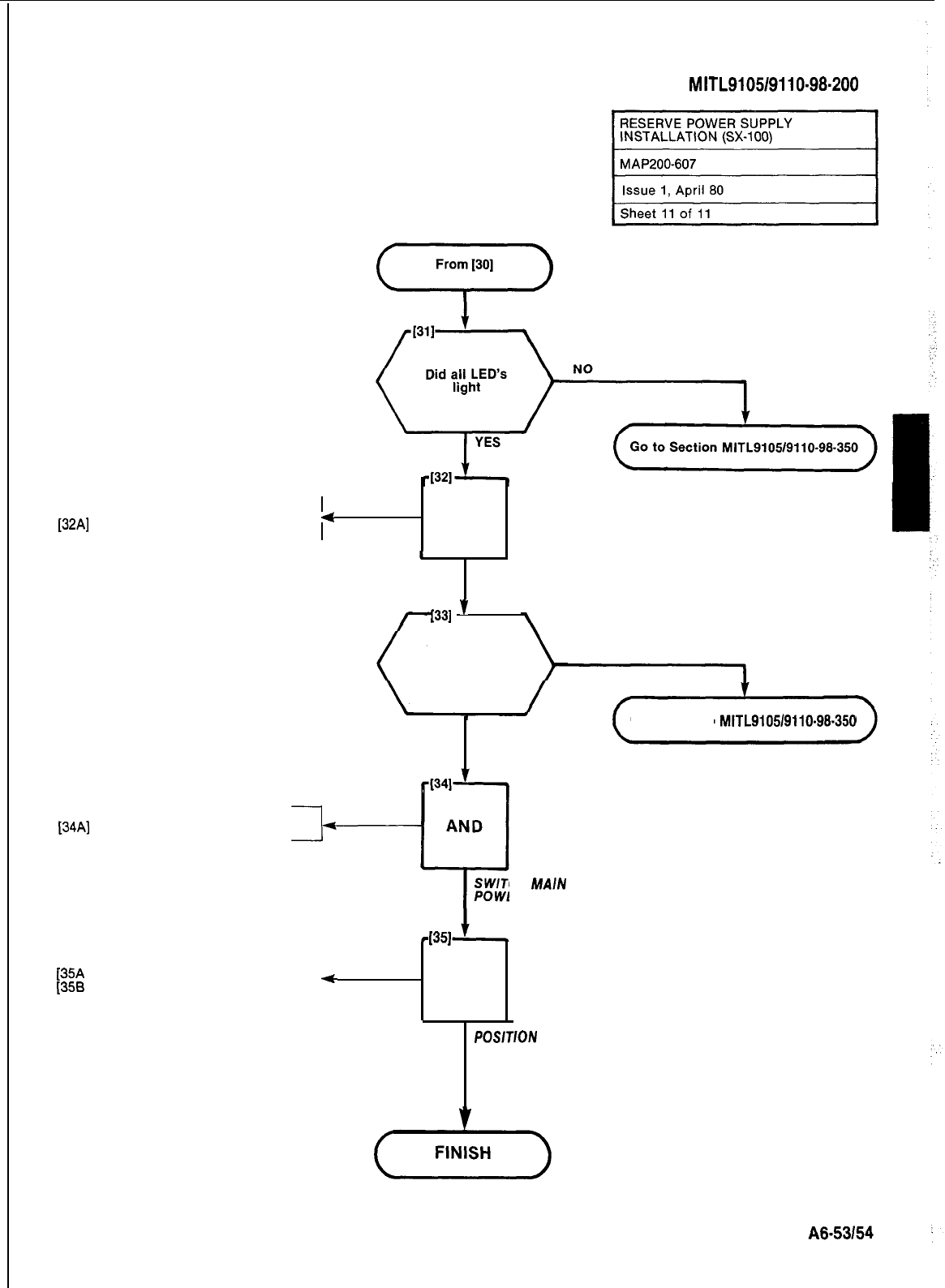
r
[34A]
Set AC circuit breaker to ON
SECTION
MITL9105/9110-98-200
AT SX-100 EQUIPMENT
[32A]
Set AC circuit breaker to OFF
4
AND
4
SWITCH MAIN
POWER SUPPLY OFF
1331
’
Does System
remain fully NO
operational
YES
Go to Section
MITL9105/9110-98.350
(341
AND
!7
SWITCH
MAIN
POWER SUPPLY ON
(351
[35A
(356
1
Close and lock all cabinet doors
Place cabinet in final position 7
+
AND
POSlTlON
CAB/NET
MlTEL
STANDARD PRACTICE SECTION
MITL9105/9110-98-205
Issue 3, August 1980
SX-lOO*
AN D SX-200*
SUPERSWITCH”
ELECTRONIC PRIVATE AUTOMATIC BRANCH EXCHANGE
INSTALLATION FORMS
CONTENTS PAGE Reason For Reissue
1.
INTRODUCTION . . . . . . . . . . . . . . . . . . . . .
1
General . . . . . . . . , . . . . . . . . . . . . . . . . . . .
1
Reason for Reissue . . . . . . . . . . . . . . . . . .
1
1.02 This section is reissued to include all
Generic 205 information
2. INSTALLATION
2.
INSTALLATION.. . . . . . . . . . . . . . . . . . . . .
I
Cabling . . . . . . . . . . . . . . . . . . . . . , . . . . . .
1
Programming . . . . . . . . . . . . . . . . , . . . . . .
1
Cabling
3.
INSTALLATION FORMS . . . . . . . . . . . . . .
2
General . . . . . . . . . . . . . . . . . . . . . , . . . . . .
2
Identification.. . . . . . . . . . . . . . . . . . . . . . .
2
CodeEntry..........................
2
Forms Included
APPENDIX 1. . . . . . . . . . . . . . . . . . . . . .
Al-l
Programming Error Codes . . . . . . . . . .
Al-3
Programming Confirm Codes . . . . . . . Al -4
Extended Programming Error Codes
Al.5
Extended Programming Confirm
Codes........................... Al-8
Speed Call Error Codes . . . . . . . . . . . . . . . Al -7
Installation Forms . . . . . . . . . . . . . . . . . . . .
Trunk Card Switch Settings. . . . . . . . . . . . .
2.01 All connections for the line and trunk cir-
cuits are made from the cross-connect
frame to the PABX equipment cabinet through 25
pair connector ended cables. The attendant con-
soles are connected to the equipment cabinet
through standard 25 pair cables with a plug on the
cabinet end and a connector at the console.
Programming
2.02 The system contains ten individual pro-
grams. Each program details a different
aspect of the system configuration.
1. INTRODUCTION
General
l
Tenant Service (Generic 203 or higher)-If
the system is to be used by multiple
tenants “Tenant Service” must be selected
when programming is started.
1.01
installation of the SX-100 or SX-200 PABX
consists of connecting the system to the
cross-connect frame, applying power, and pro-
gramming. SECTION
MITL9105/9110-98-200
details the system cabling requirements,
SECTION
MITL9105/9110-98-210
gives detailed in-
structions for programming the system and
SECTION
MITL9105/9110-98-215
details the test
procedures to be performed after the system pro-
gramming is completed. This section contains a
general description of the system installation, the
type of installation forms and the data required to
complete the installation.
l System Options-The system options are
those options which affect all extensions
and trunks within the system. A number of
options are provided (code numbers 100
through 234) any of which may be selected.
l Features-A number of features (code
numbers 1 through 42) require access
codes to be dialed by the extension user to
gain access to the features. The Feature
program allows the selected access codes
to be assianed.
I
.
I
:..
--I
0
MITEL Corporation 1980
* Trademark of MITEL Corporation
Page1
SECTION
MITL9105/9110-98-205
l Class of Service Options-A maximum of
16 different Classes of Service (COS) may
be defined. Each COS specifies the
features and services (code numbers 33
through 94) that may be accessed by an ex-
tension or dial-in trunk assigned to that
cos.
l Extension-The Extension program allows
the tenant, equipment number, directory
(extension) number, COS (the features and
services which may be accessed), toll
restrictions, and the optional busy lamp
and pick-up group assignments to be made
for each extension.
lHunt Groups-This program defines the ex-
tensions within a tenant that form a hunt
group and the type of hunting to be perform-
ed. A maximum of 12 individual hunt groups
may be specified per system.
l Trunks-This program allows the tenant,
equipment number, busy lamp assignment,
trunk type, console appearance, day and
night number assignments, COS, toll
restriction, and incoming number defini-
tions of each trunk to be made.
lTrunk Groups-A maximum of 12 different
trunk groups may be programmed per
system. The access code and type, the toll
restriction and the overflow group (the trunk
group to which the trunk will hunt when all
trunks in the trunk group are busy) of each
trunk group are specified.
l
Multi Digit Toll Control (Generic
204/Up)-If
Toll Control is to be employed, refer to Sec-
tion
MITL9105/9110-98-212
for instructions.
lSpeed Call (Generic
205)-If
Speed Call is
to be employed, refer to Section
MITL9105/
911 o-98-220.
3. INSTALLATION FORMS
General
3.01
A complete set of installation forms is con-
tained in
Mite1
publication
SX-lOO/SX-200
Installation Forms. For descriptive purposes a
copy of each type of installation form is included
in this section. Each installation form is divided
into a number of columns, the headings of which
serve two purposes-
(a) to identify the information that should be
entered into the column, and
(b) to show the actions to be performed to
enter the codes into the system memory.
3.02
A list of features or options is included on
the relevant installation form if applicable.
These features and options, and any conflicts
(mutual exclusions), are described in Section
MITL9105/9110-98-105
Features and Services
Description.
3.03 In addition to the “programming” installa-
tion forms the various types of trunks re-
quire the trunk card switches to be set to meet the
proper operational configuration. This type of
form is also included at the rear of this Section.
Identification
3.04
The name of the button shown at the top of
each column identifies the type of code to
be entered in that column. The number following
the button name shows the range of codes
associated with the operation.
Code Entry
3.05 To enter the information contained in each
table the button shown at the top of the col-
umn must be pressed and the code number dial-
ed. An example is shown in Fig. 3-1, Typical Pro-
gramming Entry.
3.08 Table 3-1 is a list of all forms included in
Mite1
publication SX-lOO/SX-200 Installation
Forms. The number of pages of each type of form
is also included.
_-
Page 2
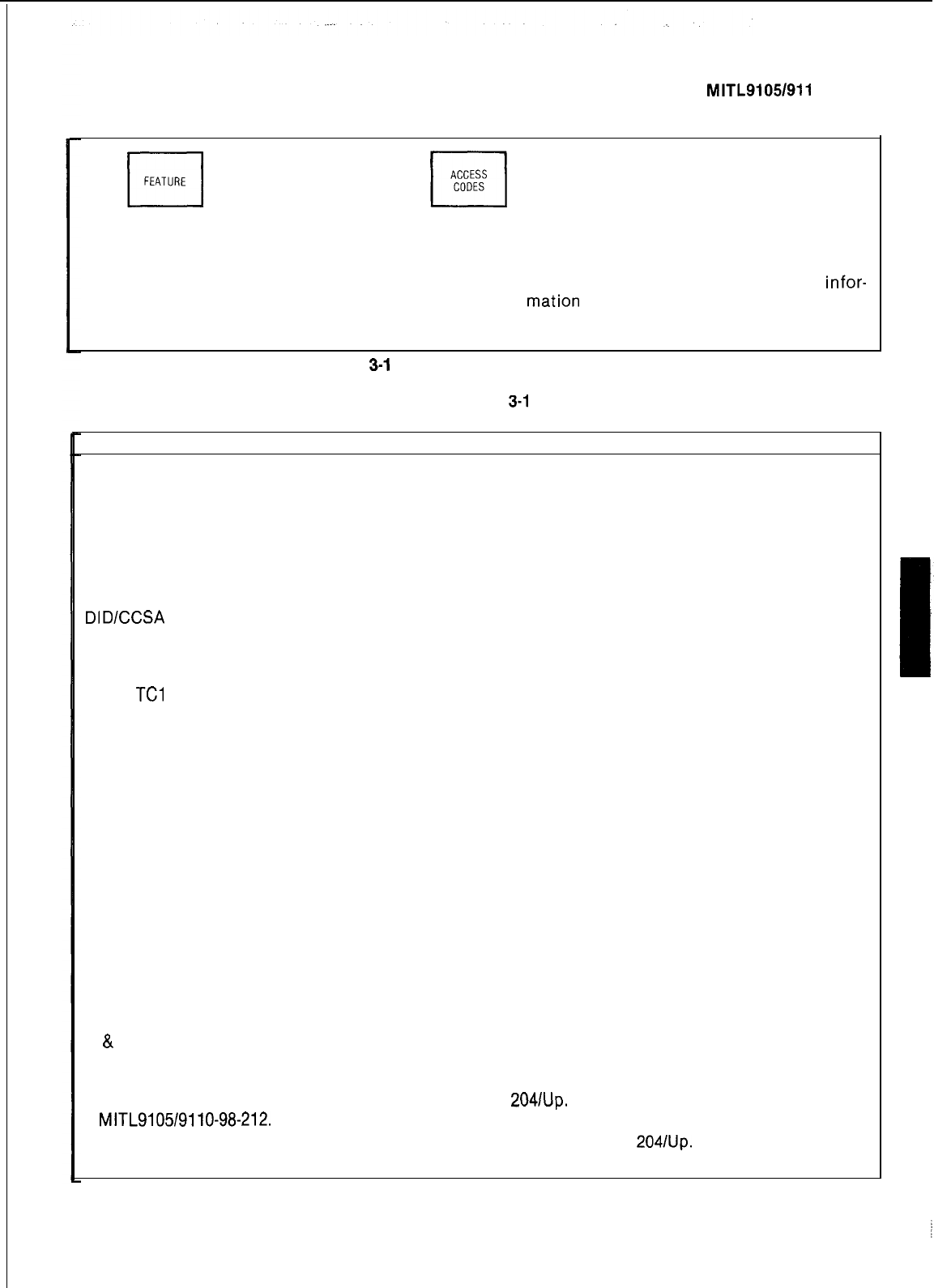
SECTION MITL9105/911 O-98-205
I
ASSIGN AND
FEATURE DIAL ACCESS
1-42
I
CODES DIAL ACCESS
CODES
cl
ENTER
To assign feature access codes.
(1) Press FEATURE button.
(2) Dial feature number (range i-42).
(4)
Dial the access code to be assigned to the
feature
(5) Press the ENTER button to store the
infor-
mation
entered.
(3) Press ACCESS CODE button.
(6)
Repeat steps (1) through (5) as required.
Fig.
3-l
Typical Programming Entry
TABLE
3-l
INSTALLATION FORMS
Title Number of Forms
Customer Changes
4
System Options
3
Features
1
Class of Service Options
2
Extensions*
16
Hunt Groups
2
Non Dial-In Trunks
6
Dial-In Trunks*
6
DIDICCSA
Trunks
6
Trunk Groups
2
Multi Digit Toll Control
Toll Control Outline Forms
TCl
4
TC2
4
TC3
6
TC4
1
TC5 6
Absorb Plan (Note 1)
2
Class of Restriction (Note 1)
3
Control Plan (Note 1)
5
Restriction Tables (Note 1)
12
4 Entry Restriction Table
6
20 Range Restriction Table
6
800 Range Restriction Table
Speed Call Forms
SC1 (Note 2)
1
SC2 (Note 2)
1
Trunk Card Switch Settings
2
CO Trunks
Trunk Card Switch Settings
6
E
&
M/Tie Trunks
Trunk Card Switch Settings
6
DID/Tie Trunk Card
* Includes column for Multi-Digit Toll Control Generic
2041Up.
For further information see Section
MITL9105/9110-98-212.
Note 1:
These forms are peculiar to Multi-Digit Toll Control Generic
2041Up.
Note 2: These forms are peculiar to Speed Call Generic 205.
Page3
i
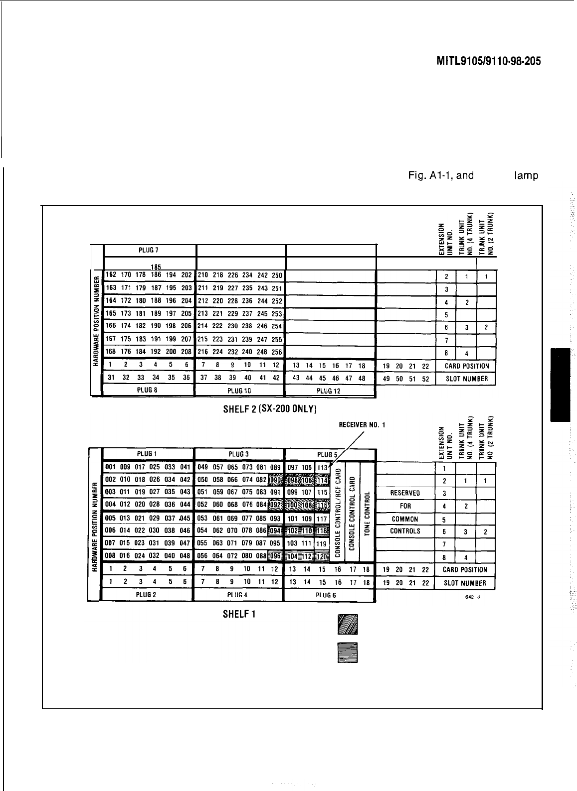
SECTION
MITL9105/9110~98-205
APPENDIX 1
EQUIPMENT AND BUSY LAMP NUMBERS
AND PROGRAMMING ERROR CODES
1. GENERAL
Al.01
The equipment numbers used in the SX-100 and SX-200 are shown in Fig-Al-l,and the
busy
Iamp
field numbering in Fig. Al-2.
PLUG1
PLUG9
EL
3.
z.
PLUG11
ES
EZ
f5z
161 169 177 185 193
201
209 217 225 233 241 249
1
I
1
sHELF2(%200ONLY)
DUALANDORQUAD
RECEIVER EQUIPMENT NUMBERS
QUAD RECEIVER
EQUIPMENT NUMBERS
NOTES: 1. EQUIPMENT POSITION 001 IS RESERVED FORTHETEST LINE AND MUST
THEREFORE BE EQUIPPED WITH A LINE CARD.
2,TRUNKEQUlPMENTNUMBERISSAMEASlNDlVlDUALTRUNKACCESSCODE.
Fig. Al-l Hardware/Equipment Numbering
Al-l j
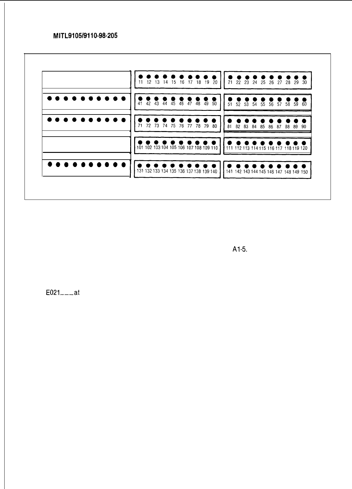
SECTION
MITL9105/9110-98-205
l ooooooooo
12
3
4 5 6 7 8 910
l
ooooo~oeo
31 32
33
34 35 36 37 38 39 40
l
oooeoo~oo
61 62
63
64 65 66 67 68 69 70
l ooooeoooo
91 92
93
94 95 96 97 98 99 100
eo9ooooooo
121122
123
124125126127128129 130
Fig. Al-2 Busy Lamp Position Numbering
Al.02 Error codes and confirm codes, which may appear as console displays during programming, are
respectively described in Tables Al-l and Al-2, Al-3, Al-4 and
Al-5
Al.03 Standard and Extended Programming Overlays appear in Fig. Al-3.
Al.04 Before a system can be initially programmed, the RAM (and the extended RAM if applicable) must
be initialized. Until the RAM(s) have been initialized system diagnostics may present an error
E021---at
the console.
Al.05 Refer to Fig. Al-4 for the proper initialization procedure of the RAM (Standard Programming). Refer
to Fig. Al-5 for the proper initialization procedure of the RAM (Extended Programming).
Al.08 Refer to Fig. Al-6 to enter or exit programming (Extended or Standard).
Al-2
SECTION
MITL9105/9110~98-205
TABLE Al-l
STANDARD PROGRAMMING ERROR CODES
Error
Key Key
code Cause affected flashing Meaning Action Required
EO
Invalid key pressed. ALL None The last key pressed is invalid Check procedure and press
at this time.
ALL None The number entered is out correct key.
El Invalid number. Press key associated with
of range or contains entry and re-enter number.
corrupted data.
E2
Key other than
LAMP TEST,
ENTER, An attempt was made to
leavepress
ENTER to transfer the
ENTER or CANCEL TENANT, OPTION CANCEL the current mode after some data to permanent store or
pressed. COS DEFINE, parameters were changed CANCEL to remove the data
FEATURE but before ENTER or CANCEL from the temporary store.
EXTN NUMBER, were pressed. ENTER may be
HUNT GROUP, used to write the new
pro-
TRUNK GROUP,
gramming
information back to
NEXT, EQPT the non-volatile RAM or use
NUMBER CANCEL to ignore all pro-
gramming changes made
since the last time ENTER
was pressed.
E3
Access code has HUNT GROUP ACCESS
not been entered. TRUNK GROUP CODE In Trunk mode an attempt
is made to delete a member Press ACCESS CODE key an
of a trunk group. enter required access code.
Equipment Numbers desired
E4
The extension
EXTN,
None must be entered. Check code entered.
number or access ACCESS In Trunk Group mode an
at-
1 If code is correct,
terminate
code entered is CODE tempt is made to place a
already assigned. trunk into a trunk group while entry, remove other appear
ante
of code and re-enter
that trunk is currently
pro-
all new data.
grammed into another trunk 2 If code is incorrect, press
group.
Attempting to enter members key associated with entry
and re-enter extension
into a Hunt or Trunk group number or access code.
before an access code has
been assigned to the group.
The extension number or
access code entered is
already assigned to an
extension, feature, hunt
group or trunk group.
Callback and Executive Over-
ride conflict, i.e. trying to
enter a Callback code while
same code assigned to Ex-
ecutive Busy Override and
vice-versa.
E5
Number entered EXTN NUMBER None The extension number or
contains incorrect ACCESS CODE access code is in conflict Check entry. Press key
number of digits or with the existing numbering associated with entry and
re-enter number.
conflicting option
enabled in this COS. plan. Attempting to add
an option to a COS in which
a conflicting option is enabl-
ed.
Attempting to add a System
Option when a conflicting
Incorrect equipment EQPT NUMBER COS option exists.
E6
None Attempting to assign an
number entered. equipment number that is: Remove conflicting option
l undefined (a) Assign equipment
l defined as a trunk to number correctly
an extension hunt group (b)
,E$aa;rew
equipment
or extension
l defined as an extension to
a trunk group or a trunk
l an extension with message
registration to hunt group
or pickup group
An equipment number assign-
ed to an extension must be
deleted as an extension
before being programmed as
a trunk. An equipment number
assigned to a trunk must be
deleted as a trunk before be-
ing programmed as an exten-
sion (Generic
20411~~).
Al-3
SECTION
MITL910519110-98-205
TABLE Al-l (Cont’d)
STANDARD PROGRAMMING ERROR CODES
Error
code Cause
E7 System is busy.
Key
affected
ENTER,
TENANT
Key
flashing
None
Meaning Action Required
(a)Attempting to initialize
system while PABX is in (a) Wait until system is idle
use.
(b)Attempting
to change data (b) Wait until extension or
of an extension or trunk trunk is idle
while that extension or
trunk is in use. It must be
idle or busied-out.
Extension has aENTER None
message register
l a valid message Zero message register,
that is not zeroed register exists for
this extension reset message waiting
or Do Not Disturb
or has a message
waiting, or has
Do Not Disturb
set.
l extension has a
message waiting or
Do Not Disturb set
and reprogram
E8 Trunk or equipment ENTER
number already
assigned.
In Tenant Service, pressing
the Hunt Group key when all
hunt groups are assigned to
other tenants,
In Tenant Service, pressing
the Trunk Group key when all
trunk groups are assigned to
other tenants.
In Tenant Service, attempting
to put an extension assigned
to one tenant into a hunt
group of a different tenant.
In Tenant Service, attempting
to put a trunk assigned to one
tenant into a trunk group of a
different tenant.
None Attempting to assign a
trunk or equipment (a) Key proper trunk or
number to more than one equipment number
tenant at the same time.
(b)
Press ENTER
In Tenant Service, entering a
hunt group number assigned
to a different tenant (after
pressing HUNT GROUP).
In Tenant Service, Trunk
Group
Programmrng,
selecting
an overflow group that
belongs to another tenant.
In Tenant Service, entering a
trunk group number assigned
to a different tenant (after
pressing TRUNK GROUP).
E9
Non-Volatile RAM
ENTER
error.
E022-22
At Power up
None
None
Ones and Zeros test failed Go to Section
prior to initializing
Non-
M ITL91051911 o-98-350
Volatile RAM.
RAM programmed in Generic Non-Volatile RAM must
202 or 203 is used be initialized and/or
with Generic
2041~~
reprogrammed
_-
Al-4
SECTION
MITL9105/9110-98-205
TABLE Al-2
STANDARD PROGRAMMING CONFIRM CODES
Confirm
Key
Flashing
code Cause affected lamp Action
co
Attempting to assign an EQPT
CONFIRM Check assignment
-
equipment number for
NUMBER l if correct press CONFIRM
an extension to a slot key. Equipment number entered
containing a trunk card is accepted as the number
for the equipment type being
Attempting to assign an EQPT
CONFIRM
programmed. All data associated
equipment number for
NUMBER
with the original appearance
a trunk to an empty of the equipment number
slot or a slot containing is removed
an extension card.
l if incorrect press EQPT NUMBER
and re-enter new equipment number
Cl Attempting to assign an
extension that already
exists
EXTN
NUMBER CONFIRM Check assignment
-
l if correct press CONFIRM key.
The extension number entered is
accepted as the extension number
for the equipment being defined.
ALL data associated with the
original appearance of the
extension number is removed.
l if incorrect press EXTN NUMBER
and re-enter extension number.
c2
The busy lamp
asslgment
already
exists
BUSY
LAMP
CONFIRM Check assignment
-
l if correct press CONFIRM key. Busy lamp
assignment is accepted for this equipment.
All data associated with original assignment
is removed
l if incorrect press BUSY LAMP and re-enter
busy lamp assignment.
TABLE Al-3
TOLL CONTROL PROGRAMMING ERROR CODES
Error
EO
Applies to:
Meaning
All modes Invalid key pressed. Consult MAP for correct pro-
cedure.
El Absorb Plan mode
Trunk Group mode
Control Plan mode
Number is not within the range of the
parameter being defined. Re-enter
parameter key defined.
E2
All modes An attempt was made to leave the current mode
after some parameters were changed but before
ENTER or CANCEL was pressed. ENTER may be
used to write the new programming information
back to the non-volatile RAM or use CANCEL to ig-
nore all programming changes made since the last
time ENTER was pressed.
Al-5
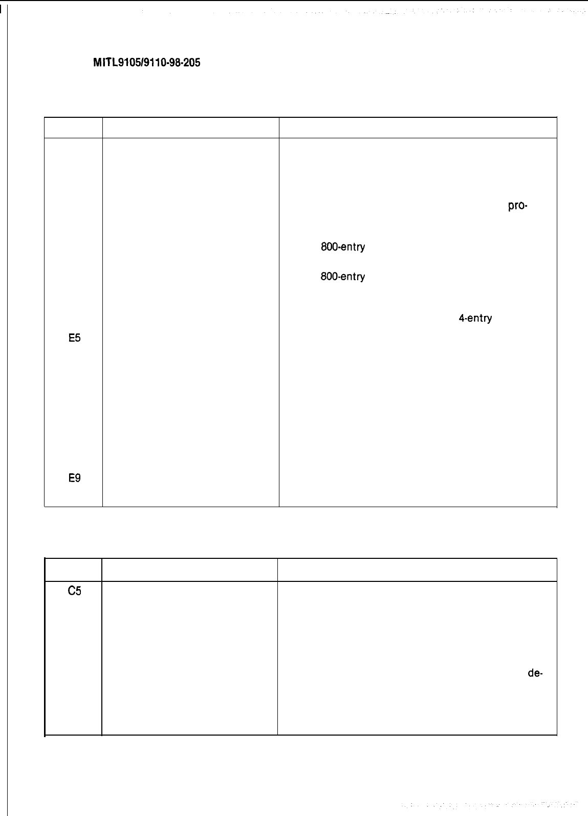
SECTION
MITL9105/9110-98-205
TABLE Al-3 (Cont’d)
TOLL CONTROL PROGRAMMING ERROR CODES
Error
E3
Applies to:
Control Plan mode
Table mode
Meaning
The table number entered is not valid for the
current configuration. Re-enter a number which ex-
ists for the configuration of the extended non-
volatile customer RAM.
E4
E5
E6
Table mode The table entry code is invalid for the table
pro-
grammed. This occurs in the following situation:
1.
A code of more than 3 digits in length for an
800.entry or 20-range table.
2.
A code not in the range of 200-999 for an
800-entry
table.
3.
A code which already exists or a code which
would be ambiguous in conjunction with the
existing table entries, for a
4-entry
table.
Table mode The table is full and cannot hold the entry.
Not used in extended programm-
ing
E7
Configuration mode Configuration is not allowed because the Tone
Control card switches are not 7776 or the system
is not idle.
E8
Not used in extended programm-
ing
E9
Configuration mode A hardware failure was detected while clearing the
extended customer non-volatile RAM.
TABLE Al-4
TOLL CONTROL PROGRAMMING CONFIRM CODES
Error
C5
Applies To:
Control Plan mode
Table mode
Meaning
An attempt was made to assign a table which is
currently assigned elsewhere. Pressing the confirm
key will de-assign the table from wherever it was
previously assigned to assign it to the specified
place.
C6 Table mode
A request has been made to delete all entries in a
table. If CONFIRM is pressed all entries will be
de-
assigned. The old data in the non-volatile RAM will
not be destroyed until the ENTER key is pressed,
and the table itself can be reprogrammed as
desired before the ENTER key is used.
__
Al
-6
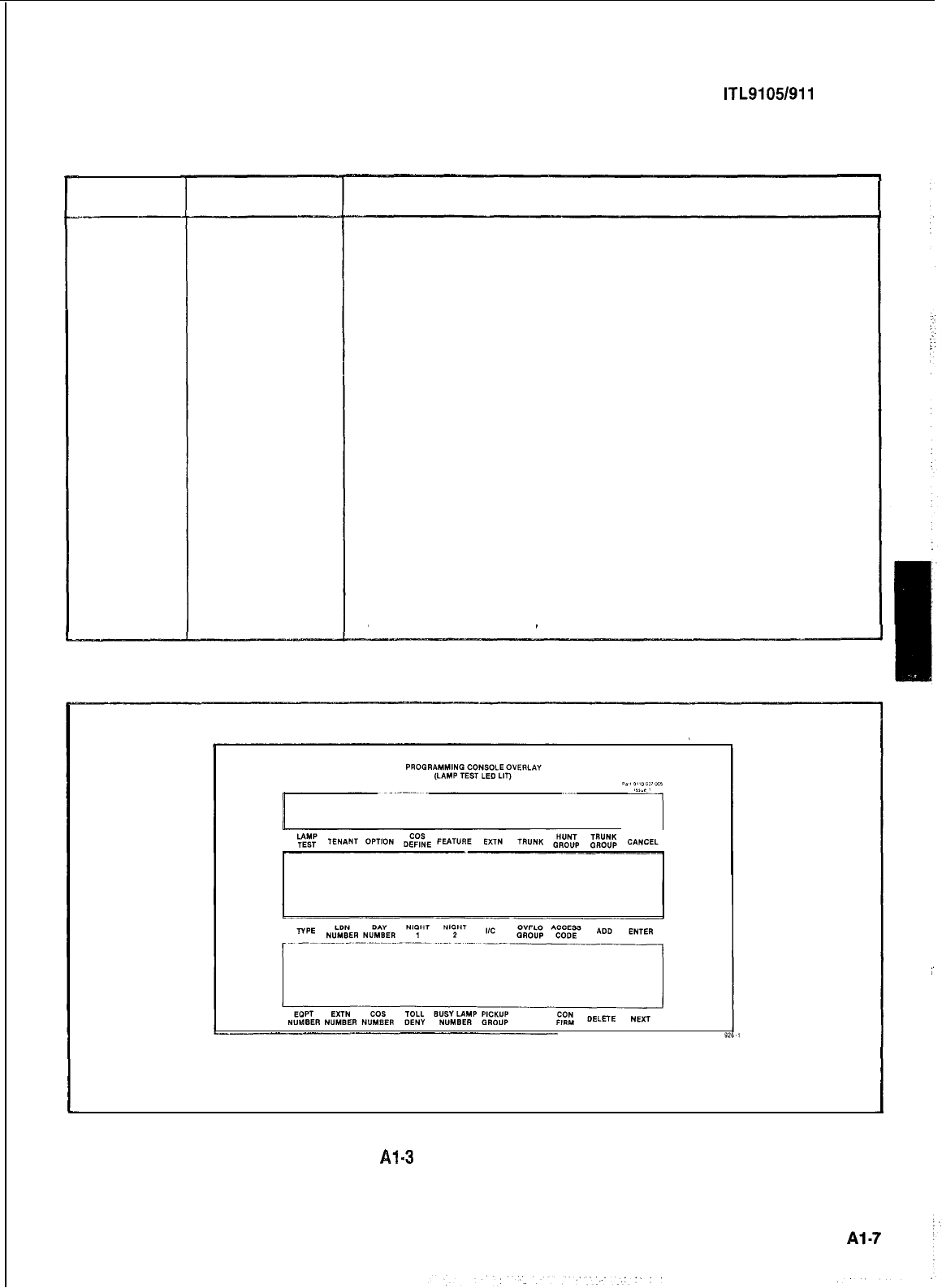
r
Error
El
El
E3
E4
E4
E5
E5
E6
SECTION M ITL9105/911 O-98-205
TABLE Al-5
SPEED CALL PROGRAMMING ERROR CODES
Applies To:
EQPT
NUMBER
NUMBER
REDIAL
TABLE
ACCESS
NUMBER
NUMBER
REDIAL
ACCESS
NUMBER
NUMBER
REDIAL
SPEED
CALL
Meaning
The equipment number entered is outside the range of valid
numbers
An invalid number redial value was entered
The table number entered is not consistent with that allowed
for the current configuration of the extended NV RAM
An attempt was made to enter an access number for a
common-use table
An attempt was made to enter a number redial digit for a
common-use table
The access number entered already exists for another table
assigned to the same equipment number
Number redial already exists for another table assigned to
the same equipment number, (only 1 number redial attribute
per user is allowed)
The Configuration of the extended NV RAM does not include
the speed call feature
(a) Basic Programming
Fig.
Al=3
Programming Overlays
1’
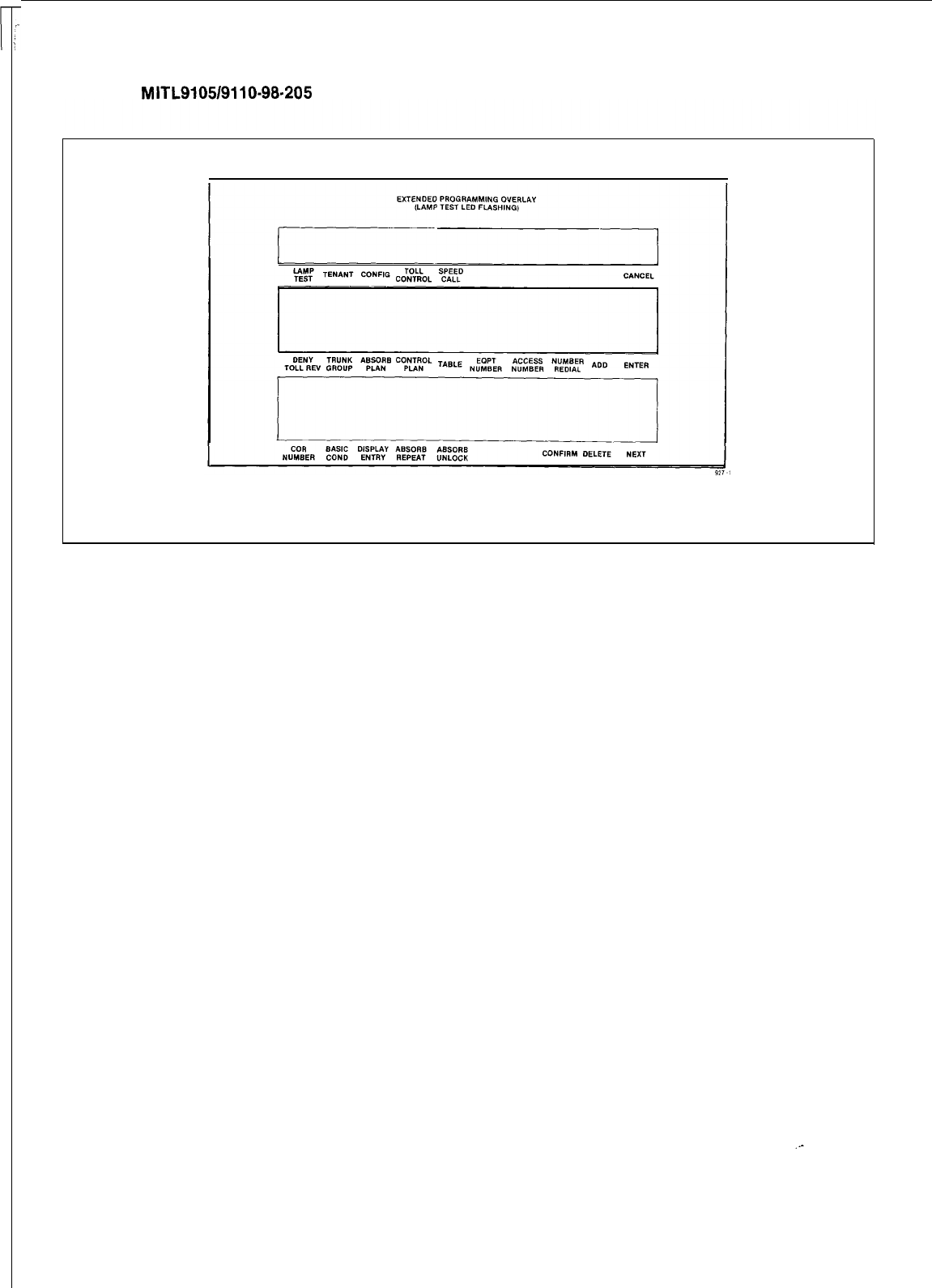
SECTION
MITL9105/9110-98-205
(b) Extended Programming
Fig. Al-3 Programming Overlays (cont’d)
Al-8
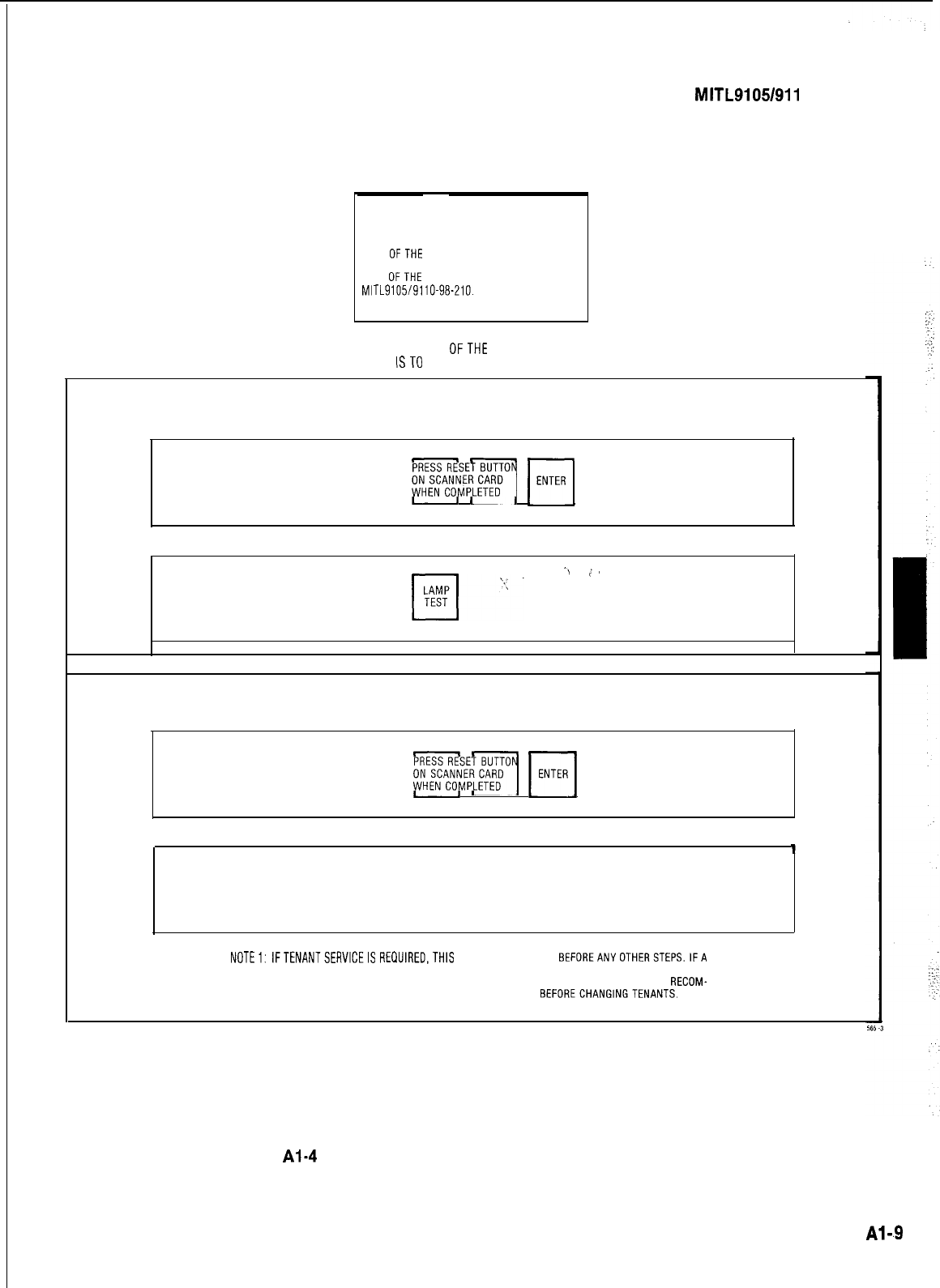
SECTION
MITL9105/911
O-98-205 I
CAUTION
ONE
OFTHE
FOLLOWING PROCEDURES MUST
BE PERFORMED FOR STANDARD PROGRAMM-
ING
OFTHE
SYSTEM SEESECTION
MITL9105/9110-98-210.
SELECT PROGRAMMING MODESTANDARD OR EXTEND-
ED THEN PERFORM ONE
OFTHE
FOLLOWING STEPS IF
THESYSTEM
ISTO
BECOMPLETELY PROGRAMMED
TO CHANGE FROM MULTI-TENANT SERVICE TO SINGLE TENANT
SERVICE OR TO ORIGINALLY PROGRAM SINGLE TENANT SERVICE (INITIALIZE)
SETTHUMBWHEEL SWITCHESTO 7776 PRESS
m
H
T;;;;KI
Fd;;{%&$iON
-> /I,
SET THUMBWHEEL SWITCHESTO 777X
(WHERE XIS THE PROGRAMMING PRESS
CONSOLE)
TO ORIGINALLY SET-UP MULTI-TENANT SERVICE OR CHANGE FROM
SINGLE TENANT SERVICE TO MULTI-TENANT SERVICE.
SET THUMBWHEEL SWITCHES TO 7776
PRESS
m
m
m
~i?;~t;%&DN
SET THUMBWHEEL SWITCHESTO 777X
(WHEREX IS THE PROGRAMMING PRESS
LAMP
CONSOLE)
q
TEST
NOTEl:
IFTENANTSERVICEIS
REQUIRED,THIS
STEP MUSTBEDONE
BEFOREANYOTHERSTEPS.IFA
SYSTEMISTOBECHANGEDFROM NON-TENANTTOTENANTSERVICE,THEMEMORYMUSTBE
INITIALIZED AND ALL DATA RE-ENTERED. STARTING WITH THE ABOVE STEP. IT IS RECOM-
MENDEDTHATALLDATA FOR ONETENANT BE ENTERED
BEFORECHANGINGTENANTS.
Fig.
Al.4
Initialization of RAM (Standard Programming)
Page
Al-.9
’
SECTION M ITL9105/911 O-98-205
CAUTION
THE DATA OF THE FOLLOWING FORMS CAN BE
ENTERED AFTER THE CONSOLE HAS BEEN PLACED
IN THE DESIRED PROGRAMMING MODE (STANDARD
OR EXTENDED)
TO ENTER STANDARD PROGRAMMING MDDE:
SET THUMBWHEEL SWITCHES TO 777X LAMP
WHERE X
=
THE PROGRAMMING CONSOLE
PRESS
q
TEST
LAMP TEST LEO LIT
OR
DIAL FEATURE ACCESS CODE FOR FEATURE NUMBER 29 FROM THE CONSOLE (GENERIC
204/lJP)
TO ENTER EXTENDED PROGRAMMING MODE:
ENTER STANDARD PROGRAMMING
PRESS
cl
NEXT
LAMP TEST LED FLASHES
TO TERMINATE EXTENDED PROGRAMMING MODE.
PRESS
cl
NEXT
LAMP TEST LEO LIT SOLID SYSTEM IS IN STANDARD PROGRAMMING MODE
TO TERMINATE STANDARD PROGRAMMING MODE: .
IF THE SYSTEM WAS PUT IN STANDARD PROGRAMMING
MODE
WITH
FEATURE NUMBER
29
PRESS
LAMP
cl
LAMP TEST LED UNLIT
TEST
SYSTEM OUT OF PROGRAMMING MODE
IF THE SYSTEM WAS PUT IN STANDARD PROGRAMMING
MODE BY CHANGING THE THUMBWHEEL SWITCHES
PRESS
LAMP
SET THUMBWHEEL SWITCHES TD 7780
III
LAMP TEST LEO UNLIT
TEST
SYSTEM OUT OF PROGRAMMING MODE
.-
Fig.
Al-5
Initialization of Extended RAM (Generic
2041~~)
Page Al-10
SECTION
MITL9105/9110-98-205
CAUTION
THE FOLLOWING PROCEDURE
MUSTBE
PERFORMED WHEN COMPLETELY PROGRAMMING
THESYSTEM
A. THE SYSTEM MUST BE IN STANDARD
PROGRAMMING MODE
8.
THE SYSTEM MUST HAVE BEEN INITIALIZED IN
STANDARD PROGRAMMING
(FIG. Al-4)
C. SELECTTHE EXTENDED PROGRAMMINGOVERLAY
PRESS
cl
NEXT SET THETHUMBWHEEL SWITCHES TO 7776
PRESS
n
CONFIG DIAL SINGLE DIGIT CONFIGURATION CODE-(SEE NOTE 2)
.I
.
;
*:
I
A
x-.--
PRESS
0
ENTER PRESS RESET BUTTON ON THESCANNERCARD (THE SYSTEM WILLEXIT FROM PROGRAMMING)
PRESS
. LAMP
0
TEST PRESS
0
NEXT THE SYSTEM IS
NOWIN
EXTENDED PROGRAMMING
NOTE 1:INITIALIZATION IS NOT POSSIBLE IF SYSTEM IS IN USE
NOTE 2:IN GENERIC 204/205 SYSTEMSTHEREARE FOUR CONFIGURATIONS
AVAILABLE:
1.
AUTOMATICWAKEUPANDTOLL
CONTROL STANDARD (2040NLY)
,,.*<
TOLLCONTROL STANDARD AND SPEEDCALL
STANDARD(205ONLY)
I
3.' TOLLCONTROL BASIC AND SPEEDCALL
EXTENDED(205ONLY)
'..
_
4. TOLLCONTROL EXTENDED(204 ONLY)
Fig.
Al-8
Enter or Exit Programming
Page Al-11
CUSTOMER CHANGES
MiTEL
CUSTOMER NAME:
CUSTOMER
SITE:
DATE OF CHANGE SERVICE PERSON TYPE OF CHANGE REMARKS
/
.,..,
.,.
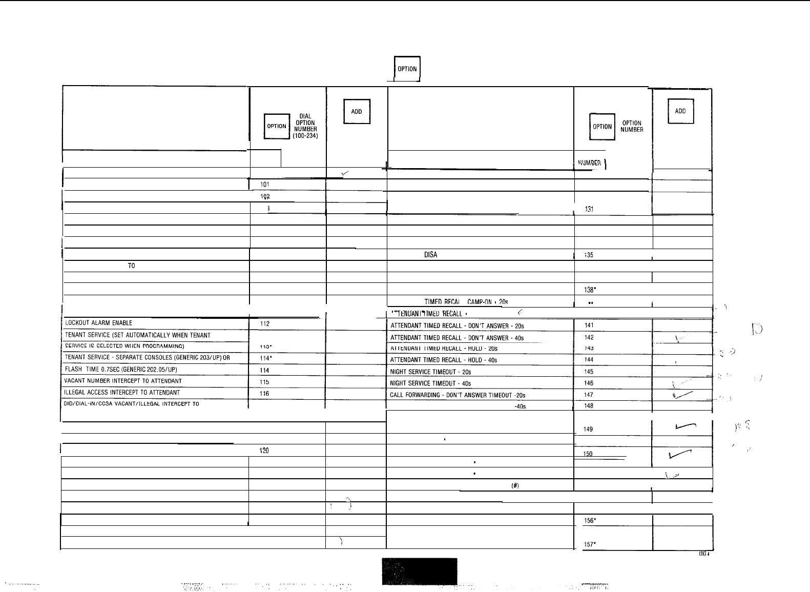
SYSTEM OPTIONS
b[
I-1
cl
DIAL
OPTION
,$;;;R
(100-234)
OPTION
OPTION NAME
./’
ATTENDANT CO TRUNK-CO TRUNK CONNECT ENABLE
129
ATTENDANT CO TRUNK-NON CO TRUNK CONNECT ENABLE
130
ATTENDANT NON CO TRUNK-NON CO TRUNK CONNECT
OPTION NAME
I
DISCRIMINATING RINGING
TRANSFER DIAL TDNF
OPTION
NUMBER
100
I
FLEXIBLE NIGHT SERVICE
NIGHT SERVICE AUTOMATIC SWITCHING I I”3 ENABLE i
111
0
ADD
1OUTGOING TRUNK CALLBACK
TAFAS AVAILABLE DURING DAY
104 CONTROLLED OUTGOING RESTRICTION SET-UP
132’
OUTGOING TRUNK CAMP-ON
105
CONTROLLED STATION RESTRICTION SET-UP 133’
106
CONTROLLED STATION TO STATION RESTRICTION SET-UP 134’
ATTENDANT
DISA
CODE SET-UP ENABLE
I
i35
I
1 CAN FLASH IF TALKING TO AN INCOMING TRUNK
I
107 -1
CAN FLASH IF TALKING
TO
AN OUTGOING TRUNK
I
108
LIMITED WAIT FOR DIAL TONE
136
CAN FLASH IF TALKING TO STATION
109
MESSAGE WAITING SET-UP (LAMP) 137’
I
CANNOT DIAL A TRUNK AFTER FLASHING
110
MESSAGE WAITING SET-UP (BELL)
138’
I
CANNOT DIAL A TRUNK AFTER FLASHING IF HOLDING ATTENDANT
TIMFD
RFCAI
I
CAMP-IIN
-
71%
139
‘1
1 OR IN CONFERENCE WITH A TRUNK
I
111
I
.--
_..^...
-
_..
--
---..
..~
I
I
~~ 1
1 Al
ItNUANl
IlMtU
HtCALL
-
CAMP-ON 40s
(
140
CALL
FORWARDING DON’T ANSWER TIMEOUT
I
I
ATTENDANT
I
117
ICALL FORWARDING BUSY (SYSTEM, DID. DIAL-IN TIE
I
<-
‘:
.:
,’
ATTENDANT CAMP-ON
118
TRUNK, CCSA)
ATTENDANT CONFERENCE 119
CALL FORWARDING
-
DON’T ANSWER (SYSTEM, DID. DIAL-IN
1 ATTENDANT BUSY OVERRIDE
I
17”
1-1
TIE TRUNK, CCSA)
’
)
/
ATTENDANT SERIAL GALL
121
PARK AND CALL-HOLD RECALL
-
2 MINUTES
151
I
BELL OFF ENABLE
122
PARK AND CALL-HOLD RECALL
-
4 MINUTES
152
\,
-2
.
PAGE BUTTON ENABLE
123
END’OF DIAL SIGNAL FOR OUTGOING TRUNKS
(#)
153
I
NEW CALL TONE ENABLE
124
‘-,
24 HOUR CLOCK
BOTH MODE STANDARD
125
:
.!
FIRST DIGIT TOLL DENY
CALLBACK BUTTON ENABLE
126
MESSAGE REGISTRATION ENABLE
I
1
154
II
TRUNK BUSY-OUT ENABLE
BOTH BUTTON ENABLE
I
127
MESSAGE REGISTRATION: COUNT ADDITIONAL
128
‘)
SUPERVISIONS
F----/--I
,283
4
r----
I
,,I,,
I,
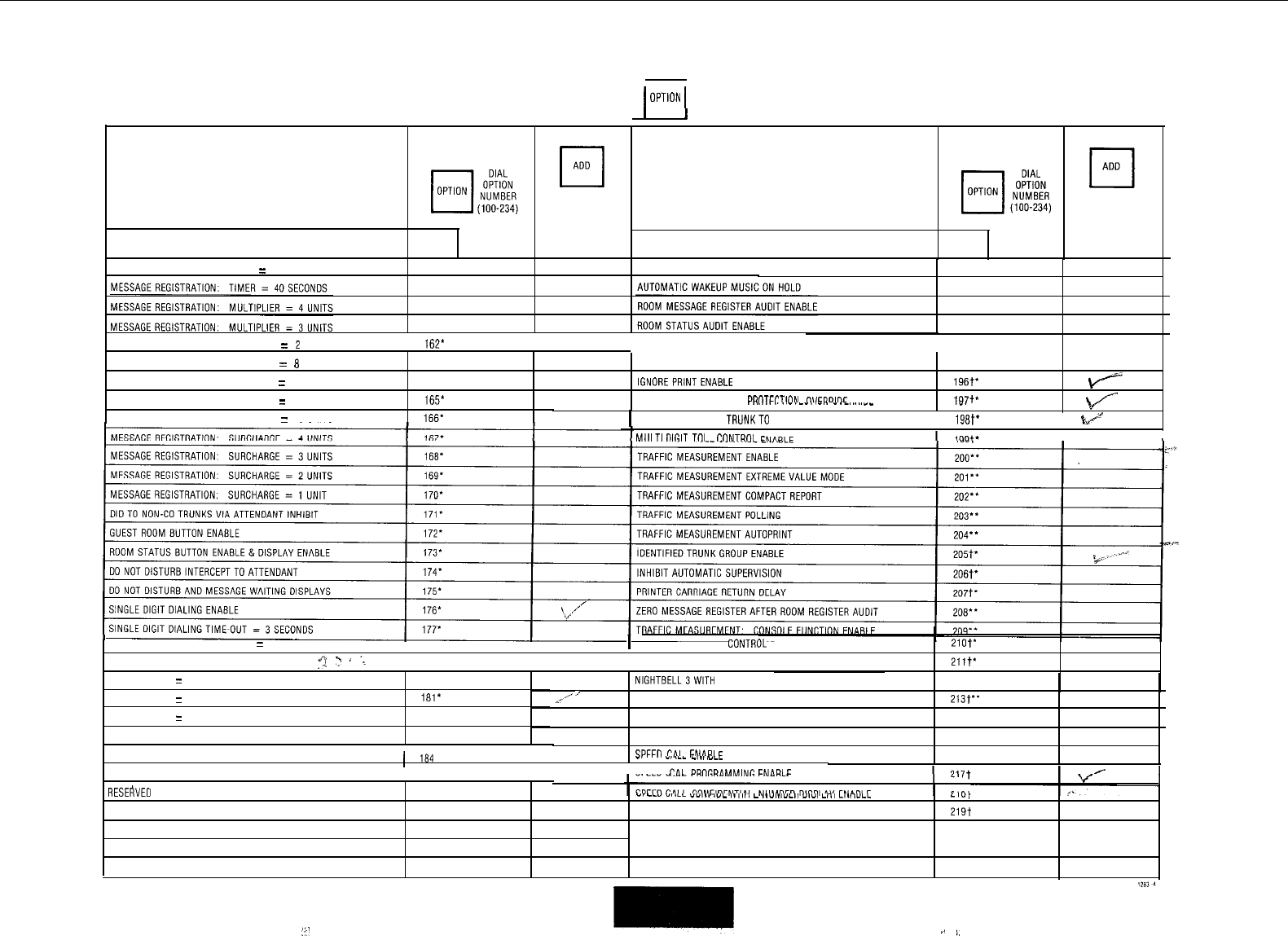
I I
SYSTEM OPTIONS 1
OPTioN
1
I
I
OPTION NAME OPTION
NUMBER OPTION NAME OPTION
NUMBER
MESSAGE REGISTRATION: TIMER
=
20 SECONDS
158'
AUTOMATIC WAKEUP PRINT
MESSAGE REGISTRATION: MULTIPLIER
=
2
UNITS
16P
I
MESSAGE REGISTER&MESSAGE WAITING CHANGE
I
MESSAGE REGISTRATION: SURCHARGE
=
8
UNITS
163'
PRINT ENABLE
195"'
MESSAGE REGISTRATION: SURCHARGE
=
7 UNITS
164'
IGNOREPRINTENABLE 19Lw
k-+
MESSAGE REGISTRATION: SURCHARGE = 6 UNITS
165*
REMOTF SYSTFM RFSFT PRDTFCTION
flVFRRlnF
I
-
--
-
-.
.---
.“-‘--“-‘.-.-““‘--
IQ,,'
.I.
\A---
I
?fi
MESSAGE REGISTRATION: SURCHARGE
=
5 UNITS
166.
1
EXTENSION NON-CO TRUNKTO TRUNK CONNECT ENABLE
I
19Bt'
@.
.e
--
MlllTIDlRlT
T,,
I
CnNTR”,
II
1
SINGLE DIGIT DIALING TIME-OUT
=
5 SECONDS
I
178'
I
ATTENDANT PRINTER CONTR(
II
IL
ENABLE
210t*
ATTENDANT STATION BUSY-OUT ENABLE
"1
“
_
.I
'
179'
SYSTEM ID ENABLE
211t*
212t
FLASH TIMING = 0.7 SECONDS
180'
FLASH TIMING = 0 9 SECONDS
181*
FLASH TIMING = 1.1 SECONDS
182'
TRUNK RECALL PARTIAL INHIBIT
183'
/.'
/
NlGHTBELL3WlTH MINOR ALARM ENABLE
PRINTOUTS: EXTRA LINE FEEDS
WAKE-UPALARM ENABLE
RESERVED
SPFFII
r.i,
I
FNPR,
F
213t**
214"
215
216t
RESERVED
1
164
I
-.
---
-, .__ -,.,,
ILL
RESERVED
185
SPFF”
CA,
I
PR”GRdMMINC
FNdRl
F
RESERVED
186
-,
-_I
-I.-L
ll,..
."-
,.,,,,
L
I.Y,.,YLII
yly,
L-,
L,."VLL LI",
. .
RESERVED
187
RESERVED 219t
RESERVED
188
STATION MESSAGE DETAIL RECORDING
RESERVED
189
OUTGOING CALLS 220t
AUTOMATIC WAKEUP ENABLE 190" STATION MESSAGE DETAIL RECORDING INCOMINGCALLS 221t
:?I
I
.,
b,
:
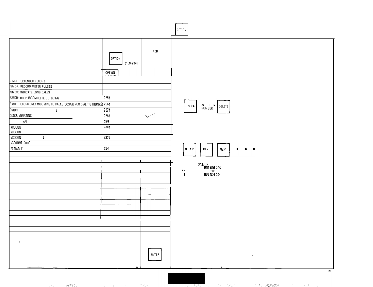
SYSTEM OPTIONS
Fi
OPTION NAME
cl
DIAL
cl
ADD
OPTION OPTION
NUMBER
(100-234)
3MDR: DROPlNCOMPLETEOUTGOlNG CALLS 2257
~MDR:RECDRDONLYlNCOMlNGCOCALLS(CCSA&NONDlALTIETRUNKS)226t
jMDR: DROPCALLS OF LESS THAN
8
DIGITS 2277
XCRIMINATING DIAL TONE 22at
SPECIAL
ANI
FEATURE 229t
XCOIJNT CODEENABLE 230t
\CCOUNT CODE LENGTH:4 DIGITS 231t
\CCOUNT CODE LENGTH:
8
DIGITS 232t
\CCOUNTCODE LENGTH: 12 DIGITS
IARIABLE
LENGTH ACCOUNTCODES 234t
I I
I I
I I I
1I
I I
I I
I I
II
I I I
I I I
NOTES
TO DELETE SYSTEM OPTIONS
AFTER ALL REQUIREDOPTIONS HAVE BEEN REMOVED
cl
ENTER
TO REVIEW SYSTEM OPTIONS
'GENERIC 203/UP
**GENERIC 204
BUTNOT
t'
GENERIC 204AND
205
t
GENERIC 205
BUTNOT
AFTER ALL OPTIONS ARE ADDED
*
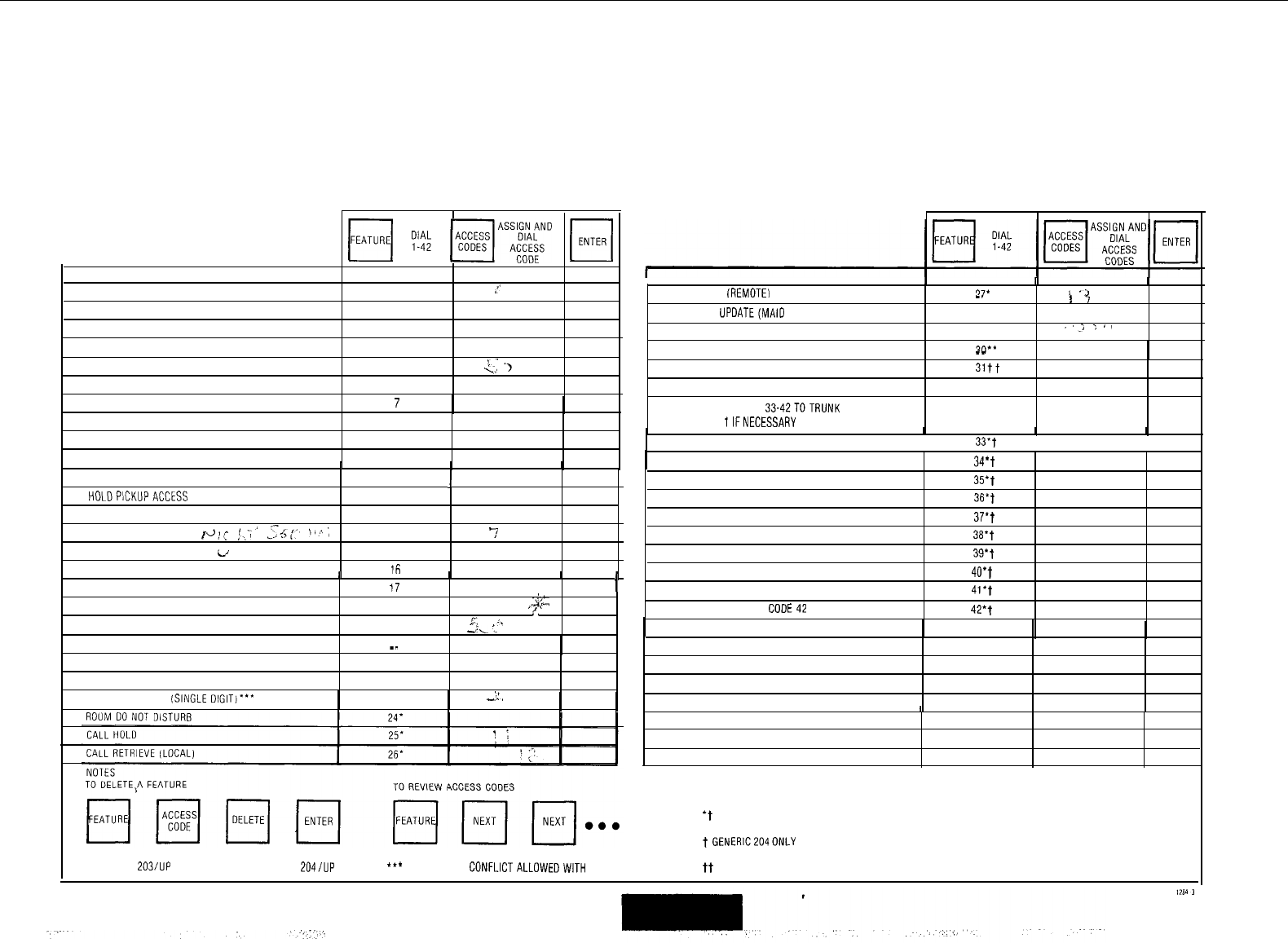
FEATURES
H
y;;
lqAs;!gJD
m
DESCRIPTION FEATURE NUMBER
ATTENDANT ACCESS
1
:'
CALLBACK-DON'T ANSWER
2
CALL FORWARD-BUSY
3
CALL FORWARD DON'T ANSWER
4
CALL FORWARD FOLLOW ME
5
!:
')
..'
CALL PARK
6
DIAL CALL PICKUP
7
DIRECTED CALL PICKUP
8
MEET-ME CONFERENCE
9
PAGER 1
10
PAGER 2
I I I
11
I
1
HOLDPICKUPACCESS
12
PAGER 1 AND 2
13
TAFAS ALL
pJ!(
!~,','
,s;,,
\'t;
14
7
TAFAS 1
i/
15
TAFAS 2
ifi
1
II
TAFAS 3
17
I
ATTENDANT FUNCTION
18
,.$A
'.
MAINTENANCE FUNCTION
19
,p.
.f.
4‘<
:.
DID ATTENDANT ACCESS CODE
20
I I I
CALL RETRIEVE (REMOTE1
77’
I
‘2
_.
I
7
ROOM STATUS UPDATE(MAID IN ROOM)
28'
PROGRAMMING SECURITY CODE
29"
.'i
;
.,
ALARM CALL xl*'
ACCOUNTCODE
SPEED CALL
ASSIGN ACCESS CODES
33.42TOTRUNK
TRUNK GROUP 1lFNECESSARY
--
31tt
32tt
II I
TRUNKGROUP ACCESS CODE33
33-t
TRUNKGROUP ACCESS CODE 34
I
34*t
I I
TRUNKGROUP ACCESS CODE 35
TRUNKGROUP ACCESS CODE 36
TRUNKGROUP ACCESS CODE 37
TRUNK GROUP ACCESS CODE 38
TRUNKGROUP ACCESSCOOE39
TRUNK GROUP ACCESS CODE 40
TRUNKGROUP ACCESS CODE41
TRUNK GROUP ACCESS
CODE42
35*t
36.T
37*t
38't
39.t
40*t
41.t
42*t
DIRECT INWARD SYSTEM ACCESS
21
EXECUTIVE BUSY OVERRIDE (SINGLE DIGIT)".
22
CALLBACK BUSY
(SINGLE
DIGIT)*** 23
i'
--.
t
II I
't
GENERICS 204AND 205
t
GENERlC204ONLY
'GENERIC 203/UP **GENERIC 204/UP
**'
FIRST DIGIT CONFLICTALLOWEDWITH OTHER ACCESS CODES tt GENERIC205
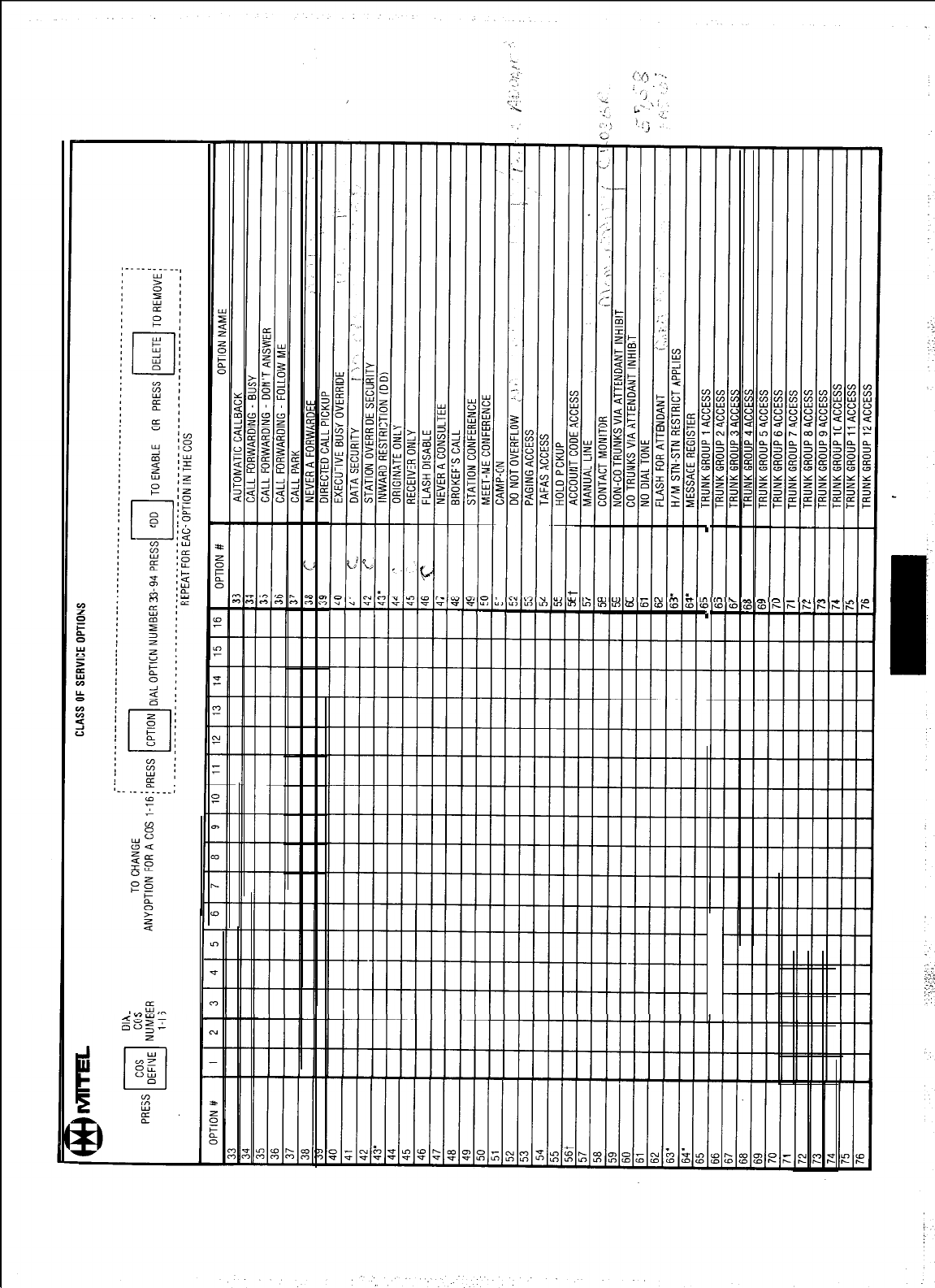
.
,
.
I
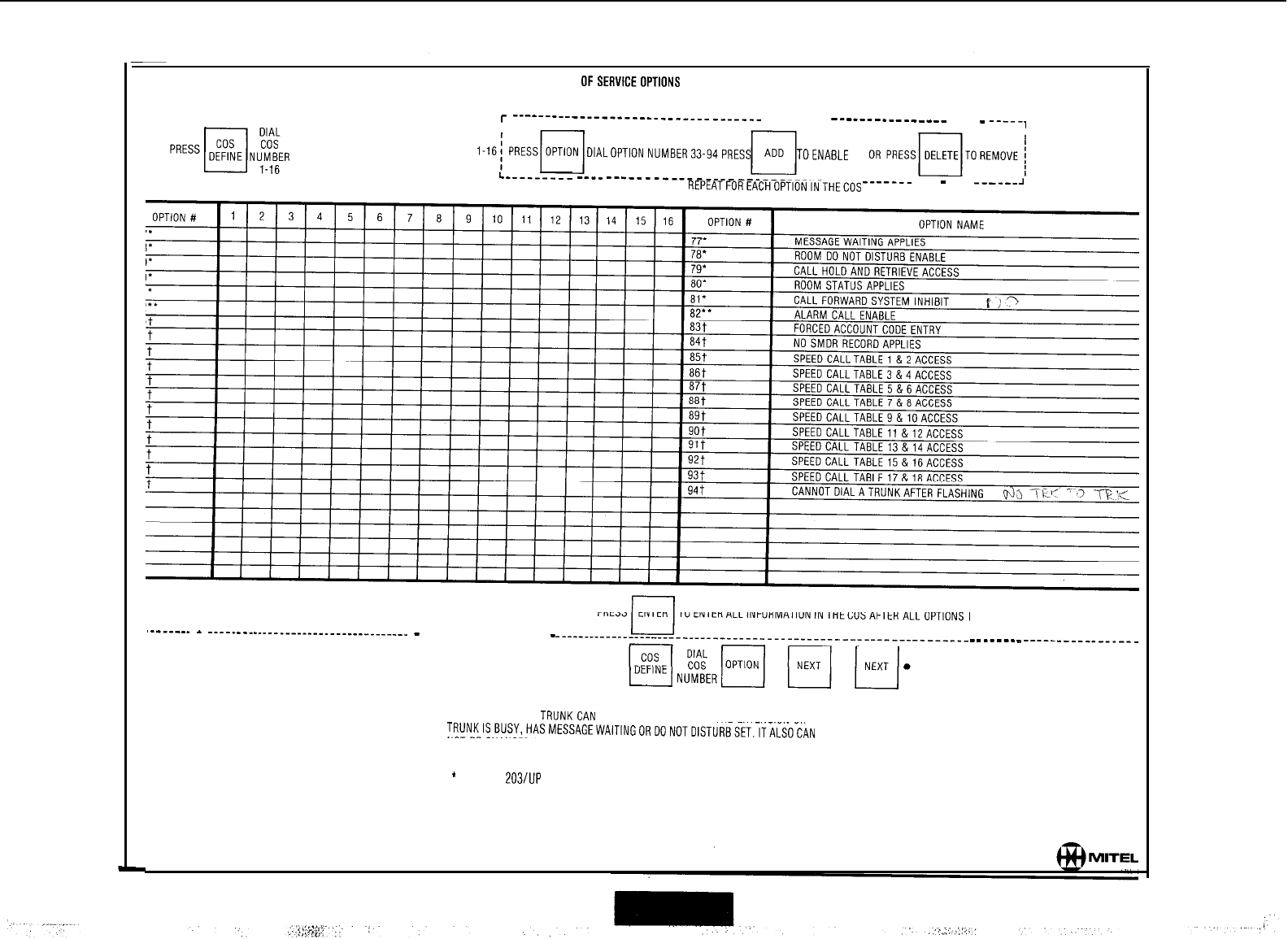
CLASS
OFSERVICEOPTIONS
r
__--_--___-____-___________________
----- -----
-___--__---_-_--
----
-
-----,
TO CHANGE
II
ANYOPTION FOR ACOS
DlALOPTlONNUMBER33-94PRESS TOENABLE
L---------
---_
-__---__---_-___--_-___________________
----
-
----
-----_~
REPEATFOREACHOPTIONINTHECOS
IN THAT COS HAVE BEEN DEFINED
._______
*
____________-_______________________ - ________________________
- -
_-----
-
_____________--__
TO REVIEW THE OPTIONS WITHIN A COS
NOTE: AN EXTENSION OR
TRUNKCAN
NOT CHANGE ITS COSIFTHE EXTENSION OR
TRUNKISBUSY,HASMESSAGEWAlTlNGORDONOTDlSTURBSET.ITALSOCAN
NOT BECHANGED UNLESSTHE MESSAGE REGISTER IS CLEARED.
*
GENERIC 203/UP
l
* GENERIC 204
t GENERIC 205
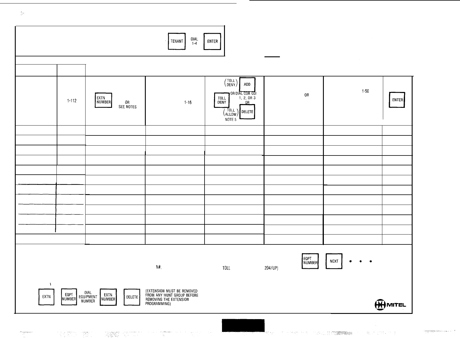
:.
APPLIES TO GENERIC 203 AN0 ABOVE
EXTENSIONS
IF TENANT SERVICE IS IN USE
ALL ENTRIES MADE ARE ASSIGNED TO THE TENANT NUMBER DIALED
I
1
TENANT
NUMBER
EQPT
cl
NUMBER
DIAL
NAME
l-112
OR
161-256
(SEE NOTE 1)
1
NOTES’
TD ENTER EXTENSION PROGRAMMING PRESS EXTN
L-l
DIAL
DIAL DE
CODE
cos
cl
DIAL
SEEONROTES
NUMBER
l-16
2, 3, OR 4
q
l-150
BUSY OR
LAMP
NUMBER
cl
DELETE
I I
DIAL
l-50
cl
OR
PICKUP
GROUP
q
DELETE
1.
EQUIPMENT NUMBERS 161-256 APPLIES TO SX-200 ONLY
2. TO ASSIGN NON CONFLICTING SINGLE DIGIT DIRECTORY NUMBER ENTER
N#.
WHEN N IS THE SINGLE DIGIT.
3. TO REMOVE EXTENSION PROGRAMMING
/
4. TO SEE THE NEXT EQPT NUMBER ASSIGNED AS AN EXTENSION:
5 COR 1-3 APPLIES ONLY, IF
TOLL
CONTROL (GENERIC
204/UP)
IS USED
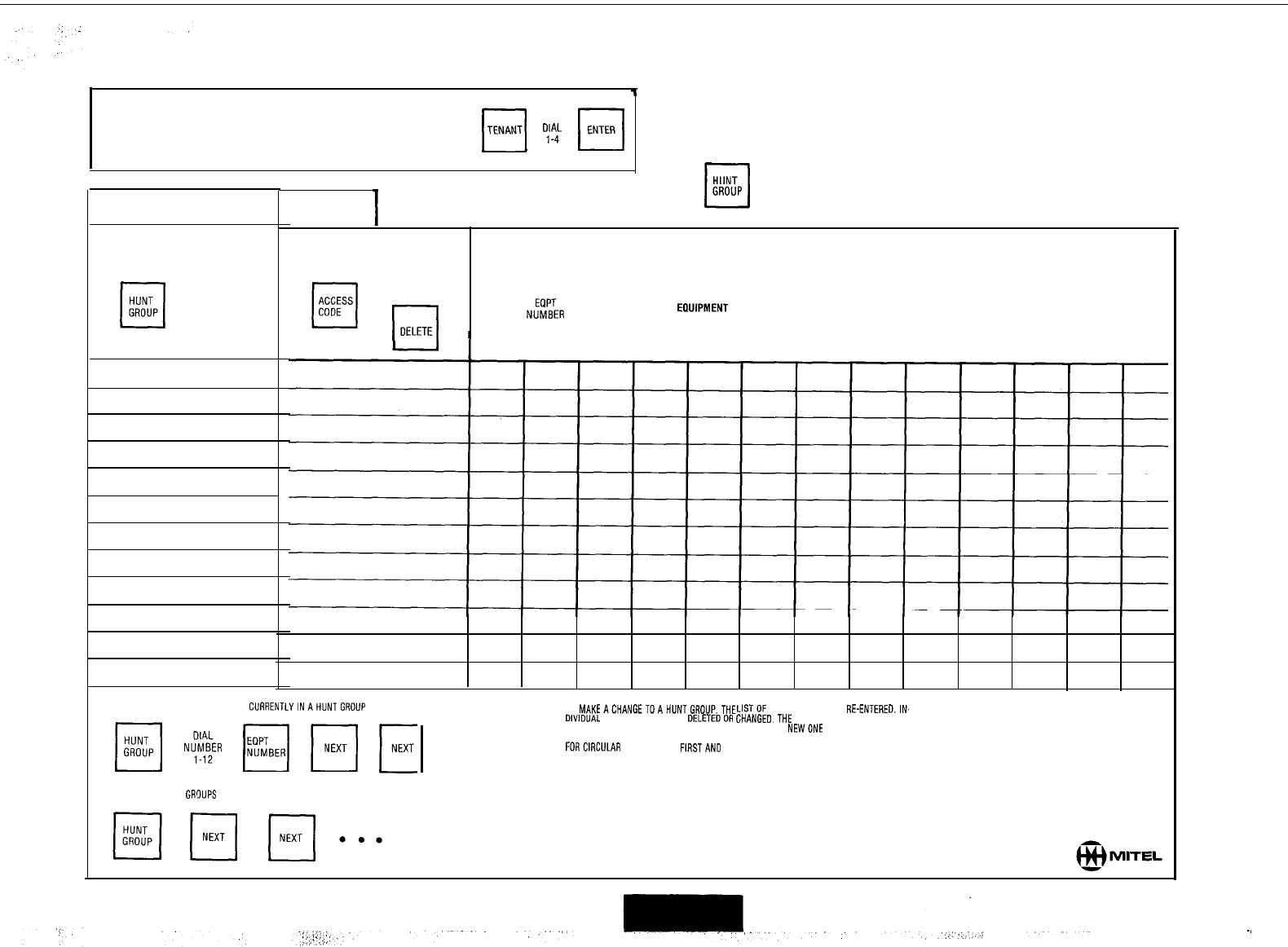
APPLIES TO GENERIC 203 AND ABOVE
’
HUNT GROUPS
IF TENANT SERVICE IS IN USE
ALL ENTRIES MADE ARE ASSIGNED TO THE TENANT NUMBER DIALED
H
4'f4'
r;;;;"]
I
TENANT
NUMBER
cl
HUNT
GROUP
DIAL
1-12
(EXTENSION INFORMATION MUST BE ENTERED BEFORE HUNT GROUP DATA)
DIAL
CODE
OR
l-l
DELETE
PRESS N,$f-ER BEFORE DIALING EACH ERUIPMENT NUMBER ENTRY
cl
AFTER LAST ENTRY IN EACH GROUP PRESS ENTER
q
TO SEETHEEOUIPMENTNUMBERS
ClJARENTLYINAHUNTGROLlP
m
N$ER
14
m
E
TO SE6 ALL HUNT GRDUPS
TO
MAKEACHANGETOAHUNTGROLlP,THE
LISTOF
MEMBERS MUST BE
RE-ENTEREDJN.
DIVIDUAL MEMBERS CANNOT BE DELETEDOR GHANGED.THE EXISTING GROUP LIST IS
I
AUTOMATICALLY DELETED WHEN YOU STARTTD ENTER A NEWONE
. . .
FORCIRCULAR HUNTGROUPS FIRSTAND LASTNUMBERS MUST BE IDENTICAL.
~.
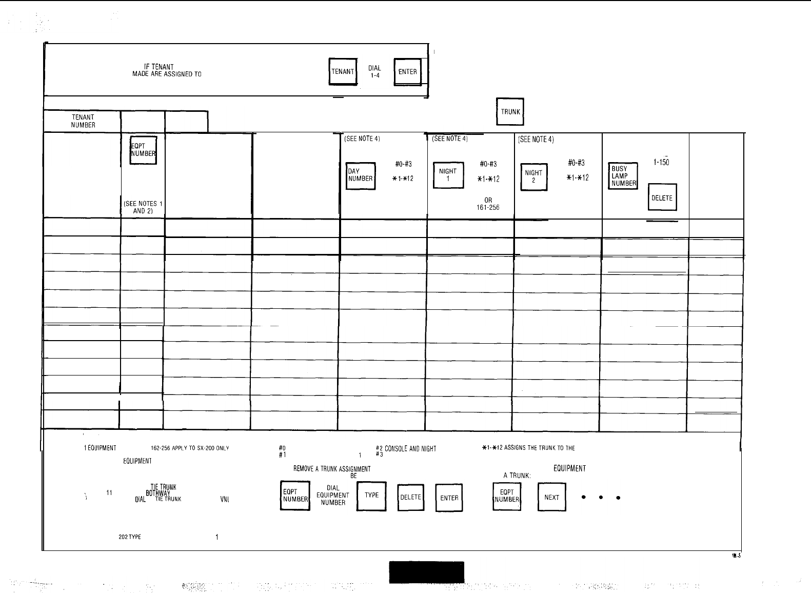
IFTENANT SERVICE IS IN USE
ALL ENTRIES
MADEAREASSIGNEDTO
THETENANT NUMBER DIALED
APPLIES TO GENERIC 203 AND ABOVE NON
DIAL-IN TRUNKS
LDN
DIAL
NUMBER
Z-112
OR
162-256
I
SEE NOTE 3
DIAL
cl
1, 5, 11.
51
TYPE OR
cl
DELETE
LDN
q
DIAL
NUMBER
1-4
1
EOUIPMENT
NUMBERS
162.256APPLYTOSX-ZOOONLY
2
ONLY EVEN
EOUIPMENT
NUMBERS MAY BE ASSIGNED
TO TRUNKS
3 TYPE 1 = STANDARDEOTHWAY COTRUNKVNL
TYPE 5 = NON DIAL IN
TIETRUNK
(NON CO)VNL
‘)
TYPE
11
= STANDARD
BOTHWAY
CO TRUNK NON VNL
TYPE 51 = NON
DIAL
IN
TIETRUNK
(NON CO)NON
VN,
(SEENOTE4)
DIAL
#O-x3
OR
x1-*12
OR
I-112
OR
161-256
TO ENTERTRUNK PROGRAMMING PRESS
III
TRUNK
(SEENDTE4)
El
#O-#3
NIGHT OR
1
*i-*12
OR
l-112
16pp256
[SEENOTE4)
DIAL
#O-#3
OR
*i-*12
OR
l-112
OR
161 256
cl
l-15a
BUSY OR
LAMP
NUMBER
NOTES:
4
#II
CONSOLEONLY
#2
CONSOLEANDNIGHT
BELL 2
#i
-CONSOLE AND NIGHT BELL 1
!43
CONSOLE AND NIGHT BELL 3
5 TO
REMOVEATRUNKASSIGNMENT
(NOTE. TRUNK MUST FIRST
BE
REMOVEDFROM TRUNK GROUP]
Xl-Xl2ASSlGNSTHETRUNKTOTHE
HUNTGROUPSELECTED
1-112, 161-256
ASSIGNS THE TRUNK TO THE SPECIFIED EXTENSION
6. TO SEETHE NEXT EDUIPMENT NUMBER PROGRAMMED
AS ATRUNK:
q
ENTER
GENERIC 202TYPE CODE DISPLAY DEFAULTS TO
1
WHEN TRUNK IS DELETED
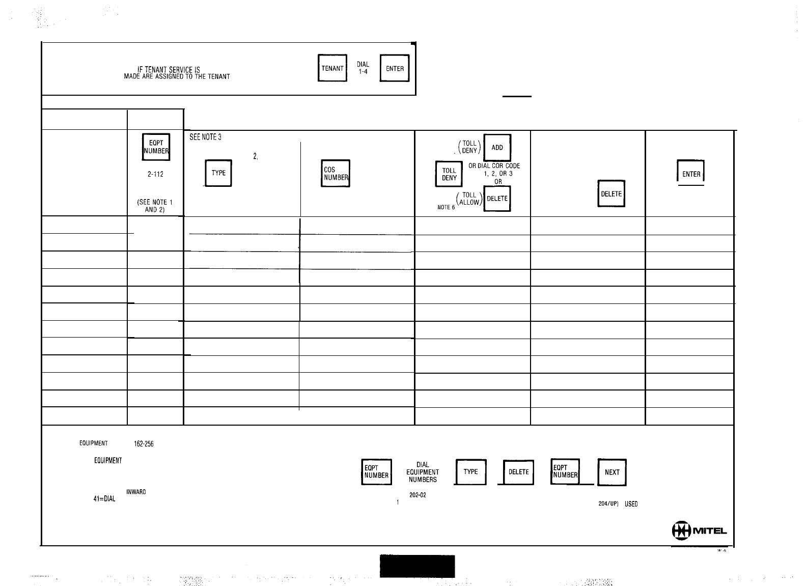
APPLIES TO GENERIC 203 AN0 ABOVE
4
DIAL-IN TRUNKS
IFTENANTSERVICEIS IN USE
ALL ENTRIES
MADEAREASSIGNEOTDTHETENANT
NUMBER DIALED
I
1
TENANT
NUMBER
LDN
NUMBER
DIAL
Z-112
OR
162-256
1
TO ENTERTRUNK PROGRAMMING PRESS TRUNK
L-l
SEENOTE
I
DIAL
2,
4, 21,
OR 41
OR
cl
DELETE
cos
cl
DIAL
NUMBER
l-16
NOTES:
1.
EOUIPMENT
NUMBERS
162-256
APPLIES TO SX-200 ONLY 4 TO REMOVE A TRUNK ASSIGNMENT:
NOTE TRUNK MUST FIRST GE REMOVE0 FROM TRUNK GROUP
i-150
BUSY
q
OR
LAMP
NUMBER
r-l
ENTER
2. EVEN EOUIPMENT NUMBERS ONLY MAY GE ASSIGNED TO TRUNKS
TYPE
2 = DIRECT INWARD SYSTEM ACCESS VNL
TYPE 4 = DIAL IN TIE TRUNK (NON CO) VNL
TYPE 21 = DIRECT
INWARO
SYSTEM ACCESS NON VNL
TYPE
41
=
DIAL
IN TIE TRUNK (NON CO) NON VNL
EQPT
cl
NUMBER
E;dk&;T
[=I
I[
bi
Fi
. . .
GENERIC 202-02 TYPE CODE DISPLAY DEFAULTS
TO
1
WHEN TRUNK IS DELETED. 6. COR l-3 APPLIES ONLY, IF TOLL CONTROL
(GENERIC
204/UP)
IS
USED
5. TO SEE THE NEXT EOPT NUMBER ASSIGNED AS A TRUNK
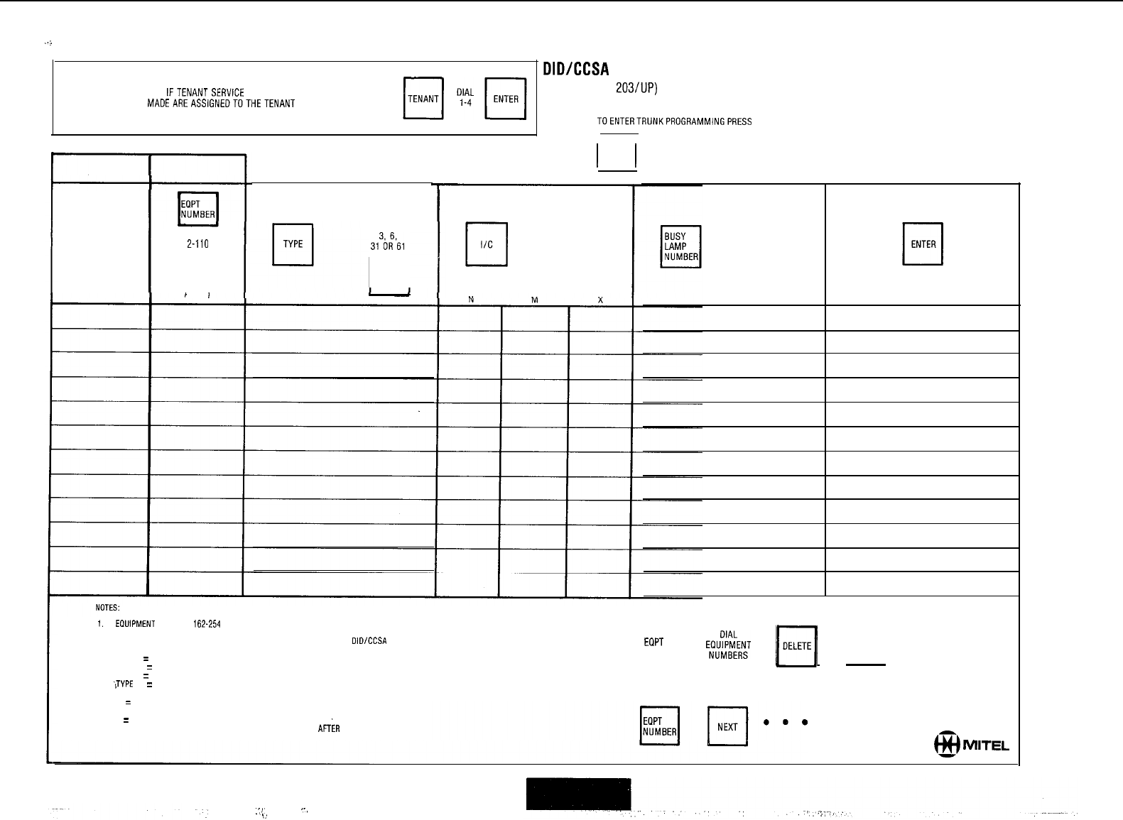
..;
APPLIESTO GENERIC 203ANDABOVE
DIDICCSA
TRUNKS
IFTENANTSERVICE IS IN USE
(GENERIC 203/UP)
ALL ENTRIES
MADEAREASSIGNEDTOTHETENANT
NUMBER DIALED
TOENTERTRUNKPROGRAMMINGPRESS
I I
TENANT
NUMBER
LDN
NUMBER
DIAL
Z-110
OR
162-254
(SEE NOTES 1
AND 2)
SEE NOTE3
DIAL
3136i?61
rl
DELETE
1.
EOUIPMENT
NUMBERS
162-254
APPLY TO SX-200 ONLY
2. ALTERNATE EVEN NUMBERS ONLY MAY BE ASSIGNED TO
OlDlCCSA
TRUNKS
3.
TYPE 3
=
DID VNL
TYPE 31
=
DID NON VNL
TYPE 6
=
CCSA VNL
‘JYPE
61
=
CCSA NON VNL
4.
N
=
NUMBER OF DIGITS TO BE RECEIVED AFTER TRUNK IS SEIZED (l-9)
M = NUMBER OF DIGITS TO BE ABSORBED AFTER TRUNK IS SEIZED (O-B)
X
=
LEADING DIGIT TO BE INSERTED, IF REWIRED.
MAXIMUM NUMBER OF DIGITS IS 4 (3 IF TENANT SERVICE)
AFiR
ABSORPTION (M)
AND ADDING A DIGIT (X).
I
I
TRUNK
17
DIAL
I/C
NMX CODE
(NOTE 4)
DIAL
l-150
OR
cl
DELETE
5. TO REMOVE A TRUNK ASSIGNMENT.
(TRUNK MUST FIRST BE REMOVED FROM TRUNK GROUP)
q
EQPT
NUMBER
ElU$k;T
m
m
6.
TO SEE
THE NEXT EOPT NUMBER ASSIGNED AS A TRUNK
@4
MITEL
.‘,‘.
‘-,
5;
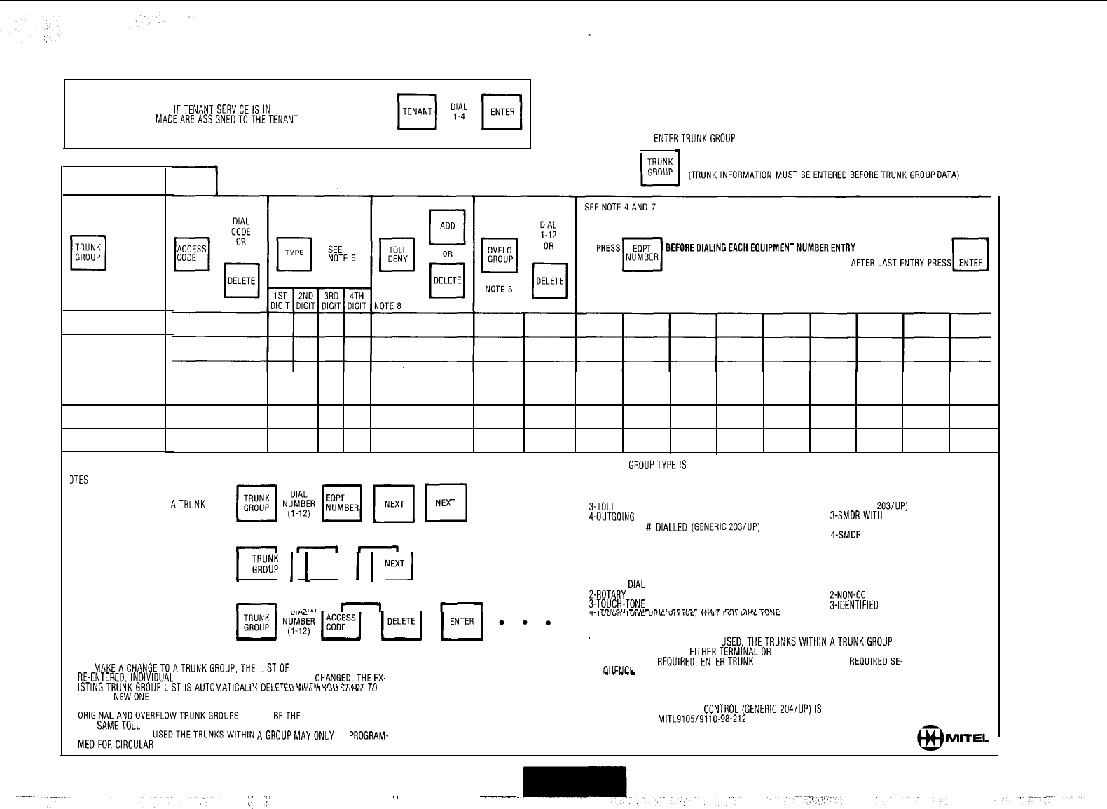
APPLIES TO GENERIC 203ANOABOVE
TRUNK GROUPS
IFTENANT SERVICEISIN USE
ALL ENTRIES
MADEAREASSIGNEOTOTHETENANT
NUMBER DIALED
TO
ENTERTRUNKGROUP
PROGRAMMING PRESS
.
TENANT
NUMBER
TRUNK
cl
DIAL
GROUP
l-12
BEFOREDlALlNGEACHEOUlPMENTNUMBERENTRY
6. TRUNK GROUPTYPEIS 4 DIGITS
3TES
1st DIGIT 2nd DIGIT
~INER[~
F[
Fi
. . l
l-NO SUPERVISION I-NO MESSAGE REGISTER
Z-ANSWER SUPERVISION Z-MESSAGE REGISTER
TO SEETHE TRUNKS IN
ATRUNK
GROUP: 3-TOLL REVERSAL (GENERIC 203/UP)
4-OUTGOING AUDIO INHIBITED UNTIL ANSWER SUPERVISION 3-SMDRWITH MESSAGE REGISTER
TIMEOUT OR # DIALLED (GENERIC203/UP)
(GENERIC 205)
4-SMDR WITHOUT MESSAGE REGISTER
nnn
(GENERIC 205)
TO SEEALLTRUNKGROUPS
1
'G",","u;
1
1
NEXT
1
1
NExTJ
l . l
I
nlAI
n
n
I
3rd DIGIT
I-ROTARY
DIAL
OFFICE, NO WAIT FOR DIAL TONE
2-ROTARY DIAL OFFICE, WAIT FOR DIAL TONE
3-TOUCH-TONE DIAL OFFICE, NO WAIT FOR DIAL TONE
,
T",,,.II
--..-
^,.,
AvrlAr
,.,",1
7""
nl",
Tr%.lr
4th DIGIT
I-CENTRAL OFFICE
2-NON-CO
3-IDENTIFIED
TRUNK GROUP (NON-CO)
TO DELETETRUNKGROUP: 7. IFGENERIC 2030R HIGHER IS
USED.THETRUNKSWlTHlNATRUNKGROUP
MAY
BE PROGRAMMED FOR EITHERTERMINALOR CIRCULAR HUNTING, IFTERMINAL
TO
MAKEACHANGETOATRUNKGROUP,THE
LISTOF MEMBERS MUST BE HUNTING IS REQUIRED,ENTERTRUNK EQUIPMENT NUMBERSIN REQUIREDSE-
OIIFNCF
RE-ENTEREDJNDIVIDUAL MEMBERS CANNOT BE DELETED OR CHANGED.THE
EX-
_
_
_
_
_
ISTINGTRUNKGROUP
LISTISAUTOMATICALL,
YLLLILV
VV~CIY
IUV
.,,nno
IV
\I
nca
CTC"
I",ur~I
wn,,
CT&"7 Tn IF CIRCULAR HUNTING IS REQUIRED MAKELASTTRUNK EQUIPMENT NUMBER
ENTER A
NEWONE
THESAMEASTHE FIRSTTRUNK EQUIPMENT NUMBER.
ORIGINALANDOVERFLOWTRUNKGROUPS
MUST BETHE SAMETYPEAND HAVE
THE
SAMETOLL
RESTRICTION CHARACTERISTICS.
IF GENERIC 202 IS
USEDTHETRUNKSWITHIN
AGROUP
MAYONLY
BE PROGRAM-
MEDFORCIRCULAR
HUNTING.
8. DOES NOT APPLY IF TOLL CONTROL(GENERIC 204/UP)IS USED
SEE SECTION MITL9105/9110-98-212 OR TOLL CONTROL FORMSTHIS SECTION.
MlTEb
;.i
::;i
., ----

.-
:
_’
MULTI DIGIT TOLL CONTROL FORMS
GENERICS 2041205
.-
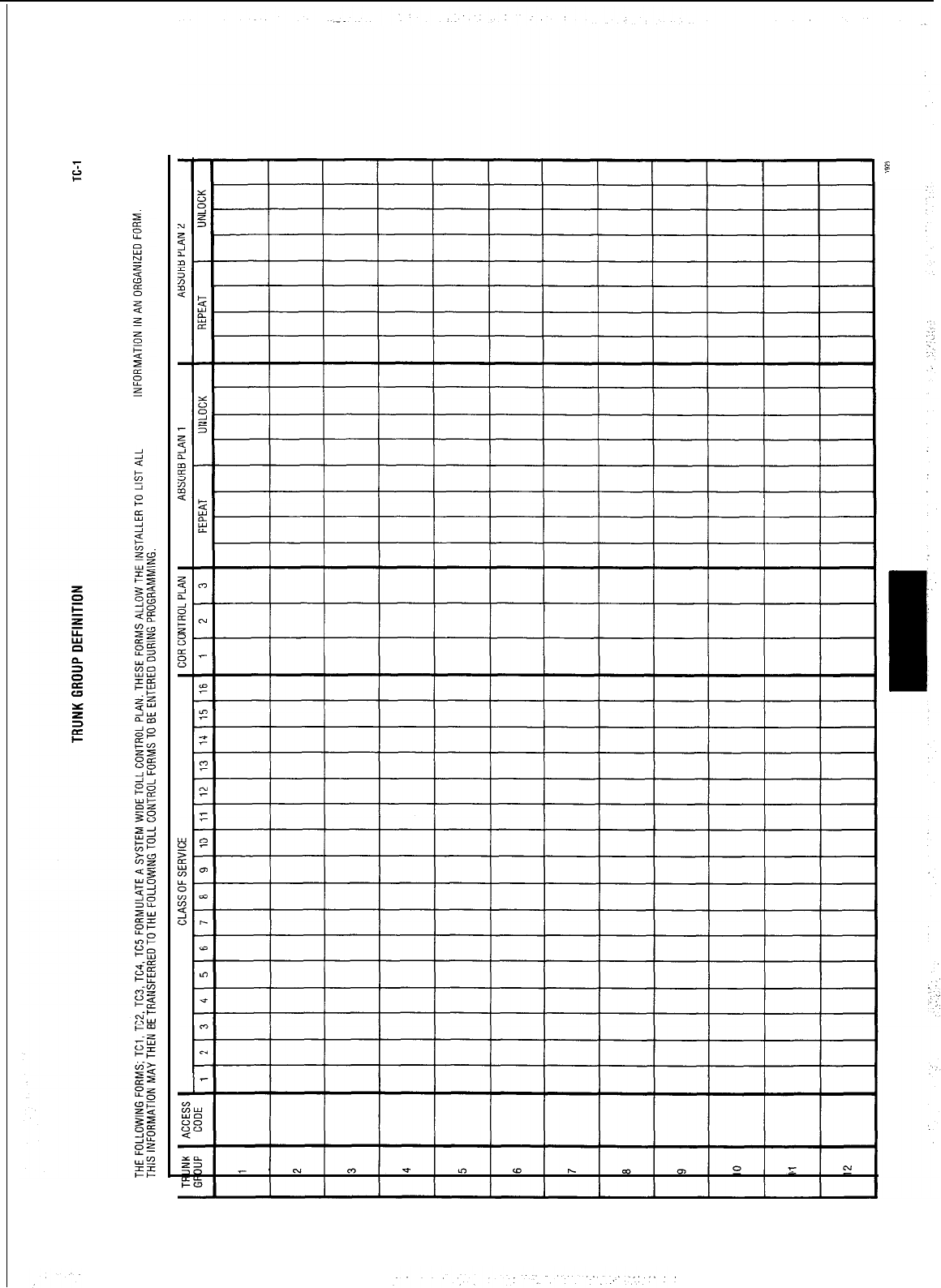
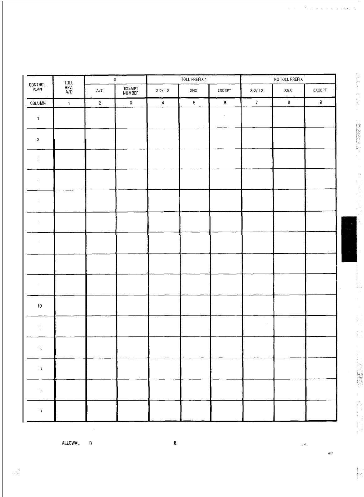
TOLL CONTROL- CONTROL PLAN DEFINITION
TC-2
3
4
5
6
7
8
9
10
11
12
13
14
15
ENTER A FOR BASIC
ALLOWAL
AND
D
FOR BASIC DENIAL IN COLUMNS 2.4. 5. 7 AND
8.
,-
ENTER A CONSECUTIVE NUMBER FOR EACH SET OF EXCEPTIONS IN COLUMNS 3.0 AND 9 IF APPLICABLE.

TOLL CONTROL
-
EXCEPTION LIST STRUCTURE
1. WRITE ALL NUMBERSOFTHE EXCEPTION LIST IN COLUMN 1.
2. WRITE ALL NUMBERS IN NUMERICAL ORDER OF THE FIRST THREE DIGITS (I.E. 613, 614,
615)IN
COLUMN 2.
3. WRITE ALL NUMBERS IN NUMERICAL ORDER
OFTHE
SECONDTHREE DIGITS (I.E. 592. 593, 594)IN COLUMN 3.
4. WRITE ALL NUMBERS IN NUMERICAL ORDER
OFTHE
NEXT FOUR DIGITS (I.E. 4000, 4001,
4002)IN
COLUMN 4
1
EXCEPTION LIST CONTROLPLAN BASIC CONDITION
SHEET
COLUMN4
TOLL CONTROL -TABLE ALLOCATION
TC-4
1.
COMPLETE ALL REQUlREDTC3 FORMS. ALL NUMBER GROUPS OF COLUMN 2 REPRESENT ONETABLE. ALL NUMBER GROUPS
OFTABLE3AND
4 REPRESENT
ONETABLE(IFTHEY
HAVE THE SAME PREVIOUS NUMBER GROUP IN COLUMN 2).
2.
IDENTIFY NUMBER GROUPS WITH
MORETHAN
3 DIGITSANDASSIGN
A4-ENTRY
TABLE FOR EACH SUCH GROUP.
3.
IDENTIFYREMAINING NUMBER GROUPS WHICH HAVE A FIRST DIGIT
OORl.
ALLOCATEA4-ENTRYTABLEIFTHE
NUMBER OF
DIGITS DOES NOT EXCEED 4
OTHERWISEALLOCATEA
20 RANGE TABLE.
4.
ASSIGN ALL NUMBERS WHICH REQUIRE BOO ENTRYTABLES. ENSURETHAT ALL THE LOWERTABLES (4 ENTRY, 20 RANGE)
HAVE BEEN FILLED.
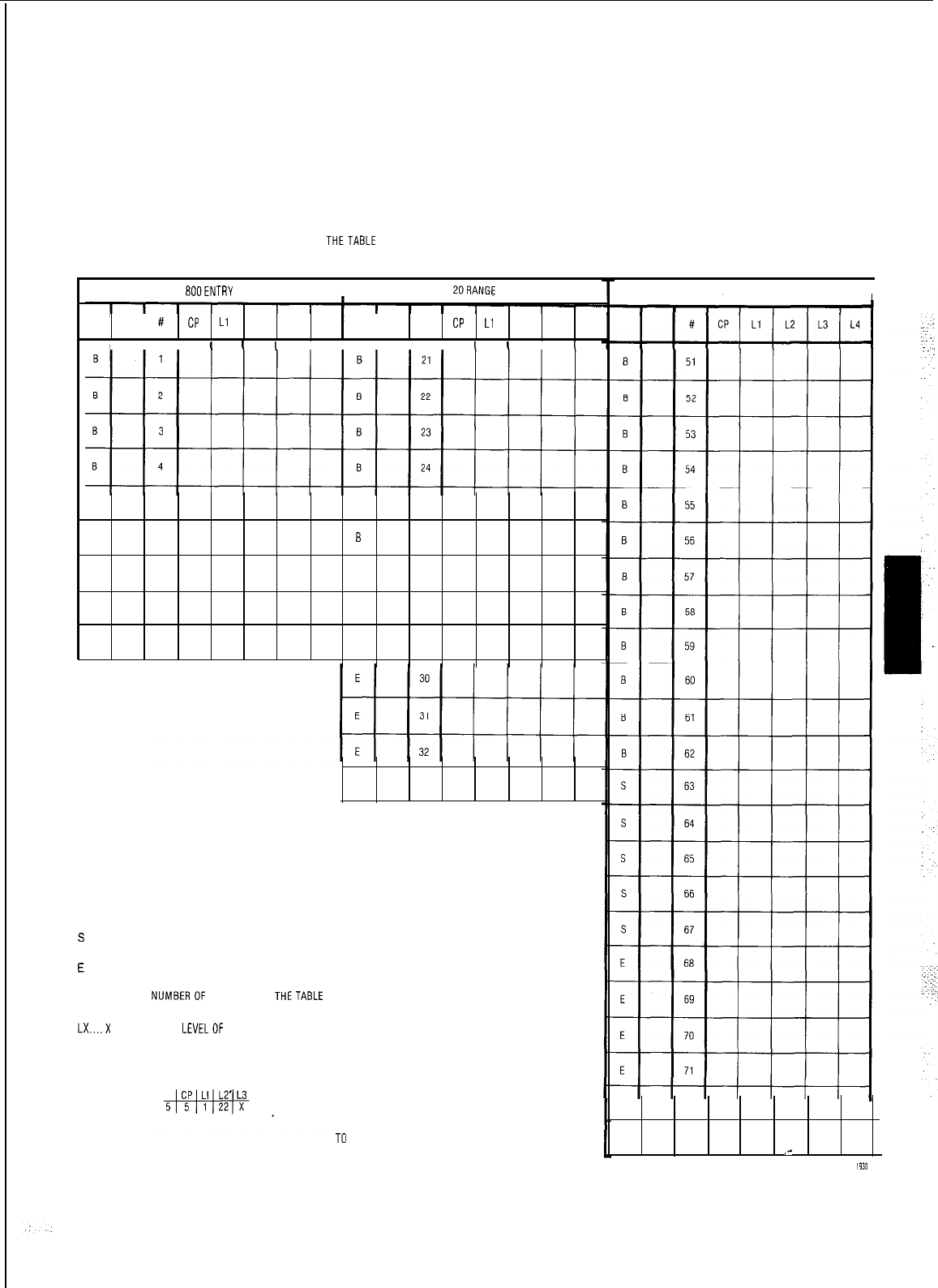
TABLE ASSIGNMENTS
TC-5
TOLL CONTROL
THIS FORM IS INTENDEDTO PROVIDE AN OVERVIEWOF THETABLE STRUCTURE USED FOR A PARTICULAR SYSTEM INSTALLATION.
BOOENTRY
I
ZORANGE
#
CP
Ll
L2 L3 L4
I
#CP
Ll
L2 L3 L4
I I
II I I
I
I
I
I
I I
I
I
S 5 B
25
S 6 B26
S 7 B
27
E a S 28
E 9 S 29
E
33
B
Basic
s
Standard
E
Extended
CP....TO ENTER NIJMBEROF CONTROL PLAN THETABLE IS USED IN
LX....X
IS NUMBERDF LEVELOF EXCEPTION TABLE; ENTER TABLE NUMBERS OF
PREVIOUS EXCEPTION TABLES AND MARK AN 'X'WHEREVER THE PARTICULAR
TABLE IS USED.
I.E.
TABLE 5 IS USED IN CONTROL PLAN 5 AS AN EXCEPTION TO TABLE 22. WHICH IS AN
EXCEPTION TO TABLE 1.
4ENTRY
I
E72
E73 ,-
lSlD
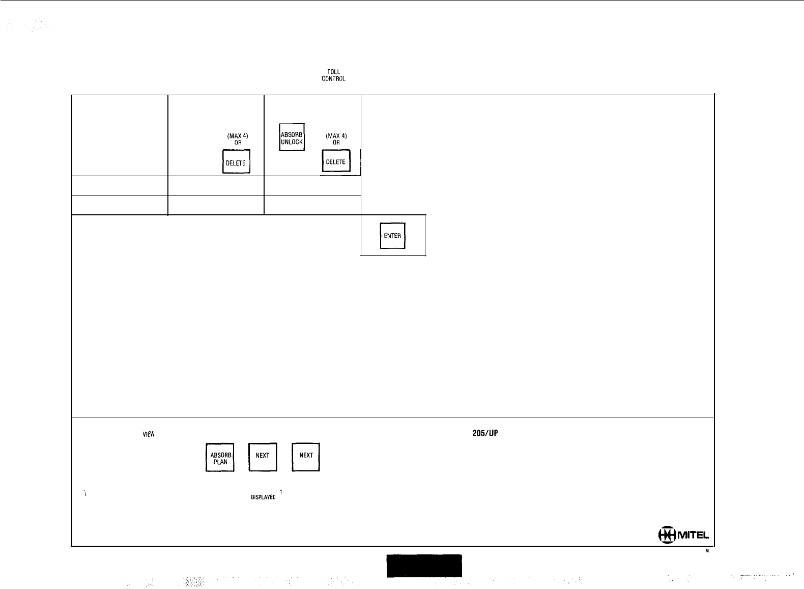
q
coiko~
ABSORB PLAN
DIAL DIAL
UNLOCK
ABSORB
cl
DIAL ABSORB
PLAN 1 OR 2
cl
REPEAT
DIGITS DIGITS
REPEAT
‘M;;
4)
‘M;;
4)
ABSORB PLAN NUMBER 1
ABSORB PLAN NUMBER 2
TO
WE’,,
THE ABSORB PLANS’
GENERIC
205/lJP
PLAN NUMBER 1PLAN NUMBER 2
OISPLAYEO DISPLAYED
MITEL
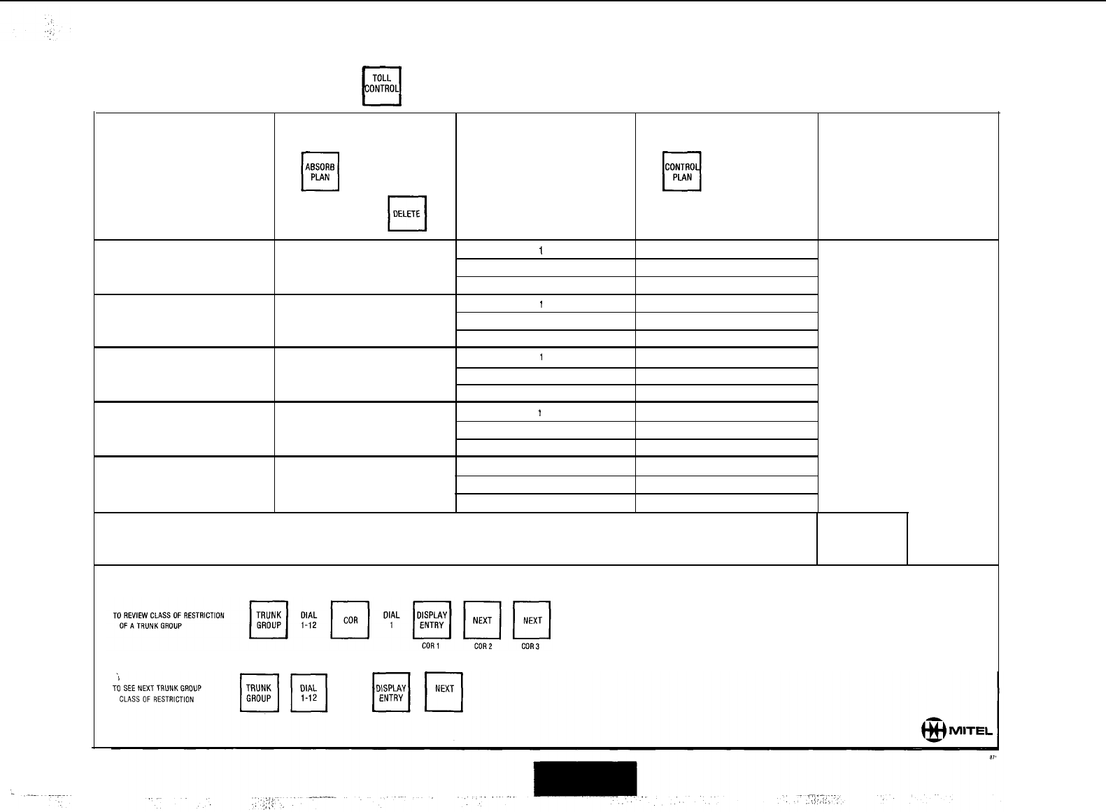
CLASS OF RESTRICTION
(TRUNKGROUP)
TRUNK
cl
DIAL DIAL DIAL DIAL
GROUP
1-12 1-2
q
COR
1-3 1-15
OR OR
cl
DELETE
1
2
3
1
2
3
1
2
3
1
2
3
1
2
3
q
ENTER
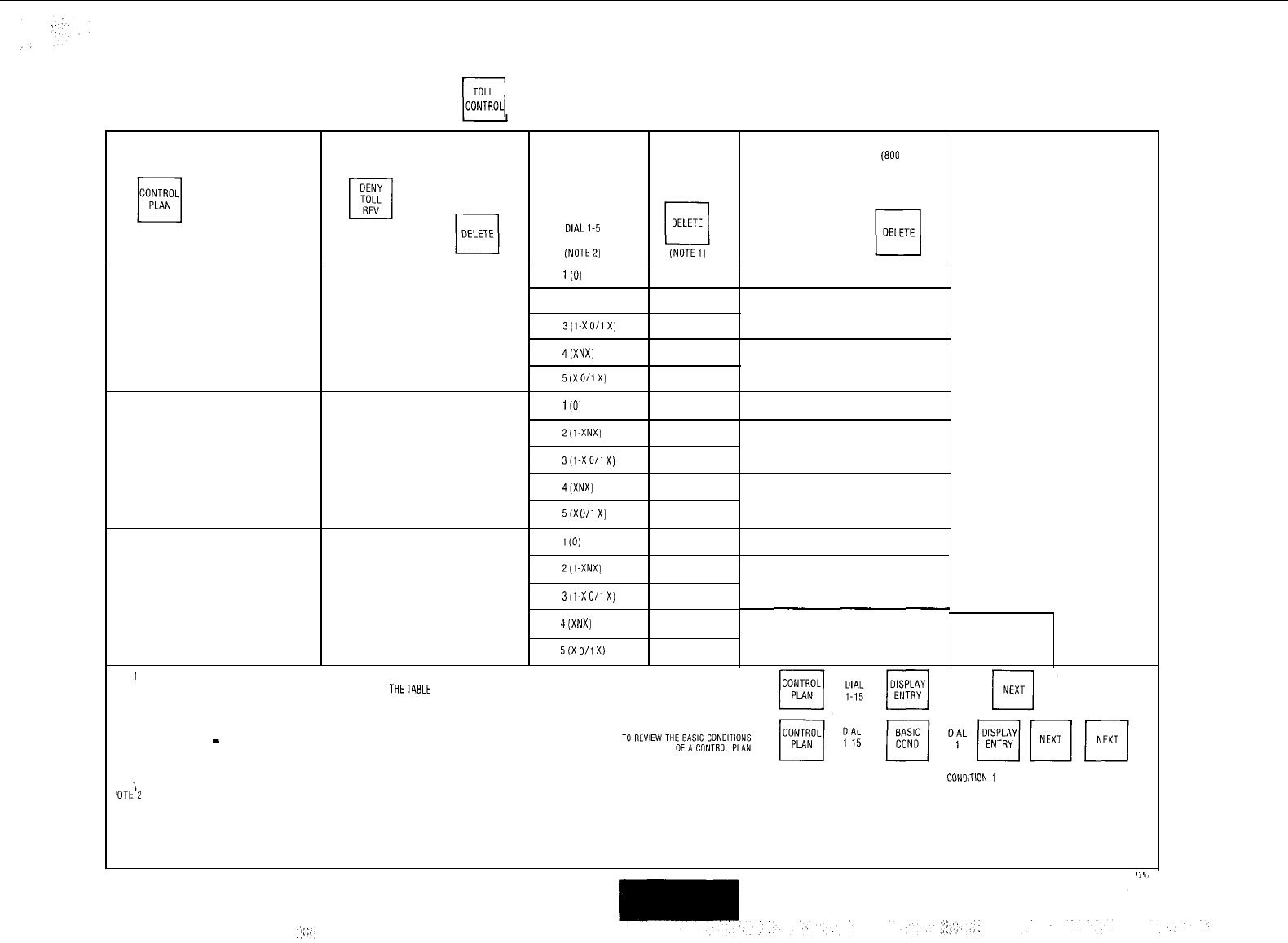
I\
CONTROL PLAN
ICONTROL]
q
q
DIAL
ADD ADD 1-9
(800
ENTRY)
21-33 (20 RANGE)
51-73 (4 ENTRY)
DIAL BASIC
OR
l-15
OR
q
COND
cl
TABLE OR
DIALl-5
(NOTEZ) (NOTEl)
1
(0)
2 (I-XNX)
3(1-X0/1X)
4(XNX)
5(X0/1X)
l(O)
2(1-XNX)
3(1-X0/1
X)
4(XNX)
5(X 0/1X)
l(O)
Z(l-XNX)
3(1-X0/1X)
4(XNX)
q
ENTER
5(X
O/l
X)
OTE
1
q
ADD -ALLOW ALL COOES EXCEPTTHOSE LISTED IN
THETABLE
SPECIFIED TO REVIEW CONTROL PLAN ASSIGNMENTS
q
DELETE
-
OENYALLCODES EXCEPTTHOSE LISTED IN THE TABLE SPECIFIED
DISPLAY DISPLAY DISPLAY
BASIC CONDlTlON
1
BASIC CONDITION 2 BASIC CONDITION 3
'OT;'2
N IS ANY NUMBER 2-9
XIS ANY NUMBER O-9
;,:i:..
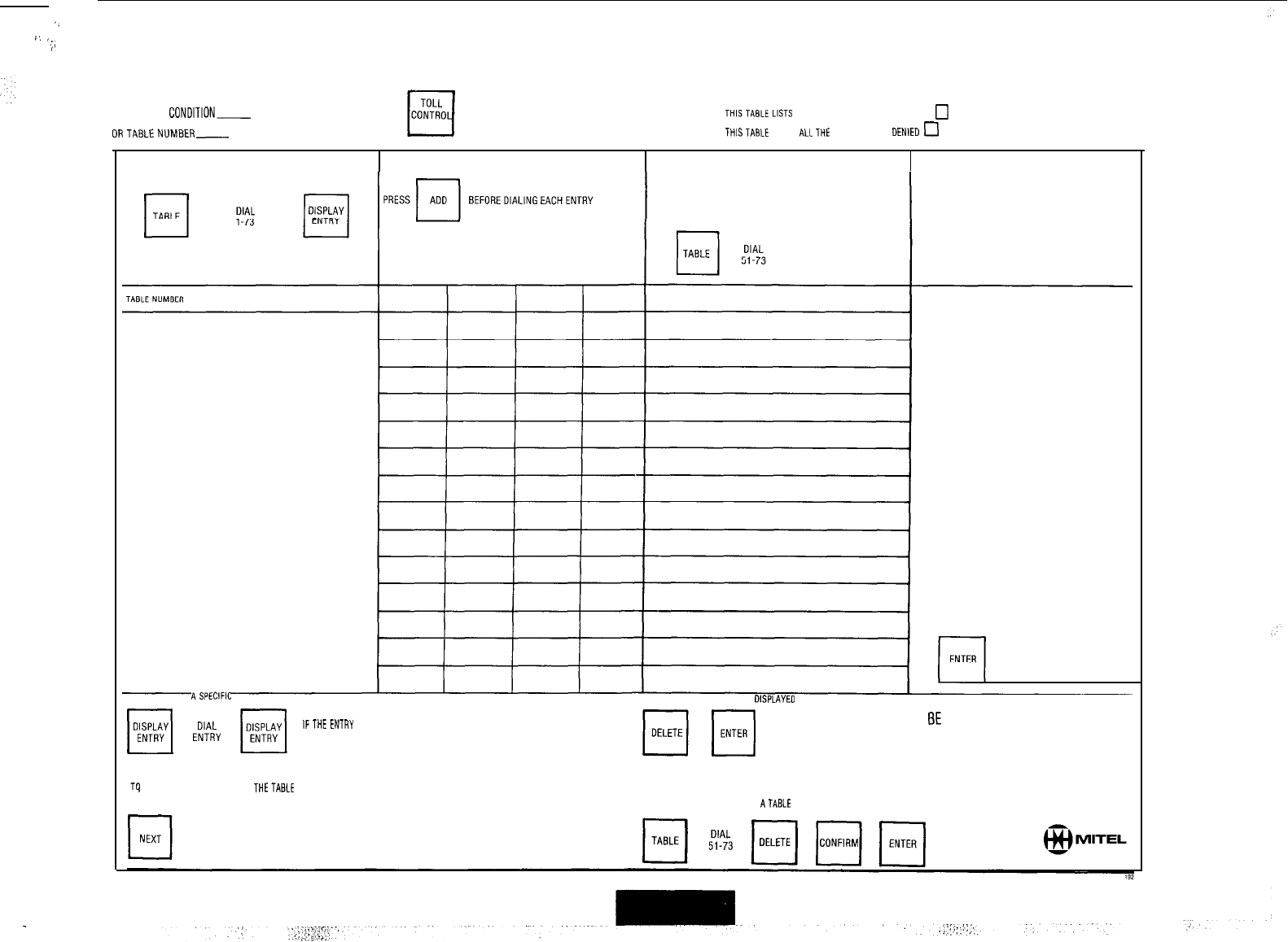
‘_
a.
‘...
/
4 ENTRY EXCEPTION TABLE
.
FROM BASIC
CONDITION-
THlSTABtELlSTS
ALLTHECODES THATAREALLOWED
,,
DRTABLENUMBER-
CONTROL PLAN __
THISTABLE LISTS
ALLTHE
CODESTHAT ARE DENlED
0
IF AN EXCEPTION TABLE IS TO BE APPLIEDTO THIS ENTRY
TO SEARCH FOR ASPECIFIC ENTRY TO DELETETHE ENTRY BEING OKSPLAYED
H
E;;;y
ARE SHOWN IN THE ENTRY DISPLAY
m
IFTHEENTRY
DOES NOT EXIST DASHES
NOTE: ANY OPERATION MAY
BE
PERFORMED IN ANY ORDER.
Tq DISPLAYTHE NEXT ENTRY IN
THETABLE
AFTER AN ENTRY HAS BEEN SELECTED
TO DELETE ALL ENTRIES
FROM
ATABLE
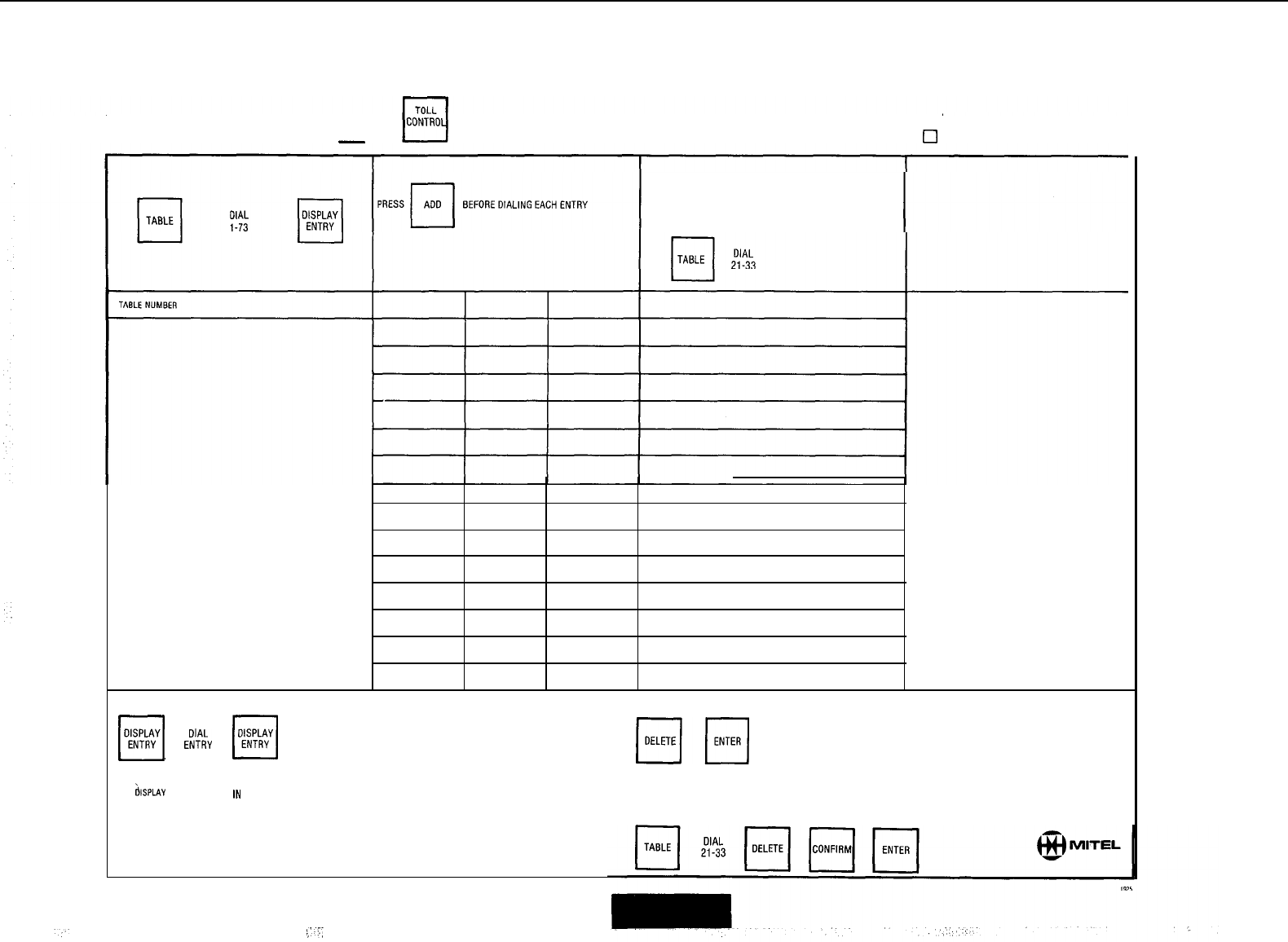
20 RANGE EXCEPTION TABLE
FROM BASIC CONDITION-
THIS TABLE LISTS ALL THE CODES THAT ARE ALLOWED
q
OR TABLE NUMBER- CONTROL PLAN
-
THIS TABLE LISTS ALL THE CODES THAT ARE DENIED
0
IF AN EXCEPTION TABLE IS TO BE APPLIED TO THIS ENTRY
q
ENTER
TO SEARCH FOR A SPECIFIC ENTRY TO DELETE THE ENTRY BEING DISPLAYED
H
E;;;y
ARE SHOWN IN THE ENTRY DISPLAY.
[q
IF THE ENTRY DOES NOT EXIST DASHES
NOTE: ANYOPERATION MAY BE PERFORMED IN ANYOROER.
TO
&SPLAY
THE NEXT ENTRY IN THE TABLE
AFTER AN ENTRY HAS BEEN SELECTED
cl
NEXT
TO DELETE ALL ENTRIES FROM A TABLE
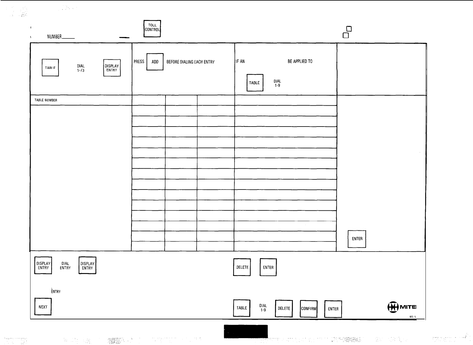
800 ENTRY EXCEPTION TABLE
FROM BASIC CONDITION- THIS TABLE LISTS ALL THE CODES THAT ARE ALLOWED
0
OR TABLE
NUMBER-
CONTROL PLAN
-
THIS TABLE LISTS ALL THE CODES THAT ARE DENIED
IFAN EXCEPTION TABLE IS TO BEAPPLIEDTO THIS ENTRY
TO SEARCH FOR A SPECIFIC ENTRY TO DELETE THE ENTRY BEING DISPLAYED
IF THE ENTRY DOES NOT EXIST DASHES
NOTE: ANYOPERATION MAY BE PERFORMED IN ANYORDER.
ARE SHOWN IN THE ENTRY DISPLAY.
TO DISPLAY THE NEXT ENTRY IN THE TABLE
AFTER AN
INTRY
HAS BEEN SELECTED
TO DELETE ALL ENTRIES FROM A TABLE

SPEED CALL FORMS
GENERIC 205
I’
.:.
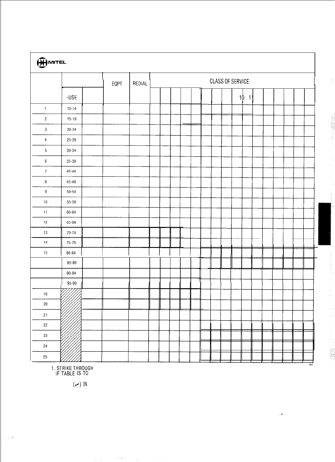
MITEL
SPEED CALL TABLE ALLOCATIONS FORM SC-I
ENTRY ACCESS
1
TABLE
NUMBERS
EQPT REDIAL
NUMBER
_
COMMON
NUMBER
-USE
PERSONAL
1
2 3 4 5
CLASSOFSERVICE
16 85-89
17 90-94
18 95-99
NOTES: I.STRIKETHROUGH NUMBERSIN COMMON-USECOLUMN,
IFTABLE ISTO BE A PERSONALTABLE;THEN ENTER
NEWENTRYACCESS NUMBERSIN PERSONALCOLUMN.
2. CHECK
(r/)IN
REMAINING COLUMNS AS REQUIREDIN
RESPECTTO EACH TABLE.
6 7 8 9
IO
11
12 13 14 15 16
_-
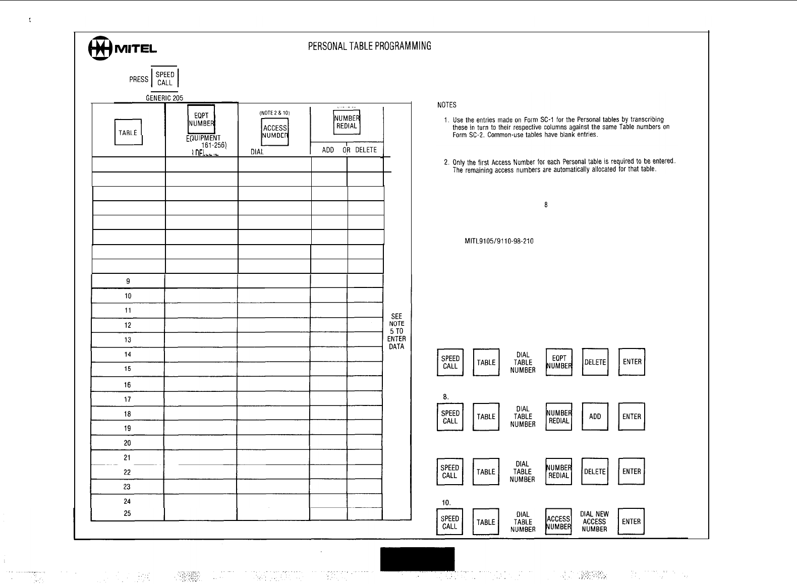
:
6,
MITEL
PERSONALTABLEPROGRAMMING
FORMSC-2
(SYSTEM MUST BE IN EXTENDED PROGRAMMING)
DIAL
Er
(l-11
DIAL TABLE NO.
OF.
I___.
_OIAL
ACCESS NO
1
1
IUIPMENT
NO.
2;
161.256).
1
nFI
FTF
7
3
4
7
a
3. The Saved Number Redial operation is initially omitted if not required. For sub-
sequent programming see Notes
8
and 9.
4. Personal table data is programmed in Extended Programming Mode. See Sec-
tion
MITL9105/9110-98-210
Appendix 2 for full details.
5. The ENTER button may be pressed at any time to enter data, or pressed when
all data is entered.
6. Removing a Personal table removes all its contents, Access Numbers and Redial
value (if any).
7. To remove a Personal table;
8.
To add a Redial attribute:
9. To remove a Redial attribute:
10.
To change a Speed Call Access Number:
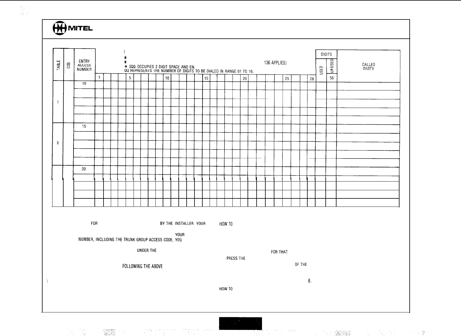
SPEED CALL NUMBER RECORDS FORM SC-3 (Sheet 1 of 4)
SPEED CALL FEATURE CODE
SPEEDCALL NUMBER
SPECIALSEQUENCES CAN BE ENTEREOATANY POINT IN THETELEPHONE NUMBER LISTING:
*
1 OCCUPIES 1 DIGIT SPACE AND CAUSES A 5 SEC. PAUSE IN USE
*
2 OCCUPIES 1 DIGIT SPACE AND CAUSES WAIT FOR DlALTONE(SYSTEM OPTION 136APPLIES)
ABLES MANUALLY DIALED DIGITS TO BE ENTERED.
3
LISTING YOUR NUMBERS INSTRUCTIONS FOR USER(ATTENDANT)
1.
TABLES AVAILABLE FOR USE ARE INDICATED ON THE FORM
BYTHE
INSTALLER.YOUR
FEATURE ACCESS CODE AND CLASSES OF SERVICE HAVE BEEN ALSO ENTERED.
HOWTO
ENTER OR CHANGE A NUMBER
2.
OPPOSITETHE FIRST AVAILABLE ENTRY ACCESS NUMBER, WRITE IN
YOUR
FIRST 5. DIAL FEATURE ACCESS CODE.
TELEPHONE
NUMBER,lNCLUDlNGTHETRUNKGROUPACCESSCODE.YOU
CAN USE 6. DIAL 0.
SPECIAL SEQUENCES (SEE ABOVE). 7. DIAL ENTRY ACCESS NUMBER REQUIRED.
3.
WRITE IN THE NEXT ENTRY ACCESS NUMBER,
UNDERTHE
FIRST ENTRY NUMBER, US-
ING A FRESH LINE AND CONTINUING WITH THE NEXTTELEPHONE NUMBER OPPOSITE 8. DIALTELEPHONE NUMBER
FORTHAT
ENTRY NUMBER.
THISSECOND ENTRY NUMBER. 9.
PRESSTHE
RELEASE BUTTON.
4. COMPLETE YOUR LIST OF NUMBERS
FOLLOWINGTHEABOVE
PROCEDURE. IO. REPEATTHE ABOVE SEQUENCE FOR EACH
OFTHE
REMAINING ENTRIES ON THE LIST.
HOWTD DELETE A NUMBER
,h
11. PERFORM STEPS 5 THROUGH 9 BUT OMIT STEP
8.
HOWTO
DIAL A SPEED CALL NUMBER
12. DIAL FEATURE ACCESS CODE.
SEE CONSOLEOPERATING INSTRUCTIONS FOR OTHER DETAILS 13 DIAL ENTRY ACCESS NUMBER.
14. CALL PROCEEDSIN USUAL MANNER
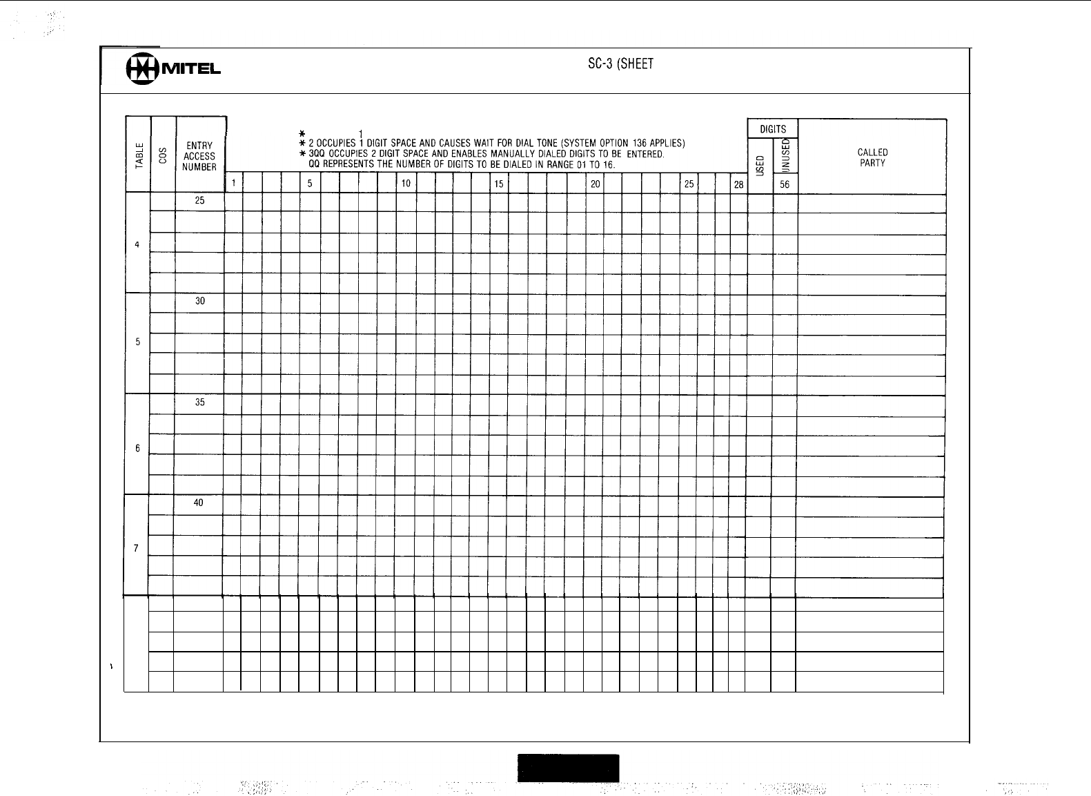
MITEL
SPEED CALL NUMBER RECORDS FORM SC-3(SHEET 2 OF 4)
SPEED CALL FEATURE CODE
SPEED CALL NUMBER
SPECIAL SEQUENCES CAN BE ENTEREDATANY POINT IN THE TELEPHONE NUMBER LISTING:
*
1 OCCUPIES
1
DIGIT SPACE AND CAUSES A 5 SEC. PAUSE IN USE
45
a
h
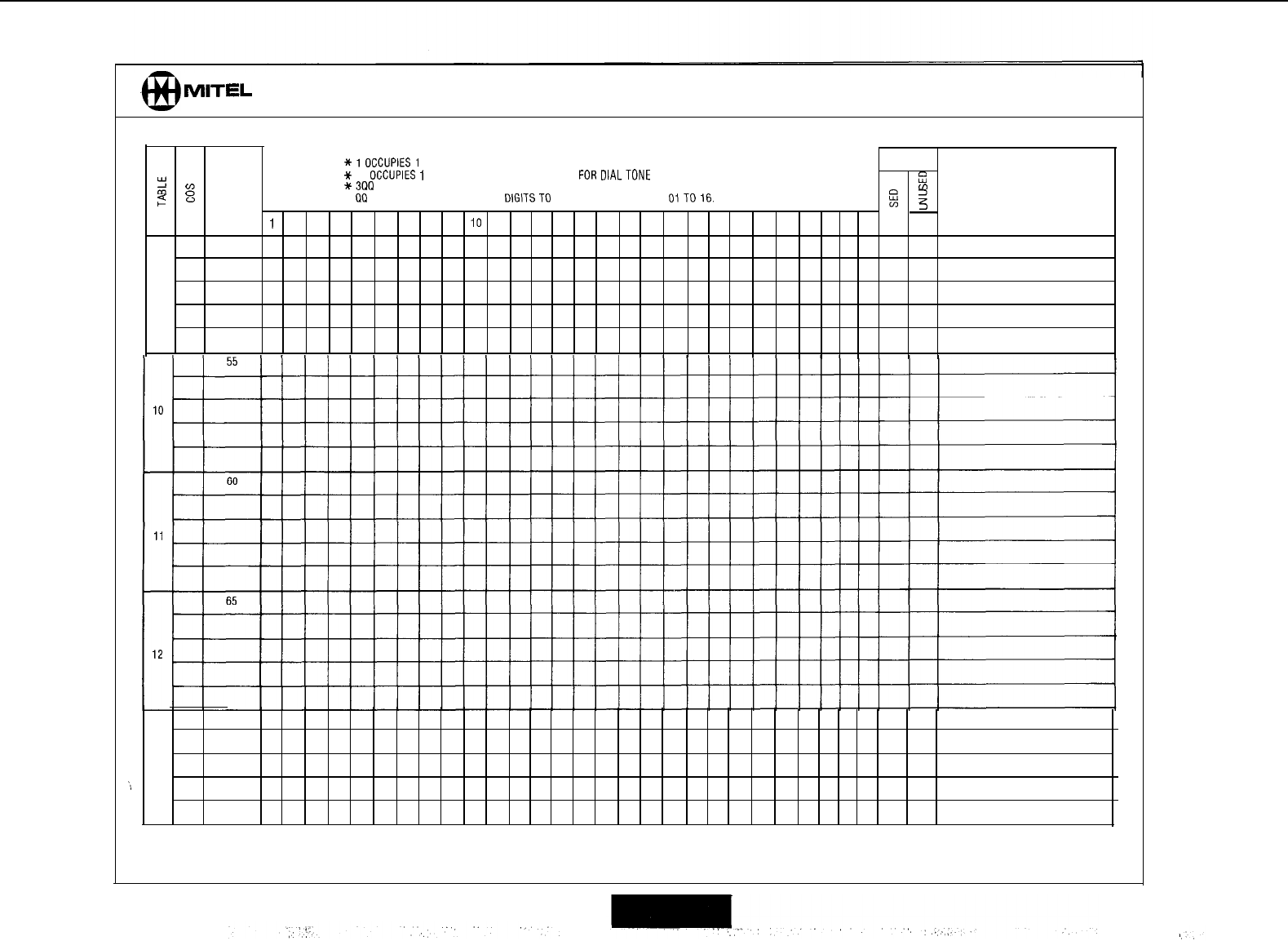
MITEL
SPEED CALL NUMBER RECORDS FORM SC-3 (SHEET 3 OF 4)
SPEED CALL FEATURE CODE
.
SPEED CALL NUMBER
SPECIAL SEQUENCES CAN BE ENTEREDATANY POINT IN THETELEPHONE NUMBER LISTING.
*lOCCUPlESl
DlGlTSPACEANDCAUSESA5 SEC. PAUSE IN USE DIGITS
ENTRY
+
2
occupies
I
DIGIT SPACE AND CAUSES WAIT
FOR
DIALTONE
(SYSTEM OPTION 136 APPLIES)
2
B
E
ACCESS
*3QQ
OCCUPIES 2 DIGIT SPACE AND ENABLES MANUALLY DIALED DIGITS TO BE ENTERED.
m
CALLED
2
QQ REPRESENTSTHE NUMBER OF DIGITSTO BE DIALED IN RANGE
OiTO16.
E
NUMBER
z
PARTY
1
5
3
3
10 15 20 25 28 56
50
9
70
13
,/
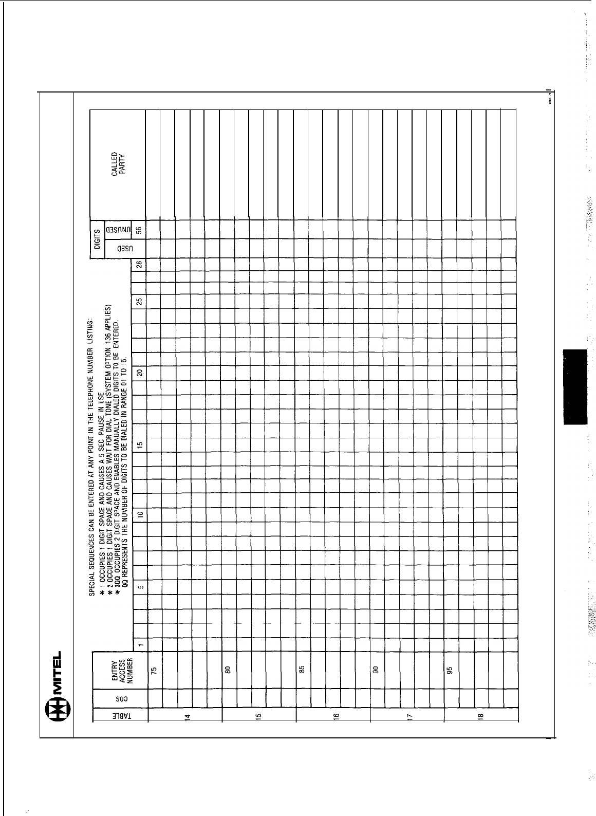
:
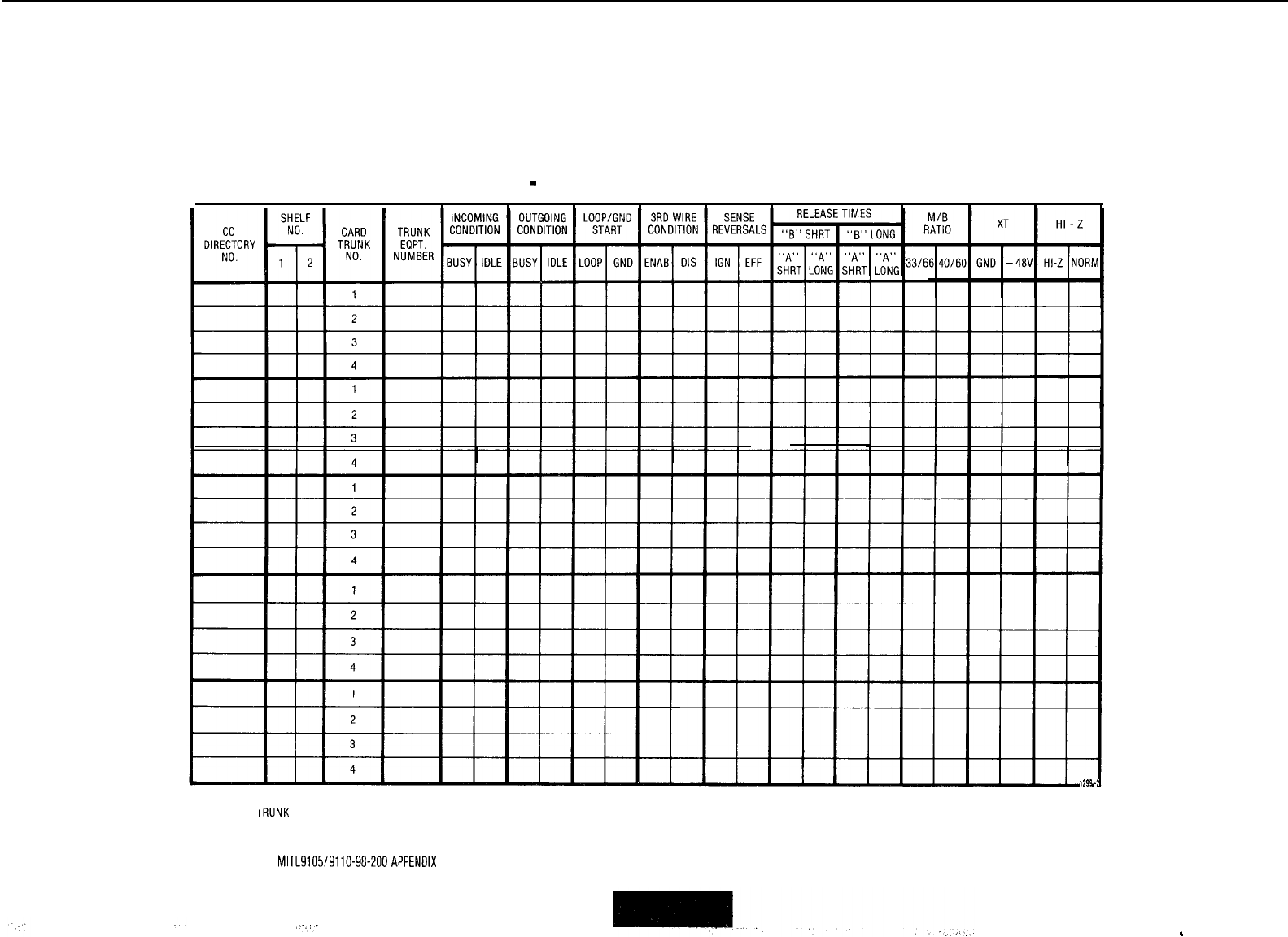
TRUNK CARD SWITCH SETTINGS
-
CD TRUNK CARDS
CARD
SLOT
NO:
CARD
SLOT
NO:
CARD
SLOT
NO:
CARD
SLOT
NO:
CARD
SLOT
NO:
NOTES
,299
-*
1.
EARLIER IRUNK CARDVERSIONS 00 NOT HAVE ALL SWITCHES LISTED ABOVE
2.
CHECK APPROPRIATE COLUMN E.G. "BUSY" OR "IDLE" FOR DESIRED SETTING
3. SEE SECTION MITL9105/9110-98-ZOO APPENDIX 5 FOR PROCEDURES USED IN
SETTING TRUNK CARD SWITCHES.
.
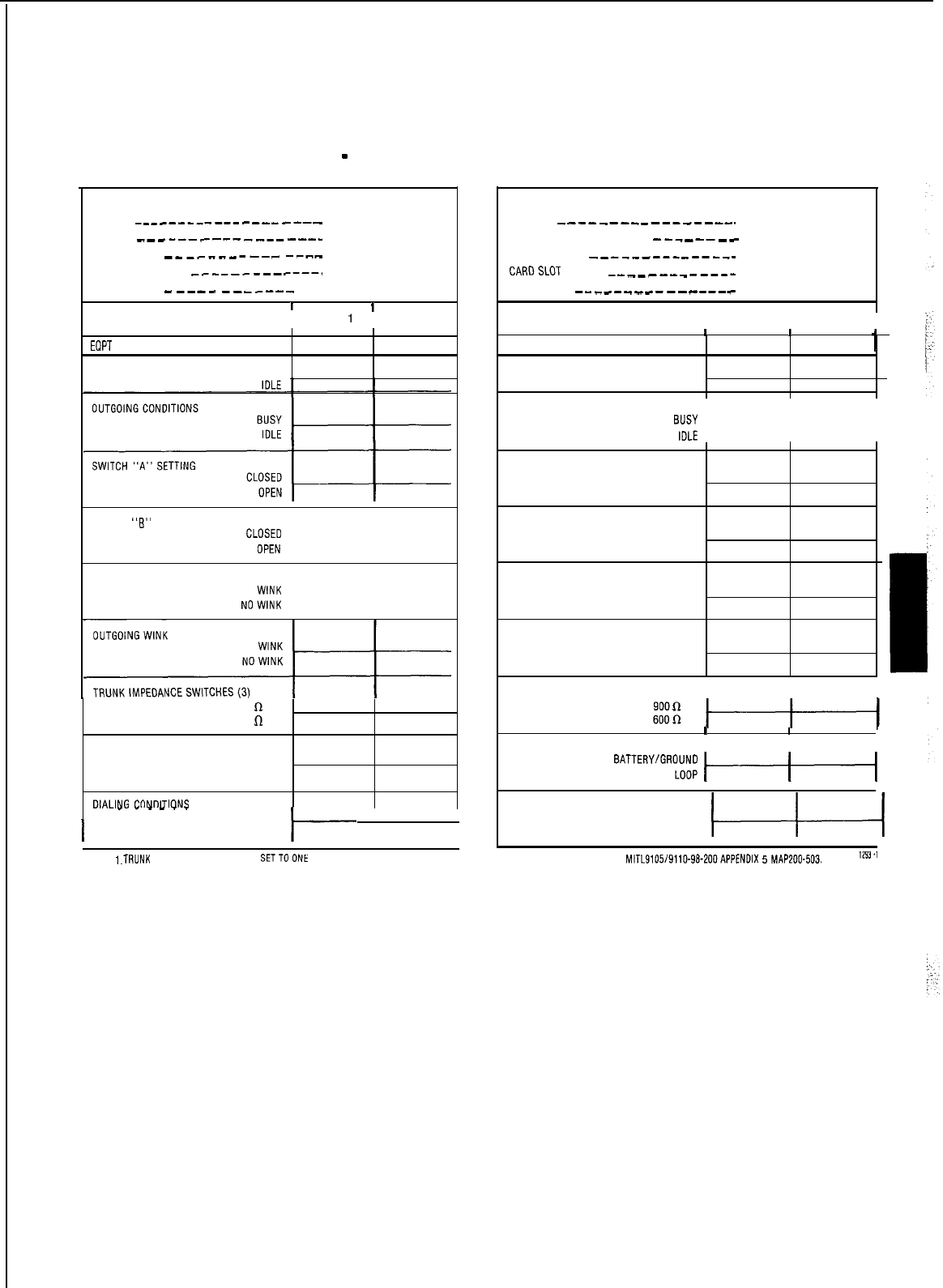
TRUNK CARD SWITCH SETTINGS
-
DID/TIE TRUNK CARD
CIRCUIT REFERENCE NUMBERS
TRUNK 1
-___---_-----
____--_
TRUNK 2
___---_---
____----
SHELFNUMBER
-------__--
-___
CARD SLOT NUMBER
__----
---_---.
TRUNKCARD
-
--__
----__-
____
1
I
SWITCH SETTINGS ITRUNK
1
ITRUNK 2
ECIPT
NUMBER
INCOMING CONDITIONS
BUSY
SWITCH
“6”
SETTING
“‘,“E
L---l--
INCOMING WINK
NO:;;::
I----+--
‘“‘““;“*’
900
R
600
R
PULSING CONDITION
BATTERY/GROUND
LOOP
DIALING
CI-INI-IITI~NS
_ _
_
_
_
_
I
STOP DIAL
t--
I
I
NOT STOP DIAL
CIRCUIT REFERENCE NUMBERS
TRUNK 1
_---_--__---_----_
TRUNK2 _________
--__--__
SHELFNUMBER
__-___--__---__
CARDSLOT
NUMBER
--___--_----_
TRUNKCARD
--__-___---_---_
I
I
SWITCH SETTINGS ITRUNK 1 ITRUNK 2 I
I
1
EQPT NUMBER
I I
1
INCOMING CONDITIONS
BUSY
IDLE
OUTGOING CONDITIONS
“,“,s:
k-l-4
SWITCH “A” SETTING
CLOSED
OPEN
SWITCH “B” SETTING CLOSED
OPEN
INCOMING WINK WINK
NO WINK
OUTGOING WINK
WINK
NO WINK
TRUNK IMPEDANCE SWITCHES (3) I II
I
I
PULSING CONDITION I
I
I
BATTERY/GROU;;
1-1
DIALING CONDITIONS
NOT%%
&j-----1
NOTES:
i.TRlJNK
CARD SWITCHES MUST BE SETTO ONt OFTHETWO POSSIBLE SETTINGS FOR EACHSWITCH AS DETAILED IN SECTION
MITL9105/9110-98.ZOO APPENDIX
5
MAPZOO-503.
"""
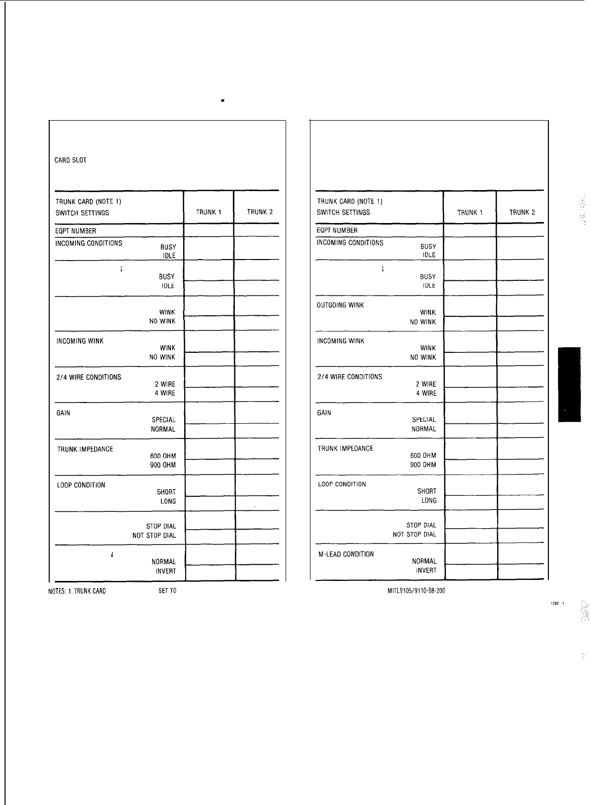
TRUNK CARD SWITCH SETTINGS
-
E AND M/TIE
CIRCUIT REFERENCE NUMBERS
TRUNK1
TRUNK2
CARDSLOT
NUMBER
SHELFNUMBER
EPPTNUMBER
OUTGOING CONDITIONS
OUTGOING WINK
DIALING CONDITION
M-LEAD CONDITION
TRUNK CARD
CIRCUIT REFERENCE NUMBERS
TRUNK1
TRUNK2
CARD SLOT NUMBER
SHELF NUMBER
EQPTNUMBER
OUTGOING CONDITIONS
DIALING CONDITION
NOTES:,.TRUNKCARD SWITCHES MUST BE SETTO ONE OFTHETWO POSSIBLE SETTINGS FOR EACHSWITCH AS DETAILED IN SECTION
MITL9105/9110-98-200
APPENDIX 5 MAP200-502
MITEL STANDARD PRACTICE
SECTION
MITL9105/9110-98-210
Issue 3, July 1980
SX-100” AND SX-200*
SUPERSWITCH*
ELECTRONIC PRIVATE AUTOMATIC BRANCH EXCHANGE
SYSTEM PROGRAMMING
CONTENTS PAGE
1.
GENERAL
..........................
1
Introduction
........................
1
Reason for Reissue
...................
2
Purpose.. ..........................
2
2.
PROGRAM DESCRIPTION
.............
2
General
............................
2
TenantMode
........................
2
System Options
.....................
3
Class-Of-Setvice Options
.............
7
Feature Access Codes.
...............
8
Extensions
.........................
9
Hunt Groups
..................
12
Trunks
.............................
12
Trunk Groups
.......................
14
3.
PROGRAMMING
.....................
15
General
............................
15
Error/Confirm Codes
.................
15
Attendant Function Access Codes
.....
15
Maintenance Function Access Codes
...
15
Timeout Information
.................
15
4.
EXAMPLES
.........................
25
Introduction
........................
25
APPENDIX 1
-
MITEL ACTION
PROCEDURES
........................ Al.1
APPENDIX 2
-
SYSTEM PROGRAMMING
MAPS
...............................
A2.112
System Programming
(MAP21
O-201)
......................
A2.3
Select Programming Mode
(MAP21
O-202)
......................
A2.5
Program System Options
(MAP21
O-203)
......................
A2.9
Program COS Options
(MAP210.204)
.....................
A2.13
Assign Feature Access Codes
(MAPSIO-205).
....................
82.19
Program Extensions
(MAP210=206).
....................
A2.23
CONTENTS PAGE
Program Extension Hunt Groups
:..
(MAPSlO-207). . . . . . . . . . . . . . . . . . . . . A2.31
.”
Program Non Dial-In Trunks
(MAPSlO-208). . . . . . . . . . . . . . . . . . . . . A2-37
Program Dial-In Tie Trunks
(MAPPIO-209). . . . . . . . . . . . . . . . . . . . . A2-47
Program DID Trunks
(MAP21
O-21
0) . . . . . . . . . . . . . . . . . . . . . A2-55
Program Trunk Groups
(MAPSlO-211). . . . . . . . . . . . . . . . . . . . .
A2-61
Terminating Programming Mode
(MAPSIO-212). . . . . . . . . . . . . . . . . . . . . A2-69
1:
1. GENERAL
Introduction
1.01 The SX-100 and SX-200
PABX’s
are
processor-controlled switching systems. In
order to process calls the central processor needs
to know certain information about the calling and
called equipment. This information is described
by blocks of data held in the system memories. A
number of service change programs are provided
to allow additions, deletions and changes to be
made to the blocks of data to reflect changes I
made to the equipment configuration. The eight
service change programs provided are:
:
lTenant Mode-Defines whether the system
is to be used by single or multi tenants.
l System
Options-
Describes the options
-1
which may be enabled on a system basis.
:
:
l Class Of Service Options-Each class of
service specifies the features which may be
used by stations assigned that Class Of
Service (COS). A maximum of sixteen dif-
ferent classes of service may be specified
for each system.
l Feature Access Codes-A number of
features within the system are
accessed
by
0
MITEL Corporation 1979
*
Trademark of MITEL Corporation
Page 1 ;
SECTION
MITL9105/9110-98-210
dialing a special access code. This program
allows the access codes for the features to
be defined.
Extensions-This program allows the
equipment number, extension number,
Class Of Service (features allowed), toll ac-
cess, busy lamp field assignment and pick-
up group assignment for each extension to
be made.
Hunt Groups-This program allows the ex-
tensions within each hunt group to be
specified, together with the hunt group
master number (access code).
Trunks-This program allows each trunk to
be described in terms of the equipment
number, trunk type, listed directory number,
day and night numbers, busy lamp number,
COS and toll access.
Trunk Group-This program allows the
trunks within each group to be specified,
together with trunk group type, access code
and overflow group.
Other additional service programs,
depen-
dant upon the type of software Generic in-
stalled in the PABX, may be implemented. These
are listed below and include relevant MITEL Prac-
tice references, which should be consulted for
descriptions and programming requirements.
a) Traffic Measurement (Generic 204 only).
See Section
MITL9105/9110-98-450
b)
Multi Digit Toll Control (Generic 204 or 205
only). See Section
MITL9105/9110-98-212
c) Station Message Detail Recording (Generic
2050nly).
See Section
MITL9105/9110-98-451
d)
Speed Call (Generic 205 only). See Section
M ITL9105/911 O-98-220
Reason For Reissue
1.03 This Section is reissued to incorporate
Generic 205 information for the SX-100 and
SX-200
PABX’s.
Purpose
1.04 This Section consists of four parts, each
part explaining a different facet of the
system programming.
Part 1
General-general description of system
programming contents and purpose of
the programming manual.
Part 2 Program Description-a description of
each program and definition of each en-
try and possible response.
Part 3 Programming-this part contains a
general introduction to the system pro-
gramming and MITEL Action Pro-
cedures (MAP’s) which detail how to
use each program. When entering data,
the system checks each entry to ensure
that the codes entered are correct and if
an error is detected it sounds the con-
sole ringer and displays the required er-
ror code. These codes and their mean-
ing are defined in this part.
Part 4 Examples-The examples in this part
show how the programs are used to
define a typical system.
2. PROGRAM DESCRIPTION
General
2.01
Because the PABX is controlled by a pro-
cessor, data describing each extension,
trunk, feature etc. must be entered into the
system. This is done by pressing keys and dialing
codes. The codes dialed are held in the system
memories and used by the system during call pro-
cessing. Eight basic programs are provided which
allow data to be entered into the system as equip-
ment is added, or existing data to be changed or
removed as the system configuration changes.
The following paragraphs describe the eight pro-
grams (see 1.01). These programs specify the keys
to be pressed and explain the entries that may be
made. The Appendices to this section contain an
introduction to MITEL Action Procedures (MAP’s)
and the actual MAP’s which detail each step in
system programming. A complete description of
each feature and option is given in Section
MITL9105/9110-98-105
Features and Services
Description. Other types of programs are
referenced in 1.02.
Tenant Mode
2.02
The tenant program allows a user to specify
the number of the tenant for which entries
are to be made. If multi-tenant service is to be
selected the system must be placed in the
pro-
Page 2
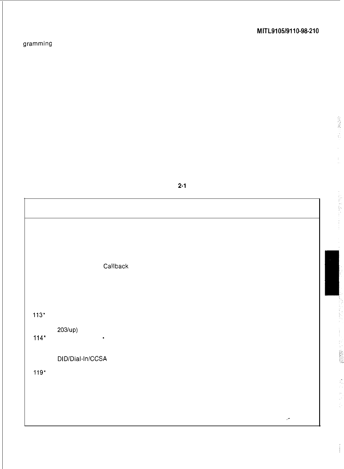
SECTION
MITL9105/9110-98-210
gramming
mode then the TENANT key pressed
and the tenant number entered. If single tenant
service is required TENANT mode should not be .
selected.
making the option available for use by the
system.
System Options
DELETE Pressing the DELETE key after
dialing an option code removes the code
from the active option list inhibiting further
use of that option.
2.03
The system options are selected by the con- .
sole keys as described below:
l OPTION This key selects the option pro-
gram which allows the system to set-up or
change the active option list. The code
entered (Table 2-l) after selecting the op- .
tion program defines the option to be added
or removed from the active option list, but
see Table 2-2 for possible option conflicts.
lADD When pressed, this key adds the op-
tion code to the active system option list,
CANCEL As entries are made during the
option program they are stored in a tem-
porary memory. If after making a number of
entries an error is discovered, all new en-
tries may be removed by pressing the
CANCEL key.
ENTER After all entries have been made
to the system option, they may be moved
from the temporary storage to permanent
storage by pressing the ENTER key. Addi-
tional changes may be made by reentering
the option program.
TABLE
2-l
SYSTEM OPTIONS
Option
Number Option Name
100
Discriminating Ringing
101
Transfer Dial Tone
102
Flexible Night Service
103
Night Service Automatic Switching
104
TAFAS Available During Day
105
Outgoing Trunk Camp-on
106
Outgoing Trunk
Ca!lback
107
Can Flash if on an Incoming Trunk
108 Can Flash if on an Outgoing Trunk
109
Can Flash if Talking to Station
110
Cannot Dial a Trunk After Flashing
111
Cannot dial a Trunk After Flashing if Holding or in Conference with a Trunk
112
Lockout Alarm Enable
113*
Tenant Service (set automatically when tenant service is selected when programming)
114
Flash Timer 0.7 seconds (Generic 202 only and REV 5 up) (See also 180-182 for Generic
20311~~)
114*
Tenant Service
-
Separate Consoles
115
Vacant Number Intercept to Attendant
116
Illegal Access Intercept to Attendant
117
DID/Dial-InlCCSA
Vacant/Illegal Access Intercept to Attendant
118
Attendant Camp-On
119*
Attendant Conference
120
Attendant Busy Over-ride
121
Attendant Serial Call
122
Bell Off Enable
123
Page Button Enable
124
New Call Tone Enable
125
Both Mode Standard
126
Callback Button Enable
,-
Page 3
i
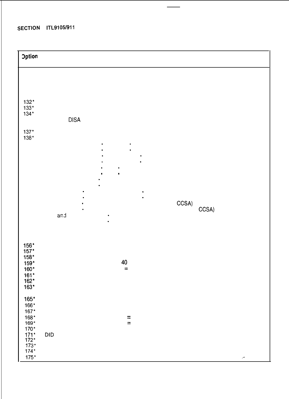
SECTION
M ITL91051911 O-9821
0
TABLE 2-1 (Cont’d)
SYSTEM OPTIONS
3ption
lumber Option Name
127
Trunk Busy-Out Enable
128
Both Button Enable
129
Attendant CO Trunk-CO Trunk Connect Enable
130
Attendant CO Trunk-Non CO Trunk Connect Enable
131
Attendant Non CO Trunk-Non CO Trunk Connect Enable
132*
Controlled Outgoing Restriction Set-Up (Room Restriction)
133*
Controlled Station Restriction Set-Up (Do Not Disturb)
134*
Controlled Station to Station Restriction Set-Up (Call Blocking)
135
Attendant
DISA
Code Set-Up Enable
136
Limited Wait For Dial Tone
137*
Message Waiting Set-Up (lamp)
138*
Message Waiting Set-Up (bell)
139
Attendant Timed Recall
-
Camp-On
-
20s
140
Attendant Timed Recall
-
Camp-On
-
40s
141
Attendant Timed Recall
-
Don’t Answer
-
20s
142
Attendant Timed Recall
-
Don’t Answer
-
40s
143
Attendant Timed Recall
-
Hold
-
20s
144
Attendant Timed Recall
-
Hold
-
40s
145
Night Service Timeout
-
20s
146
Night Service Timeout
-
40s
147
Call Forwarding
-
Don’t Answer Timeout
-
20s
148
Call Forwarding
-
Don’t Answer Timeout
-
40s
149
Call Forwarding
-
Busy (System, DID Dial-In Tie Trunk,
CCSA)
150
Call Forwarding
-
Don’t Answer (System, DID Dial-In Tie Trunk,
CCSA)
151
Park
and
Call-Hold Recall
-
2 minutes
152
Park and Call-Hold Recall
-
4 minutes
153
End of Dial Signal for Outgoing Trunks (#)
154
24 Hour Clock
155
First Digit Toll Deny
156*
Message Registration Enable
157*
Message Registration: Count Additional Supervisions
l58*
Message Registration: Timer = 20 s
159*
Message Registration: Timer =
40
s
160*
Message Registration: Multiplier
=
4 units
161*
Message Registration: Multiplier = 3 units
162*
Message Registration: Multiplier = 2 units
163*
Message Registration: Surcharge = 8 units
164’ Message Registration: Surcharge = 7 units
165*
Message Registration: Surcharge = 6 units
166*
Message Registration: Surcharge = 5 units
167*
Message Registration: Surcharge = 4 units
168*
Message Registration: Surcharge
=
3 units
169*
Message Registration: Surcharge
=
2 units
170*
Message Registration: Surcharge = 1 unit
171* DID
to Non-CO Trunks via Attendant Inhibit
172*
GUEST ROOM Button Enable
173*
ROOM STATUS Button/Display/Change Enable
174*
Do Not Disturb Intercept to Attendant
175*
Do Not Disturb and Message Waiting Displays
,-
Page 4
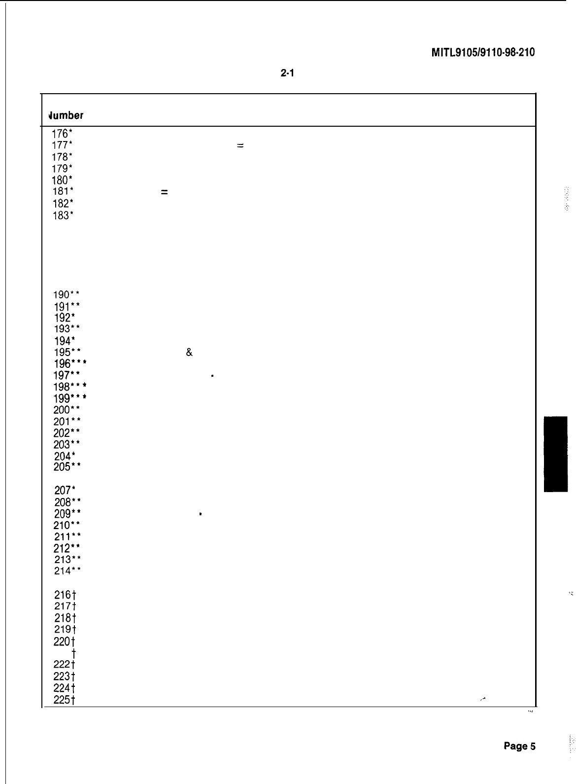
SECTION
MITL9105/9110-98-210
TABLE
2-l
(Cont’d)
SYSTEM OPTIONS
Option
Umber
Option Name
176*
Single Digit Dialing Enable
177*
Single Digit Dialing Time-Out
=
3 s
178*
Single Digit Dialing Time-Out = 5 s
179*
Attendant Station Busy-Out Enable
180*
Flash Timing = 0.7 s
181*
Flash Timing
=
0.9 s
182*
Flash Timing = 1.1 s
183*
Trunk Recall Partial Inhibit
184
Reserved
185
Reserved
186
Reserved
187
Reserved
188
Reserved
189
Reserved
190**
Automatic Wakeup Enable
191**
Automatic Wakeup Print
192*
*
Automatic Wakeup Music On Hold
193**
Room Register Audit Enable
194*
lMessage Register Print
195**
Message Register
&
Message Waiting Change Print Enable
196**
*
Ignore Print Enable
197**
lRemote System Reset
-
Protection Override
198*’
*
Enable Non-CO Trunk to Trunk Connect by Extension
199**
*
Toll Control Enable
200**
Traffic Measurement Enable
201**
Traffic Measurement Extreme Value Mode
202**
Traffic Measurement Compact Report
203+*
Traffic Measurement Polling
204*
l
Traffic Measurement Autoprint
205**
lIdentified Trunk Group Enable
206’ l l Inhibit Automatic Supervision
207*
l l Printer Carriage Return Delay
208**
Zero Message Register after Room Register Audit
209**
Traffic Measurement
-
Console Enable
210**
lAttendant Printer Control Enable
211**
lSystem ID Enable
212**
lNight Bell 3 with Minor Alarm Enable
213**
H/M Printouts: Extra Line Feeds
214**
Automatic Wakeup Alarm
215 Reserved
216t
Speed Call Enable
217t
Speed Call Programming Enable
2187
Speed Call: Confidential Number Display and Change Enable
219t
Reserved
220t
Station Message Detail Recording: Outgoing Calls
221
t
Station Message Detail Recording: Incoming Calls
222t
SMDR: Extended Record
223t
SMDR: Record Meter Pulses
224t
SMDR: Indicate Long Calls
225t
SMDR: Drop Incomplete Outgoing Calls
,-
..,
.
.:
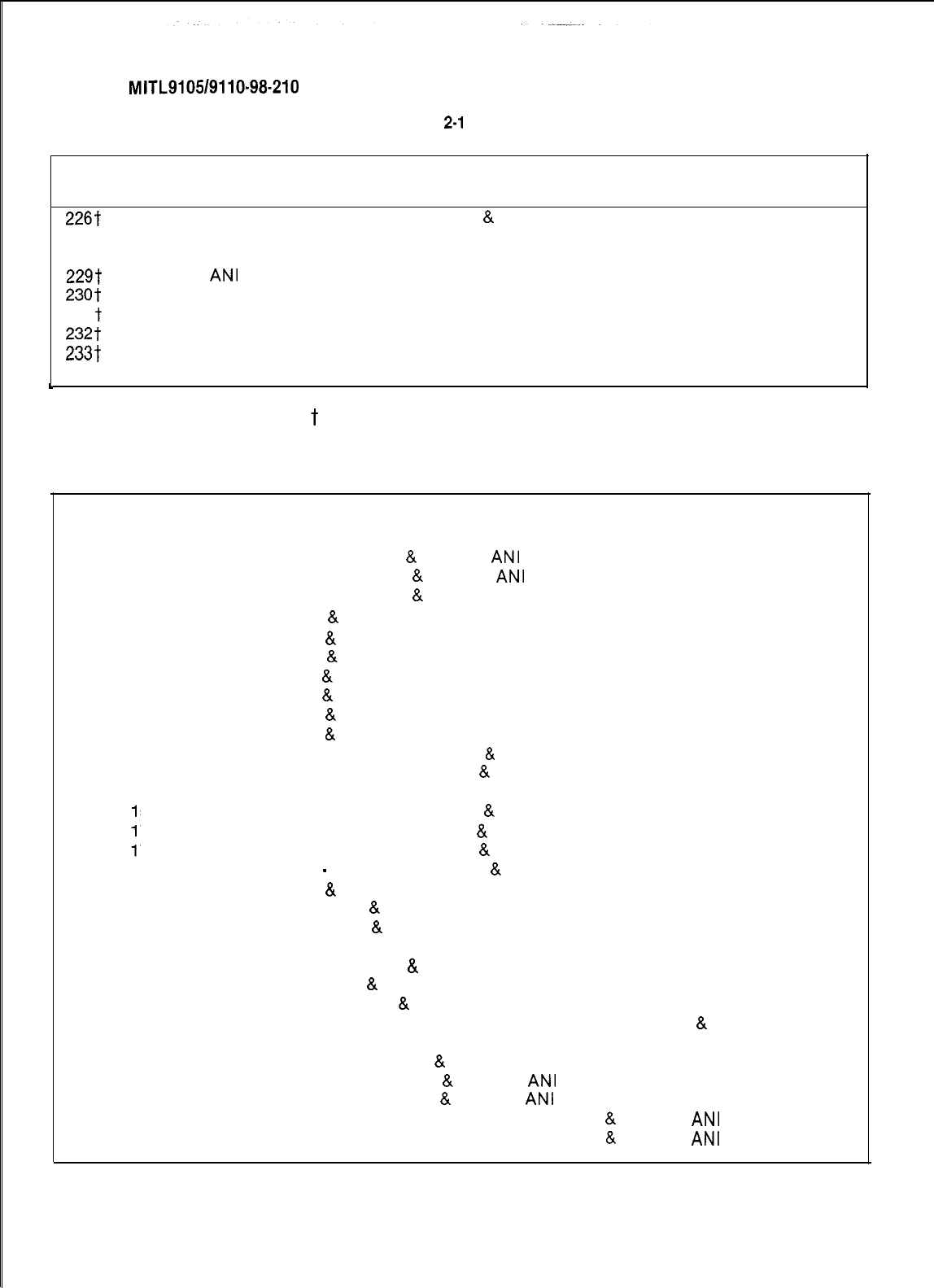
SECTION
MITL9105/9110-98-210
TABLE
2-l
(CONT’D)
SYSTEM OPTIONS
Option
Number Option Name
226-f
SMDR: Record Only Incoming calls (CCSA
&
Non-dial tie trunks)
227t SMDR: Drop Calls of Less Than 8 Digits
228-t
Discriminating Dial Tone
229t
Special
ANI
Feature
230t
Account Code Enable
231
t
Account Code Length, 4 Digits
232t
Account Code Length, 8 Digits
233t
Account Code Length, 12 Digits
234-t
Variable Length Account Codes
c
* Generic 203 and above
** Generic 204 only
l ** Generic 204 and 205
t
Generic 205 only
TABLE 2-2
SYSTEM OPTION CONFLICTS
The following System Options are mutually exclusive, i.e. they cannot be simultaneously enabled on
the same PABX.
105
and 229
106
and 229
106
and 230
113
and
132
113
and
134
113 and
156
113
and
172
113
and
173
113
and
190
113
and 205
114 and
114 and
114 and
114 and
114 and
1
1
32
34
56
72
73
114and 190
114 and 205
121 and 172
121 and 173
137 and 138
191 and 203
193 and 203
194 and 203
195 and 203
203 and 204
205 and 229
207 and 229
220 and 229
221
and 229
Outgoing Trunk Camp-On
8.
Special
ANI
Feature
Outgoing Trunk Call Back
&
Special
ANI
Feature
Outgoing Trunk Call Back
&
Account Code Enable
Tenant Service
&
Controlled Outgoing Restriction Setup.
Tenant Service
&
Controlled Station to Station Restriction Setup.
Tenant Service
&
Message Registration Enable.
Tenant Service
&
GUEST ROOM Button.
Tenant Service
&
ROOM STATUS Enable.
Tenant Service
&
Automatic Wakeup Enable.
Tenant Service
&
Identified Trunk Group Enable.
Tenant Service-Separate Consoles
&
Controlled Outgoing Restriction Setup.
Tenant Service-Separate Consoles
&
Controlled Station to Station Restric-
tion Setup.
Tenant Service-Separate Consoles
&
Message Registration Enable.
Tenant Service-Separate Consoles
&
GUEST ROOM Button Enable.
Tenant Service-Separate Consoles
&
Room Status Eanble.
Tenant Service
-
Separate Consoles
&
Automatic Wakeup Enable.
Tenant Service
&
Identified Trunk Group Enable.
Attendant Serial Call
&
GUEST ROOM Button Enable.
Room Status Enable
&
Attendant Serial Call.
Message Waiting Set-ups (lamp or bell)
Automatic Wakeup Print
8t
Traffic Measurement Polling.
Room Audit Enable
&
Traffic Measurement Polling.
Message Register Print
&
Traffic Measurement Polling.
Message Register and Message Waiting Change Print Enable
&
Traffic
Measurement Polling.
Traffic Measurement Polling
&
Traffic Measurement Autoprint.
Identified Trunk Group Enable
&
Special
ANI
Feature
Printer Carriage Return Delay
8.
Special
ANI
Feature
Station Message Detail Recording: Outgoing Calls
&
Special
ANI
Feature
Station Message Detail Recording: Incoming Calls
&
Special
ANI
Feature
/-
Page 8
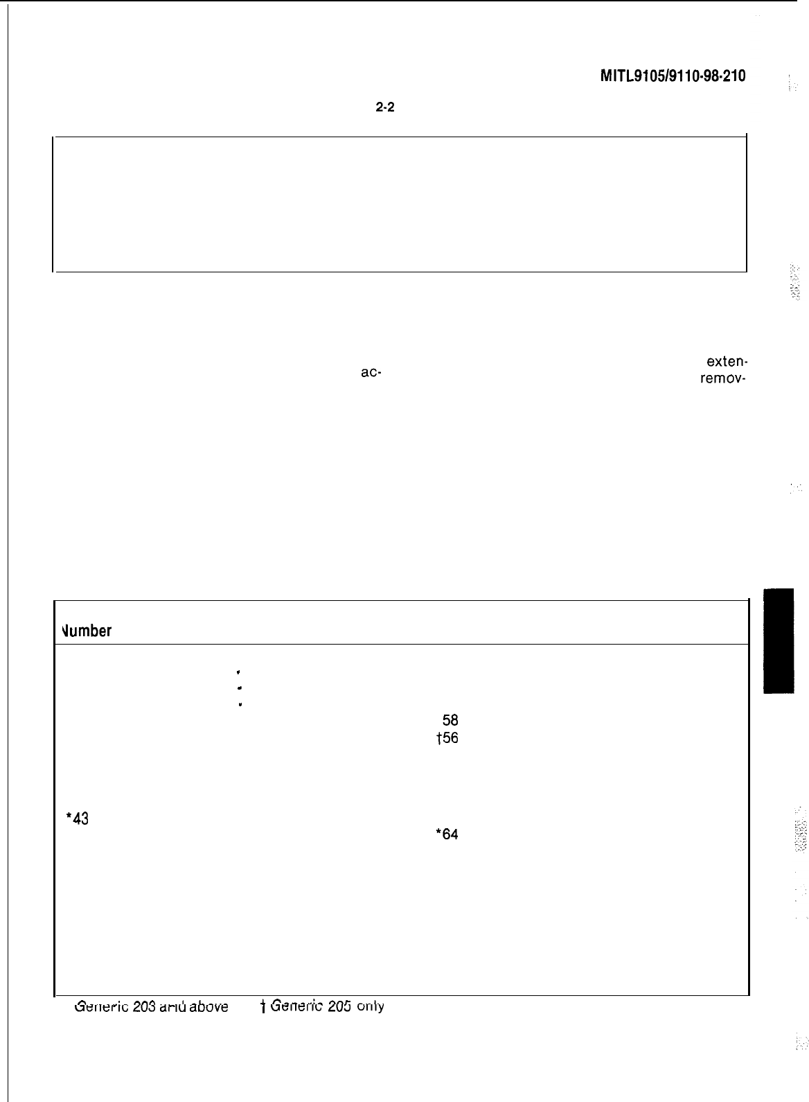
SECTION
MITL9105/9110-98-210
TABLE
2-2
(CONT’D)
SYSTEM OPTION CONFLICTS
In addition to the above system options, some console service features are mutually exclusive.
These features are listed below:
ROOM RESTRICT and NIGHT 2. CALL BLOCK and HOLD 4.
ROOM STATUS and NIGHT 2. SERIAL CALL and GUEST ROOM.
NOTE:
The Room Restriction and Room Status features utilize the same button, but are not mutually
exclusive, as the Room Status feature can be arranged to include the Room Restriction
function if System Option 132 is selected.
Class-Of-Service Options
2.04
Each system may contain up to 16 different
Classes Of Service (COS). The COS defines
which of the available options (Table 2-3) are
ac-
tive, and therefore available for use by any exten-
sions assigned that COS.
2.05 The individual Classes of Service are
selected by the console keys as described
below:
The entry made after selecting the program
identifies which COS is to be modified.
lOPTION
The code entered (Table 2-3) after
pressing the OPTION key defines the
exten-
sion option which is to be added or
remov-
ed from the COS specified.
lADD Add the option to this COS.
l DELETE Remove the option from the
cos.
I
l COS DEFINE This key selects the Class
Of Service program which permits changes
to be made to any of the 16 individual COS.
l CANCEL If after entering a number of
codes for a COS, an error is discovered, the
new entries may be removed from the
system by pressing the CANCEL key.
TABLE 2-3
CLASS-OF-SERVICE OPTIONS
Option
slumber
Extension Options
33
Automatic Callback
34
Call Forwarding
-
Busy
35
Call Forwarding
-
Don’t Answer
36
Call Forwarding
-
Follow Me
37
Call Park
38
Never a Forwardee
39 Directed Call Pickup
40
Executive Busy Over-ride
41
Data Security
42
Station Over-ride Security
*43
Inward Restriction (DID or CCSA)
44
Originate Only
45 Receive Only
46
Flash Disable
47
Never a Consultee
48
Broker’s Call
49
Station Conference
50
Meet-Me Conference
51
Camp-On
52
Do Not Overflow
53
Paging Access
*
PA..,..:,
oncl
^^,.A
^I.^..^
uellel
Ic;
LU3
ai
IU
auuve
+
r?r...ar:r.
onr
^^I..
1
uellcllb
LULJ
ullly
Option
Number Extension Options
54
TAFAS Access
55
Hold Pickup
56
Account Code Access
57
Manual Line
Contact Monitor
+E
Account Code Access
59
Non-CO Trunks via Attendant Inhibit
60
CO Trunks via Attendant Inhibit
61
No Dial Tone
62
Flash for Attendant
‘63 Call Blocking Applies
*64
Message Register
65
Trunk Group 1 Access
66
Trunk Group 2 Access
67
Trunk Group 3 Access
68
Trunk Group 4 Access
69
Trunk Group 5 Access
70
Trunk Group 6 Access
71
Trunk Group 7 Access
72
Trunk Group 8 Access
73
Trunk Group 9 Access
I
-
** Generic 204 only
Page7 1
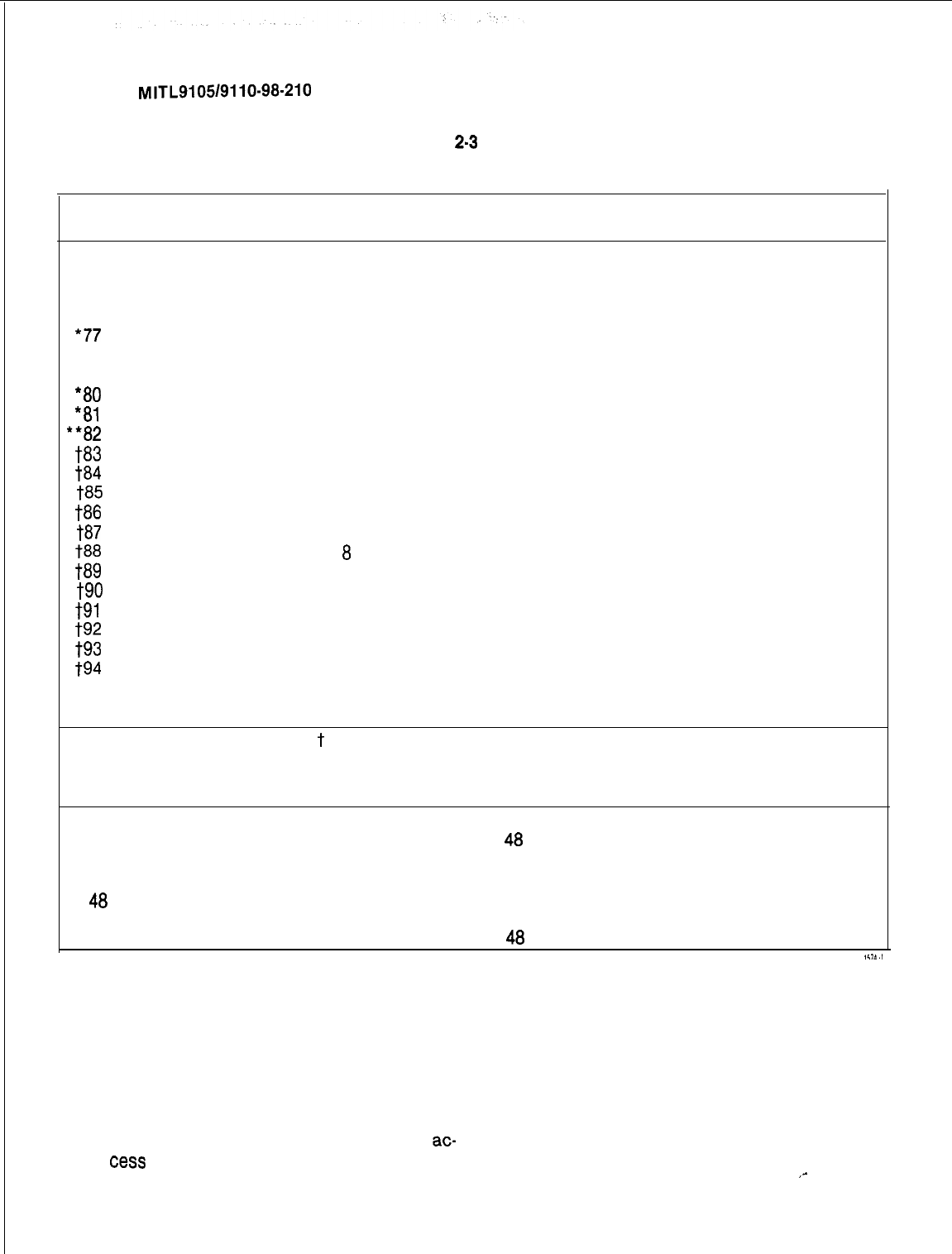
TABLE
2-3
(Cont’d)
CLASS-OF-SERVICE OPTIONS
SECTION MITL9105/9110-98-210
Option
Number Extension Options
74
Trunk Group 10 Access
75
Trunk Group 11 Access
76
Trunk Group 12 Access
*77
Message Waiting Applies
l
7a
Room Do Not Disturb Setup Enable
l 79
Call Hold and Retrieve Access
*a0
Room Status Applies
*al
Call Forward System Inhibit
**a2
Alarm Call Setup Enable
ta3
Forced Account Code Entry
tad
No SMDR Record for This Line
ta5
Speed Call Table 1 and 2 Access
w
Speed Call Table 3 and 4 Access
ta7
Speed Call Table 5 and 6 Access
ta8
Speed Call Table 7 and
8
Access
tag
Speed Call Table 9 and 10 Access
t90
Speed Call Table 11 and 12 Access
t91
Speed Call Table 13 and 14 Access
t92
Speed Call Table 15 and 16 Access
l-93
Speed Call Table 17 and 18 Access
t94
Cannot Dial a Trunk After Flashing
l
Generic 203 and above
l
* Generic 204 only
f
Generic 205 only
OPTION CONFLICTS
45 Receive Only
46
Flash Disable
46
Flash Disable
46
Flash Disable
48
Broker’s Call
62
Flash for Attendant
62
Flash for Attendant
and
58
Contact Monitor
48 Broker’s Cal I
49
Station Conference
62
Flash for Attendant
49
Station Conference
49
Station Conference
48
Broker’s Call
l ENTER After all entries have been made
for the COS the entries may be transferred
to permanent storage by pressing the
ENTER key.
code must be unique within the system. The
feature access codes are programmed from the
console keys as described below:
Feature Access Codes
2.06 A number of features (Table 2-4) require ac-
cess
codes to allow the extension users to
select and use the features. Each feature access
l FEATURE This key selects the feature
program and allows the access codes to be
defined. The number dialed (Table 2-4) after
pressing the FEATURE key specifies the
feature to which the access code is to be
assigned.
,-
Page 8
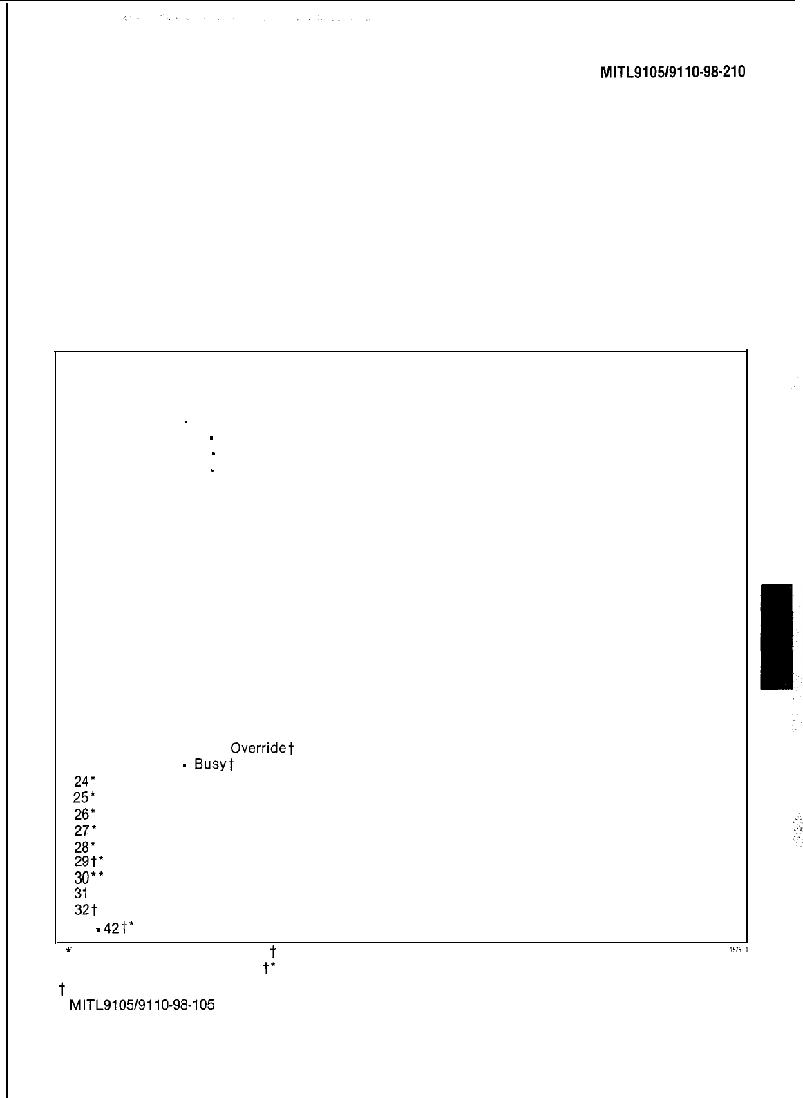
SECTION
MlTL9105/9110-98-210
l ACCESS CODE After pressing this key
the number dialed (1 to 4 digits) is assigned
as the access code of the feature selected.
The system automatically checks to see if
the code is assigned to any other equip-
ment or feature within the system, and if a
match is found displays an error message.
l CANCEL The access just assigned to a
feature may be removed by pressing the
CANCEL key. The new access code may be
assigned immediately.
lDELETE Pressing this key deletes the ac-
cess code assigned to the feature, render-
ing the feature inoperative.
l ENTER Transfers all new entries to per-
manent memory.
Extensions
2.07 The extension program allows all data
associated with extensions to be specified,
TABLE 2-4
FEATURE ASSIGNMENTS
Feature
Number Description
1
Attendant Access
2
Callback
-
Don’t Answer
3
Call Forward
-
Busy
4
Call Forward
-
Don’t Answer
5
Call Forward
-
Follow Me
6
Call Park
7
Dial Call Pickup
8
Directed Call Pickup
9
Meet-Me Conference
10
Pager 1
11
Pager 2
12
Hold Pickup Access
13
Pager 1 and 2
14
TAFAS-AI I
15
TAFAS-1
16
TAFAS-2
17
TAFAS3
18
Attendant Function
19
Maintenance Function
20
DID Attendant Access Code
21
Direct Inward System Access
22
Executive Busy
Overridet
(Single Digit)
23
Callback
-
Busyt
(Single Digit)
24*
Room Do Not Disturb Setup and Cancel
25*
Call Hold
26*
Call Retrieve (Local)
27*
Call Retrieve (Remote)
28*
Room Status Update (Maid in Room)
29t*
Programming Security Code
30**
Alarm Call
31
t Account Code
32t
Speed Call
33
-
42t*
Trunk Group 1 Assign access codes 33-42 to Trunk Group 1 if necessary
*
Generic 203 and above
t
Generic 205 only
l * Generic 204 only
t*
Generic 204 and 205
t
First digit conflicts between these codes and other access codes are allowed. See Section
MITL9105/9110-98-105
for complete description of feature operation.
Page 9
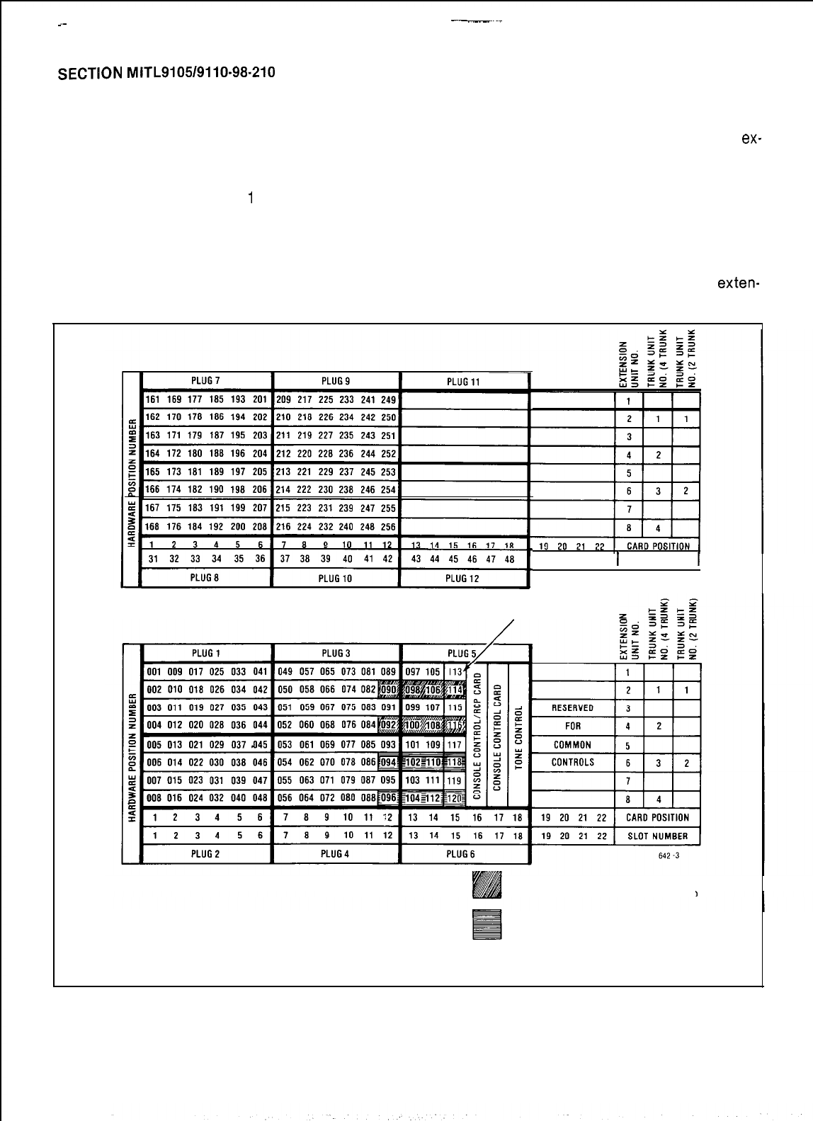
-__~-
-~
SECTION
MITL9105/9110-98-210
changed, or removed from the system memories.
The extension program is selected by the console
keys as described below:
l EXTN Pressing this key enables the
ex-
tension program which allows new data to
be entered or existing data to be changed or
lTENANT The number,
1
to 4, entered after removed.
pressing the TENANT key specifies the te-
nant for which the extensions are being pro-
grammed, if the system is to be used as a
multi-tenant system. If the system is to be
used by a single tenant, the TENANT key
must not be pressed.
* EQPT NUMBER The number (I-112,
161-256) entered after pressing the EQPT
NUMBER key defines the equipment
number of the line circuit serving the
exten-
sion (Fig. 2-l).
49 50 51 52
1
SLOT NUMBER
1
SHELF 2
(-5x-200
ONLY)
RECEIVER NO.1
SHELF
1
DUALANDOR QUAD
RECEIVER EQUIPMENT NUMBERS
QUAD RECEIVER
EQUIPMENT NUMBERS
NOTES: 1. EQUIPMENT POSITION 001 IS RESERVED FORTHETEST LINE AND MUST
THEREFORE BE EQUIPPED WITH A LINE CARD.
2,TRUNKEQUlPMENTNUMBERISSAMEASlNDlVlDUALTRUNKACCESSCODE.
Fig. 2-l Equipment Number
Page 10
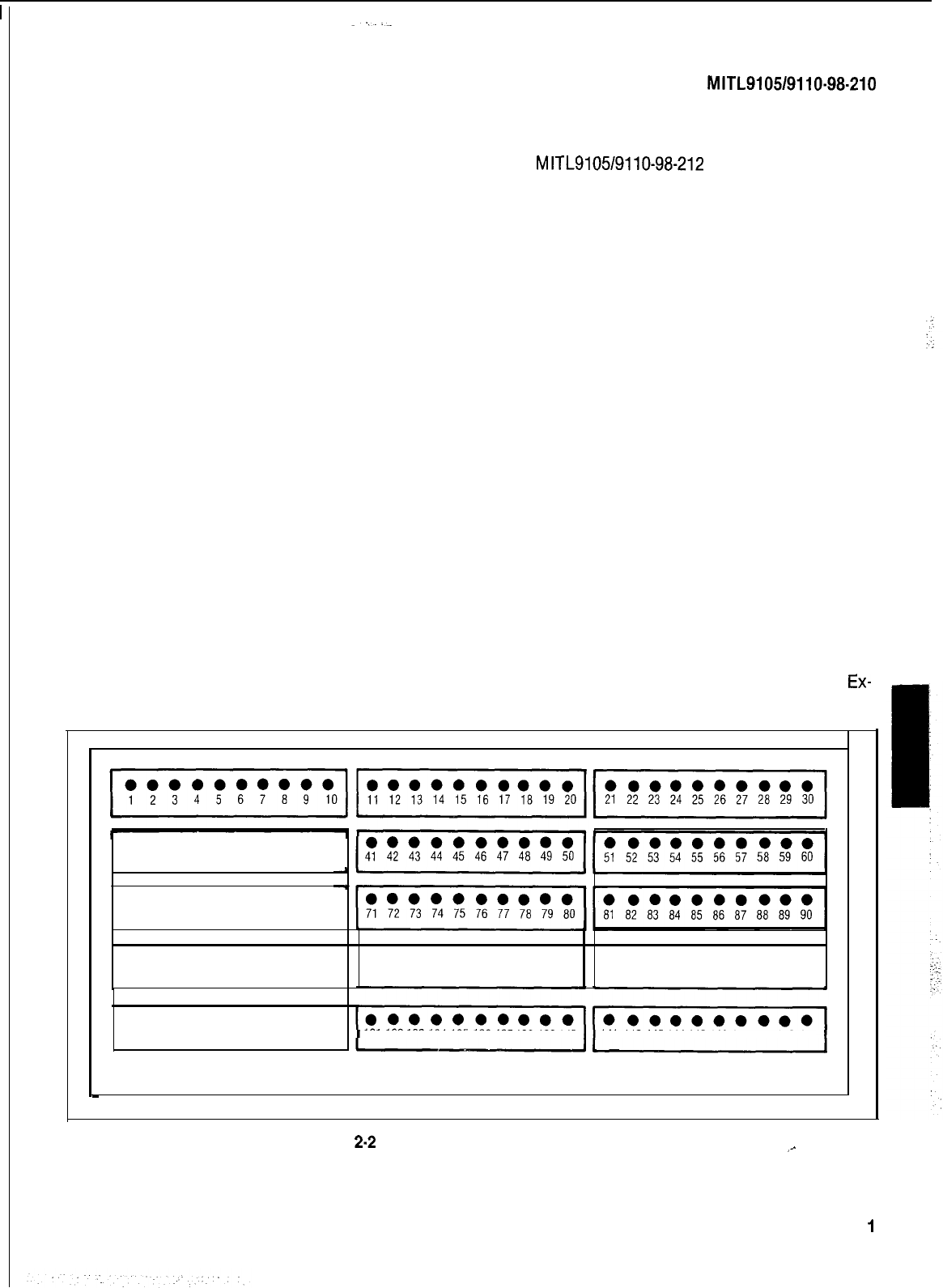
l EXTN NUMBER The 1, 2, 3 or 4 digit
number entered after pressing the EXTN
NUMBER key specifies the extension
number of the telephone set being added or
changed. This number must not conflict
with other extension numbers or access
codes. If non-conflicting single digit dialing
is required, enter N#, where N is the single
digit.
lCOS NUMBER The number (1-16) entered,
after pressing the COS NUMBER key,
specifies the Class-Of-Service, and
therefore the features, that may be access-
ed by the extension. See 2.04 Class-Of-
Service Option.
lTOLL DENY Each extension may be defin-
ed as TOLL ALLOWED-allowed to
originate calls to the toll network; or TOLL
DENIED-not allowed to make calls to the
toll network. To make the extension TOLL
ALLOWED press the TOLL DENY key then
the DELETE key. To make the extension
TOLL DENIED press the TOLL DENY key
then the ADD key. The extension will be
TOLL DENIED only if the extension and the
trunk group are TOLL DENIED. This allows
SECTION
MITL9105/9110-98-210
Option 199 was enabled. See also Section
MITL9105/9110-98-212
Multi-Digit Toll Con-
trol.
l BUSY LAMP NUMBER After pressing this
key the number entered (l-150) defines the
position (Fig. 2-2) of the busy lamp to be
associated with the extension. If the exten-
sion is not to be assigned a busy lamp, no
entry is required.
l DELETE Pressing the DELETE key
removes the existing busy lamp assign-
ment.
lPICKUP GROUP The system may hold up
to 50 independant call pickup groups. An
extension may be made a member of any
group, by entering the pickup group number
after pressing the PICKUP GROUP key. Any
number of extensions may be assigned to a
pickup group, but an extension may only be
a member of one group at any time.
Membership in a pickup group is mutually
exclusive with message registration and
room status.
l CANCEL Pressing the CANCEL key, prior
to the operation of the ENTER key, removes
any data entered during the foregoing
Ex-
Toll Denial on a trunk group basis if System tension Program sequence.
l ooooooooo
31 32
33
34 35 36 37 38 39
40
l ooooooooo
61 62
63
64 65 66 67 68 69
70
l ooooooooo l ooooooooo l ooooooooo
91 92
93
94 95 96 97 98 99
100 101 102 103104 105
106 107108109110
111
112113 114115 116117 118119120
l ooooooeoo
121122
123
124125126127128129
130 131
132133 134135 136137138 139140
141 142
143144145
146 147 148 149 150
Fig.
2.2
Busy Lamp Position Numbering
_-
Page 1
I

SECTION M ITL9105/911 O-98-21 0
l ENTER Transfer all new data for the ex-
tension to permanent memory.
Hunt Groups
2.08 The system can hold up to 12 different hunt
groups. Each hunt group may contain an
unlimited number of members and be specified
as:
l TERMINAL HUNTING The hunt group se-
quence starts at the first equipment
number and ends at the last number in the
hunt chain. The call is completed at the first
idle number encountered.
l CIRCULAR HUNTING Hunting starts at
the last equipment number reached and
hunts over all members of the hunt group.
The call is completed at the first idle
number found.
l SECRETARIAL HUNTING This is terminal
hunting where the last number is common
to two or more extension hunt groups.
l DUAL NUMBER ACCESS An extension
may be programmed to allow it to be ac-
cessed by two different numbers. The first
number is assigned when programming the
extension and the second number by pro-
gramming a hunt group with the extension
as the only member. The extension may
therefore be accessed by dialing the exten-
sion number or the hunt group master
number (see Section
MITL9105/9110-98-105,
Single Digit Dialing).
Note: When changing the list of members
of a hunt group in any way, all members of
the hunt group must be re-entered.
2.09 The following console keys are activated to
program the hunt groups:
l TENANT If multi-tenant service is to be
selected the number (l-4) entered after
pressing the TENANT key, specifies the te-
nant for which the hunt groups are being
programmed. If single tenant operation is
to be used, the TENANT key must not be
pressed.
Page 12
l HUNT GROUP Allows the hunt group re-
quired to be selected by dialing the hunt
group number (1-12).
lACCESS CODE Allows the
1,2,3
or 4 digit
code identifying the hunt group master
number to be entered.
l DELETE Pressing this key deletes the
hunt group from the system memory.
lEQPT NUMBER This key must be pressed
before dialing the equipment number of
each extension in the hunt group. If circular
hunting is to be defined, the last entry in the
hunt group must be the same as the first en-
try. Membership in a hunt group is mutually
exclusive with “message registration” and
“room status” for this extension.
l CANCEL Deletes all new data entered
associated with the hunt group.
lENTER Transfers all new data for the hunt
group to permanent memory.
Trunks
2.10 This program allows the type, console ap-
pearances, day and night assignment, COS
and toll deny codes of each trunk to be specified.
2.11
The following console keys are employed to
enter this program:
l TENANT If the multi-tenant service is to
be selected the number (l-4) entered after
pressing the TENANT key, specifies the te-
nant for which the hunt groups are being
programmed. If single tenant operation is
to be used, the TENANT key must not be
pressed.
l TRUNK Selects the trunk program
l EQPT NUMBER The number entered
(2-112; 162-256, even numbers only)
specifies the equipment number of the
trunk circuit serving this trunk (Pig. 2-l).
l TYPE The code entered, defines the type
of trunk being specified. (See
MITL9105/9110-98-105
Features and Ser-
vices Description for definition of VNL)
Code
1
-
CO trunk + VNL
Code
2
-
DISA
trunk + VNL
Code
3
-
DID trunk + VNL
Code
4
-
Dial-In tie trunk + VNL
Code
5
-
Non Dial-In tie trunk + VNL
Code
6
-
CCSA trunk + VNL
Code
11
-
CO trunk + NON VNL
Code
21
-
DISA
trunk + NON VNL
Code
31
-
DID trunk + NON VNL
Code
41
-
Dial-In tie trunk + NON VNL
Code
51
-
Non Dial-In tie trunk + NON VNL
Code
61
-
CCSA trunk + NON VNL
.
DELETE If this key is pressed, the infor-
mation associated with this trunk is remov-
ed from the system memory.
lBUSY LAMP NUMBER The number (l-150)
defines the position (Fig. 2-2) of the busy
lamp to be associated with this trunk. If the
trunk is not to be assigned a busy lamp no
entry is required.
l DELETE If this key is pressed the busy
lamp assignment for this trunk is deleted.
l LDN NUMBER (Types 1, 5, 11, 51 only)
This single digit entry defines the Listed
Directory Number key (LDN 1, 2, 3 or 4) on
the attendant console which is to be
associated with the trunk. If the trunk is not
to appear on the attendant console, no en-
try is required. DID trunk calls to the atten-
dant always appear on LDN 4.
lDAY NUMBER (Types
1,5,11,51
only) The
code entered for Day Number specifies any
special assignments of the trunk during
normal day time service. These
assignments may be:
.no assignment to bells, extensions or
hunt groups, console appearance on-
ly (Default code #0)
.
assigned to ring bell 1, code
#l
lassigned to ring bell 2, code
#2
SECTION
MITL9105/9110-98-210
.
assigned to ring bell 3, code
#3
.assigned to one extension
-
enter
equipment number of extension
.assigned to a hunt group, codes
1
to 12
I/C
(Types 3, 6, 31, 61 only) This two or
three digit entry for DID or CCSA trunks
defines the number of incoming digits, the
number of digits to be absorbed; and the
digit to be added to the incoming number
after absorbtion.
NIGHT 1 (Types
1,5,11,51
only) This entry
defines the assignment of the trunk during
Night Service 1. Assignment is made in the
same manner as for DAY NUMBER assign-
ment.
NIGHT 2 The entry defines the assign-
ment of the trunk during Night Service 2.
This assignment is made in the same man-
ner as for DAY NUMBER assignment.
COS NUMBER (Types
2,4,21,41
only) The
number (l-16) entered, after pressing this
key, specifies the Class-of-Service and
therefore the features, that may be access-
ed by the dial-in trunk. See 2.04 Class of.
Service Option.
TOLL DENY (Types 2, 4, 21, 41 only) Each
dial-in trunk may be defined as TOLL
ALLOWED-allowed to originate calls to
the toll network; or TOLL DENIED-not
allowed to make calls to the toll network. To
make the tie trunk TOLL ALLOWED press
the TOLL DENY key then the DELETE key.
To make the tie trunk TOLL DENIED press
the TOLL DENY key then the ADD key. If
System Option 199 is enabled see also Sec-
tion
MITL9105/9110-98-212
Multi-Digit Toll
Control.
CANCEL Pressing this key, prior to the
operation of the ENTER key, removes any
data entered in the temporary storage.
ENTER Deletes previous data associated
with this trunk and stores the new data.
Page13 i
---_-
SECTION
MITL9105/9110-98-210
Trunk Groups
2.12 The trunk group program specifies the
trunks forming the trunk group, the restric-
tions and options common to all trunks in the
group. The trunk group may employ terminal or
circular hunting (see 2.08). When making any
change to the list of members of a trunk group all
members of the group must be re-entered. The
following console keys are activated to program
the trunk groups:
0
TENANT The number, 1 to 4, entered after
pressing the TENANT key specifies the te-
nant for which the extensions are being pro-
grammed, if the system is to be used as a
multi-tenant system. If the system is to be
used by a single tenant, the TENANT key
must not be pressed.
lTRUNK GROUP The number (1-12) entered
specifies the trunk group to be set-up or
changed.
lACCESS CODE Allows the
1,2,3
or 4 digit
code identifying the trunk group to be
specified.
l DELETE Pressing this key deletes the
trunk group from the system memory.
l TYPE The four digit code entered after
pressing the TYPE key specifies the trunk
group type parameters as detailed in Table
2-5.
TABLE
2-5
TRUNK GROUP TYPE CODES
First Digit (Note 1) Second Digit Third Digit (Note 2) Fourth Digit
1 No supervision 1 No message
tl
Dial pulse, 1 CO trunk
2 Answer
super-
register no wait for 2 Non CO trunk
vision
l
2 Message register
dial tone
**3
Identified Trunk
3 Toll reversal
fl3
SMDR Enable
t2
Dial pulse, Group (Type XX13
4 Outgoing audio
@4
SMDR Enable and wait for dial only is valid)
inhibited until Message Register tone
answer supervision Enable $3 DTMF, no wait
for dial tone
t4
DTMF, wait for
dial tone
* Available in Generic 203 and above
0
Generic 205 only
15%
l * Available in Generic 204
f
If extensions are DTMF the trunk will convert to dial pulse. Early line split is not provided.
$
Trunks will repeat DTMF or dial pulse signals.
Note 1 l
.
.
.
.
Note 2 l
Page 14
If answer supervision is not required (or not provided by the CO), then use 1
-
(No supervi-
sion).
If trunks provide answer supervision and tandem trunking or message registration is used,
then specify 2, (Answer Supervision).
If supervision is used to indicate toll calls, and this feature is required, then use 3
-
(Toll
supervision).
If audio cut-through on tie-trunk tandem calls is required only after receipt of answer
supervision, then use 4
-
(Outgoing audio inhibit until answer supervision),
If audio cut-through on tie-trunk tandem calls is required only after receipt of answer
supervision, then use 4
-
(Outgoing audio inhibit until answer supervision). In addition for
Generic 205 the audio is inhibited until timed out or unless a # is dialed.
_
If “wait for dial tone” is selected then any digits dialed prior to receipt of CO dial tone
are ignored by the PABX. This prevents circumvention of the toll denial by dialing a fast
valid digit before CO dial tone is received.

r
SECTION
MITL9105/911
O-98-21 0
l TOLL DENY Each trunk group may be
specified as TOLL ALLOWED-allowed to
originate calls to the toll network or TOLL
DENIED-not allowed to make calls to the
toll network. To make the trunk group TOLL
ALLOWED press the TOLL DENY key then
the DELETE key. To make the trunk group
TOLL DENIED press the TOLL DENY key
then the ADD key. Toll Denial is effective
only when both the trunk group and the ex-
tension or dial-in trunk involved are TOLL
DENIED.
l OVERFLOW The number entered (1-12)
specifies the trunk overflow group number.
If all trunks within the trunk group being
defined are busy, any additional calls
directed to the trunk group will be rerouted
to the overflow group. Overflow ar-
rangements which direct the call back to
the original group must NOT be specified.
lEQPT NUMBER This key must be pressed
before dialing the equipment number
(2-112; 162-256) of each trunk in the group. If
circular hunting is to be defined, the last en-
try in the hunt group must be the same as
the first entry. If circular hunting is not re-
quired, the trunk group is terminal hunting
(see 2.08).
l CANCEL Pressing the CANCEL key
removes all new data entered for the trunk
group, leaving any existing data unchang-
ed.
l ENTER Removes all old data associated
with the trunk group and transfers the new
data entered to permanent memory.
3. PROGRAMMING
General
3.01
After all installation procedures have been
completed in accordance with Section
MITL9105/9110-98-200
the system should be pro-
grammed as detailed in the
MITEL
Action Pro-
cedures (MAPS) contained in Appendix 1 and 2.
ErrorlConf
irm Codes
3.02 During standard system programming the
console DESTINATION display may show
“error” or “confirm” codes, with the meanings in-
dicated in Tables 3-1 and 3-2 respectively. These
tables also indicate required action when the
code is displayed. In the extended programming
mode errors may also be displayed at the console.
Figs 3-3 and 3-4 show the meanings of these er-
rors.
Attendant Function Access Codes
3.03
Table 3-5 is a listing of the attendant func-
tion access codes. To select any of the at-
tendant functions the access code for Feature 18
must have been dialed. The code
*
is used in
Table 3-5.
Maintenance Function Access Codes
3.04
Table 3-6 lists the maintenance function ac-
cess codes. To select any of the
maintenance functions the access code assigned
for the maintenance function must be dialed
(Feature Number 19). The code 555 is used in
Table 3-6, for the maintenance code and may be
dialed from the test line or console.
Timeout Information
3.05
During programming it may be necessary to
know the timeout information with regard
to certain functions. Table 3-7 is such a listing of
the timeout information.
Page15
I.
SECTION
MITL9105/9110-98-210
TABLE
3-l
PROGRAMMING ERROR CODES
Callback and Executive Over-
ride conflict, i.e. trying to
enter a Callback code while
same code assigned to Ex-
ecutive Busy Override and
vice-versa.
E5
Number entered EXTN NUMBER None The extension number or
contains incorrect, ACCESS CODE access code is in conflict Check entry. Press key
number of digits or
conflicting option with the existing numbering associated with entry and
re-enter number.
enabled in this COS. plan. Attempting to add
an option to a COS in which
a conflicting option is enabl-
ed.
Attempting to add a System
Option when a conflicting op-
tion exists.
E6
Incorrect equipment EQPT NUMBER None
number entered. Attempting to assign an
equipment number that is: Remove conflicting option
l undefined (a) Assign equipment
l defined as a trunk to number correctly
an extension hunt group (b)
,E,nE;e:ew
equipment
or extension
Error Key
code Cause affected
Key
flashing Meaning Action Required
EO
Invalid key pressed. ALL None The last key pressed is invalid Check procedure and press
at this time.
El Invalid number. ALL None The number entered is out correct key.
of range or contains Press key associated with
corrupted data. entry and re-enter number.
E2
Key other than LAMP TEST,
ENTER,
ENTER or CANCEL TENANT, OPTION CANCEL An attempt was made to
leavepress
ENTER to transfer the
the current mode after some
pressed. COS DEFINE, data to permanent store or
FEATURE parameters were changed CANCEL to remove the data
EXTN NUMBER, but before ENTER or CANCEL from the temporary store.
TRUNK HUNT GROUP, was pressed. ENTER may be
TRUNK GROUP, used to write the new
pro-
NEXT, EQPT
gramming
information back to
the non-volatile RAM or use
NUMBER CANCEL to ignore all pro-
gramming changes made
Ssince
the last time ENTER
was pressed.
E3
Access code has HUNT GROUP ACCESS
not been entered. TRUNKGROUP CODE Attempting to enter members Press ACCESS CODE key
ant
into a Hunt or Trunk group
before an access code has enter required access code.
E4
The extension
EXTN,
None been assigned to the group.
The extension number or Check code entered.
number or access ACCESS access code entered is
code entered is CODE
already assigned. already assigned to an 1 If code is correct, terminate
extension, feature, hunt entry, remove other
appear-
ante
of code and re-enter
group or trunk group. all new data.
In Trunk mode an attempt
is made to delete a member 2 If code is incorrect, press
of a trunk group. key associated with entry
and re-enter extension
Equipment Numbers desired number or access code.
must be entered.
In Trunk Group mode an at-
tempt is made to place a
trunk into a trunk group while
that trunk is currently pro-
grammed into another trunk
group.
l defined as an extension to
a trunk group or a trunk
l an extension with message
registration to hunt group
or pickup group
An equipment number assign-
ed to an extension must be
deleted as an extension
before being programmed as
a trunk. An equipment number
assigned to a trunk must be
deleted as a trunk before be-
ing programmed as an exten-
sion (Generic
204/up).
Page 16
SECTION
MITL9105/9110-98-210
TABLE 3-1 (Cont’d)
PROGRAMMING ERROR CODES
(b)Attempting
to change data (b) Wait until extension or
of an extension or trunk trunk is idle
while that extension or
trunk is in use. It must be
idle or busied-out.
E7
Extension has a
ENTER
None l a valid message
message register register exists for Zero message register,
reset message waiting
that is not zeroed this extension or Do Not Disturb
or has a message l extension has a and reprogram
waiting, or has message waiting or
Do Not Disturb Do Not Disturb set
set.
E8
Trunk or equipment ENTER None Attempting to assign a(a) Key proper trunk or
number already trunk or equipment equipment number
assigned. number to more than one (b) Press ENTER
tenant at the same time.
In Tenant Service, pressing
Error Key Key
code Cause affected flashing Meaning Action Required
E7
System is busy. ENTER, None
TENANT (a)Attempting to initialize (a) Wait until system is idle
system while PABX is in
use.
the Hunt Group key when all
hunt groups are assigned to
other tenants.
In Tenant Service, pressing
the Trunk Group key when all
trunk groups are assigned to
other tenants.
In Tenant Service, attempting
to put an extension assigned
to one tenant into a hunt
group of a different tenant.
In Tenant Service, attempting
to put a trunk assigned to one
tenant into a trunk group of a
different tenant.
In Tenant Service, entering a
hunt group number assigned
to a different tenant (after
pressing HUNT GROUP).
In Tenant Service, Trunk
Group
Programmtng,
selecting
an overflow group that
belongs to another tenant.
In Tenant Service, entering a
trunk group number assigned
to a different tenant (after
pressing TRUNK GROUP).
E9
Non-Volatile RAM
ENTER
None Ones and Zeros test failed Go to Section
error. prior to initializing
Non-
MITL9105/9110-98-350
Volatile RAM.
E022-22
At Power up None RAM programmed in Generic Non-Volatile RAM must
202 or 203 is used be initialized and/or
with Generic
2041~~
reprogrammed
1
:.
:
Page17
’
r
SECTION
MITL9105/9110-98-210
TABLE
3-2
CONFIRM CODES
Confirm
Key
Code Cause Affected Flashing
Lamp Action
co Attempting to assign an
equipment number for
an extension to a slot
containing a trunk card
EQPT
NUMBER CONFIRM Check assignment-
l if correct press CONFIRM
key. Equipment number entered
is accepted as the number
co
Attempting to assign an
equipment number for
a trunk to an empty
slot or a slot containing
an extension card.
EQPT
NUMBER CONFIRM for the equipment type being
programmed. All data associated
with the original appearance
of the equipment number
is removed
l if incorrect press EQPT NUMBER
and re-enter new equipment number
Cl Attempting to assign an
extension that already
exists
EXTN
NUMBER CONFIRM Check assignment-
l if correct press CONFIRM key.
The extension number entered is
accepted as the extension number
for the equipment being defined.
All data associated with the
original appearance of the
extension number is removed.
l if incorrect press EXTN NUMBER
and re-enter extension number.
c2 The busy lamp assignment BUSY CONFIRM
already exists LAMP Check assignment-
l if correct pass CONFIRM key. Busy
lamp assignment is accepted for this
equipment. All data associated with
original assignment is removed.
l if incorrect press BUSY LAMP and
re-enter busy lamp assignment
TABLE
3-3
EXTENDED PROGRAMMING ERROR CODES
-
TOLL CONTROL
Error
Applies to:
EO
All modes
Meaning
Invalid key pressed. Consult MAP for correct pro-
cedure.
El Absorb Plan mode
Trunk Group mode
Control Plan mode
Number is not within the range of the
parameter being defined. Re-enter
parameter key defined.
E2
All modes An attempt was made to leave the current mode
after some parameters were changed but before
ENTER or CANCEL was pressed. ENTER may be
used to write the new programming information
back to the non-volatile RAM or use CANCEL to ig-
nore all programming changes made since the last
time ENTER was pressed.
E3
Control Plan mode
Table mode
The table number entered is not valid for the
current configuration. Re-enter a number which ex-
ists for the configuration of the extended non-
volatile customer RAM.

SECTION
MITL9105/9110-98-210
TABLE
3-3
(Cont’d)
E4
E5
EXTENDED PROGRAMMING ERROR CODES -TOLL CONTROL
Table mode The table entry code is invalid for the table pro-
grammed. This occurs in the following situation:
1.
A code of more than 3 digits in length for an
800-entry
or
20-range
table.
2.
A code not in the range of 200-999 for an
800-entry
table.
3.
A code which already exists or a code which
would be ambiguous in conjunction with the
existing table entries, for a
4-entry
table.
Table mode The table is full and cannot hold the entry.
E7
Configuration mode Configuration is not allowed because the Tone
Control card switches are not 7776 or the system
is not idle.
E9
Configuration mode A hardware failure was detected while clearing the
extended customer non-volatile RAM.
I
Page19
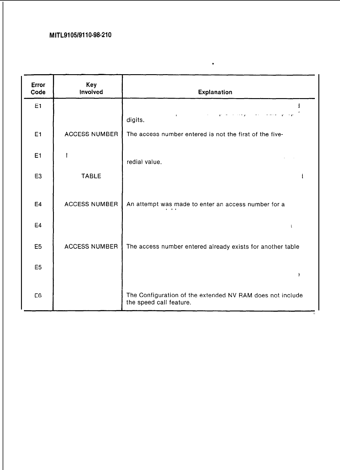
SECTION
MITL9105/9110-98-210
TABLE 3-4
EXTENDED PROGRAMMING ERROR CODES
-
SPEED CALL
EQPT NUMBER The equipment number entered is outside the range of valid
numbers. Check procedure and press key then redial proper
number group. Enter the proper access number.
NUMBER REDIAL An invalid number redial value was entered. Enter the proper
The table number entered is not consistent with that allowed
for the current Configuration of the extended NV RAM.
Check the Configuration number.
common-use table.
NUMBER REDIAL An attempt was made to enter a number redial digit for a
common-use table.
assigned to the same equipment number.
NUMBER REDIAL Number redial already exists for another table assigned to
the same equipment number, (only 1 number redial attribute
per user is allowed).
SPEED CALL
Page 20
SECTION MITL9105/911 O-98-21 0
TABLE
3-5
ATTENDANT FUNCTION ACCESS CODES
These codes assume the use of
3t
as the Attendant Function code (Feature number 16).
To cancel all call forwarding: To make trunk group attendant access:
a) Dial
*
1 a) Dial
*
6
b) Dial #
b)
Dial trunk group (1 through 12)
c) Press RELEASE c) Dial+
d) Press RELEASE
To access an individual trunk:
a) Dial
*
2 To change the Direct Inward System Access
Code:
b) Dial individual trunk access number
(equipment number) a) Dial
+
7
c) Dial
*
b) Dial
DISA
code
d) Press RELEASE c) Press RELEASE
To force-release an individual trunk: To cancel a minor alarm:
(Note 1)
a)
bial*
2
a) Dial
*
8
b) Dial individual trunk access number b) Dial #
(equipment number) c) Press RELEASE
c) Dial
#
#
d) Press RELEASE
t
To busy out an individual trunk:
t
To make flexible night service assignments: a) Dial
*
9
a) Dial
*
3 b) Dial individual trunk access number
b) Dial individual trunk access number (equipment number)
(equipment number) c) Dial
*
c)
Press Night 1 or Night 2 d) Press RELEASE
d) Dial extension number
e) Press RELEASE
t
To de-busy an individual trunk:
To cancel all system callbacks:
a) Dial
)c
4
b) Dial
#
c) Press RELEASE
a) Dial
+
9
b) Dial individual trunk access number
(equipment number)
c) Dial #
d) Press RELEASE
To set the clock time:
t
To change the status of all occupied clean rooms
to occupied and needs cleaning: (Note 2)
a) Dial
*
5
b)
Dial time (hour plus minutes)
c)
Dial
*
for p.m., otherwise a.m.
d) Press RELEASE
To make trunk group dial access:
a) Dial
*
6
b)
Dial trunk group (1 through -12)
c) Dial #
d)
Press RELEASE
a) Dial
*
10
b) Dial
*
c)
Press RELEASE
tTo
change the status of all occupied rooms in the
need of cleaning to occupied clean: (Note 2)
a) Dial
*
10
b) Dial #
c)
Press RELEASE
Page 21
SECTION
MITL9105/9110-98-210
TABLE
3-5
(CONT’D)
ATTENDANT FUNCTION ACCESS CODES
To set up call forwarding: (Note 2)
i’
To enable the printer: (Note 3)
a)
Dial*
llnnn, where nnn is the extension
number of the forwarding extension a) Dial
)c
14 #
b) Dial call forwarding code (l-3) b) Press RELEASE
c)
Dial nnn, where nnn is the number to which
the calls are to be forwarded To change the date: (Note 3)
d) Press RELEASE
a)
Dial
*
15 and 3 or 4 digit date (one or two
To cancel call forwarding for an extension:(Note 2) digit month, two digit day)
b)
Press
RELEASE
a)
Dial
*
llnnn, where nnn is the extension
number of the forwarding extension
tTo
print the room audit (registers): (Notes 3
ant
b) Dial #
4)
cj Press RELEASE
.To
busy out an extension:(Note 2)
a) Dial
*
16
b) Press RELEASE
a) Dial*
12nnn,
where nnn is the number of
tT
d’
the extension to be busied out o
tsplay
system identity: (Note 3)
b) Dial+
c) Press RELEASE a) Dial
*
17
b) Press RELEASE
1
To de-busy an extension: (Note 2)
tTo
change the system identity: (Note 3)
a)
Dial
*
12nnn,
where nnn is the number of
the extension to be de-busied
b) Dial #
c) Press RELEASE
a)
Dial* 17 nnn (where nnn is a 1 to 3 digit
ID, O-999)
b) Press RELEASE
tTo
suspend the printer: (Note 3)
f
To print the “room status” audit: (Notes 3 and
a) Dial
*
14
*
4)
b) Press RELEASE a) Dial
3c
18
tTo
purge and ignore the printer: (Note 3)
a) Dial
3c
14 00
b) Press RELEASE
b)
Press RELEASE
Note 1 The errors will be sequentially stacked in the memory and may be recalled sequen-
tially (most recent first) by repeating the above procedure.
Note 2 Applies to Generic
203/up
Note 3 Applies to Generic
204/up
Note 4 Printer starts after RELEASE key is pressed.
t
Requires system option programming
Page 22
SECTION
MITL9105/9110-98-210
TABLE 3-8
MAINTENANCE FUNCTION ACCESS CODES
‘o
select any of the functions the access code assigned for the maintenance function must be dialed
Feature Number 19). The code 555 is used in the following part for the maintenance code and may be
lialed
from the test line or console in Generic
203/up.
Clear all errors: **To initiate system dump (from test line):
a) Dial 555 + 1
a)
Dial 555 + 7 and hang up
b) Go off-hook
Direct trunk or station access:
c)
Dial 555 + 8 + # (or 2)
a) Dial 555 + 2**To initiate system dump (from console):
b)
Dial individual equipment number (3 digit
equipment number for trunk or station) a) Dial 555 + 7
b) Dial
*
14 #
Busy out of a receiver:
a) Dial 555 + 3
b)
Dial equipment number of receiver
Busy out of a speech path:
a) Dial 555 + 33
b)
Dial speech path number (01-31)
De-busy a receiver:
a) Dial 555 + 4
b)
Dial equipment number of receiver
De-busy a speech path:
a) Dial 555 + 43
b)
Dial speech path number (01-31)
Initialize card slot:
**TO suspend printer:
a) Dial 555 + 8 +
*
(or
I),
or
b)
Dial
*
14
it
(console only)
l *To enable printer:
a)
Dial 555 + 8 + # (or
2),
or
b)
Dial
*
14
#
(console only)
t**To
purge and ignore printer:
a) Dial 555 + 8 + 00, or
b)
Dial
*
1400 (console only)
a) Dial 555 + 5
b)
Dial card slot number (01-17, 31-42)
t*
System reset: (Note 2)
a) Dial 555 + 6
t
Requires System Option Programming
l Generic
2031~~
l * Generic
204/up
Notes
1.
For Traffic Measurement Access Codes see
MITL9105/9110-98-450.
2.
System Reset requires thumbwheel switches be set to 777n (n = 0 to 9) on Tone
Cont;bl
card for
Genpric
20311~~.
Page23 j
SECTION
MITL9105/9110-98-210
TABLE
3-7
SYSTEM TIMEOUT INFORMATION
Description
Attendant Timed Recall (Don’t Answer)
Attendant Timed Recall (Camp-On)
Attendant Timed Recall (Hold)
Automatic Night Switching
Dial Tone Timeout
Interdigit Timeout (Extensions)
Interdigit Timeout (Trunks)
Lockout Timeout
Callback Clear Timeout
Callback Don’t Answer Reset
Call Park Recall
Call Hold Recall
Call Forward
-
Don’t Answer Timeout
Switchhook Flash
Ringing Timeout
Automatic Wakeup Ringing
Automatic Wakeup Attempts
Timeout
2Os,
30s
or 40s
2os,
3os,
or 40s
2Os,
3Os,
or 40s
2Os,
3Os,
or 40s
15s
15s
10s
45s
8 hours
6 rings
2, 3 or 4 minutes
2, 3 or 4 minutes
2Os,
3Os,
or 40s
Min. 200ms
Max.
0.7s
0.9s,
1.1s
or 4.5s
5 minutes
6 rings, 3s each
3 at 5 minute Intervals
Page 24
4. EXAMPLES
Introduction
4.01
This part describes the steps required to program the SX-100 and SX-200
PABX’s
using the Installa-
tion Forms, and provides typical examples of completed Installation Forms.
4.02 System Options
Step Operation
1.
2.
3.
4.
5.
/Press the OPTION key.
Dial the number of the required option.
~
(See Tables 2-l and 2-2)
Press the ADD key to add the option,
OR
Press the DELETE key to remove the
option
Press the ENTER key to enter all options in-
to the memory.
Repeat steps 1, 2, and 3 above until all re-
quired options have been added or deleted.
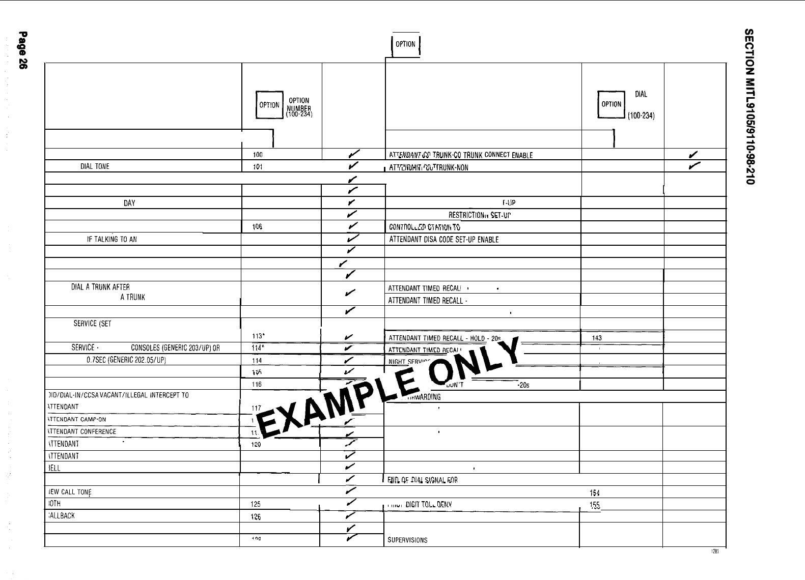
I
1
SYSTEM OPTIONS
1
mm
1
t
I
I I I
II
cl
DIAL
q
ADD
OPT!ON
;l,T$R
(100-234)
cl
DIAL
cl
ADD
OPTION
OPT'ON
NUMBER
(100-234)
OPTION NAME
DISCRIMINATING RINGING
.__
I
r -I
LI.Y"l.I
"V
I
II",,,\
v..
TRANSFER DIALTONE
I",
J
nTTChl"nhlT
rn
TDI,hIY.hlr
FLEXIBLE NIGHT SERVICE
I
OPTION
NUMBER
OPTION NAME OPTION
NUMBER
ion
J
4TTEhlndhlT
PO
TDllhlK.Pq
TRUNK CONNECT ENABLE
129
J
.-.
I
_
I
no
ILI.YIIIII
YY ~w,.w,.JN CO TRUNK CONNECT ENABLE
130
J
102
J
ATTENDANTNON COTRUNK-NONCOTRUNKCONNECT
NIGHT SERVICE AUTOMATIC SWITCHING
103
J
ENABLE
TAFAS AVAILABLE DURING DAY
104
/
CONTROLLEDOUTGOING RESTRICTION SE'
OUTGOINGTRUNKCAMP-ON
105
J
CONTROLLEDSTATION
REPTalrTfnhl
QET.
OUTGOINGTRUNK CALLBACK
lOI7
J
P"hlTD"l
I
Erl
9TdTlr-m
Trl
I 131
132'
133'
.._
-w>.,,,vLLLY
w,n,,w,.
Iv
STATION RESTRICTION SET-UP
134'
CAN FLASH IFTALKINGTOAN INCOMINGTRUNK
107
ATTENOANTOISACOOESET-UPENABLE 135
CAN FLASH IFTALKING TO AN OUTGOINGTRUNK
108
J
LIMITED WAIT FOR DIAL TONE
136
CAN FLASH IF TALKING TO STATION
109
I/
MESSAGE WAITING SET-UP (LAMP)
137'
I
CANNOT DIAL ATRUNKAFTER FLASHING
110
J
MESSAGE WAITING SET-UI
CANNOT
OIALATRUNKAFTER
FLASHING IF HOLDING
OR IN CONFERENCEWITH
ATRUNK
111
J
ATTENDANTTIMED
REGAL1
'(BELL)
138'
L
-
CAMP-ON
-
20s
139
ATTENOANTTIMEORECALL- CAMP-ON -40s 140
LOCKOUT ALARM ENABLE
112
/
ATTENDANTTIMED RECALL-DON'T ANSWER
-
20s
141
TENANT SERVlCE(SET AUTOMATICALLY WHEN TENANT ATTENDANTTIMED RECALL-DON'T ANSWER 40s
142
SERVICE IS SELECTED WHEN PROGRAMMING)
TENANT SERVICE. SEPARATE CONSOLES(GENERIC203/UP)OR
FLASH TIME 0.7SEC(GENERIC202.05/UP)
JACANT NUMBER INTERCEPTTO ATTENDANT
114*
144
145
.I 146
LLEGALACCESS INTERCEPT TO ATTENDANT
IIDIDIAL-lN/CCSA VACANT/ILLEGALlNTERCEPTTO
TRUNK,CCSA) 149
CALL FORWARDING
-
DON'T ANSWER (SYSTEM, DID, DIAL-IN
\TTENDANT BUSY OVERRIDE
,-"
TIETRUNK. CCSA)
150
\TTENDANT SERIAL CALL
121
PARK AND CALL-HOLD RECALL 2 MINUTES
151
IELL
OFF ENABLE
122
J
PARK AND CALL-HOLD RECALL
-
4 MINUTES
152
?LIN,T
ANSWER TIMEOUT
-20s
1
147
I
ARDING
-
OON'T ANSWER TIMEOUT -40s
146
I
CALL FORWARDING
-
BUSY (SYSTEM, DID, DIAL-IN TIE
I
J
I
ENI)
OF
DlAl
SIANAl
FflR
OUTGOING TRUNKS (#) 153
154
'AGE BUTTON ENABLE
123
I
IEWCALLTONf
ENABLE
124
>
I
-.--
-'
-..'-
-'-'."-
-" .
24 HOURCLOCK
._.
IOTH
MODESTANDARD
125
I
J
I FIRST
"ICIT
T",
I
nrhl" 155
:ALLBACK BUTTON ENABLE
1%
,b”
/
MESSAGE REGISTRATION ENABLE
156'
RUNK BUSY-OUTENABLE
127
J
MESSAGE REGISTRATION: COUNT ADDITIONAL
BOTH BUTTON ENABLE
rn(l
J
SUPERVISIONS
157'
128,
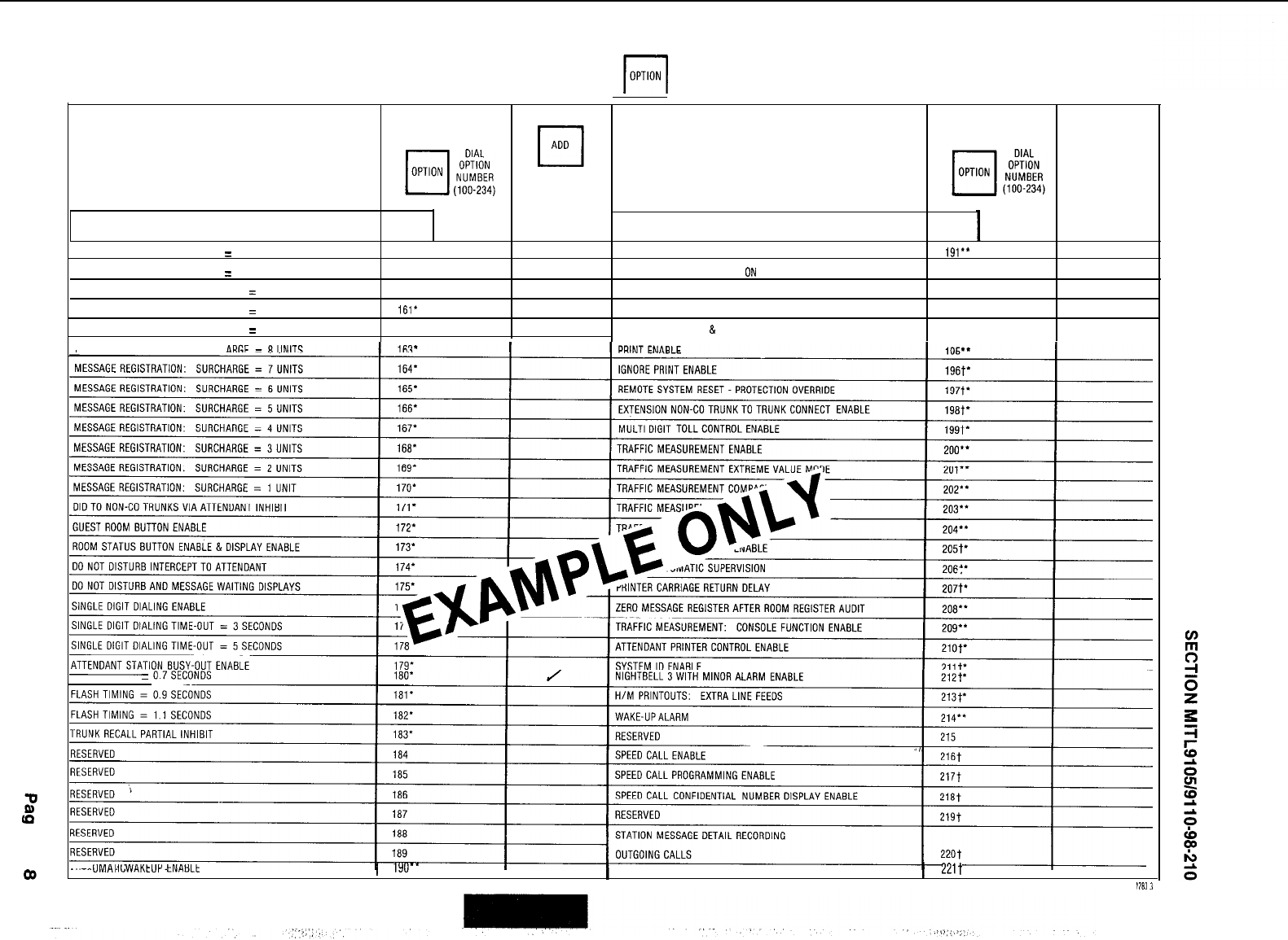
SYSTEM OPTIONS
F]
I
I
cl
ADD
OPTION NAME
MESSAGE REGISTRATION: TIMER
=
20 SECONDS
MESSAGE REGISTRATION: TIMER
=
40 SECONDS
MESSAGE REGISTRATION: MULTIPLIER
=
4 UNITS
MESSAGE REGISTRATION: MULTIPLIER
=
3 UNITS
MESSAGE REGISTRATION: MULTIPLIER
=
2 UNITS
MESSAGE REGISTRATION: SURCH
OPTION
NUMBER
158’
159’
160’
161’
162’
OPTION NAME
AUTOMATIC WAKEUP PRINT
AUTOMATIC WAKEUP MUSIC
ON
HOLD
ROOM MESSAGE REGISTER AUDIT ENABLE
ROOM STATUS AUDIT ENABLE
MESSAGE REGISTER
&
MESSAGE WAITING CHANGE
OPTION
NUMBER
191.’
192”’
193”
194”
FLASH TIMING
=
AU I
UMAI
II;WAKtUV tNALlLt
1
1YO”
I
STATION MESSAGE DETAIL RECORDING INCOMING CALLS 1
221t
I
1x3
1
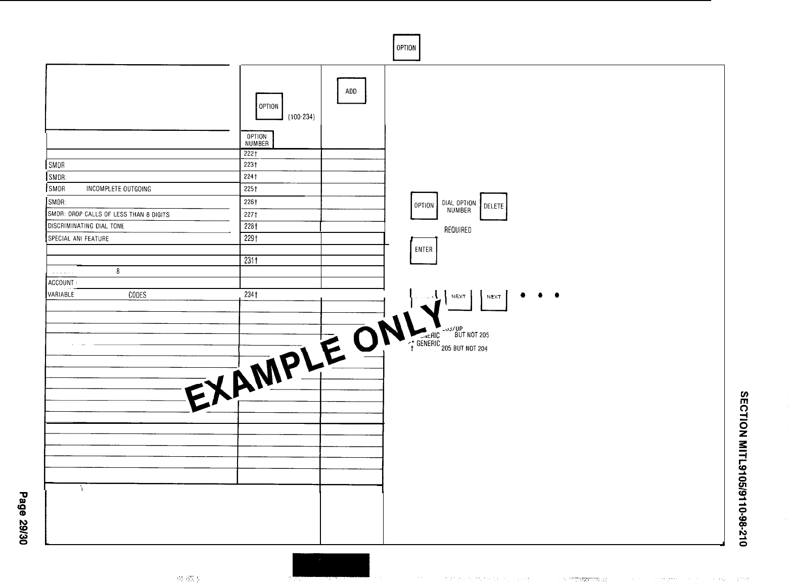
OPTION NAME
SMOR. EXTENOEORECORO
ISMDR RECORD METER PULSES
ISMDR. INDICATE LONG CALLS
ISMDR
DROP
~NCOMPLETEOUTGOING
CALLS
ISMDR. RECORDONLY INCOMING CO CALLS
SMDR DROPCALLS OF LESSTHAN
8
DIGITS
3
ACCOUNTCODE ENABLE 230t ENTER
ACCOUNT CODE LENGTH:4 DIGITS 231t
I
ACCOUNT CODE LENGTH.
8
DIGITS
IACCOUNT
232t TO REVIEWSYSTEM OPTIONS
CODE LENGTH. 12 DIGITS
nnn
IVARIABLE
LENGTH ACCOUNT
CODES
I
234t
I
I
I
OPTION
SYSTEM OPTIONS
F[
I
I
DIAL
OPTION
NUMBER
(100-234)
NOTES
TO DELETE SYSTEM OPTIONS
22Eit
I
AFTER ALL REOUIRED OPTIONS HAVE BEEN REMOVED
229t
I 1
204
BUTNOT
204 AND 205
't
GENERIC 205BUTNOT204
AFTER ALL OPTIONS ARE ADDED
cl
ENTER
.
.
.
I
I
,.,;,
,A/,(
:,
4.03 COS Options
Step Operation
1.
Press the COS DEFINE key.
2.
Dial the number of the COS required
(1 through 16).
3.
4.
Press the OPTION key.
Dial the number of the extension option
required to be added or deleted to the
COS selected in step 2.
(See CLASS-OF-SERVICE DEFINITIONS).
5.
Press the ADD key to add the option to
the selected COS.
OR
Press the DELETE key to remove the op-
tion from the selected COS.
6.
Repeat steps 3, 4, and 5 until all required
extension options have been added or
deleted to the selected COS.
7.
Press the ENTER key to enter all COS op-
tions into the memory.
8.
Repeat steps 1 through 7 for the next re-
quired COS.
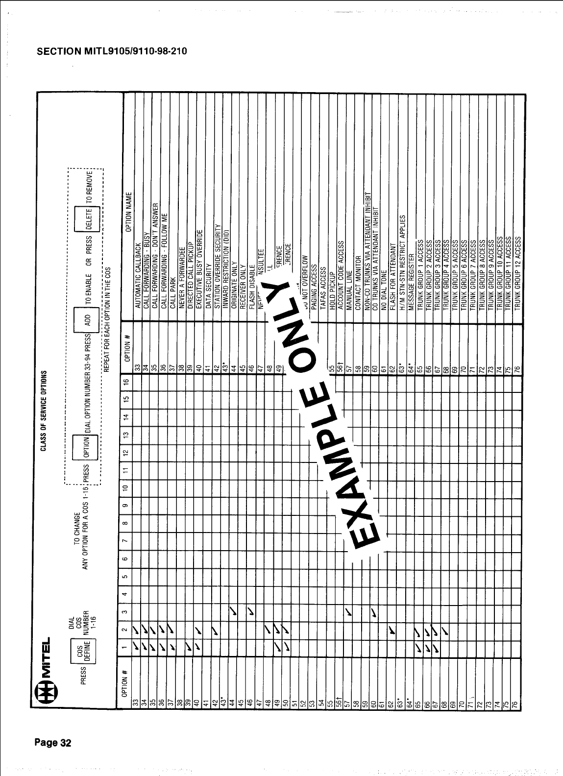
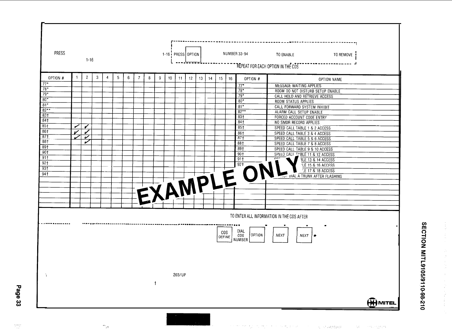
CLASS OF SERVICE OPTIONS
cos
PRESS
DEFINE NUMBER
q
DIAL
cos
l-16
(-
--------------------____________________-----
-
-------------------------,
1
TO CHANGE
ANYOPTION FOR A COS DIALOPTION
NUMBER33-94
PRESS ADD
q
TOENABLE
OR PRESS DELETE
TOREMOVE
j
q
I
I
I
L
___-___---_____-_-______
--------------------
-
-______---_____---__--
J
REPEATFOREACHOPTIONINTHECOS
PRESS ENTER
TOENTERALLINFORMATIONINTHECOSAFTER
ALL OPTIONS IN THAT COS HAVE BEEN DEFINED
.----_------_
------
------_
q
i
__________________-_____________________----
-
------_----------
-
------___------
-- -------
-
------
-
-------
-
------
-
-------- -- ------ -- -----
_
TO REVIEW THE OPTIONS WITHIN A COS
NOTE: AN EXTENSION OR TRUNK CAN NOT CHANGE ITS COS IF THE EXTENSION OR
TRUNK IS BUSY. IT ALSO CAN NOT BE CHANGED UNLESS THE MESSAGE
REGISTER IS CLEARED.
*GENERIC 203/UP
l
* GENERIC 204
t
GENERIC 205
..,
.
,,.
4.04 Features
Step
1.
2.
Operation
Press the FEATURE key.
Dial the number of the required feature.
(See FEATURE ASSIGNMENTS TABLE 2-4)
3.
4.
Press the ACCESS CODE button.
Dial the access code to be assigned
to the feature.
OR
Press the DELETE key to remove an access
code
5.
Press the ENTER key to enter information
into the memory.
6.
Repeat steps 1 through 5 until all
required access codes have been assigned
or deleted.
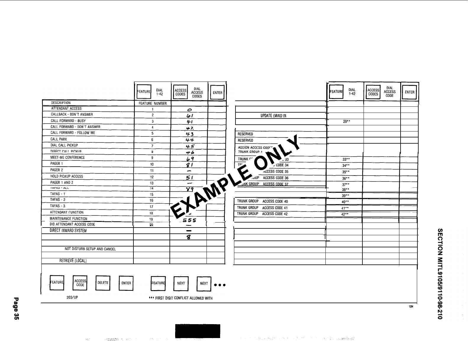
FEATURES
I‘
CALL RETRIEVE (REMOTE)
OIRECTINWAROSYSTEM ACCESS
EXECUTIVE BUSY OVERRIDE (SINGLE DIGIT)
CALLBACK. BUSY (SINGLE DIGIT)
__
21
22
23
-
%
b
ROOM DO NOTOISTURBSETUPANDCANCEL
24'
CALL HOLD
25'
CALL
RETRlEVE(LOCAL) 26'
NOTES
TO DELETE A FEATURE
TO REVIEWACCESS CODES
ROOM STATUS UPDATE(MAIDIN ROOM)
PROGRAMMING SECURITYCODE
ALARM CALL
TRUNKGROUP ACCESS CODE 38
TRUNKGROUP ACCESS CODE34
I1
I I
I-I
FEATURES
F;;“41
27'
28'
29'.
30"
31
32
*GENERIC 203/UP **GENERIC 204
***
FIRST
DIGIT
CONFLICTALLOWEDWITH OTHER ACCESS CODES
111 .I
D
4
4.05 Extensions
f
Step
Operation
1.
2.
3.
4.
5.
6.
7.
a.
9.
IO.
Il.
12.
If TENANT service is used commence at
Step 1. If TENANT service is not used, start
at Step 4 (Note 1).
Press TENANT key.
Dial required tenant number (1, 2, 3 or 4).
Press ENTER key.
Press the EXTN key.
Press the EQPT NUMBER key.
Dial the required equipment number (see
EQUIPMENT NUMBERING, Fig. 2-l).
Press the EXTN NUMBER key.
Dial the required extension number
OR
Press the DELETE key to remove existing
extension information.
Press the COS Number key.
Dial the required COS number (1 through
16).
Press the TOLL DENY key. (See Note 2)
Press the ADD key to implement toll denial
for the extension selected
OR
Press the DELETE key to remove toll denial
for the extension selected.
Step
13.
14.
Operation
Press the BUSY LAMP NUMBER key.
Dial the number of the busy lamp which is
to be associated with the selected exten-
sion. (See BUSY LAMP POSITION NUMBER-
ING, Fig. 2-2)
OR
Press the DELETE key if no busy lamp is re-
quired.
15.
16.
Press the PICKUP GROUP key.
Dial the number of the required pickup
group (1 through 50)
OR
Press the DELETE key if no pickup group
assignment is required.
17.
Press the ENTER key to enter all extension
information into the memory.
18.
Repeat steps 1 through
18
or 4 through
18
for all required extensions.
Notes:
1.
All extensions in one tenant
group should be entered in
succession following the
listed steps. The next
group of extensions are
are entered in a similar
manner using the TENANT
and ENTER keys again.
2. For Multi-Digit Toll Control,
see Section
MITL9105/9110-98-212
Programming Procedures.
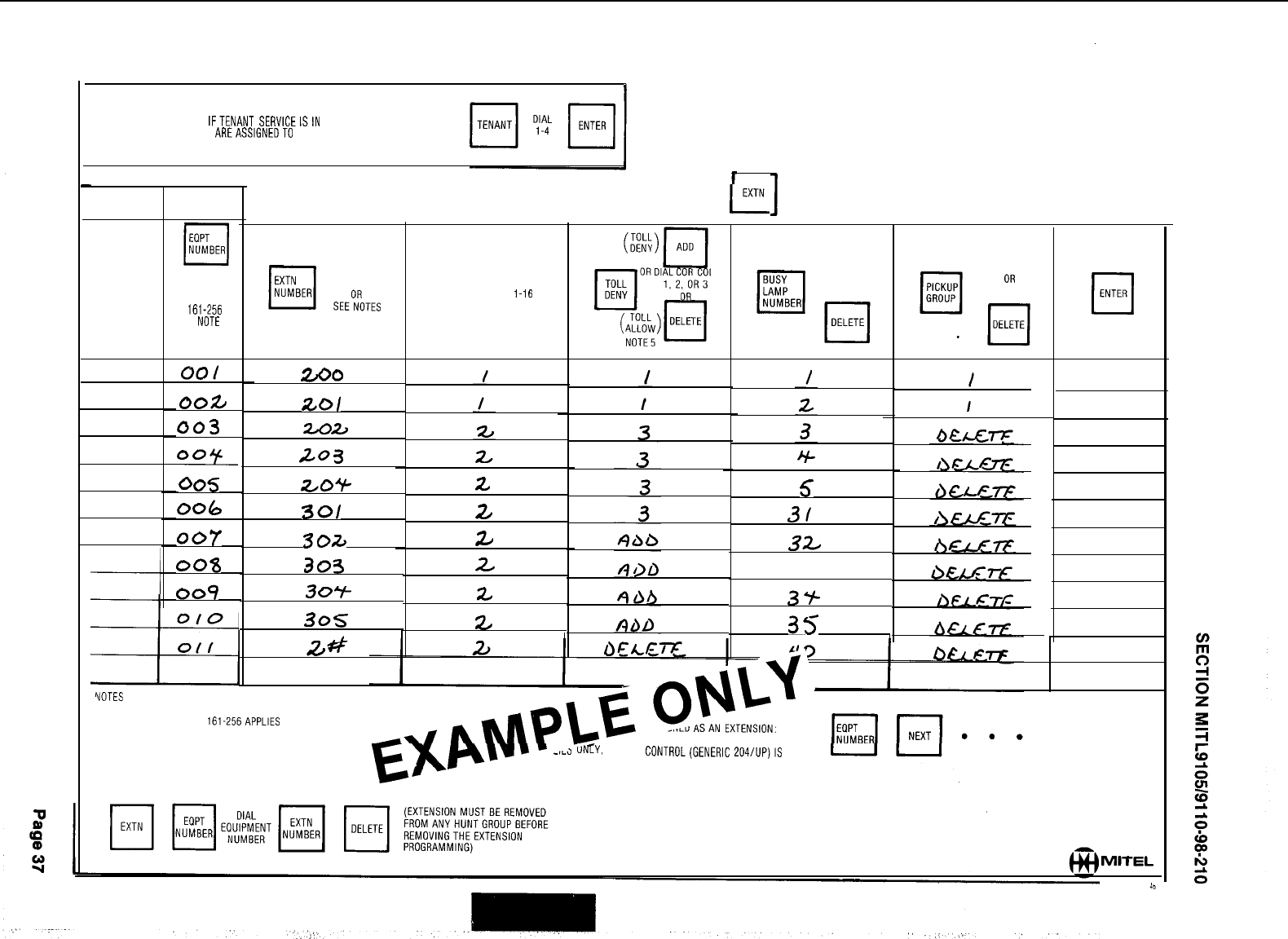
APPLIES TO GENERIC 203 AND ABOVE
1
EXTENSIONS
IFTENANT SERVICEISIN USE
ALL ENTRIES MADE AREASSIGNEDTD THE TENANT NUMBER DIALED
TO ENTER EXTENSION PROGRAMMING PRESS EXTN
L-
TENANT
NUMBER
EQPT
cl
NUMBER
DIAL
l-112
OR
161-256
(SEE NOTE 1)
DE
cl
ENTER
l-150
OR
i-50
DIAL
CODE
SEEETES
2. 3. OR 4
cos
q
DIAL
NUMBER
l-16
NAME
cm/
wo
0025
003
003c
005
006
007
00%
009
ZOI
202
to3
z/0+
301
3oa
303
307
305
-
.I
24
2
2,
5
3/
32
33
3Y-
35
1
24
z
VOTES
i
EQUIPMENT NUMBERS 161.256APPLlES TO SX-200 ONLY
2
TO ASSIGN NON CONFLICTING SINGLE DIGIT DIRECTORY N
WHEN N IS THE SINGLE DIGIT.
3 TO REMOVE EXTENSION PROGRAMMING
--~a
UifY. IF TOLL CONTRDL(GENERIC 204/UP)IS USED
MITEL
Operation
Repeat steps 10 and 11 until all required
extensions have been dialed.
Press the ENTER key to enter all hunt
group information into the memory.
Repeat steps 1 through 13 for all required
hunt groups.
4.06 Hunt Groups
1.
2.
3.
4.
5.
6.
7.
8.
8.
10.
11.
Operation
If TENANT service is used commence at
Step 1. If TENANT service is not used start
at Step 4 (Note 1)
Press TENANT key
Dial required tenant number (1, 2, 3 or 4)
Press ENTER key
Press the HUNT GROUP key.
Dial the number of the required hunt group
(1 through 12).
Press the ACCESS CODE key.
Dial the required ACCESS CODE (master
number).
OR
Press the DELETE key to remove an ex-
isting hunt group.
Press the EQPT NUMBER key.
Dial the equipment number of the first
extension in the hunt group.
Press the EQPT NUMBER key.
Dial the equipment number of the next
extension in the hunt group.
Step
12.
13.
14.
Notes:
1.
All extensions in one tenant group should be entered
in succession following the listed steps. The next
group of extensions are entered in a similar manner
using the TENANT and ENTER keys again.
2.
If the hunt group is to be a circular hunt group, then
the first equipment number entered must be
reentered as the last number.
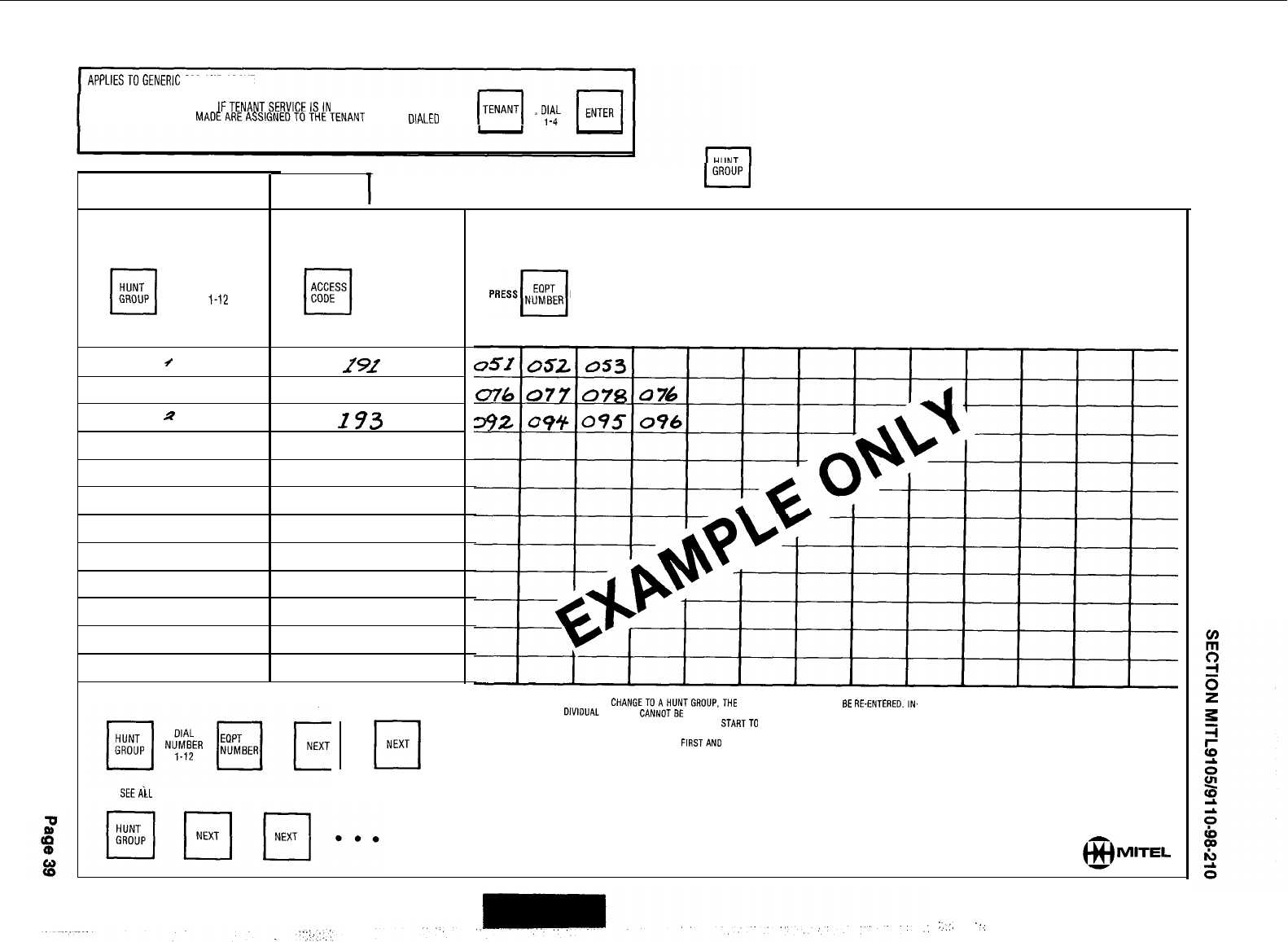
APPLIESTOGENERIC
203ANOABOVE
I
IFTENANTSERVICEISIN USE
ALL ENTRIES
MAOEAREASSIGNEDTOTHETENANT
NUMBER DIALEO
(TENANTI
TENANT
NUMBER
cl
HUNT
GROUP DIAL
l-12
/
2
s?
HUNT GROUPS
GROUP
L-l
(EXTENSION OR TRUNK INFORMATION
MUSTBEENTEREDBEFORETRUNKGROUPDATA)
DIAL
CODE
OR
cl
DELETE
292
192
173
TO SEETHE EOUIPMENT NUMBERS CURRENTLY IN A HUNT GROUP
TO SEEilL HUNTGROUPS
BEFORE DIALING EACH EGUIPMENT NUMBER ENTRY
AFTER LAST ENTRY IN EACH GROUP PRESS
cl
ENTER
TO MAKE A CHANGETOAHUNTGROUP.THE LIST OF MEMBERS MUST
BE
RE-ENTERED.,N.
DIVIDUAL
MEMBERS CANNOTBE DELETEDOR CHANGED.THE EXISTING GROUP LIST IS
AUTOMATICALLY DELETED WHEN YOU STARTTO ENTERANEWONE.
cl
NEXT
. . .
FOR CIRCULAR HUNT GROUPS
FIRSTAND
LAST NUMBERS MUST BE IDENTICAL
@
MITEL
:_,:,
“,
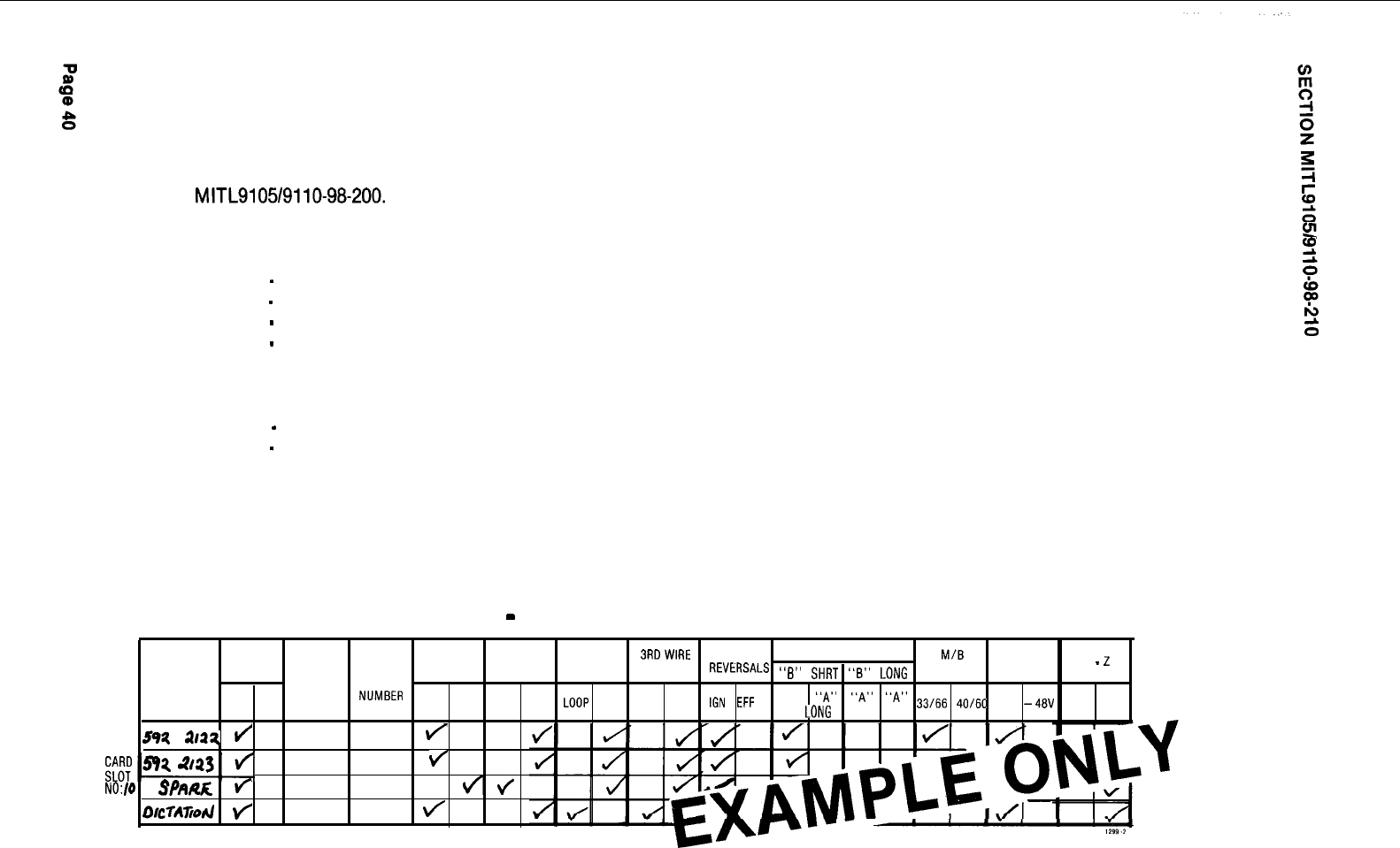
4.07 Trunks
(a) Trunk Card Settings
Before programming the trunk circuits the Installation Forms which detail the trunk card switch
settings must have been completed, and the switches on these cards set to their proper positions.
Full details of the switch setting procedures are given in Appendix 5 to Section
MITL9105/9110-98-200.
Typical configurations are shown in the following examples.
CO TRUNK CARD SWITCH SETTINGS: The example shown has the following meaning:
e
2
Trunk 1
-
Trunk is active with a ground start configuration
Trunk 2
-
Trunk is the same configuration as Trunk 1
Trunk 3
-
Trunk is similar to Trunk 1 but is a spare trunk
Trunk 4
-
Trunk is a dictation trunk with loop start and the 3rd wire condition active
DID/TIE TRUNK CARD SWITCH SETTINGS: The example shown has the following meanings:
Trunk 1
-
Trunk is a loop tie trunk with no wink or “stop-dial” requirements
Trunk 2
-
Trunk is a DID/Tie trunk with no wink or “stop-dial” requirements and uses loop pulsing
TRUNK CARD SWITCH SETTINGS
-
CD TRUNK CARDS
SHELF INCOMING
OUTGOING LOOP/GND
3RDWlRE
SENSE
RELEASETIMES
M/B
co NO.
CARD TRUNK CONDITION CONDITION
START
CONDITION
REVkRSALS
ssB"
SHRT
ssB>>
LDNG
' RATIO
XT HI
-
2
DIRECTORY
TRUNK
EQPT.
NO.
12
NO.
NUMBER
BUSY IDLE BUSY IDLE
LOOP
GND ENAB DIS "A"
"A"
"A"
"A"
lGN
EFF
SHRT
LONG
SHRT LONG
33166
40160
GND
-48V
HI-Z NORM
592
llll
d
1
/
2
t
NO:/0
SPARA
f
3
4/
olcm~od
f
4
\/
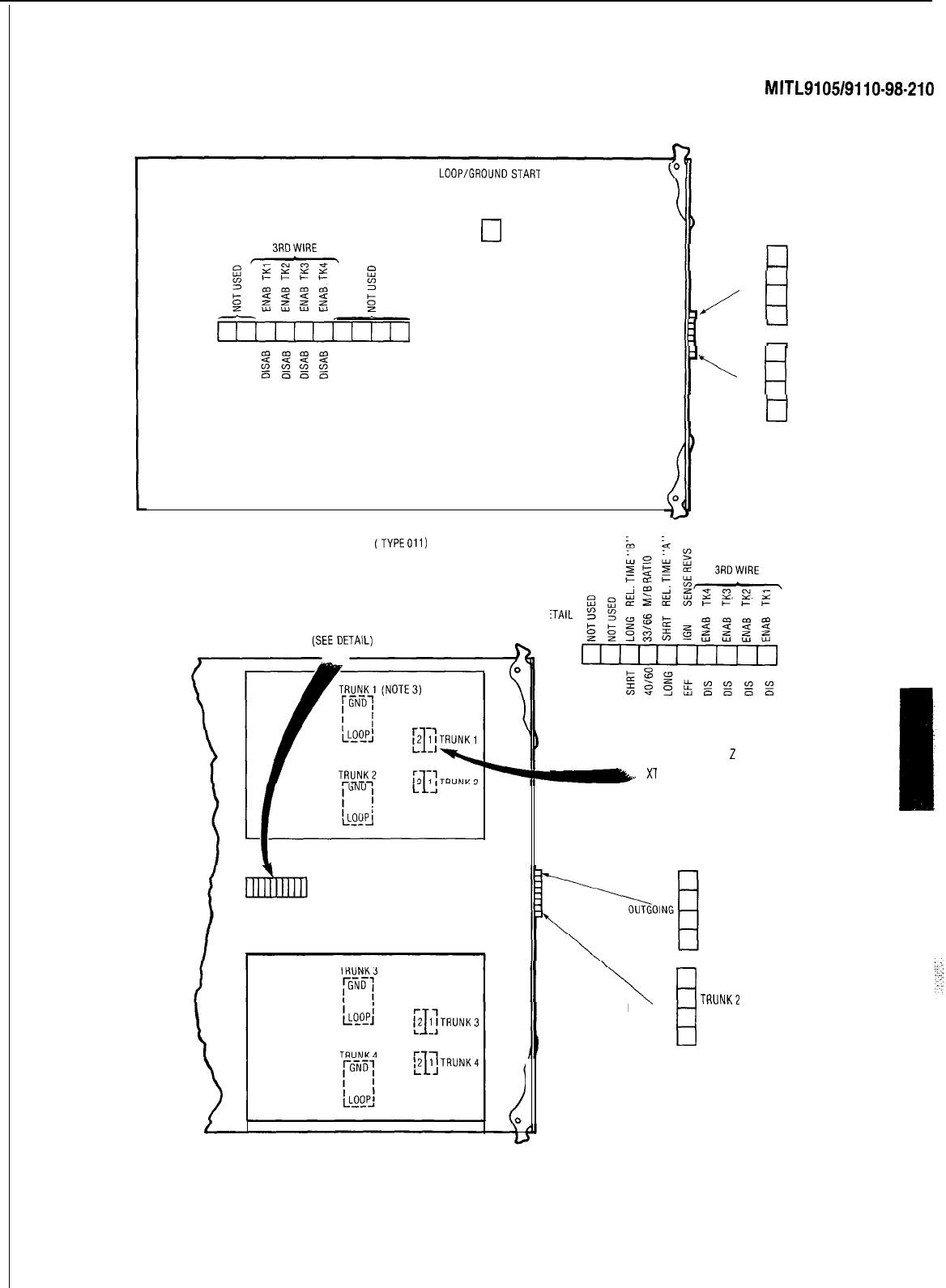
OPEN
CLOSED
3RDWlRE
LOOP/GROUNDSTART
SWITCHES
TRUNK1
LOOP
0
GND
TRUNK2
LOOP
q
GND
TRUNK3
LOOP
q
GND
TRUNK4
LOOP
q
GND
CO TRUNKCARD- SINGLE ASSEMBLY
(TYPEOIl)
SECTION
MITL9105/9110-98-210
TRUNKBUSY
SWITCHES
TRUNK1
TRUNK2
OUTGOING
/
TRUNK3
TRUNK4
\
TRUNK1
TRUNK2
INCOMING
TRUNK3
TRUNK4
BUSY IDLE
iTAlL
GND
HIGH 2
Be
Xl
1 2 HI-Z
q
-48 NORMAL
BUSY IDLE
TRUNK1
TRUNK2
TRUNK3
TRUNK4
w
TRUNK1
TRUNK2
INCOMING
TRUNK3
TRUNK4
TRUNKBUSY
SWITCHES
COTRUNKCARD-MODULARASSEMBLIES
CO Trunk Card Switch identification
Page 41
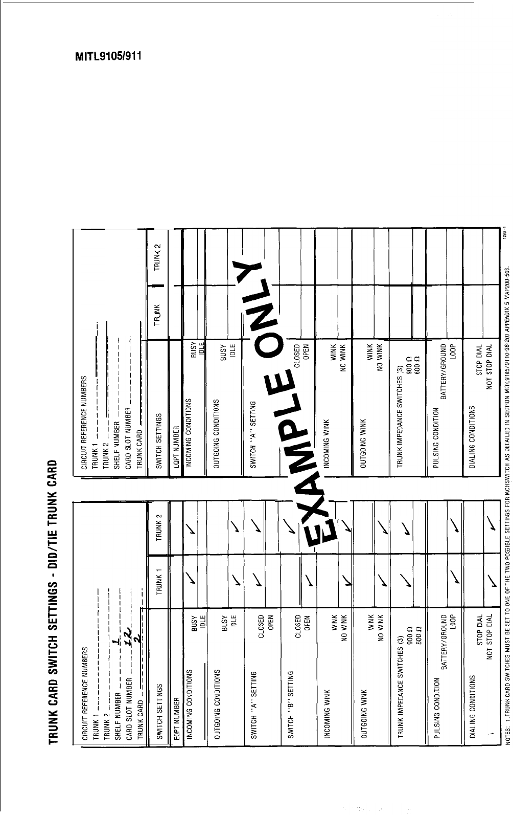
SECTION
MITL9105/911
O-98-21 0
N
Y
5
5
-
25
3
E
I (
I ,
I I
I-
%
l-
\
IN
Page 42
W
Non Dial-h Trunks
step Operation
If TENANT service is used commence at
step 1. If TENANT service is not used, start
at step 4 (Note 1)
1.
2.
3.
4.
5.
6.
Press TENANT key.
Dial required tenant number (1, 2, 3 or 4).
Press ENTER key.
Press the TRUNK key.
Press the EQPT NUMBER key.
Dial the equipment number to be
associated with the required trunk (See
EQUIPMENT NUMBERING, Fig. 2-1)
Step
10.
11.
12.
13.
14.
15.
16.
Operation
Dial the number of LDN key with which the
trunk is to be associated. (1 through 4)
Press the DAY NUMBER key.
Dial equipment number, or # (night bell
number), or
*
(hunt group number).
Press the NIGHT 1 key.
Dial equipment number, or # (night bell
number), or
*
(hunt group number).
Press the NIGHT 2 key.
Dial equipment number, or # (night bell
number), or
*
(hunt group number).
7.
8.
Press the TYPE key.
Dial the required trunk type number (1
-Standard
Bothway
CO Trunk VNL, 5
-
Non
Dial-In Tie Trunk VNL, 11
-
Standard
Bothway
CO Trunk Non VNL and 51 . Non
Dial-In Tie Trunk Non VNL).
OR
17.
18.
Press the BUSY LAMP NUMBER key.
Dial the number of the busy lamp to be
associated with the trunk (see BUSY LAMP
POSITION NUMBERING, Fig. 2-2)
OR
Press the DELETE key if no busy lamp is re-
quired.
Press the DELETE key to delete all trunk in-
formation.
19.
Press the ENTER key to enter all trunk in-
formation into the memory.
9.
Press the LDN NUMBER key.
20.
Repeat steps 1 through 20for all trunks required
’
Notes:
1.
All trunks in one tenant group should be entered in succession following the listed steps. The next
2.
group of trunks are entered in a similar manner using the TENANT and ENTER keys again.
For Multi-Digit Toll Control, see Section
MITL9105/9110-98-212
Programming Procedures.
,-,I.:;‘,,
m
,,
._
,‘,,.‘?I
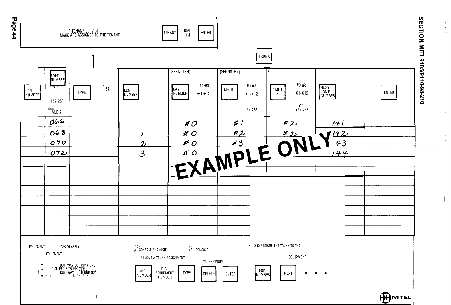
21
APPLIESTO GENERIC 203ANDABOVE
1
NON DIAL-IN TRUNKS
I
IFTENANTSERVICE IS IN USE
%
ALL ENTRIES
MADEAREASSIGNEDTOTHETENANT
NUMBER DIALED
II
TO ENTERTRUNK PROGRAMMING PRESS
1I1
TENANT
NUMBER
NOTES'
DIAL
Z-112
OR
162-256
:SEE
NOTES
ANDZ)
I
SEE NOTE 3
DIAL
1.
5, 11.
51
OR
cl
DELETE
I
I
I
I
1
EOUIPMENT
NUMBERS
162.256APPLY
TO SX-200 ONLY
2
ONLY EVEN
EOUIPMENT
NUMBERS MAY BE ASSIGNED
TO TRUNKS
3 TYPE 1 = STANDARD BOTHWAYCOTRUNKVNL
TYPE 5 = NON DlALINTIETRUNK(NON CO)VNL
TYPE
ii
= STANOARD BOTHWAY CO TRUNKNON VNL
TYPE 51 ='NON DIAL IN TIE TRUNK(NON CO)NON VNL
DIAL
1-4
I
/
-
(SEENOTE4) [SEENOTE4)
DIAL
#O-#3
OR
Xl-Xl2
OR
i-112
OR
161-256
$0
NO
ff0
d0
-
-
,
-
EXP
-
1
TRUNK1
DIAL
#O-#3
OR
*i-*12
OR
1-112
OR
161-256
RI
SEENOTE4)
DIAL
#O-#3
OR
x1-*12
OR
l-112
16yR256
DIAL
I-150
OR
r
DELETE
1
4.
ilO_
CONSOLEONLY
If2
-CONSOLE AN0 NIGHT BELL 2
#,
CONSOLEANDNIGHT BELL 1 #3-CONSOLE AND NIGHT BELL3
5. TO REMOVEATRUNKASSIGNMENT
(NOTE
TRUNK MUST FIRST BE REMOVED FROM TRUNKGROUPi
*l-X12ASSlGNSTHETRUNKTOTHE HUNT GROUPSELECTED
l-112, 161-256 ASSIGNS THE TRUNK TO THE SPECIFIED EXTENSION
6. TO SEETHE NEXT EDUIPMENT NUMBER PROGRAMMED
ASATRUNK:
r-l
ENTER
GENERIC 202TYPE CODE DISPLAY DEFAULTS TO
1
WHEN TRUNK IS DELETED
@I
MI-TEL
(a
Dial-h Trunks
Step Operation
If TENANT service is used commence at
step 1. If TENANT service is not used, start
at step 4 (Note 1).
1.
2.
3.
4.
5.
6.
7.
8.
Press TENANT key.
Dial required tenant number (1, 2, 3 or 4).
Press ENTER key.
Press the TRUNK key.
Press the EQPT NUMBER key.
Dial the equipment number to be
associated with the required trunk (See
EQUIPMENT NUMBERING, Fig. 2-2)
Press the TYPE key.
Dial the required trunk type number (2
-Direct Inward System Access or 4
-
Dial-In
Tie Trunk).
OR
Press the DELETE key to delete all trunk in-
formation.
9.
10.
Press the COS number key.
Dial the required COS number (1 through
16).
11.
Press the TOLL DENY key.
12.
13.
14.
15.
16.
Press the ADD key to implement toll denial
for the trunk selected.
Press the DELETE key to remove toll denial
for the trunk selected.
Press the BUSY LAMP NUMBER key.
Dial the number of the busy lamp which is
to be associated with the selected trunk.
(See BUSY LAMP POSITION NUMBERING,
Fig. 2-2)
OR
Press the DELETE key if no busy lamp is re-
quired.
Press the ENTER key to enter all Dial-In
Trunk information into the memory.
Repeat steps 1 through 16 for all Dial-In
trunks required.
Notes:
1.
All extensions in one tenant
group should be entered in
succession following the listed
steps. The next group of
extensions are entered using
the TENANT and ENTER keys
again.
2. For Multi-Digit Toll Control,
see Section
MITL9105/9110-98-212
Programming Procedures.
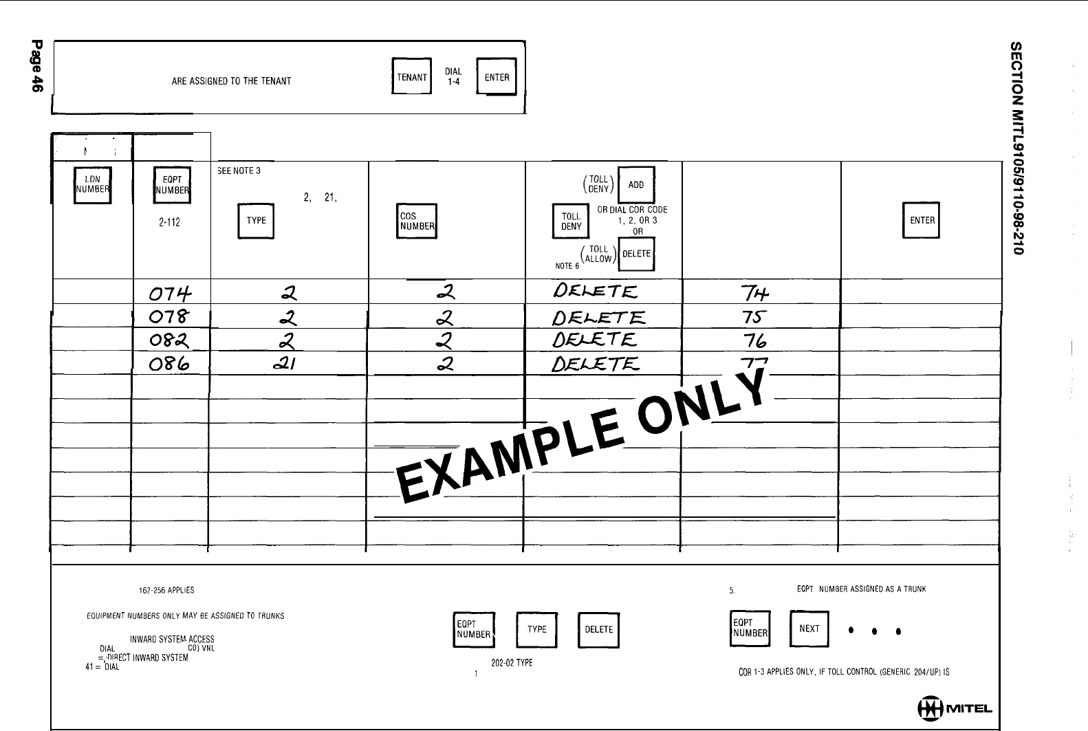
9
APPLIESTO GENERIC 203ANDABOVE
’
DIAL-IN TRUNKS
%
IF TENANT SERVICE IS IN USE
$
ALL ENTRIES MADE
AREASSIGNEDTOTHETENANT
NUMBER DIALED
TENANT
NUMBER
I
TO ENTERTRUNK PROGRAMMING PRESS
cl
TRUNK
DIAL
2-112
OR
162-256
(SEE NOTE 1
AND 2)
074
07&
084
086
DIAL
2,
4,
21,
OR 41
OR
cl
DELETE
2
n
4
DIAL
l-16
DIAL
l-150
BUSY
cl
OR
LAMP
NUMBER
q
DELETE
1 EOUIPMENT NUMBERS
162.256APPLlES
TO SX-200 ONLY
2 EVEN EQUIPMENTNUMBERSONLY MAYBEASSIGNEOTOTRUNKS
3 TYPE 2 = DIRECT lNWAADSYSTEM.ACCESS VNL
TYPE 4 =
OIAL
IN TIE TRUNK (NON CO)VNL
TYPE 21 =9IRECTlNWARDSYSTEM ACCESS NON VNL
TYPE
41
=blAL IN TIE TRUNK (NON CO)NON VNL
cl
ENTER
4 TO REMOVEATRUNKASSIGNMENT:
5.
TOSEETHENEXT
EOPT
NUMBERASSIGNEOASATRUNK
NOTETRUNK MUST FIRST BE REMOVED FROM TRUNKGROUP
pq
pq
.
.
.
GENERIC
202.02TYPE
CODE DISPLAY DEFAULTS
TO
1
WHEN TRUNK IS DELETED.
6
COR
I-3APPLlESONLY,IFTOLLCONTROL(GENERIC
204/UPIIS
USED
fd)
DIDKCSA
Dial-In Tie Trunks
Step Operation
If TENANT service is used commence at
step 1. If TENANT service is not used, start
at step 4 (Note 1)
1.
2.
3.
4.
5.
6.
7.
8.
Press TENANT key.
Dial required tenant number (1, 2, 3 or 4).
Press ENTER key.
Press the TRUNK key.
Press the EQPT NUMBER key.
Dial the equipment number to be
associated with the required trunk (See
EQUIPMENT NUMBERING, Fig. 2-1)
Press the TYPE key.
Dial the required trunk type code (3
-
DID
VNL, 6
-
CCSA VNL, 31
-
DID Non VNL and
61
-
CCSA Non VNL)
OR
Press the DELETE key to delete all trunk in-
formation.
Notes:
Step
9.
10.
Operation
Press the
I/C
key.
Dial the required NMX code (N
-
number of
digits to be received after the trunk is seiz-
ed, M
-
number of digits to be absorbed
after the trunk is seized, X
-
the actual
leading digit to be inserted, if required).
11.
12.
Press the BUSY LAMP NUMBER key.
Dial the number of the busy lamp which is
to be associated with the selected trunk
(see BUSY LAMP POSITION NUMBERING,
Fig. 2-2)
OR
Press the DELETE key, if no busy lamp is
required.
13.
Press the ENTER key to enter all
DIDlCCSA
Dial-In Tie Trunk information into the
memory.
14.
Repeat steps 1 through 13 for all
DID/CCSA
trunks required.
1.
‘\
All trunks in one tenant group should be entered in succession following the listed steps. The next
2.
group of trunks are entered in a similar manner using the TENANT and ENTER keys again.
For Multi-Digit Toll Control, see Section
MITL9105/9110-98-212
Programming Procedures.
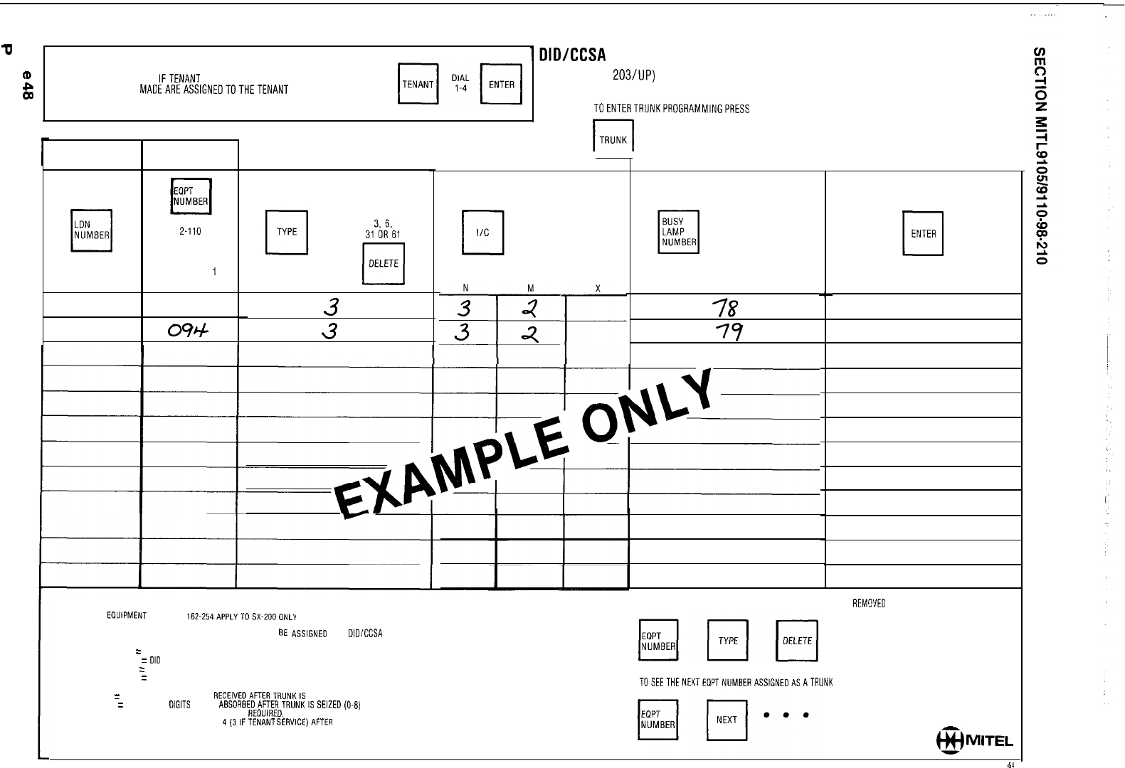
Q
6
APPLIES TO GENERIC 203 AND ABOVE
'DIDICCSA
TRUNKS
tD
IFTENANT SERVICE IS IN USE
(GENERIC 203/UP)
%
ALL ENTRIES
MADEAREASSIGNEDTOTHETENANT
NUMBER DIALED
TOENTERTRUNKPROGRAMMINGPRESS
l-l
TRUNK
TENANT
NUMBER
DIAL
2-110
OR
162-254
(SEE NOTES
1
AND 2)
090
094
SEE NOTE 3
DIAL
313i261
cl
DELETE
3
3
NOTES.
1.
EOUIPMENT NUMBERS 162.254APPLYTOSX-ZOOONLY
2
ALTERNATE EVEN NUMBERS ONLY MAY
BE
ASSIGNEO
TO
DlDlCCSA
TRUNKS
3
TYPE3 = OIOVNL
TYPE 31 =
DID
NON VNL
TYPE 6 = CCSAVNL
TYPE 61
=
CCSA NON VNL
4
N = NUMBER OF DIGITS TO BE RECEIVEDAFTERTRUNKIS SEIZED (l-9)
M = NUMBER OF
OIGITS
TO BE ABSORBEOAFTERTRUNKIS
SElZED(O-8)
X = LEADING DIGIT TD BE INSERTED, IF REOUIRED.
MAXIMUM NUMBER OF DIGITS IS 4(3lFTENANT
SERVICE)AFTER
ABSORPTION (M)
AND ADDING A DIGIT (X).
DIAL
NMXCODE
(NOTE 4)
DIAL
l-150
OR
q
DELETE
78
77
C
0
ENTER
5. TO REMOVEATRUNKASSIGNMENT: (TRUNK MUSTFIRST BE REMWED FROM TRUNKGROUP)
6. TOSEETHE NEXTEQPTNUMBERASSIGNEDAS ATRUNK
@I
MITEL

4.08 Trunk Croups
Step
1.
2.
3.
4.
5.
6.
7.
a.
9.
10.
11.
Operation
If TENANT service is used commence at
step 1. If TENANT service is not used, start
at step 4 (Note 1)
Press TENANT key.
Dial required tenant number (1, 2, 3 or 4).
Press ENTER key.
Press the TRUNK GROUP key.
Dial the required trunk group number (1
through 12).
Press the ACCESS CODE key.
Dial the required trunk group access code
OR
Press the DELETE key to remove all trunk
group information.
Press the TYPE key.
Dial the four-digit trunk group type (See
TRUNK GROUP TYPE CODES, Table 2-4).
Press the TOLL DENY key.
Press the ADD key to provide toll denial on
the trunk group.
OR
Step
Operation
Press the DELETE key if toll denial is not
required on the trunk group.
12.
13.
Press the OVFLO GROUP key.
Dial the number of the trunk group (1
through 12) to which calls will overflow if
the trunk group is busy. You must not
overflow into the same group. (See Note 1)
OR
Press the DELETE key if no overflow is re-
quired.
14.
Press the EQPT NUMBER key.
15.
Dial the equipment number of the first
trunk in the trunk group.
16.
17.
Press the EQPT NUMBER key.
Dial the equipment number of the next
trunk in the trunk group.
ia.
Repeat steps 16 and 17 until all required
equipment numbers have been dialed.
19.
Press the ENTER key to enter all trunk
group information into the memory.
20.
Repeat steps 1 through 19 for all required
trunk groups.
Note 1: If a call to a trunk group is routed to the overflow group the restrictions of the overflow
group are in effect for that call.
22
rb
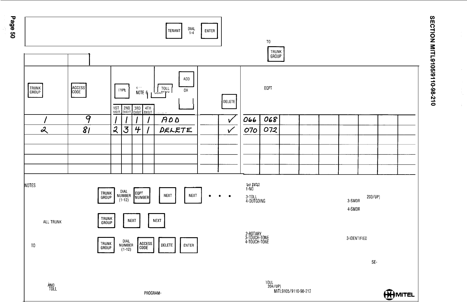
APPLIES TO GENERIC 203 AND ABOVE TRUNKGROUPS
IF TENANT SERVICE IS IN USE
ALL ENTRIES MADE ARE ASSIGNED TO THE TENANT NUMBER DIALED
TENANT
NUMBER
TRUNK
cl
DIAL
GROUP
1-12
DIAL
CODE
OR
q
DELETE
SEENOTE
6
1 1
,T%
1
OR
ll
n
I
1
DELETE
1
q-q
I
DIGIT DIGIT NOTE 8
TO ENTER TRUNK GROUP PROGRAMMING PRESS
TRUNK
cl
GROUP (TRUNK INFORMATION MUST BE ENTERED BEFORE TRUNK GROUPDATA)
DIAL
cl
1-12
OVFLO OR
GROUP
NOTE 5
TO SEE THE TRUNKS IN A TRUNK GROUP:
TO SEE
ALLTRUNK
GROUPS:
pl
F[
Fi
. . l
TO DELETE TRUNK GROUP:
E[
Nl%&
14
Fi
F[
. . .
TO MAKE A CHANGE TO A TRUNK GROUP. THE LIST OF MEMBERS MUST BE
RE-ENTERED. INDIVIDUAL MEMBERS CAN'NOT BE DELETED OR CHANGED. THE EX-
ISTING TRUNK GROUP LIST IS AUTOMATICALLY DELETED WHEN YOU START TO
ENTER A NEW ONE
ORIGINAL
I\ND
OVERFLOW TRUNK GROUPS MUST BE THE SAME TYPE AND HAVE
THE SAME TOLL RESTRICTION CHARACTERISTICS.
IF GENERIC 202 IS USED THE TRUNKS WITHIN A GROUP MAY ONLY BE PRDGRAM-
MED FOR CIRCULAR HUNTING.
SEE NOTE 4 AND 7
PRESS
EOPT
cl
BEFORE DIALING EACH EQUIPMENT NUMBER ENTRY
NUMBER cl
AFTER LAST ENTRY PRESS ENTER
6. TRUNK GROUP TYPE IS 4 DIGITS
-.
1.
-,
2nd DIGIT
l-NO
SUPERVISION l-NO MESSAGE REGISTER
P-ANSWER SUPERVISION Z-MESSAGE REGISTER
3-TOLL REVERSAL (GENERIC
203/lJP)
4-OUTGOING AUDIO INHIBITED UNTIL ANSWER SUPERVISION
3SMDR
WITHOUT MESSAGE REGISTER
(GENERIC 203. 204) (GENERIC 205)
OUTGOING AUDIO INHIBITED UNTIL ANSWER SUPERVISION 4-SMDR WITH MESSAGE REGISTER
TIMEOUT OR # DIALED (GENERIC 205)
(GENERIC 205)
3rd DIGIT
l-ROTARY DIAL OFFICE, NO WAIT FOR DIAL TONE
2-ROTARY DIAL OFFICE, WAIT FOR DIAL TONE
3-TOUCH-TONE DIAL OFFICE, NO WAIT FOR DIAL TONE
4-TOUCH-TONE DIAL OFFICE. WAIT FOR DIAL TONE
4th DIGIT
I-CENTRAL OFFICE
P-NON-CO
3-IDENTIFIED
TRUNK GROUP (NON-CO)
7.
IF GENERIC 203 OR HIGHER IS USED, THE TRUNKS WITHIN A TRUNK GROUP MAY
BE PROGRAMMED FOR EITHER TERMINAL OR CIRCULAR HUNTING, IF TERMINAL
HUNTING IS REQUIRED, ENTER TRUNK EOUIPMENT NUMBERS IN REOUIRED
SE-
OUENCE.
IF CIRCULAR HUNTING IS REOUIRED MARE LAST TRUNK EOUIPMENT NUMBER
THE SAME AS THE FIRST TRUNK EOUIPMENT NUMBER.
8.
USE OF
.I'OLL
DENY KEY DOES NOT APPLY IF TOLL CONTROL
(GENERIC 204/UP) IS USED
SEE SECTION MITL9105/9110-98-212 OR TOLL CONTROL FORMS THIS SECTION.
-
MITEL
SECTION
MITL9105/9110-98-210
APPENDIX
1
MITEL ACTION PROCEDURES
GENERAL
Al.01 Task oriented functions in this section are
implemented using
MITEL
ACTION
PROCEDURES (MAP’s).
Al.02 A MAP is a step by step procedure using a
flow chart principle, written and il-
lustrated where necessary to a level of detail that
allows both experienced and inexperienced per-
sonnel to carry out the tasks detailed. A MAP con-
tains two levels of information as follows:
(a) For experienced personnel, a series of
steps (level one) each numbered [n] and
annotated with minimal information.
(b) For inexperienced personnel, each step
referred to in (a) above is amplified by a
connected series of numbered
substeps
[nA]
(level two).
Al.03 A typical example of a MAP is shown in
Fig. Al, with the two levels detailed.
MAP SYMBOLS
Al.04 There are four basic symbol shapes which
may be used in a MAP, and are
defined as follows.
Al.05 AND Block: Used to indicate a level one
step that must be performed. Con-
sists of a square with the word AND
centred
in the
block.
Al.08 OR Block: Used to indicate a choice of
level one steps, one of which must be
performed. Consists of a rectangle, with the text
centred
in the block, and with the word OR ap-
pearing between the alternative operations.
Al.07 The rectangle is also used to border in-
structions which imply that the operator
must perform a task outside the scope of the
MAP. The text is
centred
in the rectangle.
Al.08 DECISION Block: Used to indicate a
decision within the level one steps which
must be made. The symbol is based on a hexagon
with the top and bottom sides extended. Decision
text is
centred
in the symbol.
Al.09 START/FINISH/JUMP TO Block: Used to
indicate the start and finish of a MAP.
Also used to indicate ‘jump to’ points within the
MAP, for example “go to [n]” or “from [n]” or
“return to [n]“. The symbol is a rectangle with
semi circular ends. Text is
centred
in the symbol.
THE OPERATORS USE OF MAP’S
Experienced Operator
Al.10 For the experienced operator to complete
a task using a MAP, reference to the se-
quential short form level one steps is usually all
that is necessary. Using Fig. Al-l as an example,
the experienced operator would proceed as
follows.
Al.11 At
[l]
makes a decision based on the infor-
mation within the block. If the answer is
YES the operator must proceed to a different
MAP. If the answer is NO the operator is faced
with another decision at block
[2].
Al.12 At
[2]
if the decision is NO there is no re-
quirement to proceed further and the test
is abandoned. This naturally results in a FINISH
block. If the decision is YES the operator pro-
ceeds to
[3]
and
[4]
in succession, i.e. dials the DID
station number and completes the call to the
check extension.
Al.13 The description of the instructions carried
out in Al.05 and Al.06 have assumed
that the level of competence of the operator is
such that short form level one steps contain suffi-
cient information, and therefore the operator reads
only the centre column of the MAP,-top to bot-
tom of the page.
Al-l
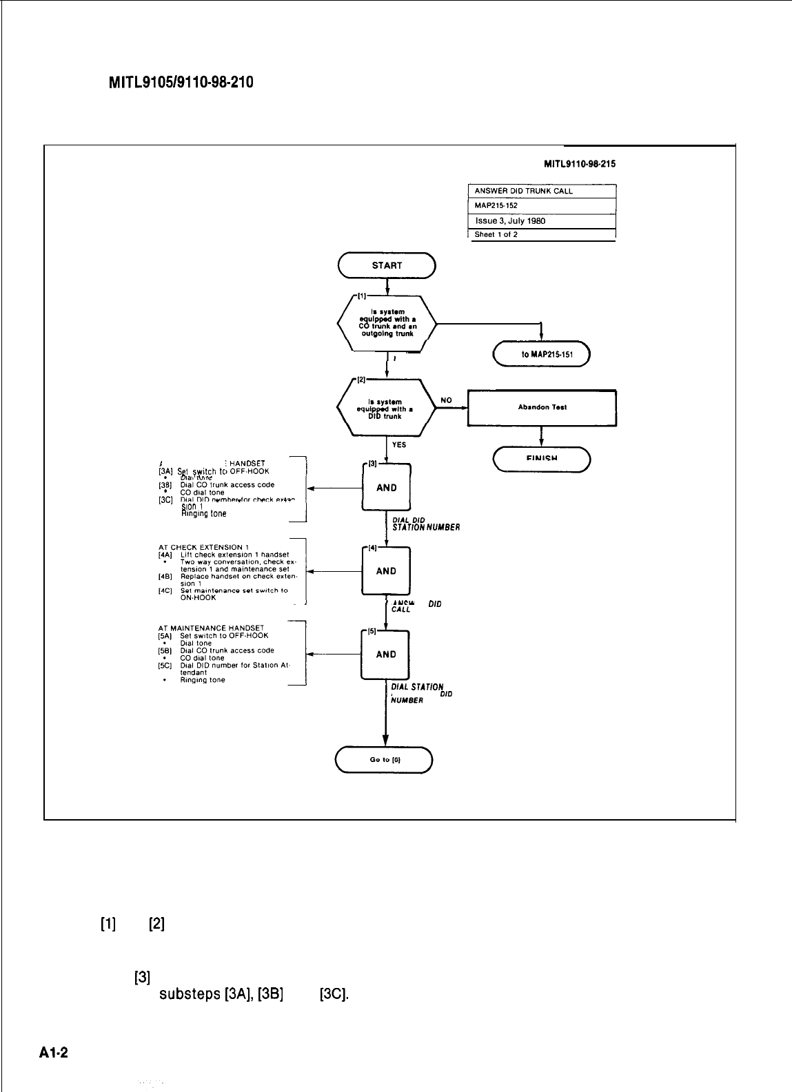
SECTION
MITL9105/9110-98-210
SECTION
MITL9110.99-215
YES
c
NO Go
lo
MAP215.15,
AT MAINTENANCE
[3A]
Se,
swkh
tc
,;
?.
.I
..-.
r3.c.
__
_
_
_
.__
Slcl”
1
.
mng,ng
tone
STATlON
NUMBER
ANSWER
DID
DIAL
STATfON
ATTENDANT
DID
A3.25
Fig. Al Typical Map Page
Al.15 Using Fig. Al as an example the path TOOLS, TEST EQUIPMENT AND SPECIAL
followed should be: INSTRUCTIONS
(a)
At
[l]
and
[2]
make the decisions called for Al.18 Any tools, test equipment or special in-
at these steps as before. structions that the operator requires or
needs to know are stated on the first page of each
(b)
At step
[3]
dial the DID station number by MAP. If the MAP is long, and contains a number of
performing
substeps
[3A],
[3B]
and
[3C].
sub procedures, these are listed in synopsis form
on the first page.
Al.2
SECTION
MITL9105/9110-98-210
‘;
APPENDIX 2
PROGRAMMING PROCEDURES
1. GENERAL
A2.01
This appendix details the preferred order in which the SX-100 or SX-200 PABX should be program-
med for features and options required by the customer. This appendix also includes procedures
for programming Multi Digit Toll Control and Speed Call.
A2.02
Multi Digit Toll Control is available in Generic
2041~~.
Speed Call is available in generic 205 only,
Note that both features require the use of the Extended Programming mode. In this appendix
MAP210-221
will cover entering the Extended mode for both features.
MAP210-244
will cover exiting the
Extended mode for both features.
:.
”
A2.03
Table
A2-1
details the order of the standard system programming procedures. Table
A2-2
details
the order of the Multi Digit Toll Control programming procedures. Table
A2-3
details the order of
Speed Call programming of the system.
Step
1
System Programming
2
Select Programming Options
3
Program System Options
4
Program COS Options
5
Assign Feature Access Codes
6
Program New Extensions
7
Program Extension Hunt Group
8
Program New Non Dial-In Trunks
9
Program New Dial-In Trunks
10
Program New DID Trunks
11
Program Trunk Groups
12
Terminate Programming Mode
Order
1
2
3
4
5
6
7
8
9
10
TABLE
A2-1
STANDARD
Title MAP
21 O-201
21 O-202
21 O-203
21 O-204
21 O-205
21 O-206
21 O-207
21 O-208
21 O-209
210-210
21 o-21 1
210-212
TABLE
A2-2
MULTI DIGIT TOLL CONTROL
Option
Selection of Extended Programming
Absorb Plan
Control Plan
Trunk Group Class of Restriction
Restriction Tables
Add an Entry
Displaying Sequential Entrys
Search for an Entry
Delete an Entry
Terminating Programming
MAP No.
21 o-221
21 o-222
21 O-223
21 O-224
21 O-225
21 O-226
21 O-227
21 O-228
2 1 o-229
21 O-244
:
‘.
;‘.
A2-1
:
SECTION
MITL9105/9110-98-210
TABLE
A2-3
SPEED CALL
Order
Option MAP No.
1
Selection of Extended Programming
21 o-221
2
Programming Personal Tables
21 O-242
3
Convert Tables From Personal to Common Use
21 O-243
4
Terminating Programming
21 O-244
A2- 2
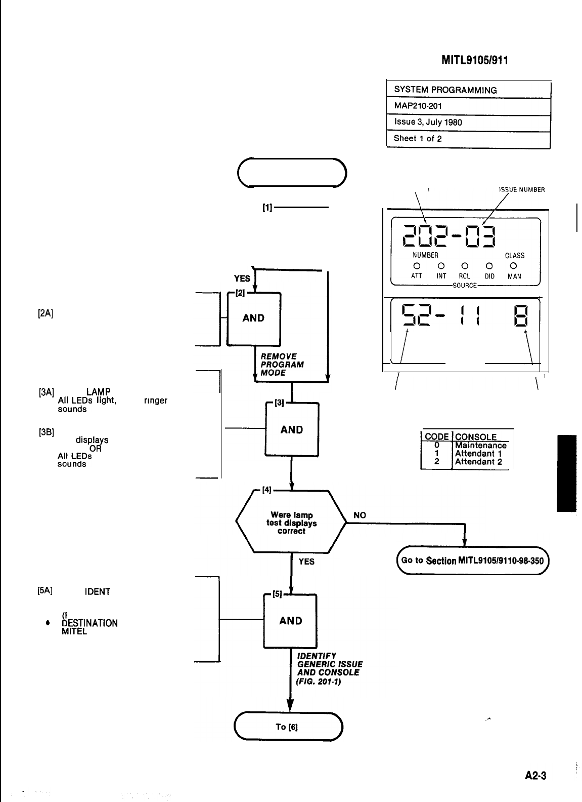
At Equipment:
[2A] Set thumbwheel switch on tone
control card (slot 18, yellow) to
8888
At the Programming Console:
[3A] Press LAM.P TEST key
l
Al&\~~s
light,
tone
rmger
OR
l
All displays show 8
[3B] Press LAMP TEST key
l
All disp&ys show 8
l
I&fLLis
light, tone ringer
WI
.
.
Press IDENT key
Source display shows software
generic number and its issue
bFig. 201-l)
ESTINATION display shows the
MITEL internal issue number and
the code number for the console
(Fig. 201-l)
111
(I)
Is the system in
programming
mode
YESI
NO
START
131
-0
AND
I
PERFORM
LAMP TEST
SECTION MITL9105/911 O-98-21 0
GENERIC NUMBER
NUMBER
CLASS
0 0 0 0
ATT RING
BUSY
ERROR
\DESTINATION
\
1
INTERNAL FIRMWARECODE
CONSOLE CODE
Fig. 201-l
(>
Go to
Sectlon
MITL9105/9110-99.350
I
.-
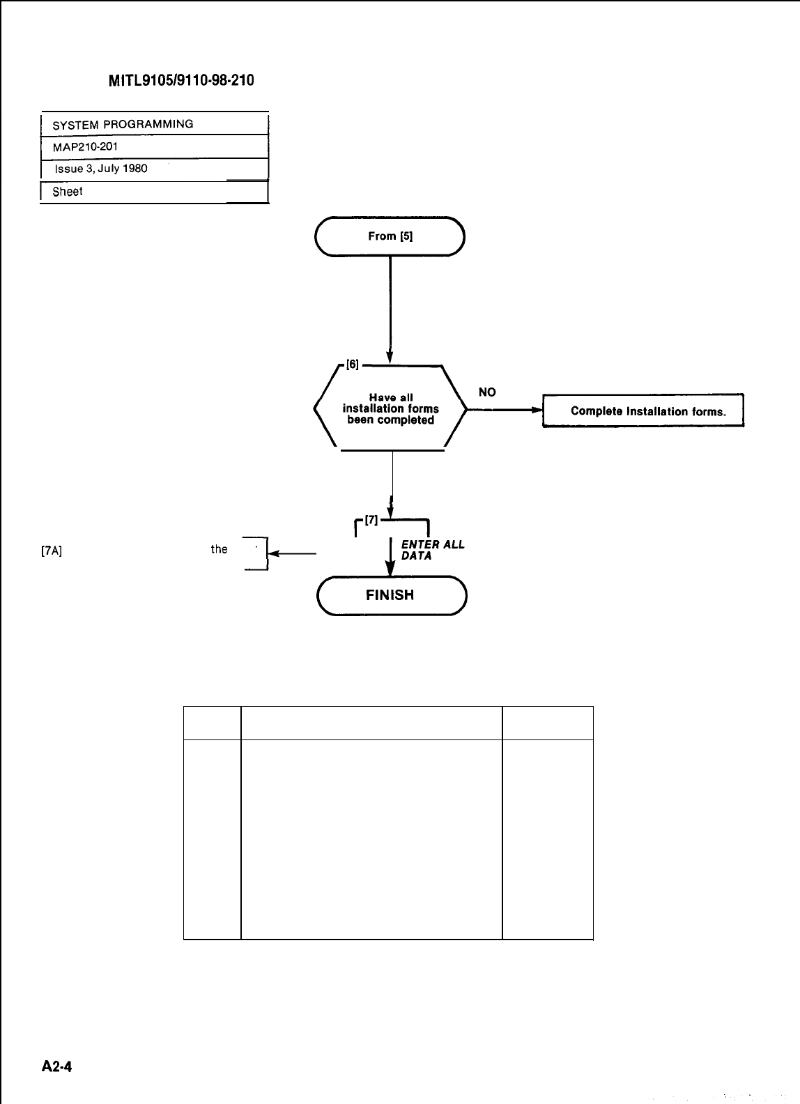
SECTION
MITL9105/9110-98-210
bheet
2 of 2
From
[51
T
YES
[7A]
Enter all system data in
tha
order
listed in Table 201-l
ENTER ALL
23
FINISH
DATA
TABLE 201-l
Step
Title
MAP
1
2
3
4
5
6
7
8
l 9
10
11
Select Programming Mode
Program System Options
Program COS Options
Assign Feature Access Codes
Program New Extensions
Progam Extension Hunt Group
Program New Non Dial-In Trunks
Program New Dial-In Trunks
Program New DID Trunks
Program Trunk Groups
Terminate Programming Mode
21 O-202
21 O-203
21 O-204
21 O-205
21 O-206
21 O-207
21 O-208
21 O-209
210-210
21 o-21 1
210-212
* Not supplied with Generic 202
A24
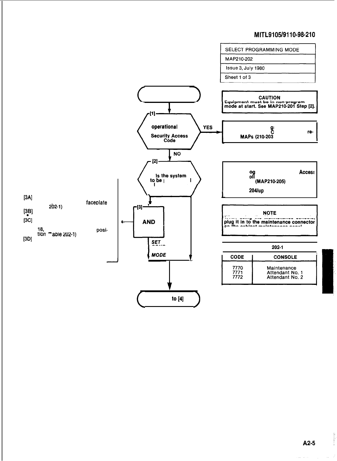
Place console in programming mode
[3A]
Place programming console
overlav over console faceolate
(Fig. 2b2-1)
(381
Press ENTER key twice
All displays dark
[3;]
Set thumbwheel switches on
tone control card (card position
18,
yellow) to appropriate posi-
-
. . ---
_.
[3D] non
(I
acile
202-l)
Press LAMP TEST key
.
LAMP TEST lamp lit
SECTION
MITL9105/9110-98.210
START
Is system
operatronal
and
programmed with
SecurrtidAeccefs
Place console in pro ram mode by dial-
ing Security Access
I!
ode and go to
re-
quired
MAPS
(210-203
through -214)
I
programmed
from a consolefrom a console
YES
i-
CONSOLE TO
PROGRAMMING I
f
NO
(
Go
to[4]
)
1
NOTE
To use Pr
“B
ramming Security
Access
Code the fol owing criteria must apply:
l Feature 29
(MAP210.205)
is programm
ed with the code
l Generic
204/up
is installed
When using the Maintenance console
on the cabinet maintenance panel.
I
TABLE
202.1
I I
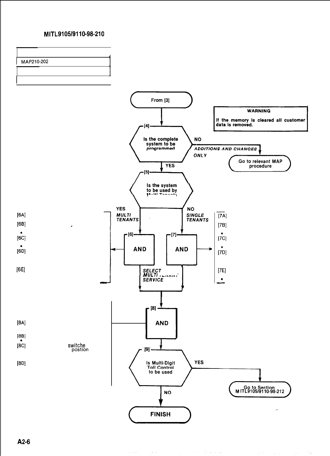
SECTION
MITL9105/9110~98-210
SELECT PROGRAMMING MODE
I
1
MAP210-202
Issue 3, July 1980
WI
WI
.
r&
.
61
.
.
PEI
.
1Sheet 2 of 3
I
Multi Tenants
Set thumbwheel switches on the
Tone Control card to 7776
Press TENANT kev
TENANT lamp lit
’
SOURCE shows 1 or 0
Press ADD key
ADD key lit
DESTINATION shows 1
Press ENTER key
SOURCE display shows 00000000
DESTINATION display shows
00000000
Press RESET key on Scanner
card (card position 19, orange)
System reset, no longer in pro-
gram mode
-
Place console in programming mode
[8A]
Place programming console
overlay over attendant console
faceplate (Fig. 202-l)
[8B]
Press ENTER key twice
&]
All displays dark
Set thumbwheel
switche
on tone
control card (card
postion
18,
yellow) to appropriate position
[8D]
(Table 202-l)
Press LAMP TEST key
.LAMP TEST lamp lit
MULTl
TENANT
I
SELECT
SINGLE
TENANT
SERVICE
[7Al
17Bl
.
64
.
[h
.
.
[7El
*
-
Set thumbwheel switches on the
Tone Control card to 7776
Press TENANT key
TENANT lamp lit
SOURCE shows 1 or 0
Press DELETE key
DELETE lamp lit
DESTINATION shows 0
Press ENTER key
SOURCE display shows 00000000
DESTINATION display shows
00000000
Press RESET key on Scanner
card (card position 19, orange)
System reset, no longer in pro-
gram mode
lTL9105/9110-96-212
A2-6
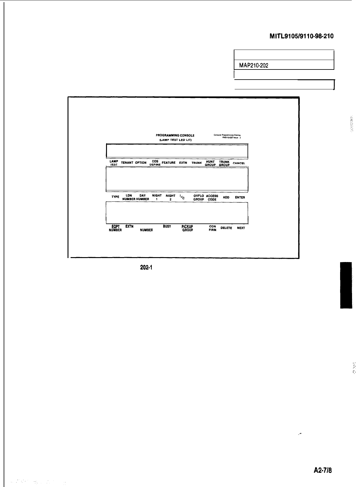
SECTION
MITL9105/9110-98-210
SELECT PROGRAMMING MODE
MAP210-202
1Issue 3, July 1980
I
Sheet 3 of 3
EQPT
EXTN
cos TOLL
BUSY
LAMP
P,CWP
NUYllER
NUMBER
NUM8ER
DENY NUMBER
GROUP
Fig.
202-l
Programming Console Overlay
.:
:-
.:
..-
_-
A2-718
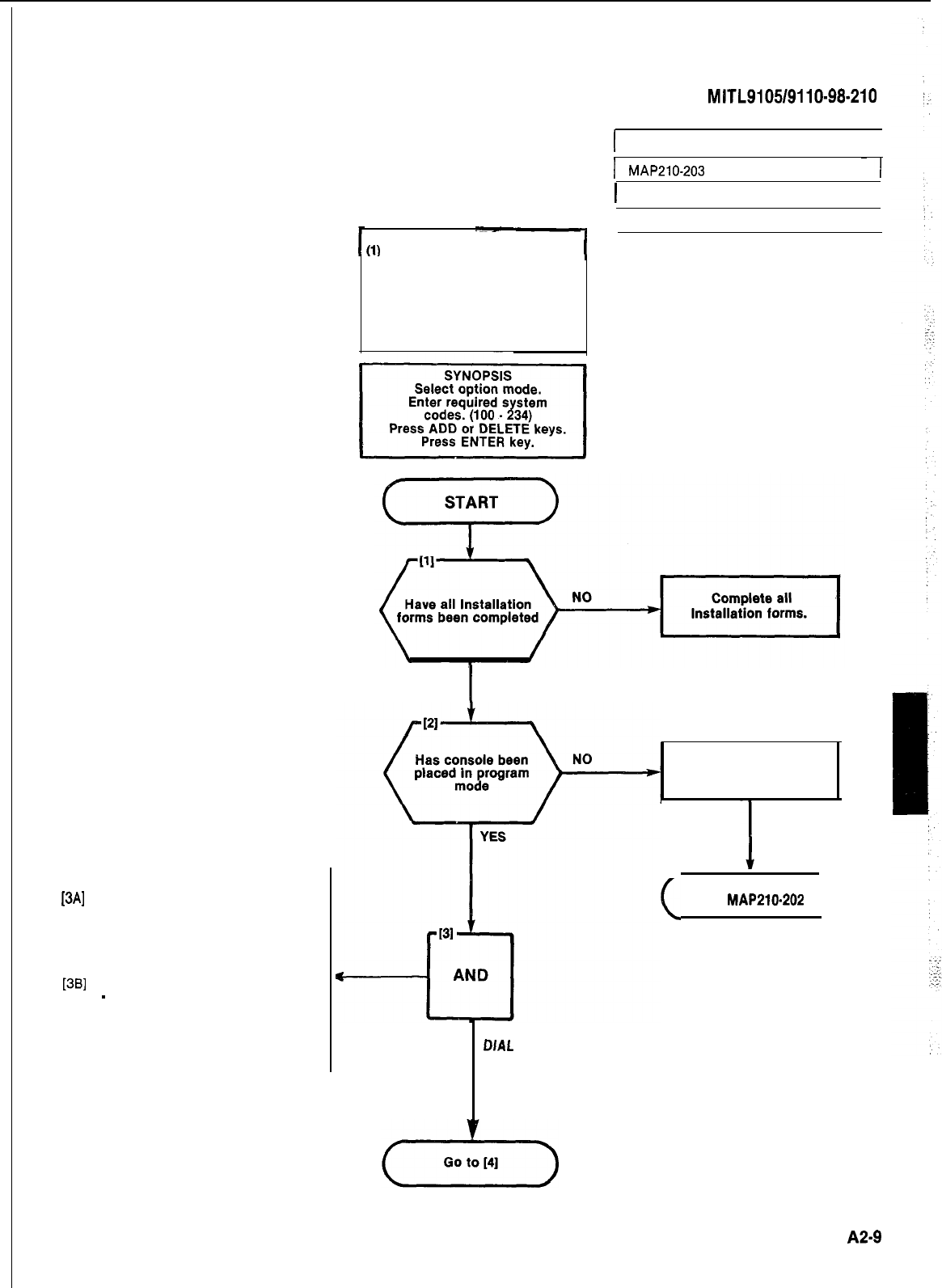
Select System Option
[3A]
Press OPTION key.
l OPTION lamp lit
l
SOURCE display shows 100 and
0 if no options enabled or the
number of the first option enabl-
ed and 1.
[3S]
Dial option number required (100
-
234) Table 203-l
l
SOURCE display shows number
dialed and 1 if the option enabl-
ed or 0 if the option is not enabl-
ed
SECTION
MITL9105/9110-98-210
I
PROGRAM SYSTEM OPTIONS
I
I
MAP210-203
~
I
1
Issue 3, July 1980
I
Sheet 1 of 4
NOTES
I
(1)
All entries are made from the
console dial pad.
(2) OPTION lamp lit throughout
procedure.
(3) A display of EO indicates that
an incorrect key had been
pressed. Press the key
specified.
I
YES
Place console In
programming mode.
PRESS OPTION KEY
DIAL OPTION CODE
(TABLE 203-l)
(
Go to
MAP210-202
)
A2-9
r
SECTION
MITL9110.98-210
PROGRAM SYSTEM OPTIONS
GO-203
I
1~
Issue 3, July 1980
I
Sheet 2 of 4
TABLE 203-l
SYSTEM OPTIONS
Option
Number Option Name
100
Discriminating Ringing
101
Transfer Dial Tone
102
Flexible Night Service
103
Night Service Automatic Switching
104
TAFAS Available During Day
105
Outgoing Trunk Camp-On
106
Outgoing Trunk Callback
107
Can Flash if on an Incoming Trunk
108
Can Flash if on an Outgoing Trunk
109
Can Flash if Talking to Station
110
Cannot Dial a Trunk After Flashing
111
Cannot Dial a Trunk After Flashing if Holding
or in Conference with a Trunk
112
113’ Lockout Alarm Enable
Tenant Service (set automatically when te-
nant service is selected when programming)
114
Flash Time
0.7s
(Only in Generic 202 and REV
5
UP)
114’
115
116
117
Tenant Service
-
Separate Consoles
Vacant Number Intercept to Attendant
Illegal Access Intercept to Attendant
DID/Dial-InlCCSA
Vacant/Illegal Intercept to
Attendant
118
119*
120
121
122
123
124
125
126
127
128
129
Attendant Camp-On
Attendant Conference
Attendant Busy Override
Attendant Serial Call
Bell Off Enable
Page Button Enable
New Call Tone Enable
Both Mode Standard
Callback Button Enable
Trunk Busy-Out Enable
Both Button Enable
Attendant CO Trunk-CO Trunk Connect
Enable
130
Attendant CO Trunk-Non CO Trunk Connect
Enable
131
Attendant Non CO Trunk-Non CO Trunk Con-
nect Enable
132*
Controlled Outgoing Restriction Set-Up
(Room Restriction)
133*
Controlled Station Restriction Set-Up (Do Not
Disturb)
134’ Controlled Station to Station Restriction
Set-
Up (Call Blocking)
135
136
137*
138’
139
140
141
142
143
144
145
146
147
148
149
Attendant
DISA
Code Set-Up Enable
Limited Wait For Dial Tone
Message Waiting Set-Up (lamp)
Message Waiting Set-Up (bell)
Attendant Timed Recall
-
Camp-On -20s
Attendant Timed Recall
-
Camp-On -40s
Attendant Timed Recall
-
Don’t Answer
-
20s
Attendant Timed Recall
-
Don’t Answer
-
40s
Attendant Timed Recall
-
Hold
-
20s
Attendant Timed Recall
-
Hold
-
40s
Night Service Timeout
-
20s
Night Service Timeout
-
40s
Call Forwarding
-
Don’t Answer Timeout -20s
Call Forwarding
-
Don’t Answer Timeout -40s
Call Forwarding
-
Busy (System, DID Dial-In
Tie Trunk, CCSA)
A2-10
SECTION
MITL9110.98-210
TABLE 203-l (CONT’D)
SYSTEM OPTIONS
Option
Number Option Name Option
Number Option Name
150
151
152
153
154
155
156’
157*
158’
159*
160’
161’
162’
163’
164’
165*
166”
167*
168’
169’
170’
171*
172*
173’
174*
175’
176’
177’
178’
179’
180’
181’
182’
183*
184
185
186
187
188
189
190”
191”
192**
193”
194”
195”
196”
197**
198’*
199”
200**
201”
202**
203**
204’*
205’ l
Call Forwarding
-
Don’t Answer (System, DID
Dial-In Tie Trunk, CCSA)
Park and Call-Hold Recall
-
2 minutes
Park and Call-Hold Recall
-
4 minutes
End of Dial Signal for Outgoing Trunks (#)
24 Hour Clock
First Digit Toll Deny
Message Registration Enable
Message Registration: Count Additional
Supervisions
Message Registration: Timer = 20 seconds
Message Registration: Timer
=
40 seconds
Message Registration: Multiplier
=
4 units
Message Registration: Multiplier
=
3 units
Message Registration: Multiplier
=
2 units
Message Registration: Surcharge
=
8 units
Message Registration: Surcharge
=
7 units
Message Registration: Surcharge
=
6 units
Message Registration: Surcharge
=
5 units
Message Registration: Surcharge
=
4 units
Message Registration: Surcharge
=
3 units
Message Registration: Surcharge
=
2 units
Message Registration: Surcharge
=
1 unit
DID to Non-CO Trunks via Attendant Inhibit
GUEST ROOM Button Enable
ROOM STATUS Button Enable
&
Display
Enable
Do Not Disturb Intercept to Attendant
Do Not Disturb and Message Waiting
Displays
Single Digit Dialing Enable
Single Digit Dialing Time-Out
=
3 seconds
Single Digit Dialing Time-Out
=
5 seconds
Attendant Station Busy-Out Enable
Flash Timing
=
0.7 seconds
Flash Timing
=
0.9 seconds
Flash Timing = 1.1 seconds
Trunk Recall Partial Inhibit
Reserved
Reserved
Reserved
Reserved
Reserved
Reserved
Automatic Wakeup Enable
Automatic Wakeup Print
Automatic Wakeup Music On Hold
Room Register Audit Enable
Room Status Audit Enable
Message Register
&
Message Waiting
Change Print Enable
Ignore Print Enable
Remote System Reset
-
Protection Override
Enable Non-CO Trunk to Trunk Connect
Toll Control Enable
Traffic Measurement Enable
Traffic Measurement Extreme Value Mode
Traffic Measurement Compact Report
Traffic Measurement Polling
Traffic Measurement Autoprint
Identified Trunk Group Enable
206*
l
207”
208**
209*
l
210**
211”
212**
213**
214*’
215
216t
217t
218t
219t
220t
221t
222t
223t
224t
225t
226t
227t
228t
229t
230t
231
t
232t
233t
234t
Inhibit Automatic Supervision
Printer Carriage Return Delay
Zero Message Register After Room Register
Audit
Traffic Measurement
-
Console Enable
Attendant Printer Control Enable
System ID Enable
Nightbell 3 with Minor Alarm Enable
HIM Printouts: Extra Line Feeds
Automatic Wakeup Alarm
Reserved
Speed Call Enable
Speed Call Programming Enable
Speed Call: Confidential Number Display
and Change Enable
Reserved
Station Message Detail Recording:
Outgoing Calls
Station Message Detail Recording:
Incoming Calls
SMDR: Extended Record
SMDR: Record Meter Pulses
SMDR: Indicate Long Calls
SMDR: Drop Incomplete Outgoing Calls
SMDR: Record Only Incoming calls
(CCSA
&
Non-dial tie trunks)
SMDR: Drop Calls of Less Than 8 Digits
Discriminating Dial Tone
Special
ANI
Feature
Account Code Enable
Account Code Length, 4 Digits
Account Code Length, 8 Digits
Account Code Length, 12 Digits
Variable Length Account Codes
1.
:
:
i.
:
.:
Generic 203 and above
*
l
* Generic 204 and 205
**
Generic 204 only
t
Generic 205 only
A2-11
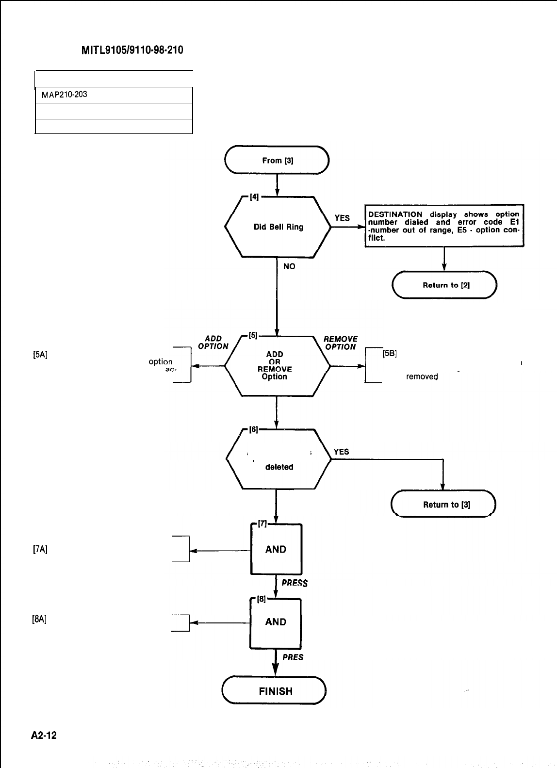
SECTION
MITL9105/9110-98-210
PROGRAM SYSTEM OPTIONS
I
MAP210-203
Issue 3, July 1980
Sheet 4 of 4
[5A]
Press ADD key
lSOURCE display shows
opti
number dialed and 1, option
tive
[5B]
Press DELETE key
l
SOURCE display shows option
number dialed and 0, option
Are more options
to be added or
I
NO
Store system options
[7A]
Press ENTER key
.ENTER lamp lit
S
ENTER KEY
[8A]
Press LAMP TEST key
.LAMP TEST lamp lit
S LAMP TEST KEY
A2-12
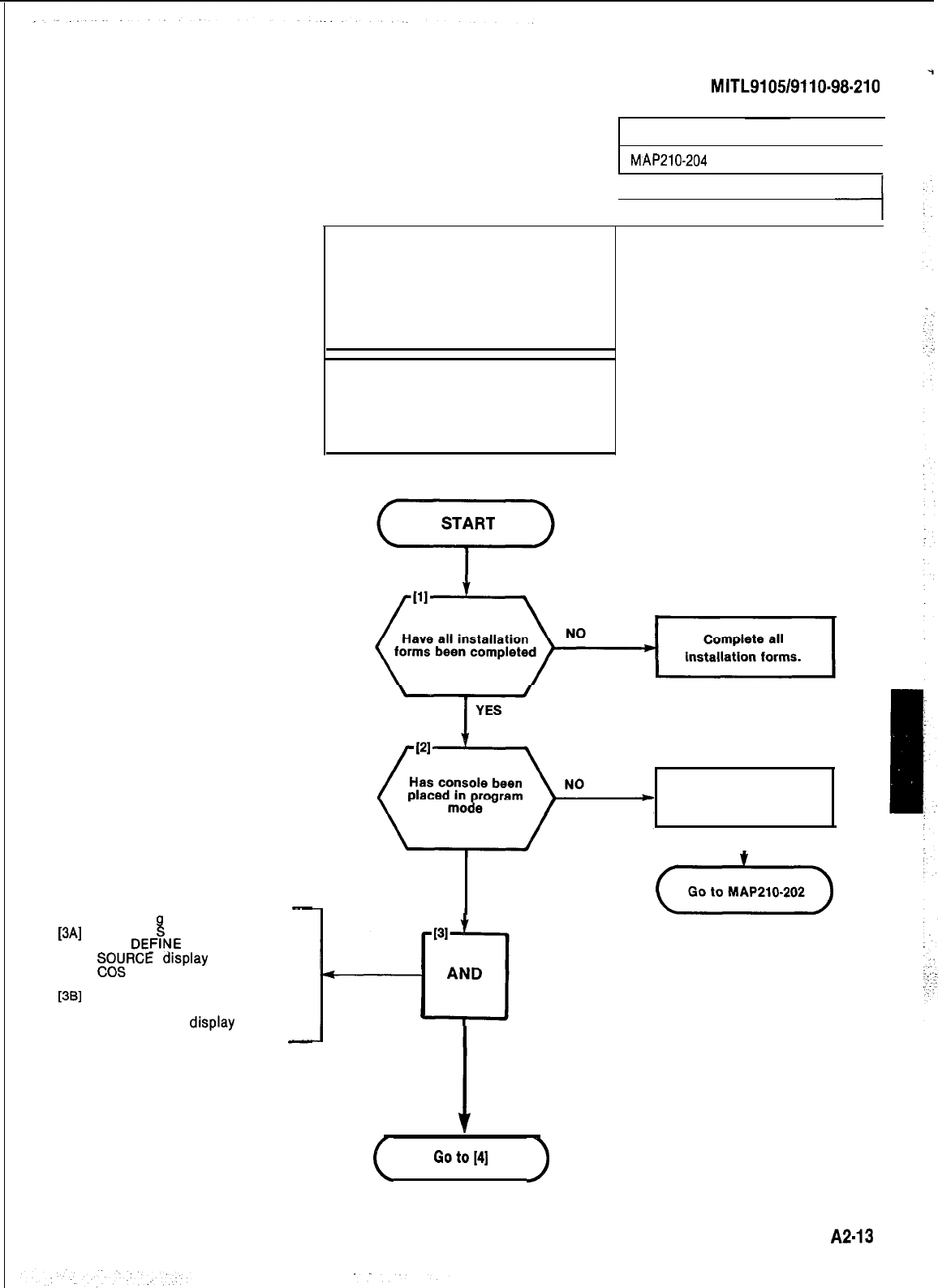
SECTION
MITL9105/9110-98-210
-
Select COS Pro
ram
[3A]
Press CO
ki
DEFINE key
.
COS DEFIYE lamp lit
l
gg:FiCE
display shows current
[3B] Dial class-of-service number to
. be defined (l-16).
DESTINATION display shows
COS number dialed
-
(1) All entries are made from the
console dial pad
(2) COS DEFINE lamp remains lit
through procedure
(3)A display of EO indicates that an
incorrect key was pressed; press
key specified
SYNOPSIS
Define COS
group (1 . 16)
Enter all option codes (33 . 94)
Press ADD or DELETE keys
Press ENTER key
PROGRAM COS OPTIONS
I
MAP210-204
I
Issue 3, July 1980
Sheet 1 of 6
Place console in
programming mode.
I
YES
(e)
PRESS COS DEFINE KEY
DIAL COS NUMBER
(
Goto[4]
)
A2-13
:
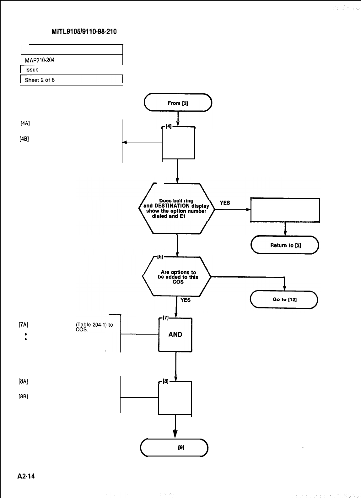
SECTION
MITL9105/9110-98-210
PROGRAM COS OPTIONS
MAP216204
Lie
3,
July 1980
I
[4A]
Press OPTION key
l OPTION lamp lit
[46] SOURCE display shows COS
number dialed followed by 33
4
AND
and 0 (no options assigned) or
first option assigned to the COS
followed by a 1.
PRESS OPTION
KEY
COS number dialed
out of range 1-16
NO
NO (Delete options)
Add
[74
.
.
options to COS
Dial option code
be added to this
OPTION lamp lit.
SOURCE display shows COS
number followed by option
number dialed, followed by 0.
VI
-cl
AND
I
DIAL OPTION
CODE (TABLE 204-l)
[8A]
Press ADD key
l ADD lamp lit
[8B] SOURCE display shows COS
number, new option code and 1
(option active)
rI61
’
AND
ADD OPTION
v
Go to
191
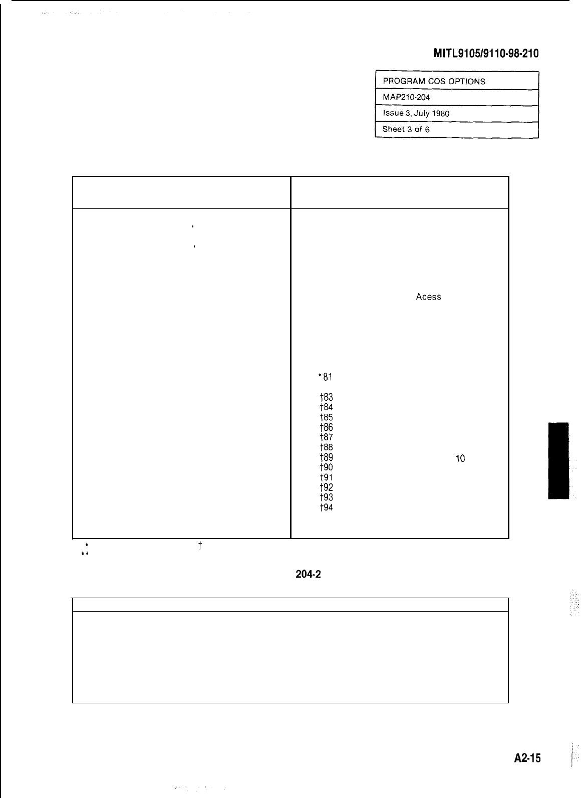
SECTION
MITL9105/9110-98-210
TABLE 204-l
CLASS-OF-SERVICE OPTIONS
Option
Number Extension Options
33
Automatic Callback
34
Call Forwarding
-
Busy
35
Call Forwarding
-
Don’t Answer
36
Call Forwarding
-
Follow Me
37
Call Park
38
Never a Forwardee
39
Directed Call Pickup
40
Executive Busy Override
41
Data Security
42
Station Override Security
‘43
Inward Restriction (DID)
44
Originate Only
45
Receive Only
46
Flash Disable
47
Never a Consultee
48
Broker’s Call
49
Station Conference
50
Meet-Me Conference
51
Camp-On
52
Do Not Overflow
53
Paging Access
54
TAFAS Access
55
Hold Pickup
56
Account Code Access
57
Manual Line
58
Contact Monitor
59
Non-CO Trunk via Attendant Inhibit
60
CO Trunks via Attendant Inhibit
61
No Dial Tone
62
Flash for Attendant
‘63
Call Blocking
l
64
Message Register
*
Generic 203 and above
t
Generic 205 only
** Generic 204 only
Option
Number Extension Options
65
Trunk Group 1 Access
66
Trunk Group 2 Access
67
Trunk Group 3 Access
68
Trunk Group 4 Access
69
Trunk Group 5 Access
70
Trunk Group 6 Access
71
Trunk Group 7 Access
72
Trunk Group 8 Access
73
Trunk Group 9
Acess
74
Trunk Group 10 Access
75
Trunk Group 11 Access
76
Trunk Group 12 Access
‘77
Message Waiting Applies
l
78
Room Do Not Disturb Setup Enable
l 79
Call Hold and Retrieve Access
l
80
Room Status Applies
*al
Call Forward System Inhibit
“82
Alarm Call Setup Enable
t83
Forced Account Code Entry
t84
No SMDR Record for This Line
t85 Speed Call Table 1 and 2 Access
t86 Speed Call Table 3 and 4 Access
t87 Speed Call Table 5 and 6 Access
t88 Speed Call Table 7 and 8 Access
t89
Speed Call Table 9 and
IO
Access
t90 Speed Call Table 11 and 12 Access
t91 Speed Call Table 13 and 14 Access
t92 Speed Call Table 15 and 16 Access
t93 Speed Call Table 17 and 18 Access
t94
Cannot Dial a Trunk After Flashing
TABLE
204.2
OPTION CONFLICTS
45
46
46
46
48
62
62
Option
Receive Disable
Flash Disable
Flash Disable
Flash Disable
Brokers Call
Flash for Attendant
Flash for Attendant
and
58
48
49
62
49
49
48
Option
Contact Monitor
Brokers Call
Station Conference
Flash for Attendant
Station Conference
Station Conference
Brokers Call
A2-15 j.
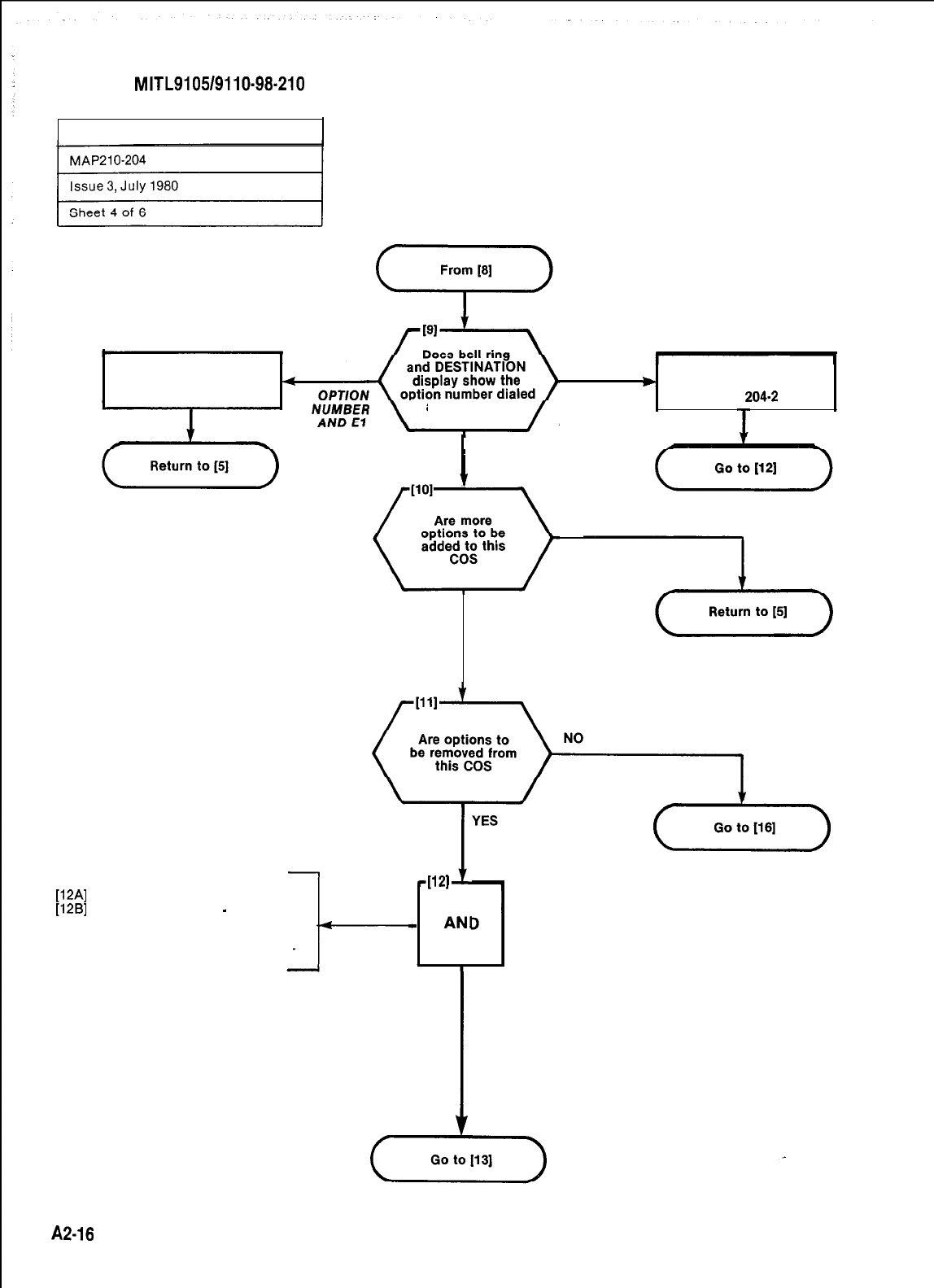
SECTION
MITL9105/9110-98-210
PROGRAM COS OPTIONS
Option number dialed
out of range 33.94
Conflicting option exists.
OPTION
)
Remove conflicting option.
and El or E5 Table
204-2
NUMBER
AND E5
NO
YES
NO
Remove Option from COS
[12A]
Press OPTION key
[12B]
Dial option code (33
-
82) to be
removed from the COS
lSOURCE display shows COS
number, option code, and 1 (op-
tion active)
51
1121
-
ANI
PRESS OPT/ON KEY
DIAL OPTION CODE
A2-18
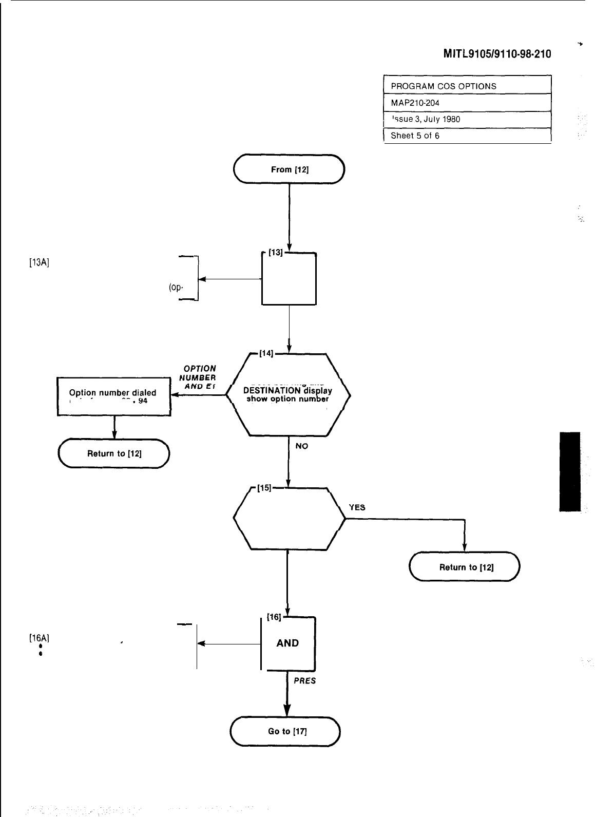
*
SECTION
MITL9105/9110-98-210
-
[13A]
Press DELETE key
.DELETE lamp lit
lSOURCE display shows COS
number, option code, and 0
(op.
tion inactive)
-
:
..;.
4
-
AND
DELETE OPTION
AND CHECK DISPLAYS
Does bell
ring and
out of range 33
-
dialed and El or E5
Are more options
to be removed
from the COS
NO
Store COS Options
[16A]
Press ENTER kev
-
.
ENTER lamp lit
L
*
SOURCE display shows current
COS number
<
WI
AND
i
PRESS ENTER KEY
(oolollll)
A2.17
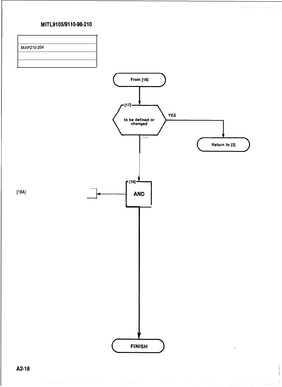
SECTION
MITL9105/9110-98.210
PROGRAM COS OPTIONS
MAP210-204
Issue 3, July 1980
Sheet 6 of 6
[18A]
Press LAMP TEST key
.LAMP TEST lamp
Are more COS
NO
PRESS LAMP TEST KEY
A2-18
1181
ri
AND
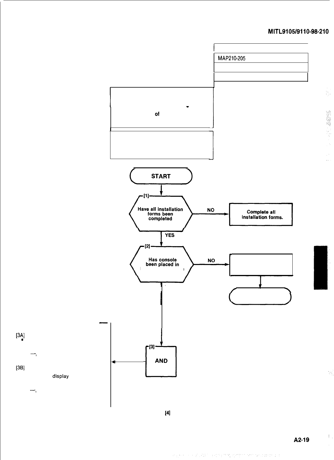
SECTION
MITL9105/9110-98.210
SELECT FEATURE ACCESS CODE
-
PROGRAM
[3A]
Press FEATURE key.
e
SOURCE display shows feature
number and its assigned access
code or the feature number and
----,
no access code assigned to
the feature.
[3B]
Dial number of feature to be add-
ed or changed (Table 205-l)
l
SOURCE
display
shows feature
number and its assigned access
code or the feature number and
---*,
no access code assigned to
the feature.
l
DESTINATION display shows
feature number dialed.
I
ASSIGN FEATURE ACCESS CODES
I
MAP210-205
Issue 3, July 1980
Sheet 1 of 3
I
NOTES
1.
All entries are made from the
I
console dial pad.
2.
FEATURE lamp lit throuahout
procedure. .
-
3.
A display
ot
EO indicates that an
incorrect key was pressed, check
procedure and press correct key.
SYNOPSIS
Enter feature number.
Assign or delete access code.
Press ENTER key.
Repeat for all required features.
YES
f
\
Programming mode
t
Set console to
programming mode.
[31
d
AND
I-
Go to MAP210-202
PRESSFEATUREKEY
DIAL FEATURE CODE
(TABLE 205-l)
A
Go to
[4]
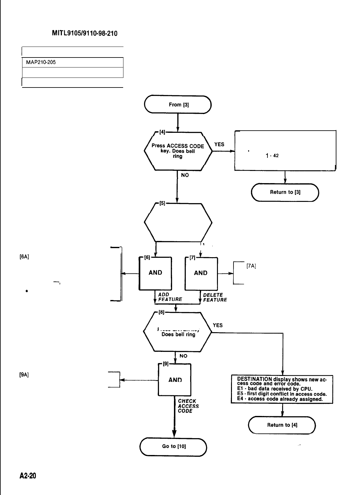
SECTION
MITL9105/9110-98-210
I
ASSIGN FEATURE ACCESS CODES
MAP210-205
Issue 3, July 1980
I
Sheet 2 of 3
I
ASSIGN FEATURE ACCESS CODE
-
WI
Dial new access code
.ACCESS CODE lamp lit
.SOURCE display shows new
feature number-and its access
code or the feature number
and
----,
if no access code is
assigned to the feature.
e
DESTINATION display shows
access code to be assigned.
-
-I
STORE FEATURE ACCESS CODE
DESTINATION display shows feature
number dialed and error code.
El
-
feature number dialed out of
range
1
.42
Check feature number (Table 205-l)
Is feature to
be removed from
system
NO
I
YES
(Y&T)
[7Al
.Press DELETE key.
SOURCE display shows the
feature number and 0, feature
not active.
Press ENTER key
WI
SOURCE display shows
feature number and
access code. assigned
A2-20
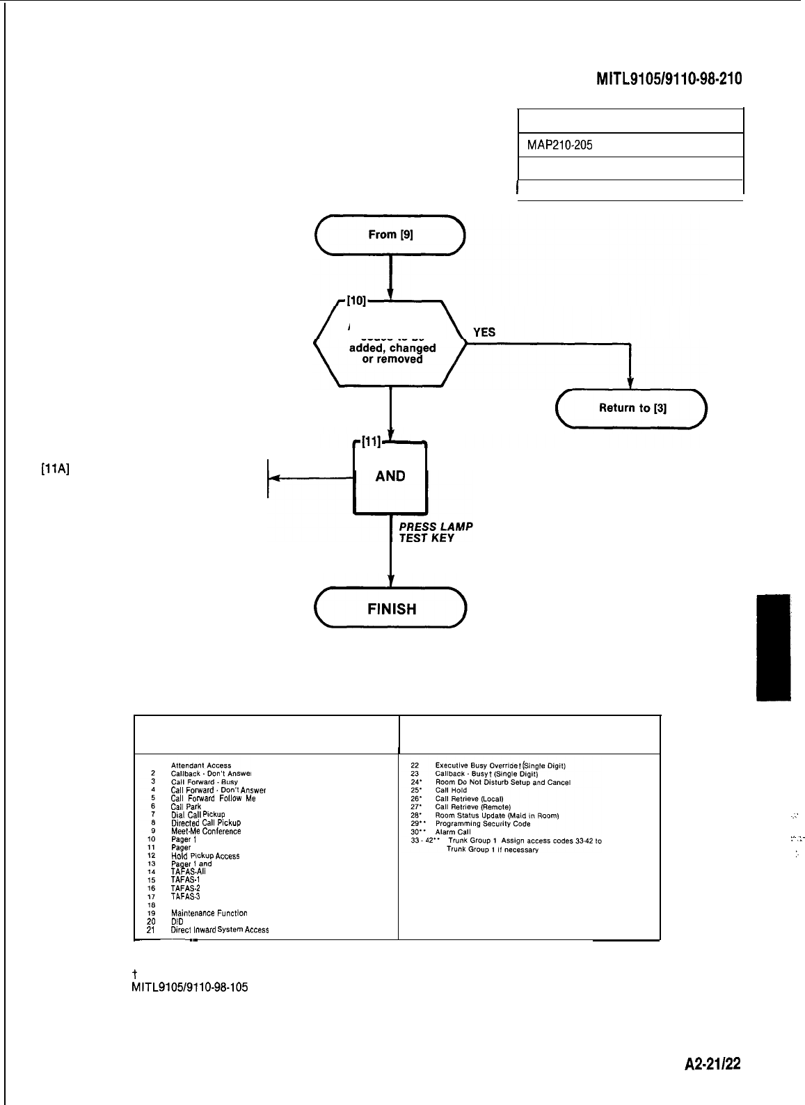
SECTION
MITL9105/9110-98-210
ASSIGN FEATURE ACCESS CODES
MAP210-205
issue 3, July 1980
Press LAMP TEST key
All lamps dark
Are more access
codes to be
NO
TABLE 205-l
FEATURE ASSIGNMENTS
Feature Feature
Number Description Number Description
1 Sheet 3 of 3
I
20
21
Cal,
Forwards
Lbn;t
Answer
Call
Forward
Follow
MB
Call
Park
Did
cau
Pickup
Directed
Cdl
PiCkUP
Meet-Me
Conference
pager
1
pager
2
HCM
Pick”*
ACCBSS
pager
1
and
2
TAFASAII
TAFAS.1
TAFAS-2
TAFAS-3
Attendant Function
hlain,enance
Function
DID
Attendant Access Code
Direct
inward
System
Access
-~
~~
l Generic 203 and above
l l Generic 204 only
t
First digit conflicts between these codes and other access codes are allowed. See Section
MITL9105/9110-98-105
for complete description of feature operation.
..:
:-.i-
:.
A2-21122
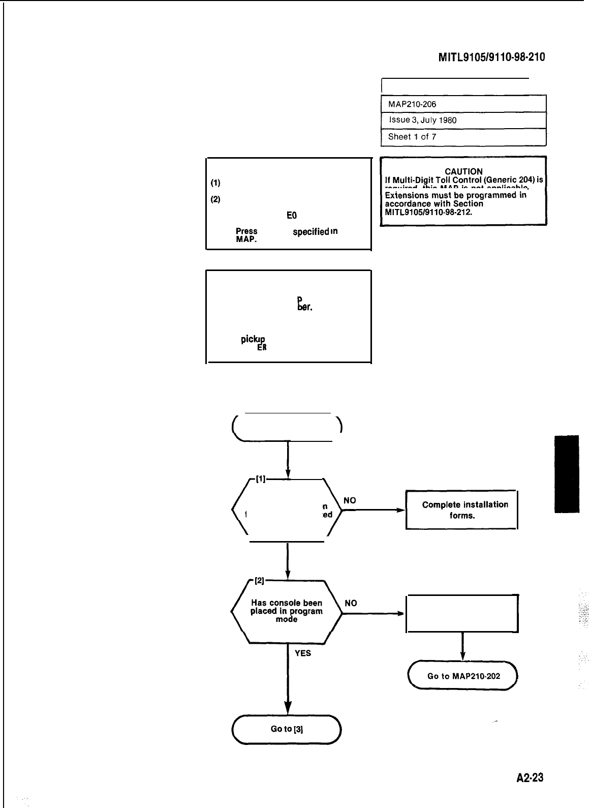
SECTION
MITL9105/9110-98-210
I
PROGRAM EXTENSIONS 1
NOTES
(1)
All entries are made from the
console dial pad. required, this MAP
is
not applicable.
(2)
EXTN lamp lit throughout pro-
cedure.
(3)
A display of
EQ
indicates that an
incorrect key has been pressed.
;rps
the key
specrfred
In
the
SYNOPSIS
Select required tenants (l-4)
Enter extension equi ment number.
Enter extension num
rid
er.
Enter COS number.
Enter toll allow/deny.
Enter busy lamp position number.
Enter picku group number.
Press ENT
R
key.
P
f
START
1
Have all installation
)No
forms been completed
I
YES
Place console
in programming mode.
A2-23
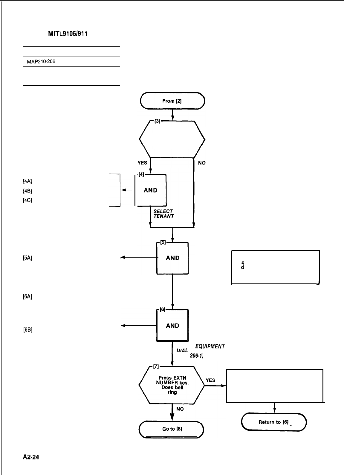
SECTION
MlTL9105/911
O-98-21 0
PROGRAM EXTENSIONS
MAPPlO-206
Issue 3, July 1980
Sheet 2 of 7
[4A]
Press TENANT key
[4B]
Dial tenant number (l-4)
[4C]
Press ENTER key
SELECT EXTENSION PROGRAM
[5A]
Press EXTN key
.EXTN lamp lit
Is multi tenant
service to be used
4
ENTER EQUIPMENT NUMBER
[6A]
Press EQPT NUMBER key
.EQPT NUMBER lamp lit
lSOURCE display shows lowest
assigned equipment number or
001 if no equipment number is
assigned
[6B]
Dial equipment number to be
defined, Fig. 206-l. (l-1121161-256)
.EQPT NUMBER lamp lit
lSOURCE display shows current
equipment number
.DESTINATION display shows
equipment number dialed
A2-24
(SINGLE
TENANT)
PRESS EXTN KEY
L
NOTE
E
uipment number 001 is reserv-
e
ii
for the test line and should
not be assigned to a working ex-
tension.
J
I
PRESS
ECWPMENT
NUMBER KEY
DIAL
EQUIPMENT NUMBER
(FIG.
206.7)
DESTINATION display shows equipment
number and error code. El number dial-
ed out of range l-1121161-256.
Check number. Fig. 206-l
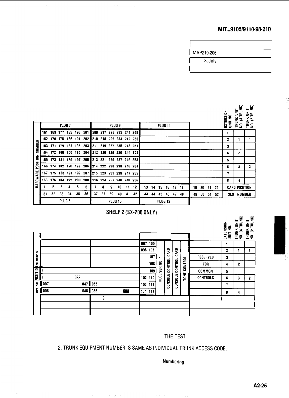
SECTION
MITL9105/9110-98-210
I
PROGRAM EXTENSIONS 1
I
MAP210-206
---I
1
issue
&July
1980
I
1
Sheet3 of 7
I
SHELFZ(SX-2000NLY)
I
PLUG1
I
PLUG3
001 009 017 025 033 041 049 057 065 073 081 089
002 010 018 026 034 042 050 058 066 074 082
5
090
g
003 011 019 027 035 043 051 059 067 075 083 091
=
004 012 020 028 036 044 052 060 068 076 084 092
005 013 021 029 037 0451053 061 069 077 085 093
006 014 022 030
038
0461054 062 070 078 086 094
S 1007 015 023 031 039 0471055 063 071 079 087 095
g 1008 016 024 032 040 0481056 064 072 080
088
096
099
1071
100
1081
101
1091
PLUG5
-I-
2123456
78910 11 12 13 14 15 16 17 18
123456
7 8 9 10 11 12 13 14 15 16 17 18
PLUG2 PLUG4 PLUG6
SHELF1
19 20 21 22
1
CARD POSITION
1
19 20 21 22
1
SLOTNUMBER
I
1.
:
NOTES: 1. EQUIPMENT POSITION 001 IS RESERVED FOR
THETEST
LINE AND MUST
THEREFORE BE EQUIPPED WITH A LINE CARD.
2.TRUNKEQUlPMENTNUMBERISSAMEASlNDlVlDUALTRUNKACCESSCODE.
Fig. 206-l Hardware/Equipment
Numbering
A2-25

SECTION
MITL9105/9110-98-210
r
PROGRAM EXTENSIONS
I
1
MAP210-206
1
Issue 3, July 1980
I
Sheet 4 of 7
I
ENTER EXTENSION NUMBER
[8A]
Dial extension number
.
EXTN NUMBER lamp lit
l
SOURCE display shows equip-
ment number and existing exten-
sion number if assigned
l DESTINATION display shows
dialed extension number
-
I
Cl Numbering plan conflict, check entry.
If entry is correct, press CONFIRM key
and continue, the original assignment is
deleted. If entry is incorrect, return to
[A.
EXTENSION NUMBER
DESTINATION display shows El, E4 or E5
El -bad data received by CPU.
E4-extension
number exists.
E5-extension
number in conflict
with existing numbering plan.
ENTER COS NUMBER
[lOA] Dial COS number (l-16)
l
COS NUMBER lamp lit
l
SOURCE display sho.ws equip-
rn;-n;;;mber
and exrstmg COS
.
DESTINATION display shows
COS number dialed
A2-26
COS NUMBER
Press TOLL DENY
key. Does bell ring
DESTINATION display shows COS
number and error code. El-COS
number out of range (1.16).
NO
(-Qk-)
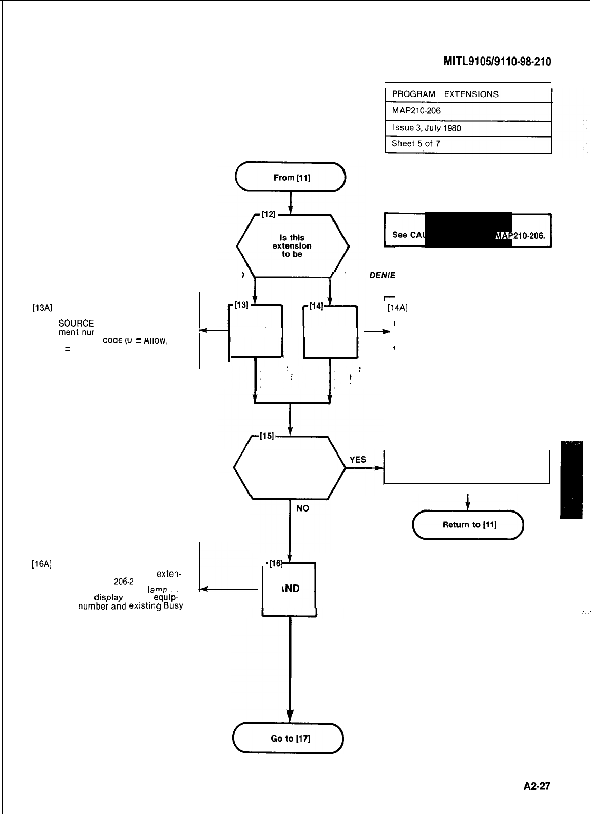
SECTION
MITL9105/9110-98.210
TOLLTOLL ALLOWED
ALL
TOLL DEN/ED
DEN/E
ASSIGN TOLL ACCESS
[13AJ
Press DELETE key
.DELETE lamp lit
l
SmOJK$
display shows equip-
Allow/Deny
coae
(u
=
HIIOW,
1
=
Deny)
.DESTINATION display shows
O-Toll Allow
ASSIGN TOLL ACCESS
r
[13AJ
Press DELETE key
.DELETE lamp lit
[l
[14A]
Press ADD key
.
l
SOURCE display shows equip- ADD lamp lit
4
.
ment number and existing Toll
t-
AND AND
+
SOURCE display shows equip-
Allow/Deny code (0
=
Allow, ment number and the existing
1
=
Deny) toll access code
4
.
.DESTINATION display shows DESTINATION display shows
..
O-Toll Allow code 1 (Deny)
PRESS PRESS
L
DELETE ADD
KEY KEY
See CAUTION at start of MAPSlO-206.
I-
Press BUSY
LAMP NUMBER
key. Does bell ring
DESTINATION display shows Toll Allow
or Deny code and error code. El, bad
data received by CPU.
I
[16A]
Dial BUSY LAMP NUMBER
(l-150) to be assigned to
exten-
ER
lame
lit
sion (See Fig.
206-2
.BUSY LAMP NUMB
l
SOURCE
disolav
shows
eq’uip-
9
BUSY
ment
numbed
and
existin
Lamp assignment
.DESTINATION display shows
new Busy Lamp Number
I
ASSIGN EXTENSION TO BUSY LAMP
FIELD
NO
-T-
m[161
7
AND
(y&F)
DIAL REQUIRED BUSY
LAMP NUMBER
(FIG. 206-2)
A2-27
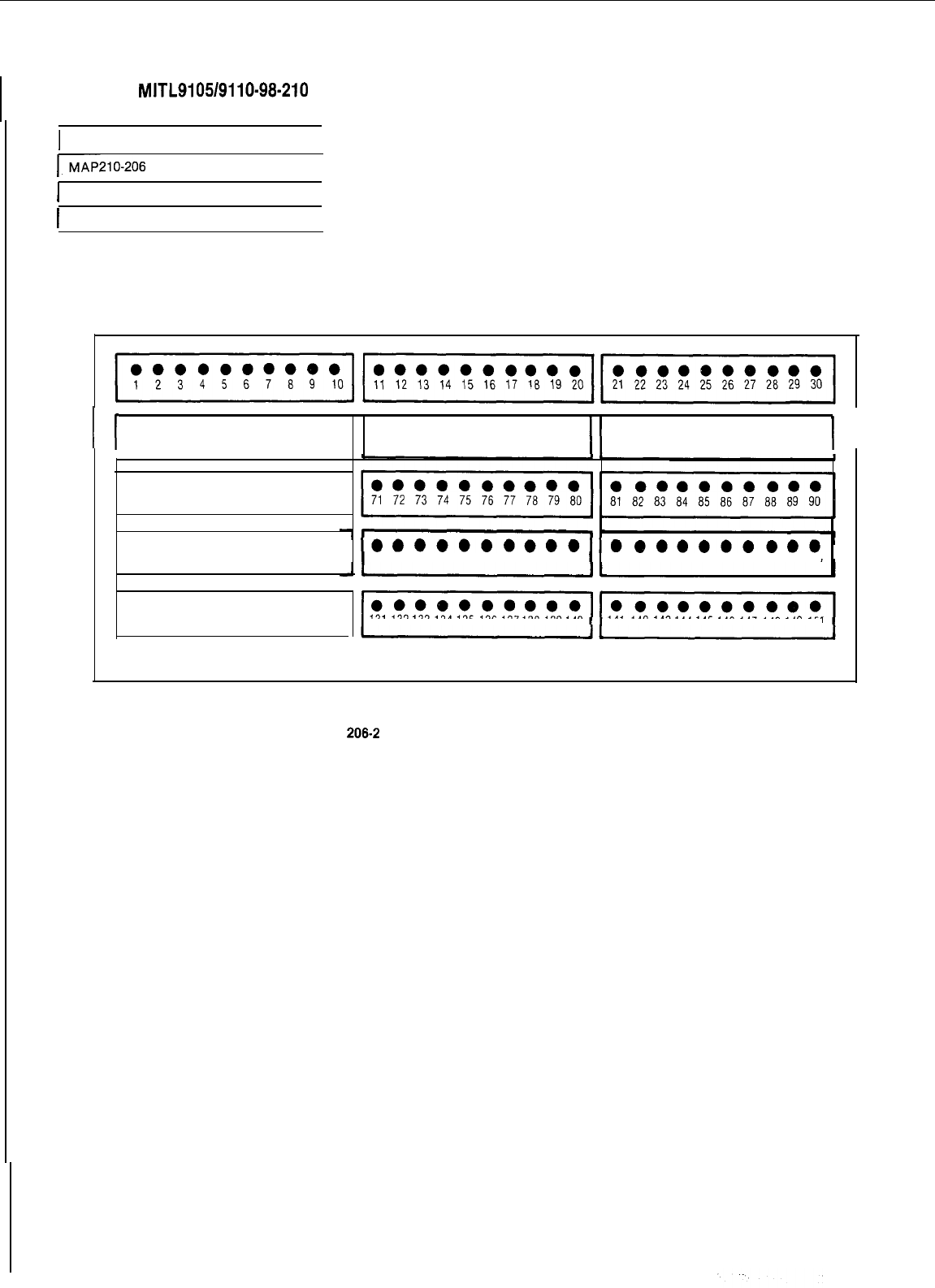
SECTION
MITL9105/9110-98-210
1 PROGRAM EXTENSIONS
I
EMAP210-206
I
1
Issue 3, July 1980
I
I
Sheet 6 of 7
I
A2.28
I
I
l ooooooooo l ooooooooo l ooooooooo
31
32 33 34 35 36 37 38 39 40
41
42 43 44 45 46 47 48 49 50
51
52 53 54 55 56 57 58 59 60
II
l *eeaeoeoo
61
62 63 64 65 66 67 68 69 70
l ooooooooo
91
92 93 94 95 96 97 98 99 100 101 102
103104
105 106
107108
109 110 111 112 113
114115 116117 118119120
l ooooooooo
121122
123 124
125126127128129
130 131
132133
134 135 136
137138 139140
141 142
143144145146
147
148149
150
Fig.
206-2
Busy Lamp Position Numbering
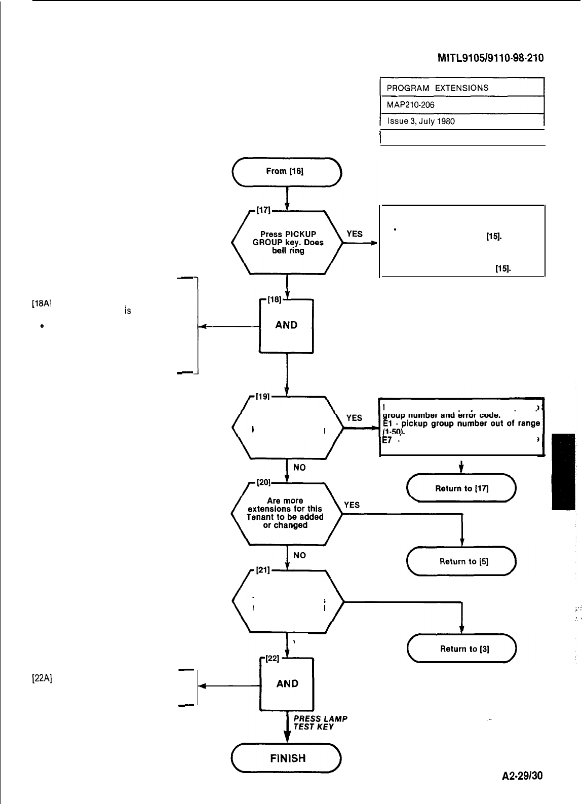
SECTION
MITL9105/9110-98-210
-
ASSIGN EXTENSION TO PICKUP
GROUP
f1SA1
Dial Pickup Group number to
.
which extension
is
assigned
.PICKUP Group lamp lit
e
SOURCE display shows equip-
ment number and current pickup
group assignment, 0 is displayed
if no assignment IS made
.DESTINATION display shows
new pickup group assignment
-
I
[22A]
Press LAMP TEST key
.LAMP TEST lamp lit
.All lamps except LAMP TEST go
dark
-
I
NO
[181
-If
AND
I
Sheet 7 of 7
I
DESTINATION display shows Busy
Lamp Number and error code.
El
-
number entered out of range (1.150).
Check entry and return to
[15].
C2 . position dialed already assigned. If
this IS a valid change press the CON-
FIRM key and continue. If Busy Lamp
position is in error return to
[15].
I
DIAL PICKUP
GROUP NUMBER
DESTINATION display shows pickup
Press ENTER
key. Does bell ring
i7
y
extension has a used message
register. Clear message register.
.
I
(Returnfollll)
Are other
Tenant extensions
to be programmed
NO
YES
4
.:
,:
.‘.
.
A2-29130
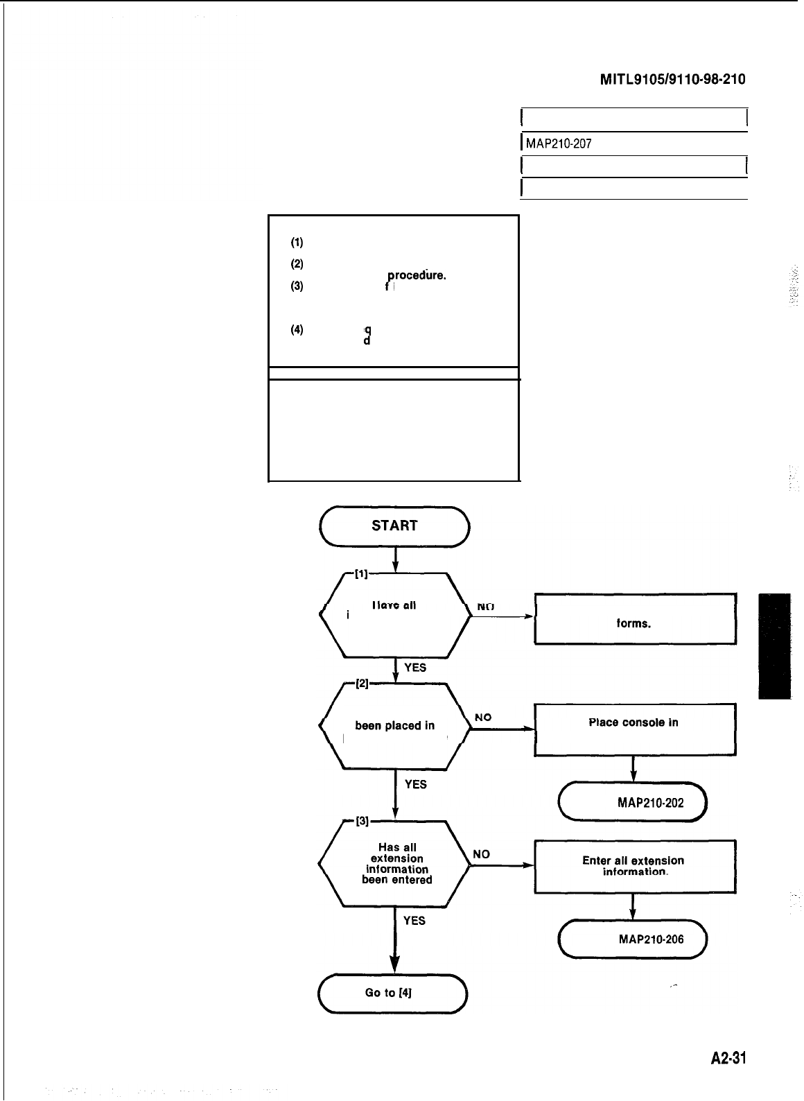
NOTES
(1)
All entries are made from the
(2)
console dial pad.
HUNT GROUP lamp remains lit
(3)
throughout
rocedure.
A display o
P
EO indicates that an
incorrect key has been pressed.
Press the key specified in the
MAP.
(4)
If any e
change
iI
uipment number is to be
wrthin a hunt group, the
hunt group must be re-entered.
SECTION
MITL9105/9110-98-210
1 PROGRAM EXTENSION HUNT GROUPS 1
1
MAP210-207
I
1 Issue 3, July 1980
1 Sheet I of 6
I
SYNOPSIS
Select required tenant.
Enter hunt group number (l-12).
Enter master hunt number.
Enter all required equipment
numbers.
Determine type of hunting
Press ENTER key.
installation forms
been completed
Complete installation
Has console
programming mode programming mode.
Go to
MAP210-202
Go to
MAP210.206
A2-37
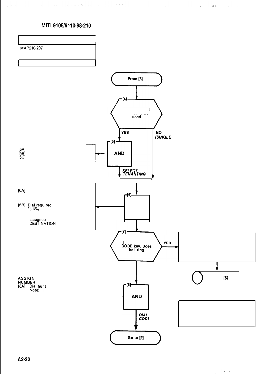
SECTION
MITL9105/9110-98-210
PROGRAM EXTENSION HUNT GROUPS
MAP2107207
Issue 3, July 1980
1 Sheet 2 of 6
[5A]
Press TENANT key
[5B]
Dial tenant number (l-4)
[5C]
Press ENTER key
I-
SELECT HUNT GROUP PROGRAM
[6A]
Press HUNT GROUP key
l
SOURCE display shows hunt
group 1 and access code if
assigned
[6B]
lI?\;equired
hunt group number
\’
‘-I
l
SOURCE display shows hunt
group 1 and master number if
assi ned
.
DES%NATlON
display shows
new hunt group number
Is multi tenant
service to be
TENANT/NG
s
-161
’
~!%GLE
TENANT)
;;;lzE;
HUNT GROUP MASTER
[8A)
;ioae;unt
group master code (See
lACCESS CODE lamp lit
lSOURCE display shows hunt
group number and existing
master number
.DESTINATION display shows
master number dialed
I-
I
NO
-
AND
PRESS HUNT GROUP KEY
D/AL HUNT GROUP NUMBER
Press ACCESS
DESTINATION display
shows hunt group
number dialed and error
code. El -number out of
range 1-12.
PI
AND
P
DIAL MASTER
CODE NUMBER
(xi-)
(
Return to
[6]
)
NOTE The master number is the
number which when dialed will
access the hunt group. This
number cannot be assigned to
an extension.
A2-32
:
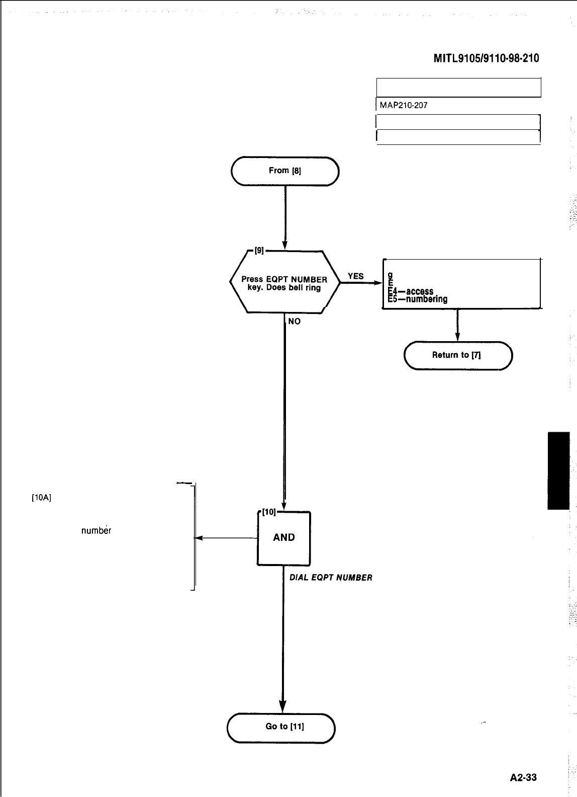
SECTION
MITL9105/9110-98-210
PROGRAM EXTENSION HUNT GROUPS
I
MAP210-207
I
1 Issue 3, July 1980
1 Sheet 3 of 6
From
[8]
7
DESTINATION display shows hunt
I!
roup master number and error code.
l-bad data received by CPU
E4-access code already assigned
Efi-numbering plan conflict
-
ASSIGN EXTENSIONS TO HUNT GROUP
[lOA]
Dial equipment number of first
extension in this hunt group
.EQPT NUMBER lamp lit
l
SOURCE display shows hunt
group
number
and existing equip-
ment number if one is assigned
or the hunt group number alone
if no equipment number is
assigned to the hunt group
.DESTINATION display shows
equipment number dialed
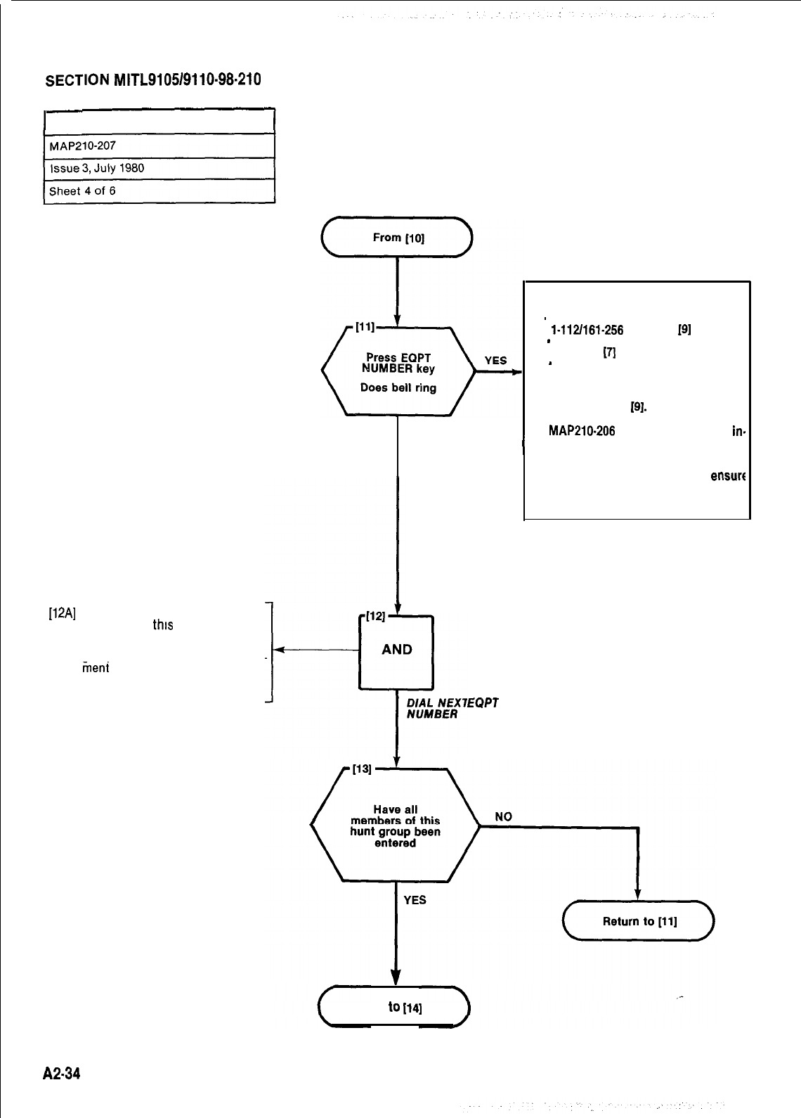
r
SECTION
MITL9105/9110-98.210
PROGRAM EXTENSION HUNT GROUPS
[12A]
Dial equipment number of next
extension in
this
hunt group
lEQPT NUMBER lamp lit
lSOURCE display shows hunt
group number and existing equip
tieni
number
.DESTINATION display shows
equipment number dialed
DESTINATION display shows equipmenf
number dialed and error code.
El
-
number entered out of range
l-112/161-256
return to
[9]
E3
-
master number not entered,
return to
(71
NO
E6
-
equipment number dialed is not
defined as an extension or exten-
sion has a used message register.
Check equipment number; if incor-
rect return to
191.
If correct, press
LAMP TEST key and go to
MAP210-206
and enter extension
in-
EOPT
I
formation.
If message register shows a non-zerc
content, clear the register and
ensure
COS of extension does not include Op
tion 64 (Message Register).
Go
to
114)
A2-34
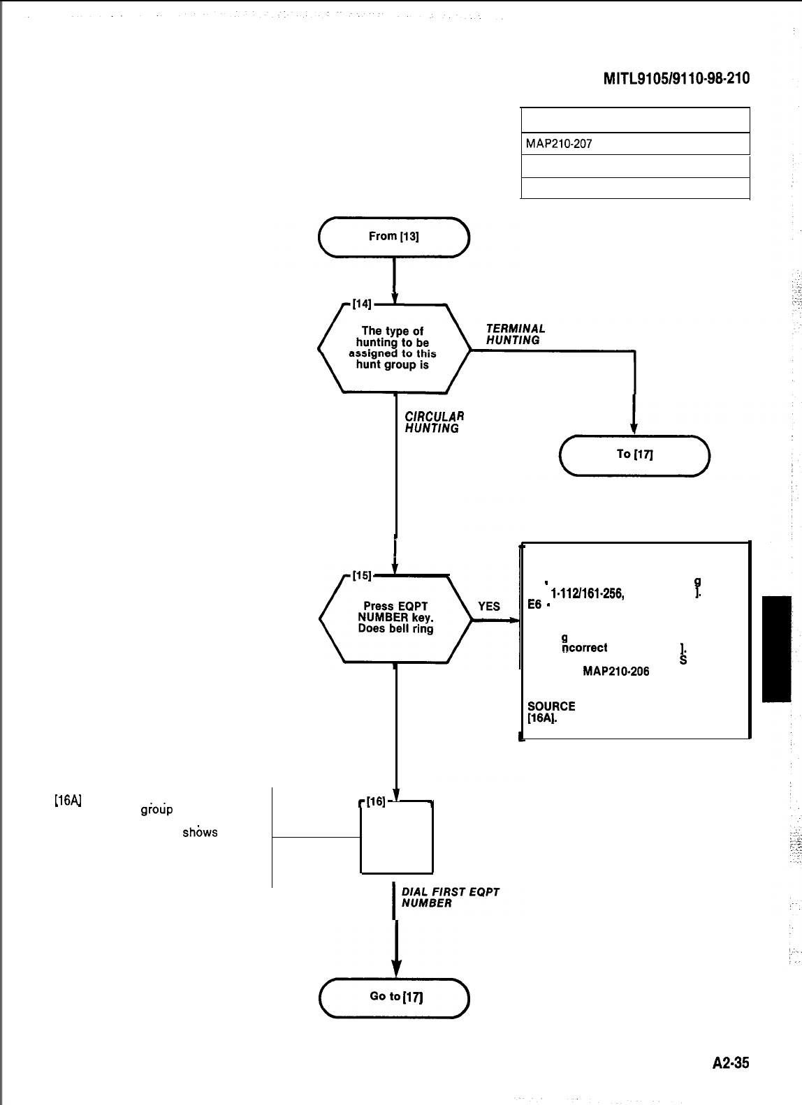
ASSIGN TYPE OF HUNTING
Il6Al
Dial first equipment number on
.
-
this hunt
giotip
.EQPT NUMBER lamp lit
lSOURCE display
shbws
hunt
group and last equipment
number entered
.DESTINATION display shows
first equipment number entered
SECTION
MITL9105/9110-98-210
PROGRAM EXTENSION HUNT GROUPS
MAP210-207
Issue 3, July 1980
Sheet 5 of 6
ClRCULA
R
HfJNTlNG
NO
-1161
’
7
l
AND
I
23
Go to
(171
DESTINATION display shows equipment
number dialed and error code
El
-
number entered out of ran
e
I-112/161-256,
return to [II
7.
56
-
equipment number dialed is not
defined as an extension or
extension has a used message
re
B
ister. Check equipment number,
if
ncorrect
return to [II
. If
correct, press LAMP TEsT key and
go to MAP210-206 and enter
extension information.
EWIFtCE
display is as shown in Step
A2-35
:
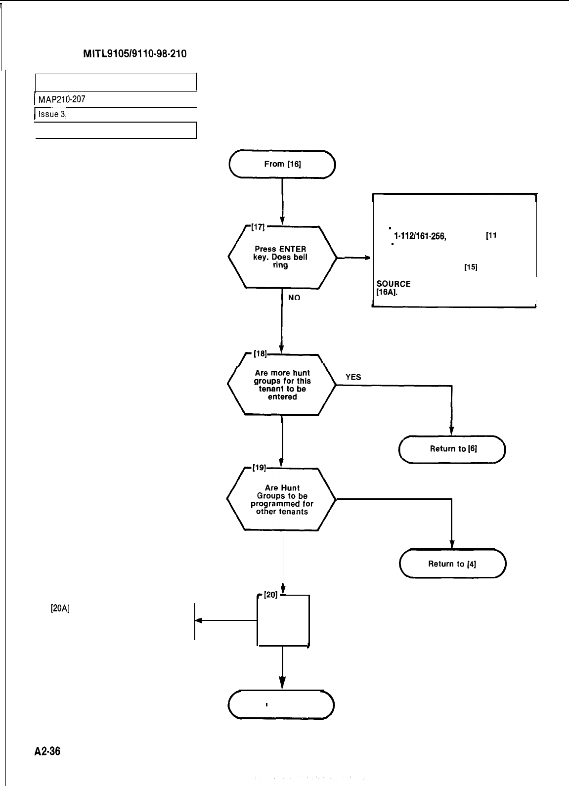
SECTION
MITL9105/9110-98-210
PROGRAM EXTENSION HUNT GROUPS
I
MAP210-207
I
klssue3,
July 1980
I
Sheet 6 of 6
STORE HUNT GROUP DATA
YES
-
Incorrect Number Dialed
DESTINATION display shows equipment
number dialed and error code
El
-
number entered out of ran
e
l-112/161-256,
return to
111
3
E6
-
equipment number dialed is not
defined as an extension or
extension has a used message
register, return to
1151
~~~IRCE
display is as shown in Step
I
f
1161
NO
YES
NO
.
[20AI
Press LAMP TEST key
.All displays dark
.All lamps dark except LAMP
4
AND
TEST lamp
b
PRESS
LAMP TEST KEY
v
FINISH
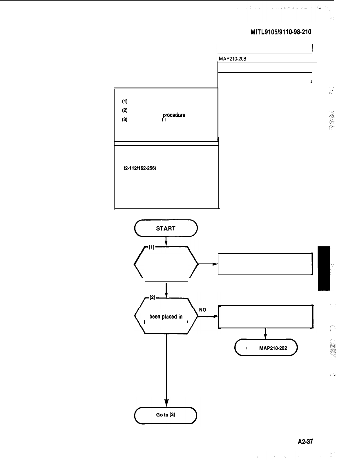
NOTES
(1)
All entries are made from the
console dial pad
(2)
TRUNK lamp remains lit
throughout
rocedure
(4
A display o
P
EO indicates that an
incorrect key was pressed. Press
the key specified in MAP and
proceed.
SECTION
MITL9105/9110-98-210
I
PROGRAM NON DIAL-IN TRUNKS
I
1
MAP210-208
I
Issue 3, July 1980
Issue 1 of 10
SYNOPSIS
Select tenant service if required
Enter equipment number
(2-1121162-256)
Enter Trunk type number (1 or 5,11 or 51)
Enter LDN assignment
Enter DAY assignment
Enter NIGHT 1 assignment
Enter NIGHT 2 assignment
Enter Busy Lamp Position number
Press ENTER key
Have all
installation forms
been completed
NO
P
Complete all installation forms.
I
YES
Has console
programming mode Set console to programming mode.
YES 1
Go to
MAPPlO-202
A2-37
i
:
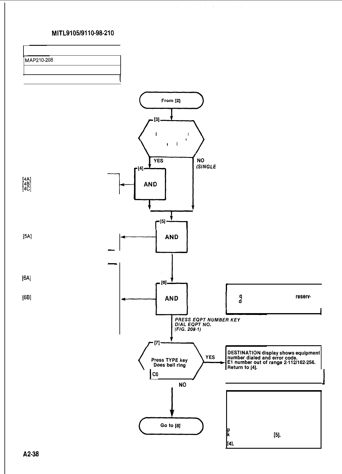
SECTION
MITL9105/9110-98-210
PROGRAM NON DIAL-IN TRUNKS
I
MAP210-298
Issue 3, July 1980
rIssue 2 of 10
SELECT TENANT SERVICE
[4A]
Press TENANT key
[4B]
Dial tenant number (l-4)
[4C]
Press ENTER key
-I-
SELECT TRUNK PROGRAM 1
[5A]
Press TRUNK key
l
TRUNK lamp lights and remains
lit throughout procedure.
-
-
ENTER EQUIPMENT NUMBER
[6A]
Press EQPT NUMBER key
.EQPT NUMBER lamp lit
l
SOURCE display shows current
equipment number
[6B]
Dial equipment number of trunk
(Fig. 208-l)
.EQPT number lamp lit
l
SOURCE display shows current
equipment number
.DESTINATION display shows
equipment number dialed
\
used
/
(EVG‘E
TENANT)
Is multi tenant
service to be
+-tfJ
PRESS TRUNK KEY
NOTE I
I
E
uipment number 001 is
reset-v
e
1
for the test line and must not
be assigned to a trunk.
I
I
\
ICO
Confirm entry see NOTE below.
1
,
NO
/
NOTE
The equipment number dialed is either
assigned to an extension or does not
contain a trunk card.
Check equipment number and card slot.
If you wish to remove the previous
assignment and assign this equipment
R
osition to the trunk press CONFIRM
ey and return to
[S].
If you wish to
change the equipment entry, return to
141.
A2-38
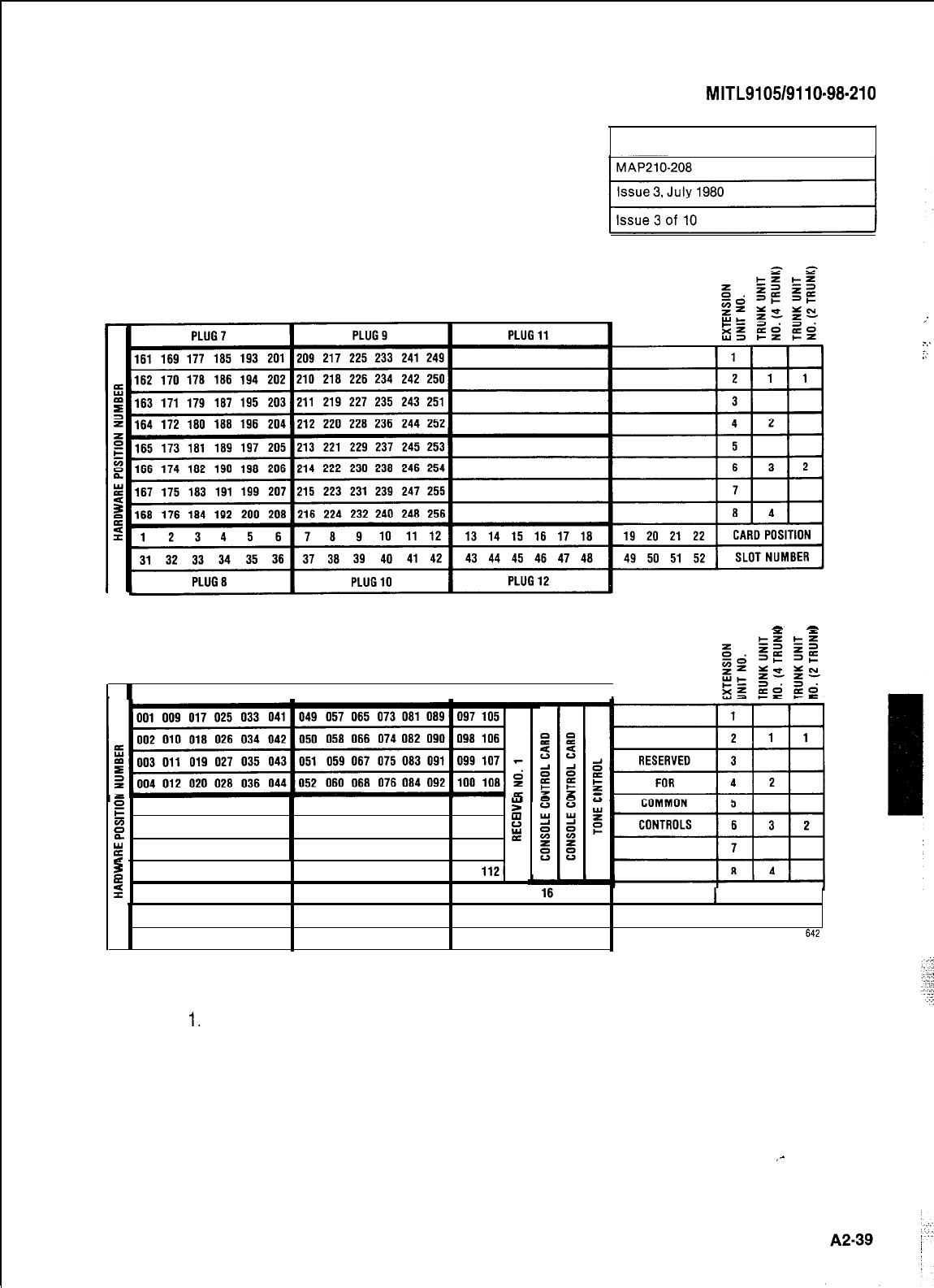
SECTION
MITL9105/9110-98-210
PROGRAM NON DIAL-INTRUNKS
SHELF 2 (SX-200 ONLY)
-
-
I
PLUG1
I
PLUG3
I
PLUG5
I
E
005 013 021 029 037 045 053 061 069 077 085 093 101 109
g
g
006 014 022 030 038 046 054 062 070 078 088 094 102 110
i
;
007 015 023 031 039 047 055 063 071 079 087 095 103 111
2
008 016 024 032 040 048
056 064 072 080 088 096 104 1121
2
. 123456
78910 11 12 13 14 15 17 18 19 20 21 22
1
CARD
POSITION
123456
7 8 9 10 11 12 13 14 15 16 17 18 19 20 21 22 SLOT
NUMBER
PLUG2 PLUG4 PLUG6
642
SHELF 1
NOTES:
1.
EQUIPMENT POSITION 001 IS RESERVED FOR THE TEST LINE AND MUST
THEREFORE BE EQUIPPED WITH A LINE CARD.
2,TRUNKEQUIPMENTNUMBERISSAMEASINDIVIDUALTRUNKACCESSCODE.
Fig. 208-l Hardware/Equipment Numbering
,-
.-
.-..
:
.’
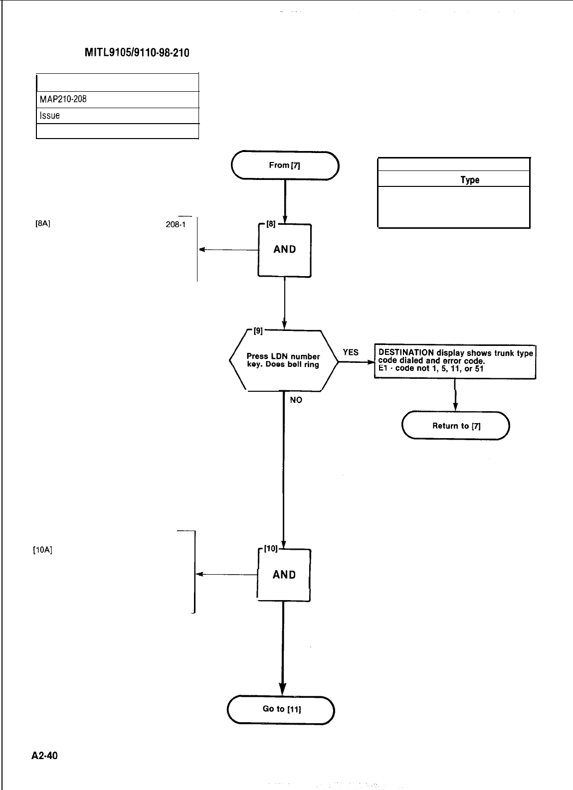
SECTION
MITL9105/9110-98-210
PROGRAM NON DIAL-IN TRUNKS
MAP210-208
Issue
3, July 1980
Issue 4 of 10
SELECT TRUNK TYPE
[8A]
Dial trunk type code, Table
2087
l TYPE lamp lit
lSOURCE display shows equip-
ment number of trunk and its
current type
.DESTINATION display shows
new trunk type entered
ASSIGN TRUNK TO LDN KEY
[lOA]
Dial LDN key number (l-4) to be
assigned to trunk
.LDN lamp lit
l
SOURCE display shows equip-
ment number and current LDN
key assignment
.DESTINATION display shows
new LDN assignment
DIAL TRUNK TYPE
TABLE 208-l
Code
TABLE 008-l
Type
1
5
Both way CO Trunk VNL
Non Dial-In Tie Trunk VNL
11
51
Both way CO Trunk Non VNL
Non Dial-In Tie Trunk Non VNL
G;;;)E-j,
DESTINATION display shows trunk type
+---j
AND
I
I
DIAL LDN
ASSIGNMENT
A2-40
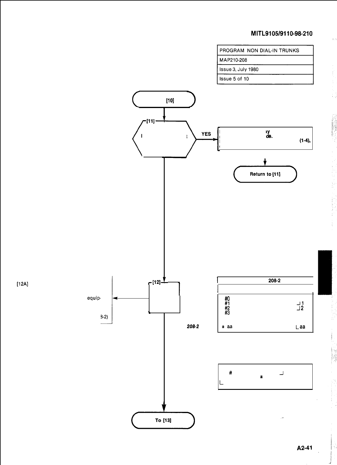
Press DAY NUMBER
key. Does bell ring
NO
DESTINATION displa shows equipment
number and error co
x
8.
El-LDN
assignment out of range (l-4),
check assignment.
I
(-Y&-)
SECTION
MITL9105/9110-98-210
From [lo]
ENTER DAY ASSIGNMENT
[12A]
Dial DAY assignment of trunk.
See Table 208-2
.DAY lamp lit
l
SOURCE display shows
equip-
ment number and current day
i
assignment (Table 208-2)
.DESTINATION display shows
new day assignment (Table 208-2)
-wd
I
TABLE
208-2
I
1
Code Assignment
Display 1
AND
#O
Attendant JO
#l
Bell 1 plus Attendant
-I1
#2
Bell 2 plus Attendant
J2
-
l
J3
#3
Bell 3 plus Attendant
DIAL DAY nnn Equipment number
nnn
ASSIGNMENT of extension
TABLE
208.2
+r
aa
Hunt group number 1-12
Las
NOTE
The
#
Key is displayed as
J
on the con-
sole display. The
*
Key is displayed as
L
on the console display.
(Yz--)
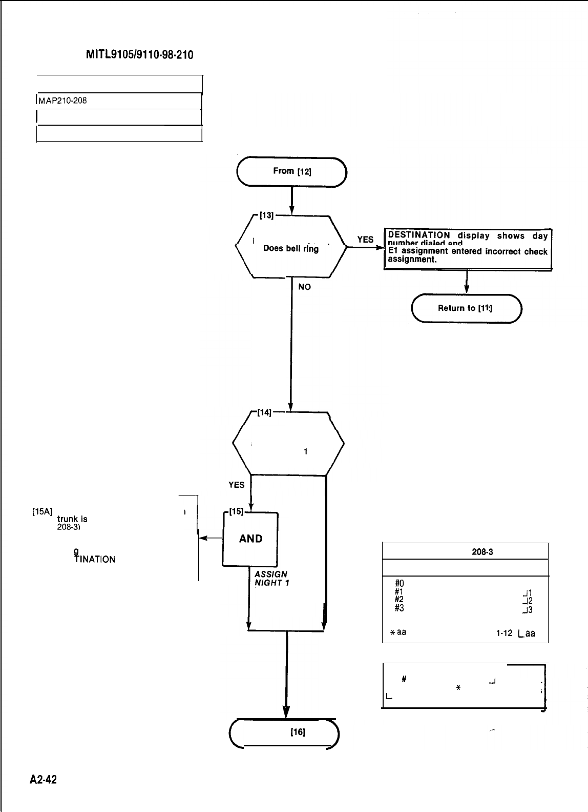
SECTION
MITL9105/9110-98-210
PROGRAM NON DIAL-IN TRUNKS
lMAP210-208
1 Issue 3, July 1980
Sheet 6 of 10
I
ENTER NIGHT 1 ASSIGNMENT
[18A]
Dial code of equipment to which
&u&is
to be connected (Table
l
NIGHT 1 lamp lit
l SOURCE display shows current
-
assi
l
DES
INATION
display shows
B
nment of trunk
code dialed
A2-42
NONO
I
Is this Trunk to be
Is this Trunk to be
assigned to NIGHTassigned to NIGHT
service
1
service
1
NONO
TABLE 208-3
Press NIGHT 1Press NIGHT 1
key.key.
TABLE
2063
Code Assignment Display
#O
Attendant console
#I
Bell 1 plus Attendant
JO
#2
Bell 2 plus Attendant
Jl
#3
Bell 3 plus Attendant
nnn Equipment number
5
nnn
of extension
+aa
Hunt group number
l-12
Las
NOTE
The
#
Key is displayed as
J
on the con-
sole display. The
*
Key is displayed as
L
on the console display.
Go to
1161
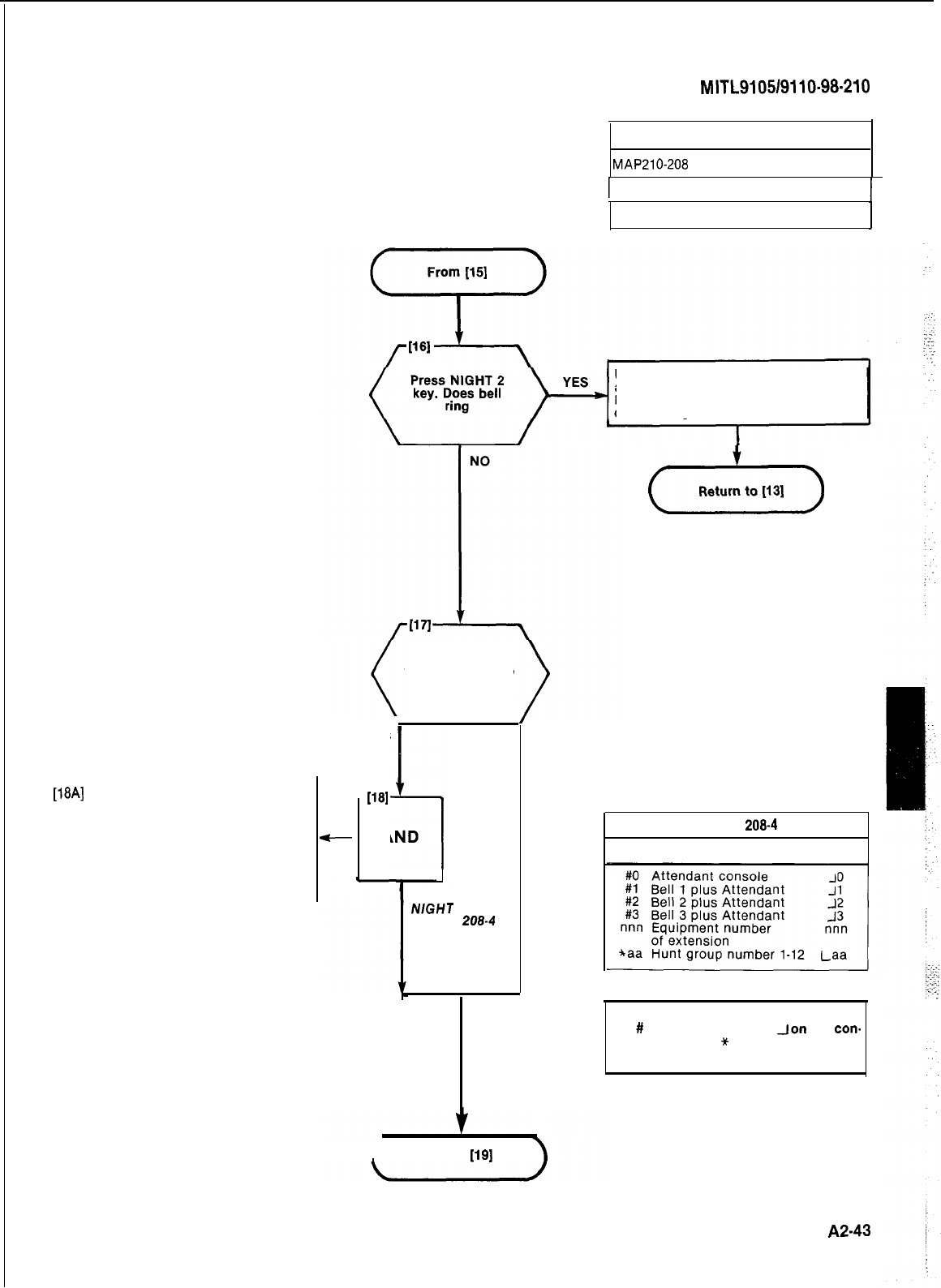
ENTER NIGHT 2 ASSIGNMENT
[18A]
Dial code of equipment
to which trunk is to be
connected. Table 208-4
.NIGHT 2 lamp lit
l SOURCE display shows
current assignment of
trunk
.DESTINATION display
shows code dialed
SECTION
MITL9105/9110-98-210
PROGRAM NON DIAL-IN TRUNKS
MAP210-208
1
Issue 3, July 1980
Sheet 7 of 10
DESTINATION display shows night
assignment dialed and error code.
El -assignment entered incorrect,
check assignment.
Is this trunk
to be assigned to
NIGHT service 2
YES
1181
5
AND
J
ASSIGN
NlGHT
2
TABLE
208-4
NO
(Y&T-)
TABLE
208-4
Code Assignment Display
NOTE
The
#
Key is displayed as
eon
the
con.
sole display. The
*
Key is displayed as
L on the console display.
fGo to
[I91
A243
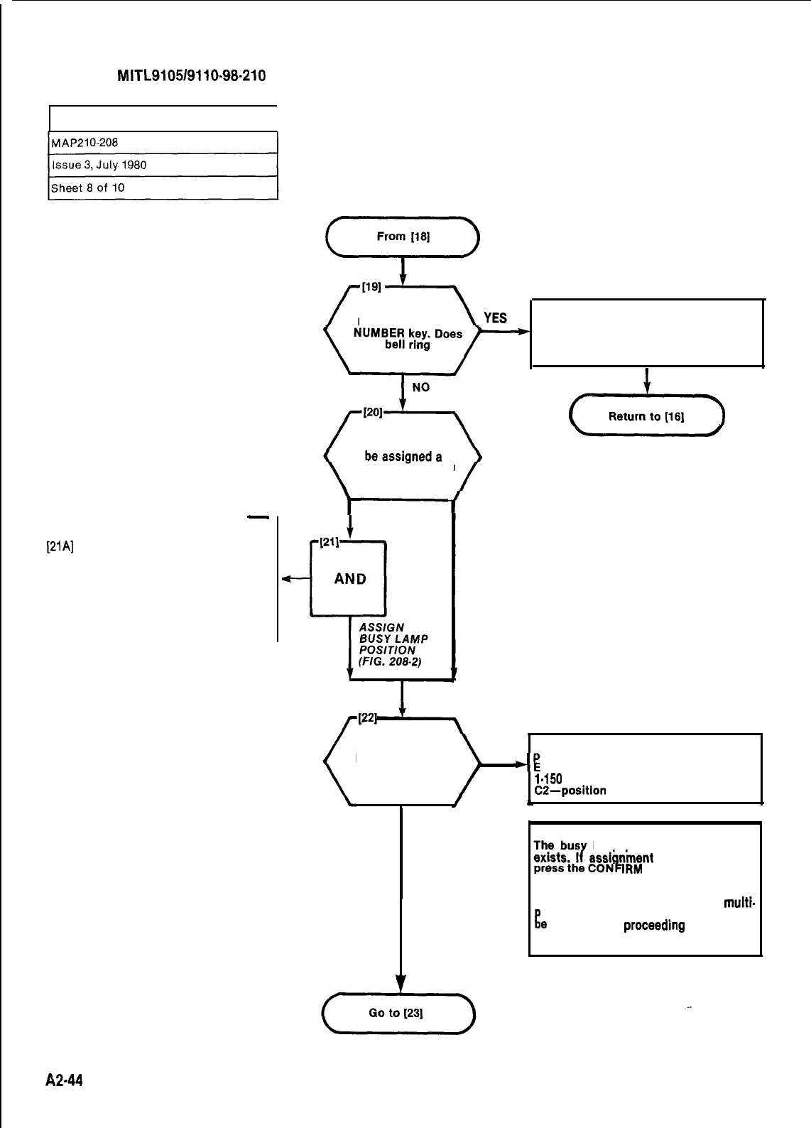
SECTION
MITL910519110~98-210
PROGRAM NON DIAL-IN TRUNKS
1
-
ASSIGN TRUNK TO BUSY LAMP FIELD
[21A]
Dial busy lamp position assigned
to the trunk (Fig. 208-2)
.BUSY LAMP number lamp lit
lSOURCE display shows equip-
ment number of trunk and cur-
rent busy lamp assignment
.DESTINATION display shows
new busy lamp assignment
h2-44
YES
I-
NO
Press
BUSY LAMP
DESTINATION display shows Night
assignment dialed and
El -assignment entered incorrect,
check assignment.
Is
this trunk to
busy lamp position
Press ENTER key
Does bell ring
DESTINATION display shows busy lamp
YES osition dialed and
4
1 -position number dialed out of range
1.150
CZ-position
assigned see NOTE below
t
NO
NOTE
lamp position dialed already
dialed is correct,
IRM key, this will remove
the original assignment and assign the
busy lamp positron to this trunk. The
busy lamp will therefore, indicate multi-
!Ile numbers. Multiple appearances may
e
removed by proceedmg through this
MAP.
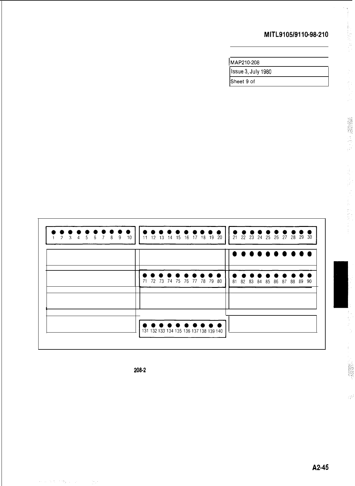
SECTION
MITL9105/9110-98-210
PROGRAM NON DIAL-INTRUNKS
I
lMAP210-208
I
lssue3,July1980
Sheet9of
10
l ooooooooo l ooooooooo
ooooooooeo
31 32 33 34 35 36 37 38 39 40
41
42 43 44 45 46 47 48 49 50
51
52 53 54 55 56 57 58 59 60
l ooooooooo
61
62 63 64 65 66 67 68 69 70
l oooeooooo l ooooooooo l ooooooooo
91
92 93 94 95 96 97 98 99 100 101 102 103104 105 106
107108109
110
111
112 113 114115
116117 118119120
4
0000000000
yj
131 132133 134 135 136 137138 139140
0.00000000
121122 123 124125126127128129 130
141 142 143144145 146 147 148 149 150
Fig.
208-2
Busy Lamp Position Numbering
A245
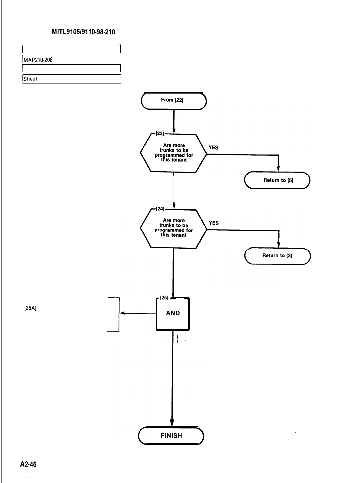
SECTION
MITL9105/9110-98-210
I
PROGRAM NON DIAL-IN TRUNKS
I
I
MAP210-208
I
1 Issue 3, July 1980
ISheet
10 of 10
I
Are trunks
to be programmed
for other
tenants
-
[25A]
Press LAMP TEST key
.All displays dark
.All lamps dark except LAMP
TEST lamp
NO
NO
PRESS LAMP TEST
KEY
_-
A246
.
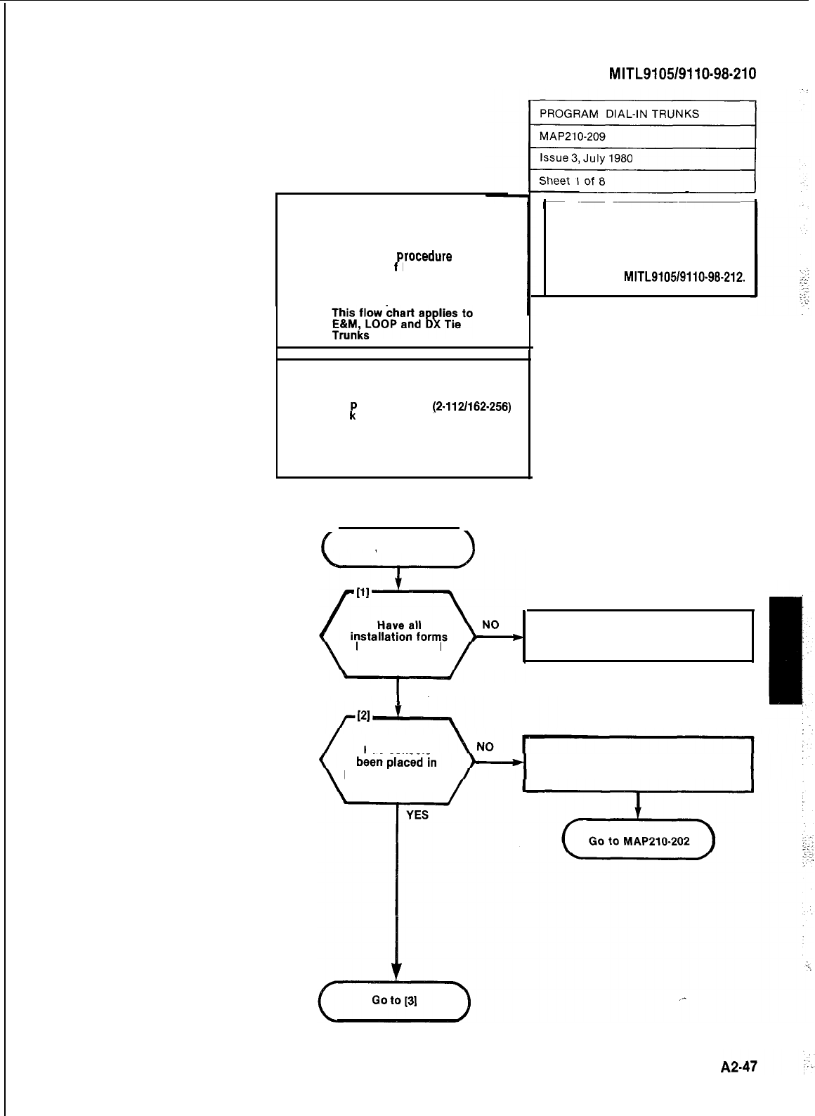
NOTES
(1) All entries are made from the
console dial pad
(2) TRUNK lamp remains lit
throughout
rocedure
(3) A display o
P
EO indicates that
an incorrect key was pressed.
Press the key specified in
MAP and proceed.
(4)
SYNOPSIS
Select tenant service if required.
Press TRUNK key.
Enter Equi
Enter Trun
R
ment number
(2.112/162-256)
type number 2 or 4, 21 or 41
Enter Trunk COS
Enter Toll Allow/Deny code
Enter Busy Lamp Position number
Press ENTER
START
\
SECTION
MITL9105/9110-98-210
CAUTION
If Multi-Digit Toll Control
(Generic 204) is required this
MAP is not applicable. Trunks
must be programmed in accordance
with Section
MITL9105/9110-96-212.
been completed Complete all installation forms.
I
YES
Has console
programming mode Set console to programming mode.
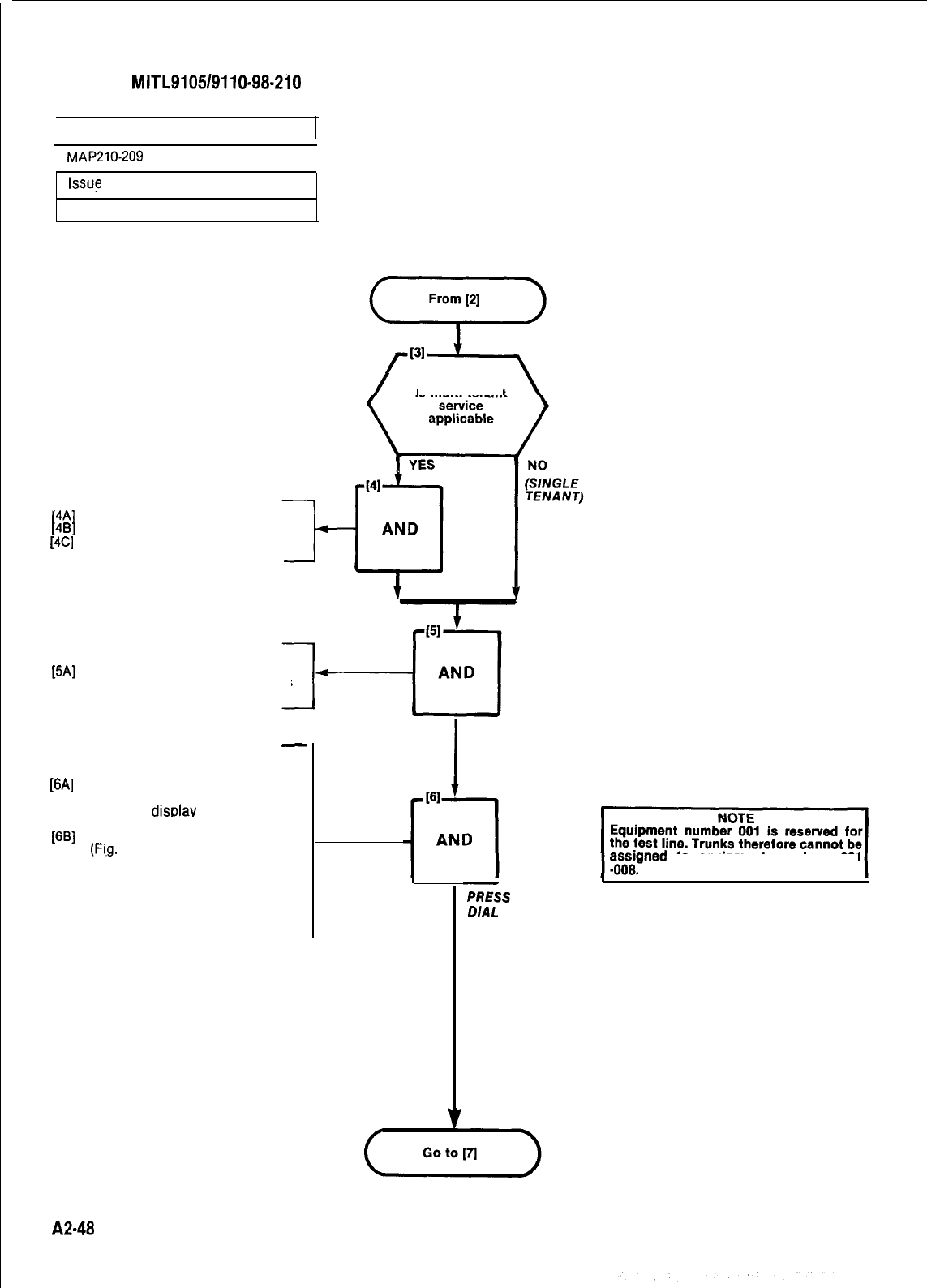
SECTION
MITL9105/9110-98-210
rPROGRAM DIAL-IN TRUNKS
I
r
MAP210-209
1
Issue
3,
July 1980
Sheet 2 of 8
Is multi tenant
SELECT TENANT SERVICE
[4A]
Press TENANT key
[4B]
Dial tenant number (l-4)
[4C]
Press ENTER key
SELECT TRUNK PROGRAM
[5A]
Press TRUNK key
lTRUNK lamp lights and remains
lit throughout procedure.
-
ENTER EQUIPMENT NUMBER
[6A]
Press EQPT NUMBER key
.EQPT NUMBER lamp lit
lSOURCE
displav
shows current
equipment number
[6B]
Dial equipment number of trunk
(Fi,g.
209-l)
lEQPT number lamp lit
l
SOURCE display shows current
equipment number
.DESTINATION display shows
equipment number dialed
I
PRESS TRUNK KEY
yoss;gned
to equipment numbers 001
=iS
EQPT NUMBER KEY
DIAL
EQPT NO.
(FIG. 209-l)
A2-48
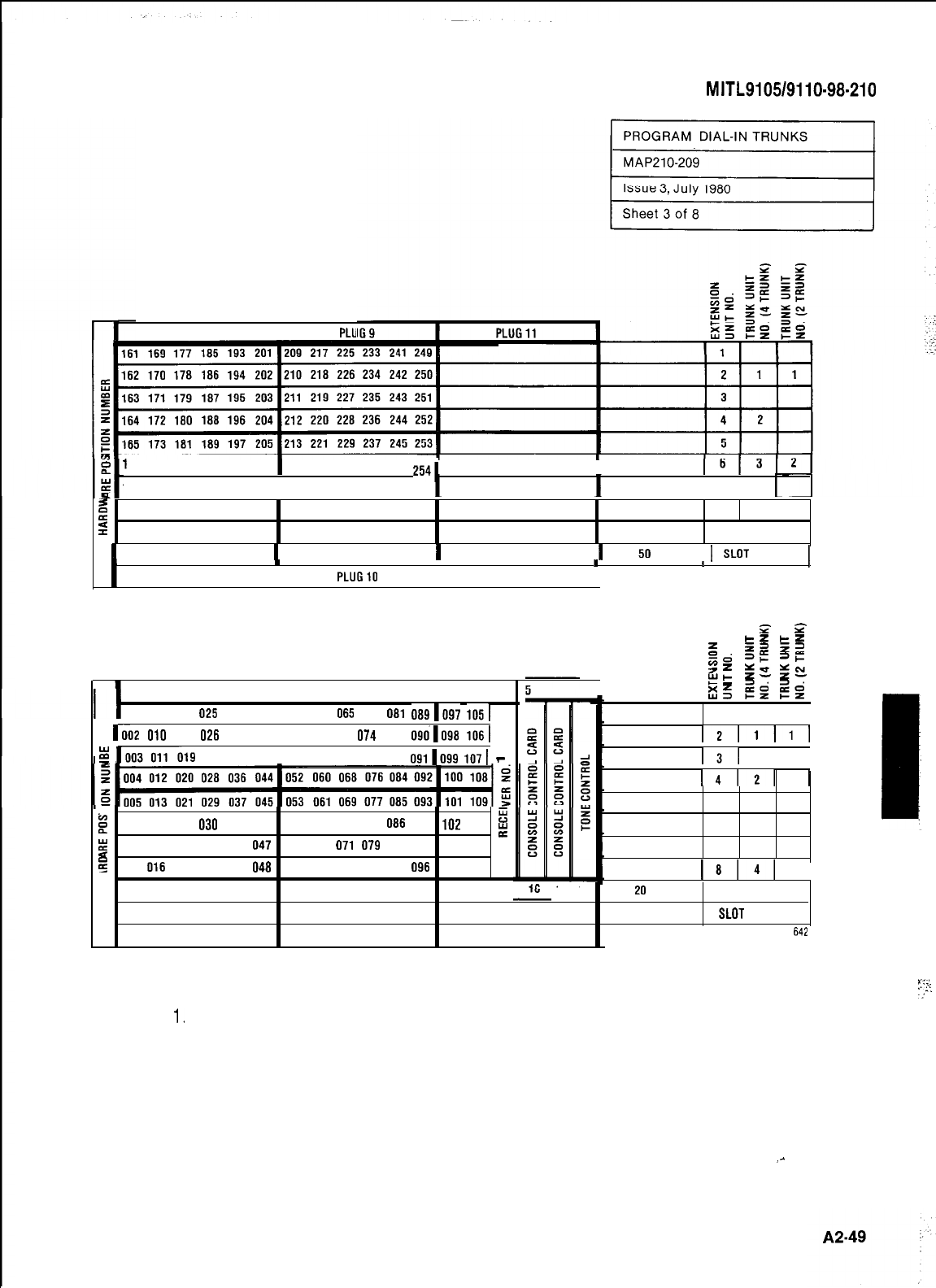
PLUG7
I
PLU
66 174 182 190 198
206 214
222 230 238 246
2541
I
167 175 183 191 199
2071215
223 231 239 247 255 7
I
g
168 176
184 192 200 208 216 224 232 240 248 256 8 4
5
12
3 4
5
6 7 8 9 10 11 12 13 14 15 16 17 18 19 20 21 22
CARD
POSITION
1
31 32 33 34 35 36
1
37 38 39 40 41 42
1
43 44 45 46 47 48
1
49
50
51 52
1
SLOT
NUMBER
1
I
..
1
I
PLUG8
I
PLUG10
I
PLUG12
I
SHELF 2 (SX-200 ONLY)
P
P
z
=z
cz
zjd
z=
zs
3:
=I-
z=
EL
gz
=ct
I
fi=
2s
22
PLUG1
I
PLUG3
I
PLL
001 009 017 025 033
0411049
057 065 073 081
0891097
1051
ri2
010
018
026
034 0421050 058 066
074
082
0901098
1061
i
~019
027 035 0431051 059 067 075 083
091[099
1071
-
t
8
DO6 014 022 030 038 046 054 062 070 078 086 094 102 110
E
;
:
DO7 015 023 031 039 047 055 063 071 079 087 095 103 111
5
2
DO8 016 024 032 040 048 056 064 072 080 088 096 104 112
1211111
RESERVED
I31
I I
FOR
14121
1
COMMON
5
CONTROLS 6 3 2
I:
7
18141
I
SECTION
MITL9105/9110-98-210
2123456 7 8
9
10
11
12 13 14 15 17 18 19 20 21 22
CARD
POSITION
123456 78
9
10 11 12 13 14 15 16 17 18 19 20 21 22
SLOT
NUMBER
PLUG2 PLUG4 PLUG6
642
SHELF 1
NOTES:
1.
EQUIPMENT POSITION 001 IS RESERVED FORTHETEST LINE AND MUST
THEREFORE BE EQUIPPED WITH A LINE CARD.
2,TRUNKEQUIPMENTNUMBERISSAMEASINDlVlDUALTRUNKACCESSCODE.
. .
._.
..‘
z
-:
-:i-
:_
Fig. 209-l Hardware/Equipment Numbering
_-
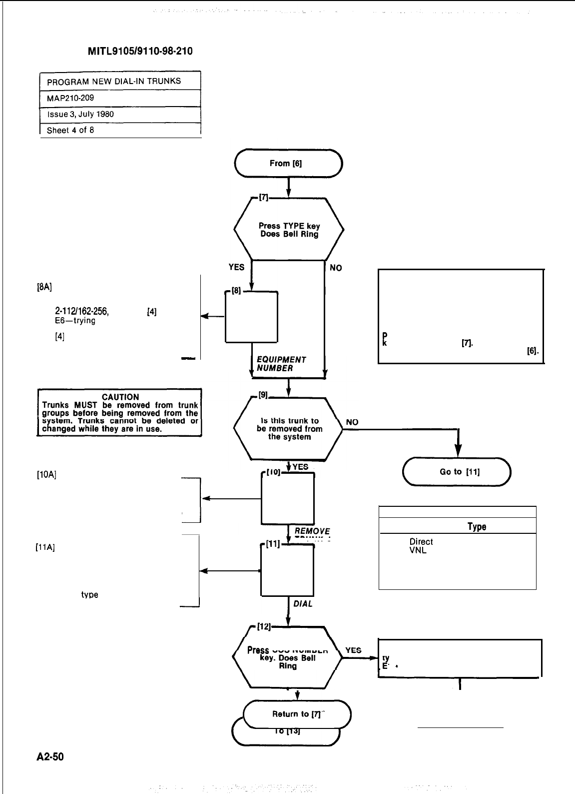
SECTION
MITL9105/9110-98-210
[BA]
DESTINATION display shows
equipment number dialed and
El-number out of range
2-112/162-256,
return to
[4]
EG-trying
to program an extension
with message registration, return to
[41
-
AND
CO-Confirm entry see NOTE
-
Remove Trunk
.
CORRECT
NOTE
The equipment number dialed is either
assigned to an extension or does not
contain a trunk card.
Check equipment number and card slot.
If you wish to remove the previous
assignment and assign this equipment
R
osition to the trunk press CONFIRM
ey and return to
[A.
If you wish to
change the equipment entry return to
161.
[lOA]
Press DELETE key
.DELETE lamp lit
.SOURCE display shows equip-
ment number and its current
class
.DESTINATION display shows 0
. AND
Code
TABLE 209-l
Type
SELECT TRUNK TYPE TRUNK DATA
[llA]
Dial trunk code. Table 209-l
l TYPE lamp lit
2
@c.t
Inward System Access
lSOURCE display shows the 4 Dial-In Trunk VNL
equipment number of the trunk
4
_
AND 21 Direct Inward System Access
and its current type Non VNL
.DESTINATION display shows 41 Dial-In Trunk Non VNL
A
trunk
type
entered
D/AL
TRUNK TYPE
CODE. TABLE 209.1
Press
COS NUMBER DESTINATION display shows the trunk
t
P
pe code and error code
1
-
code is not 2, 4, 21 or 41
(+l)
(-T&q
A2450
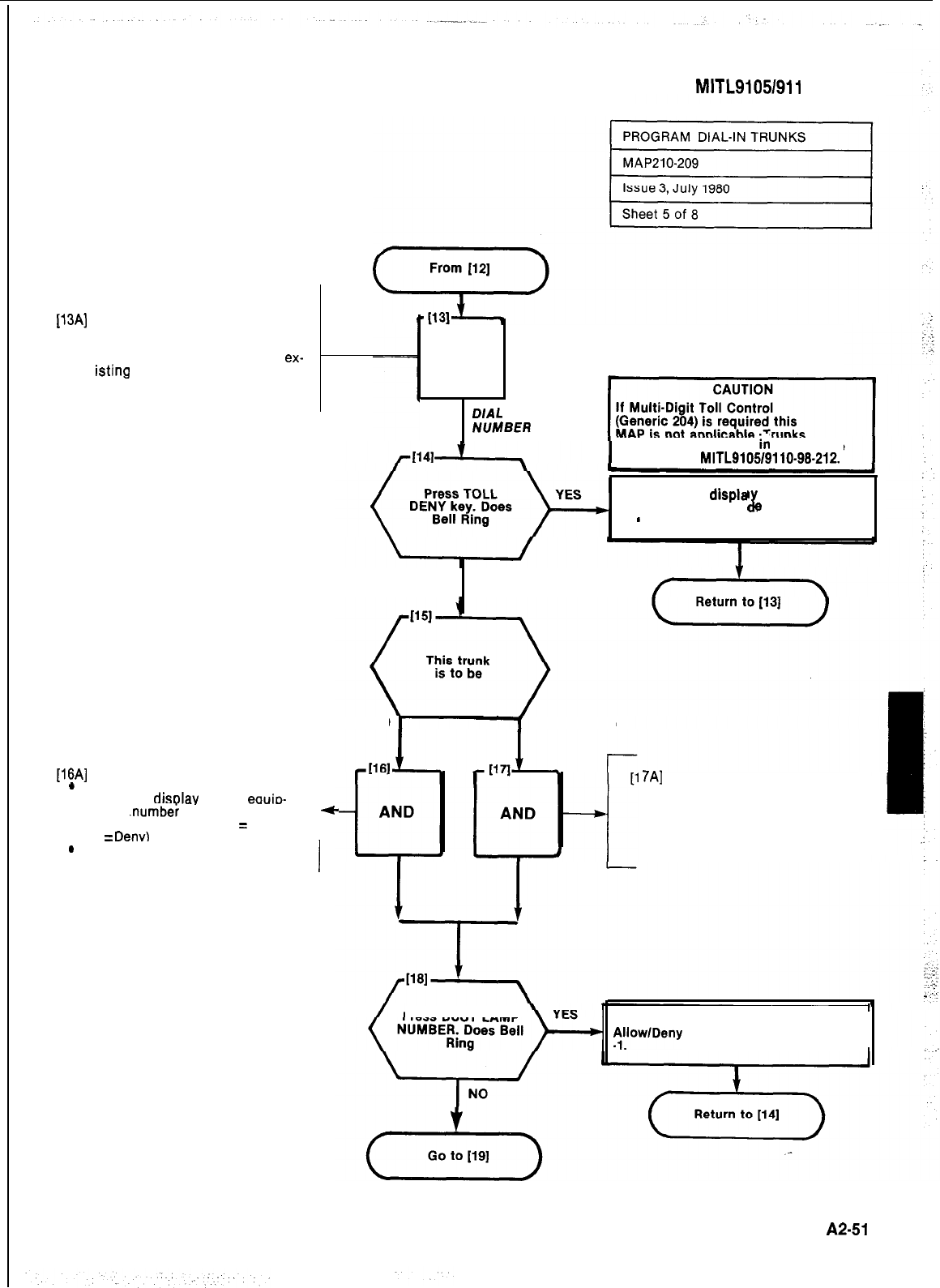
SECTION MITL91051911 O-98-21 0
ENTER COS NUMBER
[13A]
Dial COS number (l-16)
.COS NUMBER lamp lit
.SOURCE display shows equip-
ment number of trunk and its
ex-
isting
COS number
.DESTINATION display shows
COS number dialed
AND
.
DIAL
COS
M/MBER
must be programmed
in
accordance
with Section
MITL9105/9110-98-212.
DESTINATION
displa
shows equipment
number and error co
J
e
El
-
COS number dialed out of range l-18
NO
TOLL ALLOWED TOLL DENIED
ASSIGN TOLL ACCESS
[16A]
Press DELETE key
*
DELETE lamp lit
l
SOURCE
displav
shows
eauio-
1
7A]
Press ADD key
.ADD lamp lit
ment
.numbei
and the existing .
4-
SOURCE display shows equip-
toll Allow/Deny code (0
=
Allow, ment number and the existing
1
=
Denv)
toll access code
.DESTINATION display shows
code 1 (Deny)
.
DESTINATION display shows 0
TOLL ALLOWED
I
,
Press
BUSY LAMP DESTINATION display shows Toll
fjllow/Deny
code and El, out of range 0
A2-51
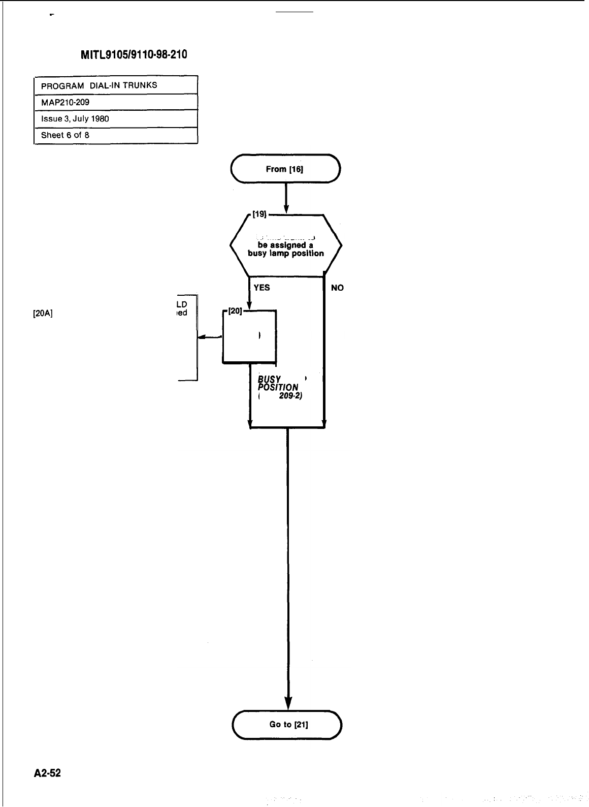
SECTION
MITL9105/9110~98-210
ASSIGN TRUNK TO BUSY LAMP FIE
[2OA] Dial busy lamp position assign
to the trunk (Fig. 209-2)
l
BUSY LAMP NUMBER lamp lit
l
SOURCE display shows equip-
ment numbei of trunk and-cur-
rent busy lamp assignment
l DESTINATION display shows
new busy lamp assignment
Is
this trunk to
-
AND
ASSIGN
BOW
LAMP
POSlTlON
(FIG.
209.2)
A2-52

SECTION
MITL9105/9110-98-210
‘.
l ooooooooo
31 32
33
34 35 36 37 38 39
40
l ooooooooo
61 62
63
64 65 66 67 68 69
70
l ooooooooo91 92
93
94 95 96 97 98 99
100
pxxG7-p
101 102 103104 105
..o
. . . . . .
106 107108109 110 111 112113 114115 116117 118119120
l ooooooooo
121122
123
124125126127128129
130 131
132133 134 135 136 137138 139140 141 142 143144145146
147
148149 150
Fig.
209.2
Busy Lamp Position Numbering
:
I
:-:
:
:,-
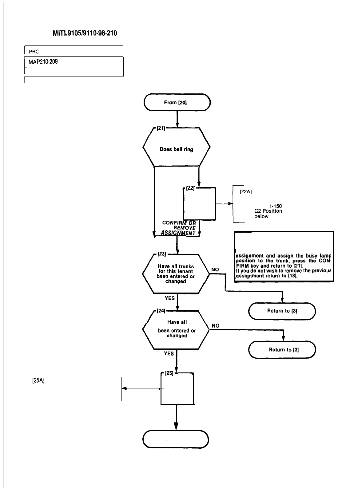
SECTION
MITL9105/9110-98-210
r-
PROGRAM DIAL-IN TRUNKS
I
MAP210-209
Issue 3, July 1980
1 Sheet 8 of 8
I
Press ENTER keyPress ENTER key
NO
CoNzlz
CoNzlz
7
ASSlGNMl
ASSIG
NM1
l--
I
I
YES
AND
DESTINATION display showsDESTINATION display shows
busy lamp position dialed andbusy lamp position dialed and
El position number dialed out ofEl position number dialed out of
range
1.-!50
range
1.-!50
;il:;rtron
Assigned see NOTE
;il:;rtron
Assigned see NOTE
NOTE
The busy lamp position dialed is already
assigned to an extension or trunk.
If you wish to remove the previous
tenants trunks
-1251'
7
[25Al
Press LAMP TEST key
.All displays dark
.All lamps dark except LAMP
4
1
AND
TEST lamp
.
PRESS
LAMP TEST KEY
v
FINISH
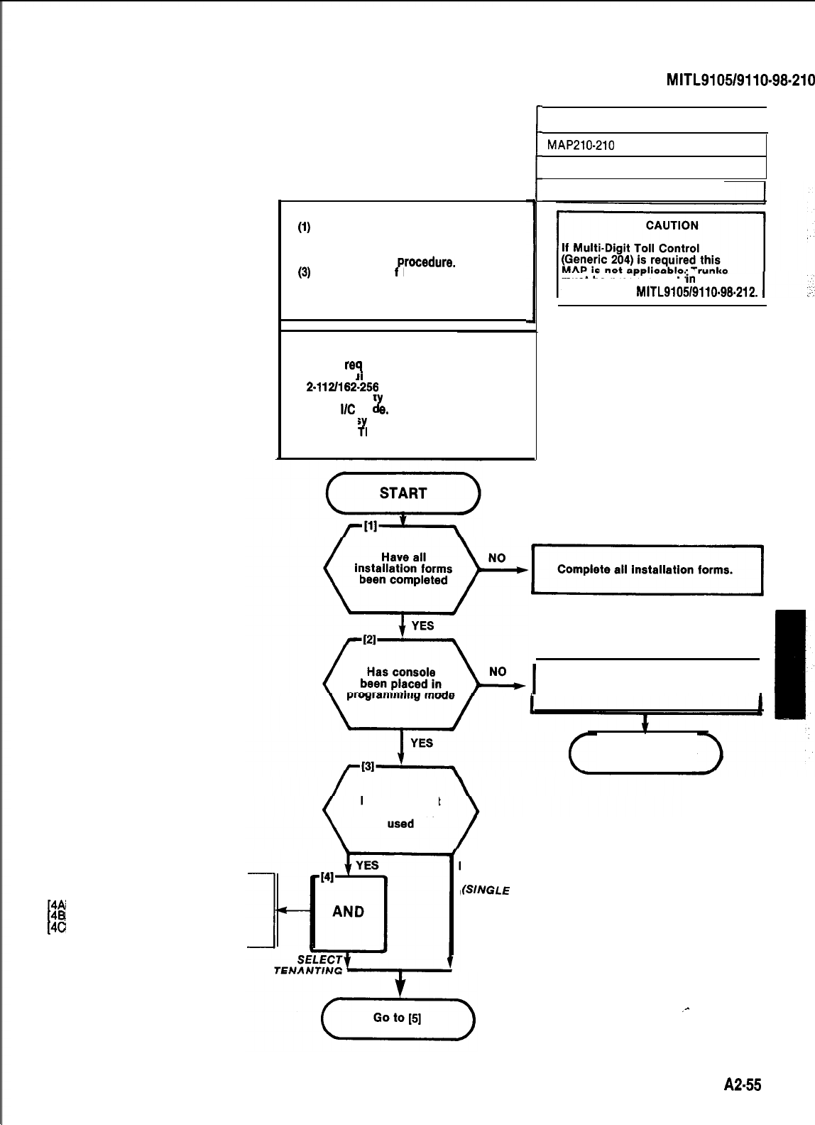
NOTES
(1)
All entries are made from the
(2)
console dial pad.
Trunk lamp remains lit
(3)
throughout
rocedure.
A display o
P
EO indicates that an
incorrect key has been pressed.
Press the key specified in the
MAP and proceed.
SYNOPSIS
Select
re
Enter equ pment number9uired tenant.
2-l
121162-256
Enter trunk t
Enter I/C co
d
pe code 3, 31, 6, or 61.
e.
Enter Bus Lamp assignment.
Press EN
J
ER.
SELECT TENANT SERVICE
[4A
[4B
Press TENANT key
[4C
Dial tenant number (l-4)
Press ENTER key
t
I
1
SECTION
MITL9105/9110-98-210
PROGRAM DID TRUNKS
I
MAP210-210
Issue 3, July 1980
Sheet 1 of 6
must be programmed
in
accordance
with Section MITL9105/9110-96.212.
I]
Complete all installation forms
Is multi tenant
service to be
NO
(SINGLE
TENANT)
I
Set console to programming mode.
I
Go to MAP210-202
.-
A2-55
j
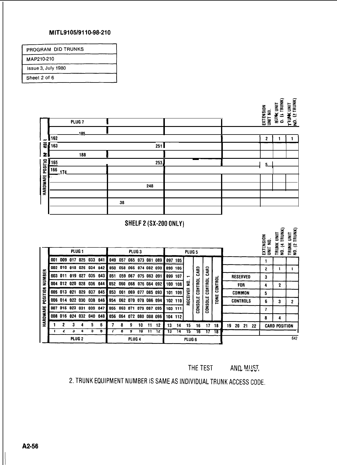
SECTION
MITL9105/9110-98-210
pz
u,
YN
rl
2:
z-
PLUG9
E!t
PLUG11
XL
ozo
20;
YD
l-z
l-z
161 169 177 186 193 201 209 217
225 233
241 249
1
I I
1
,I162
170 178 186 194 2021210 218 226 234 242 2501
1
El163
171 179 187 195 2031211 219 227 235 243
2511
I
Ei
2
3:
I
. .
164 172 180 108 196 204 212 220 228 236 244 252
4 3
2
1
El165
173 181 189 197 2051213 221 229 237 245
2531
~
--I
. .
I
15
1I
174 162 190 198 206 214 222 230 238 246 254
I
63 2
L
167 175 183 191 199 207 215 223
231 239 247 255 7
168 176 184 192 200 208 216 224
232 240 248 256 a4
12345678
9 10 11 12 13 14 15 16 17 18 19 20 21 22
CARD
POSITION
31 32 33 34 35 36 37
38 39 40 41 42 43 44 45 46 47 48 49 50 51 52
SLOT NUMBER
PLUG8 PLUG10 PLUG12
SHELFZ(SX-2000NLY)
SHELF1
19 20 21 22 SLOT NUMBER
642
A
NOTES: 1. EQUIPMENT POSITION 001 IS RESERVED FOR
THETEST
LINE
ANn
MIIST
THEREFORE BE EQUIPPED WITH A LINE CARD.
2.TRUNKEQUlPMENTNUMBERISSAMEASlNDlVlDUALTRUNKACCESSCODE.
Fig. 210-l Hardware/Equipment Numbering
A2-58
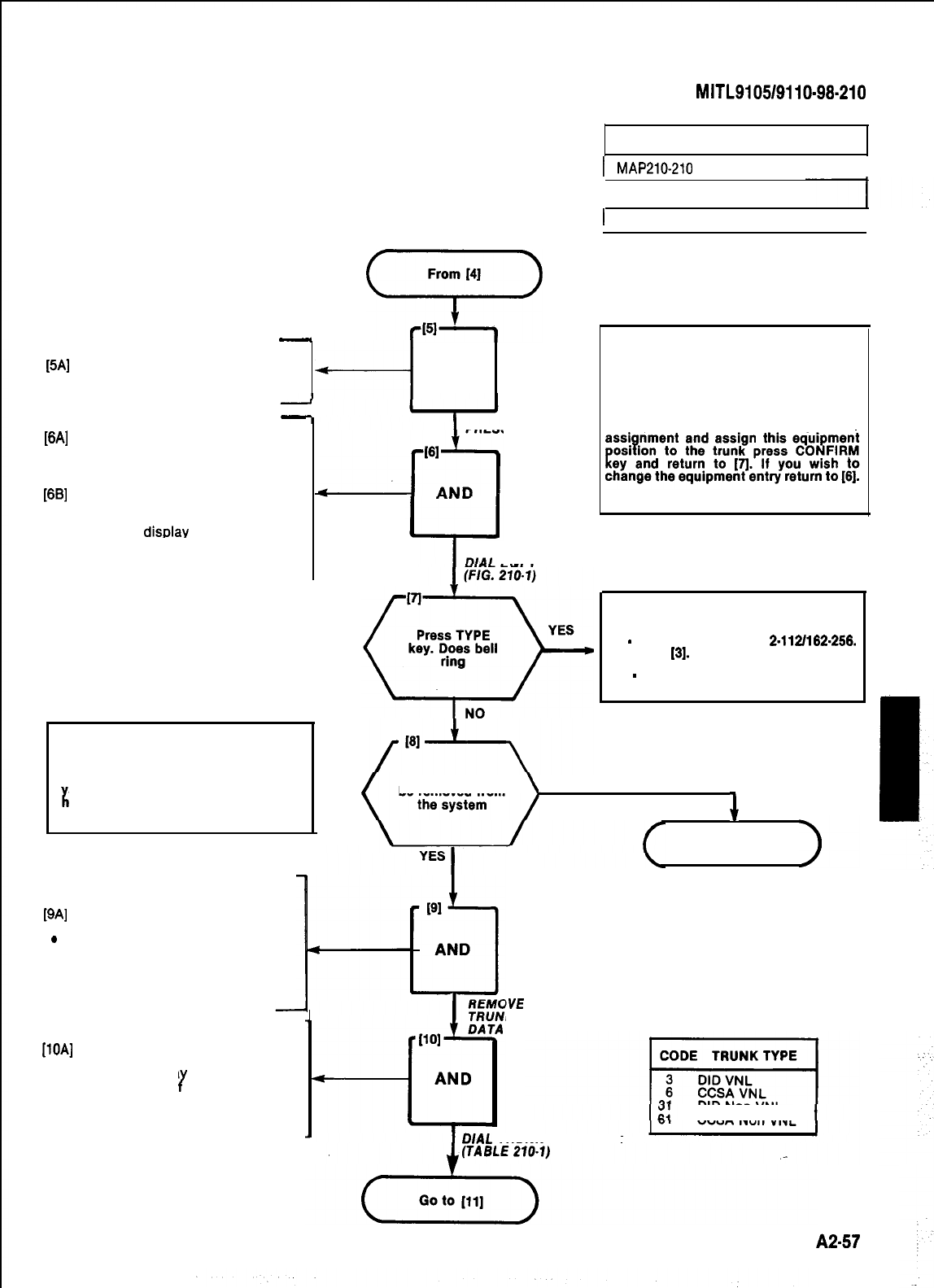
From
141
__
cFr;-’
SELECT TRUNK PROGRAM
[5A]
Press TRUNK key
l
Trunk lamp lights and remains lit
+-i
AND
throughout procedure
-
ENTER EQUIPMENT NUMBER
[6A]
Press EQPT NUMBER key
.
EQPT NUMBER lamp lit
l
SOURCE display shows current
equipment number
[6B] Dial equipment number of trunk
(Fig. 210-l)
l
EQPT NUMBER lamp lit
l
SOURCE disDlav shows current
equipment number
.
DESTINATION display shows
equipment number entered
Remove Trunk
CAUTION
Trunks MUST be removed from trunk
groups before being removed from the
s stem. Trunks cannot be deleted or
c
7l
anged while they are in use.
[QA]
Press DELETE key
.
DELETE lamp lit
’
!
SOURCE display shows equip-
ment number and its current
class
.
DESTINATION display shows 0
ENTER TYPE CODE
[lOA] Dial type code. Table 210-l
l TYPE lamp lit
l SOURCE displa
ment number o
Y
shows equip-
the trunk and its
current type code
l DESTINATION display shows
new trunk type code
SECTION
MITL9105/9110-98-210
PROGRAM DJD TRUNKS
I
MAP210-210
I
Issue 3, July 1980
1 Sheet 3 of 6
I
PRESS TRUNK KEY
Check equipment number and card slot.
If you wish to remove the previous
L
PRESS EQPT NUMBER KEY
EQPT NUMBER
NOTE
The equipment number dialed is either
assigned to an extension or does not
contain a trunk card.
DESTINATION display shows equipmenl
number dialed and
El
-
number out of range
2-1121162-256.
Return to
[3].
CO
-
confirm entry see NOTE.
J
Is this trunk to
be removed from NO
+
Go to [lo]
IVE
K
DIAL
TRUNK TYPE CODE
TABLE 210-l
DID Non VNL
CCSA Non VNL
A2-57
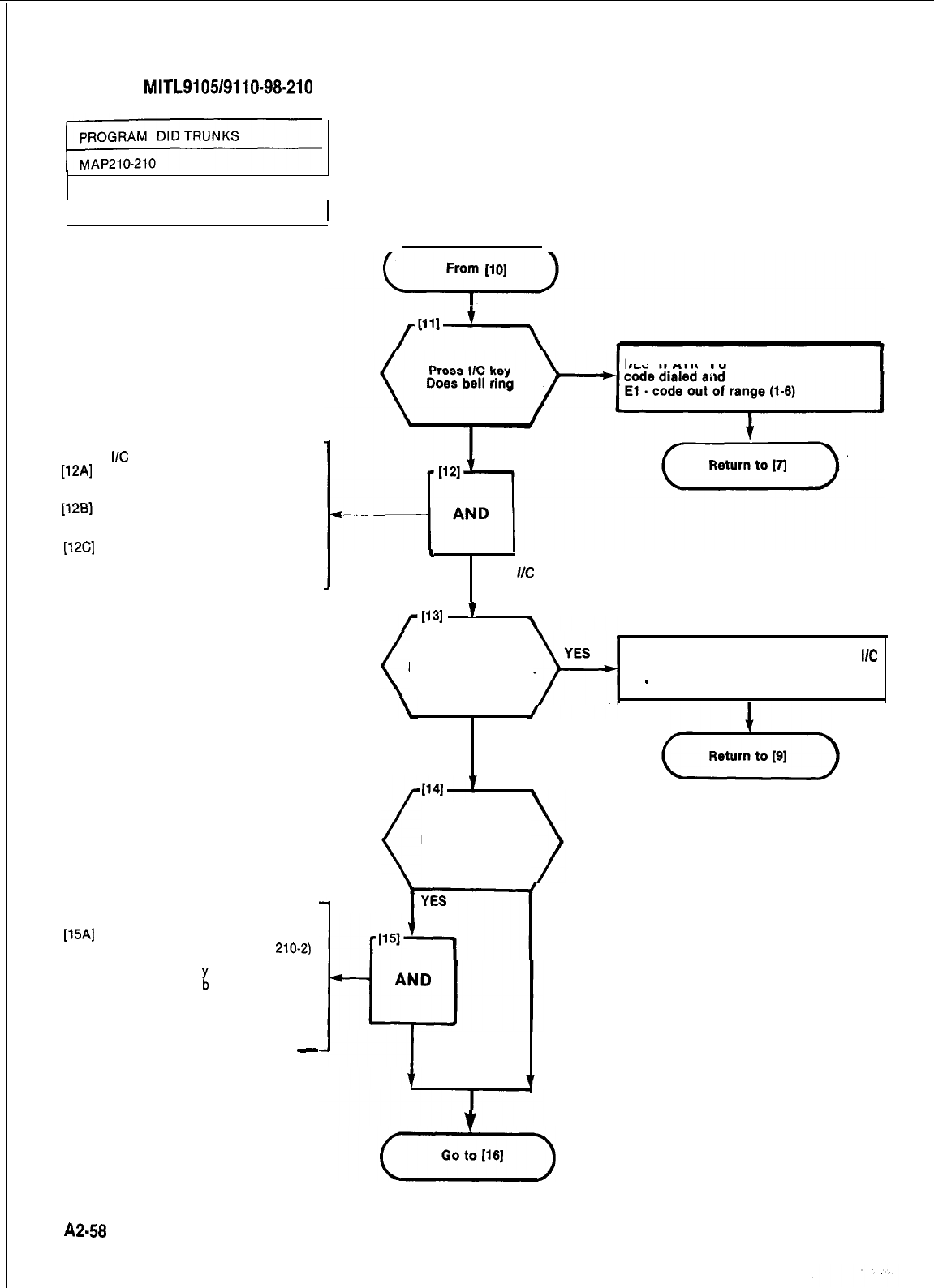
SECTION
MITL910519110-98-210
Issue 3,
July 1980
I
r
Sheet 4 of 6
ENTER
I/C
CODE
[12A]
Enter number of digits to be
received after the trunk has been
seized (l-9)
[128]1
Enter number of digits to be ab-
sorbed after the trunk is seized
(O-8)
[12C]
If a leading digit is to be in-
serted, dial the actual digit to be
inserted. See Note.
ENTER BUSY LAMP ASSIGNMENT
[15A] Dial the busy lamp position
assigned to the trunk (Fig.
210-2)
l
BUSY LAMP lamp lit
l SOURCE displa
shows the
equipment num
L
er of the trunk
and its current busy lamp assign-
ment
.
DESTINATION display shows the
new busy lamp assignment
-
DESTINATION display shows trunk type
t
J
DIAL
UC
CODE
1131
’
Press BUSY
LAMP NUMBER key.
Does bell ring
DESTINATION display shows the
I/C
code entered and
El
-
digit length incorrect
NO
Is trunk to
be assigned to a
Busy Lamp
NO
YES
7
ASSIGN BUSY
LAMP POSITION
A2-58
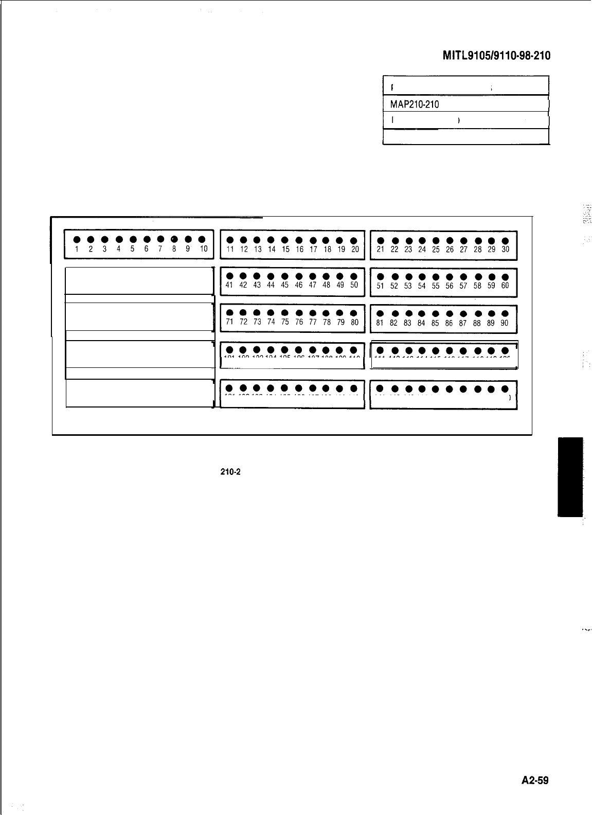
SECTION
MITL9105/9110-98.210
SECTION
MITL9105/9110-98.210
PROGRAM DID TRUNKS
I
MAP210-210
I
I
issue 3, July 1980
I
1 Sheet 5 of 6
l ooooooooo
31
32 33 34 35 36 37 38 39 40
l ooooooooo
61
62 63 64 65 66 67 68 69 70
l ooooooooo
91 92 93 94 95 96 97 98 99 100 101 102
103104
105 106
107108 109110
111
112113 114115 116117 118119120
.
l ooooooooo
121122
123
124125126127128129
130 131
132133 134135 136137138 139140
141 142
143144145146
147
148149
150
I
J
Fig.
210-2
Busy Lamp Position Numbering
.._.
A2-59
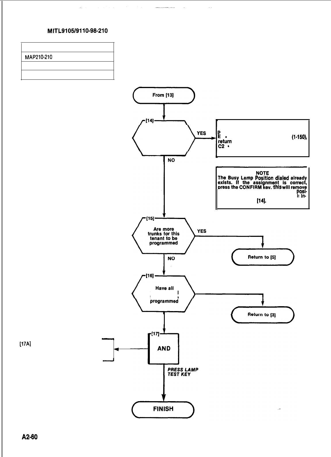
r
SECTION
MITL9105/9110-98-210
PROGRAM DID TRUNKS
MAP210-210
Issue 3, July 1980
Sheet 6 of 6
Press ENTER
Does bell ring
DESTINATION display shows busy lamp
osition
ii
1
assigned and
-
number dialed out of range (l-150),
rem
to [lo]
-
position already assigned. See
Note.
ti
The Busy Lamp PosItion dialed already
exists. If the assi nment is correct,
press the CONFIRM ey, this will remove
the old assignment and assign the
osi-
tion to this trunk. If the assignment s
in-
r
correct, return to
114).
[17Al
Press LAMP TEST key
l
All indicators go dark except
*
LAMP TEST lamp
trunks for all
tenants been
NO
YES
A2-80
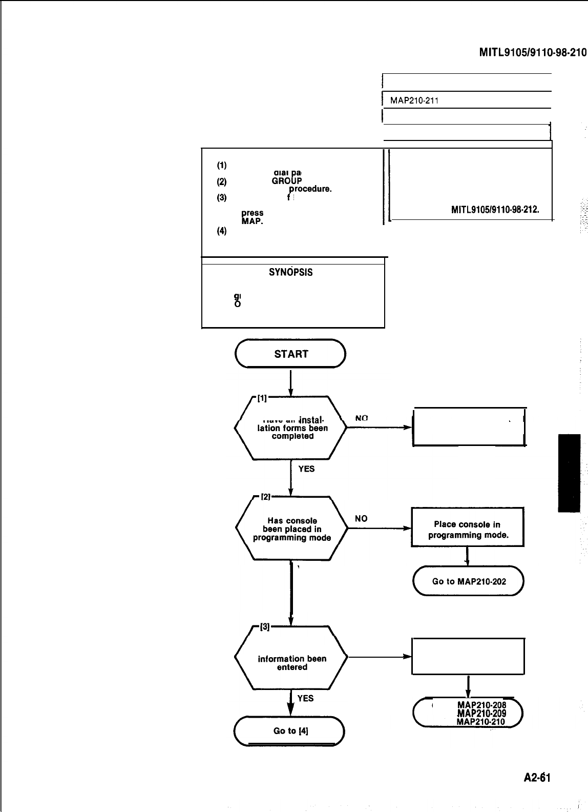
SECTION
MITL9105/9110-98.210
I
PROGRAM TRUNK GROUPS
I
I
MAP210-211
I
1Issue 3, July 1980
I
Sheet 1 of 7
(1)
(2)
(3)
NOTES
All entries are made from the
console dial ad.
TRUNK
GROeP
lamp remains lit
throughout
rocedure.
A display o
P
EO indicates that an
incorrect key has been pressed,
pAv
the key specified in the
(4)
If an equipment number is to be
changed all trunks within the
trunk group must be re-entered.
I
SYNCPSIS
Select required tenant.
Set up trunk group and access code.
Assi n trunk
and verflow
8
8
roup type, Toll Deny
roup codes.
Enter all trunk equipment numbers
assigned to the trunk group.
CAUTION
If Multi-Digit Toll Control
(Generic 204) is required this
MAP is not applicable. Trunks
must be programmed in accordance
with Section
MlTL9105/9110-99212.
Have all
instal-
Complete installation
forms.
YES
(OotD)
Has all trunk NO
*
Enter all trunk Information.
I
Go to
MAP210-208
MAP210-209
A241
I
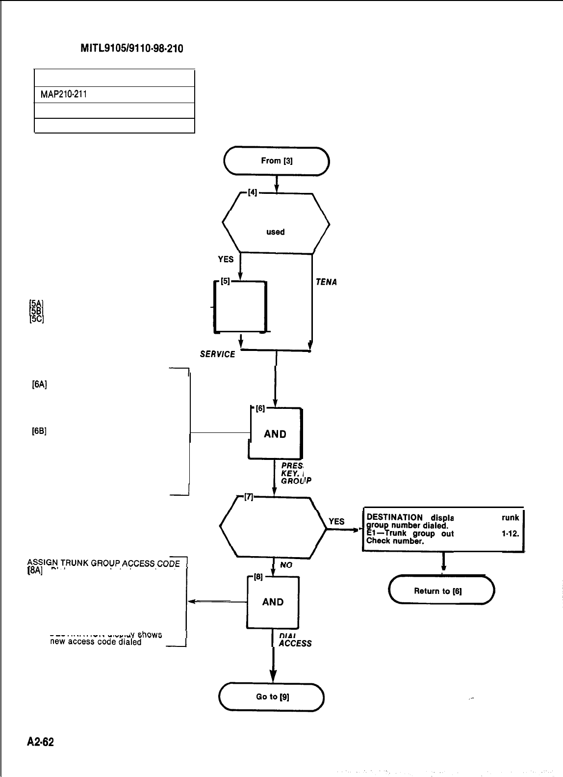
SECTION
MITL9105/9110-98.210
PROGRAM TRUNK GROUPS
MAP210-211
Issue 3, July 1980
Sheet 2 of 7
SELECT TENANT SERVICE
[5A]
Press TENANT key
[5B]
Dial tenant number (l-4)
[5Cl
Press ENTER I-
Is multi tenant
service to be
AND
SELECT
TENANT
SERWCE
‘+-
SELECT TRUNK GROUP PROGRAM
[6A]
Press TRUNK GROUP key
lTRUNK GROUP lamp lit
lSOURCE display shows trunk
group 1 and its access code if
assigned or trunk group 1 and
[6B]
----if no access code assigned
Dial number of trunk group (1-12)
l
SOURCE display shows current
trunk group number and its ac-
cess code if one is assigned or
trunk group 1 and ---- if no access
code assigned
l DESTINATION display shows
NO
SINGLE
TENA
NT
S TRUNK GROUP
DIAL TRUNK
IP
NUMBER
trunk group number dialed
1
Press
Access Code key
Does bell ring
[8A]
Dial access code to be assigned
to this trunk group
l
ACCESS CODE lamp lit
l
SOURCE display shows new
trunk group and existing access
code if assigned or the new trunk
group and ---- if no access code
assigned.
.DESTINATION displa
CODE
23
Go to
(91
DESTINATION display shows trunk
~~~rKi?&$le~
of range
I-X2.1
A2-62
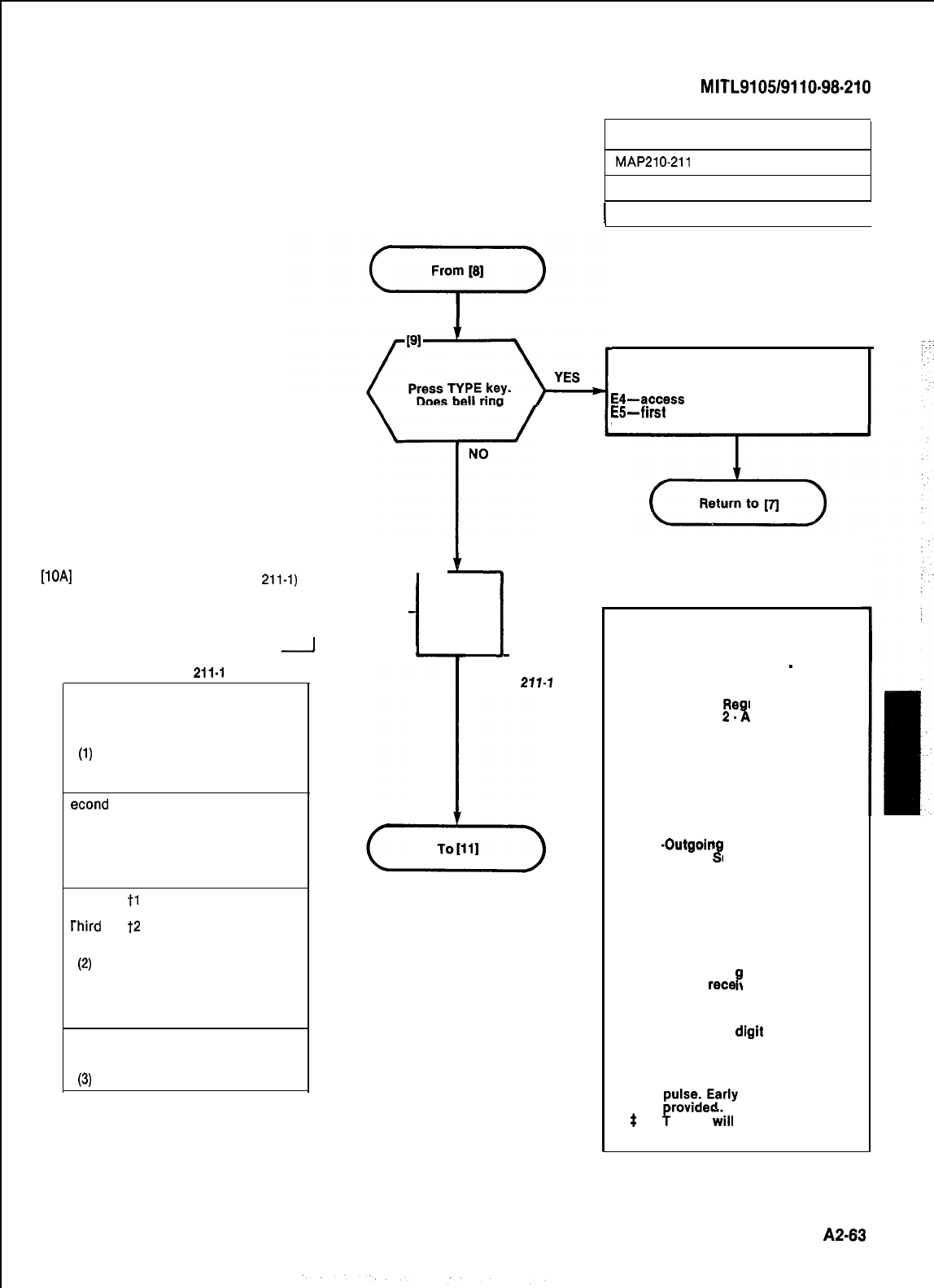
type code dialed
TABLE
211.1
Entry Code
Description
First 1 No Answer Supervisior
digit 2 Answer Supervision
Note 3 Toll Supervision
(1)
4 Outgoing audio in-
hibited until answer
supervision
econd
digit 1 No message register
2 Message register
3 SMDR without messagr
register
4 SMDR with message
register
tl
Rotary dial office, no
wait for dial tone
rhird
digit
t2
Rotary dial office, wait
for dial tone
Note
(2)
$3 DTMF dial office,
no wait for dial
tone
$4 DTMF dial office,
wait for dial tone
tone
‘ourth 1 CO trunk
digit 2 Non-CO trunk
Note 3 Non-CO with
(3)
identification
PROGRAM TRUNK GROUPS
MAP210-211
Issue 3, July 1980
I
Sheet 3 of 7
I
NO
T
p
_t,
ASSIGN TRUNK TYPE
[TOAl
Dial trunk type code (Table
211-1)
l TYPE lamp lit
l
SOURCE display shows trunk
group number and current type
.--I--
DESTINATION display four digit
AND
-I
I
DIAL TYPE CODE
TABLE
271-7
SECTION
MITL9105/9110~98~210
r
DESTINATION display shows equipment
number dialed and
El -bad data received by CPU
E4-access code already assigned
E5-first
digit conflict
Check entry.
YOTE 1
.
If answer supervision is not
required (or not provided by
the CO), then use 1
-
No
Answer Supervision.
.
If tandem trunking or
Message
Re
then use
2.
istration is used,
B
sion. nswer Supervi-
.
If supervision is used to in-
dicate toll calls, and this
feature is required, then use 3
. Toll Supervision.
.
If audio cut-through or tie
trunk tandem calls is required
only after receipt of answer
supervision, then use 4
*Outgoin Audio Inhibit until
Answer upewision.
8
VOTE 2
.
If “wait for dial tone” is
selected then any digits dial.
ed prior to recei
tone are ignore
8
t of CO dial
by the PABX.
This prevents circumvention
of the toll denial by dialing a
fast valid di
tone is
B
it before CO dial
rece
ved.
NOTE 3
.
If the fourth digit selected is
3, the third digrt must be 1.
t
If extensions are DTMF
the trunk will convert to dial
p;fs;deyrly
line split is not
$
Yrunks
iill
repeat DTMF
or dial pulse signals.
A2-63
j
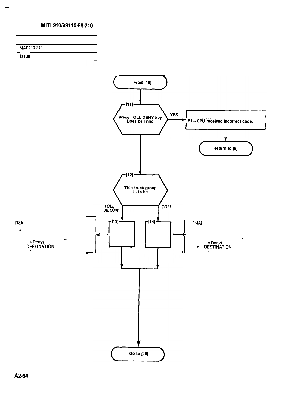
-
SECTION
MITL9105/9110-98-210
PROGRAM TRUNK GROUPS
MAP210-211
l-Issue
3,
July 1980
1
I-
Sheet 4 of 7
-1
ASSIGN TOLL ACCESS
-
[13AJ
PRESS DELETE key
l DELETE lamp lit
SOURCE disolav shows trunk
.
group number and existing Toll
Allow/Deny code (0
=
Allow,
1~
Denv\
.
DESTitiATION
display shows
0
-
Toll Allow
-
DESTINATION
code dialed. display shows trunk type
Check code.
NO
DENY
-
AND AND
+
.
I
PRESS DELETE PRESS ADD
KEY
I
KEY
1
14A]
.
.
.
Press ADD key
ADD lamp lit
SOURCE display shows trunk
group number and existing Toll
Allow/Deny code (0
=
Allow,
1
=
Denv\
DESTIgATION
display shows
1
-
Toll Deny
A2.64
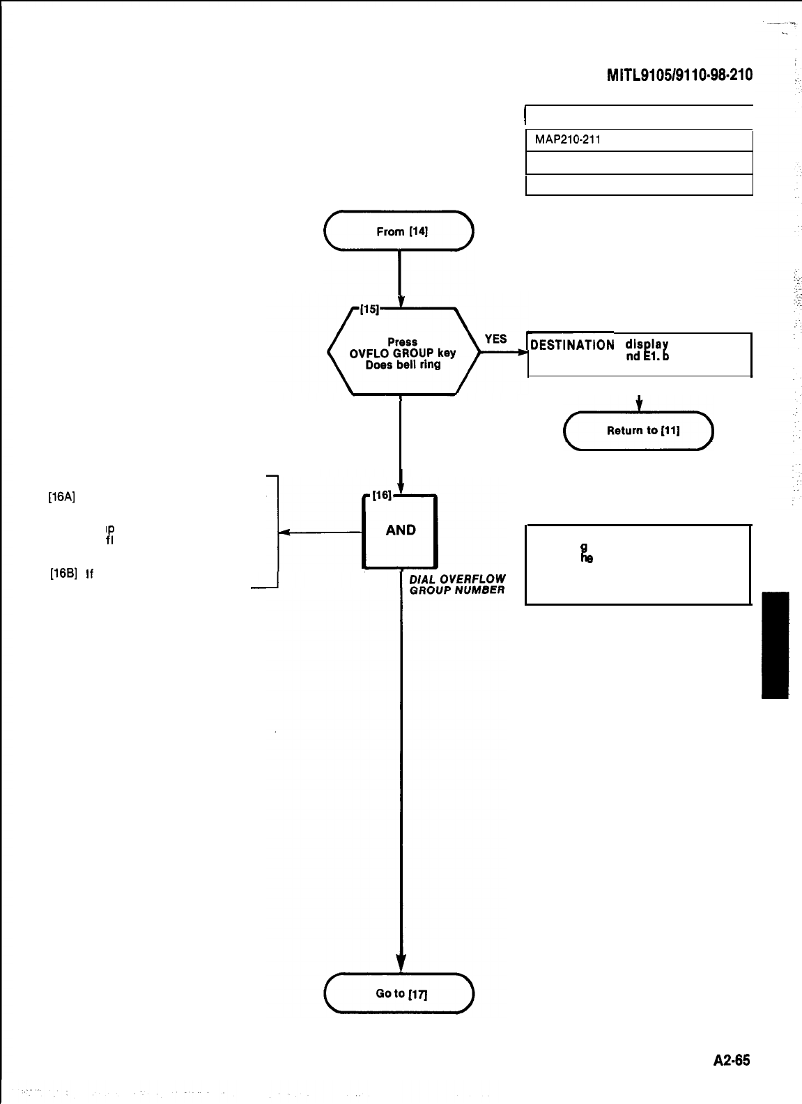
SECTION
MITL9105/9110-98-210
I
PROGRAM TRUNK GROUPS
I
MAP210-211
issue 3, July 1980
ASSIGN OVERFLOW GROUP
[16A] Dial overflow group number (1-12)
l
OVFLO group lamp lit
l
SOURCE display shows trunk
grou
overPnumber and assigned
low group number
l DESTINATION display shows
new overflow group number
[16B]
If
no overflow group required
press DELETE
Sheet 5 of 7
From
1141
7
-DESTINATION diseiag
shows toil
allow/deny code and 1, ad data receiv-
ed by CPU.
I
NO
(dz-)
NOTE
Overflow roup number must not be the
same as t
il
e
current trunk group number.
if a call to a trunk group is routed to the
overflow group, the restrictions of the
overflow group are in force for that call.
I
A2-85
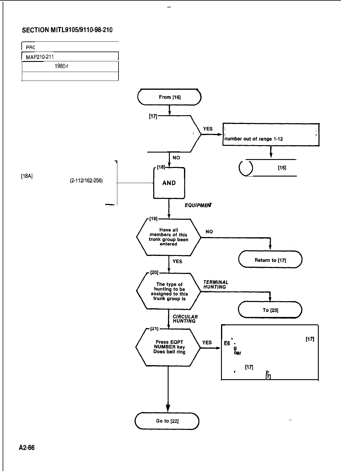
SECTION
MITL9105/9110-98-210
r-
PROGRAM TRUNK GROUPS
I
IP210-211
Issue 3, July
1980!r
79
Sheet 6 of 7
1
ASSIGN EQUIPMENT NUMBERS
TO THIS TRUNK GROUP
[18A]
Dial equipment number of trunk
in trunk group
(2-112/162-256)
.EQPT NUMBER lamp lit
.SOURCE display shows the trunk
group number and existing equip-
ment number
-
(
1171
Press EQPT NUMBER
key. Does bell ring
DESTINATION display shows trunk
group number and El . overflow group
AND
L-J
I
DIAL
EQUIPMEN
NUMBER
(
Return to
(151
)
NO
DESTINATION display shows equipment
number dialed and
El
-
number out of range, return to
[17)
E8
-
equipment number dialed not
1 assi ned
ti
to a trunk. If equipment
num
er
is correct, press LAMP TEST,
return to required trunk programming
MAP, if equipment number is incorrect
return to
(171
E3
-
trunk grou
P
access code not
entered, return to
7j
A2.86
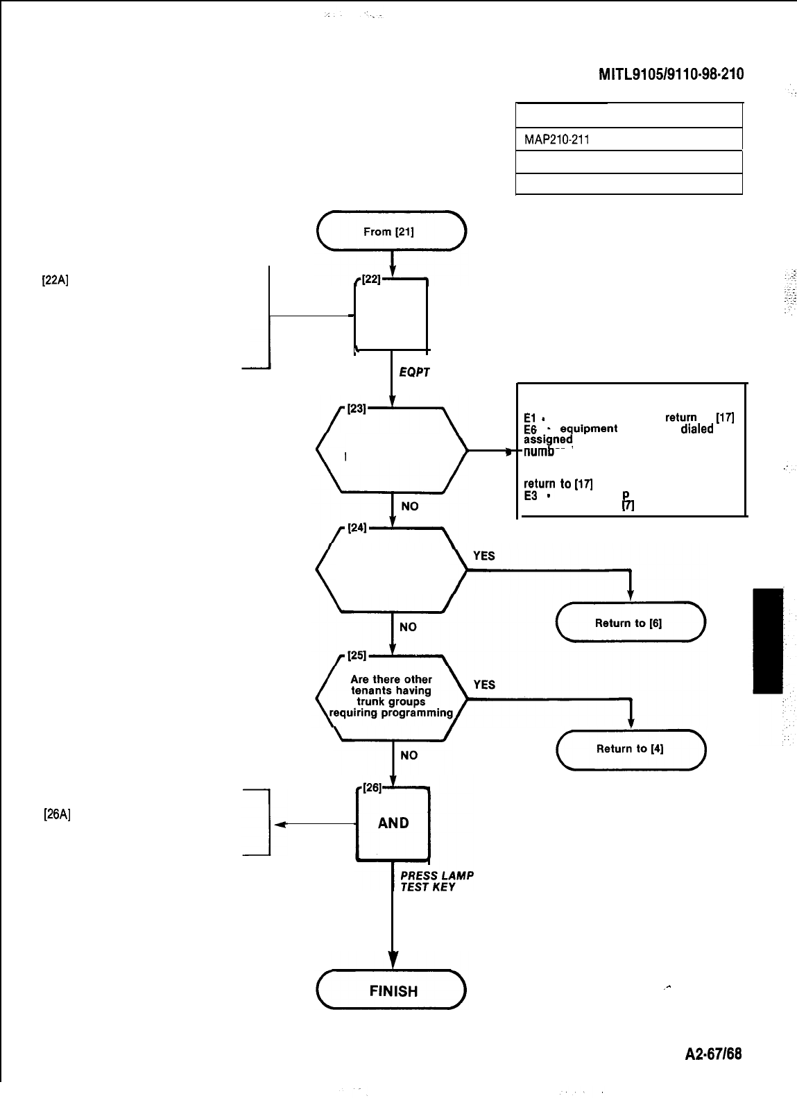
SECTION
MITL9105/9110-98-210
[22A]
Dial first equipment number on
this trunk group
.EQPT NUMBER lamp lit
.SOURCE display shows trunk
1
group number and last equip-
ment number entered
.DESTINATION display shows
first equipment number entered
-
AND
*
l
DIAL
EQPT
NUMBER
Press ENTER
YES
key. Does bell ring
P
PROGRAMTRUNKGROUPS
MAP210-211
Issue 3, July 1980
Sheet 7 of 7
DESTINATION display shows equipment
number dialed and
E;
-
number out of range,
return
to
[17]
equrpment
number
draled
not
to a trunk. If equipment
er is correct, press LAMP TEST,
return to required trunk programming
MAP, if equipment number is incorrect
Eurn
to
m
-
trunk grou
P
access code not
entered, return to
fl
Are any more
trunk groups for
this tenant to be
programmed
I
STORE TRUNK GROUP DATA
[26A]
Press LAMP TEST key
.All displays dark
.
All lamps dark except LAMP
TEST
(,,.,,,,,,)
.-
A2-87168
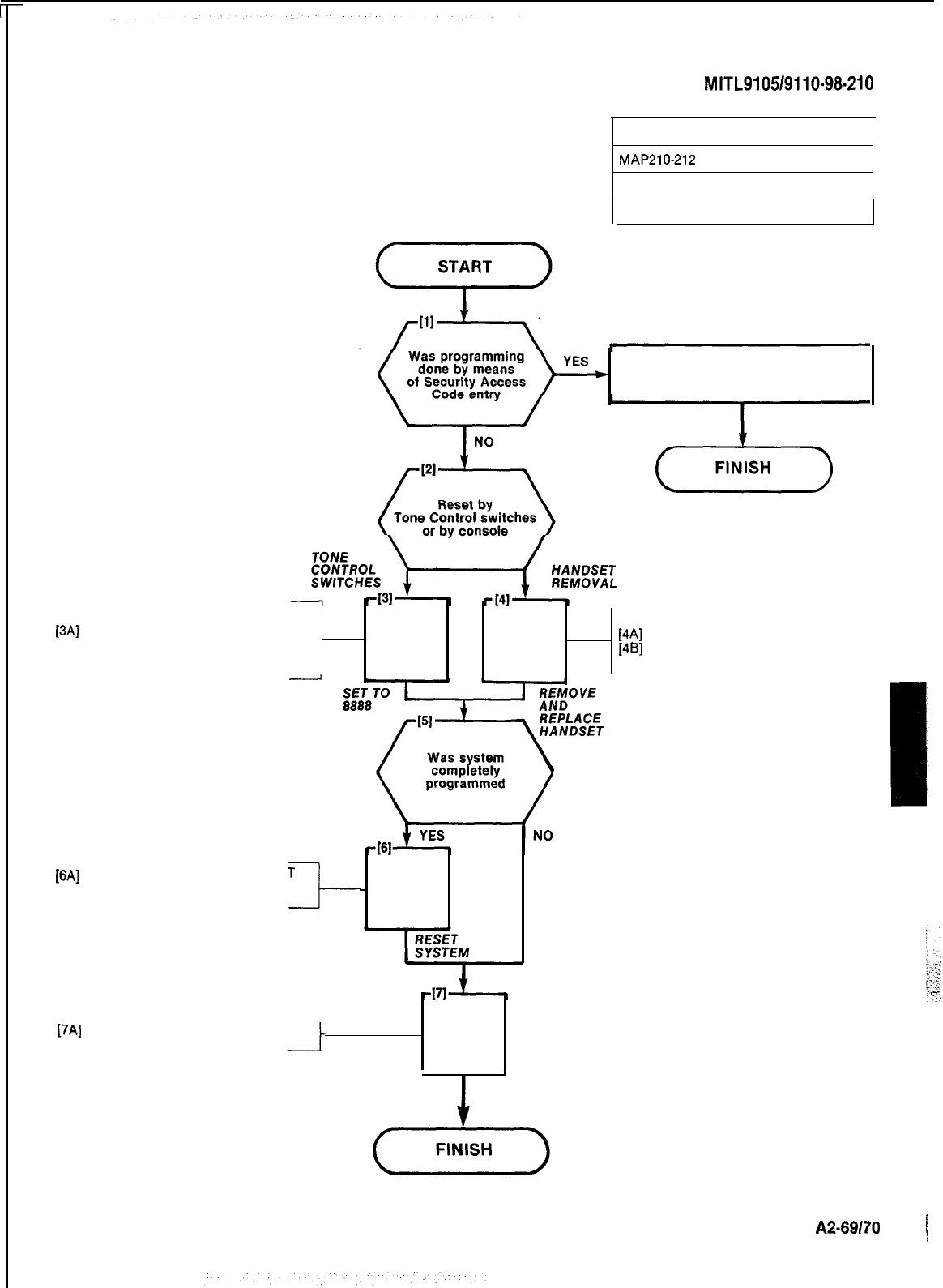
[6A]
Press SYSTEM MASTER RESET
button on Scanner card (card
position 19, orange)
It-
SECTION
MITL9105/9110~98-210
TERMINATING PROGRAMMING MODE
I
MAPPlO-212
I
Issue 3, July 1980
I
Sheet 1 of 1
Press LAMP TEST button
handset removal
[3A]
Set thumbwheel switches on
Tone Control card (card position
18, yellow) to 8888
-
AND AND .
[4A]
Remove console handset
[48]
Replace console handset
-
AND
[7A]
Close and lock cabinet doors AND
CLOSE AND LOCK
CABINET DOORS
A2-69170
/
i
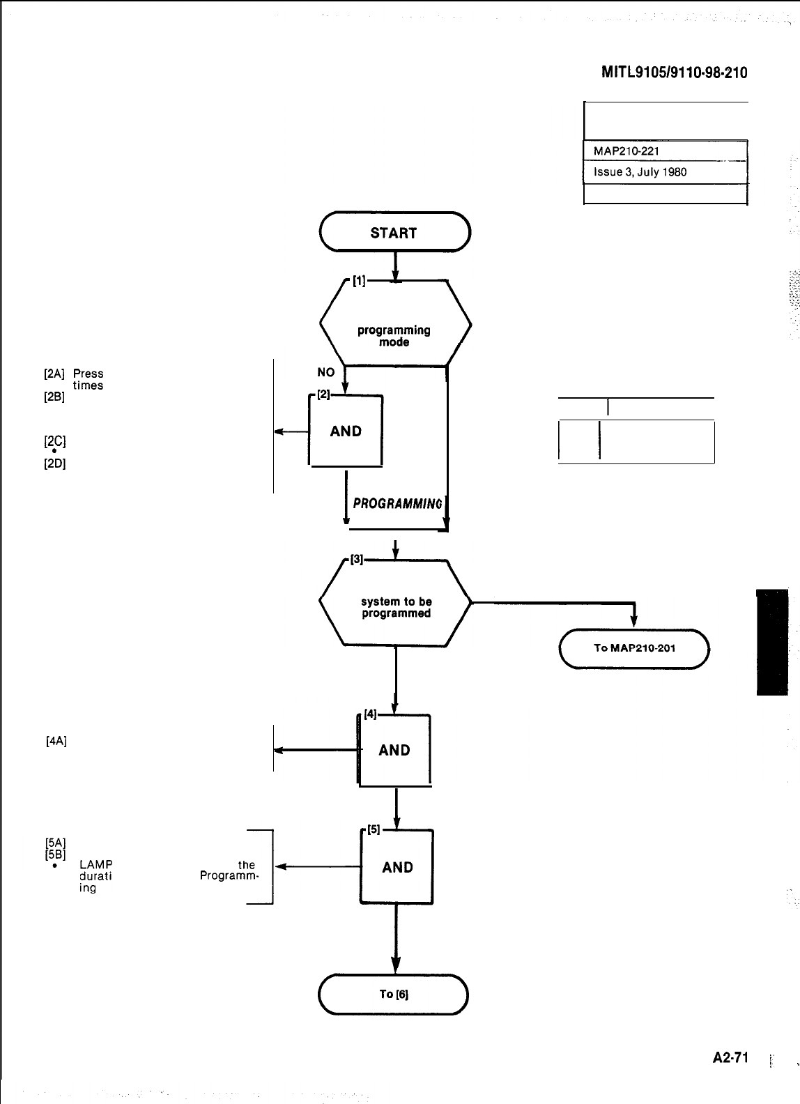
SECTION
MITL9105/9110-98-210
[2A]
;?I?;;
RELEASE button several
[2B]
Set thumbwheel switches on
Tone Control card (card position
18 yellow) for console to be used
in programming (Table 221-1)
[2C]
Press LAMP TEST button
LAMP TEST LED lit
[2b]
Alternately enter Programming
Security Code from console
(Feature 29)
[4A]
Place Extended Programming
console overlay over console but-
tons
/
VI
Is the system
in standard
progfo7ring
1
SELECT
I
STANDARD
PROGRAMMIN(:
MODE
YES
SELECTION OF EXTENDED
PROGRAMMING
I
Sheet 1 of 2
TABLE 221-l
CODE
i
CONSOLE
I
7770 Maintenance
I
I
7771 Attendant 1
7772 Attendant 2
Is the complete
YES
NO
MULTI-DIGIT TOLL
CONTROL ONLY
I
SELECT EXTENDED
PROGRAMMING OVERLAY
Press LAMP TEST button
Press NEXT button
;P
TEST LED flashes for
tg+-[Fi
duration of Extended
Programm-
1
SELECT
(T-)
EXTENDED PROGRAMMING
1.
A2-71
i’
_
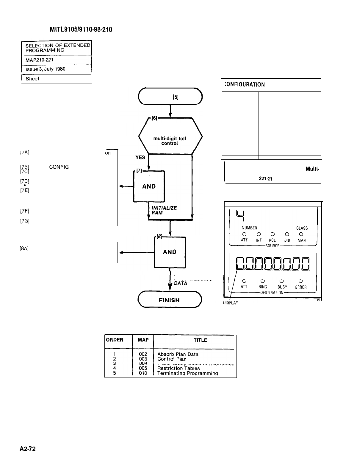
SECTION
MITL9105/9110-98-210
ISheet
2 of 2
I
17Al
1761
[7Cl
[701
1h
[7Fl
17Gl
WI
Set the thumbwheel switches
07
the Tone Control Card (Card
Position 18 yellow) to 7776
Press
CONFIG
button
Dial single digit configuration
code (Table 221-2)
Press ENTER button
Display shown in Fig. 221-1 I
Return the thumbwheel switches
on the Tone Control card to the
Standard Programming console
designation (Fig. 221-l)
Press the MASTER RESET button
on the Scanner card
Repeat Steps 2, 4 and 5
Enter all extended programming
data in the order shown in Table
221-3
1
.
From
[S]
Is all new data to
be entered for
PI
--III
AND
NO
TABLE 221-2
:ONFIGURATI~N
CODE DESCRIPTION
1
Automatic Wakeup
Toll Control Standard
2
Toll Control Standard
and Speed Call
Standard
3
Toll Control Basic and
Speed Call Extended
4
Toll Control Extended
(No Automatic
Wakeup)
I
NOTE
To have Automatic Wakeup and
Multi.
Digit Toll Control, select Configuration
code 1 (Table
221.2)
I
CONFIGURATION
COPE
ENTER EXTENDED
PROGRAMMING
I-l
17
17
1-i
1-l
17
In
1-i
1
I)
1.)
0
0
0
0
0
1
-.--.a.-.-.-.-.
I
NUMBER
CLASS
UISPLAY
AFTER ENTER
BUTTON
PRESSED
Fig. 221-l
TABLE 221-3
Trunk Group Class of Restriction
A2-72
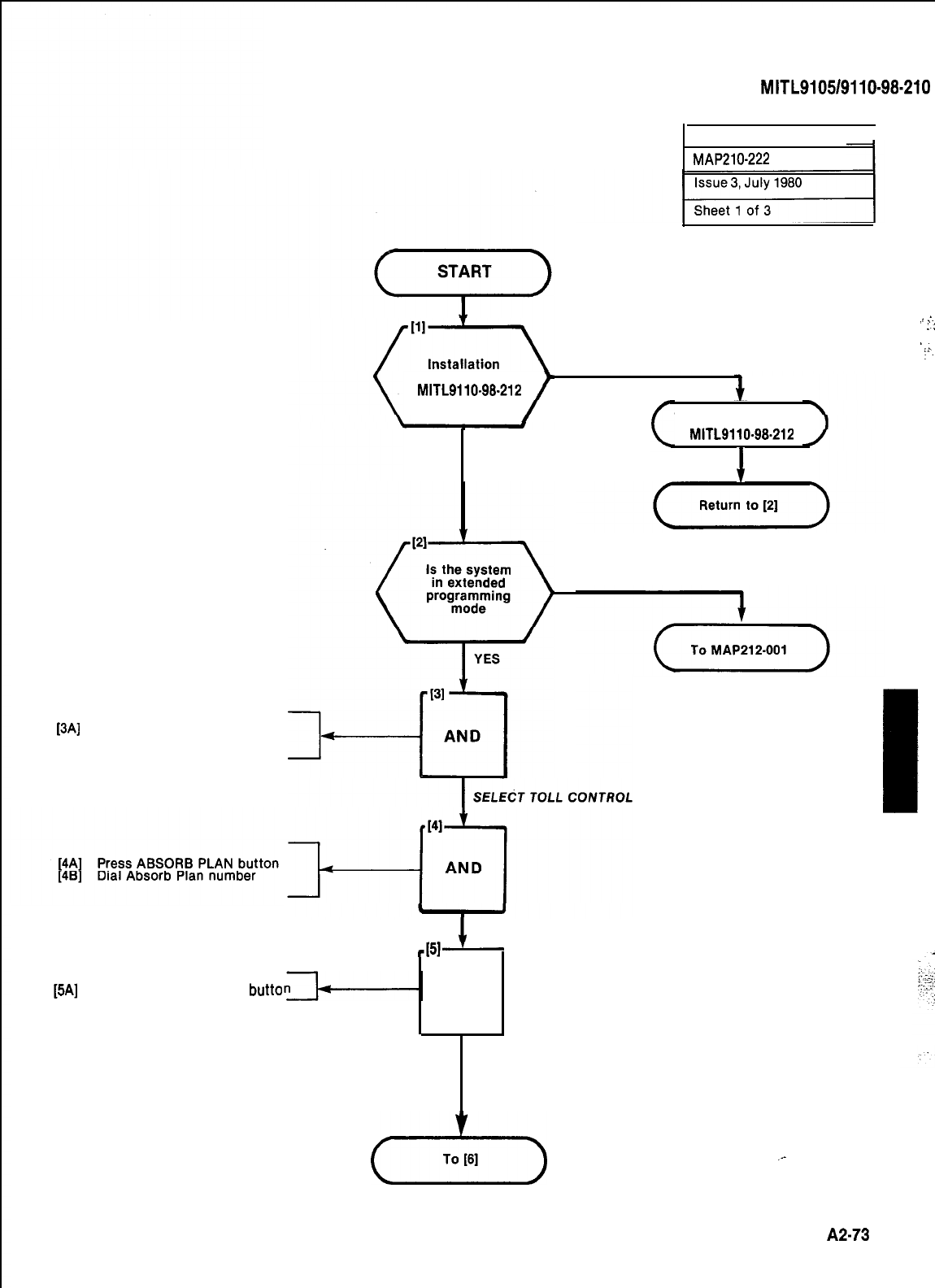
SECTION
MITL9105/9110-98-210
ABSORB PLAN
I
MAP210-222
NO
forms completed
in
MITL9110.98.212
To Installation Forms
YES MITL9110.98.212
I
NO
,,
:-
::
‘..
:‘.
.
[3A]
Press TOLL CONTROL button
.Toll Control LED lights
I
SELECT ABSORB PLAN
451
[5A]
Press ABSORB REPEAT
butto
AND
SELECT ABSORB REPEAT
(+-)
.-
A2-73
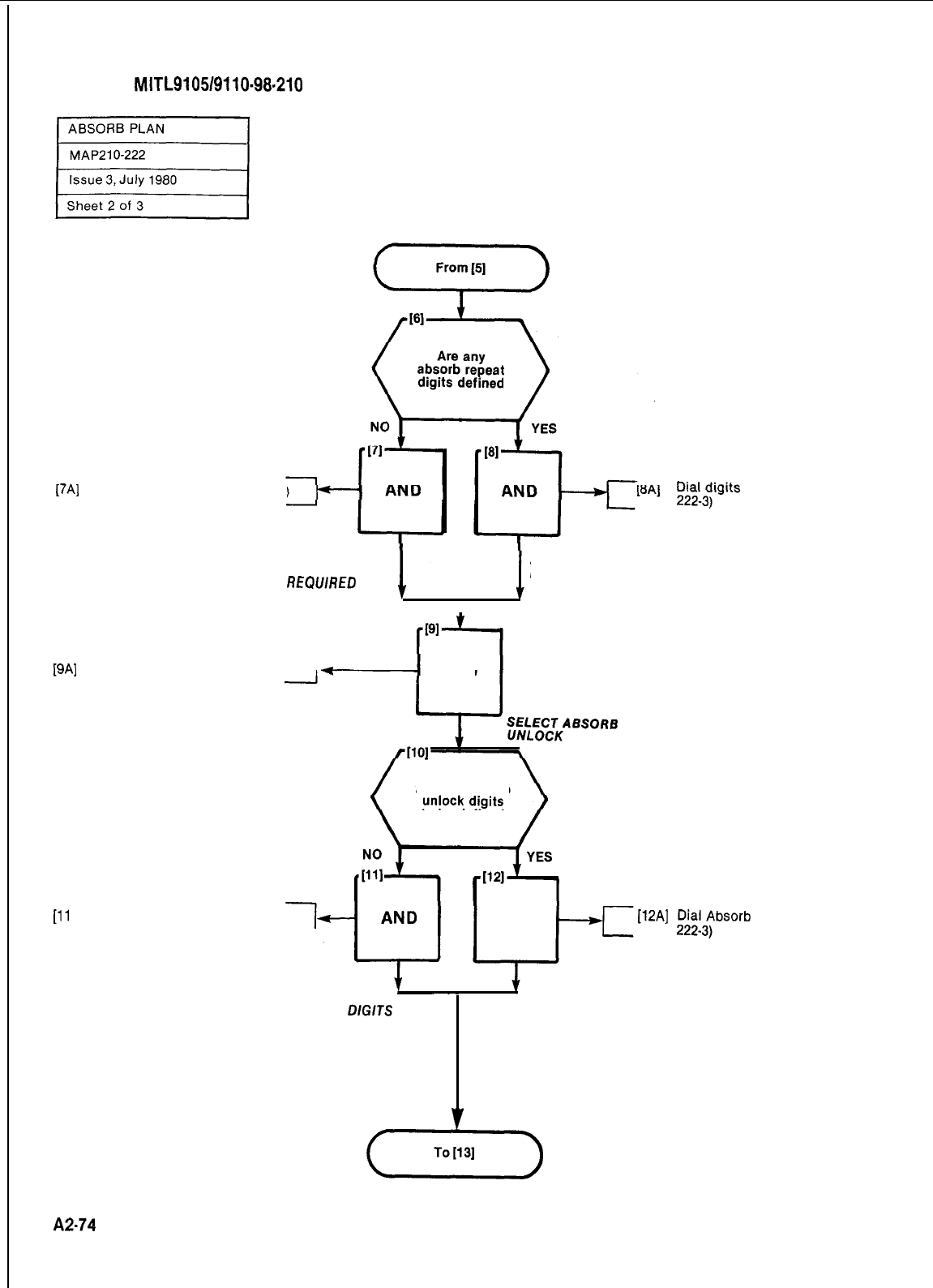
SECTION
MITL9105/9110-98.210
[7A]
Press DELETE button (Fig. 222-2)
NO ABSORB
REPEAT DIGITS
REQWRED
Di&igits
to be absorbed (Fig.
ABSORB REPEAT
DIGITS REQUIRED
[9A]
Press ABSORB UNLOCK button
1AND
[ll
A] Press DELETE button
l-
Are any absorb
to be defined
AND
[12A]
:;;13Tbsorb
Unlock Digits (Fig.
NO ABSORB
UNLOCK
DlGlTS
ABSORB UNLOCK
REQUIRED DIGITS REQUIRED
A2.74
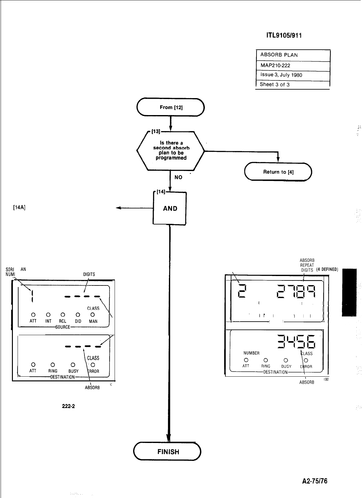
SECTION M ITL91051911 O-98-21 0
::
.:
‘.’
YES
[14A]
Press the ENTER button I
SORI
NUM
3 PL
BER
5
ABSORB
REPEAT
NUMBER
NUMBER
AB\SORB
':
UNLOCK
DIGITS
Fig.
222.2
DELETE
INDICATION
ENTER ABSORB
DATA
ABSORB
PLAN
NUMBER
NUMBER
CLASS
00 0 0 0 00000
ATT
INT
RCL
DID
MAN
.
SOURCE
ABSORB
"W
UNLOCK
DIGITS
(4 DEFINED)
Fig. 222.3
A2-75176
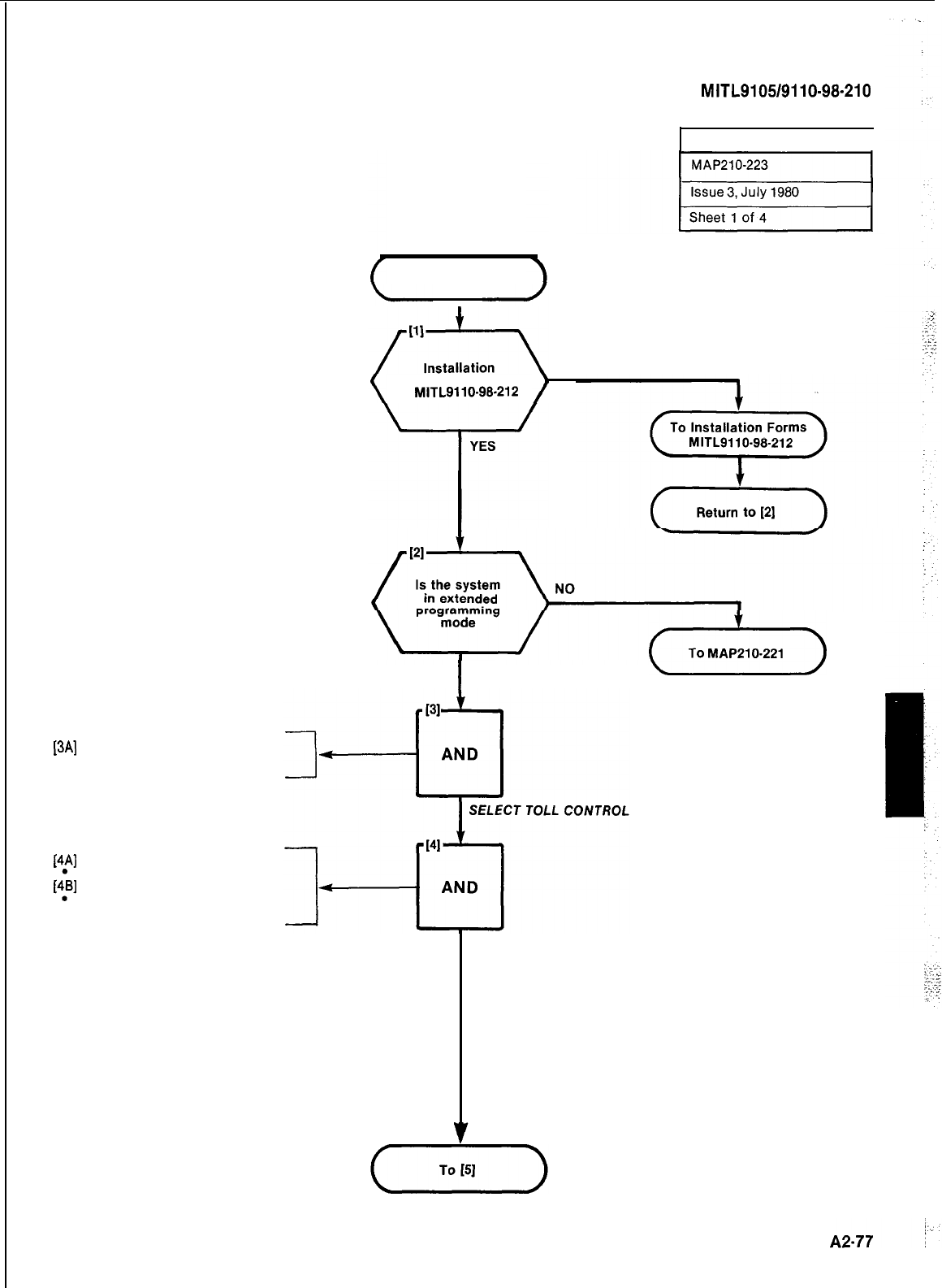
SECTION
MITL9105/9110-98-210
CONTROL PLAN
1
START
tables completed
in
MITL9110-99-212
NO
I
YES
(dz-)
[3A]
Press TOLL CONTROL button
.Toll Control LED lights
[4A]
Press CONTROL PLAN button
Control Plan LED lights
[4::B]
Dial Control Plan number
DESTINATION Display shows
Control Plan Number
ENTER CONTROL PLAN
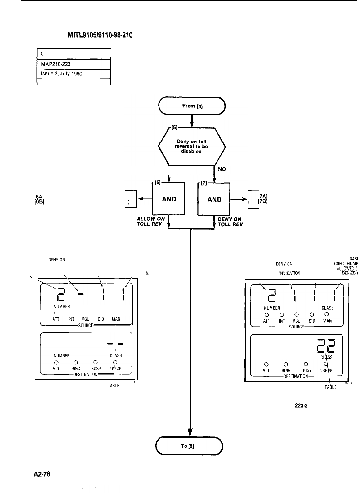
SECTION
MITL9105/9110~98-210
r-
CONTROL PLAN
I
Sheet 2 of 4
YES
I
[6A]
Press DENY TOLL REV button
[6B]
Press DELETE button (Fig. 003-l)
DENYON
TOLL FIRST FIRST BASIC
CONTROL REVERSAL DISABLE
BASIC
COND. NUMBER
PLAN INDICATION CONO. ALLOWED (1)
NUMBER \ NUMBER
OR DENIED
(0)
.
CLASS
0 0 0 0 0
NUMBER
Fig. 223-l
[7A]
c
Press DENY TOLL REV button
[7B]
Press ADD button (Fig. 003-2)
FIRST FIRST BASI
CONTROL
DENYON
TOLL BASIC
COND.NUME
PLAN
REVERSALENABLE COND.
ALLOWED(
NUMBER
INDlCATlON
NUMBER
OR DENlED(
I
,
7
-i
r
1’
--
NUMBER
TABLE
NUMBER ALLOWEDOR
DENIED
Fig.
223-2
A2-78
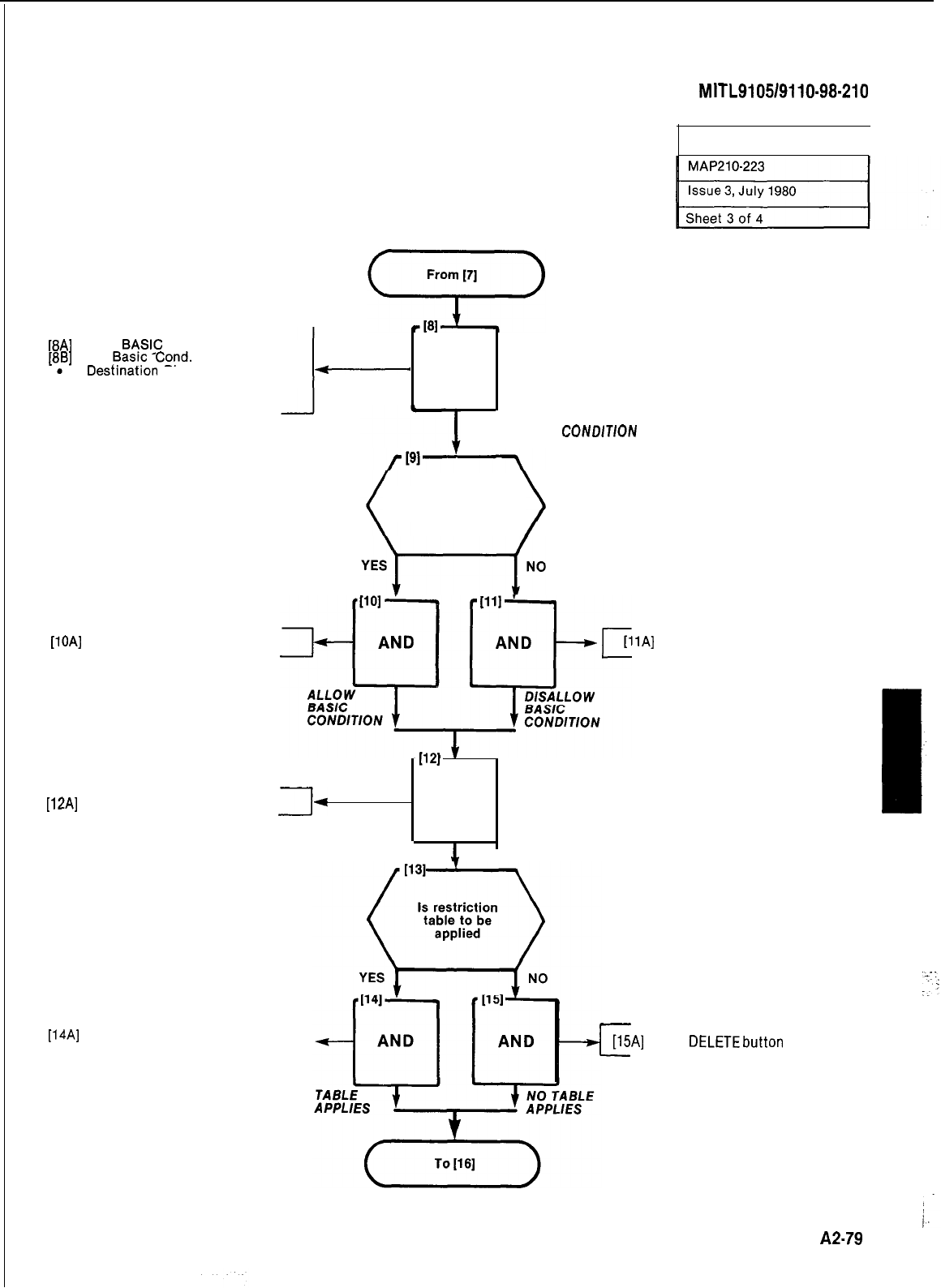
SECTION
MfTL9105/9110-98-210
[8A]
Press
B+SlC
COND button
[8.B]
Dial
!3as!c
Cord.
number
Destlnatlon
Display shows Basic
-
Cond. number
-
AND
ENTER BASIC
Basic Condition
to be allowed
CONDlTlON
CONTROL PLAN
I
[lOA]
Press ADD button (Fig. 223-2)
[llA]
Press DELETE button (Fig. 223-2)
ziLi+~~E
I.
WI
[12A]
Press TABLE button
3
AND
SELECT TABLE
[14A]
Dial Table number (Fig. 223-l)
7
c
[15A]
Press
DELETEbutton
(Fig. 223-l)
A2-79
j
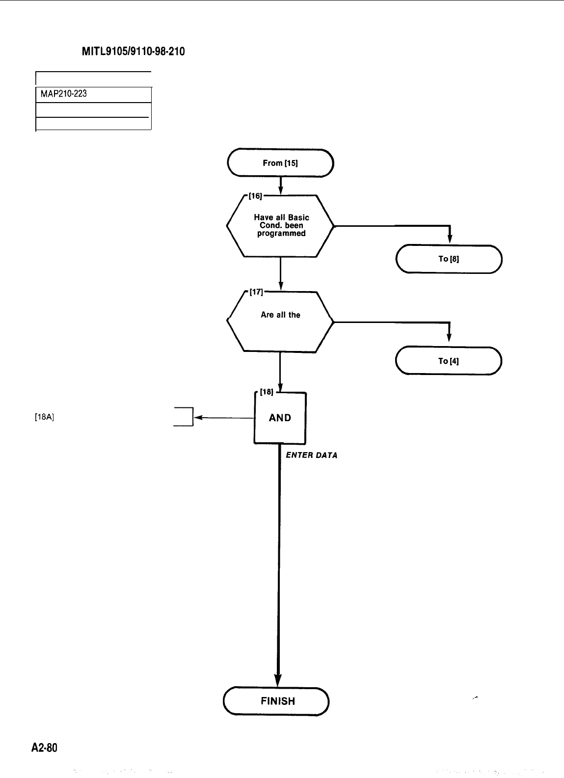
SECTION
MITL9105/9110-98-210
I
CONTROL PLAN
I
MAP210-223
Issue 3, July 1980
Sheet 4 of 4
[18A]
Press ENTER button
NO
YES
required Control
Plans programmed
NO
YES
A2-80
_-
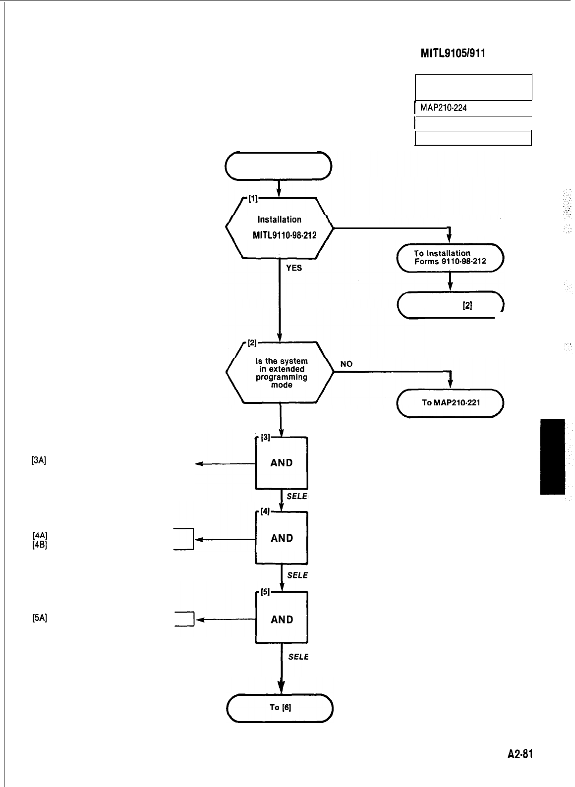
SECTION MITL91051911 O-98-21 0
TRUNK GROUP CLASS OF
RESTRICTION
I
MAP210-224
I
1
Issue 3,
July 1980
I
Sheet 1 of 3
START
NO
tables completed
in
MITL9110-98-212 J
Return to
[2] 1
I
YES
I31
[3A] Press TOLL CONTROL button
.Toll Control LED lights 7
--u
AND
SELECT TOLL CONTROL
[4A] Press TRUNK GROUP button
[4B] Dial Trunk Group number
Y
SELECT TRUNK GROUP
[5A]
Press ABSORB PLAN button
-+Yq
-I-
SELECT ABSORB PLAN
(-+-)
A2-81
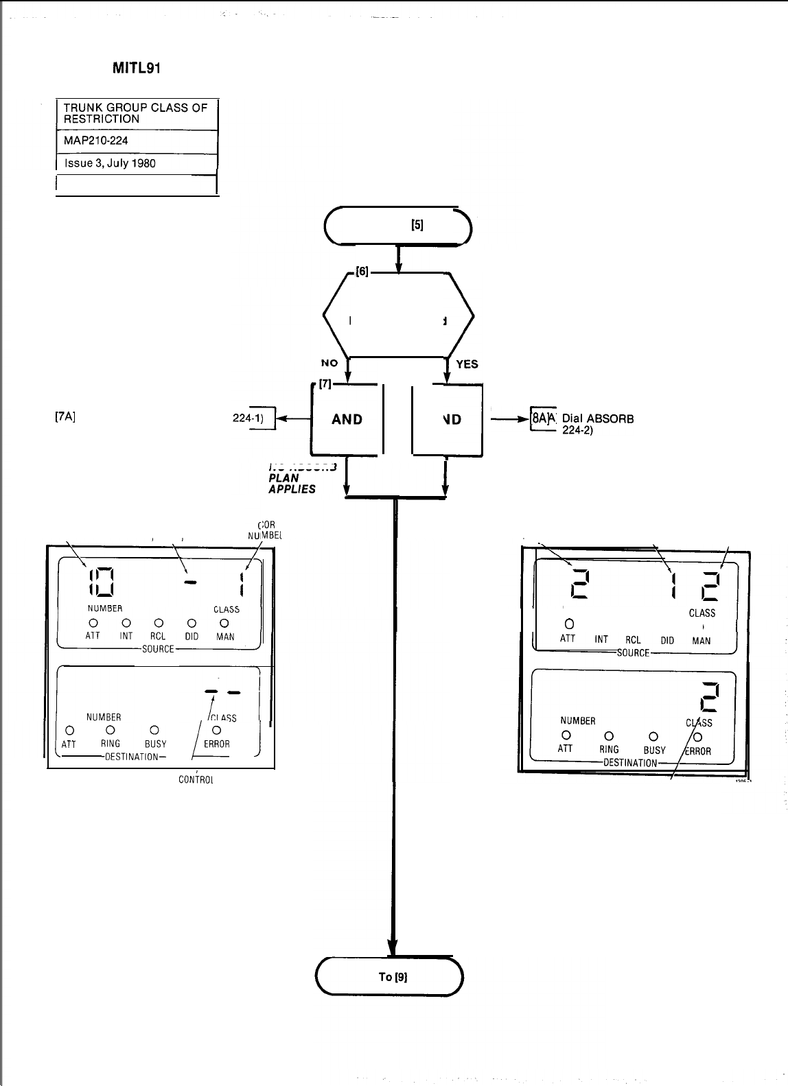
SECTION
MITLSI
051911 O-98-21 0
1 Sheet 2 of 3
From
151
161
Is an Absorb
Plan to be applied
I
:.
YES
l
I61
AND
--IC
[8A]
Dk!2;BSORB
PLAN 1 or 2 (Fig.
[7A]
Press DELETE button (Fig.
NO ABSORB
TRUNK
GROUP
NUMBER
NO ABSORB
PLAN
NUMBER
APPLIED
A::
Ri;T,NAT~~
/ERROR
J
CONiROL
PLAN
NUMBER
Fig. 224-l
:OR
MBEI
ABSORB
PLAN
APPLIES
TRUNK
GROUP
NUMBER
ABSORB
PLAN
NUMBER
COR
NUMBER
NUMBER
0
0000
CONTROL
PLAN
NUMBER
Fig. 224.2
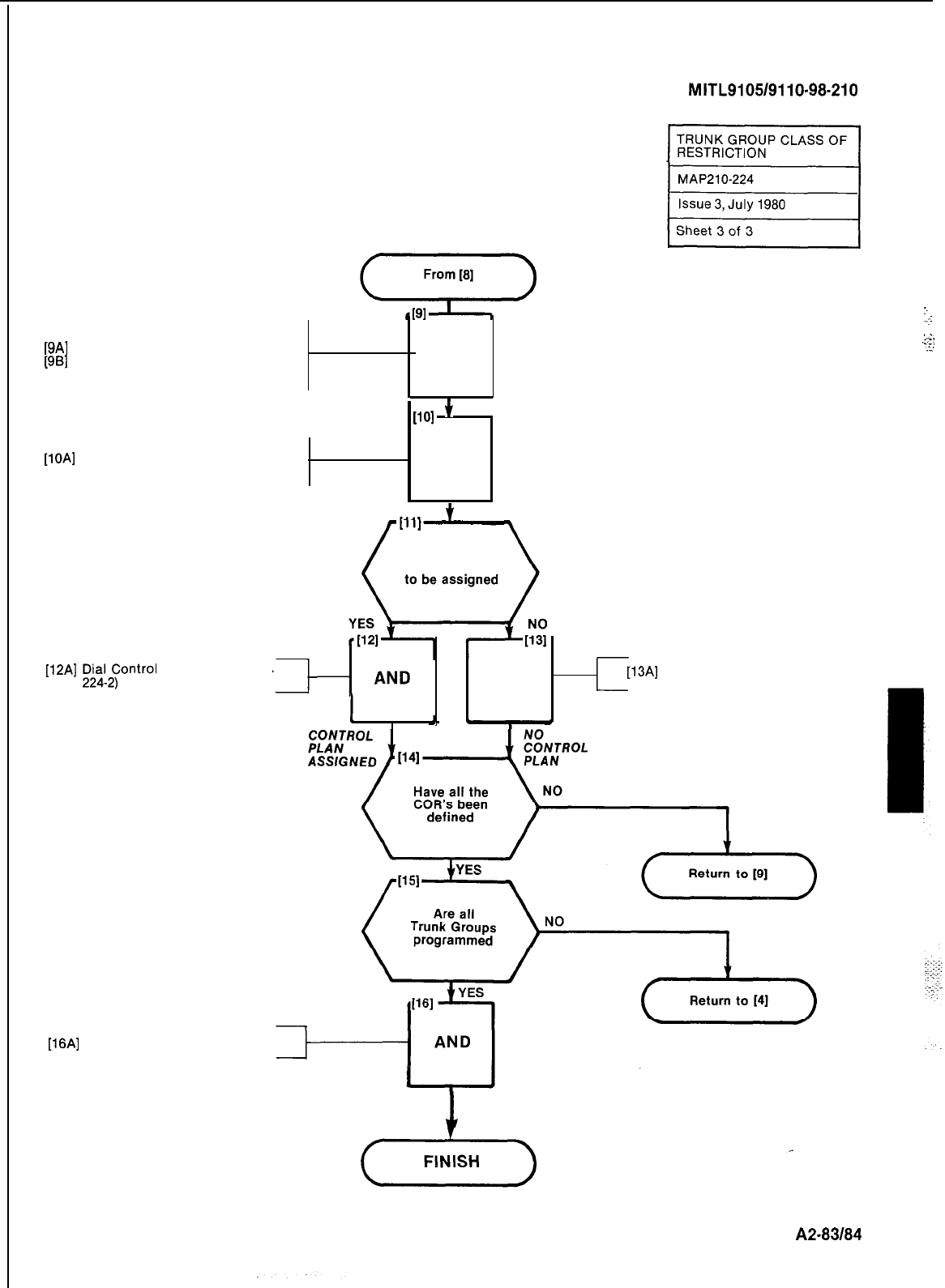
SECTION
MITL9105/9110-98-210
[9A]
Press COR button
[9B]
Dial COR number
[lOA]
Press CONTROL PLAN button
:.
-j
._..
AND
._.-;
:-;
.:
WI
+
SELECT COR
AND
+
SELECT CONTROL PLAN
Control Plan
[12A]
;IH2&ntrol
Plan number (Fig. AND
c
[13A]
Press DELETE button (Fig. 224-l)
I
I
J
[16A]
Press ENTER button
ENTER TRUNK GROUP DATA
A2-83184
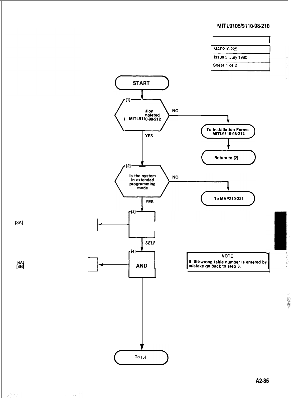
SECTION
MITL9105/9110-98.210
RESTRICTION TABLES
1
[3A] Press the TOLL CONTROL button
_
.
Toll Control LED lights
[4A]
Press TABLE button
[4B]
Dial Table number
(
111
7
installation
Tables completed
in
MITL9110-98-212
JNO
(+I
PI
(7)
/
I
AND
I
+
SELECT TOLL CONTROL
I
t
SELECT TABLE
~“z-l
1
If
!he
wrong table number is entered by
J
i
A2-85
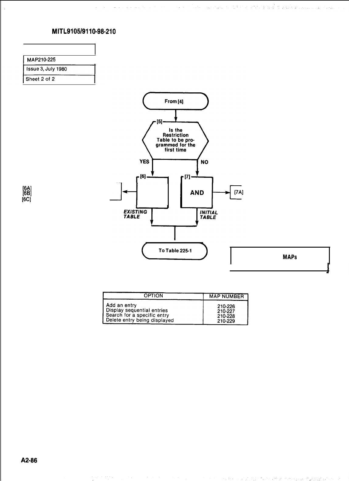
SECTION
MITL9105/9110-98-210
RESTRICTION TABLES
I
MAP210-225
I
[6A]
Press DELETE button
[6B]
Press CONFIRM button
[6C]
Press ENTER button
AND Press DISPLAY ENTRY button
u
desired modifications.
NOTE: Use these
MAPS
to perform
TABLE 225-l
~1
A2-88
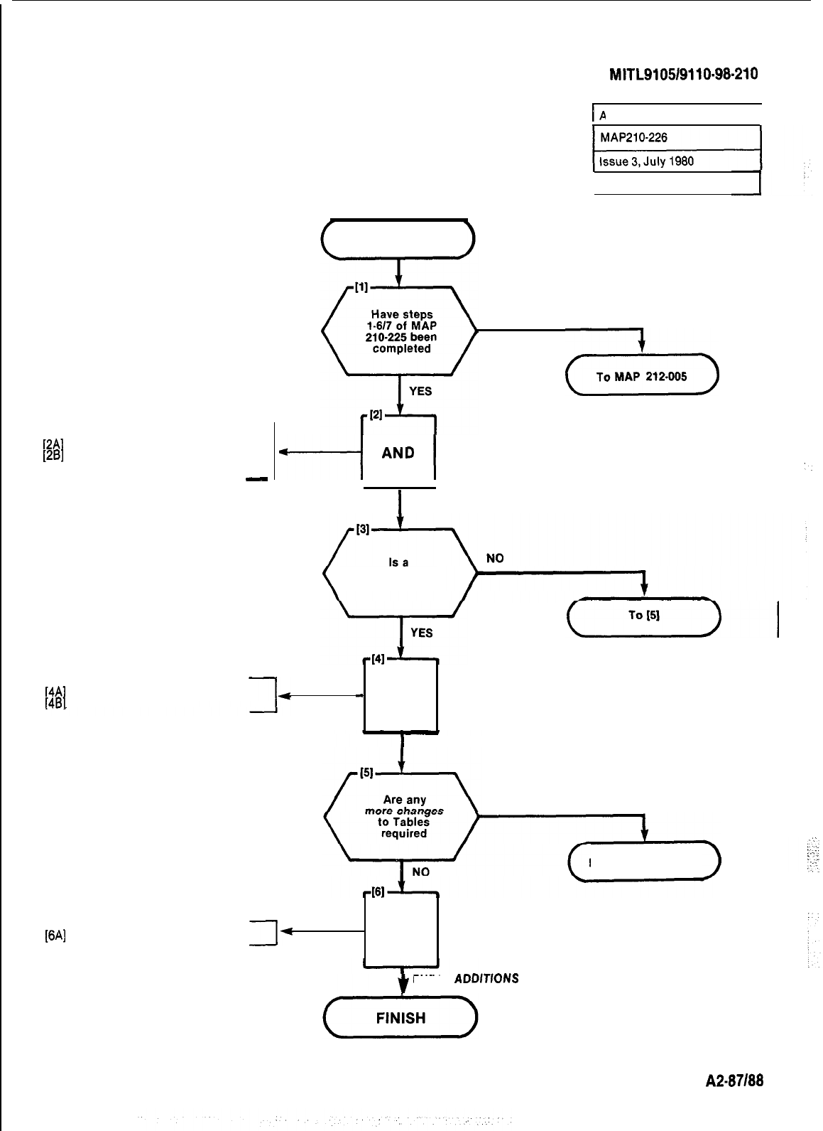
SECTION MITL9105/9110-98-210
NOTE 1: If the wrong entry digits are keyed by mistake, at-
tempt to add the entry as it was keyed. If the entry is
accepted remove it with the delete key. If an error is
given no further action is required, as the entry was
ignored.
[2A]
Press ADD button
[26] Dial ENTRY digits (See Note 1)
-
r
~~
ADD AN ENTRY
I
Sheet 1 of 1
START
NO
(-Tik-)
Y
AND
I
[4A]
Press TABLE button
[4B]
Dial Table number
III
I
ADD AN ENTRY
Restriction
Table to apply
-
AND I
ENTER RESTRICTION TABLE
YES
Refer to Table 005-l
[6~]
Press ENTER button AND
ENTER
ADDfTlONS
A2-87188
/
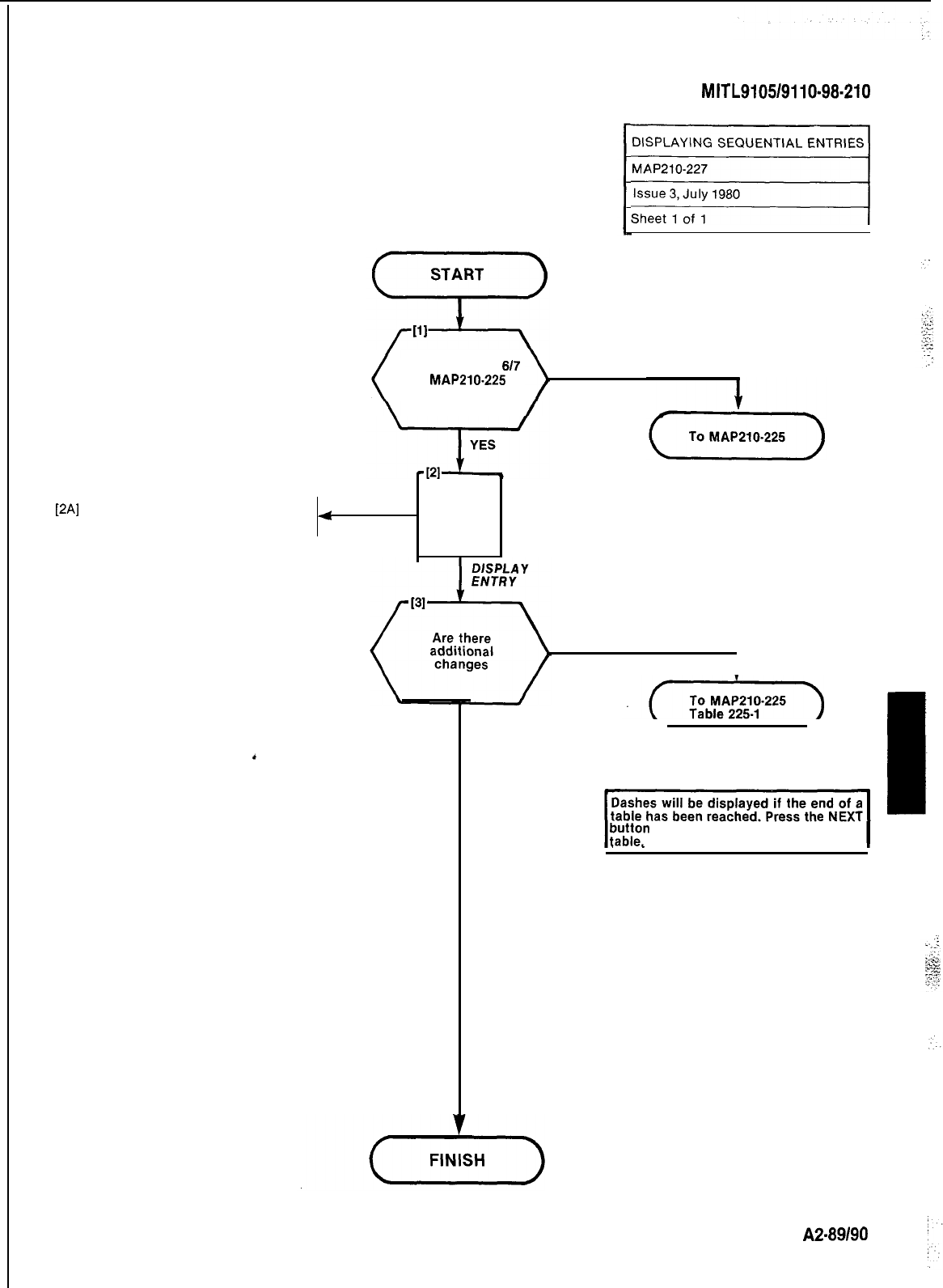
SECTION
MITL9105/9110-98-210
DISPLAYING SEQUENTIAL ENTRIES
iiij=q
Have steps 1 to
617
of
MAP210.225
been completed
NO
[2A]
Press NEXT button
.Next sequential entry displayed
4
AND
.
YES
1
NO
NOTE
;i;;m
to get back to the start of the
A2-89190
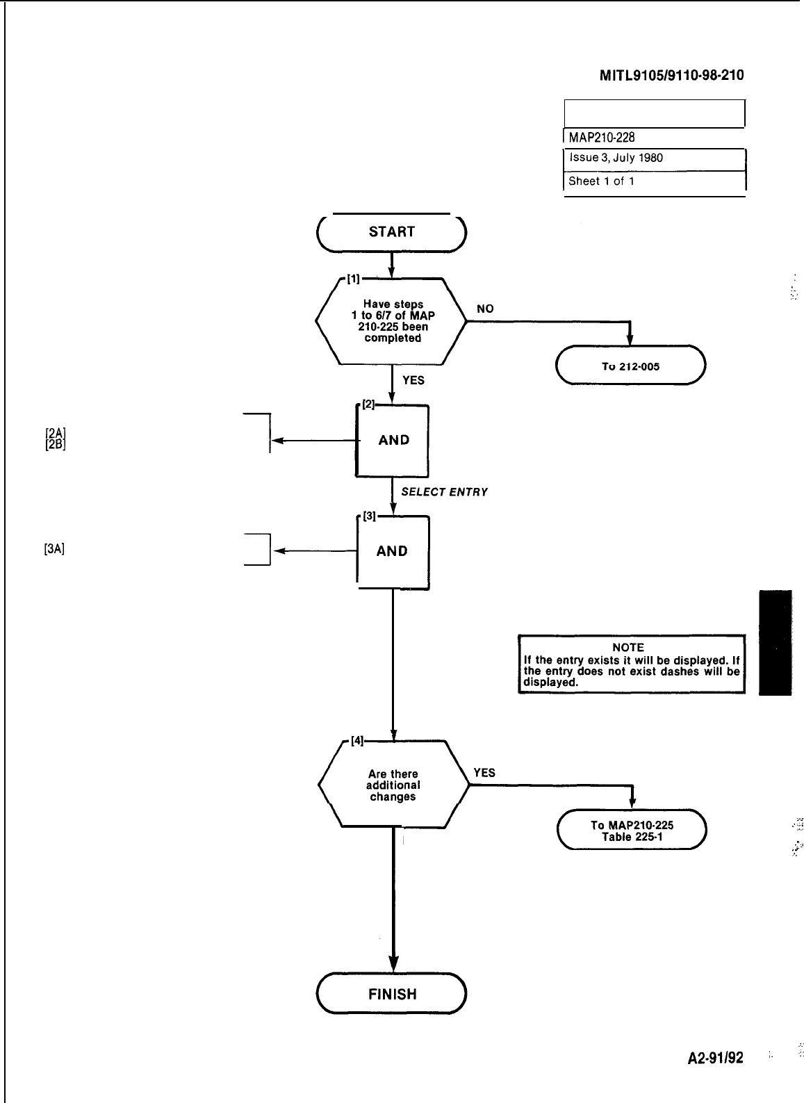
SECTION
MITL9105/9110~98-210
SEARCH FOR AN ENTRY
1
MAP210-228
I
:
:.
::
:
-.
[2A]
Press DISPLAY ENTRY button
[26]
Dial Entry digits
[3A]
Push DISPLAY ENTRY button
,4--~[31zq
-
DISPLAY ENTRY
NO
(T$g--)
-<
..
,:
.
-.
1
.
..:
A2-9,,92
:.
.:
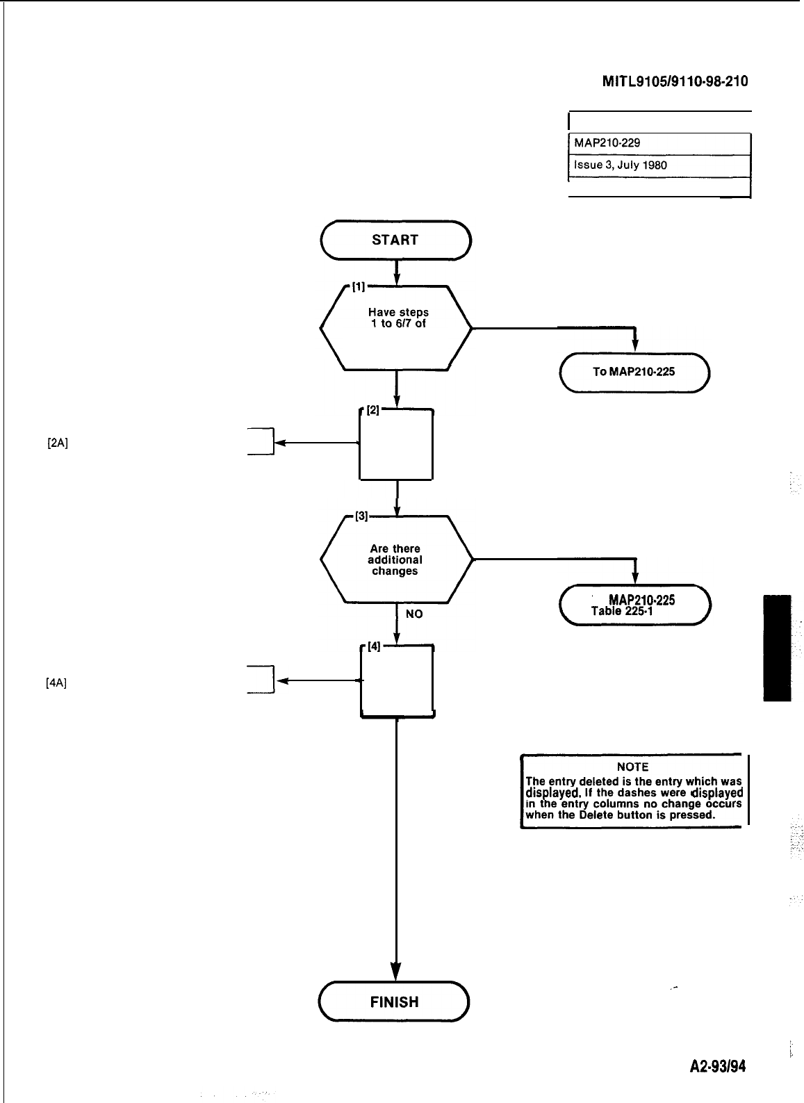
[2A]
Press DELETE button
SECTION
MITL9105/9110-98-210
I
DELETE AN ENTRY
I
Sheet 1 of 1
MAP210-225
been completed
1
AND
l
DELETE DATA
[4A]
Press ENTER button
YESYES
To
MAP210.225
To
MAP210.225
-
AND
-
AND
ENTER DELETION DATA
The entry deleted is the entry which was
v
dlsplayed.
If the dashes were
dlsplayed
in the entry columns no change occurs
when the Delete button is pressed.
/.
A2-93194
1
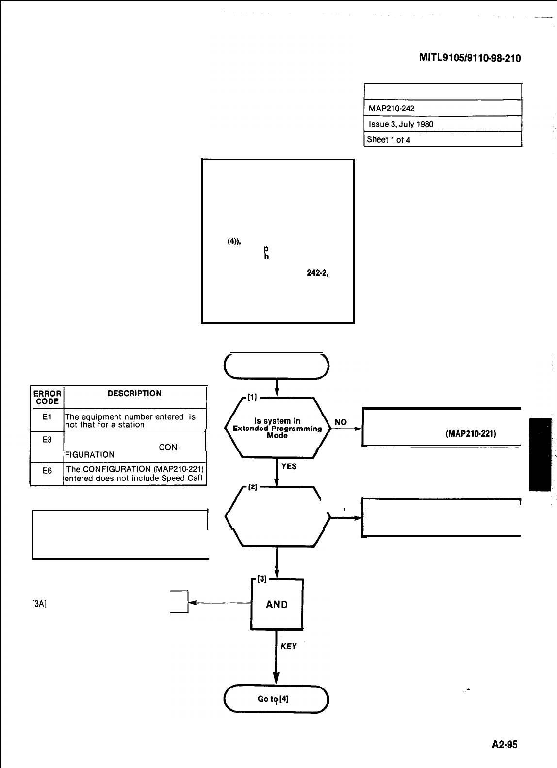
TABLE 242-l
NOTES
1. Prior to making programming en-
tries on this MAP, Form SC-2 must
have been completed. The completed
form is used in conjunction with the
relevant steps noted in this MAP.
2. After digit entries are made (e.g.
Step
(4)),
the bell may ring and an er-
ror code may a
TION display w
PI
pear in the DESTINA-
en the key in the next
sequence is pressed. In this event
refer to Tables 242-l or
242.2,
and
repeat the sequence, i.e. the relevant
function key and its digit entries, in
order to correct the previous entry.
Fig. 242-2 shows a typical error code
entry.
11
The equipment number entered is
The table number entered is not
valid for the current size
CON-
START
[3A]
Press TABLE key
1 PROGRAMMING PERSONAL TABLES 1
SECTION
MITL9105/9110-98.210
4
/
Press SPEED \YES
NOTE CALL key. Does
bell ring
The SPEED CALL LED remains lit during
programming in the Speed Call mode. I
u
I
NO
Place System In Extended
Programming Mode
(MAP210-221)
I
DESTINATION display shows E6. Refer
to Table 242-l
I
PRESS TABLE
.-
A2-95
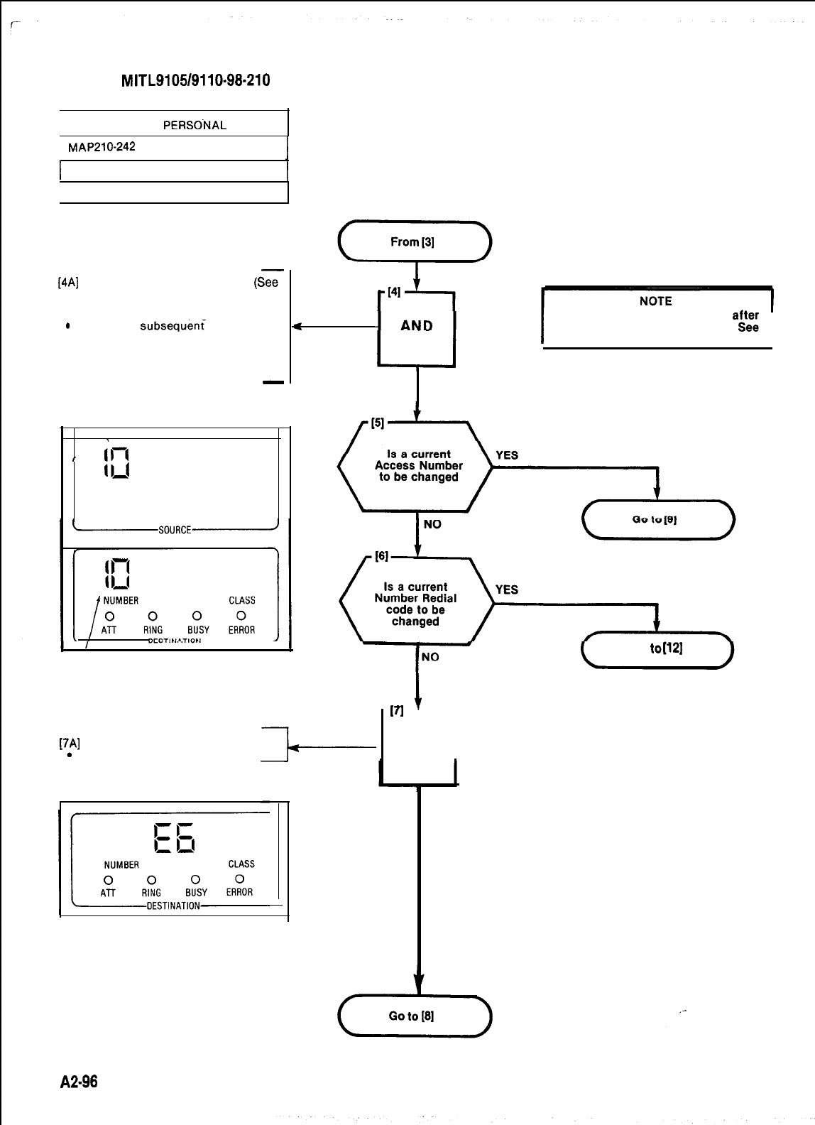
SECTION
MITL9105/9110-98-210
PROGRAMMING
PERSO.NAL
TABLES
r
MAP210-242
1 Issue 3, July 1980
Sheet 2 of 4
[4A]
Enter Table number required
(See
Form SC-2)
.DESTINATION display shows
number entered (Fig. 242-l)
.
When a
subsequ&i
Key opera-
tion occurs the number is
transferred to the SOURCE
display and three hyphens ap-
pear as shown in Fig. 242-l)
-
SPEED CALL
TABLE NUMBER
,
b-4
o,l
---
NUMBER CLASS
00 00 0
ATT
INT
RCL DID
MAN
Go
to[12]
DIAL TABLE
NUMBER
I
Error E3 (Table 242-l) may occur
at;;
a subsequent key operation.
Note 2 and Fig. 242-2
I
ECHOED
DIGITS
Fig. 242-l Typical Entry Displays
i7p1
Press EQPT NUMBER key
EQPT NUMBER LED is lit
Fig. 242.2
Typical Error Code Display
A2-98
III
1
AND
PRESS EQPT
NUMBER KEY
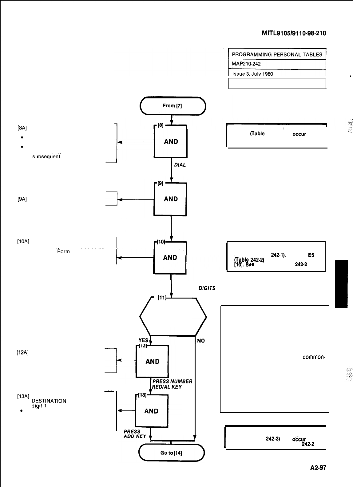
PAI
.
.
Dial equipment number digits for
selected table
DESTINATION display shows
dialed digits
SOURCE display shows digits
entered (Fia. 242-3) when a
subsequeni
key operation occurs
-
I
D/AL
EQUIPMENT
NUMBER DIGITS
[9A]
Press ACCESS NUMBER key
+qlAg
I
PRESS ACCESS
NUMBER KEY
[lOA]
Dial first speed call access
number diaits for the selected 1
table (see
Form
SC-2)
.DESTINATION display shows
dialed digits (Fig. 242-3) in first I
two positions which go to the
last two positions when a subse-
quent key operation occurs
ll2Al
Press Number Redial Key
It-
-
[l3A]
Press ADD key
.
fX~T;NATION
display shows
-a--
.
SOURCE display shows digit 1
where a subsequent key opera-
tion occurs
I
DIAL ACCESS
NUMBER
DiGiTS
/
[111
1
Is Number
Redial to be
used for this
Station
SECTION
MITL9105/9110-98.210
.
Sheet 3 of 4
I
NOTE
Error El
(Table
242-l) may
oCcur
after a
subsequent key operation. See Note 2
and Fig. 242-2.
I
I
NOTE
Error El (Table
242-l),
or Error
E5
may occur after Step
)e
Note 2 and Fig.
242-2
Table 242-2
ERROR
CODE DESCRIPTION
E4
Indicates attempt to enter access
number (Step 10) for a common-use
table
E4
Indicates attempt made to allocate
number redial digits in a
common-
use table (Step 12)
E5
Indicates number redial already ex-
ists for another table (Step 13)
assigned to the same equipment
E5
Indicates access number (Step 10)
already exists for another table
assigned to the equipment
.
_..
I
NOTE
Error E5 (Table
242-3)
may
o6cur
after
Step (13). See Note 2 and Fig.
242.2
I
A2-97
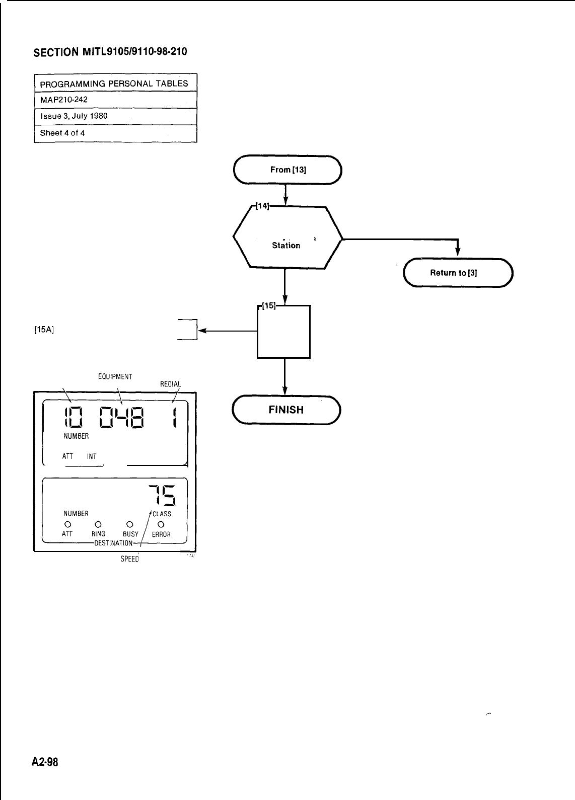
SECTION
MITL9105/9110-98-210
[15A]
Press ENTER key
CLASS
0 0 0 0 0
RCL
DID
MAN
SOURCE
TABLE EOUIPMENT
NUMBER
NUMBER NUMBER
REOIAL CODE
Are all tables
entered for this NO
YES
-1151
’
AND
PRESS ENTER
KEY
SPEEd CALL
ACCESS NUMBER
Fig. 242-3 Completed Entries Dislay
A2-98
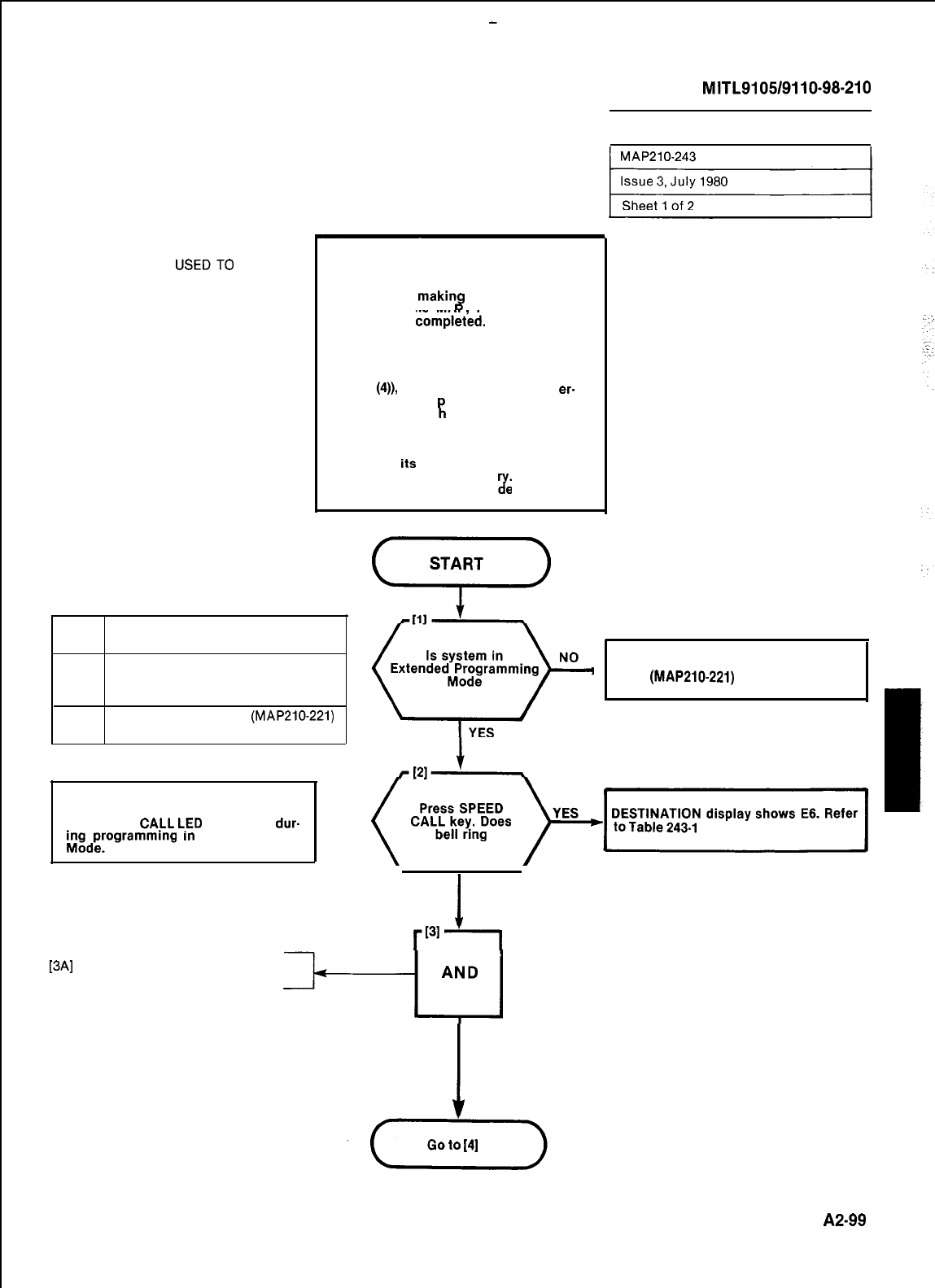
COMMON-USE TABLES DO NOT RE-
QUIRE PROGRAMMING. THIS MAP IS
THE PROCEDURE
USEDTO
CONVERT
A PERSONAL TABLE TO A COMM-USE
TABLE.
SECTION
MITL9105/9110-98.210
CONVERT TABLE FROM PERSONAL TO
COMMON-USE
NOTES
1. Prior to
makin
tries on this MA
8
programming en-
Form SC-2 must
have been
compleied.
The completed
form is used in conjunction with the
relevant steps noted in this MAP.
2. After digit entries are made (e.g.
Step
(4)),
the bell may ring and an
er.
ror code may a
TION display w
rl
pear in the DESTINA-
en the key in the next
sequence is pressed. In this event
refer to Table 243-1, and repeat the
sequence, i.e. the relevant function
key and
Its
digit entries, in order to
correct the previous ent
shows a typical error co
7.
Fig. 243-2
e entry.
TABLE 243-l
ERROR DESCRIPTION
CODE
E3
The table number entered is not Place System in Extended Programming
valid for the current size CON- * Mode
(MAP210-221)
FIGURATION
E6
The CONFIGURATION
(MAP210-221)
entered does not include Speed Call
NOTE
The SPEED
CA.LL
L-ED
remains lit
dur-
inidP,‘Ogrammmg
n-r
the Speed Call
DESTINATION display shows E6. Refer
(
cF;tpes
p+Izl-y
I
NO
Pi
[3A]
Press TABLE key
I
PRESS TABLE
KEY
A2-99
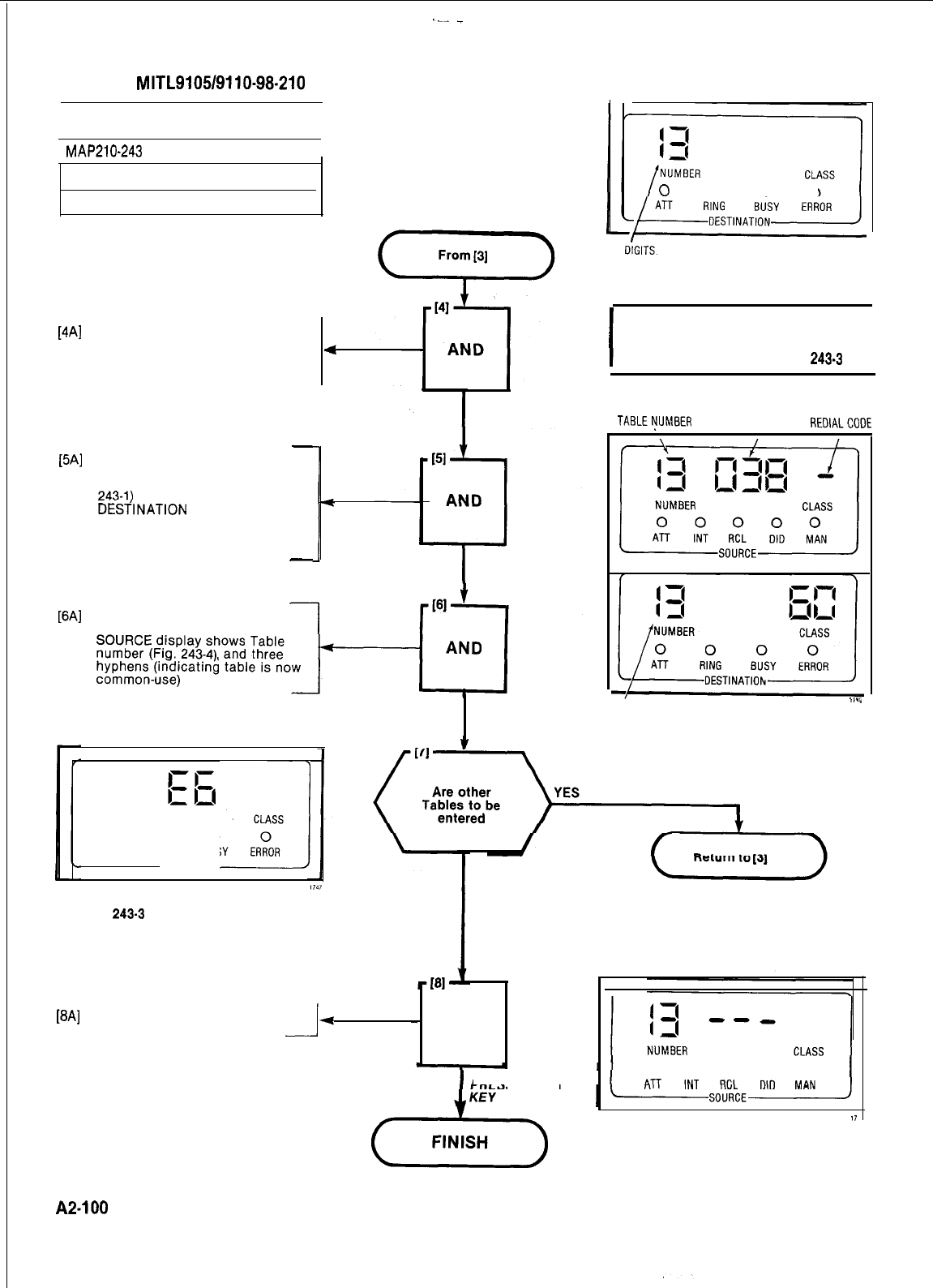
.--
_
SECTION
MITL9105/9110-98-210
CONVERT TABLE FROM PERSONAL TO
COMMON-USE
0
0 0 0
r
MAP210-243
I
Issue 3, July 1980
Sheet 2 of 2
DIALED
DIGITS.
Fig. 243-l Table
Number Display
I
NOTE
Error E3 (Table 003-l) may occur after
Step (4). See Note 2 and Fig.
243.3
I
Enter Table number required (See
Form SC-2)
DESTINATION display shows
number entered (Fig. 243-l).
[4Al
.
WI
.
.
WI
.
.
4
DIAL TABLE
NUMBER
SPEED CALL
TABLEt?JMEER
EQUIPMENT
NUMBER
NUMBER
REDIALCODE
-
Press EQPT NUMBER key
SOURCE display shows the data
associated with the table (Fig.
243-l)
DESilNATlON
display shows the
first access number of the table,
and the table number (Step 4)
disappears
-
I
PRESS EQPT
NUMBER KEY
Press DELETE key
DELETE LED is lit
PRESS DELETE
KEY
DIALED
,.."
DIGITS
Fig. 243-2
Typical Entry Displays
NUMBER
J
CLASS
0 00 0
ATT RING
BUSY
ERROR
DESTINATION
NO
Fig.
243-3
Typical Error Code
Display
[8A]
Press ENTER key
-I-
-
AND
PRESS ENTER
A2-100
0 0 0 0 0
17
Fig. 243-4
Completed Entry Display
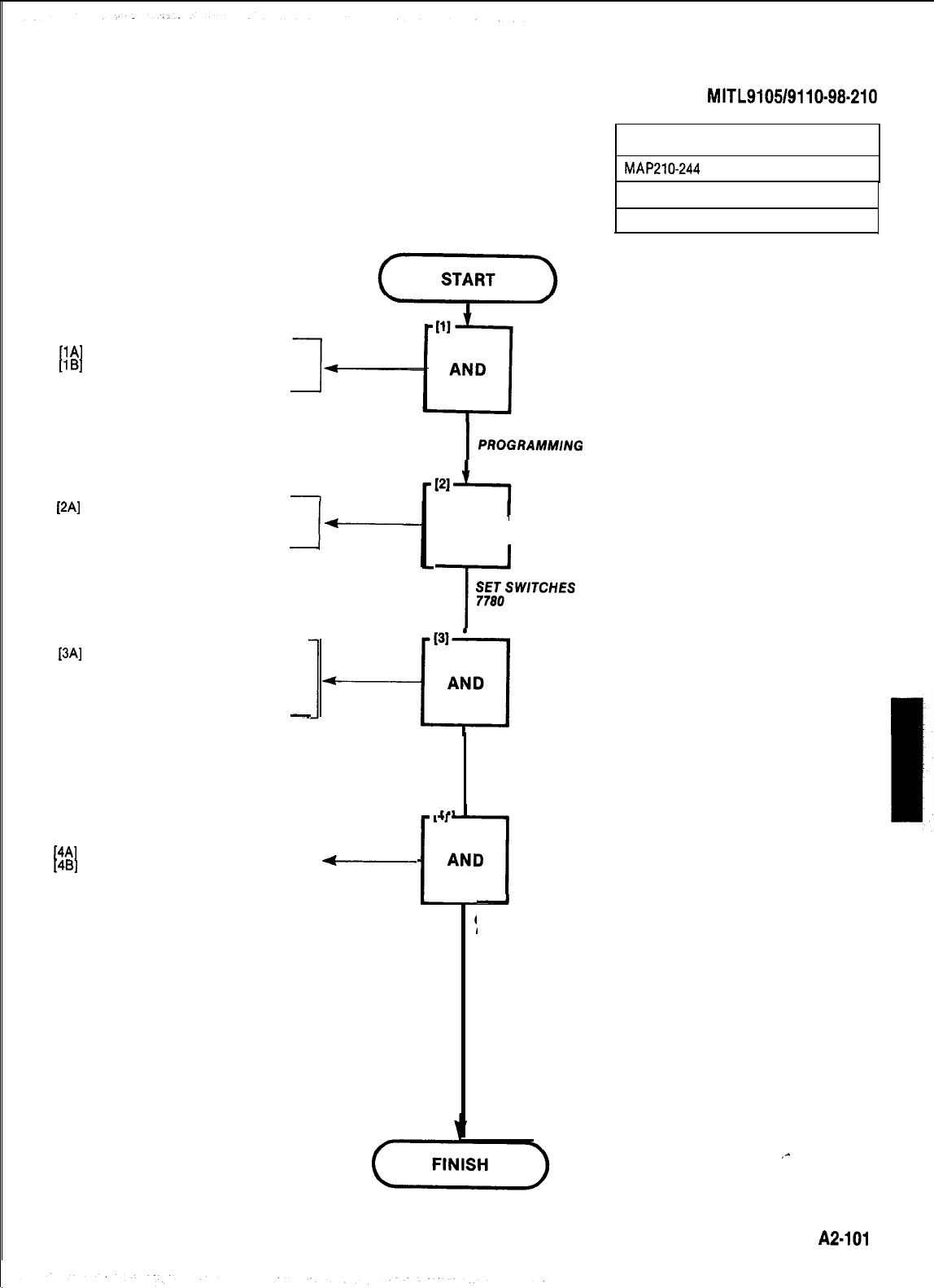
SECTION
MITL9105/9110-98-210
[lA]
Press the LAMP TEST button
[lB]
Press the NEXT button
.
LAMP TEST LED solid
[2A] Set the thumbwheel switches on
Tone Control card (card position
18, yellow) to 7780
*p
[3A]
Press SYSTEM MASTER RESET
button on Scanner card (card
position 19, orange)
.
System is taken out of the pro-
gramming mode
-
TERMINATING PROGRAMMING
MAP210-244
Issue 3, July 1980
Sheet 1 of 1
ENTER STANDARD
PROGRAMMlNG
MODE
AND
I
T’
;;;oSWITCHES
TO
[4A] Enter time on console display
[4B]
Close and lock the cabinet doors
7
-
-
141
’
-
AND
,l
t
1
I
CLOSE AND
LOCK CAB/NET
RESET SYSTEM
,-
A2-101
:
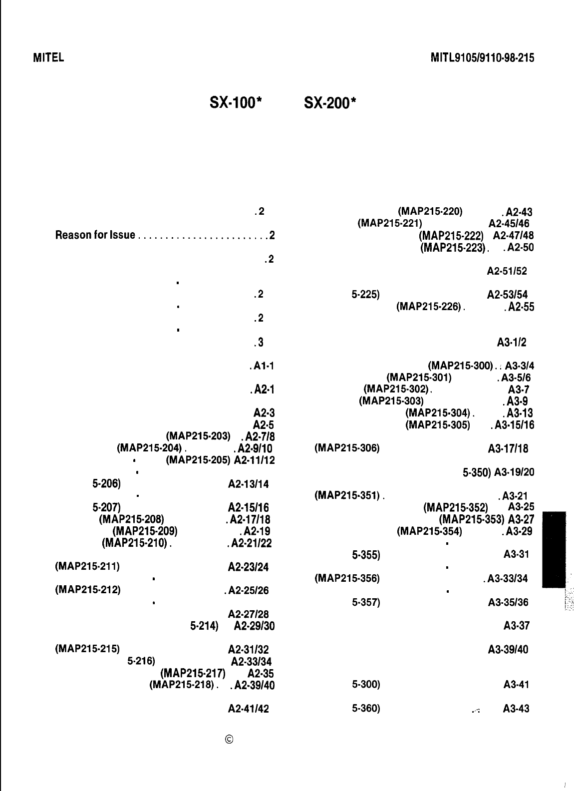
MITEL
STANDARD PRACTICE SECTION
MITL9105/9110~98-215
Issue 2, July 1980
SX-lOO*
AND
SX-200*
SUPERSWITCH”
ELECTRONIC PRIVATE AUTOMATIC BRANCH EXCHANGE
SYSTEM TEST PROCEDURES
CONTENTS PAGE
1.
INTRODUCTION . . . . . . . . . . . . . . . . . . . . . . . .2
General . . . . . . . . . . . . . . . . . . . . . . . . . . . . ...2
Reasonforlssue........................2
2.
DETAILED TEST PROCEDURES . . . . . . . . . . .2
General . . . . . . . . . . . . . . . . . . . . . . . . . . . . ...2
System Test Procedures
-
Generic 202
Equipment. . . . . . . . . . . . . . . . . . . . . . . . . . . . .2
System Test Procedures
-
Generic 203
Equipment. . . . . . . . . . . . . . . . . . . . . . . . . . . . .2
System Test Procedures
-
Generic 204
Equipment. . . . . . . . . . . . . . . . . . . . . . . . . . . . .3
APPENDIX 1 MITEL ACTION PROCEDURES
.Al-1
APPENDIX 2 GENERIC 202 SYSTEM TESTS. .A2-1
Set Up Test Equipment (MAP215201). . . . A2-3
Test Extension Options (MAP215202) . . .
A25
Test Console Features (MAP215.203) . .A2-7/8
Broker’s Call (MAP215-204). . . . . . . . . .A2-9/10
Call Forwarding
-
Busy (MAP215-205)
A2-11112
Call Forwarding
-
Don’t Answer
(MAP21 5.208) . . . . . . . . . . . . . . . . . . . . A2-13/14
Call Forwarding
-
Follow Me
(MAP21 5-207) . . . . . . . . . . . . . . . . . . . . A2-15/18
Call Park (MAP215-208) . . . . . . . . . . . .A2-17118
Call Pick-up (MAP215-209) . . . . . . . . . . . .A2.19
Camp-On (MAP215-210). . . . . . . . . . . .A2-21/22
Consultation Hold/Transfer/Add-On
(MAP215-211) . . . . . . . . . . . . . . . . . . . .
A2-23124
Automatic Callback
-
Don’t Answer
(MAP215-212) . . . . . . . . . . . . . . . . . . . .A2-25/28
Automatic Callback
-
Busy
(MAP21 5-213) . . . . . . . . . . . . . . . . . . . .
A2-27128
Meet-Me Conference (MAP21 5-214) . .
A2-29130
Executive Busy Override
(MAP215-215) . . . . . . . . . . . . . . . . . . . .
A2-31132
Paging (MAP21
5-218)
. . . . . . . . . . . . . .
A2-33134
Answer Incoming Call (MAP215-217) . . . A2-35
Automatic Callback (MAP215-218). . .A2-39/40
Extending Internal Calls
(MAP21 5-219) . . . . . . . . . . . . . . . . . . . . A2.41/42
CONTENTS PAGE
Answering Recall (MAP215.220) . . . . . . .A2-43
Override (MAP215-221) . . . . . . . . . . . . A2-45/48
Flexible Night Service (MAP215-222) . A2-47/48
Trunk Busy Operation (MAP215-223). . . .A2-50
Trunk Group Attendant Access
(MAP21 5-224) . . . . . . . . . . . . . . . . . . . .
A2-51152
Trunk Group Dial Access
(MAP21 5-225) . . . . . . . . . . . . . . . . . . . . A2-53/54
Test Termination (MAP215-226). . . . . . . .A2-55
APPENDIX 3 GENERIC 203 SYSTEM
TESTS . . . . . . . . . . . . . . . . . . . . . . . . . . . . . . . .
A3-l/2
Test Extension Options (MAP215-300).
:
A3-3/4
Do Not Disturb (MAP215-301) . . , . . . . . .A3-5/6
Call Block (MAP215-302). . . . . . . . . . . . . . . A3-7
Call Hold (MAP215-303) . . . . . . . . . . . . . . .A3=9
Single Digit Dialing (MAP215-304). . . . . .A3-13
Transfer Into Busy (MAP215-305) . . . .A3-15/16
Common Alerting Devices
(MAP215-306) . . . . . . . . . . . . . . . . . . . .
A3-17118
Test Console Features (MAP21 5-350) A3-19/20
Answer Incoming CO Trunk Call
(MAP215-351). . . . . . . . . . . . . . . . . . . . . . .A3-21
Answer DID Trunk Call (MAP215-352) . . . A3-25
Attendant Do Not Disturb (MAP215-353) A3-27
Message Waiting (MAP215-354) . . . . . . .A3-29
Attendant Call Forwarding
-
Busy
(MAP21 5-355) . . . . . . . . . . . . . . . . . . . . . . .
A3-31
Attendant Call Forwarding
-
Don’t Answer
(MAP215-356) . . . . . . . . . . . . . . . . . . . .A3-33134
:
Attendant Call Forwarding
-
Follow Me
I
(MAP21 5.357) . . . . . . . . . . . . . . . . . . . . A3-35/36
;.
Attendant Controlled Conference
I,:;’
1
”
(MAP21 5-358) . . . . . . . . . . . . . . . . . . . . . . . A3-37
Attendant Station Busy-Out
(MAP21 5-359) . . . . . . . . . . . . . . . . . . . .
A3-39140
i
Test Console Features (H/M)
(MAP21 5-300) . . . . . . . . . . . . . . . . . . . . . . .
A3-41
:
Attendant Do Not Disturb (H/M)
(MAP21 5-360) . . . . . . . . . . . . . . . . .
.,<
. . . . A3-43
0
MITEL Corporation 1980
l
Trademark of MITEL Corporation
Page 1 i
I
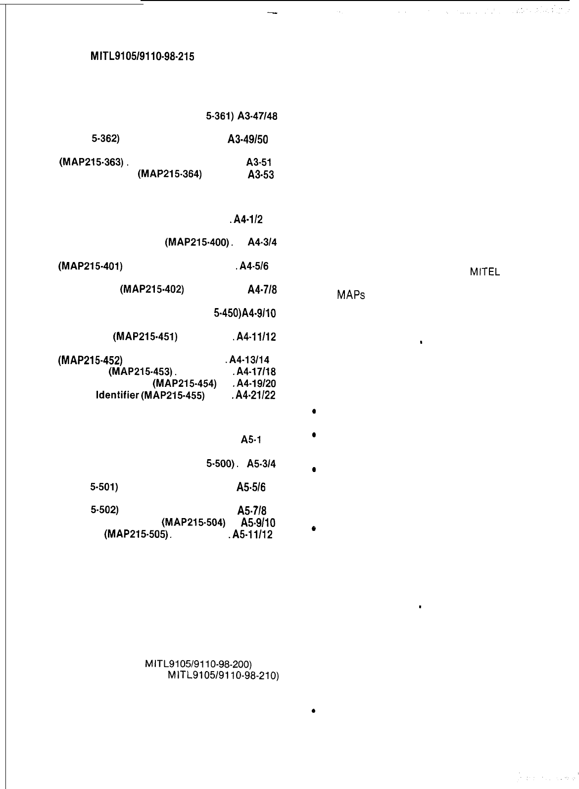
--
SECTION
MITL9105/9110-98-215
CONTENTS PAGE
Message Waiting (H/M) (MAP21
5-361)
A3-47148
Message Registration
(MAP21
5362)
. . . . . . . . . . . . . . . . . . . . A3-49150
Controlled Outgoing Call Restriction (H/M)
(MAP215-363).
. . . . . . . . . . . . . . . . . . . . . . A3-51
Room Status (H/M)
(MAP215-364)
. . . . . .
A3-53
Reason for Issue
1.02 This section is issued to incorporate pro-
cedures for Generic 205 information.
1.03
It should be noted that a particular system
test is valid only if the required option(s)
has been programmed to satisfy the system test
result.
APPENDIX 4 GENERIC 204 SYSTEM
TESTS. . . . . . . . . . . . . . . . . . . . . . . . . . . . . . . .A4-112
2. DETAILED TEST PROCEDURES
Test Extension Option
(MAP215-400).
. .
A4-314
Automatic Wake-Up (Alarm Call)
(MAP215-401)
. . . . . . . . . . . . . . . . . . . . .
.A4-5/6
Enable Non-CO Trunk to
Trunk Connect
(MAP215-402)
. . . . . . . . . A4-718
General
2.01
All test procedures in this Section are per-
formed in accordance with
MITEL
Action
Test Extensions Options (MAP21
5-450)A4-9110
Console Date Display and
Date Utility
(MAP215-451)
. . . . . . . . .
.A4-11112
Customer Program Dump/Load
(MAP215-452)
. . . . . . . . . . . . . . . . . . . .A4-13114
Room Audit
(MAP215-453).
. . . . . . . .
.A4-17/18
Automatic Wakeup
(MAP215-454)
. .
.A4-19120
System
ldentifier(MAP215.455)
. . . .
.A4-21/22
Procedures (MAPS). An outline of the purpose and
use of
MAPS
is contained in Appendix 1. Actual
system test procedures to be used for the PABX
are as detailed in the following paragraphs.
System Test Procedures
-
Generic 202 Equipment
2.02
The system test procedures for Generic 202
equipment are detailed in Appendix 2. Pro-
cedures are performed in a set order as follows:
0
Set up the required test conditions
APPENDIX 5 GENERIC 205 SYSTEM
TESTS . . . . . . . . . . . . . . . . . . . . . . . . . . . . . . . . . A5-1
0
Perform the tests required for extension
features
Test Extension Options (MAP21
5-500).
.
A5-3/4
Use a Personal Speed Call
(MAP21
5-501)
. . . . . . . . . . . . . . . . . . . . . .
A5-5/6
Use a Common Use Speed Call
(MAP21
5-502)
. . . . . . . . . . . . . . . . . . . . . . A5-718
Test Console Options
(MAP215-504)
. .
A5-9/10
Speed Call
(MAP215-505).
. . . . . . . . .
.A5-11/12
0
Perform the tests required for console
features
lRemove the test conditions
0
Perform a final console “lamp-test”
verification
1. INTRODUCTION
These procedures are listed in Tables 2-1 and 2-2
in addition to appearing in Appendix 2.
General
System Test Procedures
-
Generic 203 Equipment
1.01 This Section details the system test pro-
cedures to be performed after the system
installation (Section
MITL9105/9110-98-200)
and
programming (Section
MITL9105/9110-98-210)
have been completed. Upon completion of the
tests listed in this Section all programmed system
options and features will have been checked.
2.03 The system test procedures for Generic 203
equipment are detailed in Appendix 3. Pro-
cedures are similar to those performed for
Generic 202 equipment, but are modified due to
the fact that Generic 203 equipment can provide
three basic configurations which are:
0
A standard single customer configuration
Page 2
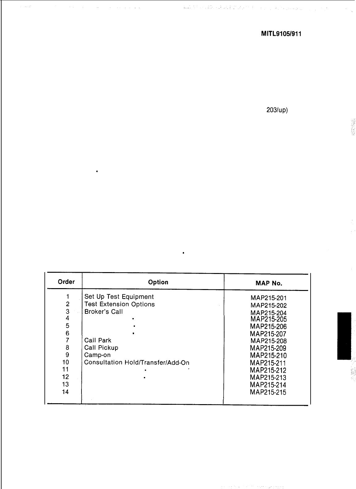
lA system configured for use with more than 2.08 The system test procedures for Generic 205
one customer (tenant) equipment are detailed in Appendix 5. Pro-
l A system configured to provide facilities
which are peculiar to a hotel or motel en-
vironment
cedures are similar to Generics 203 and 204 but
are modified for the additional features in Generic
205.
2.04 The pattern of test procedures for Generic
203 equipment closely parallels that shown
in 2.02, with the exception, that in so far as the
console tests are concerned a choice of pro-
cedures is given; ie. the choice is dependant upon
whether the system has been programmed with or
without “hotel/motel” features. Tables 2-3 and 2-4
list the procedures to be followed with Table 2-4
listing the choice of console features.
System Test Procedures
-
Generic 204 Equipment
2.05
The system test procedures for Generic 204
equipment are detailed in Appendix 4. Pro-
cedures are similar to those performed for
Generic 203 but are modified for the additional
features in Generic 204.
2.07 Where several customers (tenants) share
one PABX (Generic
2031~~)
then the test
procedures to be performed (listed in Tables 2-3,
2-4, 2-5, 2-6, 2-7 and 2-8) are in respect to the “Non-
Hotel/Motel” options, ie. they are the same as for
a single customer configuration. It should be
noted however that the console SOURCE and
DESTINATION displays, during the test pro-
cedures, will reflect the fact that a multi-tenant
configuration is in effect. These displays will
show the “tenant” digit which prefixes the exten-
sion number. A typical example of this difference
is illustrated in Figs. 2-1 and 2-2, respectively
showing a single customer extension display, and
a display which indicates that the calling exten-
sion (333) forms part of Tenant group 2.
SECTION
MITL9105/911
O-98-21 5
TABLE 2-l
GENERIC 202 EQUIPMENT
-
EXTENSION OPTIONS
TEST ORDER
Call Forwarding
-
Busy
Call Forwarding
-
Don’t Answer.
Call Forwarding
-
Follow Me
Automatic Callback
-
Don’t Answer
Automatic Callback
-
Busy
Meet-Me Conference
Executive Busy Override
MAP215-205
MAP215-206
MAP215-207
MAP215-208
MAP215-209
MAP215-210
MAP215-211
MAP215-212
MAP215-213
MAP215-214
MAP215-215
Page3 :
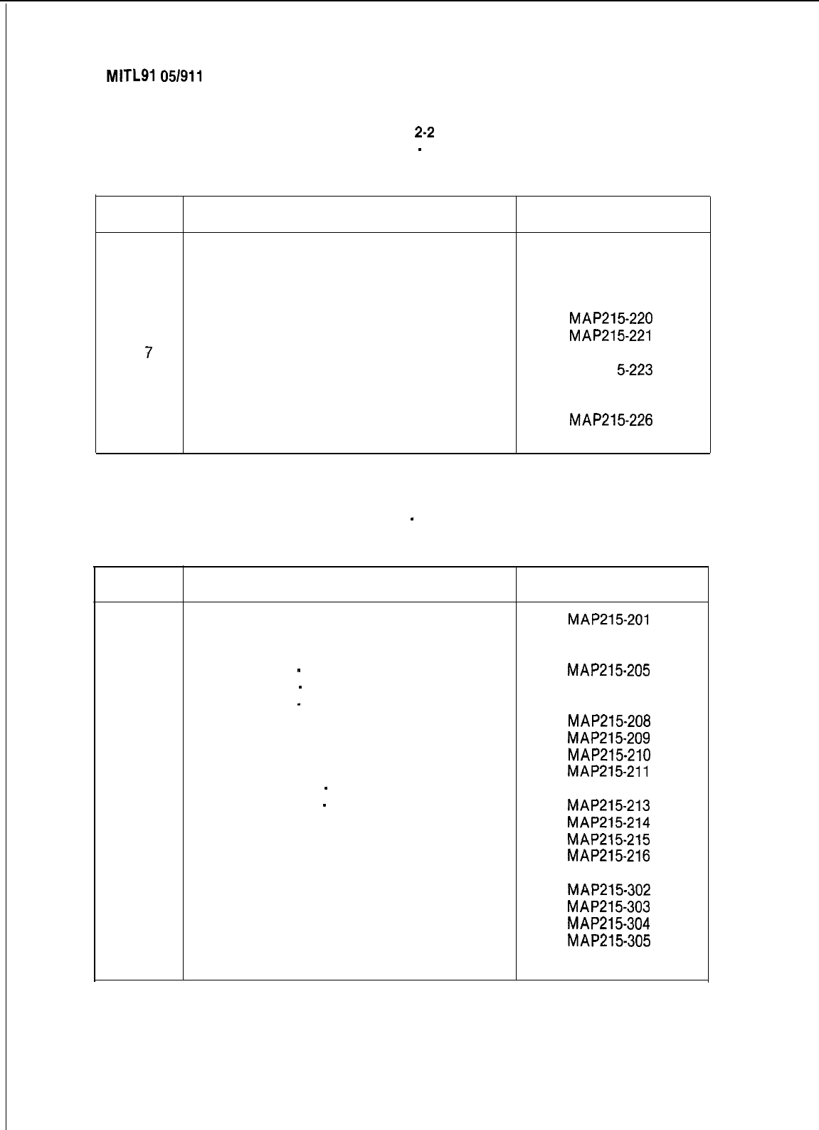
SECTION
MITLSI
05/911 O-98-21 5
TABLE
2-2
GENERIC 202 EQUIPMENT
-
CONSOLE OPTIONS
TEST ORDER
Order
Option MAP No.
1
Test Console Features MAP215203
2
Answer Incoming Call MAP215217
3
Automatic Callback MAP215218
4
Extending Internal Calls MAP215219
5
Answering a Recall
MAP215-220
6
Override
MAP215-221
7
Flexible Night Service
MAP21 5-222
8
Trunk Busy Operation
MAP21
5-223
9
Trunk Group Attendant Access
MAP21 5-224
10
Trunk Group Dial Access
MAP21 5-225
11
Test Termination
MAP215-226
TABLE 2-3
GENERIC 203 EQUIPMENT
-
EXTENSION OPTIONS
TEST ORDER
Order
Option MAP No.
1
Set Up Test Equipment
MAP215-201
2
Test Extension Options
MAP21 5-300
3
Broker’s Call
MAP21 5-204
4
Call Forwarding
-
Busy
MAP215-205
5
Call Forwarding
-
Don’t Answer
MAP21 5-206
6
Call Forwarding
-
Follow Me
MAP21 5-207
7
Call Park
MAP215-208
a
Call Pick-Up
MAP215-209
9
Camp-On
MAP215-210
10
Consultation Hold/Transfer/Add-On
MAP215-211
11
Automatic Callback
-
Don’t Answer MAP215212
12
Automatic Callback
-
Busy
MAP215-213
13
Meet Me Conference
MAP215-214
14
Executive Busy Override
MAP215-215
15
Paging
MAP215-216
16
Do Not Disturb
MAP21 5-301
17
Call Block
MAP215-302
18
Call Hold
MAP215-303
19
Single Digit Dialing
MAP215-304
20
Transfer Into Busy
MAP215-305
21
Common Alerting Devices
MAP21 5-306
Page 4
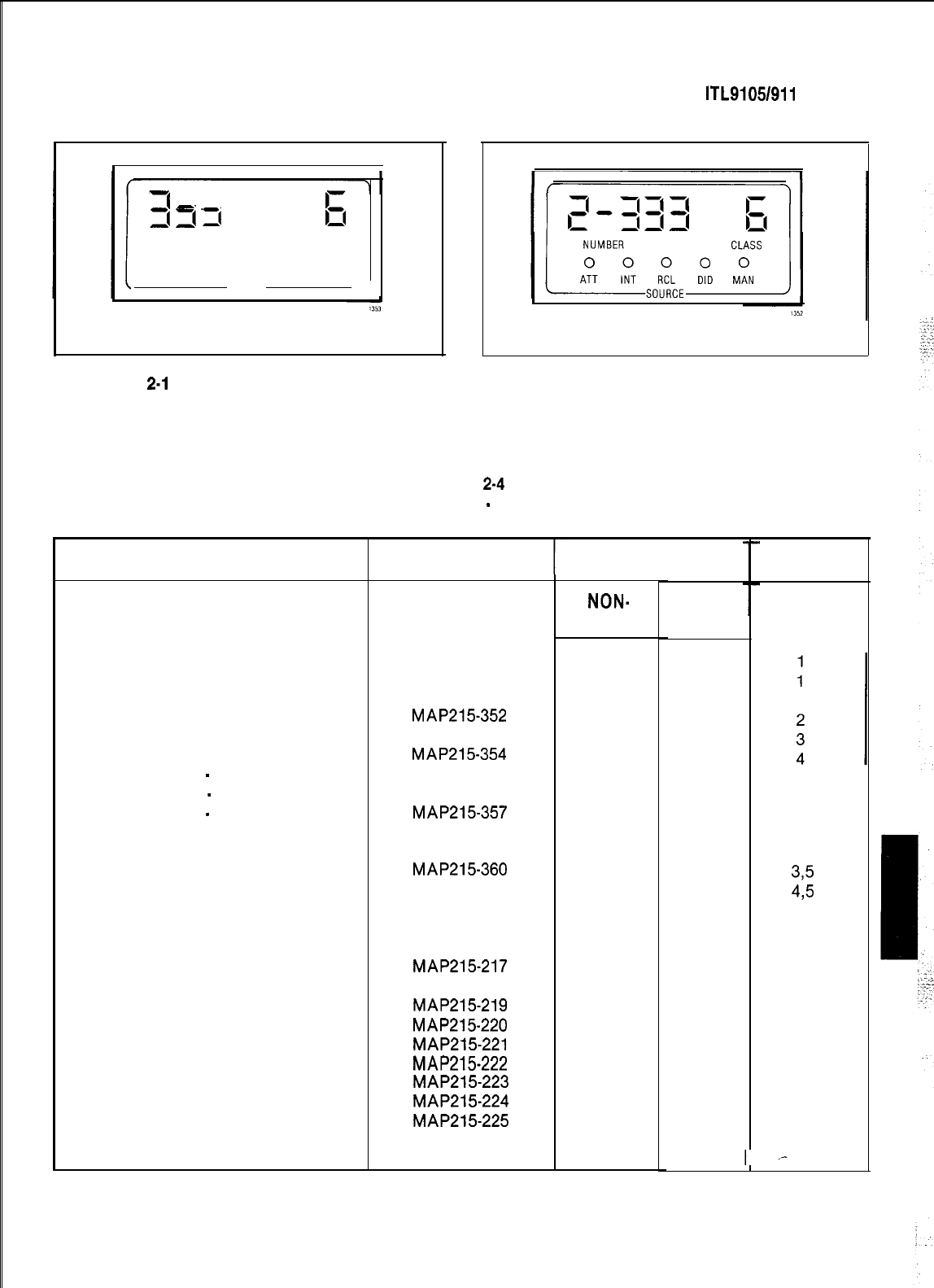
3
,I
‘I(
7
3
6
NUMBER
CLASS
0 0 0 0 0
ATT INT RCL DID
MAN
SOURCE
Fig.
2-l
Single Customer Display
OPTION
SECTION M ITL9105/911 O-98-21 5
Fig. 2-2 Multi-Tenant Display
TABLE
2-4
GENERIC 203 EQUIPMENT
-
CONSOLE OPTIONS
TEST ORDER
Test Console Features
Test Console Features
Answer CO Trunk Call
Answer DID Trunk Call
Attendant Do Not Disturb
Message Waiting
Call Forwarding
-
Busy
Call Forwarding
-
Don’t Answer
Call Forwarding
-
Follow Me
Attendant Controlled Conference
Attendant Station Busy-Out
Attendant Do Not Disturb
Message Waiting
Message Registration
Controlled Outgoing Restriction
Room Status
Answer Incoming Call
Automatic Callback
Extending Internal Calls
Answering a Recall
Override
Flexible Night Service
Trunk Busy Operation
Trunk Group Attendant Access
Trunk Group Dial Access
Test Termination
MAP NO.
T
MAP215350
MAP215300
MAP215351
MAP215-352
MAP215353
MAP215-354
MAP21 5-355
MAP21 5-356
MAP215-357
MAP21 5-358
MAP21 5-359
MAP215-360
MAP21 5-361
MAP21 5-362
MAP21 5-363
MAP21 5-364
MAP215-217
MAP215218
MAP215-219
MAP215-220
MAP215-221
MAP215-222
MAP215-223
MAP215-224
MAP215-225
MAP21 5-226
ORDER
NON-
H/M
1
2
3
4
5
6
7
8
9
10
11
12
13
14
15
16
17
18
19
H/M
1
2
3
4
5
6
7
8
9
11
12
13
14
15
16
17
18
19
20
21
22
23
24
NOTES
375
495
5
5
5
6
Page 5
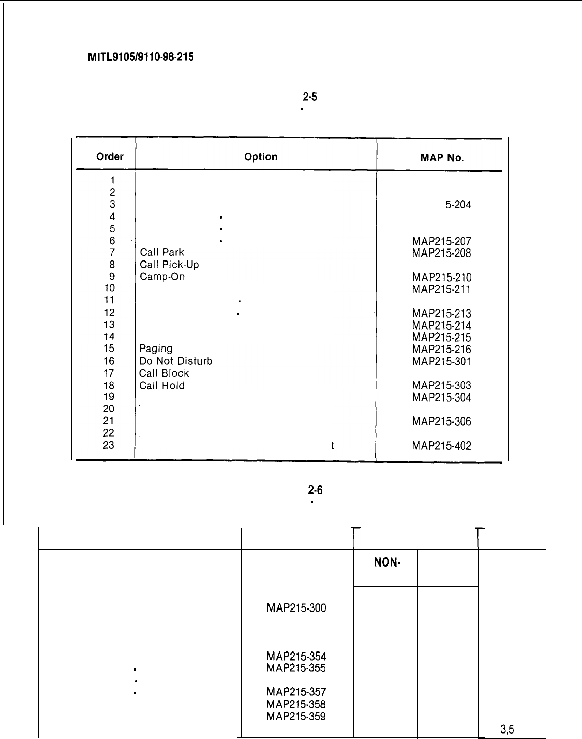
SECTION
MITL9105/9110-98-215
TABLE
2-5
GENERIC 204 EQUIPMENT
-
EXTENSION OPTIONS
TEST ORDER
Set Up Test Equipment
Test Extension Options
Broker’s Call
Call Forwarding
-
Busy
Call Forwarding
-
Don’t Answer
Call Forwarding
-
Follow Me
Consultation Hold/Transfer/Add-On
Automatic Callback
-
Don’t Answer
Automatic Callback
-
Busy
Meet Me Conference
Executive Busy Override
Single Digit Dialing
Transfer Into Busy
Common Alerting Devices
Automatic Wake-Up (Alarm Call)
Enable Non-CO Trunk to Trunk Connect
MAP215001
MAP215300
MAP21
5-204
MAP215205
MAP21 5-206
MAP215-207
MAP215-208
MAP21 5-209
MAP215-210
MAP215-211
MAP21 5-212
MAP215-213
MAP215-214
MAP215-215
MAP215-216
MAP215-301
MAP21 5-302
MAP215-303
MAP215-304
MAP21 5-305
MAP215-306
MAP21 5-401
MAP215-402
TABLE
2-8
GENERIC 204 EQUIPMENT
-
CONSOLE OPTIONS
TEST ORDER
OPTION
Test Console Features
MAP21 5-350
Test Console Features
MAP215-300
Answer CO Trunk Call
MAP21 5-351
Answer DID Trunk Call
MAP21 5-352
Attendant Do Not Disturb
MAP21 5-353
Message Waiting
MAP215-354
Call Forwarding
-
Busy
MAP215-355
Call Forwarding
-
Don’t Answer
MAP21 5-356
Call Forwarding
-
Follow Me
MAP215-357
Attendant Controlled Conference
MAP215-358
Attendant Station Busy-Out
MAP215-359
Attendant Do Not Disturb
MAP21 5-360
Page 6
MAP NO.
r
ORDER
NON-
H/M
1
2
3
4
5
6
7
8
9
10
HIM
1
2
3
4
5
6
7
8
9
11
NOTES
1
1
2
3
4
3,5
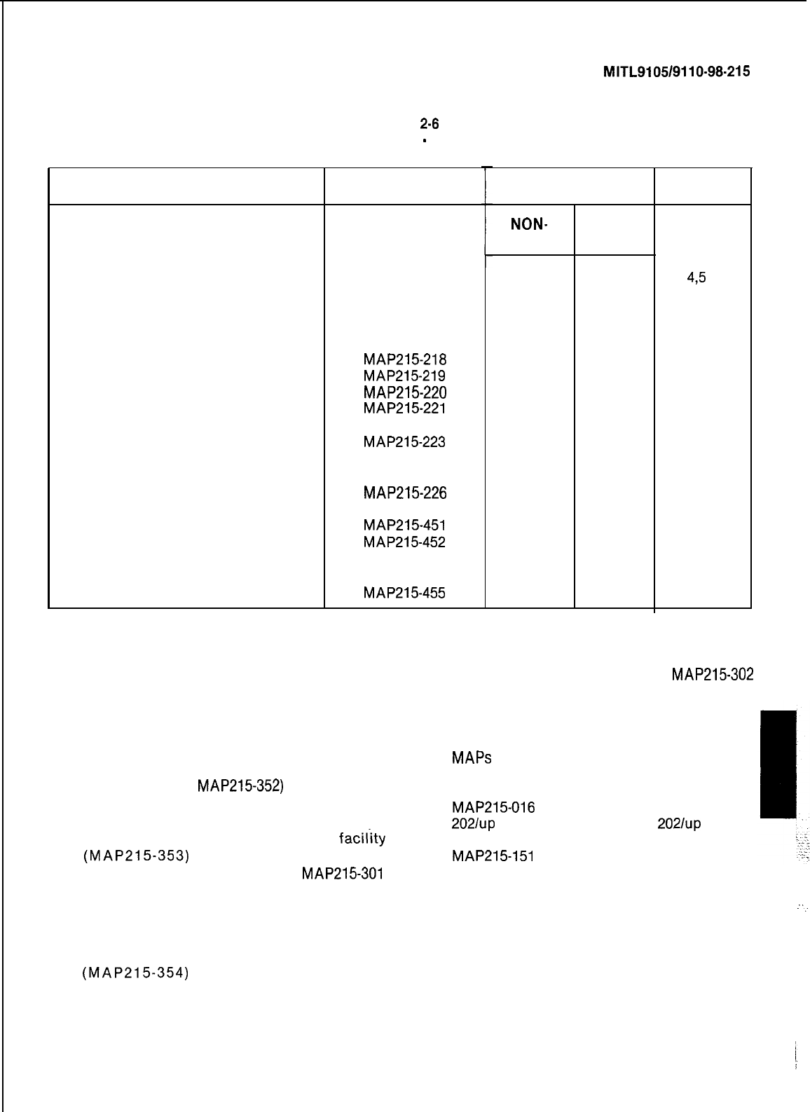
SECTION
MITL9105/9110-98-215
TABLE
2-8
GENERIC 204 EQUIPMENT
-
CONSOLE OPTIONS
TEST ORDER
OPTION MAP NO.
Message Waiting
Message Registration
Controlled Outgoing Restriction
Room Status
Answer Incoming Call
Automatic Callback
Extending Internal Calls
Answering a Recall
Override
Flexible Night Service
Trunk Busy Operation
Trunk Group Attendant Access
Trunk Group Dial Access
Test Termination
Console Date Display and Date
Utility
Customer Program Dump/Load
Room Audit
Automatic Wake-Up
System I.D.
MAP21 5-361
MAP21 5-362
MAP215363
MAP215364
MAP21 5-217
MAP215-218
MAP215-219
MAP215-220
MAP215-221
MAP21 5-222
MAP215-223
MAP21 5-224
MAP21 5-225
MAP215-226
MAP215-451
MAP215-452
MAP21 5-453
MAP21 5-454
MAP215-455
ORDER NOTES
NON-
H/M
11
16
12 17
13 18
14 19
15 20
16
21
17 22
18 23
19 24
20
21
22
24
25
27
28
NOTES
1.
The Generic 203 console features to be
tested depend on whether the equipment is
programmed with or without Hotel/Motel
features, and respectively refer to columns
“H/M” or “NON-H/M” in the above Table.
2.
DID Trunks (see
MAP215-352)
are not provid-
ed for Hotel/Motel use.
3.
The “Attendant Do Not Disturb”
facility
(MAP215-353)
is applicable in the
“NON-H/M” and “H/M” column.
MAP215-301
applies only to a Hotel/Motel environment as
it tests the use of the “Hotel/Motel” console
keys.
4.
The “Message Waiting” facility
(MAP215-354)
is applicable in the
5.
6.
7.
8.
HIM
12
13
14
15
435
5
5
5
6
7, 8
“NON-H/M” and “H/M” column.
MAP215-302
applies only to a Hotel/Motel environment as
it tests the use of the “Hotel/Motel” console
keys.
MAPS
215-301 through -305 inclusive are ap-
plicable only to Hotel/Motel options.
MAP215-016
tests are performed on Generic
2021~~
equipment. Generic
2021~~
equip-
ment tests are listed in Table 2-4 starting at
MAP215-151
incorporating the use of the
SERIAL/GUEST ROOM key.
A printer is required for use with some
Generic 204 options.
:...
A storage device is required for use with
some Generic 204 options.
Page 7
i
r
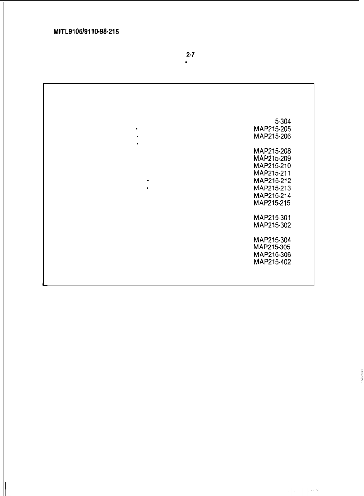
SECTION
MITL9105/9110-98-215
TABLE
2-7
GENERIC 205 EQUIPMENT
-
EXTENSION OPTIONS
TEST ORDER
Order Option MAP No.
1
Set Up Test Equipment
MAP215201
2
Test Extension Options MAP215500
3
Broker’s Cal IMAP21 5-304
4
Call Forwarding
-
Busy
MAP215-205
5
Call Forwarding
-
Don’t Answer
MAP215-206
6
Call Forwarding
-
Follow Me
MAP21 5-207
7
Call Park
MAP215-208
8
Call Pick-Up
MAP215-209
9
Camp-On MAP215-210
10
Consultation Hold/Transfer/Add-On
MAP215-211
11
Automatic Callback
-
Don’t Answer
MAP215-212
12
Automatic Callback
-
Busy
MAP215-213
13
Meet Me Conference
MAP215-214
14
Executive Busy Override
MAP215-215
15
Paging MAP21 5-216
16
Do Not Disturb
MAP215-301
17
Call Block
MAP215-302
18
Call Hold
MAP21 5-303
19
Single Digit Dialing
MAP215-304
20
Transfer Into Busy
MAP215-305
21
Common Alerting Devices
MAP215-306
22
Enable Non-CO Trunk to Trunk Connect
MAP215-402
23
Use a Personnel Speed Call
MAP21 5-501
24
Use a Common Use Speed Call
MAP21 5-502
Page 8
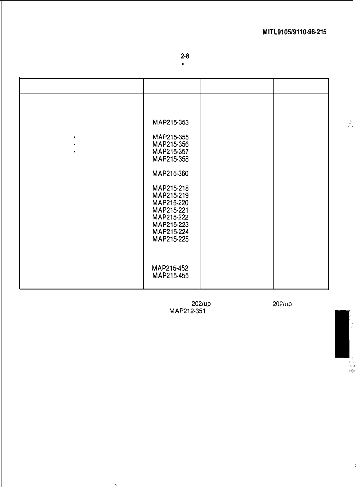
SECTION
MITL9105/9110-98.215
TABLE
2-8
GENERIC 205 EQUIPMENT
-
CONSOLE OPTIONS
TEST ORDER
OPTION MAP NO. ORDER NOTES
Test Console Features
Answer CO Trunk Call
Answer DID Trunk Call
Attendant Do Not Disturb
Message Waiting
Call Forwarding
-
Busy
Call Forwarding
-
Don’t Answer
Call Forwarding
-
Follow Me
Attendant Controlled Conference
Attendant Station Busy-Out
Attendant Do Not Disturb
Answer Incoming Call
Automatic Callback
Extending Internal Calls
Answering a Recall
Override
Flexible Night Service
Trunk Busy Operation
Trunk Group Attendant Access
Trunk Group Dial Access
Test Termination
Console Date Display and Date
Utility
Customer Program Dump/Load
System I.D.
Speed Call
MAP215504
1
MAP21 5-351
2
MAP21 5-352
3
MAP215-353
4
MAP21 5-354
5
MAP215-355
6
MAP215-356
7
MAP215-357
8
MAP215-358
9
MAP21 5-359
10
MAP215-360
11
MAP21 5-217
12
1
MAP215-218
13
MAP215-219
14
MAP215-220
15
MAP215-221
16
MAP215-222
17
MAP215-223
18
MAP215-224
19
MAP215-225
20
MAP21 5-226
21
MAP21 5-451
22
MAP215-452
23
2, 3
MAP215-455
24
MAP21 5-505
25
Notes 1. MAP 215-216 tests are performed on Generic
2021~~
equipment. Generic
2021~~
equipment
tests are listed in Table 2-4 starting at
MAP212-351
incorporating the use of the
Serial/Guest Room key.
2.
A printer may be used.
3.
A storage device may be used.
.:
..:
:
Page 9
:
;
SECTION MITL9105/9110-98-215
APPENDIX 1
MITEL ACTION PROCEDURES
GENERAL
Al.01
Task oriented functions in this section are
implemented using MITEL ACTION
PROCEDURES (MAP’s).
Al.02
A MAP is a step by step procedure using a
flow chart principle, written and il-
lustrated where necessary to a level of detail that
allows both experienced and inexperienced per-
sonnel to carry out the tasks detailed. A MAP con-
tains two levels of information as follows:
(a) For experienced personnel, a series of
steps (level one) each numbered [n] and
annotated with minimal information.
(b) For inexperienced personnel, each step
referred to in (a) above is amplified by a
connected series of numbered substeps
[nA] (level two).
Al.03
A typical example of a MAP is shown in
Fig. Al, with the two levels detailed
MAP SYMBOLS
Al.04
There are four basic symbol shapes which
may be used in a MAP, and are
defined as follows.
Al.05 AND Block:
Used to indicate a level one
step that must be performed. Con-
sists of a square with the word AND centred in the
block.
Al.06 OR Block:
Used to indicate a choice of
level one steps, one of which must be
performed. Consists of a rectangle, with the text
centred in the block, and with the word OR ap-
pearing between the alternative operations.
Al.07
The rectangle is also used to border in-
structions which imply that the operative
must perform a task outside the scope of the
MAP. The text is centred in the rectangle.
Al.08 DECISION Block:
Used to indicate a
decision within the level one steps which
must be made. The symbol is based on a hexagon
with the top and bottom sides extended. Decision
text is centred in the symbol.
Al.09 START/FINISH/JUMP TO Block:
Used to
indicate the start and finish of a MAP.
Also used to indicate ‘jump to’ points within the
MAP, for example “go to [n]” or “from [n]” or
“return to [n]“. The symbol is a rectangle with
semi circular ends. Text is centred in the symbol.
THE OPERATORS USE OF MAP’S
Experienced Operator
Al.10
For the experienced operator to complete
a task using a MAP, reference to the se-
quential short form level one steps is usually all
that is necessary. Using Fig. Al as an example,
the experienced operator would proceed as
follows.
Al.11
At [l] makes a decision based on the infor-
mation within the block. If the answer is
YES the operator must proceed to a different
MAP. If the answer is NO the operator is faced
with another decision at block [2].
Al.12
At [2] if the decision is NO there is no re-
quirement to proceed further and the test
is abandoned. This naturally results in a FINISH
block. If the decision is YES the operator pro-
ceeds to [3] and [4] in succession, i.e. dials the DID
station number and completes the call to the
check extension.
Al.13
The description of the instructions carried
out in Al.05 and Al.06 have assumed
that the level of competence of the operator is
such that short form level one steps contain suffi-
cient information, and therefore the operator
reads only the centre column of the MAP, top to
bottom of the page. ,-
Al-l
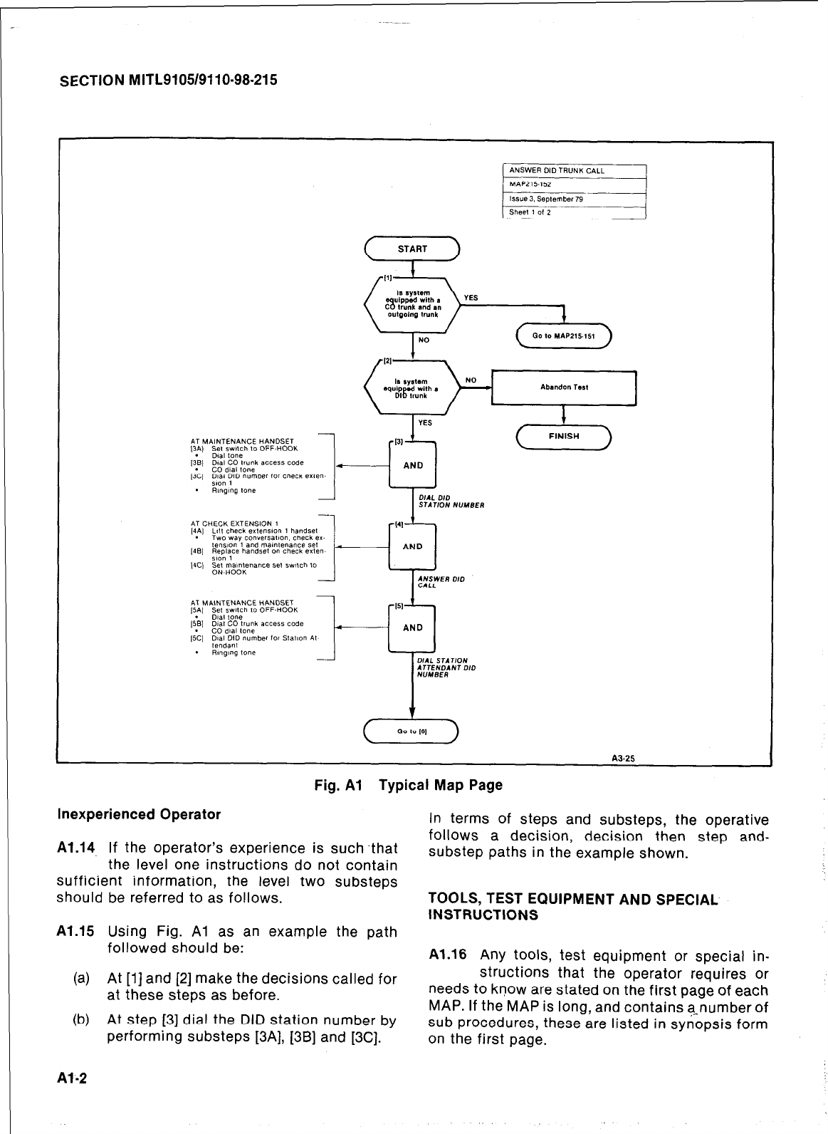
SECTION MITL9105/9110-98-215
START
*TTEND*NT DID
Fig. Al Typical Map Page
Inexperienced Operator
Al.14 If the operator’s experience is such that
the level one instructions do not contain
sufficient information, the level two substeps
should be referred to as follows.
Al.15 Using Fig. Al as an example the path
followed should be:
(a) At [l] and [2] make the decisions called for
at these steps as before.
(b) At step [3] dial the DID station number by
performing substeps [3A], [3B] and [3C].
Al-2
In terms of steps and substeps, the operative
follows a decision, decision then step and-
substep paths in the example shown.
TOOLS, TEST EQUIPMENT AND SPECIAL
INSTRUCTIONS
Al.16 Any tools, test equipment or special in-
structions that the operator requires or
needs to know are stated on the first page of each
MAP. If the MAP is long, and contains a-number of
sub procedures, these are listed in synopsis form
on the first page.
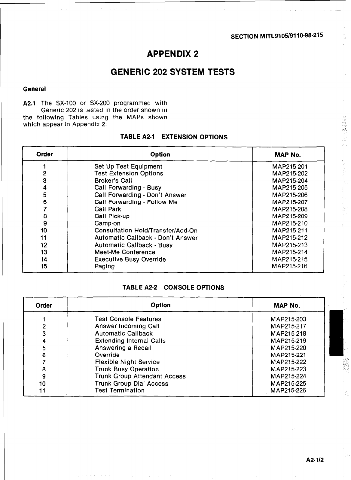
SECTION MITLSI 05/911 O-98-21 5
APPENDIX 2
GENERIC 202 SYSTEM TESTS
General
A2.1 The SX-100 or SX-200 programmed with
Generic 202 is tested in the order shown in
the following Tables using the MAPS shown
which appear in Appendix 2:
TABLE A2-1 EXTENSION OPTIONS
Order Option
1 Set Up Test Equipment
2 Test Extension Options
3 Broker’s Call
4 Call Forwarding - Busy
5 Call Forwarding - Don’t Answer
6 Call Forwarding - Follow Me
7 Call Park
8 Call Pick-up
9 Camp-on
10 Consultation Hold/Transfer/Add-On
11 Automatic Callback - Don’t Answer
12 Automatic Callback - Busy
13 Meet-Me Conference
14 Executive Busy Override
15 Paging
MAP No.
MAP21 5-201
MAP21 5-202
MAP215204
MAP21 5-205
MAP215-206
MAP21 5-207
MAP215-208
MAP215-209
MAP215-210
MAP215-211
MAP215-212
MAP21 5-213
MAP215-214
MAP215-215
MAP215-216
TABLE A2-2 CONSOLE OPTIONS
Order Option
1 Test Console Features
2 Answer Incoming Call
3 Automatic Callback
4 Extending Internal Calls
5 Answering a Recall
6 Override
7 Flexible Night Service
8 Trunk Busy Operation
9 Trunk Group Attendant Access
10 Trunk Group Dial Access
11 Test Termination
MAP No.
MAP215-203
MAP215-217
MAP215-218
MAP215-219
MAP215-220
MAP21 5-221
MAP215-222
MAP21 5-223
MAP215-224
MAP21 5-225
, MAP215-226
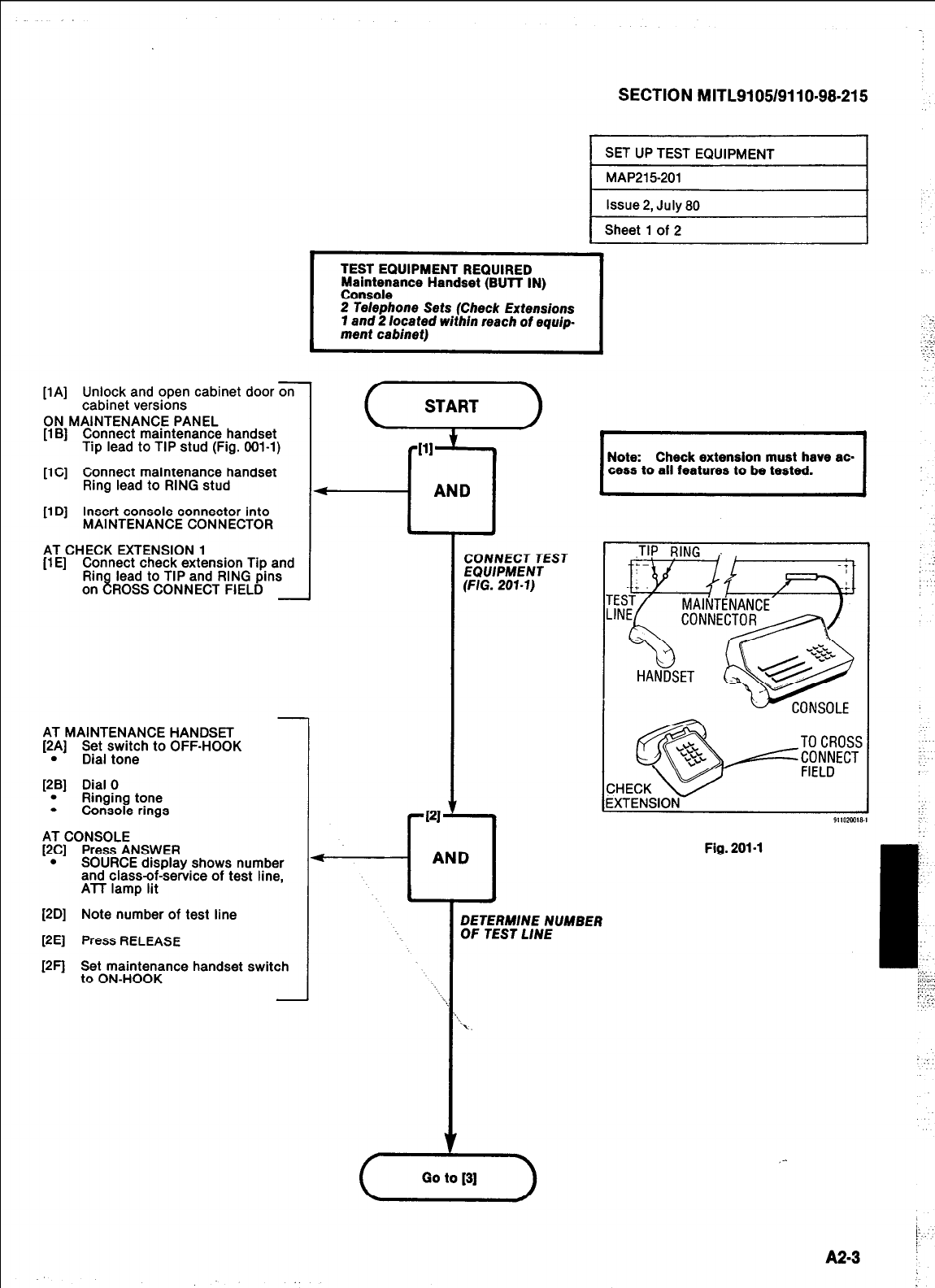
[l A] Unlock and open cabinet door on
cabinet versions
ON MAINTENANCE PANEL
[l B] Connect maintenance handset
Tip lead to TIP stud (Fig. 001-l)
[lC] Connect maintenance handset
Ring lead to RING stud
[l D] Insert console connector into
MAINTENANCE CONNECTOR
AT CHECK EXTENSION 1
(1 E] Connect check extension Tip and
Rin lead to TIP and RING pins
on 8 ROSS CONNECT FIELD
AT MAINTENANCE HANDSET
[2A] Set switch to OFF-HOOK
. Dial tone
[2B] Dial 0
. Ringing tone
. Console rings
AT CONSOLE
[2C] Press ANSWER
. SOURCE display shows number
and class-of%e&ce of test line,
ATT lamp lit
[2D] Note number of test line
[2E] Press RELEASE
[2F] Set maintenance handset switch
to ON-HOOK
SECTION MITL9105/9110-98.215
I
SET UP TEST EQUIPMENT I
I
MAP215201 I
I
Issue 2, July 80 I
I
Sheet 1 of 2
TEST EQUIPMENT
Maintenance Handset (Bun IN)
Console
2 Telephone Sets (Check Extensions
7 and 2 located within reach of equip.
merit cabinet)
f
START
\ +
PI
f-l
AND
CONNECT TEST
EQUIPMENT
(FIG.207.7)
c
Go
I
Note: Check extension must have ac-
cess to all features to be tested. I
DETERMINE NUMBER
OF TEST LINE
Fig. 201-l
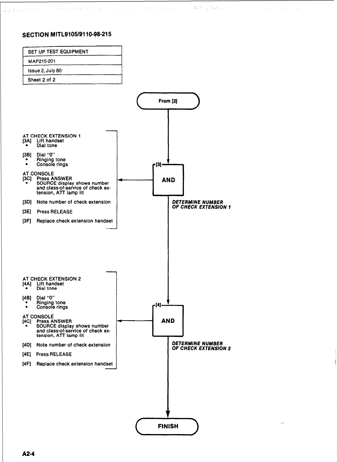
SECTION MITL9105/9110-98-215
SET UP TEST EQUIPMENT
MAP215-201
Issue 2, July 80’
Sheet 2 of 2
AT CHECK EXTENSION 1
[3A] Lift handset
. Dial tone
[38] Dial “0”
. Ringing tone
. Console rings 1
AT CONSOLE
[3C] Press ANSWER
. SOURCE display shows number
and class-of-service of check ex-
tension, All lamp lit
(3D] Note number of check extension
[3E] Press RELEASE
[3F] Replace check extension handset
-
AT CHECK EXTENSION 2
[4A] Lift handset
. Dial tone
[4B] Dial “0”
. Ringing tone
. Console rings
AT CONSOLE
[4C] Press ANSWER
. SOURCE display shows number
and class-of-service of check ex-
tension, ATT lamp lit
[4D] Note number of check extension
[4E] Press RELEASE
[4F] Replace check extension handset
DETERMINE NUMBER
OF CHECK EXTENSION 1
DETERMINE NUMBER
OF CHECK EXTENSION 2
A24
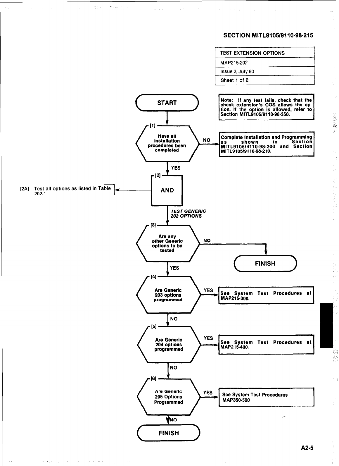
SECTION MITL9105/9110~98~215
If any test fails, check that the
check extension’s COS allows the op
[2A] Test all options as listed in Ta
202-l
AND
4
TEST GENERIC
202 OPTIONS
See System Test Procedures
I
A2-5 :
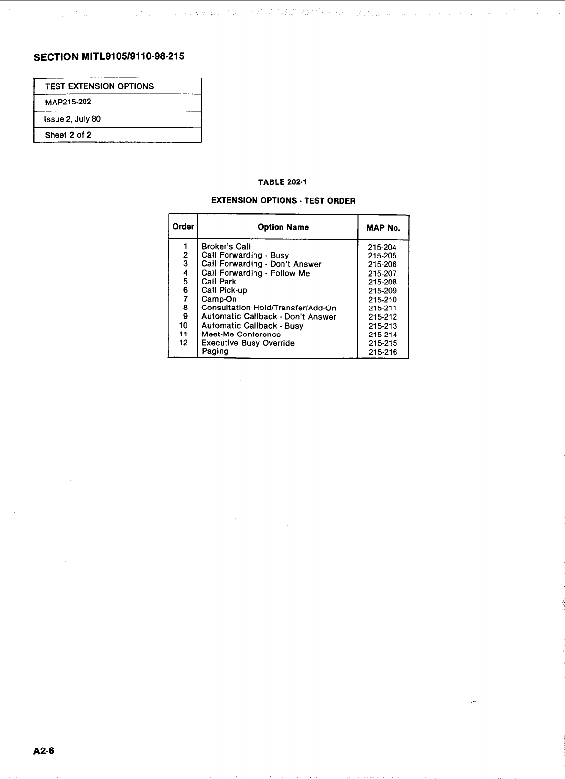
_.
SECTION MITL91051911 O-98-21 5
TEST EXTENSION OPTIONS
MAP215-202
issue 2, July 80
Sheet 2 of 2
,
A2-6
TABLE 202-l
EXTENSION OPTIONS - TEST ORDER
Order Option Name MAP No.
1 Broker’s Call 215-204
2 Call Forwarding - Busy 215-205
3 Call Forwarding - Don’t Answer 215-206
4 Call Forwarding - Follow Me 215-207
5 Call Park 215-208
6 Call Pick-up 215-209
7 Camp-On 215-210
i Consultation Hold/Transfer/Add-On 215-211
Automatic Callback - Don’t Answer 215-212
10 Automatic Callback - Busy 215-213
11 Meet-Me Conference 215-214
12 Executive Busy Override 215215
Paging 215-216

PAI
Test all
203-l options as listed
SECTION MITL9105/9110-98-215
in
Sheet 1 of 2
1 YES
. AND
TEST GENE/?/C
202
OPTIONS
NO
+-)
Are Generic See System Test Procedures at
MAP215250 or - 300.
See System Test Procedures at
MAP21 5-400.
Are Generic
205 options
programmed
See System Test Procedures at
A2-7
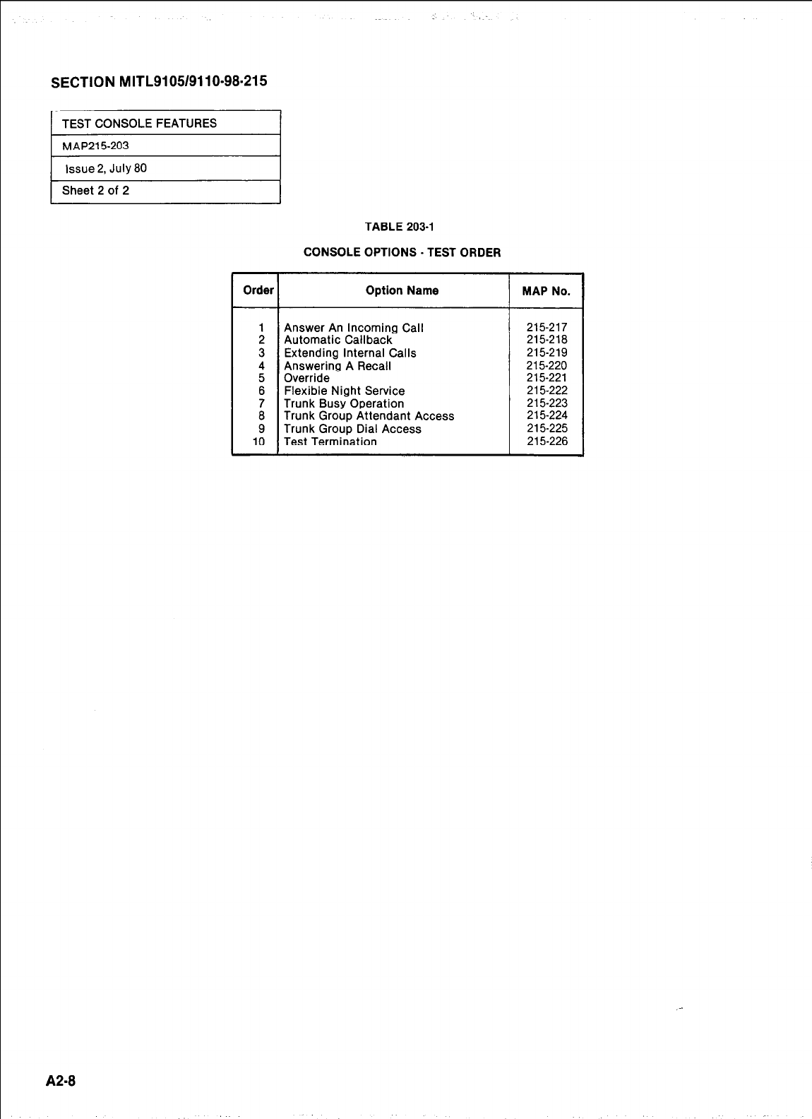
SECTION MITL9105/9110-98.215
1 TEST CONSOLE FEATURES I
1 MAP215-203
1 Issue 2, July 80
I
1 Sheet 2 of 2
TABLE 203-l
CONSOLE OPTIONS - TEST ORDER
Order Option Name MAP No.
: Answer Automatic An Callback Incoming Call 215217 215218
3 Extending Internal Calls 215219
4 Answering A Recall 215-220
5 Override 215-221
6 Flexible Night Service 215-222
ii Trunk Busy Operation 215-223
Trunk Group Attendant Access 215-224
9 Trunk Group Dial Access 215-225
10 Test Termination 215-226
A2-8
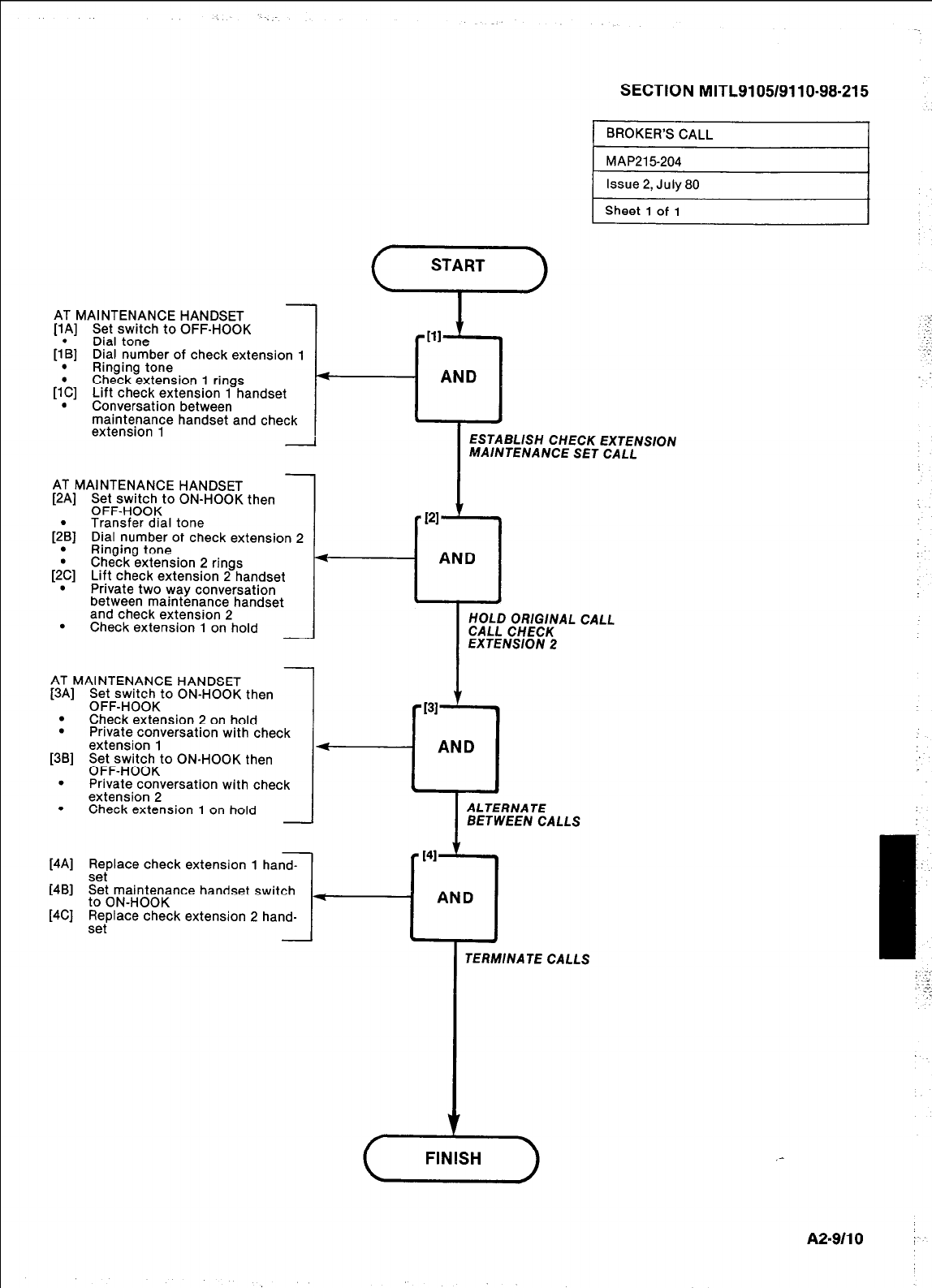
AT MAINTENANCE HANDSET
[lA] Set switch to OFF-HOOK
[lb] Dial tone
Dial number of check extension 1
_ _
.
Ringing tone
[l*C] Check extension 1 rings
Lift check extension 1 handset
. Conversation between
maintenance handset and check
extension 1
AT MAINTENANCE HANDSET
[2A] Set switch to ON-HOOK then
OFF-HOOK
[2:B] Transfer dial tone
Dial number ot check extension 2
Ringing tone
[2:C] Check extension 2 rings
Lift check extension 2 handset
Private two way conversation
between maintenance handset
and check extension 2
. Check extension 1 on hold -
AT MAINTENANCE HANDSET
[3A] Set switch to ON-HOOK then
OFF-HOOK
. Check extension 2 on hold
. Private conversation with check
extension 1
[36] Set switch to ON-HOOK then
OFF-HOOK
. Private conversation with check
extension 2
. Check extension 1 on hold -
[4A] Replace check extension 1 hand-
sei
[4B] Set maintenance handset switch
to ON-HOOK
[4C] Replace check extension 2 hand-
set
SECTION MITL9105/9110-98-215
Sheet 1 of 1
.:
,-.
- AND
. .
ESTABLISH CHECK EXTENSION
MAINTENANCE SET CALL
-7121 v
l
AND
.
HOLD ORIGINAL CALL
CALL CHECK
EXTENSION 2
131 '
+--u
AND
I
ALTERNATE
BETWEEN CALLS
[41
I
TERMINATE CALLS
,-
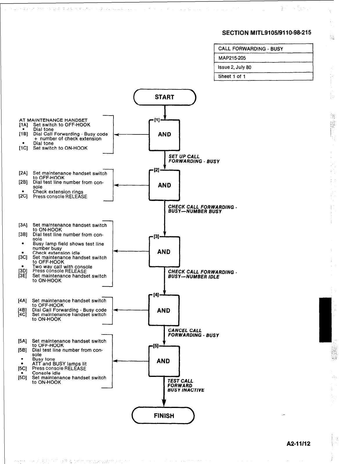
AT MAINTENANCE HANDSET
Set switch to OFF-HOOK
Dial tone
PAI
lh
[h
Dial Call Forwarding - Busy code
+ number of check extension
Dial tone
Set switch to ON-HOOK
-1
-
Set maintenance handset switch
to OFF-HOOK
Dial test line number from con-
sole
Check extension rings
Press console RELEASE
[3Al
1381
.
&I
[iE/
Set maintenance handset switch
to ON-HOOK
Dial test line number from con-
sole
Busy lamp field shows test line
number busy
Check extension idle
Set maintenance handset switch
to OFF-HOOK
Two way call with console
Press console RELEASE
Set maintenance handset switch
to ON-HOOK
[4Al
[4Bl
[4Cl
Set maintenance handset switch
to OFF-HOOK
Dial Call Forwarding - Busy code
Set maintenance handset switch
to ON-HOOK -
Set maintenance handset switch
to OFF-HOOK
Dial test line number from con-
sole
Busy tone
ATT and BUSY lamps lit
Press console RELEASE
Console idle
Set maintenance handset switch
to ON-HOOK
-
-
-
4
-I
SECTION MITL9105/9110-98.215
1 CALL FORWARDING - BUSY I
1 MAP215205 I
Issue 2, July 80
Sheet 1 of 1
4 AND
SET UP CALL
FORWARDING - BUSY
_
: .
:.
I
I
CHECK CALL FORWARDING -
BUSY-NUMBER BUSY
I31
-cl
AND
CHECK CALL FORWARDING.
BUSY-NUMBER IDLE
I
CANCEL CALL
FORWARDING - BUSY
-v
4
AND
. ,
TEST CALL
FORWARD
BUSY INACTIVE
‘I
FINISH
i :
A2-11112 i
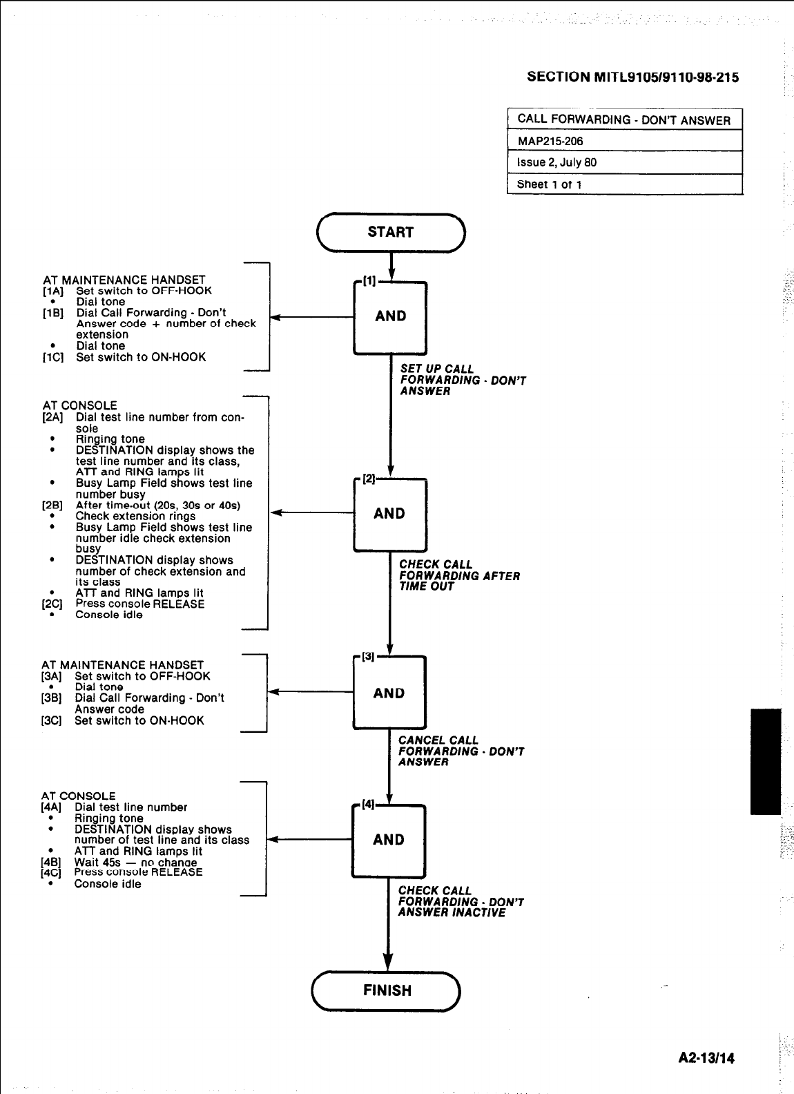
AT MAINTENANCE HANDSET
[lA] Set switch to OFF-HOOK
[I\] Dial tone
Dial Call Forwarding - Don’t
Answer code + number of check
extension
[;C] Dial tone
Set switch to ON-HOOK
AT CONSOLE
[2A] CIX$s test line number from con-
. Ringing tone
. DESTINATION display shows the
test line number and its class,
ATT and RING lamps lit
. Busy Lamp Field shows test line
[2B] number busy
. After time-out (205, 30s or 40s)
Check extension rmgs
. Busy Lamp Field shows test line
number idle check extension
busy
. DESTINATION display shows
number of check extension and
its class
[;C] ATT and RING lamps lit
Press console RELEASE
. Console idle
SECTION MITL9105/9110-98-215
( CALL FORWARDING - DON’T ANSWER 1
I
CHECK CALL
;fMREW;$lNG AFTER
AT MAINTENANCE HANDSET
[3A] Set switch to OFF-HOOK
[3\] Dial tone
Dial Call Forwarding - Don’t
Answer code
[3C] Set switch to ON-HOOK
431 ’
4
AND
c 1
CANCEL CALL
FORWARDlNG - DON’T
ANSWER
AT CONSOLE
[4A) Dial test line number
_ _
.
Ringing tone
. DESTINATION disolav shows
number of test line and its class
[:B] ATT and RING lamps lit
Wait 45s - no chanoe
[4C] Press console RELEASE
. Console idle
A2-13114
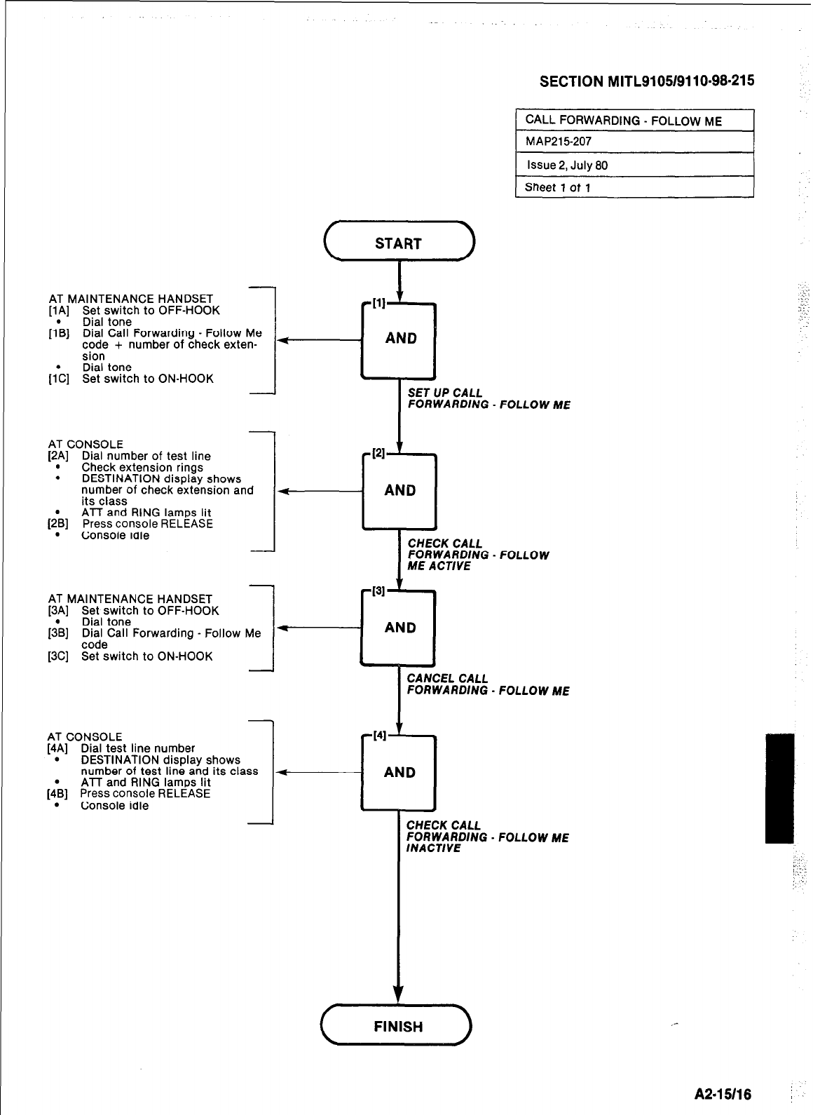
SECTION MITL9105/9110-98-215
CALL FORWARDING - FOLLOW ME
MAP215-207
Issue 2, July 80
Sheet 1 of 1
AT MAINTENANCE HANDSET
[lA] Set switch to OFF-HOOK
*[ll t
[IL] Dial tone
Dial Call Forwarding - Follow Me
code + number of check exten- * -
AND
sion
Dial tone
[;C] Set switch to ON-HOOK . .
SET UP CALL
FOR WARDlNG FOLLOW ME
-
AT CONSOLE
[2.A] Dial number of test line
Check extensron rmgs
. DESTINATION display shows
number of check extension and
its class
ATT and RING lamps lit
(2& Press console RELEASE
. Console rare -
I
CHECK CALL
FORWARDlNG
ME ACT/YE FOLLOW
AT MAINTENANCE HANDSET
[3A] Set switch to OFF-HOOK
Dial tone
[TS] FF;eCall Forwarding - Follow
[3C] Set switch to ON-HOOK
FOLLOW ME
AT CONSOLE
[4.A] Dial test line number
DESTINATION display shows
number of test line and its class
ATT and RING lamps lit
[4\] Press console RELEASE
. Console idle
- CHECK CALL
FORWARDlNG - FOLLOW ME
lNACT/VE
A2-15118 j
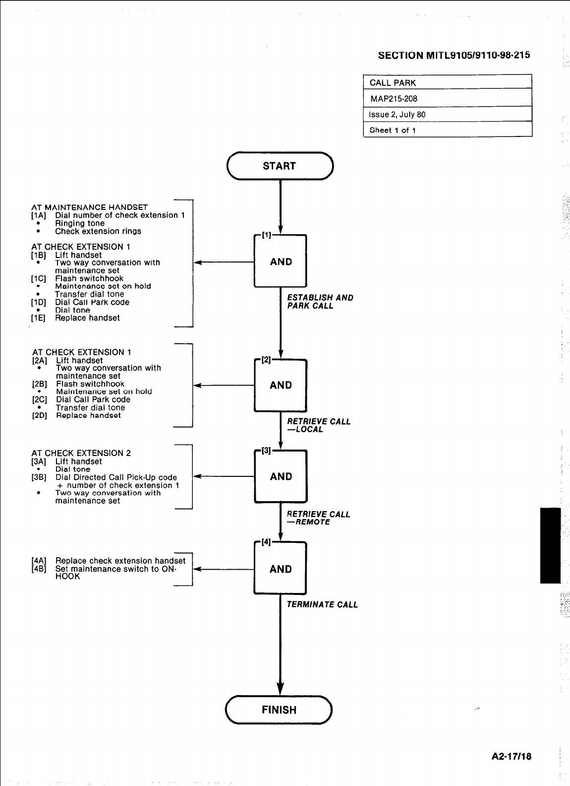
AT MAINTENANCE HANDSET
[lA] Dial number of check extension 1
. Ringing tone
. Check extension rings
AT CHECK EXTENSION 1
[lB] Lift handset
. Two way conversation with
maintenance set
[lC] Flash switchhook
. Maintenance set on hold
Transfer dial tone
[l*D] Dial Call Park code
Dial tone
[lk] Replace handset
SECTION MITL9105/9110-98.215 .
CALL PARK
MAP215-208
Issue 2, July 80
Sheet 1 of 1 I
AT CHECK EXTENSION 1
[2p] Lift handset
Two way conversation with
maintenance set
[2B] Flash switchhook
Maintenance set on hold
&C] Dial Call Park code
Transfer dial tone
[;D] Replace handset
-121
4
AND
. *
RiEL/--;;;E CALL
AT CHECK EXTENSION 2
[3p] Lift handset
Dial tone
[3B] Dial Directed Call Pick-Up code
I
*
pi31 y
AND
+ number of check extension 1
. Two way conversation with
maintenance set
l :
RETRlEYE CALL
-REMOTE
[4A] Replace check extension
[4B] perr-rrntenance switch
TERMINATE CALL
A2-17/18 i
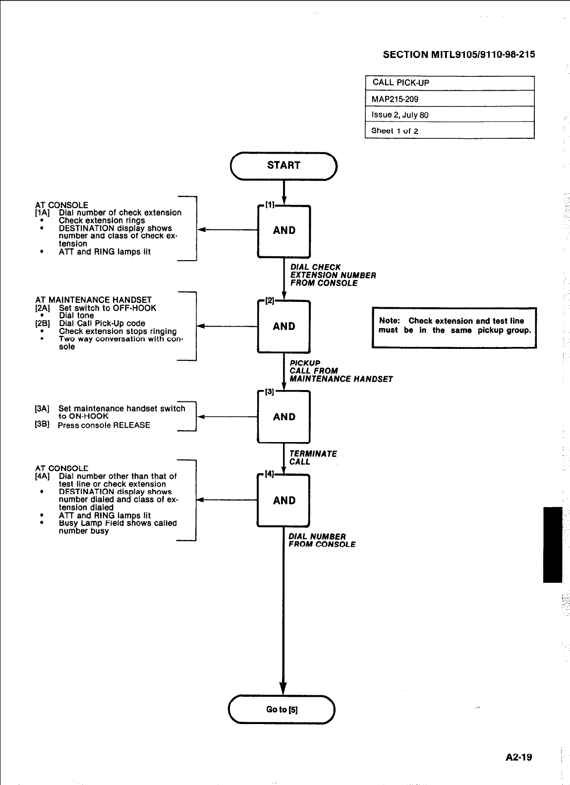
SECTION MITLSI 05/911 O-98-21 5
1 CALL PICK-UP
AT CONSOLE
[lA] Dial number of check extension
. Check extension rings
. DESTINATION display shows
number and class of check ex-
tension
. ATT and RING lamps lit
I
D/AL CHECK
EXTENSION NUMBER
FROM CONSOLE
AT MAINTENANCE HANDSET
[2A] Set switch to OFF-HOOK
Dial tone
[;B] Dial Call Pick-Up code
. Check extension stops ringing
. Two wav conversation with con-
rf211-7
AND I I
Note: Check extension and test line
must be in the same pickup group.
sole -
MAINTENANCE HANDSET
[3A] Set maintenance handset switch
to ON-HOOK
I3Bl
Press console RELEASE
3-1 AND
AT CONSOLE
[4A] Dial number other than that of
test line or check extension
. DESTINATION display shows
number dialed and class of ex-
lled
ING lam s lit
> Field s
1 ows called
SC.,
tension dif
. ATT and R
. Busy Laml
number bu=,
DIAL NUMBER
FROM CONSOLE
1
j
(F)
_-
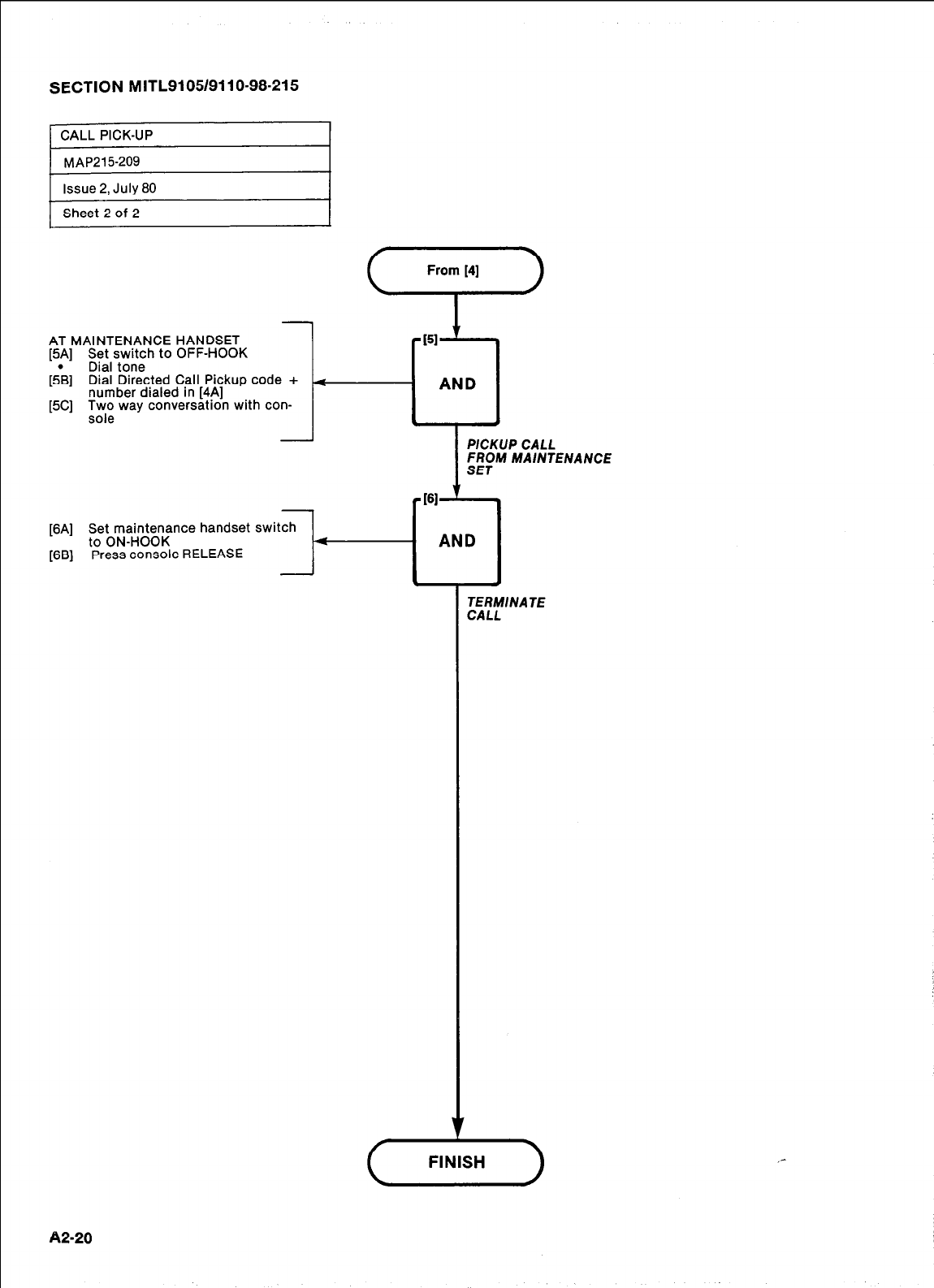
SECTION MITL9105/9110-98-215
AT MAINTENANCE HANDSET
[5A] Set switch to OFF-HOOK
[5\] Dial tone
Dial Directed Call Pickup code +
[5C] number dialed in [43
l%; way conversation with con-
[6A] Set maintenance handset switch
to ON-HOOK 4
[6B] Press console RELEASE
-
AND
PlCKUP CALL
FROM MAINTENANCE
SET
161
’ .
AND
.
TERMINATE
CALL
A2-20
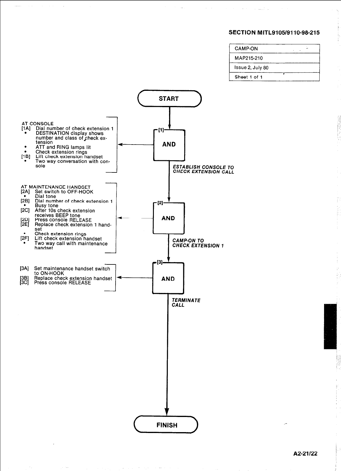
AT CONSOLE
[l.A] Dial number of check extension 1
DESTINATION drsplay shows
number and class of check ex-
tension
.
&I
I&
PDI
[=I
1&
.
[3Al
138
[3C I
- AT MAINTENANCE HANDSET
PAI
Set switch to OFF-HOOK
Dial tone
Dial number of check extension 1
Busy tone
After 10s check extension
receives BEEP tone
Press console RELEASE
Replace check extension 1 hand-
sei
Check extension rings
Lift check extension handset
Two way call with maintenance
handset
1
.
+I
PI
Set maintenance handset switch
to ON-HOOK
Replace check extension handset -
Press console RELEASE 1
-
SECTION MITL9105/9110-98-215 :
1 CAMP-ON -- I
MAP215210
Issue 2, July 80
ESTABLISH CONSOLE TO
CHECK EXTENSlON CALL
.
Sheet 1 of 1
.
ATT and RING lamps lit
Check extension rings
[l*B] Lift check extension handset
. Two way conversation with con.
sole
AND
CAMP-ON TO
CHECK EXTENSlON 7
TERMlNA TE
CALL
A2.21122 !

AT MAINTENANCE HANDSET
[lA] Set switch to OFF-HOOK
[l*B] Dial tone
Dial number of check extension 1
. Ringing tone
. Check extension 1 rings
AT CHECK EXTENSION 1
[2A] Lift handset
. Two way private conversation
with maintenance handset
[26] Flash switchhook
. Maintenance handset on hold
[;C] Transfer dial tone
Dial number of check extension 2
. Ringing tone
[2b] Check extension 2 rings
Lift check extension 2 handset
. Private conversation, check ex-
tension 1 and check extension 2
-
AT CHECK EXTENSION 1
[3A] Flash switchhook
. Three way call, check extension
1, check extension 2, and
maintenance handset
[3B] Replace check extension 1 hand-
l-
SECTION MITL9105/9110-98-215
CONSULTATION
HOLDTTRANSERIADD-ON I
* . AND
. I .
set
. Two way call, maintenance hand-
set and check extension 2
ESTABLISH MAlNTENANCE
HANDSET A ND CHECK
EXTENS/ON 7 CALL
PI
-cl
AND
CONSULT WTH
CHECK EXTENSlON 2
I
TRANSFER CALL
TO CHECK EXTENSION 2
[4A] Set maintenance handset switch
to ON-HOOK
[4B] ,R,eplace check extension 2 hand- --i
AND
- I I J
TERMINATE
CALL
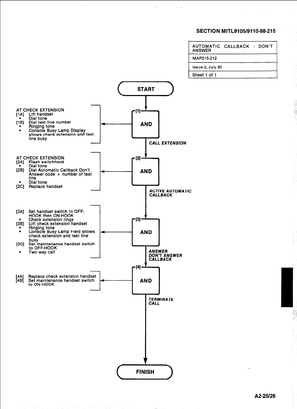
-
AT CHECK EXTENSION
[lA] Lift handset
Dial tone
[IL] Dial test line number
. Ringing tone
. Console Busy Lamp Display
shows check extension and test
line busy -
SECTION MITL9105/9110-98.215
;;;WF;TIC CALLBACK - DON’T
y1
[=I
&I
AT CHECK EXTENSION
Flash switchhook
Dial tone
Dial Automatic Callback Don’t
Answer code + number of test 4
line
Dial tone
Replace handset -
[3Al
[+I
.
[3Cl
.
Set handset switch to OFF-
HOOK then ON-HOOK
Check extension rings
Lift check extension handset
Ringing tone
Console Busy Lamp Field shows
check extension and test line
kifYmaintenance handset switch
to OFF-HOOK
Two way call
Beplace check extension handset
Set maintenance handset switch
to ON-HOOK
1 AND
. I
ACTIVE AUTOMATIC
CALLBACK
TERMlNA TE
CALL
DON’T ANSWER
_-
A2-25128 :
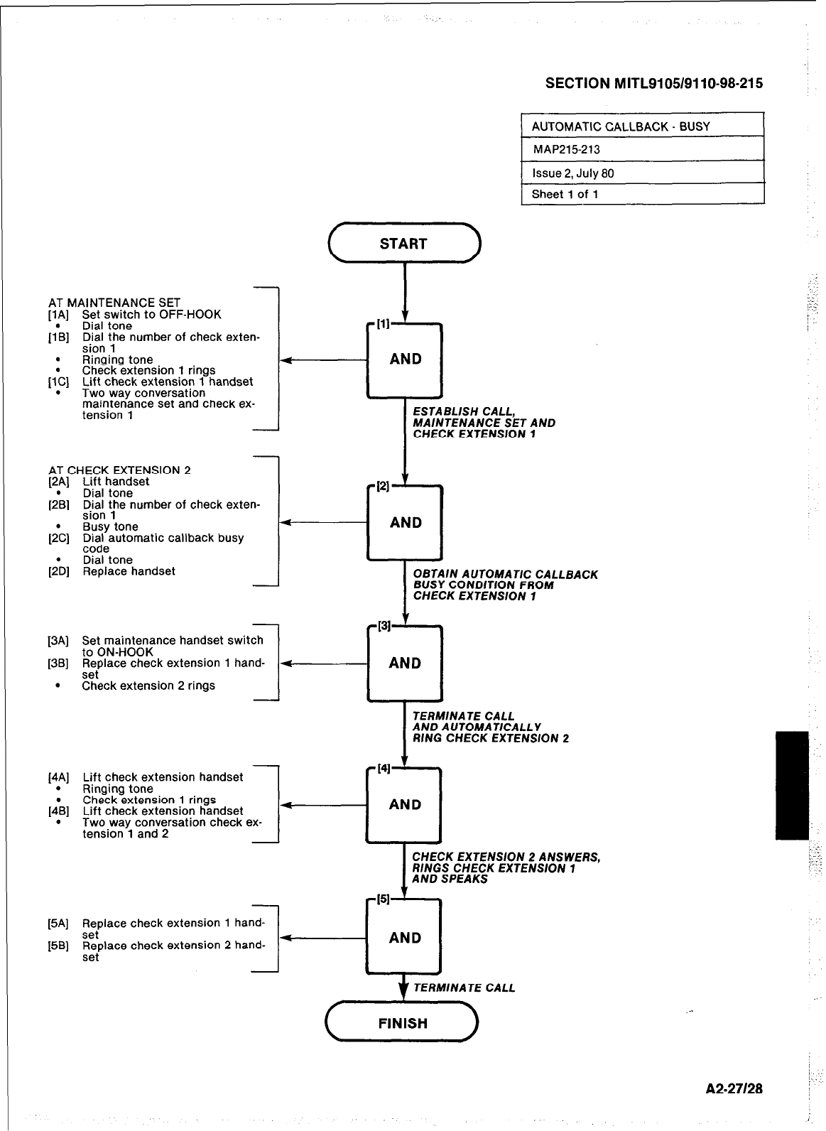
SECTION MITL9105/9110-98-215
AT MAINTENANCE SET
[lA] Set switch to OFF-HOOK
(l*B] Dial tone
,“i’b”:, ;he number of check exten-
. Ringing tone
(I:] Check extension 1 rings
Lift check extension 1 handset
Two way conversation
maintenance set and check ex-
tension 1
AT CHECK EXTENSION 2
[2.A] Lift handset
Dial tone
[2B] Di)iA t,he number of check exten-
Busy tone
f&I Dial automatic callback busv
_ -
code
Dial tone
[;D] Replace handset
EI-;;,““BA~K - BUSY 1
Sheet 1 of 1
d
[3A] Set maintenance handset switch
to ON-HOOK
[3B] Replace check extension 1 hand-
set
. Check extension 2 rings 1
-
AND
ESTABLISH CALL,
MAINTENANCE SET AND
CHECK EXTENSION 1
AND
I
[4.A] Lift check extension handset
Ringmg tone
]4:B] Check extension 1 rings
Lift check extension handset
Two way conversation check ex-
tension 1 and 2
OBTAIN AUTOMATIC CALLBACK
BUSY CONDlTlON FROM
CHECK EXTENSION 1
[5A] ,R,eplace check extension 1 hand-
[5B] Replace check extension 2 hand- -
set
CHECK EXTENSION 2 ANSWERS,
RINGS CHECK EXTENSION 1
AND SPEAKS
TERMINATE CALL
/:
A2-27128 [
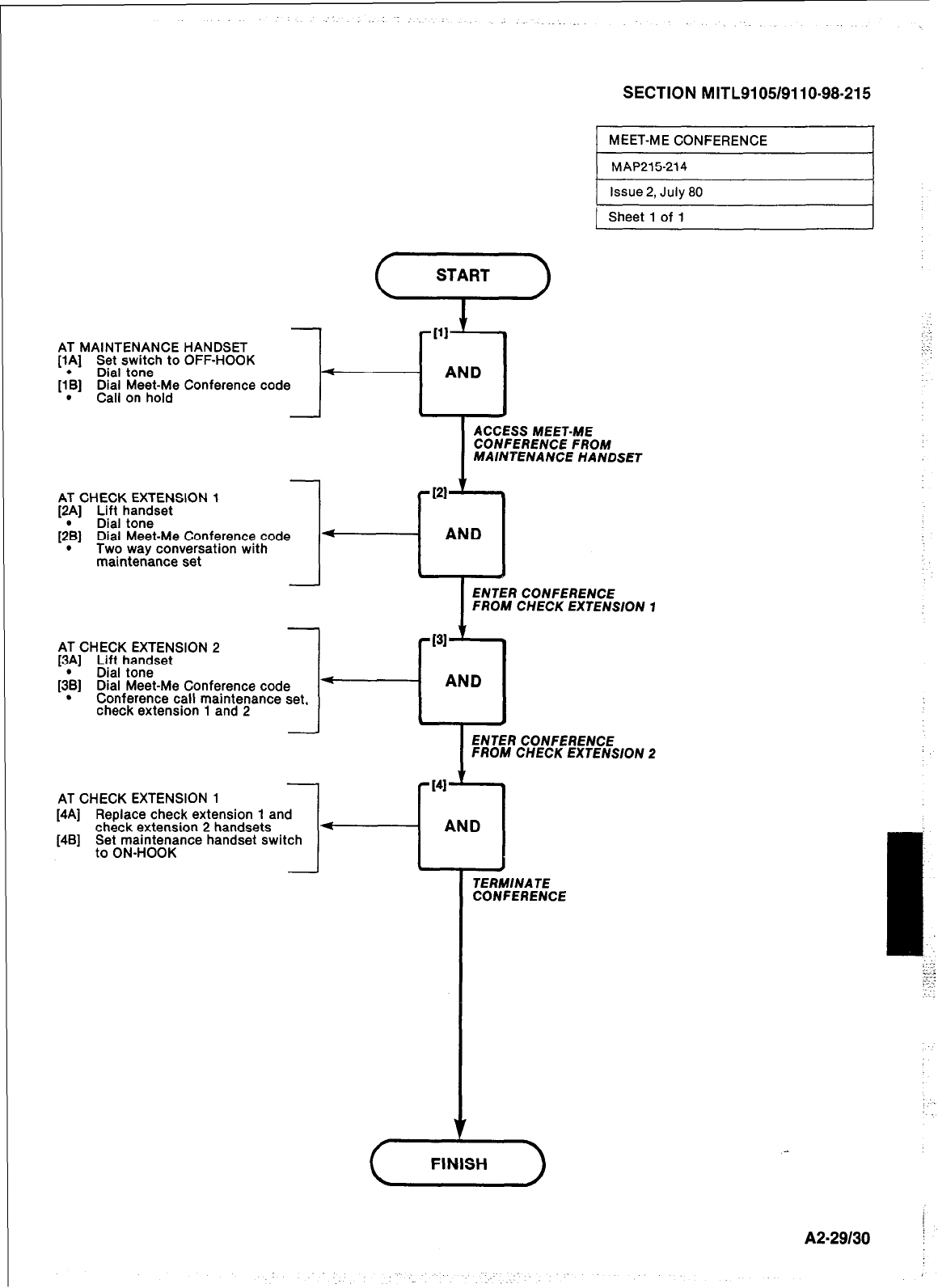
SECTION MITL9105/9110-98-215
MEET-ME CONFERENCE I
AT MAINTENANCE HANDSET
[lA] Set switch to OFF-HOOK
Dial tone
[I’B] Dial Meet-Me Conference code
. Call on hold
AT CHECK EXTENSION 1
[2A] Lift handset
Dial tone
[;B] Dial Meet-Me Conference code
. Two way conversation with
maintenance set
AT CHECK EXTENSION 2
[3!] yeI ll”,“,se’
[3B] Dial Meet-Me Conference code
. Conference call maintenance set,
check extension 1 and 2 -
AT CHECK EXTENSION 1
[4A] Replace check extension 1 and
check extension 2 handsets
[4B] Set maintenance handset switch
to ON-HOOK
,111
AND
i
ACCESS MEET-ME
CONFERENCE FROM
MAINTENANCE HANDSET
RI
‘--cl
AND
ENTER CONFERENCE
FROM CHECK EXTENSION 1
ENTER CONFERENCE
FROM CHECK EXTENSION 2
1
TERMINATE
CONFERENCE
/
A2.29130 !
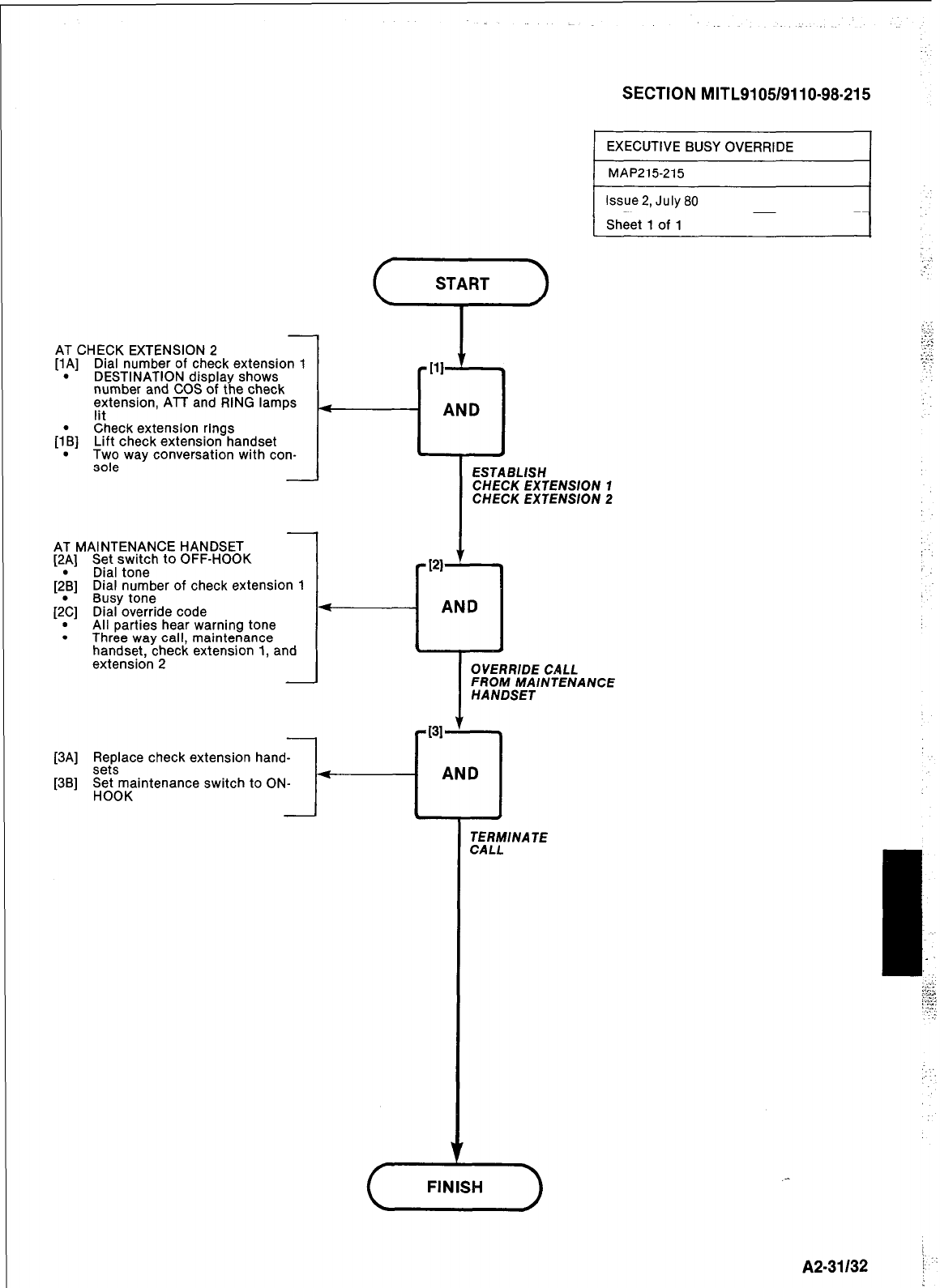
SECTION MITL9105/9110-98-215
EXECUTIVE BUSY OVERRIDE I
issue 2, July 80
Sheet 1 of 1
AT CHECK EXTENSION 2
[lA] Dial number of check extension 1
. DESTINATION display shows
number and COS of the check
extension, ATT and RING lamps
lit
[IL] Check extension rings
Lift check extension handset
. Two way conversation with con-
sole I-
-
AT MAINTENANCE HANDSET
[2A] Set switch to OFF-HOOK
[2\] Dial tone
Dial number of check extension 1
Busy tone
[2>] Dial override code
. All parties hear warning tone
. Three way call, maintenance
handset, check extension 1, and
extension 2 OVERRIDE CALL
FROM MAlNTENANCE
HANDSET
1 MAP215215 I
[3A] ,ReePslace check extension hand-
[3B] perr~intenance switch to ON-
t----i
AND
TERMINATE
CALL
: . .
.-
FINISH
A2-31132 i
-’
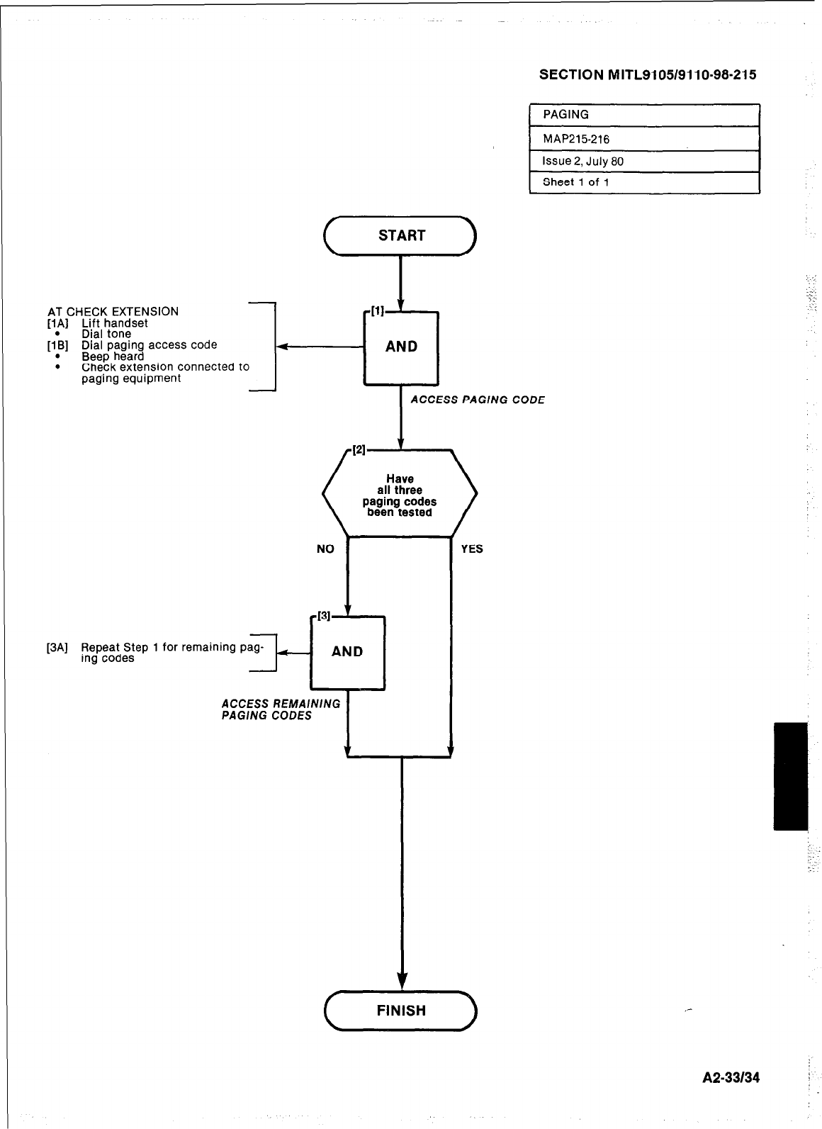
SECTION MITL9105/911 O-98-21 5
I
PAGING I
START
i-’
-
AT CHECK EXTENSION
[IA] Lift handset
Dial tone
[I\] Dial paging access code
. Beep heard
. Check extension connected to
pag.ing equipment -
[3A] Repeat Step 1 for remaining pag-
ing codes ---I-
ACCESS PAGING CODE
YES
NO
431 ’
AND
I
ACCESS REMAINING
PAGlNG CODES
L
A2-33134
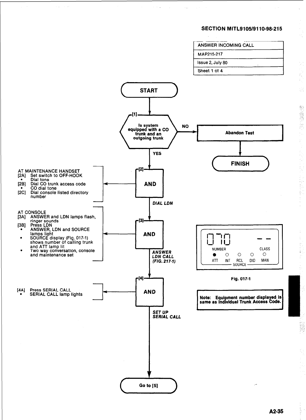
SECTION MITL9105/911 O-98-21 5
’ ANSWER INCOMING CALL
MAP215-217
t Issue 2, Julv 80 I
Sheet 1 of 4
NO I
trunk and an Abandon Test
YES
4
AND
AT CONSOLE
[3A] ANSWER and LDN lamps flash,
ringer sounds
[3B] Press LDN
. ANSWER, LDN and SOURCE
lamps light
. SOURCE display (Fig. 017-l)
shows number of calling trunk
and ATT lamp lit
. Two way conversation, console
and maintenance set
-131 f 4
<
1 AND
ANSU IER
LDN C :ALL
(FIG. 217.1)
[4A] Press SERIAL CALL 4
. SERIAL CALL lamp lights
SET UP
SERIAL CALL
[-;a
:
, , 1 p Fig.017.1 .
Note: Equi ment number displayed IS
same as Ind vidual Trunk Access Code.
A2-35 i
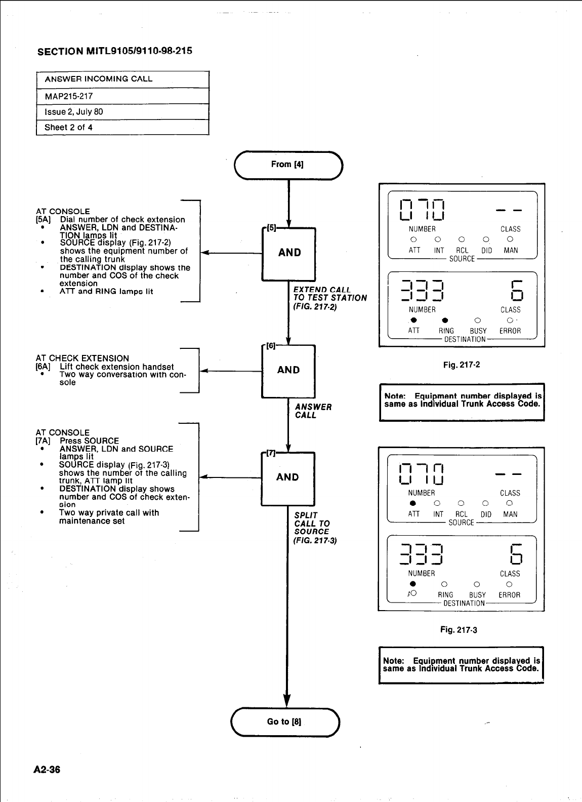
SECTION MITL9105/9110-98-215
1 Sheet 2 of 4
AT CONSOLE
[5$] Dial number of check extension
ANSWER. LDN and DESTINA-
TION lambs lit
. SOURCE display (Fig. 217-2)
shows the eauioment number of
the calling trunk
. DESTINATION display shows the
number and COS of the check
extension
. ATT and RING lamps lit I
- AND
.
EXTEND CALL
TO TEST STAT/ON
(FIG. 217.2)
AT CHECK EXTENSION
[6A] Lift check extension handset
. ;T; way conversatron wrth con-
AT CONSOLE
[7A] Press SOURCE
. ANSWER, LDN and SOURCE
lamps lit
. SOURCE display (Fig. 217-3)
shows the number of the calling
trunk, ATT lamp lit
. DESTINATION disolav shows
number and COS of check exten-
sion
. Two way private call with
maintenance set -
A2-38
-
SPLIT
CALL TO
SOURCE
(FIG. 217.3)
1
l-l 7 l-l
LI I - -
l-l
NUMBER CLASS
0 0 0 0 0
ATT INT RCL DID MAN
SOURCE
1; 1; 1;
---
NUMBER CLASS
0 0 0 0.
ATT RING BUSY ERROR
DESTINATION
1
Fig. 217-2
--
NUMBER CLASS
0 0 0 0 0
( ATT INT SOR;;cE DID MAN ) 1
NUMBER
0 0 0
FO RING BUSY
DESTINATION
Fig. 217-3
I I
I
Note: Equipment number displayed is
same as lndlvidual Trunk Access Code. I
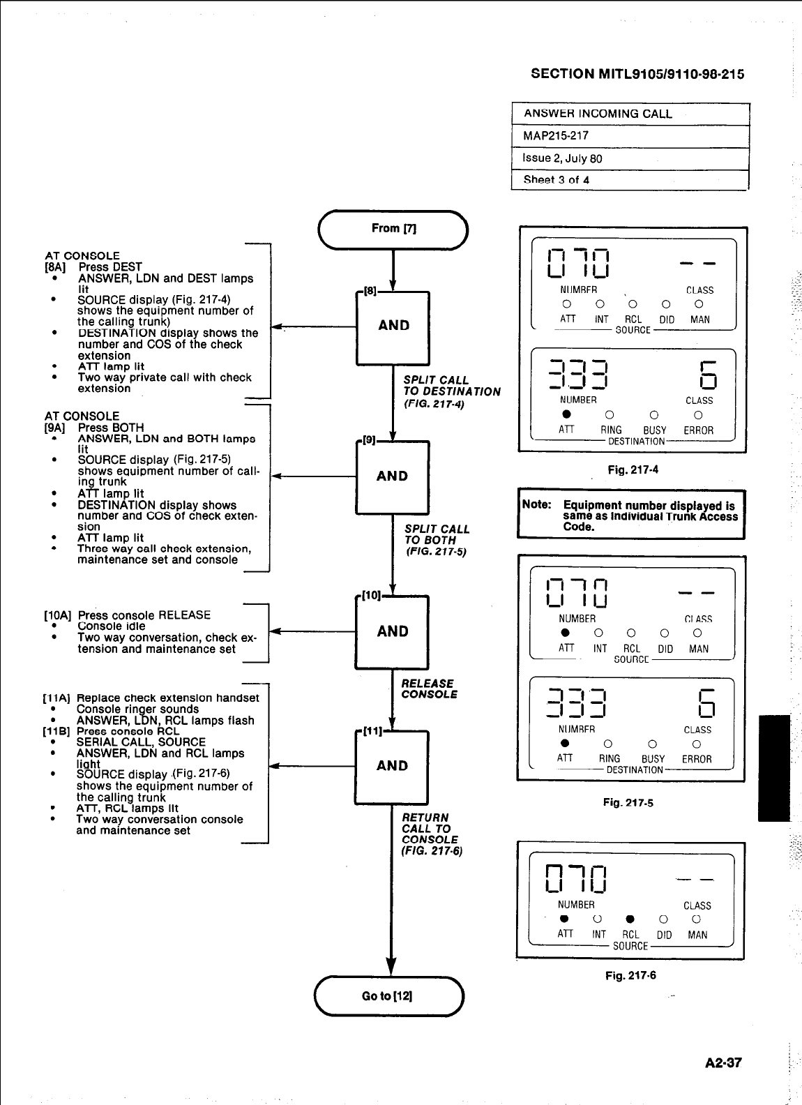
SECTION MITL9105/9110-98-215 j
1 ANSWER INCOMING CALL I
From [7j
AT CONSOLE
[8A] Press DEST
. :tNSWER, LDN and DEST lamps
. SOURCE display (Fig. 217-4)
shows the eauioment number of
the calling trunk)
. DESTINATION display shows the
number and COS of the check
extension
. ATT lamp lit
. Two way private call with check
extension
TION
SPLIT CALL SPLIT CALL
TO DESTINA TO DESTINA
(FIG. 217.4) (FIG. 217.4)
PI t
PI ’
I
AND
I
;gL;m;LL
(FIG. 217-S)
[lOA] Press console RELEASE
. Console idle
. Two way conversation, check ex-
tension and maintenance set t-
AND
RELEASE
CONSOLE
!f
WI
AND AND
I
I
I
I
RETURN RETURN
CALL TO CALL TO
CONSOLE CONSOLE
(FIG. 27 7-6) (FIG. 27 7-6)
V
(,,,.,,)
-
AT CONSOLE
[9A] Press BOTH
. ftNSWER, LDN and BOTH lamps
. SOURCE display (Fig. 217-5)
shows equipment number of call-
ing trunk
. ATT lamp lit
. DESTINATION display shows
number and COS of check exten-
sion
. ATT lamp lit
. Three way call check extension,
maintenance set and console
Fig. 217-4
qote: Equipment number displayed is
1 Code. ’ ’
same as lndlwdual Trunk Access
-
[ll A] Replace check extension handset
. Console rin er sounds
% ANSWER L N RCL lamps flash
1; B] Press co&sole kCL
. SERIAL CALL, SOURCE
. ANSWER, LDN and RCL lamps
. .%hiRCE display .(Fig. 217-6)
shows the equipment number of
the calling trunk
. ATT, RCL lamps lit
. Two way conversation console
and maintenance set -
-- 3 11’3 r
13
NUMBER CLASS
0 0 0 0
All RING BUSY ERROR
DESTINATION
Fig. 217-5
Fig. 217-6
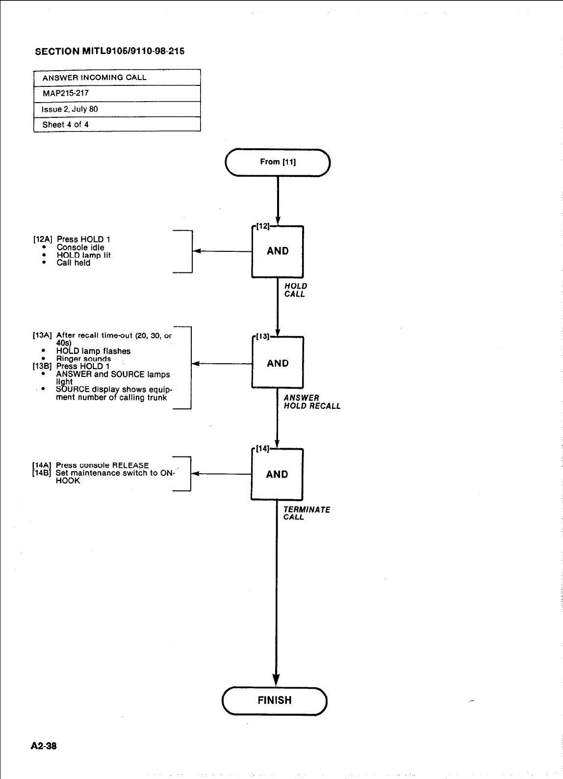
SECTION MITL9105/9110-98-215
ANSWER INCOMING CALL
MAP215-217
rlssue 2,
July
80
rziSheet -4 of 4 I
[12A] Press HOLD 1
l
Console idle
l
HOLD lamp lit
l
Call held
-
-
[13A] $.;ty recall time-out (20, 30, or
. HOLD lamp flashes
l
Ringer sounds
[13B] Press HOLD 1
l
;:h:WER and SOURCE lamps
l
SOURCE displa shows equip-
ment number o Y calling trunk -
1121. t
i -
AND
t-
[14A
[14B Press cpnsole RELEpsE
penytenance switch to ON- ’
HOLD
CALL
AND
HOLD RECALL
TERMINATE
CALL
A2-38
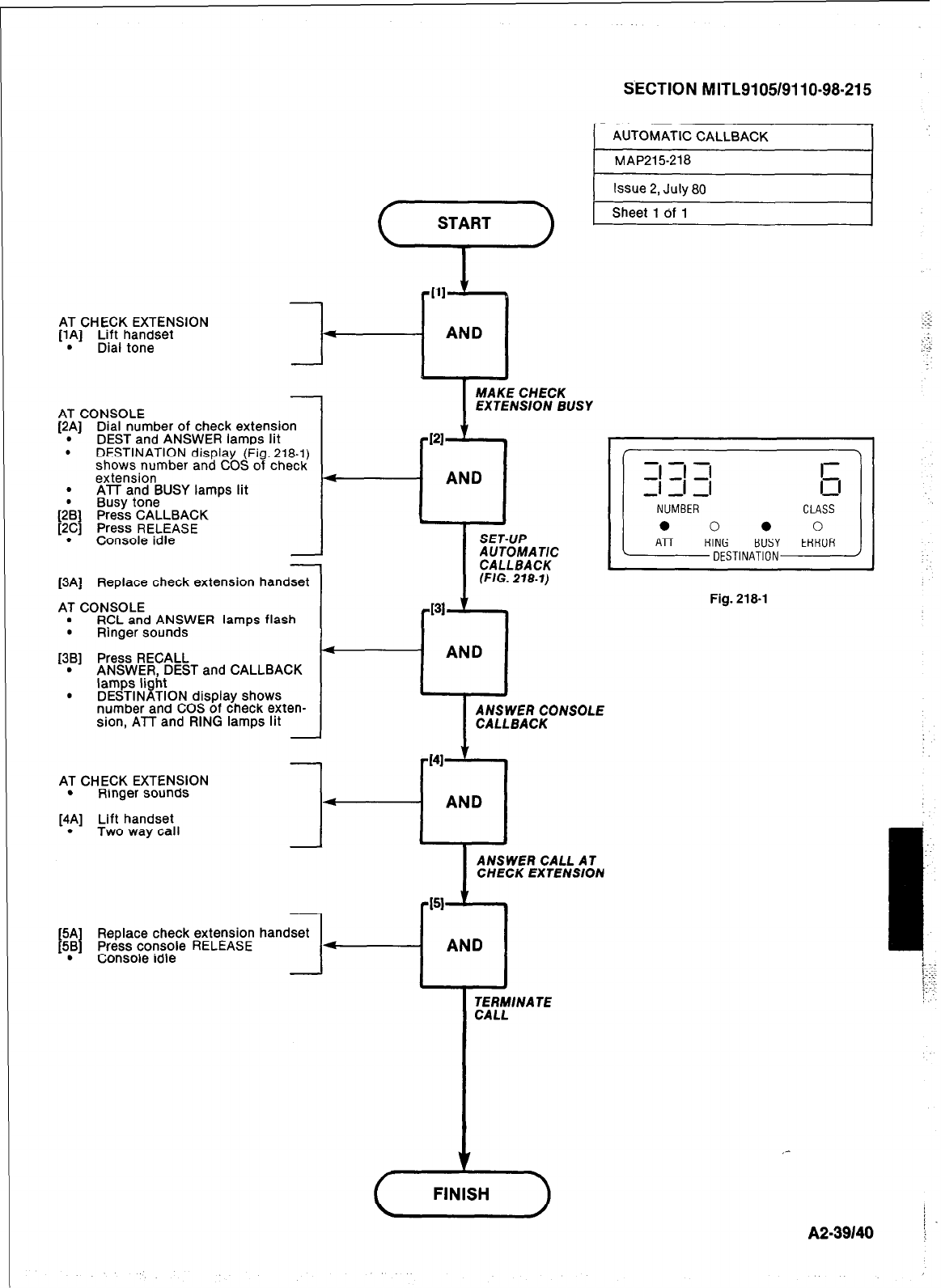
AT CHECK EXTENSION
[lA] Lift handset
. Dial tone l-
S’ECTION MITL9105/911 O-98-21 5
AT CONSOLE
[2p] Dial number of check extension
DEST and ANSWER lamps Irt
. DESTINATION display (Fig. 218-l)
shows number and COS of check
extension
. ATT and BUSY lamps lit
Busy tone
(2@B] Press CALLBACK
[2C] Press RELEASE
. Console idle
-
[3A] Replace check extension handset
AT CONSOLE
. RCL and ANSWER lamps flash
. Ringer sounds
[3B] Press RECALL
. ANSWER, DEST and CALLBACK
lamps light
. DESTINATION display shows
number and COS of check exten-
sion, ATT and RING lamps lit
4
PI
MAKE CHECK
EXTENSION BUSY
A UTOMA T/C
131
-0
AND
-I
AT CHECK EXTENSION
. Ringer sounds
[4p] Lift handset
Two way call
Replace check extension handset
Press console RELEASE
. Console idle
I
ANSWER CONSOLE
CALLBACK
- AND
ANSWER CALL AT
CHECK EXTENSION
t51 ,,
AND
TERMINATE
CALL
Fig. 218-1
A2.39140 i
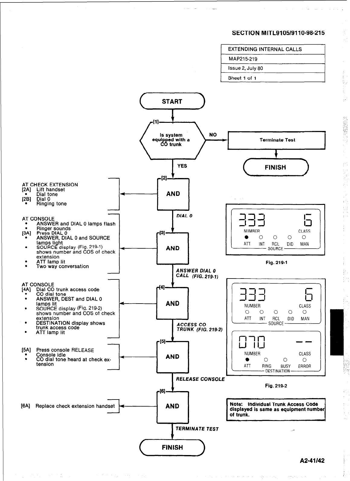
SECTION MITL9105/9110-98-215
EXTENDING INTERNAL CALLS
MAP215-219
Issue 2, July 80
Sheet 1 of 1
START 1
Terminate Test
(,,.,,,)
AT CHECK EXTENSION
[2.A] Lift handset
Dral tone
[2B] Dial 0
. Ringing tone
1-
I
DIAL 0
b
NUMBER CLASS
0 0 0 0 0
A7T INT RCL DID MAN
SOURCE
AT CONSOLE
. ANSWER and DIAL 0 lamps flash
Ringer sounds
[iA] Press DIAL 0
. ANSWER, DIAL 0 and SOURCE
lamps light
. SOURCE display (Fig. 219-l)
shows number and COS of check
extension
. ATT lamp lit
. Two way conversation
131
--Cl
AND
Fig. 219-1
I
ANSWER DIAL 0
CALL (FIG. 219.1)
J
AT CONSOLE
[4.A] 1331d~. ;Fn;k access code
. ANSWER, DEST and DIAL 0
lamps lit A
. SOURCE display (Fig. 219-2)
shows number and COS of check
extension
. DESTINATION disolav shows I
E
AND
I
CLASS
0 0 0 0 0
RCL DID MAN
SOURCE
J
ACCESS CO
TRUNK (F/G. 219-2)
151
f
AND
RELEASE CONSOLE
trunk access code’ -
. ATT lamp lit
[5A] Press console RELEASE
. Console idle
. CO dial tone heard at check ex-
tension --I--
-
Fig. 219.2
ct61 t
[6A] Replace check extension han
AND
TERMINATE TEST
Note: Individual Trunk Access Code
z----j
displayed is same as equipment number
A2-41142 j
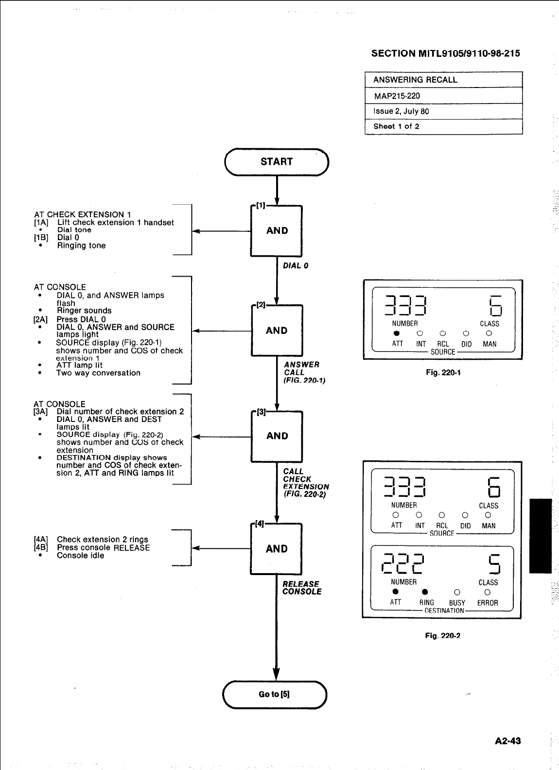
AT CHECK EXTENSION 1
[lA] Lift check extension 1 handset
Dial tone
[l*B] Dial 0
. Ringing tone
---c
,
r
Ill ’
II
AT CDNSOLE
. DIAL 0, and ANSWER lamps
flash
Ringer sounds
[2:] Press DIAL 0
. DIAL 0. ANSWER and SOURCE
lamps fight
. SOURCE display (Fig. 220-l)
shows number and COS of check
extension 1
. ATT lamp lit
. Two way conversation
-
AT CONSOLE
[3p] Dial number of check extension 2
DIAL O,.ANSWER and DEST
lamps Irt
. SOURCE display (Fig. 220-2)
shows number and c;uS OT check
extension
e DESTINATION display shows
number and COS of check exten-
sion 2, ATT and RING lamps lit
I-
I
DIAL 0
1
4
1
CHECK
EXTENSION
(FIG. 220-2)
[4A] Check extension 2 rings
[4B] Press console RELEASE
.
Console idle
PI41 t
4
AND
RELEASE
CONSOLE
SECTION MITL9105/9110-98-215
) ANSWERING RECALL I
1 MAP2157220
Issue 2, July 80
Sheet 1 of 2
IT:
ll
CLASS
0 0 0 0 0
DID MAN
Fig. 220-l
--- 333
NUMBER CLASS
0 0 0 0 0
ATT INT RCL DID MAN
SOURCE
Fig. 220-2
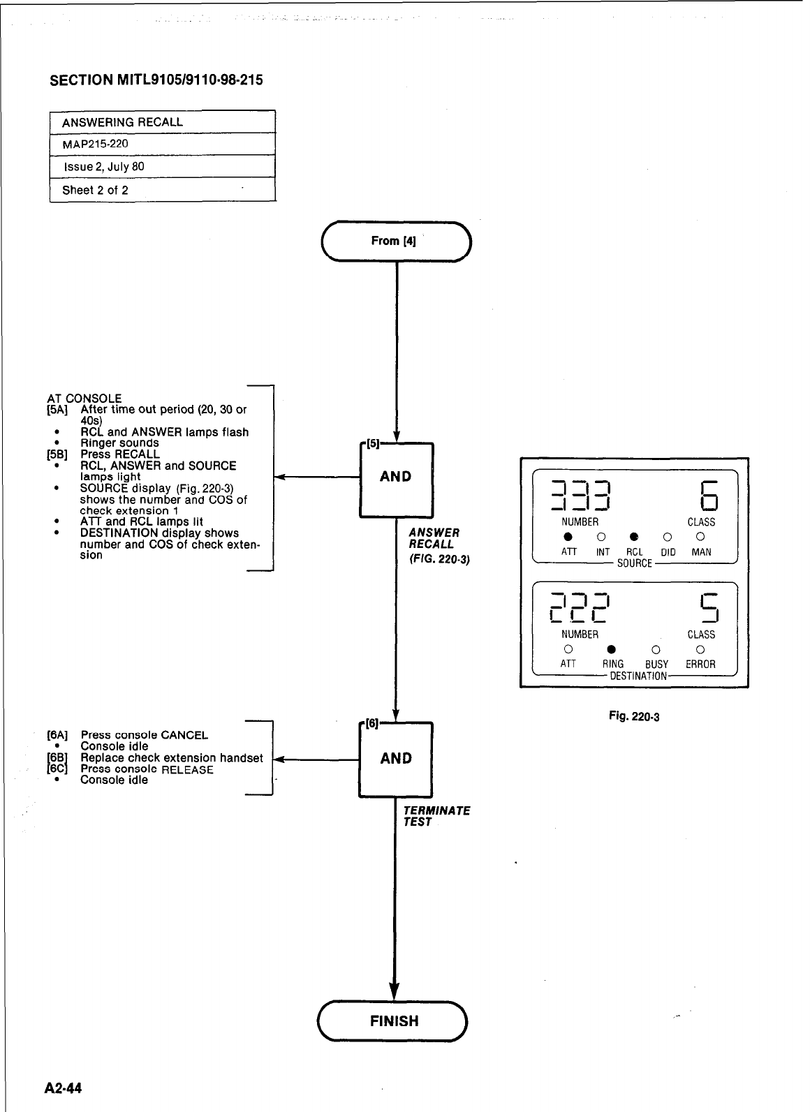
SECTION MITL9105/9110-98-215
ANSWERING RECALL
MAP215220
Issue 2,
July 80
Sheet 2 of 2
-
AT CONSOLE
[5A] t;$r time out period (20, 30 or
. RCL and ANSWER lamps flash
Ringer sounds
[&] Press RECALL
. RCL, ANSWER and SOURCE
lamps light
. SOURCE display (Fig. 220-3)
shows the number
and COS of
check extension 1
. ATT and RCL lamps lit
. DESTINATION display shows
number and COS of check exten-
sion -
[6A] Press console CANCEL
[6\ Console idle
[6C
Replace check extension
. F’r%sso~~~rele RELEASE
J
by
AND
I
ANSWER
RECALL
(FIG. 220-3)
handset 4
-PI ‘I
AND
--- -1 ‘I 3
NUMBER CLASS
0 0 e 0 0
ATT INT RCL DID MAN
SOURCE
Fig. 220.3
A2-44
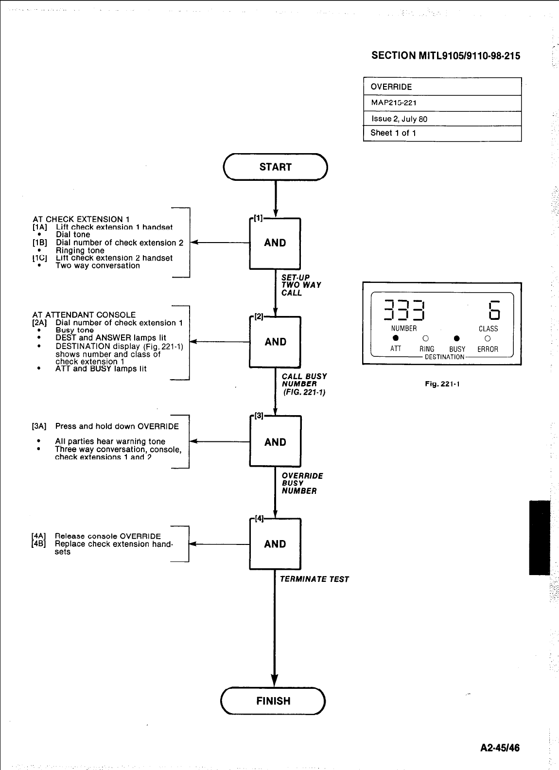
SECTION MITL9105/9110-98-215 :;
‘+
AT CHECK EXTENSION 1
[lA] Lift check extension 1 handset
[I\] Dial tone
Dial number of check extension 2
[l:C] Ringing tone
Lift check extension 2 handset
Two way conversation
-
AT ATTENDANT CONSOLE
[2A] Dial number of check extension 1
. Busy tone
. DEST and ANSWER lamps lit
.
DESTINATION display (Fig. 221-1)
shows number and class of
check extension 1
. ATT and BUSY lamps lit
OVERRIDE I
I
SET-UP
TWO WAY
CALL
PI
-cl
AND
Fig. 221-l
[3A] Press and hold down OVERRIDE
.
. Ali parties hear warning tone I-[?
Three way conversation, console,
check extensions 1 and 2
[4A] Release console OVERRIDE
[4B] Replace check
sets
TERMINATE TEST
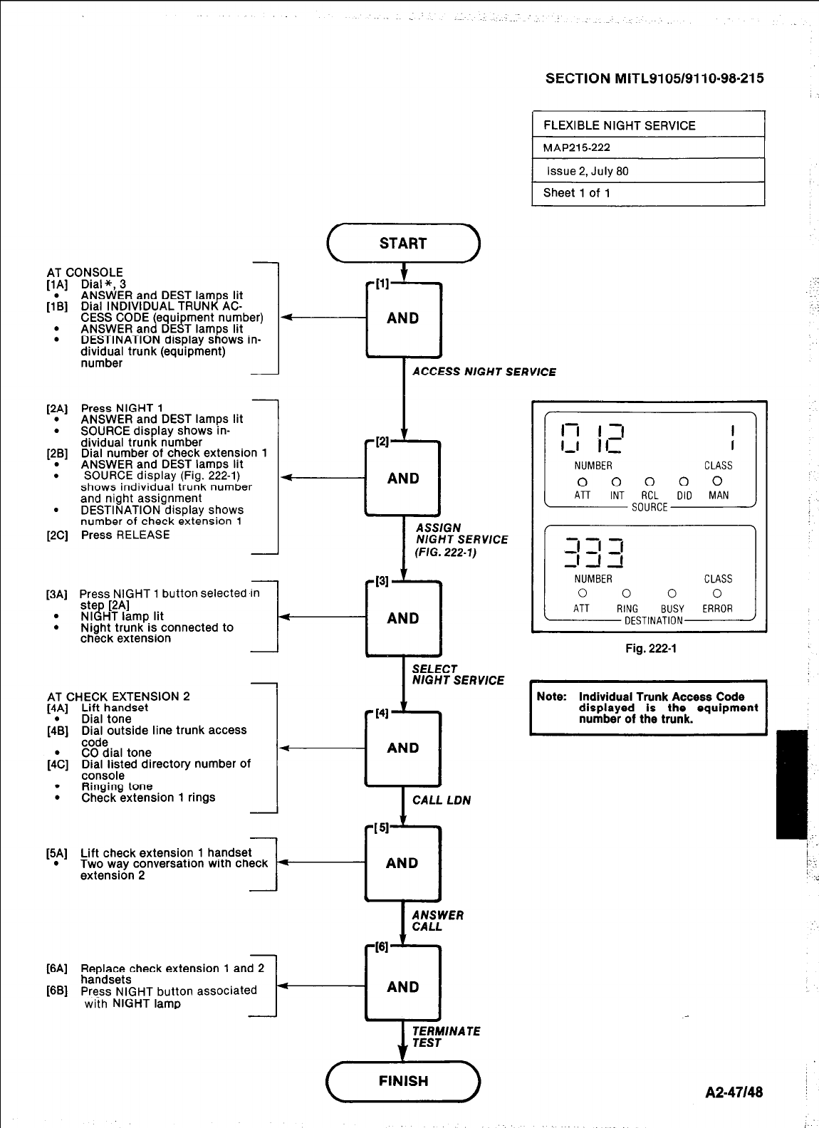
SECTION MITL9105/9110-98.215
FLEXIBLE NIGHT SERVICE I
1 MAP215222
Issue 2. Julv 80
Sheet 1 of 1
(xii--)
-
AT CONSOLE
WI
Dial *, 3
h
.
.
ANSWER and DEST lamps lit
Dial INDIVIDUAL TRUNK AC-
Ill
-cl
AND
PA1
.
.
WI
.
.
.
WI
[3Al
.
.
CESS CODE (equi ment number)
ANSWER and DE t T lamps lit
D.ESTlNATlON display shows in-
clrr$r~,“l’ trunk (equipment)
ACCESS NIGHT SERVICE
J
Press NIGHT 1
ANSWER and DEST lamps lit
SOURCE display shows in-
dividual trunk number
Dial number of check extension 1
ANSWER and DEST lamos lit
SOURCE display (Fig. 222-l)
shows individual trunk number
and night assignment
DESTINATION display shows
number of check extension 1
Press RELEASE
I
NUMBER CLASS
NlGHT SERWCE
.
( ATT INT ,,","d-,, DID MAN
J
Press NIGHT 1 button selected In
ste [2A]
NI l HT lamp lit
Night trunk is connected to
check extension I-
Fig. 222-l
I
SELECT
NIGHT SERVICE
Individual Trunk Access Code
AT CHECK EXTENSION 2
[4A] Lift handset
Dial tone
bl
ih
.
.
Dial outside line trunk access 1 I I
code
CO dial tone
Dial listed directorv number of t----l AND I
console
Ringing tone
Check extension 1 rings
Ey
Pw
WI
Lift check extension 1
Two way conversation with check
extension 2
4
AND
-
Replace check extension 1 and 2
handsets
Press NIGHT button associated
with NIGHT lamp
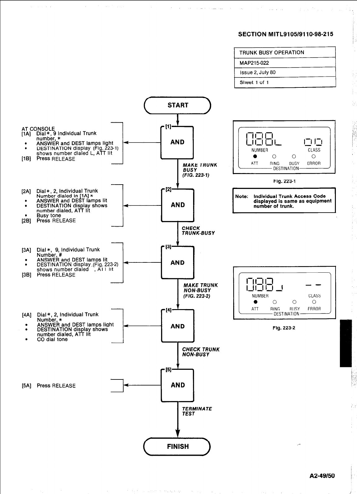
AT CONSOLE
[l A] Dial *. 9 Individual Trunk
1
number, *
ANSWER and DEST lamps light A
DESTINATION display (Fig. 223-l)
shows number dialed L, ATT lit
Press RELEASE
.
.
11 Bl
[3Al
.
.
1381
[4Al
.
.
.
SECTION MITL9105/9110-98-215
-
Dial*, 2, Individual Trunk I
Numb&dialed in lA] *
ANSWER and DE 4 T lamps lit I
DESTINATION display shows
number dialed. ATT lit
Busy tone ’
Press RELEASE
Dial *, 9. Individual Trunk
1
Numbbr,f
ANSWER and DEST lamps lit
DESTINATION display.(Fig. 223-2)
shows number dialed ,
Al I Ilt
Press RELEASE t-
TRUNK-BUSY
MAKE TRUNK
NON-BUSY
(FIG. 223-2)
JERMINA JE
CLASS
0
ERROR
Fig. 223-l
Note: Individual Trunk Access Code
I / \
II
I-I I3 13
l,ll-II I 1 - -
--
Fig. 223-2
1
J
I
A2-49150 I
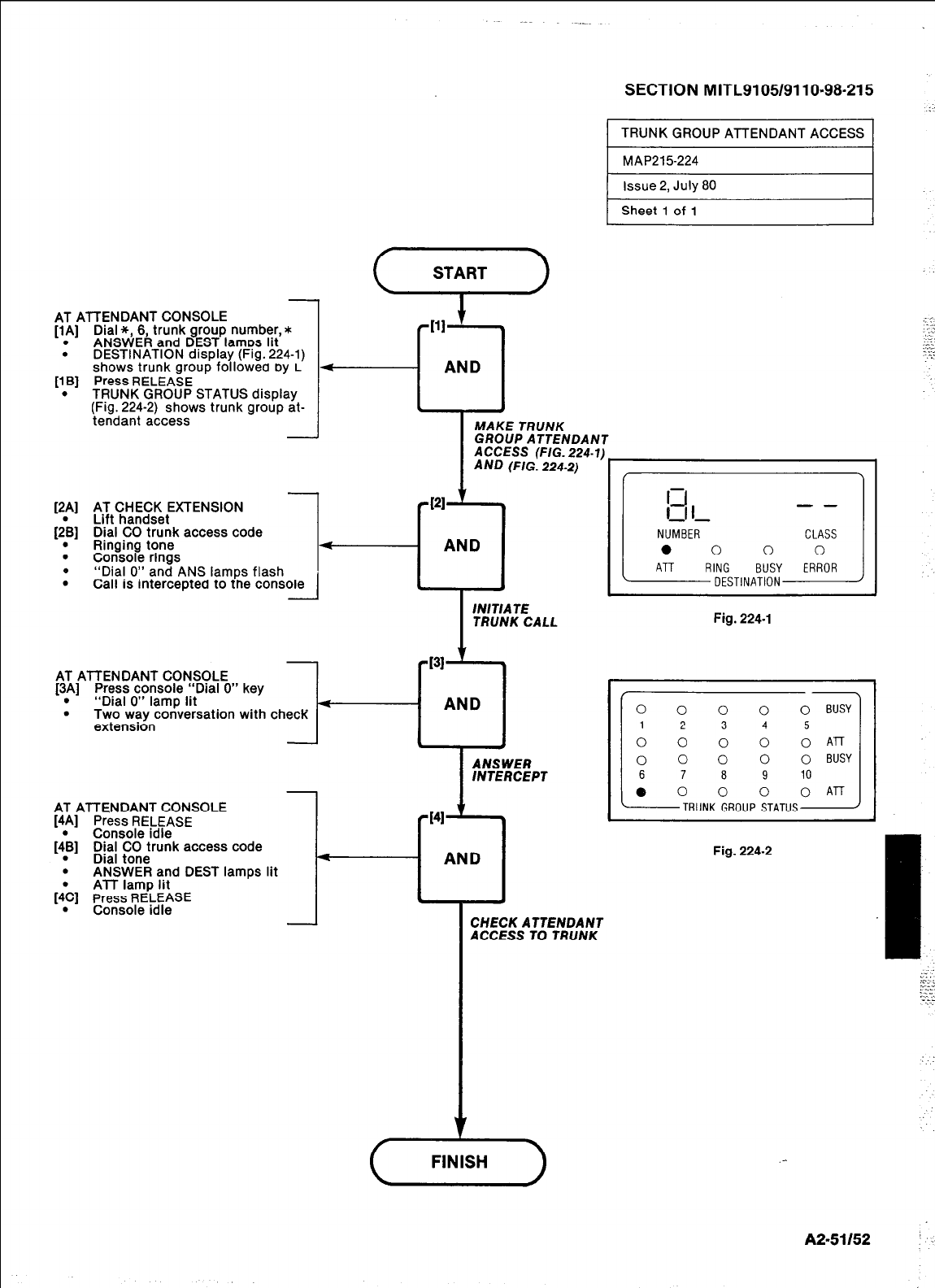
AT ATTENDANT CONSOLE
[lA] Dial *, 6, trunk group number,*
. ANSWER and DEST lamos lit
DESTINATION display (Fig. 224-l)
shows trunk group followea my L
.
11 Bl
.
Press RELEASE
TRUNK GROUP STATUS display
(Fig. 224-2) shows trunk group at-
tendant access
y1
'2~1
.
.
.
AT CHECK EXTENSION
Lift handset
Dial CO trunk access code
Ringing tone
Console rings
“Dial 0” and ANS lamps flash
Call is interceptea to tne console
-
-
AT ATTENDANT CONSOLE
[3A] Press console “Dial 0” key
. “Dial 0” lamp lit
. Two way conversation with check
extension
AT ATTENDANT CONSOLE
_-.._-.- .-.-
Xal CO trunk access code
I481 bial tom
.
. ANSWEF
[‘& I,,,,,,, I”lt:
.
; and DEST lamps lit
ATT lamp lit
sress RELEASE
-^___I_ :A‘-
MAKE TRUNK
SECTION MITL9105/9110.98-215
TRUNK GROUP ATTENDANT ACCESS
MAP215-224
Issue 2, July 80
Sheet 1 of 1
tOUP ATTENDANT
TRUNK CALL Fig. 224-l
AND
I
ANSWER
INTERCEPT
d41 .
4
- AND
.
-
CHECK ATTENDANT
ACCESS TO TRUNK
Fig. 224-2
. :
:::
. . .
-1
:;‘t
.-
A2-51152
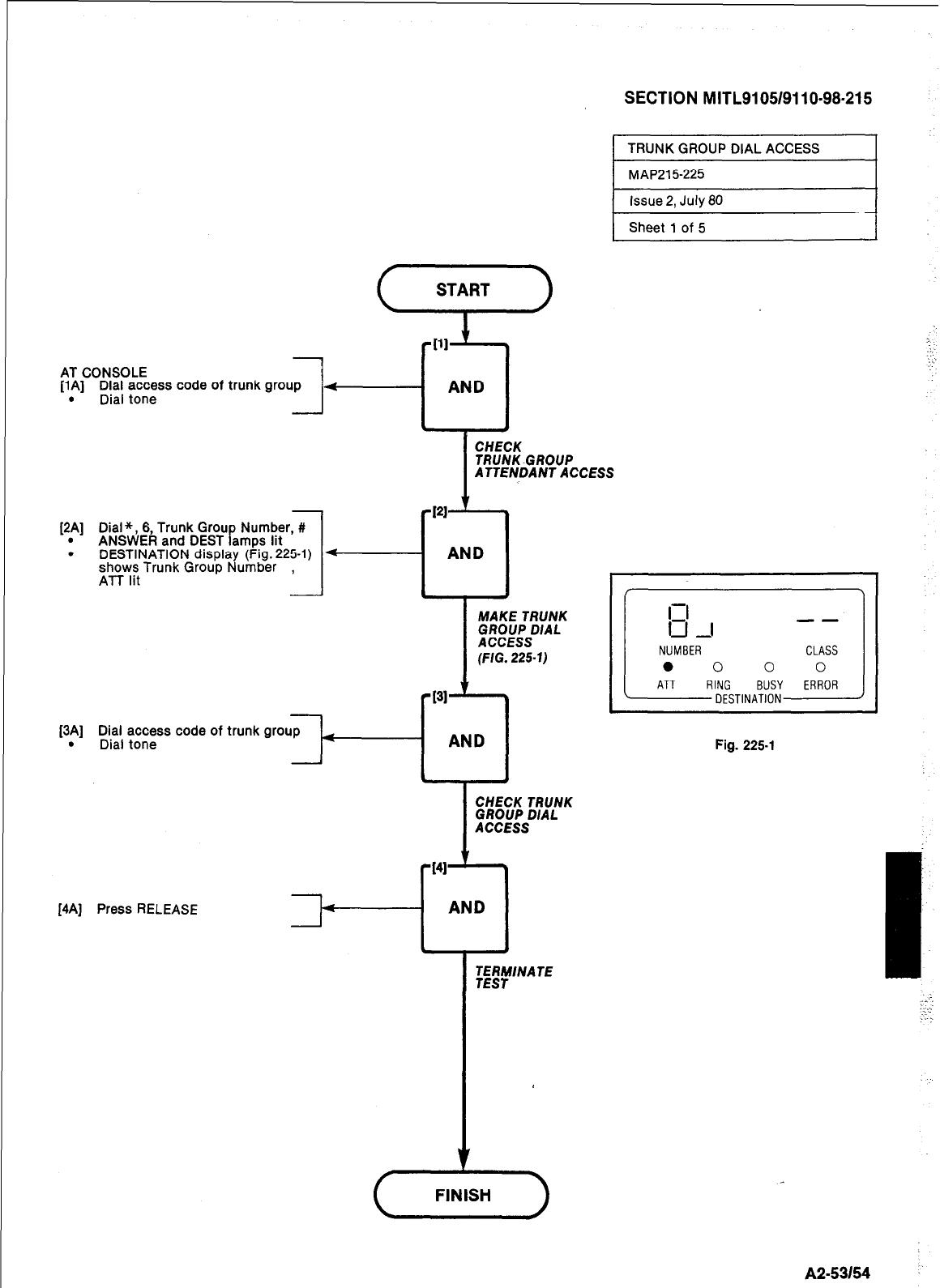
SECTION MITL9105/9110-98-215
AT CONSOLE
[lA] Dial access code of trunk group
. Dial tone -
[2A] Dial*, 6, Trunk Grou Number, #
. ANSWER and DEST amps lit P
. DESTINATION display (Fig. 225-l)
shows Trunk Group Number ,
ATT lit
[3Al
.
TRUNK GROUP DIAL ACCESS
MAP215225
Issue 2, July 80
Sheet 1 of 5
I
CHECK
TRUNK-GROUP
ATTENDANT ACCESS
$4
AND
i
MAKE TRUNK
GROUP DIAL
ACCESS
(FIG. 225-l)
Dial access code of trunk group
Dial tone
I4A] Press RELEASE
CHECK TRUNK
GROUP DIAL
ACCESS
-141 t
l
- AND
TERMINATE
TEST
Fig. 225-l
A2.53154
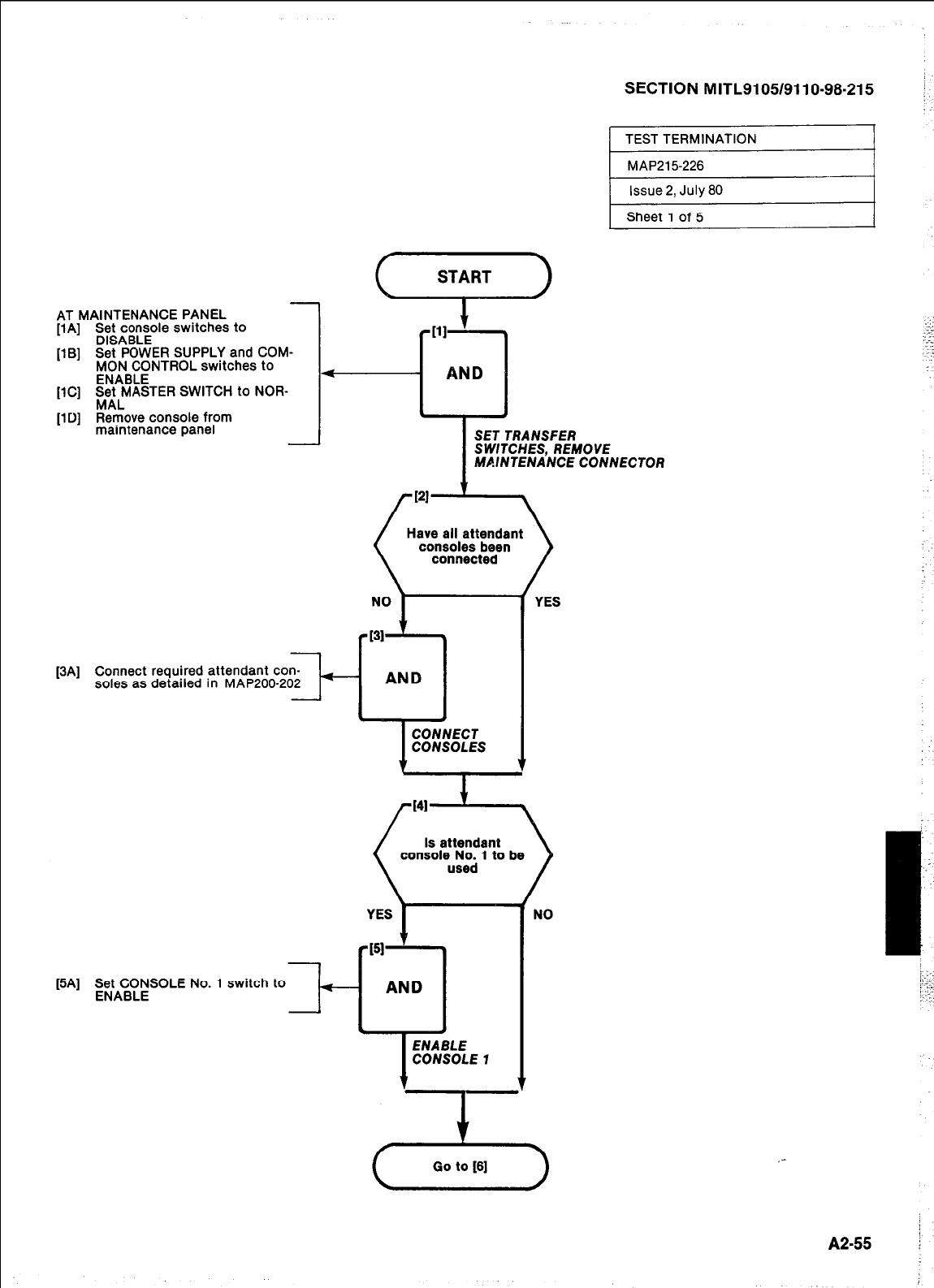
AT MAINTENANCE PANEL
[lA] Sg4c;sole switches to
IlBl Set PO _ -kER SUPPLY and COM-
‘--’ FiiBCENTROL switches to
[lCl Set MASTER SWITCH to NOR-
_ _
MAL
[lD] Remove console from
maintenance panel
WI
-
Connect required attendant con-
soles as detailed in MAP200-202
SECTION MITL9105/9110-98-215
TEST TERMINATION
MAP215226
Issue 2, July 80
Sheet 1 of 5
I
SET TRANSFER
SWITCHES, REMOVE
MAINTENANCE CONNECTOR
connected
-1
AND
-
[5A] gtA;r$.SOLE No. 1 switch to
Is attendant
console No. 1 to be
/
YES
NO
I..:
I?--. ._
..-.
:-
_ ~.,
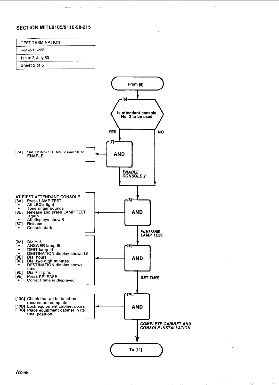
SECTION MITL9105/9110~98-215
Issue 2, July 80
Sheet 2 of 5
[7A] g;tA%$SOLE No. 2 switch to
k-
AT FIRST ATTENDANT CONSOLE
[8A] Press LAMP TEST
. All LED’s light
[8& Tone ringer sounds
Release and press LAMP TEST
%%~plays show 8
[8\] Release
. Console dark
PA1
.
N’AI
1
YES
PI .
- AND
. t
ENABLE
CONSOLE 2
From [5]
Is attendant console
No.
2
to be used
NO
Dial* 5
ApISWFR lamn lit
DEST lamp lit
DESTINATION display shows L5
Dial hours
Dial two digit minutes
DESTINATION display shows
time
Dial* if p.m.
Press RELEASE
Correct time is displayed
I
PERFORM
LAMP TEST
-------1 ANC
L-r’
SET 1
1 *I101
Check that all installation
records are complete
Lock equipment cabinet doors
Place equipment cabinet in its
I- *‘:
AND
final position
COMPLETE CAB/NET AND
CONSOLE /NSTALLAT/ON
A2-58
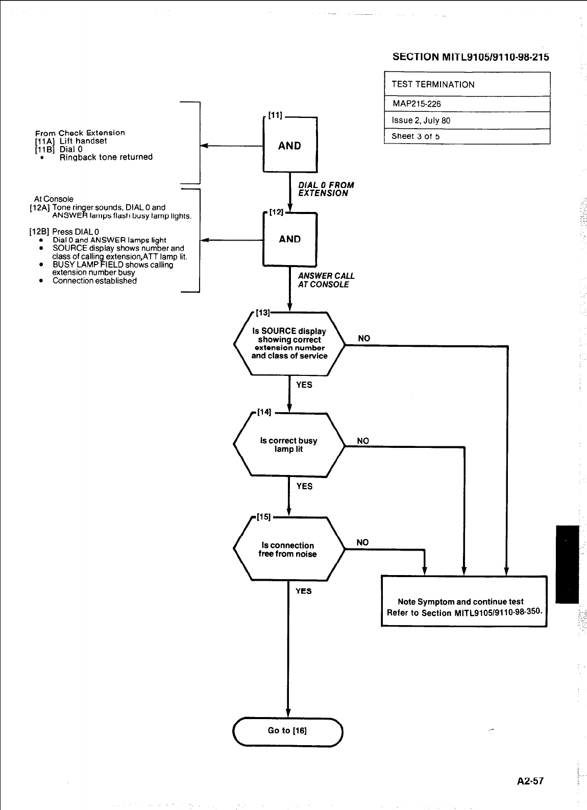
From Check Extension
[ll A] Lift handset
[llB] Dial 0
. Ringback tone returned
I-
--J
-
\t Console
2Aj Tone rin er sounds, DIAL 0 and
ANSWE 8 lamps flash busy lamp lights.
281 Press DIAL 0
l
Dial 0 and ANSWER lamps light
l
SOURCE display shows number and
class of callin extension,ATT lamp lit.
l
t
BUSY LAMP IELD shows calling
extension number busy
l
Connection established -
SECTION MITL9105/9110-98-215
TEST TERMINATION I
DIAL 0 FROM
EXTENSION
a-1 AND
ANSWER CALL
AT CONSOLE
YES
YES
i
I
Note Symptom and continue test
Refer to Section MITL9105/9110-96-360. I
,-
;.
A2-57 :
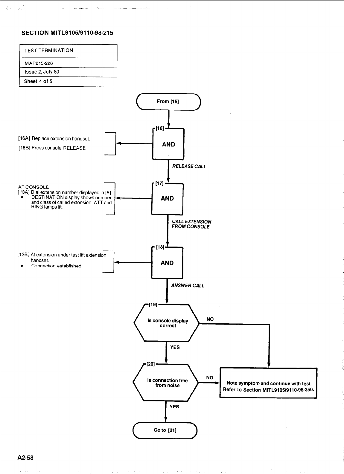
SECTION MITL9105/9110-98-215
Issue 2, July 80
Sheet 4 of 5
[16A] Replace extension handset.
[16B] Press console RELEASE
I
RELEASE CALL
AT CONSOLE
[13A] Dial extension number displayed in [8].
. DESTINATION display shows number
and class of called extension, ATT and
RING lamps lit.
FROM CONSOLE
I1381 At extension under test lift extension
handset. 4
. Connection established
I
ANSWER CALL
Is console display
Is connection free
YES
A2-58
Note symptom and continue with test.
Refer to Section MITL9105/9110-98.350.
1
::
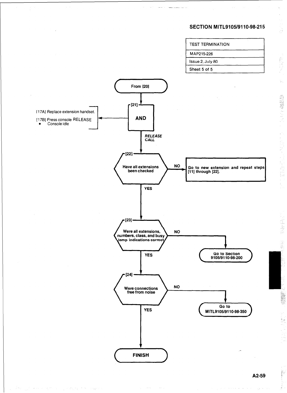
SECTION MITLSI 05/911 O-98-21 5
) Sheet 5 of 5 I
u AND
RELEASE
CALL
Have all extensions
been checked Go to new extension and repeat steps
[l l] through [22].
-
[17A] Replace extension handset.
[17B] Press console RELEASE
. Console idle
YES
Were all extensions,
numbers, class, and busy NO
YES Go to Section
9105/9110-98-200
Were connections
free from noise
YES
(+-)
;:
A2.59 i”
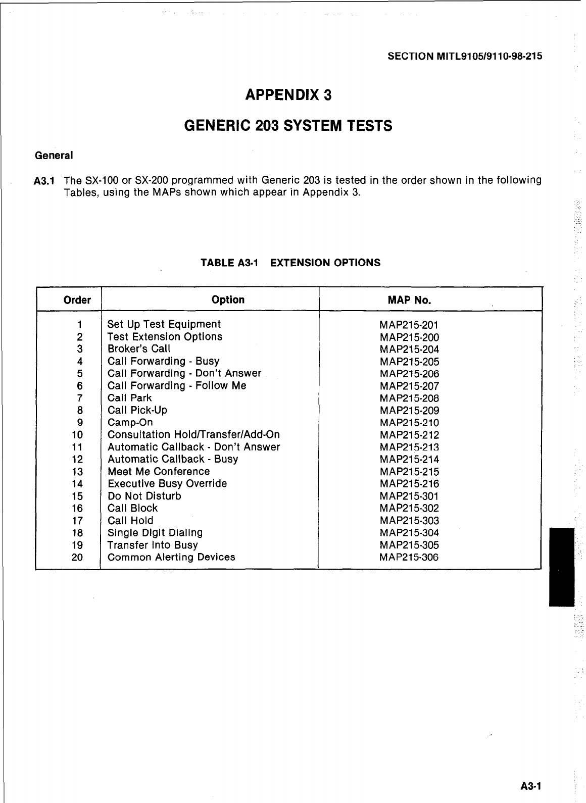
SECTION MITL9105/9110~98-215
APPENDIX 3
GENERIC 203 SYSTEM TESTS
General
A3.1
The SX-100 or SX-200 programmed with Generic 203 is tested in the order shown in the following
Tables, using the MAPS shown which appear in Appendix 3.
TABLE A3-1 EXTENSION OPTIONS
Order Option MAP No.
1 Set Up Test Equipment MAP215201
2 Test Extension Options MAP21 5200
3 Broker’s Call M AP215204
4 Call Forwarding - Busy MAP215-205
5 Call Forwarding - Don’t Answer MAP215-206
6 Call Forwarding - Follow Me MAP21 5-207
7 Call Park MAP215-208
8 Call Pick-Up MAP21 5-209
9 Camp-On MAP215-210
10 Consultation Hold/Transfer/Add-On MAP215-212
11 Automatic Callback - Don’t Answer MAP215-213
12 Automatic Callback - Busy MAP215-214
13 Meet Me Conference MAP215-215
14 Executive Busy Override MAP215-216
15 Do Not Disturb MAP215-301
16 Call Block MAP21 5-302
17 Call Hold MAP21 5-303
18 Single Digit Dialing MAP215-304
19 Transfer Into Busy MAP215-305
20 Common Alerting Devices MAP215-306
I-
-.
:
:
:
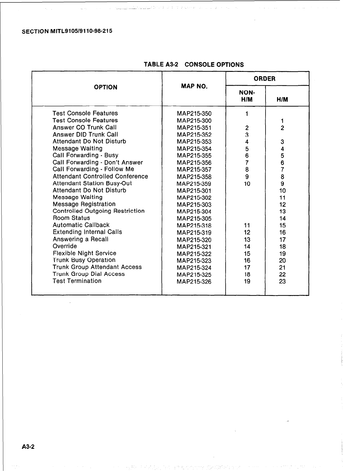
SECTION MITL9105/9110-98-215
TABLE A3-2 CONSOLE OPTIONS
ORDER
OPTION MAP NO. NON-
HIM H/M
-
Test Console Features MAP215350 1
Test Console Features MAP21 5-300 1
Answer CO Trunk Call MAP215351 2 2
Answer DID Trunk Call MAP21 5-352 3
Attendant Do Not Disturb MAP21 5-353 4 3
Message Waiting MAP215-354 5 4
Call Forwarding - Busy MAP215-355 6 5
Call Forwarding - Don’t Answer MAP215-356 7 6
Call Forwarding - Follow Me MAP21 5-357 8 7
Attendant Controlled Conference MAP215-358 9
a
Attendant Station Busy-Out MAP215-359 10 9
Attendant Do Not Disturb MAP215-301 10
Message Waiting MAP215-302 11
Message Registration MAP215303 12
Controlled Outgoing Restriction MAP21 5-304 13
Room Status MAP215-305 14
Automatic Callback MAP215-318 11 15
Extending Internal Calls MAP215319 12 16
Answering a Recall MAP215-320 13 17
Override MAP215-321 14 18
Flexible Night Service MAP215322 15 19
Trunk Busy Operation MAP21 5-323 16 20
Trunk Group Attendant Access MAP215-324 17 21
Trunk Group Dial Access MAP21 5-325 18 22
Test Termination MAP215-326 19 23
A3-2
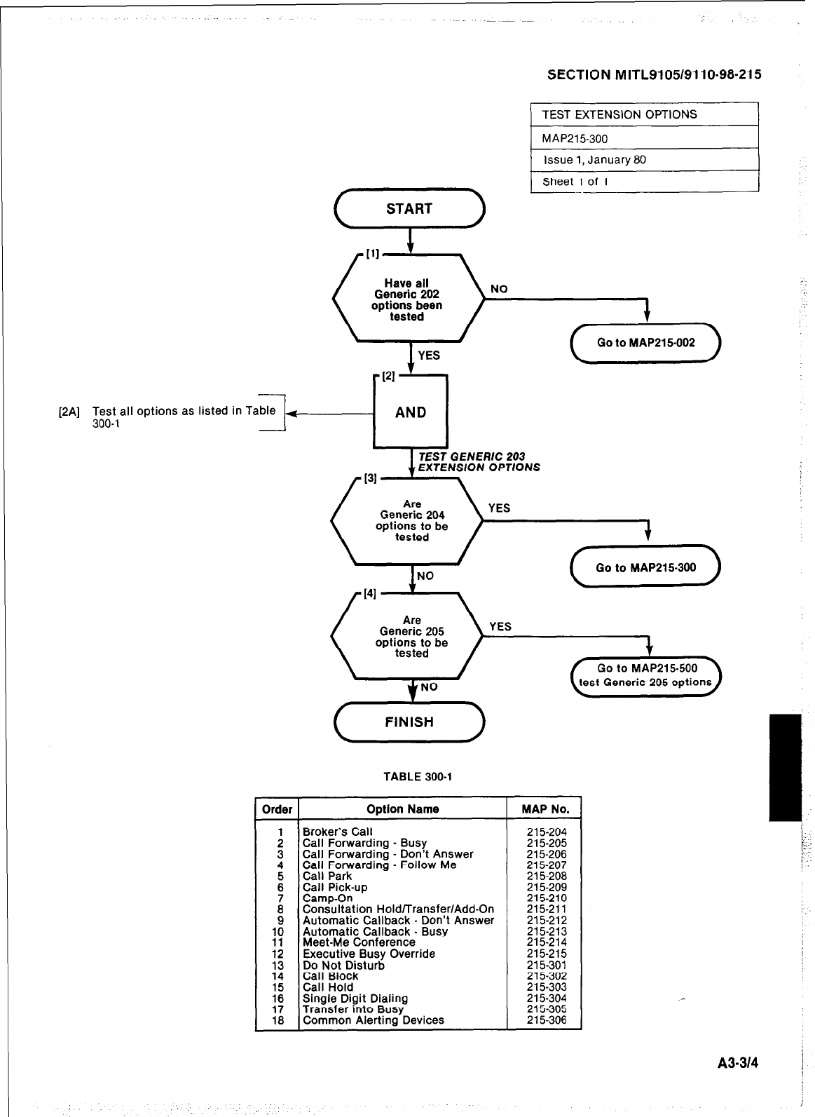
SECTION M ITL91051911 O-98-21 5
) TEST EXTENSION OPTIONS I
1 MAP215300 I
1 Issue 1, January 80 I
[2A] Test all options
as
listed in Table +
300-l -
L..
Sheet 1 of 1
I I
TEST GENERlC 203
EXTENSlON OPTIONS
YES
(QLEk-)
TABLE 300-l
Drder Option Name
: Broker’s Call
Call Forwarding - Busy
3 Call Forwarding - Don’t Answer
4 Call Forwarding - Follow Me
: Call Park
Call Pick-up
i %&%ition Hold/Transfer/Add-On
9 Automatic Callback - Don’t Answer
;: Automatic Callback - Busy
Meet-Me Conference
;: Executive Busy Override
Do Not Disturb
14 Call Block
2 Call Hold
Single Digit Dialing
:i Transfer into Busy
Common Alerting Devices
MAP No.
215-204
215-205
215-206
215-207
215-208
215-209
215210
215211
215-212
215-213
215-214
215-215
215-301
215-302
215-303
215-304
215-305
215-306
A3-314 j
I
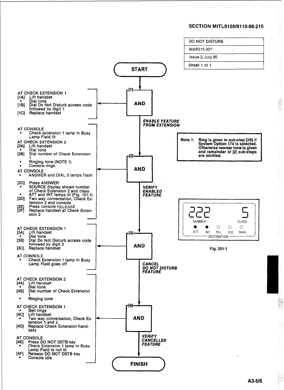
SECTION MITL9105/9110-98-215
1
DO
NOT DISTURB I
-
AT CONSOLE
.
Check extension 1 lamp in Busy
Lamp Field lit
AT CHECK EXTENSION 2
[2p] Lift handset
Dral tone
[2B] pial number of Check Extension
. Ringing tone (NOTE 1)
. Console rings
AT- CONSOLE
. ANSWER and DIAL 0 lamps flash
[2C] Press ANSWER
. SOURCE display shows number
of Check Extension 2 and class
[;D] ATT and INT lamps lit (Fig. 101-l)
Two way conversation, Check Ex-
tension 2 and console
Press console RELEASE
Replace handset at Check Exten-
sion 2
AT CHECK EXTENSION 1
[lA] Lift handset
Dial tone
[l*B] Dial Do Not Disturb access code 4
AND
.‘1.
:-:
. . .
followed by digit 1 : :
. . . .
[lC] Replace handset
ENABLE FEATURE
FROM EXTENSION
-
AT CHECK EXTENSION 1
[3A] Lift handset
[3*B] Dial tone
Dial Do Not Disturb access code
followed by digit 2
[3C] Replace handset
AT CONSOLE
. Check Extension 1 lamp in Busy
Lamp Field goes off
AT CHECK EXTENSION 2
[4A] Lift handset
(4& Dial tone
pial number of Check Extension
. Ringing tone
AT CHECK EXTENSION 1
Bell rings
[dc] Lift handset
. Two way conversation, Check Ex-
tension 1 and 2
[4D] Fttace Check Extension hand-
AT CONSOLE
[4E] Press DO NOT DSTB key
. Check Extension 1 lamp in Busy
[4FJ
Lamp Field is not lit
Release DO NOT DSTB key
.
Console idle
-PI ’
a AND
VERIFY
ENABLED
FEATURE
- AND
Fig. 301-l
CANCEL
DO NOT DISTURB
FEATURE
-141 t
- AND
VERIFY
CANCELLED
FEATURE
I
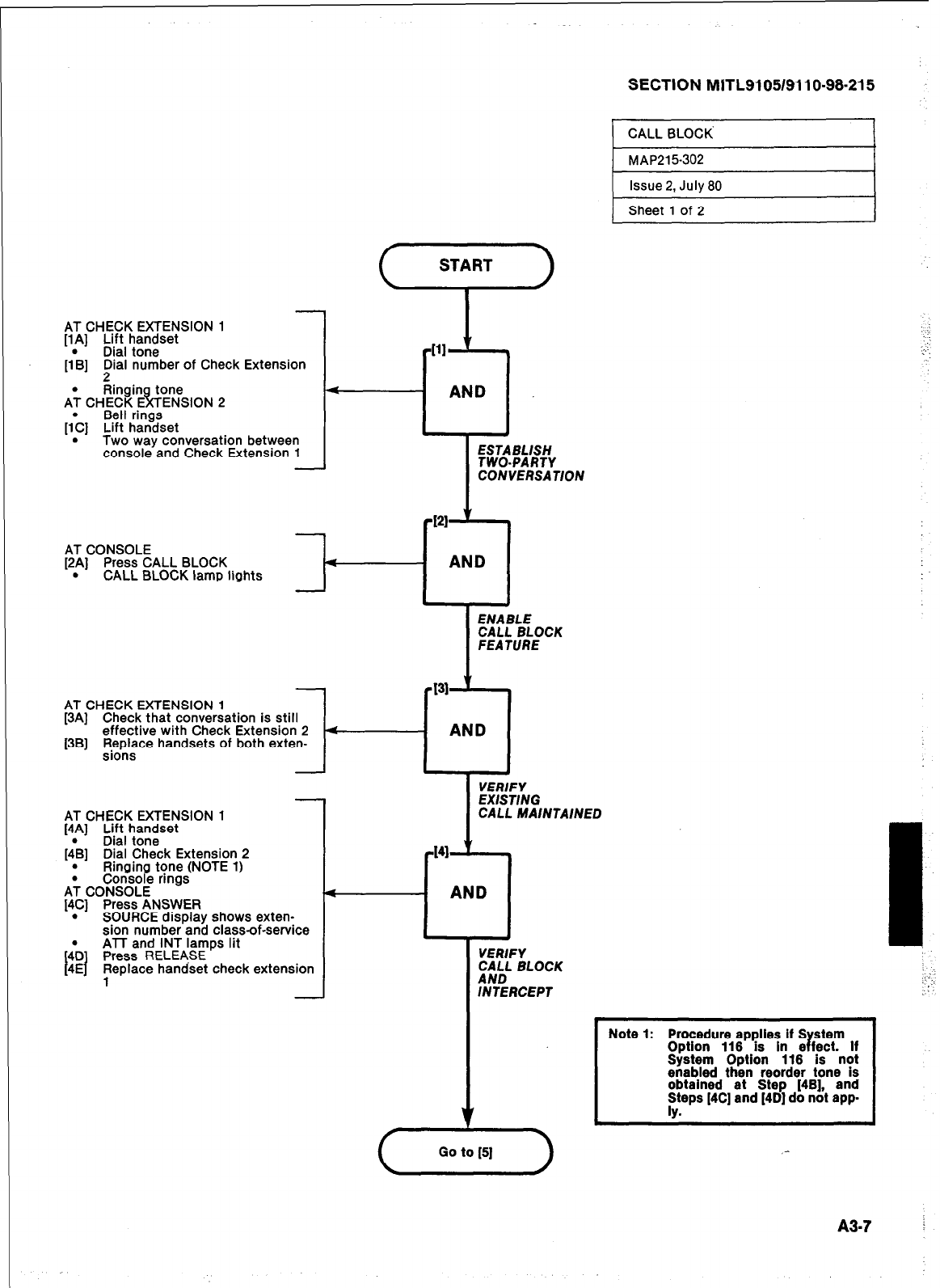
AT CHECK EXTENSION 1
[lA] Lift handset
[I’B] Dial tone
l$al number of Check Extension
A’; CHECK E
Ringin tone
IT ENSION 2
Bell rings
[;C] Lift handset
. Two way conversation between
console and Check Extension 1
-
4
-AND
SECTION MlTL9105/9110-98-215
,
r[ll ’ .
AT CONSOLE
[2A] Press CALL BLOCK
. CALL BLOCK lamp lights
-
AT CHECK EXTENSION 1
[3A] Check that conversation is still
effective with Check Extension 2
[3B] Replace handsets of both exten-
sions -
AT CHECK EXTENSION 1
[4A] Lift handset
Dial tone
[;B] Dial Check Extension 2
. Ringing tone (NOTE 1)
A; CONSOLE
Corisofe rings.
[4C] Press ANSWER
. SOURCE disolav shows exten-
sion number’and class-of-service
ATT and INT lamps lit
Press RELEASE
Replace handset check extension
1
- AND
.
VERIFY
EXISTING
CALL MAINTAINED
-141 y 9
4
1 AND
VERIFY
CALL BLOCK
AND
INTERCEPT
I
CALL BLOCK I
1 MAP215302
I Issue 2, July 80 I
1 Sheet 1 of 2
I
Note 1: Procedure applies if S r stem
Option 116 is in e feet. If
System Option 116 is not
enabled then reorder tone is
obtained et Step [4B], and
T [4C] and [4D] do not app
A3.7 i
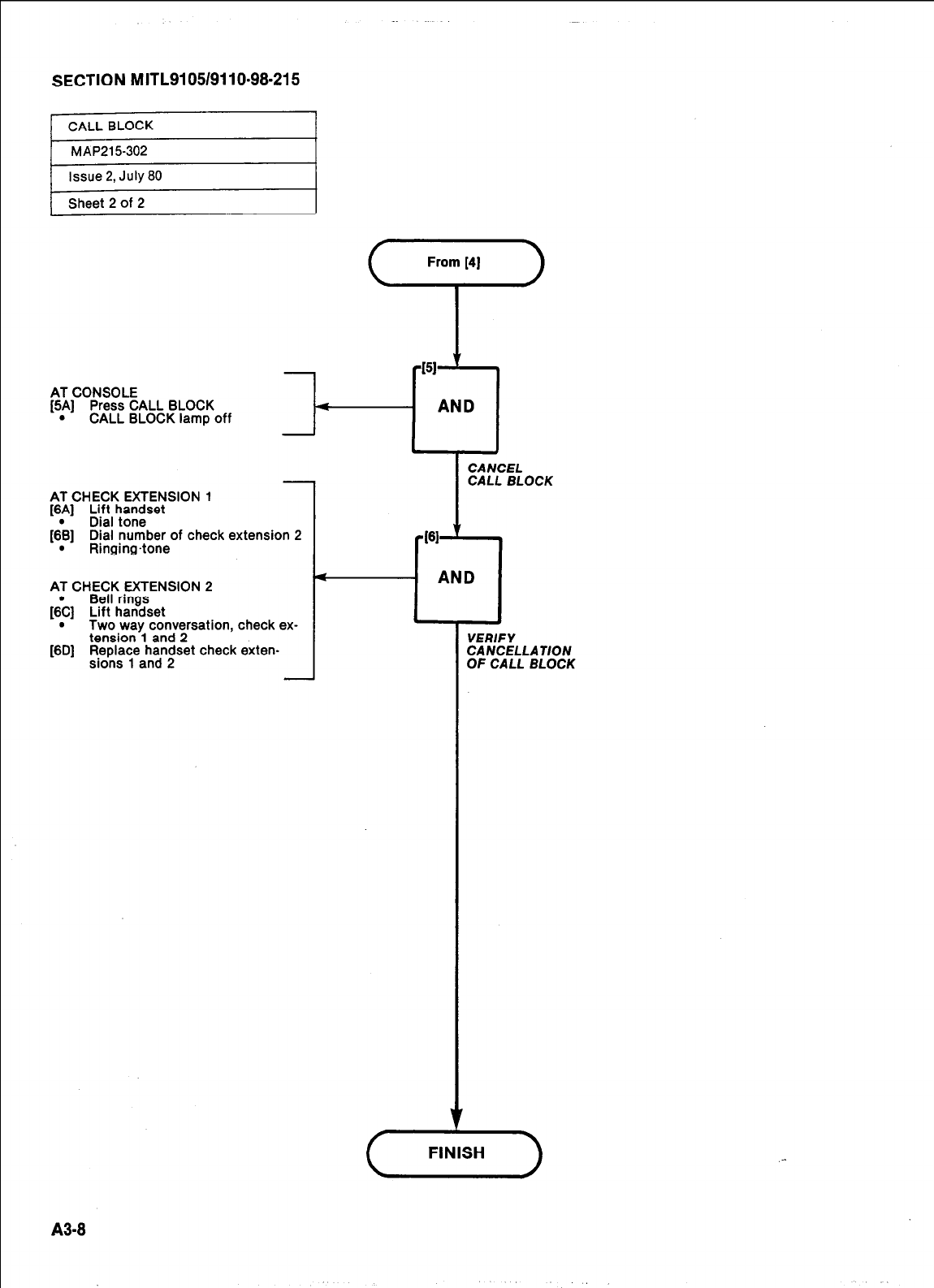
SECTION MITL9105/9110-98.215
Ieet
2
of 2 I
AT CONSOLE
[5A] Press CALL BLOCK
.
CALL BLOCK lamp off
AT CHECK EXTENSION 1
[6A] Lift handset
(;B] Dial tone
Dial number of check extension 2
. Ringing4one
AT CHECK EXTENSION 2
Bell rings
I&] Lift handset
. Two way conversation, check ex-
tension 1 and 2
[SD] ;e&$Tapdn;set check exten-
CANCEL
CALL BLOCK
461
‘I
4
. AND
VERIFY
CANCELLAUON
OF CALL BLOCK
A3-8
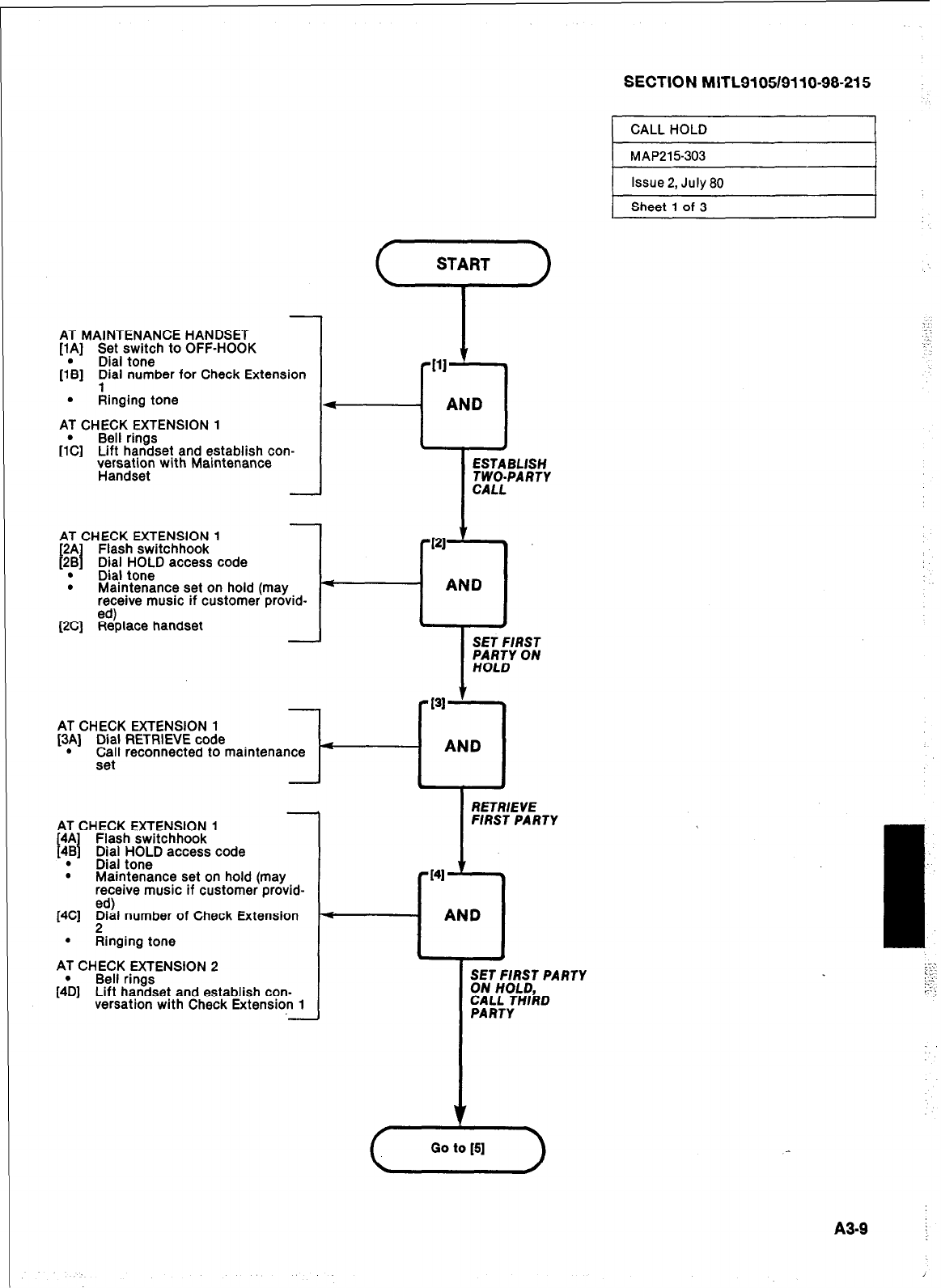
SECTION MlTL9105/9110-98-215
1 CALL HOLD I
AT MAINTENANCE HANDSET
[lA] Set switch to OFF-HOOK
[I;] Dial tone
Dial number for Check Extension
. Ringing tone
AT CHECK EXTENSION 1
[I& Bell rings
Lift handset and establish con-
versation with Maintenance
Handset
-
AT CHECK EXTENSION 1
[2A I Flash switchhook
f2B Dial HOLD access code
_ _
.
Dial tone
. Maintenance set on hold (may
receive music if customer provid-
ed)
[2C] Replace handset J
1
AT CHECK EXTENSION 1
[3A] Dial RETRIEVE code
. Call reconnected to maintenance
set
AT CHECK EXTENSION 1
4A Flash switchhook
f I
4B Dial HOLD access code
. Dial tone
. Maintenance set on hold (may
receive music if customer provid-
ed)
[4C] ;ial number of Check Extension
. Ringing tone
AT CHECK EXTENSION 2
[4& Bell rings
Lift handset and establish con-
versation with Check Extension 1
START
‘r’
r Ill
--I AND
1 I
ESTABLISH
TWO-PARTY
CALL
-I21
’ .
l
- AND
* ,
4
a-
l
SET FIRST
%EY ON
PI-~
AND
-A
RETRlEVE
FIRST PARTY
141
c
AND
;;T;;;;T PARTY
CALL THlkD
PARTY
MAP215303
Issue 2, July 80
Sheet 1 of 3
A3-9 I
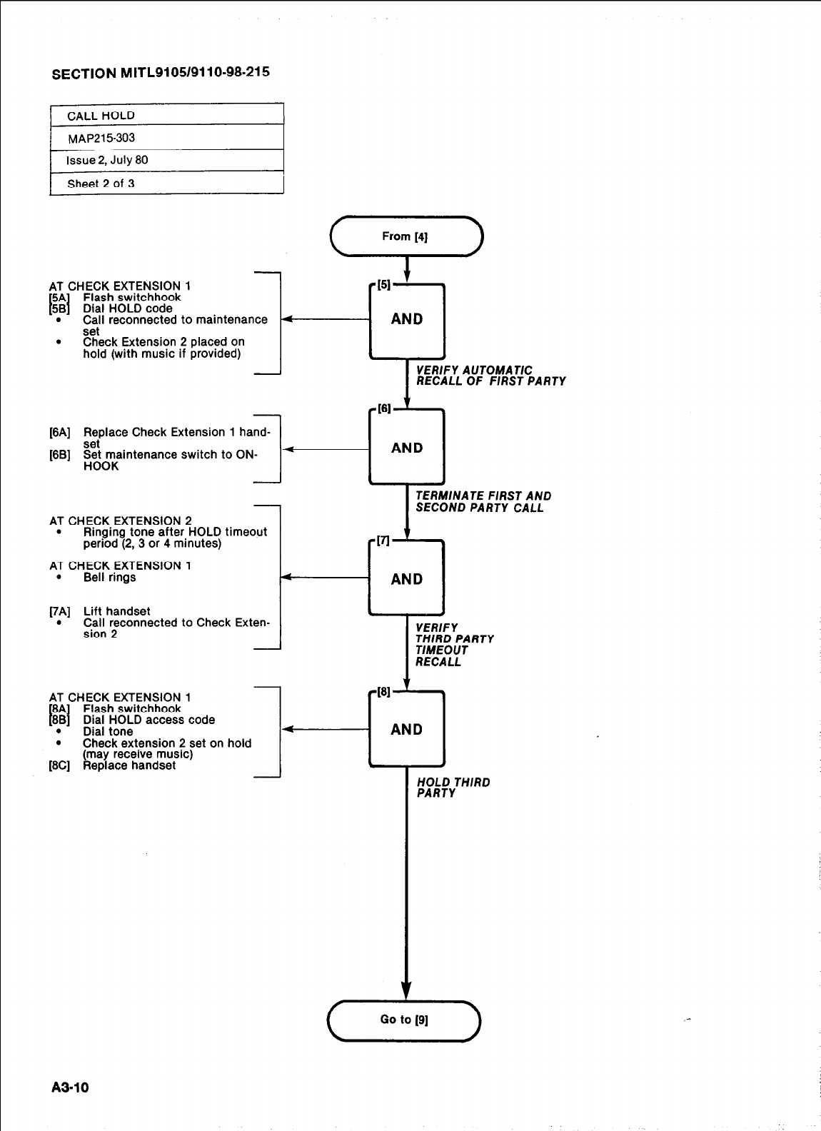
SECTION MITL9105/9110-98-215
AT CHECK EXTENSION 1
5A Flash switchhook
I I
58 Dial HOLD code
. Call reconnected to maintenance
set
. Check Extension 2 placed on
hold (with music if provided)
[6A] z;@ace Check Extension 1 hand-
[6B] p;e;intenance switch to ON-
161
:+-cl
AND
TERMINATE FIRST AND
SECOND PARTY CALL
AT CHECK EXTENSION 2
. Ringing tone after HOLD timeout
period (2, 3 or 4 minutes) -VI ’ *
AT CHECK EXTENSION 1
. Bell rings 4
AND
[7A] Lift handset
. C$lln ynnected to Check Exten-
-
6 A
YERlFY
THIRD PARTY
TIMEOUT
RECALL
AT CHECK EXTENSION 1
6A Flash switchhook
I 1
68 Dial HOLD access code
. Dial tone
.
Check extension 2 set on hold
(may receive music)
[6C] Replace handset
1 AND
-I
HOLD THIRD
PARTY
A3-10
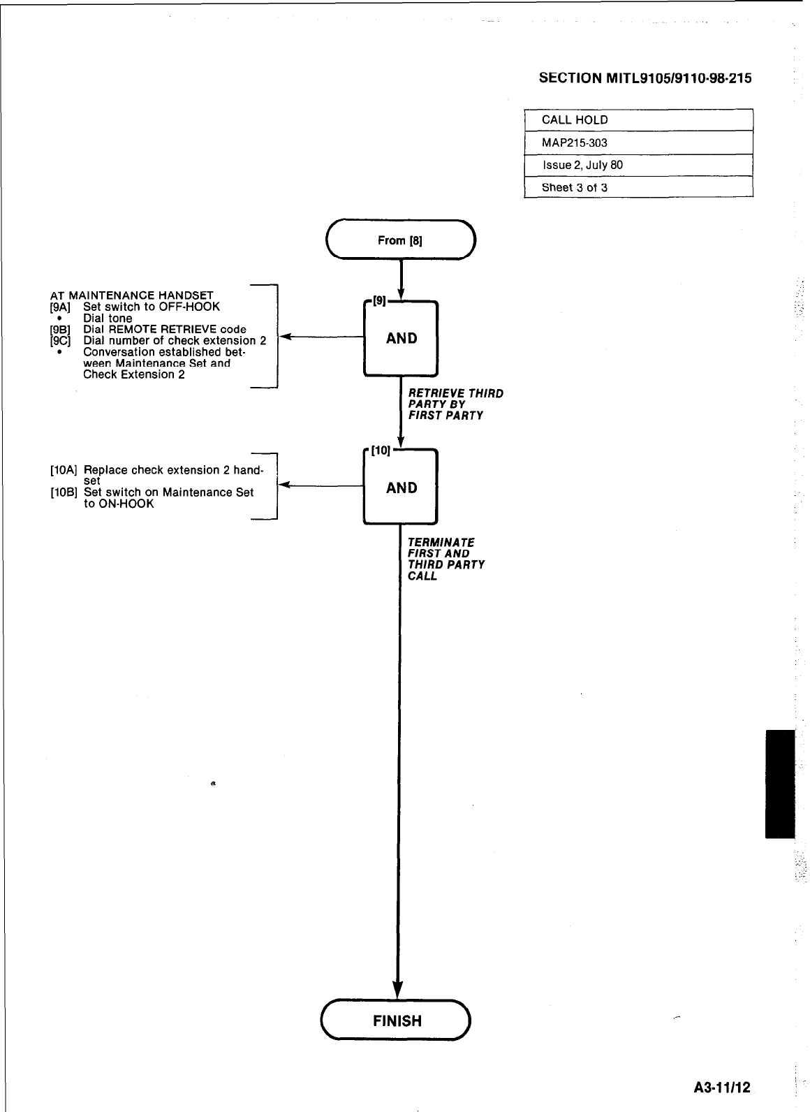
SECTION MITL9105/9110-98-215
] CALL HOLD I
AT MAINTENANCE HANDSET
[9A] Set switch to OFF-HOOK
Dial tone
[9\] Dial REMOTE RETRIEVE code
[9C] Dial number of check extension 2
. Conversation established bet-
ween Maintenance Set and
Check Extension 2
-
[lOA] Replace check extension 2 hand-
set
[lOB] Set switch on Maintenance Set
to ON-HOOK -
1 MAP215-303 I
Issue 2, July 80
Sheet 3 of 3
RETRIEVE THIRD
FIRST PARTY
<
AND
4 .
TERM/NATE
FIRST A ND
THIRD PARTY
CALL
A3-11112 ’
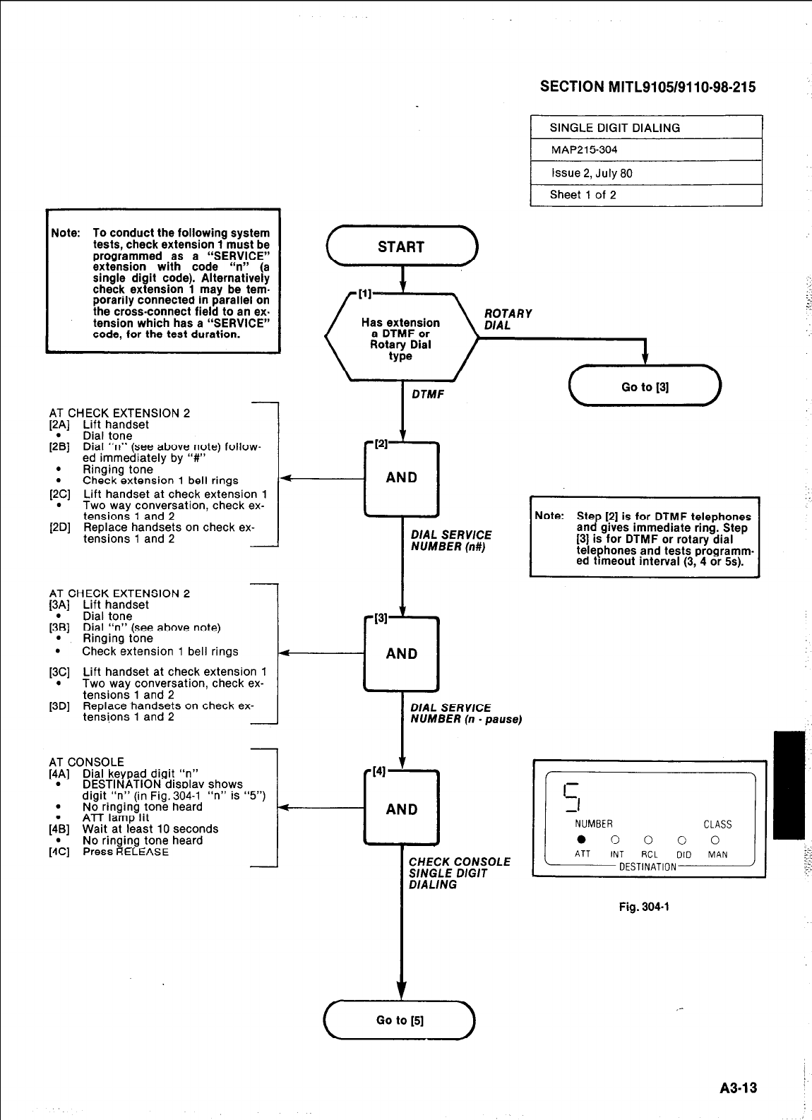
SECTION MITL9105/9110.98-215
1 SINGLE DIGIT DIALING I
MAP215-304
Issue 2, July 80
1 Sheet 1 of 2 I
Note: To conduct the following system
tests, check extension 1 must be
programmed as a “SERVICE”
extension with code “n” (a
single digit code). Alternatively
check extension 1 may be tem-
porarily connected in parallel on
the cross-connect field to an ex.
tension which has a “SERVICE”
code, for the test duration.
DTMF
AT CHECK EXTENSION 2
[2p] Lift handset
Dial tone
[2B] Dial “n” (see above note) follow-
ed immediately by “#”
. Ringing tone
. Check extension 1 bell rings
[2.C] Lift handset at check extension 1
Two way conversahon, check ex-
tensions 1 and 2
[2D] Replace handsets on check ex-
tensions 1 and 2 DIAL SERVICE
NUMBER (n#)
Note: Ste [2] is for DTMF telephones
an cr gives immediate ring. Step
[3] is for DTMF or rotary dial
telephones and tests programm-
ed timeout interval (3, 4 or 5s).
DIAL SERVICE
NUMBER (n - pause)
CHECK CONSOLE
SlNGLE D/G/T
DIALING
AT CHECK EXTENSION 2
[3A] Lift handset
[;B] Dial tone
Dial “n” (see above note)
. Ringing tone
. Check extension 1 bell rings
[3.C] Lift handset at check extension 1
Two way conversahon, check ex-
tensions 1 and 2
[3D] Replace handsets on check ex-
tensions 1 and 2 I-
I
AT CONSOLE
[4A] Dial keypad digit “n”
. DESTINATION disolav shows
digit “n” (in Fig. 304-l “n” is
. No ringing tone heard
ATT lamp lit
[:B] Wait at least 10 seconds
No ringing tone heard
[:C] Press RELEASE
“5”) - AN
.
Fig. 304-l
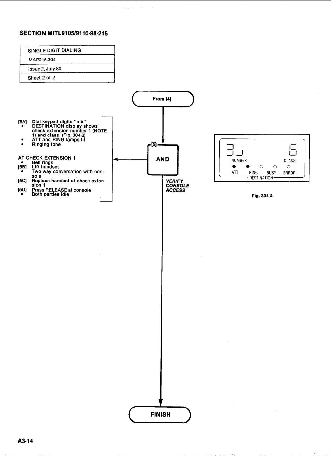
SECTION MITL910519110-98-215
[5A] Dial keypad digits “n #”
. DESTINATION display shows
check extension number 1 (NOTE
1) and class (Fig. 304-2)
. ATT and RING lamps lit
. Ringing tone
AT CHECK EXTENSION 1
Bell rings
[;B] Lift handset
. Wi way conversation with con-
[%I :;pnly handset at check exten-
[5D] Press RELEASE at console
. Both parties idle
VERIFY
CONSOLE
ACCESS
A3-14
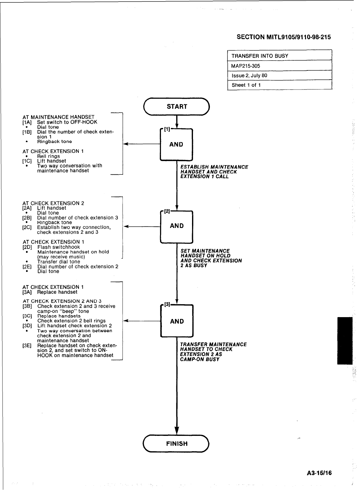
SECTION MITL9105/9110-98-215
AT MAINTENANCE HANDSET
[lA] Set switch to OFF-HOOK
[AL] Dial tone
DiDi; ;he number of check exten-
. Ringback tone
AT CHECK EXTENSION 1
Bell rings
[I’C] Lift handset
. Two way conversation with
maintenance handset
AT CHECK EXTENSION 2
f2A] Lift handset
_ -
.
Dial tone
f2Bl Dial number of check extension 3
-. -
Ringback tone
[2C] Establish two way connection,
check extensions 2 and 3
AT CHECK EXTENSION 1
[2D] Flash switchhook
. Maintenance handset on hold
(may receive music)
]2:E] Transfer dial tone
;;$ ptn;ber of check extension 2
AT CHECK EXTENSION 1
[3A] Replace handset
AT CHECK EXTENSION 2 AND 3
[3B] Check extension 2 and 3 receive
camp-on “beep” tone
PC] Rep!ace handsets
[;D] Check extension 2 bell rings
Lift handset check extension 2
. Two way conversation between
check extension 2 and
maintenance handset
[3E] Replace handset on check exten-
sion 2, and set switch to ON-
HOOK on maintenance handset -
AND
Pl-
L
TRANSFER INTO BUSY
MAP215-305
Issue 2, July 80
Sheet 1 of 1
ESTABLISH MAINTENANCE
HANDSET AND CHECK
EXTENSION 7 CALL
AND
7
SET MAINTENANCE
HANDSET ON HOLD
AND CHECK EXTENSlON
2 AS BUSY
TFfANSFER MAINTENANCE
HANDSET TO CHECK
EXTENSION 2 AS
CAMP-ON BUSY
A3-15/16
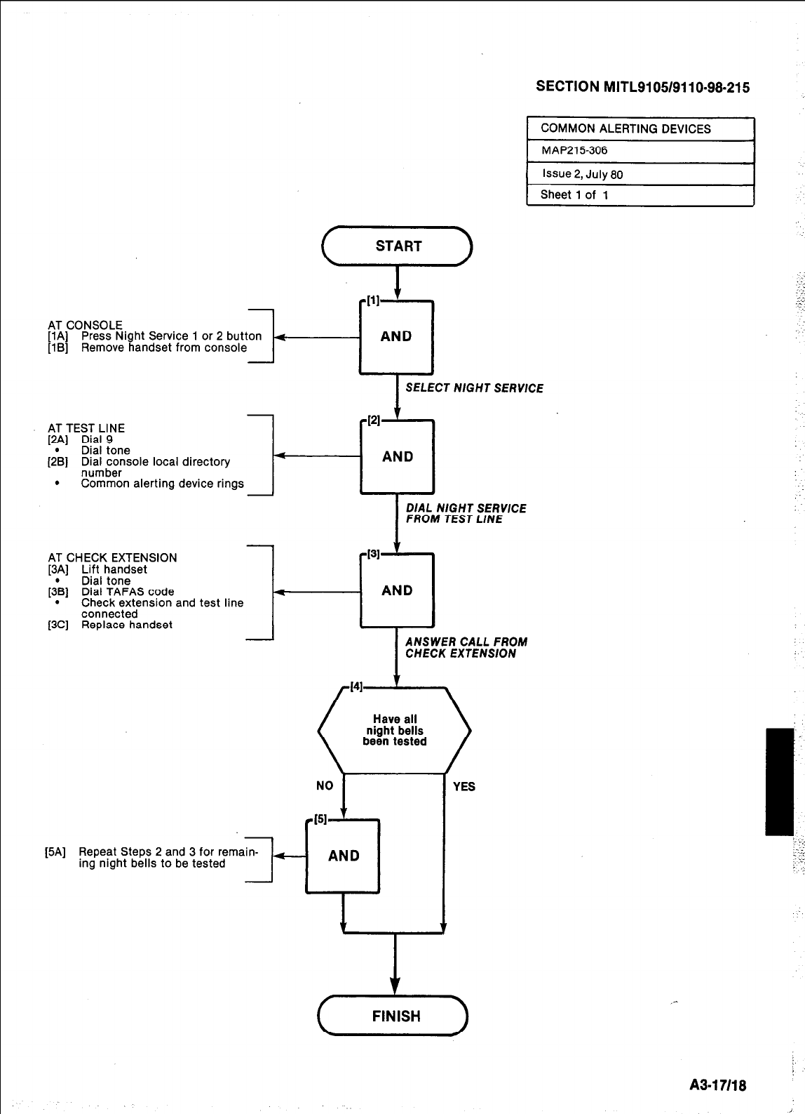
AT CONSOLE
[lA] Press Night Service 1 or 2 button 4
[lB] Remove handset from console
I
SELECT NlGHT SERVlCE
AT TEST LINE
[2A] Dial 9
Dial tone
(2;) Di$;irnsole local directory
. Common alerting device rings
I
DIAL NIGHT SERVICE
FROM TEST LINE
-
AT CHECK EXTENSION
[3p] Lift handset
Dral tone
[3B] Dial TAFAS code
. Check extension and test line
connected
[3C] Replace handset
1
-
NO
I
[5A] Repeat Steps 2 and 3 for remain-
ing night bells to be tested t-
131
cl
AND
I
ANSWER CALL FROM
CHECK EXTENSION
YES
- AND
_-
A3-17118
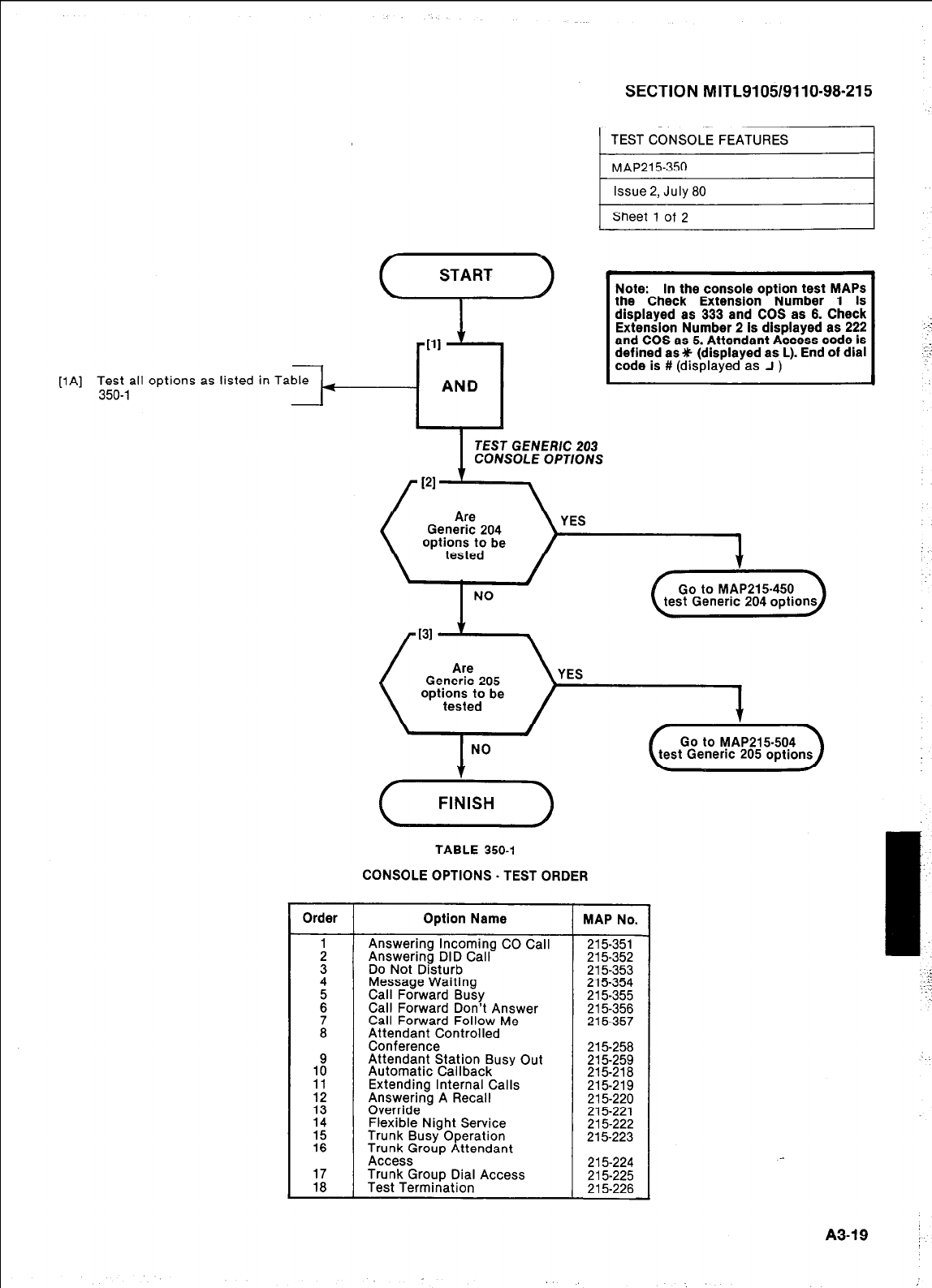
SECTION MITL9105/9110-98-215
[lA] Test all options as listed in Ta
350-l
Sheet 1 of 2
Note: In the console option test MAPS
the Check Extension Number 1 is
displayed as 333 and COS as 6. Check
Extension Number 2 is displayed as 222
and COS as 5. Attendant Access code is
defined as 9 (displayed as L). End of dial
code is
# (displayed as J )
TEST GENERIC 203
CONSOLE OPTIONS
(xi--)
TABLE 350-l
CONSOLE OPTIONS. TEST ORDER
Option Name
Answering Incoming CO Call
Answering DID Call
Do Not Disturb
Message Waiting
Call Forward Busy
Call Forward Don’t Answer
Call Forward Follow Me
Attendant Controlled
Conference
Attendant Station Busy Out
Automatic Internal Callback Calls
Extending
Answering A Recall
Override
Trunk Flexible Night Service
Busy Operation
Trunk Group Attendant
Access
Trunk Group Dial Access
Test Termination
MAP No.
215-351
215-352
215353 215-354
215-355
215-356
215-357
215-258
215-259
215-218 215-219
215-220
215-221
215-223 215-222
215-224
215-225
215-226
:
A3-19 :
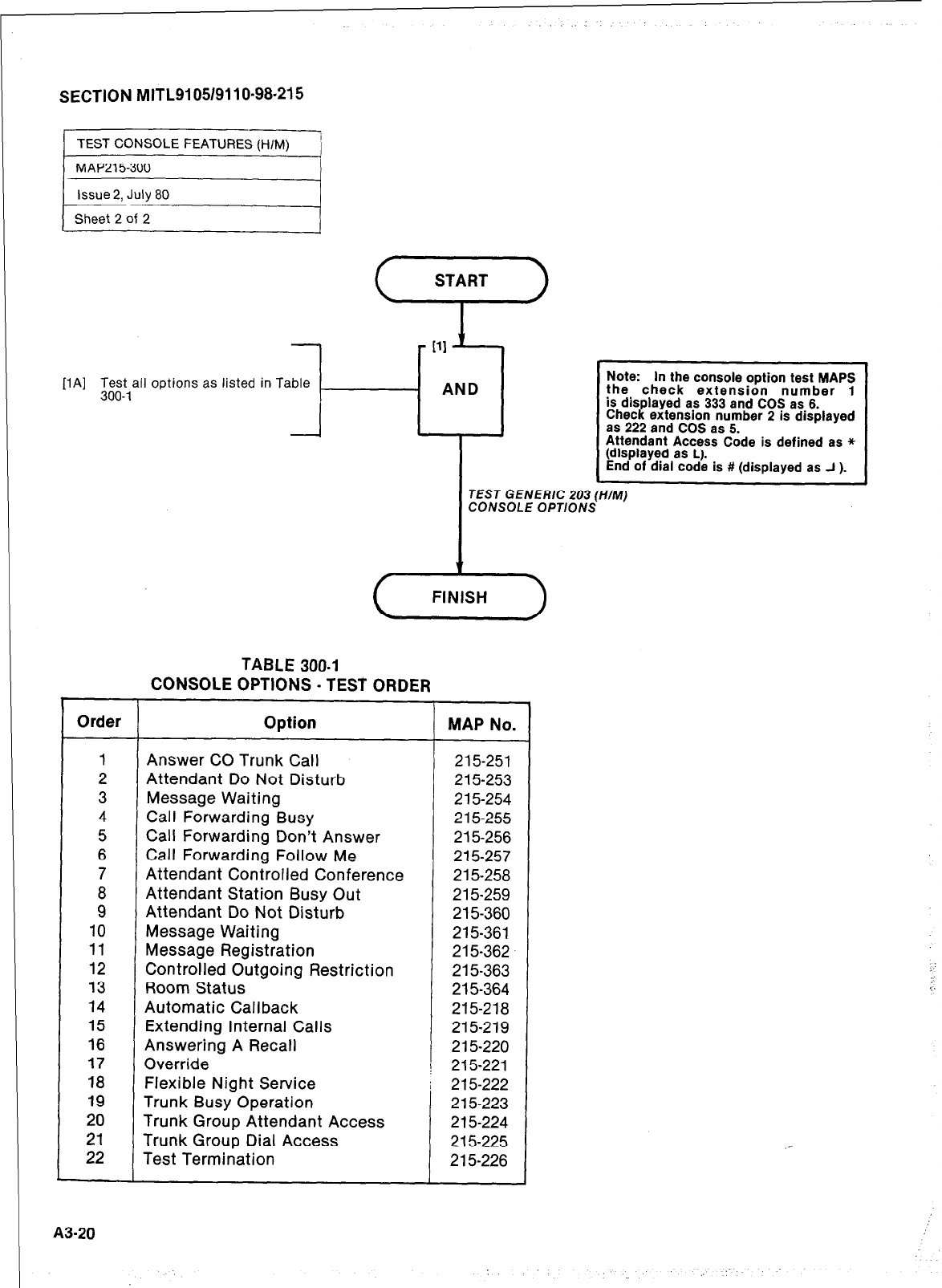
SECTION MITL9105/911 O-98-21 5
[lA] lk&t,all options as listed in Table
l-
- AND
Note: In the console option test MAPS
the check extension number 1
is displayed as 333 and COS as 6.
Check extension number 2 is displayed
as 222 and COS as 5.
Attendant Access Code is defined as *
(displayed as L).
End of dial code is # (displayed as J ).
TEST GENERIC 203 (HIM)
CONSOLE OPTIONS
TABLE 300.1
CONSOLE OPTIONS - TEST ORDER
Order Option MAP No.
1 Answer CO Trunk Call 215-251
2 Attendant Do Not Disturb 215253
3 Message Waiting 2 15-254
4 Cal I Forwarding Busy 215-255
5 Call Forwarding Don’t Answer 215-256
6 Call Forwarding Follow Me 215-257
7 Attendant Controlled Conference 215-258
8 Attendant Station Busy Out 215-259
9 Attendant Do Not Disturb 215-360
10 Message Waiting 215-361
11 Message Registration 215-362
12 Controlled Outgoing Restriction 215-363
13 Room Status 215-364
14 Automatic Callback 215-218
15 Extending Internal Calls 215-219
16 Answering A Recall 215-220
17 Override \ 215-221
18 Flexible Night Service I 215-222
19 Trunk Busy Operation 215-223
20 Trunk Group Attendant Access 215-224
21 Trunk Group Dial Access 215-225
22 Test Termination 215-226
A3-20
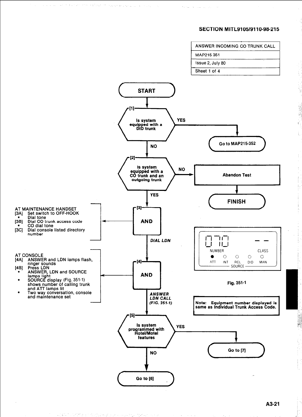
SECTION MITL9105/9110-98-215
AT MAINTENANCE HANDSET
[3A] Set switch to OFF-HOOK
[3@B] Dial tone
Dial CO trunk access code
CO dial tone
[3\] Di$;~rsole listed directory
AT CONSOLE
[4A] ANSWER and LDN lamps flash,
ringer sounds
[4B] Press LDN
. ANSWER, LDN and SOURCE
lamps Ii ht
. SOURC -i display (Fig. 351-l)
shows number of calling trunk
and ATT lamps lit
. Two way conversation, console
and maintenance set -
(“‘4”>
NO
/
(Ool.M*P211312)
[PI
I
YES
r 131 t .
*
AND
* *
DIAL LDN
-141 ’ 9
I
AND
. .
I
Fig. 351-l
I
A NSWEfl
LDN CALL
(FIG. 357-7) Note: Equipment number displayed is
same as lndwidual Trunk Access Code.
YES
(G-)
A3-21
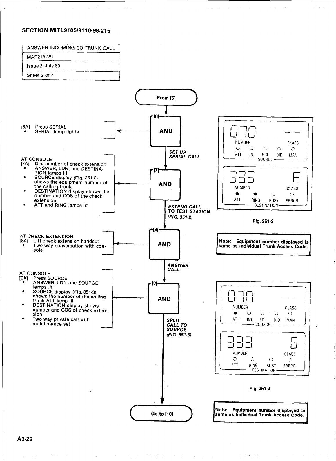
SECTION MITL9105/9110-98-215
[6A] Press SERIAL
. SERIAL lamp lights
AND
k .
I
SET UP
SERIAL CALL
TO TEST STATION
I
FIG.351-2)
AT CONSOLE
[7A] Dial number of check extension
. ANSWER, LDN, and DESTINA-
TION lamps lit
. SOURCE display (Fig. 351-2)
shows the eauioment number of
the calling trunk
. DESTINATION display shows the
number and COS of the check
extension
. ATT and RING lamps lit
AT CHECK EXTENSION
[8A] Lift check extension handset
. Two way conversation with con- f---
sole
Fig. 351-2
111
Equipment number displayed is
same as lndwdual Trunk Access Code.
AT CONSOLE
[9A] Press SOURCE
. ANSWER, LDN and SOURCE
lamps lit
. SOURCE display (Fig. 351-3)
shows the number of the calling
trunk ATT lamp lit 4
AND
.
DESTINATION display shows
number and COS of check exten-
sion
l .
.
Two way private call with
maintenance set SPLIT
CALL TO
SOURCE
(FIG. 351.3)
NUMBER
Fig. 351-3
I
Note: Equi
same as ment number displayed is
Ind vidual Trunk Access Code. P
A3-22
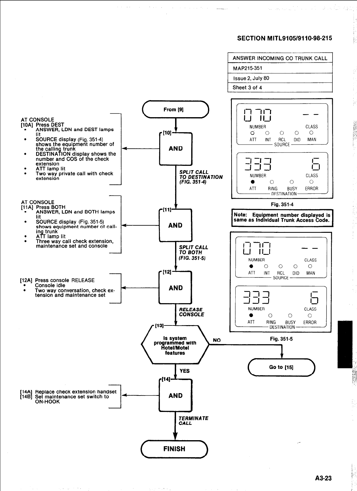
SECTION MITL9105/9110-98-215 /
AT CONSOLE
[lOA] Press DEST
. ANSWER LDN and DEST lamps
lit
. SOURCE display (Fig. 351-4)
shows the equipment number of
the callin 8 trunk
. DESTINA ION display shows the
number and COS of the check
extension
. ATT lamp lit
. Two way private call with check
extension
AT CONSOLE
[llA] Press BOTH
. ANSWER. LDN and BOTH lamps
lit
. SOURCE display (Fig. 351-5)
shows equipment number ot call-
* %T,‘Z! lit
. Three way call check extension,
maintenance set and console
[12A] Press console RELEASE [12A] Press console RELEASE
. . Console idle Console idle
. . Two way conversation, check ex- Two way conversation, check ex-
tension and maintenance set tension and maintenance set -I- -I-
SPLIT CALL
TO DESTINATION
(FIG.351-4)
SPLIT CALL
TO BOTH
(FIG. 351-S)
RELEASE
CONSOLE
Fig. 351-4
I
Note: Equipment number displayed is
same as lndwidual Trunk Access Code. I
3 1 ,7 -
dJ-l 11
NUMBER CLASS
0 0 0 0
ATT RING BUSY ERROR
DESTINATION
NO
Fig. 351-5
Replace check extension handset
g; ;;;;nance set swatch to
I4
- AND
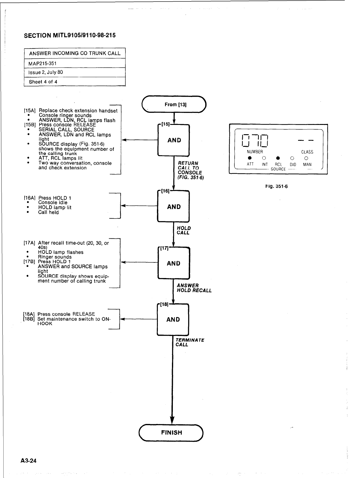
SECTION MITLSI 05/911 O-98-21 5
ANSWER INCOMING CO TRUNK CALL
[15A] Replace check extension handset
. Console ringer sounds
ANSWER LDN RCL lamps flash
p&q Press console RELEASE
. SERIAL CALL, SOURCE
. ANSWER, LDN and RCL lamps
. !%!RCE display (Fig. 351-6)
shows the equipment number of
the calling trunk
. ATT, RCL lamps lit
.
Two. way conversation, console
and check extension
[16A] Press HOLD 1
. Console idle
. HOLD lamp.lit
. Call held
(7)
1151
cl
AND
RETURN
CALL TO
CONSOLE
(FIG. 357-6)
[17A] $ft$r recall time-out (20, 30, or
. HOLD lamp flashes
1
Ringer sounds
[I&] Press HOLD 1
c ANSWER and SOURCE lamps
light
. SOURCE displa
ment number o Y shows equip-
calling trunk
Press console RELEASE
Set maintenance switch to
HOOK
oi+-..--
HOLD RECALL
TERMlNA TE
CALL
.
AND
Fig. 351-6
A3-24
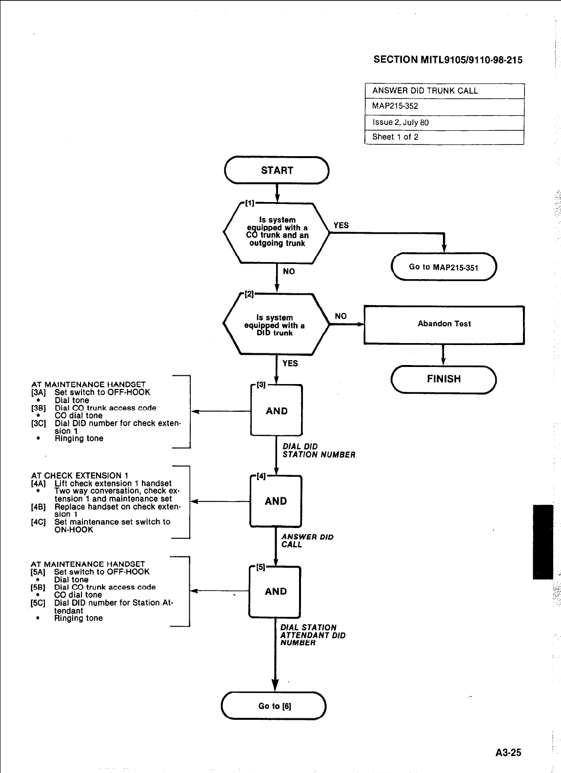
AT MAINTENANCE HANDSET
[3A] Set switch to OFF-HOOK
[;B] Dial tone
Dial CO trunk access code
[{C] CO dial tone
:fit; YID number for check exten-
. Ringing tone
AT CHECK EXTENSION 1
[4A] Lift check extension 1 handset
. Two way conversation, check ex-
tension 1 and maintenance set
[4B] p&y handset on check exten-
[4C] F; ;raa;nance set switch to
SECTION MITL9105/9110-98-215
( ANSWER
DID TRUNK CALL I
MAP215352
1 Issue 2, July 80 I
1 Sheet 1 of 2
(“T”‘)
YES
Go to MAP215-351
Abandon Test
1 J
I
I
DIAL DID
STATION NUMBER
AT MAINTENANCE HANDSET
f5Al Set switch to OFF-HOOK I
_ _
ftB1 Dial tone
Dial CO trunk access code
I- Y--- AND 1
$Z] CO dial tone
p,i)ia;,91p number for Station At- r-l I
.
Ringing tone I
DIAL
STATION
T
fETEh’/l NT DID
_-
A3-25 ’
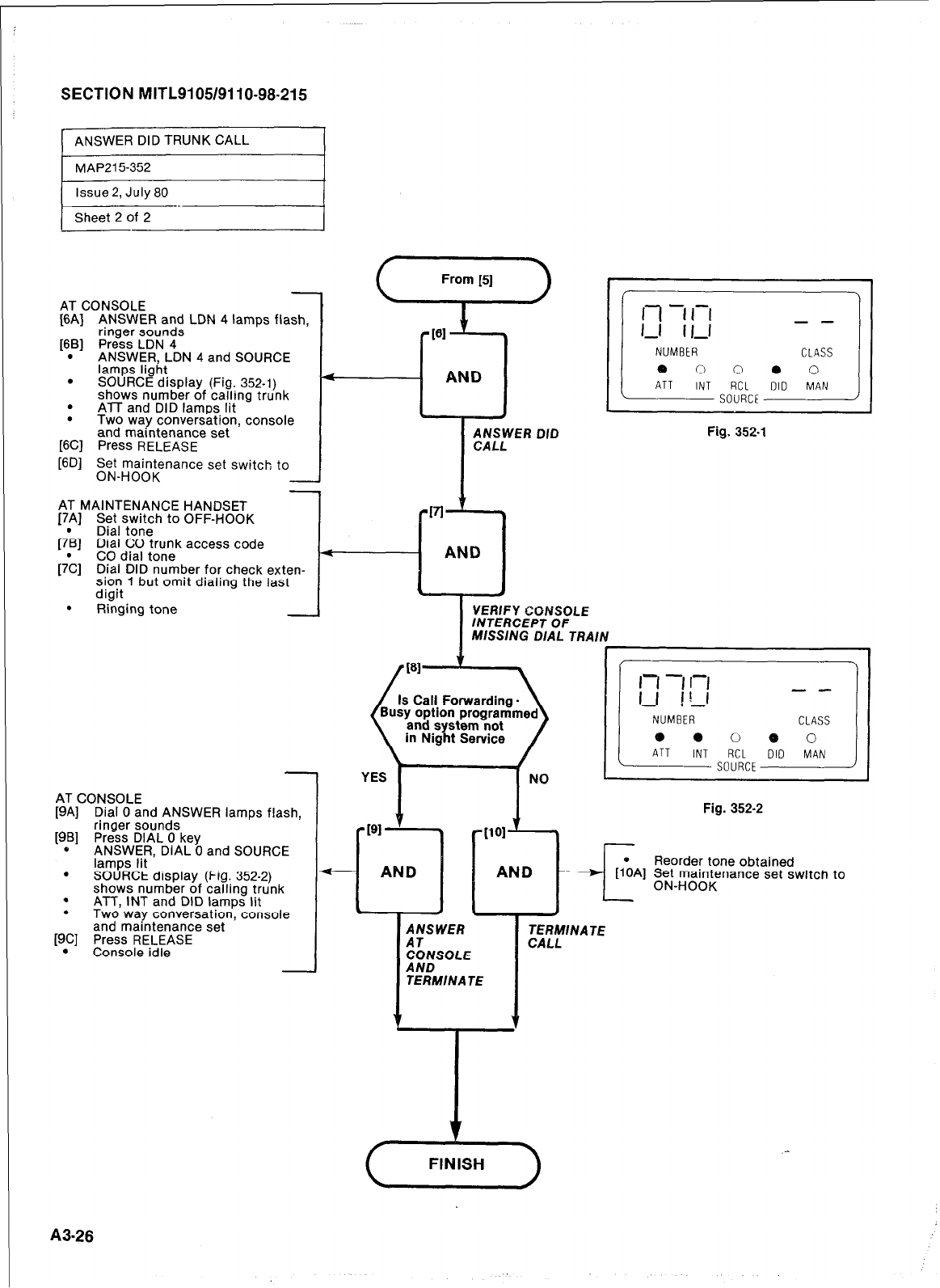
SECTION MITL9105/9110-98-215
ANSWER DID TRUNK CALL
MAP215-352
issue 2, July 80
Sheet 2 of 2
AT CONSOLE
[6A] ANSWER and LDN 4 lamps flash,
ringer sounds
[6B] Press LDN 4
. ANSWER, LDN 4 and SOURCE
lamps light
. SOURCE display (Fig. 352-l)
shows number of calling trunk
. ATT
and
DID lamos lit
.
Two way conversation, console
and maintenance set
[6Cl Press RELEASE
[6D] E$d-;;rFnance set switch to -
AT MAINTENANCE HANDSET
[7A] Set switch to OFF-HOOK
[7*B] Dial tone
[;C]
E$ld~~ ;rou”,” access code
Dial DID number for check exten-
sion 1 but omit dialing the last
diait
.
Ringing tone -
AT CONSOLE
[9A] Dial 0 and ANSWER lamps flash,
[9B] ringer sounds
Press DIAL 0 key
c ANSWER, DIAL 0 and SOURCE
lamps lit
. SOURCE display (Fig. 352-2)
shows number of tailing trunk
. ATT, INT and DID lamps lit
. Two way conversation, console
and maintenance set
[9C] Press RELEASE
. Console idle
I
VERIFY CONSOLE
lNTERCEP T OF
MISSING DIAL TRAIN
f \ I
Fig. 352-l
NUMBER
e e 0 0 0
ATT INT RCL
SOURCE
TERMINATE
Fig. 352-2
Reorder tone obtained
Fd-Hmgaignsnance set switch to
A3.26
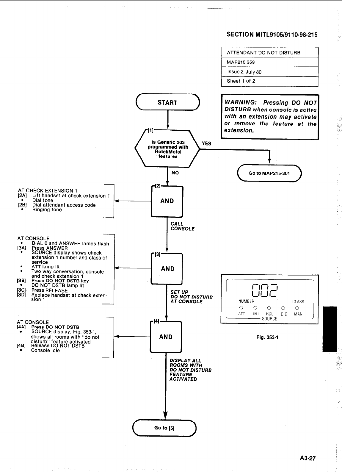
AT CHECK EXTENSION 1
[2A] Lift handset at check extension 1
[2*B] Dial tone
Dial attendant access code
. Ringing tone
AT CONSOLE
[{A] Press ANSWER
DIAL 0 and ANSWER lamps flash
. SOURCE display shows check
extension 1 number and class of
service
. ATT lamp lit
. Two way conversation, console
and check extension 1
1381 Press DO NOT DSTB key
@C. Press RELEASE
I
DO NOT DSTB lamp lit
[3D Replace handset at check exten-
sion 1
AT CONSOLE
[4Al Press DO NOT DSTB
. SOURCE display, Fig. 353-l.
shows all rooms with “do not
disturb” feature activated
[4B] Release DO NOT DSTB
. Console idle
SECTION MITL9105/9110-98-215
ATTENDANT DO NOT DISTURB
DISTURB when console is active
I
NO
4
d-
AND
PI31
I
CALL
CONSOLE
AND
s 4
SET UP
DO NOT DISTURB
AT CONSOLE
DISPLAY ALL
ROOMS WITH
;~AtV;;XTllRB
ACTIVATED
I
(CotoMiiPlliJO1)
NUMBER CLASS
0 0 0 0 0
ATT INT RCL DID MAN
SOURCE
Fig. 353-l
(y-z-)
,
A3-27
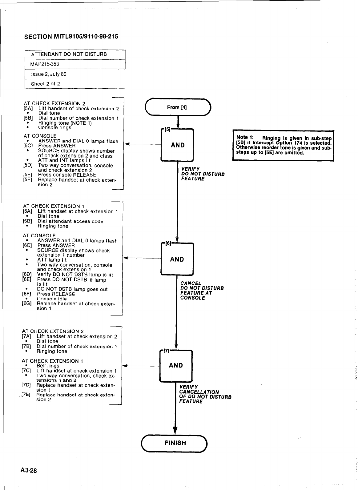
SECTION MITL9105/9110-98-215
ATTENDANT DO NOT DISTURB
r
MAP215-353
1 lssue2, July80 I
1
AT CHECK EXTENSION 2
[5.A] ;ft, ha;zset of check extension 2
[5.B] Dial number of check extension 1
Ringing tone (NOTE 1)
. Console rings
AT CONSOLE
ANSWER and DIAL 0 lamps flash
[S’c] Press ANSWER
. SOURCE display shows number
of check extension 2 and class
ATT and INT lamps lit
[sb] Two way conversation console
and check extension 2
[5E] Press console RELEASE
[5F] Replace handset at check exten-
sion 2 -
AT CHECK EXTENSION 1
[6.A] ~ft,h;;~set at check extension 1
[6.B] Dial attendant access code
Ringing tone
AT CONSOLE
[S’C] Press ANSWER
ANSWER and DIAL 0 lamps flash
. SOURCE display shows check
extension 1 number
. ATT lamp lit
. Two way conversation, console
and check extension 1
[6D]
[6E] Verify DO NOT DSTB lamp is lit
E:;s DO NOT DSTB if lamp
DO NOT DSTB lamp goes out
[QF] Press RELEASE
[6;] Console idle
Replace handset at check exten-
sion 1
AT CHECK EXTENSION 2
[7A] Lift handset at check extension 2
[7*B] Dial tone
Dial number of check extension 1
. Ringing tone
AT CHECK EXTENSION 1
[7\] Bell rings
Lift handset at check extension 1
. Two way conversation, check ex-
tensions 1 and 2
[7D] Replace handset at check exten-
sion 1
[7E] Replace handset at check exten-
sion 2
t
1
YEWI
DO N
FEA T
\ND
4
CANC
DO NI
FEAT
CONS
\ND I
FY
:;;EDISTURB
v
:ELLATlON
;RNEOT DISTURB
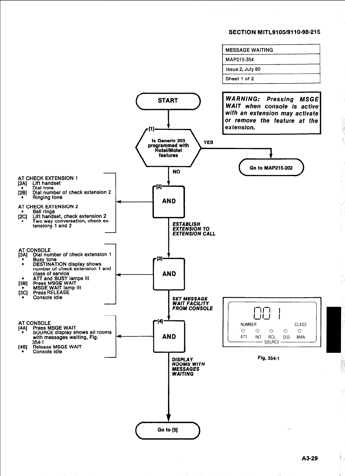
AT CHECK EXTENSION 1
[2A] Lift handset
[;B] Dial tone
Dial number of check extension 2
. Ringing tone
AT CHECK EXTENSION 2
&C] Bell rings
Lift handset, check extension 2
. Two way conversation, check ex-
tensions 1 and 2
AT CONSOLE
[3A] Dial number of check extension 1
.
Busy tone
. DESTINATION display shows
number of check extension 1 and
class of service
ATT and BUSY lamps lit
[;B] Press MSGE WAIT
MSGE WAIT lamp lit
&] Press RELEASE
. Console idle
AT CONSOLE
[4A] c’&;;CMISGE WAIT
. : display shows all rooms
with messages waiting, Fig.
354-I
[4B] Release MSGE WAIT
. Console idle
SECTION M ITL9105/911 O-98-21 5
I
MESSAGE WAITING I
1 Issue 2, July 80
Sheet 1 of 2
( START ) 1 WARNING: Pressing MSGE
WAIT when console is active
/Ill 1 , with an extension may activate
I:;tg~~; the feature at the
/
Is Generic 203
aroarammed with
tellMotel
I
NO Lx
PI
4-l
AND
ESTABLISH
-T-
EXTENSION TO
EXTENSION CALL
4
I41
-0
AND
DISPLAY
ROOMS WlTH
MESSAGES
WAITING
CLASS
0 0 0
Fig. 354-l
1~
:
z.;
A3-29 I
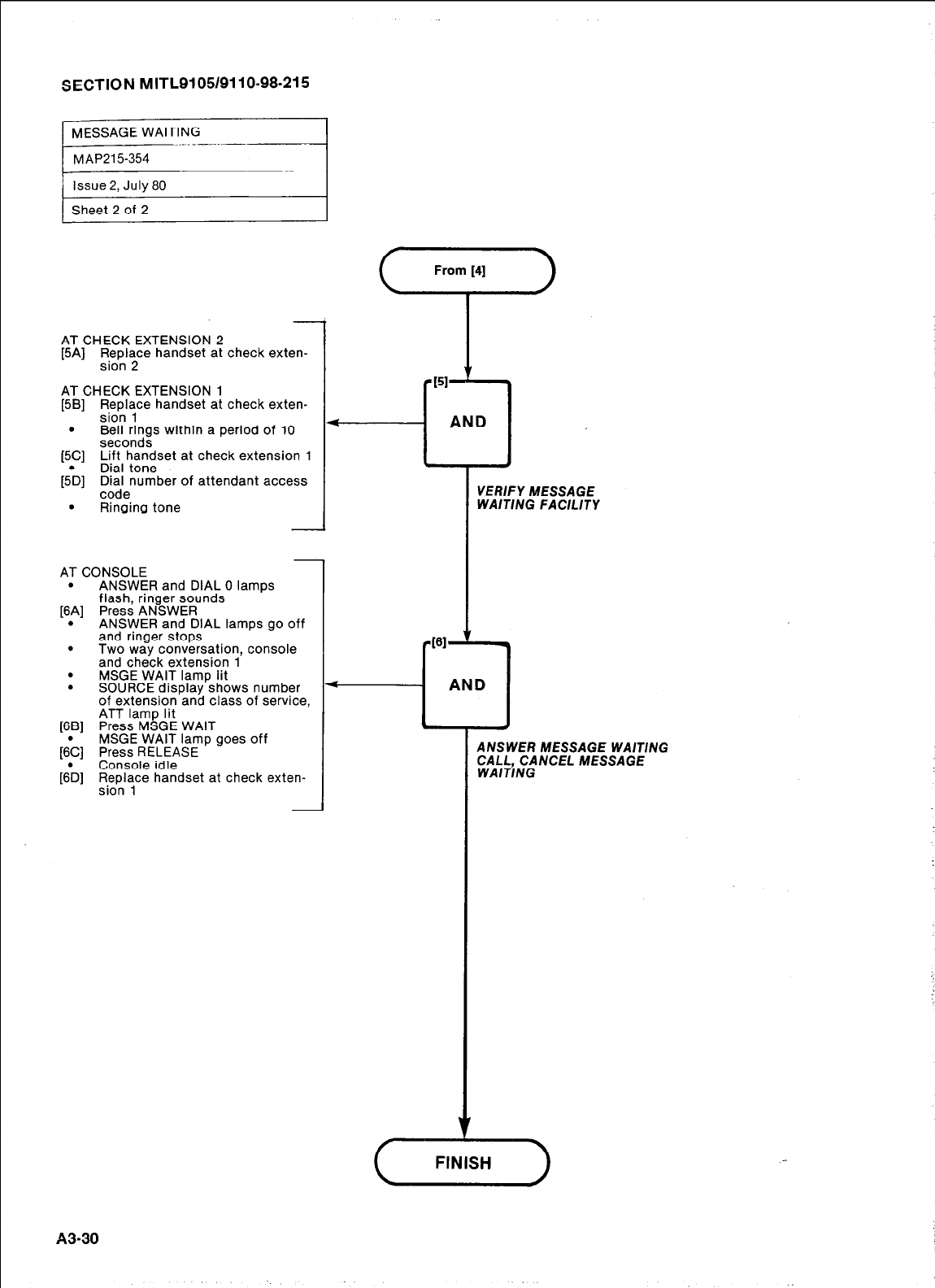
SECTION MITL9105/9110-98-215
MESSAGE WAITING --.__
MAP215354
AT CHECK EXTENSION 2
[5A] Fe&lye handset at check exten-
AT CHECK EXTENSION 1
[5B] Replace handset at check exten-
sion 1
. Bell rings within a period of 10
seconds
15Cl Lift handset at check extension 1
_ _
[sb] Dial tone
~h&number of attendant access
. Ringing tone
AT CONSOLE
. ANSWER and DIAL 0 lamps
flash, ringer sounds
[6A] Press ANSWER
. ANSWER and DIAL lamps go off
and ringer stops
. Two way conversation, console
and check extension 1
. MSGE WAIT lamp lit
. SOURCE display shows number
of extension and class of service,
ATT lamp lit
[6B] Press MSGE WAIT
MSGE WAIT lamp goes off
(6:] Press RELEASE
[sb] Console idle
;Il$ce handset at check exten-
From [4]
7
AND
---L
ANSWER MESSAGE WA/T/NG
CALL, CANCEL MESSAGE
WAlTlNG
VERIFY MESSAGE
WAlTlNG FACILITY
A3-30
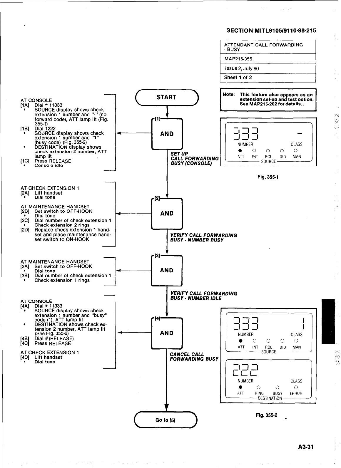
SECTION MITL9105/9110-98-215
AFUTTYDANT CALL FORWARDING I
-
AT CONSOLE
[IA] Dial * 11333
. SOURCE disolay shows check
extension 1 number and “-I’ (no
‘,o:,Fd code), ATT lamp lit (Fig.
[IB] Dial i222
. SOURCE display shows check
extension 1 number and “1”
(busy code) (Fig. 355-2)
s DESTINATION display shows
check extension 2 number. ATT
[lC] %%s’iELEASE
. Console idle
AT CHECK EXTENSION 1
[2.A] Lift handset
Dial tone
AT MAINTENANCE HANDSET
[2B] Set switch to OFF-HOOK
(2& Dial tone
Dial number of check extension 1
[2& Check extension 2 rings
Replace check extensron 1 hand-
set and place maintenance hand-
set switch to ON-HOOK
AT MAINTENANCE HANDSET
1
13Al Set switch to OFF-Hot
3K
_ _ I
(3\] Dial tone 4
Dial number of check extension 1
. Check extension 1 rings
CALL FORWARDING
BUSY (CONSOLE)
Fig. 355-l
VERIFY CALL FORWARDING
BUSY - NUMBER BUSY
AT CONSOLE
[4A] Dial * 11333
. SOURCE display shows check
extension 1 number and “busy”
code (I), ATT lamp lit
. DESTINATION shows check ex-
tension 2 number, ATT lamp lit
(See Fig. 355-2)
[4B
[4C
I Dial #(RELEASE)
Press RELEASE
AT CHECK EXTENSION 1
[4D] Lift handset
. Dial tone
VERIFY CALL FORWARDING
BUSY - NUMBER IDLE
CANCEL CALL
FORWARDING BUSY
L
Fig. 355-2
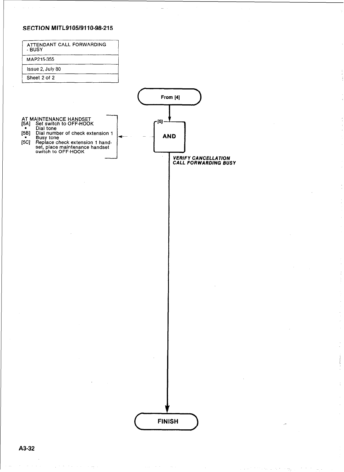
SECTION MITL9105/9110-98-215
ATTENDANT CALL FORWARDING
- BUSY
1 MAP215355
( Issue 2, July 80 I
FSheet 2 of 2
-
AT MAINTENANCE HANDSET
(5A] Set switch to OFF-HOOK
[&] Dial tone
Dial number of check extension 1
Busy tone
[S’c] Replace check extension 1 hand-
set, place maintenance handset
switch to OFF-HOOK
~43-32
VERFY CANCELLAWON
CALL FORWARDlNG BUSY
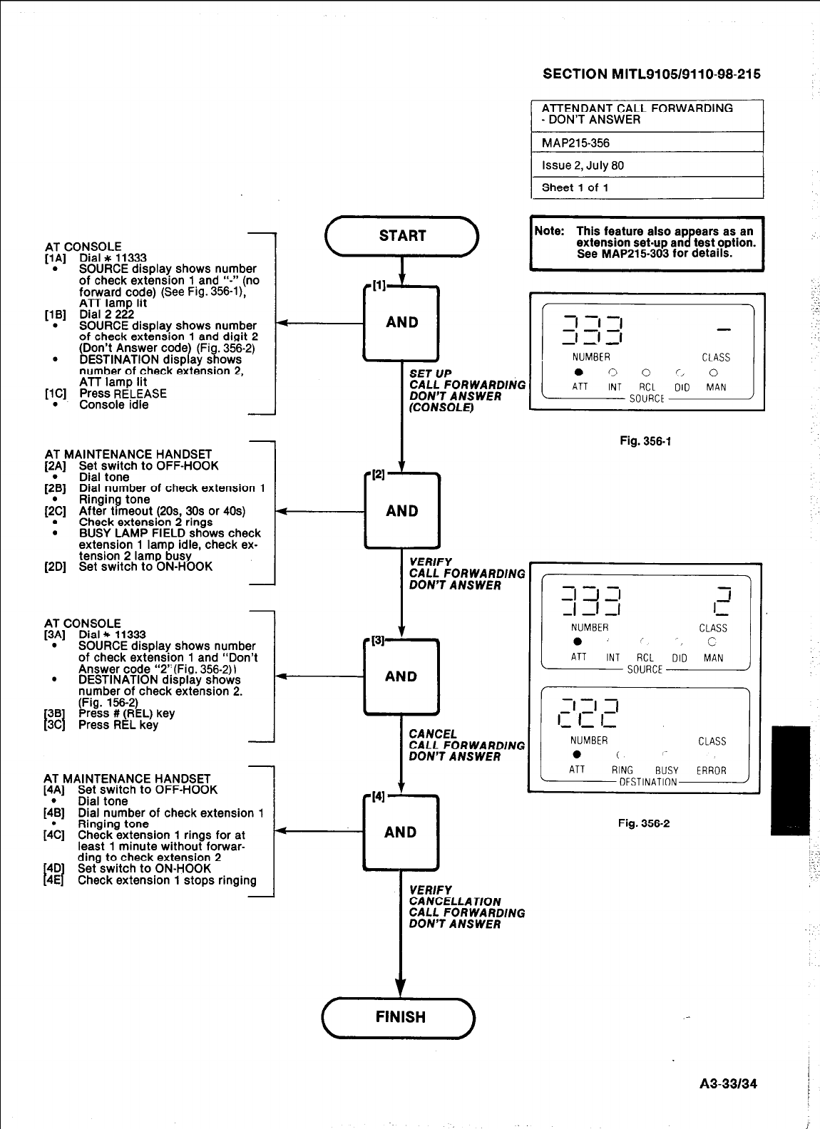
AT CONSOLE
[lA] Dial * 11333
. SOURCE display shows number
of check extension 1 and ‘I-” (no
forward code) (See Fig. 356-l),
ATT lamp lit
[lB] Dial 2 222
. SOURCE display shows number
of check extension 1 and digit 2
(Don’t Answer code (Fig. 356-2)
. 1
DESTINATION disp ay shows
number of check extension 2,
ATT lamp lit
[lC] Press RELEASE
. Console idle
AT MAINTENANCE HANDSET
[2A] Set switch to OFF-HOOK
&B] Dial tone
Dial number of check extension 1
[;C] Ringing tone
After timeout (20s 30s or 40s)
. Check extension 2 rings
. BUSY LAMP FIELD shows check
extension 1 lamp idle, check ex-
tension 2 lamp busy
[2D] Set switch to ON-HOOK
J
-
CANCEL
CALL FORWARDlNG
DON’T ANSWER
SET UP
CALL FORWARDING
DON’T ANSWER
(CONSOLE)
SECTION MITL91051911 O-98-21 5
START
-
AT MAINTENANCE HANDSET
14Al Set switch to OFF-HOOK
$B] Dial tone
Dial number of check extension 1
[JC] Ringing tone
Check extension 1 rings for at
least 1 minute without forwar-
4D
I I
ding to check extension 2
Set switch to ON-HOOK
4E Check extension 1 stops ringing
-
Issue 2, July 80
Sheet 1 of 1
PI
’ *
l
AND
. *
VERIFY
CALL FORWARDING
DON’T ANSWER
AT CONSOLE
[3A] Dial * 11333 PI31 c
. SOURCE display shows number l
of check extension 1 and “Don’t
Answer code “2”(Fig. 356-2))
. DESTINATION display shows 4
AND
number of check extension 2.
(Fig. 156-2)
Press # (REL) key 4 4
I41
AND
Y
VERIFY
CANCELLATlON
CALL FORWARDING
DON’T ANSWER
Fig. 356-l
Fig. 356-2
(GE-)
A3-33134 !
I
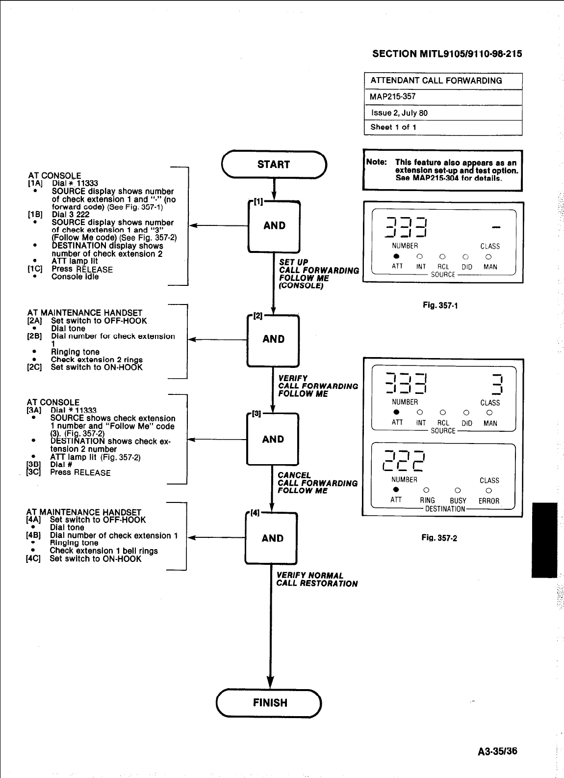
AT CONSOLE
[lA] Dial *~ 11333
. SOURCE display shows number
of check extension 1 and I‘-” (no
forward code) (See Fig. 357-l)
118) Dial 3 222
. SOURCE display shows number
of check extension 1 and “3”
. ~$;N,AMT”lo”;d;/$& ~cO~7-2’
number of check extension 2
ATT lamp lit
hl
Press RELEASE
. Console idle
AT MAINTENANCE HANDSET
[2A] Set switch to OFF-HOOK
(2\] Dial tone
Dial number for check extension
. Ainging tone
&] Check extension 2 rings
Set switch to ON-HOOK
AT CONSOLE
[3A] Dial * 11333
. SOURCE shows check extension
1 number and “Foiiow Me” code
tension 2 number
;B Dial #
t I
ATT lamp lit (Fig. 357-2)
3C Press RELEASE
41 ’
l
AND
*
l
SET UP
CALL FORWARDlNG
FOLLOW ME
(CONSOLE)
I
VERIFY
CALL FORWARDiNG
FOLLOW ME
I31
--cl
AND
I
CANCEL
CALL FORWARDiNG
FOLLOW ME
- 1
AT MAINTENANCE HANDSET
[4A] Set switch to OFF-HOOK
. Dial tone
[4B] Dial number of check extension 1
. Ringing tone
Check extension 1 bell AND I
rings
Id
;C] Set switch to ON-Hook ;
VERiFY NORMAL
CALL RESTORATiON
--I T
(-TlG--)
SECTION MITL9105/9110~98-215
1 ATTENDANT CALL FORWARDING I
1 MAP21 5-357
1 issue 2, July 80 I
1 Sheet 1 of 1
I
Note: This feature also ap ears as an
extension set-up an 8 test optlon.
See MAP21 5304 for details. I
Fig. 357-i
/
-t
ZI s -1-1 3 2
1
NUMBER CLASS
0 0 0 0 0
ATT INT RCL DID MAN
SOURCE
Fig. 357.2
A3-35138
J
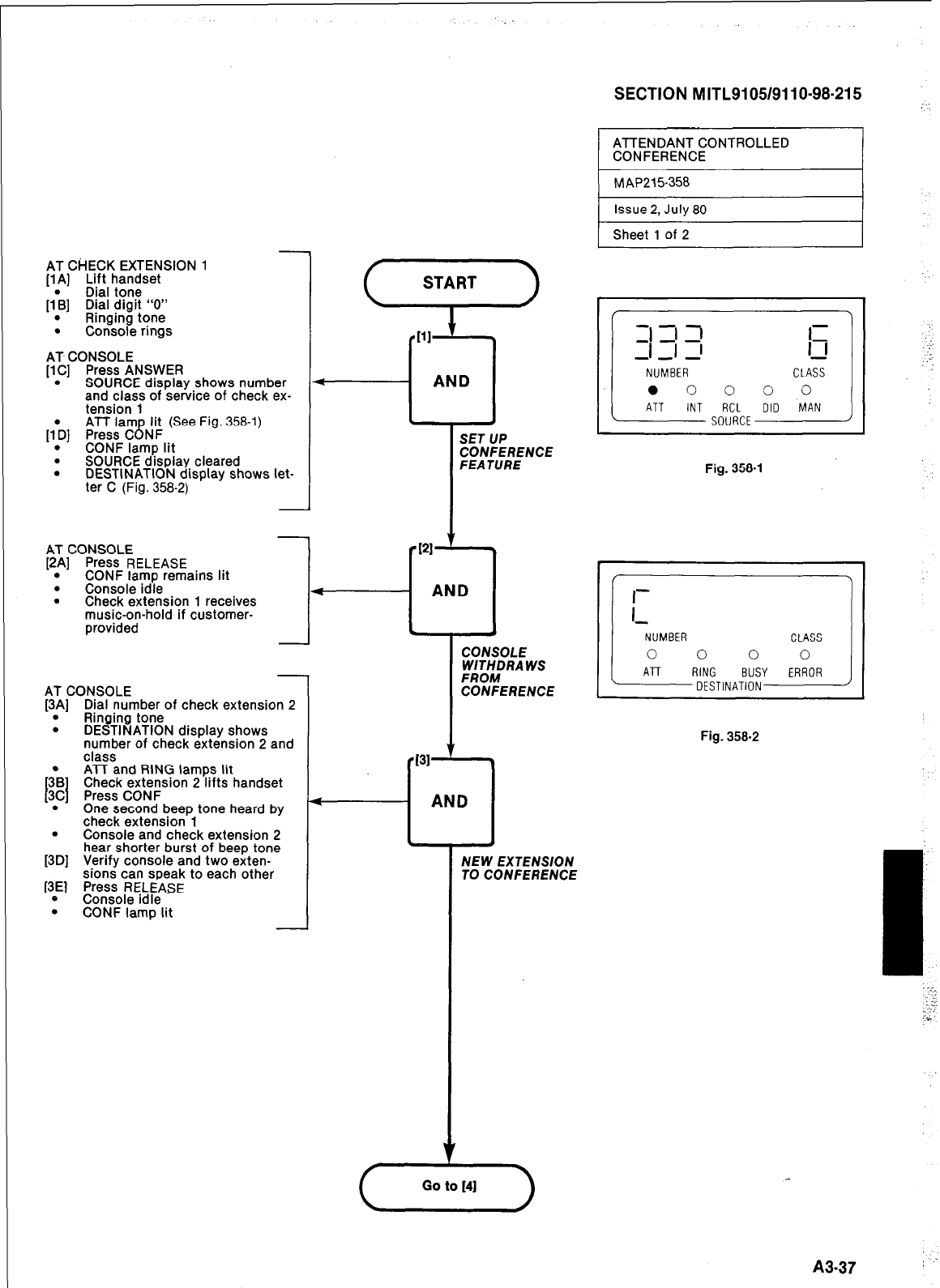
AT CHECK EXTENSION 1
[lA] Lift handset
Dial tone
[I\] Dial digit “0”
. Ringing tone
. Console rings
AT CONSOLE
[lC] Press ANSWER
. SOURCE display shows number
and class of service of check ex.
tension 1
ATT lam lit (See Fig. 358-l)
[I\] Press C NF 8
. CONF lamp lit
. SOURCE display cleared
. DESTINATION display shows let-
ter C (Fig. 358-2)
AT CONSOLE
[2A] Press RELEASE
. CONF lamp remains lit
.
Console idle
. Check extension 1 receives
music-on-hold if customer-
provided
-
AT CONSOLE
[3A] Dial number of check extension 2
. Ringing tone
. DESTINATION display shows
number of check extension 2 and
class
TE?
I I
ATT and RING lamps lit
Check extension 2 lifts handset
3C Press CONF
. One second beep tone heard by
check extension 1
. Console and check extension 2
[3D] hear shorter burst of beep tone
Verify console and two exten-
sions can speak to each other
[3E] Press RELEASE
e Console idle
. CONF lamp lit
SECTION MITL9105/911 O-98-21 5 7
AND I
1
SET UP
CONFERENCE
FEATURE
PI
.
AND
.
CONSOLE
WlTHDRA WS
FROM
CONFERENCE
131 ’ I
AND
NEW EXTENSlON
TO CONFERENCE
ATTENDANT CONTROLLED
CONFERENCE
Fig. 358-l
Fig. 358-2
‘.
A3-37
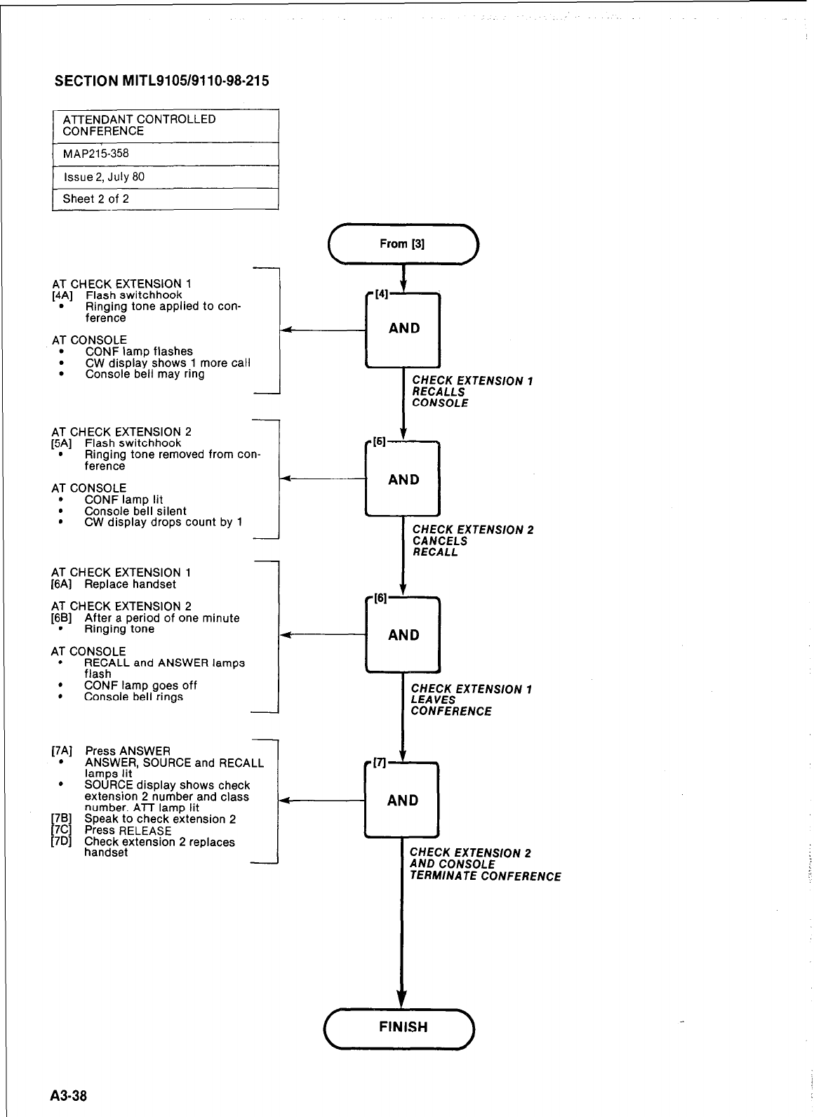
SECTION MITL9105/9110~98-215
/
ATTENDANT CONTROLLED
CONFERENCE
MAP215358
Issue 2, July 80
Sheet 2 of 2
AT CHECK EXTENSION 1
[4A] Flash switchhook
. Ringing tone applied to con-
fereince
AT CONSOLE
. CONF lamp flashes
. CW display shows 1 more call
. Console bell may ring
-
-
AT CHECK EXTENSION 2
[5A] Flash switchhook
. Ringing tone removed from con-
ference
AT CONSOLE
b CONF lamp lit
. Console bell silent
. CW display drops count by 1
AT CHECK EXTENSION 1
[6A] Replace handset
AT CHECK EXTENSION 2
[6B] After a period of one minute
. Ringing tone
AT CONSOLE
. RECALL and ANSWER lamos
flash
. CONF lamp goes off
. Console bell rings
[7Al
.
.
Press ANSWER
ANSWER, SOURCE and RECALL
lamos lit
SOURCE display shows check
extension 2 number and class
number. ATT lamp lit
Speak to check extension 2
Press RELEASE
~~;;;e~tensron 2 replaces
I
AND
I
I
CHECK EXTENSION 1
LEA YES
CONFERENCE
CHECK EXTENSION 2
AND CONSOLE
TERM/NATE CONFERENCE
( FINISH )
A3-38
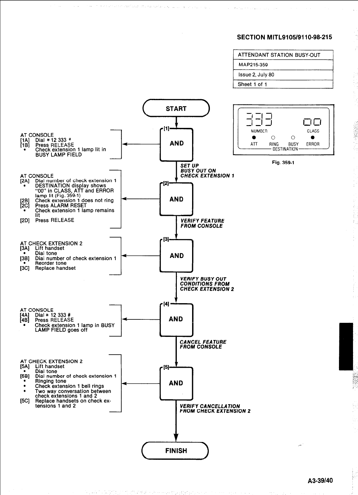
SECTION MITL9105/9110-98-215
ATTENDANT STATION BUSY-OUT
AT CONSOLE
[lA] Dial * 12 333 *
[lB] Press RELEASE
. Check extension 1 lamp lit in
BUSY LAMP FIELD 1-
AT CONSOLE
[2p] Dial number of check extension 1
DESTINATION drsplay shows
“00” in CLASS, ATT and ERROR
lamp lit (Fig. 359-l)
[2B] Check extension 1 does not ring
[2C] Press ALARM RESET
. Check extension 1 lamp remains
lit
[2D] Press RELEASE
AT CHECK EXTENSION 2
[3;] Lift handset
Dral tone
[3B] Dial number of check extension 1
Reorder tone
[;C] Replace handset
AT CONSOLE
[4A Dial * 12 333 #
[4B Press RELEASE
. Check extension 1 lamp in BUSY
LAMP FIELD goes off
AT CHECK EXTENSION 2
[5A] Lift handset
[& Dial tone
1
Dial number of check extension 1
.
Ringing tone
. Check extension 1 bell rings k-
.
Two way conversation between
check extensions 1 and 2
[5C] Replace handsets on check ex-
tensions 1 and 2
c
31
-9
AND
I
BUSY OUT ON
CHECK EXTENSlON 1
121
AND
I
I
VERIFY FEATURE
FROM CONSOLE
VERIFY BUSY OUT
CONDWONS FROM
CHECK EXTENSlON 2
AND
I
CANCEL FEATURE
-T-
FROM CONSOLE
151
i
AND
VERIFY CANCELLATION
FROM CHECK EXTENSlON 2
f FINISH
Fig. 359-l
/Xl-39140 ”
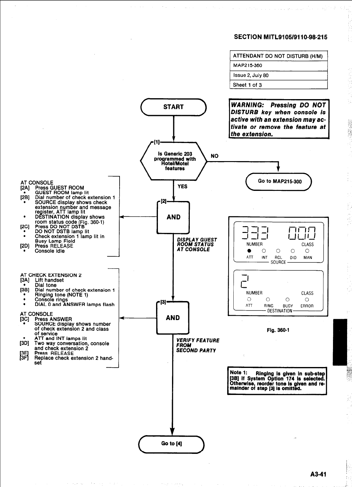
SECTION MITLSI 05/9110-98-215
AT C
y1
y1
.
19
.
y
iONSOLE
Press GUEST ROOM
GUEST ROOM lamp lit
Dial number of check extension 1
SOURCE display shows check
extension number and message
re
D I! ister, ATT lamp lit
STINATION displav shows
room status code ’ Fig. 360-l)
Press DO NOT DS i B
DO NOT DSTB lamp lit
Check extension 1 lamp lit in
Busy Lamp Field
Press RELEASE
Console idle
AT CHECK EXTENSION 2
[3A] Lift handset
[;B] Dial tone
Dial number of check extension 1
. Ringing tone (NOTE 1)
. Console rings
. DIAL 0 and ANSWER lamps flash
AT CONSOLE
[3C] Press ANSWER
. SOURCE display shows number
of check extension 2 and class
h
3E
Id
3
of service
ATT and INT lamps lit
Two way conversation, console
and check extension 2
Press RELEASE
Replace check extension 2 hand-
set
1 Sheet 1 of 3
active with an extension may ac-
DISPLAY GUEST
ROOM STA TfJS
AT CONSOLE
Fig. 366-l
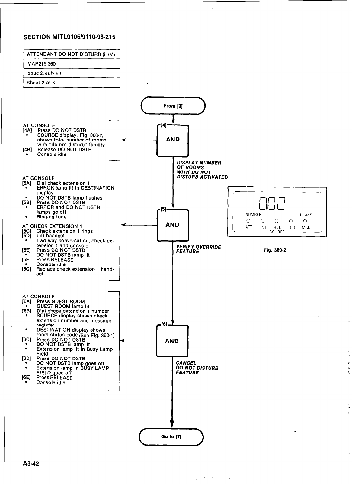
SECTION MITL9105/9110-98-215
ATTENDANT DO NOT DISTURB (H/M)
MAP215-360
Issue 2, July 60
Sheet 2 of 3
AT CONSOLE
[4A] Press DO NOT DSTB
. SOURCE display. Fia. 360-2.
shows total huri&er%t roonis
with “do not disturb” facility
[4B] Release DO NOT DSTB
. Console idle
AT CONSOLE
[5A] Dial check extension 1
. ERROR lamp lit in DESTINATION
displa
DO N 8 T DSTB lamp flashes
[;B] Press DO NOT DSTB
. ERROR and DO NOT DSTB
lamps go off
. Ringing tone
AT CHECK EXTENSION 1
[5C] Check extension 1 rings
[5D] Lift handset
. Two way conversation, check ex-
tension 1 and console
[5E] Press DO NOT DSTB
DO NOT DSTB lamp lit
15& Press RELEASE
- -
Console idle
[5& ,R,eplace check extension 1 hand-
AT CONSOLE
[6A] Press GUEST ROOM
[;B] GUEST ROOM lamp lit
Dial check extension 1 number
. SOURCE display shows check
extension number and message
l
%$i%~~l0N display
shows
room status code See
Fig. 360-l)
[6C]
Press DO NOT DS f B
.
. DO NOT DSTB lamp lit
E;;.slon lamp Ilt In Busy Lamp
[6D] Press DO NOT DSTB
. DO NOT DSTB lamp goes off
. Extension lamp in BUSY LAMP
FIELD aoes off
[6E] Press RELEASE
. Console idle
.
<
~ISS~A~‘IUMBER
W/TN DO NOT
DISTURB ACTIVATED
CANCEL
;gANpT~~~
Fig. 360-2
A342
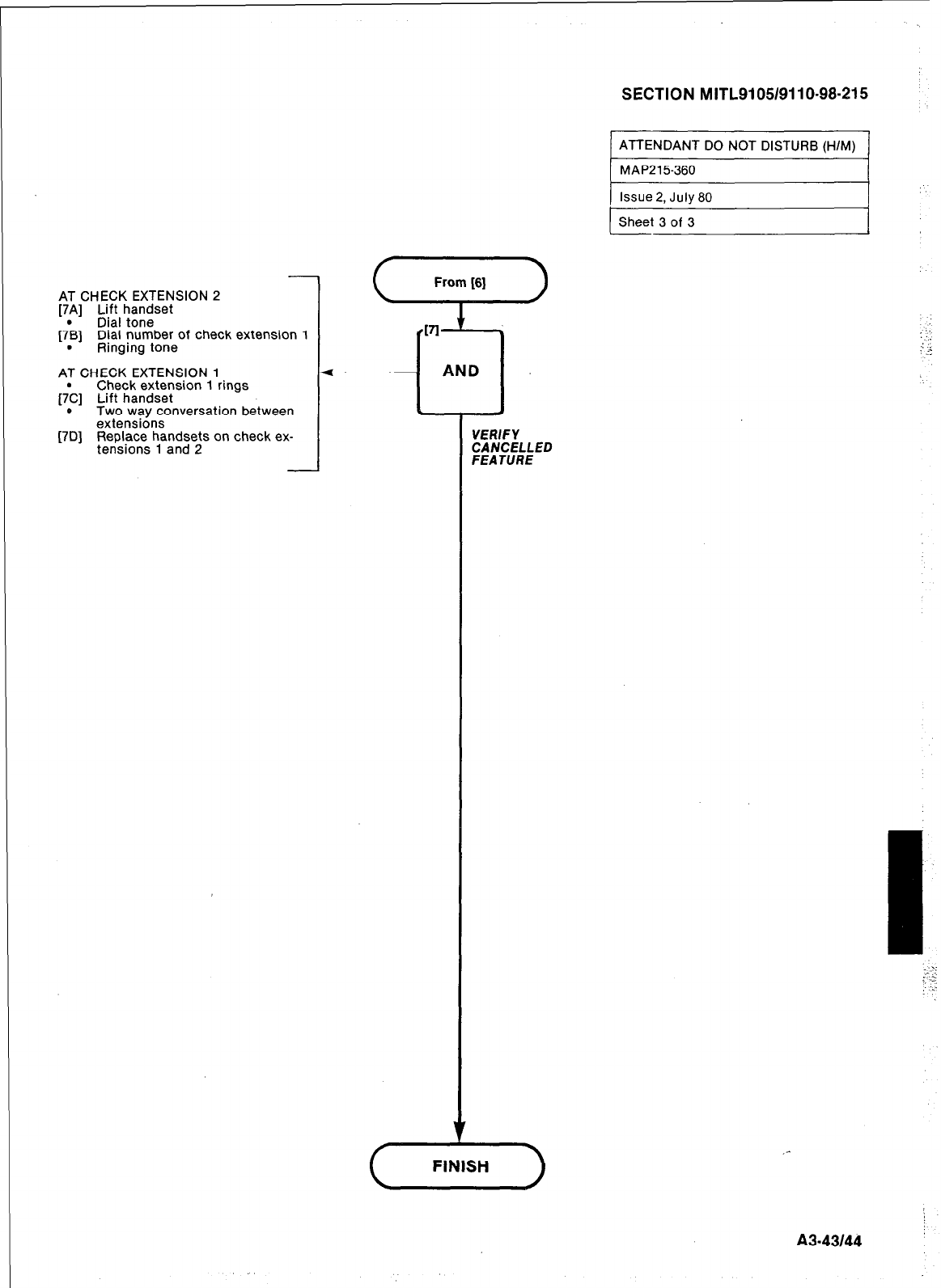
AT CHECK EXTENSION 2
[7p] Lift handset
Dlal tone
[7B] Dial number of check extension 1
. Ringing tone
AT CHECK EXTENSION 1
Check extension 1 rings
[;C] Lift handset
* Two way conversation between
extensions
[7D] Replace handsets on check ex-
tensions 1 and 2
SECTION MITL9105/9110-98-215
ATTENDANT DO NOT DISTURB (H/M)
MAP215360
I ~_____
Issue 2, July 80 I
) Sheet 3 of 3 I
I
A343144
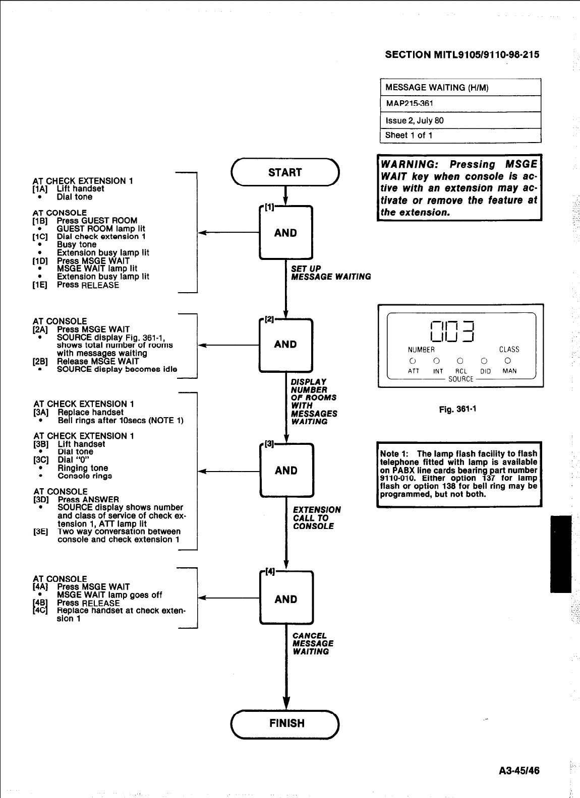
AT CHECK EXTENSION 1
[lA] Lift handset
. Dial tone
AT CONSOLE
[lB] Press GUEST ROOM
GUEST ROOM lamp lit
[;C] Dial check extension 1
.
Busy tone
Extension busy lamp lit
[TD] Press MSGE WAIT
. MSGE WAIT lamp lit
.
Extension busy lame lit
VEI Press
RELEASE ’
SECTION MITL9105/9110-98.215
MESSAGE WAITING (H/M)
MAP215-361
issue 2, July 60
Sheet 1 of 1
SET
UP
MESSAGE WAITING
-T-
l- f
AT CHECK EXTENSION 1
[3B] Lift handset
Dial tone
[&I Dial “0”
. Ringing tone
. Console rings
AT CONSOLE
[3D] Press ANSWER
. SOURCE disDlav shows number
and class of ‘seivice of check ex-
[3E] tension 1, ATT lamp lit
Two way conversation between
console and check extension 1
EXTENSION
CALL 10
CONSOLE
AT CONSOLE
[4A] Press MSGE WAIT
;B Press
RELEASE
I I
MSGE WAIT lamp goes off
4C Replace handset at check exten-
sion 1
Fig. 361-l
Note 1: The lamp flash facility to flash
~ telephone fitted with lamp is available
on PABX line cards bearing part number
i programmed, but not both.
1
9110-010. Either option 137 for lamp
flash or option 136 for bell ring may be ,
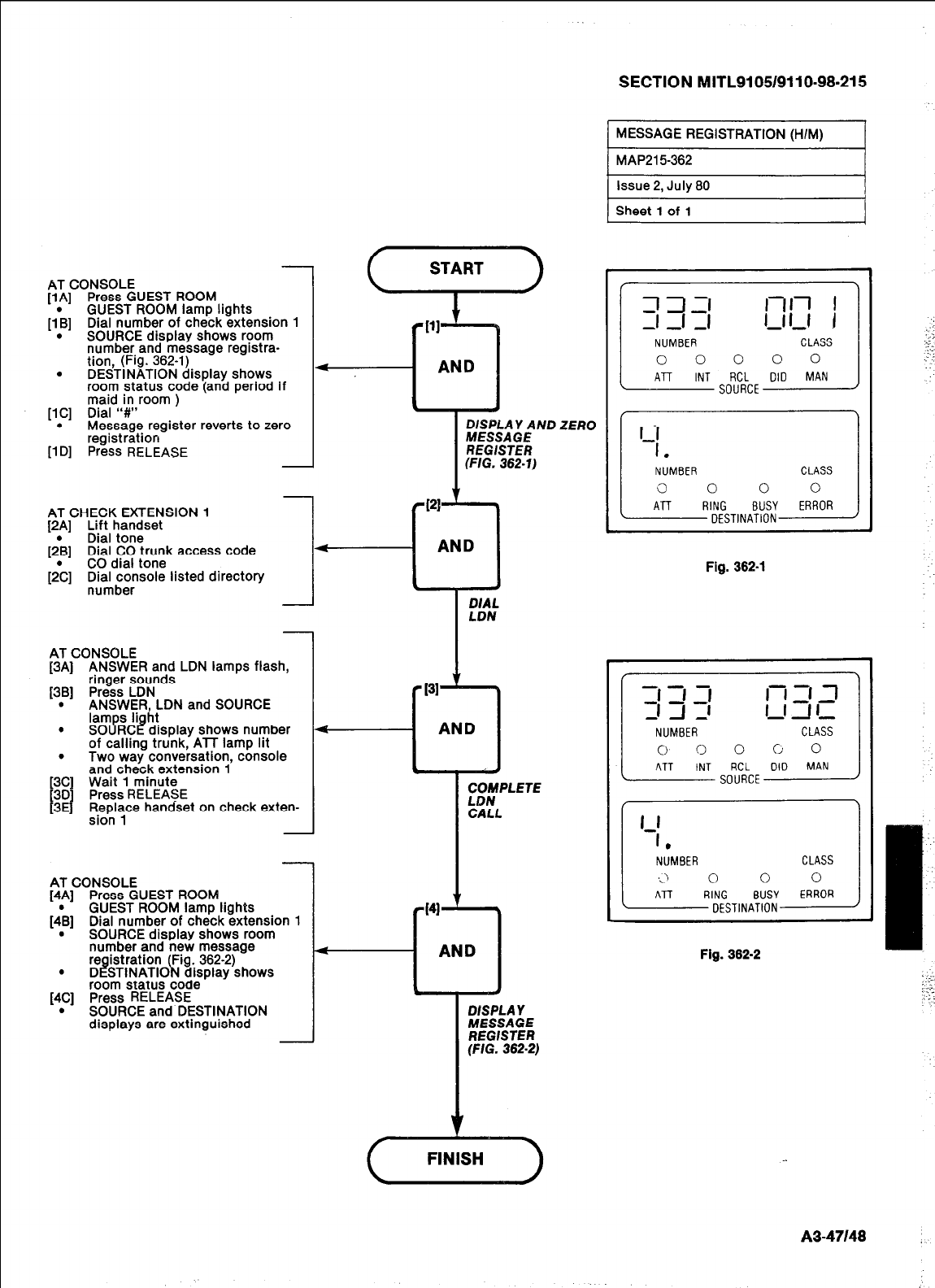
room status code ‘(and period if
maid in room )
[lC] Dial “#”
. Message register reverts to zero
registration
[lDl Press RELEASE
AT CONSOLE
[lA] Press GUEST ROOM
[I’B] GUEST ROOM lamp lights
Dial number of check extension 1
. SOURCE display shows room
number and message registra-
tion, (Fig. 362-l)
. DESTINATION display shows
I
;Wo’E” ND ZERO
REGISTER
(FIG. 362-l)
AT CHECK EXTENSION 1
[2A] /iI :a,;set
.
[2B] Dial CO trunk access code
[2;] CO dial tone
Dial console listed directory
number
AT CONSOLE
[3A] ANSWER and LDN lamps flash,
ringer sounds
[3B] Press LDN
. ANSWER, LDN and SOURCE
lamps Ii ht
. SOURC I! display shows number
of calling trunk, ATT lamp lit
.
Two way conversation, console
and check extension 1
[3C] Wait 1 minute
,“i”,l,“” handset on check exten-
-
AT CONSOLE
[4A] Press GUEST ROOM
[4\] GUEST ROOM lamp lights
Dial number of check extension 1
. SOURCE display shows room
number and new message
l ~&~~~~(#gdj~$f)&ows
room status code
[4C] Press RELEASE
. SOURCE and DESTINATION
displays are extinguished
SECTION MITL9105/9110-98-215
1 MESSAGE REGISTRATION (H/M) 1
Fig. 362-l
111 5 l-i =I ,1
-1 A -’ I-1 -I I-
NUMBER CLASS
0 0 0 c 0
ATT INT RCL DID MAN
SOURCE
1
J
Fig. 362-2
A3.47148
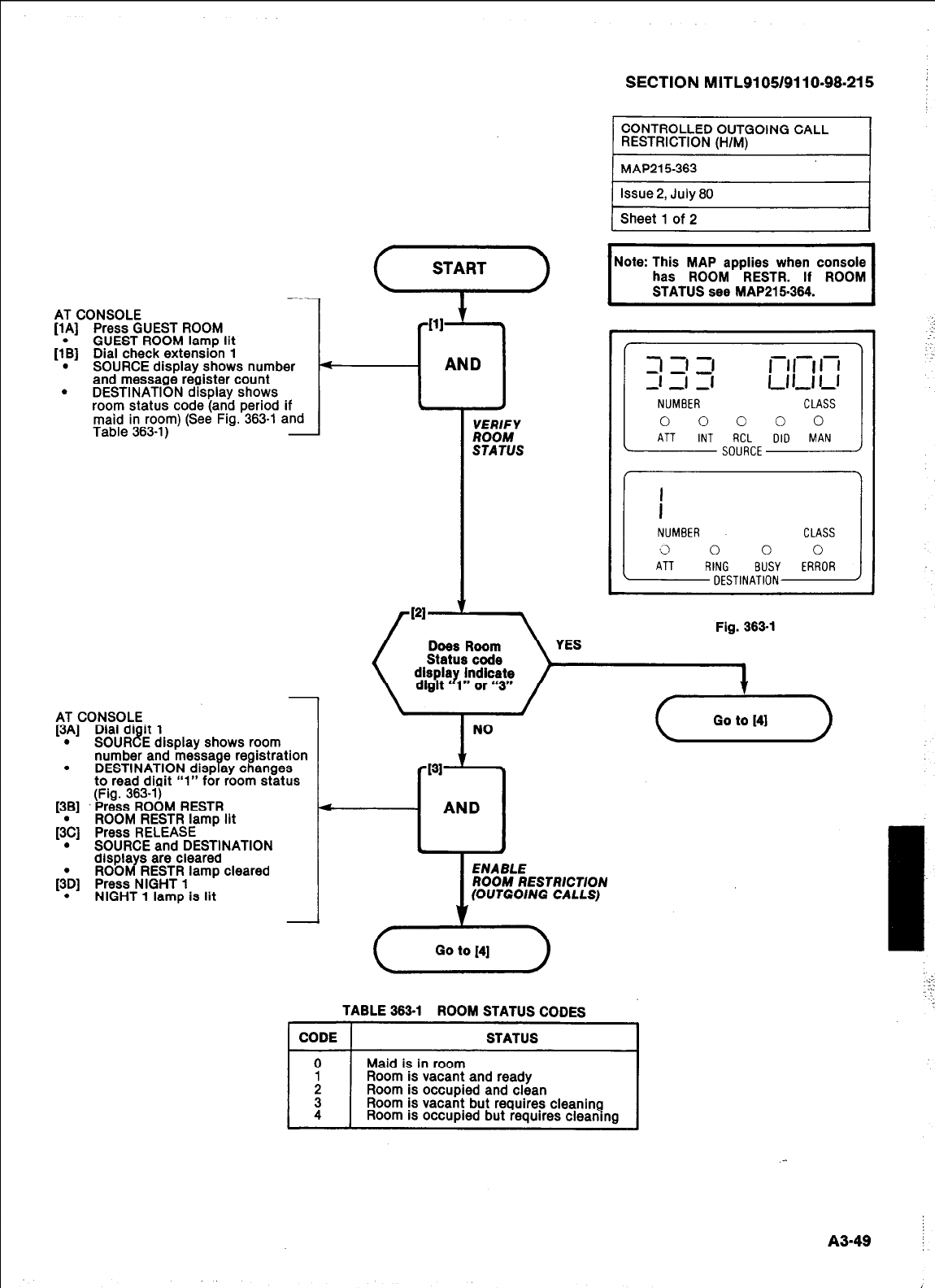
AT CONSOLE
[lA] Press GUEST ROOM
GUEST ROOM lamp lit
[lk] Dial check extension 1
. SOURCE display shows number
and message register count
. DESTINATION display shows
room status code (and period if
maid in room) (See Fig. 363-l and
Table 363-l) -
AT CONSOLE
[3A] Dial di it 1
. SOURCE display shows room
number and messa e registration
. DESTINATION disp ay changes B
to read diqit “1” for room status
(Fig. 363-l)
[3B] Press ROOM RESTR
ROOM RESTR lamp lit
&] Press RELEASE
. SOURCE and DESTINATION
displa s are cleared
ROOMRESTR lamp cleared
[{D] Press NIGHT 1
. NIGHT 1 lamp is lit
START
111
--I ’
AND
1
VERIFY
ROOM
STATUS
SECTION MITL9105/9110-98.215
CONTROLLED OUTGOING CALL
RESTRICTION (H/M) I
I
Note: This MAP applies when console
has ROOM RESTR. If ROOM
STATUS see MAP21 5364. I
Fig. 363-l
ROOM RESTRICTION
(OUTGOING CALLS)
TABLE 363-l ROOM STATUS CODES
Room is vacant but requires cleaning
Room is occupied but requires cleaning
A349 i
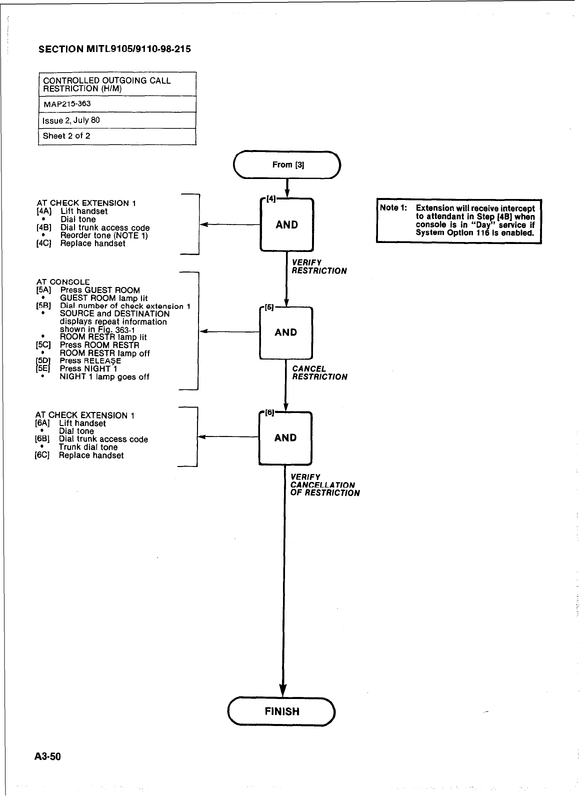
SECTION MITL9105/9110-98-215
Issue 2, July 80
Sheet 2 of 2
AT CHECK EXTENSION 1
[4A] Lift handset
Dial tone
[4& Dial trunk access code
Reorder tone (NOTE 1)
(4& Replace handset
3OOM
AT CONSOLE
[5Al Press GUEST T - -
GUEST ROOM
I& s(
. 1 Dial number of ‘%%dextensic
3URCE and DESTINATION
displays repeat information
shown in Fi . 366-l
ROOM RESQR lamp lit
[5& Press ROOM RESTR
;D] ROOM RESTR lamp off
Press RELEASE
5E] Press NIGHT-1
. NIGHT 1 lamp goes off
AT CHECK EXTENSION 1
[6A] Lift handset
Dial tone
[6&
y;;ky$ ycss code
[6;] Replace handset
)n 1
i
I
From [3]
RESTRICTION
AND
I
-T-
CANCEL
RESTRICTION
I61
L
AND
VERIFY
CANCELLATION
OF RESTRICTION
A3-50
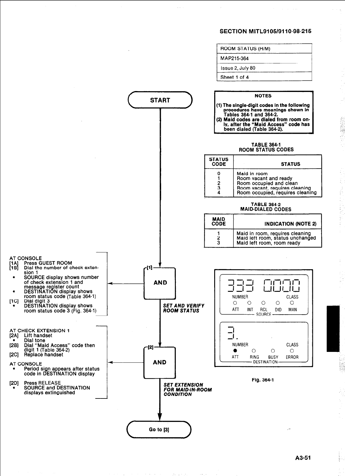
SECTION MITL9105/9110-98-215
ROOM STATUS (H/M)
MAP215-364
Issue 2, July 80
Sheet 1 of 4
I
NOTES I
(1) The single-digit codes in the following
procedures have meanings shown in
Tables 364-l and 364-2.
(2) Maid codes are dialed from room on-
ly, after the “Maid Access” code has
been dialed liable 364-2).
TABLE 364-l
ROOM STATUS CODES
Room vacant, requires cleaning
Room occupied, requires cleaning
TABLE 364-2
MAID-DIALED CODES
MAID
CODE INDICATION (NOTE 2)
I I
: Maid in room, requires cleaning
Maid left room, status unchanged
3 Maid left room, room ready
AT CONSOLE
[lA Press GUEST ROOM
flB I Dial the number of check exten-
I
J
1
_ _
sion 1
. SOURCE display shows number
of check extension 1 and
message re ister count
e DESTINATI 8 N display shows
room status code (Table 364-l)
[lC] Dial digit 3
. DESTINATION display shows
room status code 3 (Fig. 364-l)
SET AND VERIFY
ROOM STA TVS
AT CHECK EXTENSION 1
[2A] Lift handset
12;) Dial tone
Dial “Maid Access” code then
digit 1 (Table 364-2)
[2C] Replace handset
AT CONSOLE
.
Period sign appears after status
code in DESTINATION display Fig. 364-l
[2D] Press RELEASE
. SOURCE and DESTINATION
displays extinguished
SET EXTENSION
FOR MAID-IN-ROOM
CONDITION
Go to [S]
A3-51
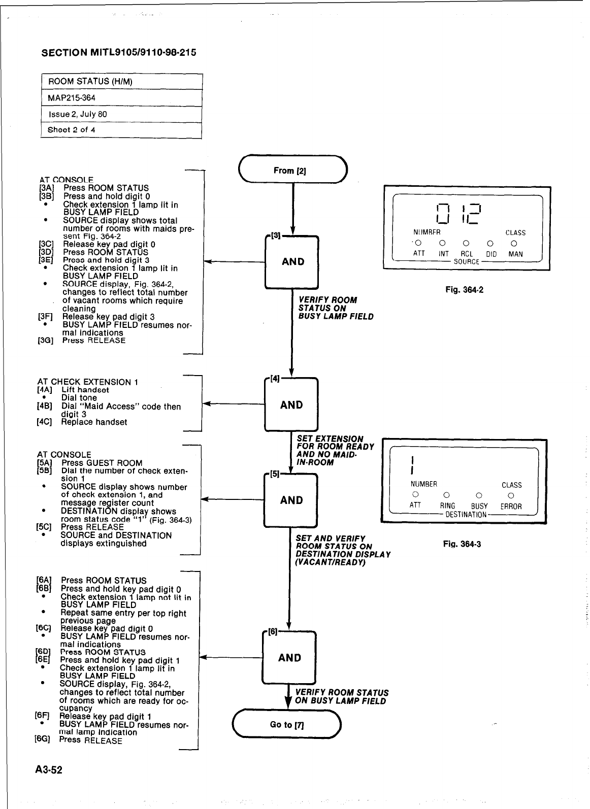
SECTION MITL9105/9110-98-215
) ROOM STATUS (H/M) 1
AT CONSOLE
f3Al Press ROOM STATUS
[3Bj Press and hold digit 0
. Check extension 1 lamp lit in
BUSY LAMP FIELD
. SOURCE display shows total
number of rooms with maids pre-
[3C] sent Fig. 364-2
Release key pad digit 0
[3D] Press ROOM STATUS
13El Press and hold diait 3
- _
.
Check extension 7 lamp lit in
BUSY LAMP FIELD
. SOURCE display, Fig. 364-2,
changes to reflect total number
of vacant rooms which require
[3F] cleaning
Release key pad digit 3
. BUSY LAMP FIELD resumes nor-
mal indications
[3G] Press RELEASE
i
From [2]
‘r’
131
+J
AND
AT CHECK EXTENSION 1
[4!] Lift handset
Dral tone
1481 D.ia! “Maid Access” code then
[4C] dR’egd:&e handset
AT CONSOLE
[5A] Press GUEST ROOM
[5B] Dial the number of check exten-
sion 1
. SC 3URCE display shows number
Of
’ check extension 1, and
message re ister count
r
.
DESTINATI F 8 J display shows
room status code .“I”
(Fig.
364-3)
[5C] Press RELEASE
. SOURCE and DESTINATION
displays extinguished I
[6A] Press ROOM STATUS
[6B] Press and hold key pad digit 0
. Check extension 1 lamp not lit in
BUSY LAMP FIELD
. Repeat same entry per top riaht
169
6D
t 1
6E
.
.
previous page - ”
Release key pad digit 0
BUSY LAMP FIELD resumes nor-
mal indications
Press ROOM STATUS
Press and hold key pad digit 1
Check extension 1 lamp lit in
BUSY LAMP FIELD
SOURCE display, Fig. 364-2,
changes to reflect total number
of rooms which are ready for oc-
[6F] %?&?zlkey pad digit 1
. BUSY LAMP FIELD resumes nor-
mal lamp indication
]6G1
Press
RELEASE
VERIFY ROOM
STATUS ON
BUSY LAMP FIELD
AND
r
PI-
+---I AND
1-1 I 7
1-l II,-
NUMBER
L
CLASS
.o 0 0 0 0
ATT INT RCL DID MAN
SOURCE
Fig. 364.2
SET EXTENSION
SET AND VERIFY
ROOM STATUS ON
DESTINATION DISPLAY
(VACANT/READY)
VERIFY
ROOM
STATUS
ON BUSY LAMP FIELD
Fig. 364-3
A3-52
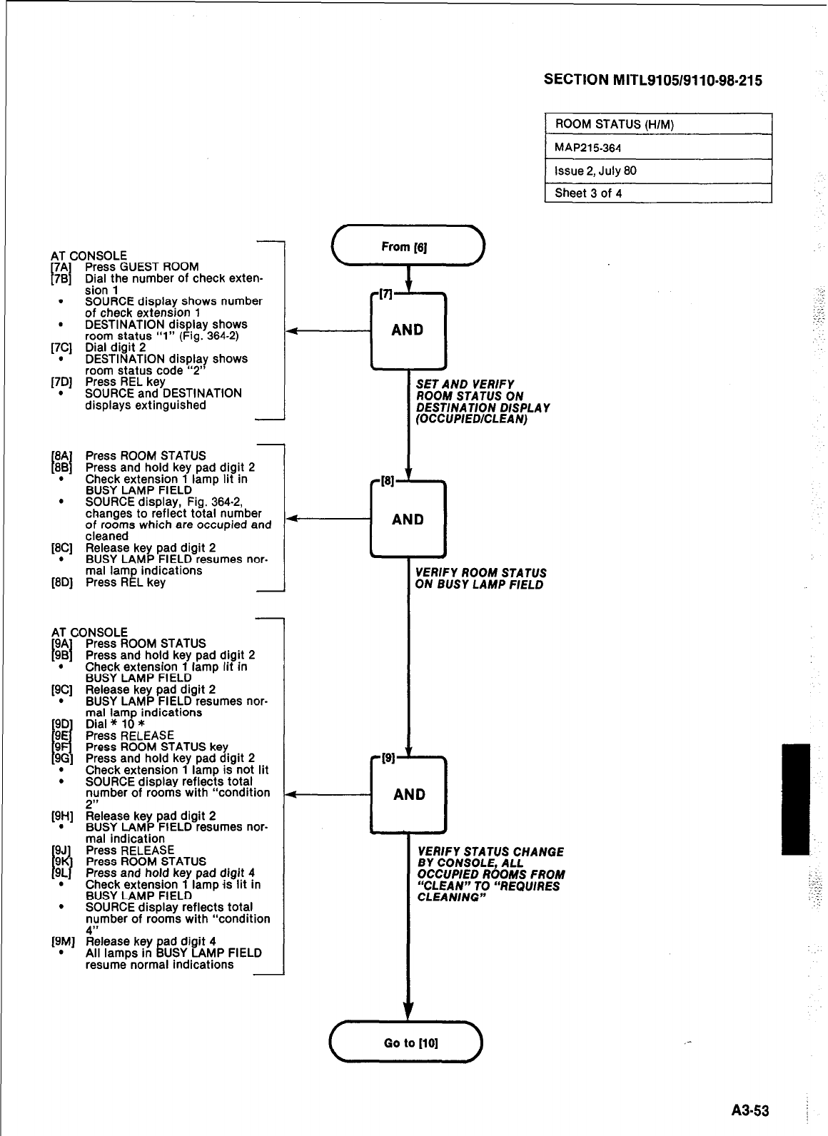
SECTION MITL9105/9110-98.215
1 ROOM STATUS (H/M) I
AT CONSOLE
I
7A] Press GUEST ROOM
781 Dial the number of check exten-
.
.
[7Cl
.
170
.
sion 1
SOURCE display shows number
of check extension 1
DESTINATION display shows
room status “1” (Fig. 364-2)
Dial digit 2
DESTINATION display shows
room status code “2”
Press REL key
SOURCE and DESTINATION
displays extinguished
I I
tt
.
.
WI
.
ml
Press ROOM STATUS
Press and hold key pad digit 2
Check extension 1 lamp lit in
BUSY LAMP FIELD
SOURCE display, Fig. 364-2,
changes to reflect total number
of rooms which are occupied and
cleaned
Release key pad digit 2
BUSY LAMP FIELD resumes nor-
mal lamp indications
Press REL key
AT CONSOLE
9A Press ROOM STATUS
I I
9B Press and hold key pad digit 2
. Check extension 1 lamp lit in
BUSY LAMP FIELD
[9C] Release key pad digit 2
. BUSY LAMP FIELD resumes nor-
mal lamp indications
Press ROOM STATUS key
Press and hold key pad digit 2
. Check extension 1 lamp is not lit
. SOURCE display reflects total
number of rooms with “condition
1)1)
P,Hl
.
.
helease key pad digit 2
BUSY LAMP FIELD resumes nor-
mal indication
Press RELEASE
Press ROOM STATUS
Press and hold key pad digit 4
Check extension 1 lamp is lit in
BUSY LAMP FIELD
SOURCE display reflects total
number of rooms with “condition
A”
[9M] Release key ad digit 4
. All lamps in i USY LAMP FIELD
resume normal indications
AND
t
W-
MAP215364 I
SET AND VERIFY
ROOM STATUS ON
DESTlNATlON DISPLAY
(OCCUPIED/CLEAN)
Issue 2, July 80
Sheet 3 of 4
AND
I
VERlFY ROOM STATUS
ON BUSY LAMP FIELD
VERIFY STATUS CHANGE
BY CONSOLE, ALL
OCCUPIED ROOMS FROM
“CLEAN” TO “REQUIRES
CLEANING”
I-
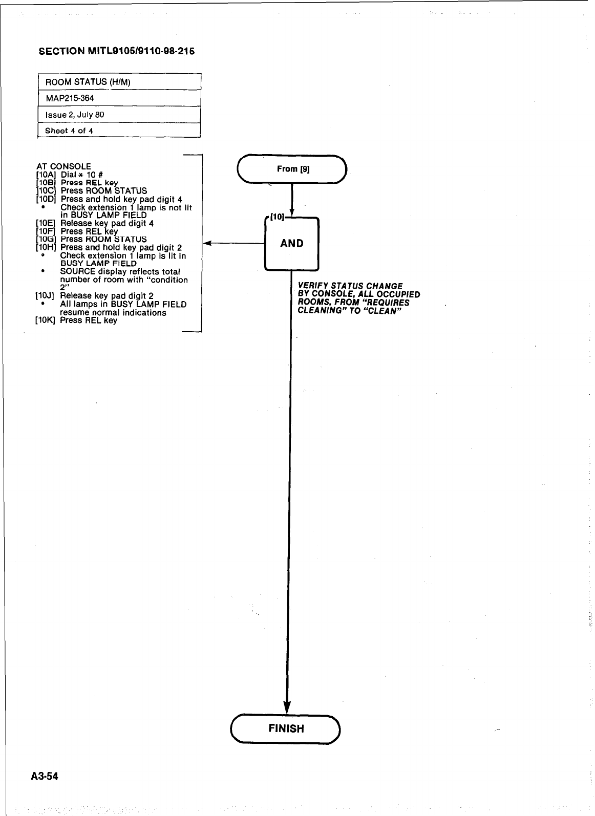
SECTION MITL9105/9110-98-215
1 ROOM STATUS (HIM) I
I
MAP215-364 I
Issue 2, July 80
Sheet 4 of 4
AT CONSOLE
.
WJI
.
VW
-Dial x 10 #
Press REL key
Press ROOM STATUS
Press and hold key pad digit 4
Check extension 1 lamp is not lit
in BUSY LAMP FIELD
Release key pad digit 4
Press REL key
Press ROOM STATUS
Press and hold key pad digit 2
Check extension 1
BUSY LAMP FIELD lamp is lit in
SOURCE display reflects total
number of room with “condition
2”
Release key pad digit 2
All lamps in BUSY LAMP FIELD
resume normal indications
Press REL key
I101
A-
AND
--L
VERIFY STATUS CHANGE
BY CONSOLE, ALL OCCUPIED
ROOMS, FROM “REQUIRES
CLEANING” TO “CLEAN”
A3-54
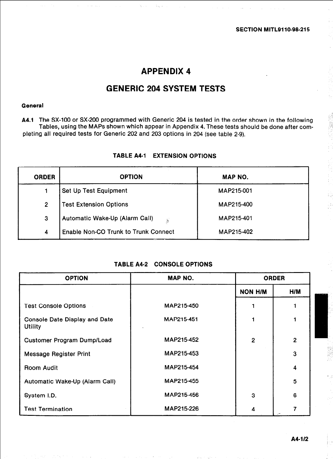
SECTION MITL9110.98.215
APPENDIX 4
GENERIC 204 SYSTEM TESTS
General
A4.1
The SX-100 or SX-200 programmed with Generic 204 is tested in the order shown in the following
Tables, using the MAPS shown which appear in Appendix 4. These tests should be done after com-
pleting all required tests for Generic 202 and 203 options in 204 (see table 2-9).
ORDER
TABLE A4-1 EXTENSION OPTIONS
OPTION I MAP NO. I
Set Up Test Equipment
Test Extension Options
Automatic Wake-Up (Alarm Call) L-Y
Enable Non-CO Trunk to Trunk Connect
MAP21 5-001
MAP21 5-400
MAP215401
MAP215402
TABLE A4-2 CONSOLE OPTIONS
OPTION
Test Console Options
Console Date Display and Date
Utility
Customer Program Dump/Load
Message Register Print
Room Audit
Automatic Wake-Up (Alarm Call)
System I.D.
Test Termination
MAP NO.
MAP215-450
MAP215-451
MAP215-452
MAP215-453
MAP21 5-454
MAP215-455
MAP21 5-456
MAP215-226
r
ORDER
NON H/M
1
H/M
2
3
4
5
6
7
,-
A4-112
I:
:
‘..,
:......
:
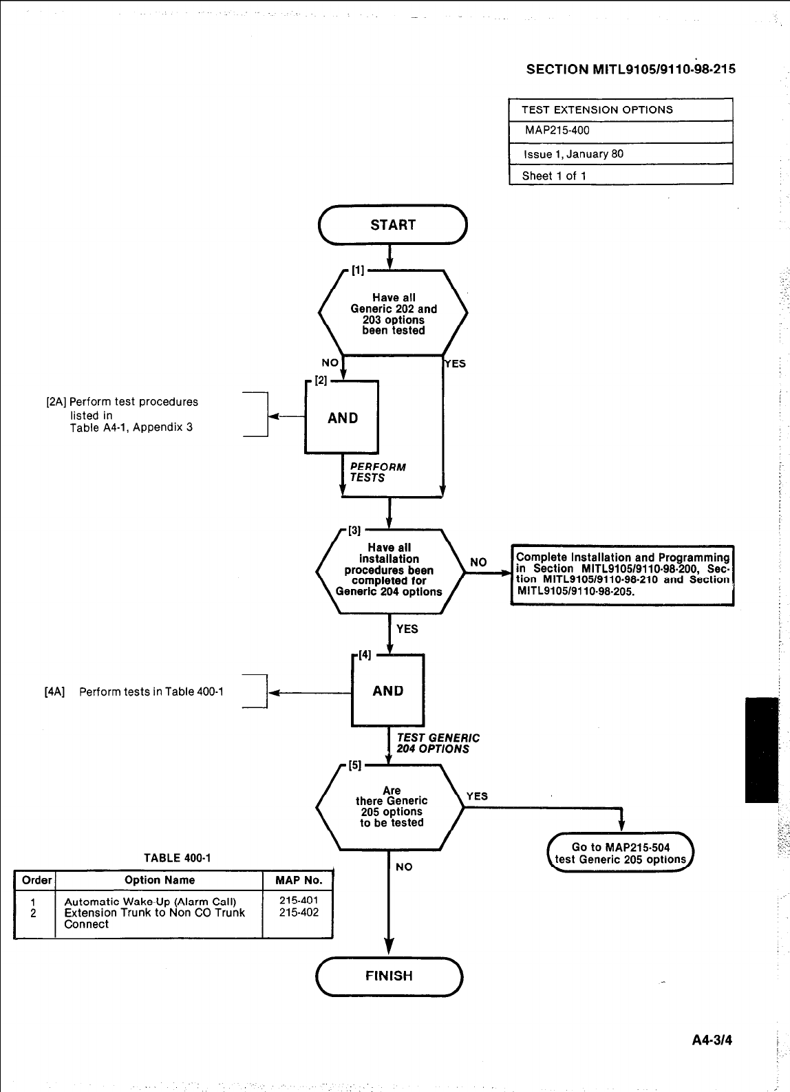
Generic 202 and
been tested
[2A] Perform test procedures
listed in
Table A4-1, Appendix 3
f-- AND
I
TABLE 400-l
ES
SECTION MITL9105/9110-68.215
I
TEST EXTENSION OPTIONS I
I
MAP215400 I
Issue 1, January 80
Sheet 1 of 1
[4A] Perform tests in Table 400-l 3
procedures been
enerlc 204 option
- AND
TEST GENERIC
204 OPTIONS
there Generic
to be tested
YES
Automatic Wake-Up (Alarm Call)

AT CHECK EXTENSION
[lA] Lift handset
Dial tone
[I;] Dial Automatic Wake-Up Access
I;oorgarrd Wake-Up time (24 hour
Dial tone
[I\] Replace handset
SECTION MITLSI 05/911 O-98-21 5 j
( AUTOMATIC WAKE-UP I
1 MAP215401
Issue 2, July 80
Sheet 1 of 1
i.:.i
.,‘;.‘:
.-.- -.
:: ”
. . . .
..: :.
.
I
ENTER WAKE-UP TIME FROM
CHECK EXTENSION
AT CHECK EXTENSION
[2A] Check extension rings at re-
quested time
WAKE-UP CALL RINGS
CHECK EXTENSlON
AT CHECK EXTENSION
[3A] Repeat steps 1A + 1B
Dial tone
[3\] ~~;b~r~ma;gc Wake-Up Access 4
Dial tone
[3& Replace handset
et31 ’ *
AND
6 a
CANCEL WAKE-UP CALL FROM
CHECK EXTENSION
AT CHECK EXTENSION
[4A] Check extension does not rina at
time requested steps
r I41 t \
M
AND
a ,
WAKE-UP CALL CANCELLED
A4-518 i
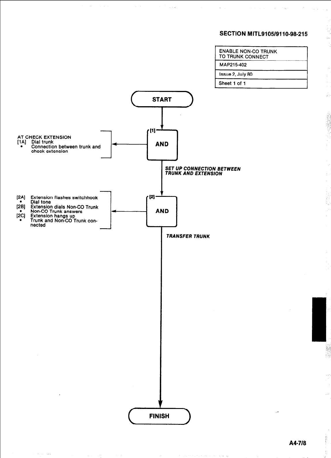
AT CHECK EXTENSION
[lA] Dial trunk
. Connection between trunk and
check extension -
[2A] Extension flashes switchhook
[2\] Dial tone
Extension dials Non-CO Trunk
Non-CO Trunk answers
[2;] Extension hangs up
. Trunk and Non-CO Trunk con-
nected
-
J
TRANSFER TRUNK
SECTION MITL9105/9110-98-215
,
ENABLE NON-CO TRUNK
TO TRUNK CONNECT
MAP215402
Issue 2, July 80
Sheet 1 of 1
- AND
s a
SET UP CONNECTION BETWEEN
TRUNK AND EXTENSION
:-.
,..
: . .
,-
FINISH
A4-718
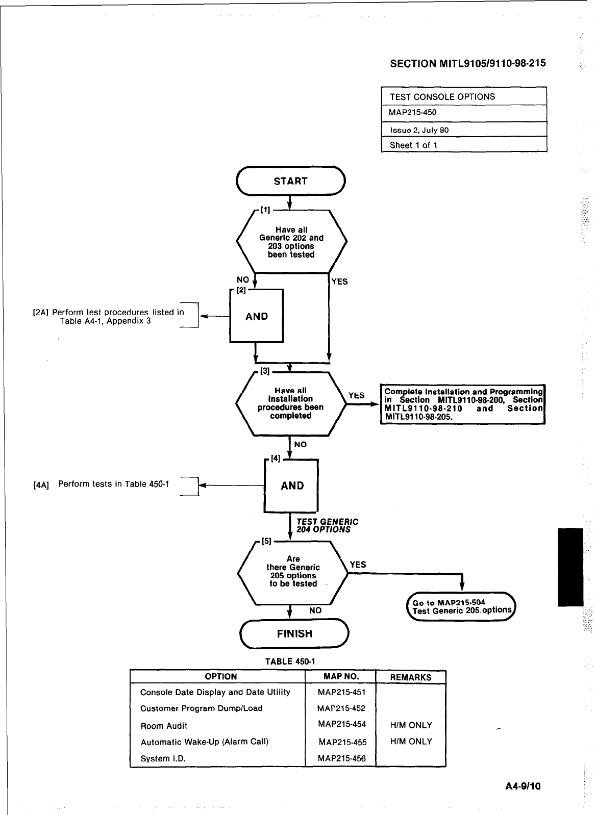
SECTION MITL9105/9110-98-215
[2A] Perform test procedures listed in
Table A4-1, Appendix 3 7
f-
1 TEST CONSOLE OPTIONS I
Generic 202 and
been tested
START
MAP215450
Issue 2. July 80
Sheet 1 of 1
IES
Complete Installation and Programming
in Section MITL9110.98-200, Section
1
NO
[4A] Perform tests in Table 450-l
TEST GENERIC
204 OPTIONS
YES
TABLE 450-l
OPTION [ MAPNO. 1 REMARKS
Console Date Display and Date Utility
Customer Program Dump/Load
Room Audit
Automatic Wake-Up (Alarm Call]
System I.D.
MAP215451
MAP21 5-452
MAP215-454
MAP215-455
MAP215-456
HIM ONLY
HIM ONLY
A4-9110
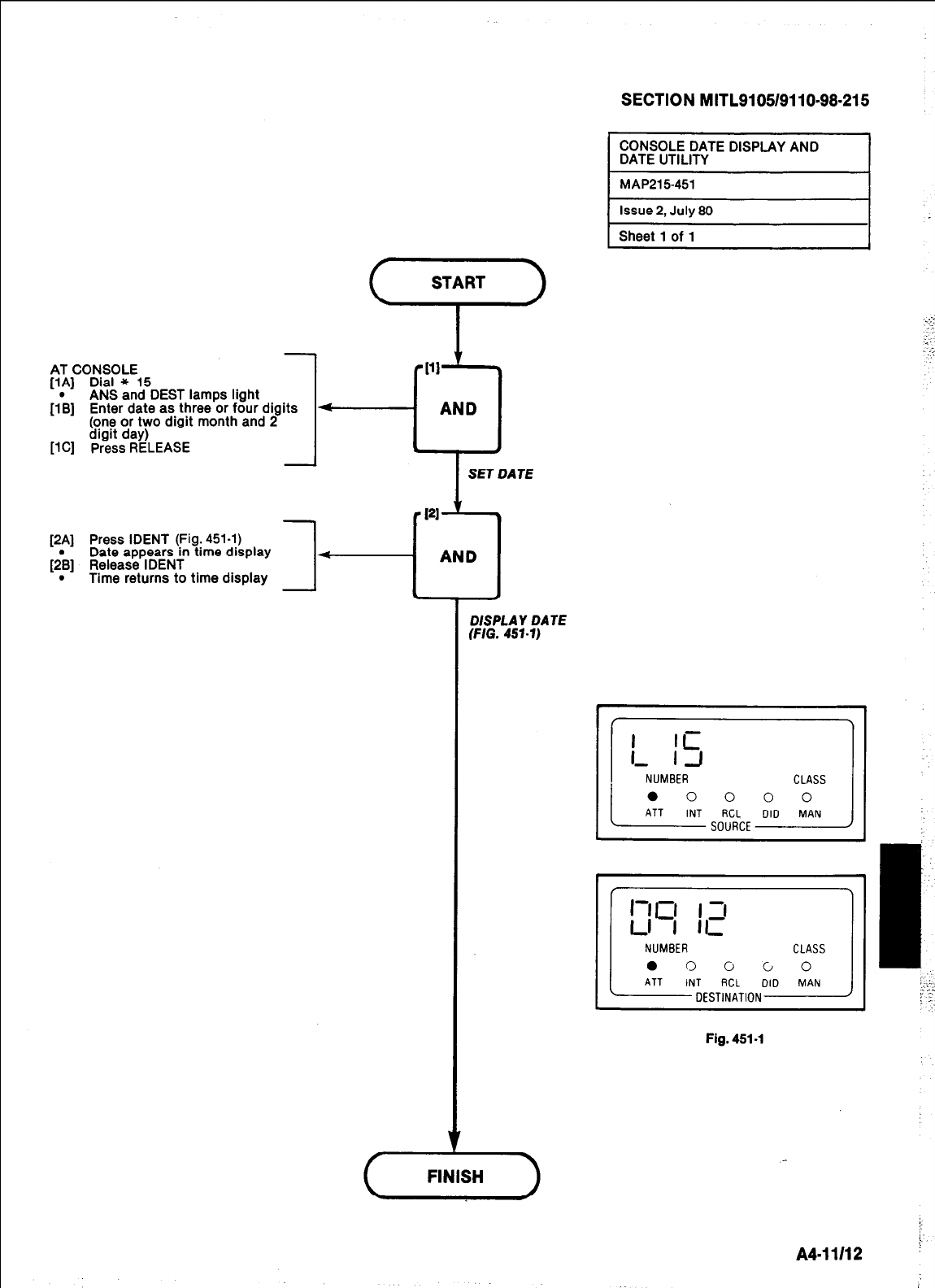
SECTION MITL9105/9110-98-215
START
.-+.
I
.
-
.:’
AT CONSOLE
(1AJ Dial * 15
ANS and DEST lamps light
[l& Enter date as three or four digits 4
(one or two digit month and 2
digit day)
[lC] Press RELEASE
[2A] Press IDENT (Fig. 451-l)
Date appears in time display
[2& Release IDENT
. Time returns to time display
DISPLAY DATE
(FIG. 457-7)
0 0 0 0 0
Fig. 451-l
A411112
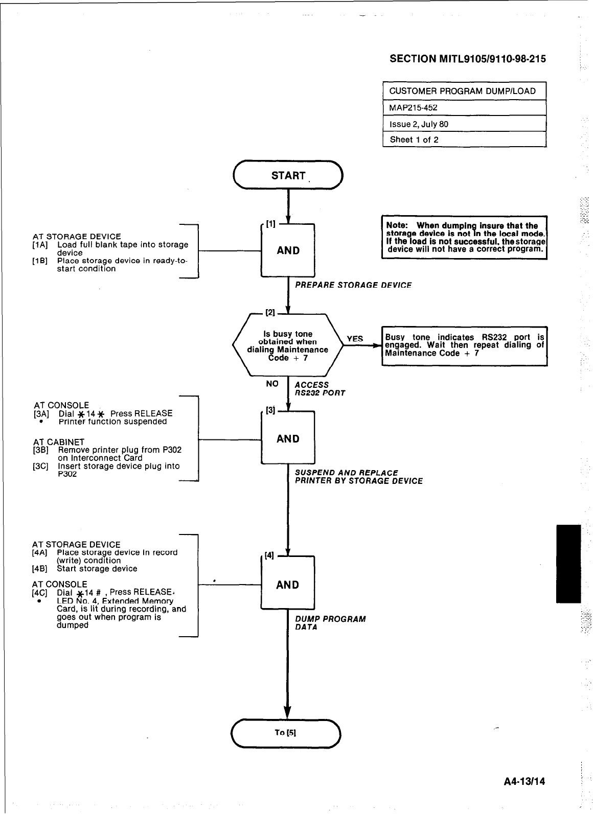
-
START.
I
-Ill ’
AT STORAGE DEVICE
[lA] to-;iuII blank tape into storage
[l B] Place storage device in ready-to-
start condition J-
- AND
PREPARE STORAGE DEVICE
SECTION MITL9105/9110-98-215 ;
CUSTOMER PROGRAM DUMP/LOAD
MAP21 5-452
AT CONSOLE
[3A] Dial * 14 Jc Press RELEASE
. Printer function suspended
AT CABINET
[3B] Remove printer plug from P302
on Interconnect Card
[3C] Fn;;t storage device plug into
Note: When dumpin insure that the
storage device is not B n the local mode.
If the load is not successful. thestorage
device will not have a correct program.
.- .-i
“-
e
\
Code + 7 /
Busy tone indicates RS232 port is
I
J
ACCESS
RS232 PORT
AT STORAGE DEVICE
[4A] Place storage device in record
(write) condition
[4B] Start storage device
AT CONSOLE
[4C] Dial ~14 # , Press RELEASEA
. LED No. 4, Extended Memory
Card, is lit during recording. and
goes out when program is
dumped
Issue 2, July 80
Sheet 1 of 2
SUSPEND AND REPLACE
PRINTER BY STORAGE DEVICE
DUMP PROGRAM
DATA
-
AN
A413114 i-
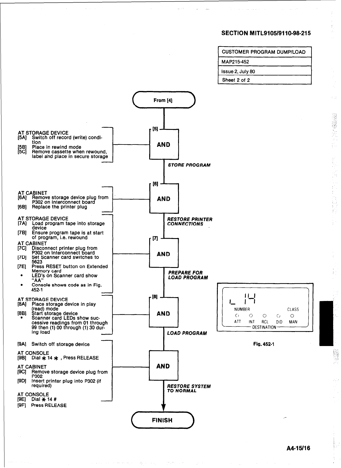
From 14)
i-’
AT STORAGE DEVICE
[5A] i;lntch off record (write) condi-
[5B] Place in rewind mode
[5C] Remove cassette when rewound,
label and place in secure storage t
-
AT CABINET
STORE PROGRAM
[6Aj Remove storage device plug from
P302 on Interconnect board
[6B] Replace the printer plug t--i AND I
-
AT STORAGE DEVICE
I7AJ ;z;zirogram tape into storage
[7B] Ensure program tape is at start
of program, i.e. rewound
AT CABINET
[7C] Disconnect printer plug from
P302 on Interconnect board
[7D] g;;Scanner card switches to
[7E] Press RESET button on Extended
RESTORE PRINTER
CONNECTIONS
Memory card
. LED’s on Scanner card show I I
PREPARE FOR
“AA,, LOAD PROGRAM
. . . .
.
Console shows code as in Fig.
452-l -I
AT STORAGE DEVICE
[8A] Place storage device in play
[SB] 6
read) mode
tart storage device
. Scanner card LEDs show suc-
cessive readin R J-
s from 01 through
~~gt~t;d(l) 00 t rough (1) 30 dur-
LOAD PROGRAM
[9A] Switch off storage device
AT CONSOLE
[9B] Dial z(c 14 * , Press RELEASE
AT CABINET
- AND
[9C] ;;r20ve storage device plug from
[9D] Insert printer plug into P302 (if
required)
AT CONSOLE
[9E] Dial * 14 #
[9F] Press RELEASE
c
RESTORE SYSTEM
TO NORMAL
v
FINISH
SECTION MITL9105/9110-98-215
CUSTOMER PROGRAM DUMP/LOAD
I
MAP215452 -1
Issue 2, July 80
Sheet 2 of 2
Fig. 452-l I
_-
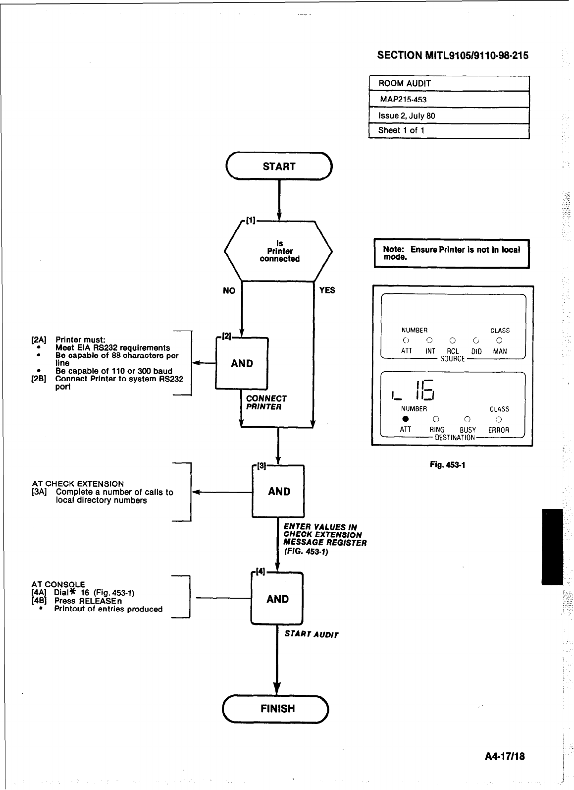
-
[2A] Printer must:
. Meet EIA RS232 requirements
. Be capable of 66 characters per
line
[;B] Be capable of 110 or 300 baud
;o$nect Printer to system RS232
1
IS
Printer
connected
NO
w
!I
AND
CONNECT
PRINTER
AT CHECK EXTENSION
[3A] Complete a number of calls to -
local directory numbers
1
YES
SECTION MITL910549110~98~215
ROOM AUDIT
MAP21 5-453
Nazi Ensure Printer is not in local
ENTER VALUES IN
CHECK EXTENSION
MESSAGE REGISTER
(FIG. 453-l)
AT CONSOLE
[4A] Dial* 16 (Fig.453-1)
[4B] Press RELEASEn
J-i
AND
. Printout of entries produced
Fig. 463-l
A4-17118
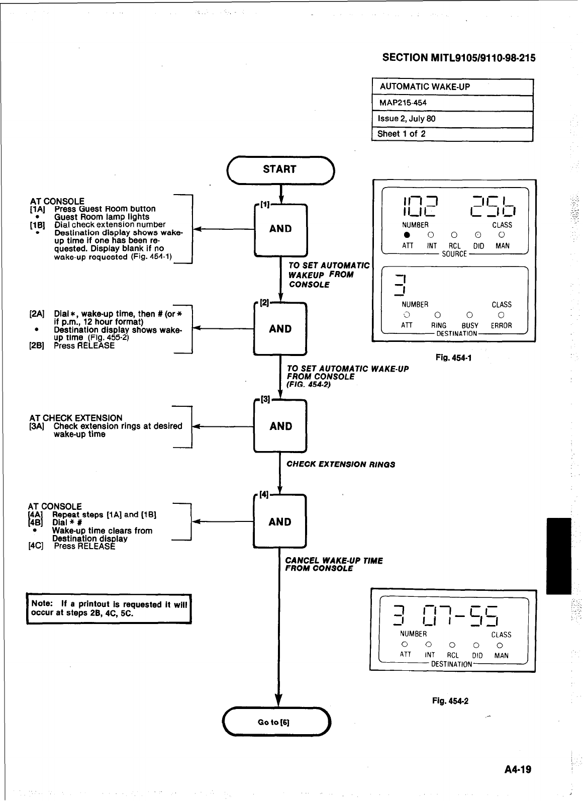
AT CONSOLE
[lA] Press Guest Room button
[I>] Guest Room lamp lights
Dial check extension number
. Destination display shows wake-
up time if one has been re-
quested. Display blank if no
wake-up requested (Fig. 454-l)
SECTION MITL9105/9110-98-215
AUTOMATIC WAKE-UP
MAP215-454
4
AND
. A
I
TO SET AUTOMATIC
WAKEUP FROM
CONSOLE
[2A] Dial *, wakeup time, then # (or +
if p.m., 12 hour format)
. Destination display shows wake-
up time (Fig. 455-2)
[2B] Press RELEASE
AT CHECK EXTENSION
[3A] Check extension rings at desired
wake-up time
131
KJ
AND
Issue 2, July 80
Sheet 1 of 2
NUMBER CLASS
0 0 0 0 0
ATT INT RCL DID MAN
SOURCE
-1
3
NUMBER CLASS
,3 0 0 0
ATT RING BUSY ERROR
DESTINATION
AT CONSOLE
4A
II
Repeat steps [i A] and [l B]
48 Dial * #
. Wake-up time clears from
Destination display
[4C] Press RELEASE
,
Note: If a printout is requested it will
occur at steps 28,4C, 5C.
I
CHECK EXTENSION RINGS
r I41
-7
AND I
CANCEL WAKE-UP T/ME
FROM CONSOLE
\ Got>
Fig. 454-l
I
TO SET AUTOMATIC WAKE-UP
FROM CONSOLE
(FIG. 454-2)
Fig. 454.2
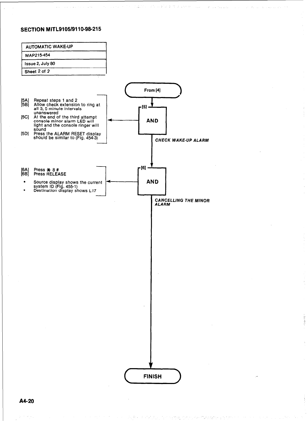
SECTION MITL91051911 O-98-21 5
AUTOMATIC WAKE-UP
MAP215454
issue 2, July 80
Sheet 2 of 2
[5Al
[5Sl
[5Cl
[5Dl
t
64
W
.
.
-
Repeat steps 1 and 2
Allow check extension to ring at
all 3.5 minute intervals
unanswered
At the end of the third attempt
console minor alarm LED will
light and the console ringer will
sound
Press the ALARM RESET display
should be similar to (Fig. 454-3)
A420
Press * 8 #
Press RELEASE
-
Source display shows the current
system ID (Fig. 455-l)
Destination display shows L17
CHECK WAKE-UP ALARM
~ CANCELLING THE MINOR
ALARM
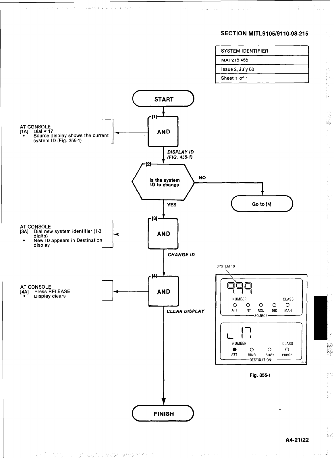
SECTION MITL9105/9110-98-215
SYSTEM IDENTIFIER
MAP215455
1 Issue 2, July 80 I
Sheet 1 of 1
AT CONSOLE
[IA] Dial * 17
. Source display shows the current -
system ID (Fig. 355-l)
DISPLAY ID
(FIG. 455-l)
NO
YES
-131 ’ t
4
AND
c I b
1.
AT CONSOLE
[3A] l$in;w system identifier (1-3
. New ID appears in Destination
display -
I
CHANGE ID
t41
ii
AND
NUMBER
0 0 0 0 0
Fig. 355-l
CLEAR DISPLAY
:.
A4-21122 :
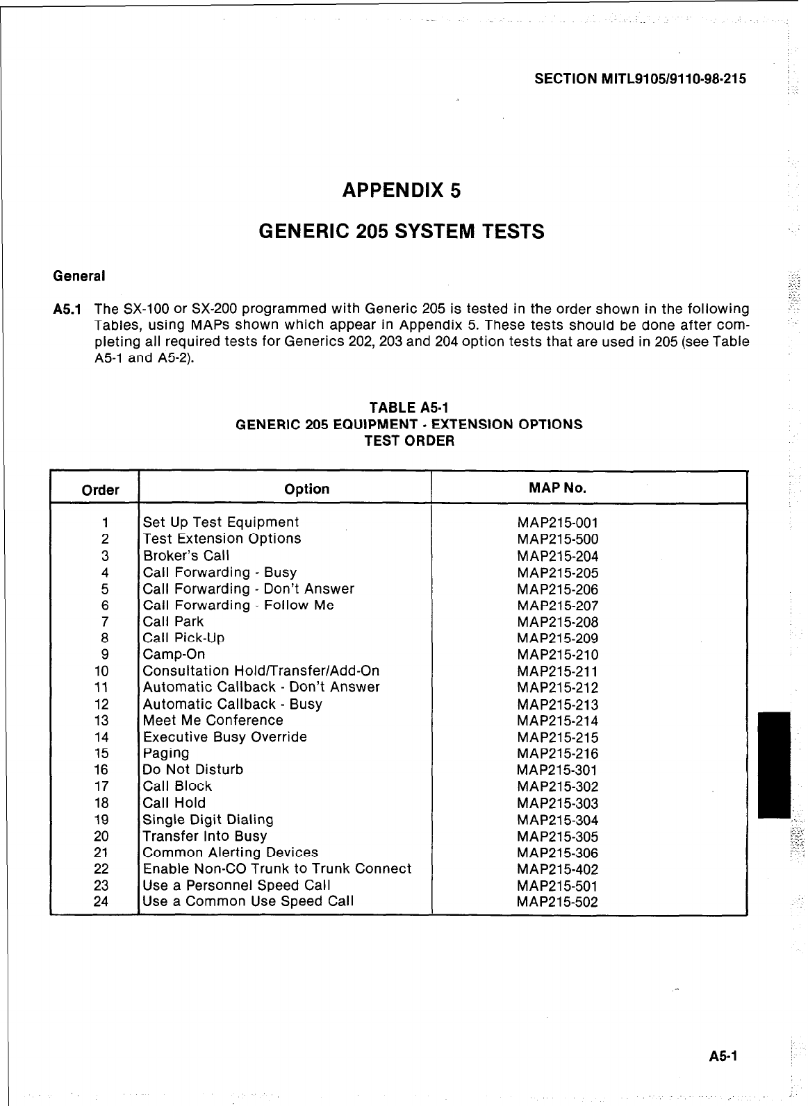
SECTION MITL9105/9110-98.215 :
: :
APPENDIX 5
GENERIC 205 SYSTEM TESTS
General
A5.1 The SX-100 or SX-200 programmed with Generic 205 is tested in the order shown in the following
Tables, using MAPS shown which appear in Appendix 5. These tests should be done after corn-
pleting all required tests for Generics 202, 203 and 204 option tests that are used in 205 (see Table
A51 and A52).
TABLE A51
GENERIC 205 EQUIPMENT - EXTENSION OPTIONS
TEST ORDER
Order Option MAP No.
1 Set Up Test Equipment MAP215-001
2 Test Extension Options MAP21 5-500
3 Broker’s Call MAP21 5-204
4 Call Forwarding - Busy MAP21 5-205
5 Call Forwarding - Don’t Answer MAP215-206
6 Call Forwarding - Follow Me MAP215-207
7 Call Park MAP21 5-208
8 Call Pick-Up MAP21 5-209
9 Camp-On MAP215-210
10 Consultation Hold/Transfer/Add-On MAP215-211
11 Automatic Callback - Don’t Answer MAP21 5-212
12 Automatic Callback - Busy MAP215-213
13 Meet Me Conference MAP215214
14 Executive Busy Override MAP215-215
15 Paging MAP215-216
16 Do Not Disturb MAP21 5-301
17 Call Block MAP21 5-302
18 Call Hold MAP215-303
19 Single Digit Dialing MAP21 5-304
20 Transfer Into Busy MAP215-305
21 Common Alerting Devices MAP215-306
22 Enable Non-CO Trunk to Trunk Connect MAP21 5-402
23 Use a Personnel Speed Call MAP215-501
24 Use a Common Use Speed Call MAP215-502
A5-1 /
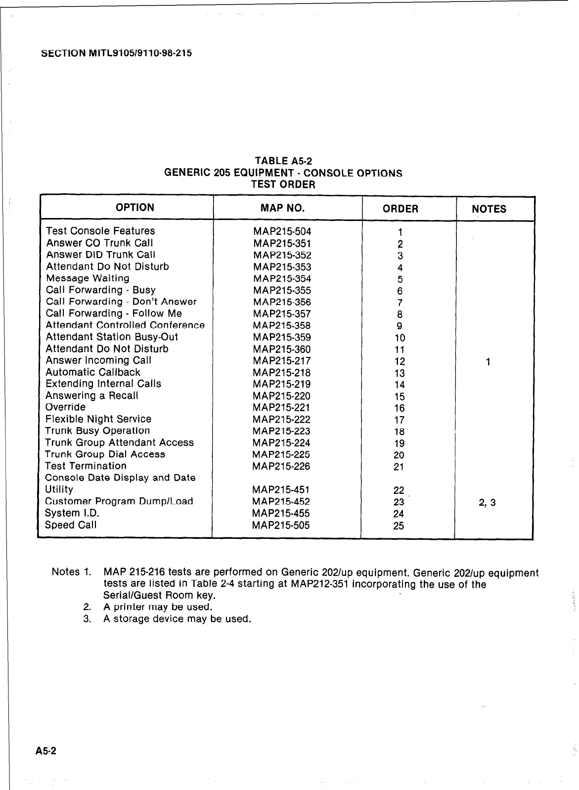
SECTION MITL9105/9110-98-215
TABLE A5-2
GENERIC 205 EQUIPMENT - CONSOLE OPTIONS
TEST ORDER
OPTION
Test Console Features
Answer CO Trunk Call
Answer DID Trunk Call
Attendant Do Not Disturb
Message Waiting
Call Forwarding - Busy
Call Forwarding - Don’t Answer
Call Forwarding - Follow Me
Attendant Controlled Conference
Attendant Station Busy-Out
Attendant Do Not Disturb
Answer Incoming Call
Automatic Callback
Extending Internal Calls
Answering a Recall
Override
Flexible Night Service
Trunk Busy Operation
Trunk Group Attendant Access
Trunk Group Dial Access
Test Termination
Console Date Display and Date
Utility
Customer Program Dump/Load
System I.D.
Speed Call
MAP NO. ORDER NOTES
MAP21 5-504 1
MAP215351 2
MAP215-352 3
MAP21 5-353 4
MAP21 5-354 5
MAP215-355 6
MAP21 5-356 7
MAP21 5-357 8
MAP21 5-358 9
MAP21 5-359 10
MAP215-360 11
MAP215-217 12 1
MAP215218 13
MAP215-219 14
MAP21 5-220 15
MAP215-221 16
MAP21 5-222 17
MAP215-223 18
MAP21 5-224 19
MAP215-225 20
MAP215-226 21
MAP215-451 22
MAP215-452 23 2, 3
MAP215-455 24
MAP215-505 25
Notes 1. MAP 215-216 tests are performed on Generic 20211~~ equipment. Generic 20211~~ equipment
tests are listed in Table 2-4 starting at MAP212-351 incorporating the use of the
Serial/Guest Room key.
2. A printer may be used.
3. A storage device may be used.
A5.2
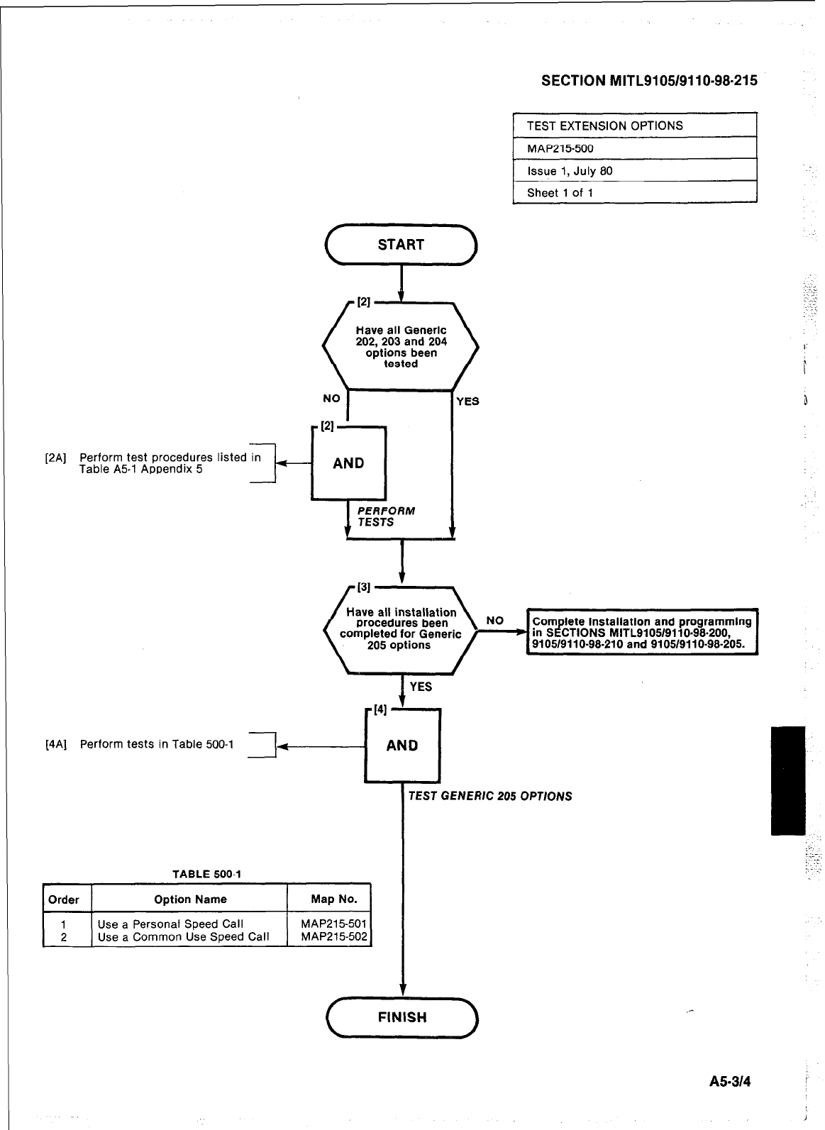
1 MAP215500 I
[2A] Perform test procedures listed in -
Table A5-1 Appendix 5.
AND
Have all Generic Have all Generic
202,203 and 204 202,203 and 204
[4A] Perform tests in Table 500-l [
-
L
TEST GENERIC 205 OPTIONS
I
TABLE 500-l
Order Option Name Map No.
1 Use a Personal Speed Call MAP215501
2 Use a Common Use Speed Call MAP215502
Issue 1, July 80
Sheet 1 of 1
4..
A5-314
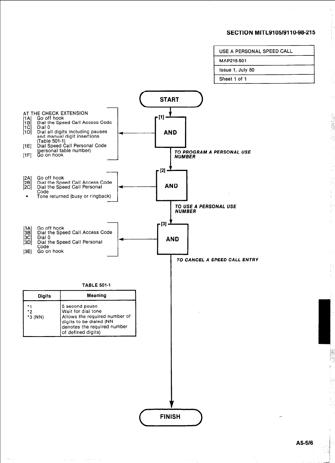
-
AT THE CHECK EXTENSION
[lA] Go off hook
[l B] Dial the Speed Call Access Code
[lC] Dial 0
[lD] Dial all digits including pauses
and manual digit insertions
(Table 501-l)
[lE] Dial Speed Call Personal Code
(personal table number)
[lF] Go on hook -
(“4”)
-
[2A] Go off hook
[2B] Dial the Speed Call Access Code
[2C] ;$he Speed Call Personal e
. Tone returned (busy or ringback)
[3A] Go off hook
[3B] Dial the Speed Call Access Code
[3C] Dial 0
[3D] t&allhe Speed Call Personal
[3E] Go on hook
TABLE 501-l
SECTION MITL9105/9110-98-215 j
USE A PERSONAL SPEED CALL
PI
L1
AND
I
TO PROGRAM A PERSONAL USE
l-
NUMBER
TO USE A PERSONAL USE
TO CANCEL A SPEED CALL ENTRY
FINISH
i
A5-518 :
:/
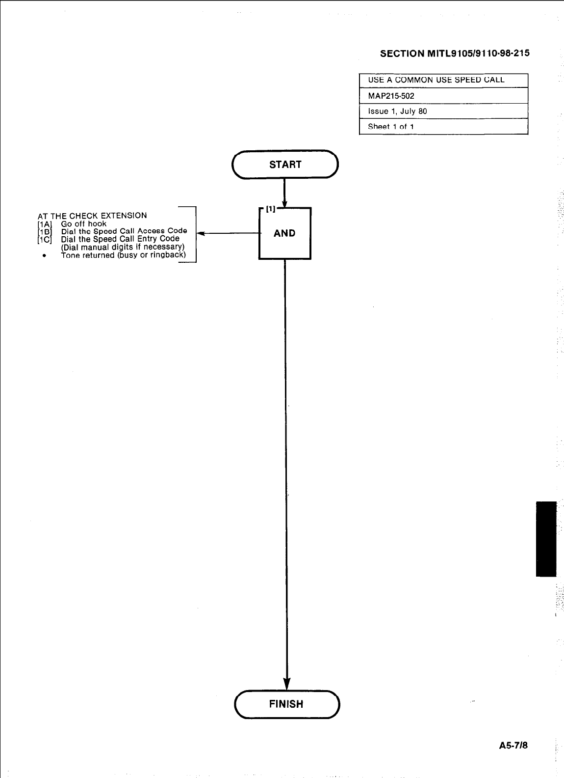
SECTION MITL9105/9110-98-215
1 USE A COMMON USE SPEED CALL I
1 MAP215502 I
AT THE CHECK EXTENSION
[lA] Go off hook
[lB] Dial the Speed Call Access Code
[lC] Dial the Speed Call Entry Code
(Dial manual digits if necessary)
. Tone returned (busy or ringback)
A5-718 :
Issue 1, July 80
Sheet 1 of 1
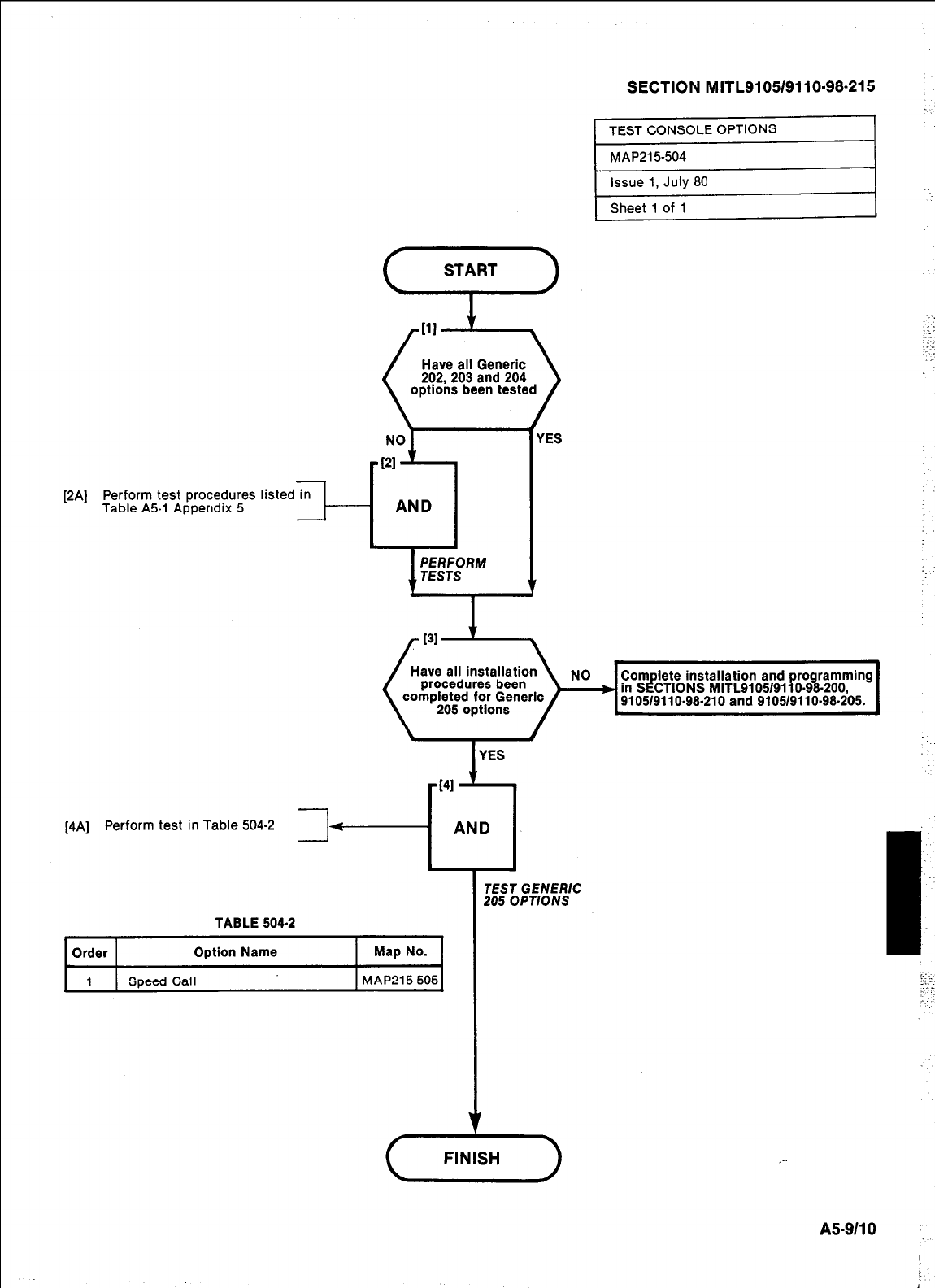
[2A] Perform test procedures listed in
Table A51 Appendix 5 II--
SECTION MITL9105/9110-98-215
Have all Generic
202,203 and 204
options been tested
Complete installation and programming
in SECTIONS MITL9105/9110-98-200,
9105/9110-98-210 and 9105/9110-98-205.
[4A] Perform test in Table 504-2
I
TEST GENERK
205 OPT/O NS
TABLE 504.2 I
Order Option Name Map No.
1 Speed Call MAP215605
I
(-GF-)
,-
AS-9110 :
1.
J
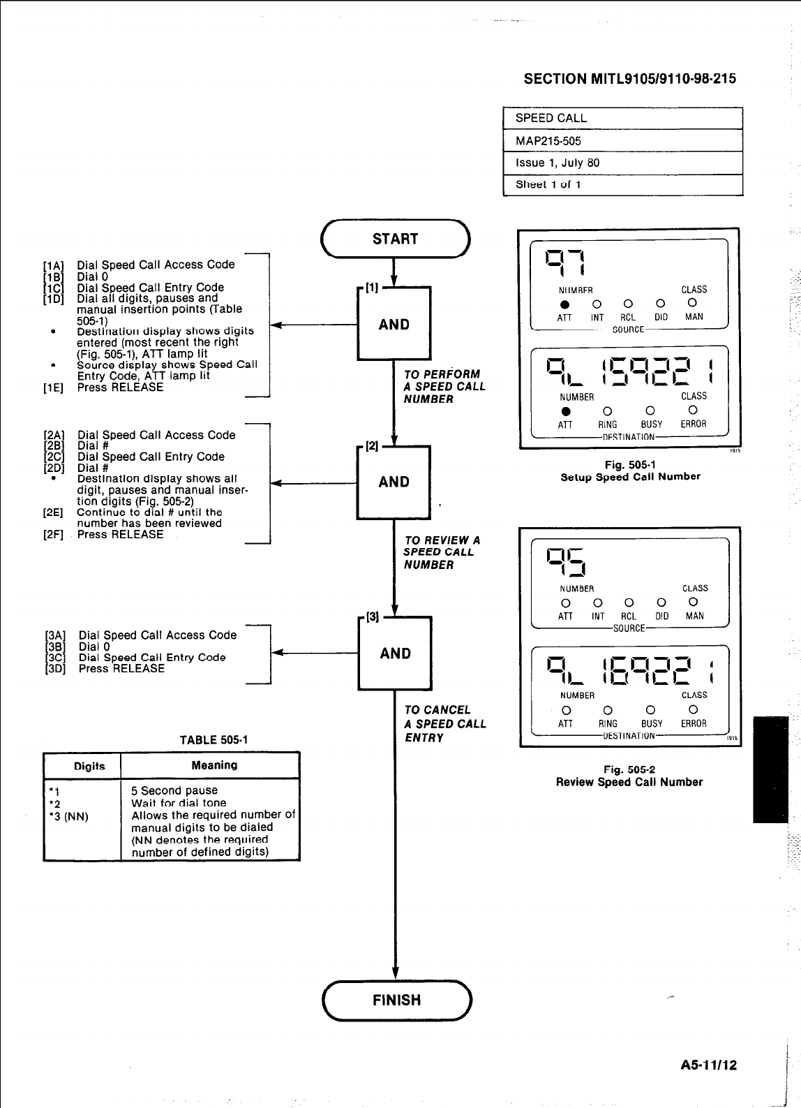
-
Eikt; zpeed Call Access Code
Dial Speed Call Entry Code
Dial all digits, pauses and
manual insertion points (Table
505-l)
Destination display shows digits
entered (most recent the right
(Fig. 505-l), ATT lamp lit
Source display shows Speed Call
Entry Code, ATT lamp lit
Press RELEASE
Dial Speed Call Access Code
Dial #
Dial Speed Call Entry Code
Dial #
Destination display shows all
digit, pauses and manual inser-
tion digits (Fig. 505-2)
Continue to dial # until the
number has been reviewed
Press RELEASE -
TO PERFORM
A SPEED CALL
NUMBER
I
TO REWEW A
SPEED CALL
NUMBER
Dial Speed Call Access Code
Dial 0
Dial Speed Call Entry Code
Press RELEASE -i-
TABLE 505.1
-R
- AND
,
Digits I Meaning I
l 1
:: (NN)
5 Second pause
Wait for dial tone
Allows the required number
Of
manual digits to be dialed
(NN denotes the required
number of defined digits) I
TO CANCEL
A SPEED CALL
ENTRY
I
L
FIN,,,)
SECTION MITL9105/9110-98-215
I1 of 1 I
W] I(
Fig. 505-l
Setup Speed Call Number
T
1
JI
191t
Fig. 505-2
Review Speed Call Number
,-
A5-11112 I.
.f
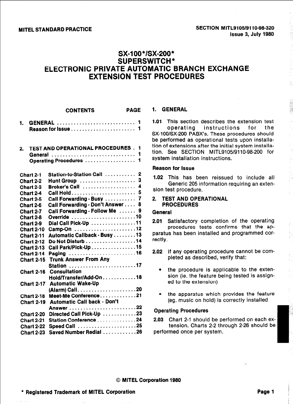
MITEL STANDARD PRACTICE SECTION M ITL91051911 O-98-320
Issue 3, July 1980
sx-100 */sx=200 *
SUPERSWITCH*
ELECTRONIC PRIVATE AUTOMATIC BRANCH EXCHANGE
EXTENSION TEST PROCEDURES
CONTENTS PAGE
1. GENERAL ............................ 1
Reason for Issue. ...................... 1
2. TEST AND OPERATIONAL PROCEDURES . 1
General . . . . . . . . . . . . . . . . . . . . . . . . . . . . . . 1
Operating Procedures . . . . . . . . . . . . . . . . . . 1
Chart 2-l Station-to-Station Call ........... 2
Chart2.2 Hunt Group .................... 3
Chart 2-3 Broker’s Call ................... 4
Chart2-4 Call Hold ....................... 5
Chart 2-5 Call Forwarding. Busy ........... 7
Chart 2.6 Call Forwarding. Don’t Answer .... 8
Chart 2.7 Call Forwarding. Follow Me ...... 9
Chart 2.8 Override
....................... 10
Chart 2.9 Dial Call Pick.Up ............... .ll
Chart 2.10 Camp.On ..................... ,12
Chart 2.11 Automatic Callback. Busy. ...... .13
Chart 2-12 Do Not Disturb. ................ .14
Chart 2.13 Call
Park/Pick.Up
............... .15
Chart 2.14 Paging ....................... .16
Chart 2.15 Trunk Answer From Any
Station ....................... .17
Chart 2-16 Consultation
Hold/Transfer/Add.On
........... .18
Chart 2.17 Automatic Wake.Up
(Alarm) Call. ................... .20
Chart 2-18 MeetMe Conference. ........... .21
Chart 2-19 Automatic Call back . Don’t
Answer........................2 2
Chart 2-20 Directed Call Pick.Up ........... .23
Chart 2-21 Station Conference ............. .24
Chart 2-22 Speed Call .................... .25
Chart 2-23 Saved Number Redial ........... .26
;;
-:.
1. GENERAL
‘7
1.01 This section describes the extension test
operating instructions for the
SX-lOO/SX-200 PABX’s. These procedures should
be performed as operational tests upon installa-
tion of extensions after the initial system installa-
tion. See SECTION MITL9105/9110-98-200 for
system installation instructions.
Reason for Issue
1.02 This has been reissued to include all
Generic 205 information requiring an exten-
sion test procedure.
2. TEST AND OPERATIONAL
PROCEDURES
General
2.01 Satisfactory completion of the operating
procedures tests confirms that the ap-
paratus has been installed and programmed car-
rectly.
2.02 If any operating procedure cannot be com-
pleted as described, verify that:
l
the procedure is applicable to the exten-
sion (ie. the feature being tested is assign-
ed to the extension)
l
the apparatus which provides the feature
(eg. music on hold) is correctly installed
Operating Procedures
2.03 Chart 2-1 should be performed on each ex-
tension. Charts 2-2 through 2-26 should be
performed once per system.
0 MITEL Corporation 1960
l
Registered Trademark of MITEL Corporation
,
Page 1 i
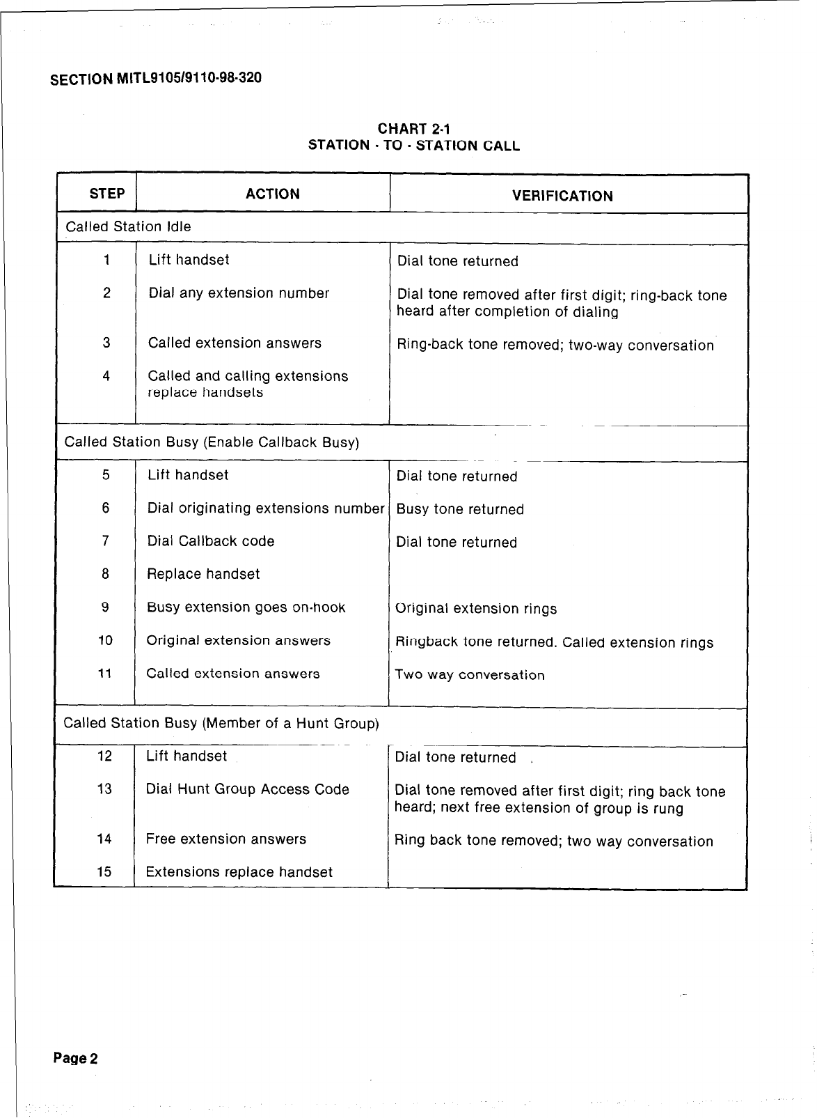
SECTION MITL9105/9110-98-320
CHART 2.1
STATION . TO - STATION CALL
STEP ACTION
Called Station Idle
1 Lift handset
2 Dial any extension number
3 Called extension answers
4 Called and calling extensions
replace handsets
VERIFICATION
Dial tone returned
Dial tone removed after first digit; ring-back tone
heard after completion of dialing
Ring-back tone removed; two-way conversation
Called Station Busy (Enable Callback Busy)
5 Lift handset Dial tone returned
6 Dial originating extensions number Busy tone returned
7 Dial Callback code Dial tone returned
8 Replace handset
9 Busy extension goes on-hook Original extension rings
10 Original extension answers Ringback tone returned. Called extension rings
11 Called extension answers Two way conversation
Called Station Busy (Member of a Hunt Group)
12 Lift handset Dial tone returned ,
13 Dial Hunt Group Access Code Dial tone removed after first digit; ring back tone
heard; next free extension of group is rung
14 Free extension answers Ring back tone removed; two way conversation
15 Extensions replace handset
Page 2
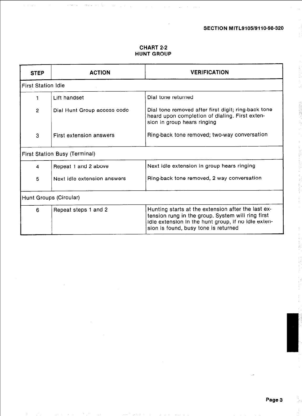
SECTION MITL9105/9110-98-320
CHART 2-2
HUNT GROUP
STEP ACTION
?rst Station Idle
1 Lift handset
2 Dial Hunt Group access code
3 First extension answers
zirst Station Busy (Terminal)
4 Repeat 1 and 2 above
5 Next idle extension answers
iunt Groups (Circular)
6 Repeat steps 1 and 2
VERIFICATION
Dial tone returned
Dial tone removed after first digit; ring-back tone
heard upon completion of dialing. First exten-
sion in group hears ringing
Ring-back tone removed; two-way conversation
Next idle extension in group hears ringing
Ring-back tone removed, 2 way conversation
Hunting starts at the extension after the last ex-
tension rung in the group. System will ring first
idle extension in the hunt group, if no idle exten-
sion is found, busy tone is returned
Page 3
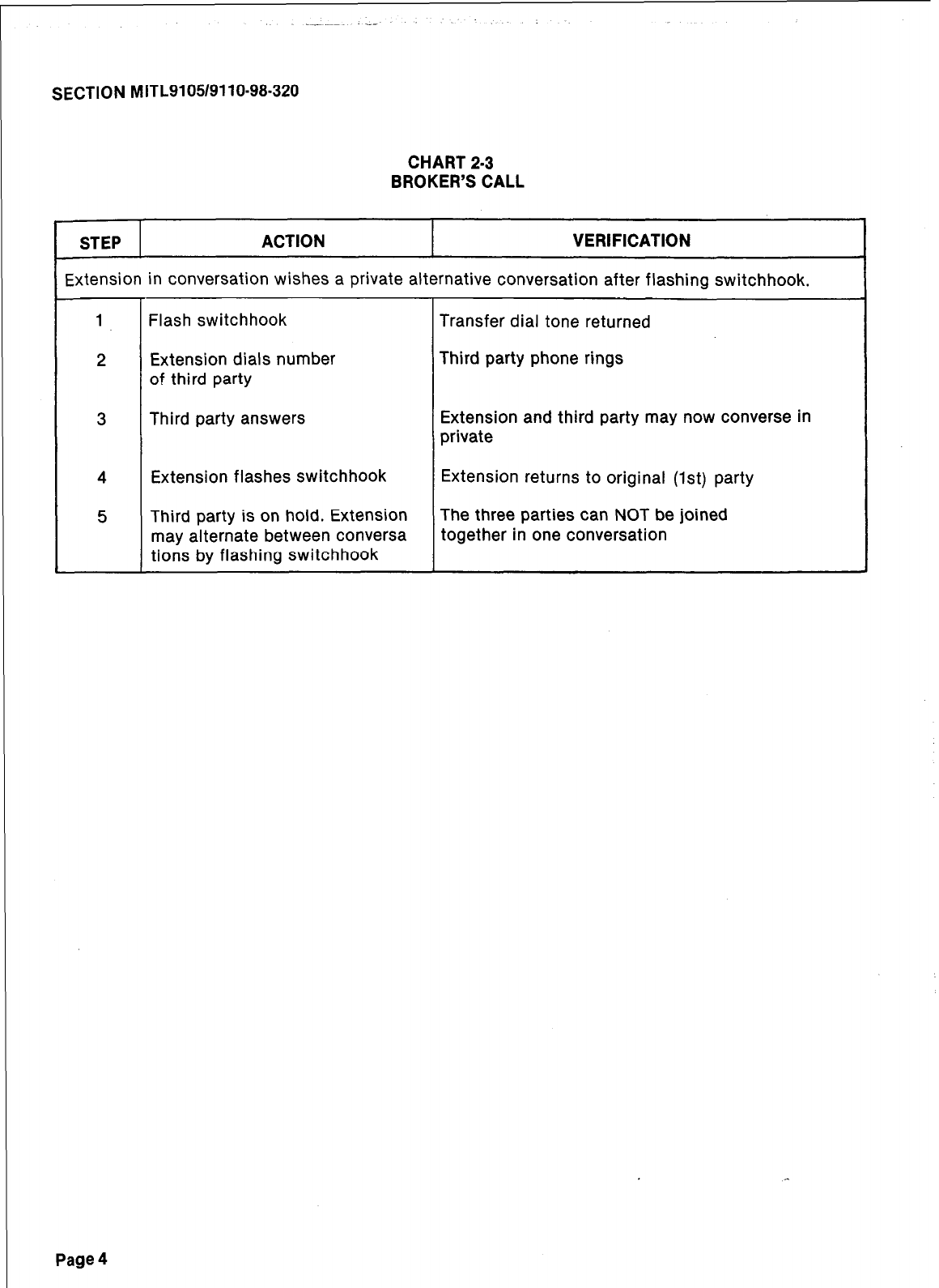
SECTION MITL9105/9110-98.320
CHART 2-3
BROKER’S CALL
STEP ACTION VERIFICATION
Extension in conversation wishes a private alternative conversation after flashing switchhook.
1 Flash switchhook Transfer dial tone returned
2 Extension dials number Third party phone rings
of third party
3 Third party answers Extension and third party may now converse in
private
4 Extension flashes switchhook Extension returns to original (1st) party
5 Third party is on hold. Extension The three parties can NOT be joined
may alternate between conversa together in one conversation
tions by flashing switchhook
Page 4
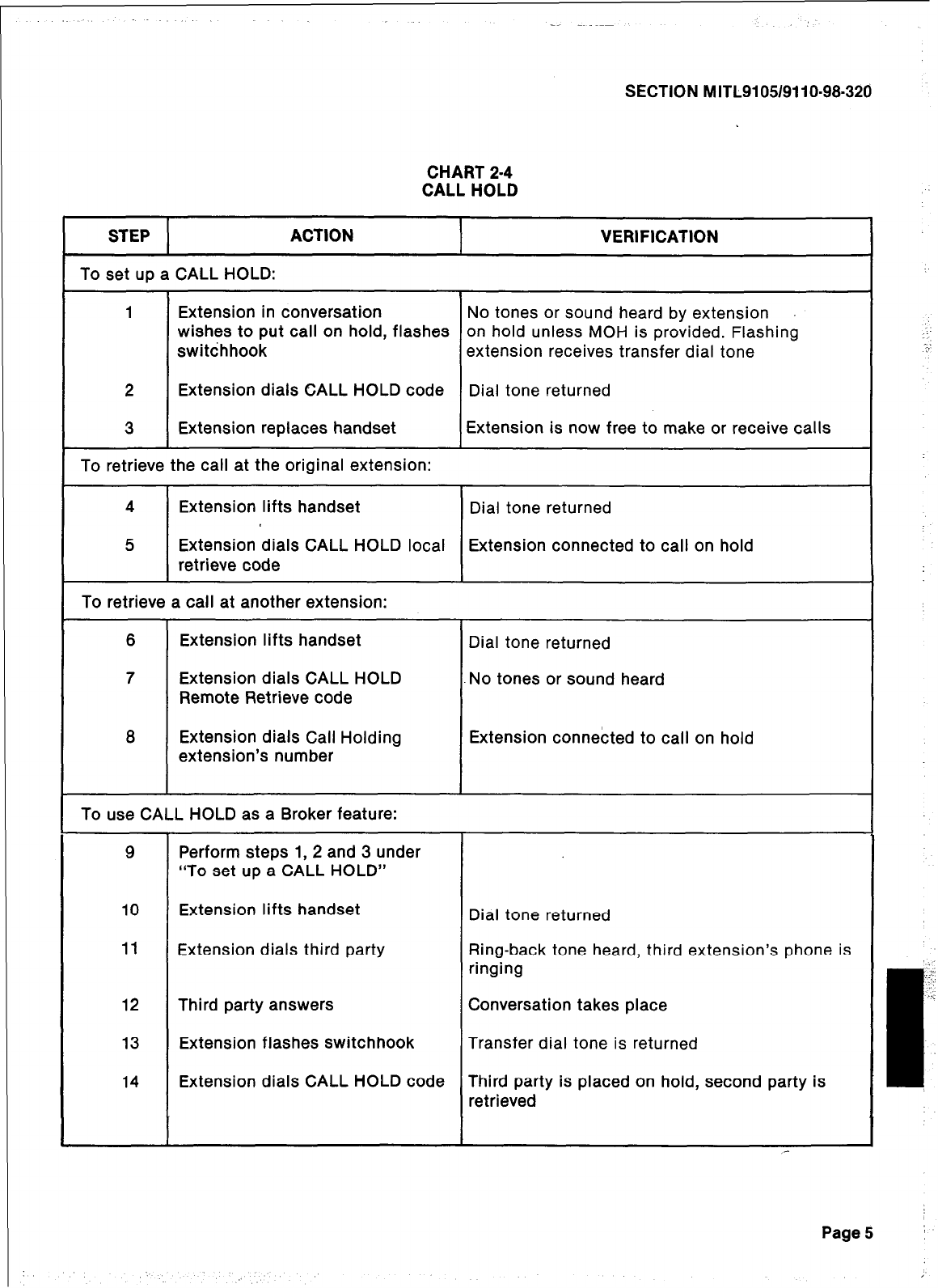
SECTION MITL9105/9110-98-320
CHART 2-4
CALL HOLD
STEP ACTION VERIFICATION
To set up a CALL HOLD:
1 Extension in conversation No tones or sound heard by extension
wishes to put call on hold, flashes on hold unless MOH is provided. Flashing
switchhook extension receives transfer dial tone
2 Extension dials CALL HOLD code Dial tone returned
3 Extension replaces handset Extension is now free to make or receive calls
To retrieve the call at the original extension:
4 Extension lifts handset Dial tone returned
5 Extension dials CALL HOLD local Extension connected to call on hold
retrieve code
To retrieve a call at another extension:
6 Extension lifts handset Dial tone returned
7 Extension dials CALL HOLD No tones or sound heard
Remote Retrieve code
8 Extension dials Call Holding Extension connected to call on hold
extension’s number
To use CALL HOLD as a Broker feature:
9
10
11
12
13
14
Perform steps 1, 2 and 3 under
“To set up a CALL HOLD”
Extension lifts handset Dial tone returned
Extension dials third party Ring-back tone heard, third extension’s phone is
ringing
Third party answers Conversation takes place
Extension flashes switchhook Transfer dial tone is returned
Extension dials CALL HOLD code Third party is placed on hold, second party is
retrieved
_-
Page5 I
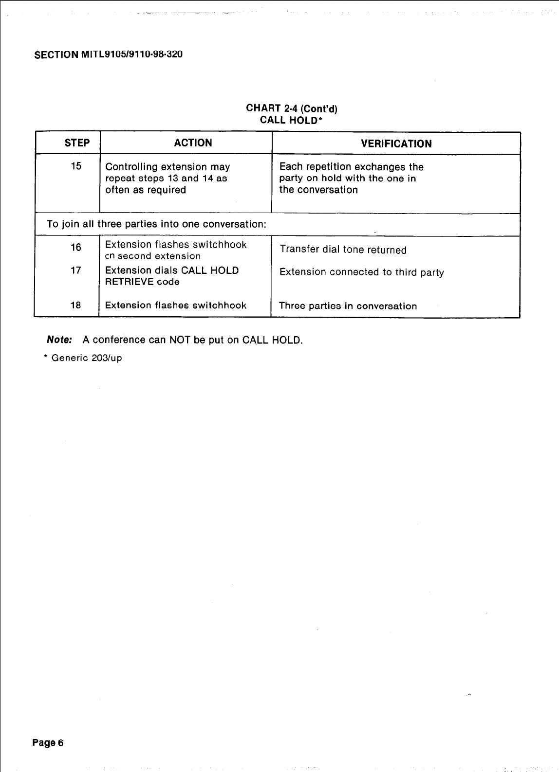
SECTION nmTL9i05/9110-98.320
CHART 2-4 (Cont’d)
CALL HOLD*
STEP ACTION VERIFICATION
15 Controlling extension may Each repetition exchanges the
repeat steps 13 and 14 as party on hold with the one in
often as required the conversation
To join all three parties into one conversation:
16 Extension flashes switchhook
cn second extension Transfer dial tone returned
17 Extension dials CALL HOLD
RETRIEVE code Extension connected to third party
18 Extension flashes switchhook Three parties in conversation
Note: A conference can NOT be put on CALL HOLD.
* Generic 2031~~
Page 6
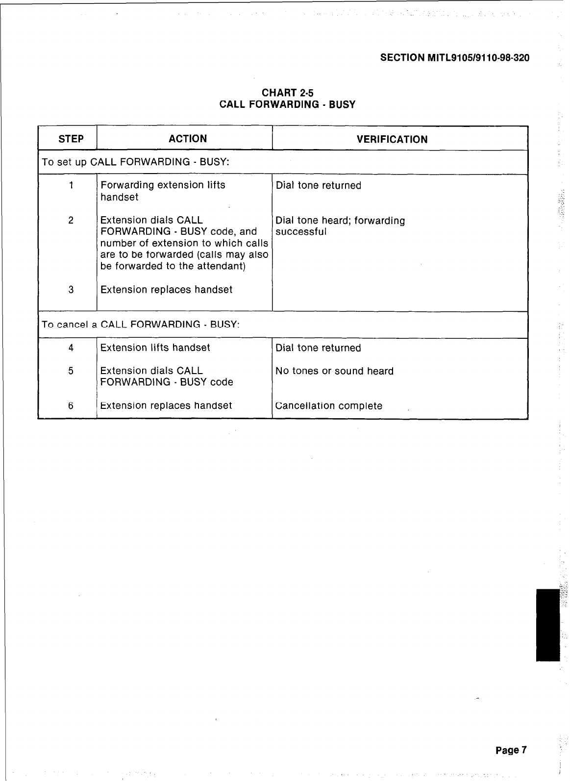
SECTION MITL9105/9110-98-320
CHART 2-5
CALL FORWARDING - BUSY
STEP ACTION
To set up CALL FORWARDING - BUSY:
VERIFICATION
1 Forwarding extension lifts Dial tone returned
handset
2 Extension dials CALL Dial tone heard; forwarding
FORWARDING - BUSY code, and successful
number of extension to which calls
are to be forwarded (calls may also
be forwarded to the attendant)
3 Extension replaces handset
To cancel a CALL FORWARDING - BUSY:
4 Extension lifts handset
5 Extension dials CALL
FORWARDING - BUSY code
6 Extension replaces handset
Dial tone returned
No tones or sound heard
Cancellation complete
Page7 :
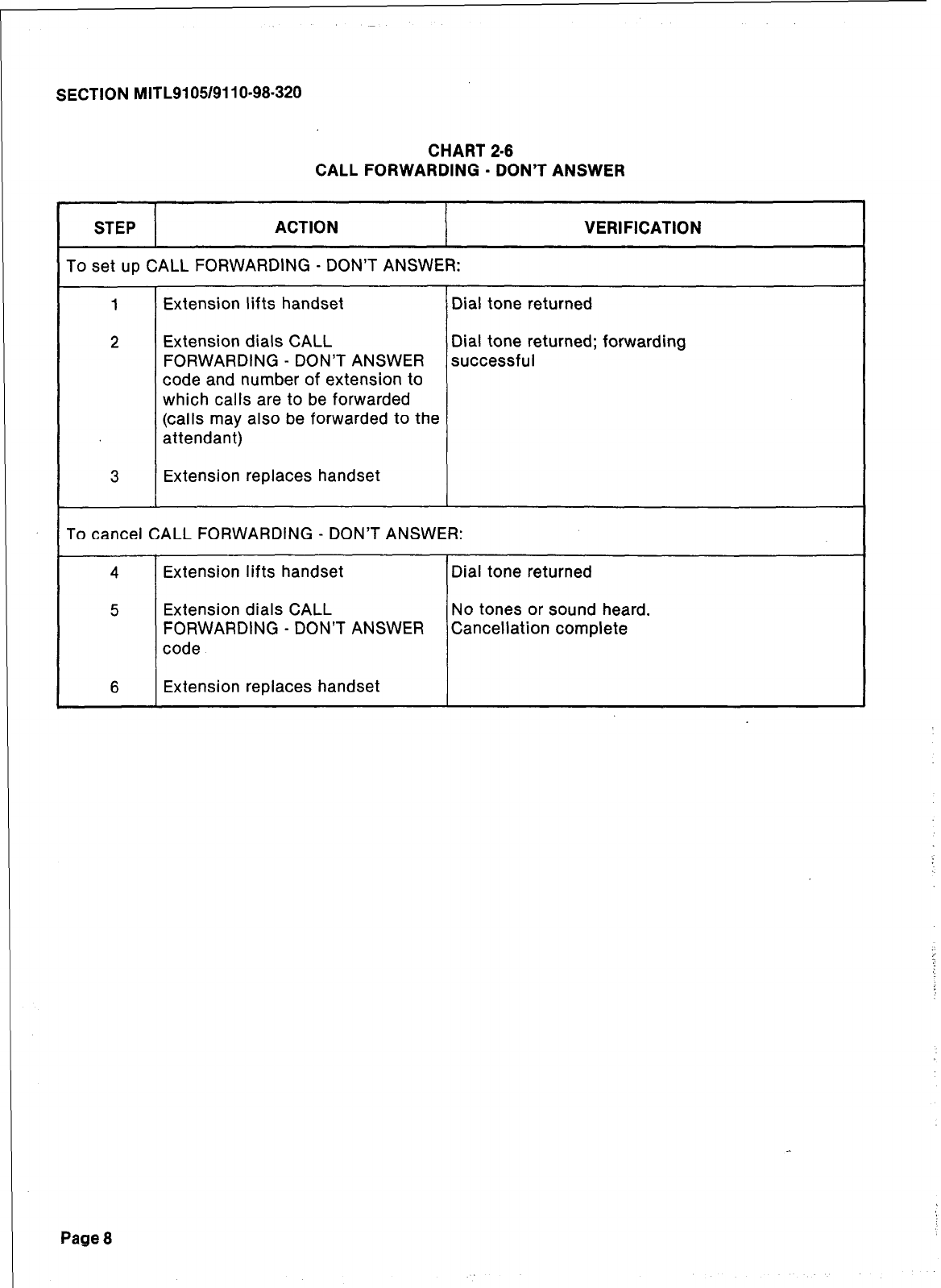
SECTION MITL9105/911 O-98-320
CHART 2-6
CALL FORWARDING - DON’T ANSWER
STEP ACTION
To set up CALL FORWARDING - DON’T ANSWER:
VERIFICATION
1 Extension lifts handset Dial tone returned
2 Extension dials CALL Dial tone returned; forwarding
FORWARDING - DON’T ANSWER successful
code and number of extension to
which calls are to be forwarded
(calls may also be forwarded to the
attendant)
3 Extension replaces handset
To cancel CALL FORWARDING - DON’T ANSWER:
4 Extension lifts handset Dial tone returned
5 Extension dials CALL No tones or sound heard.
FORWARDING - DON’T ANSWER Cancellation complete
code
6 Extension replaces handset
Page 8
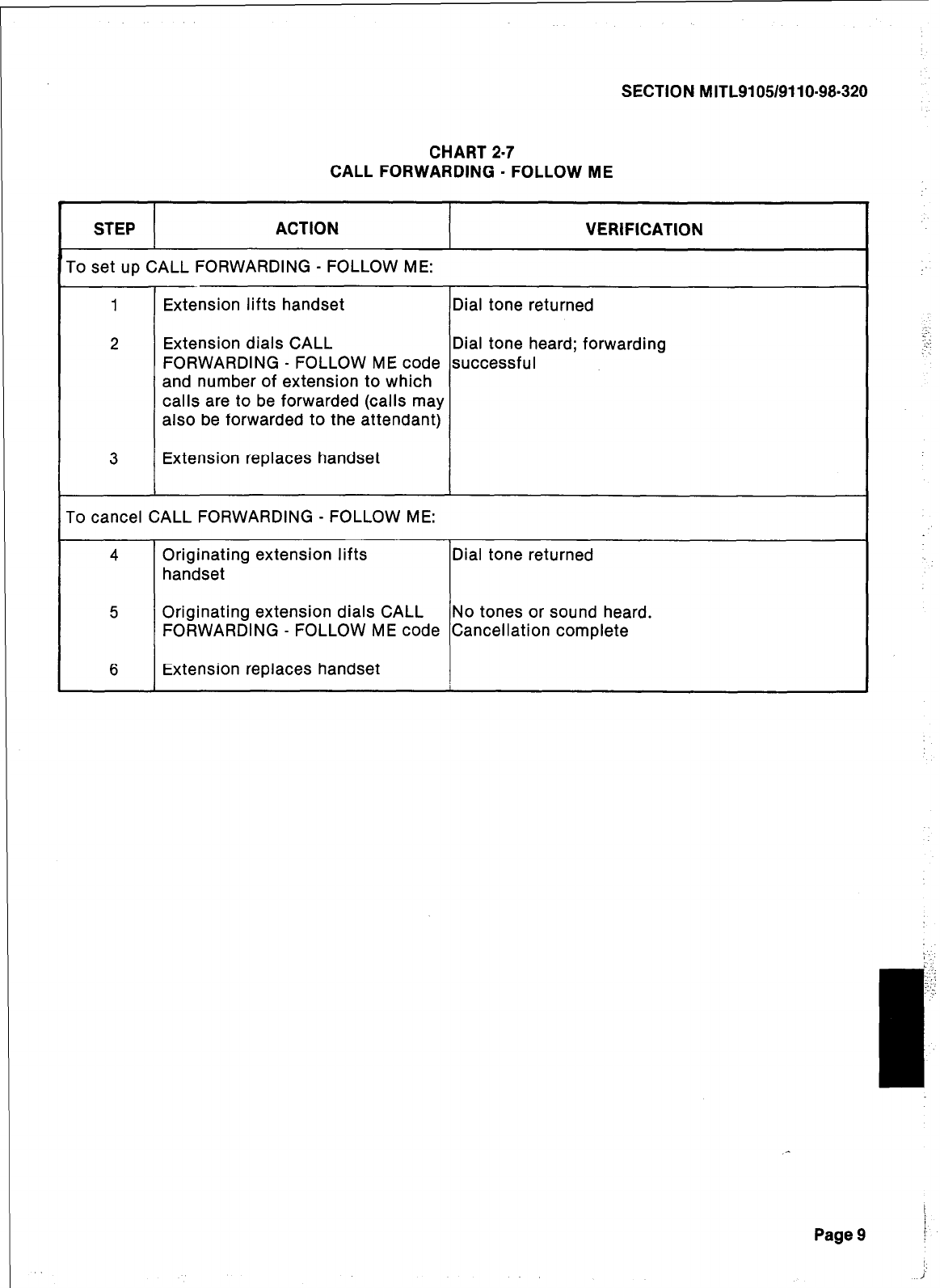
SECTION MITL9105/9110-98-320
CHART 2-7
CALL FORWARDING - FOLLOW ME
STEP ACTION VERIFICATION
To set up CALL FORWARDING - FOLLOW ME:
1 Extension lifts handset Dial tone returned
2 Extension dials CALL Dial tone heard; forwarding
FORWARDING - FOLLOW ME code successful
and number of extension to which
calls are to be forwarded (calls may
also be forwarded to the attendant)
3 Extension replaces handset
To cancel CALL FORWARDING - FOLLOW ME:
4 Originating extension lifts Dial tone returned
handset
5 Originating extension dials CALL No tones or sound heard.
FORWARDING - FOLLOW ME code Cancellation complete
6 Extension replaces handset
:
:-.
..”
j
I
Page 9 F
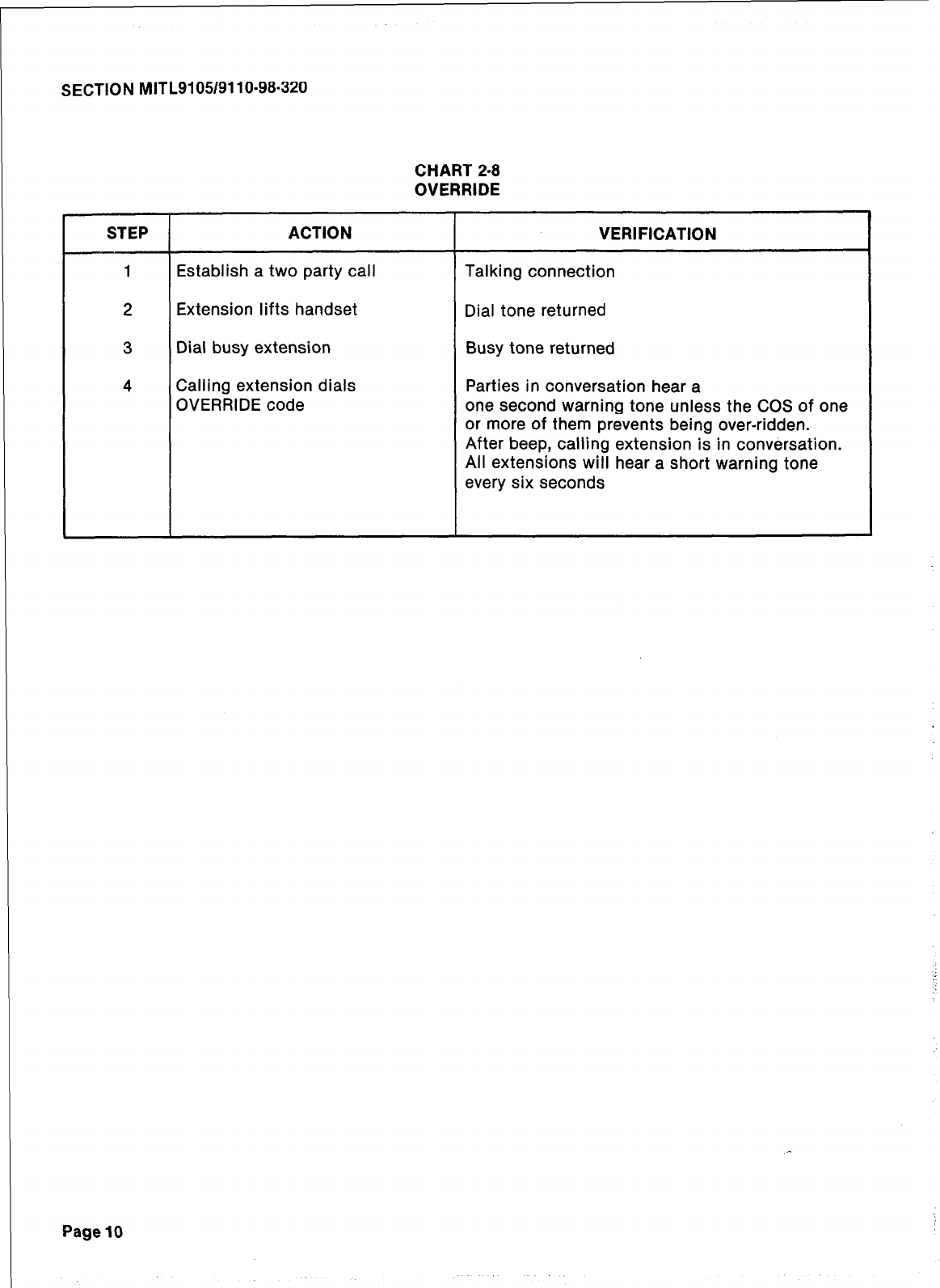
SECTION MITL91051911 O-98-320
CHART 2-8
OVERRIDE
STEP ACTION VERIFICATION
1 Establish a two party call Talking connection
2 Extension lifts handset Dial tone returned
3 Dial busy extension Busy tone returned
4 Calling extension dials Parties in conversation hear a
OVERRIDE code one second warning tone unless the COS of one
or more of them prevents being over-ridden.
After beep, calling extension is in conversation.
All extensions will hear a short warning tone
every six seconds
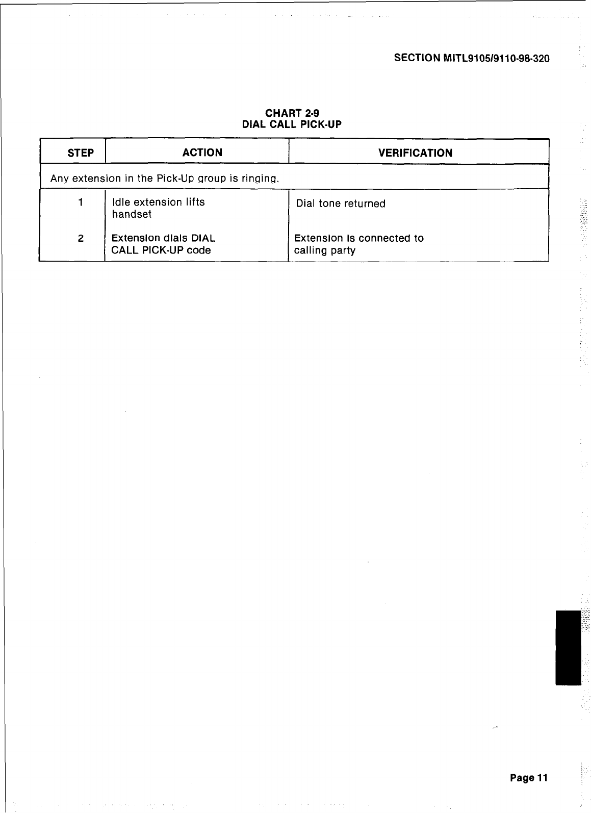
SECTION MITL9105/9110-98-320
CHART 2-9
DIAL CALL PICK-UP
STEP ACTION VERIFICATION
1 Any extension in the Pick-Up group is ringing.
I 1
L
2
Idle extension lifts
handset Dial tone returned
Extension dials DIAL Extension is connected to
CALL PICK-UP code calling party
Page 11
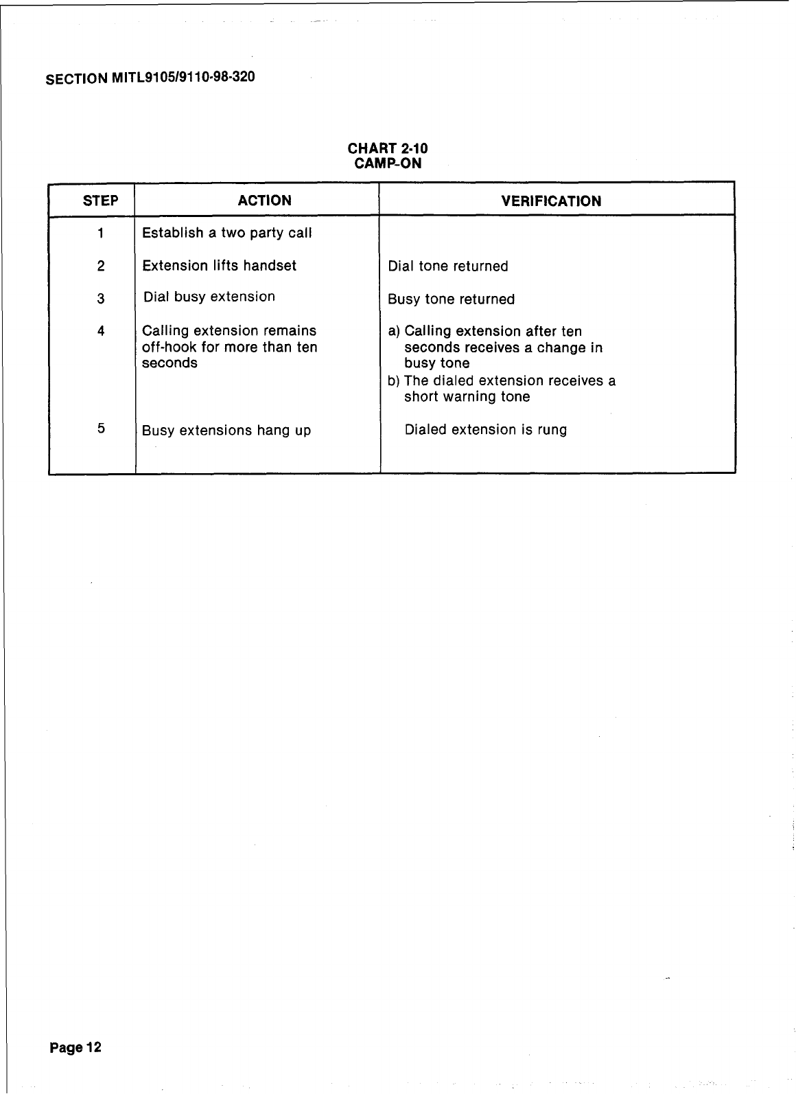
SECTION MITL9105/9110-98.320
CHART 2.10
CAMP-ON
STEP ACTION VERIFICATION
1 Establish a two party call
2 Extension lifts handset Dial tone returned
3 Dial busy extension Busy tone returned
4 Calling extension remains a) Calling extension after ten
off-hook for more than ten seconds receives a change in
seconds busy tone
b) The dialed extension receives a
short warning tone
5 Busy extensions hang up Dialed extension is rung
Page 12
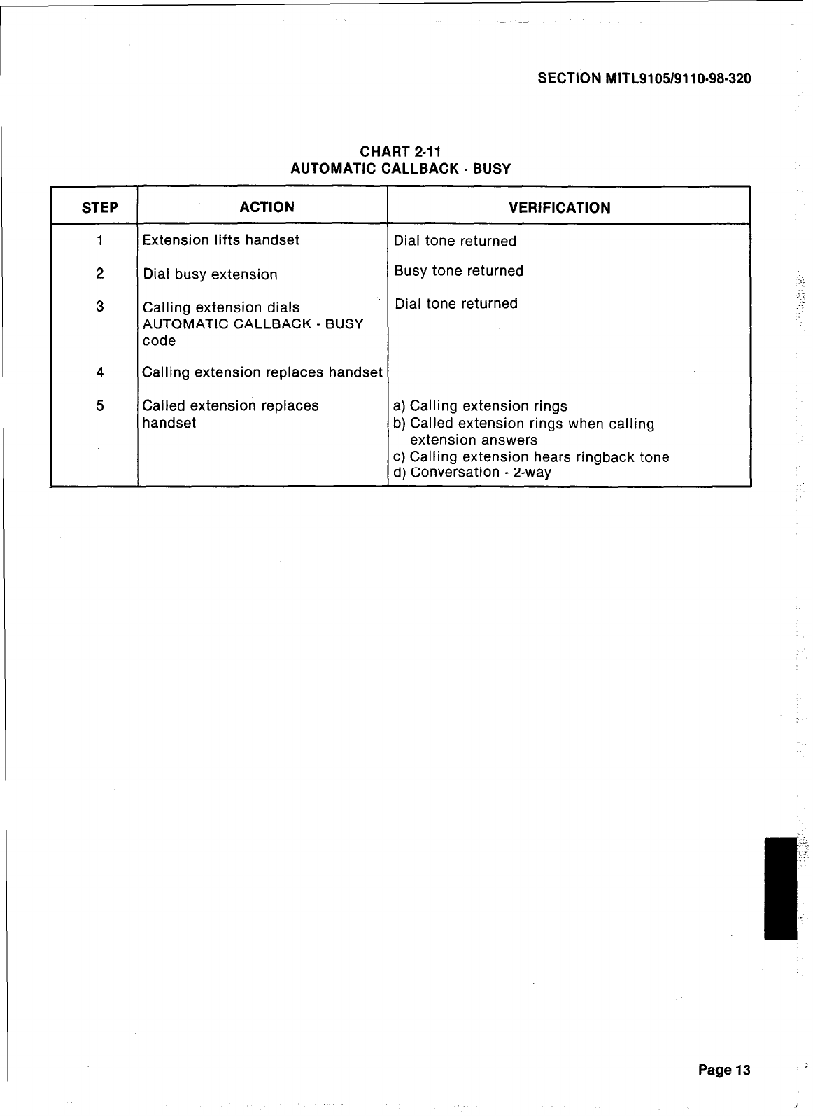
SECTION MITL9105/9110-98-320
CHART 2-11
AUTOMATIC CALLBACK - BUSY
STEP ACTION VERIFICATION
1 Extension lifts handset Dial tone returned
2 Dial busy extension Busy tone returned
3 Calling extension dials Dial tone returned
AUTOMATIC CALLBACK - BUSY
code
4 Calling extension replaces handset
5 Called extension replaces a) Calling extension rings
handset b) Called extension rings when calling
extension answers
c) Calling extension hears ringback tone
d) Conversation - 2-way
-:
.:
:.
.’
.I;
.
.
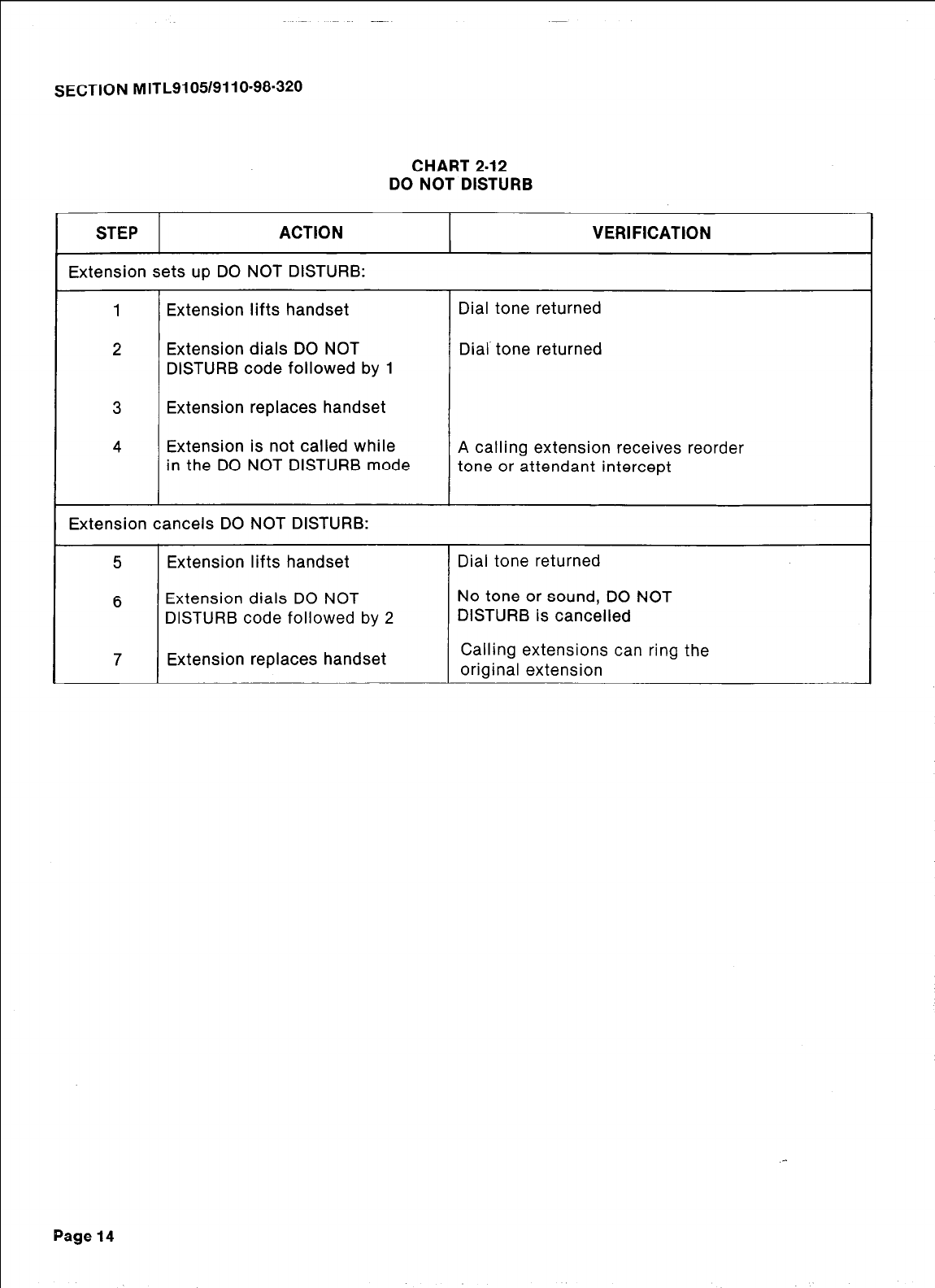
SECTION MITL9105/9110-98-320
CHART 2-12
DO NOT DISTURB
STEP ACTION
Extension sets up DO NOT DISTURB:
1 Extension lifts handset
2 Extension dials DO NOT
DISTURB code followed by 1
3 Extension replaces handset
4 Extension is not called while
in the DO NOT DISTURB mode
Extension cancels DO NOT DISTURB:
5 Extension lifts handset
6 Extension dials DO NOT
DISTURB code followed by 2
7 Extension replaces handset
VERIFICATION
Dial tone returned
Dial’ tone returned
A calling extension receives reorder
tone or attendant intercept
Dial tone returned
No tone or sound, DO NOT
DISTURB is cancelled
Calling extensions can ring the
original extension
Page 14
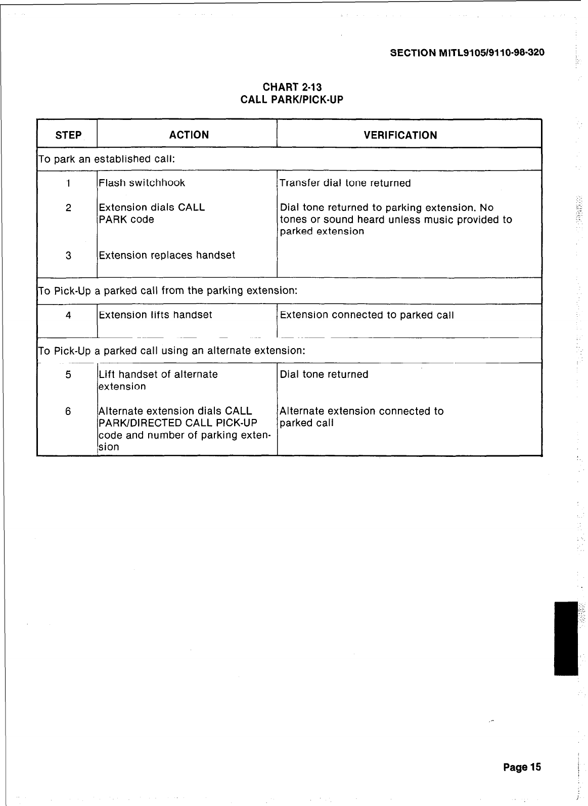
SECTION MITLSI 051911 O-98-320
CHART 2-13
CALL PARK/PICK-UP
STEP ACTION VERIFICATION
‘o park an established call:
1 Flash switchhook Transfer dial tone returned
2 Extension dials CALL Dial tone returned to parking extension. No
PARK code tones or sound heard unless music provided to
parked extension
3 Extension replaces handset
‘o Pick-Up a parked call from the parking extension:
4 Extension lifts handset Extension connected to parked call
‘o Pick-Up a parked call using an alternate extension:
5 Lift handset of alternate Dial tone returned
extension
6 Alternate extension dials CALL Alternate extension connected to
PARK/DIRECTED CALL PICK-UP parked call
code and number of parking exten-
sion
Page 15 /
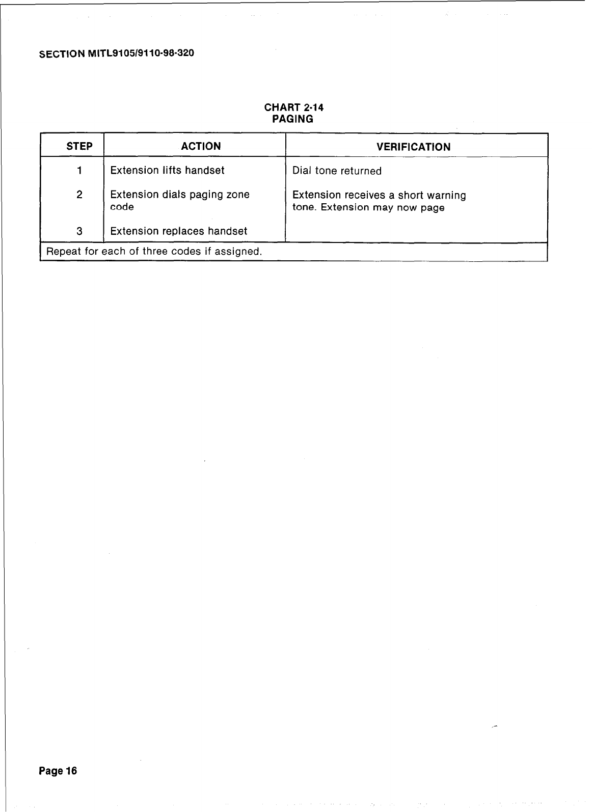
SECTION MITL9105/9110-98-320
CHART 2-14
PAGING
STEP ACTION
1 Extension lifts handset
2 Extension dials paging zone
code
3 Extension replaces handset
Repeat for each of three codes if assigned.
VERIFICATION
Dial tone returned
Extension receives a short warning
tone. Extension may now page
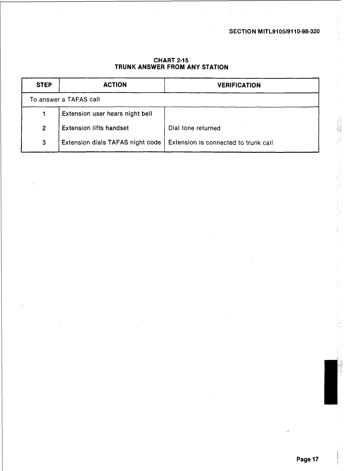
SECTION MITL9105/9110-98-320
CHART 2-15
TRUNK ANSWER FROM ANY STATION
STEP ACTION VERIFICATION
To answer a TAFAS call
1 Extension user hears night bell
2 Extension lifts handset Dial tone returned
3 Extension dials TAFAS night code Extension is connected to trunk call
;
..~.
:: :.:
.’
_-
I
Page17 \
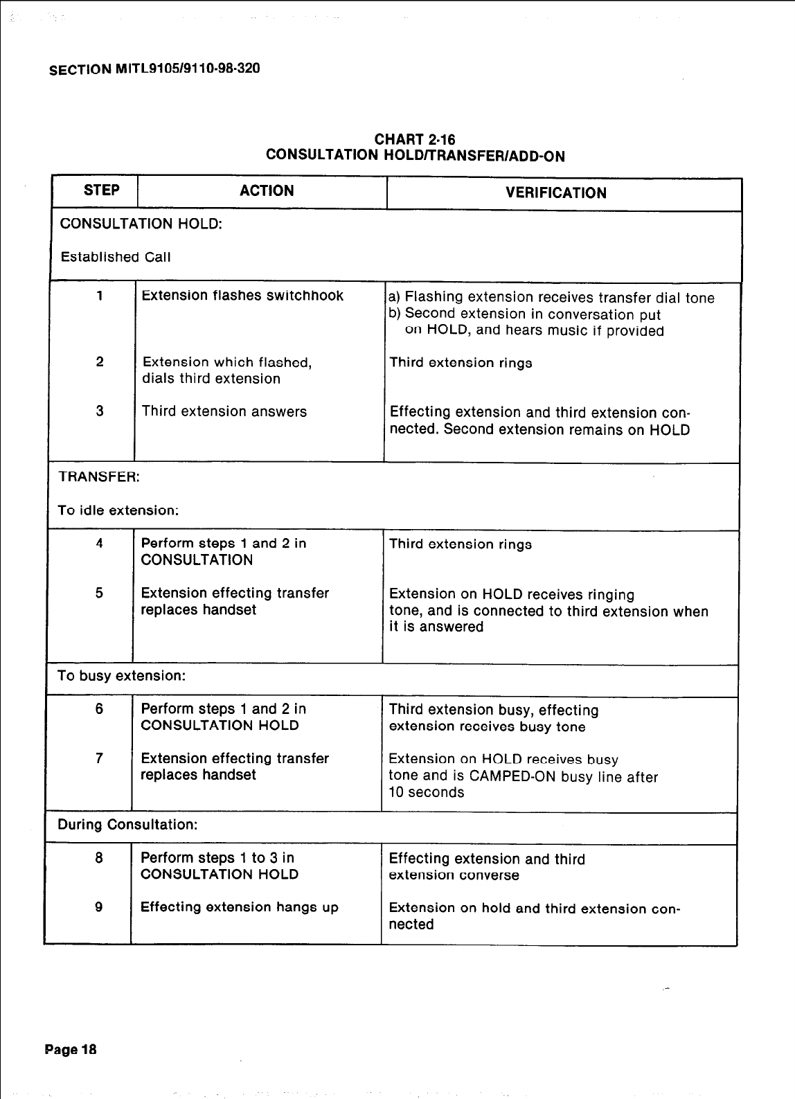
SECTION MITL9105/9110-98-320
CHART 2-16
CONSULTATION HOLD/TRANSFER/ADD-ON
STEP ACTION VERIFICATION
CONSULTATION HOLD:
Established Call
1 Extension flashes switchhook a) Flashing extension receives transfer dial tone
b) Second extension in conversation put
on HOLD, and hears music if provided
2 Extension which flashed, Third extension rings
dials third extension
3 Third extension answers Effecting extension and third extension con-
nected. Second extension remains on HOLD
TRANSFER:
To idle extension:
4 Perform steps 1 and 2 in Third extension rings
CONSULTATION
5 Extension effecting transfer Extension on HOLD receives ringing
replaces handset tone, and is connected to third extension when
it is answered
To busy extension:
6 Perform steps 1 and 2 in Third extension busy, effecting
CONSULTATION HOLD extension receives busy tone
7 Extension effecting transfer Extension on HOLD receives busy
replaces handset tone and is CAMPED-ON busy line after
10 seconds
During Consultation:
8 Perform steps 1 to 3 in Effecting extension and third
CONSULTATION HOLD extension converse
9 Effecting extension hangs up Extension on hold and third extension con-
nected
Page 18
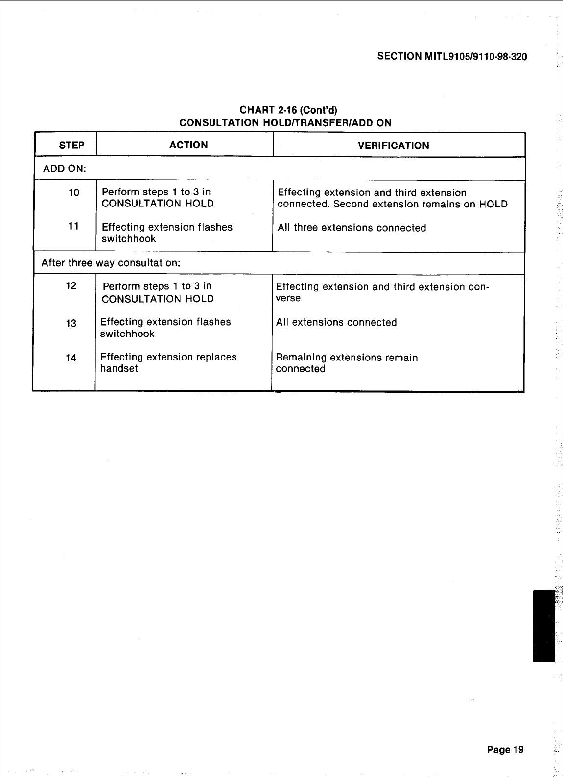
SECTION M ITL9105/911 O-98-320
CHART 2-18 (Cont’d)
CONSULTATION HOLD/TRANSFER/ADD ON
STEP ACTION VERIFICATION
ADD ON: I 1
10
11
Perform steps 1 to 3 in
CONSULTATION HOLD
Effecting extension flashes
switchhook
Effecting extension and third extension
connected. Second extension remains on HOLD
All three extensions connected
I After three way consultation:
12
13
L
14
Perform steps 1 to 3 in
CONSULTATION HOLD
Effecting extension flashes
switchhook
Effecting extension replaces
handset
Effecting extension and third extension con-
verse
All extensions connected
Remaining extensions remain
connected
1:
Page19 r’-
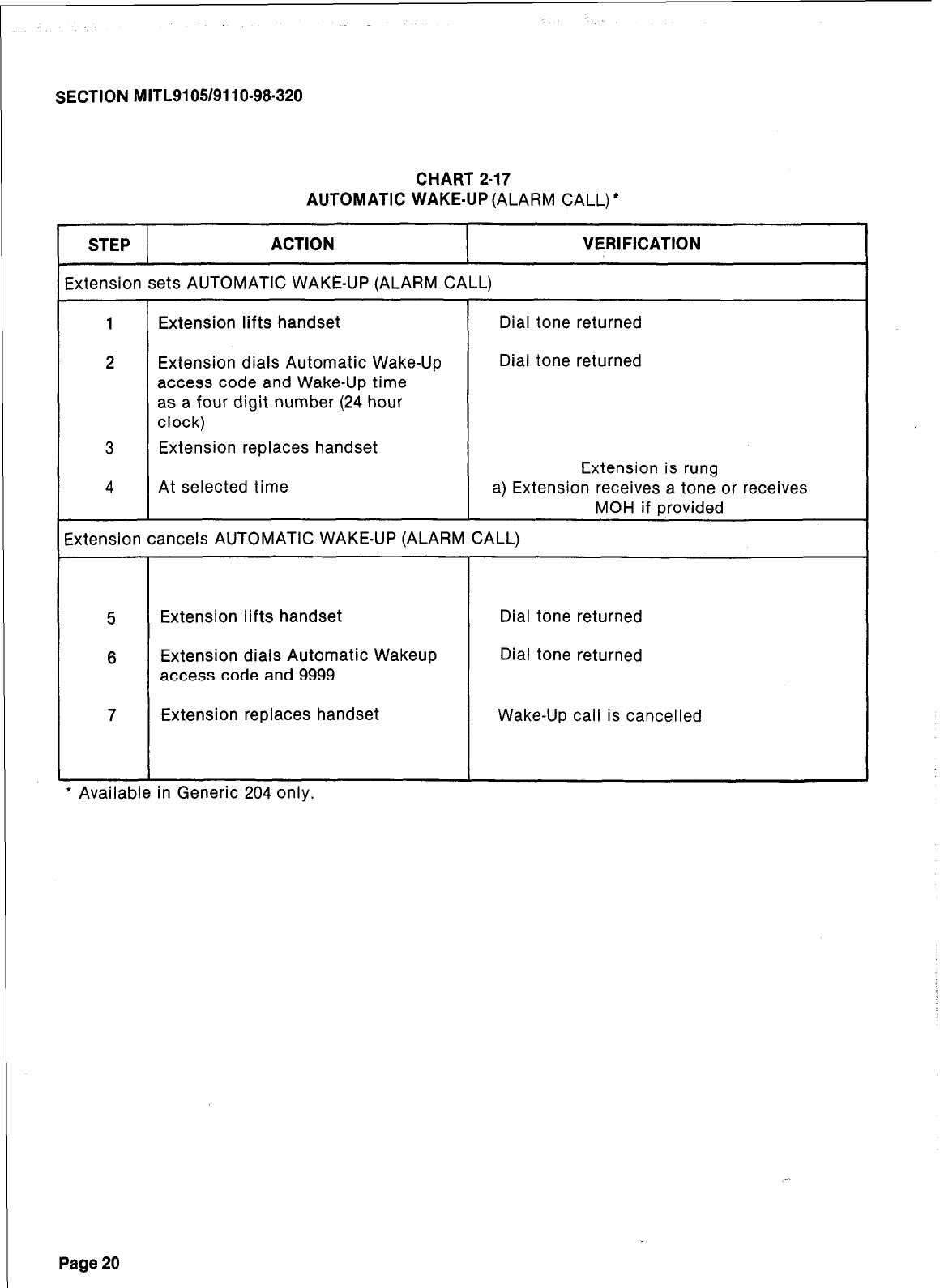
r
SECTION MITL9105/9110-98-320
CHART 2-17
AUTOMATIC WAKE-UP (ALARM CALL) *
STEP ACTION
ixtension sets AUTOMATIC WAKE-UP (ALARM CALL)
VERIFICATION
1 Extension lifts handset Dial tone returned
2 Extension dials Automatic Wake-Up Dial tone returned
access code and Wake-Up time
as a four digit number (24 hour
clock)
3 Extension replaces handset
Extension is rung
4 At selected time a) Extension receives a tone or receives
MOH if provided
Extension cancels AUTOMATIC WAKE-UP (ALARM CALL)
5 Extension lifts handset Dial tone returned
6 Extension dials Automatic Wakeup Dial tone returned
access code and 9999
7 Extension replaces handset Wake-Up call is cancelled
* Available in Generic 204 only
Page 20
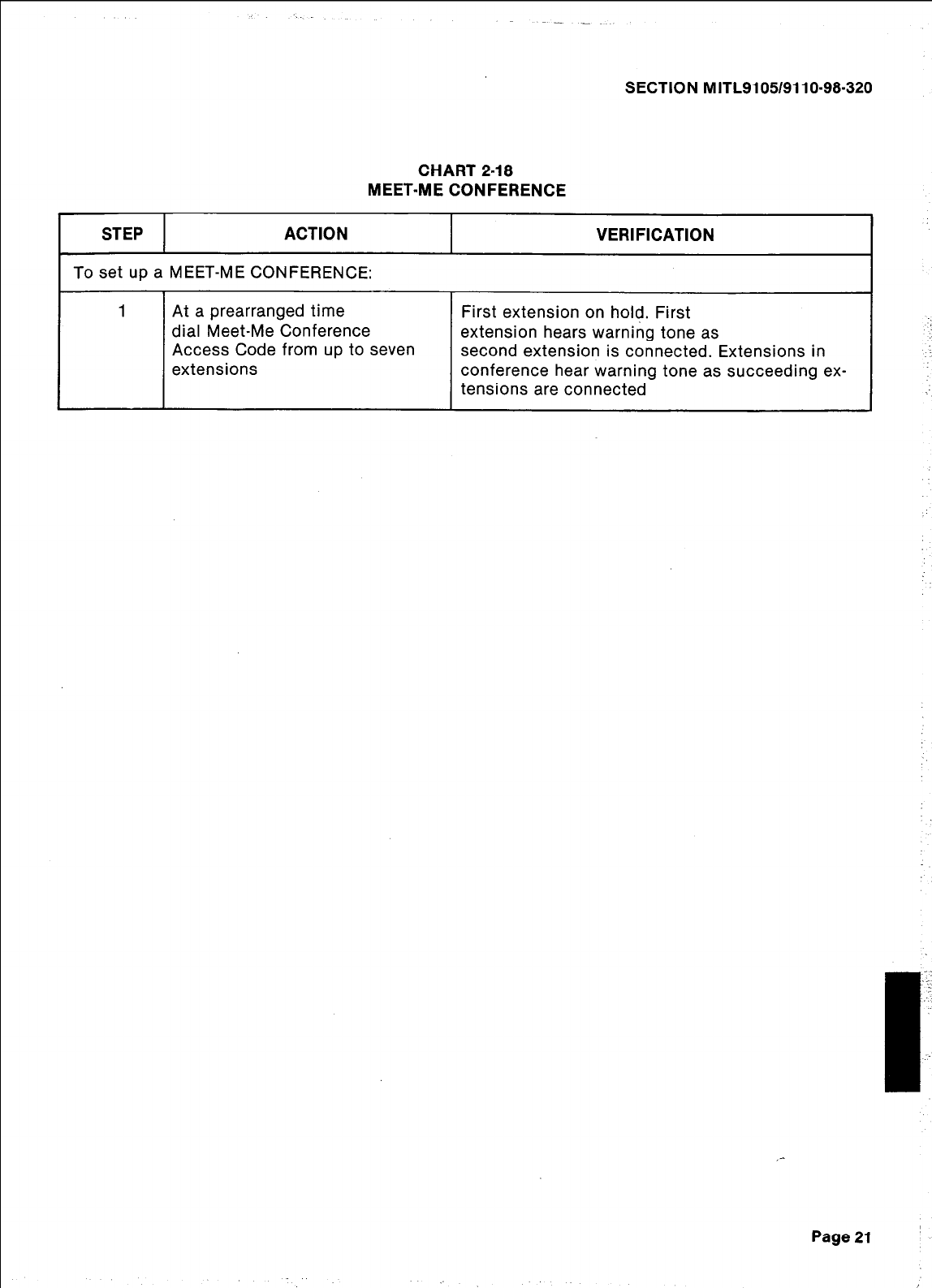
SECTION MITL9105/9110-98-320
CHART 2.18
MEET-ME CONFERENCE
STEP ACTION
To set up a MEET-ME CONFERENCE:
VERIFICATION
1 At a prearranged time First extension on ho@. First
dial Meet-Me Conference extension hears warning tone as
Access Code from up to seven second extension is connected. Extensions in
extensions conference hear warning tone as succeeding ex-
tensions are connected
Page 21
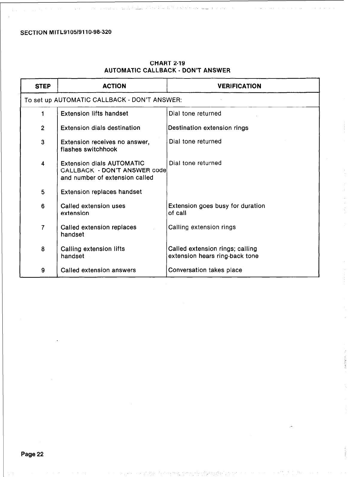
SECTION MITL9105/9110-98-320
CHART 2-19
AUTOMATIC CALLBACK - DON’T ANSWER
STEP ACTION VERIFICATION
To set up AUTOMATIC CALLBACK - DON’T ANSWER:
1 Extension lifts handset Dial tone returned
2 Extension dials destination Destination extension rings
3 Extension receives no answer, Dial tone returned
flashes switchhook
4 Extension dials AUTOMATIC Dial tone returned
CALLBACK - DON’T ANSWER code
and number of extension called
5 Extension replaces handset
6 Called extension uses Extension goes busy for duration
extension of call
7 Called extension replaces Calling extension rings
handset
8 Calling extension lifts Called extension rings; calling
handset extension hears ring-back tone
9 Called extension answers Conversation takes place
Page 22
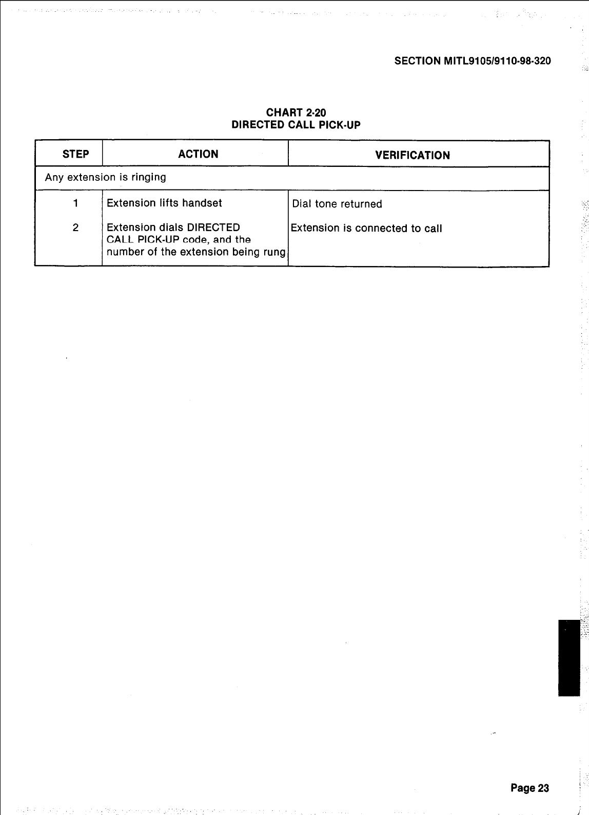
SECTION MITL9105/9110-98-320
CHART 2-20
DIRECTED CALL PICK-UP
STEP ACTION VERIFICATION
Any extension is ringing
1
i_
2
Extension lifts handset
Extension dials DIRECTED
CALL PICK-UP code, and the
number of the extension being rung
Dial tone returned
Extension is connected to call
Page23 !
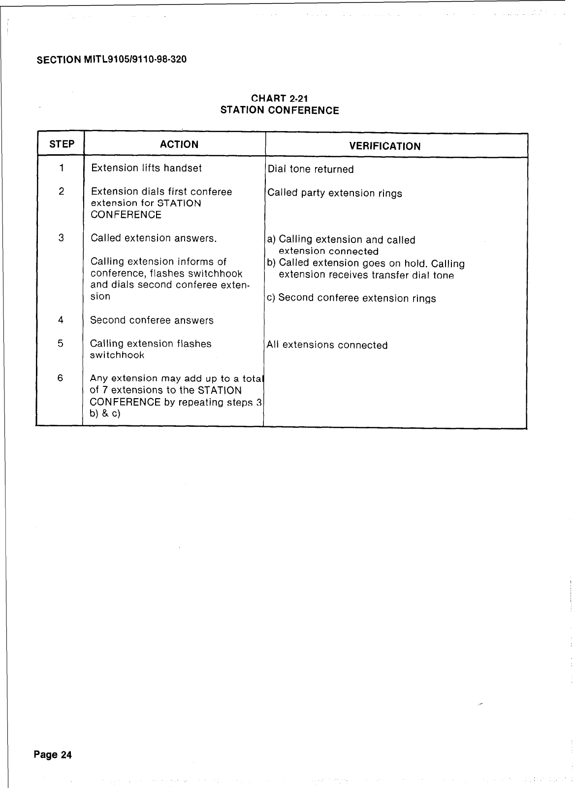
r
SECTION MITL9105/9110-98-320
CHART 2-21
STATION CONFERENCE
STEP ACTION VERIFICATION
1 Extension lifts handset Dial tone returned
2 Extension dials first conferee Called party extension rings
extension for STATION
CONFERENCE
3 Called extension answers. a) Calling extension and called
extension connected
Calling extension informs of
conference, flashes switchhook b) Called extension goes on hold. Calling
extension receives transfer dial tone
and dials second conferee exten-
sion c) Second conferee extension rings
4 Second conferee answers
5 Calling extension flashes All extensions connected
switchhook
6 Any extension may add up to a tota
of 7 extensions to the STATION
CONFERENCE by repeating steps 3
b) & c)
Page 24
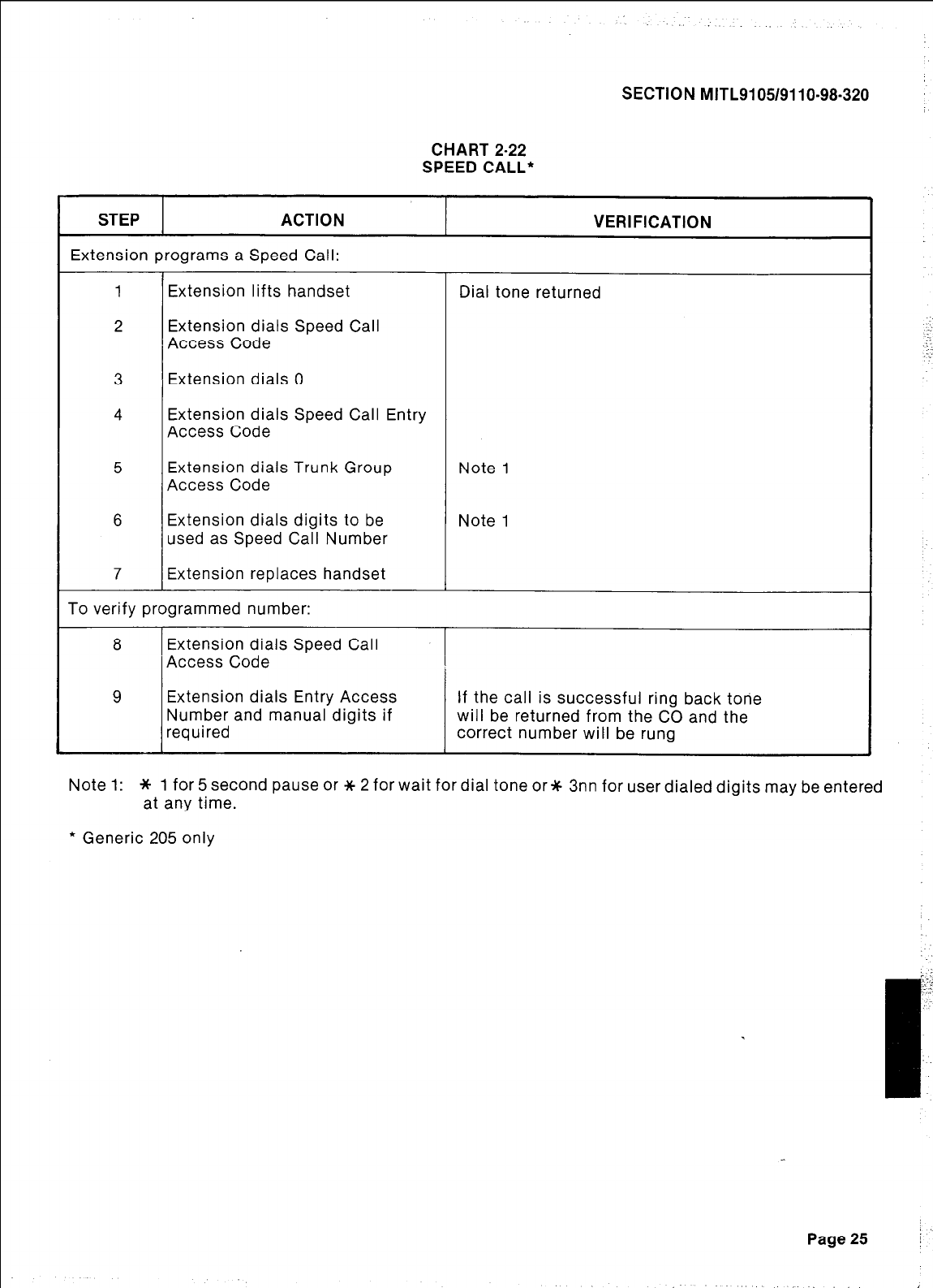
SECTION MITL9105/9110-98-320
CHART 2-22
SPEED CALL*
STEP ACTION
Extension programs a Speed Call:
1 Extension lifts handset
2 Extension dials Speed Call
Access Code
VERIFICATION
Dial tone returned
3 Extension dials 0
4 Extension dials Speed Call Entry
Access Code
5 Extension dials Trunk Group Note 1
Access Code
6 Extension dials digits to be Note 1
used as Speed Call Number
7 Extension replaces handset
To verify programmed number:
8 Extension dials Speed Call
Access Code
9 Extension dials Entry Access If the call is successful ring back tone
Number and manual digits if will be returned from the CO and the
required correct number will be rung
Note 1: * 1 for 5 second pause or * 2 for wait for dial tone or* 3nn for user dialed digits may be entered
at any time.
l
Generic 205 only
Page 25
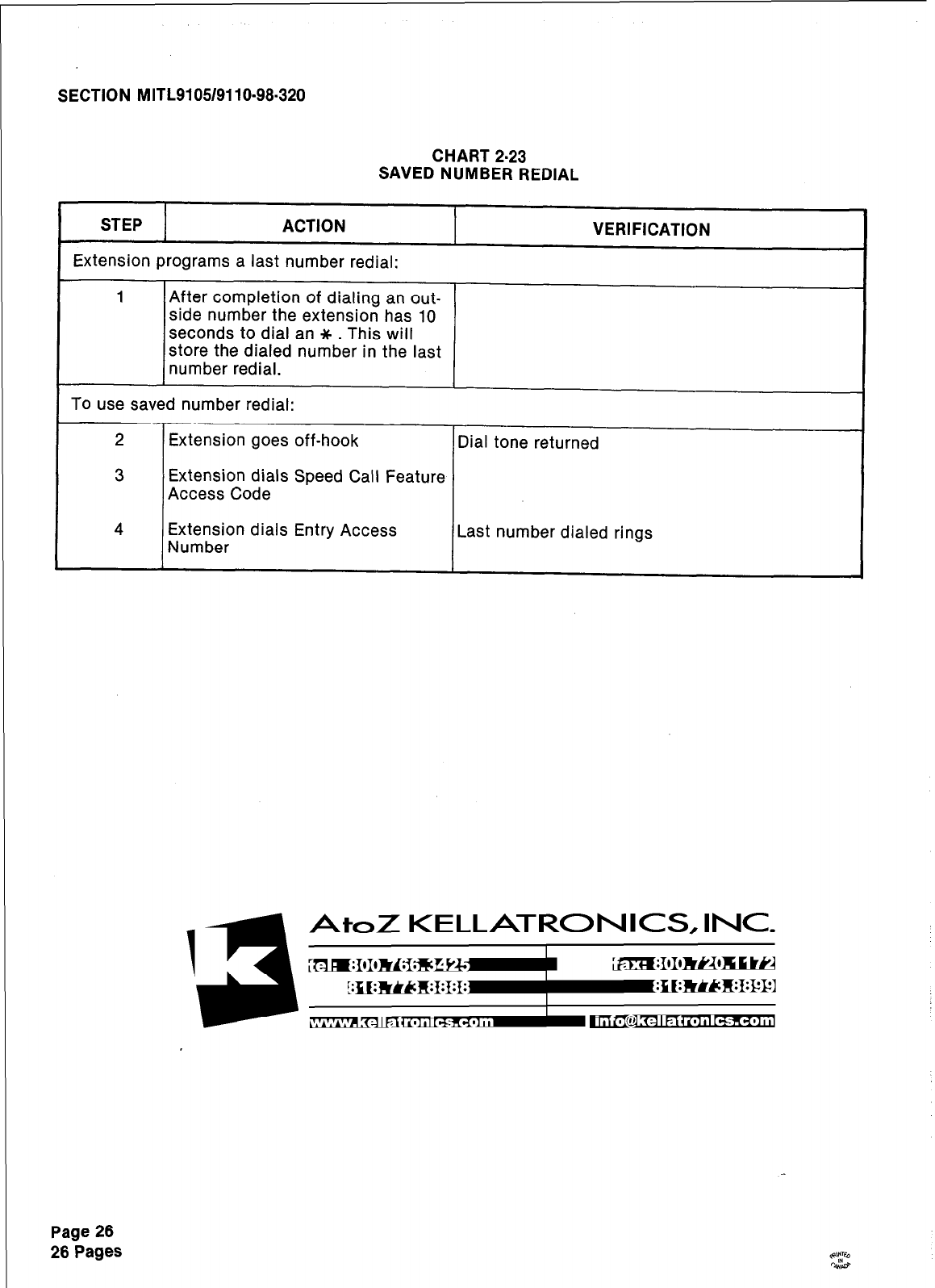
SECTION MITL9105/9110-98-320
CHART 2-23
SAVED NUMBER REDIAL
STEP ACTION
Extension programs a last number redial:
VERIFICATION
1 After completion of dialing an out-
side number the extension has 10
seconds to dial an * . This will
store the dialed number in the last
number redial.
To use saved number redial:
2 Extension goes off-hook Dial tone returned
3 Extension dials Speed Call Feature
Access Code
4 Extension dials Entry Access
Number Last number dialed rings
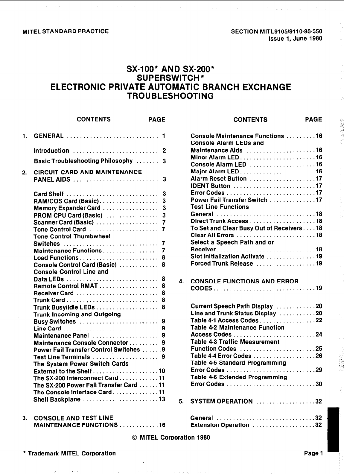
MlTEL STANDARD PRACTICE SECTION MITL9105/9110-98-350
Issue 1, June 1980
SX=lOO* AND SX-200*
SUPERSWITCH”
ELECTRONIC PRIVATE AUTOMATIC BRANCH EXCHANGE
TROUBLESHOOTING
CONTENTS PAGE CONTENTS PAGE
.::
1. GENERAL ............................ 1
Introduction .......................... 2
Basic Troubleshooting Philosophy ....... 3
2. CIRCUIT CARD AND MAINTENANCE
PANEL AIDS .......................... 3
Card Shelf ............................ 3
RAMlCOS Card (Basic). ................. 3
Memory Expander Card ................. 3
PROM CPU Card (Basic) ................ 3
Scanner Card (Basic) ................... 7
Tone Control Card ..................... 7
Tone Control Thumbwheel
Switches ............................. 7
Maintenance Functions. ................ 7
Load Functions ........................ 8
Console Control Card (Basic) ............ 8
Console Control Line and
Data LEDs ............................ 8
Remote Control RMAT .................. 8
Receiver Card ......................... 8
Trunk Card. ..... ! ..................... 8
Trunk Busy/Idle
LEDs
................... 8
Trunk Incoming and Outgoing
Busy Switches ........................ 9
LineCard ............................. 9
Maintenance Panel .................... 9
Maintenance Console Connector. ........ 9
Power Fail Transfer Control Switches ..... .9
Test Line Terminals .................... 9
The System Power Switch Cards
External to the Shelf. .................. .I0
The SX-200 Interconnect Card. .......... .I1
The SX-200 Power Fail Transfer Card ..... .I1
The Console Interface Card. ............ .I1
Shelf Backplane ...................... .I3
Console Maintenance Functions ........ .I8
Console Alarm LEDs and
Maintenance Aids .................... .I8
Minor Alarm LED. ..................... .I6
Console Alarm LED ................... .I6
Major Alarm LED. ..................... .I6
Alarm Reset Button ................... .I7
IDENT Button ........................ .I7
Error Codes .......................... .I7
Power Fail Transfer Switch ............. .I7
Test Line Functions
General ............................. .I8
Direct Trunk Access ................... .I8
To Set and Clear Busy Out of Receivers. .. .I8
Clear All Errors ....................... .I8
Select a Speech Path and or
Receiver..............................1 8
Slot Initialization Activate .............. .I9
Forced Trunk Release ................. .I9
4. CONSOLE FUNCTIONS AND ERROR
CODES...............................19
Current Speech Path Display . . . . .
Line and Trunk Status Display . . . .
Table 4-l Access Codes. . . . . . . . . .
Table 4-2 Maintenance Function
Access Codes . . . . . . . . . . . . . . . . . .
Table 4-3 Traffic Measurement
Function Codes . . . . . . . . . . . . . . . .
Table 4-4 Error Codes . . . . . . . . . . . .
Table 4-5 Standard Programming
Error Codes . . . . . . . . . . . . . . . . . . . .
Table 4-6 Extended Programming
Error Codes . . . . . . . . . . . . . . . . . . . .
. . . . .
20
. . . . . 20
. . . . . 22
. . . . . 24
. . . . .
25
. . . . . 26
. . . . . 29
. . . . .
30
5. SYSTEM OPERATION . . . . . . . . . . . . . . . . . .32
3. CONSOLE AND TEST LINE
MAINTENANCE FUNCTIONS ........... .I8 General . . . . . . . . . . . . . . . . . . . . . . . . . . . ...32
Extension Operation . . . . . . . . . . .-. . . . . . . .32
0 MITEL Corporation 1980
_:
L.
y:
* Trademark MITEL Corporation Page 1
SECTION MITL9105/911 O-98-350
CONTENTS PAGE
Console..............................3 3
Dialing a Trunk (Console). .............. .33
Hook Flash .......................... .34
Incoming Calls (GSILS Trunks) .......... .35
TABLES .............................. .35
Table 5-2 Error Code Procedures ........ .40
Table 5-3 Extension Fault Report
Procedures ......................... ..4 2
Table 5-4 Console Faults ............... .44
Table 5-5 Trunk Fault Report
Procedures ......................... ..4 5
Table 5-8 System Faults. ............... .48
6. SX-lOO/SX-200 POWER SUPPLY ......... .47
AC/DC Convertor ..................... .47
DC/DC Convertor ..................... .47
Ringing Generator .................... .47
Out of Tolerance ...................... .47
Reserve Battery Backup and
Charger ............................ ..4 7
7. REMOTE MAINTENANCE ADMINISTRATION
AND TEST SYSTEM ................... .57
APPENDIX 1 MITEL ACTION PROCEDURES . Al-l
APPENDIX 2 SYSTEM PARAMETERS ....... A2-1
APPENDIX 3 SYSTEM CABLING .......... .A3-1
APPENDIX 4 SX-100 MECHANICAL
INFORMATION ............. .A4-1
APPENDIX 5 SX-200 MECHANICAL
INFORMATION ............. .A5-1
APPENDIX 8 POWER CHECKS. ............ .A8-1
APPENDIX 7 TROUBLESHOOTING MAPS ... A7-1
1. GENERAL
Introduction
1.01 This section contains information to be
used when troubleshooting the
Page 2
SX-lOO/SX-200 PABX’s. The practice is divided in-
to six parts and seven appendices:
.
.
.
.
.
.
.
.
.
.
.
.
.
Part 1 General - gives a brief outline of the
practice and a general introduction to the
troubleshooting philosophy.
Part 2 Maintenance Aids - describes the
maintenance aids provided by the system
and gives a description of each indicator,
switch and display.
Part 3 Console and Test Line Functions
-contains a description of the maintenance
functions which can be dialed from the con-
sole or the test line.
Part 4 Error Code Troubleshooting -
describes the troubleshooting procedures
to be used in conjunction with the system
error code displays.
Part 5 Fault Report Troubleshooting - this
part details troubleshooting procedures to
be used when no error code is reported.
Part 8 SX-lOO/SX-200 Power Supply Specifi-
cations - defines the electrical and opera-
tional specifications for the SX-100/200
PABX power supplies.
Appendix one - Mite1 Action Procedures
(MAPS).
Appendix two - provides a series of tables
of all system parameters.
Appendix three - provides installation and
cabling information for the SX-100/200
PABX’s.
Appendix four - contains the mechanical in-
formation pertaining to the SX-100 in the
form of MAPS (MITEL ACTION PRO-
CEDURES) and Tables.
Appendix five - contains the mechanical in-
formation pertaining to the SX-200 in the
form of MAPS and Tables.
Appendix six - contains all power checks
pertaining to the SX-1001200 in the form of
MAPS and Tables.
Appendix seven - details, in the form of
MAPS, the procedures required to locate
and fix malfunctions in the PABX’s.
SECTION MITL9105/9110-98.350
1.02 It should be noted that certain sections and
appendices must be used as interlocking
information for complete troubleshooting.
1.03 Basic Troubleshooting Philosophy: The
SX-100/200 PABX’s employ automatic
diagnostics which, in most cases, can pinpoint
faults to a specific printed circuit card. A system
malfunction is generally corrected by the replace-
ment of an indicated faulty circuit card with a
known (good) spare. Should the need arise, the ac-
tual shelf backplane or power supply may be easi-
ly replaced by a new unit. The tables, MAPS and
explanations in this practice should be sufficient
in most cases to cover any problems which may
arise in the field.
Actual field repair of components on cards,
shelves or power supplies is never done.
All defective units should be returned to MITEL as
per Section MITL9105/9110-98-200.
2. CIRCUIT CARD AND MAINTENANCE PANEL
AIDS
2.01 The SX-1001200 PABX’s are equipped with
various maintenance aids that will be of
assistance to the repair person troubleshooting
the system. This part is a card by card description
with specific reference to all indicators, switches
and fuses on the cards. In addition the connectors
and switches on the maintenance panel are also
described.
2.02 Card Shelf: Fig. 2-1 illustrates the card
locations in the equipment shelf or shelves.
A visual display of all cards is shown in Fig. 2-2
and Fig. 2-3. Fuses on the backplane of the shelf
are described in paragraph 2.22.
2.03 Both the SX-100 and SX-200 employ only
nine basic and four optional types of cards
in the card shelf (Fig 2-2 and Fig.2-3). These may
be used in either system, minimizing stocking and
control problems for field maintenance.
2.04 RAMlCOS Card (basic): This printed cir-
cuit card contains the system 8K byte
scratch pad (volatile) Random Access Memory,
together with 2K bytes of CMOS (non-volatile)
Random Access Memory which is used for the
storage of customer configuration data (Class of
Service options, numbering plan etc.). No func-
tions other than memory read/write functions are
performed on this card. (See Fig. 2.2). This card
also contains a RAM battery pack with an LED
that will be lit to indicate that the pack is seated
correctly and is charging.
2.05 Memory Expander Card: This card has the
capability of carrying 28K bytes of Program-
mable Read Only Memory (PROM) containing
generic programs. The Memory Expander card
holds four diagnostic LEDs:
.
.
.
.
2.06
the top LED, when flashing indicates that
the automatic diagnostics are running. This
LED will not flash (the diagnostics do not
run) when the system is in programming
mode, or when less than 4 speech paths are
idle. Under these circumstances, the LED
may be either on or off, its state has no
special meaning.
the second LED, when lit, indicates that the
system is in the programming mode.
the third LED, when lit, indicates that the
RS232 port is in use (Generic 204 and up).
the fourth LED, when lit, indicates that a
Data Dump or Load is in progress (Generic
204 and up).
The PROM/RAM (optional) Expander card
can be used in place of the Memory Ex-
pander. It contains an additional 2K of CMOS
RAM. A fifth LED on the battery pack indicating
that the battery .pack is seated correctly and is
charging.
2.07 PROM/CPU Card (basic): The PROM/CPU
card contains system generic programs in
Programmable Read Only Memory (PROM), and
also contains the microprocessor, which together
with the generic program constitutes the in-
telligence of the PABX. The basic system clock is
also located on this card (See Fig. 2-2).
2.08 Scanner Card (basic): The scanner card
(Fig. 2-2) contains a two digit display which
is used to display faulty card positions. It may be
used in conjunction with the test line to display
the status of selected circuits and to support the
customer data Load and Dump. The two digit
display is read from top to bottom. If a card is
malfunctioning, the display will show the position ..‘.
number of the faulty card (01-22 for equipment
shelf 1 and 31-42 for SX-200 equipment shelf 2).
I
Page3 j :
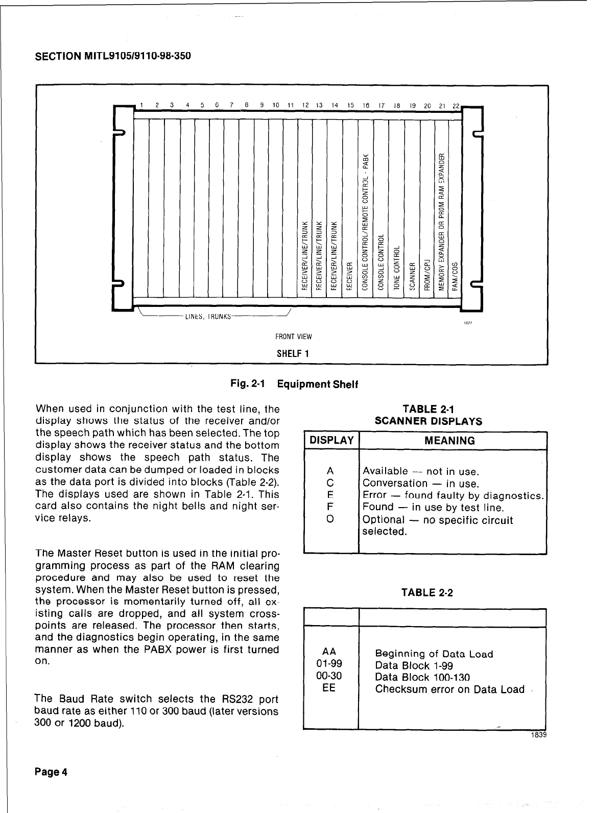
SECTION MITL9105/9110-98-350
i 2 3 4 5 6 7 a 9 10 11 12 13 14 15 lfi 17 18 19 711 71 77
LLINES. TRUNKS/
FRONTVIEW
SHELF
1
Fig. 2-I Equipment Shelf
When used in conjunction with the test line, the
display shows the status of the receiver and/or
the speech path which has been selected. The top
display shows the receiver status and the bottom
display shows the speech path status. The
customer data can be dumped or loaded in blocks
as the data port is divided into blocks (Table 2-2).
The displays used are shown in Table 2-l. This
card also contains the night bells and night ser-
vice relays.
TABLE 2-l
SCANNER DISPLAYS
MEANING DISPLAY
Available - not in use.
Conversation - in use.
Error - found faulty by diagnostics.
Found - in use by test line.
Optional - no specific circuit
selected.
TABLE 2-2
The Master Reset button is used in the initial pro-
gramming process as part of the RAM clearing
procedure and may also be used to reset the
system. When the Master Reset button is pressed,
the processor is momentarily turned off, all ex-
isting calls are dropped, and all system cross-
points are released. The processor then starts,
and the diagnostics begin operating, in the same
manner as when the PABX power is first turned
on. AA
01-99
00-30
EE
Beginning of Data Load
Data Block 1-99
Data Block loo-130
Checksum error on Data Load
The Baud Rate switch selects the RS232 port
baud rate as either 110 or 300 baud (later versions
300 or 1200 baud).
Page 4
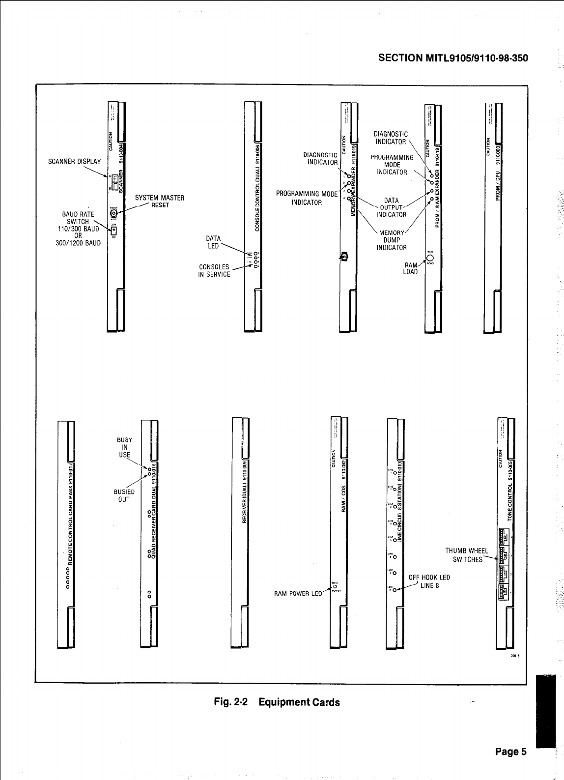
SECTION MITL9105/9110-98-350
- i,
‘:
#I
SCANNER DISPLAY :
“.,,,.
BAUD RATE w
SWITCH ./,,I
110/300 BAUb+j
300/12ooRo BAUD n(1
c
-
SYSTEM MASTER
,.---RESET
-
IN SERVICE
F
L
I- I I, si
DIAGNOSTIC I II
INDICATOR \ z
PROGRAMMING MODE
INDICATOR \
RAM POWER LED
THUMBWH
SWITCHE
HOOK LED
LINE 8
Fig. 2-2 Equipment Cards
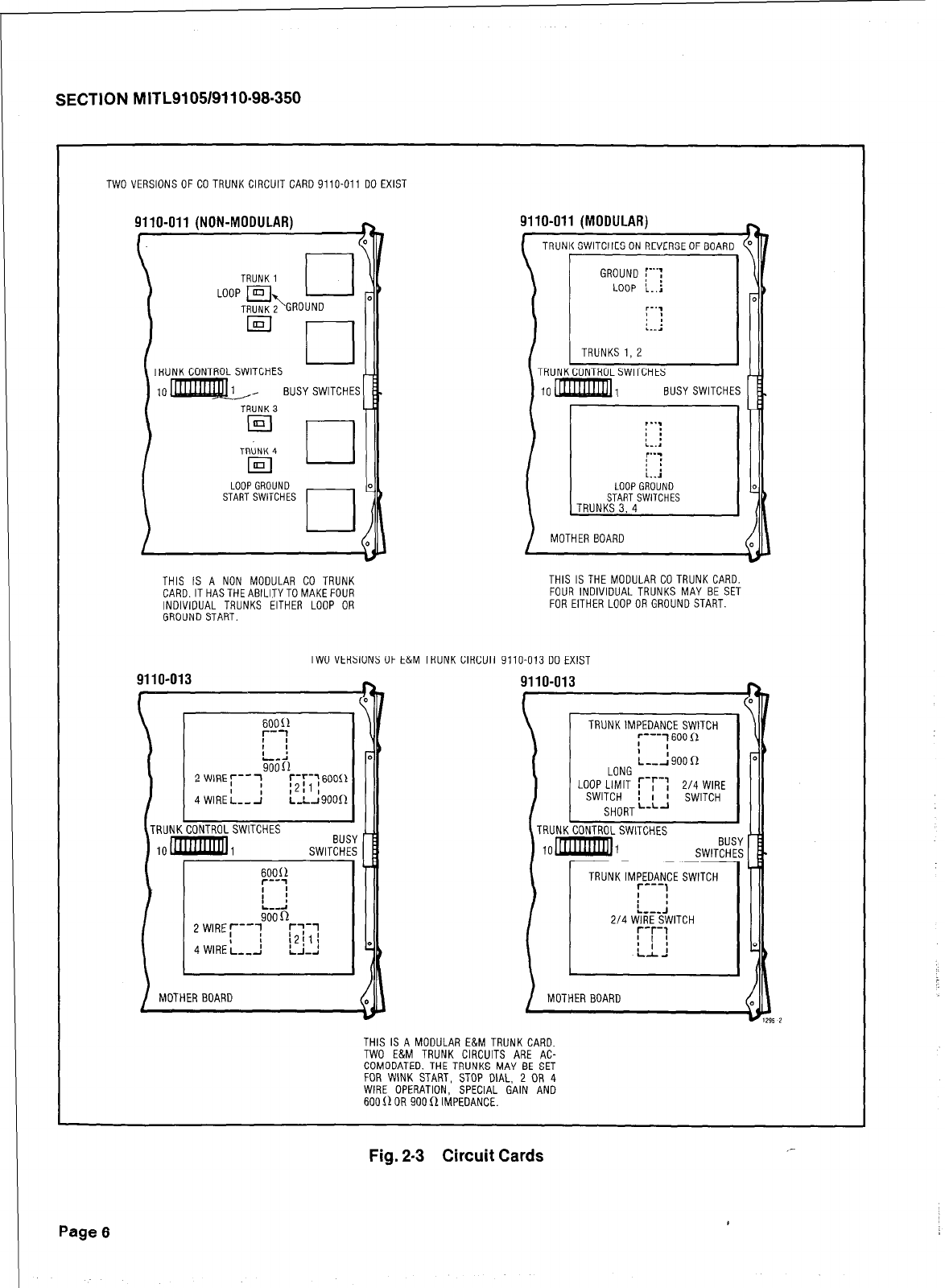
SECTION MITL9105/9110-98-350
TWO VERSIONS OF CO TRUNK CIRCUIT CARD 9110-011 DO EXIST
9110-011 (N
ON-MODULAR) h
\
TRUNK1 1
BUSYSWITCHES
9110-011 (MODULAR)
TRUNKSWITCHESON REVERSEOF
I \
:BOARD ("
\I!
/ MOTHER BOARD
THIS IS A NON MODULAR CO TRUNK
CARD.ITHASTHEABlLlTYTOMAKEFOUR
INDIVIDUAL TRUNKS EITHER LOOP OR
GROUND START.
THISISTHE MODULAR COTRUNKCARD.
FOUR INDIVIDUAL TRUNKS MAY BE SET
FOR EITHER LOOPOR GROUND START.
TWOVERSIONSOF
1 I
90011
2WIRE:--7
4
WIREis-1
:;:;:60011
Ls9oorr I
I
MOTHER BOARD
E&M TRUNK CIRCUIT 9110-013 DO EXIST
9110-013
I
;-.A9oon
LONG
L"sOW'l+;;lT r-r-: 2/4 WIRE
L L_I SWITCH
SHORT - 1
BUSY
MOTHER BOARD
THIS IS A MODULAR E&M TRUNK CARD.
TWO E&M TRUNK CIRCUITS ARE AC-
COMODATED. THE TRUNKS MAY BE SET
FOR WINK START, STOP DIAL, 2 OR 4
WIRE OPERATION, SPECIAL GAIN AND
600(10R 900RIMPEDANCE.
Fig. 2.3 Circuit Cards ,-
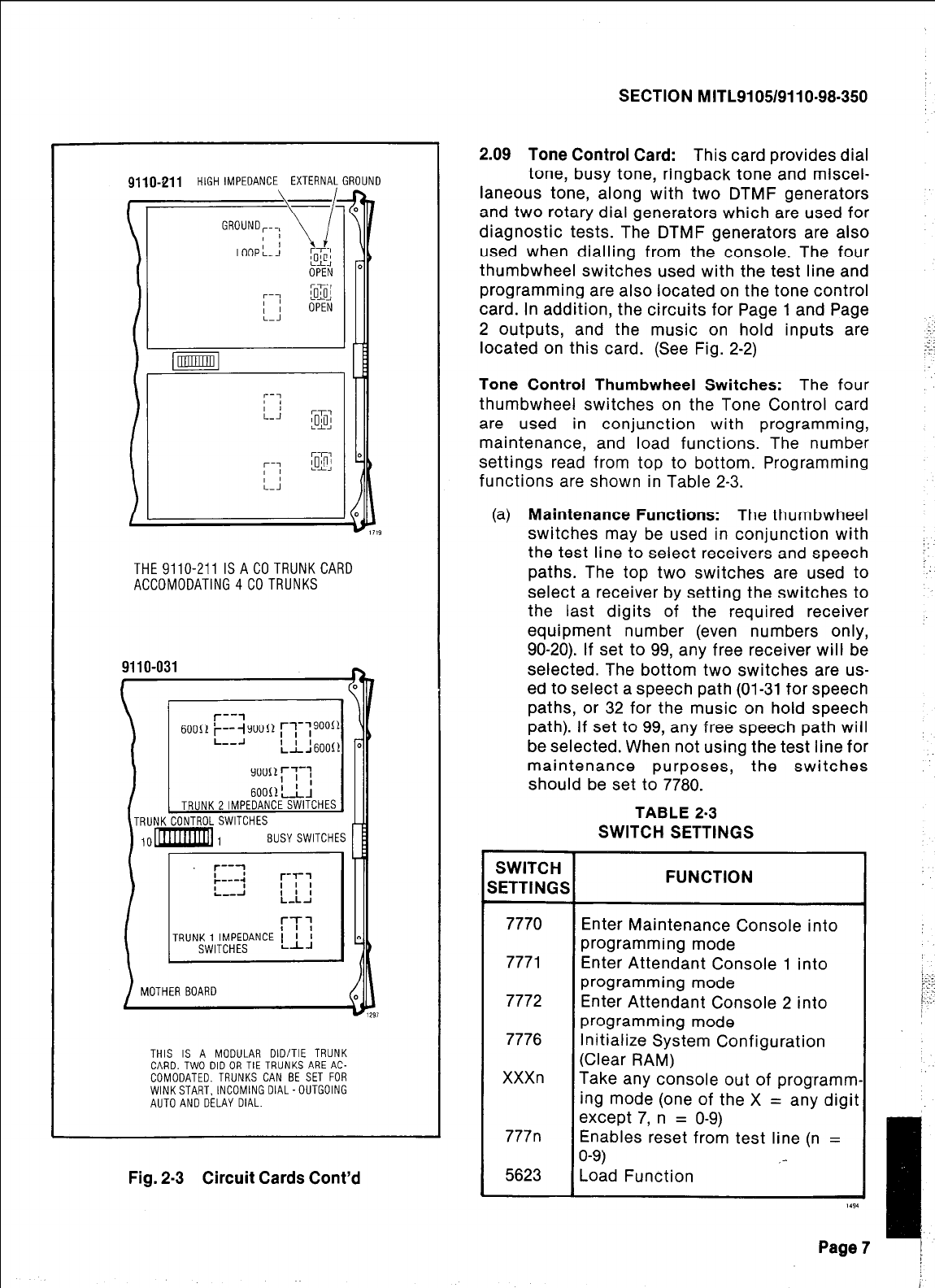
9110-211 HIGH IMPEDANCES EXTERNAkGROUND
OPEN
Fit
THE9110-211 ISACOTRUNKCARD
ACCOMODATlNG4COTRUNKS
9110-031
n
/
I1
BUSY SWITCHES 1
r-r1
TRUNK1 IMPEDANCE ' ' I
SWITCHES L-L-r
1
MOTHER BOARD
THIS IS A MODULAR DID/TIE TRUNK
CARD.TWO DID OR TIE TRUNKS ARE AC-
COMODATED. TRUNKS CAN BE SET FOR
WINKSTART. INCOMING DIAL-OUTGOING
AUTO AND DELAY DIAL.
SECTION MITL9105/9110-98-350
2.09 Tone Control Card:
This card provides dial
tone, busy tone, ringback tone and miscel-
laneous tone, along with two DTMF generators
and two rotary dial generators which are used for
diagnostic tests. The DTMF generators are also
used when dialling from the console. The four
thumbwheel switches used with the test line and
programming are also located on the tone control
card. In addition, the circuits for Page 1 and Page
2 outputs, and the music on hold inputs are
located on this card. (See Fig. 2-2)
Tone Control Thumbwheel Switches:
The four
thumbwheel switches on the Tone Control card
are used in conjunction with programming,
maintenance, and load functions. The number
settings read from top to bottom. Programming
functions are shown in Table 2-3.
(a)
Maintenance Functions:
The thumbwheel
switches may be used in conjunction with
the test line to select receivers and speech
paths. The top two switches are used to
select a receiver by setting the switches to
the last digits of the required receiver
equipment number (even numbers only,
90-20). If set to 99, any free receiver will be
selected. The bottom two switches are us-
ed to select a speech path (01-31 for speech
paths, or 32 for the music on hold speech
path). If set to 99, any free speech path will
be selected. When not using the test line for
maintenance purposes, the switches
should be set to 7780.
TABLE 2-3
SWITCH SETTINGS
Enter Maintenance Console into
programming mode
Enter Attendant Console 1 into
programming mode
Enter Attendant Console 2 into
programming mode
Initialize System Configuration
Take any console out of programm
ing mode (one of the X = any digii
except 7, n = O-9)
Enables reset from test line (n =
Fig. 2-3 Circuit Cards Cont’d
Page 7
SECTION MITL9105/9110-98-350
(b) Load Functions (Generic 2041~~): The
Customer Program Dump/Load Function re-
quires the switches to be set to 5623 to in-
itiate a load from, or dump to, an external
storage device.
2.10
Console Control Card (basic): The con-
sole control card provides the interface bet-
ween the PABX and two consoles. Console con-
trol card number 1 (position 17) is allocated to the
maintenance console connector and the atten-
dant console number 1 connector. Console con-
trol card number 2 (position 16) is allocated to the
attendant console number 2 connector. The card
provides both voice and data signals to and from
each console. (See Fig. 2-2). To identify the con-
sole, the operator may press the IDENT button.
The last segment in the DESTINATION Display
identifies the console as; 0 for maintenance, 1 for
console 1, or 2 for console 2.
2.11 Console Control Line and Data
LEDs: LINE 1 and LINE 2 LEDs,when lit,
indicate that the associated console is active, i.e.
the handset or headset is plugged in. The
designations 1 and 2 refer to the two consoles
handled by the card. The maintenance console
will appear in slot 17, line 2. Console 1 will appear
in slot 17, line 1. Console 2 will appear in slot 16,
line 1. Line 2 in slot 16 is not used. The data LEDs
indicate voice pair continuity to the console(s).
The LEDs labelled DATA 1 and DATA 2 flicker
whenever data is transmitted from the correspon-
ding console to the console control card (Data is
transmitted when any console button is pressed.)
2.12 Remote Control RMAT: The Remote Con-
trol PABX (RCP) card, can be fitted in slot 16
of the PABX shelf to provide the PABX console
button functions remotely, under the control of
the RMAT Controller (see MITL9105/9110-98-101).
The main components of the RCP card are as
follows:
0 The Micro Processor Unit (MPU), which acts
on commands received from the RMAT
Controller via the modem.
l
MEMORY PROM/RAM, which contains pro-
grammed memory and scratch pad memory
for storage and execution of commands.
* MODEM, which provides the necessary
tone transmitter and receiver, and contains
Page 8
the handshaking circuitry required to inter-
face the MPU with the external 2-wire line.
TRUNK INTERFACE, to provide the proper
termination to the line with regard to im-
pedance, ringing and supervisory condi-
tion.
MASTER/SLAVE INTERFACE, to enable the
MPU to access the PABX data bus and con-
trol lines.
2.13 Receiver Card: The receiver card contains
two rotary dial and two DTMF receivers.
Having received each dialed digit, the receiver in-
forms the processor and prepares for the next
digit. The dual receiver card contains no LEDs or
switches. The quad receiver card contains four
rotary dial, four DTMF receivers, four dial tone
detectors, and 4 sets (two each) of LEDs labelled
Al Bl, A2 B2, A3 B3, A4 B4. In each case the A
LED indicates a busy condition. The B LED in-
dicates a busied out condition.
2.14 Trunk Card: The Trunk Card contains
either two or four trunks depending upon
the trunk type. (Fig. 2-3; 4 CO Trunks, 2 E&M Tie
Trunks, or 2 DID Trunks per card). These circuits
provide the interface between the PABX and the
Central Office, other PABX’s, or other equipment.
Each trunk circuit repeats dial pulse signals from
the speech path to the Tip and Ring and passes
DTMF signals directly from the speech path to the
Trunk for outgoing calls. The busy switches on
the trunk card may be used to make a trunk con-
tinuously busy. If the trunk is in use when the
switch is set, the existing call is not disturbed.
For exact details of the trunk busy switches see
Table 2-4.
l
Trunk Busy/Idle LEds: Each trunk circuit
has associated with it an LED which shows
the busy/idle status of the trunk as follows:
l
Trunk circuit idle
l
Trunk circuit seized
l
Trunk circuit busied
out (by switch on
card or from the
console)
l
LED OFF
l
LED ON
l
LED FLASHING
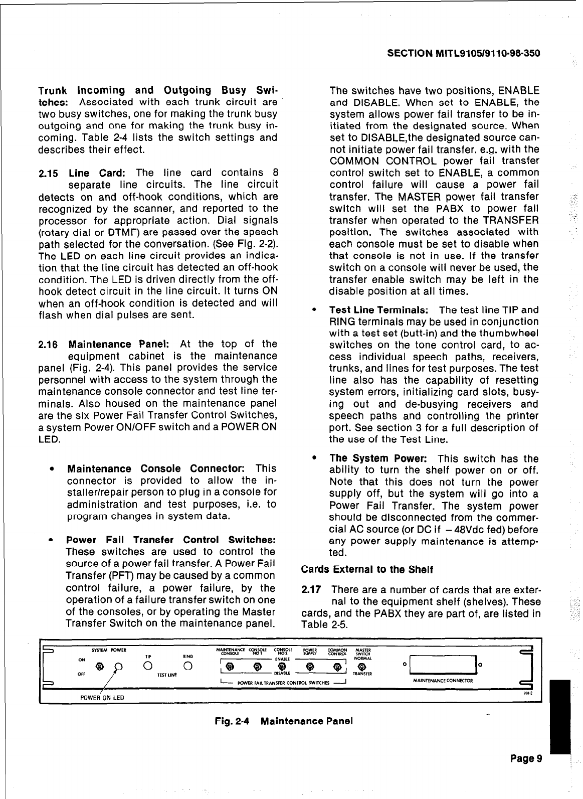
Trunk incoming and Outgoing Busy Swi-
tches: Associated with each trunk circuit are
two busy switches, one for making the trunk busy
outgoing and one for making the trunk busy in-
coming. Table 2-4 lists the switch settings and
describes their effect.
2.15 Line Card: The line card contains 8
separate line circuits. The line circuit
detects on and off-hook conditions, which are
recognized by the scanner, and reported to the
processor for appropriate action. Dial signals
(rotary dial or DTMF) are passed over the speech
path selected for the conversation. (See Fig. 2-2).
The LED on each line circuit provides an indica-
tion that the line circuit has detected an off-hook
condition. The LED is driven directly from the off-
hook detect circuit in the line circuit. It turns ON
when an off-hook condition is detected and will
flash when dial pulses are sent.
2.16 Maintenance Panel: At the top of the
equipment cabinet is the maintenance
panel (Fig. 2-4). This panel provides the service
personnel with access to the system through the
maintenance console connector and test line ter-
minals. Also housed on the maintenance panel
are the six Power Fail Transfer Control Switches,
a system Power ON/OFF switch and a POWER ON
LED.
l
Maintenance Console Connector: This
connector is provided to allow the in-
staller/repair person to plug in a console for
administration and test purposes, i.e. to
program changes in system data.
l
Power Fail Transfer Control Switches:
These switches are used to control the
source of a power fail transfer. A Power Fail
Transfer (PFT) may be caused by a common
control failure, a power failure, by the
operation of a failure transfer switch on one
of the consoles, or by operating the Master
Transfer Switch on the maintenance panel.
SECTION MITL9105/9110-96-350
The switches have two positions, ENABLE
and DISABLE. When set to ENABLE, the
system allows power fail transfer to be in-
itiated from the designated source. When
set to DISABLE,the designated source can-
not initiate power fail transfer, e.g. with the
COMMON CONTROL power fail transfer
control switch set to ENABLE, a common
control failure will cause a power fail
transfer. The MASTER power fail transfer
switch will set the PABX to power fail
transfer when operated to the TRANSFER
position. The switches associated with
each console must be set to disable when
that console is not in use. If the transfer
switch on a console will never be used, the
transfer enable switch may be left in the
disable position at all times.
.-:
I’..-:
l
Test Line Terminals: The test line TIP and
RING terminals may be used in conjunction
with a test set (butt-in) and the thumbwheel
switches on the tone control card, to ac-
cess individual speech paths, receivers,
trunks, and lines for test purposes. The test
line also has the capability of resetting
system errors, initializing card slots, busy-
ing out and de-busying receivers and
speech paths and controlling the printer
port. See section 3 for a full description of
the use of the Test Line.
l
The System Power: This switch has the
ability to turn the shelf power on or off.
Note that this does not turn the power
supply off, but the system will go into a
Power Fail Transfer. The system power
should be disconnected from the commer-
cial AC source (or DC if - 48Vdc fed) before
any power supply maintenance is attemp-
ted.
Cards External to the Shelf
2.17 There are a number of cards that are exter-
nal to the equipment shelf (shelves). These
cards, and the PABX they are part of, are listed in
Table 2-5.
1
I
Page9 j.
Fig. 2-4 Maintenance Panel
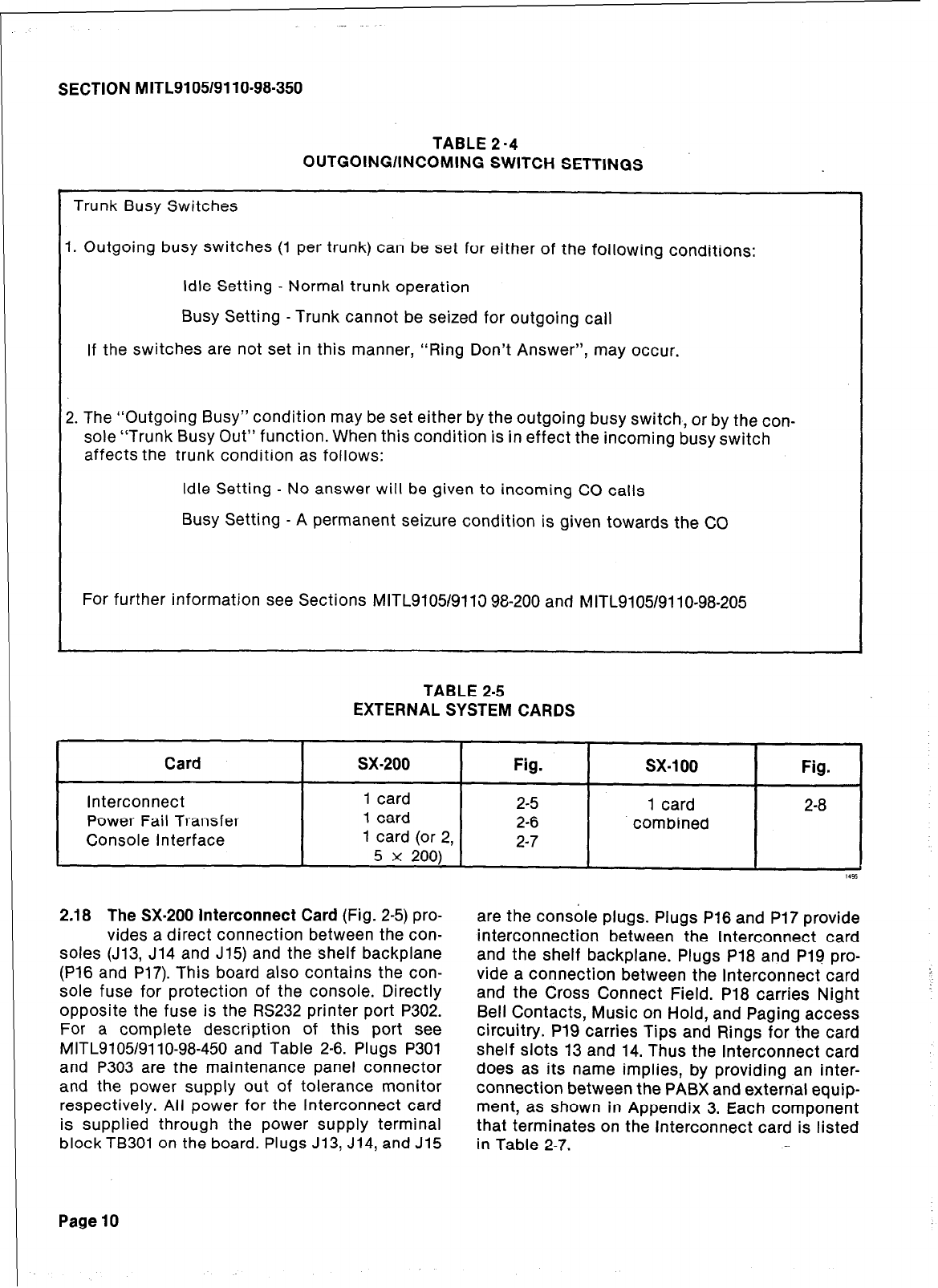
SECTION MITL9105/9110-98-350
TABLE 2 -4
OUTGOING/INCOMING SWITCH SETTINGS
Trunk Busy Switches
I. Outgoing busy switches (1 per trunk) can be set for either of the
following
conditions:
Idle Setting - Normal trunk operation
Busy Setting - Trunk cannot be seized for outgoing call
If the switches are not set in this manner, “Ring Don’t Answer”, may occur.
2. The “Outgoing Busy” condition may be set either by the outgoing busy switch, or by the con-
sole “Trunk Busy Out” function. When this condition is in effect the incoming busy switch
affects the trunk condition as follows:
Idle Setting - No answer will be given to incoming CO calls
Busy Setting - A permanent seizure condition is given towards the CC
For further information see Sections MITL910519113 98-200 and MITLS 1051911 o-98-205
TABLE 2-5
EXTERNAL SYSTEM CARDS
c
Card
sx-200
Fig. sx-1 00 Fig.
Interconnect 1 card 2-5 1 card 2-8
Power Fail Transfer 1 card 2-6 combined
Console Interface 1 card (or 2, 2-7
5 x 200) I(
2.18 The SX-200 Interconnect Card
(Fig. 2-5) pro-
vides a direct connection between the con-
soles (J13, J14 and J15) and the shelf backplane
(P16 and P17). This board also contains the con-
sole fuse for protection of the console. Directly
opposite the fuse is the RS232 printer port P302.
For a complete description of this port see
MITL9105/9110-98-450 and Table 2-6. Plugs P301
and P303 are the maintenance panel connector
and the power supply out of tolerance monitor
respectively. All power for the Interconnect card
is supplied through the power supply terminal
block TB301 on the board. Plugs J13, J14, and J15
are the console plugs. Plugs P16 and P17 provide
interconnection between the Interconnect card
and the shelf backplane. Plugs P18 and Pl9 pro-
vide a connection between the Interconnect card
and the Cross Connect Field. P18 carries Night
Bell Contacts, Music on Hold, and Paging access
circuitry. P19 carries Tips and Rings for the card
shelf slots 13 and 14. Thus the Interconnect card
does as its name implies, by providing an inter-
connection between the PABX and external equip-
ment, as shown in Appendix 3. Each component
that terminates on the Interconnect card is listed
in Table 2-7.
Page 10
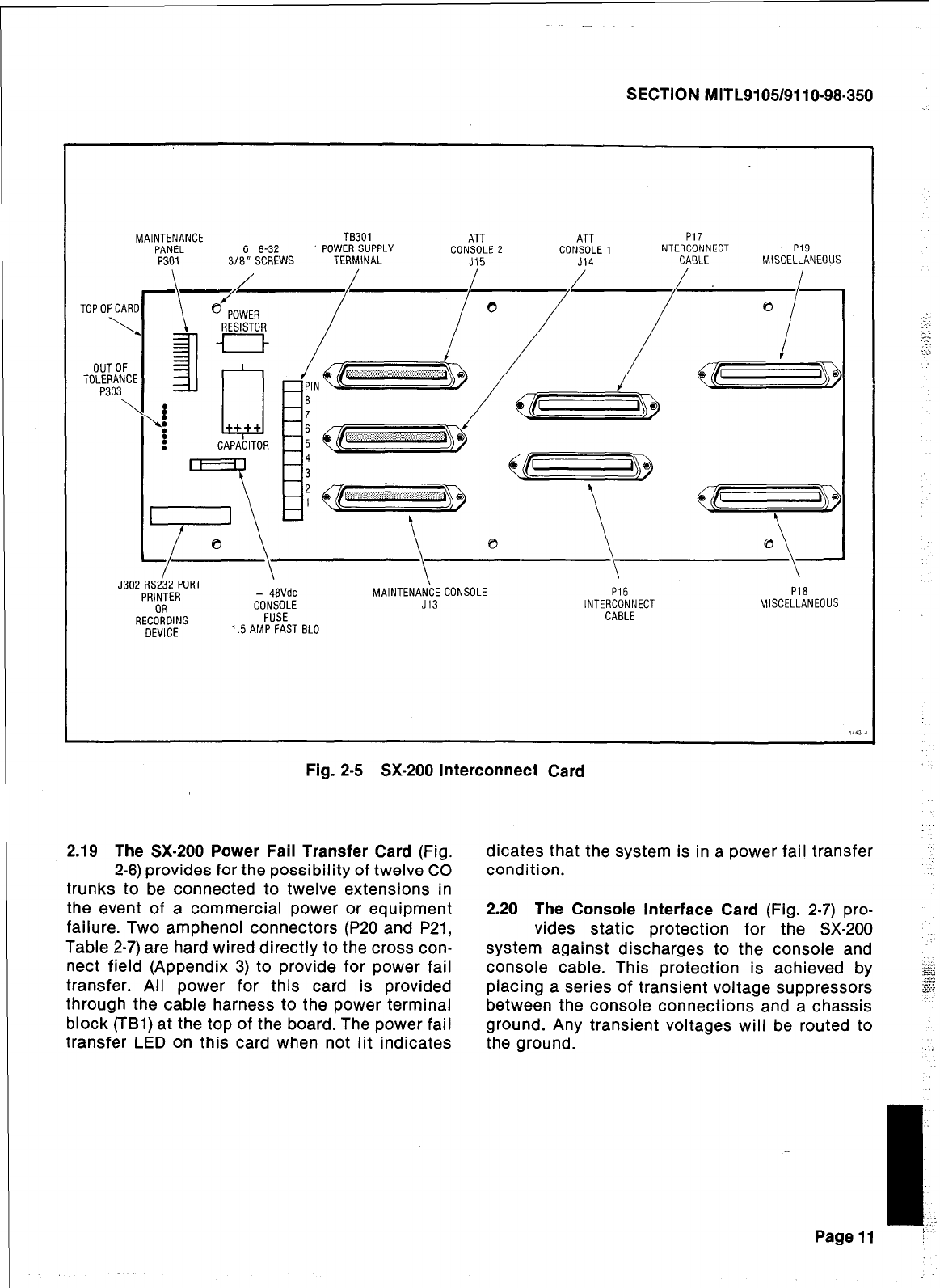
SECTION MITL9105/9110-98-350
MAINTENANCE TB301 ATT ATT P17
PANEL 6 8-32 POWER SUPPLY CONSOLE 2 CONSOLE1 INTERCONNECT P19
P301 3/E" SCREWS TERMINAL J15 J14 CABLE MISCELLANEOUS
I \
J302 RS232 PORT
\ \ \
PRINTER - 4aVdc MAINTENANCECONSOLE P16 P18
RECiiOING
CONSOLE J13 INTERCONNECT MISCELLANEOUS
FUSE CABLE
DEVICE 1.5AMP FAST BLO
Fig. 2-5 SX-200 Interconnect Card
2.19 The SX-200 Power Fail Transfer Card (Fig.
2-6) provides for the possibility of twelve CO
trunks to be connected to twelve extensions in
the event of a commercial power or equipment
failure. Two amphenol connectors (P20 and P21,
Table 2-7) are hard wired directly to the cross con-
nect field (Appendix 3) to provide for power fail
transfer. All power for this card is provided
through the cable harness to the power terminal
block (TBl) at the top of the board. The power fail
transfer LED on this card when not lit indicates
dicates that the system is in a power fail transfer
condition.
2.20 The Console Interface Card (Fig. 2-7) pro-
vides static protection for the SX-200
system against discharges to the console and
console cable. This protection is achieved by
placing a series of transient voltage suppressors
between the console connections and a chassis
ground. Any transient voltages will be routed to
the ground.
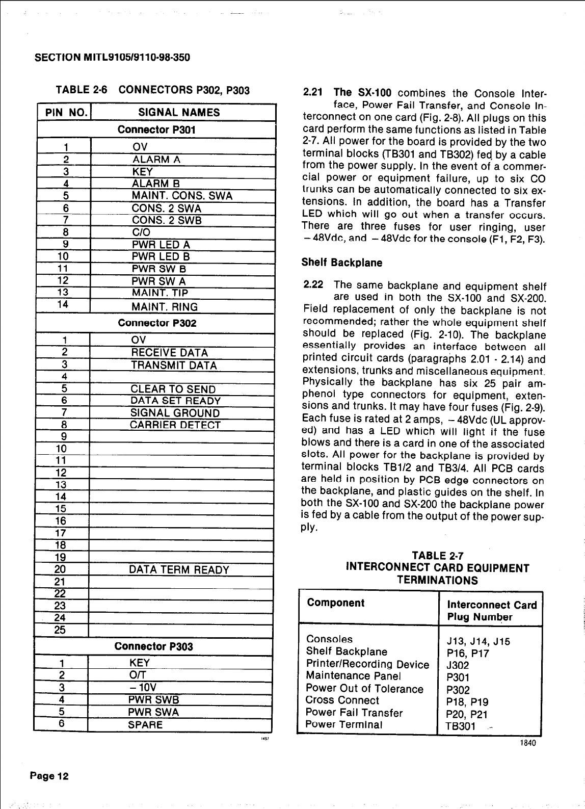
SECTION MITL9105/9110-98-350
TABLE 2-6 CONNECTORS P302, P303
2.21
The SX-100
combines the Console Inter-
PIN NO.1 SIGNAL NAMES
Connector P301
14 I MAINT. RING
Connector P302
ov
RECEIVE DATA
TRANSMIT DATA
CLEAR TO SEND
DATA SET READY
SIGNAL GROUND
CARRIER DETECT
11
12
13
14
15
16
17
ia
19
iti I
DATA TERM READY
94
Connector P303
1 KEY
2 O/l
3 -lov
4 PWR SWB
5 PWR SWA
6 SPARE
face, Power Fail Transfer, and Console In-
terconnect on one card (Fig. 2-8). All plugs on this
card perform the same functions as listed in Table
2-7. All power for the board is provided by the two
terminal blocks (TB301 and TB302) fed by a cable
from the power supply. In the event of a commer-
cial power or equipment failure, up to six CO
trunks can be automatically connected to six ex-
tensions. In addition, the board has a Transfer
LED which will go out when a transfer occurs.
There are three fuses for user ringing, user
- 48Vdc, and - 48Vdc for the console (Fl, F2, F3).
Shelf Backplane
2.22 The same backplane and equipment shelf
are used in both the SX-100 and SX-200.
Field replacement of only the backplane is not
recommended; rather the whole equipment shelf
should be replaced (Fig. 2-10). The backplane
essentially provides an interface between all
printed circuit cards (paragraphs 2.01 - 2.14) and
extensions, trunks and miscellaneous equipment.
Physically the backplane has six 25 pair am-
phenol type connectors for equipment, exten-
sions and trunks. It may have four fuses (Fig. 2-9).
Each fuse is rated at 2 amps, - 48Vdc (UL approv-
ed) and has a LED which will light if the fuse
blows and there is a card in one of the associated
slots. All power for the backplane is provided by
terminal blocks TB112 and TB3/4. All PCB cards
are held in position by PCB edge connectors on
the backplane, and plastic guides on the shelf. In
both the SX-100 and SX-200 the backplane power
is fed by a cable from the output of the power sup-
PlY.
TABLE 2-7
INTERCONNECT CARD EQUIPMENT
TERMINATIONS
Component
Consoles
Shelf Backplane J13, J14, J15
P16, P17
Printer/Recording Device J302
Maintenance Panel P301
Power Out of Tolerance P302
Cross Connect Pia, pi9
Power Fail Transfer P20, P21
Power Terminal TB301 -
Interconnect Card
Plug Number
1840
Page 12
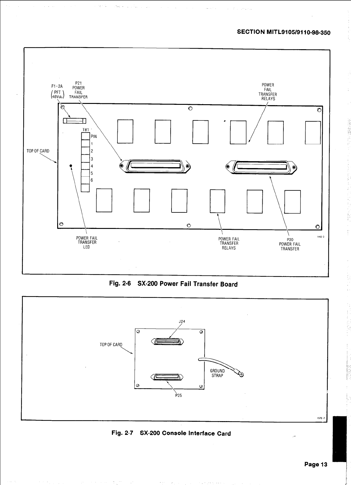
SECTION MITL9105/9110-98-350
TOPOFCARD
\
Fl-2A P21
POWER
FAIL
TRANSFER
\
POWER
FAIL
TRANSFER
RELAYS
cl c
1 II&l c
POWER FAIL POWER FAIL
TRANSFER TRANSFER
LED RELAYS
I
P20
POWER FAIL
TRANSFER
Fig. 2-6 SX-200 Power Fail Transfer Board
J24
0
TOPOFCARD
\
P25
Fig. 2-7 SX-200 Console Interface Card
Page 13 J
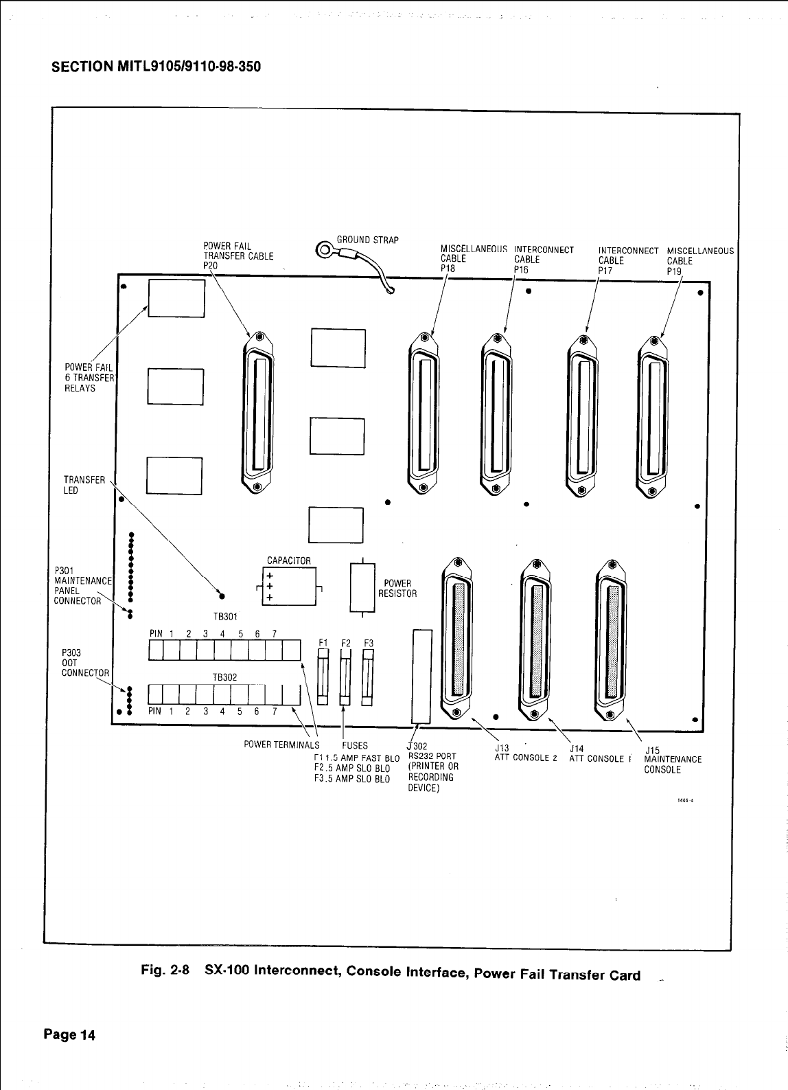
SECTION MITL9105/9110-98-350
POWER FAIL
TRANSFER CABLE
""n
d-YND STRAP MISCELLANEOUS INTERCONNECT INTERCONNECT MISCELLANEOU
CABLE CABLE CABLE
P303
OOT
CONNECTOR
\
I f
0
,~lTORI
TB301
PIN1 2 3 4 5 6 7
PIN1 2 3 4 5 6 7
:
‘.,. ;.-
:. :..
“.. L:
:. :. ,:..
::.. / :
1~~~
..,
‘.I..:.
: I..
‘. :.
. .
. . ;
“‘\’ @l @‘\ .
POWERTERMlNiLS &SES ;302 \ \ \
J13 J14
F11.5 AMP FAST BLO RS232 PoRT ATTCONSOLE 2 ATT CONSOLE 1 KINTENANCE
F2.5AMP SLO BLO (PRINTER OR CONSOLE
F3.5AMPSLO BLO RECORDING
DEVICE)
Fig. 2-8 SX-100 Interconnect, Console Interface, Power Fail Transfer Card _
Page 14
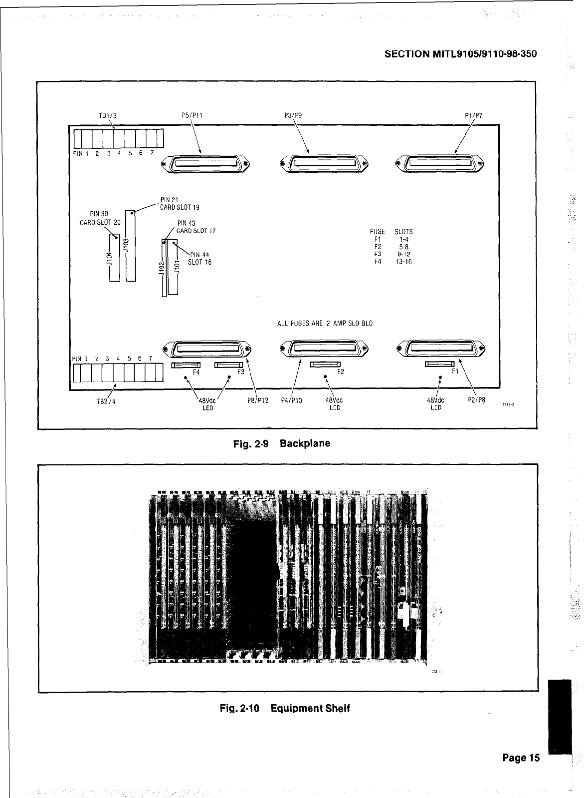
SECTION MITLSI 05/91 I O-98-350
FUSE SLOTS
Fl 1-4
F2 5-a
F3 9-12
F4 13-16
TB1/3 P5lPll P3/P9 PI/P7
PIN 21
ALL FUSES ARE 2 AMPSLO EL0
LED LED 1448 2
Fig. 2-9 Backplane
Fig. 2-10 Equipment Shelf
Page 15
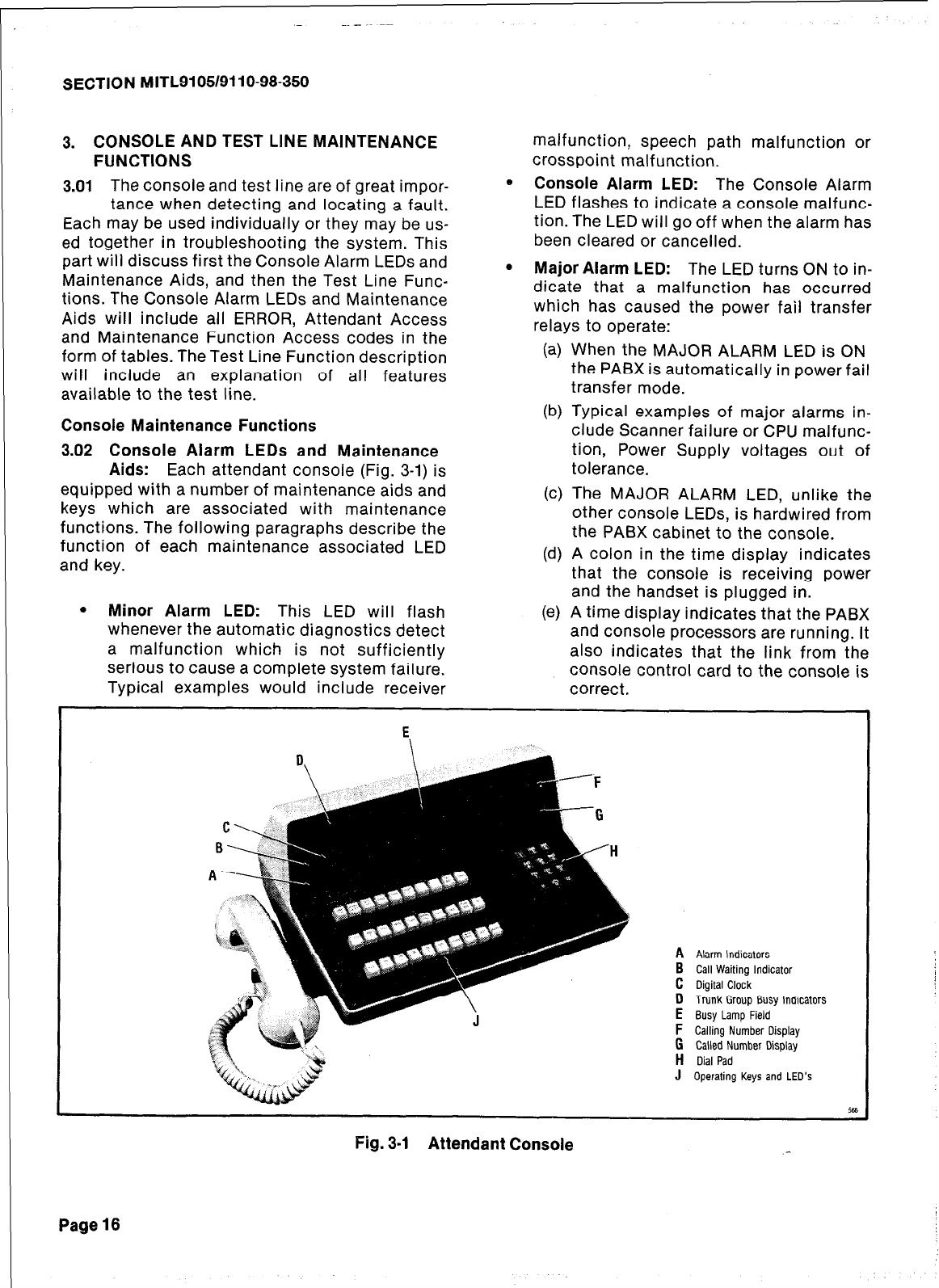
SECTION lblITL9105/9110-98-350
3. CONSOLE AND TEST LlNE MAINTENANCE
FUNCTIONS
3.01 The console and test line are of great impor-
tance when detecting and locating a fault.
Each may be used individually or they may be us-
ed together in troubleshooting the system. This
part will discuss first the Console Alarm LEDs and
Maintenance Aids, and then the Test Line Func-
tions. The Console Alarm LEDs and Maintenance
Aids will include all ERROR, Attendant Access
and Maintenance Function Access codes in the
form of tables. The Test Line Function description
will include an explanation of all features
available to the test line.
Console Maintenance Functions
3.02 Console Alarm LEDs
and
Maintenance
Aids: Each attendant console (Fig. 3-1) is
equipped with a number of maintenance aids and
keys which are associated with maintenance
functions. The following paragraphs describe the
function of each maintenance associated LED
and key.
malfunction, speech path malfunction or
crosspoint malfunction.
0 Console Alarm LED: The Console Alarm
LED flashes to indicate a console malfunc-
tion. The LED will go off when the alarm has
been cleared or cancelled.
0 Major Alarm LED: The LED turns ON to in-
dicate that a malfunction has occurred
which has caused the power fail transfer
relays to operate:
(a) When the MAJOR ALARM LED is ON
the PABX is automatically in power fail
transfer mode.
(b) Typical examples of major alarms in-
clude Scanner failure or CPU malfunc-
tion, Power Supply voltages out of
tolerance.
(c) The MAJOR ALARM LED, unlike the
other console LEDs, is hardwired from
the PABX cabinet to the console.
(d) A colon in the time display indicates
that the console is receiving power
and the handset is plugged in. .
l
Minor Alarm LED: This LED will flash (e) A time display indicates that the PABX
whenever the automatic diagnostics detect
a malfunction which is not sufficiently and console processors are running. It
also indicates that the link from the
serious to cause a complete system failure. console control card to the console is
Typical examples would include receiver correct.
Alarm Indicators
Call Waiting Indicator
Digital Clock
Trunk Group Busy Indicators
Busy Lamp Field
Calling Number Display
Called Number Display
Dial Pad
Operating Keys and LED’s
Fig. 3-I Attendant Console
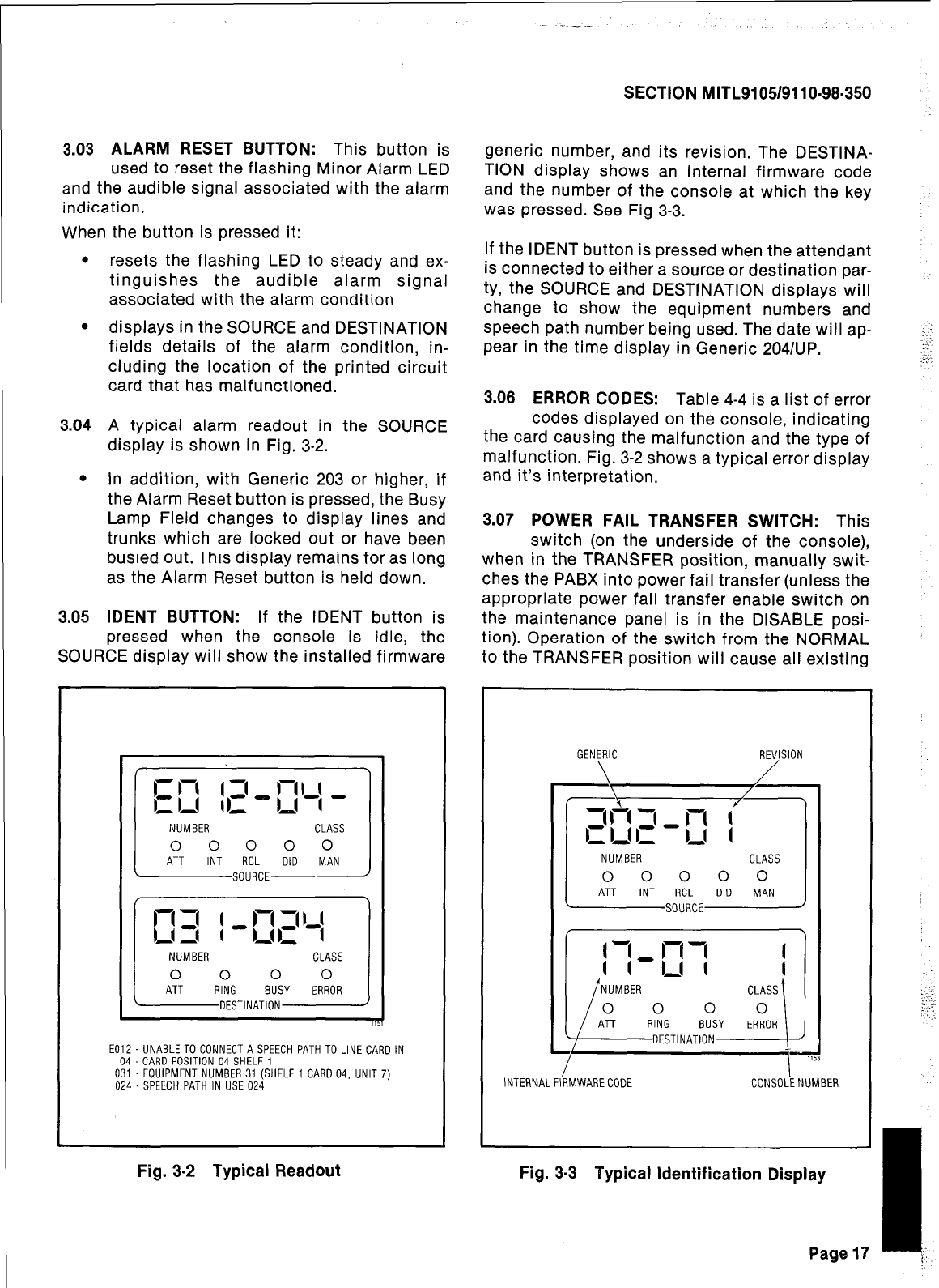
SECTION MITL9105/911 O-98-350
3.03 ALARM RESET BUTTON:
This button is generic number, and its revision. The DESTINA-
used to reset the flashing Minor Alarm LED TION display shows an internal firmware code
and the audible signal associated with the alarm
indication. and the number of the console at which the key
was pressed. See Fig 3-3.
When the button is pressed it:
. resets the flashing LED to steady and ex-
tinguishes the audible alarm signal
associated with the alarm condition
l
displays in the SOURCE and DESTINATION
fields details of the alarm condition, in-
cluding the location of the printed circuit
card that has malfunctioned.
If the IDENT button is pressed when the attendant
is connected to either a source or destination par-
ty, the SOURCE and DESTINATION displays will
change to show the equipment numbers and
speech path number being used. The date will ap-
pear in the time display in Generic 2041UP. ::’
2.:
.:-
3.04 A typical alarm readout in the SOURCE
display is shown in Fig. 3-2.
3.08
ERROR CODES:
Table 4-4 is a list of error
codes displayed on the console, indicating
l
In addition, with Generic 203 or higher, if
the Alarm Reset button is pressed, the Busy
Lamp Field changes to display lines and
trunks which are locked out or have been
busied out. This display remains for as long
as the Alarm Reset button is held down.
the card causing the malfunction and the type of
malfunction. Fig. 3-2 shows a typical error display
and it’s interpretation.
3.05 IDENT BUTTON:
If the IDENT button is
pressed when the console is idle, the
SOURCE display will show the installed firmware
3.07 POWER FAIL TRANSFER SWITCH:
This
switch (on the underside of the console),
when in the TRANSFER position, manually swit-
ches the PABX into power fail transfer (unless the
appropriate power fail transfer enable switch on
the maintenance panel is in the DISABLE posi-
tion). Operation of the switch from the NORMAL
to the TRANSFER position will cause all existing
CLASS
0 0 0 0 0
RCL DID MAN
SOURCE
CLASS
E012 - UNABLETO CONNECT A SPEECH PATH TO LINE CARD IN
04 -CARD POSITION 04 SHELF 1
031 -EQUIPMENT NUMBER 31 (SHELF 1 CARD 04, UNIT 7)
I I
024 -SPEECH PATH IN USE 024 INTERNALFIRMWARECODE CONSOLENUMBER
Fig. 3-2 Typical Readout
GENERIC REVISION
\ /
Fig. 3-3 Typical Identification Display
-I
Page 17 ;:
,..
:: .:’
-.
.’
SECTION MITL9105/9110-98-350
calls on the transferred trunks to be released, and
the MAJOR alarm LED will light. The switch
should only be operated in emergency situations.
For normal operation, the switch should be in the
NORMAL position.
Test Line Functions
3.08 General The test line is on equipment
number 001, and appears both on connec-
tor Pl and on terminal posts on the maintenance
panel. It must be programmed to be an extension,
and should have full trunk access for use by
maintenance personnel.
3.09 As well as its normal facilities as an exten-
sion, certain additional features exist ex-
clusively for the test line. These are the ability to;
directly access a trunk, set and clear the busy-out
conditions of speech paths and receivers, clear
all errors and busy-out conditions in the system
(except for trunks), select a specific speech path
and receiver for use and display their status on
the Scanner card.
3.10 Most of these features require a special ac-
cess code (the Maintenance Function
code), which will normally be “555”, but may be
different if necessary to avoid number plan con-
flicts. This document assumes the use of the
code 555.
NOTE:
The rotary switches on the tone control card (slot
18) should be set to 7780 when the test line is not
being used for maintenance purposes.
3.11 Direct Trunk Access: The test line (or con-
sole) dials 555 + 2 + nnn where “nnn” is
the 3 digit equipment number of the trunk in-
cluding leading zeros. Reorder tone indicates that
the equipment number is not that of a trunk. Busy
tone indicates that the trunk is busy, otherwise
the line is connected to the trunk. If the trunk is a
member of a group programmed “wait for dial
tone”, the connection is not made until dial tone
is received.
3.12 To Set and Clear Busv-Out of Receivers and
Speech Paths *
l
The test line (or console) dials 555 + 3 +
nnn (set) or 555 + 4 + nnn (clear) where
“nnn” is either the 3 digit equipment
number of a receiver, or is 3 + the 2 digit
speech path number (i.e. 301-331)
l
Reorder tone indicates that the number is
invalid and dial tone indicates that the
operation is completed.
3.13 Clear All Errors: The test line (or
console)dials 555 + 1. Dial tone is returned.
All outstanding minor alarms are cleared. All
busied out receivers, generators, and speech
paths are set back to normal and the diagnostic
tests are restarted.
3.14 Select A Speech Path and or a
Receiver: This procedure is used to select
a speech path and/or a receiver when the test line
goes off-hook.
3.15 The top 2 switches on the tone card select
the receiver to be used, set up as the last
two digits of the receiver equipment number (even
numbers, 90-20). If set to 99, any free receiver is
used. (Fig. 3-4)
3.18 The bottom two switches select the speech
path to be used, set up as the speech path
number (Ol-31), or the music-on-hold speech path
may be selected as 32 (in which case no receiver
will be connected). If set to 99, any free speech
path is used. When the switches are set and the
test line goes off-hook, the system waits for the
selected speech path to become free and seizes
it. It then waits for the selected receiver to
become free. A busied out speech path or receiver
may be selected; the speech path may be access-
ed, but the receiver will not respond to dialing. If
an illegal number is set up, no device will be
selected. _--
Page 18
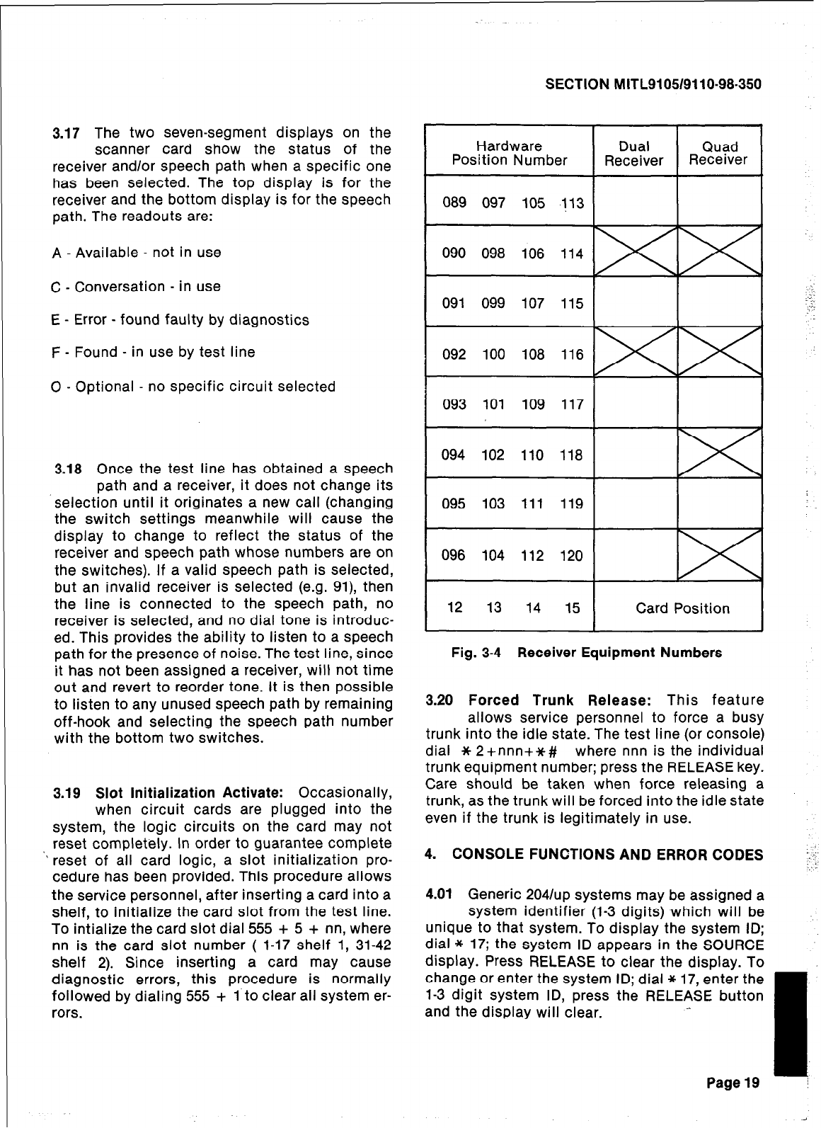
SECTION MITL9105/9110.98-350
3.17 The two seven-segment displays on the
scanner card show the status of the
receiver and/or speech path when a specific one
has been selected. The top display is for the
receiver and the bottom display is for the speech
path. The readouts are:
A - Available - not in use
C - Conversation - in use
E - Error - found faulty by diagnostics
F - Found - in use by test line
0 - Optional - no specific circuit selected
3.18 Once the test line has obtained a speech
path and a receiver, it does not change its
.selection until it originates a new call (changing
the switch settings meanwhile will cause the
display to change to reflect the status of the
receiver and speech path whose numbers are on
the switches). If a valid speech path is selected,
but an invalid receiver is selected (e.g. 91), then
the line is connected to the speech path, no
receiver is selected, and no dial tone is introduc-
ed. This provides the ability to listen to a speech
path for the presence of noise. The test line, since
it has not been assigned a receiver, will not time
out and revert to reorder tone. It is then possible
to listen to any unused speech path by remaining
off-hook and selecting the speech path number
with the bottom two switches.
3.19 Slot Initialization Activate: Occasionally,
when circuit cards are plugged into the
system, the logic circuits on the card may not
reset completely. In order to guarantee complete
” reset of all card logic, a slot initialization pro-
cedure has been provided. This procedure allows
the service personnel, after inserting a card into a
shelf, to initialize the card slot from the test line.
To intialize the card slot dial 555 + 5 + nn, where
nn is the card slot number ( 1-17 shelf 1, 31-42
shelf 2). Since inserting a card may cause
diagnostic errors, this procedure is normally
followed by dialing 555 + 1 to clear all system er-
rors.
Hardware
Position Number
089 097 105 113 / ( (
090 098 106 114
091 099 107 ::
115 -:.
-:.
.,
092 100 108 116
093 101 109 117 I I I
094 102 110 118
095 103 111 119
12 13 14 15 Card Position
Fig. 3-4 Receiver Equipment Numbers
3.20 Forced Trunk Release: This feature
allows service personnel to force a busy
trunk into the idle state. The test line (or console)
dial * 2+nnn+*# where nnn is the individual
trunk equipment number; press the RELEASE key.
Care should be taken when force releasing a
trunk, as the trunk will be forced into the idle state
even if the trunk is legitimately in use.
4. CONSOLE FUNCTIONS AND ERROR CODES ‘:’
t
4.01 Generic 20411~~ systems may be assigned a
system identifier (1-3 digits) which will be
unique to that system. To display the system ID;
dial * 17; the system ID appears in the SOURCE
display. Press RELEASE to clear the display. To
change or enter the system ID; dial * 17, enter the
l-3 digit system ID, press the RELEASE button
and the display will clear.
- I
Page19 !
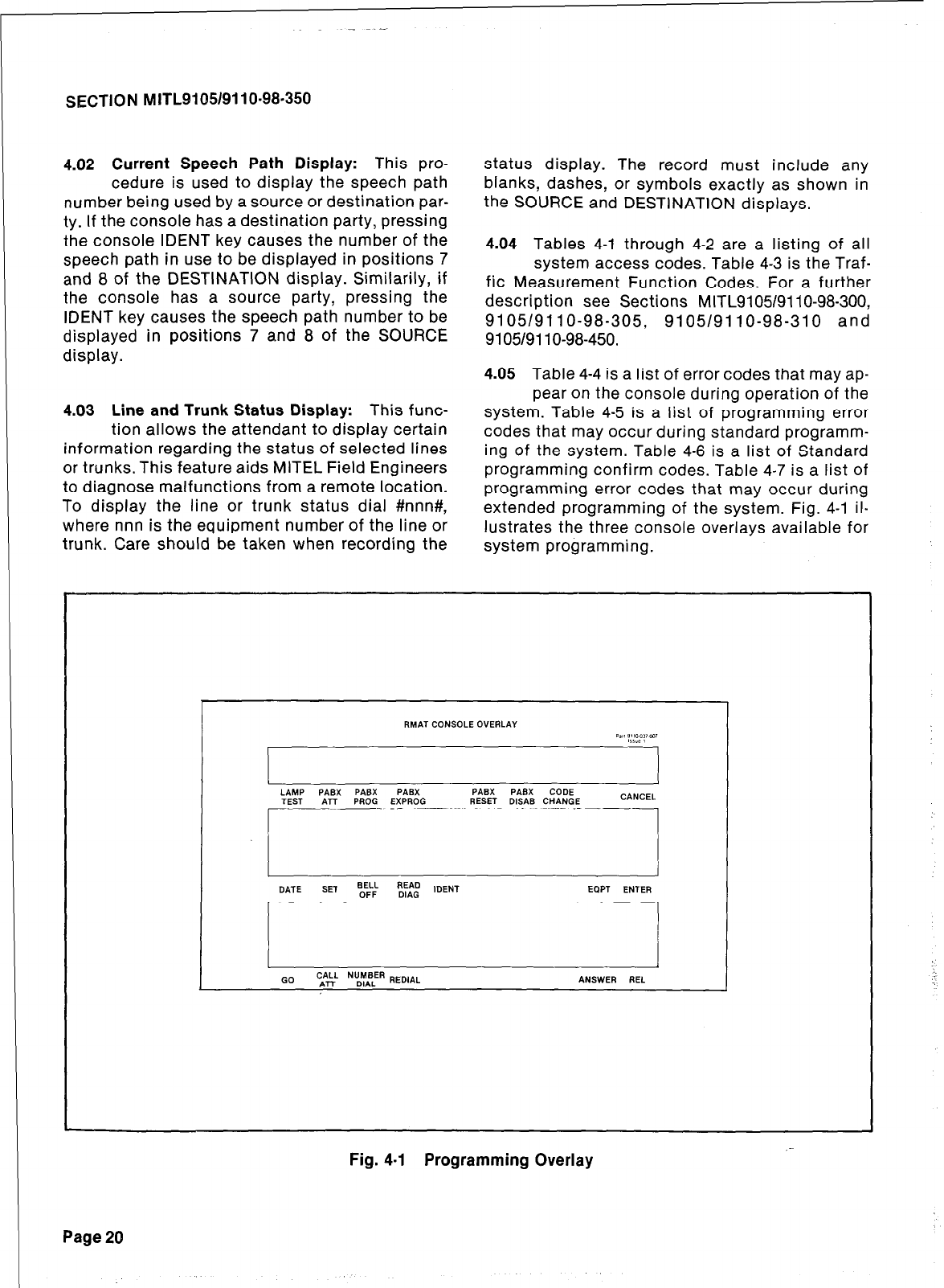
SECTION MITL91O5/9110-98.350
4.02 Current Speech Path Display: This pro-
cedure is used to display the speech path
number being used by a source or destination par-
ty. If the console has a destination party, pressing
the console IDENT key causes the number of the
speech path in use to be displayed in positions 7
and 8 of the DESTINATION display. Similarily, if
the console has a source party, pressing the
IDENT key causes the speech path number to be
displayed in positions 7 and 8 of the SOURCE
display.
4.03 Line and Trunk Status Display: This func-
tion allows the attendant to display certain
information regarding the status of selected lines
or trunks. This feature aids MITEL Field Engineers
to diagnose malfunctions from a remote location.
To display the line or trunk status dial #nnn#,
where nnn is the equipment number of the line or
status display. The record must include any
blanks, dashes, or symbols exactly as shown in
the SOURCE and DESTINATION displays.
4.04 Tables 4-1 through 4-2 are a listing of all
system access codes. Table 4-3 is the Traf-
fic Measurement Function Codes. For a further
description see Sections MITL9105/9110-98-300,
9105/9110-98-305, 9105/9110-98-310 and
9105/9110-98-450.
4.05 Table 4-4 is a list of error codes that may ap-
pear on the console during operation of the
system. Table 4-5 is a list of programming error
codes that may occur during standard programm-
ing of the system. Table 4-6 is a list of Standard
programming confirm codes. Table 4-7 is a list of
programming error codes that may occur during
extended programming of the system. Fig. 4-l il-
lustrates the three console overlavs available for
trunk. Care should.be taken when recording the -,--
system programming.
RMAT CONSOLE OVERLAY
Pa:, P1100,1m,
IISYL 1
I I
LAMP PASX PABX PASX PASX PASX CODE
TEST ATT PROG EXPROG RESET D&AS CHANGE CANCEL
r -.
I ‘1 I
DATE SET BELL READ
OFF DIAG IDENT EQPT ENTER
Q
GO cAAkL N\y,f!ER REDlAL ANSWER REL
Fig. 4-l Programming Overlay
Page 20
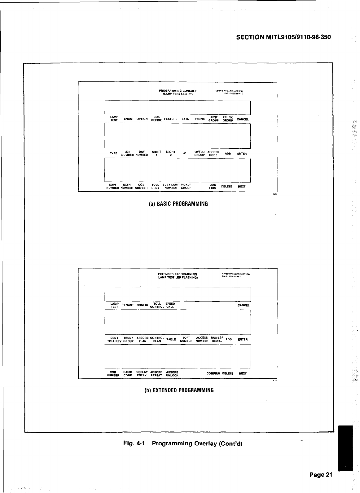
SECTION MITL9105/9110-98.350
(a) BASIC PROGRAMMING
Fig. 4-l Programming Overlay (Cont’d)
-I,
Page21 j
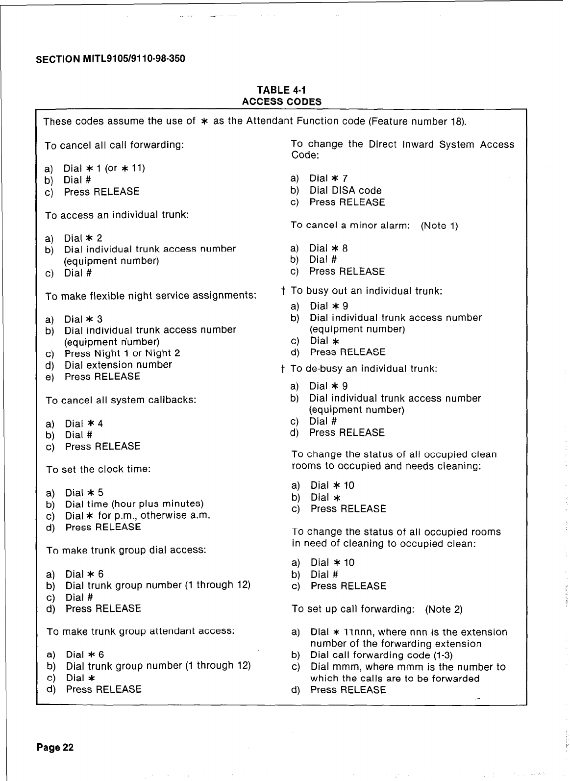
SECTION MITL9105/9110-98-350
TABLE 4-I
ACCESS CODES
These codes assume the use of * as the Attendant Function code (Feature number 18).
To cancel all call forwarding:
a) Dial #c 1 (or * 11)
b) Dial #
c) Press RELEASE
To change the Direct Inward System Access
Code:
a) Dial * 7
b) Dial DISA code
c) Press RELEASE
To access an individual trunk: To cancel a minor alarm: (Note 1)
a) Dial * 2
b) Dial individual trunk access number
(equipment number)
c) Dial #
a) Dial * 8
b) Dial #
c) Press RELEASE
To make flexible night service assignments:
a) Dial * 3
b) Dial individual trunk access number
(equipment number)
c) Press Night 1 or Night 2
d) Dial extension number
e) Press RELEASE
To cancel all system callbacks:
a) Dial * 4
b) Dial #
c) Press RELEASE
To set the clock time:
t To busy out an individual trunk:
a) Dial * 9
b) Dial individual trunk access number
(equipment number)
c) Dial *
d) Press RELEASE
t To de-busy an individual trunk:
a) Dial * 9
b) Dial individual trunk access number
(equipment number)
c) Dial #
d) Press RELEASE
To change the status of all occupied clean
rooms to occupied and needs cleaning:
a) Dial * 5
b) Dial time (hour plus minutes)
c) Dial * for p.m., otherwise a.m.
d) Press RELEASE
To make trunk group dial access:
a) Dial * 6
b) Dial trunk group number (1 through 12)
c) Dial #
a) Dial I 10
b) Dial #
c) Press RELEASE
d) Press RELEASE To set up call forwarding: (Note 2)
a) Dial * 10
b) Dial *
c) Press RELEASE
To change the status of all occupied rooms
in need of cleaning to occupied clean:
To make trunk group attendant access: a) Dial * llnnn, where nnn is the extension
number of the forwarding extension
a) Dial I 6
b) Dial trunk group number (1 through 12)
c) Dial *
d) Press RELEASE
b) Dial call forwarding code (l-3)
c) Dial mmm, where mmm is the number to
which the calls are to be forwarded
d) Press RELEASE
Page 22
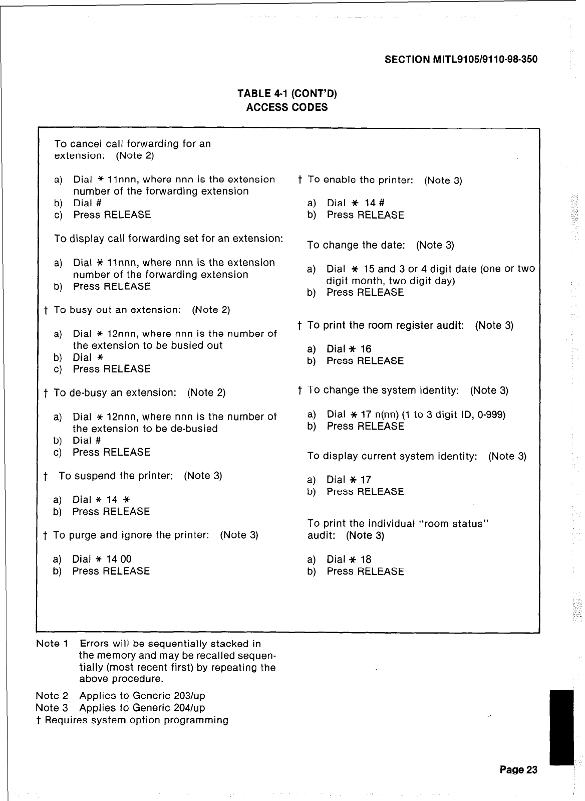
SECTION MITL9105/9110-98-350
TABLE 4-I (CONT’D)
ACCESS CODES
To cancel call forwarding for an
extension: (Note 2)
a) Dial * llnnn, where nnn is the extension t TO enable the printer: (Note 3)
number of the forwarding extension
b) Dial # a) Dial * 14 #
c) Press RELEASE b) Press RELEASE
To display call forwarding set for an extension: To change the date: (Note 3)
a) Dial * llnnn, where nnn is the extension
number of the forwarding extension a) Dial JC 15 and 3 or 4 digit date (one or two
b) Press RELEASE digit month, two digit day)
b) Press RELEASE
f To busy out an extension: (Note 2)
a) Dial * 12nnn, where nnn is the number of t To print the room register audit: (Note 3)
the extension to be busied out
b) Dial * a) Dial Jt 16
c) Press RELEASE b) Press RELEASE
f To de-busy an extension: (Note 2) t To change the system identity: (Note 3)
a) Dial * 12nnn, where nnn is the number of a) Dial * 17 n(nn) (1 to 3 digit ID, O-999)
the extension to be de-busied b) Press RELEASE
b) Dial #
c) Press RELEASE To display current system identity: (Note 3)
f To suspend the printer: (Note 3) a) Dial JC 17
a) Dial * 14 * b) Press RELEASE
b) Press RELEASE To print the individual “room status”
t To purge and ignore the printer: (Note 3) audit: (Note 3)
a) Dial * 14 00 a) Dial JC 18
b) Press RELEASE b) Press RELEASE
Note 1 Errors will be sequentially stacked in
the memory and may be recalled sequen-
tially (most recent first) by repeating the
above procedure.
Note 2 Applies to Generic 203/up
Note 3 Applies to Generic 2041~~
t Requires system option programming
Page 23
.
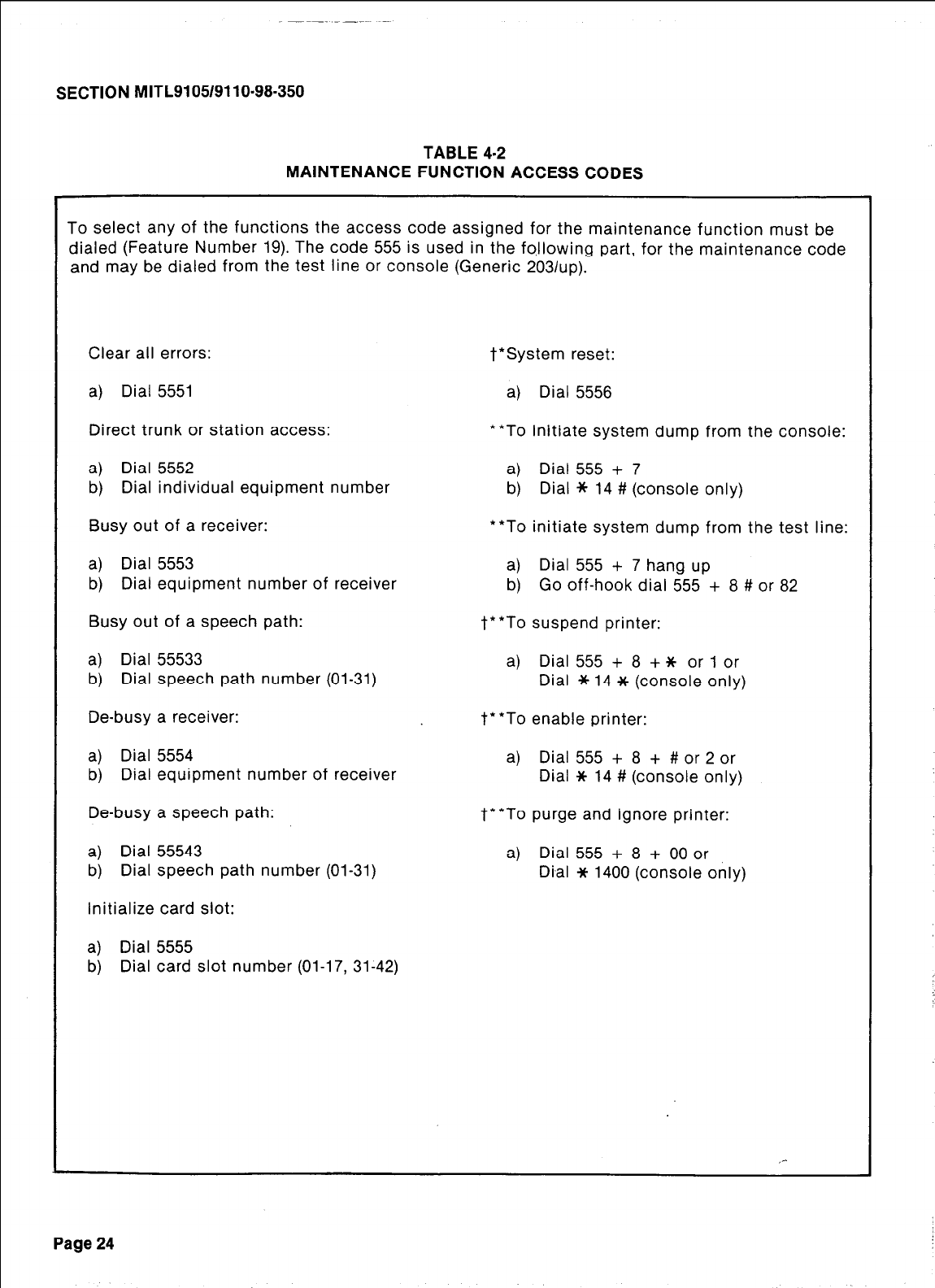
SECTION MITL9105/9110-98-350
TABLE 4-2
MAINTENANCE FUNCTION ACCESS CODES
To select any of the functions the access code assigned for the maintenance function must be
dialed (Feature Number 19). The code 555 is used in the fotlowing part, for the maintenance code
and may be dialed from the test line or console (Generic 2031~~).
Clear all errors:
a) Dial 5551
Direct trunk or station access:
a) Dial 5552
b) Dial individual equipment number
Busy out of a receiver:
a) Dial 5553
b) Dial equipment number of receiver
Busy out of a speech path:
a) Dial 55533
b) Dial speech path number (01-31)
De-busy a receiver:
a) Dial 5554
b) Dial equipment number of receiver
De-busy a speech path:
a) Dial 55543
b) Dial speech path number (01-31)
Initialize card slot:
a) Dial 5555
b) Dial card slot number (01-17, 31-42)
t*System reset:
a) Dial 5556
**To initiate system dump from the console:
a) Dial 555 + 7
b) Dial * 14 # (console only)
**To initiate system dump from the test line:
a) Dial 555 + 7 hang up
b) Go off-hook dial 555 + 8 # or 82
t**To suspend printer:
a) Dial 555 + 8 + it or 1 or
Dial * 14 JC (console only)
t**To enable printer:
a) Dial 555 + 8 + #or 2 or
Dial Jt 14 # (console only)
t**To purge and ignore printer:
a) Dial 555 + 8 + 00 or
Di,al * 1400 (console only)
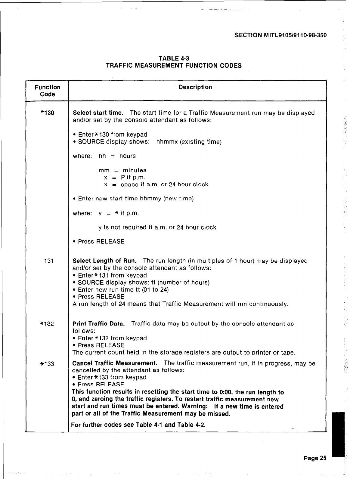
SECTION MITL9105/9110-98-350
TABLE 4-3
TRAFFIC MEASUREMENT FUNCTION CODES
Function
Code
Description
*130 Select start time. The start time for a Traffic Measurement run may be displayed
and/or set by the console attendant as follows:
l
Enter*130 from keypad
l
SOURCE display shows: hhmmx (existing time)
where: hh = hours
mm = minutes
x = P if p.m.
x = space if a.m. or 24 hour clock
l
Enter new start time hhmmy (new time)
where: y = *if p.m.
y is not required if a.m. or 24 hour clock
l
Press RELEASE
131 Select Length of Run. The run length (in multiples of 1 hour) may be displayed
and/or set by the console attendant as follows:
l
Enter*131 from keypad
l
SOURCE display shows: tt (number of hours)
l
Enter new run time tt (01 to 24)
l
Press RELEASE
A run length of 24 means that Traffic Measurement will run continuously.
*132 Print Traffic Data. Traffic data may be output by the console attendant as
follows:
l
Enter *132 from keypad
l
Press RELEASE
The current count held in the storage registers are output to printer or tape.
w133 Cancel Traffic Measurement. The traffic measurement run, if in progress, may be
cancelled by the attendant as follows:
l
Enter *133 from keypad
l
Press RELEASE
This function results in resetting the start time to O:OO, the run length to
0, and zeroing the traffic registers. To restart traffic measurement new
start and run times must be entered. Warning: If a new time is entered
part or all of the Traffic Measurement may be missed.
For further codes see Table 4-l and Table 4-2. _-
Page 25
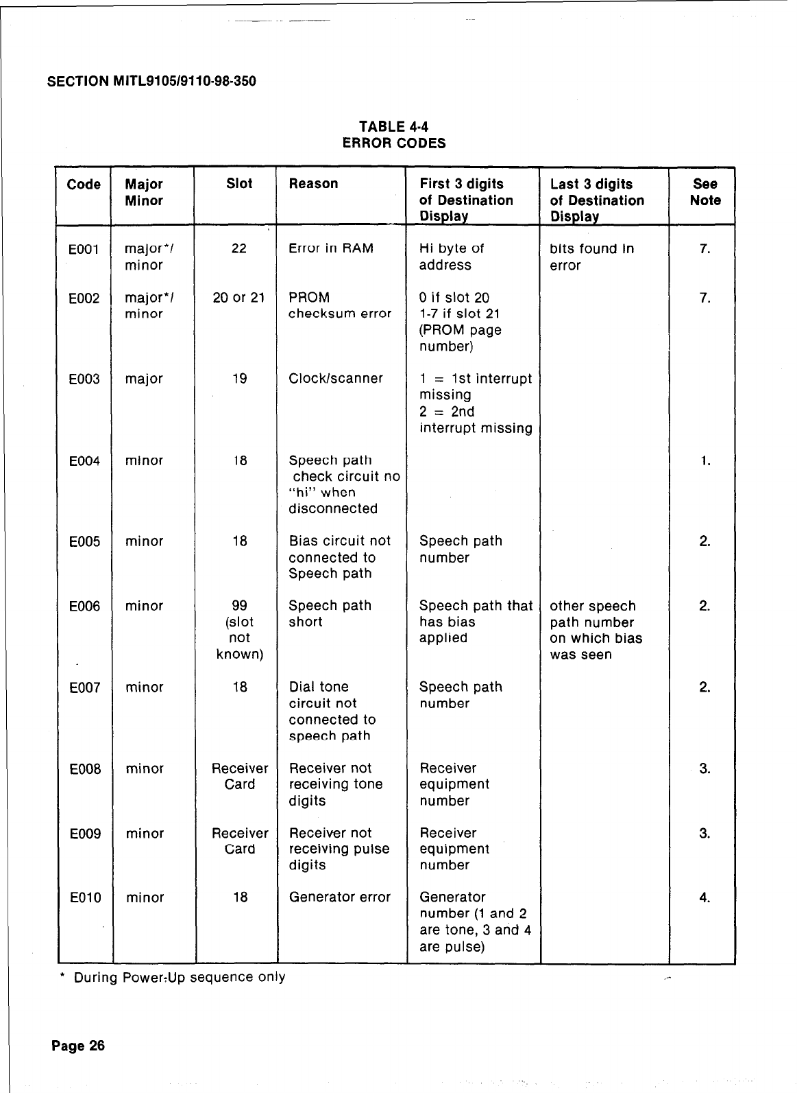
SECTION MITL9105/9110-98.350
TABLE 4-4
ERROR CODES
Code Major Slot Reason First 3 digits Last 3 digits See
Minor of Destination of Destination Note
Display Display
EOOl major*/ 22 Error in RAM Hi byte of bits found in 7.
minor address error
E002 major*/ 20 or 21 PROM 0 if slot 20 7.
minor checksum error 1-7 if slot 21
(PROM page
number)
E003 major 19 Clock/scanner 1 = 1st interrupt
missing
2 = 2nd
interrupt missing
E004 minor 18 Speech path 1.
check circuit no
“hi” when
disconnected
E005 minor 18 Bias circuit not Speech path 2.
connected to number
Speech path
E006 minor (Et Speech path Speech path that other speech 2.
short has bias path number
not applied on which bias
known) was seen
E007 minor 18 Dial tone Speech path 2.
circuit not number
connected to
speech path
E008 minor Receiver Receiver not Receiver 3.
Card receiving tone equipment
digits number
E009 minor Receiver Receiver not Receiver 3.
Card receiving pulse equipment
digits number
EOlO minor 18 Generator error Generator 4.
number (1 and 2
are tone, 3 and 4
are pulse)
l
During PowerUp sequence only ,-
Page 26
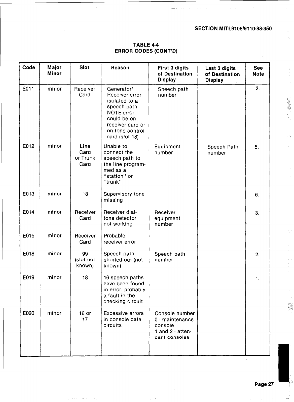
SECTION MITL9105/9110-98-350
TABLE 4-4
ERROR CODES (CONT’D)
Code
EOll
Major
Minor
minor
Slot
Receiver
Card
Reason
Generator/
Receiver error
isolated to a
speech path
NOTE-error
could be on
receiver card or
on tone control
card (slot 18)
First 3 digits
of Destination
Display
Speech path
number
Last 3 digits
of Destination
Display
See
Note
2.
E012 minor Line Unable to Equipment Speech Path 5.
Card connect the number number
or Trunk speech path to
Card the line program-
med as a
“station” or
“trunk”
E013 minor 18 Supervisory tone
missing 6.
E014 minor Receiver Receiver dial- Receiver 3.
Card tone detector equipment
not working number
E015 minor Receiver Probable
Card receiver error
E018
E019
minor
minor
99 Speech path Speech path 2.
(slot not shorted out (not number
known) known)
18 16 speech paths 1.
have been found
in error, probably
a fault in the
checking circuit
E020 minor 16 or
17 Excessive errors
in console data
circuits
Console number
0 - maintenance
console
1 and 2 - atten-
dant consoles
Page 27
.
‘__- ---
” . .
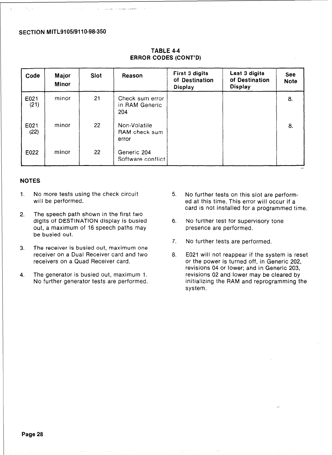
SECTION MITL9105/9110-98-350
TABLE 4-4
ERROR CODES (CONT’D)
Code
E021
(21)
Major
Minor
minor
Slot
21
Reason First 3 digits Last 3 digits See
of Destination of Destination Note
Display Display
Check sum error
a.
in RAM Generic
204
E021
(22)
minor 22 Non-Volatile
RAM check sum
error
a.
E022 minor 22 Generic 204
Software conflict
NOTES
1.
2.
3.
4.
No more tests using the check circuit
will be performed.
The speech path shown in the first two
digits of DESTINATION display is busied
out, a maximum of 16 speech paths may
be busied out.
The receiver is busied out, maximum one
receiver on a Dual Receiver card and two
receivers on a Quad Receiver card.
The generator is busied out, maximum 1.
No further generator tests are performed.
5. No further tests on this slot are perform-
ed at this time. This error will occur if a
card is not installed for a programmed time.
6. No further test for supervisory tone
presence are performed.
7. No further tests are performed.
a.
E021 will not reappear if the system is reset
or the power is turned off, in Generic 202,
revisions 04 or lower; and in Generic 203,
revisions 02 and lower may be cleared by
initializing the RAM and reprogramming the
system.
Page 28
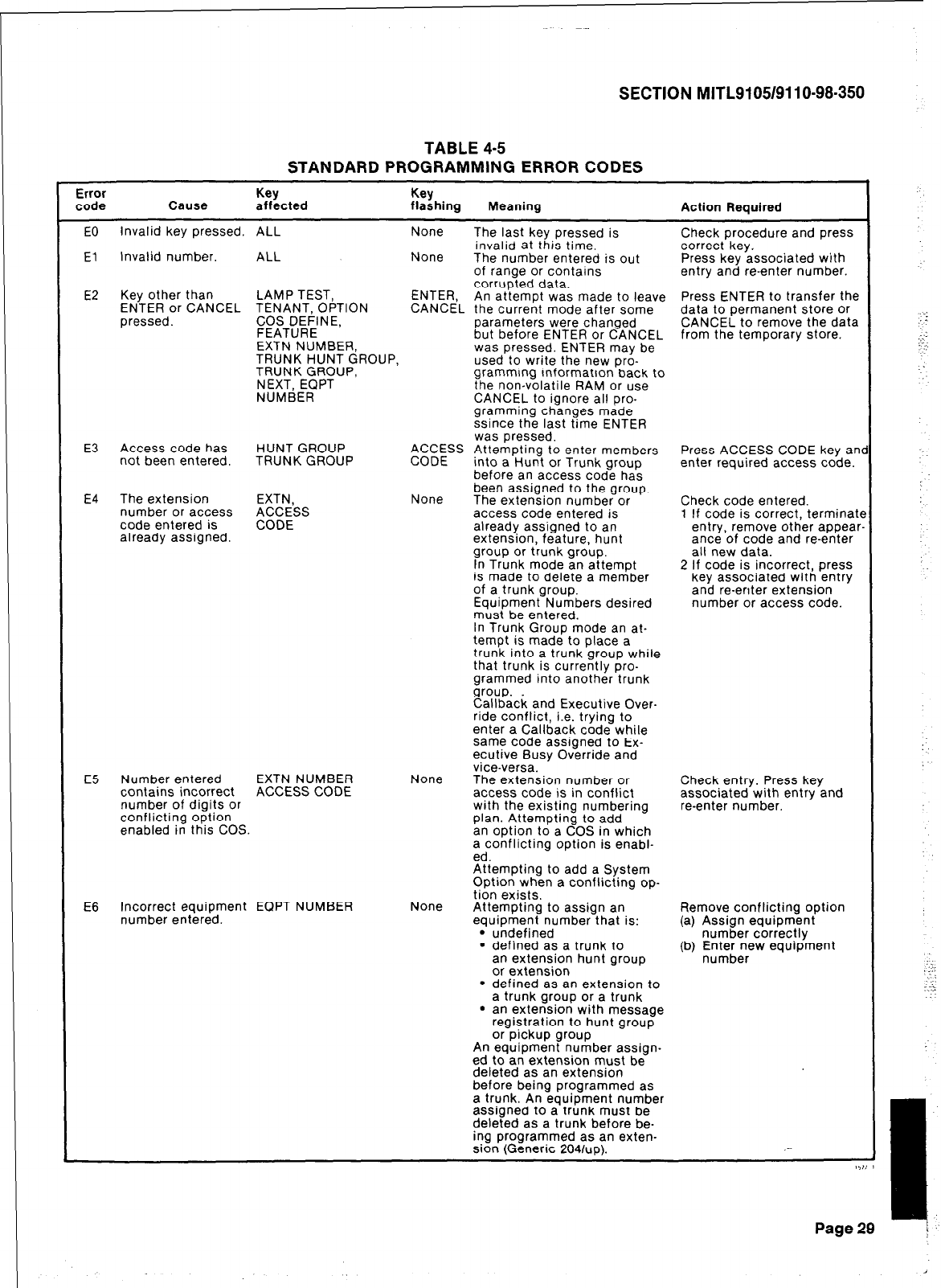
SECTION MITL9105/911 o-98-350
TABLE 4-5
STANDARD PROGRAMMING ERROR CODES
Error Key Key
code Cause affected flashing Meaning Action Required
EO Invalid key pressed. ALL None The last key pressed is Check procedure and press
invalid at this time.
El Invalid number. ALL None correct key.
The number entered is out Press key associated with
of range or contains entry and re-enter number.
E2 Key other than LAMP TEST, ENTER, corrupted data. Press ENTER to transfer the
ENTER or CANCEL TENANT, OPTION An attempt was made to leave
CANCEL the current mode after some data to permanent store or
pressed. COS DEFINE, parameters were changed CANCEL to remove the data
FEATURE but before ENTER or CANCEL
EXTN NUMBER, from the temporary store.
TRUNK HUNT GROUP, was pressed. ENTER may be
TRUNK GROUP, used to write the new pro-
NEXT, EQPT gramming information back to
the non-volatile RAM or use
NUMBER CANCEL to ignore all pro-
gramming changes made
ssince the last time ENTER
was pressed.
E3 Access code has HUNT GROUP
not been entered. TRUNK GROUP ACCESS Attempting to enter members
CODE into a Hunt or Trunk group Press ACCESS CODE key an
enter required access code.
before an access code has
E4 The extension EXTN, None been assigned to the group.
The extension number or Check code entered.
number or access ACCESS access code entered is
code entered is CODE 1 If code is correct, terminate
already assigned. already assigned to an entry, remove other appear
extension, feature, hunt ante of code and re-enter
group or trunk group. all new data.
In Trunk mode an attempt 2 If code is incorrect, press
is made to delete a member key associated with entry
of a trunk group. and re-enter extension
Equipment Numbers desired number or access code.
must be entered.
In Trunk Group mode an at-
tempt is made to place a
trunk into a trunk group while
that trunk is currently pro-
grammed into another trunk
group.
Callback and Executive Over-
ride conflict, i.e. trying to
enter a Callback code while
same code assigned to Ex-
ecutive Busy Override and
vice-versa.
E5 Number entered EXTN NUMBER None The extension number or
contains incorrect ACCESS CODE Check entry. Press key
access code is in conflict
number of digits or associated with entry and
conflicting option with the existing numbering re-enter number.
enabled in this COS. plan. Attempting to add
an option to a COS in which
a conflicting option is enabl-
ed.
Attempting to add a System
Option when a conflicting op-
tion exists.
E6 Incorrect equipment EQPT NUMBER None
number entered. Attempting to assign an Remove conflicting option
equipment number that is:
l
undefined (a) Assign equipment
number correctly
l
defined as a trunk to
an extension hunt group
or extension
(b) E;E;zrew equipment
l
defined as an extension to
a trunk group or a trunk
l
an extension with message
registration to hunt group
or pickup group
An equipment number assign-
ed to an extension must be
deleted as an extension
before being programmed as
a trunk. An equipment number
assigned to a trunk must be
deleted as a trunk before be-
ing programmed as an exten-
sion (Generic 2041~~). .-
I,?; I
Page 29
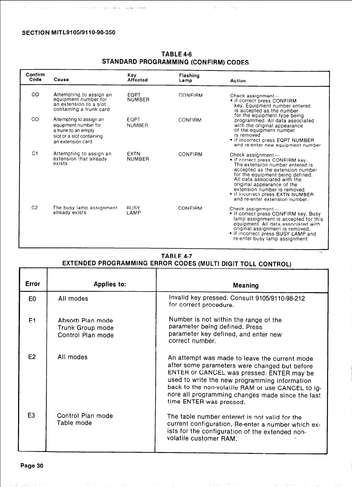
MITL91051911 O-98-350
TABLE 4-6
STANDARD PROGRAMMING (CONFIRM) CODES
Confirm
Code Cause Key
Affected Flashing
Lamp Action
co
co
Cl
c2
Attempting to assign dn EQPT CONFIRM
equipment number for NUMBER Check assignment-
an extension to a slot
l
if correct press CONFIRM
containing a trunk card key. Equipment number entered
is accepted as the number
AttemptIng to asslgn an EQPT CONFIRM for the equipment type being
programmed. All data associated
equipment number for NUMBER with the original appearance
a trunk to an empty of the equipment number
slot or a slot contamIng is removed
an extension card
l
if incorrect press EQPT NUMBER
and re-enter new equipment number
Attempting to assign an EXTN CONFIRM
extension that already NUMBER Check assignment-
exists
l
if correct press CONFIRM key.
The extension number entered is
accepted as the extension number
for the equipment being defined.
All data associated with the
original appearance of the
extension number is removed.
l
if incorrect press EXTN NUMBER
and re-enter extension number.
The busy lamp assignment BUSY CONFIRM
already exists LAMP Check assignment-
l
if correct press CONFIRM key. Busy
lamp assignment is accepted for this
equipment. All data,associated with
original assignment is removed.
l
if incorrect press BUSY LAMP and
re-enter busy lamp assignment
‘0
TABLE 4-7
Absorb Plan mode
Trunk Group mode
Control Plan mode
Number is not within the range of the
parameter being defined. Press
parameter key defined, and enter new
correct number.
An attempt was made to leave the current mode
after some parameters were changed but before
ENTER or CANCEL was pressed. ENTER may be
used to write the new programming information
back to the non-volatile RAM or use CANCEL to ig-
nore all programming changes made since the last
time ENTER was pressed.
Control Plan mode The table number entered is not valid for the
current configuration. Re-enter a number which ex-
ists for the configuration of the extended non-
volatile customer RAM.
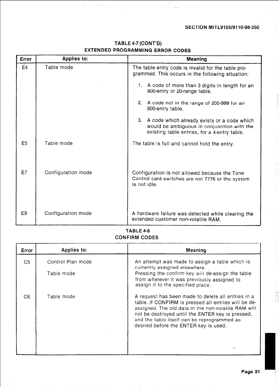
Error
E4
E7
E9
Error
C5
C6
SECTION MITL9105/9110-98-350
TABLE 4-7 (CONT’D)
EXTENDED PROGRAMMING ERROR CODES
Applies to:
Table mode
Table mode
Configuration mode
Configuration mode
Meaning
The table entry code is invalid for the table pro-
grammed. This occurs in the following situation:
1. A code of more than 3 digits in length for an
800-entry or 20-range table.
2. A code not in the range of 200-999 for an
800-entry table.
3. A code which already exists or a code which
would be ambiguous in conjunction with the
existing table entries, for a 4-entry table.
The table is full and cannot hold the entry.
Configuration is not allowed because the Tone
Control card switches are not 7776 or the system
is not idle.
A hardware failure was detected while clearing the
extended customer non-volatile RAM.
TABLE 4-8
CONFIRM CODES
Applies to:
Control Plan mode
Table mode
Table mode
Meanina
An attempt was made to assign a table which is
currently assigned elsewhere.
Pressing the confirm key will de-assign the table
from wherever it was previously assigned to
assign it to the specified place.
A request has been made to delete all entries in a
table. If CONFIRM is pressed all entries will be de-
assigned. The old data in the non-volatile RAM will
not be destroyed until the ENTER key is pressed,
and the table itself can be reprogrammed as
desired before the ENTER key is used.
Page 31
-.-_
.:
I;
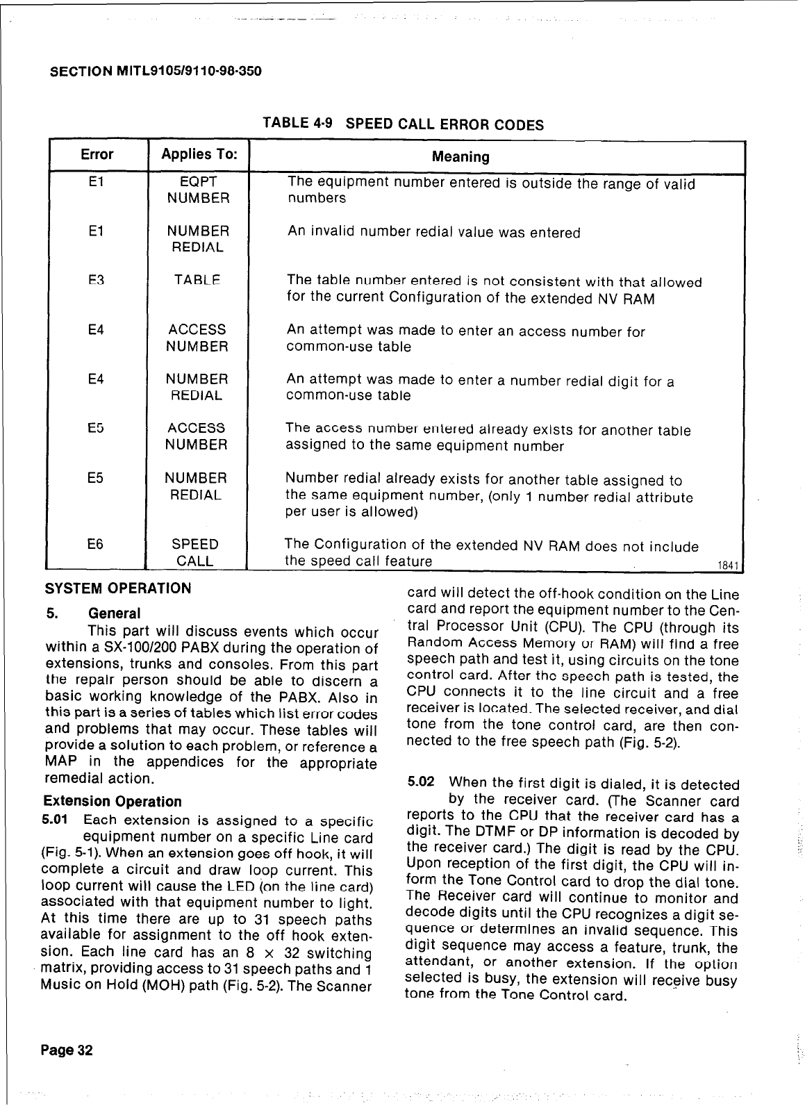
SECTION MITL9105/9110-98-350
TABLE 4-9 SPEED CALL ERROR CODES
Error
El
El
Applies To:
EQPT
NUMBER
NUMBER
REDIAL
Meaning
The equipment number entered is outside the range of valid
numbers
An invalid number redial value was entered
E3 TABLE The table number entered is not consistent with that allowed
for the current Configuration of the extended NV RAM
E4
E4
E5
E5
ACCESS
NUMBER
NUMBER
REDIAL
ACCESS
NUMBER
NUMBER
REDIAL
An attempt was made to enter an access number for
common-use table
An attempt was made to enter a number redial digit for a
common-use table
The access number entered already exists for another table
assigned to the same equipment number
Number redial already exists for another table assigned to
the same equipment number, (only 1 number redial attribute
per user is allowed)
E6 SPEED
CALL The Configuration of the extended NV RAM does not include
the speed call feature
184.
SYSTEM OPERATION
5. General
This part will discuss events which occur
within a SX-100/200 PABX during the operation of
extensions, trunks and consoles. From this part
the repair person should be able to discern a
basic working knowledge of the PABX. Also in
this part is a series of tables which list error codes
and problems that may occur. These tables will
provide a solution to each problem, or reference a
MAP in the appendices for the appropriate
remedial action.
Extension Operation
5.01
Each extension is assigned to a specific
equipment number on a specific Line card
(Fig. 5-l). When an extension goes off hook, it will
complete a circuit and draw loop current. This
loop current will cause the LED (on the line card)
associated with that equipment number to light.
At this time there are up to 31 speech paths
available for assignment to the off hook exten-
sion. Each line card has an 8 x 32 switching
matrix, providing access to 31 speech paths and 1
Music on Hold (MOH) path (Fig. 5-2). The Scanner
Page 32
card will detect the off-hook condition on the Line
card and report the equipment number to the Cen-
tral Processor Unit (CPU). The CPU (through its
Random Access Memory or RAM) will find a free
speech path and test it, using circuits on the tone
control card. After the speech path is tested, the
CPU connects it to the line circuit and a free
receiver is located. The selected receiver, and dial
tone from the tone control card, are then con-
nected to the free speech path (Fig. 5-2).
5.02 When the first digit is dialed, it is detected
by the receiver card. (The Scanner card
reports to the CPU that the receiver card has a
digit. The DTMF or DP information is decoded by
the receiver card.) The digit is read by the CPU.
Upon reception of the first digit, the CPU will in-
form the Tone Control card to drop the dial tone.
The Receiver card will continue to monitor and
decode digits until the CPU recognizes a digit se-
quence or determines an invalid sequence. This
digit sequence may access a feature, trunk, the
attendant, or another extension. If the option
selected is busy, the extension will receive busy
tone from the Tone Control card.
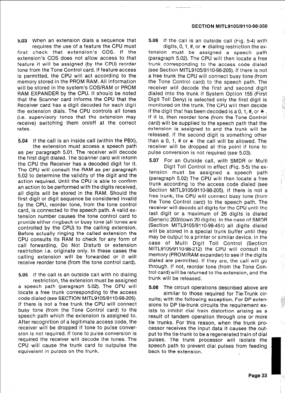
5.03 When an extension dials a sequence that
requires the use of a feature the CPU must
first check that extension’s COS. If the
extension’s COS does not allow access to that
feature it will be assigned (by the CPU) reorder
tone from the Tone Control card. If feature access
is permitted, the CPU will act according to the
memory stored in the PROM RAM. All information
will be stored in the system’s COSlRAM or PROM
RAM EXPANDER by the CPU. It should be noted
that the Scanner card informs the CPU that the
Receiver card has a digit decoded for each digit
the extension dials. The CPU controls all tones
(i.e. supervisory tones that the extension may
receive) switching them on/off at the correct
rates.
5.04 If the call is an inside call (within the PBX),
the extension must access a speech path
as per paragraph 5.01. The receiver will decode
the first digit dialed. The Scanner card will inform
the CPU the Receiver has a decoded digit for it.
The CPU will consult the RAM as per paragraph
5.02 to determine the validity of the digit and the
action required. Until the CPU is able to confirm
an action to be performed with the digits received,
all digits will be stored in the RAM. Should the
first digit or digit sequence be considered invalid
by the CPU, reorder tone, from the tone control
card, is connected to the speech path. A valid ex-
tension number causes the tone control card to
provide either ringback or busy tone (all tones are
controlled by the CPU) to the calling extension.
Before actually ringing the called extension the
CPU consults its RAM to check for any form of
call forwarding, Do Not Disturb or extension
restriction i.e. originate only. In these cases the
calling extension will be forwarded or it will
receive reorder tone (from the tone control card).
5.05 If the call is an outside call with no dialing
restriction, the extension must be assigned
a speech path (paragraph 5.02). The CPU will
locate a free trunk corresponding to the access
code dialed (see SECTION MITL9105/9110-98-205).
If there is not a free trunk the CPU will connect
busy tone (from the Tone Control card) to the
speech path which the extension is assigned to.
After recognition of a legitimate access code, the
receiver will be dropped if tone to pulse conver-
sion is not required. If tone to pulse conversion is
required the receiver will decode the tones. The
CPU will cause the trunk card to outpulse the
equivalent in pulses on the trunk.
SECTION MITL9105/9110-98-350
5.08 If the call is an outside call (Fig. 5-4) with
digits, 0, 1, #, or it dialing restriction the ex-
tension must be assigned a speech path
(paragraph 5.02). The CPU will then locate a free
trunk corresponding to the access code dialed
(see Section MITL9105/9110-98-205). If there is not
a free trunk the CPU will connect busy tone (from
the Tone Control card) to the speech path. The
receiver will decode the first and second digit
dialed into the trunk if System Option 155 (First
Digit Toll Deny) is selected only the first digit is
monitored on the trunk. The CPU will then decide
if the digit that has been decoded is a 0, 1, #, or * .
If it is, then reorder tone (from the Tone Control
card) will be supplied to the speech path that the
extension is assigned to and the trunk will be
released. If the second digit is something other
than a 0, 1, # or * the call will be allowed. The
receiver will be dropped at this point if tone to
pulse conversion is not required (see 5.03).
5.07 For an Outside call, with SMDR or Multi
Digit Toll Control in effect (Fig. 5-5) the ex-
tension must be assigned a speech path
(paragraph 5.02) The CPU will then locate a free
trunk according to the access code dialed (see
Section MITL9105/9110-98-205). If there is not a
free trunk, the CPU will connect busy tone (from
the Tone Control card) to the speech path. The
receiver will decode all digits for the CPU until the
last digit or a maximum of 26 digits is dialed
(Generic 203/dawn 20 digits). In the case of SMDR
(Section MITL9105/9110-98-451) all digits dialed
will be stored in a special trunk buffer until they
may be output to a printer or similar device. In the
case of Multi Digit Toll Control (Section
MITL9105/9110-98-212) the CPU will consult its
memory (PROM/RAM expander) to see if the digits
dialed are permitted. If they are, the call will go
through. If not, reorder tone (from the Tone Con-
trol card) will be returned to the extension, and the
trunk will be released.
_-
5.08 The circuit operations described above are
similar to those required for Tie-Trunk cir-
cuits; with the following exception. For DP exten-
sions to DP tie-trunk circuits the requirement ex-
ists to inhibit dial train distortion arising as a
result of tandem operation through one or more
tie trunks. For this reason, when the trunk pro-
cessor receives the input data it causes the out-
put to the tie-trunk to be a regenerated train of dial
pulses. The trunk processor will isolate the
speech path to prevent dial pulses from feeding
back to the extension.
- 1,
Page 33
.‘:
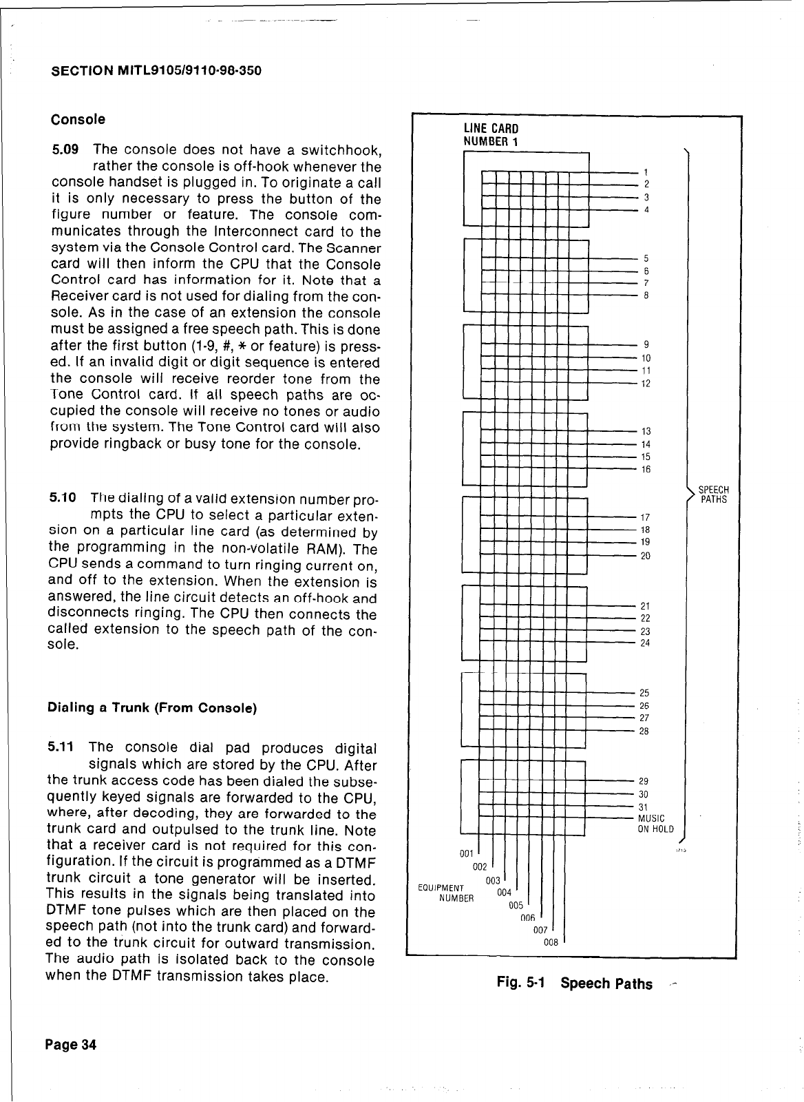
SECTION MITL9105/9110-98-350
Console
5.09 The console does not have a switchhook,
rather the console is off-hook whenever the
console handset is plugged in. To originate a call
it is only necessary to press the button of the
figure number or feature. The console com-
municates through the Interconnect card to the
system via the Console Control card. The Scanner
card will then inform the CPU that the Console
Control card has information for it. Note that a
Receiver card is not used for dialing from the con-
sole. As in the case of an extension the console
must be assigned a free speech path. This is done
after the first button (l-9, #, * or feature) is press-
ed. If an invalid digit or digit sequence is entered
the console will receive reorder tone from the
Tone Control card. If all speech paths are oc-
cupied the console will receive no tones or audio
from the system. The Tone Control card will also
provide ringback or busy tone for the console.
5.10
The dialing of a valid extension number pro-
mpts the CPU to select a particular exten-
sion on a particular line card (as determined by
the programming in the non-volatile RAM). The
CPU sends a command to turn ringing current on,
and off to the extension. When the extension is
answered, the line circuit detects an off-hook and
disconnects ringing. The CPU then connects the
called extension to the speech path of the con-
sole.
Dialing a Trunk (From Console)
5.11
The console dial pad produces digital
signals which are stored by the CPU. After
the trunk access code has been dialed the subse-
quently keyed signals are forwarded to the CPU,
where, after decoding, they are forwarded to the
trunk card and outpulsed to the trunk line. Note
that a receiver card is not required for this con-
figuration. If the circuit is programmed as a DTMF
trunk circuit a tone generator will be inserted.
This results in the signals being translated into
DTMF tone pulses which are then placed on the
speech path (not into the trunk card) and forward-
ed to the trunk circuit for outward transmission.
The audio path is isolated back to the console
when the DTMF transmission takes place.
Page 34
LINE
CARD
NUMBER
1
‘1
1
2
3
4
17
18
19
20
21
22
23
24
25
26
27
28
SPEECH
PATHS
Fig. 5-1 Speech Paths I-
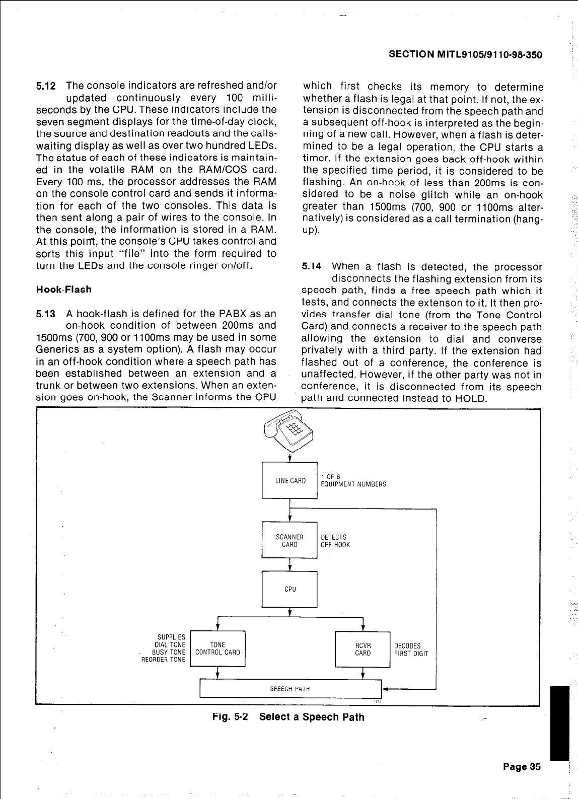
5.12 The console indicators are refreshed and/or
updated continuously every 100 milli-
seconds by the CPU. These indicators include the
seven segment displays for the time-of-day clock,
the source and destination readouts and the calls-
waiting display as well as over two hundred LEDs.
The status of each of these indicators is maintain-
ed in the volatile RAM on the RAMlCOS card.
Every 100 ms, the processor addresses the RAM
on the console control card and sends it informa-
tion for each of the two consoles. This data is
then sent along a pair of wires to the console. In
the console, the information is stored in a RAM.
At this point, the console’s CPU takes control and
sorts this input “file” into the form required to
turn the LEDs and the console ringer on/off.
Hook-Flash
5.13 A hook-flash is defined for the PABX as an
on-hook condition of between 200ms and
1500ms (700,900 or 1lOOms may be used in some
Generics as a system option). A flash may occur
in an off-hook condition where a speech path has
been established between an extension and a
trunk or between two extensions. When an exten-
sion goes on-hook, the Scanner informs the CPU
SECTION MITL9105/9110-98-350 :
which first checks its memory to determine
whether a flash is legal at that point. If not, the ex-
tension is disconnected from the speech path and
a subsequent off-hook is interpreted as the begin-
ning of a new call. However, when a flash is deter-
mined to be a legal operation, the CPU starts a
timer. If the exte.nsion goes back off-hook within
the specified time period, it is considered to be
flashing. An on-hook of less than 200ms is con-
sidered to be a noise glitch while an on-hook
greater than 1500ms (700, 900 or 1100ms alter-
natively) is considered as a call termination (hang-
up).
5.14 When a flash is detected, the processor
disconnects the flashing extension from its
speech path, finds a free speech path which it
tests, and connects the extenson to it. It then pro-
vides transfer dial tone (from the Tone Control
Card) and connects a receiver to the speech path
allowing the extension to dial and converse
privately with a third party. If the extension had
flashed out of a conference, the conference is
unaffected. However, if the other party was not in
conference, it is disconnected from its speech
path and connected instead to HOLD.
SUPPLIES
DIAL TONE
BUSYTONE
'REORDERTONE
t
r-l
SCANNER SCANNER DETECTS DETECTS
CARD CARD OFF-HOOK OFF-HOOK
f
CPU
TONE TONE RCVR
CONTROL CARD CONTROL CARD CRK! OECOOES
CARD FIRST DIGIT
Fig. 5.2 Select a Speech Path _-
Page
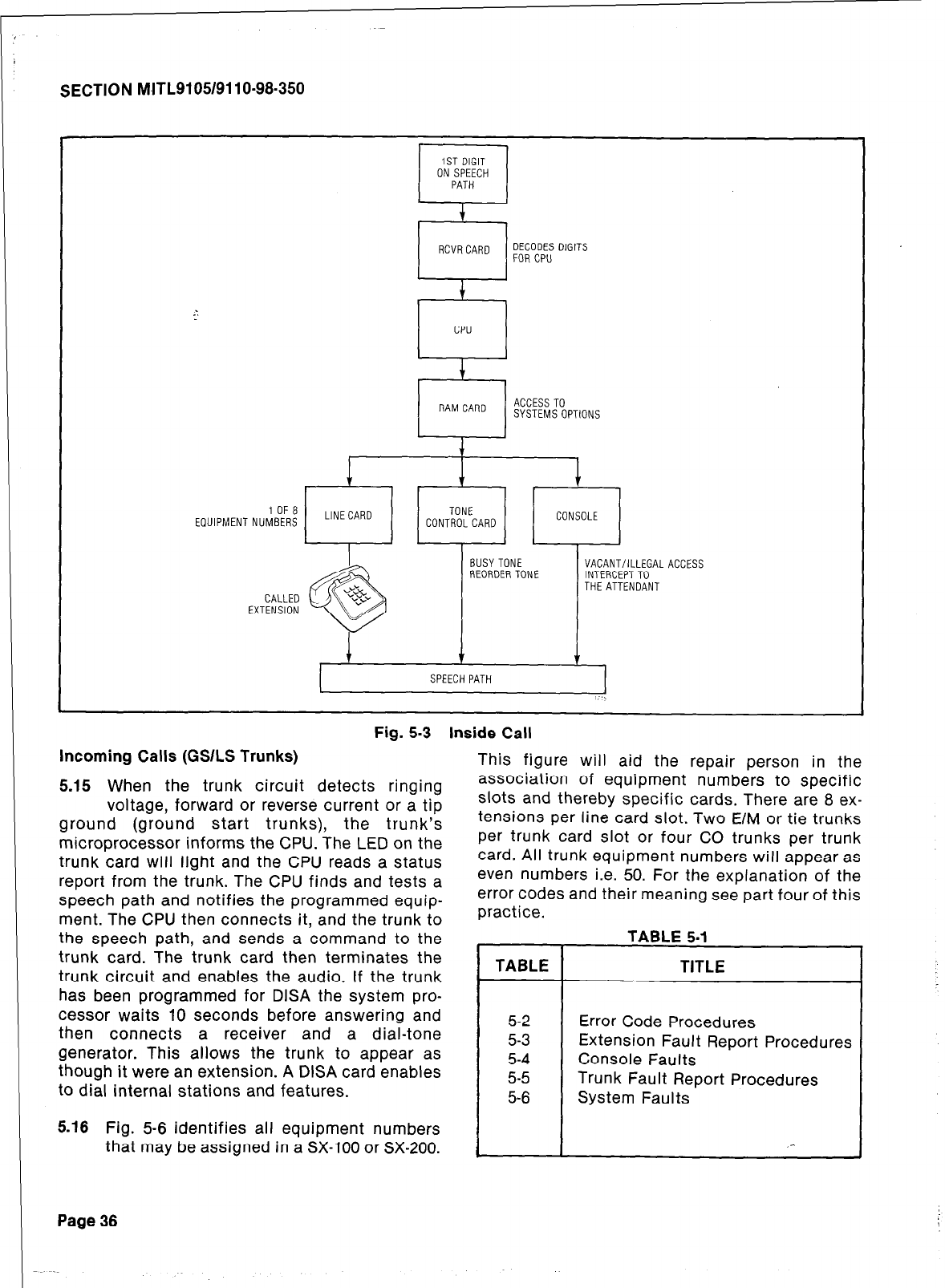
SECTION M~ITL9105/9110-98-350
IST DIGIT
ON SPEECH
PATH
4
RCVRCARD DECODES DIGITS
FORCPU
f
CPU
+
RAMCARD ACCESS TO
SYSTEMSOPTIONS
1
1 OF 8 LINECARD TONE
EOUIPMENT NUMBERS CONTROLCARD CONSOLE
BUSYTONE VACANT/ILLEGAL ACCESS
REORDER TONE INTERCEPTTO
THE ATTENDANT
1 1
SPEECH PATH
I,..,
Fig. 5-3 Inside Call
Incoming Calls (GSILS Trunks)
5.15 When the trunk circuit detects ringing
voltage, forward or reverse current or a tip
ground (ground start trunks), the trunk’s
microprocessor informs the CPU. The LED on the
trunk card will light and the CPU reads a status
report from the trunk. The CPU finds and tests a
speech path and notifies the programmed equip-
ment. The CPU then connects it, and the trunk to
the speech path, and sends a command to the
trunk card. The trunk card then terminates the
trunk circuit and enables the audio. If the trunk
has been programmed for DISA the system pro-
cessor waits 10 seconds before answering and
then connects a receiver and a dial-tone
generator. This allows the trunk to appear as
though it were an extension. A DISA card enables
to dial internal stations and features.
5.18 Fig. 5-6 identifies all equipment numbers
that may be assigned in a SX-100 or SX-200.
This figure will aid the repair person in the
association of equipment numbers to specific
slots and thereby specific cards. There are 8 ex-
tensions per line card slot. Two E/M or tie trunks
per trunk card slot or four CO trunks per trunk
card. All trunk equipment numbers will appear as
even numbers i.e. 50. For the explanation of the
error codes and their meaning see part four of this
practice.
TABLE 5-l
TABLE TITLE
5-2 Error Code Procedures
5-3 Extension Fault Report Procedures
5-4 Console Faults
5-5 Trunk Fault Report Procedures
5-6 System Faults
Page 36
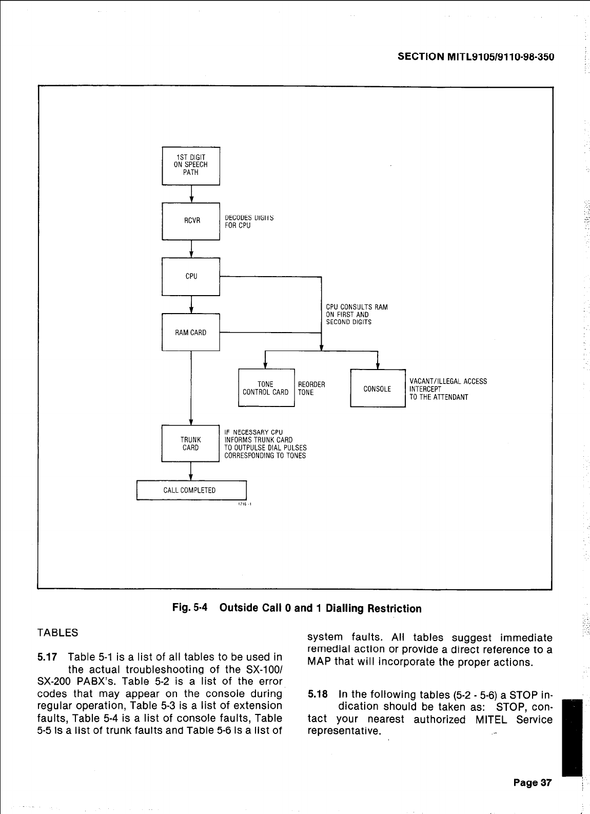
SECTION MITL9105/9110-98-350
I RCVR
DECODES DIGITS
FOR CPU
r-l
IF NECESSARYCPU
TRUNK INFORMSTRUNKCARD
CARD TO OUTPULSE DIAL PULSES
CORRESPONDINGTOTONES
VACANT/ILLEGALACCESS
INTERCEPT
TOTHEATTENDANT
CALLCOMPLETED I
,716 I
Fig. 5-4 Outside Call 0 and 1 Dialling Restriction
TABLES
5.17 Table 5-1 is a list of all tables to be used in
the actual troubleshooting of the SX-1001
SX-200 PABX’s. Table 5-2 is a list of the error
codes that may appear on the console during
regular operation, Table 5-3 is a list of extension
faults, Table 5-4 is a list of console faults, Table
5-5 is a list of trunk faults and Table 5-6 is a list of
system faults. All tables suggest immediate
remedial action or provide a direct reference to a
MAP that will incorporate the proper actions.
5.18 In the following tables (5-2 - 5-6) a STOP in-
dication should be taken as: STOP, con-
tact your nearest authorized MITEL Service
representative. .-
Page 37
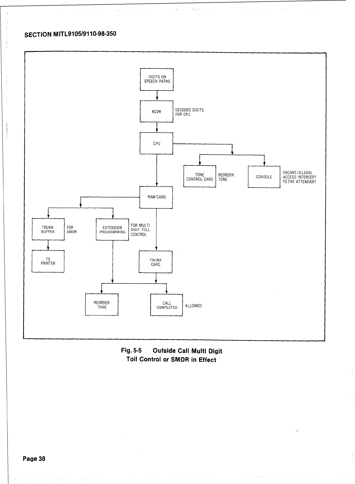
SECTION MITL9105/9110-98.350
DIGITS ON
SPEECH PATHS
Fl
RCVR DECODES DIGITS
FOR CPU
1
CPU
1
1
1
TONE REORDER VACANT/ILLEGAL
CDNTROLCARD TONE CONSOLE ACCESS INTERCEPT
7 TOTHE ATTENDANT
. RAMCARD
TRUNK FOR
BUFFER SMDR p;&!g$$NG gT;F
t
TRUNK
CARD
REORDER CALL
TONE COMPLETED ALLOWED
Fig. 5-S Outside Call Multi Digit
Toll Control or SMDR in Effect
Page 38
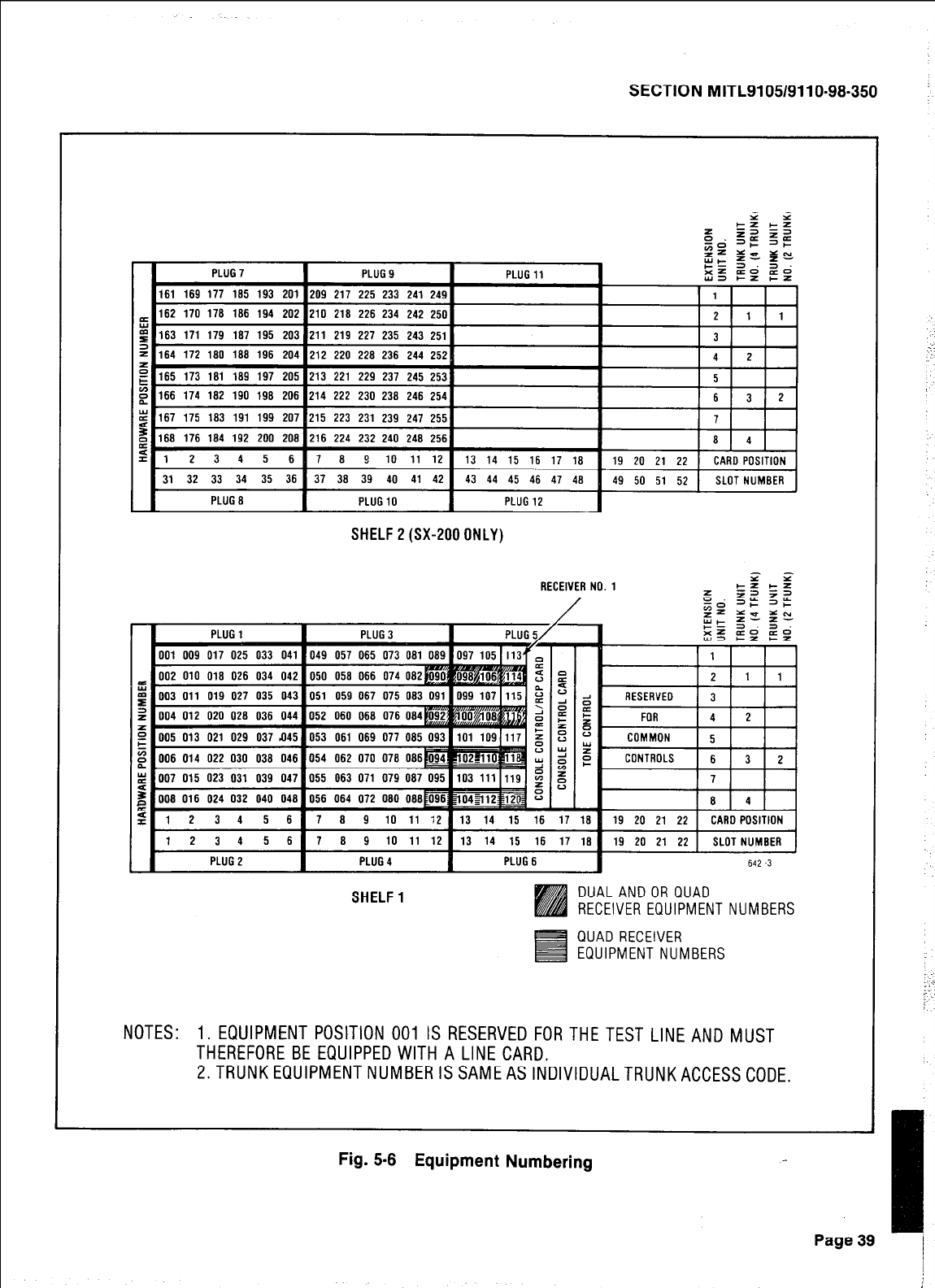
SECTION MITL9105/9110-98-350
2 2
x 55 55
zs DE Y =E
r= g”
PLUG7 :!z 3.3.
PLUG9 PLUG11 E5 Etz EZ
161 169 177 185 193 201 209 217 225 233 241 249
_ 162 170 178 186 194 202 210 218 226 234 242 250
1 El163 171 179 187 195 2031211 219 227 235 243 2511 --
2
\
3
164 172 180 188 196 204 212 220 228 236 244 252 4 2
E
F 165 173 181 189 197 205 213 221 229 237 245 253 5
166 174 102 190 198 206 214 222 230 238 246 254
167 175 183 191 199 2071215 223 231 239 247 2551
1168 176 184 192 200 2081216 224 232 240 248 2561
I
I 7
A d
1 1 2 3 4 5 6 I 7 8 9 10 11 12 I 13 14 15 16 17 18
SHELF2(SX-2000NLY)
1613121
31 32 33 34 35 36 37 30 39 40 41 42 43 44 45 46 47 48
PLUG8 I PLUG10 I PLUG12
I
PLUG1 PLUG3
NOTES: 1. EQUIPMENT POSITION 001 IS RESERVED FORTHETEST LINE AND MUST
THEREFORE BE EQUIPPED WITH A LINE CARD.
2.TRUNKEQUlPMENTNUMBERISSAMEASlNDlVlDUALTRUNKACCESSCODE.
9 1005 013 021 029 037 ~I451053 061 069 077 085 0931101 1091117 I
RECEIVER NO. 1
FOR 14121 1
L
2123456 78 9 10 11 :2 13 14 15 16 17 18 19 20 21 22 CARD POSITION
12345678 9 10 11 12 13 14 15 16 17 18 19 20 21 22 1 SLOT NUMBER
PLUG2 PLUG4 PLUG6 642
.3
SHELF1 DU ,LANDOR QUAD
RE EIVER EQUIPMENT NUMBERS
QUAD RECEIVER
EQUIPMENT NUMBERS
Fig. 5-8 Equipment Numbering
Page 39
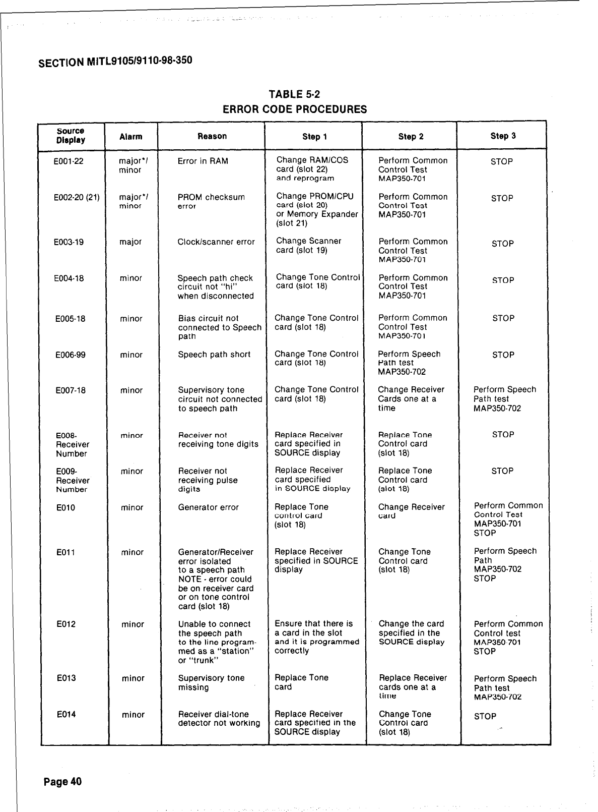
SECTION MITL9105/9110-98-350
TABLE 5-2
ERROR CODE PROCEDURES
source
Display Alarm Reason step 1 step 2 step 3
EOOl-22
E002-20 (21)
major’/
minor
major’/
minor
Error in RAM
PROM checksum
error
Change RAMICOS
card (slot 22)
and reprogram
Change PROM/CPU
card (slot 20)
or Memory Expander
(slot 21)
Perform Common
Control Test
MAP350-701
Perform Common
Control Test
MAP350-701
STOP
STOP
E003-19 major Clock/scanner error Change Scanner
card (slot 19) Perform Common
Control Test
MAP350-701
STOP
E004-1 a minor Speech path check
circuit not “hi”
when disconnected
Change Tone Control Perform Common
card (slot la) Control Test STOP
MAP350-701
E00518
E006-99
minor
minor
Bias circuit not Change Tone Control Perform Common STOP
connected to Speech card (slot la) Control Test
path MAP350-701
Speech path short Change Tone Control Perform Speech STOP
card (slot la) Path test
MAP350-702
E007-la minor Supervisory tone Change Tone Control Change Receiver Perform Speech
circuit not connected card (slot la) Cards one at a Path test
to speech path time MAP350-702
E008-
Receiver
Number
E009-
Receiver
Number
EOlO
minor
minor
minor
Receiver not Replace Receiver Replace Tone STOP
receiving tone digits card specified in Control card
SOURCE display
(slot
ia)
Receiver not Replace Receiver Replace Tone STOP
receiving pulse card specified Control card
digits in SOURCE display
(slot
ia)
Generator error Replace Tone Change Receiver Perform Common
control card card Control Test
(slot
ia) MAP350-701
STOP
EOll minor Generator/Receiver
error isolated
to a speech path
NOTE - error could
be on receiver card
or on tone control
card (slot la)
Replace Receiver
specified in SOURCE
display
Change Tone
Control card
(slot
ia)
Perform Speech
Path
MAP350-702
STOP
E012 minor Unable to connect Ensure that there is Change the card Perform Common
the speech path a card in the slot specified in the Control test
to the line program- and it is programmed SOURCE display MAP350-701
med as a “station” correctly STOP
or “trunk”
E013
E014
minor
minor
Supervisory tone Replace Tone Replace Receiver Perform Speech
missing card cards one at a Path test
time MAP350-702
Receiver dial-tone Replace Receiver Change Tone STOP
detector not working card specified in the Control card
SOURCE display
(slot
ia)
Page 40
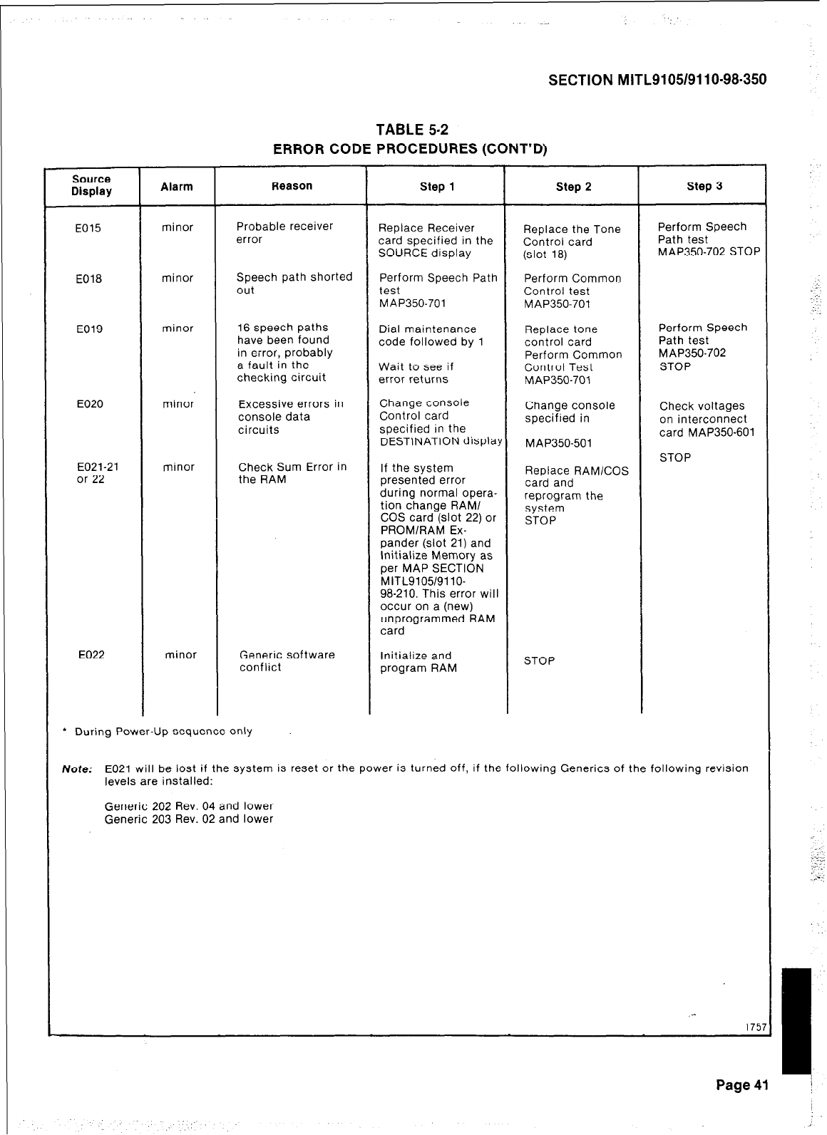
SECTION MITL9105/9110-98-350
TABLE 5-2
ERROR CODE PROCEDURES (CONT’D)
Source
Display Alarm Reason Step 1 Step 2 Step 3
E015 minor Probable receiver
error Replace Receiver Replace the Tone Perform Speech
card specified in the Control card Path test
SOURCE display (slot 18) MAP350-702 STC
E018 minor Speech path shorted
out Perform Speech Path Perform Common
test Control test
MAP350-701 MAP350-701
E019
E020
E021-21
or 22
minor
minor
minor
16 speech paths
have been found
in error, probably
a fault in the
checking circuit
Excessive errors in
console data
circuits
Check Sum Error in
the RAM
Dial maintenance Replace tone Perform Speech
code followed by 1 control card Path test
Perform Common MAP350-702
Wait to see if Control Test STOP
error returns MAP350-701
Change console
Control card Change console Check voltages
specified in on interconnect
specified in the
DESTINATION display card MAP350-60
MAP350-501
STOP
If the system
presented error Replace RAMlCOS
card and
during normal opera-
tion change RAM/ reprogram the
COS card (slot 22) or system
STOP
PROM/RAM Ex-
pander (slot 21) and
Initialize Memory as
per MAP SECTION
MITL9105/9110-
98-210. This error will
occur on a (new)
unprogrammed RAM
card
E022 minor Generic software Initialize and
conflict program RAM STOP
l
During Power-Up sequence only
Note: E021 will be lost if the system is reset or the power is turned off, if the following Generics of the following revision
levels are installed:
Generic 202 Rev. 04 and lower
Generic 203 Rev. 02 and lower
,-
1
I
Page41 j
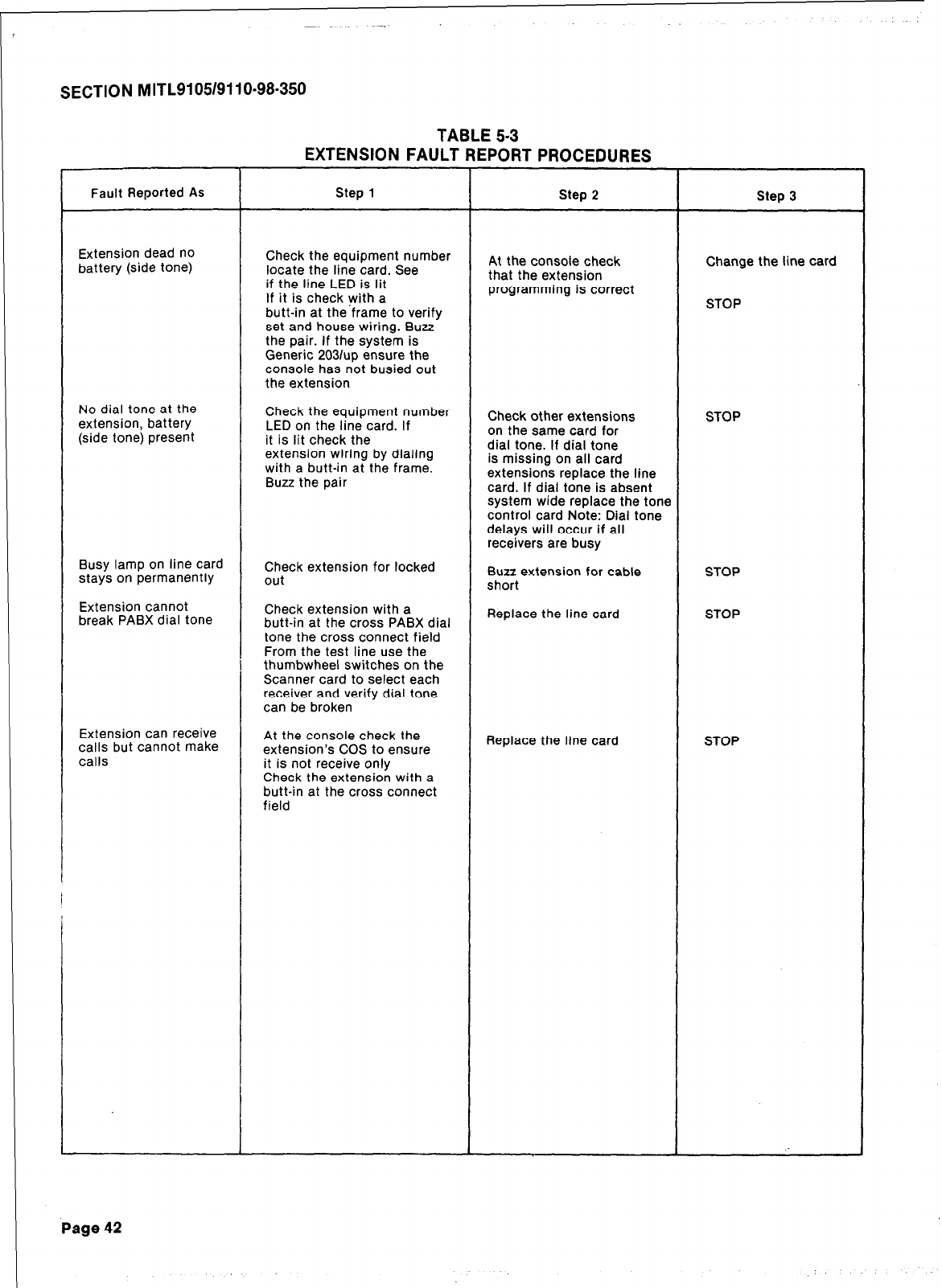
. .
SECTION MITL9105/9110-98-350
TABLE 5-3
EXTENSION FAULT REPORT PROCEDURES
Fault Reported As
Extension dead no
battery (side tone)
No dial tone at the
extension, battery
(side tone) present
Busy lamp on line card
stays on permanently
Extension cannot
break PABX dial tone
Extension can receive
calls but cannot make
calls
Step 1
Check the equipment number
locate the line card. See
if the line LED is lit
If it is check with a
butt-in at the frame to verify
set and house wiring. Buzz
the pair. If the system is
Generic 2031~~ ensure the
console has not busied out
the extension
Check the equipment number
LED on the line card. If
it is lit check the
extension wiring by dialing
with a butt-in at the frame.
Buzz the pair
Check extension for locked
out
Check extension with a
butt-in at the cross PABX dial
tone the cross connect field
From the test line use the
thumbwheel switches on the
Scanner card to select each
receiver and verify dial tone
can be broken
At the console check the
extension’s COS to ensure
it is not receive only
Check the extension with a
butt-in at the cross connect
field
Step 2
At the console check
that the extension
programming is correct
Check other extensions
on the same card for
dial tone. If dial tone
is missing on all card
extensions replace the line
card. If dial tone is absent
system wide replace the tone
control card Note: Dial tone
delays will occur if all
receivers are busy
Buzz extension for cable
short
Replace the line card
Replace the line card
Step 3
Change the line card
STOP
STOP
STOP
STOP
STOP
Page 42
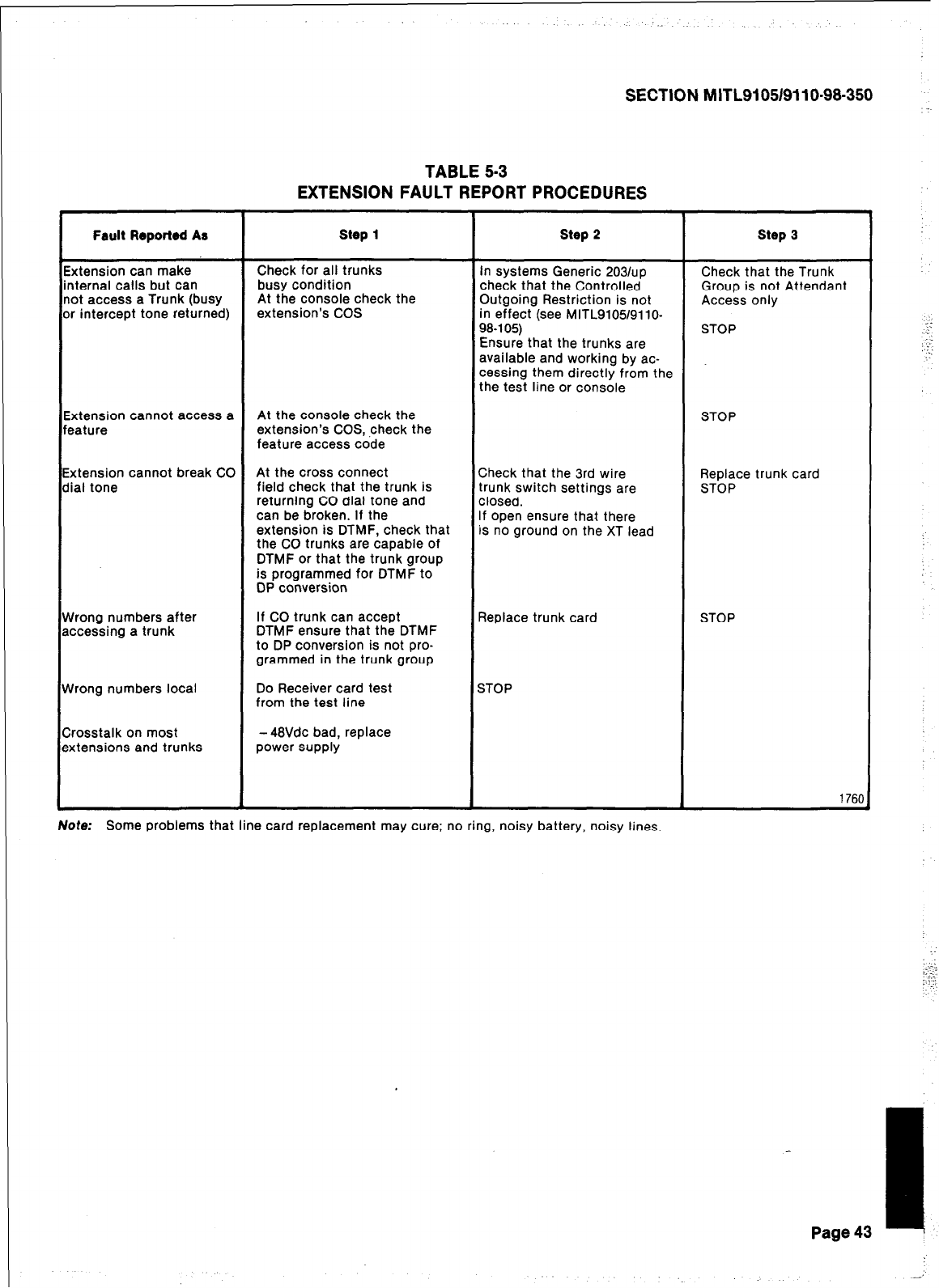
Fault Reported As step 1
b
in
nc
or
(tension can make Check for all trunks In systems Generic 203/up Check that the Trunk
ternal calls but can busy condition check that the Controlled Group is not Attendant
)t access a Trunk (busy At the console check the Outgoing Restriction is not Access only
intercept tone returned) extension’s COS in effect (see MITL910519110-
98-l 05) STOP
Ensure that the trunks are
available and working by ac-
cessing them directly from the
the test line or console
E>
fe (tension cannot access a At the console check the STOP
ature extension’s COS, ,check the
feature access code
Ex
di,
:tension cannot break CO At the cross connect Check that the 3rd wire Replace trunk card
al tone field check that the trunk is trunk switch settings are STOP
returning CO dial tone and closed.
can be broken. If the If open ensure that there
extension is DTMF, check that
iS
no ground on the XT lead
the CO trunks are capable of
DTMF or that the trunk group
is programmed for DTMF to
DP conversion
W rong numbers after
ac
cessing a trunk
W rong numbers local
Cr
‘osstalk on most
ex tensions and trunks
-
SECTION MITLSI 051911 O-98-350
TABLE 5-3
EXTENSION FAULT REPORT PROCEDURES
step 2 step 3
If CO trunk can accept
DTMF ensure that the DTMF
to DP conversion is not pro-
grammed in the trunk group
Replace trunk card STOP
Do Receiver card test
from the test line
-48Vdc bad, replace
power supply
STOP
1760
Note: Some problems that line card replacement may cure; no ring, noisy battery, noisy lines.
Page 43
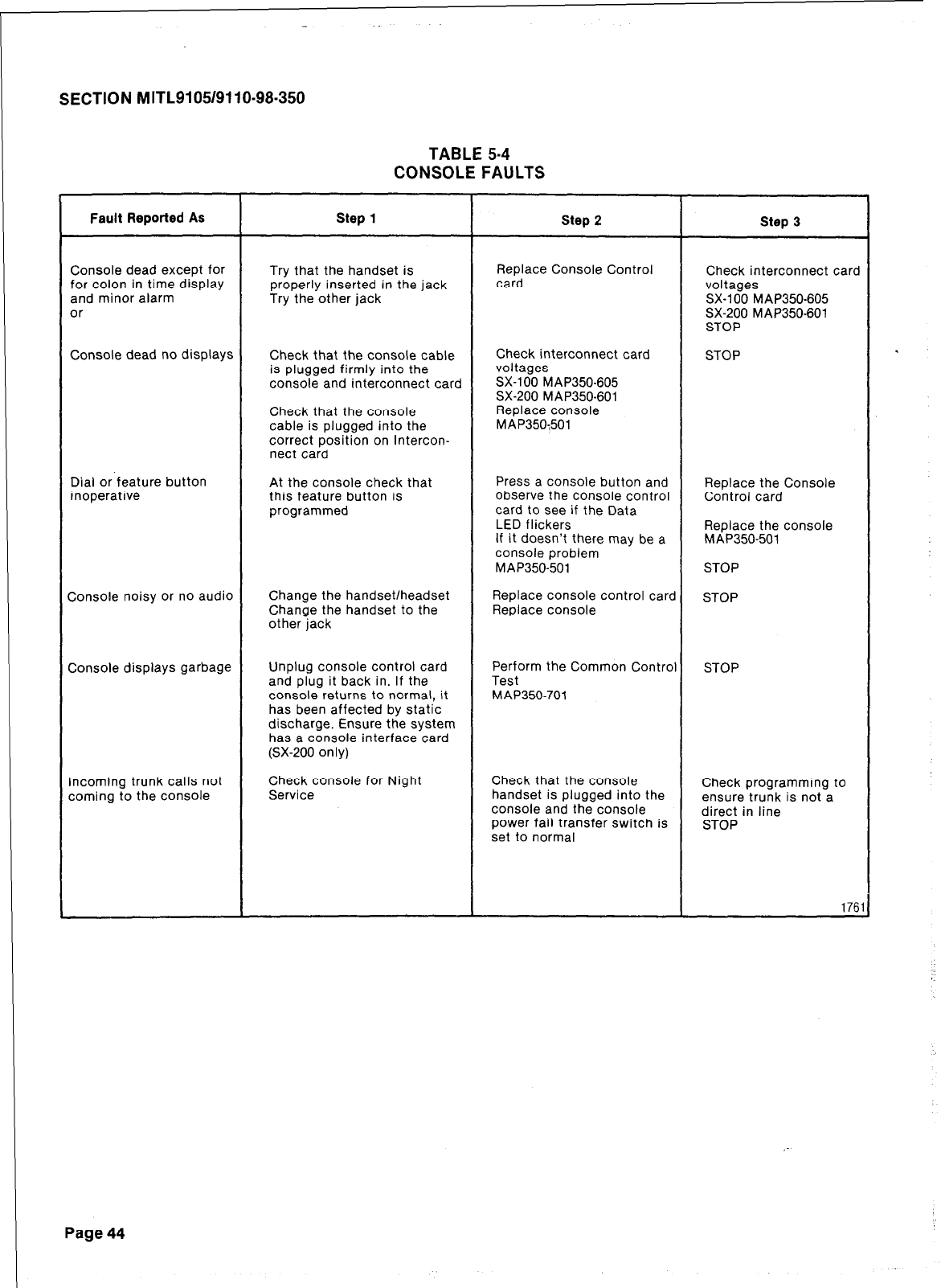
SECTION MITL9105/9110-98-350
TABLE 5-4
CONSOLE FAULTS
Fault Reported As step 1 Step 2 Step 3
Console dead except for
for colon in time display
and minor alarm
or
Try that the handset is
properly inserted in the jack
Try the other jack
Replace Console Control
card Check interconnect card
voltages
SX-100 MAP350-605
SX-200 MAP350-601
STOP
Console dead no displays Check that the console cable
is plugged firmly into the
console and interconnect card
Check that the console
cable is plugged into the
correct position on Intercon-
nect card
Check interconnect card
voltages
SX-100 MAP350-605
SX-200 MAP350-601
Replace console
MAP350:501
STOP
Dial or feature button
inoperative
Console noisy or no audio
At the console check that
this feature button is
programmed
Change the handset/headset
Change the handset to the
other jack
Press a console button and Replace the Console
observe the console control Control card
card to see if the Data
LED flickers Replace the console
If it doesn’t there may be a MAP350-501
console problem
MAP350-501 STOP
Replace console control card STOP
Replace console
Console displays garbage Unplug console control card
and plug it back in. If the
console returns to normal, it
has been affected by static
discharge. Ensure the system
has a console interface card
(SX-200 only)
Perform the Common Control
Test
MAP350-701
STOP
Incoming trunk calls not
coming to the console
Check console for Night
Service Check that the console
handset is plugged into the
console and the console
power fail transfer switch is
set to normal
Check programming to
ensure trunk is not a
direct in line
STOP
1761
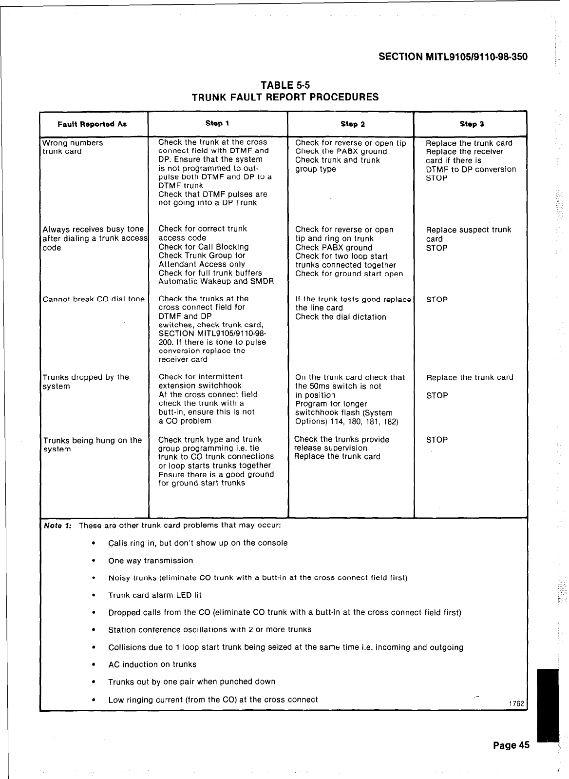
SECTION M ITL91051911 o-98-350 j
TABLE 5-5
TRUNK FAULT REPORT PROCEDURES
Fault Reported As
rVrong numbers
runk card
Step 1
Check the trunk at the cross
connect field with DTMF and
DP. Ensure that the system
is not programmed to out-
pulse both DTMF and DP to a
DTMF trunk
Check that DTMF pulses are
not going into a DP Trunk
step 2
Check for reverse or open tip
Check the PABX ground
Check trunk and trunk
group type
Step 3
Replace the trunk card
Replace the receiver
card if there is
DTMF to DP conversion
STOP
Always receives busy tone Check for correct trunk Check for reverse or open Replace suspect trunk
Ifter dialing a trunk access access code tip and ring on trunk card
:ode Check for Call Blocking Check PABX ground STOP
Check Trunk Group for Check for two loop start
Attendant Access only trunks connected together
Check for full trunk buffers Check for ground start open
Automatic Wakeup and SMDR
;annot break CO dial tone Check the trunks at the If the trunk tests good replace STOP
cross connect field for the line card
DTMF and DP Check the dial dictation
switches, check trunk card,
SECTION MITL9105/9110-9%
200. If there is tone to pulse
conversion replace the
receiver card
rrunks dropped by the Check for intermittent On the trunk card check that Replace the trunk card
;ystem extension switchhook the 50ms switch is not
At the cross connect field in position STOP
check the trunk with a Program for longer
butt-in, ensure this is not switchhook flash (System
a CO problem Options) 114, 180, 181, 182)
rrunks being hung on the Check trunk type and trunk Check the trunks provide STOP
jystem group programming i.e. tie release supervision
trunk to CO trunk connections Replace the trunk card
or loop starts trunks together
Ensure there is a good ground
for ground start trunks
Note 7: These are other trunk card problems that may occur:
. Calls ring in, but don’t show up on the console
. One way transmission
. Noisy trunks (eliminate CO trunk with a butt-in at the cross connect field first)
. Trunk card alarm LED lit
. Dropped calls from the CO (eliminate CO trunk with a butt-in at the cross connect field first)
. Station conference oscillations with 2 or more trunks
. Collisions due to 1 loop start trunk being seized at the same time i.e. incoming and outgoing
. AC induction on trunks
. Trunks out by one pair when punched down
. Low ringing current (from the CO) at the cross connect ,-
1762
:.
:
::
I
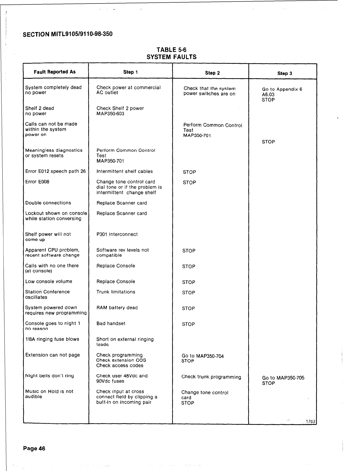
SECTION MITL9105/9110-98-350
TABLE 5-6
SYSTEM FAULTS
Fault Reported AS
System completely dead
no power
Shelf 2 dead
no power
Calls can not be made
within the system
power on
Meaningless diagnostics
or system resets
step 1
Check power at commercial
AC outlet
Check Shelf 2 power
MAP350-603
Perform Common Control
Test
MAP350-701
step 2
Check that the system
Power switches are on
Perform Common Control
Test
MAP350-701
Step 3
Go to Appendix 6
A6.03
STOP
STOP
Error E012 speech path 26 Intermittent shelf cables STOP
Error E008 Change tone control card STOP
dial tone or if the problem is
intermittent change shelf
Double connections Replace Scanner card
Lockout shown on console Replace Scanner card
while station conversing
Shelf power wihl not
come up P301 interconnect
Apparent CPU problem,
recent software change
Calls with no one there
(at console)
Software rev levels not
compatible
Replace Console
STOP
STOP
Low console volume
Station Conference
oscillates
Replace Console STOP
Trunk limitations STOP
System powered down RAM battery dead STOP
requires new programming
Console goes to night 1
no reason Bad handset STOP
118A ringing fuse blows Short on external ringing
leads
Extension can not page
Night bells don’t ring
Music on Hold is not
audible
Check programming
Check extension COS
Checkaccess codes
Check user 48Vdc and
9OVdc fuses
Check input at cross
connect field by clipping a
butt-in on incoming pair
Go to MAP350-704
STOP
Check trunk programming
Change tone control
card
STOP
Go to MAP350-705
STOP
1763
Page 46
SX.iOO/SX-200 POWER SUPPLY
6. The SX-lOO/SX-200 power supplies form an
integral part of the equipment cabinets. The
SX-100 power supply is housed immediately to the
right hand side (front view) of the equipment shelf
(Fig. 6-l). In the SX-200 the power supply is hous-
ed in a metal cabinet forming the lower rear door
of the system (Fig. 6-2). Both supplies are fully
R.F. filtered and may be operated from either AC
or DC inputs to produce multiple DC output rails
as well as ringing voltage. This part will discuss
the power supplies in 4 parts. There is also a sec-
tion on the Reserve Battery Back-Up.
l
AC - DC Converter
l
Control Voltage Supply and DC/DC con-
verter
l
Ringing Generator
l
Out of Tolerance Circuit
l
AC/DC Converter The SX-iOO/SX-200
AC/DC Converters are designed to operate
with a AC power source in the range of 100
-130Vac or 200 - 250Vac with an internal
modification for the SX-200 and a converter
for the SX-100, (see MITL9105/9110-98-200).
The SX-200 converter has an output of - 60
to -64Vdc while the SX-100 converter has
an output of -5OVdc to -56Vdc.
l
DC/DC Converter The converter output is
fed to the main DC/DC converter and Con-
trol Voltage Supply. The DC/DC converter
may also be fed by a 48Vdc reserve power
supply. The battery supply may be con-
nected permanently and will allow instan-
taneous cut over should the AC power fail.
The control voltage section provides the
following voltages:
.
+ 8Vdc
.
- 5Vdc
l
OVdc
.
- 10Vdc
.
- 48Vdc
l
Ringing Generator The ringing generator
uses a -48Vdc output from the main con-
verter to produce a SOVac, 20Hz (optional
17Hz, 25Hz) supply for the system ringing.
SECTION MITL.9105/9110-98-350
l
Out of Tolerance All voltage levels are
regulated
25%
except for the -48Vdc
which may vary f 10%. An Out-Of-
Tolerance (OOT) circuit monitors all levels
continuously (white/green wire of P303).
Should a deviation occur, an OOT signal
will activate the power fail transfer circuit
through the Interconnect card. It should be
noted that if a - 48Vdc reserve power supp-
ly is used, the power fail transfer will not be
activated in the event of a power failure. In
the SX-100 and SX-200 there are provisions
to program a port as a Contact Monitor
(MITL9105/9110-98-105) This monitor may
be used to alert the attendant that the
system is on battery power (Wiring Appen-
dix 3) by wiring it to a contact monitor port
(at the cross connect field).
6.02 Reserve Battery Backup and Charger. The
SX-100 and SX-200 both accept a -48Vdc
source fed to the terminals indicated on the ter-
minal blocks shown in Figs. 6-2, 6-3. The installa-
tion of the reserve supply in the systems is
described in MITL9105/9110-98-200. A pictorial
view of the power supply is shown in Figs. 6-2 and
6-4. The MITEL reserve battery and charger (MITL
part number 9110-014) has an OOT circuit which
may be used to alert the attendant that the system
is on reserve battery power. The indicator is a dry
relay contact that may be used to ring an external
alarm or it may be wired to a system port as a Con-
tact Monitor.
6.03 Fusing
.
The SX-200 is protected by fuses which are
located on the back door of the cabinet
(Fig. 6-5). The back door has imprinted upon
it a circuit description defining each fuse
and the circuit breaker. In addition to these
fuses there are a series of LEDs which also
are defined by the circuit on the back door.
These LEDs will be lit if there is power in
the area that they designate, or in the case
of the reserve battery backup, if the battery
is connected. In addition to the cabinet
door fuses, there are fuses located on the
backplane, interconnect card and power
fail transfer card. The fuses on the
backplane are for - 48Vdc and have an LED
which will be lit if the fuse blows and there
is a card in one of the associated slots. The
Page 47
SECTION MITL9105/9110-98-350
fuse on the interconnect card protects the
console’s -48Vdc and the fuse on the
power fail transfer card protects the power
fail transfer - 48Vdc.
l
The SX-100 has the same backplane as the
SX-200 hence, the same fusing appears on
the backplane. There are three fuses on the
interconnect card for; user SOVac, user
- 48Vdc and the console - 48Vdc (Fig. 6-3).
The front panel of the power supply has two
circuit breakers; one is for the DC battery
supply, the other is for the AC supply (Fig.
6-l).
Note: Some early versions of the SX-100/200 do
not have all the fusing of later models.
This point should be taken into account
when troubleshooting the system.
l
If the system is equipped with a reserve bat-
tery backup (MITLgllO-014 SX-200 or
9105014 SX-100) separate fusing is includ-
ed in the charger unit itself, Fig. 6-6 There
are three fuses; a one amp charging fuse, a
five amp output fuse and a two amp AC
fuse. In addition there are two 20 amp cir-
cuit breaker (one on the battery pack, one
on the charger unit) for the battery protec-
tion. All reserve battery and charger con-
nections are shown in (Fig. 6-2 and Fig. 6-3).
Installation of the reserve battery back-up is
described in MITL9105/9110-98-200.
6.04 When troubleshooting the systems for
power failures the Power Supply Block
Diagram (Fig. 6-7), and Charts 6-1 through 6-10
should be consulted. The Charts outlined cover
the trouble and it’s effect on the System. In most
cases the repair person will be directed to a
specific MAP for remedial action. Under the
heading “Check” a yes answer to the question
asked, is an indication to go on to the next ques-
tion in the “Check” column. If a no answer is en-
countered the repair person should go to the “Ac-
tion” column and follow the instructions listed
there. There is also a column indicating by a X to
which system the action applies. Above all it must
be remembered that fuse replacement is not a
remedy. The cause of a power failure should be
determined before the system is powered up.
Utilizing the information provided in this section
and the MAPS referred to in Charts 6-1 through
6-10, the repair person should be able to pin point
faults and take proper replacement action. At all
times the repair person should follow all safety
precautions suggested in the MAPS to ensure
maximum personal and equipment safety.
Page 48
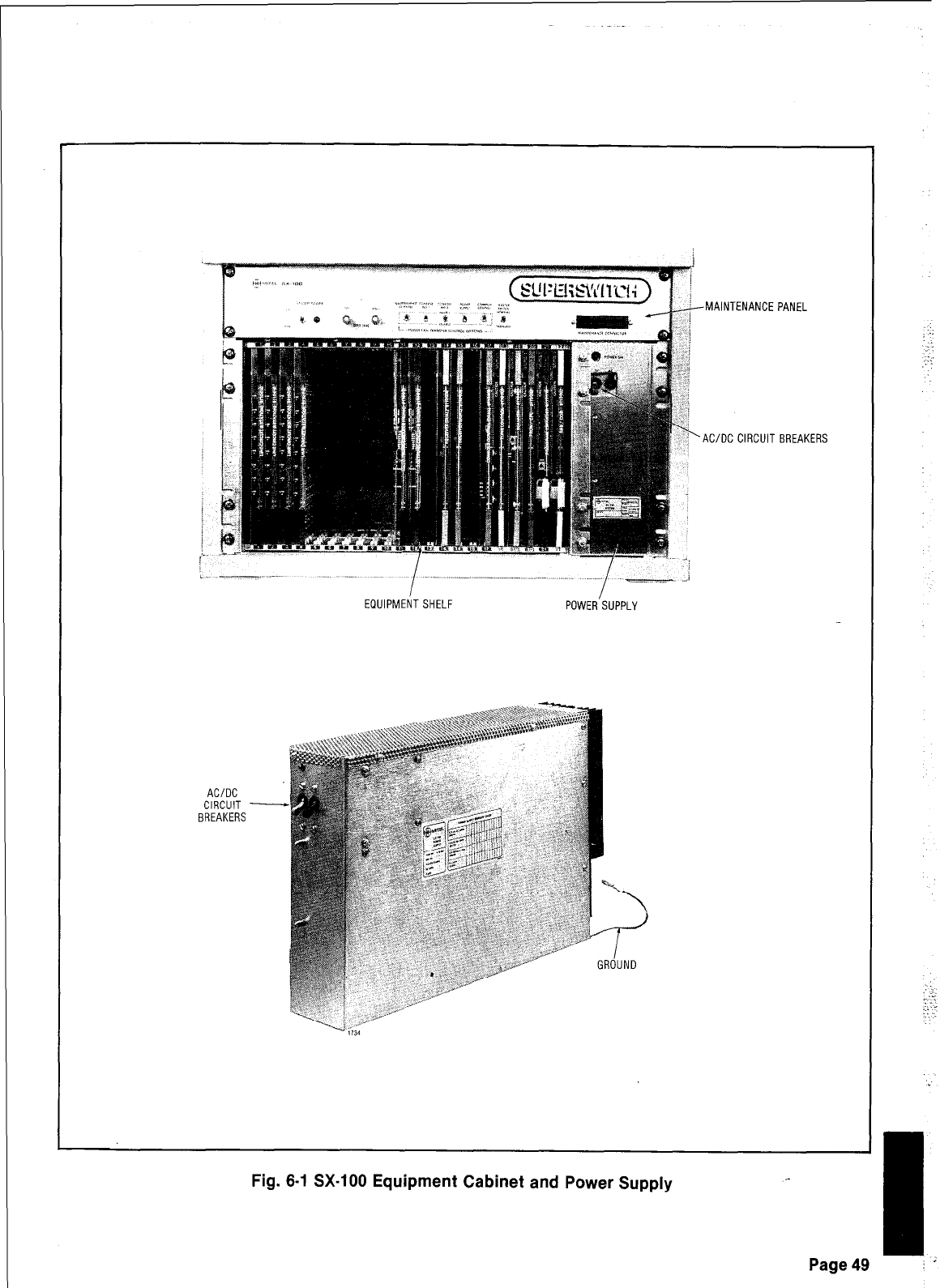
MAINTENANCE PANEL
AC/DC CIRCUIT BREAKERS
.- -. .- .._ .-
- .- _i
EQUIPMENTSHELF POWER SUPPLY
Fig. 6-1 SX-100 Equipment Cabinet and Power Supply
: ..:
:
:, :
-::
:
-I
Page49 :
s
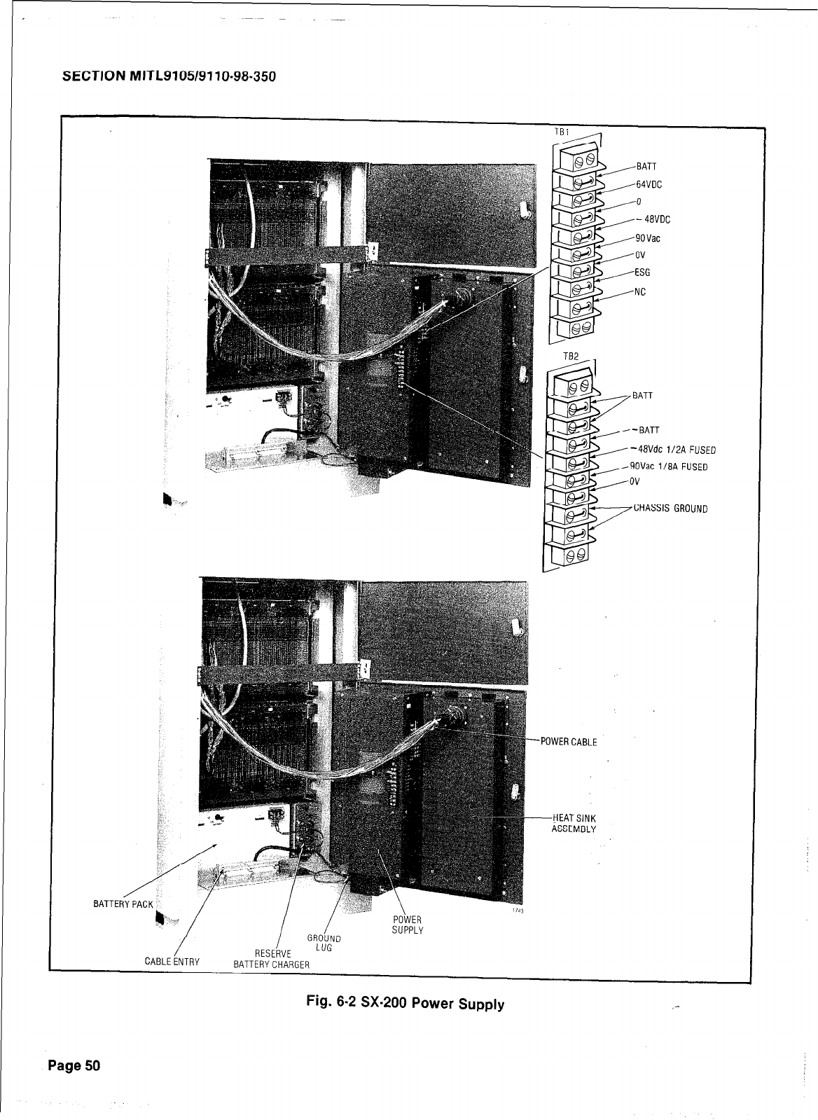
SECTION MITL9105/9110~96-350
BAT .TER;
CABLEENTRY BATTERYCHARGER
<
<
<
<
<:
BAT1
BATT
4avdc 112~ FUSED
Vat l/BA FUSED
HASSIS GROUND
‘OWER CABLE
--HEATSINK
ASSEMBLY
Fig. 6-2 SX-200 Power Supply ,-
Page 50
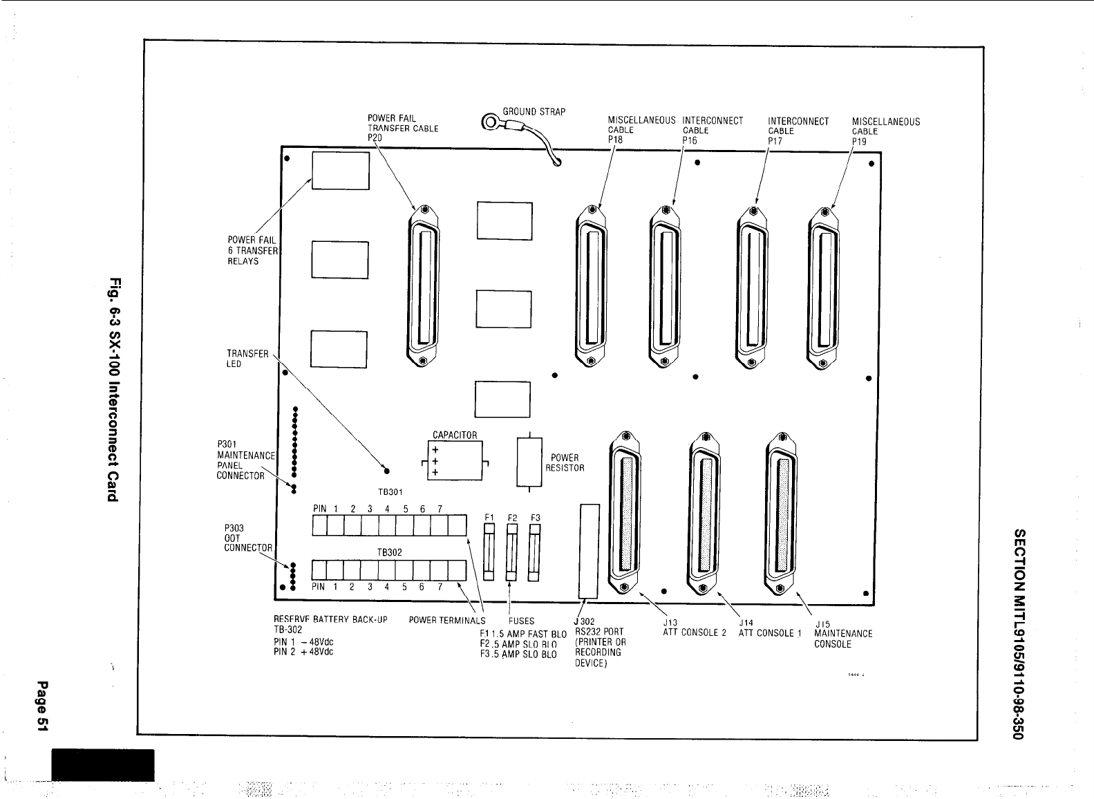
r
/
POWER FA
6 TRANSF
RELAYS
TRANSFER
LED
P301
MAINTENANC
PANEL
CONNECTOR\
P303
OOT
CONNECTO,
\
POWER FAIL
TRANSFER CABLE
P?O
MISCELLANEOUS INTERCONNECT INTERCONNECT MISCELLANEOUS
CABLE
qRAp P18 P16 P17 P19
CABLE CABLE CABLE
\, ,APAC'TOR ~
1
TB301
a
POWER
RESISTOR
.
d
@\
PIN1 2 3 4 5 6 7
II I I I I I I I I
PIN1 2 3 4 5 6 7
F2 F3
vi a
I
RESERVE BATTERY BACK-UP POWERTERMIN,iL; J'302 \ \ \
FUSES
TB-302 Jl3 J14
PIN 1 -48Vdc F11.5 AMP FAST BLO RS232 PoRT J15
ATTCONSOLE 2 ATT CONSOLE1 MAINTENANCE
F2.5AMP SLO BLO (PRINTER OR CONSOLE
PIN 2 +48Vdc F3SAMPSLO BLO RECORDING
DEVICE)
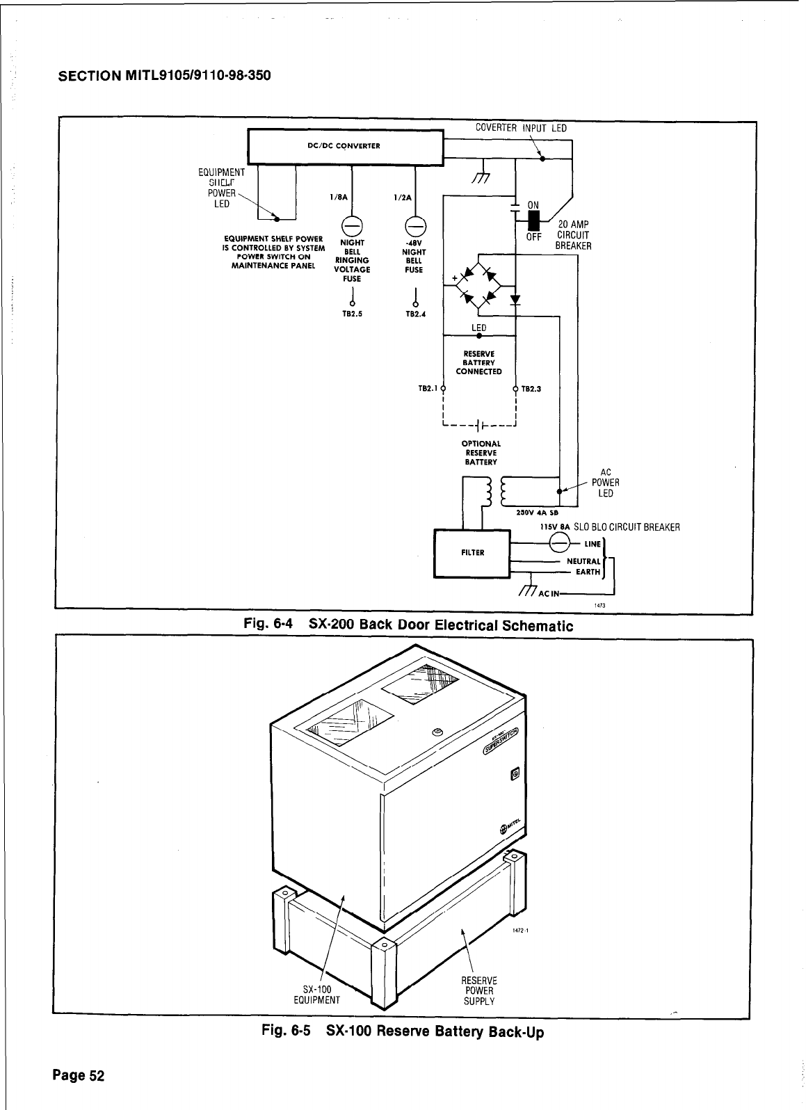
SECTION MITL91051911 O-98-350
I
COVERTER INPUT LED
DC/DC CQNVERTER
EQUIPMENT
SHELF
POWER
LED \
EQUIPMENT SHELF POWER
IS CONTROLLED BY SYSTEM
POWER SWITCH ON
MAINTENANCE PANEL RINGING
VOLTAGE
d b
182.5
TB2.4
782.1
CONNECTED
l-
-+--:
OPTIONAL
RESERVE
BATTERY
I-F
250V 4A
Y
AC
. POWER
LED
115~8~
SLOBLOCIRCUITBREAKEA
~pL;J,
,113
Fig. 8-4 SX-200 Back Door Electrical Schematic
SUPPLY _-
Fig. 8-5 SX-100 Reserve Battery Back-Up
Page 52
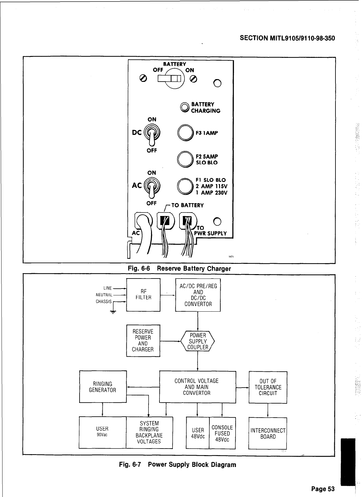
SECTION MITL9105/9110-98-350
1111
Fig. 6-6 Reserve Battery Charger
1
LINE- AC/DC PRE/REG
NEUTRAL- RF AND
FILTER - DC/DC
CONVERTOR
RESERVE
POWER
AND
CHARGER
7
POWER
SUPPLY
COUPLER
RINGING CONTROLVOLTAGE OUTOF
GENERATOR * AND MAIN - TOLERANCE
CONVERTOR CIRCUIT
.i
Fig. 6-7 Power Supply Block Diagram
Page 52
I
I
;‘.
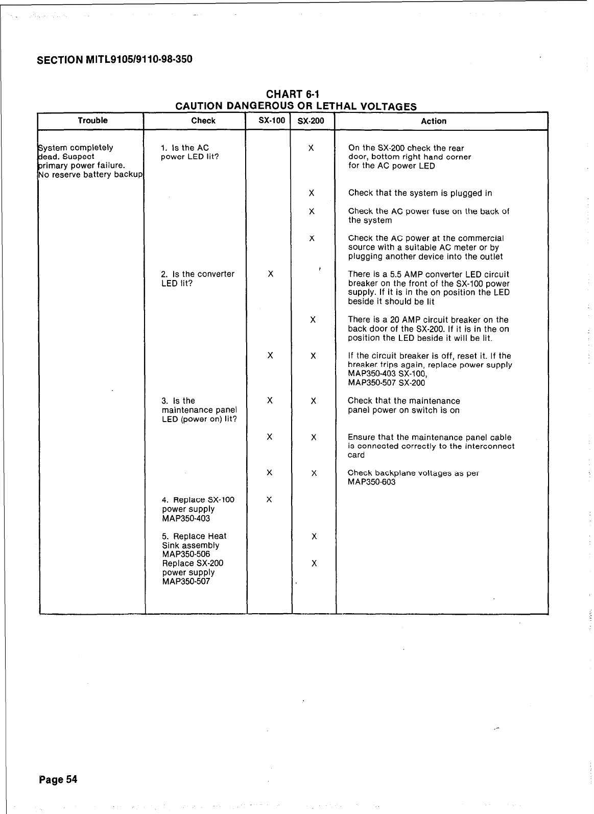
SECTION MITL9105/9110-98-350
CHART 8-1
Trouble
CAUTION DANGEROUS OR LETHAL VOLTAGES
Check sx-100 sx.200 Action
/stem completely 1. Is the AC X On the SX-200 check the rear
?ad. Suspect power LED lit? door, bottom right hand corner
,imary power failure. for the AC power LED
D reserve battery backup
X Check that the system is plugged in
X Check the AC power fuse on the back of
the system
X Check the AC power at the commercial
source with a suitable AC meter or by
plugging another device into the outlet
2. Is the converter
LED lit?
X , There is a 5.5 AMP converter LED circuit
breaker on the front of the SX-100 power
supply. If it is in the on position the LED
beside it should be lit
X There is a 20 AMP circuit breaker on the
back door of the SX-200. If it is in the on
position the LED beside it will be lit.
X X If the circuit breaker is off, reset it. If the
breaker trips again, replace power supply
MAP350-403 SX-100,
MAP350-507 SX-200
3. Is the
maintenance panel
LED (power on) lit?
X X Check that the maintenance
panel power on switch is on
X X Ensure that the maintenance panel cable
is connected correctly to the interconnect
card
X X Check backplane voltages as per
MAP350-603
4. Replace SX-100 X
power supply
MAP350-403
5. Replace Heat
Sink assembly
MAP350-506
Replace SX-200
power supply
MAP350507
X
X
Page 54
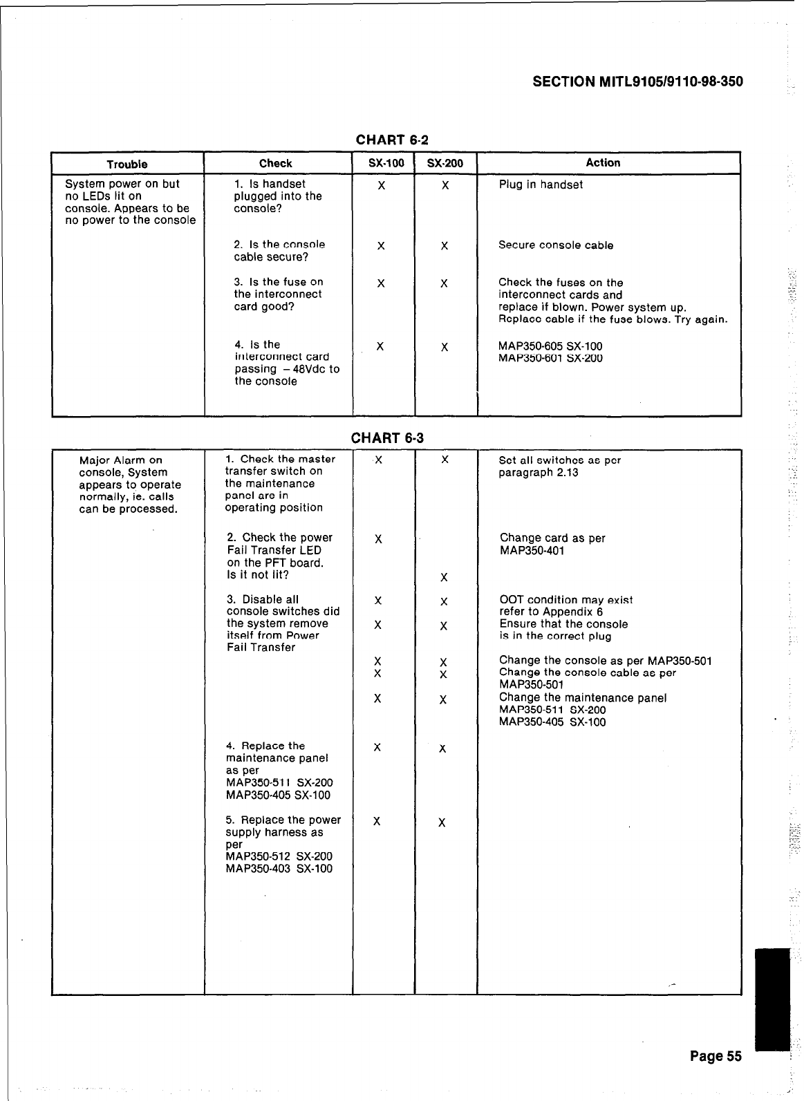
SECTION MITL9105/9110-98-350
CHART 6-2
Trouble
System power on but
no LEDs lit on
console. Appears to be
no power to the console
Check
1. Is handset
plugged into the
console?
sx-100 sx-200 Action
X X Plug in handset
2. Is the console
cable secure? X X Secure console cable
3. Is the fuse on
the interconnect
card good?
X X Check the fuses on the
interconnect cards and
replace if blown. Power system up.
Replace cable if the fuse blows. Try again.
4. Is the X X MAP350-605 SX-100
interconnect card MAP350-601 SX-200
passing - 48Vdc to
the console
CHART 6-3
Major Alarm on 1. Check the master X X Set all switches as per
console, System transfer switch on
the maintenance paragraph 2.13
appears to operate
normally, ie. calls panel are in
can be processed. operating position
2. Check the power X Change card as per
Fail Transfer LED MAP350-401
on the PFT board.
Is it not lit? X
3. Disable all X X OOT condition may exist
console switches did refer to Appendix 6
the system remove X X Ensure that the console
itself from Power is in the correct plug
Fail Transfer
X
X ::
Change the console as per MAP350501
Change the console cable as per
MAP350-501
X X Change the maintenance panel
MAP35051 1 SX-200
MAP350-405 SX-100
4. Replace the X X
maintenance panel
as per
MAP350-511 SX-200
MAP350-405 SX-100
5. Replace the power X X
supply harness as
per
MAP350-512 SX-200
MAP350-403 SX-100
,-
Page 55
.:
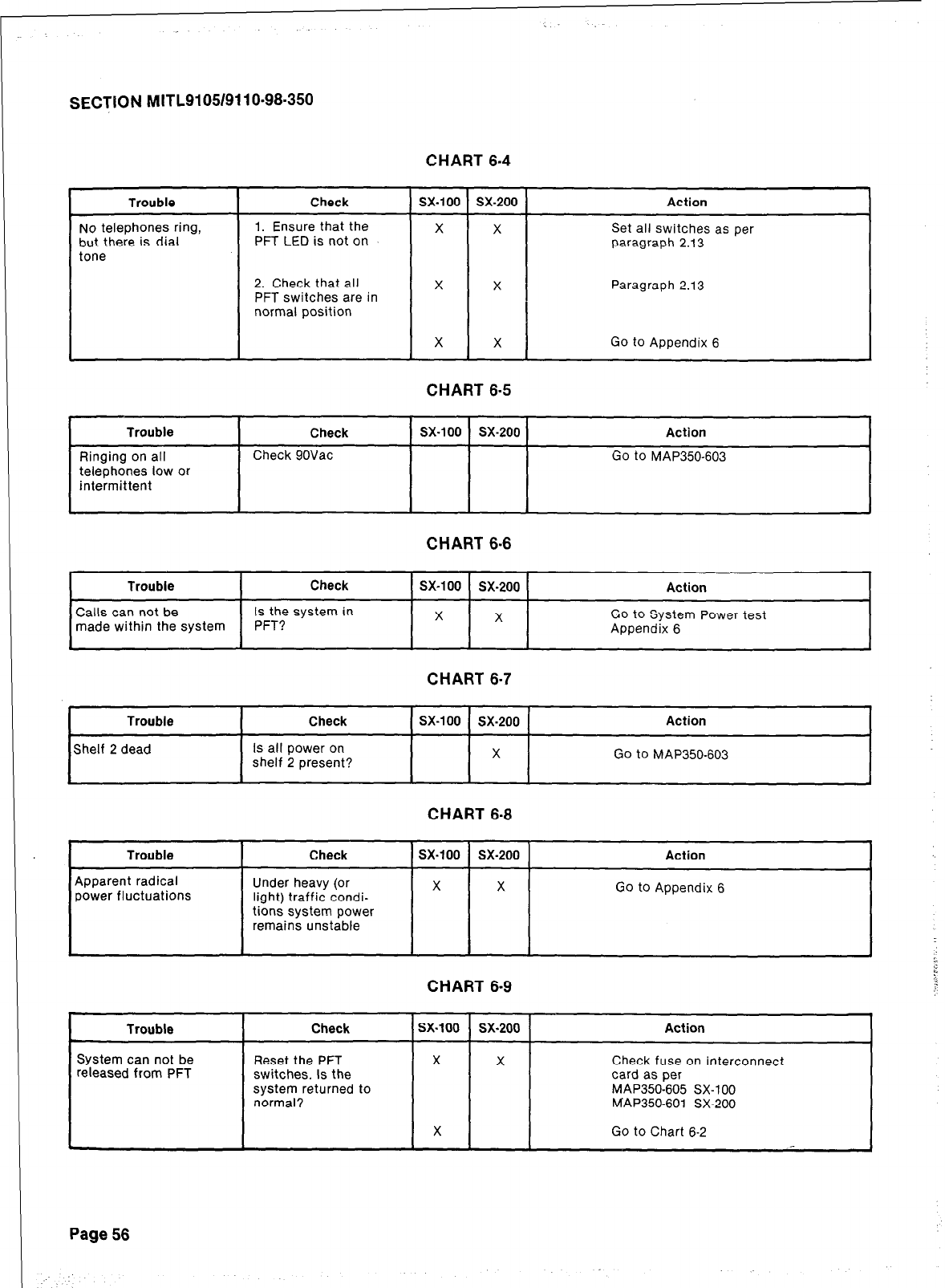
SECTION MITL9105/9110~98-350
CHART 6-4
tone
telephones low or
Check I sx-100 I sx-200 I Action
1. Ensure that the X X
PFT LED is not on Set all switches as per
paragraph 2.13
2. Check that all
PFT switches are in
normal position
X X Paragraph 2.13
X X Go to Appendix 6
Check
Check 9OVac
;
CHART 6-5
sx-100 sx-200 Action I
I I
Go to MAP350-603
CHART 6-6
sx-100 sx-200
X X
Action
GO to System Power test
Appendix 6
CHART 6-7
Trouble
Shelf 2 dead
Check
Is all power on
shelf 2 present?
sx-100 sx-200
X
Action
Go to MAP350-603
Trouble
Apparent radical
power fluctuations
Check
Under heavy (or
light) traffic condi-
tions system power
remains unstable
System can not be
released from PFT
CHART 6-8
sx-100 sx-200
X X
Action
GO to Appendix 6
CHART 6-9
Check sx-100 sx.200 Action
I I I
Reset the PFT
switches. Is the
system returned to
normal?
X X Check fuse on interconnect
card as per
MAP350-605 SX-100
MAP350-601 SX-200
X Go to Chart 6-2
Page 56
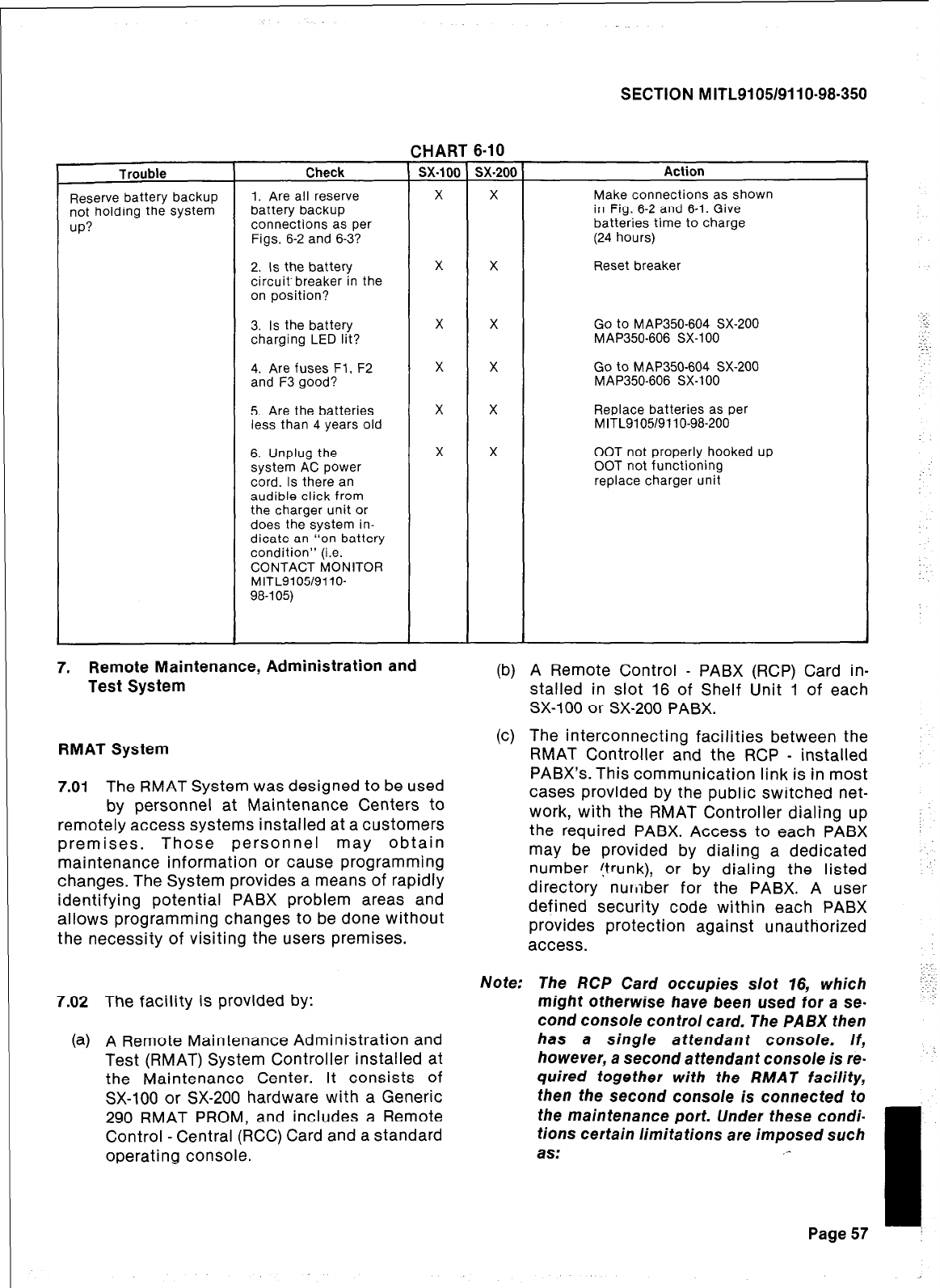
Trouble Check
Reserve battery backup
not holding the system
up?
1. Are all reserve
battery backup
connections as per
Figs. 6-2 and 6-3?
SECTION M ITL91051911 O-98-350
2. Is the battery
circuit-breaker in the
on position?
3. Is the battery
charging LED lit?
4. Are fuses Fl, F2
and F3 good?
5. Are the batteries
less than 4 years old
6. Unplug the
system AC power
cord. Is there an
audible click from
the charger unit or
does the system in-
dicate an “on battery
condition” (i.e.
CONTACT MONITOR
MITL9105/9110-
98-105)
7. Remote Maintenance, Administration and
Test System
RMAT System
7.01 The RMAT System was designed to be used
by personnel at Maintenance Centers to
remotely access systems installed at a customers
premises. Those personnel may obtain
maintenance information or cause programming
changes. The System provides a means of rapidly
identifying potential PABX problem areas and
allows programming changes to be done without
the necessity of visiting the users premises.
7.02 The facility is provided by:
(a) A Remote Maintenance Administration and
Test (RMAT) System Controller installed at
the Maintenance Center. It consists of
SX-100 or SX-200 hardware with a Generic
290 RMAT PROM, and includes a Remote
Control - Central (RCC) Card and a standard
operating console.
6-10
sx-201
X
X
Action
Make connections as shown
in Fig. 6-2 and 6-1. Give
batteries time to charge
(24 hours)
Reset breaker
X Go to MAP3507604 SX-200
MAP350-606 SX-100
X Go to MAP350-604 SX-200
MAP350-606 SX-100
X Replace batteries as per
M ITL9105/911 o-98-200
X OOT not properly hooked up
OOT not functioning
replace charger unit
(b) A Remote Control - PABX (RCP) Card in-
stalled in slot 16 of Shelf Unit 1 of each
SX-100 or SX-200 PABX.
(c) The interconnecting facilities between the
RMAT Controller and the RCP - installed
PABX’s. This communication link is in most
cases provided by the public switched net-
work, with the RMAT Controller dialing up
the required PABX. Access to each PABX
may be provided by dialing a dedicated
number (trunk), or by dialing the listed
directory nur,lber for the PABX. A user
defined security code within each PABX
provides protection against unauthorized
access.
Note: The RCP Card occupies slot 16, which
might otherwise have been used for a se-
cond console control card. The PABX then
has a single attendant console. If,
however, a second attendant console is re-
quired together with the RMAT facility,
then the second console is connected to
the maintenance port. Under these condi-
tions certain limitations are imposed such
as: ,-
Page 57
SECTION MITL9105/9110-98.350
.
.
.
.
.
7.03
shared HOLD positions between the two
consoles
shared conference call setting capability
no timeout to night service on the second
console
audio connection between attendant con-
soles when both are idle
separate console configuration in a tenant
installation is not possible
Once the RCP Card has been accessed the
RMAT Controller can perform the following
functions at the PABX:
(a) Duplication by the RMAT Console operator
of the PABX normal attendant console
functions and displays. (NOTE: No speech
path is available to the RMAT console
operator once the RCP is accessed.)
(b) Programming functions for the remote
PABX including extended programming for
Multi-Digit Toll Control purposes.
(c) Detection of alarm conditions at the PABX
and the ability to clear alarms, to busy-out
lines and trunks and perform reset and
PABX disable conditions.
60
(e)
(0
(9)
7.04
If the RCP is connected as a PABX exten-
sion the PABX attendant, or any other PABX
extension, has the facility of originating a
RMAT call to the RMAT Controller. In addi-
tion, if the RCP extension has the COS op-
tion “Flash for Attendant” enabled, the
RMAT operator can re-enter into speech
mode with the PABX attendant after being
in the Remote Administration Mode.
The RMAT Controller can access the RCP
card by dialing the RCP access code, and
has the capability to change the access
code when required.
The RMAT Controller’s receiver and trunk
cards may be programmed by its console
for the type of operation required to access
the remote PABX equipments; local
features such as time or date display can
also be programmed from the console.
The RMAT Controller equipment includes
the capability of displaying and clearing
diagnostics registers for its own or for the
remote PABX RCP Card.
For further information see SECTION MITL-
9105/911 O-98-1 01 and 9105/911 o-98-301.
Page 58
58 Pages
SECTION MITL91Q5/9110-98-350
APPENDIX 1
MITEL ACTION PROCEDURES
GENERAL
Al.01 Task oriented functions in this section are
implemented using MITEL ACTION
PROCEDURES (MAP’s). Also there is a brief
discussion of tools and safety practices.
Al.02 A MAP is a step by step procedure using a
flow chart principle, written and il-
lustrated where necessary to a level of detail that
allows both experienced and inexperienced per-
sonnel to carry out the tasks detailed. A MAP con-
tains two levels of information as follows:
(a) For experienced personnel, a series of
steps (level one) each numbered [n] and
annotated with minimal information.
(b) For inexperienced personnel, each step
referred to in (a) above is amplified by a
connected series of numbered substeps
[nA] (level two).
Al.b3 A typical example of a MAP is shown in
Fig. Al, with the two levels detailed.
MAP SYMBOLS
Al.04 There are four basic symbol shapes which
may be used in a MAP, and are
defined as follows.
Al.05 AND Block: Used to indicate a level one
step that must be performed. Con-
sists of a square with the word AND centred in the
block.
Al.06 OR Block: Used to indicate a choice of
level one steps, one of which must be
performed. Consists of a rectangle, with the text
centred in the block, and with the word OR ap-
pearing between the alternative operations.
Al.07 The rectangle is also used to border in-
structions which imply that the operator
must perform a task outside the scope of the
MAP. The text is centred in the rectangle.
Al.08 DECISION Block: Used to indicate a
decision within the level one steps which
must be made. The symbol is based on a hexagon
with the top and bottom sides extended. Decision
text is centred in the symbol.
Al.09 START/FINISH/JUMP TO Block: Used to
indicate the start and finish of a MAP.
Also used to indicate ‘jump to’ points within the
MAP, for example “go to [n]” or “from [n]” or
“return to [n]“. The symbol is a rectangle with
semi circular ends. Text is centred in the symbol.
THE OPERATORS USE OF MAP’S
Experienced Operator
Al.10 For the experienced operator to complete
a task using a MAP, reference to the se-
quential short form level one steps is usually all
that is necessary. Using Fig. Al-l as an example,
the experienced operator would proceed as
follows.
Al.11 At [l] makes a decision based on the infor-
mation within the block. If the answer is
YES the operator must proceed to a different
MAP. If the answer is NO the operator is faced
with another decision at block [2].
Al.12 At [2] if the decision is NO there is no re-
quirement to proceed further and the test
is abandoned. This naturally results in a FINISH
block. If the decision is YES the operator pro-
ceeds to [3] and [4] in succession, i.e. dials the DID
station number and completes the call to the
check extension.
Al.13 The description of the instructions carried
out in Al.05 and Al.06 have assumed
that the level of competence of the operator is
such that short form level one steps contain suffi-
cient information, and therefore the operator reads
only the centre column of the MAP, top to bot-
tom of the page. ,-
I
Al-l i
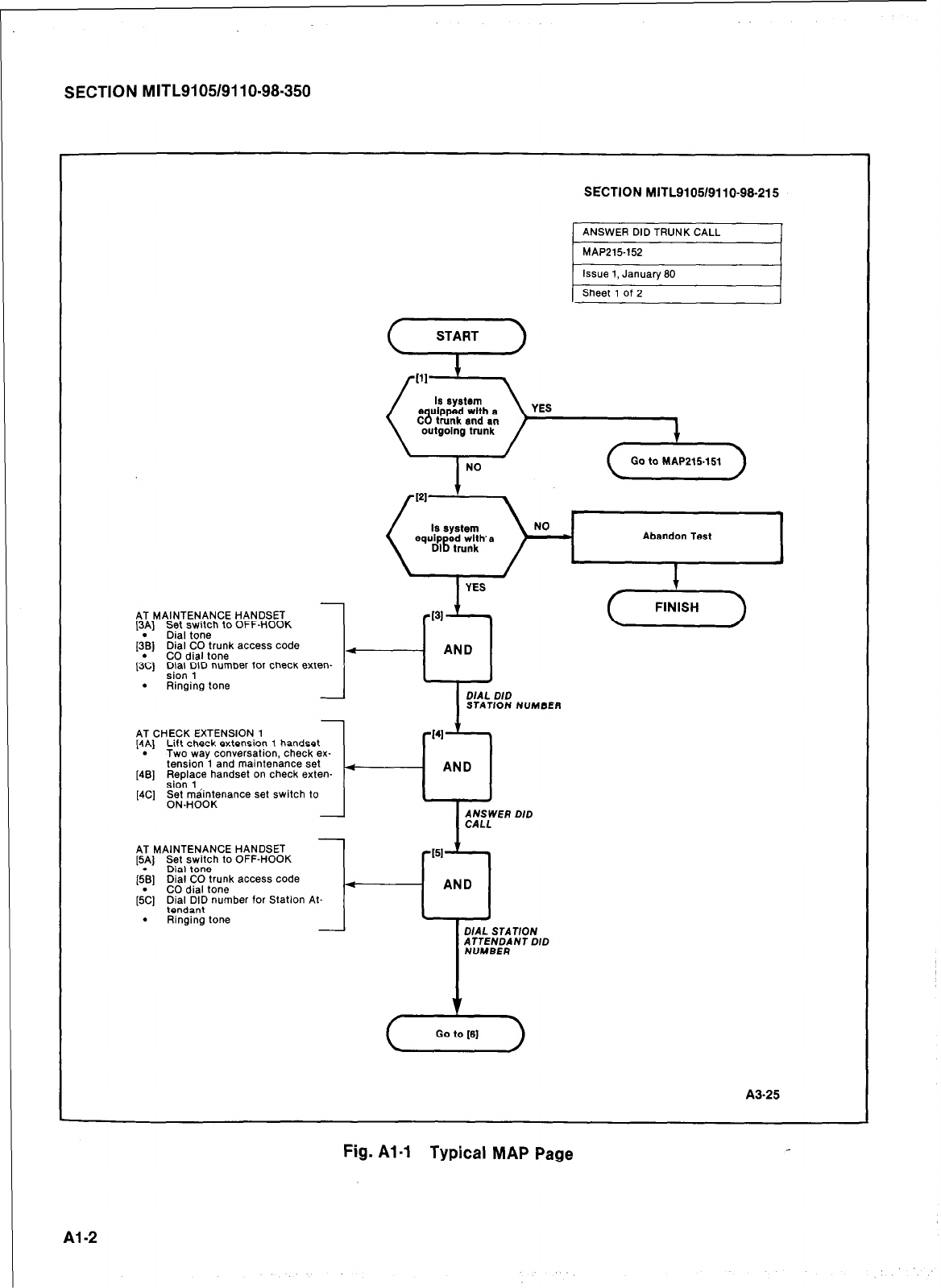
SECTION MITL9105/9110-98.350
SECTION MITL9105/9110-98-215
ANSWER DID TRUNK CALL
MAP215152
Issue 1, January SO
Sheet 1 of 2
YES
Go to MAP215.151
Is system
equip g” with’s
DI trunk
Abandon Test
AT MAINTENANCE HANDSET
[SA] Set switch to OFF-HOOK
[;B] Dial tone
Dial CO trunk access code
@Cl CO dial tone
;i; YID number for check exten-
. Ringing tone
STATION NUMBER
-
AT CHECK EXTENSION, 1
[4p] Lift check extenslo? 1 handset
Two way conversatton, check ex-
tension 1 and maintenance set
[4B] F&&ye handset on check exten-
[4C] F;.;$$enance set switch to
-
AT MAINTENANCE HANDSET
[5A] Set switch to OFF-HOOK
. Dial tone
[5.B] Dial CO trunk access code
CO dial tone
[5C] ;;li,SII number for Station
. Ringing tone
DIAL STATION
fLE;;;NT DID
c5
Go to [S]
A%25
Fig. Al-1 Typical MAP Page
Al-2
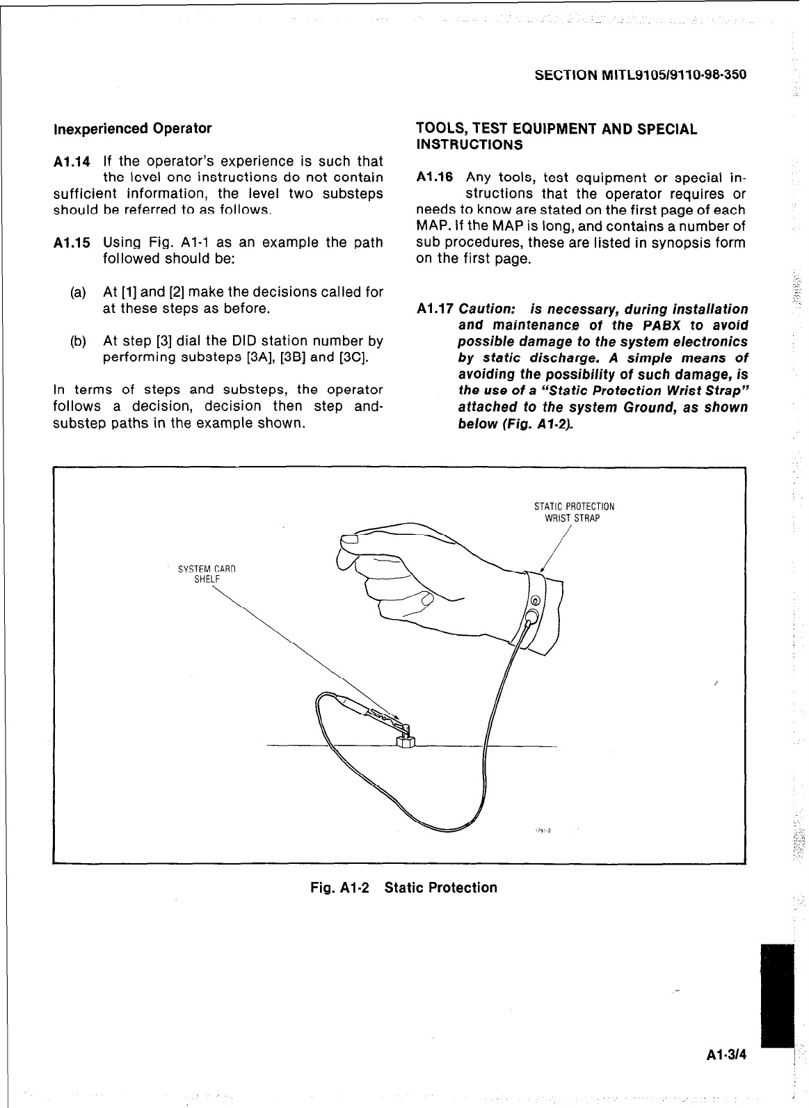
SECTION MITL9105/9110-98-350
Inexperienced Operator
Al.14 If the operator’s experience is such that
the level one instructions do not contain
sufficient information, the level two substeps
should be referred to as follows.
Al.15 Using Fig. Al-l as an example the path
followed should be:
(a) At [l] and [2] make the decisions called for
at these steps as before.
(b) At step [3] dial the DID station number by
performing substeps [3A], [3B] and [3C].
In terms of steps and substeps, the operator
follows a decision, decision then step and-
TOOLS, TEST EQUIPMENT AND SPECIAL
INSTRUCTIONS
Al.18 Any tools, test equipment or special in-
structions that the operator requires or
needs to know are stated on the first page of each
MAP. If the MAP is long, and contains a number of
sub procedures, these are listed in synopsis form
on the first page.
Al .17 Caution: is necessary, during ins talla tion
and maintenance of the PABX to avoid
possible damage to the system electronics
by static discharge. A simple means of
avoiding the possibility of such damage, is
the use of a “Static Protection Wrist Strap”
attached to the system Ground, as shown
substep paths in the example shown. below (Fig. Al-2).
STATIC PROTECTION
WRIST STRAP
SYSTEM CARD
SHELF
Fig. Al-2 Static Protection
Al -314
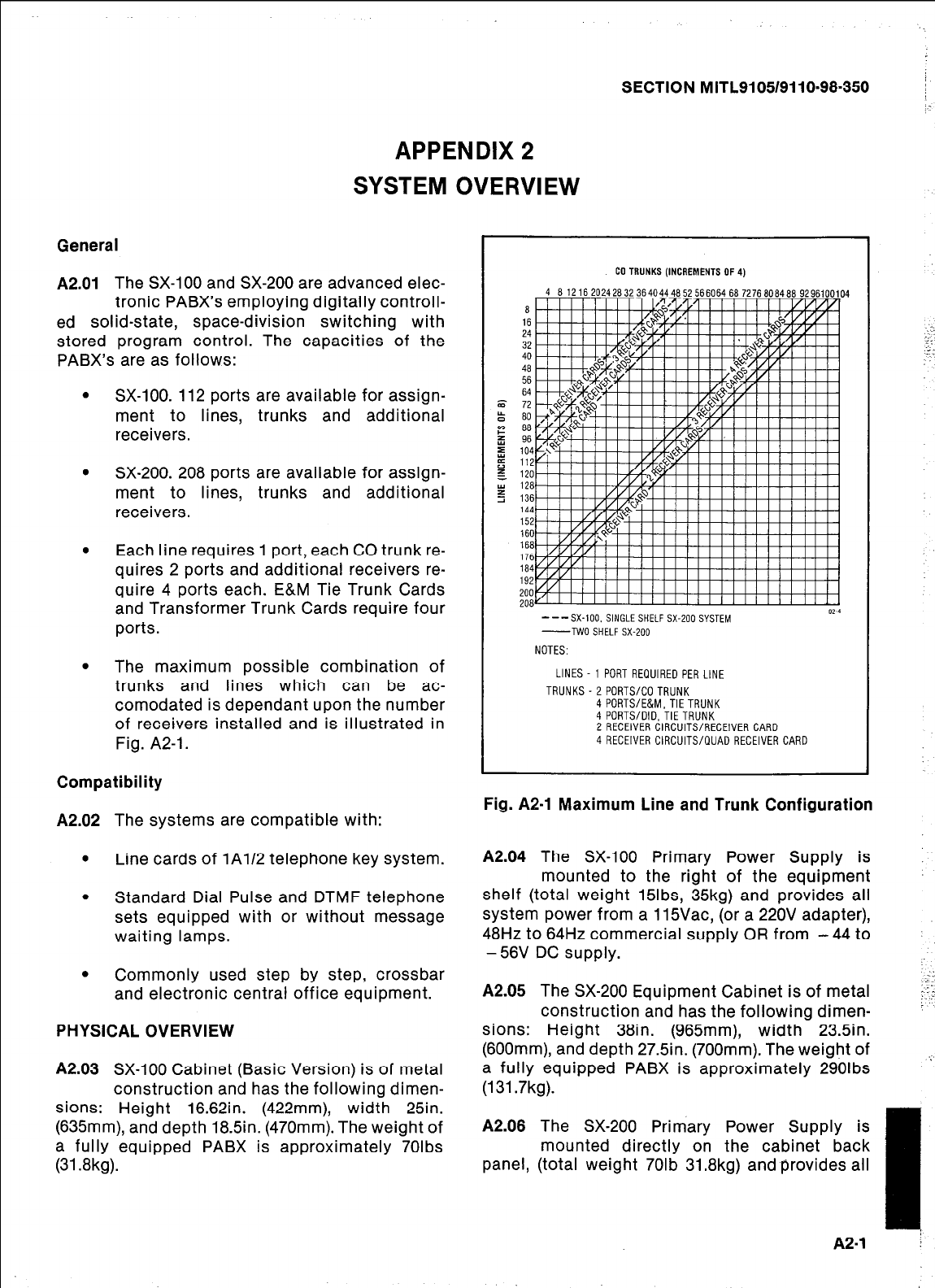
SECTION MITL9105/9110-98.350
APPENDIX 2
SYSTEM OVERVIEW
General
A2.01
The SX-100 and SX-200 are advanced elec-
tronic PABX’s employing digitally controll-
ed solid-state, space-division switching with
stored program control. The capacities of the
PABX’s are as follows:
SX-100. 112 ports are available for assign-
ment to lines, trunks and additional
receivers.
SX-200. 208 ports are available for assign-
ment to lines, trunks and additional
receivers.
Each line requires 1 port, each CO trunk re-
quires 2 ports and additional receivers re-
quire 4 ports each. E&M Tie Trunk Cards
and Transformer Trunk Cards require four
ports.
The maximum possible combination of
trunks and lines which can be ac-
comodated is dependant upon the number
of receivers installed and is illustrated in
Fig. A2-1.
Compatibility
A2.02 The systems are compatible with:
.
Line cards of IAl/ telephone key system.
.
Standard Dial Pulse and DTMF telephone
sets equipped with or without message
waiting lamps.
.
Commonly used step by step, crossbar
and electronic central office equipment.
PHYSICAL OVERVIEW
A2.03 SX-100 Cabinet (Basic Version) is of metal
construction and has the following dimen-
sions: Height 16.62in. (422mm), width 25in.
(635mm), and depth 18.5in. (470mm). The weight of
a fully equipped PABX is approximately 70lbs
(31.8kg).
CO TRUNKS (INCREMENTSOF
4 612162024263236404446525660646672766084669296100104
a
_^
24 1
32 32
40 40
46 46
56 56
64 64
72 72
60 60
88 88
96 96
104 104
112 112
120
126
136
144
152
160
166
176
164
192
200
206
---SX-100. SINGLE SHELF SX-200 SYSTEM
-TWO SHELF SX-200
NOTES:
LINES 1 PORT REQUIRED PER LINE
TRUNKS-ZPORTS/COTRUNK
4 PORTS/E&M.TlETRUNK
4 PORTS/DID, TIE TRUNK
2 RECEIVER CIRCUITS/RECEIVER CARD
4 RECEIVER CIRCUITS/QUAD RECEIVER CARD
Fig. A2-1 Maximum Line and Trunk Configuration
A2.04 The SX-100 Primary Power Supply is
mounted to the right of the equipment
shelf (total weight 15lbs, 35kg) and provides all
system power from a 1 ISVac, (or a 220V adapter),
48Hz to 64Hz commercial supply OR from - 44 to
-56V DC supply.
A2.05 The SX-200 Equipment Cabinet is of metal
construction and has the following dimen-
sions: Height 38in. (965mm), width 23.5in.
(600mm), and depth 27.5in. (700mm). The weight of
a fully equipped PABX is approximately 290lbs
(131.7kg).
A2.08
The SX-200 Primary Power Supply is
mounted directly on the cabinet back
panel, (total weight 701b 31.8kg) and provides all
A2-1
SECTION MITL9105/9110-98.350
system power from either a 115Vac, or a 220Vac,
44Hz - 64Hz commercial supply, OR a -44 to
- 56Vdc supply.
A2.07 The SX-lOO/SX-200 Equipment Shelf holds
up to 22 printed circuit cards which plug
into the shelf backplane. On the rear of the
backplane are a number of Amphenol type plugs
providing interconnections between the shelves
and external equipment. In addition to the plugs
are a number of screw down terminals, allowing
shelf connections to the primary power supply
unit. The equipment shelves measure 10.75in.
(273mm) high, 19in. (480mm) wide, 15375in.
(415mm) deep and weigh approximately 271bs
(12.3kg) fully equipped. Equipment Shelf 2 (SX-200
only) is identical in construction to equipment
shelf 1 and holds up to 12 additional line or trunk
cards.
A2.08
The Reserve Power Supply in the PABX’s
provides a -48Vdc source. The supply
consists of a shelf unit containing 8 Globe Gel Gc
6200A batteries providing -48.3Vdc nominal at
20 C. A separate temperature-compensated
charging unit maintains the correct battery
voltage level. The SX-200 reserve battery power
supply measures 7in. (178mm) high, 19in. (483mm)
wide, 15in. (381mm) deep and weighs 1lOlbs
(43kg). The SX-100 reserve battery power supply
measures 8.2in. (200.9mm) high, 25.0in. (635mm)
wide, 18.5in. (40mm) deep, and weighs 125lbs. The
SX-lOO/SX-200 charging unit measures 5in.
(127mm) wide, 7in. (178mm) high, 14in. (355mm)
deep and weighs 14lbs (6.4kg).
A2.09
The Attendant Console weighs approx-
imately 13lbs (5.9kg) and its dimensions
are: 13.75in. (350mm) wide, 6.8in. (176mm) high,
9.25in. (236mm) deep.
A2.10
Table A2-1 lists all the tables that com-
prise the remainder of this appendix.
A2-2
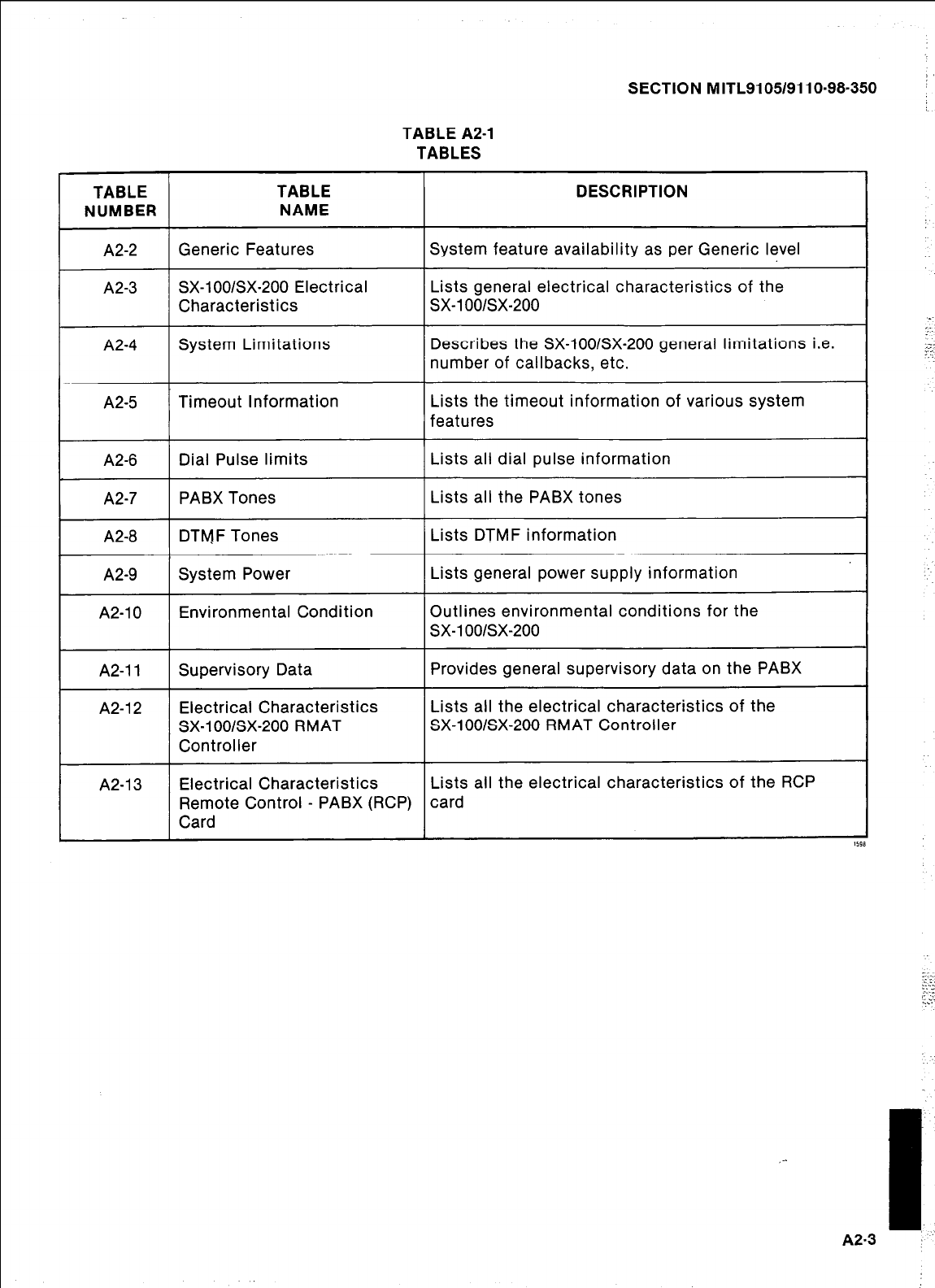
TABLE TABLE
NUMBER NAME
A2-2 Generic Features
A2-3 SX-lOO/SX-200 Electrical
Characteristics
A2-4 System Limitations
A2-5 Timeout Information
A2-6 Dial Pulse limits
A2-7 PABX Tones
A2-8 DTfvJF Tones
A2-9 System Power
A2-10 Environmental Condition
A2-11 Supervisory Data
A2-12 Electrical Characteristics
SX-lOO/SX-200 RMAT
Controller
A2-13 Electrical Characteristics
Remote Control - PABX (RCP)
Card
SECTION MITL9105/9110-98-350
TABLE A2-1
TABLES
DESCRIPTION
System feature availability as per Generic level
Lists general electrical characteristics of the
sx-1 oo/sx-200
Describes the SX-lOO/SX-200 general limitations i.e.
number of callbacks, etc.
Lists the timeout information of various system
features
Lists all dial pulse information
Lists all the PABX tones
Lists DTMF information
Lists general power supply information
Outlines environmental conditions for the
sx-1 oo/sx-200
Provides general supervisory data on the PABX
Lists all the electrical characteristics of the
SX-lOO/SX-200 RMAT Controller
Lists all the electrical characteristics of the RCP
card
,-
I
~2.3 :.’
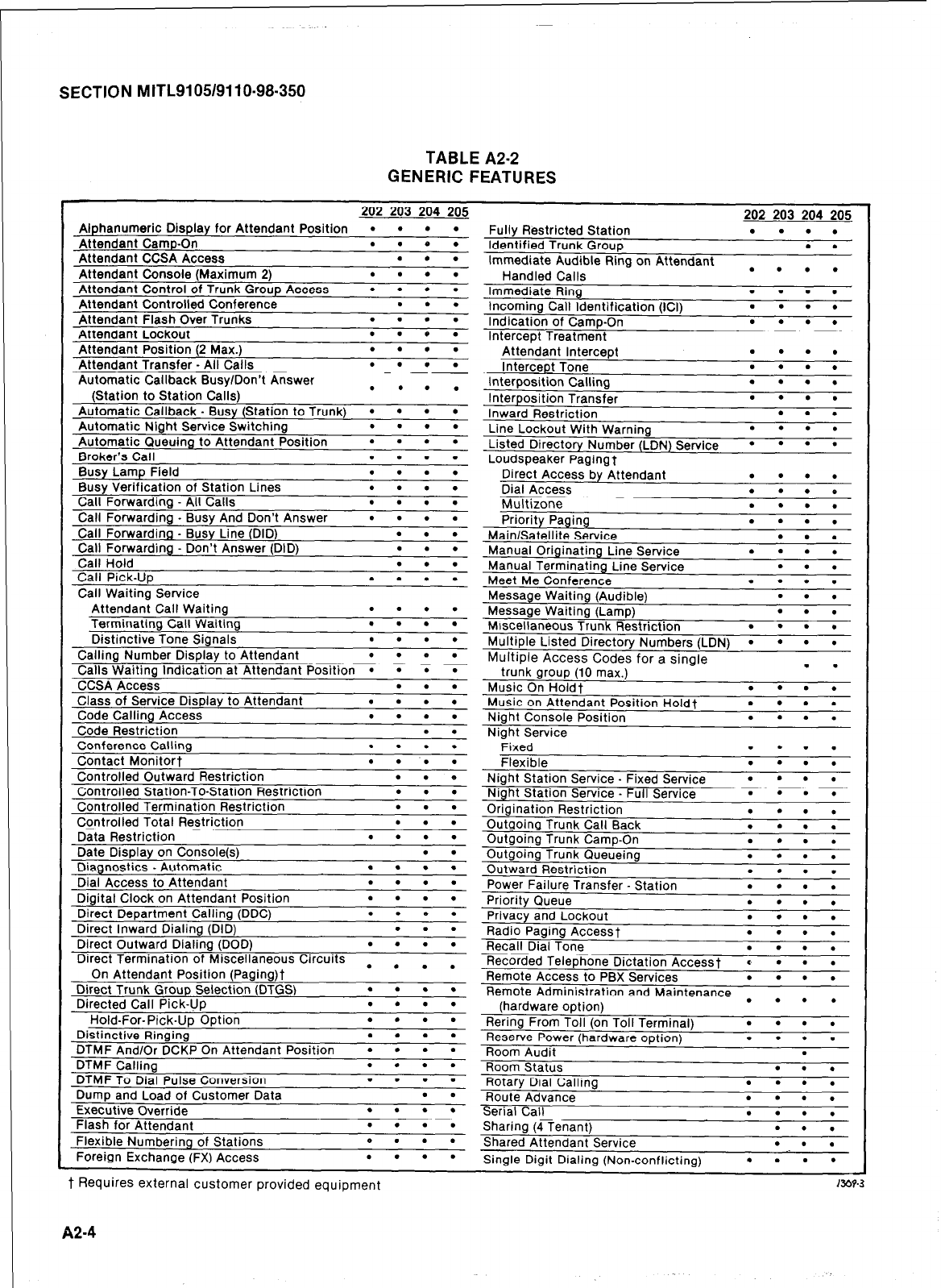
SECTION MITL9105/9110-98-350
TABLE A2-2
GENERIC FEATURES
202 203 204 205
Alphanumeric Display for Attendant Position
l l l l
Attendant Camp-On . . 0 .
Attendant CCSA Access . . .
Attendant Console (Maximum 2) . . . .
Attendant Control of Trunk Group Access
l l l l
Attendant Controlled Conference
l . .
Attendant Flash Over Trunks . . . .
Attendant Lockout . . e .
Attendant Position (2 Max.) . . . .
Attendant Transfer - All Calls . . . .
Automatic Callback BusvlDon’t Answer
(Station to Station Cal&) . . . .
Automatic Callback . Busy (Station to Trunk)
l l l l
Automatic Night Service Switching . . . .
Automatic Queuing to Attendant Position
l l l l
Broker’s Call . . . .
Busy Lamp Field . . . .
Busy Verification of Station Lines . . . .
Call Forwarding - All Calls . . . .
Call Forwarding _ Busy And Don’t Answer
l l l l
Call Forwarding - Busy Line (DID) . . .
Call Forwarding - Don’t Answer (DID) . . .
Call Hold . . .
Call Pick-Up . . . .
Call Waitina Service
Date Display on Console(s)
Diagnostics _ Automatic
Dial Access to Attendant
. .
. . . .
. . . .
Digital Clock on Attendant Position . . . .
Direct Department Calling (DDC) . . e .
Direct Inward Dialing (DID) . . .
Direct Outward Dialing (DOD) . . . .
Direct Termination of Miscellaneous Circuits _ _
On Attendant Position (Paging)t . . . .
Direct Trunk Group Selection (DTGS) . . . .
Directed Call Pick-Up . . . .
Hold-For-Pick-Uo Ootion . . . .
Distinctive Ringins . . . .
DTMF And/Or DCKP On Attendant Position
l l l l
DTMF Calling . . . .
DTMF To Dial Pulse Conversion . . . .
Dump and Load of Customer Data . .
Executive Override . . . .
Flash for Attendant . . . .
Flexible Numbering of Stations 0 . . .
Foreign Exchange (FX) Access . . . .
202 203 204 205
Fully Restricted Station . . . .
Identified Trunk Group . .
Immediate Audible Ring on Attendant
Handled Calls . . . .
Immediate Ring . . . .
Incoming Call Identification (ICI) . . . .
Indication of Camp-On . . . .
Intercept Treatment
Attendant Intercept . . . .
Intercept Tone . . . .
Interposition Calling . . . .
Interposition Transfer . . . .
Inward Restriction . . .
Line Lockout With Warning . . . .
Listed Directory Number (LDN) Service
l l l l
Loudspeaker Pagingf
Direct Access by Attendant . . . .
Dial Access . . . e
Multizone . . . .
Priority Paging . . . .
Main/Satellite Service . . .
Manual Originating Line Service . . . .
Manual Terminating Line Service . . .
Meet Me Conference . . . .
B . .
Message Waiting (Audible)
Message Waiting (Lamp)
j Trunk Restriction
I
. . .
l . . .
Multiple Listed Directory Numbers (LDN)
l l l l
h,
lultiple Access Codes for a sinale
trunk group (10 max.) . .
Music On Holdf . . . .
Music on Attendant Position Holdf
l l l l
Night Console Position . . . .
Night Service
Fixed
. l . .
Flexible . . . .
Night Station Service. Fixed Service
l l l l
Night Station Service. Full Service
l l l l
Origination Restriction . . . .
Outgoing Trunk Call Back . . . .
Outaoina Trunk Camo-On . . . .
Outgoing Trunk Queueing
Outward Restriction
. . . .
. . . .
. . . .
Radio Paging Accessf
Recall Dial Tone
. . . .
. . . .
. . . .
Recorded Telephone Dictation Accessf *
l l l
Remote Access to PBX Services . . . .
Remote Administration and Maintenance . . . .
(hardware option)
Rering From Toll (on Toll Terminal)
l l l l
Reserve Power (hardware option) . . . .
Room
Alhit .
_ _ _ _
Room Status
Rotary Dial Calling
Route Advance
. . .
. . . .
. . . .
Serial Call . . . .
Sharing (4 Tenant) . . .
Shared Attendant Service . . .
Single Digit Dialing (Non-conflicting)
l l l l
t Requires external customer provided equipment 133?3
A24
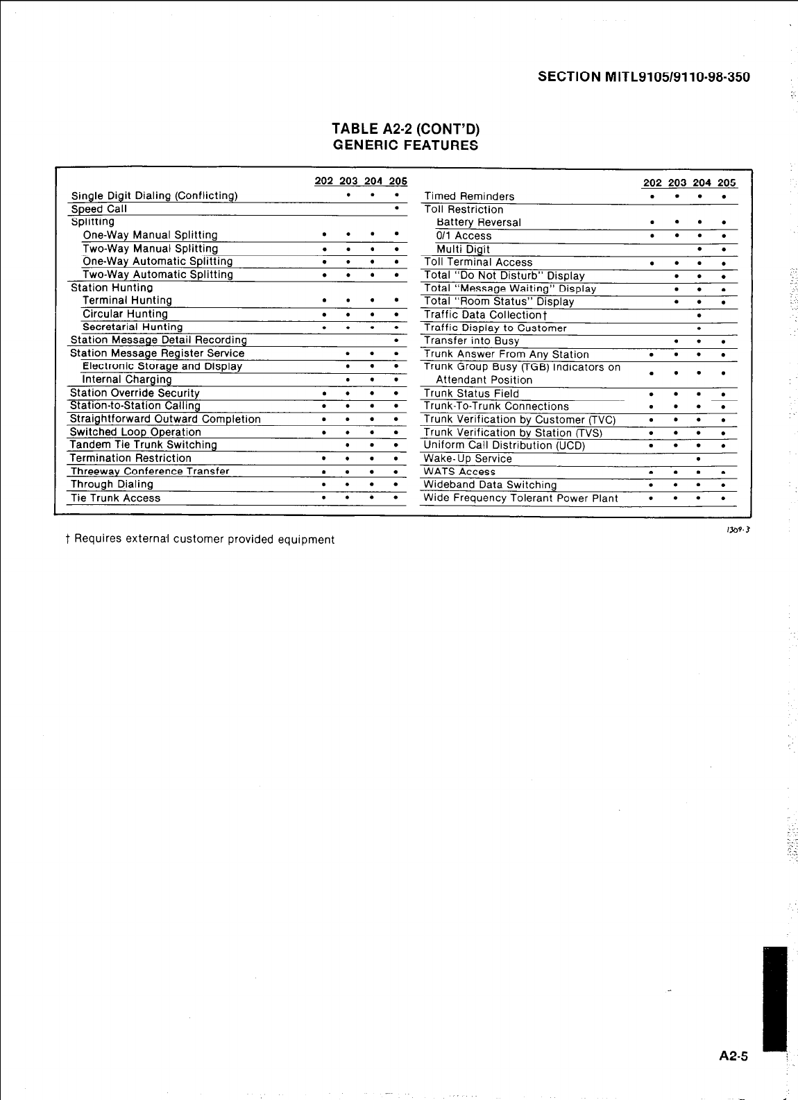
SECTION MITL9105/9110-98-350
TABLE A2-2 (CONT’D)
GENERIC FEATURES
Single Digit Dialing (Conflicting)
Speed Call
Splitting
One-Way Manual Splitting
Two-Wav Manual Solittina
202 203 204 205
. . .
.
. . . .
. . . .
One-Way Automatic Splitying
Two-Way Automatic Splitting
Station Hunting
. . . .
. . . .
Terminal Hunting
Circular Hunting
Secretarial Hunting
Station Message Detail Recording
Station Message Register Service
Electronic Storage and Display
Internal Charging
Station Override Securitv
. . . .
. . . .
. . . .
.
. . .
. . .
. . .
. . . .
Station-to-Station Calling . . . .
Straightforward Outward Completion . . . .
Switched Loop Operation . . . .
Tandem Tie Trunk Switching . . .
Termination Restriction
Threewav Conference Transfer
Through Dialing
Tie Trunk Access
. . . .
. . . .
. . . .
. . . .
Timed Reminders
Toll Restriction
Battery Reversal
011 Access
Multi Diait
202 203 204 205
. . . .
. . . .
. . . .
. .
-a.-
Toll Terminal Access . . . .
Total “Do Not Disturb” Display . . .
Total “Message Waiting” Display . . .
Total “Room Status” Display . . .
Traffic Data Collectionf .
Traffic Display to Customer .
Transfer into Busy . . .
Trunk Answer From Any Station . . . .
Trunk Group Busy (TGB) Indicators on
Attendant Position
. . . .
Trunk Status Field . . . .
Trunk-To-Trunk Connections . . . .
Trunk Verification by Customer (TVC)
l l l l
Trunk Verification by Station (TVS) . . . .
Uniform Call Distribution (UCD) . . . .
Wake- Up Service .
WATS Access . . . .
Wideband Data Switching . . . .
Wide Frequency Tolerant Power Plant
l l l l
t Requires externa-I customer provided equipment
I
A2-5 I
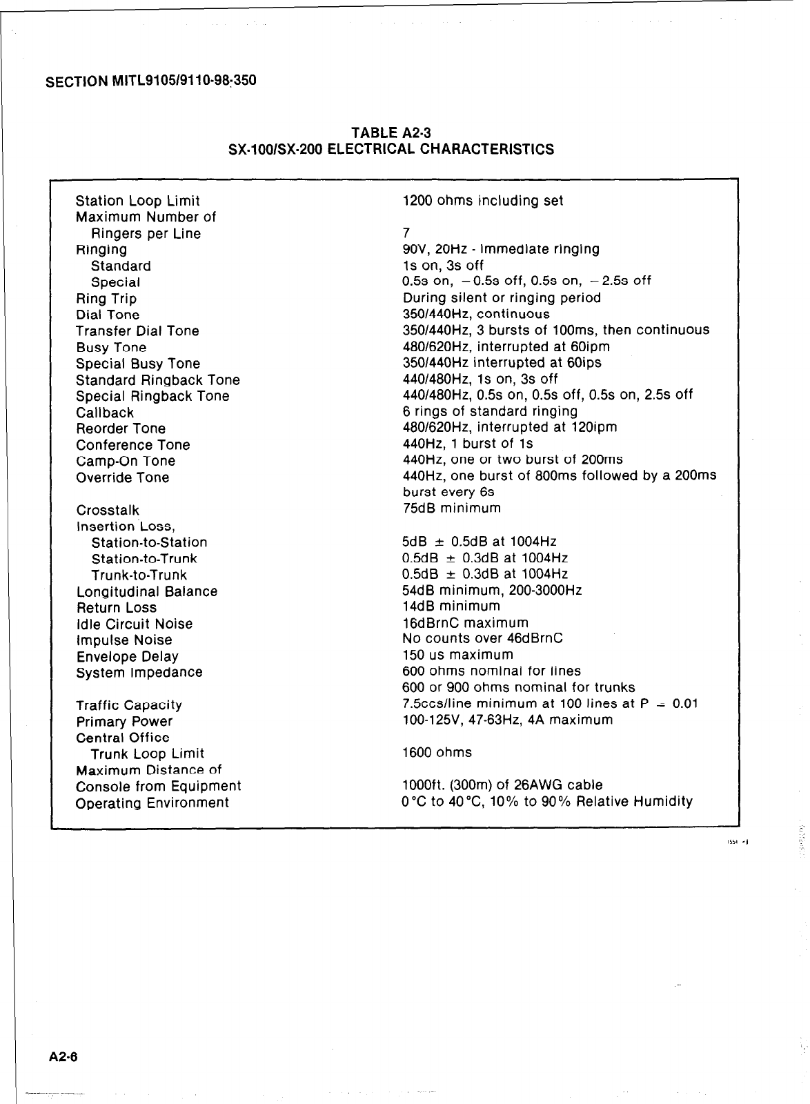
SECTION MITL9105/9110-98:350
TABLE A2-3
SX-lOO/SX-200 ELECTRICAL CHARACTERISTICS
Station Loop Limit
Maximum Number of 1200 ohms including set
Ringers per Line
Ringing
Standard
Special
Ring Trip
Dial Tone
Transfer Dial Tone
Busy Tone
Special Busy Tone
Standard Ringback Tone
Special Ringback Tone
Callback
Reorder Tone
Conference Tone
Camp-On Tone
Override Tone
Crosstalk
Insertion Loss,
Station-to-Station
Station-to-Trunk
Trunk-to-Trunk
Longitudinal Balance
Return Loss
idle Circuit Noise
Impulse Noise
Envelope Delay
System Impedance
Traffic Capacity
Primary Power
Central Office
Trunk Loop Limit
Maximum Distance of
Console from Equipment
Operating Environment
7
9OV, 20Hz - immediate ringing
1s on, 3s off
0.5s on, -0.5s off, 0.5s on, -2.5s off
During silent or ringing period
350/440Hz, continuous
350/440Hz, 3 bursts of looms, then continuous
480/620Hz, interrupted at 60ipm
350/440Hz interrupted at 60ips
440/480Hz, Is on, 3s off
440/480Hz, 0.5s on, 0.5s off, 0.5s on, 2.5s off
6 rings of standard ringing
480/620Hz, interrupted at 120ipm
440Hz, 1 burst of 1s
440Hz, one or two burst of 200ms
440Hz, one burst of 800ms followed by a 200ms
burst every 6s
75dB minimum
5dB + 0.5dB at 1004Hz
0.5dB -+ 0.3dB at 1004Hz
0.5dB f 0.3dB at 1004Hz
54dB minimum, 200-3000Hz
14dB minimum
16dBrnC maximum
No counts over 46dBrnC
150 us maximum
600 ohms nominal for lines
600 or 900 ohms nominal for trunks
7.5ccs/line minimum at 100 lines at P = 0.01
lOO-125V, 47-63Hz, 4A maximum
1600 ohms
lOOOft. (300m) of 26AWG cable
0°C to 40°C 10% to 90% Relative Humidity
A2-6
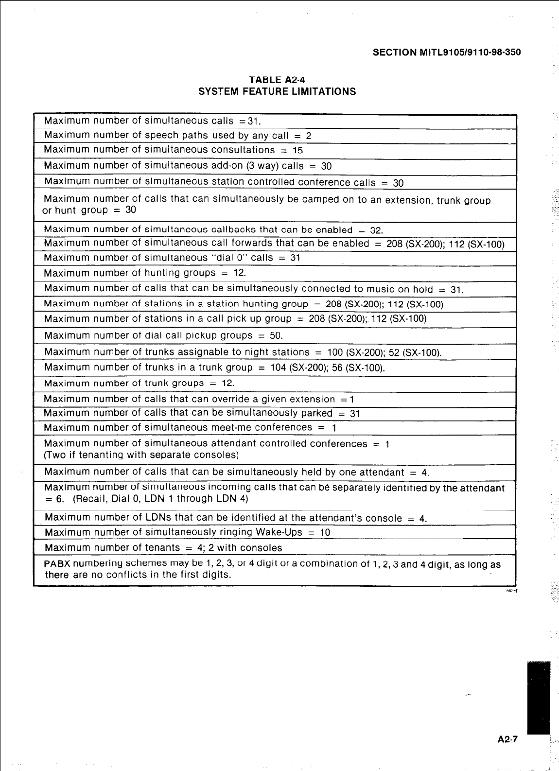
SECTION MITL9105/9110-98.350
TABLE A2-4
SYSTEM FEATURE LIMITATIONS
Maximum number of simultaneous calls = 31.
Maximum number of speech paths used by any call = 2
Maximum number of simultaneous consultations = 15
Maximum number of simultaneous add-on (3 way) calls = 30
Maximum number of simultaneous station controlled conference calls = 30
Maximum number of calls that can simultaneously be camped on to an extension, trunk group
or hunt group = 30
Maximum number of simultaneous callbacks that can be enabled = 32.
Maximum number of simultaneous call forwards that can be enabled = 208 (SX-200); 112 (SX-100)
Maximum number of simultaneous “dial 0” calls = 31
Maximum number of hunting groups = 12.
Maximum number of calls that can be simultaneously connected to music on hold = 31.
Maximum number of stations in a station hunting group = 208 (SX-200); 112 (SX-100)
Maximum number of stations in a call pick up group = 208 (SX-200);.112 (SX-100)
Maximum number of dial call pickup groups = 50.
Maximum number of trunks assignable to night stations = 100 (SX-200); 52 (SX-100).
Maximum number of trunks in a trunk group = 104 (SX-200); 56 (SX-100).
Maximum number of trunk groups = 12.
Maximum number of calls that can override a given extension = 1
Maximum number of calls that can be simultaneously parked = 31
Maximum number of simultaneous meet-me conferences = 1
Maximum number of simultaneous attendant controlled conferences = 1
(Two if tenanting with separate consoles)
Maximum number of calls that can be simultaneously held by one attendant = 4.
Maximum number of simultaneous incoming calls that can be separately identified by the attendant
= 6. (Recall, Dial 0, LDN 1 through LDN 4)
Maximum number of LDNs that can be identified at the attendant’s console = 4.
Maximum number of simultaneously ringing Wake-Ups = 10
Maximum number of tenants = 4; 2 with consoles
PABX numbering schemes may be 1, 2, 3, or 4 digit or a combination of 1, 2, 3 and 4 digit, as long as
there are no conflicts in the first digits.
_-
A2-7 /
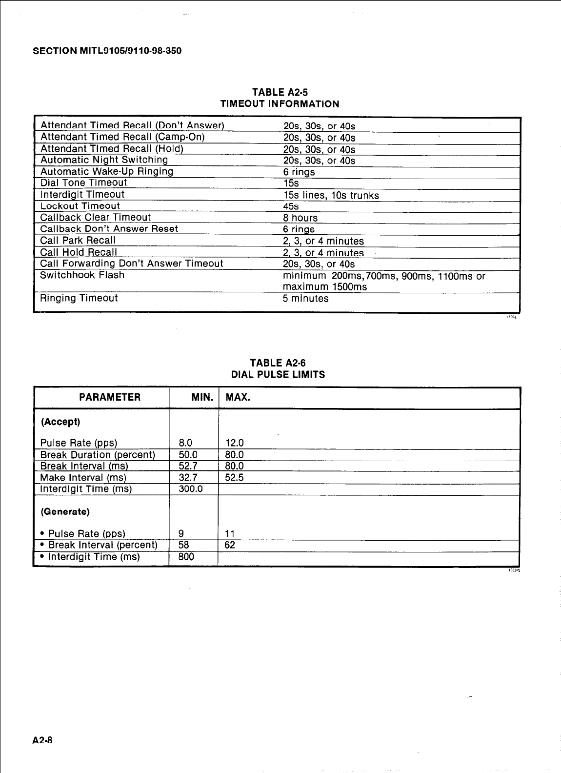
SECTION MITL9105/9110-98.350
TABLE A2-5
TIMEOUT INFORMATION
Attendant Timed Recall (Don’t Answer)
Attendant Timed Recall (Camp-On)
Attendant Tlmed Recall (Hold)
Automatic Night Switching
Automatic Wake-Up Ringing
Dial Tone Timeout
Interdigit Timeout
Lockout Timeout
Callback Clear Timeout
Callback Don’t Answer Reset
Call Park Recall
Call Hold Recall
Call Forwarding Don’t Answer Timeout
Switchhook Flash
2Os, 30s or 40s
2Os, 3Os, or 40s
2Os, 3Os, or 40s
2Os, 30s or 40s
6 rings
15s
15s lines, 10s trunks
45s
8 hours
6 rings
2, 3, or 4 minutes
2, 3, or 4 minutes
2Os, 3Os, or 40s
minimum 200ms,700ms, 900ms, 1100ms or
Ringing Timeout maximum 1500ms
5 minutes
PARAMETER
(Accept)
TABLE A2-8
DIAL PULSE LIMITS
MIN. MAX.
Pulse Rate (pps)
Break Duration (percent)
Break Interval (ms)
Make Interval (ms)
Interdigit Time (ms)
8.0 12.0
50.0 80.0
52.7 80.0
32.7 52.5
300.0
(Generate)
l
Pulse Rate (pps) 9 11
l
Break Interval (percent) 58 62
l
Interdigit Time (ms) 800
_-
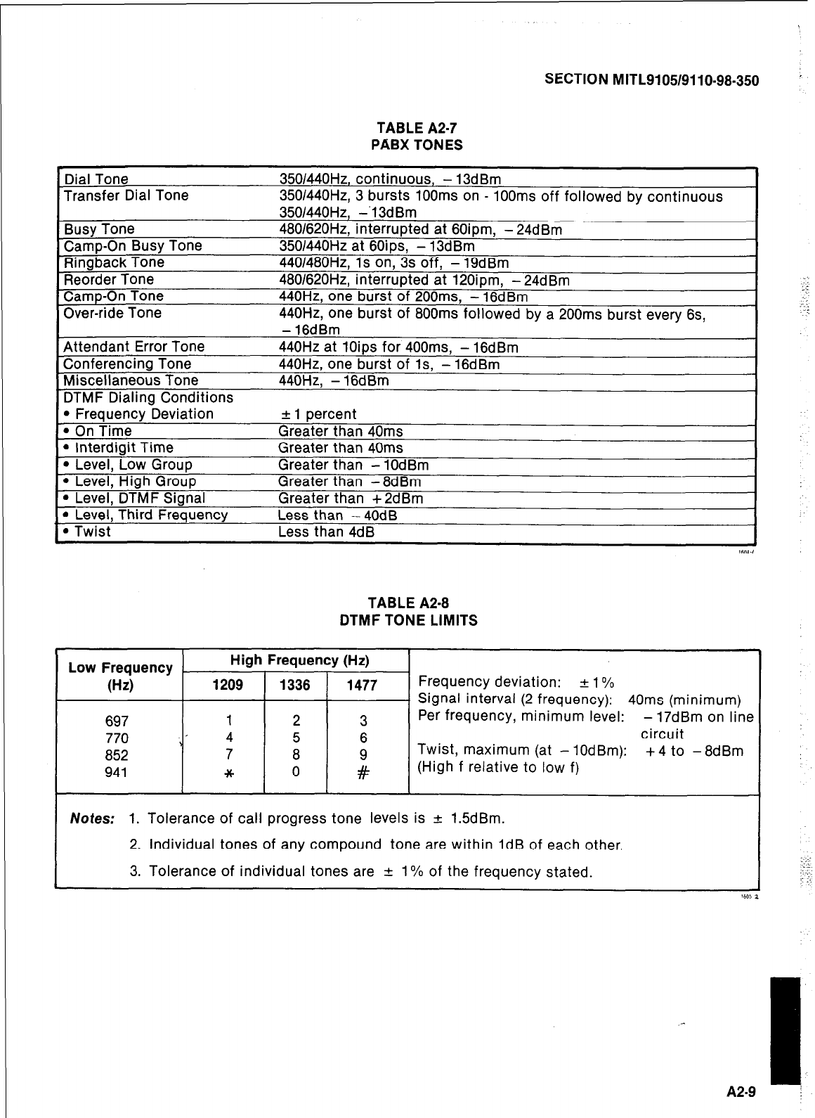
SECTION MITL9105/9110-98-350 ’
TABLE A2-7
PABX TONES
Dial Tone
Transfer Dial Tone
Busy Tone
Camp-On Busy Tone
Ringback Tone
Reorder Tone
Camp-On Tone
Over-ride Tone
Attendant Error Tone
Conferencing Tone
Miscellaneous Tone
DTMF Dialing Conditions
l
Frequency Deviation
l
On Time
l
Interdigit Time
l
Level, Low Group
l
Level, High Group
l
Level, DTMF Signal
l
Level, Third Frequency
l
Twist
3501440H2, continuous, - 13dBm
350/440Hz, 3 bursts 1OOms on - 100ms off followed by continuous
350/440Hz, -‘13dBm
480/620Hz, interrupted at 60ipm, - 24dBm
3501440Hz at 6Oips, - 13dBm
440/480Hz, 1s on, 3s off, - 19dBm
480/620Hz, interrupted at 120ipm, - 24dBm
440Hz, one burst of 200ms, - 16dBm
440Hz, one burst of 800ms followed by a 200ms burst every 6s,
- 16dBm
440Hz at 1Oips for 400ms, - 16dBm
440Hz, one burst of Is, - 16dBm
440Hz, - 16dBm
+ 1 percent
Greater than 40ms
Greater than 40ms
Greater than - 1OdBm
Greater than -8dBm
Greater than +2dBm
Less than -4OdB
Less than 4dB 16OP.I
TABLE A2-8
DTMF TONE LIMITS
Low Frequency High Frequency (Hz)
(Hz) 1209 1336 1477 Frequency deviation: + 1%
- Signal interval (2 frequency): 40ms (minimum)
697 1 2 3 Per frequency, minimum level: - 17dBm on line
770 \’ 4 5 6 circuit
852 7 8
t
Twist, maximum (at - 10dBm): +4 to -8dBm
941 * 0 (High f relative to low f)
Notes: 1. Tolerance of call progress tone levels is & 1.5dBm.
2. Individual tones of any compound tone are within 1dB of each other
3. Tolerance of individual tones are + 1% of the frequency stated.
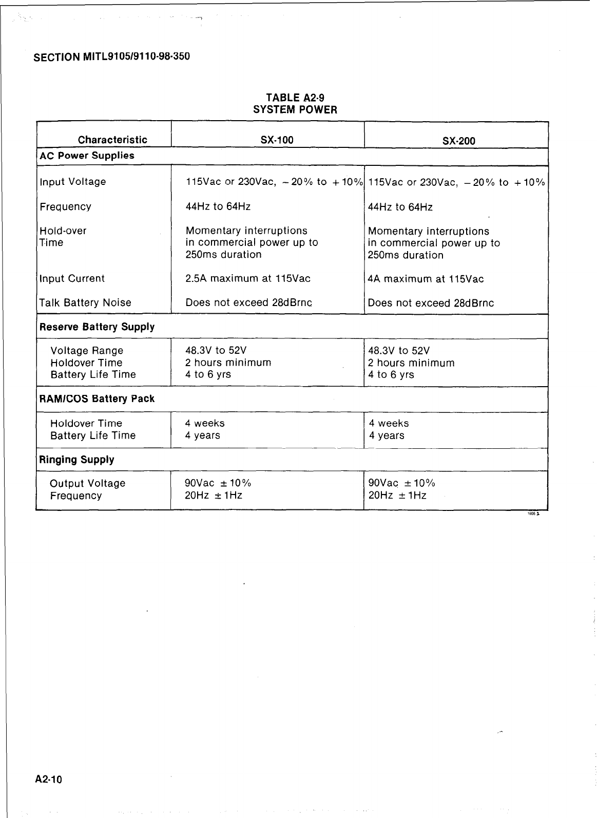
SECTION MITL9105/9110-98-350
TABLE A2-9
SYSTEM POWER
Characteristic
AC Power Supplies
sx-100 sx-200
Input Voltage
Frequency
Hold-over
Time
Input Current
Talk Battery Noise
Reserve Battery Supply
Voltage Range
Holdover Time
Battery Life Time
RAMlCOS Battery Pack
115Vac or 230Vac, -20% to +lO% 115Vac or 230Vac, -20% to +lO”/
44Hz to 64Hz 44Hz to 64Hz
Momentary interruptions Momentary interruptions
in commercial power up to in commercial power up to
250ms duration 250ms duration
2.5A maximum at 115Vac 4A maximum at 115Vac
Does not exceed 28dBrnc Does not exceed 28dBrnc
48.3V to 52V 48.3V to 52V
2 hours minimum 2 hours minimum
4 to 6 yrs 4 to 6 yrs
Holdover Time
Battery Life Time
Ringing Supply
4 weeks
4 years 4 weeks
4 years
Output Voltage 9OVac + 10
O/O
Frequency 20Hz I 1Hz 9OVac + 10%
20Hz f 1 Hz
A2.10
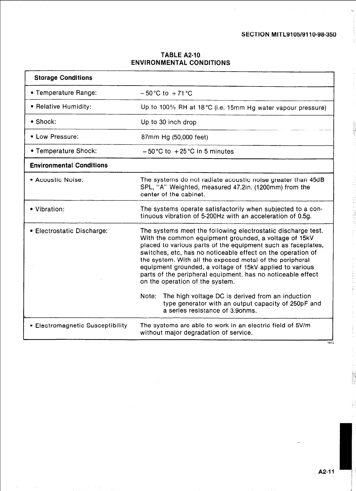
SECTION MlTL9105/9110-98-350
TABLE A2-10
ENVIRONMENTAL CONDITIONS
Storage Conditions
l
Temperature Range:
l
Relative Humidity:
. Shock:
* Low Pressure:
l
Temperature Shock:
Environmental Conditions
-50°C to +71 “C
UP
to 100% RH at 18°C (i.e. 15mm Hg water vapour pressure)
Up to 30 inch drop
87mm Hg (50,000 feet)
-50°C to +25X in 5 minutes
l
Acoustic Noise: The systems do not radiate acoustic noise greater than 45dB
SPL, “A” Weighted, measured 47.2in. (1200mm) from the
center of the cabinet.
l
Vibration: The systems operate satisfactorily when subjected to a con-
tinuous vibration of 5-200Hz with an acceleration of 0.59.
l
Electrostatic Discharge: The systems meet the following electrostatic discharge test.
With the common equipment grounded, a voltage of 15kV
placed to various parts of the equipment such as faceplates,
switches, etc, has no noticeable effect on the operation of
the system. With all the exposed metal of the peripheral
equipment grounded, a voltage of 15kV applied to various
parts of the peripheral equipment, has no noticeable effect
on the operation of the system.
Note: The high voltage DC is derived from an induction
type generator with an output capacity of 25OpF and
a series resistance of 3.9ohms.
l
Electromagnetic Susceptibility The systems are able to work in an electric field of 5Vlm
without major degradation of service.
A2-11
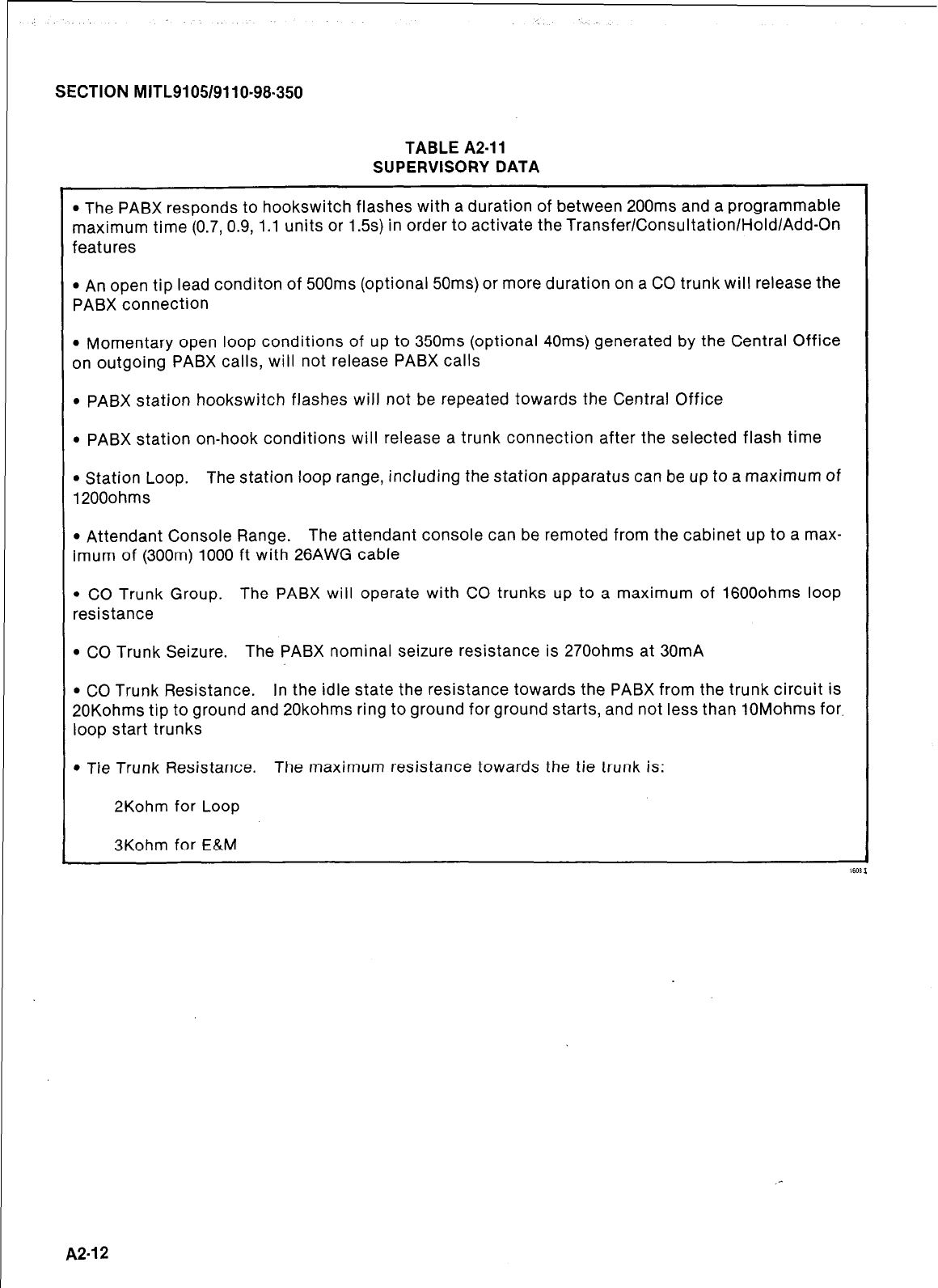
SECTION MITL9105/9110-98-350
TABLE A2-11
SUPERVISORY DATA
l
The PABX responds to hookswitch flashes with a duration of between 200ms and a programmable
maximum time (0.7, 0.9, 1.1 units or 1.5s) in order to activate the Transfer/Consultation/Hold/Add-On
features
l
An open tip lead conditon of 500ms (optional 50ms) or more duration on a CO trunk will release the
PABX connection
l
Momentary open loop conditions of up to 350ms (optional 40ms) generated by the Central Office
on outgoing PABX calls, will not release PABX calls
l
PABX station hookswitch flashes will not be repeated towards the Central Office
l
PABX station on-hook conditions will release a trunk connection after the selected flash time
l
Station Loop. The station loop range, including the station apparatus can be up to a maximum of
1200ohms
l
Attendant Console Range. The attendant console can be remoted from the cabinet up to a max-
imum of (300m) 1000 ft with 26AWG cable
l
CO Trunk Group. The PABX will operate with CO trunks up to a maximum of 16000hms loop
resistance
l
CO Trunk Seizure. The PABX nominal seizure resistance is 2700hms at 30mA
l
CO Trunk Resistance. In the idle state the resistance towards the PABX from the trunk circuit is
20Kohms tip to ground and 20kohms ring to ground for ground starts, and not less than 10Mohms for,
loop start trunks
l
Tie Trunk Resistance. The maximum resistance towards the tie trunk is:
2Kohm for Loop
3Kohm for E&M
A2-12
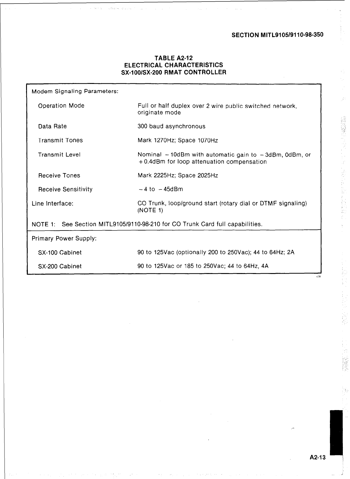
SECTION MITL9105/9110-98-350
TABLE A2-12
ELECTRICAL CHARACTERISTICS
SX-lOO/SX-200 RMAT CONTROLLER
Modem Signaling Parameters:
Operation Mode Full or half duplex over 2 wire public switched network,
originate mode
Data Rate 300 baud asynchronous
Transmit Tones Mark 1270Hz; Space 1070Hz
Transmit Level Nominal - 10dBm with automatic gain to - 3dBm, OdBm, or
+ 0.4dBm for loop attenuation compensation
Receive Tones Mark 2225Hz; Space 2025Hz
Receive Sensitivity -4 to -45dBm
Line Interface: CO Trunk, loop/ground start (rotary dial or DTMF signaling)
(NOTE 1)
NOTE 1: See Section MITL9105/9110-98-210 for CO Trunk Card full capabilities.
Primary Power Supply:
SX-100 Cabinet 90 to 125Vac (optionally 200 to 250Vac); 44 to 64Hz; 24
SX-200 Cabinet 90 to 125Vac or 185 to 250Vac; 44 to 64Hz, 4A
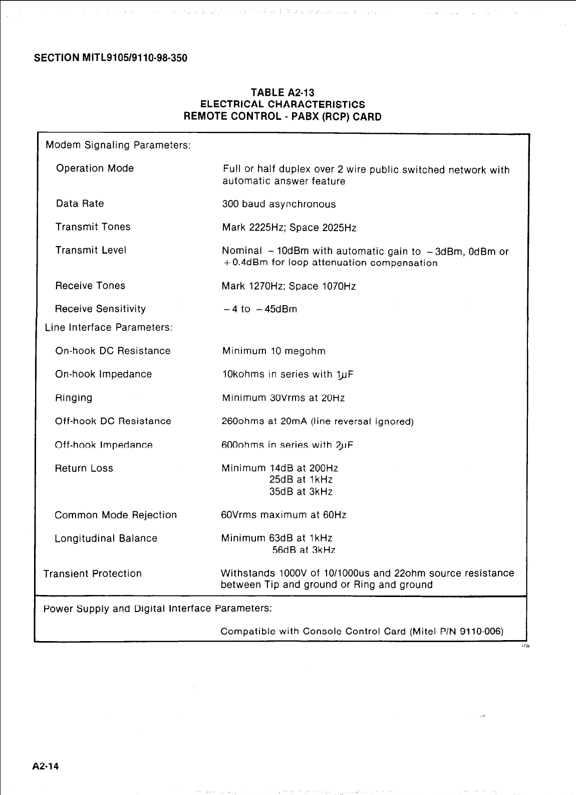
SECTION MITL9105/9110-98-350
TABLE A2-13
ELECTRICAL CHARACTERISTICS
REMOTE CONTROL - PABX (RCP) CARD
Modem Signaling Parameters:
Operation Mode Full or half duplex over 2 wire public switched network with
automatic answer feature
Data Rate 300 baud asynchronous
Transmit Tones Mark 2225Hz; Space 2025Hz
Transmit Level Nominal - IOdBm with automatic gain to -3dBm, OdBm or
+ 0.4dBm for loop attenuation compensation
Receive Tones Mark 1270Hz; Space 1070Hz
Receive Sensitivity - 4 to - 45dBm
Line Interface Parameters:
On-hook DC Resistance Minimum 10 megohm
On-hook Impedance 10kohms in series with ~JJF
Ringing Minimum 30Vrms at 20Hz
Off-hook DC Resistance 2600hms at 20mA (line reversal ignored)
Off-hook Impedance 6000hms in series with 2yF
Return Loss Minimum 14dB at 200Hz
25dB at 1kHz
35dB at 3kHz
Common Mode Rejection 6OVrms maximum at 60Hz
Longitudinal Balance Minimum 63dB at 1kHz
56dB at 3kHz
Transient Protection Withstands 1OOOV of 10/1000us and 220hm source resistance
between Tip and ground or Ring and ground
Power Supply and Digital interface Parameters:
Compatible with Console Control Card (Mite1 P/N 9110-006)
A2-14
SECTION MITLSI 051911 O-98-350
APPENDIX 3
SYSTEM CABLING
Cabling and Cross-Connections
General
A3.01 This part details the cabling and cross-
connections required when installing the
SX-100 or SX-200 PABX’s.
Telephone Set and Trunk Cabling
A3.02 Telephone set and trunk cabling terminates
on the building cross-connection terminal
in the normal manner. The cabling requirements
and limits for stations and consoles are shown in
Fig. A3-l(a) and (b).
Cable Terminations, SX-100
A3.03 All interconnecting cables must be ter-
minated in accordance with Tables A3-1,
A3-2 and Fig. A3-2.
Cable Terminations, SX-200
A3.04 All interconnecting cables must be ter-
minated in accordance with Fig. A3-3 and
Tables A3-1, A3-2, A3-3, and A3-5. In addition if
Shelf 2 is installed the interconnecting cables
listed in Table A3-4 must be terminated.
Cross-Connections
A3.05 Jumpers should be run using Z type 24AWG
cross-connecting cables or equivalent.
A3.06 Connection between the equipment
cabinet, cross connect field, stations,
trunks and consoles should be made using
26AWG connector ended cable in accordance
with Tables A3-1 through A3-5.
A3.07 Cabling connections between Shelf 1, the
interconnect board, and cross connect field
are shown in Figs A3-7 and A3-3.
A3.08 Figs A3-4 and A3-5 illustrate typical block
and wiring diagrams for a power fail
transfer circuit. Fig. A3-6 illustrates typical night
bell wiring connections and Fig. A3-7 shows the
connections for music and PA requirements.
A3.09 When backplane translator boards are used
with the lines and trunk circuits different
terminal connections result. In this case the cabl-
ing arrangements must conform to the termina-
tion connections shown in Fig. A3-8 and Table
A3-6 of this Appendix.
A3.10 Figures A3-9, A3-10 and A3-11 are in depth
wiring explanations. These figures outline
the card position in relation to a specific Am-
phenol type connector to the cross connect
frame.
A3-1
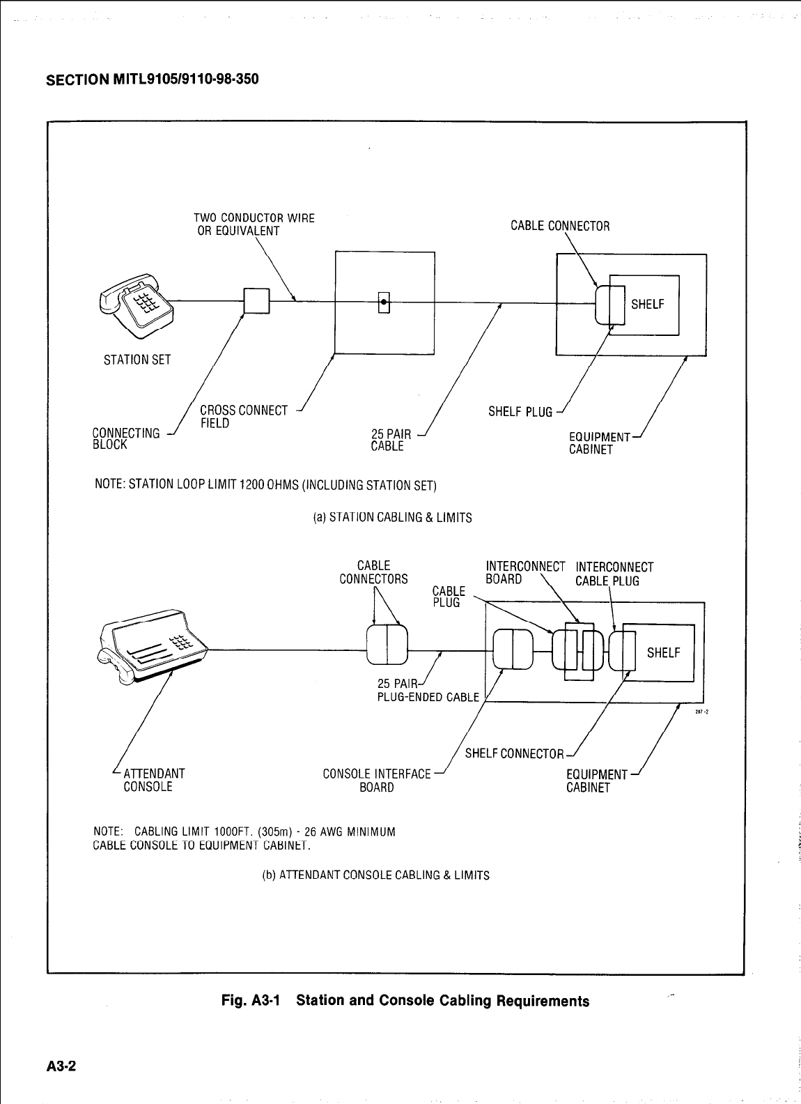
SECTION MITL9105/9110-98.350
TWO CONDUCTOR WIRE
OR EQUIVI , r) , cABLEcrc
. 1-l
STATIONSET
CROSSCONNECT -/
i;;J;CTlNG FIELD SHELF PLUG1
25 PAIR
CABLE EQUIPMENT
CABINET
NOTE:STATION LOOPLlMlT1200OHMS(INCLUDINGSTATlONSET)
(a)STATlON CABLING & LIMITS
CABLE INTERCONNECT INTERCONNECT
CONNECTORS BOARD \
PLUG-ENDED CABL 2
L
SHELFCONNECTOR-/
ATTENDANT CONSOLE INTERFACE EQUIPMENT
CONSOLE BOARD CABINET
NOTE: CABLING LIMIT IOOOFT. (305m)- 26 AWG MINIMUM
CABLECONSOLETO EQUIPMENTCABINET.
(b)ATTENDANTCONSOLECABLlNG& LIMITS
Fig. A3-1 Station and Console Cabling Requirements _-
A3-2
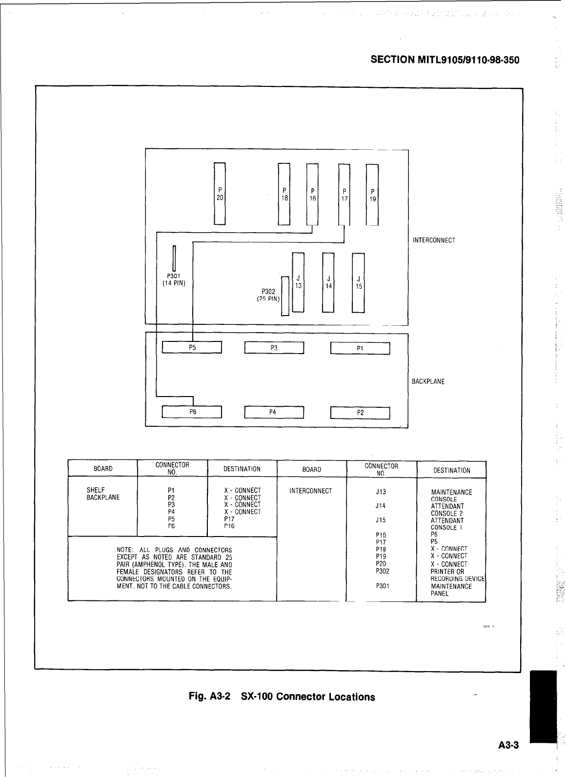
SECTION MITL9105/9110-98-350
0
P301
(14 PIN) P302
(25 PIN)
1
INTERCONNECT
BACKPLANE
I
BOARD I
CONNECTOR
I DESTINATION I BOARD CONNECTOR
NO. NO. DESTINATION
SHELF I Pl 1 X-CONNECT 1 INTERCONNECT J13 MAINTENANCE
BACKPLANE
P4
FZ
X-CONNECT
X-CONNECT
X-CONNECT
P17
P16
J14
J15
P16
PI7
PI6
P19
P20
P302
CONSOLE
ATTENDANT
CONSOLE 2
ATTENDANT
CONSOLE1
P6
!" CONNECT
X-CONNECT
X-CONNECT
PRINTER OR
NOTE: ALL PLUGS AND CONNECTORS
EXCEPT AS NOTED ARE STANDARD 25
PAIR (AMPHENOL TYPE). THE MALE AND
FEMAIF OESIGNATI-IRS RFFFA TO THF
CijN,,&(j~~~~~&f&) ii THE’ &jii:
MENT.NOTTOTHECABLECONNECTORS. P301 RECORDING DEVICE
MAINTENANCE
PANEL
Fig. A3-2 SX-100 Connector Locations
‘.. :
Y.---G
,,.
:
_.
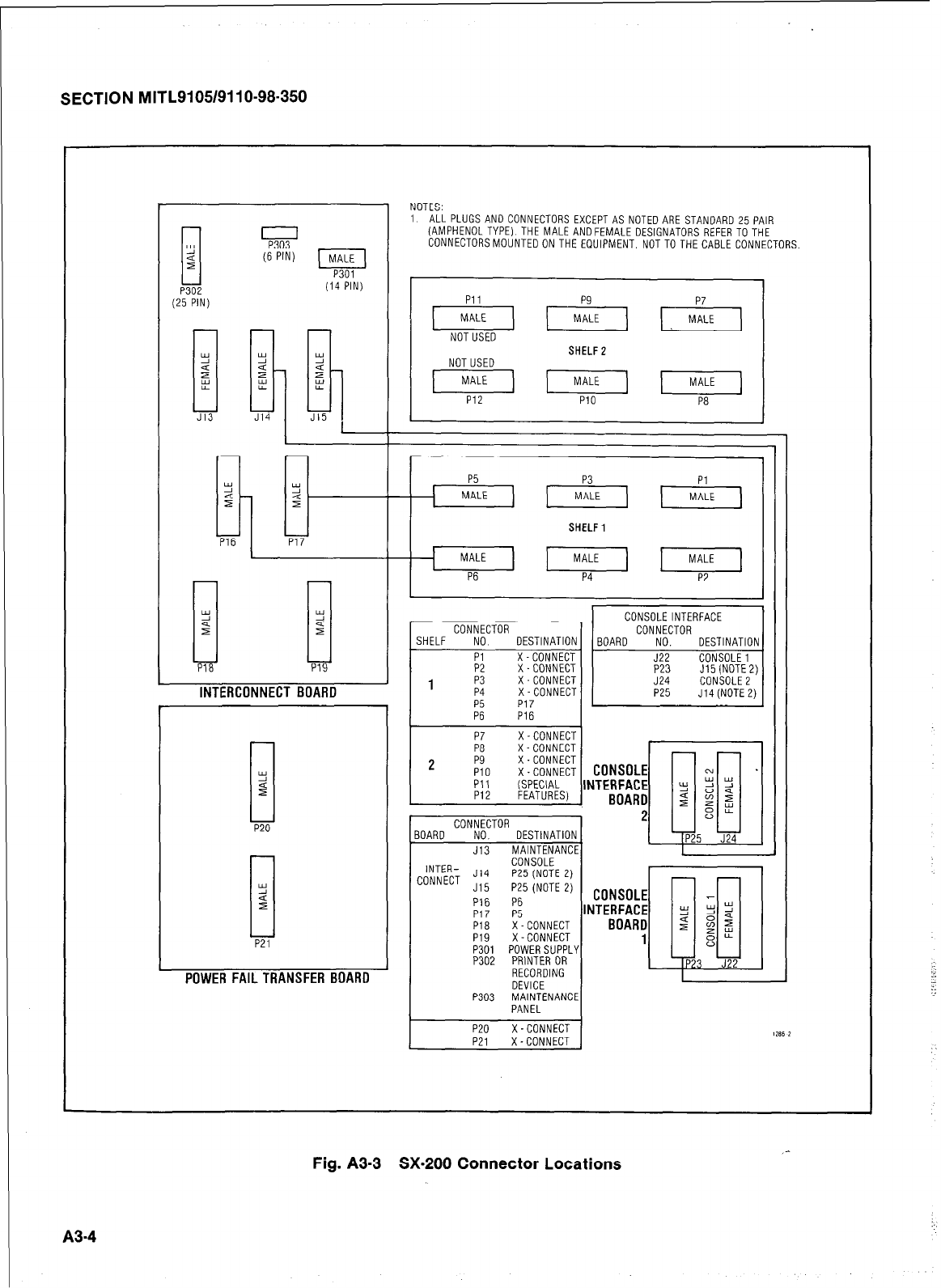
SECTION MITL9105/9110-98-350
P302
25 PIN)
J13 J14
ki
c
2
PI6
1
NOTES:
1 ALL PLUGS AND CONNECTORS EXCEPT AS NOTEDARE STANDARD 25 PAIR
(AMPHENOLTYPE) THE MALEANDFEMALE DESIGNATORS REFER TOTHE
CONNECTORSMOUNTEDON THE EQUIPMENT, NOT TO THE CABLE CONNECTORS
(6 PIN) t--iiid
p301
(14 PIN) I I
Pll
piq (-iEq +q
NOTUSED SHELF2
NOTUSED
[MALES piiF- piq
PI2 PI0 P8
P5
MALE
P17
SHELF1
Tii-
INTERCONNECT BOARD
I I I fYlNNFi-.TnR
1
21 I I zl-l
LUNNtLI J15
P16
Pi7 P5
I I P301 POWERSUPPLY 'I I I =I
I I
POWER FAILTRANSFER BOAR0
,,
P18 i--CONNECT
P19 X-CONNECT
P302 PRINTER OR
RECORDING
nFVICF
P:
L-.,-L
103 MAINTENANCE
PANEL
I
P20 X-CONNECT 1 .,oc ,
I
P21 X-CONNECT 1 ,‘"" ‘
A34
Fig. A3-3 SX-200 Connector Locations
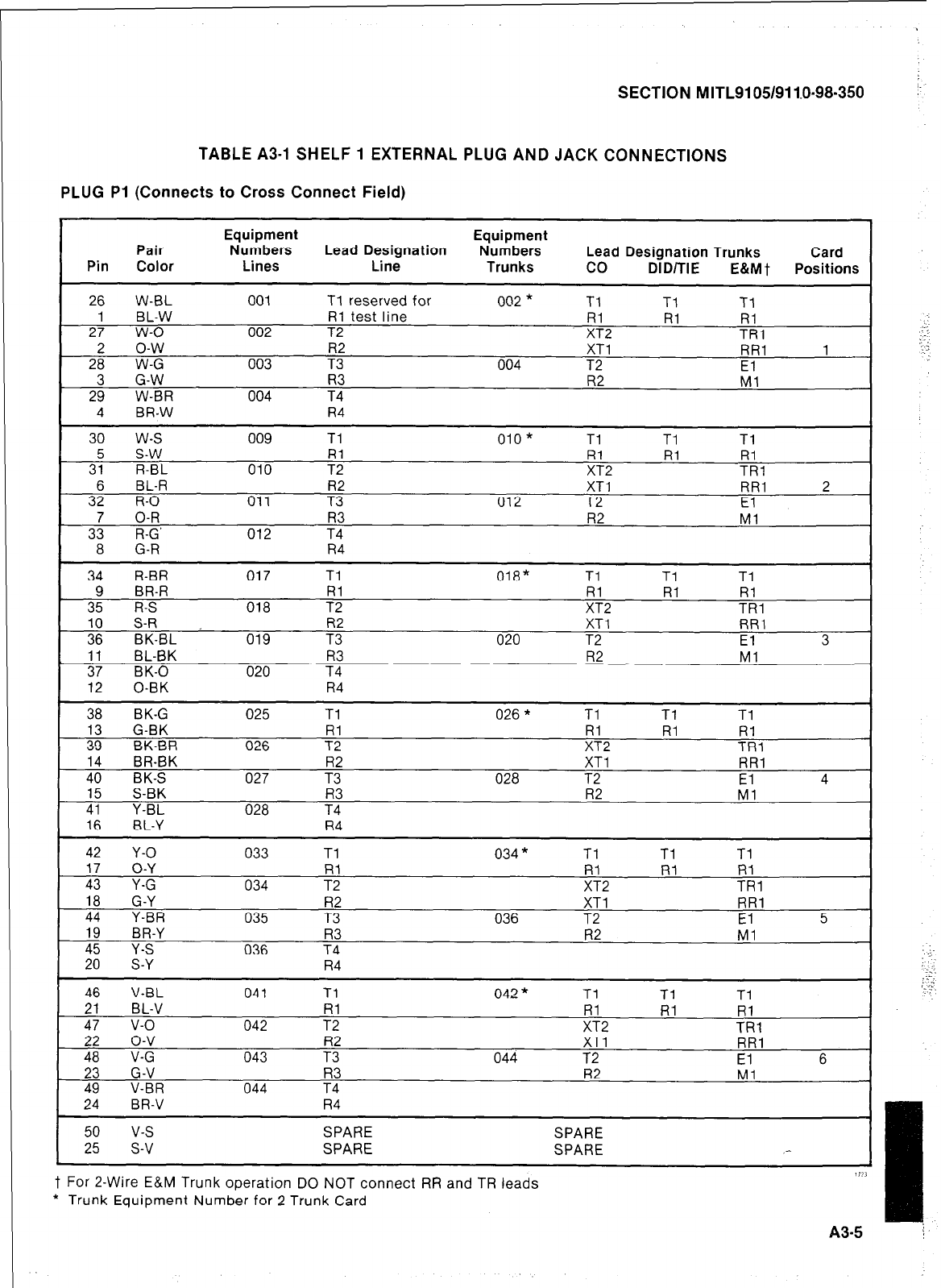
SECTION MITL9105/911.0~98-350 :-
TABLE A3-1 SHELF 1 EXTERNAL PLUG AND JACK CONNECTIONS
PLUG Pi (Connects to Cross Connect Field)
Equipment Equipment
Pair Numbers Lead Designation Numbers Lead Designation Trunks Card
Pin Color Lines Line Trunks co DID/TIE E&Mt Positions
26 W-BL 001 Tl reserved for 002 * Tl Tl Tl
1 BL-W Rl test line Rl Rl Rl
27 w-o 002 T2 XT2 TRl
2 o-w R2 XT1 RR1 1
28 W-G 003 T3 004 T2 El
3 G-W R3 R2 Ml
29 W-BR 004 T4
4 BR-W R4
30 w-s 009 Tl 010 * Tl Tl Tl
5 S-W Rl Rl Rl Rl
31 R-BL 010 T2 XT2 TRl
3: R-O BL-R 011 T3 R2 012 T2 XT1 RR1 El 2
7 O-R R3 R2 Ml
33 R-G’ 012 T4
8 G-R R4
34 R-BR 017 Tl 018* Tl Tl Tl
9 BR-R RI Rl Rl Rl
35 R-S 018 T2 XT2 TRl
;: S-R R2
BK-BL XT1 RR1
019 T3 020 T2 El 3
11 BL-BK R3 R2 Ml
37 BK-0 020 T4
12 0-BK R4
38 BK-G 025 Tl 026 * Tl Tl Tl
13 G-BK Rl Rl Rl Rl
39 BK-BR 026 T2 XT2 TRl
14 BR-BK R2 XT1 RR1
40 BK-S 027 T3 028 T2 El 4
15 S-BK R3 R2 Ml
41 Y-BL 028 T4
16 BL-Y R4
42 Y-O 033 Tl 034 * Tl Tl Tl
17 O-Y Rl Rl Al Rl
43 Y-G 034 T2 XT2 TRl
18 G-Y R2 XT1 RR1
44 Y-BR 035 T3 036 T2 El 5
19 BR-Y R3 R2 Ml
Y-S 036 T4
S-Y R4
46 V-BL 041 Tl 042 * Tl Tl Tl
F-z?.
21 BL-V Rl Rl Rl
47 v-o 042 T2 ;;2 TRl
22 o-v XT1 RR1
48 V-G 043 E 044 T2 El 6
23 G-V R3 R2 Ml
49 V-BR 044 T4
R4
50 v-s
25 s-v SPARE
SPARE SPARE
SPARE
t For 2-Wire E&M Trunk operation DO NOT connect RR and TR leads
* Trunk Equipment Number for 2 Trunk Card
1121
A3-5
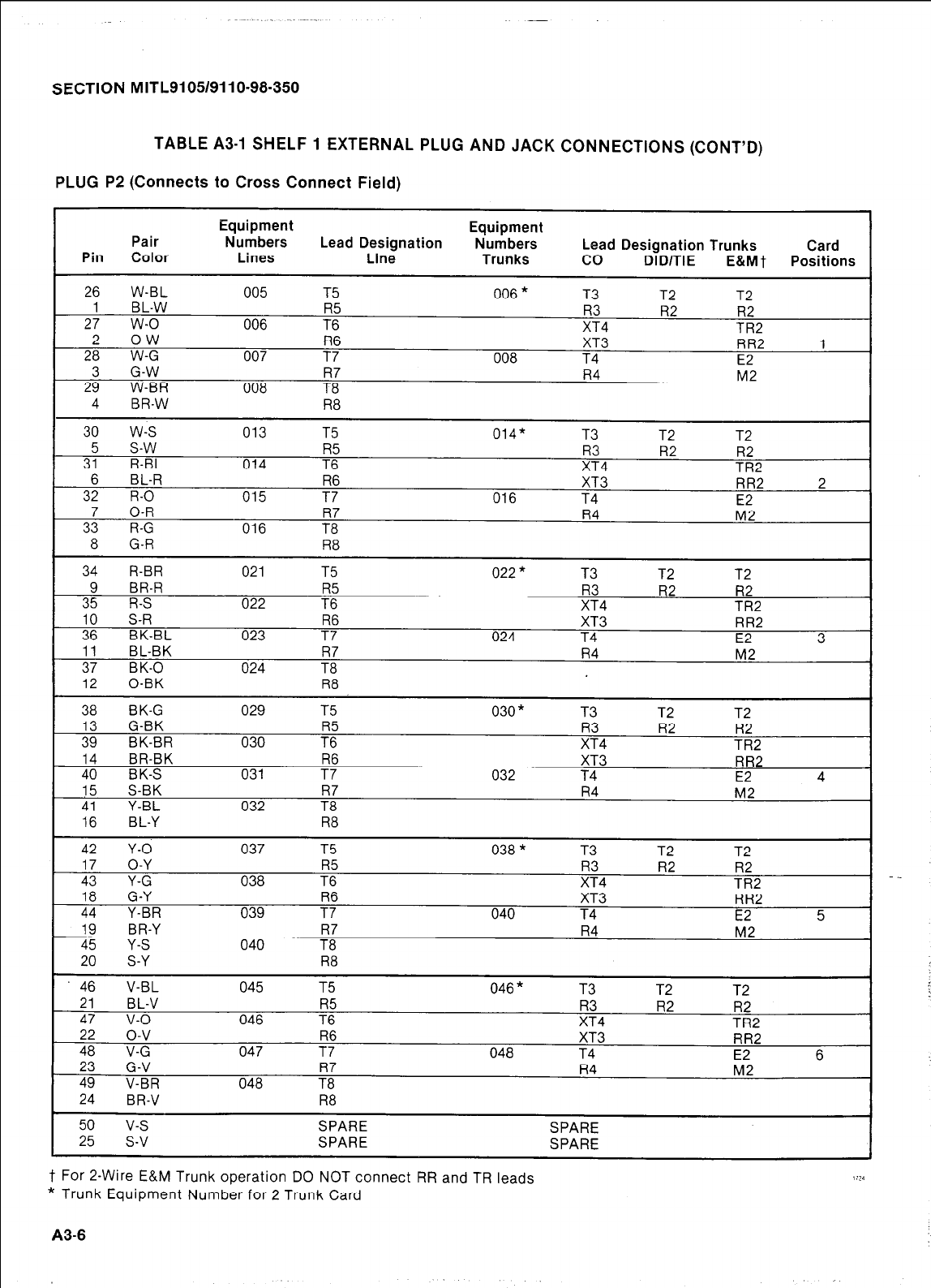
SECTION MITL910519110-98-350
SECTION MITL9105/9110-98-350
TABLE A3-1 SHELF 1 EXTERNAL PLUG AND JACK CONNECTIONS (CONT’D)
TABLE A3-1 SHELF 1 EXTERNAL PLUG AND JACK CONNECTIONS (CONT’D)
PLUG P2 (Connects to Cross Connect Field) PLUG P2 (Connects to Cross Connect Field)
Equipment Equipment
Pair Numbers Lead Designation Numbers Lead Designation Trunks Card
Pin Color Lines Line Trunks co DID/TIE E&Ml Positions
26 W-BL 005 T5 006 * T3 T2 T2
1 BL-W I35 R3 R2 R2
27 w-o 006 T6 XT4 TR2
2 o-w R6 XT3 RR2 1
28 W-G 007 T7 008 T4 E2
3 G-W R7 R4 M2
29 W-BR 008 T8
4 BR-W R8
30 w-s 013 T5 014* T3 T2 T2
5 s-w R5 R3 R2 R2
31 R-BL 014 T6 XT4 TR2
6 BL-R R6 XT3 RR2 2
32 R-O 015 T7 016 T4 E2
7 O-R R7 R4 M2
33 R-G 016 T8
8 G-R R8
34 R-BR 021 T5 022 * T3 T2 T2
9 BR-R R5 R3 R2 R2
35 R-S 022 T6 XT4 TR2
10 S-R R6 XT3 RR2
36 BK-BL 023 T7 024 T4 E2 3
11 BL-BK R7 R4 M2
37 BK-0 024 T8
12 0-BK R8
38 BK-G 029 T5 030* T3 T2 T2
13 G-BK R5 R3 R2 R2
39 BK-BR 030 T6 XT4 TR2
14 BR-BK R6 XT3 RR2
40 BK-S 031 T7 032 T4 E2 4
15 S-BK R7 R4 M2
41 Y-BL 032 T8
16 BL-Y R8
42 Y-O 037 T5 038 * T3 T2 T2
17 O-Y R5 R3 R2 R2
43 Y-G 038 T6 XT4 TR2
18 G-Y R6 XT3 RR2
44 Y-BR 039 T7 040 T4 E2 5
19 BR-Y R7 R4 M2
45 Y-S 040 T8
20 S-Y R8
46 V-BL 045 T5 046 * T3 T2 T2
21 BL-V R5 R3 R2 R2
47 v-o 046 T6 XT4 TR2
22 o-v R6 XT3 RR2
48 V-G 047 T7 048 T4 E2 6
23 G-V R7 R4 M2
49 V-BR 048 T8
24 BR-V R8
50 v-s SPARE SPARE
25 s-v SPARE SPARE
t For 2-Wire E&M Trunk operation DO NOT connect RR and TR leads 1 i24
* Trunk Equipment Number for 2 Trunk Card
t For 2-Wire E&M Trunk operation DO NOT connect RR and TR leads
* Trunk Equipment Number for 2 Trunk Card
A3-6 A3-6

SECTION MITL9105/9110-98-350
TABLE A3-1 SHELF 1 EXTERNAL PLUG AND JACK CONNECTIONS (CCNT’D)
PLUG P3 (Connects to Cross Connect Field)
Equipment Equipment
Pair Numbers Lead Designation Numbers Card
Pin Color Lines Line Lead Designation Trunks
Trunks co DID/TIE E&Mt Positions
26 W-BL 049 Tl 050 * Tl Tl Tl
1 BL-W Rl Rl Rl
27 w-o 050 T2 TRl
2 o-w R2 XT1 RR1 7
28 W-G 051 T3 052 T2 El
3 G-W R3 R2 Ml
29 W-BR 052 T4
4 BR-W R4
30 w-s 057 Tl 058* Tl Tl Tl
3; s-w Rl Rl
R-BL 058 T2 xR:2 TR&
6 BL-R R2 XT1 RR1 8
32 R-O 059 T3 060 T2 El
3: O-R R3 R2 Ml
R-G 060 T4
8 G-R R4 sx-
34 R-BR 065 Tl 066 * Tl Tl
Tl
BR-R Rl Rl Ii; iii
R-S 066 T2 XT2 TRl
10 S-R XT1 RR1
36 BK-BL 067 E 068 T2 El 9
11 BL-BK R3 R2 Ml
37 BK-0 068 T4
12 0-BK R4
38 BK-G 073 Tl 074 * Tl Tl Tl
;9” G-BK Rl Rl Rl Rl
BK-BR 074 T2 XT2 TRl
14 BR-BK R2 XT1 RR1
40 BK-S 075 T3 076 T2 El 10
15 S-BK R3 R2 Ml
41 Y-BL 076 T4
16 BL-Y R4
42 Y-O 081 Tl 082 * Tl Tl Tl
17 O-Y Rl Rl Rl
43 Y-G 082 T2 xR:2 TRl
18 G-Y R2 XT1 RR1
44 Y-BR 083 T3 084 T2 El 11
19 BR-Y R3 R2 Ml
Y-S 084 T4
S-Y R4
46
21
2427
2438
49
24
V-BL
BL-V
v-o
o-v
V-G
G-V
V-BR
BR-V
089
090
091
092
Tl
Rl
T2
R2
T3
R3
T4
R4
090 *
092
Tl
xR:2
XT1
T2
R2
Tl
Rl Tl
Rl
TRl
RR1
El 12
Ml See Note
;“5
v-s
SPARE SPARE
s-v SPARE SPARE
Note: Position 12 can be used for lines, trunks, or receiver #4 card.
t For 2-Wire E&M Trunk operation DO NOT connect RR and TR leads
* Trunk Equipment Number for 2 Trunk Card
A3-7
. .
:.:.
-.,.
2:.
._ .-a:
. .
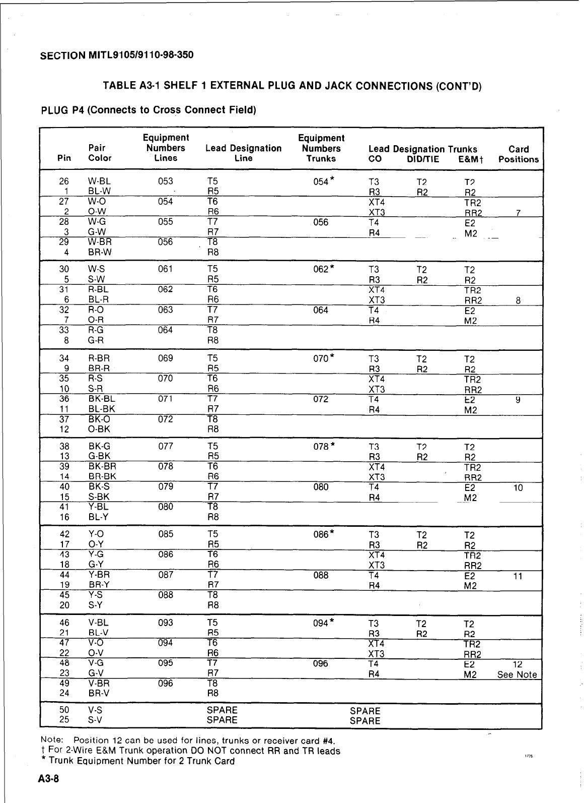
SECTION MITL9105/9110-98-350
TABLE A3-1 SHELF 1 EXTERNAL PLUG AND JACK CONNECTIONS (CCNT’D)
PLUG P4 (Connects to Cross Connect Field)
Equipment Equipment
Pair
Numbers Lead Designation Numbers Card
Pin Color Lines Lead Designation Trunks
Line Trunks co DlDillE E&Mt Positions
26 W-BL 053 T5 054 * T3 T2 T2
1 BL-W R5 ;:4 Fi2 R2
27 w-o 054 T6 TR2
2 o-w
28 W-G 055 -7; XT3 RR2 7
056 T4 E2
3 G-W R7 R4 M2
29 W-BR 056
T8
4 BR-W R8
I 30 w-s 061 T5 062 * T3 T2 T2 I
5 s-w R5 R2 R2
31 R-BL 062 T6 TR2
6 BL-R R6 XT3 RR2 8
32 R-O 063 T7 064 T4 E2
7 O-R R7 R4 M2
33 R-G 064 T8
8 G-R R8
34 R-BR 069 T5 070 * T3 T2 T2
3: BR-R R5 R3 R2 R2
R-S 070 T6 XT4 TR2
10 S-R R6 XT3 RR2
36 BK-BL 071 T7 072 T4 E2 9
11 BL-BK R7 R4 M2
37 BK-0 072 T8
I
12
0-BK R8 I
38 BK-G 077 T5 078 * T3 T2 T2
13 G-BK R5 R2 R2
39 BK-BR 078 T6 z4 TR2
14 BR-BK R6 XT3 RR2
40 BK-S 079 T7 080 T4 E2 10
15 S-BK R7 R4 M2
41 Y-BL 080 T8
16 BL-Y R8
42 Y-O 085 T5 086 * T3 T2 T2
17 O-Y R5 R3 R2 R2
43 Y-G 086 T6 XT4 TR2
18 G-Y
44 Y-BR
19 BR-Y
45 Y-S
20 S-Y
46 V-BL
21 BL-V
47 v-o
_ 22 o-v
48 V-G
23 G-V
49 V-BR
24 BR-V
087
088
093
094
095
096
R6
T7
R7
T8
R8
T5
R5
T6
R6
T7
7:
R8
088
094 *
096
XT3
T4
R4
T3
R3
XT4
XT3
T4
R4
T2
R2
.-
RR2
E2 11
M2
T2
TR:2
RR2
E2 12
M2 See Note
50 v-s SPARE SPARE
25 s-v SPARE SPARE
Note: Position 12 can be used for lines, trunks or receiver card #4.
t For 2-Wire E&M Trunk operation DO NOT connect RR and TR leads
* Trunk Eauipment Number for 2 Trunk Card
A3-8
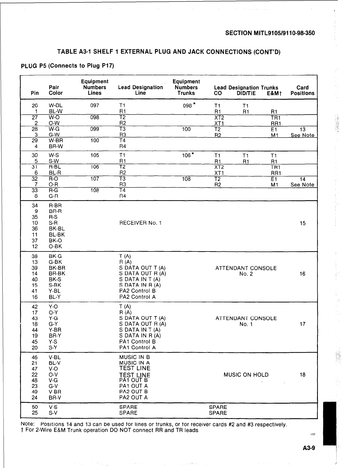
SECTION MITL9105/9110-98-350
TABLE A3-1 SHELF 1 EXTERNAL PLUG AND JACK CONNECTIONS (CGNT’D)
PLUG P5 (Connects to Plug P17)
Equipment Equipment
Pair Numbers Lead Designation Numbers Lead Designation Trunks Card
Pin Color Lines Line Trunks co DID/TIE
E&MT
Positions
26 W-BL 097 Tl 098 * Tl Tl
1 BL-W RI RI RI Rl
27 w-o 098 T2 XT2 TRI
2 o-w R2 XT1 RR1
28 W-G 099 T3 100 T2 El 13
3 G-W R3 R2 Ml See Note
29 W-BR 100 T4
4 BR-W R4
30 w-s 105 Tl 106* Tl Tl Tl
5 s-w Rl Rl Rl Rl
31 R-BL 106 T2 XT2 TRl
6 BL-R R2 XT1 RR1
32 R-O 107 T3 108 T2 El 14
7 O-R R3 R2 Ml See Note
33 R-G 108 T4
8 G-R R4
34 R-BR
9 BR-R
35 R-S
10 S-R RECEIVER No. 1 15
36 BK-BL
11 BL-BK
37 BK-0
12 0-BK
38 BK-G T (A)
13 G-BK R (4
39 BK-BR S DATA OUT T (A) ATTENDANT CONSOLE
14 BR-BK S DATA OUT R (A) No. 2 16
40 BK-S S DATA IN T (A)
15 S-BK S DATA IN R (A)
41 Y-BL PA2 Control B
16 BL-Y PA2 Control A
42 Y-O -f (4
17 O-Y R (4
43 Y-G S DATA OUT T (A) ATTENDANT CONSOLE
18 G-Y S DATA OUT R (A) No. 1 17
44 Y-BR S DATA IN T (A)
19 BR-Y S DATA IN R (A)
45 Y-S PA1 Control B
20 s-v PA1 Control A
46 V-BL MUSIC IN B
21 BL-V MUSIC IN A
47 v-o
TEST LINE
22 o-v E%lF3E MUSIC ON HOLD 18
48 V-G
23 G-V PA1 OUT A
49 V-BR PA2 OUT B
24 BR-V PA2 OUT A
z v-s SPARE SPARE
s-v SPARE SPARE
.
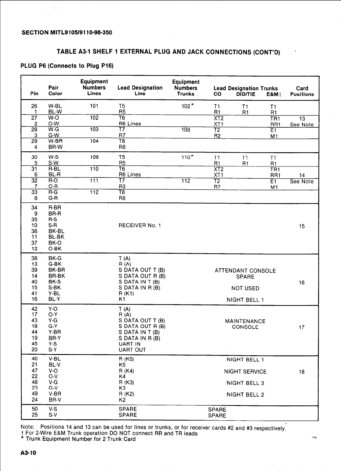
SECTION MITL9105/9110-98-350
TABLE A3.1 SHELF 1 EXTERNAL PLUG AND JACK CONNECTIONS (CCNT’D) *
PLUG P8 (Connects to Plug P18)
Equipment Equipment
Pair Numbers Lead Designation Numbers Lead Designation Trunks Card
Pin Color Lines Line Trunks CO DID/TIE E&Mt Positions
26 w-BL 101 T5 102* Tl Tl Tl
1 BL-W R5 Rl Rl Rl
27 w-o 102 T6 XT2 TRl
o-w 13
2 R6 Lines XT1 RR1 See Note
28 W-G 103 T7 108 T2
G-W El
R7 R2 Ml
2; W-BR 104 T8
4 BR-W R8
30 w-s 109 T5 110* Tl Tl Tl
5 s-w R5 Rl Rl Rl
31 R-BL 110 T6 XT2 TRl
6 BL-R R6 Lines XT1 RR1
32 R-O 14
111 T7 112 T2 El See Note
7 O-R R3 R7 Ml
33 R-G 112 T8
8 G-R R8
34 R-BR
9 BR-R
35 R-S
10 S-R RECEIVER No. 1
36 15
BK-BL
11 BL-BK
37 BK-0
12 0-BK
38 BK-G T (4
13 G-BK R (4
39 BK-BR S DATA OUT T (B) ATTENDANT CONSOLE
14 BR-BK S DATA OUT R (B) SPARE
40 BK-S S DATA IN T (B)
15 S-BK 16
S DATA IN R (B) NOT USED
41 Y-BL R Wl)
16 BL-Y Kl NIGHT BELL 1
42 Y-O T (4
17 O-Y R (4
43 Y-G S DATA OUT T (B) MAINTENANCE
18 G-Y S DATA OUT R (B) CONSOLE
44 Y-BR 17
S DATA IN T (B)
19 BP-Y S DATA IN R (B)
Y-S UART IN
4: S-Y UART OUT
46 V-BL R (K5) NIGHT BELL 1
21 BL-V
47 v-o ::K4) NIGHT SERVICE
22 o-v 18
48 V-G :4K3)
23 NIGHT BELL 3
G-V
49 V-BR !;K2)
24 NIGHT BELL 2
BR-V K2
50 v-s SPARE SPARE
25 s-v SPARE SPARE
Note: Positions 14 and 13 can be used for lines or trunks, or for receiver cards #2 and #3
respectively,
t For 2-Wire E&M Trunk operation DO NOT connect RR and TR leads
* Trunk Equipment Number for 2 Trunk Card 1111
A3-10
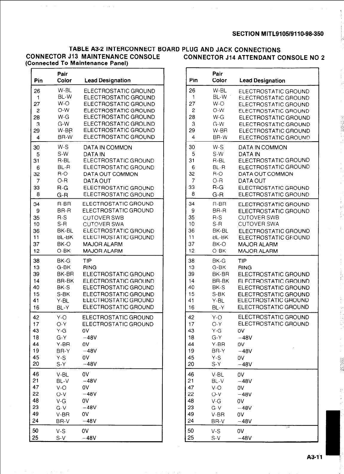
SECTION MITL9105/9110-98-350
TABLE A3-2 INTERCONNECT BOARD PLUG AND JACK CONNECTIONS
CONSOLE CONNECTOR 513 MAINTENANCE
(Connected To Maintenance Panel) CONNECTOR 514 ATTENDANT CONSOLE NO 2
Pin
26
1
27
2
28
3
29
4
30
5
31
6
32
7
33
8
34
9
35
10
36
11
37
12
38
13
39
14
40
15
41
16
42
17
43
18
44
19
45
20
46
21
47
22
48
33
49
24
50
?5
Pair
Color Lead Designation
W-BL ELECTROSTATIC GROUND
BL-W ELECTROSTATIC GROUND
w-o ELECTROSTATIC GROUND
o-w ELECTROSTATIC GROUND
W-G ELECTROSTATIC GROUND
G-W ELECTROSTATIC GROUND
W-BP ELECTROSTATIC GROUND
BR-W ELECTROSTATIC GROUND
w-s DATA IN COMMON
s-w DATA IN
R-BL ELECTROSTATIC GROUND
BL-R ELECTROSTATIC GROUND
R-O DATA OUT COMMON
O-R DATA OUT
R-G ELECTROSTATIC GROUND
G-R ELECTROSTATIC GROUND
R-BR ELECTROSTATIC GROUND
BR-R ELECTROSTATIC GROUND
R-S CUTOVER SWB
S-R CUTOVER SWA
BK-BL ELECTROSTATIC GROUND
BL-BK ELECTROSTATIC GROUND
BK-0 MAJOR ALARM
0-BK MAJOR ALARM
BK-G TIP
G-BK RING
BK-BR ELECTROSTATIC GROUND
BR-BK ELECTROSTATIC GROUND
BK-S ELECTROSTATIC GROUND
S-BK ELECTROSTATIC GROUND
Y-BL ELECTROSTATIC GROUND
BL-Y ELECTROSTATIC GROUND
Y-O ELECTROSTATIC GROUND
O-Y ELECTROSTATIC GROUND
Y-G ov
G-Y -48V
Y-BR OV
BR-Y -48V
Y-S ov
S-Y -48V
V-BL OV
BL-V -48V
v-o ov
o-v -48V
V-G ov
G-V -48V
V-BR OV
BR-V -48V
v-s ov
s-v -48V
Pin
26
1
27
2
28
3
29
4
30
5
31
6
32
7
33
8
34
9
35
10
36
11
37
12
38
13
39
14
40
15
41
16
42
17
43
18
44
19
45
20
46
21
47
32
48
23
49
24
50
25
Pair
Color Lead Designation
W-BL ELECTROSTATIC GROUND
BL-W ELECTROSTATIC GROUND
w-o ELECTROSTATIC GROUND
o-w ELECTROSTATIC GROUND
W-G ELECTROSTATIC GROUND
G-W ELECTROSTATIC GROUND
W-BR ELECTROSTATIC GROUND
BR-W ELECTROSTATIC GROUND
w-s DATA IN COMMON
s-w DATA IN
R-BL ELECTROSTATIC GROUND
BL-R ELECTROSTATIC GROUND
R-O DATA OUT COMMON
O-R DATA OUT
R-G ELECTROSTATIC GROUND
G-R ELECTROSTATIC GROUND
R-BR ELECTROSTATIC GROUND
BR-R ELECTROSTATIC GROUND
R-S CUTOVER SWB
S-R CUTOVER SWA
BK-BL ELECTROSTATIC GROUND
BL-BK ELECTROSTATIC GFiOUND
BK-0 MAJOR ALARM
0-BK MAJOR ALARM
BK-G TIP
G-BK RING
BK-BR ELECTROSTATIC GROUND
BR-BK ELECTROSTATIC GROUND
BK-S ELECTROSTATIC GROUND
S-BK ELECTROSTATIC GROUND
Y-BL ELECTROSTATIC GROUND
BL-Y ELECTROSTATIC GROUND
Y-O ELECTROSTATIC GROUND
O-Y ELECTROSTATIC GROUND
Y-G ov
G-Y -48V
Y-BR OV
BR-Y -48V
Y-S ov
S-Y -48V
V-BL OV
BL-V -48V
v-o ov
o-v -48V
V-G ov
G-V -48V
V-BR OV
BR-V -48V ,-
v-s ov
s-v -48V
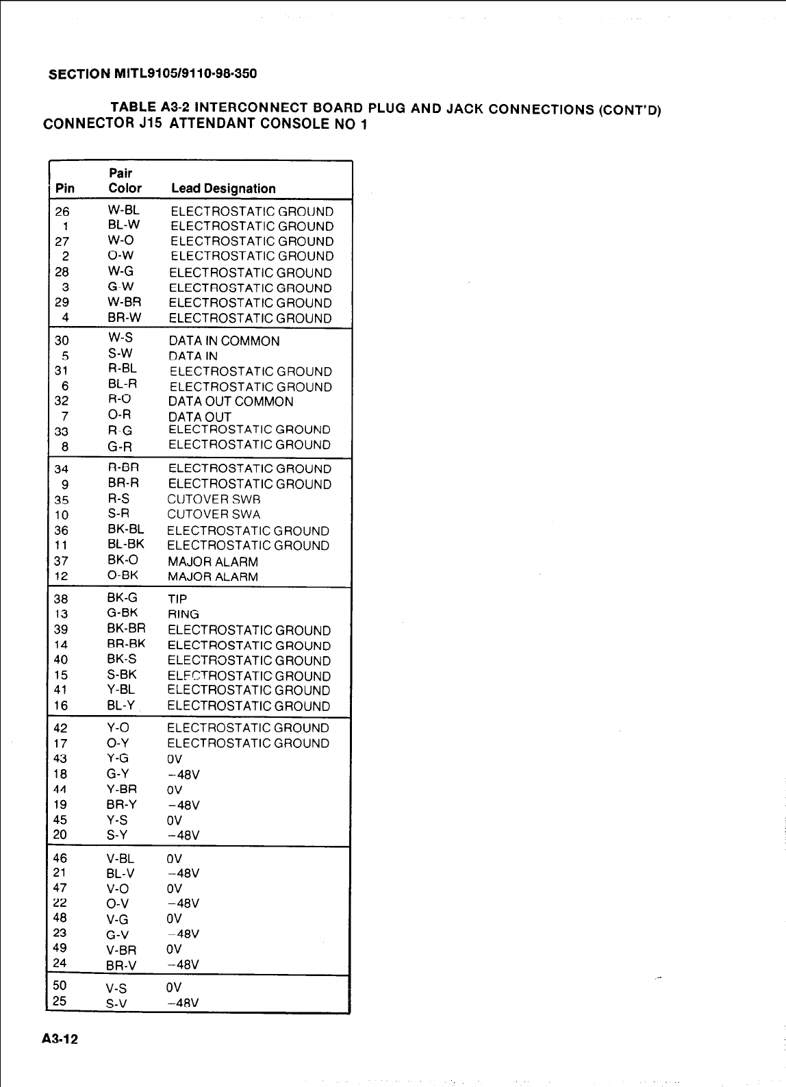
SECTION MITL9105/9110~98-350
TABLE A3-2 INTERCONNECT BOARD PLUG AND JACK CONNECTIONS (CONT’D)
CONNECTOR J15 ATTENDANT CONSOLE NO 1
Pin
26
1
27
2
28
3
29
4
30
5
31
6
32
7
33
8
34
9
35
10
36
11
37
12
38
13
39
14
40
15
41
16
42
17
43
18
44
19
45
20
46
21
47
22
48
23
49
24
50
25
Pair
Color Lead Designation
w-BL ELECTROSTATIC GROUND
BL-W ELECTROSTATIC GROUND
w-o ELECTROSTATIC GROUND
o-w ELECTROSTATIC GROUND
W-G ELECTROSTATIC GROUND
G-W ELECTROSTATIC GROUND
W-BR ELECTROSTATIC GROUND
BR-W ELECTROSTATIC GROUND
w-s DATA IN COMMON
s-w DATA IN
R-BL ELECTROSTATIC GROUND
BL-R ELECTROSTATIC GROUND
R-O DATA OUT COMMON
O-R DATA OUT
R-G
ELECTROSTATIC GROUND
G-R
ELECTROSTATIC GROUND
R-BR ELECTROSTATIC GROUND
BR-R ELECTROSTATIC GROUND
R-S CUTOVER SWB
S-R CUTOVER SWA
BK-BL ELECTROSTATIC GROUND
BL-BK ELECTROSTATIC GROUND
BK-0 MAJOR ALARM
0-BK MAJOR ALARM
BK-G TIP
G-BK RING
BK-BR ELECTROSTATIC GROUND
BR-BK ELECTROSTATIC GROUND
BK-S ELECTRaSTATIC GROUND
S-BK ELFCTROSTATIC GROUND
Y-BL ELECTROSTATIC GROUND
BL-Y ELECTROSTATIC GROUND
Y-O ELECTROSTATIC GROUND
O-Y ELECTROSTATIC GROUND
Y-G ov
G-Y -48V
Y-BR OV
BR-Y -48V
Y-S ov
S-Y -48V
V-BL OV
BL-V -48V
v-o ov
o-v -48V
V-G ov
G-V -48V
V-BR OV
BR-V -48V
v-s ov
s-v -48V
A3-12

SECTION MITLSI 051911 O-98-350
TABLE A3-2 SHELF 2 (SX-200 ONLY) EXTERNAL PLUG AND JACK CONNECTIONS
PLUG PI (Connects to Cross Connect Field)
Equipment Equipment
Pair Numbers Lead Designation Numbers Lead Designation Trunks Card
Pin Color Lines Line Trunks co DID/TIE E&Mt Positions
26 W-BL 161 Tl 162* Tl Tl Tl
1 BL-W Rl Rl Rl Rl
27 w-o 162 T2 XT2 TRl
2 o-w R2 XT1 RR1 1
28 W-G 163 T3 164 T2 El
3 G-W R3 R2 Ml
29 W-BR 164 T4
4 BR-W R4
30 w-s 169 Tl 170* Tl Tl Tl
3: s-w Rl Rl Rl
R-BL 170 7; XT2 TRl
6 BL-R R2 XT1 RR1 2
32 R-O 171 T3 172 T2 El
337 O-R R3 R2 Ml
R-G 172 T4
8 G-R R4
34 R-BR 177 Tl 178* Tl Tl Tl
9 BR-R Rl Rl Rl
35 R-S 178 T2 XT2 TR:1
10 S-R R2 XT1 RR1
36 BK-BL 179 T3 180 T2 El 3
11 BL-BK R3 R2 Ml
37 BK-0 180 T4
12 0-BK R4
38 BK-G 185 Tl 186* Tl Tl Tl
13 G-BK Rl Rl Rl
39 BK-BR 186 T2 XT2 TRAl
14 BR-BK R2 XT1 RR1
40 BK-S 187 T3 188 T2 El 4
15 S-BK R3 R2 Ml
41 Y-BL 188 I T4
16 BL-Y R4
42 Y-O 193 Tl 194* Tl Tl Tl
17 O-Y Rl Rl Rl
43 Y-G 194 T2 ;;2 TRl
18 G-Y XT1 RR1
44 Y-BR 195 7: 196 T2 El 5
19 BR-Y R2 Ml
45 Y-S 196 7:
20 S-Y R4
46 V-BL 201 Tl 202 * Tl Tl Tl
21 BL-V Rl Rl Rl Rl
47 v-o 202 T2 XT2 TRl
22 o-v R2 XT1 RR1
48 V-G 203 T3 204 T2 El 6
23 G-V R3 R2 Ml
49 V-BR 204 T4
24 BR-V R4
50 v-s SPARE SPARE
25 s-v SPARE SPARE
t For 2-Wire E&M Trunk operation DO NOT connect RR and TR leads
* Trunk Equipment Number for 2 Trunk Card
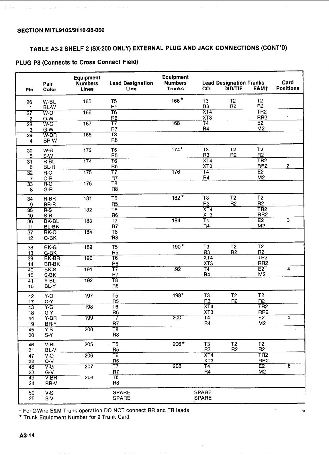
SECTION MITL9105/9110-98-350
TABLE A3-2 SHELF 2 (SX-200 ONLY) EXTERNAL PLUG AND JACK CObiNECTlCNS (CCNT’D)
PLUG P8 (Connects to Cross Connect Field)
Equipment Equipment
Pair Numbers Lead Designation Numbers Lead Designation Trunks Card
Pin Color Lines Line Trunks co DID/TIE E&Mt Positions
26 W-EL 165 T5 166* T3 12 T2
1 BL-W R3 R2 R2
27 w-o 166 ?i XT4 TR2
2 o-w R6 XT3 RR2 1
28 W-G 167 T7 168 T4
3 G-W 7; R4 z2
29 W-BR 168
30 w-s 173 T5 174* T3 T2 T2
5 s-w R2 R2
31 R-BL 174 7: !z4 TR2
6 BL-R XT3 RR2 2
32 R-O 175 TR76 176 T4 E2
7 O-R R7 R4 M2
33 R-G 176 T8
R8
8 G-R
34 R-BR 181 T5 182* T3
9 BR-R R2
35 R-S 182 7: !!+4
10 S-R XT3
36 BK-BL 183 F 184 T4
;: BL-BK R7 R4 M2
BK-0 184 T8
T2 T2
TR:2
RR2
E2 3
I 12 0-BK fl8
I xl
RK-G 189
T5 190” T3 T2 T2
is &$ R5 R2
39 BK-BR 190 T6 Iz4 TR;2
14 BR-BK R6 XT3 RR2
40 BK-S 191 T7 192 T4 E2 4
15 S-BK R7 R4 M2
41 Y-BL 192 T8
1 16 BL-Y R8
42 42 Y-O Y-O 197 197 T5 T5 19a* 19a* T3 T3 T2 T2 T2 T2
17
17 O-Y
O-Y
43 43 Y-G Y-G 198 198 7: 7: ;:4 ;:4 R2 R2 R2 R2
TR2 TR2
18 18 G-Y G-Y R6 R6 XT3 XT3 RR2 RR2
44 44 Y-BR Y-BR 199 199 T7 T7 200 200 T4 T4 E2 5 5
19 19 BR-Y BR-Y R7 R7 R4 R4 M2
45
45 Y-S Y-S 200 200 T8 T8
20 S-Y R8
46 V-BL 205 T5 206 * T3 T2 T2
21 BL-V R5 R2
47 v-o 206 T6 ;;4 ?:2
22 o-v XT3 RR2
48 V-G 207 ?Y 208 T4 E2 6
_ 23 G-V R4 M2
49 V-BR 208 7:
24 BR-V R8
I
50 v-s SPARE SPARE
25 s-v SPARE SPARE
t For 2-Wire E&M Trunk operation DO NOT connect RR and TR leads
* Trunk Equipment Number for 2 Trunk Card
A3-14
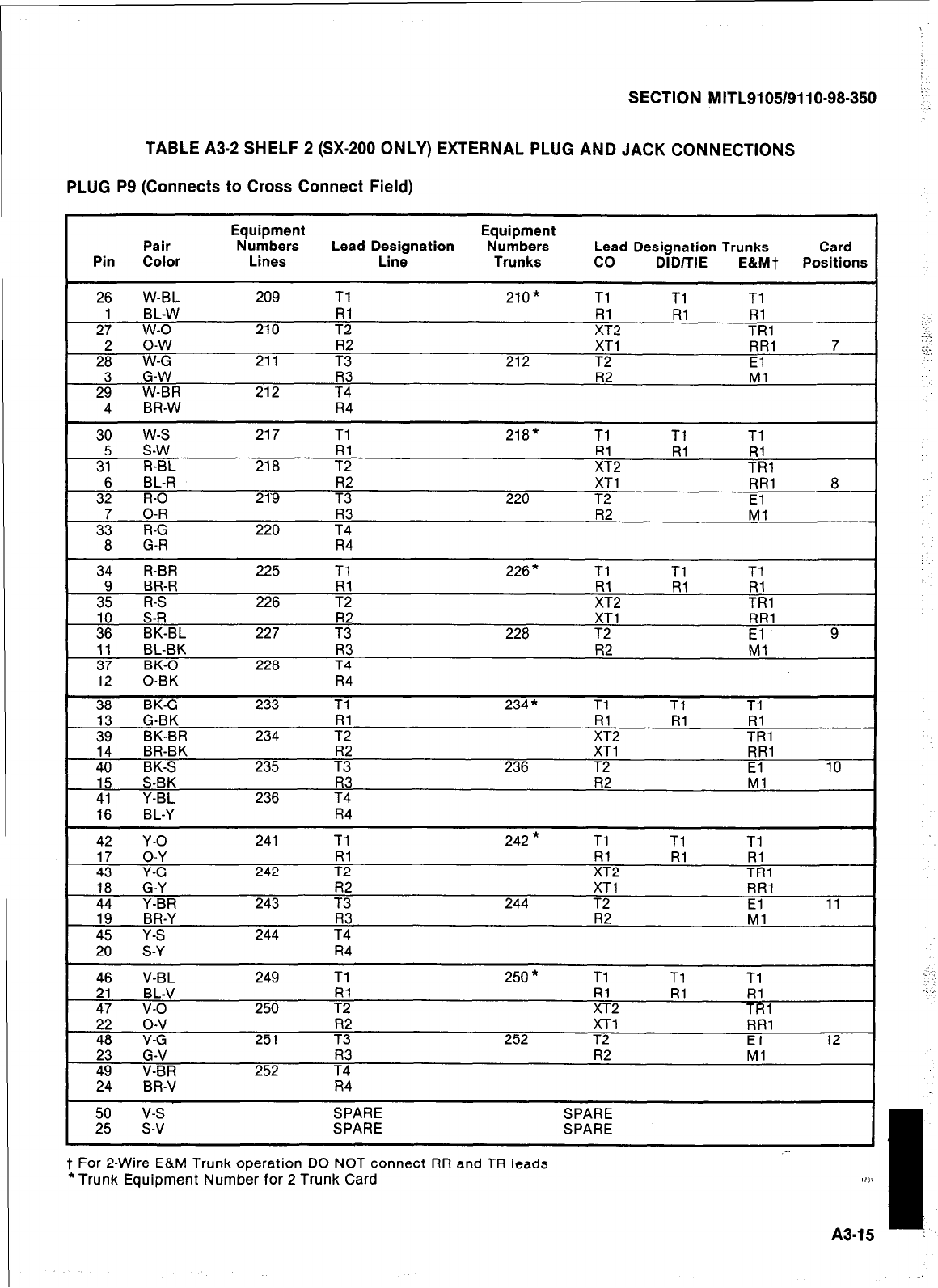
SECTION MITL9105/9110-98-350
TABLE A3-2 SHELF 2 (SX-200 ONLY) EXTERNAL PLUG AND JACK CONNECTIONS
PLUG P9 (Connects to Cross Connect Field)
Equipment Equipment
Pair Numbers Lead Designation Numbers Lead Designation Trunks Card
Pin Color Lines Line Trunks co DID/TIE E&Mt Positions
1
26 W-BL 209 Tl 210* Tl Tl Tl
2: BL-W Rl Rl RI
w-o 210 T2 ;;2 TRl
2; o-w R2 XT1 RR1 7
W-G 211 T3 212 T2
2; G-W R2 El-1
W-BR 212 7:
4 BR-W R4
I 30 w-s 217 Tl 2la* Tl Tl Tl
3;
s-w ii ii
R-BL 218 7; ;+2 TRl
6 BL-R XT1 RR1 a
32 R-O 219 7: 220 T2 El
3; O-R R2 Ml
R-G 220 7:
a G-R R4
34 R-BR 225 Tl 226* Tl Tl Tl
9 BR-R Rl Rl RI
35 R-S 226 T2 TRl
10 S-R R2 XT1 RR1
36 BK-BL 227 T3 228 T2 El 9
:: BL-BK R3 R2 Ml
BK-0 228 T4
12 0-BK R4
38 BK-G 233 Tl 234 * Tl Tl Tl
G-BK Rl Rl
BK-BR 234 TRl
14 BR-BK R2 XT1 RR1
40 BK-S 235 T3 236 T2 El 10
15 S-BK R3 R2 Ml
41 Y-BL 236 T4
1 16 BL-Y R4
42 Y-O
17 O-Y
43 Y-G
ia G-Y
44 Y-BR
19 BR-Y
40” Y-S
S-Y
47 V-BL
BL-V
47 v-o
22 o-v
4: V-G
G-V
V-BR
BR-V
241 Tl 242 * Tl Tl Tl
242 7; Iz2 Rl RI
TRl
XT1 RR1
243 7: 244 T2 El 11
R3 R2 Ml
244 T4
R4
249 Tl 250 * Tl Tl Tl
Rl Rl RI
250 T2 ;;2 TRl
XT1 RR1
251 ?i 252 T2 El 12
R3 R2 Ml
252 T4
R4
2”:
v-s
SPARE SPARE
s-v SPARE SPARE
t For 2-Wire E&M Trunk operation DO NOT connect RR and TR leads
*Trunk Equipment Number for 2 Trunk Card
- I
1111
A3-15 :
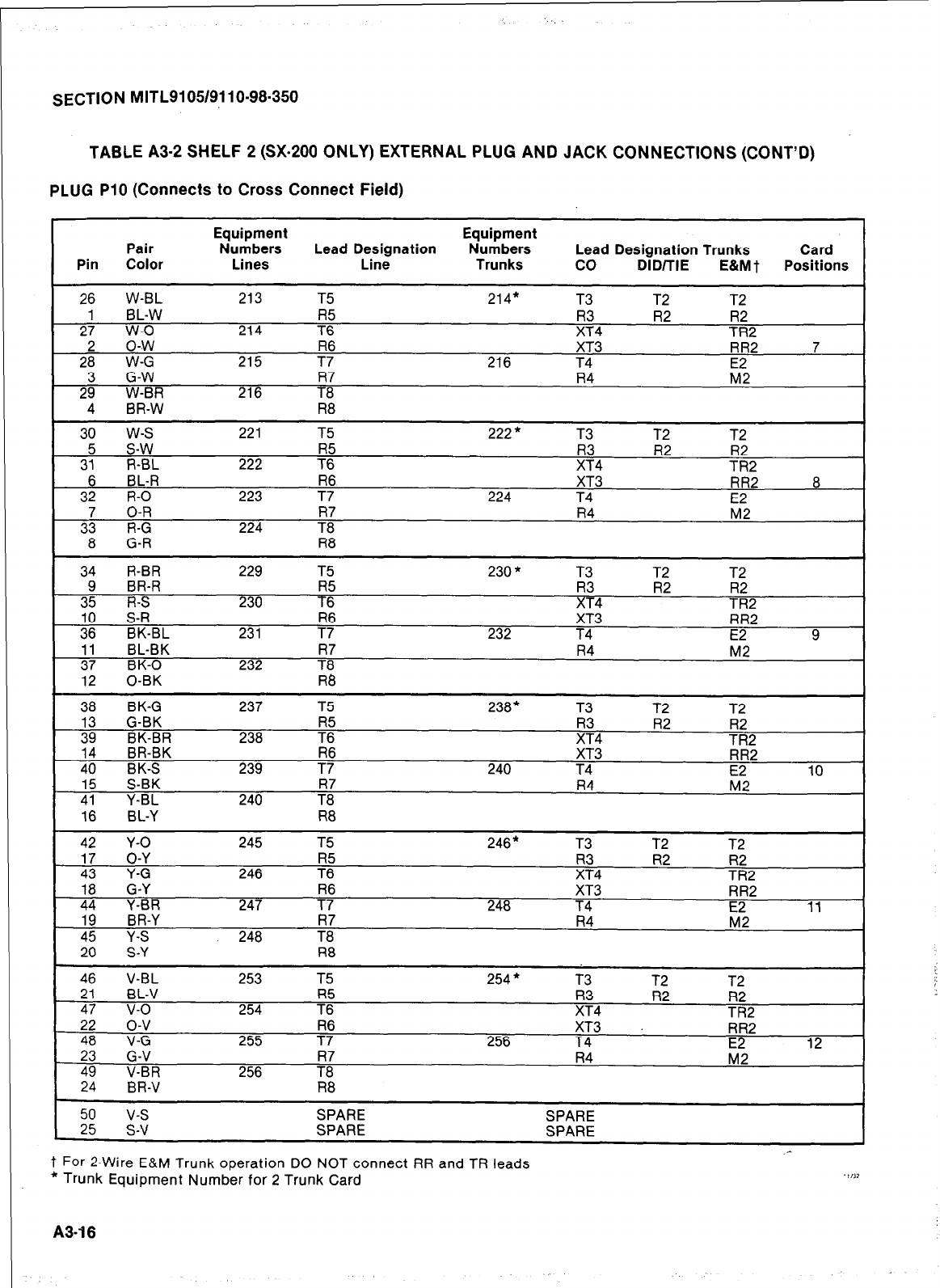
. .
SECTION MITL9105/9!10-98.350
TABLE A3-2 SHELF 2 (SX-200 ONLY) EXTERNAL PLUG AND JACK CONNECTIONS (CONT’D)
PLUG
PlO (Connects to Cross Connect Field)
Equipment Equipment
Pair Numbers Lead Designation Numbers Lead Designation Trunks Card
Pin Color Lines Line Trunks co DID/TIE E&MT Positions
26 W-BL 213 T5 214* T3 T2 T2
1 BL-W R5 R3 R2 R2
27 w-o 214 T6 XT4 TR2
2 o-w R6 XT3 RR2 7
28 W-G 215 T7 216 T4
3 G-W R7 R4 E
29 W-BR 216 T8
4 BR-W R8
30 w-s 221 T5 222* T3 T2 T2
5 s-w R5 R3 R2 R2
31 R-BL 222 T6 XT4 TR2
6 BL-R R6 XT3 RR2 8
32 R-O 223 T7 224 T4
7 O-R A4
F2
33 R-G 224
8 G-R R8 I
34 R-BR 229 T5 230 * T3 T2 T2 -1
9 BR-R R5 R3 R2 R2
35 R-S 230 T6 XT4 TR2 I
10 S-R R6 XT3 RR2
36 BK-BL 231 T7 232 T4 E2 9
11 BL-BK R4 M2
37 BK-0 232
12 0-BK R8 I
38 BK-G 237 T5 238* T3 T2 T2
13 G-BK R3 R2 R2
39 BK-BR 238 7: XT4 TR2
14 BR-BK XT3 RR2
40 BK-S 239 7; 240 T4 10
15 S-BK R7 R4 L??
41 Y-BL 240 T8
16 BL-Y R8
42 Y-O 245 T5 246* T3 T2 T2
17 O-Y R3 R2
43 Y-G 246 7: XT4 TR:2
18 G-Y R6 XT3 RR2
44 Y-BR 247 T7 248 T4 E2 11
19 BR-Y R7 R4 M2
45 Y-S 248 T8
20 S-Y R8
46 V-BL 253 T5 254 * T3 T2 T2
21 BL-V 7: F4 R2 R2
47 v-o 254 TR2
22 o-v R6 XT3 RR2
48 V-G 255 T7 256 T4 12
23 G-V R7 R4
49 V-BR 256 T8
24 BR-V R8 I
50 v-s SPARE SPARE
25 S-V SPARE SPARE
_-
t For 2-Wire E&M Trunk operation DO NOT connect RR and TR leads
* Trunk Equipment Number for 2 Trunk Card .I,JI
A3-16
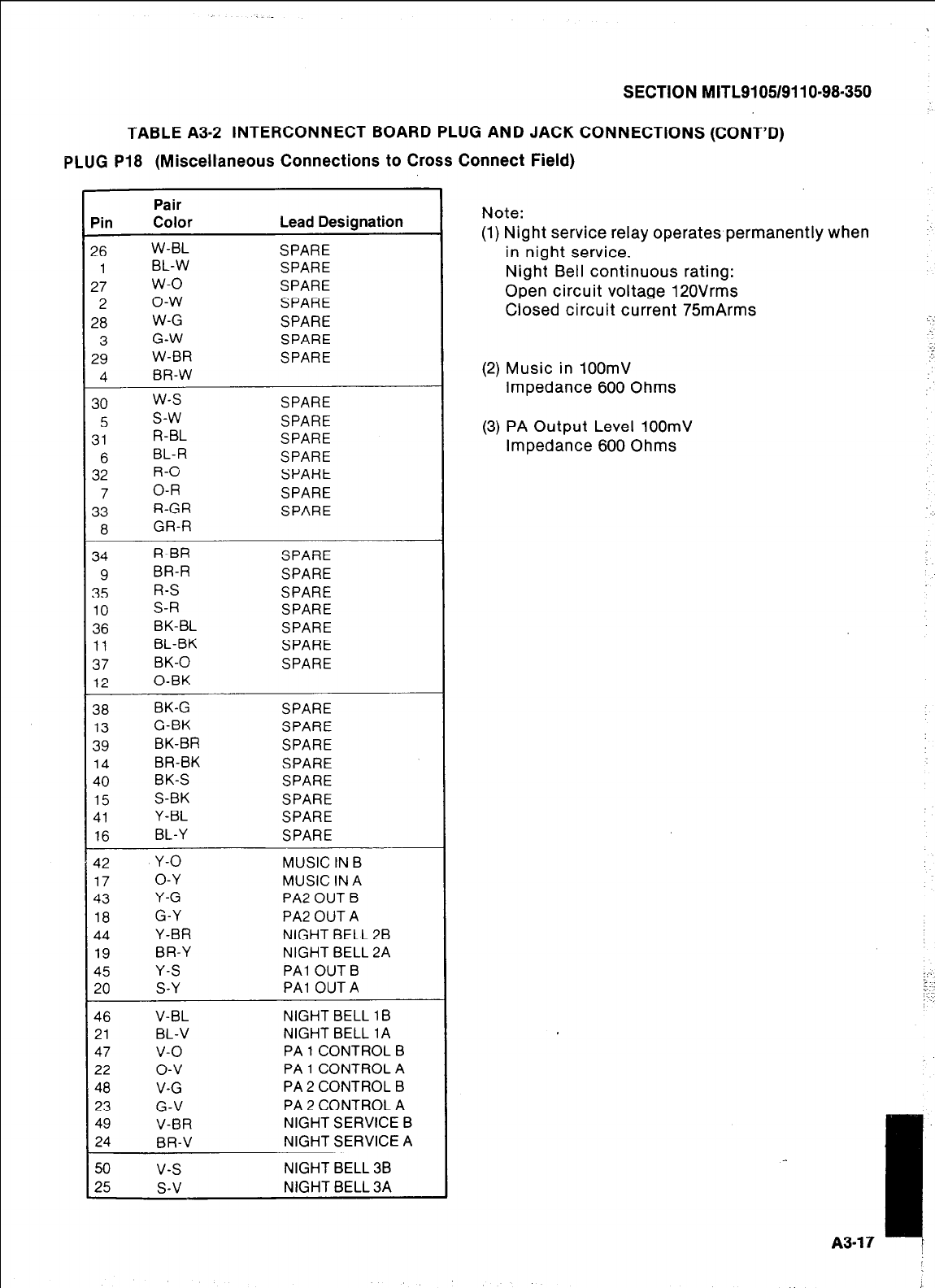
I
SECTION M ITL91051911 O-98-350
TABLE A3-2 INTERCONNECT BOARD PLUG AND JACK CONNECTIONS (CONT’D)
PLUG
P18 (Miscellaneous Connections to Cross Connect Field)
ain
!6
1
27
2
?8
3
29
4
30
5
31
6
32
7
33
8
34
9
35
10
36
11
37
12
38
13
39
14
40
15
41
16
42
17
43
18
44
19
45
20
46
21
47
22
48
23
49
24
50
25
Pair
Color
W-BL
BL-W
w-o
o-w
W-G
G-W
W-BR
BR-W
w-s
s-w
R-BL
BL-R
R-O
O-R
R-GR
GR-R
R-BR
BR-R
R-S
S-R
BK-BL
BL-BK
BK-0
0-BK
BK-G
G-BK
BK-BR
BR-BK
BK-S
S-BK
Y-BL
BL-Y
Y-0
O-Y
Y-G
G-Y
Y-BR
BR-Y
Y-S
S-Y
V-BL
BL-V
v-o
o-v
V-G
G-V
V-BR
BR-V
v-s
s-v
Lead Designation
SPARE
SPARE
SPARE
SPARE
SPARE
SPARE
SPARE
SPARE
SPARE
SPARE
SPARE
SPARE
SPARE
SPARE
SPARE
SPARE
SPARE
SPARE
SPARE
SPARE
SPARE
SPARE
SPARE
SPARE
SPARE
SPARE
SPARE
SPARE
SPARE
MUSIC IN B
MUSIC IN A
PA2 OUT B
PA2 OUT A
NIGHT BELL 28
NIGHT BELL 2A
PA1 OUT B
PA1 OUT A
NIGHT BELL 1 B
NIGHT BELL 1A
PA 1 CONTROL B
PA 1 CONTROL A
PA 2 CONTROL B
PA 2 CONTROL A
NIGHT SERVICE B
NIGHT SERVICE A
NIGHT BELL 38
NIGHT BELL 3A
Note:
(1) Night service relay operates permanently when
in night service.
Night Bell continuous rating:
Open circuit voltage 12OVrms
Closed circuit current 75mArms
(2) Music in 100mV
Impedance 600 Ohms
(3) PA Output Level 100mV
Impedance 600 Ohms
I
A3-17 t
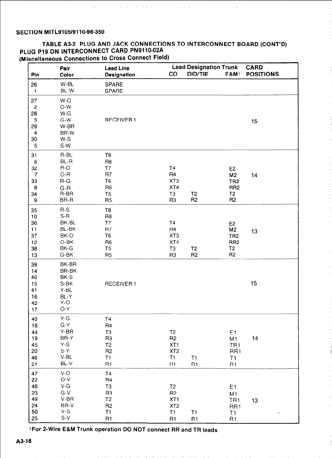
SECTION MITL9105/9110-98-350
Pin Pair
Color Lead Line
Designation
Lead Designation Trunk CARD
co DID/TIE E&M+ POSITIONS
26
1
W-BL
BL-W SPARE
SPARE
27
2
28
3
29
4
30
5
w-o
o-w
W-G
G-W RECEIVER 1 15
W-BR
BR-W
w-s
s-w
31
6
32
7
33
8
34
9
R-BL
BL-R
R-O
O-R
R-G
G-R
R-BR
BR-R
T6
R8
T7 T4 E2
R7 R4 M2 14
T6 XT3 TR2
R6 XT4 RR2
T5 T3 T2 T2
R5 R3 R2 R2
35
10
36
11
37
12
38
13
R-S
S-R
BK-BL
BL-BK
BK-0
0-BK
BK-G
G-BK
T8
R8
T7 T4 E2
R7 R4 M2 13
T6 XT3 TR2
R6 XT4 RR2
T5 T3 T2 T2
R5 R3 R2 R2
TABLE m-2 PLUG AND JACK CONNECTIONS TO INTERCONNECT BOARD (CONT’D)
PLUG P19 ON INTERCONNECT CARD PN9110-02A
(Miscellaneous Connections to Cross Connect Field)
39
14
40
15
41
16
42
17
BK-BR
BR-BK
BK-S
S-BK RECEIVER 1 15
Y-BL
BL-Y
Y-O
O-Y
43
18
44
19
45
20
46
21
Y-G
G-Y
Y-BR
BR-Y
Y-S
S-Y
V-BL
BL-V
T4
R4
T3 T2 El
R3 R2 Ml 14
T2 XT1 TRl
R2 XT2 RR1
Tl Tl Tl Tl
Rl Hl Rl Rl
47 v-o T4
22 o-v R4
48 V-G T3 T2 El
23 G-V R3 R2 Ml
49 V-BR T2 XT1 TRl 13
24 BR-V R2 XT2 RR1
50 V-S Tl Tl Tl Tl
25 s-v Rl Rl Rl fii
tFor 2-Wire E&M Trunk operation DO NOT connect RR and TR leads
A3-18
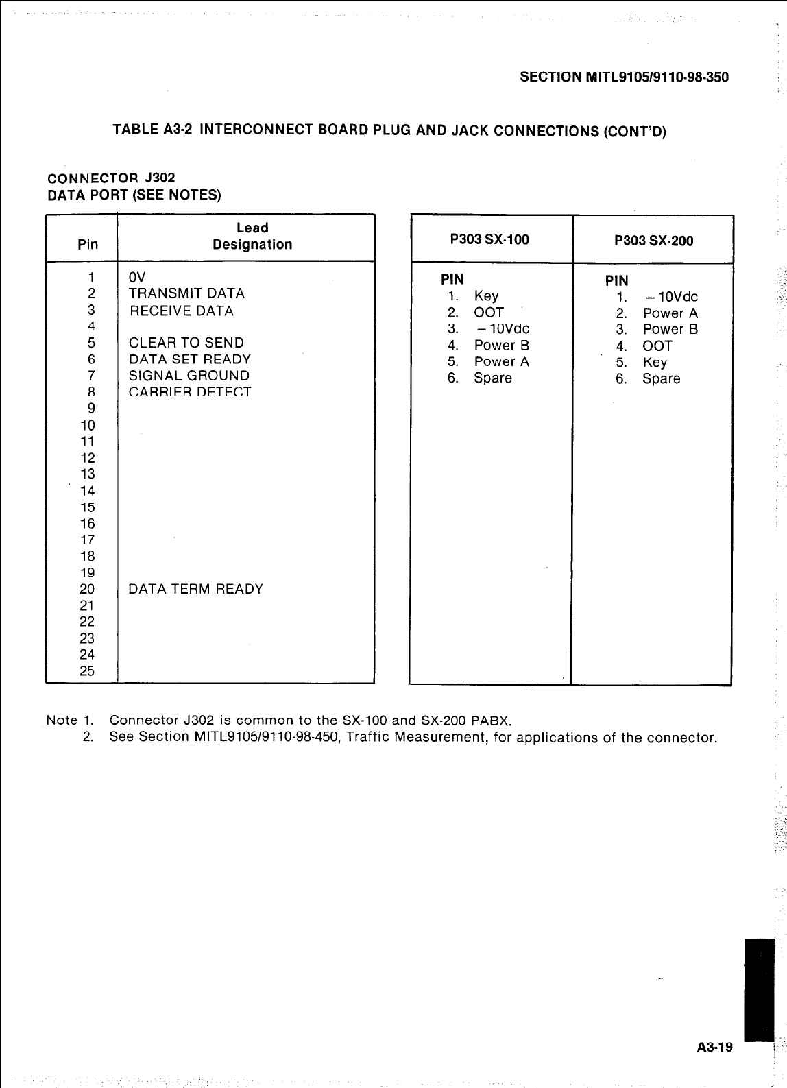
SECTION MITL9105/9110-98-350
TABLE A3-2 INTERCONNECT BOARD PLUG AND JACK CONNECTIONS (CONT’D)
CONNECTOR 5302
DATA PORT (SEE NOTES)
Lead
Pin Designation
1 ov
2 TRANSMIT DATA
3 RECEIVE DATA
4
5 CLEAR TO SEND
6 DATA SET READY
7 SIGNAL GROUND
8 CARRIER DETECT
9
10
11
12
13
14
15
16
17
18
19
20 DATA TERM READY
21
22
23
24
25
P303 sx-100
PIN
1. Key
2. OOT
3. - 1OVdc
4. Power B
5. Power A
6. Spare
P303 sx-200
PIN
1. - 10Vdc
2. Power A
3. Power B
4. OOT
5. Key
6. Spare
Note 1. Connector J302 is common to the SX-100 and SX-200 PABX.
2. See Section MITL9105/9110-98-450, Traffic Measurement, for applications of the connector.
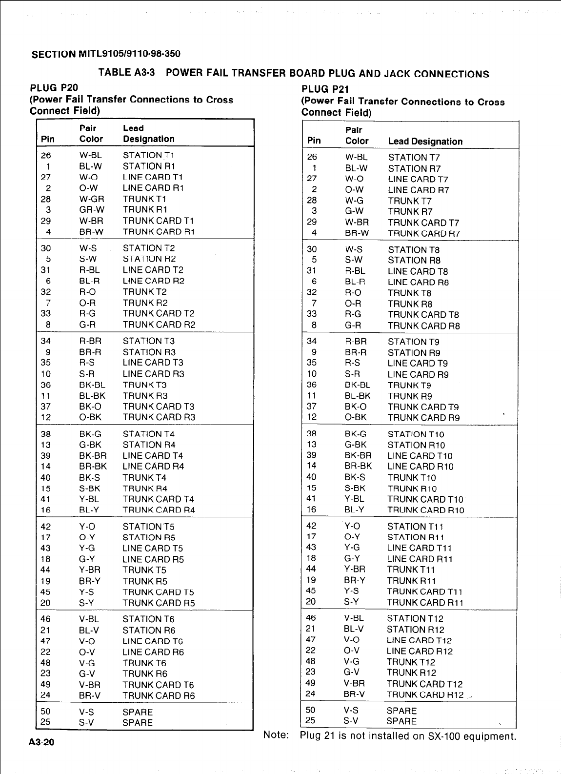
SECTION MITL9105/9110-98.350
TABLE A3-3 POWER FAIL TRANSFER BOARD PLUG AND JACK CONNECTIONS
PLUG P20
(Power Fail Transfer Connections to Cross
Connect Field)
Pin
26
1
27
2
28
3
29
4
Pair Lead
Color Designation
W-BL STATION .Tl
BL-W STATION Rl
w-o LINE CARD Tl
o-w LINE CARD Rl
W-GR TRUNK Tl
GR-W TRUNK Rl
W-BR TRUNK CARD Tl
BR-W TRUNK CARD Rl
30
5
31
6
32
7
33
8
34
9
35
10
36
11
37
12
w-s
s-w
R-BL
BL-R
R-O
O-R
R-G
G-R
R-BR
BR-R
R-S
S-R
BK-BL
BL-BK
BK-0
0-BK
STATION T2
STATION R2
LINE CARD T2
LINE CARD R2
TRUNK T2
TRUNK R2
TRUNK CARD T2
TRUNK CARD R2
STATION T3
STATION R3
LINE CARD T3
LINE CARD R3
TRUNK T3
TRUNK R3
TRUNK CARD T3
TRUNK CARD R3
38
13
39
14
40
15
41
16
BK-G
G-BK
BK-BR
BR-BK
BK-S
S-BK
Y-BL
BL-Y
STATION T4
STATION R4
LINE CARD T4
LINE CARD R4
TRUNK T4
TRUNK R4
TRUNK CARD T4
TRUNK CARD R4
42
17
43
18
44
19
45
20
Y-O
O-Y
Y-G
G-Y
Y-BR
BR-Y
Y-S
S-Y
STATION T5
STATION R5
LINE CARD T5
LINE CARD R5
TRUNK T5
TRUNK R5
TRUNK CARD T5
TRUNK CARD R5
46
21
47
22
48
23
49
24
V-BL
BL-V
v-o
o-v
V-G
G-V
V-BR
BR-V
STATION T6
STATION R6
LINE CARD T6
LINE CARD R6
TRUNK T6
TRUNK R6
TRUNK CARD T6
TRUNK CARD R6
50
25 v-s
s-v SPARE
SPARE
A3-20
PLUG P21
(Power Fail Transfer Connections to Cross
Connect Field)
Pin
26
1
27
2
28
3
29
4
30
5
31
6
32
7
33
8
34
9
35
10
36
11
37
12
38
13
39
14
40
15
41
16
42
17
43
18
44
19
45
20
46
21
47
22
48
23
49
24
50
25
-.
Pair
Color Lead Designation
W-BL STATION T7
BL-W STATION R7
w-o LINE CARD T7
o-w LINE CARD R7
W-G TRUNK T7
G-W TRUNK R7
W-BR TRUNK CARD T7
BR-W TRUNK CARD R7
w-s STATION T8
s-w STATION R8
R-BL LINE CARD T8
BL-R LINE CARD R8
R-O TRUNK T8
O-R TRUNK R8
R-G TRUNK CARD T8
G-R TRUNK CARD R8
R-BR STATION T9
BR-R STATION R9
R-S LINE CARD T9
S-R LINE CARD R9
BK-BL TRUNK T9
BL-BK TRUNK R9
BK-0 TRUNK CARD T9
0-BK TRUNK CARD R9
BK-G STATION TlO
G-BK STATION RlO
BK-BR LINE CARD TlO
BR-BK LINE CARD RlO
BK-S TRUNK TlO
S-BK TRUNK RlO
Y-BL TRUNK CARD TlO
BL-Y TRUNK CARD RlO
Y-O STATION Tl 1
O-Y STATION Rll
Y-G LINE CARD Tll
G-Y LINE CARD Rll
Y-BR TRUNK Tll
BR-Y TRUNK Rll
Y-S TRUNK CARD Tll
S-Y TRUNK CARD Rll
V-BL STATION T12
BL-V STATION R12
v-o LINE CARD T12
o-v LINE CARD R12
V-G TRUNK T12
G-V TRUNK R12
V-BR TRUNK CARD T12
BR-V TRUNK CARD R12 _-
v-s SPARE
s-v SPARE
Note:
Plug 21
is not installed on SX-100 equipment.
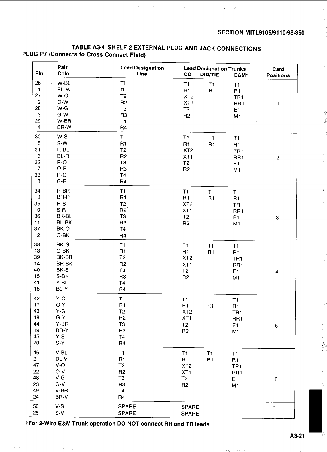
PLUG
SECTION MITL9105/9110~98-350
TABLE A3-4 SHELF 2 EXTERNAL PLUG AND JACK CONNECTIONS
P7 (Connects to Cross Connect Field)
Pin
26
1
27
2
28
3
29
4
30
5
31
6
32
7
33
8
34
9
35
10
36
11
37
12
38
13
39
14
40
15
41
16
42
17
43
18
44
19
45
20
46
21
47
22
48
23
49
24
50
25
Pair Lead Designation
Color Line
W-BL TI
BL-W Rl
w-o T2
o-w R2
W-G T3
G-W R3
W-BR T4
BR-W R4
w-s Tl
s-w Rl
R-BL T2
BL-R R2
R-O T3
O-R R3
R-G T4
G-R R4
R-BR Tl
BR-R Rl
R-S T2
S-R R2’
BK-BL T3
BL-BK R3
BK-0 T4
0-BK R4
BK-G Tl
G-BK Rl
BK-BR T2
BR-BK R2
BK-S T3
S-BK R3
Y-BL T4
BL-Y R4
Y-O Tl
O-Y Rl
Y-G T2
G-Y R2
Y-BR T3
BR-Y R3
Y-S T4
S-Y R4
V-BL Tl
BL-V Rl
v-o T2
o-v R2
V-G T3
G-V R3
V-BR T4
BR-V R4
v-s SPARE
s-v SPARE
Lead Designation Trunks
co DID/TIE E&M?
Tl Tl Tl
RI RI Rl
XT2 TRI
XT1 RR1
T2 El
R2 Ml
Tl Tl Tl
Rl RI Rl
XT2 TRl
XT1 RR1
T2 El
R2 Ml
Tl Tl Tl
Rl Rl RI
XT2 TRl
XT1 RR1
T2 El
R2 Ml
Tl Tl Tl
Rl Rl Rl
XT2 TRl
XT1 RR1
T2 El
R2 Ml
Tl Tl Tl
Rl Rl Rl
XT2 TRl
XT1 RR1
T2 El
R2 Ml
Tl Tl Tl
Rl RI Rl
XT2 TRl
XT1 RR1
T2 El
R2 Ml
SPARE
SPARE
Card
Positions
1
2
3
4
5
6
.-
tFor P-Wire E&M Trunk operation DO NOT connect RR and TR leads
A3-21
: T.
‘:,
.::.,
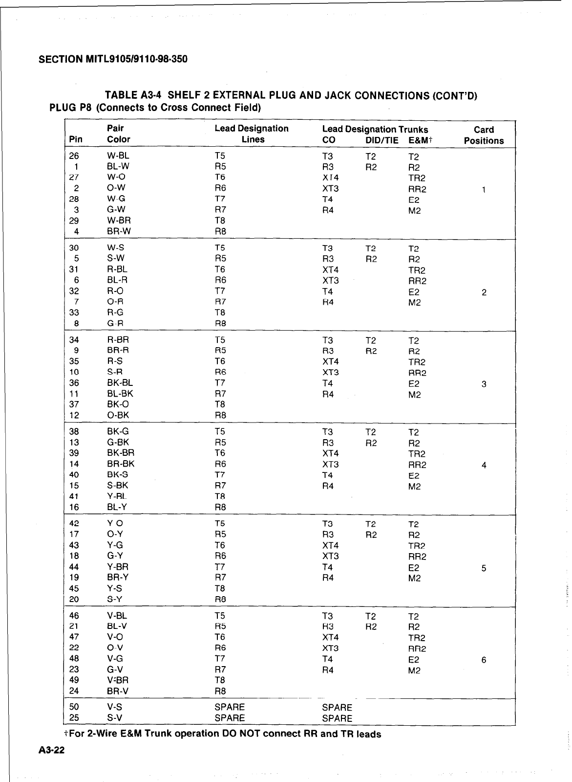
SECTION MlTL9105/9110-98.350
TABLE A3-4 SHELF 2 EXTERNAL PLUG AND JACK CONNECTIONS (CONT’D)
PLUG P8 (Connects to Cross Connect Field)
Pair
Pin Color
26 W-BL
1 BL-W
27 w-o
2 o-w
28 W-G
3 G-W
29 W-BR
4 BR-W
30 w-s
5 s-w
31 R-BL
6 BL-R
32 R-O
7 O-R
33 R-G
8 G-R
34 R-BR
9 BR-R
35 R-S
10 S-R
36 BK-BL
11 BL-BK
37 BK-0
12 0-BK
38 BK-G
13 G-BK
39 BK-BR
14 BR-BK
40 BK-S
15 S-BK
41 Y-BL
16 BL-Y
42 Y-O
17 O-Y
43 Y-G
18 G-Y
44 Y-BR
19 BR-Y
45 Y-S
20 S-Y
46 V-BL
21 BL-V
47 v-o
22 o-v
48 V-G
23 G-V
49 V’BR
24 BR-V
50 v-s
25 s-v
- - .__. --_- - .
Lead Designation Lead Designation Trunks Card
Lines co DID/TIE E&W Positions
T5 T3 T2 T2
R5 R3 R2 R2
T6 XT4 TR2
R6 XT3 RR2 1
T7 T4 E2
R7 R4 M2
T8
R8
T5 T3 T2 T2
R5 R3 R2 R2
T6 XT4 TR2
R6 XT3 RR2
T7 T4 E2 2
R7 R4 M2
T8
R8
T5 T3 T2 T2
R5 R3 R2 R2
T6 XT4 TR2
R6 XT3 RR2
T7 T4 E2 3
R7 R4 M2
T8
R8
T5 T3 T2 T2
R5 R3 R2 R2
T6 XT4 TR2
R6 XT3 RR2 4
T7 T4 E2
R7 R4 M2
T8
R8
T5 T3 T2 T2
R5 R3 R2 R2
T6 XT4 TR2
R6 XT3 RR2
T7 T4 E2 5
R7 R4 M2
T8
R8
T5 T3 T2 T2
R5 R3 R2 R2
T6 XT4 TR2
R6 XT3 RR2
T7 T4 E2 6
R7 R4 M2
T8
R8
SPARE SPARE
SPARE SPARE
. . -- _.-- --
4-For z-wire E&M TrUnK OperatlOn UO
NOT
Connect
RR and TR leads
83-22
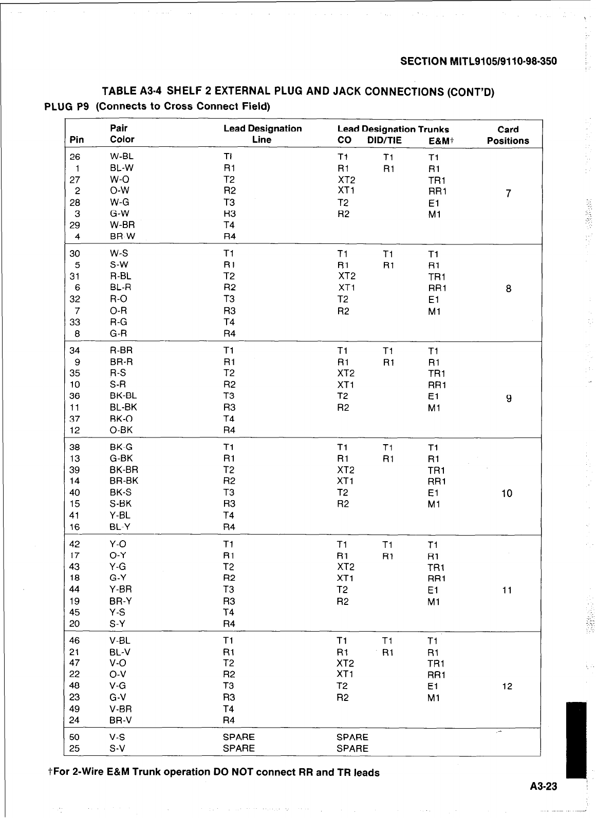
SECTION MITL9105/9110-98-350
TABLE A3-4 SHELF 2 EXTERNAL PLUG AND JACK CONNECTIONS (CONT’D)
PLUG P9 (Connects to Cross Connect Field)
Pin
26
1
27
2
28
3
29
4
30
5
31
6
32
7
33
8
34
9
35
10
36
11
37
12
38
13
39
14
40
15
41
16
42
17
43
18
44
19
45
20
46
21
47
22
48
23
49
24
50
25
Pair Lead Designation
Color Line
W-BL TI
BL-W RI
w-o T2
o-w R2
W-G T3
G-W R3
W-BR T4
BR-W R4
w-s Tl
s-w Rl
R-BL T2
BL-R R2
R-O T3
O-R R3
R-G T4
G-R R4
R-BR Tl
BR-R Rl
R-S T2
S-R R2
BK-BL T3
BL-BK R3
BK-0 T4
0-BK R4
BK-G Tl
G-BK Rl
BK-BR T2
BR-BK R2
BK-S T3
S-BK R3
Y-BL T4
BL-Y R4
Y-O Tl
O-Y Rl
Y-G T2
G-Y R2
Y-BR T3
BR-Y R3
Y-S T4
S-Y R4
V-BL Tl
BL-V Rl
v-o T2
o-v R2
V-G T3
G-V R3
V-BR T4
BR-V R4
v-s SPARE
s-v SPARE
Lead Designation Trunks
co DID/TIE E&Mf
Tl Tl Tl
Rl Rl Rl
XT2 TRl
XT1 RR1
T2 El
R2 Ml
Tl Tl Tl
Rl Rl Rl
XT2 TRl
XT1 RR1
T2 El
R2 Ml
Tl Tl Tl
Rl Rl Rl
XT2 TRl
XT1 RR1
T2 El
R2 Ml
Tl Tl Tl
Rl Rl RI
XT2 TRl
XT1 RR1
T2 El
R2 Ml
Tl Tl Tl
Rl Rl Rl
XT2 TRl
XT1 RR1
T2 El
R2 Ml
Tl Tl Tl
Rl Rl Rl
XT2 TRI
XT1 RR1
T2 El
R2 Ml
SPARE
SPARE
Card
Positions
7
8
9
10
11
12
,-
tFor 2-Wire E&M Trunk operation DO NOT connect RR and TR leads
A3-23
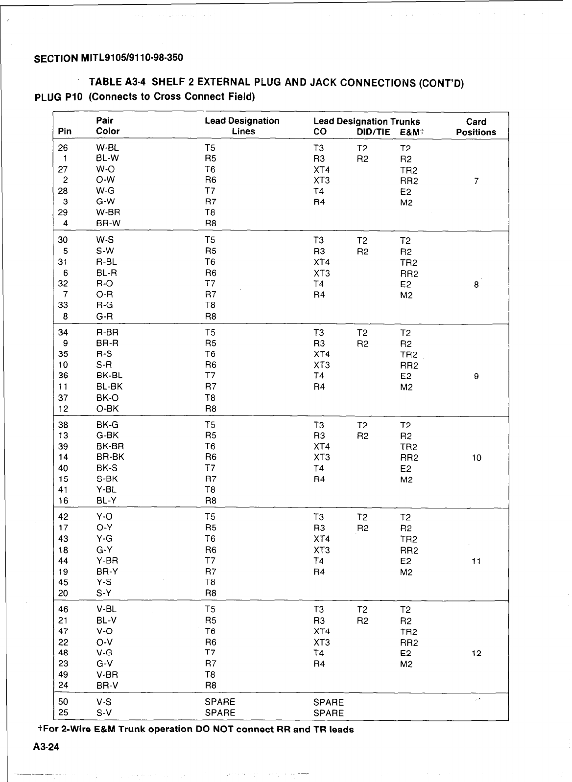
r
SECTION MITL9105/911 O-98-350
TABLE A3.4 SHELF 2 EXTERNAL PLUG AND JACK CONNECTIONS (CONT’D)
PLUG PI0 (Connects to Cross Connect Field)
Pair Lead Designation Lead Designation Trunks
Pin Color Lines co DID/TIE E&M?
26 W-BL T5 T3 T2 T2
1 BL-W R5 R3 R2 R2
27 w-o T6 XT4 TR2
2 o-w R6 XT3 RR2
28 W-G T7 T4 E2
3 G-W R7 R4 M2
29 W-BR T8
4 BR-W R8
30 w-s T5 T3 T2 T2
5 s-w R5 R3 R2 R2
31 R-BL T6 XT4 TR2
6 BL-R R6 XT3 RR2
32 R-O T7 T4 E2
7 O-R R7 R4 M2
33 R-G T8
8 G-R R8
34 R-BR T5 T3 T2 T2
9 BR-R R5 R3 R2 R2
35 R-S T6 XT4 TR2
10 S-R R6 XT3 RR2
36 BK-BL T7 T4 E2
11 BL-BK R7 R4 M2
37 BK-0 T8
12 0-BK R8
38 BK-G T5 T3 T2 T2
13 G-BK R5 R3 R2 R2
39 BK-BR T6 XT4 TR2
14 BR-BK R6 XT3 RR2
40 BK-S T7 T4 E2
15 S-BK R7 R4 M2
41 Y-BL T8
16 BL-Y R8
42 Y-O T5 T3 T2 T2
17 O-Y R5 R3 R2 R2
43 Y-G T6 XT4 TR2
18 G-Y R6 XT3 RR2
44 Y-BR T7 T4 E2
19 BR-Y R7 R4 M2
45 Y-S T8
20 S-Y R8
46 V-BL T5 T3 T2 T2
21 BL-V R5 R3 R2 R2
47 v-o T6 XT4 TR2
22 o-v R6 XT3 RR2
48 V-G T7 T4 E2
23 G-V R7 R4 M2
49 V-BR T8
24 BR-V R8
50 v-s SPARE SPARE
25 s-v SPARE SPARE
tFor P-Wire
E&M
Trunk operation DO NOT connect RR and TR leads
Card
Positions
7
8.
9
10
-
11
12
_-
A3=24
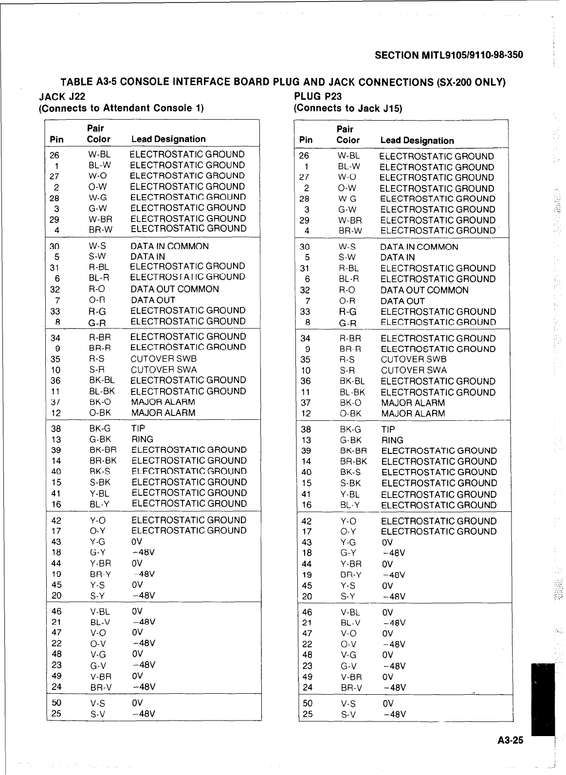
SECTION MITL9105/9110-98-350
TABLE A3-5 CONSOLE INTERFACE BOARD PLUG AND JACK CONNECTIONS (SX-200 ONLY)
JACK 522
(Connects to Attendant Console 1) PLUG P23
(Connects to Jack J15)
Pin
26
1
27
2
28
3
29
4
30
5
31
6
32
7
33
8
34
9
35
10
36
11
37
12
38
13
39
14
40
15
41
16
42
17
43
18
44
19
45
20
46
21
47
22
48
23
49
24
50
25
Pair
Color Lead Designation
W-BL ELECTROSTATIC GROUND
BL-W ELECTROSTATIC GROUND
w-o ELECTROSTATIC GROUND
o-w ELECTROSTATIC GROUND
W-G ELECTROSTATIC GROUND
G-W ELECTROSTATIC GROUND
W-BR ELECTROSTATIC GROUND
BR-W ELECTROSTATIC GROUND
w-s DATA IN COMMON
s-w DATA IN
R-E3L ELECTROSTATIC GROUND
BL-R ELECTROSTATIC GROUND
R-O DATA OUT COMMON
O-R DATA OUT
R-G
ELECTROSTATIC GROUND
G-R
ELECTROSTATIC GROUND
R-BR ELECTROSTATIC GROUND
BR-R ELECTROSTATIC GROUND
R-S CUTOVER SWB
S-R CUTOVER SWA
BK-BL ELECTROSTATIC GROUND
BL-BK ELECTROSTATIC GROUND
BK-0 MAJOR ALARM
0-BK MAJOR ALARM
BK-G TIP
G-BK RING
BK-BR ELECTROSTATIC GROUND
BR-BK ELECTROSTATIC GROUND
BK-S ELECTROSTATIC GROUND
S-BK ELECTROSTATIC GROUND
Y-BL ELECTROSTATIC GROUND
BL-Y ELECTROSTATIC GROUND
Y-O ELECTROSTATIC GROUND
O-Y ELECTROSTATIC GROUND
Y-G ov
G-Y -48V
Y-BR OV
BR-Y -48V
Y-S ov
S-Y -48V
V-BL OV
BL-V -48V
v-o ov
o-v -48V
V-G ov
G-V -48V
V-BR OV
BR-V -48V
v-s ov
s-v -48V
pin Pair
Coior Lead Designation
!
‘6 W-BL ELECTROSTATIC GROUND
1 BL-W ELECTROSTATIC GROUND
27 w-o ELECTROSTATIC GROUND
2 o-w ELECTROSTATIC GROUND
28 W-G ELECTROSTATIC GROUND
3 G-W ELECTROSTATIC GROUND
29 W-BR ELECTROSTATIC GROUND
4 BR-W ELECTROSTATIC GROUND
30
w-s
DATA IN COMMON
5
s-w
DATA IN
31 R-BL ELECTROSTATIC GROUND
6 BL-R ELECTROSTATIC GROUND
32 R-O DATA OUT COMMON
7 O-R DATA OUT
33
R-G
ELECTROSTATIC GROUND
8
G-R
ELECTROSTATIC GROUND
34 R-BR ELECTROSTATIC GROUND
9 BR-R ELECTROSTATIC GROUND
35 R-S CUTOVER SWB
10 S-R CUTOVER SWA
36 BK-BL ELECTROSTATIC GROUND
11 BL-BK ELECTROSTATIC GROUND
37 BK-0 MAJOR ALARM
12 0-BK MAJOR ALARM
38 BK-G TIP
13 G-BK RING
39 BK-BR ELECTROSTATIC GROUND
14 BR-BK ELECTROSTATIC GROUND
40 BK-S ELECTROSTATIC GROUND
15 S-BK ELECTROSTATIC GROUND
41 Y-BL ELECTROSTATIC GROUND
16 BL-Y ELECTROSTATIC GROUND
42 Y-O ELECTROSTATIC GROUND
17 O-Y ELECTROSTATIC GROUND
43 Y-G ov
18 G-Y -48V
44 Y-BR OV
19 BR-Y -48V
45 Y-S ov
20 S-Y -48V
46 V-BL OV
21 BL-V -48V
47 v-o ov
22 o-v -48V
48 V-G ov
23 G-V -48V
49 V-BR OV
24 BR-V -48V
50 v-s ov
25 s-v -48V
A3-25
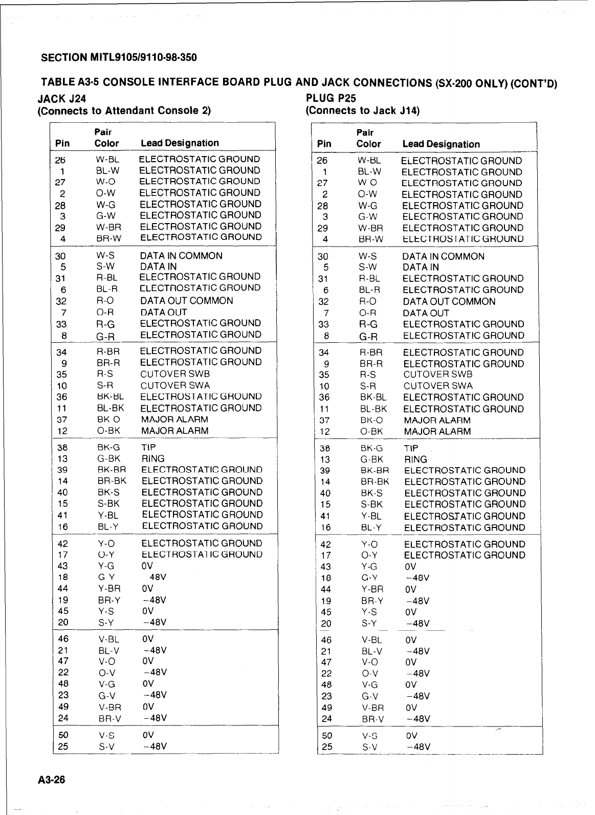
SECTION MITL9105/9110-98.350
TABLE A3-5 CONSOLE INTERFACE BOARD PLUG AND JACK CONNECTIONS (SX-200 ONLY) (CONT’D)
JACK J24 PLUG P25
(Connects to Jack J14)
(Connects to Attendant Console 2)
Pin
?6
1
?7
2
28
3
?9
4
30
5
31
6
32
7
33
8
34
9
35
10
36
11
37
12
38
13
39
14
40
15
41
16
42
17
43
18
44
19
45
20
46
21
47
22
48
23
49
24
50
25
Pair
Color Lead Designation
W-BL ELECTROSTATIC GROU
BL-W ELECTROSTATIC GROU
w-o ELECTROSTATIC GROU
o-w ELECTROSTATIC GROlj
W-G ELECTROSTATIC GROC
G-W ELECTROSTATIC GROC
W-BR ELECTROSTATIC GROC
BR-W ELECTROSTATIC GROl
w-s DATA IN COMMON
s-w DATA IN
R-BL ELECTROSTATIC GROL
BL-R ELECTROSTATIC GROL
R-O DATA OUT COMMON
O-R DATA OUT
R-G ELECTROSTATIC GROC
G-R
ELECTROSTATIC GROL
R-BR ELECTROSTATIC GROL
BR-R ELECTROSTATIC GROl
R-S CUTOVER SWB
S-R CUTOVER SWA
BK-BL ELECTROSTATIC GROl
BL-BK ELECTROSTATIC GRO:
BK-0 MAJOR ALARM
0-BK MAJOR ALARM
BK-G TIP
G-BK RING
BK-BR ELECTROSTATIC GROl
BR-BK ELECTROSTATIC GROL
BK-S ELECTROSTATIC GROl
S-BK ELECTROSTATIC GROl
Y-BL ELECTROSTATIC GROl
BL-Y ELECTROSTATIC GROl
Y-O ELECTROSTATIC GROl
O-Y ELECTROSTATIC GROl
Y-G ov
G-Y -48V
Y-BR OV
BR-Y -48V
Y-S ov
S-Y -48V
V-BL OV
BL-V -48V
v-o ov
o-v -48V
V-G ov
G-V -48V
V-BR OV
BR-V -48V
v-s ov
s-v -48V
~~~ __~..
--I
I
IND
IND
IND
IND
IND
JND
JND
JND
IND
IND
JND
JND
JND
JND
JND
JND
JND
JND
JND
JND
JND
JND
JND
JND
Pair
Pin Color Lead Designation
26 W-BL ELECTROSTATIC GROUNC
1 BL-W ELECTROSTATIC GROUN[:
27 w-o ELECTROSTATIC GROUNC
2 o-w ELECTROSTATIC GROUN[
28 W-G ELECTROSTATIC GROUNI
3 G-W ELECTROSTATIC GROUNI
29 W-BR ELECTROSTATIC GROUNI
4 BR-W ELECTROSTATIC GROUNI
30 w-s DATA IN COMMON
5 s-w DATA IN
31 R-BL ELECTROSTATIC GROUNI
6 BL-R ELECTROSTATIC GROUNI
32 R-O DATA OUT COMMON
7 O-R DATA OUT
33
R-G
ELECTROSTATIC GROUN’
8
G-R
ELECTROSTATIC GROUN
34 R-BR ELECTROSTATIC GROUNI
9 BR-R ELECTROSTATIC GROUNI
35 R-S CUTOVER SWB
10 S-R CUTOVER SWA
36 BK-BL ELECTROSTATIC GROUNI
11 BL-BK ELECTROSTATIC GROUNI
37 BK-0 MAJOR ALARM
12 0-BK MAJOR ALARM
36 BK-G TIP
13 G-BK RING
39 BK-BR ELECTROSTATIC GROUN
14 BR-BK ELECTROSTATIC GROUN
40 BK-S ELECTROSTATIC GROUN
15 S-BK ELECTROSTATIC GROUN
41 Y-BL ELECTROSJATIC GROUN
16 BL-Y ELECTROSTATIC GROUN
42 Y-O ELECTROSTATIC GROUN
17 O-Y ELECTROSTATIC GROUN
43 Y-G ov
18 G-Y -48V
44 Y-BR OV
19 BR-Y -48V
45 Y-S ov
20 S-Y -48V
46 V-BL OV
21 BL-V -48V
47 v-o ov
22 o-v -48V
48 V-G ov
23 G-V -48V
49 V-BR OV
24 BR-V -48V ,-
50 v-s ov
25 s-v -48V
____
1
--
>
1
1
I
3
3
3
D
1
D
D
D
D
D
D
D
D
D
D
D
D
D
D
D
D
--I
i
83-28
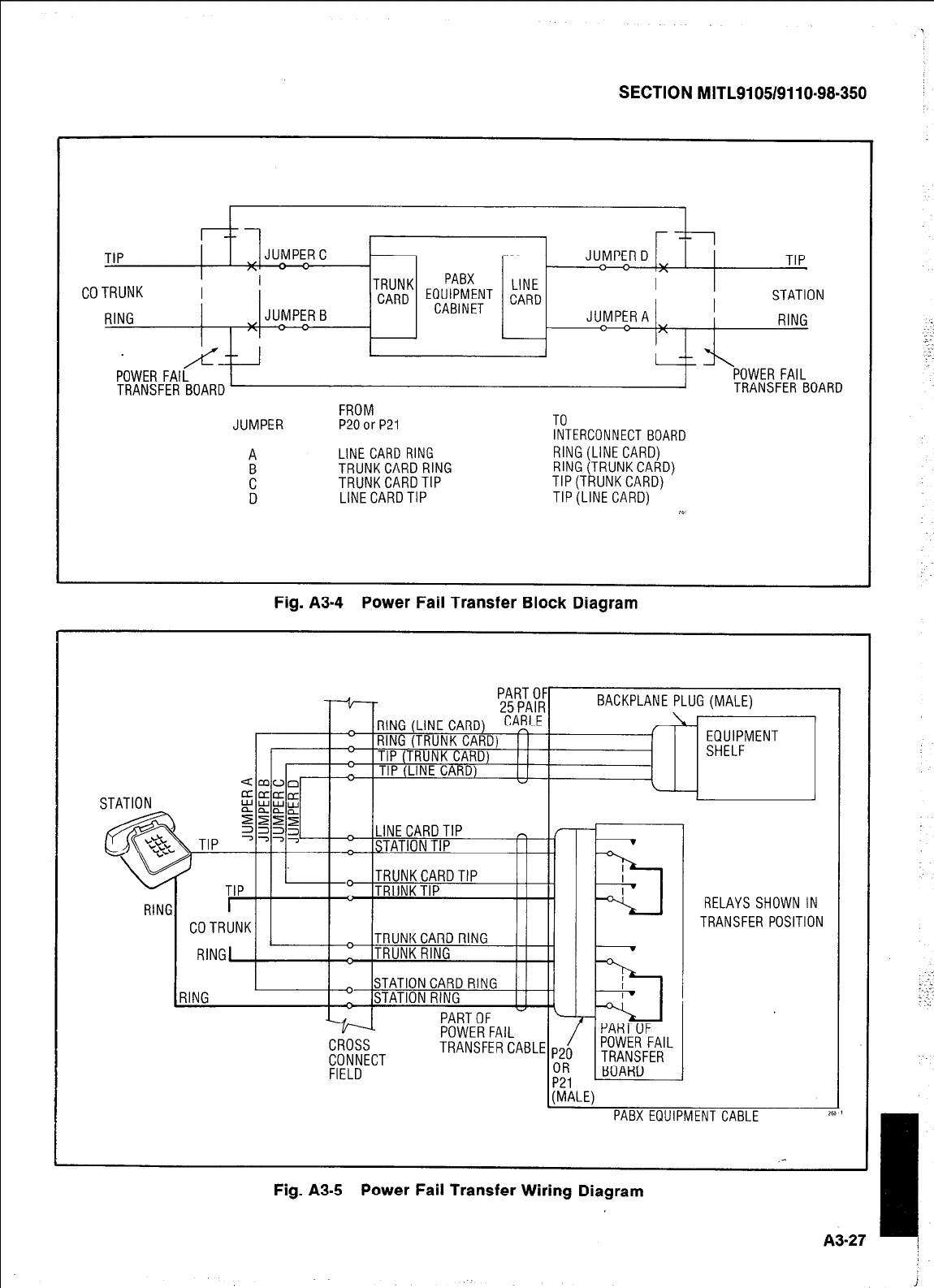
SECTION MITL9105/9110-98-350
TIP JUMPERC JUMPERD TIP
I\
PABX
COTRUNK TRUNK
CARD EQUIPMENT k;rD STATION
RING JUMPERB CABINET JUMPERA RING
/c-- 1 1 -- %\
POWER FAIL POWER FAIL
TRANSFER BOARD TRANSFER BOARD
FROM
JUMPER P20orP21 TO
INTERCONNECT BOARD
A LINE CARD RING RlNG(LINECARD)
F TRUNKCARDRING RlNG(TRUNKCARD)
TRUNKCARDTIP TIP(TRUNKCARD)
D LINE CARDTIP TIP(LINE CARD) x
Fig. A3-4 Power Fail Transfer Block Diagram
RELAYS SHOWN IN
TRANSFER POSITION
TRANSFERCABLE
PABX EQUIPMENT CABLE
A3-27 !
Fig. A3-5 Power Fail Transfer Wiring Diagram
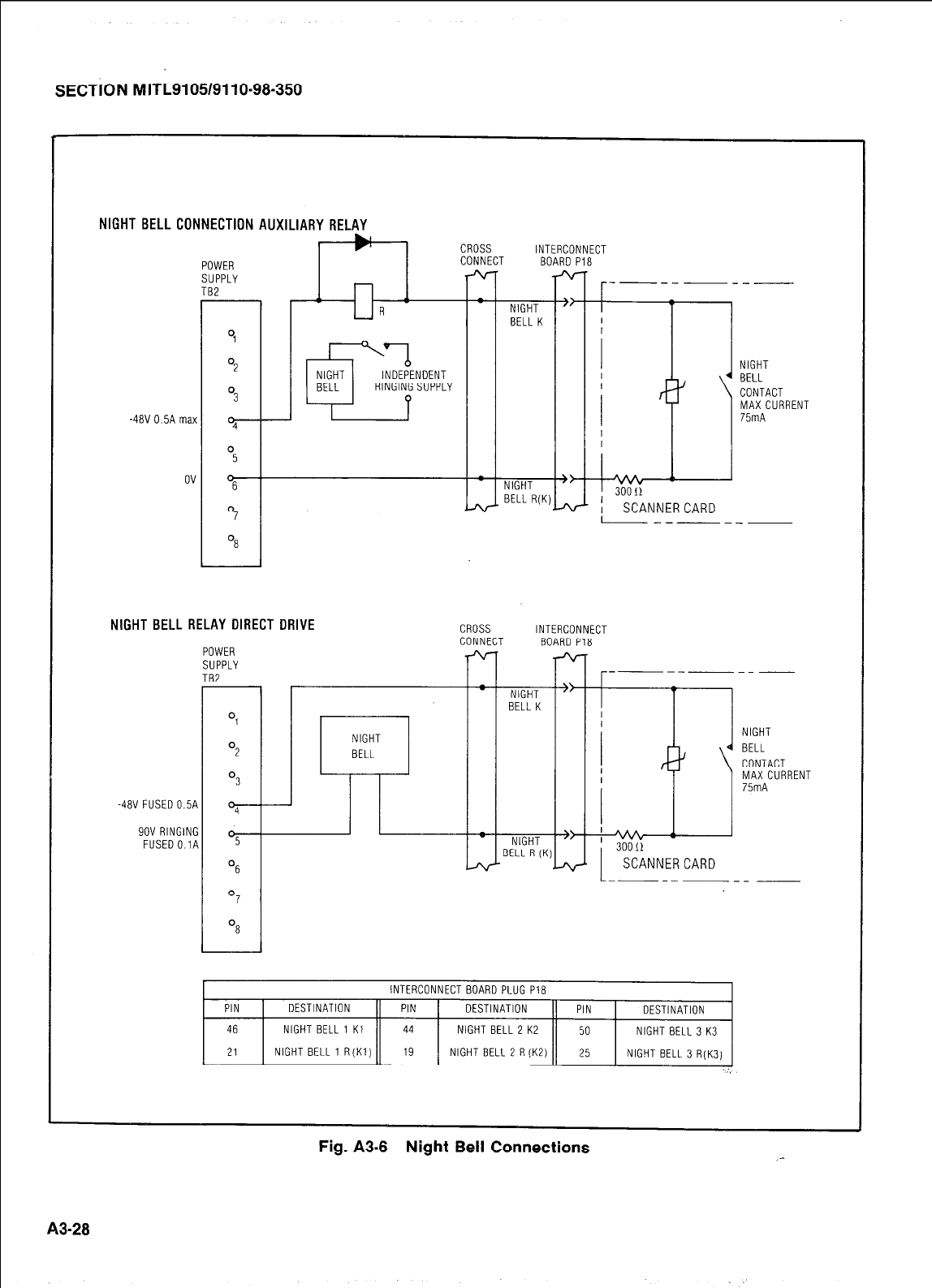
SECTION MITL9105/9110-98-350
I 1
NIGHT
BELL
CONTACT
MAXCURRENl
75mA
- NIGHT w t
BELL R(K) 300!1
- ; SCANNERCARD
NIGHT BELL CONNECTION AUXILIARY RELAY
AI
1 V' I CROSS INTERCONNECl
-48V OSA max
ov
NIGHT BELL RELAY DIRECT DRIVE
POWER
SUPPLY
TB2
Ol
O2
O3
-4av FUSEDO.~A "4
9OV RINGING
FUSEDO.lA O5
OS
O7
NIGHT
BELL
CROSS INTERCONNECT
CONNECT BOARD Pla
--- ----- -
- NIGHT "
BELL K
NIGHT
4 BELL
CONTACT
MAX CURRENT
75mA
~&?::I()~ i %,,,', CARD
---- ---
'8
PIN
46
21
INTERCONNECT BOARD PLUG Pia
DESTINATION PIN DESTINATION PIN DESTINATION
NIGHT BELL 1 Kl 44 NIGHT BELL 2 K2 50 NIGHT BELL 3 K3
NIGHT BELL 1 R(K1) 19 NIGHT BELL 2 R(K2) 25 NIGHT BELL 3 R(K3)
Fig. A3-8 Night Bell Connections _-
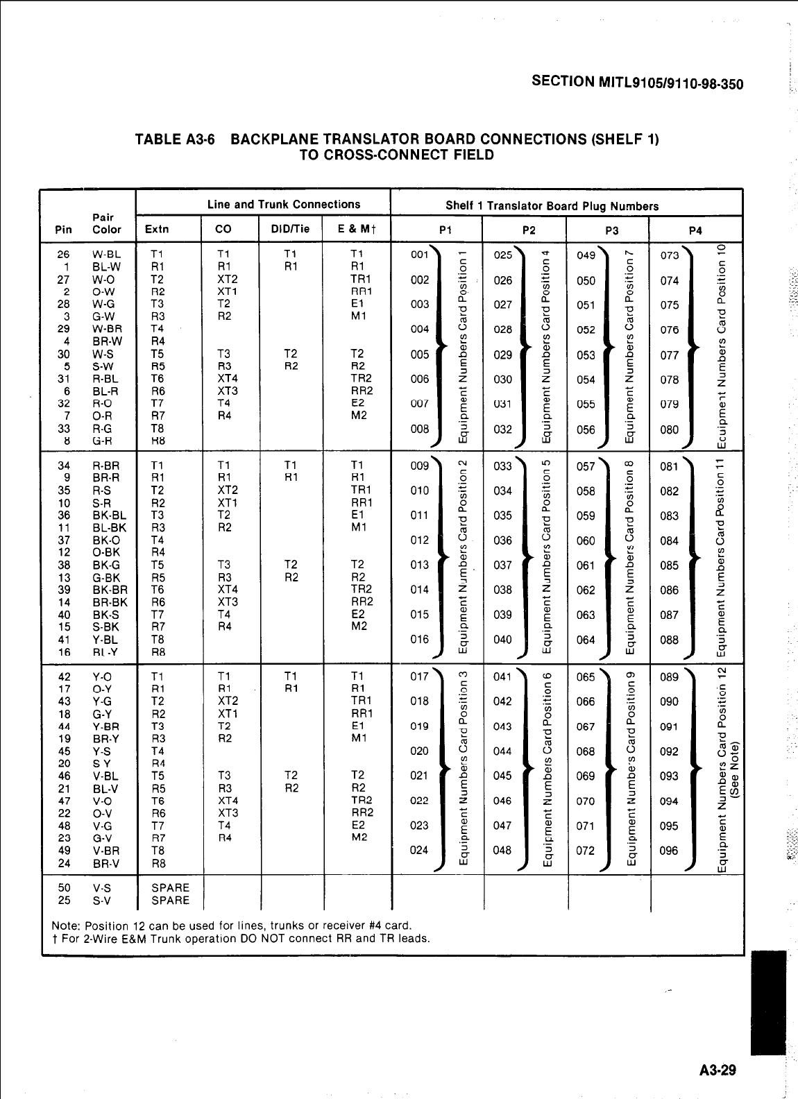
SECTION MITL9105/9110-98-350
TABLE A3-8 BACKPLANE TRANSLATOR BOARD CONNECTIONS (SHELF 1)
TO CROSS-CONNECT FIELD
Pair
Pin Color
26 W-BL
1 BL-W
27 w-o
2 o-w
28 W-G
3 G-W
29 W-BR
4 BR-W
30 w-s
5 s-w
31 R-BL
6 BL-R
32 R-O
7 O-R
33 R-G
8 G-R
34 R-BR
9 BR-R
35 R-S
10 S-R
36 BK-BL
11 BL-BK
37 BK-0
12 0-BK
38 BK-G
13 G-BK
39 BK-BR
14 BR-BK
40 BK-S
15 S-BK
41 Y-BL
16 BL-Y
42 Y-O
17 O-Y
43 Y-G
18 G-Y
44 Y-BR
19 BR-Y
45 Y-S
20 S-Y
46 V-BL
21 BL-V
47 v-o
22 o-v
48 V-G
23 G-V
49 V-BR
24 BR-V
50 v-s
25 s-v
Shelf 1 Translator Board Plug Numbers
Line and Trunk Connections
co DID/lie E & Mt
Tl Tl
Rl Rl
XT2
XT1
T2
R2
Tl
Rl
TRl
RR1
El
Ml
T3 T2
R3 R2
XT4
XT3
T4
R4
T2
R2
TR2
RR2
E2
M2
Tl Tl
Rl Rl
XT2
XT1
T2
R2
Tl
Rl
TRl
RR1
El
Ml
T3 T2
R3 R2
XT4
XT3
T4
R4
T2
R2
TR2
RR2
E2
M2
Tl Tl
Rl Rl
XT2
XT1
T2
R2
Tl
Rl
TRl
RR1
El
Ml
T3 T2
R3 R2
XT4
XT3
T4
R4
T2
R2
TR2
RR2
E2
M2
Pl P2 P3 P4
073
074
075
076
077
078
079
080
081
082
083
084
085
086
087
088
-
089
090
091
092
093
094
095
096
-
Tl
Rl
T2
R2
T3
R3
T4
R4
T5
R5
T6
R6
T7
R7
T8
R8
025’
026
027
028
029
030
031
032
033
034
035
036
037
038
039
040
049’
050
051
052
053
054
055
056
057
058
059
060
061
062
063
064
001’
002
003
004
005
006
007
008
009
010
011
012
013
014
015
016
017
018
019
020
021
022
023
024
Tl
Rl
T2
R2
T3
R3
T4
R4
T5
R5
T6
R6
T7
R7
T8
R8
Tl
Rl
T2
R2
T3
R3
T4
R4
T5
R5
T6
R6
T7
R7
T8
R8
065 ’
066
067
068
069
070
071
072
041 .
042
043
044
045
046
047
048
SPARE
SPARE
Note: Position 12 can be used for lines, trunks or receiver #4 card.
t For 2-Wire E&M Trunk operation DO NOT connect RR and TR leads.
A3-29
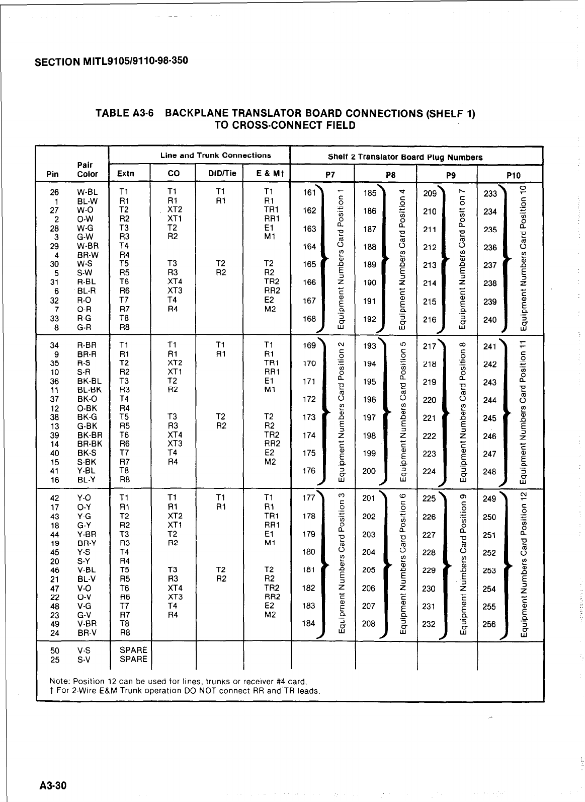
SECTION MITL9105/9110-98-350
TABLE A3-8 BACKPLANE TRANSLATOR BOARD CONNECTIONS (SHELF 1)
TO CROSS-CONNECT FIELD
Line and Trunk Connections
Pair . Shelf 2 Translator Board Plug Numbers
Pin Color Extn co DID/Tie E & Mt PI
P8
P9 PlO
26 w-BL Tl Tl Tl Tl
1 BL-W Rl Rl Rl Fil
27 w-o T2 XT2 TRl
2 o-w R2 XT1 RR1
28 W-G T3 T2 El
3 G-W R3 R2 Ml
29 W-BR T4
4 BR-W R4
30 w-s T5 T3 T2 T2
5 s-w R5 R3 R2 R2
31 R-BL T6 XT4 TR2
6 BL-R R6 XT3 RR2
32 R-O T7 T4 E2
7 O-R R7 R4 M2
33 R-G T8
8 G-R R8
34 R-BR Tl Tl Tl Tl
9 BR-R Rl Rl Rl Rl
35 R-S T2 XT2 TRl
10 S-R R2 XT1 RR1
36 BK-BL T3 T2 El
11 BL-BK R3 R2 Ml
37 BK-0 T4
12 0-BK R4
38 BK-G T5 T3 T2 T2
13 G-BK R5 R3 R2 R2
39 BK-BR T6 XT4 TR2
14 BR-BK R6 XT3 RR2
40 BK-S T7 T4 E2
15 S-BK R7 R4 M2
41 Y-BL T8
16 BL-Y R8
42 Y-O Tl Tl Tl Tl
17 O-Y Rl Rl Rl Rl
43 Y-G T2 XT2 TRl
18 G-Y R2 XT1 RR1
44 Y-BR T3 T2 El
19 BR-Y R3 R2 Ml
45 Y-S T4
20 S-Y R4
46 V-BL T5 T3 T2 T2
21 BL-V R5 R3 R2 R2
47 v-o T6 XT4 TR2
22 o-v R6 XT3 RR2
48 V-G T7 T4 E2
23 G-V R7 R4 M2
49 V-BR T8
24
50
25 I I
Note: Position 12 can be used for lines, trunks or receiver #4 card.
t For P-Wire E&M Trunk operation DO NOT connect RR and TR leads.
I I
I
A3-30
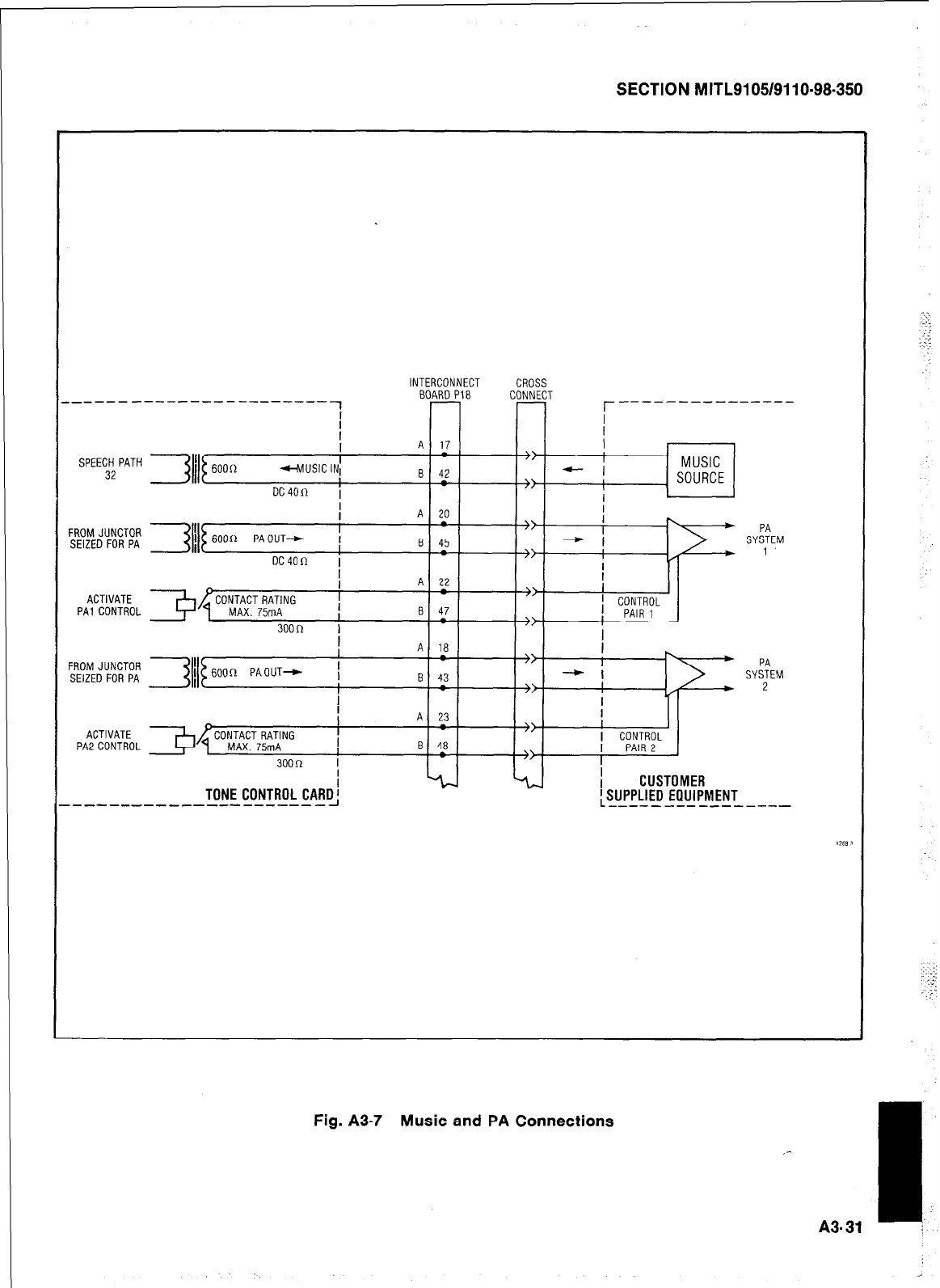
SECTION MITL9105/9110-98-350
INTERCONNECT CROSS
BOARD P18 CONNECT
r----- ----------
SPEECH PATH I MUSIC
32 - I
> ; SOURCE
FROMJUNCTOR
SEIZED FOR PA
ACTIVATE
PAI CONTROL
I
> ' CONTROL
> ] PAIR 1
I
FROM JUNCTOA
SEIZED FOR PA
> \
I ) PA
- I SYSTEM
fl
* 2
I
ACTIVATE CONTACT RATING
PAZCONTROL MAX. 75mA
300R
TONE CONTROL CARD’
----------------------~
A 23
8 48
I
I
I CONTROL
PAIR 2
CUSTOMER
’ SUPPLIED EQUIPMENT
L----------------
Fig. A3-7 Music and PA Connections
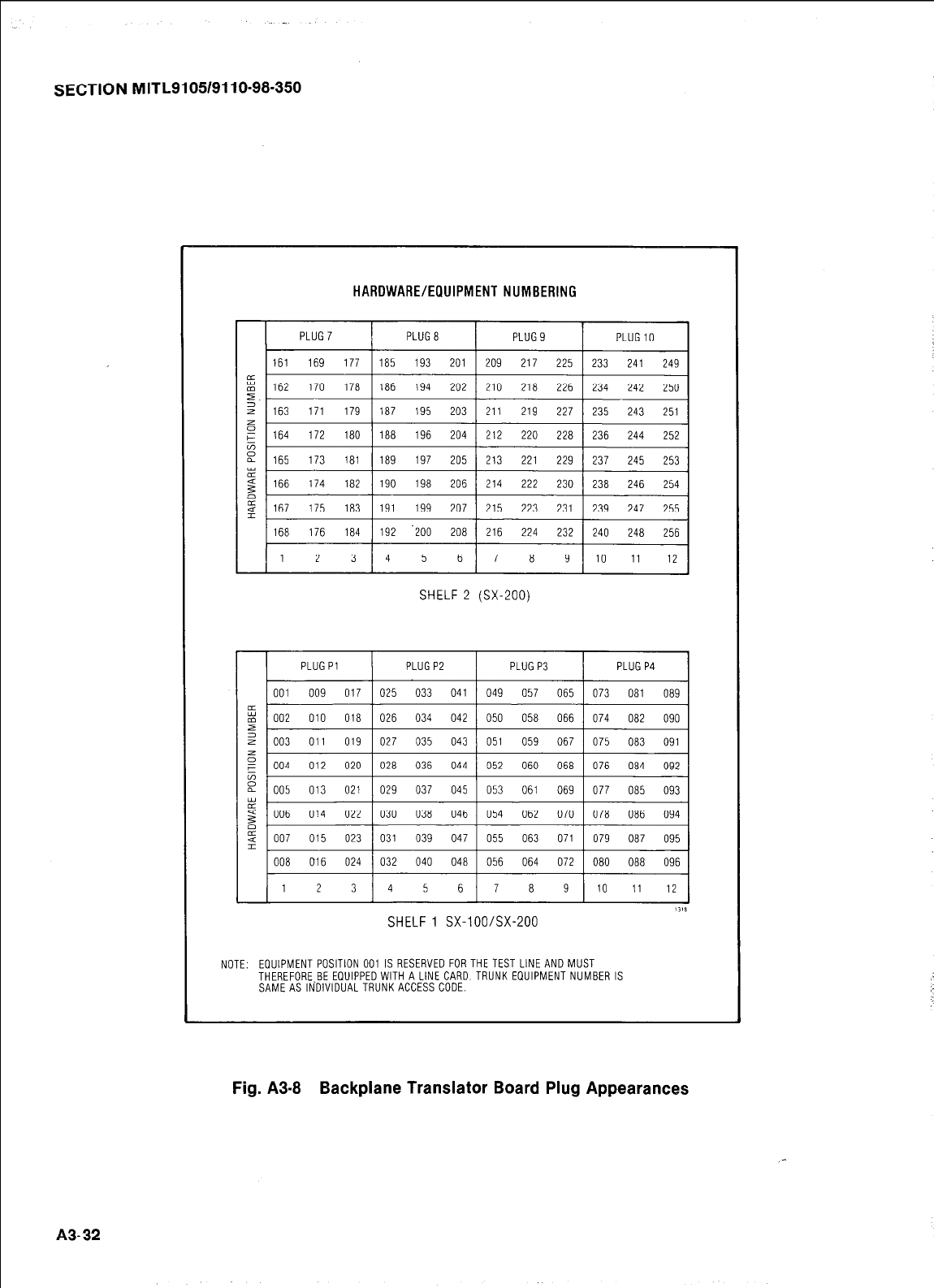
-
SECTION MITL9105/9110-98-350
HARDWARE/EllUIPMENT NUMBERING
SHELF 2 (SX-200)
PLUGPl PLUGPE PLUGP3 PLUGP4
002 010 018 I 026 034 042 / 050 058 066 1 074 082 090
003 011 019 1 027 035 043 j 051 059 067 1 075 083 091
008 016 024 032 040 048 056 064 072 080 088 096
1 2 3 4 5 6 7 8 9 10 ii l2
I I I I
1118
SHELF 1 SX-lOO/SX-200
NOTE: EOUIPMENT POSITION 001 IS RESERVED FOR THE TEST LINE AND MUST
THEREFORE BE EDUIPPEDWITH A LINE CARD TRUNK EQUIPMENT NUMBER IS
SAMEASIN‘DIVIDUALTRUNKACCESS CODE.
Fig. A3-8 Backplane Translator Board Plug Appearances
A3-32
_-
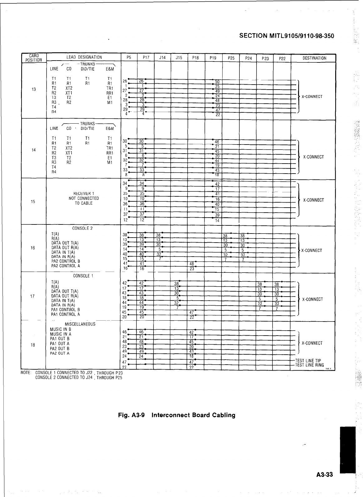
SECTION MITL9105/9110-98-350
CARD
POSITION
15
18
MISCELLANEOUS
MUSIC IN B
MUSIC IN A
PA1 OUT B
PA1 OUT A
PAZOIJT B
PA2 OUT A
ITE COh LE 1 CONNECTEDTOJ22 ,THROUGH P
COh LE 2 CONNECTED TO J24 ,THROUGH P
LEAD DESIGNATION
/----TRUNKS----,
LINE CO DID/TIE E&M
Ti Ti Tl Tl
RI Rl RI RI
T2 XT2 TRl
R2 XT1 RR1
T3 T2 El
R3 . RE Ml
T4
R4
LINE
-TRUNKS-&
CO DID/TIE
Tl
A; RI Tl Tl
RI RI
T2 XT2 TRI
R2 XT1 RR1
53 T2 El
R2 Ml
R4
RECEIVER 1
NOTCONNECTED
TO CABLE
CONSOLE 2
T(A)
R(A)
DATA OUT T(A)
DATA OUT R(A)
DATA IN TIA)
DATA IN R(Aj
PA2 CONTROL B
PA2 CONTROL A
CONSOLE 1
WV
R(A)
DATA OUT T(A)
DATA OUT R(A)
DATA IN T(A)
DATA IN RiAj
PA1 CONTROL B
PAICONTROLA
P5 P17 J14 Ji5 P18 P19 P25 P24 P23 P22 DESTINATION
!6
1
!7
2
28
3
29
4
X-CONNECT
!
, ‘to, I I I \
I -“,I ! I
X-CONNECT
30
3:
6
32
7
33
a
Fig. A3-9 Interconnect Board Cabling
I
A3-33 j
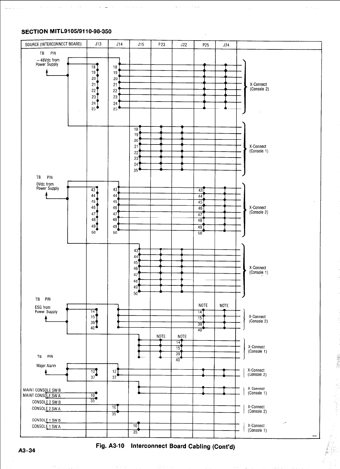
SECTION MITL9105/9110-98-350
SOURCE
fINTERCONNECTBOARD) t J13 1 J14 1 J15 1 P23 1
,177 1
Fig. A3-10 Interconnect Board Cabling (Cont’d)
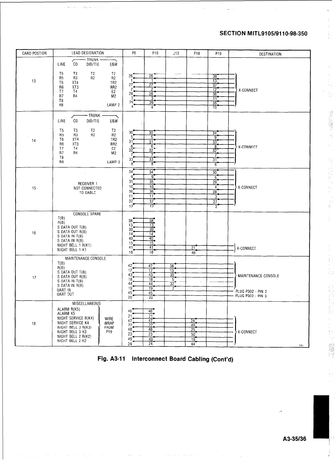
SECTION MITL9105/9110-98-350
NIGHT BELL 1 Kl
MAINTENANCE CONSOLE
Fig. A3-11 Interconnect Board Cabling (Cont’d)
A3-35136 I.
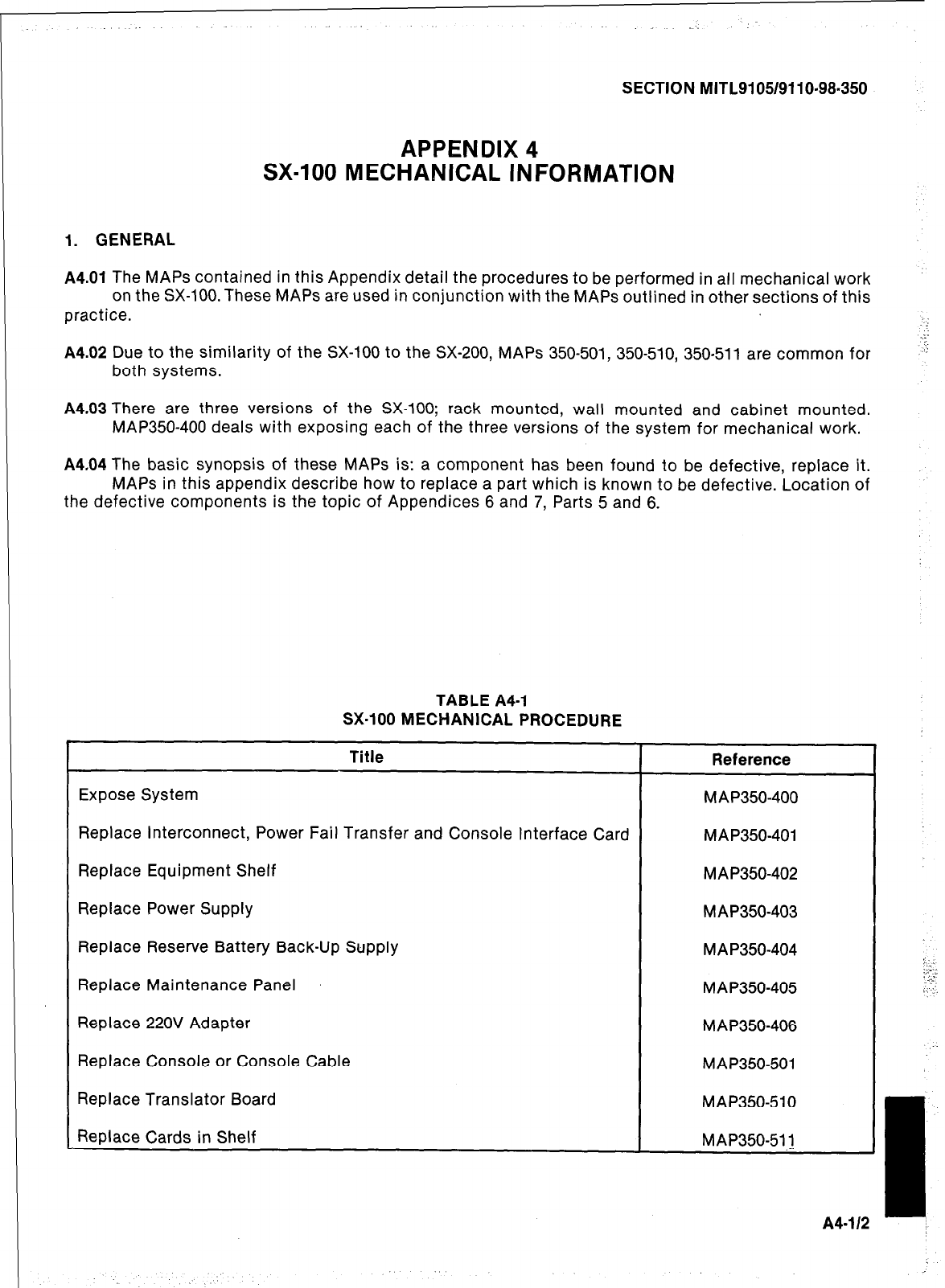
SECTION MITL9105/9110-98-350
APPENDIX 4
SX-100 MECHANICAL INFORMATION
1. GENERAL
A4.01
The MAPS contained in this Appendix detail the procedures to be performed in all mechanical work
on the SX-100. These MAPS are used in conjunction with the MAPS outlined in other sections of this
practice.
A4.02 Due to the similarity of the SX-100 to the SX-200, MAPS 350-501, 350-510, 350-511 are common for
both systems.
A4.03 There are three versions of the SX-100; rack mounted, wall mounted and cabinet mounted.
MAP350-400 deals with exposing each of the three versions of the system for mechanical work.
A4.04 The basic synopsis of these MAPS is: a component has been found to be defective, replace it.
MAPS in this appendix describe how to replace a part which is known to be defective. Location of
the defective components is the topic of Appendices 6 and 7, Parts 5 and 6.
TABLE A4-I
SX-100 MECHANICAL PROCEDURE
Title Reference
Expose System M AP350-400
Replace Interconnect, Power Fail Transfer and Console Interface Card MAP350-401
Replace Equipment Shelf MAP350-402
Replace Power Supply M AP350-403
Replace Reserve Battery Back-Up Supply MA P350-404
Replace Maintenance Panel MA P350-405
Replace 220V Adapter MAP350-406
Replace Console or Console Cable MAP350-501
Replace Translator Board MAP350510
Replace Cards in Shelf MAP350-51.1
,I
A4-112 I
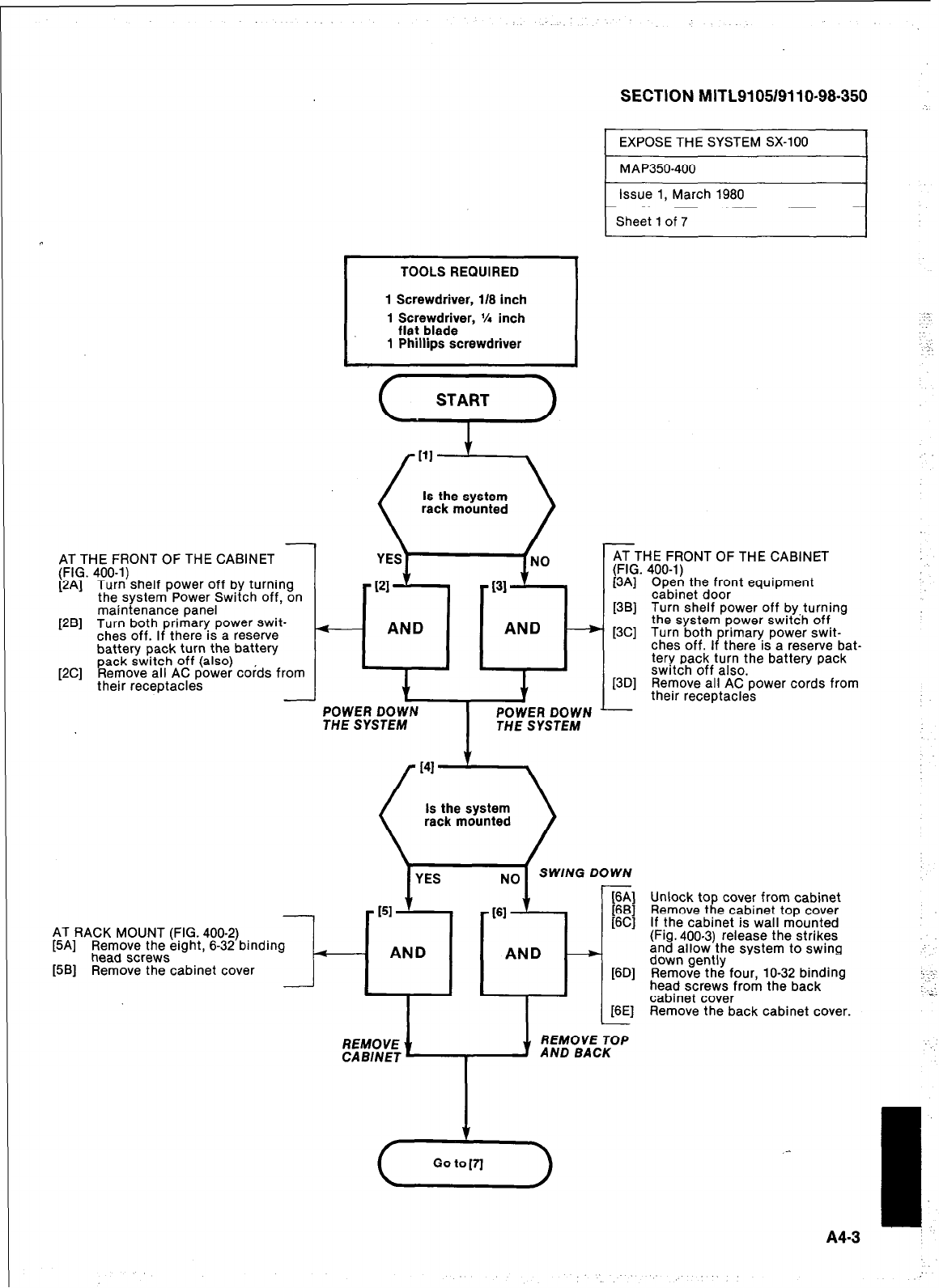
-
AT THE FRONT OF THE CABINET
(FIG. 400-l)
[2A] Turn shelf power off by turning
the svstem Power Switch off. on
maintenance panel
[2B] Turn both primary power swit-
ches off. If there is a reserve
battery pack turn the battery
[2C] pack switch off (also)
Remove all AC power cords from
their receptacles
TOOLS REQUIRED
1 Screwdriver, 118 inch
1 Screwdriver, % inch
flat blade
1 Phillips screwdriver
e---
- AND AND -
,
J 1
THE SYSTEM THE SYSTEM
AT RACK MOUNT (FIG. 400-2)
[5A] Remove the eight, 6-32 binding
head screws
[5B] Remove the cabinet cover It-
SECTION MITL9105/9110-98-350
EXPOSE THE SYSTEM SX-100 1
Is the system
0 -
rack mounted
YES NO SWING DOWN
AT THE FRONT OF THE CABINET
(FIG. 400-l)
[3A] Open the front equipment
cabinet door
[3B] Turn shelf power off by, turning
the system power switch off
[3C] Turn both
ches off. I P rimary power swit-
there is a reserve bat-
tery pack turn the batterv pack
switch off also.
.
f3Dl Remove all AC Dower cords from
their receptacles
-
Unlock top cover from cabinet
Remove the cabinet top cover
If the cabinet is wall mounted
(Fig. 400-3) release the strikes
and allow the svstem to swina
16Dl down gently -
Remove the four. lo-32 bindina
head screws from the back -
cabinet cover
[6E] Remove the back cabinet cover.
(G-)
1.
A43
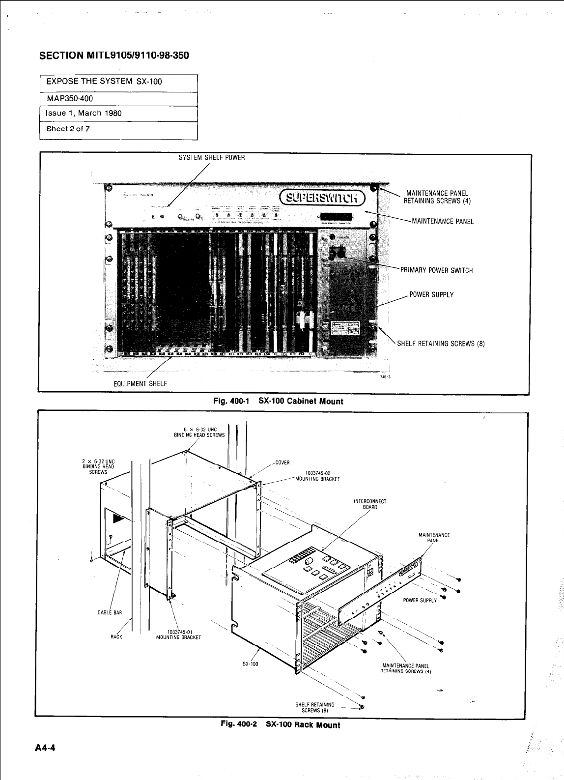
SECTION MITL91051911 O-98-350
1 EXPOSE THE SYSTEM SX-100 I
1 MAP3507400 I
Issue 1, March 1980
Sheet 2 of 7
SYSTEM SHELF POWER
MAINTENANCE PANEL
RETAINING SCREWS (4)
MAINTENANCE PANEL
PRIMARY POWER SWITCH
SHELF RETAINING SCREWS (8)
--_ -- 146 -3
EQUIPMENT SHELF
Fig. 400-l SX-100 Cabinet Mount
i
6 x 6-32
UNC
2 x 6-32"NC
1033745-02
'MOUNTING BRACKET
INTERCONNECT
MALNTENANCE PANEL
RETAINING SCREWS 14)
SHELF RETAINING _~
SCREWS (8) ->
Fig.
400-2 SX-100 Rack Mount
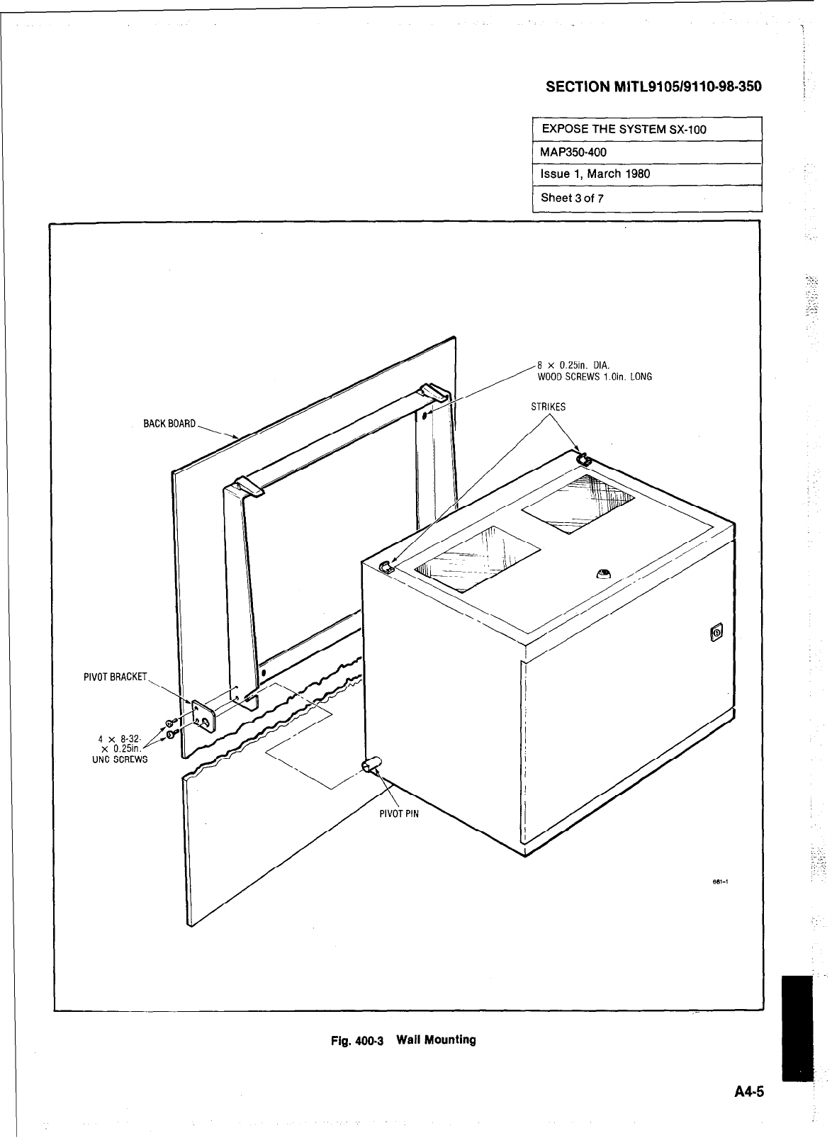
SECTION MITL9105/9110-98-350
EXPOSE THE SYSTEM SX-100
Fig. 400.3 Wall Mounting
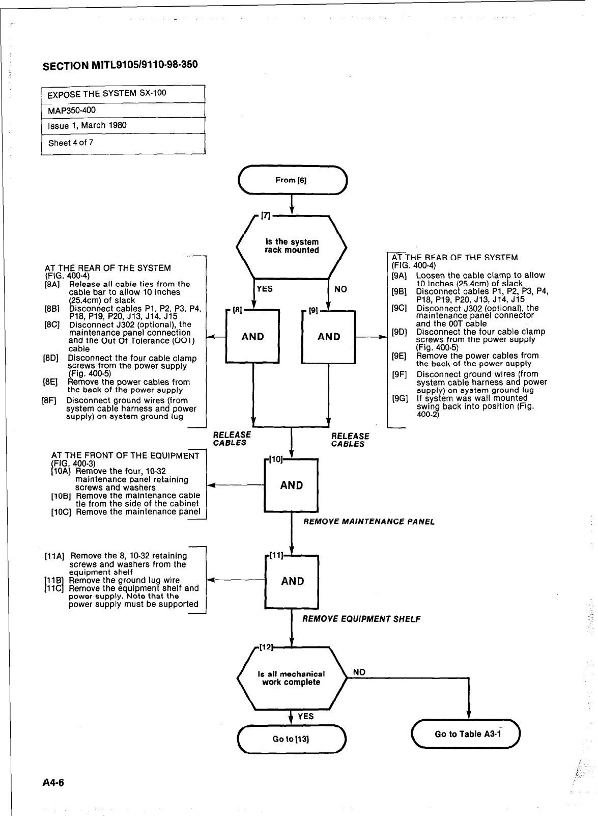
SECTION M1TL9105/9110-98.350
1 EXPOSE THE SYSTEM SX-100
AT THE REAR OF THE SYSTEM
(FIG. 400-4)
[8A] Release all cable ties from the
cable bar to allow 10 inches
(254cm) of slack
[SB] Disconnect cables Pl, P2, P3, P4,
P18, P19, P20, J13, J14, J15
[8C] Disconnect J302 (optional), the
maintenance panel connection
,a;a,;he Out Of Tolerance (OOT)
18Dl Disconnect the four cable clamo
screws from the power supply ’
(Fist. 400-5)
(BE] Reri-rove the power cables from
the back of the power supply
[8F] Disconnect ground wires (from
system cable harness and power
supply) on system ground lug
AT THE FRONT OF THE EQUIPMENT
(FIG. 400-3)
[lOAl Remove the four. lo-32
1
maintenance panel retaining
screws and washers
[lOB] Remove the maintenance cable
tie from the side of the cabinet
[lOC] Remove the maintenance Panel
-
[llA] Remove the 8, lo-32 retaining
screws and washers from the
I I
equipment shelf
11B Remove the ground lug wire
11C Remove the equipment shelf and
power supply. Note that the
power supply must be supported -
1
rack mounted
I
YES
1
NO
181
191
A-
AND AND
3’
I-+
t
L
ATTHE REAR OF THE SYSTEM
(FIG. 400-4)
[9A] Loosen the cable clamp to allow
10 inches (254cm) of slack
[9B] Disconnect cables Pl, P2, P3, P4,
P18, P19, P20, J13, J14, J15
[9C] Disconnect J302 (optional), the
maintenance panel connector
and the OOT cable
[SD] Disconnect the four cable clamp
screws from the power supply
(Fig. 400-5)
[9E] Remove the power cables from
the back of the power supply
[9F] Disconnect ground wires (from
system cable harness and power
[9G] supply) on system ground lug
If system was wall mounted
swing back into position (Fig.
400-2)
I
REMOVE MAINTENANCE PANEL
1111
r-l
AND
REMOVE EQUIPMENT SHELF
84-6
,’
:-.
,” ;
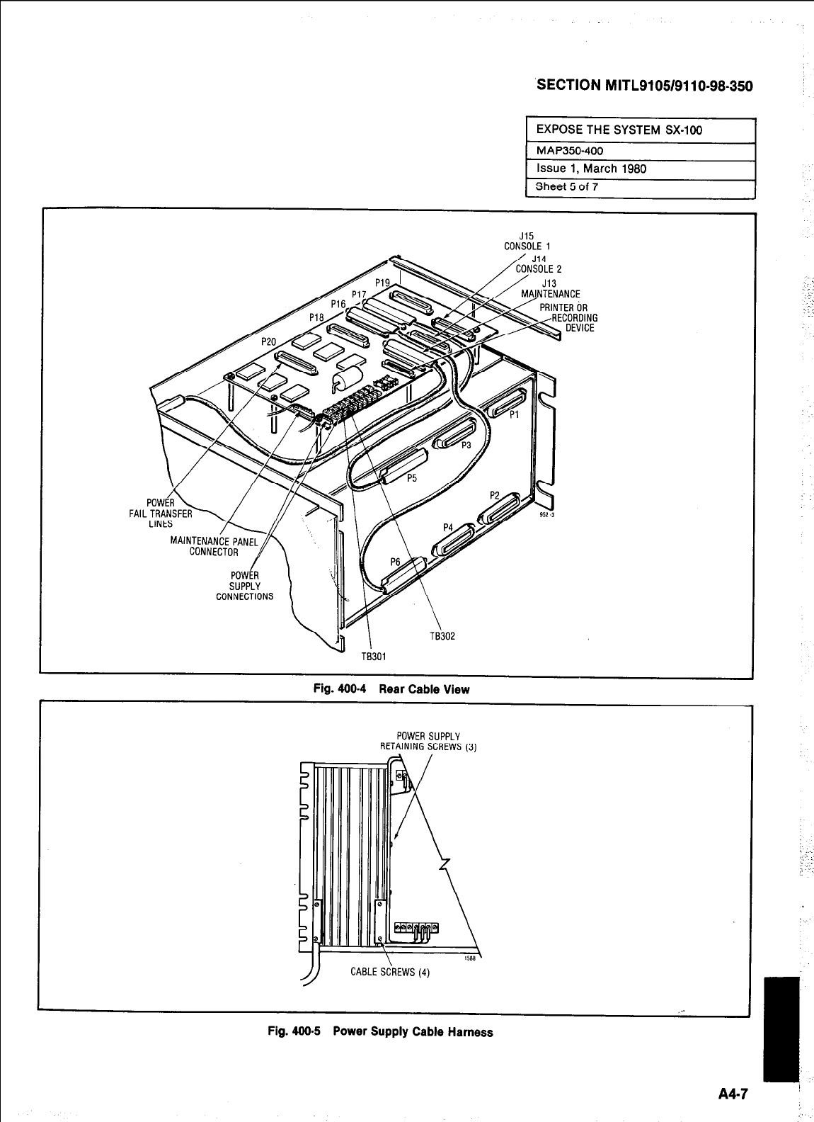
SECTION MITL9105/9110-98-350
J15
CONSOLE 1
FAIL
Fig. 400-4 Rear Cable View
POWER SUPPLY
RETAINING SCREWS (3)
CABLESkWS (4)
_-
Fig. 400.5 Power Supply Cable Harness
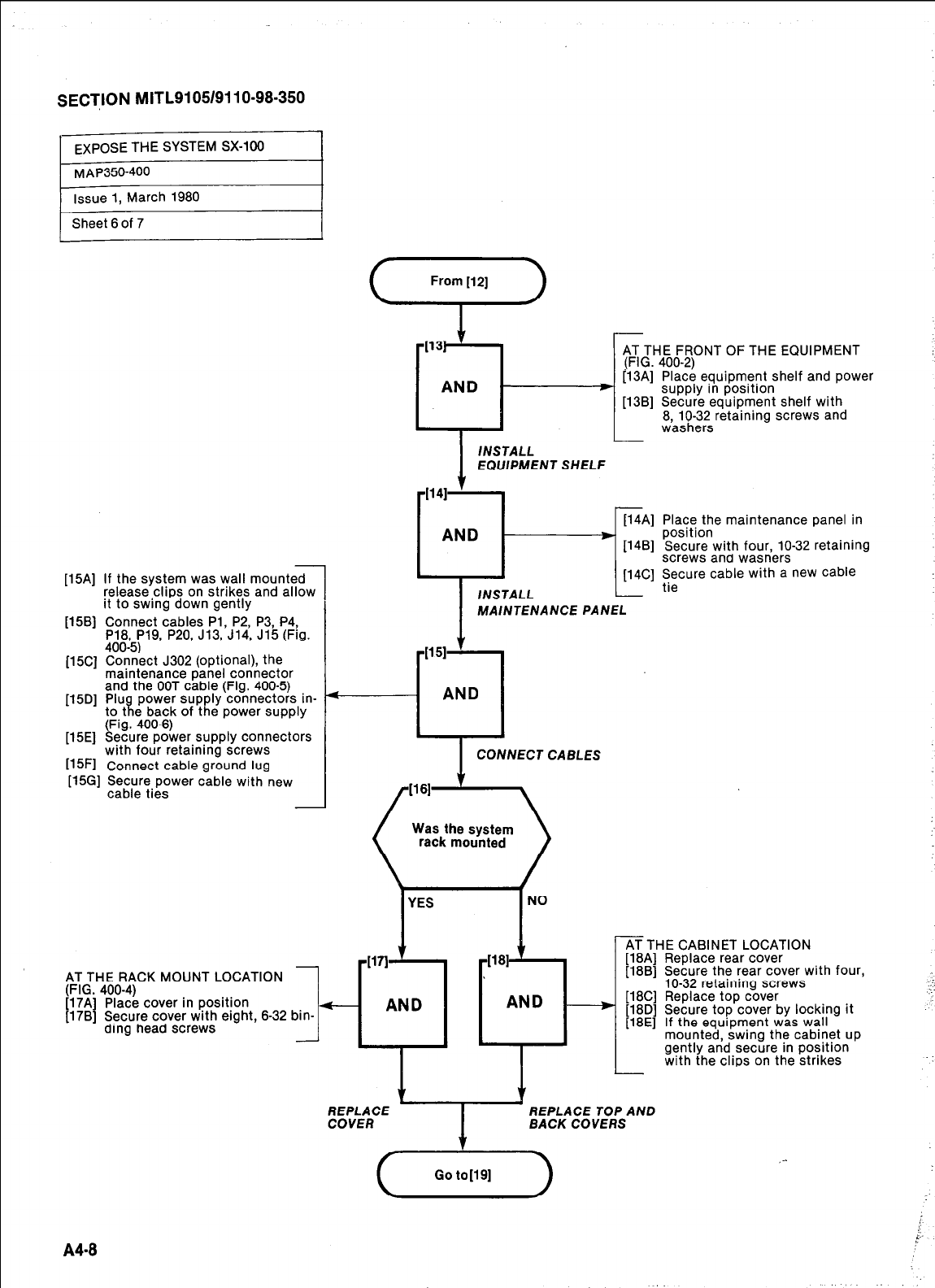
SECTION MITL9105/9110~98~350
[15A] If the system was wall mounted
release clips on strikes and allow
it to swing down gently
[15B] Connect cables Pl, P2, P3, P4,
P18, P19, P20, J13, J14, J15 (Fig.
400-5)
[15C] Connect J302 (optional), the
maintenance panel connector
and the OOT cable (Fig. 400-5)
[15D] Pluft power supply connectors in-
to t e back of the power supply
(Fig. 400-8)
[15E] Secure power supply connectors
with four retaining screws
[15Fl
Connect cable ground lug
[15G] Secure power cable with new
cable ties
AT THE RACK MOUNT LOCATION
(FIG. 400-4)
[17A] Place cover in position
[17B] Secure cover with eight, 6-32 bin
ding head screws
1
.
FRONT OF THE EQUIPMENT
[13A] Place equipment shelf and power
supply in position
[13B] Secure equipment shelf with
8, lo-32 retaining screws and
I
/NSTALL
EQUlPMENT SHELF
v
rIl4li
I
I
[14A] Place the maintenance panel in
ANL ,
’ !-{ lII:and wasners
11481 Secure with four, lo-32 retaining
L
[14C] ;;cure cable with a new cable
MAINTENANCE PANEL
1151
--u
AND
I
CONNECT CABLES
YES
Was the system
rack mounted
NO
-WI 1
-1181
’
- AND AND -/
,
AT THE CABINET LOCATION
[18A] Replace rear cover
[18B] Secure the rear cover with four,
lo-32 retaining screws
[18C] Replace top cover
[18D] Secure top cover by locking it
[18E] If the equipment was wall
mounted, swing the cabinet up
gently and secure in position
with the clips on the strikes
-
L
\r Y
EvkFE I
REPLACE TOP A ND
BACK COVERS
(&ii--)
A48
,-
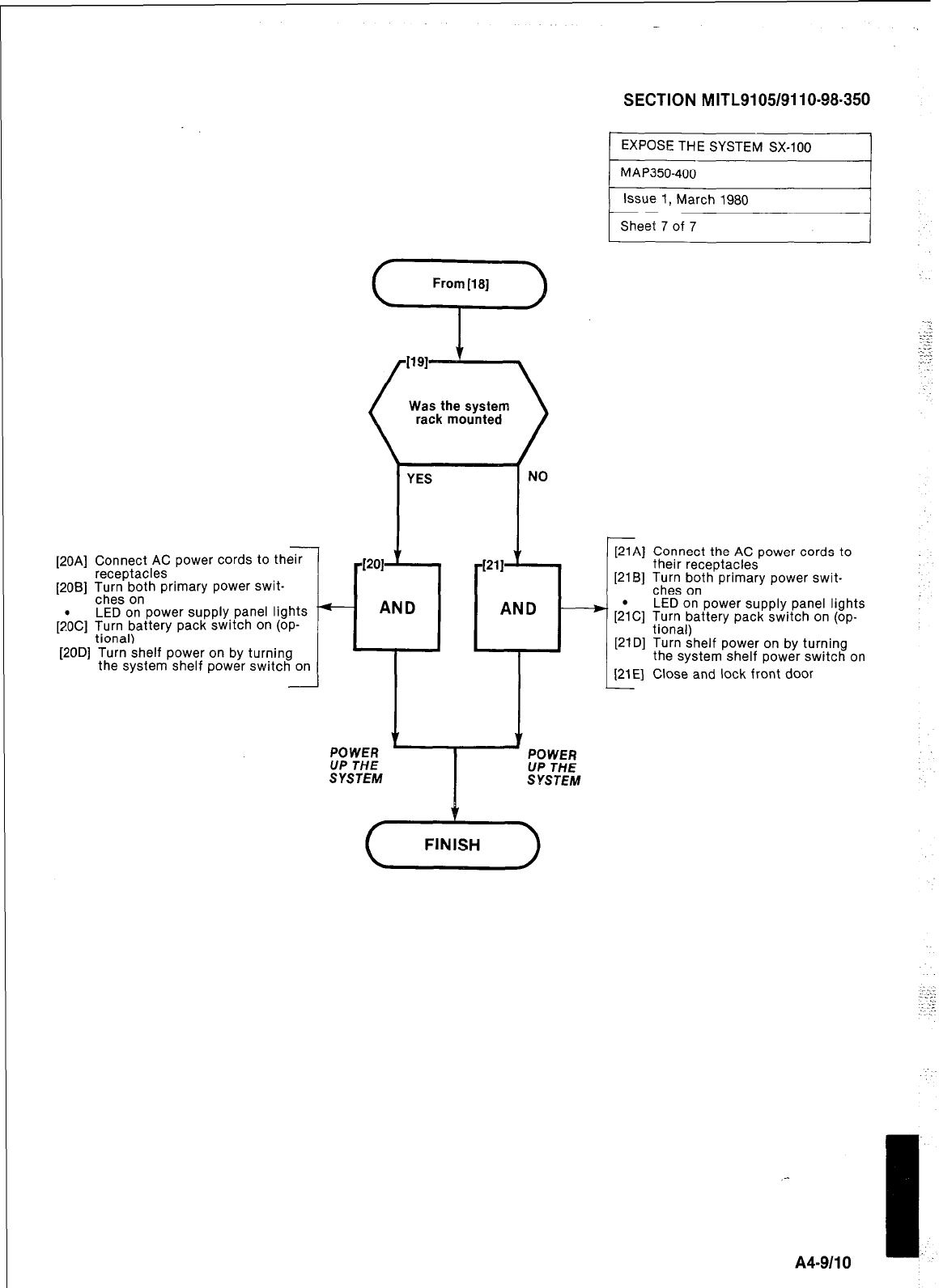
[20A] Connect AC power cords to the7
receptacles
[2OB] I%:?“, pnth primary power swit-
LED on power supply panel lights
&C] Turn battery pack switch on (op-
tional)
[20D] Turn shelf power on by turning
the system shelf power switch on
YES
11
-m
- AND
Was the system
rack mounted
SYSTEM
SECTION M ITL9105/911 O-98-350
1 EXPOSE THE SYSTEM SX-100 1
1 MAP350-400 I
Issue 1, March 1980
Sheet 7 of 7 I
I I
[21A] Connect the AC power cords to
their receptacles
[21B] Turs “,o,th primary power swit-
LED on power supply panel lights
[2;C] Turn battery pack switch on (op-
tional)
[21D] Turn shelf power on by turning
the system shelf power switch on
[21E] Close and lock front door
-
A4-9110 I..
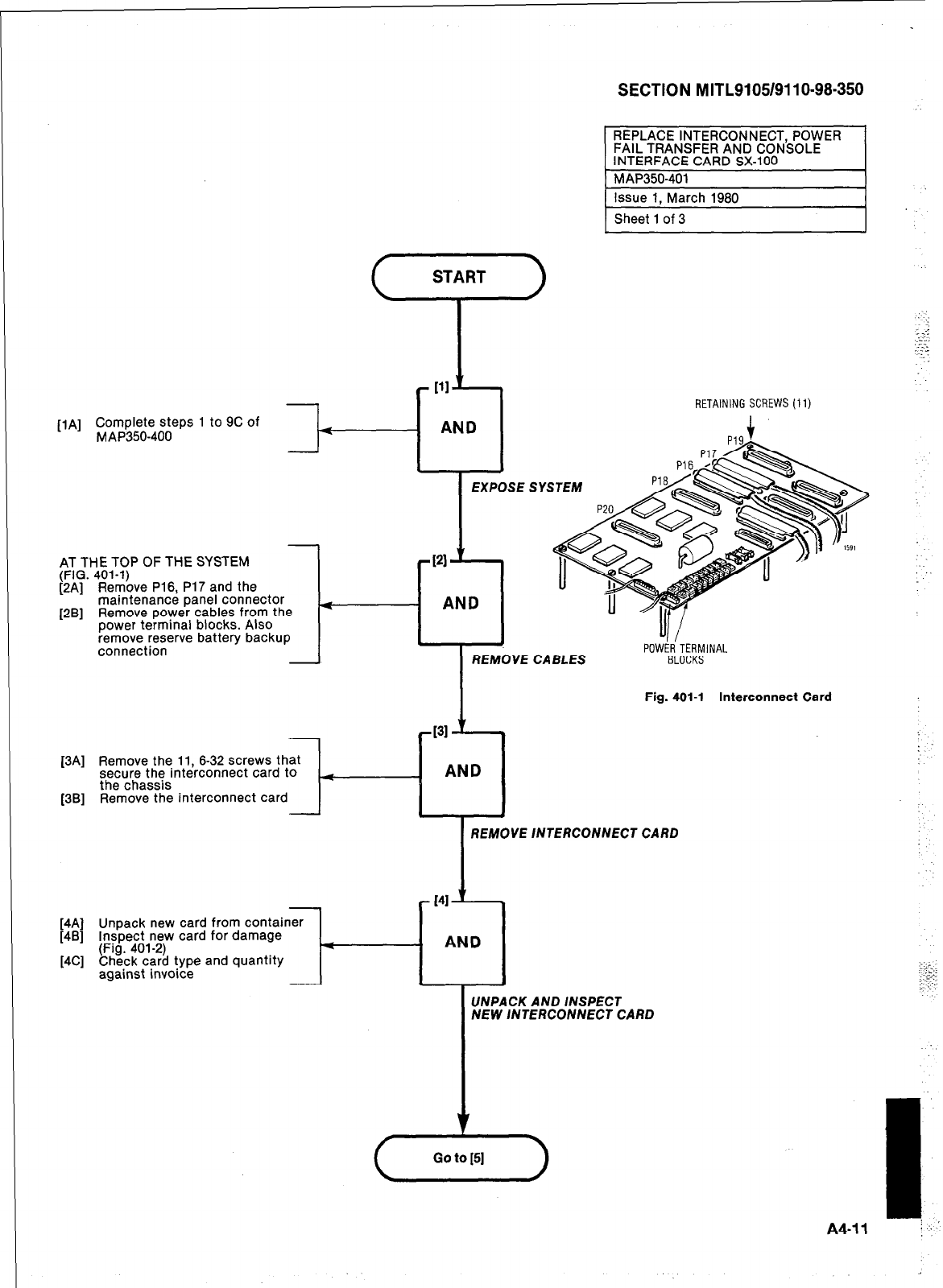
SECTION MITL9105/9110-98-350
-
AT THE TOP OF THE SYSTEM
(FIG. 401-l)
[ZA] Remove P16, P17 and the
maintenance panel connector
[2B] Remove power cables from the
power terminal blocks. Also
remove reserve battery backup
connection -
issue 1, March 1980
Sheet 1 of 3
@I’ ,
RETAINING SCREWS (I 1)
[lA] Complete steps 1 to 9C of
MAP350-400 4
AND
EXPOSE SYSTEM
F
I21
’
AND
J
-T-
REMOVE CABLES
POW& TERMINAL
BLOCKS
Fig. 401-l Interconnect Card
[3Al
[3Bl
l-4
131 A-
Remove the 11, 6-32 screws that
secure the interconnect card to
AND
the chassis
Remove the interconnect card
- I I
I
REMOVE INTERCONNECT CARD
UNPACK AND INSPECT
NEW lNTERCONNECT CARD
-
I
A4.11 i,.’
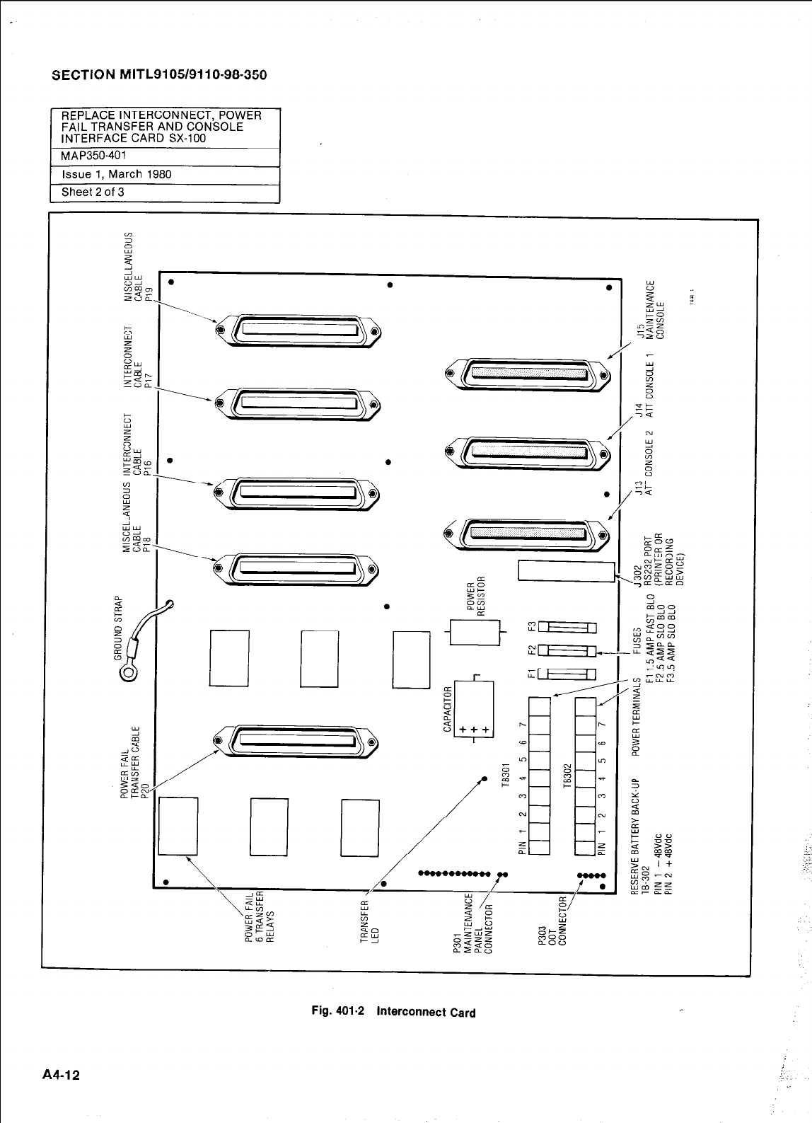
SECTKIN MITL9105/911 O-98-350
Sheet 2 of 3
17
Fig. 401-2 interconnect Card
A4-12
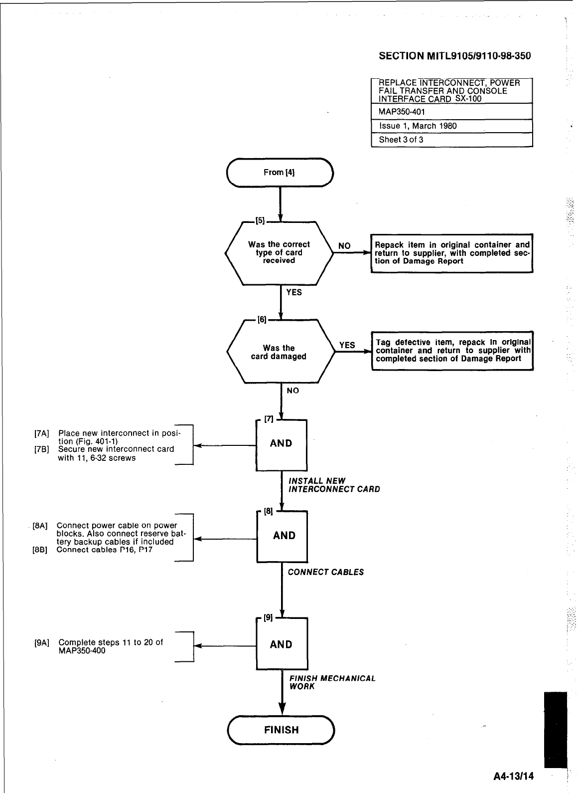
SECTION MITL9105/9110-98-350
REPLACE INTERCONNECT, POWER
FAIL TRANSFER AND CONSOLE
INTERFACE CARD SX-100
1 MAP350-401 I
Issue 1, March 1980
Sheet 3 of 3
.
(
1 YES
Tag defective item, repack in original
( car!%A?ged )qq[ container and return to supplier with ‘-.
completed section of Damage Report
[7B] Secure new interconnect card
with 11, 6-32 screws It--
[7A] Place new interconnect in posi-
tion (Fig. 401-l)
INSTALL NEW
/NTERCONNECT
[BA] Connect power cable on power
blocks. Also connect reserve bat-
tery backup cables if included
[BB] Connect cables P16, P17 I--
AND
CARD
-
CONNECT CABLES
-T-
[9A] C$JA;$z?;-?;;eps 11 to 20 of 4
-
-PI +
- AND
FINISH MECHANICAL
WORK
I
A4-13114 j‘
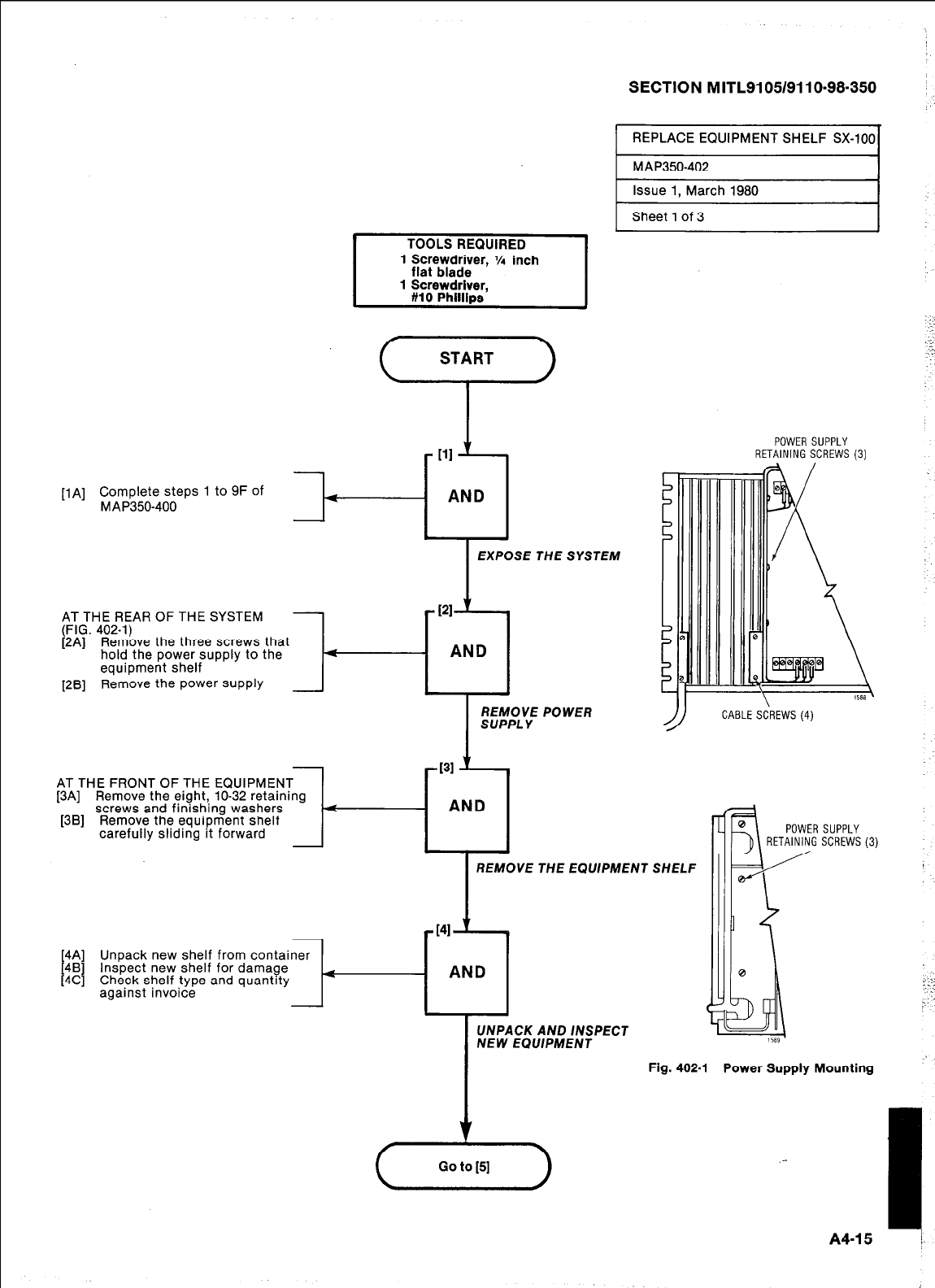
SECTION MITL9105/9110-98-350
REPLACE EQUIPMENT SHELF W-100
[lA] Complete steps 1 to 9F of
MAP350-400 4
AT THE REAR OF THE SYSTEM
(FIG. 402-i)
1
i2A]. R&&e the three screws that
hold the power supply to the 4
equipment shelf
I
-111 ’
- AND
I
EXPOSE THE SYSTEM
[28] Remove the power supply 1
I
REMOVE POWER
SUPPLY
AT THE FRONT OF THE EQUIPMENT
[3A] Remove the eight, lo-32 retaining
[3B] “,“,‘:,::,~,“,,~~~~h,~~o~~r~rs l-p3
Remove the equipment snelf
POWER SUPPLY
RETAINING SCREWS (3)
LE SCREWS (4)
POWER SUPPLY
RETAINING SCREWS (3)
REMOVE THE EQUlPMENT SHELF
[4A] Unpack new shelf from
[4B]
[4C] Inspect new shelf for damage
Check shelf type and quantity
against invoice
UNPACK AND /NSPECT
NEW ECMPMENT
Fig. 402-l Power Supply Mounting
.-
I
A4-15 t,
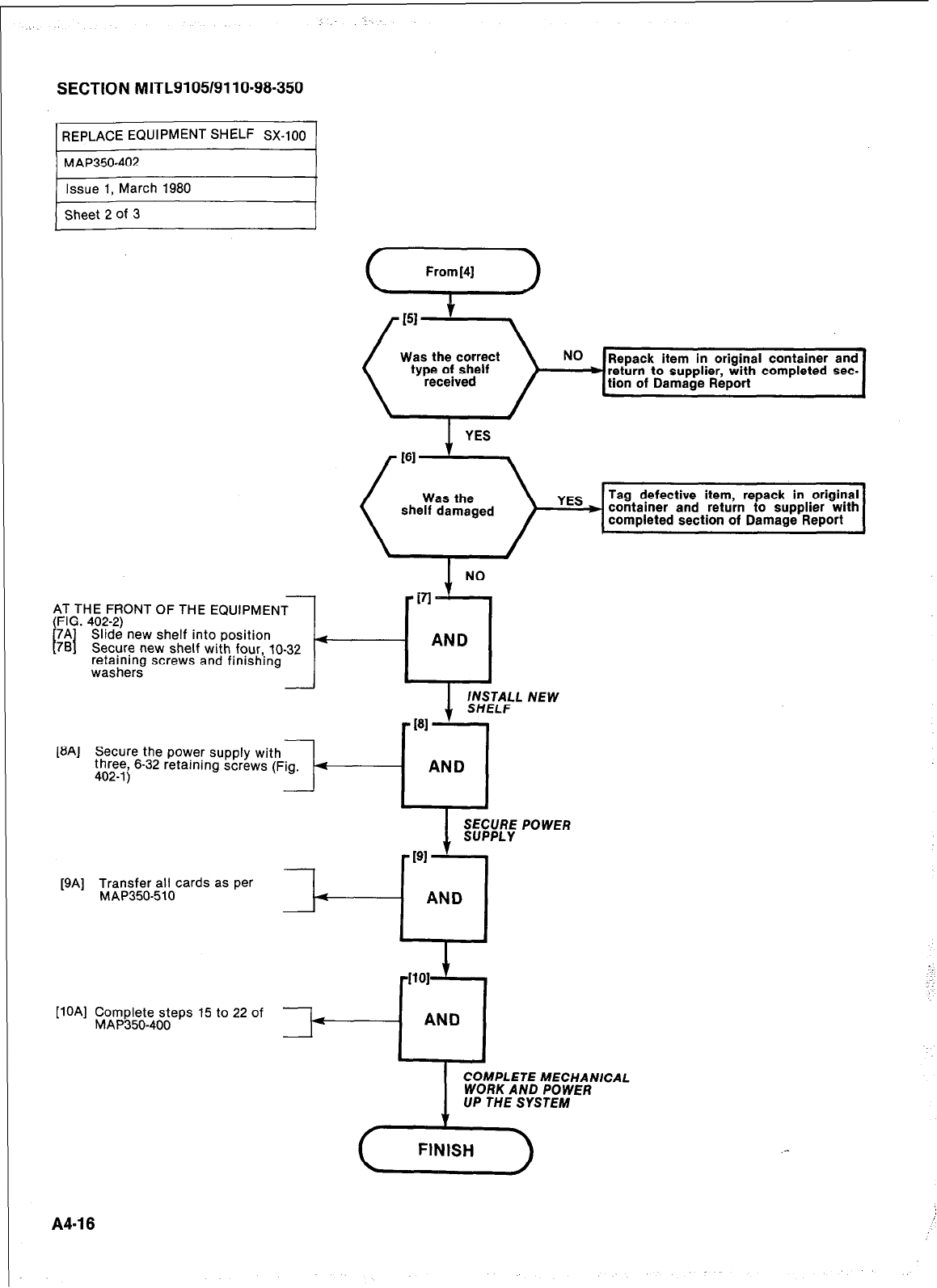
SECTION MITL9105/911 O-98-350
REPLACE EQUIPMENT SHELF Sx-100
3,
From [4] J
Was the correct NO
type of shelf IRepack item in original container and
received +I
return to sui pplier, with completed sec-
tion of Damage I Report
\ / c
Tag defective item, repack in original
( she!%$ged )lqqi container and return to supplier with
completed section of Damage Report
1
NO
AT THE FRONT OF THE
(FIG. 402-2)
7A
I I
78 Slide new shelf into position
Secure new shelf with four,, 10-32
retaining screws and finishrng
washers
[8A] Secure the power supply with
three, 6-32 retaining screws (Fig. 4
402-l)
AND
[9A] Transfer all cards as per
MAP350-510
[lOA] Complete steps 15 to 22 of
MAP350-400
I
COMPLETE MECHANICAL
WORK AND POWER
UP THE SYSTEM
A4-18
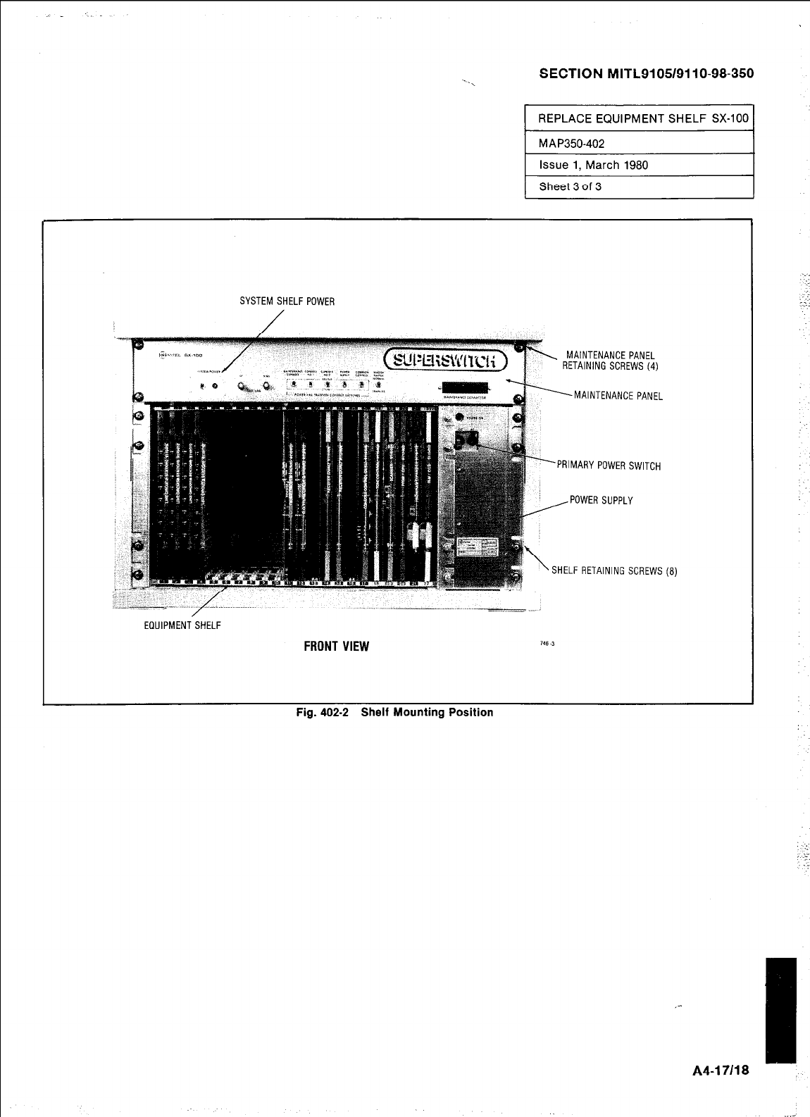
SECTION MITL9105/9110-98-350
REPLACE EQUIPMENT SHELF SX-100
MAP350-402
Issue 1, March 1980
Sheet 3 of 3
Fig. 402-2 Shelf Mounting Position
SYSTEM SHELF POWER
. MAINTENANCE PANEL
RETAINING SCREWS (4)
'MAINTENANCE PANEL
-PRIMARY POWER SWITCH
,POWER SUPPLY
SHELF RETAINING SCREWS (8)
EQUIPMENTSHELF
FRONT VIEW 745 -3
,-
I
A4-17118
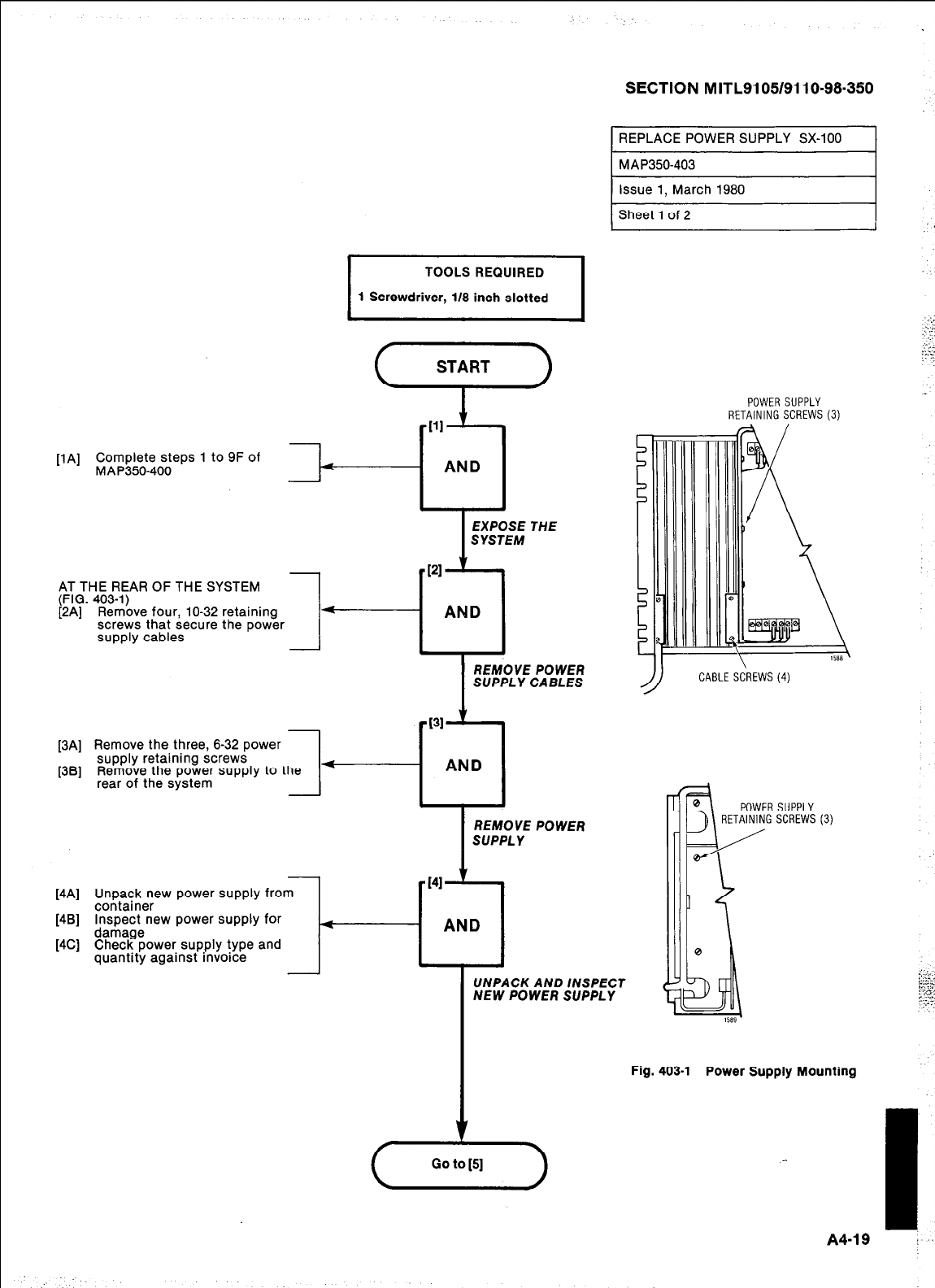
g1
1 Screwdriver, l/8 inch slotted
WI
Complete steps 1 to 9F of
MAP350400
111
+----cl
AND
I
EXPOSE THE
SYSTEM
AT THE REAR OF THE SYSTEM
(FIG. 403-l)
[2A] Remove four, lo-32 retaining
screws that secure the power
supply cables
REMOVE POWER
SUPPLY CABLES
[3A] Remove the three, 6-32 power
supply retaining screws
[38] Remove the power supply to the
rear of the system
I
REMOVE POWER
SUPPLY
[4Al
[4Bl
[4Cl
Unpack new power supply from
container
1
Inspect new power supply for
damage
Check Dower
SUDDIV
tvDe and
1 AND I
SECTION MITL9105/9110-98-350
1 REPLACE POWER SUPPLY SX-100 I
1 MAP350-403
) issue 1, March 1980
[Sheet lof2~
quantity against invoice
UNPACK AND /NSPECT
NEW POWER SUPPLY
POWER SUPPLY
RETAINING SCREWS (3)
//
CABLE SCREWS(4)
POWER SUPPLY
RETAINING SCREWS (3)
Fig. 403-l Power Supply Mounting
A4-19
1..
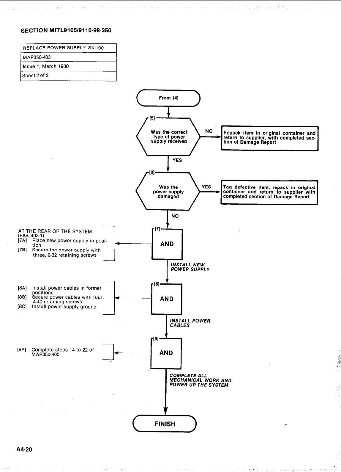
SECTION MITL9105/9110-98-350
AT THE REAR OF THE SYSTEM
(FIG. 403-l)
(7A] ;b”,“e new power supply in posi-
[7B] Secure the power supply with
three, 6-32 retaining screws
[8A] Install power cables in former
positions
[8B] Secure power cables with four,
[8C] 4-40 retaining screws
Install power supply ground
- -181 ’
4 AND
IcNAsBT;9:sL POWER
ml v
[9AJ Complete steps 14 to 22 of
MAP350-400 f
AND
COMPLETE ALL
MECHANlCAL WORK AND
POWER UP THE SYSTEM
c
From [4]
return to supplier, with completed sec-
Tag defective item, repack in original
container and return to supplier with
completed section of Damage Report
4
AND
INSTALL NEW
POWER SUPPLY
A420
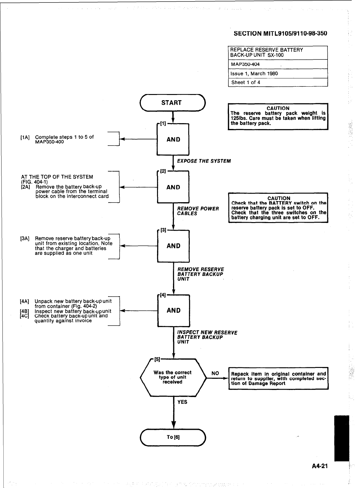
SECTION M ITL91051911 o-98-350
REPLACE RESERVE BATTERY
BACK-UP UNIT SX-100
[lA] Complete steps 1
to
5 of
MAP350-400
AT THE TOP OF THE SYSTEM
(FIG. 404-l)
[2A] Remove the battery back-up
power cable from the terminal
block on the interconnect card -
[3AJ Remove reserve battery back-up
unit from existing location. Note
that the charger and batteries
are supplied as one unit -
PI
-cl
AND
4
[4A] Unpack new battery back-up unit
from container (Fig. 404-2)
48
t I
4C Inspect new battery back-upunit
Check battery back-up unit and
quantity against invoice -t-
131
REMOVE RESERVE
IY
7
AND
CAUTION
Check that the BATTERY switch on the
reserve battery pack is set to OFF.
Check that the three switches on the
battery charging unit are set to OFF.
INSPECT NEW RESERVE
Was the correct NO Repack item in original container and
* return to supplier, with completed sec-
tion of Damage Report
A4-21
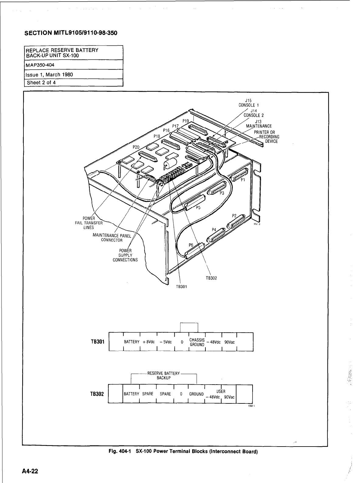
SECTION MITL9105/9110-98-350
J15
CONSOLE 1
FAll
I 1
I I
I I I I I I I
TB301 BATTERY +EVdc -5Vdc 0 ~R$$~ -4BVdc 9OVac
I I
I I I I
I I
/
RESERVE BATTERY
BACKUP
1
I I I
I I I
TB302 BATTERY SPARE SPARE 0 GROUND USER
I
I I I
-4BVdc 9OVac
I 1591 I
.-
Fig. 404-l SX-100 Power Terminal Blocks (Interconnect Board)
I
A4-22
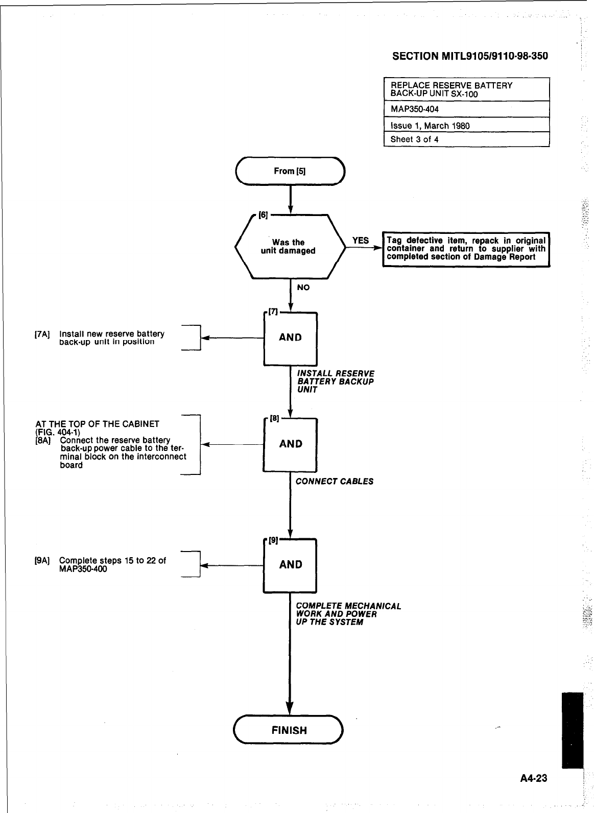
[7Al
SECTION MITL9105/9110-98-350
I
REPLACERESERVEBATTERY
BACK-UP UNIT SX-100
Install new reserve battery
back-up unit in position
AT THE TOP OF THE CABINET
(FIG. 404-l)
[8A] Connect the reserve battery
back-u.p power cable to the ter-
minal block on the interconnect
board
[BA] Complete steps 15 to 22 of
MAP350-400
I
NO
VI
i
AND
I J
INSTALL RESERVE
BATTERY BACKUP
UNIT
161
i
AND
CONNECT CABLES
Ti
I 11
1
AND
COMPLETE MECHANICAL
WORK AND POWER
UP THE SYSTEM
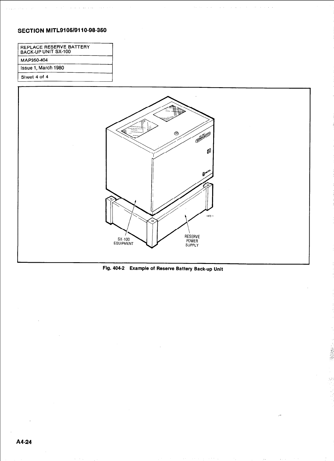
SECTION MITL9105/9110-98.350
Fig. 404-2 Example of Reserve Battery Back-up Unit
A4-24
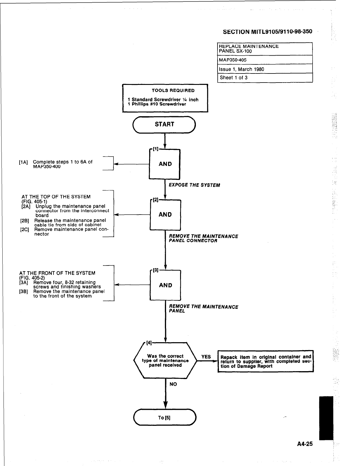
Issue 1, March 1980
Sheet 1 of 3
START
AT THE TOP OF THE SYSTEM
(FIG. 405-l)
[2A] Unplug the maintenance panel
connector from the interconnect
board
[2B] Release the maintenance Panel
cable tie from side of cabinet
[2C] ;~;ze marntenance panel con-
AT THE FRONT OF THE SYSTEM
(FIG. 405-2)
[3A] Remove four, 8-32 retaining
screws and finishing washers
[3B] Remove the maintenance panel
to the front of the system
SECTION MITL9105/9110~98~350
REPLACE MAINTENANCE
PANEL SX-100
1 MAP350-405
[lA] Complete steps 1 to 8A of
MAP350-400
EXPOSE THE SYSTEM
I
REMOVE THE MAlNTENANCE
PANEL CONNECTOR
PI
REMOVE THE MAINTENANCE
PANEL
Repack item in original container and
A4-25
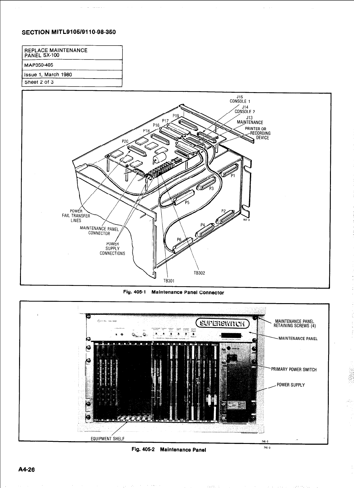
I ,
J15
CONSOLE 1
TB301
Fig. 405.1 Maintenance Panel Connector
,
MAINTENANCE PANEL
RETAINING SCREWS (4)
MAINTENANCE PANEL
PRIMARY POWER SWITCH
_-a / -..__ -.i
EQUIPMENT SHELF 746.3
Fig. 4052 Maintenance Panel 146 -3
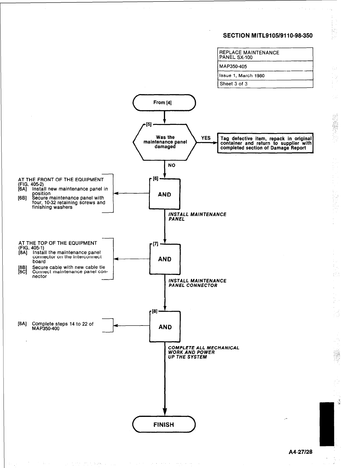
SECTION MITL9105/9110-98.350
AT THE FRONT OF THE EQUIPMENT
t FIG. 4052)
6A] install new maintenance panel in
position
[6B] Secure maintenance panel with
four, lo-32 retaining screws and
finishing washers
AT THE TOP OF THE EQUIPMENT
(FIG. 405-1)
[8A] Install the maintenance panel
connector on the interconnect
board
88
I I Secure cable with new cable tie
8C Connect maintenance panel con-
- _
nectar
034
Complete steps 14 to 22 of
MAP350-400
REPLACE MAINTENANCE
PANEL 8.X-100
Tag defective item, repack in original
container and return to supplier with
completed section of Damage Report I
AND
MAINTENANCE
fNSTALL MAINTENANCE
PANEL CONNECTOR
-
COMPLETE ALL MECHANICAL
WORK AND POWER
UP THE SYSTEM
(,,,,,,
J
A427128
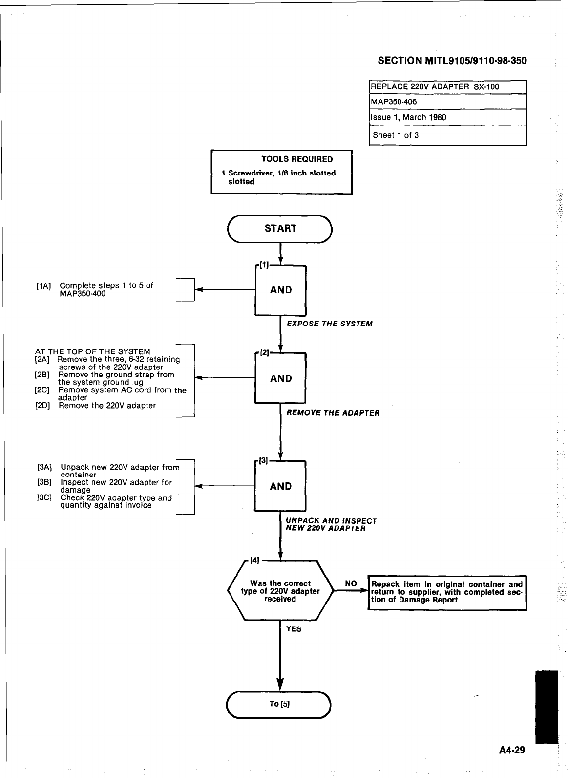
TOOLS REQUIRED
1 Screwdriver, 118 inch slotted
slotted
SECTION MITL9105/9110-98-350
IREPLACE 220V ADAPTER SX-100 I
lMAP350-406 I
111
[lA] Complete steps 1 to 5 of
MAP350-400
J---cl
AND
EXPOSE THE SYSTEM
AT THE TOP OF THE SYSTEM
[2A] Remove the three, 6-32 retaining
-PI ’
screws of the 220V adapter
[2B] Remove the ground strap from
the system ground lug 4
AND
[2C] F;$o;; system AC cord from the
[2D] Remove the 220V adapter REMOVE THE ADAPTER
[3Al Uw
‘ack new 220V adapter from
container
[3Bl
Inspect new 220V adapter for
dati rage
I3Cl
Che
_ _ ck 220V adapter type and
quantity against invoice I-
UNPACK AND INSPECT
NEW 220V ADAPTER
Was the correct
type of 220V adapter NO Repack item in original container and
b return to supplier, with completed sec.
tion of Damage Report
::
.,
::’
I
YES
A4-29
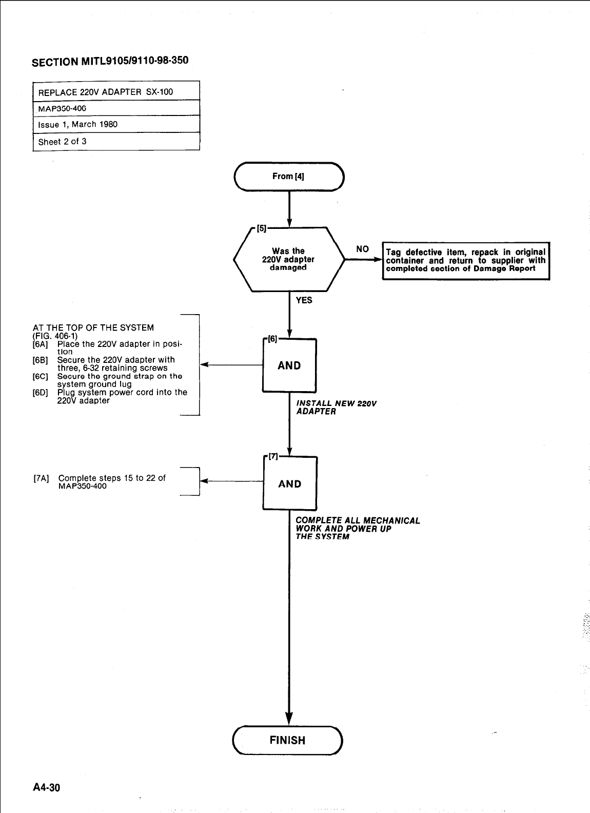
SECTION MITL9105/9110-98.350
[7A] Complete steps 15 to 22 of
MAP350-400
-+-----~A:D
I L-
b
COMPLETE ALL MECHANICAL
WORK AND POWER UP
THE SYSTEM
Tag defective item, repack in original
container and return to supplier with
completed section of Damage Report
YES
AT THE TOP OF THE SYSTEM
(FIG. 406-l)
[6A] ;b”,“e the 220V adapter in posi-
[6B] Secure the 220V adapter with
three, 6-32 retaining screws
[6C] Secure the ground strap on the
system ground lug
[6D] Plug system power cord into the
220V adapter
I INSTALL NEW 220V
ADAPTER
361
’ .
AND
A430
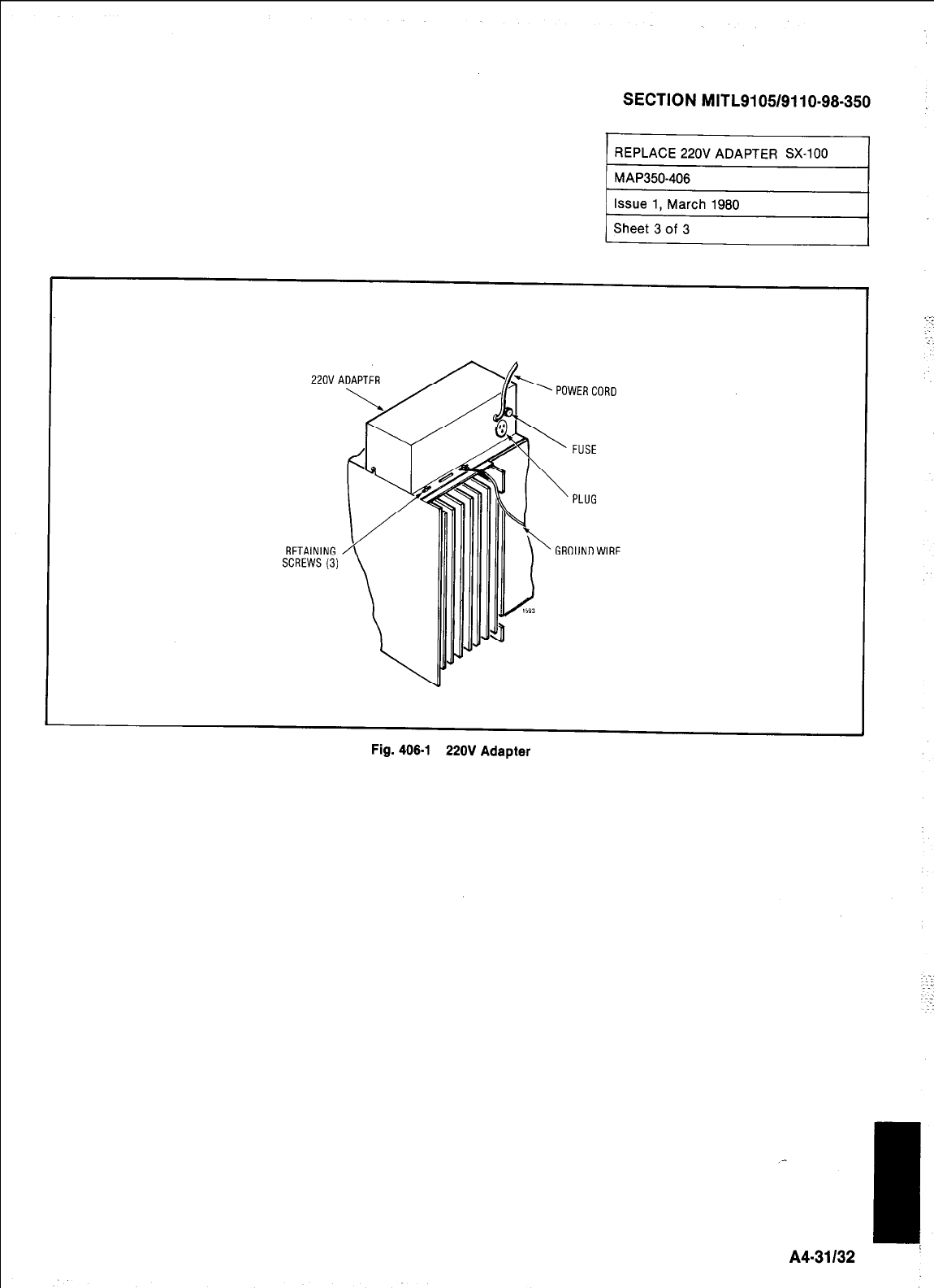
SECTION MITL9105/9110-98-350
ZOVADAPTER
RETAINING
SCREWS(3)
Fig. 406-l 220V Adapter
_-
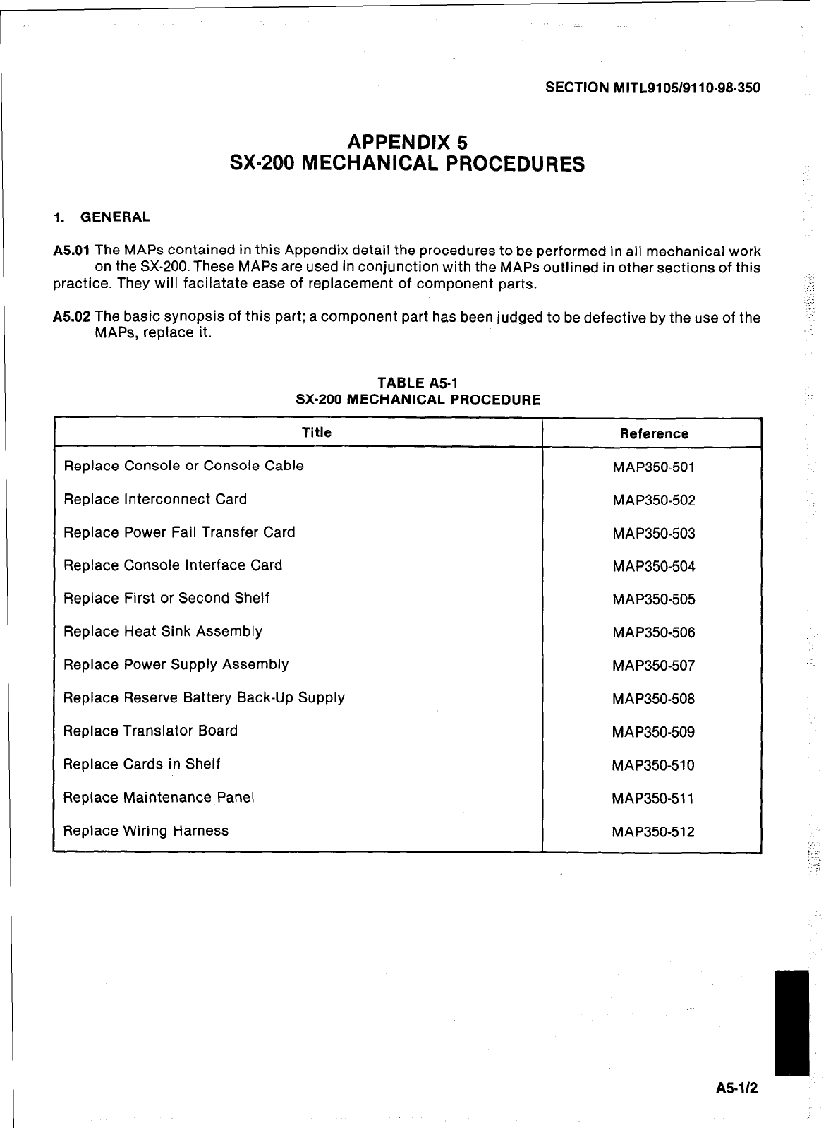
SECTION MITL91051911 O-98-350
APPENDIX 5
SXm200 MECHANICAL PROCEDURES
1. GENERAL
A5.01
The MAPS contained in this Appendix detail the procedures to be performed in all mechanical work
on the SX-200. These MAPS are used in conjunction with the MAPS outlined in other sections of this
practice. They will facilatate ease of replacement of component parts.
A5.02 The basic synopsis of this part; a component part has been judged to be defective by the use of the
MAPS, replace it.
TABLE A5-1
SX-200 MECHANICAL PROCEDURE
Title
Replace Console or Console Cable
Replace Interconnect Card
Replace Power Fail Transfer Card
Replace Console Interface Card
Replace First or Second Shelf
Replace Heat Sink Assembly
Replace Power Supply Assembly
Replace Reserve Battery Back-Up Supply
Replace Translator Board
Replace Cards in Shelf
Replace Maintenance Panel
Replace Wiring Harness
Reference
MAP350501
MAP350502
MAP350-503
MAP350-504
MAP350-505
MAP350-506
MAP350-507
MAP350-508
MA P350-509
MAP350-510
MAP350-511
MAP350-512
A5-1 I2
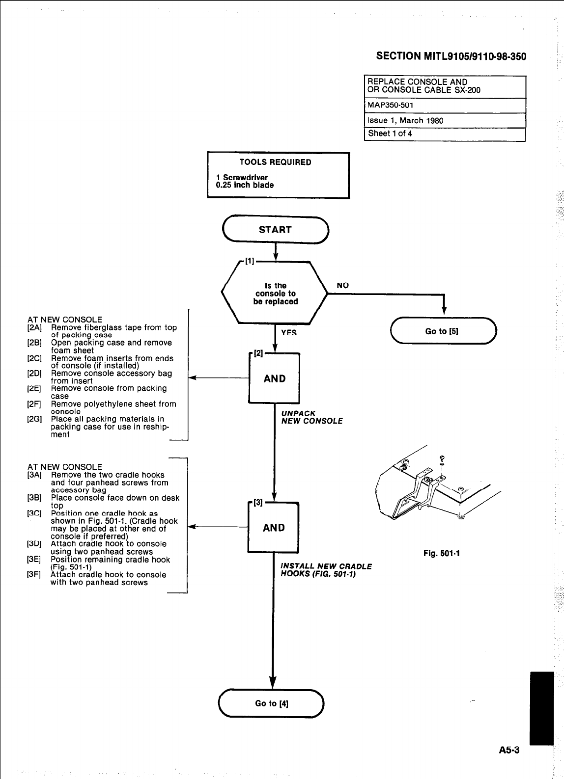
SECTION MITL9105/9110-98.350
AT NEW CONSOLE
[2A] Remove fiberglass tape from top
of packing case
[2B] Open packing case and remove
foam sheet
[2C] Remove foam inserts from ends
12Dl of console (if installed)
_ _
Remove console accessory baa
from insert _ -
12El Remove console from oackina
- .
case
12Fl Remove oolvethvlene sheet from
console . -
[2G] Place all packing materials in
paec,:‘ng case for use in reshrp-
. -
AT NEW CONSOLE
[3A] Remove the two cradle hooks
and four panhead screws from
[3B] accessory bag
Place console face down on desk
[3C] %ition one cradle hook as
shown in Fig. 501-l. (Cradle hook
may be placed at other end of
13Dl console if preferred)
- .
Attach cradle hook to console
usina two oanhead screws
[3E] Position remaining cradle-hook
[3F] (Fig. 501-l)
Attach cradle hook to console
with two panhead screws
TOOLS REQUIRED
1 Screwdriver
0.25 inch blade
REPLACE CONSOLE AND
OR CONSOLE CABLE SX-200
NO NO
(A--)
PI
l
--cl
AND AND
I
UNPACK
NEW CONSOLE
INSTALL NEW CRADLE
HOOKS (FIG. 501-l)
Fig. 501-l
,: . . .
j.-:
.:.
_-
I
A5-3 ;
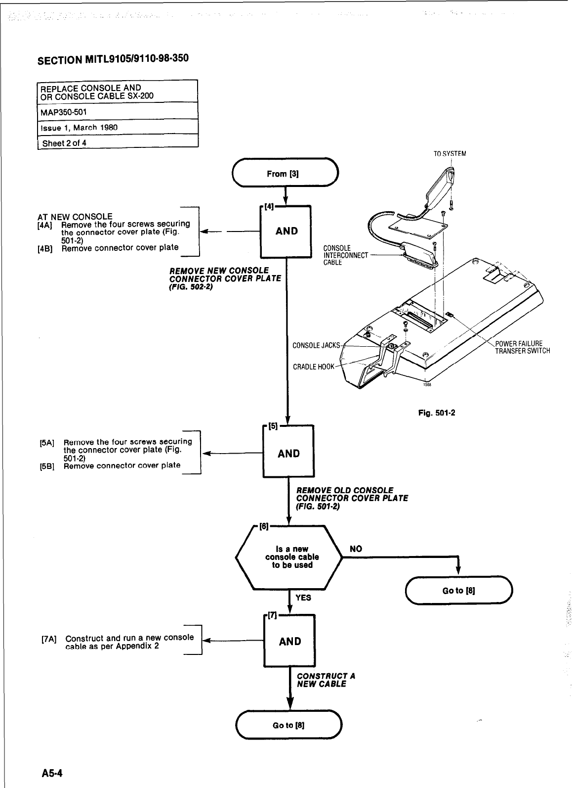
SECTION MITL9105/9110-98-350
gi
1
TO SYSTEM
AT NEW CONSOLE
[4A] Remove the four screws securing
the connector cover plate (Fig.
[4B] “ve connector cover plate
REMOVE NEW CONSOLE
CONNECTOR COVER PLATE
(FIG. 502-2)
-
[5A] Remove the four screws securing
the connector cover plate (Fig.
[5B] %k%e connector cover plate -
Fig. 501-2
[7A] Construct and run a new console +
cable as per Appendix 2
REMOVE OLD CONSOLE
CONNECTOR COVER PLATE
(FIG. 507-2)
NO
CONSTRUCT A
NEW CABLE
A5-4
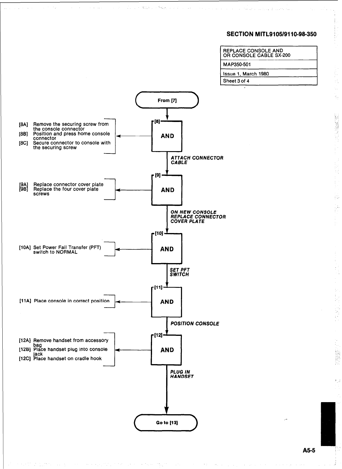
fSA]
_ -
Remove the securing screw from -I
the console connector
[SB] Position and press home console
connector
f8Cl Secure connector to console with
. -
the securing screw / NTBp_LcEH CONNECTOR
PI ‘I
1
9A
I I
Replace connector cover plate
98 Replace the four cover plate 4
AND
screws
From [fl
9
:,
t-
-;
._
4
- AND
SECTION MITL9105/9110-98.350 :
I
REPLACE CONSOLE AND
OR CONSOLE CABLE SX-200
ON NEW CONSOLE
REPLACE CONNECTOR
COVER PLATE
-1101 ’ -r
- AND
[liA] Place console in correct posit
[12A] Remove handset from accessory
[12B] #ce handset plug into console
(12C] %e handset on cradle hook
I
POSITION CONSOLE
AND
PLUG IN
HANDSET
v
(Xi-)
:
::
I
A5.5 i
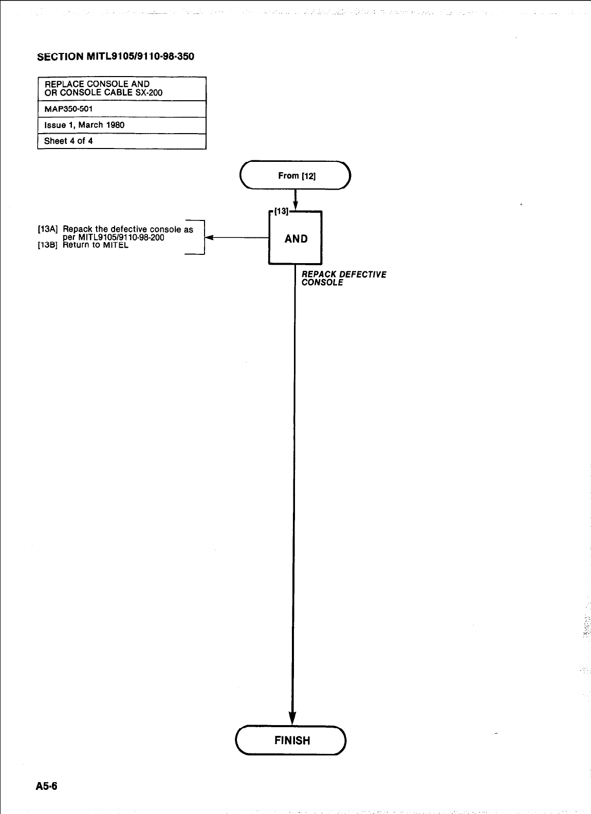
SECTION MITL9105/9110-98.350
From 1121
[i3A] Repack the defective console
per M ITL9105/911 o-98-200
[13B] Return to MITEL
- l-
FINISH
A5-8
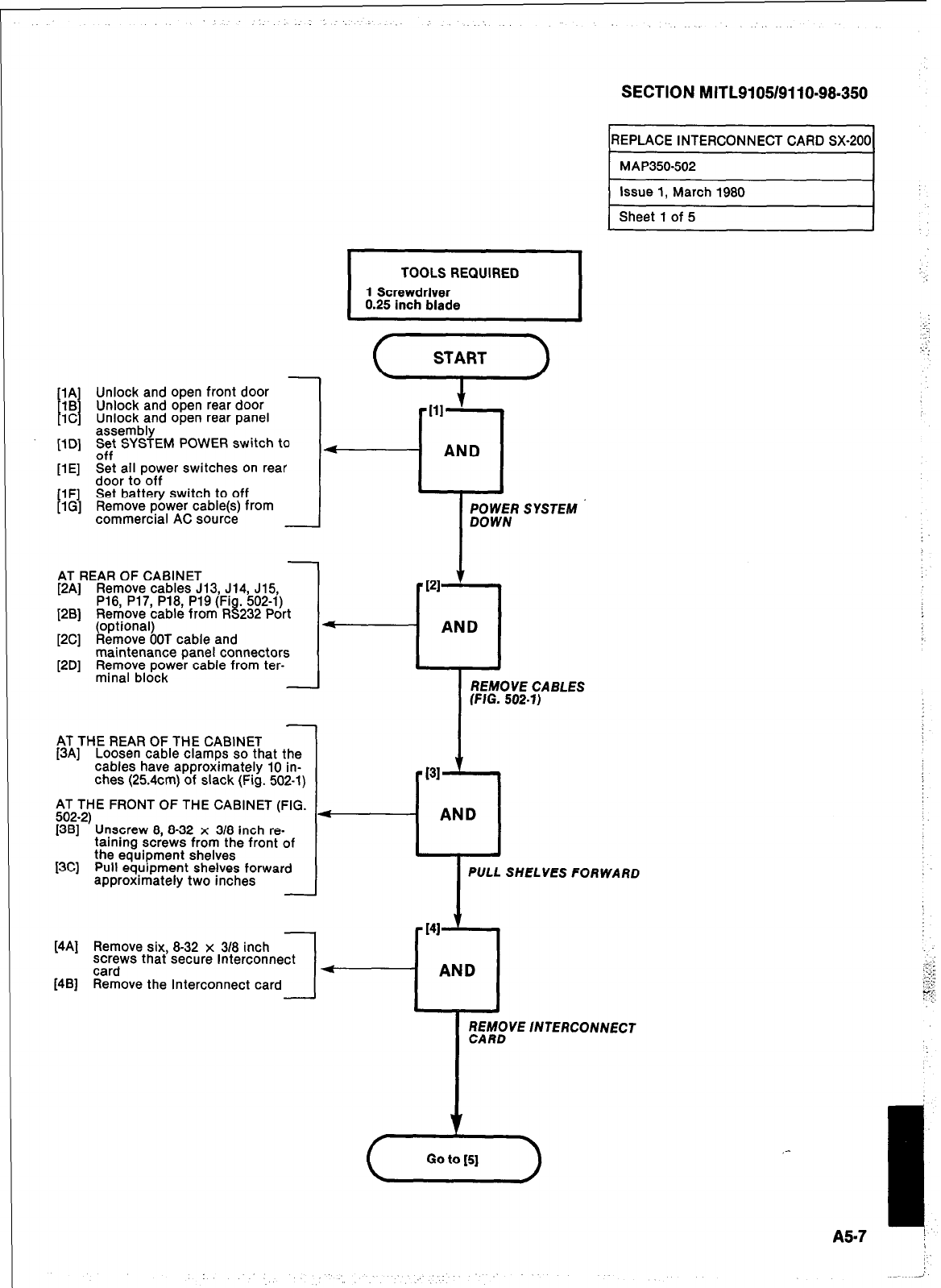
SECTION MITL9105/9110~98-350
REPLACE INTERCONNECT CARD SX-200
[lA] Unlock and open front door
1B
I I Unlock and open rear door
1C Unlock and open rear panel
assembly
[lD] z;t SYSTEM POWER switch to
[lE] Set all power switches on rear
door to off
[lF] Set battery switch to off
[lG] Remove power cable(s) from
commercial AC source
-
AT REAR OF CABINET
[2A] Remove cables J13, J14, J15,
P16, P17, P18, P19 (Fi
[2B] Remove cable from R ti . 502-l)
232 Port
(optional)
[2Cl Remove OOT cable and
maintenance panel connectors
[2D] Remove power cable from ter-
minal block
-
AT THE REAR OF THE CABINET
[3A] Loosen cable clamps so that the
cables have approximately 10 in-
ches (254cm) of slack (Fig. 502-l)
AT THE FRONT OF THE CABINET (FIG.
Fli2)Unscrew 8 8-32 x 318 inch re-
taining sciews from the front of
[3C] the equipment shelves
Pull equrpment shelves forward
approximately two inches
I
TOOLS REQUIRED
1 Screwdriver
0.25 inch blade I
[4A] Remove six, 8-32 x 318 inch
screws that secure Interconnect
card
[4B] Remove the Interconnect card
I-
POWER SYSTEM
AND
REMOVE CABLES
I
PULL SHELVES FORWARD
141 ‘I
AND
~~iM;VE INTERCONNECT
v
(,.,,,)
A57
1
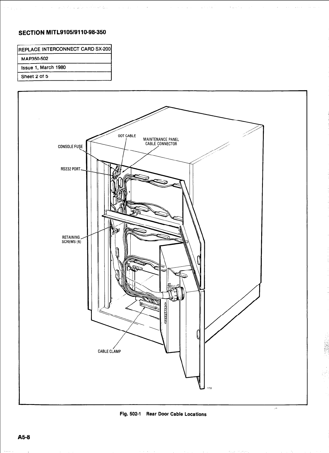
SECTION MITL9105/9110-98-350
REPLACE INTERCONNECT CARD SX-200
ui
:
_-
Fig. 502-l Rear Door Cable Locations
B-8
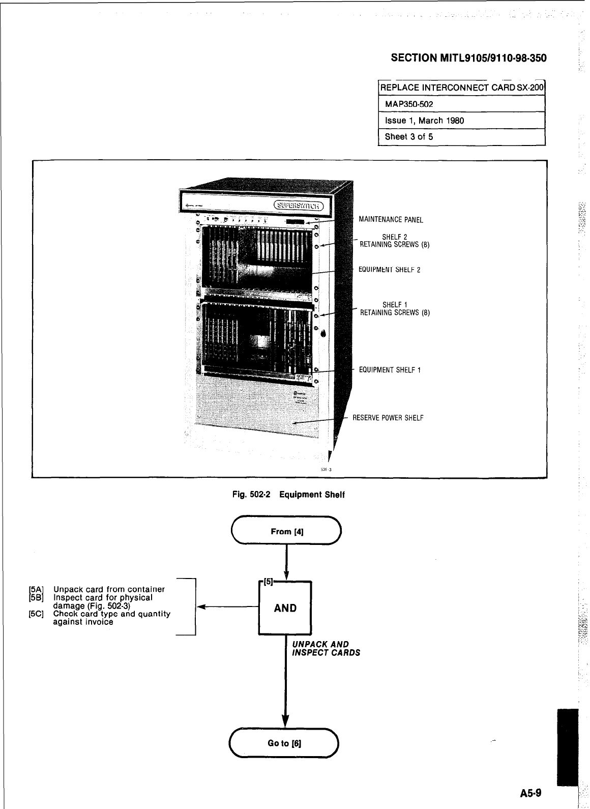
SECTION MITL9105/9110-98-350
MAINTENANCEPANEL
EQUIPMENTSHELF 2
SHELF 1
- RETAINING SCREWS (8)
EQUIPMENT SHELF 1
RESERVE POWER SHELF
Fig. 502-2 Equipment Shelf
From [S]
‘T’
[5A Unpack card from container
[5B Inspect card for physical
[5C] damage (Fig. 502-3)
Check card type and quantity
against invoice
UNPACK AND
INSPECT CARDS
,-
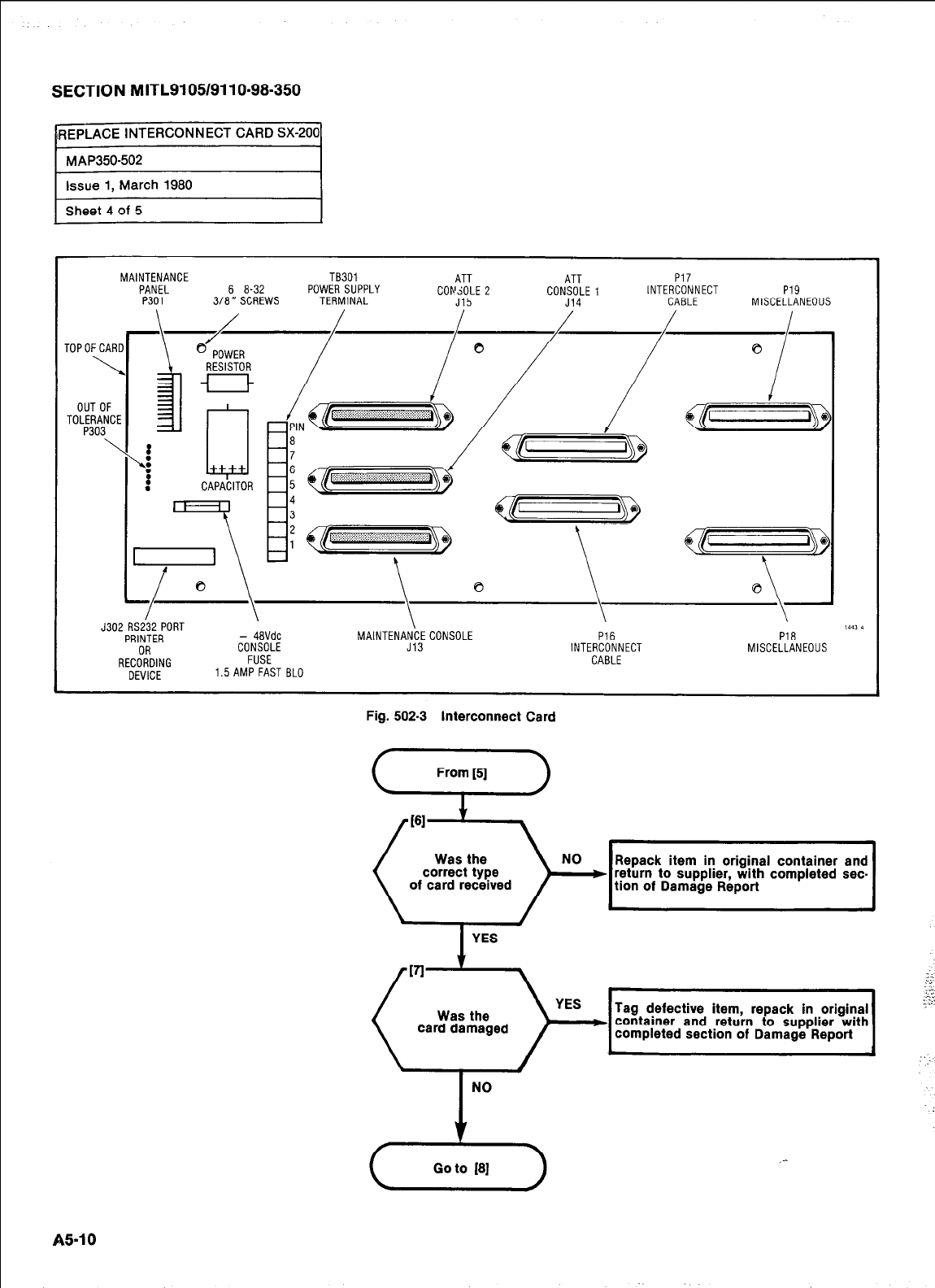
SECTION MITL9105/9110-98-350
IREPLACE INTERCONNECT CARD SX-200
MAP350-502
issue 1, March 1980
Sheet 4 of 5
MAINTENANCE TB301 ATT ATT P17
PANEL 6 a-32 POWER SUPPLY COlr'dOLE 2 CONSOLE1 INTERCONNECT P19
P301 3180 SCREWS TERMINAL J15 J14 CABLE MISCELLANEOUS
OUT OF
TOLERANCE
P303
\
! w
CAPACITOR
J302 RSi32 PORT \ \
PRINTER - 48VdC MAINTENANCECONSOLE P16 Pia ""*
RECi-fDING
CONSOLE J13 INTERCONNECT MISCELLANEOUS
FUSE CABLE
DEVICE 1.5 AMP FAST BLO
Fig. 502-3 interconnect Card
Was the
correct type
of card received
Repack item in original container and
YES
Go to [8]
_-
A51 0
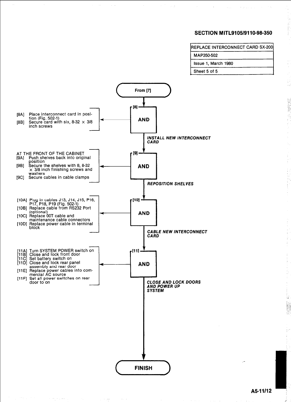
[8A] Place Interconnect card in posi-
tion (Fig. 502-l)
--I--
[8B] Sme+;~~;~ wrth six, 8-32 x 318
SECTION MITL9105/9110-98.350 :
REPLACE INTERCONNECT CARD SX-200
gi
1 Issue 1, March 1980 I
Sheet 5 of 5
181
5
AND 1
INSTALL NEW lNTERCONNECT
AT THE FRONT OF THE CABINET
[9A] Push shelves back into original
position
[9B] Secure the shelves with 8, 8-32
x 3/8 inch finishing screws and
washers
[9C] Secure cables in cable clamps
REPOSITION SHELVES
[lOA] Plug in cables J13, J14, J15, P16,
P17, P18, P19 (Fig. 502-l)
[lOB] Replace cable from RS232 Port
(optional)
[lOC] Replace OOT cable and
maintenance cable connectors
[lOD] !$p$ce power cable in terminal
-
IllA] Turn SYSTEM POWER switch on
I1 El
Close and lock front door
Set battery switch on
Close and lock rear panel
assembly and rear door
[ll E] Replace power cables into com-
mercial AC source
I-
[llF] Set atl power switches on rear
[*. -,
[llC] !
[llD] (
door to on
1101
-u
AND
CABLE NEW INTERCONNECT
CARD
CLOSE AND LOCK DOORS
;;iT;gWER UP
FINISH
I
A5-11112 I
i
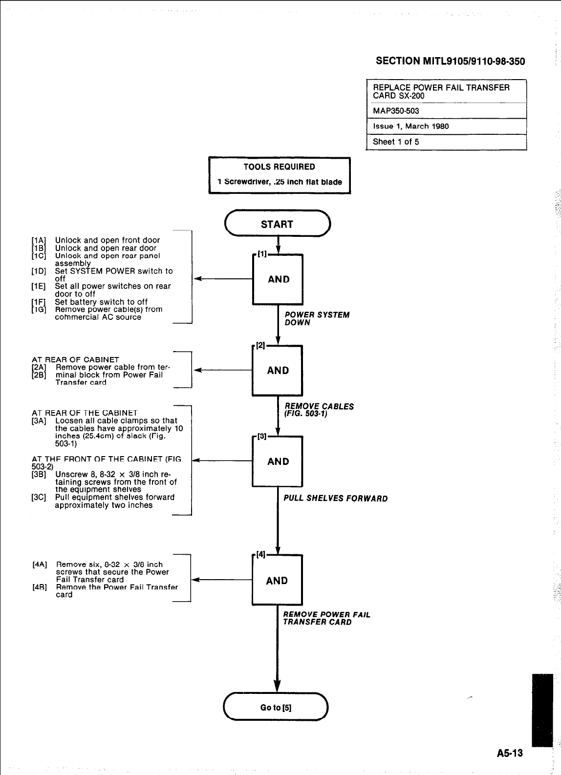
[lA] Unlock and open front door
[l B] Unlock and open rear door
[lC] Unlock and open rear panel
assembly
[ID] S$ SYSTEM POWER switch to
flE] Set all power switches on rear
_ _
door to-off
[lF] Set battery switch to off
[lG] Remove power cable(s) from
commercial AC source
J
I
TOOLS REQUIRED
1 Screwdriver, .25 inch flat blade
(,,,,)
Ill
+--cl
AND
I
POWER SYSTEM
DOWN
AT REAR OF CABINET
[2A] Remove power cable from ter-
[2B] ,m,inJfborzrzrrom Power Fall
--I
+
AT REAR OF THE CABINET
[3A] Loosen all cable clamps so that
the cables have aooroximatelv 10
inches (254cm) of slack (Fig. ’
503-l) I
;J3;yE FRONT OF THE CABINET (FIG.
[3B] Unscrew 8, 8-32 x 3/8 inch re-
taining screws from the front of
[3C] the equipment shelves
Pull equrpment shelves forward
approximately two inches
PI
AND
i
REMOVE CABLES
(FIG. 503-l)
[4A] Remove six, 8-32 x 318 inch
screws that secure the Power
Fail Transfer card
[4B] ;$ove the Power Fail Transfer
SECTION MITL9105/9110-98-350
REPLACE POWER FAIL TRANSFER
CARD SX-200
MAP350503
Issue 1, March 1980
Sheet 1 of 5
I
PULL SHELVES FORWARD
REMOVE POWER FAIL
TRANSFER CARD
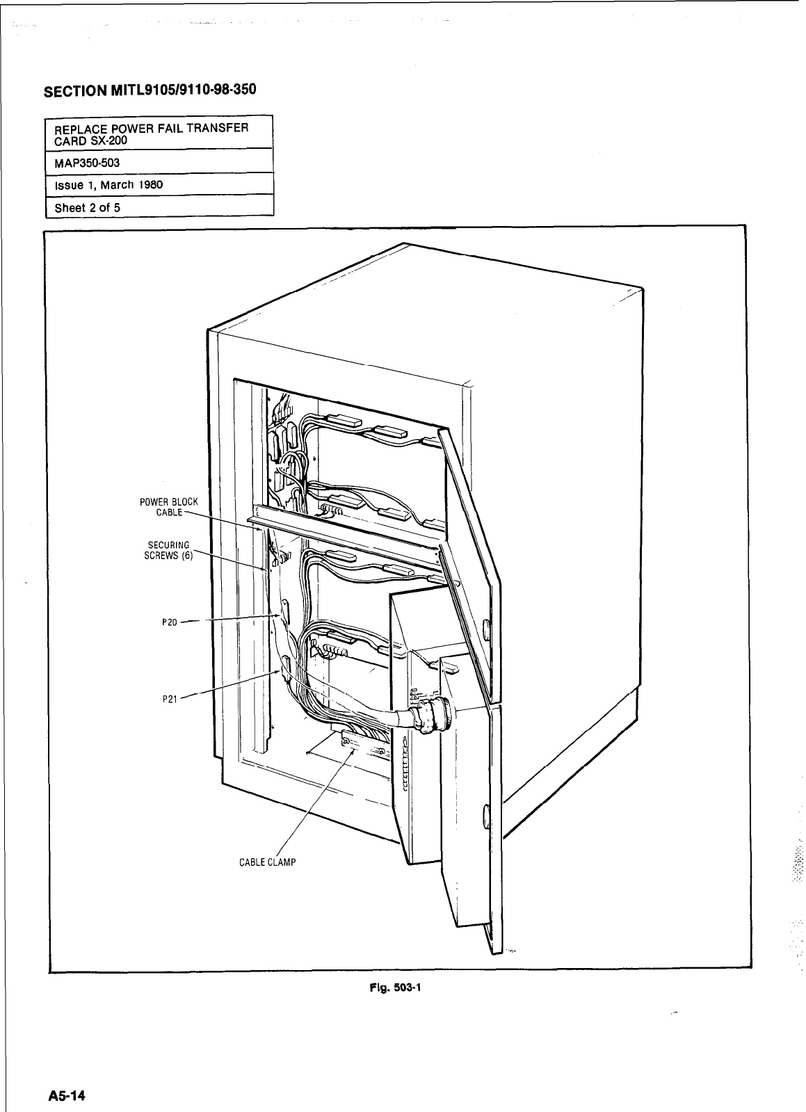
SECTION MITL9105/9110-98-350
Sheet 2 of 5
I ’
P21
-7-n
CABLECiAMP
Fig. 503-l
A5-14
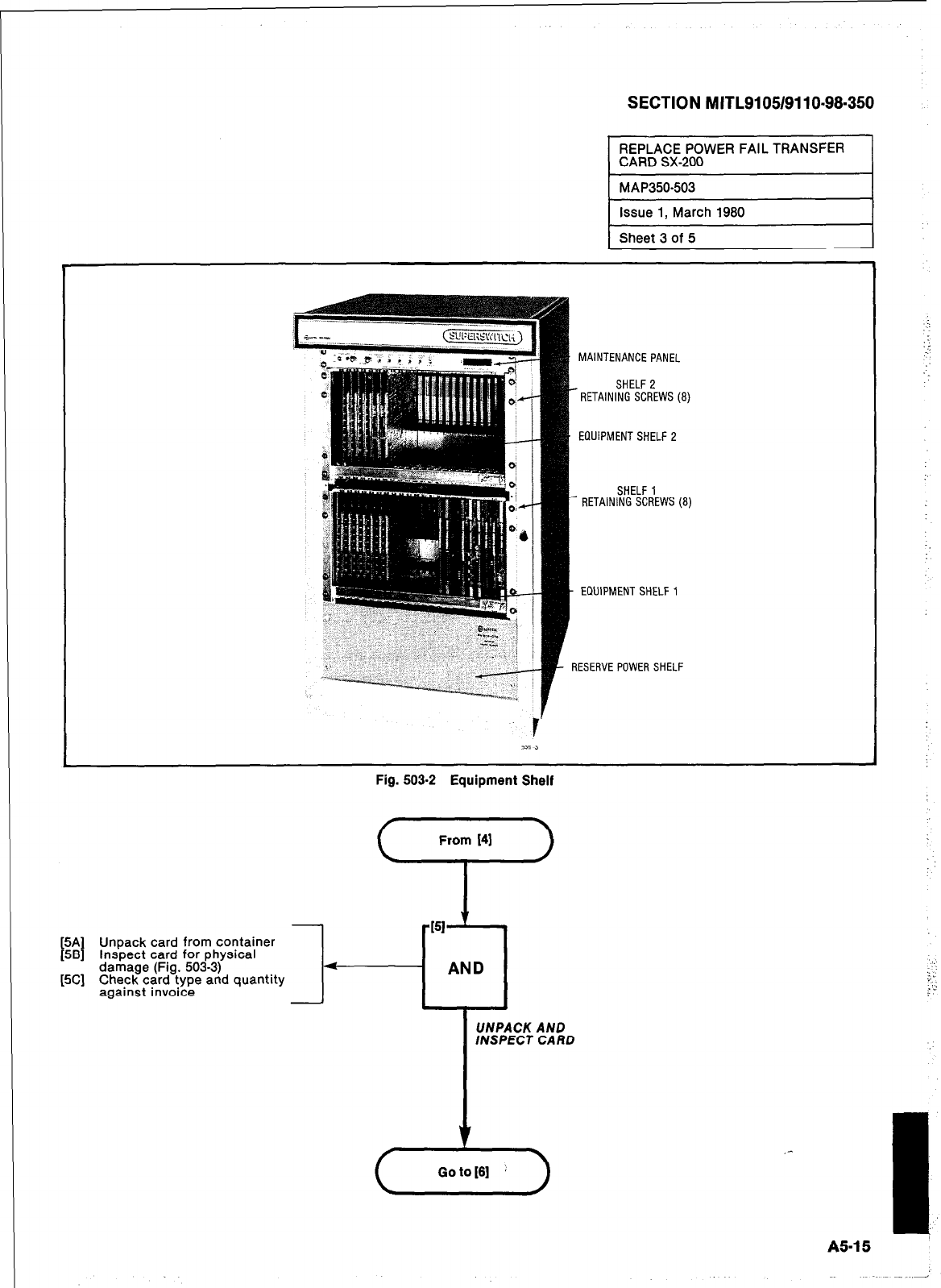
SECTION MITL9105/9110-98.350
I
REPLACE POWER FAIL TRANSFER
CARD SX-200 I
MAP350-503
issue 1, March 1980
Sheet 3 of 5
MAINTENANCE PANEL
- RETAINl?l~Es'~FfEWS (8)
Fig. 503-2 Equipment Shelf
From 141
‘-i
EQUIPMENT SHELF 2
SHELF 1
- RETAINING SCREWS (8)
- EQUIPMENT SHELF 1
RESERVE POWER SHELF
5A
t I
Unpack card from container
58 Inspect card for physical
[5C] damage (Fig. 503-3)
Check card type and quantity
against invoice
- AND
UNPACK AND
INSPECT CARD
.“‘.
::,r,
. ;
Goto[61 ’ )
A5-15
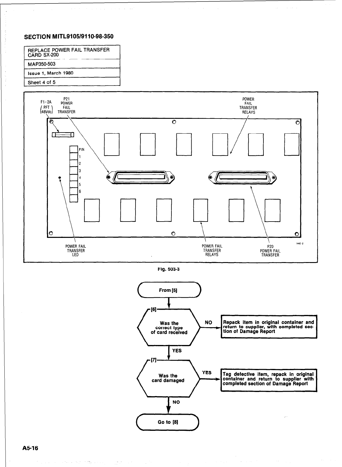
SECTION MITL9105/9110-98.350
1 Sheet 4 of 5 I
Fl-2A P21
POWER .._
TRANSFER
RELAYS
POWER
FAII
i
3
l
\
4
5
6
c
1 c
3 \
I 0
6
POWER FAIL
TRANSFER
LED
POWER FAIL
TRANSFER
RELAYS
Fig. 503-3
From [5]
NO Repack item in original container and
) return to supplier, with completed sec-
tion of Damage Report
Tag defective item, repack in original
( car%r!?ged )=dj container and return to supplier with
completed section of Damage Report
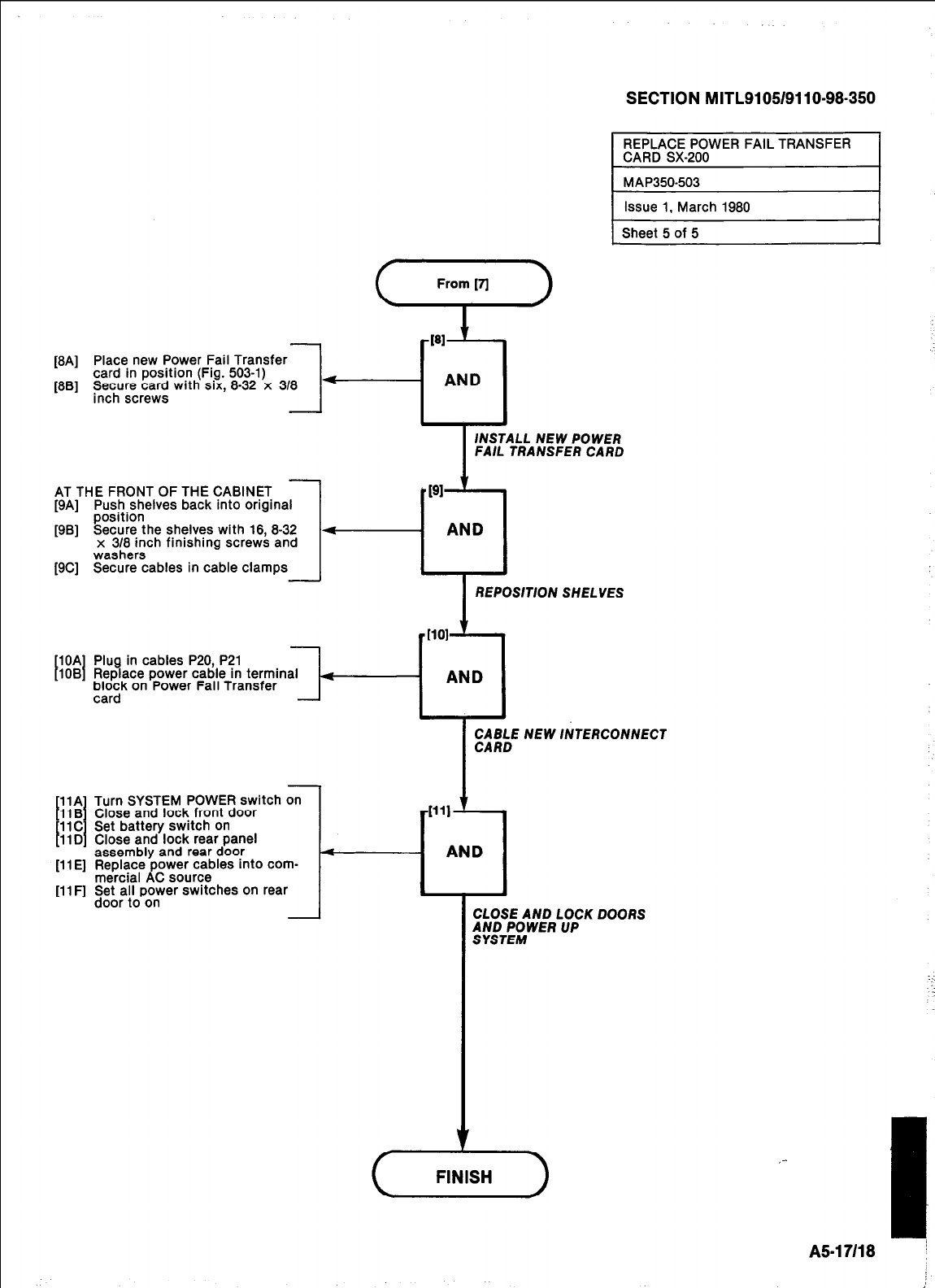
[8A] Place new Power Fail Transfer
card in position (Fig. 503-l)
1
(861 ~~mre;cJ with SIX, 8-32 x 318 -
SECTION MITL9105/9110-98.350
1 Sheet 5 of 5
I
INSTALL NEW POWER
FAIL TRANSFER CARD
AT THE FRONT OF THE CABINET
[9A] Push shelves back into original
position
[9B] Secure the shelves with 18, 8-32
x 318 inch finishing screws and
washers
[9C] Secure cables in cable clamps
REPOSITION SHELVES
t I
10A Plug in cables P20, P21
1OB Replace power cable in terminal
block on Power Fail Transfer
card
-T-
E;M3bE NEW INTERCONNECT
1 I
[llF] Set all power switches on rear
door to on
Turn SYSTEM POWER switch on
Close and lock front door 4111
Set battery switch on
Close and lock rear panel
assembly and rear door 4
[ll E] Replace power cables into com-
mercial AC source i
- AND
CLOSE AND LOCK DOORS
iliT;;WER UP
A517118 j
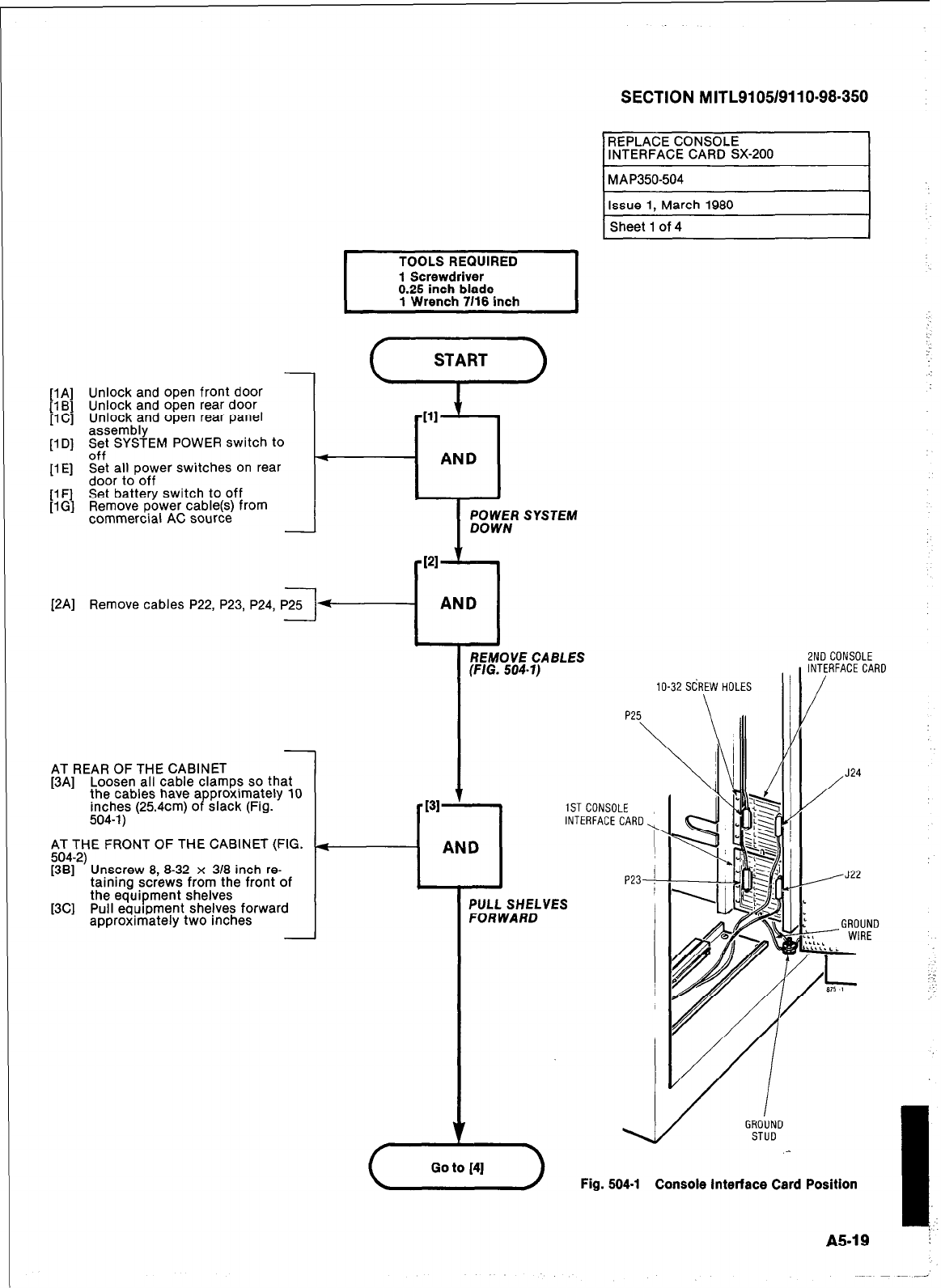
SECTION MITL9105/9110-98.350
REPLACE CONSOLE
r
INTERFACE CARD SX-200
MAP350-504
Issue 1, March 1980
Sheet 1 of 4
TOOLS REQUIRED
1 Screwdriver
0.25 inch blade
1 Wrench 7116 inch I
[lA] Unlock and open front door
[lB] Unlock and open rear door
IlCl Unlock and open rear panel
assembly
[lD] zf”f’ SYSTEM POWER switch to
[lE] Set all power switches on rear
door to off
[lF] Set battery switch to off
[lG] Remove power cable(s) from
commercial AC source POWER SYSTEM
DOWN
[2A] Remove cables P22, P23, P24, P25
ZNDCONSOLE
REMOVE CABLES
‘F/G. 504-l)
NTERFACE CARD
lo-32 SCREW HOLES
AT REAR OF THE CABINET
[3A] Loosen all cable clamps so that
the cables have a
inches (254cm) o P proximately 10
slack (Fig.
504-l)
/
J24
INTERFACECARD
AT THE FRONT OF THE CABINET (FIG.
g&2’ Unscrew 8 8-32 x 3/8 inch re-
taining sc;ews from the front of
[3C] the equipment shelves
Pull equipment shelves forward
approximately two inches -
‘ULL SHELVES
‘OR WARD
GROUND
STUD
Fig. 504-l Console Interface Card Position
A5-19
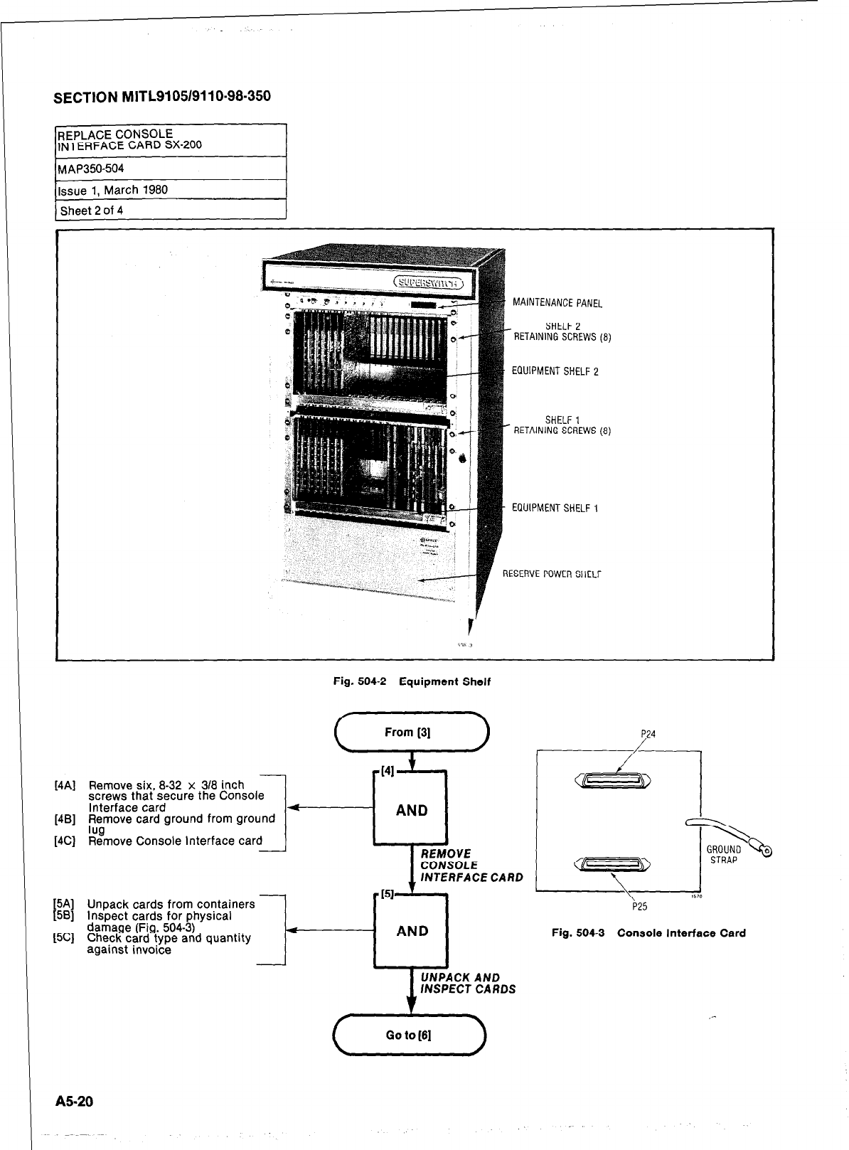
SECTION MITL9105/9110-98-350
REPLACE CONSOLE
INTERFACE CARD SX-200
MAINTENANCE PANEL
- RETAdl!E~~FfEWS (8)
EQUIPMENT SHELF 2
SHELF 1
RETAINING SCREWS (8)
EQUIPMENT SHELF 1
1ESERVE POWER SHELF
Fig. 504-2 Equipment Shelf
[4A] Remove six, 8-32 x 318 inch
screws that secure the Console
Interface card
[4B] Remove card ground from ground
[4C] %move Console Interface
[5A] Unpack cards from containers
[5B] Inspect cards for physical
[5C
damage (Fig. 504-3)
4
;] Check card-type and quantity
against invoice I
-
AND
4
REMOVE
CONSOLE
ISI ’
fNTERFACE CARD
AND
UNPACK AND
fNSPEC1 CARDS
P25
Fig. 504-3 Console Interface Card
( Goto[6] >
AS-20
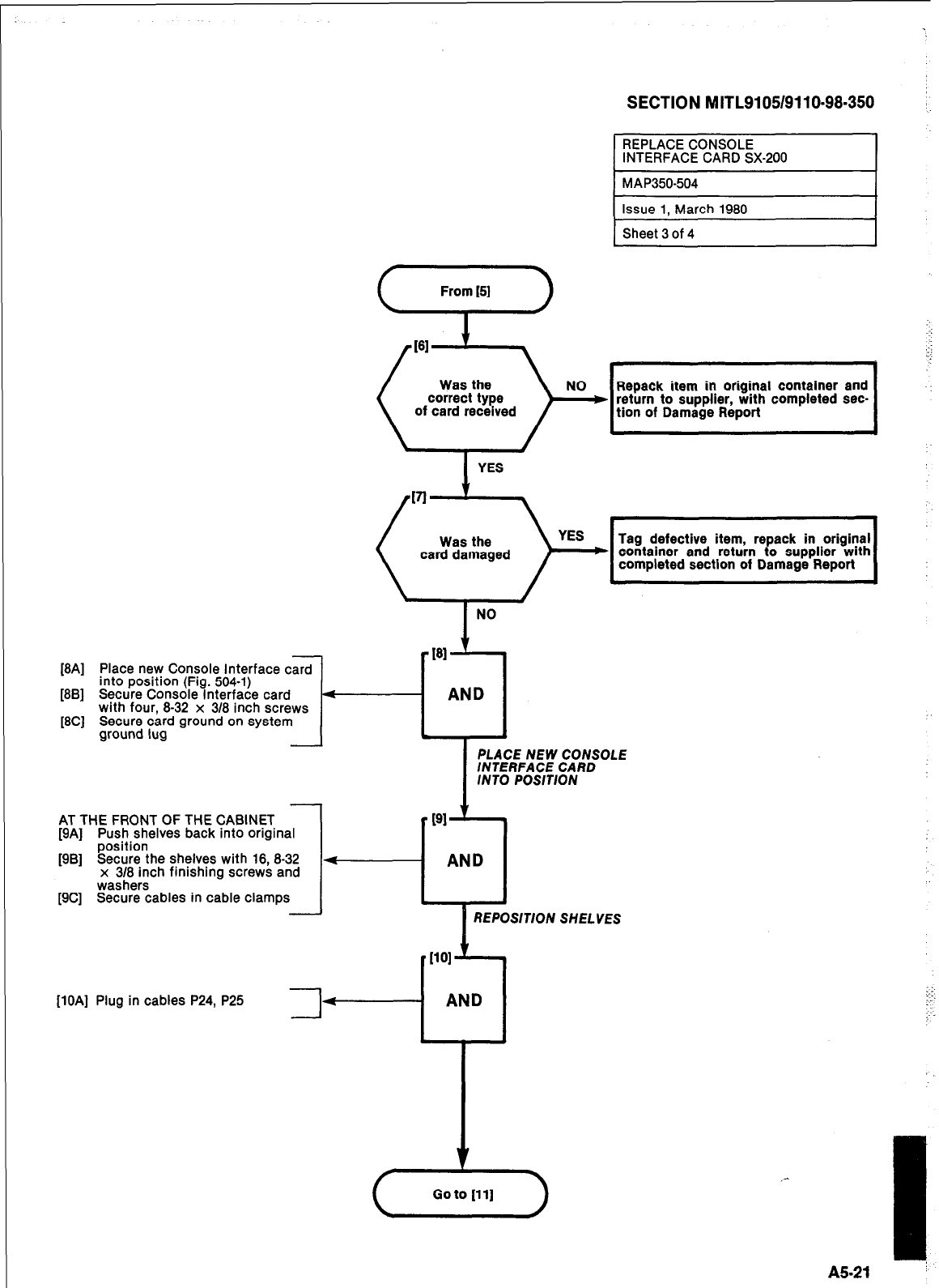
SECTION MITL9105/9110~98~350
[8A] Place new Console Interface card
into position (Fig. 504-l)
[8B] Secure Console Interface card
with four, 8-32 x 318 inch screws
[8C] Secure card ground on system
ground lug
I
l-
AT THE FRONT OF THE CABINET
[9A] Push shelves back into original
position
[9B] Secure the shelves with 16, 8-32
x 318 inch finishing screws and
washers
[9C] Secure cables in cable clamps
Issue 1, March 1980
Sheet 3 of 4
161 c
Was the
correct type
of card received )
YES
Was the
card damaged completed section of Damage Report
NO
I
PLACE NEW CONSOLE
INTERFACE CARD
INTO POSITION
PI
--cl
AND
I
REPOSITION SHELVES
[lOA] Plug in cables P24, P25 3
AND
,-
I
A5-21 ’
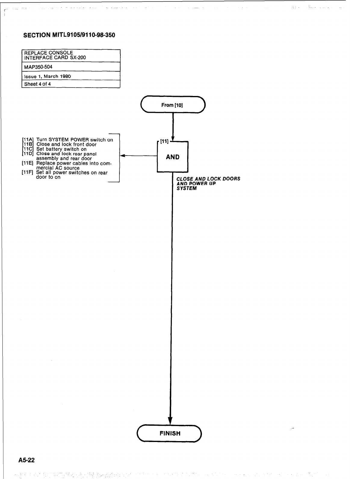
SECTION MITL9105/9110-98-350
[llA Turn SYSTEM POWER switch on
[llB I Close and lock front door
1 I
11C Set battery switch on
11 D Close and lock rear panel
assembly and rear door
[llE] Replace power cables into com-
mercial AC source
[llF] Set all power switches on rear
door to on
A5-22
CLOSE AND LOCK DOORS
JM;;WER UP
l
AND
( FINISH
J
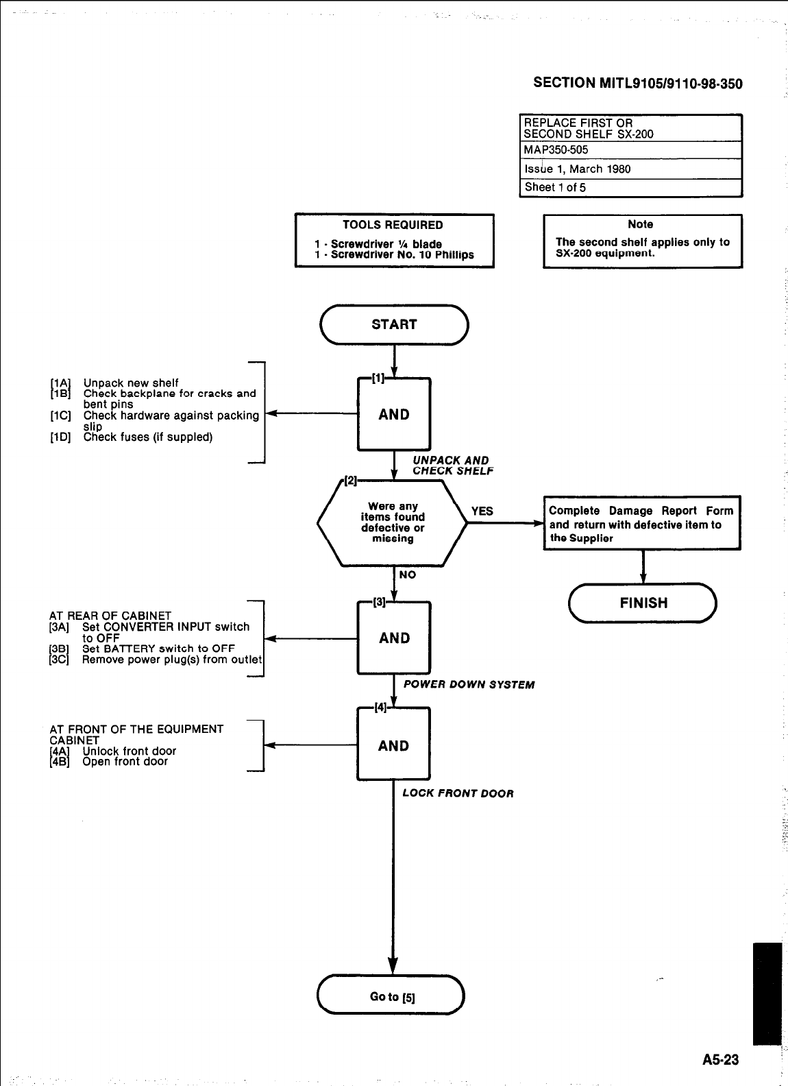
SECTION MITL9105/9110-98.350
I
TOOLS REQUIRED I
1 - Screwdriver 55 blade
1 - Screwdriver No. 10 Phillips
[lA I Unpack new shelf
[lB Check backplane for cracks and
bent pins
[lC] Check hardware against packing 4
AND
[lD] %$ck fuses (if suppled)
,G&RN(I;T OF THE EQUIPMENT
4A Unlock front door
I I
48 Open front door
LOCK FRONT DOOR
1 Sheet 1 of 5
A
UNPACK AND
CHECK SHELF
Complete Damage Report Form
and return with defective item to
the Supplier
AT REAR OF CABINET
[3A] ;;b($NVERTER INPUT switch 4
AND
I
381 Set BATTERY switch to OFF
3C] Remove power plug(s) from outlet
POWER DOWN SYSTEM
A523
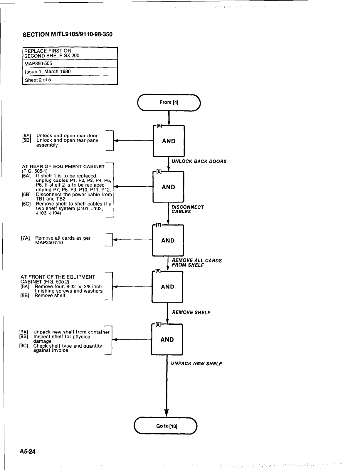
SECTION MITL9105/9110-98-350
REPLACE FIRST OR
SECOND SHELF SX-200 I
- ANQ
c
[5A] Unlock and open rear door
[5B] Unlock and open rear panel f
assembly
AT REAR OF EQUIPMENT CABINET
(FIG. 505-l)
[6A] If shelf 1 is to be replaced,
unplug cables Pl, P2, P3, P4, P5,
P6. If shelf 2 is to be replaced
unplug P7, P8, P9, PlO, Pll, P12.
[6B] Disconnect the power cable from
TBl and TB2
[6C] Remove shelf to shelf cables if a
two shelf system (JlOl, J102,
J103, J104)
I
UNLOCKBACKDOORS
[7A] Remove all cards as per
MAP350510
[8B] Remove shelf
AT FRONT OF THE EQUIPMENT
CABINET (FIG. 505-2)
[8A] Remove four, 8-32 x 318 inch
finishing screws and washers
I--
-
[9A]
[9B] Unpack new shelf from container
Inspect shelf for physical
[SC] %r!%?helf type and quantity
against invoice -
AND
I
REMOVE ALL CARDS
FROM SHELF
461
AND
I
I
REMOVE SHELF
UNPACK NEW SHELF
A5-24
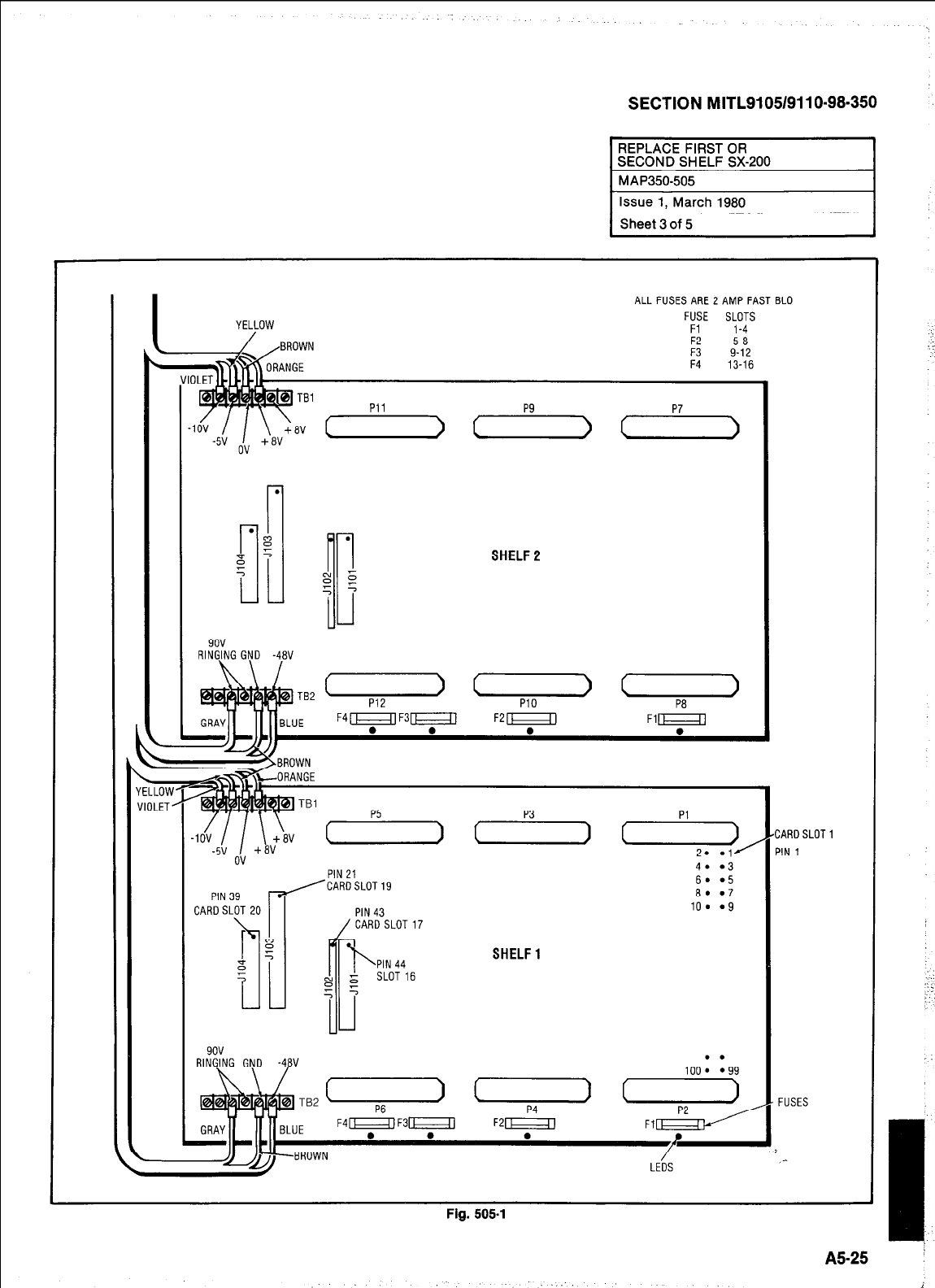
SECTION MITL9105/9110-98-350
REPLACE FIRST OR
SECOND SHELF SX-200 I
/
IOV
YELLOW
.
.
:;I
8
::
5
5
9ov
RINGJNG GND -4BV
TB2
--BROWN
ALL FUSES ARE 2 AMP FAST BLO
FUSE SLOTS
Fl 1-4
F2 5-a
:: 9-12
13-16
c
SHELF2
( >
P12
( >
PI0
( )
pa
TBl Pi
_. __ /CARiSLOT19
WN3Y C
CARDSLOT 20
wlv
PIN 43
/ CARD SLOT17
PIN 44
SLOT 16
SHELF1
FUSES
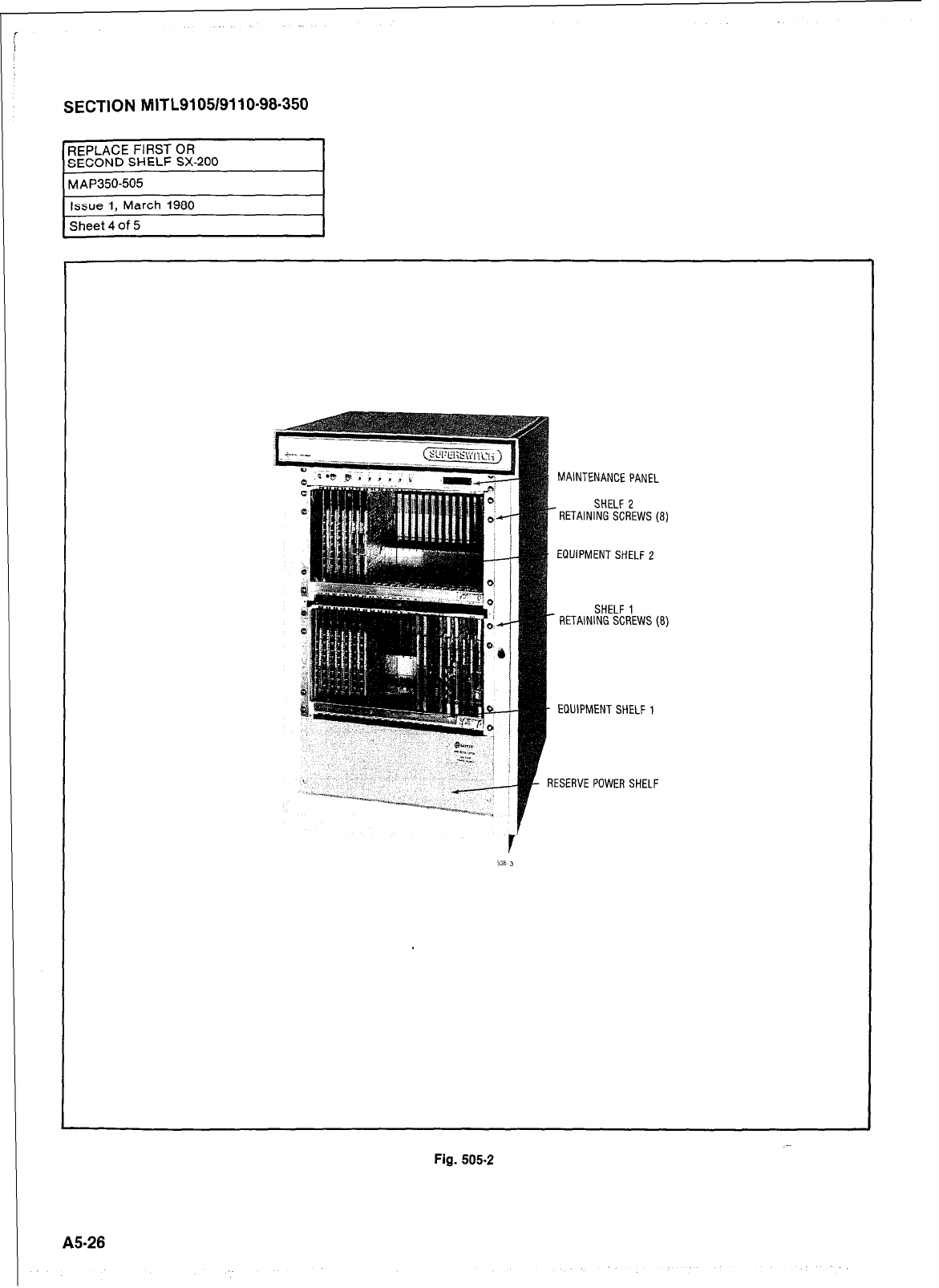
SECTION MITL9105/9110-96-350
REPLACE FIRST OR
SECOND SHELF SX-200
Sheet 4 of 5
155-26
MAINTENANCE PANEL
- RETAINl%%R’EWS (8)
EQUIPMENT SHELF 2
SHELF 1
- RETAINING SCREWS (8)
EQUIPMENT SHELF 1
I
RESERVE POWER SHELF
.-
Fig. 505.2
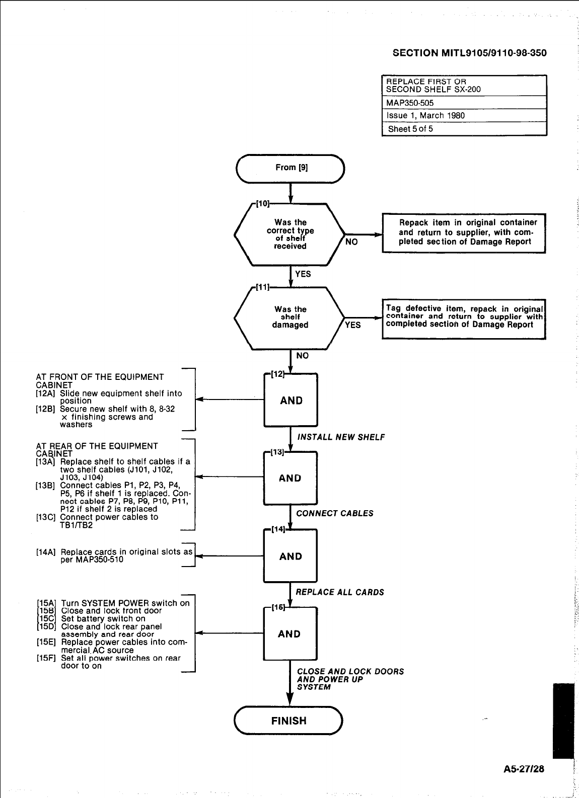
SECTION MITL9105/9110-98-350
return to supplier with
tioh of Damage Report
;I;,RNF;T OF THE EQUIPMENT
[12A] Slide new equipment shelf into
position
[12B] Secure new shelf with 8, 8-32
x finishing screws and
washers
LL NEW SHELF
AT REAR OF THE EQUIPMENT
CABINET
[13A] Replace shelf to shelf cables if a
two shelf cables (JiOl, J102,
J103, J104)
[13B] Connect cables Pl, P2, P3, P4,
P5, P6 if shelf 1 is replaced. Con-
nect cables P7, P8, P9, PlO, Pll,
P12 if shelf 2 is replaced
[13C] +Xx$?;; power cables to NNECT CABLES
[14A] Replace cards in original slots as
per MAP350-510
-
1 REPLACE ALL CARDS
[15Al
‘;$I
I I
15D
[15El
P5Fl
Turn SYSTEM POWER switch on
Close and lock front door
Set battery switch on
Close and lock rear panel
assembly and rear door
Replace power cables into com-
mercial. AC source
Set all power switches on rear
door to on
1
CLOSE AND LOCK
AND POWER UP
SYSTEM
DOORS
( FINISH ) .-
A5-27128 ;
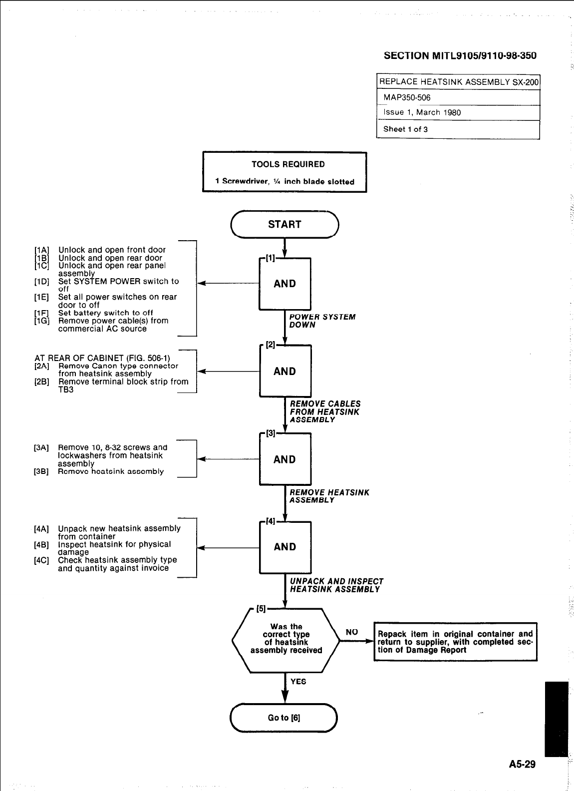
llA1 Unlock and open front door
]lCj ock and open rear door
Unlock and open rear panel
assembly
[lD] S$ SYSTEM POWER switch to
-. .
[lE] Set all power switches on rear
door to off
[lF] Set battery switch to off
[lG] Remove power cable(s) from
commercial AC source
,
I
TOOLS REQUIRED
1 Screwdriver, % inch blade slotted I
AT REAR OF CABINET (FIG. 506-l)
[2A] Remove Canon type connector
from heatsink assembly
WI
l-l
AND
Remove terminal block strip from
TB3
J
1
REMOVE CABLES
FROM HEATSINK
ASSEMBLY
[3Al
13Sl
Remove 10,8-32 screws and
lockwashers from heatsink
assembly 4
Remove heatsink assembly
I
REMOVE HEATSINK
ASSEMBLY
[4Al
14Sl
[4Cl
Unpack new heatsink assembly
from container
Inspect heatsink for physical
damage
Check heatsink assembly type
and quantity against invoice
UNPACK AND /NSPECT
HEATSINK ASSEMBLY
SECTION MITL9105/9110~98-350
REPLACE HEATSINK ASSEMBLY SX-200
MAP350-506
4
SYSTEM
t
Repack item in original container and
return to supplier, with completed sec-
tion of Damage Report
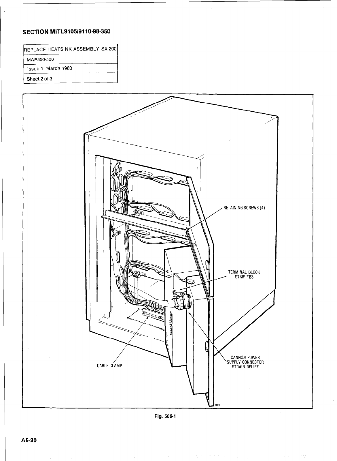
SECTION MITL9105/9110-98-350
REPLACE HEATSINK ASSEMBLY SX-200
rIssue 1, March 1980
r
Sheet 2 of 3 I
RETAINING SCREWS (4)
TERMINAL BLOCK
CANNON POWER
SUPPLY CONNECTOR
STRAIN RELIEF
Fig. 506-l
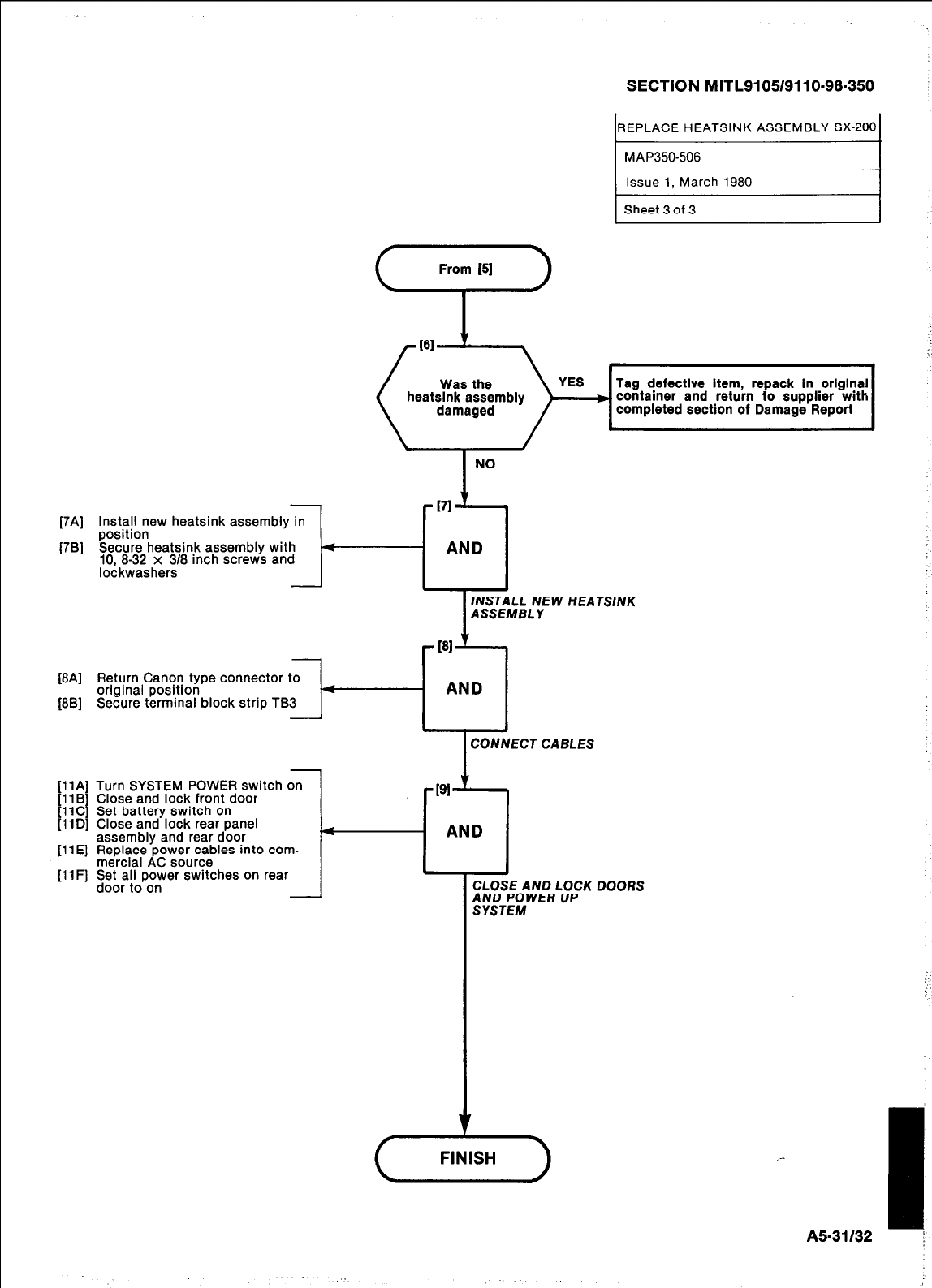
SECTION MITL9105/911 O-98-350
REPLACE HEATSINK ASSEMBLY SX-200
MAP350-506
1 Issue 1, March 1980
1 Sheet 3 of 3
Tag defective item, repack in original
container and return to supplier with
completed section of Damage Report
NO
-VI v
[7A] Install new heatsink assembly in
position
[7B] Secure heatsink assembly with 4
AND
10, 8-32 x 318 inch screws and
lockwashers
INSTALL NEW HEATSINK
ASSEMBLY
-
[al
’
[8A] Return Canon type connector to
original position 4
AND
[8B] Secure terminal block strip TB3
CONNECT CABLES
[llA] Turn SYSTEM POWER switch on
[ll B
I Close and lock front door -PI ’
t
11C Set battery switch on
llD] Close and lock rear panel
assembly and rear door 4
AND
[ll E] Replace power cables into com-
mercial AC source
[ll F] Set all power switches on rear
door to on
- CLOSE AND LOCK DOORS
;;iT;;WER UP
,-
I.
‘.
AS-31 132 I
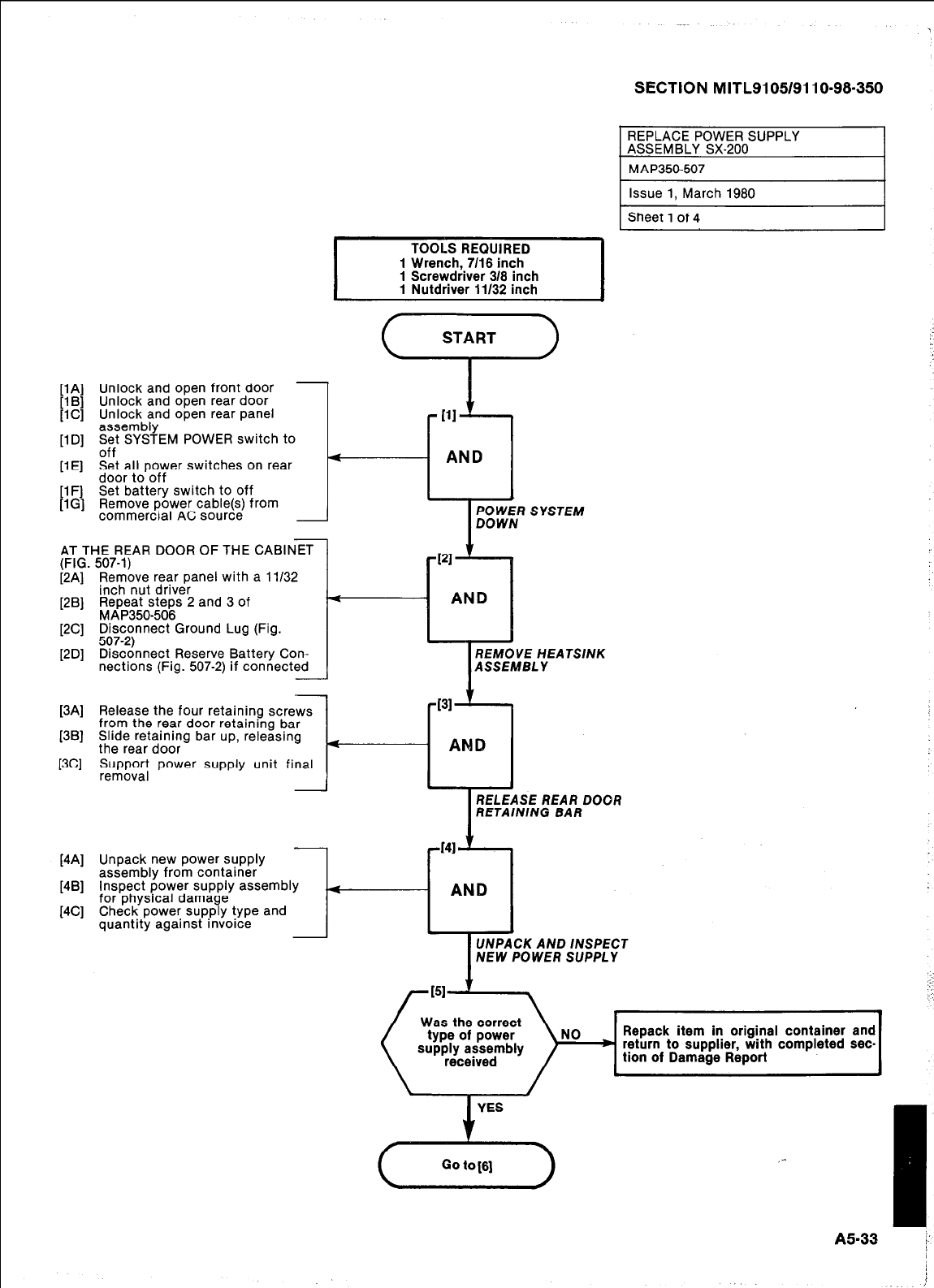
I
TOOLS REQUIRED
1 Wrench,.7116 inch
1 Screwdnver 316 inch
1 Nutdriver 11132 inch I
[lA] Unlock and open front door
[l B] Unlock and open rear door
[lC] Unlock and open rear panel
assembly
[lD] z;t SYSTEM POWER switch to
[lE] Set all power switches on rear
door to off
[lF] Set battery switch to off
[IG] Remove power cable(s) from
commercial AC source I-
AT THE REAR DOOR OF THE CABINET
(FIG. 507-l)
[2A] Remove rear panel with a 1:/32
inch nut driver
[2B] Repeat steps 2 and 3 of
MAP350-506
[2C] it7ccnnect Ground Lug (Fig.
[2D] Disconnect Reserve Battery Con-
nections (Fig. 507-2) if connected
I
REMOVE HEATSINK
ASSEMBLY
SECTION MITL9105/9110-98-350
REPLACE POWER SUPPLY
ASSEMBLY SX-200
MAP350-507
Issue 1, March 1980
Sheet 1 of 4
1
[3A] Release the four retaining screws
from the rear door retaining bar
[3B] Slz;er,;;;;:g bar up, releasing
[3C] F;,;,“J;; power supply unit final
d31
AND
RELEASE REAR DOOR
RETAlNlNG BAR
[4A] Unpack new power supply
assembly from container
[4B] Inspect power supply assembly
for physical damage
[4C] Check power supply type and
quantity against invoice
NEW POWER SUPPLY
Was the correct
type of power
supply assembly
received
Repack item in original container and
return to supplier, with completed sec-
tion of Damage Report I
,-
I
A5-33 ;:
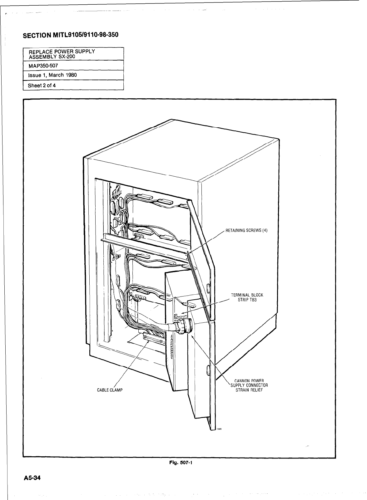
SECTION MITL9105/9110-98.350
r
Sheet 2 of 4 I
CAELECiAMP
\
1:
/
2:
RETAINING SCREWS(4)
TERMINAL BLOCK
, STRlPTB3
CANNON POWER
SUPPLY CONNECTOR
STRAIN RELIEF
Fig. 507-l
A534
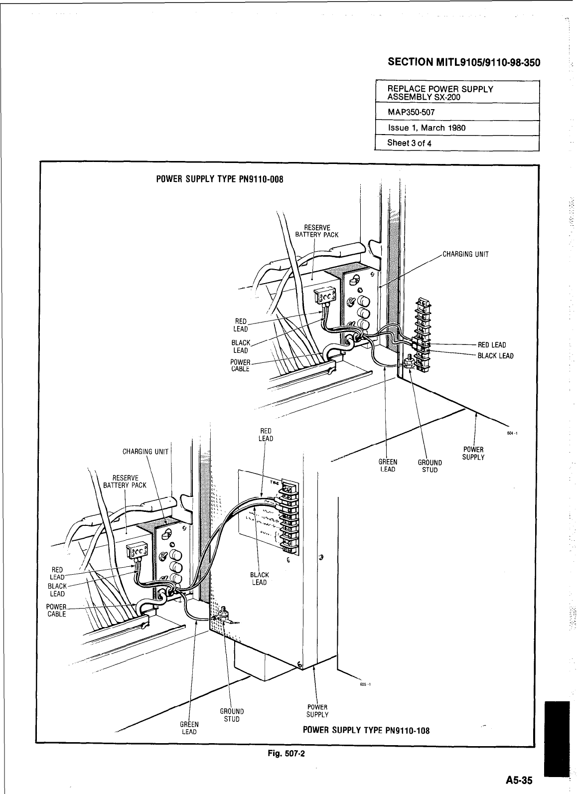
SECTION MITL9105/911 O-98-350
Issue 1, March 1980
Sheet 3 of 4
POWER SUPPLY TYPE PN9110-008
/CHARGING UNIT
RED LEAD
-BLACK LEAD
HtU
LEAD
I
CHARGING UNIT I I( ,I .I
BLACK
LEAD II I
LEAD STUD
-I
A5-35 :
GRdUND
/L STUD
r”YYCfl
SUPPLY
./
U”LLlY
LEAD POWER SUPPLY TYPE PN9110-108 _-
L. -^- ^
tlg. WI-Z
::
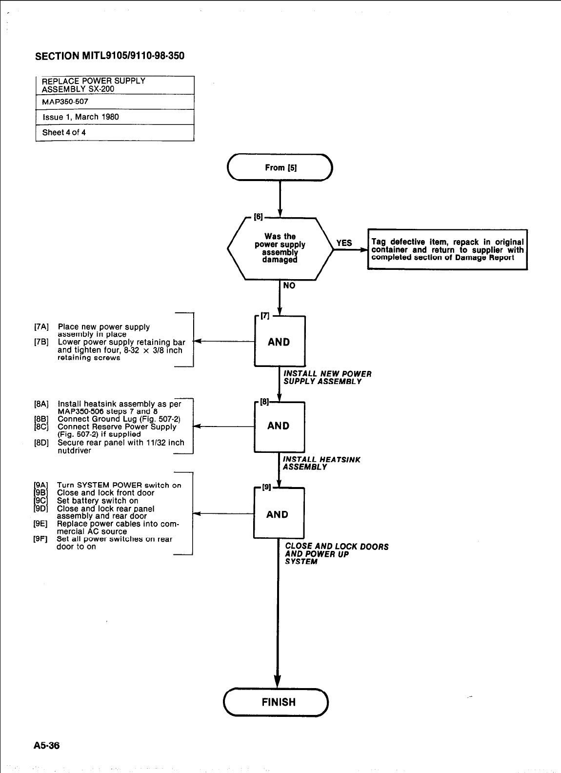
SECTION MITL91051911 O-98-350
REPLACE POWER SUPPLY
ASSEMBLY SX-200
[7Al
[7W
w41
PBI
KU
WI
cs)Y= ,=,
Tag defectwe item, repack In orlgmai
container and return to supplier with
completed section of Damage Report
Place new power supply
assembly in place
Lower power supply retaining bar
and tighten four, 8-32 x 318 inch
retaining screws I-
AND
INSTALL NEW POWER
SUPPLY ASSEMBLY
install heatsink assembly as per
MAP350-506 steps 7 and 8
Connect Ground Lug (Fig. 507-2)
Connect Reserve Power Supply -4
AND
(Fig. 507-2) if supplied
Secure rear panel with 11132 inch
nutdriver 4
INSTALL HEATSINK
ASSEMBLY
Turn SYSTEM POWER switch on
Close and lock front door
Set battery switch on
Close and lock rear panel
assembly and rear door
Replace power cables into com-
mercial AC source
AND
Set ail power switches on rear
door to on
CLOSE AND LOCK DOORS
$fiT;iWER UP
,-
FINISH )
A5-35
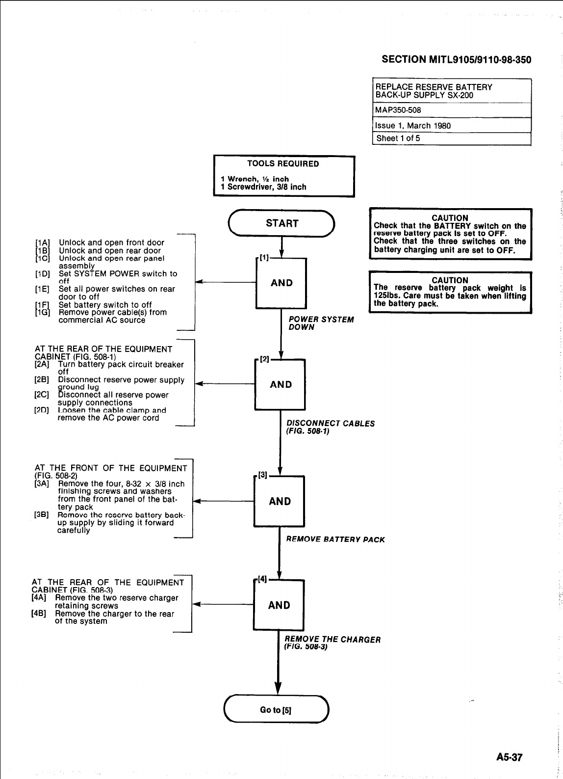
-
[lA] Unlock and open front door
[lB] Unlock and open rear door
flC1 Unlock and ooen rear oanel
1
. -
assembly ’
[lD] zf”t SYSTEM POWER switch to
[lE] Set all power switches on rear
door to off
[l F] Set battery switch to off
[lG] Remove power cable(s) from
commercial AC source
AT THE REAR OF THE EQUIPMENT
CABINET (FIG. 508-l)
[2A] -l
2:r-r battery pack circuit breaker
<
AT THE FRONT OF THE EQUIPMENT
(FIG. 508-2)
[3A] Remove the four, 8-32 x 3/8 inch
finishing screws and washers
from the front panel of the bat-
tery pack
[3B] Remove the reserve battery back-
up supply by sliding it forward
carefully
I
POWER SYSTEM
DOWN
VI I
[2B] Disconnect reserve power supply
[2C] f3YZ%k!t all reserve power
[2D] supply connections
Loosen the cable clamp and
remove the AC power cord 1c
-
REPLACERESERVEBATTERY
BACK-UP SUPPLY SX-200
TOOLS REQUIRED
1 Wrench,.% inch
1 Screwdrrver, 3/8 inch
SECTION MITL9105/9110-98-350
Check that the BATTERY switch on the
reserve battery pack is set to OFF
Check that the three switches on the
battery charging unit are set to OFF.
I
CAUTION
The reserve battery pack weight is
125lbs. Care must be taken when lifting
the battery pack. I
e
REMOVE BATTERY PACK
AT THE REAR OF THE EQUIPMENT
CABINET (FIG. 508-3)
[4A] Remove the two reserve charger
[4B] retaining screws
Remove the charger to the rear
of the system
I
REMOVE THE CHARGER
(FIG. 508-3)
,-
A5-37
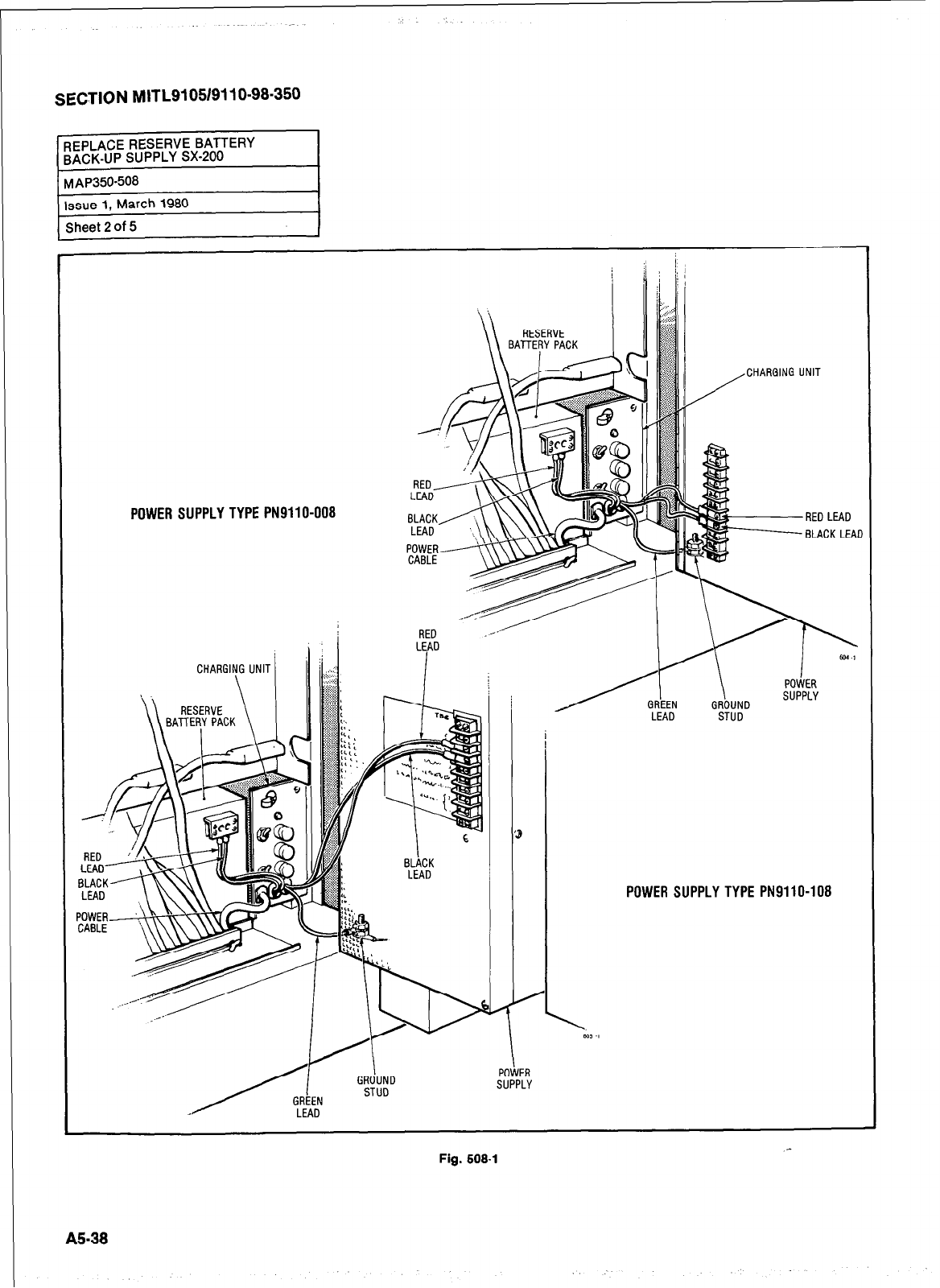
SECTION MITL9I05/9110-98.350
POWER SUPPLY TYPE PN9110-008
,
CHARGIN
\ \ I
’ I
G UNIT
LEAD
2 BLACK LEAD
\ \ \ I LEAD STUD
POWER
SUPPLY
POWER SUPPLY TYPE PN9110-108
Fig. 508-l
A538
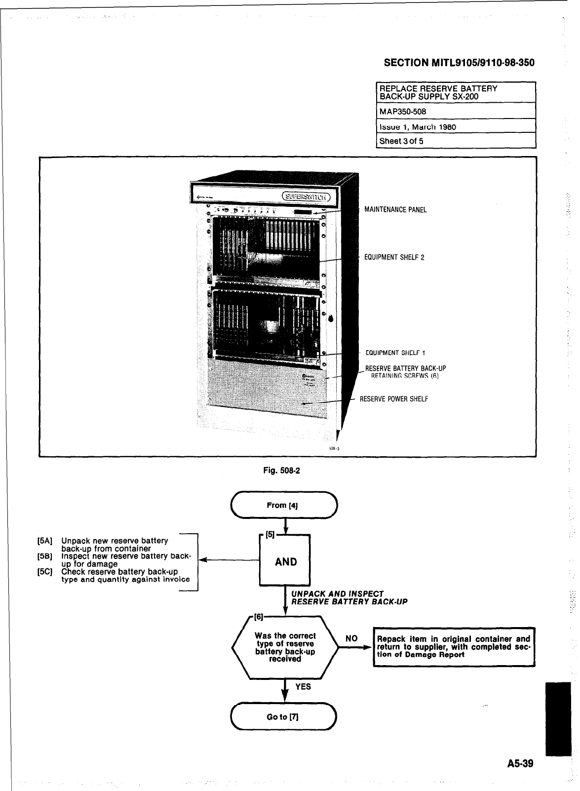
SECTION MITLSI 051911 O-98-350
MAINTENANCE PANEL
EQUIPMENT SHELF 2
EQUIPMENT SHELF 1
I--
RESERVE BATTERY BACK-UP
RETAINING SCREWS (6)
RESERVE POWER SHELF
[5A] Unpack new reserve battery
[5B] back-up from container
Inspect new reserve battery back-
up for damage
[5CJ Check reserve battery back-up
type and quantity against invoice
Fig. 508-2
I
UNPACK AND /NSPECT
RESERVE BATTERY BACK-UP
t
/181-
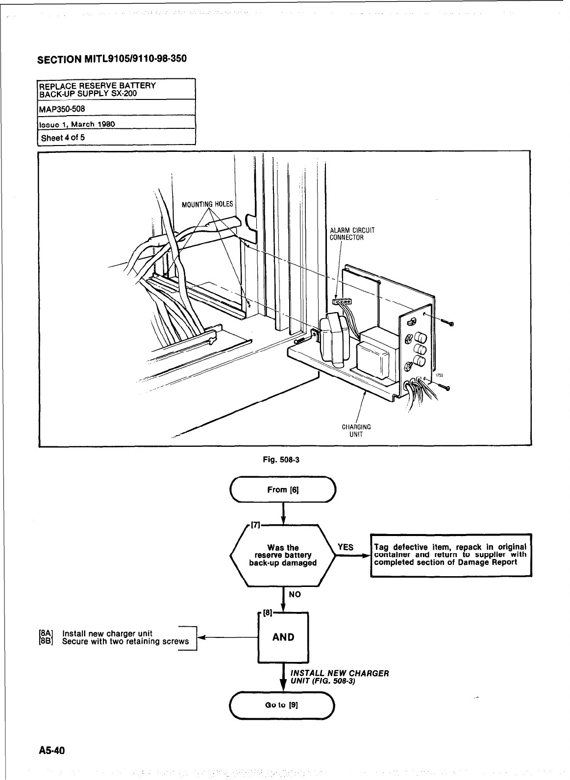
SECTION MITL9105/9110-98.350
Issue 1, March 1980
Sheet 4
Of
5
Fig. 508-3
Was the
reserve battery
back-up damaged
YES Tag
defective
item, repack in original
m container and return to supplier with
completed section of Damage Report
\ I
NO
v
PI
1
8A
I 1
88 Install new charger unit
Secure with two retaining screws 4
AND
MSTALL
NEW
CHARGER
UNIT (FIG. 508-3)
AS-40
:
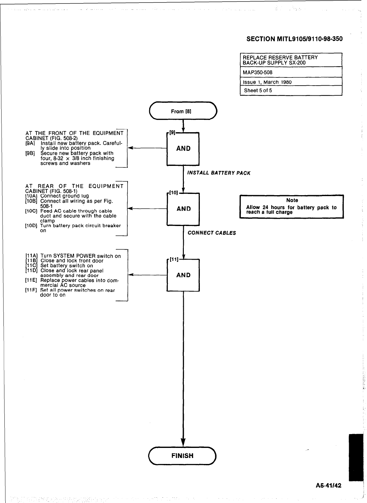
SECTION MITL9105/911 O-98-350
AT THE FRONT OF THE EQUIPMENT
CABINET (FIG. 508-2)
[9A] Install new battery pack. Careful-
ly slide into position
[9B] Secure new battery pack with
four. 8-32 x 3/8 inch finishina
scre’ws and washers
- AND
INSTALL BATTERY PACK
4
AT REAR OF THE EQUIPMENT
CABINET (FIG. 508-l)
[lOA] Connect ground lug
[lOB] ;;c&ect all wrrrng as per Fig.
[lOC] Feed AC cable through cable
duct and secure with the cable
clamp
[lOD] Turn battery pack circuit breaker
on
[llA] Turn SYSTEM POWER switch
11 B
t I
Close and lock front door
1 IC Set battery switch on
[liDI Close and lock rear panel
assembly and rear door
[ll E] Replace power cables into com-
mercial AC source
[liF] Set all power switches on rear
door to on
- AND
I
Note
Allow 24 hours for battery pack to
reach a full charge I
CABLES
!...
i.
i-
1
A5-41142 I
I
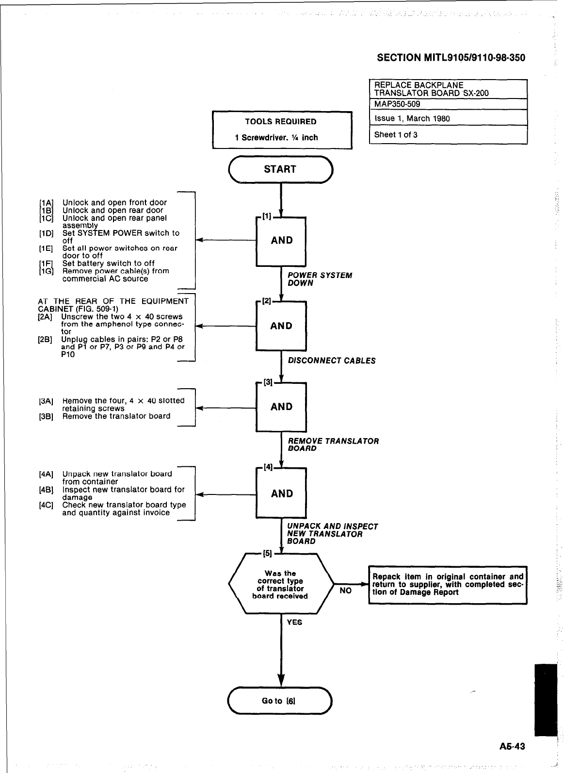
[lA Unlock and open front door
t
1B Unlock and open rear door
lC] Unlock and open rear panel
sembly
flD1 2 t SYSTEM POWER switch to
. -
off
[lE] Set all power switches on rear
door to off
[l F] Set battery switch to off
[lG] Remove power cable(s) from
commercial AC source -
AT THE REAR OF THE EQUIPMENT
CABINET (FIG. 509-l)
[2A] Unscrew the two 4 x 40 screws
from the amphenol type connec-
tor
[2B] Unplug cables in pairs: P2 or P8
and Pl or P7, P3 or P9 and P4 or
PlO
I
TOOLS REQUIRED I
I
1 Screwdriver. ‘A inch I
Ill
--cl
AND
SECTION MITL9105/911 O-98-350
/ ;s;It :‘Jt,“‘“h 1980 /
I
POWER SYSTEM
DOWN
PI
-0
AND
DISCONNECT CABLES
[3A] Remove the four, 4 x 40 slotted
retaining screws
[3B] Remove the translator board
[4A] Unpack new translator board
from container
[4B] Inspect new translator board for
damage
[4C] Check new translator board type
and quantity against invoice
I
UNPACK AND INSPECT
MdR;RANSLATOR
Repack item in original container and
return to supplier, with completed sec-
CA3
Go to 161
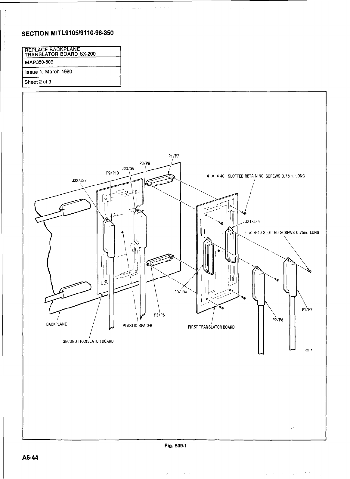
SECTION MITL9105/9110-98.350
PI/P7
BACKPLANE
SECONDTRANSLATOR BOARD
4 x 4-40 SLOTTED RETAINING SCREWS 0.75in. LONG
/
PLASTIC'SPACER FlRSTTRANSiATORBOARO
,J31/J35
2 x 4-40 SLOTTED SCREWS 0.75in.LONG
\
\ \
\
Pl/P7
1052 2
Fig. 509-l
A5-44
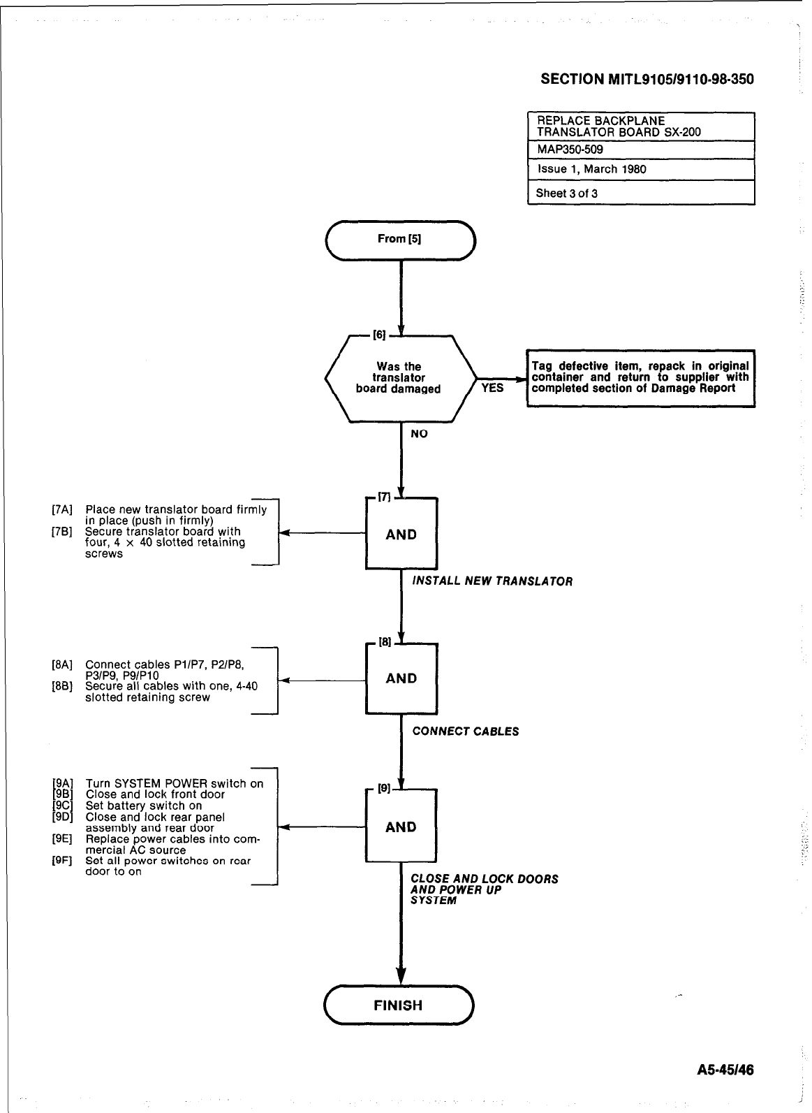
[7Al
[7Bl
WI
IW
board damaged
Tag defective item, repack in original
container and return to supplier with
completed section of Damage Report
Connect cables PllP7, P21P8,
P3/P9, P91PlO
Secure all cables with one, 4-40
slotted retaining screw
SECTION MITL9105/9110-98-350
Sheet 3 of 3
NO
Place new translator board firmly
in place (push in firmly)
Secure translator board with
$ur,;s x 40 slotted retaining 1-r:
I
INSTALL NEW TRANSLATOR
Turn SYSTEM POWER switch on
Close and lock front door
Set battery switch on
Close and lock rear panel
assembly and rear door
Replace power cables into com-
mercial AC source
Set all power switches on rear
door to on
I
CONNECT CABLES
4 AND
4
CLOSE AND LOCK
;;tT;$WER UP
(+-)
DOORS
A545146
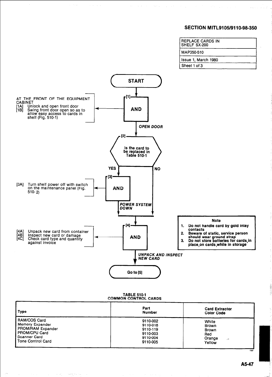
,A;BA;ETFRONT OF THE EQUIPMENT
[lA] Unlock and open front door
[lB] Swing front door open so as to
allow easy access to cards in
shelf (Fig. 510-l)
[3A] Turn shelf power off with switch
on the maintenance panel (Fig.
510-
2)
[4A]
[4B] Unpack new card from container
[4C] Inspect new card or damage
Check card type and quantity
against invoice
I
I
OPEN DOOR
AND
POWER SYSTEM
DOWN
v
REPLACE CARDS IN
SHELF SX-200
TABLE
510-l
COMMON CONTROL CARDS
SECTION MITL9105/9110~98-350
Note
1. Do not handle card by gold inlay
contacts
2. Beware of static, service person
should wear round strap
3. Do not store t atteries for cards,in
place,on cards,while in storage
1
:
UNPACK AND INSPECT
Card Extractor
Color Code
--.-. _-__ I
Type
Part
Number
RAMKOS Card
Memory Expander
PROM/RAM Expander
PROM/CPU Card
Scanner Card
Tone Control Card
911 O-002
9110-018
9110-119
911 O-003
911 O-004
911 O-005
White
. . . ..--
Brown
Brown
Red
Orange ,-
Yellow
A547
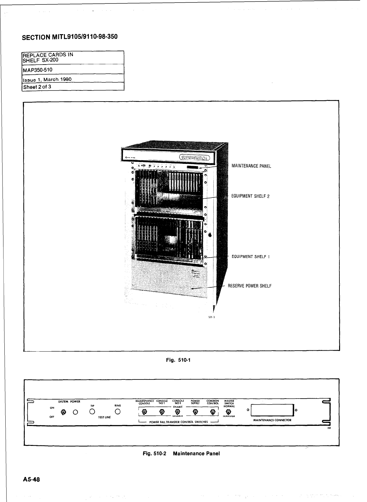
SECTION MITL9105/9110-98-350
Fig. 510-2 Maintenance Panel
MAINTENANCE PANEL
EQUIPMENTSHELFP
EOUIPMENT SHELF1
3ESERVE POWER SHELF
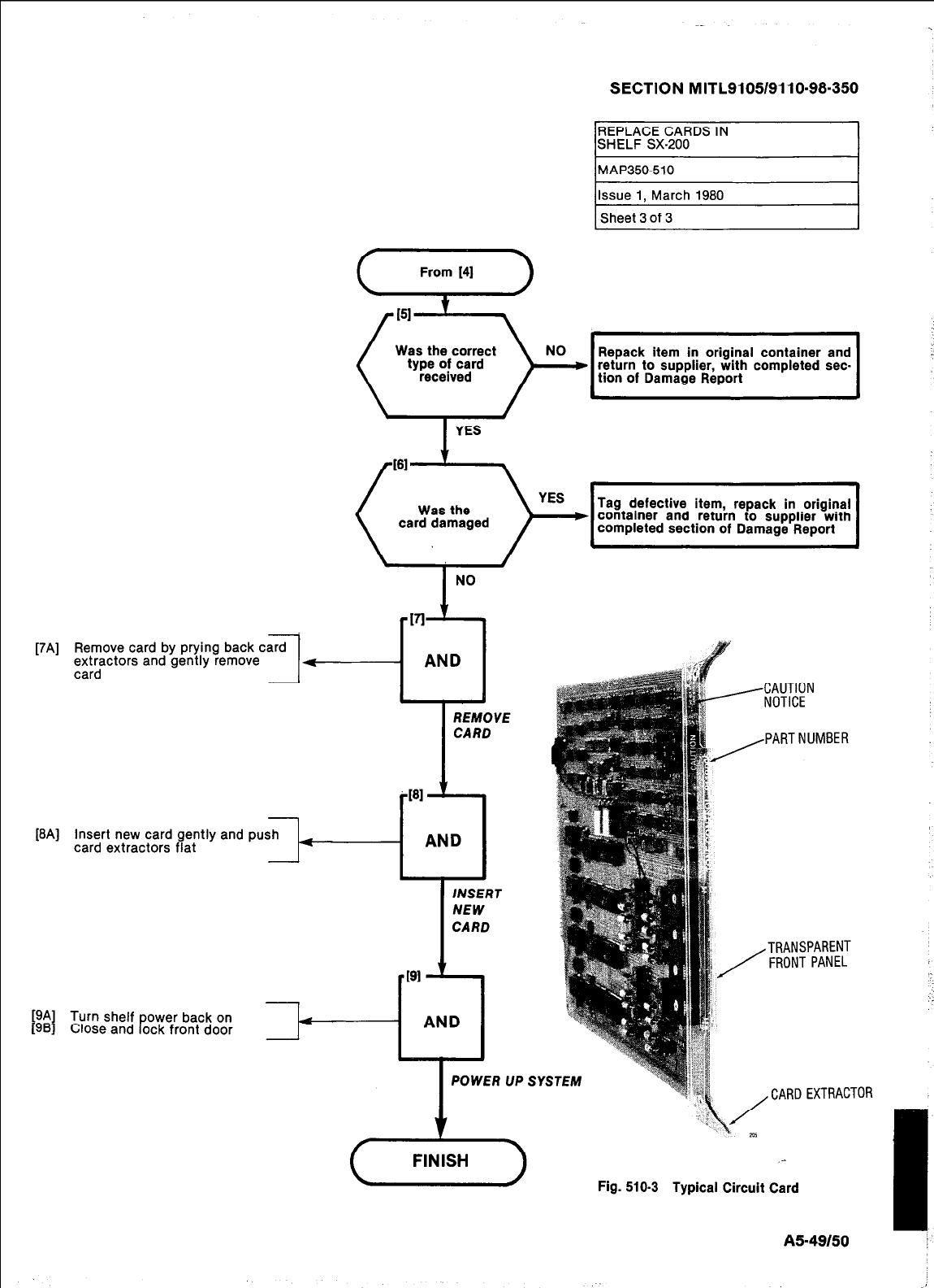
-
[7A] Remove card by prying back card
extractors and gently remove
card -
1
I-
-
[8A] Insert new card gently and push
card extractors fiat -
SECTION MITL9105/9110-98-350
REPLACE CARDS IN
SHELF SX-200
MAP350-510
Issue 1, March 1980
Sheet 3 of 3
(Yyi-)
151 t
Was the correct
type of card Repack item in original container and
received ) “O’l,i........;..,j
return to suppher, with completed set
card damaged
I
NO
17
----r-l
AND
M
AND
REMOVE
CARD
l
AND
INSERT
NEW
CARD
INSERT
T
NEW
CARD
[9A]
1961 Turn shelf power back on
Close and lock front door
-PI t
- AND
POWER UP SY
-CAUTION
NOTICE
,PART NUMBER
TRANSPARENT
FRONT PANEL
, CARD EXTRAC
Fig. 510-3 Typical Circuit Card
AS-49150
:TOR
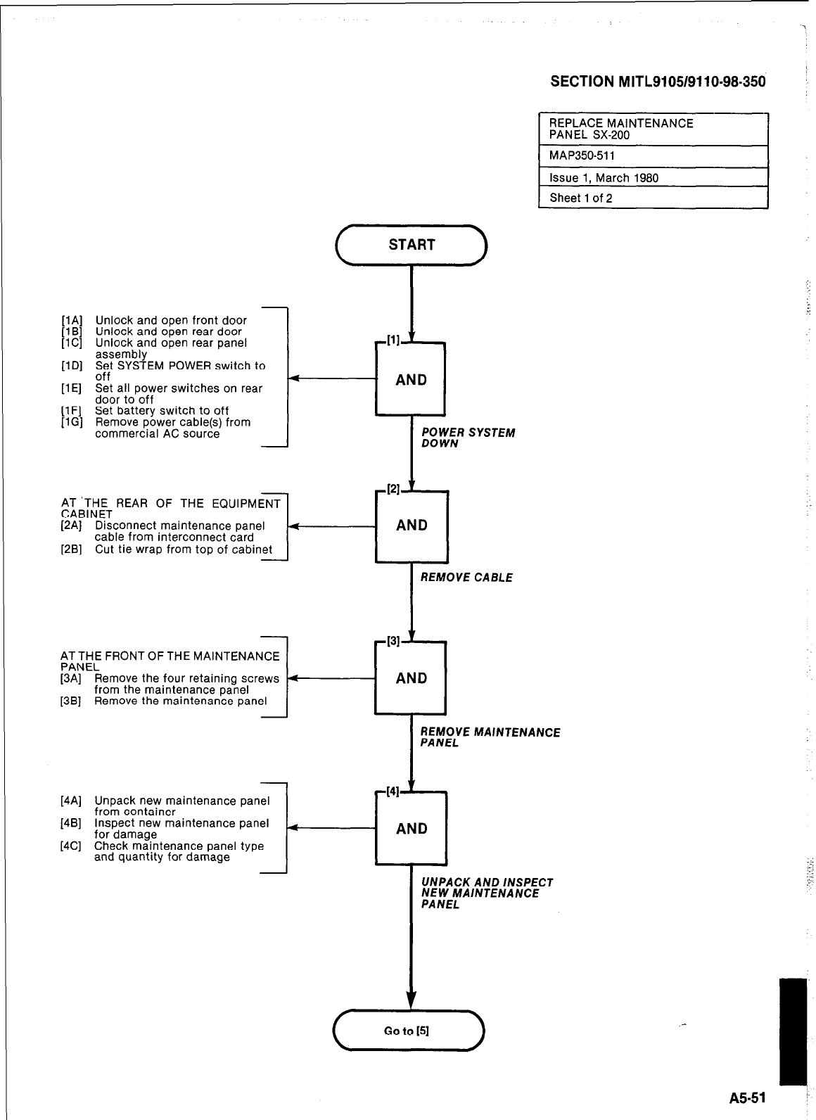
SECTION MITL9105/9110-98-350
-
[lA] Unlock and open front door
[lB]
[iC] Unlock and open rear door
Unlock and open rear panel
assembly
11 Dl
Set SYSTEM POWER switch to
nff
-..
[lE] Set all power switches on rear
door to off
[lF] Set battery switch to off
[lG] Remove power cable(s) from
commercial AC source
$TTHETREAR OF THE EQUIPMENT
[2A] Disconnect maintenance panel
cable from interconnect card
[2B] Cut tie wrap from top of cabinet
AT THE FRONT OF THE MAINTENANCE
PANEL
[3A] Remove the four retaining screws
from the maintenance panel
[3B] Remove the maintenance panel
SYSTEM
REMOVE CABLE
c
REPLACE MAINTENANCE
PANEL SX-200
1
MAP35051 1 I
REMOVE MAINTENANCE
Issue 1, March 1980
Sheet 1 of 2
- AND
7
-I
UNPACK AND /NSPECT
NEW MAINTENANCE
PANEL
[4A] Unpack new maintenance panel
from container
[4B] Inspect new maintenance panel (
for damage
[4C] Check maintenance panel type
and quantity for damage
A5-51 :
i.
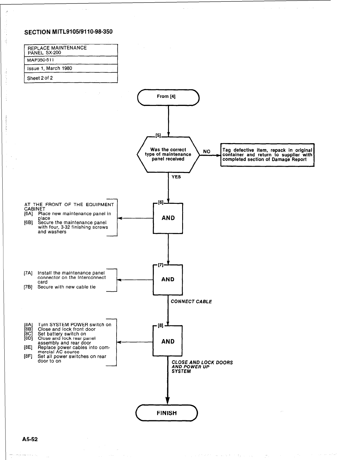
SECTION MITL9105/9110-98.350
REPLACE MAINTENANCE
PAN EL SX-200
1 MAP35051 1 I
Issue 1, March 1980
Sheet 2 Of 2
eTTTETFRONT OF THE EQUIPMENT
1
WI
WI
Place new maintenance panel in
place
Secure the maintenance panel
with four, 3-32 finishing screws
and washers -
From [4j
7
Was the correct
type of maintenance
panel received
Tag defective item, repack in original
container and return to supplier with
completed section of Damage Report
Install the maintenance panel
connector on the Interconnect
card
Secure with new cable tie l-
Turn SYSTEM POWER switch on
Close and lock front door
Set battery switch on
Close and lock rear panel
assembly and rear door
Replace power cables into com-
mercial AC source
Set all power switches on rear
door to on
t
E
L
YES
#I61 ”
AND
.
I
‘171 ’
AND
A
CONNECT CABLE
I
*I81 ’
AND
CLOSE AND LOCK DOORS
~bfV;WER UP
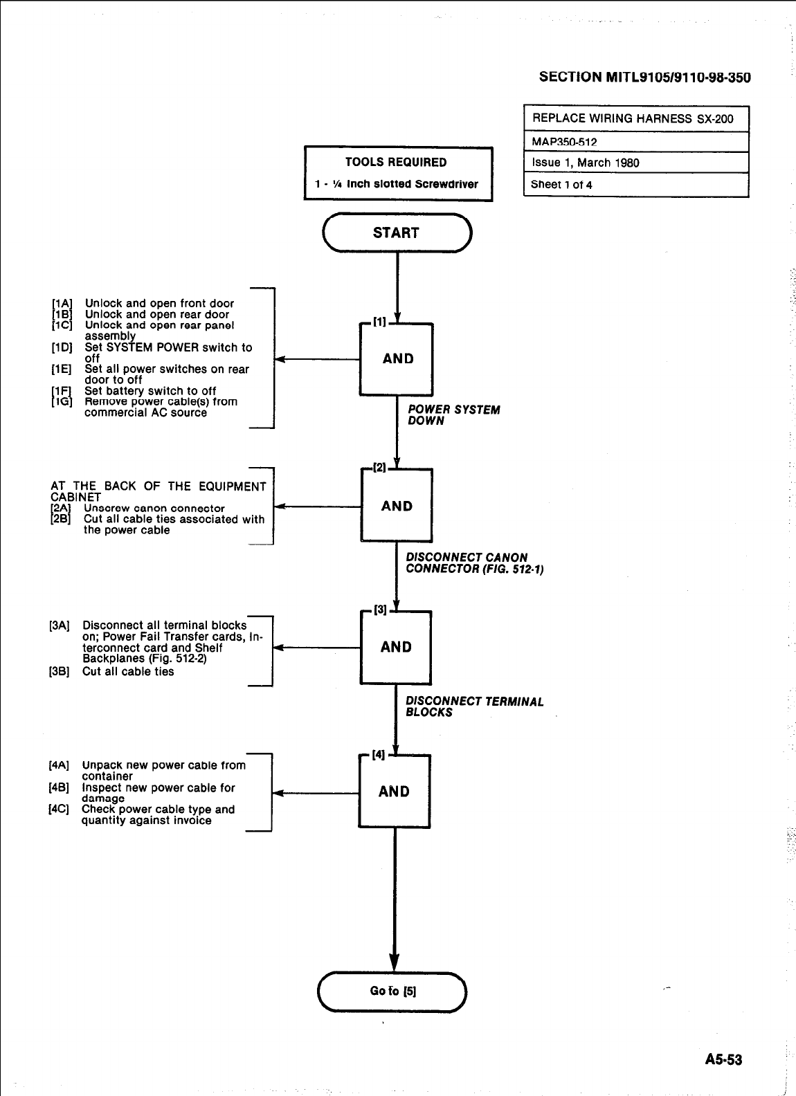
[lA Unlock and open front door
[l B 3 Unlock and open rear door
[lC] Unlock and open rear panel
assembly
[lD] E$t SYSTEM POWER switch to
-. .
[lE] Set all power switches on rear
door to off
Set battery switch to off
Remove power cable(s) from
commercial AC source
$;BT;;TBACK OF THE EQUIPMENT
I
2A] Unscrew canon connector
281 Cut all cable ties associated with
the power cable l-
[34
[3Bl
-t11 ‘I 4
AND
421.
1,
AND
SECTION M ITL9105/9110=98-350
REPLACE WIRING HARNESS SX-200
ml
POWER SYSTEM
DOWN
DISCONNECT CANON
CONNECTOR (F/G. 572-1)
[4A] Unpack new power cable from
container
[4B] Inspect new power cable for
[4C] %r.?!zower cable type and
quantity against invoice l-
I
Sheet 1 of 4 I
Disconnect all terminal blocks
on; Power Fail Transfer cards, In-
terconnect card and Shelf
Backplanes (Fig. 512-2)
Cut all cable ties
TERMINAL
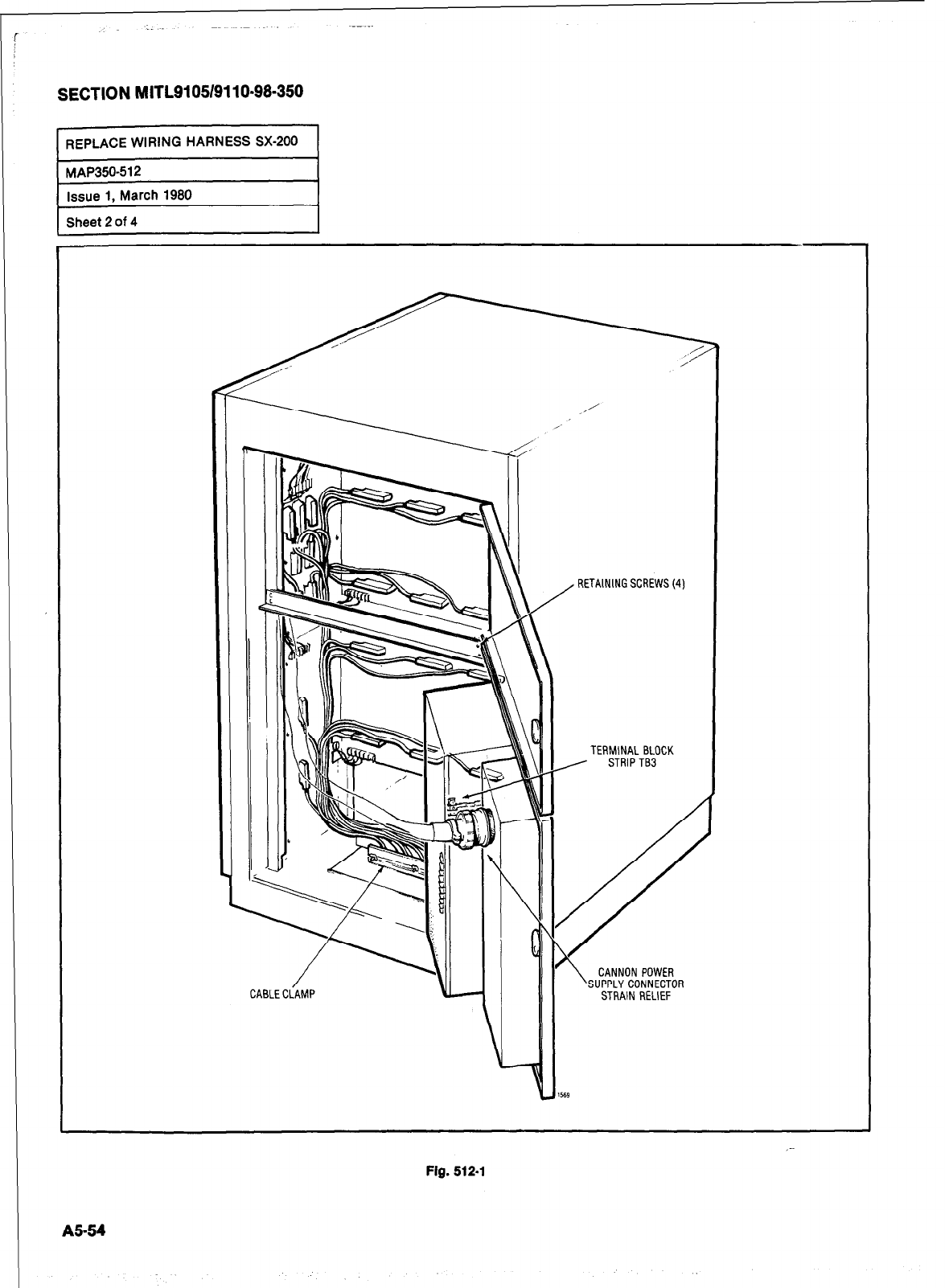
SECTION MITL9105/9110-98-350
RETAINING SCREWS (4)
TERMlNAL BLOCK
CANNON POWER
SUPPLY CONNECTOR
STRAIN RELIEF
_-
Fig. 512.1
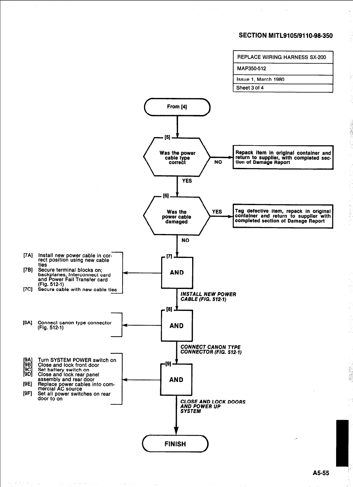
17AJ
[7Rl
[7Cl
m41
WI
WI
install new power cable in car--
rect position using new cable
ties
Secure terminal blocks on;
back lanes, Interconnect card
and B ower Fail Transfer card
(Fig. 512-l)
Secure cable with new cable ties
-
From [4]
i->
SECTION MITL9105/9110-98-350
1 Sheet 3 of 4
1
Repack item In original container and
return to supplier, with completed sec-
tion of Damage Report
YES
Tag defective item, repack in original
container and return to supplier with
completed section of Damage Report
NO
-VI ’
4
AND
.
INSTALL
NEW
POWER
CABLE (FIG. 512.1)
Connect canon type connector
(Fig. 512-1)
Turn SYSTEM POWER switch on
Close and lock front door
Set battery switch on
Close and lock rear panel
assembly and rear door
Replace power cables into com-
mercial AC source
Set all power switches on rear
door to on
-l-
CONNECT CANON TYPE
CONNECTOR (FIG. 572-1)
CLOSE AND LOCK DOORS
,-
I
AS-55 ”
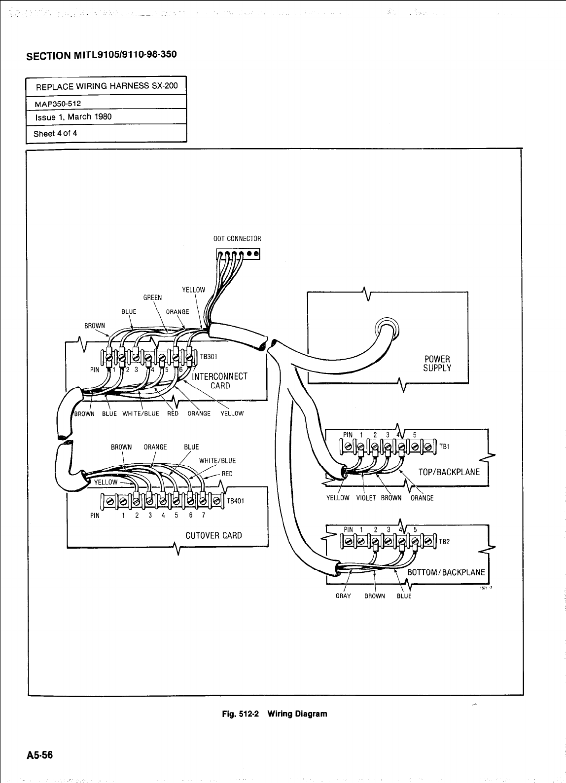
-.- _. :
SECTION MITh9105/9110-98-350
REPLACE WIRING HARNESS SX-200
MAP350-512
Issue 1. March 1980
Sheet 4 of 4
OOTCONNECTOR
BROWN BLUE WHITE/BLUE ORANGE YELLOW
V
f4
BROWN ORANGE BLUE
CUTOVER CARD
A I
V
GRAY BROWN BLUE
A5-56
Fig. 512-2 Wiring Diagram
.-
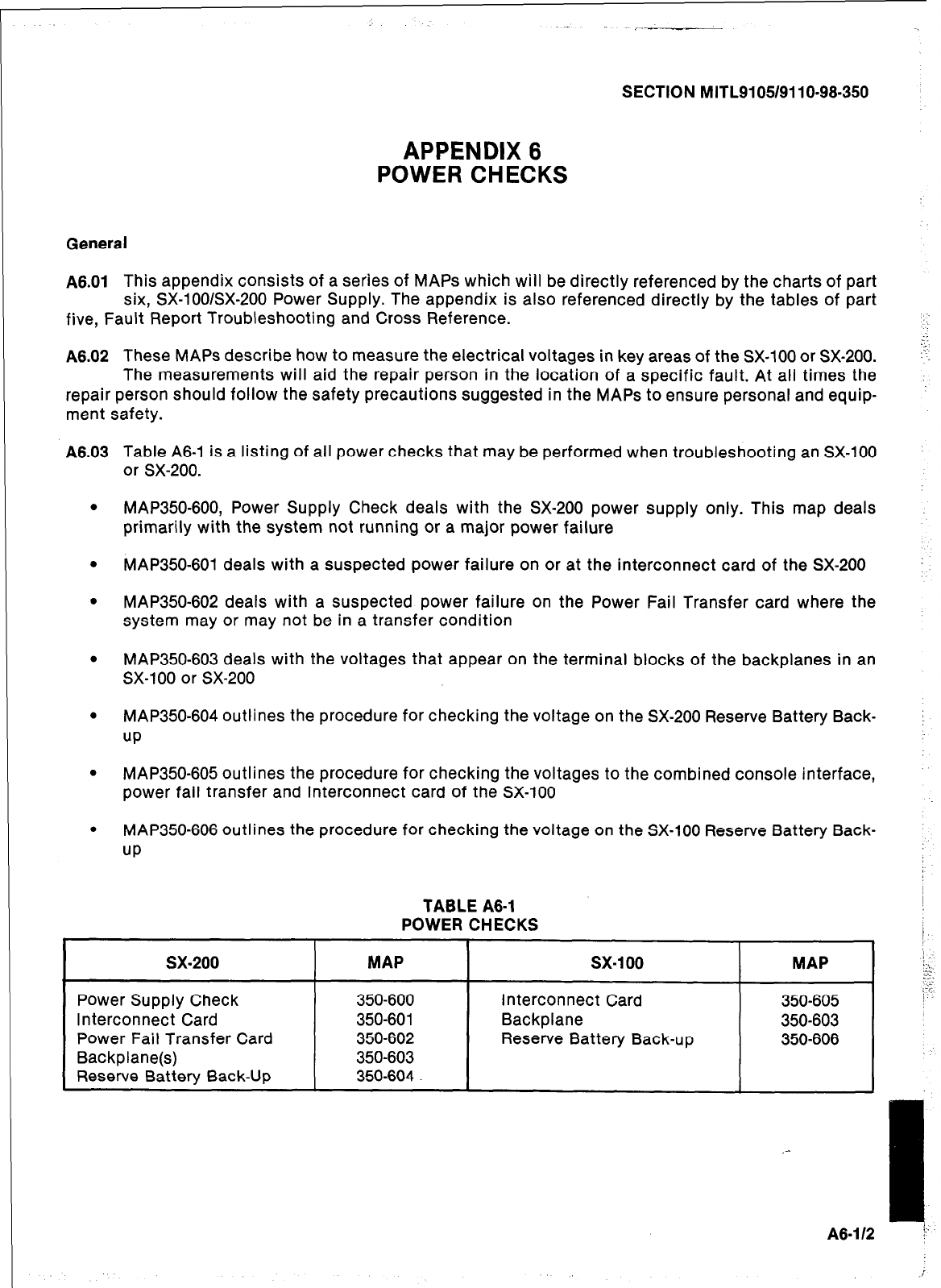
SECTION MITL9105/9110-98-350
APPENDIX 6
POWER CHECKS
General
A8.01
This appendix consists of a series of MAPS which will be directly referenced by the charts of part
six, SX-lOO/SX-200 Power Supply. The appendix is also referenced directly by the tables of part
five, Fault Report Troubleshooting and Cross Reference.
A6.02
These MAPS describe how to measure the electrical voltages in key areas of the SX-100 or SX-200.
The measurements will aid the repair person in the location of a specific fault. At all times the
repair person should follow the safety precautions suggested in the MAPS to ensure personal and equip-
ment safety.
A6.03
Table A6-1 is a listing of all power checks that may be performed when troubleshooting an SX-100
or SX-200.
.
MAP350-600, Power Supply Check deals with the SX-200 power supply only. This map deals
primarily with the system not running or a major power failure
.
MAP350-601 deals with a suspected power failure on or at the interconnect card of the SX-200
.
MAP350-602 deals with a suspected power failure on the Power Fail Transfer card where the
system may or may not be in a transfer condition
.
MAP350-603 deals with the voltages that appear on the terminal blocks of the backplanes in an
SX-100 or SX-200
.
MAP350-604 outlines the procedure for checking the voltage on the SX-200 Reserve Battery Back-
up
.
MAP350-605 outlines the procedure for checking the voltages to the combined console interface,
power fail transfer and interconnect card of the SX-100
.
MAP350-606 outlines the procedure for checking the voltage on the SX-100 Reserve Battery Back-
up
TABLE A6-1
POWER CHECKS
sx-200 I MAP
Power Supply Check
350-600
Interconnect Card 350-601
Power Fail Transfer Card
350-602
Backplane(s)
350-603
Reserve Batterv Back-Up
350-604
sx-100
MAP I
Interconnect Card
350-605
Backplane
350-603
Reserve Battery Back-up
350-606
A8-1 I2
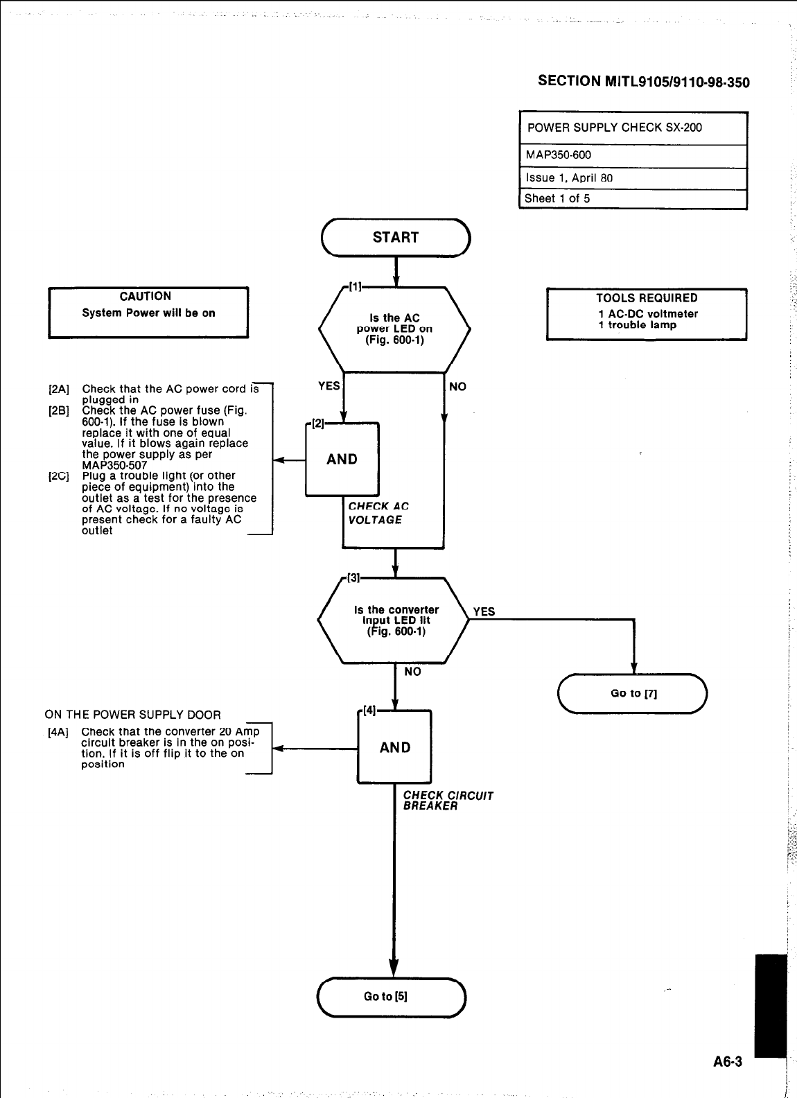
SECTION MITL9105/9110-98-350
I
CAUTION
System Power will be on I
[2A] Check that the AC power cord i7
plugged in
[2B] Check the AC power fuse (Fig.
600-l). If the fuse is blown
replace it with one of equal
value. If it blows again replace
the power supply as per
MAP350-507
[2C] Plug a trouble light (or other
piece of eauipment) into the
butlet as a’t&st for ihe presence
of AC voltage. If no voltage is
present check for a faulty AC
outlet -
ON THE POWER SUPPLY DOOR
-
START
Is the AC
power LED on
(Fig. 600-l)
YES I NO
POWER SUPPLY CHECK SX-200
MAP350-600
Issue 1, April 80
Sheet 1 of 5
[4A] Check that the converter 20 Amp
circuit breaker is in the on posi-
tion. If it is off flip it to the on
AND
position
CHECK C/RCU/T
BREAKER
:
,-
A8-3 I
Is the converter
NO
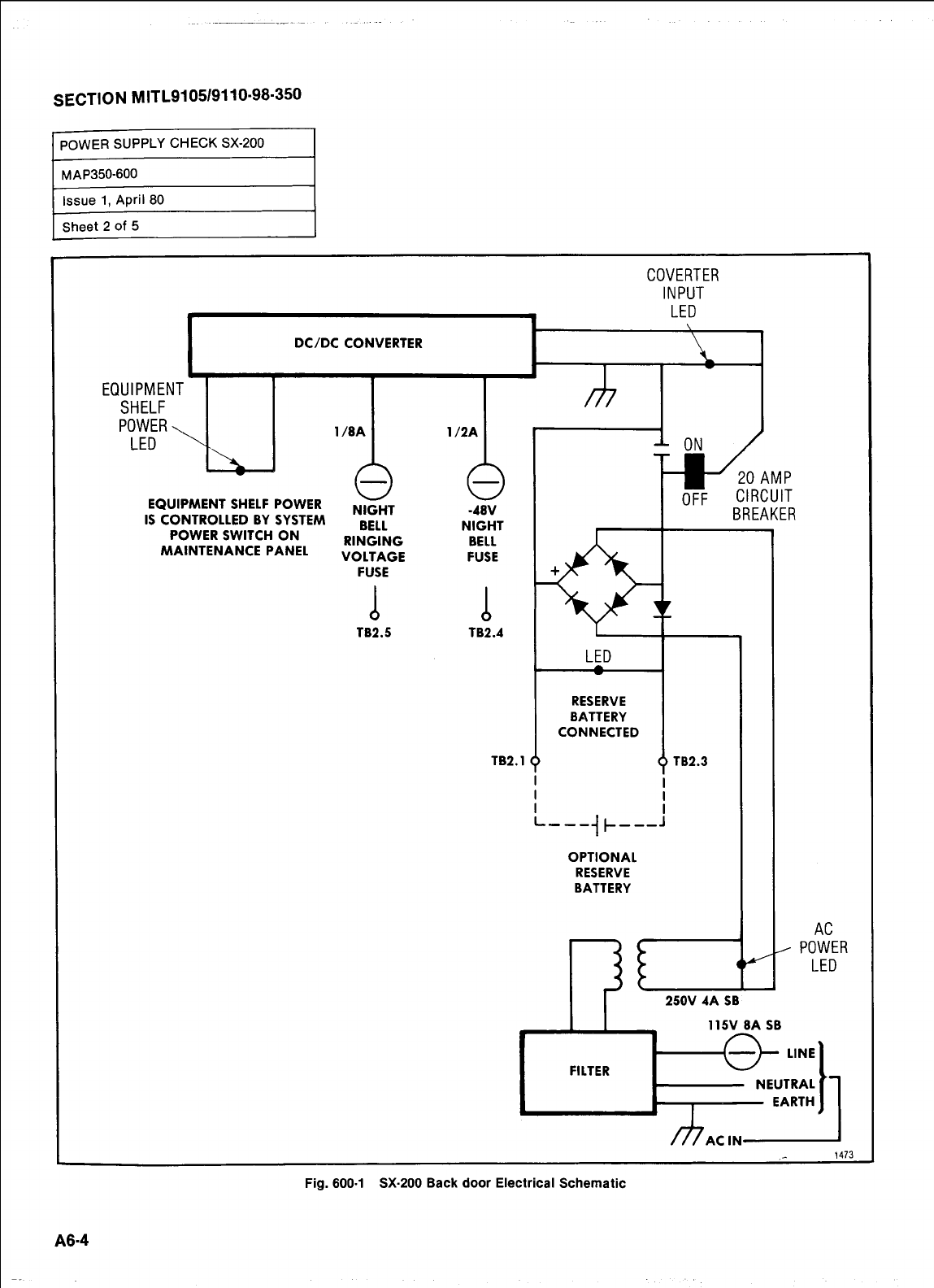
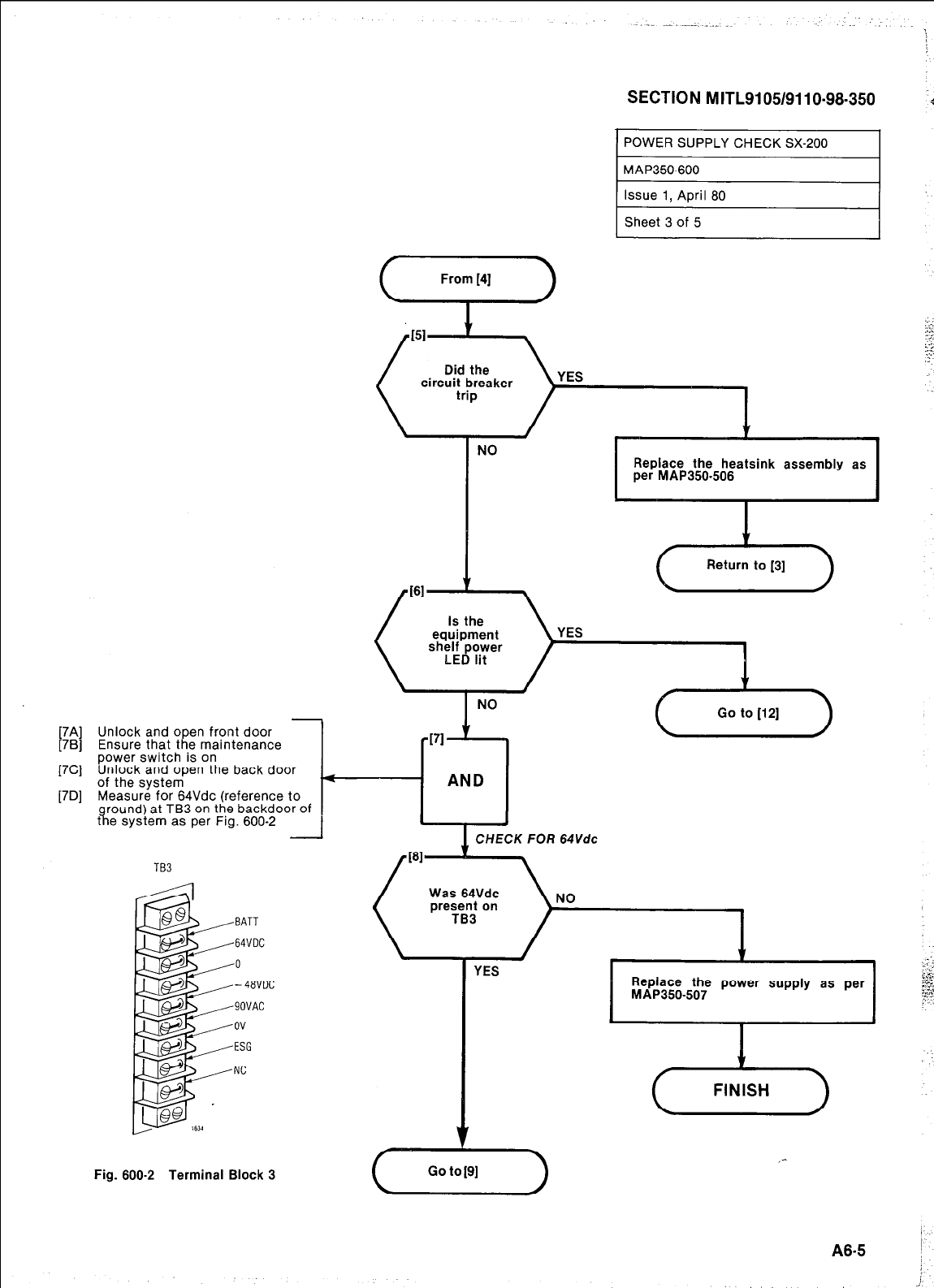
[7Cl
[7Dl
YES
NO
1
.
Replace the heatsink assembly as
per MAP350.506
/
El -
TB3
(--Lk-)
SECTION MITLSI 05/9110.98-350
1
Unlock and open front door
Ensure that the maintenance
power switch is on
Unlock and open the back door
of the system
Measure for 64Vdc (reference to
round) at TB3 on the backdoor of
8,
t e system as per Fig. 600-2 I J
-BATT
-64VDC
-0
--48VDC
-90VAC
.ov
-ESG
-NC
CHECK FOR 64Vdc
NO
1
YES Replace the power supply as per
MAP350-507
I
(hi--)
,-
Fig. 600-2 Terminal Block 3 Go to [9]
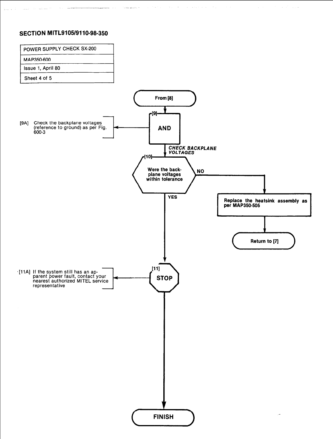
SECTION MITL9105/9110~98-350
r
POWER SUPPLY CHECK SX-200 I
r
MAP350-600
PA1
t11Al
Check the backplane voltages.
@&ence to ground) as per Fig. <
-
AND
YES Replace the heatsink assembly as
per MAP350-505
If the system still has an ap-
parent power fault, contact your
nearest authorized MITEL service
representative
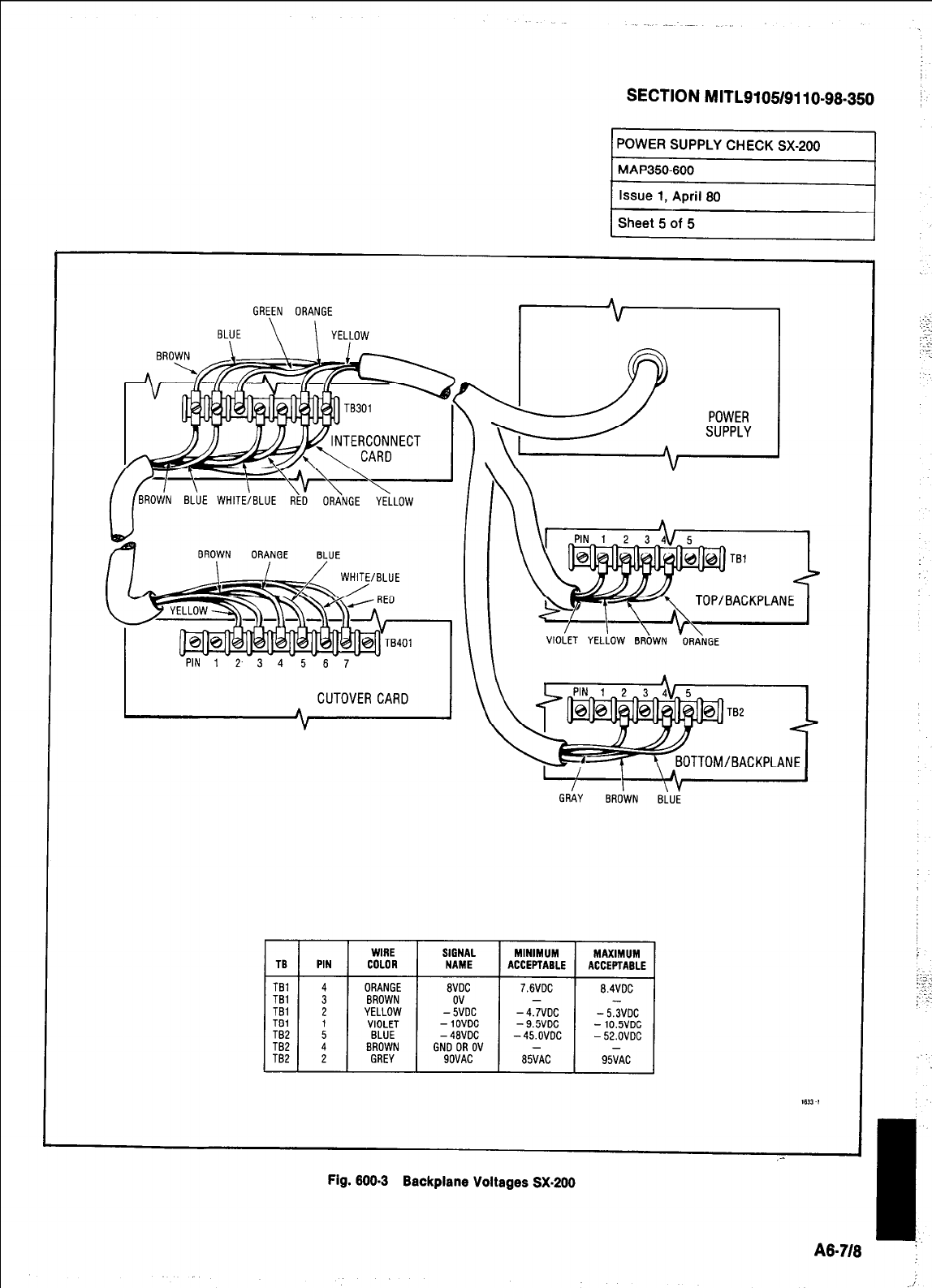
SECTION MITL9105/9110-98-350
GREEN ORANGE A
BLUE
\ \ I YELLOW
1
POWER
SUPPLY
VIOLET YELLOW BROWN ORANGE
GRkY EiRoiYN BLii
WIRE SIGNAL MINIMUM MAXIMUM
TG PIN COLOR NAME ACCEPTABLE ACCEPTABLE
TBI ORANGE avoc 7.6VDC B.4VDC
TBI l BROWN -
TBI 2 YELLOW -Y/DC -4.7VDC - 5iVDC
TBI
TB2 : VIOLET -1ovrlc -9.5VDC -10.5VDC
BLUE -48VDC -45.OVDC -52.OVDC
TB2 4 BROWN GNO OR OV
TB2 2 GREY SOVAC 85;AC 95;AC
1631-1
,- I
I
;.
A8-?I8
Fig. 600-3 Backplane Voltages SX-200
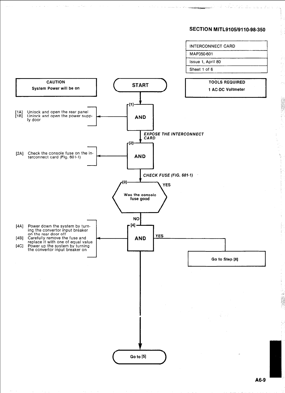
SECTION MITL91051911 O-98-350
I
INTERCONNECT CARD I
START
mill
.:.:’
. .
,t.‘ :
_
._
[lA] Unlock and open the rear panel :
[lB] $r~~~co; and open the power supp- (
AND
EXPOSE THE /NTERCONNECT
[2A] Check the console fuse on the in-
terconnect card (Fig. 601-l)
AND
I
1 CHECK FUSE (FIG. 601-7)
Was the console
I
I
Go to Step [8]
[4A] Power down the system by turn-
ing the convertor input breaker
on the rear door off
[4B] Carefully remove the fuse and 4
replace it with one of equal value
[4C] Power up the system by turning
the convertor input breaker on
Ll
Go to [51
I
86-9
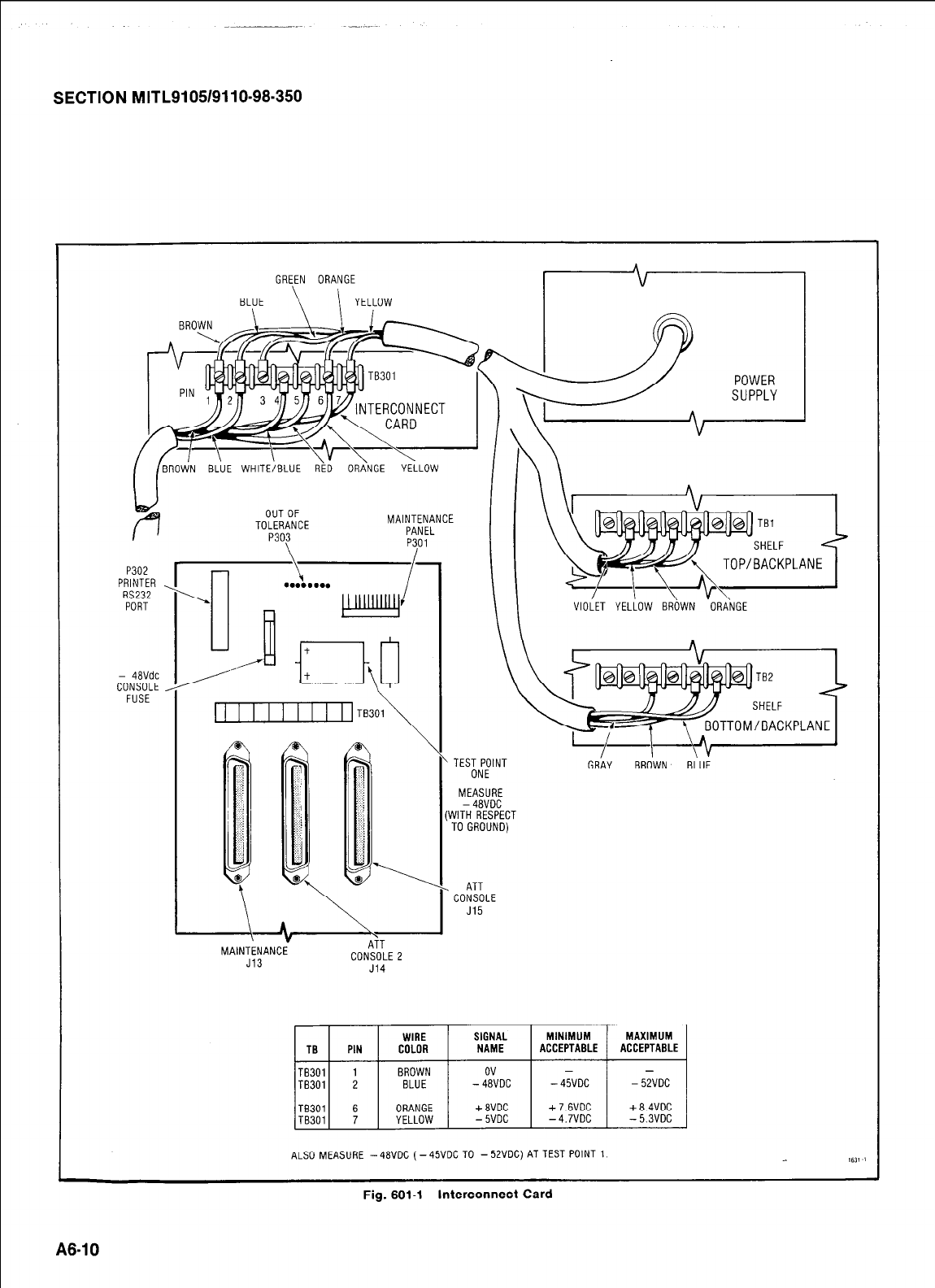
SECTION MITL9105/9110-98.350
GREEN ORANGE
BLUE \ \ YELLOW / I
LUE WHITE/BL NGE YELLOW
P302
PRINTER .
RS232
PORT
- 48Vdc
CONSOLE
FUSE
OUTOF
TOLERANCE
P30\3
MAINTENANCE
PANEL
p3/01
1,
VIOLET YELLOW BROWN ORANGE
GRAY BROWN BLUE
MEASURE
-48VOC
(WITH RESPECT
TOGROUND)
M
AINTENANCE
J13 CONSOLE 2
J14
ALSO MEASURE -48VDC (-45VDC TO -5ZVDC)AT TEST POINT 1. 1611 !
Fig. 601-l Interconnect Card
A6-10
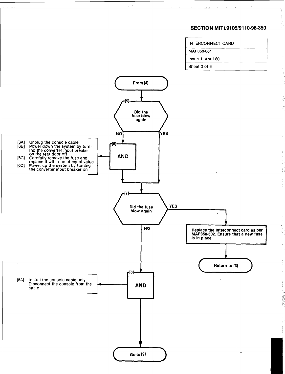
[6A] Unplug the console cable
[6B] Power down the system by turn-
ing the converter input breaker
on the rear door off
[6C] Carefully remove the fuse and
- AND
[6D] replace rt with one of equal value
Power up the system by turning
the converter input breaker on I
1
7
NO
I
Replace the interconnect card as per
MAP350-502. Ensure that a new fuse
is in place
SECTION MITL9105/9110-98-350
INTERCdNNECT CARD I
1 MAP350-601 I
Issue 1, April 80
Sheet 3 of 6
[8A] Install the console cable only.
Disconnect the console from the
cable
I
I
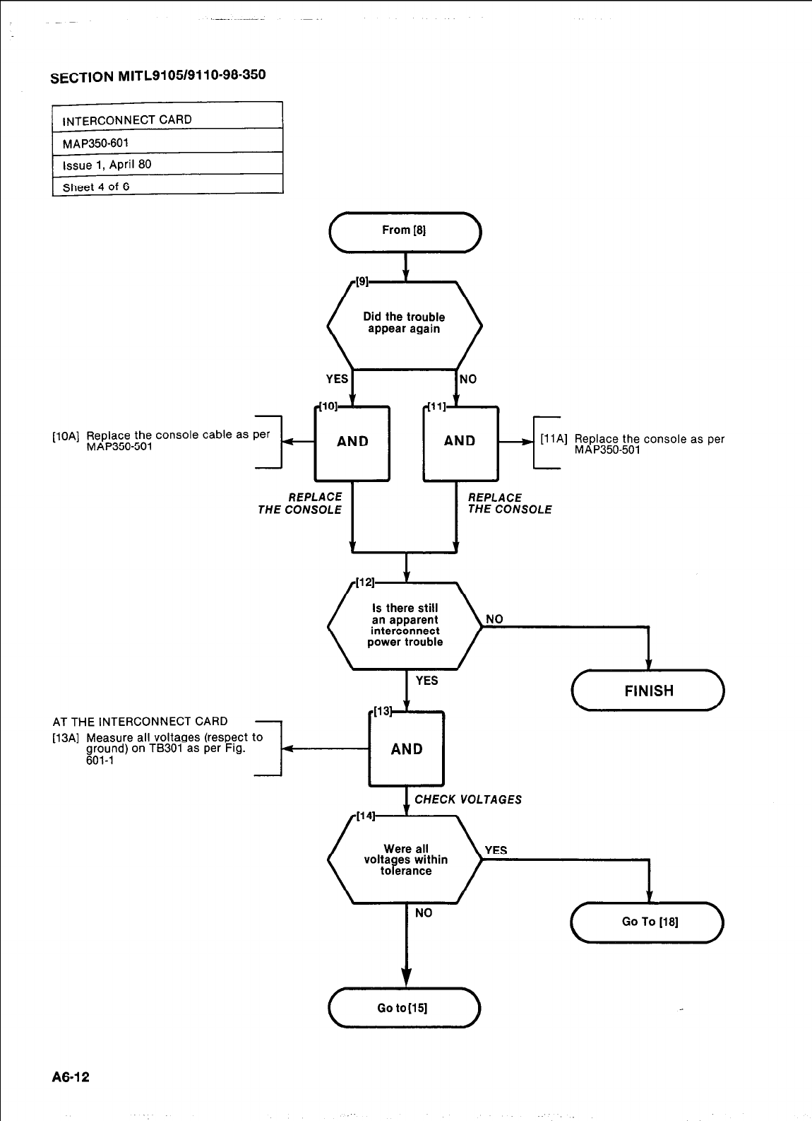
SECTION MITL9105/9110-98-350
[lOA] Replace the console cable as per
MAP350-501 -I-
THE
From IS]
+
Did the trouble
- [llA] Replace the console as per
MAP350-501
REPLACE
THE CONSOLE
T
Is there still
interconnect NO
YES
AT THE INTERCONNECT CARD
[13A] Measure all voltages (respect to
iroy,nd) on TB301 as per Fig.
4
1
4131 1r
AND
CHECK VOLTAGES
YES
NO
A6.12
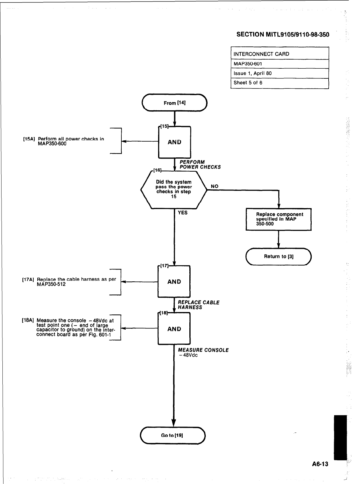
SECTION MITL9105/9110-98.350 :
[15A] Perform all power checks in
MAPSO-600
[17A] Replace the cable harness as per
MAP350-512
[16A] Measure the console -48Vdc at [18A] Measure the console -48Vdc at
test point one (- end of large test point one (- end of large
capacttor to ground) on the mter- capacttor to ground) on the mter-
connect board as per Fig. 601-l connect board as per Fig. 601-l
REPLACE CABLE
MEASURE CONSOLE
- 48Vdc
I
INTERCONNECT CAR
I
MAP350-601 I
I
A8.4 3
j.-:
i
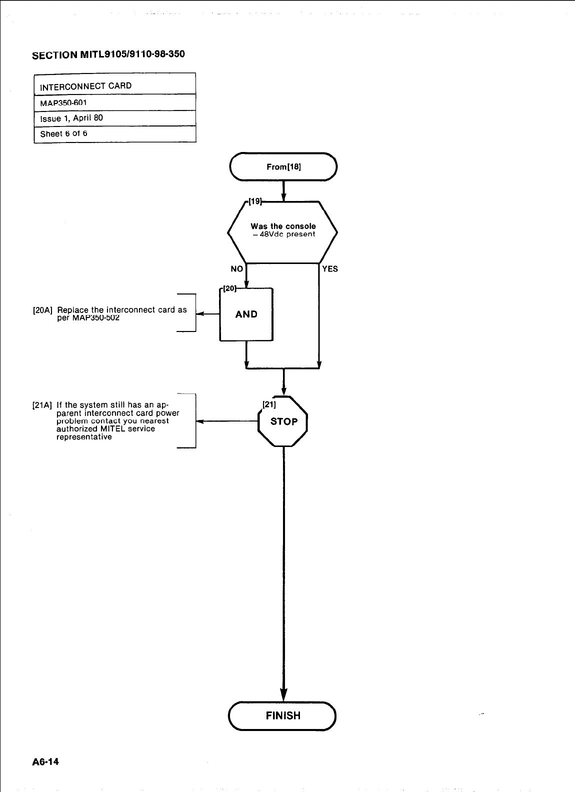
SECTION MITL9105/9110-98.350
Sheet 6 of 6
[20A] Replace the interconnect card as
per MAP350-502
-t-
[21A] If the system still has an ap-
1
pare!t interconnect card power
problem contact you nearest
authorized MITEL service
representative
Was the console
- 48Vdc present
YES
4
,-
A6-14
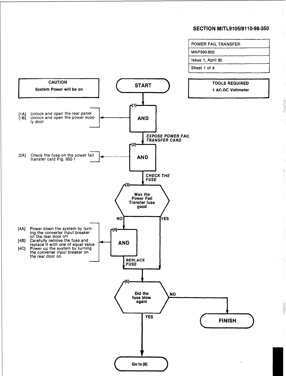
r
CAUTION
System Power will be on
[IA] Unlock and open the rear panel
[1B] rfo;7 and open the power supp-
[2A] Check the fuse on the power fail
transfer card Fig. 602-l
[4A] Power down the system by turn-
ing the converter input breaker
on the rear door off
[4B] Carefully remove the fuse and
[4C] replace It with one of equal value
Power up the system by turning
the converter input breaker on
the rear door on
SECTION MITL9105/9110-98-350
I
TOOLS REQUIRED
1 AC-DC Voltmeter I
EXPOSE POWER FAIL
TRANSFER CARD
Was the
Power Fail
Transfer fuse
/
‘ES
NO
YES
f-i
Go to (61
I
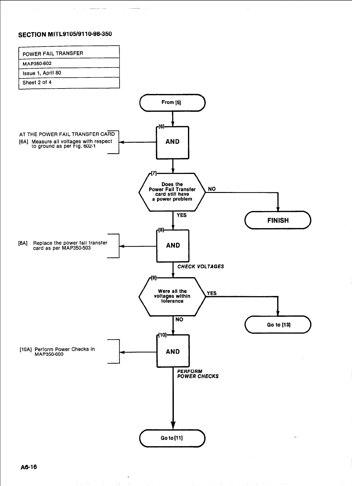
SECTION MITL9105/9110-98.350
AT THE POWER FAIL TRANSFER CARD
[6A] Measure all voltages with respect
to ground as per Fig. 602-l It-
WI
161
+ 1
AND
a power problem
YES
Replace the power fail transfer
card as per MAP350-503 r
AND
t 4
CHECK VOLTAGES
Were all the
volta B es within
to erance
[lOA] Perform Power Checks in
MAP350-600 w
PERFORM
POWER CHECKS
c5
Go to [X3]
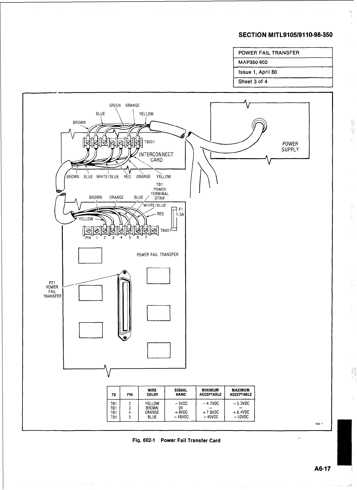
SECTION MITL9105/9110-98-350
Sheet 3 of 4
GREEN ORANGE
BLUE \ \ YELLOW
[BROtiN BLUE WHITE/BLUE RiO ORA‘NGE YELLOW I
TBl
/
POWER FAILTRANSFER
WIRE SIGNAL MINIMUM MAXIMUM
TG PIN COLOR NAME ACCEPTABLE ACCEPTABLE
TBl 2 YELLOW -5VDC -4.7VDC -5.3VDC
Fig. 602-l Power Fail Transfer Card
A8-1 i
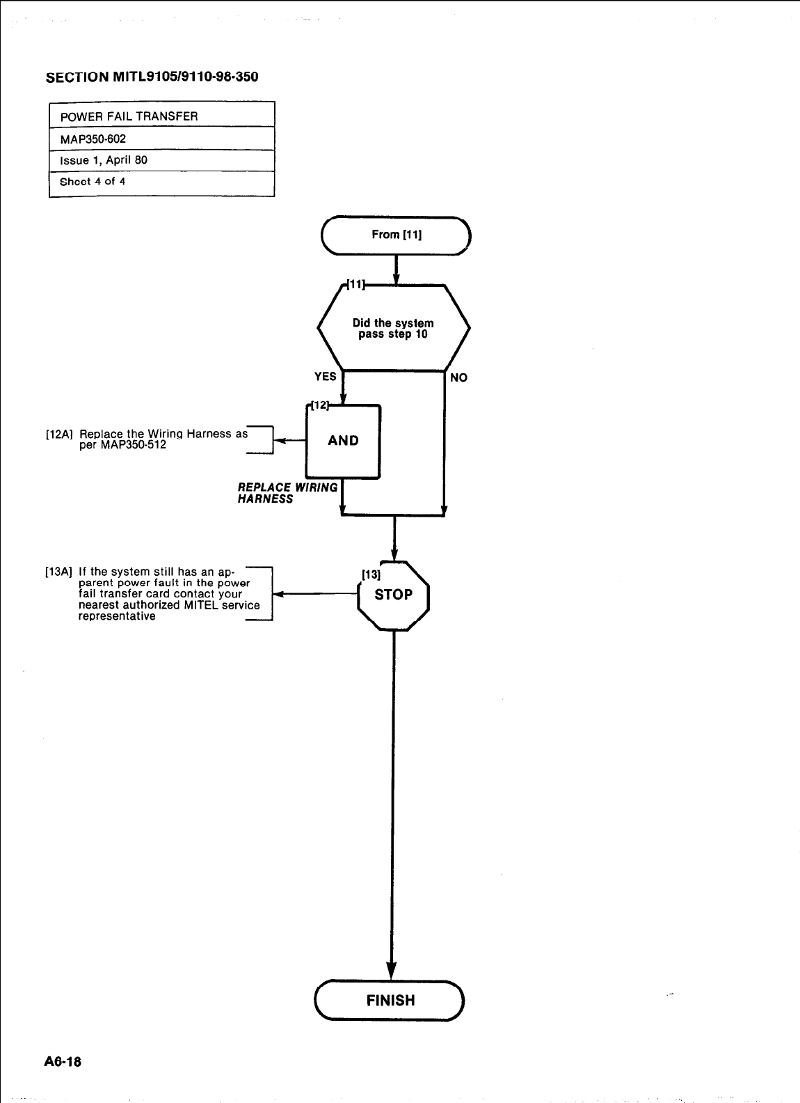
SECTION MITL9105/9110-98.350
POWER FAIL TRANSFER
MAP350-602
Eue 1, April 80
1
r
Sheet 4 of 4
REPLACE WIRING
HARNESS
[12A] Replace the Wiring Harness as
per MAP350-512 I-
P3Al
If the system still has an ap-
parent power fault in the power
fail transfer card contact your
nearest authorized MITEL service
representative
NO
.-
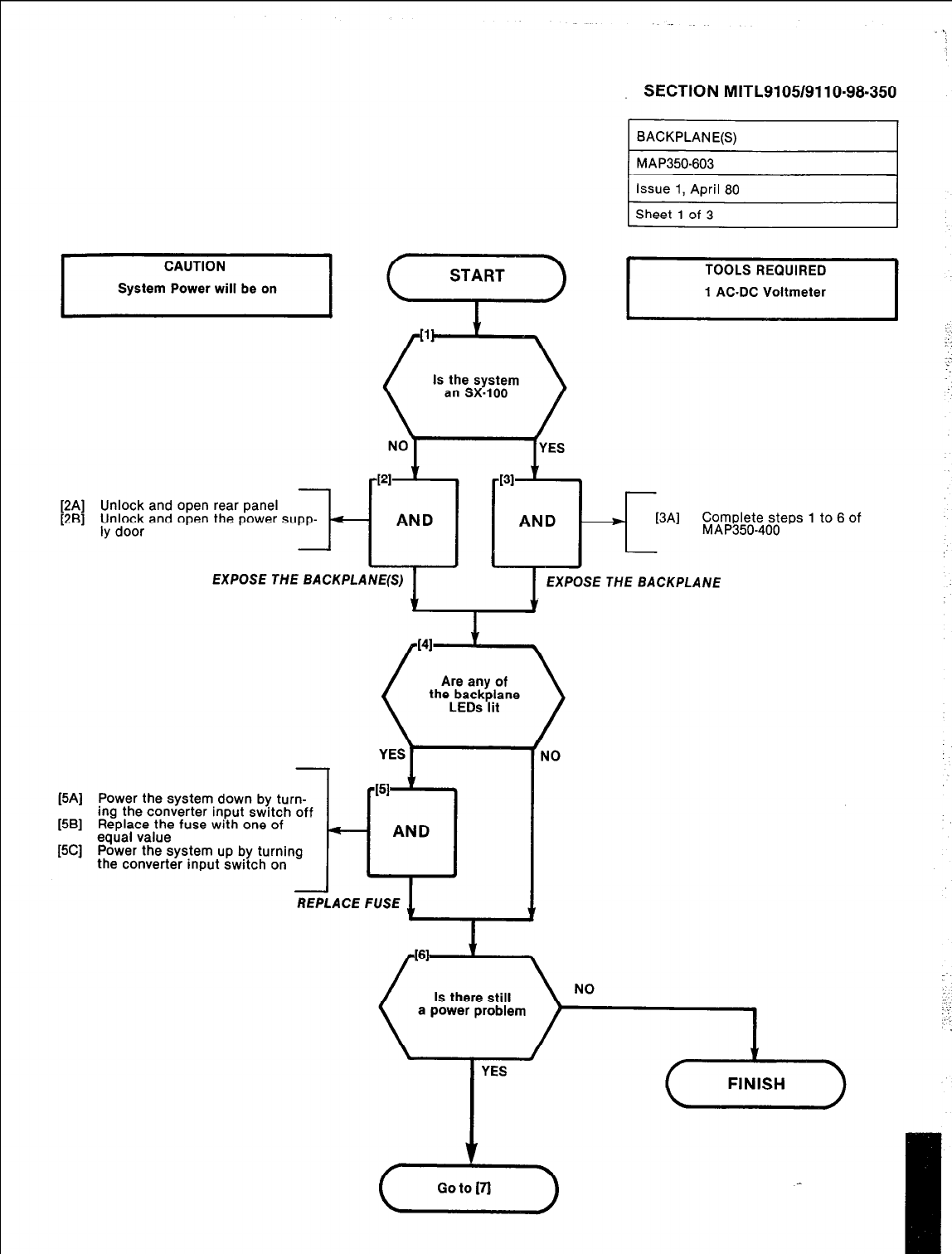
-
[2A] Unlock and open rear panel
[2B] pto;F and open the power supp-
I--
SECTION MITL9105/9110-98-350
BACKPLANE(S)
MAP350-603
1 Issue 1, April 80
Sheet 1 of 3
I
TOOLS REQUIRED
1 AC-DC Voltmeter
I
- AND AND 3
[3Al
Complete steps 1 to 6 of
MAP350-400
EXPOSE THE BACKPLANE(S) EXPOSE THE BACKPLANE
I
(5A] Power the system down by turn-
[5B] ing the converter input switch off
Replace the fuse with one of
[5C] equal value
Power the system up by turning
the converter input switch on
NO
YES
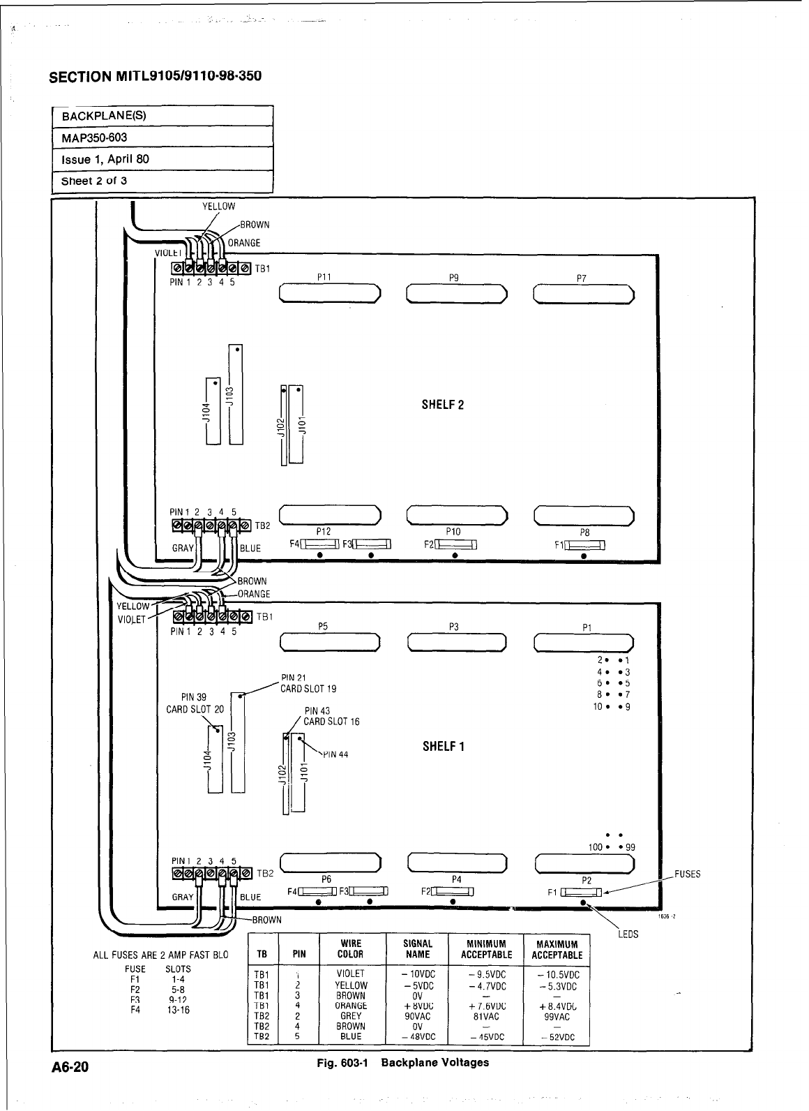
SECTION MITL9105/9110~98-350
.
r
B
5
L
YELLOW
PIN1 2 3 4 5 Pll
SHELF2
L
12345
TB2 + c (
PlO P8
E F41Fm F21 VEZXI
PIN39 p
CARDSLOT 20 1
?a
J
5
B
5
1
PIN 21
/CARD~LOT~~
SHELF1
PIN1 2 3 4 5
c /-BROWN \
. I CrlP
ALL FUSES ARE 2AMP FAST BLO
FUSE SLOTS
Fi 1-4
F2
5-8
F3 9-12
F4 13-16
1 I I I I
TBl 1 , 1 VIOLET 1 -1OVOC 1 -9.5VOC 1 -lO.SVDC
-FUSES
TBl 4
TB2 2
TB2 i TB2
ORANGE +aVDC
GREY SOVAC
BROWN ov
BLUE -48VDC
+7.6VDC +8.4VOL
81 VAC 99VAC
- -
-45VDC -52VDC
A8-20
Fig. 603-l Backplane Voltages
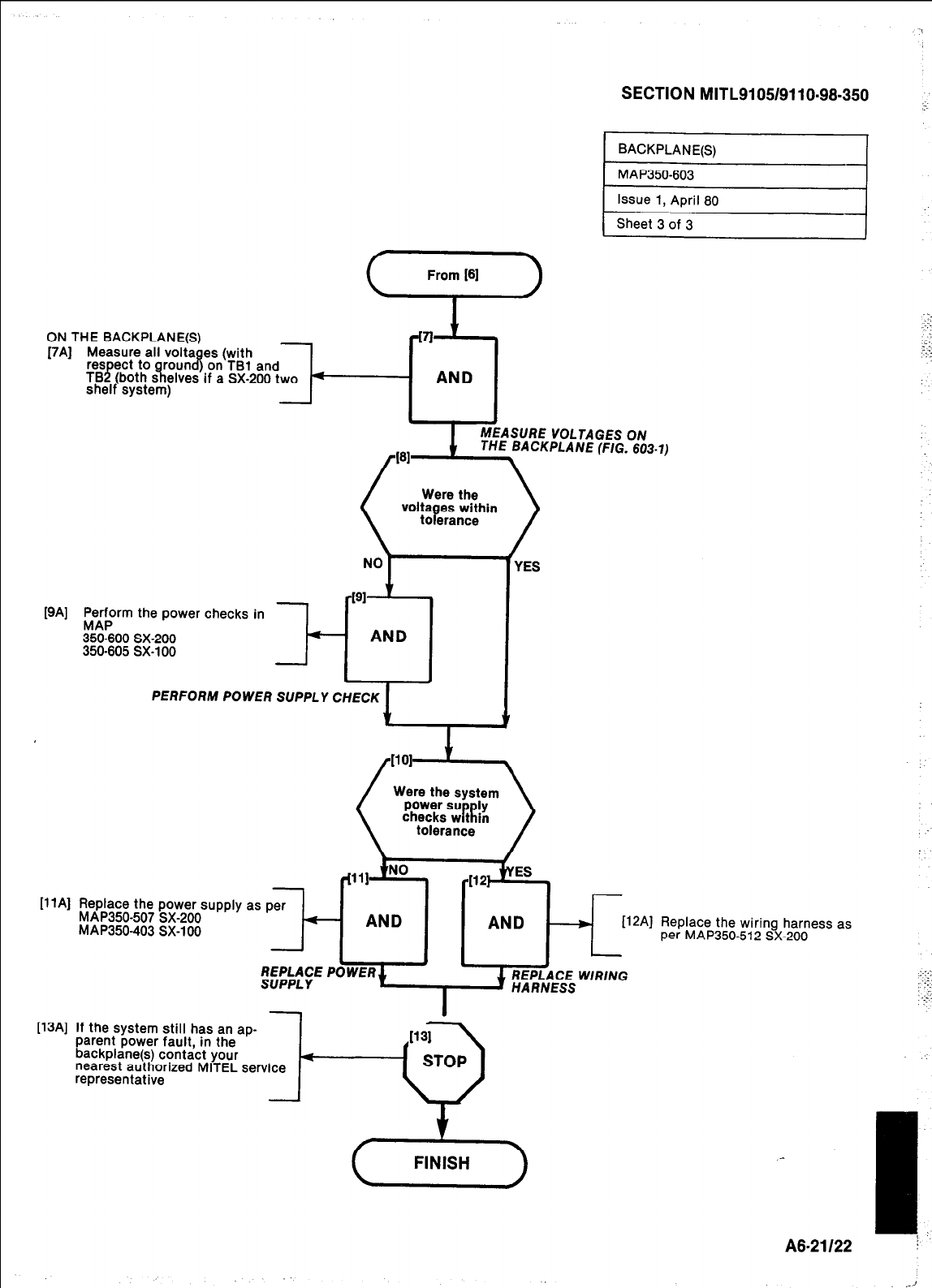
[9A] r$rrn the power checks in
350-600 SX-200
350-605 SX-100 I-
PlAl
Replace the power supply
MAP350-507 SX-200
MAP350-403 SX-100
SECTION MITL9105/9110-98-350
::.
PERFORM POWER SUPPLY CHECK 1
as
r[l l]J=
per
- AND AND 4 WA1
I
[13A] If the system still has an ap-
parent power fault, in the
backplane(s) contact your 4-
nearest authorized MITEL service
representative
Replace the wiring harness as
per MAP350-512 SX-200
A8-21122
1..
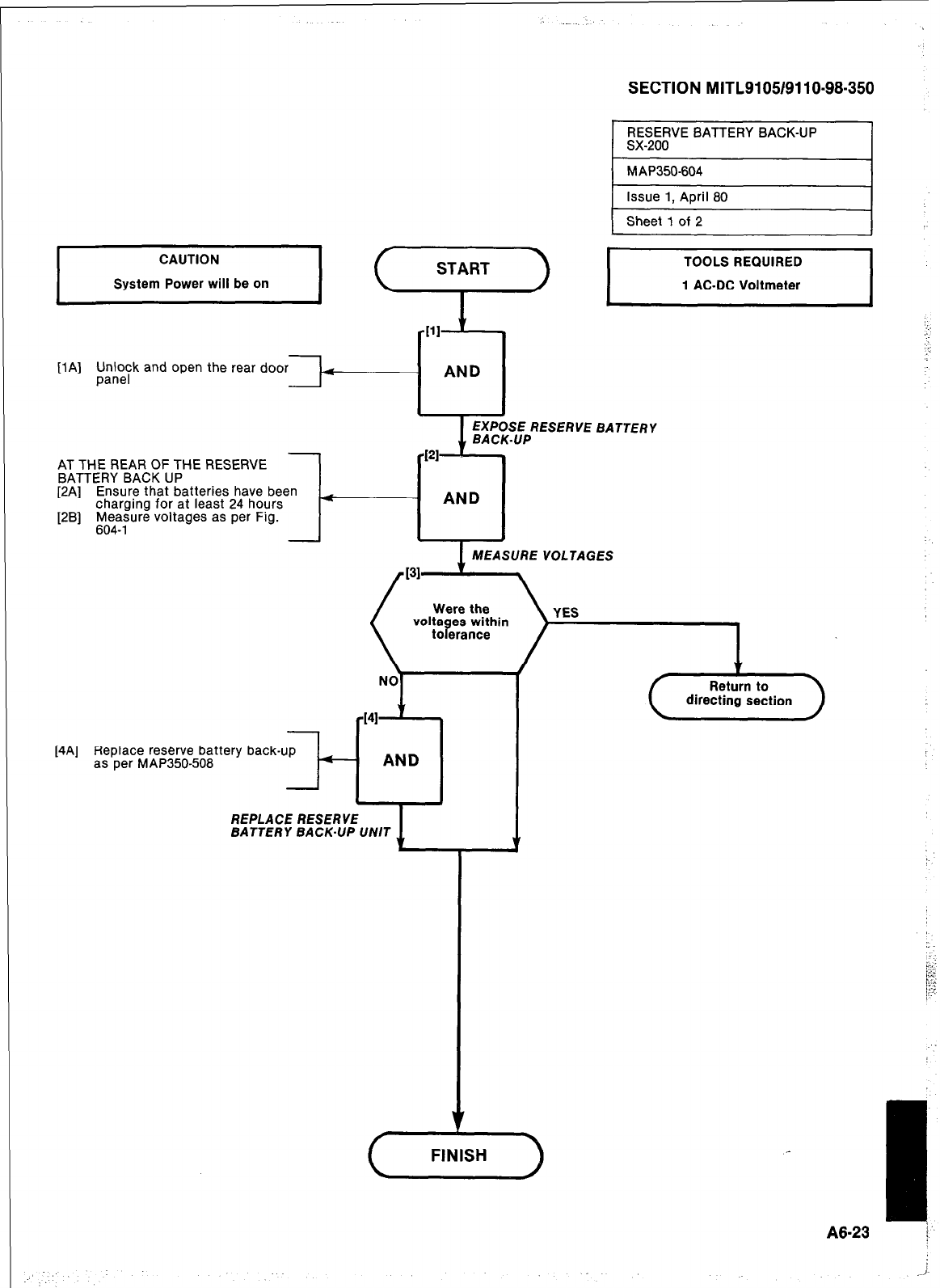
SECTION MITL9105/9110-98-350
[lA] lJJ:eyk and open the rear door
AT THE RE AR OF THE RESERVE
BATTERY BACK UP
[2A] Ensure that batteries have been
charaina for at least 24 hours
[2B] r14twe voltages as per Fig.
I
111
I
RESERVE BATTERY BACK-UP
sx-200 I
MAP350-604
Issue 1, April 80
I
Sheet 1 of 2
1
I
TOOLS REQUIRED
1 AC-DC Voltmeter I
::.‘
:
BATTERY
MEASURE VOLTAGES
directing section
[4A] Replace reserve battery back-up
as per MAP350-508
REPLACE RESERVE
BATTERY BACK-UP UN/T
A8-23 /.
: : i
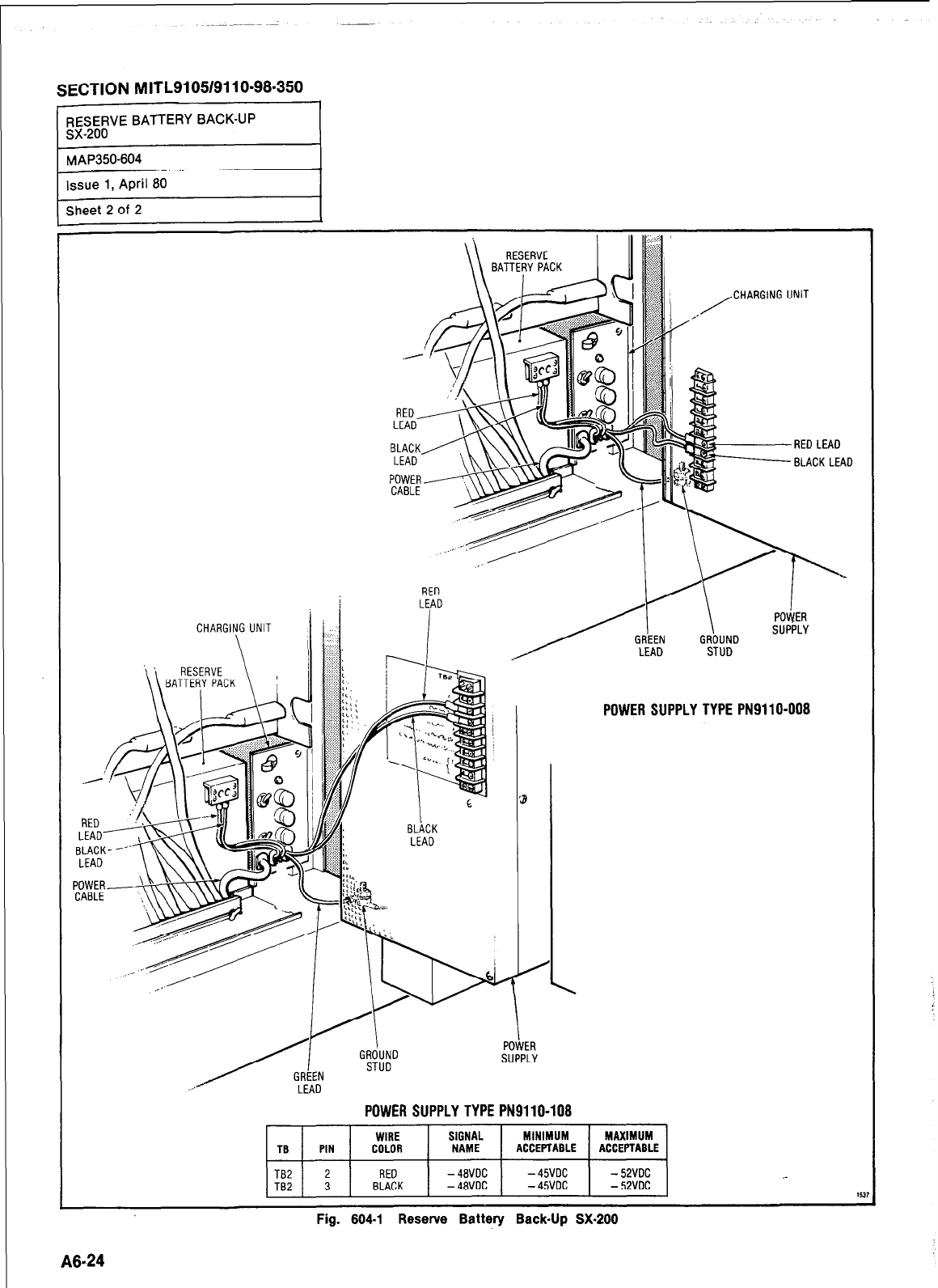
SECTION M ITL9105/911 O-98-350
-
RESERVE BATTERY BACK-UP
sx-200
MAP350-604
Issue 1, April 80
Sheet 2 of 2
RED
LEN
POWER SUPPLY TYPE PN9110-008
POWER SUPPLY TYPE PN9110-108
TB PIN
TB2 2
TB2 3
WIRE SIGNAL MINIMUM MAXIMUM
COLOR NAME ACCEPTABLE ACCEPTABLE
RED -4BVDC -45VDC -52VDC
BLACK -48VDC -45VDC -52VDC II
Fig. 604-l Resenre Battery Back-Up SX-200
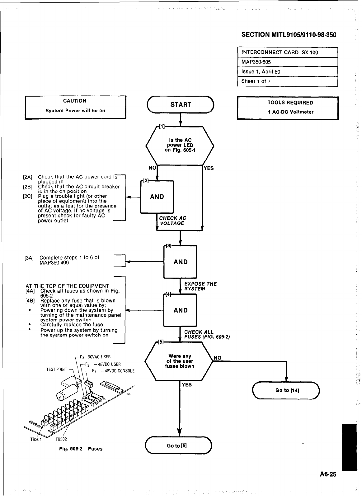
K-41
[.=I
PC1
Check that the AC power cord ifl
plugged in
Check that the AC circuit breaker
is in the on position
Plug a trouble light (or other
piece of equipment) into the
outlet as a test for the presence
of AC voltage. If no voltage is
present check for faulty AC
power outlet
[3Al
Complete steps 1 to 6 of
MAP350-400
-
THE TOP OF THE EQUIPMENT
] C$e;k all fuses as shown In Fig.
[4B] Replace any fuse that is blown
with one of equal value by;
. Powering down the system by
turning of the maintenance panel
system power switch
. Carefully replace the fuse
. Power up the system by turning
the system power switch on
Is the AC
power LED
on Fig. 605-l
SECTION MITL9105/9110-98-350
INTERCONNECT CARD SX-100
MAP350-605
F3 SOVAC USER
YFZ -48VDC USER
TESTPo'NT 7 \\ rF1 -48VOC CONSOLE
Issue 1, April 80
Sheet 1 of 7
YES
1
EXPOSE THE
SYSTEM
41
--El
AND
Fig. 605-2 Fuses
fuses blown
;
; !
A8-25
1
-1
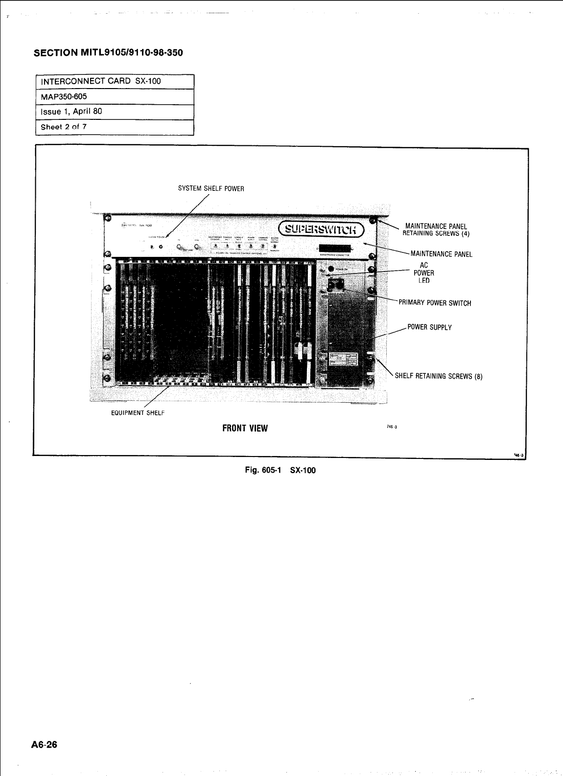
SECTION MITL9105/9110-98-350
INTERCONNECT CARD SX-100
MAP350-605
Issue 1, April 80
Sheet 2 of 7
SYSTEM SHELF POWER
RETAINING SCREWS (4)
MAINTENANCE PANEL
PRIMARY POWER SWITCH
i
, POWER SUPPLY
‘SHELF RETAINING SCREWS (8)
EQUIPMENT SHELF
FRONT VIEW 746 -3
c 4
Fig. 605-l SX-100
_-
A8-26
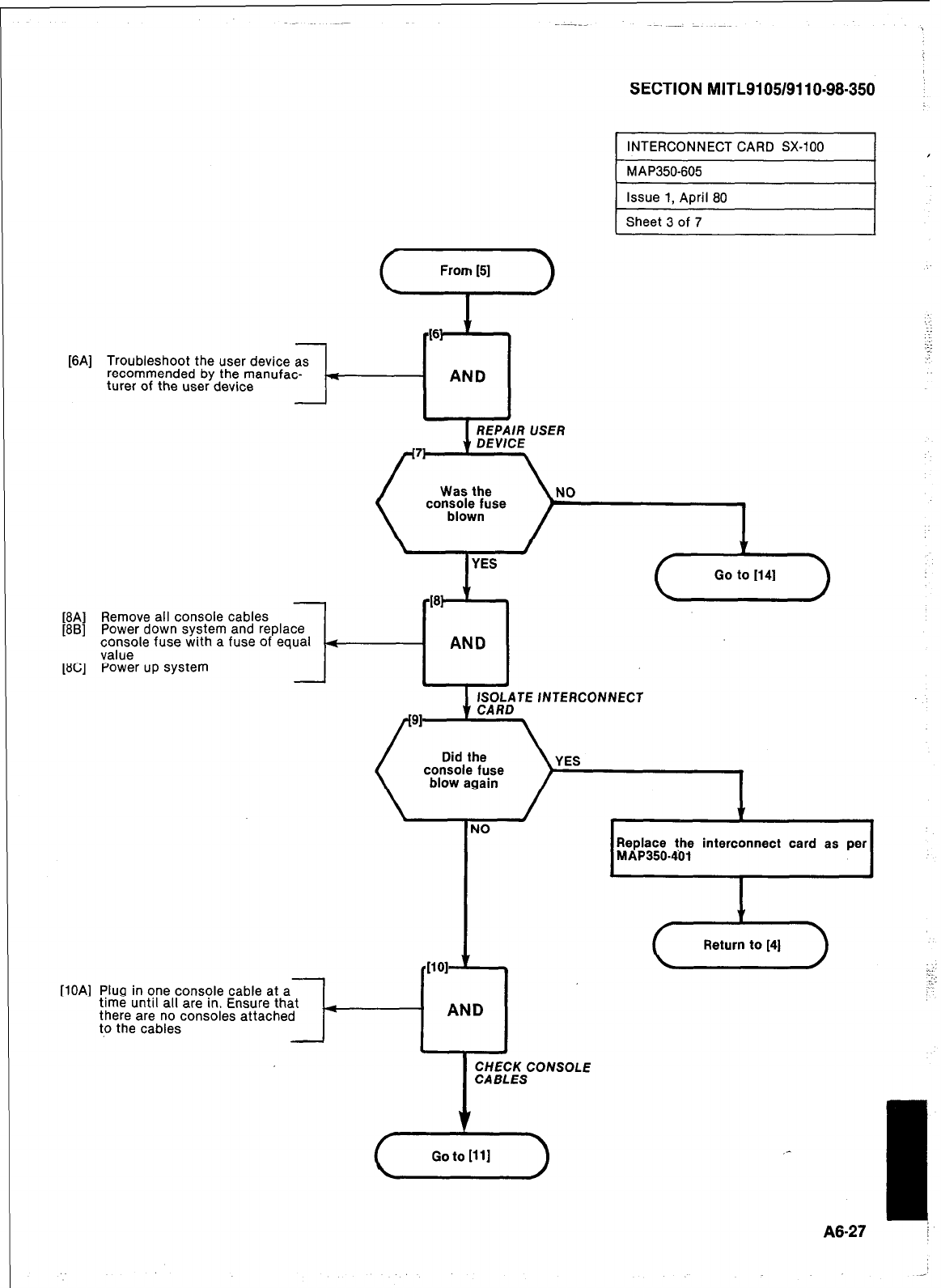
SECTION MITL9105/9110-98-350 :
461 +
[6A] Troubleshoot the user device as
recommended by the manufac- .:
turer of the user device
- AND
[8A] Remove all console cables
[8B] Power down system and replace
;,“nseole fuse with a fuse of equal 4
AND
[8C] Power up system . *
ISOLATE INTERCONNECT
91
console fuse
v
NO Replace the interconnect card as per
MAP350401
[lOA] Plug in one console cable at a
time until all are in. Ensure that
there are no consoles attached
to the cables t-i AND I
- 1 I
CHECK CONSOLE
CABLES
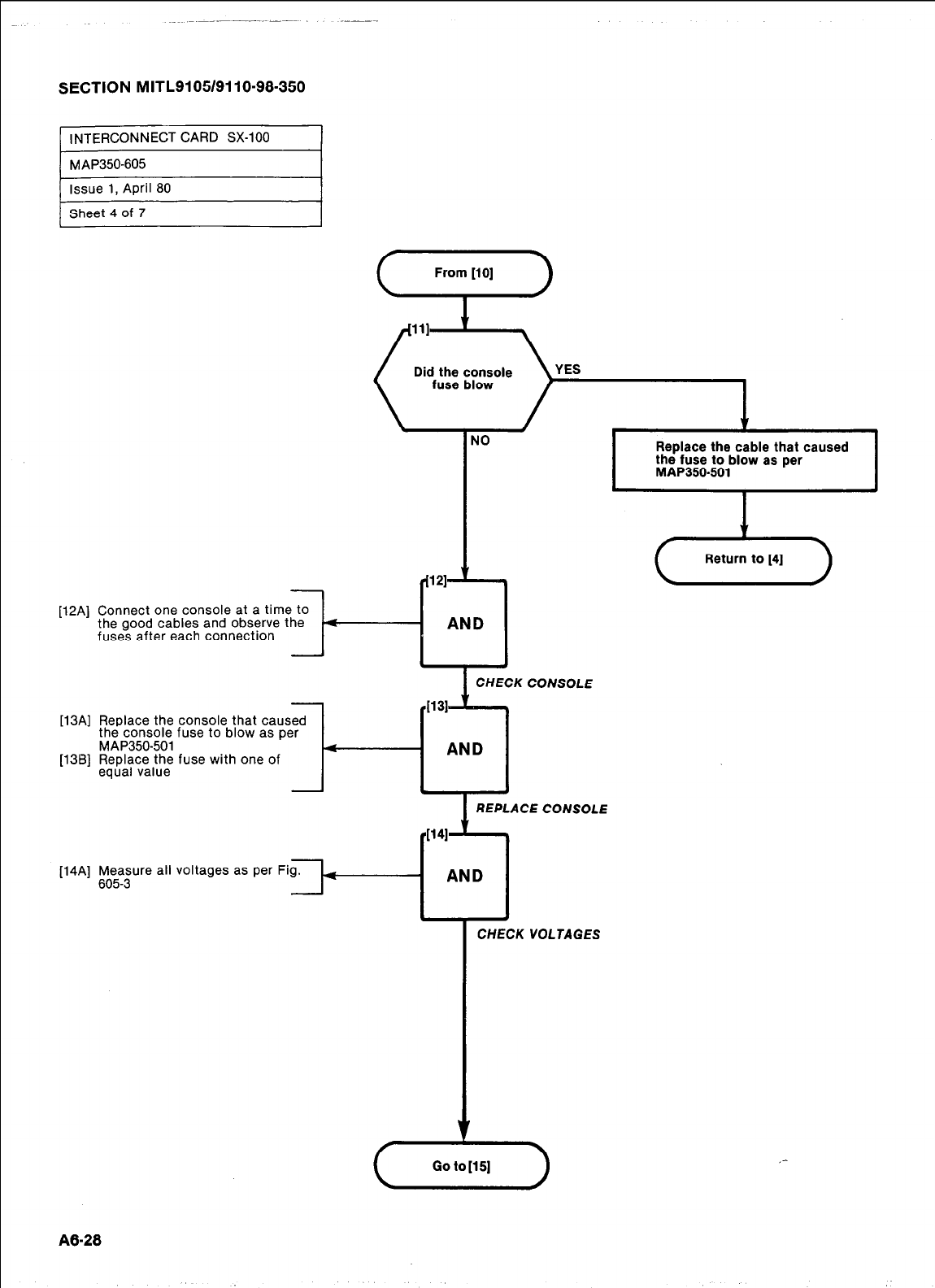
SECTION MITL9105/9110-98-350
1 INTERCONNECT CARD SX-100
m-605 I
Issue 1, April 80
Sheet 4 of 7
[124
NO
Replace the cable that caused
the fuse to blow as per
MAP350401
Connect one console at a time to
the good cables and observe the 4
AND
fuses after each connection
[13A] Replace the console that caused
the console fuse to blow as per
MAP350-501
[138] Replace the fuse with one of
equal value
[14Al Measure
605-3 all voltages as per
1 CHECK CONSOLE
VOLTAGES
A8-28
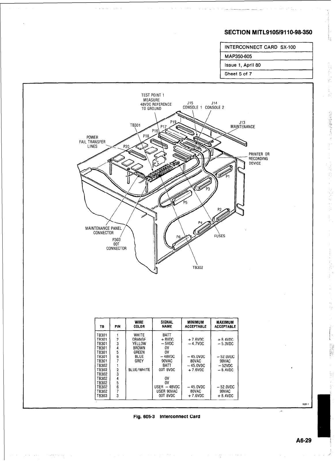
SECTION MITL9105/911 O-98-350
INTERCONNECT CARD SX-100
MAP350-605
Issue 1, April 60
Sheet 5 of 7
WIRE SIGNAL MINIMUM MAXIMUM
TG PIN COLOR NAME
ACCEPTABLE ACCEPTABLE
TB301 WHITE BATT
TB301 : ORANGE +8VOC +7.6VDC +8.4VDC
TB301 3 YELLOW -5VDC -4.7VDC -5.3VDC
TB301 4 BROWN
TB301 GREEN I
TB301 i BLUE -48VDC -45.OVDC -52.OVDC
TB301 7 GREY SOVAC 8OVAC 99VAC
TB302 : BATT -45.OVDC -52VDC
TB302 BLUE/WHITE OOT 8VDC +7.6VDC -8.4VDC
TB302 3
TB302 4
TB302 ii
TB302 z USER -48VDC -45.OVDC -52.OVDC
TB302 ; USER SOVAC 80VAC 99VAC
TB303 OOT 8VDC +7.6VDC +8.4VDC
1638-I
Fig. 605-3 Interconnect Card
1
I
A8=29 !
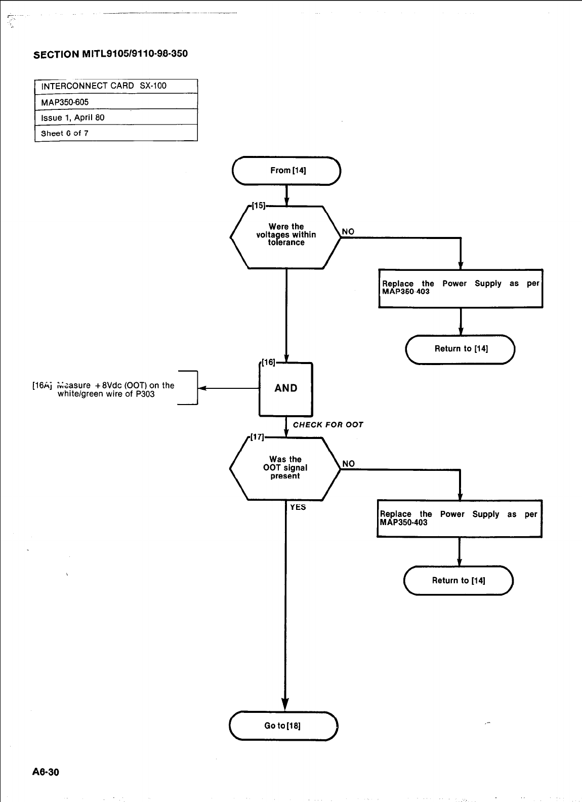
SECTION MITL9105/9110-9.8-350
Were the
voltages within
tolerance
[ISA; Assure +8Vdc COOT) on the
white/green wire of P303
4
Replace the Power Supply as per
MAP350-403
I
I?
P61
1
AND I
(T&T)
CHECK FOR OOT
NO
A8-30
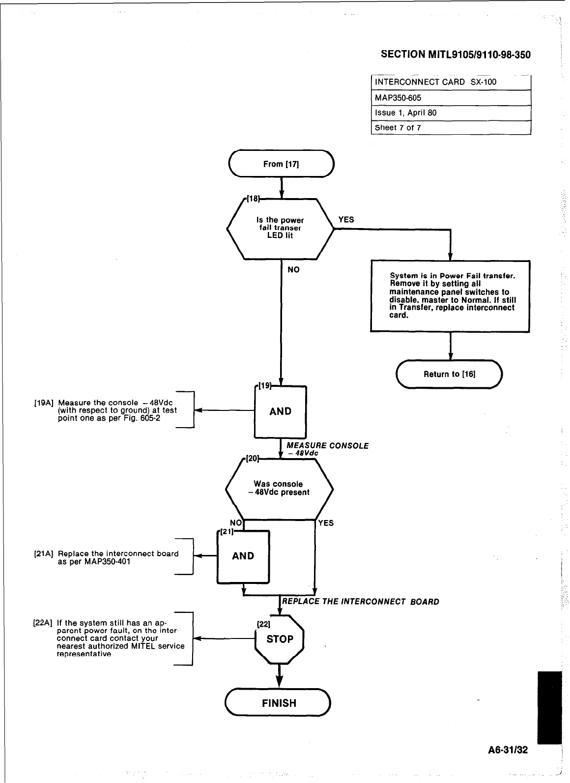
SECTION MITL9105/9110-98-350 !
NO
-
[19A] Measure the console -48Vdc
(with respect to ground) at test A
point one as per Fig. 805-2
Was console
- 48Vdc present
[21A] Replace the interconnect board
as per MAP350-401 -
AND
.
+
[22A] If the system still has an ap-
parent power fault, on the inter-
connect card contact your <
nearest authorized MITEL service
representative
INTERCONNECT CARD SX-100
System is in Power Fail transfer.
Remove it by setting all
maintenance panel switches to
disable, master to Normal. If still
in Transfer, replace interconnect
card.
YES
THE /NTERCONNECT BOARD
A8-31132
Ii
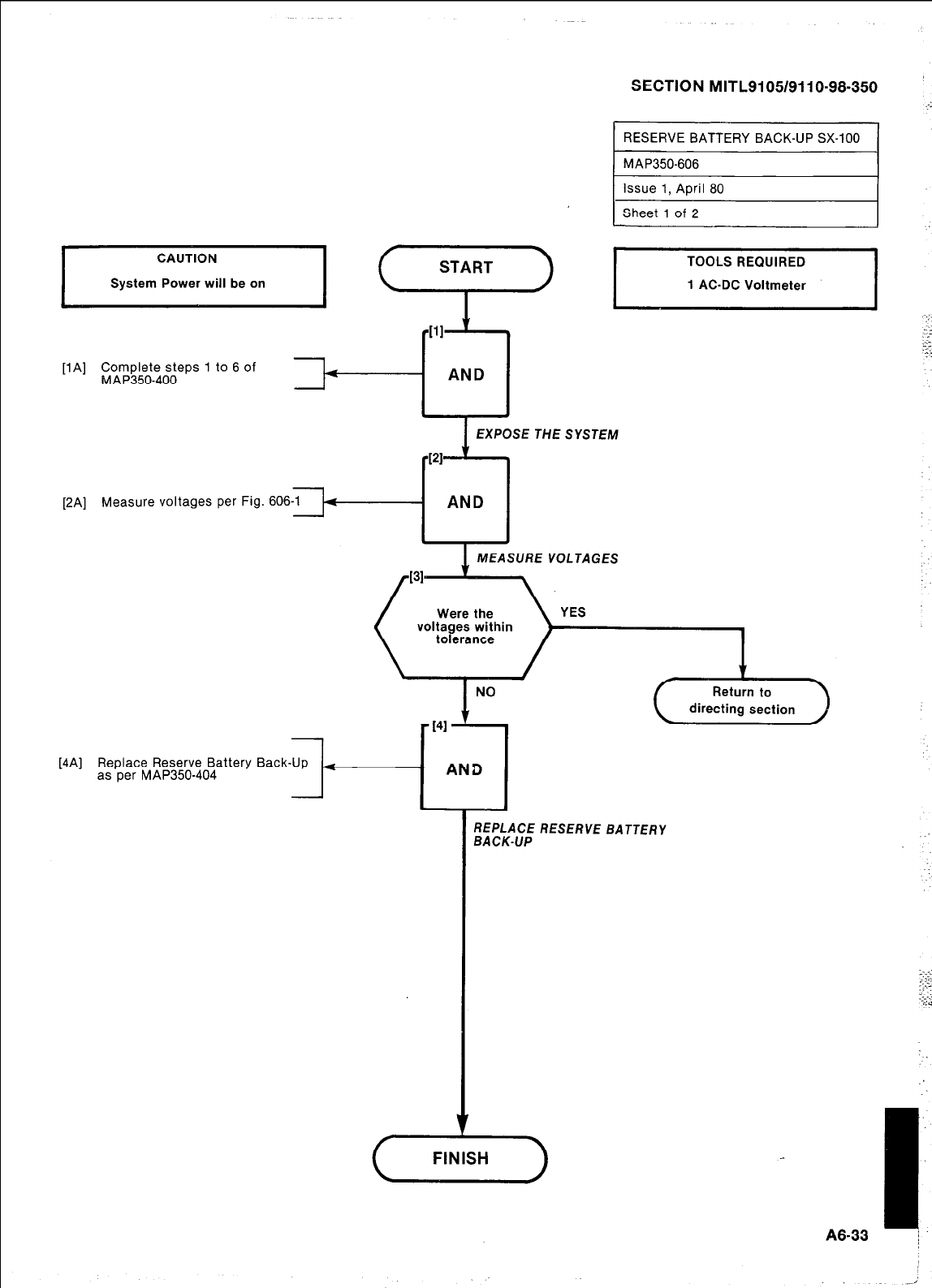
SECTION MITL9105/9110-98-350
RESERVE BATTERY BACK-UP SX-100
y
START
,;
-111 \ ::
.-.-
.=:
1“
[lA] Complete steps 1 to 6 of
MAP350-400
AND
EXPOSE THE SYSTEM
[2A] Measure voltages per Fig. 606
AND
[4A] Replace Reserve Battery Back-Up
as per MAP350-404
MEASURE VOLTAGES MEASURE VOLTAGES
directing section directing section
. AND . AND
4 4
REPLACE RESERVE BATTERY REPLACE RESERVE BATTERY
BACK-UP BACK-UP
v
FINISH
I
A6-33 j
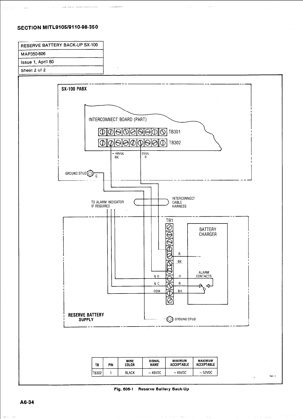
SECTION MITL9105/9110-98.350
RESERVE BATTERY BACK-UP SX-100 1
MAP350-606
Issue 1, April 80
Sheet 2 of 2
SX-100 PABX
OVdc
R
II
INTERCONNECT
CABLE
HARNESS
TO ALARM INDICATOR
IF REWIRED
C
, RESERVE BATTERY
LYLY -- __ __
0 GROUNOSTUO
--I
TBl
TB PIN
TB302 1
WIRE SIGNAL MINIMUM MAXIMUM
COLOR NAME ACCEPTABLE ACCEPTABLE
BLACK -48VDC - 45VDC - 52VOC 1641 .1
.-
Fig. 606-l Reserve Battery Back-Up
A6-34
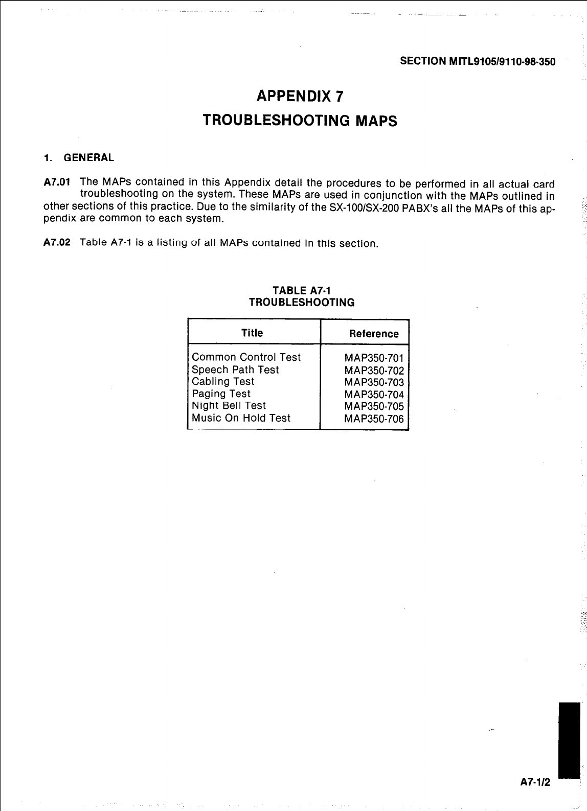
SECTION MITL9105/9110-98.350
APPENDIX 7
TROUBLESHOOTING MAPS
1. GENERAL
A7.01
The MAPS contained in this Appendix detail the procedures to be performed in all actual card
troubleshooting on the system. These MAPS are used in conjunction with the MAPS outlined in
other sections of this practice. Due to the similarity of the SX-iOO/SX-200 PABX’s all the MAPS of this ap-
pendix are common to each system.
A7.02
Table A7-1 is a listing of all MAPS contained in this section.
TABLE A7-1
TROUBLESHOOTING
I
Title I Reference I
~ Common Control Test
~ Speech Path Test
Cabling Test
Paging Test
Night Bell Test
Music On Hold Test
MAP350-701
MAP350-702
MAP350-703
MAP350-704
MAP350-705
MAP350-706
1.
A7-l/2 i
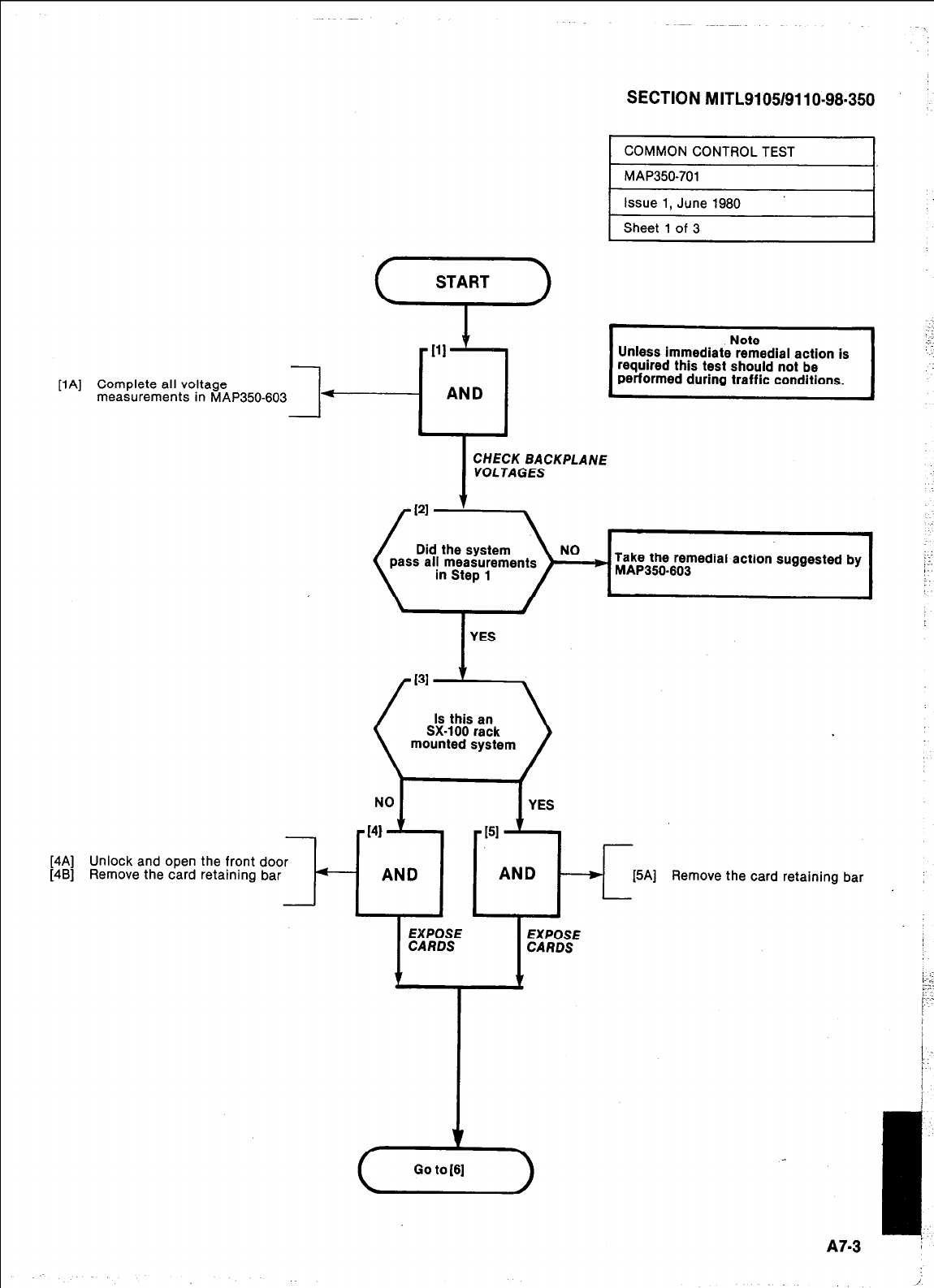
PAI
SECTION MITL9105/9110-98.350
Complete all voltage
measurements in MAP350-fX3~~~[1’~~
I
COMMON CONTROL TEST I
t MAP350-701 I
Issue 1, June 1980
Sheet 1 of 3
I
CHECK BACKPLANE
VOLTAGES
Take the remedial action suggested by
MAP350.603
I
YES
Unless immediate remedial action is
required this test should not be
performed during traffic conditions.
Note
mounted system
Unlock and open the front door
Remove the card retaining bar
- AND AND T
[5A] Remove the card retaining bar
KE EEE
1 t
!Ff.
.-_.
:-
/:I--
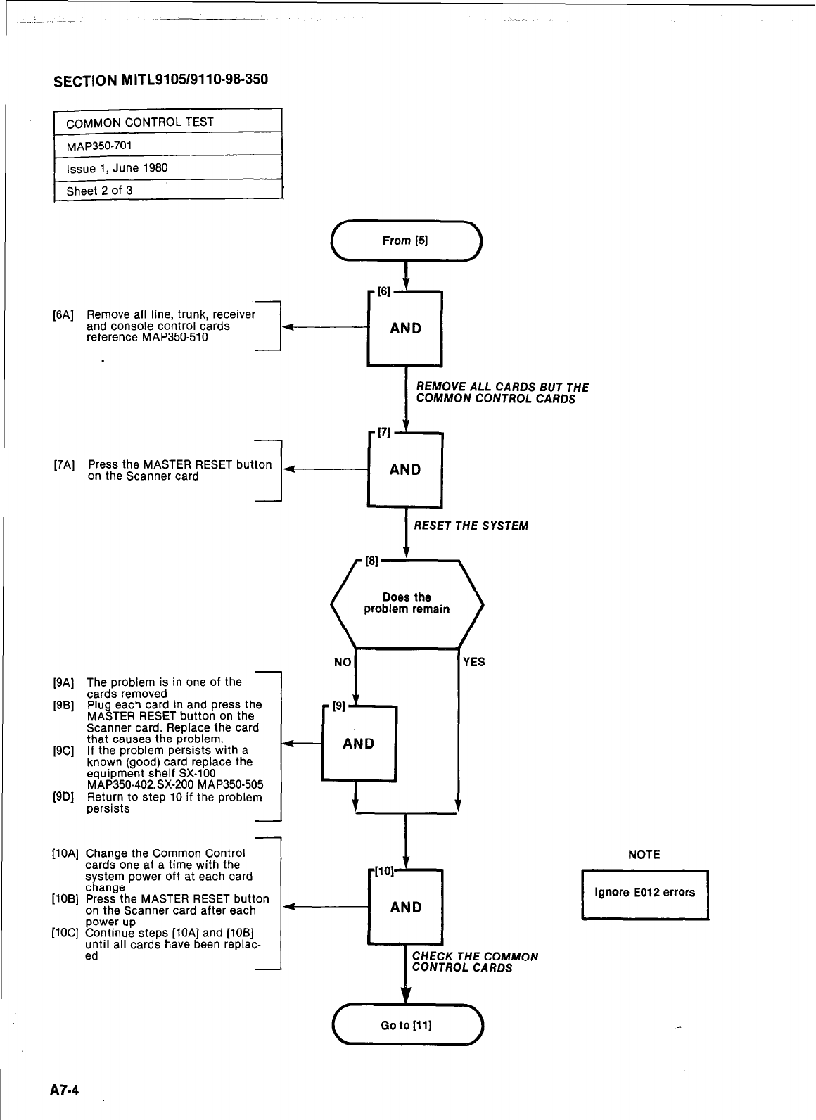
SECTION MITL9105/9110-98-350
[6A] Remove all line, trunk,
and console control cards
reference MAP350510
-
[7A] Press the MASTER RESET button
on the Scanner card
[9A] The problem is in one of the -
cards removed
[9B] Plug each card in and press the
MASTER RESET button on the
Scanner card. Replace the card
that causes the problem.
[9C] If the problem persists with a
known (good) card replace the
equipment shelf SX-100
MAP350-402.SX-200 MAP350-505
[9B] Return to step 10 if the problem
persists
-
[lOA] Change the Common Control
cards one at a time with the
system power off at each card
[lOB] %&?he MASTER RESET button
on the Scanner card after each
[lOC] %~&% steps [lOA] and [lOB]
until all cards have been replac-
ed -
1
.
4
NOI
I
REMOVE ALL CARDS BUT THE
COMMON CONTROL CARDS
AND
?,
I
RESET THE SYSTEM
problem remain
r
191
YES
I
CHECK THE COMMON
CONTROL CARDS
NOTE
I
Ignore E012 errors
I
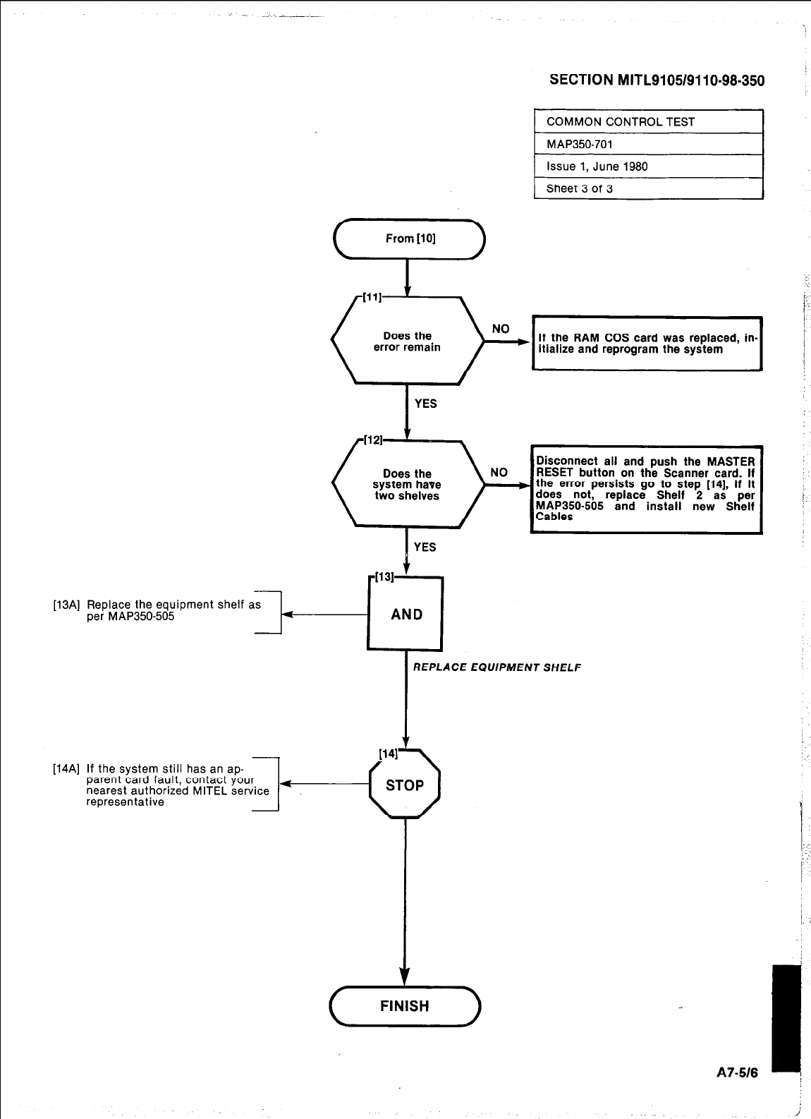
[14Al
Replace the equipment
per MAP350405 shelf
SECTION MITL9105/9110-98-350 ’
COMMON CONTROL TEST
MAP350-701
Issue 1, June 1980
Sheet 3 of 3
From [lo]
If the RAM COS card was replaced, In-
itialize and reprogram the system
I
YES
Disconnect all and push the MASTER
RESET button on the Scanner card. If
the error persists go to step [14], if it
does not, replace Shelf 2 as per
MAP350-505 and install new Shelf
Cables
YES
-1131 +
as 4
AND
REPLACE EQUIPMENT SHELF
If the system still has an ap-
parent card fault, contact your
7
nearest authorized MITEL service +
representative
CL
FINISH
1;
i
: :
j.
:
A7.518 I
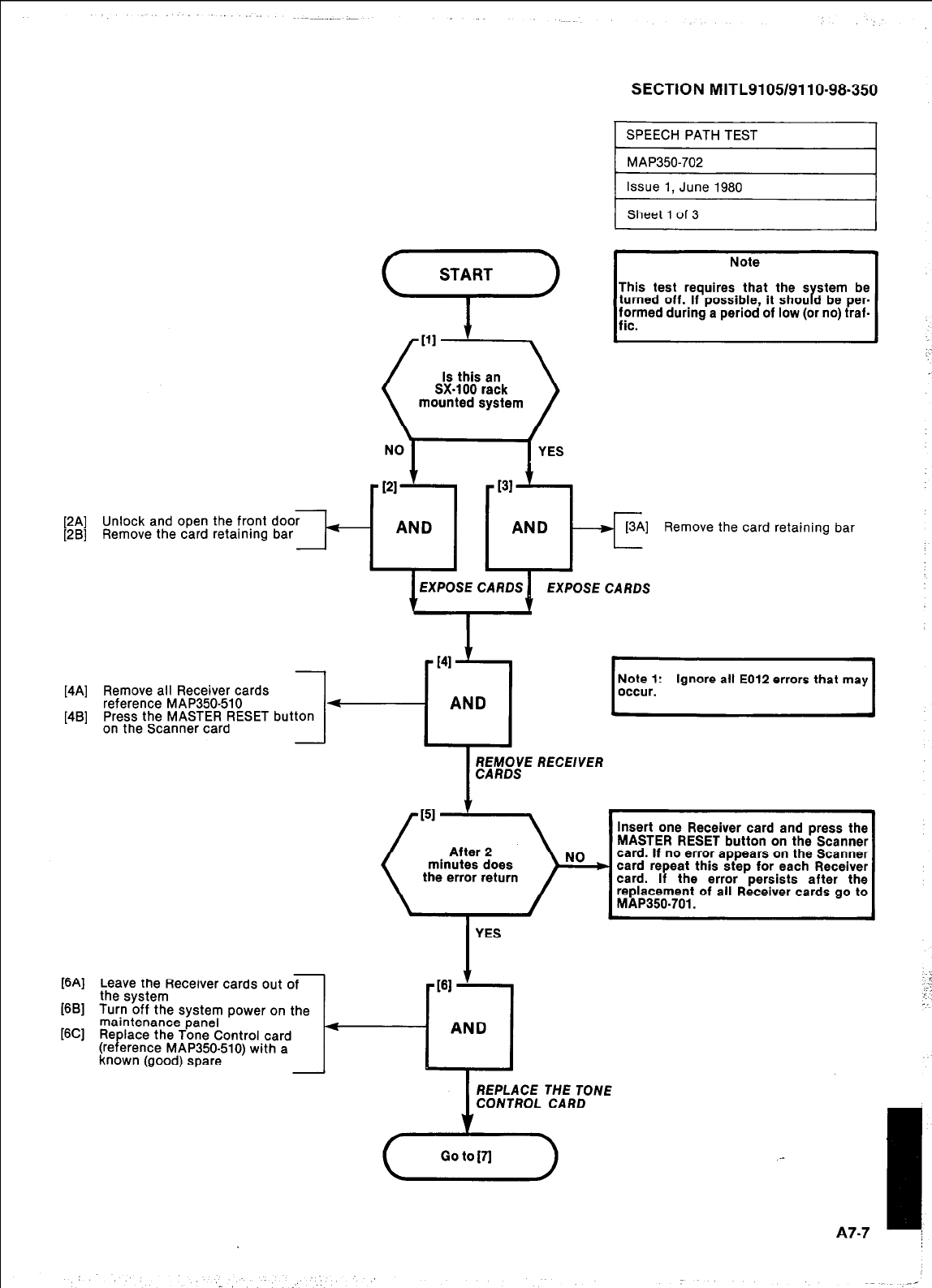
[2A] Unlock and open the front door
[2B] Remove the card retaining bar --I-
SECTION MITL9105/9110-98-350
EXPOSE CARDS EXPOSE CARDS EXPOSE CARDS EXPOSE CARDS
WV
WI
WI
Note
This test requires that the s stem be
turned off..lf possible, it shou d be per-
r
f;med durmg a period of low (or no) traf-
[4A] Remove all Receiver cards
reference MAP350610
[4B] Press the MASTER RESET button
on the Scanner card --I-
Leave the Receiver cards out of
the system
Turn off the system power on the
maintenance panel
Re
(re P lace the Tone Control card
erence MAP350-510) with a I-
known (good) spare
Remove the card retaining bar
:
[IJ
Ignore all E012 errors that may
Insert one Receiver card and press the
MASTER RESET button on the Scanner
card. If no error appears on the Scanner
the error return card repeat this step for each Receiver
card. If the error persists after the
replacement of all Receiver cards go to
MAP350.701.
YES
7
r'"1
AND
1
REPLACE THE TONE
CONTROL CARD
I
A7-7 I
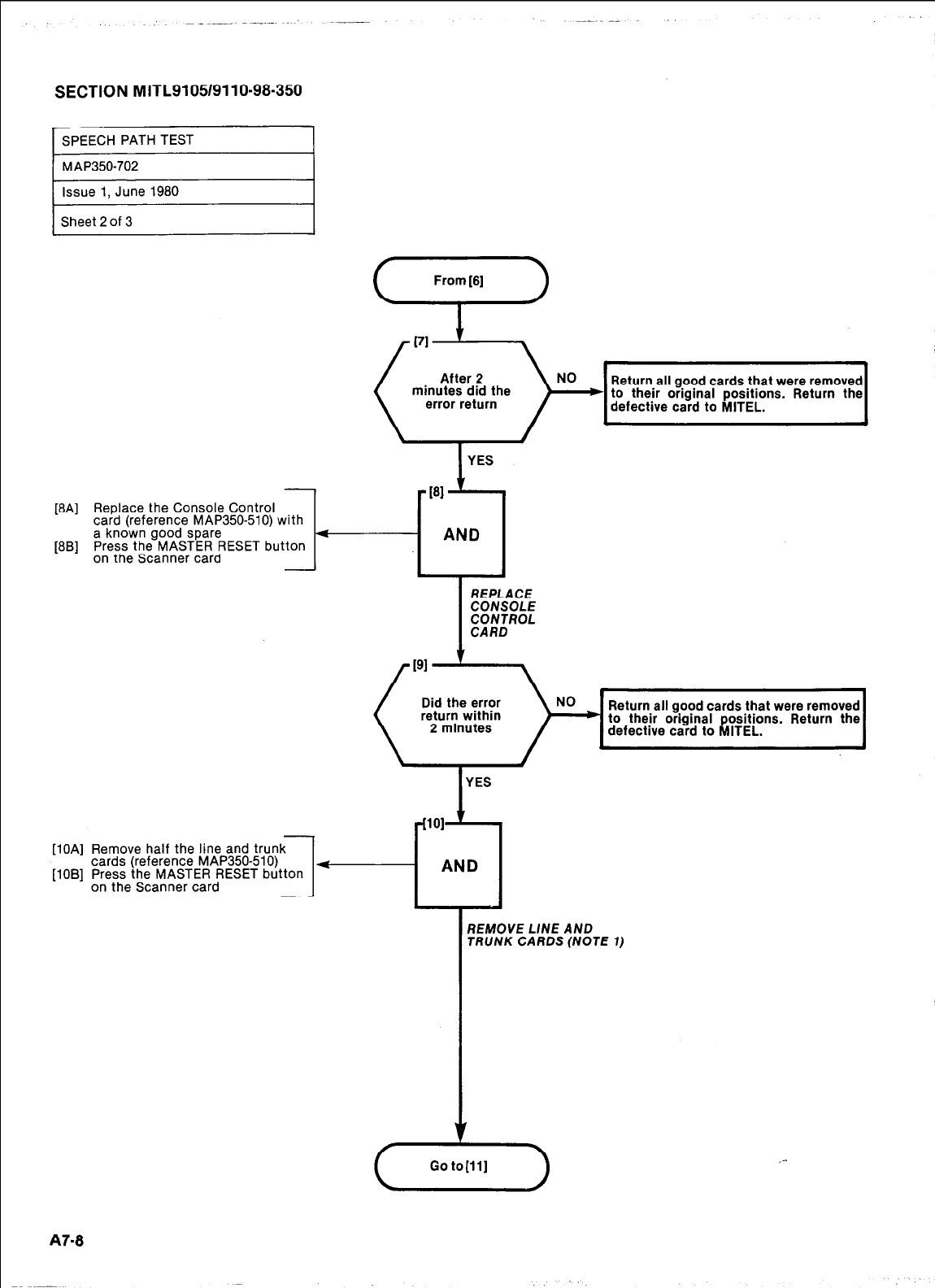
SECTION MITL9105/911 O-98-350
1
SPEECH PATH TEST I
Issue 1, June 1980
Sheet 2 of 3
-
[8A] Replace the Console Control
card (reference MAP350-510) with
a known good spare
[8B] Press the MASTER RESET button
on the Scanner card -
Return all good cards that were removed
I
YES
Did the error
return within
2 minutes
Return all good cards that were removed
to their original positions. Return the
defective card to MITEL. I
I
YES
[lOA] Remove half the line and trunk
cards (reference MAP350-510)
1-i
[lOB] Press the MASTER RESET button
AND
on the Scanner card
1
REMOVE L/NE AND
TRUNK CARDS (NOTE 1)
A7-8
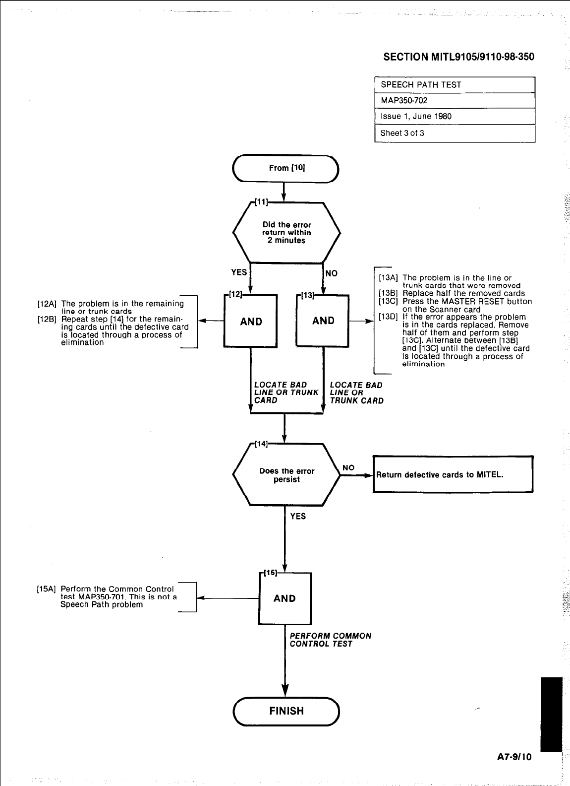
SECTION MITL9105/9110-98-350
SPEECH PATH TEST
1
[12Al
[1W
Did the error
return within
]13Al
V3Bl
The problem is in the remain
line or trunk cards
Repeat step [14] for the remain-
ing cards until the defective
is located through a process
elimination
AND - V3Cl
The problem is in the line or
trunk cards that were removed
Replace half the removed cards
Press the MASTER RESET button
on the Scanner card
If the error appears the problem
is in the cards replaced. Remove
half of them and perform step
[13C]. Alternate between [13B]
and [13C] until the defective card
is located through a process of
elimination
( Doe;Jz;rror )No ]]I Return defective cards to MITEL
YES
-1151 ’
[15A] Perform the Common Control
test MAP350-701. This is not a 4
Speech Path problem
AND
PERFORM COMMON
CONTROL TEST
A7-9110 I
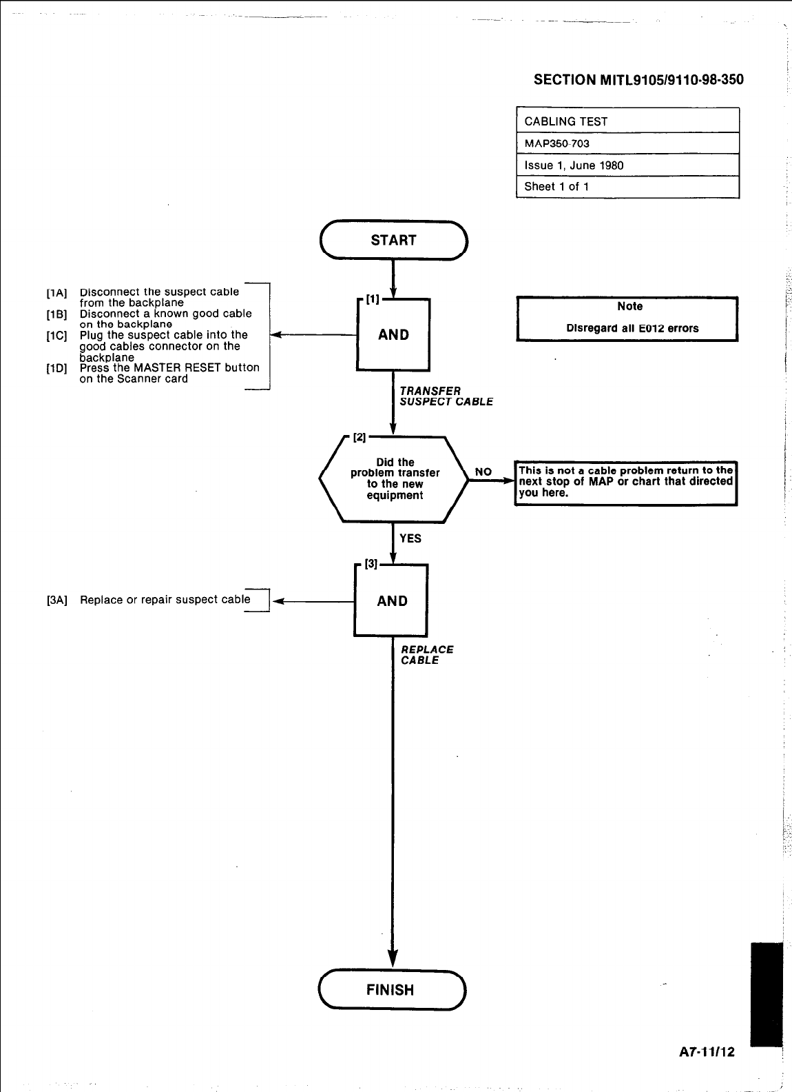
SECTION MITL9105/9110-98-350
WI
[l Bl
WI
UDI
Disconnect the suspect cable
from the backplane
Disconnect a known good cable
on the backplane
Plug the suspect cable into the
good cables connector on the
backplane
Press the MASTER RESET button
on the Scanner card
I31
[3A] Replace or repair suspect cable
1
ii
AND
I-
I
YES
CABLING TEST I
This is not a cable problem return to the
(::F)NO,o,
next stop of MAP or chart that dwected
I
Note
Disregard all E012 errors I
i
REPLACE
CABLE
I
A7-11112 :
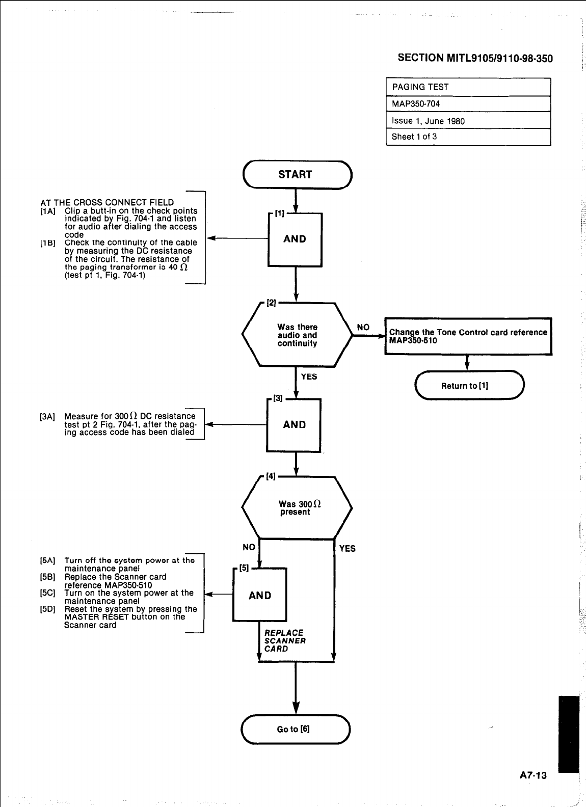
AT THE CROSS CONNECT FIELD
[lA] Clip a butt-in on the check points
indicated b Fig. 704-l and listen
for audio a Y .’ ter dralrng the access
code
[lB] Check the continuity of the cable
by measuring the DC resistance
of the circuit. The resistance of
the paging transformer is 40 R
(test pt 1, Fig. 704-l)
[3Al
l
SECTION MITL9105/9110-98-350
PAGING TEST I
I
MAP350-704 1
Issue 1, June 1980
Sheet 1 of 3
NO
) Change the Tone Control card reference
MAP350.510
Measure for 3000 DC resistance
test pt 2 Fig. 704-1, after the pag- 4
ing access code has been dialed
AND
[5A] Turn off the system power at the
maintenance panel
[5B] Replace the Scanner card
reference MAP350-510
[5C] Turn on the system power at the
maintenance panel
[5D] Reset the system by pressing the
MASTER RESET button on the
Scanner card t
YES
I
A7-13 ;
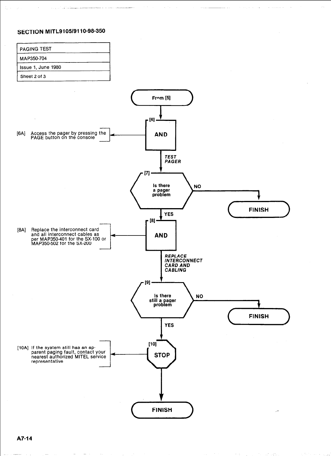
SECTION MITL9105/9110-98-350
PAGING TEST
MAP350-704
Issue 1, June 1980
Sheet 2 of 3
Frnm (51
53
161
[6A] Access the pager by pressing
PAGE button on the console
AND
TEST
PAGER
FINISH
WI
[l W
Replace the interconnect card
and all interconnect cables as
3--[Ag
per MAP350-401 for the SX-100 or
MAP350-502 for the SX-200
-
I
REPLACE
/NTERCONNECT
CARD AND
CABLlNG
FINISH
I
YES
If the system still has an ap-
parent paging fault, contact your
nearest authorized MITEL service (
representative
A7-14
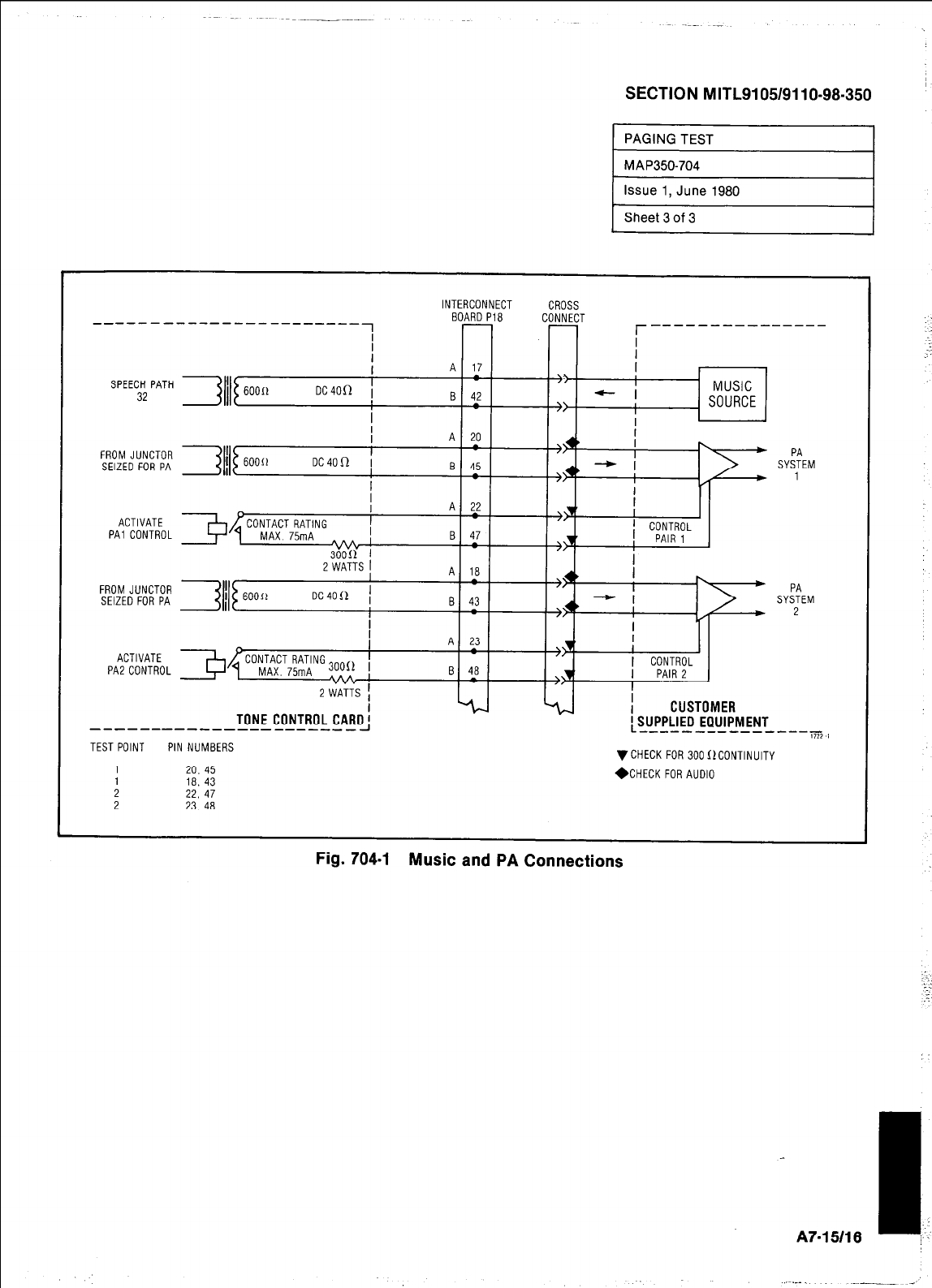
SECTION MITL9105/9110-98-350
INTERCONNECT CROSS
BOARD PI8 CONNECT --------_------
SPEECH PATH
32
FROM JUNCTOR
SEIZED FOR PA
ACTIVATE
PA1 CONTROL
FROM JUNCTOR
SEIZED FOR PA SYifEM
2
ACTIVATE
PA2 CONTROL
TONE CONTROL CARO'
-----------------------I :SJJJPL'EO EQUIPMENT
- -----------~~,
TEST POINT PIN NUMBERS VCHECK FOR 300f1CONTINUlTY
1 20. 45
: 22, 18. 43 47 *CHECK FOR AUDIO
2 23. 48
Fig. 704-l Music and PA Connections
A7-15116
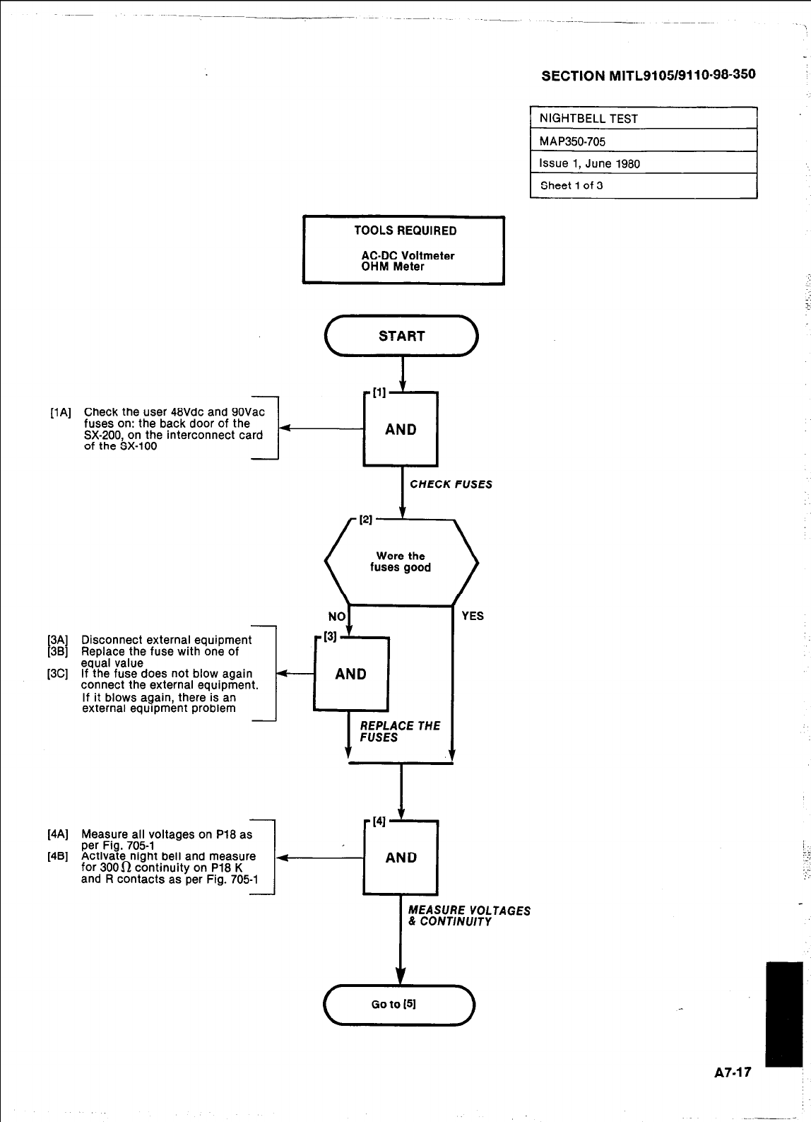
SECTION MITL9105/9110~98-350 ’
[lA] Check the user 48Vdc and 9OVac
fuses on: the back door of the
SX-200, on the interconnect card
of the SX-100
[3A] Disconnect external equipment
[3B] Replace the fuse with one of
[3C] equal value
If the fuse does not blow again
connect the external equipment.
If it blows again, there is an
external equipment problem
[4A] Measure all voltages on P18 as
per Fig. 705-i
[4B] Activate night bell and measure
for 3000 continuity on P18 K
and R contacts as per Fig. 705-l
TOOLS REQUIRED
AC-DC Voltmeter
OHM Meter
4
- AND
CHECK FUSES CHECK FUSES
4
AND
I
YES
I
MEASURE VOLTAGES
& CONTINUITY
23
Go to 151
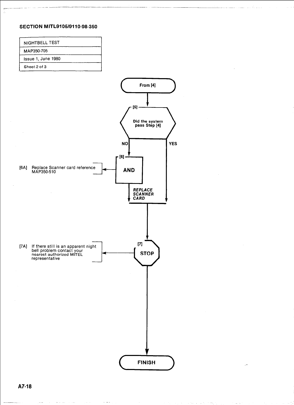
SECTION MITL91051911 O-98-350
I
NIGHTBELL TEST I
) MAP350-705
Issue 1, June 1980
Sheet.2 of 3
[6A] Replace Scanner card reference
MAP350410 II---
[7Al If there still is an apparent
bell problem contact your
nearest authorized MITEL
representative
night
4
1
YES
A
FINISH
A7-18
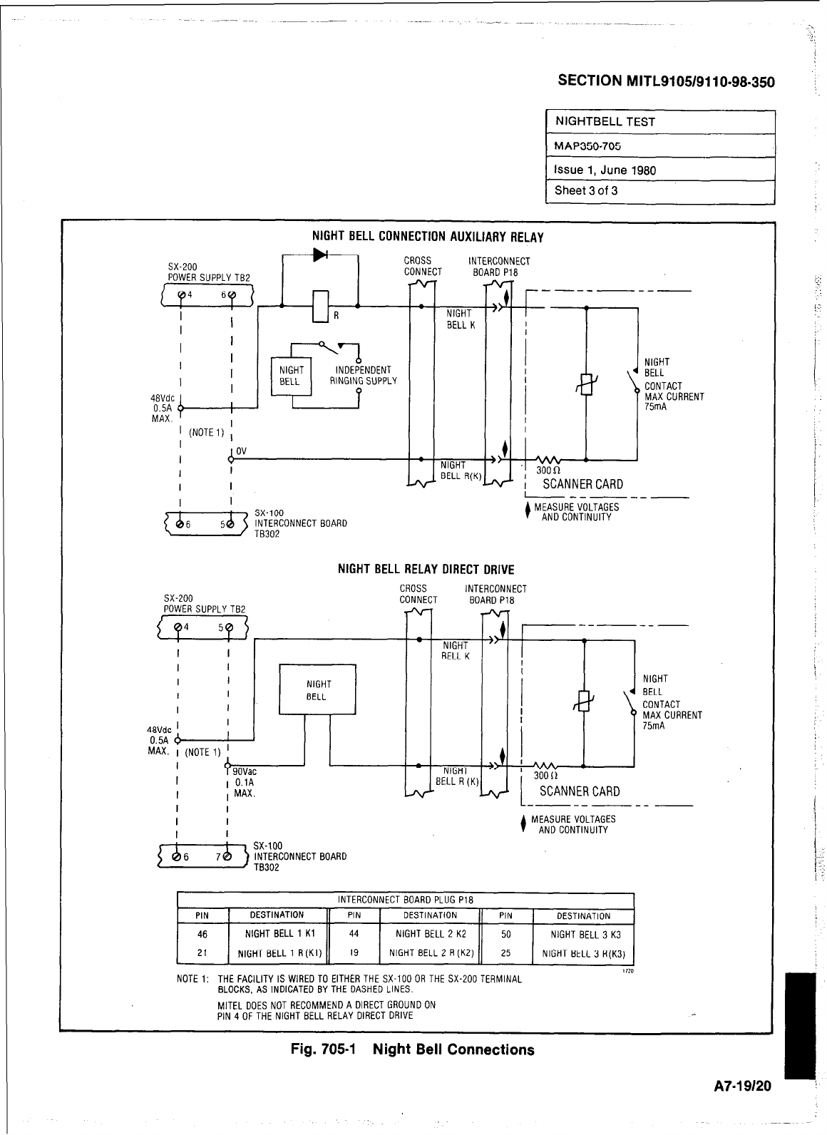
SECTION MITL9105/9110-98-350
NIGHTBELL TEST
M AK350705
Issue 1, June 1980 I
1 Sheet 3 of 3
NIGHT BELL CONNECTION AUXILIARY RELAY
I
I I
I I
NIGHT
BELL
CONTACT
MAX CURRENT
75mA
NIGHT BELL RELAY DIRECT DRIVE
I------
l
MEASURE VOLTAGES
AND CONTINUITY
CROSS CROSS INTERCONNECT INTERCONNECT
sx-200
sx-200 CONNECT CONNECT BOARD Pi8 BOARD Pi8
POWER SUPPLYTBZ POWER SUPPLYTBZ
aa4 Ex 1 1
---
----- -
---
- NIGHT " - NIGHT "
BELL K BELL K
I I I I
I I I I NIGHT NIGHT NIGHT NIGHT
I I I I BELL BELL 4 BELL 4 BELL
I I I I CONTACT CONTACT
I I I I MAX CURRENT MAX CURRENT
4avdc ’ 4avdc ’ 75mA 75mA
0.5A 6 0.5A 6 I I
MAX. 1 (NOTE 1) ! MAX. 1 (NOTE 1) I
I
I
f)GK
+ +
9OVac - NIGHT " - NIGHT " MA : MA :
I I 1 O.lA 1 O.lA BELL R(K) ' 30011
I I I MAX. I MAX. 3~~~NN~~ CARD SCANNER CARD
I I I I
1 ------- ~
I I I I MEASURE VOLTAGES MEASURE VOLTAGES
I I I I
I
I AND CONTINUITY AND CONTINUITY
L------- ~
{V) !{+NNECT BOARD
PIN
46
INTERCONNECT BOARD PLUG PlB
DESTINATION PIN 1 DESTINATION PIN DESTINATION
NIGHT BELL 1 Kl 44 NIGHT BELL 2 KE 50 NIGHT BELL 3 K3
21 1 NIGHT BELL 1 R(KI) 11 19 1 NIGHT BELL 2 R(K2) 11 25 1 NIGHT BELL 3 R(K3) 1
1120
NOTE 1: THE FACILITYISWIREDTO EITHER THE SX-100 OR THE SX-200 TERMINAL
BLOCKS, AS INDICATED BYTHE DASHED LINES.
MITEL DOES NOT RECOMMEND A DIRECTGROUND ON
PIN 4 OFTHE NIGHT BELL RELAY DIRECT DRIVE
Fig. 705-l Night Bell Connections
‘I
A7-19120
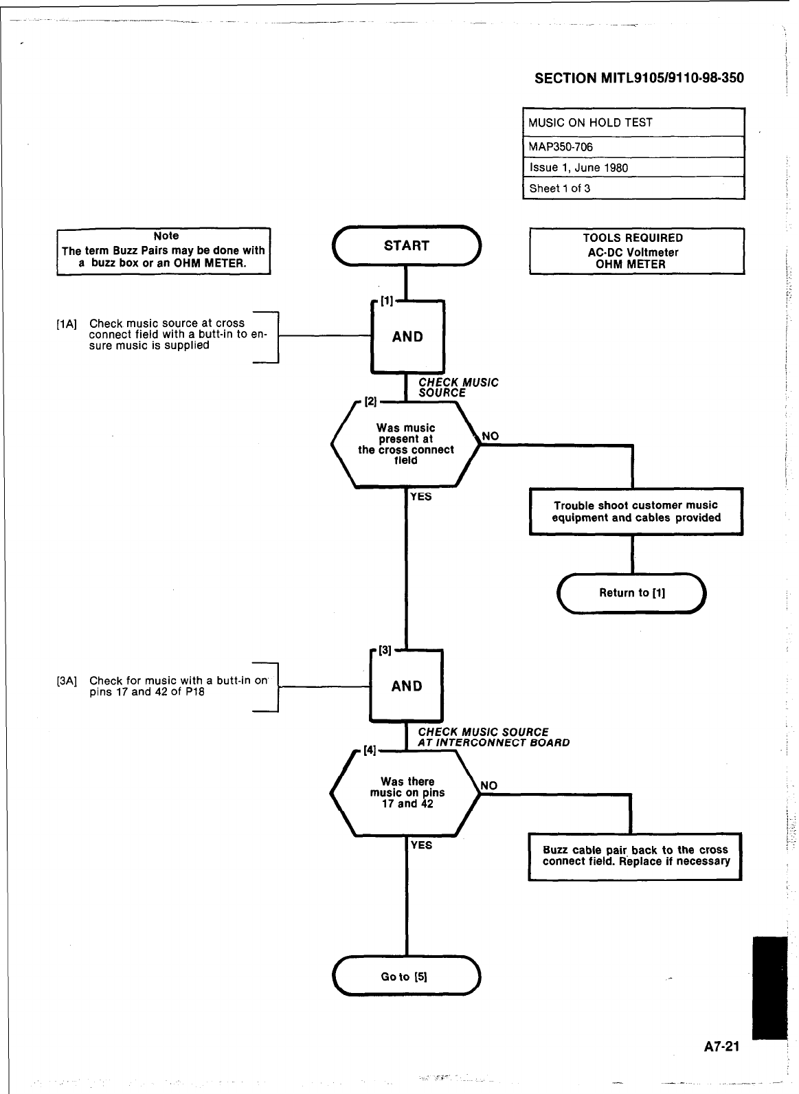
SECTION MITL9105/9110~98-350
[IA] Check music source at cross
connect field with a butt-in to en-
sure music is supplied
[3A] Check for music with a butt-in on
pins 17 and 42 of P18
l-i AND1
I fES
CHECK MUSIC
the cross connect
Trouble shoot customer music
equipment and cables provided
.
Buzz cable pair back to the cross
connect field. Replace if necessary
A
Go to [5]
I
AI-21 :
- --
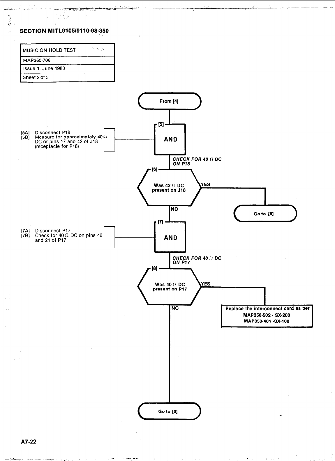
./
;.
z.:. :
SECTION MITL9105/9110-98.350
MUSIC ON HOLD TEST
MAP350-706
c . . I.,
Issue 1, June 1980
Sheet 2 of 3
- AND
[5A] Disconnect P18
[5B] Measure for approximately 40 (1
DC or pins 17 and 42 of J18
(receptacle for P18)
Disconnect P17
Check for 40 II DC
and 21 of P17 on pins 46
Was 42 II DC
present on J18
AND
I
CHECK FOR 40 II DC
ON P17
Was 4011 DC
present on P17
NO Replace the interconnect card as per
MAP350.502 - SX-200
MAP350.401 -SX-100
.
(Yz-)
A7-22
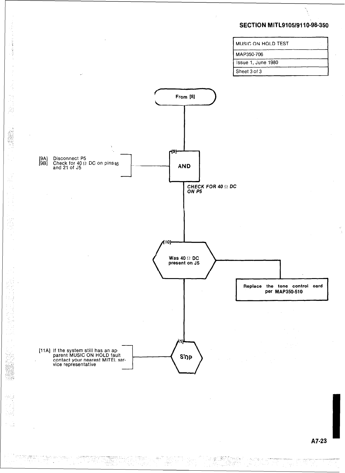
From [aI
T
[9A] Disconnect P5
[9B]
?” -l---
,“,“d”“:, f;;‘J”5” I1 DC on pins46
CHECK FOR 40 II DC
ON P5
SECTION MITL9105/9110-98-350
MUSIC ON HOLD TEST I
MAP350-706 I
Issue 1, June 1980
Sheet 3 of 3
147.23
I
