IB(NA) 66522 C Mitsubishi Freqrol FR A024 Manual
User Manual: Mitsubishi-Freqrol-FR-A024-Manual Igor's of metalworking and electrical manuals
Open the PDF directly: View PDF ![]() .
.
Page Count: 167 [warning: Documents this large are best viewed by clicking the View PDF Link!]
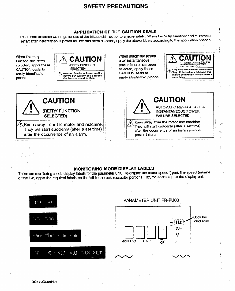
- SAFETY PRECAUTIONS
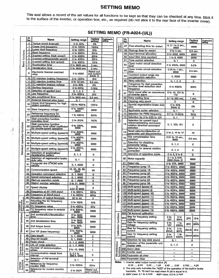
- SETTING MEMO
- SAFETY INSTRUCTIONS
- CONTENTS
- GUIDELINES FOR HANDLING
- 1. PRECAUTIONS
- 2. NOMENCLATURE AND FUNCTIONS
- 3. PREPARATION BEFORE OPERATION
- 4. OPERATION CONTROL MODES
- 5. INSTALLATION
- 6. WIRING
- 7. SETTlNG PARAMETERS BEFORE STARTUP
- 8. NOMENCLATURE OF PARAMETER UNIT
- 9. PRECAUTIONS ON OPERATING THE PARAMETER UNIT
- 10. OUTLINE OF THE FUNCTIONS
- 11. OPERATION
- 11.1 Operation Modes
- 11.2 Selecting the Operation Mode
- 11.3 External Operation Mode (Operation Using External input Signals)
- 11.4 PU Operation Mode (Operation Using the Parameter Unit)
- 11.5 Combination Operation Mode (Operation Using both External Signals and Parameter Unit)
- 11.6 Switch over mode
- 11.7 Edit Enable Signal Mode
- 11.8 Local/Auto External Signal Selection Mode
- 12. SETTING AND CHANGING THE PARAMETERS
- 13. INITIALIZING THE PARAMETERS
- 14. MONITORING
- 15. ERRORS
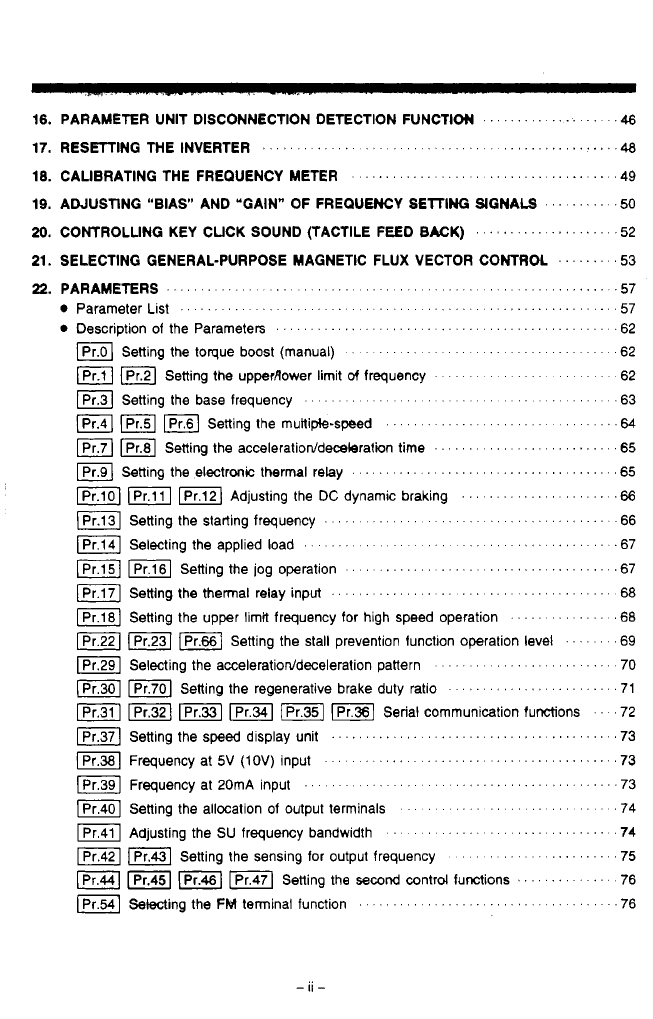
- 16. PARAMETER UNIT DISCONNECTION DETECTION FUNCTION
- 17. RESETTING THE INVERTER
- 18. CALIBRATING THE FREQUENCY METER
- 19. ADJUSTING "BlAS" AND "GAIN" OF FREQUENCY SETTING SIGNALS
- 20. CONTROLLING KEY CLICK SOUND (TACTILE FEED BACK)
- 21. SELECTING GENERAL-PURPOSE MAGNETIC FLUX VECTOR CONTROL
- 22. PARAMETERS
- Parameter List
- Description of the Parameters
- Pr.0: Setting the torque boost (manual)
- Pr.1, Pr2: Setting the upper/lower limit of frequency
- Pr.3: Setting the base frequency
- Pr.4, Pr5, Pr6: setting the multiple-speed
- Pr.7, Pr.8: Setting the acceleration/deceleration time
- Pr.9: Setting the electronic thermal relay
- Pr.10, Pr.11, Pr.12: Adjusting the DC Injection braking
- Pr.13: Setting the starting frequency
- Pr.14: Selecting the applied load
- Pr.15, Pr.16: Setting the Jog operation
- Pr.17: Setting the thermal relay input
- Pr.18: Setting the upper limit frequency for high speed operation
- Pr.22, Pr.23, Pr.66: Setting the stall prevention function operation level
- Pr.29: Selecting the acceleration/deceleration pattern
- Pr.30, Pr.70: Setting the regenerative brake duty ratio
- Pr.31, Pr.32, Pr.33, Pr.34, Pr.35, Pr.36: Serial communication functions
- Pr.37: Setting the speed display unit
- Pr.38: Frequency at 5V (10V) input
- Pr.39: Frequency at 20mA input
- Pr.40: Sestting the allocation of output terminals
- Pr.41: Adjusting the SU frequency bandwidth
- Pr.42, Pr43: Setting the sensing for output frequency
- Pr.44, Pr.45, Pr.46, Pr.47: Setting the second control functions
- Pr.54: Selecting the FM terminal function
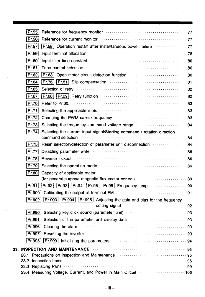
- Pr.55 Reference for frequency monitor
- Pr.56: Reference for current monitor
- Pr.57, Pr.58: Operation restart after instantaneous power failure
- Pr.59: Input terminal allocation
- Pr.60: Input filter time constant
- Pr.61: Tone control selection
- Pr.62, Pr.63: Open motor circuit detection function
- Pr.64, Pr76, Pr.81: Slip compensation
- Pr65: Selection o retry
- Pr.67, Pr68, Pr.69: Retry function
- Pr.70: Refer to Pr.30
- Pr.71: Selecting the applicable motor
- Pr.72: Changing the PWM carrier frequency
- Pr.73: Selecting the frequency command voltage range
- Pr.74: Selecting the current input signal/Starting command - rotation direction command selection
- Pr.75: Reset selection/detection of parameter unit disconnection
- Pr.77: Disabling parameter write
- Pr.78: Reverse lockout
- Pr.79: Selecting the operation mode
- Pr.80: Capacity of applicable motor (for general-purpose magnetic flux vector control)
- Pr.91, Pr.92, Pr.93, Pr.94, Pr.95, Pr.96: Frequency jump
- Pr.900: Calibrating the output at terminal FM
- Pr.902, Pr.903, Pr.904, Pr.905: Adjusting the gain and bias for the frequency setting signal
- Pr.990: Selecting key click sound (parameter unit)
- Pr.991: Selection of the parameter unit display data
- Pr.996: Clearing the alarm
- Pr.997: Resetting the inverter
- Pr.998, Pr.999: Initializing the parameters
- 23. INSPECTION AND MAINTENANCE
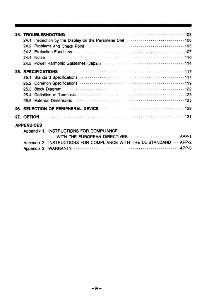
- 24. TROUBLESHOOTING
- 25. SPECIFICATIONS
- 26. SELECTION OF PERIPHERAL DEVICE
- 27. OPTION
- APPENDICES
- Revisions
Thank you for choosing the Mitsubishi Inverter.
This instruction manual gives handling informalion and precautions for use of this equipment.
Incorrect handling might
cause
an
unexpected
fault. Before using the inverter, please read this
manual carefully
to
use the equipment to
its
optimum.
Please forward this manual
to
the end user.
This
section
Is
speclfically
about
safety
matters
Do
not attempt
to
install, operate, maintain or insped the inverter until you have read throug,
this instruction manual
and
appeM
documents carefuliy
and
can
us
the equipment correctl)
Do
not
use
the inverter until
you
have a full
knowledge
of
the equipment, safety information an'
instructions.
In this instruction manual,
the
safety instruction levels are classified into
WARNING"
ani
"CAUTION".
Assumes that incorrect handling may cause hazardous conditions,
resulting in death or severe injury.
Assumes that incorrect handling may cause hazardous conditions,
only.
resulting in medium or slight injury, or may
cause
physical damage
Note that the CAUTION level may lead to a serious consequence according
to
conditions.
Please
follow
the instructions of both levels
because
they are important to personnel safety.
SAFETY INSTRUCTIONS
1
1.
Electric
Shock
Prevention
WARNING
I
A
While power is on or when the inverter is running, do not open the front cover.
You
may get an electric shock.
exposed high-voltage terminals and charging
parl
and get an electric shock.
You may access the charged inverter
circuits
and get an
electric
shock.
Use
a class
3
or higher earthing
method
to earth
the
inverter.
and check for no residual voltage with a tester.
Any person who
is
involved in the wiring or inspection of this equipment should
be
fully
competent to
do
the work.
,
Always install the inverter before wiring. Otherwise,
you
may
get
an electrr. shock or be
injured.
j
Operate the switches with dry hands
to
prevent an electric shock.
j
Do
not subject the cables to scratches, excessive stress, heavy loads or pinching.
A
Do
not run the inverter
Ath
the front cover removed.
Otherwise,
you may access the
A
If
power
is
OH,
do not remove
the
front cover
except
for wiring or
periodic
inspection.
A
Before starting wiring or inspection, wHch power
OH,
wait for more than
10
minutes,
Otherwise. you may get an electric shock.
2.
Fire Prevention
I
A
CAUTION
I
'3
a
Mount the inverter and brake resistor on a noncombustible surface. Installing the
inverter directly on or near a combustible surface could lead to a fire.
a
If
the inverter has become faulty, switch power
OH
on the inverter's power supply side.
A continuous flow of a large current could cause a fire.
a
When using a brake resistor, use a circuit to cut
OH
the power when an inverter error
signal occurs. Failure to do
so
could cause the brake resistor
to
abnormally overheat
and a fire
to
start
if
a fault occurs in the brake transistor, etc.
a
Do
not connect the resistor directly to the
DC
terminals
P,N.
Thls could cause a fire.
3.
Injury Prevention
f
L
a
CAUTION
A
Apply only the voltage specified in the instruction manual to each terminal to prevent
damage, etc.
Ensure that the cables are connected to the correct terminals. Otherwise, damage, etc.
may occur.
While power is on or for some time after power-off, do not touch the inverter or brake
resistor as these will be not and you may be burned.
A
Always make sure that polarky is correct
to
prevent damage, etc.
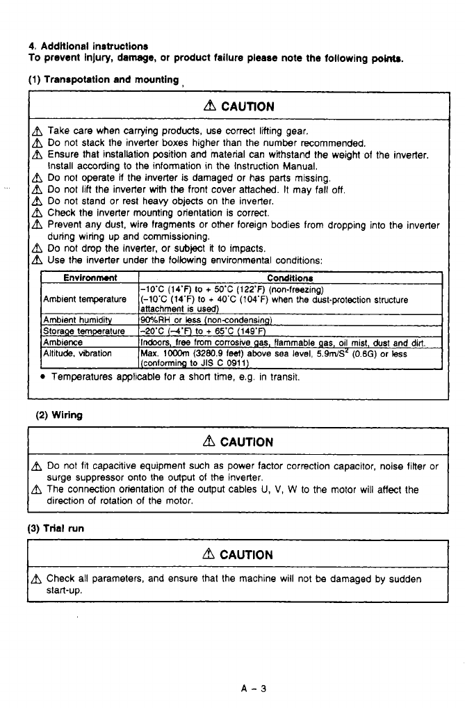
4. Additional instructions
To
prevent injury, damage, or product failure please note the following
pow.
(1)
Transpotation and mounting,
bl
CAUTION
h
Take care when carrying products, use correct lifting gear.
h
Do
not slack the inverter boxes higher than the number recommended.
Ensure that installation position and material can withstand the weight of the inverter.
install according to the information in the Instruction Manual.
h
Do
no1 operate
a
the inverter is damaged
or
has parts missing.
h
Do
not lift (he inverter with the front cover attached.
It
may fall
off,
h
Do
not stand or rest heavy objects on the inverter.
h
Check the inverter mounting orientation is correct.
h
Prevent any dust, wire fragments or other foreign bodies from dropping into the inverter
h
Do
not drop the inverter, or subject
it
to impacts.
h
Use the inverter under the following environmental conditions:
during wiring up and commissioning.
Temperatures applicable for a short time, e.g. in transit.
(2)
Wiring
d
CAUTION
Do
not fit capacitive equipment such as power factor correction capacitor, noise filter or
surge suppressor onto the output
of
the inverter.
The connection orientalion of the output cables
U,
V,
W
to
the motor will affect the
direction of rotation of the motor.
(3)
trial run
d
CAUTION
~~~
A
Check all parameters, and ensure that the machine will not be damaged by sudden
start-up.
I
.
._
(4)
ow-
d
CAUTION
&
When retry function is selected, the Mer
will
try
to
restart the machine up
to
10
times over a one hour
period.
Ensure operator safety with other devices.
&
The stop key is valid only when furrtion setting
has
been made. Prepare an
emergency stop switch separately.
&
Switch
off
the start signal when resetting the inverter. Failure to do
so
may start the
motor immediateiy after reset.
&
Do
not
use for loads other than
the
$phase induction motor.
If
another electric device
is connected to the inverter output,
the
device could be damaged
A
Do
not modify the equipment.
&
The electronic motor thermal protection
does
not guarantee
lo
prevent motor burn
out.
A
Do
not use a contactor on the inverter input
for
lrequent startinwstopping of the
inverter, use control signals.
To reduce the effect of mains conducted electromagnetic interference, use a
RFI
noise
finer. Take care to ensure that electromagnetic radiation from
the
inverter does not
&
When driving a
400
V
class Wr with the inverter, use an insulation-enhamed motor,
damage or affect the operation of
nearby
electrical equipment.
or measures should be taken
to
suppress
the
surge vottage. Surge vonages atributable
to
the wiring constant may occur at motor terminals, deterioraling the insulation of the
A
When parameter clear or all parameter clear
is
performed, each parameter returns to
motor.
the
factory setting. Re-set the
requlred
parameters before starting operation.
&
The inverter can be easiiy
set
for high-speed operatin. Wore changing its setting,
fully examine the performances of the motor and machine.
A
The inverter does not have a holding stop facility. For emergency stop, another circuit
must be used.
(5)
Emergency stop
d
CAUTION
A
Provide a safety backup such as an emergency brake which wiil prevent the machine
and equipment from hazardous
conditions
if
the inverter fails.
(6) Malntenenco, inopedon
and
pmta
mplacemont
CAUTION
Do
not carry
out
a megger (imulaticm resistance) test
on
the control circuit of the inverler.
(7)
Dlsporing
of
the
inverter.
r
~~
d
CAUTION
Treat as industrial waste.
(8) General
[Many of the diagrams and drawings in the instruction manual show the inverter without a
I
cover, or partially open. Never mn
the
inverter like this. Always replace the cover and fol-
low this instruction manual when operating the inverter.
A-4

24.
25.
26.
27.
APPENDICES
Appendix
1.
INSTRUCTIONS FOR COMPLIANCE
Appendix 2. INSTRUCTIONS
FOR
COMPLIANCE WITH THE
UL
STANDARD
.
'.
APP-2
WITH THE EUROPEAN DIRECTIVES
.
,
',
'.
.
',
'
'.
' ' ' ' '
APP-1
Appendix
3,
WARRANTY
. .
.
. . . .
.
. . . .
.
,
. .
.
. . . . . . . . . . . . . . . .
.
.
.
,
.
APP-3
1
-
iv-
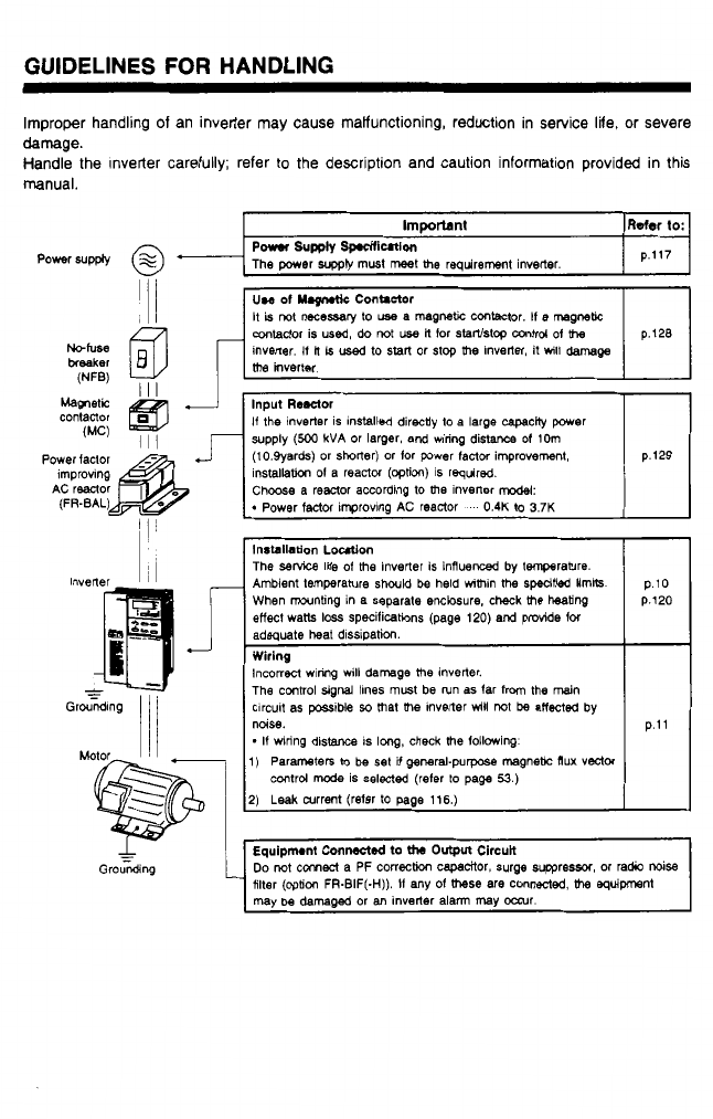
GUIDELINES
FOR
HANDLING
Improper handling of an inverler may cause malfunctioning, reduction in service
life.
or severe
damage.
Handle the Inverter carefully; refer
to
the description and caution information provided in this
manual.
I
Immmnt
I
Refer
to:l
The power
suppb
must meet me requirement inverter.
Po*mS"pplY
sp.stfiutlon p.117
conlador is used, do
not
use
il
for
slanlstop
mtrd
of
me
inverter.
If
H
is
used
to
start or stop
me
Inverter, it
will
damage
supply
(500
kVA
or larger, and wiring distance
of
IMn
(10.9yards) or shorter) or lor power fadw improvement,
installath
of
a reactor
(option)
is required.
Choose a reactor according to
me
inverter model:
Installation
Ldon
The
service
Iile
of
me inverter is influenced
by
temperature.
Ambient temperature
should
be
held Whin
the
specified lmik p.10
adequate
heat
dissipation.
The
control
signal ihnes must be run as far
from
me
main
clrcuit as possible
so
mat me inverter
will
not
be
atfected
by
-
If
unring distance
IS
long.
check
me
following
I)
Parametem
to
be
set
it
general-purpose magnebc
flux
vector
control
mode
is selected (refer
to
page
53.)
2)
Leak
current (refer
to
page 116.)
p.11
.?
1.
PRECAUTIONS
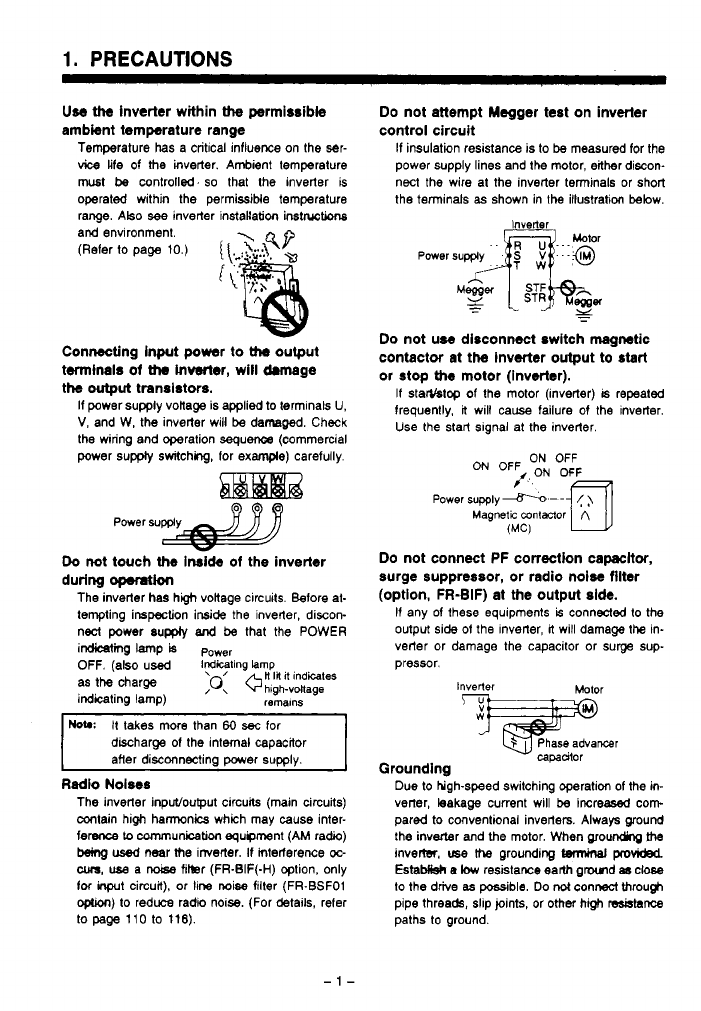
Use
ttte
inverter within
the
permissible Do not attempt Megger test on inverter
ambient temperature range control circuit
Temperature has a critical influence
on
the ser-
If
insulation reSiStanCe is to
be
measured for the
vice
life of
the
inverter. Ambient tempereture power supply lines and the motor, either discon-
must
be
controll%d.
so
that the inverter is
operated within the permissible temperature nect the wire at the inverter terminals or short
the terminals
as
shown in the illustration below.
range. ~tso
see
inverter instakation
inst~tions
and environment.
(Refer
to
page 10.)
{
\.
'
:?-:A
4P
ic
Connecting input power to
Uw
output
twninals
of
Uw
inverter, will drmage
the
output
transistors.
If power supply vonage is
applied
to terminals
U,
V,
and W, the inverter will
be
damaged. Check
the wiring and operation sequence (commercial
power
supply
switching, for
example)
carefully.
Power
supply
a
Do
not touch
the
Inside
of
the inverter
during
opemtion
The inverter has hgh vokage circuits. Before at-
tempting inspection inside the inverter, discon-
nect power supply
and
be
that the POWER
imine
lamp
is
P~~~~
OFF.
(also used
iGGting
!amp
as
the
charge
;o:
+H
I#
it
indites
indicating lamp)
hlgh-voltage
remalns
HOW
It takes more than
60
sec
for
discharge
of
the internal capacitor
after disconnecting power supply.
Radio Noiws
The inverter input/ouput circuits (main circuits)
contain high hannonics which may
cause
inter-
ference
Lo
cnmmunicaticm equipment (AM radio)
b3ing
used
near
the
irrverter.
If
mteriarence
oc-
cum,
use
a
noise
fikr (FR-EIF(-H) option, only
foc
inprt
circuit), or line
noise
filter (FR-BSFO1
optron)
to
reduce radio noise. (For details, refer
to
page
110 to 116).
Inverter
-.
Do
not use disconnect switch magnetic
contactor at the inverter output to start
or
stop
the
motor (inverter).
If
starYstop of the motor (inverter)
is
repeated
frequently,
it
will
cause
failure of the inverter.
Use
the start slgnal at the inverter.
ON
OFF
ON
OFF
/,ON OF&
Power
supply
-.-
-
(
)
Magnetic
mntmor
A
(MC)
UJ
Do
not connect PF correction capacttor,
surge suppressor, or radio noise filter
(option, FR-BIF) at the output side.
If any of these equipments
is
connected to the
output side
of
the inverter,
it
will damage
the
in-
verter or damage the capacitor or surge
sup-
pressor.
Inverter
%jiE!Oml
capadtor
Grounding
Due to hgh-speed switching operation
of
the
in-
verter, leakage current will
be
increased
corn
pared to conventional inverters. Always ground
the inverter and
the
motor. When ~~ounding
fhe
invertsr.
use
the
grounding
twmiml
provided
EstaMisk
e
low
resistawe earlh gmd
8s
close
to
the drive
as
possible.
Do
not
connect through
pipe threads, slip joints, or other high
resblsnce
paths
to
ground.
2.
NOMENCLATURE AND FUNCTIONS
-
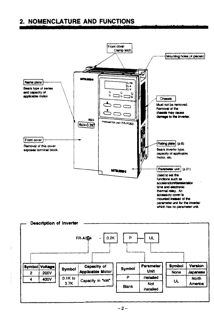
Descrlptlon
of
InvW
-2-
.
2.
NOMENCLATURE AND FUNCTIONS
m
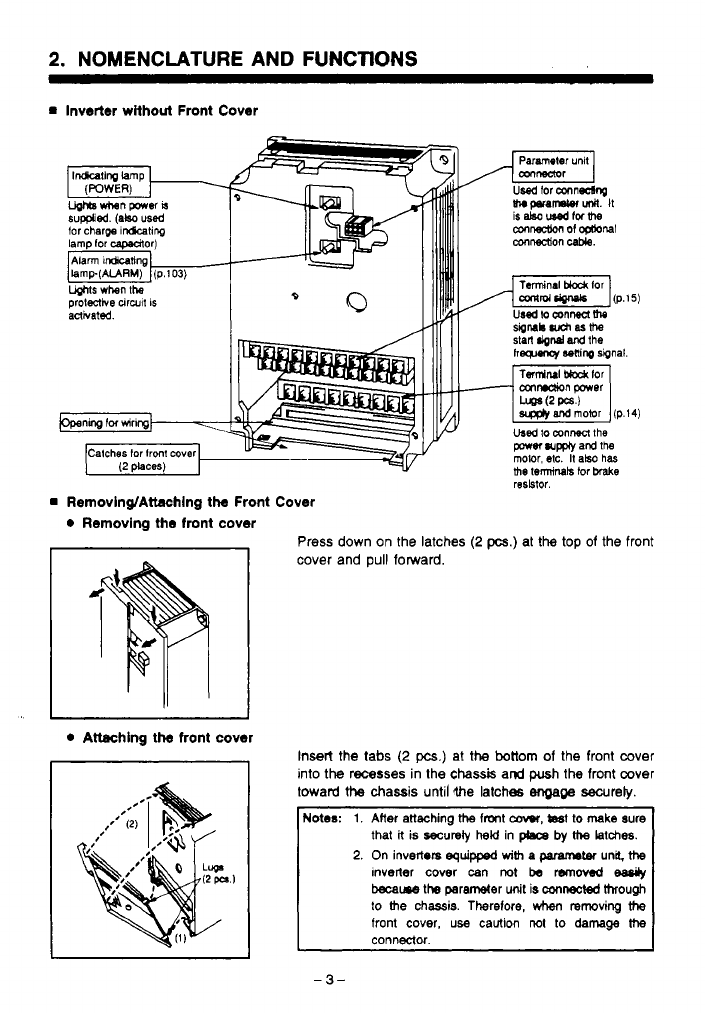
inverter without Front Cover
tor charpe
rchting
lamp lor capadtor)
t
1
Removing/Attachlng the Front Cover
0
Removing the front cover
I
I
0
Attaching
the
front cover
stitl
Mnd
and
the
hg~~nor
Sonlrq
sipnal
Ts~NI
t&&
lor
cmndion
power
Used
lo
mnnen
the
porn
wm
and
ths
the
terminals
tor
brake
molor, etc.
It
also
has
resbtor.
Press down on the latches
(2
pcs.) at
the
top
of the front
cover and
pull
forward.
Insert the
tabs
(2
pcs.)
at
the
bottom
of
the front cover
into
the
recesses in the
chassis
and
push
the
front cover
toward
the
chassis until
the
latches
engage
secureb.
Notes:
1.
Alter
attaching
ttte
fmnt
caw,
tsst
to
make
sure
that
k
is
securety
held
in
phca by
the
latches.
2.
On
inverters
equipped
with
a
paramem
una.
ttte
tnveiler
cover
can
not
be
removed
eaady
became
the parameter
unit
is
mnected
through
to
the
chassis. Therelore,
hm
reroving
the
front
cover,
use
caUtion
not
to
damage
the
-
3-
.
..
..
2.
NOMENCLATURE
AND
FWCTWS
rn
Parameter Unit Location
The parameter unit can be mounted directly on the inverter, or installed in a remote location
with an optional cable.
In
a
remote installation, the parameter unit may
be
used
as a hand-held unit or mounted in an
enclosure.
Removal
and
installation
of
the parameter unit
is
permissible while the inverter
is
powered up
or in operation.
rn
Removing and installlng the Parameter Unit
Removing the parameter
Unn
from the Inverter
rd
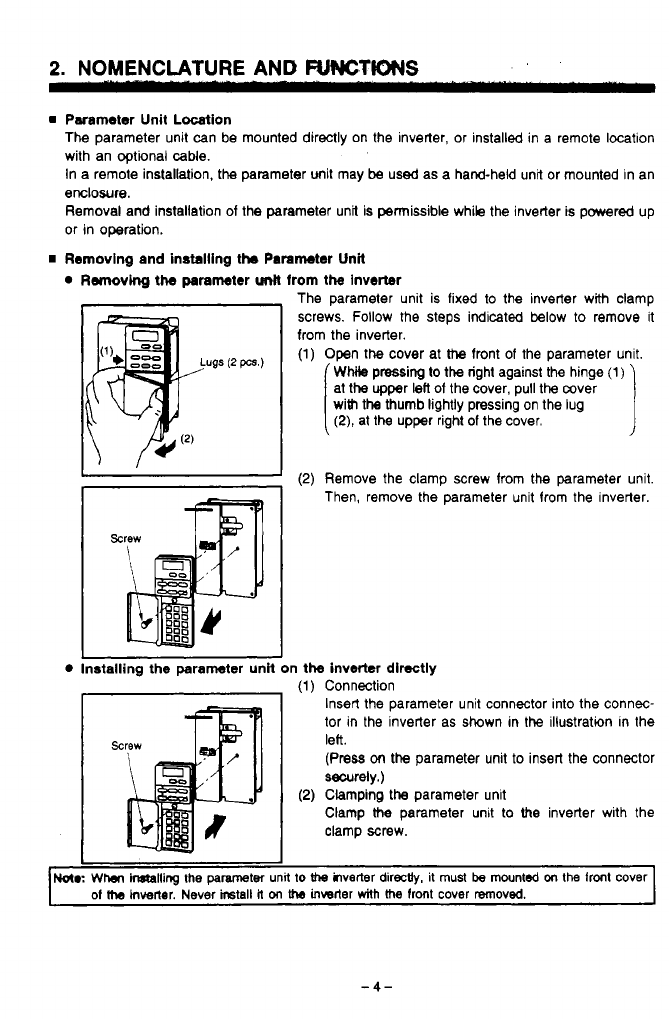
The parameter unit is fixed to the inverter with clamp
4
screws. Follow the steps indicated below
to
remove it
from the inverter.
(1)
Open the cover at
the
front
of
the parameter unit.
WMle
pressing
to
the right against the hinge
(1)
with
the thumb lightly pressing on the lug
at the upper
left
of
the cover, pull the mver
(2),
at the upper right of the cover.
I
I
I
(2)
Remove the clamp screw from the parameter unit
Then, remove the parameter unit from the inverter.
Installing the parameter unH on the inverter directly
(1)
Connection
Insert the parameter unit connector into the connec-
tor in the inverter as shown in the illustration in the
lee.
(Press
on
the parameter unit to insert the connector
securely.)
Clamp
the
parameter unit to
the
inverter with the
clamp screw.
,d
(2)
Clamping the parameter unit
I
1
No(.:
Whar
inftailing
the
parameter
unit
to
the
ilverter
directly.
it
must
be
mounted
on
the
front cover
of
Me
hvener. Never
ircstall
it
on
the
inwrter
with
the
lront cover removed.
c
-4-
.
2.
NOMENCLATURE AND FUNCTIONS
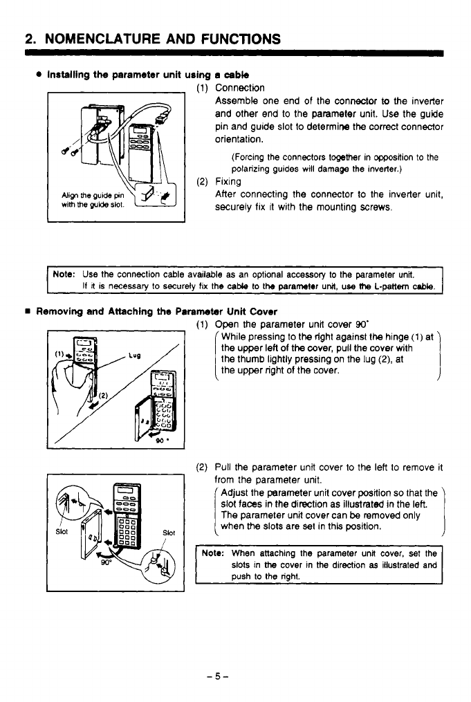
Installing the parameter unit using
a
cabb
(1)
Connection
Assemble one end of the connector
to
the inverter
and other end to the parameter unit. Use the guide
pin and guide
slot
to
determine the correct connector
orientation.
(Forcing the connectors together in Wsition
to
the
polarizing guides
will
damage the inverter.)
(2)
Fixing
Align
me
guide
pin
After connecting the connector to the inverter unit,
with
me
guide
slot.
securely
fix
It
with the mounting
screws.
~ ~~~~~
Note:
Use
the connection cable available as an optional accessory
to
the parameter unit.
I1
It
is necessary to securely
fix
the
cable
to
tb
parameter
unit,
use
the
L-pattern
cable.
Removing and Attaching the
Paremeter
Unit Cover
I
I
(1)
Open the parameter unit cover
90'
While pressing to the right against the hinge
(1)
at
the thumb lightly pressing on the lug
(2),
at
the upper left
of
the cover, pull the cover with
the upper right
of
the
cover.
I
(2)
Pull
the parameter unit cover to the left
to
remove it
from the parameter unit.
Adjust the parameter unit cover position
so
that the
slot faces
in
the direction as illustrated
in
the left.
when the
slots
are
set
in this position.
The parameter unit cover can
be
removed only
r
Note:
When attaching the parameter una cover,
set
the
slots in
the
cover in
the
direction
as
illustrated and
push to the right.
2.
NOMENCLATURE
AND
FUNCTIONS
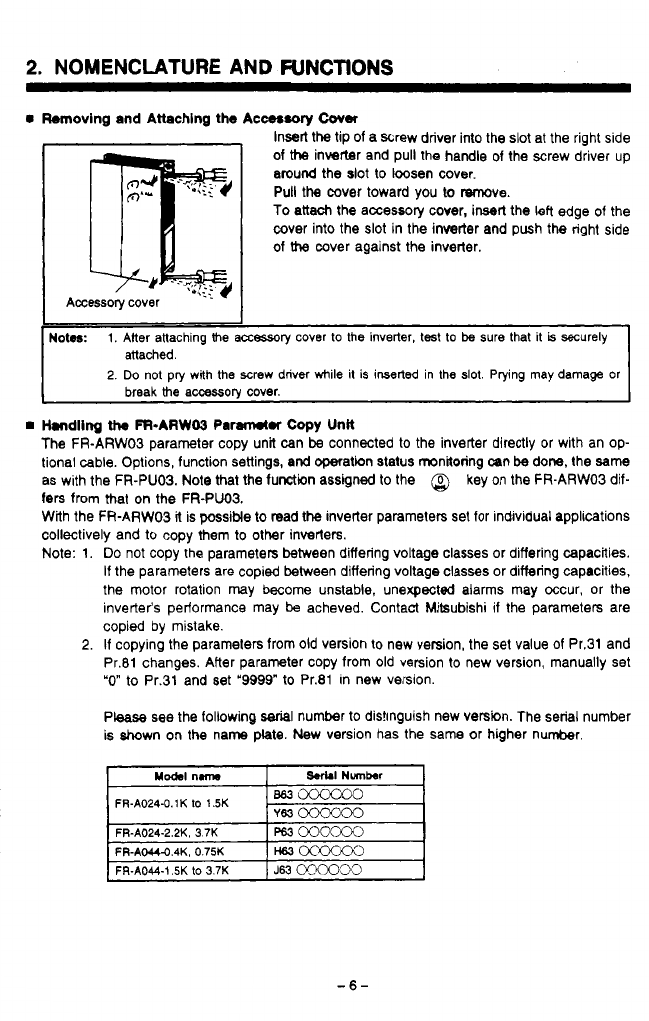
Removing and Attaching the Acc08sory
Cover
Insert the tip of a screw driver into the
slot
at the right side
of
the
inverter and pull the handle of the screw driver up
around the slot to loosen cover.
Pull the cover toward you to T%moye.
To attach the accessory cover, insert the left edge of the
cover into the slot in the inverter and push the right side
of
the
cover against the inverter.
Handling
th.
FFbARW03
Par#rwtr
Copy
Unk
The FR-ARWOS parameter copy unit can
be
connected to the inverter directly or with an op-
tional cable. Options, function settings, and operation status monitoring mn
be
done, the
same
as with the FR-PUO3. Note that the function assigned to the
@
key on the FR-ARW03 dif-
fers
from that on the FR-PUO3.
With the FR-ARW03
it
is possible to read
the
inverter parameters set for individual applications
collectively and to copy them to other inverters.
Note: 1.
Do
not copy the parameters between differing voltage classes or differing capacities.
If
the parameters are copied between differing voltage classes or differing capacities,
the motor rotation may become unstable, unexpected alarms may occur, or the
inverter‘s performance may
be
acheved. Contact Mitsubishi if the parameters are
copied by mistake.
2.
If
copying the parameters from old version to new version, the set value of Pr.31 and
Pr.81 changes. After parameter copy from old version to new version, manually set
“0”
to Pr.31 and set
‘9999”
to Pr.81 in new version.
Please see the following
serial
number to distinguish new version. The serial number
is shown on the name plate. New version has the same or higher number.
FR-A024-0.1K
lo
1.5K
-6-

2.
NOMENCLATURE
AND
FUNCTIONS
Handling
the
FR-PUM1 Parameter Unk
The
FR-PUO2.1 parameter unit can
be
connected
to
the
inverler using an optional
cable.
Note: With
the
FR-PUO2.1, setting the inverter parameters. operating
frequency,
and running
operation for forward and reverse rotation can
be
done. However, monitoring (including
graphic) and other operations can be done only within a limited range.
If
the FR-PUO2.1, is
used
and Pr.
37
(speed unit) is
set
to
100
or higher, a value that
ignores the third and above digits, and which also ignores
the
monitor display will be
applied. (Note that the set value is registered,
so
il
the Pr.
37
set
value is read with the
FR-PUOS,
a
value that is set to
100
or higher will display.
-7-
.
._ .
.
~.-
__
. .
.
. .
-
.
.
.
. ..
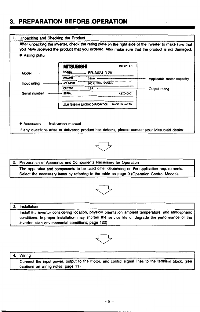
3.
PREPARATION
BEFORK
,OPERATION
-
Applicable
motor capaaty
-
Output rabng
0
Accassory
.
lnstnrclion manual
If any questions arise or &livered product has defects, please contact your Mitsubkhi dealer.
2. Preparation of Apparatus and Components Necessary lor Operation
The apparatus and components to
be
used
differ depending on
the
application requirements.
Select the necessary
items
by referring to the table
on
page
9
(Operation Control
Modes).
3.
Installation
conditions. Improper installation may shorten the setvice lite
or
degrade the performance of the
Install the inverter considering location, physical orientation ambient temperature. and atmospheric
inverter.
(see
environmental conditions; page
120)
4. Wiring
cautions on wiring notes; page
11)
Connect the input power, output to the motor, and control signal lines to the terminal block.
(see
-8-
I
5.
INSTALLATION
.. .
-".
"
1
b,..
.
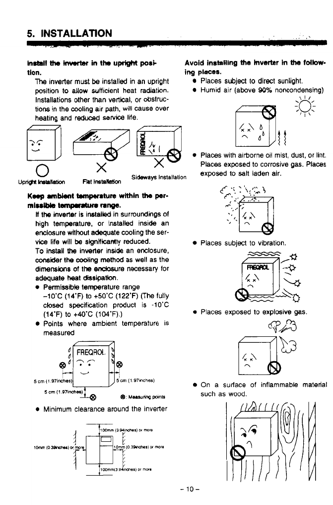
Instnll
tho
lnwrter
in
the
upright
posC
Avoid instaling
the
inverter
in
tho
follow-
tlon.
ing
places.
The
inverter must
be
installed in an upright Places subject to direct sunlight.
position to dow sufficient heat radiation. Humid air (above
90%
noncondensing)
Installations other than vertical, or obstruc-
tions in the cooling air path, will cause over
heating and
reduced
service
life.
fq
pgq
0
Places with airborne oil mist, dust, or lint.
Places exposed
to
corrosive
gas.
Places
0
X
upw--
Flrt
lnstsllation
sideways
Installation
exposed
lo
sa'
laden
air.
Keep
mbknt
tempr.hrre
within
tho
pr-
if the inverter is installed in surroundings
of
high temperature, or installed inside an
enclosure without adequate cooling the ser-
vice life will
be
significantly reduced.
To
install
the
inverter inside an enclosure,
cwgider
the
coding
method
as well as the
dimensbns of the eodowre necessary for
adequate
heat
c#ssipation.
0
Petmlssble temperature range
rniulbb
temprrtun
nnge.
-1o'C (14'F)
to
+50'C (122'F) (The fully
closed specification product is -1O'C
(14'F)
to
+WC
(lM'F).)
Points where ambient temperature is
measured
@
Me~mrq
pants
0
Minimum clearance around the inverter
1
mmm (3
WlrWmIi
DI
rare
Places subject
to
vibration.
Places exposed to explasive
gas
On a surface
of
inflammable material
such as wood.
.
-
10-
\
6.
WIRING
6.1
Precautions
When wiring, consider the following items to avoid erroneous operation, damage or incorrect
usage to the inverter.
Cautions on Wiring
(1)
Do
not connect the power supply wires to the output terminals
(U,
V,
W)
01
the inverter.
If
they are connected to these terminals,
it
will damage the inverter.
(2)
Terminals P and
PR
are used for connection
01
the optional brake resistor (refer to
page
131).
Never short circuit or connect anything other than the brake resistor across
these terminals.
(3)
Use sleeved
solderless
terminals for the connection
of
the power supply and the motor.
(4)
Common terminals
SD,
5,
and
SE
in
the terminal block for the control circuit are not
at the same potential.
Do
not connect or ground these terminals.
(5)
Use only shielded or twisted caMes to connect the control circuits. These wires must
be
routed as far as possible from the main power and AC relay logic circuits.
(6)
During wiring, close the
slots
on
the top of the inverter with a cover
so
that cut pieces
of
wire
will
not
enter
the
inverter.
(7)
If
modilkation
of
the
wiring
OT
other work becomes necessary aiter operating the in-
verter, do not touch the wire or terminals until power is disconnect and the POWER
CHARGE indicating lamp is extinguished for at least
two
minutes.
(8)
Any pekon who is involved in the wiring
of
this equipment should
be
fully competent
to carry out the work.
-
Wire
Size
and
Wiring
Distance
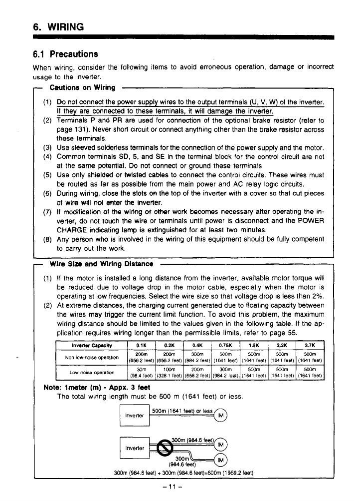
(1)
If
the motor is installed a long distance from the inverter, available motor torque will
be reduced due to voltage drop in the motor cable, especially when the motor is
operating at low frequencies. Select the wire size
so
that voltage drop is
less
than
2%.
(2)
At extreme distances. the charging current generated due to floating capacity between
the wires may trigger the current limit function. To avoid this problem, the maximum
wiring distance should be limited
to
the values given in the following table. If the ap-
plication
requires wiring longer than the permissible lirnlts, refer to page
55.
Note:
lmtw
(m)
-
Appx.
3
feet
The total wiring length must
be
500
m
(1641
feet) or
less.
lnvener
500m
(1MI
feet)
or
less
IM
lnvelter
3Wm
(984.6 feet)
+
3oom
(984.6
feet)=6OCin
(1969.2
1881)
-
11
-
6.
WIRING
-
Items
to
60
Checked
when
Designing an
Application
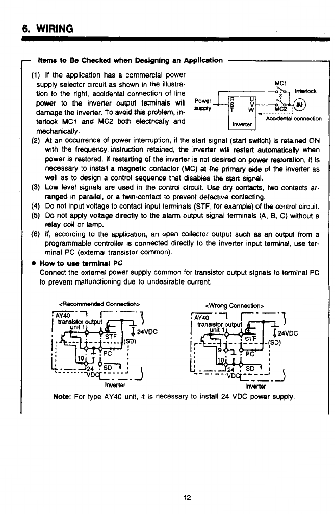
(1)
If
the application
has
a commercial power
supply selector circuit as shown in the illustra-
tion
to
the right, accidental connection of line
power
to
IIM
inverter
output
terminals will
Power
JjTFbF
damage the inverter.
To
avoid
this
problem, in-
*'
*__._______.
terlock
MC1
and
MC2
both
electrically and
mechanically.
(2)
At an occurrence
01
power interruption, il the start signal (start
switch)
is
retained
ON
with the frequency instruction retained, the inverter will restart automaticaliy when
power is restored.
It
restarting
of
the
inverter is not desired on
poww
restoration,
it
is
necessary to install a
magnetic
contactor
(MC)
at
the primary
side
of
the
inverter as
well as
to
design
a
control sequence
that
disables the
s@rt
signal.
(3)
Low level signals are used in
the
control circuit.
Use
dry contacts,
hwo
contacts ar-
ranged in parallel, or a twincontact
to
prevent defective wntecting.
(4)
Do
not input voltage to contact input terminals
(STF,
for example)
of
the
control circuit,
(5)
Do
not
apply
voltage directty to the
alarm
output
signal
terminals (A,
8,
C)
without
a
relay
coil or lamp.
(6)
If,
according to the ap@cation, an open collector output
such
as
an
output
from a
programmable controller is connected directly
to
the
inverter input terminal, use ter-
minal
PC
(external transistor common).
Acddaal
connection
IWMieI
How
to
u.0
trnnirui
PC
Connect the external power supply common for tramistor output signals
to
terminal
PC
to prevent malfunctioning due
to
undesirable current.
Note:
For type
AY40
unit,
it
is necessary to install
24
VDC
power
suppiy.
-12-
..
I I.
,
6.
WIRING
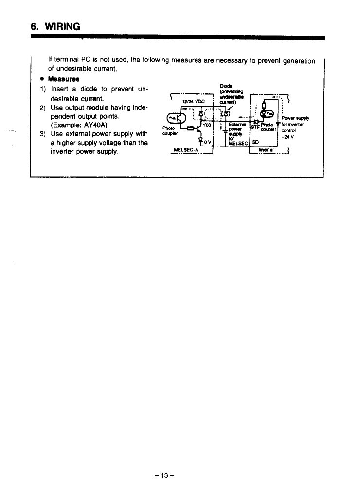
It
temlnal
PC
is not
used,
the follow
of
undesirable current.
Measures
Insert
a
diode
to
prevent un-
desirable
cumt.
Use
wtput
module
having inde-
pendent
output
points.
(Example:
AY40A)
Use
external power
supply
with
a higher
supply
voltage than the
inverter power
supply.
ing measures are necessary to prevent generation
-13-

6.
WIRING
6.2
Connecting
the
Power Supply
and Motor
Termid
block
drait
breaka
ed
ckm(indcat6dbyenamm)HhenviervedfrcmUwmotor
Brake resistor
Brake
unit
(option)
(Refer
to
page 133)
(OPM)
.?.
Do
not use the optional brake unit and brake resistor simultaneously.
Uotes:
1.
Terminal
block
(Configuration
of
the terminal
Mock
varies depending
on
the inverter capacity.)
0
Arrangement
of
terminals
.
. . .
See
the illustration above.
Screw size
.
. .
.
. .
.
.
,
. .
,
.
.
.
.
M3.5
screws (FR-A024-0.1 K
to
1.5 K). (FR-AM-
0.4K to 1.5K)
M4 screws (FR-A024-2.2 K.
3.7
K),
(FR-AM-2.2K,
3.7K)
Specification
of
terminals.
.
,
. .
Refer to 'Specifications
of
Terminals' (page
123).
2. Grounding terminals (Configuration
of
the terminal
block
varies depending on the inverter
capaclty.)
0
Arrangement
of
grounding terminals
Screw size
.
. .
.
. .
.
. .
.
,
. . .
. .
M3.5
screws (FR-A024-0.1 K
to
1.5
K), (FR-AM-
0.4 K
to
1.5
K)
3.7
K)
M4 screws (FR-A024-2.2 K,
3.7
K), (FR-AM-2.2 K,
,
, , ,
.
,
,
,
.
,
.
.
.
. .
.
,
.
Two terminals beneath the terminal
block
Solderless terminals
(If
grounding wire is connected using
the
solderless
terminals)
.
, ,
. .
,
,
,
. .
,
.
. . . .
.
.
Nominal size
2-3.5
(FR-A024-0.1
K
to
1.5
K). (FR-
AM-0.4 K to 1.5 K)
Nominal size 2-4 (FR-A024-2.2 K,
3.7
K), (FR-AM-
2.2
K
,
3.7
K)
3.
Wire
sue
Rder
to "Selection
of
Peripheral Devices" (page 128)
-14-

6.
WIRING
6.3
Connecting
the
Control
Signalr
Frequency
meter
This
rasblci is rot neceswy
U
calbra&x
is
made
using
me
parameter
unit.
Frequewy
sethng
variaMe
restor
a2WlM)(Nde4)
I1
I
Notes:
1.
Terminal block
Arrangement
of
terminals .-.See the illustration above (in
two
rows).
Screw size
M3
screws
be changed by changing the setting for the corresponding parameter.
2.
For the terminals indicated by an asterisk
(*),
input or output specifications may
3.
Two
SD
terminals are internally connected.
4.
I1
frequency setting must be changed frequently,
it
is recommended to use
2
W.
1
kR
resistor.
6.
WIRING
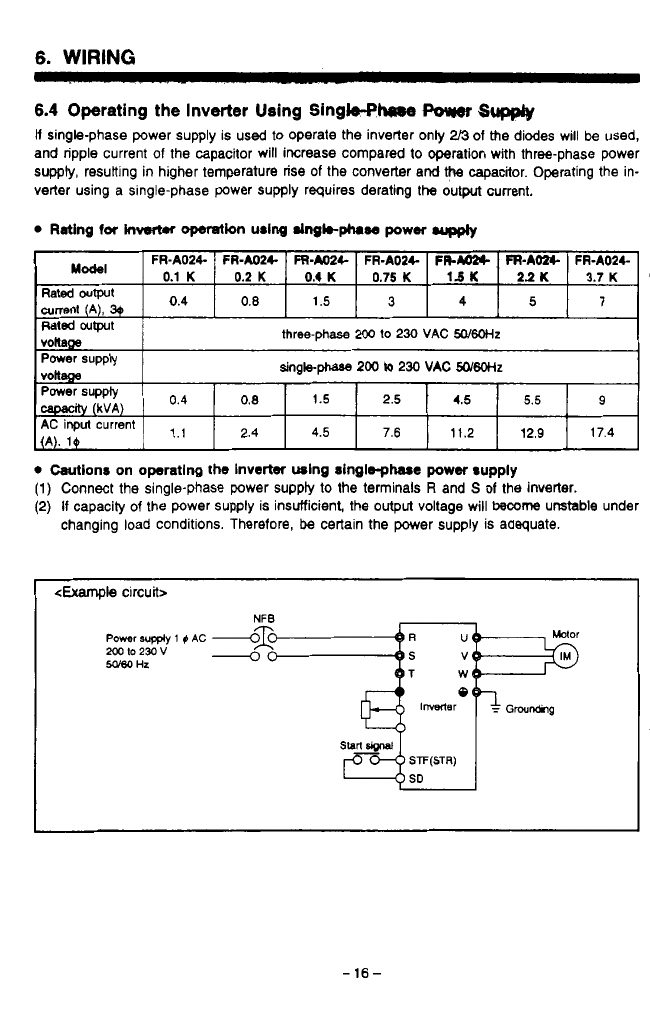
6.4 Operating the Inverter Using Single+-
Power
Sw
li
single-phase power supply is used
to
operate the inverter only
2/3
of the diodes will be used,
and ripple current of the capacitor will increase compared
to
operation with three-phase power
supply, resuiting in higher temperature rise of the converter and
the
capacitor. Operating the in-
verter using a Single-phase power supply requires derating the output current.
currenr
1.1
2.4
4.5
7.6
11.2
12.9
17.4
0
Wionr on operating
the
Inverter using singlsphasc
power
supply
(1)
Connect the single-phase power suppty
to
the terminals
R
arid
S
of
the inverter.
(2)
If
capacity
of
the power supply is insufficient, the
output
voltage will
become
unstable under
changing load conditions. Therefore,
be
certain the power supply is adequate.
<Example
circuit>
NFB
Power
supply
1
0
AC
Sago
Hz
mto23ov
-
-16-
6.
WIRING
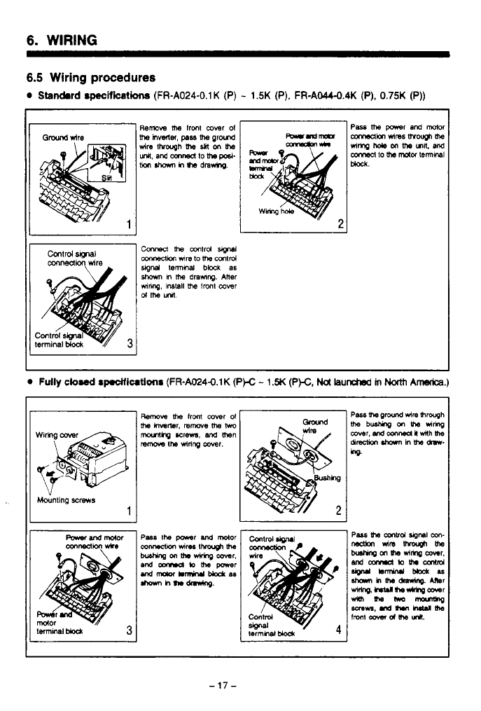
6.5 Wiring
procedures
0
Standard
specificatha
(FR-A024-0.1K
(P)
-
1.5K
(P).
FR-AW.4K
(P),
0.75K
(P))
J
Mounting
screws
1
-17-
..
6.
WIRING
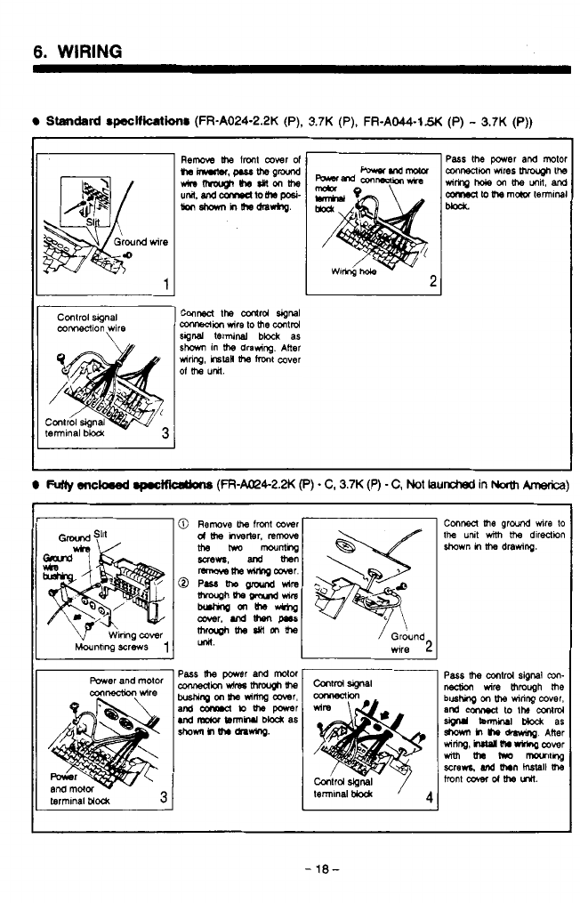
Standtlrd
~wlficllti~
(FR-A024-2.2K
(P),
3.7K
(P),
FR-AO44-1.W
(P)
-
3.7K
(P))
1
Control
wgnal
mMeCllon
wire
Conred
the
adrd
signa
CoMeClion
wire to
me
mlrd
sgnd
terminal
block
as
mnng,
r6taH
me
mxlt
cover
sham
in
me
drawing. Alter
Of
me
UW.
I
FUlW
eneked
.p.otfkOtbM
(FR-a4-2.N
e)
-
C,
3.7K
(P)
-
C,
Not
iaunctred
in
Nath
knerica)
Power
and mtor
cqnnection
wire
contrd
signal
Conrmci
me
ground
we
to
the
U~I
with
me
dlreCtwn
ahown
in
ltm
drawing.
I
I
-18-
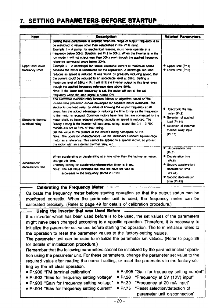
7.
SElTlNG
PARAMETERS
BEFORE
STARTUP
The major parameters to be set, and the functions
of
these
parameters, are explained
in
the fol-
lowing table. Set the parameters according
to
the application requirements (load and operation
specifications).
For details
of
the setting procedure, refer to page
38.
Refer
to
page
57
lor a complete list of
parameters. The term "Pr." is an abbreviation for parameter.
Setting
the
parameters
Set the parameters using the parameter unit. Reler
lo
page
38
lor operating instructions.
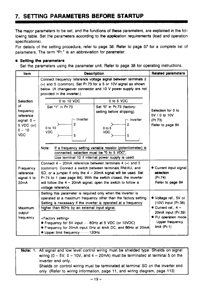
Itern
Selection
of
frequency
reference
slgnal:
0
-
5
VDC (or)
0-
10
VDC
Frequency
reference
signal 4 to
20mA
Maximum
output
frequency
Description
:onnecl frequency refereme vMaga
signal
Ween terminals 2
+)
and
5
(common).
Set
Pr.73 for a
5
or 1OV signal as Shown
!elow. (A changeover connector and 10
V
power supply are not
rrovided in
the
inverter.)
__~
0
to
10
VDC
Set '1" in Pr.73
Inverter
010
10
0 to
5
VDC
Set
r)"
in Pr.73 Ifactow
setting before shipping).
..
VDC
Jote:
If
a frequency setting variable resistor (potentiometer) is
connected, selection must
be
'0
to
5
VDC".
Use terminal
10
U
internal power
supply
is
used.
:onnect 4
-
20mA reference between terminals
4
(+)
and
5
common). Connect a switch between terminals RWAU, and
3D, or a jumper
if
only the
4
-
20mA signal will be used. Set
'r.74 to
1
(see
page
84).
With the switch closed, the inverter
Hill
follow the
4
-
20mA slgnal: open the switch to follow a
loltaae reference.
jetting this parameter is required only when
the
inverter is
merated at a maximum freauencv other than the factory setting.
..
jetting is necessary
if
the inverter
is
operated at a frequency
ligher than
6OHz
by
an external input signal.
<Factory setting>
D
Frequency
for
5V Inpat
...
.60Hz
at
5
VDC (Or 1OVDC)
D
Frequency for 20mA input.
OHz
at 4mA DC, and
BOHz
at 20mP
D
Umer limil freauencv
'
120Hz
Related
prarneters
Selection
for
0
to
5V
/
0
to 1OV
(Pr.73)
Refer to page
84
Current input signa
selection
(Pr.74)
Refer to
page
84
Voltage ref., 5V or
(1OV) input (Pr.38)
0
Current ref.,
4
-
20mA input (Pr.39)
PU operatibn mode
Upper
frequency
limit (Pr.l)
Note:
1.
All
signal
arid
low
level control wiring must be shielded type. Shields on signal
wiring
(0
-
5V,
0
-
IOV.
and
4
-
20mA) must be terminated at termiml
5
on the
inverter end only.
Shields on control wiring must
be
terminated at terminal
SD
on the inverter end
only. (Refer
to
wiring information, page
11,
and wiring diagram, page
113)
-
19-
7.
SElTlNG
PARAMSTERS
BEPORE
B'IXFtTuP
L
~
r
Callk.t*lg
the
Fmqqurnoy
Yan
I
Calibrate Me frequency meter
before
statling operation
so
that the output status can
be
monitored correctly. When
the
parameter unit is
used,
the frequency meter can be
I
calibrated oreciselv. (Refer
11
If
an inverter which has been
used
before
is
to
be
used, the set values
01
the parameters
might have been changed according to a
specific
operation. Therefore, it
is
necessary
to
initialize
the
parameter set values before starting the operation. The ten initialize refers
to
the
operation to reset the parameter values
to
the factory-setting values.
The parameter unit can be
used
to
initialize the parameter set values. (Refer
to
page 39
for details of initialization procdure.)
Remember that the following parameters cannot
be
initialized by the parameter clear opera-
tion using the parameter unit. For these parameters, change the parameter set value
to
the
required value after reading the current setting, or reset the parameters
to
the factory-set-
ting by the aU clear operation.
e
Pr.900
'FM
terminal calibration' Pr.905 "Gain for frequency setting current"
Pr.902 'Bias for frequency setting voltage' Pr.38 "Frequency at
5V
(IOV)
input"
Pr.903 "Gain for frequency setting voltage' Pr.39 'Frequency at 20 mA input"
e
Pr.904 gias for frequency setting current" Pr.75 "Reset selectiorddetection
of
parameter unit disconnection"
-
20
-
L
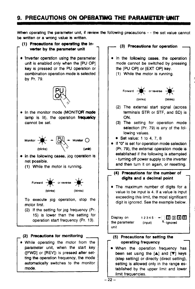
9.
PRECAUTIONS
ON
OP6RATWG
THE
RARAMHERWCT
~~ ~~ ~~~~
When
operating the parameter
unit,
if
review
ttm
following precautions
-
-
the
set value cannot
be
writtin or a wmg value
is
witten.
..
(1)
Plscattionr for
operating
the
in-
verter
by
the
parameter
unit
lnvetter Operation uslng the parameter
unit is enabled only when the
[PU OP]
key is pressed or the
PU
operation or
combination operation mode is selected
by
Pr.
79.
In the monitor mode
(MONITORrode
lamp is lit), the operation
cannot
be
set.
(blinks)
\+
(unsl)
In
the
fdbwing
cases,
jog operation is
not possible.
(1)
While the motor is running.
(blinks)
(MnkS)
To
execute jog operation, stop the
motor first.
(2)
If
the setting for
jog
frequency (Pr.
15)
is lower than the setting for
operation start frequency (Pr.
13).
-
(2)
Precautions
for
monitoring
-
While operating the motor from the
parameter unit, when the start key
([FWD]
or
[REV)
is pressed after set-
ting
the
operation frequency, the mode
automticalty
switches to the monitor
mode.
-
(3)
Precautions
for
operation
-
r
In
the
fobwing
cases,
the operation
mode cannot be switched by pressing
the
[PU OP]
or
[EXT
OP]
key.
(1)
While the motor is running.
(4)
Precautions for
the
number
of
-
r
digits
and a decimal
point
(2)
The external start signal (across
terminals STR or STF, and
SD)
is
ON.
(3)
The setting for operation mode
selection (Pr.
79)
is any of the fol-
lowing values.
Set value:
1
to
4,
7,
8
If
"0" is set for operation mode selection
(Pr.
79),
the external operation
mode
is
established if the following is attempted
-
turning
off
power supply to the inverter
and then turn it on again, or resetting.
Precautions for
the
number
of
-
digits
and a decimal
polnt
The maximum number
of
digits for a
value to
be
input is
4.
It a value is input
exceeding this limit, the most significant
digit is ignored. See the example below.
Display
on
1
23
4
s
-8
-,
the
parameter
(input)
i~gnored
(5)
Precautions for setting the
operating frequency
When the operation frequency has
been set using the
[A]
and
p]
keys
(step setting) or directly (direct setting),
setting is allowed only in the range es-
tablished by the upper limit and lower
limit frequencies.
-22-
-,
.
,
*.
9.
PRECAUTIONS ON OPERATING
THE
PARAMETER UNIT
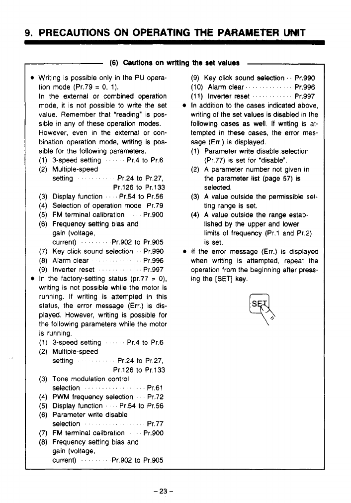
(6) Cautlons on writing
the
set
values
Writing is possible only in the PU opera-
tion mode (Pr.79
=
0,
1).
In the external
or
combined operation
mode, it is not possible
to
write the set
value. Remember that “reading” is
pos-
siMe in any of these operation modes.
However, even in the external or con-
bination operation mode, writing is
pos-
sible for the following parameters.
(1) 3-speed setting
’
Pr.4 to Pr.6
(2) Multiple-speed
setting
.....
Pr.24 to Pr.27,
Pr.126 to Pr.133
(3) Display function
...
Pr.54
to
Pr.56
(4) Selection
of
operation mode Pr.79
(5)
FM
terminal calibration
. .
Pr.900
(6) Frequency setting bias and
gain (voltage,
current)
....
Pr.902
to
Pr.905
(7) Key click sound selection
.
Pr.990
(8)
Alarm clear
........
Pr.996
(9) Inverter reset
.......
Pr.997
In the factory-setting status (pr.77
=
0).
writing is not possible while the motor is
running. If writing is attempted in this
status, the error message (Err.) is dis-
played. However, writing is possible for
the following parameters while the motor
is running.
(1) 3-speed setting
’ ’ ’
Pr.4
to
Pr.6
(2) Multiple-speed
setting
....
Pr.24
to
Pr.27,
Pr.126 to Pr.133
(3) Tone modulation control
selection
.............
.
.
Pr.61
(4) PWM frequency selection Pr.72
(5)
Display function
’
Pr.54 to Pr.56
(6) Parameter write disable Pr.77
(7)
FM
terminal calibration
. .
Pr.900
(8)
Frequency setting bias and
selection
..........
gain (voltage,
current)
’
Pr.902 to Pr.905
(9) Key click sound selection
’.
Pr.990
(IO)
Alarm clear.
...........
Pr.996
(1
1)
Inverter reset
............
Pr.997
In addition to the cases indicated above,
writing of the set values is disabled in the
following
cases
as well. If writing is at-
tempted in these cases, the error mes-
sage
(En.)
is displayed.
(1) Parameter write disable selection
(Pr.77) is set for ‘disable”.
(2) A parameter number not given in
the parameter list (page
57)
is
selected.
(3) A value outside the permissible set-
ting range is set.
(4) A value outside the range estab-
lished by the upper and lower
limits of frequency (Pr.1 and Pr.2)
is set.
If
the error message (Err.) is displayed
when writing is attempted, repeat the
operation from the beginning after press-
ing the
[SET]
key.
10.
WTLW
OF
THE
FUNCTIONS
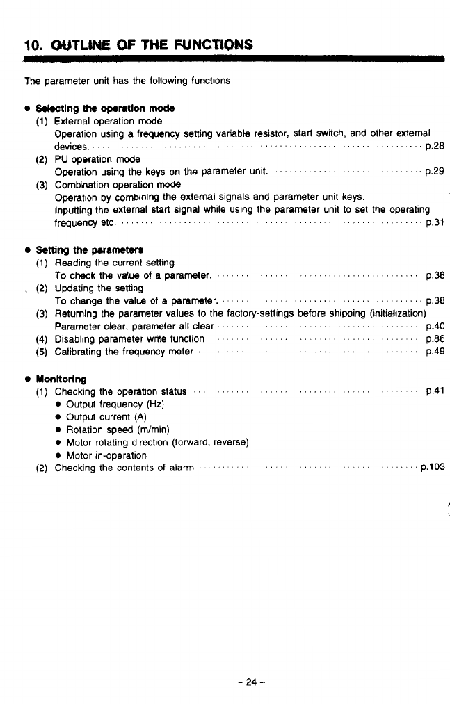
The parameter unit has the following functions
0
kkcting
the
operation
mcde
External operation
rode
Operation using a frequency setting variable resistor,
start
switch, and other external
PU
operation mode
operation using the keys on the parameter unit.
.........................
p.29
Combination operation
mode
Operation by combining
the
external signals and parameter unit keys.
m
Inputting the external
start
signal while using the parameter unit
to
set the operating
devices,
.............................................................
p.28
U'
frequency etc,
..............................................
.
''
p.31
Setting
the pMmetrr
Monltorlng
(1)
Checking the operation Status
....................................
p.41
Output frequency
(Hz)
Output current
(A)
Rotation
speed
(dmin)
0
Motor rotating direction (forward, reverse)
0
Motor in-operation
(2) Checking the contents of alarm
'' ' '' '' '' '' ' '
.....
.
.
p.103
-24-
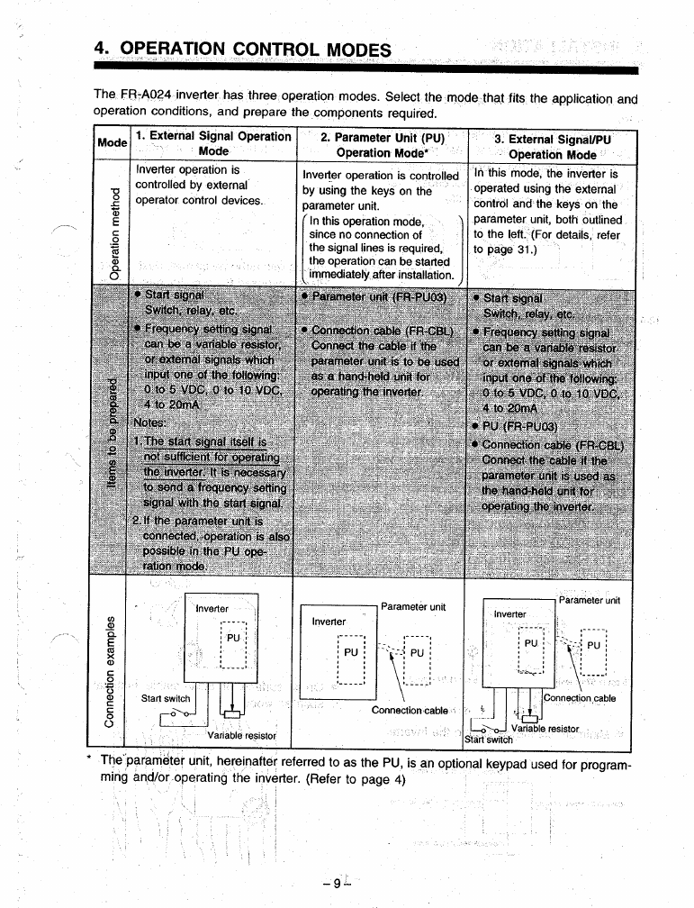
11.
OPERATION
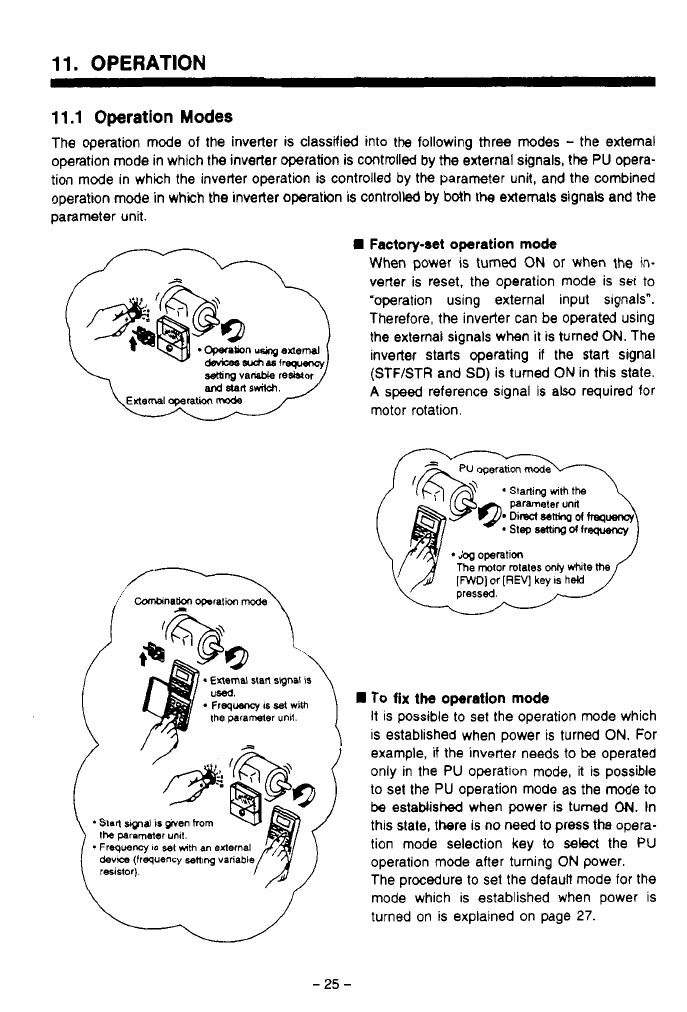
11.1
Operation
Modes
The operation mode
of
the inverter is classified into the following three modes
-
the external
operation mode in which the inverter operation is controlled by the external signals, the
PU
opera-
tion mode in which the inverter operation is controlled by the parameter unit, and the combined
operation mode in which the inverter operation is controlled by both
the
externals signals and the
parameter unit.
Factory-set operation
mode
When power is turned
ON
or
when the in-
verter is reset, the operation mode is set to
"operation using external input slgnals".
Therefore, the inverter can be operated using
the external signals when
it
is tumed
ON.
The
inverter starts operating if the start signal
(STF/STR and
SD)
is turned
ON
in this state.
A
speed reference signal is also required for
motor rotation.
To
fix the operation
mode
it is possible to set the operation mode which
is established when power is turned
ON.
For
example, if the inverter needs to
be
operated
only in the PU operation mode, it is possible
to set the PU operation mode as the mode to
be
estaMished when power is tumed
ON.
In
this state, there is no need to press the opera-
the
paramam
unll.
devm
(frequency
sen~ng
varlabl
operation mode aiter turning
ON
power.
*
Freqwncy
IS
$91
mth
an
0Iternal
tion mode selection key to
select
the PU
The procedure to set the default mode for the
mode which is established when power is
turned on
is
explained on page
27.
-
25
-
11.
OPERATION
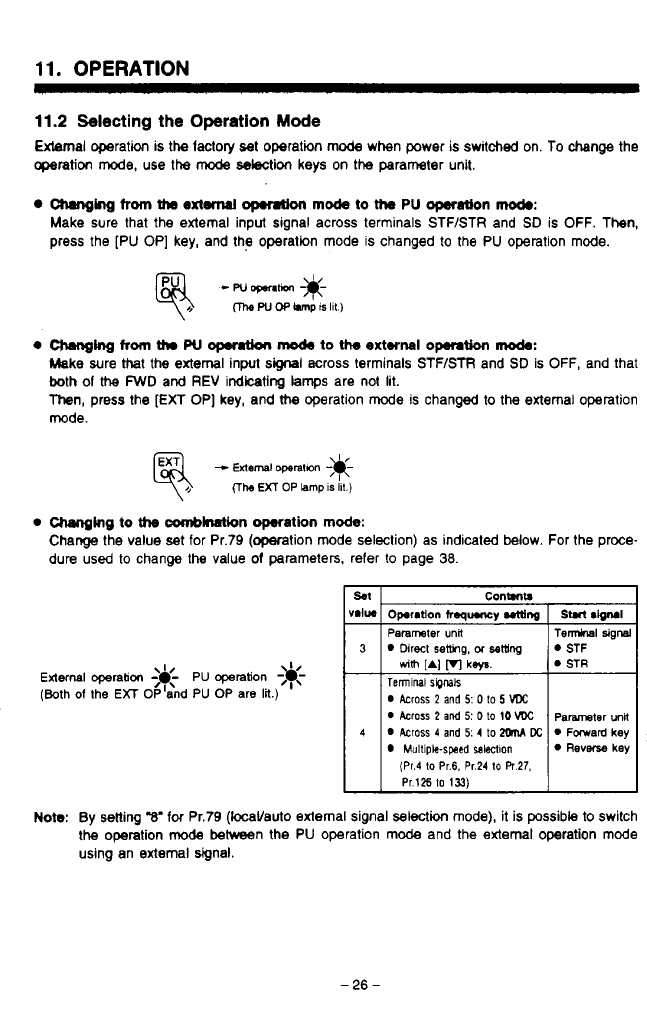
11.2
Selecting
the
Operation
Mode
External operation is the lactoly set operation
mode
when power is switched on.
To
change the
operation
mode,
use the
mode
selection keys on the parameter unit.
Changing
from
the
extanal
opmtion
mock
to
the
PU
operation
mod.:
Make sure that the external input signal across terminals STF/STR and
SD
is OFF. Then,
press the [PU OP] key, and the operation mode
IS
changed to the PU operation mode.
e
aunnghg
from
thr
w
0pemt.h
mO&
to the
external
opemtion
mode:
Make sure that the external input
signal
across terminals STF/STR and
SD
is
OFF,
and that
both
of
the
FWD
and
REV
indicating
lamps
are not lit.
Then,
press the
[EXT
OP] key, and me operation mode is changed to the extemal operation
mode.
-
External
operatan
;*-
(The
EXT
OP
lamp
IS
ill.)
0
Changing
to
tfm
amblnation operation
mode:
Change the value
set
for Pr.79 (operation mode seleclion) as indicaled
below.
For the proce-
dure used to change the value
of
parameters, refer to page
38.
External
operation
<&-
PU
operation
-3c
(Both
of
the
EXT
OP'and PU OP are
lit.)
I/
T
Contmtr
Operation
freqqwncy
utting
Parameter
unit
Direct
setting,
OT
sew
Teninal
SipMk
0
Across
2
and
5:
0
to
5
VDC
0
Across 2
and
5:
0
to
10
VDC
Across
4
and
5: 4
to
XhM
Dc
Multiple-swsd
salectlon
dm
[AI
VI
ks/s.
(Pr.4
to
Pr.6.
Pr.24
to
PT
27,
Pr.126
to
133)
n
v
1
Note:
By
Setting
"8'
for
Pr.79 (locaVauto external signal selection mode), it is possible to switch
the operation
mode
between the PU operation mode and the extemal operation mode
using an external signal.
-
26
-
-.
,
,
11.
OPERATION
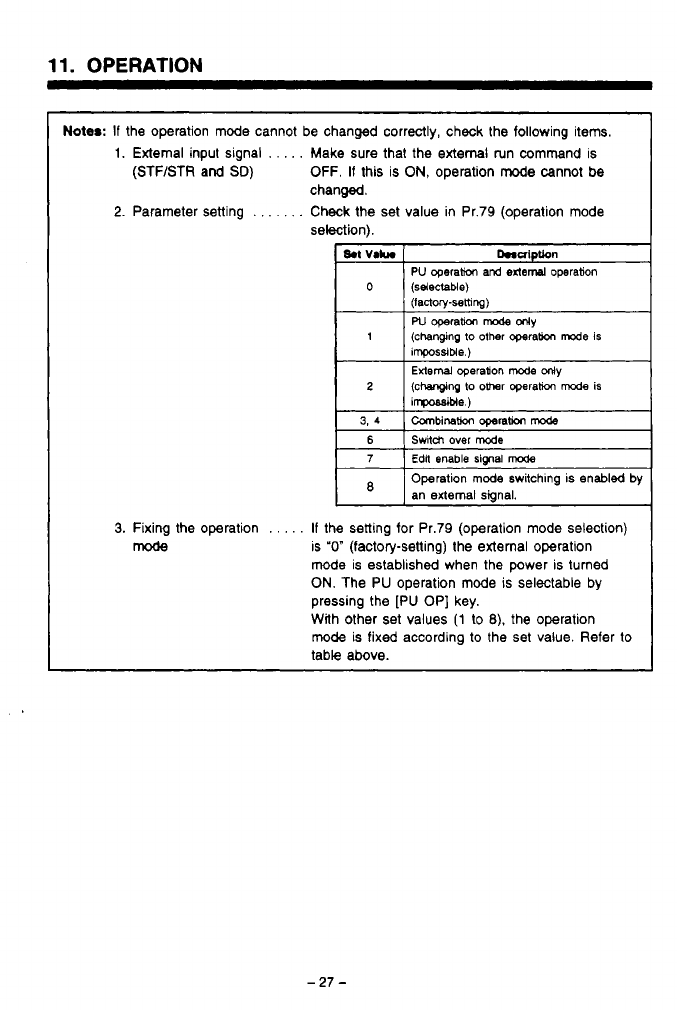
Notes:
If
the operation mode cannot be changed correctly, check the following items.
1.
External input signal
.
.
. . .
Make sure that the external run command is
(STF/STR and
SD)
OFF.
If
this is
ON,
operation
mode
cannot
be
2.
Parameter setting
.
.
. .
. .
.
Check the set value in Pr.79 (operation mode
changed.
selection).
I
8.t
VI*.
Dnaiptbn
PU
operakm and
exled
operation
(lactwpsethng)
W
operam
mode
only
ihpossible.)
2 (changing
lo
o-r
operath
mode
is
iwble
)
External
operadon
mode
ollly
0
(selectable)
1
(changing to other opera(ion
We
is
3,4
Canbinatlor
operation
mode
6
Edlt
enable signal
mode
7
Switch
over
mode
Operation
mode
switchmg
is enabled
by
an
external
signal.
3.
Fixing the operation
.
.
.
. .
If
the setting for Pr.79 (operation mode selection)
mode
is
"0"
(factory-setting) the external operation
mode is established when the power is turned
ON.
The PU operation mode
is
selectable by
pressing the [PU OP] key.
With other
set
values
(1
to
8).
the operation
mode
is fixed according
to
the set value. Refer
to
table above.
11.
OPERATION
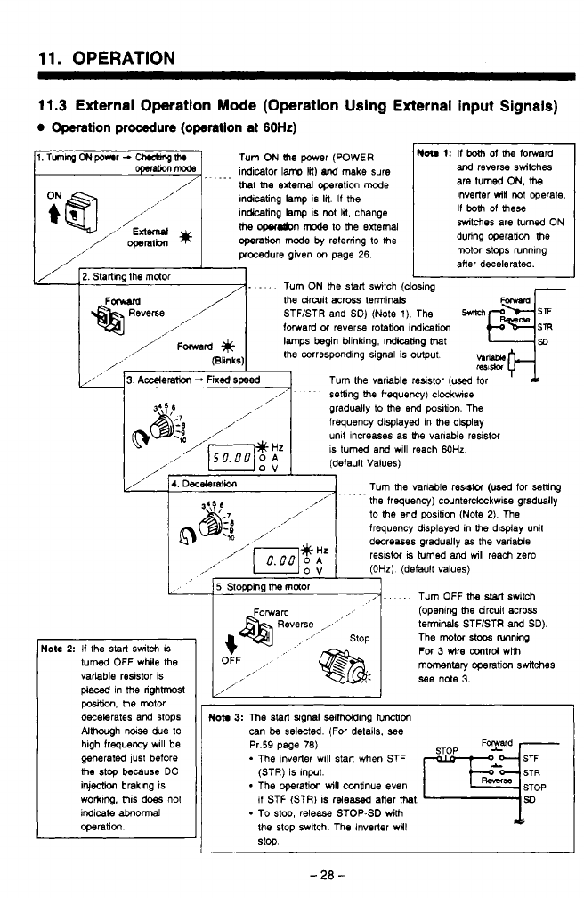
11.3
External Operation
Mode
(Operation Using External input Signals)
Operation
procedure
(operation
at
60Hz)
~l.TunhgONpo*sr-U&bnptJd
-
qnh
mode
indlcator
lam,
18)
and
make sure
Turn
ON
(he
power (POWER
that
me
external
operation
mode
Indicating lamp is
lil.
If
the
in-ting lamp is not
111,
change
/
openth
*
operation
m~de
by
referring
to
the
the
owdon
n-c4e
to
the
external
.
...
,,’
External
,/’
,
procedure
given
on
page
26.
2.
Starthg the muor
.....
Turn
ON
the
stalt
switch
(c
FOWd
/
the drwif across terminals
and
reverse switches
are
tumed ON,
the
inverter
win
not
operate.
If
both
of
mese
switches
are turned ON
during operation,
the
motor stops wnnlng
aHer decelerated.
U
Yosing
I
lote
2:
If
the
start
switch
IS
turned
OFF whRe
the
variable reslstor is
placed
In
me
righhnost
position,
the
motor
decelerates and
stops.
Almwgh
noise
due
to
generated just before
hlgh
frequency
wlll be
me
stop
because
DC
inj-
brakmg is
worktng, this
does
not
Indicate
abnormal
operation.
STFISTR and SD)
(Note
1).
The
mpjzj
forward
or
reversa
rotation
indication
lamps
begin
blinking, indicemg
that
,,/
Fmad
/’
(81,nlcs)
the
mrrespondlng signal is
*ut
b-
y/
’
3.
Aderaion
-
Fixed
speed
mi*
Turn the variable resistor
(used
for
gradually
to
the
end
postion. The
frequency displayed in
the
display
unlt Increases as
me
vanable
resistor
IS
turned and wlll reach
M)Hz
(default Values)
4.
Deceleratkm
Turn
the
vanable re&@
(used
for sening
the
frequency)
cwnterckckwlse gradually
to
the
end position
(Note
2).
The
frequency displayed in
the
dlsplay unit
decreasas graduelly
as
the variable
reslstci
is
turned
and
will
reach
zero
(OHz)
(default values)
I,-.
-. .
Turn OFF
the
start
fw~tch
(openng
the
drcuit across
teninals
STF/STR
and
SD).
The
motor
stops
Rnning.
For 3 wire mtrd wiih
momentary
operation switches
see
note
3.
/’~
.
’
setting
the
hequewy) c~o~kwise
/
,,’
5.
Stopping
lbe
maor
OFF
/’
,/’
I
Noh
3:
The
start
~lgnal selfhdding
tunction
can
be
selected. (For details.
see
Pr.59 page
78)
The lnverler wlll
Stan
when
STF
*
The operation
will
continue even
(STR)
is
Input.
if
STF (STR) is rdeesed after
that.
To
stop
release
STOP6D with
the stop swllch The inverter wll
stop
F
d
-
2a
-
11.
OPERATION
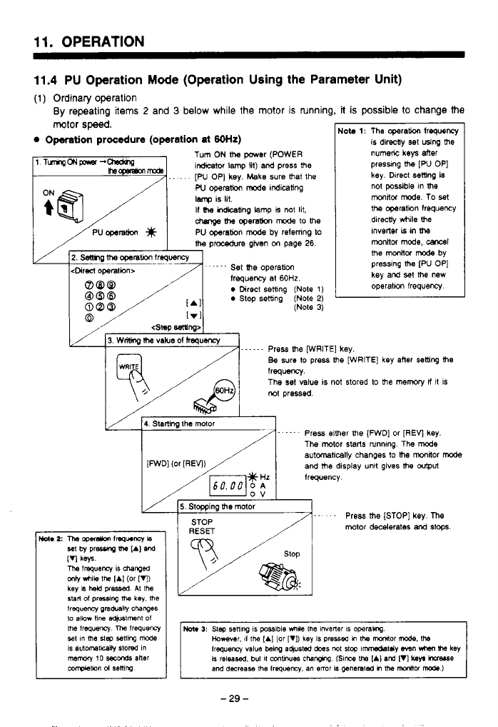
11.4
PU Operation
Mode
(Operation Using the Parameter Unit)
(1)
Ordinary operation
By
repeating
items
2
and
3
below while the motor is running,
it
is
possible
to
change the
motor
speed.
Operation
procedure
(operation
at
60th)
1 TumgONpnsr-- Tum
ON
the
power (POWER
~ ~
irdicabr lamp
lit)
ard
press
lhe
-
,
..
.
[W
OP] key. Make sure
that
the
W
operat!m
mode
indicating
lenp
is lit.
If
indkating
lamp
is
not
lit,
chmQe
the
opemU0n
mode
to
the
I
/PUoperation
#
1
PU operation
mode
by refemng
to
I
is directly
set
using
the
Nob
1:
The operaw
frequency
numk
keys
Mer
preswng
Uw
[PU OP]
key.
Direct
setting
is
not
possible
in
the
monitor
mode.
To set
the operation frequency
dirdy while
the
Inverter
is
in
the
the
procedure
given
on
page
26.
monkor
mode,
carrsl
the
monitor
mode
by
pressing
the
[PU OP]
key
and
set
the
new
2.
Semg
me
opsrarion
lreqoency
<Direct
operafwn~
.
-.
-
-
Set
the
operation
frequency
at
60HZ.
0
Direct
setting
(Note
1)
0
Step setting
(Note
2)
(Note
3)
[.
Irl
,'
/
3.
wrisng
IIW
vabe of
hequency
Press me [WRITE]
key.
Be sure
to
press Re [WRITE] key after setting
the
e
is not stored
to
the
memory
if
it
is
4.
Starling
the
mor Press elther he [FWD] or [REV key.
The mtor starts runnmg The
mode
automatically
changes to
the
monbr
mode
and
lhe
display unlt gives
lhe
w@Ut
frequency
5.
Slopping
!he
motor
- - -
Press
the
[STOP] key.
me
mtor
decelerates
and
stops.
-29-
1
1.
OPERATION
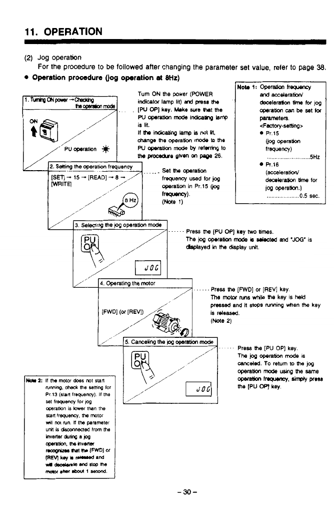
(2)
Jog
operation
0
Omtion
procedure
(jog
operation
at
Wz)
For the procedure
to
be
followed
after changing the parameter
set
value, refer to page
38.
T@J
/’
/”
/
I
3.
Sewing
the
&
operation
mode
......
/
me
i~a
opetam
mode
i~
and
‘JOG’
IS
Press
Um
[PU
OP]
key
hvo
b;mes.
dap4ayed
in
the
display
unlt.
,x’
4.
Operating
the
Mor
.....
/
Press
the
[FWD]
or
[REV]
key.
The
motor
nms
while
Re
key
is
hehl
pressed
and
it
stops
nnning
when
the
key
is
releafed.
I
-30-
11.
OPERATION
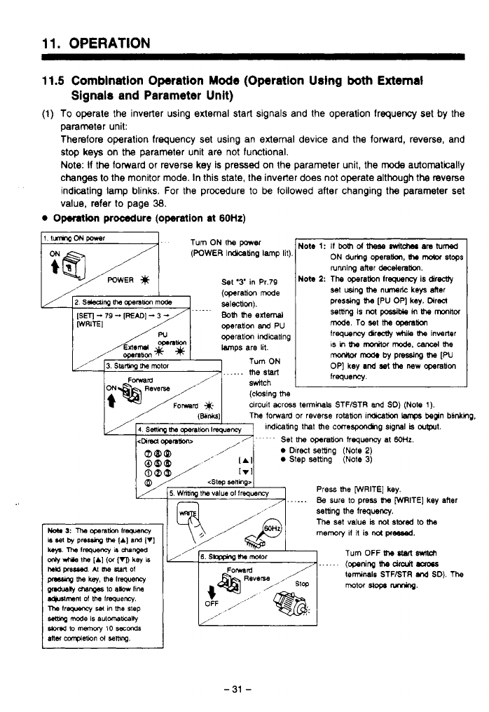
11.5
Combination Operation Mode (Operation Using
both
External
(1)
To
operate the inverter using external start signals and the operation frequency set by the
parameter unit:
Therefore operation frequency set using an external device and the forward, reverse, and
stop keys
on
the
parameter unit are not functional.
Note:
If
the
forward or reverse key is pressed
on
the parameter unit, the
mode
automatically
changes
to
the monitor mode. In this state, the inverter does not operate although the reverse
indicating lamp blinks. For the procedure
to
be
followed after changing
the
parameter set
Signals and Parameter Unit)
value, refer to page
38.
Operation
procedure
(operation
at
60Hz)
1
ItmwqONpaer
Turn ON
me
WWBT
.
sMch
(closing
me
circuit acrm
terminals
STF/STR
and
SO)
(Note
1).
Mote
1:
If
both
ot
meSe
switches
am
turned
ON
durhg
operatbn,
(hr
mdor
stops
NOW
2:
The operatbn frequency
is
direcUy
running after
decelera!km.
set
using
the
nunelic
keys
der
pressing
the
[PU
OP]
key.
Direcl
setting
is
not
pcssible
in
the
mitot
frequency dirw
while
Ihe
inverter
mode.
To
set
Itm
cpmlion
IS
in
Um
marfor
mode.
cancel
the
monkor
mods
by
pressing
Ihe
[PU
frequency.
OP]
key
and
sat
the
new
cgerabon
1
Press
the
[WRITE]
key.
......
Be
sure
to
Press
Ihe
[WRITE]
key
after
\
/
L
I===
6.
SbFphg
#-a
malar
11.
OPERATION
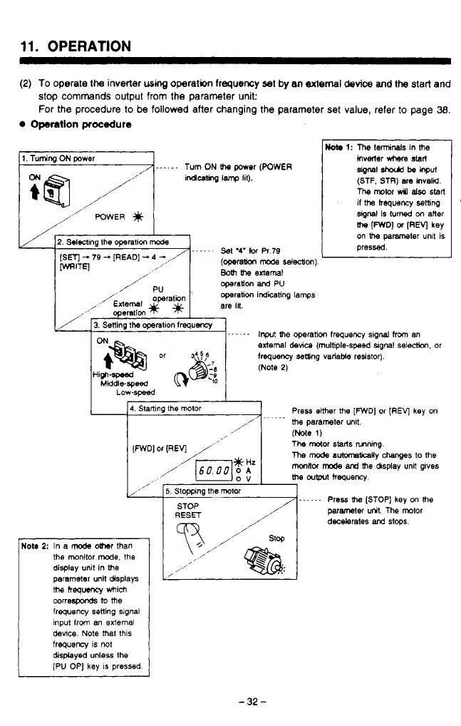
(2)
To
operate
the
inverter
wmg
operation
frequency
set by
8n
Bxtemal
device
and
the
start and
stop commands output from the parameter unit:
For the procedure to be followed after changing the parameter
set
value, refer
to
page
38.
Operation
procedure
1.
Tuming
ON
power
,,
/
1.
- -
.
.
-
Turn
ON
lb
power
(POWER
indleAng
lamp
lit).
//”
/,,,,’
POWER
,/
/
/’
2.
Selening the
operatlon
mode
[Sm
-
79
-
[READ]
-
4
-
,/
MITE]
......
Set
‘4‘
for
R.79
Bolh
the
external
(opefa(ion
mode
selection)
Not.
1:
The
termids in
me
hverier
M
sbrl
(STF, STR)
are
invalid.
The
mkn
W
alsc
start
if
ttm
frequency
setting
signal
is
turned on
alter
the
[FWD]
01
[REV]
key
on
parameler
unlt is
pressed.
sgnal
ahodd
be
hput
Iota
2:
In a
mode
oUmr
than
display unit in the
the monitor
mode.
the
me
hequeocy
which
parameter
unn
displays
correspoods
to
me
frequency setting signal
input from an external
device.
Note
that
this
frequerq
is
not
displayed unless the
[PU OP] key
IS
pressed.
4.
Startlng the motor
..
...
Press either
me
[FWD]
or
(REV]
key
on
,
m%
parameter unlt.
(Note
1)
The mor
starts
nmnmg
me
mode
auMna(kaRy
ms
to
me
milor
mode
and
the &play unil glves
the
outprt
hequercy
[FWD]
or
[REV]
/”
,/
’
(6ooo1!
,
”
5.
Stopping the
mol01
......
STOP
RESET
Press
the
[STOP] key
on
me
parametei
uW.
The rotor
decelerates
and
stops.
I’
I
-32-
n
W
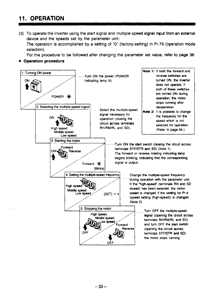
11.
OPERATION
~~~ ~ ~~ ~~~~~ ~~~
(3)
To operate the inverter using the start signal and multiple-speed signal
input
from
an external
device and the speeds set
by
the parameter unit:
The operation
is
accomplished
by
a setting
of
"0"
(factory-setting) in Pr.79 (operation mode
selection).
For the procedure
'to
be
followed after changing the parameter set value. refer
to
page
38.
0
Operation procedure
.
---Turn
ON
the
power
(WWER
revem
6wW-a~
are
inditing lamp lit).
turned
ON,
Uw
inwrler
does
rot
operate.
ll
both
of
meSe
swilches
I//F
2.
Selecting
the
rnuniple-speed slgnal
. . .
Select
the
rnultiple.speed
I
N~
1:
dixbrabm
stops
is
possiMe
nrnring
lo
aner
change
signal
necessary
for
drcuit
ea068
temsinals
operatlon (closing
the
me
frequency for
the
speed
which is not
selected
tor
operahon.
(Reter
to
page
64.)
Hlgh
speed
RWRWRL
and
SD).
Middle speed
Low
rmed
Turn OFF
(he
multiple-speed
terminals
RWRhURL
and
SD)
and
turn
OFF
(he
start
sdtd~
(opening
me
arc&
BMSS
terminals STFBTR
end
SD).
me
mtw
stops
nnning.
(openinp
(he
drwn
acw
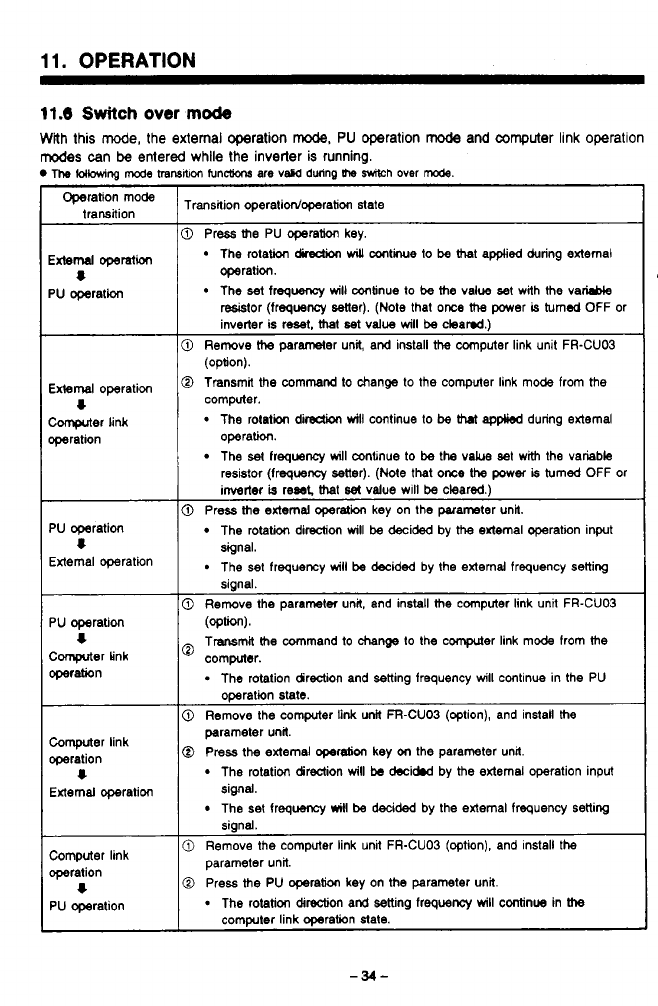
11.
OPERATION
11.6
Switch
over
mode
With this mode, the external operation
rode,
PU
operation
mode
and
computer
link operation
modes
can
be
entered while the inverter
is
running.
The
(OHOwing
mcde
transNm
func(ions are vscd dwinp
the
Wh
over
rode.
~~
Operation mode
trahsaion
Transition operatidoperation state
External
operation
PU
operation
8
External
operation
computer
link
wration
4
0
Press
the
PU operation key.
The rotation
dLection
will
antie
to
be
that appked during external
The
set
frequency
will
continue
to
be
the
value
set
with
the
vaM
operation.
resistor (frequency setter). (Note that
once
the
power
is
turned
OFF or
inverter is
reset.
mat
set
value
will
be
cleamd.)
@
Remove
the
parameter unit, and install
the
computer link unit FR-CU03
0
Transmit the command to change
to
the computer link mode from the
(option).
computer.
The
rotation
dirsdion
will
continue
to
be
that
applied
during external
The
set
frequency
will
mnenue to
be
the
vakre set with the variable
operation.
resistor (frequeocy setter).
(Nde
that
once
the
power
is
turned OFF or
inverter
is
reset
that
set
value will
be
cleared.)
PU
operation
External operation
4
PU
operation
Comprter
Link
operation
4
Computer link
operation
External owration
4
0
Press
the
external operation key on the parameter unit.
The rotation direction
will
be
decided by
the
external operation input
The set frequency
will
be
decided by the external frequency setting
signal.
signal.
0
Remove the parameter unit, and install
the
computer link unit FR-CUO3
(optW.
Transmit
the
command
to
change
lo the cwnputer link mode from
the
computer.
.
The rotation direction and setting frequency
will
continue in the PU
operation state.
0
Remove the computer
link
unit FFI-CUO3 (option), and install
the
@
Press
the
external
operebon
key
on
the parameter unrt.
parameter unit
The rotation direction
will
be
decidnd by
the
external operation input
The
set
frequancy
will
be
decided by the external frequency setting
signal.
siand.
0
Remove the computer link unit FR-CUO3 (option), and install the
Computer link
operation parameter unit.
1
0
Press
the
PU operation key on
the
parameter unit.
PU operation
-
The rotation direction and setting frequency
will
continue in
the
computer link operation state.
3
w'
i
-34-
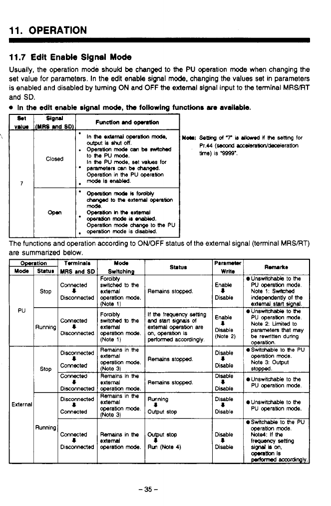
F>
.
..
11.
OPERATION
11.7
Edit
Enable
Signal
Mode
Usually, the operation mode should
be
changed
to
the
PU
operation mode when changing the
set value for parameters. In the
edit
enable sigml mode, changing the values set in parameters
is enabled and disabled by turning
ON
and
OFF
the
external
signal input to the terminal
MRS/RT
and
SD.
0
In
the
odlt
enable
signal
mo&,
ths
following
functkns
am
available.
The functions and operation according to
ONOFF
status
of
the external signal (terminal MRSBT)
are summarized below.
Mode Switching
MRS
Md
SD
Mation
Mod.
Twrninais
Connected
operam
mode.
Discmected
switched
lo
the
Forcibly
stop
extemal
I
(Note
I)
Forubtf
Running
I
external
(Note
1)
PU
Cwected
operam
mode.
Disconnected
switched
lo
the
Stlhn
Remains
stopped
If
the
frequency setting
external
operation
are
m,
operation
is
perfwmed
accordingly
and
start
signe.ls
d
Remains
stopped
Running
8
output
stop
0
UnsmtchaMe
to
the
Note
2.
Limited
to
Disable
DisaMe
be
rewritten dunng
(Note
2)
parameters
hl
may
0
SwitchaMe
to
Ihe
PU
operation.
Note
3:
output
operation
mode.
stopped
0
UnswNcheble
to
the
"p""
eunswit-
to
the
Disable
pu
operam
mode.
0
Switchable
to
he
PU
Disable
Me4:
If
the
operam
mode.
I
lreguency
setting
Disable
SigMlkon,
-tion
is
Pec(0mad
-%I)
-35-
11.
OPERATION
Note:
1
2
3
4
5
6
After turning
ON
the
MRS
terminal, if the setting for Pr.79
is
changed to any value other
than '7" in the PU operation mode, the
MRS
terminal functions as the ordinary
MRS
terminal (mechanical reset terminal) instead
of
the edit enable signal terminal. Then the
operation
mode
is changed according to the new setting for Pr.79.
When mode changed is attempted between the external operation mode to the PU
operation mode with the
MRS
terminal
ON,
the mode change will not occur
if
the STF
or STR terminal is
ON.
In the setting
of
Pr.79
=
7 with the
MRS
terminal
ON,
if the
MRS
terminal is turned OFF
while in the PU operation mode, the operation
mode
is changed to
the
external opera-
tion
mode
independent
of
the OWOFF status of the terminal (STF,
STR).
Therefore,
if
the
MRS
terminal
is
turned OFF while either the STF or STR terminal
IS
ON,
the motor
is controlled in the external operation mode.
During the operation in the PU operation mode, the ordinary
MRS
function does not
work.
When the mode is changed from the PU operation mode to the external operation
mode forcibly, the parameter unit is internally reset once
to
secure the monitor screen.
If an alarm has occurred, the inverter can be reset by pressing the stop key in the PU
operation mode. Resetting
of
the inverter in the external operation mode is not possible.
Therefore, resetting the inverter always changes the mode to the PU operation mode.
-36-
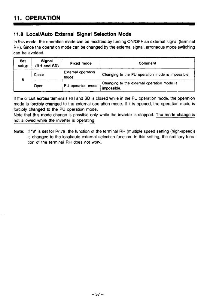
11.
OPERATION
11.8
LocaVAuto
External
Signal
Selection
Mode
In this mode, the operation mode can
be
modified
by
turning ON/OFF an external signal (terminal
RH). Since the operation
mode
can
be
changed by the external signal, erroneous mode switching
can
be
avoided.
Set
Signal
value
(RH
and
SD)
Flxsd
mode
Comment
I
~
1
Close
I
mode
External
operatm
1
Changing
to
the
PU
operation mode is impossible.
I
8
Open
Changing
to
the
external
operation
mode
is
PU
operation
mode
impo~ible,
If the circuk acw terminals RH and
SD
is closed while in the
PU
operation
mode,
the operation
mode is forcibly changed
to
the external operation mode. If it is opened, the operation mode is
forcibly changed
to
the
PU
operation mode.
Note that this
mode
change is possible only while the inverter is stopped. The
mode
change
is
not allowed while
the
inverter is operating.
Note:
If
'8'
is
set
for Pr.79, the function of the terminal RH (multiple speed setting (high-speed))
is changed to the locaVauto external selection function. In this setting, the ordinary func-
tion of the terminal RH does not work.
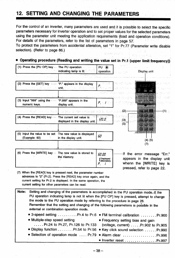
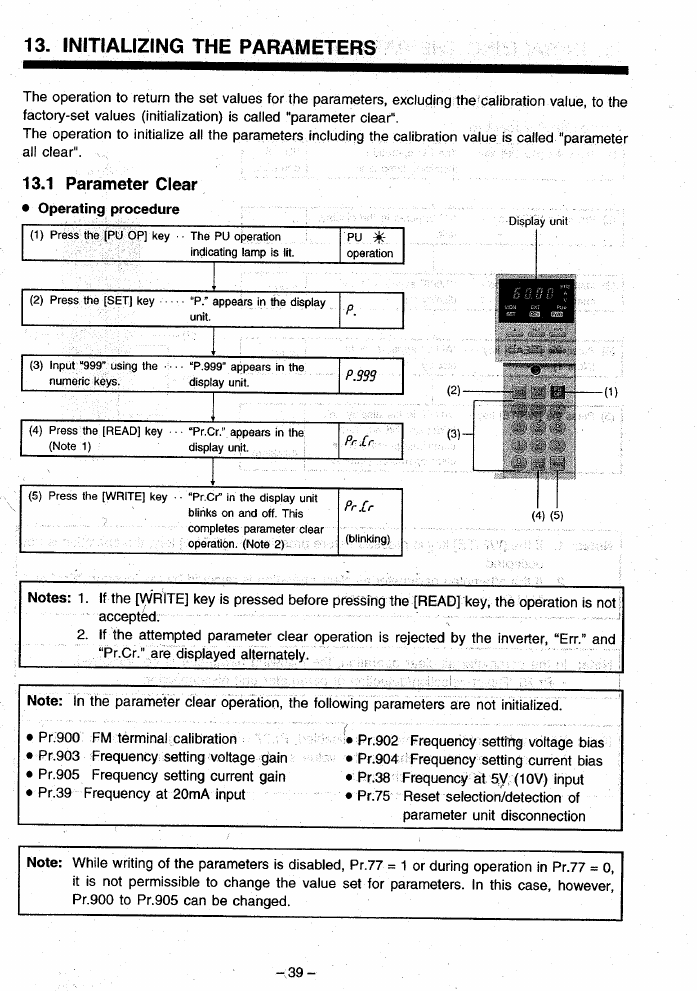
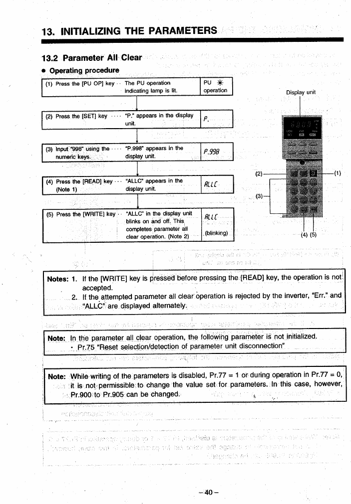
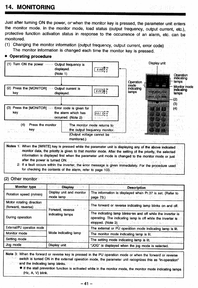
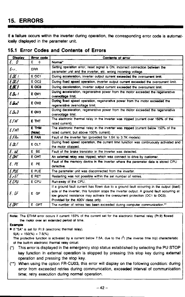
15.
ERRORS
If
a
failwe
occurs within the inverter dwing operation,
the
corresponding error
code
is automat-
ically
disprayed in the parameter unit.
15.1
Error
Codes and Contents
of
Errors
f.
bf
Fault
ol
mmwy
device
h
Ihe
invetter
where
(he
parameter
deta is sivred CPU
E
PE
f,
pf
h
extd
day
WBS
tripped. which
was
cmwt
to
drive
by
cmtmr.
E
OHT
fmf
Faun
of
the
brake
transistor in
the
inverter was
detected.
E
BE
[.&E
E
PUE The parameter unit was disconnected from
the
inverter.
frff
E
RET
Run-away
of
he
CPU.
E
CPU
E.CPU
Restarting was not
possible
wimin the
set
number
of
retries.
f,
cF
E
side
01
me
inverter. this tunctim
stops
UM
inverter output.
A
ground IauR occurring at
If
a ground lault current has flown due
to
a ground lault occurring in
tha
output
(bed)
low
wnd
resistance
may activale
me
overanent protection
(E1
lo
OC3).
Probidmi
lor
the
4M)V
class
mly.
f,GPf
E OPT The number
of
retnes
has
besn exceeded dunng computer communication."
defecrive.
Now
The
ETHM
error occurs if current
150%
01
the
current
set
for
the
electronic
thermal
relay (R.9) flowed
the
nwbr
over
nn
extended
pew
d
bme.
II
'SA'
IS
set
lor Pr.9 (electronic thermal relay).
Ex-
5(A)
x
150(%)
=
7.5(%)
The
protecoive Iuncthn is acbvated by a current below
7.5A.
due
to
the
1'1
(h
lnverse
time
mp) charwleristic
d
me
buin-in electrmk
thermal
relay circuit.
(*)
This error is displayed in the emergency stop status established by selecting the
PU
STOP
key function in external operation is slopped by pressing this stop key during
external
operation and pressing the stop key.
(")
When using the option
FR-CU03,
this error will display on the following condition: during
error from exceeded retries during communication, exceeded interval
of
communication
time; retry execution during
normal
operation.
-42-
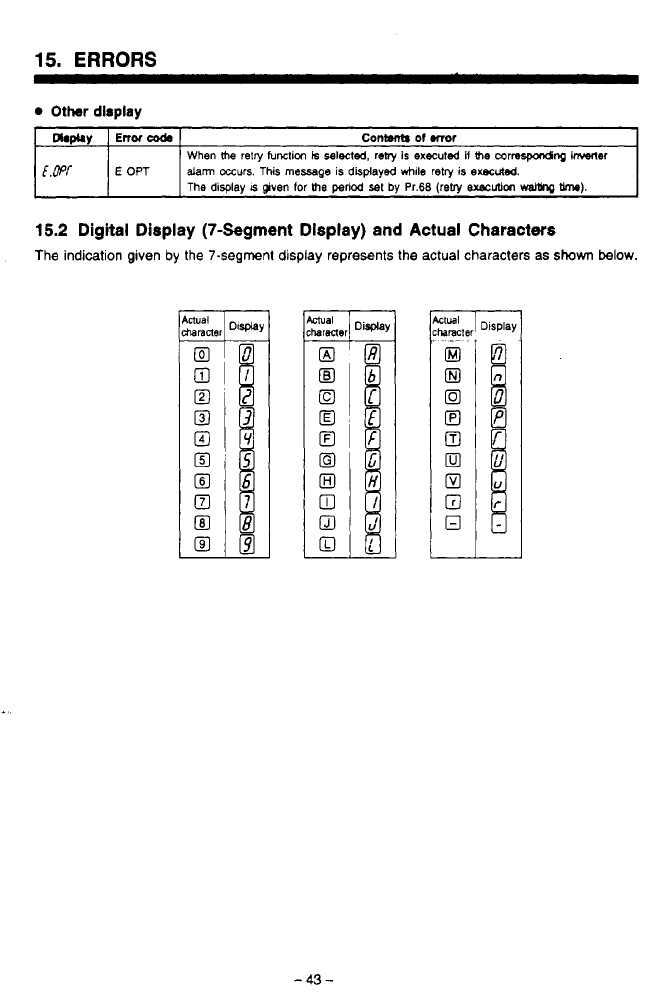
15.
ERRORS
Other
dirpiay
Dbphy
Conwnb
of
mor
Enor
coda
[&'f
dam occurs.
This
message
is
displayed
while
retry
is
execrded.
E
OPT
When
the
retry
function
k
selected.
reby
is
executea
if
the
correJpondnp
kw"
The
display
IS
given
for
the
penod
set
by
Pr.68
(reby
exscuUon
waWq
W).
-
15.2
Digital Display (7-Segment Dlsplay) and Actual Characters
The indication given by the 7-segment display represents the actual characters
as
shown
below.
-
43
-
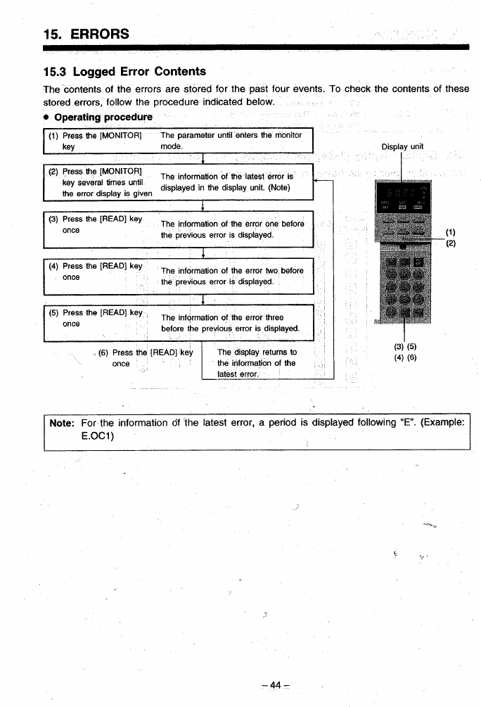

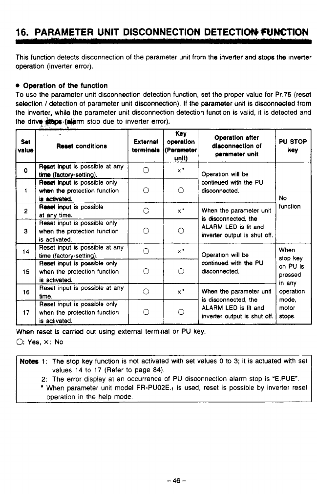
16.
PARAMETER UNIT DISCONNECTION DETECTIW
FUNCTION
This function detects disconnection of the parameter unit from the inverter and stops
the
inverter
operation (inverter error).
Operation
of
the
function
To use the parameter unit disconnection detection function, set the proper value for Pr.75 (reset
selection
/
detection of parameter unit disconnection).
If
the
parameter unit is disconnected from
the inverter, while the parameter unit disconnection detection function is valid, it
is
detected and
the
drivq
P69().[~rm
stop due
to
inverter error).
hael
conditions
)ssIbIe
at any
3
X*
When
the
parameter unit
Reset input is possible only
is adivaled
is disconnected, the
ALARM LED is
lil
and
inverter output is shut
OH
17 when the protection function
0
PU
STOP
key
No
function
When
stop
key
on
PU
is
pressed
in any
operation
mode,
motor
a+.
0
Yes,
x:
No
rc
Notes
1:
The stop key function is not activated with set values
0
io
3;
it is actuated with set
ij
values 14 to 17 (Refer
to
page 84).
2:
The error display at an occurrence of PU disconnection alarm stop
is
'E.PUE".
When parameter unit model FR-PUOPE.1 is
used,
reset
is
possible by inverter reset
operation in the help mode.
-
46
-

16.
PARAMETER
UNIT
DISCONNECTION
DETECTION
FUNCTION
Cautions
on
setting
iha
parameter
unR
disconnection
detecictlon
function:
(1)
If
the parameter unit is not connected at the start of operation, an alarm does not occur.
(2)
This function recognizes "disconnection" when the parameter unit is disconnected for more
than
1
second.
(3)
To restart the inverter operation after the occurrence of the disconnection alarm, confirm the
connection of the parameter unit and reset the inverter. (refer
to
page
48)
(4)
If the inverter is operated without selecting the parameter unit disconnection detection func-
tlon, inverter operation is continued even after the parameter unit is disconnected from the
inverter, which will create a hazardous situation. Therefore, to ensure safe operation, it
is
recommended
that
the parameter unit disconnection detection function
be
selected.
-47-
.-
,.
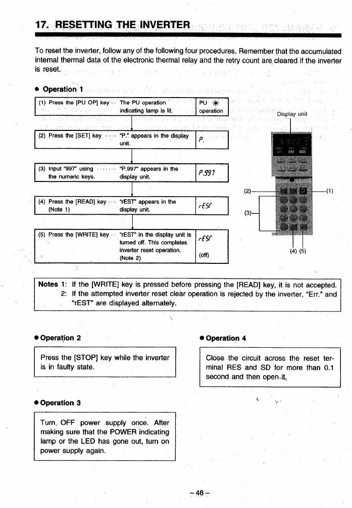
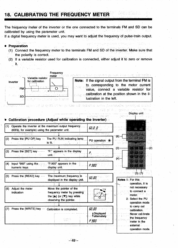
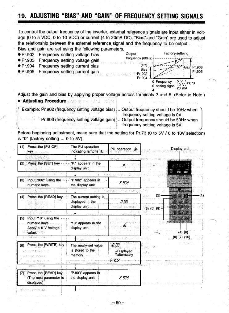
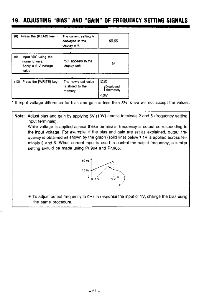
19.
ADJUSTING
“BIAS”
AND “GAIN” OF
FREQUENCY
SETTING
SIGNALS
(8)
Press
me
[READ]
key
The
wmnt
sew
Is
asplawnme
60
RO
display
unit.
I
(9)
Input
‘50”
using
me
numenc
keys
Apply
a
5
V
vdtage
display
unit.
value.
‘50’
appears
in
me
53
1
(10)
Press
me
[WRITE)
key
The
newly
set
value
SOAW
is
stored
to
the
mew
I
:;%%Iy
PW
*
If
input voltage difference for bias and gain is less than
5%,
drive will not accept the values.
Note:
Adjust bias and gain by applying
5V
(IOV)
across terminals
2
and
5
(frequency setting
input terminals).
While voltage is applied across these terminals, frequency is output corresponding to
the input voltage. For example,
if
the bias and gain are set as explained, output fre-
quency is obtained as shown by the graph (solid line) below
if
1V
is applied across ter-
minals
2
and
5.
When current input is used to control the output frequency, a similar
setting should be made using Pr.904 and Pr.905.
*’
*
To
adjust output frequency to
OHz
in response the input
of
1
V,
change the bias using
the same procedure.
-.
.

20.
CONTROLLING
KEY
CLICK
SOUND
(TACTILE
FEED
BACK)
With the
model
FR-PUO3 parameter unit, a key click
sound
can
be
added
to
confirm complete
execution
of
key stroke.
To
output key click
sound,
follow
the procedure
below.
Pr.990
is
factory set
to
0
for no key click sound.
.To
change
the
setting
to
With key click sound",
set
'1"
in Pr.990.
d
1
Noto:
To
set
'no key clock
sound'
again, set Pr. 990
to
"0"
(factory-
setting).
4
4
-
52
-
21.
SELECTING GENERAL-PURPOSE MAGNETIC FLUX VECTOR CONTROL
The general-purpose magnetic flux vector control can be selected by setting the motor capacity
and
type
of motor.
The general-purpose magnetic flux vector control is effective for applications where greater start-
ing torque or more than
VF
mode
torque at low speed is required. or the load is varying.
(1) Conditions for selecting the general-purpose magnetic flux vector control
The general-purpose magnetic flux vector control can be effectively used only when the foi-
lowing conditions are satisfied. If
the
general-purpose magnetic flux vector control is selected
while any of these conditions is not satisfied, it will cause insufficient torque, irregular rotation,
and other problems. In which
case,
VF
control
should
be
selected.
Conditions
*The motor capacity is either equivalent to or *The number of poles is
2,
4, or 6. (It is not
one rank below the inverter capacity. necessary to set the number of poles. For
*The motor type is Mitsubishi standard motor constant torque motors, 4
poles
only)
(0.1
kW
(1/8HP) or larger, 200V class; *The motor is controlled by its own inverter.
0.2kW (1/4HP) or larger 400V class), Mit- OWinng distance between the motor and the
subishl constant torque motor (SF-JRC, inverter is within 30m (98.46 feet).
If
the dis-
200V
class, 4
poles,
0.4 (1/2HP) to 3.7kW tance exceeds 30m (98.46 feet), refer to
(5HP)) or MlTSUBlSHl equivalent. MITSUBISHI.
(2)
Selecting the general-purpose magnetic flux vector control
...
Set the motor capacity (other
than “9999”; “9999”
calls
for the V/F control.) for Pr.80 (motor capacity). If a Mitsubishi con-
stant torque motor is
used,
set ‘1” for Pr.71 (applicable motor).
Note: Cautlonr on general-purpose magnetk
flux
vector
control
(1) Irregular rotation of the motor will be a little more apparent than in the
V/F
control.
(2) At the start, 0.1 to 0.2 second delay is generated due to control data calculation.
(3) If this control is selected, the following parameter settings will be ignored. (Pr.0, Pr.3,
Pr.14, Pr.19, Pr.46, Pr.47)
Applications for which the general-purpose magnetic flux vector control is recommended
*The machine which requires greater start- *The machine in which torque variation is
*The machine which requires more than
V/F
(This control is not recommended for machines, such as grinders and lapping machines, which
requires low irregularity at
speed
control at low-speed operation.)
ing torque excessive
mode torque at low-speed.
-53-
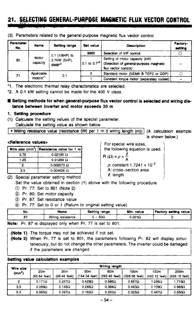
.
..
..
21.
SWCTlN6
GENERAL-PURPOSE
"TIC
FLUX
VECTOR
CONTROL
.~...
-
.2-..
~
-
--
..
.
.
.
.
(3)
Parameters related
to
the general-purpose magnetic flux vector control
"\"
F.*wy-
Dosulption
st
va~ue
~.t(lng
range
Name
wmne-
0.1
(1/8HP)
to
3.7KW
(5HP).
selecllon
Of
vF
amI'd
Bgss
0
80
capanty
9999'2
0.1
to
3.7.'
(Selecbon
d
QmeraCprrpose
msgneR
Setting
01
motor
capaaty
(kW)
Rux
vector
m~d)
,,
Applwe
rotors"
01
0
-
Constant
torque
motor
(separataly
coded)
1
0
SWrd rotor
(NEMA
B
TEFC
M
ODP)
'1.
The electronic thermal relay characteristics are selected.
'2.
A
0.1
kW
setting cannot
be
made for the 400
V
class.
Settlng
methods
for
when
general-purpose flux vector
control
is
selected
and wiring dis-
tance between inverter
and
motor exceeds
30
rn
1.
setting
procedura
(1)
Calculate the setting values of the special parameter.
Calculate the setting value as shown below.
I
WMng
resistance
value (resistance
(w)
per
1
m
6
wiring length (m))]
(A
calculation example
is shown
below.)
<Reference values>
'
For special wire sizes,
the following equation is used.
R(R)=pxz
1
D:
constant 1.7241
x
10.'
t
3.5
0.004926
R
i
A:
cross-section area
1:
length
(2) Special parameter setting method
Set the value obtained in section
(1)
above with the following procedure.
0
Pr. 77: Set
to
801 (Note
2)
0
Pr.
80:
Set motor capacity
0
Pr.
87:
Set resistance value
0
Pr. 77: Set
to
0
or
1
(Return
to
oriainal settina value)
Note:
Pr. 87 is displayed only when Pr. 77 is set
to
801.
(Note
1)
The torque may not
be
achieved if not set.
(Note
2)
When Pr. 77 is set
to
801, the parameters following Pr. 82 will display simul-
taneously, but do not change the other parameters. The inverter could
be
damaged
if the parameters are changed.
Settlnq
value
calculatlon examples
Wlre
Sh
.
Wlrlng length
20m
30m
2OOm
150m
1
OOm
8Om
5om
(mm2)
(65.64 feel)
0.65oR
0
487P
0.325R
O.26OR
0.162fl
0
097i2
0.065R
5.5
0.985~
o
73w 0.49~1
0.3~~
0.24.511
0.148n
o
09w 3.5
1.715~
1.266~
0.857~
o.wn
0.42~
0.257~
0.171~
2
(656.16
feet)
(492.12
(eel)
(328.08
feet)
(262.46
feet) (164.04 leet)
(96.46
leet)
-54-
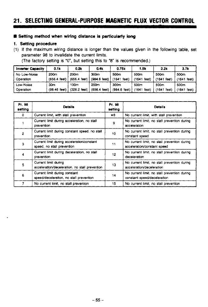
21.
SELECTING GENERAL-PURPOSE MAGNETIC
FLUX
VECTOR CONTROL
!Setting
wthod
when wlrlng
dlstance
Is
particularly
long
1.
!Setting
procedure
(1)
If
the maximum wiring distance is longer than the values given in
the
following table, set
parameter
98
to invalidate
the
current limits.
(The
factory setting is
'O",
but
setting this
to
'8"
is recommended.)
Operafion
Low.Noise
1%
IIWm
1% 1300m
I5~m
1500m
15~m
(1641 feet) (1641 feel) (1641 teet) (1641 feel)
(W.6
feel)
(656.4 feet)
(656.4
feet)
Operation
(1641
feet)
(1641 feel) (1641
feel)
(964.6
feel)
(656.4
teel)
(3282
teel)
(9846
feel)
-55-
.
.
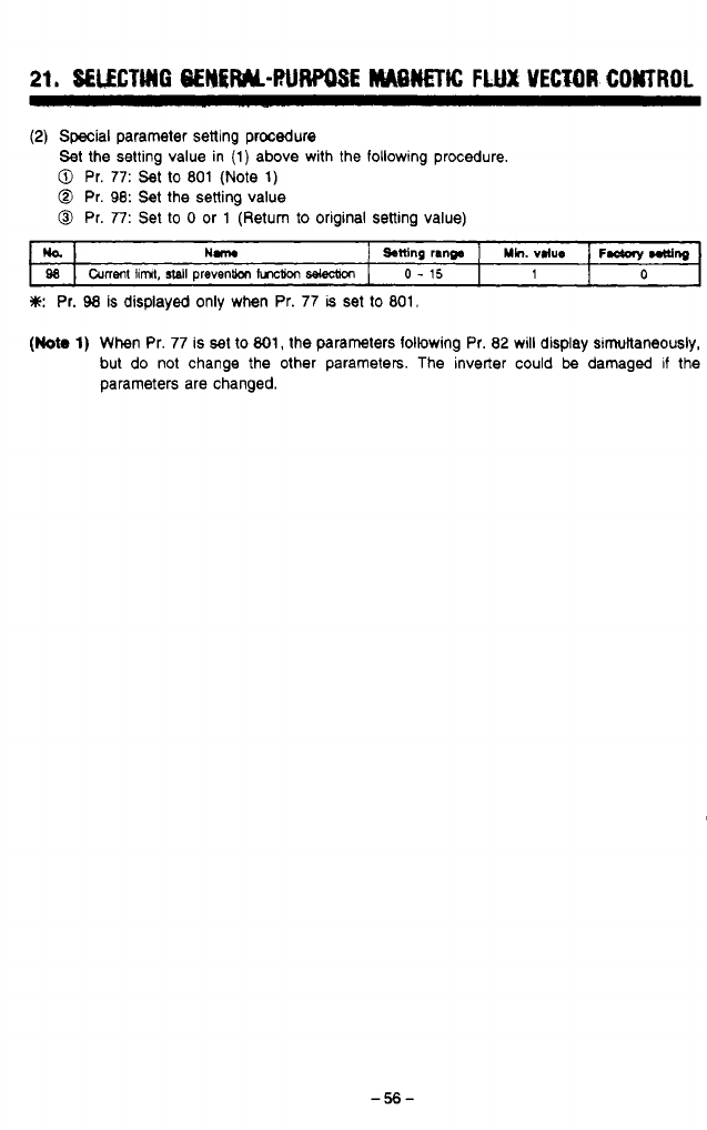
(2)
Special
parameter setting procedure
Set the setting value in (1) above with the following procedure.
0
Pr.
77:
Set to
801
(Note
1)
@
Pr.
98:
Set the setting value
0
Pr.
77:
Set
to
0
or 1 (Return to original setting value)
ULbl
Hm
j
Sttlng
rang.
]
~h.
vdue
1
F-
~ng
ga
I
current
linnt,
stall
prevention
tvlction
I
0
-
15
0
1
*:
Pr.
98
is displayed only when Pr. 77
is
set to 801,
(Nota
1)
When Pr.
77
is set to
801,
the parameters following Pr. 82 will display simuitaneously,
but do not change the other parameters. The inverter could
be
damaged if the
parameters are changed.
9
w
#
*
-56-

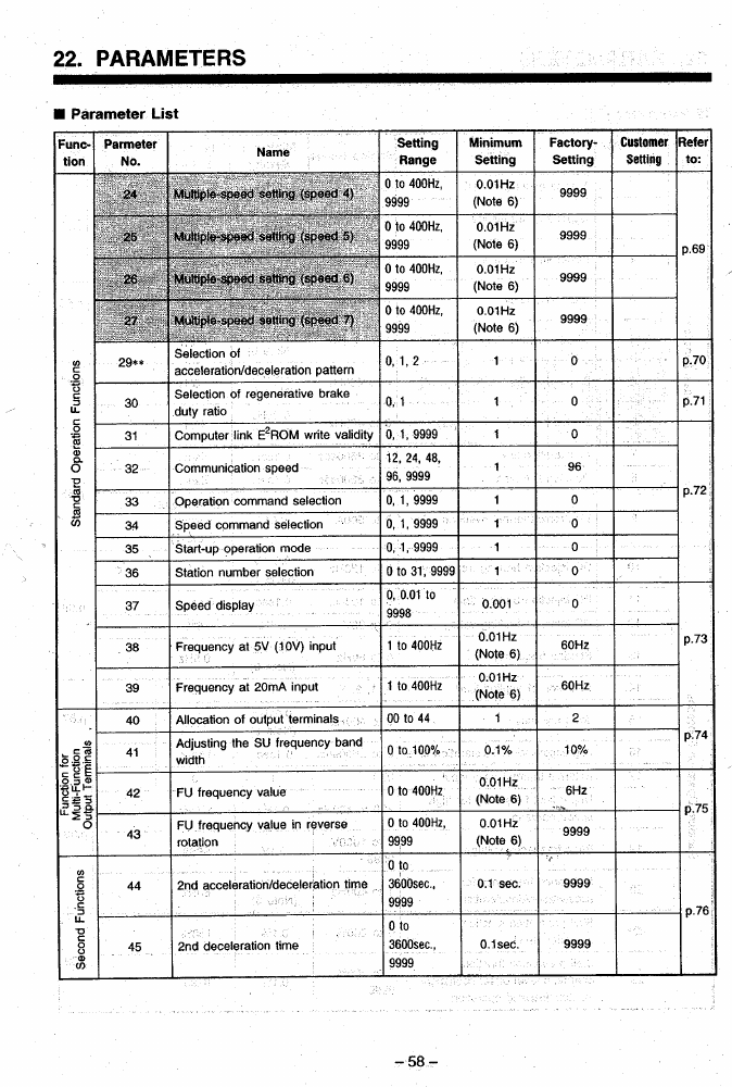
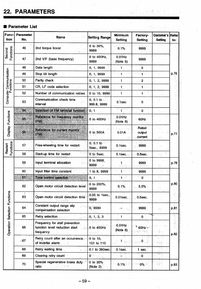
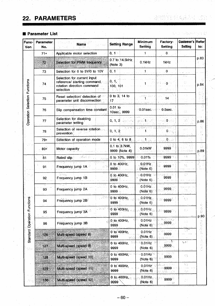
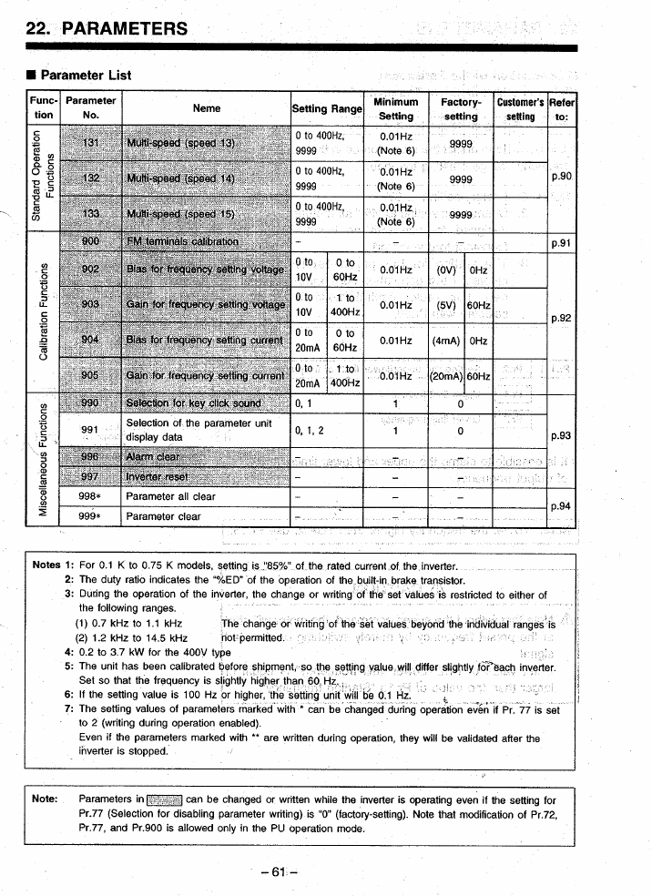
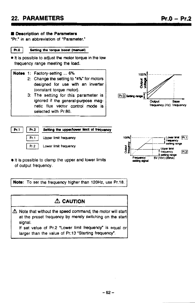
...
~
.
.
.
22.
PARAMETERS
Pr.0
-
Pr.2
H
Description
of
the
Parameters
‘Pr,’
in
an abbreviation
of
“Parameter.”
&tung
the
lorqua
booat
(mmul)
0
ti
is possible to adjust the
motor
torque in the
low
frequency range meeting the load.
Notw
1:
Factory-setting
...
6%
2:
Change
the
setting to
‘4%’
for motors
designed lor
use
with an inverter
(constant torque motor).
3:
The setting lor this parameter is
ignored if the general-purpose
mag
netic flux vector control mode is
selected with Pr.80.
n.
u’
It is possible to clamp the upper and lower limits
of output frequency.
Note.:
To
set the frequency higher than 120H2, use Pr.18.
A
CAUTION
L?I
Note that without the
speed
command, the motor will start
at the prsset frequency by mereiy switching on the start
signal.
If
set value of Pr.2 “Lower limit frequency“ is equal or
larger than the value
of
Pr.13 “Starting frequency‘.
-62-
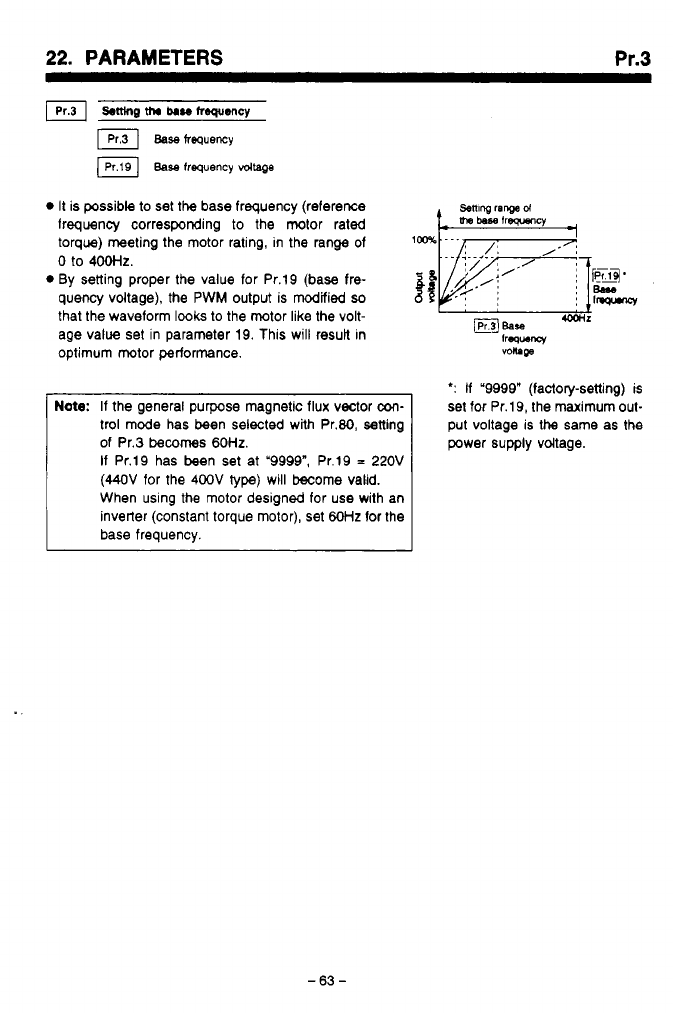
22.
PARAMETERS
Pr.3
It is possible to set
the
base frequency (reference
lrequency corresponding
to
the motor rated
torque) meeting the motor rating, in the range of
setting
ranged
0
to
4ootlZ.
By setting proper the value for Pr.19 (base fre-
mj.
quency voltage), the PWM output is modified
so
that the waveform lwks
to
the motor like the volt-
age value set in parameter 19. This will result in
optimum motor performance.
Be90
1W-W
,,
BEaSe
-r
frww
voltage
Note:
If the general purpose magnetic flux vector
con-
trol mode has been selected with Pr.80, setting
of Pr.3
becomes
60HZ.
If
Pr.19 has been set at '9999", Pr.19
=
220V
(44OV
for the
400V
type) will become valid.
When using the motor designed for use with an
inverter (constant torque motor), set
60Hz
for the
base frequency.
*:
If
'9998" (factory-setting) is
set for Pr.19, the maximum out-
put voltage is the same as the
power supply vdtage.
-63-
"

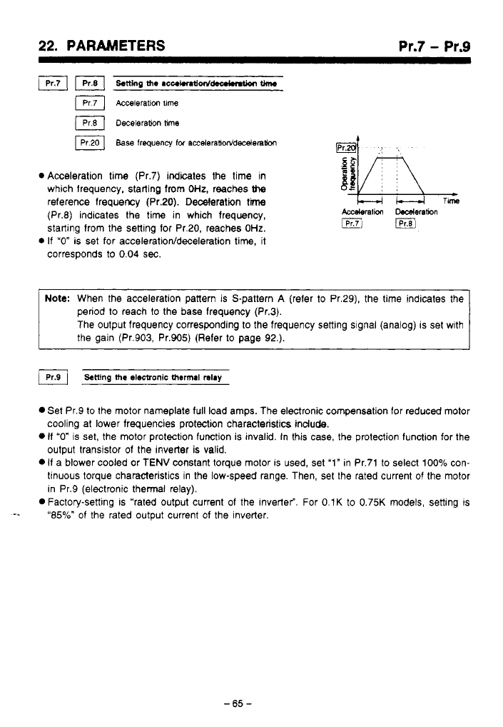
..
..
-.
,,
,
.,,
22.
PARAMETERS Pr.7
-
Pr.9
Acceleration time (Pr.7) indicates the time in
which frequency, starting from
OHz,
reaches
the
reference frequency (Pr.20). Deceleration
time
(Pr.8) indicates the time in which frequency,
starting from the setting for Pr.20, reaches
OHz.
If
"0"
is set for
accelerationfdeceleration
time, it
corresponds to
0.04
sec.
Note:
When the acceleration pattern is S-pattern
A
(refer to Pr.29), the time indicates the
period
to
reach
to
the base frequency (Pr.3).
The output frequency corresponding to the frequency setting signal (analog) is set wlth
the gain (Pr.903, Pr.905) (Refer to page
92.).
Set Pr.9 to the motor nameplate full load amps. The electronic compensation for reduced motor
cooling at lower frequencies protection characteristics include.
0
If
"0"
is set, the motor protection function is invalid. In this case, the protection function for the
output transistor of the inverter is valid.
0
If a blower cooled or TENV constant torque motor
IS
used, set '1" in Pr.71 to select 100% con-
tinuous torque characteristics in the low-speed range. Then, set the rated current of the motor
in Pr.9 (electronic thermal relay).
0
Factory-setting is "rated output current of the inverter". For 0.lK to 0.75K models, setting is
-e
"85%" of the rated output current of the inverter.
-65
-
.
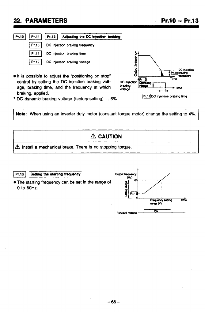
22.’
PARAMETERS
Pr.W
-
Pr.13
1-
wl
Adjusting
tha
DC
hi.oam
br*dng
Dc
injection
braking
lrequency
a
DC
injection
bralung
time
DC
ifjection
brsking
vdlage
0
It
is
possiMe to adjust the “positioning on stop’
control by setting the
DC
injection braking
volt-
age.
braking
tlm,
and the frequency at
whkh
mi~l~~T~n-n~m
braking, applied.
-;
,
W
DC
dynamic braking voltage (factoly-setting)
...
6%
~TTmi~~~
I
Note:
When using an inverter duty motor (constant toque motor) change the setting to
4%.
I
.
A
CAUTlON
A
Install a mechanical brake. There is no stopping toque.
1
IR13]
wng
tha
s~ng
fqtmcy
0
The
starting frequency can
be
at in the
range
of
0
to
60HZ.
~
F~ancrmnO
:
mwM
-66-
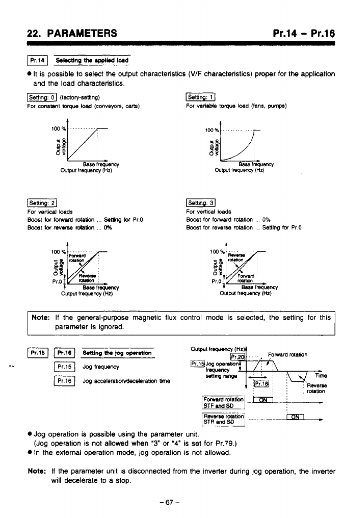
22.
PARAMETERS
Pr.14
-
Pr.16
s*ctinp
th.
.ppl*d
M
0
It
is possible
to
select the output characteristics
(V/F
characteristics) proper for
the
application
and the load characteristics.
f-1
(factory-setting)
r-1
For
-MI
lwque
load
IWVeprs,
-1
For
varllble
ioque
load (fans.
pmps)
t
Note:
If
the general-purpose magnetic flux control
mode
is
selected,
the
setting for this
parameter is ignored.
IKI
smingth.jogoprnfon
I.
JOS
frequency
~og
acceleram*ram
0
Jog operation
b
possible using the parameter unit.
0
In the
external
operation
mode,
jog operation is not allowed.
Note:
If
the
parameter unit
is
disconnected from the inverter during jog operatin, the inverter
(Jog operation is not allowed when
'3"
or
'4"
is set for Pr.79.)
will decelerate
to
a stop.
-67-
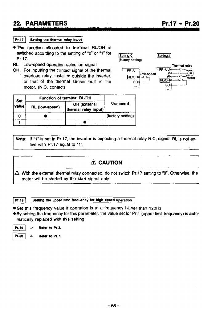
22, PARAWTERS Pr.17
-
Pr.20
.The
function
allocated
to terminal
RUOH
is
switched according to the setting
of
"0"
or
"1"
for
Pr.17.
(IaQoly-semng)
RL
Low-speed operation selection signal
OH:
For inputting the contact signal of the thermal
Tlm-md
MY
.
overload relay, installed outside the inverter,
'r*id&eor
or that of the thermal sensor
built
in the
SD
~
motor.
(N.C.
contact)
,-?
Note:
I1
'1'
is set in Pr.17, the inverter is expecting a thermal relay
N.C,
signal.
RL is not
ac-
tive with Pr.17 equal
to
"Im.
A
CAUTION
A
With the external thermal relay connected, do not switch Pr.17 setting
to
"0". Otherwise, the
motor will
be
s!erted by the start signal only.
setting
the
uppr
llmh
frequency
lor
hlgh
spud
operation
.Set
this frequency value if operation is at a frequency higher than
120Hz.
0
By setting the frequency for this parameter, the value set lor Pr.1 (upper limit frequency)
is
auto-
matically replaced with this setting.
D
hfer
to
~r.3.
,?
u
Rehr
to
Pr.7.
d
-68-
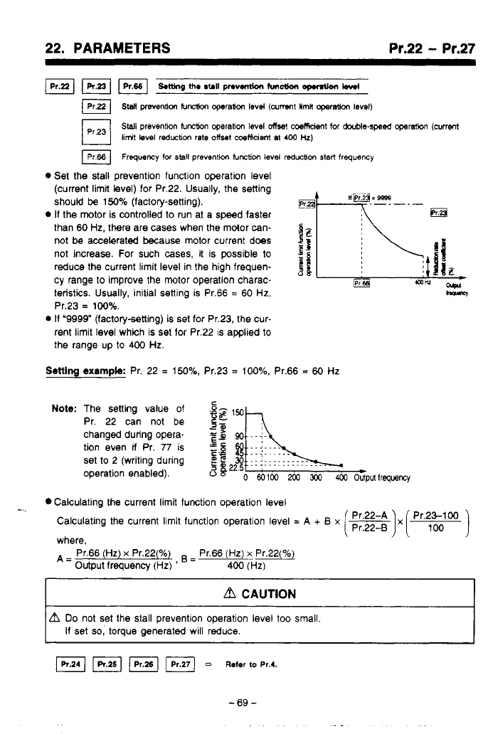
22. PARAMETERS Pr.22
-
Pr.27
S.ningth.rclllpnv.miontunctlonopMUon
bwf
lPrpl
sw
mention
f~ncb~n
qwah
lev4
(arrent
Hrnh
operatio0
level)
SWI
prevenhon
IuM
operation
level
Onset
coemdent
for
dwble-sped
operat&
(current
limit
level reductlcn rate offset
metfidsni
at
400
Hz)
IPr66]
Frequency
for
sal1
prevention
function
level reduction
start
frequency
Set the stall prevention functlon operation level
(current limit level) for Pr.22. Usually, the setting
should
be
150%
(factory-setting).
If
the motor is controlled to run at a speed faster
than 60
Hz,
there are cases when the mdor can-
not
be
accelerated because motor current does
not increase. For such cases,
it
is possible
to
If
reduce the current limit level in the high frequen-
cy range to improve the motor operation charac-
teristis. Usually, initial setting is Pr.66
=
60
Hz,
Pr.23
=
100%.
0
If
‘9999” (factorysetting)
is
set for Pr.23, the cur-
rent limit level which is set for Pr.22 is applied
to
the range up
to
400
Hz.
apr
hM
Setting
example:
Pr. 22
=
150%,
Pr.23
=
100%.
Pr.66
=
60
Hz
Note:
The setting value of
Pr. 22 can not be
changed during opera-
tion even
il
Pr.
77
is
set to 2 (writing during
operation enabled).
Calculating the current limit function operation level
-..
CalCUlating the current limit function operation level
=
A
+
B
x
where,
A=
output frequency
(HZ)
=
~-
Pr.66
(Hz)
x
Pr.22(%) Pr.66
(Hz)
x
Pr.22(%)
400
(Hz)
I
d
CAUTION
I
Do
not set the stall preventlon operation level
too
small.
If set
so,
torque generated will reduce.
=
Refer
to
~r.4.
-69-
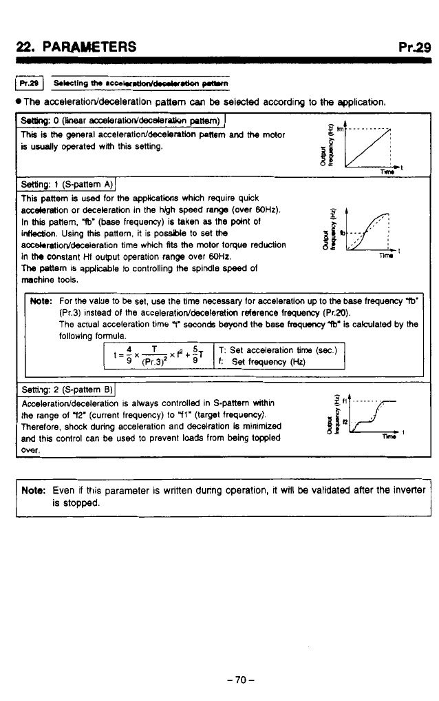
Pr.29
.The
acceleration/deceleration
pattern
can
be
selected according to
the
epplicetin.
o
(hr accekratiod'decderotion
paw)
I
This
is
the
general acceleratioddecelertion
panem
and
the
motor
b
usually operated with this setting.
i
p*
gh
..........
a
rm
Mng:
1
(S-pattem
A)]
This pattem
is
used
for
the
apphcatiw which require quick
acceleration or deceleration in the high speed range
(over
WHz).
In
this
pattern,
W
(base
frequency) is taken
as
the point
of
gfI
f
*
inHeUion. Using
thk
pattern,
it
is
pome
to
set
ths
accekrtioddeceleration time which
Ms
the
motor
toque
reduction
in
the
constant
Hf
output operation range over
WHz.
llw
pattern
is
applicable to controlling
the
spindle
speed
of
machine tools.
b
...
I
nim
Mote:
For
the
value
to
be
set, use the time necessary lor acceleration up to
the
base lrequency
W
The actual acceleration time
11'
seconds
beyond
the
base
frequency
"W
is calculated by
the
(Pr.3) instead
of
the
acceleratiorddeceleratim
rderence lrequency (Pr.20).
following formula.
Setting:
2
(S-pattern
B)
I
Acceleratiorddeceieration
is atways controlled in S-pattem withtn
the range
of
72'
(current Irequency) to
"ll'
(target frequency).
Therefore, shock during acceleration and decelration
is
minimized
and this control can be used to prevent
loads
from being toppled
over.
A
A
r-
Note:
Even if this parameter
is
written during operation,
it
will
be
validated after the inverter
is StODDed.
-70-
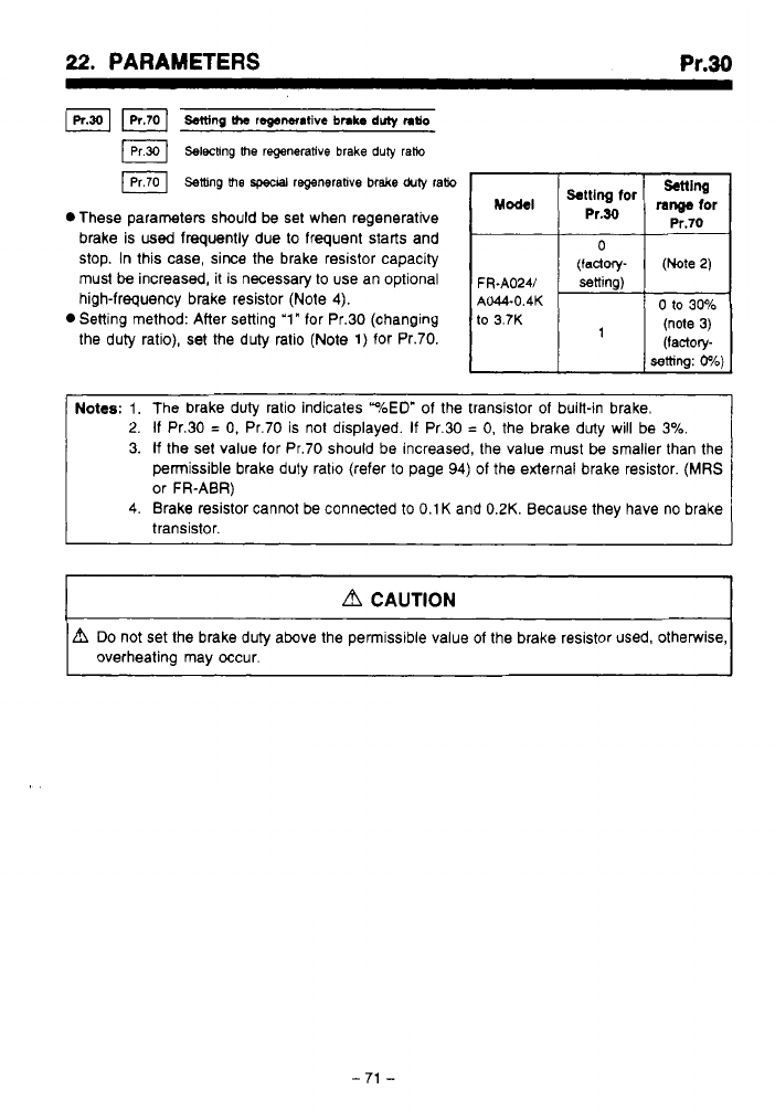
. I.. .
I
...
.
22.
PARAMETERS
Pr.30
Fl
Salting
the
regenantive
bnb
duly
ntlo
Selechng me regenerative brake
duiy
rafio
Setting
me
spwal
regenerative brake
duty
ram
setting
Pr.70
0
These parameters should be set when regenerative
brake is
used
frequently due to frequent starts and
stop.
In this case, since the brake resistor capacity
must
be
increased,
it
is necessary to use an optional
FR.A024/
=ning)
high-frequency brake resistor (Note
4).
the duty ratio),
set
the duty ratio (Note 1) for Pr.70.
M-I
range
for
%:“&for
0
(factory-
(Note
2)
0
Setting method: After setting
‘1“
for Pr.30 (changing
to
3.7K
AM-0.4K
0
to
30%
(note
3)
’
setting:
0%)
(factory-
2.
If
Pr.30
=
0,
Pr.70 is not displayed.
If
Pr.30
=
0,
the brake duty will be
3%
3.
If
the set value for Pr.70 should be increased, the value must
be
smaller than the
permissible brake duty ratlo (refer
to
page
94)
of the external brake resistor.
(MRS
or FR-ABR)
4.
Brake resistor cannot be connected
to
0.1
K
and
0.2K.
Because they have no brake
transistor.
d
CAUTION
A
Do
not set the brake duty above the permissible value of the brake resistor used, otherwise,
overheating may occur.
-
71
-

..
.
as.
PARAMETERS
Pr.31
-
Pr.36
*These
Parameters
are
for
Communication Option
CU03.
ll
CW3
is
not
used,
do
not change the
Factory
setting
of
these
Parameters.
For
information on setting
value,
refer
to
CU03
manual.
1
-72-
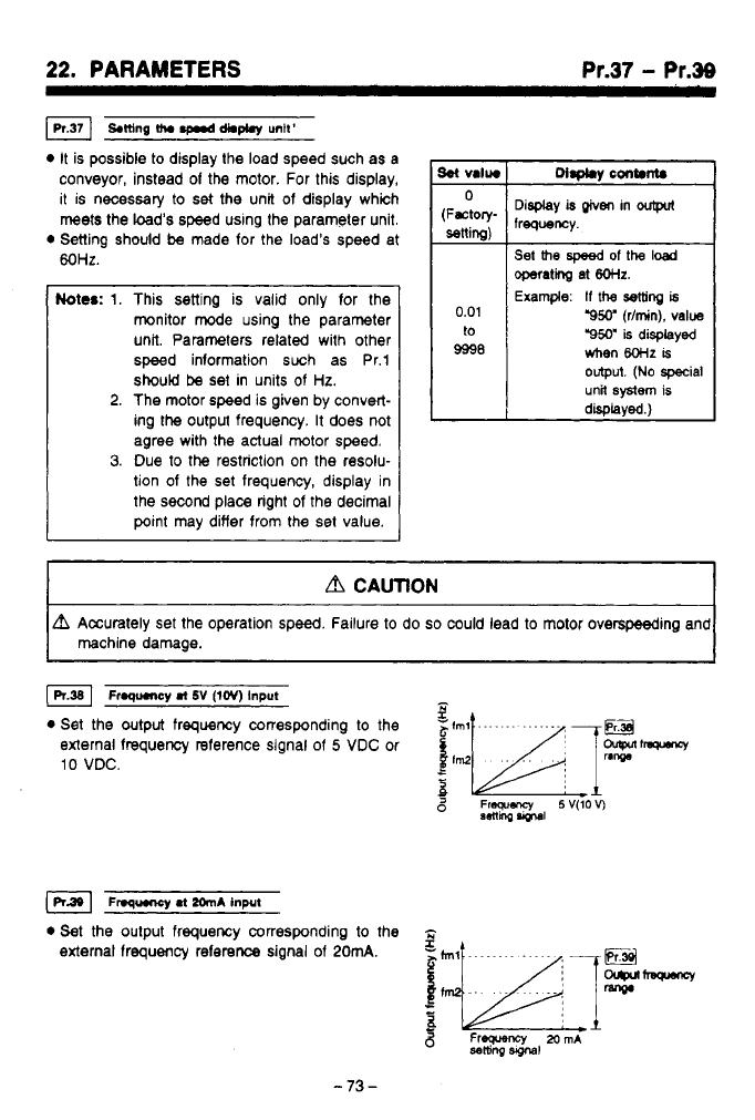
22.
PARAMETERS
Pr.37
-
Pr.39
IPr371
SMng
th.
d*m
untt'
0
It is possible to display the load speed such as
a
conveyor, instead
of
the motor. For this display,
it is necessary to
set
the unit of display which
meets the load's speed using the parameter unit.
0
Setting should
be
made for the load's speed at
MHz.
Notes:
1.
This sening is valid only for the
monitor mode using the parameter
unit. Parameters related with other
speed information such as Pr.1
should
be
set in units of
Hz.
2.
The motor speed is given by convert-
ing the output frequency. It does not
agree with the actual
motor
speed.
3.
Due to the restriction on the resolu-
tion
of
the set frequency, display in
the second place right
of
the decimal
point may differ from the set value.
L
Display
is
given
in
Set
the
speed
of
the
load
0.01
to
9998
operati
at
6OHz.
Example:
If
the
setting
is
"9W
(Vmin),
value
"950"
is
displayed
hen
8oHz
is
output.
(No
special
unit
system
is
disolaved.1
,,
,
CAUTION
~ ~ ~~
L?l
Accurately set the operation speed. Failure to do
so
could lead to motor overspeeding and
machine damage.
Froqumcy
ml
SV
(lev)
Input
-
0
Set the output frequency corresponding to the
external frequency reference signal
of
5
VDC
or
10
VDC.
5
Frequency
5V(lOV)
aetlhg
vprul
~nq~ryl
.t
2~n~
input
0
Set the output frequency corresponding to the
-
external frequency reference signal of
20mA.
Freweru~
MmA
ssltiiq
Slglal
-73-
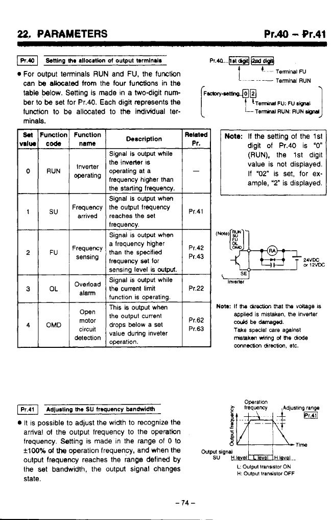
..
.
..
. ._
~.-.
.
-.
.
22,
PARAMETERS
Pr.40
-
Or.41
Senlng
me
allocation
~f
output
terminair
Pr.a...RFM
0
For output terminals
RUN
and
FU,
the function
1.
'-
-~
TermlnaiN
can
be
akcated from the four functions
in
the
table below. Setting is made
in
a twodigit nun
(~-.~tfho.@@
-l
~
Terminal
RUN
ber
to
be
set for Pr.40. Each digit represents the
function
to
be allocated
to
the
individual ter-
minals.
Sal
Fumllor
MIW
code
0
RUN
1
su
2 FU
3
OL
4
OMD
Funcllon
name
Inverter
operating
Frequency
arrived
Frequency
sensing
Overload
alann
Open
motor
detection
circuit
Signal is output while
the inverter
IS
operating at a
frequency higher than
Signal is output when
the output frequency
reaches the
set
freauencv.
Pr.41
Signal
is
output when
a frequency higher
than the specified
frequency
set
for
sensing level
is
output.
Signal
is
output while
the
current
limit
function is operating. Pr.22
This
is
output when
the output current
drops below a set
value during lnveter
operation.
pr,43
Pr.42
Pr.62
Pr.63
Adju8ting
h
SU
froqu~~cy
bandrvldth
It
is possible
to
adjust the width to recognize the
arrival
of
the output frequency
to
the operatin
frequency.
Setting
is made in the range of
0
to
flw%
of
the
operation frequency, and when the
wputrig~
oulput frequency reaches the range defined by
SU
H
I
vel
HI
v
I..
the set bandwidth, the output signal changes
L:
Oulpn
lransslor
ON
state.
Operallon
H:
Output
lraruislor
OFF
J
Note:
If the setting of the
lsl
digit of Pr.40 is
"0"
(RUN),
the 1st digit
value is not displayed.
If "02"
is set, for ex-
ample,
'2"
is displayed.
Nota:
If
bre chredion
bret
the
voltage
IS
coold
be
damam.
applied
is
mistaken,
me
Inverter
Take
special
care
against
mstakm
wiring
d
\he
dode
mnnedh
chreotion,
etc.
-
74
-
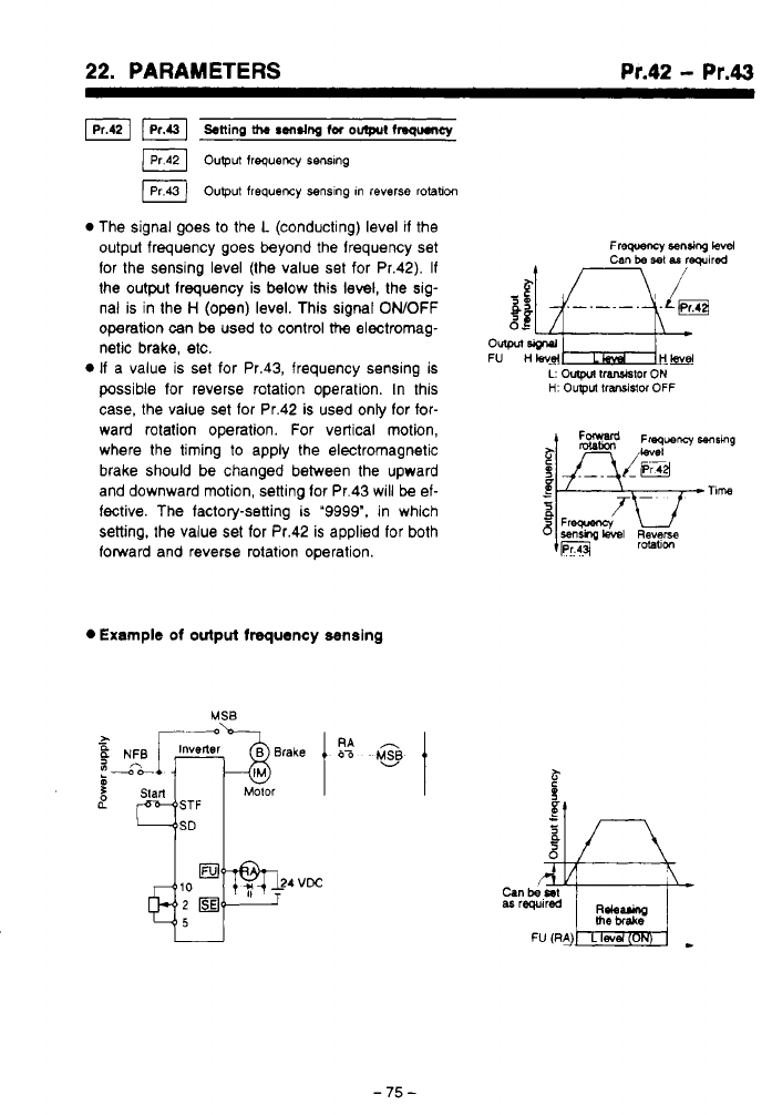
*,
.
..
,.-,.
-.
1
*
-
..__...I.
22.
PARAMETERS
..
. .
..*...
,
.,,
Pr.42
-
Pr.43
F]
stting
the
rens~ng
fa
om
fngumy
output
frequency
senslng
IPr43)
output frequency
senslng In
reverse
rotaticm
0
The signal goes to the
L
(conducting) level
if
the
output frequency goes beyond the lrequency set
for the sensing level (the value set for Pr.42).
If
the output lrequency is below this level, the sig-
nal is in the
H
(open) level. This signal
ONOFF
operation can
be
used to control
the
electromag-
netic brake, etc.
If
a value is set for Pr.43, frequency sensing is
possible for reverse rotation operation. In this
case, the value set lor Pr.42 is used only for for-
ward rotation operation. For vertical motion,
where the timing
to
apply the electromagnetic
brake should be changed between the upward
and downward motion, setting lor Pr.43 will
be
el-
fective. The factory-setting
ls
"9999".
in which
setting, the value set for Pr.42 is applied for both
forward and reverse rotatlon operation.
0
Example
of
output frequency semslng
-75-
.
.
.
..
-
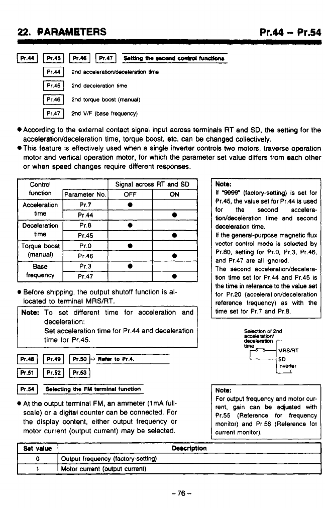
22.
PARAMBTERS
Pr.44
-
Pr.54
Lpr.uI
pKiq
piq
&~Ih.nc4r+doon+dtundknr
2nd
acwleramdmxleraticm
me
2nd
decebram
time
2nd
torque
b00s1
(mad)
M
VF
(base
frequency)
*Amding
to
the external contact signal input across terminak
RT
and
SD,
H-te
setting
for the
acceleratioddeceieration
time, torque
boost,
etc.
can
be
changed coliectively.
,-!
*This feature
is
effectively used when a single invetter
controls
two
motors,
traverse
operation
h..‘
rotor and vertical operation mtor, for which the parameter set value differs from each other
or when speed changes require difierent respons%s.
Control Signal
acmss
RT
and
SD
functkn Parameter
No.
OFF
ON
Acceleration Pr.7
a
time
Pr.44
a
Deceleration Pr.8
a
time Pr.45
a
Toque
boost
Pr.0
a
(manual) Pr.46
a
I
Belore shipping,
the
output shutoff function is al-
located
to
terminal MRSiRT.
deceleration:
Set acceleration time for Pr.44 and deceleration
time for Pr.45.
I
J
FI
Fl
~.t.r
to
~r.4.
(R.511
pzq
F1
SWng
me
FM
t.rm~rul
function
At
the output terminal FM, an ammeter
(1mA
full-
scale) or a digital counter can
be
connected. For
the display content, either output frequency or
motor current (output current) may
be
selected.
btb:
If
9999’
(ladory-setting)
is
set
tor
Pr.45,
the
value
set for Pr.44 is
used
lor
the
second accelera-
tiiddeceleration lime and second
decelaration time.
It
the
general-purpose rnagmtic flux
vector
mntrol
mode
is
sdded
by
Pr.80, setting for Pr.0, Pr.3, Pr.46,
and Pr.47 are all ignored.
The
second acceleratioddecelera-
lion
time
set for Pr.44 and Pr.45 is
the
lime
in
reterem
to
the
vab
set
for Pr.20
(acceleratioddeceleration
reference frequency) as
with
the
lime set for Pr.7 and Pr.8.
SeleCtKn
ol2nd
aaxleraliow
Note:
rent, gain
can
be
edjusted
with
For
output
trequency and motor cur-
Pr.55 (Reference tor frequency
monitor) and Pr.56 (Reference lor
currenl monitor).
I
1
I
Motor
current
foutDut
current)
1
-
76
-
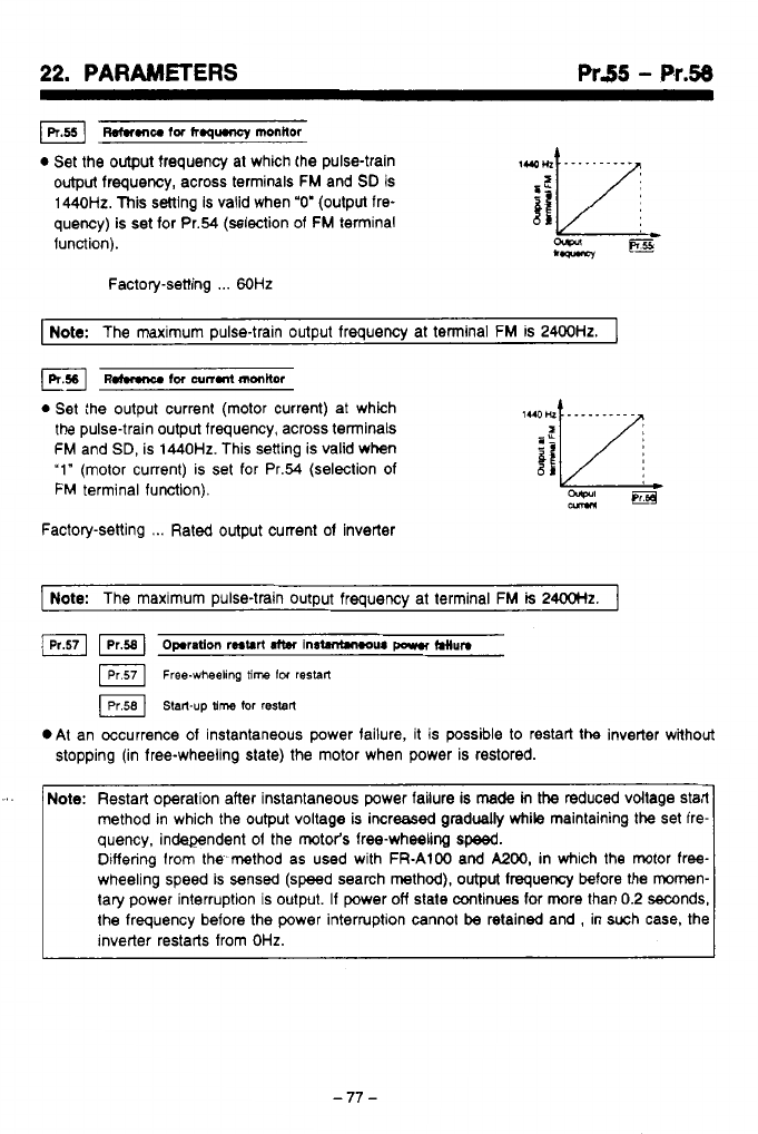
22.
PARAMETERS
Pr55
-
Pr.58
mu
tor
h.qumcy
monitor
0
Set the output frequency at which the pulse-train
output
frequency, across terminals FM and
SD
is
1440Hz. This setting is valid when
"0'
(output fre-
quency)
is
set for Pr.54 (selection of
FM
terminal
function).
Factory-setting
...
60Hz
I
Note:
The maximum pulse-train output frequency at tenninal FM is
2400Hz.
I
udmnu
fw
~n.nt
mttw
0
Set the output current (motor current) at which
the pulse-train output frequency, across terminals
FM
and SD, is
1440Hz.
This setting is valid when
'1"
(motor current) is set for Pr.54 (selection
of
FM
terminal function).
Factory-setting
...
Rated output current of inverter
pote:
The maximum pulse-train output frequency at terminal FM
is
24ooHz.
I
Fl
Opration
restart
atter
1n-w
porn
~lun
Free-wheeling
8me
lw
restarl
Start-up
time
tor
restart
.At an Occurrence of instantaneous power failure, it is possible to restart the inverter wahout
stopping (in free-wheeling slate) the motor when power is restored.
'.
Note:
Restart operation after instantaneous power failure is
made
in
the
reduced vdtage start
quency, independent of the motor's free-wheeling
speed.
method in which the output voltage is increased gradually
while
maintaining the set fre-
wheeling speed is sensed (speed search method).
output
frequency before the mornen-
Differing from the method as used with FR-A100 and
MOO,
in which the motor free-
tary power interruption is output.
If
power
off
state continues for more than
0.2
mnds,
the frequency before the power interruption cannot
be
retained and
,
in such case, the
inverter restarts from
OHz.
-77-
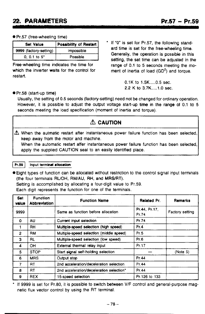
Pr.57
- Pr.59
0
Pr.57 (free-wheeling time)
'
If
"0"
is set for Pr.57, the following stand-
ard time is set for the free-wheeling time.
Generally, the operation is possibk in this
setting, the set time can
be
adjusted in the
Freewheeling time indicates the time for range of
0.1
to
5
seconds meeting the mo-
which the inverter waits for the control for ment of inertia of load
(GO')
and torque.
restart.
0.1K
to
1.5K
.....
0.5
sec.
2.2
K to 3.7K
.....
t
.O
sec.
n
Pr.58 (start-up time)
bd
Usually, the setting of
0.5
seconds (factory-setting) need not
be
changed for ordinary operation.
However,
it
is possible to adjust the output voltage start-up time
m
the range of
0.1
to
5
seconds meeting the load specification (moment of inertia and torque),
keep away from the motor and machine.
When the automatic restart affer instantaneous power failure function
has
been selected,
Input
tom~
r~loutlon
0
Eight types of function can
be
allocated without restriction to the control slgnal input terminals
(the four terminals
RUOH,
RWAU,
RH,
and
MRWRT).
Setting is accomplished by allocating a four-digit value
to
Pr.59.
Each digit represents the function for one
of
the terminals.
Set
Abbndation
value
Function Function Name
Remarks
Related
Pr.
9999
Factoty
setting
Pr'44'
Pr'17'
Same as function
More
allocation
Pr.74
3
External thermal relay input
*
If
9999
is set for Pr.80, it
is
possible to switch between
VIF
control and general-purpose mag-
netic flux vector control by using the
RT
terminal.
-70-
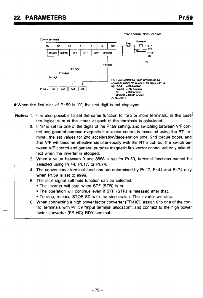
*,
.
..
,.-
.-.
_.._.
-.
..
,I
.
22.
PARAMETERS
Pr.59
.I
..
Notes:
1.
It
IS
also possible to set the same function for two or more terminals. In this case
the logical sum of the inputs at each of the terminals is calculated.
2. If
'8'
is set for one of the digits of the Pr.59 setting, and switching between
VIF
con-
trol and general-purpose magnetic flux vector control is executed using the RT ter-
minal, the set values for 2nd
acceleration/deceleration
tme, 2nd torque
boost,
and
2nd VIF will become effective simultaneously with the RT input, but the switch be-
tween
V/F
control and general-purpose magnetic flux vector control will only take ef-
fect when the inverter is stopped.
3.
When a value between
0
and
8888
is set for Pr.59, terminal functions cannot be
selected using Pr.44, Pr.17, or Pr.74.
4.
The conventional terminal functions are determined by Pr.17, Pr.44 and Pr.74 only
when Pr.59 is set to 9999.
5. The start signal self-hold function can be selected.
The inverter WIII start when STF (STR)
is
on.
The operation will continue even
if
STF (STR) is released after that.
To stop, release STOP-SD with the stop switch. The inverter will stop.
6.
When connecting a high power factor converter (FR-HC), assign
6
to one of the con-
trol terminals with Pr. 59 'Input terminal allocation", and connect to the high power
factor converter
(FR-HC) RDY
terminal.
-79
-
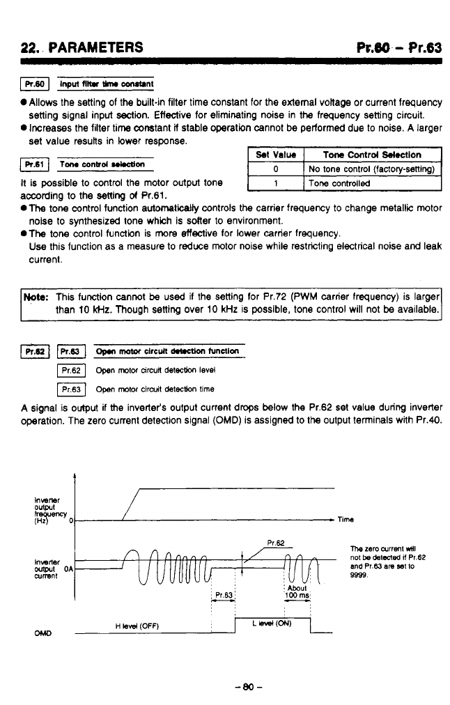
22.
PARAMETERS
R.86
-
Pr.63
~nput
~ltr
w
COrUtlnt
Allows the setting of the built-in filter time constant for the external voiiage or current frequency
0
Increases the filter time constant
if
stable operation cannot
be
performed due to noise. A larger
setting signal input sectin. Effective for eliminating ndse in the frequency setting circuit.
set
value resutts in lower response.
Tomconbd~on
It is possible to control the motor output tone
according to the setting
of
Pr.61.
*The
tone control function automatically controls the carrier frequency
to
change metallic motor
.The
tone control function is
more
effective for lower carrier frequency.
noise to synthesized tone which is solter to environment.
Use
this function as a measure to reduce motor noise while restricting electrical noise and leak
current.
Note:
This function cannot
be
used if the setting for Pr.72 (PWM carrier frequency) is larger
than 10
kHz.
Though setting over 10 kHz is possible, tone control will not
be
available.
open
motor
arcun
&tech
level
[Prs31
Open
motor
ctrdt
detection
tlme
A signal is
output
if
the inverter's output current drops below the Pr.62
set
value during inverter
operation. The zero current detection signal
(OMD)
is assigned to
the
output tenninals with Pr.40.
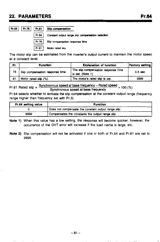
*,
.~
.,,.I^_.....___
.
..
.
.
....
..
.
,
,
.
..__....
.”.
..
,
....
22.
PARAMETERS
at a constant level.
Pr.
9999
The
md&s
rated
slip
is
set.
Motor rated
slp
(%)
81
is
set,
(Nde
,)
Slip
compensation
respxse
time
76
Factory
mlng
Expbnatlon
of
function
Functkn
The
slip
compensation
response time
o,5
~
Pr.81 Rated slip
=
Pr.64 selects whether
to
activate
the
slip
compensation
at the constant output range (frequency
range higher than frequency set with Pr.3).
Synchronous
speed
at base frequency
-
Rated
speed
x
(yo)
Synchronous
speed
at
base
frequency
Pr.64
cenlng
value
I
Fumtlon
t
0
I
Does
not
compensate
the constant output
range
slip.
9599
I
Compensates the constants the
output
range
slip.
Note
1)
When this value has a low setting, the response will
become
quicker, however, the
Occurrence of
the
OVT
enor will increase if the load inertia is large, etc.
Note
2)
Slip compensation will
not
be
activated if one or both of Pr.64 and Pr.81 are set
to
9999.
-
81
-
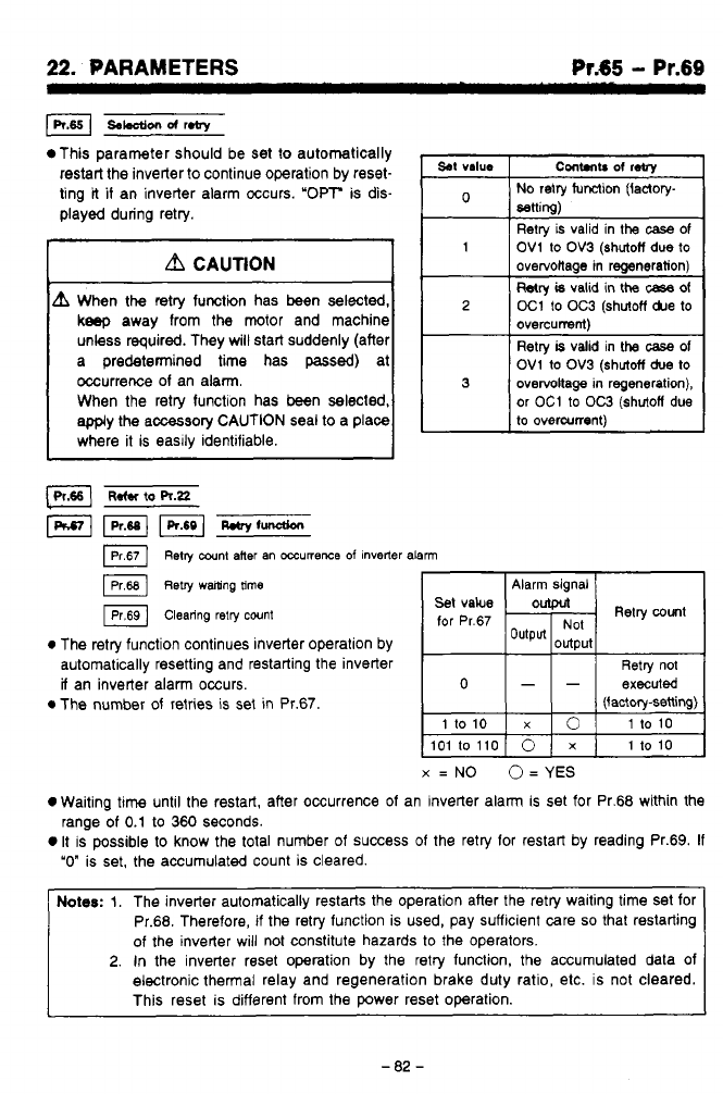
.
.
-
..
--
22.
PARAMETERS
Pr.65
-
Pr.69
This parameter should be set
to
automatically
restart the inverter
to
continue operation by reset-
ting
it
if
an inverter alarm occurs. 'OPT is dis-
played during retry.
a
CAUTION
When
the
retry function has
been
selected,
keep
away from the motor and machine
unless required. They will start suddenly (after
a predetermined time has
passed)
at
occurrence of an alarm.
When the retry function has been selected,
apply the accessory CAUTION seal
to
a place
where it is easlly identifiable.
set
value
Cont.nb
of
reby
No
retry function (factory-
setting)
1
OV1
to
OV3
(shutoff
due
to
Retry is valid in
the
case of
overvoltage in regeneration)
Wry
is
valid
in
the
case
of
2
oC1
to
OC3
(shutoff
&e
to
overcurrent)
OV1
to
OV3
(shutoff
due
to
Retry
is
valid
in
the
case
of
3
overvottage in regeneration),
or
OC1
to
OC3
(shutoff
due
to
overcurrent)
Retry
cant
aner
an
mumeme
of
inverter
alarm
IPr68]
~etry
walting
time
Alarm signal
@
Clearing
retry
count
for
Pr.67
0
The retry function continues inverter operation by
automatically resetting and restarting the inverter Retry no1
if
an inverte; alarm occurs.
0
The number of retries is set
in
Pr.67
0
--
executed
(factory-setting)
X
=
NO
O=
YES
0
Waiting
time
until the restart, after occurrence of an inverter alarm
is
set for Pr.68 within the
0
It is possible to know the total number of success
of
the retry for restart by reading Pr.69.
If
range of
0.1
to
360 seconds.
"0"
is set, the accumulated count is cleared.
Notes:
1.
The inverter automatically restarts the operation after the retry waiting time Set for
Pr.68. Therefore,
if
the retry function is used, pay suffcient care
so
that restarting
of the inverter wiii not constitute hazards to the operators.
2.
In
the inverter reset operation by the retry function, the accumulated data of
electronic thermal relay and regeneration brake duty ratio, etc. is not cleared.
This reset is different from the power reset operation.
-
82
-
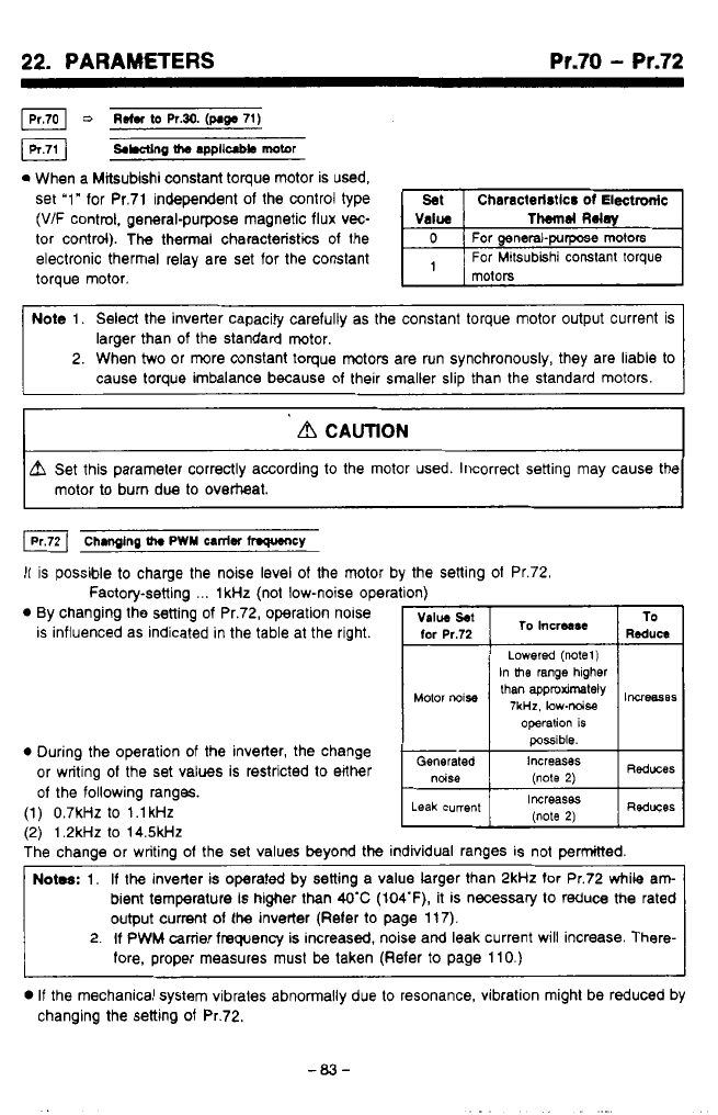
-
,
_.
,.l.l
._
.
..-
..
-
.
.
.
.
.
.
.I.
..
..
..
.
,..”..
.
,
,
22.
PARAMETERS
Pr.70
-
Pr.72
0
When a Mitsubishi constant torque motor is used,
set ‘1” for Pr.71 independent of the control type
(V/F control, general-purpose magnetic flux vec-
tor control). The thermal characteristics of the
electronic thermal relay are set for the constant
torque motor.
Note 1. Select the inverter capacity carefully as the constant torque motor output current is
larger than
of
the standard motor.
2. When
two
or more constant toque motors are run synchronously, they are liable to
cause torque imbalance because of their smaller slip than the standard motors.
__
d
CAUTION
A
Set this parameter correctly according to the motor used. Incorrect setting may cause the
motor to burn due to overtteat.
Chmglng
th.
PWY
=niW
hWUlCY
It is possible to charge the noise level
of
the motor b
Factory-setting
...
1kHz (not low-noise opera
0
By changing the setting
of
Pr.72, operation nolse
is influenced as indicated in the table at the right.
0
During the operation of the inverter, the change
or writing
of
the set values is restricted to either
of
the following ranges.
(1) 0.7kHZ to l.lkHz
f2)
1.2kHz to 14.5kJ-k
the setting
of
Pr.72.
possible.
The chanae or writing of the set values
beyond
the individual ranges is not permitted.
\,
Notes:
1.
If
the inverler is operated by setting a value larger than 2kHz for Pr.72 while am-
bient temperature
is
higher than
WC
(104‘F),
it is necessary to reduce
the
rated
output
current
of
the inverter (Refer to page 11 7).
2.
If
PWM carrier frequency is increasd, noise and leak current will increase. There-
fore, proper measures must
be
taken (Refer
to
page 110.)
0
If
the mechanical system vibrates abnormally due to resonance, vibration might be reduced by
changing the setting
of
Pr.72.
-03-
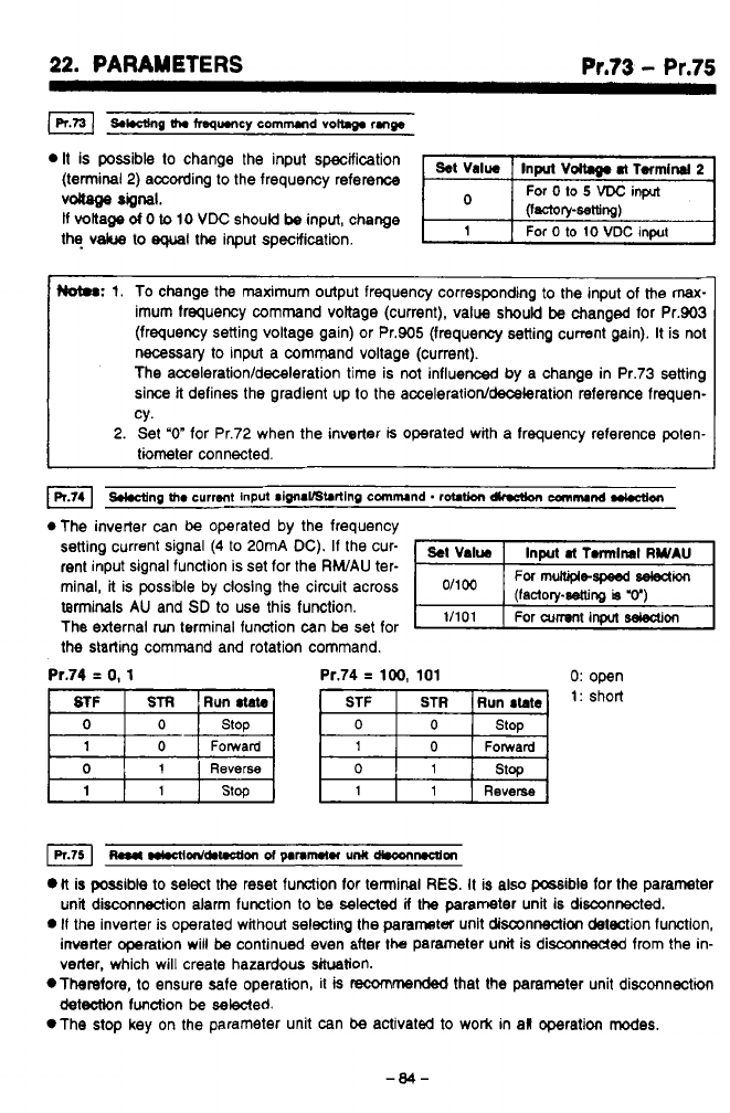
22.
PARAMETERS
Pr.73
-
Pr.75
It
is possible
to
change the input specification
(terminal
2)
according to the frequency reference
vdiage
“1.
If
voltage
d
0
to
10
VDC
should
be
input, change
the
vakre
to
equal
the
input specification.
Hot#:
1.
To change the maximum output frequency corresponding
to
the input of the max-
imum frequency command vottage (current), value
should
be
changed for Pr.903
(frequency setting voltage gain) or Pr.905 (frequency setting current gain).
It
is not
necessary
to
input a command voltage (current).
The
acceleration/deceleration
time is not influenced by a change in Pr.73 setting
since
it
defines the gradient
up
to
the
acceleration/deceleratbn
reference frequen-
cy.
2.
Set
“0”
for Pr.72 when the inverter
is
operated with a frequency reference poten-
tiometer connected.
*The inverter can
be
operated by the frequency
setting current signal
(4
to
20mA
DC).
If the cur-
rent input signal function is set for the
RWAU
ter-
minal,
it
is possible by closing the circuit across
terminals
AU
and
SD
to use this function.
The external
run
terminal function can be set for
the starting command and rotation command.
-,
11101
1
For
cumnt
input
Won
Pr.74
=
0,
1
Pr.74
=
100,
101 0:
open
Forward Forward
Reverse
0
1 1
~a*
m~nld.t.ctlon
~f
panmtn
unlt
d*conmm
li
is possible
to
select
the
reset function for terminal
RES.
It is also possible for the parameter
unit disconnection alarm function
to
be selected
if
the parameter unit is
disconnected.
0
if
the inverter is operated without selecting the parameter unit disconnection detection function,
inverter operation will
be
continued even after the parameter
unit
is disconnected from the in-
verter, which will create hazardous situation.
*Therefore.
to
ensure safe operation, it
is
racommended
that the parameter unit disconnection
detection
function
be
sewed.
*The
stop
key
on
the parameter unit can
be
activated
to
work in al operation modes.
-84-
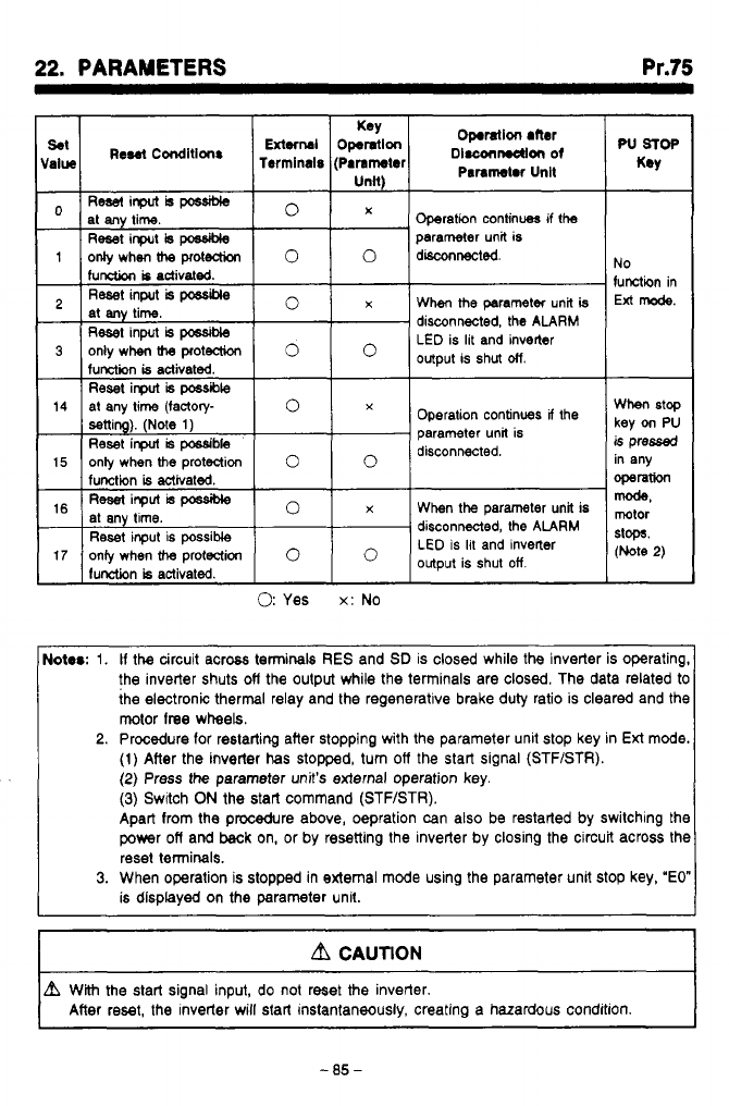
"
, ,
.
,
.
,
-
.
-.
.
.
I.
.
.
.
-.
.
.
.
.
.
..
..
..
.
...
..
.
_.-
*..
.
,
,.
,
,
....,
22.
PARAMETERS Pr.75
Ress(inputhpcssiMe
at any time.
Reset
input
is
possible
parameter unit is
0
X
Operation continues if !he
1
onlywhenh
protection
0
0
disconnected
function
is
activated.
Reset
input
is
possible
at
any
time.
Reset
input
is
posslMe
1unetit-m
is
activated
0
x
When
the
parameter unit
is
disconnected. the
ALARM
LED
is lit and inverter
output is shut
otf.
3
only when
h
proteaion
0
Operation continues
If
the
parameter unit is
disconnected.
Reset inpuf
is
possible
When the parameter unit is
disconnected, the
ALARM
LED
is
lit
and invener
output is shut
off.
Reset input is possible
17
oniy when
the
protection
lunction
is
activated.
0:
Yes
x:
No
No
function in
Ext
mode.
When
stop
key
on
PU
is
pressed
in any
operation
mode,
mtor
stops.
(Note
2)
Notrr:
1.
If
the circuit across terminals
RES
and
SD
is closed while the inverter is operating,
the inverter shuts
ofl
the output while the terminals are closed. The data related
to
the electronic thermal relay and the regenerative brake duty ratio is cleared and the
motor
lree
wheels.
2.
Procedure
for
restarting after stopping with the parameter unit stop key in
Ext
mode.
(1)
After the inverter
has
stopped, turn
off
the start signal (STFISTR).
(2)
Press
the
parameter unit's external operation key.
(3)
Switch
ON
the start command (STF/STR).
Apart from the procedure above, oepration can also be restarted by switching the
power
off
and
back
on, or by resetting the inverter by closing the circuit across the
reset terminals.
3.
When operation is stopped in external mode using the parameter unit stop key,
'EO"
is displayed on the parameter unit.
I
Lb
CAUTION
I
I
L?L
With
the
start signal input, do not reset
the
inverter.
After reset, the inverter will start instantaneously. creating a hazardous condition.
I
-85-
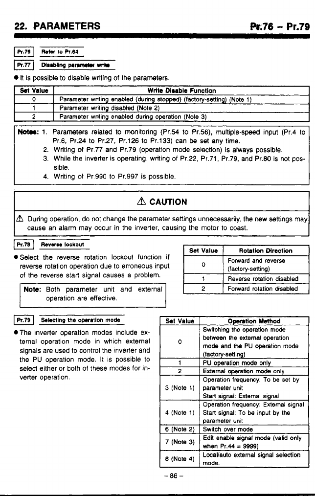
22.
PARAMETERS
k.76
-
Pr.79
R.m
to
R.64
DI=~II~~
pInn~n
mln
It
is possible
to
disable writing of the parameters.
Sel
Value
Wrlte
Disable
Function
0
2
Parameter writing disabl8d (Note
2)
1
Parameter writing enabled (during stopped) (lactory-setting) (Note
1)
Parameter writing
enabled
during operation (Note
3)
2.
Writing
of
Pr.77 and Pr.79 (operation mode selection) is always possible.
3.
While the inverter is operating, writing
of
Pr.22, Pr.71, Pr.79, and Pr.80 is not pos-
sible.
a
CAUTION
unng operation,
do
not change the parameter settings unnecessarily, the new settings may
cause an alarm may occur in the inverter, causing the motor
to
coast.
I
lpltal
Reverse
lockout
eSelect the reverse rotation lockout function
if
reverse rotation operation due to erroneous input
of
the reverse start signal causes a problem.
Note:
Both parameter unit and external
operation are effective.
Reverse rotation disabled
Fomard rotation
disabled
4
swing
the
operation
mode
.The inverter operation modes include ex-
ternal operation mode in which external
signals are
used
to control the inverter and
the PU operation mode. It
is
possible
to
select either or both
of
these modes
for
in-
verter operation.
beweeithe
extern1 operation
mode
and
the
PU operation mode
(factory-setting)
1
PU operation
mode
only
2
External
CQeration
mode
only
Operatlon frequmy:
To
be
set
by
Start
signal:
External signal
Operation frequency: External signal
parameter unfi
3
(Note
1)
parameter unit
4
(Note
1)
Switch over
mode
6
(Note
2)
Start signal:
To
be
input
by the
(Note
3)
Edit enable
signal
mode (valid only
when Pr.44
=
9999)
'3
-
.
-
86
-
1
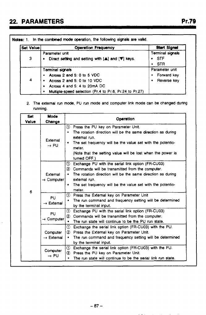
,
.
,
,*
-.__.......
.
-
..
..
..
.I .
r-l.
.-.,.
,
.-
22.
PARAMETERS
Pr.79
toter:
1.
In
ttm
CMbind
mode
operation, the
following
signak are
valid.
Set
Value
Terminal
Wals
Parameter unit
M
Slgnrl
Operation
Frmqwncy
3
STF
Direct
setling
and setting
with
[A]
and
[q
keys.
Terminal
sig-tals
Parameter unit
Across
2
and
5:
0
to
10
VDC Reverse key
Across
4
and
5:
4
to
20mA
DC
2.
The external
nm
mode, PU run mode and computer link mode can
be
changed during
running.
SO1
Value
6
Chnge
Mode
Operation
10
Press the PU kev on Parameter Unit.
I
.
The
rotation direction will be the same direction
as
during
The set frequency will be the value set with the potentio-
edema1 run.
--f
pu
meter.
(Note
that the setting value w~ll
be
lost
when the power
is
turned
OFF.)
0
Exchange PU with the
serial
link option (FR-CUOB)
0
Commands will
be
transmitted from the computer.
External
The set frequency will
be
the value set with the potentio-
The rotation direction will be the
same
direction as during
+
Computer external run.
meter.
_,
,
0
Press the External key on Parameter Unit
The run command and frequency setting will
be
detenined
0
Exchange PU with the serial link option (FR-CUOB)
The run state will continue
to
be
the PU run state.
0
Commands will be transmitted from the computer.
0
Exchange the serial link option (FR-CUOB) with
the
PU.
-07-
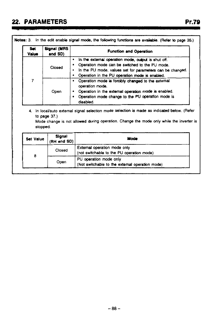
22.
PARAMETERS
Pr.79
Wer:
3.
In the
edit
enable signal
mode,
the idlowing functions
are
avdable.
(Refer
to
page
35.)
lnthr
extW operation
mode.
ocgxrt
is shut
on.-
Operation
mode
can
be
awildwd
to
the PU
mode.
*
In
the
PU mode, values set
for
parameters
can
be changed.
1 1
7
Operation in the PU operation
mode
is
embkd.
Operation
mode
is
forcibty
chsnged
to
the external
operation
mode.
Open
Operation
mode
change
to
the
PU
operatton mode is
Operation in the
external
operation
mode
is
enabled.
4.
In IOcaVauto external signal selection mode selection
is
made
as
indicated below. (Refer
to
page
37.)
Mode change is not allowed during operation. Change the mode only while the inverter
is
stopped.
(RH
and
SD)
Slgnal
yod.
External
operation
mode
only
‘Iosed (not switchable
to
the PU operation mode)
R
1-
I
Open
I
PU operation
mode
only
(Not
switchable
to
the
external
omration mode)
m,
w
h
w
4
-88-
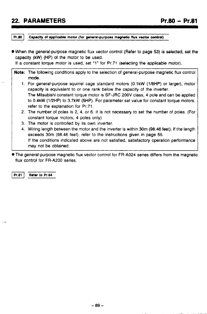
22,
PARAMETERS
Pr.80
-
Pr.81
0
When the general-purpose magnetic flux vector control (Refer
to
page
53)
is selected, set the
-
-
0
The general-purpose magnetic flux vector control for FR-A024 series differs from the magnetic
flux control for FR-A200 series.
capacity
(kW)
(HP)
01
the motor to be used.
I1 a constant torque motor is used, set
‘1”
lor Pr.71 (selecting the applicable motor).
Note:
The following condltions apply to the selection of general-purpose magnetic flux control
1.
For general-purpose squirrel cage standard motors
(O.lkW
(1BHP)
or larger), motor
capacity is equivalent to or one rank below the capacity of the inverter.
The Mksubishi constant torque motor is SF-JRC 200V class,
4
pole and can
be
applied
to
0.4kW
(112HP) to
3.7kW
(5HP).
For parameter set value for constant torque motors,
refer to the explanation for Pr.71,
2. The number 01 poles is
2,
4, or 6.
It
is not necessary to set the number of poles. (For
constant torque motors, 4 poles only)
3.
The motor
is
controlled by its own inverter.
4. Wiring length between the motor and the inverter is within 30m (98.46 feet).
If
the length
exceeds 30m (98.46 feet), refer
to
the instructions given in page
55.
If
the conditions indicated above are not satisfied, satisfactory operation performance
may
not be obtained.
mode.
-89-
..
.
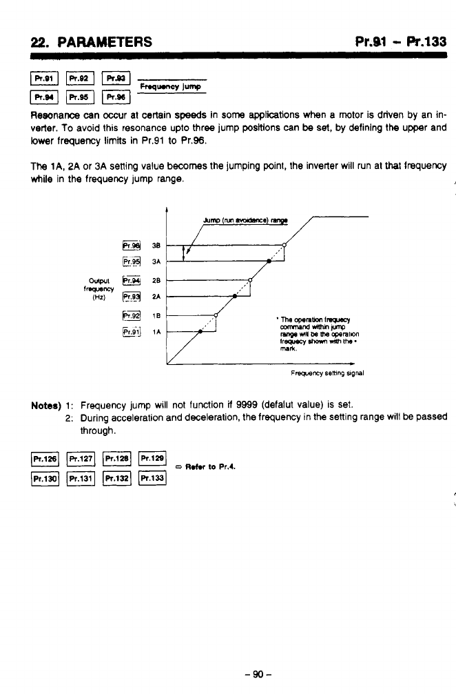
22.
PARAMETERS Pr.91
-
Pr.133
Resonance can occur at certain
speeds
in
some
appliitions when a motor is driven by an in-
verter. To avoid this resonance upto three jump positions can
be
set,
by defining the upper and
lower frequency limits in Pr.91 to Pr.96.
The
lA,
2A
or
3A
setting value
becomes
the jumping point, the inverter will run at that frequency
while in the frequency jump range.
?*
w
&mp
(M
m.almxe
E@*
E.4
3A
Notes)
1:
Frequency jump will not function
ii
9999 (defalut value) is set.
2:
During acceleration and deceleration, the frequency in the sening range will be passed
through.
JPr.(2BI
FJ
pq
(Pr.1311
IR.1331
o
~.tn
to
Pr.4.
-90-
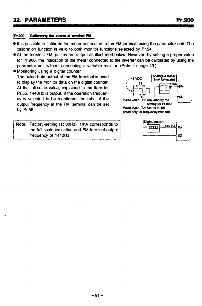
22.
PARAMETERS
Pr.900
-nw-nwm
0
It
is possible
to
calibmte the meter connected to the
FM
terminal using the parameter unit. The
calibration function is valid to both monitor functions selected by Pr.54.
0
At the terminal
FM,
pulses are output as illustrated
below.
However, by setting a proper value
for Pr.900, the indication
of
the meter connected
to
the
inverter can
be
calibrated
by
using the
parameter unit without connecting a variable resistor. (Reler
to
page 49.)
The
pulse-train
output
at
the
FM
terminal
is
used
to
display the monitor data on the digital counter.
At the full-scale value, explained in the item for
Pr.55,
1440Hz
is output.
If
the operation frequen-
cy
is
selected
to
be
monitored, the ratio
of
the
pdse~h
T(:
~qusl~~~
output frequency at the
FM
terminal can be set
Semrq
tu
Pr.800
by Pr.55.
0
Monitoring using a digital counter
Pulse
cyde
T2:
S#
IM
Pr.55
(vslid
fM
hw
mOnhOr)
Note:
Factory-setting (at
60Hz):
1
mA
corresponds to
the full-scale indication and
FM
terminal output
frequency of
1440Hz.
(Dbjtfi
meter)
-91
-
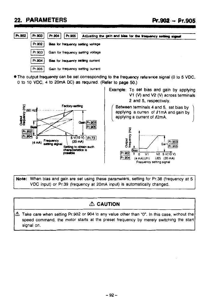
22.
PARAMETERS
Pr.soP.
-L
Pr.906
.The output frequency can
be
set corresponding
to
the frequency reference signal
(0
to
5
VDC,
0
to
10
VDC,
4
to
20mA
DC)
as required. (Refer
lo
page
50.)
,Pt
;'
Example:
To
set bias and gain by applying
b'
2
V1
(V)
and V2
(V)
across terminals
2 and
5,
respectively.
Between terminals
4
and
5,
set bias by
applying a curren of
11
mA
and gain by
applying a current
of
P2mA.
I
Note:
When bias and gain are set using these parameters, setting for Pr.38 (frequency at
5
VDC
input) or Pr.39 (frequency at 20mA input) is automaticallv chanaed.
dl
CAUTION
L?l
Take care when setting Pr.902 or 904
to
any value other than
"0".
In this case, without the
speed command, the motor starts at the preset frequency by merely switching the start
signal on.
"J
-
92
-
22.
PARAMETERS Pr.990
-
Pr.997
Sobcting
key
click
sound
(p.rm&er
unlt)
*This parameter is used
to
select whether
click sound is output or not in response
to
the key operation on the parameter unit.
(Refer
to
page
52).
-bcctionofth.p.rMrmitd(.plym
*The contents of monitor display of the
parameter unit can be fixed (or given
priority) to the set frequency.
(Note
1)
Fixed to
the
se!
lrequency.
(Note
2)
Note:
1.
Pressing the [A] or
[VI
key during the operation frequency monitor will change the
display
to
the set lrequency.
At
10
seconds after the [A] or [VI key has been released, the monitor display will
automatically return
to
the operation lrequency.
2.
The monitor display is given only when the [MONITOR] key
is
pressed.
It
the [WRITE] key is pressed after reading the data set for Pr.966,dhe inverter alarm is cleared.
(Refer
to
page
45)
Note:
The accumulated values for the electronic thermal relay and the retry count are not
cleared.
When the data in Pr.996 is read,
"frrdl"
is always displayed. It blinks on and
off
when the alarm
is cleared.
*setting
the
invatw
It
is possible
to
reset the inverter using the [WRITE] key after reading the data in Pr.997 without
inputting a signal
to
the
RES
terminal or turning on and
off
the power. (Refer to page
48).
Note:
In
this
reset operation,
the
accumulated values lor the electronic thermal relay and
the
retw count are cleared
0
When the data in Pr.997 is read,
"rf
Sf"
is always displayed. The display is cleared once and
then the initial Screen appears when the inverter is reset.
-
93
-

22.
PARAJWT€RS
Pr.W
-
Pr.999
*,.*a-
I
i
I*.
.i
(R.0081
Ip1.ooo1
Init*lidngth.purn*
Parameter
all
&&l
Parmmterdsar
0
By pressing the
[WRITE)
key
after reading the data in Pr.998 or Pr.999, the values
set
for the
parameter can be changed
to
the values initially set before shipping (factory-setting) collective-
‘Y.
*The
parameters for which the set
values
can
be
changed colWiely are:
Pr.998
...
All
parameters
Pr.899
...
Parameters excluding those used for calibration (Pr.900
to
Pr.905).
3
OH
the
parameter write is disabled (Pr.77
=
1,
or during operation in the setting of Pr.77
=
0),
*When
the
set
values
for the parameters are read, the display in the display unit is:
you may not change
the
setting of
the
parameters.
“/UP
for Pr.998 and
“6‘rL-r’
for Pr.999.
The
display blinks on and off when the parameters are initialized.
-44-
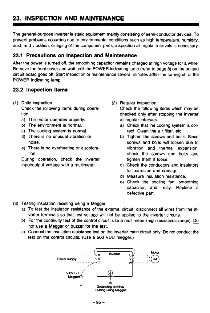
23.
INSPECTION AND MAINTENANCE
The general-purpose inverter is
static
equipment mainly consisting of semiconductor devices. To
prevent problems occurring due
to
environmental conditions such as high temperature, humidity,
dust, and vibration, or aging of the component parts, inspection at regular intervals is necessary.
23.1
Precautions on Inspection and Maintenance
After the power is turned
olf,
the smoothing capacitor remains charged at high voltage for a while.
Remove the front cover and wait until the POWER indicating lamp (refer
to
page
3)
on the printed
circuit board
goes
off.
Start inspection or maintenance several minutes affter
the
turning
off
of
the
POWER indicating lamp.
23.2
Inspection
items
(1)
Daily inspection
Check the iollowing items during opera-
tion.
a) The motor operates property.
b) The environment is normal.
c) The cooling system is nonnal.
d) There is no unusual vibration
or
e) There is no overheating or discolora-
During operation, check the inverter
inpuVoutput voltage with a multimeter.
noise.
tion.
(2)
Regular inspection
Check the following items which may
be
checked only after stopping the inverter
at regular intervals.
a) Check that the cooling system is cor-
rect. Clean the air filter, etc.
b) Tighten the mews and bolts. Since
screws and bolts will loosen due
to
vibration and thermal expansion,
check the screws and
bolts
and
tighten them
if
bose.
c) Check
the
conductors and insulators
for corrosion and damage.
d) Measure insulation resistance.
e)
Check the cooling fan, smoothing
capacitor, and relay. Replace a
defective part.
(3)
Testing insulation resisting using a Megger
a)
To
test the insulation resistance of the external circuit, disconnect ail wires from
the
in-
b) For the continuity
test
of
the
cootrol circuit.
use
a multimeter (high resistance range).
c) Conduct the insulation resistance test on the inverter main circuit only. Do not conduct the
verter terminals
so
that test voltage will
not
be
applied
to
the inverter circuits.
not use a Megger or buzzer for
!he
test.
test on the control circuits.
(Use
a
500
VDC
megger.)
-
95
-
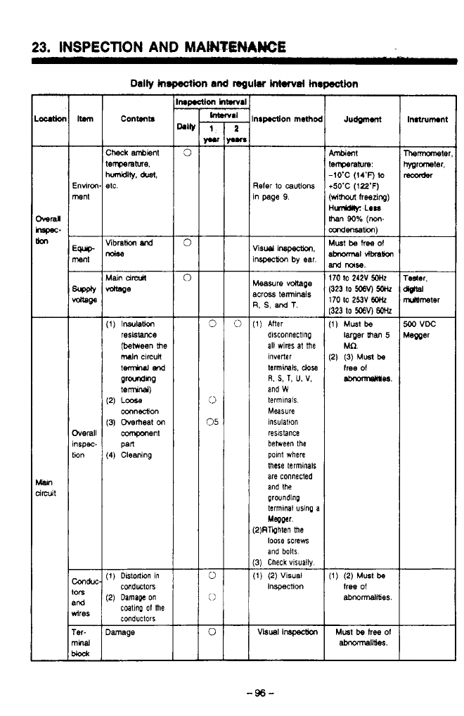
23.
INSPECTION
AND
MAWTENAWE
Content8
nrp.aion
rnethmoc
%fer
io
cautions
n page
9.
fisu
inspearon.
nspecM
by
ear.
deasure
vdtage
%cross terminals
3,
S,
and
T.
1)
After
dlsconnectlng
all wires at the
terminals,
close
Inverter
and
W
R.
S,
T,
U.
V,
terminals
Measure
insulation
reslsbnce
between the
polnt where
these terminals
are connected
and the
grwnding
termlnal using a
Megper.
2)RTQhten the
loose screws
and bolts
3)
Check vlsuaily
1)
(2)
Visual
inspection
Visual
lnspectm
went
errperaturn:
-1O'C
(14'F)
to
b50'C
(122'F)
wim
freezing)
iML6s:
LOW
han
90%
(m-
mdensation)
Must
be
free
Of
Ibnom\sl~~
lrd
IloIsB.
170
to
242V
5OHz
323
to
WV)
W
1)
Must
be
larger
than
5
Mfl.
2)
(3)
Must
be
free
of
-98.
1)
(2)
Must
be
free
Of
abnormalities.
Inatrumon1
.
-96-
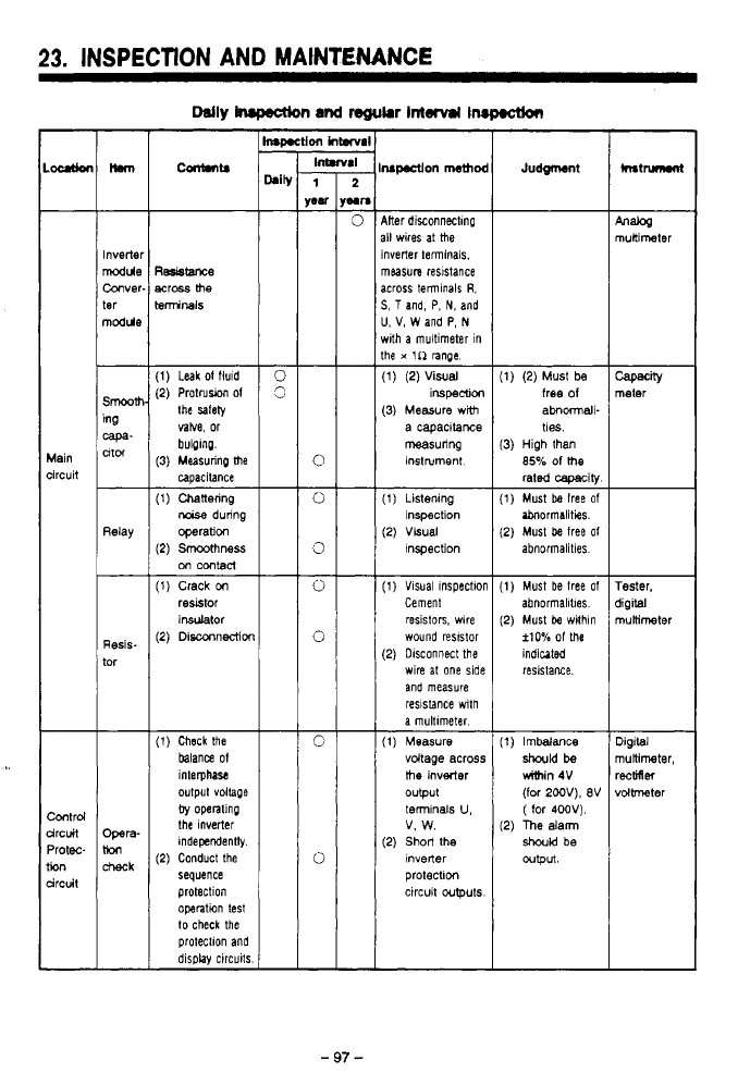
-
,.
_.
,.._
~ ~
-._.
-
.
.
.
,.
.
.. .
,
..._-*
.,.
,
I
,
23.
INSPECTION
AND
MAINTENANCE
7;;
ir
r
Con(.ntS
JudgcMnt
Mer diSonneCtmp
111
wires
at
me
Inverter terminals.
measure
resistance
across temlnals
R,
S,
5
and, P,
N,
and
U.
V,
W
and
P,
N
rrith
a
muitimeter in
the
x
1n nnge.
(1)
(2)
Visual
(3) Measure
wtth
iwpBCtlon
a capacitance
measuring
instrument
Inverter
Mule
Conver.
ter
Resicltance
moss
me
lerminais
(1)
Leak
of
fluld
(2)
Protruwn
of
the salely
vabe. or
bulplng.
(3)
Measurinp
me
capacitance
(1)
Chattering
Faise
during
(2)
SmOOmnes
operation
on
contacl
(1)
Crack
on
resetor
insulator
(2)
Disconnecfior
Wity
neter
1)
(2)
Must
be
free
of
ahmall-
ties.
3)
High than
85%
Of
Me
rated
cawdly
1)
Must
be
free
of
2)
Must
be
tree
of
Ibnormalities.
abnormalitles
lain
ircuit
(1
)
Listening
(2)
Vkuai
inspection
inspection
Relay
-
tor
ReSIS-
1)
Must be free
of
abnormalltles.
2)
Must
be
wilhln
f10%
Of
me
indiuted
resistance.
(1)
Visual lnspectlon
Cement
wound reststor
resistoIs, wlre
(2)
Olsconnect
the
wire
at
one side
and measure
a
multimeter
reslslance with
(1)
Measure
voltage across
the
inverter
output
terminals
U,
(2)
Short
the
v.
w.
inverter
circuit wputs
protection
rester.
jigital
nuninmter
Digital
nuillmeter,
rectifier
dolbmter
(1)
Check the
balance
of
output voilape
interphase
the Inverter
by
opentlnp
(2)
Conduct the
Independently.
sequence
protection
operation
test
to
check the
protection and
display circuits
1)
Imbalance
should
be
uimin 4V
(for
2WV),
BV
2)
me
dann
(
for 400V).
should
be
OUtpvt.
htrd
ircuit
'rote
ircuit
on
-
97
-
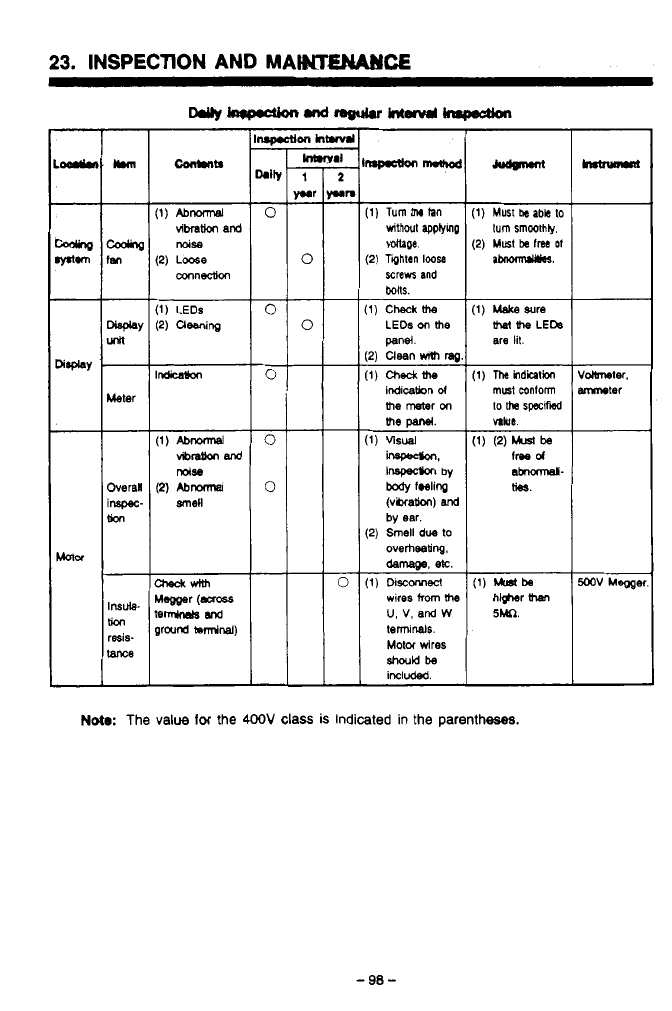
. ..
-
23.
INSPECTION AND MAWMCE
ILL-
I
I
(1)
Turn
thr
Ian
vithoul
applymp
voltage.
(2)
Tahtan
Iwse
screws
and
(1)
Check
UM
LEDs
on
the
panel.
12)
Clean
with
ma
(1)
Checktb
indicakn
d
the
meter
on
(1)
visual
inspec#m
by
body
fWlinp
(vkxakm)
and
(2)
Smell
due
lo
by
ear.
overheadng.
dernage.
8%.
wlres
from
the
U,
V,
and
W
terninals.
Motor
wires
included.
(1)
Must
k
abk
to
(2)
Must
be
frea
Of
turn
smoothly.
(1)
Make
sure
are
lit.
the
LEb
volbneter.
mter
5M.
Nota:
The
value
for
the
4OOV
class
is
indicated in the parentheses.
3
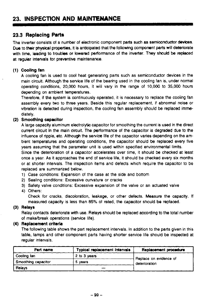
23.
INSPECTION AND MAIN'TEMNCE
23.3
Replacing
Pam
The inverter consists of a number of electronic component
parts
such
as
semiconductor
devices.
Due
to their
physical
properties,
it
is anticipated that the following component
patts
will deteriorate
with time,
kadw
to troubles or hered performance of the inverter. They should
be
rephced
at regular Intervals for preventive maintenance.
(1)
Cooling fan
A cooling fan is used to cool heat generating parts such as semiconductor devices in the
main circuit. Although the service life
of
the bearing used in the cooling fan is, under normal
operating conditions,
20,000
hours, it will vary in the range of
10,OOO
to
35,000
hours
depending on ambient temperatures.
Therefore, if the system
is
continuously operated, it is necessary to replace the cooling fan
assembly every
two
to three years. Beside this regular replacement, if abnormal noise or
vibration is detecled during inspection, the cooling fan assembly should
be
replaced imme-
diately.
A
large capacity aluminum electrolytic capacitor for smoothing the current is
used
in me direct
current circuit
in
the main circuit.
The
performance of the capacitor
is
degraded due to the
influence of ripple, etc. Although the service life
of
the capacitor varies depending on the am-
bient temperatures and operating conditions, the capacitor should be replaced every five
years assuming that the parameter unit is used within specified environmental limits.
Since the deterioration of a capacitor accelerates over lime, it should be checked at least
once a year. As it approaches the end of service life, it should be checked every six months
or at shorter intenals. The inspection items and defects which require the capacitor to be
replaced are summarized below.
1)
Case conditions: Expansion
of
the case at the side and bottom
2)
Sealing conditions: Excessive curvature or cracks
3)
Safety valve conditions: Excessive expansion
of
the valve or an actuated valve
4)
Others:
(2)
Smoothing
wpncltor
Check for cracks, discoloration, leakage, or other defects. Measure the capacity.
If
measured capacity is less than
85%
of rated, the capacitor should
be
replaced.
(3)
Relays
Relay contacts deteriorate with use. Relays should be replaced according to the total number
of
makebreak operations (service life).
The following table shows the part replacement intervals. In addition to the parts given in this
table, lamps and other component parts having shorter service life should be inspected at
regular intervals.
(4)
Replacemsnt
criterb
I
Part
name
I
Typlcal
nplllcrment
Intervals
[
Ropl-t
proodur
Cooling
Ian
Smoothing
capacitor
2
to
3
years
-
RelaV5
Replace
on
evidence
of
deterioration
5
years
-99-
.
..
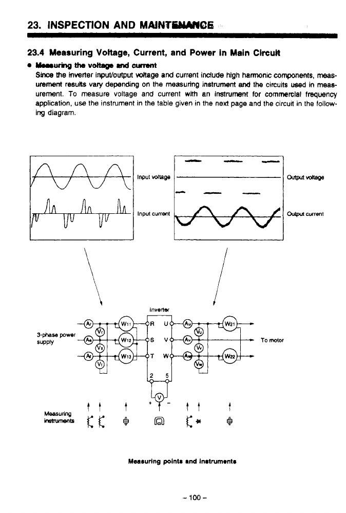
23.
INSPECTION
AND
MAiNVMO6
b
'
23.4
Measuring
Voltage,
Current, and Power in
Main
Ckcult
Qyrw~ttleV~Rnd~
Since
the
inverier inpulloutput
voltage and
current include high harmonic
components,
meas-
urement
resub vary depending on
the
measuring instrument
and
the
circuits
used
in
meas-
urement.
To
measure voltage and current
with
an
instrument
for
commerclal frequency
application,
use
the instrument in the table given in the next page and the circuit in the
follow-
ing
diagram.
Measuring pointr and in8lrum~ntr
0
.
-
100-
I
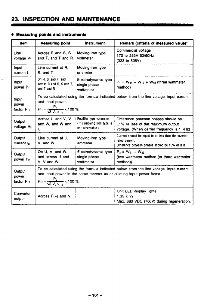
.'
,
..
_1
.._..__._
~.
.
.
.
.
.
.
..
.
,
,
.
".-*..
.._.,.
..
I
....
23.
INSPECTION AND MAINTENANCE
0
hurring
points
and
Instruments
Item
Line
voltage V1
Input
current
Il
Input
power P1
Input
power
factor
Pf,
output
votlage VZ
output
current
12
output
power Pz
output
factor
Pfz
power
Converter
Output
Across
R
and
S,
S
voltmeter and
T,
and
T
and
R.
Moving-iron
type
170 to 253V
50/60Hz
(323
to
506'4
Line current at
R,
ammeter
S.
and
T
Moving4ron
type
On
R'
s'
and
T'
and
pl
=
Wll
+
W,2
+
W13 (three wanmeter
type
across
R
and
S.
S
and
T,
method)
wattmeter
and
T
and
R
single-phase
To
be
calculated using the formula indicated below, from the line
voltage,
input Current
and input power.
raled
current.
Dlflerence
behveen
~haser
should
be
10%
or
less
On
U,
V, and W. single-phase
and across
U
and P?
=
We1
+
WZ
Electrodynamic
type
V,VandW
(two
wattmeter method (or three wattmeter
wattmeter method))
To
be
calculated using the formula indicated below, from
the
line voltage, input current
and input power in the same manner as calculatlng input power factor.
Pfz=+xloo% P
PX
12
Across
P(+)
and
N
Unit LED display lights
1.35
x
v1
Max.
380
VDC (7") during reomeration
-
101
-
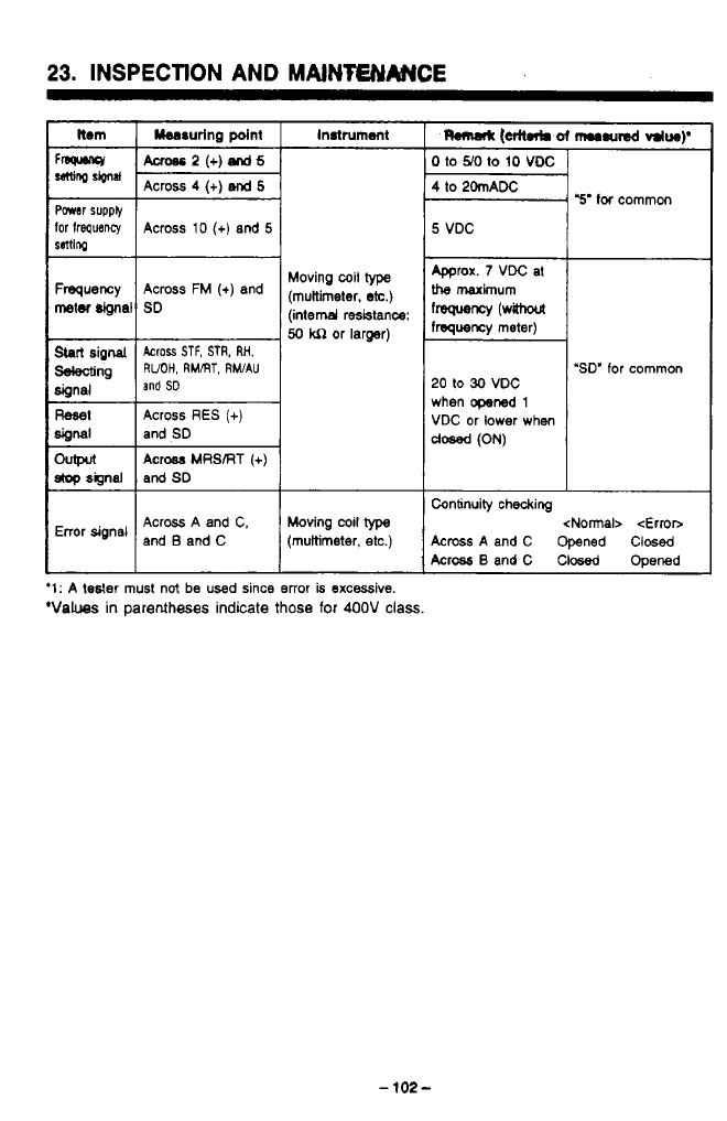
.
..
_____--_
..
23.
INSPECTION
AND
MAlNfENArNCE
Instrument
Across
2
(+)
snd
6
Powar
supply
50
kn
or larger)
Sbrl
signal
Across
STF,
STR,
RH.
dipnal
Mng
RUOH,
RMRT,
RWAU
and
SD
Reset
Across
RES
(+)
SiOfMl
I
and
SD
Ch@ul
Across
MRSRT
(+)
*signal and
SD
Error signal Across A and C, Moving
coil
type
and
B
and C (multimeter,
etc.)
‘1:
A
tesler
must
not
be
used since error
is
excessive.
‘Values
in
parentheses indicate
those
for 400V
class.
-
102-
0
to
YO
to
10
voc
4
to
20mADC
5
VDC
mrox.
7
VDC at
the
maximum
frequency
(wahout
frequency meter)
20
to
30
VDC
when opened
1
VDC or lower
when
dosed
(ON)
Y’
for
common
‘SD’
for common
Continuity checking <Normal>
<Error>
Across
A and C Opened Clwed
Across
B
andC Closed ODened
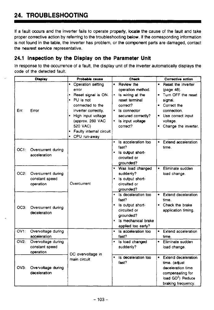
24.
TROUBLESHOOTING
If
a fault
occurs
and the inverter fails
to
operate properly,
locate
the cause of the fault and take
proper corrective action by referring
to
the troubleshooting
below.
If
the corresponding information
is not found in the table, the inverter has problem, or the component parts are damaged, contact
the nearest service representative.
24.1
Inspection
by the Display
on
the Parameter
Unit
In response
to
the Occurrence
of
a fauk, the display unit of the inverter automatically displays the
code
of
the detected fault.
Err: Error
OC1:
Overcurrent during
acceleration
error
Reset
signal is
ON.
PU is
1x)t
connected
to
the
inverter correctly.
High input votlage
(approx.
260
VAC
520
VAG)
Faulty Internal circuit
CPU run-away
OC2: Overcurrent during
constant speed
operation Overcurrent
OC3: Overcurrent during
deceleration
constant speed
DC overvoltage in
main circuit
OV3: Ovecvdlage during
deceleration
ChdI
Review the
I
Reset
the
inverter
I
con8ctivo
action
operation
method.
.
Is
wiring
at
the
reset terminal
correct?
Is
connector
secured correctly?
Is
input
voltage
correct?
(page
48).
Turn
OFF
the reset
Correct the
Slgnal.
Use correct
input
connection.
Change the Inverter
voltage.
Is
acceleration
too
Extend acceleration
fast?
circuited or
grounded?
suddenly?
circuited
or
grounded?
fast?
circuited or application timing.
grounded?
*
Is
mechanical
brake
applied
too
eady?
Is
acceleration
too
Extend acceleration
fast? time.
Is
load changed Eliminate sudden
suddenly? load change.
IS
output
Short- tune.
Was
load changed Eliminate sudden
0
IS
Output short- load change.
.
Is
deceleration
too
Is
output short-
Extend deceleration
Check the brake
time.
Is
deceleration
too
Extend deceleration
fast? time. (aqust
deceleration
time
compensating for
load
GD')
Reduce
braking frequency.
-
103
-
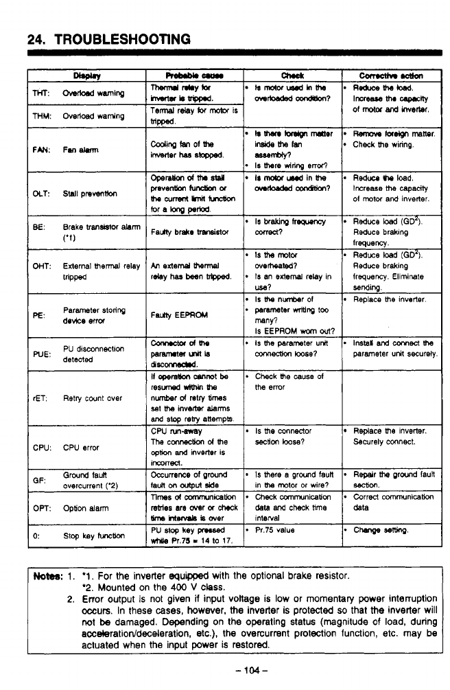
.
.
-.
. .~
24.
TROUBLESHOOTING
resuned
W-An
Uw
sat
me
inverter
&rms
and
stop
reby
anempk
CW rungvsy
The
conneaion
d
me
seciion
loose?
option
and
inverter is
IWKVUed.
rET.
Retry
cwnt over number
d
retry
times
Is
me
connector Replace
me
inverter.
CPU: CPU error Securely connect.
GF:
Ground faun
*
chmlgesewlg
while
Pr.75
I
14
lo
17.
*
Pr.75 value
PU
stop
key
pl.sed
o:
stop
key
func~
1nterral data
data
and
check
lime
rstrles
are
over
or
check
Srm
htenmb
is
over
Correct communication
Checkcommunication Tlmesdamrmnicakm
OPT:
Option
alarm
*
Repeir
wand lauil
*
Is
mete
a
ground
faun
Occurrence
of
ground
overcurrent
('2)
sec(ion.
in motor or wire?
IaUn
on
output
side
Notes:
1.
'1.
For the inverter equppd with the optional brake resistor.
'2.
Mounted on the
400
V
class.
2.
Error output
is
not given
ii
input voltage
is
low or momentary power interruption
occurs.
In these
cases,
however,
the
inverter is protected
so
that
the
inverter will
not
be
damaged. Depending on the operating status (magnitude
of
load, during
acceleratiodd/deceleration,
etc.),
the
overcurrent protection function, etc. may be
actuated when the input power
is
restored.
-
1w-
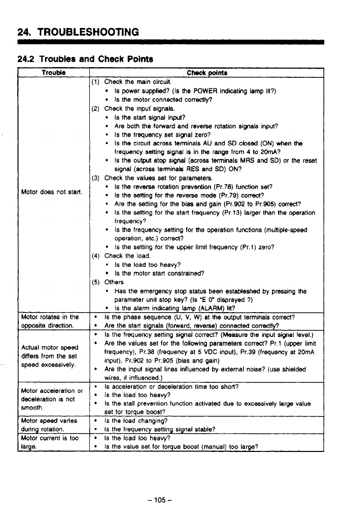
,
-
.__ .
..
-
.
,
.
-
-
.~.
--._
---.
24.
TROUBLESHOOTING
24.2
Troubles
and
Check
Points
Troubl8
Wotor does not start.
Wotor rotates in the
>pposite direction.
9ctual motor
speed
jiers from the
set
speed excessively.
Wotor acceleration or
kceleration
IS
not
smooth.
Wotor
speed
vanes
bring rotation.
Wotor current is too
arge.
Chock
point.
1)
Check the main circuit.
Is
power supplied?
(Is
the POWER indicating lamp
la?)
Is
the motor connected conecty,
Is
the start signal inpcd?
Are both
the
forward and reverse rotation signals input?
-
Is
the frequency set signal zero?
*
Is
the circuit across terminals AU and
SD
closed
(ON)
when
the
Is
the output
slop
signal
(across terminals
MRS
and
SD)
or the reset
2)
Check the mpuf signals.
frequency setting signal
is
in
the
range from
4
to
2OmA?
signal (across terminak RES and
SD)
ON?
3)
Check the values set for parameters.
Is
the reverse rotation prevention (Pr.78) function set?
Is
the setting
for
the reverse mode (Pr.79) cored?
Are the setting for the bias and gain (Pr.902
to
Pr.905) correct?
Is
the setting for the start frequency (Pr.13) larger than the operation
lrequency?
Is
the frequency setting for the operation functions (mutlipie-speed
operation, etc.) correct?
Is
the setting for the upper
limil
frequency (Pr.1) zero?
Is
the motor start constrained?
*
Is
the load too heavy?
*
Has the emergency
stop
status been estableshed by pressing the
4)
Check the load.
5)
Others
parameter unit stop key?
(Is
'E
V
disprayed
7)
Is
the alarm indicating lamp
(ALARM)-Ii?
Is
the phase sequence
(U,
V.
W) at
the
output
terminals correct?
Are the start sgnals (forward, reverse) connected
correctly?
Is
the frequency setting signal correct? (Measure the input signal level.)
Are Ihe values set for the following parameters correct? Pr.1 (upper limit
frequency), Pr.38 (frequency at
5
VDC input), Pr.39 (frequency at 20mA
input), Pr.902 to Pr.905 (bias and gain)
wires,
11
influenced.)
Is
acceleration or deceleration time
too
short?
Is
the load too heavy?
Is
the stall prevention function activated due to excessivdv larae value
Are the input signal lines influenced by external noise?
(use
shielded
set for torque boost?
Is
the load changing?
-
1s
the frequency setting signal stable?
Is
the load
too
heavy?
Is
the value set for torque boost (manual)
too
large?
.-
-
105
-
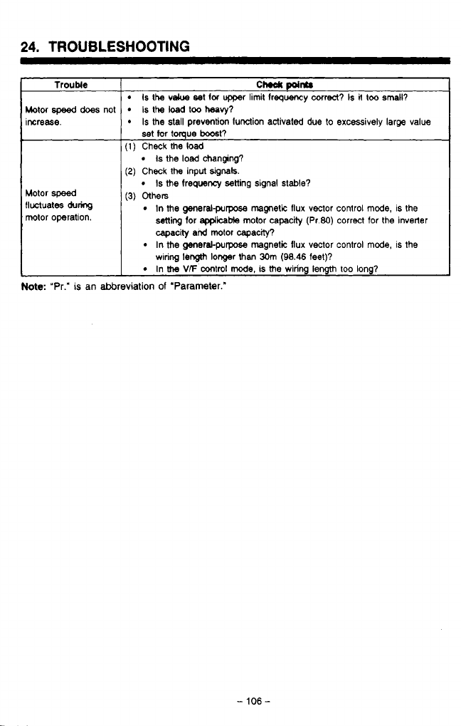
-
-
-
-
.
.
.
-.
24.
TROUBLESHOOTING
~~
Trouble
Motor
speed
does
not
increase.
Motor
speed
fluctuates
du-
motor operation.
CM
points
Is
the
velue
set
lor
upper limit
frequency
correct?
Is
it
too small?
Is
the
load
too
heavy?
Is
the stall prevention function activated
due
to
excessively large value
set
tar
tomue
boast?
I
(1)
Check the load
(2)
Check
the
input
signak.
I
(3)
Others
Is
the
load
changing?
Is
the
frequency setting signal
stable?
In
me
generalpurpose magnetic flux vector control
mode,
is the
ming
for
applicable
motor capacity (Pr.80) correct for the inverter
capacity
and
motor capacity?
wring
length
longer
than
30m
(98.46
feet)?
In the generakpurpose magnetic flux vector control mode, is the
In
the
V/F
control
mode,
is
me
wiring length too long?
Note:
"Pr."
is
an abbreviation
of
'Parameter."
-
106
-
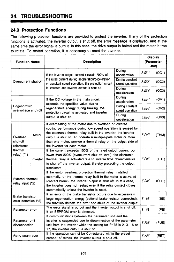
24.
TROUBLESHOOTING
~~
24.3
Protection
Functions
The
following protection functions are provided to protect
the
inverter. If any of the protection
functions is activated, the inverter output
is
shut
off,
the error
massage
is
displayed, and at the
same
time the error signal
is
output. In this case,
the
drive output
is
halted
and the motor is free
to
rotate.
To
restart operation,
it
is necessary
to
reset
the
inverter
Function
Name
Overcurrent shut-M
Regenerative
overvoltage shut-off
Overload
shut-ofi
thermal
(electronic
rew
('1)
Motor
-
Inverter
-
External thermal
relay input ('2)
Brake transistor
error detection ('3)
Parameter error
Parameter unit
disconnection
Retry count over
heription
Dlsplay
(Paramhw
Unit\
If
the inverter output current
Bxceeds
200%
of
the rated current during
aEceleration/deceleration
or
constant speed operation, the protection circuit
is
actuated and Inverter output is
shut
oft
If the DC voltage in
the
main circuit During
exceeds the
specfied
value due
to
regenerative anergy during braking, the
Ouring
protection circuit is activated and inverter speed operation
"ouz
(OV2)
output is shut off. During
deceleration
If
overheating of the motor
due
to ovebad or lowered
cooling performance during low
speed
operation is sensed by
the ekronic thermal relay buiR in the inverter, the inverter
output is shut off.
To
operate a muHiipole motor or more
than one motor, provide a thermal relay on the output side
of
the inverter for each motor.
If the current exceeds
150%
of the rated output current, but
lower than 200% (overcurrent shut-off level), the electronic
thermal relay is activated due to inversa time characteristics
C.THT
(THT)
to shut off the inverter output. thereby protecting the output
transistors.
If
the motor overheat protection thermal relay, installed
extemaliy, or the thermal relay built in the motor is activated
(contact break), the Inverter output is shut
off
In this case,
E.OHf
(OHT)
the inverter
does
not restart even
if
the relay contacl closes
automatically unless the inverter
is
reset.
If an error
of
the brake transistor occurs due to excesslvely
large regeneration energy (optional brake resistor connwted),
E,
bE
(BE)
the function detects the error and shuts of the inverter output.
The error signal is output and the inverter output is shut
off.
If an EEPROM error
is
detected.
If
communications between the parameter unit and the
Inverter is suspended due to disconnection
01
the parameter
unit from the inverter while the senlng for Pr.75 is 2,
3,
16
or
17, the Inverter output is shut off.
If
the operation cannot be Co-restarted within the preset
number
of
retries, the inverter output is shut off.
E.Cu
(OV1)
E.0~3
(OV3)
Em
(THM)
E.
Pf
(PE)
E.PUE
(PUE)
ErEr
(RET)
-
107
-
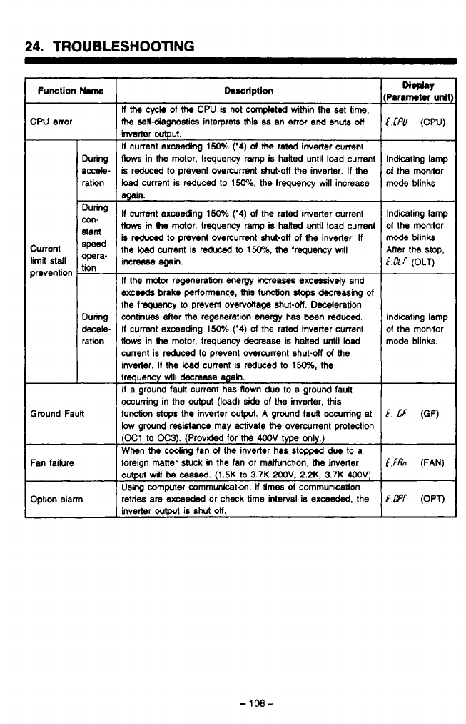
24.
TROUBLESHOOTING
Function
Mame
CPU error
Cunent
prevention
limn
stall
Ground Fault
During
accele-
ration
Dumg
slant
8P-d
opera-
tin
-
con-
-
During
decele-
ration
Fan failure
Option alarm
Descrlptlon
ll
the
cycle
of
the
CPU
is
not
completed within the
set
time,
rhe
selfdiagnostics interprets
MIS
as
an
error and shuts
off
Mrter
output.
If
current exc%eding
150%
(‘4)
of
the
rated inverter cumnt
Aows
in
the
motor, frequency
ramp
is hailed until load current
is reduced
to
prevent overcurrent shut-off
the
inverter.
If
the
load current is reduced to
150%,
the
frequency
will
iwrease
am.
If
current
exceedng
150%
(‘4)
of
the
rated inverter current
fbws
m
(he
motor,
fmquency
ramp
is
hatted
until
load current
is
reduced
to
pmnl overcurrent
shut-otf
of
the
inverter.
If
the
!+ad
arrent is reduxd
to
150%,
the
frequency
wlll
imreese again.
If
the mtor regeneration
energy
increases
excmsively and
exceeds
brake
petlonsnce,
ais
function stops
decreasing
of
the freqwncy to prevent
overvoltage
shut-&.
Dederation
conthwrs after
the
regeneration energy has been reduced.
If
current exceeding
150%
(‘4)
of
the rated inverter current
flows
in
the
motor, frequency decrease is halted until load
current is reduced
to
prevent overcurrent shut-&
d
the
inverler.
If
the load current
is
reduced
to
150%,
the
frequency
will
decrease again.
If
a ground fauil current
has
flown
due
to a ground faun
occurring in the
output
(load)
side
of the
inverter, this
function
stops
the
inverter
output.
A
ground faun occurring at
low ground residtraxe may activate
the
overcurrent protection
(03
to
OC3).
(Provided for
the
4OOV
type
only.)
When
the
Cooring
fan
of
the
inverter has
stopped
due
to
a
foreign matter stuck in the fan or maiiunction, the inverter
output
witl
be
c8ased.
(1.5K
to
3.7K
2OOV.
2.N.
3.7K
4OOV)
Uskg
computec communication,
ii
times
of
communication
retries are exceeded or check time interval
is
exceeded.
the
inverter
outplt
is shut
on.
€.fPU
(CPU)
Indicating lamp
d
the monitor
mode
blinks
f-t
LCd
Indicating lamp
of
the monitor
mode
blinks
E.&[
(OLT)
Alter the
stop.
1
Indicating lamp
of
the
mmRor
mode blinks.
I
E.
Cf
(OF)
E,fRn
(FAN)
Em
(OPT)
.d
-
108-
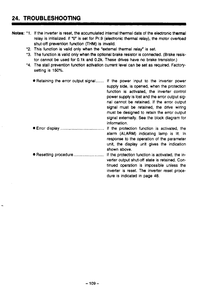
-
........
........
.-
.....
......
,.
..~,
24.
TROUBLESHOOTING
Notes:
'1.
'2.
'3.
'4.
If
the
inverter is reset, the accumulated internal thermal data of the electronic thermal
relay is initialized.
If
"0'
is
set
for Pr.9 (electronic thermal
relay),
the motor overload
shut-off prevention function
FHM)
is invalid.
This function
is
valid only when the "external thermal relay" is set.
The lunction is valid only when the optional brake resistor is connected. (Brake resis-
tor cannot
be
used for O.lk and 0.2k. These drives have
ria
brake transistor.)
The stall prevention lunctim activation current level can
be
set as required. Factory-
setting is
150%.
0
Retaining the error output signal
0
Error display
...............................
0
Resetting procedure
....................
If
the power input
to
the
inveder power
supply side, is opened, when the protection
function is activated, the inverter control
power supply is
lost
and the error output sig-
nal cannot
be
retained.
If
the error output
signal must
be
retained, the drive wiring
must
be
designed to retain the error output
signal externally. See the block diagram for
inlormatin.
If
the protection function is activated, the
alarm
(ALARM)
indicating lamp is
lit.
In
response to the operation of the parameter
unit, the display unit gives the indication
shown above.
If the protection function is activated, the in-
verter output shut-off state is retained. Con-
tinued operation is impossible unless the
inverter is reset. The inverter reset proce-
dure is indicated in page
48.
-
109-
......
-.
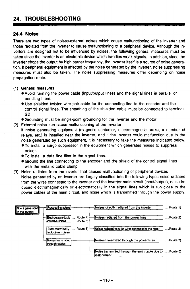
24.
TROUBLESHOOTING
24.4
Nolse
There are two
types
of noises-external mises which cause malfunctioning
of
the inverter and
those radiated from the inverter to cause malfunctioning of a peripheral device. ARhough the in-
verters are designed not to
be
influenced by noises, the following general measures must be
taken siree the inverter is an electronic device which handles weak signals. In addition, since the
inverter chops the output by high carrier frequency, the inverter itsel is a source of noise genera-
tion. If peripheral equipment is affected by the noise generated by the inverter, noise suppressing
measures must also be taken. The noise suppressing measures differ depending on noise
propagation route.
x4
General measures
OAvoid running the power cable (inpuffoutput lines) and the signal lines in parallel or
bundling them.
0
Use shielded twisted-wire pair cable for the connecting line
to
the encoder and the
control signal lines. The sheathing of the shielded cable must
be
connected to terminal
SO.
0
Grounding must be single-point grounding for the inverter and the motor.
External noise can cause malfunctioning
of
the inverter
If noise generating equipment (magnetic contactor, electromagnetic brake, a number of
relays, etc.) is installed near the inverter, and if the inverter could malfunction due to the
noise generated by such equipment, it is necessary to take the measures indicated below.
.To
install a surge suppressor in the equipment which generates noises to suppress
.To install a data line filter in the signal lines.
0
Ground the line connecting to the encoder and the shield
of
the control signal lines
Noise radiated from the inverter that causes malfunctioning of peripheral devices
Noise generated by an inverter are largely classified into the following types-noise radiated
from the wires connected to the inverter and the inverter main circuit (inpuffoutput), noise in-
duced electromagnetically or electrostatically in the signal lines which is run close to the
power cables of the main circuit, and noise which is transmitted through the power supply.
noises.
with the metallic cable clamp.
Noises
transmhlec
through
the
power lines
I...
.
.Route
7)
-110-
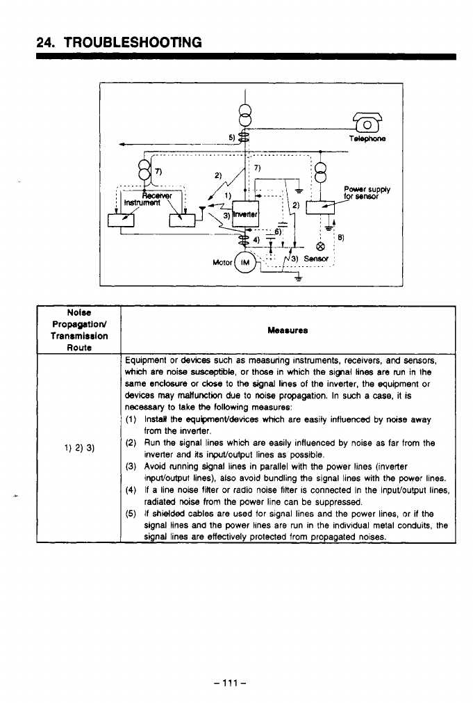
24.
TROUBLESHOOTING
Propagatlord
Tranrmlrrlon Measures
Equipment or
devices
such as measuring Instruments, receivers,
and
sensors,
which
am
noise
suscqble,
or thcse in which
Me
sipal lines are run in the
same
endosure
or cbe
to
the
signal lines of the inverter, the equipment or
devices
may
mallunction
due
to
noise propagation. In such
a
case,
it is
necessaiy lo
lake
the
following measures:
(1) Install
Me
equipmenVdewces which are easily influenced by noise away
(2)
Run the signal lines which are easily influenced by noise as far from
the
(3)
Avoid running signal lines in parallel with the power lines (inverter
(4)
If
a line noise finer or radio noise filter
IS
connected in the inputloutput lines,
(5)
If
shielded
cables are used for signal lines and the power lines, or
if
the
from the Inverter.
inverter and
its
inpuVoulput lines as possible.
inpuvoutput lines), also avoid bundling
the
signal lines with
the
power lines.
radiated noise from the power line can be suppressed.
signal lines and the power lhnes are run in
the
individual metal conduits,
the
signal lines are effectively protected from propagated noises.
-
111
-
24.
TROUBLESHOOTING
Mee8urw
Route
If
the
sbal
lines
are run in parallel to the power lines or
if
the
signal lines are
brnaed
with the power lines, nW (electromagnetically induced noise,
electrostatically
Wed
noise)
may propagate to
the
signal
lines causing
mahnctioning. In such
cases,
it
is
necessaly
to take
the
following measures:
(1)
Install
the
equpmenVdevices which are easily influenced by noise away from
4)
5)
6)
(2)
Run
the
signal
lines which are easily influenced by noise
as
far hom the
the
inverter.
inverter
and
il8
inpuVoutput
he8
as
possible.
(3)
Avoid luming signal lines parallel with tho
power
lines (inverter inpuVoutput
lines),
at30
avoid bundling
the
signal
lines
with
the power
lines.
(4)
If shielded
cables
are
used
lor signal lines and the power lines, or
if
the
signal
lines and
Iha
power lines are run in the individual metal conduits,
the
signal
lines
are
effectively protected from propagation
of
noise.
If
peripheral
device
is connected
to
the
same power supply where
the
inverter is
connected, noise generated by
the
inverter may
be
transmitted
to
the
peripheral
devi
through
the
power
lines
causing
malfunctioning
of
the
periphsral device.
In
(1) Install a radio
noise
Mer (FR-BIF(-H)) in the power line (input lim)
of
the
(2)
Install a
line
noise
filter (FR-BSFO1) in
the
power line (inpuVoutpn in=)
d
the
If
a
CW
loop circuit
is
formed due
to
the
wiring of a peripheral
device
to
the
inverter,
leakage
cumt may flow into
the
peripheral
device
through
the
grounding
occurs,
disconnect
the
grounding cable of
the
peripheral
device.
,)
such a
case,
R
is
necessary
to
take the following measures:
inverter.
inverter.
')
cable
of
the
inverter
and
caw8
matfunctioning of
the
peripheral equipment.
If
this
-
112-
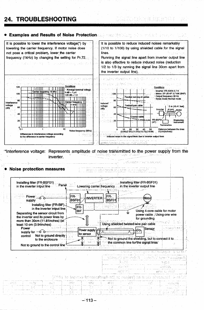
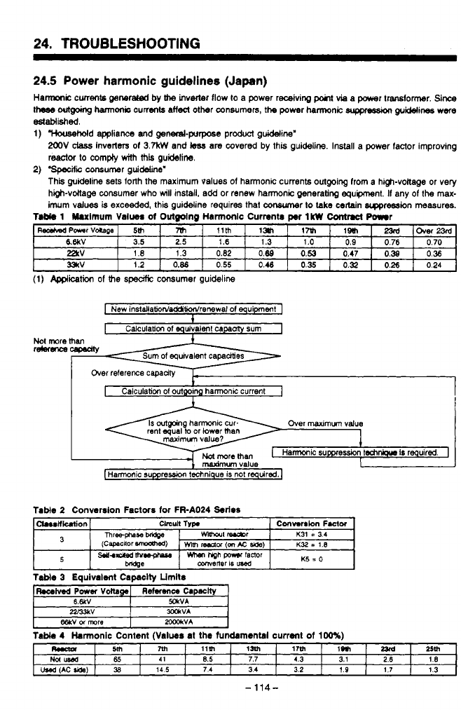
24.
TROUBLESHOOTING
~~~~~
24.5
Power harmonic guidelines (Japan)
Hamic
currents
generated
by
h
inverter flow
lo
a power receiving
point
via a power transfomr.
Since
theas
outgokg
harm& currents
affect
other consumers,
the
power harmonic
suppression
guuines
were
Ctstablkhed.
1)
"""""""'Sd
appliance
and
genend-purpase product guideline'
2OOV
class
Inve~ers of
3.W
and
kss
are
covered by this guideline. Install
a
power factor improving
reactor to compiy
with
this
guideline.
This guideline sets forth the maximum
values
of
harmonic
currents
outgoing from
a
high-voitage or very
high-vottage consumer who
will
install, add or renew harmonic generating equpment. If any of the
max-
imum values is
exceeded,
this guideline requires that conwmer
lo
take
certain
srppression measures.
4
2)
'speufic
consumer guideline'
n
T.b(.
1
Uulmum
Value#
of
Outmlno
Harmonlc Currents
IkW
Contract
Power
WPaarVaCape -0ver23rd
,~
17~1
IIHI
m
5th
~~ ~
&6kV
=V
331rV
3.5
0.24
0.26
0.32
0.35
0.46
0.55
0.86
1.2
0.36
0.38
0.47
0.53
0.89
0.82
1.3
I
.e
0.70
0.76
0.9
1.0
1.3
1.6 2.5
(1)
Application
of
the
speafic
consumer guideline
I
New
InstdlatidddiWrenewal
01
equipment
1
1
Not
more
re4eru-m
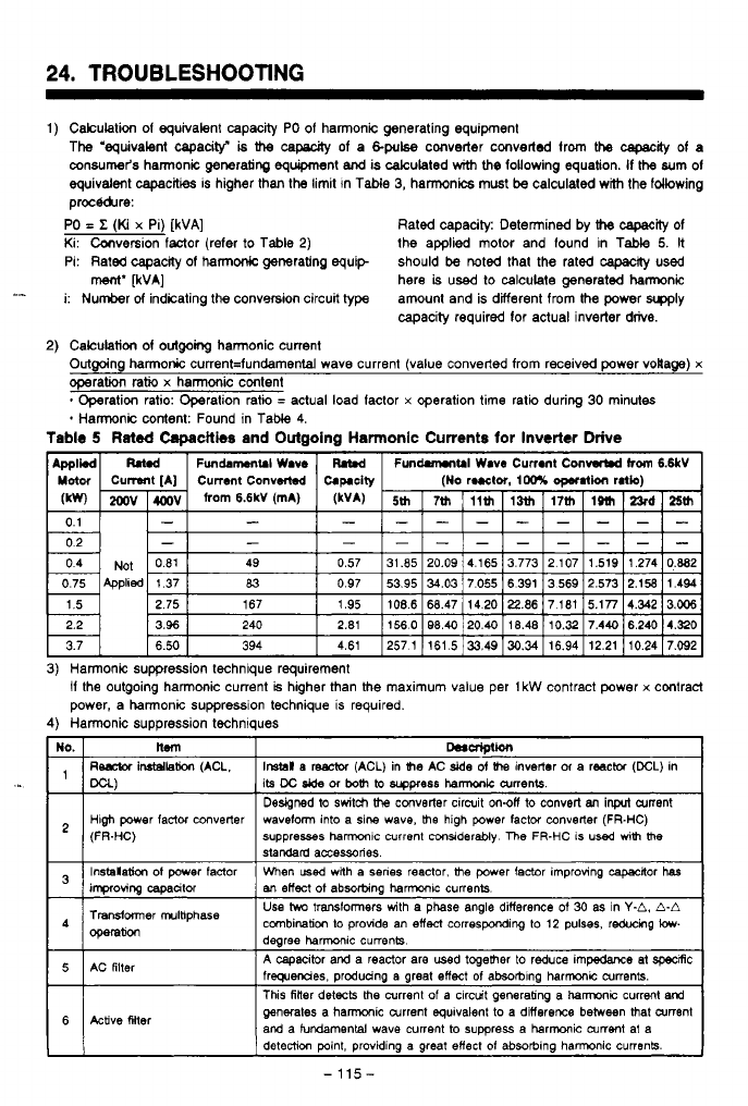
24.
TROUBLESHOOTING
1)
Calculation
of
equivalent capacrty PO
of
harmonic generating equipment
The 'equivalent capacity^
is
the
capauty
of
a
&pulse
converter converted from the
capacrty
of
a
oonsumer's harmonic generating equipment
and
is calculated
with
the
following equation. If
the
sum
of
equivalent capacities is higher than the limit In Table
3,
harmonics must
be
calculated with the fdlowing
proc&&re:
PO
=
Z
(Ki
x
Pi)
[kVA]
Rated capacity: Determined by
the
capaclly
of
Ki: Canversion factor (refer to Table
2)
the applied motor and found in Table
5.
It
Pi: Rated capacrty
of
harmonic generating equip should
be
noted that the rated
capacrty
used
here
is
used to calculate generated hamnic
i: Number
of
indicating the conv9rsion circuit type amount and is ditferent from the power
wly
capacity required for actual inverter
drive.
ment'
FVA]
-I
2)
Calculation
of
outgoing
harmonic current
Outgoing harmonic current=fundamental wave current (value converted from received power voila@)
x
operation
ratio
x
harmonic content
*
Harmonic content: Found in Tabie
4.
Operation ratio: Operation ratio
=
actual load factor
x
operation time ratio during
30
minutes
Tabie
5
Rated
Capacities
and Outgoing Harmonic Currents
for
Inverter
Drive
1
I
3)
Harmonic suppression technique requirement
if
the outgoing harmonic current
is
higher than the maximum value per
1
kW
contract power
x
contract
power, a harmonic suppression technique is required.
4)
Harmonic suppression techniques
I
its
DC
Jde
or
both
to
wpress
hamk
aments
I
Designed
to
switch
the
converter circuit
m-off
to convert
an
inprt
current
I
1
(FR-HC)
High
power
factor converter waveform into
a
sine wave,
the
high power factor converter
(FR-HC)
suppresses ham~c current
considerably
The
FR-HC
IS
used
mth
tlw
stardad
accessories
I
-
I
Instdation
of
mer
factor
I
When
lad
with
a
senes
reactor.
the
wwer factor imDrowng cacackor
has
I
'
an
effect
of
absorbing
harmonu:
currenk.
impro~ing
capacitor
.
-.
Transformer
~ItiPhaSe
Operation
Use
hvo
transformers
with
a phase angle difference
of
30
as in
Y-A,
A-A
dearee
harmonlc
currenh
combination
lo
provide an
effect
corresponding to
12
pulses, reducing
low-
5
AC
filter
A
capacitor and a reactor are used together to reduce impedance at specrRc
frequencies. prcduang a great effect
of
absortlng harmc CUnBnk.
I
This
filler
deteck
the
current
of
a circcuit generating a harmonic current and
6
Active Mer generates a hamxxic Current
equivalent
to
a difference between that ament
and a tundamental wave current to suppress a harmonic Current at a
detectiw
point, providing
a
great
effect
of
absorbing harmonic cunenk.
-115-
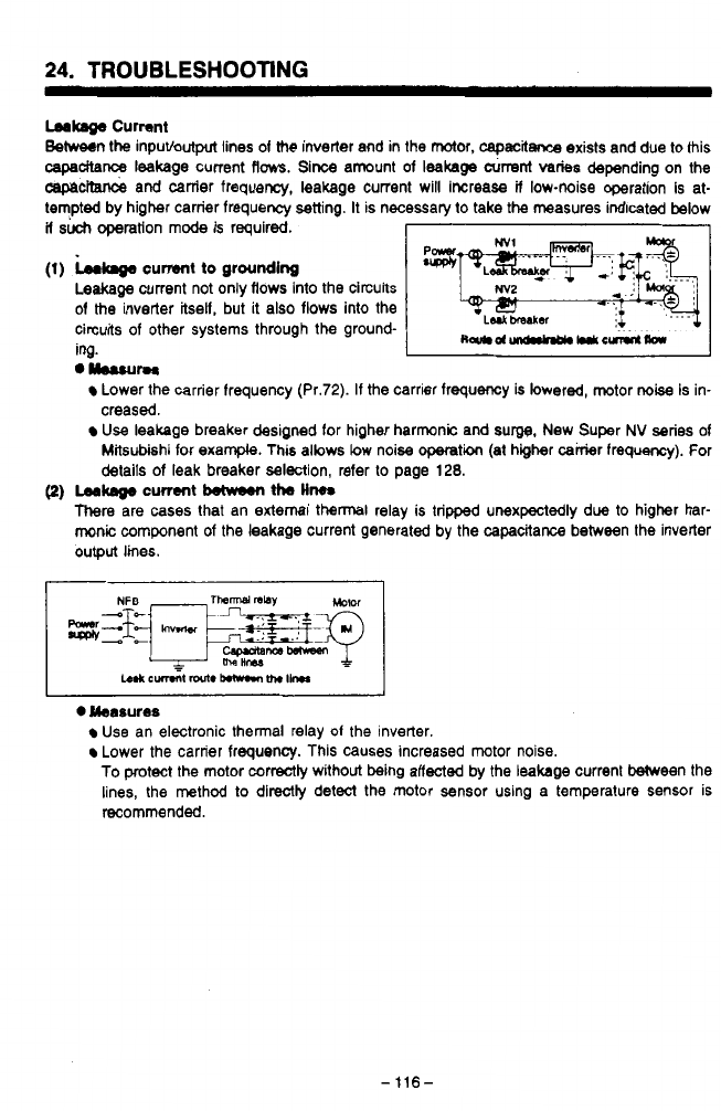
Leakage
Current
Between the inputbutput lines of
the
inverter and in the motor,
capacitance
exists and due to this
capadta~
leakage current
flows.
Since amount of leakage
airrent
varies
depending on the
cepecrtance
and canter frequency, leakage current will increase
if
low-noise operation is at-
tempted by higher carrier frequency setting.
It
is necessary
to
take
the
measures indicated below
if
such
ooeration
mode
is reauired.
I
1
._~
-r-
~
(1)
kaga
current
to
grounding
Leakage
current not only flows into the circuits
of
the
inverter itself, but it also flows into the
circuits of other systems through the ground-
ing.
I
I
."urn
Lower the carrier frequency (Pr.72). If the carrier frequency
is
lowered, motor
noise
is in-
creased.
Use
leakage breaker designed for higher harmonic and
surgg,
New Super
NV
series of
Mitsubishi for exarnpb. This allows low noise
operati
(at higher cairier frequency). For
details of leak breaker selection, refer
to
page
128.
(2)
Lea-
current
between
the
Hm
There
are
cases
that an external
thennal
relay is tripped unexpectedly due to higher har-
monic
component of the leakage current generated by the capacitance between the inverter
output
lines.
0
Measures
Use an electronic thermal relay
01
the inverter.
Lower the carrier frequency. This causes increased mtor noise.
To
protect the motor correctly without being affected by the leakage current Ween the
lines, the method to directly detect the motor sensor using a temperature sensor is
pL
recommended.
v
-
116-
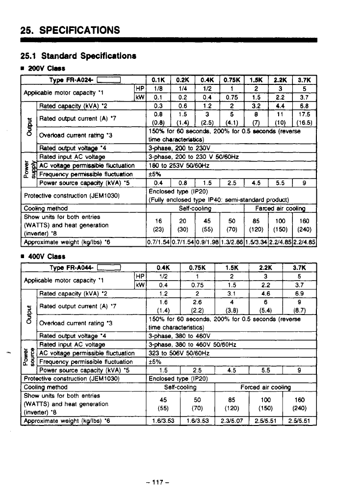
25.
SPECIFICATIONS
25.1
Standard
Specifications
rn
2oov
Cless
(WAlTS)
and heat
generation
-117-
25.
SPECIFICATIONS
Notes:
'1: The values in the
table
indicate the maximum
appwcclMe
capclclty for
Mlsvbbhi
standard
squirrel-cage
type
motor 4P. Generally,
the
rated current (at SOHz)
01
the
appkcable
motor
should
not exceed
the
rated
output
current.
'2:
The
rated
capedty
indicated
assumes
that
the
outpul
voltage
is
22OV
for the
200'4
class and
44OV
for the
4ooV
class.
'3:
The value
(Oh)
for rated overload current indicates
the
ratio to the rated ouwut current
of
the
invetter.
'4: The output voltage cannot exceed the
sum
voitage.
'5: The power
supply
capaclty varies
depending
on
the
impedance of
the
power supply circuil
._
(including reactor in
the
input
circuit
and power line).
The
power supply which has
the
/?
capacity larger than the
specihbd
value
is
required.
\j
*
proximately O.lkg.(2.21!x)
quency for Pr.72 when ambient temperature
is
greater thn
40
'C
(lo4
'F)
'6:
The value indicates the inverter
rvithout
a
parameter unit
A
parameter unit WeMS
ap-
'7:
Rated output current in
(
)
is
for
low-noise
operation
by
setting
2wlz
of
higher canier lre-
'8: The values in
(
)
indicate
the
heat generation
during
low-noise
operation (Pr.72=14.5kHz).
-118-
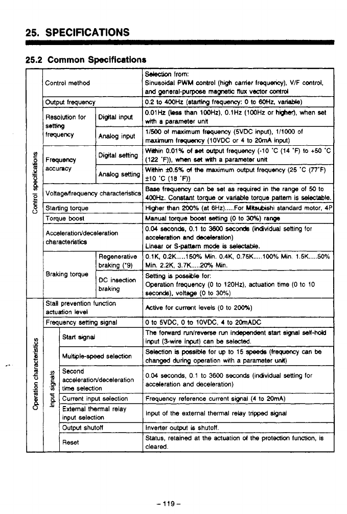
25.
SPECIFICATIONS
25.2
Common
Specifications
sdedion
from:
hntroi method Sinusoidal
PWM
control (high carrier frequency), V/F control.
and general-purpose
magnetic
flux
voztor
control
Mput frequency
0.2
to
400k
(stamng
lreqwncy:
0
to
6OHz.
variable)
3esoiution for Digital input
with
parameter
unit
0.01Hz
(bas
than
100Hr),
O.1Hz
(100Hz
or
higher),
when
set
*mng
requency
Analog
input
1/500
of
maximum frequency (5VDC input),
1/1ooO
of
maxknum
frequency
(1OVDC
or
4
to 20mA
input)
Wain
0.01%
d
&
artput
frequency
(-10
'C
(14
'F)
to
+50
'C
Within
M.5%
d
the
maximum
ovtput
frequency
(25
'C
(77°F)
Disital
selling
Analog
setting
-rweney
(122
'F)),
when
ha
dh
a parameter una
lccumcy
f10
'C
(18
'0)
lonagelfrequency characteristics
Base
frequency can
be
set
as
required
in
range of
50
to
400k.
Constant torque
01
variable torque pallem is
Wtabk
;tatting toque
I
Hwer than
*,6
(ai
6Hz)
.....
For Mltsubishi standard motor,
4f
roraue
boost
I
MW~U~I
toraue
b00st
settina
(0
to
30%)
ram
3raking torque
3aH prevention function
actuation level
%auencv
Senm
sianal
0
to
5VDC.
0
to
1OVDC.
4
to
20mADC
Active
for current levels
(0
to
2m)
The
toward turdre-
nm
in&pe&ent
start
signal
sa#W
input (%wire
input)
can
be
selected.
changed
during
operation with a parameter
unit)
Selection
is
pcable
for
up
to
15
(keguency can
be
-
V)
Second
?
acceleratiorddeceleration
acce(eration
and
0.04
seconds,
0.1
to
3600
seconds
(individual selling for
'3
time selection
2
Current input selection Frequency reference current smai
(4
to 20mA)
-
input
of
the external thermal relay tripped
signal
Start signal
seleaicn
G3
L
inout
seleeticm
Outpvt
shutM Inverter
output
is
shutoff.
Reset Status, retained at the actuation
of
the protection function, is
cleared
-119-

25.
SPECIFICATIONS
8F
Monitor
'1
0
Incorporated functions
Parameter una
1-
operation
LED
display
'rotection and warning functions
Am-
bmnt Temperature
('15)
Temperature
5
[
1
Storage temperature '13
i
Atmosphere
.
1
Altitude, viibration
Selection
of
lwo
from:
frequancy
reached
(FU),
overload
(OL),
and open motor
lwoperation
(RUN),
Max
frequency roach
(Su),
preset
drcuit
(OMDI
1
fOrmCconMsignal
meter
11440
Hugo
Hz)
For
outpulling
lo
the
analog
meter
(1
mA
full
scale)
or digital
Cwent
lima,
sening
01
upper and lower limit frequency.
satkg
d
pin
ad
bias,
eledronic
thermal
relay for motor
OL,
sdedlon
d
operation
mode,
seledion
of
functions
Med
to
the
terminals, setting the
output
signal activation
point.
saleuion
d
FM terminal
output
specificaton, sdiing
the
swmd
furrtiMI
(torque
boost,
base
frequency.
acceleratioddecderation time), calibrating
the
frequency
qeler,
restart
aLr momentary power intemption, correct
the
slip,
retly after
alarm,
etc.
dirSc(i0n
Ou@U
frequency, motor current (VI),
set
frequency, rotation
Alm
code
after
the activation
d
protection
functiw,
stores
w
to four
events
of
alarm occurrence
Power
on
(POWER), protection function actuation (ALARM)
Overcunent
shutoff
(&ring
acceleration,
fixed
speed
shu(df,
owdoad
shut
df
(electronic thermal relay), brake
operatm,
and deceleration). regeneration ovewoltage
transietor
alarm.
low
bokage
('12),
momentary power
int~tNptiOn
(*lZ),
external thermal relay activation, stall
prevention,
grwnd fault overcurrenl.14
-10
'C
(14
'fl
to
+
50
'C
(122
'fl
(no freezina)
-RH
or
less
(non
condensation)
-20
'C
(4
'F)
to
+
65
'C
(149
'F)
Indoor, must
be
free of corrosive
gas,
inftammable gas, oil
mist,
and
dGst
Bekw
loo0 m
(3280.8
feet)
above
sea
Level,
less
than
5.9
nv'd
(0,s)
(oonforms
to
JiS
Cog1
1
.)
-
120
-

25.
SPECIFICATIONS
Notes:
'9:
The magnitude of braking torque is not continuous regenerative torque.
It
is
tlm
short
term
average deceleration torque when an unloaded motor
is
decelerated from
6oHz
in the
shortest possible time. This value also vanes with motor
losses.
The deceleration torque
decreases beyond
base
frequency. Since this inverter is not equiped
with
a brake resistor,
use the optional brake resistors from
page
144
for applications where large magnitudes of
regenerative energy must
be
dissipated.
CAUTION:
A
brake resistor may not
be
used on
0.1K
and
0.2K
units.
'10:
It
is
posslble to select output frequency or motor current monitor.
Specrty
selection for out-
put signals in Pr.54 using a parameter unit.
'11:
Displays may not be accurate, depending on the operating status, during accelera-
tioddeceleration, low-load operation, etc.
'12:
In the case
of
low
vollage or momentary
power
interption, alarm
is
not dkplayed and no
alarm signal is output. However, the inverter
itsetl
is protected. The overcunent protection
function or other protection functions may
be
activated when the power is restored based
on the operating conditions (load, etc.)
'13:
This temperature range
is
applicable during transportation.
'14:
Only the
FR-A044
(400
V
class) functions.
'15:
When using
the
fully closed specifications, this
will
be
-1o'C (14'F)
to
+WC
(104'F).
-
-
121
-
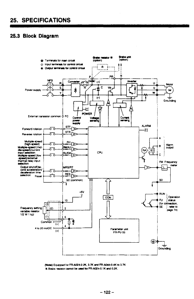
25.
SPECIFICATIONS
25.3
Block
Diagram
!
+5v
cw
-
K
T-
.
-
122
-
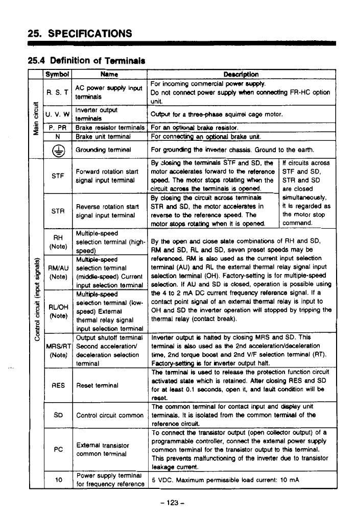
25.
SPECIFICATIONS
25.4
Definition
of
Terminals
STR
RH
(Note)
-
RWAU
(Note)
-
RUOH
(Note)
-
ARS/RT
(Note)
RES
SD
-
PC
10
Name
9C power
supply
input
terminals
Inverter
outprt
terminals
Braka
resistor terminals
Brake unit terminal
Groudicg termlnal
Fomerd rotation start
signal input terminal
Reverse rotation start
signal input terminal
Mukiile-speed
selection terminal (high.
selection terminal
(middle-spwd)
Current
input
selection
terminal
Multple-speed
selection terminal (low-
speed)
External
thermal relay signal
input
sel&
terminal
Output
shutdf terminal
Second acceleration/
deceleration selection
terminal
Reset terminal
Control circuit commm
External transistor
common terminal
Power supply tenninal
for frequency reference
De.alptlon
For incoming commercial
power
WKQIY.
DO
not conA power
supply
*rhen mg
FR-HC
option
..
.
ovtpa
for
a
three-phase
squirrel
cage
motor.
For
M
opti
brake
resislor
For connectinp
an
OptiMal
brake unil
For grounding
he
lnwwter chassis. Ground to the earth.
By
ck&g
the
terminals STF and SD.
the
If
circuits across
motor accelerates forward to
tha
rdaence
the motor stop
reverse
to
the
reference
speed.
The
it
is regarded
as
STR
and
SD,
the
motor
accelerates
in simultrnusb,
By
dosing
the
drcuit
mobs
terminab are closed
circuit aCrw
the
tminals
is
opened.
STR and
SD
speed.
The
motor
s.tc+s
rotating
when
the STF and SD.
mmrnand.
motor
stops
rotatkg when
it
is
opened.
By
the
open
and
close
state comblnations of
RH
and
SD,
RM
and
SD.
RL
and
SD, seven preset
speeds
may
be
referenced.
RM
is
also
used
as
the
current input selection
terminal
(AU)
and
RL
the external
thermal
relay signal input
selection
terminal
(OH).
Factorpsetting
is
for muttiple-speed
se!e3ii.
If
AU
and SD
IS
closed, operation is possible wing
the
4
to 2
m4
DC current frequency reference signal. If a
contaCt point
dgnal
of an external
thermal
relay is input to
OH
and SD the inverter operation
will
stopped by tnpping
the
thermal relay (contact break).
Invecter
oulput
is
halted by closing
MRS
and
SD.
This
terminal
is
elso
used
as
the
2nd acceleratioddecelatim
ti,
2nd torque
boost
and 2nd
VF
selection
terminal (RT).
Fsctory-wtthg
b
for hverter output halt.
The terminal
is
used
to release
the
protection function circuit
activated
state
which
is
retained. Mer
cbsing
RES
and SD
for
at
least
0.1
seconds,
open
I&
and
fault
condaion
will
be
mt.
The
common
tenninal for contau input and my unl
terminals.
It
is
isolated from
the
commcn
terminal
of
the
To
conned
tha
t-tor
output
(om
cdledor wtput) of a
reference circuit
programmable controller, connect the axtemal power supp~y
common terminal for
the
trarsMor
output
to
thii
terminal.
This prevents manunctioning
of
the
inverter
due
to transistor
leakage cummt.
5
VDC. Maximum
permissible
load
current:
10
mA
-
123
-
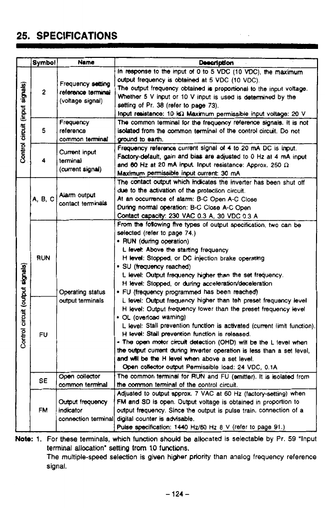
-PZL
-
I
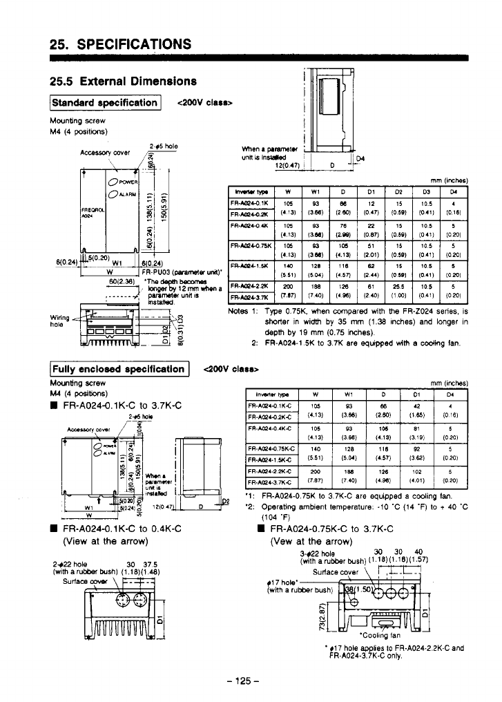
25.
SPECIFICATIONS
25.5
External Dimensions
Standard
specification
I
4M)V
class>
Mounting screw
M4 (4
pas~l~oos)
Notes
1:
Type
0.75K. when compared
with
the
FR-Z024 series, is
shorter
in width
by
35
mm
(1.38
Inches) and longer
In
depm
by
19
mm
(0.75 inches)
2:
FR-A024-1
5K
to
3
7K are
equipped
wim
a cooling Ian.
Mwnting
screw
M4
(4
posib0nS)
FR-A024-0.1K-C
to
3.7K-C
FR-A024-0.1 K-C
to
0.4K-C
(View
at
the
arrow)
2$22
hole
(w~th
a
30
375
surf
'1:
FR-A024-0.75K
lo
3.7K-C are equipped a cooling
Ian.
'2: Operating ambient temperature.
-10
'C (14 'F)
lo
t
40
'C
(104
'F)
FR-A024-0.75K-C
to
3.7K-C
(Vew
at
the
arrow)
$1
7 hole'
(wRh
a
ru
'Coollng
fan
*!
R.AO24-3.7K-C only.
17 hole
applies
to
FR-A024-2.2K-C and
-
125
-
.
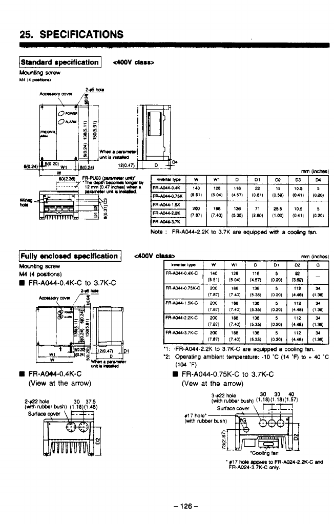
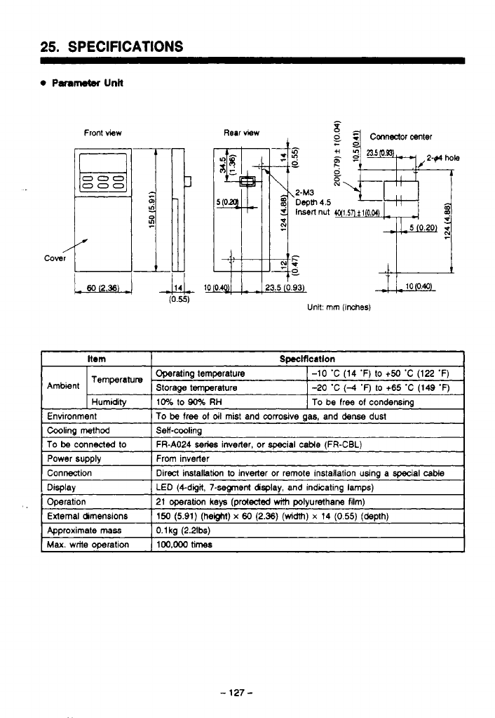
25.
SPECIFICATIONS
Front view Rear view
Unit: mm
(inches)
Hem
Temperature
Spccificatlon
Operating temperature
1-10
'C (14 'F) to
t50
'C (122 'F)
Ambient Storage temperature 1-20 'C
(-4
'F) to
+65
'C (149 'F)
I
Humidity
I
10%
lo
90%
RH
I
To
be
free
of
condensing
Environment
1
To
be
free
of
dl
mist and corrosive
as.
and dense dust
To
be
connected to
LED (+digit, 7-segment dsplay, and indicating lamps)
Display
Direct irstallatin
lo
inverter or remote installation using a special
cable
Connection
From inverter
Power supply
FR-A024
series
inverter, or special
cable
(FR-CBL)
Operation
0.1
kg
(2.21bs)
Approximate
MSS
150
(5.91)
(height)
x
60
(2.36)
(width)
x
14
(0.55)
(depth)
Exlemal dimensions 21 operation
keys
(protected
with
polyurethane film)
Max.
write operation
100,ooO
times
-
127
-
..
..
.
.
.
-
.
.
.
-
.
.
..
.
.
.
.
,
.
..
.
..
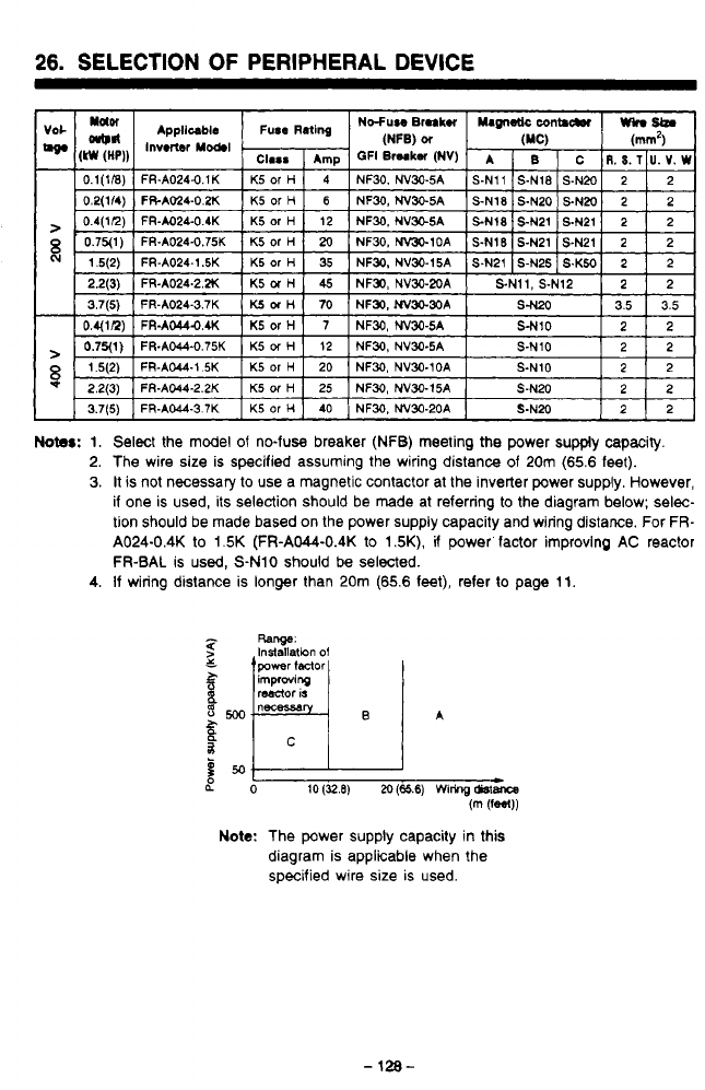
26.
SELECTION
OF
PERIPHERAL DEVICE
r?
J
Notes:
1. Select the model of no-fuse breaker (NFB) meeting the power supply capacity.
2. The wire size is specified assuming the wiring distance of
20m
(65.6
feet).
3.
It
is
not necessary
to
use a magnetic contactor at the inverter power supply. However,
if one is used, its selection should be made at referring
to
the diagram below; selec-
tion should be made based on the power supply capacity and wiring distance. For
FR-
A024-0.4K
to
1.5K
(FR-AW-0.4K
to
1.5K),
if
power factor improving
AC
reactor
1
FR-BAL
is used, S-N10 should
be
selected.
4.
If wiring distance is longer than 20m
(65.6
feet), refer to page 11.
LO
10
(32.8)
M
(65.6)
Wiring
&stance
(m
(fW)
Note:
The power supply capacity in this
diagram is applicable when the
specified wire size is used.
-
128-
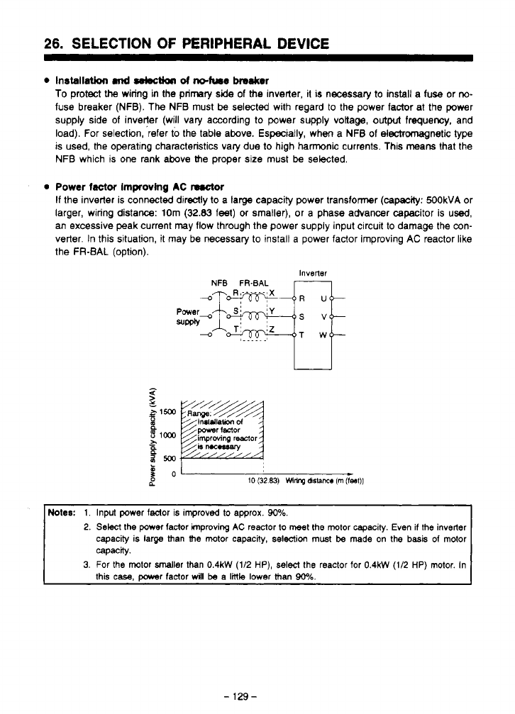
26.
SELECTION
OF
PERIPHERAL
DEVICE
0
Installation
md
sebctioa
d
ndum~
haker
To protect
the
wiring
in
the primary
side
of
the inverter,
it
is
necessary
to
install a fuse or
no-
fuse breaker (NFB).
The
NFB must
be
selected with regard to the power factor at the power
supply side of inveqer (will vary according to power supply voltage,
output
frequency, and
load). For selection, refer
to
the table above. Especially, when a NFB of electromagnetic type
is used, the operating characteristics vary due to high hamnic currents. This means that the
NFB which is one rank above the proper
size
must
be
selected.
0
Power
factor
Improving
AC
nrctar
If
the inverter is connected direclly
to
a large capacity power transformer (cam: 500kVA or
larger, wiring distance: 10m
(32.83
feel)
or
smaller), or a phase advancer capacitor is
used,
an excessive peak current may flow through the power supply input circuit
to
damage the con-
verter.
In
this situation,
it
may be necessary to install a power factor Improving AC reactor like
the FR-BAL (option).
Inverter
NFB
FR-BAL
b
B
NoIes:
1.
Input power faclor is improvd to approx.
90%.
2.
Select
the
power
factor improving
AC
reactor to meet
the
motor capacity. Even
if
the
inverter
capacity is large than
the
motor capacity,
selection
must
be
made
on
the
basis
of
motor
3.
For
the
motor smaller than
0.4kW
(1/2
HP),
select
the
reactor for
0.4kW
(1/2
HP)
motor. In
capacity.
this
case,
DOwer
factor
will
be
a
little
lower
than
90%.
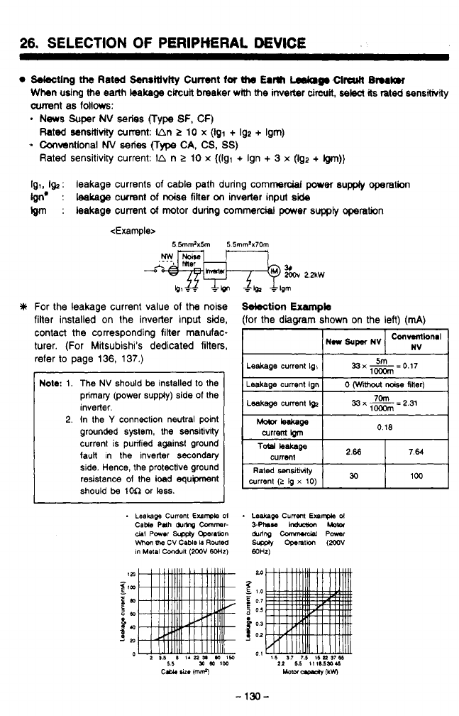
26.
SELECTION
OF
PERlPMRAt
DEVICE
Sdecting
the
Rated
Senritlvity
Current
for
the
Earn
Lsdclg.
Clrcutl
L3nrk.r
Whn
udng
the
earth
kalrage
circuit breaker
with
the
inverter
circuit,
selec(
its
rated
sensitivity
cunent
as follows:
.
News
Super
NV
series
(Type
SF, CF)
-
Convsntlonal
NV
series
(Type
CA,
CS,
SS)
Rated
sensitivity current:
IAR
>
10
x
(Igl
+
192
+
Ism)
Rated sensitivity current:
IA
n
2
10
x
((91
+
Ign
+
3
x
(Ig2
+
@n))
Ig,,
I&
:
leakage currents
of
cable path during commercial
per
supply
operation
Ign*
:
teakage
cwrent of
noise
filter
on
invetter inpu
side
Igm
:
leakage current
of
motor during commercial
power
supply
opetation
<Example>
For the leakage current value of
the
noise
filter installed on
the
invetter input side,
contact the corresponding filter manufac-
turer. (For Mitsubishi's dedicated filters,
refer
to
page
136,
137.)
Note:
1.
2.
I
The
NV
should
be
installed
to
the
primary (power supply) side
of
the
inverter.
In the
Y
connection neutral point
grounded system,
the
sensitivity
current is purified against ground
faun in the inverter secondary
side. Hence,
the
protective ground
resistance
of
the
load
equipment
should
be
1M
or
less.
Sdection
Exampb
(for the
diagram
shown on the left) (mA)
Leakage
current
Ig,
current
!grn
n
w
/-
W
I

27.
OPTION
':
Type
for
400VAC
class
has
H.
-
131
-
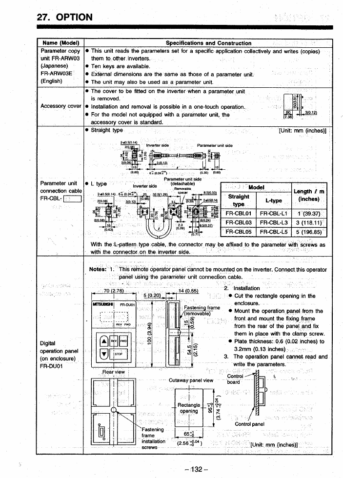
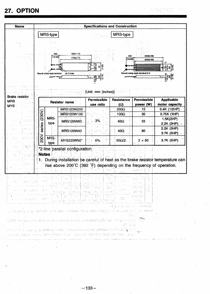
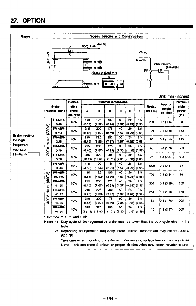
27.
OPTION
1
Unit:
mm
(inche
Common
to
1.5K
and
2.2K
loma
1:
Duty
cyde
of
t%
regenerative brake
must
be
tmr
Ihe
duty
cyde
given
in
lhe
2:
Depending
on operation
Irequenq
brake resistor
renperatwe
may
exceed
3OO'C
Take
care
when
mwnting
the
external brake
resista,
surface tmprature
may
cause
bum.
Lack
see
(note
2
below)
01
proper air
cinuiation
may
causa
resistor
failure.
table.
(572
'F).
I
-
134-
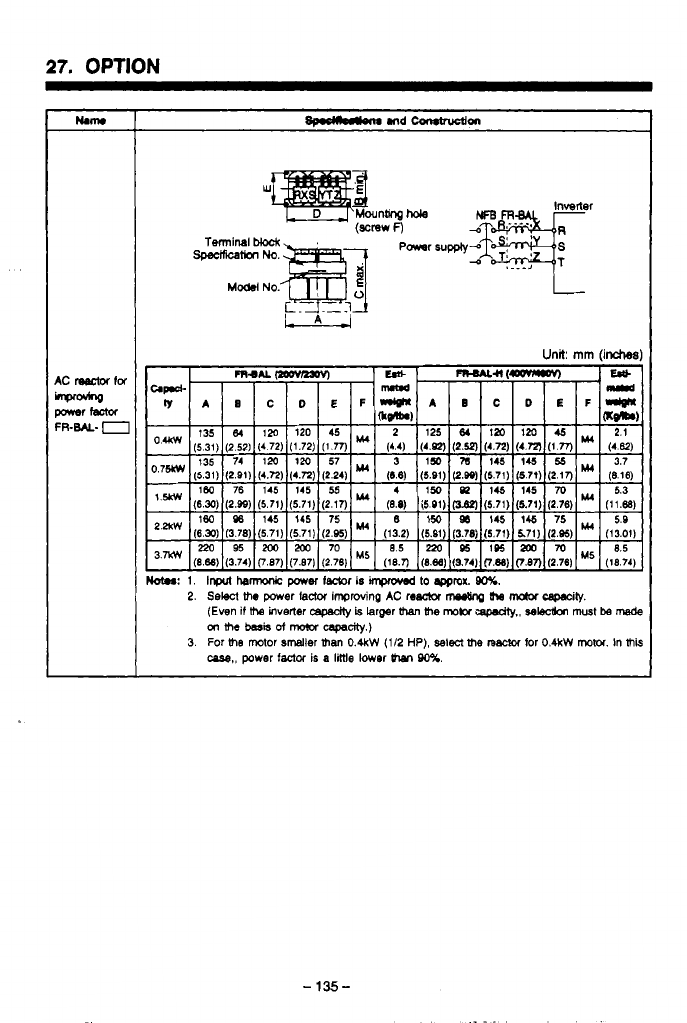
27.
OPTION
-
135-
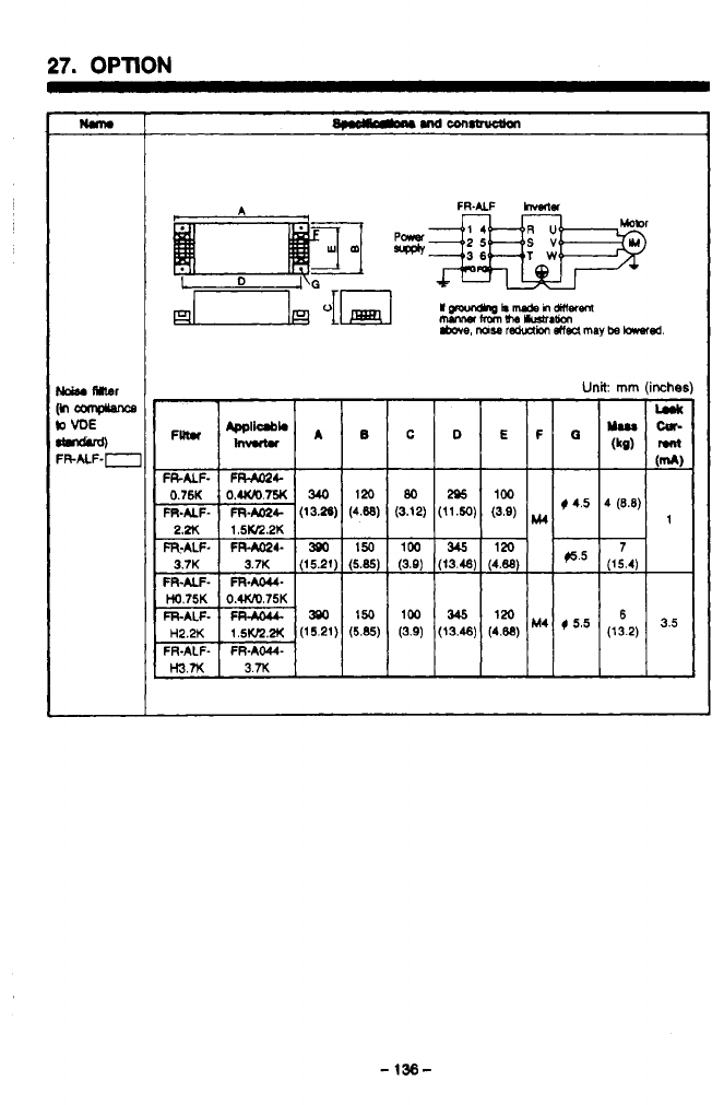
27.
OPTION
nm
Unit
rnm
(inche
I
(3.12) (11.50)
(3.9)
ITw
P
(3.9)
(13.48)
(4.88
(3.9)
(13.46)
(4.86)
loo
I
345
I
120
-
136-
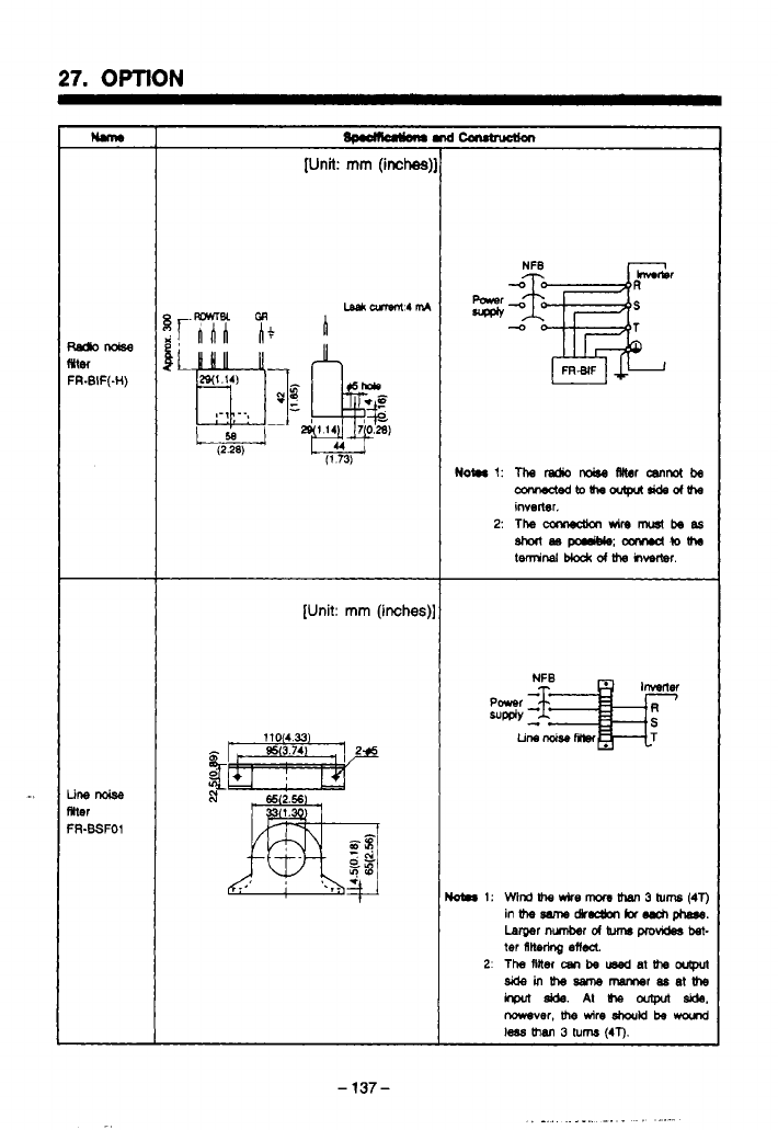
27.
OPTION
Ilm
r
[Unit:
mm
(inches)
[Unit:
mm
(inches),
-
137
-
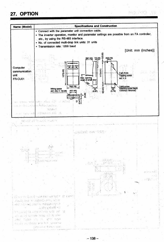
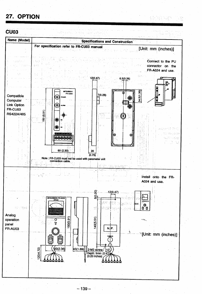
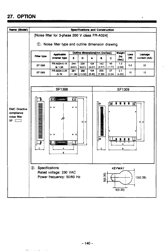
27.
OPTION
[Noise filter for
&phase
200
V
class
FR-A024]
0.
Noise
filter
type
and outline dimension drawing
SF1
308
SF1
309
0.
Specifications
Rated voltage:
230
VAC
Power frequency:
S/60
Hz
-
140-
.
.
-
_.
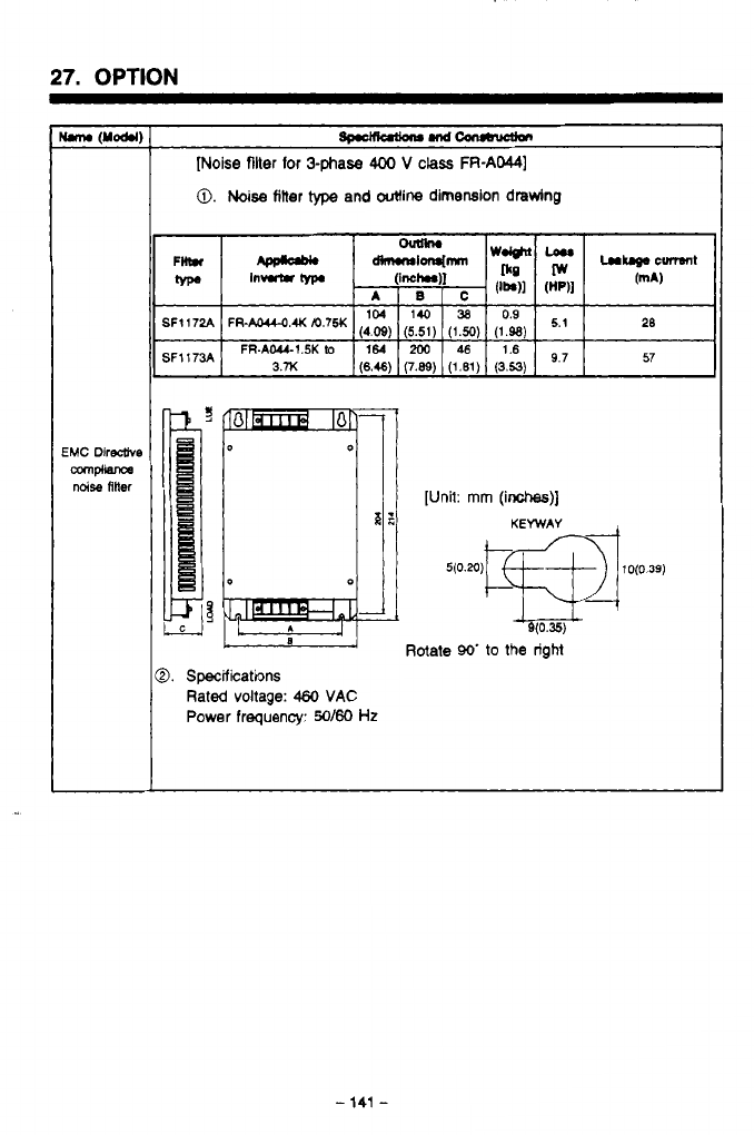
27.
OPTION
[Noise
filter
for
3phase
400
V
class
FR-AM)
0.
Noise
titter
type
and outline dimension drawing
FR-AOU-OAKm’75K
(4.09)
(5.51)
(1.50)
(1.98)
FR-AWI.5Klo
164
200
46
1.6
3.x
(6.46)
(7.89)
(1.61)
(3.53)
9’7
L
Rotate
90’
to
the right
9.
Specifications
Rated
voltage:
460
VAC
Power
frequency:
50160
Hz
-
141
-
.
,_
.
.-
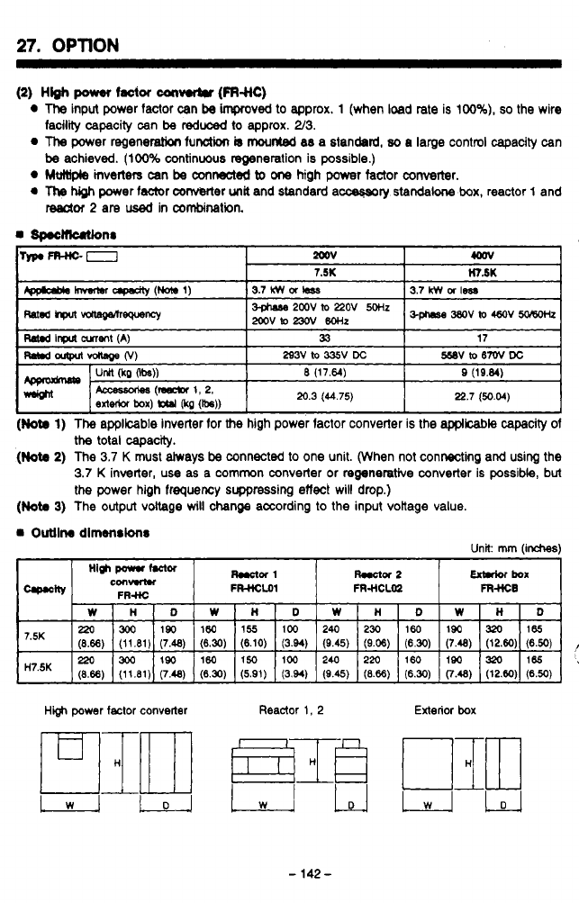
27.
OPTION
I
(2)
HW
power
factor
can-
(FRs1c)
0
The
input power factor can
be
impcoved to approx. 1 (when load rate is 100%),
so
the wire
The
power regeneration funoliwr
is
mounted
a8 a standsrd,
80
a large control capacity can
0
Mt*)pls
inverters
can
be
mnedd
to
one
high
power
factor converter.
0
The
high
power fsctor ConvMer
unit
and standard a-ry
standalone
box, reactor
1
and
facility capacity can
be
reduced
to
approx. 2/3.
be
achieved. (100% continuous regeneration is possible.)
I
Mor
2
are
used
in
combination.
A
the
total capacity.
(Nota
2)
The 3.7
K
must always
be
connected to one unit. (When not connecting and using the
3.7
K
inverter, use as a common converter or regenerative converter is possible, but
the power high frequency suppressing
effect
will drop.)
(Not.
3)
The output voltage
will
change according to the input vokage value.
Outll~
dlmmnrlons Unit
mm
(inches)
High
par
Mor
C0IIHR.I
Rw*or
1
Wor
2
maiof
boa
FWLOI
FR-HCLOZ
FR-HCB
High
power
factor
converter
Reactor
1,
2
Exterior
box
-
142
-
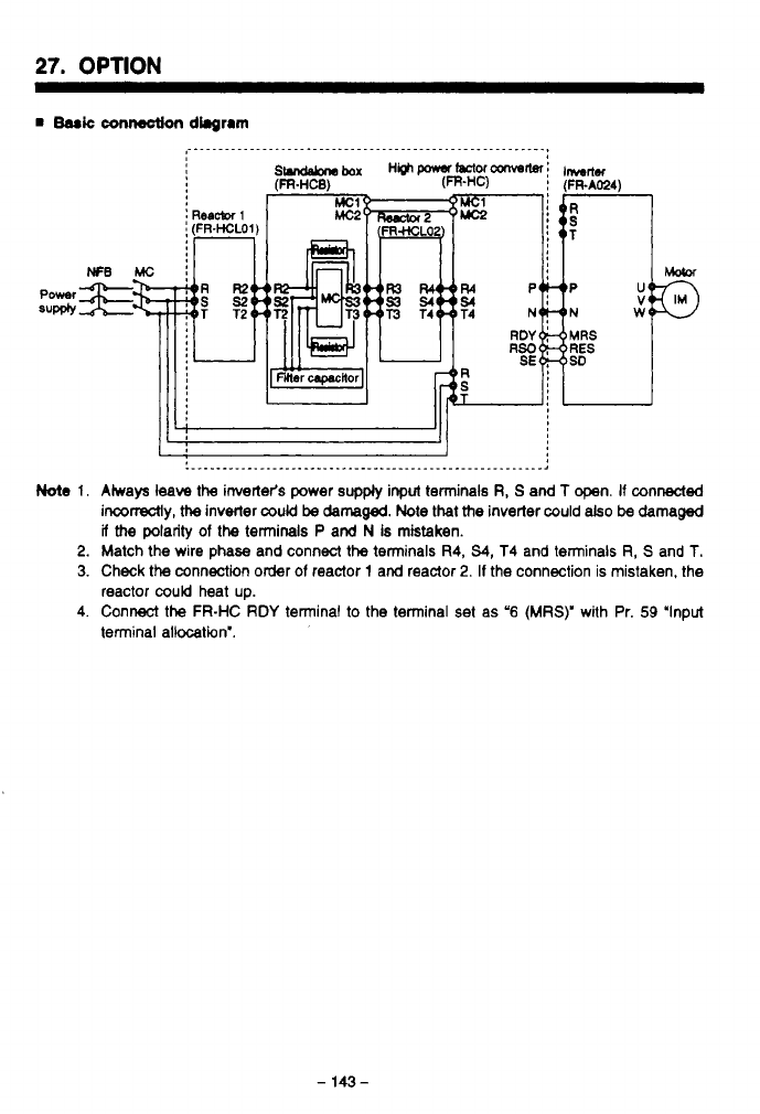
27.
OPTION
Note
1.
2.
3.
4.
.__..._______.____.___..._.____._________._.____________.,
Aiways
leave
the inverter's power
supply
input terminals
R,
S
and
T
open.
If
connected
inconectly,
the
inverter
could
be
damaged.
Note
that
the
inverter could
also
be
damaged
if
the
polarity
of
the
terminals P and
N
Is mistaken.
Match the wire phase and connect the terminals
R4,
54,
T4 and terminals
R,
S
and
T.
Check the connection order
of
reactor
1
and reactor
2.
If
the connection is mistaken, the
reactor
could
heat up.
Connect
the
FR-HC
RDY
terminal to the terminal set as
'6
(MRS)'
with Pr.
59
'Input
terminal allocation'.
-
143
-
.
_.
-
..
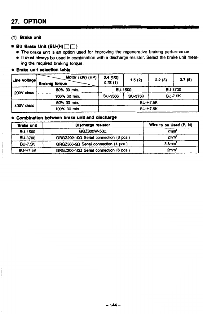
27.
OPTION
(1)
Brake
unit
m
BU
Brake
Unii
(BU-(H)
0
0)
0
Thg
brake
unit
is an option
used
for
improving
the
regenerative braking perf0tmanCe.
0
It
must
atways
be
used in cornbination with a discharge resistor. Select the brake unit
meet-
ing
tt?a
required braking
torque.
0
BraIB
unit
sektlon
tabb
-
. -.
..
-
.
. . .
.
-
144-
4
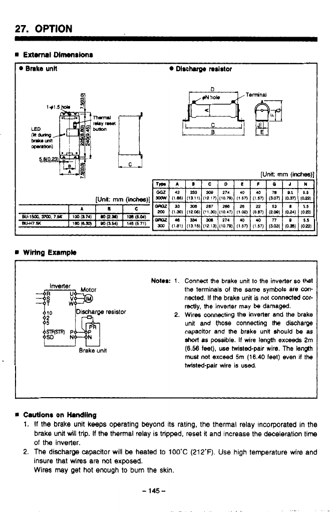
27.
OPTION
Brake
unH
Mrcharge
resistor
I
rn
Wiring
Exampb
I
Inverter
TW
uu
Brake unit
Notor:
1.
2.
Connect
the
brake unit
to
the inverter
so
that
the terminals
01
the
same
symbols are
un-
nected.
II
the
brake unit
is
not connected wr-
redly,
the
inverter may
be
damaged.
Wires mnectig
the
inverter and
the
brake
unit and
those
connecting
Me
discharge
capacitor and
the
brake unit
should
be
as
short
as
possible.
If
wire length
exceeds
2m
(6.58
feet),
use
hvistebpair wire.
The
length
must
not
exceed
5m
(16.40 feet) even
if
the
hvisted-pair wire is
used.
rn
Cautlonr
on Handling
1.
If
the brake unit keeps operating beyond its rating,
the
thermal relay incorporated in the
brake unit
will
trip.
If
the thermal relay
is
tripped, reset it and increase the deceleration
time
of
the
inverter.
2.
The discharge capacitor will
be
heated
to
1OO'C
(212'F).
Use high temperature wire and
insure that
wires
are
not
exposed.
Wires may get hot enough
to
bum the skin.
-
145-
..
.
.
..

27.
OPTION
I
rn
Brake UnW (FR-BU)
The
brake
unit
and resistor am
both
options
used
for improving
the
regenerattve braking
per-
e
Select
the brake unit and the resistor from the selection table, meeting the required braking
e
The brake
unit
is equipped with
the
7-segment
LEDs
which indicates
the
duty cycle
(%ED)
formance
of
the inverter. They are always used in a set.
toque and deceleration
time.
includes
and
the
resistor cooling
time
alarm code.
0
Brake
unW
doction
tabb
0.2K (1/4HP) GGZ300W-50n
1-1
FR-BU-1
SK
GGZ300W-50n
GGZ300W-50Ll
t-””-i
2.2K (3HP)
GRGZ2WlOn
Serial
mnnection
(3
pcs.)
GRGZ300.M
Seriai
.amwcbn
(4
pcs.)
GGZW-200R
FR-BU-H15K GRGZ300-2On
Serial
connection (4
pcs.)
e
Shod-tlme
pwmirrlbb
power
‘F
‘a
P
e
e
P
-
146-
.
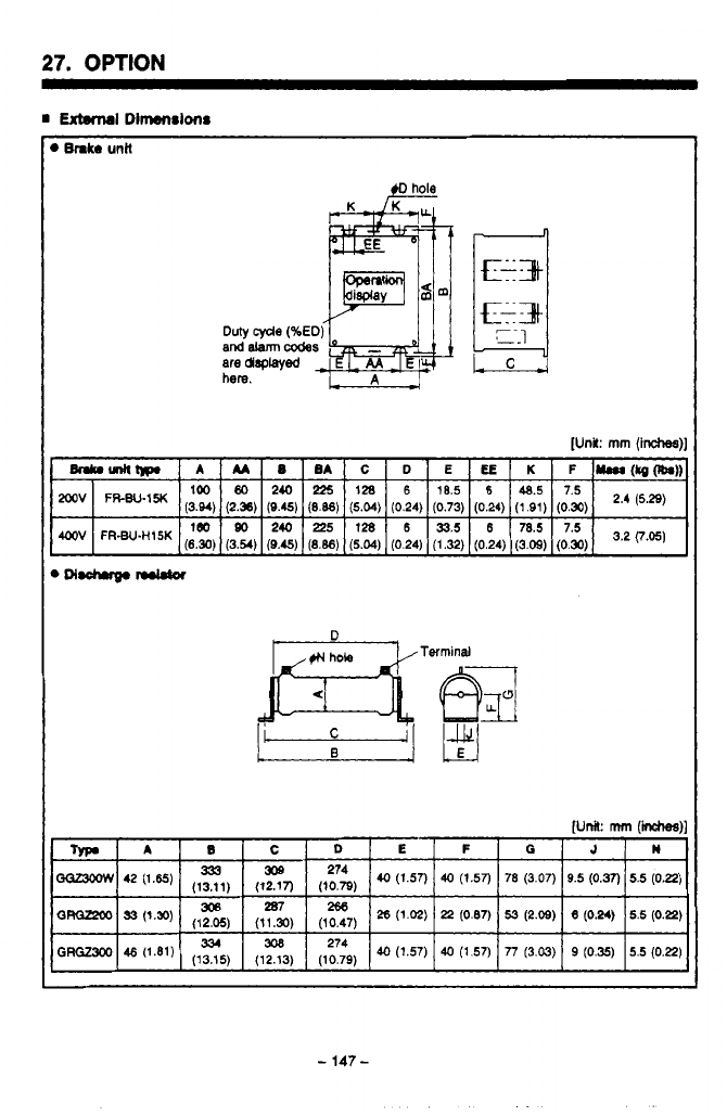
27.
OPTION
[Unit:
mm
(inches)]
D
,1N
hole Terminal
.
..
-
147
-
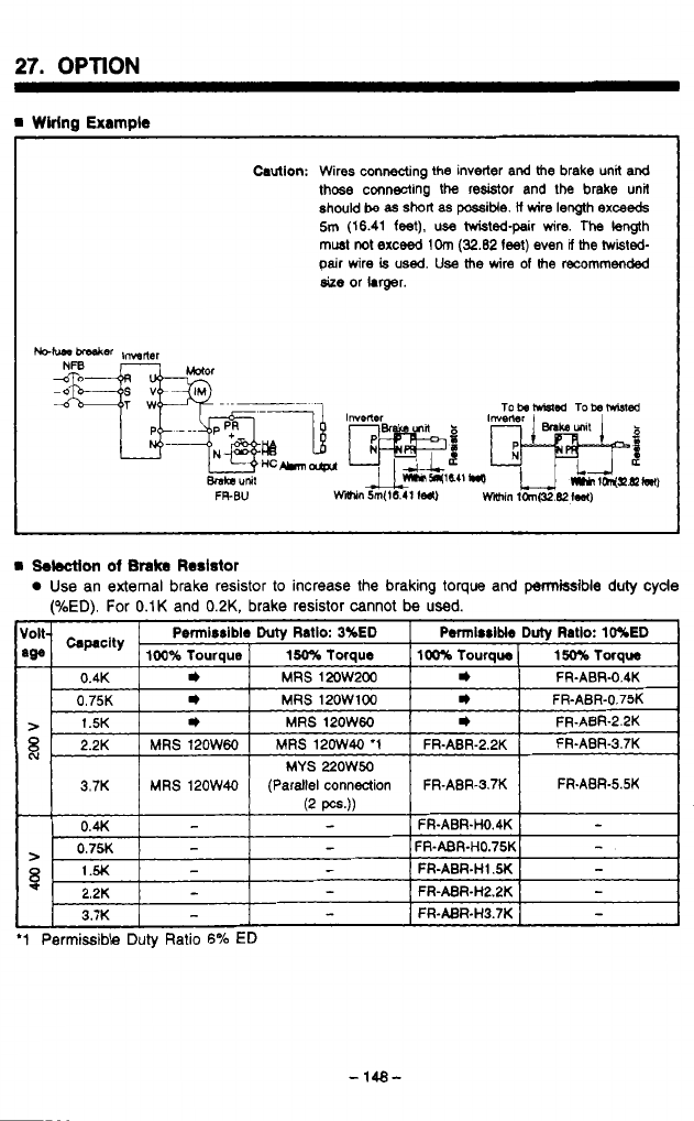
27.
OPTION
m
Wiring
Example
Caution:
Wires connecting
the
inverter and
the
brake unit
and
those
connecting the resistor and
the
brake unit
should
be as
short
as
possitie.
il
wire
length
exceeds
5m
(16.41
feet),
use hvisted-pair wire. The
length
must
not
exceed
1Om
(32.82
feet)
even
V
the
twisted-
pair
wire
is
used.
Use
the
wire
of
the
recommended
size
or hrger.
P5
'Ld
a
Selection
of
Brake
Reslstor
Use an external brake resistor
to
increase the braking
toque
and permissible duly cyde
(%ED). For
0.1K
and
0.2K,
brake resistor cannot
be
used.
FR-ABR-5.5K
'1
Permissible Duly Ratio
6%
ED
n
'..I-.
-
148-
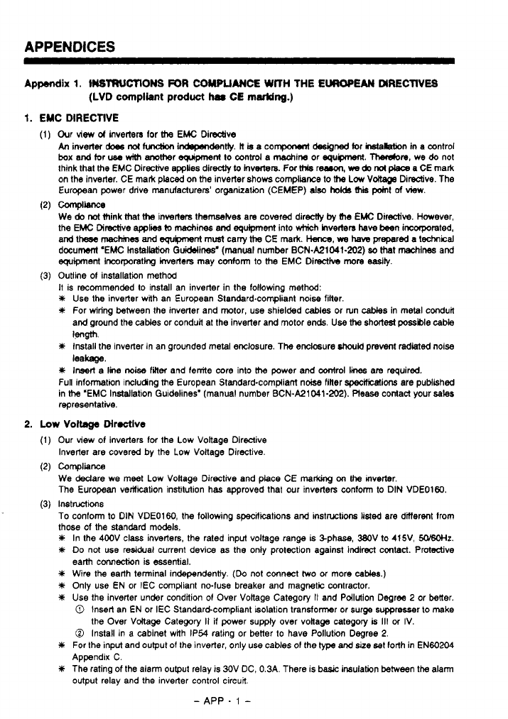
APPENDICES
Appendix
1.
WTRUCTIOMS
FOR
COMPLIANCE
WITH THE
EUROPEAN
DIRECTIVES
(LVD
compliant
product
har
CE
marking.)
1.
EMC
DIRECTIVE
Our view
d
inverters
for
the
EMC
Dirsctve
An
inverter
does
not
hndbn
mdently.
lt
b
a compoMnt
designed
for installation
in
a cantrol
box
and tor
use
with
anomer
eguipmenl
to
mtrd
a machin, or
egupment.
Therobre, we
do
not
think that
the
EMC Directive
applies
directly
to
Invecters. Fw
Mls
r-,
we
do
nol
p&w
a CE mark
on the inverter. CE mark placed on
the
inverter shows compliance to
the
Low
Vokage
Diredive. The
European power drive manufacturers’ organization (CEMEP)
also
hob
this
pOml
of
view.
We
do
not
think that
the
inverters themselves are covered directiy
ty
(he
EMC Directive. However,
the EMC Directive
applies
(0
machines and
equipment
into which hv&n
have
teen
incorporated,
and
these
maches
and
Sgupnent
mudt cany
the
CE mark.
Hence,
we
haw
prepared a technical
document ‘EMC
Installation
Guidelines‘ (manual number BCN.A21041-202)
bo
that machines and
equipment
lncorporatlng inverters may conform to
the
EMC Dimcth more
easibj.
Outline
of
installation method
It
is recommended to install an inverter in the following method:
Y
Use
the inverter with an European Standard-compliant noise filter.
#
For wiring between the inverter and motor, use shielded
cables
or run
caMes
in metal conduit
and ground the
caks
or conduit at the inverter and motor ends
Use
the
short&
possble
cable
Y
install the inverter in an grounded metal enclosure. The endosure
should
prevent
died
noise
#
Insart
a
line
noise
finer
and ferrite core into
the
power
and
contrd
li
are required.
Full information including
the
European Standard-compliant nobe filler specificatiw are pubiished
in
the
‘EMC
Installation Guidelines‘ (manual number BCN-A21041-202). Please contact your
sales
representative.
ComplWe
WW
leakage.
2.
Low
Voltage
Directive
Our view of inverters
for
the Low Voltage Directive
Inverter are covered by the Low Voltage Directive.
COmplianCe
We
Mare we meet Low Voltage Directive and place CE
marcOng
on
the mverter.
The European verikation institution has approved that our inverters conform to DIN VDE01W.
Instwions
To conform
to
DIN VDEOl60, the following specifications and instructions
listed
are dinerent from
those of the standard models.
In the 400V class inverters, the rated input voltage range
is
%phase, WV to 415V,
50/60Hz.
Do
not use residual current device as the only protection against indirect contact. Protective
earth connection is essential.
Wire the earth terminal independently.
(Do
not cmnect
two
or more
cables.)
Only use EN or IEC compliant no-fuse breaker and magnetic contractor.
Use
the inverter under condition
of
Over Voltage Category
It
and Pollution Degree
2
or better.
0
Insert an
EN
or IEC Standardcompliant isolation transformer or surge suppresser
to
make
0
Install in a cabinet with IP54 rating or better to have Pollution Degree
2.
For the
input
and output
of
the inverter, only use cables
of
the type and size bet forth
in
EN60204
Appendix C.
The rating of the alarm output relay is 30V DC. 0.3A. There is basic insulation between the a!am
output relay and the inverter control circuit
the Over Voltage Category
II
if power supply over vollage category
is
111
cf
IV.
-
APP
.
1
-
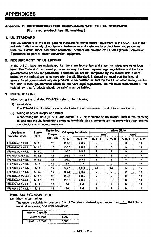
APPENDICES
2
W3TRWTDNS
FOR
COWL"€
WITH
THE
UL
STMAR0
(UL
listed
product
ha
UL
mrldng.)
1.
UL STANDARD
The UL
Standard
is
the
most
*nerd
standard
for
mO(0r
cmhol-
in
ths
USA.
This
star&
udaarlormtha~letyof~,~Wd~bJpmbldlive6wd~
from
fin.
deet*
8hock
and
other
m.
Invmten
an
cawred
by
UCMLec
(Mr
Carversion
E-t).optldpowwanwrdon-
2.
REWIREWENT
OF
UL
USMG
In
the
USA., laws are multiplexed, i.e.
there
are
lederal
law
and
state.
municprl
.nd
dmr
bcal
'
m.
me
F-~I
00wm
pa
for
onty
th.
k.st
WI
rcguwne
and
me
bca~
u'
~tPprovidefor~.Thordonm,Mnot~byth~hwtocom-
~bythelederalLawtoco~~meULStandud#.haJdbeMted~melausof
cevec.l~povemmentsrsquinpmbrcgtobscsrWbdr~~by~ULor~Lgtinginstitu-
tioo,andinkcalpove~whichdonothaML.011nguloObN~minLnumnquircwrontolthe
l&ral law Mat 'products
should
be
de'
must
be
fuhilled.
m
3.
INSTRUCTIONS
When
using
the
UL-listed FR-A024, refer
to the
Idbwing:
(1)
lnslallation
(2)
Wiring
d
power
wp@y
and
motor
The
FR-A024
is
UL-listed
as
a product used in an enclosure.
Install
it in
an
encbsure.
When wiring
the
input
(R,
S.
T)
and
ouput (U,
V,
W)
terminals
of
the
inverter,
dm
to
the
following
list
and
use
the
UL-lhled
lround
crinpirg
tennir\ph.
Use
a crimping
tool
recomnendd
your
terminal
manufactwe
to
crimping
tennluk
Note:
Use 75'C copper wires.
(3)
Short circuit ratings
The
drive
is
suitable
for
use on a Circuit
capable
01
delivering
not
more
than
RMS Sym
metrical
Aqres,
500
volts
Maximum.
0.75kW
M
less
1.5kw 10
3.w
-
APP
-
2
-
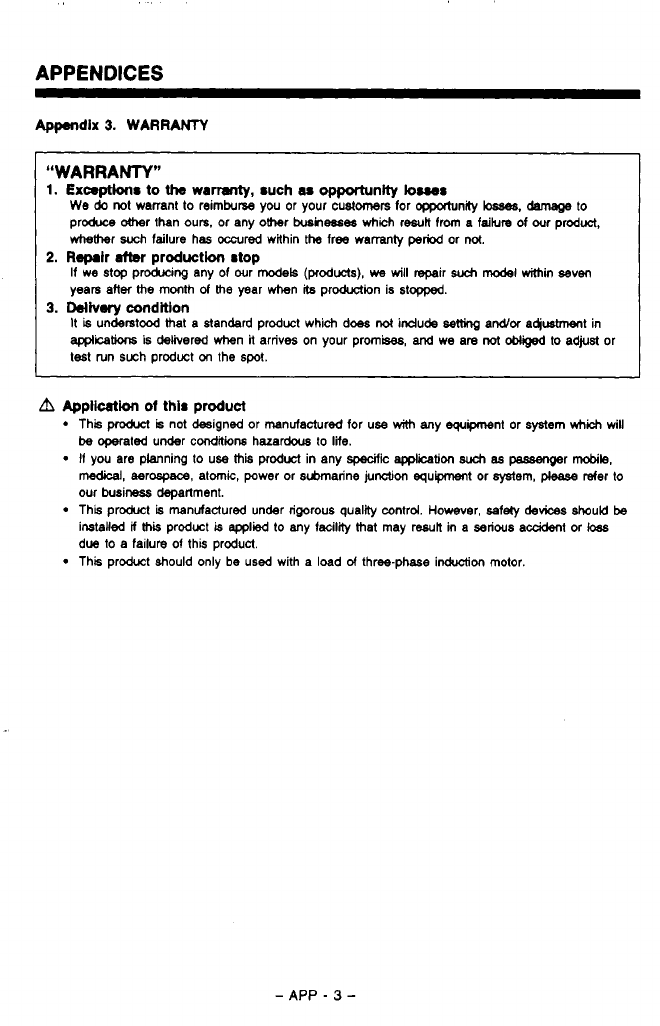
APPENDICES
Appendix
3.
WARRANTY
“WARRANTY”
1.
Exceptions
to
the
wamnty,
such
M
opportunity
buss
We
do
not warrant
to
reimburse you
or
your
customers
for
opportunity
ksaes.
damage
to
produce
&her
than ours. or any ohr
busmesee
which
result from a faiture
of
our
product,
whether
such
failure has
occured
within
the
free warranty
period
or
not.
If we
stop
producing any
of
our
models (products),
we
will
repair
such
model
within seven
years after
the
month
of
Me
year when
its
production is stopped.
It
is
understood
that
a standard product which does
not
indude
setting
ardor a4iusbnent in
applcations
is
delivered when
it
arrives on your prom&,
and
we are
not
ebb@
to adjusl or
test tun such product
on
the
spot.
2.
R-lr
after
production stop
3.
Ddiv.ry
condltlon
A
Appkation
of
this product
This
produa
is
not designed or manufactured for use
with
any equipment or system
which
will
I1
you are planning to use
this
prodwt
in any
specific
application
such
as
passenOer
mobile,
be
mated under
coodiwns
hazardous to
life.
medical,
aerospace, atomic, power or submarine junction equipment
or
system,
please
refer
to
our busineds depallment.
This product
is
manufactured under rigorous quality control. However, .safely
devices
should
be
installed
if
Mi
product
is
applied
lo
any facility
Mat
may result in a serious acddent
or
loas
due
to
a
failure of this product.
This product should only
be
used with a load
d
three-phase induction motor.
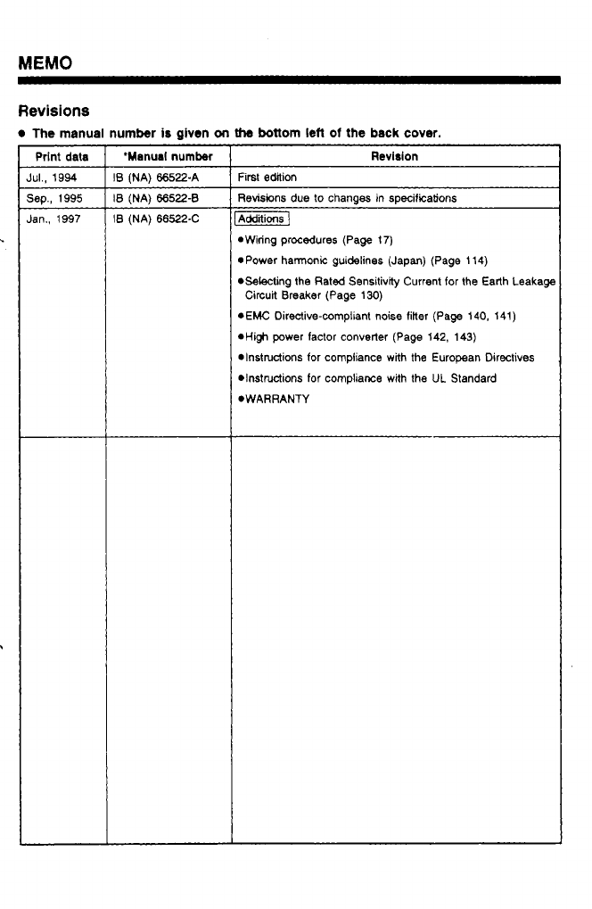
Revisions
The
manual number
is
given
on
the
bottom
lefl
of
the
back
cover.
Prlnt
data
IUI.,
1994
jep., 1995
Ian.,
1997
'Manual
number
B
(NA) 66522-A
B
(NA) 66522-8
B
(NA)
66522-C
Revision
First edition
Revisions due to changes in specifications
Additions]
*Wiring procedures (Page
17)
*Power harmonic guidelines (Japan) (Page 114)
*Selecting the Rated Sensitivity Current for the Earth Leakage
rEMC Directive-compliant noise filter (Page 140, 141)
*Hi$ power factor converter (Page 142, 143)
*Instructions for compliance with the European Directives
DInSttUctiOnS for compliance with the UL Standard
*WARRANTY
Circuit Breaker (Page
130)

A
MlTSUBlSHl ELECTRIC CORPORATION
HEAD
OFFICE:
MlTSUBlSHl
DENKl
BLDG.
MARUNOUCHI
TOKYO
1W
3
1
Tf;:
1
FR-A024
ElBUN TOAISETU
1
1A2-G24
IB(NA)6652X(9701) ROD
Printed
in
Japan Specifications
subjecl
to
change
withoul
notice.
i