F 040411L !! Murray 4
22 Self-Propelled to the manual 049d9f92-989e-485e-836f-c73dc56d3907
User Manual: !! Murray Lawn Mower Manuals - Lawn Mower Manuals – The Best Lawn Mower Manuals Collection
Open the PDF directly: View PDF ![]() .
.
Page Count: 40

The owner must be certain that all
the product information is included with the unit.
This information includes
the INSTRUCTION BOOKS,
the REPLACEMENT PARTS and the WARRANTIES.
This information must be included to make sure state laws
and other laws are followed.
PRODUCT INFORMATION
This Instruction Book contains information for several models.
Read and keep this book for future reference.
This book contains important information on
SAFETY, ASSEMBLY, OPERATION, AND MAINTENANCE.
RECORD THE FOLLOWING INFORMATION ABOUT YOUR UNIT.
THIS INFORMATION IS NECESSARY WHEN ORDERING PARTS
OR IN CASE OF LOSS OR THEFT.
F-040411L
BUILT IN THE
Models
22” Self-Propelled

2
F-040411L
MURRAY, INC. Two Year Limited Warranty
Murray, Inc. warrants to the original purchaser that this unit shall be free from defects in ma-
terial and workmanship under normal use and service for a period of Two (2) Years from
the date of purchase; however, this warranty does not cover engines, accessories (such as
snow blowers, snow blades, grass baggers and plows), transmissions, batteries and Nor-
mal Wear Parts (except as noted below) or transaxles as the companies that manufacture
these items furnish their own warranties and provide service through their authorized field
service facilities. For additional information, see the warranties covering these particular
parts. If you are uncertain whether your unit contains or is equipped with one or more of
these parts, consult your dealer prior to purchase. Subject to the terms and conditions noted
in this Limited Warranty, we shall, at our option, repair or replace at no cost to the original
purchaser any part covered by this Limited Warranty during the applicable warranty period.
In the event the battery proves defective within ninety (90) days from the date of purchase,
we will replace it without charge. If the battery proves defective after (90) days but within one
hundred twenty (120) days from the date of purchase, we will replace it for a charge of one
half (1/2) of the retail price of the battery in effect at the time of return.
Normal Wear Parts are defined as belts, blades, blade adapters, pneumatic tires, headlights
and seat covers. These parts are warranted to be free from defects in material and work-
manship as delivered with the product. Any claim for repair or replacement of Normal Wear
Parts must be made within thirty (30) days of the date of purchase. No claims involving dam-
age caused from material use, abuse or misuse will be honored.
This Murray, Inc. Two (2) Year Limited Warranty is your exclusive remedy; however, this
warranty is void or does not apply to any unit that has been tampered with, altered, misused,
abused or used for rental or other commercial and/or professional (non-homeowner) uses.
Your warranty does not cover minor mechanical adjustments which are not due to any de-
fect in material or workmanship. For assistance in making such adjustments, consult your
Instruction Book.
To make a claim under this Murray, Inc. Two (2) Year Limited Warranty, return the unit (or
if authorized in advance, the defective part) along with your proof of purchase to an Autho-
rized Service Center near you. To locate the nearest Authorized Service Center, call the
Central Parts Distributor for your area shown in the list provided with your unit or check the
Yellow Page listings in your local telephone directory. If you return the entire unit, we will
repair the unit. If we authorize the return of the defective part only, we will either replace or
repair the part. In the case of a defect in a transmission or differential (as distinguished from
a transaxle), the entire transmission or differential must be returned since they do not in-
clude user serviceable parts.
This Murray, Inc. Two (2) Year Limited Warranty gives you specific legal rights, and you
may also have other rights which vary from state to state. This Limited Warranty is given
in lieu of all other expressed and implied warranties including the implied warranty
of merchantability and warranty of fitness for a particular purpose. If you need addi-
tional information on this written warranty or assistance in obtaining service, call or write to
the address below. The model number along with the CUSTOMER CARE Center 1-800
number is on the Model Number Nameplate attached to the unit.
MURRAY, INC.
Outdoor Power Equipment
Customer Service Department
P.O. Box 268
Brentwood, Tennessee 37027

OWNER’S INFORMATION
3
F-040411L
This instruction book is written for a person with some mechanical ability. Like most service books,
not all the steps are described. Steps on how to loosen or tighten fasteners are steps anyone can
follow with some mechanical ability. Read and follow these instructions before you use the unit.
Know your product: If you understand the unit and how the unit operates, you will get the best
performance. As you read this manual, compare the illustrations to the unit. Learn the location and
the function of the controls. To help prevent an accident, follow the operating instructions and the
safety rules. Keep this manual for future reference.
IMPORTANT: Many units are not assembled and are sold in cartons. It is the responsibility of the
owner to make sure the assembly instructions in this manual are exactly followed. Other units are
purchased in an assembled condition. On assembled units, it is the responsibility of the owner to
make sure the unit is correctly assembled. The owner must carefully check the unit according to
the instructions in this manual before it is first used.
RESPONSIBILITY OF THE OWNER
The responsibility of the owner is to follow the instructions below.
1. Carefully read and follow the rules for safe operation.
2. Follow all the assembly and preparation instructions.
3. Inspect the unit.
4. Make sure that the operator of the unit knows how to correctly use all standard and accessory
equipment.
5. Operate the unit only with guards, shields, and other safety items in place and working correctly.
6. Correctly adjust the unit.
7. Service the unit only with authorized or approved replacement parts.
8. Complete all maintenance on the unit.
Engine Exhaust, some of its constituents, and
certain vehicle components contain or emit
chemicals known to the State of California to
cause cancer and birth defects or other repro-
ductive harm.
Battery posts, terminals and related accesso-
ries contain lead and lead compounds, chemi-
cals known to the State of California to cause
cancer and birth defects or other reproductive
harm. WASH HANDS AFTER HANDLING.
IMPORTANT
4
F-040411L
Safe Operation Practices for Walk-Behind Mowers.
This cutting machine is capable of amputating hands and feet and throwing objects. Failure to ob-
serve the following safety instructions could result in serious injury or death.
I. General Operation
1. Read, understand, and follow all instruc-
tions on the machine and in the manual(s).
Be thoroughly familiar with the controls and
the proper use of the mower before starting.
2. Do not put hands or feet near or under rotat-
ing parts. Keep clear of the discharge open-
ing at all times.
3. Only allow responsible individuals, who are
familiar with the instructions, to operate the
mower.
4. Thoroughly inspect the mower and area
where the equipment is to be used. Clear
the area of objects such as rocks, toys, wire,
bones, sticks etc., which could be picked up
and thrown by the blade.
5. Be sure the area is clear of other people be-
fore mowing. Stop mower if anyone enters
the area.
6. Do not operate the mower when barefoot or
wearing open sandals. Always wear sub-
stantial foot wear.
7. Do not pull mower backwards unless abso-
lutely necessary. Look down and behind be-
fore and while moving backwards.
8. Do not operate the mower without proper
guards, plates, grass catcher or other safety
protective devices in place.
9. See manufacturer’s instructions for proper
operation and installation of accessories.
Only use accessories approved by the
manufacturer.
10. Stop the blade(s) when crossing gravel
drives, walks, or roads.
11. Stop the engine (motor) whenever you
leave the equipment, before cleaning the
mower or unclogging the chute.
12. Shut the engine (motor) off and wait until the
blade comes to complete stop before re-
moving grass catcher.
13. Mow only in daylight or good artificial light.
14. Do not operate the mower while under the
influence of alcohol, drugs or other medica-
tion which can cause drowsiness or affect
your ability to operate this machine safely.
15. Never operate mower in wet grass. Always
be sure of your footing; keep a firm hold on
the handle and walk; never run.
16. Disengage the self-propelled mechanism
or drive clutch on mowers so equipped be-
fore starting the engine (motor).
17. If the equipment should start to vibrate ab-
normally, stop the engine (motor) and check
immediately for the cause. Vibration is gen-
erally a warning of trouble such as a blade
that is damaged, a loose blade, or the en-
gine mounting bolts are loose.
18. Always wear safety goggles or safety
glasses with side shields when operating
mower to protect your eyes from foreign ob-
jects which can be thrown from the unit.
19. Plan your mowing pattern to avoid dis-
charge of material toward roads, sidewalks,
bystanders and the like.
20. After striking a foreign object, stop the en-
gine. Remove the wire from the spark plug.
Inspect the blade and mower for damage. If
damaged, repair before starting and operat-
ing the mower.
21. Keep any washout ports and other mower
housing service openings closed when
mowing.
II. Slope Operation
Slopes are a major factor related to slip and fall
accidents which can result in severe injury. All
slopes require extra caution. If you feel uneasy
on a slope, do not mow it.
DO:
Mow across the face of slopes; never up
and down. Do not mow excessively steep
slopes (maximum 15 degrees) or areas
where the ground is very rough. See the
“Guide” in the back of this manual to check
a slope. Exercise extreme caution when
changing direction on slopes.
Remove objects such as rocks, tree limbs,
etc.
Watch for holes, ruts, or bumps. Tall grass
can hide obstacles.
(Continued Following Page)
IMPORTANT
5
F-040411L
DO NOT:
Do not mow near drop-offs, ditches, or em-
bankments. The operator could lose footing
or balance.
Do not mow excessively steep slopes.
Do not mow on wet grass. Reduced footing
could cause slipping.
III. Children
Tragic accidents can occur if the operator is not
alert to the presence of children. Children are
often attracted to the mower and the mowing
activity. Never assume that children will remain
where you last saw them.
1. Keep children out of the mowing area and
under the watchful care of a responsible
adult.
2. Be alert and turn mower off if children enter
the area.
3. Before and while moving backwards, look
behind and down for small children.
4. Never allow children to operate the mower.
5. Use extra care when approaching blind cor-
ners, shrubs, trees, or other objects that
may obscure vision.
IV. Service
*1. Use extra care in handling gasoline and oth-
er fuels. They are flammable and vapors are
explosive.
a. Use only an approved container.
b. Never remove gas cap or add fuel with
the engine running. Allow engine to cool
before refueling. Do not smoke.
c. Never refuel the machine indoors.
d. Never store the machine or fuel contain-
er inside where there is an open flame,
such as a water heater.
*2. Never run an engine indoors or inside a
closed area.
3. Never make adjustments or repairs to items
such as the height adjusters or grass catch-
er with the engine (motor) running. Discon-
nect the spark plug wire, and keep the wire
away from the plug to prevent accidental
starting. Always wear eye protection when
you make adjustments or repairs.
4. Keep all nuts and bolts, especially blade at-
tachment bolts, tight and keep equipment in
good condition.
5. Never tamper with safety devices. Check
their proper operation regularly.
6. To reduce fire hazard, keep mower free of
grass, leaves, or other debris build-up.
Clean up oil or fuel spillage. Allow mower to
cool before storing.
7. Stop and inspect the equipment if you strike
an object. Repair, if necessary, before re-
starting.
8. Never attempt to make wheel height adjust-
ments while the engine (motor) is running.
9. Always disconnect electric mowers (live op-
erated) before cleaning, repairing, or ad-
justing.
10. Grass catcher components are subject to
wear, damage, and deterioration, which
could expose moving parts or allow objects
to be thrown. Frequently check components
and replace with manufacturer’s recom-
mended parts, when necessary. For stor-
age, always make sure grass catcher is
empty.
11. Mower blades are sharp and can cut. Wrap
the blade(s) or wear gloves, and use extra
caution when servicing them.
12. Do not change the engine governor setting
or over-speed the engine.
13. Frequently check the blade for wear or dam-
ages such as cracks and nicks. A blade that
is bent or damaged must be immediately re-
placed with a factory replacement blade.
For safety and good cutting performance,
replace the blade every two years. Fre-
quently check the blade bolt and the engine
mounting bolts. Replace damaged bolts
and tighten loose bolts.
14. Use only original equipment or authorized
replacement parts.
* Asterisked items do not apply to electric mowers.
SAFE MOWING GUIDE
6
F-040411L
Every person who uses power equipment
must learn the difference between proper and
improper use, safe and unsafe mowing prac-
tices. Read the next few pages carefully.
They can help you learn. Too often the mow-
er user is inexperienced, not properly in-
structed, or has not read the Instruction Book
and instructions on the unit before using it for
the first time. This can result in unsafe use en-
dangering the operator, bystanders, and the
equipment. Another result can be a poor ap-
pearance of the area mowed.
Read this Instruction Book. Read the in-
structions on the unit. Operate the mower ac-
cording to the Safe Mowing Guide and other
safety rules and recommendations in this In-
struction Book and on the unit. Make sure any-
one who uses the unit has read the instructions
and has been told how to operate the mower
safely.
Your mower is designed to provide good ser-
vice and durability in normal residential cut-
ting. If the mower is not properly serviced and
maintained or used on unsuitable terrain or in
conditions not suitable for mowing, product
performance and safety will be reduced.
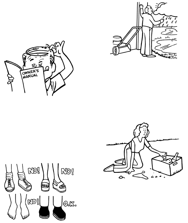
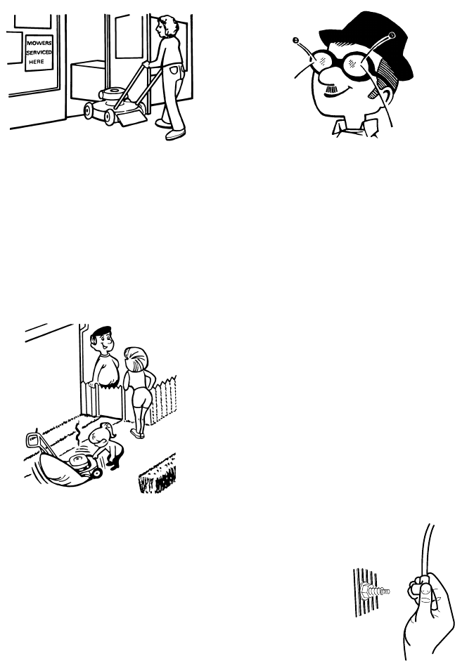
Proper attire is an important part of safe mow-
ing. Safety glasses protect the eyes from
thrown objects. Safety shoes with steel toes
can protect a foot from being cut by the blade.
Shirts and pants that cover the arms and legs
can stop or deflect a thrown object.
Practice using the mower before you actually
begin cutting grass. Select a large open level
area. Learn the location and function of the
controls and how they work. It is important that
the blade can be stopped quickly in an emer-
gency. Learn how to cut and how to keep con-
trol of the mower at all times.
Many mowers are started manually. When us-
ing a pull start or rope start, place your feet
firmly and away from the blade. Hold the rope
handle securely, but never wrap the rope
around your arm or fingers for a “better grip”.
The mower is designed for use by one person.
Always mow alone. Never carry passengers.
Carrying a passenger is dangerous for the
passenger and the operator. A mower is not for
amusement or for carrying objects.
Is the area you are planning to mow wet? Nev-
er cut a wet lawn. Cutting wet grass can cause
an accident. It can affect mower performance
and also cause problems with future lawn
growth and appearance. Wet grass is slippery
and might cause the operator to fall or the
mower to slip. Someone could be hurt by
touching the blade. Wet grass tends to clog the
mower, causing poor discharge. Wet clippings
bunch up on the lawn retarding the growth of
grass. A wet mower can cause parts to rust
and reduce the useful life of the unit.
When you look over the lawn, refresh your
memory about hard, immovable obstacles
such as pipes, stumps, and rocks and avoid
them. They can cause damage to the mower
or an accident injuring the operator or a by-
stander. Take a litter bag along and walk over
the area to be cut. Pick up any stones, toys,
wire, bones, or other loose objects. These
items can damage the mower or they can be-
come dangerous flying objects if the mower
blade hits them. The blade of a power mower
travels very fast. It can throw rocks and other
objects with force over long distances. Objects
thrown by mowers can break windows, cause

SAFE MOWING GUIDE
7
F-040411L
bruises, or even put out an eye. Often the per-
son hurt by a thrown object is a bystander such
as a child, another family member or a neigh-
bor. Keep people and pets completely away
from the mowing area. Direct the mower’s dis-
charge away from areas where people can be.
Planning your mowing pattern has a double
benefit. It can reduce chances of an injury and
make the clean up after mowing easier.
Are there ditches,
walls, or major in-
clines in the area to be
cut? Plan the mowing
pattern to avoid such
danger areas. In-
clines and rough ter-
rain must be mowed
carefully and some
areas must not be cut
with a mower at all.
With walk behind
equipment, mow
across the incline so
that if you or the mow-
er slip, you won’t run
into each other.
Never mow slopes greater than 15 degrees.
See the “Guide” in the back of this Instruction
Book to check any slopes.
Ready to start cutting? Not yet. Be sure the
mower has been fully assembled according to
directions in the Instruction Book. Even if as-
sembly was done by a lawn and garden shop
or the store where the unit was purchased, it
must be checked. Are all nuts, bolts and
screws tight? Does the engine have oil? These
items must be checked periodically throughout
the life of the mower.
Your mower has a gasoline engine. Gas is
dangerous. Store fuel only in a approved gas
container. Do not store large amounts of gas.
Put out all cigarettes, pipes and cigars before
working with gasoline. Store fuel and the mow-
er itself in a well ventilated area away from any
possible source of ignition such a pilot light on
a furnace. If the mower is to be stored for an ex-
tended time, remove the gas from the tank.
This minimizes the chance of a fire and keeps
the tank clear of deposits and old gasoline,
thus improving mower performance. Move the
mower outside before adding gasoline. Use a
funnel and wipe up any spilled fuel before start-
ing. Remember, gasoline expands when
heated so leave some expansion room. Also,
most mower gas caps are vented to allow for
expansion. Always use the proper cap. People
are needlessly burned by fires, hurt in explo-
sions, mowers and other property are dam-
aged because of failure to follow basic safety
rules related to gasoline and fueling.
Never add gasoline to an engine that is running
or that is hot from recent use, this can cause an
accident. Remove dry grass and other debris
from the mower. Keeping the mower clean will
improve the performance, help the engine stay
cooler, extend the life of moving parts, and
minimize the danger of fire. People get burned
working with and around their mowers for oth-
er reasons than fire and explosions. It takes
only a few seconds of operation for the engine
and the muffler to become hot. Do not touch
these parts when the mower is running. Stop
the engine and let it cool down before servicing
the mower. Remember, exhaust fumes can be
dangerous. Never operate the engine indoors
or in an enclosed area.
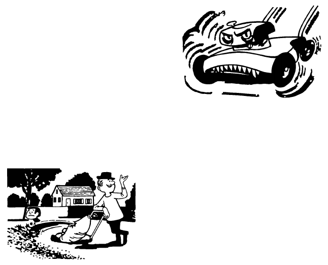
Getting a new mower can be a big event for a
family. Let family members satisfy their curios-
ity about the mower and at the same time, tell
them about its dangers. Remember, a mower
is not a toy and is not for use by children or any-
one lacking in age, strength or experience.
As with any power equipment, a mower can be
dangerous if not assembled, misused, or not
properly maintained. The most important rule
is to always use good judgement and common
sense.
Your mower will cut thick grass and heavy
plant stems with ease. Fingers and toes are no
more resistant to the mower’s blade. Many
people are injured because they “forgot” and
reached into the discharge chute. Always treat
your lawn mower as if the blade is rotating.
Never perform any service or try to make any
adjustment,except carburetor, while the en-
gine is running.
Use only accessories suited for your mower.
Use of improper accessories can reduce the
safety designed into both the mower and the
accessory, it can even damage the unit. Read
and follow the instructions which come with the
accessory and the mower.
SAFE MOWING GUIDE
8
F-040411L
Use only original equipment or approved sub-
stitutions as service parts. If you need profes-
sional service, select a shop that is an
Authorized Service Center for your brand of
mower. If you plan to service the unit yourself,
follow directions in the Instruction Book.
As you mow, remember children and pets are
sometimes attracted to the activity. Be espe-
cially careful when trimming around shrubbery
or when backing up. If at all possible, don’t
mow when moving backwards. It is dangerous
because vision is restricted. Also, blades are
designed to cut while the unit is moving for-
ward so cutting performance is reduced when
mowing in reverse.
Never leave the mower running and unat-
tended. Shut off the engine. Put the mower in
a position so that it can not roll. If the unit is
self-propelled, make sure the drive control is
disengaged.
When mowing, be aware of your condition and
the weather conditions. After mowing a long
time, you will be tired. This is the time when
reactions slow down, your attention wanders;
the time when you are wide open for an acci-
dent. Take a short break. If temperatures are
high, take precautions to avoid becoming de-
hydrated. If you are angry, tired, or unable to
give your full attention to mowing, if you have
been consuming alcohol, medicines, or drugs,
do not use your mower or any type of power
equipment.
If weather conditions become worse while you
are cutting, stop and finish later. Cutting grass
in the rain is no fun and it is dangerous. Always
seek shelter in an electrical storm. In extreme-
ly dry mowing conditions, your safety glasses
can serve a dual purpose by protecting your
eyes from dust and thrown objects, also a dust
or pollen mask can be helpful.
Your mower is equipped with a number of safe-
ty features which are important to the safety of
the operator and bystanders and must never
be altered or removed. If a safety feature be-
comes inoperable, lost, or damaged, it must be
repaired or replaced before the mower is used.
Engine speed is a key to safe mowing and a
nice looking lawn. The maximum speed of the
engine on your mower has been set at the fac-
tory. Do not change the engine governor in any
way.
Select the maximum engine and ground speed
that is right for the terrain and the height of
grass. You get the best cutting and bagging
performance when using a grass catcher by
operating the engine at maximum speed. Nev-
er walk fast or run just to get the job done soon-
er. On inclines, reduce ground speed and
exercise extreme care.
It is best to mow only during daylight hours;
however, if you must mow in the late afternoon
or evening, make sure there is good artificial
light.
Your mower will require maintenance including
service and adjustments before and after use
as with any machine. The frequency of the
maintenance is generally based on hours of
use, however, the frequency can vary because
of mowing conditions. Check the Instruction
Book for more detailed instructions. Proper
maintenance protects your investment in the
mower and helps insure that it will function
safely and reliably.
Never attempt any
service (with the pos-
sible exception of car-
buretor adjustment)
with the engine run-
ning. After turning the
engine off, always
disconnect the spark
plug wire to prevent
accidental restarting
while the unit is being
serviced.
SAFE MOWING GUIDE
9
F-040411L
While mowing, if you hit a foreign object, stop
the engine. Remove the spark plug wire. Care-
fully and thoroughly inspect the mower for
damage. Make necessary repairs before re-
starting. If the unit starts to vibrate abnormally,
stop the engine immediately and check for the
cause. Vibration is generally a warning of
trouble. Keep all nuts, bolts, and screws tight.
The blade is the most dangerous part of the
mower and also the most important part in ob-
taining a nice lawn appearance. Check the
blade and the blade mounting hardware fre-
quently. Keep it tight. If the blade hits a solid
object, check it thoroughly for deformation or
cracks and replace if damaged. For safety,re-
place the blade every two years. A sharp blade
reduces the work load on the engine and cuts
grass more cleanly, for a better looking cut with
less work. The blade is always close to the out-
side of the mower housing. For best trimming
on side discharge mowers, cut with the left
side of the housing toward the area that needs
trimming.
A useful accessory for your mower is a grass
catcher. There are grass catchers available for
most models. For best performance and safe-
ty, be sure the grass catcher is approved for
use with your mower. Assemble as directed
and follow operating and safety instructions
with the catcher and in the Instruction Book.
Before mounting, checking or emptying the
grass catcher, always turn the engine off. Re-
member to check the grass catcher before
each use for cracks, wear, or deterioration. Re-
place any part that is damaged with the man-
ufacturer’s recommended replacement part
before using the grass catcher again.
Proper cutting technique is important if you
want your lawn to look good. Avoid the tempta-
tion to cut grass too short. Cutting grass too
short can kill the plant, cause grass to turn yel-
low, or make the lawn look brown and thatchy.
Use the lower cutting heights in cool months
when the grass is lush. Use the higher cutting
heights in extremely dry periods. Cutting with
a dull blade or low engine speed bruises,
shreds, and can uproot some grass making
the lawn look dull and brown a few days after
cutting. Always put the throttle control in FAST
position when mowing and bagging. When
bagging, slower ground speed will provide the
best results.
Change the mowing pattern slightly each time
you cut. If you always cut the same way, the
grass will develop a “set” and clippings will ac-
cumulate more heavily in some areas more
than in others causing grass to get thinner in
those areas. Do not service your mower over
the grass. Spilled oil and gas can kill the grass.
In tall grass or very heavy grass, do not try to
cut it all at once. Raise the height of cut on the
first cutting and lower it for the next cutting the
same day or within a few days. Another way is
to cut only part of the width of the mower and
adjust your ground speed (not the engine) to
move more slowly so the mower can clear it-
self as it moves forward.
When cutting with a walk behind mower, al-
ways push the unit. Do not pull it. Pushing the
unit keeps the operator behind the mower in
the “operator’s zone” for better control. Push-
ing the unit also gives you a chance to see ex-
actly where and what you are mowing. There
will be times while you are mowing that you will
have to pull the mower backwards (such as
when the front of the mower has come up
against a wall or fence). If you must back up,
make sure your feet are in the clear. Stand well
back from the mower, plant your feet firmly with
each step and back up being careful to look be-
hind you. Resume normal mowing as soon as
possible.
If your unit is self-propelled, remember that
the drive mechanism is not designed to do all
the work, but the unit can move without your
help. Always keep your hands on the handle
near the controls when the engine is running.
Remember too that the self-propelled mecha-
nism can be dangerous. Keep hands and feet
away from belts and chains. Always turn off the
engine before attempting to remove anything
that becomes entangled in the self-propelled
system.
Remember, your mower is a useful tool, but it
can be dangerous. Follow the instructions in
this Instruction Book. Use the mower properly
and carefully and it will give you many hours of
trouble free, accident free operations.

STEPS TO FOLLOW
10
F-040411L
BEFORE MOWING
DBe sure to dress correctly. Wear hard shoes, not sandals or tennis shoes.
DExamine the blade. A blade that is bent, cracked, or damaged must be replaced with a factory
replacement blade.
DFill the fuel tank outside. Clean off spilled fuel.
DRead and follow the Owner’s Manual, the instructions with the engine, and the instructions with
any attachments. Owner’s Manual instructions are for your safety and the safety of others.
DExhaust fumes are dangerous. Start the engine outside.
DMake sure all safety devices are in place and working correctly.
DOperation of the mower is only for a person that has experience.
DWet grass can be dangerous. Let the grass dry.
DInstruct children and others to keep away from the work area.
DNever cut the grass without good light.
DPick up loose objects. Remove them from the mowing area.
WHILE MOWING
DWatch for fixed objects and avoid them. They can damage the mower or cause injury.
DA hot engine and muffler will cause a burn. Do not touch.
DInclines and slopes must be carefully mowed. See the “Guide” in the back of this book to check
a slope.
DLack of daylight or good artificial light is cause to stop mowing.
DExamine the mower, the blade, and other parts for damage after hitting a foreign object or if the
unit vibrates excessively.
DDo not make adjustments or repairs without stopping the engine (except for carburetor). Dis-
connect the spark plug wire.
DOn or near roads, watch out for traffic. Direct discharge away from roads.
DWhen mowing, avoid areas where traction is unsure. Before and while moving backwards, look
behind and down for small children.
DIn heavy grass, raise the cutting height. Cut slower. Stop the engine to remove clogged grass
from the mower.
DNever remove any safety related parts.
DDo not pour gasoline into a engine that is hot or running.
AFTER MOWING
DAlways let the mower cool before storing in an enclosed area.
DForeign material on the mower is dangerous. Clean off grass, leaves, grease and oil before
storing.
DTighten all loose nuts, bolts and screws before you use the unit.
DEmpty and clean any grass catcher or other accessory.
DRemove the key or disconnect the spark plug wire to prevent unauthorized use.
DMake sure the mower is not kept near a source of ignition. Gas fumes can cause an explosion.
DOnly original parts or factory approved substitutes can be used to service the mower.
DWhen storing the mower for an extended period, remove the fuel from the fuel tank.
DInstruct children to leave the mower alone. It is not a toy.
DNever keep gasoline near a source of ignition. Always use an approved container. Keep
gasoline away from children.
DLubricate according to the Instruction Book. See “Lubrication”.
IMPORTANT--Read the Instruction Book. Keep this book for future use and
reference. WARNING: Look for this symbol to point out important
safety precautions. It means: “Attention! Become
Alert! Your Safety Is Involved.”

PREPARATION
11
F-040411L
UNPACKING INSTRUCTIONS
The mower was fully assembled at the factory.
When the mower was put in the carton, the
handle was put in the storage position. To put
the handle in the operating position, follow the
steps below.
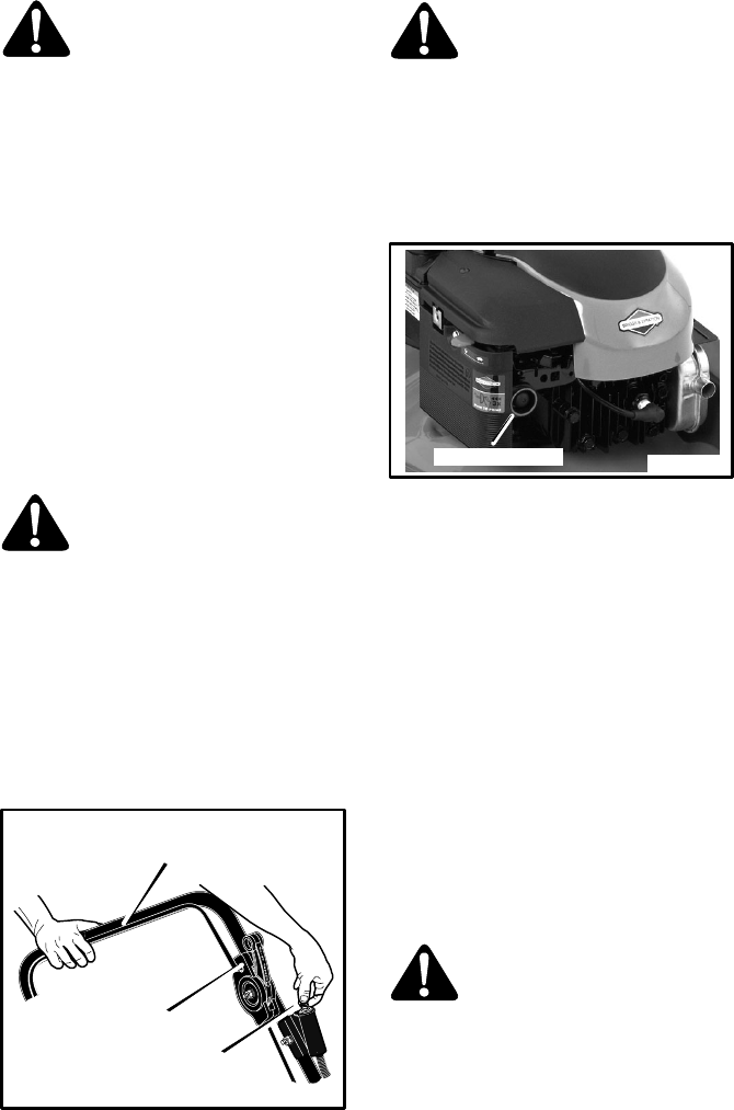
Handle
1. Remove the mower from the carton.
2. Put the lower handle in the operating posi-
tion. Make sure the lower handle is be-
tween the locking tabs (Figure 1).
3. Put the upper handle in the operating
position. Tighten the knobs.
CAUTION: Be careful when you fold or
raise the handle. Do not damage the
cables. A cable that is bent will not work
correctly. Before you use the unit, re-
place a bent or damaged cable.
4. To attach the recoil-start grip to the rope
guide, twist the rope through the rope
guide mounted on the right side of the han-
dle (Figure 2).
NOTE: If you cannot attach the
recoil-start grip because the rope is too
short, hold the engine stop lever
against the handle. Slowly pull the
recoil-start grip.
Knob
Upper Handle
Figure 1
Knob
Lower Handle
Figure 2
Recoil-Start
Grip
Rope
Guide
PREPARATION
12
F-040411L
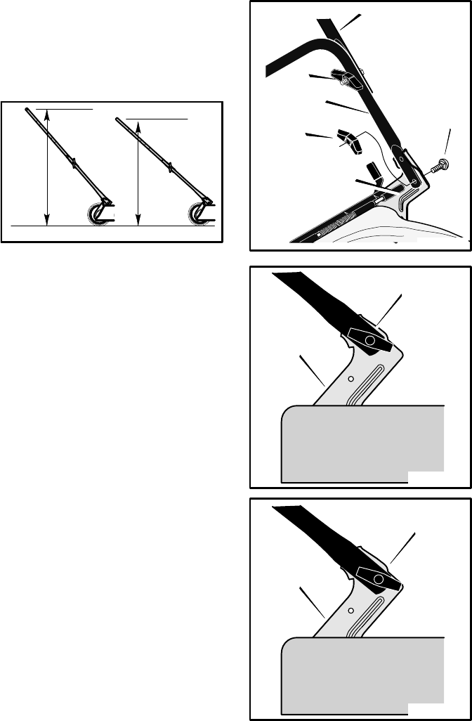
HOW TO ADJUST THE HANDLE HEIGHT
The handle bracket has two assembly posi-
tions. A HIGH and a LOW position (Figure 3).
The HIGH position will raise the handle ap-
proximately four inches.
Figure 3
LOW
HIGH
1. Remove the knobs and bolts from the
right and left handle brackets (Figure 4).
2. To raise the handle, mount the lower han-
dle in the HIGH position shown in Figure 5.
3. To lower the handle, mount the lower han-
dle in the LOW position shown in Figure 6.
4. Attach the lower handle to the handle
brackets with the bolts and knobs.
(Figure 4).
Knob
Lower
Handle
Handle
Bracket
Upper Handle
Figure 4
Knob Bolt
Figure 5
HIGH Position
Handle
Bracket
Figure 6
LOW Position
Handle
Bracket
PREPARATION
13
F-040411L
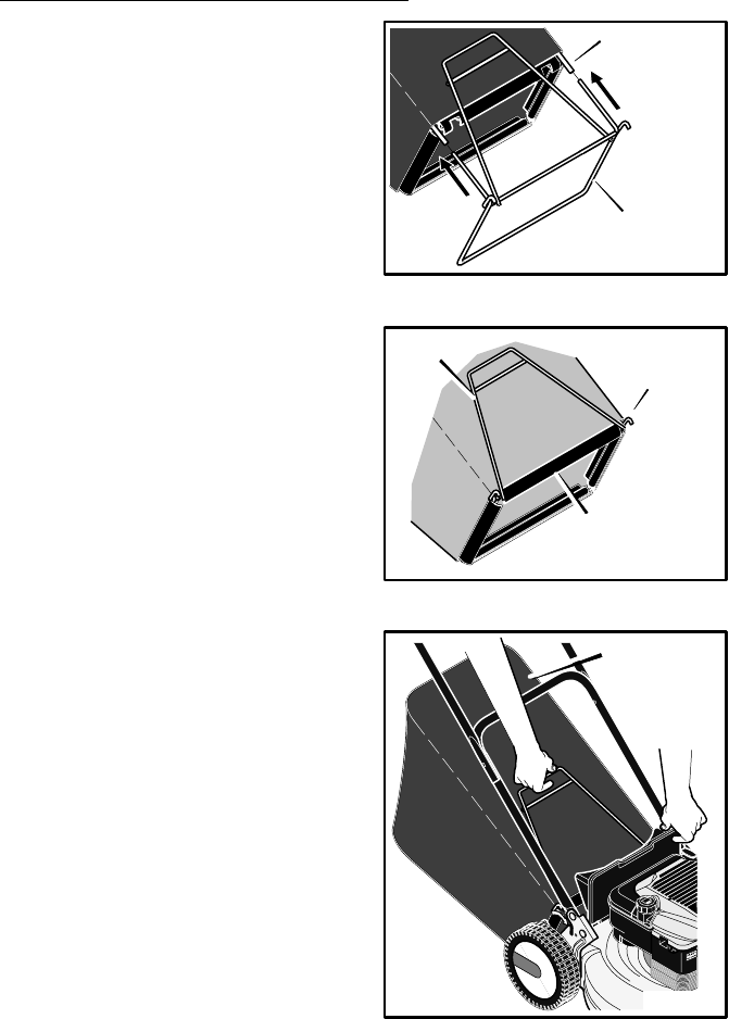
MODELS WITH OPTIONAL GRASS BAG
HOW TO ASSEMBLE THE GRASS BAG
1. Slide the frame assembly into the ends of
the support tube (Figure 7).
2. Make sure the handle is on the outside of
the grass bag (Figure 8).
3. Attach the clips to the frame assembly
(Figure 8).
4. Close the top cover. When operating the
mower with the grass bag, the top cover
must be in the closed operating position
(Figure 9).
Figure 7
Support Tube
Frame Assembly
Figure 8
Clips
Frame
Assembly
Handle
Figure 9
Top
Cover
PREPARATION
14
F-040411L
MODELS WITH OPTIONAL GRASS BAG
HOW TO MOUNT
THE GRASS BAG
1. To mount the grass bag on the mower,
raise the rear door. Hold the handle of the
grass bag. Put the grass bag in the
operating position (Figure 10). Lower the
rear door.
IMPORTANT: Make sure the hooks, on each
side of the frame assembly, are mounted
on the pivot rod.
WARNING: Do not use the grass
bag unless the cover is in the op-
erating postion.
Figure 10
Mount Frame
Hooks To Pivot Rod
Handle Bracket
Handle
Rear Door
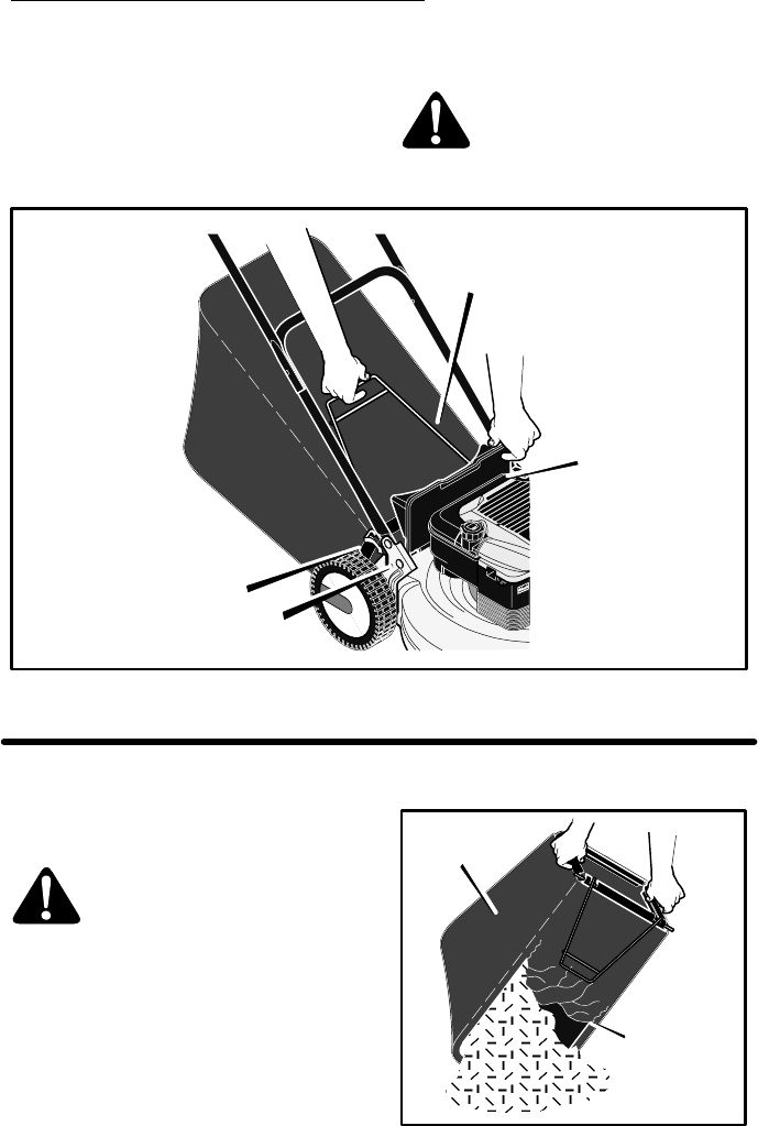
HOW TO EMPTY THE GRASS BAG
WARNING: Before you remove
the grass bag, stop the engine.
Before you remove any grass
from the mower housing,
disconnect the wire from the
spark plug.
1. Hold the rear door. Raise the rear door to
a vertical position (Figure 10).
2. Lift the frame assembly over the two
handle notches.
3. Open the top cover (Figure 11). Empty the
grass from the grass bag.
4. To mount the grass bag on the mower, see
“How To Mount The Grass Bag”. Figure 11
Top Cover
Grass Bag
PREPARATION
15
F-040411L
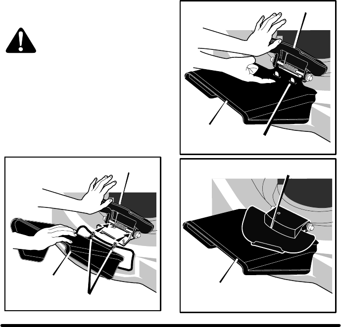
HOW TO ATTACH THE SIDE MOUNTED
DISCHARGE DEFLECTOR
WARNING: To prevent the en-
gine from starting, disconnect
the wire from the spark plug.
1. Raise the mulcher cover (Figure 12).
2. Slide the two tabs on the side deflector un-
der the pivot pin.
3. Lower the side deflector. Make sure the
locking tab goes through the slot in the side
deflector (Figure 13).
4. Lower the mulcher cover (Figure 14).
Figure 12
Side Deflector
Mulcher Cover
Tabs
Figure 13
Side Deflector
Mulcher Cover
Locking Tab
Figure 14
Side Deflector
Mulcher Cover
MULCHING TIPS
Mulching finely cuts the grass so that the grass
can be easily recycled. Because the nutrients
are returned to the soil, the lawn will need less
fertilizer. To correctly mulch the lawn, follow
the tips below.
SThe grass must be dry. If the grass is wet,
it will be difficult to cut and cause heavy
clumps of grass.
SThe grass must not be too tall. The maxi-
mum height to effectively cut is 4 1/2 in-
ches. Set the height adjusters so that only
the top third of the grass is cut.
SIf the grass is more than 4 1/2 inches high,
two mowings will be necessary. For the first
mowing, set the height adjusters in the
highest position. Then, lower the height ad-
justers for the second mowing.
SKeep a sharp edge on the blade. A blade
that is not sharp will cause the ends of the
grass to become brown.
SClean the underside of the mower housing.
Grass and other debris can keep the mow-
er from working correctly.
If the quality of cut is marginal, try the
following:
SSet the height adjusters at a higher cutting
height.
SCut the grass more frequently.
SOperate the mower at a slower ground
speed.
SOverlap the cutting swaths instead of cut-
ting a full swath with each pass.
SMow across the marginal areas a second
time.

PREPARATION
16
F-040411L
ELECTRIC START MODELS
When the mower was shipped from the facto-
ry, the battery was not fully charged. Before the
first use, the battery must be charged for 16
hours. See “How To Charge The Battery” in the
Maintenance section.
HOW TO PREPARE THE ENGINE
ENGINE DOES NOT CONTAIN
OIL OR GASOLINE
See the engine manufacturer’s instructions for
the type of gasoline and oil to use. Before you
use the unit, read the information on safety, op-
eration, maintenance, and storage.
WARNING: Follow the engine
manufacturer’s instructions for
the type of gasoline and oil to
use. Always use a safety gaso-
line container. Do not smoke
when adding gasoline to the en-
gine. When inside an enclosure,
do not fill with gasoline. Before
you add gasoline, stop the
engine. Let the engine cool for
several minutes.
IMPORTANT: This unit is equipped with an
internal combustion engine and must not
be used on or near any unimproved forest-
covered, brush-covered or grass-covered
land unless the engine’s exhaust system is
equipped with a spark arrester meeting
applicable local or state laws (if any). If a
spark arrester is used, it must be main-
tained in effective working order by the op-
erator.
In the State of California the above is re-
quired by law (Section 4442 of the Califor-
nia Public Resources Code). Other states
may have similar laws. Federal laws apply
on federal lands. See an Authorized Ser-
vice Center for a spark arrester for the
muffler.
ENGINE TIPPING
When you service the engine, inspect the
blade, or clean the underside of the mower
housing; make sure to always tip the engine
with the spark plug up (see Figure 15). Trans-
porting or tipping the engine with the spark
plug down will cause:
SHard starting.
SEngine smoking.
SSpark plug fouling.
SOil or gas saturation of the air filter.
Figure 15
IMPORTANT: Actual sustained horsepow-
er will likely be lower due to operating limi-
tations and environmental factory.
FINAL ASSEMBLY
Before you use the mower, check the assem-
bly of the wheels, the handle, and the controls.
Make sure all the fasteners are tight. Make
sure the throttle control and the engine stop le-
ver work correctly.
OPERATION
17
F-040411L
ENGINE STOP LEVER
Release the engine stop lever and the engine
and the blade will automatically stop. To run
the engine, hold the engine stop lever in the
Operating position (Figure 17).
Before you start the engine, operate the en-
gine stop lever several times. Make sure the
cable moves easily.
Figure 16
Engine Stop
Lever
Operating Position
FRONT WHEEL DRIVE SYSTEM
The mower has a front wheel drive system.
Operate the drive system as follows.
1. Hold the engine stop lever in the Operat-
ing Position (Figure 16 and Figure 17).
2. Push the drive lever completely forward.
When the drive lever clicks, release the
drive lever. The drive system is now en-
gaged.
NOTE: To stop the engine, release the
engine stop lever.
3. To disengage the drive system and stop
the engine, completely release the engine
stop lever.
4. To disengage only the drive system, re-
lease the engine stop lever approximate-
ly two inches. The drive system will
disengage but the engine will continue to
run.
NOTE: When the drive system is
disengaged on a new unit, it is possible for
the front wheels to rotate if lifted off the
ground. This is normal and will stop after
one or two hours of operation.
WARNING: For safe operation,
the drive system must immedi-
ately disengage when the drive
lever is released. If the drive
system does not disengage
correctly, do not operate the
mower until the drive system is
adjusted or repaired by an
authorized service center.
Figure 17
Hold the engine stop lever
in the Operating position.
To go forward, move the
drive lever forward.
Drive Lever
HOW TO STOP THE ENGINE
To stop the engine, release the engine stop
lever. Disconnect the wire from the spark plug
to prevent the engine from starting. On models
equipped with an electric start engine, remove
the key from the key switch. Keep the key
away from children.
If the engine will not stop, hold a screwdriver
against the spark plug and against the engine
cooling fins. The spark will go to ground and
the engine will stop. Before you start the en-
gine, check the engine stop cable. Make sure
the engine stop cable is assembled correctly.
Before you operate the unit, replace a bent or
damaged engine stop cable.
OPERATION
18
F-040411L
HOW TO START ENGINE
WARNING: The blade will rotate
when the engine runs.
IMPORTANT: Before you start the engine,
operate the engine stop lever several
times. Make sure the engine stop cable
moves freely.
NOTE: The engine design does not include
a throttle control or an engine speed ad-
justment. The engine is set at the best
speed for cutting grass, bagging grass,
and for extended engine life.
1. Check the oil.
2. Fill the fuel tank with regular unleaded gas-
oline. Make sure the gasoline is clean.
Leaded gasoline will increase deposits and
shorten the life of the valves.
NOTE: Do not use gasohol or methanol. Do
not use premium unleaded gasoline.
WARNING: Always use a safety
gasoline container. Do not smoke
when adding gasoline to the fuel
tank. When inside an enclosure,
do not add gasoline. Before you
add gasoline, stop the engine and
let the engine cool for several
minutes.
3. Make sure the spark plug wire is connected
to the spark plug.
4. Electric Start Models: Make sure the bat-
tery is connected to the wiring harness.
5. Make sure the drive lever is in the DISEN-
GAGED position (Figure 18).
Hold the engine stop lever
in the operating position.
Figure 18
Ignition Key
Drive Lever
WARNING: To prevent an acci-
dent, make sure the drive lever is
in the DISENGAGED position.
When the drive lever is in the EN-
GAGED position, do not start the
engine.
6. Some models have a primer button on the
front or side of the engine (Figure 19). Ev-
ery time you push the primer button, wait
two seconds. For the number of times re-
quired to push the primer button, see the
engine manufacturer’s instructions.
Primer Button Figure 19
NOTE: Do not use the primer button to
start a warm engine.
7. Stand behind the mower. Hold the engine
stop lever in the OPERATING position
(Figure 18).
8. Electric Start Models: Turn the ignition
key to the START position. Use short start-
ing cycles (15 seconds per minute). When
the engine starts, release the ignition key.
If the engine will not turn over, charge the
battery. See “How To Charge The Battery”.
9. Recoil-Start Models: Rapidly pull the re-
coil-start grip. Slowly return the recoil-
start grip.
10. If the engine does not start in 5 or 6 tries,
See the “Problem and Repair” Instructions.
HOW TO OPERATE THE MOWER
WARNING: Check the condition
of the grass bag for wear or dete-
rioration. If worn or damaged, re-
place the parts only with ap-
proved factory replacement
parts. For replacement parts,
see the parts list in this book.
To completely fill the grass bag, operate the
engine with the throttle control in the FAST
position.
MAINTENANCE
19
F-040411L
ELECTRIC START MODELS
HOW TO CHARGE THE BATTERY
WARNING: The battery contains
sulfuric acid which is harmful to
the skin, eyes and clothing. If
acid gets on the body or cloth-
ing, wash with water. Do not at-
tempt to open the battery. If the
battery has a crack, replace the
battery. Do not burn a damaged
or old battery or an explosion
can result.
WARNING: When you charge the
battery, do not smoke. Keep the
battery away from any sparks.
The fumes from the battery acid
can cause an explosion.
The battery is in the battery case mounted on
the handle. To charge the battery, remove the
battery case from the handle.
IMPORTANT: Make sure to use the battery
charger supplied with the mower. The use
of any other battery charger will damage
the battery.
1. Disconnect the wiring harness from the
battery (Figure 20).
2. Push the quick release on top of the bat-
tery case. Remove the battery case and
battery from the handle.
3. Attach the battery charger wire to the
battery. Connect the battery charger to an
electrical outlet.
4. Charge the battery for 16 hours.
5. Disconnect the battery charger from the
electrical outlet and from the battery.
6. Align the two tabs on the bottom of the bat-
tery case with the two holes in the battery
bracket. Rotate the battery case until the
quick release locks the battery in the OP-
ERATING position.
7. Connect the wiring harness to the bat-
tery. If the battery will not be used for a long
period of time or during storage, do not
connect the wiring harness to the battery.
Figure 20
Wiring Harness
Battery Case
Quick Release
Battery Bracket
Handle
Battery Charger Wire
HOW TO REMOVE THE BATTERY
If the engine will not turn over or turns over
slowly when the key is turned on, charge the
battery. See “How To Charge The Battery”. If
the battery will not charge fully and will not start
the engine, replace the battery as follows.
1. Disconnect the wiring harness from the
battery (Figure 20).
2. Push the quick release on top of the bat-
tery case. Remove the battery case and
battery from the handle.
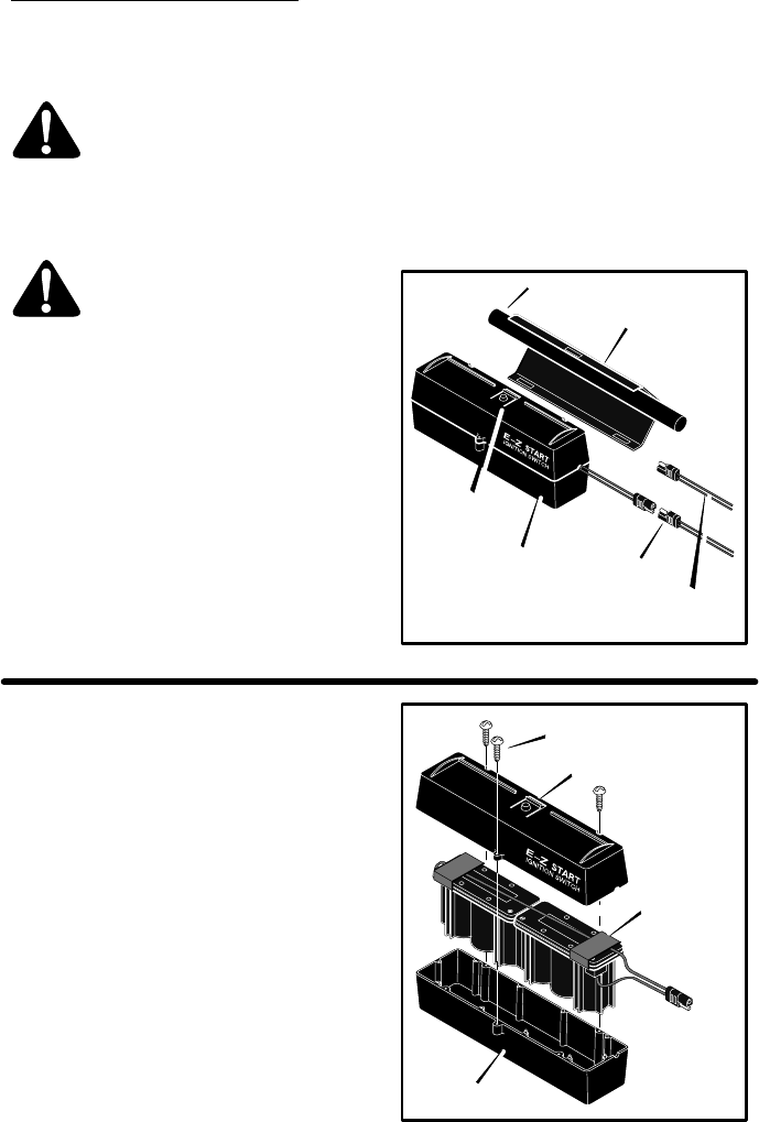
3. To open the battery case, remove the
three screws. Remove the battery from
the battery case (Figure 21).
4. Replace the battery with an authorized
factory replacement battery.
5. Charge the new battery for 16 hours. See
“How To Charge The Battery”.
6. To install the battery, reverse the above
steps. Figure 21
Screw
Battery Case
Battery
Battery Case

MAINTENANCE
20
F-040411L
ENGINE MAINTENANCE
Use the following maintenance section to keep
your unit in good operating condition. All the
maintenance information for the engine is in
the “Engine Instruction Book”. Before you start
the engine, read this book.
WARNING: Before you make an
inspection, adjustment (except
carburetor), or repair, stop the
engine and disconnect the wire
from the spark plug.
ENGINE TIPPING
When you service the engine, inspect the
blade, or clean the underside of the mower
housing; make sure to always tip the engine
with the spark plug up (see Figure 22). Trans-
porting or tipping the engine with the spark
plug down will cause:
SHard starting.
SEngine smoking.
SSpark plug fouling.
SOil or gas saturation of the air filter.
Figure 22
HOW TO CLEAN
THE MOWER HOUSING
WARNING: The blade will rotate
when the engine runs. Before
you clean the mower housing,
stop the engine and disconnect
the wire from the spark plug.
Grass and other debris can keep the mower
from working correctly. After you mow, clean
the mower housing as follows.
1. Stop the engine.
2. Disconnect the wire from the spark plug.
3. Clean the top and the bottom of the mower
housing.
LUBRICATION
1. For maximum performance, lubricate the
wheels and all pivot points with engine oil
every 25 hours.
2. To lubricate the engine, refer to the “En-
gine Instruction Book”.
NOTE: Do not lubricate the engine stop
cable. Lubricants will damage the cable
and prevent the cable from moving freely.
Replace the cable if bent or damaged.
HOW TO ADJUST
THE HEIGHT OF CUT
WARNING: The blade will rotate
when the engine runs. Before
you change the height of cut,
stop the engine and disconnect
the wire from the spark plug.
To change the height of cut, move the position
of the adjuster arm at each wheel (Figure 23).
Make sure each adjuster arm is in the same
position so that the mower will cut level.
1. Disengage the adjuster arm.
2. Move the adjuster arm to another posi-
tion.
Adjuster
Arm
Figure 23
MAINTENANCE
21
F-040411L
HOW TO REMOVE THE DRIVE BELT
WARNING: Before you remove
the belt, disconnect the wire
from the spark plug.
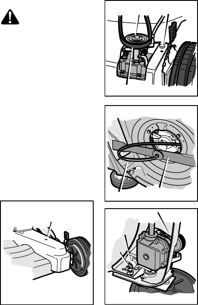
1. Remove the belt cover (Figure 24).
2. Loosen the belt tension bolt (Figure 25).
3. Remove the front of the drive belt from
the transmission pulley.
4. To remove the rear of the drive belt, slip
the drive belt over the end of the blade
(Figure 26).
NOTE: Make sure you replace the drive
belt only with a replacement belt from
the factory.
5. To assemble the drive belt, reverse the
above steps.
6. Set the belt tension.
a. Tighten the adjuster nut until the nut
touches the spacer (Figure 27). Try to
turn the spacer. When the adjuster
nut touches the spacer, the spacer
will not turn.
b. Then, loosen the adjuster nut only
enough to allow the spacer to turn.
The tension on the drive belt is now
correct.
7. Install the belt cover (Figure 24).
8. Before you begin to mow, make sure the
drive system will correctly disengage and
that the mower will stop. If the drive system
will not disengage, take the mower to an
authorized service center before you op-
erate the mower.
Figure 24
Belt Cover
Figure 25
Belt Tension Bolt
Transmission
Pulley
Drive Belt
Figure 26
Belt Tension Bolt Blade
Figure 27
Adjuster
Nut
Spacer
MAINTENANCE
22
F-040411L
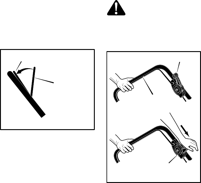
HOW TO ADJUST THE DRIVE CABLE
WARNING: Before you adjust the
drive cable, release the engine
stop lever and wait for the engine
to stop.
If the drive system does not engage and disen-
gage correctly, check the handle for correct as-
sembly. Make sure that all parts are in good
condition, not broken or bent, and that all fas-
teners are tight.
Worn parts and cable stretch will change the
performance of the drive system. When you
mow in high or thick grass or on hills, the drive
system can slip. If the drive system is slipping,
adjust as follows or take the mower to an au-
thorized service center.
IMPORTANT: Before you start the engine,
operate the engine stop lever several
times. Make sure the engine stop cable
moves freely.
NOTE: The engine design does not include
a throttle control or an engine speed ad-
justment. The engine is set at the best
speed for cutting grass, bagging grass,
and for extended engine life.
1. If the drive system is slipping, turn the
cable adjuster one turn in the direction
shown in Figure 28. Test the drive system
and check for slippage.
2. If the drive system still slips, turn the cable
adjuster one more turn to shorten the
cable. Again, test the drive system.
3. Repeat the adjustment and test until the
drive system does not slip.
4. Before you begin to mow, make sure the
drive system will correctly disengage and
that the mower will stop. If the drive system
will not disengage, take the mower to an
authorized service center before you oper-
ate the mower.
Cable Adjuster Figure 28
MAINTENANCE
23
F-040411L
BLADE SERVICE
WARNING: Before you inspect
the blade or the blade adapter,
disconnect the wire to the spark
plug. If the blade hits an object,
stop the engine. Disconnect the
wire to the spark plug. Check the
unit for damage.
Frequently check the blade for wear or dam-
age such as cracks. Frequently check the bolt
that holds the blade. Keep the bolt tight. If the
blade hits an object, stop the engine. Discon-
nect the wire to the spark plug. Check the
blade adapter for damage. Check for a bent or
damaged blade, a badly worn blade, or other
damage. Before you operate the unit, dam-
aged parts must be replaced with factory re-
placement parts. For safety, replace the blade
every two years. Keep a sharp edge on the
blade. A blade that is not sharp will cause the
ends of the grass to become brown. Remove
the blade as follows.
HOW TO REMOVE THE BLADE
WARNING: Before you remove
the blade, disconnect the wire to
the spark plug. The blade has
sharp edges. When you hold the
blade, use gloves or cloth materi-
al to protect your hands.
1. Drain the fuel tank.
2. Lift the side of the mower that has the
muffler or spark plug.
3. Use a piece of wood to keep the blade
from rotating.
4. Remove the bolt that holds the blade.
5. Check the blade according to the “Blade
Service” instructions. Replace a badly
worn or damaged blade with a factory re-
placement blade.
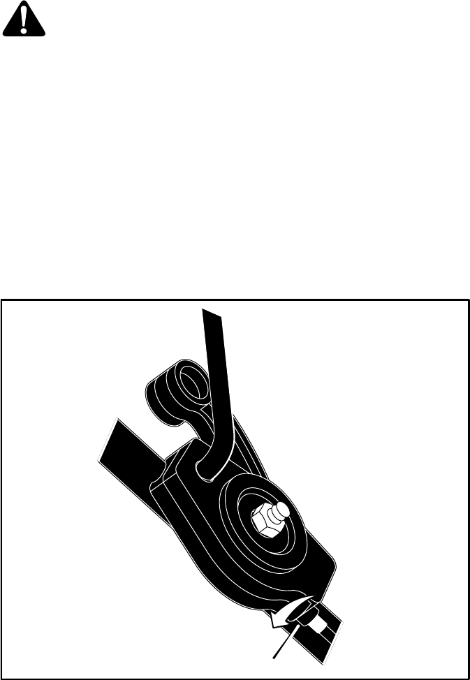
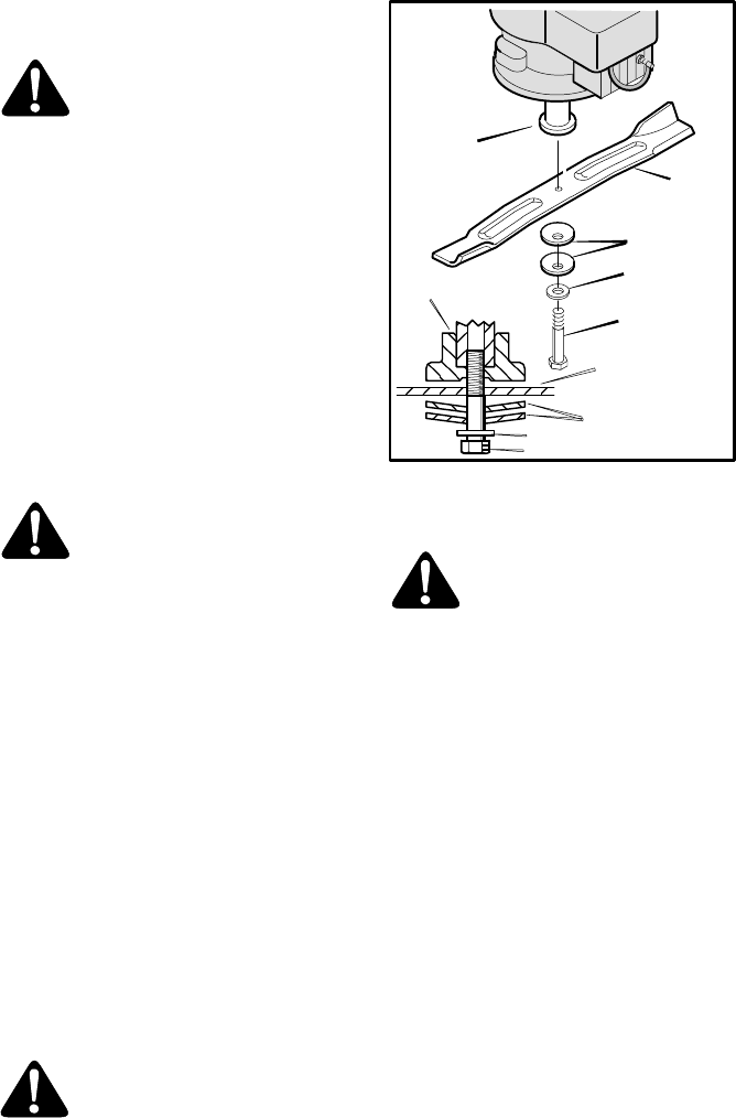
6. Mount the blade with the curved edges to-
ward the housing. If the blade is upside
down, the blade will not cut correctly and
can cause an accident.
7. Fasten the blade with the original wash-
ers and bolt. Make sure the outside rims
of the Belleville washers are toward the
blade (Figure 29).
8. Tighten the bolt that holds the blade to a
torque of 30 foot pounds.
WARNING: Always keep the bolt
that holds the blade tight. A loose
bolt or blade can cause an acci-
dent.
Blade Adapter
Blade
Belleville
Washer
Washer
Bolt
Figure 29
Belleville Washer
Mulching Blade
Bolt
Blade Adapter
Flat Washer
HOW TO SHARPEN THE BLADE
WARNING: Vibration is the result
if the blade is not correctly bal-
anced. A blade that is damaged
with cracks can break and cause
an accident.
1. Sharpen the blade two times a year or ev-
ery 25 hours.
2. If the blade is on the unit, do not sharpen.
Remove the blade according to the in-
structions in “How To Remove The Blade”.
3. Clean the blade with a brush, soap, and
water. Check the blade. Look for cracks,
nicks, or other damage. Replace a blade
that is badly worn, bent, or damaged with
a factory replacement blade.
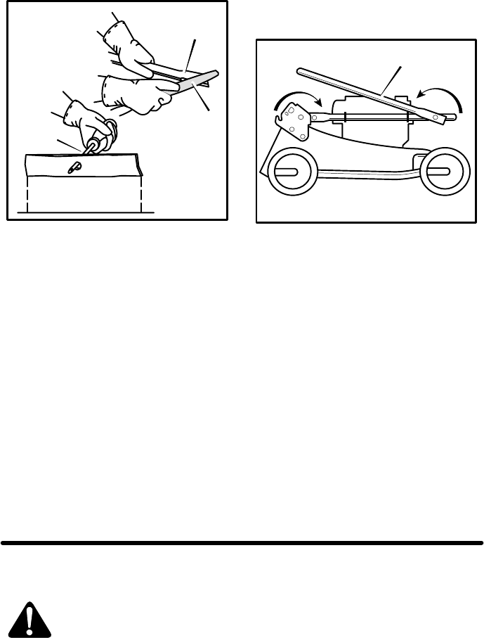
4. Sharpen the blade with a file. Make sure
you keep the original beveled cutting edge
(Figure 30).
5. Make sure the blade is balanced. Use a
screwdriver and hold the blade parallel to
the ground as shown. A blade that is bal-
anced will stay parallel to the ground. If the
blade is not balanced, the heavy end will
rotate toward the ground. Sharpen the
heavy end until the blade is balanced.
6. A new blade will cut better than a badly
worn blade. Every two years replace the
old blade with a factory replacement
blade.
(Continued following page)
MAINTENANCE
24
F-040411L
Ground
Blade is balanced
when parallel to
the ground.
Screwdriver
Blade
File
Figure 30
CHECK THE LEVEL OF CUT
Test the unit in a small area. If the height of cut
is not level or if the cut grass is not discharged,
the cause can be: (1) the blade is bent or dam-
aged, (2) the blade is not sharp, (3) a worn
blade, (4) or a broken blade adapter. Before
you use the unit, correct the problem.
STORAGE FOR HANDLES THAT FOLD
CAUTION: Be careful when you fold or
raise the handle. Do not damage the
cables. A cable that is bent will not work
correctly. Before you use the unit, replace a
bent or damaged cable.
How To Fold The Handle
1. Loosen the fasteners that hold the upper
part of the handle to the lower part of the
handle. As you fold the handle, make sure
the cables are not around the loose fasten-
ers and do not become damaged. Rotate
the upper part of the handle back
(Figure 31).
2. Loosen the knobs on the lower handle.
Push in on the ends of the lower handle.
3. Rotate the handle forward over the engine
as shown. Make sure the cables are not
damaged.
Folding Handle
Figure 31
How To Raise The Handle
1. Pull the handle back until the ends of the
lower handle lock into position. Tighten the
knobs.
2. Lift the upper part of the handle into the op-
erator’s position. Tighten the fasteners
that hold the handle.
STORAGE FOR
NON-FOLDING UPPER HANDLES
For storage, fold the handle forward.
How To Fold The Handle
1. Push in on the ends of the lower handle.
Move the ends of the lower handle past the
locking tabs.
2. Rotate the handle forward over the en-
gine. Make sure the cables are not dam-
aged.
How To Raise The Handle
1. Pull the handle back until the ends of the
lower handle lock into position.
HOW TO PREPARE
THE MOWER FOR STORAGE
WARNING: Do not remove gaso-
line while inside a building, near
a fire, or while you smoke.
Gasoline fumes can cause an
explosion or a fire.
1. Drain the fuel tank.
2. Let the engine run until it is out of gasoline.
3. Drain the oil from the warm engine. Fill the
engine crankcase with new oil.
4. Remove the spark plug from the cylinder.
Pour one ounce of oil into the cylinder.
Slowly pull the recoil-start grip so that the
oil will protect the cylinder. Install a new
spark plug in the cylinder.
5. Clean the dirt and debris from the cylinder
cooling fins and the engine housing.
6. Clean the bottom of the mower housing.
7. Make sure the grass bag is empty of grass.
Grass remaining in the bag during storage
will damage the bag.
8. Completely clean the mower to protect the
paint.
9. Put the unit in a building that has good ven-
tilation.
TROUBLE SHOOTING CHART
25
F-040411L
The Engine will not start.
1. Move the throttle control lever to the FAST or START position.
2. Make sure the fuel tank is filled with clean gasoline. Do not use old gasoline.
3. On a cold engine, push the primer button (optional on some models) five times.
4. Make sure the wire for the spark plug is connected to the spark plug.
5. Adjust the Carburetor. See the “Engine Instruction Book”.
6. There is too much gasoline in the engine cylinder. Remove and dry the spark plug. Put the
throttle control in the SLOW position. Pull the recoil-start grip several times. Install the spark
plug. Connect the wire to the spark plug. Start the engine.
7. The engine is difficult to start in heavy or high grass. Move the mower to a clean dry surface.
8. Make sure the engine stop lever is in the operating position.
9. Make sure the fuel valve is in the ON position. See the “Engine Instruction Book”.
10. On electric start models, make sure the wiring harness is connected. Charge the battery.
The Engine will not stop.
1. Release the engine stop lever.
2. Check the engine stop cable. Replace the cable if bent or damaged.
The Engine performance is bad.
1. Check the height of cut settings. Raise the height of cut if the grass is high.
2. Check the bottom of the blade housing. Clean the blade housing of grass and other debris.
3. Check the wire to the spark plug. Make sure the wire is connected.
4. Clean the engine cooling fins of grass and other debris.
5. Check the carburetor adjustments. See the “Engine Instruction Book”.
6. Check the spark plug gap. Set the spark plug gap at 0.030”.
7. Check the amount of oil in the engine. Fill with oil if necessary.
8. Check the engine air cleaner. See the “Engine Instruction Book”.
9. The gasoline is bad. Drain and clean the fuel tank. Fill the fuel tank with clean gasoline.
10. Check the throttle control. Make sure the lever is not in the CHOKE position.
Excessive Vibration.
1. Remove the blade. Check the blade and balance if necessary. See the blade maintenance
instructions.
2. Check for a bent or broken blade. A DAMAGED BLADE IS DANGEROUS AND MUST BE
REPLACED.
3. Check the blade adapter. REPLACE A BROKEN BLADE ADAPTER.
4. If the vibration continues, take the mower to an Authorized Service Center.
The grass will not discharge correctly.
1. Clean the bottom of the mower housing.
2. Check for a badly worn blade. Remove and sharpen the blade. For safety, replace the blade
every two years with a factory replacement blade.
3. Move the throttle control lever to the FAST position. Check the speed of the engine according
to the “Engine Instruction Book”.
The grass is not cut even.
1. Check the height adjustment at each wheel. The height adjustment must be the same for each
wheel.
2. Make sure the blade is sharp.
3. Check for a bent or broken blade. A DAMAGED BLADE IS DANGEROUS AND MUST BE
REPLACED.
4. Check for a broken blade adapter. REPLACE A BROKEN BLADE ADAPTER.
NOTES
26
F-040411L
NOTES
27
F-040411L

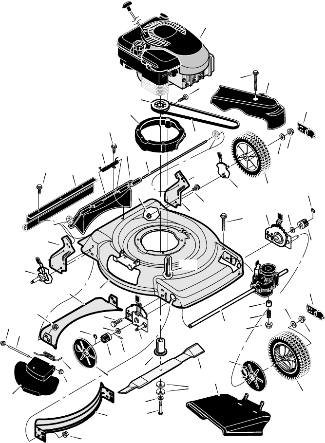
MULCHER MODELS
28
F-040411L
1
2
3
4
5
6
7
8
10
11
12
13
23
25
24
26
45
46
24
25
23
34
37 42
40
41
39
38
34
32
31
30
29
62
29
28
31 30
44
43
44
48
49
50
51
54
50
53
59 61
60
59
58 57
55
52
14
MULCHER MODELS
29
F-040411L
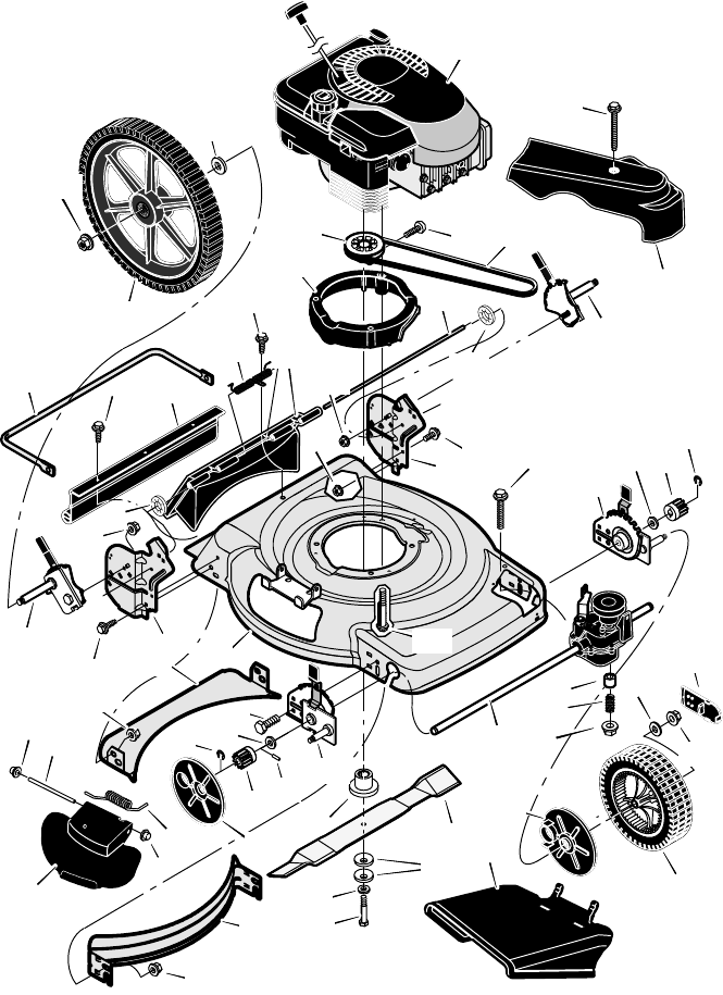
KEY
NO. PART NO. DESCRIPTION KEY
NO. PART NO. DESCRIPTION
1 1101340E717 Housing
2 − − − − − Engine *
3 1101653 Pulley, Drive
4 1101331
1101332
Spacer, Engine (Black)
Spacer, Engine (Gray)
5 1101596
1101568
Cover, Belt (Black)
Cover, Belt (Gray)
6 26x304 Screw
7 672605 Adjuster, Left Rear
Height
8 26x303 Screw
10 1101571 Transmission − Note:
There are no internal
serviceable parts for
the transmission.
11 043844 Spacer
12 164x27 Spring, Compression
13 015x88 Nut
14 01x156 Bolt
23 011x16 E−Ring
24 17x186 Washer
25 071792 Gear, Pinion
26 1101029 Adjuster, Left Front
Height
28 37x123 Belt
29 672122 Cap, Hub
30 015x84 Nut, Flange
31 17x169 Washer
32 071133 Wheel & Tire, Front
34 071780 Cover, Dust
37 043629 Pin, Drive
38 1101120E701 Blade
39 17x137 Washer, Belleville
40 17x124 Washer
41 01x144 Bolt
42 1101336 Adapter, Blade
43 672915E700 Baffle, Front **
44 015x68 Nut, Flange
45 1101028 Adjuster, Right Front
Height
46 001x85 Bolt
48 672916E700 Baffle, Rear **
49 672604 Adjuster, Right Rear
Height
50 028x49 Retainer, Push
51 1101238E701 Bracket, Right Handle
52 015x79 Nut, Flange
53 001x45 Bolt
54 1101239E701 Bracket, Left Handle
55 025x11 Bolt, Engine
57 215x21 Rod, Pivot
58 672611
672713
Door, Rear (Black)
Door, Rear (Gray)
59 26x245 Screw
60 166x44 Spring
61 1101105 Guard, Rear
62 071132 Wheel & Tire, Rear
− − F−040411L Book, Instruction
* Parts are available from an Authorized Engine Service Center. See Engines, Gasoline" or Gasoline
Engines" in the yellow pages of the telephone directory.
* * Included with Housing, Key No. 1.
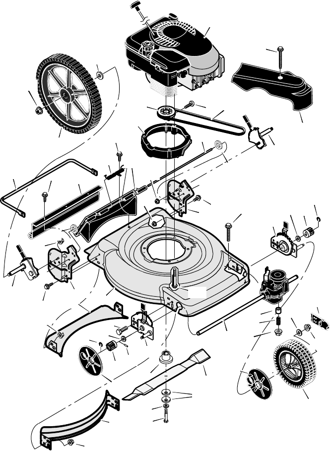
SIDE DISCHARGE MODELS
30
F-040411L
1
2
3
4
5
6
7
8
10
11
12
13
23
25
24
26
45
46
24
25
23
34
37 42
40
41
39
38
34
32
31
30
29
62
29
28
31 30
44
43
44
48
49
50
51
54
50
53
59 61
60
59
58 57
55
52
66
70
67
69
67 68
14
SIDE DISCHARGE MODELS
31
F-040411L
KEY
NO. PART NO. DESCRIPTION KEY
NO. PART NO. DESCRIPTION
1 1101340E717 Housing
2 − − − − − Engine *
3 1101653 Pulley, Drive
4 1101331
1101332
Spacer, Engine (Black)
Spacer, Engine (Gray)
5 1101596
1101568
Cover, Belt (Black)
Cover, Belt (Gray)
6 26x304 Screw
7 672605 Adjuster, Left Rear
Height
8 26x303 Screw
10 1101571 Transmission − Note:
There are no internal
serviceable parts for
the transmission.
11 043844 Spacer
12 164x27 Spring, Compression
13 15x88 Nut
14 01x156 Bolt
23 011x16 E−Ring
24 17x186 Washer
25 071792 Gear, Pinion
26 1101029 Adjuster, Left Front
Height
28 37x123 Belt
29 672122 Cap, Hub
30 015x84 Nut, Flange
31 17x169 Washer
32 071133 Wheel & Tire, Front
34 071780 Cover, Dust
37 043629 Pin, Drive
38 1101120E701 Blade
39 17x137 Washer, Belleville
40 17x124 Washer
41 01x144 Bolt
42 1101336 Adapter, Blade
43 672915E700 Baffle, Front **
44 015x68 Nut, Flange
45 1101028 Adjuster, Right Front
Height
46 001x85 Bolt
48 672916E700 Baffle, Rear **
49 672604 Adjuster, Right Rear
Height
50 028x49 Retainer, Push
51 1101238E701 Bracket, Right Handle
52 015x79 Nut, Flange
53 001x45 Bolt
54 1101239E701 Bracket, Left Handle
55 025x11 Bolt, Engine
57 215x21 Rod, Pivot
58 672611
672613
Door, Rear (Black)
Door, Rear (Gray)
59 26x245 Screw
60 166x44 Spring
61 1101105 Guard, Rear
62 071132 Wheel & Tire, Rear
66 1101097
672917
Deflector, Chute (Black)
Deflector, Chute (Gray)
67 028x42 Push On Cap
68 215x19 Z Rod, Pivot
69 166x38 Spring, Torsion
70 1101098
672920
Cover, Mulch (Black)
Cover, Mulch (Gray)
− − F−040411L Book, Instruction
* Parts are available from an Authorized Engine Service Center. See Engines, Gasoline" or Gasoline
Engines" in the yellow pages of the telephone directory.
* * Included with Housing, Key No. 1.
MULCHER MODELS WITH 14” REAR WHEELS
32
F-040411L
52
46
23
56
54 53
46
44
42
45
44
44
24
37
25
34
49
7
44
62
38
30
47
39
40
41
61
59
58
59
1
43
48
50
50
57
60
2
38
4
28
26
34
32
31
29
23
24
30
25
6
5
55
51
10
11
12
13
14
MULCHER MODELS WITH 14” REAR WHEELS
33
F-040411L
KEY
NO. PART NO. DESCRIPTION KEY
NO. PART NO. DESCRIPTION
1 − − − − − Housing
2 − − − − − Engine *
3 1101653 Pulley, Drive
4 1101331
1101332
Spacer, Engine (Black)
Spacer, Engine (Gray)
5 1101596
1101568
Cover, Belt (Black)
Cover, Belt (Gray)
6 26x304 Screw
7 672919 Adjuster, Left Rear
Height
8 26x303 Screw
10 1101571 Transmission − Note:
There are no internal
serviceable parts for
the transmission.
11 043844 Spacer
12 164x27 Spring, Compression
13 015x88 Nut
14 01x156 Bolt
23 011x16 E−Ring
24 17x186 Washer
25 071792 Gear, Pinion
26 1101029 Adjuster, Left Front
Height
28 37x123 Belt
29 672122 Cap, Hub
30 015x84 Nut, Flange
31 17x169 Washer
32 071133 Wheel & Tire, Front
34 071780 Cover, Dust
37 043629 Pin, Drive
38 1101120E701 Blade
39 17x137 Washer, Belleville
40 17x124 Washer
41 01x144 Bolt
42 1101336 Adapter, Blade
43 672915E700 Baffle, Front * *
44 015x68 Nut, Flange
45 1101028 Adjuster, Right Front
Height
46 001x85 Bolt
47 0020x3 Washer
48 672916E700 Baffle, Rear * *
49 672918 Adjuster, Right Rear
Height
50 028x49 Retainer, Push
51 1101244E701 Bracket, Right Handle
52 015x68 Nut, Flange
53 001x85 Bolt
54 1101245E701 Bracket, Left Handle
55 025x11 Bolt, Engine
56 1101008E701 Brace
57 215x21 Rod, Pivot +
58 1101070
672613
Door, Rear (Black)
Door, Rear (Gray)
59 26x245 Screw
60 166x44 Spring +
61 672684 Guard, Rear
62 071841 Wheel & Tire, Rear
− − F−040411L Book, Instruction
* Parts are available from an Authorized Engine Service Center. See Engines, Gasoline" or Gasoline
Engines" in the yellow pages of the telephone directory.
* * Included with Housing, Key No. 1.
+ Included with Key No. 58.
SIDE DISCHARGE MODELS WITH 14" REAR WHEELS
34
F-040411L
52
46
23
56
54 53
46
44
42
45
44
44
24
37
25
34
49
7
44
62
38
30
47
39
40
41
61
59
58
59
1
43
48
50
50
57
60
2
38
4
28
26
34
32
31
29
23
24
30
25
6
5
55
51
66
70
67
69
67 68 10
11
12
13
14
SIDE DISCHARGE MODELS WITH 14" REAR WHEELS
35
F-040411L
KEY
NO. PART NO. DESCRIPTION KEY
NO. PART NO. DESCRIPTION
1 1101340E717 Housing
2 − − − − − Engine *
3 1101653 Pulley, Drive
4 1101331
1101332
Spacer, Engine (Black)
Spacer, Engine (Gray)
5 1101596
1101568
Cover, Belt (Black)
Cover, Belt (Gray)
6 26x304 Screw
7 672919 Adjuster, Left Rear
Height
8 26x303 Screw
10 1101571 Transmission − Note:
There are no internal
serviceable parts for
the transmission.
11 043844 Spacer
12 164x27 Spring, Compression
13 015x88 Nut
14 01x156 Bolt
23 011x16 E−Ring
24 17x186 Washer
25 071792 Gear, Pinion
26 1101029 Adjuster, Left Front
Height
28 37x123 Belt
29 672122 Cap, Hub
30 015x84 Nut, Flange
31 17x169 Washer
32 071133 Wheel & Tire, Front
34 071780 Cover, Dust
37 043629 Pin, Drive
38 1101120E701 Blade
39 17x137 Washer, Belleville
40 17x124 Washer
41 01x144 Bolt
42 1101336 Adapter, Blade
43 672915E700 Baffle, Front * *
44 015x68 Nut, Flange
45 1101028 Adjuster, Right Front
Height
46 001x85 Bolt
47 0020x3 Washer
48 672916E700 Baffle, Rear * *
49 672918 Adjuster, Right Rear
Height
50 028x49 Retainer, Push
51 1101244E701 Bracket, Right Handle
52 015x68 Nut, Flange
53 001x85 Bolt
54 1101245E701 Bracket, Left Handle
55 025x11 Bolt, Engine
56 1101008E701 Brace
57 215x21 Rod, Pivot +
58 1101070
672613
Door, Rear (Black)
Door, Rear (Gray)
59 26x245 Screw
60 166x44 Spring +
61 672684 Guard, Rear
62 071841 Wheel & Tire, Rear
66 1101097
672917
Deflector, Chute (Black)
Deflector, Chute (Gray)
67 028x42 Push On Cap
68 215x19 Z Rod, Pivot
69 166x38 Spring, Torsion
70 1101098
672920
Cover, Mulch (Black)
Cover, Mulch (Gray)
− − F−040411L Book, Instruction
* Parts are available from an Authorized Engine Service Center. See Engines, Gasoline" or Gasoline
Engines" in the yellow pages of the telephone directory.
* * Included with Housing, Key No. 1.
+ Included with Key No. 58.
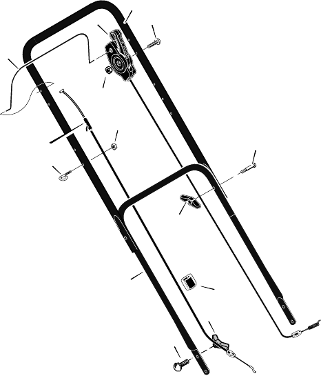
HANDLE - RECOIL-START MODELS
36
F-040411L
1
2
3
4
8
12
13
16
5
6
5
29
31
7
KEY
NO. PART NO. DESCRIPTION KEY
NO. PART NO. DESCRIPTION
1 1101557E701
1101557E724
Handle, Upper (Black)
Handle, Upper (Gray)
2 672906E701
672906E724
Handle, Lower (Black)
Handle, Lower (Gray)
3 025x14 Bolt
4 1101670 Control, Drive
5 15x116 Locknut
6 1101365
1101366
Cable, Stop (Briggs)
Cable, Stop, (Tecumseh)
7 1101353 Fastener, Double Cable
8 1101076E701 Lever, Stop
12 002x77 Bolt
13 071294 Knob
16 071530 Guide, Rope
29 002x81 Bolt, Carriage
31 071495 Knob, Plastic
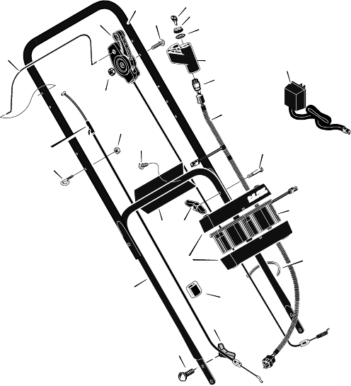
HANDLE - ELECTRIC-START MODELS
37
F-040411L
1
2
3
4
8
12
13
27
17
18
20
21
22
23
24
25
26
10
16
5
6
5
29
31
7
11
KEY
NO. PART NO. DESCRIPTION KEY
NO. PART NO. DESCRIPTION
1 1101557E701
1101557E724
Handle, Upper (Black)
Handle, Upper (Gray)
2 672907E701
672907E724
Handle, Lower (Black)
Handle, Lower (Gray)
3 025x14 Bolt
4 1101670 Control, Drive
5 15x116 Locknut
6 1101365
1101366
Cable, Stop (Briggs)
Cable, Stop (Tecumseh)
7 1101353 Fastener, Double Cable
8 1101076E701 Lever, Stop
10 26x220 Screw
11 071372 Fastener, Cable
12 002x77 Bolt
13 071294 Knob
16 071530 Guide, Rope
17 091488 Cap
18 091489 Nut
20 1101602 Cover, Ignition
21 776011 Switch Ignition & Key
22 671992 Charger, Battery
23 250x110 Harness, Wiring
24 776014 Battery
25 776013 Case, Battery
26 671959E701 Bracket, Battery
27 672220 Key, Ignition
29 002x81 Bolt, Carriage
31 071495 Knob, Plastic
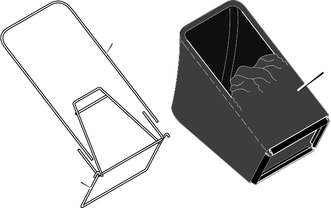
GRASS BAG
38
F-040411L
1
2
3
KEY
NO. PART NO. DESCRIPTION
1 1101075 Tube, Bag
2 1101074 Frame Assembly
3 1101005 Bag, Cloth
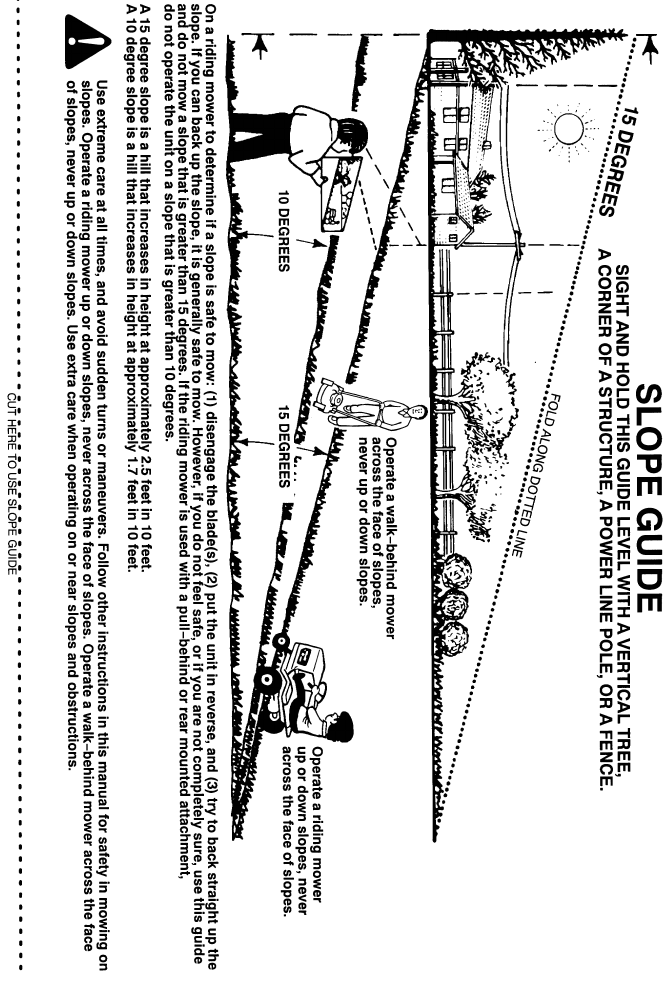
39
F-040411L
HOW TO ORDER REPAIR PARTS
F-040411L
Only use a factory repair part. Repair parts, except for the engine or the transmission, are available from the store where
the unit was purchased, a service shop recommended by the store, or an authorized service shop found in the yellow
pages of the telephone directory. If you cannot get a repair part or service as described above, call or write to the Central
Parts Distributor shown below. When you order, include the following information: (1) Complete Model Number (see
nameplate), (2) Date of Manufacture, (3) Complete Part Number, (4) Description, (5) Quantity.
Repair parts for the engine or the transmission are available from the manufacturer’s authorized service center found
in the yellow pages of the telephone directory. See the individual engine or transmission warranties.
MURRAY, INC. LAWN MOWER CENTRAL PARTS DISTRIBUTORS
BILLIOU’S, INC.
1343 South Main St.
Porterville, CA. 93257
(559)784−41021−877−245−5468
FAX 1−800−266−7337
Arizona, California, Hawaii,
Nevada
BROWN & WISER, INC.
9991 S.W. Avery Street
Tualatin, OR. 97062
(503)692−03301−800−882−4782
FAX (503)691−2041
Alaska, Idaho (counties Ada,
Adams, Benewah, Boise, Bonner,
Boundry, Canyon, Clearwater,
Elmore, Gem, Idaho, Kooten,
Latah, Lewis, NEZ Perce, Owyee,
Payette, Ravalli, Shoshone, Valley,
Washington), Montana (counties
Flathead, Lake, Lincoln, Mineral,
Missoulo, Ravalli, Sanders),
Oregon, Washington
CPT CANADA POWER
TECHNOLOGY LIMITED
Mississauga
161 Watline Avenue
Mississauga, Ontario
L4Z−1P2
(905)890−69001−800−861−9559
Edmonton
101−10411−178 Street
Edmonton, Alberta
T5S 1R5
(780)453−57911−800−861−9559
Ville St−Laurent
234 Migneron Street
Ville St−Laurent, Quebec
H4T 1Y7
(514)731−35591−800−861−9559
Canada
FRANK EDWARDS CO.
3626 Parkway Blvd.
West Valley City, UT 84120
1−800−318−0201
FAX (801)736−8067
Colorado, Idaho (counties
Bannock Bearlake, Bingham,
Blaine, Booneville, Butte, Camas,
Caribou, Cassia, Custer, Franklin,
Fremont, Gooding, Jefferson,
Jerome, Lemhi, Lincoln, Madison,
Minidoka, Oneida, Power, Teton,
Twin Falls) Montana (all counties
except Flathead, Lake, Lincoln,
Mineral, Missoulo, Ravalli,
Sanders), Utah, Wyoming
GARDNER, INC.
3641 Interchange Road
Columbus, OH. 43204−1499
1−800−848−8946
FAX 1−800−626−4735
Alabama, Arkansas, (except these
counties: Hempstead, Howard,
Lafayette, Little River, Miller,
Nevada, Pike, Sevier),
Connecticut, Delaware, District
of Columbia, Florida, Georgia,
Illinois (South of Hwy. 80),
Indiana, Iowa, Kansas, Kentucky,
Louisiana, Maine, Maryland,
Massachusetts, Michigan (except
upper Peninsula), Mississippi,
Missouri, Nebraska, New
Hampshire, New Jersey, New
York, North Carolina, Ohio,
Pennsylvania, Rhode Island,
South Carolina, Tennessee,
Vermont, Virgina, West Virginia
Puerto Rico
GULF COAST ENGINE, INC.
4202 Russell Dr.
Corpus Christi, TX. 78408
1−800−825−6999
FAX (888)888−7036
Arkansas (counties Hempstead,
Howard, Lafayette, Little River,
Miller, Nevada, Pike, Sevier) New
Mexico, Oklahoma, Texas,
Mexico
WISCONSIN MAGNETO
4727 N. Teutonia Ave.
Milwaukee, WI. 53209
1−800−733−7388
FAX 1−800−733−0127
Illinois (N. of Hwy. 80), Michigan
(upper Peninsula), Minnesota,
North Dakota, South Dakota,
Wisconsin
