N1 Manual
User Manual:
Open the PDF directly: View PDF ![]() .
.
Page Count: 19

N1 Manual
Dirk Heisswolf
January 23, 2019
Revision History
Date Change
January 23, 2019 Pre-release
1

CONTENTS CONTENTS
Contents
1 Glossary 5
2 Overview 7
3 Instruction Set 8
3.1 Return from a Call (;)........................... 9
3.2 Jump Instructions ............................. 9
3.3 Call Instructions .............................. 9
3.4 Conditional Branches ............................ 9
3.5 Literals ................................... 9
3.6 ALU Instructions .............................. 9
3.7 Stack Instructions ............................. 11
3.8 Memory Access Instructions ........................ 14
3.9 Control Instructions ............................ 14
4 ANS Forth Words 15
5 Stacks 16
5.1 Parameter Stack .............................. 16
5.2 Return Stack Stack ............................. 17
2


LIST OF TABLES LIST OF TABLES
List of Tables
3-1 ALU operations ............................... 10
3-2 Common stack operations ......................... 12
3-2 Common stack operations ......................... 13
3-2 Common stack operations ......................... 14
3-3 Control instructions ............................ 14
4-1 ALU operations ............................... 15
4

Glossary
1 Glossary
;
End of a word definition in Forth.
ALU
Arithmetic Logic Unit.
byte
An 8-bit data entity.
call
A change of the program flow, where a return address is kept on the return
stack.
cell
A data entity within a stack.
conditional branch
A change of the program flow without return option, only if a certain (non-zero)
argument value is given.
Forth
Forth is a extensible stack-based programming language.
intermediate stack
The section of the stack, which serves as a buffer between the lower stack and
the upper stack. See Section 5 “Stacks“.
IST
A bit field in the stack instruction which contols data movement on the interme-
diate parameter stack or return stack. The mnemonic stands for “Iintermediate
Stack Transition”.
jump
A change of the program flow without return option.
literal
A fixed numerical value within the program code.
lower stack
The section of the stack which stored in RAM. See Section 5 “Stacks“.
opcode
Encoding of a machine instruction. Short for “operation code”.
parameter stack
ALIFO storage mainly for keeping call parameters and return values.
5

Glossary Glossary
RAM
Random access memory.
return stack
ALIFO storage mainly for maintaining return addresses of calls.
stack
ALIFO storage.
upper stack
The section of the stack, which contains the TOS. It supports reordering of its
storage cell. See Section 5 “Stacks“.
UST
A bit field in the stack instruction which contols data movement between two
neighboring cells in the upper parameter stack or return stack. The mnemonic
stands for “Upper Stack Transition”.
word
The term word is used in two different contexts throughout this document.
It refers to either a 16-bit data entity or a callable code sequence in Forth
terminology.
6

2 OVERVIEW
2 Overview
The N1 is a snall stack machine, inspired by the J1 Forth CPU[1]. Just like its
paragon, the N1 is a 16-bit processor wich implements basic Forth words directly in
hardware. However the N1 parts from the J1’s simplistic design approach in in two
ways:
•The N1 support a larger code space of up to 32KB. Therefore it has its own
instruction set (see Section 3 “Instruction Set“.
•The N1 implements its parameter and return stacks as shallow register stacks,
which overflow into RAM. The overall depth of each stack is determined by the
available RAM. (see Section 5 “Stacks“.
7

3 INSTRUCTION SET
3 Instruction Set
The intent of the N1’s instruction set is to map most of the essential Forth words to
single cycle instructions. Figure 3-1 illustrates the basic structure of the instructuion
encoding.
End of
Word
Change
of Flow
Instructions
15 14 13 12 11 10 9 8 7 6 5 4 3 2 1 0
1111111111111111Jump
( addr – )
15 14 13 12 11 10 9 8 7 6 5 4 3 2 1 0
1 1 14-bit absolute word address <0x3FFF Jump
( – )
15 14 13 12 11 10 9 8 7 6 5 4 3 2 1 0
0111111111111111Call
( addr0 – ) (R: – addr1 )
15 14 13 12 11 10 9 8 7 6 5 4 3 2 1 0
0 1 14-bit absolute word address <0x3FFF Call
( – ) (R: – addr )
15 14 13 12 11 10 9 8 7 6 5 4 3 2 1 0
;011111111111111Conditional branch
( flag addr – )
15 14 13 12 11 10 9 8 7 6 5 4 3 2 1 0
;0 1 13-bit relative word address <0x1FFF Conditional branch
( flag – )
Literals
15 14 13 12 11 10 9 8 7 6 5 4 3 2 1 0
;0 0 1 12-bit signed integer Literals
( – n )
ALU
Instructions
15 14 13 12 11 10 9 8 7 6 5 4 3 2 1 0
;0 0 0 1 1 Operator Operand 6= 0 ALU operation
(x–x)
15 14 13 12 11 10 9 8 7 6 5 4 3 2 1 0
;0 0 0 1 1 Operator 00000ALU operation
( x x – x )
15 14 13 12 11 10 9 8 7 6 5 4 3 2 1 0
;0 0 0 1 0 Operator Operand 6= 0 ALU operation
( x – x x )
15 14 13 12 11 10 9 8 7 6 5 4 3 2 1 0
;0 0 0 1 0 Operator 00000ALU operation
(xx–xx)
Stack
Instructions
15 14 13 12 11 10 9 8 7 6 5 4 3 2 1 0
;0 0 0 0 1 Stack transition pattern Stack operation
Memory
Access
Instructions
15 14 13 12 11 10 9 8 7 6 5 4 3 2 1 0
;000001111111111Byte read
( c-addr – x )
15 14 13 12 11 10 9 8 7 6 5 4 3 2 1 0
;000001111111110Word read
( addr – x )
15 14 13 12 11 10 9 8 7 6 5 4 3 2 1 0
;0 0 0 0 0 1 1 8-bit word address <0xFE Word read
( – x )
15 14 13 12 11 10 9 8 7 6 5 4 3 2 1 0
;000001011111111Byte write
( x c-addr – )
15 14 13 12 11 10 9 8 7 6 5 4 3 2 1 0
;000001111111110Word write
( x addr – )
15 14 13 12 11 10 9 8 7 6 5 4 3 2 1 0
;0 0 0 0 0 1 1 8-bit word address <0xFE Word write
( x – )
Control
Instructions
15 14 13 12 11 10 9 8 7 6 5 4 3 2 1 0
;0 0 0 0 0 0 1 Instruction Comtrol instruction
( – )
15 14 13 12 11 10 9 8 7 6 5 4 3 2 1 0
;0 0 0 0 0 0 1 Reserved Reserved
Figure 3-1: Instruction encoding
8

3.1 Return from a Call (;) 3 INSTRUCTION SET
3.1 Return from a Call (;)
Rather than providing a dedicated instruction to end the execution of word in Forth
and to return the program flow to its caller, the N1 allows to perform this operation
in parallel to the execution of any of its instructions. Each opcode contains a bit
(bit 15) to indicate, that the current instruction in the last operation in the current
word. If this bit is set, the program flow will resume at the calling word as soon as
the operationis performed.
As shown in Figure 3-1, bit 15 is also used to distinguish jump and call. Consid-
ering that the last call in a word definition can be optimized to a jump to the first
instruction of the called word, bit 15 can ber regarded as termination bit for these
instructions as well.
For a Forth compiler, this means that the semi-colon (;) always translates to
setting bit 15 of the last instruction.
3.2 Jump Instructions
Jump instructions transfer the program flow to any word location within the sup-
ported 64KB program space. Jump instructions consume an absolute destination
address, which can be either placed on the top of the Parameter stack or encoded
into the opcode of the instruction (only for destination addresses <0x3FFF).
3.3 Call Instructions
Call instructions temporarily transfer the program flow to any word location within
the supported 64KB program space, while pushing a return address onto the return
stack. Call instructions consume an absolute destination address, which can be either
placed on the top of the Parameter stack or encoded into the opcode of the instruction
(only for destination addresses <0x3FFF).
3.4 Conditional Branches
Conditional branches invoke a change of program flow depending on an argument on
the parameter stack. The branch destination cab be either an absolute address placed
on the the top of the Parameter stack or relative relative address, encoded into the
opcode of the instruction (only for destination addresses <0x1FFF).
3.5 Literals
Signed integer literals of 12-bit length can be pushed onto the parameter stack within
a single instruction. For larger integers a supplemental TBD call is required.
3.6 ALU Instructions
ALU instructions perform an operation on two cell values, resulting in a new double
cell value. The reult can be either placed entirely onto the parameter stack, or trun-
cated, discarding the most significant cell. The first operand is always taken from the
Parameter stack. The second operand can be either taken from the Parameter stack
or encoded into the opcode of the instruction. In the latter case, the interpretation
of the embedded 5-bit value depends on the operation. It is either regarded as an
unsigned (uimm), a sign extended (simm), or an offsetted (oimm) integer value:
9

3.6 ALU Instructions 3 INSTRUCTION SET
uimm = opcode[4:0]
simm =(opcode[4:0],if opcode[4:0] <16
opcode[4:0] −32,if opcode[4:0] ≥16
oimm = opcode[4:0] −16
Table 3-1 lists the supported ALU operations.
Table 3-1: ALU operations
Encoding Operation ( x1 – d ) ( x1 x2 – d )
00000 Sum x1 + uimm x1 + x2
00001 Sum oimm + x1 x2 + x1
00010 Difference x1 −uimm x1 −x2
00011 Difference oimm −x1 x2 −x1
00100 Unsigned lower-than comparison x1 < uimm? x1 <x2?
00101 Signed greater-than comparison oimm < x1? x2 <x1?
00110 Unsigned greater-than comparison x1 > uimm? x1 >x2?
00111 Signed lower-than comparison oimm > x1? x2 >x1?
01000 Equals comparison x1 = uimm? x1 = x2?
01001 Equals comparison oimm = x1? x2 = x1?
01010 Not-equals comparison x1 6=uimm? x1 6= x2?
01011 Not-equals comparison oimm 6= x1? x2 6= x1?
01100 Unsigned product x1 ∗uimm x1 ∗x2
01101 Unsigned product x1 ∗simm x1 ∗x2
01110 Signed product x1 ∗uimm x1 ∗x2
01111 Signed product x1 ∗simm x1 ∗x2
10000 Logic AND x1 ∧simm x1 ∧x2
10001 Logic OR x1 ∨uimm x1 ∨x2
10010 Logic XOR x1 ⊕simm x1 ⊕x2
10011 Reserved
10100 Logic right shift x1 uimm x2 x1
10101 Logic left shift x1 uimm x2 x1
10110 Arithmetic right shift x1 uimm x2 x1
10111 Reserved
11000 Set upper bits of an immediate value simm, x1[11:0] simm, x2[11:0]
11001 Reserved
11010 Reserved
11011 Reserved
11100 Current interrupt vector vector address
11100 Current error code throw code
11100 Parameter stack status IPS:UPS
11100 Return stack status IPS:UPS
10
3.7 Stack Instructions 3 INSTRUCTION SET
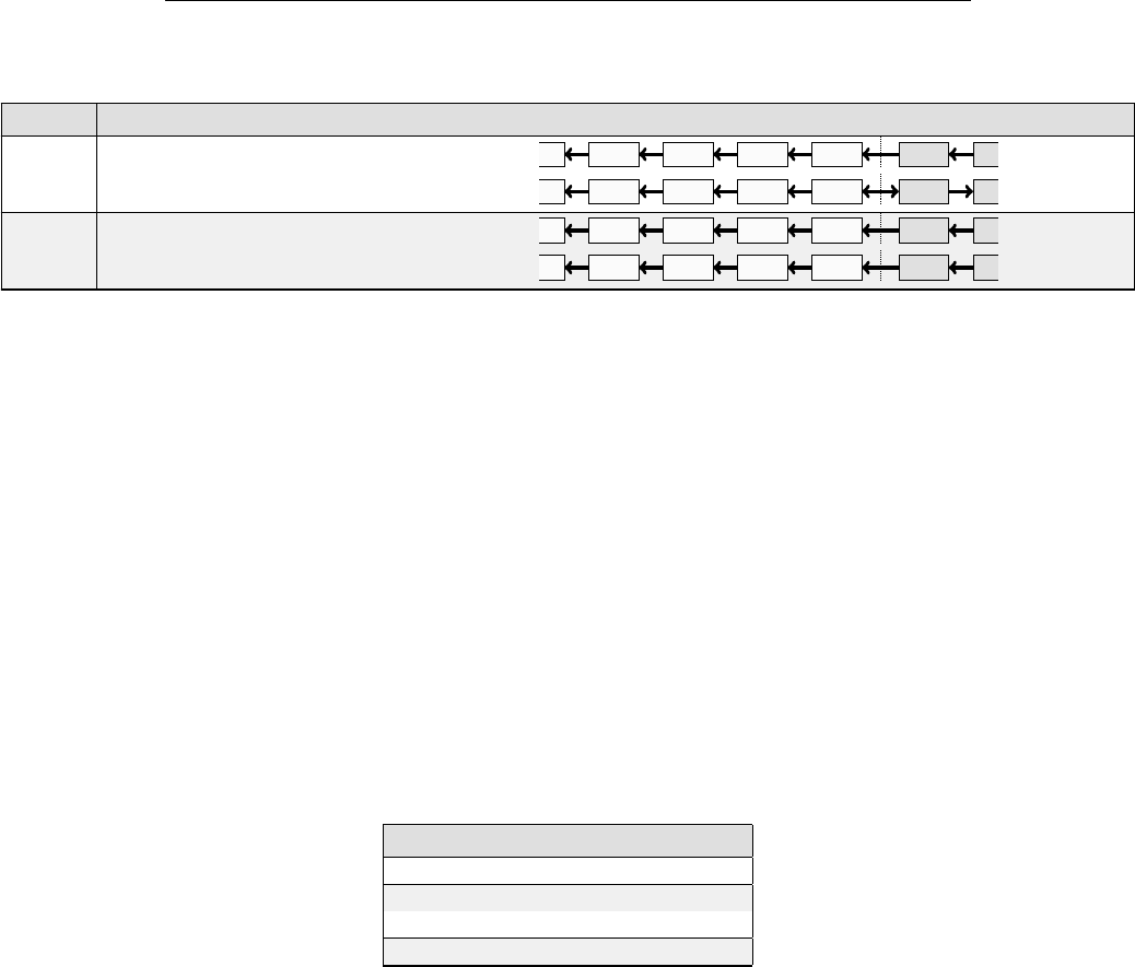
3.7 Stack Instructions
The N1’s stack instruction aims at efficiently implementing the essential stack opera-
tions in Forth only using the data pathes which needed for the stack’s push and pull
operations.
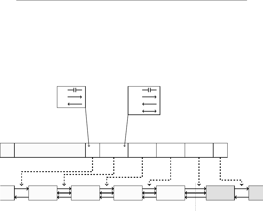
The opcode of the stack instruction contains a 10-bit wide field to specify a tran-
sition pattern of the upper cells of the parameter stack and the return stack. The
structure transition patter is shown in Figure 3-2.
15 14 13 12 11 10 9 8 7 6 5 4 3 2 1 0
;00001IST UST UST UST UST IST
Stack Instruction
IST
0:
1:or
UST
00:
01:
10:
11:
TOS
Parameter stack
TOS
Return stack
Figure 3-2: Transition encoding of stack instructions
The stack instruction contains four UST fields which control the data transfer
within the upper four cells of the parameter stack and the top of the return stack.
Each UST field determines the direction of data transfer between two neighboring
stack cells. Four options are selectable:
•No data transfer
•Data transfer upwards (or towards the return stack)
•Data transfer downwards (or towards the parameter stack)
•Data exchange between two stack cells
It is possible to put the UST fields into a combination which would trigger a data
transfer of two source cells to a single desination cell. In these cases, the resulting
data in the desination cell is undefined.
The two remaining IST fields in the stack instruction control the data movement
of the lower stacks. Two options are selectable:
•No data transfer
•Data shift throughout the entire intermediate stack. The direction is determined
by the data movement of the lowest cell of the upper stack.
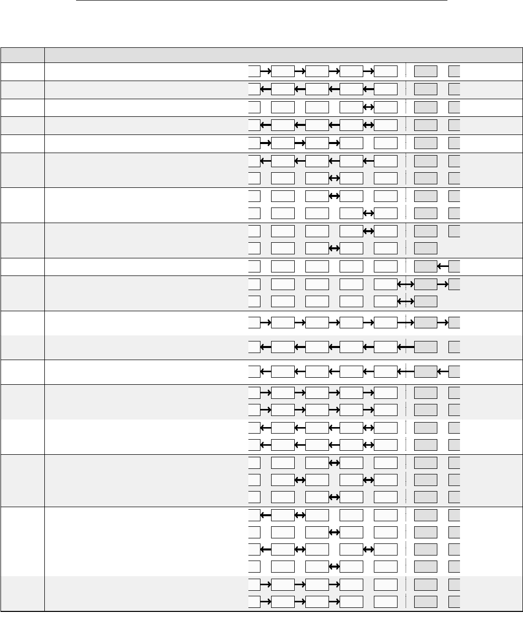
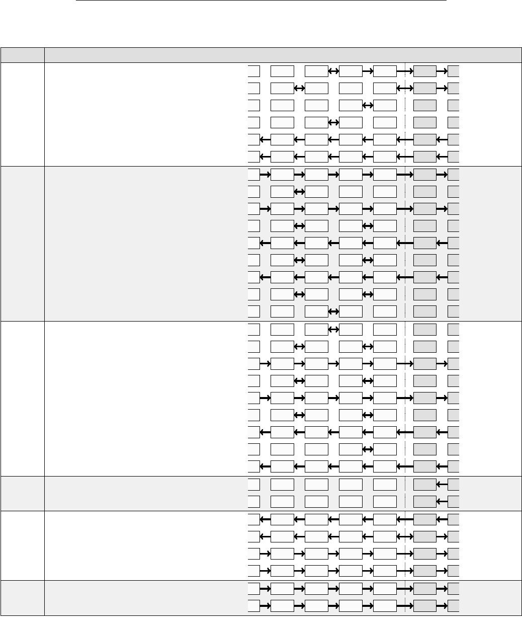
Table 3-2 shows how stack operations in Forth are mapped N1 instructions.
11
3.7 Stack Instructions 3 INSTRUCTION SET
Table 3-2: Common stack operations
Word Description Transitions Opcode
DROP ( x – ) TOS TOS 0x06A8
DUP ( x – x x ) TOS TOS 0x0750
SWAP ( x1 x2 – x2 x1 ) TOS TOS 0x0418
OVER ( x1 x2 – x1 x2 x1 ) TOS TOS 0x0758
NIP ( x1 x2 – x2 ) TOS TOS 0x06A0
TUCK ( x1 x2 – x2 x1 x2 )
TOS TOS
TOS TOS
0x0750
0x0460
ROT ( x1 x2 x3 – x2 x3 x1 )
TOS TOS
TOS TOS
0x0460
0x0418
-ROT ( x1 x2 x3 – x3 x1 x2 )
TOS TOS
TOS TOS
0x0418
0x0460
RDROP ( R: x – ) TOS TOS 0x0001
RDUP ( R: x – x x )
TOS TOS
TOS TOS
0x0007
0x0006
>R ( x – )
( R: – x ) TOS TOS 0x06AB
R@ ( – x )
( R: x – x ) TOS TOS 0x0754
R> ( – x )
( R: x – ) TOS TOS 0x0755
2DROP ( x1 x2 – )
TOS TOS
TOS TOS
0x06A8
0x06A8
2DUP ( x1 x2 – x1 x2 x1 x2 )
TOS TOS
TOS TOS
0x0758
0x0758
2SWAP ( x1 x2 x3 x4 – x4 x3 x1 x2 )
TOS TOS
TOS TOS
TOS TOS
0x0460
0x0598
0x0460
2OVER ( x1 x2 x3 x4 – x1 x2 x3 x4 x1 x2 )
TOS TOS
TOS TOS
TOS TOS
TOS TOS
0x0780
0x0460
0x0798
0x0460
2NIP ( x1 x2 x3 x4 – x3 x4 )
TOS TOS
TOS TOS
0x06A0
0x06A0
...continued
12
3.7 Stack Instructions 3 INSTRUCTION SET
Table 3-2: Common stack operations
Word Description Transitions Opcode
2TUCK ( x1 x2 x3 x4 – x3 x4 x1 x2 x3 x4 )
TOS TOS
TOS TOS
TOS TOS
TOS TOS
TOS TOS
TOS TOS
0x046B
0x0487
0x0418
0x0460
0x0755
0x0755
2ROT ( x1 x2 x3 x4 x5 x6 – x3 x4 x5 x6 x1 x2 )
TOS TOS
TOS TOS
TOS TOS
TOS TOS
TOS TOS
TOS TOS
TOS TOS
TOS TOS
TOS TOS
0x06AB
0x0580
0x06AB
0x0598
0x0755
0x0598
0x0755
0x0598
0x0460
-2ROT ( x1 x2 x3 x4 x5 x6 – x5 x6 x1 x2 x3 x4 )
TOS TOS
TOS TOS
TOS TOS
TOS TOS
TOS TOS
TOS TOS
TOS TOS
TOS TOS
TOS TOS
0x0460
0x0598
0x06AB
0x0598
0x06AB
0x0598
0x0755
0x0018
0x0755
2RDROP ( R: x1 x2 – )
TOS TOS
TOS TOS
0x0001
0x0001
2RDUP ( R: x1 x2 – x1 x1 x1 x2 )
TOS TOS
TOS TOS
TOS TOS
TOS TOS
0x0755
0x0757
0x06AB
0x06AB
2>R ( x1 x2 – )
( R: – x1 x2 )
TOS TOS
TOS TOS
0x0000
0x0000
...continued
13
3.9 Control Instructions 3 INSTRUCTION SET
Table 3-2: Common stack operations
Word Description Transitions Opcode
2R@ ( – x1 x2 )
( R: x1 x2 – x1 x2 )
TOS TOS
TOS TOS
0x0000
0x0000
2R> ( – x1 x2 )
( R: x1 x2 – )
TOS TOS
TOS TOS
0x0000
0x0000
3.8 Memory Access Instructions
Memory access instruction perform read or write acesses to the system’s 64-Kbyte
address space. Data can be accessed in word or byte entities. Misaligned word
accesses are not supported. Word accesses to a 510-Kbyte subset of the address
space can be done through an immediate addressing. This will offer faster access to
frequently used system variables.
3.9 Control Instructions
The N1 implements of set of instrictions to controls some of its internal components.
None of these instructions consume input arguments from the parameter stack, nor do
they produce a return value. The encoding of these instructions is shown in Table 3-3.
Multiple control instructions can be combined to one.
Table 3-3: Control instructions
Encoding Instruction
xxxxxx11 Enable interrupts
xxxxxx10 Disable interrupts
xxxxx1xx Reset parameter stack
xxxx1xxx Reset return stack
14
4 ANS FORTH WORDS
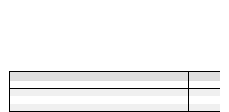
4 ANS Forth Words
Table 4-1 provides a list of standard ANS Forth words (see [?]) which directly map
to hardware instructions of the N1 processor.
Table 4-1: ALU operations
Word Stack Description Opcode
! ( x a-addr – ) Store cell 0000
* ( n1|u1 n2|u2 – n3|u3) Multiply two cells 0000
+ ( n1|u1 n2|u2 – n3|u3) Add two cells 0000
- ( n1|u1 n2|u2 – n3|u3) Subtract a cell from another. 0000
15
5 STACKS
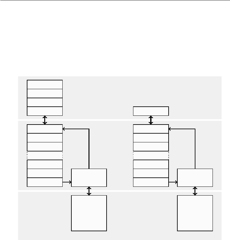
5 Stacks
The N1 operates with two stacks: the parameter stack to perform data transactions
and the return stack to manage the program flow. As illustrated in Figure 5-1, each of
these stacks consists of three hardware components: the upper stack, the intermediate
stack, and the lower stack.
Lower Stack Intermediate Stack Upper Stack
RAM
RAM
Controller
TOS
Parameter Stack
RAM
RAM
Controller
TOS
Return Stack
Figure 5-1: Stack Architecture
5.1 Parameter Stack
The upper stack of the parameter stack contains is four cells deep and contains the
most recent data entries. It’s purpose is to perform stack and ALU operations (see
Section 3.7 “Stack Instructions“ and Section 3.6 “ALU Instructions“). When the ca-
pacity of the upper stack is exceeded, older data entries are transferred to the inter-
mediate stack.
The intermediate stack serves as a buffer between the upper stack and the lower
stack which resides in RAM. The purpose of the intermediate stack is to minimize
RAM traffic to and from the lower stack. Push operation to the intermediate stack are
only propagated to the lower stack, when the buffer capacity is exceeded. Pull oper-
ations are onle propagated, when the intermediate stack is empty. Stack fluctuations
within the buffer capacity are not visible to the lower stack.
The lower stack is a region of the RAM, which is managed by the memory con-
troller of the intermediate stack.
16


