NCR_SCSI_Engineering_Notebook_Rev2_Oct85 NCR SCSI Engineering Notebook Rev2 Oct85
User Manual: NCR_SCSI_Engineering_Notebook_Rev2_Oct85
Open the PDF directly: View PDF ![]() .
.
Page Count: 46
MICROELECTRONICS
DIVISION
SCSI
ENGINEERING
NOTEBOOK
10/85
Rev.
2
Cooyrignt
1984,
by
NCR
Corporation
Coloraoo
Spr1ngs,
Coloraco
All
Rignts
Reserveo
Printed
1n
U.S.A.
Wnile
the
information
nerein
presentee
~aS
been
cnec~ec
for
~o~,
accut"'acy
aY',d
t"'sliaoility.,·
NCR
assumES
t'",c.
t"'esp.:.t"',sloillty
f.:!}·" 2:!."t.""'e)·"
1':5
u.se
r:':'r'
for
tne
infringement
of
any
patents
or
otner
rlgnts
of
t~iro
partles,
w~ic~
coule
resu~t
from
its
use.
The
puolicatlon
ana
alssemina~ion
of
tne
enciosec
i1'"lfot"f,1a't
1':'1'",
cc,nfet"'s
1'",':'
1
iceY",se.,
by
imol
icat
iO"(1
':11''''
'::.t:1et"'wlse~
tt1'"ldet'"
o·:",:,!
j:}a~;e
or
oatent
rlgnts
owned
by
NCR.
~CR
Mlcroelectronics
Division
~635
Aeroplaza
Drlve
Colorado
Sorlngs,
Coloraco
80916
~none:
800/525-2252
Telex:
45
2457
NCR
MICRO CSP
m[3~
Microelectronics
AWAMA
Hughes
Associates.
Int.
2913
Governors
Dnve
H~.AllS805
(205)
s:n.91~
AAIlOHA
8H
& B
Sales,
Inc.
7353E.6IllAY'I!.
SaltIsdale.
~
852S
1
(602)~
8H
& B
Sales.
Inc.
1()41
W.
ComobabI
TIQOfl.
~
85704
(602)
299-
1~
CA1..EORNIA
Custorn~
992S.
Rd.
San
Jose.
CA
95129
(~)2S2·~1
Ell1e
AssocIates.
Inc
SIite
200
7SB5
Ronson
Rd.
San~.CA92111
(619)
27S-5441
Orion
SIies.
Inc.
SuitllF
82S
E.
Colorado
Blvd.
Giendale.
CA
91205
(818)
240-3151
Orion
Sales,
Inc
2!5UAamSt
Tustm.
CA
92S8O
(714)
832-9667
COlORADO
Bearoayne,
Inc.
Sua
110
2620~erRd.
Aurora.
CO
kX)14
r.ml~
AU8.UlA
4825
Ul'MI'SIIy
SQ
H\Il!Me.
A.l.
3S&)S
(205',
837.9l).J
COHHECnClrT
1
12
Maln
Strge:
~CT0685'
f'203)~'515
FlORlOA
221
N.
Lake
BIYd.
AItamonIe
~
Ft:!VOl
(3)5)~
674
S.
Miitary
TIU
0wfIaId
Beact~
F'1.
~
(XI5)
42&-68n
GEOfQA
5853
e
PeIchtrM
Comers
East
Norcross,
GA
Dl92
(404)
448-1711
IJ.IfOIS
15&
1
CInnen
f)rio,te
9:
Grow
VIIage.1L
m7
(312)
437.-0
INDIANA
&4OB
CatIe!Uce
Drive
~,IN48250
(317)
&4&-7300
IlASSACHUSETTS
44
HII1WII
MnUl
UxingIon,
MA
02173
(617)
161-t200
CONNECTICUT
Data
Mart.,
Inc.
47
CIapboartI
HI
Rd.
Guilford.
CT
06437
(20314S3-{)575
flORIDA
\JMoeI'SaI
Mmting &
Sales.
Inc
4'3t.1attinRd.
Nom
Palm
Beach,
Fl33406
~}&42"440
UnNersaI
Marketing
&
Sales,
Inc
355
GrIn!
Ave.
PO.
Box
2582
Salelllle
Beach,
Fl32937
(n)m-2S8
1
GEOfIGA
Hughes
Associates,
Inc.
1)45
AIIa~
Blvd.
&;ts
122
NoIttos$.
GA
30071
(404)662"587
I.1.IfOCS
ElgIe
Technical
Sales,
Inc.
1~
Hicics
Road
Roling
Meadows,
IL
SXXl8
(312)
991-0700
IfOIAH.A
Tec:hnoIogy
MarkatJng
Co!por1tion
S99lnc1ustrial
Dr
CIrmei.
IN
46032
(311)
844-8462
~~ting
3428
W.
Taylor
St
Fort
Wayrte.
IN
468Q.(
(219)
432·5553
IlA.QYl.AND
9100
Gaithef
Road
~."D2Oen
(3)1;921~
Illa!IGAH
13485~-nre
Livonia.
l.Ii4E150
(313)
52>
1800
IIINHESOTA
10203
b
Road
EISI
Minnetonka.
loiN
55343
(612)
935-5444
NEW.&SEY
45Rl4S
Pile
Brook.
~
07058
(201)m.3S10
NEW'tDRK
1.
\I8stII
PalMy
East
\tIstaI,NYl3850
~7)
748211
a.o
FUpott
Pm
FIirport,
NY
14450
(71&)
381·7070
eo
Crossways
Perk
West
~,NYl17i7
151&)
921~700
NCR
Microelectronics
Sales
Representatives
KANSAS
NEWIIEXICO
OI(UHQMA
UTAH
Kebc:o.
Inc.
NeIco
Electronix
ION
Associates.
Inc
Electrodyne.
Inc.
16047E
Kellogg
4801
General
Bradley.
N.E.
9726
E.
42nd
Street
Suite
109
Wdlita.KS6m:l
Albuquerque.
NM87111
Suite
122
2480
South
Main
51
(316)
733-1~1
(505)
293-1399
Tulsa.
OK
74145
SaIl
=.
UT
&4115
Kebco,
Inc.
NEW
YORK
(918)664-0186
(B01)
1
10111
Santa
F,
0riYe
Ontec
Elec.
Mk!.
OREGON
WASHINGTON
~
Park.
K5
66212
167
Aande~
51.
Electronic
Component
Electronic
Component
Sales
(913)
541-&431
Rochester.
NY
14619
Sales
9311
5.E.
36th
51.
KENT\JCICY
(716)
464-8636
15255
S.W.
72nd
AYe
Mercer
Island.
WA
~
Technology
Martteting
0nIec
Eltc.
Mk!.
=.OR97223
(206)
232.g~1
Corporation
16
Gabriela
Road
)2~2342
CANADA
1819
Roma.'1
Ct.
P.O.
BoxS25
PENNSYlVANIA
Camec
Representatives.
Inc.
PO.
Box
91
147
Wappinger
Falls,
NY
12590
TCA
Associates
8
Stratheam
AY'I!.-Unit
"8
Louisville.
KY
40291
(914;
462·7188
B01
Media
Line
Rd.
8ramp(on,
Ontario,
(502)
499-7808
Ontec
EItt.
Mk!.
Broomall.
PA
19008
Canada
L6T
4LB
IlARYlAHO
161
FotTest
Way
(215)
~2022
.
(4161791·5922
Mmtmn.lnc.
P.O.
Box
24
TENNESSEE
Camec
RepresentatiYes,
Inc.
1688
Easl
Guide
Dr.
Camilus,
NY
13131
Hughes
Associates,
Inc.
1573
L.aperriere
Ave.
RociMIIe.
MD
20850
(315)
672-&409
732
White
Oak
Circle
Ottawa
Ontario,
(:1)1)251-8890
OC
Associa1es
Morristown.
TN
37814
Canada
1<12
7T3
IIICHIGAN
209
RoIie
9
W.
(615)
581-5971
.
(613)725-3704
Westbay
&
Associa1es
Congers.
NY
10920
Carnec
Representatives,
Inc.
(914)268-4435
TEXAS
Suite
116
27476~ileRd.
ION
AssociaIes,
Inc.
lMlnia.
MI48154
NORTH
CAAOUNA
1504
109th
Street
3639
Sources
Rd.
(313)
421·7460
HIq'Ies
Associates,
Inc.
Grand
Prairie,
TX
7S05O
00Iard
des
Onneaux,
_MESOTA
975
Walnll.
St.
(214)
647-m5 Quebec,
Canada
H98
21<4
Suile:m.e
(514)583-6131
~.Inc.
Cary.
He
27S
11
ION
Associates,
Inc.
FARUST
7138
Rd
(919)467·7029
12731
Research
B/Yd.
PCI,
Hong
Kong,
LTD.
Eden
Prairie.
MN
55344
&iteA100
(EI2)~
()HK)
Austin.
TX
78759
1145
Sonora
Ct.
MISSISSIPPI
Beat
Marketing,
Inc.
(512)
331-7251
Sunnyvale.
CA
94068
3623
BrectsviIIe
Rd.
ION
Associates,
Inc.
(~)
7J3.4&13
Hughes
Associates,
Inc.
P.O.
Box
177
6.»J
Westpark
Dr.
UNITED
KJNGOOM
1204
Garden
Lane
Rd1IieId.
OH
44286
P.O.
Box
1541
Suite
310
Manhattan
Skyline
Ud.
Corinth.
Miss.
38834
(216)
659-3131
Houston,
TX
T7'JS7
Manhattan
House
(601)287·2915
Bear
Marketing
Inc.
(713)9n~
8ridgeRoad
1563
E.
Dorothy
Lane
Madenhead
IIISSOURi
Deyton.
OH
45429
Berkshire
SL680B
Kebco,Inc.
(513)52059
England
75
WlrthIngIon
Dr.
Maindenhead
(0628)
75851
Mar)1a'ld
Heights.
Me
63043
(314)
576-411
1
NCR
Microelectronics
Distributors
WYU
LAIORATORIES
1lANHAT11N
KYUNE,
LTD.
NORTH
CAROlINA
ARIZONA
OREGON
UNITED
KIHGOOM
9801
A
Southam
Pine
B/Yd.
8155
North
24th
Street
5289
N.E.
Elam
"IbIlg
Pkwy.
Manlla!tan
House
Chatio!te,
NC
28210
Pt1oenix.
~
85021
8Idgl00
8ridgeRoad
(704)
527~1B8
(602)
2G2232
HiIlsIJoro,
OR
97124
Maidenhead
OHIO
1010
E.
Ptnnsytvania
(503)~
Beruhire
Sl6
80B
4800
East
131st
Stree1
$ljte203
TEXAS
E~and
0eYeIand.
OH
44105
T\t:SOr
..
AZ
85714
1810
Glt8llvile
Or
Matr\denhead
(0628j
75a51
(216)
587-36OC\
(6)2)
884-7082
RdIirdson,
TX
1~1
4433lnterpoint
BIvC.
CALFOAHIA
(214)
235-9953
Deyton,
OH
45424
124
Maryland
51.
2120
Breaker
Lane
S\ite
F
(513)23&9900
El
Seg;m:l,
CA
90245
AISin,
TX
78758
PENHSYlYAHtA
(213)
322~100
(512)
834-9957
261
Gibraltar
Road
17872
Cowan
M.
11001
SouthWIicrest
Horsham,
PA
19044
Nne,
CA
92714
&;te100
(215)
67....aoo
(714)~
Houston,
TX
77099
2S9
Kappa
OrNe
9S25=:;Or.
(713)8~
=PAl5238
SarI=,
92123
UTAH
(412)
.zm
(619)
9171
1959
5.
41~
West
TEXAS
3000
Bowers
Ave.
Sar.
t.ke
City,
UT
841
()4
9!Kl1
&met
Road
Santa
am.
CA
95051
~1)
974-9953
Austin.
TX
78758
(G)n7-2500
WASHINGTON
(512)
B3>4OOO
11151
SIJ\
Center
Or.
1750
132ndA'I8.
H.E.
13710
Omega
Road
AMdIo
Ccn:lova.
CA
95670
Bellevue.
WA
BX6
OllIs.
TX
75244
~16)
6J8.S282
(206)
453-8300
(214)_7300
COlORADO
5853
Point
West
Drive
451
Easl.1241h
M.
HousIon,
TX
77036
'TIIomton,
CO
80241
(71~_55SS
(:m)
457-9953
MD-60S 0485
TABLE
OF
CONTENTS
I.
NCR
SCSI
Product
Families
A.
NCR
5385/86
Product
Family
B.
NCR
5380
Product
Family
C.
Choosing
the
Right
Product
Family
for
Your
Design
D.
Differences
Between
the
NCR
5385E
and
the
NCR
5386
II.
NCR
5385/86
state
~~chine
Operation
III.
NCR
5385S
Synchronous
Operation
IV. SCSI Accommodates
Flexible
System
Arch1tectures
(Article)
v.
SCSI
Packaging
Options

I.
NCR
SCSI
PRODUCT
FAMILIES
NCR
5385/86
PRODUCT FAMILY
fhe
NCR
5385,
which
was
the
first
general
purpose
SCSI
protocol
controller
available
in
the
market,
has
been
replaced
by
the
upgraded
NCR
5385E
(lienhay,ced
ll
).
The
NCR
5386
is
primat"i
ly
a
cClst
reduced
version
of
the
5385E,
with
a
few
additional
features
such
as
pass
parity
and
the
ability
to
suppress
spurious
phase
changes.
Shortly
following
the
introduction
of
the
5386,
a
synchronous
version
(the
NCR
5386S)
will
be
available.
This
device
is
capable
of
supporting
3.3
Mbyte
operation
using
a
synchronous
(offset
of
one)
handshake.
In
spite
of
continuing
enhancements,
these
devices
have
Maintained
pin
and
software
compatibility.
Future
upgrades
such
as
higher
offsets,
faster
transfer
rates,
lower
power
CMOS,
and
on-chip
bus
transceivers
are
being
plaY"IY"led.
IY"I
add
it
iCIY",
to
the
staY"ldat"'d
48-piYI
DIP,
these
devices
are
available
in
52
or
68-pin
J-Ieaded
PLCC
(surface
Mounted)
packages.
To
provide
a
Single-chip
open-collector
interface
to
the
SCSI
bus,
the
NCR
8310
General
Purpose
48
mA
Bus
Transceiver
may
be
used
as
a
companion
chip
with
any
members
of
the
NCR
5385/86
family.
A
summary
of
the
product
family
is
listed
below.
NCR
5385
First
family
Member
-
Replaced
by
the
NCR
5385E
NCR
S385E
Currently
in
production
Supports
latest
ANSC
timings
(Post
Revision
10)
Manufactured
until
the
NCR
5386
is
in
production
NCR
5386
-
Samples
currently
available
Superset
of
the
NCR
5385/85E
-
Production
availability
2/85
NCR
5386S
Samples
available
1/86
Identical
to
NCR
5386
with
synchronous
operation
to
3.3
Mbytes/sec
NCR
8310
Samples
available
Production
12/85
Single-chip
open-collector
bus
interface
-1-
NCR
5380
PRODUCT FAMILY
The
NCR
5380
was
the
first
SCSI
interface
device
to
provide
on-chip
open-collector
48
mA
bus
transceivers.
This
provides
for
low
parts
count
and
direct
SCSI
bus
interfacing.
Since
the
5380
is
an
NMOS
device,
and
not
susceptible
to
latch-up
like
CMOS,
the
single
ground
pin
is
adequate
to
handle
14
signals
sinking
48
rnA
simultaneously.
(When
operating
as
a
Target
device,
a
maximum
of
14
signals
May
be
siMultaneously
active.)
Inductance
problems
are
avoided
by
purposely
slowing
each
signals
turn-on
time.
This
provides
the
added
benefit
of
reducing
the
RF
generated
due
to
switching
signals.
However,
to
maintain
ground
integrity,
it
is
recommended
that
inexpensive
sockets
not
be
used.
To
accommodate
differential-pair
operation,
the
4B-pin
NCR
5381
can
be
used.
This
device
allows
use
of
the
internal
open-collector
bus
transceivers
and
provides
the
additional
signals
necessary
to
control
external
differential-pair
bus
transceivers.
SCSI
is
finding
its
way
into
lap-top
computing.
To
provide
t~e
lowest
power
possible,
the
53C80/81
will
be
introduced
in
the
4th
quarter
of
1985.
Since
CMOS
is
susceptible
to
latch-up,
four
additional
ground
lines
have
been
provided.
Due
to
this
consideration,
the
part
has
maintained
functional
compatibility
but
not
pin
compatibility.
Additionally,
the
REQ/ACK
response
time
has
been
considerably
improved
over
its
NMOS
counterpart.
~ll
of
these
devices
are
available
in
standard
DIP
or
surface
mountable
PLCC
packaging.
A
summary
of
the
devices
is
listed
below.
NCR
5380
On-chip
open-collector
bus
transceivers
-
Currently
in
production
NCR
5381
Supports
external
differential-pair
bus
transceivers
Samples
available
Production
12/85
NCR
53C80
Functionally
equivalent
to
the
NCR
5380
-
Samples
available
11/85
NCR
53C81
Functionally
equivalent
to
the
NCR
5381
-
Samples
available
12/85
-2-
CHOOSING
THE
RIGHT
PRODUCT
FAMILY
FOR
YOUR
DESIGN
The
NCR
5385/86
family
and
the
NCR
5380
family
are
all
fully
featured
SCSI
protocol
controller
devices.
Both
product
lines
support
nearly
every
option
available
in
the
proposed
SCSI
standard
and
can
be
used
in
a
variety
of
configurations.
However,
differences
between
the
faMilies
will
make
one
device
more
appropriate
than
another
for
your
application.
REASONS
TO
CHOOSE THE
NCR
5385/86
PRODUCT FAMILY
You
probably
would
need
an
NCR
5385E
or
NCR
5386
if
the
most
important
factors
influencing
your
choice
are:
*
Performance
*
System
Integrity
*
Guaranteed
Compatibility
PERFORMANCE
All
members
of
the
NCR
5385/86
product
family
are
capable
of
2.0
Mbyte/sec
operation
using
the
asynchronous
SCSI
handshake.
The
NCR
5386
provides
3.3
Mbyte/sec
operation
using
the
synchronous
(offset
of
one)
handshake.
Future
products
in
this
family
will
support
faster
transfer
rates
and
greater
offsets.
The
NCR
5380
product
family
is
rated
at
1.5
Mbyte/sec
operation
and
is
currently
not
planned
to
~upport
synchronous
operation.
Even
if
your
transfer
requirements
are
less
than
1.5
Mbyte/sec
operation,
the
NCR
5380
has
longer
REQ/ACK
response
times
than
the
combination
of
the
NCR
5385/86
and
the
associated
bus
transceiver
delay.
Because
of
this
delay,
your
overall
transfer
rate
could
be
reduced
depending
on
the
cable
length
being
used
and
the
response
of
the
other
SCSI
bus
devices.
Additionally,
the
NCR
5385/86
family
supports
a
slightly
faster
MPU
interface.
This
could
prevent
the
insertion
of
wait
states
if
the
device
is
being
addressed
by
high-end
processors.
SYSTEM INTEGRITY
Many
designs
have
the
requirement
to
maintain
parity
throughout
the
system.
The
NCR
5386
and
5386S
will
optionally
pass,
or
check
and
pass,
parity
through
the
chip.
The
NCR
5380
family
does
not
SUppOt~t
this
feature.
GUARANTEED
COMPATIBILITY
The
NCR
5380
product
is
firmware
oriented
thus
adherance
to
the
SCSI
protocol
is
the
responsibility
of
the
programmer.
It
is
imposible
to
violate
any
of
the
SCSI
speCifications
using
the
NCR
5385/86
device.
(3)
~EASONS
TO
CHOOSE
THE
NCR
5380
PRODUCT FAMILY
You
probably
would
need
an
NCR
5380
or
NCR
5381
if
the
most
important
factors
influencing
your
choice
are:
*
Board
Space
*
Cost
*
Flexibility
*
Low-power
BOARD
SPACE
The
NCR
5380
family
was
the
first
SCSI
interface
device
to
include
on-chip
open-collector
bus
transceivers.
By
providing
the
high-current
transceivers
on-chip,
fewer
parts
are
required
to
implement
the
interface
and
the
device
pin-out
requirements
are
reduced.
Even
though
the
5385/86
family
does
not
have
on-chip
bus
transceivers,
the
NCR
8310
provides
a
convenient
single-chip
bus
interface.
Future
members
of
the
5385/86
product
line
will
include
the
bus
transceivers
on
chip.
Another
board
savings
feature
is
the
absence
of
a
clock
pin.
No
clock
circuitry,
resistors,
or
capacitors
are
required
to
make
the
device
operate.
The
exclusive
process-independant,
free-running
internal
oscillator
is
unique
to
the
NCR
5380
(patent
pending).
COST
~he
NCR
5380
and
the
NCR
5386
products
are
comparably
priced,
however
the
NCR
5386
requires
an
external
bus
transceiver.
Since
the
NCR
5380
requires
fewer
parts
and
uses
less
board
space,
it
is
a
less
expensive
solution.
FLEXIBILITY
Since
the
NCR
5380
is
a
register-oriented
device
and
most
bus
signals
may
be
freely
asserted
or
sampled,
it
is
capable
of
supporting
variations
of
the
SCSI
interface
such
as
XSASI
and
SCSI/PLUS.
XSRSI
is
the
interface
used
by
XEBEC
on
many
of
its
products
and
varies
slightly
from
the
proposed
SCSI
standard.
SCSI/Plus
is
a
proposed
superset
for
the
SCSI
interface
that
allows
up
to
64
bus
devices
compared
to
the
8
devices
specified
by
the
X3T9.2
subcommittee.
This
flexibility
a1s0
makes
it
a
perfect
tool
for
use
in
SCSI
testing,
analyzing,
and
bus
emulating
equipment.
Additionally,
the
versatility
of
the
NCR
5380
allows
it
to
be
used
In
non-SCSI
applications
such
as
industrial
control
busses,
local
lID
communication
links,
and
other
interfaces
requiring
48
ma
sink
capability_
LOW
POWER
CONSUMPTION
Jhe
NCR
5380
typically
draws
110
rna
of
current,
while
the
NCR
53C80
raws
only
a
few
microamps.
This
makes
the
them
ideal
products
for
"low-power
applications.
(4)
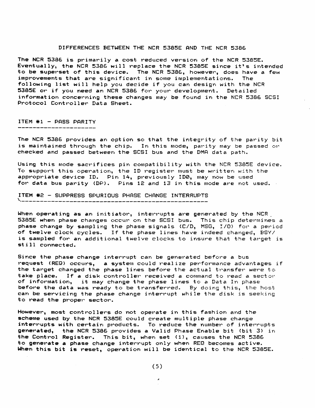
DIFFERENCES
BETWEEN
THE
NCR
5385E
AND
THE
NCR
5386
The
NCR
5386
is
primarily
a
cost
reduced
version
of
the
NCR
5385E.
Eventually,
the
NCR
5386
will
replace
the
NCR
5385E
since
it's
intended
to
be
superset
of
this
device.
The
NCR
5386,
however,
does
have
a
few
improvements
that
are
significant
in
some
implementations.
The
following
list
will
help
you
decide
if
you
can
design
with
the
NCR
5385E
or
if
you
need
an
NCR
5386
for
your
development.
Detailed
information
concerning
these
changes
may
be
found
in
the
NCR
5386
SCSI
Protocol
Controller
Data
Sheet.
ITEM
#1
-PASS PARITY
The
NCR
5386
provides
an
option
so
that
the
integrity
of
the
parity
bit
is
maintained
through
the
chip.
In
this
mode,
parity
may
be
passed
or
checked
and
passed
between
the
SCSI
bus
and
the
DMA
data
path.
Using
this
mode
sacrifices
pin
compatibility
with
the
NCR
5385E
device.
To
support
this
operation,
the
ID
register
must
be
written
with
the
appropriate
device
10.
Pin
14,
previously
100,
may
now
be
used
for
data
bus
parity
(DP).
Pins
12
and
13
in
this
mode
are
not
used.
ITEM
*2
-
SUPPRESS
SPURIOUS
PHASE
CHANGE
INTERRUPTS
~--------------------------------------------------
When
operating
as
an
initiator,
interrupts
are
generated
by
the
NCR
_
5385E
when
phase
changes
occur
on
the
SCSI
bus.
This
chip
determines
a
phase
change
by
sampling
the
phase
signals
(C/D,
MSG,
I/O)
for
a
period
of
twelve
clock
cycles.
If
the
phase
lines
have
indeed
changed,
BSYI
is
sampled
for
an
additional
twelve
clocks
to
insure
that
the
target
is
still
connected.
Since
the
phase
change
interrupt
can
be
generated
before
a
bus
request
(REQ)
occurs,
a
system
could
realize
performance
advantages
if
the
target
changed
the
phase
lines
before
the
actual
transfer
were
to
take
place.
If
a
disk
controller
received
a
command
to
read
a
secto~
of
information,
it
may
change
the
phase
lines
to
a
Data
In
phase
before
the
data
was
ready
to
be
transferred.
By
doing
this,
the
host
can
be
serVicing
the
phase
change
interrupt
while
the
disk
is
seeking
to
read
the
proper
sector.
However,
most
controllers
do
not
operate
in
this
fashion
and
the
scheme
used
by
the
NCR
5385E
could
create
multiple
phase
change
interrupts
with
certain
products.
To
reduce
the
number
of
interrupts
generated,
the
NCR
5386
provides
a
Valid
Phase
Enable
bit
(bit
3)
in
the
Control
Register.
This
bit,
when
set
(1),
causes
the
NCR
5386
to
generate
a
phase
change
interrupt
only
when
REQ
becomes
active.
When
this
bit
is
reset,
operation
will
be
identical
to
the
NCR
5385E.
(5)
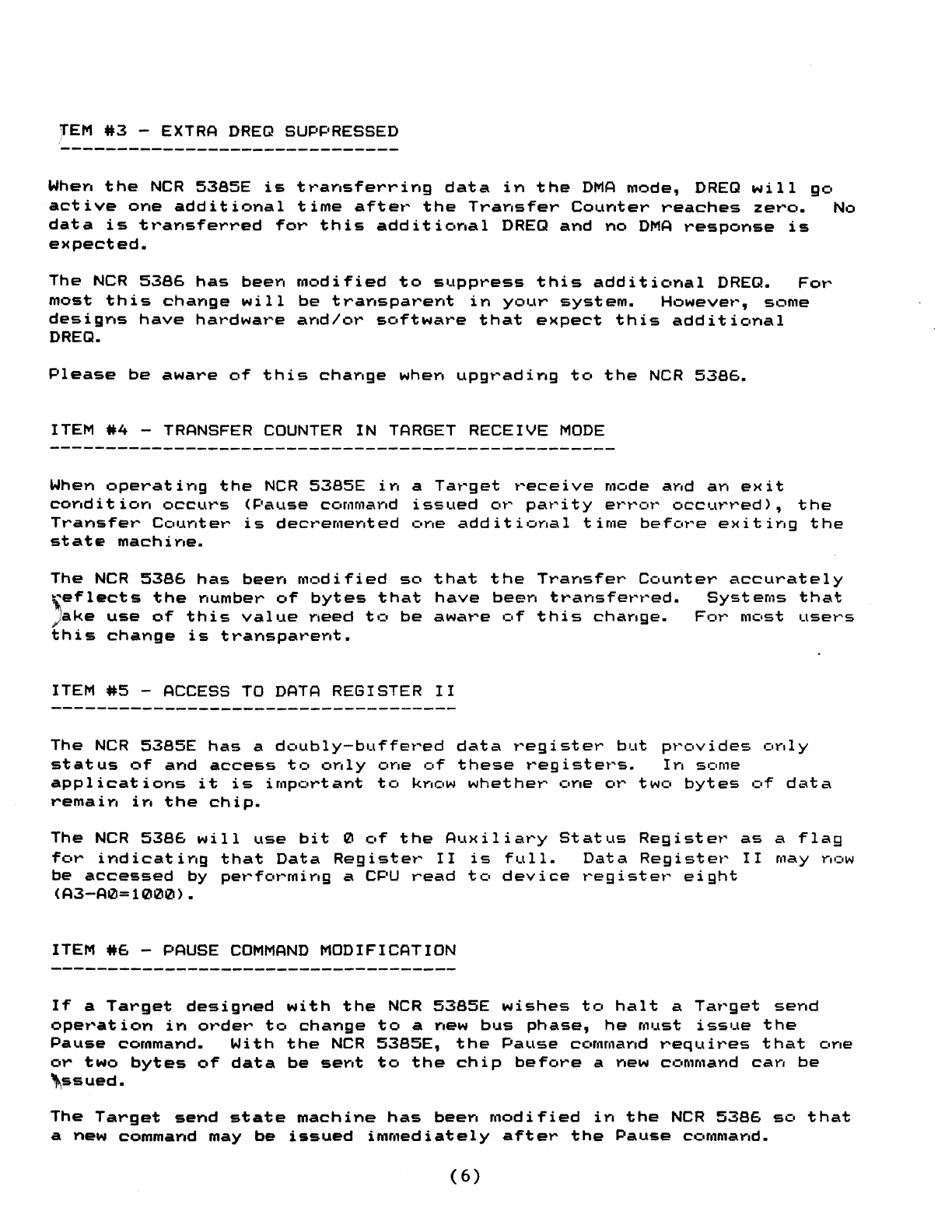
rEM
*3
-EXTRA
DREQ
SUPPRESSED
When
the
NCR
S385E
is
transferring
data
in
the
DMA
mode,
DREQ
will
go
active
one
additional
time
after
the
Transfer
Counter
reaches
zero.
No
data
is
transferred
for
this
additional
DREQ
and
no
DMA
response
is
expected.
The
NCR
53S6
has
been
modified
to
suppress
this
additional
DREQ.
For
most
this
change
will
be
transparent
in
your
system.
However,
some
designs
have
hardware
and/or
software
that
expect
this
additional
DREQ.
Please
be
aware
of
this
change
when
upgrading
to
the
NCR
5386.
ITEM
*4
- TRANSFER COUNTER
IN
TARGET
RECEIVE
MODE
When
operating
the
NCR
538SE
in
a
Target
receive
mode
and
an
exit
condition
occurs
(Pause
command
issued
or
parity
error
occurred),
the
Transfer
Counter
is
decremented
one
additional
time
before
exiting
the
state
machine.
The
NCR
53S6
has
been
modified
so
that
the
Transfer
Counter
accurately
[eflects
the
number
of
bytes
that
have
been
transferred.
Systems
that
Jake
use
of
this
value
need
to
be
aware
of
this
change.
For
most
users
this
change
is
transparent.
ITEM
#5
-ACCESS
TO
DATA
REGISTER
II
The
NCR
S38SE
has
a
doubly-buffered
data
register
but
provides
only
status
of
and
access
to
only
one
of
these
registers.
In
some
applications
it
is
important
to
know
whether
one
or
two
bytes
of
data
remain
in
the
chip.
The
NCR
S3S6
will
use
bit
0
of
the
Auxiliary
Status
Register
as
a
flag
for
indicating
that
Data
Register
II
is
full.
Data
Register
II
may
now
be
accessed
by
performing
a CPU
read
to
device
register
eight
(A3-A0=1000).
ITEM
*6
-PAUSE
COMMAND
MODIFICATION
If
a
Target
designed
with
the
NCR
S3SSE
wishes
to
halt
a
Target
send
operation
in
order
to
change
to
a
new
bus
phase,
he
must
issue
the
Pause
command.
With
the
NCR
S3SSE,
the
Pause
command
requires
that
one
or
two
bytes
of
data
be
sent
to
the
chip
before
a
new
command
can
be
'ssued.
The
Target
send
state
machine
has
been
modified
in
the
NCR
5386
so
that
a
new
command
may
be
issued
immediately
after
the
Pause
command.
(6)
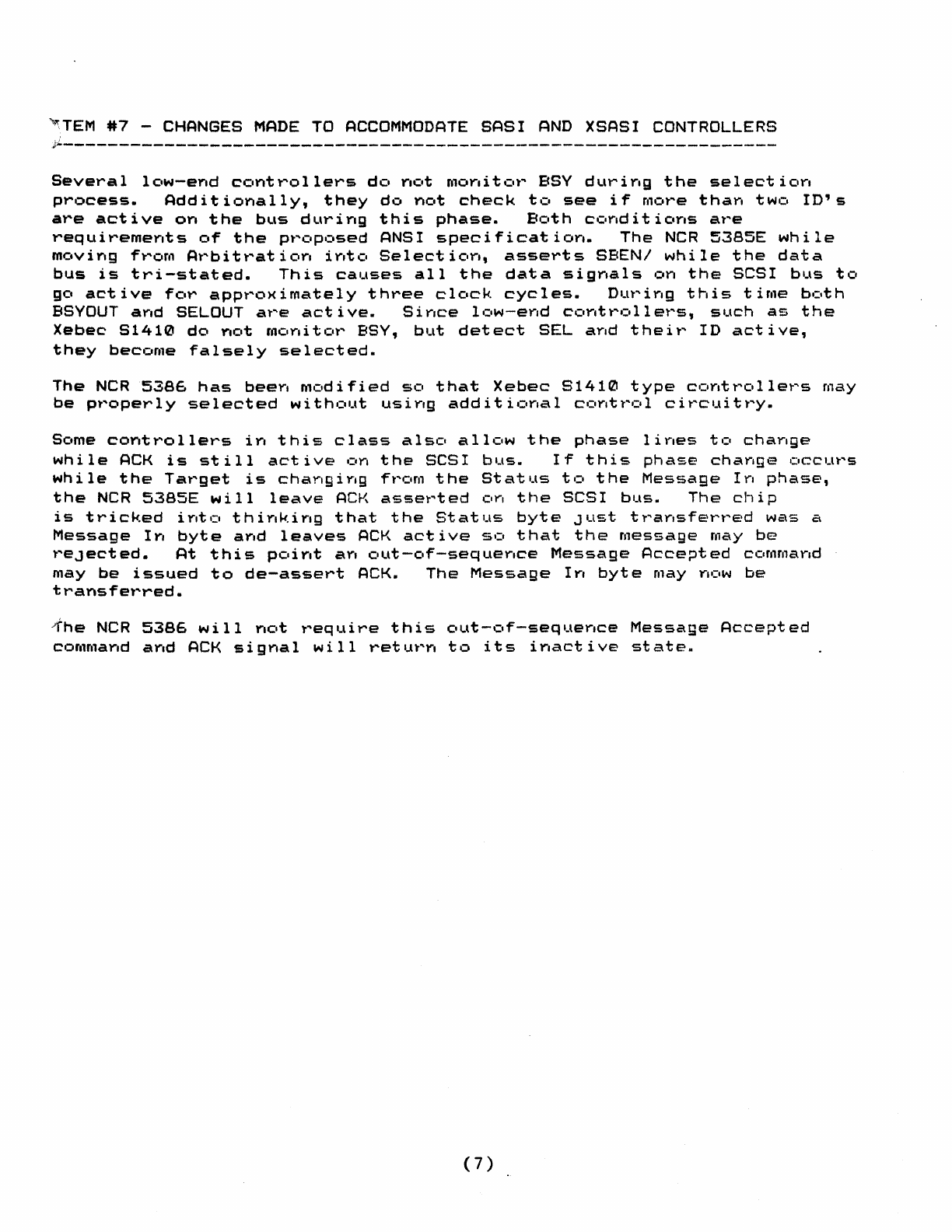
~TEM
#7
-CHANGES
MADE
TO
ACCOMMODATE
SASI
AND
XSASI CONTROLLERS
~-----------------------------------------------------
----------
Several
low-end
controllers
do
not
monitor
BSY
during
the
selection
process.
Additionally,
they
do
not
check
to
see
if
more
than
two
ID's
are
active
on
the
bus
during
this
phase.
Both
conditions
are
requirements
of
the
proposed
ANSI
specification.
The
NCR
53B5E
while
Moving
from
Arbitration
into
Selection,
asserts
SBEN/
while
the
data
bus
is
tri-stated.
This
causes
all
the
data
signals
on
the
SCSI
bus
to
go
active
for
approximately
three
clock
cycles.
During
this
time
both
BSYOUT
and
SELOUT
are
active.
Since
low-end
controllers,
such
as
the
Xebec
81410
do
not
monitor
BSY,
but
detect
SEL
and
their
ID
active,
they
become
falsely
selected.
The
NCR
5386
has
been
modified
so
that
Xebec
S1410
type
controllers
may
be
properly
selected
without
using
additional
control
circuitry.
Some
controllers
in
this
class
also
allow
the
phase
lines
to
change
while
ACK
is
still
active
on
the
SCSI
bus.
If
this
phase
change
occurs
while
the
Target
is
changing
from
the
Status
to
the
Message
In
phase,
the
NCR
53S5E
will
leave
ACK
asserted
on
the
SCSI
bus.
The
chip
is
tricked
into
thinking
that
the
Status
byte
Just
transferred
was
a
Message
In
byte
and
leaves
ACK
active
so
that
the
message
may
be
reJected.
At
this
point
an
out-of-sequence
Message
Accepted
command
may
be
issued
to
de-assert
ACK.
The
Message
In
byte
may
now
be
transferred.
1he
NCR
5386
will
not
require
this
out-of-sequence
Message
Accepted
command
and
ACK
signal
will
return
to
its
inactive
state.
(7)
II.
NCR
5385/86
STATE
MACHINE
OPERATION
A.
Initiator
Output
state
Mach~ne
B.
Target
Receive
State
Machine
c.
Initiator
Input
state
Mach1ne
D.
Target
Send
State
Machine
NCR
5385
STATE
MACHINE
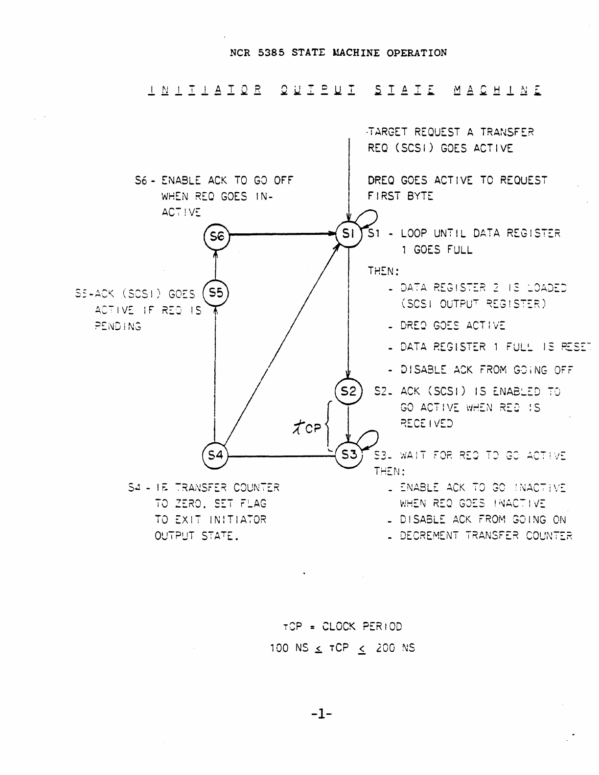
OPERATION
S6-
ENABLE
ACK
TO
GO
OFF
WHEN
REO
GOES
IN-
AC7!V~
ss-~c~
(SCSI)
GOES
/
S.l
-
,r:
~~ANSFER
CDUN7ER
70
ZE~O.
S~T
r~AG
TO
EXIT
INlTIA70R
OU7PUT
STATE.
~
TAT
~
M A
~
H I N
~
~---
...
--~--_.&
·TARGET
REQUEST
A
TRANSFER
REQ
(SCSI)
GOES
ACTIVE
DREQ
GOES
ACTIVE
TO
REQUEST
FIRST
BYTE
DATA
REGISTER
GOES
FULL
THEN:
(SCSI
OUTPU~
~EG!ST~R)
-
DRE8
GO~S
ACTlV~
-
DATA
REGISTER
1
FUL~
I~
RES~~
-
DISABLE
ACK
FROM
GOiNG
OFF
S2.
ACK
(SCSI)
IS
~NA8~ED
70
GO
ACTIVE
w~EN
RE~
:S
~ECEIVEJ
_
~NA8LE
ACK
TO
GO
:NAC7iV~
WHEN
REO
GJ~S
!~AC~IVE
-
DISABLE
ACK
FROM
GOING
ON
-
DECREMENT
TRANSFER
COUNTER
rep
=
CLOCK
PERIOD
100
NS
<
rep
< 200
NS
--
-1-
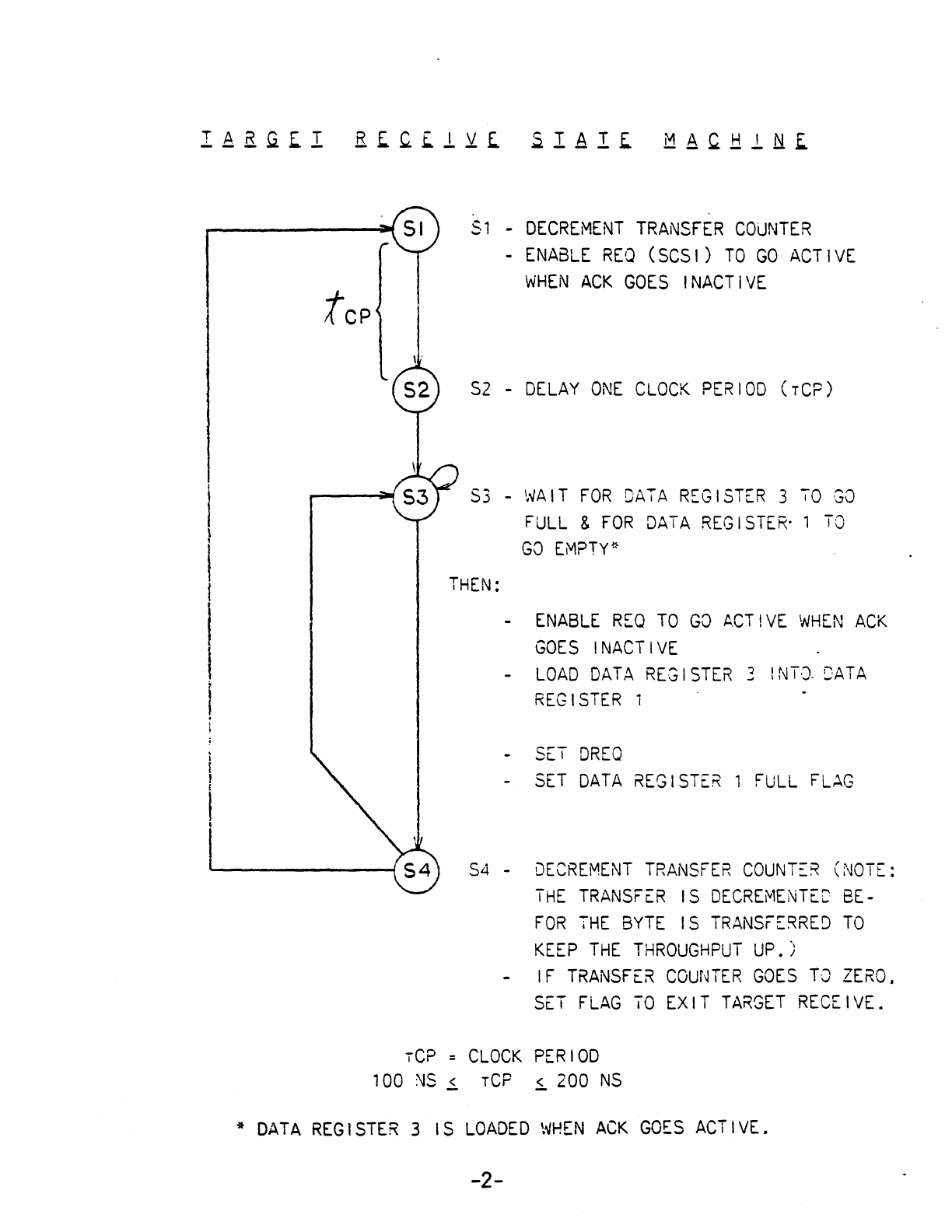
~p
51
-
DECREMENT
TRANSFER
COUNTER
-
ENABLE
REO
(SCSI)
TO
GO
ACTIVE
WHEN
ACK
GOES
INACTIVE
S2
-
DELAY
ONE
CLOCK
PERIOD
(rCP)
53
-
WAIT
FOR
DAiA
REGISTER
3
TO
GO
FULL
&
FOR
DATA
REGISTER-
1
TO
GO
EMPTY*
THEN:
-
ENABLE
REQ
TO
GO
ACT!VE
WHEN
ACK
GOES
INACTIVE
LOAD
DATA
REGISTER
3
!NTQ
SAT
A
REGISTER
-
SET
DREO
-
SET
DATA
REGISTER
1
FULL
FLAG
S4 -
DECREMENT
TRANSFER
COUNT~R
(NOTE:
THE
TRANSF£R
IS
OECREMENTEC
BE-
FOR
THE
BYTE
IS
TRANSFE~RED
TO
KEEP
THE
THROUGHPUT
UP.)
IF
TRANSFER
COUNTER
GOES
TO
ZERO.
SET
FLAG
TO
EXIT
TARGET
RECEIVE.
rCP
=
CLOCK
PERIOD
100
~S
~
rCP
~
200
NS
*
DATA
REGISTER
3
IS
LOADED
WHEN
ACK
GOES
ACTIVE.
-2-
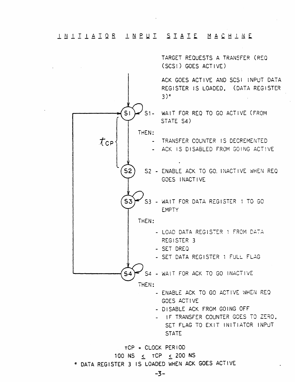
TARGET
REQUESTS
A
TRAN5FER
(R~Q
(SCSI)
GOES
ACTIVE)
ACK
GOES
ACTIVE
AND
SCSI
INPUT
DATA
REGISTER
IS
LOADED,
(DATA
REGISTER
3)*
S1-
WAIT
FOR
REO
TO
GO
ACTIVE
(F~OM
STATE
S4)
THEN:
-
TRANSFER
COUNTER
IS
DECREMENTED
-
ACK
IS
DISABLED
FROM
GOING
ACT!VE
S2
-
ENABLE
ACK
TO
GO.
I
NACT
I
VE
WHEN
REQ
GOES
INACTIVE
S3
-
WAIT
FOR
DATA
REGISTER
TO
GO
EMPTY
THEN:
-
LOAD
DATA
REGIS~ER
FROM
DA7A
REGISTER
3
-
SET
DREQ
-
SET
DATA
REGISTER
1
FULL
FL~G
S4
-
WAIT
FOR
ACK
TO
GO
INACTIVE
THEN:
-
ENABLE
ACK
TO
GO
ACTIVE
WHEN
REO
GOES
ACTIVE
-
DISABLE
ACK
FROM
GOING
OFF
IF
TRANSFER
COUNTER
GOES
TO
Z~~O,
SET
FLAG
TO
EXIT
INITIATOR
INPuT
STATE
Tep =
CLOCK
PERIOD
100
NS
~
rCP
~
200
NS
*
DATA
REGISTER
3
IS
LOADED
WHEN
ACK
GOES
ACTIVE
-3-
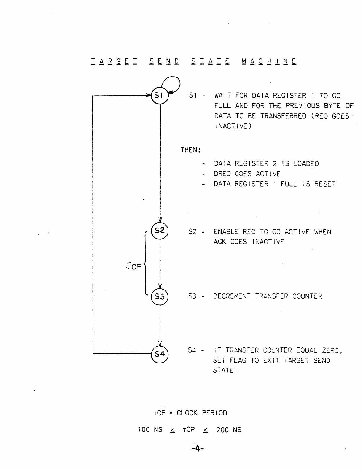
I
~
51 -
WAIT
FOR
DATA
REGISTER
1
TO
GO
FULL
AND
FOR
THE
PREVIOUS
BY7E
OF
DATA
TO
BE
TRANSFERRED
(REQ
GOES'
INACTIVE)
THEN:
-
DATA
REGISTER
2
IS
LOADED
-
DREQ
GOES
ACTIVE
-
DATA
REGISTER
1
FULL
:S
RESET
S2
-
ENABLE
REQ
TO
GO
ACTIVE
WHEN
ACK
GOES
INACTIVE
S3
-
DECREMENT
TRANSFER
COUNTER
S4
-
IF
TRANSFER
COUNTER
EQUAL
ZERO.
SET
FLAG
TO
EXiT
TARGET
SEND
STATE
rep =
CLOCK
PERIOD
100
NS
~
rep
~
200
NS
~-
III.
NCR
5385S
SYNCHRONOUS
OPERATION
NCR
5386S
Synchronous
Operation
The
NCR
5386S
SCSI
Protocol
Controller
is
pin
and
software
compatible
with
the
NCR
5385E
and
5386
but
may
additionally
be
used
to
transfer
data
in
a
synchronous
fashion.
Using
a
10
Mhz
clock
the
NCR
53868
is
capable
of
transferring
data
up
to
3.3
MBytes/sec.
The
following
information
describes
how
to
invoke
the
synchronous
operation
and
what
is
required
to
achieve
to
maximum
data
rate.
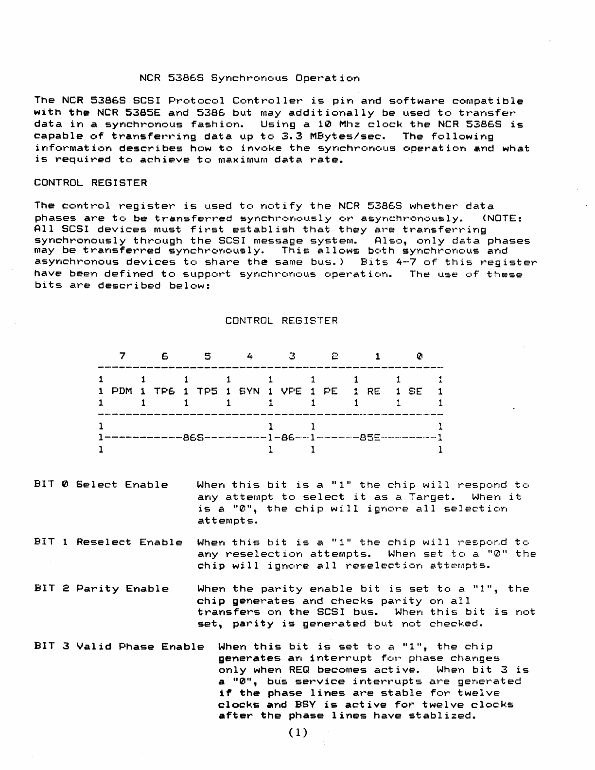
CONTROL REGISTER
The
control
register
is
used
to
notify
the
NCR
53868
whether
data
phases
are
to
be
transferred
synchronously
or
asynchronously.
(NOTE:
All
SCSI
devices
Must
first
establish
that
they
are
transferring
synchronously
through
the
SCSI
message
system.
Also,
only
data
phases
may
be
transferred
synchronously.
This
allows
both
synchronous
and
asynchronous
devices
to
share
th~
same
bus.)
Bits
4-7
of
this
register
have
been
defined
to
support
synchronous
operation.
The
use
of
these
bits
are
described
below:
CONTROL
REGISTER
7 6 5 4 3 2
1 1
111
1
1
PDM
1
TP6
1
TP5
1
8VN
1 VPE 1
PE
1 1 1 1 1 1
I 1 1
1
1
1
RE
1
o
1
1
SE
1
of
J.
1
1
1
1-----------86S---------1-86--1------85E--------I
III
1
BIT
0
Select
Enable
Wherl
this
bit
is
a
Ill"
the
chip
will
l""'esp.:lnd
t,:.
any
attempt
to
select
it
as
a
Target.
When
it
i
sa"
0 " ,
the
chi
p w
ill
i 9 nc.
t"
e a 1 I
se
1 e c t i
CI
n
attempts.
BIT
1
Reselect
EYlable
WheYI
this
bit
is
a "111
the
chip
will
t
....
espc1nd
tel
aYIY
t"'ese
1
ect
i clr,
at
tempt
s.
When
SE·t
t.:,
a
"tZl"
the
chip
will
ignore
all
reselection
attempts.
BIT
2
Parity
Enable
When
the
pat"ity
eY,able
bit
is
set
to
a
"1",
the
chip
generates
and
checks
parity
on
all
transfers
on
the
SCSI
bus.
When
this
bit
is
not
set,
parity
is
generated
but
not
checked.
BIT
3
Valid
Phase
Enable
Whey,
this
bit
is
set
tCI
a
"1",
the
chip
generates
an
interrupt
for
phase
changes
only
when
REQ
becomes
active.
When
bit
3
is
a
"0",
btlS
sel'''vice
iy,tert"upts
al'''e
geY'tet"'ated
if
the
phase
lines
are
stable
for
twelve
clocks
and
BSV
is
active
for
twelve
clocks
after
the
phase
lines
have
stablized.
(1)
IT
4 SYYlchroYlc,uS
SCSI
When
this
bit
is
set
to
a
"1",
the
chi
p
is
con-·
~igured
to
transfer
all
data
phases
across
the
SCSI
bus
using
the
synchronous
offset
of
one
handshake.
When
this
bit
is
a
zero,
the
chip
will
handshake
data
as
the
NCR
5385E
and
the
5386
in
an
asynchronous
~ashion.
BIT
5,6
Transfer
Period
The
Transfer
Period
bits
are
provided
so
aIT
7
Pulsed
DMA
Mode
you
may
program
the
NCR
53868
to
ma~ch
the
transfer
rate
of
your
application.
These
bits
determine
the
minimuM
REQ
cycle
time
and
are
only
used
when
operating
as
a
Target
device.
These
transfer
period
bits
are
only
used
in
synchronous
data
transfers.
TP6
TP5
MINIMUM
REQ
CYCLE TIME
0
IZI
3
Cl.:.ck
Pe","iods
0 1
3.5
C 1
clck
Pen'iods
1 0 4
Clock
Pel'''i
t:lds
1 1
4.5
Cloc~.
Pe
.....
iods
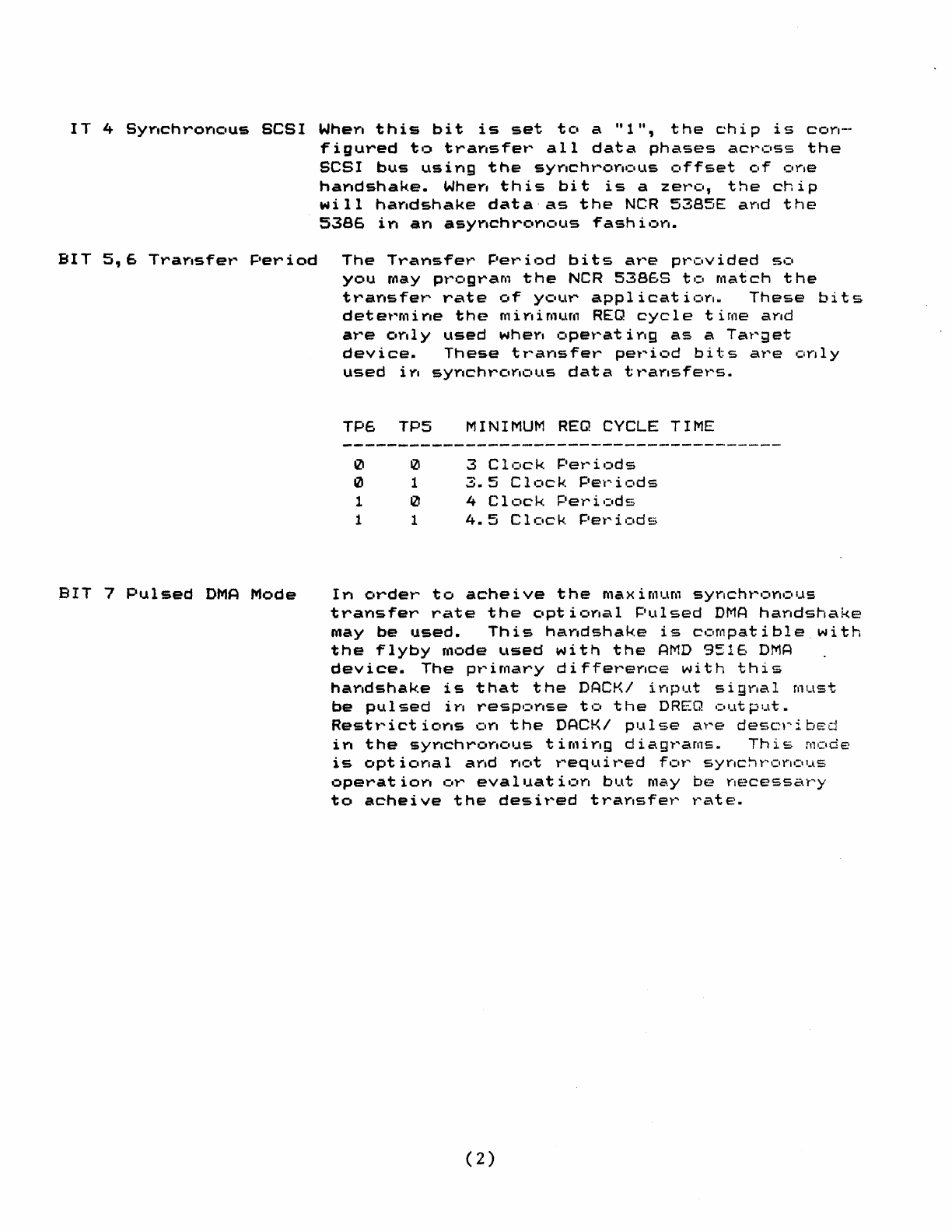
In
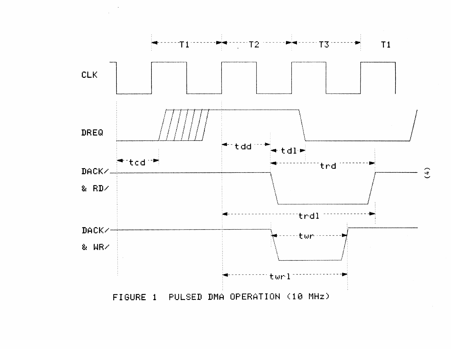
order
to
acheive
the
maximum
synchronous
transfer
rate
the
optional
Pulsed
DMA
handshake
may
be
used.
This
handshake
is
compatible
with
the
flyby
mode
used
with
the
AMD
9516
DMA
device.
The
primary
difference
with
this
handshake
is
that
the
DACKI
input
signal
must
be
pulsed
in
response
to
the
DREQ
output.
Restl'''ict
ioY,s
elY,
the
DACKI
pulse
a"r"e
desc::y'i
bEd
in
the
synchronous
timing
diagrams.
This
Mode
is
optional
and
not
required
for
synchronous
operation
or
evaluation
but
m~y
be
necessary
to
acheive
the
desir~d
transfer
rate.
(2)
iDENTIFICATION
In
the
10
Register
Bit
6
is
used
to
identifiy
the
device
as
an
NCR
53869.
This
read
only
bit
notifies
the
controlling
software
that
synchronous
data
transfers
are
supported.
If
this
bit
is
not
set
then
the
device
is
either
an
NCR
5385E
or
NCR
5386.
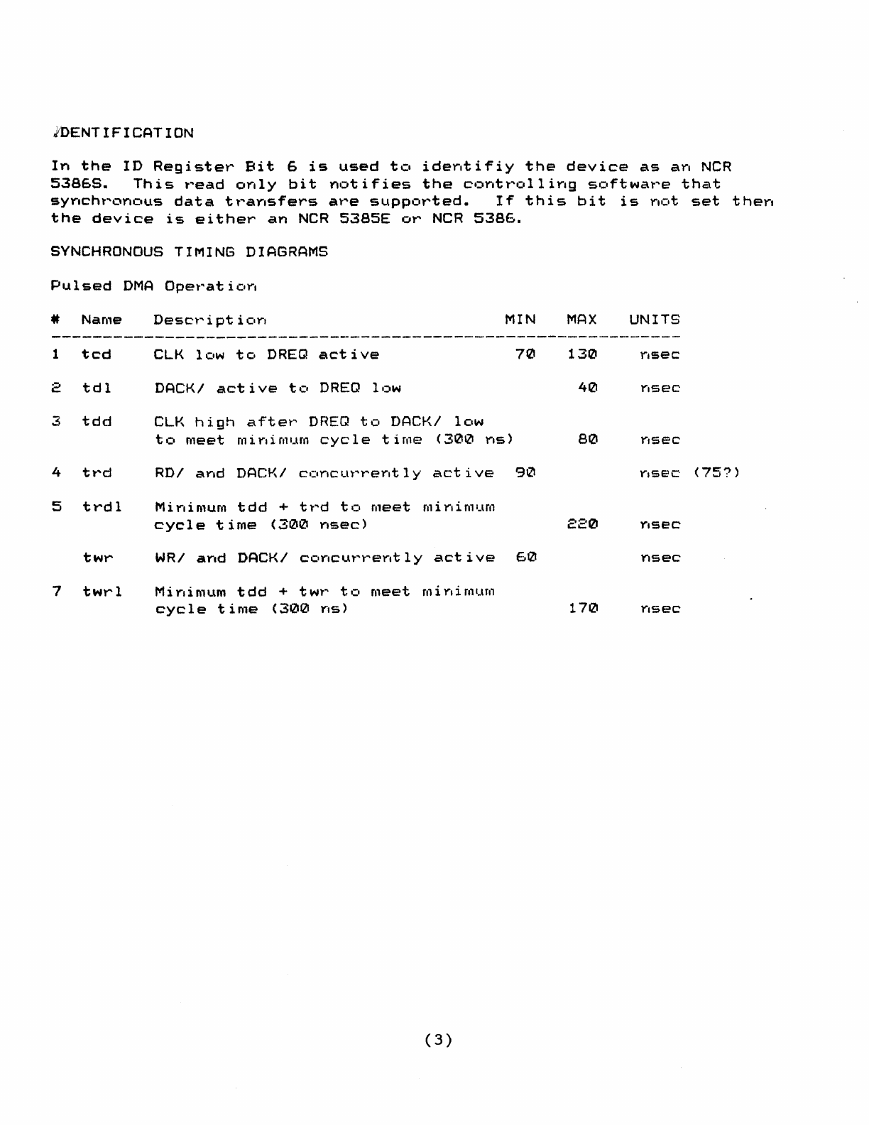
SYNCHRONOUS
TIMING DIAGRAMS
Pulsed
DMA
Operation
4t
Name
Desct
....
i
pt
i
orl
MIN
MAX
UNITS
1
tcd
CLK
lClw
tel
DREQ
active
70
130
2
tdl
DACKI
active
tCI
DREQ
ll;)w
4121
3
tdd
eLK
high
aftet"
DREQ
tCI
DACKI
lClw
to
meet
mi
rli
mum
cycle
time
(300
Y",s)
80
Y'lsec
4 tl'''d RDI
arid
DACKI
cl:lr'cLn
....
·
.....
er't
1 y
active
90
nsec'
(757)
5
trdl
Mi
Y",imum
tdd
+
tt
....
d
to
meet
fIli
Y"limum
cycle
time
(3121121
Y",sec)
220
Y,sec
twr
WRI
arid
DACKI
cclr'cul'''t
....
er't
1 y
active
60
nsec
7
twrl
Mi
Y',in1um
tdd
+ twt"
tel
meet
r.l
i
r,i
mum
cycle
time
(3121121
Y",s)
17121
r.sec
(3)
elK
DREQ
" "
• -----
-T
1 ---
~
----..... --
-,
---T 2 ---
--
--
~
------T 3 -------
.~
T 1
lL------l
..
I " I I i
/'
i I
.'
" t J
, , I ' I '
,I
I I ' , I '
"
..
I'
,I
,I
I }
"
t'
I J
,I
I I
l l l I I l
~-----',Ll
l I I
,I
--lL-----J
\L...-' -
________
----il
~--
t d.j
---.
:
~
·tdl-.-.
-.--------"----tr·d
---------..:
DACK/------------------------------~"
~------
\ I
\~
_________
____J/
~-
--------------------t
t-·
d 1 -------------
~
DA
CK/
-.-.;...-----------------------.\
t
~
------t
1.1
...... · - - - - - - -
-"":/~
. I .
. \ l :
\ l :
\,
l :
~-
-------
.-
---t
IJ.t
t-·
1 -------
.-
---
--
--
-~
FIGURE
1
PULSED
DMA
OPERATION
(10
MHz)
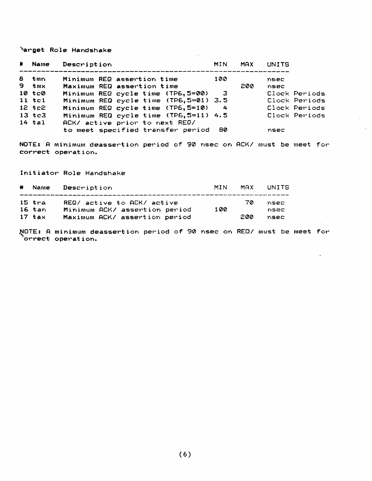
~~rget
Role
Hay.dshake
tt
Name
Descri
pt
ioY.
MIN
e
tmY'.
Minimum
REQ
assel'''t
i
OY.
time
100
9
tmx
Maximum
REQ
assel'''t
i c.n
time
10
tc0
Minimum
REQ
cycle
time
(TPe"5=00)
3
11
tel
Minimum
REQ
cycle
time
(TP6,5=01)
3.5
12
tc2
Mi
rti
mum
REQ
cycle
time
(TP6,5=10)
4
13
tc3
Mi Ylimum
REQ
cycle
time
(TP6,5=11)
L
...
5
14
tal
ACKI
active
pt"'
i
Cit"'
to
rlext
REQI
to
meet
specified
tl'''arlsfet''
pel'''icld
80
NOTE: A
minimum
deasset"t
ic.rl
pel'''iod
clf
90
nsec
CtY',
correct
opel'''at
iClra.
Iyti
t
iator"
..
Name
15
tra
16
tay.
17
tax
RClle
Harldshake
Desct'"
i
pt
i
Clrl
REQ/
active
to
ACK/
active
Minimum
ACKI
assertion
period
Maximum
ACKI
assertion
period
MIN
100
~OTE:
A
minimum
deassertion
period
of
90
nsec
on
grrect
operation.
(6)
MAX
200
ACKI
MAX
70
200
UNITS
Yisec
rlsec
Cl.:.ck
Clc.ck.
Cl.:lck
C 1.:lck
rlsec
must
be
UNITS
r,sec
nsec
r,sec
Pe~"'il:.ds
Pel'"'ic.ds
Pel'''i,=:tds
Pel'''ic.ds
meet
fell'"'
REQI
must
be
meet
for
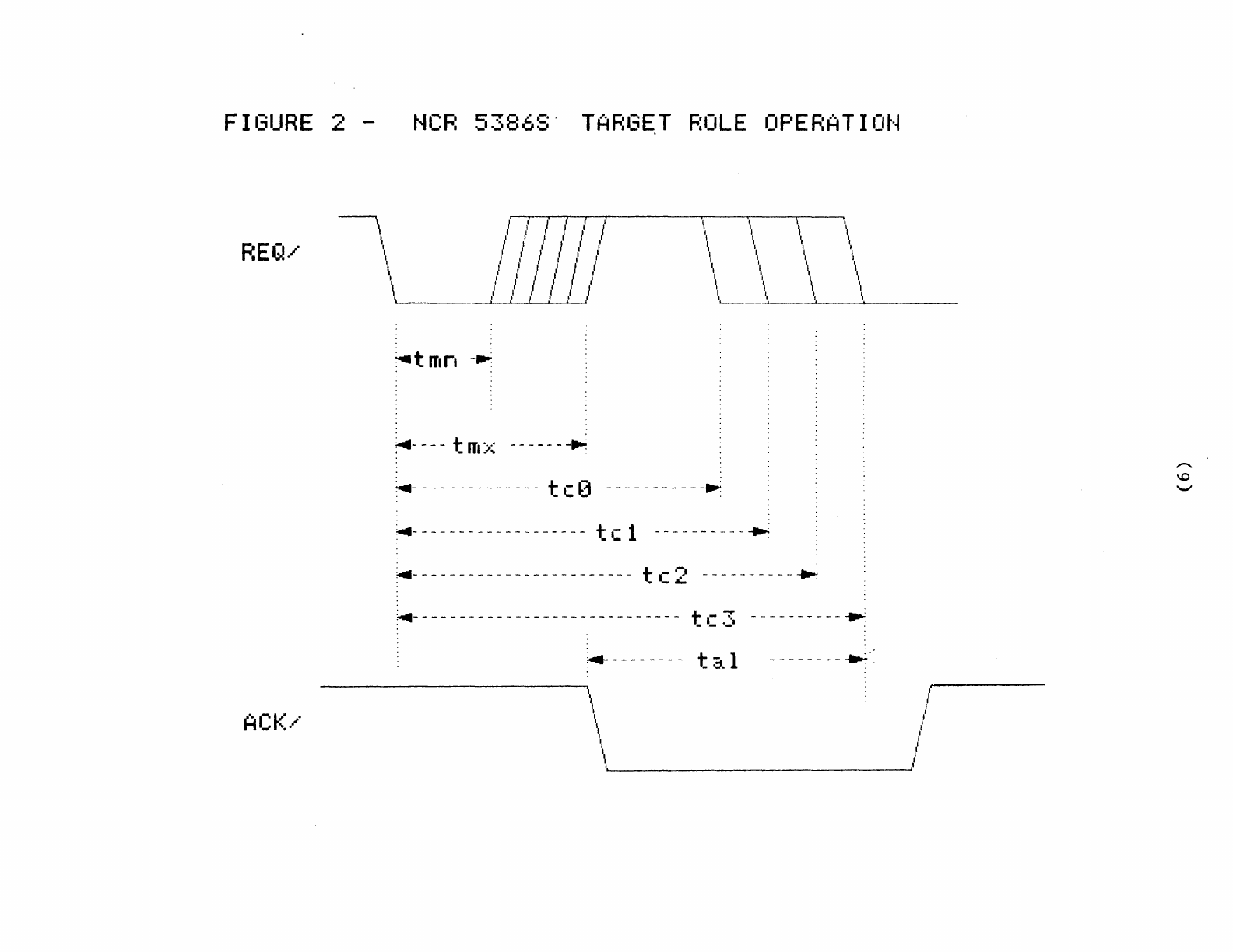
FIGURE
2
~
...
REQ/
I
\
t·
ll
--
R
C"
....
8 /
ro·
.
.,
....
I
__
I.)
0':'
l / /
/ I
l , /
l
,
/
..
I'
I I l
,
I'
TARG~T
ROLE
OPERATION
( "
'\
\,
\ \
l l ,
II
\
, ,
, ,
I'
, , ,
/
I,
I I
~
, , I
I \ \ \ \
/ / / \ \
\ 1 I I
'I 'I
I l ,
,
, l
\,
,
I
...
,
1
,
~tmn
-~
~-
---t m
::<
------
-...:
~-
-------------. t c 0 ----------
-~
;...-
------------------
tel
-------
_.
--
~
~-
----------------------- t c 2 ----------
..
~-
---------------------------- t c 3 ----- -----
~
.--------
t::..l
--------~.,
"
I"
"
\
,III
\'1,
'
~.
______________________________________
~J
A
"I--
L/
'"
...,r
...
·
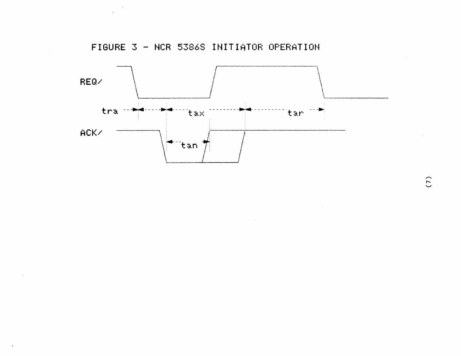
FIGURE
3 -
NCR
53868·
INITIATOR
OPERATION
\ l \
I I
I 'I
REQ/
/ ,
I l
I,
II
/ \
I \
~
\,
li~
t r a --
-~
----
-~
----t
a>::
--------
-~
---------. t
~.
r'
--
-~
IV.
SCSI
ACCOMMODATES
FLEXIBLE
SYSTEM
ARCHITECTURES
SCSI
ACCOMMODATES
FLEXIBLE
SYS~EM
ARCHITECTURES
The
SCSI
interface
is
rapidly
gaining
acceptance
as
a
standard
for
interconnecting
intell
igent
peripheral
device
s.
Mu
ch
of
the
standard's
success
may
be
directly
attributed
to
the
flexibility
that
the
interface
offers.
In
order
to
demonstrate
the
v e r
sa
til
i
ty
of
the
SCSI
standard,
four
unique
sy
stem
architectures
will
be
described:
single-user/single
tasking,
mul
ti-tasking,
mul
ti-user,
and
mul
ti-processing
systems.
These
examples
represent
actual
product
offerings
that
span
a
range
of
computing
requi
rements.
The
SCSI
interface
provides
a
readily
available,
cost-effective
solution
for
the
differing
needs
of
..
'.
each
c0nf
lS1ur
ation.
SINGLE-USERISINGLE-TASKING
SYSTEMS
The
personal
computer
products,
which
make
up
a maj
or
i
ty
of
the
computers
sold,
may
be
generally
characterized
as
a
single-
user/single-tasking
system.
In
these
~stems
I/O
is
performed
in
a
sequential
manner.
For
example,
if
you
wish
to
store
a
file
to
disk
and
then
read
another
file
from
disk,
you
would
wait
for
the
first
task
to
complete
before
the
second
task
can
be
performed.
Figure
1
shows
a
block
diagram
of
products
which
represent
this
category.
Because
the
SCSI
interface
operates
with
generic
device
types,
the
system
may
be
designed
to
operate
with
a
variety
of
intelligent
mass
storage
devices.
This
allows
the
user
a
choice
(1)
of
configurations
that
meet
his
performance
and
storage
capacity
requirements.
Flexibility
is
important,
but
product
cost
is
the
primary
concern
for
this
class
of
computer.
A
hard
disk
drive
and
a
controller
board
may
account
for
as
much
as
50%
of
the
system
cost.
Disk
drive
manufacturers
have
traditionally
provided
drive-level
interfaces
that
interface
to
the
host
bus
through
a
disk
controller.
However,
with
the
increasing
integration
of
controller
electronics,
several
manufacturers
are
finding
it
less
costly
to
provide
an
integrated
SCSI
controller
directly
on
the
disk
drive.
Obviously,
a
single
board
is
less
expensive
than
two
boards,
plus
the
hardware
required
to
interconnect
the
boards.
Less
obvious
is
the
savings
realized
by
achieving
higher
manufacturing
yields
on
the
drive's
head/drive
assembly.
Since
the
disk
is
addressed
as
a
logical
storage
device
and
the
controller
manages
the
surface
defect
mapping,
the
manufacturer's
assembly
yields
are
increased,
thereby
reducing
the
overall
product
cost.
MULTI-~ASKING
SYSTEMS
In
single-tasking
or
single-threaded
enviromnents,
system
performance
suffers
due
to
the
sequential
nature
of
all
1/0
operations.
Seek
and
rotational
latencies,
associated
with
the
-2-
disk
drive,
may
occupy
up
to
70%
of
the
time
required
to
access
a
sector
of
information.
In
single-user/mul
ti-tasking
systems,
to
take
advantage
of
this
"dead"
time,
the
SCSI
standard
allows
devices
not
actively
transferring
data
to
remove
themselves
from
the
bus,
so
that
other
I/O
operations
may
be
initiated.
Therefore,
multiple
disk
drives
may
be
seeking
data
simultaneously,
providing
for
higher
bus
util
ization.
The
drive
which
locates
its
data
first
will
reselect
the
host
and
complete
the
transfer.
Figure
2
shows
a
block
diagram
of
a
single-user/multi-tasking
system.
Many
workstations
are
being
designed
around
this
architecture.
Since
these
systems
are
more
sophisticated,
additional
devices
such
as
optical
disks
and
tape
back-up
units
may
optionally'
be
added.
The
SCSI
bus
is
easily
expanded
to
include
additional
devices,
without
occupying
valuable
backplane
slots.
Again,
since
the
SCSI
interface
supports
generic
device
types,
all
peripherals
may
be
upgraded
to
the
user's
performance
and
storage
r
eq
ui
rement
s.
MULTI-USER
SYSTEMS
In
today's
office
environment,
personal
computers
are
stand-alone
dev
ices
tha
t
suppor
t
individual
productivi
ty
requirements.
However,
if
data
needs
to
be
shared
between
users,
then
the
-3-
system
components
need
to
be
networked.
Local
area
networks,
such
as
Omninet,
Ethernet,
Arcnet
and
Appletalk,
may
be
used
to
accompl
ish
this
interf
aci
ng
task.
Since
da
ta
is
shared
be
tween
these
various
components,
fileservers
are
used
as
common
storage
elements.
Fileservers,
in
many
cases,
are
personal
computers
modified
to
support
multi-user
file
management.
Figure
3
shows
a
common
fileserver
implementation.
In
some
cases,
the
mere
fact
of
having
multiple
users
dramatically
reduces
system
responsiveness,
which
is
so
important
in
mul
ti-user
env
irornnents.
However,
since
the
SCSI
bus
supports
data
rates
at
1.5
Mbytes/sec
in
an
a~nchronous
mode
and
up
to
4
Mbytes/sec
using
a
~ndhronous
handshake,
system
performance
need
not
suffer.
~his
fast
transfer
rate
coupled
with
the
disconnect
capability
allows
for
high
data
throughput
and
efficient
bus
utilization.
Additionally,
these
transfer
rates
match
or
exceed
the
performance
of
the
commonly
used
local
area
networks
(LANs).
The
SCSI
interface
supports
several
conunands
to
accommodate
multi-user
systems
by
providing
increased
system
performance
and
shared
file
protection.
Sear
ch
conunands,
implemented
in
the
fileserver
or
the
disk
controller,
allow
key
words
to
be
searched
locally
rather
than
occu~ing
the
LAN
or
the
SCSI
bus
with
large
data
transfers.
while
reducing
These
commands
increase
the
system
performance
the
bus
bandwidth
requirements.
To
keep
shared
-4-
files
from
being
accessed
simultaneously,
the
Reserve
and
Release
commands may
be
used
to
manage
file
activity.
Reserved
files
are
not
available
to
other
users
until
the
files
have
been
Released
by
the
current
users.
Aside
from
sharing
data,
fileservers
may
be
used
to
share
expensive
system
resources.
Laser
printers,
large
storage
devices,
color
plotters,
and
even
copiers
may
act
as
shared
resources
in
the
multi-user
envirorunent.
The
SCSI
interface
allows
the
f
ileserver
to
be
easily
reconf
igured
for
specif
ic
system
req
ui
rement
s.
MULTI-PROCESSOR
SYSTEMS
Systems
supporting
multiple
operating
systems,
real
time
data
acquisition,
communication
processors,
or
other
dedica.ted
processors
have
traditionally
used
backplane
architectures
to
support
thei
r
multi-processing
requirements.
These
systems
requi
re
a
local
communica
tions
bus
as
well
as
an
intelligent
peripheral
interface.
The
SCSI
interface,
with
its
multi-host
capability,
provides
the
needed
functionality
at
a
fraction
of
the
backplane
cost.
In
addi
tional
to
file
tran
sfers
be
tween
individual
processors
and
mass
storage
devices,
inter-processor
communications
can
be
accomplished
across
the
SCSI
interface.
Futhermore,
freedom
from
backplane
form
factors
provides
increased
design
flexibili
ty.
Figure
4
shows
a
block
diagram
of
a
multi-processor
~stem.
-5-
Since
the
SCSI
interface
is
limited
to
directly
supporting
up
to
eight
bus
devices,
this
may
preclude
the
use
of
the
standard
SCSI
interface
in
complex
multi-processing
configurations.
SCSI/Plus
(tm)
addresses
this
I
imitation
by
taking
advantage
of
unused
bus
phases
to
provide
a
binary
selection
phase.
Using
the
binary
selection
phase,
up
to
64
bus
devices
may
be
supported.
SCSI/Plus
is
a
superset
of
the
SCSI
standard
and
the
different
bus
devices
may
co-exist
on
the
same
bus.
SUMMARY
The
systems
described
in
this
article
are
a few
of
the
many
configurations
that
use
SCSI
as
the
backbone
of
their
architectures.
The
standard
offers
the
flexibility
needed
to
incorporate
a
range
of
system
requirements,
spanning
several-
hundred-dollar
personal
computers
to,
several-hundred-thousand-
dollar
multi-user
systems.
Additionally,
integrated
circuits,
board
level
products,
and
fully
integrated
bus
devices
are
readily
available
from
a
variety
of
manufacturers.
In
each
product
category,
SCSI
offers
a
cost-effective
solution
that
pr
ov
ide
s
the
ne
cessa
ry
performance,
feat
ure
s
and
vendor
uniqueness
to
make
it
a
truly
usable
standard.
SCSI/Plus
is
a
trademark
of
Aropro
Computers,
Inc.
-6-
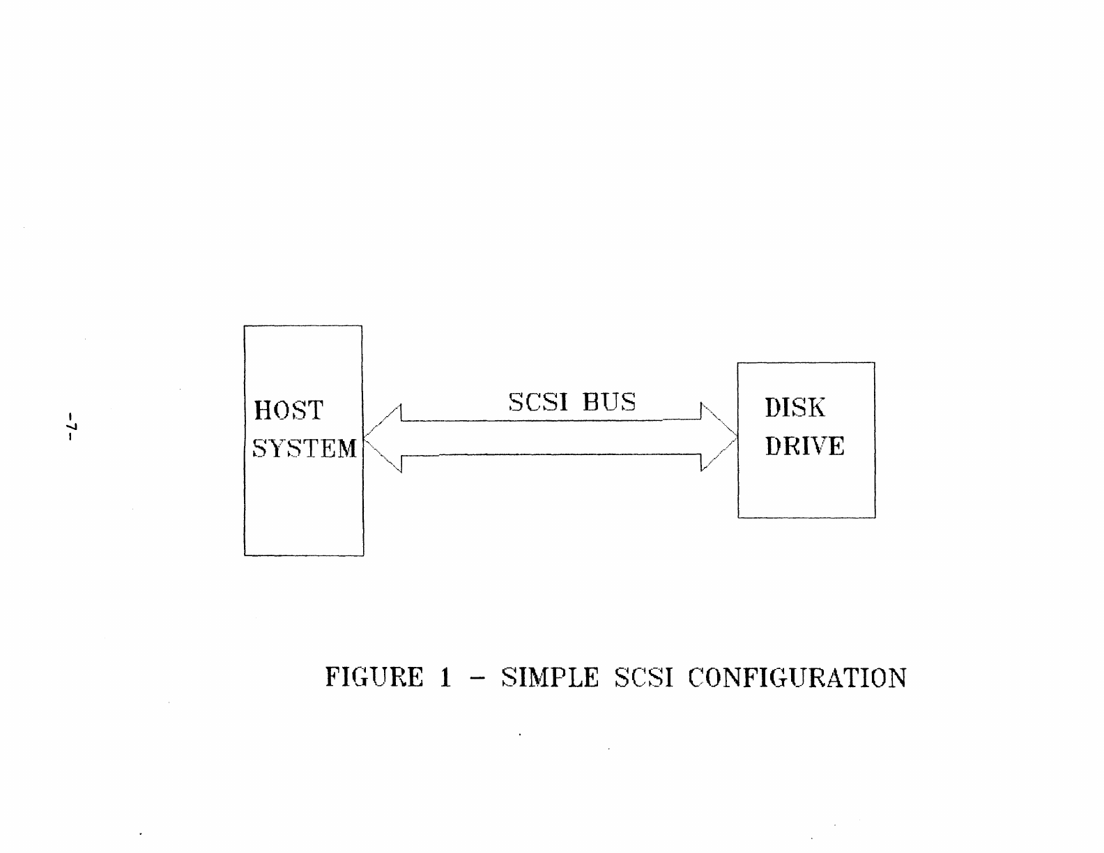
I
~
I
H
O--iT
-~
FICi-lJRE
1 -
SI~lfPLE
SC~~SI
C~ONFI(;lJRATION
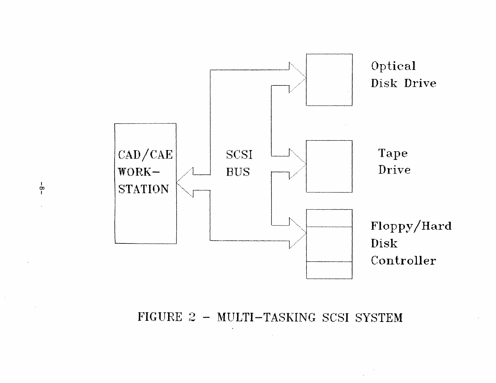
I
ex>
I
"''1.
'---'
••••
'1.'1..
C~AD/CAE
lVORK-
./
BIJS
.......
~./.
STATION
'~I
'."
~-t.///
l)l)tic~al
Disl{ Dl'i,7e
Tape
I)ri\le
Flopp~y~/Hal'd
I)isl{
Cl111troller
J?IG1~TRE
2 -
~/ITJLTI-T~~SI(ING
SC~SI
S)~STE~f
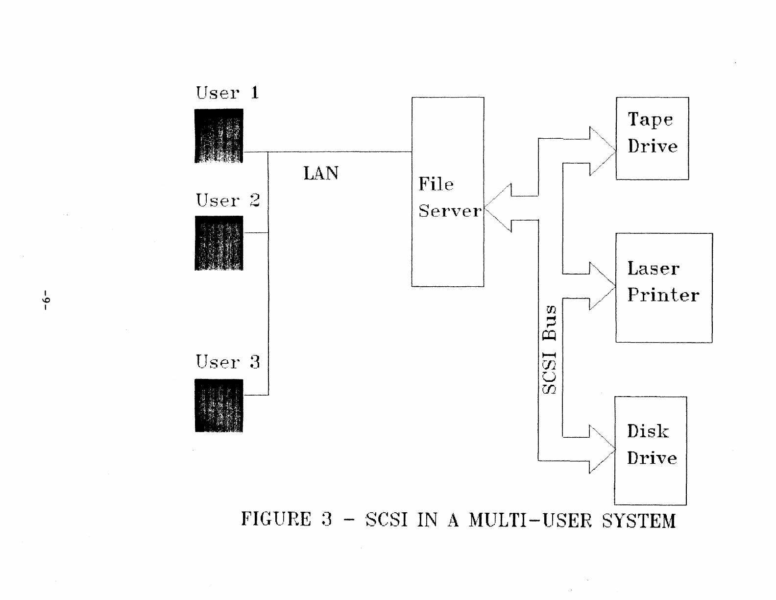
I
\0
I
TJsel" 1
L;\N
File
lJS€l"
2
Sel',7el'
.
TJS€l"
:3
Tape
DI'ive
Laser
Pl"ill
t..er
Disl~
Dl"i,;:re
FIGlJRE
:3
-
'S(~SI
IN i\
1\..flJLTI
-lJSER
S)TSTE1.f
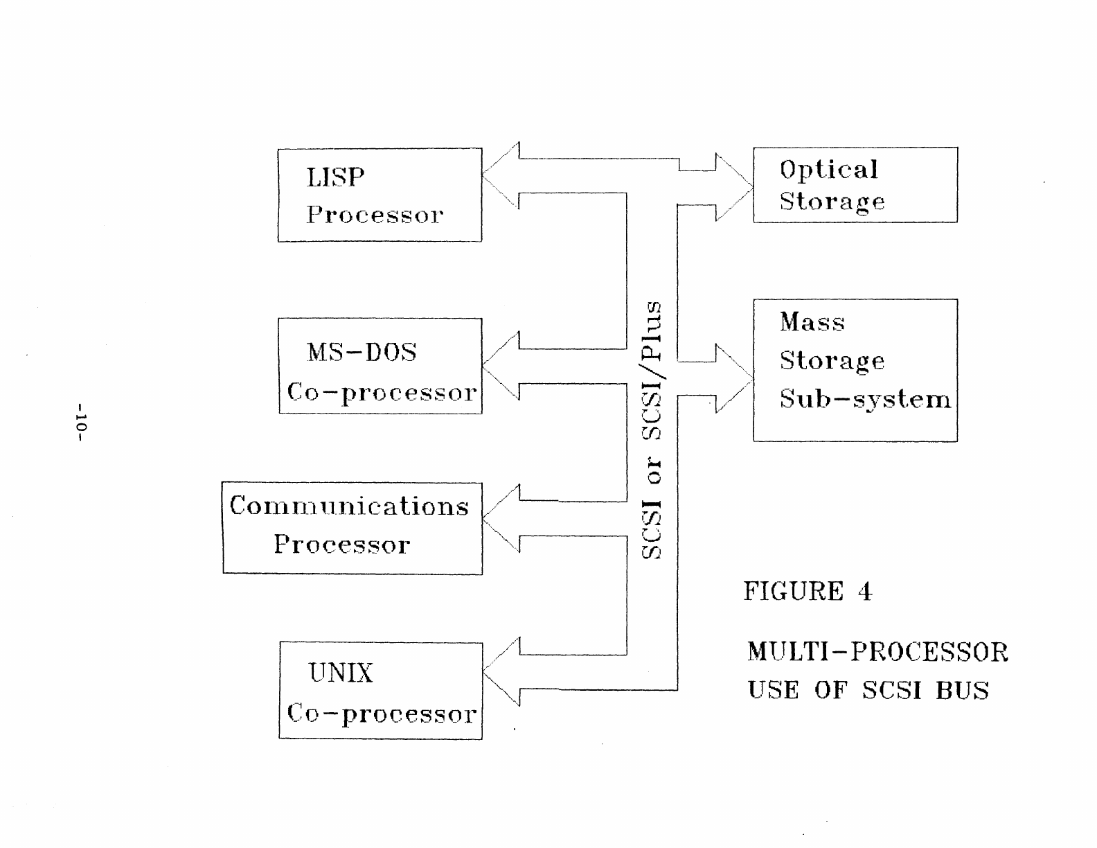
I
.....
o
I
LISP
Prr)CeSS()l'
1\.fS-DOS
(~o
-r)1
1
0CeSS()1'
..
~
...
//L
..
__
U
if1
C~
0 1111111111 i
C~
a
ti
0
11
S
..........
//~.-----'
W
",
lJNIX
(:0
-proceSSOI"
.............
.
'.
~
••
r
./
...
'------'
U
if1
~Iass
Stol~age
Stlt)-s,rsteITl
L)
FIC;lJRE
4
~flJLTI
-
PRO(~~ESSOR
l_TSE
OF
SCSI BlJS
v.
SCSI
PACKAGING
OPTIONS
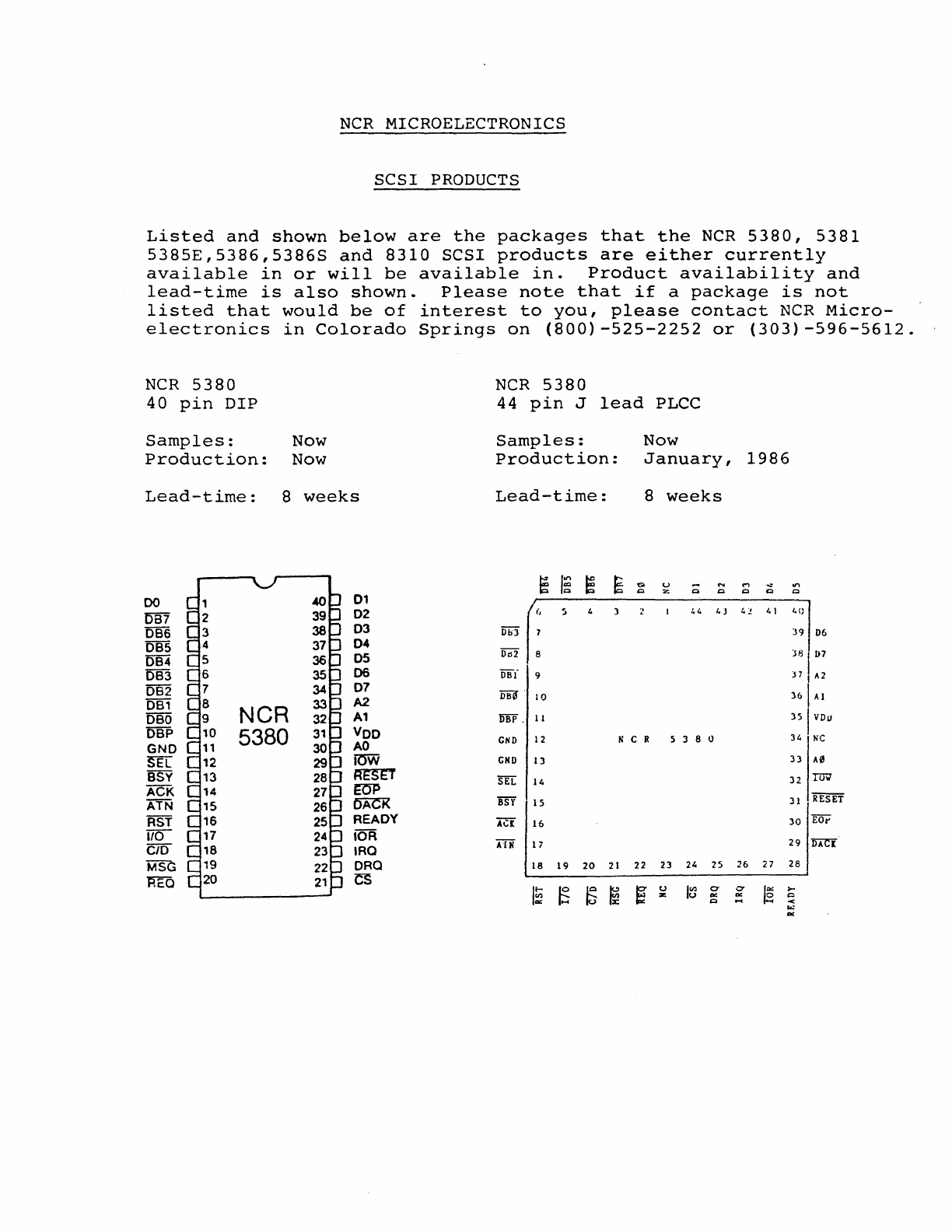
NCR
MICROELECTRONICS
SCSI
PRODUCTS
Listed
and
shown
below
are
the
packages
that
the
NCR
5380,
5381
5385E,5386,5386S
and
8310
SCSI
products
are
either
currently
available
in
or
will
be
available
in.
Product
availability
and
lead-time
is
also
shown.
Please
note
that
if
a
package
is
not
listed
that
would
be
of
interest
to
you,
please
contact
NCR
Micro-
electronics
in
Colorado
Springs
on
(800)-525-2252
or
(303)-596-5612.
NCR
5380
NCR
5380
40
pin
DIP
44
pin
J
lead
PLCC
Samples:
Now
Samples:
Now
Production:
Now
Production:
January,
1986
Lead-time:
8
weeks
Lead-time:
8
weeks
~
I~
~
~
G U
~
.....
....
oJ
.....
Q
::z
Q Q Q Q
00
01
DB7
02
(,
5 t.t.
I.)
t.!.
4\
40
OB6
03
Db3
7 39
D6
OB5
04
DIl2
DB4
05
8
381
D7
OB3
06
OBI
9 J 7 ,
A2
082
07
m
361
Al
OB1
A2
10
OBO
NCR
A1
OBi'
. 11 3S I
VDu
OBP 5380
Voo
CND
12
NCR
5 3 8 0 34
NC
GNO
AO
SEL
lOW
CND
l3
33
A0
BSV
~
SEL
14
32
Tm1
ACK
14
EO'P
Rfffi
ATN
15
~
BSY
15
31
RST
16
READY
ACt
16
30
EOI'
1/0
17 lOR
AlN
29
DAC[
c/o
18
IRa
11
MSG
19 ORO
18
19
20
21
22 23
24
2S
26
27
28
REO 20
CS
IE
~ ~
~
e-
u
I~
Cf
0-
le
>-
z
co::
co::
c::>
Q
....
<
eo:
co::
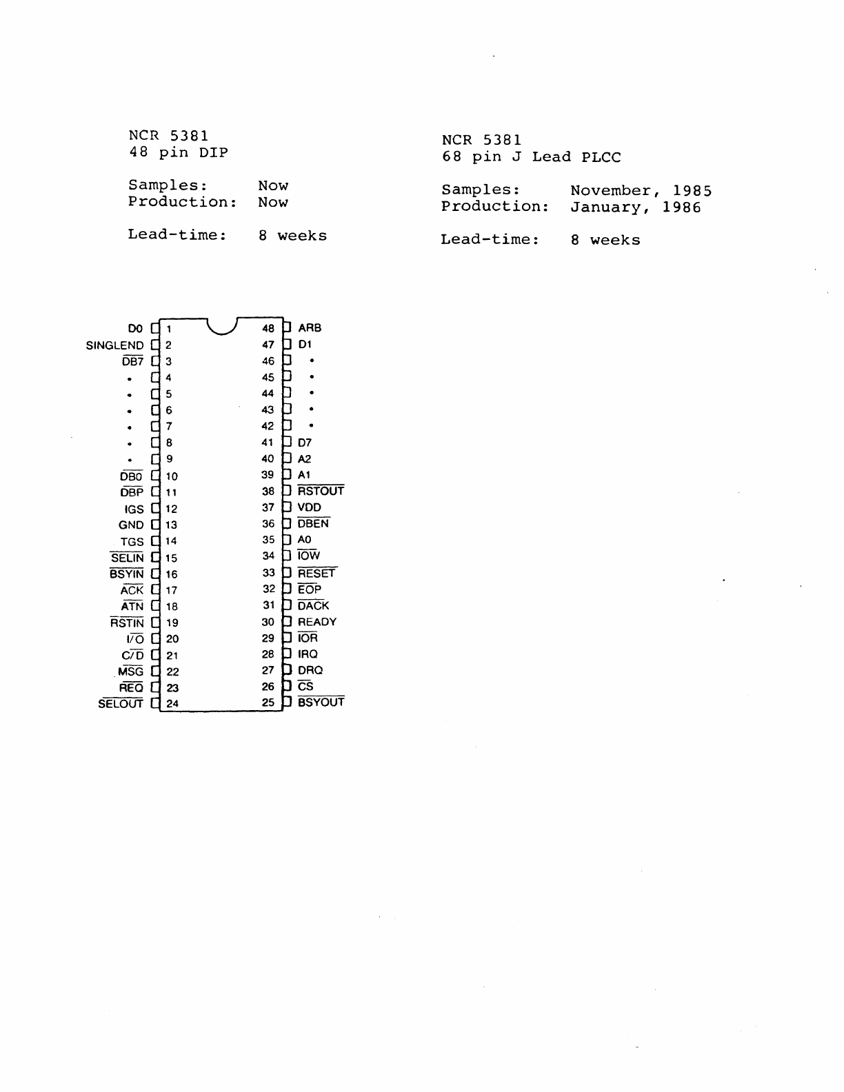
NCR
5381
48
pin
DIP
Samples:
Production:
Lead-time:
00
SINGLEND
DB7
DBO
DBP
tGS
GNO
TGS
SELIN
BSYIN
ACK
ATN
ASTIN
1/0
CIO
MSG
REO
SELOUT
Now
Now
8
weeks
ARB
01
07
A2.
A1
RSTOUT
VDO
OBEN
AO
lOW
RESET
EOP
DACK
READY
lOR
IRQ
ORO
CS
BSYOUT
NCR
5381
68
pin
J
Lead
PLCe
Samples:
Production:
Lead-time:
November,
1985
January,
1986
8
weeks
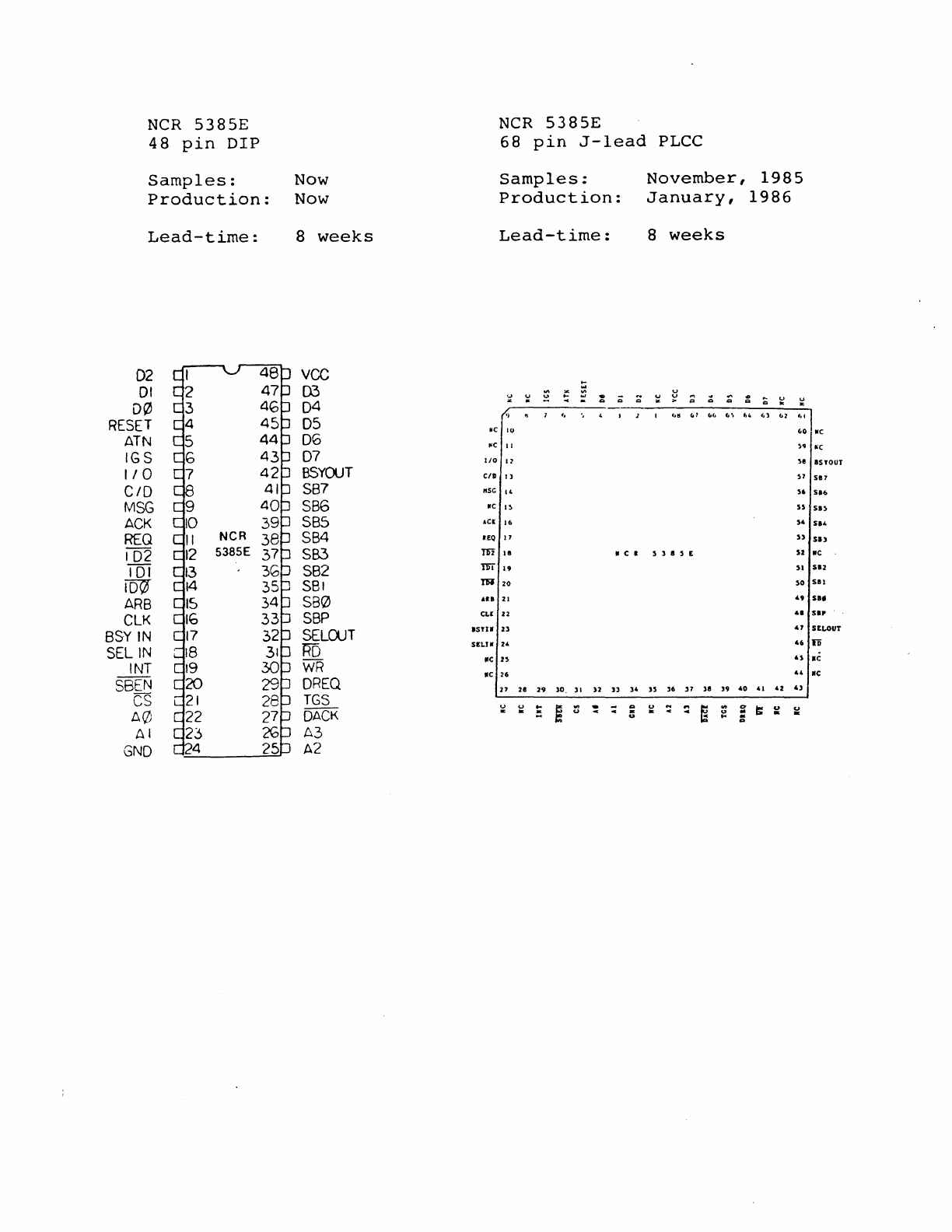
NCR
5385E
NCR
5385E
48
pin
DIP
68
pin
J-lead
PLCC
Samples:
Now
Samples:
November,
1985
Production:
Now
Production:
January,
1986
Lead-time:
8
weeks
Lead-time:
8
weeks
02
vee
....
01
D3
u u
...
'"
..
u
~
Q
;::
~
u
~
;;
~
...
:;
u u
D0
04
Q Q " "
RESET
05
</
" I " . I 1 1
.,~
('7
(,.,
(,\
U (,1
1>1
("I
~c
IU
('0
IfC
ATN
06
NC
II
)'1
~c
IGS
07
I/O
11 )e
IS
YOUT
I/O
BSYOUT
C/D
Il
)7
517
C/D
SB7
"SC
14
S6
51.
MSG
SB6
IfC
I~
ss
SIS
ACK
SBS
ACl
I.
S4
514
REQ
NCR
SB4
JEQ
17
5)
513
102
5385E
5B3
m Ie
II
C • S 3 I S E
52
lie
TOi
SB2
m
19
51
512
roo
S81
m
20
so
SII
ARB
580
All
21
49
$I,
eLK
SBP
CLI
22
41
SIP
.
BSY
IN
SELOJT
ISYU
Z3
41
SELOUT
SELIN
Jill
sE1.J1f
24
46
ro
INT
WR
lie
n
4S
lie
IIC
26
44
lie
SBEN
OREQ
27
ze
29
lO.
II
n
))
)4
)S
)6
37
3e
19
40
41
42
43
CS
TGS
u
..
i
'"
...
u
..
A0
OACK
~
: :
::
~
..
a
r:
u u
. . u . . 4
..
..
. .
..
..
.
...
AI
A3
GNO
A2
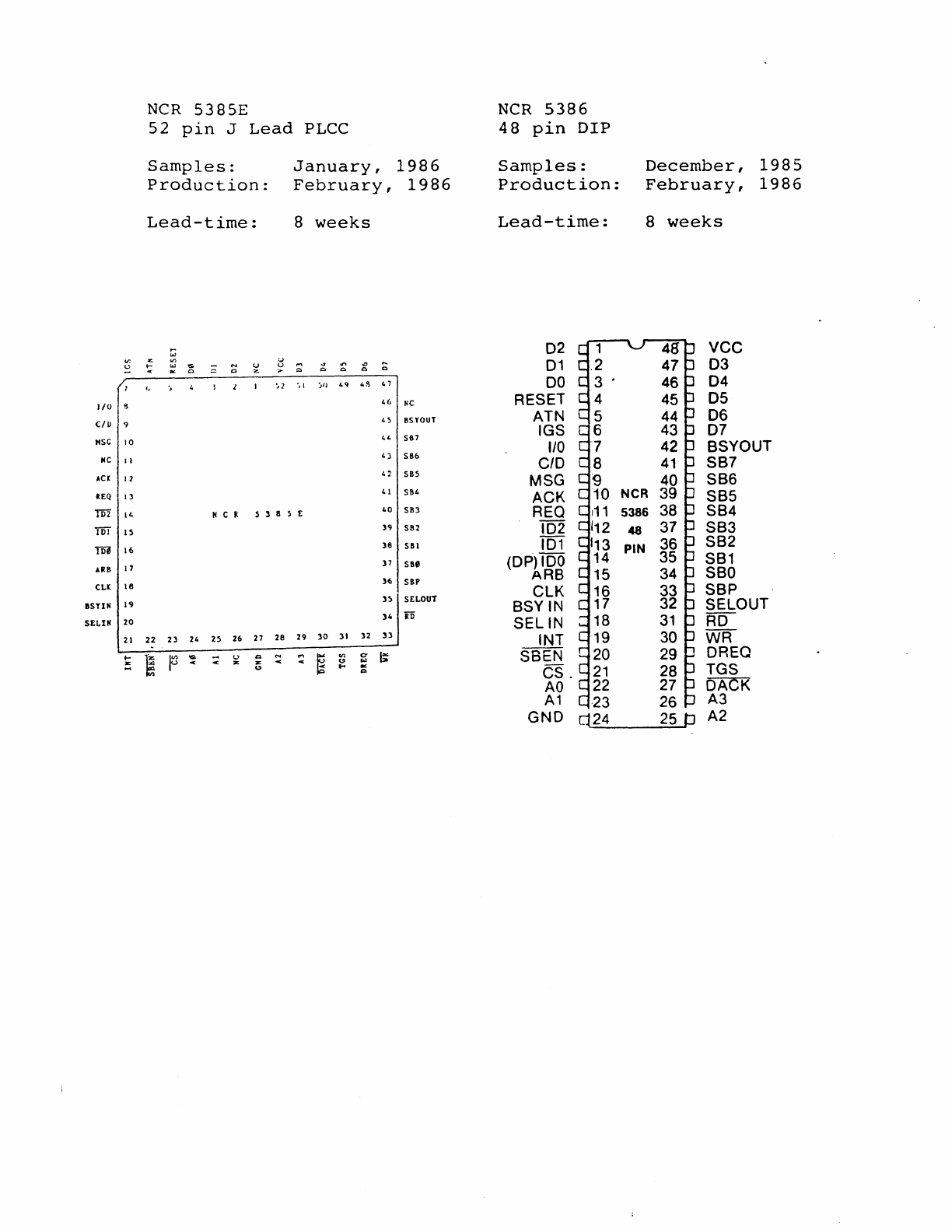
NCR
5385E
NCR
5386
52
pin
J
Lead
PLCC
48
pin
DIP
Samples:
January,
1986
Samples:
December,
1985
Production:
February,
1986
Production:
February,
1986
Lead-time:
8
weeks
Lead-time:
8
weeks
t; 02 vee
or.
'"
III
....
:.J
...,
4
oro
.:>
~
01
03
..,
....
:oJ
...
~
~
""
c -C Q C Q Q
! 1
~2
'd
~"
4'1
loS
4 7
DO
04
1/0
s
H,
IIC
RESET
05
e!u 9
4~
BSYOUT
ATN
06
44
SB7
IGS
07
"sc
10
110
BSYOUT
MC
II
4)
SB6 c/o
SB7
Acr
12
0 SB5
MSG
SB6
REQ
13
41 SB4
ACK
SB5
m
14
II
C
It
5 3 8 5 E
40
SB3
REO
SB4
TiiT
15
39
SB2 102
SB3
TDl
16
38
SBl
101
SB2
17
37
SBe
(OP) 100
SB1
ARB
ARB
SBO
36
SBP
eLl
16
elK
SBP
n SELOUT
ISHII
19
BSYIN
SElOUT
20
34
iO
SELIN
RD
SELIN
21
22
23
24
25
26
27 28
29
30
31
32
33
INT
WR
~
~
~
~
~
U Q
....
....
~
III
C t
SBEN
DREQ
lE lE
40
'"'
U
~
U
....
Q
es.
TGS
AO
DACK
A1
A3
GND
A2
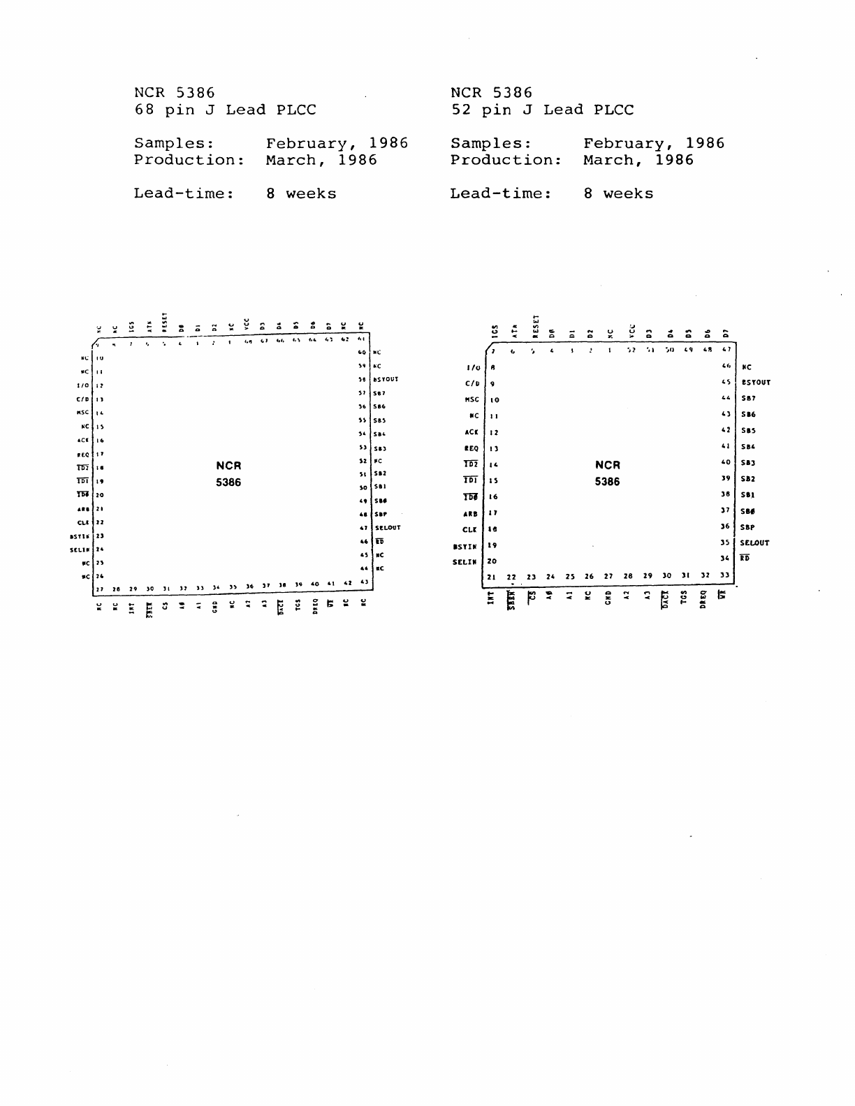
'.1
';
(.
0(;
_c
"
I/O
'1
C/D
11
N5C "
~e
I'
oCI
16
atQ
If
m
\8
m
19
m
20
••
1
11
CLl
J2
15tH
U
SHU
24
lie
n
lie
24
Z1
J8
~
~
NCR
5386
68
pin
J
Lead
PLCC
Samples:
Production:
Lead-time:
v
.
';
v
;:;
:::
-
..
-
'"
NCR
5386
29
)0
11
)l
H
)'
n
)6
...
g
~
: :;
..
~
~
u
February,
1986
March,
1986
8
weeks
~
;;
:;
'"
;
~
~
'"
~,
t.l
Co:
"'\
CoO
.,
)~
~c
H
~s
YOUT
)1
5.7
)6
516
))
51'
)'
51'
))
Sil
)2
"
)'
saz
)0
SII
"
S"
41
Sir
47
S£LOUT
U
iD
4)
ae
u
ae
"
)8
lor;
40
.\
42
4)
0'
~
: B u
I;
~
...
'"
NCR
5386
52
pin
J
Lead
PLCC
Samples:
Production:
Lead-time:
...
...
til
til
U
0-
W
...
'"
-
'"
Q
f.
1/0
1\
c/p
9
"SC
10
IIC
II
AC(
12
IEQ
13
rn
14
ill
IS
m
16
AU
17
eLI:
18
ISTIIi
19
SELI"
20
21
22
2l
24
2S
E E p :
:;
February,
1986
March,
1986
8
weeks
:.J
~
~
~
..,
..
'"
oJ>
~
'"
co
co
a
-,2
-
..
'}II
'"
"I
,,7
'I,
,s
(,,,
4)
42
' 1
NCR
'0
5386
]9
38
37
)6
3S
14
26
27
28
29
30
31
32
II
~
...
~
....
~
.,.
c
I;
Z
~
u
::
u
...
...
IIC
eSYOUT
SII7
SI6
SIS
SU
SI]
sa2
SI.l
Sl'
sap
SELOUT
iD
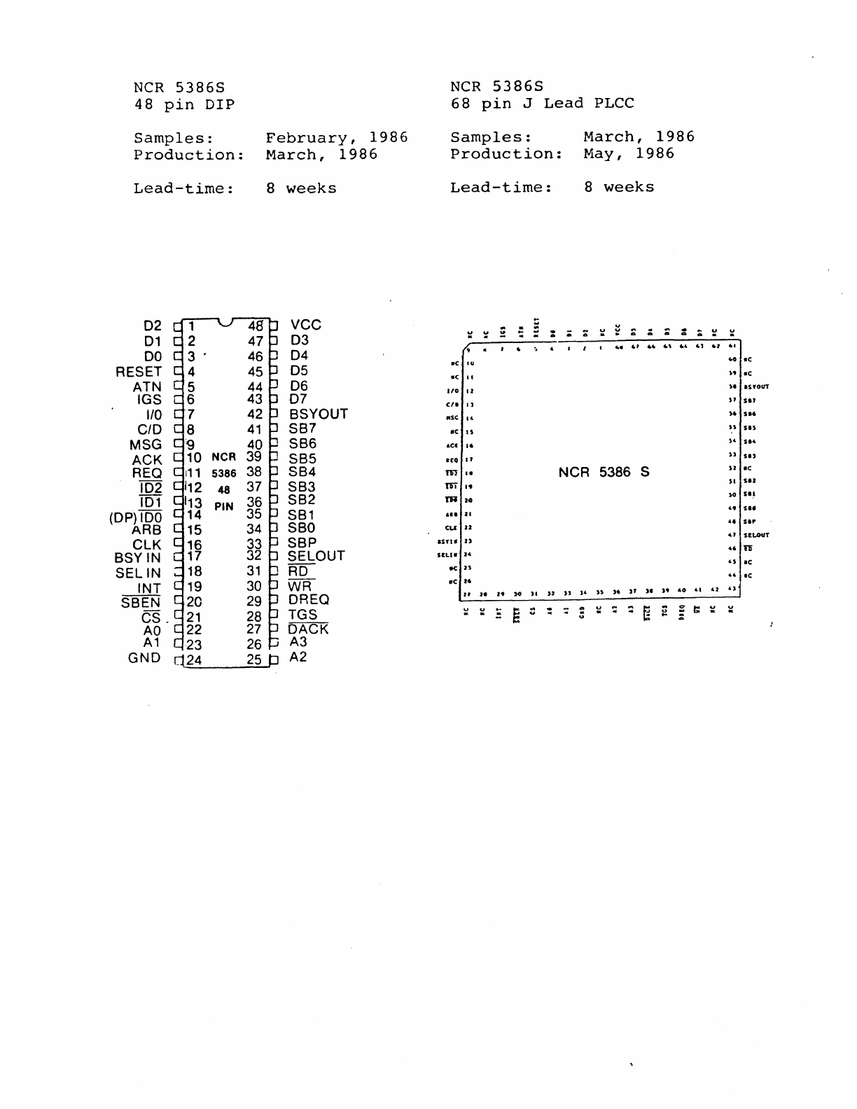
NCR
53865
48
pin
DIP
Samples:
Production:
Lead-time:
02
01
DO
RESET
ATN
IGS
110
C/O
MSG
ACK
REO
102
101
(OP)
100
ARB
eLK
BSYIN
SELIN
INT
SBEN
CS.
AO
A1
GND
February,
1986
March,
1986
8
weeks
vce
03
04
05
06
07
BSYOUT
SB7
SS6
SB5
SB4
SS3
SB2
SB1
SSO
SBP
SELOUT
RD
WR
DREO
TGS
DACK
A3
A2
NCR
53865
68
pin
J
Lead
PLCC
Samples:
Production:
March,
1986
May,
1986
Lead-time:
8
weeks
..
..
...
u .
~
~
y
..
. ;; :
~
u : : :
..
..
..
, • " . I I .
....
r
••
.,
.,
.e
IV
.e
••
110
II
C/.
'J
lise
..
.c
J)
ace
..
IEQ
If
m
..
NCR
5386 S
liT
"
m
zo
AI.
U
eLI U
lUll
U
SltLU
Z4
IICn
.e
I.
Jl
I. I.
)0
JI
)I
n
]'
))
,.
"
)I
,.
"0
:;
~
.,
.,
"
'I
~ ~
E
~
:
-:
..
~
~
::
~
..
<:T
t:
~
u
..
-u
~
.,
.0
.c
"
.c
U ISYOUT
Sf
5.'
,.
5
••
n
sn
" s
••
))
51)
u
.e
SI
51!
)0
Sli
..
5
..
••
s.r
.,
SlLOVT
..
iD
')
.e
u Ie
']
~
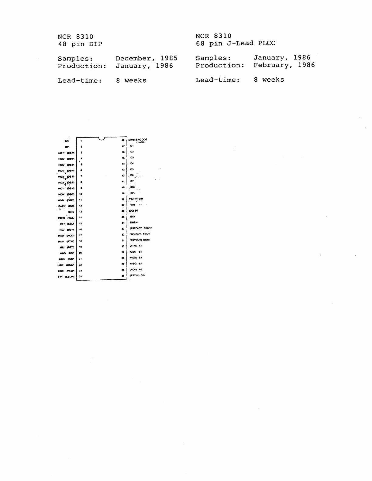
NCR
8310
NCR
8310
48
pin
DIP
68
pin
J-Lead
PLCC
Samples:
December,
1985
Samples:
January,
1986
Production:
January,
1986
Production:
February,
1986
Lead-time:
8
weeks
Lead-time:
8
weeks
DO
• 1A"
••
fHCOOf
1'01',
~
.1
0'
M011
1D111~
•
D2
-
CDtI6'l
.s
02
-
1DII5IJ
~
-
10M)
a
os
~-.
M03I
~
42
.
DI.
~
-
~.
MOlt,,~
.,
07
MD
••
1118'"
..,
1021
-
~
'0
)6
lOll
-
IDIIPtl
"
)6
(RSTI~£IN
.
HDC
tIGSI
'2
~7
Ydd
p'
..
-
)6
4110180
...
D
'3
N£H
(YG$I
,.
»
IDOl
MFI ISfLII
,S
~
O4KNI
HGI
!MYII M
~
\fIS~OISTIl
£OIJT(
MAGI
.,.ctUI
11
32
ISfl.OOT)
FOIST
MAli
IATH/I "
31
(tIsrollT)
GOUT
M£I (lllST" "
30
lATH I AI
H80I
lIIO'I
20
ze
PDI
8'
... "
(C/Dt\
2'
a
(fIEOIII3
-
tMSGII
22
27
...
SG182
t4tIl'
l"'£011
23 a lACK'
AO
F
...
(5(l""
2_
2S
(tISYIN,
GIH

NCR
8310
52
pin
J
Lead
PLCC
Samples:
Production:
Lead-time:
January,
1986
March,
1986
8
weeks
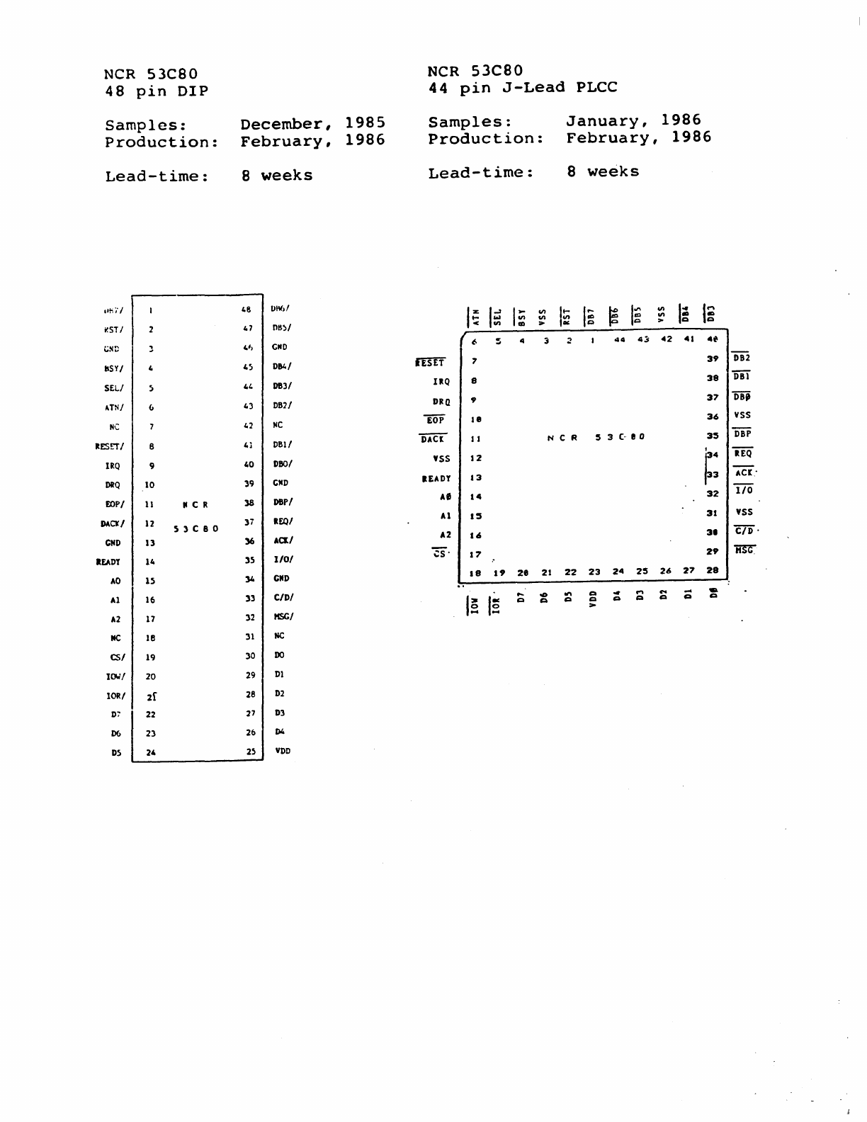
NCR
53C80
NCR
53C80
48
pin
DIP
44
pin
J-Lead
PLCC
Samples:
December,
1985
Samples:
January,
1986
Production:
February,
1986
Production:
February,
1986
Lead-time:
8
weeks
Lead-time:
8
weeks
'Ihi"'
48
D"M
I;
Ig
I:
IE
I~
~
I~
411
I:
I~
411
411
411
r.ST'
47
nB:>1
> >
t;ND 41,
eND
/
~
:; 4
:;
2
44
4~
.. 2 41
4"
bSYI
4:1
01141
IESET
7
39
DB2
SELl
~
41.
DB31
IltQ
8
38
Dil
"TNI
(,
43
DB21 OltQ 9
37
08,
He
42
He
ToP
18
36
YSS
RESITI 8
41
DB11
"DAcl
II
NCR
:5
3
C"
eo
3:5
DiP
, IEQ
IRQ
9 40
DBOI
'55
12
~:
DRQ
10 39
eND
lEADY
13
AC[-
FlJPI
D8P/
A'
14
32
ITo
11
II
C R
38
DACJI
12
)i
REOI
AI
1:5
31
YS5
5 ) C
80
CND
1)
36 ACl/
A2
16
31
c/o
-
lEADY 14
35
1/01
E-
17
29
~
AO
15
34
CliO
18
19
2.
21
22
23
24
2:5
26
27
28
Al
16
33
c/o/
po.
00
.,..
Q
..
....
C'oO
-
..
I~
I~
Q Q Q Q Q Q Q Q Q
>
A2
17
)2
HSC/
IfC 18
31
He
CS/
19
30
DO
ICJJ/ 20
29
Dl
IORI 2f
28
02
D:"
22 27
OJ
D6
23
2&
D4
D5
24 25
VOD
